WO2022172556A1 - Impact detection device and impact detection method - Google Patents
Impact detection device and impact detection method Download PDFInfo
- Publication number
- WO2022172556A1 WO2022172556A1 PCT/JP2021/042870 JP2021042870W WO2022172556A1 WO 2022172556 A1 WO2022172556 A1 WO 2022172556A1 JP 2021042870 W JP2021042870 W JP 2021042870W WO 2022172556 A1 WO2022172556 A1 WO 2022172556A1
- Authority
- WO
- WIPO (PCT)
- Prior art keywords
- impact detection
- detection device
- timing
- impact
- sensor
- Prior art date
Links
- 238000001514 detection method Methods 0.000 title claims abstract description 96
- 238000004891 communication Methods 0.000 claims description 19
- 238000013075 data extraction Methods 0.000 claims description 17
- 238000005452 bending Methods 0.000 claims description 6
- 238000000034 method Methods 0.000 claims description 4
- 230000003595 spectral effect Effects 0.000 claims 3
- 230000002123 temporal effect Effects 0.000 abstract 1
- 238000010586 diagram Methods 0.000 description 10
- 238000004458 analytical method Methods 0.000 description 7
- 238000000605 extraction Methods 0.000 description 7
- 230000005540 biological transmission Effects 0.000 description 6
- 230000007274 generation of a signal involved in cell-cell signaling Effects 0.000 description 6
- 239000000284 extract Substances 0.000 description 4
- 230000005856 abnormality Effects 0.000 description 3
- 238000013473 artificial intelligence Methods 0.000 description 3
- 238000004364 calculation method Methods 0.000 description 3
- 238000006243 chemical reaction Methods 0.000 description 3
- XEEYBQQBJWHFJM-UHFFFAOYSA-N Iron Chemical compound [Fe] XEEYBQQBJWHFJM-UHFFFAOYSA-N 0.000 description 2
- 230000002159 abnormal effect Effects 0.000 description 2
- 230000001133 acceleration Effects 0.000 description 2
- 230000010287 polarization Effects 0.000 description 2
- 230000000694 effects Effects 0.000 description 1
- 238000005516 engineering process Methods 0.000 description 1
- 230000006870 function Effects 0.000 description 1
- 230000010354 integration Effects 0.000 description 1
- 229910052742 iron Inorganic materials 0.000 description 1
- 238000004519 manufacturing process Methods 0.000 description 1
- 229920000747 poly(lactic acid) Polymers 0.000 description 1
- 239000004626 polylactic acid Substances 0.000 description 1
- 229920006395 saturated elastomer Polymers 0.000 description 1
- 238000001228 spectrum Methods 0.000 description 1
- -1 utility Substances 0.000 description 1
- 239000002023 wood Substances 0.000 description 1
Images


Classifications
-
- A—HUMAN NECESSITIES
- A63—SPORTS; GAMES; AMUSEMENTS
- A63B—APPARATUS FOR PHYSICAL TRAINING, GYMNASTICS, SWIMMING, CLIMBING, OR FENCING; BALL GAMES; TRAINING EQUIPMENT
- A63B60/00—Details or accessories of golf clubs, bats, rackets or the like
- A63B60/46—Measurement devices associated with golf clubs, bats, rackets or the like for measuring physical parameters relating to sporting activity, e.g. baseball bats with impact indicators or bracelets for measuring the golf swing
-
- A—HUMAN NECESSITIES
- A63—SPORTS; GAMES; AMUSEMENTS
- A63B—APPARATUS FOR PHYSICAL TRAINING, GYMNASTICS, SWIMMING, CLIMBING, OR FENCING; BALL GAMES; TRAINING EQUIPMENT
- A63B53/00—Golf clubs
- A63B53/10—Non-metallic shafts
-
- A—HUMAN NECESSITIES
- A63—SPORTS; GAMES; AMUSEMENTS
- A63B—APPARATUS FOR PHYSICAL TRAINING, GYMNASTICS, SWIMMING, CLIMBING, OR FENCING; BALL GAMES; TRAINING EQUIPMENT
- A63B24/00—Electric or electronic controls for exercising apparatus of preceding groups; Controlling or monitoring of exercises, sportive games, training or athletic performances
- A63B24/0003—Analysing the course of a movement or motion sequences during an exercise or trainings sequence, e.g. swing for golf or tennis
- A63B24/0006—Computerised comparison for qualitative assessment of motion sequences or the course of a movement
-
- A—HUMAN NECESSITIES
- A63—SPORTS; GAMES; AMUSEMENTS
- A63B—APPARATUS FOR PHYSICAL TRAINING, GYMNASTICS, SWIMMING, CLIMBING, OR FENCING; BALL GAMES; TRAINING EQUIPMENT
- A63B24/00—Electric or electronic controls for exercising apparatus of preceding groups; Controlling or monitoring of exercises, sportive games, training or athletic performances
- A63B24/0062—Monitoring athletic performances, e.g. for determining the work of a user on an exercise apparatus, the completed jogging or cycling distance
-
- A—HUMAN NECESSITIES
- A63—SPORTS; GAMES; AMUSEMENTS
- A63B—APPARATUS FOR PHYSICAL TRAINING, GYMNASTICS, SWIMMING, CLIMBING, OR FENCING; BALL GAMES; TRAINING EQUIPMENT
- A63B69/00—Training appliances or apparatus for special sports
- A63B69/36—Training appliances or apparatus for special sports for golf
- A63B69/3623—Training appliances or apparatus for special sports for golf for driving
- A63B69/3632—Clubs or attachments on clubs, e.g. for measuring, aligning
-
- A—HUMAN NECESSITIES
- A63—SPORTS; GAMES; AMUSEMENTS
- A63B—APPARATUS FOR PHYSICAL TRAINING, GYMNASTICS, SWIMMING, CLIMBING, OR FENCING; BALL GAMES; TRAINING EQUIPMENT
- A63B71/00—Games or sports accessories not covered in groups A63B1/00 - A63B69/00
- A63B71/06—Indicating or scoring devices for games or players, or for other sports activities
- A63B71/0619—Displays, user interfaces and indicating devices, specially adapted for sport equipment, e.g. display mounted on treadmills
- A63B71/0622—Visual, audio or audio-visual systems for entertaining, instructing or motivating the user
-
- A—HUMAN NECESSITIES
- A63—SPORTS; GAMES; AMUSEMENTS
- A63B—APPARATUS FOR PHYSICAL TRAINING, GYMNASTICS, SWIMMING, CLIMBING, OR FENCING; BALL GAMES; TRAINING EQUIPMENT
- A63B24/00—Electric or electronic controls for exercising apparatus of preceding groups; Controlling or monitoring of exercises, sportive games, training or athletic performances
- A63B24/0062—Monitoring athletic performances, e.g. for determining the work of a user on an exercise apparatus, the completed jogging or cycling distance
- A63B2024/0068—Comparison to target or threshold, previous performance or not real time comparison to other individuals
-
- A—HUMAN NECESSITIES
- A63—SPORTS; GAMES; AMUSEMENTS
- A63B—APPARATUS FOR PHYSICAL TRAINING, GYMNASTICS, SWIMMING, CLIMBING, OR FENCING; BALL GAMES; TRAINING EQUIPMENT
- A63B2102/00—Application of clubs, bats, rackets or the like to the sporting activity ; particular sports involving the use of balls and clubs, bats, rackets, or the like
- A63B2102/32—Golf
-
- A—HUMAN NECESSITIES
- A63—SPORTS; GAMES; AMUSEMENTS
- A63B—APPARATUS FOR PHYSICAL TRAINING, GYMNASTICS, SWIMMING, CLIMBING, OR FENCING; BALL GAMES; TRAINING EQUIPMENT
- A63B2220/00—Measuring of physical parameters relating to sporting activity
- A63B2220/20—Distances or displacements
-
- A—HUMAN NECESSITIES
- A63—SPORTS; GAMES; AMUSEMENTS
- A63B—APPARATUS FOR PHYSICAL TRAINING, GYMNASTICS, SWIMMING, CLIMBING, OR FENCING; BALL GAMES; TRAINING EQUIPMENT
- A63B2220/00—Measuring of physical parameters relating to sporting activity
- A63B2220/50—Force related parameters
- A63B2220/51—Force
-
- A—HUMAN NECESSITIES
- A63—SPORTS; GAMES; AMUSEMENTS
- A63B—APPARATUS FOR PHYSICAL TRAINING, GYMNASTICS, SWIMMING, CLIMBING, OR FENCING; BALL GAMES; TRAINING EQUIPMENT
- A63B2220/00—Measuring of physical parameters relating to sporting activity
- A63B2220/50—Force related parameters
- A63B2220/58—Measurement of force related parameters by electric or magnetic means
-
- A—HUMAN NECESSITIES
- A63—SPORTS; GAMES; AMUSEMENTS
- A63B—APPARATUS FOR PHYSICAL TRAINING, GYMNASTICS, SWIMMING, CLIMBING, OR FENCING; BALL GAMES; TRAINING EQUIPMENT
- A63B2220/00—Measuring of physical parameters relating to sporting activity
- A63B2220/62—Time or time measurement used for time reference, time stamp, master time or clock signal
-
- A—HUMAN NECESSITIES
- A63—SPORTS; GAMES; AMUSEMENTS
- A63B—APPARATUS FOR PHYSICAL TRAINING, GYMNASTICS, SWIMMING, CLIMBING, OR FENCING; BALL GAMES; TRAINING EQUIPMENT
- A63B2220/00—Measuring of physical parameters relating to sporting activity
- A63B2220/80—Special sensors, transducers or devices therefor
- A63B2220/803—Motion sensors
-
- A—HUMAN NECESSITIES
- A63—SPORTS; GAMES; AMUSEMENTS
- A63B—APPARATUS FOR PHYSICAL TRAINING, GYMNASTICS, SWIMMING, CLIMBING, OR FENCING; BALL GAMES; TRAINING EQUIPMENT
- A63B2220/00—Measuring of physical parameters relating to sporting activity
- A63B2220/80—Special sensors, transducers or devices therefor
- A63B2220/83—Special sensors, transducers or devices therefor characterised by the position of the sensor
- A63B2220/833—Sensors arranged on the exercise apparatus or sports implement
-
- A—HUMAN NECESSITIES
- A63—SPORTS; GAMES; AMUSEMENTS
- A63B—APPARATUS FOR PHYSICAL TRAINING, GYMNASTICS, SWIMMING, CLIMBING, OR FENCING; BALL GAMES; TRAINING EQUIPMENT
- A63B2225/00—Miscellaneous features of sport apparatus, devices or equipment
- A63B2225/50—Wireless data transmission, e.g. by radio transmitters or telemetry
-
- A—HUMAN NECESSITIES
- A63—SPORTS; GAMES; AMUSEMENTS
- A63B—APPARATUS FOR PHYSICAL TRAINING, GYMNASTICS, SWIMMING, CLIMBING, OR FENCING; BALL GAMES; TRAINING EQUIPMENT
- A63B2225/00—Miscellaneous features of sport apparatus, devices or equipment
- A63B2225/74—Miscellaneous features of sport apparatus, devices or equipment with powered illuminating means, e.g. lights
Definitions
- Patent Document 1 it is necessary to use a plurality of sensors, and the user's swing is detected by comprehensively analyzing the information obtained from these sensors. That is, there is a possibility that the structure of the device becomes complicated and the processing becomes complicated.
- the timing at which the columnar portion of the sports equipment impacts a desired object with a simple structure.
- the sports equipment is a golf club
- the timing at which the golf club impacts the golf ball can be detected more accurately.
- the impact detection device 10 includes a transmission side device 11 and a reception side device 12 . As shown in FIG. 1 , transmitting device 11 is attached to the surface of shaft 201 of golf club 200 .
- the sensor signal generation unit 120, the feature data extraction unit 130, and the communication unit 140 are realized, for example, by a plurality of electronic circuit elements such as ICs mounted on a circuit board or the like.
- the sensor signal generation section 120 outputs the sensor signal to the feature data extraction section 130 .
- the AD converter 131 AD-converts (analog-to-digital converts) the sensor signal.
- the AD converter 131 outputs the digitized sensor signal to the impact timing detector 132 .
- the feature point extraction unit 133 extracts a sensor signal of a predetermined length of time from the impact timing and outputs it as the feature point extraction unit 133 . More specifically, the feature point extraction unit 133 cuts out several seconds (for example, two seconds) before and after the impact timing. As shown in the graph of FIG. 5, the feature data extraction section 130 extracts a plurality of feature points from the clipped result.
- the false detection determination unit 135 determines whether an abnormality has occurred in the feature point. A more specific flow of processing will be described with reference to FIGS. 8 and 9.
- FIG. 9 the feature data extractor 130 extracts a plurality of feature points F5, F6, F7 and F8.
- the false detection determination unit 135 determines the size of each feature point using a reference voltage (reference voltage V3 in this case).
- the erroneous detection determination unit 135 determines that the amplitude of the voltage with respect to the reference voltage V3 is too small at the feature points F5 and F6 (between V2 and V4). In this case, the erroneous detection determination unit 135 determines that the contact failure of the impact detection device 10A has occurred. Also, at the characteristic point F8, it is determined that the amplitude of the reference voltage V3 is too large (V1). In this case, the erroneous detection determination unit 135 determines that the voltage is saturated. On the other hand, the erroneous detection determination unit 135 determines that the characteristic point F7 is normal.
- the feature data extraction unit 130 determines whether to continue subsequent processing. At this time, if at least one abnormal value occurs, the feature data extraction unit 130 may suspend the process and display a warning message or the like.
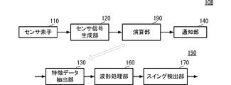
- the impact detection device 10B has the configuration of the transmitting device 11 and the receiving device 12 according to the first embodiment. It differs from the impact detection device 10 .
- Other configurations of the impact detection device 10B are the same as those of the impact detection device 10, and descriptions of the same parts are omitted.
Landscapes
- Health & Medical Sciences (AREA)
- General Health & Medical Sciences (AREA)
- Physical Education & Sports Medicine (AREA)
- Engineering & Computer Science (AREA)
- Human Computer Interaction (AREA)
- Multimedia (AREA)
- Golf Clubs (AREA)
Abstract
An impact detection device (10) includes: a sensor (110) that, with respect to sports equipment (200) having a columnar part (201) and a striking part (202) connected to the columnar part (201), is not connected to the striking part (202) but is attached to the columnar part (201) and that outputs sensor signals acquired as a result of the sports equipment (200) being swung; and a feature-data identifying unit (130) that employs the sensor signals to detect the timing at which the striking part (202) receives an external pressure on the basis of temporal changes in the sensor signals output as a result of the striking part (202) receiving the external pressure.
Description
本発明は、スポーツ用具が所望の物体へインパクトするタイミングを検出する技術に関する。
The present invention relates to technology for detecting the timing at which sports equipment impacts a desired object.
特許文献1には、シャフトにセンサ装置を取り付けることによって、利用者のゴルフクラブをスイングする動作を解析する装置が記載されている。
Patent Document 1 describes a device that analyzes a user's swinging motion of a golf club by attaching a sensor device to a shaft.
特許文献1のセンサ装置には、複数のセンサが含まれている。具体的には、加速度センサ、角速度センサ、および歪みセンサである。当該装置は、加速度センサ、および角速度センサから得られる情報と、シャフトの歪みから得られる情報に基づいて使用者のゴルフクラブのスイングを解析している。
The sensor device of Patent Document 1 includes a plurality of sensors. Specifically, they are an acceleration sensor, an angular velocity sensor, and a strain sensor. The device analyzes the swing of the user's golf club based on information obtained from the acceleration sensor and the angular velocity sensor and information obtained from the distortion of the shaft.
しかしながら、特許文献1に示すような従来の構成では、複数のセンサを用いる必要があり、それらのセンサから得られる情報を統合的に解析することによって使用者のスイングを検出している。すなわち、装置の構造が複雑になり、処理が煩雑になる虞があった。
However, in the conventional configuration shown in Patent Document 1, it is necessary to use a plurality of sensors, and the user's swing is detected by comprehensively analyzing the information obtained from these sensors. That is, there is a possibility that the structure of the device becomes complicated and the processing becomes complicated.
したがって、本発明の目的は、簡素な構造でゴルフクラブがゴルフボールへインパクトするタイミングをより精度よく検出できる装置を提供することにある。
Accordingly, an object of the present invention is to provide a device that can more accurately detect the timing at which a golf club impacts a golf ball with a simple structure.
この発明のインパクト検出装置は、柱状部と、柱状部に接続される打撃部とを有するスポーツ用具に対して、打撃部には接続されず、柱状部に取り付けられ、スポーツ用具がスイングされることによって得られるセンサ信号を出力するセンサと、センサ信号を用いて、打撃部が外部から圧力を受けることによって出力されるセンサ信号の時間変化から、打撃部が外部から圧力を受けるタイミングを検出する特徴データ抽出部とを備える。
The impact detection device of the present invention is not connected to the striking part but is attached to the pillar part, and the sports equipment is swung. A sensor that outputs a sensor signal obtained by and uses the sensor signal to detect the timing at which the striking part receives pressure from the outside from the time change of the sensor signal that is output when the striking part receives pressure from the outside. and a data extractor.
この構成では、簡素な構造を用いて、スポーツ用具が所望物体へインパクトするタイミングを検出することができる。
With this configuration, it is possible to detect the timing at which sports equipment impacts a desired object using a simple structure.
この発明によれば、簡素な構造でスポーツ用具の柱状部が所望物体へインパクトするタイミングをより精度よく検出できる。例えば、スポーツ用具がゴルフクラブであれば、ゴルフクラブがゴルフボールへインパクトするタイミングをより精度よく検出できる。
According to this invention, it is possible to more accurately detect the timing at which the columnar portion of the sports equipment impacts a desired object with a simple structure. For example, if the sports equipment is a golf club, the timing at which the golf club impacts the golf ball can be detected more accurately.
(第1の実施形態)
本発明の第1の実施形態に係るインパクト検出装置について、図を参照して説明する。図1は、第1の実施形態に係るインパクト検出装置10の概要図である。図2は、第1の実施形態に係るインパクト検出装置10のブロック図である。図3は、第1の実施形態に係るインパクト検出装置10の特徴データ抽出部130のブロック図である。図4は、第1の実施形態に係るインパクト検出装置10を動作させることによって検出される電圧を示すグラフである。図5は、第1の実施形態に係るインパクト検出装置10を動作させることによって検出される電圧の特徴点を抽出した結果を示すグラフである。図6は、第1の実施形態に係るインパクト検出装置10の動作を示すフローチャートである。図7は、第1の実施形態に係るインパクト検出装置10の受信側装置12の動作を示すフローチャートである。なお、各図は、インパクト検出装置の構成を分かり易くするため、それぞれの構成要素の形状を部分的または全体として誇張して記載している。 (First embodiment)
An impact detection device according to a first embodiment of the present invention will be described with reference to the drawings. FIG. 1 is a schematic diagram of animpact detection device 10 according to the first embodiment. FIG. 2 is a block diagram of the impact detection device 10 according to the first embodiment. FIG. 3 is a block diagram of the feature data extractor 130 of the impact detection device 10 according to the first embodiment. FIG. 4 is a graph showing voltages detected by operating the impact detection device 10 according to the first embodiment. FIG. 5 is a graph showing the result of extracting feature points of voltages detected by operating the impact detection device 10 according to the first embodiment. FIG. 6 is a flow chart showing the operation of the impact detection device 10 according to the first embodiment. FIG. 7 is a flow chart showing the operation of the receiving device 12 of the impact detection device 10 according to the first embodiment. In addition, in each drawing, in order to facilitate understanding of the configuration of the impact detection device, the shape of each component is partially or wholly exaggerated.
本発明の第1の実施形態に係るインパクト検出装置について、図を参照して説明する。図1は、第1の実施形態に係るインパクト検出装置10の概要図である。図2は、第1の実施形態に係るインパクト検出装置10のブロック図である。図3は、第1の実施形態に係るインパクト検出装置10の特徴データ抽出部130のブロック図である。図4は、第1の実施形態に係るインパクト検出装置10を動作させることによって検出される電圧を示すグラフである。図5は、第1の実施形態に係るインパクト検出装置10を動作させることによって検出される電圧の特徴点を抽出した結果を示すグラフである。図6は、第1の実施形態に係るインパクト検出装置10の動作を示すフローチャートである。図7は、第1の実施形態に係るインパクト検出装置10の受信側装置12の動作を示すフローチャートである。なお、各図は、インパクト検出装置の構成を分かり易くするため、それぞれの構成要素の形状を部分的または全体として誇張して記載している。 (First embodiment)
An impact detection device according to a first embodiment of the present invention will be described with reference to the drawings. FIG. 1 is a schematic diagram of an
(インパクト検出装置の概要)
図1を用いて、インパクト検出装置10の概要を示す。インパクト検出装置10は、送信側装置11と受信側装置12を備える。図1に示すように、送信側装置11は、ゴルフクラブ200のシャフト201の表面に取り付けられている。 (Overview of impact detection device)
An overview of theimpact detection device 10 is shown using FIG. The impact detection device 10 includes a transmission side device 11 and a reception side device 12 . As shown in FIG. 1 , transmitting device 11 is attached to the surface of shaft 201 of golf club 200 .
図1を用いて、インパクト検出装置10の概要を示す。インパクト検出装置10は、送信側装置11と受信側装置12を備える。図1に示すように、送信側装置11は、ゴルフクラブ200のシャフト201の表面に取り付けられている。 (Overview of impact detection device)
An overview of the
ゴルフクラブ200は例えば、ドライバーである。ゴルフクラブ200はドライバーに限らず、フェアウェイウッド、ユーティリティ、アイアン、ウェッジ、パターのいずれであってもよい。なお、ゴルフクラブ200が本発明の「スポーツ用具」に対応し、シャフト201が本発明の「柱状部」に対応し、ヘッド202が本発明の「打撃部」に対応する。
The golf club 200 is, for example, a driver. The golf club 200 is not limited to a driver, and may be a fairway wood, utility, iron, wedge, or putter. The golf club 200 corresponds to the "sports equipment" of the present invention, the shaft 201 corresponds to the "columnar portion" of the present invention, and the head 202 corresponds to the "hitting portion" of the present invention.
利用者は、ゴルフクラブ200を用いて、ゴルフボールを打つ(スイング動作)。この時、センサ素子110は、このスイング動作による捻れを検出する。送信側装置11は、この捻れから算出したセンサ信号を用いて、解析を行う。
The user uses the golf club 200 to hit the golf ball (swing motion). At this time, the sensor element 110 detects the twist caused by this swing motion. The transmitting device 11 performs analysis using the sensor signal calculated from this twist.
送信側装置11は、当該結果を受信側装置12に送信する。受信側装置12は、当該結果を受信する。受信側装置12は、当該結果を用いて、グラフ化等の処理を行う。利用者は、グラフ化等のGUI表示された特徴を確認する。なお、この特徴とは利用者のスイングの強弱、タイミング、癖などである。さらに、利用者のスイングに対するアドバイスが表示されているとよい。
The transmitting device 11 transmits the result to the receiving device 12. The receiving device 12 receives the result. The receiving device 12 uses the result to perform processing such as graphing. The user confirms the GUI-displayed features such as graphing. It should be noted that this feature is the strength, timing, habit, etc. of the user's swing. Furthermore, it is preferable that advice for the user's swing is displayed.
(インパクト検出装置の詳細)
次に、図1、図2、図3、図4、図5、図6、図7を用いて、インパクト検出装置10の詳細な構成について説明する。インパクト検出装置10の送信側装置11は、センサ素子110、センサ信号生成部120、特徴データ抽出部130、通信部140を備える。特徴データ抽出部130は、AD変換部131、インパクトタイミング検出部132、および、特徴点抽出部133を備える。 (Details of the impact detection device)
Next, a detailed configuration of theimpact detection device 10 will be described with reference to FIGS. 1, 2, 3, 4, 5, 6, and 7. FIG. The transmission side device 11 of the impact detection device 10 includes a sensor element 110 , a sensor signal generation section 120 , a feature data extraction section 130 and a communication section 140 . The feature data extraction section 130 includes an AD conversion section 131 , an impact timing detection section 132 and a feature point extraction section 133 .
次に、図1、図2、図3、図4、図5、図6、図7を用いて、インパクト検出装置10の詳細な構成について説明する。インパクト検出装置10の送信側装置11は、センサ素子110、センサ信号生成部120、特徴データ抽出部130、通信部140を備える。特徴データ抽出部130は、AD変換部131、インパクトタイミング検出部132、および、特徴点抽出部133を備える。 (Details of the impact detection device)
Next, a detailed configuration of the
センサ信号生成部120、特徴データ抽出部130、通信部140は、例えば、回路基板等に実装されたIC等の複数の電子回路素子によって実現される。
The sensor signal generation unit 120, the feature data extraction unit 130, and the communication unit 140 are realized, for example, by a plurality of electronic circuit elements such as ICs mounted on a circuit board or the like.
インパクト検出装置10の受信側装置12は、通信部150、波形処理部160、スイング検出部170、通知部180を備える。なお、受信側装置12は、例えばスマートフォン、タブレット等の通信手段および表示手段等を備えた装置であればよい。
The receiving device 12 of the impact detection device 10 includes a communication unit 150, a waveform processing unit 160, a swing detection unit 170, and a notification unit 180. Note that the receiving-side device 12 may be a device such as a smartphone, a tablet, or the like, provided with communication means, display means, and the like.
インパクト検出装置10の詳細な構成、および処理の流れを説明する。利用者は、ゴルフクラブ200を用いて、ゴルフボールを打つ(スイング動作)。
A detailed configuration and processing flow of the impact detection device 10 will be described. A user uses the golf club 200 to hit a golf ball (swing motion).
利用者がゴルフボールを打つことで、ゴルフクラブ200のヘッド202にゴルフボールが衝突(インパクト)する。このことによって、ゴルフボールは前方へ飛ぶ。この際、ヘッド202には、インパクトの瞬間に反発力が伝わり、この反発力がシャフト201に伝わる。この反発力によって、シャフト201には捻れが発生する。なお、反発力とはヘッド202が外部から圧力を受けることによって発生する力である。
When the user hits the golf ball, the golf ball collides (impacts) with the head 202 of the golf club 200 . This causes the golf ball to fly forward. At this time, a repulsive force is transmitted to the head 202 at the moment of impact, and this repulsive force is transmitted to the shaft 201 . This repulsive force causes the shaft 201 to twist. Note that the repulsive force is a force generated when the head 202 receives pressure from the outside.
センサ素子110は、この捻れを検出する。より具体的には、センサ素子110は、圧電性を有する膜状の主体と、検出用電極とを備える。主体は、例えば、ポリ乳酸を主成分としており、曲げおよび捻れに応じて分極する。検出用電極は、シャフト201の表面に取り付けられている。検出用電極は、曲げによる電荷、および、捻れによる電荷を出力可能なように、シャフト201に取り付けられている。
The sensor element 110 detects this twist. More specifically, the sensor element 110 includes a film-like main body having piezoelectricity and a detection electrode. The main body is made mainly of polylactic acid, for example, and is polarized according to bending and twisting. A detection electrode is attached to the surface of the shaft 201 . The detection electrodes are attached to the shaft 201 so as to output charges due to bending and charges due to twisting.
このセンサ素子110を用いた場合、曲げの方向および捻れの方向に応じて分極方向が変化する。また、曲げの大きさおよび捻れの大きさに応じて分極によって生じる電荷の大きさが異なる。すなわち、利用者がゴルフクラブ200をスイングした際に、インパクトのような強い衝撃時には大きな電荷が発生し、インパクトがない小さい衝撃時には小さな電荷が発生する。
When this sensor element 110 is used, the polarization direction changes according to the direction of bending and the direction of twisting. Also, the magnitude of electric charge generated by polarization differs depending on the magnitude of bending and twisting. That is, when the user swings the golf club 200, a large electric charge is generated when there is a strong impact such as an impact, and a small electric charge is generated when there is no impact and a small impact.
センサ信号生成部120は、センサ素子110で発生した電荷から電圧信号を生成する。センサ信号生成部120は、所定の電子回路によって実現される。センサ信号生成部120は、例えば、積分回路を含み、センサ素子110で発生した電荷から電圧信号であるセンサ信号を生成する。
The sensor signal generation section 120 generates a voltage signal from the charges generated by the sensor element 110 . The sensor signal generator 120 is realized by a predetermined electronic circuit. The sensor signal generator 120 includes, for example, an integration circuit, and generates a sensor signal, which is a voltage signal, from charges generated in the sensor element 110 .
センサ信号生成部120は、センサ信号を特徴データ抽出部130に出力する。AD変換部131は、センサ信号をAD変換(アナログデジタル変換)する。AD変換部131は、デジタル化されたセンサ信号を、インパクトタイミング検出部132に出力する。
The sensor signal generation section 120 outputs the sensor signal to the feature data extraction section 130 . The AD converter 131 AD-converts (analog-to-digital converts) the sensor signal. The AD converter 131 outputs the digitized sensor signal to the impact timing detector 132 .
インパクトタイミング検出部132は、例えば、センサ信号が閾値を超えたタイミングを検出し、この検出タイミングをインパクトのタイミング(以下、インパクトタイミング)として検出する。インパクトタイミング検出部132は、センサ信号とインパクトタイミングとを、特徴点抽出部133に出力する。
The impact timing detection unit 132 detects, for example, the timing at which the sensor signal exceeds the threshold, and detects this detection timing as the impact timing (hereinafter, impact timing). The impact timing detection section 132 outputs the sensor signal and the impact timing to the feature point extraction section 133 .
なお、インパクトタイミング検出部132が閾値として用いる値は、任意に設定できる。閾値は、例えばゴルフクラブ200の種類によって決定されるものでも、利用者の性別や体型によって決定されるものであってもよい。
Note that the value used as the threshold value by the impact timing detection unit 132 can be set arbitrarily. The threshold value may be determined, for example, by the type of golf club 200, or may be determined by the user's sex or body type.
このように、インパクト検出装置10はシャフト201に取り付けたセンサ素子110からの出力(センサ信号)だけで、インパクトタイミングを検出することができる。
In this way, the impact detection device 10 can detect the impact timing only with the output (sensor signal) from the sensor element 110 attached to the shaft 201 .
特徴点抽出部133は、インパクトタイミングから所定時間長のセンサ信号を抽出して、特徴点抽出部133として出力する。より具体的には、特徴点抽出部133は、インパクトタイミングの前後数秒間(例えば2秒間)を切り出す。特徴点抽出部133は、図5のグラフに示すように、特徴データ抽出部130は、この切り出した結果から複数の特徴点を抽出する。
The feature point extraction unit 133 extracts a sensor signal of a predetermined length of time from the impact timing and outputs it as the feature point extraction unit 133 . More specifically, the feature point extraction unit 133 cuts out several seconds (for example, two seconds) before and after the impact timing. As shown in the graph of FIG. 5, the feature data extraction section 130 extracts a plurality of feature points from the clipped result.
図5における特徴点とは、例えばF1,F2,F3,F4などである。この特徴点は、所定時間内において各値の微分値が正から負に変わる点、または負から正に変わる点などを用いる。特徴点抽出部133は、特徴点F1,F2,F3,F4を8bitのデータ(以下、特徴点データ)に変換する。特徴点データには、インパクトタイミングを含んでもよい。
The feature points in FIG. 5 are F1, F2, F3, F4, etc., for example. The characteristic point is a point where the differential value of each value changes from positive to negative or from negative to positive within a predetermined time. The feature point extraction unit 133 converts the feature points F1, F2, F3, and F4 into 8-bit data (hereinafter referred to as feature point data). The feature point data may include impact timing.
なお、特徴データ抽出部130は、所定時間あたりの電圧の変化量が閾値以上(閾値は例えば、2.0V~2.5V、もしくは3V)である点や、大きさ、方向性を持つ値の変化を用いて、特徴点を抽出してもよい。
Note that the characteristic data extracting unit 130 detects points where the amount of change in voltage per predetermined time is greater than or equal to a threshold value (threshold value is, for example, 2.0 V to 2.5 V or 3 V), and values having magnitude and directionality. Variations may be used to extract feature points.
特徴データ抽出部130は、通信部140を介して、特徴点データを受信側装置12に送信する。通信部140は無線通信を行う。この無線通信は、例えば、BLE(Bluetooth(登録商標) Low Energy)である。BLEを用いることによって、省電力かつスマートフォンなどのデバイスとの親和性が向上し、利便性が高い通信を実現できる。
The feature data extraction unit 130 transmits the feature point data to the receiving device 12 via the communication unit 140 . The communication unit 140 performs wireless communication. This wireless communication is, for example, BLE (Bluetooth (registered trademark) Low Energy). By using BLE, power saving and compatibility with devices such as smartphones are improved, and highly convenient communication can be realized.
受信側装置12の通信部150は、特徴点データを受信する。通信部150は、特徴点データを波形処理部160に出力する。波形処理部160は、特徴点データをフーリエ変換し、各周波数成分で比較する。
The communication unit 150 of the receiving device 12 receives the feature point data. The communication section 150 outputs the feature point data to the waveform processing section 160 . The waveform processing unit 160 Fourier-transforms the feature point data and compares each frequency component.
この比較方法を詳しく説明する。まず、フーリエ変換後の固有振動数を低周波数側、高周波数側の2つの領域に分けて解析を行う。具体的には、波形処理部160は、低周波数側、高周波数側のそれぞれの範囲で発生する最大スペクトルの周波数を取得する。例えば、低周波数側は3~10Hzであり、高周波数側は10~100Hzである。なお、低周波数側と高周波数側の周波数は適宜決定できる。
I will explain this comparison method in detail. First, analysis is performed by dividing the natural frequency after Fourier transform into two regions, one on the low frequency side and the other on the high frequency side. Specifically, the waveform processing unit 160 acquires the frequency of the maximum spectrum occurring in each of the low frequency side and the high frequency side. For example, the low frequency side is 3-10 Hz and the high frequency side is 10-100 Hz. The frequencies on the low frequency side and the high frequency side can be determined as appropriate.
波形処理部160は、利用者のスイングの強弱、タイミング、癖などの解析結果から得られたデータをスイング検出部170に出力する。スイング検出部170は、解析結果から得られたデータを数値化する。このとき、スイング検出部170は、当該数値がシャフト201の種別(ゴルフクラブ200の種別)に依存する値であるか、利用者に依存する値であるかを判定する。
The waveform processing unit 160 outputs to the swing detection unit 170 the data obtained from the analysis results of the user's swing intensity, timing, habits, and the like. The swing detection unit 170 digitizes the data obtained from the analysis results. At this time, the swing detection unit 170 determines whether the numerical value depends on the type of the shaft 201 (type of the golf club 200) or the user.
さらに、スイング検出部170は、人工知能AI(Artificial Intelligence)を用いて解析するとよい。この場合、AIは実験データで得られたデータとターゲットであるラベル付けがされたデータに近いものに分類する学習データ(教師データ)を用いてもよいし、波形の特徴からK-means法を用いて、任意のN個に分類してもよい。このようにAIを用いることによって、利用者のスイングの特徴(利用者のスイングの強弱、タイミング、癖など)を比較することができる。
Furthermore, the swing detection unit 170 may analyze using artificial intelligence (AI). In this case, the AI may use learning data (teacher data) that classifies the data obtained from the experimental data and data close to the labeled data that is the target, or use the K-means method from the characteristics of the waveform. may be used to classify into arbitrary N numbers. By using AI in this way, it is possible to compare the characteristics of the user's swing (strength, timing, habit, etc. of the user's swing).
スイング検出部170は、数値化した結果を通知部180に出力する。通知部180は、図1に示す通知部180のようにグラフ等を用いて、当該結果をGUI表示する。利用者は、自身のスイング動作から得られた特徴を確認する。通知部180には、利用者のスイングの強弱、タイミング、癖などがグラフで表示されており、さらには利用者のスイングに対するアドバイスが表示されているとよい。このとき、通知部180には、スイングの特徴がグラフを用いて表示されているため、利用者にとって視覚的に分かりやすいというメリットが得られる。
The swing detection unit 170 outputs the quantified result to the notification unit 180 . The notification unit 180 uses a graph or the like like the notification unit 180 shown in FIG. 1 to display the result in a GUI. The user confirms the features obtained from his own swing motion. In the notification section 180, the user's swing strength, timing, habit, etc. are displayed in a graph, and further advice on the user's swing may be displayed. At this time, since the characteristic of the swing is displayed using a graph in the notification unit 180, there is an advantage that the user can easily understand the swing visually.
図6、図7を用いて、インパクト検出装置10の処理の流れを説明する。まず、図6を用いて、送信側装置11の処理の流れを説明する。
The flow of processing of the impact detection device 10 will be described with reference to FIGS. 6 and 7. FIG. First, with reference to FIG. 6, the processing flow of the transmitting device 11 will be described.
センサ素子110は、スイング動作によって発生する、捻れを検出する(S101)。
The sensor element 110 detects twist caused by swing motion (S101).
センサ信号生成部120は、センサ素子110で発生した電荷から電圧信号を生成する。センサ信号生成部120は、電圧信号を特徴データ抽出部130に出力する(S102)。
The sensor signal generation section 120 generates a voltage signal from the charges generated by the sensor element 110 . The sensor signal generator 120 outputs the voltage signal to the feature data extractor 130 (S102).
特徴データ抽出部130は、AD変換後の電圧の絶対値を算出し、この電圧の絶対値が閾値を超えたタイミングから、ゴルフクラブ200のヘッド202がゴルフボールにインパクトしたタイミングを検出する(S103)。
The feature data extraction unit 130 calculates the absolute value of the voltage after AD conversion, and detects the timing at which the head 202 of the golf club 200 impacts the golf ball from the timing when the absolute value of the voltage exceeds the threshold (S103). ).
特徴データ抽出部130は、インパクトのタイミングの前後数秒間から特徴点を抽出する(S104)。
The feature data extraction unit 130 extracts feature points from several seconds before and after the impact timing (S104).
特徴データ抽出部130は、通信部140を介して、特徴点データを受信側装置12に送信する(S105)。
The feature data extraction unit 130 transmits the feature point data to the receiving device 12 via the communication unit 140 (S105).
次に、図7を用いて、受信側装置12の処理の流れを説明する。
受信側装置12の通信部150は、特徴点データを受信する(S111)。 Next, the processing flow of the receivingdevice 12 will be described with reference to FIG.
Thecommunication unit 150 of the receiving device 12 receives the feature point data (S111).
受信側装置12の通信部150は、特徴点データを受信する(S111)。 Next, the processing flow of the receiving
The
通信部150は、特徴点データを波形処理部160に出力する。波形処理部160は、当該特徴点データをフーリエ変換し、各周波数成分で比較する(S112)。
The communication unit 150 outputs the feature point data to the waveform processing unit 160. The waveform processing unit 160 Fourier-transforms the feature point data and compares each frequency component (S112).
波形処理部160は、解析を行った結果をスイング検出部170に出力する。スイング検出部170は、解析結果から得られたデータを数値化する(S113)。
The waveform processing section 160 outputs the analysis result to the swing detection section 170 . The swing detection unit 170 digitizes the data obtained from the analysis results (S113).
スイング検出部170は、数値化した結果を通知部180に出力する。通知部180は、当該結果をGUI表示する(S114)。
The swing detection unit 170 outputs the quantified result to the notification unit 180 . The notification unit 180 displays the result as a GUI (S114).
このように構成することで、シャフトにのみ取り付けられた簡素な構造であっても、インパクトタイミングを含む、利用者自身のスイング時の特徴を精度よく検出できる。また、シャフトに取り付けられたインパクト検出装置は非常に軽量であるため、利用者の使用感を損なわない。
By configuring in this way, even with a simple structure attached only to the shaft, it is possible to accurately detect the characteristics of the user's own swing, including the impact timing. Moreover, since the impact detection device attached to the shaft is extremely lightweight, it does not impair the user's usability.
上述の構成では、インパクト検出装置10の送信側装置11の取り付け位置を特に既定していない。このことによって、使用者は取り付け位置を意識する必要がなく、利便性が高い。
In the above configuration, the attachment position of the transmission side device 11 of the impact detection device 10 is not specified. This eliminates the need for the user to be conscious of the mounting position, which is highly convenient.
なお、上述の構成において、送信側装置11を取り付ける位置は任意である。しかしながら、利用者がパター(ゴルフクラブ200)をスイングする場合には、ヘッド202に近い位置に取り付けるとよい。この場合、センサ素子110は、ゴルフボールからの反発力が小さくてもシャフト201の捻れを精度よく検出できる。逆に言えば、ゴルフクラブ200の種類が異なっていた場合に送信側装置11を取り付ける位置を同じにすると、ゴルフクラブ200の種類を判定できる。
In addition, in the above configuration, the position where the transmitting device 11 is attached is arbitrary. However, when the user swings the putter (golf club 200 ), it is preferable to attach the putter at a position close to the head 202 . In this case, the sensor element 110 can accurately detect the twist of the shaft 201 even if the repulsive force from the golf ball is small. Conversely, when the types of the golf clubs 200 are different, the type of the golf club 200 can be determined by making the position where the transmitting device 11 is attached the same.
また、上述の構成では、受信側装置12に波形処理部160、スイング検出部170を備える構成を示した。しかしながら、送信側装置11に波形処理部160、スイング検出部170を備える構成であってもよい。この場合、受信側装置12は、結果を表示するのみでよい。このように構成することで、受信側装置12の種別、スペックに影響されない構成を提供できる。
Also, in the above configuration, the receiving device 12 includes the waveform processing unit 160 and the swing detection unit 170 . However, the transmission-side device 11 may be configured to include the waveform processing section 160 and the swing detection section 170 . In this case, the receiving device 12 only needs to display the result. By configuring in this way, it is possible to provide a configuration that is not affected by the type and specifications of the receiving device 12 .
また、上述の構成では、センサ素子110はシャフト201の捻れを検出している。しかしながら、センサ素子110はシャフト201の曲げを検出してもよい。
Also, in the above configuration, the sensor element 110 detects twisting of the shaft 201 . However, sensor element 110 may detect bending of shaft 201 .
また、第1の実施形態におけるインパクト検出装置10は、利用者の履歴データを保存できる記憶部を備えている構成であってもよい。この場合、通知部180に出力するデータを履歴表示することが可能である。この構成であれば、インパクト時を含めた前回までのスイングと今回のスイングの比較等を行うことができる。
Also, the impact detection device 10 in the first embodiment may be configured to include a storage unit capable of storing user history data. In this case, it is possible to display the history of the data output to the notification unit 180 . With this configuration, it is possible to compare the current swing with the previous swing including the time of impact.
さらに、この記憶部にゴルフの見本となるプレイヤーのスイング時の特徴を記憶させておくことにより、自身のスイングと見本となるプレイヤーのスイングとの比較を行うことができる構成であってもよい。
Furthermore, by storing the characteristics of the swing of a golf sample player in the storage unit, it may be possible to compare the player's own swing with the swing of the sample player.
(第2の実施形態)
本発明の第2の実施形態に係るインパクト検出装置について、図を参照して説明する。図8は、第2の実施形態に係るインパクト検出装置10Aのブロック図である。図9は、第2の実施形態に係るインパクト検出装置10Aを動作させることによって検出される電圧を示すグラフである。 (Second embodiment)
An impact detection device according to a second embodiment of the present invention will be described with reference to the drawings. FIG. 8 is a block diagram of animpact detection device 10A according to the second embodiment. FIG. 9 is a graph showing voltages detected by operating the impact detection device 10A according to the second embodiment.
本発明の第2の実施形態に係るインパクト検出装置について、図を参照して説明する。図8は、第2の実施形態に係るインパクト検出装置10Aのブロック図である。図9は、第2の実施形態に係るインパクト検出装置10Aを動作させることによって検出される電圧を示すグラフである。 (Second embodiment)
An impact detection device according to a second embodiment of the present invention will be described with reference to the drawings. FIG. 8 is a block diagram of an
図8、図9に示すように、第2の実施形態に係るインパクト検出装置10Aは、送信側装置11Aの構成において、第1の実施形態係るインパクト検出装置10と異なる。インパクト検出装置10Aの他の構成は、インパクト検出装置10と同様であり、同様の箇所の説明は省略する。
As shown in FIGS. 8 and 9, the impact detection device 10A according to the second embodiment differs from the impact detection device 10 according to the first embodiment in the configuration of the transmitting device 11A. Other configurations of the impact detection device 10A are the same as those of the impact detection device 10, and descriptions of the same parts are omitted.
図8に示すように、インパクト検出装置10Aは、送信側装置11Aと受信側装置12を備える。送信側装置11Aは、センサ素子110、センサ信号生成部120、特徴データ抽出部130、誤検知判定部135、通信部140を備える。
As shown in FIG. 8, the impact detection device 10A includes a transmission side device 11A and a reception side device 12. 11 A of transmission side apparatuses are provided with the sensor element 110, the sensor signal production|generation part 120, the characteristic data extraction part 130, the misdetection determination part 135, and the communication part 140. FIG.
誤検知判定部135は、特徴点に異常が発生しているかどうかを判定する。より具体的な処理の流れを図8、図9を用いて説明する。図9に示すように、特徴データ抽出部130は、複数の特徴点F5,F6,F7,F8を抽出する。
The false detection determination unit 135 determines whether an abnormality has occurred in the feature point. A more specific flow of processing will be described with reference to FIGS. 8 and 9. FIG. As shown in FIG. 9, the feature data extractor 130 extracts a plurality of feature points F5, F6, F7 and F8.
誤検知判定部135は、基準となる電圧(この場合は基準電圧V3)を用いて、各特徴点の大きさを判定する。誤検知判定部135は、特徴点F5,F6においては、基準電圧V3に対する電圧の振幅が小さすぎると判定する(V2-V4の間)。この場合、誤検知判定部135は、インパクト検出装置10Aの接触不良が発生していると判定する。また、特徴点F8においては、基準電圧V3における電圧の振幅が大きすぎると判定する(V1)。この場合、誤検知判定部135は、電圧が飽和すると判定する。一方、特徴点F7においては、誤検知判定部135は正常であると判定する。
The false detection determination unit 135 determines the size of each feature point using a reference voltage (reference voltage V3 in this case). The erroneous detection determination unit 135 determines that the amplitude of the voltage with respect to the reference voltage V3 is too small at the feature points F5 and F6 (between V2 and V4). In this case, the erroneous detection determination unit 135 determines that the contact failure of the impact detection device 10A has occurred. Also, at the characteristic point F8, it is determined that the amplitude of the reference voltage V3 is too large (V1). In this case, the erroneous detection determination unit 135 determines that the voltage is saturated. On the other hand, the erroneous detection determination unit 135 determines that the characteristic point F7 is normal.
誤検知判定部135は、複数の特徴点において少なくとも1つの異常値が発生していると判定した場合、判定結果を特徴データ抽出部130に出力する。
When the erroneous detection determination unit 135 determines that at least one abnormal value occurs at a plurality of feature points, it outputs the determination result to the feature data extraction unit 130 .
特徴データ抽出部130は、当該判定結果に基づいて、以降の処理を継続するかどうかを判定する。このとき、少なくとも1つの異常値が発生している場合には、特徴データ抽出部130は、処理を中断し、警告メッセージ等を表示するとよい。
Based on the determination result, the feature data extraction unit 130 determines whether to continue subsequent processing. At this time, if at least one abnormal value occurs, the feature data extraction unit 130 may suspend the process and display a warning message or the like.
このように構成することでも利用者自身のスイングおよびインパクト時の特徴を精度よく検出できる。さらには、インパクト検出装置10Aに異常が発生した場合には、異常データを用いて判定を行うことがなくなるため、より精度の高いスイングおよびインパクト時の特徴を検出できる。
With this configuration, it is possible to accurately detect the characteristics of the user's own swing and impact. Furthermore, when an abnormality occurs in the impact detection device 10A, since the abnormality data is not used for determination, it is possible to detect swing and impact characteristics with higher accuracy.
(第3の実施形態)
本発明の第3の実施形態に係るインパクト検出装置について、図を参照して説明する。図10は、第3の実施形態に係るインパクト検出装置10Bのブロック図である。 (Third embodiment)
An impact detection device according to a third embodiment of the present invention will be described with reference to the drawings. FIG. 10 is a block diagram of animpact detection device 10B according to the third embodiment.
本発明の第3の実施形態に係るインパクト検出装置について、図を参照して説明する。図10は、第3の実施形態に係るインパクト検出装置10Bのブロック図である。 (Third embodiment)
An impact detection device according to a third embodiment of the present invention will be described with reference to the drawings. FIG. 10 is a block diagram of an
図10に示すように、第3の実施形態に係るインパクト検出装置10Bは、第1の実施形態における送信側装置11と受信側装置12の構成を備えている点において、第1の実施形態係るインパクト検出装置10と異なる。インパクト検出装置10Bの他の構成は、インパクト検出装置10と同様であり、同様の箇所の説明は省略する。
As shown in FIG. 10, the impact detection device 10B according to the third embodiment has the configuration of the transmitting device 11 and the receiving device 12 according to the first embodiment. It differs from the impact detection device 10 . Other configurations of the impact detection device 10B are the same as those of the impact detection device 10, and descriptions of the same parts are omitted.
図10に示すように、インパクト検出装置10Bは、センサ素子110、センサ信号生成部120、演算部190、通知部180を備える。演算部190は、特徴データ抽出部130、波形処理部160、スイング検出部170を備える。通知部180は、例えばLEDのような簡素な通知機能を備えている。この通知部180は、利用者がスイングした結果を色や表示等で通知する。
As shown in FIG. 10, the impact detection device 10B includes a sensor element 110, a sensor signal generation section 120, a calculation section 190, and a notification section 180. The calculation section 190 includes a feature data extraction section 130 , a waveform processing section 160 and a swing detection section 170 . The notification unit 180 has a simple notification function such as an LED. The notification unit 180 notifies the result of the user's swing by color, display, or the like.
演算部190(スイング検出部170)は、解析結果から得られたデータを数値化する。スイング検出部170は、数値化した結果から、例えばゴルフボールに正常にインパクトしたかどうかを判定するようなOK,NG等の簡易結果を算出する。スイング検出部170はこの簡易結果を通知部180に出力する。通知部180は、簡易結果に基づいて、LEDの色を変える。このことによって、利用者はスイングした結果が正常かどうかを視覚的に判断できる。
The calculation unit 190 (swing detection unit 170) quantifies the data obtained from the analysis results. The swing detection unit 170 calculates a simple result such as OK or NG, such as judging whether or not the golf ball is normally impacted, from the quantified result. The swing detection section 170 outputs this simple result to the notification section 180 . The notification unit 180 changes the color of the LED based on the simple result. This allows the user to visually determine whether the result of swinging is normal.
このように構成することでも利用者自身のスイングおよびインパクト時の特徴を精度よく検出できる。さらには、インパクト検出装置10Bは、通信部を備えない構成を用いた場合、通信不良等で結果が表示されないなどの不具合を解消できる。
With this configuration, it is possible to accurately detect the characteristics of the user's own swing and impact. Furthermore, when the impact detection device 10B is configured without a communication unit, it is possible to solve problems such as failure to display results due to poor communication or the like.
なお、上述の説明では、スポーツ用具として、ゴルフクラブを用いる態様を示した。しかしながら、柱状部を有し、ボールやシャトル等の所望物体がインパクトした際に、柱状部に変位が生じるスポーツ用具(例えば、野球等のバット、テニスやバドミントン等のラケット)であれば、本願発明の構成を適用し、同様の作用効果を奏することができる。
In addition, in the above description, a mode using a golf club as the sporting goods has been shown. However, the invention of the present application can be applied to sports equipment that has a columnar portion and that displaces the columnar portion when a desired object such as a ball or shuttlecock impacts it (for example, a bat for baseball or a racket for tennis or badminton). By applying the configuration of , the same effect can be obtained.
In addition, in the above description, a mode using a golf club as the sporting goods has been shown. However, the invention of the present application can be applied to sports equipment that has a columnar portion and that displaces the columnar portion when a desired object such as a ball or shuttlecock impacts it (for example, a bat for baseball or a racket for tennis or badminton). By applying the configuration of , the same effect can be obtained.
F1,F2,F3,F4,F5,F6,F7,F8…特徴点
10,10A,10B…インパクト検出装置
11,11A…送信側装置
12…受信側装置
110…センサ素子
120…センサ信号生成部
130…特徴データ抽出部
131…AD変換部
132…インパクトタイミング検出部
133…特徴点抽出部
135…誤検知判定部
140,150…通信部
160…波形処理部
170…スイング検出部
180…通知部
190…演算部
200…ゴルフクラブ
201…シャフト
202…ヘッド F1, F2, F3, F4, F5, F6, F7, F8... Characteristic points 10, 10A, 10B... Impact detection devices 11, 11A... Transmitting side device 12... Receiving side device 110... Sensor element 120... Sensor signal generator 130 ...feature data extraction section 131...AD conversion section 132...impact timing detection section 133...feature point extraction section 135...erroneous detection determination section 140, 150...communication section 160...waveform processing section 170...swing detection section 180...notification section 190... Operation unit 200 Golf club 201 Shaft 202 Head
10,10A,10B…インパクト検出装置
11,11A…送信側装置
12…受信側装置
110…センサ素子
120…センサ信号生成部
130…特徴データ抽出部
131…AD変換部
132…インパクトタイミング検出部
133…特徴点抽出部
135…誤検知判定部
140,150…通信部
160…波形処理部
170…スイング検出部
180…通知部
190…演算部
200…ゴルフクラブ
201…シャフト
202…ヘッド F1, F2, F3, F4, F5, F6, F7, F8...
Claims (8)
- 柱状部と、前記柱状部に接続される打撃部とを有するスポーツ用具に対して、前記打撃部には接続されず、前記柱状部に取り付けられ、前記スポーツ用具がスイングされることによって得られるセンサ信号を出力するセンサと、
前記センサ信号を用いて、前記打撃部が外部から圧力を受けることによって出力される前記センサ信号の時間変化から、前記打撃部が外部から圧力を受けるタイミングを検出する特徴データ抽出部と、
を備えた、インパクト検出装置。 A sensor obtained by swinging the sports equipment, which is not connected to the hitting part but attached to the sports equipment having a columnar part and a hitting part connected to the columnar part, and is attached to the sports equipment. a sensor that outputs a signal;
a feature data extracting unit that uses the sensor signal to detect the timing at which the striking part receives pressure from the outside, based on the time change of the sensor signal that is output when the striking part receives pressure from the outside;
An impact detection device with - 前記センサは、前記柱状部の捻れ成分を検出し、前記センサ信号を出力する、請求項1に記載のインパクト検出装置。 The impact detection device according to claim 1, wherein the sensor detects a torsion component of the columnar portion and outputs the sensor signal.
- 前記特徴データ抽出部は、
前記捻れ成分の特定周波数のスペクトル強度を用いて、前記タイミングを判定する、請求項1に記載のインパクト検出装置。 The feature data extraction unit is
2. The impact detection device according to claim 1, wherein the timing is determined using a spectral intensity of a specific frequency of the torsion component. - 前記特徴データ抽出部は、
前記特定周波数のスペクトル強度に対する閾値を記憶しており、
前記スペクトル強度が前記閾値を超えた時点を基準として、前記タイミングを抽出する、請求項3に記載のインパクト検出装置。 The feature data extraction unit is
storing a threshold value for the spectral intensity of the specific frequency;
4. The impact detection device according to claim 3, wherein the timing is extracted with reference to the point in time when the spectral intensity exceeds the threshold. - 前記タイミングを送信する通信部を備えた、請求項4に記載のインパクト検出装置。 The impact detection device according to claim 4, comprising a communication unit that transmits the timing.
- 前記タイミングを解析することによって得られた結果を通知する通知部を備えた、請求項1乃至請求項5のいずれかに記載のインパクト検出装置。 The impact detection device according to any one of claims 1 to 5, comprising a notification unit that notifies the result obtained by analyzing the timing.
- 前記センサは、前記柱状部の曲げ成分を検出し、前記センサ信号を出力する、請求項1に記載のインパクト検出装置。 The impact detection device according to claim 1, wherein the sensor detects a bending component of the columnar portion and outputs the sensor signal.
- 柱状部と、前記柱状部に接続される打撃部とを有するスポーツ用具に対して、前記打撃部には接続されず、前記柱状部に取り付けられ、前記スポーツ用具がスイングされることによって得られるセンサ信号を出力するステップと、
前記センサ信号を用いて、前記打撃部が外部から圧力を受けることによって出力される前記センサ信号の時間変化から、前記打撃部が外部から圧力を受けるタイミングを検出するステップと、
を備えた、インパクト検出方法。 A sensor obtained by swinging the sports equipment, which is not connected to the hitting part but attached to the sports equipment having a columnar part and a hitting part connected to the columnar part, and is attached to the sports equipment. outputting a signal;
a step of using the sensor signal to detect the timing at which the striking portion receives pressure from the outside, based on the time change of the sensor signal output when the striking portion receives pressure from the outside;
A method of impact detection, comprising:
Priority Applications (2)
| Application Number | Priority Date | Filing Date | Title |
|---|---|---|---|
| JP2022581199A JPWO2022172556A1 (en) | 2021-02-10 | 2021-11-24 | |
| US18/446,633 US20230381614A1 (en) | 2021-02-10 | 2023-08-09 | Impact detection device and impact detection method |
Applications Claiming Priority (2)
| Application Number | Priority Date | Filing Date | Title |
|---|---|---|---|
| JP2021-019524 | 2021-02-10 | ||
| JP2021019524 | 2021-02-10 |
Related Child Applications (1)
| Application Number | Title | Priority Date | Filing Date |
|---|---|---|---|
| US18/446,633 Continuation US20230381614A1 (en) | 2021-02-10 | 2023-08-09 | Impact detection device and impact detection method |
Publications (1)
| Publication Number | Publication Date |
|---|---|
| WO2022172556A1 true WO2022172556A1 (en) | 2022-08-18 |
Family
ID=82838608
Family Applications (1)
| Application Number | Title | Priority Date | Filing Date |
|---|---|---|---|
| PCT/JP2021/042870 WO2022172556A1 (en) | 2021-02-10 | 2021-11-24 | Impact detection device and impact detection method |
Country Status (3)
| Country | Link |
|---|---|
| US (1) | US20230381614A1 (en) |
| JP (1) | JPWO2022172556A1 (en) |
| WO (1) | WO2022172556A1 (en) |
Citations (2)
| Publication number | Priority date | Publication date | Assignee | Title |
|---|---|---|---|---|
| US5951410A (en) * | 1997-01-03 | 1999-09-14 | True Temper Sports, Inc. | Apparatus for obtaining compound bending data of a golf club |
| JP2010187749A (en) * | 2009-02-16 | 2010-09-02 | Mizuno Corp | Swing analyzer and golf club shaft selecting system |
-
2021
- 2021-11-24 JP JP2022581199A patent/JPWO2022172556A1/ja active Pending
- 2021-11-24 WO PCT/JP2021/042870 patent/WO2022172556A1/en active Application Filing
-
2023
- 2023-08-09 US US18/446,633 patent/US20230381614A1/en active Pending
Patent Citations (2)
| Publication number | Priority date | Publication date | Assignee | Title |
|---|---|---|---|---|
| US5951410A (en) * | 1997-01-03 | 1999-09-14 | True Temper Sports, Inc. | Apparatus for obtaining compound bending data of a golf club |
| JP2010187749A (en) * | 2009-02-16 | 2010-09-02 | Mizuno Corp | Swing analyzer and golf club shaft selecting system |
Also Published As
| Publication number | Publication date |
|---|---|
| US20230381614A1 (en) | 2023-11-30 |
| JPWO2022172556A1 (en) | 2022-08-18 |
Similar Documents
| Publication | Publication Date | Title |
|---|---|---|
| US11322044B2 (en) | Information processing device, sensor device, information processing system, and storage medium | |
| US8992346B1 (en) | Method and system for swing analysis | |
| US8827847B2 (en) | Training aid | |
| CN102553194A (en) | Swing analyzing apparatus | |
| JP2013505761A (en) | Method and apparatus for enhancing racket sports performance | |
| WO2022172556A1 (en) | Impact detection device and impact detection method | |
| KR20160042892A (en) | Measuring apparatus with remote control | |
| CN113521702A (en) | Electronic sword beating target with force value display | |
| WO2022172555A1 (en) | Grip force estimation device and grip force estimation method | |
| US20170203177A1 (en) | Intelligent striking practice system | |
| Partridge et al. | A wireless-sensor scoring and training system for combative sports | |
| US20240091620A1 (en) | Processing device | |
| US20170065862A1 (en) | Athletic equipment with feedback device | |
| KR20130013398A (en) | Electronic training system using smartphone for sports | |
| CN112742007B (en) | Intelligent badminton | |
| WO2022172554A1 (en) | Hit-position estimating device and hit-position estimating method | |
| CN104801033A (en) | Auxiliary testing system for tennis technique | |
| CN210612822U (en) | Golf club | |
| TWI541050B (en) | Device and method for improving hitting posture | |
| WO2023286502A1 (en) | Data processing device and program | |
| JP7448096B2 (en) | sensor unit | |
| KR200232864Y1 (en) | Golf Club Head Having Display Function | |
| CN211410917U (en) | Electronic sports protective tool based on flexible array type pressure sensor | |
| CN111790131A (en) | Intelligent boxing glove data correction training system | |
| KR200315040Y1 (en) | Apparatus for detecting impact factory at a putter |
Legal Events
| Date | Code | Title | Description |
|---|---|---|---|
| 121 | Ep: the epo has been informed by wipo that ep was designated in this application |
Ref document number: 21925800 Country of ref document: EP Kind code of ref document: A1 |
|
| ENP | Entry into the national phase |
Ref document number: 2022581199 Country of ref document: JP Kind code of ref document: A |
|
| NENP | Non-entry into the national phase |
Ref country code: DE |
|
| 122 | Ep: pct application non-entry in european phase |
Ref document number: 21925800 Country of ref document: EP Kind code of ref document: A1 |