WO2022153963A1 - Dispositif de mesure de caractéristiques optiques, dispositif de correction de décalage de longueurs d'onde, procédé de correction de décalage de longueurs d'onde et programme - Google Patents
Dispositif de mesure de caractéristiques optiques, dispositif de correction de décalage de longueurs d'onde, procédé de correction de décalage de longueurs d'onde et programme Download PDFInfo
- Publication number
- WO2022153963A1 WO2022153963A1 PCT/JP2022/000488 JP2022000488W WO2022153963A1 WO 2022153963 A1 WO2022153963 A1 WO 2022153963A1 JP 2022000488 W JP2022000488 W JP 2022000488W WO 2022153963 A1 WO2022153963 A1 WO 2022153963A1
- Authority
- WO
- WIPO (PCT)
- Prior art keywords
- wavelength
- emission line
- deviation
- correction
- incident light
- Prior art date
Links
- 238000012937 correction Methods 0.000 title claims abstract description 125
- 238000005259 measurement Methods 0.000 title claims abstract description 65
- 230000003287 optical effect Effects 0.000 title claims description 56
- 238000000034 method Methods 0.000 title claims description 19
- 238000006243 chemical reaction Methods 0.000 claims abstract description 21
- 239000006185 dispersion Substances 0.000 claims abstract description 17
- 238000004364 calculation method Methods 0.000 claims description 19
- 238000012886 linear function Methods 0.000 claims description 9
- 229910052754 neon Inorganic materials 0.000 description 46
- GKAOGPIIYCISHV-UHFFFAOYSA-N neon atom Chemical compound [Ne] GKAOGPIIYCISHV-UHFFFAOYSA-N 0.000 description 46
- DGJPPCSCQOIWCP-UHFFFAOYSA-N cadmium mercury Chemical compound [Cd].[Hg] DGJPPCSCQOIWCP-UHFFFAOYSA-N 0.000 description 5
- 102100027340 Slit homolog 2 protein Human genes 0.000 description 4
- 101710133576 Slit homolog 2 protein Proteins 0.000 description 4
- 238000013041 optical simulation Methods 0.000 description 3
- 238000001228 spectrum Methods 0.000 description 3
- 238000012888 cubic function Methods 0.000 description 2
- 238000010586 diagram Methods 0.000 description 2
- 238000002474 experimental method Methods 0.000 description 2
- 230000005484 gravity Effects 0.000 description 2
- 101700004678 SLIT3 Proteins 0.000 description 1
- 102100027339 Slit homolog 3 protein Human genes 0.000 description 1
- 230000001133 acceleration Effects 0.000 description 1
- 239000003795 chemical substances by application Substances 0.000 description 1
- 238000013461 design Methods 0.000 description 1
- 230000035945 sensitivity Effects 0.000 description 1
- 238000004088 simulation Methods 0.000 description 1
- 230000003595 spectral effect Effects 0.000 description 1
- 239000000126 substance Substances 0.000 description 1
- 239000000758 substrate Substances 0.000 description 1
- 238000012360 testing method Methods 0.000 description 1
Images


Classifications
-
- G—PHYSICS
- G01—MEASURING; TESTING
- G01J—MEASUREMENT OF INTENSITY, VELOCITY, SPECTRAL CONTENT, POLARISATION, PHASE OR PULSE CHARACTERISTICS OF INFRARED, VISIBLE OR ULTRAVIOLET LIGHT; COLORIMETRY; RADIATION PYROMETRY
- G01J3/00—Spectrometry; Spectrophotometry; Monochromators; Measuring colours
- G01J3/28—Investigating the spectrum
- G01J3/2823—Imaging spectrometer
-
- G—PHYSICS
- G01—MEASURING; TESTING
- G01J—MEASUREMENT OF INTENSITY, VELOCITY, SPECTRAL CONTENT, POLARISATION, PHASE OR PULSE CHARACTERISTICS OF INFRARED, VISIBLE OR ULTRAVIOLET LIGHT; COLORIMETRY; RADIATION PYROMETRY
- G01J3/00—Spectrometry; Spectrophotometry; Monochromators; Measuring colours
- G01J3/12—Generating the spectrum; Monochromators
- G01J3/18—Generating the spectrum; Monochromators using diffraction elements, e.g. grating
-
- G—PHYSICS
- G01—MEASURING; TESTING
- G01J—MEASUREMENT OF INTENSITY, VELOCITY, SPECTRAL CONTENT, POLARISATION, PHASE OR PULSE CHARACTERISTICS OF INFRARED, VISIBLE OR ULTRAVIOLET LIGHT; COLORIMETRY; RADIATION PYROMETRY
- G01J3/00—Spectrometry; Spectrophotometry; Monochromators; Measuring colours
- G01J3/28—Investigating the spectrum
- G01J3/2803—Investigating the spectrum using photoelectric array detector
-
- G—PHYSICS
- G01—MEASURING; TESTING
- G01J—MEASUREMENT OF INTENSITY, VELOCITY, SPECTRAL CONTENT, POLARISATION, PHASE OR PULSE CHARACTERISTICS OF INFRARED, VISIBLE OR ULTRAVIOLET LIGHT; COLORIMETRY; RADIATION PYROMETRY
- G01J3/00—Spectrometry; Spectrophotometry; Monochromators; Measuring colours
- G01J3/28—Investigating the spectrum
- G01J2003/2866—Markers; Calibrating of scan
- G01J2003/2879—Calibrating scan, e.g. Fabry Perot interferometer
Definitions
- the present invention relates to an optical characteristic measuring device, a wavelength shift correction device, a wavelength shift correction method, and a program for measuring wavelength by dispersing incident light, such as a spectrocolorimeter, a spectrophotometer, and the like.
- the wavelength is generally calibrated at the time of shipment from the factory, and the measurement is performed by the calibrated wavelength until it is calibrated again.
- the actually measured wavelength of optical components such as spectroscopic means and lenses provided in the optical characteristic measuring device may fluctuate due to changes in position over time, which results in a measurement error. ..
- the user cannot know whether the difference is due to the deviation of the optical characteristic measuring device or the difference of the object to be measured. In order to know this, it was necessary to send a measuring device to a factory or service base and perform wavelength calibration there. However, this makes it impossible for the user to use the optical characteristic measuring device while sending the optical characteristic measuring device for wavelength calibration.
- Patent Document 1 and Patent Document 2 are a light source that emits an emission line having a known emission line wavelength and a photoelectric conversion element that disperses incident light according to the wavelength and arranges a plurality of dispersed lights in the dispersion direction.
- the wavelength of the emission line output is estimated from the relative output of the light receiving unit at the emission line wavelength, and the estimated wavelength of the emission line output is known. This is a method of estimating the amount of wavelength change from the difference from the emission line wavelength.
- Patent Document 1 discloses an example of using a mercury cadmium lamp.
- a mercury cadmium lamp is often used for wavelength calibration of a spectroscope and has a plurality of emission lines in the visible light wavelength range, so that a wavelength shift can be estimated in the entire visible light wavelength range.
- Patent Document 2 discloses a method of calibrating the wavelength of a spectrometer using a bright line of a neon lamp.
- a neon lamp is a small and inexpensive light source that is often used for an indicator of an electric product, and emits light having a bright line, so that a wavelength shift in the vicinity of the bright line can be estimated.
- the mercury cadmium lamp used as a light source for emitting emission lines in Patent Document 1 is useful when wavelength calibrating a spectroscope at a factory, it contains light having a wavelength that is dangerous when directly visually recognized in the ultraviolet region. Because of the fact that there is no small lamp light source and that it contains harmful substances, it is difficult to easily perform wavelength calibration without bringing it to a factory, etc. Therefore, if a wavelength shift occurs, the factory will still do so. Wavelength calibration is required at the service base.
- the neon lamp used in Patent Document 2 does not have the same problem as the mercury cadmium lamp, and can be used as an inexpensive, compact and safe light source for wavelength calibration. Therefore, if wavelength calibration can be easily performed using a neon lamp, the user of the optical characteristic measuring device can use the emission line light source without sending the measuring device back to the factory or service base when the measurement error becomes large, for example. It is possible to estimate the amount of wavelength shift and confirm whether the error is due to the shift of the optical characteristic measuring device.
- the wavelength shift caused by the change in the position of the optical component over time cannot be said to occur uniformly in the visible light wavelength range, and has some wavelength dependence. There are many. Therefore, although the amount of wavelength shift estimated near 724 nm and the amount of wavelength shift in the shorter wavelength region are different, the correction is performed with a uniform correction amount, so that the correction error in the short wavelength region becomes large. There's a problem.
- the present invention has been made in view of such a technical background, and even when a correction light source having a small number of independent emission line wavelengths such as a neon lamp is used, it is dispersed by spectroscopic means. It is an object of the present invention to provide an optical characteristic measuring device, a wavelength deviation correction device, a wavelength deviation correction method, and a program capable of accurately correcting a wavelength deviation over a possible wavelength range.
- a spectroscopic means for dispersing incident light according to a wavelength a photoelectric conversion element having a plurality of pixels arranged in the dispersion direction of the incident light by the spectroscopic means and receiving the dispersed incident light, and the photoelectric conversion. It includes a measuring means for measuring the wavelength and the amount of incident light based on a signal from each pixel of the element, and an emission line having at least one wavelength in the wavelength range dispersible by the spectroscopic means when correcting the wavelength deviation. The difference between the measured value when the measuring means measures the emission line wavelength of the incident light from the wavelength deviation correction light source that emits light and the original emission line wavelength of the correction light source is calculated as the emission line wavelength deviation measurement amount.
- a coefficient determining means for determining each coefficient of the polymorphism from the emission line wavelength deviation reference amount for the same emission line wavelength as the wavelength deviation correction light source and the emission line wavelength deviation measurement amount calculated by the calculation means, and the coefficient.
- An optical characteristic measuring apparatus including a correction means for obtaining a wavelength shift correction amount by the polynomial whose coefficient is determined by the determination means and correcting the wavelength of incident light measured by the measuring means with the wavelength shift correction amount.
- each coefficient of the polynomial determined by the coefficient determining means is represented by a linear function of the emission line wavelength shift measurement amount.
- the acquisition means for acquiring the measurement value when the measurement means measures the emission line wavelength of the incident light from the wavelength shift correction light source that emits light including the emission line of at least one wavelength, and the acquisition means.
- the calculation means for calculating the difference between the measured value and the original emission line wavelength of the correction light source as the emission line wavelength deviation measurement amount, and the characteristics of the wavelength deviation generated in the wavelength range dispersible by the spectroscopic means are measured as wavelength or
- the emission line wavelength deviation reference amount for the same emission line wavelength as the wavelength deviation correction light source, and the emission line wavelength deviation calculated by the calculation means which are obtained by using a polymorphism of a linear expression or higher expressing parameters related to wavelength as variables. It is provided with a coefficient determining means for determining each coefficient of the polynomial value from the measured amount, and is measured by the measuring means with a wavelength shift correction amount obtained by the polymorphic agent whose coefficient is determined by the coefficient determining means.
- a wavelength shift correction device that corrects the wavelength of incident light.
- the emission line wavelength of the incident light from the wavelength deviation correction light source that emits light including the emission line of at least one wavelength in the wavelength range dispersible by the spectroscopic means is determined by the measurement step.
- the emission line wavelength deviation reference amount for the same emission line wavelength as the wavelength deviation correction light source which is a polymorphism of the first-order equation or higher represented and obtained by using a polymorphism having a wavelength or a parameter related to the wavelength as a variable, and the above calculation.
- the wavelength deviation correction amount is obtained by the coefficient determination step for determining each coefficient of the polynomial and the polynomy whose coefficient is determined by the coefficient determination step, and the measurement step is used.
- a wavelength shift correction method comprising a correction step of correcting the wavelength of the incident light to be measured by the wavelength shift correction amount.
- a spectroscopic means for dispersing incident light according to a wavelength a photoelectric conversion element having a plurality of pixels arranged in the dispersion direction of the incident light by the spectroscopic means and receiving the dispersed incident light, and the photoelectric conversion.
- an optical characteristic measuring device provided with a measuring means for measuring the wavelength and the amount of incident light based on a signal from each pixel of the element, within the wavelength range dispersible by the spectroscopic means when correcting the wavelength deviation.
- the calculation step of calculating the difference between the measured value and the original emission line wavelength of the correction light source as the emission line wavelength deviation measurement amount, and the characteristics of the wavelength deviation generated in the wavelength range dispersible by the spectroscopic means are shown.
- Calculated by the calculation step and the emission line wavelength deviation reference amount for the same emission line wavelength as the wavelength deviation correction light source which is a polymorphism of the following equation or more and is obtained by using a polymorphism having parameters related to wavelength or wavelength as variables. From the obtained emission line wavelength deviation measurement amount, a coefficient determination step for determining each coefficient of the polynomial is performed by a computer, and the wavelength deviation correction amount obtained by the polynomy whose coefficient is determined by the coefficient determination step is used.
- a program that corrects the wavelength of incident light measured by the measuring means (12) The program according to item 11 above, wherein each coefficient of the polynomial determined by the coefficient determination step is represented by a linear function of the emission line wavelength shift measurement amount. (13) The program according to item 11 or 12 above, wherein the polynomial is a cubic expression.
- the incident light is based on signals from a plurality of pixels of the photoelectric conversion element arranged in the dispersion direction of the incident light by spectroscopic means. Wavelength is measured.
- the measured value when the emission line wavelength of the incident light from the wavelength deviation correction light source that emits light containing the emission line of at least one wavelength in the wavelength range dispersible by the spectroscopic means is measured.
- the difference from the original emission line wavelength of the correction light source is calculated as the emission line wavelength deviation measurement amount.
- wavelength deviation correction obtained by using a polymorphism of a first-order equation or higher expressing the characteristics of wavelength deviation generated in a wavelength region dispersible by spectroscopic means and having wavelength or a parameter related to wavelength as a variable.
- Each coefficient of the polynomial is determined from the emission line wavelength deviation reference amount for the same emission line wavelength as the light source and the calculated wavelength deviation measurement amount. Then, the wavelength of the incident light is corrected by the wavelength shift correction amount obtained by the polynomial whose coefficient is determined.
- the characteristic of the wavelength deviation generated in the wavelength region dispersible by the spectroscopic means is represented by a polymorphism of a linear expression or higher with the wavelength or a parameter related to the wavelength as a variable, and the correction is performed based on this polynomial.
- a neon lamp is used as the light source, not only the wavelength deviation near 724 nm, which is the emission line wavelength, but also the wavelength deviation in the shorter wavelength region can be corrected with high accuracy.
- the wavelength shift can be corrected with high accuracy over the entire dispersible wavelength range.
- each coefficient of the polynomial is determined by obtaining the emission line wavelength deviation measurement amount and the emission line wavelength deviation reference amount from one emission line wavelength of the wavelength deviation correction light source, the number of independent emission line wavelengths as the wavelength deviation correction light source. It can be used without any problem even if there are few.
- each coefficient of the polynomial can be represented by a linear function of the emission line wavelength shift measure.
- the optical characteristic measuring device is provided with a wavelength shift correction light source, the user can perform an operation for wavelength shift correction without separately preparing a wavelength shift correction light source. It can be carried out.
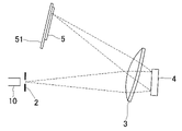
- FIG. 5 It is a block diagram which shows the structural example of the optical characteristic measuring apparatus which concerns on one Embodiment of this invention. It is a figure which shows the optical path when the light of a neon lamp is incident as a light source for wavelength deviation correction from an incident slit. It is a figure which shows an example of the spectrum of a neon lamp. It is a figure which shows an example of the output of a photoelectric conversion element when the light of a neon lamp is measured. It is a figure which shows the state of the wavelength deviation about some optical parts obtained by an optical simulation. It is a figure which shows one of the wavelength deviations of the optical component shown in FIG. 5 excerpted and enlarged. It is a figure which shows the result of having measured the amount of wavelength deviation at each wavelength by an experiment when the temperature of an optical characteristic measuring apparatus was changed from room temperature.
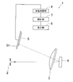
- FIG. 1 is a block diagram showing a configuration example of an optical characteristic measuring device according to an embodiment of the present invention.
- the optical characteristic measuring device 1 includes an incident slit 2 for incident light from an object to be measured, a lens 3, a reflection type diffraction grating 4 which is a spectroscopic means, and an image sensor (also simply referred to as a sensor) which is a photoelectric conversion element. ) 5, a wavelength measuring unit 6, a correction unit 7, and a display unit 8.
- the light incident from the incident slit 2 is incident on the lens 3 and is made into substantially parallel light, and is incident on the diffraction grating 4.
- the diffraction grating 4 disperses the light incident from the incident slit 2 and passing through the lens 3 for each wavelength.
- the incident light is diffracted by the diffraction grating 4 at different angles according to the wavelength, and then again by the lens 3. It is condensed and imaged at different positions according to the wavelength on the light receiving surface of the sensor 5.
- the sensor 5 is arranged in the direction of light dispersion by the diffraction grating 4, has a plurality of pixels that receive the dispersed light, and outputs a signal corresponding to the amount of light received by each pixel.
- the sensor 5 has 40 pixels along the light dispersion direction by the diffraction grating 4, and can measure the distribution of the amount of light in the dispersion direction.
- Reference numeral 51 is a substrate on which the sensor is mounted.
- the wavelength measuring unit 6 measures the wavelength (spectral spectrum) of the light emitted from the object to be measured based on the received light data at each pixel of the sensor 5.
- the correction unit 7 calculates the wavelength deviation correction amount in the correction mode, and corrects the wavelength deviation amount measured by the wavelength measurement unit 6. The correction method will be described later.
- the wavelength measurement unit 6 and the correction unit 7 are composed of a CPU, a ROM in which an operation program of the CPU and the like are stored, and a calculation unit including a RAM and the like as a work area when the CPU operates according to the operation program. Is also good.
- the display unit 8 displays the measurement result of the wavelength measurement unit 6, or the corrected measurement result when the wavelength deviation is corrected by the correction unit 7.
- the actually measured wavelength may fluctuate due to changes in the positions of optical components such as the diffraction grating 4, the lens 3, and the sensor 5 over time, that is, a wavelength shift may occur. That would be a measurement error.
- the optical characteristic measuring device 1 includes a light source for wavelength shift correction that emits a emission line of an independent wavelength such as a neon lamp, and can correct the wavelength shift in the wavelength shift correction mode. There is.
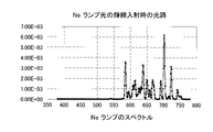
- FIG. 3 shows an example of the spectrum of the neon lamp (Ne lamp) 10.
- the neon lamp 10 has a somewhat independent emission line in the vicinity of 724 nm that can be used for wavelength estimation.
- FIG. 4 shows an example of the output of the sensor 5 when the light of the neon lamp 10 is measured.
- the initial wavelength is acquired from the output of the sensor 5 when the light of the neon lamp 10 is incident at the time of shipment from the factory, and the wavelength measured at the time of correction measurement is compared with the initial wavelength to obtain the wavelength deviation amount.
- the amount of wavelength shift near the emission line wavelength of the neon lamp 10 can be estimated, in other words, the amount of wavelength shift over the entire wavelength range dispersed by the diffraction grating 4 and received by the sensor 5 is obtained. I can't.
- the wavelength shift near the emission line wavelength of the neon lamp 10 can be accurately estimated over the entire wavelength range dispersed by the diffraction grating 4 and received by the sensor 5.
- the following method is adopted.
- FIG. 5 shows the state of wavelength deviation of some optical components obtained by optical simulation.
- the horizontal axis is the pixel number of 40 pixels, and the vertical axis is the amount of wavelength shift.
- the optical elements with particularly high error sensitivity are the rotation of the diffraction grating 4 in the dispersion direction and the positional deviation of the lens 3 and the sensor 5 in the dispersion direction.
- the larger the pixel number the longer the wavelength. Indeed, the wavelength shift is small.
- the bright line (724 nm) of the neon lamp 10 is incident between pixel numbers 38 and 39. Therefore, in order to correct the wavelength deviation caused by the deviation of the positions and orientations of these optical elements, the pixel number on the short wavelength side is larger than the amount of the wavelength deviation estimated by the measurement of the emission line of the neon lamp 10. Needs to be corrected.
- FIG. 6 shows the characteristic curve of the wavelength shift due to the change in the inclination of the diffraction grating ⁇ , which is excerpted from FIG. 5 and enlarged.
- the wavelength shift amount y (x) of the characteristic curve shown in FIG. 6 is approximated by a cubic function of the pixel number x. , It is expressed by the following cubic equation (1).
- y (x) -1.52477 x 10 -5 x 3 +1.26376 x 10 -3 x 2 -4.566637 x 10 -2 x + 6.04060 ...
- x pixel number
- y (x) wavelength shift amount (nm)
- the emission line of 724 nm of the neon lamp 10 is exactly between pixel numbers 38 and 39. Image image.
- each coefficient of the equation (1) must be obtained by using the emission line wavelength deviation reference amount and the emission line wavelength deviation measurement amount of the neon lamp 10.
- Each coefficient of the formula (1) is a coefficient of an approximate formula when the measured amount of the emission line wavelength deviation of the neon lamp 10 is 5.2856 nm, which is equal to the emission line wavelength deviation reference amount.
- the amount of wavelength shift with respect to the change in the inclination of the diffraction grating ⁇ is roughly proportional to the amount of inclination regardless of the wavelength. If the emission line wavelength deviation measurement amount of the neon lamp 10 can be calculated from this, each coefficient of the equation (1) may be proportional to the emission line wavelength deviation measurement amount of the neon lamp 10. Therefore, the approximate expression of the amount of wavelength deviation for an arbitrary wavelength is a cubic expression.
- y (x) ax 3 + bx 2 + cx + d ...
- ⁇ '(x) ⁇ (x) -y (x) ... (7)
- the difference between the measured value when the emission line wavelength of the incident light from the neon lamp 10 for wavelength deviation correction is measured and the original emission line wavelength of the neon lamp 10 is used.
- a certain wavelength shift measurement amount is calculated.
- using a cubic polynomial that expresses the characteristics of the wavelength shift that occurs in the wavelength range dispersed by the diffraction grating 4 and received by the sensor 5 with the pixel number as a variable the emission line wavelength for the same emission line wavelength as that of the neon lamp 10.
- the deviation reference amount is calculated, and each coefficient of the polypoly is determined from the emission line wavelength deviation measurement amount and the emission line wavelength deviation reference amount. Then, the wavelength of the incident light is corrected by the wavelength shift correction amount obtained by the polynomial whose coefficient is determined.
- the characteristic of the wavelength shift generated in the wavelength region dispersed by the diffraction grating 4 and received by the sensor 5 is represented by a cubic polynomial with the pixel number as a variable, and correction is performed based on this polynomial, so that the wavelength shift is corrected.
- a neon lamp 10 is used as the correction light source, not only the wavelength deviation near the emission line wavelength of 724 nm but also the wavelength deviation in the shorter wavelength region can be corrected with high accuracy, and the diffraction can be performed. It is possible to accurately correct the wavelength deviation over the entire wavelength range dispersed by the grating 4 and received by the sensor 5.
- each coefficient of the polynomial is determined by obtaining the emission line wavelength deviation measurement amount and the emission line wavelength deviation reference amount from one emission line wavelength of the neon lamp 10, the number of independent emission line wavelengths as a light source for wavelength deviation correction is small.
- the neon lamp 10 and the like can be used without any problem.
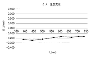
- FIG. 7 is a graph showing the results of experimentally measuring the amount of wavelength deviation at each wavelength when the optical characteristic measuring device 1 is changed in temperature from room temperature. This wavelength deviation is caused by the deviation of the position and inclination of the optical component due to the temperature change, but it is considered that the optical component whose position and inclination change due to the temperature change is likely to cause the same change with time. That is, it is expected that the wavelength shift of the same tendency as in FIG. 7 will occur even if the time changes.
- the horizontal axis represents the wavelength and the vertical axis represents the wavelength shift amount.
- the wavelength deviation amount y ( ⁇ ) of the wavelength deviation characteristic curve shown in FIG. 7 is approximated by a cubic function of the wavelength ⁇ . It is represented by the following cubic equation (8).
- y ( ⁇ ) -7.20085 ⁇ 10 -9 ⁇ 3 + 1.19511 ⁇ 10 -5 ⁇ 2 -6.21233 x 10 -3 ⁇ + 7.98425 x 10 -1 ...
- ⁇ wavelength (nm)
- y ( ⁇ ) wavelength shift (nm)
- the wavelength deviation is corrected by using a cubic equation expressing the characteristic of the wavelength deviation generated in the wavelength region dispersed by the diffraction grid 4 and received by the sensor 5 with the wavelength as a variable. Therefore, even when the neon lamp 10 is used as the wavelength deviation correction light source, the wavelength deviation in the shorter wavelength region can be corrected with high accuracy as well as the correction of the wavelength deviation near 724 nm. It is possible to accurately correct the wavelength deviation over the entire wavelength range dispersed by the diffraction grid 4 and received by the sensor 5.
- each coefficient of the polynomial is determined by obtaining the emission line wavelength deviation measurement amount and the emission line wavelength deviation reference amount from one emission line wavelength of the neon lamp 10, the number of independent emission line wavelengths as a light source for wavelength deviation correction can be increased. A small number of neon lamps 10 and the like can be used.
- the present invention is not limited to the above embodiment.
- the pixel number is used as a variable as a parameter related to the wavelength, but the wavelength may be used as a variable as in the correction example 2.
- the parameter related to the wavelength is not limited to the pixel number.
- the wavelength deviation characteristic is approximated by a cubic equation with the wavelength or a parameter related to the wavelength as a variable, it may be approximated by a linear equation or a quadratic equation according to the characteristics of each component. It may be approximated by a polynomial of degree 4 or higher.
- the neon lamp 10 is used as the light source for correcting the wavelength deviation
- a light source that emits light including a emission line having at least one wavelength may be used as the light source for correcting the wavelength deviation.
- the neon lamp 10 which is the light source for correcting the wavelength deviation is provided in the optical characteristic measuring device 1
- the optical characteristic measuring device 1 has a built-in correction unit 7 to correct the wavelength deviation in the own device, a correction device consisting of a personal computer or the like existing outside the optical characteristic measuring device 1 is used. Then, the wavelength deviation may be corrected. In this case, at the time of correction, the correction device may acquire the emission line wavelength measurement result of the wavelength deviation correction light source from the optical characteristic measurement device 1, calculate the emission line wavelength deviation measurement amount, and determine the coefficient of the polymorphism. Further, the calculation of the wavelength shift correction amount by the polynomial after the coefficient determination and the correction of the measured wavelength may be performed on the correction device side, or the polynomial whose coefficient is determined is transmitted to the optical characteristic measurement device 1. The optical characteristic measuring device 1 may calculate or correct the amount of wavelength shift correction using the received polynomial.
- the polynomial representing the wavelength shift characteristic may be stored in advance in the optical characteristic measuring device 1 or the correction device, or the optical characteristic measuring device 1 or the correction device acquires the polynomial from a separate storage location at the time of correction. Is also good.
- the present invention can be used as an optical characteristic measuring device that separates incident light to measure wavelength, such as a spectrocolorimeter or a spectrophotometer.
Landscapes
- Physics & Mathematics (AREA)
- Spectroscopy & Molecular Physics (AREA)
- General Physics & Mathematics (AREA)
- Spectrometry And Color Measurement (AREA)
Abstract
Priority Applications (3)
| Application Number | Priority Date | Filing Date | Title |
|---|---|---|---|
| CN202280010130.6A CN116829913A (zh) | 2021-01-15 | 2022-01-11 | 光学特性测定装置、波长偏移校正装置、波长偏移校正方法以及程序 |
| US18/272,256 US20240068870A1 (en) | 2021-01-15 | 2022-01-11 | Optical characteristic measuring apparatus, wavelength shift correcting apparatus, wavelength shift correction method, and program |
| JP2022575579A JPWO2022153963A1 (fr) | 2021-01-15 | 2022-01-11 |
Applications Claiming Priority (2)
| Application Number | Priority Date | Filing Date | Title |
|---|---|---|---|
| JP2021004965 | 2021-01-15 | ||
| JP2021-004965 | 2021-01-15 |
Publications (1)
| Publication Number | Publication Date |
|---|---|
| WO2022153963A1 true WO2022153963A1 (fr) | 2022-07-21 |
Family
ID=82446329
Family Applications (1)
| Application Number | Title | Priority Date | Filing Date |
|---|---|---|---|
| PCT/JP2022/000488 WO2022153963A1 (fr) | 2021-01-15 | 2022-01-11 | Dispositif de mesure de caractéristiques optiques, dispositif de correction de décalage de longueurs d'onde, procédé de correction de décalage de longueurs d'onde et programme |
Country Status (4)
| Country | Link |
|---|---|
| US (1) | US20240068870A1 (fr) |
| JP (1) | JPWO2022153963A1 (fr) |
| CN (1) | CN116829913A (fr) |
| WO (1) | WO2022153963A1 (fr) |
Citations (5)
| Publication number | Priority date | Publication date | Assignee | Title |
|---|---|---|---|---|
| JP2000205955A (ja) * | 1999-01-08 | 2000-07-28 | Minolta Co Ltd | ポリクロメ―タの校正デ―タ算出装置及びその算出方法 |
| JP2007010364A (ja) * | 2005-06-28 | 2007-01-18 | Konica Minolta Sensing Inc | 分光装置の波長校正方法及び分光装置 |
| US20130250294A1 (en) * | 2012-01-16 | 2013-09-26 | Scott A. Chalmers | Automatic real-time wavelength calibration of fiber-optic-based spectrometers |
| CN104568173A (zh) * | 2013-10-29 | 2015-04-29 | 南开大学 | 一种ccd波长校准的方法 |
| KR101642354B1 (ko) * | 2015-01-30 | 2016-08-01 | (주)노스트 | 분광기 ccd 보정방법 및 장치 |
-
2022
- 2022-01-11 WO PCT/JP2022/000488 patent/WO2022153963A1/fr active Application Filing
- 2022-01-11 US US18/272,256 patent/US20240068870A1/en active Pending
- 2022-01-11 JP JP2022575579A patent/JPWO2022153963A1/ja active Pending
- 2022-01-11 CN CN202280010130.6A patent/CN116829913A/zh active Pending
Patent Citations (5)
| Publication number | Priority date | Publication date | Assignee | Title |
|---|---|---|---|---|
| JP2000205955A (ja) * | 1999-01-08 | 2000-07-28 | Minolta Co Ltd | ポリクロメ―タの校正デ―タ算出装置及びその算出方法 |
| JP2007010364A (ja) * | 2005-06-28 | 2007-01-18 | Konica Minolta Sensing Inc | 分光装置の波長校正方法及び分光装置 |
| US20130250294A1 (en) * | 2012-01-16 | 2013-09-26 | Scott A. Chalmers | Automatic real-time wavelength calibration of fiber-optic-based spectrometers |
| CN104568173A (zh) * | 2013-10-29 | 2015-04-29 | 南开大学 | 一种ccd波长校准的方法 |
| KR101642354B1 (ko) * | 2015-01-30 | 2016-08-01 | (주)노스트 | 분광기 ccd 보정방법 및 장치 |
Also Published As
| Publication number | Publication date |
|---|---|
| CN116829913A (zh) | 2023-09-29 |
| US20240068870A1 (en) | 2024-02-29 |
| JPWO2022153963A1 (fr) | 2022-07-21 |
Similar Documents
| Publication | Publication Date | Title |
|---|---|---|
| JP4660694B2 (ja) | 分光装置の波長校正方法及び分光装置 | |
| US7151600B2 (en) | Calibration system for a spectral luminometer and a method for calibrating a spectral luminometer | |
| JP5340878B2 (ja) | イメージングスペクトログラフのキャリブレーションを行う方法 | |
| US9163990B2 (en) | Color measuring device calibration | |
| US20060132760A1 (en) | Calibration source for calibrating spectroradiometer, calibration method using the same, and calibration system | |
| JP3702889B2 (ja) | 分光装置及び分光装置の補正方法 | |
| KR102022730B1 (ko) | 분광 특성 측정 장치 및 분광 특성 측정 방법 | |
| KR101890944B1 (ko) | 분광 특성 측정 방법 및 분광 특성 측정 장치 | |
| US11307093B2 (en) | Method of calibrating spectral apparatus and method of producing calibrated spectral apparatus | |
| US7705983B2 (en) | Wavelength displacement correcting system | |
| JP6733667B2 (ja) | 分光測色装置、および分光反射率の算出方法 | |
| TWI247464B (en) | Method and apparatus for measuring bandwidth of an optical spectrum output of a very small wavelength very narrow bandwidth high power laser | |
| WO2022153963A1 (fr) | Dispositif de mesure de caractéristiques optiques, dispositif de correction de décalage de longueurs d'onde, procédé de correction de décalage de longueurs d'onde et programme | |
| JP5556362B2 (ja) | 分光特性測定装置およびその校正方法 | |
| KR20210024468A (ko) | 막두께 측정 장치 및 보정 방법 | |
| AU2005218371A1 (en) | Method for standardizing system response of spectrophotometer | |
| JP6992812B2 (ja) | 波長シフト補正システムおよび波長シフト補正方法 | |
| JP2004177147A (ja) | 発光測定装置 | |
| US20240085323A1 (en) | Method and apparatus for measuring surface gloss and spectral reflectance | |
| US20220373391A1 (en) | Spectrometer and computer program | |
| JP2005338021A (ja) | 波長測定方法およびこれを用いた分光装置 | |
| JP2020159951A (ja) | 測定方法及び装置 | |
| JP2013152145A (ja) | 光検査装置 |
Legal Events
| Date | Code | Title | Description |
|---|---|---|---|
| 121 | Ep: the epo has been informed by wipo that ep was designated in this application |
Ref document number: 22739370 Country of ref document: EP Kind code of ref document: A1 |
|
| ENP | Entry into the national phase |
Ref document number: 2022575579 Country of ref document: JP Kind code of ref document: A |
|
| WWE | Wipo information: entry into national phase |
Ref document number: 18272256 Country of ref document: US |
|
| WWE | Wipo information: entry into national phase |
Ref document number: 202280010130.6 Country of ref document: CN |
|
| NENP | Non-entry into the national phase |
Ref country code: DE |
|
| 122 | Ep: pct application non-entry in european phase |
Ref document number: 22739370 Country of ref document: EP Kind code of ref document: A1 |