WO2022145205A1 - Antenna device - Google Patents
Antenna device Download PDFInfo
- Publication number
- WO2022145205A1 WO2022145205A1 PCT/JP2021/045614 JP2021045614W WO2022145205A1 WO 2022145205 A1 WO2022145205 A1 WO 2022145205A1 JP 2021045614 W JP2021045614 W JP 2021045614W WO 2022145205 A1 WO2022145205 A1 WO 2022145205A1
- Authority
- WO
- WIPO (PCT)
- Prior art keywords
- base member
- antenna device
- antenna
- substrate
- fixing member
- Prior art date
Links
- 239000002826 coolant Substances 0.000 claims description 15
- 239000000758 substrate Substances 0.000 description 77
- 230000017525 heat dissipation Effects 0.000 description 21
- 239000000463 material Substances 0.000 description 16
- 238000012986 modification Methods 0.000 description 15
- 230000004048 modification Effects 0.000 description 15
- 239000004020 conductor Substances 0.000 description 14
- RYGMFSIKBFXOCR-UHFFFAOYSA-N Copper Chemical compound [Cu] RYGMFSIKBFXOCR-UHFFFAOYSA-N 0.000 description 9
- 229910052751 metal Inorganic materials 0.000 description 9
- 239000002184 metal Substances 0.000 description 9
- 229920005989 resin Polymers 0.000 description 9
- 239000011347 resin Substances 0.000 description 9
- 229910052802 copper Inorganic materials 0.000 description 8
- 239000010949 copper Substances 0.000 description 8
- 229910000838 Al alloy Inorganic materials 0.000 description 3
- OKTJSMMVPCPJKN-UHFFFAOYSA-N Carbon Chemical compound [C] OKTJSMMVPCPJKN-UHFFFAOYSA-N 0.000 description 3
- 229910052799 carbon Inorganic materials 0.000 description 3
- 238000009833 condensation Methods 0.000 description 3
- 230000005494 condensation Effects 0.000 description 3
- 238000009834 vaporization Methods 0.000 description 3
- 230000008016 vaporization Effects 0.000 description 3
- 229910052782 aluminium Inorganic materials 0.000 description 2
- XAGFODPZIPBFFR-UHFFFAOYSA-N aluminium Chemical compound [Al] XAGFODPZIPBFFR-UHFFFAOYSA-N 0.000 description 2
- 239000010410 layer Substances 0.000 description 2
- 238000000034 method Methods 0.000 description 2
- 229910000679 solder Inorganic materials 0.000 description 2
- 239000007787 solid Substances 0.000 description 2
- LVGUZGTVOIAKKC-UHFFFAOYSA-N 1,1,1,2-tetrafluoroethane Chemical compound FCC(F)(F)F LVGUZGTVOIAKKC-UHFFFAOYSA-N 0.000 description 1
- 239000000853 adhesive Substances 0.000 description 1
- 230000001070 adhesive effect Effects 0.000 description 1
- 230000005540 biological transmission Effects 0.000 description 1
- KYKAJFCTULSVSH-UHFFFAOYSA-N chloro(fluoro)methane Chemical compound F[C]Cl KYKAJFCTULSVSH-UHFFFAOYSA-N 0.000 description 1
- 239000011889 copper foil Substances 0.000 description 1
- 239000003989 dielectric material Substances 0.000 description 1
- 230000000694 effects Effects 0.000 description 1
- 239000003822 epoxy resin Substances 0.000 description 1
- 238000010438 heat treatment Methods 0.000 description 1
- 239000007769 metal material Substances 0.000 description 1
- 230000000149 penetrating effect Effects 0.000 description 1
- 238000007747 plating Methods 0.000 description 1
- 229920000647 polyepoxide Polymers 0.000 description 1
- -1 polytetrafluoroethylene Polymers 0.000 description 1
- 229920001343 polytetrafluoroethylene Polymers 0.000 description 1
- 239000004810 polytetrafluoroethylene Substances 0.000 description 1
- 230000035945 sensitivity Effects 0.000 description 1
- 229920002050 silicone resin Polymers 0.000 description 1
- 239000002356 single layer Substances 0.000 description 1
- 239000000126 substance Substances 0.000 description 1
- 229920001187 thermosetting polymer Polymers 0.000 description 1
- XLYOFNOQVPJJNP-UHFFFAOYSA-N water Substances O XLYOFNOQVPJJNP-UHFFFAOYSA-N 0.000 description 1
Images


Classifications
-
- H—ELECTRICITY
- H01—ELECTRIC ELEMENTS
- H01Q—ANTENNAS, i.e. RADIO AERIALS
- H01Q1/00—Details of, or arrangements associated with, antennas
- H01Q1/12—Supports; Mounting means
-
- F—MECHANICAL ENGINEERING; LIGHTING; HEATING; WEAPONS; BLASTING
- F28—HEAT EXCHANGE IN GENERAL
- F28D—HEAT-EXCHANGE APPARATUS, NOT PROVIDED FOR IN ANOTHER SUBCLASS, IN WHICH THE HEAT-EXCHANGE MEDIA DO NOT COME INTO DIRECT CONTACT
- F28D15/00—Heat-exchange apparatus with the intermediate heat-transfer medium in closed tubes passing into or through the conduit walls ; Heat-exchange apparatus employing intermediate heat-transfer medium or bodies
- F28D15/02—Heat-exchange apparatus with the intermediate heat-transfer medium in closed tubes passing into or through the conduit walls ; Heat-exchange apparatus employing intermediate heat-transfer medium or bodies in which the medium condenses and evaporates, e.g. heat pipes
- F28D15/0266—Heat-exchange apparatus with the intermediate heat-transfer medium in closed tubes passing into or through the conduit walls ; Heat-exchange apparatus employing intermediate heat-transfer medium or bodies in which the medium condenses and evaporates, e.g. heat pipes with separate evaporating and condensing chambers connected by at least one conduit; Loop-type heat pipes; with multiple or common evaporating or condensing chambers
-
- F—MECHANICAL ENGINEERING; LIGHTING; HEATING; WEAPONS; BLASTING
- F28—HEAT EXCHANGE IN GENERAL
- F28D—HEAT-EXCHANGE APPARATUS, NOT PROVIDED FOR IN ANOTHER SUBCLASS, IN WHICH THE HEAT-EXCHANGE MEDIA DO NOT COME INTO DIRECT CONTACT
- F28D15/00—Heat-exchange apparatus with the intermediate heat-transfer medium in closed tubes passing into or through the conduit walls ; Heat-exchange apparatus employing intermediate heat-transfer medium or bodies
- F28D15/02—Heat-exchange apparatus with the intermediate heat-transfer medium in closed tubes passing into or through the conduit walls ; Heat-exchange apparatus employing intermediate heat-transfer medium or bodies in which the medium condenses and evaporates, e.g. heat pipes
- F28D15/0275—Arrangements for coupling heat-pipes together or with other structures, e.g. with base blocks; Heat pipe cores
-
- H—ELECTRICITY
- H01—ELECTRIC ELEMENTS
- H01Q—ANTENNAS, i.e. RADIO AERIALS
- H01Q1/00—Details of, or arrangements associated with, antennas
- H01Q1/02—Arrangements for de-icing; Arrangements for drying-out ; Arrangements for cooling; Arrangements for preventing corrosion
-
- H—ELECTRICITY
- H01—ELECTRIC ELEMENTS
- H01Q—ANTENNAS, i.e. RADIO AERIALS
- H01Q1/00—Details of, or arrangements associated with, antennas
- H01Q1/12—Supports; Mounting means
- H01Q1/22—Supports; Mounting means by structural association with other equipment or articles
- H01Q1/2283—Supports; Mounting means by structural association with other equipment or articles mounted in or on the surface of a semiconductor substrate as a chip-type antenna or integrated with other components into an IC package
Definitions
- the embodiment of the disclosure relates to an antenna device.
- the antenna device includes an antenna portion, a first base member, a second base member, a support column, and a first fixing member.
- the antenna portion, the first base member, the second base member, and the support column are arranged in this order.
- the first base member and the second base member are separated from each other and connected via the first fixing member.
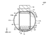
- FIG. 1 is a perspective view showing the main body of the antenna device according to the embodiment.
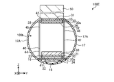
- FIG. 2 is a cross-sectional view showing an outline of the antenna device according to the embodiment.
- FIG. 3 is a plan view showing an outline of an antenna portion included in the antenna device according to the embodiment.
- FIG. 4 is a sectional view taken along line IV-IV of FIG.
- FIG. 5 is a cross-sectional view showing an outline of the antenna device according to the first modification of the embodiment.
- FIG. 6 is a cross-sectional view showing an outline of the antenna device according to the second modification of the embodiment.
- FIG. 7 is a cross-sectional view showing an outline of the antenna device according to the third modification of the embodiment.
- FIG. 8 is a perspective view showing the main body of the antenna device according to another embodiment.
- FIG. 9 is a cross-sectional view showing an outline of an antenna device including the antenna device main body shown in FIG.
- FIG. 10 is a cross-sectional view illustrating the outline of the antenna device of another embodiment.
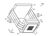
- FIG. 11 is a perspective view showing the main body of the antenna device according to another embodiment.
- FIG. 1 is a perspective view showing the main body of the antenna device according to the embodiment.
- FIG. 2 is a cross-sectional view showing an outline of the antenna device according to the embodiment.
- the antenna device 100 includes an antenna portion 1, a housing 17, a radome 18, a first base member 20, a second base member 30, a first fixing member 40, and a support column 50. To prepare for.
- the antenna device 100 includes an antenna device main body 100a, a housing 17, and a support column 50.
- the antenna device main body 100a shown in FIG. 1 has an antenna portion 1, a first base member 20, a second base member 30, and a first fixing member 40.
- the antenna unit 1 includes a first board 2 and a second board 4. In FIG. 2, the configuration located in the antenna portion 1 and its vicinity is not shown. The details of the antenna unit 1 will be described later.
- FIGS. 1 and 2 three-dimensional dimensions in which the arrangement directions of the plurality of second substrates 4 are the X-axis and the Y-axis, respectively, and the direction intersecting the XY plane is the Z-axis.
- the Cartesian coordinate system is illustrated. Such a Cartesian coordinate system is also shown in other drawings used in the description below. Further, in the following description, for convenience, the Z-axis positive direction side may be referred to as "upper” and the Z-axis negative direction side may be referred to as "lower”. Further, the same components as those of the antenna device main body 100a shown in FIG. 1 and the antenna device 100 shown in FIG. 2 are designated by the same reference numerals, and the description thereof will be omitted or simplified.
- the housing 17 has a first support member 15, a second support member 16, and a curved support portion 17A.
- the housing 17 has a substantially spherical outer surface.
- the curved support portion 17A has a circular shape when the sphere is cut in the XY plane.
- the first support member 15 shown in FIG. 2 is a flat portion of the housing 17 that is in contact with the antenna portion 1 and the first base member 20.
- the second support member 16 is a flat portion of the housing 17 that is in contact with the second base member 30 and the support column 50.
- the curved support portion 17A is a portion of the housing 17 excluding the first support member 15 and the second support member 16.
- the material of the first support member 15 and the second support member 16 may be a metal such as copper. Further, the material of the portion (curved support portion 17A) of the housing 17 excluding the first support member 15 and the second support member 16 may be a metal such as aluminum or an aluminum alloy.
- the first support member 15 and the second support member 16 are located at both ends of the housing 17 in the height direction (Z-axis direction).
- the antenna portion 1 and the first base member 20 are attached to the first support member 15 located on the negative side of the Z axis.
- a second base member 30 and a support column 50 are attached to the second support member 16 located at the end of the housing 17 on the positive direction side of the Z axis.
- the radome 18 protrudes from the first support member 15 in a spherical crown shape in the negative direction of the Z axis.
- the radome 18 is made of a material such as polytetrafluoroethylene that covers the conductor portion 5 (see FIG. 4) described later of the antenna portion 1 and does not interfere with the transmission of radio waves transmitted from the antenna portion 1.
- the radius of curvature of the housing 17 (curved support portion 17A) and the radius of curvature of the radome 18 should be the same.
- the radius of curvature of the housing 17 (curved support portion 17A) and the radius of curvature of the radome 18 are the same, there are no protruding parts, sharply bent parts, or recessed parts on the outer surfaces of the housing 17 and the radome 18. Therefore, the resistance to external pressure such as an impact received from the outside is increased. As a result, the housing 17 has high durability.
- the first base member 20 is located between the antenna portion 1 and the second base member 30.
- the first base member 20 has a first surface 21 facing the second base member 30 and a second surface 22 facing the antenna portion 1.
- the first base member 20 is located above the first support member 15 (on the positive direction side of the Z axis).
- the antenna portion 1 is located below the first base member 20 with the first support member 15 interposed therebetween. Since the antenna portion 1 is located below the first base member 20, for example, the heat generated in the antenna portion 1 is generated by the convection action due to the property that the heat tends to rise as the temperature rises. It becomes easy to convey to. Therefore, since the first base member 20 can efficiently dissipate the heat generated in the antenna unit 1, the heat dissipation of the antenna device 100 can be improved.
- the first base member 20 has a first end surface 23 located at an end in a negative direction (first direction) on the Y axis.
- the first fixing member 40 is fixed to the first end surface 23.
- the first end face 23 is shown as an example of the end face in the first base member 20.
- the second base member 30 is located between the first base member 20 and the support column 50.
- the second base member 30 has a third surface 31 facing the support column 50 and a fourth surface 32 facing the first base member 20.
- the first surface 21 of the first base member 20 and the fourth surface 32 of the second base member 30 are configured such that the surfaces face each other.
- the second base member 30 is located below the second support member 16 (on the negative direction side of the Z axis). By locating the second base member 30 below the support column 50, for example, heat transferred from the antenna portion 1 side to the second base member 30 through the space inside the first fixing member 40 and the housing 17 is transferred to the support column 50. It is possible to improve the heat dissipation property of the antenna device 100 because it is easily transmitted to the antenna and heat can be dissipated efficiently.
- the second base member 30 has a second end surface 33 located at the end in the negative direction (first direction) of the Y axis.
- the first fixing member 40 is fixed to the second end surface 33.
- the second base member 30 is connected to the end opposite to the end connected to the first base member 20.
- the end connected to the first base member 20 is referred to as the first end 41.
- the end connected to the second base member 30 is referred to as the second end 42.
- the second end surface 33 is shown as an example of the end surface in the second base member 30.
- first surface 21 of the first base member 20 facing the fourth surface 32 of the second base member 30 is located away from the fourth surface 32 of the second base member 30 facing the first surface 21. ..
- first base member 20 and the second base member 30 are dissipated by, for example, the outside air moving between the first base member 20 and the second base member 30.
- the first base member 20 and the second base member 30 may be metal members such as copper, for example.
- the first fixing member 40 is located between the first base member 20 and the second base member 30, and is bridged between the first base member 20 and the second base member 30. In other words, the first base member 20 and the second base member 30 are connected via the first fixing member 40.
- the first fixing member 40 is, for example, a solid rod-shaped body. Further, as described above, the first fixing member 40 has a first end portion 41 and a second end portion 42. The first end portion 41 is connected to the first end surface 23 of the first base member 20. The second end portion 42 is connected to the second end surface 33 of the second base member 30.
- the first fixing member 40 has a positioning function of facing the first surface 21 of the first base member 20 and the fourth surface 32 of the second base member 30 at predetermined intervals, and contributes to heat dissipation. For example, the heat generated on the first base member 20 side is transferred to the second base member 30 via the first fixing member 40. In this way, the first fixing member 40 is fixed so as to be bridged over the first base member 20 and the second base member 30 located apart from each other, so that the heat generated in the antenna portion 1 is efficiently dissipated. can do. Therefore, the heat dissipation of the antenna device main body 100a can be improved.
- the first fixing member 40 may be a metal member such as copper.
- the support column 50 is located above the second support member 16 (on the positive direction side of the Z axis).
- the column 50 has, for example, a quadrangular prism shape that is long in the Z-axis direction.
- the strut 50 may be, for example, an aluminum alloy or other metal member.
- a plurality of through holes extending in the Z-axis direction may be provided inside the support column 50 to improve the heat dissipation of the antenna device 100.
- a fin member (not shown) projecting to the outside of the support column 50 may be positioned.
- the antenna device 100 may have a power supply unit 60.
- the power supply unit 60 supplies power to the antenna unit 1.
- the power supply unit 60 converts the electric power output from an external power source (not shown) into a predetermined electric power value as necessary, and supplies the electric power to the antenna unit 1.
- the power supply unit 60 is located, for example, on the first surface 21 of the first base member 20. By locating the power supply unit 60 so as to be in contact with the first surface 21 of the first base member 20 in this way, the heat generated in the power supply unit 60 due to the power supply can be efficiently dissipated. Therefore, the antenna device 100. The heat dissipation of the antenna can be improved.
- the support column 50 is located above the second support member 16 when the ground surface is used as the reference surface and the Z-axis positive direction is on the sky side.
- the antenna portion 1 is located below the support column 50.
- FIG. 3 is a plan view showing an outline of an antenna portion included in the antenna device according to the embodiment.
- FIG. 4 is a sectional view taken along line IV-IV of FIG.
- the antenna portion 1 includes a first substrate 2, a second substrate 4, a conductor portion 5, and an element portion 10.
- each surface of the first substrate 2 and the second substrate shown in FIG. 4 is defined as follows.
- the main surface of the first substrate 2 in the negative direction (downward) of the Z axis is defined as the fifth surface 2a.
- the main surface of the first substrate 2 in the positive direction (upward) of the Z axis is defined as the sixth surface 2b.
- the main surface of the second substrate 4 in the negative direction (downward) of the Z axis is defined as the seventh surface 4a.
- the main surface of the second substrate 4 in the positive direction (upward) of the Z axis is defined as the eighth surface 4b.
- the first substrate 2 has a plurality of through holes 2c penetrating in the thickness direction (Z-axis direction).
- the through hole 2c has, for example, a square columnar shape, and is open to the fifth surface 2a and the sixth surface 2b located at both ends in the thickness direction (Z-axis direction) of the first substrate 2.
- the first substrate 2 may have a through hole 2c having a thickness shorter than the length of the side having the minimum length among the sides forming the through hole 2c, and even in such a case, the first substrate 2 may have a square columnar shape. It may be referred to as a through hole 2c.
- the same applies to the through hole 2c such as a hexagonal columnar structure shown as a structure other than the square columnar structure.
- the side of the through hole 2c is one side when the shape of the first substrate 2 of the through hole 2c when viewed in a plan view in the Z-axis direction is a square shape in the above case.
- the side of the through hole 2c is the side of the opening along the fifth surface 2a and the sixth surface 2b of the first substrate 2.
- the surface extending from the opening of the fifth surface 2a of the first substrate 2 to the opening of the sixth surface 2b is defined as an inner wall.
- the plurality of through holes 2c are arranged side by side at predetermined intervals along the X axis and the Y axis intersecting the X axis.
- the shape of the through hole 2c is not limited to a square columnar shape, and may be, for example, a hexagonal columnar shape, an octagonal columnar shape, or any other square columnar shape, or may be any columnar shape such as a cylindrical columnar shape or an elliptical columnar shape.
- the arrangement of the plurality of through holes 2c of the first substrate 2 may be rectangular grid-like as shown in FIG. 3, and may be arbitrary such as an oblique grid shape, a triangular grid shape, or a hexagonal grid shape. It may be an array of. Further, the plurality of through holes 2c may be arranged irregularly.
- the second substrate 4 is positioned so as to be fitted into the through hole 2c of the first substrate 2.
- the second substrate 4 has a square columnar shape, and is located at both ends in the thickness direction (Z-axis direction) of the second substrate 4, the seventh surface 4a and the eighth surface 4b, and the seventh surface 4a and the eighth surface. It has a side surface 4c located between 4b.
- the side surface 4c of the second substrate 4 is located so as to face the wall surface of the through hole 2c.
- the second substrate 4 has a square shape when viewed in a plan view.
- the second substrate 4 has a predetermined thickness in the Z-axis direction.
- the second substrate 4 is a flat plate having a rectangular shape (or a rectangular shape) when viewed in a plan view. Sometimes it's a shape.
- the shape of the second substrate 4 when viewed in a plan view is illustrated, but the shape of the second substrate 4 may be a shape in which the corners are rounded. Other shapes such as the hexagonal columnar shown below may also have rounded corners.
- the side surface 4c of the second substrate 4 has a gap between the side surface 4c and the through hole 2c, and is located facing the through hole 2c.
- the side surface 4c of the second substrate 4 is located away from the wall surface of the through hole 2c.
- the first board 2 and the second board 4 are, for example, wiring boards.
- the first substrate 2 and the second substrate 4 may be, for example, a multilayer wiring board which is located along the XY plane and in which each layer having an organic resin as an insulating layer is laminated in the Z-axis direction.
- the second substrate 4 may be, for example, a dielectric substrate containing a dielectric material.
- the second substrate 4 may be an AIP (Antenna In Package).
- the thicknesses of the first substrate 2 and the second substrate 4 may be the same or different.
- the second board 4 is fixed to the first board 2.
- a method of fixing the second substrate 4 to the first substrate 2 for example, a method of attaching a plate plate to the fifth surface 2a of the first substrate 2 so as to project into the through hole 2c can be mentioned. can.
- the shape of the second substrate 4 is not limited to a square columnar shape, and may be, for example, a hexagonal columnar column, an octagonal columnar column, or any other prismatic columnar shape, a columnar columnar shape, or an elliptical columnar shape.
- the second substrate 4 may be positioned so that the side surface 4c and the through hole 2c are equally spaced over the entire surface, and for example, the spacing in the X-axis direction and the spacing in the Y-axis direction are different from each other. It may be located.
- the conductor portion 5 is located on the seventh surface 4a of the second substrate 4.
- the conductor portion 5 is, for example, a patch, and may be, for example, a conductor film made of a conductive material such as copper.
- the conductor portion 5 may have, for example, copper, copper foil, copper plating, or the like as the material of the conductor.
- the conductor portion 5 is located below the circuit portion 7 described later of the element portion 10.
- the heat generated in the conductor portion 5 is dissipated as the air flows through the gap between the first substrate 2 and the second substrate 4. This makes it possible to increase the heat transport capacity of the antenna device 100.
- the element unit 10 is mounted on the eighth surface 4b of the second substrate 4.
- the element unit 10 includes a circuit unit 7, a first radiator body 8, and a radiator member 9.
- the circuit unit 7 is, for example, an integrated circuit.
- the circuit unit 7 may include, for example, an RFIC (Radio Frequency Integrated Circuit) or the like.
- the circuit unit 7 is electrically connected to the second substrate 4 via the first connecting member 11 described later.
- the RFIC may be, for example, HEMT (High Electron Mobility Transistor) or HBT (Heterojunction Bipolar Transistor).
- the first connecting member 11 is located on the eighth surface 4b of the second substrate 4.
- the first connecting member 11 has a predetermined height in the thickness direction of the second substrate 4, and connects the second substrate 4 and the circuit unit 7.
- the first connecting member 11 may be, for example, a columnar bump.
- the first radiator body 8 is located between the radiator member 9 and the circuit unit 7.
- the first radiator 8 may be, for example, a TIM (Thermal Interface Material).
- the first radiator 8 contains, for example, carbon. When the first radiator 8 contains carbon, the thermal conductivity can be increased as compared with the case where the first radiator 8 does not contain carbon. Further, the first radiator 8 may contain an organic resin such as an epoxy resin or a silicone resin.
- the surface of the first radiator 8 may have adhesiveness.
- the circuit portion 7 and the heat radiating member 9 can be adhered to each other without using, for example, an adhesive or another member.
- the first heat radiating body 8 may be located over the entire surface of the circuit portion 7 facing the heat radiating member 9.
- the heat radiating member 9 and the circuit portion 7 can be joined without a gap, and the heat transfer area is expanded. This makes it possible to increase the heat transport capacity.
- the first radiator 8 may have a layered structure.
- the layered first radiator 8 may be, for example, a film in which organic resin films having different elastic moduli are laminated in the thickness direction (Z-axis direction).
- the first radiator 8 may have different components from the surface material and the internal material.
- the heat radiating member 9 accommodates the circuit unit 7.
- the heat radiating member 9 seals the circuit portion 7 between the heat radiating member 9 and the second substrate 4, for example, to suppress the exposure of the circuit portion 7.
- the heat radiating member 9 may have, for example, a lid shape that covers the periphery of the circuit portion 7. Further, the heat radiating member 9 may be, for example, a heat spreader that promotes rapid heat radiating from the circuit unit 7.
- the material of the heat radiating member 9 can be, for example, an aluminum alloy or other metal. Further, the material of the heat radiating member 9 may be, for example, a resin such as a thermosetting resin or a photocurable resin.
- the heat radiating member 9 can be made of a metal, for example, from the viewpoint of mechanical strength, heat resistance, and thermal conductivity.
- the heat radiating member 9 may have a single-layer structure, or may be, for example, a structure in which a metal plate and an organic resin film (organic resin plate) are laminated. Further, the heat radiating member 9 can be made of a metal on the outside and an organic resin on the inside, for example, from the viewpoint of lowering the sensitivity to the ambient temperature.
- the antenna unit 1 further includes an interposer 12 and a second radiator body 14.
- the interposer 12 connects the first board 2 and the second board 4.
- the interposer 12 is electrically connected to the wirings of the first substrate 2 and the second substrate 4 via the second connecting member 13, which will be described later.
- the second connecting member 13 is located on the sixth surface 2b of the first substrate 2 and on the eighth surface 4b of the second substrate 4, respectively.
- the second connecting member 13 has a predetermined height in the thickness direction of the second substrate 4, and connects the first substrate 2 and the second substrate 4 to the interposer 12.
- the second connecting member 13 is shown as an example of the connecting member.
- the second connecting member 13 may be, for example, a columnar bump.
- the second connecting member 13 may be a so-called solder ball. Further, the second connecting member 13 may have the same shape and / or material as the first connecting member 11, or may be different.
- the second radiator body 14 is located between the radiator member 9 and the first support member 15.
- the second radiator 14 may be, for example, a TIM (Thermal Interface Material).
- the material and characteristics of the second radiator body 14 may be, for example, the same as those of the first radiator body 8 described above.
- the first support member 15 supports the antenna portion 1.
- the first support member 15 is fixed to the heat radiating member 9 via the second radiating body 14.
- the material of the first support member 15 may be, for example, a metal material such as copper or aluminum. Further, the first support member 15 may be a part of the housing 17 (see FIG. 2).
- FIG. 5 is a cross-sectional view showing an outline of the antenna device according to the first modification of the embodiment.
- the same reference numerals are used for the members having the same arrangement as the above-mentioned antenna device 100 for convenience.
- the antenna device 100A according to the first modification is different from the antenna device 100 according to the embodiment shown in FIG. 2 in that the first fixing member 40 has a hollow portion 44.
- the first fixing member 40 may be a tubular body having a hollow portion 44. As described above, even if the first fixing member 40 is a tubular body having the hollow portion 44, the heat dissipation of the antenna device 100A can be improved as compared with the case where the first fixing member 40 is not provided.
- FIG. 6 is a cross-sectional view showing an outline of the antenna device according to the second modification of the embodiment.
- the antenna device 100B according to the second modification is different from the antenna device 100A shown in FIG. 5 in that the first fixing member 40 is a heat pipe in which the cooling medium 45 is sealed in the hollow portion 44. ..
- the first fixing member 40 may be a tubular body having a hollow portion 44.
- the cooling medium 45 is vaporized by heating the first fixing member 40, and is condensed by being cooled.
- the material of the first fixing member 40 may be, for example, copper.
- the cooling medium 45 may be, for example, water or an alternative chlorofluorocarbon (for example, HFC-134a).
- the antenna device 100B is further enhanced in heat dissipation. Further, when the first base member 20, which tends to have a higher temperature than the second base member 30, is positioned below the second base member 30, the cooling medium 45 rises due to vaporization and descends smoothly due to condensation. Since it is done, the heat transport capacity can be further increased.
- FIG. 7 is a cross-sectional view showing an outline of the antenna device according to the third modification of the embodiment.
- the antenna device 100C according to the third modification has the antenna devices 100A shown in FIG. 5 in that they have cavities 20a and 30a located inside the first base member 20 and the second base member 30, respectively. Is different from.
- the cooling medium 45 flows through the cavities 20a and 30a. By making the cooling medium 45 circulate to the inside of the first base member 20 and the second base member 30 in this way, the antenna device 100C is further enhanced in heat dissipation.
- FIG. 7 shows an example in which the hollow portion 44 of the first fixing member 40 and the cavities 20a and 30a communicate with each other, but the present invention is not limited to this.
- the first end 41 and the second end 42 of the first fixing member 40 may be positioned inside the first base member 20 and the second base member 30, respectively.
- the cooling medium 45 may be circulated only inside one of the first base member 20 and the second base member 30.
- FIG. 8 is a perspective view showing the main body of the antenna device according to another embodiment.
- FIG. 9 is a cross-sectional view showing an outline of an antenna device including the antenna device main body shown in FIG.
- the antenna device main body 100b shown in FIG. 8 and the antenna device 100D shown in FIG. 9 are different from the antenna device main body 100a shown in FIG. 1 and the antenna device 100 shown in FIG. 2 in that they further have a second fixing member 46. do.
- the second fixing member 46 is located between the third end surface 24 of the first base member 20 and the fourth end surface 34 of the second base member 30, and is mounted on the first base member 20 and the second base member 30. Has been passed.
- the third end surface 24 is located at an end portion of the first base member 20 opposite to the first end surface 23 along the Y-axis direction. Further, the fourth end surface 34 is located at an end portion of the second base member 30 opposite to the second end surface 33 along the Y-axis direction.
- the first fixing member 40 fixed to the first end surface 23 and the second end surface 33 and the second fixing member 46 fixed to the third end surface 24 and the fourth end surface 34 in this way, the first The heat dissipation path is increased as compared with the case where only the fixing member 40 is provided. Thereby, the heat dissipation of the antenna device 100D can be further improved.
- FIG. 10 is a cross-sectional view showing an outline of an antenna device main body according to another embodiment.
- the antenna device 100E includes the antenna device main body 100b shown in FIG. 8 and the antenna device 100D shown in FIG. 9 in that the first fixing member 40 and the second fixing member 46 are heat pipes. It's different.
- the first fixing member 40 and the second fixing member 46 may be tubular bodies having hollow portions 44 and 47, respectively. Further, for example, cavities 20a and 30a through which the cooling medium 45 flows may be located inside the first base member 20 and the second base member 30, respectively. The cavities 20a and 30a communicate with the hollow portions 44 and 47.
- the cooling medium 45 is enclosed in an annular flow path composed of a cavity 20a, a hollow portion 44, a cavity 30a, and a hollow portion 47.
- the cooling medium 45 can dissipate heat from the antenna device 100E by repeating vaporization and condensation according to the temperature of the circulating member.
- the cooling medium 45 rises due to vaporization and descends smoothly due to condensation. Since it is done, the heat transport capacity can be further increased.
- FIG. 10 shows an example in which the hollow portions 44, 47 of the first fixing member 40 and the second fixing member 46 and the cavities 20a, 30a communicate with each other, but the present invention is not limited to this.
- the first base member 20 and the second base member 30 are positioned around a heat pipe in which a cooling medium 45 is sealed in an annular hollow portion corresponding to the cavity 20a, the hollow portion 44, the cavity 30a, and the hollow portion 47. May be good.
- FIG. 11 is a perspective view showing the main body of the antenna device according to another embodiment. As shown in FIG. 11, in the antenna device main body 100c, the antenna device main body 100b shown in FIG. 8 and FIG. 9 are shown in that the first fixing member 40 and the second fixing member 46 each have a plurality of fixing members. The antenna device 100D is different from the antenna device 100E shown in FIG.
- the first fixing member 40 constituting the antenna device main body 100c is a plurality of fixing members 401 to parallel in the X-axis direction as the second direction intersecting the thickness direction (Z-axis direction) and the first direction (Y-axis direction).
- the second fixing member 46 has a plurality of fixing members 461 to 463 parallel to each other in the X-axis direction.
- the first fixing member 40 and the second fixing member 46 each have a plurality of fixing members, the heat dissipation path is increased. As a result, the heat dissipation of the antenna device including the antenna device main body 100c can be further improved.
- the first fixing member 40 and the second fixing member 46 may be solid or hollow. Further, the first fixing member 40 and the second fixing member 46 may be heat pipes in which the cooling medium 45 is enclosed. Further, the numbers of the fixing members 401 to 403 and 461 to 463 shown in FIG. 11 are merely examples, and the numbers can be changed as needed. Further, the fixing members 401 to 403 and 461 to 463 may be separated from each other for the purpose of improving heat dissipation. Further, of the first fixing member 40 and the second fixing member 46, for example, one may be a medium substance and the other may be a heat pipe.
- the first substrate 2 has dimensions of 50 mm in both the X-axis direction and the Y-axis direction and a thickness of 1 mm, and the dimensions of the through hole 2c in the X-axis direction and the Y-axis direction are both 5 mm.
- the second substrate 4 has dimensions of 4 mm in both the X-axis direction and the Y-axis direction, a thickness of 1 mm, and a distance of 0.5 mm between the side surface 4c of the second substrate 4 and the through hole 2c.
- the height of the interposer 12 from the sixth surface 2b of the first substrate 2 was 0.5 mm
- the dimensions of the circuit unit 7 in the X-axis direction and the Y-axis direction were both 2 mm
- the power supply was 9 W.
- the thickness of the first heat radiating body 8 and the second heat radiating body 14 was set to 0.1 mm
- the thickness of the first support member 15 and the second support member 16 was set to 2 mm.
- the outer diameter of the housing 17 is 150 mm
- the thickness of the first base member 20 and the second base member 30 are both 10 mm
- the height of the support column 50 is 1 m.
- the thermal conductivity of the first substrate 2, the second substrate 4, and the interposer 12 is set to 10 W / mK (X-axis direction and Y-axis direction) and 1 W / mK (Z-axis direction), and the circuit unit 7 and the first radiator 8.
- the thermal conductivity of the second radiator 14 is 4.3 W / mK and 50 W / mK, respectively, and the thermal conductivity of the first support member 15, the second support member 16, the first base member 20 and the second base member 30 is set.
- the ratio was 385 W / mK
- the thermal conductivity of the first fixing member 40 and the second fixing member 46 as heat pipes was 50,000 W / mK.
- the configuration of the antenna device main body 100b shown in FIG. 8 was used.
- the antenna device according to the reference example was manufactured using the same material as the antenna device main body 100b according to the above experimental example, except that the first fixing member 40 and the second fixing member 46 are not provided.
- the temperature directly below the conductor portion 5 was 100 ° C. or less in the antenna device according to the experimental example, and the antenna device had heat dissipation suitable for the application. It became clear that. On the other hand, in the antenna device according to the reference example, the temperature directly below the conductor portion 5 exceeded 100 ° C. As a result, it was clarified that the heat dissipation is improved by locating the first fixing member 40 and the second fixing member 46 between the first base member 20 and the second base member 30.
- Antenna part 1st board 4 2nd board 5 Conductor part 7 Circuit part 8 1st radiator 9 Heat dissipation member 10 Element part 12 Interposer 14 2nd radiator 15 1st support member 16 2nd support member 17 Housing 20th 1 Base member 30 2nd base member 40 1st fixing member 46 2nd fixing member 50 Support 60 Power supply unit 100 Antenna device
Abstract
Description
実施形態に係るアンテナ装置の構成について、図1、図2を用いて説明する。図1は、実施形態に係るアンテナ装置本体を示す斜視図である。図2は、実施形態に係るアンテナ装置の概略を示す断面図である。 [Embodiment]
The configuration of the antenna device according to the embodiment will be described with reference to FIGS. 1 and 2. FIG. 1 is a perspective view showing the main body of the antenna device according to the embodiment. FIG. 2 is a cross-sectional view showing an outline of the antenna device according to the embodiment.
次に、アンテナ部1の一例について、図3、図4を用いて説明する。図3は、実施形態に係るアンテナ装置が有するアンテナ部の概略を示す平面図である。図4は、図3のIV-IV断面図である。 <Antenna part>
Next, an example of the
次に、図5~図11を用いて、アンテナ装置100の変形例について説明する。図5は、実施形態の第1変形例に係るアンテナ装置の概略を示す断面図である。 [First modification]
Next, a modification of the
図6は、実施形態の第2変形例に係るアンテナ装置の概略を示す断面図である。図6に示すように、第2変形例に係るアンテナ装置100Bは、第1固定部材40が中空部44に冷却媒体45を封入したヒートパイプである点で図5に示すアンテナ装置100Aと相違する。第1固定部材40は、中空部44を有する管状体であってよい。冷却媒体45は、第1固定部材40が熱せられることにより気化し、冷却されることにより凝縮する。第1固定部材40の材料は、例えば、銅であってもよい。また、冷却媒体45は、例えば、水であってもよく、代替フロン(例えば、HFC-134a)であってもよい。このように第1固定部材40をヒートパイプとすることにより、アンテナ装置100Bは放熱性がさらに高まる。また、第2ベース部材30と比較して高温になりやすい第1ベース部材20を第2ベース部材30よりも下方に位置させると、冷却媒体45の気化に伴う上昇と凝縮に伴う下降が円滑に行われることから、熱輸送能力をさらに高めることができる。 [Second modification]
FIG. 6 is a cross-sectional view showing an outline of the antenna device according to the second modification of the embodiment. As shown in FIG. 6, the
図7は、実施形態の第3変形例に係るアンテナ装置の概略を示す断面図である。図7に示すように、第3変形例に係るアンテナ装置100Cは、第1ベース部材20および第2ベース部材30の内部に位置する空洞20a,30aをそれぞれ有する点で図5に示すアンテナ装置100Aと相違する。空洞20a,30aには、冷却媒体45が流通する。このように冷却媒体45を第1ベース部材20および第2ベース部材30の内部にまで流通可能とすることにより、アンテナ装置100Cは放熱性がさらに高まる。 [Third modification example]
FIG. 7 is a cross-sectional view showing an outline of the antenna device according to the third modification of the embodiment. As shown in FIG. 7, the
図8は、実施形態の他の態様のアンテナ装置本体を示す斜視図である。図9は、図8に示すアンテナ装置本体を備えるアンテナ装置の概略を示す断面図である。 [Fourth variant]
FIG. 8 is a perspective view showing the main body of the antenna device according to another embodiment. FIG. 9 is a cross-sectional view showing an outline of an antenna device including the antenna device main body shown in FIG.
図10は、実施形態の他の態様のアンテナ装置本体の概略を示す断面図である。図10に示すように、アンテナ装置100Eは、第1固定部材40および第2固定部材46がヒートパイプである点で、図8に示したアンテナ装置本体100b、図9に示したアンテナ装置100Dと相違する。 [Fifth variant]
FIG. 10 is a cross-sectional view showing an outline of an antenna device main body according to another embodiment. As shown in FIG. 10, the
図11は、実施形態の他の態様のアンテナ装置本体を示す斜視図である。図11に示すように、アンテナ装置本体100cは、第1固定部材40および第2固定部材46が、複数の固定部材をそれぞれ有する点で、図8に示したアンテナ装置本体100b、図9に示したアンテナ装置100D、図10に示したアンテナ装置100Eと相違する。 [Sixth variant]
FIG. 11 is a perspective view showing the main body of the antenna device according to another embodiment. As shown in FIG. 11, in the antenna device
図10に示すアンテナ装置において、第1固定部材40および第2固定部材46の有無に伴う放熱性の相違について評価した。 [Experimental example]
In the antenna device shown in FIG. 10, the difference in heat dissipation due to the presence or absence of the first fixing
2 第1基板
4 第2基板
5 導体部
7 回路部
8 第1放熱体
9 放熱部材
10 素子部
12 インターポーザ
14 第2放熱体
15 第1支持部材
16 第2支持部材
17 筐体
20 第1ベース部材
30 第2ベース部材
40 第1固定部材
46 第2固定部材
50 支柱
60 電源部
100 アンテナ装置 1
Claims (11)
- アンテナ部と、
第1ベース部材と、
第2ベース部材と、
支柱と、
第1固定部材と
を備え、
前記アンテナ部、前記第1ベース部材、前記第2ベース部材および前記支柱が、この順に配列しており、前記第1ベース部材および前記第2ベース部材は互いに離間されて、前記第1固定部材を介して連結されている
アンテナ装置。 Antenna part and
The first base member and
The second base member and
With stanchions
Equipped with a first fixing member
The antenna portion, the first base member, the second base member, and the support column are arranged in this order, and the first base member and the second base member are separated from each other to form the first fixing member. Antenna devices connected via. - 前記第1ベース部材は、前記第2ベース部材に対向する第1面と、該第1面の反対に位置する第2面と、前記第1面と前記第2面とのそれぞれに繋がる第1端面とを有し、
前記第2ベース部材は、前記第1端面に沿う第2端面を有し、
前記第1端面および前記第2端面が前記第1固定部材により連結されている
請求項1に記載のアンテナ装置。 The first base member is a first surface facing the second base member, a second surface located opposite to the first surface, and a first surface connected to each of the first surface and the second surface. With an end face,
The second base member has a second end face along the first end face.
The antenna device according to claim 1, wherein the first end surface and the second end surface are connected by the first fixing member. - 前記第1ベース部材および前記第2ベース部材を連結する第2固定部材をさらに備え、
前記第1ベース部材は、前記第1端面とは反対側に位置する第3端面を有し、
前記第2ベース部材は、前記第2端面とは反対側に位置する第4端面を有し、
前記第2固定部材は、前記第3端面と前記第4端面とに固定される
請求項2に記載のアンテナ装置。 A second fixing member for connecting the first base member and the second base member is further provided.
The first base member has a third end face located on the opposite side of the first end face.
The second base member has a fourth end face located on the opposite side of the second end face.
The antenna device according to claim 2, wherein the second fixing member is fixed to the third end surface and the fourth end surface. - 前記第1固定部材および前記第2固定部材のうちの少なくとも一方は、中空部を有する管状体である
請求項3に記載のアンテナ装置。 The antenna device according to claim 3, wherein at least one of the first fixing member and the second fixing member is a tubular body having a hollow portion. - 前記第1固定部材および前記第2固定部材のうちの少なくとも一方は、前記中空部に冷却媒体を有するヒートパイプである
請求項4に記載のアンテナ装置。 The antenna device according to claim 4, wherein at least one of the first fixing member and the second fixing member is a heat pipe having a cooling medium in the hollow portion. - 前記第1ベース部材および前記第2ベース部材のうち少なくとも一方は、前記冷却媒体が流通する空洞を有する
請求項5に記載のアンテナ装置。 The antenna device according to claim 5, wherein at least one of the first base member and the second base member has a cavity through which the cooling medium flows. - 前記第1固定部材および前記第2固定部材のうちの少なくとも一方は、前記第1ベース部材と前記第2ベース部材との間をそれぞれ連結する複数の固定部材により構成される
請求項3~6のいずれか1つに記載のアンテナ装置。 The third to sixth aspect, wherein at least one of the first fixing member and the second fixing member is composed of a plurality of fixing members connecting between the first base member and the second base member, respectively. The antenna device according to any one. - 前記アンテナ部は、前記支柱よりも下方に位置している
請求項1~7のいずれか1つに記載のアンテナ装置。 The antenna device according to any one of claims 1 to 7, wherein the antenna portion is located below the support column. - 前記第2ベース部材に対向する前記第1ベース部材の第1面に位置する電源部を有する
請求項1~8のいずれか1つに記載のアンテナ装置。 The antenna device according to any one of claims 1 to 8, further comprising a power supply unit located on the first surface of the first base member facing the second base member. - 前記アンテナ部は、前記第2ベース部材に対向する前記第1ベース部材の第1面とは反対の第2面側に位置している
請求項1~9のいずれか1つに記載のアンテナ装置。 The antenna device according to any one of claims 1 to 9, wherein the antenna portion is located on the second surface side opposite to the first surface of the first base member facing the second base member. .. - 前記アンテナ部は、前記第1ベース部材の下方に位置している
請求項1~10のいずれか1つに記載のアンテナ装置。 The antenna device according to any one of claims 1 to 10, wherein the antenna portion is located below the first base member.
Priority Applications (4)
| Application Number | Priority Date | Filing Date | Title |
|---|---|---|---|
| US18/267,594 US20240047847A1 (en) | 2020-12-28 | 2021-12-10 | Antenna device |
| EP21915066.1A EP4270634A1 (en) | 2020-12-28 | 2021-12-10 | Antenna device |
| JP2022572973A JPWO2022145205A1 (en) | 2020-12-28 | 2021-12-10 | |
| CN202180083576.7A CN116568983A (en) | 2020-12-28 | 2021-12-10 | Antenna device |
Applications Claiming Priority (2)
| Application Number | Priority Date | Filing Date | Title |
|---|---|---|---|
| JP2020219127 | 2020-12-28 | ||
| JP2020-219127 | 2020-12-28 |
Publications (1)
| Publication Number | Publication Date |
|---|---|
| WO2022145205A1 true WO2022145205A1 (en) | 2022-07-07 |
Family
ID=82260445
Family Applications (1)
| Application Number | Title | Priority Date | Filing Date |
|---|---|---|---|
| PCT/JP2021/045614 WO2022145205A1 (en) | 2020-12-28 | 2021-12-10 | Antenna device |
Country Status (5)
| Country | Link |
|---|---|
| US (1) | US20240047847A1 (en) |
| EP (1) | EP4270634A1 (en) |
| JP (1) | JPWO2022145205A1 (en) |
| CN (1) | CN116568983A (en) |
| WO (1) | WO2022145205A1 (en) |
Citations (6)
| Publication number | Priority date | Publication date | Assignee | Title |
|---|---|---|---|---|
| US4620593A (en) * | 1984-10-01 | 1986-11-04 | Haagensen Duane B | Oil recovery system and method |
| JP2003158465A (en) * | 2001-11-20 | 2003-05-30 | Anritsu Corp | Antenna device |
| JP2018064205A (en) * | 2016-10-13 | 2018-04-19 | 住友電気工業株式会社 | Active antenna system and signal processing module |
| WO2018168391A1 (en) | 2017-03-13 | 2018-09-20 | 三菱電機株式会社 | Microwave device and antenna |
| JP2019198009A (en) * | 2018-05-10 | 2019-11-14 | 三菱電機株式会社 | Antenna device |
| CN210745840U (en) * | 2019-10-18 | 2020-06-12 | 大连大学 | Heat pipe radiator applied to 5G base station |
-
2021
- 2021-12-10 CN CN202180083576.7A patent/CN116568983A/en active Pending
- 2021-12-10 EP EP21915066.1A patent/EP4270634A1/en active Pending
- 2021-12-10 US US18/267,594 patent/US20240047847A1/en active Pending
- 2021-12-10 WO PCT/JP2021/045614 patent/WO2022145205A1/en active Application Filing
- 2021-12-10 JP JP2022572973A patent/JPWO2022145205A1/ja active Pending
Patent Citations (6)
| Publication number | Priority date | Publication date | Assignee | Title |
|---|---|---|---|---|
| US4620593A (en) * | 1984-10-01 | 1986-11-04 | Haagensen Duane B | Oil recovery system and method |
| JP2003158465A (en) * | 2001-11-20 | 2003-05-30 | Anritsu Corp | Antenna device |
| JP2018064205A (en) * | 2016-10-13 | 2018-04-19 | 住友電気工業株式会社 | Active antenna system and signal processing module |
| WO2018168391A1 (en) | 2017-03-13 | 2018-09-20 | 三菱電機株式会社 | Microwave device and antenna |
| JP2019198009A (en) * | 2018-05-10 | 2019-11-14 | 三菱電機株式会社 | Antenna device |
| CN210745840U (en) * | 2019-10-18 | 2020-06-12 | 大连大学 | Heat pipe radiator applied to 5G base station |
Also Published As
| Publication number | Publication date |
|---|---|
| US20240047847A1 (en) | 2024-02-08 |
| CN116568983A (en) | 2023-08-08 |
| EP4270634A1 (en) | 2023-11-01 |
| JPWO2022145205A1 (en) | 2022-07-07 |
Similar Documents
| Publication | Publication Date | Title |
|---|---|---|
| KR101941737B1 (en) | System and method | |
| JP5876966B2 (en) | Conductive cooling of multi-channel flip chip based panel array circuits | |
| JP5871076B2 (en) | Semiconductor device, method for attaching heat dissipation member to semiconductor device, and method for manufacturing semiconductor device | |
| US9595505B2 (en) | Thermally-enhanced three dimensional system-in-packages and methods for the fabrication thereof | |
| JP2003188323A (en) | Graphite sheet and its manufacturing method | |
| US8120921B2 (en) | Device having electronic components mounted therein and method for manufacturing such device | |
| US9253925B1 (en) | Panel for enhancing thermal conduction in an electronic assembly | |
| KR20150088820A (en) | Flexible thermal interface for elecronics | |
| US20210175145A1 (en) | Electronic control device | |
| CN112514055A (en) | Electronic control device | |
| US10925148B2 (en) | Printed circuit board assembly | |
| JP2002289995A (en) | Metal board and manufacturing method thereof | |
| JP2008235576A (en) | Heat dissipation structure of electronic component and semiconductor device | |
| WO2022145205A1 (en) | Antenna device | |
| US7355276B1 (en) | Thermally-enhanced circuit assembly | |
| WO2022145206A1 (en) | Antenna device | |
| CN114503795A (en) | Thermal control system for mesh network devices and associated mesh network devices | |
| JP2004079949A (en) | Heat sink of heat generating semiconductor device in memory module | |
| JP2011077075A (en) | Module substrate incorporating heat-generative electronic component, and method of manufacturing the same | |
| US8584743B2 (en) | Solid type heat dissipation device | |
| JP2017183677A (en) | Circuit module and its manufacturing method | |
| KR102081200B1 (en) | Heat radiating structure and method for constructing heat radiating system | |
| JPH06252299A (en) | Semiconductor device and board mounted therewith | |
| JP2016162988A (en) | Semiconductor device | |
| WO2022045000A1 (en) | Antenna device and array antenna |
Legal Events
| Date | Code | Title | Description |
|---|---|---|---|
| 121 | Ep: the epo has been informed by wipo that ep was designated in this application |
Ref document number: 21915066 Country of ref document: EP Kind code of ref document: A1 |
|
| WWE | Wipo information: entry into national phase |
Ref document number: 202180083576.7 Country of ref document: CN |
|
| WWE | Wipo information: entry into national phase |
Ref document number: 18267594 Country of ref document: US |
|
| ENP | Entry into the national phase |
Ref document number: 2022572973 Country of ref document: JP Kind code of ref document: A |
|
| WWE | Wipo information: entry into national phase |
Ref document number: 2021915066 Country of ref document: EP |
|
| NENP | Non-entry into the national phase |
Ref country code: DE |
|
| ENP | Entry into the national phase |
Ref document number: 2021915066 Country of ref document: EP Effective date: 20230728 |