WO2022137933A1 - Ceramic article, method for molding ceramic material, method for producing ceramic article, and mold - Google Patents
Ceramic article, method for molding ceramic material, method for producing ceramic article, and mold Download PDFInfo
- Publication number
- WO2022137933A1 WO2022137933A1 PCT/JP2021/042664 JP2021042664W WO2022137933A1 WO 2022137933 A1 WO2022137933 A1 WO 2022137933A1 JP 2021042664 W JP2021042664 W JP 2021042664W WO 2022137933 A1 WO2022137933 A1 WO 2022137933A1
- Authority
- WO
- WIPO (PCT)
- Prior art keywords
- ceramic
- cavity
- molding
- molding die
- resin
- Prior art date
Links
- 239000000919 ceramic Substances 0.000 title claims abstract description 201
- 238000000465 moulding Methods 0.000 title claims abstract description 197
- 238000000034 method Methods 0.000 title claims abstract description 64
- 229910010293 ceramic material Inorganic materials 0.000 title claims abstract description 55
- 238000004519 manufacturing process Methods 0.000 title claims description 21
- 239000007788 liquid Substances 0.000 claims abstract description 81
- 238000005266 casting Methods 0.000 claims abstract description 80
- 229920005989 resin Polymers 0.000 claims abstract description 77
- 239000011347 resin Substances 0.000 claims abstract description 77
- 239000003125 aqueous solvent Substances 0.000 claims abstract description 48
- 238000005245 sintering Methods 0.000 claims abstract description 27
- 239000000843 powder Substances 0.000 claims abstract description 26
- 239000003795 chemical substances by application Substances 0.000 claims abstract description 23
- 239000002904 solvent Substances 0.000 claims abstract description 23
- 238000002156 mixing Methods 0.000 claims abstract description 18
- 238000001723 curing Methods 0.000 claims description 72
- 238000002347 injection Methods 0.000 claims description 37
- 239000007924 injection Substances 0.000 claims description 37
- 238000010304 firing Methods 0.000 claims description 26
- 239000003822 epoxy resin Substances 0.000 claims description 22
- 229920000647 polyepoxide Polymers 0.000 claims description 22
- 238000001035 drying Methods 0.000 claims description 19
- YMWUJEATGCHHMB-UHFFFAOYSA-N Dichloromethane Chemical compound ClCCl YMWUJEATGCHHMB-UHFFFAOYSA-N 0.000 claims description 18
- 239000004793 Polystyrene Substances 0.000 claims description 18
- 229920002223 polystyrene Polymers 0.000 claims description 18
- 238000005238 degreasing Methods 0.000 claims description 15
- 239000000463 material Substances 0.000 claims description 14
- 238000010438 heat treatment Methods 0.000 claims description 10
- XLYOFNOQVPJJNP-UHFFFAOYSA-N water Substances O XLYOFNOQVPJJNP-UHFFFAOYSA-N 0.000 claims description 10
- CSCPPACGZOOCGX-UHFFFAOYSA-N Acetone Chemical compound CC(C)=O CSCPPACGZOOCGX-UHFFFAOYSA-N 0.000 claims description 9
- YXFVVABEGXRONW-UHFFFAOYSA-N Toluene Chemical compound CC1=CC=CC=C1 YXFVVABEGXRONW-UHFFFAOYSA-N 0.000 claims description 9
- -1 sintering aid Substances 0.000 claims description 8
- 238000011049 filling Methods 0.000 claims description 7
- XMGQYMWWDOXHJM-JTQLQIEISA-N (+)-α-limonene Chemical compound CC(=C)[C@@H]1CCC(C)=CC1 XMGQYMWWDOXHJM-JTQLQIEISA-N 0.000 claims description 6
- 239000004925 Acrylic resin Substances 0.000 claims description 5
- 229920000178 Acrylic resin Polymers 0.000 claims description 4
- 229920000515 polycarbonate Polymers 0.000 claims description 4
- 239000004417 polycarbonate Substances 0.000 claims description 4
- 229920000728 polyester Polymers 0.000 claims description 4
- 239000000047 product Substances 0.000 description 89
- 239000002002 slurry Substances 0.000 description 45
- 230000002093 peripheral effect Effects 0.000 description 41
- 229910052581 Si3N4 Inorganic materials 0.000 description 28
- HQVNEWCFYHHQES-UHFFFAOYSA-N silicon nitride Chemical compound N12[Si]34N5[Si]62N3[Si]51N64 HQVNEWCFYHHQES-UHFFFAOYSA-N 0.000 description 28
- 238000002844 melting Methods 0.000 description 14
- 230000008018 melting Effects 0.000 description 14
- 238000005498 polishing Methods 0.000 description 13
- 239000002994 raw material Substances 0.000 description 13
- 238000002591 computed tomography Methods 0.000 description 10
- 239000002270 dispersing agent Substances 0.000 description 7
- 238000004090 dissolution Methods 0.000 description 7
- 229920000642 polymer Polymers 0.000 description 7
- 230000007547 defect Effects 0.000 description 6
- 238000011156 evaluation Methods 0.000 description 6
- 239000002245 particle Substances 0.000 description 6
- 238000007517 polishing process Methods 0.000 description 6
- 239000000203 mixture Substances 0.000 description 5
- 229910052799 carbon Inorganic materials 0.000 description 4
- 238000010586 diagram Methods 0.000 description 4
- 239000007789 gas Substances 0.000 description 4
- 239000003002 pH adjusting agent Substances 0.000 description 4
- 150000003839 salts Chemical class 0.000 description 4
- 239000004094 surface-active agent Substances 0.000 description 4
- QTBSBXVTEAMEQO-UHFFFAOYSA-N Acetic acid Chemical compound CC(O)=O QTBSBXVTEAMEQO-UHFFFAOYSA-N 0.000 description 3
- OKTJSMMVPCPJKN-UHFFFAOYSA-N Carbon Chemical group [C] OKTJSMMVPCPJKN-UHFFFAOYSA-N 0.000 description 3
- MUBZPKHOEPUJKR-UHFFFAOYSA-N Oxalic acid Chemical compound OC(=O)C(O)=O MUBZPKHOEPUJKR-UHFFFAOYSA-N 0.000 description 3
- VYPSYNLAJGMNEJ-UHFFFAOYSA-N Silicium dioxide Chemical compound O=[Si]=O VYPSYNLAJGMNEJ-UHFFFAOYSA-N 0.000 description 3
- 229920006328 Styrofoam Polymers 0.000 description 3
- 150000008065 acid anhydrides Chemical class 0.000 description 3
- 150000001412 amines Chemical class 0.000 description 3
- 239000011324 bead Substances 0.000 description 3
- 238000006243 chemical reaction Methods 0.000 description 3
- KRKNYBCHXYNGOX-UHFFFAOYSA-N citric acid Chemical compound OC(=O)CC(O)(C(O)=O)CC(O)=O KRKNYBCHXYNGOX-UHFFFAOYSA-N 0.000 description 3
- 230000007423 decrease Effects 0.000 description 3
- 230000000694 effects Effects 0.000 description 3
- 239000012467 final product Substances 0.000 description 3
- 239000000155 melt Substances 0.000 description 3
- 239000011148 porous material Substances 0.000 description 3
- 238000002360 preparation method Methods 0.000 description 3
- 230000010349 pulsation Effects 0.000 description 3
- HBMJWWWQQXIZIP-UHFFFAOYSA-N silicon carbide Chemical compound [Si+]#[C-] HBMJWWWQQXIZIP-UHFFFAOYSA-N 0.000 description 3
- 239000008261 styrofoam Substances 0.000 description 3
- 238000012360 testing method Methods 0.000 description 3
- NIXOWILDQLNWCW-UHFFFAOYSA-N Acrylic acid Chemical compound OC(=O)C=C NIXOWILDQLNWCW-UHFFFAOYSA-N 0.000 description 2
- QGZKDVFQNNGYKY-UHFFFAOYSA-N Ammonia Chemical compound N QGZKDVFQNNGYKY-UHFFFAOYSA-N 0.000 description 2
- RTZKZFJDLAIYFH-UHFFFAOYSA-N Diethyl ether Chemical compound CCOCC RTZKZFJDLAIYFH-UHFFFAOYSA-N 0.000 description 2
- LYCAIKOWRPUZTN-UHFFFAOYSA-N Ethylene glycol Chemical compound OCCO LYCAIKOWRPUZTN-UHFFFAOYSA-N 0.000 description 2
- NBIIXXVUZAFLBC-UHFFFAOYSA-N Phosphoric acid Chemical compound OP(O)(O)=O NBIIXXVUZAFLBC-UHFFFAOYSA-N 0.000 description 2
- 230000001133 acceleration Effects 0.000 description 2
- 239000002253 acid Substances 0.000 description 2
- 125000001931 aliphatic group Chemical group 0.000 description 2
- 150000003863 ammonium salts Chemical class 0.000 description 2
- 238000005452 bending Methods 0.000 description 2
- IISBACLAFKSPIT-UHFFFAOYSA-N bisphenol A Chemical compound C=1C=C(O)C=CC=1C(C)(C)C1=CC=C(O)C=C1 IISBACLAFKSPIT-UHFFFAOYSA-N 0.000 description 2
- PXKLMJQFEQBVLD-UHFFFAOYSA-N bisphenol F Chemical compound C1=CC(O)=CC=C1CC1=CC=C(O)C=C1 PXKLMJQFEQBVLD-UHFFFAOYSA-N 0.000 description 2
- PMHQVHHXPFUNSP-UHFFFAOYSA-M copper(1+);methylsulfanylmethane;bromide Chemical compound Br[Cu].CSC PMHQVHHXPFUNSP-UHFFFAOYSA-M 0.000 description 2
- 238000007599 discharging Methods 0.000 description 2
- 238000006073 displacement reaction Methods 0.000 description 2
- 238000001746 injection moulding Methods 0.000 description 2
- JVTAAEKCZFNVCJ-UHFFFAOYSA-N lactic acid Chemical compound CC(O)C(O)=O JVTAAEKCZFNVCJ-UHFFFAOYSA-N 0.000 description 2
- 230000014759 maintenance of location Effects 0.000 description 2
- 229910052751 metal Inorganic materials 0.000 description 2
- 239000002184 metal Substances 0.000 description 2
- 150000001247 metal acetylides Chemical class 0.000 description 2
- 239000012778 molding material Substances 0.000 description 2
- 239000012299 nitrogen atmosphere Substances 0.000 description 2
- 229920003986 novolac Polymers 0.000 description 2
- TWNQGVIAIRXVLR-UHFFFAOYSA-N oxo(oxoalumanyloxy)alumane Chemical compound O=[Al]O[Al]=O TWNQGVIAIRXVLR-UHFFFAOYSA-N 0.000 description 2
- RVTZCBVAJQQJTK-UHFFFAOYSA-N oxygen(2-);zirconium(4+) Chemical compound [O-2].[O-2].[Zr+4] RVTZCBVAJQQJTK-UHFFFAOYSA-N 0.000 description 2
- 238000013001 point bending Methods 0.000 description 2
- 238000006116 polymerization reaction Methods 0.000 description 2
- 238000003825 pressing Methods 0.000 description 2
- 229910010271 silicon carbide Inorganic materials 0.000 description 2
- 229910052814 silicon oxide Inorganic materials 0.000 description 2
- 230000003746 surface roughness Effects 0.000 description 2
- WGTYBPLFGIVFAS-UHFFFAOYSA-M tetramethylammonium hydroxide Chemical compound [OH-].C[N+](C)(C)C WGTYBPLFGIVFAS-UHFFFAOYSA-M 0.000 description 2
- 229910001928 zirconium oxide Inorganic materials 0.000 description 2
- BJEPYKJPYRNKOW-REOHCLBHSA-N (S)-malic acid Chemical compound OC(=O)[C@@H](O)CC(O)=O BJEPYKJPYRNKOW-REOHCLBHSA-N 0.000 description 1
- VILCJCGEZXAXTO-UHFFFAOYSA-N 2,2,2-tetramine Chemical compound NCCNCCNCCN VILCJCGEZXAXTO-UHFFFAOYSA-N 0.000 description 1
- AHDSRXYHVZECER-UHFFFAOYSA-N 2,4,6-tris[(dimethylamino)methyl]phenol Chemical compound CN(C)CC1=CC(CN(C)C)=C(O)C(CN(C)C)=C1 AHDSRXYHVZECER-UHFFFAOYSA-N 0.000 description 1
- SMZOUWXMTYCWNB-UHFFFAOYSA-N 2-(2-methoxy-5-methylphenyl)ethanamine Chemical compound COC1=CC=C(C)C=C1CCN SMZOUWXMTYCWNB-UHFFFAOYSA-N 0.000 description 1
- LKMJVFRMDSNFRT-UHFFFAOYSA-N 2-(methoxymethyl)oxirane Chemical compound COCC1CO1 LKMJVFRMDSNFRT-UHFFFAOYSA-N 0.000 description 1
- HZAXFHJVJLSVMW-UHFFFAOYSA-N 2-Aminoethan-1-ol Chemical compound NCCO HZAXFHJVJLSVMW-UHFFFAOYSA-N 0.000 description 1
- QTWJRLJHJPIABL-UHFFFAOYSA-N 2-methylphenol;3-methylphenol;4-methylphenol Chemical compound CC1=CC=C(O)C=C1.CC1=CC=CC(O)=C1.CC1=CC=CC=C1O QTWJRLJHJPIABL-UHFFFAOYSA-N 0.000 description 1
- VPWNQTHUCYMVMZ-UHFFFAOYSA-N 4,4'-sulfonyldiphenol Chemical class C1=CC(O)=CC=C1S(=O)(=O)C1=CC=C(O)C=C1 VPWNQTHUCYMVMZ-UHFFFAOYSA-N 0.000 description 1
- MWSKJDNQKGCKPA-UHFFFAOYSA-N 6-methyl-3a,4,5,7a-tetrahydro-2-benzofuran-1,3-dione Chemical compound C1CC(C)=CC2C(=O)OC(=O)C12 MWSKJDNQKGCKPA-UHFFFAOYSA-N 0.000 description 1
- IJGRMHOSHXDMSA-UHFFFAOYSA-N Atomic nitrogen Chemical compound N#N IJGRMHOSHXDMSA-UHFFFAOYSA-N 0.000 description 1
- 229930185605 Bisphenol Natural products 0.000 description 1
- ZOXJGFHDIHLPTG-UHFFFAOYSA-N Boron Chemical group [B] ZOXJGFHDIHLPTG-UHFFFAOYSA-N 0.000 description 1
- KXDHJXZQYSOELW-UHFFFAOYSA-N Carbamic acid Chemical compound NC(O)=O KXDHJXZQYSOELW-UHFFFAOYSA-N 0.000 description 1
- FEWJPZIEWOKRBE-JCYAYHJZSA-N Dextrotartaric acid Chemical compound OC(=O)[C@H](O)[C@@H](O)C(O)=O FEWJPZIEWOKRBE-JCYAYHJZSA-N 0.000 description 1
- RWSOTUBLDIXVET-UHFFFAOYSA-N Dihydrogen sulfide Chemical class S RWSOTUBLDIXVET-UHFFFAOYSA-N 0.000 description 1
- RAXXELZNTBOGNW-UHFFFAOYSA-O Imidazolium Chemical compound C1=C[NH+]=CN1 RAXXELZNTBOGNW-UHFFFAOYSA-O 0.000 description 1
- 229920000877 Melamine resin Polymers 0.000 description 1
- 239000004640 Melamine resin Substances 0.000 description 1
- GRYLNZFGIOXLOG-UHFFFAOYSA-N Nitric acid Chemical compound O[N+]([O-])=O GRYLNZFGIOXLOG-UHFFFAOYSA-N 0.000 description 1
- ISWSIDIOOBJBQZ-UHFFFAOYSA-N Phenol Chemical compound OC1=CC=CC=C1 ISWSIDIOOBJBQZ-UHFFFAOYSA-N 0.000 description 1
- 229920002732 Polyanhydride Polymers 0.000 description 1
- RTAQQCXQSZGOHL-UHFFFAOYSA-N Titanium Chemical group [Ti] RTAQQCXQSZGOHL-UHFFFAOYSA-N 0.000 description 1
- GSEJCLTVZPLZKY-UHFFFAOYSA-N Triethanolamine Chemical compound OCCN(CCO)CCO GSEJCLTVZPLZKY-UHFFFAOYSA-N 0.000 description 1
- 235000011054 acetic acid Nutrition 0.000 description 1
- 230000002378 acidificating effect Effects 0.000 description 1
- 125000005396 acrylic acid ester group Chemical group 0.000 description 1
- 229920000122 acrylonitrile butadiene styrene Polymers 0.000 description 1
- 230000002411 adverse Effects 0.000 description 1
- 150000001298 alcohols Chemical class 0.000 description 1
- 239000004844 aliphatic epoxy resin Substances 0.000 description 1
- 229910052784 alkaline earth metal Inorganic materials 0.000 description 1
- 150000001342 alkaline earth metals Chemical class 0.000 description 1
- HSFWRNGVRCDJHI-UHFFFAOYSA-N alpha-acetylene Natural products C#C HSFWRNGVRCDJHI-UHFFFAOYSA-N 0.000 description 1
- BJEPYKJPYRNKOW-UHFFFAOYSA-N alpha-hydroxysuccinic acid Natural products OC(=O)C(O)CC(O)=O BJEPYKJPYRNKOW-UHFFFAOYSA-N 0.000 description 1
- 229910000147 aluminium phosphate Inorganic materials 0.000 description 1
- 150000001413 amino acids Chemical class 0.000 description 1
- 229910021529 ammonia Inorganic materials 0.000 description 1
- 239000007864 aqueous solution Substances 0.000 description 1
- 150000004982 aromatic amines Chemical class 0.000 description 1
- 239000012298 atmosphere Substances 0.000 description 1
- QVGXLLKOCUKJST-UHFFFAOYSA-N atomic oxygen Chemical compound [O] QVGXLLKOCUKJST-UHFFFAOYSA-N 0.000 description 1
- 230000015572 biosynthetic process Effects 0.000 description 1
- 239000006227 byproduct Substances 0.000 description 1
- 238000001354 calcination Methods 0.000 description 1
- OEYIOHPDSNJKLS-UHFFFAOYSA-N choline Chemical compound C[N+](C)(C)CCO OEYIOHPDSNJKLS-UHFFFAOYSA-N 0.000 description 1
- 229960001231 choline Drugs 0.000 description 1
- 235000015165 citric acid Nutrition 0.000 description 1
- 239000011248 coating agent Substances 0.000 description 1
- 238000000576 coating method Methods 0.000 description 1
- 238000012790 confirmation Methods 0.000 description 1
- 229920001577 copolymer Polymers 0.000 description 1
- 229930003836 cresol Natural products 0.000 description 1
- 239000013078 crystal Substances 0.000 description 1
- ZWAJLVLEBYIOTI-UHFFFAOYSA-N cyclohexene oxide Chemical compound C1CCCC2OC21 ZWAJLVLEBYIOTI-UHFFFAOYSA-N 0.000 description 1
- FWFSEYBSWVRWGL-UHFFFAOYSA-N cyclohexene oxide Natural products O=C1CCCC=C1 FWFSEYBSWVRWGL-UHFFFAOYSA-N 0.000 description 1
- 230000001066 destructive effect Effects 0.000 description 1
- 150000004985 diamines Chemical class 0.000 description 1
- ZBCBWPMODOFKDW-UHFFFAOYSA-N diethanolamine Chemical compound OCCNCCO ZBCBWPMODOFKDW-UHFFFAOYSA-N 0.000 description 1
- GYZLOYUZLJXAJU-UHFFFAOYSA-N diglycidyl ether Chemical compound C1OC1COCC1CO1 GYZLOYUZLJXAJU-UHFFFAOYSA-N 0.000 description 1
- 229910001873 dinitrogen Inorganic materials 0.000 description 1
- BXKDSDJJOVIHMX-UHFFFAOYSA-N edrophonium chloride Chemical compound [Cl-].CC[N+](C)(C)C1=CC=CC(O)=C1 BXKDSDJJOVIHMX-UHFFFAOYSA-N 0.000 description 1
- 230000007613 environmental effect Effects 0.000 description 1
- 125000002534 ethynyl group Chemical group [H]C#C* 0.000 description 1
- 238000001125 extrusion Methods 0.000 description 1
- 238000001879 gelation Methods 0.000 description 1
- 125000003055 glycidyl group Chemical group C(C1CO1)* 0.000 description 1
- 150000002357 guanidines Chemical class 0.000 description 1
- 238000013007 heat curing Methods 0.000 description 1
- 125000000623 heterocyclic group Chemical group 0.000 description 1
- 229920001519 homopolymer Polymers 0.000 description 1
- 238000001513 hot isostatic pressing Methods 0.000 description 1
- 238000007731 hot pressing Methods 0.000 description 1
- WGCNASOHLSPBMP-UHFFFAOYSA-N hydroxyacetaldehyde Natural products OCC=O WGCNASOHLSPBMP-UHFFFAOYSA-N 0.000 description 1
- 238000007654 immersion Methods 0.000 description 1
- 238000010348 incorporation Methods 0.000 description 1
- 238000010102 injection blow moulding Methods 0.000 description 1
- 238000007689 inspection Methods 0.000 description 1
- 239000013067 intermediate product Substances 0.000 description 1
- 239000004310 lactic acid Substances 0.000 description 1
- 235000014655 lactic acid Nutrition 0.000 description 1
- 239000001630 malic acid Substances 0.000 description 1
- 235000011090 malic acid Nutrition 0.000 description 1
- 238000005259 measurement Methods 0.000 description 1
- 150000007522 mineralic acids Chemical class 0.000 description 1
- 238000004421 molding of ceramic Methods 0.000 description 1
- 229910017604 nitric acid Inorganic materials 0.000 description 1
- 150000007524 organic acids Chemical class 0.000 description 1
- 235000005985 organic acids Nutrition 0.000 description 1
- 239000003960 organic solvent Substances 0.000 description 1
- 235000006408 oxalic acid Nutrition 0.000 description 1
- AFEQENGXSMURHA-UHFFFAOYSA-N oxiran-2-ylmethanamine Chemical compound NCC1CO1 AFEQENGXSMURHA-UHFFFAOYSA-N 0.000 description 1
- 239000001301 oxygen Substances 0.000 description 1
- 229910052760 oxygen Inorganic materials 0.000 description 1
- 239000005011 phenolic resin Substances 0.000 description 1
- XYFCBTPGUUZFHI-UHFFFAOYSA-O phosphonium Chemical compound [PH4+] XYFCBTPGUUZFHI-UHFFFAOYSA-O 0.000 description 1
- 125000005496 phosphonium group Chemical group 0.000 description 1
- 229920002647 polyamide Polymers 0.000 description 1
- 229920000768 polyamine Polymers 0.000 description 1
- 230000002265 prevention Effects 0.000 description 1
- 238000012545 processing Methods 0.000 description 1
- 238000010298 pulverizing process Methods 0.000 description 1
- JUJWROOIHBZHMG-UHFFFAOYSA-O pyridinium Chemical compound C1=CC=[NH+]C=C1 JUJWROOIHBZHMG-UHFFFAOYSA-O 0.000 description 1
- 125000001453 quaternary ammonium group Chemical group 0.000 description 1
- 229910052761 rare earth metal Inorganic materials 0.000 description 1
- 150000002910 rare earth metals Chemical class 0.000 description 1
- 239000004576 sand Substances 0.000 description 1
- 229910052706 scandium Inorganic materials 0.000 description 1
- SIXSYDAISGFNSX-UHFFFAOYSA-N scandium atom Chemical group [Sc] SIXSYDAISGFNSX-UHFFFAOYSA-N 0.000 description 1
- 238000009751 slip forming Methods 0.000 description 1
- 239000007787 solid Substances 0.000 description 1
- 229910052596 spinel Inorganic materials 0.000 description 1
- 239000011029 spinel Substances 0.000 description 1
- 230000003068 static effect Effects 0.000 description 1
- 239000000126 substance Substances 0.000 description 1
- 229940095064 tartrate Drugs 0.000 description 1
- 150000003512 tertiary amines Chemical class 0.000 description 1
- 229920002803 thermoplastic polyurethane Polymers 0.000 description 1
- 229910052719 titanium Inorganic materials 0.000 description 1
- 239000010936 titanium Substances 0.000 description 1
- 230000007704 transition Effects 0.000 description 1
- 229910052720 vanadium Inorganic materials 0.000 description 1
- LEONUFNNVUYDNQ-UHFFFAOYSA-N vanadium atom Chemical group [V] LEONUFNNVUYDNQ-UHFFFAOYSA-N 0.000 description 1
- 239000004846 water-soluble epoxy resin Substances 0.000 description 1
Images


Classifications
-
- B—PERFORMING OPERATIONS; TRANSPORTING
- B28—WORKING CEMENT, CLAY, OR STONE
- B28B—SHAPING CLAY OR OTHER CERAMIC COMPOSITIONS; SHAPING SLAG; SHAPING MIXTURES CONTAINING CEMENTITIOUS MATERIAL, e.g. PLASTER
- B28B1/00—Producing shaped prefabricated articles from the material
- B28B1/14—Producing shaped prefabricated articles from the material by simple casting, the material being neither forcibly fed nor positively compacted
-
- B—PERFORMING OPERATIONS; TRANSPORTING
- B28—WORKING CEMENT, CLAY, OR STONE
- B28B—SHAPING CLAY OR OTHER CERAMIC COMPOSITIONS; SHAPING SLAG; SHAPING MIXTURES CONTAINING CEMENTITIOUS MATERIAL, e.g. PLASTER
- B28B7/00—Moulds; Cores; Mandrels
- B28B7/34—Moulds, cores, or mandrels of special material, e.g. destructible materials
Definitions
- the present invention relates to a ceramic article, a method for forming a ceramic material, a method for manufacturing a ceramic article, and a molding die.
- Various molding methods such as injection molding, casting molding, extrusion molding, and gel casting can be used for molding ceramic articles, and ceramic articles of various shapes can be produced.
- Patent Document 1 describes a molding die that melts with heated water at the time of demolding
- Patent Documents 2 and 3 describe a molding die made of Styrofoam that melts with a solvent at the time of demolding.
- Patent Documents 2 and 3 describe a molding die made of Styrofoam that melts with a solvent at the time of demolding.
- Japanese Unexamined Patent Publication No. 2004-34572 Japanese Patent No. 5146010 Japanese Unexamined Patent Publication No. 2010-228424
- One aspect of the present invention has been made in view of the above problems, and is a method for forming a ceramic material capable of appropriately molding a molded body to obtain a ceramic article having good properties and a ceramic article having good properties. It is an object of the present invention to provide a method for manufacturing a ceramic article and a molding die.
- the ceramic article according to the present disclosure is a spherical ceramic article which is a sintered body of ceramics, and has a concave portion along the circumferential direction on the surface thereof.
- the recess has a depth of 1% or less with respect to the diameter of the ceramic article.
- the method for forming a ceramic material according to the present disclosure is a ceramic injection in which a ceramic powder, a sintering aid, a resin, a curing agent and a solvent are mixed to form a ceramic material.
- the molding includes a step of curing the resin to form a cured product having a desired shape, and a step of dissolving the molding mold in the non-aqueous solvent to demold the cured product.
- the method for manufacturing a ceramic article according to the present disclosure includes a step of drying the cured body obtained by the method for forming a ceramic material to form a molded body. It includes a step of degreasing the molded body to make a degreased body and a step of firing the degreased body to make a sintered body.
- the molding die according to the present disclosure contains a soluble resin soluble in a non-aqueous solvent, and a ceramic material is filled therein to obtain a cured product having a desired shape.
- the elastic modulus is 500 [MPa] to 5000 [MPa]
- the thermal conductivity is 0.05 [W / mK] to 0.40 [W / mK].
- a ceramic article having good properties can be obtained.
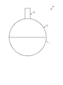
- FIG. 1 is a schematic view of a molding die according to the present embodiment.
- FIG. 2 is a schematic cross-sectional view of the molding die according to the present embodiment.
- FIG. 3 is a partially enlarged view of FIG.
- FIG. 4 is a flowchart illustrating a method of molding a ceramic material according to the present embodiment.
- FIG. 5 is a diagram illustrating a step of obtaining a cured product having a desired shape.
- FIG. 6 is a flowchart illustrating a method for manufacturing a ceramic article according to the present embodiment.
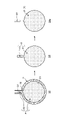
- FIG. 7 is a schematic view of the ceramic article according to the present embodiment.
- FIG. 8 is a diagram schematically showing a CT image of the ceramic article according to the present embodiment.
- FIG. 1 is a schematic view of a molding die according to the present embodiment.
- FIG. 2 is a schematic cross-sectional view of the molding die according to the present embodiment.
- the molding die 10 according to the present embodiment is a mold in which a ceramic material is filled therein and a cavity C for obtaining a cured product having a desired shape is formed. It can be said that the molding die 10 is formed of a soluble resin and the cavity C is covered with the mold made of the soluble resin.
- the mold 10 is soluble in a non-aqueous solvent.
- the soluble resin used in the molding die 10 is a resin that dissolves in a non-aqueous solvent.
- a description of the non-aqueous solvent will be described later.
- the molding die 10 preferably has a dissolution rate in a non-aqueous solvent of 1 ⁇ m / min to 80 ⁇ m / min, more preferably 5 ⁇ m / min to 30 ⁇ m / min, and 6 ⁇ m / min to 15 ⁇ m / min. Is more preferable. When the melting rate is within this range, the molding die 10 can be appropriately melted and demolded.
- the melting rate of the molding die 10 refers to a value obtained by dividing the thickness ( ⁇ m) of the molding die 10 to be melted by time.
- the method for measuring the dissolution rate of the molding die 10 is arbitrary, but it may be measured by the following method.
- the ceramic material is cured in the molding die 10 having a thickness of 1.6 mm, and the molding die 10 is immersed in methylene chloride having a temperature of 25 ° C. Then, the time at which all the molding molds 10 are completely dissolved is measured and used as the dissolution time, and the value obtained by dividing 1.6 mm by the dissolution time is used as the dissolution rate.
- the numerical range represented by "-" means a numerical range including the numerical values before and after "as the lower limit value and the upper limit value", and when "-" is used thereafter, it means the same meaning.
- the molding die 10 does not melt due to heating during curing of the ceramic material in the cavity C.
- the melting point of the molding die 10 is preferably 70 ° C. or higher, and may be 80 ° C. to 250 ° C., or 100 ° C. to 230 ° C. Further, the melting point of the molding die 10 may be 100 ° C. or higher, 120 ° C. to 250 ° C., or 150 ° C. to 230 ° C. When the melting point of the molding die 10 is in this range, the molding die 10 is suppressed from melting during molding, and a cured product having a desired shape can be appropriately obtained.
- the molding die 10 has an elastic modulus of 500 MPa to 5000 MPa, preferably 700 MPa to 4000 MPa, and more preferably 1100 MPa to 2600 MPa.
- the elastic modulus here is a tensile elastic modulus, that is, Young's modulus, and may refer to, for example, a value under the conditions of 23 ° C. and a relative humidity of 0% ° C.
- the molding die 10 preferably has a tensile strength of 500 MPa to 5000 MPa, more preferably 1000 MPa to 3000 MPa.
- the tensile strength here may refer to a value under the conditions of, for example, 23 ° C. and a relative humidity of 0% ° C.
- the shape of the molded body is not deformed to the extent that it can be formed into a desired shape, and the shape of the molding material is stabilized until the molding material is cured (gelled). Can be held.
- Tensile strength and tensile modulus can be measured by ISO 527-1 and ISO 527-2.
- the mold 10 has a thermal conductivity of 0.05 [W / mK] to 0.40 [W / mK] and 0.08 [W / mK] to 0.30 [W / mK]. Is preferable, and it is more preferably 0.1 [W / mK] to 0.2 [W / mK].
- the thermal conductivity can be measured by, for example, JIS A1412-2.
- the soluble resin used in the mold 10 is mainly composed of at least one material selected from the group consisting of polystyrene, ABS (Acrylonitrile-Butadiene-Stylerene) resin, acrylic resin, polycarbonate, epoxy resin, and polyester. Is preferable. Further, it is more preferable that the soluble resin used in the molding die 10 contains polystyrene as a main component.
- polystyrene for example, by using a soluble resin used in the molding die 10 such as toyostyrene impact-resistant polystyrene H350 as such a material, the above-described characteristics can be appropriately imparted to the molding die 10. .
- the main component here means, for example, that the ratio of the material to the whole of the molding die 10 is 50% or more by mass ratio, preferably 80% or more, and more preferably 95% or more.
- the molding die 10 does not have a film or the like formed on the inner surface of a component other than the soluble resin. That is, in the molding die 10, it is preferable that the soluble resin is not completely covered by the coating film of other components on the inner surface side, and the soluble resin is exposed in at least a part of the inner surface, and the inner surface is preferably exposed. It is preferable that the soluble resin is exposed over the entire area. If a film of a component other than the soluble resin is present on the inner surface of the molding die 10, it may remain undissolved when the soluble resin as the main component is dissolved, and the film may need to be removed in another step. Therefore, if the film is not present or is present in a small amount, the productivity is improved, which is preferable. Further, if the film is an unnecessary component for the finally obtained ceramic material, it is preferable that it does not remain.
- the molding die 10 is composed of two or more divided bodies, and the divided bodies are fitted together. As shown in FIGS. 1 and 2, in the present embodiment, the molding die 10 includes the first divided body 12 and the second divided body 14. An injection port portion 16 is connected to the first divided body 12.
- a first cavity (space) C1a is formed inside the first divided body 12. Since the portion of the first divided body 12 to be fitted with the second divided body 14 is not covered with the member (soluble resin), the first cavity C1a includes the first divided body 12 and the second divided body 14. It is open when it is not fitted.
- a first cavity (space) C1b is formed inside the second divided body 14. Since the portion of the second divided body 14 to be fitted with the first divided body 12 is not covered with the member (soluble resin), the first cavity C1b is formed by the first divided body 12 and the second divided body 14. It is open when it is not fitted.
- a second cavity (space) C2 is formed inside the injection port portion 16. Since the inlet portion 16 has an open end on the side connected to the first divided body 12, the second cavity C2 and the first cavity C1a are the first divided body 12 and the second cavity C2. It communicates through the connection point of. Further, the injection port 16a has an injection port 16a open at an end portion on the side opposite to the side connected to the first divided body 12. Therefore, the second cavity C2 and the first cavity C1a communicate with the outside via the injection port 16a. Further, on the inner peripheral surface of the connection portion between the injection port portion 16 and the first divided body 12, in other words, a constriction 18 is formed between the second cavity C2 and the first cavity C1a.
- the constriction 18 is a protruding portion that protrudes inward in the radial direction from the inner peripheral surface of the connection portion between the injection port portion 16 and the first divided body 12. Therefore, when viewed from the axial direction of the injection port portion 16, the opening area of the portion between the second cavity C2 and the first cavity C1a (the portion where the constriction 18 is formed) is the opening area of the second cavity C2. And smaller than the opening area of the first cavity C1a.
- the shape of the injection port portion 16 is not limited to the above description and may be arbitrary. Further, the constriction 18 is not an essential configuration and may not be provided.
- the first cavity C1a is formed inside the first divided body 12
- the first cavity C1b is formed inside the second divided body 14
- the second cavity C1b is formed inside the injection port portion 16.
- Cavity C2 is formed.
- the first cavity C1a, the first cavity C1b, and the second cavity C2 communicate with each other to form the cavity C. That is, the cavity C includes a first cavity C1a, a first cavity C1b, and a second cavity C2.
- the portions formed by the first cavities C1a and the first cavities C1b are shaped so as to give the cured body a desired shape. That is, assuming that the portion formed by the first cavity C1a and the first cavity C1b is the first cavity C1, the first cavity C1 has a shape such that the cured body has a desired shape.
- the first cavity C1 is spherical in the present embodiment, and the obtained cured body, molded body, and sintered body are also spherical.
- the first cavity C1 is not limited to a spherical shape and may have an arbitrary shape.
- the molding die 10 since the molding die 10 is demolded by dissolving the molding die 10 with a non-aqueous solvent, the cavity has a complicated shape with many irregularities or intricate shape, and damage such as a constriction or a fine line shape. Even when it has a shape that is easy to form, a cured product, a molded product, and a sintered body that retain the desired shape can be stably obtained without impairing the desired shape.
- the first cavity C1 includes the first cavity C1a and the first cavity C1b, and can be said to be a cavity formed inside the fitted first divided body 12 and the second divided body 14.
- the portion of the second cavity C2 in the cavity C communicates with the first cavity C1 and is provided with an injection port 16a. It can be said that the second cavity C2 is a portion for injecting a ceramic material into the first cavity C1.
- the molding die 10 preferably has one injection port for injecting a ceramic material. This is because when the injection of the ceramic material is completed, it can be easily sealed by closing only one injection port. However, a plurality of injection ports may be provided. When there is only one injection port, it is preferable that the number of processes for obtaining a desired shape is small in the vicinity of the injection port of the molded body or the sintered body. When there are a plurality of injection ports, it is preferable in terms of uniform injection of the ceramic casting liquid and improvement of productivity, but it may be necessary to process a plurality of locations in the vicinity of the injection port in the molded body or sintered body.
- the thickness of the portion of the molding die 10 that forms the first cavity C1 is defined as the thickness D1.
- the thickness D1 is preferably 0.5 mm to 3.0 mm, more preferably 0.6 mm to 2.0 mm, and even more preferably 0.8 mm to 1.6 mm. Since the thickness D1 of the molding die 10 is in this range, the molding die 10 can be appropriately melted at the time of demolding while maintaining the strength at the time of molding.
- the thickness D1 can also be said to be the length from the inner peripheral surface to the outer peripheral surface of the portion forming the first cavity C1.
- the thickness D1 is the thickness from the inner peripheral surface 12a to the outer peripheral surface 12b of the first divided body 12, and is the thickness from the inner peripheral surface 14a to the outer peripheral surface 14b of the second divided body 14. It can be said that.
- the arithmetic mean roughness Ra specified in JIS B 0601: 2001 on the inner surface of the portion of the molding die 10 forming the first cavity C1 is preferably 0.01 ⁇ m or more and 5 ⁇ m or less, preferably 0.05 ⁇ m or more and 1 ⁇ m. It is more preferably 0.1 ⁇ m or more, and further preferably 0.5 ⁇ m or less.
- the surface roughness of the inner surface of the first cavity C1 is within this range, the dimensional accuracy and surface flatness of the cured product can be ensured, and the appearance defect can be suppressed.
- the inner surface of the portion forming the first cavity C1 is the inner peripheral surface 12a of the first divided body 12, and can be said to be the inner peripheral surface 14a of the second divided body 14.
- the volume of the second cavity C2 is preferably 0.5% by volume to 5% by volume, more preferably 0.8% by volume to 4% by volume, based on the volume of the first cavity C1. It is more preferably 1% by volume to 3% by volume. When the volume of the second cavity C2 is within this range, even when the ceramic material is cured and shrunk, the ceramic material filled in the second cavity C2 is drawn into the first cavity C1, and the dimensional accuracy of the cured body is appropriate. Can be secured to.
- FIG. 3 is a partially enlarged view of FIG. FIG. 3 shows a fitting portion between the first divided body 12 and the second divided body 14.
- the first divided body 12 includes a main body portion 12A and a protruding portion 12B.
- the main body portion 12A is a portion forming the first cavity C1a, and in the example of the present embodiment, the main body portion 12A is a hollow hemispherical member in which the portion on the side fitted to the second divided body 14 is open.
- the protruding portion 12B projects from the end portion 12Aa of the main body portion 12A on the side fitted to the second divided body 14 to the side fitted to the second divided body 14.
- the protruding portion 12B is provided so that the inner peripheral surface of the protruding portion 12B and the inner peripheral surface of the main body portion 12A are integrated. That is, the inner peripheral surface of the protruding portion 12B and the inner peripheral surface of the main body portion 12A form the inner peripheral surface 12a of the first divided body 12.
- the protruding portion 12B is provided so that the outer peripheral surface of the protruding portion 12B is located on the inner peripheral surface 12a side (inner in the radial direction) with respect to the outer peripheral surface of the main body portion 12A. That is, the outer peripheral surface of the main body portion 12A forms the outer peripheral surface 12b of the first divided body 12.
- FIG. 3 is a cross-sectional view showing only a part in the circumferential direction
- the protruding portion 12B is formed over the entire area of the main body portion 12A in the circumferential direction.
- the second divided body 14 includes a main body portion 14A and a protruding portion 14B.
- the main body portion 14A is a portion forming the first cavity C1b, and in the example of the present embodiment, the main body portion 14A is a hollow hemispherical member in which the portion on the side fitted to the first divided body 12 is open.
- the protruding portion 14B protrudes from the end portion 14Aa of the main body portion 14A on the side fitted to the first divided body 12 to the side fitted to the first divided body 12.
- the protruding portion 14B is provided so that the outer peripheral surface of the protruding portion 14B and the outer peripheral surface of the main body portion 14A are integrated.
- the outer peripheral surface of the protruding portion 14B and the outer peripheral surface of the main body portion 14A form the outer peripheral surface 14b of the second divided body 14.
- the protruding portion 14B is provided so that the inner peripheral surface of the protruding portion 14B is located on the outer peripheral surface 14b side (outer in the radial direction) with respect to the inner peripheral surface of the main body portion 14A. That is, the inner peripheral surface of the main body portion 14A forms the inner peripheral surface 14a of the second divided body 14.
- the protruding portion 14B is formed over the entire area of the end portion 14Aa in the circumferential direction.
- FIG. 3 is a cross-sectional view showing only a part in the circumferential direction
- the protruding portion 14B is formed over the entire area of the main body portion 14A in the circumferential direction.
- the first division body 12 and the second division body 14 are such that the protrusion 12B of the first division body 12 is inserted inside the protrusion 14B of the second division body 14. It is fitted.
- the tip portion 12Ba of the protruding portion 12B of the first divided body 12 is radially inside the protruding portion 14B of the second divided body 14. , Contact with the end portion 14Aa of the main body portion 14A of the second split body 14.
- tip portion 14Ba of the protruding portion 14B of the second divided body 14 comes into contact with the end portion 12Aa of the main body portion 12A of the first divided body 12 on the radial outer side of the protruding portion 12B of the first divided body 12.
- the thickness D2 of the protruding portion 12B is preferably 0.5 mm to 2.0 mm, more preferably 0.7 mm to 1.5 mm, and even more preferably 0.8 mm to 1 mm.
- the thickness D2 is within this range, the alignment between the tip portion 12Ba of the protruding portion 12B and the end portion 14Aa of the main body portion 14A is ensured, and a gap is formed between the first divided body 12 and the second divided body 14. Can be suppressed. As a result, it is possible to appropriately manufacture the cured product by suppressing the entry of outside air into the inside of the molding die 10.
- the thickness D2 of the protruding portion 12B is within the above numerical range, it is possible to prevent the protrusion 12B from becoming too thin and to secure the strength.
- the thickness D2 can be said to be the thickness in the normal direction of the portion where the divided bodies are fitted to each other, and can also be said to be the thickness of the member on the inner peripheral surface side at the portion where the divided bodies are fitted to each other.
- the first divided body 12 and the second divided body 14 are fitted as described above, but the fitting structure is not limited to that described above.
- the protruding portion 12B formed on the inner peripheral surface side is provided on the first divided body 12 side
- the protruding portion 14B formed on the outer peripheral surface side is provided on the second divided body 14 side.
- the protrusion 12B was inserted into the protrusion 14B, but the present invention is not limited to this.
- a protrusion formed on the inner peripheral surface side is provided on the second divided body 14 side
- a protrusion formed on the outer peripheral surface side is provided on the first divided body 12 side
- the second divided body is provided.
- the protrusion on the 14 side may be inserted into the protrusion on the 12 side of the first divided body.
- the molding die 10 has the above configuration.
- the molding die 10 is not limited to the configuration described above.
- the molding die 10 may be an integrally formed mold, for example, instead of a configuration including a plurality of divided bodies.
- the molding die 10 can be manufactured by an arbitrary method so as to have a cavity C having a desired shape.
- Examples of the molding method of the molding die 10 include melt molding.
- the melt molding is a method in which the material of the molding die 10 is melted, molded into a desired shape, and cured.
- examples of the molding method of the molding die 10 include injection molding, blow molding and the like.
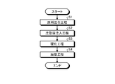
- FIG. 4 is a flowchart illustrating a method of molding a ceramic material according to the present embodiment.
- the raw material mixing step is a step of mixing a ceramic powder having a desired composition with a resin, a curing agent and a solvent to obtain a slurry-shaped ceramic material (hereinafter referred to as a ceramic casting liquid) (S1).
- the ceramic powder is not particularly limited as long as it becomes ceramic by sintering, and examples thereof include known ceramic powder.
- examples of the ceramic powder include aluminum oxide, zirconium oxide, silicon oxide, silicon nitride, silicon carbide, aluminum nitride, and sialon. One of these may be used alone, or two or more thereof may be mixed and used.
- the ceramic powder preferably has a 50 % particle size D50 of less than 1.0 ⁇ m so that a stable sintered body can be obtained in the sintering step described later. If the 50% particle size D 50 is 1.0 ⁇ m or more, molding defects may occur due to particle settling in the slurry, which may lead to a decrease in sintering density.
- the 50% particle size D50 is more preferably less than 0.9 ⁇ m, still more preferably less than 0.8 ⁇ m. Further, a particle size D 50 of 0.1 ⁇ m or more is preferable because it facilitates scattering, clogging prevention and procurement during handling.
- the structure obtained by sintering is a bonded phase in which the main phase crystal particles containing silicon nitride as a main component are vitreous and / or crystalline. It is preferable that the form is combined with.
- the ceramic powder When silicon nitride is used as the ceramic powder, the ceramic powder preferably has a silicon nitride pregelatinization rate of 70% or more, more preferably 80% or more, still more preferably 90% or more.
- the silicon nitride powder has a pregelatinization rate of less than 70%, the effect of incorporating the needle-like structure during the phase transition from ⁇ to ⁇ during sintering cannot be sufficiently obtained, and the strength of the sintered body decreases. If the silicon nitride powder has a pregelatinization rate of 90% or more, a sufficient incorporation effect can be obtained and a sintered body having high strength, particularly toughness, can be obtained.
- the content of silicon nitride having such a pregelatinization rate in the ceramic powder is preferably 85% by mass or more, more preferably 92% by mass or more.
- a sintering aid for improving sintering is added to the ceramic powder.
- Group 2 alkaline earth metal
- Group 3 rare earth (scandium group)
- Group 4 titanium group
- Group 5 earth metal (vanadium group)
- 13th group as sintering aids
- the content in the ceramic powder is 1 in terms of oxide. It is preferably mass% to 15% by mass, more preferably 2% by mass to 8% by mass.
- the content of the sintering aid is small, but if it is less than 1% by mass, sintering may become difficult.
- the resin is a component for molding a ceramic material into a desired shape in a curing step described later, and examples thereof include known curable resins.
- a resin that is required to have shape retention in the curing step and forms a three-dimensional network structure by a polymerization reaction is used.
- the resin is preferably liquid in that it enhances the fluidity of the ceramic casting liquid and has good filling property into the molding mold 1 described later.
- the resin can be easily removed from the ceramic molded product in the degreasing step after the curing step and before sintering.
- the resin used in this embodiment include epoxy resin, phenol resin, melamine resin, acrylic acid resin, urethane resin and the like. Among them, epoxy resin is preferably used because it has good shape retention.
- the epoxy resin include glycidyl ether type epoxy resin of bisphenols such as bisphenol A type and bisphenol F type, phenol novolac type epoxy resin, cresol novolac type epoxy resin, glycidylamine type epoxy resin, and glycidyl such as aliphatic epoxy resin.
- the resin added to the ceramic casting liquid is preferably a material different from the soluble resin of the molding die 10.
- the average molecular weight of the epoxy resin is preferably 20,000 to 30,000.
- the average molecular weight of the epoxy resin is more preferably 50 to 3000, still more preferably 50 to 2500, in that the resin and the powder can be easily mixed and a constant mechanical strength can be obtained.
- the curing agent cures the resin and is selected according to the resin used.
- the curing agent is preferably water-soluble and rapidly cures the resin, and examples thereof include amine-based curing agents, acid anhydride-based curing agents, and polyamide-based curing agents.
- the amine-based curing agent is preferable in that the reaction is rapid, and the acid anhydride-based curing agent is preferable in that a cured product having excellent heat impact resistance can be obtained.
- Examples of the amine-based curing agent include aliphatic amines, alicyclic amines, aromatic amines, and any of monoamines, diamines, triamines, and polyamines can be used.
- Examples of the acid anhydride-based curing agent include methyltetrahydrophthalic anhydride and dibasic acid polyanhydride.
- the solvent adjusts the viscosity of the mixture of the raw materials to be used to form a slurry, which facilitates filling of the ceramic casting liquid into the molding die 10 described later.
- the solvent for example, water ( H2O ), alcohols, and other organic solvents can be used. Among them, the water system is preferable from the viewpoint of manufacturing cost and environmental load.
- the selection of the resin and the solvent should be a combination having a good affinity between the resin and the solvent in order to facilitate the removal of the resin in the degreasing step described later. If the affinity between the resin and the solvent is poor, the resin and the solvent may separate and segregate inside the molded product, which may cause defects such as pores during sintering.
- the above-mentioned ceramic powder, resin, curing agent and solvent are mixed to prepare a ceramic casting liquid. If necessary, a dispersant or the like is added. At this time, mixing may be performed by a known method, for example, a dissolver, a homomixer, a kneader, a roll mill, a sand mill, a ball mill, a bead mill, a vibrator mill, a high-speed impeller mill, an ultrasonic homogenizer, a shaker, a planetary mill, and a self-revolution. Examples include mixers and in-line mixers.
- a pH adjuster As the dispersant to be added as needed, a pH adjuster, a surfactant, a polymer dispersant, etc. can be appropriately selected and added in order to dissociate and further disperse the agglomerates of the ceramic powder.
- the pH adjuster, surfactant, polymer dispersant and the like are preferably those that do not adversely affect the gelation of the above-mentioned curable resin.
- a basic organic substance can be used, for example, alkanolamines such as ammonia, monoethanolamine, diethanolamine and triethanolamine, choline, guanidines, tetramethylammonium hydroxide and the like 4 Examples include grade ammonium salts.
- inorganic acids, organic acids and salts thereof can be used, for example, phosphoric acid, nitric acid, citric acid, malic acid, acetic acid, lactic acid, oxalic acid, tartrate acid and the like, salts thereof, amino acids. Androgynous salts and the like can be mentioned.
- surfactant examples include alkylamine salts, aliphatic or aromatic quaternary ammonium salts, heterocyclic quaternary ammonium salts such as pyridinium and imidazolium, phosphonium or sulfonium salts containing an aliphatic or heterocycle, and acetylene. Glycol and the like can be mentioned.
- polymer dispersant examples include polymers having a primary to tertiary amine, a quaternary ammonium base, a quaternary phosphonium base, etc. in the polymer main chain or side chain, acrylic acid, a homopolymer of a salt thereof, and water-soluble.
- examples thereof include a sex aminocarboxylic acid-based polymer and a (co) polymer of an acrylic acid ester.
- pH adjusters may be used alone or in combination of two or more.
- the resin-added slurry containing the resin and the curing agent-added slurry containing the curing agent are separately prepared.
- the separately prepared slurries may be mixed at the time of use.
- the ceramic powder may be mixed with either slurry or both slurries, separately from both slurries.
- a slurry containing ceramic powder may be prepared separately.
- a ceramic casting liquid is prepared using the raw material slurry which is the above-mentioned raw material mixture.
- the viscosity of the ceramic casting liquid may be any viscosity as long as it can be easily filled in the casting liquid injection step described later.
- the viscosity at a shear rate of 10 [1 / s] is preferably 50 Pa ⁇ s or less, preferably 20 Pa. -S or less is more preferable.
- the viscosity of the ceramic casting liquid is more preferably in the range of 0.1 Pa ⁇ s to 10 Pa ⁇ s.
- the viscosity of the ceramic casting liquid can be easily adjusted by adjusting the amount of solvent used and the amount of resin added in the raw material used.
- air or the like may be entrained by mixing in the raw material mixing step, and gas may be contained in the obtained ceramic casting liquid. Therefore, if necessary, a defoaming step for removing the gas contained in the ceramic casting liquid is performed before the casting liquid injection step, which is the next step. If gas is contained in the ceramic casting liquid, pores due to air bubbles may be generated inside in the curing step and may remain in the ceramic article obtained by firing.
- the ceramic casting liquid may be defoamed under reduced pressure, and a defoaming pump (vacuum pump), a defoaming mixer, or the like is used. Defoaming may be performed, for example, for 1 minute to 120 minutes under a reduced pressure of 0.6 kPa to 10 kPa.
- a defoaming mixer the raw material mixing step and the defoaming step can be carried out at the same time.
- the defoaming mixer include a rotation / revolution mixer equipped with a vacuum pump, a planetary mixer, and the like.
- the casting liquid injection step is a step of injecting the ceramic casting liquid obtained through the raw material mixing step and, if necessary, the defoaming step into the molding die 10 (S2).
- the ceramic casting liquid is injected into the cavity C from the injection port 16a.
- it is preferable to inject the ceramic casting liquid so that the ceramic casting liquid is filled in the first cavity C1 and the second cavity C2 of the cavities C.
- a device capable of sending the ceramic casting liquid and supplying it into the molding mold 10 may be used.
- a pump such as a diaphragm pump, a tube pump, or a syringe pump may be used.
- a rotary positive displacement diaphragm pump equipped with a precision constant velocity cam having a structure that does not generate pulsation is preferable.
- an in-line mixer or the like that can send a liquid while mixing raw materials to prepare a ceramic casting liquid can also be used. When using an in-line mixer, the raw material mixing step and the casting liquid injection step can be performed at the same time.
- both slurries can be mixed and immediately sent to the molding die 10 for filling, which is preferable. ..
- a two-component mixing / discharging device may be used.
- a method of discharging with a constant capacity cylinder may be used, or a valve switching method using a mono pump that suppresses pulsation may be used.
- a separate mixer may be used as the slurry mixing device.
- the resin component in the ceramic casting liquid is cured to cure the ceramic material into a desired shape (S3).
- the ceramic casting liquid is cured under desired curing conditions according to the characteristics of the ceramic casting liquid.
- the reaction starts from the time when the resin-added slurry and the curing agent-added slurry are mixed and cured, so that it may be left for a predetermined time.
- the curing time is about 1 hour to 3 days, preferably 1 hour to 24 hours from the viewpoint of production efficiency, and more preferably 1 hour to 12 hours.
- the heating temperature for curing the resin is preferably in the range of 30 ° C to 85 ° C, more preferably in the range of 40 ° C to 70 ° C, and in the range of 50 ° C to 60 ° C. It is more preferable to have.
- the heating time that is, the time for maintaining the heating temperature is preferably 5 minutes to 2880 minutes, more preferably 10 minutes to 1440 minutes, and further preferably 30 minutes to 180 minutes.
- the demolding step is a step of taking out the cured body of the ceramic material cured in the curing step from the molding die 10 (S4).
- the molding die 10 is brought into contact with a non-aqueous solvent, the molding die 10 is dissolved in the non-aqueous solvent, and the cured product is demolded.
- the contact with the non-aqueous solvent is preferably immersed in the non-aqueous solvent. If immersion in a non-aqueous solvent is used to dissolve the molding die 10, the molding die 10 in which the ceramic material is cured inside can be easily removed by simply leaving the molding die 10 in the non-aqueous solvent.
- the non-aqueous solvent is a liquid whose main component is a component other than water, and dissolves the soluble resin of the molding die 10.
- the non-aqueous solvent is preferably a solvent that dissolves the soluble resin of the molding die 10 and does not dissolve the resin in the ceramic casting liquid.
- the main component is at least one material selected from the group consisting of methylene chloride, d-limonene, acetone, and toluene.
- the main component here means, for example, that the ratio of the material to the whole non-aqueous solvent is 50% or more.
- the mold 10 is dissolved in a non-aqueous solvent in a temperature environment lower than the heating temperature at which the resin in the ceramic casting liquid is cured in the curing step to demold the cured product. Is preferable. Furthermore, in the demolding step, it is preferable to dissolve the molding die 10 in a non-aqueous solvent in an environment of 10 ° C. to 40 ° C. to demold the cured product. By demolding at a relatively low temperature in this way, it is possible to suppress heating of the cured product more than necessary, and to produce an appropriate ceramic article.
- the demolding time that is, the time for contacting the molding die 10 with the non-aqueous solvent is preferably 20 minutes to 1800 minutes, more preferably 30 minutes to 240 minutes, and 60 minutes to 180 minutes. Is even more preferable. By setting the demolding time within this range in this way, the molding die 10 can be appropriately melted and appropriately demolded.
- the demolding step may proceed at the same time as the curing step described above. That is, the demolding step may be performed immediately after injecting the ceramic casting liquid into the molding die 10. In this case, the molding die 10 filled with the ceramic casting liquid is immediately contacted with the non-aqueous solvent immediately after the ceramic casting liquid is filled, and the melting of the molding die 10 proceeds. At this time, the curing (gelling) of the ceramic casting liquid is allowed to proceed at the same time as the melting of the molding die 10.
- the molding die 10 is manufactured so that the exposure melting time of the molding die 10 is longer than the curing time of the ceramic casting liquid (curing time ⁇ exposure melting time). By adjusting both the curing time and the exposure melting time, the molding die 10 is melted (a part of the cured body inside is exposed) after the ceramic casting liquid is cured, and a cured body having a desired shape can be obtained. ..
- the curing time means the time from immediately after the ceramic casting liquid is adjusted until the ceramic casting liquid can maintain the shape of the molding mold by gel curing, and the exposure melting time means that the molding mold 10 is immersed in a non-aqueous solvent. It means the time from when it is made until a part of the cured body inside it is exposed.
- curing time means a cured product in which the ceramic casting liquid is a viscoelastic solid as the formation of a three-dimensional network structure progresses due to the polymerization reaction of the resin and the curing agent in the ceramic casting liquid. It is the time until it has sufficient hardness to withstand handling.
- the cured product is not hardened to a predetermined hardness or higher before the demolding step or the cured product after the demolding is advanced to the drying step, the cured product may be deformed or cracked.
- the hardness that can be said to be sufficient for handling is appropriately determined by the shape and dimensions, but the "hardness that can be said to be sufficient for handling" in the present specification means that the cured product has a bending elastic modulus of 2 MPa or more. Is.
- a round bar cured product for destructive inspection is subjected to a predetermined elapsed time (for example, 5 minutes, 10 minutes, 15 minutes, 20 minutes, 30 minutes).
- the measurement conditions are as follows.
- the flexural modulus in the 3-point bending test is calculated from the load-elongation graph using the tangential method that takes any two points from the initial gradient of the straight part.
- L is the distance between fulcrums (mm)
- D is the sample diameter (mm)
- Fmax is the maximum load d (N)
- ⁇ F is the amount of change in bending load (N)
- ⁇ S is the amount of change in elongation (N). Is.
- the curing time and exposure dissolution time can be adjusted by adjusting the temperature of the non-aqueous solvent used for demolding, the type of molding mold 10 (type of resin and curing agent, amount of addition, etc.), thickness, and the like.
- the present embodiment may include a step of removing a part of the cured product after demolding the cured product by a demolding step to obtain a cured product having a desired shape.
- FIG. 5 is a diagram illustrating a step of obtaining a cured product having a desired shape.
- the ceramic casting liquid is cured in the molding die 10 to form the cured product P in the molding die 10. Since the ceramic casting liquid is injected into the first cavity C1 and the second cavity C2 in the molding die 10, the cured product P is the cured product P1 which is a portion injected into the first cavity C1 and cured. 1 Includes a cured body P2 which is a portion injected into the cavity C1 and cured.
- the demolding step step S4
- the molding die 10 is melted to obtain a cured product P demolded from the molding die 10.
- a constriction 18 is formed between the first cavity C1 and the second cavity C2. Therefore, the portion between the cured product P1 and the cured product P2 corresponding to the constriction 18 is a constricted portion having a diameter smaller than that of the cured product P2.
- the cured body P2 is removed from the cured body P starting from the constricted portion between the cured body P1 and the cured body P2, and the cured body P1 is cured into a desired shape. Get as a body.
- the method for manufacturing a ceramic article includes a drying step of drying a cured product obtained by the above-mentioned molding method of a ceramic material to form a molded body, a degreasing step of degreasing the molded body to obtain a degreased body, and sintering the degreased body. It has a sintering process for forming a sintered body.
- FIG. 6 is a flowchart illustrating a method for manufacturing a ceramic article according to the present embodiment.
- the method for manufacturing a ceramic article according to the present embodiment includes a raw material mixing step (step S1), a casting liquid injection step (step S2), a curing step (step S3), and a demolding step. It has (step S4), a drying step (step S5), a degreasing step (step S6), and a baking step (step S7).
- step S1 the raw material mixing step to the demolding step
- steps S1 to S4 are the same as the molding method of the ceramic material, the description thereof will be omitted.
- the drying step is a step of removing water, a volatile solvent, and the like from the cured product obtained in the demolding step and drying the cured product to obtain a molded product (step S5).
- the cured product is slowly dried so as not to cause cracks or the like. That is, the cured product is dried while preventing cracks and the like due to shrinkage stress caused by the difference in drying speed between the surface and the inside of the cured product.
- the moisture contained in the cured product over a long period of time under relatively mild conditions such as 25 ° C to 50 ° C, relative humidity 50% to 95%, 48 hours to 7 days, etc. Remove.
- the drying step is preferably carried out until the water content of the cured product is 20% or less of the mass at the time of absolute drying.
- the degreasing step is a step of removing the resin, the non-volatile solvent and the like from the molded body obtained in the drying step to obtain a degreased body (step S6).
- a degreased body step S6
- most of the components that inhibit sintering are removed in the sintering step of the next step. If a large amount of components that inhibit sintering remain, pores may occur in the sintered body during sintering, or carbides may occur as by-products, making it impossible to obtain the characteristics required for the final product. There is a risk of.
- the temperature is slowly raised and maintained from 250 ° C. to 800 ° C., and the total processing time is contained in the molded product over a relatively long time such as 3 to 14 days. Removes resin components and the like.
- the degreasing step particularly for silicon nitride is preferably carried out until the amount of residual carbon in the molded product is 900 ppm or less.
- the amount of residual carbon is not limited to carbides such as silicon carbide (SiC).
- the firing step is a step of firing the degreased body that has undergone the degreasing step to sintered the ceramic material into a sintered body (ceramic article) (step S7).
- the ceramic material is sintered to form a sintered body, that is, a ceramic article, and a known firing method may be applied.
- the conditions of the firing step are not particularly limited as long as the firing step can be performed to obtain a sintered body.
- the firing is performed in a nitrogen atmosphere with an oxygen concentration of 50 ppm or less. preferable.
- the maximum firing temperature in the firing step is set to 1800 ° C. or lower at which silicon nitride begins to thermally decompose, and the maximum temperature is preferably in the range of 1650 ° C. to 1750 ° C.
- the firing time is preferably in the range of 240 minutes to 15 hours, and may be in the range of 240 minutes to 12 hours.
- the sintered body obtained in the firing step may be subjected to a secondary firing step in order to further obtain a sintered body having desired characteristics.
- This secondary firing step is a step of further applying a high pressure treatment to the sintered body obtained in the above-mentioned firing step (primary firing) to densify the structure of the sintered body.
- the high pressure treatment in this secondary firing step a hot isostatic pressing method (HIP), gas pressure firing, hot pressing, etc. can be used.
- HIP hot isostatic pressing method
- the sintered body obtained by sintering has high strength, and is preferably treated with HIP in the range of 1500 ° C to 1750 ° C and 50 MPa to 200 MPa.
- FIG. 7 is a schematic view of the ceramic article according to the present embodiment.
- the ceramic article (sintered body) manufactured by the method for manufacturing a ceramic article according to the present embodiment will be referred to as the ceramic article 100, and the characteristics of the ceramic article 100 will be described below.
- the ceramic article 100 is a sintered body of ceramics.
- the ceramic article 100 is preferably a sintered body of at least one ceramic of, for example, aluminum oxide, zirconium oxide, silicon oxide, silicon nitride, silicon carbide, aluminum nitride, and Sialon, and is a sintered body of silicon nitride. It is more preferable to have.
- the ceramic article 100 is a sintered body after the firing step and before polishing. That is, the surface of the sintered body may be polished after the firing step (sintering step), but the ceramic article 100 of the present embodiment is a sintered body in an unpolished state (state before polishing). Point to. However, the present invention is not limited to this, and the ceramic article 100 may refer to a sintered body in a state of being polished after sintering.
- the ceramic article 100 may be used for any purpose, and may be used, for example, as a bare ball for a bearing ball.
- the raw ball here means an intermediate product when the final product is a bearing ball, and for example, by polishing the surface of the ceramic article 100, the bearing ball which is the final product is formed.
- the ceramic article 100 is spherical.
- the sphere here is not limited to a true sphere, and for example, the ceramic article 100 is preferably true within 3%, more preferably within 2.5%, still more preferably within 2% with respect to the diameter D. It may be spherical.
- the sphericity is preferably 1.5 mm or less, more preferably 1.25 mm or less, still more preferably 1.0 mm or less.
- the sphericity is preferably 0.3 mm or less, more preferably 0.25 mm or less, still more preferably 0.2 mm or less.
- the diameter D here may refer to an average diameter (arithmetic mean value of the maximum and minimum values of the diameter).
- the ceramic article 100 is a sintered body of the cured product P1 from which the cured product P2 corresponding to the constricted portion of the molding die 10 has been removed, and there are cases where protrusions remain at the locations where the cured product P2 has been removed. be.
- the diameter D of the ceramic article 100 refers to the diameter measured at a position other than the protrusion on the surface 100a of the ceramic article 100.
- the arithmetic mean value of the maximum value and the minimum value of the diameter is the maximum value of the diameter of the ceramic article 100 measured at a place other than this protrusion and the diameter of the ceramic article 100 measured at a place other than this protrusion. Refers to the arithmetic mean value with the minimum of.
- the diameter D of the ceramic article 100 is preferably 0.5 mm or more and 80 mm or less, more preferably 30 mm or more and 55 mm or less, further preferably 45 mm or more and 55 mm or less, and 49 mm or more and 51 mm or less. More preferred. When the diameter is in this range, it can be suitably used for, for example, a bearing ball.
- the ceramic article 100 has a recess 102 formed on the surface 100a along the circumferential direction R. It can be said that the concave portion 102 is formed by manufacturing the ceramic article 100 by the manufacturing method of the present embodiment using the molding die 10 which is a split die.
- the circumferential direction R is the circumferential direction when the direction along the axis passing through the center of the ceramic article 100 is the axial direction and the circumferential direction when the direction along the axis passing through the center of the ceramic article 100 is the axial direction. Point in the direction.
- the circumferential direction in the vicinity is a circumferential direction deviated within 5% from the position in the circumferential direction when the direction along the axis passing through the center of the ceramic article 100 is taken as the axial direction.
- the recess 102 refers to a recessed portion of the surface 100a.
- the ceramic article 100 is not limited to the entire circumference of the circumferential direction R along the portion where the recess 102 is formed, but is a part of the entire circumference of the circumferential direction R along the portion where the recess 102 is formed. May not be dented or may be protruding.
- the recess 102 may be formed over the entire circumference of the circumferential direction R in the circumferential direction R of the surface 100a, and may be formed in a section of 50% or less with respect to the entire circumference of the circumferential direction R. It is more preferable that it is formed in a section of 25% or less with respect to the entire circumference of the circumferential direction R.
- the recess 102 may be formed in a section of 5% or more with respect to the entire circumference of the circumferential direction R in the circumferential direction R of the surface 100a, or may be formed in a section of 10% or more, or 15%. It may be formed by the above sections. That is, the recess 102 may be formed over the entire circumference of 5% or more of the circumferential direction R in the circumferential direction R of the surface 100a, and is 10% or more and 50% or less with respect to the entire circumference of the circumferential direction R. It may be formed in a section, or may be formed in a section of 15% or more and 25% or less with respect to the entire circumference of the circumferential direction R.
- the fact that the recess 102 is formed in a section of 50% or less with respect to the entire circumference of the circumferential direction R means that the recess 102 is continuously formed in a section of 50% or less with respect to the entire circumference of the circumferential direction R. It is not limited to being done.
- the recess 102 is formed intermittently along the circumferential direction R, and the total length of the recess 102 may be 50% or less with respect to the entire circumference of the circumferential direction R. The same may mean that the recess 102 is formed in a section of 25% or less with respect to the entire circumference of the circumferential direction R, or is formed in a section of 5% or more.
- the recess 102 is preferably formed along one circumferential direction R of the ceramic article 100.
- the ceramic article 100 does not have a plurality of recesses 102 extending along different circumferential directions R.
- a plurality of recesses 102 are formed in series along the same circumferential direction R.
- the recess 102 is located on the surface 100a at a position facing or facing a boundary position (see FIG. 3) between the inner peripheral surface 12a of the first divided body 12 and the inner peripheral surface 14a of the second divided body 14. It is formed in the vicinity.
- the circumferential direction R in which the recess 102 is formed is a portion facing or facing the boundary position between the inner peripheral surface 12a of the first divided body 12 and the inner peripheral surface 14a of the second divided body 14 on the surface 100a. It will be near the location. Since the ceramic article 100 can shrink through the firing step, the circumferential direction R in which the recess 102 is formed is the boundary between the inner peripheral surface 12a of the first divided body 12 and the inner peripheral surface 14a of the second divided body 14. It may shift to the vicinity of the location facing the position.
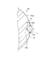
- FIG. 8 is a diagram schematically showing a CT image of the ceramic article according to the present embodiment.
- the depth A1 refers to the distance between the straight line L connecting one end point 102A and the other end point 102B of the recess 102 and the bottom 102C of the recess 102 in the CT (Computed Tomography) image of the ceramic article 100.
- the end point 102A refers to the boundary position on one side of the concave portion 102 and a portion other than the concave portion 102 on the surface 100a in the CT image of the ceramic article 100 in the direction along the surface 100a.
- the end point 102B points to the other side boundary position of the recess 102 and a portion other than the recess 102 on the surface 100a in the CT image of the ceramic article 100 in the direction along the surface 100a.
- the bottom portion 102C refers to the deepest portion (the portion located on the innermost side in the radial direction) of the recess 102 in the CT image of the ceramic article 100.
- the width A2 refers to the distance between the end points 102A and the end points 102B of the recess 102 in the CT image of the ceramic article 100.
- an InspecXio SMX-225CT manufactured by Shimadzu Corporation was used, and the ceramic article 100 was imaged under the conditions that the acceleration voltage was 150 kV, the acceleration current was 70 ⁇ m, and the Voxel size was 0.045 mm to 0.070 mm for the magnification. Point to the image.
- the depth A1 of the recess 102 has a length of 1% or less, preferably 0.1% or more and 1% or less, and 0.1% or more and 0.6% with respect to the diameter D of the ceramic article 100. It is more preferably 0.1% or more and 0.4% or less. That is, as the recess 102, the depth A1 is 1% or less, preferably 0.1% or more and 1% or less, more preferably 0.1% or more and 0.6% or less, still more preferably 0.1, with respect to the diameter D. A section of% or more and 0.4% or less may be formed over 5% or more of the entire circumference of the circumferential direction R of the ceramic article 100 or less, and 10% with respect to the entire circumference of the circumferential direction R of the ceramic article 100.
- the concave portion 102 may be formed in a section of 50% or more, or may be formed in a section of 15% or more and 25% or less with respect to the entire circumference of the circumferential direction R of the ceramic article 100.
- the convex portion is first scraped, then the burnt surface is removed, and the diameter is made uniform. Is needed.
- a polishing allowance for the convex portion is required, but in the case of a concave portion, the shaving allowance for the concave portion and the shaving allowance for removing the burnt surface of the surface and making the diameter uniform can be overlapped.
- the concave portion can have a smaller polishing allowance than the convex portion.
- the depth A1 of the recess 102 is preferably 0.5 mm or less, more preferably 0.05 mm or more and 0.3 mm or less, and further preferably 0.05 mm or more and 0.2 mm or less.
- the width A2 of the recess 102 is preferably 1% or less, more preferably 0.1% or more and 1% or less, and 0.1% or more and 0, with respect to the diameter D of the ceramic article 100. It is more preferably 6.6% or less, and further preferably 0.1% or more and 0.4% or less. That is, the width A2 of the recess 102 is preferably 1% or less, more preferably 0.1% or more and 1% or less, still more preferably 0.1% or more and 0.6% or less, still more preferably 0, with respect to the diameter D. .
- the section of 1% or more and 0.4% or less may extend over the entire circumference of 5% or more and the entire circumference of the ceramic article 100 with respect to the entire circumference of the circumferential direction R of the ceramic article 100.
- the width A2 of the recess 102 is preferably 0.5 mm or less, more preferably 0.05 mm or more and 0.3 mm or less, and further preferably 0.05 mm or more and 0.2 mm or less.
- the arithmetic mean roughness Ra specified by JIS B 0601: 2001 on the surface 100a at a portion other than the recess 102 and the protrusion is preferably 0.1 ⁇ m or more and 50 ⁇ m or less, preferably 0.5 ⁇ m or more and 20 ⁇ m or less. It is more preferably 1 ⁇ m or more and 10 ⁇ m or less.
- the arithmetic mean roughness Ra1 is calculated by extracting the roughness curve of the surface 100a by the reference length.
- the reference length is, for example, 0.8 mm.
- the molding method according to the present embodiment includes a step of mixing a ceramic powder, a sintering aid, a resin, a curing agent and a solvent to prepare a ceramic casting liquid to be a ceramic material, and a non-aqueous system.
- the step of injecting the ceramic casting liquid into the molding mold 10 which is soluble in a solvent and the cavity C is formed inside, and the resin in the ceramic casting liquid injected into the molding mold 10 are cured to be desired.
- the present invention includes a step of forming a cured product having the shape of the above, and a step of dissolving the molding die 10 in a non-aqueous solvent to demold the cured product.
- the mold 10 is formed of a soluble resin that is soluble in a non-aqueous solvent.
- the molding die 10 has an elastic modulus of 500 MPa to 5000 MPa and a thermal conductivity of 0.05 W / mK to 0.40 W / mK.
- a shape is formed by gel casting using a molding die 10. Since the accuracy is good, the surface texture is good, and the curing time is short, the productivity can be increased, so that the molded product can be appropriately molded and a good molded product can be obtained.
- the molding die 10 uses a member that can be dissolved in a non-aqueous solvent, it can be dissolved in a non-aqueous solvent and demolded, and the cured product can be demolded without applying stress. Damage can be suppressed.
- the molding die 10 having a high elastic modulus since the molding die 10 having a high elastic modulus is used, deformation during injection and curing can be suppressed, dimensional accuracy and surface flatness of the cured product can be maintained, and appearance defects can be suppressed. Further, since the molding die 10 having a relatively high thermal conductivity is used, it is possible to prevent external heat from being easily transferred to the ceramic casting liquid and to cure in a short time.
- the molding method according to the present embodiment it is preferable to use water as a solvent for the ceramic casting liquid. By using water, the cured product can be appropriately molded.
- the soluble resin of the molding die 10 contains at least one material selected from the group consisting of polystyrene, ABS resin, acrylic resin, polycarbonate, epoxy resin, and polyester as a main component. By using such a material, it becomes possible to appropriately mold the cured product while appropriately suppressing damage to the cured product during demolding.
- non-aqueous solvent it is preferable to use a solvent that can dissolve the soluble resin and does not dissolve the resin in the ceramic casting liquid. By using such a non-aqueous solvent, it is possible to appropriately mold the cured product while appropriately suppressing damage to the cured product during demolding.
- the heating temperature at which the resin in the ceramic casting liquid is cured is in the range of 30 ° C to 85 ° C. When the heating temperature is within this range, the ceramic casting liquid can be appropriately cured.
- this molding method it is preferable to dissolve the molding die 10 in a non-aqueous solvent in an environment of 10 ° C. to 40 ° C. to demold the cured product.
- a non-aqueous solvent in an environment of 10 ° C. to 40 ° C.
- the molding die 10 includes, as the cavity C, a first cavity C1 having a shape in which the cured product has a desired shape, and an injection port 16a for communicating with the first cavity C1 and filling the ceramic casting liquid. It is preferable that the cavity C2 is formed and a constriction 18 is formed between the first cavity C1 and the second cavity C2. In this case, in this molding method, starting from the portion corresponding to the constriction 18, the cured product is injected into the first cavity C1 and hardened (hardened body P1) and the cured product is injected into the second cavity C2 and cured.
- the cured body P2 has a step of breaking into (cured body P2) and obtaining a cured body P1 having a desired shape, which is a portion injected into the first cavity C1 and cured.
- this molding method by filling the ceramic casting liquid up to the second cavity C2, even when the ceramic material is cured and shrunk, the ceramic material filled in the second cavity C2 is drawn into the first cavity C1.
- the dimensional accuracy of the cured product can be appropriately guaranteed.
- the portion corresponding to the constriction 18 has a smaller diameter than the other portions and is easily broken. Therefore, the cured product P1 having a desired shape can be easily obtained by removing the cured product P2 filled in the second cavity C2 starting from the portion corresponding to the constriction 18.
- a ceramic article as a sintered body can be appropriately manufactured.
- the molding die 10 is formed of a soluble resin soluble in a non-aqueous solvent, and a ceramic material is filled therein to form a cavity C for obtaining a cured product having a desired shape. ..
- the molding die 10 has an elastic modulus of 500 MPa to 5000 MPa and a thermal conductivity of 0.05 W / mK to 0.40 W / mK. By using this molding die 10, it is possible to appropriately mold the cured product while suppressing damage to the cured product during demolding.
- the molding die 10 uses a member that can be dissolved in a non-aqueous solvent, it can be dissolved in a non-aqueous solvent and demolded, and the cured product can be demolded without applying stress. Damage can be suppressed. Further, since the molding die 10 having a high elastic modulus is used, deformation during injection and curing can be suppressed, dimensional accuracy and surface flatness of the cured product can be maintained, and appearance defects can be suppressed. Further, since the molding die 10 having a relatively high thermal conductivity is used, it is possible to prevent external heat from being easily transferred to the ceramic casting liquid and to cure in a short time.
- the soluble resin of the molding die 10 preferably contains at least one material selected from the group consisting of polystyrene, ABS (Acrylonitrile-Butadie-Stylene) resin, acrylic resin, polycarbonate, epoxy resin, and polyester as a main component. .. By using such a material, it becomes possible to appropriately mold the cured product while appropriately suppressing damage to the cured product during demolding.
- the non-aqueous solvent preferably contains at least one material selected from the group consisting of methylene chloride, d-limonene, acetone, and toluene as a main component.
- the molding die 10 is composed of two or more divided bodies, and the divided bodies are fitted together to form the molding die 10.
- the thickness D2 in the normal direction of the portion where the divided bodies are fitted to each other is 0.5 mm to 2.0 mm.
- the cavity C of the molding die 10 includes a first cavity C1 having a shape that makes the cured product a desired shape, and a second cavity C2 that includes an injection port 16a that communicates with the first cavity C1 and fills the ceramic material. It is preferable to include.
- the molding die 10 includes the first cavity C1 and the second cavity C2, so that the cured product can be appropriately molded.
- the volume of the second cavity C2 is preferably 1% by volume to 5% by volume with respect to the volume of the first cavity C1.
- the volume of the second cavity C2 is within this range, even when the ceramic material is cured and shrunk, the ceramic material filled in the second cavity C2 is drawn into the first cavity C1, and the dimensional accuracy of the cured body is appropriate. Can be secured to.
- the thickness D1 of the molding die 10 of the portion forming the first cavity C1 is 0.5 mm to 3.0 mm.
- the thickness D1 is in this range, it can be appropriately melted at the time of demolding while maintaining the strength at the time of molding.
- the arithmetic mean roughness Ra specified by JIS B 0601: 2001 on the inner surface of the molding die 10 of the portion forming the first cavity C1 is 0.01 ⁇ m or more and 5 ⁇ m or less.
- the surface roughness of the inner surface of the first cavity C1 is within this range, the dimensional accuracy and surface flatness of the cured product can be ensured, and the appearance defect can be suppressed.
- the molding die 10 can be melt-molded. Since the molding die 10 can be molded by melt molding, the molding die 10 can be easily manufactured.
- the ceramic article 100 according to the present embodiment is a sintered body of spherical ceramics, and a recess 102 is formed on the surface 100a along the circumferential direction R.
- the recess 102 has a depth of 1% or less with respect to the diameter D of the ceramic article 100.
- the ceramic article 100 according to the present embodiment is polished by forming the concave portion 102, as compared with the case where, for example, when the ceramic article 100 is polished, for example, convex portions are formed in all sections in the circumferential direction. The allowance can be reduced, the polishing process can be simplified, the life of the grindstone can be extended, and good properties can be obtained.
- the width A2 of the recess 102 is preferably 1% or less with respect to the diameter D of the ceramic article 100.
- the concave portion 102 having such a width is formed, for example, when polishing the ceramic article 100, for example, when a convex portion is formed in the entire section in the circumferential direction, etc.
- the polishing allowance can be reduced, the polishing process can be simplified, and the life of the grindstone can be extended, resulting in good properties.
- the recess 102 has a depth A1 of 0.1% or more and 1% or less with respect to the diameter of the ceramic article 100, and a width A2 of 0.1% or more and 1% or less with respect to the diameter of the ceramic article 100. It is preferable that the section has a length of 5% or more and not more than the entire circumference with respect to the entire circumference in the circumferential direction R of the ceramic article 100.
- the polishing allowance can be reduced, the polishing process can be simplified, and the grindstone can be used. The life of the ceramic can be extended and the properties are good.
- the diameter D of the ceramic article 100 is preferably 0.5 mm or more and 80 mm or less. When the diameter D is in this range, it can be suitably used for, for example, a bearing ball.
- Example 1 (Preparation of slurry ab) Silicon nitride powder (manufactured by Denka Co., Ltd., trade name SN-9FWS) 75.73 parts by mass, spinel powder 3.22 parts by mass as sintering aid, 19.36 parts by mass of water as solvent, fourth grade as dispersant 1.69 parts by mass of a 35% aqueous solution of ammonium salt (manufactured by Seichem) was mixed with a bead mill to prepare a silicon nitride slurry (slurry ab) as a base for the casting liquid. In the bead mill, silicon nitride balls (manufactured by Nikkato Corporation, diameter 1 mm) were used as the pulverizing medium.
- silicon nitride balls manufactured by Nikkato Corporation, diameter 1 mm
- a vacuum pump is installed with 99.19 parts by mass of the above slurry ab and 0.81 parts by mass of a curing agent (a mixture of triethylenetetramine and 2,4,6-tris (dimethylaminomethyl) phenol in a mass ratio of 2: 1).
- a curing agent a mixture of triethylenetetramine and 2,4,6-tris (dimethylaminomethyl) phenol in a mass ratio of 2: 1).
- a silicon nitride slurry (slurry a2) containing a curing agent was prepared by mixing with a rotating and revolving mixer. By the reduced pressure treatment (0.6 kPa), the slurry a2 did not contain bubbles of 10 ⁇ m or more.
- the slurry a1 was filled in the slurry tank 1 and the slurry a2 was filled in the slurry tank 2 so as to have the same volume. Subsequently, using two rotary positive displacement diaphragm pumps manufactured by Takumina Co., Ltd. equipped with a precision constant velocity cam that does not generate pulsation and does not generate air entrainment, slurry a1 and slurry from slurry tank 1 and slurry tank 2, respectively. The a2 was sucked and discharged, and the liquid was sent to an in-line mixer (trade name: static mixer) manufactured by Noritake Company via a pipe for merging the slurry a1 and the slurry a2.
- an in-line mixer trade name: static mixer
- the polystyrene molding mold of Example 1 had an elastic modulus of 2500 MPa and a thermal conductivity of 0.12 [W / mK].
- the polystyrene molding die used here has the shapes shown in FIGS. 1 and 2, and is a molding die having a spherical cavity inside.
- the polystyrene molded mold is made of impact-resistant polystyrene, has a wall thickness of 1.6 mm, and has a cavity having a diameter of 62.4 mm.
- the inlet is a two-piece mold provided with one opening with a diameter of 6.0 mm.
- the impact-resistant polystyrene constituting the polystyrene molding mold has a flexural modulus of 2500 MPa.
- the two-divided mold has the shape shown in FIG. 2 by combining the openings in advance and attaching the tape from the outside while pressing the mold.
- the volume of the second cavity C2 was 0.3% with respect to the volume of the first cavity C1.
- the polystyrene molding mold 1 was immersed in methylene chloride at room temperature (25 ° C.), the polystyrene molding mold 1 was dissolved in methylene chloride and demolded, and the spherically cured silicon nitride cured product A was taken out.
- the demolded silicon nitride cured product (1) has a temperature of 50 ° C. and a relative humidity of 90 in order to suppress the occurrence of cracks due to rapid drying (cracks due to shrinkage stress due to the difference in drying speed between the surface of the sphere and the inside of the sphere). It was allowed to stand for 3 days and dried in a constant temperature bath controlled to gradually decrease from% to 10%.
- the silicon nitride molded product (1) obtained by drying is heated from room temperature to 600 ° C. over 3 days in an air atmosphere, held at 600 ° C. for 3 hours, and contained in the silicon nitride molded product (1).
- the cured resin component was burned down and degreased.
- the degreased silicon nitride molded product (1) was calcined in a nitrogen atmosphere at 1700 ° C. and a holding time of 7 hours. After this firing, a spherical silicon nitride sintered body (1) was obtained.
- the silicon nitride sintered body (1) was subjected to HIP (hot isotropic pressing) at 1700 ° C. under a pressure of 100 MPa using nitrogen gas as a pressure medium and a holding time of 5 hours. After HIP, a dense spherical silicon nitride sintered body (1) having a density of 3.2 g / cm 3 was obtained. The diameter of the dense spherical silicon nitride sintered body was 50 mm.
- Example 2 A styrofoam mold divided into two parts was used. The outer shape is 102.4 mm spherical and the internal cavity is spherical with a diameter of 62.4 mm. The thickness was set to 20 mm in order to suppress deformation due to the weight of the slurry. The upper and lower molds were combined and joined by attaching tape from the outside of the joint. Since the curing requires time for the temperature of the slurry to rise, it was allowed to stand in a constant temperature bath at 50 ° C. for 48 hours. Other than that, it was carried out in the same manner as in [Example 1]. The Styrofoam type of Example 2 had an elastic modulus of 7.5 MPa and a thermal conductivity of 0.03 [W / mK].
- Table 1 is a table showing the evaluation results of each example.
- Examples 1 to 3 of Examples recesses along the circumferential direction were formed.
- the surface texture is flat and the curing time is 4 hours or less.
- Example 2 does not satisfy at least one of the flat surface texture and the curing time of 4 hours or less. Therefore, it can be said that Examples 1 and 3 are more preferable.
- Example 3 had a good surface texture and could be cured in a short time. Further, no dent was formed between the first cavity C1 and the second cavity C2 used as the injection port. In Example 2, unevenness was observed on the surface. Furthermore, it took a long time to cure.
- Example 1 had good surface texture and curing time.
- the difference in diameter of the sintered body obtained in Example 3 was 0.3 mm. That is, it was found that the diameter difference between the five molded bodies having the largest diameter and the one having the smallest diameter was 0.3 mm, which was a good one.
- Example 1 [Confirmation of recess] A CT image of the spherical silicon nitride sintered body obtained in Example 1 was taken and observed. As a result, it was confirmed that the depth A1 (see FIG. 8) was 0.5 mm (1% of the diameter) or less and the concave portion along the circumferential direction was formed. The concave portion of Example 1 having a depth A1 having a diameter of 1% or less could not be visually confirmed as a concave portion (unevenness).
- the embodiments are not limited by the contents of the embodiments and the embodiments.
- the above-mentioned components include those that can be easily assumed by those skilled in the art, those that are substantially the same, that is, those in a so-called equal range. Further, the above-mentioned components can be combined as appropriate. Further, various omissions, replacements or changes of the components can be made without departing from the gist of the above-described embodiment.
- Molding mold 12 1st divided body 14 2nd divided body 16 Injection port 100 Ceramic article 100a Surface 102 Recessed C cavity C1 1st cavity C2 2nd cavity
Landscapes
- Engineering & Computer Science (AREA)
- Manufacturing & Machinery (AREA)
- Chemical & Material Sciences (AREA)
- Ceramic Engineering (AREA)
- Mechanical Engineering (AREA)
- Moulds For Moulding Plastics Or The Like (AREA)
Abstract
According to the present invention, a ceramic article having good properties is obtained. A method for molding a ceramic material comprises: a step for mixing a ceramic powder, a sintering aid, a resin, a curing agent, and a solvent to prepare a ceramic casting liquid that becomes a ceramic material; a step for injecting the ceramic casting liquid into a mold which can be dissolved in a non-aqueous solvent and inside which a cavity is formed; a step for forming a cured body having a desired shape by curing the resin in the ceramic casting liquid that has been injected into the mold; and a step for dissolving the mold in a non-aqueous solvent to release the cured body. The mold is formed from a soluble resin which can be dissolved in a non-aqueous solvent, and has an elastic modulus of 500 [MPa] to 5,000 [MPa] and a thermal conductivity of 0.05 [W/mK] to 0.40 [W/mK].
Description
本発明は、セラミックス物品、セラミックス材料の成形方法、セラミックス物品の製造方法及び成形型に関する。
The present invention relates to a ceramic article, a method for forming a ceramic material, a method for manufacturing a ceramic article, and a molding die.
セラミックス物品の成形は、射出成型、鋳込み成型、押出成形、ゲルキャスティング等の各種成形方法を使用でき、様々な形状のセラミックス物品が作製されるようになっている。
Various molding methods such as injection molding, casting molding, extrusion molding, and gel casting can be used for molding ceramic articles, and ceramic articles of various shapes can be produced.
セラミックス物品の成形においては、所望の製品形状とするための成形型が用いられる。例えば特許文献1には、脱型時に加熱した水で溶融する成形型が記載されており、特許文献2、3には、脱型時に溶剤で溶解させる発泡スチロール製の成形型が記載されている。このように、成形型を溶融や溶解させて脱型させることにより、成形体に応力を加えることなく脱型することが可能となり、脱型時における成形体の破損を抑制できる。
In the molding of ceramic articles, a molding mold is used to obtain a desired product shape. For example, Patent Document 1 describes a molding die that melts with heated water at the time of demolding, and Patent Documents 2 and 3 describe a molding die made of Styrofoam that melts with a solvent at the time of demolding. In this way, by melting or melting the molding die to remove the mold, it is possible to remove the mold without applying stress to the molded body, and it is possible to suppress damage to the molded body at the time of removing the mold.
ここで、良好な性状のセラミックス物品を得ることが求められている。
Here, it is required to obtain a ceramic article having good properties.
本発明の一態様は、上記課題に鑑みてなされたものであり成形体を適切に成形し、良好な性状のセラミックス物品、良好な性状のセラミックス物品を得ることが可能なセラミックス材料の成形方法、セラミックス物品の製造方法及び成形型を提供することを目的とする。
One aspect of the present invention has been made in view of the above problems, and is a method for forming a ceramic material capable of appropriately molding a molded body to obtain a ceramic article having good properties and a ceramic article having good properties. It is an object of the present invention to provide a method for manufacturing a ceramic article and a molding die.
上述した課題を解決し、目的を達成するために、本開示に係るセラミックス物品は、セラミックスの焼結体である球状のセラミックス物品であって、表面に、周方向に沿った凹部を有し、前記凹部は、前記セラミックス物品の直径に対して1%以下の深さである。
In order to solve the above-mentioned problems and achieve the object, the ceramic article according to the present disclosure is a spherical ceramic article which is a sintered body of ceramics, and has a concave portion along the circumferential direction on the surface thereof. The recess has a depth of 1% or less with respect to the diameter of the ceramic article.
上述した課題を解決し、目的を達成するために、本開示に係るセラミックス材料の成形方法は、セラミックス粉末、焼結助剤、樹脂、硬化剤及び溶媒を混合して、セラミックス材料となるセラミックス注型液を調製するステップと、非水系溶剤に溶解可能であり、内部にキャビティを有する成形型に、前記セラミックス注型液を注入するステップと、前記成形型に注入された前記セラミックス注型液中の前記樹脂を硬化させて、所望の形状を有する硬化体とするステップと、前記成形型を前記非水系溶剤に溶解させて前記硬化体を脱型させるステップと、を含み、前記成形型は、前記非水系溶剤に溶解可能な溶解性樹脂で形成され、弾性率が500[MPa]~5000[MPa]であり、熱伝導率が0.05[W/mK]~0.40[W/mK]である。
In order to solve the above-mentioned problems and achieve the object, the method for forming a ceramic material according to the present disclosure is a ceramic injection in which a ceramic powder, a sintering aid, a resin, a curing agent and a solvent are mixed to form a ceramic material. A step of preparing a mold liquid, a step of injecting the ceramic casting liquid into a molding mold that is soluble in a non-aqueous solvent and has a cavity inside, and a step of injecting the ceramic casting liquid into the molding mold. The molding includes a step of curing the resin to form a cured product having a desired shape, and a step of dissolving the molding mold in the non-aqueous solvent to demold the cured product. It is made of a soluble resin that is soluble in the non-aqueous solvent, has an elasticity of 500 [MPa] to 5000 [MPa], and has a thermal conductivity of 0.05 [W / mK] to 0.40 [W / mK]. ].
上述した課題を解決し、目的を達成するために、本開示に係るセラミックス物品の製造方法は、前記セラミックス材料の成形方法で得られた前記硬化体を乾燥させて、成形体とするステップと、前記成形体を脱脂して脱脂体とするステップと前記脱脂体を焼成して焼結体とするステップと、を含む。
In order to solve the above-mentioned problems and achieve the object, the method for manufacturing a ceramic article according to the present disclosure includes a step of drying the cured body obtained by the method for forming a ceramic material to form a molded body. It includes a step of degreasing the molded body to make a degreased body and a step of firing the degreased body to make a sintered body.
上述した課題を解決し、目的を達成するために、本開示に係る成形型は、非水系溶剤に溶解する溶解性樹脂を含み、内部にセラミックス材料が充填されて所望の形状の硬化体を得るためのキャビティを有し、弾性率が500[MPa]~5000[MPa]であり、熱伝導率が0.05[W/mK]~0.40[W/mK]である。
In order to solve the above-mentioned problems and achieve the object, the molding die according to the present disclosure contains a soluble resin soluble in a non-aqueous solvent, and a ceramic material is filled therein to obtain a cured product having a desired shape. The elastic modulus is 500 [MPa] to 5000 [MPa], and the thermal conductivity is 0.05 [W / mK] to 0.40 [W / mK].
本発明の一態様によれば、良好な性状のセラミックス物品を得ることができる。
According to one aspect of the present invention, a ceramic article having good properties can be obtained.
以下に添付図面を参照して、本発明の好適な実施形態を詳細に説明する。なお、この実施形態により本発明が限定されるものではなく、また、実施形態が複数ある場合には、各実施形態を組み合わせて構成するものも含むものである。また、数値については四捨五入の範囲が含まれる。
A preferred embodiment of the present invention will be described in detail below with reference to the accompanying drawings. It should be noted that the present invention is not limited to this embodiment, and when there are a plurality of embodiments, the present invention also includes a combination of the respective embodiments. In addition, the rounding range is included for the numerical values.
(成形型)
図1は、本実施形態に係る成形型の模式図である。図2は、本実施形態に係る成形型の模式的な断面図である。本実施形態に係る成形型10は、図2に示すように、内部にセラミックス材料が充填されて所望の形状の硬化体を得るためのキャビティ(空間)Cが形成された型である。成形型10は、溶解性樹脂で形成され、溶解性樹脂製の型でキャビティCが覆われた形状であるといえる。 (Molding mold)
FIG. 1 is a schematic view of a molding die according to the present embodiment. FIG. 2 is a schematic cross-sectional view of the molding die according to the present embodiment. As shown in FIG. 2, themolding die 10 according to the present embodiment is a mold in which a ceramic material is filled therein and a cavity C for obtaining a cured product having a desired shape is formed. It can be said that the molding die 10 is formed of a soluble resin and the cavity C is covered with the mold made of the soluble resin.
図1は、本実施形態に係る成形型の模式図である。図2は、本実施形態に係る成形型の模式的な断面図である。本実施形態に係る成形型10は、図2に示すように、内部にセラミックス材料が充填されて所望の形状の硬化体を得るためのキャビティ(空間)Cが形成された型である。成形型10は、溶解性樹脂で形成され、溶解性樹脂製の型でキャビティCが覆われた形状であるといえる。 (Molding mold)
FIG. 1 is a schematic view of a molding die according to the present embodiment. FIG. 2 is a schematic cross-sectional view of the molding die according to the present embodiment. As shown in FIG. 2, the
(成形型の特性)
成形型10は、非水系溶剤に溶解可能である。言い換えれば、成形型10に使用される溶解性樹脂は、非水系溶剤に溶解する樹脂である。非水系溶剤の説明は後述する。成形型10は、非水系溶剤に対する溶解速度が、1μm/min~80μm/minであることが好ましく、5μm/min~30μm/minであることがより好ましく、6μm/min~15μm/minであることが更に好ましい。溶解速度がこの範囲となることで、成形型10を適切に溶解して脱型することができる。なお、成形型10の溶解速度は、溶解する成形型10の厚み(μm)を、時間で除した値を指す。成形型10の溶解速度の測定方法は任意であるが、次の方法で測定してよい。1.6mmの厚さの成形型10内でセラミックス材料を硬化させて、成形型10を温度25℃の塩化メチレンに浸漬させる。そして、成形型10が全て溶解した時間を測定して溶解時間とし、1.6mmを溶解時間で除した値を、溶解速度とする。なお、「~」で表される数値範囲は、~の前後の数値を下限値及び上限値として含む数値範囲を意味し、以降でも「~」を使用する場合は、同様の意味を指す。 (Characteristics of molding mold)
Themold 10 is soluble in a non-aqueous solvent. In other words, the soluble resin used in the molding die 10 is a resin that dissolves in a non-aqueous solvent. A description of the non-aqueous solvent will be described later. The molding die 10 preferably has a dissolution rate in a non-aqueous solvent of 1 μm / min to 80 μm / min, more preferably 5 μm / min to 30 μm / min, and 6 μm / min to 15 μm / min. Is more preferable. When the melting rate is within this range, the molding die 10 can be appropriately melted and demolded. The melting rate of the molding die 10 refers to a value obtained by dividing the thickness (μm) of the molding die 10 to be melted by time. The method for measuring the dissolution rate of the molding die 10 is arbitrary, but it may be measured by the following method. The ceramic material is cured in the molding die 10 having a thickness of 1.6 mm, and the molding die 10 is immersed in methylene chloride having a temperature of 25 ° C. Then, the time at which all the molding molds 10 are completely dissolved is measured and used as the dissolution time, and the value obtained by dividing 1.6 mm by the dissolution time is used as the dissolution rate. The numerical range represented by "-" means a numerical range including the numerical values before and after "as the lower limit value and the upper limit value", and when "-" is used thereafter, it means the same meaning.
成形型10は、非水系溶剤に溶解可能である。言い換えれば、成形型10に使用される溶解性樹脂は、非水系溶剤に溶解する樹脂である。非水系溶剤の説明は後述する。成形型10は、非水系溶剤に対する溶解速度が、1μm/min~80μm/minであることが好ましく、5μm/min~30μm/minであることがより好ましく、6μm/min~15μm/minであることが更に好ましい。溶解速度がこの範囲となることで、成形型10を適切に溶解して脱型することができる。なお、成形型10の溶解速度は、溶解する成形型10の厚み(μm)を、時間で除した値を指す。成形型10の溶解速度の測定方法は任意であるが、次の方法で測定してよい。1.6mmの厚さの成形型10内でセラミックス材料を硬化させて、成形型10を温度25℃の塩化メチレンに浸漬させる。そして、成形型10が全て溶解した時間を測定して溶解時間とし、1.6mmを溶解時間で除した値を、溶解速度とする。なお、「~」で表される数値範囲は、~の前後の数値を下限値及び上限値として含む数値範囲を意味し、以降でも「~」を使用する場合は、同様の意味を指す。 (Characteristics of molding mold)
The
成形型10は、キャビティC内でのセラミックス材料の硬化時の加温により融解しないことが好ましい。成形型10の融点は、70℃以上が好ましく、80℃~250℃であってもよく、100℃~230℃であってもよい。また、成形型10の融点は、100℃以上であってもよく、120℃~250℃であってもよく、150℃~230℃であってもよい。成形型10の融点がこの範囲にあると、成形時に成形型10が融解することが抑制されて、所望の形状の硬化体を適切に得ることができる。
It is preferable that the molding die 10 does not melt due to heating during curing of the ceramic material in the cavity C. The melting point of the molding die 10 is preferably 70 ° C. or higher, and may be 80 ° C. to 250 ° C., or 100 ° C. to 230 ° C. Further, the melting point of the molding die 10 may be 100 ° C. or higher, 120 ° C. to 250 ° C., or 150 ° C. to 230 ° C. When the melting point of the molding die 10 is in this range, the molding die 10 is suppressed from melting during molding, and a cured product having a desired shape can be appropriately obtained.
成形型10は、弾性率が500MPa~5000MPaであり、700MPa~4000MPaであることが好ましく、1100MPa~2600MPaであることがより好ましい。ここでの弾性率は、引張弾性率、すなわちヤング率であり、例えば、23℃及び相対湿度0%℃の条件下での値を指してよい。また、成形型10は、引張強度が500MPa~5000MPaであることが好ましく、1000MPa~3000MPaであることがより好ましい。ここでの引張強度は、例えば、23℃及び相対湿度0%℃の条件下での値を指してよい。成形型10の弾性率や引張強度をこの範囲とすることで、成形体の形状を所望の形状とできる程度に変形せず、成形材料が硬化(ゲル化)するまで、成形材料の形状を安定的に保持できる。引張強度および引張弾性率は、ISO 527-1およびISO 527-2により、測定できる。
The molding die 10 has an elastic modulus of 500 MPa to 5000 MPa, preferably 700 MPa to 4000 MPa, and more preferably 1100 MPa to 2600 MPa. The elastic modulus here is a tensile elastic modulus, that is, Young's modulus, and may refer to, for example, a value under the conditions of 23 ° C. and a relative humidity of 0% ° C. Further, the molding die 10 preferably has a tensile strength of 500 MPa to 5000 MPa, more preferably 1000 MPa to 3000 MPa. The tensile strength here may refer to a value under the conditions of, for example, 23 ° C. and a relative humidity of 0% ° C. By setting the elastic modulus and tensile strength of the molding die 10 within this range, the shape of the molded body is not deformed to the extent that it can be formed into a desired shape, and the shape of the molding material is stabilized until the molding material is cured (gelled). Can be held. Tensile strength and tensile modulus can be measured by ISO 527-1 and ISO 527-2.
成形型10は、熱伝導率が、0.05[W/mK]~0.40[W/mK]であり、0.08[W/mK]~0.30[W/mK]であることが好ましく、0.1[W/mK]~0.2[W/mK]であることがより好ましい。熱伝導率がこの範囲となることで、硬化工程の際にキャビティC内のセラミックス材料に適切に伝熱して、セラミックス材料を適切に硬化させることができる。なお、熱伝導率は、例えば、JIS A1412-2により、測定できる。
The mold 10 has a thermal conductivity of 0.05 [W / mK] to 0.40 [W / mK] and 0.08 [W / mK] to 0.30 [W / mK]. Is preferable, and it is more preferably 0.1 [W / mK] to 0.2 [W / mK]. When the thermal conductivity is within this range, heat can be appropriately transferred to the ceramic material in the cavity C during the curing step, and the ceramic material can be appropriately cured. The thermal conductivity can be measured by, for example, JIS A1412-2.
成形型10に使用される溶解性樹脂は、ポリスチレン、ABS(Acrylonitrile-Butadiene-Styrene)樹脂、アクリル樹脂、ポリカーボネート、エポキシ樹脂、及びポリエステルからなる群より選ばれる少なくとも1種の材料を主成分とすることが好ましい。また、成形型10に使用される溶解性樹脂は、ポリスチレンを主成分とすることがより好ましい。ポリスチレンとしては、例えば、トーヨースチロール耐衝撃ポリスチレンH350などが挙げられる成形型10に使用される溶解性樹脂をこのような材料とすることで、上記説明した特性を、成形型10に適切に付与できる。ここでの主成分とは、例えば、成形型10の全体に対するその材料の割合が、質量比で50%以上を指し、好ましくは80%以上、より好ましくは95%以上とする。
The soluble resin used in the mold 10 is mainly composed of at least one material selected from the group consisting of polystyrene, ABS (Acrylonitrile-Butadiene-Stylerene) resin, acrylic resin, polycarbonate, epoxy resin, and polyester. Is preferable. Further, it is more preferable that the soluble resin used in the molding die 10 contains polystyrene as a main component. As the polystyrene, for example, by using a soluble resin used in the molding die 10 such as toyostyrene impact-resistant polystyrene H350 as such a material, the above-described characteristics can be appropriately imparted to the molding die 10. .. The main component here means, for example, that the ratio of the material to the whole of the molding die 10 is 50% or more by mass ratio, preferably 80% or more, and more preferably 95% or more.
成形型10は、内面に、溶解性樹脂以外の成分の被膜などが形成されていないことが好ましい。すなわち、成形型10は、内面側で溶解性樹脂が他の成分の被膜に完全に覆われずに、内面の少なくとも一部の領域で、溶解性樹脂が露出していることが好ましく、内面の全域で、溶解性樹脂が露出していることが好ましい。成形型10の内面に溶解性樹脂以外の成分の被膜が存在すると、主成分である溶解性樹脂の溶解時に溶け残り、別工程で被膜除去が必要になる場合がある。そのため、被膜が存在しない又は存在が少なければ、生産性が向上し好ましい。また、被膜が最終的に得るセラミックス材料にとって不要な成分であれば、残存しないことが好ましい。
It is preferable that the molding die 10 does not have a film or the like formed on the inner surface of a component other than the soluble resin. That is, in the molding die 10, it is preferable that the soluble resin is not completely covered by the coating film of other components on the inner surface side, and the soluble resin is exposed in at least a part of the inner surface, and the inner surface is preferably exposed. It is preferable that the soluble resin is exposed over the entire area. If a film of a component other than the soluble resin is present on the inner surface of the molding die 10, it may remain undissolved when the soluble resin as the main component is dissolved, and the film may need to be removed in another step. Therefore, if the film is not present or is present in a small amount, the productivity is improved, which is preferable. Further, if the film is an unnecessary component for the finally obtained ceramic material, it is preferable that it does not remain.
(成形型の形状)
成形型10は、2つ以上の複数の分割体からなり、分割体同士が嵌め合わせて構成される。図1及び図2に示すように、本実施形態では、成形型10は、第1分割体12と第2分割体14とを含む。第1分割体12には、注入口部16が接続されている。 (Shape of molding mold)
The molding die 10 is composed of two or more divided bodies, and the divided bodies are fitted together. As shown in FIGS. 1 and 2, in the present embodiment, the molding die 10 includes the first dividedbody 12 and the second divided body 14. An injection port portion 16 is connected to the first divided body 12.
成形型10は、2つ以上の複数の分割体からなり、分割体同士が嵌め合わせて構成される。図1及び図2に示すように、本実施形態では、成形型10は、第1分割体12と第2分割体14とを含む。第1分割体12には、注入口部16が接続されている。 (Shape of molding mold)
The molding die 10 is composed of two or more divided bodies, and the divided bodies are fitted together. As shown in FIGS. 1 and 2, in the present embodiment, the molding die 10 includes the first divided
図2に示すように、第1分割体12の内部には、第1キャビティ(空間)C1aが形成されている。第1分割体12の第2分割体14と嵌め合わされる部分は、部材(溶解性樹脂)で覆われていないため、第1キャビティC1aは、第1分割体12と第2分割体14とが嵌め合っていない状態において、開口している。第2分割体14の内部には、第1キャビティ(空間)C1bが形成されている。第2分割体14の第1分割体12と嵌め合わされる部分は、部材(溶解性樹脂)で覆われていないため、第1キャビティC1bは、第1分割体12と第2分割体14とが嵌め合っていない状態において、開口している。
As shown in FIG. 2, a first cavity (space) C1a is formed inside the first divided body 12. Since the portion of the first divided body 12 to be fitted with the second divided body 14 is not covered with the member (soluble resin), the first cavity C1a includes the first divided body 12 and the second divided body 14. It is open when it is not fitted. A first cavity (space) C1b is formed inside the second divided body 14. Since the portion of the second divided body 14 to be fitted with the first divided body 12 is not covered with the member (soluble resin), the first cavity C1b is formed by the first divided body 12 and the second divided body 14. It is open when it is not fitted.
図2に示すように、注入口部16の内部には、第2キャビティ(空間)C2が形成されている。注入口部16は、第1分割体12と接続されている側の端部が開口しているため、第2キャビティC2と第1キャビティC1aとは、第1分割体12と第2キャビティC2との接続箇所を介して連通している。また、注入口部16は、第1分割体12と接続されている側とは反対側の端部に、注入口16aが開口している。従って、第2キャビティC2と第1キャビティC1aとは、注入口16aを介して外部に連通している。また、注入口部16と第1分割体12との接続箇所の内周面には、言い換えれば、第2キャビティC2と第1キャビティC1aとの間には、くびれ18が形成されている。くびれ18は、注入口部16と第1分割体12との接続箇所の内周面から、径方向内側に突出する突出部である。そのため、注入口部16の軸方向から見た場合、第2キャビティC2と第1キャビティC1aとの間の部分(くびれ18が形成されている部分)の開口面積は、第2キャビティC2の開口面積及び第1キャビティC1aの開口面積よりも、小さい。ただし、注入口部16の形状は、以上の説明に限られず任意であってよい。また、くびれ18も必須の構成でなく、設けられていなくてもよい。
As shown in FIG. 2, a second cavity (space) C2 is formed inside the injection port portion 16. Since the inlet portion 16 has an open end on the side connected to the first divided body 12, the second cavity C2 and the first cavity C1a are the first divided body 12 and the second cavity C2. It communicates through the connection point of. Further, the injection port 16a has an injection port 16a open at an end portion on the side opposite to the side connected to the first divided body 12. Therefore, the second cavity C2 and the first cavity C1a communicate with the outside via the injection port 16a. Further, on the inner peripheral surface of the connection portion between the injection port portion 16 and the first divided body 12, in other words, a constriction 18 is formed between the second cavity C2 and the first cavity C1a. The constriction 18 is a protruding portion that protrudes inward in the radial direction from the inner peripheral surface of the connection portion between the injection port portion 16 and the first divided body 12. Therefore, when viewed from the axial direction of the injection port portion 16, the opening area of the portion between the second cavity C2 and the first cavity C1a (the portion where the constriction 18 is formed) is the opening area of the second cavity C2. And smaller than the opening area of the first cavity C1a. However, the shape of the injection port portion 16 is not limited to the above description and may be arbitrary. Further, the constriction 18 is not an essential configuration and may not be provided.
以上説明したように、第1分割体12の内部には第1キャビティC1aが形成され、第2分割体14の内部には第1キャビティC1bが形成され、注入口部16の内部には第2キャビティC2が形成されている。第1分割体12の第2分割体14が嵌め合わされた状態においては、第1キャビティC1a、第1キャビティC1b、及び第2キャビティC2が連通して、キャビティCが形成される。すなわち、キャビティCは、第1キャビティC1a、第1キャビティC1b、及び第2キャビティC2を含む。
As described above, the first cavity C1a is formed inside the first divided body 12, the first cavity C1b is formed inside the second divided body 14, and the second cavity C1b is formed inside the injection port portion 16. Cavity C2 is formed. In the state where the second divided body 14 of the first divided body 12 is fitted, the first cavity C1a, the first cavity C1b, and the second cavity C2 communicate with each other to form the cavity C. That is, the cavity C includes a first cavity C1a, a first cavity C1b, and a second cavity C2.
キャビティCのうち、第1キャビティC1a及び第1キャビティC1bで形成される部分は、硬化体を所望の形状とするような形状となっている。すなわち、第1キャビティC1a及び第1キャビティC1bで形成される部分を第1キャビティC1とすると、第1キャビティC1が、硬化体を所望の形状とするような形状となっている。第1キャビティC1は、本実施形態では、球状となっており、得られる硬化体、成形体及び焼結体も、球状となる。ただし、第1キャビティC1は球状に限られず、任意の形状とできる。本実施形態においては、成形型10の脱型を、非水溶剤による成形型10の溶解で行うため、キャビティが、凹凸が多かったり入り組んでいたりする複雑な形状や、くびれや細線形状等の損傷しやすい形状を有する場合であっても、所望の形状を保持した硬化体、成形体及び焼結体を、所望の形状を損なわずに安定して得られる。なお、第1キャビティC1は、第1キャビティC1a及び第1キャビティC1bを含むものであり、嵌め合わされた第1分割体12及び第2分割体14の内部に形成されるキャビティであるともいえる。
Of the cavities C, the portions formed by the first cavities C1a and the first cavities C1b are shaped so as to give the cured body a desired shape. That is, assuming that the portion formed by the first cavity C1a and the first cavity C1b is the first cavity C1, the first cavity C1 has a shape such that the cured body has a desired shape. The first cavity C1 is spherical in the present embodiment, and the obtained cured body, molded body, and sintered body are also spherical. However, the first cavity C1 is not limited to a spherical shape and may have an arbitrary shape. In the present embodiment, since the molding die 10 is demolded by dissolving the molding die 10 with a non-aqueous solvent, the cavity has a complicated shape with many irregularities or intricate shape, and damage such as a constriction or a fine line shape. Even when it has a shape that is easy to form, a cured product, a molded product, and a sintered body that retain the desired shape can be stably obtained without impairing the desired shape. The first cavity C1 includes the first cavity C1a and the first cavity C1b, and can be said to be a cavity formed inside the fitted first divided body 12 and the second divided body 14.
一方、キャビティCのうちの第2キャビティC2の部分は、第1キャビティC1に連通しており、注入口16aが設けられている。第2キャビティC2は、第1キャビティC1に、セラミックス材料を注入するための部分であるといえる。
On the other hand, the portion of the second cavity C2 in the cavity C communicates with the first cavity C1 and is provided with an injection port 16a. It can be said that the second cavity C2 is a portion for injecting a ceramic material into the first cavity C1.
成形型10は、セラミックス材料を注入する注入口は、1つであることが好ましい。これは、セラミックス材料の注入が終了したとき、注入口を1か所塞ぐだけで容易に密閉できるためである。ただし、注入口を複数設けてもよい。注入口が一つの場合、成形体又は焼結体の注入口近傍において、所望の形状を得るための加工数が少ない点で好ましい。注入口が複数の場合、セラミックス注型液の均一注入や生産性の向上の点で好ましいが、成形体又は焼結体において注入口近傍の複数箇所の加工が必要となる場合がある。
The molding die 10 preferably has one injection port for injecting a ceramic material. This is because when the injection of the ceramic material is completed, it can be easily sealed by closing only one injection port. However, a plurality of injection ports may be provided. When there is only one injection port, it is preferable that the number of processes for obtaining a desired shape is small in the vicinity of the injection port of the molded body or the sintered body. When there are a plurality of injection ports, it is preferable in terms of uniform injection of the ceramic casting liquid and improvement of productivity, but it may be necessary to process a plurality of locations in the vicinity of the injection port in the molded body or sintered body.
成形型10の、第1キャビティC1を形成する部分の厚さを、厚さD1とする。この場合、厚さD1は、0.5mm~3.0mmであることが好ましく、0.6mm~2.0mmであることがより好ましく、0.8mm~1.6mmであることが更に好ましい。成形型10は、厚さD1がこの範囲となることで、成形時に強度を保ちつつ、脱型時に適切に溶解させることができる。なお、厚さD1は、第1キャビティC1を形成する部分の内周面から外周面までの長さともいえる。すなわち、厚さD1は、第1分割体12の内周面12aから外周面12bまでの厚さであるともいえ、第2分割体14の内周面14aから外周面14bまでの厚さであるともいえる。
The thickness of the portion of the molding die 10 that forms the first cavity C1 is defined as the thickness D1. In this case, the thickness D1 is preferably 0.5 mm to 3.0 mm, more preferably 0.6 mm to 2.0 mm, and even more preferably 0.8 mm to 1.6 mm. Since the thickness D1 of the molding die 10 is in this range, the molding die 10 can be appropriately melted at the time of demolding while maintaining the strength at the time of molding. The thickness D1 can also be said to be the length from the inner peripheral surface to the outer peripheral surface of the portion forming the first cavity C1. That is, it can be said that the thickness D1 is the thickness from the inner peripheral surface 12a to the outer peripheral surface 12b of the first divided body 12, and is the thickness from the inner peripheral surface 14a to the outer peripheral surface 14b of the second divided body 14. It can be said that.
また、成形型10の、第1キャビティC1を形成する部分の内面における、JIS B 0601:2001規定の算術平均粗さRaは、0.01μm以上5μm以下であることが好ましく、0.05μm以上1μm以下であることがより好ましく、0.1μm以上0.5μm以下であることが更に好ましい。第1キャビティC1の内面の表面粗さがこの範囲となることで、硬化体の寸法精度や表面平坦性を担保し、外観不良も抑制できる。なお、第1キャビティC1を形成する部分の内面は、第1分割体12の内周面12aであるともいえ、第2分割体14の内周面14aであるともいえる。
Further, the arithmetic mean roughness Ra specified in JIS B 0601: 2001 on the inner surface of the portion of the molding die 10 forming the first cavity C1 is preferably 0.01 μm or more and 5 μm or less, preferably 0.05 μm or more and 1 μm. It is more preferably 0.1 μm or more, and further preferably 0.5 μm or less. When the surface roughness of the inner surface of the first cavity C1 is within this range, the dimensional accuracy and surface flatness of the cured product can be ensured, and the appearance defect can be suppressed. It can be said that the inner surface of the portion forming the first cavity C1 is the inner peripheral surface 12a of the first divided body 12, and can be said to be the inner peripheral surface 14a of the second divided body 14.
また、第2キャビティC2の体積は、第1キャビティC1の体積に対し、0.5体積%~5体積%であることが好ましく、0.8体積%~4体積%であることがより好ましく、1体積%~3体積%であることが更に好ましい。第2キャビティC2の体積がこの範囲となることで、セラミックス材料が硬化収縮した場合にも、第2キャビティC2に充填したセラミックス材料を第1キャビティC1内に引き込んで、硬化体の寸法精度を適切に担保できる。
The volume of the second cavity C2 is preferably 0.5% by volume to 5% by volume, more preferably 0.8% by volume to 4% by volume, based on the volume of the first cavity C1. It is more preferably 1% by volume to 3% by volume. When the volume of the second cavity C2 is within this range, even when the ceramic material is cured and shrunk, the ceramic material filled in the second cavity C2 is drawn into the first cavity C1, and the dimensional accuracy of the cured body is appropriate. Can be secured to.
(分割体同士の嵌め合い箇所)
図3は、図2の一部拡大図である。図3は、第1分割体12と第2分割体14との嵌め合い箇所を示している。図3に示すように、第1分割体12は、本体部12Aと突出部12Bとを含む。本体部12Aは、第1キャビティC1aを形成する部分であり、本実施形態の例では、第2分割体14に嵌め合う側の部分が開放された中空の半球状の部材である。突出部12Bは、本体部12Aの、第2分割体14に嵌め合う側の端部12Aaから、第2分割体14に嵌め合う側に突出する。突出部12Bは、突出部12Bの内周面と本体部12Aの内周面とが一体となるように、設けられている。すなわち、突出部12Bの内周面と本体部12Aの内周面とが、第1分割体12の内周面12aを形成している。一方、突出部12Bは、突出部12Bの外周面が、本体部12Aの外周面よりも、内周面12a側(径方向内側)に位置するように、設けられている。すなわち、本体部12Aの外周面が、第1分割体12の外周面12bを形成している。なお、図3は周方向における一部のみを示した断面図であるが、突出部12Bは、本体部12Aの周方向における全域にわたって形成されている。 (Matching points between divided bodies)
FIG. 3 is a partially enlarged view of FIG. FIG. 3 shows a fitting portion between the first dividedbody 12 and the second divided body 14. As shown in FIG. 3, the first divided body 12 includes a main body portion 12A and a protruding portion 12B. The main body portion 12A is a portion forming the first cavity C1a, and in the example of the present embodiment, the main body portion 12A is a hollow hemispherical member in which the portion on the side fitted to the second divided body 14 is open. The protruding portion 12B projects from the end portion 12Aa of the main body portion 12A on the side fitted to the second divided body 14 to the side fitted to the second divided body 14. The protruding portion 12B is provided so that the inner peripheral surface of the protruding portion 12B and the inner peripheral surface of the main body portion 12A are integrated. That is, the inner peripheral surface of the protruding portion 12B and the inner peripheral surface of the main body portion 12A form the inner peripheral surface 12a of the first divided body 12. On the other hand, the protruding portion 12B is provided so that the outer peripheral surface of the protruding portion 12B is located on the inner peripheral surface 12a side (inner in the radial direction) with respect to the outer peripheral surface of the main body portion 12A. That is, the outer peripheral surface of the main body portion 12A forms the outer peripheral surface 12b of the first divided body 12. Although FIG. 3 is a cross-sectional view showing only a part in the circumferential direction, the protruding portion 12B is formed over the entire area of the main body portion 12A in the circumferential direction.
図3は、図2の一部拡大図である。図3は、第1分割体12と第2分割体14との嵌め合い箇所を示している。図3に示すように、第1分割体12は、本体部12Aと突出部12Bとを含む。本体部12Aは、第1キャビティC1aを形成する部分であり、本実施形態の例では、第2分割体14に嵌め合う側の部分が開放された中空の半球状の部材である。突出部12Bは、本体部12Aの、第2分割体14に嵌め合う側の端部12Aaから、第2分割体14に嵌め合う側に突出する。突出部12Bは、突出部12Bの内周面と本体部12Aの内周面とが一体となるように、設けられている。すなわち、突出部12Bの内周面と本体部12Aの内周面とが、第1分割体12の内周面12aを形成している。一方、突出部12Bは、突出部12Bの外周面が、本体部12Aの外周面よりも、内周面12a側(径方向内側)に位置するように、設けられている。すなわち、本体部12Aの外周面が、第1分割体12の外周面12bを形成している。なお、図3は周方向における一部のみを示した断面図であるが、突出部12Bは、本体部12Aの周方向における全域にわたって形成されている。 (Matching points between divided bodies)
FIG. 3 is a partially enlarged view of FIG. FIG. 3 shows a fitting portion between the first divided
第2分割体14は、本体部14Aと突出部14Bとを含む。本体部14Aは、第1キャビティC1bを形成する部分であり、本実施形態の例では、第1分割体12に嵌め合う側の部分が開放された中空の半球状の部材である。突出部14Bは、本体部14Aの、第1分割体12に嵌め合う側の端部14Aaから、第1分割体12に嵌め合う側に突出する。突出部14Bは、突出部14Bの外周面と本体部14Aの外周面とが一体となるように、設けられている。すなわち、突出部14Bの外周面と本体部14Aの外周面とが、第2分割体14の外周面14bを形成している。一方、突出部14Bは、突出部14Bの内周面が、本体部14Aの内周面よりも、外周面14b側(径方向外側)に位置するように、設けられている。すなわち、本体部14Aの内周面が、第2分割体14の内周面14aを形成している。なお、突出部14Bは、端部14Aaの周方向における全域にわたって形成されている。なお、図3は周方向における一部のみを示した断面図であるが、突出部14Bは、本体部14Aの周方向における全域にわたって形成されている。
The second divided body 14 includes a main body portion 14A and a protruding portion 14B. The main body portion 14A is a portion forming the first cavity C1b, and in the example of the present embodiment, the main body portion 14A is a hollow hemispherical member in which the portion on the side fitted to the first divided body 12 is open. The protruding portion 14B protrudes from the end portion 14Aa of the main body portion 14A on the side fitted to the first divided body 12 to the side fitted to the first divided body 12. The protruding portion 14B is provided so that the outer peripheral surface of the protruding portion 14B and the outer peripheral surface of the main body portion 14A are integrated. That is, the outer peripheral surface of the protruding portion 14B and the outer peripheral surface of the main body portion 14A form the outer peripheral surface 14b of the second divided body 14. On the other hand, the protruding portion 14B is provided so that the inner peripheral surface of the protruding portion 14B is located on the outer peripheral surface 14b side (outer in the radial direction) with respect to the inner peripheral surface of the main body portion 14A. That is, the inner peripheral surface of the main body portion 14A forms the inner peripheral surface 14a of the second divided body 14. The protruding portion 14B is formed over the entire area of the end portion 14Aa in the circumferential direction. Although FIG. 3 is a cross-sectional view showing only a part in the circumferential direction, the protruding portion 14B is formed over the entire area of the main body portion 14A in the circumferential direction.
図3に示すように、第1分割体12と第2分割体14とは、第1分割体12の突出部12Bが、第2分割体14の突出部14Bの内側に挿入されることで、嵌め合わされる。第1分割体12と第2分割体14とが嵌め合わされた状態においては、第1分割体12の突出部12Bの先端部12Baが、第2分割体14の突出部14Bよりも径方向内側において、第2分割体14の本体部14Aの端部14Aaと接触する。また、第2分割体14の突出部14Bの先端部14Baが、第1分割体12の突出部12Bよりも径方向外側において、第1分割体12の本体部12Aの端部12Aaと接触する。
As shown in FIG. 3, the first division body 12 and the second division body 14 are such that the protrusion 12B of the first division body 12 is inserted inside the protrusion 14B of the second division body 14. It is fitted. In the state where the first divided body 12 and the second divided body 14 are fitted, the tip portion 12Ba of the protruding portion 12B of the first divided body 12 is radially inside the protruding portion 14B of the second divided body 14. , Contact with the end portion 14Aa of the main body portion 14A of the second split body 14. Further, the tip portion 14Ba of the protruding portion 14B of the second divided body 14 comes into contact with the end portion 12Aa of the main body portion 12A of the first divided body 12 on the radial outer side of the protruding portion 12B of the first divided body 12.
なお、突出部12Bの厚さD2は、0.5mm~2.0mmであることが好ましく、0.7mm~1.5mmであることがより好ましく、0.8mm~1mmであることが更に好ましい。厚さD2がこの範囲となることで、突出部12Bの先端部12Baと本体部14Aの端部14Aaとのアラインメントを担保して、第1分割体12と第2分割体14とに隙間ができることを抑制できる。これにより、成形型10の内部に外気が入ることを抑制して、硬化体を適切に製造できる。また、突出部12Bの厚さD2が上記の数値範囲となることで、薄くなりすぎることを抑制して、強度を担保することができる。なお、厚さD2は、分割体同士が嵌め合わされる部分の法線方向の厚さということもでき、分割体同士が嵌め合わされる部分における内周面側の部材の厚さともいえる。
The thickness D2 of the protruding portion 12B is preferably 0.5 mm to 2.0 mm, more preferably 0.7 mm to 1.5 mm, and even more preferably 0.8 mm to 1 mm. When the thickness D2 is within this range, the alignment between the tip portion 12Ba of the protruding portion 12B and the end portion 14Aa of the main body portion 14A is ensured, and a gap is formed between the first divided body 12 and the second divided body 14. Can be suppressed. As a result, it is possible to appropriately manufacture the cured product by suppressing the entry of outside air into the inside of the molding die 10. Further, when the thickness D2 of the protruding portion 12B is within the above numerical range, it is possible to prevent the protrusion 12B from becoming too thin and to secure the strength. The thickness D2 can be said to be the thickness in the normal direction of the portion where the divided bodies are fitted to each other, and can also be said to be the thickness of the member on the inner peripheral surface side at the portion where the divided bodies are fitted to each other.
第1分割体12と第2分割体14とは、以上のようにして嵌め合わされるが、嵌め合い構造は、以上説明したものに限られない。例えば、上記の例では、第1分割体12側に、内周面側に形成される突出部12Bを設け、第2分割体14側に、外周面側に形成される突出部14Bを設け、突出部12Bを突出部14B内に挿入していたが、それに限られない。例えば、逆に、第2分割体14側に、内周面側に形成される突出部を設け、第1分割体12側に、外周面側に形成される突出部を設け、第2分割体14側の突出部を、第1分割体12側の突出部内に挿入してもよい。
The first divided body 12 and the second divided body 14 are fitted as described above, but the fitting structure is not limited to that described above. For example, in the above example, the protruding portion 12B formed on the inner peripheral surface side is provided on the first divided body 12 side, and the protruding portion 14B formed on the outer peripheral surface side is provided on the second divided body 14 side. The protrusion 12B was inserted into the protrusion 14B, but the present invention is not limited to this. For example, conversely, a protrusion formed on the inner peripheral surface side is provided on the second divided body 14 side, and a protrusion formed on the outer peripheral surface side is provided on the first divided body 12 side, and the second divided body is provided. The protrusion on the 14 side may be inserted into the protrusion on the 12 side of the first divided body.
成形型10は、以上のような構成となっている。ただし、成形型10は、以上説明した構成に限られない。例えば、成形型10は、例えば、複数の分割体を含んだ構成でなく、一体で形成された型であってもよい。
The molding die 10 has the above configuration. However, the molding die 10 is not limited to the configuration described above. For example, the molding die 10 may be an integrally formed mold, for example, instead of a configuration including a plurality of divided bodies.
成形型10は、所望の形状のキャビティCを有するように、任意の方法により製造可能である。成形型10の成形方法としては、例えば、溶融成形が挙げられる。溶融成形とは、成形型10の材料を溶融させて、所望の形状に成形して硬化させる方法である。例えば、成形型10の成形方法としては、射出成型、ブロー成型等が挙げられる。
The molding die 10 can be manufactured by an arbitrary method so as to have a cavity C having a desired shape. Examples of the molding method of the molding die 10 include melt molding. The melt molding is a method in which the material of the molding die 10 is melted, molded into a desired shape, and cured. For example, examples of the molding method of the molding die 10 include injection molding, blow molding and the like.
(セラミックス材料の成形方法)
次に、本実施形態に係るセラミックス材料の成型方法を説明する。本実施形態では、成形型10を用いて、セラミックス材料を成形する。図4は、本実施形態に係るセラミックス材料の成型方法を説明するフローチャートである。 (Forming method of ceramic material)
Next, a method for molding the ceramic material according to the present embodiment will be described. In this embodiment, the ceramic material is molded using the molding die 10. FIG. 4 is a flowchart illustrating a method of molding a ceramic material according to the present embodiment.
図4に示すように、本成型方法においては、最初に、原料混合工程を実行する。原料混合工程は、所望の組成を有するセラミックス粉末と、樹脂、硬化剤及び溶媒とを混合して、スラリー状のセラミックス材料(以下、セラミックス注型液と称する)を得る工程である(S1)。
As shown in FIG. 4, in this molding method, the raw material mixing step is first executed. The raw material mixing step is a step of mixing a ceramic powder having a desired composition with a resin, a curing agent and a solvent to obtain a slurry-shaped ceramic material (hereinafter referred to as a ceramic casting liquid) (S1).
セラミックス粉末は、焼結によりセラミックスとなるものであれば特に限定されるものではなく、公知のセラミックス粉末が挙げられる。このセラミックス粉末としては、例えば、酸化アルミニウム、酸化ジルコニウム、酸化ケイ素、窒化ケイ素、炭化ケイ素、窒化アルミニウム、サイアロン等が挙げられる。これらは1種を単独で用いてもよいし、2種以上を混合して用いてもよい。
The ceramic powder is not particularly limited as long as it becomes ceramic by sintering, and examples thereof include known ceramic powder. Examples of the ceramic powder include aluminum oxide, zirconium oxide, silicon oxide, silicon nitride, silicon carbide, aluminum nitride, and sialon. One of these may be used alone, or two or more thereof may be mixed and used.
セラミックス粉末は、後述する焼結工程において安定した焼結体が得られるように、セラミックス粉末の50%粒径D50は1.0μm未満が好ましい。50%粒径D50が1.0μm以上では、スラリー中の粒子沈降による成形不良を引き起こし、焼結密度の低下を招くおそれがある。50%粒径D50は、より好ましくは0.9μm未満、さらに好ましくは0.8μm未満である。また、粒径D50は0.1μm以上が、取扱い時の飛散、詰まり防止や調達が容易になるため好ましい。
The ceramic powder preferably has a 50 % particle size D50 of less than 1.0 μm so that a stable sintered body can be obtained in the sintering step described later. If the 50% particle size D 50 is 1.0 μm or more, molding defects may occur due to particle settling in the slurry, which may lead to a decrease in sintering density. The 50% particle size D50 is more preferably less than 0.9 μm, still more preferably less than 0.8 μm. Further, a particle size D 50 of 0.1 μm or more is preferable because it facilitates scattering, clogging prevention and procurement during handling.
また、セラミックス粉末として窒化ケイ素(Si3N4)を使用する場合、焼結して得られる組織は、窒化ケイ素を主成分とする主相結晶粒子が、ガラス質及び/又は結晶質の結合相にて結合した形態のものとなることが好ましい。
When silicon nitride (Si 3N 4 ) is used as the ceramic powder, the structure obtained by sintering is a bonded phase in which the main phase crystal particles containing silicon nitride as a main component are vitreous and / or crystalline. It is preferable that the form is combined with.
セラミックス粉末として窒化ケイ素を使用する場合、セラミックス粉末としては、粉末に含まれる窒化ケイ素のα化率が70%以上の粉末が好ましく、80%以上がより好ましく、90%以上がさらに好ましい。α化率が70%未満の窒化ケイ素粉末の場合は、焼結時のαからβへの相転移の際の針状組織の組み込み効果が十分得られず焼結体の強度が低下する。α化率が90%以上の窒化ケイ素粉末であれば、充分な組み込み効果が得られ強度、特に靱性の高い焼結体が得られる。セラミックス粉末中に、このようなα化率を有する窒化ケイ素の含有量は85質量%以上が好ましく、92質量%以上がより好ましい。
When silicon nitride is used as the ceramic powder, the ceramic powder preferably has a silicon nitride pregelatinization rate of 70% or more, more preferably 80% or more, still more preferably 90% or more. When the silicon nitride powder has a pregelatinization rate of less than 70%, the effect of incorporating the needle-like structure during the phase transition from α to β during sintering cannot be sufficiently obtained, and the strength of the sintered body decreases. If the silicon nitride powder has a pregelatinization rate of 90% or more, a sufficient incorporation effect can be obtained and a sintered body having high strength, particularly toughness, can be obtained. The content of silicon nitride having such a pregelatinization rate in the ceramic powder is preferably 85% by mass or more, more preferably 92% by mass or more.
また、セラミックス粉末には、焼結を改善するための焼結助剤を配合する。焼結助剤として、第2族(アルカリ土類金属)、第3族(希土類(スカンジウム族))、第4族(チタン族)、第5族(土類金属(バナジウム族))、第13族(ホウ素族(土類金属))、第14族(炭素族)の元素群から選ばれる少なくとも1種を含む焼結助剤が挙げられ、そのセラミックス粉末中の含有量は酸化物換算で1質量%~15質量%が好ましく、2質量%~8質量%がさらに好ましい。均一で高強度な焼結体を得るためには焼結助剤の含有量は、少ない方が好ましいが、1質量%未満になると焼結が困難になるおそれがある。
In addition, a sintering aid for improving sintering is added to the ceramic powder. Group 2 (alkaline earth metal), Group 3 (rare earth (scandium group)), Group 4 (titanium group), Group 5 (earth metal (vanadium group)), 13th group as sintering aids Examples thereof include sintering aids containing at least one selected from the group (boron group (earth metal)) and group 14 (carbon group) element groups, and the content in the ceramic powder is 1 in terms of oxide. It is preferably mass% to 15% by mass, more preferably 2% by mass to 8% by mass. In order to obtain a uniform and high-strength sintered body, it is preferable that the content of the sintering aid is small, but if it is less than 1% by mass, sintering may become difficult.
樹脂は、後述する硬化工程において、セラミックス材料を所望の形状に成形するための成分であり、公知の硬化性樹脂が挙げられる。本実施形態に用いられる樹脂としては、硬化工程において保形性が求められ、重合反応により3次元網目構造を形成するものが使用される。樹脂は、セラミックス注型液の流動性を高め、後述する成形型1への充填性が良好な点で液状が好ましい。
The resin is a component for molding a ceramic material into a desired shape in a curing step described later, and examples thereof include known curable resins. As the resin used in this embodiment, a resin that is required to have shape retention in the curing step and forms a three-dimensional network structure by a polymerization reaction is used. The resin is preferably liquid in that it enhances the fluidity of the ceramic casting liquid and has good filling property into the molding mold 1 described later.
また、樹脂は、硬化工程後、焼結する前の脱脂工程においてセラミックス成形体から容易に除去できる必要もある。本実施形態に用いられる樹脂としては、例えば、エポキシ樹脂、フェノール樹脂、メラミン樹脂、アクリル酸樹脂、ウレタン樹脂等が挙げられる。なかでも、エポキシ樹脂は、保形性が良好であるため好適に用いられる。エポキシ樹脂としては、例えば、ビスフェノールA型、ビスフェノールF型等のビスフェノール類のグリシジルエーテル型エポキシ樹脂、フェノールノボラック型エポキシ樹脂、クレゾールノボラック型エポキシ樹脂、グリシジルアミン型エポキシ樹脂、脂肪族エポキシ樹脂等のグリシジルエーテル型エポキシ樹脂、グリシジルエステル型エポキシ樹脂、メチルグリシジルエーテル型エポキシ樹脂、シクロヘキセンオキサイド型エポキシ樹脂、ゴム変性エポキシ樹脂、等が挙げられる。なお、セラミックス注型液に添加する樹脂は、成形型10の溶解性樹脂とは異なる材料であることが好ましい。
It is also necessary that the resin can be easily removed from the ceramic molded product in the degreasing step after the curing step and before sintering. Examples of the resin used in this embodiment include epoxy resin, phenol resin, melamine resin, acrylic acid resin, urethane resin and the like. Among them, epoxy resin is preferably used because it has good shape retention. Examples of the epoxy resin include glycidyl ether type epoxy resin of bisphenols such as bisphenol A type and bisphenol F type, phenol novolac type epoxy resin, cresol novolac type epoxy resin, glycidylamine type epoxy resin, and glycidyl such as aliphatic epoxy resin. Examples thereof include an ether type epoxy resin, a glycidyl ester type epoxy resin, a methyl glycidyl ether type epoxy resin, a cyclohexene oxide type epoxy resin, and a rubber-modified epoxy resin. The resin added to the ceramic casting liquid is preferably a material different from the soluble resin of the molding die 10.
セラミックス注型液に添加する樹脂にエポキシ樹脂を用いる場合、エポキシ樹脂の平均分子量は20~30000が好ましい。エポキシ樹脂の平均分子量は、樹脂と粉体との混合が容易であり、かつ一定の機械強度が得られる点で、50~3000がより好ましく、50~2500がさらに好ましい。
When an epoxy resin is used as the resin to be added to the ceramic casting liquid, the average molecular weight of the epoxy resin is preferably 20,000 to 30,000. The average molecular weight of the epoxy resin is more preferably 50 to 3000, still more preferably 50 to 2500, in that the resin and the powder can be easily mixed and a constant mechanical strength can be obtained.
硬化剤は、樹脂を硬化させるものであり、使用する樹脂に応じて選択する。硬化剤としては、水溶性で、樹脂を速やかに硬化させるものが好ましく、例えば、アミン系硬化剤、酸無水物系硬化剤、ポリアミド系硬化剤等が挙げられる。アミン系硬化剤は反応が迅速であるという点で好ましく、酸無水物系硬化剤は耐熱衝撃性に優れた硬化物が得られるという点で好ましい。
The curing agent cures the resin and is selected according to the resin used. The curing agent is preferably water-soluble and rapidly cures the resin, and examples thereof include amine-based curing agents, acid anhydride-based curing agents, and polyamide-based curing agents. The amine-based curing agent is preferable in that the reaction is rapid, and the acid anhydride-based curing agent is preferable in that a cured product having excellent heat impact resistance can be obtained.
アミン系硬化剤としては、脂肪族アミン、脂環族アミン、芳香族アミン等が挙げられ、モノアミン、ジアミン、トリアミン、ポリアミンのいずれも使用できる。酸無水物系硬化剤としてはメチルテトラヒドロ無水フタル酸、2塩基酸ポリ無水物等が挙げられる。
Examples of the amine-based curing agent include aliphatic amines, alicyclic amines, aromatic amines, and any of monoamines, diamines, triamines, and polyamines can be used. Examples of the acid anhydride-based curing agent include methyltetrahydrophthalic anhydride and dibasic acid polyanhydride.
溶媒は、使用する原料の混合物の粘度を調整してスラリー状にし、後述する成形型10内へのセラミックス注型液の充填を容易にするものである。溶媒としては、例えば、水(H2O)、アルコール類、その他有機溶媒が使用できる。その中でも、製造コストや環境負荷の観点から水系が好ましい。
The solvent adjusts the viscosity of the mixture of the raw materials to be used to form a slurry, which facilitates filling of the ceramic casting liquid into the molding die 10 described later. As the solvent, for example, water ( H2O ), alcohols, and other organic solvents can be used. Among them, the water system is preferable from the viewpoint of manufacturing cost and environmental load.
なお、樹脂と溶媒の選択は後述する脱脂工程において、樹脂の除去を容易にするため、樹脂と溶媒との親和性が良好な組み合わせとする。樹脂と溶媒との親和性が悪いと樹脂と溶媒が分離して成形体内部で偏析し、焼結時にポアなどの欠陥が発生する原因となるおそれがある。
The selection of the resin and the solvent should be a combination having a good affinity between the resin and the solvent in order to facilitate the removal of the resin in the degreasing step described later. If the affinity between the resin and the solvent is poor, the resin and the solvent may separate and segregate inside the molded product, which may cause defects such as pores during sintering.
上記した、セラミックス粉末、樹脂、硬化剤及び溶媒を混合して、セラミックス注型液とする。また必要に応じて分散剤等を添加する。このとき、混合は公知の方法により行えばよく、例えば、ディゾルバー、ホモミキサー、ニーダー、ロールミル、サンドミル、ボールミル、ビーズミル、バイブレーターミル、高速インペラーミル、超音波ホモジナイザー、振とう機、遊星ミル、自公転ミキサー、インラインミキサー等が挙げられる。
The above-mentioned ceramic powder, resin, curing agent and solvent are mixed to prepare a ceramic casting liquid. If necessary, a dispersant or the like is added. At this time, mixing may be performed by a known method, for example, a dissolver, a homomixer, a kneader, a roll mill, a sand mill, a ball mill, a bead mill, a vibrator mill, a high-speed impeller mill, an ultrasonic homogenizer, a shaker, a planetary mill, and a self-revolution. Examples include mixers and in-line mixers.
必要に応じて添加する分散剤としては、セラミックス粉末の凝集を解離し、より分散させるため、pH調整剤、界面活性剤、高分子分散剤等を、適宜選択して添加できる。pH調整剤、界面活性剤、高分子分散剤等は、上記した硬化性樹脂のゲル化に悪影響を与えないものが好ましい。
As the dispersant to be added as needed, a pH adjuster, a surfactant, a polymer dispersant, etc. can be appropriately selected and added in order to dissociate and further disperse the agglomerates of the ceramic powder. The pH adjuster, surfactant, polymer dispersant and the like are preferably those that do not adversely affect the gelation of the above-mentioned curable resin.
塩基性のpH調整剤には、塩基性有機物質を用いることができ、例えば、アンモニア、モノエタノールアミン、ジエタノールアミン、トリエタノールアミン等のアルカノールアミン、コリン、グアニジン類、テトラメチルアンモニウムハイドロオキサイド等の4級アンモニウム塩等が挙げられる。
As the basic pH adjuster, a basic organic substance can be used, for example, alkanolamines such as ammonia, monoethanolamine, diethanolamine and triethanolamine, choline, guanidines, tetramethylammonium hydroxide and the like 4 Examples include grade ammonium salts.
酸性のpH調整剤には、無機酸、有機酸及びその塩類を用いることができ、例えば、リン酸、硝酸、クエン酸、リンゴ酸、酢酸、乳酸、シュウ酸、酒石酸等やそれらの塩類、アミノ酸類等の両性塩類等が挙げられる。
As the acidic pH adjuster, inorganic acids, organic acids and salts thereof can be used, for example, phosphoric acid, nitric acid, citric acid, malic acid, acetic acid, lactic acid, oxalic acid, tartrate acid and the like, salts thereof, amino acids. Androgynous salts and the like can be mentioned.
界面活性剤としては、例えば、アルキルアミン塩類、脂肪族又は芳香族第4級アンモニウム塩類、ピリジニウム、イミダゾリウム等の複素環第4級アンモニウム塩類、脂肪族若しくは複素環を含むホスホニウム又はスルホニウム塩類、アセチレングリコール等が挙げられる。
Examples of the surfactant include alkylamine salts, aliphatic or aromatic quaternary ammonium salts, heterocyclic quaternary ammonium salts such as pyridinium and imidazolium, phosphonium or sulfonium salts containing an aliphatic or heterocycle, and acetylene. Glycol and the like can be mentioned.
高分子分散剤としては、ポリマー主鎖又は側鎖に第1~3級アミン、第4級アンモニウム塩基、若しくは第4級ホスホニウム塩基等を有する高分子、アクリル酸、その塩の単独重合体、水溶性アミノカルボン酸系重合体、或いは、アクリル酸エステルの(共)重合体等が挙げられる。
Examples of the polymer dispersant include polymers having a primary to tertiary amine, a quaternary ammonium base, a quaternary phosphonium base, etc. in the polymer main chain or side chain, acrylic acid, a homopolymer of a salt thereof, and water-soluble. Examples thereof include a sex aminocarboxylic acid-based polymer and a (co) polymer of an acrylic acid ester.
これらのpH調整剤、界面活性剤、高分子分散剤は単独で使用してもよく、2種以上を組み合わせて使用してもよい。
These pH adjusters, surfactants, and polymer dispersants may be used alone or in combination of two or more.
また、室温硬化型の場合、樹脂と硬化剤とを混合した時点から反応が開始してしまうため、樹脂を含有する樹脂添加スラリーと、硬化剤を含有する硬化剤添加スラリーと、を別々に調製しておき、別々に調整したスラリーを、使用時に混合するようにしてもよい。樹脂添加スラリーと硬化剤添加スラリーを別々に調整した場合、セラミックス粉末は、いずれかのスラリーに混合しておけばよく、両方のスラリーに混合しておいてもよく、両方のスラリーとは別に、セラミックス粉末を含有するスラリーを別に用意しておいてもよい。なかでも、混合したとき濃度変動等が少なく、安定した操作ができるため、セラミックス粉末は樹脂添加スラリーと硬化剤添加スラリーの両方のスラリーに混合し、同程度の濃度に調製しておくと好ましい。
Further, in the case of the room temperature curing type, since the reaction starts when the resin and the curing agent are mixed, the resin-added slurry containing the resin and the curing agent-added slurry containing the curing agent are separately prepared. However, the separately prepared slurries may be mixed at the time of use. When the resin-added slurry and the curing agent-added slurry are prepared separately, the ceramic powder may be mixed with either slurry or both slurries, separately from both slurries. A slurry containing ceramic powder may be prepared separately. Above all, it is preferable to mix the ceramic powder with both the resin-added slurry and the curing agent-added slurry to prepare the ceramic powder at the same concentration because the concentration does not fluctuate when mixed and stable operation can be performed.
上記した原料混合物である原料スラリーを用いセラミックス注型液を調製する。
セラミックス注型液の粘度は、後述する注型液注入工程における充填が容易に行える粘度であればよく、例えば、せん断速度が10[1/s]における粘度は、50Pa・s以下が好ましく、20Pa・s以下がより好ましい。充填後のハンドリング性を考慮すると、セラミックス注型液の粘度は、0.1Pa・s~10Pa・sの範囲がさらに好ましい。セラミックス注型液の粘度は、使用する原料において溶媒の使用量や樹脂の添加量によって容易に調整できる。 A ceramic casting liquid is prepared using the raw material slurry which is the above-mentioned raw material mixture.
The viscosity of the ceramic casting liquid may be any viscosity as long as it can be easily filled in the casting liquid injection step described later. For example, the viscosity at a shear rate of 10 [1 / s] is preferably 50 Pa · s or less, preferably 20 Pa. -S or less is more preferable. Considering the handleability after filling, the viscosity of the ceramic casting liquid is more preferably in the range of 0.1 Pa · s to 10 Pa · s. The viscosity of the ceramic casting liquid can be easily adjusted by adjusting the amount of solvent used and the amount of resin added in the raw material used.
なお、原料混合工程における混合によって空気等が巻き込まれ、得られたセラミックス注型液中に気体が含まれる場合がある。そのため、必要に応じて、次工程である注型液注入工程の前に、セラミックス注型液に含有される気体を除去する脱泡工程を行う。セラミックス注型液中に気体が含まれていると、硬化工程において内部に気泡によるポアが生じ、焼成して得られるセラミックス物品中にも残ってしまうおそれがある。
In addition, air or the like may be entrained by mixing in the raw material mixing step, and gas may be contained in the obtained ceramic casting liquid. Therefore, if necessary, a defoaming step for removing the gas contained in the ceramic casting liquid is performed before the casting liquid injection step, which is the next step. If gas is contained in the ceramic casting liquid, pores due to air bubbles may be generated inside in the curing step and may remain in the ceramic article obtained by firing.
脱泡工程は、セラミックス注型液を減圧状態において脱泡させればよく、脱泡ポンプ(真空ポンプ)や脱泡ミキサー等が用いられる。脱泡は、例えば、1分~120分、0.6kPa~10kPaの減圧下において処理すればよい。脱泡ミキサーを使用する場合、原料混合工程と脱泡工程を同時に実施できる。脱泡ミキサーとしては、例えば、真空ポンプ搭載の自転・公転ミキサー、プラネタリーミキサー等が挙げられる。
In the defoaming step, the ceramic casting liquid may be defoamed under reduced pressure, and a defoaming pump (vacuum pump), a defoaming mixer, or the like is used. Defoaming may be performed, for example, for 1 minute to 120 minutes under a reduced pressure of 0.6 kPa to 10 kPa. When using a defoaming mixer, the raw material mixing step and the defoaming step can be carried out at the same time. Examples of the defoaming mixer include a rotation / revolution mixer equipped with a vacuum pump, a planetary mixer, and the like.
(注型液注入工程)
注型液注入工程は、上記原料混合工程及び必要に応じて脱泡工程を経て得られたセラミックス注型液を、成形型10に注入する工程である(S2)。注型液注入工程においては、注入口16aから、キャビティC内にセラミックス注型液を注入する。この場合、キャビティCのうちの第1キャビティC1及び第2キャビティC2にセラミックス注型液が充填されるように、セラミックス注型液を注入することが好ましい。 (Pouring liquid injection process)
The casting liquid injection step is a step of injecting the ceramic casting liquid obtained through the raw material mixing step and, if necessary, the defoaming step into the molding die 10 (S2). In the casting liquid injection step, the ceramic casting liquid is injected into the cavity C from theinjection port 16a. In this case, it is preferable to inject the ceramic casting liquid so that the ceramic casting liquid is filled in the first cavity C1 and the second cavity C2 of the cavities C.
注型液注入工程は、上記原料混合工程及び必要に応じて脱泡工程を経て得られたセラミックス注型液を、成形型10に注入する工程である(S2)。注型液注入工程においては、注入口16aから、キャビティC内にセラミックス注型液を注入する。この場合、キャビティCのうちの第1キャビティC1及び第2キャビティC2にセラミックス注型液が充填されるように、セラミックス注型液を注入することが好ましい。 (Pouring liquid injection process)
The casting liquid injection step is a step of injecting the ceramic casting liquid obtained through the raw material mixing step and, if necessary, the defoaming step into the molding die 10 (S2). In the casting liquid injection step, the ceramic casting liquid is injected into the cavity C from the
成形型10にセラミックス注型液を注入するには、セラミックス注型液を送液して成形型10内に供給できる装置を用いればよく、例えば、ダイヤフラムポンプ、チューブポンプ、シリンジポンプ等のポンプが一般的に挙げられる。特に、脈動を発生させない構造をもつ、精密等速カムを搭載した回転容積式ダイヤフラムポンプが好ましい。また、原料を混合してセラミックス注型液を調製しながら送液可能なインラインミキサー等も使用できる。インラインミキサーを使用する場合には、上記原料混合工程と注型液注入工程とを同時に行うようにできる。また、インラインミキサーは、上記したように樹脂添加スラリーと、硬化剤添加スラリーと、を別々に用意して成形する場合、両スラリーを混合して直ぐに成形型10に送液し充填可能であり好ましい。
また、上述の装置以外に、2液混合吐出装置を使用してもよい。さらに、定容量シリンダで吐出する方式を利用してもよく、脈動を抑えたモーノポンプによるバルブ切り替え方式を利用してもよい。スラリー混合装置として別途ミキサーを用いてもよい。 In order to inject the ceramic casting liquid into themolding mold 10, a device capable of sending the ceramic casting liquid and supplying it into the molding mold 10 may be used. For example, a pump such as a diaphragm pump, a tube pump, or a syringe pump may be used. Generally mentioned. In particular, a rotary positive displacement diaphragm pump equipped with a precision constant velocity cam having a structure that does not generate pulsation is preferable. In addition, an in-line mixer or the like that can send a liquid while mixing raw materials to prepare a ceramic casting liquid can also be used. When using an in-line mixer, the raw material mixing step and the casting liquid injection step can be performed at the same time. Further, in the in-line mixer, when the resin-added slurry and the curing agent-added slurry are separately prepared and molded as described above, both slurries can be mixed and immediately sent to the molding die 10 for filling, which is preferable. ..
In addition to the above-mentioned device, a two-component mixing / discharging device may be used. Further, a method of discharging with a constant capacity cylinder may be used, or a valve switching method using a mono pump that suppresses pulsation may be used. A separate mixer may be used as the slurry mixing device.
また、上述の装置以外に、2液混合吐出装置を使用してもよい。さらに、定容量シリンダで吐出する方式を利用してもよく、脈動を抑えたモーノポンプによるバルブ切り替え方式を利用してもよい。スラリー混合装置として別途ミキサーを用いてもよい。 In order to inject the ceramic casting liquid into the
In addition to the above-mentioned device, a two-component mixing / discharging device may be used. Further, a method of discharging with a constant capacity cylinder may be used, or a valve switching method using a mono pump that suppresses pulsation may be used. A separate mixer may be used as the slurry mixing device.
(硬化工程)
硬化工程は、成形型10内にセラミックス注型液を注入した後、セラミックス注型液内の樹脂成分を硬化させてセラミックス材料を所望の形状に硬化させるものである(S3)。硬化工程においては、セラミックス注型液の特性に応じて、所望の硬化条件として硬化させるものである。 (Curing process)
In the curing step, after injecting the ceramic casting liquid into the molding die 10, the resin component in the ceramic casting liquid is cured to cure the ceramic material into a desired shape (S3). In the curing step, the ceramic casting liquid is cured under desired curing conditions according to the characteristics of the ceramic casting liquid.
例えば、室温硬化型のセラミックス注型液の場合は、樹脂添加スラリーと硬化剤添加スラリーとを混合した時点から反応が始まり硬化するため、所定時間放置しておけばよい。硬化時間としては、1時間~3日程度とし、製造効率の点から1時間~24時間が好ましく、1時間~12時間がより好ましい。
For example, in the case of a room temperature curing type ceramic casting liquid, the reaction starts from the time when the resin-added slurry and the curing agent-added slurry are mixed and cured, so that it may be left for a predetermined time. The curing time is about 1 hour to 3 days, preferably 1 hour to 24 hours from the viewpoint of production efficiency, and more preferably 1 hour to 12 hours.
また、加熱硬化型の注型液の場合は、所望の温度に加熱し、十分な硬化時間を確保すればよい。例えば、樹脂を硬化させる際の加熱温度が、30℃~85℃の範囲内であることが好ましく、40℃~70℃の範囲内であることがより好ましく、50℃~60℃の範囲内であることが更に好ましい。また、加熱時間、すなわち加熱温度に維持する時間は、5分~2880分であることが好ましく、10分~1440分であることがより好ましく、30分~180分であることが更に好ましい。
In the case of a heat-curing type casting liquid, it is sufficient to heat it to a desired temperature to secure a sufficient curing time. For example, the heating temperature for curing the resin is preferably in the range of 30 ° C to 85 ° C, more preferably in the range of 40 ° C to 70 ° C, and in the range of 50 ° C to 60 ° C. It is more preferable to have. Further, the heating time, that is, the time for maintaining the heating temperature is preferably 5 minutes to 2880 minutes, more preferably 10 minutes to 1440 minutes, and further preferably 30 minutes to 180 minutes.
(脱型工程)
脱型工程は、硬化工程で硬化させたセラミックス材料の硬化体を、成形型10から取り出す工程である(S4)。脱型工程においては、成形型10を非水系溶剤に接触させて、成形型10を非水系溶剤に溶解させて、硬化体を脱型させる。なお、成形型10の溶解を効果的に行うために、非水系溶剤との接触は、非水系溶剤中への浸漬が好ましい。成形型10の溶解に非水系溶剤中への浸漬を利用すれば、内部でセラミックス材料が硬化された成形型10を非水系溶剤中に放置しておくだけで、容易に脱型できる。 (Demolding process)
The demolding step is a step of taking out the cured body of the ceramic material cured in the curing step from the molding die 10 (S4). In the demolding step, the molding die 10 is brought into contact with a non-aqueous solvent, the molding die 10 is dissolved in the non-aqueous solvent, and the cured product is demolded. In order to effectively dissolve the molding die 10, the contact with the non-aqueous solvent is preferably immersed in the non-aqueous solvent. If immersion in a non-aqueous solvent is used to dissolve the molding die 10, the molding die 10 in which the ceramic material is cured inside can be easily removed by simply leaving the molding die 10 in the non-aqueous solvent.
非水系溶剤は、水以外の成分を主成分とする液体であり、成形型10の溶解性樹脂を溶解させる。非水系溶剤は、成形型10の溶解性樹脂を溶解させ、かつ、セラミックス注型液中の樹脂は溶解させない溶剤であることが好ましい。非水系溶剤としては、例えば、塩化メチレン、d-リモネン、アセトン、トルエンからなる群より選ばれる少なくとも1種の材料を主成分とすることが好ましい。ここでの主成分とは、例えば、非水系溶剤の全体に対するその材料の割合が、50%以上を指す。
The non-aqueous solvent is a liquid whose main component is a component other than water, and dissolves the soluble resin of the molding die 10. The non-aqueous solvent is preferably a solvent that dissolves the soluble resin of the molding die 10 and does not dissolve the resin in the ceramic casting liquid. As the non-aqueous solvent, for example, it is preferable that the main component is at least one material selected from the group consisting of methylene chloride, d-limonene, acetone, and toluene. The main component here means, for example, that the ratio of the material to the whole non-aqueous solvent is 50% or more.
脱型工程においては、硬化工程でセラミックス注型液中の樹脂を硬化させる際の加熱温度よりも、低い温度環境下で、成形型10を非水系溶剤に溶解させて硬化体を脱型させることが好ましい。さらにいえば、脱型工程においては、10℃~40℃の範囲内の環境下で成形型10を非水系溶剤に溶解させて硬化体を脱型させることが好ましい。このように比較的低温で脱型させることにより、硬化体を必要以上に加熱させることを抑制して、適切なセラミックス物品を製造できる。
また、脱型時間、すなわち成形型10を非水系溶剤に接触させる時間は、20分~1800分であることが好ましく、30分~240分であることがより好ましく、60分~180分であることが更に好ましい。このように脱型時間をこの範囲とすることで、成形型10を適切に溶解させて、適切に脱型させることができる。 In the demolding step, themold 10 is dissolved in a non-aqueous solvent in a temperature environment lower than the heating temperature at which the resin in the ceramic casting liquid is cured in the curing step to demold the cured product. Is preferable. Furthermore, in the demolding step, it is preferable to dissolve the molding die 10 in a non-aqueous solvent in an environment of 10 ° C. to 40 ° C. to demold the cured product. By demolding at a relatively low temperature in this way, it is possible to suppress heating of the cured product more than necessary, and to produce an appropriate ceramic article.
The demolding time, that is, the time for contacting the molding die 10 with the non-aqueous solvent is preferably 20 minutes to 1800 minutes, more preferably 30 minutes to 240 minutes, and 60 minutes to 180 minutes. Is even more preferable. By setting the demolding time within this range in this way, the molding die 10 can be appropriately melted and appropriately demolded.
また、脱型時間、すなわち成形型10を非水系溶剤に接触させる時間は、20分~1800分であることが好ましく、30分~240分であることがより好ましく、60分~180分であることが更に好ましい。このように脱型時間をこの範囲とすることで、成形型10を適切に溶解させて、適切に脱型させることができる。 In the demolding step, the
The demolding time, that is, the time for contacting the molding die 10 with the non-aqueous solvent is preferably 20 minutes to 1800 minutes, more preferably 30 minutes to 240 minutes, and 60 minutes to 180 minutes. Is even more preferable. By setting the demolding time within this range in this way, the molding die 10 can be appropriately melted and appropriately demolded.
脱型工程は、上記した硬化工程と同時に進行させてもよい。すなわち、成形型10に、セラミックス注型液を注入後、すぐに脱型工程を行ってもよい。この場合、セラミックス注型液が充填された成形型10が、セラミックス注型液充填後、直ちに非水系溶剤と接触され、成形型10の溶解が進行する。このとき、セラミックス注型液の硬化(ゲル化)を、成形型10の溶解と同時に進行させる。
The demolding step may proceed at the same time as the curing step described above. That is, the demolding step may be performed immediately after injecting the ceramic casting liquid into the molding die 10. In this case, the molding die 10 filled with the ceramic casting liquid is immediately contacted with the non-aqueous solvent immediately after the ceramic casting liquid is filled, and the melting of the molding die 10 proceeds. At this time, the curing (gelling) of the ceramic casting liquid is allowed to proceed at the same time as the melting of the molding die 10.
ただし、この場合、セラミックス注型液が十分に硬化する前に、脱型に使用する非水系溶剤との接触をしないように、成形型10の溶解に対して、セラミックス注型液を十分に硬化させておく。具体的には、セラミックス注型液の硬化時間よりも、成形型10の露出溶解時間が長くなるように(硬化時間<露出溶解時間)、成形型10を製造する。硬化時間と露出溶解時間の両者の時間の調整によって、セラミックス注型液が硬化した後に、成形型10が溶解(内部の硬化体の一部が露出)され、所望の形状の硬化体が得られる。硬化時間は、セラミックス注型液を調整直後から、ゲル硬化によりセラミックス注型液が成形型通りの形状を保持できるまでの時間を意味し、露出溶解時間は、成形型10が非水系溶剤に浸漬されてからその内部の硬化体の一部が露出するまでの時間を意味する。
However, in this case, before the ceramic casting liquid is sufficiently cured, the ceramic casting liquid is sufficiently cured against the dissolution of the molding mold 10 so as not to come into contact with the non-aqueous solvent used for demolding. Let me do it. Specifically, the molding die 10 is manufactured so that the exposure melting time of the molding die 10 is longer than the curing time of the ceramic casting liquid (curing time <exposure melting time). By adjusting both the curing time and the exposure melting time, the molding die 10 is melted (a part of the cured body inside is exposed) after the ceramic casting liquid is cured, and a cured body having a desired shape can be obtained. .. The curing time means the time from immediately after the ceramic casting liquid is adjusted until the ceramic casting liquid can maintain the shape of the molding mold by gel curing, and the exposure melting time means that the molding mold 10 is immersed in a non-aqueous solvent. It means the time from when it is made until a part of the cured body inside it is exposed.
なお、本明細書における「硬化時間」とは、セラミックス注型液中の樹脂と硬化剤の重合反応により3次元網目構造の形成が進行して、セラミックス注型液が粘弾性固体である硬化体となり、ハンドリングに耐える充分な硬さを有するまでの時間のことである。硬化体が所定以上の硬さになっていない状態で脱型工程に進めたり、脱型後の硬化体を乾燥工程に進めたりした際には、硬化体に変形やクラックが生じるおそれがある。
The term "curing time" as used herein means a cured product in which the ceramic casting liquid is a viscoelastic solid as the formation of a three-dimensional network structure progresses due to the polymerization reaction of the resin and the curing agent in the ceramic casting liquid. It is the time until it has sufficient hardness to withstand handling. When the cured product is not hardened to a predetermined hardness or higher before the demolding step or the cured product after the demolding is advanced to the drying step, the cured product may be deformed or cracked.
ハンドリングに充分といえる硬さは形状や寸法により適宜決定されるが、本明細書における「ハンドリングに充分といえる硬さ」とは、硬化体が2MPa以上の曲げ弾性率の値を持っていることである。本明細書における「硬化時間」の確認方法は、本実施形態における硬化体と同時に、破壊検査用の丸棒硬化体を所定の経過時間(例えば5分、10分、15分、20分、30分、60分、120分、180分)で最低3個(n=3)ずつ測定できる個数(例えば24個)作製し、所定の経過時間ごとに3点曲げ試験を行い、曲げ弾性率が2MPa以上になった時間とする。例えば、測定条件は下記の通りである。
The hardness that can be said to be sufficient for handling is appropriately determined by the shape and dimensions, but the "hardness that can be said to be sufficient for handling" in the present specification means that the cured product has a bending elastic modulus of 2 MPa or more. Is. In the method of confirming the "curing time" in the present specification, at the same time as the cured product in the present embodiment, a round bar cured product for destructive inspection is subjected to a predetermined elapsed time (for example, 5 minutes, 10 minutes, 15 minutes, 20 minutes, 30 minutes). A minimum of 3 pieces (n = 3) can be measured (for example, 24 pieces) in minutes, 60 minutes, 120 minutes, and 180 minutes, and a 3-point bending test is performed every predetermined elapsed time, and the flexural modulus is 2 MPa. It is assumed that the time has reached the above. For example, the measurement conditions are as follows.
温度 室温(25±5℃)
支点間距離 30mm
試験片サイズ φ9mm×35mm
装置 島津製作所製 万能試験機テンシロン AGS-J10kN Temperature Room temperature (25 ± 5 ° C)
Distance between fulcrums 30 mm
Specimen size φ9 mm x 35 mm
Equipment Shimadzu universal testing machine Tensilon AGS-J10kN
支点間距離 30mm
試験片サイズ φ9mm×35mm
装置 島津製作所製 万能試験機テンシロン AGS-J10kN Temperature Room temperature (25 ± 5 ° C)
Distance between fulcrums 30 mm
Specimen size φ9 mm x 35 mm
Equipment Shimadzu universal testing machine Tensilon AGS-J10kN
3点曲げ試験における曲げ弾性率は、荷重-伸びのグラフから、直線部の初期勾配から任意の2点をとる接線法を用いて計算する。ここでは荷重0.3N、0.6Nの2点を取り、式(1)、(2)により計算を行い、測定数n=3で、その平均値を硬化体の曲げ弾性率とできる。
The flexural modulus in the 3-point bending test is calculated from the load-elongation graph using the tangential method that takes any two points from the initial gradient of the straight part. Here, two points of loads of 0.3N and 0.6N are taken, calculations are performed by the equations (1) and (2), the measured number is n = 3, and the average value can be used as the flexural modulus of the cured product.


上記式において、Lは支点間距離(mm)、Dはサンプル直径(mm)、Fmaxは最大荷重d(N)、ΔFは曲げ荷重の変化量(N)、ΔSは伸びの変化量(N)である。
In the above formula, L is the distance between fulcrums (mm), D is the sample diameter (mm), Fmax is the maximum load d (N), ΔF is the amount of change in bending load (N), and ΔS is the amount of change in elongation (N). Is.
なお、硬化時間と露出溶解時間は、脱型に使用する非水系溶剤の温度、成形型10の種類(樹脂及び硬化剤の種類や添加量等)や厚さ等により調整できる。
The curing time and exposure dissolution time can be adjusted by adjusting the temperature of the non-aqueous solvent used for demolding, the type of molding mold 10 (type of resin and curing agent, amount of addition, etc.), thickness, and the like.
また、本実施形態では、脱型工程により硬化体を脱型した後に、硬化体の一部を取り除いて、所望の形状の硬化体を得る工程を含んでいてもよい。図5は、所望の形状の硬化体を得る工程を説明する図である。図5に示すように、硬化工程(ステップS3)において、成形型10内で、セラミックス注型液を硬化させて、成形型10内で硬化体Pが形成される。セラミックス注型液は、成形型10内の第1キャビティC1及び第2キャビティC2に注入されるため、硬化体Pは、第1キャビティC1に注入されて硬化した部分である硬化体P1と、第1キャビティC1に注入されて硬化した部分である硬化体P2とを含む。その後、脱型工程(ステップS4)により、成形型10が溶解されて、成形型10から脱型された硬化体Pが得られる。
Further, the present embodiment may include a step of removing a part of the cured product after demolding the cured product by a demolding step to obtain a cured product having a desired shape. FIG. 5 is a diagram illustrating a step of obtaining a cured product having a desired shape. As shown in FIG. 5, in the curing step (step S3), the ceramic casting liquid is cured in the molding die 10 to form the cured product P in the molding die 10. Since the ceramic casting liquid is injected into the first cavity C1 and the second cavity C2 in the molding die 10, the cured product P is the cured product P1 which is a portion injected into the first cavity C1 and cured. 1 Includes a cured body P2 which is a portion injected into the cavity C1 and cured. Then, by the demolding step (step S4), the molding die 10 is melted to obtain a cured product P demolded from the molding die 10.
ここで、第1キャビティC1と第2キャビティC2との間には、くびれ18が形成されている。そのため、硬化体P1と硬化体P2との間の、くびれ18に対応する部分は、硬化体P2よりも径が小さいくびれ部分となっている。所望の形状の硬化体を得る工程においては、硬化体P1と硬化体P2との間のくびれ部分を起点として、硬化体Pから硬化体P2を取り除いて、硬化体P1を、所望の形状の硬化体として得る。
Here, a constriction 18 is formed between the first cavity C1 and the second cavity C2. Therefore, the portion between the cured product P1 and the cured product P2 corresponding to the constriction 18 is a constricted portion having a diameter smaller than that of the cured product P2. In the step of obtaining a cured body having a desired shape, the cured body P2 is removed from the cured body P starting from the constricted portion between the cured body P1 and the cured body P2, and the cured body P1 is cured into a desired shape. Get as a body.
(セラミックス物品の製造方法)
次に、本実施形態に係るセラミックス物品の製造方法について説明する。セラミックス物品の製造方法は、上記セラミックス材料の成形方法により得られた硬化体を乾燥させ成形体とする乾燥工程と、成形体を脱脂して脱脂体とする脱脂工程と、脱脂体を焼結させ焼結体とする焼結工程と、を有する。 (Manufacturing method of ceramic articles)
Next, a method for manufacturing the ceramic article according to the present embodiment will be described. The method for manufacturing a ceramic article includes a drying step of drying a cured product obtained by the above-mentioned molding method of a ceramic material to form a molded body, a degreasing step of degreasing the molded body to obtain a degreased body, and sintering the degreased body. It has a sintering process for forming a sintered body.
図6は、本実施形態に係るセラミックス物品の製造方法を説明するフローチャートである。図6に示すように、本実施形態に係るセラミックス物品の製造方法は、原料混合工程(ステップS1)と、注型液注入工程(ステップS2)と、硬化工程(ステップS3)と、脱型工程(ステップS4)と、乾燥工程(ステップS5)と、脱脂工程(ステップS6)と、焼成工程(ステップS7)と、を有する。ただし、原料混合工程から脱型工程まで(ステップS1~ステップS4)は、上記セラミックス材料の成形方法と同一であるため説明を省略する。
FIG. 6 is a flowchart illustrating a method for manufacturing a ceramic article according to the present embodiment. As shown in FIG. 6, the method for manufacturing a ceramic article according to the present embodiment includes a raw material mixing step (step S1), a casting liquid injection step (step S2), a curing step (step S3), and a demolding step. It has (step S4), a drying step (step S5), a degreasing step (step S6), and a baking step (step S7). However, since the raw material mixing step to the demolding step (steps S1 to S4) are the same as the molding method of the ceramic material, the description thereof will be omitted.
(乾燥工程)
乾燥工程は、脱型工程で得られた上記硬化体から水分、揮発性溶媒等を除去して乾燥させ成形体とする工程である(ステップS5)。乾燥工程においては、硬化体にクラック等を生じさせないように緩やかに乾燥を行う。すなわち、硬化体の表面と内部における乾燥速度の差に起因する収縮応力によるクラック等の発生を防止しながら、乾燥させる。 (Drying process)
The drying step is a step of removing water, a volatile solvent, and the like from the cured product obtained in the demolding step and drying the cured product to obtain a molded product (step S5). In the drying step, the cured product is slowly dried so as not to cause cracks or the like. That is, the cured product is dried while preventing cracks and the like due to shrinkage stress caused by the difference in drying speed between the surface and the inside of the cured product.
乾燥工程の条件としては、例えば、25℃~50℃、相対湿度50%~95%で、48時間~7日等の比較的穏やかな条件で、長い時間かけて硬化体に含有する水分等を除去する。乾燥工程は、好ましくは、硬化体の含水率が絶乾時の質量に対して20%以下となるまで行う。
As the conditions of the drying step, for example, the moisture contained in the cured product over a long period of time under relatively mild conditions such as 25 ° C to 50 ° C, relative humidity 50% to 95%, 48 hours to 7 days, etc. Remove. The drying step is preferably carried out until the water content of the cured product is 20% or less of the mass at the time of absolute drying.
(脱脂工程)
脱脂工程は、乾燥工程で得られた上記成形体から樹脂、不揮発性溶媒等を除去して脱脂体とする工程である(ステップS6)。脱脂工程においては、次工程の焼結工程で焼結を阻害する成分の大部分を取り除く。焼結を阻害する成分が多量に残留していると、焼結時に焼結体内にポアが生じたり、炭化物が副生成物として生じたりして、最終的な製品として求める特性が得られなくなる等のおそれがある。 (Degreasing process)
The degreasing step is a step of removing the resin, the non-volatile solvent and the like from the molded body obtained in the drying step to obtain a degreased body (step S6). In the degreasing step, most of the components that inhibit sintering are removed in the sintering step of the next step. If a large amount of components that inhibit sintering remain, pores may occur in the sintered body during sintering, or carbides may occur as by-products, making it impossible to obtain the characteristics required for the final product. There is a risk of.
脱脂工程の条件としては、例えば、250℃~800℃までゆっくり時間をかけて昇温、保持し、その合計の処理時間として、3日~14日等の比較的長い時間かけて成形体に含有する樹脂成分等を除去する。ここで、特に窒化ケイ素における脱脂工程は、好ましくは、成形体中の残存炭素量が900ppm以下となるまで行う。なお、残存炭素量について、炭化ケイ素(SiC)等の炭化物に関してはこの限りではない。
As a condition of the degreasing step, for example, the temperature is slowly raised and maintained from 250 ° C. to 800 ° C., and the total processing time is contained in the molded product over a relatively long time such as 3 to 14 days. Removes resin components and the like. Here, the degreasing step particularly for silicon nitride is preferably carried out until the amount of residual carbon in the molded product is 900 ppm or less. The amount of residual carbon is not limited to carbides such as silicon carbide (SiC).
(焼成工程)
焼成工程は、脱脂工程を経た脱脂体を焼成してセラミックス材料を焼結させ、焼結体(セラミックス物品)とする工程である(ステップS7)。焼成工程における焼成は、セラミックス材料を焼結させて、焼結体、すなわちセラミックス物品とするものであり、公知の焼成方法を適用すればよい。 (Baking process)
The firing step is a step of firing the degreased body that has undergone the degreasing step to sintered the ceramic material into a sintered body (ceramic article) (step S7). In the firing in the firing step, the ceramic material is sintered to form a sintered body, that is, a ceramic article, and a known firing method may be applied.
焼成工程は焼成して焼結体とできれば、焼成工程の条件は特に限定されないが、例えば窒化ケイ素を含む成形体を焼成する場合には、焼成は窒素雰囲気下で酸素濃度が50ppm以下の雰囲気が好ましい。また、焼成工程における焼成温度の最高温度を、窒化ケイ素が熱分解をし始める1800℃以下とするもので、この最高温度は1650℃~1750℃の範囲が好ましい。また、焼成時間は240分~15時間の範囲が好ましく、240分~12時間の範囲であってもよい。
The conditions of the firing step are not particularly limited as long as the firing step can be performed to obtain a sintered body. For example, when a molded body containing silicon nitride is fired, the firing is performed in a nitrogen atmosphere with an oxygen concentration of 50 ppm or less. preferable. Further, the maximum firing temperature in the firing step is set to 1800 ° C. or lower at which silicon nitride begins to thermally decompose, and the maximum temperature is preferably in the range of 1650 ° C. to 1750 ° C. The firing time is preferably in the range of 240 minutes to 15 hours, and may be in the range of 240 minutes to 12 hours.
(2次焼成工程)
焼成工程で得られた焼結体を、さらに所望の特性を有する焼結体とするために、2次焼成工程に付してもよい。この2次焼成工程は、上記した焼成工程(1次焼成)で得られた焼結体に対して、さらに高圧処理をして、焼結体の組織を緻密化する工程である。 (Secondary firing process)
The sintered body obtained in the firing step may be subjected to a secondary firing step in order to further obtain a sintered body having desired characteristics. This secondary firing step is a step of further applying a high pressure treatment to the sintered body obtained in the above-mentioned firing step (primary firing) to densify the structure of the sintered body.
この2次焼成工程における高圧処理としては、熱間等方圧加圧法(HIP)、ガス圧焼成、ホットプレス等を使用できる。一般に焼結により得られる焼結体は強度が高く、好ましくは、HIPにより1500℃~1750℃、50MPa~200MPaの範囲で処理する。
As the high pressure treatment in this secondary firing step, a hot isostatic pressing method (HIP), gas pressure firing, hot pressing, etc. can be used. Generally, the sintered body obtained by sintering has high strength, and is preferably treated with HIP in the range of 1500 ° C to 1750 ° C and 50 MPa to 200 MPa.
(セラミックス物品)
図7は、本実施形態に係るセラミックス物品の模式図である。本実施形態に係るセラミックス物品の製造方法で製造されたセラミックス物品(焼結体)を、以下、セラミックス物品100として、セラミックス物品100の特性について説明する。 (Ceramics article)
FIG. 7 is a schematic view of the ceramic article according to the present embodiment. The ceramic article (sintered body) manufactured by the method for manufacturing a ceramic article according to the present embodiment will be referred to as theceramic article 100, and the characteristics of the ceramic article 100 will be described below.
図7は、本実施形態に係るセラミックス物品の模式図である。本実施形態に係るセラミックス物品の製造方法で製造されたセラミックス物品(焼結体)を、以下、セラミックス物品100として、セラミックス物品100の特性について説明する。 (Ceramics article)
FIG. 7 is a schematic view of the ceramic article according to the present embodiment. The ceramic article (sintered body) manufactured by the method for manufacturing a ceramic article according to the present embodiment will be referred to as the
セラミックス物品100は、セラミックスの焼結体である。セラミックス物品100は、例えば、酸化アルミニウム、酸化ジルコニウム、酸化ケイ素、窒化ケイ素、炭化ケイ素、窒化アルミニウム、及びサイアロンの少なくとも1種のセラミックスの焼結体であることが好ましく、窒化ケイ素の焼結体であることがより好ましい。
The ceramic article 100 is a sintered body of ceramics. The ceramic article 100 is preferably a sintered body of at least one ceramic of, for example, aluminum oxide, zirconium oxide, silicon oxide, silicon nitride, silicon carbide, aluminum nitride, and Sialon, and is a sintered body of silicon nitride. It is more preferable to have.
セラミックス物品100は、焼成工程後であって研磨前の焼結体である。すなわち、焼結体は、焼成工程(焼結工程)後に表面が研磨される場合があるが、本実施形態のセラミックス物品100は、研磨されていない状態(研磨前の状態)の焼結体を指す。ただしそれに限られず、セラミックス物品100は、焼結後に研磨された状態の焼結体を指してもよい。
セラミックス物品100は、任意の用途で用いられてよいが、例えば、ベアリングボール用の素球として用いられてよい。ここでの素球とは、最終製品をベアリングボールとした場合の中間製品を意味し、例えばセラミックス物品100の表面を研磨することで、最終製品であるベアリングボールが形成される。 Theceramic article 100 is a sintered body after the firing step and before polishing. That is, the surface of the sintered body may be polished after the firing step (sintering step), but the ceramic article 100 of the present embodiment is a sintered body in an unpolished state (state before polishing). Point to. However, the present invention is not limited to this, and the ceramic article 100 may refer to a sintered body in a state of being polished after sintering.
Theceramic article 100 may be used for any purpose, and may be used, for example, as a bare ball for a bearing ball. The raw ball here means an intermediate product when the final product is a bearing ball, and for example, by polishing the surface of the ceramic article 100, the bearing ball which is the final product is formed.
セラミックス物品100は、任意の用途で用いられてよいが、例えば、ベアリングボール用の素球として用いられてよい。ここでの素球とは、最終製品をベアリングボールとした場合の中間製品を意味し、例えばセラミックス物品100の表面を研磨することで、最終製品であるベアリングボールが形成される。 The
The
セラミックス物品100は、球状である。ここでの球状とは、真球に限定されず、例えば、セラミックス物品100は、直径Dに対して、好ましくは3%以内、より好ましくは2.5%以内、更に好ましくは2%以内の真球度であってよい。例えば、直径50mmの焼結体であれば真球度は1.5mm以下が好ましく、1.25mm以下がより好ましく、1.0mm以下がさらに好ましい。例えば、直径10mmの焼結体であれば真球度は0.3mm以下が好ましく、0.25mm以下がより好ましく、0.2mm以下がさらに好ましい。ここでの直径Dとは、平均直径(直径の最大値と最小値との算術平均値)を指してよい。
なお、セラミックス物品100は、成形型10のくびれ部に対応する硬化体P2が除去された硬化体P1の焼結体であり、硬化体P2が除去された箇所に突起部が残っている場合がある。この場合、セラミックス物品100の直径Dは、セラミックス物品100の表面100aにおいて、この突起部以外の箇所で測定した直径を指す。従って、直径の最大値と最小値との算術平均値とは、この突起部以外の箇所で測定したセラミックス物品100の直径の最大値と、この突起部以外の箇所で測定したセラミックス物品100の直径の最小との算術平均値を指す。 Theceramic article 100 is spherical. The sphere here is not limited to a true sphere, and for example, the ceramic article 100 is preferably true within 3%, more preferably within 2.5%, still more preferably within 2% with respect to the diameter D. It may be spherical. For example, in the case of a sintered body having a diameter of 50 mm, the sphericity is preferably 1.5 mm or less, more preferably 1.25 mm or less, still more preferably 1.0 mm or less. For example, in the case of a sintered body having a diameter of 10 mm, the sphericity is preferably 0.3 mm or less, more preferably 0.25 mm or less, still more preferably 0.2 mm or less. The diameter D here may refer to an average diameter (arithmetic mean value of the maximum and minimum values of the diameter).
Theceramic article 100 is a sintered body of the cured product P1 from which the cured product P2 corresponding to the constricted portion of the molding die 10 has been removed, and there are cases where protrusions remain at the locations where the cured product P2 has been removed. be. In this case, the diameter D of the ceramic article 100 refers to the diameter measured at a position other than the protrusion on the surface 100a of the ceramic article 100. Therefore, the arithmetic mean value of the maximum value and the minimum value of the diameter is the maximum value of the diameter of the ceramic article 100 measured at a place other than this protrusion and the diameter of the ceramic article 100 measured at a place other than this protrusion. Refers to the arithmetic mean value with the minimum of.
なお、セラミックス物品100は、成形型10のくびれ部に対応する硬化体P2が除去された硬化体P1の焼結体であり、硬化体P2が除去された箇所に突起部が残っている場合がある。この場合、セラミックス物品100の直径Dは、セラミックス物品100の表面100aにおいて、この突起部以外の箇所で測定した直径を指す。従って、直径の最大値と最小値との算術平均値とは、この突起部以外の箇所で測定したセラミックス物品100の直径の最大値と、この突起部以外の箇所で測定したセラミックス物品100の直径の最小との算術平均値を指す。 The
The
セラミックス物品100の直径Dは、0.5mm以上80mm以下であることが好ましく、30mm以上55mm以下であることがより好ましく、45mm以上55mm以下であることが更に好ましく、49mm以上51mm以下であることがさらに好ましい。直径がこの範囲であることで、例えばベアリングボールなどに好適に使用できる。
The diameter D of the ceramic article 100 is preferably 0.5 mm or more and 80 mm or less, more preferably 30 mm or more and 55 mm or less, further preferably 45 mm or more and 55 mm or less, and 49 mm or more and 51 mm or less. More preferred. When the diameter is in this range, it can be suitably used for, for example, a bearing ball.
セラミックス物品100は、表面100aに、周方向Rに沿って凹部102が形成されている。セラミックス物品100は、分割型である成形型10を用いた本実施形態の製造方法で製造されることで、凹部102が形成されるといえる。周方向Rとは、セラミックス物品100の中心を通る軸に沿った方向を軸方向とした場合の周方向およびセラミックス物品100の中心を通る軸に沿った方向を軸方向とした場合の近傍の周方向を指す。近傍の周方向とは、セラミックス物品100の中心を通る軸に沿った方向を軸方向とした場合の周方向の位置から直径に対して5%以内の範囲でずれた周方向とする。凹部102は、表面100aのうちで窪んでいる箇所を指す。セラミックス物品100は、凹部102が形成される箇所に沿った周方向Rの全域が窪んでいることに限られず、凹部102が形成される箇所に沿った周方向Rの全周における一部の区間が窪んでいなかったり、突出していたりしていてもよい。例えば凹部102は、表面100aの周方向Rにおいて、周方向Rの全周に渡って形成されていてもよく、周方向Rの全周に対して50%以下の区間で形成されていることが好ましく、周方向Rの全周に対して25%以下の区間で形成されていることがより好ましい。例えば凹部102は、表面100aの周方向Rにおいて、周方向Rの全周に対して5%以上の区間で形成されていてもよく、10%以上の区間で形成されていてもよく、15%以上の区間で形成されていてもよい。
すなわち、凹部102は、表面100aの周方向Rにおいて、周方向Rの5%以上全周以下に渡って形成されていてもよく、周方向Rの全周に対して10%以上50%以下の区間で形成されていてもよく、周方向Rの全周に対して15%以上25%以下の区間で形成されていてもよい。
ここで、凹部102が周方向Rの全周に対して50%以下の区間で形成されているとは、周方向Rの全周に対して50%以下の区間で連続的に凹部102が形成されていることに限られない。凹部102は、周方向Rに沿って断続的に形成され、凹部102の合計の長さが、周方向Rの全周に対して50%以下となっていてもよい。凹部102が、周方向Rの全周に対して25%以下の区間で形成されている場合や、5%以上の区間で形成されているなどの意味も同様であってよい。
本実施形態においては、凹部102は、セラミックス物品100の1つの周方向Rに沿って形成されていることが好ましい。言い換えれば、セラミックス物品100は、異なる周方向Rに沿って延在する複数の凹部102が形成されていないことが好ましい。ただしこの場合、同じ周方向Rに沿って複数の凹部102が直列に形成されていることは許容される。なお、凹部102は、表面100a上の、第1分割体12の内周面12aと第2分割体14の内周面14aとの境界位置(図3参照)に対向する箇所や対向する箇所の近傍に形成される。言い換えると凹部102が形成される周方向Rは、表面100a上の、第1分割体12の内周面12aと第2分割体14の内周面14aとの境界位置に対向する箇所や対向する箇所の近傍になる。セラミックス物品100は焼成工程を経ることにより収縮しうるため、凹部102が形成される周方向Rは、第1分割体12の内周面12aと第2分割体14の内周面14aとの境界位置に対向する箇所の近傍にずれうる。 Theceramic article 100 has a recess 102 formed on the surface 100a along the circumferential direction R. It can be said that the concave portion 102 is formed by manufacturing the ceramic article 100 by the manufacturing method of the present embodiment using the molding die 10 which is a split die. The circumferential direction R is the circumferential direction when the direction along the axis passing through the center of the ceramic article 100 is the axial direction and the circumferential direction when the direction along the axis passing through the center of the ceramic article 100 is the axial direction. Point in the direction. The circumferential direction in the vicinity is a circumferential direction deviated within 5% from the position in the circumferential direction when the direction along the axis passing through the center of the ceramic article 100 is taken as the axial direction. The recess 102 refers to a recessed portion of the surface 100a. The ceramic article 100 is not limited to the entire circumference of the circumferential direction R along the portion where the recess 102 is formed, but is a part of the entire circumference of the circumferential direction R along the portion where the recess 102 is formed. May not be dented or may be protruding. For example, the recess 102 may be formed over the entire circumference of the circumferential direction R in the circumferential direction R of the surface 100a, and may be formed in a section of 50% or less with respect to the entire circumference of the circumferential direction R. It is more preferable that it is formed in a section of 25% or less with respect to the entire circumference of the circumferential direction R. For example, the recess 102 may be formed in a section of 5% or more with respect to the entire circumference of the circumferential direction R in the circumferential direction R of the surface 100a, or may be formed in a section of 10% or more, or 15%. It may be formed by the above sections.
That is, therecess 102 may be formed over the entire circumference of 5% or more of the circumferential direction R in the circumferential direction R of the surface 100a, and is 10% or more and 50% or less with respect to the entire circumference of the circumferential direction R. It may be formed in a section, or may be formed in a section of 15% or more and 25% or less with respect to the entire circumference of the circumferential direction R.
Here, the fact that therecess 102 is formed in a section of 50% or less with respect to the entire circumference of the circumferential direction R means that the recess 102 is continuously formed in a section of 50% or less with respect to the entire circumference of the circumferential direction R. It is not limited to being done. The recess 102 is formed intermittently along the circumferential direction R, and the total length of the recess 102 may be 50% or less with respect to the entire circumference of the circumferential direction R. The same may mean that the recess 102 is formed in a section of 25% or less with respect to the entire circumference of the circumferential direction R, or is formed in a section of 5% or more.
In the present embodiment, therecess 102 is preferably formed along one circumferential direction R of the ceramic article 100. In other words, it is preferable that the ceramic article 100 does not have a plurality of recesses 102 extending along different circumferential directions R. However, in this case, it is permissible that a plurality of recesses 102 are formed in series along the same circumferential direction R. The recess 102 is located on the surface 100a at a position facing or facing a boundary position (see FIG. 3) between the inner peripheral surface 12a of the first divided body 12 and the inner peripheral surface 14a of the second divided body 14. It is formed in the vicinity. In other words, the circumferential direction R in which the recess 102 is formed is a portion facing or facing the boundary position between the inner peripheral surface 12a of the first divided body 12 and the inner peripheral surface 14a of the second divided body 14 on the surface 100a. It will be near the location. Since the ceramic article 100 can shrink through the firing step, the circumferential direction R in which the recess 102 is formed is the boundary between the inner peripheral surface 12a of the first divided body 12 and the inner peripheral surface 14a of the second divided body 14. It may shift to the vicinity of the location facing the position.
すなわち、凹部102は、表面100aの周方向Rにおいて、周方向Rの5%以上全周以下に渡って形成されていてもよく、周方向Rの全周に対して10%以上50%以下の区間で形成されていてもよく、周方向Rの全周に対して15%以上25%以下の区間で形成されていてもよい。
ここで、凹部102が周方向Rの全周に対して50%以下の区間で形成されているとは、周方向Rの全周に対して50%以下の区間で連続的に凹部102が形成されていることに限られない。凹部102は、周方向Rに沿って断続的に形成され、凹部102の合計の長さが、周方向Rの全周に対して50%以下となっていてもよい。凹部102が、周方向Rの全周に対して25%以下の区間で形成されている場合や、5%以上の区間で形成されているなどの意味も同様であってよい。
本実施形態においては、凹部102は、セラミックス物品100の1つの周方向Rに沿って形成されていることが好ましい。言い換えれば、セラミックス物品100は、異なる周方向Rに沿って延在する複数の凹部102が形成されていないことが好ましい。ただしこの場合、同じ周方向Rに沿って複数の凹部102が直列に形成されていることは許容される。なお、凹部102は、表面100a上の、第1分割体12の内周面12aと第2分割体14の内周面14aとの境界位置(図3参照)に対向する箇所や対向する箇所の近傍に形成される。言い換えると凹部102が形成される周方向Rは、表面100a上の、第1分割体12の内周面12aと第2分割体14の内周面14aとの境界位置に対向する箇所や対向する箇所の近傍になる。セラミックス物品100は焼成工程を経ることにより収縮しうるため、凹部102が形成される周方向Rは、第1分割体12の内周面12aと第2分割体14の内周面14aとの境界位置に対向する箇所の近傍にずれうる。 The
That is, the
Here, the fact that the
In the present embodiment, the
図8は、本実施形態に係るセラミックス物品のCT画像を模式的に示した図である。ここで、図8に示すように、凹部102の深さA1と幅A2とを定義する。
深さA1は、セラミックス物品100のCT(Computed Tomography)画像において、凹部102の一方の端点102Aと他方の端点102Bとを結んだ直線Lと、凹部102の底部102Cとの間の距離を指す。端点102Aは、セラミックス物品100のCT画像において、凹部102と、表面100a上において凹部102以外の箇所との、表面100aに沿った方向における一方側の境界位置を指す。同様に、端点102Bは、セラミックス物品100のCT画像において、凹部102と、表面100a上において凹部102以外の箇所との、表面100aに沿った方向における他方側の境界位置を指す。また、底部102Cは、セラミックス物品100のCT画像において、凹部102の最も深い箇所(最も径方向内側に位置する箇所)を指す。
幅A2は、セラミックス物品100のCT画像において、凹部102の端点102Aと端点102Bとの間の距離を指す。
セラミックス物品100のCT画像は、島津製作所製のInspecXioSMX-225CTを用い、加速電圧150kV、加速電流70μm、倍率についてはVoxelサイズが0.045mm~0.070mmとなるような条件で、セラミックス物品100を撮像した画像を指す。 FIG. 8 is a diagram schematically showing a CT image of the ceramic article according to the present embodiment. Here, as shown in FIG. 8, the depth A1 and the width A2 of therecess 102 are defined.
The depth A1 refers to the distance between the straight line L connecting oneend point 102A and the other end point 102B of the recess 102 and the bottom 102C of the recess 102 in the CT (Computed Tomography) image of the ceramic article 100. The end point 102A refers to the boundary position on one side of the concave portion 102 and a portion other than the concave portion 102 on the surface 100a in the CT image of the ceramic article 100 in the direction along the surface 100a. Similarly, the end point 102B points to the other side boundary position of the recess 102 and a portion other than the recess 102 on the surface 100a in the CT image of the ceramic article 100 in the direction along the surface 100a. Further, the bottom portion 102C refers to the deepest portion (the portion located on the innermost side in the radial direction) of the recess 102 in the CT image of the ceramic article 100.
The width A2 refers to the distance between theend points 102A and the end points 102B of the recess 102 in the CT image of the ceramic article 100.
For the CT image of theceramic article 100, an InspecXio SMX-225CT manufactured by Shimadzu Corporation was used, and the ceramic article 100 was imaged under the conditions that the acceleration voltage was 150 kV, the acceleration current was 70 μm, and the Voxel size was 0.045 mm to 0.070 mm for the magnification. Point to the image.
深さA1は、セラミックス物品100のCT(Computed Tomography)画像において、凹部102の一方の端点102Aと他方の端点102Bとを結んだ直線Lと、凹部102の底部102Cとの間の距離を指す。端点102Aは、セラミックス物品100のCT画像において、凹部102と、表面100a上において凹部102以外の箇所との、表面100aに沿った方向における一方側の境界位置を指す。同様に、端点102Bは、セラミックス物品100のCT画像において、凹部102と、表面100a上において凹部102以外の箇所との、表面100aに沿った方向における他方側の境界位置を指す。また、底部102Cは、セラミックス物品100のCT画像において、凹部102の最も深い箇所(最も径方向内側に位置する箇所)を指す。
幅A2は、セラミックス物品100のCT画像において、凹部102の端点102Aと端点102Bとの間の距離を指す。
セラミックス物品100のCT画像は、島津製作所製のInspecXioSMX-225CTを用い、加速電圧150kV、加速電流70μm、倍率についてはVoxelサイズが0.045mm~0.070mmとなるような条件で、セラミックス物品100を撮像した画像を指す。 FIG. 8 is a diagram schematically showing a CT image of the ceramic article according to the present embodiment. Here, as shown in FIG. 8, the depth A1 and the width A2 of the
The depth A1 refers to the distance between the straight line L connecting one
The width A2 refers to the distance between the
For the CT image of the
凹部102の深さA1は、セラミックス物品100の直径Dに対して、1%以下の長さであり、0.1%以上1%以下であることが好ましく、0.1%以上0.6%以下であることがより好ましく、0.1%以上0.4%以下であることが更に好ましい。すなわち、凹部102として、深さA1が直径Dに対して1%以下、好ましくは0.1%以上1%以下、より好ましくは0.1%以上0.6%以下、更に好ましくは0.1%以上0.4%以下となる区間が、セラミックス物品100の周方向Rの5%以上全周以下に渡って形成されていてもよく、セラミックス物品100の周方向Rの全周に対し10%以上50%以下の区間に形成されていてもよく、セラミックス物品100の周方向Rの全周に対し15%以上25%以下の区間に形成されていてもよい。
このような深さA1の凹部102が形成されることで、例えばセラミックス物品100を研磨する際に、例えば周方向の全区間に目視で確認できる幅を持った凸部が形成されている場合などに比べて、研磨代を小さくすることができ、研磨加工を簡便にしたり、砥石の寿命を長くしたりできる。これは、目視で確認できる幅を持った凸部が形成された球状の焼結体の場合、研磨加工において、まず凸部を削った後に表面の焼き肌を除去し、かつ、直径を揃える研磨が必要になるからである。凸部の場合は凸部分の研磨代が必要になるが、凹部の場合は凹部の削り代と表面の焼き肌除去や直径を揃えるための削り代を重複できる。その結果、凹部は凸部よりも研磨代を小さくできる。
凹部102の深さA1は、0.5mm以下であることが好ましく、0.05mm以上0.3mm以下であることがより好ましく、0.05mm以上0.2mm以下であることが更に好ましい。 The depth A1 of therecess 102 has a length of 1% or less, preferably 0.1% or more and 1% or less, and 0.1% or more and 0.6% with respect to the diameter D of the ceramic article 100. It is more preferably 0.1% or more and 0.4% or less. That is, as the recess 102, the depth A1 is 1% or less, preferably 0.1% or more and 1% or less, more preferably 0.1% or more and 0.6% or less, still more preferably 0.1, with respect to the diameter D. A section of% or more and 0.4% or less may be formed over 5% or more of the entire circumference of the circumferential direction R of the ceramic article 100 or less, and 10% with respect to the entire circumference of the circumferential direction R of the ceramic article 100. It may be formed in a section of 50% or more, or may be formed in a section of 15% or more and 25% or less with respect to the entire circumference of the circumferential direction R of the ceramic article 100.
By forming theconcave portion 102 having such a depth A1, for example, when polishing the ceramic article 100, for example, when a convex portion having a width that can be visually confirmed is formed in the entire section in the circumferential direction. The polishing allowance can be reduced, the polishing process can be simplified, and the life of the grindstone can be extended. In the case of a spherical sintered body having a convex portion having a width that can be visually confirmed, in the polishing process, the convex portion is first scraped, then the burnt surface is removed, and the diameter is made uniform. Is needed. In the case of a convex portion, a polishing allowance for the convex portion is required, but in the case of a concave portion, the shaving allowance for the concave portion and the shaving allowance for removing the burnt surface of the surface and making the diameter uniform can be overlapped. As a result, the concave portion can have a smaller polishing allowance than the convex portion.
The depth A1 of therecess 102 is preferably 0.5 mm or less, more preferably 0.05 mm or more and 0.3 mm or less, and further preferably 0.05 mm or more and 0.2 mm or less.
このような深さA1の凹部102が形成されることで、例えばセラミックス物品100を研磨する際に、例えば周方向の全区間に目視で確認できる幅を持った凸部が形成されている場合などに比べて、研磨代を小さくすることができ、研磨加工を簡便にしたり、砥石の寿命を長くしたりできる。これは、目視で確認できる幅を持った凸部が形成された球状の焼結体の場合、研磨加工において、まず凸部を削った後に表面の焼き肌を除去し、かつ、直径を揃える研磨が必要になるからである。凸部の場合は凸部分の研磨代が必要になるが、凹部の場合は凹部の削り代と表面の焼き肌除去や直径を揃えるための削り代を重複できる。その結果、凹部は凸部よりも研磨代を小さくできる。
凹部102の深さA1は、0.5mm以下であることが好ましく、0.05mm以上0.3mm以下であることがより好ましく、0.05mm以上0.2mm以下であることが更に好ましい。 The depth A1 of the
By forming the
The depth A1 of the
凹部102の幅A2は、セラミックス物品100の直径Dに対して、1%以下の長さであることが好ましく、0.1%以上1%以下であることがより好ましく、0.1%以上0.6%以下であることが更に好ましく、0.1%以上0.4%以下であることが更に好ましい。すなわち、凹部102は、幅A2が直径Dに対して好ましくは1%以下、より好ましくは0.1%以上1%以下、更に好ましくは0.1%以上0.6%以下、更に好ましくは0.1%以上0.4%以下となる区間が、セラミックス物品100の周方向Rの全周に対し5%以上全周以下の区間にわたっていてよく、セラミックス物品100の周方向Rの全周に対し10%以上50%以下の区間にわたっていてよく、セラミックス物品100の周方向Rの全周に対し15%以上25%以下の区間にわたっていてよい。
このような幅A2の凹部102が形成されることで、例えばセラミックス物品100を研磨する際に、例えば周方向の全区間に凸部が形成されている場合などに比べて、研磨代を小さくすることができ、研磨加工を簡便にしたり、砥石の寿命を長くしたりできる。
凹部102の幅A2は、0.5mm以下であることが好ましく、0.05mm以上0.3mm以下であることがより好ましく、0.05mm以上0.2mm以下であることが更に好ましい。 The width A2 of therecess 102 is preferably 1% or less, more preferably 0.1% or more and 1% or less, and 0.1% or more and 0, with respect to the diameter D of the ceramic article 100. It is more preferably 6.6% or less, and further preferably 0.1% or more and 0.4% or less. That is, the width A2 of the recess 102 is preferably 1% or less, more preferably 0.1% or more and 1% or less, still more preferably 0.1% or more and 0.6% or less, still more preferably 0, with respect to the diameter D. . The section of 1% or more and 0.4% or less may extend over the entire circumference of 5% or more and the entire circumference of the ceramic article 100 with respect to the entire circumference of the circumferential direction R of the ceramic article 100. It may span a section of 10% or more and 50% or less, and may span a section of 15% or more and 25% or less with respect to the entire circumference of the circumferential direction R of the ceramic article 100.
By forming such aconcave portion 102 having a width A2, for example, when polishing the ceramic article 100, the polishing allowance is reduced as compared with the case where a convex portion is formed in the entire section in the circumferential direction, for example. This makes it possible to simplify the polishing process and extend the life of the grindstone.
The width A2 of therecess 102 is preferably 0.5 mm or less, more preferably 0.05 mm or more and 0.3 mm or less, and further preferably 0.05 mm or more and 0.2 mm or less.
このような幅A2の凹部102が形成されることで、例えばセラミックス物品100を研磨する際に、例えば周方向の全区間に凸部が形成されている場合などに比べて、研磨代を小さくすることができ、研磨加工を簡便にしたり、砥石の寿命を長くしたりできる。
凹部102の幅A2は、0.5mm以下であることが好ましく、0.05mm以上0.3mm以下であることがより好ましく、0.05mm以上0.2mm以下であることが更に好ましい。 The width A2 of the
By forming such a
The width A2 of the
セラミックス物品100は、凹部102及び突起部以外の箇所の表面100aにおけるJIS B 0601:2001規定の算術平均粗さRaが、0.1μm以上50μm以下であることが好ましく、0.5μm以上20μm以下であることがより好ましく1μm以上10μm以下であることが更に好ましい。なお、算術平均粗さRa1は、表面100aの粗さ曲線を、基準長さだけ抜き取って、算出される。基準長さは、例えば、0.8mmである。
In the ceramic article 100, the arithmetic mean roughness Ra specified by JIS B 0601: 2001 on the surface 100a at a portion other than the recess 102 and the protrusion is preferably 0.1 μm or more and 50 μm or less, preferably 0.5 μm or more and 20 μm or less. It is more preferably 1 μm or more and 10 μm or less. The arithmetic mean roughness Ra1 is calculated by extracting the roughness curve of the surface 100a by the reference length. The reference length is, for example, 0.8 mm.
(効果)
以上説明したように、本実施形態に係る成型方法は、セラミックス粉末、焼結助剤、樹脂、硬化剤及び溶媒を混合して、セラミックス材料となるセラミックス注型液を調製するステップと、非水系溶剤に溶解可能であり、内部にキャビティCが形成される成形型10に、セラミックス注型液を注入するステップと、成形型10に注入されたセラミックス注型液中の樹脂を硬化させて、所望の形状を有する硬化体とするステップと、成形型10を非水系溶剤に溶解させて硬化体を脱型させるステップと、を含む。成形型10は、非水系溶剤に溶解可能な溶解性樹脂で形成される。成形型10は、弾性率が500MPa~5000MPaであり、熱伝導率が0.05W/mK~0.40W/mKである。 (effect)
As described above, the molding method according to the present embodiment includes a step of mixing a ceramic powder, a sintering aid, a resin, a curing agent and a solvent to prepare a ceramic casting liquid to be a ceramic material, and a non-aqueous system. The step of injecting the ceramic casting liquid into themolding mold 10 which is soluble in a solvent and the cavity C is formed inside, and the resin in the ceramic casting liquid injected into the molding mold 10 are cured to be desired. The present invention includes a step of forming a cured product having the shape of the above, and a step of dissolving the molding die 10 in a non-aqueous solvent to demold the cured product. The mold 10 is formed of a soluble resin that is soluble in a non-aqueous solvent. The molding die 10 has an elastic modulus of 500 MPa to 5000 MPa and a thermal conductivity of 0.05 W / mK to 0.40 W / mK.
以上説明したように、本実施形態に係る成型方法は、セラミックス粉末、焼結助剤、樹脂、硬化剤及び溶媒を混合して、セラミックス材料となるセラミックス注型液を調製するステップと、非水系溶剤に溶解可能であり、内部にキャビティCが形成される成形型10に、セラミックス注型液を注入するステップと、成形型10に注入されたセラミックス注型液中の樹脂を硬化させて、所望の形状を有する硬化体とするステップと、成形型10を非水系溶剤に溶解させて硬化体を脱型させるステップと、を含む。成形型10は、非水系溶剤に溶解可能な溶解性樹脂で形成される。成形型10は、弾性率が500MPa~5000MPaであり、熱伝導率が0.05W/mK~0.40W/mKである。 (effect)
As described above, the molding method according to the present embodiment includes a step of mixing a ceramic powder, a sintering aid, a resin, a curing agent and a solvent to prepare a ceramic casting liquid to be a ceramic material, and a non-aqueous system. The step of injecting the ceramic casting liquid into the
セラミックス材料を成形する際には、成形体を適切に成形し、良好な成形体を得ることが求められており、本成型方法によると、成形型10を用いてゲルキャスト成型することで、形状精度が良く、表面性状が良好であり、硬化時間が短いことで生産性を高くすることができるので、成形体を適切に成形し、良好な成形体を得ることが可能となる。具体的には、成形型10として、非水系溶剤に溶解可能な部材を用いるため、非水系溶剤に溶解させて脱型させることが可能となり、応力を加えずに脱型して、硬化体の破損を抑制できる。また、弾性率が高い成形型10を使用するため、注入や硬化時の変形が抑制されて、硬化体の寸法精度や表面平坦性を維持でき、外観不良も抑制できる。また、熱伝導率が比較的高い成形型10を使用するため、外部の熱がセラミックス注型液に伝わり難くなることを抑制して、短時間で硬化させることも可能となる。
When molding a ceramic material, it is required to properly mold a molded body to obtain a good molded body. According to this molding method, a shape is formed by gel casting using a molding die 10. Since the accuracy is good, the surface texture is good, and the curing time is short, the productivity can be increased, so that the molded product can be appropriately molded and a good molded product can be obtained. Specifically, since the molding die 10 uses a member that can be dissolved in a non-aqueous solvent, it can be dissolved in a non-aqueous solvent and demolded, and the cured product can be demolded without applying stress. Damage can be suppressed. Further, since the molding die 10 having a high elastic modulus is used, deformation during injection and curing can be suppressed, dimensional accuracy and surface flatness of the cured product can be maintained, and appearance defects can be suppressed. Further, since the molding die 10 having a relatively high thermal conductivity is used, it is possible to prevent external heat from being easily transferred to the ceramic casting liquid and to cure in a short time.
また、本実施形態に係る成型方法においては、セラミックス注型液用の溶媒として、水を用いることが好ましい。水を用いることで、硬化体を適切に成形できる。
Further, in the molding method according to the present embodiment, it is preferable to use water as a solvent for the ceramic casting liquid. By using water, the cured product can be appropriately molded.
また、成形型10の溶解性樹脂は、ポリスチレン、ABS樹脂、アクリル樹脂、ポリカーボネート、エポキシ樹脂、及びポリエステルからなる群より選ばれる少なくとも1種の材料を主成分とすることが好ましい。このような材料を用いることで、脱型時における硬化体の破損を適切に抑制しつつ、硬化体を適切に成形することが可能となる。
Further, it is preferable that the soluble resin of the molding die 10 contains at least one material selected from the group consisting of polystyrene, ABS resin, acrylic resin, polycarbonate, epoxy resin, and polyester as a main component. By using such a material, it becomes possible to appropriately mold the cured product while appropriately suppressing damage to the cured product during demolding.
また、非水系溶剤として、溶解性樹脂を溶解可能であり、セラミックス注型液中の樹脂は溶解させない溶剤を用いることが好ましい。このような非水系溶剤を用いることで、脱型時における硬化体の破損を適切に抑制しつつ、硬化体を適切に成形することが可能となる。
Further, as the non-aqueous solvent, it is preferable to use a solvent that can dissolve the soluble resin and does not dissolve the resin in the ceramic casting liquid. By using such a non-aqueous solvent, it is possible to appropriately mold the cured product while appropriately suppressing damage to the cured product during demolding.
また、セラミックス注型液中の樹脂を硬化させる際の加熱温度が、30℃~85℃の範囲内であることが好ましい。加熱温度がこの範囲となることで、セラミックス注型液を適切に硬化できる。
Further, it is preferable that the heating temperature at which the resin in the ceramic casting liquid is cured is in the range of 30 ° C to 85 ° C. When the heating temperature is within this range, the ceramic casting liquid can be appropriately cured.
また、本成型方法においては、10℃~40℃の範囲内の環境下で、成形型10を非水系溶剤に溶解させて硬化体を脱型させることが好ましい。脱型時の温度をこの範囲とすることで、硬化体を必要以上に加熱させることを抑制して、適切なセラミックス物品を製造できる。
Further, in this molding method, it is preferable to dissolve the molding die 10 in a non-aqueous solvent in an environment of 10 ° C. to 40 ° C. to demold the cured product. By setting the temperature at the time of demolding within this range, it is possible to suppress heating the cured product more than necessary and to manufacture an appropriate ceramic article.
また、成形型10は、キャビティCとして、硬化体を所望の形状とする形状の第1キャビティC1と、第1キャビティC1に連通しセラミックス注型液を充填するための注入口16aを含む第2キャビティC2とが形成されており、かつ、第1キャビティC1と第2キャビティC2との間には、くびれ18が形成されていることが好ましい。この場合、本成型方法は、くびれ18に対応する部分を起点として、硬化体を、第1キャビティC1に注入されて硬化した部分(硬化体P1)と第2キャビティC2に注入されて硬化した部分(硬化体P2)とに破断して、第1キャビティC1に注入されて硬化した部分である所望の形状の硬化体P1を得るステップをさらに有する。本成型方法においては、第2キャビティC2までセラミックス注型液を充填することで、セラミックス材料が硬化収縮した場合にも、第2キャビティC2に充填したセラミックス材料を第1キャビティC1内に引き込んで、硬化体の寸法精度を適切に担保できる。また、くびれ18に対応する部分は、他の部分より径が小さく、破断されやすい。そのため、くびれ18に対応する部分を起点として、第2キャビティC2に充填された硬化体P2を取り除くことで、所望の形状の硬化体P1を、容易に得ることが出来る。
Further, the molding die 10 includes, as the cavity C, a first cavity C1 having a shape in which the cured product has a desired shape, and an injection port 16a for communicating with the first cavity C1 and filling the ceramic casting liquid. It is preferable that the cavity C2 is formed and a constriction 18 is formed between the first cavity C1 and the second cavity C2. In this case, in this molding method, starting from the portion corresponding to the constriction 18, the cured product is injected into the first cavity C1 and hardened (hardened body P1) and the cured product is injected into the second cavity C2 and cured. Further, it has a step of breaking into (cured body P2) and obtaining a cured body P1 having a desired shape, which is a portion injected into the first cavity C1 and cured. In this molding method, by filling the ceramic casting liquid up to the second cavity C2, even when the ceramic material is cured and shrunk, the ceramic material filled in the second cavity C2 is drawn into the first cavity C1. The dimensional accuracy of the cured product can be appropriately guaranteed. Further, the portion corresponding to the constriction 18 has a smaller diameter than the other portions and is easily broken. Therefore, the cured product P1 having a desired shape can be easily obtained by removing the cured product P2 filled in the second cavity C2 starting from the portion corresponding to the constriction 18.
また、本実施形態に係るセラミックス物品の製造方法は、上記のセラミックス材料の成形方法で得られた硬化体を乾燥させて、成形体とするステップと、成形体を脱脂して脱脂体とするステップと脱脂体を焼成して焼結体とするステップと、を含む。本製造方法によると、上記のセラミックス材料の成形方法を用いるため、焼結体としてのセラミックス物品を適切に製造できる。
Further, in the method for manufacturing a ceramic article according to the present embodiment, a step of drying a cured body obtained by the above-mentioned molding method of a ceramic material to form a molded body and a step of degreasing the molded body to form a degreased body. And the step of calcining the degreased body into a sintered body. According to this manufacturing method, since the above-mentioned molding method for ceramic materials is used, a ceramic article as a sintered body can be appropriately manufactured.
また、本実施形態に係る成形型10は、非水系溶剤に溶解可能な溶解性樹脂で形成され、内部にセラミックス材料が充填されて所望の形状の硬化体を得るためのキャビティCが形成される。成形型10は、弾性率が500MPa~5000MPaであり、熱伝導率が0.05W/mK~0.40W/mKである。この成形型10を用いることで、脱型時における硬化体の破損を抑制しつつ、硬化体を適切に成形することが可能となる。具体的には、成形型10として、非水系溶剤に溶解可能な部材を用いるため、非水系溶剤に溶解させて脱型させることが可能となり、応力を加えずに脱型して、硬化体の破損を抑制できる。また、弾性率が高い成形型10を使用するため、注入や硬化時の変形が抑制されて、硬化体の寸法精度や表面平坦性を維持でき、外観不良も抑制できる。また、熱伝導率が比較的高い成形型10を使用するため、外部の熱がセラミックス注型液に伝わり難くなることを抑制して、短時間で硬化させることも可能となる。
Further, the molding die 10 according to the present embodiment is formed of a soluble resin soluble in a non-aqueous solvent, and a ceramic material is filled therein to form a cavity C for obtaining a cured product having a desired shape. .. The molding die 10 has an elastic modulus of 500 MPa to 5000 MPa and a thermal conductivity of 0.05 W / mK to 0.40 W / mK. By using this molding die 10, it is possible to appropriately mold the cured product while suppressing damage to the cured product during demolding. Specifically, since the molding die 10 uses a member that can be dissolved in a non-aqueous solvent, it can be dissolved in a non-aqueous solvent and demolded, and the cured product can be demolded without applying stress. Damage can be suppressed. Further, since the molding die 10 having a high elastic modulus is used, deformation during injection and curing can be suppressed, dimensional accuracy and surface flatness of the cured product can be maintained, and appearance defects can be suppressed. Further, since the molding die 10 having a relatively high thermal conductivity is used, it is possible to prevent external heat from being easily transferred to the ceramic casting liquid and to cure in a short time.
成形型10の溶解性樹脂は、ポリスチレン、ABS(Acrylonitrile-Butadiene-Styrene)樹脂、アクリル樹脂、ポリカーボネート、エポキシ樹脂、及びポリエステルからなる群より選ばれる少なくとも1種の材料を主成分とすることが好ましい。このような材料を用いることで、脱型時における硬化体の破損を適切に抑制しつつ、硬化体を適切に成形することが可能となる。
The soluble resin of the molding die 10 preferably contains at least one material selected from the group consisting of polystyrene, ABS (Acrylonitrile-Butadie-Stylene) resin, acrylic resin, polycarbonate, epoxy resin, and polyester as a main component. .. By using such a material, it becomes possible to appropriately mold the cured product while appropriately suppressing damage to the cured product during demolding.
非水系溶剤は、塩化メチレン、d-リモネン、アセトン、トルエンからなる群より選ばれる少なくとも1種の材料を主成分とすることが好ましい。このような非水系溶剤を用いることで、成形型10を適切に溶解して、脱型させることができる。
The non-aqueous solvent preferably contains at least one material selected from the group consisting of methylene chloride, d-limonene, acetone, and toluene as a main component. By using such a non-aqueous solvent, the molding die 10 can be appropriately dissolved and demolded.
成形型10は、2つ以上の分割体からなり、分割体同士が嵌め合わされて成形型10を構成することが好ましい。成形型10は、分割体同士が嵌め合わされる部分の法線方向の厚さD2が、0.5mm~2.0mmであることが好ましい。厚さD2をこの範囲とすることで、成形型10の内部に外気が入ることを抑制して、硬化体を適切に製造できる。また、厚さD2がこの範囲となることで、薄くなりすぎることを抑制して、強度を担保することができる。
It is preferable that the molding die 10 is composed of two or more divided bodies, and the divided bodies are fitted together to form the molding die 10. In the molding die 10, it is preferable that the thickness D2 in the normal direction of the portion where the divided bodies are fitted to each other is 0.5 mm to 2.0 mm. By setting the thickness D2 in this range, it is possible to suppress the entry of outside air into the inside of the molding die 10 and appropriately manufacture the cured product. Further, when the thickness D2 is in this range, it is possible to prevent the thickness from becoming too thin and to secure the strength.
また、成形型10のキャビティCは、硬化体を所望の形状とする形状の第1キャビティC1と、第1キャビティC1に連通しセラミックス材料を充填するための注入口16aを含む第2キャビティC2とを含むことが好ましい。成形型10は、第1キャビティC1、第2キャビティC2を含むことで、硬化体を適切に成形することが可能となる。
Further, the cavity C of the molding die 10 includes a first cavity C1 having a shape that makes the cured product a desired shape, and a second cavity C2 that includes an injection port 16a that communicates with the first cavity C1 and fills the ceramic material. It is preferable to include. The molding die 10 includes the first cavity C1 and the second cavity C2, so that the cured product can be appropriately molded.
また、第2キャビティC2の体積は、第1キャビティC1の体積に対し、1体積%~5体積%であることが好ましい。第2キャビティC2の体積がこの範囲となることで、セラミックス材料が硬化収縮した場合にも、第2キャビティC2に充填したセラミックス材料を第1キャビティC1内に引き込んで、硬化体の寸法精度を適切に担保できる。
Further, the volume of the second cavity C2 is preferably 1% by volume to 5% by volume with respect to the volume of the first cavity C1. When the volume of the second cavity C2 is within this range, even when the ceramic material is cured and shrunk, the ceramic material filled in the second cavity C2 is drawn into the first cavity C1, and the dimensional accuracy of the cured body is appropriate. Can be secured to.
また、第1キャビティC1を形成する部分の成形型10の厚さD1が、0.5mm~3.0mmであることが好ましい。厚さD1がこの範囲となることで、成形時に強度を保ちつつ、脱型時に適切に溶解させることができる。
Further, it is preferable that the thickness D1 of the molding die 10 of the portion forming the first cavity C1 is 0.5 mm to 3.0 mm. When the thickness D1 is in this range, it can be appropriately melted at the time of demolding while maintaining the strength at the time of molding.
第1キャビティC1を形成する部分の成形型10の内側の表面におけるJIS B 0601:2001規定の算術平均粗さRaが、0.01μm以上5μm以下であることが好ましい。第1キャビティC1の内面の表面粗さがこの範囲となることで、硬化体の寸法精度や表面平坦性を担保し、外観不良も抑制できる。
It is preferable that the arithmetic mean roughness Ra specified by JIS B 0601: 2001 on the inner surface of the molding die 10 of the portion forming the first cavity C1 is 0.01 μm or more and 5 μm or less. When the surface roughness of the inner surface of the first cavity C1 is within this range, the dimensional accuracy and surface flatness of the cured product can be ensured, and the appearance defect can be suppressed.
また、成形型10は、溶融成形可能であることが好ましい。溶融成形により成形型10が成形可能であることで、成形型10を容易に製造できる。
Further, it is preferable that the molding die 10 can be melt-molded. Since the molding die 10 can be molded by melt molding, the molding die 10 can be easily manufactured.
本実施形態に係るセラミックス物品100は、球状のセラミックスの焼結体であって、表面100aに、周方向Rに沿って凹部102が形成されている。凹部102は、セラミックス物品100の直径Dに対して1%以下の深さである。本実施形態に係るセラミックス物品100は、凹部102が形成されることで、例えばセラミックス物品100を研磨する際に、例えば周方向の全区間に凸部が形成されている場合などに比べて、研磨代を小さくすることができ、研磨加工を簡便にしたり、砥石の寿命を長くしたりでき、良好な性状となる。
The ceramic article 100 according to the present embodiment is a sintered body of spherical ceramics, and a recess 102 is formed on the surface 100a along the circumferential direction R. The recess 102 has a depth of 1% or less with respect to the diameter D of the ceramic article 100. The ceramic article 100 according to the present embodiment is polished by forming the concave portion 102, as compared with the case where, for example, when the ceramic article 100 is polished, for example, convex portions are formed in all sections in the circumferential direction. The allowance can be reduced, the polishing process can be simplified, the life of the grindstone can be extended, and good properties can be obtained.
凹部102の幅A2は、セラミックス物品100の直径Dに対して1%以下であることが好ましい。本実施形態に係るセラミックス物品100は、このような幅の凹部102が形成されることで、例えばセラミックス物品100を研磨する際に、例えば周方向の全区間に凸部が形成されている場合などに比べて、研磨代を小さくすることができ、研磨加工を簡便にしたり、砥石の寿命を長くしたりでき、良好な性状となる。
The width A2 of the recess 102 is preferably 1% or less with respect to the diameter D of the ceramic article 100. In the ceramic article 100 according to the present embodiment, when the concave portion 102 having such a width is formed, for example, when polishing the ceramic article 100, for example, when a convex portion is formed in the entire section in the circumferential direction, etc. The polishing allowance can be reduced, the polishing process can be simplified, and the life of the grindstone can be extended, resulting in good properties.
凹部102は、深さA1がセラミックス物品100の直径に対して0.1%以上1%以下であり、かつ、幅A2がセラミックス物品100の直径に対して0.1%以上1%以下となる区間が、セラミックス物品100の周方向Rの全周に対して、5%以上全周以下の長さ分存在することが好ましい。本実施形態に係るセラミックス物品100は、このような幅の凹部102が形成されることで、例えばセラミックス物品100を研磨する際に研磨代を小さくすることができ、研磨加工を簡便にしたり、砥石の寿命を長くしたりでき、良好な性状となる。
The recess 102 has a depth A1 of 0.1% or more and 1% or less with respect to the diameter of the ceramic article 100, and a width A2 of 0.1% or more and 1% or less with respect to the diameter of the ceramic article 100. It is preferable that the section has a length of 5% or more and not more than the entire circumference with respect to the entire circumference in the circumferential direction R of the ceramic article 100. In the ceramic article 100 according to the present embodiment, by forming the recess 102 having such a width, for example, when polishing the ceramic article 100, the polishing allowance can be reduced, the polishing process can be simplified, and the grindstone can be used. The life of the ceramic can be extended and the properties are good.
セラミックス物品100の直径Dは、0.5mm以上80mm以下であることが好ましい。直径Dがこの範囲であることで、例えばベアリングボールなどに好適に使用できる。
The diameter D of the ceramic article 100 is preferably 0.5 mm or more and 80 mm or less. When the diameter D is in this range, it can be suitably used for, for example, a bearing ball.
(実施例)
以下、実施例に基づき本発明の一態様をさらに詳しく説明するが、本発明はこれら実施例に限定して解釈されるものではない。 (Example)
Hereinafter, one aspect of the present invention will be described in more detail based on Examples, but the present invention is not construed as being limited to these Examples.
以下、実施例に基づき本発明の一態様をさらに詳しく説明するが、本発明はこれら実施例に限定して解釈されるものではない。 (Example)
Hereinafter, one aspect of the present invention will be described in more detail based on Examples, but the present invention is not construed as being limited to these Examples.
[例1]
(スラリーabの調製)
窒化ケイ素粉末(デンカ(株)製、商品名SN-9FWS)75.73質量部、焼結助剤としてスピネル粉末3.22質量部、溶媒として水19.36質量部、分散剤として第4級アンモニウム塩35パーセント水溶液(セイケム製)1.69質量部、をビーズミルにより混合し、注型液のベースとなる窒化ケイ素スラリー(スラリーab)を調製した。
なお、上記ビーズミルにおいては、粉砕メディアとして窒化ケイ素ボール((株)ニッカトー製、直径1mm)を用いた。 [Example 1]
(Preparation of slurry ab)
Silicon nitride powder (manufactured by Denka Co., Ltd., trade name SN-9FWS) 75.73 parts by mass, spinel powder 3.22 parts by mass as sintering aid, 19.36 parts by mass of water as solvent, fourth grade as dispersant 1.69 parts by mass of a 35% aqueous solution of ammonium salt (manufactured by Seichem) was mixed with a bead mill to prepare a silicon nitride slurry (slurry ab) as a base for the casting liquid.
In the bead mill, silicon nitride balls (manufactured by Nikkato Corporation, diameter 1 mm) were used as the pulverizing medium.
(スラリーa1の調製及び脱泡)
上記スラリーabを94.56質量部、水溶性エポキシ樹脂(ナガセケムテックス(株)製)5.44質量部、を真空ポンプ搭載自転公転式ミキサーにより混合し、エポキシ樹脂含有窒化ケイ素スラリー(スラリーa1)を調製した。
なお、減圧処理(0.6kPa)により、スラリーa1は10μm以上の気泡を含まないものとした。 (Preparation and defoaming of slurry a1)
94.56 parts by mass of the above slurry ab and 5.44 parts by mass of a water-soluble epoxy resin (manufactured by Nagase ChemteX Corporation) are mixed by a rotating and revolving mixer equipped with a vacuum pump, and an epoxy resin-containing silicon nitride slurry (slurry a1) is mixed. ) Was prepared.
By the reduced pressure treatment (0.6 kPa), the slurry a1 did not contain bubbles of 10 μm or more.
(スラリーa2の調製及び脱泡)
上記スラリーab99.19質量部、硬化剤(トリエチレンテトラミンと2,4,6-トリス(ジメチルアミノメチル)フェノールを2:1の質量比で混合したもの)0.81質量部、を真空ポンプ搭載自転公転式ミキサーにより混合し、硬化剤含有窒化ケイ素スラリー(スラリーa2)を調製した。
なお、減圧処理(0.6kPa)により、スラリーa2は10μm以上の気泡を含まないものとした。 (Preparation and defoaming of slurry a2)
A vacuum pump is installed with 99.19 parts by mass of the above slurry ab and 0.81 parts by mass of a curing agent (a mixture of triethylenetetramine and 2,4,6-tris (dimethylaminomethyl) phenol in a mass ratio of 2: 1). A silicon nitride slurry (slurry a2) containing a curing agent was prepared by mixing with a rotating and revolving mixer.
By the reduced pressure treatment (0.6 kPa), the slurry a2 did not contain bubbles of 10 μm or more.
(注型)
スラリーa1をスラリータンク1に、スラリーa2をスラリータンク2に、それぞれ同じ体積となるように充填した。続けて、脈動を発生させず、エアーの巻き込みを発生させない、精密等速カムを搭載した株式会社タクミナ製回転容積式ダイヤフラムポンプ2台を用いてスラリータンク1及びスラリータンク2からそれぞれスラリーa1及びスラリーa2を吸引、吐出させ、スラリーa1及びスラリーa2を合流させる配管を介して、ノリタケカンパニー製インラインミキサー(商品名:スタティックミキサー)に送液した。 (Casting)
The slurry a1 was filled in the slurry tank 1 and the slurry a2 was filled in the slurry tank 2 so as to have the same volume. Subsequently, using two rotary positive displacement diaphragm pumps manufactured by Takumina Co., Ltd. equipped with a precision constant velocity cam that does not generate pulsation and does not generate air entrainment, slurry a1 and slurry from slurry tank 1 and slurry tank 2, respectively. The a2 was sucked and discharged, and the liquid was sent to an in-line mixer (trade name: static mixer) manufactured by Noritake Company via a pipe for merging the slurry a1 and the slurry a2.
インラインミキサーにて、混合してエポキシ樹脂及び硬化剤を含有する注型液Aとし、注型液Aをインラインミキサーの出口側に接続したポリスチレン成形型に供給し、充填した。例1のポリスチレン成形型は、弾性率が2500MPaであり、熱伝導率が0.12[W/mK]であった。
Using an in-line mixer, the mixture was mixed to obtain a casting liquid A containing an epoxy resin and a curing agent, and the casting liquid A was supplied to a polystyrene molding mold connected to the outlet side of the in-line mixer and filled. The polystyrene molding mold of Example 1 had an elastic modulus of 2500 MPa and a thermal conductivity of 0.12 [W / mK].
ここで使用したポリスチレン成形型は、図1及び2に示した形状であり、その内部に球状のキャビティを有する成形型である。ポリスチレン成形型は、耐衝撃性ポリスチレン製で肉厚が1.6mmであり有するキャビティの直径は62.4mmである。注入口としては、直径6.0mmの開口部が1つ設けられている2分割の型である。ポリスチレン成形型を構成する耐衝撃性ポリスチレンは曲げ張弾性率が2500MPaである。2分割の型は、事前に開口部を組み合わせ、押し付けながら外部からテープを貼り付けることで図2の形状となる。例1のポリスチレン成形型は、第2キャビティC2の体積が、第1キャビティC1の体積に対して、0.3%であった。
The polystyrene molding die used here has the shapes shown in FIGS. 1 and 2, and is a molding die having a spherical cavity inside. The polystyrene molded mold is made of impact-resistant polystyrene, has a wall thickness of 1.6 mm, and has a cavity having a diameter of 62.4 mm. The inlet is a two-piece mold provided with one opening with a diameter of 6.0 mm. The impact-resistant polystyrene constituting the polystyrene molding mold has a flexural modulus of 2500 MPa. The two-divided mold has the shape shown in FIG. 2 by combining the openings in advance and attaching the tape from the outside while pressing the mold. In the polystyrene molding mold of Example 1, the volume of the second cavity C2 was 0.3% with respect to the volume of the first cavity C1.
(硬化)
注型液Aが充填されたポリスチレン成形型1内で、エポキシ樹脂と硬化剤とを50℃に保持した恒温槽内で3.5時間反応させ硬化させた。 (Curing)
In the polystyrene molding mold 1 filled with the casting liquid A, the epoxy resin and the curing agent were reacted in a constant temperature bath kept at 50 ° C. for 3.5 hours to be cured.
注型液Aが充填されたポリスチレン成形型1内で、エポキシ樹脂と硬化剤とを50℃に保持した恒温槽内で3.5時間反応させ硬化させた。 (Curing)
In the polystyrene molding mold 1 filled with the casting liquid A, the epoxy resin and the curing agent were reacted in a constant temperature bath kept at 50 ° C. for 3.5 hours to be cured.
(脱型)
室温(25℃)でポリスチレン成形型1を塩化メチレン中に浸漬させ、ポリスチレン成形型1を塩化メチレン中に溶解させ脱型し、球状に硬化した窒化ケイ素硬化体Aを取り出した。 (Demolding)
The polystyrene molding mold 1 was immersed in methylene chloride at room temperature (25 ° C.), the polystyrene molding mold 1 was dissolved in methylene chloride and demolded, and the spherically cured silicon nitride cured product A was taken out.
(乾燥)
脱型した窒化ケイ素硬化体(1)は、急速な乾燥によるクラック(球体表面と球体内部の乾燥速度差に起因する収縮応力によるクラック)の発生を抑制するために、温度50℃、相対湿度90%から10%に段階的に低下するように制御した恒温槽内で、3日静置し乾燥させた。 (Dry)
The demolded silicon nitride cured product (1) has a temperature of 50 ° C. and a relative humidity of 90 in order to suppress the occurrence of cracks due to rapid drying (cracks due to shrinkage stress due to the difference in drying speed between the surface of the sphere and the inside of the sphere). It was allowed to stand for 3 days and dried in a constant temperature bath controlled to gradually decrease from% to 10%.
(脱脂)
乾燥して得られた窒化ケイ素成形体(1)を、大気雰囲気下で、室温から600℃まで3日間かけて昇温させ、600℃で3時間保持して窒化ケイ素成形体(1)に含有する硬化樹脂成分を焼失させて脱脂処理を行った。 (Degreasing)
The silicon nitride molded product (1) obtained by drying is heated from room temperature to 600 ° C. over 3 days in an air atmosphere, held at 600 ° C. for 3 hours, and contained in the silicon nitride molded product (1). The cured resin component was burned down and degreased.
(焼成)
脱脂した窒化ケイ素成形体(1)を、窒素雰囲気下1700℃、保持時間7時間で焼成した。この焼成後に球状の窒化ケイ素焼結体(1)を得た。 (Baking)
The degreased silicon nitride molded product (1) was calcined in a nitrogen atmosphere at 1700 ° C. and a holding time of 7 hours. After this firing, a spherical silicon nitride sintered body (1) was obtained.
脱脂した窒化ケイ素成形体(1)を、窒素雰囲気下1700℃、保持時間7時間で焼成した。この焼成後に球状の窒化ケイ素焼結体(1)を得た。 (Baking)
The degreased silicon nitride molded product (1) was calcined in a nitrogen atmosphere at 1700 ° C. and a holding time of 7 hours. After this firing, a spherical silicon nitride sintered body (1) was obtained.
(HIP)
さらに、窒化ケイ素焼結体(1)に対し、窒素ガスを圧媒として100MPaの圧力下1700℃、保持時間5時間でHIP(熱間等方圧プレス)を行った。HIP後に密度が3.2g/cm3の緻密な球状の窒化ケイ素焼結体(1)を得た。緻密な球状の窒化珪素焼結体の直径は50mmであった。 (HIP)
Further, the silicon nitride sintered body (1) was subjected to HIP (hot isotropic pressing) at 1700 ° C. under a pressure of 100 MPa using nitrogen gas as a pressure medium and a holding time of 5 hours. After HIP, a dense spherical silicon nitride sintered body (1) having a density of 3.2 g / cm 3 was obtained. The diameter of the dense spherical silicon nitride sintered body was 50 mm.
[例2]
削り出した2分割の発泡スチロール型を用いた。外形は102.4mmの球状で内部のキャビティは球状で直径62.4mmである。スラリーの重量による変形を抑えるため20mmの厚さとした。上型と下型を組み合わせ、接合部の外部からテープを貼り付けることで接合した。硬化はスラリーの温度が上昇する時間を要するため50℃の恒温槽内で48時間静置した。それ以外は[例1]と同様に実施した。例2の発泡スチロール型は、弾性率が7.5MPaであり、熱伝導率が0.03[W/mK]であった。 [Example 2]
A styrofoam mold divided into two parts was used. The outer shape is 102.4 mm spherical and the internal cavity is spherical with a diameter of 62.4 mm. The thickness was set to 20 mm in order to suppress deformation due to the weight of the slurry. The upper and lower molds were combined and joined by attaching tape from the outside of the joint. Since the curing requires time for the temperature of the slurry to rise, it was allowed to stand in a constant temperature bath at 50 ° C. for 48 hours. Other than that, it was carried out in the same manner as in [Example 1]. The Styrofoam type of Example 2 had an elastic modulus of 7.5 MPa and a thermal conductivity of 0.03 [W / mK].
[例3]
第2キャビティC2の体積が第1キャビティC1の体積に対して2.5体積%であること以外は、[例1]と同様に注型と硬化、脱型を行った。 [Example 3]
Casting, curing, and demolding were performed in the same manner as in [Example 1] except that the volume of the second cavity C2 was 2.5% by volume with respect to the volume of the first cavity C1.
第2キャビティC2の体積が第1キャビティC1の体積に対して2.5体積%であること以外は、[例1]と同様に注型と硬化、脱型を行った。 [Example 3]
Casting, curing, and demolding were performed in the same manner as in [Example 1] except that the volume of the second cavity C2 was 2.5% by volume with respect to the volume of the first cavity C1.
[評価]
各例について評価を行った。評価としては、5つの成形体に対し、成形体の表面性状を確認した。目視で凹凸なく平坦であるか、凹凸が確認できるかを判断した。なお、本評価で目視評価する表面性状(凹凸)からは、周方向に形成される凹部は除いて判断した。
第2の評価として、硬化時間についても評価対象とした。5つの成形体の成形に際し、硬化時間を測定した。硬化時間が4時間以内であるか、4時間より長いかを判定した。
また、5つの成形体に対し、第1キャビティC1と第2キャビティC2の連結部に凹みが発生していないかを確認した。目視で成形体球延長面から凹んでいるものを凹みありとした。表1の分母が成形体の総数であり、分子が凹み有りの成形体の数である。 [evaluation]
Each example was evaluated. As an evaluation, the surface texture of the molded product was confirmed for the five molded products. It was judged whether it was flat without any unevenness visually and whether the unevenness could be confirmed. From the surface texture (unevenness) visually evaluated in this evaluation, the concave portion formed in the circumferential direction was excluded from the judgment.
As the second evaluation, the curing time was also evaluated. The curing time was measured during the molding of the five molded bodies. It was determined whether the curing time was within 4 hours or longer than 4 hours.
Further, it was confirmed whether or not a dent was generated in the connecting portion between the first cavity C1 and the second cavity C2 for the five molded bodies. Those that were visually dented from the extension surface of the molded body sphere were considered to have dents. The denominator in Table 1 is the total number of compacts, and the numerator is the number of compacts with dents.

[評価結果]
表1は、各例の評価結果を示す表である。
実施例である例1-例3は、周方向に沿った凹部が形成されていた。
例1、3は、表面性状が平坦であり硬化時間が4時間以下である。例2は、表面性状が平坦であり硬化時間が4時間以下であることの少なくとも1つを満たさない。そのため、例1、3がより好ましいといえる。
例えば、例3は、表面性状が良好であり、短時間で硬化可能であった。さらに、注液口として使用した第1キャビティC1と第2キャビティC2との間に凹みが生じなかった。例2では、表面性状に凹凸が見られた。さらに、硬化に長時間を要した。例1は、表面性状及び硬化時間が良好であった。 [Evaluation results]
Table 1 is a table showing the evaluation results of each example.
In Examples 1 to 3 of Examples, recesses along the circumferential direction were formed.
In Examples 1 and 3, the surface texture is flat and the curing time is 4 hours or less. Example 2 does not satisfy at least one of the flat surface texture and the curing time of 4 hours or less. Therefore, it can be said that Examples 1 and 3 are more preferable.
For example, Example 3 had a good surface texture and could be cured in a short time. Further, no dent was formed between the first cavity C1 and the second cavity C2 used as the injection port. In Example 2, unevenness was observed on the surface. Furthermore, it took a long time to cure. Example 1 had good surface texture and curing time.
例3で得られた焼結体の直径の差は、0.3mmであった。すなわち、5つの成形体のうちで直径が最大のものと最小のものとの、直径差が、0.3mmであり、良好なものであることがわかった。
The difference in diameter of the sintered body obtained in Example 3 was 0.3 mm. That is, it was found that the diameter difference between the five molded bodies having the largest diameter and the one having the smallest diameter was 0.3 mm, which was a good one.
[凹部の確認]
例1で得られた球状の窒化ケイ素焼結体のCT画像を撮影し、観察した。その結果、深さA1(図8参照)が0.5mm(直径の1%)以下で周方向に沿った凹部が形成されていることを確認した。なお、深さA1が直径1%以下である例1の凹部は、目視では凹部(凹凸)としては確認できなかった。 [Confirmation of recess]
A CT image of the spherical silicon nitride sintered body obtained in Example 1 was taken and observed. As a result, it was confirmed that the depth A1 (see FIG. 8) was 0.5 mm (1% of the diameter) or less and the concave portion along the circumferential direction was formed. The concave portion of Example 1 having a depth A1 having a diameter of 1% or less could not be visually confirmed as a concave portion (unevenness).
以上のように、本実施形態の成形型と方法を用いて成形体を作製すると、形状精度が良く、表面性状が良好であり、硬化時間が短いことで生産性が高くなることがわかる。
As described above, it can be seen that when a molded product is produced using the molding mold and method of the present embodiment, the shape accuracy is good, the surface texture is good, and the curing time is short, so that the productivity is high.
以上、本発明の実施形態及び実施例を説明したが、この実施形態及び実施例の内容により実施形態が限定されるものではない。また、前述した構成要素には、当業者が容易に想定できるもの、実質的に同一のもの、いわゆる均等の範囲のものが含まれる。さらに、前述した構成要素は適宜組み合わせることが可能である。さらに、前述した実施形態の要旨を逸脱しない範囲で構成要素の種々の省略、置換又は変更を行うことができる。
Although the embodiments and examples of the present invention have been described above, the embodiments are not limited by the contents of the embodiments and the embodiments. Further, the above-mentioned components include those that can be easily assumed by those skilled in the art, those that are substantially the same, that is, those in a so-called equal range. Further, the above-mentioned components can be combined as appropriate. Further, various omissions, replacements or changes of the components can be made without departing from the gist of the above-described embodiment.
10 成形型
12 第1分割体
14 第2分割体
16 注入口部
100 セラミックス物品
100a 表面
102 凹部
C キャビティ
C1 第1キャビティ
C2 第2キャビティ 10Molding mold 12 1st divided body 14 2nd divided body 16 Injection port 100 Ceramic article 100a Surface 102 Recessed C cavity C1 1st cavity C2 2nd cavity
12 第1分割体
14 第2分割体
16 注入口部
100 セラミックス物品
100a 表面
102 凹部
C キャビティ
C1 第1キャビティ
C2 第2キャビティ 10
Claims (21)
- セラミックスの焼結体である球状のセラミックス物品であって、
表面に、周方向に沿った凹部を有し、
前記凹部は、前記セラミックス物品の直径に対して1%以下の深さである、
セラミックス物品。 A spherical ceramic article that is a sintered body of ceramics.
The surface has recesses along the circumferential direction,
The recess has a depth of 1% or less with respect to the diameter of the ceramic article.
Ceramic articles. - 前記凹部の幅は、前記セラミックス物品の直径に対して1%以下である、請求項1に記載のセラミックス物品。 The ceramic article according to claim 1, wherein the width of the recess is 1% or less with respect to the diameter of the ceramic article.
- 前記凹部は、深さが前記セラミックス物品の直径に対して0.1%以上1%以下であり、かつ、幅が前記セラミックス物品の直径に対して0.1%以上1%以下となる区間が、前記セラミックス物品の周方向の全周に対して、5%以上全周以下の長さ分存在する、請求項1又は請求項2に記載のセラミックス物品。 The recess has a section having a depth of 0.1% or more and 1% or less with respect to the diameter of the ceramic article and a width of 0.1% or more and 1% or less with respect to the diameter of the ceramic article. The ceramic article according to claim 1 or 2, wherein the ceramic article is present for a length of 5% or more and the entire circumference or less with respect to the entire circumference in the circumferential direction of the ceramic article.
- 直径が0.5mm以上80mm以下である、請求項1から請求項3のいずれか1項に記載のセラミックス物品。 The ceramic article according to any one of claims 1 to 3, wherein the ceramic article has a diameter of 0.5 mm or more and 80 mm or less.
- セラミックス粉末、焼結助剤、樹脂、硬化剤及び溶媒を混合して、セラミックス材料となるセラミックス注型液を調製するステップと、
非水系溶剤に溶解可能であり、内部にキャビティを有する成形型に、前記セラミックス注型液を注入するステップと、
前記成形型に注入された前記セラミックス注型液を硬化させて、所望の形状を有する硬化体とするステップと、
前記成形型を前記非水系溶剤に溶解させて前記硬化体を脱型させるステップと、
を含み、
前記成形型は、前記非水系溶剤に溶解可能な溶解性樹脂で形成され、弾性率が500[MPa]~5000[MPa]であり、熱伝導率が0.05[W/mK]~0.40[W/mK]である、
セラミックス材料の成形方法。 Steps to prepare a ceramic casting liquid to be a ceramic material by mixing ceramic powder, sintering aid, resin, curing agent and solvent.
The step of injecting the ceramic casting liquid into a molding mold that is soluble in a non-aqueous solvent and has a cavity inside,
A step of curing the ceramic casting liquid injected into the molding mold to obtain a cured product having a desired shape.
The step of dissolving the molding die in the non-aqueous solvent to demold the cured product, and
Including
The molding die is formed of a soluble resin soluble in the non-aqueous solvent, has an elastic modulus of 500 [MPa] to 5000 [MPa], and has a thermal conductivity of 0.05 [W / mK] to 0. 40 [W / mK],
Molding method for ceramic materials. - 前記溶媒として、水を用いる、請求項5に記載のセラミックス材料の成形方法。 The method for molding a ceramic material according to claim 5, wherein water is used as the solvent.
- 前記溶解性樹脂は、ポリスチレン、ABS(Acrylonitrile-Butadiene-Styrene)樹脂、アクリル樹脂、ポリカーボネート、エポキシ樹脂、及びポリエステルからなる群より選ばれる少なくとも1種の材料を主成分とする、請求項5又は請求項6に記載のセラミックス材料の成形方法。 15. Item 6. The method for molding a ceramic material according to Item 6.
- 前記非水系溶剤として、前記溶解性樹脂を溶解可能であり、前記セラミックス注型液中の前記樹脂は溶解させない溶剤を用いる、請求項5から請求項7のいずれか1項に記載のセラミックス材料の成形方法。 The ceramic material according to any one of claims 5 to 7, wherein as the non-aqueous solvent, a solvent capable of dissolving the soluble resin and not dissolving the resin in the ceramic casting liquid is used. Molding method.
- 前記樹脂を硬化させる際の加熱温度が、30℃~85℃の範囲内である、請求項5から請求項8のいずれか1項に記載のセラミックス材料の成形方法。 The method for molding a ceramic material according to any one of claims 5 to 8, wherein the heating temperature for curing the resin is in the range of 30 ° C to 85 ° C.
- 10℃~40℃の範囲内の環境下で、前記成形型を前記非水系溶剤に溶解させて前記硬化体を脱型させる、請求項5から請求項9のいずれか1項に記載のセラミックス材料の成形方法。 The ceramic material according to any one of claims 5 to 9, wherein the molded product is dissolved in the non-aqueous solvent to demold the cured product in an environment of 10 ° C. to 40 ° C. Molding method.
- 前記成形型は、前記キャビティとして、前記硬化体を前記所望の形状とする形状の第1キャビティと、前記第1キャビティに連通し前記セラミックス注型液を充填するための注入口を含む第2キャビティとを有し、かつ、前記第1キャビティと前記第2キャビティとの間には、くびれを有し、
前記硬化体を、前記くびれに対応する部分を起点として、前記第1キャビティにて硬化した部分と前記第2キャビティにて硬化した部分とに破断して、前記第1キャビティにて硬化した部分である所望の形状の硬化体を得るステップをさらに有する、
請求項5から請求項10のいずれか1項に記載のセラミックス材料の成形方法。 The molding die has a second cavity as the cavity, which includes a first cavity having a shape in which the cured product has a desired shape, and an injection port that communicates with the first cavity and fills the ceramic casting liquid. And has a constriction between the first cavity and the second cavity.
The cured body was broken into a portion cured in the first cavity and a portion cured in the second cavity starting from the portion corresponding to the constriction, and the portion cured in the first cavity. Further having a step of obtaining a cured product having a desired shape,
The method for molding a ceramic material according to any one of claims 5 to 10. - 請求項5から請求項11のいずれか1項に記載のセラミックス材料の成形方法で得られた前記硬化体を乾燥させて、成形体とするステップと、
前記成形体を脱脂して脱脂体とするステップと
前記脱脂体を焼成して焼結体とするステップと、
を含む、セラミックス物品の製造方法。 A step of drying the cured product obtained by the method for molding a ceramic material according to any one of claims 5 to 11 to obtain a molded product.
A step of degreasing the molded body to make a degreased body, a step of firing the degreased body to make a sintered body, and a step of forming the sintered body.
A method for manufacturing a ceramic article, including. - 非水系溶剤に溶解する溶解性樹脂を含み、
内部にセラミックス材料が充填されて所望の形状の硬化体を得るためのキャビティを有し、
弾性率が500[MPa]~5000[MPa]であり、熱伝導率が0.05[W/mK]~0.40[W/mK]である、
成形型。 Contains a soluble resin that dissolves in non-aqueous solvents
The inside is filled with a ceramic material and has a cavity for obtaining a cured product having a desired shape.
The elastic modulus is 500 [MPa] to 5000 [MPa], and the thermal conductivity is 0.05 [W / mK] to 0.40 [W / mK].
Molding mold. - 前記溶解性樹脂は、ポリスチレン、ABS(Acrylonitrile-Butadiene-Styrene)樹脂、アクリル樹脂、ポリカーボネート、エポキシ樹脂、及びポリエステルからなる群より選ばれる少なくとも1種の材料を主成分とする、請求項13に記載の成形型。 13. The thirteenth aspect of the present invention, wherein the soluble resin contains at least one material selected from the group consisting of polystyrene, ABS (Acrylonitrile-Butadiene-Stylene) resin, acrylic resin, polycarbonate, epoxy resin, and polyester as a main component. Molding mold.
- 前記非水系溶剤は、塩化メチレン、d-リモネン、アセトン、トルエンからなる群より選ばれる少なくとも1種の材料を主成分とする、請求項13又は請求項14に記載の成形型。 The molding die according to claim 13 or 14, wherein the non-aqueous solvent contains at least one material selected from the group consisting of methylene chloride, d-limonene, acetone, and toluene as a main component.
- 2つ以上の分割体からなり、前記分割体同士が嵌め合わされて前記成形型を構成し、
前記分割体同士が嵌め合わされる部分の法線方向の厚さが、0.5mm~2.0mmである、請求項13から請求項15のいずれか1項に記載の成形型。 It is composed of two or more divided bodies, and the divided bodies are fitted together to form the molding die.
The molding die according to any one of claims 13 to 15, wherein the thickness of the portion where the divided bodies are fitted together in the normal direction is 0.5 mm to 2.0 mm. - 前記キャビティは、前記硬化体を前記所望の形状とする形状の第1キャビティと、前記第1キャビティに連通し前記セラミックス材料を充填するための注入口を含む第2キャビティとを含む、請求項13から請求項16のいずれか1項に記載の成形型。 13. The cavity comprises a first cavity having a shape that makes the cured product have the desired shape, and a second cavity that communicates with the first cavity and includes an injection port for filling the ceramic material. The molding die according to any one of claims 16.
- 前記第2キャビティの体積は、前記第1キャビティの体積に対し、0.5体積%~5体積%である、請求項17に記載の成形型。 The molding die according to claim 17, wherein the volume of the second cavity is 0.5% by volume to 5% by volume with respect to the volume of the first cavity.
- 前記第1キャビティを形成する部分の前記成形型の厚さが、0.5mm~3.0mmである、請求項17又は請求項18に記載の成形型。 The molding die according to claim 17 or 18, wherein the thickness of the molding die of the portion forming the first cavity is 0.5 mm to 3.0 mm.
- 前記第1キャビティ部分の前記成形型の内側の表面におけるJIS B 0601:2001規定の算術平均粗さRaが、0.01μm以上5μm以下である、請求項17から請求項19のいずれか1項に記載の成形型。 17. The molding die described.
- 溶融成形可能である、請求項13から請求項20のいずれか1項に記載の成形型。 The molding die according to any one of claims 13 to 20, which can be melt-molded.
Priority Applications (1)
| Application Number | Priority Date | Filing Date | Title |
|---|---|---|---|
| JP2022571982A JPWO2022137933A1 (en) | 2020-12-24 | 2021-11-19 |
Applications Claiming Priority (2)
| Application Number | Priority Date | Filing Date | Title |
|---|---|---|---|
| JP2020215735 | 2020-12-24 | ||
| JP2020-215735 | 2020-12-24 |
Publications (1)
| Publication Number | Publication Date |
|---|---|
| WO2022137933A1 true WO2022137933A1 (en) | 2022-06-30 |
Family
ID=82159051
Family Applications (1)
| Application Number | Title | Priority Date | Filing Date |
|---|---|---|---|
| PCT/JP2021/042664 WO2022137933A1 (en) | 2020-12-24 | 2021-11-19 | Ceramic article, method for molding ceramic material, method for producing ceramic article, and mold |
Country Status (2)
| Country | Link |
|---|---|
| JP (1) | JPWO2022137933A1 (en) |
| WO (1) | WO2022137933A1 (en) |
Cited By (1)
| Publication number | Priority date | Publication date | Assignee | Title |
|---|---|---|---|---|
| WO2023068189A1 (en) * | 2021-10-19 | 2023-04-27 | Agc株式会社 | Ceramic article production method |
Citations (6)
| Publication number | Priority date | Publication date | Assignee | Title |
|---|---|---|---|---|
| JPS49112810A (en) * | 1973-02-09 | 1974-10-28 | ||
| JPS6280004A (en) * | 1985-10-03 | 1987-04-13 | トヨタ自動車株式会社 | Manufacture of ceramic structure |
| JPS63309281A (en) * | 1987-06-11 | 1988-12-16 | セイコーエプソン株式会社 | Pinball |
| JPH02214606A (en) * | 1989-02-15 | 1990-08-27 | Toshiba Corp | Manufacture of spherical body |
| JPH06315919A (en) * | 1993-04-30 | 1994-11-15 | Kikusui Kagaku Kogyo Kk | Manufacture of ceramic |
| JP2005248217A (en) * | 2004-03-02 | 2005-09-15 | Yoshinobu Shimoitani | Method for producing green compact and method for producing sintered compact |
-
2021
- 2021-11-19 JP JP2022571982A patent/JPWO2022137933A1/ja active Pending
- 2021-11-19 WO PCT/JP2021/042664 patent/WO2022137933A1/en active Application Filing
Patent Citations (6)
| Publication number | Priority date | Publication date | Assignee | Title |
|---|---|---|---|---|
| JPS49112810A (en) * | 1973-02-09 | 1974-10-28 | ||
| JPS6280004A (en) * | 1985-10-03 | 1987-04-13 | トヨタ自動車株式会社 | Manufacture of ceramic structure |
| JPS63309281A (en) * | 1987-06-11 | 1988-12-16 | セイコーエプソン株式会社 | Pinball |
| JPH02214606A (en) * | 1989-02-15 | 1990-08-27 | Toshiba Corp | Manufacture of spherical body |
| JPH06315919A (en) * | 1993-04-30 | 1994-11-15 | Kikusui Kagaku Kogyo Kk | Manufacture of ceramic |
| JP2005248217A (en) * | 2004-03-02 | 2005-09-15 | Yoshinobu Shimoitani | Method for producing green compact and method for producing sintered compact |
Cited By (1)
| Publication number | Priority date | Publication date | Assignee | Title |
|---|---|---|---|---|
| WO2023068189A1 (en) * | 2021-10-19 | 2023-04-27 | Agc株式会社 | Ceramic article production method |
Also Published As
| Publication number | Publication date |
|---|---|
| JPWO2022137933A1 (en) | 2022-06-30 |
Similar Documents
| Publication | Publication Date | Title |
|---|---|---|
| JP7092030B2 (en) | How to mold ceramic materials and how to manufacture ceramic articles | |
| JP5146010B2 (en) | Method for producing ceramic molded body and method for producing ceramic sintered body using the same | |
| US6953503B2 (en) | Method of manufacturing molded body, slurry for molding, core for molding, method of manufacturing core for molding, hollow ceramic molded body, and light emitting container | |
| WO2022137933A1 (en) | Ceramic article, method for molding ceramic material, method for producing ceramic article, and mold | |
| Tu et al. | SiC reticulated porous ceramics by 3D printing, gelcasting and liquid drying | |
| US7517490B2 (en) | Method of manufacturing ceramic green body | |
| JP2007515367A (en) | Polymer ceramic slip and method for producing ceramic body therefrom | |
| CN115551818A (en) | Method for producing ceramic sintered body and ceramic sintered body | |
| JP2007501761A (en) | A method for producing an article made of calcined amorphous silica and the mold and slurry used in the method | |
| Rueschhoff et al. | Near-net shaping of silicon nitride via aqueous room-temperature injection molding and pressureless sintering | |
| CN108275958A (en) | A kind of water solubility evaporative pattern core, preparation method and application | |
| EP1552913A1 (en) | Method for producing ceramic formed article | |
| KR20030095238A (en) | A method of producing sintered bodies, a method of producing shaped bodies, sintered bodies, shaped bodies and corrosion resistant members | |
| JP6434053B2 (en) | Method for casting ceramic parts | |
| JP2007261925A (en) | Method for producing ceramic molding and method for producing ceramic sintered compact using the molding | |
| JP2021187156A (en) | Molding die, method for molding ceramic material and method for producing ceramic article | |
| JP7392729B2 (en) | Evaluation method and manufacturing method for ceramic articles | |
| WO2023068189A1 (en) | Ceramic article production method | |
| JP2009234852A (en) | Method of manufacturing ceramic molded boy and method of manufacturing ceramic sintered compact | |
| JP7144603B2 (en) | Manufacturing method of three-dimensional sintered body | |
| KR102356364B1 (en) | Method for manufacturing ceramic sintered body | |
| JP2007136912A (en) | Manufacturing method of ceramic molding, and manufacturing method of ceramic sintered article using the molding | |
| JP2010228424A (en) | Method for manufacturing ceramic molding, and method for manufacturing ceramic sintered body using the same | |
| JP6474688B2 (en) | Embedded formwork board | |
| JPH01261251A (en) | Forming of powder |
Legal Events
| Date | Code | Title | Description |
|---|---|---|---|
| 121 | Ep: the epo has been informed by wipo that ep was designated in this application |
Ref document number: 21910086 Country of ref document: EP Kind code of ref document: A1 |
|
| ENP | Entry into the national phase |
Ref document number: 2022571982 Country of ref document: JP Kind code of ref document: A |
|
| NENP | Non-entry into the national phase |
Ref country code: DE |
|
| 122 | Ep: pct application non-entry in european phase |
Ref document number: 21910086 Country of ref document: EP Kind code of ref document: A1 |