WO2022097564A1 - Insert and cutting tool - Google Patents
Insert and cutting tool Download PDFInfo
- Publication number
- WO2022097564A1 WO2022097564A1 PCT/JP2021/039811 JP2021039811W WO2022097564A1 WO 2022097564 A1 WO2022097564 A1 WO 2022097564A1 JP 2021039811 W JP2021039811 W JP 2021039811W WO 2022097564 A1 WO2022097564 A1 WO 2022097564A1
- Authority
- WO
- WIPO (PCT)
- Prior art keywords
- groove
- insert
- cutting edge
- length
- end portion
- Prior art date
Links
- 230000007423 decrease Effects 0.000 claims abstract description 5
- 239000002826 coolant Substances 0.000 claims description 21
- 238000001816 cooling Methods 0.000 description 13
- 230000000694 effects Effects 0.000 description 13
- 239000000758 substrate Substances 0.000 description 11
- 239000000463 material Substances 0.000 description 8
- 238000005259 measurement Methods 0.000 description 5
- 229910000831 Steel Inorganic materials 0.000 description 3
- 239000011247 coating layer Substances 0.000 description 3
- 239000000110 cooling liquid Substances 0.000 description 3
- 239000002245 particle Substances 0.000 description 3
- 239000010959 steel Substances 0.000 description 3
- 230000003746 surface roughness Effects 0.000 description 3
- 239000010936 titanium Substances 0.000 description 3
- RTAQQCXQSZGOHL-UHFFFAOYSA-N Titanium Chemical compound [Ti] RTAQQCXQSZGOHL-UHFFFAOYSA-N 0.000 description 2
- 239000011195 cermet Substances 0.000 description 2
- 230000002708 enhancing effect Effects 0.000 description 2
- 238000010304 firing Methods 0.000 description 2
- 230000001965 increasing effect Effects 0.000 description 2
- 239000010410 layer Substances 0.000 description 2
- 238000003754 machining Methods 0.000 description 2
- 229910052751 metal Inorganic materials 0.000 description 2
- 239000002184 metal Substances 0.000 description 2
- 229910052719 titanium Inorganic materials 0.000 description 2
- 229910001018 Cast iron Inorganic materials 0.000 description 1
- 229910000883 Ti6Al4V Inorganic materials 0.000 description 1
- 239000000919 ceramic Substances 0.000 description 1
- 239000000470 constituent Substances 0.000 description 1
- 238000005553 drilling Methods 0.000 description 1
- 238000005286 illumination Methods 0.000 description 1
- XEEYBQQBJWHFJM-UHFFFAOYSA-N iron Substances [Fe] XEEYBQQBJWHFJM-UHFFFAOYSA-N 0.000 description 1
- 229910052742 iron Inorganic materials 0.000 description 1
- 238000000034 method Methods 0.000 description 1
- 238000003801 milling Methods 0.000 description 1
- 230000002093 peripheral effect Effects 0.000 description 1
- 238000003466 welding Methods 0.000 description 1
Images


Classifications
-
- B—PERFORMING OPERATIONS; TRANSPORTING
- B23—MACHINE TOOLS; METAL-WORKING NOT OTHERWISE PROVIDED FOR
- B23B—TURNING; BORING
- B23B27/00—Tools for turning or boring machines; Tools of a similar kind in general; Accessories therefor
- B23B27/14—Cutting tools of which the bits or tips or cutting inserts are of special material
- B23B27/141—Specially shaped plate-like cutting inserts, i.e. length greater or equal to width, width greater than or equal to thickness
- B23B27/145—Specially shaped plate-like cutting inserts, i.e. length greater or equal to width, width greater than or equal to thickness characterised by having a special shape
-
- B—PERFORMING OPERATIONS; TRANSPORTING
- B23—MACHINE TOOLS; METAL-WORKING NOT OTHERWISE PROVIDED FOR
- B23B—TURNING; BORING
- B23B27/00—Tools for turning or boring machines; Tools of a similar kind in general; Accessories therefor
- B23B27/10—Cutting tools with special provision for cooling
-
- B—PERFORMING OPERATIONS; TRANSPORTING
- B23—MACHINE TOOLS; METAL-WORKING NOT OTHERWISE PROVIDED FOR
- B23B—TURNING; BORING
- B23B27/00—Tools for turning or boring machines; Tools of a similar kind in general; Accessories therefor
- B23B27/14—Cutting tools of which the bits or tips or cutting inserts are of special material
-
- B—PERFORMING OPERATIONS; TRANSPORTING
- B23—MACHINE TOOLS; METAL-WORKING NOT OTHERWISE PROVIDED FOR
- B23B—TURNING; BORING
- B23B27/00—Tools for turning or boring machines; Tools of a similar kind in general; Accessories therefor
- B23B27/22—Cutting tools with chip-breaking equipment
-
- B—PERFORMING OPERATIONS; TRANSPORTING
- B23—MACHINE TOOLS; METAL-WORKING NOT OTHERWISE PROVIDED FOR
- B23C—MILLING
- B23C5/00—Milling-cutters
- B23C5/28—Features relating to lubricating or cooling
-
- B—PERFORMING OPERATIONS; TRANSPORTING
- B23—MACHINE TOOLS; METAL-WORKING NOT OTHERWISE PROVIDED FOR
- B23B—TURNING; BORING
- B23B2200/00—Details of cutting inserts
- B23B2200/04—Overall shape
- B23B2200/0471—Square
- B23B2200/0476—Square rounded
-
- B—PERFORMING OPERATIONS; TRANSPORTING
- B23—MACHINE TOOLS; METAL-WORKING NOT OTHERWISE PROVIDED FOR
- B23B—TURNING; BORING
- B23B2200/00—Details of cutting inserts
- B23B2200/08—Rake or top surfaces
- B23B2200/086—Rake or top surfaces with one or more grooves
Definitions
- This disclosure relates to inserts and cutting tools.
- Cemented carbide, cermet, and ceramics are used as inserts for cutting tools because they are materials with excellent heat resistance and wear resistance. Since the insert comes into contact with the work material at high speed during use, the temperature rises.
- Patent Document 1 provides a plurality of grooves functioning as a flow path for the coolant on the rake face of the insert. Further, in Japanese Patent No. 4275856 (Patent Document 2), the groove provided on the upper surface has a constant groove depth.
- the insert of the present disclosure has a first surface, a second surface connected to the first surface, and a cutting edge located at least a part of the ridgeline of the first surface and the second surface.
- the first surface has a groove extending from the first end closest to the cutting edge toward the second end farthest from the cutting edge at a position away from the ridgeline.
- the groove has an opening located on the first surface and a bottom surface. When the distance from the bottom surface to the opening is defined as the groove depth and the groove length in the extending direction of the groove is defined as the groove length, the groove is located at a position closer to the first end than half of the groove length, and is the second. It has a first groove portion in which the groove depth increases from the end portion to the first end portion, and a second groove portion in which the groove depth decreases toward the first end portion from the second end portion. The first groove is located closer to the second end than the second groove.
- the cutting tool of the present disclosure has a length extending from the first end to the second end, and has a holder having a pocket located on the side of the first end and the above-mentioned insert located in the pocket.
- FIG. It is a perspective view which shows an example of the insert of this disclosure. It is a top view of the insert shown in FIG. It is an enlarged view in the vicinity of the corner portion in the insert shown in FIG. It is sectional drawing of the IV-IV cross section in the insert shown in FIG. It is the same sectional view as FIG. It is a perspective view which shows an example of the insert of this disclosure. It is a top view of the insert shown in FIG. It is a perspective view which shows an example of the insert of this disclosure. It is a top view of the insert shown in FIG. It is a perspective view which shows an example of the insert of this disclosure. It is a top view of the insert shown in FIG. It is a perspective view which shows an example of the insert of this disclosure. It is a top view of the insert shown in FIG. It is a top view which shows an example of the cutting tool of this disclosure. It is a top view which shows an example of the cutting tool of this disclosure.
- the conventional insert cannot provide a cooling effect that can sufficiently contribute to increasing the cutting speed.
- the present disclosure provides inserts and cutting tools that can provide a cooling effect that can sufficiently contribute to higher cutting speeds.
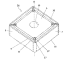
- the insert 1 shown in FIGS. 1 to 5 is an example of a cutting insert with a replaceable cutting edge, which is attached to a predetermined position at the tip of a holder (not shown) and used.
- the insert 1 may be paraphrased as a cutting insert 1.
- the insert 1 may have a substrate 3 made of cemented carbide, cermet, or the like.
- the insert 1 may include a substrate 3 made of a so-called cemented carbide containing WC and Co, Ni, and Fe which are bonding phases. When such a substrate 3 is used, it is excellent in welding resistance to a metal containing Ti.
- the WC is WC particles.
- the WC particles may have, for example, an average particle size of 0.5 ⁇ m to 1.5 ⁇ m.
- the substrate 3 may contain 4 to 12% by mass of the bound phase.
- the substrate 3 may have only WC as the balance other than the bound phase.
- the substrate 3 may contain a hard phase containing WC and a bound phase containing Co. In the present disclosure, when the range is indicated, such as 4 to 12% by mass, it means the value of the lower limit or more and the value of the upper limit or less.
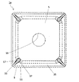
- the insert 1 may have a polygonal plate shape, and may have a first surface 5 and a second surface 7 connected to the first surface 5. Further, the insert 1 may have a square shape when the first surface 5 is viewed in a plan view.
- the insert 1 may have a cutting edge 11 located at least a part of the ridge line 9 of the first surface 5 and the second surface 7.
- the first surface 5 corresponds to the rake surface 5, and the second surface 7 corresponds to the flank surface 7.
- the first surface 5 may be provided with a through hole 13 that vertically penetrates the insert 1 in order to fix the insert 1 to a holder described later.
- the cutting edge 11 may be located at least in a part of the ridge line 9, may be located in a portion corresponding to two sides, and may be located in an annular shape over the entire outer peripheral portion of the first surface 5. May be.
- the insert 1 may have a third surface 15 located on the opposite side of the first surface 5.
- the first surface 5 is called the “upper surface”
- the second surface 7 is called the “side surface”
- the third surface 15 is called the “lower surface”.
- the size of the insert 1 is not particularly limited, but for example, the length of one side of the first surface 5 is set to about 5 to 20 mm, and the height from the first surface 5 to the third surface 15 is set. It is set to about 3 to 20 mm.
- the first surface 5 may have a groove 17.
- the groove 17 can function as a flow path for the coolant.
- the number of grooves 17 may be one or a plurality.
- the groove 17 may extend from the first end portion 17a closest to the cutting edge 11 toward the second end portion 17b farthest from the cutting edge 11 at a position away from the ridge line 9. With such a configuration, since the groove 17 is not connected to the ridge line 9, the cutting edge 11 is excellent in fracture resistance.
- the groove 17 may be separated from the ridge line 9 within a range of 40 ⁇ m or more and 700 ⁇ m or less from the ridge line 9.
- the distance between the groove 17 and the ridge line 9 may be 40 ⁇ m or more and 700 ⁇ m or less.
- the cutting edge 11 is less likely to be damaged.
- the distance between the groove 17 and the ridge line 9 is 700 ⁇ m or less, the cooling effect of the cutting edge 11 is enhanced, and the cutting resistance is easily reduced.
- the distance between the groove 17 and the ridge line 9 may be 50 ⁇ m or more and 120 ⁇ m or less. With such a configuration, the cutting edge 11 of the insert 1 is less likely to be damaged, and the cutting resistance is small. As the distance between the groove 17 and the ridge line 9, the shortest distance between the groove 17 and the ridge line 9 may be measured.
- the groove 17 may have an opening 19 located on the first surface 5 and a bottom surface 21.
- the distance from the bottom surface 21 to the opening 19 may be the groove depth D.
- the groove depth D may be defined as follows. First, a virtual straight line passing through the center of the first surface 5 and the center of the third surface 15 may be used as the central axis O of the insert 1. Next, a virtual plane orthogonal to the central axis O and located between the first surface 5 and the third surface 15 may be used as the reference surface S. Then, the dimension between the bottom surface 21 and the opening 19 in the virtual straight line L1 orthogonal to the reference plane S may be the groove depth D.
- the length of the groove 17 in the extending direction of the groove 17 may be the groove length L.
- the groove 17 may have a first groove portion 23 and a second groove portion 25 at a position closer to the first end portion 17a than half (midpoint) of the groove length L.
- the groove depth D of the first groove portion 23 may increase from the second end portion 17b toward the first end portion 17a.
- the groove depth D of the second groove portion 25 may decrease from the second end portion 17b toward the first end portion 17a.
- the first groove portion 23 may be located closer to the second end portion 17b than the second groove portion 25.
- the groove 17 becomes a flow path for the coolant, and the coolant is supplied in the order of the first groove 23 and the second groove 25 in the vicinity of the cutting edge. Can be shed. Then, the groove 17 in the vicinity of the cutting edge can be deepened by the first groove portion 23 and the second groove portion 25, and the depth of the groove 17 can be changed in the vicinity of the cutting edge.
- the groove 17 in the vicinity of the cutting edge it is possible to increase the contact area with the coolant and enhance the cooling effect in the vicinity of the cutting edge. Further, by changing the depth of the groove 17 in the vicinity of the cutting edge, it is possible to generate turbulent flow of the coolant and improve the heat exchange efficiency. Therefore, since the insert 1 has excellent cooling performance, it can be cut at high speed.
- FIG. 4 shows an example in which the first surface 5 is flat and the opening 19 is also on the flat first surface 5.
- the first surface 5 may be higher on the cutting edge 11 side.
- the cutting speed (Vc) is 60 to 100 m / min
- the feed rate (f) is 0.05 to 0.3 mm / rev
- the cutting (cutting) ( ap) can be set to 0.2 to 2.0 mm.
- Vc it is possible to set Vc to 80 m / min, f to 0.1 mm / rev, and ap to 0.5 mm.
- Vc 100 m / min, f to 0.15 mm / rev, and ap to 0.5 mm.
- the work material is SCM435, it is possible to set Vc to 250 m / min, f to 0.3 mm / rev, and ap to 2.0 mm.
- the groove depth D and the groove length L are not limited to specific values.
- the groove depth D may be set to about 40 ⁇ m or more and 700 ⁇ m or less.
- the groove length L may be set to about 40 ⁇ m or more and 5000 ⁇ m or less.
- the second groove portion 25 may exist within a range of 1/5 of the groove length L from the first end portion 17a. With such a configuration, the cooling effect near the ridgeline of the cutting edge can be further enhanced.
- the first groove portion 23 may exist within a range of less than 1/2 of the groove length L from the first end portion 17a.
- the portion 27 having the deepest groove depth D in the groove 17 may exist within a range of less than 1/2 of the groove length L from the first end portion 17a. With such a configuration, even in a situation where crater wear occurs on the tool rake surface, the groove is formed deeper than the crater, so that the cooling effect of the deepest part of the crater wear, which is the chip contact portion, is promoted. Can be done.
- the portion 27 having the deepest groove depth D in the groove 17 may exist within a range of 1/3 of the groove length L from the first end portion 17a.
- the portion 27 having the deepest groove depth D in the groove 17 may be located between the first groove portion 23 and the second groove portion 25.
- the portion 27 having the deepest groove depth D in the groove 17 may be a portion in the groove 17 whose bottom surface 21 is closest to the reference surface S.
- the portion 27 having the deepest groove depth D in the groove 17 may be rephrased as the groove deepest portion 27.
- the groove 17 may have a roundness with a radius R of 20 ⁇ m or more and a radius of 500 ⁇ m or less from the portion 27 having the deepest groove depth D to the second groove portion 25 in the groove 17. With such a configuration, the flow of the coolant is less likely to be obstructed. Further, by using a high-pressure coolant in combination with such a configuration, the effect of pushing up the chips by the coolant is increased, and the chips can be finely divided.
- the second groove portion 25 may be connected to the deepest groove portion 27 via a roundness having a radius R of 20 ⁇ m or more and a radius of 500 ⁇ m or less. Further, the first groove portion 23 may be directly connected to the deepest groove portion 27.
- the width of the opening 19 in the direction orthogonal to the extending direction of the groove 17 may be the opening width W.
- the ratio of the groove depth D to the opening width W may be 0.5 or more in the portion 27 of the groove 17 having the deepest groove depth D.
- the upper limit of the ratio (groove depth D / opening width W) may be 3. With such a configuration, the flow velocity of the coolant is unlikely to decrease at the deepest portion 27 of the groove. Therefore, it is easy to maintain the cooling effect.
- the opening width W may be set to about 40 ⁇ m or more and 700 ⁇ m or less.
- the groove length of the first groove portion 23 may be longer than the groove length of the second groove portion 25.
- the bottom surface 21 of the first groove portion 23 and the second groove portion 25 may be inclined with respect to the reference surface S. That is, the bottom surface 21 of the first groove portion 23 may be inclined so as to approach the reference surface S toward the first end portion 17a. Further, the bottom surface 21 of the second groove portion 25 may be inclined so as to be separated from the reference surface S toward the first end portion 17a.
- the inclination angle ⁇ 1 of the bottom surface 21 of the first groove portion 23 with respect to the reference surface S may be smaller than the inclination angle ⁇ 2 of the bottom surface 21 of the second groove portion 25 with respect to the reference surface S.
- the inclination angles ⁇ 1 and ⁇ 2 of the bottom surface 21 of the first groove portion 23 and the second groove portion 25 are not limited to specific values.
- the inclination angle ⁇ 1 of the bottom surface 21 of the first groove portion 23 may be set to about 5 ° or more and 30 ° or less.
- the inclination angle ⁇ 2 of the bottom surface 21 of the second groove portion 25 may be set to about 30 ° or more and 85 ° or less.
- the groove 17 may have a portion 29 that is located closer to the second end portion 17b than the first groove portion 23 and whose bottom surface 21 is parallel to the reference surface S.
- the first groove portion 23 may be connected to the portion 29.
- the groove 17 may have an end surface connecting the end portion of the portion 29 on the side of the second end portion 17b and the second end portion 17b. This end face may be parallel to the central axis O.
- the second end portion 17b is not limited to the configuration connected to the above-mentioned end face.
- the second end portion 17b may be opened so as to communicate with a space such as a recess, for example.
- the groove 17 may have a side wall surface 31 extending from the bottom surface 21 to the opening 19.
- the surface roughness of the side wall surface 31 may be R1 and the surface roughness of the bottom surface 21 may be R2.
- R1 may be Ra3.0 ⁇ m or less, and R1> R2 may be satisfied. With such a configuration, the surface area on the side wall surface 31 side increases, the cooling effect is enhanced, and the roughness is different, so that turbulence is likely to occur.
- the lower limit value of R1 may be Ra 0.5 ⁇ m.
- R2 may be set to Ra 0.2 ⁇ m or more and Ra 2.5 ⁇ m or less.
- the surface roughness may be evaluated by, for example, the arithmetic mean roughness (Ra).
- the arithmetic mean roughness (Ra) may be measured according to, for example, JIS B 0601-2013.
- the first surface 5 may have a land surface 32 that is located closer to the cutting edge 11 than the second groove portion 25 and is inclined with respect to the second groove portion 25. Further, the first end portion 17a may be located at the boundary between the second groove portion 25 and the land surface 32. Then, the first end portion 17a may have a roundness. When the first end portion 17a corresponding to the ridgeline between the second groove portion 25 and the land surface 32 inclined with respect to the second groove portion 25 has a roundness, the coolant is likely to be smoothly discharged from the groove 17 to the cutting edge.
- the roundness of the first end portion 17a may be a radius R of 20 ⁇ m or more and a radius of 100 ⁇ m or less.
- the first surface 5 may have a corner portion 33.
- the groove 17 may extend along the bisector of the corner portion 33.
- the groove 17 may be located on the bisector of the corner portion 33.
- the insert 1 may be provided with, for example, a coating layer (not shown) containing a TiCN layer (not shown) or an Al 2O 3 layer (not shown) on the surface of the substrate 3. Further, the insert 1 may have the substrate 3 exposed at least in a region near the cutting edge 11 and the groove 17 on the first surface 5. In other words, the coating layer may not be present on the surface of the substrate 3 in the vicinity of the cutting edge 11 and the groove 17 on the rake face 5.
- the above-mentioned region may be a region within 0.5 mm from the cutting edge 11 and the groove 17. That is, the insert 1 may have the substrate 3 exposed in the region of the first surface 5 which is within 0.5 mm from the cutting edge 11 and the groove 17.
- the coating layer may not be present on the entire surface of the substrate 3.
- the shape of the groove 17 (hereinafter, also referred to as the cross-sectional shape of the groove 17) may be such that the opening width W is wider than the width of the bottom surface 21.
- the cross-sectional shape of the groove 17 may be, for example, a semicircular shape, a triangular shape, or a trapezoidal shape.
- the insert 1 having such a groove 17 on the rake face 5 is formed into the groove 17 in the insert 1 by, for example, drilling or laser light after producing an insert-shaped cemented carbide without the groove 17.
- a groove 17 may be formed on the rake face 5.
- an insert 1 can also be obtained by producing a molded body having a concave portion that becomes the groove 17 after firing using a mold having a convex portion corresponding to the groove 17, and firing the molded body.
- the shape of the groove 17 can be measured using, for example, a shape analysis laser microscope. For example, it may be measured using VK-X1000 manufactured by KEYENCE.
- the measurement conditions may be as follows. Measurement mode: Easy measurement Scan mode: Focus variation Measurement size: Standard pitch: 4.50 ⁇ m Brightness: 70 Enable noise area processing: ON Coaxial epi-illumination: 100 Ring lighting: OFF Z-axis mode: Recommended setting Fixed Z measurement distance: OFF Automatic upper and lower limit: ON Head: R Objective lens name: Plan Objective lens magnification: 10 x NA: 0.3 WD: 16.5 mm Brightness mode: Auto Brightness (auto): 70 Brightness (manual): 2 Edge enhancement: 5
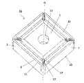
- inserts 1a to 1c of the present disclosure will be described with reference to FIGS. 6 to 11.
- the differences between the inserts 1a to 1c and the insert 1 will be mainly described, and detailed description of the points having the same configuration as the insert 1 may be omitted.
- the inserts 1a to 1c may have a breaker groove 35 located on the first surface 5 along the cutting edge 11, as in the case of the non-limiting example shown in FIGS. 6 to 11.
- the breaker groove 35 may approach the reference surface S as the distance from the cutting edge 11 increases.
- the inserts 1a to 1c may have a convex portion 37 located inside the first surface 5 with respect to the cutting edge 11.
- the convex portion 37 can control the flow direction of chips generated by the cutting edge 11. Further, the convex portion 37 can exert a chip dividing effect.
- the convex portion 37 is also called a breaker protrusion. At least a part of the convex portion 37 may be located inside the first surface 5 with respect to the breaker groove 35.
- the convex portion 37 may extend along the bisector of the corner portion 33.
- the groove 17 may be positioned so as to overlap the convex portion 37.
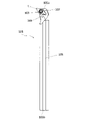
- the cutting tool 101 has a length extending from the first end 105a (upper end in FIG. 12) to the second end 105b (lower end in FIG. 12), as in the non-limiting example shown in FIG. It may have a holder 105 having a pocket 103 located on the side and the above-mentioned insert 1 located in the pocket 103.
- the cutting tool 101 has the insert 1, it can be cut at a high speed because of its excellent cooling performance, and stable cutting can be performed for a long period of time.
- the description of the groove 17 and the like is omitted.
- the case where the shape when the first surface 5 is viewed in a plan view is a rhombus shape is illustrated. These points are the same in FIG. 13, which will be described later.
- the holder 105 may be a rod-shaped body extending from the first end 105a toward the second end 105b.
- the first end 105a is called the "tip" and the second end 105b is called the "rear end”.
- the length from the first end 105a to the second end 105b is not limited to a specific value.
- the length from the first end 105a to the second end 105b may be set to about 100 to 250 mm.
- the pocket 103 is a portion to which the insert 1 is mounted, and may have a seating surface parallel to the lower surface of the holder 105 and a restraint side surface perpendicular to or inclined with respect to the seating surface. Further, the pocket 103 may be opened on the side of the first end 105a of the holder 105.
- the insert 1 may be located in the pocket 103.
- the lower surface of the insert 1 may be in direct contact with the pocket 103, or a sheet (not shown) may be sandwiched between the insert 1 and the pocket 103.
- the insert 1 is provided so that at least a part of the portion used as the cutting edge 11 on the ridge line 9 where the first surface 5 which is the rake surface 5 and the second surface 7 which is the flank surface 7 intersects protrudes outward from the holder 105. It may be attached to the holder 105.
- the insert 1 may be attached to the holder 105 by a fixing screw 107. That is, the fixing screw 107 is inserted into the through hole 13 of the insert 1, the tip of the fixing screw 107 is inserted into the screw hole (not shown) formed in the pocket 103, and the screw portions are screwed together to insert the insert. 1 may be mounted on the holder 105.
- the cutting tool 101 may be provided with a hose (not shown) having a nozzle at the tip in order to supply the cooling liquid to the cutting edge 11.
- a pump for supplying the coolant may be connected to this hose.
- the cutting tool 101 may be provided with the nozzle 109 for supplying the cooling liquid to the cutting edge 11 in the holder 105.
- the ejection port of the nozzle 109 When the ejection port of the nozzle 109 is located in the vicinity of the insert 1, it becomes easy to supply the coolant to the cutting edge 11.
- the nozzle 109 may be fixed to a part of the holder 105.
- a hole may be provided in the holder 105 and used as the nozzle 109.
- the coolant discharged from the nozzle 109 may be, for example, a water-soluble one or an oil-based one.
- the nozzle 109 may be connected to a pump (not shown), and may, for example, discharge the coolant at a pressure of 0.5 to 20 MPa. When the pressure is 10 MPa or more, processing at higher speed becomes possible.
- the holder 105 may have a flow path through which the coolant flows.
- steel, cast iron, or the like can be used as the material of the holder 105.
- steel having high toughness may be used.
- a cutting tool 101 used for so-called turning is illustrated.
- the turning process include inner diameter processing, outer diameter processing, and grooving processing.
- the cutting tool is not limited to the one used for turning.
- the above-mentioned insert 1 may be used as a cutting tool used for milling.
- the cutting tool 101 has an insert 1, but is not limited to such a form.
- the cutting tool 101 may have any of the inserts 1a to 1c.
Landscapes
- Engineering & Computer Science (AREA)
- Mechanical Engineering (AREA)
- Cutting Tools, Boring Holders, And Turrets (AREA)
Abstract
This insert comprises a first surface, a second surface connected to the first surface, and a cutting blade located on at least a part of a ridgeline of the first surface and the second surface. In a position away from the ridgeline, the first surface has a groove which extends from a first end nearest to the cutting blade towards a second end furthest from the cutting blade. The groove has an opening positioned on the first surface, and has a bottom surface. In a position nearer to the first end than half of the groove length, the groove has a first groove section with a groove depth that increases from the second end towards the first end, and a second groove section with a groove depth that decreases from the second end towards the first end. The first groove section is positioned nearer to the second end than the second groove section. This cutting tool has the aforementioned insert.
Description
本出願は、2020年11月9日に出願された日本国特許出願2020-186482号の優先権を主張するものであり、この先の出願の開示全体を、ここに参照のために取り込む。
This application claims the priority of Japanese Patent Application No. 2020-186482 filed on November 9, 2020, and the entire disclosure of future applications is incorporated herein by reference.
本開示は、インサートおよび切削工具に関する。
This disclosure relates to inserts and cutting tools.
超硬合金やサーメット、セラミックスは、耐熱性及び耐摩耗性に優れた材料であることから、切削工具用のインサートとして用いられている。インサートは使用時に高速で被削材と接触するため、温度が上昇する。
Cemented carbide, cermet, and ceramics are used as inserts for cutting tools because they are materials with excellent heat resistance and wear resistance. Since the insert comes into contact with the work material at high speed during use, the temperature rises.
そのため、切削加工時には、冷却液を用いてインサートと被削材を冷却することが行われている。このような冷却効果を高くする目的で、特許第5843102号公報(特許文献1)では、インサートのすくい面に冷却液の流路として機能する複数の溝を設けている。また、特許第4275856号公報(特許文献2)では、上面に設けられた溝が、一定の溝深さを有する。
Therefore, at the time of cutting, the insert and the work material are cooled using a coolant. For the purpose of enhancing such a cooling effect, Japanese Patent No. 5843102 (Patent Document 1) provides a plurality of grooves functioning as a flow path for the coolant on the rake face of the insert. Further, in Japanese Patent No. 4275856 (Patent Document 2), the groove provided on the upper surface has a constant groove depth.
本開示のインサートは、第1面と、第1面に繋がる第2面と、第1面および第2面の稜線の少なくとも一部に位置する切刃と、を有する。第1面は、稜線から離れた位置において、切刃に最も近い第1端部から、切刃から最も離れた第2端部に向かって延びた溝を有する。溝は、第1面に位置する開口部と、底面と、を有する。底面から開口部までの距離を溝深さとし、溝の延びた方向における溝の長さを溝長さとした場合、溝は、溝長さの半分よりも第1端部に近い位置において、第2端部から第1端部に向かうにしたがって溝深さが大きくなる第1溝部と、第2端部から第1端部に向かうにしたがって溝深さが小さくなる第2溝部と、を有する。第1溝部は、第2溝部よりも第2端部の近くに位置する。
The insert of the present disclosure has a first surface, a second surface connected to the first surface, and a cutting edge located at least a part of the ridgeline of the first surface and the second surface. The first surface has a groove extending from the first end closest to the cutting edge toward the second end farthest from the cutting edge at a position away from the ridgeline. The groove has an opening located on the first surface and a bottom surface. When the distance from the bottom surface to the opening is defined as the groove depth and the groove length in the extending direction of the groove is defined as the groove length, the groove is located at a position closer to the first end than half of the groove length, and is the second. It has a first groove portion in which the groove depth increases from the end portion to the first end portion, and a second groove portion in which the groove depth decreases toward the first end portion from the second end portion. The first groove is located closer to the second end than the second groove.
本開示の切削工具は、第1端から第2端に亘る長さを有し、第1端の側に位置するポケットを有するホルダと、ポケットに位置する前述のインサートと、を有する。
The cutting tool of the present disclosure has a length extending from the first end to the second end, and has a holder having a pocket located on the side of the first end and the above-mentioned insert located in the pocket.
従来のインサートでは、切削速度の高速化に十分に寄与できる冷却効果を与えることができなかった。
本開示は、切削速度の高速化に十分に寄与できる冷却効果を与えることができるインサートおよび切削工具を提供する。 The conventional insert cannot provide a cooling effect that can sufficiently contribute to increasing the cutting speed.
The present disclosure provides inserts and cutting tools that can provide a cooling effect that can sufficiently contribute to higher cutting speeds.
<インサート>
以下、本開示のインサートについて、図面を用いて詳細に説明する。但し、以下で参照する各図は、説明の便宜上、各実施形態を説明する上で必要な主要部材のみを簡略化して示したものである。したがって、インサートは、参照する各図に示されていない任意の構成部材を備え得る。また、各図中の部材の寸法は、実際の構成部材の寸法及び各部材の寸法比率等を忠実に表したものではない。 <Insert>
Hereinafter, the inserts of the present disclosure will be described in detail with reference to the drawings. However, each figure referred to below is shown in a simplified manner only for the main members necessary for explaining each embodiment for convenience of explanation. Therefore, the insert may include any component not shown in each referenced figure. Further, the dimensions of the members in each drawing do not faithfully represent the dimensions of the actual constituent members, the dimensional ratio of each member, and the like.
図1~図5に示すインサート1は、ホルダ(図示しない)の先端の所定の位置に取り付けられて使用される刃先交換型の切削インサートの一例である。インサート1は、切削インサート1と言い換えてもよい。
The insert 1 shown in FIGS. 1 to 5 is an example of a cutting insert with a replaceable cutting edge, which is attached to a predetermined position at the tip of a holder (not shown) and used. The insert 1 may be paraphrased as a cutting insert 1.
インサート1は、超硬合金やサーメットなどからなる基体3を有していてもよい。インサート1は、WCと、結合相であるCoやNi、Feを含有する、いわゆる超硬合金からなる基体3を具備していてもよい。このような基体3を用いると、Tiを含有する金属との耐溶着性に優れる。
The insert 1 may have a substrate 3 made of cemented carbide, cermet, or the like. The insert 1 may include a substrate 3 made of a so-called cemented carbide containing WC and Co, Ni, and Fe which are bonding phases. When such a substrate 3 is used, it is excellent in welding resistance to a metal containing Ti.
WCとは、WC粒子のことである。WC粒子は、例えば、平均粒径が0.5μm~1.5μmであってもよい。基体3は、結合相を4~12質量%含有していてもよい。基体3は、結合相以外の残部をWCのみとしてもよい。基体3は、WCを含む硬質相と、Coを含む結合相とを含んでいてもよい。なお、本開示において、4~12質量%のように、範囲を示す場合には、下限の値以上、上限の値以下の意味である。
WC is WC particles. The WC particles may have, for example, an average particle size of 0.5 μm to 1.5 μm. The substrate 3 may contain 4 to 12% by mass of the bound phase. The substrate 3 may have only WC as the balance other than the bound phase. The substrate 3 may contain a hard phase containing WC and a bound phase containing Co. In the present disclosure, when the range is indicated, such as 4 to 12% by mass, it means the value of the lower limit or more and the value of the upper limit or less.
インサート1は、多角板形状であってもよく、第1面5と、第1面5に繋がる第2面7とを有していてもよい。また、インサート1は、第1面5を平面視した場合の形状が四角形状であってもよい。インサート1は、第1面5と第2面7の稜線9の少なくとも一部に位置する切刃11を有していてもよい。図1に示す限定されない一例においては、第1面5がすくい面5に相当しており、第2面7が逃げ面7に相当している。以降の図面においても同様である。第1面5には、インサート1を後述するホルダに固定するため、インサート1を上下に貫通する貫通穴13が設けられていてもよい。インサート1において切刃11は、少なくとも稜線9の一部に位置していればよく、2つの辺に相当する部分に位置してもよく、第1面5の外周部分の全体に環状に位置していてもよい。
The insert 1 may have a polygonal plate shape, and may have a first surface 5 and a second surface 7 connected to the first surface 5. Further, the insert 1 may have a square shape when the first surface 5 is viewed in a plan view. The insert 1 may have a cutting edge 11 located at least a part of the ridge line 9 of the first surface 5 and the second surface 7. In the non-limiting example shown in FIG. 1, the first surface 5 corresponds to the rake surface 5, and the second surface 7 corresponds to the flank surface 7. The same applies to the subsequent drawings. The first surface 5 may be provided with a through hole 13 that vertically penetrates the insert 1 in order to fix the insert 1 to a holder described later. In the insert 1, the cutting edge 11 may be located at least in a part of the ridge line 9, may be located in a portion corresponding to two sides, and may be located in an annular shape over the entire outer peripheral portion of the first surface 5. May be.
インサート1は、第1面5の反対側に位置する第3面15を有していてもよい。一般的には、第1面5が「上面」、第2面7が「側面」、第3面15が「下面」と呼ばれる。
The insert 1 may have a third surface 15 located on the opposite side of the first surface 5. Generally, the first surface 5 is called the "upper surface", the second surface 7 is called the "side surface", and the third surface 15 is called the "lower surface".
インサート1の大きさとしては特に限定されるものではないが、例えば、第1面5の一辺の長さが5~20mm程度に設定され、第1面5から第3面15までの高さは3~20mm程度に設定される。
The size of the insert 1 is not particularly limited, but for example, the length of one side of the first surface 5 is set to about 5 to 20 mm, and the height from the first surface 5 to the third surface 15 is set. It is set to about 3 to 20 mm.
ここで、第1面5は、溝17を有していてもよい。溝17は、冷却液の流路として機能することが可能である。溝17は、1つであってもよく、また、複数であってもよい。
Here, the first surface 5 may have a groove 17. The groove 17 can function as a flow path for the coolant. The number of grooves 17 may be one or a plurality.
溝17は、稜線9から離れた位置において、切刃11に最も近い第1端部17aから、切刃11から最も離れた第2端部17bに向かって延びていてもよい。このような構成を有すると、溝17が稜線9と繋がっていないため、切刃11の耐欠損性に優れる。
The groove 17 may extend from the first end portion 17a closest to the cutting edge 11 toward the second end portion 17b farthest from the cutting edge 11 at a position away from the ridge line 9. With such a configuration, since the groove 17 is not connected to the ridge line 9, the cutting edge 11 is excellent in fracture resistance.
溝17は、稜線9から40μm以上、700μm以下の範囲で稜線9と離間していてもよい。言い換えると、溝17と稜線9の間の距離は、40μm以上、700μm以下であってもよい。溝17と稜線9との距離を40μm以上とすると、切刃11が欠損しにくくなる。溝17と稜線9との距離を700μm以下とすると、切刃11の冷却効果が高まり、また、切削抵抗を小さくしやすい。
The groove 17 may be separated from the ridge line 9 within a range of 40 μm or more and 700 μm or less from the ridge line 9. In other words, the distance between the groove 17 and the ridge line 9 may be 40 μm or more and 700 μm or less. When the distance between the groove 17 and the ridge line 9 is 40 μm or more, the cutting edge 11 is less likely to be damaged. When the distance between the groove 17 and the ridge line 9 is 700 μm or less, the cooling effect of the cutting edge 11 is enhanced, and the cutting resistance is easily reduced.
溝17と稜線9との距離は、50μm以上、120μm以下としてもよい。このような構成を有すると、インサート1の切刃11が欠損しにくく、切削抵抗も小さい。溝17と稜線9との間の距離は、溝17と稜線9との最短距離を測定してもよい。
The distance between the groove 17 and the ridge line 9 may be 50 μm or more and 120 μm or less. With such a configuration, the cutting edge 11 of the insert 1 is less likely to be damaged, and the cutting resistance is small. As the distance between the groove 17 and the ridge line 9, the shortest distance between the groove 17 and the ridge line 9 may be measured.
溝17は、第1面5に位置する開口部19と、底面21とを有していてもよい。底面21から開口部19までの距離を、溝深さDとしてもよい。なお、溝深さDは、次のように定義してもよい。まず、第1面5の中心および第3面15の中心を通る仮想直線を、インサート1の中心軸Oとしてもよい。次に、中心軸Oに直交するとともに、第1面5および第3面15の間に位置する仮想平面を、基準面Sとしてもよい。そして、基準面Sに直交する仮想直線L1における底面21および開口部19の間の寸法を、溝深さDとしてもよい。
The groove 17 may have an opening 19 located on the first surface 5 and a bottom surface 21. The distance from the bottom surface 21 to the opening 19 may be the groove depth D. The groove depth D may be defined as follows. First, a virtual straight line passing through the center of the first surface 5 and the center of the third surface 15 may be used as the central axis O of the insert 1. Next, a virtual plane orthogonal to the central axis O and located between the first surface 5 and the third surface 15 may be used as the reference surface S. Then, the dimension between the bottom surface 21 and the opening 19 in the virtual straight line L1 orthogonal to the reference plane S may be the groove depth D.
溝17の延びた方向における溝17の長さを、溝長さLとしてもよい。溝17は、溝長さLの半分(中点)よりも第1端部17aに近い位置において、第1溝部23および第2溝部25を有していてもよい。第1溝部23は、第2端部17bから第1端部17aに向かうにしたがって溝深さDが大きくなっていてもよい。第2溝部25は、第2端部17bから第1端部17aに向かうにしたがって溝深さDが小さくなっていてもよい。第1溝部23は、第2溝部25よりも第2端部17bの近くに位置していてもよい。
The length of the groove 17 in the extending direction of the groove 17 may be the groove length L. The groove 17 may have a first groove portion 23 and a second groove portion 25 at a position closer to the first end portion 17a than half (midpoint) of the groove length L. The groove depth D of the first groove portion 23 may increase from the second end portion 17b toward the first end portion 17a. The groove depth D of the second groove portion 25 may decrease from the second end portion 17b toward the first end portion 17a. The first groove portion 23 may be located closer to the second end portion 17b than the second groove portion 25.
このような構成を有すると、切刃11に向けて冷却液を供給した場合には、溝17が冷却液の流路となり、刃先近傍において第1溝部23および第2溝部25の順に冷却液を流すことができる。そして、第1溝部23および第2溝部25によって、刃先近傍の溝17を深くすることができ、また、刃先近傍で溝17の深さを変更させることができる。刃先近傍の溝17を深くすることにより、冷却液との接触面積を増やし、刃先近傍の冷却効果を高めることが可能となる。また、刃先近傍で溝17の深さを変更させることで冷却液の乱流を発生させ、熱交換効率を高めることが可能となる。したがって、インサート1は、冷却性に優れるため、高速で切削することが可能となる。
With such a configuration, when the coolant is supplied toward the cutting edge 11, the groove 17 becomes a flow path for the coolant, and the coolant is supplied in the order of the first groove 23 and the second groove 25 in the vicinity of the cutting edge. Can be shed. Then, the groove 17 in the vicinity of the cutting edge can be deepened by the first groove portion 23 and the second groove portion 25, and the depth of the groove 17 can be changed in the vicinity of the cutting edge. By deepening the groove 17 in the vicinity of the cutting edge, it is possible to increase the contact area with the coolant and enhance the cooling effect in the vicinity of the cutting edge. Further, by changing the depth of the groove 17 in the vicinity of the cutting edge, it is possible to generate turbulent flow of the coolant and improve the heat exchange efficiency. Therefore, since the insert 1 has excellent cooling performance, it can be cut at high speed.
例えば、チタン材、鋼などの被削材を高速加工する場合には、刃先に熱がこもりやすくなり、クレータ摩耗が進行しやすい。クレータ摩耗が進行すると、クレータ摩耗部が起点となって、インサート1の欠損が発生しやすくなる。上記した構成を有すると、刃先近傍の冷却効果を高め、クレータ摩耗を低減させることで、インサート1の欠損やチッピングの発生を低減させることが可能となる。
For example, when machining a work material such as titanium or steel at high speed, heat tends to be trapped in the cutting edge and crater wear tends to progress. As the crater wear progresses, the crater wear portion becomes the starting point, and the insert 1 is likely to be chipped. With the above configuration, it is possible to reduce the occurrence of chipping and chipping of the insert 1 by enhancing the cooling effect in the vicinity of the cutting edge and reducing the crater wear.
なお、図4においては、第1面5が平らであり、開口部19も平らな第1面5にある例を示している。第1面5は、切刃11側で高くなっていてもよい。
Note that FIG. 4 shows an example in which the first surface 5 is flat and the opening 19 is also on the flat first surface 5. The first surface 5 may be higher on the cutting edge 11 side.
加工条件の一例として、被削材がTi-6Al-4Vの場合には、切削速度(Vc)を60~100m/分、送り速度(f)を0.05~0.3mm/rev、切り込み(ap)を0.2~2.0mmに設定することが可能である。具体例としては、Vcを80m/分、fを0.1mm/rev、apを0.5mmに設定することが可能である。また、Vcを100m/分、fを0.15mm/rev、apを0.5mmに設定することが可能である。被削材がSCM435の場合には、Vcを250m/分、fを0.3mm/rev、apを2.0mmに設定することが可能である。
As an example of machining conditions, when the work material is Ti-6Al-4V, the cutting speed (Vc) is 60 to 100 m / min, the feed rate (f) is 0.05 to 0.3 mm / rev, and the cutting (cutting) ( ap) can be set to 0.2 to 2.0 mm. As a specific example, it is possible to set Vc to 80 m / min, f to 0.1 mm / rev, and ap to 0.5 mm. Further, it is possible to set Vc to 100 m / min, f to 0.15 mm / rev, and ap to 0.5 mm. When the work material is SCM435, it is possible to set Vc to 250 m / min, f to 0.3 mm / rev, and ap to 2.0 mm.
溝深さDおよび溝長さLは、特定の値に限定されない。例えば、溝深さDは、40μm以上、700μm以下程度に設定されてもよい。また、溝長さLは、40μm以上、5000μm以下程度に設定されてもよい。
The groove depth D and the groove length L are not limited to specific values. For example, the groove depth D may be set to about 40 μm or more and 700 μm or less. Further, the groove length L may be set to about 40 μm or more and 5000 μm or less.
第2溝部25は、第1端部17aから溝長さLの1/5の範囲内に存在していてもよい。このような構成を有すると、刃先稜線付近の冷却効果をより高めることができる。なお、第1溝部23は、第1端部17aから溝長さLの1/2未満の範囲内に存在していてもよい。
The second groove portion 25 may exist within a range of 1/5 of the groove length L from the first end portion 17a. With such a configuration, the cooling effect near the ridgeline of the cutting edge can be further enhanced. The first groove portion 23 may exist within a range of less than 1/2 of the groove length L from the first end portion 17a.
溝17の中で溝深さDが最も深い部分27は、第1端部17aから溝長さLの1/2未満の範囲内に存在していてもよい。このような構成を有すると、工具すくい面にクレータ摩耗が発生する状況においても、クレータよりも溝が深く形成されているため、切りくず接触部であるクレータ摩耗最深部の冷却効果を促進させることができる。なお、溝17の中で溝深さDが最も深い部分27は、第1端部17aから溝長さLの1/3の範囲内に存在していてもよい。
The portion 27 having the deepest groove depth D in the groove 17 may exist within a range of less than 1/2 of the groove length L from the first end portion 17a. With such a configuration, even in a situation where crater wear occurs on the tool rake surface, the groove is formed deeper than the crater, so that the cooling effect of the deepest part of the crater wear, which is the chip contact portion, is promoted. Can be done. The portion 27 having the deepest groove depth D in the groove 17 may exist within a range of 1/3 of the groove length L from the first end portion 17a.
溝17の中で溝深さDが最も深い部分27は、第1溝部23および第2溝部25の間に位置していてもよい。溝17の中で溝深さDが最も深い部分27は、溝17の中で底面21が基準面Sに最も近い部分であってもよい。溝17の中で溝深さDが最も深い部分27は、溝最深部27と言い換えてもよい。
The portion 27 having the deepest groove depth D in the groove 17 may be located between the first groove portion 23 and the second groove portion 25. The portion 27 having the deepest groove depth D in the groove 17 may be a portion in the groove 17 whose bottom surface 21 is closest to the reference surface S. The portion 27 having the deepest groove depth D in the groove 17 may be rephrased as the groove deepest portion 27.
溝17は、溝17の中で溝深さDが最も深い部分27から第2溝部25にかけて、半径R20μm以上、半径R500μm以下の丸みを有していてもよい。このような構成を有すると、冷却液の流れが阻害されにくい。また、このような構成に高圧クーラントを併用することで冷却液による切りくず押し上げ効果が増大し、切りくずを細かく分断することができる。なお、第2溝部25は、半径R20μm以上、半径R500μm以下の丸みを介して、溝最深部27に繋がっていてもよい。また、第1溝部23は、溝最深部27に直接繋がっていてもよい。
The groove 17 may have a roundness with a radius R of 20 μm or more and a radius of 500 μm or less from the portion 27 having the deepest groove depth D to the second groove portion 25 in the groove 17. With such a configuration, the flow of the coolant is less likely to be obstructed. Further, by using a high-pressure coolant in combination with such a configuration, the effect of pushing up the chips by the coolant is increased, and the chips can be finely divided. The second groove portion 25 may be connected to the deepest groove portion 27 via a roundness having a radius R of 20 μm or more and a radius of 500 μm or less. Further, the first groove portion 23 may be directly connected to the deepest groove portion 27.
溝17の延びた方向に直交する方向における開口部19の幅を、開口幅Wとしてもよい。溝17の中で溝深さDが最も深い部分27において、溝深さDと開口幅Wとの比(溝深さD/開口幅W)が、0.5以上であってもよい。このような構成を有すると、切りくずが溝17に侵入しにくくなるため、溝17における冷却液の流路としての機能を溝最深部27において確保しやすい。
The width of the opening 19 in the direction orthogonal to the extending direction of the groove 17 may be the opening width W. The ratio of the groove depth D to the opening width W (groove depth D / opening width W) may be 0.5 or more in the portion 27 of the groove 17 having the deepest groove depth D. With such a configuration, chips are less likely to enter the groove 17, so that it is easy to secure the function of the cooling liquid in the groove 17 as a flow path in the deepest portion 27 of the groove.
比(溝深さD/開口幅W)の上限の値は、3であってもよい。このような構成を有すると、溝最深部27において冷却液の流速が低下しにくい。そのため、冷却効果を維持しやすい。なお、開口幅Wは、40μm以上、700μm以下程度に設定されてもよい。
The upper limit of the ratio (groove depth D / opening width W) may be 3. With such a configuration, the flow velocity of the coolant is unlikely to decrease at the deepest portion 27 of the groove. Therefore, it is easy to maintain the cooling effect. The opening width W may be set to about 40 μm or more and 700 μm or less.
第1溝部23の溝長さは、第2溝部25の溝長さよりも長くてもよい。このような構成を有すると、第1溝部23の溝長さが相対的に長くなることから、刃先近傍の溝17を深くすることができ、また、刃先近傍で溝17の深さを変更させることができる。そのため、刃先近傍の冷却効果を高めやすい。
The groove length of the first groove portion 23 may be longer than the groove length of the second groove portion 25. With such a configuration, since the groove length of the first groove portion 23 becomes relatively long, the groove 17 in the vicinity of the cutting edge can be deepened, and the depth of the groove 17 can be changed in the vicinity of the cutting edge. be able to. Therefore, it is easy to enhance the cooling effect in the vicinity of the cutting edge.
第1溝部23および第2溝部25は、底面21が基準面Sに対して傾斜していてもよい。すなわち、第1溝部23の底面21は、第1端部17aに向かうにしたがって基準面Sに近づくように傾斜していてもよい。また、第2溝部25の底面21は、第1端部17aに向かうにしたがって基準面Sから離れるように傾斜していてもよい。
The bottom surface 21 of the first groove portion 23 and the second groove portion 25 may be inclined with respect to the reference surface S. That is, the bottom surface 21 of the first groove portion 23 may be inclined so as to approach the reference surface S toward the first end portion 17a. Further, the bottom surface 21 of the second groove portion 25 may be inclined so as to be separated from the reference surface S toward the first end portion 17a.
基準面Sに対する第1溝部23の底面21の傾斜角度θ1は、基準面Sに対する第2溝部25の底面21の傾斜角度θ2よりも小さくてもよい。このような構成を有すると、冷却液が溝17から勢いよく吐出されやすい。
The inclination angle θ1 of the bottom surface 21 of the first groove portion 23 with respect to the reference surface S may be smaller than the inclination angle θ2 of the bottom surface 21 of the second groove portion 25 with respect to the reference surface S. With such a configuration, the coolant is likely to be vigorously discharged from the groove 17.
第1溝部23および第2溝部25の底面21の傾斜角度θ1、θ2は、特定の値に限定されない。例えば、第1溝部23の底面21の傾斜角度θ1は、5°以上、30°以下程度に設定されてもよい。また、第2溝部25の底面21の傾斜角度θ2は、30°以上、85°以下程度に設定されてもよい。なお、傾斜角度θ1、θ2を評価する際には、基準面Sに平行な仮想平面S’を基準にしてもよい。
The inclination angles θ1 and θ2 of the bottom surface 21 of the first groove portion 23 and the second groove portion 25 are not limited to specific values. For example, the inclination angle θ1 of the bottom surface 21 of the first groove portion 23 may be set to about 5 ° or more and 30 ° or less. Further, the inclination angle θ2 of the bottom surface 21 of the second groove portion 25 may be set to about 30 ° or more and 85 ° or less. When evaluating the inclination angles θ1 and θ2, the virtual plane S'parallel to the reference plane S may be used as a reference.
溝17は、第1溝部23よりも第2端部17bの近くに位置し、かつ、基準面Sに対して底面21が平行である部分29を有していてもよい。第1溝部23は、部分29に繋がっていてもよい。また、溝17は、部分29における第2端部17bの側の端部と、第2端部17bとを繋ぐ端面を有していてもよい。この端面は、中心軸Oに平行であってもよい。なお、第2端部17bは、上記した端面に繋げられる構成に限定されない。第2端部17bは、例えば、凹部のような空間に連通して開放されていてもよい。
The groove 17 may have a portion 29 that is located closer to the second end portion 17b than the first groove portion 23 and whose bottom surface 21 is parallel to the reference surface S. The first groove portion 23 may be connected to the portion 29. Further, the groove 17 may have an end surface connecting the end portion of the portion 29 on the side of the second end portion 17b and the second end portion 17b. This end face may be parallel to the central axis O. The second end portion 17b is not limited to the configuration connected to the above-mentioned end face. The second end portion 17b may be opened so as to communicate with a space such as a recess, for example.
溝17は、底面21から開口部19に延びる側壁面31を有していてもよい。側壁面31の面粗さをR1とし、底面21の面粗さをR2としてもよい。R1がRa3.0μm以下であり、かつ、R1>R2であってもよい。このような構成を有すると、側壁面31の側の表面積が増加し、冷却効果が高まるとともに、粗さが異なることで乱流を発生させやすい。
The groove 17 may have a side wall surface 31 extending from the bottom surface 21 to the opening 19. The surface roughness of the side wall surface 31 may be R1 and the surface roughness of the bottom surface 21 may be R2. R1 may be Ra3.0 μm or less, and R1> R2 may be satisfied. With such a configuration, the surface area on the side wall surface 31 side increases, the cooling effect is enhanced, and the roughness is different, so that turbulence is likely to occur.
R1の下限の値は、Ra0.5μmであってもよい。R2は、Ra0.2μm以上、Ra2.5μm以下程度に設定されてもよい。面粗さは、例えば、算術平均粗さ(Ra)で評価してもよい。算術平均粗さ(Ra)は、例えば、JIS B 0601-2013に準拠して測定してもよい。
The lower limit value of R1 may be Ra 0.5 μm. R2 may be set to Ra 0.2 μm or more and Ra 2.5 μm or less. The surface roughness may be evaluated by, for example, the arithmetic mean roughness (Ra). The arithmetic mean roughness (Ra) may be measured according to, for example, JIS B 0601-2013.
第1面5は、第2溝部25よりも切刃11の近くに位置し、かつ、第2溝部25に対して傾斜しているランド面32を有していてもよい。また、第1端部17aは、第2溝部25とランド面32との境界に位置していてもよい。そして、第1端部17aが丸みを有してもよい。第2溝部25と第2溝部25に対して傾斜しているランド面32との稜線にあたる第1端部17aが丸みを有すると、冷却液が溝17からスムーズに刃先に吐出されやすい。
The first surface 5 may have a land surface 32 that is located closer to the cutting edge 11 than the second groove portion 25 and is inclined with respect to the second groove portion 25. Further, the first end portion 17a may be located at the boundary between the second groove portion 25 and the land surface 32. Then, the first end portion 17a may have a roundness. When the first end portion 17a corresponding to the ridgeline between the second groove portion 25 and the land surface 32 inclined with respect to the second groove portion 25 has a roundness, the coolant is likely to be smoothly discharged from the groove 17 to the cutting edge.
第1端部17aが有する丸みは、半径R20μm以上、半径R100μm以下であってもよい。このような構成を有すると、冷却液の流れがスムーズになり、また、切りくず流出時の応力集中を緩和し、チッピングや欠損を抑制できる。
The roundness of the first end portion 17a may be a radius R of 20 μm or more and a radius of 100 μm or less. With such a configuration, the flow of the coolant becomes smooth, the stress concentration at the time of chip outflow can be alleviated, and chipping and chipping can be suppressed.
第1面5は、コーナー部33を有していてもよい。溝17は、コーナー部33の二等分線に沿って延びていてもよい。溝17は、コーナー部33の二等分線の上に位置していてもよい。
The first surface 5 may have a corner portion 33. The groove 17 may extend along the bisector of the corner portion 33. The groove 17 may be located on the bisector of the corner portion 33.
インサート1は、基体3の表面に、例えば、TiCN層(図示しない)やAl2O3層(図示しない)を含有する被覆層(図示しない)を設けてもよい。また、インサート1は、少なくとも、第1面5における切刃11や溝17の近傍の領域において基体3が露出していてもよい。言い換えると、すくい面5における切刃11や溝17の近傍においては、基体3の表面に被覆層が存在しなくてもよい。
The insert 1 may be provided with, for example, a coating layer (not shown) containing a TiCN layer (not shown) or an Al 2O 3 layer (not shown) on the surface of the substrate 3. Further, the insert 1 may have the substrate 3 exposed at least in a region near the cutting edge 11 and the groove 17 on the first surface 5. In other words, the coating layer may not be present on the surface of the substrate 3 in the vicinity of the cutting edge 11 and the groove 17 on the rake face 5.
このような構成を有すると、溶着性の高い、例えば、チタンを含有する金属を加工する場合であっても、被削材がインサート1に溶着することを抑制することができる。上記した領域は、切刃11および溝17から0.5mm以内の領域であってもよい。すなわち、インサート1は、切刃11および溝17から0.5mm以内の範囲である第1面5の領域において、基体3が露出していてもよい。なお、基体3の全面において被覆層が存在しなくてもよい。
With such a configuration, it is possible to prevent the work material from being welded to the insert 1 even when processing a metal having high weldability, for example, titanium. The above-mentioned region may be a region within 0.5 mm from the cutting edge 11 and the groove 17. That is, the insert 1 may have the substrate 3 exposed in the region of the first surface 5 which is within 0.5 mm from the cutting edge 11 and the groove 17. The coating layer may not be present on the entire surface of the substrate 3.
溝17の延びた方向に直交する断面において、溝17の形状(以下、溝17の断面形状ともいう)は、開口幅Wが底面21の幅よりも広い形状であってもよい。溝17の断面形状は、例えば、半円状、三角状、台形状であってもよい。
In the cross section orthogonal to the extending direction of the groove 17, the shape of the groove 17 (hereinafter, also referred to as the cross-sectional shape of the groove 17) may be such that the opening width W is wider than the width of the bottom surface 21. The cross-sectional shape of the groove 17 may be, for example, a semicircular shape, a triangular shape, or a trapezoidal shape.
このような溝17をすくい面5に有するインサート1は、例えば、溝17のないインサート形状の超硬合金を作製した後、例えば、ドリル加工やレーザ光を用いてインサート1における溝17となるようにすくい面5に溝17を形成してもよい。また、溝17に対応する凸部を有する金型を用いて、焼成後に溝17となる凹部を備えた成形体を作製し、その成形体を焼成することでインサート1を得ることもできる。
The insert 1 having such a groove 17 on the rake face 5 is formed into the groove 17 in the insert 1 by, for example, drilling or laser light after producing an insert-shaped cemented carbide without the groove 17. A groove 17 may be formed on the rake face 5. Further, an insert 1 can also be obtained by producing a molded body having a concave portion that becomes the groove 17 after firing using a mold having a convex portion corresponding to the groove 17, and firing the molded body.
なお、溝17の形状は、例えば、形状解析レーザ顕微鏡を用いて測定することができる。例えば、KEYENCE社製のVK-X1000を用いて測定してもよい。測定条件は、以下の条件としてもよい。
測定モード:簡単測定
スキャンモード:フォーカスバリエーション
測定サイズ:標準
ピッチ:4.50μm
明るさ:70
ノイズ領域の処理を有効にする:ON
同軸落射:100
リング照明:OFF
Z軸モード:推奨設定
Z測定距離固定:OFF
自動上下限:ON
ヘッド:R
対物レンズ名:Plan
対物レンズ倍率:10×
NA:0.3
WD:16.5mm
明るさモード:オート
明るさ(オート):70
明るさ(マニュアル):2
エッジ強調:5 The shape of thegroove 17 can be measured using, for example, a shape analysis laser microscope. For example, it may be measured using VK-X1000 manufactured by KEYENCE. The measurement conditions may be as follows.
Measurement mode: Easy measurement Scan mode: Focus variation Measurement size: Standard pitch: 4.50 μm
Brightness: 70
Enable noise area processing: ON
Coaxial epi-illumination: 100
Ring lighting: OFF
Z-axis mode: Recommended setting Fixed Z measurement distance: OFF
Automatic upper and lower limit: ON
Head: R
Objective lens name: Plan
Objective lens magnification: 10 x
NA: 0.3
WD: 16.5 mm
Brightness mode: Auto Brightness (auto): 70
Brightness (manual): 2
Edge enhancement: 5
測定モード:簡単測定
スキャンモード:フォーカスバリエーション
測定サイズ:標準
ピッチ:4.50μm
明るさ:70
ノイズ領域の処理を有効にする:ON
同軸落射:100
リング照明:OFF
Z軸モード:推奨設定
Z測定距離固定:OFF
自動上下限:ON
ヘッド:R
対物レンズ名:Plan
対物レンズ倍率:10×
NA:0.3
WD:16.5mm
明るさモード:オート
明るさ(オート):70
明るさ(マニュアル):2
エッジ強調:5 The shape of the
Measurement mode: Easy measurement Scan mode: Focus variation Measurement size: Standard pitch: 4.50 μm
Brightness: 70
Enable noise area processing: ON
Coaxial epi-illumination: 100
Ring lighting: OFF
Z-axis mode: Recommended setting Fixed Z measurement distance: OFF
Automatic upper and lower limit: ON
Head: R
Objective lens name: Plan
Objective lens magnification: 10 x
NA: 0.3
WD: 16.5 mm
Brightness mode: Auto Brightness (auto): 70
Brightness (manual): 2
Edge enhancement: 5
次に、本開示のインサート1a~1cについて、図6~図11を用いて説明する。以下では、インサート1a~1cにおけるインサート1との相違点について主に説明し、インサート1と同様の構成を有する点については詳細な説明を省略する場合がある。
Next, the inserts 1a to 1c of the present disclosure will be described with reference to FIGS. 6 to 11. In the following, the differences between the inserts 1a to 1c and the insert 1 will be mainly described, and detailed description of the points having the same configuration as the insert 1 may be omitted.
インサート1a~1cは、図6~図11に示す限定されない一例のように、切刃11に沿って第1面5に位置するブレーカ溝35を有していてもよい。ブレーカ溝35は、切刃11から離れるにしたがって基準面Sに近づいてもよい。
The inserts 1a to 1c may have a breaker groove 35 located on the first surface 5 along the cutting edge 11, as in the case of the non-limiting example shown in FIGS. 6 to 11. The breaker groove 35 may approach the reference surface S as the distance from the cutting edge 11 increases.
インサート1a~1cは、切刃11よりも第1面5の内側に位置する凸部37を有していてもよい。凸部37は、切刃11で生じた切りくずの流れる方向をコントロールすることが可能である。また、凸部37は、切りくず分断効果を発揮することが可能である。凸部37は、ブレーカ突起とも呼ばれる。凸部37は、少なくとも一部がブレーカ溝35よりも第1面5の内側に位置していてもよい。凸部37は、コーナー部33の二等分線に沿って延びていてもよい。溝17は、凸部37と重なるように位置していてもよい。
The inserts 1a to 1c may have a convex portion 37 located inside the first surface 5 with respect to the cutting edge 11. The convex portion 37 can control the flow direction of chips generated by the cutting edge 11. Further, the convex portion 37 can exert a chip dividing effect. The convex portion 37 is also called a breaker protrusion. At least a part of the convex portion 37 may be located inside the first surface 5 with respect to the breaker groove 35. The convex portion 37 may extend along the bisector of the corner portion 33. The groove 17 may be positioned so as to overlap the convex portion 37.
<切削工具>
次に、本開示の切削工具について図面を用いて説明する。 <Cutting tool>
Next, the cutting tool of the present disclosure will be described with reference to the drawings.
次に、本開示の切削工具について図面を用いて説明する。 <Cutting tool>
Next, the cutting tool of the present disclosure will be described with reference to the drawings.
切削工具101は、図12に示す限定されない一例のように、第1端105a(図12における上端)から第2端105b(図12における下端)に亘る長さを有し、第1端105aの側に位置するポケット103を有するホルダ105と、ポケット103に位置する上記のインサート1とを有していてもよい。切削工具101がインサート1を有する場合には、冷却性に優れることから高速で切削することができ、長期に渡り安定した切削加工を行うことができる。なお、図12においては溝17などの記載は省略している。また、第1面5を平面視した場合の形状が菱形形状である場合を例示している。これらの点は、後述する図13においても同様である。
The cutting tool 101 has a length extending from the first end 105a (upper end in FIG. 12) to the second end 105b (lower end in FIG. 12), as in the non-limiting example shown in FIG. It may have a holder 105 having a pocket 103 located on the side and the above-mentioned insert 1 located in the pocket 103. When the cutting tool 101 has the insert 1, it can be cut at a high speed because of its excellent cooling performance, and stable cutting can be performed for a long period of time. In FIG. 12, the description of the groove 17 and the like is omitted. Further, the case where the shape when the first surface 5 is viewed in a plan view is a rhombus shape is illustrated. These points are the same in FIG. 13, which will be described later.
ホルダ105は、第1端105aから第2端105bに向かって延びる棒状体であってもよい。一般的には、第1端105aが「先端」、第2端105bが「後端」と呼ばれる。なお、第1端105aから第2端105bに亘る長さは、特定の値に限定されない。例えば、第1端105aから第2端105bに亘る長さは、100~250mm程度に設定されてもよい。
The holder 105 may be a rod-shaped body extending from the first end 105a toward the second end 105b. Generally, the first end 105a is called the "tip" and the second end 105b is called the "rear end". The length from the first end 105a to the second end 105b is not limited to a specific value. For example, the length from the first end 105a to the second end 105b may be set to about 100 to 250 mm.
ポケット103は、インサート1が装着される部分であり、ホルダ105の下面に対して平行な着座面と、着座面に対して垂直か、又は、傾斜する拘束側面とを有していてもよい。また、ポケット103は、ホルダ105の第1端105aの側において開口していてもよい。
The pocket 103 is a portion to which the insert 1 is mounted, and may have a seating surface parallel to the lower surface of the holder 105 and a restraint side surface perpendicular to or inclined with respect to the seating surface. Further, the pocket 103 may be opened on the side of the first end 105a of the holder 105.
ポケット103にはインサート1が位置していてもよい。インサート1の下面がポケット103に直接に接していてもよく、また、インサート1とポケット103との間にシート(不図示)が挟まれていてもよい。
The insert 1 may be located in the pocket 103. The lower surface of the insert 1 may be in direct contact with the pocket 103, or a sheet (not shown) may be sandwiched between the insert 1 and the pocket 103.
インサート1は、すくい面5である第1面5及び逃げ面7である第2面7が交わる稜線9における切刃11として用いられる部分の少なくとも一部がホルダ105から外方に突出するようにホルダ105に装着されていてもよい。インサート1は、固定ネジ107によって、ホルダ105に装着されていてもよい。すなわち、インサート1の貫通穴13に固定ネジ107を挿入し、この固定ネジ107の先端をポケット103に形成されたネジ孔(不図示)に挿入してネジ部同士を螺合させることによって、インサート1がホルダ105に装着されていてもよい。
The insert 1 is provided so that at least a part of the portion used as the cutting edge 11 on the ridge line 9 where the first surface 5 which is the rake surface 5 and the second surface 7 which is the flank surface 7 intersects protrudes outward from the holder 105. It may be attached to the holder 105. The insert 1 may be attached to the holder 105 by a fixing screw 107. That is, the fixing screw 107 is inserted into the through hole 13 of the insert 1, the tip of the fixing screw 107 is inserted into the screw hole (not shown) formed in the pocket 103, and the screw portions are screwed together to insert the insert. 1 may be mounted on the holder 105.
切削工具101は、切刃11に冷却液を供給するために、先端にノズルを設けたホース(図示しない)を備えていてもよい。そして、このホースには、冷却液を供給するためのポンプが接続されていてもよい。
The cutting tool 101 may be provided with a hose (not shown) having a nozzle at the tip in order to supply the cooling liquid to the cutting edge 11. A pump for supplying the coolant may be connected to this hose.
また、図13に示す限定されない一例のように、切削工具101は、切刃11に冷却液を供給するためのノズル109をホルダ105に備えていてもよい。ノズル109の噴出口がインサート1の近傍に位置すると、切刃11に冷却液を供給しやすくなる。ノズル109は、ホルダ105の一部に固定されていてもよい。また、図13に示す限定されない一例のように、ホルダ105に穴を設け、ノズル109として用いてもよい。ノズル109から吐出する冷却液は、例えば、水溶性のものであってもよく、油性のものであってもよい。
Further, as in the case of the unrestricted example shown in FIG. 13, the cutting tool 101 may be provided with the nozzle 109 for supplying the cooling liquid to the cutting edge 11 in the holder 105. When the ejection port of the nozzle 109 is located in the vicinity of the insert 1, it becomes easy to supply the coolant to the cutting edge 11. The nozzle 109 may be fixed to a part of the holder 105. Further, as in the case of the non-limiting example shown in FIG. 13, a hole may be provided in the holder 105 and used as the nozzle 109. The coolant discharged from the nozzle 109 may be, for example, a water-soluble one or an oil-based one.
ノズル109は、ポンプ(図示しない)に接続されていてもよく、例えば、0.5~20MPaの圧力で冷却液を吐出してもよい。圧力を10MPa以上とすると、より高速での加工が可能となる。
The nozzle 109 may be connected to a pump (not shown), and may, for example, discharge the coolant at a pressure of 0.5 to 20 MPa. When the pressure is 10 MPa or more, processing at higher speed becomes possible.
ホルダ105は、冷却液が流通する流路を有していてもよい。ホルダ105の材質としては、鋼、鋳鉄などを用いることができる。これらの部材の中で靱性の高い鋼を用いてもよい。
The holder 105 may have a flow path through which the coolant flows. As the material of the holder 105, steel, cast iron, or the like can be used. Among these members, steel having high toughness may be used.
図12および図13に示す限定されない一例においては、いわゆる旋削加工に用いられる切削工具101を例示している。旋削加工としては、例えば、内径加工、外径加工及び溝入れ加工などが挙げられる。なお、切削工具としては旋削加工に用いられるものに限定されない。例えば、転削加工に用いられる切削工具に上記のインサート1を用いてもよい。
In the non-limiting example shown in FIGS. 12 and 13, a cutting tool 101 used for so-called turning is illustrated. Examples of the turning process include inner diameter processing, outer diameter processing, and grooving processing. The cutting tool is not limited to the one used for turning. For example, the above-mentioned insert 1 may be used as a cutting tool used for milling.
図12および図13に示す限定されない一例においては、切削工具101がインサート1を有するが、このような形態に限定されない。例えば、切削工具101は、インサート1a~1cのいずれかを有していてもよい。
In the non-limiting example shown in FIGS. 12 and 13, the cutting tool 101 has an insert 1, but is not limited to such a form. For example, the cutting tool 101 may have any of the inserts 1a to 1c.
本開示のインサート及びこれを用いた切削工具は、上述の形態に限定されず、本開示の要旨を逸脱しない範囲において、各種の改良および変更を行ってもよい。
The insert of the present disclosure and the cutting tool using the same are not limited to the above-mentioned form, and various improvements and changes may be made without departing from the gist of the present disclosure.
1・・・インサート
3・・・基体
5・・・第1面(すくい面)
7・・・第2面(逃げ面)
9・・・稜線
11・・・切刃
13・・・貫通穴
15・・・第3面
17・・・溝
17a・・第1端部
17b・・第2端部
19・・・開口部
21・・・底面
23・・・第1溝部
25・・・第2溝部
27・・・部分(溝最深部)
29・・・部分
31・・・側壁面
32・・・ランド面
33・・・コーナー部
35・・・ブレーカ溝
37・・・凸部
101・・・切削工具
103・・・ポケット
105・・・ホルダ
105a・・第1端
105b・・第2端
107・・・固定ネジ
109・・・ノズル
D・・・溝深さ
L・・・溝長さ
W・・・開口幅
O・・・中心軸
S・・・基準面
L1・・仮想直線 1 ...Insert 3 ... Base 5 ... First surface (rake surface)
7 ... Second side (escape side)
9 ...Ridge line 11 ... Cutting edge 13 ... Through hole 15 ... Third surface 17 ... Groove 17a ... First end 17b ... Second end 19 ... Opening 21・ ・ ・ Bottom surface 23 ・ ・ ・ 1st groove 25 ・ ・ ・ 2nd groove 27 ・ ・ ・ Part (deepest groove)
29 ...Part 31 ... Side wall surface 32 ... Land surface 33 ... Corner part 35 ... Breaker groove 37 ... Convex part 101 ... Cutting tool 103 ... Pocket 105 ... Holder 105a ... First end 105b ... Second end 107 ... Fixing screw 109 ... Nozzle D ... Groove depth L ... Groove length W ... Opening width O ... Central axis S ... Reference plane L1 ... Virtual straight line
3・・・基体
5・・・第1面(すくい面)
7・・・第2面(逃げ面)
9・・・稜線
11・・・切刃
13・・・貫通穴
15・・・第3面
17・・・溝
17a・・第1端部
17b・・第2端部
19・・・開口部
21・・・底面
23・・・第1溝部
25・・・第2溝部
27・・・部分(溝最深部)
29・・・部分
31・・・側壁面
32・・・ランド面
33・・・コーナー部
35・・・ブレーカ溝
37・・・凸部
101・・・切削工具
103・・・ポケット
105・・・ホルダ
105a・・第1端
105b・・第2端
107・・・固定ネジ
109・・・ノズル
D・・・溝深さ
L・・・溝長さ
W・・・開口幅
O・・・中心軸
S・・・基準面
L1・・仮想直線 1 ...
7 ... Second side (escape side)
9 ...
29 ...
Claims (9)
- 第1面と、
該第1面に繋がる第2面と、
前記第1面および前記第2面の稜線の少なくとも一部に位置する切刃と、を有するインサートであって、
前記第1面は、前記稜線から離れた位置において、前記切刃に最も近い第1端部から、前記切刃から最も離れた第2端部に向かって延びた溝を有し、
該溝は、
前記第1面に位置する開口部と、
底面と、を有し、
該底面から前記開口部までの距離を溝深さとし、前記溝の延びた方向における前記溝の長さを溝長さとした場合、
前記溝は、前記溝長さの半分よりも前記第1端部に近い位置において、
前記第2端部から前記第1端部に向かうにしたがって前記溝深さが大きくなる第1溝部と、
前記第2端部から前記第1端部に向かうにしたがって前記溝深さが小さくなる第2溝部と、を有し、
前記第1溝部は、前記第2溝部よりも前記第2端部の近くに位置する、インサート。 The first side and
The second surface connected to the first surface and
An insert having a cutting edge located at least part of the ridgeline of the first surface and the second surface.
The first surface has a groove extending from the first end closest to the cutting edge toward the second end farthest from the cutting edge at a position away from the ridgeline.
The groove is
The opening located on the first surface and
With the bottom,
When the distance from the bottom surface to the opening is defined as the groove depth and the length of the groove in the extending direction of the groove is defined as the groove length.
The groove is located closer to the first end than half the length of the groove.
The first groove portion in which the groove depth increases from the second end portion toward the first end portion, and the first groove portion.
It has a second groove portion in which the groove depth decreases toward the first end portion from the second end portion.
The first groove is an insert located closer to the second end than the second groove. - 前記第2溝部は、前記第1端部から前記溝長さの1/5の範囲内に存在する、請求項1に記載のインサート。 The insert according to claim 1, wherein the second groove portion exists within a range of 1/5 of the groove length from the first end portion.
- 前記溝の中で前記溝深さが最も深い部分が、前記第1端部から前記溝長さの1/2未満の範囲内に存在する、請求項1または2に記載のインサート。 The insert according to claim 1 or 2, wherein the portion having the deepest groove depth in the groove exists within a range of less than 1/2 of the groove length from the first end portion.
- 前記溝の延びた方向に直交する方向における前記開口部の幅を開口幅とした場合、
前記溝の中で前記溝深さが最も深い部分において、前記溝深さと前記開口幅との比(溝深さ/開口幅)が、0.5以上である、請求項1~3のいずれかに記載のインサート。 When the width of the opening in the direction orthogonal to the extending direction of the groove is taken as the opening width,
Any of claims 1 to 3, wherein the ratio of the groove depth to the opening width (groove depth / opening width) is 0.5 or more in the portion of the groove having the deepest groove depth. Insert described in. - 前記第1溝部の溝長さが、前記第2溝部の溝長さよりも長い、請求項1~4のいずれかに記載のインサート。 The insert according to any one of claims 1 to 4, wherein the groove length of the first groove portion is longer than the groove length of the second groove portion.
- 前記第1面は、前記第2溝部よりも前記切刃の近くに位置し、かつ、前記第2溝部に対して傾斜しているランド面を有し、
前記第1端部が、前記第2溝部と前記ランド面との境界に位置し、
前記第1端部が、丸みを有する、請求項1~5のいずれかに記載のインサート。 The first surface has a land surface that is located closer to the cutting edge than the second groove portion and is inclined with respect to the second groove portion.
The first end is located at the boundary between the second groove and the land surface.
The insert according to any one of claims 1 to 5, wherein the first end portion has a roundness. - 前記第1端部が、半径R20μm以上、半径R100μm以下の丸みを有する、請求項6に記載のインサート。 The insert according to claim 6, wherein the first end portion has a roundness with a radius R of 20 μm or more and a radius R of 100 μm or less.
- 第1端から第2端に亘る長さを有し、前記第1端の側に位置するポケットを有するホルダと、
前記ポケットに位置する請求項1~7のいずれかに記載のインサートと、を有する切削工具。 A holder having a length extending from the first end to the second end and having a pocket located on the side of the first end.
A cutting tool having the insert according to any one of claims 1 to 7 located in the pocket. - 前記ホルダは、冷却液が流通する流路を有する、請求項8に記載の切削工具。 The cutting tool according to claim 8, wherein the holder has a flow path through which a coolant flows.
Priority Applications (2)
| Application Number | Priority Date | Filing Date | Title |
|---|---|---|---|
| US18/251,397 US20240116113A1 (en) | 2020-11-09 | 2021-10-28 | Insert and cutting tool |
| JP2022560742A JPWO2022097564A1 (en) | 2020-11-09 | 2021-10-28 |
Applications Claiming Priority (2)
| Application Number | Priority Date | Filing Date | Title |
|---|---|---|---|
| JP2020186482 | 2020-11-09 | ||
| JP2020-186482 | 2020-11-09 |
Publications (1)
| Publication Number | Publication Date |
|---|---|
| WO2022097564A1 true WO2022097564A1 (en) | 2022-05-12 |
Family
ID=81457881
Family Applications (1)
| Application Number | Title | Priority Date | Filing Date |
|---|---|---|---|
| PCT/JP2021/039811 WO2022097564A1 (en) | 2020-11-09 | 2021-10-28 | Insert and cutting tool |
Country Status (3)
| Country | Link |
|---|---|
| US (1) | US20240116113A1 (en) |
| JP (1) | JPWO2022097564A1 (en) |
| WO (1) | WO2022097564A1 (en) |
Citations (5)
| Publication number | Priority date | Publication date | Assignee | Title |
|---|---|---|---|---|
| DE4134335A1 (en) * | 1991-10-17 | 1993-04-22 | Neumo Grundbesitz Gmbh | Swarf-removing cutting tool - has surface at cutting edge altering cross=section of swarf |
| JP2014018891A (en) * | 2012-07-13 | 2014-02-03 | Mitsubishi Materials Corp | Cutting insert |
| JP2016132054A (en) * | 2015-01-19 | 2016-07-25 | 株式会社豊田中央研究所 | Cutting tool and cutting method |
| WO2020184667A1 (en) * | 2019-03-14 | 2020-09-17 | 京セラ株式会社 | Insert and cutting tool |
| JP2020529326A (en) * | 2017-08-02 | 2020-10-08 | イスカル リミテッド | Negative insert for finish turning with chip formation arrangement configuration |
-
2021
- 2021-10-28 US US18/251,397 patent/US20240116113A1/en active Pending
- 2021-10-28 JP JP2022560742A patent/JPWO2022097564A1/ja active Pending
- 2021-10-28 WO PCT/JP2021/039811 patent/WO2022097564A1/en active Application Filing
Patent Citations (5)
| Publication number | Priority date | Publication date | Assignee | Title |
|---|---|---|---|---|
| DE4134335A1 (en) * | 1991-10-17 | 1993-04-22 | Neumo Grundbesitz Gmbh | Swarf-removing cutting tool - has surface at cutting edge altering cross=section of swarf |
| JP2014018891A (en) * | 2012-07-13 | 2014-02-03 | Mitsubishi Materials Corp | Cutting insert |
| JP2016132054A (en) * | 2015-01-19 | 2016-07-25 | 株式会社豊田中央研究所 | Cutting tool and cutting method |
| JP2020529326A (en) * | 2017-08-02 | 2020-10-08 | イスカル リミテッド | Negative insert for finish turning with chip formation arrangement configuration |
| WO2020184667A1 (en) * | 2019-03-14 | 2020-09-17 | 京セラ株式会社 | Insert and cutting tool |
Also Published As
| Publication number | Publication date |
|---|---|
| JPWO2022097564A1 (en) | 2022-05-12 |
| US20240116113A1 (en) | 2024-04-11 |
Similar Documents
| Publication | Publication Date | Title |
|---|---|---|
| EP1904253B1 (en) | A cutting insert for turning with chip-breaker arrangement providing room for a cooling jet | |
| KR102349807B1 (en) | Interchangeable face-milling head with integrally formed threaded shank-connector | |
| JP5751401B1 (en) | Replaceable cutting edge rotary cutting tool | |
| WO2010150696A1 (en) | Cutting insert | |
| CN109641293B (en) | Cutting insert and indexable insert type rotary cutting tool | |
| JP6668485B2 (en) | Cutting tool holder and cutting tool, and method for manufacturing cut workpiece using the same | |
| EP3771512B1 (en) | Drill | |
| SE535282C2 (en) | Cutting with radius section, tools and device for milling | |
| JP6621044B1 (en) | Cutting inserts and milling tools | |
| JP4816496B2 (en) | Drilling tool | |
| JP2006082168A (en) | Insert and throw-away type cutting tool | |
| WO2020184668A1 (en) | Insert and cutting tool | |
| JP7295219B2 (en) | inserts and cutting tools | |
| WO2022097564A1 (en) | Insert and cutting tool | |
| JP2009061587A (en) | Insert | |
| JP2022130806A (en) | cutting insert | |
| WO2022097566A1 (en) | Insert and cutting tool | |
| WO2017217481A1 (en) | Cutting insert, cutting tool, and manufacturing method for cut product | |
| WO2022097565A1 (en) | Insert and cutting tool | |
| US11731203B2 (en) | Insert and cutting tool assembly comprising same | |
| JP6974230B2 (en) | Manufacturing method for cutting inserts, cutting tools and cutting materials | |
| JP2019155558A (en) | Cutting tool | |
| JP2022155847A (en) | Boring bar | |
| JP2024015617A (en) | Cutting tool |
Legal Events
| Date | Code | Title | Description |
|---|---|---|---|
| 121 | Ep: the epo has been informed by wipo that ep was designated in this application |
Ref document number: 21889117 Country of ref document: EP Kind code of ref document: A1 |
|
| ENP | Entry into the national phase |
Ref document number: 2022560742 Country of ref document: JP Kind code of ref document: A |
|
| NENP | Non-entry into the national phase |
Ref country code: DE |
|
| 122 | Ep: pct application non-entry in european phase |
Ref document number: 21889117 Country of ref document: EP Kind code of ref document: A1 |