WO2022071437A1 - Communication terminal and method therefor - Google Patents
Communication terminal and method therefor Download PDFInfo
- Publication number
- WO2022071437A1 WO2022071437A1 PCT/JP2021/035975 JP2021035975W WO2022071437A1 WO 2022071437 A1 WO2022071437 A1 WO 2022071437A1 JP 2021035975 W JP2021035975 W JP 2021035975W WO 2022071437 A1 WO2022071437 A1 WO 2022071437A1
- Authority
- WO
- WIPO (PCT)
- Prior art keywords
- nssai
- mapped
- rejected
- pending
- serving plmn
- Prior art date
Links
- 238000004891 communication Methods 0.000 title claims abstract description 58
- 238000000034 method Methods 0.000 title claims description 91
- 238000013475 authorization Methods 0.000 claims description 45
- 238000003860 storage Methods 0.000 abstract description 62
- 230000006870 function Effects 0.000 description 31
- 238000012545 processing Methods 0.000 description 26
- 238000007726 management method Methods 0.000 description 21
- 230000004044 response Effects 0.000 description 15
- 101100477785 Saccharomyces cerevisiae (strain ATCC 204508 / S288c) SMF3 gene Proteins 0.000 description 8
- 238000010586 diagram Methods 0.000 description 8
- 238000013507 mapping Methods 0.000 description 7
- 230000005540 biological transmission Effects 0.000 description 6
- 238000005516 engineering process Methods 0.000 description 4
- 230000011664 signaling Effects 0.000 description 4
- 238000013523 data management Methods 0.000 description 3
- 230000006855 networking Effects 0.000 description 3
- 238000012546 transfer Methods 0.000 description 3
- 229910008956 UPF6 Inorganic materials 0.000 description 2
- 230000006399 behavior Effects 0.000 description 2
- 238000006243 chemical reaction Methods 0.000 description 2
- 238000004590 computer program Methods 0.000 description 2
- 238000010276 construction Methods 0.000 description 2
- 230000036541 health Effects 0.000 description 2
- 230000006872 improvement Effects 0.000 description 2
- 238000012423 maintenance Methods 0.000 description 2
- 238000004519 manufacturing process Methods 0.000 description 2
- 238000005065 mining Methods 0.000 description 2
- 238000012986 modification Methods 0.000 description 2
- 230000004048 modification Effects 0.000 description 2
- 238000012544 monitoring process Methods 0.000 description 2
- 238000007639 printing Methods 0.000 description 2
- 230000003068 static effect Effects 0.000 description 2
- 238000005303 weighing Methods 0.000 description 2
- 241000282412 Homo Species 0.000 description 1
- 241001465754 Metazoa Species 0.000 description 1
- 101150119040 Nsmf gene Proteins 0.000 description 1
- DWDGSKGGUZPXMQ-UHFFFAOYSA-N OPPO Chemical compound OPPO DWDGSKGGUZPXMQ-UHFFFAOYSA-N 0.000 description 1
- 240000007594 Oryza sativa Species 0.000 description 1
- 235000007164 Oryza sativa Nutrition 0.000 description 1
- 230000003321 amplification Effects 0.000 description 1
- 230000001413 cellular effect Effects 0.000 description 1
- 238000013144 data compression Methods 0.000 description 1
- 238000000354 decomposition reaction Methods 0.000 description 1
- 238000009826 distribution Methods 0.000 description 1
- 230000000694 effects Effects 0.000 description 1
- 230000007613 environmental effect Effects 0.000 description 1
- 238000010438 heat treatment Methods 0.000 description 1
- 230000010354 integration Effects 0.000 description 1
- 239000000463 material Substances 0.000 description 1
- 239000002184 metal Substances 0.000 description 1
- 238000010295 mobile communication Methods 0.000 description 1
- 238000003199 nucleic acid amplification method Methods 0.000 description 1
- 230000003287 optical effect Effects 0.000 description 1
- 238000005457 optimization Methods 0.000 description 1
- 239000002245 particle Substances 0.000 description 1
- 230000000737 periodic effect Effects 0.000 description 1
- 230000002265 prevention Effects 0.000 description 1
- 239000012857 radioactive material Substances 0.000 description 1
- 235000009566 rice Nutrition 0.000 description 1
- 230000011218 segmentation Effects 0.000 description 1
- 238000009958 sewing Methods 0.000 description 1
- 239000000779 smoke Substances 0.000 description 1
- 239000000126 substance Substances 0.000 description 1
- 238000012360 testing method Methods 0.000 description 1
- 239000004753 textile Substances 0.000 description 1
- 238000009423 ventilation Methods 0.000 description 1
- 238000005406 washing Methods 0.000 description 1
- XLYOFNOQVPJJNP-UHFFFAOYSA-N water Substances O XLYOFNOQVPJJNP-UHFFFAOYSA-N 0.000 description 1
Images


Classifications
-
- H—ELECTRICITY
- H04—ELECTRIC COMMUNICATION TECHNIQUE
- H04W—WIRELESS COMMUNICATION NETWORKS
- H04W48/00—Access restriction; Network selection; Access point selection
- H04W48/18—Selecting a network or a communication service
-
- H—ELECTRICITY
- H04—ELECTRIC COMMUNICATION TECHNIQUE
- H04W—WIRELESS COMMUNICATION NETWORKS
- H04W12/00—Security arrangements; Authentication; Protecting privacy or anonymity
- H04W12/06—Authentication
-
- H—ELECTRICITY
- H04—ELECTRIC COMMUNICATION TECHNIQUE
- H04W—WIRELESS COMMUNICATION NETWORKS
- H04W48/00—Access restriction; Network selection; Access point selection
- H04W48/08—Access restriction or access information delivery, e.g. discovery data delivery
-
- H—ELECTRICITY
- H04—ELECTRIC COMMUNICATION TECHNIQUE
- H04W—WIRELESS COMMUNICATION NETWORKS
- H04W48/00—Access restriction; Network selection; Access point selection
- H04W48/16—Discovering, processing access restriction or access information
-
- H—ELECTRICITY
- H04—ELECTRIC COMMUNICATION TECHNIQUE
- H04W—WIRELESS COMMUNICATION NETWORKS
- H04W84/00—Network topologies
- H04W84/02—Hierarchically pre-organised networks, e.g. paging networks, cellular networks, WLAN [Wireless Local Area Network] or WLL [Wireless Local Loop]
- H04W84/04—Large scale networks; Deep hierarchical networks
- H04W84/042—Public Land Mobile systems, e.g. cellular systems
Definitions
- This disclosure relates to a wireless communication network, and particularly to the management of network slices permitted for wireless terminals.
- the 5G system supports network slicing (see, for example, Non-Patent Documents 1 to 3, especially Section 5.15 of Non-Patent Document 1).
- Network slicing uses Network Function Virtualization (NFV) technology and software-defined networking (SDN) technology to enable the creation of multiple virtualized logical networks on top of physical networks.
- Each virtualized logical network is called a network slice.
- Network slices provide specific network capabilities and network characteristics.
- a network slice instance (NSI) is a network function (NF) instance and resources (e.g., computer processing resources, storage, and networking) to form a single network slice.
- Resources and an access network (AN) (at least one of the Next Generation Radio Access Network (NG-RAN) and Non-3GPP InterWorking Function (N3IWF)) are defined as a set.
- NG-RAN Next Generation Radio Access Network
- N3IWF Non-3GPP InterWorking Function
- S-NSSAI Single Network Slice Selection Assistance Information
- SST Slice / Service type
- SD Slice Differentiator
- SST means referreds to expected network slice behavior with respect to features and services.
- SD is optional information and complements SST to distinguish between multiple network slices of the same Slice / Service type.
- S-NSSAI can have standard values or non-standard values.
- Standard SST values 1, 2, 3, and 4 are enhanced Mobile Broad Band (eMBB), Ultra Reliable and Low Latency Communication (URLLC), Massive Internet of Things (MIoT), and Vehicle to Everything (V2X). It is associated with slice types.
- the non-standard value of S-NSSAI identifies one network slice within a particular Public Land Mobile Network (PLMN). That is, non-standard SST values are PLMN-specific values and are associated with the PLMN ID of the PLMN to which they are assigned.
- PLMN Public Land Mobile Network
- Each S-NSSAI assists the network in selecting a specific (particular) NSI.
- the same NSI may be selected via different S-NSSAIs.
- the same S-NSSAI may be associated with different NSIs.
- Each network slice may be uniquely identified by S-NSSAI.
- S-NSSAI There are two types of S-NSSAI, which are known as S-NSSAI and Mapped S-NSSAI.
- S-NSSAI identifies the network slice provided by the Serving Public Land Mobile Network (Serving PLMN) in which the User Equipment (UE) is registered, and may be referred to as Serving PLMN S-NSSAI in the present specification.
- Mapped S-NSSAI is mapped (associated, combined, or applicable) to S-NSSAI that identifies the network slice of the roaming network when the UE is roaming at Home PLMN (HPLMN) S-NSSAI. It may be, and it may be S-NSSAI included in the subscriber information of the UE user.
- S-NSSAI and Mapped S-NSSAI may be collectively referred to simply as S-NSSAI.
- NSSAI Network Slice Selection Assistance Information
- Configured NSSAI Requested NSSAI
- Allowed NSSAI Rejected NSSAI
- Pending NSSAI Pending NSSAI
- Configured NSSAI includes one or more S-NSSAIs, each of which is applicable to one or more PLMNs.
- the Configured NSSAI is set by, for example, the Serving PLMN and is applied to the Serving PLMN.
- one or more Mapped S-NSSAIs may be associated with the Serving PLMN S-NSSAI included in the Configured NSSAI.
- the Configured NSSAI may be the Default Configured NSSAI.
- the Default Configured NSSAI is set by the Home PLMN (HPLMN) and applies to any (any) PLMNs for which no specific (specific) Configured NSSAI is provided.
- Default Configured NSSAI is provisioned from Unified Data Management (UDM) of HPLMN to a wireless terminal (User Equipment (UE)) via Access and Mobility Management Function (AMF), for example.
- UDM Unified Data Management
- UE User Equipment
- AMF Access and Mobility Management Function
- Allowed NSSAI indicates one or more S-NSSAIs provided to the UE by the Serving PLMN and can be used by the UE in the current Registration Area of the Serving PLMN. Allowed NSSAI is determined by the AMF of the Serving PLMN, for example, during the registration procedure. Therefore, Allowed NSSAI is signaled to the UE by the network (i.e., AMF) and stored in the respective (non-volatile) memory of the AMF and the UE.
- AMF network
- Rejected NSSAI includes one or more S-NSSAIs rejected by the current (current) PLMN. Rejected NSSAI is sometimes called rejected S-NSSAIs. S-NSSAI is either rejected by the current PLMN as a whole or rejected by the current registration area. If the AMF rejects any one or more of the S-NSSAIs included in the Requested NSSAI, for example, in the registration procedure of the UE, these are included in the Rejected NSSAI.
- the Rejected NSSAI is signaled to the UE by the network (i.e., AMF) and stored in the respective (non-volatile) memory of the AMF and the UE.
- NSSAI Network Slice-Specific Authentication and Authorization
- the Serving PLMN must perform NSSAA on the HPLMN's S-NSSAI (s), which is subject to NSSAA based on subscription information.
- AMF implements Extensible Authentication Protocol (EAP) -based authorization procedure (invoke). EAP-based authentication procedure takes a relatively long time to obtain the result (outcome).
- EAP Extensible Authentication Protocol
- AMF determines Allowed NSSAI as described above in the registration procedure of UE, but does not include S-NSSAI (s) imposed by NSSAA in the Allowed NSSAI, and instead includes them in Pending NSSAI. Include in. Pending NSSAI is signaled to the UE by the network (i.e., AMF) and stored in the respective (non-volatile) memory of AMF and UE.
- AMF the network
- AMF manages the UE context of the UE in the Registration Management (RM) -REGISTERED state.
- the UE context is not limited to this, but may be referred to as a Mobility Management (MM) context.
- the UE context may include one or more of the Allowed NSSAI, Rejected NSSAI, and Pending NSSAI described above.
- the UE manages the UE NSSAI configuration.
- UE NSSAI settings include the above-mentioned Configured NSSAI, Allowed NSSAI, Rejected NSSAI, and Pending NSSAI.
- UENSSAI settings are stored in non-volatile memory in UE (Mobile Equipment (ME) excluding Universal Subscriber identity Module (USIM)). The memory or memory area where the UE NSSAI settings are stored is called NSSAI storage.
- Requested NSSAI IE (information element) is signaled to the network by the UE, for example, in the registration procedure to determine Serving AMF, 1 or more network slices, and 1 or more NSIs for the UE. Allows the network to do.
- Requested mapped NSSAI IE (information element) is an information element included in the Registration Request message sent to the network by a UE that does not hold S-NSSAI (Serving PLMN S-NSSAI) information.
- the information element includes one or more Mapped S-NSSAIs held by the UE.
- Requested NSSAI IE which includes both Serving PLMN S-NSSAI and Mapped S-NSSAI (s) associated with Serving PLMN S-NSSAI
- Requested mapped NSSAI IE contains only Mapped S-NSSAI (s).
- the Registration Request message in the present specification may be an Initial Registration, a Mobility Registration Update, or a Registration Request message for a Periodic Registration Update.
- 3GPP TS 23.501 V16.5.1 (2020-08) “3rd Generation Partnership Project; Technical Specification Group Services and System Aspects; System Architecture for the 5G System (5GS); Stage 2 (Release 16)”, August 2020 3GPP TS 23.502 V16.5.1 (2020-08) “3rd Generation Partnership Project; Technical Specification Group Services and System Aspects; Procedures for the 5G System (5GS); Stage 2 (Release 16)”, August 2020 3GPP TS 24.501 V16.5.1 (2020-07) “3rd Generation Partnership Project; Technical Specification Group Core Network and Terminals; Non-Access-Stratum (NAS) protocol for 5G System (5GS); Stage 3 (Release 16)” July OPPO, “NSSAA Slice handling for 1-to-many mapping in roaming scenario”, C1-205232, 3GPP TSG-CT WG1 Meeting # 125-e, Electronic meeting, 20-28 August 2020
- one Serving PLMN S-NSSAI may be associated with multiple Mapped S-NSSAIs (Home PLMN (HPLMN) S-NSSAIs). Furthermore, some or all of these multiple Mapped S-NSSAIs may be subject to Network Slice-Specific Authentication and Authorization (NSSAA).
- NSSAA Network Slice-Specific Authentication and Authorization
- the AMF receives a Registration Request including a Mapped S-NSSAI that is subject to NSSAA and a Mapped S-NSSAI that is not subject to NSSAA from a UE that supports NSSAA, and these two Mapped S-NSSAIs are the same. May be mapped (associated) to Serving PLMN S-NSSAI.
- the AMF permits the Serving PLMN S-NSSAI to the UE. Specifically, it is not clear whether the AMF should include the Serving PLMN S-NSSAI in Allowed NSSAI or Pending NSSAI.
- the AMF receives a Registration Request containing two Mapped S-NSSAIs that are subject to NSSAA from a UE that supports NSSAA, and these two Mapped S-NSSAIs are mapped to the same Serving PLMN S-NSSAI. May be (associated).
- AMF will proceed with the authentication procedure for each of these two Mapped S-NSSAIs.
- one of the two Mapped S-NSSAIs authenticates successfully and the other fails, the AMF will not be able to use the Serving PLMN S-NSSAI for the failed Mapped S-NSSAI UE. It is not clear how to notify.
- one Serving PLMN S-NSSAI is associated with a plurality of Mapped S-NSSAIs, and a part of these plurality of Mapped S-NSSAIs or Equipment, methods, and programs that contribute to enabling AMF and UE to properly manage or update the UE's NSSAI storage when all are subject to NSSAA can be provided. It should be noted that this object is only one of the purposes that the plurality of embodiments disclosed herein seek to achieve. Other objectives or issues and novel features will be apparent from the description or accompanying drawings herein.
- the UE comprises at least one memory and at least one processor coupled to the at least one memory.
- the at least one processor is configured to manage NSSAI storage, including Allowed NSSAI, Pending NSSAI, and Rejected NSSAI.
- the at least one processor is associated with the Serving PLMN S-NSSAI in the Allowed NSSAI if the Serving PLMN S-NSSAI contained in at least one of the Pending NSSAI and the Rejected NSSAI is also included in the Allowed NSSAI. It is configured to send a registration request message including the first mapped Home PLMN S-NSSAI and the Serving PLMN S-NSSAI to the core network node.
- the core network node comprises at least one memory and at least one processor coupled to the at least one memory.
- the at least one processor is configured to receive a first message indicating two or more Home PLMN S-NSSAIs from a UE that supports NSSAA.
- the at least one processor is Allowed NSSAI if the two or more Home PLMN S-NSSAIs are associated with one Serving PLMN S-NSSAI and a portion of the two or more Home PLMN S-NSSAIs is subject to NSSAA. It is configured to send a second message containing the information element and the Pending NSSAI information element to the UE.
- the Allowed NSSAI information element includes a combination of the Serving PLMN S-NSSAI and at least one first Home PLMN S-NSSAI not subject to the NSSAA.
- the Pending NSSAI information element includes a combination of the Serving PLMN S-NSSAI and at least one second Home PLMN S-NSSAI subject to the NSSAA.
- the method performed by the UE comprises the following steps: (A) Managing NSSAI storage including Allowed NSSAI, Pending NSSAI, and Rejected NSSAI, and (b) Serving PLMN S-NSSAI contained in at least one of the Pending NSSAI and the Rejected NSSAI is also included in the Allowed NSSAI. If included, send a registration request message containing the first mapped Home PLMN S-NSSAI and the Serving PLMN S-NSSAI associated with the Serving PLMN S-NSSAI in the Allowed NSSAI to the core network node.
- the method performed by the core network node comprises the following steps: (A) Receive a first message indicating two or more Home PLMN S-NSSAIs from a UE that supports NSSAA, and (b) the two or more Home PLMN S-NSSAIs become one Serving PLMN S-NSSAI. If associated and some of the above two or more Home PLMN S-NSSAIs are subject to NSSAA (B1) Allowed NSSAI information elements including a combination of the Serving PLMN S-NSSAI and at least one first Home PLMN S-NSSAI not subject to the NSSAA. (B2) A Pending NSSAI information element comprising a combination of the Serving PLMN S-NSSAI and at least one second Home PLMN S-NSSAI subject to the NSSAA. To send a second message comprising the above to the UE.
- the program includes an instruction group (software code) for causing the computer to perform the method according to the third or fourth aspect described above when the program is read by the computer.
- the UE can provide devices, methods, and programs that contribute to enabling AMFs and UEs to properly manage or update their NSSAI storage.
- the plurality of embodiments described below may be implemented independently or in combination as appropriate. These plurality of embodiments have novel features that differ from each other. Therefore, these plurality of embodiments contribute to solving different purposes or problems, and contribute to different effects.
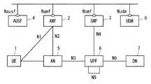
- FIG. 1 shows a configuration example of a wireless communication network (ie, 5GS) according to this embodiment.
- Each of the elements shown in FIG. 1 is a network function and provides an interface defined by the 3rd Generation Partnership Project (3GPP).
- 3GPP 3rd Generation Partnership Project
- Each element (network function) shown in FIG. 1 is, for example, as a network element on dedicated hardware, as a running software instance on dedicated hardware, or on an application platform. It can be implemented as an instantiated virtualization function.
- the wireless communication network shown in FIG. 1 may be provided by a Mobile Network Operator (MNO) or a Non-Public Network (NPN) provided by a non-MNO.
- MNO Mobile Network Operator
- NPN Non-Public Network
- the wireless communication network shown in FIG. 1 may be an independent network represented by Stand-alone Non-Public Network (SNPN) or linked with an MNO network represented by Public network integrated NPN. It may be an NPN.
- the wireless terminal (i.e., UE) 1 uses the 5G connection (connectivity) service to communicate with the data network (DN) 7. More specifically, UE1 is connected to the access network (i.e., 5GAccessNetwork (5GAN)) 5 and via the UserPlaneFunction (UPF) 6 in the core network (i.e., 5Gcorenetwork (5GC)). Communicates with the data network (DN) 7.
- AN5 includes Next Generation Radio Access Network (NG-RAN), non-3GPP AN, or both.
- the Non-3GPPAN may be a network that handles wireless LAN (WiFi) communication, or may be a network that handles wired communication represented by Wireline 5G Access Network (W-5GAN).
- the UPF 6 may include a plurality of interconnected UPFs.
- the connectivity service between UE1 and DN7 is supported by one or more Protocol Data Unit (PDU) sessions.
- a PDU session is an association, session, or connection between UE1 and DN7.
- the PDU session is used to provide a PDU connectivity service (ie, the exchange of PDUs between UE1 and DN7).
- UE1 establishes one or more PDU sessions between UE1 and UPF6 (i.e., PDU session anchor) to which DN7 is connected.
- UPF6 i.e., PDU session anchor
- a PDU session consists of a tunnel within the 5GC (N9 tunnel), a tunnel between the 5GC and AN5 (N3 tunnel), and one or more radio bearers.
- the UE 1 may establish a plurality of PDU sessions with each of a plurality of UPFs (PDU session anchors) 6 in order to access a plurality of DNs 7 at the same time (concurrently).
- AMF2 is one of the network functions in the 5GC Control Plane.
- AMF2 provides the termination of the RAN Control Plane (CP) interface (i.e., N2 interface).
- AMF2 terminates one (single) signaling connection (i.e., N1 NAS signaling connection) with UE1 and provides registration management, connection management, and mobility management.
- AMF2 provides NF services on a service-based interface (i.e., Namf interface) to NF consumers (e.g. other AMF, Session Management Function (SMF) 3, and Authentication Server Function (AUSF) 4).
- the NF service provided by AMF2 includes a communication service (Namf_Communication).
- the communication service enables an NF consumer (e.g., SMF3) to communicate with UE1 or AN5 via AMF2.
- SMF3 is one of the network functions in the 5GC Control Plane. SMF3 manages PDU sessions. SMF3 is a SM signaling message (NAS-SM messages, N1 SM messages) with the Non-Access-Stratum (NAS) Session Management (SM) layer of UE1 via the communication service provided by AMF2. To send and receive. SMF3 provides NF services (services) to NF consumers (e.g., AMF2, other SMFs) on a service-based interface (i.e., Nsmf interface). The NF service provided by SMF3 includes a PDU session management service (Nsmf_PDUSession). The NF service allows NF consumers (e.g., AMF2) to handle PDU sessions. SMF3 may be Intermediate SMF (I-SMF). The I-SMF is inserted between the AMF2 and the original SMF as needed when the UPF6 belongs to a different SMF service area and cannot be controlled by the original SMF.
- I-SMF Intermediate SMF
- AUSF4 is one of the network functions in the 5GC Control Plane.
- AUSF4 provides NF services (services) to NF consumers (e.g., AMF2, UDM8) on a service-based interface (i.e., Nausf interface).
- the NF service provided by AUSF4 includes UE authentication service (e.g. Nausf_UEAuthentication and Nausf_NSSAA_Authenticate).
- the Nausf_UEAuthentication service provides UE authentication and related key information (keying material) to NF consumers (i.e., AMF).
- AUSF4 works with UDM8 and Authentication credential Repository and Processing Function (ARPF) to support two authentication methods (i.e., 5G-Authentication and Key Agreement (AKA) and EAP-based authentication) supported by 5GS. ) Is used for authentication.
- ARPF Authentication credential Repository and Processing Function
- AKA 5G-Authentication and Key Agreement
- EAP-based authentication supported by 5GS.
- AUSF4 After executing the authentication, AUSF4 returns the master key to AMF2 if the authentication result is successful.
- the master key is used by AMF2 to derive NAS security keys and other security keys (s).
- AUSF4 works closely with UDM8.
- the Nausf_NSSAA_Authenticate service provides NF consumers (e.g., AMF2) with specialized authentication and authorization services for network slices between UE1 and AAA servers via AUSF4.
- UDM8 is one of the network functions in the 5GC Control Plane.
- UDM8 provides access to a database (i.e., User Data Repository (UDR)) in which subscriber data (subscription information) is stored.
- UDM8 provides NF services (services) to NF consumers (e.g. AMF2, AUSF4, SMF3) on a service-based interface (i.e., Nudm interface).
- the NF services provided by UDM8 include subscriber data management services.
- the NF service enables the NF consumer (e.g., AMF) to retrieve the subscriber data and provides the updated subscriber data to the NF consumer.
- the configuration example in FIG. 1 shows only typical NFs for convenience of explanation.
- the wireless communication network according to this embodiment may have a configuration specialized for roaming (see, for example, Section 4.2.4 of Non-Patent Document 1), and other NFs not shown in FIG. 1, for example, Network. Slice Selection Function (NSSF) and Policy Control Function (PCF) may be included.
- NSSF Network Slice Selection Function
- PCF Policy Control Function
- FIG. 2 is a flowchart showing an example of the operation of AMF2 according to this embodiment.
- AMF2 manages (or stores) the association between Serving PLMN S-NSSAIs and Mapped S-NSSAIs (or HPLMN S-NSSAIs).
- one or more Mapped S-NSSAIs may be associated with one Serving PLMN S-NSSAI.
- These 1 or more Mapped S-NSSAIs may be S-NSSAIs of another PLMN (HPLMN of UE1) different from the PLMN to which AMF2 belongs.
- the association will be referred to as a first association.
- a plurality of Mapped S-NSSAIs are associated with one Serving PLMN S-NSSAI. Some or all of these multiple Mapped S-NSSAIs are subject to Network Slice-Specific Authentication and Authorization (NSSAA).
- NSSAA Network Slice-Specific Authentication and Authorization
- AMF2 receives from UE1 a RegistrationRequest message containing information indicating whether UE1 supports the NSSAA function.
- the AMF2 identifies (or determines) the Mapped S-NSSAI (s) associated with the Serving PLMN S-NSSAI based on the information. More specifically, AMF2 may determine whether UE1 supports the NSSAA function based on the 5th generation mobility management (5GMM) Capability information regarding NSSAA included in the received RegistrationRequest message.
- the 5GMM Capability information about NSSAA indicates whether UE1 supports the NSSAA function.
- the 5GMM Capability information regarding NSSAA may be a Network slice-specific authentication and authorization (NSSAA) value included in the 5GMM Capability information.
- NSSAA Network slice-specific authentication and authorization
- the NSSAA value is an example of information that indicates whether the NSSAA feature is supported.
- AMF2 may recognize that UE1 supports the NSSAA function when the NSSAA value indicates "Network slice-specific authentication and authorization supported". The AMF2 then refers to the first association between the Serving PLMN S-NSSAI and the plurality of Mapped S-NSSAIs, and the association with at least one Mapped S-NSSAI that is not subject to NSSAA. Distinguish from association with at least one Mapped S-NSSAI subject to NSSAA.
- AMF2 refers to an Association of at least one Mapped S-NSSAI that is not subject to Serving PLMN S-NSSAI and NSSAA (hereinafter, this association is also referred to as a second association) as an Allowed NSSAI information element (Information Element (IE)). ). Further, AMF2 sets the association between Serving PLMN S-NSSAI and at least one Mapped S-NSSAI imposed by NSSAA (hereinafter, this association is also referred to as a third association) in Pending NSSAI IE. AMF2 transmits these Allowed NSSAI IE and Pending NSSAI IE to UE1.
- IE Information Element
- AMF2 includes not only the Serving PLMN S-NSSAI but also the Mapped S-NSSAI (s) associated with the Serving PLMN S-NSSAI in the Allowed NSSAI IE and Pending NSSAI IE sent to the UE1.
- AMF2 may send Allowed NSSAI IE and Pending NSSAI IE to UE1 using a message sent from AMF2 to UE1 to update NSSAI Storage or other UE settings.
- the message may be a NAS message, or more specifically, a Registration Accept message.
- FIG. 3 is a flowchart showing an example of the operation of UE1 related to the flowchart shown in FIG.
- UE1 receives Pending NSSAI IE and Allowed NSSAI IE from AMF2.
- the Pending NSSAI IE includes an association (third association) between the Serving PLMN S-NSSAI and one or more Mapped S-NSSAIs that are subject to NSSAA.
- the Allowed NSSAI IE includes an association (second association) between the Serving PLMN S-NSSAI and one or more Mapped S-NSSAIs that are not subject to NSSAA.
- step 302 in response to the reception of the Pending NSSAI IE and Allowed NSSAI IE, the UE 1 updates the NSSAI Storage stored in the memory of the UE 1. Specifically, the UE1 replaces or overwrites the Allowed NSSAI in the NSSAI storage with the received Serving PLMN S-NSSAI (replaces or rewrites), and one or more Mapped S- associated with the Serving PLMN S-NSSAI. Store NSSAIs.
- UE1 replaces or overwrites (replaces or rewrites) the Pending NSSAI received in the NSSAI storage with the Serving PLMN S-NSSAI, and stores one or more Mapped S-NSSAIs associated with the Serving PLMN S-NSSAI. (Store).
- FIG. 4 shows an example of the update procedure of NSSAI Storage of UE1.
- step 401 neither Allowed NSSAI nor Pending NSSAI in NSSAI Storage of UE1 has an entry. In other words, Allowed NSSAI and Pending NSSAI are both empty.
- step 402 UE1 sends a Registration Request message to AMF2.
- AMF2 may be AMF of Visited PLMN (VPLMN).
- UE1 includes S-NSSAI # 1 and S-NSSAI # 2 in the Requested mapped NSSAI IE in the Registration Request message.
- UE1 may include S-NSSAI # 1 and S-NSSAI # 2 in Requested mapped NSSAI IE based on Configured NSSAI (or Default Configured NSSAI) (not shown).
- the RegistrationRequest message indicates that UE1 supports NSSAA.
- the Registration Request message includes 5GMM Capability IE set in "Network slice-specific authentication and authorization supported".
- AMF2 makes a resource request related to UE1's Subscribed NSSAI to the Subscriber Data Management (SDM) service published by UDM8 using the Get operation.
- the request may be made, for example, via Nudm_SDM_GetApplication Programming Interface (API).
- UDM8 includes the Subscribed NSSAI of UE1 (here, S-NSSAI # 1, S-NSSAI # 2) in the message body of the message whose status code is 200 OK and returns it to AMF2.
- Subscribed NSSAI has an AdditionalSnssaiData attribute (or field). This field indicates whether each S-NSSAI is subject to NSSAA.
- the field contains a list of values for the attribute (e.g., requiredAuthnAuthz), each value indicating whether the corresponding S-NSSAI is subject to NSSAA.
- AMF2 associates a specific Serving PLMN S-NSSAI (here S-NSSAI # 3) supported by AMF2 with S-NSSAI # 1 and S-NSSAI # 2. That is, two Mapped S-NSSAIs (S-NSSAI # 1, S-NSSAI # 2) are associated with S-NSSAI # 3.
- NSSF may select a specific Serving PLMN S-NSSAI to be associated with S-NSSAI # 1 and S-NSSAI # 2.
- AMF2 may transmit S-NSSAI # 1 and S-NSSAI # 2 to NSSF.
- NSSF In response to the reception of S-NSSAI # 1 and S-NSSAI # 2, NSSF associates S-NSSAI # 1 and S-NSSAI # 2 with a specific Serving PLMN S-NSSAI (here S-NSSAI # 3). , The association (first association) may be transmitted to AMF2. NSSF may send a Configured NSSAI containing the first association to AMF2.
- AMF2 sends Allowed NSSAI IE and Pending to UE1 based on the NSSAA value ("Network slice-specific authentication and authorization supported") of the 5GMM Capability information indicating that UE1 supports NSSAA.
- NSSAI IE NSSAI IE.
- AMF2 is associated with S-NSSAI # 3 and Mapped S-NSSAI (s) (here S-NSSAI # 1), which is not subject to NSSAA associated with S-NSSAI # 3 (second). Associate) is set in Allowed NSSAI IE.
- AMF2 is charged with the NSSAA associated with S-NSSAI # 3 and S-NSSAI # 3 to update the Pending NSSAI in UE1's NSSAI Storage Mapped S-NSSAI (s) (here S). -Set the association (third association) with NSSAI # 2) in PendingNSSAIIE.
- AMF2 sends a NAS message (e.g., Registration Accept message) including these Allowed NSSAI IE and Pending NSSAI IE to UE1.
- the UE1 updates the NSSAI Storage stored in the memory of the UE1 in response to the reception of the NAS message. Specifically, UE1 replaces or overwrites the Allowed NSSAI in the NSSAI storage with the Serving PLMN S-NSSAI (here, S-NSSAI # 3) included in the received Allowed NSSAI IE, and the Serving is concerned. Stores one or more Mapped S-NSSAIs (here S-NSSAI # 1) associated with PLMNS-NSSAI.
- S-NSSAI # 3 the Serving PLMN S-NSSAI
- Mapped S-NSSAIs here S-NSSAI # 1
- UE1 is a combination (or a second association) of S-NSSAI # 3 included in the received Allowed NSSAI IE and Mapped S-NSSAI (s) (here S-NSSAI # 1) that is not subject to NSSAA. Is stored in Allowed NSSAI.
- UE1 replaces or overwrites the Pending NSSAI in the NSSAI storage with the Serving PLMN S-NSSAI (here, S-NSSAI # 3) included in the received Pending NSSAI IE, and the Serving PLMN S- Stores one or more Mapped S-NSSAIs (here S-NSSAI # 2) associated with NSSAI.
- UE1 is a combination (or a third association) of S-NSSAI # 3 included in the received PendingNSSAIIE and Mapped S-NSSAI (s) (here S-NSSAI # 2) imposed by NSSAA. ) Is stored in Pending NSSAI.
- FIG. 5 is a flowchart showing an example of the operation of UE1 according to this embodiment.
- UE1 manages NSSAI Storage including Allowed NSSAI and Pending NSSAI.
- UE1 receives Allowed NSSAI IE and Pending NSSAI IE from AMF2.
- the Allowed NSSAI IE shows a second association between S-NSSAI # 3 and Mapped S-NSSAI (s) (here S-NSSAI # 1) that is associated with S-NSSAI # 3 and is not subject to NSSAA.
- the Pending NSSAI IE is the third association between S-NSSAI # 3 and Mapped S-NSSAI (s) (here S-NSSAI # 2), which is subject to NSSAA associated with S-NSSAI # 3. Is shown.
- UE1 stores the Allowed NSSAI and Pending NSSAI received in step 502 in the Allowed NSSAI and Pending NSSAI of NSSAI Storage, respectively.
- UE1 is not subject to S-NSSAI # 3 and NSSAA included in Allowed NSSAI and the associated Mapped S-NSSAI (s) (here S-NSSAI).
- # 1) can be set in the message for the registration procedure. More specifically, UE1 has S-NSSAI # 3 as a specific Mapped S-NSSAI (s) (here S-NSSAI # 1) even if S-NSSAI # 3 is stored in PendingNSSAI.
- UE1 When associated and stored in Allowed NSSAI, UE1 has S-NSSAI # 3 associated with multiple Mapped S-NSSAIs, and S-NSSAI # 3 included in Allowed NSSAI and a specific Mapped S-NSSAI. It can be determined that the combination with (s) (S-NSSAI # 1) can be used in the registration procedure. Therefore, UE1 sets S-NSSAI # 3 and its associated Mapped S-NSSAI (s) (here S-NSSAI # 1) as a message for the registration procedure and sends it to the network. be able to.
- the message for the registration procedure may be a NAS message, and more specifically, a MobilityRegistrationUpdate or a RegistrationRequest message for a PeriodicRegistrationUpdate.
- the procedure in this embodiment is that in a roaming scenario, one Serving PLMN S-NSSAI is associated with multiple Mapped S-NSSAIs, and some or all of these Multiple Mapped S-NSSAIs are subject to NSSAA. In some cases, it allows AMF2 and UE1 to properly update one or both of the Pending NSSAI and Allowed NSSAI of the UE1 NSSAI storage. This can contribute to the improvement of the availability of the slice service.
- the procedure in this embodiment is to associate the Serving PLMN S-NSSAI and the Mapped S-NSSAI (s) indicated by the Allowed NSSAI when the same Serving PLMN S-NSSAI is included in both the Allowed NSSAI and the Pending NSSAI. Allows UE1 to use in the registration procedure. This can contribute to the improvement of the availability of the slice service. For example, normally, the Serving PLMN S-NSSAI included in the Pending NSSAI is registered as a subsequent because the NSSAA of the Home PLMN S-NSSAI mapped to the Serving PLMN S-NSSAI is ongoing. Not available by UE1 due to the procedure (see, eg, Section 5.15.5.2.1 of Non-Patent Document 1).
- each Mapped S-NSSAI associated with (or combined with) the Serving PLMN S-NSSAI within the Allowed NSSAI is associated with the Serving PLMN S-NSSAI within the Pending NSSAI. If different from NSSAI (s), UE1 can set the Serving PLMN S-NSSAI included in Allowed NSSAI and the associated Mapped S-NSSAI (s) in the Registration Request message in the subsequent registration procedure.
- ⁇ Second embodiment> The configuration example of the wireless communication network according to this embodiment may be the same as the example shown in FIG.
- This embodiment provides an association between Serving PLMN S-NSSAI and Mapped S-NSSAI (s) by AMF2, and another example of NSSAI Storage update.
- FIG. 6 is a flowchart showing an example of the operation of AMF2 according to this embodiment.
- the AMF2 manages (or stores) the association between the Serving PLMN S-NSSAIs and the Mapped S-NSSAIs (or HPLMN S-NSSAIs).
- one or more Mapped S-NSSAIs may be associated with one Serving PLMN S-NSSAI (first association).
- These 1 or more Mapped S-NSSAIs may be S-NSSAIs of another PLMN (HPLMN of UE1) different from the PLMN to which AMF2 belongs.
- In the first association at least two Mapped S-NSSAIs that are subject to NSSAA for one Serving PLMN S-NSSAI are associated (third association).
- AMF2 receives a Registration Request message from UE1 including information indicating whether UE1 supports the NSSAA function.
- the AMF2 identifies (or determines) the Mapped S-NSSAI (s) associated with the Serving PLMN S-NSSAI based on the information. More specifically, AMF2 may determine whether UE1 supports the NSSAA function based on the 5GMM Capability information about NSSAA included in the received RegistrationRequest message.
- the 5GMM Capability information about NSSAA indicates whether UE1 supports the NSSAA function.
- the 5GMM Capability information regarding NSSAA may be the NSSAA value included in the 5GMM Capability information.
- the NSSAA value is an example of information that indicates whether the NSSAA function is supported.
- AMF2 may recognize that UE1 supports the NSSAA function when the NSSAA value indicates "Network slice-specific authentication and authorization supported". The AMF2 then refers to the first association between the Serving PLMN S-NSSAI and the plurality of Mapped S-NSSAIs and is subject to at least two with at least two Mapped S-NSSAIs. Identify (or select) an association.
- AMF2 sets at least two Mapped S-NSSAIs associations (third associations) that are subject to Serving PLMN S-NSSAI and NSSAA out of the first association in Pending NSSAI IE for UE1. .. AMF2 transmits the PendingNSSAIIE to UE1. That is, the AMF2 includes not only the Serving PLMN S-NSSAI but also the Mapped S-NSSAIs associated with the Serving PLMN S-NSSAI in the Pending NSSAI IE sent to the UE1. AMF2 may send Pending NSSAI IE to UE1 using a message sent from AMF2 to UE1 to update NSSAI Storage or other UE settings. The message may be a NAS message, or more specifically, a Registration Accept message.
- FIG. 7 is a flowchart showing an example of the operation of UE1 related to the flowchart shown in FIG.
- UE1 receives PendingNSSAIIE from AMF2.
- the Pending NSSAI IE includes an association (third association) between the Serving PLMN S-NSSAI and at least two Mapped S-NSSAIs that are subject to NSSAA.
- step 702 in response to the reception of the Pending NSSAI IE, the UE 1 updates the NSSAI Storage stored in the memory of the UE 1. Specifically, UE1 replaces or overwrites the Pending NSSAI in the NSSAI storage with the received Serving PLMN S-NSSAI (replace or rewrite), and two or more Mapped S- associated with the Serving PLMN S-NSSAI. Store NSSAIs.
- FIG. 8 shows an example of the update procedure of NSSAI Storage of UE1.
- the Pending NSSAI in the NSSAI Storage of UE1 has no entry. In other words, Pending NSSAI is empty.
- UE1 sends a Registration Request message to AMF2.
- AMF2 may be AMF of Visited PLMN (VPLMN).
- UE1 includes S-NSSAI # 1 and S-NSSAI # 2 in the Requested mapped NSSAI IE in the Registration Request message.
- the RegistrationRequest message indicates that UE1 supports NSSAA.
- the Registration Request message includes 5GMM Capability IE set in "Network slice-specific authentication and authorization supported".
- AMF2 makes a resource request related to UE1's Subscribed NSSAI using the Get operation for the SDM service published by UDM8.
- the request may be made, for example, via the Nudm_SDM_Get API.
- UDM8 includes the Subscribed NSSAI of UE1 (here, S-NSSAI # 1, S-NSSAI # 2) in the message body of the message whose status code is 200 OK and returns it to AMF2.
- Subscribed NSSAI has an AdditionalSnssaiData attribute (or field). This field indicates whether each S-NSSAI is subject to NSSAA.
- the field contains a list of values for the attribute (e.g., requiredAuthnAuthz), each value indicating whether the corresponding S-NSSAI is subject to NSSAA.
- AMF2 associates a specific Serving PLMN S-NSSAI (here S-NSSAI # 3) supported by AMF2 with S-NSSAI # 1 and S-NSSAI # 2. That is, two Mapped S-NSSAIs (S-NSSAI # 1, S-NSSAI # 2) are associated with S-NSSAI # 3.
- NSSF may select a specific Serving PLMN S-NSSAI to be associated with S-NSSAI # 1 and S-NSSAI # 2.
- AMF2 may transmit S-NSSAI # 1 and S-NSSAI # 2 to NSSF.
- NSSF In response to the reception of S-NSSAI # 1 and S-NSSAI # 2, NSSF associates S-NSSAI # 1 and S-NSSAI # 2 with a specific Serving PLMN S-NSSAI (here S-NSSAI # 3). , The association (first association) may be transmitted to AMF2. NSSF may send a Configured NSSAI containing the first association to AMF2.
- AMF2 determines the Pending NSSAI IE to be sent to UE1 based on the NSSAA value ("Network slice-specific authentication and authorization supported") of the 5GMM Capability information indicating that UE1 supports NSSAA. do. Specifically, AMF2 is subject to two Mapped S-NSSAIs (here S-NSSAI # 1 and S-) that are subject to S-NSSAI # 3 and NSSAA to update the Pending NSSAI in UE1's NSSAI Storage. Set the association (third association) with NSSAI # 2) in Pending NSSAI IE.
- the third association includes a combination of S-NSSAI # 3 and S-NSSAI # 1, and further includes a combination of S-NSSAI # 3 and S-NSSAI # 2.
- AMF2 sends a NAS message (e.g., Registration Accept message) including this Pending NSSAI IE to UE1.
- NAS message e.g., Registration Accept message
- the UE1 updates the NSSAI Storage stored in the memory of the UE1 in response to the reception of the NAS message. Specifically, UE1 replaces or overwrites the Pending NSSAI in the NSSAI storage with the received Serving PLMN S-NSSAI (here, S-NSSAI # 3), and associates it with the Serving PLMN S-NSSAI. Mapped S-NSSAIs (here S-NSSAI # 1 and S-NSSAI # 2) are stored (store).
- UE1 is with each of the two or more Mapped S-NSSAIs (here S-NSSAI # 1 and S-NSSAI # 2) included in the received PendingNSSAIIE that are subject to S-NSSAI # 3 and NSSAA. Store two or more combinations (or third associations) in PendingNSSAI.
- S-NSSAI # 1 and S-NSSAI # 2 included in the received PendingNSSAIIE that are subject to S-NSSAI # 3 and NSSAA.
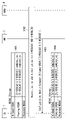
- FIG. 9 shows an example of the NSSAI Storage update procedure when the NSSAA procedure of a certain Mapped S-NSSAI (here, S-NSSAI # 2) is successfully completed after the procedure of FIG.
- UE1 manages NSSAI Storage including Allowed NSSAI and Pending NSSAI.
- the Pending NSSAI stores the first and second Mapped S-NSSAIs (S-NSSAI # 1 and S-NSSAI # 2) associated with a particular Serving PLMN S-NSSAI and subject to NSSAA. ing.
- step 902 UE1 receives Allowed NSSAI IE from AMF2 in combination with a second Mapped S-NSSAI (here S-NSSAI # 2) associated with a specific Serving PLMN S-NSSAI.
- step 903 the UE 1 deletes the combination received in step 902 from the Pending NSSAI in the NSSAI storage, and stores the combination in the Allowed NSSAI.
- the NSSAA procedure is executed for two Mapped S-NSSAIs (here, S-NSSAI # 1 and S-NSSAI # 2) associated with one Serving PLMN S-NSSAI, and the S-NSSAI # 2 is first executed.
- An example of the NSSAI Storage update procedure when the NSSAA procedure is completed successfully is shown below.
- UE1 manages Pending NSSAI.
- the Pending NSSAI at this point is the combination of Serving PLMN S-NSSAI (here S-NSSAI # 3) and Mapped S-NSSAI (here S-NSSAI # 1), and the relevant Serving PLMN S-NSSAI (S-NSSAI #).
- Stores combinations with other Mapped S-NSSAI (here S-NSSAI # 2) associated with 3).
- step 1002 the authentication and authorization procedure for S-NSSAI # 1 and S-NSSAI # 2 is executed.
- step 1003 the authentication and authorization procedure for S-NSSAI # 2 is successful.
- AMF2 sets S-NSSAI # 3 and S-NSSAI # 2 associated with S-NSSAI # 3 in Allowed NSSAI IE, and sends a Configuration Update Command message including the Allowed NSSAI IE to UE1. do.
- AMF2 indicates to UE1 that S-NSSAI # 3 and S-NSSAI # 2 associated with S-NSSAI # 3 are included in Allowed NSSAI.
- step 1004 in response to the reception of the Allowed NSSAI IE, the UE 1 updates the NSSAI Storage stored in the memory of the UE 1. Specifically, UE1 deletes the combination of S-NSSAI # 3 and S-NSSAI # 2 included in Allowed NSSAI IE received in step 1003 from Pending NSSAI in NSSAI storage, and stores the combination in Allowed NSSAI. do.
- the procedure in this embodiment can be addressed in a roaming scenario where one Serving PLMN S-NSSAI is associated with two Mapped S-NSSAIs that are both subject to NSSAA.
- the procedure in this embodiment allows UE1 to update NSSAI Storage accurately without being affected by these two Mapped S-NSSAIs being mapped to the same Serving PLMN S-NSSAI. For example, if one Serving PLMN S-NSSAI is associated with a first Mapped S-NSSAI and a second Mapped S-NSSAI, and the authentication and authorization procedure for the second Mapped S-NSSAI is successful. In that case, AMF2 sends a message to UE1 that causes the NSSAI Storage to be updated.
- the message includes not only the Serving PLMN S-NSSAI but also the information of the second Mapped S-NSSAI mapped to the Serving PLMN S-NSSAI.
- UE1 can determine that the combination of the Serving PLMN S-NSSAI included in the NSSAI Storage and the second Mapped S-NSSAI should be updated, and can update the NSSAI Storage for the combination. can.
- FIG. 11 is a flowchart showing an example of the operation of AMF2 according to this embodiment.
- step 1101 authentication and authorization procedures are performed for the first and second Mapped S-NSSAIs associated with the first Serving PLMN S-NSSAI and subject to NSSAA.
- the authentication and authorization procedure for the first Mapped S-NSSAI succeeds, and the authentication and authorization procedure for the second Mapped S-NSSAI fails.
- step 1102 AMF2 sets the combination of the first Serving PLMN S-NSSAI and the first Mapped S-NSSAI associated with the first Serving PLMN S-NSSAI in Allowed NSSAI IE, and at the same time, the first. Set Serving PLMN S-NSSAI to Rejected NSSAI. AMF2 transmits a message containing these Allowed NSSAI and Rejected NSSAI to UE1.
- FIG. 12 is a flowchart showing an example of the operation of UE1 related to the flowchart shown in FIG.
- NSSAI Storage including Pending NSSAI is managed.
- the Pending NSSAI at this point is the two Mapped S-NSSAIs (the first Mapped S-NSSAI and the second) that are subject to the first Serving PLMN S-NSSAI and the NSSAA associated with the first Serving PLMN S-NSSAI.
- the combination (or association, mapping) with Mapped S-NSSAI) is stored.
- step 1202 the authentication and authorization procedure for the first Mapped S-NSSAI succeeds, and the authentication and authorization procedure for the second Mapped S-NSSAI fails.
- UE1 receives a message containing Allowed NSSAI IE and Rejected NSSAI from AMF2.
- the Allowed NSSAI IE includes a combination of the first Serving PLMN S-NSSAI and the first Mapped S-NSSAI.
- Rejected NSSAI IE includes the first Serving PLMN S-NSSAI.
- UE1 deletes the combination of the first Serving PLMN S-NSSAI and the first Mapped S-NSSAI included in the Allowed NSSAI IE received in step 1202 from the Pending NSSAI, and makes the combination into the Allowed NSSAI. Store. Further, UE1 deletes the combination of the first Serving PLMN S-NSSAI and the second Mapped S-NSSAI from the Pending NSSAI, and stores the first Serving PLMN S-NSSAI in the Rejected NSSAI.
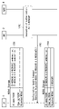
- FIG. 13 shows that the NSSAA procedure is performed for two Mapped S-NSSAIs associated with one Serving PLMN S-NSSAI, the NSSAA procedure for one Mapped S-NSSAI fails, and for the other Mapped S-NSSAI.
- An example of the NSSAI Storage update procedure when the NSSAA procedure of is successful is shown below.
- UE1 manages Pending NSSAI.
- the Pending NSSAI at this point is the combination (or association, mapping) of Serving PLMN S-NSSAI (here S-NSSAI # 3) and Mapped S-NSSAI (s) (here S-NSSAI # 1), and the Serving.
- Stores combinations (or associations, mappings) of PLMN S-NSSAI and other Mapped S-NSSAI (s) here S-NSSAI # 2).
- step 1302 the authentication and authorization procedure for S-NSSAI # 1 and S-NSSAI # 2 is executed.
- step 1303 the authentication and authorization procedure for S-NSSAI # 2 fails, and AMF2 sends a Configuration Update Command message to UE1 to indicate that S-NSSAI # 3 is included in Rejected NSSAI.
- the message includes Rejected NSSAI IE and Extended Rejected NSSAI IE.
- Rejected NSSAI IE indicates Serving PLMN S-NSSAI (here S-NSSAI # 3) that needs to be stored in Rejected NSSAI.
- Extended Rejected NSSAI indicates Serving PLMN S-NSSAI (here S-NSSAI # 3) that needs to be stored in Rejected NSSAI, and Mapped S-NSSAI (s) (here) associated with S-NSSAI # 3. S-NSSAI # 2) is shown.
- the extended Rejected NSSAI allows UE1 to determine the combination of the Serving PLMN S-NSSAI and Mapped S-NSSAI (s) that should be removed from the Pending NSSAI. Further, the extended Rejected NSSAI may be modified as follows.
- Extended Rejected NSSAI IE is not defined as an information element independent of Rejected NSSAI IE, and may be defined as extended Rejected NSSAI by extending the format of Rejected NSSAI IE. In this case, Rejected NSSAI IE must be extended to guarantee backward compatibility.
- Step 1303 may be modified as follows.
- the message in step 1303 may include Pending NSSAI IE instead of the extended Rejected NSSAI IE. More specifically, the message may include Rejected NSSAI IE and Pending NSSAI IE.
- the Rejected NSSAI IE includes S-NSSAI # 3.
- the Pending NSSAI IE includes a combination of S-NSSAI # 3 and S-NSSAI # 1. In other words, when AMF2 transfers a Serving PLMN S-NSSAI that has a combination with multiple Mapped S-NSSAIs to the Rejected NSSAI, it is mapped to the Serving PLMN S-NSSAI but is permitted to UE1 or NSSAA.
- step 1304 UE1 deletes S-NSSAI # 3 associated with S-NSSAI # 3 and S-NSSAI # 3 from Pending NSSAI, and stores S-NSSAI # 3 in Rejected NSSAI.
- step 1305 the authentication and authorization procedure for S-NSSAI # 1 (the authentication and authorization procedure for S-NSSAI # 1 is omitted in FIG. 13) succeeds.
- AMF2 sends a Configuration Update Command message to UE1 to indicate that the combination of S-NSSAI # 3 and S-NSSAI # 1 is included in Allowed NSSAI.
- the message includes Allowed NSSAI IE indicating a combination of S-NSSAI # 3 and S-NSSAI # 1.
- step 1306 UE1 deletes the combination of S-NSSAI # 3 and S-NSSAI # 1 associated with S-NSSAI # 3 from PendingNSSAI according to the received AllowedNSSAIIE, and stores the combination in AllowedNSSAI. ..
- steps 1305 and 1306 may occur at the same time as steps 1303 and 1304, or may occur before these steps.
- FIG. 14 shows a list of parameters set in the extended Rejected NSSAI IE.
- FIG. 14 refers to Section 9.11.3.37 of Non-Patent Document 3.
- the extended Rejected NSSAI IE includes an NSSAI IE Identifier (IEI) field 1401, a Length of S-NSSAI contents field 1402, and one or more S-NSSAI value fields 1403.
- the NSSAI IEI field 1401 includes an identifier indicating the extended Rejected NSSAI IE.
- the Length of S-NSSAI contents field 1402 indicates the length of the content contained in the extended Rejected NSSAI IE in octet units.
- FIG. 15 shows the type of the S-NSSAI value field 1403 shown in FIG.
- the S-NSSAI value field 1403 set in the extended Rejected NSSAI IE is the field 1501 indicating SST and SD indicating Serving PLMN S-NSSAI, and the Mapped S associated with the Serving PLMN S-NSSAI. -Includes SST and SD fields 1502 indicating NSSAI.
- the extended Rejected NSSAI IE described for the procedure of FIG. 13 may be configured as shown in FIGS. 14 and 15.
- the procedure in this embodiment is associated with two Mapped S-NSSAIs in which one Serving PLMN S-NSSAI is both subject to NSSAA in a roaming scenario, for one of these two Mapped S-NSSAIs. You can handle cases where the authentication and authorization procedure succeeds and the authentication and authorization procedure for the other fails.
- the procedure in this embodiment allows UE1 to update NSSAI Storage accurately without being affected by these two Mapped S-NSSAIs being mapped to the same Serving PLMN S-NSSAI. For example, if one Serving PLMN S-NSSAI is associated with a first Mapped S-NSSAI and a second Mapped S-NSSAI, and the authentication and authorization procedure for the second Mapped S-NSSAI fails.
- AMF2 sends a message to UE1 that causes the NSSAI Storage to be updated.
- the message is not only the Serving PLMN S-NSSAI set in the Rejected NSSAI IE, but also the Mapped S-NSSAI (s) (or the unrejected Mapped S-NSSAI) associated with and rejected by the Serving PLMN S-NSSAI. (s)) is also included.
- UE1 can determine that the combination of the Serving PLMN S-NSSAI included in the Pending NSSAI of the NSSAI Storage with the second Mapped S-NSSAI associated with it should be updated, and the NSSAI should be updated with respect to the combination. Storage can be updated.
- the configuration example of the wireless communication network according to this embodiment may be the same as the example shown in FIG.
- This embodiment provides an example of NSSAI Storage renewal in the event of authorization revocation.
- the extended Rejected NSSAI described with reference to FIGS. 13, 14, and 15 is used.
- FIG. 16 is a flowchart showing an example of the operation of AMF2 according to this embodiment.
- AMF2 manages (or stores) the association between Serving PLMN S-NSSAIs and Mapped S-NSSAIs (or HPLMN S-NSSAIs).
- one Serving PLMN S-NSSAI is associated with two Mapped S-NSSAIs (first Mapped S-NSSAI and second Mapped S-NSSAI) subject to NSSAA.
- the certification and authorization procedures for these two Mapped S-NSSAIs have been successfully completed.
- AMF2 receives a request for revocation of authorization for the second Mapped S-NSSAI from AUSF4.
- AMF2 may receive a cancellation request from Authentication, Authorization, and Accounting (AAA) Server.
- AMF2 sends a message containing the extended Rejected NSSAI including the first Serving PLMN S-NSSAI associated with the second Mapped S-NSSAI and the second Mapped S-NSSAI.
- the message may be a message sent from AMF2 to UE1 to update NSSAI Storage or other UE settings.
- the message may be a NAS message, or more specifically, a Configuration Update Command message.
- FIG. 17 shows the successful completion of both NSSAA procedures for two Mapped S-NSSAIs associated with one Serving PLMN S-NSSAI, followed by revocation of authorization for one Mapped S-NSSAI.
- An example of the NSSAI Storage update procedure when a request occurs is shown below.
- UE1 manages Allowed NSSAI. Allowed NSSAI at this point is a combination (or association, mapping) of Serving PLMN S-NSSAI (here S-NSSAI # 3) and Mapped S-NSSAI (here S-NSSAI # 1), and the relevant Serving PLMN S. -Stores combinations (or associations, mappings) of NSSAI and other Mapped S-NSSAI (here S-NSSAI # 2).
- step 1702 revocation of the authorization of S-NSSAI # 2 is executed.
- AMF2 is requested by AUSF4 (or AAA server) to revocation the authorization of S-NSSAI # 2.
- AMF2 sends a Configuration Update Command message to UE1 to indicate that S-NSSAI # 3 is included in Rejected NSSAI.
- the message contains Extended Rejected NSSAI IE.
- Extended Rejected NSSAI indicates Serving PLMN S-NSSAI (here S-NSSAI # 3) that needs to be stored in Rejected NSSAI, and Mapped S-NSSAI (here S-NSSAI) associated with S-NSSAI # 3. # 2) is shown.
- the extended Rejected NSSAI allows UE1 to determine the combination of the Serving PLMN S-NSSAI and Mapped S-NSSAI (s) that should be removed from the Pending NSSAI.
- Step 1703 may be modified as follows.
- the message in step 1703 may include Allowed NSSAI IE instead of the extended Rejected NSSAI IE. More specifically, the message may include Rejected NSSAI IE and Allowed NSSAI IE.
- the Rejected NSSAI IE includes S-NSSAI # 3.
- the Allowed NSSAI IE includes a combination of S-NSSAI # 3 and S-NSSAI # 1. In other words, when AMF2 transfers a Serving PLMN S-NSSAI that has a combination with multiple Mapped S-NSSAIs to the Rejected NSSAI, it is mapped to the Serving PLMN S-NSSAI but is permitted to UE1 or NSSAA.
- the format of the extended Rejected NSSAI of this embodiment may be the same as the examples shown in FIGS. 14 and 15.
- the procedure in this embodiment is that in a roaming scenario, the NSSAA procedure for two Mapped S-NSSAIs mapped to the same Serving PLMN S-NSSAI is successfully completed, and then authorization is granted to one Mapped S-NSSAI. ) Revocation request can be dealt with.
- the procedure in this embodiment allows UE1 to accurately update NSSAI Storage without being affected by these two Mapped S-NSSAIs being mapped to the same Serving PLMN S-NSSAI. For example, after successful completion of the authentication and authorization procedure for the first Mapped S-NSSAI and the second Mapped S-NSSAI associated with one Serving PLMN S-NSSAI, the AMF2 will be the second Mapped S-NSSAI.
- AMF2 Upon receiving a revocation request for authorization, AMF2 sends a message to UE1 to update NSSAI Storage.
- the message is not only the Serving PLMN S-NSSAI set in the Rejected NSSAI IE, but also the Mapped S-NSSAI (or the unauthorized Mapped S-NSSAI) that is associated with the Serving PLMN S-NSSAI and whose authorization is revoked. ) Is also included.
- UE1 can determine that the combination of the Serving PLMN S-NSSAI included in the Allowed NSSAI of the NSSAI Storage and the second Mapped S-NSSAI associated with the second Mapped S-NSSAI should be updated, and the NSSAI should be updated with respect to the combination. Storage can be updated.
- the configuration example of the wireless communication network according to this embodiment may be the same as the example shown in FIG.
- This embodiment provides the operation of UE1 for the registration procedure.
- the operation of UE1 described in this embodiment may be performed in combination with any of the above embodiments.
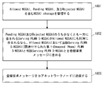
- FIG. 18 shows an example of the operation of UE1 of this embodiment.
- UE1 manages NSSAI storage including Allowed NSSAI, Pending NSSAI, and Rejected NSSAI.
- the Serving PLMN S-NSSAI contained in at least one of the Pending NSSAI and the Rejected NSSAI is also included in the Allowed NSSAI at the same time, the first Mapped (Home) associated with the Serving PLMN S-NSSAI in the Allowed NSSAI.
- PLMN S-NSSAI and the relevant Serving PLMN S-NSSAI in the registration request message.
- UE1 sends the registration procedure message to AMF2.
- the registration request message may be a MobilityRegistrationUpdate or a RegistrationRequest message for PeriodicRegistrationUpdate.
- UE1 may manage NSSAI storage similar to that shown in step 407 of FIG. 4 or step 1004 of FIG. More specifically, Allowed NSSAI stores a combination of Serving PLMN S-NSSAI (e.g., S-NSSAI # 3) and the first Mapped (HPLMN) S-NSSAI (e.g., S-NSSAI # 1). At the same time, the Pending NSSAI may store the combination of the Serving PLMN S-NSSAI (e.g., S-NSSAI # 3) and the second Mapped (HPLMN) S-NSSAI (S-NSSAI # 2).
- UE1 uses the Serving PLMN S-NSSAI (e.g., S-NSSAI # 3) even though the Serving PLMN S-NSSAI (e.g., S-NSSAI # 3) is included in the Pending NSSAI. It can be set in the Requested NSSAI (IE) of the registration request message, and the first Mapped (HPLMN) S-NSSAI (S-NSSAI # 1) can be set in the Requested mapped NSSAI (IE) of the same message.
- IE Requested NSSAI
- HPLMN HPLMN S-NSSAI # 1
- UE1 may manage NSSAI storage similar to that shown in step 1306 of FIG. More specifically, Allowed NSSAI stores a combination of Serving PLMN S-NSSAI (e.g., S-NSSAI # 3) and the first Mapped (HPLMN) S-NSSAI (e.g., S-NSSAI # 1). At the same time, the Rejected NSSAI may store the Serving PLMN S-NSSAI (e.g., S-NSSAI # 3).
- UE1 uses the Serving PLMN S-NSSAI (e.g., S-NSSAI # 3) even though the Serving PLMN S-NSSAI (e.g., S-NSSAI # 3) is included in the Rejected NSSAI. It can be set in the Requested NSSAI (IE) of the registration request message, and the first Mapped (HPLMN) S-NSSAI (S-NSSAI # 1) can be set in the Requested mapped NSSAI (IE) of the same message.
- IE Requested NSSAI
- HPLMN HPLMN S-NSSAI # 1
- FIG. 19 is a block diagram showing a configuration example of UE1.
- Radio Frequency (RF) transceiver 1901 performs analog RF signal processing to communicate with RAN nodes.
- the RF transceiver 1901 may include a plurality of transceivers.
- the analog RF signal processing performed by the RF transceiver 1901 includes frequency up-conversion, frequency down-conversion, and amplification.
- the RF transceiver 1901 is coupled with the antenna array 1902 and the baseband processor 1903.
- the RF transceiver 1901 receives the modulation symbol data (or OFDM symbol data) from the baseband processor 1903, generates a transmit RF signal, and supplies the transmit RF signal to the antenna array 1902. Further, the RF transceiver 1901 generates a baseband reception signal based on the received RF signal received by the antenna array 1902, and supplies the baseband reception signal to the baseband processor 1903.
- the RF transceiver 1901 may include an analog beamformer circuit for beamforming.
- the analog beamformer circuit includes, for example, a plurality of phase shifters and a plurality of power amplifiers.
- the baseband processor 1903 performs digital baseband signal processing (data plane processing) and control plane processing for wireless communication.
- Digital baseband signal processing includes (a) data compression / restoration, (b) data segmentation / concatenation, (c) transmission format (transmission frame) generation / decomposition, and (d) transmission path coding / decoding. , (E) Modulation (symbol mapping) / demodulation, and (f) Generation of OFDM symbol data (baseband OFDM signal) by Inverse Fast Fourier Transform (IFFT).
- IFFT Inverse Fast Fourier Transform
- control plane processing includes layer 1 (e.g., transmission power control), layer 2 (e.g., radio resource management, and hybrid automatic repeat request (HARQ) processing), and layer 3 (e.g., attach, mobility, and call management). Includes communication management (signaling regarding).
- layer 1 e.g., transmission power control
- layer 2 e.g., radio resource management, and hybrid automatic repeat request (HARQ) processing
- layer 3 e.g., attach, mobility, and call management.
- Includes communication management (signaling regarding).
- digital baseband signal processing by the baseband processor 1903 is performed by the ServiceDataAdaptationProtocol (SDAP) layer, PacketDataConvergenceProtocol (PDCP) layer, RadioLinkControl (RLC) layer, MediumAccessControl (MAC) layer, and Physical. (PHY) layer signal processing may be included.
- SDAP ServiceDataAdaptationProtocol
- PDCP PacketDataConvergenceProtocol
- RLC RadioLinkControl
- MAC MediumAccessControl
- PHY Physical.
- the control plane processing by the baseband processor 1903 may include the processing of the Non-Access Stratum (NAS) protocol, the Radio Resource Control (RRC) protocol, and the MAC Control Elements (CEs).
- the baseband processor 1903 may perform MultipleInputMultipleOutput (MIMO) encoding and precoding for beamforming.
- MIMO MultipleInputMultipleOutput
- the baseband processor 1903 includes a modem processor (e.g., Digital Signal Processor (DSP)) that performs digital baseband signal processing and a protocol stack processor (e.g., Central Processing Unit (CPU) or Micro Processing Unit (e.g., Central Processing Unit (CPU)) that performs control plane processing. MPU)) may be included.
- DSP Digital Signal Processor
- MPU Central Processing Unit
- the protocol stack processor that performs the control plane processing may be shared with the application processor 1904 described later.
- the application processor 1904 is also called a CPU, MPU, microprocessor, or processor core.
- the application processor 1904 may include a plurality of processors (a plurality of processor cores).
- the application processor 1904 is a system software program (Operating System (OS)) read from memory 1906 or a memory (not shown) and various application programs (eg, call application, web browser, mailer, camera operation application, music playback). By executing the application), various functions of UE1 are realized.
- OS Operating System
- the baseband processor 1903 and application processor 1904 may be integrated on one chip, as shown by the dashed line (1905) in FIG.
- the baseband processor 1903 and application processor 1904 may be implemented as one System on Chip (SoC) device 1905.
- SoC devices are sometimes referred to as system Large Scale Integration (LSI) or chipsets.
- the memory 1906 is a volatile memory, a non-volatile memory, or a combination thereof.
- the memory 1906 may include a plurality of physically independent memory devices.
- the volatile memory is, for example, Static Random Access Memory (SRAM), Dynamic RAM (DRAM), or a combination thereof.
- the non-volatile memory is a mask ReadOnlyMemory (MROM), Electrically ErasableProgrammableROM (EEPROM), flash memory, or hard disk drive, or any combination thereof.
- the memory 1906 may include an external memory device accessible from the baseband processor 1903, application processor 1904, and SoC 1905.
- the memory 1906 may include an internal memory device integrated in the baseband processor 1903, the application processor 1904, or the SoC 1905. Further, the memory 1906 may include the memory in the Universal Integrated Circuit Card (UICC).
- UICC Universal Integrated Circuit Card
- the memory 1906 may store one or more software modules (computer programs) 1907 including instruction groups and data for performing processing by the UE 1 described in the plurality of embodiments described above.
- the baseband processor 1903 or application processor 1904 is configured to read the software module 1907 from memory 1906 and execute it to perform the processing of UE1 described with reference to the drawings in the above embodiments. May be done.
- control plane processing and operation performed by UE1 described in the above embodiments is performed by other elements except the RF transceiver 1901 and the antenna array 1902, that is, at least one of the baseband processor 1903 and the application processor 1904 and the software module 1907. It can be realized by the memory 1906 that stores the above.
- FIG. 20 shows a configuration example of AMF2.
- UDM8 may also have the configuration shown in FIG. Referring to FIG. 20, AMF2 includes a network interface 2001, a processor 2002, and a memory 2003.
- the network interface 2001 is used, for example, to communicate with (R) AN nodes and to communicate with other network functions (NFs) or nodes within 5GC.
- Other NFs or nodes within the 5GC include, for example, UDM, AUSF, SMF, and PCF.
- the network interface 2001 may include, for example, a network interface card (NIC) compliant with the IEEE802.3 series.
- NIC network interface card
- the processor 2002 may be, for example, a microprocessor, a MicroProcessingUnit (MPU), or a CentralProcessingUnit (CPU).
- Processor 2002 may include a plurality of processors.
- Memory 2003 is composed of volatile memory and non-volatile memory.
- the memory 2003 may include a plurality of physically independent memory devices.
- the volatile memory is, for example, Static Random Access Memory (SRAM), Dynamic RAM (DRAM), or a combination thereof.
- the non-volatile memory is a mask ReadOnlyMemory (MROM), Electrically ErasableProgrammableROM (EEPROM), flash memory, or hard disk drive, or any combination thereof.
- Memory 2003 may include storage located away from processor 2002. In this case, the processor 2002 may access the memory 2003 via the network interface 2001 or the I / O interface.
- the memory 2003 may store at least one software module (computer program) 2004 including the instruction group and data for performing the processing by the AMF2 described in the above-mentioned plurality of embodiments.
- the processor 2002 may be configured to read the software module 2004 from memory 2003 and execute it to perform the processing of AMF2 described in the above embodiment.
- the wireless terminal (User Equipment (UE)) in the present specification is an entity connected to a network via a wireless interface.
- the wireless terminal (UE) of the present specification is not limited to a dedicated communication device, and is any device as follows having the communication function of the wireless terminal (UE) described in the present specification. You may.
- UE User terminal (as a word used in 3GPP)", “mobile station”, “mobile terminal”, “mobile device”, and “wireless”
- wireless device is generally intended to be synonymous with each other.
- UE is a stand-alone mobile station such as terminals, mobile phones, smartphones, tablets, cellular IoT terminals, IoT devices, etc.
- the terms “UE” and “wireless terminal” also include devices that have been stationary for extended periods of time.
- UE is, for example, production equipment / manufacturing equipment and / or energy related machinery (for example, boilers, engines, turbines, solar panels, wind power generators, hydroelectric generators, thermal power generators, nuclear power generators, storage batteries, nuclear systems, etc.
- UE is, for example, a transportation device (for example, a vehicle, an automobile, a two-wheeled vehicle, a bicycle, a train, a bus, a rear car, a rickshaw, a ship (ship and other watercraft), an airplane, a rocket, an artificial satellite, a drone, a balloon, etc.).
- a transportation device for example, a vehicle, an automobile, a two-wheeled vehicle, a bicycle, a train, a bus, a rear car, a rickshaw, a ship (ship and other watercraft), an airplane, a rocket, an artificial satellite, a drone, a balloon, etc.
- the UE may be, for example, an information communication device (for example, a computer and related devices, a communication device and related devices, electronic components, etc.).
- an information communication device for example, a computer and related devices, a communication device and related devices, electronic components, etc.
- UEs are, for example, refrigerating machines, refrigerating machine application products and equipment, commercial and service equipment, vending machines, automatic service machines, office machinery and equipment, consumer electrical and electronic machinery and equipment (for example, audio equipment, speakers, etc. It may be a radio, video equipment, television, oven range, rice cooker, coffee maker, dishwasher, washing machine, dryer, electric fan, ventilation fan and related products, vacuum cleaner, etc.).
- the UE may be, for example, an electronic application system or an electronic application device (for example, an X-ray device, a particle accelerator, a radioactive material application device, a sound wave application device, an electromagnetic application device, a power application device, etc.).
- an electronic application system for example, an X-ray device, a particle accelerator, a radioactive material application device, a sound wave application device, an electromagnetic application device, a power application device, etc.
- UEs are, for example, light bulbs, lights, weighing machines, analytical instruments, testing machines and measuring machines (for example, smoke alarms, personal alarm sensors, motion sensors, wireless tags, etc.), watches or clocks, physics and chemistry machines, etc. It may be an optical machine, a medical device and / or a medical system, a weapon, a clockwork tool, or a hand tool.
- the UE may be, for example, a personal digital assistant or device with wireless communication capabilities (for example, an electronic device to which or is configured to install or insert a wireless card, wireless module, etc. (eg, personal computer, electronic measuring instrument, etc.)). ) May be.
- a personal digital assistant or device with wireless communication capabilities for example, an electronic device to which or is configured to install or insert a wireless card, wireless module, etc. (eg, personal computer, electronic measuring instrument, etc.)).
- the UE may be, for example, a device or a part thereof that provides the following applications, services, and solutions in the "Internet of Things (IoT)" using wired or wireless communication technology.
- IoT devices include suitable electronic devices, software, sensors, network connections, etc. that allow devices to collect and exchange data with each other and with other communication devices.
- the IoT device may be an automated device that complies with software directives stored in internal memory. IoT devices may operate without the need for human supervision or response.
- the IoT device may remain inactive for a long period of time and / or for a long period of time. IoT devices can be implemented as part of a stationary device.
- IoT devices can be embedded in non-stationary devices (eg vehicles) or attached to animals or humans that are monitored / tracked. IoT technology can be implemented on any communication device that can be connected to a communication network that sends and receives data regardless of human input control or software instructions stored in memory.
- the IoT device is sometimes called a Machine Type Communication (MTC) device, a Machine to Machine (M2M) communication device, or a Narrow Band-IoT (NB-IoT) UE.
- MTC Machine Type Communication
- M2M Machine to Machine
- NB-IoT Narrow Band-IoT
- the UE may support one or more IoT or MTC applications.
- MTC applications are listed in the list shown in 3GPP TS22.368 V13.2.0 (2017-01-13) Annex B (whose content is incorporated herein by reference). This list is not exhaustive and shows an example MTC application.
- the Service Area of the MTC application is Security, Tracking & Tracing, Payment, Health, Remote Maintenance / Control, Includes Metering and Consumer Devices.
- MTC applications related to security are surveillance systems (Surveillance systems), landline backups (Backup for landline), control of physical access (eg building access) (Control of physical access (e.g. to buildings)), and vehicles. / Includes driver security (Car / driver security).
- MTC applications for tracking and tracing are Fleet Management, Order Management, Telematics Insurance: Pay as you drive (PAYD), Asset Tracking, Navigation. Includes (Navigation), Traffic information, Road tolling, and Road traffic optimization / steering.
- Examples of payment-related MTC applications include point-of-sale information management (Point of sales (POS)), vending machines, and Gaming machines.
- POS Point of sales
- Gaming machines Examples of payment-related MTC applications include point-of-sale information management (Point of sales (POS)), vending machines, and Gaming machines.
- POS Point of sales
- Examples of health-related MTC applications are Monitoring vital signs, Supporting the aged or handicapped, Web Access Telemedicine points, and Remote diagnostics. including.
- MTC applications for remote maintenance / control are Sensors, Lighting, Pumps, Valves, Elevator control, Vending machine control, and vehicles. Includes diagnostics.
- MTC applications for weighing include Power, Gas, Water, Heating, Grid control, and Industrial metering.
- Examples of MTC applications for consumer devices include digital photo frames, digital cameras, and ebooks.
- MVNO Mobile Virtual Network Operator
- PBX Primary Branch eXchange
- MVNO Mobile Virtual Network Operator
- PBX Primary Branch eXchange
- / System PHS / Digital Cordless Telephone Service / System
- Point of sales (POS) System Point of sales
- Advertisement Transmission Service / System Multimedia Broadcast and Multicast Service (MBMS) Service / System
- V2X Vehicle to Everything: Vehicle-to-Vehicle Communication
- road-to-vehicle / pedestrian communication services / systems in-train mobile wireless services / systems, location information-related services / systems, disaster / emergency wireless communication services / systems, IoT (Internet of Things) services / systems , Community service / system, video distribution service / system, Femto cell application service / system, VoLTE (Voice over LTE) service / system, wireless tag service / system, billing service / system, radio on-demand service / system, roaming service
- the UE category described above is merely an application example of the technical idea and embodiment described in the present specification.
- the UEs herein are not limited to these examples, and one of ordinary skill in the art may make various modifications to them.
- the at least one processor Manages NSSAI storage, including Allowed Network Slice Selection Assistance Information (NSSAI), Pending NSSAI, and Rejected NSSAI. If the Serving Public Land Mobile Network (PLMN) Single NSSAI (S-NSSAI) contained in at least one of the Pending NSSAI and the Rejected NSSAI is also included in the Allowed NSSAI, the Serving PLMN S-NSSAI in the Allowed NSSAI Send a registration request message containing the associated first mapped Home PLMN S-NSSAI and the Serving PLMN S-NSSAI to the core network node. Is configured as User Equipment (UE).
- UE User Equipment
- the at least one processor stores the first combination of the Serving PLMN S-NSSAI and the first mapped Home PLMN S-NSSAI in the Allowed NSSAI, while the Serving PLMN S-NSSAI and the second mapped.
- a second combination with the Home PLMN S-NSSAI is configured to be stored in the Pending NSSAI.
- UE described in Appendix 1. The at least one processor Between the Allowed S-NSSAI information element showing the association between the Serving PLMN S-NSSAI and the first mapped Home PLMN S-NSSAI and the Serving PLMN S-NSSAI and the second mapped Home PLMN S-NSSAI.
- a first message containing the Pending S-NSSAI information element indicating the association of the above is received from the core network node.
- the Serving PLMN S-NSSAI and the second It is configured to store the combination with the mapped Home PLMN S-NSSAI in the Pending NSSAI.
- the at least one processor is configured to store the Serving PLMN S-NSSAI in the Rejected NSSAI while storing the combination of the Serving PLMN S-NSSAI and the first mapped Home PLMN S-NSSAI in the Allowed NSSAI. Be done, The UE according to any one of the appendices 1 to 3.
- the at least one processor is configured to receive a second message from the core network node that includes an extended Rejected NSSAI information element indicating the association between the Serving PLMN S-NSSAI and the third mapped Home PLMN S-NSSAI. Be done, The UE according to any one of the appendices 1 to 4.
- the at least one processor In response to the second message, the Serving PLMN S-NSSAI is stored in the Rejected NSSAI. If the Allowed S-NSSAI or the Pending NSSAI includes a third combination of the Serving PLMN S-NSSAI and the third mapped Home PLMN S-NSSAI, the third combination is the Allowed S-NSSAI or the said. Remove from Pending NSSAI, The UE according to Appendix 5, which is configured as follows.
- (Appendix 7) With at least one memory With at least one processor coupled to the at least one memory, Equipped with The at least one processor Two or more Home Public Land Mobile Network (PLMN) Single Network Slice Selection Assistance Information (S-) from User Equipment (UE) that supports Network Slice-Specific Authentication and Authorization (NSSAA). Received the first message indicating NSSAIs), If the two or more Home PLMN S-NSSAIs are associated with one Serving PLMN S-NSSAI and some of the two or more Home PLMN S-NSSAIs are subject to NSSAA. An Allowed NSSAI information element comprising a combination of the Serving PLMN S-NSSAI and at least one first Home PLMN S-NSSAI not subject to the NSSAA.
- PLMN Public Land Mobile Network
- S- Single Network Slice Selection Assistance Information
- UE User Equipment
- NSSAA Network Slice-Specific Authentication and Authorization
- a Pending NSSAI information element comprising a combination of the Serving PLMN S-NSSAI and at least one second Home PLMN S-NSSAI subject to the NSSAA.
- a second message comprising the above is sent to the UE, Core network node.
- the at least one processor Perform the NSSAA procedure for each of the at least one second Home PLMN S-NSSAI.
- the Rejected NSSAI information element is an extended Rejected NSSAI information element that includes a combination of the Serving PLMN S-NSSAI and a Home PLMN S-NSSAI in which the NSSAA procedure has failed.
- the core network node described in Appendix 8. (Appendix 10)
- the at least one processor differs from the third message or the third message in the Allowed NSSAI information element containing the combination of the Serving PLMN S-NSSAI and the Home PLMN S-NSSAI for which the NSSAA procedure was successful. Configured to send to the UE using the message of 4.
- (Appendix 11) Managing NSSAI storage including Allowed Network Slice Selection Assistance Information (NSSAI), Pending NSSAI, and Rejected NSSAI, and Serving Public Land Mobile Network (PLMN) Single NSSAI included in at least one of the Pending NSSAI and the Rejected NSSAI. If (S-NSSAI) is also included in the Allowed NSSAI, a registration request including the first mapped Home PLMN S-NSSAI and the Serving PLMN S-NSSAI associated with the Serving PLMN S-NSSAI in the Allowed NSSAI. Sending a message to a core network node, A method performed by User Equipment (UE).
- UE User Equipment
- Appendix 12 Two or more Home Public Land Mobile Network (PLMN) Single Network Slice Selection Assistance Information (S-) from User Equipment (UE) that supports Network Slice-Specific Authentication and Authorization (NSSAA). Receive a first message indicating NSSAIs), and the two or more Home PLMN S-NSSAIs are associated with one Serving PLMN S-NSSAI, and some of the two or more Home PLMN S-NSSAIs are NSSAA. If you are charged An Allowed NSSAI information element comprising a combination of the Serving PLMN S-NSSAI and at least one first Home PLMN S-NSSAI not subject to the NSSAA.
- PLMN Public Land Mobile Network
- S- Single Network Slice Selection Assistance Information
- UE User Equipment
- NSSAA Network Slice-Specific Authentication and Authorization
- a Pending NSSAI information element comprising a combination of the Serving PLMN S-NSSAI and at least one second Home PLMN S-NSSAI subject to the NSSAA.
- Appendix A1 A method for communication terminals that can store at least one of Rejected Network Slice Selection Assistance Information (NSSAI) and Pending NSAAI. Received the first Single NSSAI (S-NSSAI) in the Configuration update command message, Save the first S-NSSAI in Rejected NSSAI, Extended rejected How to receive the second S-NSSAI in the NSSAI information element.
- Appendix A2 The method according to Appendix A1, wherein when the second S-NSSAI in the Extended rejected NSSAI information element is received, the second S-NSSAI is deleted from the stored Pending NSSAI.
- Appendix A3 The method according to Appendix A1, wherein when the second S-NSSAI is included in the Mapped S-NSSAI for Rejected S-NSSAI, the second S-NSSAI is deleted from the Pending NSSAI.
- Appendix A4 The method according to any one of Supplementary A1 to A3, wherein the Extended rejected NSSAI information element includes mapped Home PLMN (HPLMN) S-NSSAI.
- Appendix A5 The method according to any one of Supplementary A1 to A4, wherein the Rejected NSSAI is an S-NSSAI transmitted by the Access and Mobility Management Function (AMF).
- AMF Access and Mobility Management Function
- Appendix A6 The method according to any one of Supplementary A1 to A5, wherein the Pending NSSAI is an NSSAI indicating an S-NSSAI for which an authentication and authorization procedure is pending for a network slice.
- Appendix A7 A communication terminal capable of storing at least one of Rejected Network Slice Selection Assistance Information (NSSAI) and Pending NSSAI.
- NSSAI Network Slice Selection Assistance Information
- a means of receiving the first Single NSSAI (S-NSSAI) in the Configuration update command message As a means of storing the first S-NSSAI in Rejected NSSAI, A communication terminal comprising a means for receiving a second S-NSSAI in the Extended rejected NSSAI information element.
- Appendix A8 The communication terminal according to Appendix A7, comprising a means for deleting the second S-NSSAI from the stored Pending NSSAI when the second S-NSSAI in the Extended rejected NSSAI information element is received.
- Appendix A9 The communication terminal according to Appendix A7, comprising a means for deleting the second S-NSSAI from the Pending NSSAI when the second S-NSSAI is included in the Mapped S-NSSAI for the Rejected S-NSSAI.
- Appendix A10 The communication terminal according to any one of Supplementary A7 to A9, wherein the Extended rejected NSSAI information element includes a mapped Home PLMN (HPLMN) S-NSSAI.
- HPLMN mapped Home PLMN
Landscapes
- Engineering & Computer Science (AREA)
- Computer Security & Cryptography (AREA)
- Computer Networks & Wireless Communication (AREA)
- Signal Processing (AREA)
- Mobile Radio Communication Systems (AREA)
Abstract
A communication terminal (1) receives first single NSSAI (S-NSSAI) in a configuration update command message, and stores the first S-NSSAI in rejected NSSAI. Further, the communication terminal (1) receives second S-NSSAI among extended rejected NSSAI information elements. This makes it possible, for example, for the communication terminal (1) to appropriately manage or update the NSSAI storage of the communication terminal (1) when a plurality of mapped S-NSSAI items are associated with one serving PLMN S-NSSAI item, and when some or all of the plurality of mapped S-NSSAI items are subjected to NSSAA.
Description
本開示は、無線通信ネットワークに関し、特に無線端末に許可されるネットワークスライスの管理に関する。
This disclosure relates to a wireless communication network, and particularly to the management of network slices permitted for wireless terminals.
5G system(5GS)は、network slicingをサポートする(例えば非特許文献1~3、特に非特許文献1の第5.15節を参照)。Network slicingは、Network Function Virtualization(NFV)技術及びsoftware-defined networking(SDN)技術を使用し、複数の仮想化された論理的なネットワークを物理的なネットワークの上に作り出すことを可能にする。各々の仮想化された論理的なネットワークは、ネットワークスライス(network slice)と呼ばれる。ネットワークスライスは、特定のネットワーク能力及びネットワーク特性(specific network capabilities and network characteristics)を提供する。ネットワークスライス・インスタンス(network slice instance(NSI))は、1つのネットワークスライスを形成するためにネットワーク機能(Network Function(NF))インスタンスと、リソース(resources)(e.g., computer processing resources、storage、及びnetworking resources)と、アクセスネットワーク(AN)(Next Generation Radio Access Network(NG-RAN)及びNon-3GPP InterWorking Function (N3IWF)の少なくともいずれか)と、のセットとして定義される。
The 5G system (5GS) supports network slicing (see, for example, Non-Patent Documents 1 to 3, especially Section 5.15 of Non-Patent Document 1). Network slicing uses Network Function Virtualization (NFV) technology and software-defined networking (SDN) technology to enable the creation of multiple virtualized logical networks on top of physical networks. Each virtualized logical network is called a network slice. Network slices provide specific network capabilities and network characteristics. A network slice instance (NSI) is a network function (NF) instance and resources (e.g., computer processing resources, storage, and networking) to form a single network slice. Resources) and an access network (AN) (at least one of the Next Generation Radio Access Network (NG-RAN) and Non-3GPP InterWorking Function (N3IWF)) are defined as a set.
ネットワークスライスは、Single Network Slice Selection Assistance Information(S-NSSAI)として知られる識別子によって特定される。S-NSSAIは、Slice/Service type (SST)及びSlice Differentiator (SD)から成る。SSTは、特性及びサービス(features and services)に関して期待されるネットワークスライスの振る舞い(expected network slice behaviour)を意味する(refers to)。SDは、任意の情報(optional information)であり、同じSlice/Service typeの複数(multiple)ネットワークスライスを区別するためにSSTを補完(complements)する。
The network slice is identified by an identifier known as Single Network Slice Selection Assistance Information (S-NSSAI). S-NSSAI consists of Slice / Service type (SST) and Slice Differentiator (SD). SST means referreds to expected network slice behavior with respect to features and services. SD is optional information and complements SST to distinguish between multiple network slices of the same Slice / Service type.
S-NSSAIは、標準値(standard values)又は非標準値(non-standard values)を持つことができる。現時点では、Standard SST valuesの1、2、3、及び4は、enhanced Mobile Broad Band (eMBB)、Ultra Reliable and Low Latency Communication (URLLC)、Massive Internet of Things (MIoT)、及びVehicle to Everything (V2X)スライスタイプ(slice types)に関連付けられている。S-NSSAIのnon-standard valueは、特定のPublic Land Mobile Network(PLMN)内の1つのネットワークスライスを特定する。すなわち、non-standard SST valuesは、PLMN-specific valuesであり、これらをアサインしたPLMNのPLMN IDに関連付けられる。各S-NSSAIは、特定の(particular)NSIを選択する点でネットワークを支援する。同じNSIは、異なるS-NSSAIsを介して選択されてもよい。同じS-NSSAIは、異なるNSIに関連付けられてもよい。各ネットワークスライスはS-NSSAIによってユニークに特定されてもよい。
S-NSSAI can have standard values or non-standard values. At the moment, Standard SST values 1, 2, 3, and 4 are enhanced Mobile Broad Band (eMBB), Ultra Reliable and Low Latency Communication (URLLC), Massive Internet of Things (MIoT), and Vehicle to Everything (V2X). It is associated with slice types. The non-standard value of S-NSSAI identifies one network slice within a particular Public Land Mobile Network (PLMN). That is, non-standard SST values are PLMN-specific values and are associated with the PLMN ID of the PLMN to which they are assigned. Each S-NSSAI assists the network in selecting a specific (particular) NSI. The same NSI may be selected via different S-NSSAIs. The same S-NSSAI may be associated with different NSIs. Each network slice may be uniquely identified by S-NSSAI.
S-NSSAIには二つの種類があり、これらはS-NSSAI及びMapped S-NSSAIとして知られている。S-NSSAIは、User Equipment(UE)が登録されているServing Public Land Mobile Network(Serving PLMN)が提供するネットワークスライスを識別し、本明細書において、Serving PLMN S-NSSAIと呼ばれる場合がある。Mapped S-NSSAIは、UEがローミングしている際に、ローミング網のネットワークスライスを識別するS-NSSAIにマッピングされる(関連付けられる、組み合わせられる、または該当する)Home PLMN(HPLMN)S-NSSAIであってもよく、さらにその中でUEユーザーの加入者情報に含まれるS-NSSAIであってもよい。以降、本明細書において、S-NSSAI及びMapped S-NSSAIを総称して単にS-NSSAIと呼ぶ場合がある。
There are two types of S-NSSAI, which are known as S-NSSAI and Mapped S-NSSAI. S-NSSAI identifies the network slice provided by the Serving Public Land Mobile Network (Serving PLMN) in which the User Equipment (UE) is registered, and may be referred to as Serving PLMN S-NSSAI in the present specification. Mapped S-NSSAI is mapped (associated, combined, or applicable) to S-NSSAI that identifies the network slice of the roaming network when the UE is roaming at Home PLMN (HPLMN) S-NSSAI. It may be, and it may be S-NSSAI included in the subscriber information of the UE user. Hereinafter, in this specification, S-NSSAI and Mapped S-NSSAI may be collectively referred to simply as S-NSSAI.
一方、Network Slice Selection Assistance Information(NSSAI)は、S-NSSAIsのセットを意味する。したがって、1又はそれ以上のS-NSSAIsが1つのNSSAIに含まれることができる。NSSAIには複数のタイプがあり、これらはConfigured NSSAI、Requested NSSAI、Allowed NSSAI、Rejected NSSAI、及びPending NSSAIとして知られている。
On the other hand, Network Slice Selection Assistance Information (NSSAI) means a set of S-NSSAIs. Therefore, one or more S-NSSAIs can be included in one NSSAI. There are multiple types of NSSAI, known as Configured NSSAI, Requested NSSAI, Allowed NSSAI, Rejected NSSAI, and Pending NSSAI.
Configured NSSAIは、各々が1又はそれ以上のPLMNsに適用可能(applicable)な1又はそれ以上のS-NSSAIsを含む。Configured NSSAIは、例えば、Serving PLMNによって設定され、当該Serving PLMNに適用される。また、Configured NSSAIに含まれるServing PLMN S-NSSAIには1又はそれ以上のMapped S-NSSAIsが関連付けられている場合がある。あるいは、Configured NSSAIは、Default Configured NSSAIであってもよい。Default Configured NSSAIは、Home PLMN(HPLMN)によって設定され、特定の(specific)Configured NSSAIが提供されていない任意の(any)PLMNsに適用される。Default Configured NSSAIは、例えば、HPLMNのUnified Data Management(UDM)からAccess and Mobility Management Function(AMF)を介して無線端末(User Equipment(UE))にプロビジョンされる。
Configured NSSAI includes one or more S-NSSAIs, each of which is applicable to one or more PLMNs. The Configured NSSAI is set by, for example, the Serving PLMN and is applied to the Serving PLMN. In addition, one or more Mapped S-NSSAIs may be associated with the Serving PLMN S-NSSAI included in the Configured NSSAI. Alternatively, the Configured NSSAI may be the Default Configured NSSAI. The Default Configured NSSAI is set by the Home PLMN (HPLMN) and applies to any (any) PLMNs for which no specific (specific) Configured NSSAI is provided. Default Configured NSSAI is provisioned from Unified Data Management (UDM) of HPLMN to a wireless terminal (User Equipment (UE)) via Access and Mobility Management Function (AMF), for example.
Allowed NSSAIは、Serving PLMNによってUEに提供され、当該Serving PLMNの現在の(current)Registration Areaにおいて当該UEが使用することができる1又はそれ以上のS-NSSAIsを示す。Allowed NSSAIは、Serving PLMNのAMFによって、例えば登録手順(registration procedure)の間に決定される。したがって、Allowed NSSAIは、ネットワーク(i.e., AMF)によってUEにシグナルされ、AMF及びUEのそれぞれの(non-volatile)メモリに格納される。
Allowed NSSAI indicates one or more S-NSSAIs provided to the UE by the Serving PLMN and can be used by the UE in the current Registration Area of the Serving PLMN. Allowed NSSAI is determined by the AMF of the Serving PLMN, for example, during the registration procedure. Therefore, Allowed NSSAI is signaled to the UE by the network (i.e., AMF) and stored in the respective (non-volatile) memory of the AMF and the UE.
Rejected NSSAIは、現在の(current)PLMNによって拒絶された1又はそれ以上のS-NSSAIsを含む。Rejected NSSAIは、rejected S-NSSAIsと呼ばれることもある。S-NSSAIは、現在のPLMN全体で拒絶されるか、又は現在の(current)registration areaで拒絶される。AMFは、例えばUEの登録手順(registration procedure)において、Requested NSSAIに含まれる1又はそれ以上のS-NSSAIsのうちいずれかを拒絶したなら、これらをRejected NSSAIに含める。Rejected NSSAIは、ネットワーク(i.e., AMF)によってUEにシグナルされ、AMF及びUEのそれぞれの(non-volatile)メモリに格納される。
Rejected NSSAI includes one or more S-NSSAIs rejected by the current (current) PLMN. Rejected NSSAI is sometimes called rejected S-NSSAIs. S-NSSAI is either rejected by the current PLMN as a whole or rejected by the current registration area. If the AMF rejects any one or more of the S-NSSAIs included in the Requested NSSAI, for example, in the registration procedure of the UE, these are included in the Rejected NSSAI. The Rejected NSSAI is signaled to the UE by the network (i.e., AMF) and stored in the respective (non-volatile) memory of the AMF and the UE.
Pending NSSAIは、ネットワークスライスに特化した認証及び認可(Network Slice-Specific Authentication and Authorization(NSSAA))が保留中である1又はそれ以上のS-NSSAIsを示す。Serving PLMNは、加入者情報(subscription information)に基づいてNSSAAを課されたHPLMNのS-NSSAI(s)に対してNSSAAを行わなければならない。NSSAAを行うために、AMFは、Extensible Authentication Protocol(EAP)-based authorization procedureを実施(invoke)する。EAP-based authentication procedureはその結果(outcome)を得るまでに比較的長い時間を要する。したがって、AMFは、UEの登録手順(registration procedure)において上述のようにAllowed NSSAIを決定するが、NSSAAを課されたS-NSSAI(s)を当該Allowed NSSAIに含めず、これらを代わりにPending NSSAIに含める。Pending NSSAIは、ネットワーク(i.e., AMF)によってUEにシグナルされ、AMF及びUEのそれぞれの(non-volatile)メモリに格納される。
Pending NSSAI indicates one or more S-NSSAIs for which authentication and authorization (Network Slice-Specific Authentication and Authorization (NSSAA)) specialized for network slices are pending. The Serving PLMN must perform NSSAA on the HPLMN's S-NSSAI (s), which is subject to NSSAA based on subscription information. In order to perform NSSAA, AMF implements Extensible Authentication Protocol (EAP) -based authorization procedure (invoke). EAP-based authentication procedure takes a relatively long time to obtain the result (outcome). Therefore, AMF determines Allowed NSSAI as described above in the registration procedure of UE, but does not include S-NSSAI (s) imposed by NSSAA in the Allowed NSSAI, and instead includes them in Pending NSSAI. Include in. Pending NSSAI is signaled to the UE by the network (i.e., AMF) and stored in the respective (non-volatile) memory of AMF and UE.
AMFは、Registration Management (RM)-REGISTERED状態のUEのUEコンテキストを管理する。UEコンテキストは、これに限らないが、Mobility Management(MM)コンテキストと呼ばれてもよい。UEコンテキストは、上述のAllowed NSSAI、Rejected NSSAI、及びPending NSSAIのうち1つ以上を含んでよい。一方、UEは、UE NSSAI設定(configuration)を管理する。UE NSSAI設定は、上述のConfigured NSSAI、Allowed NSSAI、Rejected NSSAI、及びPending NSSAIを含む。UE NSSAI設定は、UE(Universal Subscriber identity Module(USIM)を除くMobile Equipment(ME))内のnon-volatileメモリにストアされる。UE NSSAI設定がストアされたメモリ又はメモリ領域は、NSSAI storageと呼ばれる。
AMF manages the UE context of the UE in the Registration Management (RM) -REGISTERED state. The UE context is not limited to this, but may be referred to as a Mobility Management (MM) context. The UE context may include one or more of the Allowed NSSAI, Rejected NSSAI, and Pending NSSAI described above. On the other hand, the UE manages the UE NSSAI configuration. UE NSSAI settings include the above-mentioned Configured NSSAI, Allowed NSSAI, Rejected NSSAI, and Pending NSSAI. UENSSAI settings are stored in non-volatile memory in UE (Mobile Equipment (ME) excluding Universal Subscriber identity Module (USIM)). The memory or memory area where the UE NSSAI settings are stored is called NSSAI storage.
Requested NSSAI IE(information element)は、例えば登録手順(registration procedure)において、UEによってネットワークにシグナルされ、当該UEのためのServing AMF、1又はそれ以上のネットワークスライス、及び1又はそれ以上のNSIsを決定することをネットワークに可能にする。
Requested NSSAI IE (information element) is signaled to the network by the UE, for example, in the registration procedure to determine Serving AMF, 1 or more network slices, and 1 or more NSIs for the UE. Allows the network to do.
Requested mapped NSSAI IE(information element)は、S-NSSAI(Serving PLMN S-NSSAI)の情報を保持していないUEがネットワークに送るRegistration Requestメッセージに含まれるinformation elementである。当該information elementは、UEが保持する1又はそれ以上のMapped S-NSSAIsを含む。Serving PLMN S-NSSAIとServing PLMN S-NSSAIに関連付けられたMapped S-NSSAI(s)の両方を含むRequested NSSAI IEとは異なり、Requested mapped NSSAI IEはMapped S-NSSAI(s)のみを含む。
Requested mapped NSSAI IE (information element) is an information element included in the Registration Request message sent to the network by a UE that does not hold S-NSSAI (Serving PLMN S-NSSAI) information. The information element includes one or more Mapped S-NSSAIs held by the UE. Unlike Requested NSSAI IE, which includes both Serving PLMN S-NSSAI and Mapped S-NSSAI (s) associated with Serving PLMN S-NSSAI, Requested mapped NSSAI IE contains only Mapped S-NSSAI (s).
以降、本明細書におけるRegistration Requestメッセージは、Initial Registration、またはMobility Registration Update、またはPeriodic Registration UpdateのためのRegistration Requestメッセージであってよい。
Hereinafter, the Registration Request message in the present specification may be an Initial Registration, a Mobility Registration Update, or a Registration Request message for a Periodic Registration Update.
ローミングシナリオにおいて、1つのServing PLMN S-NSSAIに対して複数のMapped S-NSSAIs(Home PLMN (HPLMN) S-NSSAIs)が関連付けられている場合がある。さらに、これら複数のMapped S-NSSAIsのうち一部又は全部はネットワークスライスに特化した認証及び認可(Network Slice-Specific Authentication and Authorization(NSSAA))を課される(subject to)場合がある。このとき、例えば、AMFは、NSSAAをサポートするUEからNSSAAを課されるMapped S-NSSAI及びNSSAAを課されないMapped S-NSSAIを含むRegistration Requestを受信し、且つこれら2つのMapped S-NSSAIsが同じServing PLMN S-NSSAIにマップされる(関連付けられる)かもしれない。この場合に、AMFは、当該Serving PLMN S-NSSAIをどのようにUEに許可するかが明確でない。具体的には、AMFは、当該Serving PLMN S-NSSAIをAllowed NSSAI及びPending NSSAIのどちらに含めるべきであるかが明確でない。
In a roaming scenario, one Serving PLMN S-NSSAI may be associated with multiple Mapped S-NSSAIs (Home PLMN (HPLMN) S-NSSAIs). Furthermore, some or all of these multiple Mapped S-NSSAIs may be subject to Network Slice-Specific Authentication and Authorization (NSSAA). At this time, for example, the AMF receives a Registration Request including a Mapped S-NSSAI that is subject to NSSAA and a Mapped S-NSSAI that is not subject to NSSAA from a UE that supports NSSAA, and these two Mapped S-NSSAIs are the same. May be mapped (associated) to Serving PLMN S-NSSAI. In this case, it is not clear how the AMF permits the Serving PLMN S-NSSAI to the UE. Specifically, it is not clear whether the AMF should include the Serving PLMN S-NSSAI in Allowed NSSAI or Pending NSSAI.
また、例えば、AMFは、NSSAAをサポートするUEからNSSAAを課される2つのMapped S-NSSAIsを含むRegistration Requestを受信し、且つこれら2つのMapped S-NSSAIsが同じServing PLMN S-NSSAIにマップされる(関連付けられる)かもしれない。この場合に、AMFは、これら2つのMapped S-NSSAIsそれぞれの認証手順をどのように進めるかが明確でない。特に、2つのMapped S-NSSAIsのうち一方の認証が成功し他方の認証が失敗したなら、AMFは、認証が失敗したMapped S-NSSAIのために当該Serving PLMN S-NSSAIを利用できないことをUEにどのように通知するかが明確でない。
Also, for example, the AMF receives a Registration Request containing two Mapped S-NSSAIs that are subject to NSSAA from a UE that supports NSSAA, and these two Mapped S-NSSAIs are mapped to the same Serving PLMN S-NSSAI. May be (associated). In this case, it is not clear how AMF will proceed with the authentication procedure for each of these two Mapped S-NSSAIs. In particular, if one of the two Mapped S-NSSAIs authenticates successfully and the other fails, the AMF will not be able to use the Serving PLMN S-NSSAI for the failed Mapped S-NSSAI UE. It is not clear how to notify.
また、2つのMapped S-NSSAIsが同じServing PLMN S-NSSAIにマップされ、且つこれら2つのMapped S-NSSAIsの一方又は両方がNSSAAを課される場合に、UEはNSSAI Storageをどのように管理又は更新するかが明確でない。より具体的には、非特許文献3の第4.6.2.2節はPending NSSAIのNSSAI Storage更新手順を規定している。しかしながら、1つのServing PLMN S-NSSAIにマップされる複数のMapped S-NSSAIs(HPLMN S-NSSAIs)のうち少なくとも一部がNSSAAを課される場合のNSSAI Storage更新手順が明確ではない。
Also, if two Mapped S-NSSAIs are mapped to the same Serving PLMN S-NSSAI and one or both of these two Mapped S-NSSAIs are subject to NSSAA, how does the UE manage or manage NSSAI Storage? It is not clear whether to update. More specifically, Section 4.6.2.2 of Non-Patent Document 3 stipulates the procedure for updating NSSAI Storage of Pending NSSAI. However, the NSSAI Storage update procedure is not clear when at least a part of multiple Mapped S-NSSAIs (HPLMNS-NSSAIs) mapped to one Serving PLMN S-NSSAI is subject to NSSAA.
ここに開示される実施態様が達成しようとする目的の1つは、1つのServing PLMN S-NSSAIに複数のMapped S-NSSAIsが関連付けられており、且つこれら複数のMapped S-NSSAIsの一部又は全部がNSSAAを課される場合に、UEのNSSAI storageを適切に管理又は更新することをAMF及びUEに可能にすることに寄与する装置、方法、及びプログラムを提供できる。なお、この目的は、ここに開示される複数の実施態様が達成しようとする複数の目的の1つに過ぎないことに留意されるべきである。その他の目的又は課題と新規な特徴は、本明細書の記述又は添付図面から明らかにされる。
One of the objectives to be achieved by the embodiments disclosed herein is that one Serving PLMN S-NSSAI is associated with a plurality of Mapped S-NSSAIs, and a part of these plurality of Mapped S-NSSAIs or Equipment, methods, and programs that contribute to enabling AMF and UE to properly manage or update the UE's NSSAI storage when all are subject to NSSAA can be provided. It should be noted that this object is only one of the purposes that the plurality of embodiments disclosed herein seek to achieve. Other objectives or issues and novel features will be apparent from the description or accompanying drawings herein.
第1の態様では、UEは、少なくとも1つのメモリと、前記少なくとも1つのメモリに結合された少なくとも1つのプロセッサとを備える。前記少なくとも1つのプロセッサは、Allowed NSSAI、Pending NSSAI、及びRejected NSSAIを含むNSSAI storageを管理するよう構成される。前記少なくとも1つのプロセッサは、前記Pending NSSAI及び前記Rejected NSSAIのうち少なくとも一方に含まれるServing PLMN S-NSSAIが前記Allowed NSSAIにも含まれるなら、前記Allowed NSSAIにおいて前記Serving PLMN S-NSSAIに関連付けられた第1のmapped Home PLMN S-NSSAIと前記Serving PLMN S-NSSAIとを含む登録要求メッセージをコアネットワークノードに送信するよう構成される。
In the first aspect, the UE comprises at least one memory and at least one processor coupled to the at least one memory. The at least one processor is configured to manage NSSAI storage, including Allowed NSSAI, Pending NSSAI, and Rejected NSSAI. The at least one processor is associated with the Serving PLMN S-NSSAI in the Allowed NSSAI if the Serving PLMN S-NSSAI contained in at least one of the Pending NSSAI and the Rejected NSSAI is also included in the Allowed NSSAI. It is configured to send a registration request message including the first mapped Home PLMN S-NSSAI and the Serving PLMN S-NSSAI to the core network node.
第2の態様では、コアネットワークノードは、少なくとも1つのメモリと、前記少なくとも1つのメモリに結合された少なくとも1つのプロセッサとを備える。前記少なくとも1つのプロセッサは、NSSAAをサポートするUEから2以上のHome PLMN S-NSSAIsを示す第1のメッセージを受信するよう構成される。前記少なくとも1つのプロセッサは、前記2以上のHome PLMN S-NSSAIsが1つのServing PLMN S-NSSAIに関連付けられ、前記2以上のHome PLMN S-NSSAIsの一部がNSSAAを課されるなら、Allowed NSSAI情報要素及びPending NSSAI情報要素を包含する第2のメッセージを前記UEに送信するよう構成される。前記Allowed NSSAI情報要素は、前記Serving PLMN S-NSSAIと前記NSSAAを課されない少なくとも1つの第1のHome PLMN S-NSSAIとの組み合わせを含む。前記Pending NSSAI情報要素は、前記Serving PLMN S-NSSAIと前記NSSAAを課される少なくとも1つの第2のHome PLMN S-NSSAIとの組み合わせを含む。
In the second aspect, the core network node comprises at least one memory and at least one processor coupled to the at least one memory. The at least one processor is configured to receive a first message indicating two or more Home PLMN S-NSSAIs from a UE that supports NSSAA. The at least one processor is Allowed NSSAI if the two or more Home PLMN S-NSSAIs are associated with one Serving PLMN S-NSSAI and a portion of the two or more Home PLMN S-NSSAIs is subject to NSSAA. It is configured to send a second message containing the information element and the Pending NSSAI information element to the UE. The Allowed NSSAI information element includes a combination of the Serving PLMN S-NSSAI and at least one first Home PLMN S-NSSAI not subject to the NSSAA. The Pending NSSAI information element includes a combination of the Serving PLMN S-NSSAI and at least one second Home PLMN S-NSSAI subject to the NSSAA.
第3の態様では、UEにより行なわれる方法は以下のステップを含む:
(a)Allowed NSSAI、Pending NSSAI、及びRejected NSSAIを含むNSSAI storageを管理すること、及び
(b)前記Pending NSSAI及び前記Rejected NSSAIのうち少なくとも一方に含まれるServing PLMN S-NSSAIが前記Allowed NSSAIにも含まれるなら、前記Allowed NSSAIにおいて前記Serving PLMN S-NSSAIに関連付けられた第1のmapped Home PLMN S-NSSAIと前記Serving PLMN S-NSSAIとを含む登録要求メッセージをコアネットワークノードに送信すること。 In a third aspect, the method performed by the UE comprises the following steps:
(A) Managing NSSAI storage including Allowed NSSAI, Pending NSSAI, and Rejected NSSAI, and (b) Serving PLMN S-NSSAI contained in at least one of the Pending NSSAI and the Rejected NSSAI is also included in the Allowed NSSAI. If included, send a registration request message containing the first mapped Home PLMN S-NSSAI and the Serving PLMN S-NSSAI associated with the Serving PLMN S-NSSAI in the Allowed NSSAI to the core network node.
第4の態様では、コアネットワークノードにより行なわれる方法は以下のステップを含む:
(a)NSSAAをサポートするUEから2以上のHome PLMN S-NSSAIsを示す第1のメッセージを受信すること、及び
(b)前記2以上のHome PLMN S-NSSAIsが1つのServing PLMN S-NSSAIに関連付けられ且つ前記2以上のHome PLMN S-NSSAIsの一部がNSSAAを課されるなら、
(b1)前記Serving PLMN S-NSSAIと前記NSSAAを課されない少なくとも1つの第1のHome PLMN S-NSSAIとの組み合わせを含むAllowed NSSAI情報要素と、
(b2)前記Serving PLMN S-NSSAIと前記NSSAAを課される少なくとも1つの第2のHome PLMN S-NSSAIとの組み合わせを含むPending NSSAI情報要素と、
を包含する第2のメッセージを前記UEに送信すること。 In a fourth aspect, the method performed by the core network node comprises the following steps:
(A) Receive a first message indicating two or more Home PLMN S-NSSAIs from a UE that supports NSSAA, and (b) the two or more Home PLMN S-NSSAIs become one Serving PLMN S-NSSAI. If associated and some of the above two or more Home PLMN S-NSSAIs are subject to NSSAA
(B1) Allowed NSSAI information elements including a combination of the Serving PLMN S-NSSAI and at least one first Home PLMN S-NSSAI not subject to the NSSAA.
(B2) A Pending NSSAI information element comprising a combination of the Serving PLMN S-NSSAI and at least one second Home PLMN S-NSSAI subject to the NSSAA.
To send a second message comprising the above to the UE.
第5の態様では、プログラムは、コンピュータに読み込まれた場合に、上述の第3又は第4の態様に係る方法をコンピュータに行わせるための命令群(ソフトウェアコード)を含む。
In the fifth aspect, the program includes an instruction group (software code) for causing the computer to perform the method according to the third or fourth aspect described above when the program is read by the computer.
上述の態様によれば、1つのServing PLMN S-NSSAIに複数のMapped S-NSSAIsが関連付けられており、且つこれら複数のMapped S-NSSAIsの一部又は全部がNSSAAを課される場合に、UEのNSSAI storageを適切に管理又は更新することをAMF及びUEに可能にすることに寄与する装置、方法、及びプログラムを提供できる。
According to the above aspect, when one Serving PLMN S-NSSAI is associated with a plurality of Mapped S-NSSAIs, and a part or all of these Multiple Mapped S-NSSAIs are subject to NSSAA, the UE Can provide devices, methods, and programs that contribute to enabling AMFs and UEs to properly manage or update their NSSAI storage.
以下では、具体的な実施態様について、図面を参照しながら詳細に説明する。各図面において、同一又は対応する要素には同一の符号が付されており、説明の明確化のため、必要に応じて重複説明は省略される。
Hereinafter, specific embodiments will be described in detail with reference to the drawings. In each drawing, the same or corresponding elements are designated by the same reference numerals, and duplicate explanations are omitted as necessary for the sake of clarity of explanation.
以下に説明される複数の実施態様は、独立に実施されることもできるし、適宜組み合わせて実施されることもできる。これら複数の実施態様は、互いに異なる新規な特徴を有している。したがって、これら複数の実施態様は、互いに異なる目的又は課題を解決することに寄与し、互いに異なる効果を奏することに寄与する。
The plurality of embodiments described below may be implemented independently or in combination as appropriate. These plurality of embodiments have novel features that differ from each other. Therefore, these plurality of embodiments contribute to solving different purposes or problems, and contribute to different effects.
以下に示される複数の実施態様は、3GPP第5世代移動通信システム(5G system(5GS))を主な対象として説明される。しかしながら、これらの実施態様は、5GSと類似のネットワークスライシングをサポートする他の無線通信システムに適用されてもよい。
The plurality of embodiments shown below will be described mainly for the 3GPP 5th generation mobile communication system (5G system (5GS)). However, these embodiments may be applied to other wireless communication systems that support network slicing similar to 5GS.
<第1の実施態様>
図1は、本実施態様に係る無線通信ネットワーク(i.e., 5GS)の構成例を示している。図1に示された要素の各々はネットワーク機能であり、3rd Generation Partnership Project(3GPP)により定義されたインタフェースを提供する。図1に示された各要素(ネットワーク機能)は、例えば、専用ハードウェア(dedicated hardware)上のネットワークエレメントとして、専用ハードウェア上で動作する(running)ソフトウェア・インスタンスとして、又はアプリケーション・プラットフォーム上にインスタンス化(instantiated)された仮想化機能として実装されることができる。 <First embodiment>
FIG. 1 shows a configuration example of a wireless communication network (ie, 5GS) according to this embodiment. Each of the elements shown in FIG. 1 is a network function and provides an interface defined by the 3rd Generation Partnership Project (3GPP). Each element (network function) shown in FIG. 1 is, for example, as a network element on dedicated hardware, as a running software instance on dedicated hardware, or on an application platform. It can be implemented as an instantiated virtualization function.
図1に示された無線通信ネットワークは、Mobile Network Operator(MNO)によって提供されてもよいし、MNO以外によって提供されるNon-Public Network (NPN)であってもよい。図1に示された無線通信ネットワークがNPNである場合、これはStand-alone Non-Public Network(SNPN)と表される独立したネットワークでもよいし、Public network integrated NPNと表されるMNOネットワークと連動したNPNであってもよい。
The wireless communication network shown in FIG. 1 may be provided by a Mobile Network Operator (MNO) or a Non-Public Network (NPN) provided by a non-MNO. When the wireless communication network shown in FIG. 1 is an NPN, it may be an independent network represented by Stand-alone Non-Public Network (SNPN) or linked with an MNO network represented by Public network integrated NPN. It may be an NPN.
無線端末(i.e., UE)1は、5G接続(connectivity)サービスを利用し、データネットワーク(DN)7と通信する。より具体的には、UE1は、アクセスネットワーク(i.e., 5G Access Network(5GAN))5に接続され、コアネットワーク(i.e., 5G core network(5GC))内のUser Plane Function(UPF)6を介してデータネットワーク(DN)7と通信する。AN5は、Next Generation Radio Access Network(NG-RAN)若しくはnon-3GPP AN又は両方を含む。Non-3GPP ANは、無線LAN(WiFi)通信を扱うネットワークであってもよいし、Wireline 5G Access Network(W-5GAN)と表される有線通信を扱うネットワークであってもよい。UPF6は、相互に接続された複数のUPFを含んでもよい。
The wireless terminal (i.e., UE) 1 uses the 5G connection (connectivity) service to communicate with the data network (DN) 7. More specifically, UE1 is connected to the access network (i.e., 5GAccessNetwork (5GAN)) 5 and via the UserPlaneFunction (UPF) 6 in the core network (i.e., 5Gcorenetwork (5GC)). Communicates with the data network (DN) 7. AN5 includes Next Generation Radio Access Network (NG-RAN), non-3GPP AN, or both. The Non-3GPPAN may be a network that handles wireless LAN (WiFi) communication, or may be a network that handles wired communication represented by Wireline 5G Access Network (W-5GAN). The UPF 6 may include a plurality of interconnected UPFs.
5Gアーキテクチャでは、UE1とDN7との間の接続(connectivity)サービスは、1又はそれ以上のProtocol Data Unit(PDU)セッションによってサポートされる。PDUセッションは、UE1とDN7との間のアソシエーション、セッション、又はコネクションである。PDUセッションは、PDU connectivity service(つまり、UE1とDN7との間のPDUsの交換(exchange of PDUs))を提供するために使用される。UE1は、UE1とDN7が接続されているUPF6(i.e., PDU session anchor)との間に1又はそれ以上のPDUセッションを確立する。データ転送の観点では、PDUセッションは、5GC内のトンネル(N9トンネル)、5GCとAN5との間のトンネル(N3トンネル)、及び1又はそれ以上の無線ベアラによって構成される。図1には示されていないが、UE1は、複数のDNs7に同時に(concurrently)アクセスするために、複数のUPFs(PDU session anchors)6それぞれとの複数のPDUセッションを確立してもよい。
In the 5G architecture, the connectivity service between UE1 and DN7 is supported by one or more Protocol Data Unit (PDU) sessions. A PDU session is an association, session, or connection between UE1 and DN7. The PDU session is used to provide a PDU connectivity service (ie, the exchange of PDUs between UE1 and DN7). UE1 establishes one or more PDU sessions between UE1 and UPF6 (i.e., PDU session anchor) to which DN7 is connected. From a data transfer perspective, a PDU session consists of a tunnel within the 5GC (N9 tunnel), a tunnel between the 5GC and AN5 (N3 tunnel), and one or more radio bearers. Although not shown in FIG. 1, the UE 1 may establish a plurality of PDU sessions with each of a plurality of UPFs (PDU session anchors) 6 in order to access a plurality of DNs 7 at the same time (concurrently).
AMF2は、5GC Control Plane内のネットワーク機能の1つである。AMF2は、RAN Control Plane(CP)インタフェース(i.e., N2インタフェース)の終端を提供する。AMF2は、UE1との1つの(single)シグナリングコネクション(i.e., N1 NAS signalling connection)を終端し、registration management、connection management、及びmobility managementを提供する。AMF2は、サービス・ベースド・インタフェース(i.e., Namfインタフェース)上でNFサービス(services)をNFコンシューマ(consumers)(e.g. 他のAMF、Session Management Function(SMF)3、及びAuthentication Server Function(AUSF)4)に提供する。AMF2により提供されるNFサービスは、通信サービス(Namf_Communication)を含む。当該通信サービスは、NFコンシューマ(e.g., SMF3)にAMF2を介してUE1又はAN5と通信することを可能にする。
AMF2 is one of the network functions in the 5GC Control Plane. AMF2 provides the termination of the RAN Control Plane (CP) interface (i.e., N2 interface). AMF2 terminates one (single) signaling connection (i.e., N1 NAS signaling connection) with UE1 and provides registration management, connection management, and mobility management. AMF2 provides NF services on a service-based interface (i.e., Namf interface) to NF consumers (e.g. other AMF, Session Management Function (SMF) 3, and Authentication Server Function (AUSF) 4). To provide to. The NF service provided by AMF2 includes a communication service (Namf_Communication). The communication service enables an NF consumer (e.g., SMF3) to communicate with UE1 or AN5 via AMF2.
SMF3は、5GC Control Plane内のネットワーク機能の1つである。SMF3は、PDUセッションを管理する。SMF3は、AMF2により提供される通信サービスを介して、UE1のNon-Access-Stratum (NAS) Session Management (SM)レイヤとの間でSMシグナリングメッセージ(messages)(NAS-SM messages、N1 SM messages)を送受信する。SMF3は、サービス・ベースド・インタフェース(i.e., Nsmfインタフェース)上でNFサービス(services)をNFコンシューマ(consumers)(e.g., AMF2、他のSMF)に提供する。SMF3により提供されるNFサービスは、PDUセッション管理サービス(Nsmf_PDUSession)を含む。当該NFサービスは、NFコンシューマ(e.g., AMF2)にPDUセッション(sessions)を操作する(handle)ことを可能にする。SMF3は、Intermediate SMF(I-SMF)であってもよい。I-SMFは、UPF6が異なるSMFサービスエリアに属しており、オリジナルSMFによる制御ができない場合に、必要に応じてAMF2とオリジナルSMFの間に挿入される。
SMF3 is one of the network functions in the 5GC Control Plane. SMF3 manages PDU sessions. SMF3 is a SM signaling message (NAS-SM messages, N1 SM messages) with the Non-Access-Stratum (NAS) Session Management (SM) layer of UE1 via the communication service provided by AMF2. To send and receive. SMF3 provides NF services (services) to NF consumers (e.g., AMF2, other SMFs) on a service-based interface (i.e., Nsmf interface). The NF service provided by SMF3 includes a PDU session management service (Nsmf_PDUSession). The NF service allows NF consumers (e.g., AMF2) to handle PDU sessions. SMF3 may be Intermediate SMF (I-SMF). The I-SMF is inserted between the AMF2 and the original SMF as needed when the UPF6 belongs to a different SMF service area and cannot be controlled by the original SMF.
AUSF4は、5GC Control Plane内のネットワーク機能の1つである。AUSF4は、サービス・ベースド・インタフェース(i.e., Nausfインタフェース)上でNFサービス(services)をNFコンシューマ(consumers)(e.g., AMF2、UDM8)に提供する。AUSF4により提供されるNFサービスは、UE authentication service(e.g. Nausf_UEAuthentication及びNausf_NSSAA_Authenticate)を含む。Nausf_UEAuthenticationサービスは、UEの認証及び関係する鍵情報(keying material)をNFコンシューマ(i.e., AMF)に提供する。より具体的には、AUSF4は、UDM8及びAuthentication credential Repository and Processing Function(ARPF)と連携し、5GSでサポートされる2つの認証方法(i.e., 5G-Authentication and Key Agreement (AKA)及びEAP-based authentication)のいずれかを用いた認証を実行する。認証を実行した後に、AUSF4は、AMF2に、認証結果ともし成功ならマスターキーを返信する。マスターキーは、NAS security keys及びその他のsecurity key(s)を導出するためにAMF2により使用される。UEの認証のために、AUSF4は、UDM8と密接に連携する。Nausf_NSSAA_Authenticateサービスは、NFコンシューマ(e.g., AMF2)にAUSF4を介してUE1とAAAサーバ間のネットワークスライスに特化した認証及び認可サービスを提供する。
AUSF4 is one of the network functions in the 5GC Control Plane. AUSF4 provides NF services (services) to NF consumers (e.g., AMF2, UDM8) on a service-based interface (i.e., Nausf interface). The NF service provided by AUSF4 includes UE authentication service (e.g. Nausf_UEAuthentication and Nausf_NSSAA_Authenticate). The Nausf_UEAuthentication service provides UE authentication and related key information (keying material) to NF consumers (i.e., AMF). More specifically, AUSF4 works with UDM8 and Authentication credential Repository and Processing Function (ARPF) to support two authentication methods (i.e., 5G-Authentication and Key Agreement (AKA) and EAP-based authentication) supported by 5GS. ) Is used for authentication. After executing the authentication, AUSF4 returns the master key to AMF2 if the authentication result is successful. The master key is used by AMF2 to derive NAS security keys and other security keys (s). For UE authentication, AUSF4 works closely with UDM8. The Nausf_NSSAA_Authenticate service provides NF consumers (e.g., AMF2) with specialized authentication and authorization services for network slices between UE1 and AAA servers via AUSF4.
UDM8は、5GC Control Plane内のネットワーク機能の1つである。UDM8は、加入者データ(加入者情報(subscription information))が格納されたデータベース(i.e., User Data Repository(UDR))へのアクセスを提供する。UDM8は、サービス・ベースド・インタフェース(i.e., Nudmインタフェース)上でNFサービス(services)をNFコンシューマ(consumers)(e.g. AMF2、AUSF4、SMF3)に提供する。UDM8により提供されるNFサービスは、加入者データ管理サービスを含む。当該NFサービスは、NFコンシューマ(e.g., AMF)に加入者データを取得(retrieve)することを可能にし、更新された加入者データをNFコンシューマに提供する。
UDM8 is one of the network functions in the 5GC Control Plane. UDM8 provides access to a database (i.e., User Data Repository (UDR)) in which subscriber data (subscription information) is stored. UDM8 provides NF services (services) to NF consumers (e.g. AMF2, AUSF4, SMF3) on a service-based interface (i.e., Nudm interface). The NF services provided by UDM8 include subscriber data management services. The NF service enables the NF consumer (e.g., AMF) to retrieve the subscriber data and provides the updated subscriber data to the NF consumer.
図1の構成例は、説明の便宜のために、代表的なNFsのみを示している。本実施態様に係る無線通信ネットワークは、ローミングに特化した構成であってよく(例えば、非特許文献1の第4.2.4節を参照)、図1に示されていない他のNFs、例えばNetwork Slice Selection Function(NSSF)及びPolicy Control Function(PCF)を含んでもよい。
The configuration example in FIG. 1 shows only typical NFs for convenience of explanation. The wireless communication network according to this embodiment may have a configuration specialized for roaming (see, for example, Section 4.2.4 of Non-Patent Document 1), and other NFs not shown in FIG. 1, for example, Network. Slice Selection Function (NSSF) and Policy Control Function (PCF) may be included.
図2は、本実施態様に係るAMF2の動作の一例を示すフローチャートである。ステップ201では、AMF2は、Serving PLMN S-NSSAIsとMapped S-NSSAIs(又はHPLMN S-NSSAIs)の関連付けを管理する(又は記憶する)。当該関連付けにおいて、1つのServing PLMN S-NSSAIに対して1又はそれ以上のMapped S-NSSAIsが関連付けられている場合がある。これら1又はそれ以上のMapped S-NSSAIsは、AMF2が属するPLMNとは異なる他のPLMN(UE1のHPLMN)のS-NSSAIsであってもよい。以降、本明細書において、当該関連付けを第1の関連付けと呼ぶ。当該第1の関連付けでは、1つのServing PLMN S-NSSAIに対して複数のMapped S-NSSAIsが関連付けられている。これら複数のMapped S-NSSAIsの一部又は全部は、ネットワークスライスに特化した認証及び認可(Network Slice-Specific Authentication and Authorization(NSSAA))を課される(subject to)。
FIG. 2 is a flowchart showing an example of the operation of AMF2 according to this embodiment. In step 201, AMF2 manages (or stores) the association between Serving PLMN S-NSSAIs and Mapped S-NSSAIs (or HPLMN S-NSSAIs). In the association, one or more Mapped S-NSSAIs may be associated with one Serving PLMN S-NSSAI. These 1 or more Mapped S-NSSAIs may be S-NSSAIs of another PLMN (HPLMN of UE1) different from the PLMN to which AMF2 belongs. Hereinafter, in the present specification, the association will be referred to as a first association. In the first association, a plurality of Mapped S-NSSAIs are associated with one Serving PLMN S-NSSAI. Some or all of these multiple Mapped S-NSSAIs are subject to Network Slice-Specific Authentication and Authorization (NSSAA).
ステップ202では、AMF2は、UE1がNSSAA機能をサポートしているかどうかを示す情報を含むRegistration RequestメッセージをUE1から受信する。AMF2は、当該情報に基づいて、Serving PLMN S-NSSAIに関連付けられるMapped S-NSSAI(s)を特定(又は決定)する。より具体的には、AMF2は、受信したRegistration Requestメッセージに含まれるNSSAAに関する5th generation mobility management (5GMM) Capability情報に基づいて、UE1がNSSAA機能をサポートしているか否かを判別してもよい。NSSAAに関する5GMM Capability情報は、UE1がNSSAA機能をサポートしているかどうかを示す。NSSAAに関する5GMM Capability情報は、5GMM Capability情報に含まれるNetwork slice-specific authentication and authorization (NSSAA)値であってよい。NSSAA値はNSSAA機能がサポートされているかどうかを示す情報の一例である。AMF2は、当該NSSAA値が"Network slice-specific authentication and authorization supported"を示す場合に、UE1がNSSAA機能をサポートすることを認識してもよい。そして、AMF2は、Serving PLMN S-NSSAIと複数のMapped S-NSSAIsとの間の第1の関連付けを参照し、NSSAAを課されない(not subject to)少なくとも1つのMapped S-NSSAIとの関連付けを、NSSAAを課される(subject to)少なくとも1つのMapped S-NSSAIとの関連付けから区別する。
In step 202, AMF2 receives from UE1 a RegistrationRequest message containing information indicating whether UE1 supports the NSSAA function. The AMF2 identifies (or determines) the Mapped S-NSSAI (s) associated with the Serving PLMN S-NSSAI based on the information. More specifically, AMF2 may determine whether UE1 supports the NSSAA function based on the 5th generation mobility management (5GMM) Capability information regarding NSSAA included in the received RegistrationRequest message. The 5GMM Capability information about NSSAA indicates whether UE1 supports the NSSAA function. The 5GMM Capability information regarding NSSAA may be a Network slice-specific authentication and authorization (NSSAA) value included in the 5GMM Capability information. The NSSAA value is an example of information that indicates whether the NSSAA feature is supported. AMF2 may recognize that UE1 supports the NSSAA function when the NSSAA value indicates "Network slice-specific authentication and authorization supported". The AMF2 then refers to the first association between the Serving PLMN S-NSSAI and the plurality of Mapped S-NSSAIs, and the association with at least one Mapped S-NSSAI that is not subject to NSSAA. Distinguish from association with at least one Mapped S-NSSAI subject to NSSAA.
ステップ203では、AMF2は、Serving PLMN S-NSSAIとNSSAAを課されない少なくとも1つのMapped S-NSSAIの関連付け(以下、この関連付けを第2の関連付けともいう)をAllowed NSSAI情報要素(Information Element(IE))にセットする。さらに、AMF2は、Serving PLMN S-NSSAIとNSSAAを課される少なくとも1つのMapped S-NSSAIの関連付け(以下、この関連付けを第3の関連付けともいう)をPending NSSAI IEにセットする。AMF2は、これらのAllowed NSSAI IE及びPending NSSAI IEをUE1に送信する。つまり、AMF2は、Serving PLMN S-NSSAIだけでなく、当該Serving PLMN S-NSSAIに関連付けられるMapped S-NSSAI(s)をUE1に送られるAllowed NSSAI IE及びPending NSSAI IEに含める。AMF2は、NSSAI Storage又はその他のUE設定を更新するためにAMF2からUE1に送られるメッセージを用いて、Allowed NSSAI IE及びPending NSSAI IEをUE1に送信してもよい。当該メッセージは、NASメッセージであってもよく、より具体的にはRegistration Acceptメッセージであってもよい。
In step 203, AMF2 refers to an Association of at least one Mapped S-NSSAI that is not subject to Serving PLMN S-NSSAI and NSSAA (hereinafter, this association is also referred to as a second association) as an Allowed NSSAI information element (Information Element (IE)). ). Further, AMF2 sets the association between Serving PLMN S-NSSAI and at least one Mapped S-NSSAI imposed by NSSAA (hereinafter, this association is also referred to as a third association) in Pending NSSAI IE. AMF2 transmits these Allowed NSSAI IE and Pending NSSAI IE to UE1. That is, AMF2 includes not only the Serving PLMN S-NSSAI but also the Mapped S-NSSAI (s) associated with the Serving PLMN S-NSSAI in the Allowed NSSAI IE and Pending NSSAI IE sent to the UE1. AMF2 may send Allowed NSSAI IE and Pending NSSAI IE to UE1 using a message sent from AMF2 to UE1 to update NSSAI Storage or other UE settings. The message may be a NAS message, or more specifically, a Registration Accept message.
図3は、図2で示されたフローチャートに関係するUE1の動作の一例を示すフローチャートである。ステップ301では、UE1は、Pending NSSAI IE及びAllowed NSSAI IEをAMF2から受信する。当該Pending NSSAI IEは、Serving PLMN S-NSSAIとNSSAAを課される1又はそれ以上のMapped S-NSSAIsとの関連付け(第3の関連付け)を含む。一方、当該Allowed NSSAI IEは、当該Serving PLMN S-NSSAIとNSSAAを課されない1又はそれ以上のMapped S-NSSAIsとの関連付け(第2の関連付け)を含む。
FIG. 3 is a flowchart showing an example of the operation of UE1 related to the flowchart shown in FIG. In step 301, UE1 receives Pending NSSAI IE and Allowed NSSAI IE from AMF2. The Pending NSSAI IE includes an association (third association) between the Serving PLMN S-NSSAI and one or more Mapped S-NSSAIs that are subject to NSSAA. On the other hand, the Allowed NSSAI IE includes an association (second association) between the Serving PLMN S-NSSAI and one or more Mapped S-NSSAIs that are not subject to NSSAA.
ステップ302では、当該Pending NSSAI IE及びAllowed NSSAI IEの受信に応答して、UE1は、UE1のメモリに格納されているNSSAI Storageを更新する。具体的には、UE1は、受信したServing PLMN S-NSSAIによってNSSAI storage内のAllowed NSSAIを置換又は上書きし(replace or rewrite)、当該Serving PLMN S-NSSAIに関連付けられる1又はそれ以上のMapped S-NSSAIsを格納する(store)。また、UE1は、NSSAI storage内のPending NSSAIを受信したServing PLMN S-NSSAIで置換又は上書きし(replace or rewrite)、当該Serving PLMN S-NSSAIに関連付けられる1又はそれ以上のMapped S-NSSAIsを格納する(store)。
In step 302, in response to the reception of the Pending NSSAI IE and Allowed NSSAI IE, the UE 1 updates the NSSAI Storage stored in the memory of the UE 1. Specifically, the UE1 replaces or overwrites the Allowed NSSAI in the NSSAI storage with the received Serving PLMN S-NSSAI (replaces or rewrites), and one or more Mapped S- associated with the Serving PLMN S-NSSAI. Store NSSAIs. In addition, UE1 replaces or overwrites (replaces or rewrites) the Pending NSSAI received in the NSSAI storage with the Serving PLMN S-NSSAI, and stores one or more Mapped S-NSSAIs associated with the Serving PLMN S-NSSAI. (Store).
図4は、UE1のNSSAI Storageの更新手順の一例を示す。ステップ401では、UE1のNSSAI Storage内のAllowed NSSAI及びPending NSSAIはどちらもエントリを有していない。言い換えると、Allowed NSSAI及びPending NSSAIはどちらも空(empty)である。ステップ402では、UE1は、Registration RequestメッセージをAMF2に送信する。AMF2は、Visited PLMN (VPLMN)のAMFであってもよい。UE1は、S-NSSAI#1及びS-NSSAI#2を当該Registration Requestメッセージ内のRequested mapped NSSAI IEに含める。具体的には、UE1は、図示されていないConfigured NSSAI(又はDefault Configured NSSAI)に基づいて、S-NSSAI#1及びS-NSSAI#2をRequested mapped NSSAI IEに含めてもよい。また、当該Registration Requestメッセージは、UE1がNSSAAをサポートすることを示す。具体的には、当該Registration Requestメッセージは、"Network slice-specific authentication and authorization supported"にセットされた5GMM Capability IEを含む。
FIG. 4 shows an example of the update procedure of NSSAI Storage of UE1. In step 401, neither Allowed NSSAI nor Pending NSSAI in NSSAI Storage of UE1 has an entry. In other words, Allowed NSSAI and Pending NSSAI are both empty. In step 402, UE1 sends a Registration Request message to AMF2. AMF2 may be AMF of Visited PLMN (VPLMN). UE1 includes S-NSSAI # 1 and S-NSSAI # 2 in the Requested mapped NSSAI IE in the Registration Request message. Specifically, UE1 may include S-NSSAI # 1 and S-NSSAI # 2 in Requested mapped NSSAI IE based on Configured NSSAI (or Default Configured NSSAI) (not shown). In addition, the RegistrationRequest message indicates that UE1 supports NSSAA. Specifically, the Registration Request message includes 5GMM Capability IE set in "Network slice-specific authentication and authorization supported".
ステップ403では、AMF2は、UDM8が公開するSubscriber Data Management (SDM)サービスに対してGetオペレーションを用いてUE1のSubscribed NSSAIに関連するリソース要求を行う。当該要求は、例えば、Nudm_SDM_Get Application Programming Interface (API)を介して行われてよい。ステップ404では、UDM8は、UE1のSubscribed NSSAI(ここではS-NSSAI#1, S-NSSAI#2)を、ステータスコードが200 OKのメッセージのmessage bodyに含めてAMF2に返す。なお、Subscribed NSSAIは、AdditionalSnssaiData属性(又はフィールド)を有する。当該フィールドは、各S-NSSAIがNSSAAを課されるか否かを示す。具体的には、当該フィールドは、属性(attribute)(e.g., requiredAuthnAuthz)の値のリストを含み、各値は対応するS-NSSAIがNSSAAを課されるか否かを示す。具体的には、S-NSSAI#1に関する属性値はS-NSSAI#1がNSSAAを課されないことを示し(e.g., requiredAuthnAuthz=false or absent)、S-NSSAI#2に関する属性値はS-NSSAI#2がNSSAAを課されることを示す(e.g., requiredAuthnAuthz=true)。
In step 403, AMF2 makes a resource request related to UE1's Subscribed NSSAI to the Subscriber Data Management (SDM) service published by UDM8 using the Get operation. The request may be made, for example, via Nudm_SDM_GetApplication Programming Interface (API). In step 404, UDM8 includes the Subscribed NSSAI of UE1 (here, S-NSSAI # 1, S-NSSAI # 2) in the message body of the message whose status code is 200 OK and returns it to AMF2. Note that Subscribed NSSAI has an AdditionalSnssaiData attribute (or field). This field indicates whether each S-NSSAI is subject to NSSAA. Specifically, the field contains a list of values for the attribute (e.g., requiredAuthnAuthz), each value indicating whether the corresponding S-NSSAI is subject to NSSAA. Specifically, the attribute value for S-NSSAI # 1 indicates that S-NSSAI # 1 is not subject to NSSAA (e.g., requiredAuthnAuthz = false or absent), and the attribute value for S-NSSAI # 2 is S-NSSAI #. Indicates that 2 is subject to NSSAA (e.g., requiredAuthnAuthz = true).
ステップ405では、AMF2は、AMF2がサポートしている(serveできる)特定のServing PLMN S-NSSAI(ここではS-NSSAI#3)をS-NSSAI#1及びS-NSSAI#2に関連付けている。つまり、S-NSSAI#3には2つのMapped S-NSSAIs(S-NSSAI#1, S-NSSAI#2)が関連付けられる。ここで、S-NSSAI#1及びS-NSSAI#2に関連付ける特定のServing PLMN S-NSSAIの選定を、例えば、NSSFが行ってもよい。具体的には、ステップ404の後に、AMF2は、S-NSSAI#1及びS-NSSAI#2をNSSFに送信してもよい。S-NSSAI#1及びS-NSSAI#2の受信に応じて、NSSFは、S-NSSAI#1及びS-NSSAI#2を特定のServing PLMN S-NSSAI(ここではS-NSSAI#3)に関連付け、当該関連付け(第1の関連付け)をAMF2に送信してもよい。NSSFは、当該第1の関連付けを含むConfigured NSSAIをAMF2に送信してもよい。
In step 405, AMF2 associates a specific Serving PLMN S-NSSAI (here S-NSSAI # 3) supported by AMF2 with S-NSSAI # 1 and S-NSSAI # 2. That is, two Mapped S-NSSAIs (S-NSSAI # 1, S-NSSAI # 2) are associated with S-NSSAI # 3. Here, for example, NSSF may select a specific Serving PLMN S-NSSAI to be associated with S-NSSAI # 1 and S-NSSAI # 2. Specifically, after step 404, AMF2 may transmit S-NSSAI # 1 and S-NSSAI # 2 to NSSF. In response to the reception of S-NSSAI # 1 and S-NSSAI # 2, NSSF associates S-NSSAI # 1 and S-NSSAI # 2 with a specific Serving PLMN S-NSSAI (here S-NSSAI # 3). , The association (first association) may be transmitted to AMF2. NSSF may send a Configured NSSAI containing the first association to AMF2.
ステップ406では、AMF2は、UE1がNSSAAをサポートしていることを示す5GMM Capability情報のNSSAA値("Network slice-specific authentication and authorization supported")に基づいて、UE1に送信されるAllowed NSSAI IE及びPending NSSAI IEを決定する。具体的には、AMF2は、S-NSSAI#3とS-NSSAI#3に関連付けられたNSSAAを課されないMapped S-NSSAI(s)(ここではS-NSSAI#1)との関連付け(第2の関連付け)をAllowed NSSAI IEにセットする。さらに、AMF2は、UE1のNSSAI Storage内のPending NSSAIを更新するために、S-NSSAI#3とS-NSSAI#3に関連付けられたNSSAAを課されるMapped S-NSSAI(s)(ここではS-NSSAI#2)との関連付け(第3の関連付け)をPending NSSAI IEにセットする。AMF2はこれらのAllowed NSSAI IE及びPending NSSAI IEを含むNASメッセージ(e.g., Registration Acceptメッセージ)をUE1に送信する。
In step 406, AMF2 sends Allowed NSSAI IE and Pending to UE1 based on the NSSAA value ("Network slice-specific authentication and authorization supported") of the 5GMM Capability information indicating that UE1 supports NSSAA. Determine NSSAI IE. Specifically, AMF2 is associated with S-NSSAI # 3 and Mapped S-NSSAI (s) (here S-NSSAI # 1), which is not subject to NSSAA associated with S-NSSAI # 3 (second). Associate) is set in Allowed NSSAI IE. In addition, AMF2 is charged with the NSSAA associated with S-NSSAI # 3 and S-NSSAI # 3 to update the Pending NSSAI in UE1's NSSAI Storage Mapped S-NSSAI (s) (here S). -Set the association (third association) with NSSAI # 2) in PendingNSSAIIE. AMF2 sends a NAS message (e.g., Registration Accept message) including these Allowed NSSAI IE and Pending NSSAI IE to UE1.
ステップ407では、NASメッセージの受信に応じて、UE1は、UE1のメモリに格納されているNSSAI Storageを更新する。具体的には、UE1は、受信したAllowed NSSAI IEに含まれるServing PLMN S-NSSAI(ここではS-NSSAI#3)によってNSSAI storage内のAllowed NSSAIを置換又は上書きし(replace or rewrite)、当該Serving PLMN S-NSSAIに関連付けられる1又はそれ以上のMapped S-NSSAIs(ここではS-NSSAI#1)を格納する(store)。つまり、UE1は、受信したAllowed NSSAI IEに含まれる、S-NSSAI#3とNSSAAを課されないMapped S-NSSAI(s)(ここではS-NSSAI#1)との組み合わせ(または第2の関連付け)をAllowed NSSAIに格納する。また、UE1は、受信したPending NSSAI IEに含まれるServing PLMN S-NSSAI(ここではS-NSSAI#3)によってNSSAI storage内のPending NSSAIを置換又は上書きし(replace or rewrite)、当該Serving PLMN S-NSSAIに関連付けられる1又はそれ以上のMapped S-NSSAIs(ここではS-NSSAI#2)を格納する(store)。つまり、UE1は、受信したPending NSSAI IEに含まれる、S-NSSAI#3とNSSAAを課されるMapped S-NSSAI(s)(ここではS-NSSAI#2)との組み合わせ(または第3の関連付け)をPending NSSAIに格納する。
In step 407, the UE1 updates the NSSAI Storage stored in the memory of the UE1 in response to the reception of the NAS message. Specifically, UE1 replaces or overwrites the Allowed NSSAI in the NSSAI storage with the Serving PLMN S-NSSAI (here, S-NSSAI # 3) included in the received Allowed NSSAI IE, and the Serving is concerned. Stores one or more Mapped S-NSSAIs (here S-NSSAI # 1) associated with PLMNS-NSSAI. That is, UE1 is a combination (or a second association) of S-NSSAI # 3 included in the received Allowed NSSAI IE and Mapped S-NSSAI (s) (here S-NSSAI # 1) that is not subject to NSSAA. Is stored in Allowed NSSAI. In addition, UE1 replaces or overwrites the Pending NSSAI in the NSSAI storage with the Serving PLMN S-NSSAI (here, S-NSSAI # 3) included in the received Pending NSSAI IE, and the Serving PLMN S- Stores one or more Mapped S-NSSAIs (here S-NSSAI # 2) associated with NSSAI. That is, UE1 is a combination (or a third association) of S-NSSAI # 3 included in the received PendingNSSAIIE and Mapped S-NSSAI (s) (here S-NSSAI # 2) imposed by NSSAA. ) Is stored in Pending NSSAI.
図5は、本実施態様に係るUE1の動作の一例を示すフローチャートである。ステップ501では、UE1は、Allowed NSSAIとPending NSSAIを含むNSSAI Storageを管理する。
FIG. 5 is a flowchart showing an example of the operation of UE1 according to this embodiment. In step 501, UE1 manages NSSAI Storage including Allowed NSSAI and Pending NSSAI.
ステップ502では、UE1は、AMF2からAllowed NSSAI IE及びPending NSSAI IEを受信する。当該Allowed NSSAI IEは、S-NSSAI#3とS-NSSAI#3に関連付けられたNSSAAを課されないMapped S-NSSAI(s)(ここではS-NSSAI#1)との第2の関連付けを示す。一方、当該Pending NSSAI IEは、S-NSSAI#3とS-NSSAI#3に関連付けられたNSSAAを課されるMapped S-NSSAI(s)(ここではS-NSSAI#2)との第3の関連付けを示す。
In step 502, UE1 receives Allowed NSSAI IE and Pending NSSAI IE from AMF2. The Allowed NSSAI IE shows a second association between S-NSSAI # 3 and Mapped S-NSSAI (s) (here S-NSSAI # 1) that is associated with S-NSSAI # 3 and is not subject to NSSAA. On the other hand, the Pending NSSAI IE is the third association between S-NSSAI # 3 and Mapped S-NSSAI (s) (here S-NSSAI # 2), which is subject to NSSAA associated with S-NSSAI # 3. Is shown.
ステップ503では、UE1は、ステップ502で受信したAllowed NSSAI及びPending NSSAIをNSSAI StorageのAllowed NSSAI及びPending NSSAIにそれぞれ格納する。その後、UE1が登録手順(Registration procedure)を行うとき、UE1は、Allowed NSSAIに含まれているS-NSSAI#3及びNSSAAを課されない関連付けられたMapped S-NSSAI(s)(ここではS-NSSAI#1)を登録手順のためのメッセージにセットすることができる。より具体的には、UE1は、S-NSSAI#3がPending NSSAIに格納されていたとしても、S-NSSAI#3が特定のMapped S-NSSAI(s)(ここではS-NSSAI#1)と関連付けてAllowed NSSAIにも格納されていた場合、UE1は、S-NSSAI#3が複数のMapped S-NSSAIsに関連付けられており、Allowed NSSAIに含まれるS-NSSAI#3と特定のMapped S-NSSAI(s)(S-NSSAI#1)との組み合わせを登録手順で利用できると判別できる。したがって、UE1は、S-NSSAI#3とこれに関連付けられたMapped S-NSSAI(s)(ここではS-NSSAI#1)とを登録手順のためのメッセージに設定し、それをネットワークに送信することができる。登録手順のためのメッセージは、NASメッセージであってよく、より具体的にはMobility Registration UpdateまたはPeriodic Registration UpdateのためのRegistration Requestメッセージであってよい。
In step 503, UE1 stores the Allowed NSSAI and Pending NSSAI received in step 502 in the Allowed NSSAI and Pending NSSAI of NSSAI Storage, respectively. After that, when UE1 performs the registration procedure, UE1 is not subject to S-NSSAI # 3 and NSSAA included in Allowed NSSAI and the associated Mapped S-NSSAI (s) (here S-NSSAI). # 1) can be set in the message for the registration procedure. More specifically, UE1 has S-NSSAI # 3 as a specific Mapped S-NSSAI (s) (here S-NSSAI # 1) even if S-NSSAI # 3 is stored in PendingNSSAI. When associated and stored in Allowed NSSAI, UE1 has S-NSSAI # 3 associated with multiple Mapped S-NSSAIs, and S-NSSAI # 3 included in Allowed NSSAI and a specific Mapped S-NSSAI. It can be determined that the combination with (s) (S-NSSAI # 1) can be used in the registration procedure. Therefore, UE1 sets S-NSSAI # 3 and its associated Mapped S-NSSAI (s) (here S-NSSAI # 1) as a message for the registration procedure and sends it to the network. be able to. The message for the registration procedure may be a NAS message, and more specifically, a MobilityRegistrationUpdate or a RegistrationRequest message for a PeriodicRegistrationUpdate.
本実施態様における手順は、ローミングシナリオにおいて、1つのServing PLMN S-NSSAIが複数のMapped S-NSSAIsに関連付けられており、且つこれら複数のMapped S-NSSAIsの一部又は全部がNSSAAを課される場合に、UE1のNSSAI storageのPending NSSAIおよびAllowed NSSAIの一方又は両方を適切に更新することをAMF2及びUE1に可能にする。これにより、スライスサービスの可用性の向上に寄与できる。
The procedure in this embodiment is that in a roaming scenario, one Serving PLMN S-NSSAI is associated with multiple Mapped S-NSSAIs, and some or all of these Multiple Mapped S-NSSAIs are subject to NSSAA. In some cases, it allows AMF2 and UE1 to properly update one or both of the Pending NSSAI and Allowed NSSAI of the UE1 NSSAI storage. This can contribute to the improvement of the availability of the slice service.
また、本実施態様における手順は、同じServing PLMN S-NSSAIがAllowed NSSAI及びPending NSSAIの両方に含まれる場合、Allowed NSSAIにより示される当該Serving PLMN S-NSSAIとMapped S-NSSAI(s)との関連付けを登録手順において使用することをUE1に可能にする。これにより、スライスサービスの可用性の向上に寄与できる。例えば、通常は、Pending NSSAIに含まれるServing PLMN S-NSSAIは、当該Serving PLMN S-NSSAIにマップされるHome PLMN S-NSSAIのNSSAAが実行中(ongoing)であるから、以降の(subsequent)登録手順のためにUE1によって利用されることができない(例えば、非特許文献1の第5.15.5.2.1節を参照)。しかしながら、本実施態様では、Allowed NSSAI内で当該Serving PLMN S-NSSAIに関連付けられた(又は組み合わせられた)各Mapped S-NSSAIがPending NSSAI内で当該Serving PLMN S-NSSAIに関連付けられたMapped S-NSSAI(s)と異なるなら、UE1は、Allowed NSSAIに含まれる当該Serving PLMN S-NSSAI及び関連付けられたMapped S-NSSAI(s)を以降の登録手順でRegistration Requestメッセージにセットすることができる。
Further, the procedure in this embodiment is to associate the Serving PLMN S-NSSAI and the Mapped S-NSSAI (s) indicated by the Allowed NSSAI when the same Serving PLMN S-NSSAI is included in both the Allowed NSSAI and the Pending NSSAI. Allows UE1 to use in the registration procedure. This can contribute to the improvement of the availability of the slice service. For example, normally, the Serving PLMN S-NSSAI included in the Pending NSSAI is registered as a subsequent because the NSSAA of the Home PLMN S-NSSAI mapped to the Serving PLMN S-NSSAI is ongoing. Not available by UE1 due to the procedure (see, eg, Section 5.15.5.2.1 of Non-Patent Document 1). However, in this embodiment, each Mapped S-NSSAI associated with (or combined with) the Serving PLMN S-NSSAI within the Allowed NSSAI is associated with the Serving PLMN S-NSSAI within the Pending NSSAI. If different from NSSAI (s), UE1 can set the Serving PLMN S-NSSAI included in Allowed NSSAI and the associated Mapped S-NSSAI (s) in the Registration Request message in the subsequent registration procedure.
<第2の実施態様>
本実施態様に係る無線通信ネットワークの構成例は、図1に示された例と同様であってもよい。本実施態様は、AMF2によるServing PLMN S-NSSAIとMapped S-NSSAI(s)の関連付け、及びNSSAI Storage更新の他の例を提供する。 <Second embodiment>
The configuration example of the wireless communication network according to this embodiment may be the same as the example shown in FIG. This embodiment provides an association between Serving PLMN S-NSSAI and Mapped S-NSSAI (s) by AMF2, and another example of NSSAI Storage update.
図6は、本実施態様に係るAMF2の動作の一例を示すフローチャートである。ステップ601では、AMF2は、Serving PLMN S-NSSAIsとMapped S-NSSAIs(又はHPLMN S-NSSAIs)の関連付けを管理する(又は記憶する)。当該関連付けにおいて、1つのServing PLMN S-NSSAIに対して1又はそれ以上のMapped S-NSSAIsが関連付けられている場合がある(第1の関連付け)。これら1又はそれ以上のMapped S-NSSAIsは、AMF2が属するPLMNとは異なる他のPLMN(UE1のHPLMN)のS-NSSAIsであってもよい。当該第1の関連付けでは、1つのServing PLMN S-NSSAIに対してNSSAAを課される(subject to)少なくとも2つのMapped S-NSSAIsが関連付けられている(第3の関連付け)。
FIG. 6 is a flowchart showing an example of the operation of AMF2 according to this embodiment. In step 601 the AMF2 manages (or stores) the association between the Serving PLMN S-NSSAIs and the Mapped S-NSSAIs (or HPLMN S-NSSAIs). In the association, one or more Mapped S-NSSAIs may be associated with one Serving PLMN S-NSSAI (first association). These 1 or more Mapped S-NSSAIs may be S-NSSAIs of another PLMN (HPLMN of UE1) different from the PLMN to which AMF2 belongs. In the first association, at least two Mapped S-NSSAIs that are subject to NSSAA for one Serving PLMN S-NSSAI are associated (third association).
ステップ602では、AMF2は、UE1がNSSAA機能をサポートしているかどうかを示す情報を含むRegistration RequestメッセージをUE1から受信する。AMF2は、当該情報に基づいて、Serving PLMN S-NSSAIに関連付けられるMapped S-NSSAI(s)を特定(又は決定)する。より具体的には、AMF2は、受信したRegistration Requestメッセージに含まれるNSSAAに関する5GMM Capability情報に基づいて、UE1がNSSAA機能をサポートしているか否かを判別してもよい。NSSAAに関する5GMM Capability情報は、UE1がNSSAA機能をサポートしているかどうかを示す。NSSAAに関する5GMM Capability情報は、5GMM Capability情報に含まれるNSSAA値であってよい。NSSAA値はNSSAA機能をサポートしているかどうかを示す情報の一例である。AMF2は、当該NSSAA値が"Network slice-specific authentication and authorization supported"を示す場合に、UE1がNSSAA機能をサポートすることを認識してもよい。そして、AMF2は、Serving PLMN S-NSSAIと複数のMapped S-NSSAIsとの間の第1の関連付けを参照し、NSSAAを課される(subject to)少なくとも2つのMapped S-NSSAIsとの少なくとも2つの関連付けを特定(又は選択)する。
In step 602, AMF2 receives a Registration Request message from UE1 including information indicating whether UE1 supports the NSSAA function. The AMF2 identifies (or determines) the Mapped S-NSSAI (s) associated with the Serving PLMN S-NSSAI based on the information. More specifically, AMF2 may determine whether UE1 supports the NSSAA function based on the 5GMM Capability information about NSSAA included in the received RegistrationRequest message. The 5GMM Capability information about NSSAA indicates whether UE1 supports the NSSAA function. The 5GMM Capability information regarding NSSAA may be the NSSAA value included in the 5GMM Capability information. The NSSAA value is an example of information that indicates whether the NSSAA function is supported. AMF2 may recognize that UE1 supports the NSSAA function when the NSSAA value indicates "Network slice-specific authentication and authorization supported". The AMF2 then refers to the first association between the Serving PLMN S-NSSAI and the plurality of Mapped S-NSSAIs and is subject to at least two with at least two Mapped S-NSSAIs. Identify (or select) an association.
ステップ603では、AMF2は、第1の関連付けのうちServing PLMN S-NSSAIとNSSAAを課される少なくとも2つのMapped S-NSSAIsの関連付け(第3の関連付け)をUE1のためのPending NSSAI IEにセットする。AMF2は、当該Pending NSSAI IEをUE1に送信する。つまり、AMF2は、Serving PLMN S-NSSAIだけでなく、当該Serving PLMN S-NSSAIに関連付けられるMapped S-NSSAIsをUE1に送られるPending NSSAI IEに含める。AMF2は、NSSAI Storage又はその他のUE設定を更新するためにAMF2からUE1に送られるメッセージを用いて、Pending NSSAI IEをUE1に送信してもよい。当該メッセージは、NASメッセージであってもよく、より具体的にはRegistration Acceptメッセージであってもよい。
In step 603, AMF2 sets at least two Mapped S-NSSAIs associations (third associations) that are subject to Serving PLMN S-NSSAI and NSSAA out of the first association in Pending NSSAI IE for UE1. .. AMF2 transmits the PendingNSSAIIE to UE1. That is, the AMF2 includes not only the Serving PLMN S-NSSAI but also the Mapped S-NSSAIs associated with the Serving PLMN S-NSSAI in the Pending NSSAI IE sent to the UE1. AMF2 may send Pending NSSAI IE to UE1 using a message sent from AMF2 to UE1 to update NSSAI Storage or other UE settings. The message may be a NAS message, or more specifically, a Registration Accept message.
図7は、図6で示されたフローチャートに関係するUE1の動作の一例を示すフローチャートである。ステップ701では、UE1は、Pending NSSAI IEをAMF2から受信する。当該Pending NSSAI IEは、Serving PLMN S-NSSAIとNSSAAを課される少なくとも2つのMapped S-NSSAIsとの関連付け(第3の関連付け)を含む。
FIG. 7 is a flowchart showing an example of the operation of UE1 related to the flowchart shown in FIG. In step 701, UE1 receives PendingNSSAIIE from AMF2. The Pending NSSAI IE includes an association (third association) between the Serving PLMN S-NSSAI and at least two Mapped S-NSSAIs that are subject to NSSAA.
ステップ702では、当該Pending NSSAI IEの受信に応答して、UE1は、UE1のメモリに格納されているNSSAI Storageを更新する。具体的には、UE1は、受信したServing PLMN S-NSSAIでNSSAI storage内のPending NSSAIを置換又は上書きし(replace or rewrite)、当該Serving PLMN S-NSSAIに関連付けられる2又はそれ以上のMapped S-NSSAIsを格納する(store)。
In step 702, in response to the reception of the Pending NSSAI IE, the UE 1 updates the NSSAI Storage stored in the memory of the UE 1. Specifically, UE1 replaces or overwrites the Pending NSSAI in the NSSAI storage with the received Serving PLMN S-NSSAI (replace or rewrite), and two or more Mapped S- associated with the Serving PLMN S-NSSAI. Store NSSAIs.
図8は、UE1のNSSAI Storageの更新手順の一例を示す。ステップ801では、UE1のNSSAI Storage内のPending NSSAIはエントリを有していない。言い換えるとPending NSSAIは空である。ステップ802では、UE1は、Registration RequestメッセージをAMF2に送信する。AMF2は、Visited PLMN (VPLMN)のAMFであってもよい。UE1は、S-NSSAI#1及びS-NSSAI#2を当該Registration Requestメッセージ内のRequested mapped NSSAI IEに含める。また、当該Registration Requestメッセージは、UE1がNSSAAをサポートすることを示す。具体的には、当該Registration Requestメッセージは、"Network slice-specific authentication and authorization supported"にセットされた5GMM Capability IEを含む。
FIG. 8 shows an example of the update procedure of NSSAI Storage of UE1. In step 801 the Pending NSSAI in the NSSAI Storage of UE1 has no entry. In other words, Pending NSSAI is empty. In step 802, UE1 sends a Registration Request message to AMF2. AMF2 may be AMF of Visited PLMN (VPLMN). UE1 includes S-NSSAI # 1 and S-NSSAI # 2 in the Requested mapped NSSAI IE in the Registration Request message. In addition, the RegistrationRequest message indicates that UE1 supports NSSAA. Specifically, the Registration Request message includes 5GMM Capability IE set in "Network slice-specific authentication and authorization supported".
ステップ803では、AMF2は、UDM8が公開するSDMサービスに対してGetオペレーションを用いてUE1のSubscribed NSSAIに関連するリソース要求を行う。当該要求は、例えば、Nudm_SDM_Get APIを介して行われてよい。ステップ804では、UDM8は、UE1のSubscribed NSSAI(ここではS-NSSAI#1, S-NSSAI#2)を、ステータスコードが200 OKのメッセージのmessage bodyに含めてAMF2に返す。なお、Subscribed NSSAIは、AdditionalSnssaiData属性(又はフィールド)を有する。当該フィールドは、各S-NSSAIがNSSAAを課されるか否かを示す。具体的には、当該フィールドは、属性(attribute)(e.g., requiredAuthnAuthz)の値のリストを含み、各値は対応するS-NSSAIがNSSAAを課されるか否かを示す。具体的には、S-NSSAI#1及びS-NSSAI#2それぞれに関する2つの属性値はこれらがNSSAAを課されることを示す(e.g., requiredAuthnAuthz=true)。
In step 803, AMF2 makes a resource request related to UE1's Subscribed NSSAI using the Get operation for the SDM service published by UDM8. The request may be made, for example, via the Nudm_SDM_Get API. In step 804, UDM8 includes the Subscribed NSSAI of UE1 (here, S-NSSAI # 1, S-NSSAI # 2) in the message body of the message whose status code is 200 OK and returns it to AMF2. Note that Subscribed NSSAI has an AdditionalSnssaiData attribute (or field). This field indicates whether each S-NSSAI is subject to NSSAA. Specifically, the field contains a list of values for the attribute (e.g., requiredAuthnAuthz), each value indicating whether the corresponding S-NSSAI is subject to NSSAA. Specifically, the two attribute values for each of S-NSSAI # 1 and S-NSSAI # 2 indicate that they are subject to NSSAA (e.g., requiredAuthnAuthz = true).
ステップ805では、AMF2は、AMF2がサポートしている(serveできる)特定のServing PLMN S-NSSAI(ここではS-NSSAI#3)をS-NSSAI#1及びS-NSSAI#2に関連付けている。つまり、S-NSSAI#3には2つのMapped S-NSSAIs(S-NSSAI#1, S-NSSAI#2)が関連付けられる。ここで、S-NSSAI#1及びS-NSSAI#2に関連付ける特定のServing PLMN S-NSSAIの選定を、例えば、NSSFが行ってもよい。具体的には、ステップ304の後に、AMF2は、S-NSSAI#1及びS-NSSAI#2をNSSFに送信してもよい。S-NSSAI#1及びS-NSSAI#2の受信に応じて、NSSFは、S-NSSAI#1及びS-NSSAI#2を特定のServing PLMN S-NSSAI(ここではS-NSSAI#3)に関連付け、当該関連付け(第1の関連付け)をAMF2に送信してもよい。NSSFは、当該第1の関連付けを含むConfigured NSSAIをAMF2に送信してもよい。
In step 805, AMF2 associates a specific Serving PLMN S-NSSAI (here S-NSSAI # 3) supported by AMF2 with S-NSSAI # 1 and S-NSSAI # 2. That is, two Mapped S-NSSAIs (S-NSSAI # 1, S-NSSAI # 2) are associated with S-NSSAI # 3. Here, for example, NSSF may select a specific Serving PLMN S-NSSAI to be associated with S-NSSAI # 1 and S-NSSAI # 2. Specifically, after step 304, AMF2 may transmit S-NSSAI # 1 and S-NSSAI # 2 to NSSF. In response to the reception of S-NSSAI # 1 and S-NSSAI # 2, NSSF associates S-NSSAI # 1 and S-NSSAI # 2 with a specific Serving PLMN S-NSSAI (here S-NSSAI # 3). , The association (first association) may be transmitted to AMF2. NSSF may send a Configured NSSAI containing the first association to AMF2.
ステップ806では、AMF2は、UE1がNSSAAをサポートしていることを示す5GMM Capability情報のNSSAA値("Network slice-specific authentication and authorization supported")に基づいて、UE1に送信されるPending NSSAI IEを決定する。具体的には、AMF2は、UE1のNSSAI Storage内のPending NSSAIを更新するために、S-NSSAI#3とNSSAAを課される2つのMapped S-NSSAIs(ここではS-NSSAI#1及びS-NSSAI#2)との間の関連付け(第3の関連付け)をPending NSSAI IEにセットする。当該第3の関連付けは、S-NSSAI#3及びS-NSSAI#1の組み合わせを含み、S-NSSAI#3及びS-NSSAI#2の組み合わせをさらに含む。AMF2はこのPending NSSAI IEを含むNASメッセージ(e.g., Registration Acceptメッセージ)をUE1に送信する。
In step 806, AMF2 determines the Pending NSSAI IE to be sent to UE1 based on the NSSAA value ("Network slice-specific authentication and authorization supported") of the 5GMM Capability information indicating that UE1 supports NSSAA. do. Specifically, AMF2 is subject to two Mapped S-NSSAIs (here S-NSSAI # 1 and S-) that are subject to S-NSSAI # 3 and NSSAA to update the Pending NSSAI in UE1's NSSAI Storage. Set the association (third association) with NSSAI # 2) in Pending NSSAI IE. The third association includes a combination of S-NSSAI # 3 and S-NSSAI # 1, and further includes a combination of S-NSSAI # 3 and S-NSSAI # 2. AMF2 sends a NAS message (e.g., Registration Accept message) including this Pending NSSAI IE to UE1.
ステップ807では、NASメッセージの受信に応じて、UE1は、UE1のメモリに格納されているNSSAI Storageを更新する。具体的には、UE1は、受信したServing PLMN S-NSSAI(ここではS-NSSAI#3)によってNSSAI storage内のPending NSSAIを置換又は上書きし(replace or rewrite)、当該Serving PLMN S-NSSAIに関連付けられるMapped S-NSSAIs(ここではS-NSSAI#1及びS-NSSAI#2)を格納する(store)。つまり、UE1は、受信したPending NSSAI IEに含まれる、S-NSSAI#3とNSSAAを課される2つ以上のMapped S-NSSAIs(ここではS-NSSAI#1及びS-NSSAI#2)それぞれとの2つ以上の組み合わせ(または第3の関連付け)をPending NSSAIに格納する。
In step 807, the UE1 updates the NSSAI Storage stored in the memory of the UE1 in response to the reception of the NAS message. Specifically, UE1 replaces or overwrites the Pending NSSAI in the NSSAI storage with the received Serving PLMN S-NSSAI (here, S-NSSAI # 3), and associates it with the Serving PLMN S-NSSAI. Mapped S-NSSAIs (here S-NSSAI # 1 and S-NSSAI # 2) are stored (store). That is, UE1 is with each of the two or more Mapped S-NSSAIs (here S-NSSAI # 1 and S-NSSAI # 2) included in the received PendingNSSAIIE that are subject to S-NSSAI # 3 and NSSAA. Store two or more combinations (or third associations) in PendingNSSAI.
図9は、図8の手順の後に、あるMapped S-NSSAI(ここではS-NSSAI#2)のNSSAA手順が成功完了した場合のNSSAI Storageの更新手順の一例を示す。ステップ901では、UE1は、Allowed NSSAIとPending NSSAIを含むNSSAI Storageを管理する。ここの時点のPending NSSAIは、特定のServing PLMN S-NSSAIに関連づけられ且つNSSAAを課される第1及び第2のMapped S-NSSAIs(S-NSSAI#1及びS-NSSAI#2)を格納している。
FIG. 9 shows an example of the NSSAI Storage update procedure when the NSSAA procedure of a certain Mapped S-NSSAI (here, S-NSSAI # 2) is successfully completed after the procedure of FIG. In step 901, UE1 manages NSSAI Storage including Allowed NSSAI and Pending NSSAI. The Pending NSSAI at this point stores the first and second Mapped S-NSSAIs (S-NSSAI # 1 and S-NSSAI # 2) associated with a particular Serving PLMN S-NSSAI and subject to NSSAA. ing.
ステップ902では、UE1は、特定のServing PLMN S-NSSAIと関連付けられた第2のMapped S-NSSAI(ここではS-NSSAI#2)のと組み合わせが設定されたAllowed NSSAI IEをAMF2から受信する。ステップ903では、UE1は、ステップ902で受信した組み合わせをNSSAI storage内のPending NSSAIから削除し、当該組み合わせをAllowed NSSAIに格納する。
In step 902, UE1 receives Allowed NSSAI IE from AMF2 in combination with a second Mapped S-NSSAI (here S-NSSAI # 2) associated with a specific Serving PLMN S-NSSAI. In step 903, the UE 1 deletes the combination received in step 902 from the Pending NSSAI in the NSSAI storage, and stores the combination in the Allowed NSSAI.
図10は、1つのServing PLMN S-NSSAIに関連付けられる2つのMapped S-NSSAIs(ここではS-NSSAI#1とS-NSSAI#2)についてNSSAA手順が実行され、先にS-NSSAI#2のNSSAA手順が成功完了した場合のNSSAI Storageの更新手順の一例を示す。ステップ1001では、UE1はPending NSSAIを管理している。この時点のPending NSSAIは、Serving PLMN S-NSSAI(ここではS-NSSAI#3)とMapped S-NSSAI(ここではS-NSSAI#1)の組み合わせ、及び当該Serving PLMN S-NSSAI(S-NSSAI#3)と関連付けられる他のMapped S-NSSAI(ここではS-NSSAI#2)との組み合わせを格納している。
In FIG. 10, the NSSAA procedure is executed for two Mapped S-NSSAIs (here, S-NSSAI # 1 and S-NSSAI # 2) associated with one Serving PLMN S-NSSAI, and the S-NSSAI # 2 is first executed. An example of the NSSAI Storage update procedure when the NSSAA procedure is completed successfully is shown below. In step 1001, UE1 manages Pending NSSAI. The Pending NSSAI at this point is the combination of Serving PLMN S-NSSAI (here S-NSSAI # 3) and Mapped S-NSSAI (here S-NSSAI # 1), and the relevant Serving PLMN S-NSSAI (S-NSSAI #). Stores combinations with other Mapped S-NSSAI (here S-NSSAI # 2) associated with 3).
ステップ1002では、S-NSSAI#1及びS-NSSAI#2のための認証及び認可手順が実行される。ステップ1003では、S-NSSAI#2のための認証及び認可手順が成功する。これに応じて、AMF2は、S-NSSAI#3とS-NSSAI#3に関連付けられたS-NSSAI#2をAllowed NSSAI IEにセットし、当該Allowed NSSAI IEを含むConfiguration Update CommandメッセージをUE1に送信する。これにより、AMF2は、S-NSSAI#3とS-NSSAI#3に関連付けられたS-NSSAI#2がAllowed NSSAIに含まれることをUE1に示す。
In step 1002, the authentication and authorization procedure for S-NSSAI # 1 and S-NSSAI # 2 is executed. In step 1003, the authentication and authorization procedure for S-NSSAI # 2 is successful. In response to this, AMF2 sets S-NSSAI # 3 and S-NSSAI # 2 associated with S-NSSAI # 3 in Allowed NSSAI IE, and sends a Configuration Update Command message including the Allowed NSSAI IE to UE1. do. As a result, AMF2 indicates to UE1 that S-NSSAI # 3 and S-NSSAI # 2 associated with S-NSSAI # 3 are included in Allowed NSSAI.
ステップ1004では、当該Allowed NSSAI IEの受信に応答して、UE1は、UE1のメモリに格納されているNSSAI Storageを更新する。具体的には、UE1は、ステップ1003で受信したAllowed NSSAI IEに含まれるS-NSSAI#3とS-NSSAI#2の組み合わせをNSSAI storage内のPending NSSAIから削除し、当該組み合わせをAllowed NSSAIに格納する。
In step 1004, in response to the reception of the Allowed NSSAI IE, the UE 1 updates the NSSAI Storage stored in the memory of the UE 1. Specifically, UE1 deletes the combination of S-NSSAI # 3 and S-NSSAI # 2 included in Allowed NSSAI IE received in step 1003 from Pending NSSAI in NSSAI storage, and stores the combination in Allowed NSSAI. do.
本実施態様における手順は、ローミングシナリオにおいて、1つのServing PLMN S-NSSAIが共にNSSAAを課される2つのMapped S-NSSAIsに関連付けられている場合に対処できる。本実施態様における手順は、これら2つのMapped S-NSSAIsが同一のServing PLMN S-NSSAIにマップされることに影響されず正確にNSSAI Storageを更新することをUE1に可能にする。例えば、1つのServing PLMN S-NSSAIに第1のMapped S-NSSAIと第2のMapped S-NSSAIが関連付けられている場合、且つ第2のMapped S-NSSAIのための認証及び認可手順が成功した場合、AMF2は、NSSAI Storageの更新を引き起こすメッセージをUE1に送る。当該メッセージは、Serving PLMN S-NSSAIだけでなく、当該Serving PLMN S-NSSAIにマップされる第2のMapped S-NSSAIの情報をも含む。これにより、UE1は、NSSAI Storageに含まれる当該Serving PLMN S-NSSAIと第2のMapped S-NSSAIの組み合わせが更新されるべきであることを判別でき、当該組み合わせに関してNSSAI Storageの更新を行うことができる。
The procedure in this embodiment can be addressed in a roaming scenario where one Serving PLMN S-NSSAI is associated with two Mapped S-NSSAIs that are both subject to NSSAA. The procedure in this embodiment allows UE1 to update NSSAI Storage accurately without being affected by these two Mapped S-NSSAIs being mapped to the same Serving PLMN S-NSSAI. For example, if one Serving PLMN S-NSSAI is associated with a first Mapped S-NSSAI and a second Mapped S-NSSAI, and the authentication and authorization procedure for the second Mapped S-NSSAI is successful. In that case, AMF2 sends a message to UE1 that causes the NSSAI Storage to be updated. The message includes not only the Serving PLMN S-NSSAI but also the information of the second Mapped S-NSSAI mapped to the Serving PLMN S-NSSAI. As a result, UE1 can determine that the combination of the Serving PLMN S-NSSAI included in the NSSAI Storage and the second Mapped S-NSSAI should be updated, and can update the NSSAI Storage for the combination. can.
<第3の実施態様>
本実施態様は、第2の実施態様の変形(modification)を提供する。本実施態様に係る無線通信ネットワークの構成例は、図1に示された例と同様であってもよい。 <Third embodiment>
This embodiment provides a modification of the second embodiment. The configuration example of the wireless communication network according to this embodiment may be the same as the example shown in FIG.
図11は、本実施態様に係るAMF2の動作の一例を示すフローチャートである。ステップ1101では、第1のServing PLMN S-NSSAIに関連付けられ且つNSSAAを課される第1及び第2のMapped S-NSSAIsのための認証及び認可手順が行なわれる。その結果、第1のMapped S-NSSAIのための認証及び認可手順が成功し、第2のMapped S-NSSAIのための認証及び認可手順が失敗する。
FIG. 11 is a flowchart showing an example of the operation of AMF2 according to this embodiment. In step 1101, authentication and authorization procedures are performed for the first and second Mapped S-NSSAIs associated with the first Serving PLMN S-NSSAI and subject to NSSAA. As a result, the authentication and authorization procedure for the first Mapped S-NSSAI succeeds, and the authentication and authorization procedure for the second Mapped S-NSSAI fails.
ステップ1102では、AMF2は、第1のServing PLMN S-NSSAIと第1のServing PLMN S-NSSAIに関連付けられた第1のMapped S-NSSAIとの組み合わせをAllowed NSSAI IEにセットし、同時に第1のServing PLMN S-NSSAIをRejected NSSAIにセットする。AMF2は、これらのAllowed NSSAI及びRejected NSSAIを含むメッセージをUE1に送信する。
In step 1102, AMF2 sets the combination of the first Serving PLMN S-NSSAI and the first Mapped S-NSSAI associated with the first Serving PLMN S-NSSAI in Allowed NSSAI IE, and at the same time, the first. Set Serving PLMN S-NSSAI to Rejected NSSAI. AMF2 transmits a message containing these Allowed NSSAI and Rejected NSSAI to UE1.
図12は、図11で示されたフローチャートに関係するUE1の動作の一例を示すフローチャートである。ステップ1201では、Pending NSSAIを含むNSSAI Storageを管理する。この時点のPending NSSAIは、第1のServing PLMN S-NSSAIと当該第1のServing PLMN S-NSSAIに関連付けられるNSSAAを課される2つのMapped S-NSSAIs(第1のMapped S-NSSAI及び第2のMapped S-NSSAI)との組み合わせ(又は関連付け、マッピング)を格納している。
FIG. 12 is a flowchart showing an example of the operation of UE1 related to the flowchart shown in FIG. In step 1201, NSSAI Storage including Pending NSSAI is managed. The Pending NSSAI at this point is the two Mapped S-NSSAIs (the first Mapped S-NSSAI and the second) that are subject to the first Serving PLMN S-NSSAI and the NSSAA associated with the first Serving PLMN S-NSSAI. The combination (or association, mapping) with Mapped S-NSSAI) is stored.
ステップ1202では、第1のMapped S-NSSAIのための認証及び認可手順が成功し、第2のMapped S-NSSAIのための認証及び認可手順が失敗する。これに応じて、UE1は、AMF2からAllowed NSSAI IE及びRejected NSSAIを含むメッセージを受信する。当該Allowed NSSAI IEは、第1のServing PLMN S-NSSAIと第1のMapped S-NSSAIとの組み合わせを含む。一方、Rejected NSSAI IEは、第1のServing PLMN S-NSSAIを含む。
In step 1202, the authentication and authorization procedure for the first Mapped S-NSSAI succeeds, and the authentication and authorization procedure for the second Mapped S-NSSAI fails. In response to this, UE1 receives a message containing Allowed NSSAI IE and Rejected NSSAI from AMF2. The Allowed NSSAI IE includes a combination of the first Serving PLMN S-NSSAI and the first Mapped S-NSSAI. On the other hand, Rejected NSSAI IE includes the first Serving PLMN S-NSSAI.
ステップ1203では、UE1は、ステップ1202で受信したAllowed NSSAI IEに含まれる第1のServing PLMN S-NSSAIと第1のMapped S-NSSAIとの組み合わせをPending NSSAIから削除し、当該組み合わせをAllowed NSSAIに格納する。さらにUE1は、第1のServing PLMN S-NSSAIと第2のMapped S-NSSAIの組み合わせをPending NSSAIから削除し、第1のServing PLMN S-NSSAIをRejected NSSAIに格納する。
In step 1203, UE1 deletes the combination of the first Serving PLMN S-NSSAI and the first Mapped S-NSSAI included in the Allowed NSSAI IE received in step 1202 from the Pending NSSAI, and makes the combination into the Allowed NSSAI. Store. Further, UE1 deletes the combination of the first Serving PLMN S-NSSAI and the second Mapped S-NSSAI from the Pending NSSAI, and stores the first Serving PLMN S-NSSAI in the Rejected NSSAI.
図13は、1つのServing PLMN S-NSSAIに関連付けられる2つのMapped S-NSSAIsについてNSSAA手順が実行され、一方のMapped S-NSSAIのためのNSSAA手順が失敗し、他方のMapped S-NSSAIのためのNSSAA手順が成功する場合のNSSAI Storageの更新手順の一例を示す。ステップ1301では、UE1はPending NSSAIを管理している。この時点のPending NSSAIは、Serving PLMN S-NSSAI(ここではS-NSSAI#3)とMapped S-NSSAI(s)(ここではS-NSSAI#1)の組み合わせ(又は関連付け、マッピング)、及び当該Serving PLMN S-NSSAIと他のMapped S-NSSAI(s)(ここではS-NSSAI#2)の組み合わせ(又は関連付け、マッピング)を格納している。
FIG. 13 shows that the NSSAA procedure is performed for two Mapped S-NSSAIs associated with one Serving PLMN S-NSSAI, the NSSAA procedure for one Mapped S-NSSAI fails, and for the other Mapped S-NSSAI. An example of the NSSAI Storage update procedure when the NSSAA procedure of is successful is shown below. In step 1301, UE1 manages Pending NSSAI. The Pending NSSAI at this point is the combination (or association, mapping) of Serving PLMN S-NSSAI (here S-NSSAI # 3) and Mapped S-NSSAI (s) (here S-NSSAI # 1), and the Serving. Stores combinations (or associations, mappings) of PLMN S-NSSAI and other Mapped S-NSSAI (s) (here S-NSSAI # 2).
ステップ1302では、S-NSSAI#1及びS-NSSAI#2のための認証及び認可手順が実行される。ステップ1303では、S-NSSAI#2のための認証及び認可手順が失敗し、AMF2は、S-NSSAI#3がRejected NSSAIに含まれることを示すためにConfiguration Update CommandメッセージをUE1に送信する。当該メッセージは、Rejected NSSAI IE及び拡張(Extended)Rejected NSSAI IEを含む。Rejected NSSAI IEは、Rejected NSSAIに格納される必要があるServing PLMN S-NSSAI(ここではS-NSSAI#3)を示す。拡張Rejected NSSAIは、Rejected NSSAIに格納される必要があるServing PLMN S-NSSAI(ここではS-NSSAI#3)を示し、さらにS-NSSAI#3と関連付けられるMapped S-NSSAI(s)(ここではS-NSSAI#2)を示す。拡張Rejected NSSAIは、Pending NSSAIから削除されるべきServing PLMN S-NSSAIとMapped S-NSSAI(s)との組み合わせを判別することをUE1に可能にする。また、拡張Rejected NSSAIは以下のように変形されてもよい。拡張Rejected NSSAI IEはRejected NSSAI IEとは独立した情報要素(information element)として規定されず、Rejected NSSAI IEのフォーマットを拡張することで拡張Rejected NSSAIとして規定されてもよい。この場合、Rejected NSSAI IE は後方互換性(backward compatibility)を保証し拡張されなければならない。
In step 1302, the authentication and authorization procedure for S-NSSAI # 1 and S-NSSAI # 2 is executed. In step 1303, the authentication and authorization procedure for S-NSSAI # 2 fails, and AMF2 sends a Configuration Update Command message to UE1 to indicate that S-NSSAI # 3 is included in Rejected NSSAI. The message includes Rejected NSSAI IE and Extended Rejected NSSAI IE. Rejected NSSAI IE indicates Serving PLMN S-NSSAI (here S-NSSAI # 3) that needs to be stored in Rejected NSSAI. Extended Rejected NSSAI indicates Serving PLMN S-NSSAI (here S-NSSAI # 3) that needs to be stored in Rejected NSSAI, and Mapped S-NSSAI (s) (here) associated with S-NSSAI # 3. S-NSSAI # 2) is shown. The extended Rejected NSSAI allows UE1 to determine the combination of the Serving PLMN S-NSSAI and Mapped S-NSSAI (s) that should be removed from the Pending NSSAI. Further, the extended Rejected NSSAI may be modified as follows. Extended Rejected NSSAI IE is not defined as an information element independent of Rejected NSSAI IE, and may be defined as extended Rejected NSSAI by extending the format of Rejected NSSAI IE. In this case, Rejected NSSAI IE must be extended to guarantee backward compatibility.
ステップ1303は以下のように変形されてもよい。ステップ1303のメッセージは、拡張Rejected NSSAI IEに代えて、Pending NSSAI IEを含んでもよい。より具体的には、当該メッセージは、Rejected NSSAI IE及びPending NSSAI IEを含んでもよい。当該Rejected NSSAI IEはS-NSSAI#3を含む。一方、当該Pending NSSAI IEはS-NSSAI#3とS-NSSAI#1の組み合わせを含む。言い換えると、AMF2は、複数のMapped S-NSSAIsとの組み合わせを持つServing PLMN S-NSSAIをRejected NSSAIに移す場合に、当該Serving PLMN S-NSSAIにマップされているがUE1に許可される又はNSSAAのために保留中(pending)である1又はそれ以上のMapped S-NSSAIsを明示的にUE1に示す。これにより、UE1は、複数のMapped S-NSSAIsとの組み合わせを持つ当該Serving PLMN S-NSSAIがRejected NSSAIに移されるものの、これら複数のMapped S-NSSAIsのうちの一部に関しては依然として当該Serving PLMN S-NSSAIが許可される又はNSSAAのために保留中(pending)であることを認識できる。
Step 1303 may be modified as follows. The message in step 1303 may include Pending NSSAI IE instead of the extended Rejected NSSAI IE. More specifically, the message may include Rejected NSSAI IE and Pending NSSAI IE. The Rejected NSSAI IE includes S-NSSAI # 3. On the other hand, the Pending NSSAI IE includes a combination of S-NSSAI # 3 and S-NSSAI # 1. In other words, when AMF2 transfers a Serving PLMN S-NSSAI that has a combination with multiple Mapped S-NSSAIs to the Rejected NSSAI, it is mapped to the Serving PLMN S-NSSAI but is permitted to UE1 or NSSAA. 1 or more Mapped S-NSSAIs that are pending for this purpose are explicitly shown in UE1. As a result, in UE1, the Serving PLMN S-NSSAI having a combination with multiple Mapped S-NSSAIs is transferred to the Rejected NSSAI, but some of these Multiple Mapped S-NSSAIs are still the Serving PLMN S. -Recognize that NSSAI is authorized or pending for NSSAA.
ステップ1304では、UE1は、S-NSSAI#3とS-NSSAI#3に関連付けられるS-NSSAI#2をPending NSSAIから削除し、S-NSSAI#3をRejected NSSAIに格納する。
In step 1304, UE1 deletes S-NSSAI # 3 associated with S-NSSAI # 3 and S-NSSAI # 3 from Pending NSSAI, and stores S-NSSAI # 3 in Rejected NSSAI.
ステップ1305では、S-NSSAI#1のための認証及び認可手順(図13にはS-NSSAI#1のための認証及び認可手順は省略されている。)が成功する。これに応じて、AMF2は、S-NSSAI#3及びS-NSSAI#1の組み合わせがAllowed NSSAIに含まれることを示すためにConfiguration Update CommandメッセージをUE1に送信する。当該メッセージは、S-NSSAI#3及びS-NSSAI#1の組み合わせを示すAllowed NSSAI IEを含む。
In step 1305, the authentication and authorization procedure for S-NSSAI # 1 (the authentication and authorization procedure for S-NSSAI # 1 is omitted in FIG. 13) succeeds. In response, AMF2 sends a Configuration Update Command message to UE1 to indicate that the combination of S-NSSAI # 3 and S-NSSAI # 1 is included in Allowed NSSAI. The message includes Allowed NSSAI IE indicating a combination of S-NSSAI # 3 and S-NSSAI # 1.
ステップ1306では、UE1は、受信したAllowed NSSAI IEに従って、S-NSSAI#3とS-NSSAI#3に関連付けられるS-NSSAI#1の組み合わせをPending NSSAIから削除し、当該組み合わせをAllowed NSSAIに格納する。
In step 1306, UE1 deletes the combination of S-NSSAI # 3 and S-NSSAI # 1 associated with S-NSSAI # 3 from PendingNSSAI according to the received AllowedNSSAIIE, and stores the combination in AllowedNSSAI. ..
なお、図13に示されたステップの順序は一例である。例えば、ステップ1305及びステップ1306は、ステップ1303及びステップ1304と同時に発生してもよいし、これらのステップよりも先に発生してもよい。
The order of the steps shown in FIG. 13 is an example. For example, steps 1305 and 1306 may occur at the same time as steps 1303 and 1304, or may occur before these steps.
図14及び図15を用いて、拡張Rejected NSSAI IEのフォーマットの例について説明する。図14は、拡張Rejected NSSAI IEに設定されるパラメータの一覧を示している。図14は、非特許文献3の第9.11.3.37節を参考にしている。図14の例では、拡張Rejected NSSAI IEは、NSSAI IE Identifier(IEI)フィールド1401、Length of S-NSSAI contentsフィールド1402、及び1又はそれ以上のS-NSSAI valueフィールド1403を含む。NSSAI IEIフィールド1401は、拡張Rejected NSSAI IEを示す識別子を包含する。Length of S-NSSAI contentsフィールド1402は、当該拡張Rejected NSSAI IEに含まれるコンテンツのオクテット単位の長さを示す。
An example of the extended Rejected NSSAI IE format will be described with reference to FIGS. 14 and 15. FIG. 14 shows a list of parameters set in the extended Rejected NSSAI IE. FIG. 14 refers to Section 9.11.3.37 of Non-Patent Document 3. In the example of FIG. 14, the extended Rejected NSSAI IE includes an NSSAI IE Identifier (IEI) field 1401, a Length of S-NSSAI contents field 1402, and one or more S-NSSAI value fields 1403. The NSSAI IEI field 1401 includes an identifier indicating the extended Rejected NSSAI IE. The Length of S-NSSAI contents field 1402 indicates the length of the content contained in the extended Rejected NSSAI IE in octet units.
図15は、図14に示されたS-NSSAI valueフィールド1403の型を示している。図15が示すように、拡張Rejected NSSAI IEに設定されるS-NSSAI valueフィールド1403は、Serving PLMN S-NSSAIを示すSST及びSDを示すフィールド1501と、当該Serving PLMN S-NSSAIに関連付けられるMapped S-NSSAIを示すSST及びSDフィールド1502を含む。図13の手順に関して説明された拡張Rejected NSSAI IEは、図14及び15に示された構成されてもよい。
FIG. 15 shows the type of the S-NSSAI value field 1403 shown in FIG. As shown in FIG. 15, the S-NSSAI value field 1403 set in the extended Rejected NSSAI IE is the field 1501 indicating SST and SD indicating Serving PLMN S-NSSAI, and the Mapped S associated with the Serving PLMN S-NSSAI. -Includes SST and SD fields 1502 indicating NSSAI. The extended Rejected NSSAI IE described for the procedure of FIG. 13 may be configured as shown in FIGS. 14 and 15.
本実施態様における手順は、ローミングシナリオにおいて、1つのServing PLMN S-NSSAIが共にNSSAAを課される2つのMapped S-NSSAIsに関連付けられており、これら2つのMapped S-NSSAIsのうち一方のための認証及び認可手順が成功し、他方のための認証及び認可手順が失敗した場合に対処できる。本実施態様における手順は、これら2つのMapped S-NSSAIsが同一のServing PLMN S-NSSAIにマップされることに影響されず正確にNSSAI Storageを更新することをUE1に可能にする。例えば、1つのServing PLMN S-NSSAIに第1のMapped S-NSSAIと第2のMapped S-NSSAIが関連付けられている場合、且つ第2のMapped S-NSSAIのための認証及び認可手順が失敗した場合、AMF2は、NSSAI Storageの更新を引き起こすメッセージをUE1に送る。当該メッセージは、Rejected NSSAI IEに設定されるServing PLMN S-NSSAIだけでなく、当該Serving PLMN S-NSSAIに関連付けられ且つ拒絶されるMapped S-NSSAI(s)(又は拒絶されていないMapped S-NSSAI(s))も含む。これにより、UE1は、NSSAI StorageのPending NSSAIに含まれる当該Serving PLMN S-NSSAIと関連付けられた第2のMapped S-NSSAIとの組み合わせが更新されるべきであることを判別でき、当該組み合わせに関してNSSAI Storageの更新を行うことができる。
The procedure in this embodiment is associated with two Mapped S-NSSAIs in which one Serving PLMN S-NSSAI is both subject to NSSAA in a roaming scenario, for one of these two Mapped S-NSSAIs. You can handle cases where the authentication and authorization procedure succeeds and the authentication and authorization procedure for the other fails. The procedure in this embodiment allows UE1 to update NSSAI Storage accurately without being affected by these two Mapped S-NSSAIs being mapped to the same Serving PLMN S-NSSAI. For example, if one Serving PLMN S-NSSAI is associated with a first Mapped S-NSSAI and a second Mapped S-NSSAI, and the authentication and authorization procedure for the second Mapped S-NSSAI fails. In that case, AMF2 sends a message to UE1 that causes the NSSAI Storage to be updated. The message is not only the Serving PLMN S-NSSAI set in the Rejected NSSAI IE, but also the Mapped S-NSSAI (s) (or the unrejected Mapped S-NSSAI) associated with and rejected by the Serving PLMN S-NSSAI. (s)) is also included. As a result, UE1 can determine that the combination of the Serving PLMN S-NSSAI included in the Pending NSSAI of the NSSAI Storage with the second Mapped S-NSSAI associated with it should be updated, and the NSSAI should be updated with respect to the combination. Storage can be updated.
<第4の実施態様>
本実施態様に係る無線通信ネットワークの構成例は、図1に示された例と同様であってもよい。本実施態様は、認可(authorization)の取り消し(revocation)が発生した場合のNSSAI Storage更新の例を提供する。なお、本実施態様においては図13,14,及び15を参照して説明された拡張Rejected NSSAIを用いる。 <Fourth Embodiment>
The configuration example of the wireless communication network according to this embodiment may be the same as the example shown in FIG. This embodiment provides an example of NSSAI Storage renewal in the event of authorization revocation. In this embodiment, the extended Rejected NSSAI described with reference to FIGS. 13, 14, and 15 is used.
図16は、本実施態様に係るAMF2の動作の一例を示すフローチャートである。ステップ1601では、AMF2は、Serving PLMN S-NSSAIsとMapped S-NSSAIs(又はHPLMN S-NSSAIs)の関連付けを管理する(又は記憶する)。当該関連付けにおいて、1つのServing PLMN S-NSSAIがNSSAAを課される2つのMapped S-NSSAIs(第1のMapped S-NSSAIと第2のMapped S-NSSAI)に関連付けられている。加えて、これら2つのMapped S-NSSAIsのための認証及び認可手順が成功完了している。
FIG. 16 is a flowchart showing an example of the operation of AMF2 according to this embodiment. In step 1601, AMF2 manages (or stores) the association between Serving PLMN S-NSSAIs and Mapped S-NSSAIs (or HPLMN S-NSSAIs). In this association, one Serving PLMN S-NSSAI is associated with two Mapped S-NSSAIs (first Mapped S-NSSAI and second Mapped S-NSSAI) subject to NSSAA. In addition, the certification and authorization procedures for these two Mapped S-NSSAIs have been successfully completed.
ステップ1602では、AMF2は、第2のMapped S-NSSAIに対しての認可(authorization)の取り消し(revocation)要求をAUSF4から受信する。AMF2は、取り消し要求をAuthentication, Authorization, and Accounting (AAA) Serverから受信してもよい。これに応じて、ステップ1603では、AMF2は、第2のMapped S-NSSAIに関連付けられた第1のServing PLMN S-NSSAIと当該第2のMapped S-NSSAIとを含む拡張Rejected NSSAIを含むメッセージをUE1に送信する。当該メッセージは、NSSAI Storage又はその他のUE設定を更新するためにAMF2からUE1に送られるメッセージであってもよい。当該メッセージは、NASメッセージであってもよく、より具体的にはConfiguration Update Commandメッセージであってもよい。
In step 1602, AMF2 receives a request for revocation of authorization for the second Mapped S-NSSAI from AUSF4. AMF2 may receive a cancellation request from Authentication, Authorization, and Accounting (AAA) Server. In response to this, in step 1603, AMF2 sends a message containing the extended Rejected NSSAI including the first Serving PLMN S-NSSAI associated with the second Mapped S-NSSAI and the second Mapped S-NSSAI. Send to UE1. The message may be a message sent from AMF2 to UE1 to update NSSAI Storage or other UE settings. The message may be a NAS message, or more specifically, a Configuration Update Command message.
図17は、1つのServing PLMN S-NSSAIに関連付けられる2つのMapped S-NSSAIsについてのNSSAA手順が共に成功完了し、その後に一方のMapped S-NSSAIに対して認可(authorization)の取り消し(revocation)要求が発生した場合のNSSAI Storageの更新手順の一例を示す。ステップ1701では、UE1は、Allowed NSSAIを管理している。この時点のAllowed NSSAIは、Serving PLMN S-NSSAI(ここではS-NSSAI#3)とMapped S-NSSAI(ここではS-NSSAI#1)との組み合わせ(又は関連付け、マッピング)、及び当該Serving PLMN S-NSSAIと他のMapped S-NSSAI(ここではS-NSSAI#2)の組み合わせ(又は関連付け、マッピング)を格納している。
FIG. 17 shows the successful completion of both NSSAA procedures for two Mapped S-NSSAIs associated with one Serving PLMN S-NSSAI, followed by revocation of authorization for one Mapped S-NSSAI. An example of the NSSAI Storage update procedure when a request occurs is shown below. In step 1701, UE1 manages Allowed NSSAI. Allowed NSSAI at this point is a combination (or association, mapping) of Serving PLMN S-NSSAI (here S-NSSAI # 3) and Mapped S-NSSAI (here S-NSSAI # 1), and the relevant Serving PLMN S. -Stores combinations (or associations, mappings) of NSSAI and other Mapped S-NSSAI (here S-NSSAI # 2).
ステップ1702では、S-NSSAI#2の認可(authorization)の取り消し(revocation)が実行される。AMF2は、S-NSSAI#2の認可(authorization)の取り消し(revocation)をAUSF4(又はAAAサーバ)から要求される。これに応じて、ステップ1703では、AMF2は、S-NSSAI#3がRejected NSSAIに含まれることを示すためにConfiguration Update CommandメッセージをUE1に送信する。当該メッセージは、拡張(Extended)Rejected NSSAI IEを含む。拡張Rejected NSSAIは、Rejected NSSAIに格納される必要があるServing PLMN S-NSSAI(ここではS-NSSAI#3)を示し、さらにS-NSSAI#3と関連付けられるMapped S-NSSAI(ここではS-NSSAI#2)を示す。拡張Rejected NSSAIは、Pending NSSAIから削除されるべきServing PLMN S-NSSAIとMapped S-NSSAI(s)との組み合わせを判別することをUE1に可能にする。
In step 1702, revocation of the authorization of S-NSSAI # 2 is executed. AMF2 is requested by AUSF4 (or AAA server) to revocation the authorization of S-NSSAI # 2. In response to this, in step 1703, AMF2 sends a Configuration Update Command message to UE1 to indicate that S-NSSAI # 3 is included in Rejected NSSAI. The message contains Extended Rejected NSSAI IE. Extended Rejected NSSAI indicates Serving PLMN S-NSSAI (here S-NSSAI # 3) that needs to be stored in Rejected NSSAI, and Mapped S-NSSAI (here S-NSSAI) associated with S-NSSAI # 3. # 2) is shown. The extended Rejected NSSAI allows UE1 to determine the combination of the Serving PLMN S-NSSAI and Mapped S-NSSAI (s) that should be removed from the Pending NSSAI.
ステップ1703は以下のように変形されてもよい。ステップ1703のメッセージは、拡張Rejected NSSAI IEに代えて、Allowed NSSAI IEを含んでもよい。より具体的には、当該メッセージは、Rejected NSSAI IE及びAllowed NSSAI IEを含んでもよい。当該Rejected NSSAI IEはS-NSSAI#3を含む。一方、当該Allowed NSSAI IEはS-NSSAI#3とS-NSSAI#1の組み合わせを含む。言い換えると、AMF2は、複数のMapped S-NSSAIsとの組み合わせを持つServing PLMN S-NSSAIをRejected NSSAIに移す場合に、当該Serving PLMN S-NSSAIにマップされているがUE1に許可される又はNSSAAのために保留中(pending)である1又はそれ以上のMapped S-NSSAIsを明示的にUE1に示す。これにより、UE1は、複数のMapped S-NSSAIsとの組み合わせを持つ当該Serving PLMN S-NSSAIがRejected NSSAIに移されるものの、これら複数のMapped S-NSSAIsのうちの一部に関しては依然として当該Serving PLMN S-NSSAIが許可される又はNSSAAのために保留中(pending)であることを認識できる。
Step 1703 may be modified as follows. The message in step 1703 may include Allowed NSSAI IE instead of the extended Rejected NSSAI IE. More specifically, the message may include Rejected NSSAI IE and Allowed NSSAI IE. The Rejected NSSAI IE includes S-NSSAI # 3. On the other hand, the Allowed NSSAI IE includes a combination of S-NSSAI # 3 and S-NSSAI # 1. In other words, when AMF2 transfers a Serving PLMN S-NSSAI that has a combination with multiple Mapped S-NSSAIs to the Rejected NSSAI, it is mapped to the Serving PLMN S-NSSAI but is permitted to UE1 or NSSAA. 1 or more Mapped S-NSSAIs that are pending for this purpose are explicitly shown in UE1. As a result, in UE1, the Serving PLMN S-NSSAI having a combination with multiple Mapped S-NSSAIs is transferred to the Rejected NSSAI, but some of these Multiple Mapped S-NSSAIs are still the Serving PLMN S. -Recognize that NSSAI is authorized or pending for NSSAA.
本実施態様の拡張Rejected NSSAIのフォーマットは、図14及び図15に示された例と同様であってもよい。
The format of the extended Rejected NSSAI of this embodiment may be the same as the examples shown in FIGS. 14 and 15.
本実施態様における手順は、ローミングシナリオにおいて、同じServing PLMN S-NSSAIにマップされる2つのMapped S-NSSAIsについてのNSSAA手順が成功完了し、その後に一方のMapped S-NSSAIに対して認可(authorization)の取り消し(revocation)要求が発生した場合に対処できる。本実施態様における手順は、UE1が、これら2つのMapped S-NSSAIsが同一のServing PLMN S-NSSAIにマップされることに影響されず正確にNSSAI Storageを更新することをUE1に可能にする。例えば、1つのServing PLMN S-NSSAIに関連付けられる第1のMapped S-NSSAIと第2のMapped S-NSSAIのための認証及び認可手順が成功完了した後に、AMF2が第2のMapped S-NSSAIのための認可(authorization)の取り消し(revocation)要求を受信した場合、AMF2は、NSSAI Storageの更新のためのメッセージをUE1に送る。当該メッセージは、Rejected NSSAI IEに設定されるServing PLMN S-NSSAIだけでなく、当該Serving PLMN S-NSSAIに関連付けられ、かつ認可取り消しされるMapped S-NSSAI(または認可取り消しされていないMapped S-NSSAI)も含む。これにより、UE1は、NSSAI StorageのAllowed NSSAIに含まれる当該Serving PLMN S-NSSAIと関連付けられた第2のMapped S-NSSAIとの組み合わせが更新されるべきであることを判別でき、当該組み合わせに関してNSSAI Storageの更新を行うことができる。
The procedure in this embodiment is that in a roaming scenario, the NSSAA procedure for two Mapped S-NSSAIs mapped to the same Serving PLMN S-NSSAI is successfully completed, and then authorization is granted to one Mapped S-NSSAI. ) Revocation request can be dealt with. The procedure in this embodiment allows UE1 to accurately update NSSAI Storage without being affected by these two Mapped S-NSSAIs being mapped to the same Serving PLMN S-NSSAI. For example, after successful completion of the authentication and authorization procedure for the first Mapped S-NSSAI and the second Mapped S-NSSAI associated with one Serving PLMN S-NSSAI, the AMF2 will be the second Mapped S-NSSAI. Upon receiving a revocation request for authorization, AMF2 sends a message to UE1 to update NSSAI Storage. The message is not only the Serving PLMN S-NSSAI set in the Rejected NSSAI IE, but also the Mapped S-NSSAI (or the unauthorized Mapped S-NSSAI) that is associated with the Serving PLMN S-NSSAI and whose authorization is revoked. ) Is also included. As a result, UE1 can determine that the combination of the Serving PLMN S-NSSAI included in the Allowed NSSAI of the NSSAI Storage and the second Mapped S-NSSAI associated with the second Mapped S-NSSAI should be updated, and the NSSAI should be updated with respect to the combination. Storage can be updated.
<第5の実施態様>
本実施態様に係る無線通信ネットワークの構成例は、図1に示された例と同様であってもよい。本実施態様は、登録手順のためのUE1の動作を提供する。本実施態様で説明されるUE1の動作は、上述のいずれの実施態様と組み合わせて実施されてもよい。 <Fifth Embodiment>
The configuration example of the wireless communication network according to this embodiment may be the same as the example shown in FIG. This embodiment provides the operation of UE1 for the registration procedure. The operation of UE1 described in this embodiment may be performed in combination with any of the above embodiments.
図18は、本実施態様のUE1の動作の一例を示している。ステップ1801では、UE1は、Allowed NSSAI、Pending NSSAI、及びRejected NSSAIを含むNSSAI storageを管理する。ステップ1802では、Pending NSSAI及びRejected NSSAIのうち少なくとも一方に含まれるServing PLMN S-NSSAIがAllowed NSSAIにも同時に含まれるなら、Allowed NSSAIにおいて当該Serving PLMN S-NSSAIに関連付けられた第1のMapped (Home) PLMN S-NSSAIと当該Serving PLMN S-NSSAIとを登録要求メッセージに含める。ステップ1803では、UE1は、当該登録手順メッセージをAMF2に送信する。当該登録要求メッセージは、Mobility Registration UpdateまたはPeriodic Registration UpdateのためのRegistration Requestメッセージであってもよい。
FIG. 18 shows an example of the operation of UE1 of this embodiment. In step 1801, UE1 manages NSSAI storage including Allowed NSSAI, Pending NSSAI, and Rejected NSSAI. In step 1802, if the Serving PLMN S-NSSAI contained in at least one of the Pending NSSAI and the Rejected NSSAI is also included in the Allowed NSSAI at the same time, the first Mapped (Home) associated with the Serving PLMN S-NSSAI in the Allowed NSSAI. ) Include PLMN S-NSSAI and the relevant Serving PLMN S-NSSAI in the registration request message. In step 1803, UE1 sends the registration procedure message to AMF2. The registration request message may be a MobilityRegistrationUpdate or a RegistrationRequest message for PeriodicRegistrationUpdate.
一例では、UE1は、図4のステップ407又は図10のステップ1004に示されたのと同様のNSSAI storageを管理してもよい。より具体的には、Allowed NSSAIはServing PLMN S-NSSAI(e.g., S-NSSAI#3)及び第1のMapped (HPLMN) S-NSSAI(e.g., S-NSSAI#1)の組み合わせを格納しており、同時にPending NSSAIは当該Serving PLMN S-NSSAI(e.g., S-NSSAI#3)及び第2のMapped (HPLMN) S-NSSAI(S-NSSAI#2)の組み合わせを格納してもよい。この場合、UE1は、当該Serving PLMN S-NSSAI(e.g., S-NSSAI#3)がPending NSSAIに含まれているにも関わらず、当該Serving PLMN S-NSSAI(e.g., S-NSSAI#3)を登録要求メッセージのRequested NSSAI (IE)にセットし、第1のMapped (HPLMN) S-NSSAI(S-NSSAI#1)を同メッセージのRequested mapped NSSAI (IE)にセットすることができる。
In one example, UE1 may manage NSSAI storage similar to that shown in step 407 of FIG. 4 or step 1004 of FIG. More specifically, Allowed NSSAI stores a combination of Serving PLMN S-NSSAI (e.g., S-NSSAI # 3) and the first Mapped (HPLMN) S-NSSAI (e.g., S-NSSAI # 1). At the same time, the Pending NSSAI may store the combination of the Serving PLMN S-NSSAI (e.g., S-NSSAI # 3) and the second Mapped (HPLMN) S-NSSAI (S-NSSAI # 2). In this case, UE1 uses the Serving PLMN S-NSSAI (e.g., S-NSSAI # 3) even though the Serving PLMN S-NSSAI (e.g., S-NSSAI # 3) is included in the Pending NSSAI. It can be set in the Requested NSSAI (IE) of the registration request message, and the first Mapped (HPLMN) S-NSSAI (S-NSSAI # 1) can be set in the Requested mapped NSSAI (IE) of the same message.
他の例では、UE1は、図13のステップ1306に示されたのと同様のNSSAI storageを管理してもよい。より具体的には、Allowed NSSAIはServing PLMN S-NSSAI(e.g., S-NSSAI#3)及び第1のMapped (HPLMN) S-NSSAI(e.g., S-NSSAI#1)の組み合わせを格納しており、同時にRejected NSSAIは当該Serving PLMN S-NSSAI(e.g., S-NSSAI#3)を格納してもよい。この場合、UE1は、当該Serving PLMN S-NSSAI(e.g., S-NSSAI#3)がRejected NSSAIに含まれているにも関わらず、当該Serving PLMN S-NSSAI(e.g., S-NSSAI#3)を登録要求メッセージのRequested NSSAI (IE)にセットし、第1のMapped (HPLMN) S-NSSAI(S-NSSAI#1)を同メッセージのRequested mapped NSSAI (IE)にセットすることができる。
In another example, UE1 may manage NSSAI storage similar to that shown in step 1306 of FIG. More specifically, Allowed NSSAI stores a combination of Serving PLMN S-NSSAI (e.g., S-NSSAI # 3) and the first Mapped (HPLMN) S-NSSAI (e.g., S-NSSAI # 1). At the same time, the Rejected NSSAI may store the Serving PLMN S-NSSAI (e.g., S-NSSAI # 3). In this case, UE1 uses the Serving PLMN S-NSSAI (e.g., S-NSSAI # 3) even though the Serving PLMN S-NSSAI (e.g., S-NSSAI # 3) is included in the Rejected NSSAI. It can be set in the Requested NSSAI (IE) of the registration request message, and the first Mapped (HPLMN) S-NSSAI (S-NSSAI # 1) can be set in the Requested mapped NSSAI (IE) of the same message.
本実施態様の動作によれば、複数のMapped (PLMN) S-NSSAIsが同一のServing PLMN S-NSSAIにマップされる場合に適した登録手順のためのUE動作を提供できる。
According to the operation of this embodiment, it is possible to provide a UE operation for a registration procedure suitable when a plurality of Mapped (PLMN) S-NSSAIs are mapped to the same Serving PLMN S-NSSAI.
続いて以下では、上述の複数の実施態様に係るUE1、AMF2、及びUDM8の構成例について説明する。図19は、UE1の構成例を示すブロック図である。Radio Frequency(RF)トランシーバ1901は、RAN nodesと通信するためにアナログRF信号処理を行う。RFトランシーバ1901は、複数のトランシーバを含んでもよい。RFトランシーバ1901により行われるアナログRF信号処理は、周波数アップコンバージョン、周波数ダウンコンバージョン、及び増幅を含む。RFトランシーバ1901は、アンテナアレイ1902及びベースバンドプロセッサ1903と結合される。RFトランシーバ1901は、変調シンボルデータ(又はOFDMシンボルデータ)をベースバンドプロセッサ1903から受信し、送信RF信号を生成し、送信RF信号をアンテナアレイ1902に供給する。また、RFトランシーバ1901は、アンテナアレイ1902によって受信された受信RF信号に基づいてベースバンド受信信号を生成し、これをベースバンドプロセッサ1903に供給する。RFトランシーバ1901は、ビームフォーミングのためのアナログビームフォーマ回路を含んでもよい。アナログビームフォーマ回路は、例えば複数の移相器及び複数の電力増幅器を含む。
Subsequently, in the following, configuration examples of UE1, AMF2, and UDM8 according to the above-mentioned plurality of embodiments will be described. FIG. 19 is a block diagram showing a configuration example of UE1. Radio Frequency (RF) transceiver 1901 performs analog RF signal processing to communicate with RAN nodes. The RF transceiver 1901 may include a plurality of transceivers. The analog RF signal processing performed by the RF transceiver 1901 includes frequency up-conversion, frequency down-conversion, and amplification. The RF transceiver 1901 is coupled with the antenna array 1902 and the baseband processor 1903. The RF transceiver 1901 receives the modulation symbol data (or OFDM symbol data) from the baseband processor 1903, generates a transmit RF signal, and supplies the transmit RF signal to the antenna array 1902. Further, the RF transceiver 1901 generates a baseband reception signal based on the received RF signal received by the antenna array 1902, and supplies the baseband reception signal to the baseband processor 1903. The RF transceiver 1901 may include an analog beamformer circuit for beamforming. The analog beamformer circuit includes, for example, a plurality of phase shifters and a plurality of power amplifiers.
ベースバンドプロセッサ1903は、無線通信のためのデジタルベースバンド信号処理(データプレーン処理)とコントロールプレーン処理を行う。デジタルベースバンド信号処理は、(a) データ圧縮/復元、(b) データのセグメンテーション/コンカテネーション、(c) 伝送フォーマット(伝送フレーム)の生成/分解、(d) 伝送路符号化/復号化、(e) 変調(シンボルマッピング)/復調、及び(f) Inverse Fast Fourier Transform(IFFT)によるOFDMシンボルデータ(ベースバンドOFDM信号)の生成などを含む。一方、コントロールプレーン処理は、レイヤ1(e.g., 送信電力制御)、レイヤ2(e.g., 無線リソース管理、及びhybrid automatic repeat request(HARQ)処理)、及びレイヤ3(e.g., アタッチ、モビリティ、及び通話管理に関するシグナリング)の通信管理を含む。
The baseband processor 1903 performs digital baseband signal processing (data plane processing) and control plane processing for wireless communication. Digital baseband signal processing includes (a) data compression / restoration, (b) data segmentation / concatenation, (c) transmission format (transmission frame) generation / decomposition, and (d) transmission path coding / decoding. , (E) Modulation (symbol mapping) / demodulation, and (f) Generation of OFDM symbol data (baseband OFDM signal) by Inverse Fast Fourier Transform (IFFT). On the other hand, the control plane processing includes layer 1 (e.g., transmission power control), layer 2 (e.g., radio resource management, and hybrid automatic repeat request (HARQ) processing), and layer 3 (e.g., attach, mobility, and call management). Includes communication management (signaling regarding).
例えば、ベースバンドプロセッサ1903によるデジタルベースバンド信号処理は、Service Data Adaptation Protocol(SDAP)レイヤ、Packet Data Convergence Protocol(PDCP)レイヤ、Radio Link Control(RLC)レイヤ、Medium Access Control(MAC)レイヤ、およびPhysical(PHY)レイヤの信号処理を含んでもよい。また、ベースバンドプロセッサ1903によるコントロールプレーン処理は、Non-Access Stratum(NAS)プロトコル、Radio Resource Control(RRC)プロトコル、及びMAC Control Elements(CEs)の処理を含んでもよい。ベースバンドプロセッサ1903は、ビームフォーミングのためのMultiple Input Multiple Output(MIMO)エンコーディング及びプリコーディングを行ってもよい。
For example, digital baseband signal processing by the baseband processor 1903 is performed by the ServiceDataAdaptationProtocol (SDAP) layer, PacketDataConvergenceProtocol (PDCP) layer, RadioLinkControl (RLC) layer, MediumAccessControl (MAC) layer, and Physical. (PHY) layer signal processing may be included. Further, the control plane processing by the baseband processor 1903 may include the processing of the Non-Access Stratum (NAS) protocol, the Radio Resource Control (RRC) protocol, and the MAC Control Elements (CEs). The baseband processor 1903 may perform MultipleInputMultipleOutput (MIMO) encoding and precoding for beamforming.
ベースバンドプロセッサ1903は、デジタルベースバンド信号処理を行うモデム・プロセッサ(e.g., Digital Signal Processor(DSP))とコントロールプレーン処理を行うプロトコルスタック・プロセッサ(e.g., Central Processing Unit(CPU)又はMicro Processing Unit(MPU))を含んでもよい。この場合、コントロールプレーン処理を行うプロトコルスタック・プロセッサは、後述するアプリケーションプロセッサ1904と共通化されてもよい。
The baseband processor 1903 includes a modem processor (e.g., Digital Signal Processor (DSP)) that performs digital baseband signal processing and a protocol stack processor (e.g., Central Processing Unit (CPU) or Micro Processing Unit (e.g., Central Processing Unit (CPU)) that performs control plane processing. MPU)) may be included. In this case, the protocol stack processor that performs the control plane processing may be shared with the application processor 1904 described later.
アプリケーションプロセッサ1904は、CPU、MPU、マイクロプロセッサ、又はプロセッサコアとも呼ばれる。アプリケーションプロセッサ1904は、複数のプロセッサ(複数のプロセッサコア)を含んでもよい。アプリケーションプロセッサ1904は、メモリ1906又は図示されていないメモリから読み出されたシステムソフトウェアプログラム(Operating System(OS))及び様々なアプリケーションプログラム(例えば、通話アプリケーション、WEBブラウザ、メーラ、カメラ操作アプリケーション、音楽再生アプリケーション)を実行することによって、UE1の各種機能を実現する。
The application processor 1904 is also called a CPU, MPU, microprocessor, or processor core. The application processor 1904 may include a plurality of processors (a plurality of processor cores). The application processor 1904 is a system software program (Operating System (OS)) read from memory 1906 or a memory (not shown) and various application programs (eg, call application, web browser, mailer, camera operation application, music playback). By executing the application), various functions of UE1 are realized.
幾つかの実装において、図19に破線(1905)で示されているように、ベースバンドプロセッサ1903及びアプリケーションプロセッサ1904は、1つのチップ上に集積されてもよい。言い換えると、ベースバンドプロセッサ1903及びアプリケーションプロセッサ1904は、1つのSystem on Chip(SoC)デバイス1905として実装されてもよい。SoCデバイスは、システムLarge Scale Integration(LSI)またはチップセットと呼ばれることもある。
In some implementations, the baseband processor 1903 and application processor 1904 may be integrated on one chip, as shown by the dashed line (1905) in FIG. In other words, the baseband processor 1903 and application processor 1904 may be implemented as one System on Chip (SoC) device 1905. SoC devices are sometimes referred to as system Large Scale Integration (LSI) or chipsets.
メモリ1906は、揮発性メモリ若しくは不揮発性メモリ又はこれらの組合せである。メモリ1906は、物理的に独立した複数のメモリデバイスを含んでもよい。揮発性メモリは、例えば、Static Random Access Memory(SRAM)若しくはDynamic RAM(DRAM)又はこれらの組み合わせである。不揮発性メモリは、マスクRead Only Memory(MROM)、Electrically Erasable Programmable ROM(EEPROM)、フラッシュメモリ、若しくはハードディスクドライブ、又はこれらの任意の組合せである。例えば、メモリ1906は、ベースバンドプロセッサ1903、アプリケーションプロセッサ1904、及びSoC1905からアクセス可能な外部メモリデバイスを含んでもよい。メモリ1906は、ベースバンドプロセッサ1903内、アプリケーションプロセッサ1904内、又はSoC1905内に集積された内蔵メモリデバイスを含んでもよい。さらに、メモリ1906は、Universal Integrated Circuit Card(UICC)内のメモリを含んでもよい。
The memory 1906 is a volatile memory, a non-volatile memory, or a combination thereof. The memory 1906 may include a plurality of physically independent memory devices. The volatile memory is, for example, Static Random Access Memory (SRAM), Dynamic RAM (DRAM), or a combination thereof. The non-volatile memory is a mask ReadOnlyMemory (MROM), Electrically ErasableProgrammableROM (EEPROM), flash memory, or hard disk drive, or any combination thereof. For example, the memory 1906 may include an external memory device accessible from the baseband processor 1903, application processor 1904, and SoC 1905. The memory 1906 may include an internal memory device integrated in the baseband processor 1903, the application processor 1904, or the SoC 1905. Further, the memory 1906 may include the memory in the Universal Integrated Circuit Card (UICC).
メモリ1906は、上述の複数の実施態様で説明されたUE1による処理を行うための命令群およびデータを含む1又はそれ以上のソフトウェアモジュール(コンピュータプログラム)1907を格納してもよい。幾つかの実装において、ベースバンドプロセッサ1903又はアプリケーションプロセッサ1904は、当該ソフトウェアモジュール1907をメモリ1906から読み出して実行することで、上述の実施態様で図面を用いて説明されたUE1の処理を行うよう構成されてもよい。
The memory 1906 may store one or more software modules (computer programs) 1907 including instruction groups and data for performing processing by the UE 1 described in the plurality of embodiments described above. In some implementations, the baseband processor 1903 or application processor 1904 is configured to read the software module 1907 from memory 1906 and execute it to perform the processing of UE1 described with reference to the drawings in the above embodiments. May be done.
なお、上述の実施態様で説明されたUE1によって行われるコントロールプレーン処理及び動作は、RFトランシーバ1901及びアンテナアレイ1902を除く他の要素、すなわちベースバンドプロセッサ1903及びアプリケーションプロセッサ1904の少なくとも一方とソフトウェアモジュール1907を格納したメモリ1906とによって実現されることができる。
It should be noted that the control plane processing and operation performed by UE1 described in the above embodiments is performed by other elements except the RF transceiver 1901 and the antenna array 1902, that is, at least one of the baseband processor 1903 and the application processor 1904 and the software module 1907. It can be realized by the memory 1906 that stores the above.
図20は、AMF2の構成例を示している。UDM8も図20に示された構成を有してもよい。図20を参照すると、AMF2は、ネットワークインターフェース2001、プロセッサ2002、及びメモリ2003を含む。ネットワークインターフェース2001は、例えば、(R)AN nodesと通信するため、並びに5GC内の他のネットワーク機能(NFs)又はノードと通信するために使用される。5GC内の他のNFs又はノードは、例えば、UDM、AUSF、SMF、及びPCFを含む。ネットワークインターフェース2001は、例えば、IEEE 802.3 seriesに準拠したネットワークインタフェースカード(NIC)を含んでもよい。
FIG. 20 shows a configuration example of AMF2. UDM8 may also have the configuration shown in FIG. Referring to FIG. 20, AMF2 includes a network interface 2001, a processor 2002, and a memory 2003. The network interface 2001 is used, for example, to communicate with (R) AN nodes and to communicate with other network functions (NFs) or nodes within 5GC. Other NFs or nodes within the 5GC include, for example, UDM, AUSF, SMF, and PCF. The network interface 2001 may include, for example, a network interface card (NIC) compliant with the IEEE802.3 series.
プロセッサ2002は、例えば、マイクロプロセッサ、Micro Processing Unit(MPU)、又はCentral Processing Unit(CPU)であってもよい。プロセッサ2002は、複数のプロセッサを含んでもよい。
The processor 2002 may be, for example, a microprocessor, a MicroProcessingUnit (MPU), or a CentralProcessingUnit (CPU). Processor 2002 may include a plurality of processors.
メモリ2003は、揮発性メモリ及び不揮発性メモリによって構成される。メモリ2003は、物理的に独立した複数のメモリデバイスを含んでもよい。揮発性メモリは、例えば、Static Random Access Memory(SRAM)若しくはDynamic RAM(DRAM)又はこれらの組み合わせである。不揮発性メモリは、マスクRead Only Memory(MROM)、Electrically Erasable Programmable ROM(EEPROM)、フラッシュメモリ、若しくはハードディスクドライブ、又はこれらの任意の組合せである。メモリ2003は、プロセッサ2002から離れて配置されたストレージを含んでもよい。この場合、プロセッサ2002は、ネットワークインターフェース2001又はI/Oインタフェースを介してメモリ2003にアクセスしてもよい。
Memory 2003 is composed of volatile memory and non-volatile memory. The memory 2003 may include a plurality of physically independent memory devices. The volatile memory is, for example, Static Random Access Memory (SRAM), Dynamic RAM (DRAM), or a combination thereof. The non-volatile memory is a mask ReadOnlyMemory (MROM), Electrically ErasableProgrammableROM (EEPROM), flash memory, or hard disk drive, or any combination thereof. Memory 2003 may include storage located away from processor 2002. In this case, the processor 2002 may access the memory 2003 via the network interface 2001 or the I / O interface.
メモリ2003は、上述の複数の態様で説明されたAMF2による処理を行うための命令群およびデータを含む少なくとも1つのソフトウェアモジュール(コンピュータプログラム)2004を格納してもよい。いくつかの実装において、プロセッサ2002は、当該ソフトウェアモジュール2004をメモリ2003から読み出して実行することで、上述の態様で説明されたAMF2の処理を行うよう構成されてもよい。
The memory 2003 may store at least one software module (computer program) 2004 including the instruction group and data for performing the processing by the AMF2 described in the above-mentioned plurality of embodiments. In some implementations, the processor 2002 may be configured to read the software module 2004 from memory 2003 and execute it to perform the processing of AMF2 described in the above embodiment.
本明細書における無線端末(User Equipment(UE))は、無線インタフェースを介して、ネットワークに接続されたエンティティである。本明細書の無線端末(UE)は、専用の通信装置に限定されるものではなく、本明細書中に記載された無線端末(UE)の通信機能を有する次のような任意の機器であってもよい。
The wireless terminal (User Equipment (UE)) in the present specification is an entity connected to a network via a wireless interface. The wireless terminal (UE) of the present specification is not limited to a dedicated communication device, and is any device as follows having the communication function of the wireless terminal (UE) described in the present specification. You may.
「(3GPPで使われる単語としての)ユーザー端末(User Equipment(UE)」、「移動局(mobile station)」、「移動端末(mobile terminal)」、「モバイルデバイス(mobile device)」、及び「無線端末(wireless device)」との用語は、一般的に互いに同義であることが意図されている。UEは、ターミナル、携帯電話、スマートフォン、タブレット、セルラーIoT端末、IoTデバイス、などのスタンドアローン移動局であってもよい。「UE」及び「無線端末」との用語は、長期間にわたって静止している装置も包含する。
"User terminal (as a word used in 3GPP)", "mobile station", "mobile terminal", "mobile device", and "wireless" The term "wireless device" is generally intended to be synonymous with each other. UE is a stand-alone mobile station such as terminals, mobile phones, smartphones, tablets, cellular IoT terminals, IoT devices, etc. The terms "UE" and "wireless terminal" also include devices that have been stationary for extended periods of time.
UEは、例えば、生産設備・製造設備および/またはエネルギー関連機械(一例として、ボイラー、機関、タービン、ソーラーパネル、風力発電機、水力発電機、火力発電機、原子力発電機、蓄電池、原子力システム、原子力関連機器、重電機器、真空ポンプなどを含むポンプ、圧縮機、ファン、送風機、油圧機器、空気圧機器、金属加工機械、マニピュレータ、ロボット、ロボット応用システム、工具、金型、ロール、搬送装置、昇降装置、貨物取扱装置、繊維機械、縫製機械、印刷機、印刷関連機械、紙工機械、化学機械、鉱山機械、鉱山関連機械、建設機械、建設関連機械、農業用機械および/または器具、林業用機械および/または器具、漁業用機械および/または器具、安全および/または環境保全器具、トラクター、軸受、精密ベアリング、チェーン、歯車(ギアー)、動力伝動装置、潤滑装置、弁、管継手、および/または上記で述べた任意の機器又は機械のアプリケーションシステムなど)であってもよい。
UE is, for example, production equipment / manufacturing equipment and / or energy related machinery (for example, boilers, engines, turbines, solar panels, wind power generators, hydroelectric generators, thermal power generators, nuclear power generators, storage batteries, nuclear systems, etc. Nuclear-related equipment, heavy electrical equipment, pumps including vacuum pumps, compressors, fans, blowers, hydraulic equipment, pneumatic equipment, metal processing machines, manipulators, robots, robot application systems, tools, molds, rolls, conveyors, Lifting equipment, cargo handling equipment, textile machinery, sewing machinery, printing machinery, printing-related machinery, paperwork machinery, chemical machinery, mining machinery, mining-related machinery, construction machinery, construction-related machinery, agricultural machinery and / or equipment, for forestry Machinery and / or equipment, fishing machinery and / or equipment, safety and / or environmental protection equipment, tractors, bearings, precision bearings, chains, gears, power transmissions, lubricators, valves, pipe fittings, and / Alternatively, it may be an application system of any device or machine described above).
UEは、例えば、輸送用装置(一例として、車両、自動車、二輪自動車、自転車、列車、バス、リヤカー、人力車、船舶(ship and other watercraft)、飛行機、ロケット、人工衛星、ドローン、気球など)であってもよい。
UE is, for example, a transportation device (for example, a vehicle, an automobile, a two-wheeled vehicle, a bicycle, a train, a bus, a rear car, a rickshaw, a ship (ship and other watercraft), an airplane, a rocket, an artificial satellite, a drone, a balloon, etc.). There may be.
UEは、例えば、情報通信用装置(一例として、電子計算機及び関連装置、通信装置及び関連装置、電子部品など)であってもよい。
The UE may be, for example, an information communication device (for example, a computer and related devices, a communication device and related devices, electronic components, etc.).
UEは、例えば、冷凍機、冷凍機応用製品および装置、商業およびサービス用機器、自動販売機、自動サービス機、事務用機械及び装置、民生用電気・電子機械器具(一例として音声機器、スピーカー、ラジオ、映像機器、テレビ、オーブンレンジ、炊飯器、コーヒーメーカー、食洗機、洗濯機、乾燥機、扇風機、換気扇及び関連製品、掃除機など)であってもよい。
UEs are, for example, refrigerating machines, refrigerating machine application products and equipment, commercial and service equipment, vending machines, automatic service machines, office machinery and equipment, consumer electrical and electronic machinery and equipment (for example, audio equipment, speakers, etc. It may be a radio, video equipment, television, oven range, rice cooker, coffee maker, dishwasher, washing machine, dryer, electric fan, ventilation fan and related products, vacuum cleaner, etc.).
UEは、例えば、電子応用システムまたは電子応用装置(一例として、X線装置、粒子加速装置、放射性物質応用装置、音波応用装置、電磁応用装置、電力応用装置など)であってもよい。
The UE may be, for example, an electronic application system or an electronic application device (for example, an X-ray device, a particle accelerator, a radioactive material application device, a sound wave application device, an electromagnetic application device, a power application device, etc.).
UEは、例えば、電球、照明、計量機、分析機器、試験機及び計測機械(一例として、煙報知器、対人警報センサ、動きセンサ、無線タグなど)、時計(watchまたはclock)、理化学機械、光学機械、医療用機器および/または医療用システム、武器、利器工匠具、または手道具であってもよい。
UEs are, for example, light bulbs, lights, weighing machines, analytical instruments, testing machines and measuring machines (for example, smoke alarms, personal alarm sensors, motion sensors, wireless tags, etc.), watches or clocks, physics and chemistry machines, etc. It may be an optical machine, a medical device and / or a medical system, a weapon, a clockwork tool, or a hand tool.
UEは、例えば、無線通信機能を備えたパーソナルデジタルアシスタントまたは装置(一例として、無線カードや無線モジュールなどを取り付けられる、もしくは挿入するよう構成された電子装置(例えば、パーソナルコンピュータや電子計測器など))であってもよい。
The UE may be, for example, a personal digital assistant or device with wireless communication capabilities (for example, an electronic device to which or is configured to install or insert a wireless card, wireless module, etc. (eg, personal computer, electronic measuring instrument, etc.)). ) May be.
UEは、例えば、有線や無線通信技術を使用した「あらゆるモノのインターネット(IoT:Internet of Things)」において、以下のアプリケーション、サービス、ソリューションを提供する装置またはその一部であってもよい。IoTデバイス(もしくはモノ)は、デバイスが互いに、および他の通信デバイスとの間で、データ収集およびデータ交換することを可能にする適切な電子機器、ソフトウェア、センサ、ネットワーク接続、などを備える。IoTデバイスは、内部メモリの格納されたソフトウェア指令に従う自動化された機器であってもよい。IoTデバイスは、人間による監督または対応を必要とすることなく動作してもよい。IoTデバイスは、長期間にわたって備え付けられている装置および/または、長期間に渡って非活性状態(inactive)状態のままであってもよい。IoTデバイスは、据え置き型な装置の一部として実装され得る。IoTデバイスは、非据え置き型の装置(例えば車両など)に埋め込まれ得る、または監視される/追跡される動物や人に取り付けられ得る。IoT技術は、人間の入力による制御またはメモリに格納されるソフトウェア命令に関係なくデータを送受信する通信ネットワークに接続されることができる任意の通信デバイス上に実装されることができる。IoTデバイスは、機械型通信(Machine Type Communication、MTC)デバイス、またはマシンツーマシン(Machine to Machine、M2M)通信デバイス、Narrow Band-IoT (NB-IoT) UEと呼ばれることもある。
The UE may be, for example, a device or a part thereof that provides the following applications, services, and solutions in the "Internet of Things (IoT)" using wired or wireless communication technology. IoT devices (or things) include suitable electronic devices, software, sensors, network connections, etc. that allow devices to collect and exchange data with each other and with other communication devices. The IoT device may be an automated device that complies with software directives stored in internal memory. IoT devices may operate without the need for human supervision or response. The IoT device may remain inactive for a long period of time and / or for a long period of time. IoT devices can be implemented as part of a stationary device. IoT devices can be embedded in non-stationary devices (eg vehicles) or attached to animals or humans that are monitored / tracked. IoT technology can be implemented on any communication device that can be connected to a communication network that sends and receives data regardless of human input control or software instructions stored in memory. The IoT device is sometimes called a Machine Type Communication (MTC) device, a Machine to Machine (M2M) communication device, or a Narrow Band-IoT (NB-IoT) UE.
UEは、1つまたは複数のIoTまたはMTCアプリケーションをサポートしてもよい。
The UE may support one or more IoT or MTC applications.
MTCアプリケーションのいくつかの例は、3GPP TS22.368 V13.2.0(2017-01-13) Annex B(その内容は参照により本明細書に組み込まれる)に示されたリストに列挙されている。このリストは、網羅的ではなく、一例としてのMTCアプリケーションを示すものである。このリストでは、MTCアプリケーションのサービス範囲 (Service Area)は、セキュリティ (Security)、追跡及びトレース (Tracking & Tracing)、支払い (Payment)、健康 (Health)、リモートメンテナンス/制御 (Remote Maintenance/Control)、計量 (Metering)、及び民生機器 (Consumer Devices)を含む。
Some examples of MTC applications are listed in the list shown in 3GPP TS22.368 V13.2.0 (2017-01-13) Annex B (whose content is incorporated herein by reference). This list is not exhaustive and shows an example MTC application. In this list, the Service Area of the MTC application is Security, Tracking & Tracing, Payment, Health, Remote Maintenance / Control, Includes Metering and Consumer Devices.
セキュリティに関するMTCアプリケーションの例は、監視システム (Surveillance systems)、固定電話のバックアップ (Backup for landline)、物理アクセスの制御(例えば建物へのアクセス) (Control of physical access (e.g. to buildings))、及び車/運転手のセキュリティ (Car/driver security)を含む。
Examples of MTC applications related to security are surveillance systems (Surveillance systems), landline backups (Backup for landline), control of physical access (eg building access) (Control of physical access (e.g. to buildings)), and vehicles. / Includes driver security (Car / driver security).
追跡及びトレースに関するMTCアプリケーションの例は、フリート管理 (Fleet Management)、注文管理 (Order Management)、テレマティクス保険:走行に応じた課金 (Pay as you drive (PAYD))、資産追跡 (Asset Tracking)、ナビゲーション (Navigation)、交通情報 (Traffic information)、道路料金徴収 (Road tolling)、及び道路通行最適化/誘導 (Road traffic optimisation/steering)を含む。
Examples of MTC applications for tracking and tracing are Fleet Management, Order Management, Telematics Insurance: Pay as you drive (PAYD), Asset Tracking, Navigation. Includes (Navigation), Traffic information, Road tolling, and Road traffic optimization / steering.
支払いに関するMTCアプリケーションの例は、販売時点情報管理 (Point of sales (POS))、自動販売機 (Vending machines)、及び遊戯機 (Gaming machines)を含む。
Examples of payment-related MTC applications include point-of-sale information management (Point of sales (POS)), vending machines, and Gaming machines.
健康に関するMTCアプリケーションの例は、生命徴候の監視 (Monitoring vital signs)、高齢者又は障害者支援 (Supporting the aged or handicapped)、ウェブアクセス遠隔医療 (Web Access Telemedicine points)、及びリモート診断 (Remote diagnostics)を含む。
Examples of health-related MTC applications are Monitoring vital signs, Supporting the aged or handicapped, Web Access Telemedicine points, and Remote diagnostics. including.
リモートメンテナンス/制御に関するMTCアプリケーションの例は、センサ (Sensors)、明かり (Lighting)、ポンプ (Pumps)、バルブ (Valves)、エレベータ制御 (Elevator control)、自動販売機制御 (Vending machine control)、及び車両診断 (Vehicle diagnostics)を含む。
Examples of MTC applications for remote maintenance / control are Sensors, Lighting, Pumps, Valves, Elevator control, Vending machine control, and vehicles. Includes diagnostics.
計量に関するMTCアプリケーションの例は、パワー (Power)、ガス (Gas)、水 (Water)、暖房 (Heating)、グリッド制御 (Grid control)、及び産業用メータリング (Industrial metering)を含む。
Examples of MTC applications for weighing include Power, Gas, Water, Heating, Grid control, and Industrial metering.
民生機器に関するMTCアプリケーションの例は、デジタルフォトフレーム、デジタルカメラ、及び電子ブック (ebook)を含む。
Examples of MTC applications for consumer devices include digital photo frames, digital cameras, and ebooks.
アプリケーション、サービス、及びソリューションは、一例として、MVNO(Mobile Virtual Network Operator:仮想移動体通信事業者)サービス/システム、防災無線サービス/システム、構内無線電話(PBX(Private Branch eXchange:構内交換機))サービス/システム、PHS/デジタルコードレス電話サービス/システム、Point of sales(POS)システム、広告発信サービス/システム、マルチキャスト(Multimedia Broadcast and Multicast Service(MBMS))サービス/システム、V2X(Vehicle to Everything:車車間通信および路車間・歩車間通信)サービス/システム、列車内移動無線サービス/システム、位置情報関連サービス/システム、災害/緊急時無線通信サービス/システム、IoT(Internet of Things:モノのインターネット)サービス/システム、コミュニティーサービス/システム、映像配信サービス/システム、Femtoセル応用サービス/システム、VoLTE(Voice over LTE)サービス/システム、無線タグ・サービス/システム、課金サービス/システム、ラジオオンデマンドサービス/システム、ローミングサービス/システム、ユーザー行動監視サービス/システム、通信キャリア/通信NW選択サービス/システム、機能制限サービス/システム、PoC(Proof of Concept)サービス/システム、端末向け個人情報管理サービス/システム、端末向け表示・映像サービス/システム、端末向け非通信サービス/システム、アドホックNW/DTN(Delay Tolerant Networking)サービス/システムなどであってもよい。
Applications, services, and solutions include, for example, MVNO (Mobile Virtual Network Operator) services / systems, disaster prevention wireless services / systems, and on-site wireless telephone (PBX (Private Branch eXchange)) services. / System, PHS / Digital Cordless Telephone Service / System, Point of sales (POS) System, Advertisement Transmission Service / System, Multimedia Broadcast and Multicast Service (MBMS) Service / System, V2X (Vehicle to Everything: Vehicle-to-Vehicle Communication) And road-to-vehicle / pedestrian communication) services / systems, in-train mobile wireless services / systems, location information-related services / systems, disaster / emergency wireless communication services / systems, IoT (Internet of Things) services / systems , Community service / system, video distribution service / system, Femto cell application service / system, VoLTE (Voice over LTE) service / system, wireless tag service / system, billing service / system, radio on-demand service / system, roaming service / System, user behavior monitoring service / system, communication carrier / communication NW selection service / system, function restriction service / system, PoC (Proof of Concept) service / system, personal information management service / system for terminals, display / video for terminals It may be a service / system, a non-communication service / system for terminals, an ad hoc NW / DTN (Delay Tolerant Networking) service / system, or the like.
上述したUEのカテゴリは、本明細書に記載された技術思想及び実施態様の応用例に過ぎない。本明細書のUEは、これらの例に限定されるものではなく、当業者は種々の変更をこれに行うことができる。
The UE category described above is merely an application example of the technical idea and embodiment described in the present specification. The UEs herein are not limited to these examples, and one of ordinary skill in the art may make various modifications to them.
上述した態様は本件発明者により得られた技術思想の適用に関する例に過ぎない。すなわち、当該技術思想は上述の態様に限定されるものではなく、種々の変更がこれらに対して行われることができる。
The above-mentioned aspect is merely an example relating to the application of the technical idea obtained by the inventor of the present invention. That is, the technical idea is not limited to the above-mentioned aspects, and various changes can be made to them.
例えば、上記の実施形態の一部又は全部は、以下の付記のようにも記載され得るが、以下には限られない。
For example, some or all of the above embodiments may be described as in the following appendix, but are not limited to the following.
(付記1)
少なくとも1つのメモリと、
前記少なくとも1つのメモリに結合された少なくとも1つのプロセッサと、
を備え、
前記少なくとも1つのプロセッサは、
Allowed Network Slice Selection Assistance Information (NSSAI)、Pending NSSAI、及びRejected NSSAIを含むNSSAI storageを管理し、
前記Pending NSSAI及び前記Rejected NSSAIのうち少なくとも一方に含まれるServing Public Land Mobile Network (PLMN) Single NSSAI (S-NSSAI)が前記Allowed NSSAIにも含まれるなら、前記Allowed NSSAIにおいて前記Serving PLMN S-NSSAIに関連付けられた第1のmapped Home PLMN S-NSSAIと前記Serving PLMN S-NSSAIとを含む登録要求メッセージをコアネットワークノードに送信する、
よう構成される、
User Equipment (UE)。
(付記2)
前記少なくとも1つのプロセッサは、前記Serving PLMN S-NSSAIと前記第1のmapped Home PLMN S-NSSAIとの第1の組み合わせを前記Allowed NSSAIに格納しつつ、前記Serving PLMN S-NSSAIと第2のmapped Home PLMN S-NSSAIとの第2の組み合わせを前記Pending NSSAIに格納するよう構成される、
付記1に記載のUE。
(付記3)
前記少なくとも1つのプロセッサは、
前記Serving PLMN S-NSSAI及び前記第1のmapped Home PLMN S-NSSAIの間の関連付けを示すAllowed S-NSSAI情報要素と、前記Serving PLMN S-NSSAI及び前記第2のmapped Home PLMN S-NSSAIの間の関連付けを示すPending S-NSSAI情報要素と、を含む第1のメッセージを前記コアネットワークノードから受信し、
前記第1のメッセージに応答して、前記Serving PLMN S-NSSAIと前記第1のmapped Home PLMN S-NSSAIとの組み合わせを前記Allowed NSSAIに格納しつつ、前記Serving PLMN S-NSSAIと前記第2のmapped Home PLMN S-NSSAIとの組み合わせを前記Pending NSSAIに格納するよう構成される、
付記2に記載のUE。
(付記4)
前記少なくとも1つのプロセッサは、前記Serving PLMN S-NSSAIと前記第1のmapped Home PLMN S-NSSAIの組み合わせを前記Allowed NSSAIに格納しつつ、前記Serving PLMN S-NSSAIを前記Rejected NSSAIに格納するよう構成される、
付記1~3のいずれか1項に記載のUE。
(付記5)
前記少なくとも1つのプロセッサは、前記Serving PLMN S-NSSAI及び第3のmapped Home PLMN S-NSSAIの間の関連付けを示す拡張Rejected NSSAI情報要素を含む第2のメッセージを前記コアネットワークノードから受信するよう構成される、
付記1~4のいずれか1項に記載のUE。
(付記6)
前記少なくとも1つのプロセッサは、
前記第2のメッセージに応答して、前記Serving PLMN S-NSSAIを前記Rejected NSSAIに格納し、
もし前記Allowed S-NSSAI又は前記Pending NSSAIが前記Serving PLMN S-NSSAIと前記第3のmapped Home PLMN S-NSSAIの第3の組み合わせを含むなら、前記第3の組み合わせを前記Allowed S-NSSAI又は前記Pending NSSAIから削除する、
よう構成される、付記5に記載のUE。
(付記7)
少なくとも1つのメモリと、
前記少なくとも1つのメモリに結合された少なくとも1つのプロセッサと、
を備え、
前記少なくとも1つのプロセッサは、
ネットワークスライスに特化した認証及び認可(Network Slice-Specific Authentication and Authorization(NSSAA))をサポートするUser Equipment(UE)から2以上のHome Public Land Mobile Network (PLMN) Single Network Slice Selection Assistance Information (S-NSSAIs)を示す第1のメッセージを受信し、
前記2以上のHome PLMN S-NSSAIsが1つのServing PLMN S-NSSAIに関連付けられ、且つ前記2以上のHome PLMN S-NSSAIsの一部がNSSAAを課されるなら、
前記Serving PLMN S-NSSAIと前記NSSAAを課されない少なくとも1つの第1のHome PLMN S-NSSAIとの組み合わせを含むAllowed NSSAI情報要素と、
前記Serving PLMN S-NSSAIと前記NSSAAを課される少なくとも1つの第2のHome PLMN S-NSSAIとの組み合わせを含むPending NSSAI情報要素と、
を包含する第2のメッセージを前記UEに送信する、
コアネットワークノード。
(付記8)
前記少なくとも1つのプロセッサは、
前記少なくとも1つの第2のHome PLMN S-NSSAIのそれぞれについてNSSAA手順を行い、
前記NSSAA手順が失敗したHome PLMN S-NSSAIとの関連付けに関して前記Serving PLMN S-NSSAI拒絶されることを示すRejected NSSAI情報要素を包含する第3のメッセージを前記UEに送信する、
よう構成される、
付記7に記載のコアネットワークノード。
(付記9)
前記Rejected NSSAI情報要素は、前記Serving PLMN S-NSSAIと前記NSSAA手順が失敗したHome PLMN S-NSSAIとの組み合わせを含む拡張Rejected NSSAI情報要素である、
付記8に記載のコアネットワークノード。
(付記10)
前記少なくとも1つのプロセッサは、前記Serving PLMN S-NSSAIと前記NSSAA手順が成功したHome PLMN S-NSSAIとの組み合わせを含むAllowed NSSAI情報要素を、前記第3のメッセージ又は前記第3のメッセージと異なる第4のメッセージを用いて前記UEに送信するよう構成される、
付記8又は9に記載のコアネットワークノード。
(付記11)
Allowed Network Slice Selection Assistance Information (NSSAI)、Pending NSSAI、及びRejected NSSAIを含むNSSAI storageを管理すること、及び
前記Pending NSSAI及び前記Rejected NSSAIのうち少なくとも一方に含まれるServing Public Land Mobile Network (PLMN) Single NSSAI (S-NSSAI)が前記Allowed NSSAIにも含まれるなら、前記Allowed NSSAIにおいて前記Serving PLMN S-NSSAIに関連付けられた第1のmapped Home PLMN S-NSSAIと前記Serving PLMN S-NSSAIとを含む登録要求メッセージをコアネットワークノードに送信すること、
を備える、User Equipment (UE)により行なわれる方法。
(付記12)
ネットワークスライスに特化した認証及び認可(Network Slice-Specific Authentication and Authorization(NSSAA))をサポートするUser Equipment(UE)から2以上のHome Public Land Mobile Network (PLMN) Single Network Slice Selection Assistance Information (S-NSSAIs)を示す第1のメッセージを受信すること、及び
前記2以上のHome PLMN S-NSSAIsが1つのServing PLMN S-NSSAIに関連付けられ、且つ前記2以上のHome PLMN S-NSSAIsの一部がNSSAAを課されるなら、
前記Serving PLMN S-NSSAIと前記NSSAAを課されない少なくとも1つの第1のHome PLMN S-NSSAIとの組み合わせを含むAllowed NSSAI情報要素と、
前記Serving PLMN S-NSSAIと前記NSSAAを課される少なくとも1つの第2のHome PLMN S-NSSAIとの組み合わせを含むPending NSSAI情報要素と、
を包含する第2のメッセージを前記UEに送信すること、
を備える、コアネットワークノードにより行なわれる方法。 (Appendix 1)
With at least one memory
With at least one processor coupled to the at least one memory,
Equipped with
The at least one processor
Manages NSSAI storage, including Allowed Network Slice Selection Assistance Information (NSSAI), Pending NSSAI, and Rejected NSSAI.
If the Serving Public Land Mobile Network (PLMN) Single NSSAI (S-NSSAI) contained in at least one of the Pending NSSAI and the Rejected NSSAI is also included in the Allowed NSSAI, the Serving PLMN S-NSSAI in the Allowed NSSAI Send a registration request message containing the associated first mapped Home PLMN S-NSSAI and the Serving PLMN S-NSSAI to the core network node.
Is configured as
User Equipment (UE).
(Appendix 2)
The at least one processor stores the first combination of the Serving PLMN S-NSSAI and the first mapped Home PLMN S-NSSAI in the Allowed NSSAI, while the Serving PLMN S-NSSAI and the second mapped. A second combination with the Home PLMN S-NSSAI is configured to be stored in the Pending NSSAI.
UE described inAppendix 1.
(Appendix 3)
The at least one processor
Between the Allowed S-NSSAI information element showing the association between the Serving PLMN S-NSSAI and the first mapped Home PLMN S-NSSAI and the Serving PLMN S-NSSAI and the second mapped Home PLMN S-NSSAI. A first message containing the Pending S-NSSAI information element indicating the association of the above is received from the core network node.
In response to the first message, while storing the combination of the Serving PLMN S-NSSAI and the first mapped Home PLMN S-NSSAI in the Allowed NSSAI, the Serving PLMN S-NSSAI and the second It is configured to store the combination with the mapped Home PLMN S-NSSAI in the Pending NSSAI.
UE described inAppendix 2.
(Appendix 4)
The at least one processor is configured to store the Serving PLMN S-NSSAI in the Rejected NSSAI while storing the combination of the Serving PLMN S-NSSAI and the first mapped Home PLMN S-NSSAI in the Allowed NSSAI. Be done,
The UE according to any one of theappendices 1 to 3.
(Appendix 5)
The at least one processor is configured to receive a second message from the core network node that includes an extended Rejected NSSAI information element indicating the association between the Serving PLMN S-NSSAI and the third mapped Home PLMN S-NSSAI. Be done,
The UE according to any one of theappendices 1 to 4.
(Appendix 6)
The at least one processor
In response to the second message, the Serving PLMN S-NSSAI is stored in the Rejected NSSAI.
If the Allowed S-NSSAI or the Pending NSSAI includes a third combination of the Serving PLMN S-NSSAI and the third mapped Home PLMN S-NSSAI, the third combination is the Allowed S-NSSAI or the said. Remove from Pending NSSAI,
The UE according toAppendix 5, which is configured as follows.
(Appendix 7)
With at least one memory
With at least one processor coupled to the at least one memory,
Equipped with
The at least one processor
Two or more Home Public Land Mobile Network (PLMN) Single Network Slice Selection Assistance Information (S-) from User Equipment (UE) that supports Network Slice-Specific Authentication and Authorization (NSSAA). Received the first message indicating NSSAIs),
If the two or more Home PLMN S-NSSAIs are associated with one Serving PLMN S-NSSAI and some of the two or more Home PLMN S-NSSAIs are subject to NSSAA.
An Allowed NSSAI information element comprising a combination of the Serving PLMN S-NSSAI and at least one first Home PLMN S-NSSAI not subject to the NSSAA.
A Pending NSSAI information element comprising a combination of the Serving PLMN S-NSSAI and at least one second Home PLMN S-NSSAI subject to the NSSAA.
A second message comprising the above is sent to the UE,
Core network node.
(Appendix 8)
The at least one processor
Perform the NSSAA procedure for each of the at least one second Home PLMN S-NSSAI.
Sending to the UE a third message containing the Rejected NSSAI information element indicating that the Serving PLMN S-NSSAI is rejected with respect to the association with the Home PLMN S-NSSAI where the NSSAA procedure failed.
Is configured as
The core network node described inAppendix 7.
(Appendix 9)
The Rejected NSSAI information element is an extended Rejected NSSAI information element that includes a combination of the Serving PLMN S-NSSAI and a Home PLMN S-NSSAI in which the NSSAA procedure has failed.
The core network node described inAppendix 8.
(Appendix 10)
The at least one processor differs from the third message or the third message in the Allowed NSSAI information element containing the combination of the Serving PLMN S-NSSAI and the Home PLMN S-NSSAI for which the NSSAA procedure was successful. Configured to send to the UE using the message of 4.
The core network node according toAppendix 8 or 9.
(Appendix 11)
Managing NSSAI storage including Allowed Network Slice Selection Assistance Information (NSSAI), Pending NSSAI, and Rejected NSSAI, and Serving Public Land Mobile Network (PLMN) Single NSSAI included in at least one of the Pending NSSAI and the Rejected NSSAI. If (S-NSSAI) is also included in the Allowed NSSAI, a registration request including the first mapped Home PLMN S-NSSAI and the Serving PLMN S-NSSAI associated with the Serving PLMN S-NSSAI in the Allowed NSSAI. Sending a message to a core network node,
A method performed by User Equipment (UE).
(Appendix 12)
Two or more Home Public Land Mobile Network (PLMN) Single Network Slice Selection Assistance Information (S-) from User Equipment (UE) that supports Network Slice-Specific Authentication and Authorization (NSSAA). Receive a first message indicating NSSAIs), and the two or more Home PLMN S-NSSAIs are associated with one Serving PLMN S-NSSAI, and some of the two or more Home PLMN S-NSSAIs are NSSAA. If you are charged
An Allowed NSSAI information element comprising a combination of the Serving PLMN S-NSSAI and at least one first Home PLMN S-NSSAI not subject to the NSSAA.
A Pending NSSAI information element comprising a combination of the Serving PLMN S-NSSAI and at least one second Home PLMN S-NSSAI subject to the NSSAA.
Sending a second message comprising the above to the UE,
A method performed by a core network node.
少なくとも1つのメモリと、
前記少なくとも1つのメモリに結合された少なくとも1つのプロセッサと、
を備え、
前記少なくとも1つのプロセッサは、
Allowed Network Slice Selection Assistance Information (NSSAI)、Pending NSSAI、及びRejected NSSAIを含むNSSAI storageを管理し、
前記Pending NSSAI及び前記Rejected NSSAIのうち少なくとも一方に含まれるServing Public Land Mobile Network (PLMN) Single NSSAI (S-NSSAI)が前記Allowed NSSAIにも含まれるなら、前記Allowed NSSAIにおいて前記Serving PLMN S-NSSAIに関連付けられた第1のmapped Home PLMN S-NSSAIと前記Serving PLMN S-NSSAIとを含む登録要求メッセージをコアネットワークノードに送信する、
よう構成される、
User Equipment (UE)。
(付記2)
前記少なくとも1つのプロセッサは、前記Serving PLMN S-NSSAIと前記第1のmapped Home PLMN S-NSSAIとの第1の組み合わせを前記Allowed NSSAIに格納しつつ、前記Serving PLMN S-NSSAIと第2のmapped Home PLMN S-NSSAIとの第2の組み合わせを前記Pending NSSAIに格納するよう構成される、
付記1に記載のUE。
(付記3)
前記少なくとも1つのプロセッサは、
前記Serving PLMN S-NSSAI及び前記第1のmapped Home PLMN S-NSSAIの間の関連付けを示すAllowed S-NSSAI情報要素と、前記Serving PLMN S-NSSAI及び前記第2のmapped Home PLMN S-NSSAIの間の関連付けを示すPending S-NSSAI情報要素と、を含む第1のメッセージを前記コアネットワークノードから受信し、
前記第1のメッセージに応答して、前記Serving PLMN S-NSSAIと前記第1のmapped Home PLMN S-NSSAIとの組み合わせを前記Allowed NSSAIに格納しつつ、前記Serving PLMN S-NSSAIと前記第2のmapped Home PLMN S-NSSAIとの組み合わせを前記Pending NSSAIに格納するよう構成される、
付記2に記載のUE。
(付記4)
前記少なくとも1つのプロセッサは、前記Serving PLMN S-NSSAIと前記第1のmapped Home PLMN S-NSSAIの組み合わせを前記Allowed NSSAIに格納しつつ、前記Serving PLMN S-NSSAIを前記Rejected NSSAIに格納するよう構成される、
付記1~3のいずれか1項に記載のUE。
(付記5)
前記少なくとも1つのプロセッサは、前記Serving PLMN S-NSSAI及び第3のmapped Home PLMN S-NSSAIの間の関連付けを示す拡張Rejected NSSAI情報要素を含む第2のメッセージを前記コアネットワークノードから受信するよう構成される、
付記1~4のいずれか1項に記載のUE。
(付記6)
前記少なくとも1つのプロセッサは、
前記第2のメッセージに応答して、前記Serving PLMN S-NSSAIを前記Rejected NSSAIに格納し、
もし前記Allowed S-NSSAI又は前記Pending NSSAIが前記Serving PLMN S-NSSAIと前記第3のmapped Home PLMN S-NSSAIの第3の組み合わせを含むなら、前記第3の組み合わせを前記Allowed S-NSSAI又は前記Pending NSSAIから削除する、
よう構成される、付記5に記載のUE。
(付記7)
少なくとも1つのメモリと、
前記少なくとも1つのメモリに結合された少なくとも1つのプロセッサと、
を備え、
前記少なくとも1つのプロセッサは、
ネットワークスライスに特化した認証及び認可(Network Slice-Specific Authentication and Authorization(NSSAA))をサポートするUser Equipment(UE)から2以上のHome Public Land Mobile Network (PLMN) Single Network Slice Selection Assistance Information (S-NSSAIs)を示す第1のメッセージを受信し、
前記2以上のHome PLMN S-NSSAIsが1つのServing PLMN S-NSSAIに関連付けられ、且つ前記2以上のHome PLMN S-NSSAIsの一部がNSSAAを課されるなら、
前記Serving PLMN S-NSSAIと前記NSSAAを課されない少なくとも1つの第1のHome PLMN S-NSSAIとの組み合わせを含むAllowed NSSAI情報要素と、
前記Serving PLMN S-NSSAIと前記NSSAAを課される少なくとも1つの第2のHome PLMN S-NSSAIとの組み合わせを含むPending NSSAI情報要素と、
を包含する第2のメッセージを前記UEに送信する、
コアネットワークノード。
(付記8)
前記少なくとも1つのプロセッサは、
前記少なくとも1つの第2のHome PLMN S-NSSAIのそれぞれについてNSSAA手順を行い、
前記NSSAA手順が失敗したHome PLMN S-NSSAIとの関連付けに関して前記Serving PLMN S-NSSAI拒絶されることを示すRejected NSSAI情報要素を包含する第3のメッセージを前記UEに送信する、
よう構成される、
付記7に記載のコアネットワークノード。
(付記9)
前記Rejected NSSAI情報要素は、前記Serving PLMN S-NSSAIと前記NSSAA手順が失敗したHome PLMN S-NSSAIとの組み合わせを含む拡張Rejected NSSAI情報要素である、
付記8に記載のコアネットワークノード。
(付記10)
前記少なくとも1つのプロセッサは、前記Serving PLMN S-NSSAIと前記NSSAA手順が成功したHome PLMN S-NSSAIとの組み合わせを含むAllowed NSSAI情報要素を、前記第3のメッセージ又は前記第3のメッセージと異なる第4のメッセージを用いて前記UEに送信するよう構成される、
付記8又は9に記載のコアネットワークノード。
(付記11)
Allowed Network Slice Selection Assistance Information (NSSAI)、Pending NSSAI、及びRejected NSSAIを含むNSSAI storageを管理すること、及び
前記Pending NSSAI及び前記Rejected NSSAIのうち少なくとも一方に含まれるServing Public Land Mobile Network (PLMN) Single NSSAI (S-NSSAI)が前記Allowed NSSAIにも含まれるなら、前記Allowed NSSAIにおいて前記Serving PLMN S-NSSAIに関連付けられた第1のmapped Home PLMN S-NSSAIと前記Serving PLMN S-NSSAIとを含む登録要求メッセージをコアネットワークノードに送信すること、
を備える、User Equipment (UE)により行なわれる方法。
(付記12)
ネットワークスライスに特化した認証及び認可(Network Slice-Specific Authentication and Authorization(NSSAA))をサポートするUser Equipment(UE)から2以上のHome Public Land Mobile Network (PLMN) Single Network Slice Selection Assistance Information (S-NSSAIs)を示す第1のメッセージを受信すること、及び
前記2以上のHome PLMN S-NSSAIsが1つのServing PLMN S-NSSAIに関連付けられ、且つ前記2以上のHome PLMN S-NSSAIsの一部がNSSAAを課されるなら、
前記Serving PLMN S-NSSAIと前記NSSAAを課されない少なくとも1つの第1のHome PLMN S-NSSAIとの組み合わせを含むAllowed NSSAI情報要素と、
前記Serving PLMN S-NSSAIと前記NSSAAを課される少なくとも1つの第2のHome PLMN S-NSSAIとの組み合わせを含むPending NSSAI情報要素と、
を包含する第2のメッセージを前記UEに送信すること、
を備える、コアネットワークノードにより行なわれる方法。 (Appendix 1)
With at least one memory
With at least one processor coupled to the at least one memory,
Equipped with
The at least one processor
Manages NSSAI storage, including Allowed Network Slice Selection Assistance Information (NSSAI), Pending NSSAI, and Rejected NSSAI.
If the Serving Public Land Mobile Network (PLMN) Single NSSAI (S-NSSAI) contained in at least one of the Pending NSSAI and the Rejected NSSAI is also included in the Allowed NSSAI, the Serving PLMN S-NSSAI in the Allowed NSSAI Send a registration request message containing the associated first mapped Home PLMN S-NSSAI and the Serving PLMN S-NSSAI to the core network node.
Is configured as
User Equipment (UE).
(Appendix 2)
The at least one processor stores the first combination of the Serving PLMN S-NSSAI and the first mapped Home PLMN S-NSSAI in the Allowed NSSAI, while the Serving PLMN S-NSSAI and the second mapped. A second combination with the Home PLMN S-NSSAI is configured to be stored in the Pending NSSAI.
UE described in
(Appendix 3)
The at least one processor
Between the Allowed S-NSSAI information element showing the association between the Serving PLMN S-NSSAI and the first mapped Home PLMN S-NSSAI and the Serving PLMN S-NSSAI and the second mapped Home PLMN S-NSSAI. A first message containing the Pending S-NSSAI information element indicating the association of the above is received from the core network node.
In response to the first message, while storing the combination of the Serving PLMN S-NSSAI and the first mapped Home PLMN S-NSSAI in the Allowed NSSAI, the Serving PLMN S-NSSAI and the second It is configured to store the combination with the mapped Home PLMN S-NSSAI in the Pending NSSAI.
UE described in
(Appendix 4)
The at least one processor is configured to store the Serving PLMN S-NSSAI in the Rejected NSSAI while storing the combination of the Serving PLMN S-NSSAI and the first mapped Home PLMN S-NSSAI in the Allowed NSSAI. Be done,
The UE according to any one of the
(Appendix 5)
The at least one processor is configured to receive a second message from the core network node that includes an extended Rejected NSSAI information element indicating the association between the Serving PLMN S-NSSAI and the third mapped Home PLMN S-NSSAI. Be done,
The UE according to any one of the
(Appendix 6)
The at least one processor
In response to the second message, the Serving PLMN S-NSSAI is stored in the Rejected NSSAI.
If the Allowed S-NSSAI or the Pending NSSAI includes a third combination of the Serving PLMN S-NSSAI and the third mapped Home PLMN S-NSSAI, the third combination is the Allowed S-NSSAI or the said. Remove from Pending NSSAI,
The UE according to
(Appendix 7)
With at least one memory
With at least one processor coupled to the at least one memory,
Equipped with
The at least one processor
Two or more Home Public Land Mobile Network (PLMN) Single Network Slice Selection Assistance Information (S-) from User Equipment (UE) that supports Network Slice-Specific Authentication and Authorization (NSSAA). Received the first message indicating NSSAIs),
If the two or more Home PLMN S-NSSAIs are associated with one Serving PLMN S-NSSAI and some of the two or more Home PLMN S-NSSAIs are subject to NSSAA.
An Allowed NSSAI information element comprising a combination of the Serving PLMN S-NSSAI and at least one first Home PLMN S-NSSAI not subject to the NSSAA.
A Pending NSSAI information element comprising a combination of the Serving PLMN S-NSSAI and at least one second Home PLMN S-NSSAI subject to the NSSAA.
A second message comprising the above is sent to the UE,
Core network node.
(Appendix 8)
The at least one processor
Perform the NSSAA procedure for each of the at least one second Home PLMN S-NSSAI.
Sending to the UE a third message containing the Rejected NSSAI information element indicating that the Serving PLMN S-NSSAI is rejected with respect to the association with the Home PLMN S-NSSAI where the NSSAA procedure failed.
Is configured as
The core network node described in
(Appendix 9)
The Rejected NSSAI information element is an extended Rejected NSSAI information element that includes a combination of the Serving PLMN S-NSSAI and a Home PLMN S-NSSAI in which the NSSAA procedure has failed.
The core network node described in
(Appendix 10)
The at least one processor differs from the third message or the third message in the Allowed NSSAI information element containing the combination of the Serving PLMN S-NSSAI and the Home PLMN S-NSSAI for which the NSSAA procedure was successful. Configured to send to the UE using the message of 4.
The core network node according to
(Appendix 11)
Managing NSSAI storage including Allowed Network Slice Selection Assistance Information (NSSAI), Pending NSSAI, and Rejected NSSAI, and Serving Public Land Mobile Network (PLMN) Single NSSAI included in at least one of the Pending NSSAI and the Rejected NSSAI. If (S-NSSAI) is also included in the Allowed NSSAI, a registration request including the first mapped Home PLMN S-NSSAI and the Serving PLMN S-NSSAI associated with the Serving PLMN S-NSSAI in the Allowed NSSAI. Sending a message to a core network node,
A method performed by User Equipment (UE).
(Appendix 12)
Two or more Home Public Land Mobile Network (PLMN) Single Network Slice Selection Assistance Information (S-) from User Equipment (UE) that supports Network Slice-Specific Authentication and Authorization (NSSAA). Receive a first message indicating NSSAIs), and the two or more Home PLMN S-NSSAIs are associated with one Serving PLMN S-NSSAI, and some of the two or more Home PLMN S-NSSAIs are NSSAA. If you are charged
An Allowed NSSAI information element comprising a combination of the Serving PLMN S-NSSAI and at least one first Home PLMN S-NSSAI not subject to the NSSAA.
A Pending NSSAI information element comprising a combination of the Serving PLMN S-NSSAI and at least one second Home PLMN S-NSSAI subject to the NSSAA.
Sending a second message comprising the above to the UE,
A method performed by a core network node.
(付記A1)
Rejected Network Slice Selection Assistance Information(NSSAI)およびPending NSAAIのうち少なくとも一方を保存可能な通信端末のための方法であって、
Configuration update command message中の第1のSingle NSSAI(S-NSSAI)を受信し、
Rejected NSSAIに、前記第1のS-NSSAIを保存し、
Extended rejected NSSAI information element中の第2のS-NSSAIを受信する方法。
(付記A2)
前記Extended rejected NSSAI information element中の前記第2のS-NSSAIを受信した場合に、前記第2のS-NSSAIを、stored Pending NSSAIから削除する、付記A1に記載の方法。
(付記A3)
前記第2のS-NSSAIがRejected S-NSSAIのためのMapped S-NSSAIに含まれる場合、前記第2のS-NSSAIを、Pending NSSAIから削除する、付記A1に記載の方法。
(付記A4)
前記Extended rejected NSSAI information elementは、mapped Home PLMN (HPLMN) S-NSSAIを含む、付記A1乃至A3のいずれか1項に記載の方法。
(付記A5)
前記Rejected NSSAIは、Access and Mobility Management Function (AMF)によって送信されるS-NSSAIである、付記A1乃至A4のいずれか1項に記載の方法。
(付記A6)
前記Pending NSSAIは、ネットワークスライスに関する、認証および認可手順が保留されているS-NSSAIを示すNSSAIである、付記A1乃至A5のいずれか1項に記載の方法。
(付記A7)
Rejected Network Slice Selection Assistance Information(NSSAI)およびPending NSSAIのうち少なくとも一方を保存可能な通信端末であって、
Configuration update command message中の第1のSingle NSSAI(S-NSSAI)を受信する手段と、
Rejected NSSAIに、前記第1のS-NSSAIを保存する手段と、
Extended rejected NSSAI information element中の第2のS-NSSAIを受信する手段と、を備える通信端末。
(付記A8)
前記Extended rejected NSSAI information element中の前記第2のS-NSSAIを受信した場合に、前記第2のS-NSSAIを、保存されたPending NSSAIから削除する手段を備える、付記A7に記載の通信端末。
(付記A9)
前記第2のS-NSSAIがRejected S-NSSAIのためのMapped S-NSSAIに含まれる場合、前記第2のS-NSSAIを、Pending NSSAIから削除する手段を備える、付記A7に記載の通信端末。
(付記A10)
前記Extended rejected NSSAI information elementは、mapped Home PLMN (HPLMN) S-NSSAIを含む、付記A7乃至A9のいずれか1項に記載の通信端末。
(付記A11)
前記Rejected NSSAIは、Access and Mobility Management Function (AMF)によって送信されるS-NSSAIである、付記A7乃至A10のいずれか1項に記載の通信端末。
(付記A12)
前記Pending NSSAIは、ネットワークスライスに関する認証および認可手順が保留されているS-NSSAIを示すNSSAIである、付記A7乃至A11のいずれか1項に記載の通信端末。 (Appendix A1)
A method for communication terminals that can store at least one of Rejected Network Slice Selection Assistance Information (NSSAI) and Pending NSAAI.
Received the first Single NSSAI (S-NSSAI) in the Configuration update command message,
Save the first S-NSSAI in Rejected NSSAI,
Extended rejected How to receive the second S-NSSAI in the NSSAI information element.
(Appendix A2)
The method according to Appendix A1, wherein when the second S-NSSAI in the Extended rejected NSSAI information element is received, the second S-NSSAI is deleted from the stored Pending NSSAI.
(Appendix A3)
The method according to Appendix A1, wherein when the second S-NSSAI is included in the Mapped S-NSSAI for Rejected S-NSSAI, the second S-NSSAI is deleted from the Pending NSSAI.
(Appendix A4)
The method according to any one of Supplementary A1 to A3, wherein the Extended rejected NSSAI information element includes mapped Home PLMN (HPLMN) S-NSSAI.
(Appendix A5)
The method according to any one of Supplementary A1 to A4, wherein the Rejected NSSAI is an S-NSSAI transmitted by the Access and Mobility Management Function (AMF).
(Appendix A6)
The method according to any one of Supplementary A1 to A5, wherein the Pending NSSAI is an NSSAI indicating an S-NSSAI for which an authentication and authorization procedure is pending for a network slice.
(Appendix A7)
A communication terminal capable of storing at least one of Rejected Network Slice Selection Assistance Information (NSSAI) and Pending NSSAI.
A means of receiving the first Single NSSAI (S-NSSAI) in the Configuration update command message,
As a means of storing the first S-NSSAI in Rejected NSSAI,
A communication terminal comprising a means for receiving a second S-NSSAI in the Extended rejected NSSAI information element.
(Appendix A8)
The communication terminal according to Appendix A7, comprising a means for deleting the second S-NSSAI from the stored Pending NSSAI when the second S-NSSAI in the Extended rejected NSSAI information element is received.
(Appendix A9)
The communication terminal according to Appendix A7, comprising a means for deleting the second S-NSSAI from the Pending NSSAI when the second S-NSSAI is included in the Mapped S-NSSAI for the Rejected S-NSSAI.
(Appendix A10)
The communication terminal according to any one of Supplementary A7 to A9, wherein the Extended rejected NSSAI information element includes a mapped Home PLMN (HPLMN) S-NSSAI.
(Appendix A11)
The communication terminal according to any one of Supplementary A7 to A10, wherein the Rejected NSSAI is an S-NSSAI transmitted by an Access and Mobility Management Function (AMF).
(Appendix A12)
The communication terminal according to any one of Supplementary A7 to A11, wherein the Pending NSSAI is an NSSAI indicating an S-NSSAI in which an authentication and authorization procedure for a network slice is suspended.
この出願は、2020年10月2日に出願された日本出願特願2020-167942を基礎とする優先権を主張し、その開示の全てをここに取り込む。
This application claims priority on the basis of Japanese Application Japanese Patent Application No. 2020-167942 filed on October 2, 2020, and incorporates all of its disclosures herein.
1 UE
2 AMF
3 SMF
4 AUSF
5 AN
6 UPF
7 DN
8 UDM
1903 ベースバンドプロセッサ
1904 アプリケーションプロセッサ
1906 メモリ
1907 モジュール(modules)
2002 プロセッサ
2003 メモリ
2004 モジュール(modules) 1 UE
2 AMF
3 SMF
4 AUSF
5 AN
6 UPF
7 DN
8 UDM
1903Baseband Processor 1904 Application Processor 1906 Memory 1907 Modules
2002Processor 2003 Memory 2004 Modules
2 AMF
3 SMF
4 AUSF
5 AN
6 UPF
7 DN
8 UDM
1903 ベースバンドプロセッサ
1904 アプリケーションプロセッサ
1906 メモリ
1907 モジュール(modules)
2002 プロセッサ
2003 メモリ
2004 モジュール(modules) 1 UE
2 AMF
3 SMF
4 AUSF
5 AN
6 UPF
7 DN
8 UDM
1903
2002
Claims (12)
- Rejected Network Slice Selection Assistance Information(NSSAI)およびPending NSAAIのうち少なくとも一方を保存可能な通信端末のための方法であって、
Configuration update command message中の第1のSingle NSSAI(S-NSSAI)を受信し、
Rejected NSSAIに、前記第1のS-NSSAIを保存し、
Extended rejected NSSAI information element中の第2のS-NSSAIを受信する方法。 A method for communication terminals that can store at least one of Rejected Network Slice Selection Assistance Information (NSSAI) and Pending NSAAI.
Received the first Single NSSAI (S-NSSAI) in the Configuration update command message,
Save the first S-NSSAI in Rejected NSSAI,
Extended rejected How to receive the second S-NSSAI in the NSSAI information element. - 前記Extended rejected NSSAI information element中の前記第2のS-NSSAIを受信した場合に、前記第2のS-NSSAIを、stored Pending NSSAIから削除する、請求項1に記載の方法。 The method according to claim 1, wherein when the second S-NSSAI in the Extended rejected NSSAI information element is received, the second S-NSSAI is deleted from the stored Pending NSSAI.
- 前記第2のS-NSSAIがRejected S-NSSAIのためのMapped S-NSSAIに含まれる場合、前記第2のS-NSSAIを、Pending NSSAIから削除する、請求項1に記載の方法。 The method according to claim 1, wherein when the second S-NSSAI is included in the Mapped S-NSSAI for Rejected S-NSSAI, the second S-NSSAI is deleted from the Pending NSSAI.
- 前記Extended rejected NSSAI information elementは、mapped Home PLMN (HPLMN) S-NSSAIを含む、請求項1乃至3のいずれか1項に記載の方法。 The method according to any one of claims 1 to 3, wherein the Extended rejected NSSAI information element includes a mapped Home PLMN (HPLMN) S-NSSAI.
- 前記Rejected NSSAIは、Access and Mobility Management Function (AMF)によって送信されるS-NSSAIである、請求項1乃至4のいずれか1項に記載の方法。 The method according to any one of claims 1 to 4, wherein the Rejected NSSAI is an S-NSSAI transmitted by Access and Mobility Management Function (AMF).
- 前記Pending NSSAIは、ネットワークスライスに関する、認証および認可手順が保留されているS-NSSAIを示すNSSAIである、請求項1乃至5のいずれか1項に記載の方法。 The method according to any one of claims 1 to 5, wherein the Pending NSSAI is an NSSAI indicating an S-NSSAI in which an authentication and authorization procedure is suspended for a network slice.
- Rejected Network Slice Selection Assistance Information(NSSAI)およびPending NSSAIのうち少なくとも一方を保存可能な通信端末であって、
Configuration update command message中の第1のSingle NSSAI(S-NSSAI)を受信する手段と、
Rejected NSSAIに、前記第1のS-NSSAIを保存する手段と、
Extended rejected NSSAI information element中の第2のS-NSSAIを受信する手段と、を備える通信端末。 A communication terminal capable of storing at least one of Rejected Network Slice Selection Assistance Information (NSSAI) and Pending NSSAI.
A means of receiving the first Single NSSAI (S-NSSAI) in the Configuration update command message,
As a means of storing the first S-NSSAI in Rejected NSSAI,
A communication terminal comprising a means for receiving a second S-NSSAI in the Extended rejected NSSAI information element. - 前記Extended rejected NSSAI information element中の前記第2のS-NSSAIを受信した場合に、前記第2のS-NSSAIを、保存されたPending NSSAIから削除する手段を備える、請求項7に記載の通信端末。 The communication terminal according to claim 7, further comprising means for deleting the second S-NSSAI from the stored Pending NSSAI when the second S-NSSAI in the Extended rejected NSSAI information element is received. ..
- 前記第2のS-NSSAIがRejected S-NSSAIのためのMapped S-NSSAIに含まれる場合、前記第2のS-NSSAIを、Pending NSSAIから削除する手段を備える、請求項7に記載の通信端末。 The communication terminal according to claim 7, further comprising means for deleting the second S-NSSAI from the Pending NSSAI when the second S-NSSAI is included in the Mapped S-NSSAI for the Rejected S-NSSAI. ..
- 前記Extended rejected NSSAI information elementは、mapped Home PLMN (HPLMN) S-NSSAIを含む、請求項7乃至9のいずれか1項に記載の通信端末。 The communication terminal according to any one of claims 7 to 9, wherein the Extended rejected NSSAI information element includes a mapped Home PLMN (HPLMN) S-NSSAI.
- 前記Rejected NSSAIは、Access and Mobility Management Function (AMF)によって送信されるS-NSSAIである、請求項7乃至10のいずれか1項に記載の通信端末。 The communication terminal according to any one of claims 7 to 10, wherein the Rejected NSSAI is an S-NSSAI transmitted by Access and Mobility Management Function (AMF).
- 前記Pending NSSAIは、ネットワークスライスに関する認証および認可手順が保留されているS-NSSAIを示すNSSAIである、請求項7乃至11のいずれか1項に記載の通信端末。 The communication terminal according to any one of claims 7 to 11, wherein the Pending NSSAI is an NSS AI indicating an S-NSS AI in which authentication and authorization procedures related to network slices are suspended.
Priority Applications (3)
| Application Number | Priority Date | Filing Date | Title |
|---|---|---|---|
| JP2022554064A JP7428265B2 (en) | 2020-10-02 | 2021-09-29 | Communication terminal and its method |
| US18/012,120 US20230180120A1 (en) | 2020-10-02 | 2021-09-29 | Communication terminal and method therefor |
| EP21875734.2A EP4149170A4 (en) | 2020-10-02 | 2021-09-29 | Communication terminal and method therefor |
Applications Claiming Priority (2)
| Application Number | Priority Date | Filing Date | Title |
|---|---|---|---|
| JP2020167942 | 2020-10-02 | ||
| JP2020-167942 | 2020-10-02 |
Publications (1)
| Publication Number | Publication Date |
|---|---|
| WO2022071437A1 true WO2022071437A1 (en) | 2022-04-07 |
Family
ID=80950659
Family Applications (1)
| Application Number | Title | Priority Date | Filing Date |
|---|---|---|---|
| PCT/JP2021/035975 WO2022071437A1 (en) | 2020-10-02 | 2021-09-29 | Communication terminal and method therefor |
Country Status (4)
| Country | Link |
|---|---|
| US (1) | US20230180120A1 (en) |
| EP (1) | EP4149170A4 (en) |
| JP (1) | JP7428265B2 (en) |
| WO (1) | WO2022071437A1 (en) |
Citations (1)
| Publication number | Priority date | Publication date | Assignee | Title |
|---|---|---|---|---|
| JP2020167942A (en) | 2019-04-02 | 2020-10-15 | アサヒ飲料株式会社 | Sugarless carbonated beverage with citrus flavor |
-
2021
- 2021-09-29 JP JP2022554064A patent/JP7428265B2/en active Active
- 2021-09-29 EP EP21875734.2A patent/EP4149170A4/en active Pending
- 2021-09-29 US US18/012,120 patent/US20230180120A1/en active Pending
- 2021-09-29 WO PCT/JP2021/035975 patent/WO2022071437A1/en unknown
Patent Citations (1)
| Publication number | Priority date | Publication date | Assignee | Title |
|---|---|---|---|---|
| JP2020167942A (en) | 2019-04-02 | 2020-10-15 | アサヒ飲料株式会社 | Sugarless carbonated beverage with citrus flavor |
Non-Patent Citations (9)
| Title |
|---|
| "3rd Generation Partnership Project; Technical Specification Group Core Network and Terminals; Non-Access-Stratum (NAS) protocol for 5G System (5GS); Stage 3 (Release 16", 3GPP TS 24.501, July 2020 (2020-07-01) |
| "3rd Generation Partnership Project; Technical Specification Group Services and System Aspects; Procedures for the 5G System (5GS); Stage 2 (Release 16", 3GPP TS 23.502, August 2020 (2020-08-01) |
| "3rd Generation Partnership Project; Technical Specification Group Services and System Aspects; System Architecture for the 5G System (5GS); Stage 2 (Release 16", 3GPP TS 23.501, August 2020 (2020-08-01) |
| 3GPP TS 22.368, 13 January 2017 (2017-01-13) |
| HUAWEI, HISILICON, CHINA MOBILE: "Rejected NSSAI due to subscription", 3GPP DRAFT; C1-205102, 3RD GENERATION PARTNERSHIP PROJECT (3GPP), MOBILE COMPETENCE CENTRE ; 650, ROUTE DES LUCIOLES ; F-06921 SOPHIA-ANTIPOLIS CEDEX ; FRANCE, vol. CT WG1, no. Electronic meeting; 20200820 - 20200828, 13 August 2020 (2020-08-13), Mobile Competence Centre ; 650, route des Lucioles ; F-06921 Sophia-Antipolis Cedex ; France , XP051919600 * |
| HUAWEI, HISILICON, CHINA MOBILE: "Rejected NSSAI due to subscription", 3GPP DRAFT; C1-205547, 3RD GENERATION PARTNERSHIP PROJECT (3GPP), MOBILE COMPETENCE CENTRE ; 650, ROUTE DES LUCIOLES ; F-06921 SOPHIA-ANTIPOLIS CEDEX ; FRANCE, vol. CT WG1, no. Electronic meeting; 20200820 - 20200828, 27 August 2020 (2020-08-27), Mobile Competence Centre ; 650, route des Lucioles ; F-06921 Sophia-Antipolis Cedex ; France , XP051922526 * |
| HUAWEI, HISILICON: "Correction to Configred NSSAI updation based on Rejected NSSAI.", 3GPP DRAFT; C1-205527, 3RD GENERATION PARTNERSHIP PROJECT (3GPP), MOBILE COMPETENCE CENTRE ; 650, ROUTE DES LUCIOLES ; F-06921 SOPHIA-ANTIPOLIS CEDEX ; FRANCE, vol. CT WG1, no. Electronic meeting; 20200820 - 20200828, 27 August 2020 (2020-08-27), Mobile Competence Centre ; 650, route des Lucioles ; F-06921 Sophia-Antipolis Cedex ; France , XP051922507 * |
| OPPO: "Extended rejected NSSAI storage", 3GPP DRAFT; C1-206047, 3RD GENERATION PARTNERSHIP PROJECT (3GPP), MOBILE COMPETENCE CENTRE ; 650, ROUTE DES LUCIOLES ; F-06921 SOPHIA-ANTIPOLIS CEDEX ; FRANCE, vol. CT WG1, no. Electronic meeting; 20201015 - 20201023, 7 October 2020 (2020-10-07), Mobile Competence Centre ; 650, route des Lucioles ; F-06921 Sophia-Antipolis Cedex ; France , XP051950715 * |
| See also references of EP4149170A4 |
Also Published As
| Publication number | Publication date |
|---|---|
| JPWO2022071437A1 (en) | 2022-04-07 |
| JP7428265B2 (en) | 2024-02-06 |
| US20230180120A1 (en) | 2023-06-08 |
| EP4149170A1 (en) | 2023-03-15 |
| EP4149170A4 (en) | 2023-11-15 |
Similar Documents
| Publication | Publication Date | Title |
|---|---|---|
| JP7264284B2 (en) | Network Nodes, User Equipment, and Their Methods | |
| EP3721649A1 (en) | Managing network enrollment and redirection for internet-of-things and like devices | |
| JP7484970B2 (en) | Core network device, communication terminal, method for core network device, program, and method for communication terminal | |
| WO2021132096A1 (en) | Amf node and method therefor | |
| JP7272468B2 (en) | AMF nodes and methods in AMF nodes | |
| EP3849228A1 (en) | Core network device, access network device, communication terminal, communication system, and communication method | |
| JP2021052346A (en) | Radio terminal, core network node, and method thereof | |
| WO2022071437A1 (en) | Communication terminal and method therefor | |
| WO2022070546A1 (en) | Core network node, user equipment, and method therefor | |
| JP7131721B2 (en) | AMF node and method | |
| WO2023054198A1 (en) | First node, second node, method employing first node, method employing second node, ue, and method employing ue | |
| WO2023054194A1 (en) | First node, second node, method from first node, and method from second node | |
| WO2023054568A1 (en) | Amf node, uav, smf node, method, and non-transitory computer-readable medium | |
| EP4027673A1 (en) | Communication method, apparatus and system | |
| WO2021235204A1 (en) | User equipment, wireless access network node, and method therefor | |
| EP4340410A1 (en) | Server, request entity, and methods therefor | |
| WO2022176425A1 (en) | Server, request entity, and method therefor |
Legal Events
| Date | Code | Title | Description |
|---|---|---|---|
| 121 | Ep: the epo has been informed by wipo that ep was designated in this application |
Ref document number: 21875734 Country of ref document: EP Kind code of ref document: A1 |
|
| ENP | Entry into the national phase |
Ref document number: 2022554064 Country of ref document: JP Kind code of ref document: A |
|
| ENP | Entry into the national phase |
Ref document number: 2021875734 Country of ref document: EP Effective date: 20221208 |
|
| NENP | Non-entry into the national phase |
Ref country code: DE |