WO2022071189A1 - State-monitoring device and state-monitoring method - Google Patents
State-monitoring device and state-monitoring method Download PDFInfo
- Publication number
- WO2022071189A1 WO2022071189A1 PCT/JP2021/035274 JP2021035274W WO2022071189A1 WO 2022071189 A1 WO2022071189 A1 WO 2022071189A1 JP 2021035274 W JP2021035274 W JP 2021035274W WO 2022071189 A1 WO2022071189 A1 WO 2022071189A1
- Authority
- WO
- WIPO (PCT)
- Prior art keywords
- period
- diagnostic
- monitored device
- condition monitoring
- monitoring device
- Prior art date
Links
- 238000012544 monitoring process Methods 0.000 title claims abstract description 74
- 238000012806 monitoring device Methods 0.000 title claims description 93
- 238000000034 method Methods 0.000 title claims description 38
- 238000003745 diagnosis Methods 0.000 claims abstract description 33
- 238000004364 calculation method Methods 0.000 claims abstract description 12
- 230000005856 abnormality Effects 0.000 claims description 25
- 238000011156 evaluation Methods 0.000 claims description 17
- 238000010248 power generation Methods 0.000 claims description 11
- 238000009434 installation Methods 0.000 description 16
- 238000010586 diagram Methods 0.000 description 14
- 238000012545 processing Methods 0.000 description 14
- 238000003860 storage Methods 0.000 description 12
- 230000007704 transition Effects 0.000 description 11
- 238000005259 measurement Methods 0.000 description 7
- 230000008569 process Effects 0.000 description 7
- 238000013528 artificial neural network Methods 0.000 description 5
- 230000008859 change Effects 0.000 description 5
- 230000001133 acceleration Effects 0.000 description 3
- 238000001514 detection method Methods 0.000 description 2
- 230000006870 function Effects 0.000 description 2
- 238000007689 inspection Methods 0.000 description 2
- 238000012423 maintenance Methods 0.000 description 2
- 238000004904 shortening Methods 0.000 description 2
- 238000004891 communication Methods 0.000 description 1
- 238000002405 diagnostic procedure Methods 0.000 description 1
- 238000007429 general method Methods 0.000 description 1
- 238000003754 machining Methods 0.000 description 1
- 238000004519 manufacturing process Methods 0.000 description 1
- 238000012986 modification Methods 0.000 description 1
- 230000004048 modification Effects 0.000 description 1
Images


Classifications
-
- G—PHYSICS
- G05—CONTROLLING; REGULATING
- G05B—CONTROL OR REGULATING SYSTEMS IN GENERAL; FUNCTIONAL ELEMENTS OF SUCH SYSTEMS; MONITORING OR TESTING ARRANGEMENTS FOR SUCH SYSTEMS OR ELEMENTS
- G05B23/00—Testing or monitoring of control systems or parts thereof
- G05B23/02—Electric testing or monitoring
- G05B23/0205—Electric testing or monitoring by means of a monitoring system capable of detecting and responding to faults
- G05B23/0218—Electric testing or monitoring by means of a monitoring system capable of detecting and responding to faults characterised by the fault detection method dealing with either existing or incipient faults
- G05B23/0224—Process history based detection method, e.g. whereby history implies the availability of large amounts of data
- G05B23/024—Quantitative history assessment, e.g. mathematical relationships between available data; Functions therefor; Principal component analysis [PCA]; Partial least square [PLS]; Statistical classifiers, e.g. Bayesian networks, linear regression or correlation analysis; Neural networks
-
- G—PHYSICS
- G05—CONTROLLING; REGULATING
- G05B—CONTROL OR REGULATING SYSTEMS IN GENERAL; FUNCTIONAL ELEMENTS OF SUCH SYSTEMS; MONITORING OR TESTING ARRANGEMENTS FOR SUCH SYSTEMS OR ELEMENTS
- G05B19/00—Programme-control systems
- G05B19/02—Programme-control systems electric
- G05B19/04—Programme control other than numerical control, i.e. in sequence controllers or logic controllers
- G05B19/042—Programme control other than numerical control, i.e. in sequence controllers or logic controllers using digital processors
- G05B19/0428—Safety, monitoring
-
- G—PHYSICS
- G05—CONTROLLING; REGULATING
- G05B—CONTROL OR REGULATING SYSTEMS IN GENERAL; FUNCTIONAL ELEMENTS OF SUCH SYSTEMS; MONITORING OR TESTING ARRANGEMENTS FOR SUCH SYSTEMS OR ELEMENTS
- G05B2219/00—Program-control systems
- G05B2219/20—Pc systems
- G05B2219/26—Pc applications
- G05B2219/2619—Wind turbines
-
- Y—GENERAL TAGGING OF NEW TECHNOLOGICAL DEVELOPMENTS; GENERAL TAGGING OF CROSS-SECTIONAL TECHNOLOGIES SPANNING OVER SEVERAL SECTIONS OF THE IPC; TECHNICAL SUBJECTS COVERED BY FORMER USPC CROSS-REFERENCE ART COLLECTIONS [XRACs] AND DIGESTS
- Y02—TECHNOLOGIES OR APPLICATIONS FOR MITIGATION OR ADAPTATION AGAINST CLIMATE CHANGE
- Y02E—REDUCTION OF GREENHOUSE GAS [GHG] EMISSIONS, RELATED TO ENERGY GENERATION, TRANSMISSION OR DISTRIBUTION
- Y02E10/00—Energy generation through renewable energy sources
- Y02E10/70—Wind energy
- Y02E10/72—Wind turbines with rotation axis in wind direction
Definitions
- the present invention relates to a condition monitoring device and a condition monitoring method, and more particularly to a condition monitoring device and a condition monitoring method for monitoring the state of rotating equipment and the like.
- the condition monitoring system described in Patent Document 1 is a condition monitoring system for diagnosing an abnormality of a device provided in a wind power generation device, and measures measurement data indicating the state of the device and operating conditions of the wind power generation device.
- a first threshold for diagnosing an abnormality in a device including a monitoring device that includes a plurality of sensors that measure the indicated operating condition data, a monitoring device that calculates diagnostic parameters from the measurement data, and a storage unit that stores information. It includes a monitoring side control device that is set and diagnoses an abnormality of the device based on the first threshold value, and a monitoring terminal device that includes a display unit for displaying information and monitors the state of the device.
- the monitoring side control device is coupled to each of the monitoring device and the monitoring terminal device by a communication line.
- a first period for collecting basic data, a second period for setting a first threshold value, and a third period for diagnosing an abnormality of the device are sequentially set by the monitoring terminal device.
- the measurement data measured and calculated by the monitoring device, the operating condition data, and the diagnostic parameters are stored in the storage unit and displayed on the display unit, and the diagnostic operating conditions are set using the monitoring terminal device.
- the diagnostic parameters calculated from the measurement data measured when the operating conditions of the wind power generator satisfy the diagnostic operating conditions are stored in the storage unit, and the monitoring side control device stores the diagnostics stored in the storage unit. Generate a first threshold based on the parameters.
- the diagnostic parameters calculated from the measurement data measured when the operating conditions of the wind power generator satisfy the diagnostic operating conditions are stored in the storage unit, and the monitoring side control device stores the diagnostics stored in the storage unit.
- the parameter is compared with the first threshold value, and if the diagnostic parameter exceeds the first threshold value, it is determined that an abnormality has occurred in the device, and the determination result is stored in the storage unit and displayed. Is displayed in.
- Patent Document 1 data is required to set diagnostic criteria. Diagnosis cannot be performed during the adjustment period in which the diagnostic criteria are set based on the data after the condition monitoring device is installed. Therefore, it is preferable that the adjustment period is short.
- the condition monitoring system may determine that an abnormality has occurred in the monitored device even if it is in a normal state. Therefore, it is necessary to lengthen the adjustment period so that the diagnostic criteria are set based on as many conditions as possible of the monitored device.
- an object of the present invention is to provide a condition monitoring device and a condition monitoring method capable of short adjustment period and highly accurate diagnosis.
- the present invention is a condition monitoring device that can be connected to a monitored device.
- the first period before the monitored device is connected to the status monitoring device and the second period after the monitored device is connected to the status monitoring device and in the preparatory stage for diagnosing the abnormality of the monitored device.
- a third period for diagnosing the abnormality of the monitored device is set.
- the state monitoring device includes a sensing data input unit that acquires sensing data indicating the state of the monitored device from a sensor included in the monitored device in the second period and the third period, and a second period and a third period.
- a regression model generator that generates the regression model to be represented, a diagnostic parameter estimation unit that estimates diagnostic parameters in the first period corresponding to the characteristic data in the first period using the regression model, and a first period and a first period. It includes a diagnostic criteria setting unit that sets diagnostic criteria using the diagnostic parameters in the second period, and a diagnostic criteria unit that diagnoses abnormalities in the monitored device based on the diagnostic parameters in the third period and the diagnostic criteria. ..
- the present invention is a condition monitoring method in a condition monitoring device that can be connected to a monitored device.
- a third period for diagnosing the abnormality of the monitored device is set.
- the condition monitoring method includes a step in which the condition monitoring device acquires sensing data representing the state of the monitored device from a sensor included in the monitored device in the second period, and a state monitoring device in the second period.
- the condition monitoring device acquires sensing data indicating the state of the monitored device from the sensor included in the monitored device.
- the adjustment period can be shortened while maintaining the accuracy of diagnosis. Therefore, it is possible to shorten the period from the installation of the condition monitoring device to the transition to the operating state in which the monitored device is diagnosed.
- FIG. 1 is a diagram showing a configuration example of a general condition monitoring system.
- FIG. 2 is a diagram showing a configuration example of the condition monitoring system according to the first embodiment.
- a general condition monitoring system includes a monitored device 901, a condition monitoring device 902, a status display 903, and a storage 904.
- the monitored device 901 includes a sensor 905.
- the condition monitoring device 902 includes a sensing data input unit 906, a diagnostic parameter calculation unit 907, a diagnostic unit 908, a diagnostic standard setting unit 909, and an output unit 910.
- the state monitoring system of the present embodiment includes a monitoring target device 101, a state monitoring device 102, a state display 903, and a storage 904.
- the difference between the monitored device 101 and the monitored device 901 is that the monitored device 101 further includes a logger 103.
- the state monitoring device 102 differs from the state monitoring device 902 in that the state monitoring device 102 further includes a characteristic data input unit 104, a regression model generation unit 105, and a diagnostic parameter estimation unit 106.
- the adjustment period can be shortened while maintaining the diagnostic accuracy by utilizing the information of the logger 103 which is not used.
- the monitored device 101 is a device to be monitored and diagnosed by the state monitoring device 102.
- the monitored device 101 is, for example, a wind power generation facility, a production facility, a machine tool, or the like.
- the sensor 905 is installed in the monitored device 101.
- the sensor 905 measures physical quantities such as acceleration, temperature, or current of the monitored device 101.
- the sensor 905 is, for example, an acceleration sensor, a temperature sensor, a proximity sensor, or the like.
- the storage 904 stores data and the like input to the condition monitoring device 102.
- the storage 904 is a non-volatile memory built in the condition monitoring device 102, a server connected by the Internet, or the like.
- the status display 903 is a device that displays the diagnosis result of the status monitoring device 102.
- the status indicator 903 is, for example, a display panel (indicator lamp) installed in the monitored device 101.
- the logger 103 is a device or medium that holds the characteristic data of the monitored device 101.
- the logger 103 does not necessarily have to be built in the monitored device 101.
- the logger 103 is, for example, a control device (such as a memory of PLC (Programmable Logic Controller) or SCADA (Supervisory Control And Data Acquisition)), or another state monitoring device.
- a control device such as a memory of PLC (Programmable Logic Controller) or SCADA (Supervisory Control And Data Acquisition)
- SCADA Supervisory Control And Data Acquisition
- FIG. 3 is a diagram showing a state transition of the state monitoring system of the first embodiment.
- the condition monitoring system has three states.
- the non-installed state is a state in which the state monitoring device 102 is not installed and the state monitoring device 102 and the monitored device 101 are not connected.
- the adjustment state is a state in which the state monitoring device 102 and the monitored device 101 are connected, and the state monitoring device 102 collects sensing data and characteristic data of the monitored device 101 and sets diagnostic criteria. In the adjusted state, no diagnosis is made.
- the operating state is a state in which the state monitoring device 102 and the monitored device 101 are connected, the state monitoring device 102 collects the sensing data of the monitored device 101, and the diagnosis is performed based on the set diagnostic criteria. Is.
- Installation is a state in which the condition monitoring device 102 is installed and the condition monitoring device 102 and the monitored device 101 are connected to each other. Depending on the installation, the condition monitoring device 102 shifts from the non-installed state to the adjusted state.
- Removal means removing the state monitoring device 102 by disconnecting the connection between the state monitoring device 102 and the monitored device 101. As a result, the condition monitoring device 102 shifts from the adjusted state or the operating state to the non-installed state.
- the condition monitoring device 102 shifts from the adjusted state to the operating state.
- the state change means that there is a change in the configuration of the state monitoring device 102 and its surroundings, and the diagnostic criteria become inappropriate.
- the state change includes, for example, maintenance of the monitored device 101 or replacement of a sensor. Due to the state change, the state monitoring device 102 shifts from the operating state to the adjusting state.
- the period in the non-installed state is the first period
- the period in the adjusted state is the second period
- the period in the operational state is the third period. That is, the state monitoring device 102 is the monitoring target device during the first period before the monitoring target device 101 is connected to the state monitoring device 102 and after the monitoring target device 101 is connected to the state monitoring device 102.
- the sensing data input unit 906 is subjected to the monitoring target device 101 from the sensor 905 included in the monitoring target device 101 in the second period (adjustment period) and the third period (operation period). Acquires sensing data representing the state of.
- the diagnostic parameter calculation unit 907 diagnoses in the second period (adjustment period) and the third period (operation period) based on the sensing data in the second period (adjustment period) and the third period (operation period). Calculate the parameters.
- the characteristic data input unit 104 acquires characteristic data representing the characteristics of the monitored device in the first period (non-installed period) and the second period (adjustment period) from the logger 103 included in the monitored device 101.
- the diagnostic parameter estimation unit 106 estimates the diagnostic parameters in the first period (non-installed period) corresponding to the characteristic data in the first period (non-installed period) using the regression model.
- the diagnostic standard setting unit 109 sets diagnostic criteria using the diagnostic parameters in the first period (non-installed period) and the second period (adjustment period).
- the diagnostic unit 908 diagnoses an abnormality in the monitored device 101 based on the diagnostic parameters in the third period (operation period) and the set diagnostic criteria.
- FIG. 4 is a diagram comparing the utilization of data in a general condition monitoring system and the utilization of data in the condition monitoring system of the present embodiment.
- the basic data used for setting the diagnostic criteria by the diagnostic criteria setting unit 909 is the diagnostic parameters calculated based on the sensing data output by the sensor 905 in the second period (adjustment period). be.
- the basic data used for setting the diagnostic criteria by the diagnostic criteria setting unit 109 is a diagnosis calculated based on the sensing data output by the sensor 905 in the second period (adjustment period). In addition to the parameters, it is a diagnostic parameter in the first period (non-installed period) estimated from the characteristic data in the first period (non-installed period).
- Adjustment period the period required for the transition from the adjustment state to the operation state
- the above problem can be solved by adding the diagnostic parameters in the non-installation period estimated from the characteristic data held in the logger 103 in the non-installation period to the basic data.
- the estimated diagnostic parameters during the non-installation period are used as basic data. By adding to, a sufficient amount of basic data can be secured. This allows the correct diagnostic criteria to be set in a short adjustment period.
- the diagnostic parameters of the non-installed period are estimated and added to the basic data to obtain the basic data. Bias can be reduced. This allows the correct diagnostic criteria to be set.
- the regression model if the regression model is accurate, a sufficient amount of diagnostic parameters can be estimated from the characteristic data accumulated in the logger and added to the basic data. This allows the adjustment period to be completed at an appropriate time by evaluating the performance of the regression model.
- FIG. 5 is a flowchart showing a processing procedure in the adjustment state of a general condition monitoring system.
- FIG. 6 is a flowchart showing a processing procedure in the adjusted state of the state monitoring system of the first embodiment. The transition to the non-installed state due to removal can be performed at any time during the adjustment state, so it is not described in these flowcharts.
- the adjustment state processing procedure of a general condition monitoring system includes steps S101, S102, and S106.
- the procedure for processing the adjusted state of the state monitoring system of the present embodiment includes steps S101 to S106.
- the sensing data input unit 906 collects sensing data representing the state of the monitored device 101 output from the sensor 905 installed in the monitored device 101 during the adjustment period (data). measurement).
- the sensing data of the sensor 905 is, for example, data of an acceleration sensor, a current sensor, a voltmeter, a color sensor, an azimuth sensor, a wind speed sensor, a flow rate sensor, a pressure sensor, or a proximity sensor.
- the diagnostic parameter calculation unit 907 calculates the diagnostic parameter in the adjustment period based on the sensing data in the adjustment period.
- the diagnostic parameters are not only the detection data of the sensor 905 itself, but also the effective value, modulation value, average value, median value, sharpness, distortion, and other statistics of the detection data of the sensor 905, and the current value multiplied by the rated voltage. It is a physical quantity such as the amount of electric power obtained in the above process, the time difference between the inputs of the proximity sensors installed at a plurality of locations of the conveyor included in the monitored device 101, and the speed of the conveyed object obtained from the distance between these proximity sensors. ..
- the characteristic data input unit 104 acquires characteristic data representing the characteristics of the monitored device 101 during the non-installation period and the adjustment period from the logger 103 included in the monitored device 101.
- the characteristic data of the monitored device 101 includes pressure, temperature, rotation speed, current value, flow rate, maintenance information, and the like of the monitored device.
- the characteristic data when the monitored device 101 is a wind power generation facility includes wind direction, wind speed, weather, atmospheric pressure, and the like.
- the characteristic data of the machine tool whose monitored device 101 is a machine tool includes a type of machined product, a type of machining process, tool information, a type of material, and the like.
- the regression model generation unit 105 generates a regression model showing the relationship between the characteristic data and the diagnostic parameters by using the characteristic data in the adjustment period and the diagnostic parameters in the adjustment period.
- the regression model is various neural networks such as a simple regression model (single regression equation), a multiple regression model (multiple regression equation), a feedforward neural network, or an RBF (Radial Basis Function) network.
- step S105 the diagnostic parameter estimation unit 106 estimates the diagnostic parameters in the non-installed period corresponding to the characteristic data in the non-installed period using the regression model.
- the diagnostic standard setting unit 109 creates a diagnostic standard from basic data including the diagnostic parameter of the non-installed period and the diagnostic parameter of the adjustment period.
- Diagnostic criteria are thresholds, or adjusted neural networks.
- the threshold value is, for example, a value obtained by adding a constant multiple (for example, 3 times) of the standard deviation of the basic data to the average value of the basic data.
- step S101 the sensing data input unit 906 collects vibration data representing the vibration state of the monitored device 101 output from the vibration sensor installed in the monitored device 101 during the adjustment period.
- step S102 the diagnostic parameter calculation unit 907 calculates the effective vibration value in the adjustment period as a diagnostic parameter from the vibration data in the adjustment period.
- step S103 the characteristic data input unit 104 determines from the logger 103 included in the monitored device 101 the characteristics of the wind power generation facility the spindle rotation speed stored in the control device of the wind power generation facility during the non-installation period and the adjustment period. Get as data.
- step S104 the regression model generation unit 105 uses the characteristic data (spindle rotation speed) in the adjustment period and the diagnostic parameter (vibration effective value) in the adjustment period to represent a quadratic polynomial representing the relationship between the characteristic data and the diagnostic parameter. Generate a regression model.
- step S105 the diagnostic parameter estimation unit 106 estimates the diagnostic parameters (vibration effective value) in the non-installed period corresponding to the characteristic data (spindle rotation speed) in the non-installed period by using the quadratic polynomial regression model.
- the diagnostic standard setting unit 909 creates a diagnostic standard consisting of the first threshold value Th1 and the second threshold value Th2 from the basic data consisting of the vibration effective value in the non-installed period and the vibration effective value in the adjustment period. ..
- the first threshold value Th1 and the second threshold value Th2 are expressed as follows, where the standard deviation and the average of the basic data are ⁇ and ⁇ , respectively.
- Th1 ⁇ + a ⁇ ⁇ ... (1)
- Th2 ⁇ + a ⁇ ⁇ ⁇ n ... (2)
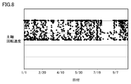
- FIG. 7 is a diagram showing the transition of diagnostic parameters after the installation of the condition monitoring device. It is assumed that a condition monitoring device is installed on 8/1.
- FIG. 8 is a diagram showing data of the spindle rotation speed of the wind power generation facility stored in SCADA. For one month (8/1 to 9/1) after the condition monitoring device was installed, the spindle speed of the windmill continued to be low, and only the effective vibration value (diagnostic parameter) when the spindle speed was low could be measured. .. Therefore, in the general method, there is a problem that the correct diagnostic standard cannot be set unless the vibration data is measured by the vibration sensor for one month or more after the condition monitoring device is installed.
- FIG. 9 is a diagram showing changes in diagnostic parameters during the adjustment period in the first embodiment.
- One month (8/1 to 9/1) after the installation of the condition monitoring device is set as the adjustment period, and the vibration effective value, which is a diagnostic parameter, is calculated from the sensing data of the sensor 905 in this adjustment period.
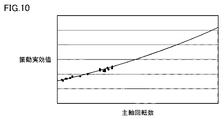
- FIG. 10 is a diagram showing a quadratic polynomial regression model in the first embodiment.
- the spindle rotation speed (characteristic data) is used by using a set of the effective vibration value (diagnosis parameter) and the spindle rotation speed (characteristic data) during the adjustment period, which is one month (8/1 to 9/1) after the installation of the state monitoring device.
- a quadratic polynomial regression model that estimates the effective vibration value (diagnosis parameter) from the characteristic data) is generated. Since the spindle speed is low during the adjustment period, a quadratic polynomial regression model is generated from the low spindle speed and the corresponding vibration effective value.
- FIG. 11 is a diagram showing estimated diagnostic parameters.
- the effective vibration value (diagnostic parameter) corresponding to the spindle speed (characteristic data) during the non-installation period can be obtained.
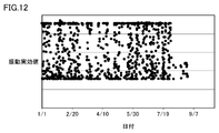
- FIG. 12 is a diagram showing an example of basic data.
- Effective vibration value (diagnostic parameter) calculated from the sensing data of the vibration sensor during the adjustment period, and effective vibration value estimated from the spindle rotation speed (characteristic data) using a quadratic polynomial regression model during the non-installation period. (Diagnostic parameters) is the basic data.
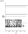
- FIG. 13 is a diagram showing an example of basic data and diagnostic criteria. As shown in FIG. 13, a first threshold value Th1 and a second threshold value Th2, which are diagnostic criteria, are set from the basic data. As described above, in the present embodiment, the diagnostic criteria can be set and the state can be changed to the operation state one month after the state monitoring device is installed.
- FIG. 14 is a diagram showing an example of basic data and diagnostic parameters during the operation period.
- the operation period will start on 9/1.
- the diagnosis is effective by comparing the effective vibration value (diagnosis parameter) obtained from the sensing data of the vibration sensor with the first threshold value Th1 and the second threshold value Th2 during the operation period.
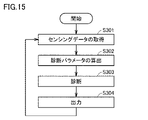
- FIG. 15 is a flowchart showing a processing procedure in an operating state in the state monitoring system of the first embodiment.
- transition to non-installation due to removal and the transition to adjustment due to state change can be performed at any time in the operating state, so it is not described in the flowchart. Furthermore, since the operational status is continued unless it is removed or the status is changed, the end of the flowchart is not described.
- step S301 during the operation period, the sensing data input unit 906 collects sensing data representing the state of the monitored device 101 output from the sensor 905 installed in the monitored device 101.
- step S302 the diagnostic parameter calculation unit 907 calculates the diagnostic parameter in the operation period based on the sensing data in the operation period.
- step S303 the diagnostic unit 908 diagnoses the state of the monitored device 101 by analyzing the diagnostic parameters calculated in step S302 using the diagnostic criteria set in the adjustment period.
- step S304 the output unit 910 outputs the diagnosis result to the status display 903.
- the diagnostic method by the diagnostic unit 908 includes a method of diagnosing the state of the monitored device 101 by comparing the diagnostic parameters and the threshold value, a method of diagnosing by clusters classified by clustering the diagnostic parameters, and an adjusted neural network. There is a method of inputting diagnostic parameters to the network and using the output of the neural network as the diagnostic result.
- FIG. 16 is a flowchart showing a diagnosis procedure in the condition monitoring system of the first embodiment.
- step S501 when the diagnostic parameter (x) is equal to or less than the first threshold value (Th1), the process proceeds to step S503.
- step S503 When the diagnostic parameter (x) exceeds the first threshold value (Th1), the process proceeds to step S502.
- step S502 when the diagnostic parameter (x) is equal to or less than the second threshold value (Th2), the process proceeds to step S504.
- step S504. When the diagnostic parameter (x) exceeds the second threshold value (Th2), the process proceeds to step S505.
- step S503 the diagnostic unit 908 determines that the monitored device 101 is in the "normal state". "Normal” is a state in which there is no abnormality in the monitored device 101.
- step S504 the diagnostic unit 908 determines that the monitored device 101 is in the "inspection required state".
- the "inspection required state” is a state in which the monitored device 101 has some sign of abnormality and needs to be inspected.
- step S505 the diagnostic unit 908 determines that the monitored device 101 is in the "stop required state".
- the "stop required state” is a state in which the monitored device is damaged when the monitored device 101 is continuously operated.
- the accuracy of diagnosis can be maintained even if the adjustment period is shortened by utilizing the data existing in the control device or the like.
- the time lag between the installation of the condition monitoring device and the start of diagnosis can be reduced, so there is a possibility that an abnormality will occur before the diagnosis is started and the abnormality will be overlooked. Can be reduced.
- FIG. 17 is a diagram showing a configuration example of the condition monitoring system according to the second embodiment.
- the condition monitoring system in the second embodiment includes a characteristic data selection unit 107 in addition to the configuration of the condition monitoring system in the first embodiment, and includes a regression model generation unit 205 in place of the regression model generation unit 105.
- the characteristic data selection unit 107 selects characteristic data whose correlation coefficient with the diagnostic parameter in the second period is equal to or higher than the threshold value among the characteristic data in the plurality of second periods. For example, suppose that when the diagnostic parameter is the effective vibration value, the spindle rotation speed, the wind direction, and the air volume are obtained as characteristic data. In the characteristic data selection unit 107, the correlation coefficient between the spindle rotation speed in the second period and the effective vibration value in the second period is equal to or higher than the threshold value, and the wind direction in the second period and the effective vibration value in the second period are used. When the correlation coefficient of is less than the threshold value and the correlation coefficient between the air volume in the second period and the effective vibration value in the second period is less than the threshold value, the spindle rotation speed is selected.
- FIG. 18 is a flowchart showing a processing procedure of the adjustment state of the state monitoring system of the second embodiment. The difference between the flowchart of the second embodiment of FIG. 18 and the flowchart of the first embodiment of FIG. 6 is that the flowchart of the second embodiment of FIG. 18 includes step S201.
- the characteristic data selection unit 107 has characteristic data in which the correlation coefficient with the diagnostic parameter in the second period (adjustment period) is equal to or higher than the threshold value among the characteristic data in the plurality of second periods (adjustment period). Is selected and output to the regression model generation unit 205.
- FIG. 19 is a diagram showing a configuration example of the condition monitoring system according to the third embodiment.
- the condition monitoring system in the third embodiment includes a regression model evaluation unit 303 in addition to the configuration of the condition monitoring system in the second embodiment.
- the regression model evaluation unit 303 obtains the evaluation value of the regression model based on the evaluation index.
- the evaluation index is a correct answer rate, a precision rate, a recall rate, an F value, a root mean square error, a root mean square error, or a coefficient of determination.
- the sensing data input unit 906 acquires the sensing data
- the diagnostic parameter calculation unit 907 calculates the diagnostic parameters
- the characteristic data input unit 104 acquires the characteristic data
- the regression model is repeated.
- FIG. 20 is a flowchart showing a processing procedure of the adjustment state of the state monitoring system of the third embodiment.
- the flowchart of the third embodiment of FIG. 20 differs from the flowchart of the second embodiment of FIG. 18 in that the flowchart of the third embodiment of FIG. 20 includes step S401 after step S105. be.
- step S401 the regression model evaluation unit 303 obtains the evaluation value of the regression model based on the evaluation index.
- step S105 When the evaluation value of the regression model is equal to or higher than the predetermined value, the process proceeds to step S105. When the evaluation value of the regression model is less than a predetermined value, the process proceeds to step S101.
- the end time of the adjustment period can be appropriately determined by evaluating the performance of the regression model. By appropriately determining the end time of the adjustment period, it is possible to reduce the risk of unnecessarily lengthening the adjustment period and the risk of making a misdiagnosis by making the adjustment period shorter than the required period.
- condition monitoring system of the fourth embodiment has a function of modifying diagnostic criteria during the operation period.
- FIG. 21 is a flowchart showing a processing procedure of the operating state of the state monitoring system of the fourth embodiment.
- step S601 during the operation period, the sensing data input unit 906 collects sensing data representing the state of the monitored device 101 output from the sensor 905 installed in the monitored device 101.
- step S602 the diagnostic parameter calculation unit 907 calculates the diagnostic parameter in the operation period based on the sensing data in the operation period.
- step S603 the diagnostic unit 908 determines the status of the monitored device 101 by analyzing the diagnostic parameters calculated in step S602 using the diagnostic criteria set in the adjustment period or the diagnostic criteria modified in the operation period. Diagnose.
- step S604 the output unit 910 outputs the diagnosis result to the status display 903.
- step S605 the characteristic data input unit 104 acquires characteristic data representing the characteristics of the monitored device 101 during the operation period from the logger 103 included in the monitored device 101.
- step S606 the regression model generation unit 205 modifies the regression model representing the relationship between the characteristic data and the diagnostic parameters by using the characteristic data in the adjustment period and the operation period and the diagnostic parameters in the adjustment period and the operation period.
- step S607 the diagnostic parameter estimation unit 106 re-estimates the diagnostic parameters in the non-installed period corresponding to the characteristic data in the non-installed period using the modified regression model.
- step S608 the diagnostic standard setting unit 109 corrects the diagnostic standard from the basic data consisting of the diagnostic parameter of the non-installed period, the diagnostic parameter of the adjustment period, and the diagnostic parameter of the operating period.
Landscapes
- Physics & Mathematics (AREA)
- Engineering & Computer Science (AREA)
- General Physics & Mathematics (AREA)
- Automation & Control Theory (AREA)
- Artificial Intelligence (AREA)
- Evolutionary Computation (AREA)
- Mathematical Physics (AREA)
- Testing And Monitoring For Control Systems (AREA)
Abstract
A diagnosis parameter calculation unit (907) calculates a diagnosis parameter during a second interval on the basis of sensing data from the second interval. A characteristic data input unit (104) obtains characteristic data which expresses the characteristics of a monitoring target device during a first interval and the second interval from a logger included in the monitoring target device. A regression model generation unit (105) generates a regression model which expresses the relationship between the characteristic data and the diagnosis parameter by using the characteristic data in the second interval and the diagnosis parameter in the second interval. A diagnosis parameter estimation unit (106) estimates a diagnosis parameter during the first interval, which corresponds to the characteristic data in the first interval, by using the regression model. A diagnosis standard setting unit (109) sets a diagnosis standard by using the diagnosis parameters in the first interval and the second interval.
Description
本発明は、状態監視装置および状態監視方法に関し、特に回転機器などの状態を監視する状態監視装置および状態監視方法に関する。
The present invention relates to a condition monitoring device and a condition monitoring method, and more particularly to a condition monitoring device and a condition monitoring method for monitoring the state of rotating equipment and the like.
従来から、機器の状態を表わす測定データに基づいて診断基準を設定し、その診断基準に従って、機器の状態を診断する装置が知られている。
Conventionally, there has been known a device that sets a diagnostic standard based on measurement data indicating the state of a device and diagnoses the state of the device according to the diagnostic standard.
たとえば、特許文献1に記載されている状態監視システムは、風力発電装置に設けられた機器の異常を診断する状態監視システムであって、機器の状態を示す測定データと風力発電装置の運転条件を示す運転条件データとを計測する複数のセンサを含み、測定データから診断パラメータを算出するモニタ装置と、情報を記憶する記憶部を含み、機器の異常を診断するための第1のしきい値を設定し、第1のしきい値に基づいて機器の異常を診断する監視側制御装置と、情報を表示する表示部を含み、機器の状態を監視する監視用端末装置とを備える。監視側制御装置は、モニタ装置および監視用端末装置の各々と通信回線によって結合されている。基礎データを収集する第1の期間と、第1のしきい値を設定する第2の期間と、機器の異常を診断する第3の期間とが監視用端末装置によって順次設定される。第1の期間では、モニタ装置によって計測および算出された測定データ、運転条件データ、および診断パラメータが記憶部に格納されて表示部に表示され、監視用端末装置を用いて診断運転条件が設定される。第2の期間では、風力発電装置の運転条件が診断運転条件を満たす場合に計測された測定データから算出された診断パラメータが記憶部に格納され、監視側制御装置は記憶部に格納された診断パラメータに基づいて第1のしきい値を生成する。第3の期間では、風力発電装置の運転条件が診断運転条件を満たす場合に計測された測定データから算出された診断パラメータが記憶部に格納され、監視側制御装置は記憶部に格納された診断パラメータと第1のしきい値とを比較し、診断パラメータが第1のしきい値を超えている場合は機器に異常が発生したと判別され、その判別結果が記憶部に格納されて表示部に表示される。
For example, the condition monitoring system described in Patent Document 1 is a condition monitoring system for diagnosing an abnormality of a device provided in a wind power generation device, and measures measurement data indicating the state of the device and operating conditions of the wind power generation device. A first threshold for diagnosing an abnormality in a device, including a monitoring device that includes a plurality of sensors that measure the indicated operating condition data, a monitoring device that calculates diagnostic parameters from the measurement data, and a storage unit that stores information. It includes a monitoring side control device that is set and diagnoses an abnormality of the device based on the first threshold value, and a monitoring terminal device that includes a display unit for displaying information and monitors the state of the device. The monitoring side control device is coupled to each of the monitoring device and the monitoring terminal device by a communication line. A first period for collecting basic data, a second period for setting a first threshold value, and a third period for diagnosing an abnormality of the device are sequentially set by the monitoring terminal device. In the first period, the measurement data measured and calculated by the monitoring device, the operating condition data, and the diagnostic parameters are stored in the storage unit and displayed on the display unit, and the diagnostic operating conditions are set using the monitoring terminal device. To. In the second period, the diagnostic parameters calculated from the measurement data measured when the operating conditions of the wind power generator satisfy the diagnostic operating conditions are stored in the storage unit, and the monitoring side control device stores the diagnostics stored in the storage unit. Generate a first threshold based on the parameters. In the third period, the diagnostic parameters calculated from the measurement data measured when the operating conditions of the wind power generator satisfy the diagnostic operating conditions are stored in the storage unit, and the monitoring side control device stores the diagnostics stored in the storage unit. The parameter is compared with the first threshold value, and if the diagnostic parameter exceeds the first threshold value, it is determined that an abnormality has occurred in the device, and the determination result is stored in the storage unit and displayed. Is displayed in.
特許文献1では、診断基準を設定するためにデータが必要である。
状態監視装置を設置してから、データに基づいて診断基準を設定する調整期間には、診断を実施することができない。したがって、調整期間は短い方が好ましい。 In Patent Document 1, data is required to set diagnostic criteria.
Diagnosis cannot be performed during the adjustment period in which the diagnostic criteria are set based on the data after the condition monitoring device is installed. Therefore, it is preferable that the adjustment period is short.
しかしながら、監視対象機器が、運用期間において、調整期間と異なる状態になると、例え正常な状態であっても、状態監視システムは監視対象機器に異常が発生したと判断することがある。よって、監視対象機器のできるだけ多くの状態に基づいて、診断基準が設定されるように、調整期間を長くする必要がある。
However, if the monitored device is in a state different from the adjustment period during the operation period, the condition monitoring system may determine that an abnormality has occurred in the monitored device even if it is in a normal state. Therefore, it is necessary to lengthen the adjustment period so that the diagnostic criteria are set based on as many conditions as possible of the monitored device.
上記理由のため、従来では、調整期間と診断精度とは、トレードオフとなる課題がある。
For the above reasons, there has been a trade-off between the adjustment period and the diagnostic accuracy in the past.
それゆえに、本発明の目的は、調整期間が短く、かつ高精度の診断が可能な状態監視装置および状態監視方法を提供することである。
Therefore, an object of the present invention is to provide a condition monitoring device and a condition monitoring method capable of short adjustment period and highly accurate diagnosis.
本発明は、監視対象機器と接続可能な状態監視装置である。監視対象機器が状態監視装置に接続される前の第1の期間と、監視対象機器が状態監視装置に接続された後であって、監視対象機器の異常の診断の準備段階の第2の期間と、監視対象機器が状態監視装置に接続された後であって、監視対象機器の異常の診断を実施する第3の期間とが設定される。状態監視装置は、第2の期間および第3の期間において、監視対象機器に含まれるセンサから、監視対象機器の状態を表わすセンシングデータを取得するセンシングデータ入力部と、第2の期間および第3の期間におけるセンシングデータに基づいて、第2の期間および第3の期間における診断パラメータを算出する診断パラメータ算出部と、監視対象機器に含まれるロガーから、第1の期間および第2の期間における監視対象機器の特性を表わす特性データを取得する特性データを取得する特性データ入力部と、第2の期間における特性データおよび第2の期間における診断パラメータを用いて、特性データと診断パラメータとの関係を表わす回帰モデルを生成する回帰モデル生成部と、回帰モデルを用いて、第1の期間における特性データに対応する第1の期間における診断パラメータを推定する診断パラメータ推定部と、第1の期間および第2の期間における診断パラメータを用いて、診断基準を設定する診断基準設定部と、第3の期間における診断パラメータと、診断基準とに基づいて、監視対象機器の異常を診断する診断部とを備える。
The present invention is a condition monitoring device that can be connected to a monitored device. The first period before the monitored device is connected to the status monitoring device and the second period after the monitored device is connected to the status monitoring device and in the preparatory stage for diagnosing the abnormality of the monitored device. And after the monitored device is connected to the condition monitoring device, a third period for diagnosing the abnormality of the monitored device is set. The state monitoring device includes a sensing data input unit that acquires sensing data indicating the state of the monitored device from a sensor included in the monitored device in the second period and the third period, and a second period and a third period. Monitoring in the first period and the second period from the diagnostic parameter calculation unit that calculates the diagnostic parameters in the second period and the third period based on the sensing data in the period of 1 and the logger included in the monitored device. Acquiring characteristic data representing the characteristics of the target device Using the characteristic data input unit that acquires characteristic data, the characteristic data in the second period, and the diagnostic parameters in the second period, the relationship between the characteristic data and the diagnostic parameters can be determined. A regression model generator that generates the regression model to be represented, a diagnostic parameter estimation unit that estimates diagnostic parameters in the first period corresponding to the characteristic data in the first period using the regression model, and a first period and a first period. It includes a diagnostic criteria setting unit that sets diagnostic criteria using the diagnostic parameters in the second period, and a diagnostic criteria unit that diagnoses abnormalities in the monitored device based on the diagnostic parameters in the third period and the diagnostic criteria. ..
本発明は、監視対象機器と接続可能な状態監視装置における状態監視方法である。監視対象機器が状態監視装置に接続される前の第1の期間と、監視対象機器が状態監視装置に接続された後であって、監視対象機器の異常の診断の準備段階の第2の期間と、監視対象機器が状態監視装置に接続された後であって、監視対象機器の異常の診断を実施する第3の期間とが設定される。状態監視方法は、状態監視装置が、第2の期間において、監視対象機器に含まれるセンサから、監視対象機器の状態を表わすセンシングデータを取得するステップと、状態監視装置が、第2の期間におけるセンシングデータに基づいて、第2の期間おける診断パラメータを算出するステップと、状態監視装置が、監視対象機器に含まれるロガーから、第1の期間および第2の期間における監視対象機器の特性を表わす特性データを取得する特性データを取得するステップと、状態監視装置が、第2の期間における特性データおよび第2の期間における診断パラメータを用いて、特性データと診断パラメータとの関係を表わす回帰モデルを生成するステップと、状態監視装置が、回帰モデルを用いて、第1の期間における特性データに対応する第1の期間における診断パラメータを推定するステップと、状態監視装置が、第1の期間および第2の期間における診断パラメータを用いて、診断基準を設定するステップと、状態監視装置が、第3の期間において、監視対象機器に含まれるセンサから、監視対象機器の状態を表わすセンシングデータを取得するステップと、状態監視装置が、第3の期間におけるセンシングデータに基づいて、第3の期間おける診断パラメータを算出するステップと、状態監視装置が、第3の期間における診断パラメータと、診断基準とに基づいて、監視対象機器の異常を診断するステップとを備える。
The present invention is a condition monitoring method in a condition monitoring device that can be connected to a monitored device. The first period before the monitored device is connected to the status monitoring device and the second period after the monitored device is connected to the status monitoring device and in the preparatory stage for diagnosing the abnormality of the monitored device. And after the monitored device is connected to the condition monitoring device, a third period for diagnosing the abnormality of the monitored device is set. The condition monitoring method includes a step in which the condition monitoring device acquires sensing data representing the state of the monitored device from a sensor included in the monitored device in the second period, and a state monitoring device in the second period. The step of calculating the diagnostic parameters in the second period based on the sensing data, and the condition monitoring device expresses the characteristics of the monitored device in the first period and the second period from the logger included in the monitored device. Acquiring characteristic data The step of acquiring characteristic data and the condition monitoring device use the characteristic data in the second period and the diagnostic parameters in the second period to create a regression model that represents the relationship between the characteristic data and the diagnostic parameters. The step to generate, the step in which the condition monitoring device estimates the diagnostic parameters in the first period corresponding to the characteristic data in the first period using the regression model, and the condition monitoring device in the first period and the first period. In the step of setting the diagnostic criteria using the diagnostic parameters in the second period, and in the third period, the condition monitoring device acquires sensing data indicating the state of the monitored device from the sensor included in the monitored device. The step, the step in which the condition monitoring device calculates the diagnostic parameters in the third period based on the sensing data in the third period, and the condition monitoring device in the diagnostic parameters and the diagnostic criteria in the third period. Based on this, a step of diagnosing an abnormality in the monitored device is provided.
本発明によれば、診断の精度を維持したまま調整期間を短縮することができる。よって、状態監視装置を設置してから、監視対象機器の診断を実施する運用状態に移行するまでの期間を短縮することができる。
According to the present invention, the adjustment period can be shortened while maintaining the accuracy of diagnosis. Therefore, it is possible to shorten the period from the installation of the condition monitoring device to the transition to the operating state in which the monitored device is diagnosed.
以下、実施の形態について、図面を参照して説明する。
[第1の実施形態]
(状態監視システムの構成)
図1は、一般的な状態監視システムの構成例を表わす図である。図2は、第1の実施形態における状態監視システムの構成例を表わす図である。 Hereinafter, embodiments will be described with reference to the drawings.
[First Embodiment]
(Configuration of condition monitoring system)
FIG. 1 is a diagram showing a configuration example of a general condition monitoring system. FIG. 2 is a diagram showing a configuration example of the condition monitoring system according to the first embodiment.
図1に示すように、一般的な状態監視システムは、監視対象機器901と、状態監視装置902と、状態表示器903と、ストレージ904とを備える。監視対象機器901は、センサ905を備える。状態監視装置902は、センシングデータ入力部906と、診断パラメータ算出部907と、診断部908と、診断基準設定部909と、出力部910とを備える。
As shown in FIG. 1, a general condition monitoring system includes a monitored device 901, a condition monitoring device 902, a status display 903, and a storage 904. The monitored device 901 includes a sensor 905. The condition monitoring device 902 includes a sensing data input unit 906, a diagnostic parameter calculation unit 907, a diagnostic unit 908, a diagnostic standard setting unit 909, and an output unit 910.
図2に示すように、本実施の形態の状態監視システムは、監視対象機器101と、状態監視装置102と、状態表示器903と、ストレージ904とを備える。
As shown in FIG. 2, the state monitoring system of the present embodiment includes a monitoring target device 101, a state monitoring device 102, a state display 903, and a storage 904.
監視対象機器101が、監視対象機器901と相違する点は、監視対象機器101が、さらに、ロガー103を備える点である。状態監視装置102が、状態監視装置902と相違する点は、状態監視装置102が、さらに、特性データ入力部104と、回帰モデル生成部105と、診断パラメータ推定部106とを備える点である。
The difference between the monitored device 101 and the monitored device 901 is that the monitored device 101 further includes a logger 103. The state monitoring device 102 differs from the state monitoring device 902 in that the state monitoring device 102 further includes a characteristic data input unit 104, a regression model generation unit 105, and a diagnostic parameter estimation unit 106.
本実施の形態では、一般的な状態監視ステムでは、利用しないロガー103の情報を活用することによって、診断精度を維持しつつ調整期間を短縮することができる。
In the present embodiment, in the general condition monitoring stem, the adjustment period can be shortened while maintaining the diagnostic accuracy by utilizing the information of the logger 103 which is not used.
監視対象機器101は、状態監視装置102が状態監視および診断を行う対象の機器である。監視対象機器101は、例えば、風力発電設備、生産設備、または工作機械などである。
The monitored device 101 is a device to be monitored and diagnosed by the state monitoring device 102. The monitored device 101 is, for example, a wind power generation facility, a production facility, a machine tool, or the like.
センサ905は、監視対象機器101に設置される。センサ905は、監視対象機器101の加速度、温度、または電流などの物理量を計測する。センサ905は、例えば、加速度センサ、温度センサ、または近接センサなどである。
The sensor 905 is installed in the monitored device 101. The sensor 905 measures physical quantities such as acceleration, temperature, or current of the monitored device 101. The sensor 905 is, for example, an acceleration sensor, a temperature sensor, a proximity sensor, or the like.
ストレージ904は、状態監視装置102に入力されたデータなどを保存する。ストレージ904は、状態監視装置102に内蔵された不揮発性メモリ、またはインターネットによって接続されたサーバなどである。
The storage 904 stores data and the like input to the condition monitoring device 102. The storage 904 is a non-volatile memory built in the condition monitoring device 102, a server connected by the Internet, or the like.
状態表示器903は、状態監視装置102の診断結果を表示する機器である。状態表示器903は、たとえば、監視対象機器101に設置される表示盤(表示灯)である。
The status display 903 is a device that displays the diagnosis result of the status monitoring device 102. The status indicator 903 is, for example, a display panel (indicator lamp) installed in the monitored device 101.
ロガー103は、監視対象機器101の特性データを保持している機器または媒体である。ロガー103は、必ずしも、監視対象機器101に内蔵されている必要はない。ロガー103は、例えば、制御装置(PLC(Programmable Logic Controller)またはSCADA(Supervisory Control And Data Acquisition)のメモリなど)、または他の状態監視装置などである。
The logger 103 is a device or medium that holds the characteristic data of the monitored device 101. The logger 103 does not necessarily have to be built in the monitored device 101. The logger 103 is, for example, a control device (such as a memory of PLC (Programmable Logic Controller) or SCADA (Supervisory Control And Data Acquisition)), or another state monitoring device.
(状態監視の状態遷移)
図3は、第1の実施形態の状態監視システムの状態遷移を表わす図である。 (State transition of state monitoring)
FIG. 3 is a diagram showing a state transition of the state monitoring system of the first embodiment.
図3は、第1の実施形態の状態監視システムの状態遷移を表わす図である。 (State transition of state monitoring)
FIG. 3 is a diagram showing a state transition of the state monitoring system of the first embodiment.
状態監視システムには、3つの状態がある。
未設置状態は、状態監視装置102が設置されておらず、状態監視装置102と監視対象機器101とが接続されていない状態である。 The condition monitoring system has three states.
The non-installed state is a state in which thestate monitoring device 102 is not installed and the state monitoring device 102 and the monitored device 101 are not connected.
未設置状態は、状態監視装置102が設置されておらず、状態監視装置102と監視対象機器101とが接続されていない状態である。 The condition monitoring system has three states.
The non-installed state is a state in which the
調整状態は、状態監視装置102と監視対象機器101とが接続され、状態監視装置102が、監視対象機器101のセンシングデータおよび特性データを収集し、診断基準を設定している状態である。調整状態では、診断は行われない。
The adjustment state is a state in which the state monitoring device 102 and the monitored device 101 are connected, and the state monitoring device 102 collects sensing data and characteristic data of the monitored device 101 and sets diagnostic criteria. In the adjusted state, no diagnosis is made.
運用状態は、状態監視装置102と監視対象機器101とが接続され、状態監視装置102が監視対象機器101のセンシングデータを収集して、設定された診断基準に基づいて診断が行われている状態である。
The operating state is a state in which the state monitoring device 102 and the monitored device 101 are connected, the state monitoring device 102 collects the sensing data of the monitored device 101, and the diagnosis is performed based on the set diagnostic criteria. Is.
設置とは、状態監視装置102を設置して、状態監視装置102と、監視対象機器101とが接続された状態である。設置によって、状態監視装置102は、未設置状態から調整状態に移行する。
Installation is a state in which the condition monitoring device 102 is installed and the condition monitoring device 102 and the monitored device 101 are connected to each other. Depending on the installation, the condition monitoring device 102 shifts from the non-installed state to the adjusted state.
撤去とは、状態監視装置102と監視対象機器101との接続を解除して、状態監視装置102を撤去することである。これによって、状態監視装置102は、調整状態または運用状態から未設置状態に移行する。
Removal means removing the state monitoring device 102 by disconnecting the connection between the state monitoring device 102 and the monitored device 101. As a result, the condition monitoring device 102 shifts from the adjusted state or the operating state to the non-installed state.
診断基準の設定によって、状態監視装置102は、調整状態から運用状態に移行する。
状態変化とは、状態監視装置102とその周辺の構成に変化があり、診断基準が不適切になることである。状態変化には、例えば、監視対象機器101のメンテナンス、またはセンサの交換などがある。状態変化によって、状態監視装置102は、運用状態から調整状態に移行する。 Depending on the setting of the diagnostic criteria, thecondition monitoring device 102 shifts from the adjusted state to the operating state.
The state change means that there is a change in the configuration of thestate monitoring device 102 and its surroundings, and the diagnostic criteria become inappropriate. The state change includes, for example, maintenance of the monitored device 101 or replacement of a sensor. Due to the state change, the state monitoring device 102 shifts from the operating state to the adjusting state.
状態変化とは、状態監視装置102とその周辺の構成に変化があり、診断基準が不適切になることである。状態変化には、例えば、監視対象機器101のメンテナンス、またはセンサの交換などがある。状態変化によって、状態監視装置102は、運用状態から調整状態に移行する。 Depending on the setting of the diagnostic criteria, the
The state change means that there is a change in the configuration of the
本実施の形態では、未設置状態にある期間を第1の期間、調整状態にある期間を第2の期間、運用状態にある期間を第3の期間とする。すなわち、状態監視装置102は、監視対象機器101が状態監視装置102に接続される前の第1の期間と、監視対象機器101が状態監視装置102に接続された後であって、監視対象機器101の異常の診断のための調整段階の第2の期間と、監視対象機器101が状態監視装置102に接続された後であって、監視対象機器101の異常の診断を実施する第3の期間とが設定される。
In the present embodiment, the period in the non-installed state is the first period, the period in the adjusted state is the second period, and the period in the operational state is the third period. That is, the state monitoring device 102 is the monitoring target device during the first period before the monitoring target device 101 is connected to the state monitoring device 102 and after the monitoring target device 101 is connected to the state monitoring device 102. The second period of the adjustment stage for diagnosing the abnormality of the 101, and the third period of performing the diagnosis of the abnormality of the monitored device 101 after the monitored device 101 is connected to the condition monitoring device 102. And are set.
本実施の形態では、調整状態にある期間(第2の期間)を短縮することによって、早期に運用状態へ移行できるようにする。
In the present embodiment, by shortening the period in the adjustment state (second period), it is possible to shift to the operation state at an early stage.
再び、図2を参照して、センシングデータ入力部906は、第2の期間(調整期間)および第3の期間(運用期間)において、監視対象機器101に含まれるセンサ905から、監視対象機器101の状態を表わすセンシングデータを取得する。
Again, referring to FIG. 2, the sensing data input unit 906 is subjected to the monitoring target device 101 from the sensor 905 included in the monitoring target device 101 in the second period (adjustment period) and the third period (operation period). Acquires sensing data representing the state of.
診断パラメータ算出部907は、第2の期間(調整期間)および第3の期間(運用期間)におけるセンシングデータに基づいて、第2の期間(調整期間)および第3の期間(運用期間)における診断パラメータを算出する。
The diagnostic parameter calculation unit 907 diagnoses in the second period (adjustment period) and the third period (operation period) based on the sensing data in the second period (adjustment period) and the third period (operation period). Calculate the parameters.
特性データ入力部104は、監視対象機器101に含まれるロガー103から、第1の期間(未設置期間)および第2の期間(調整期間)における監視対象機器の特性を表わす特性データを取得する。
The characteristic data input unit 104 acquires characteristic data representing the characteristics of the monitored device in the first period (non-installed period) and the second period (adjustment period) from the logger 103 included in the monitored device 101.
回帰モデル生成部105は、第2の期間(調整期間)における時刻tiの特性データおよび第2の期間(調整期間)における時刻tiの診断パラメータを用いて、特性データと診断パラメータとの関係を表わす回帰モデルを生成する。ただし、i=1~nである。
The regression model generation unit 105 uses the characteristic data of time ti in the second period (adjustment period) and the diagnostic parameter of time ti in the second period (adjustment period) to represent the relationship between the characteristic data and the diagnostic parameter. Generate a regression model. However, i = 1 to n.
診断パラメータ推定部106は、回帰モデルを用いて、第1の期間(未設置期間)における特性データに対応する第1の期間(未設置期間)における診断パラメータを推定する。
The diagnostic parameter estimation unit 106 estimates the diagnostic parameters in the first period (non-installed period) corresponding to the characteristic data in the first period (non-installed period) using the regression model.
診断基準設定部109は、第1の期間(未設置期間)および第2の期間(調整期間)における診断パラメータを用いて、診断基準を設定する。
The diagnostic standard setting unit 109 sets diagnostic criteria using the diagnostic parameters in the first period (non-installed period) and the second period (adjustment period).
診断部908は、第3の期間(運用期間)における診断パラメータと、設定された診断基準とに基づいて、監視対象機器101の異常を診断する。
The diagnostic unit 908 diagnoses an abnormality in the monitored device 101 based on the diagnostic parameters in the third period (operation period) and the set diagnostic criteria.
出力部910は、診断部908の診断結果を出力する。
(調整データ)
図4は、一般的な状態監視システムにおけるデータの活用と、本実施の形態の状態監視システムにおけるデータの活用とを比較した図である。 Theoutput unit 910 outputs the diagnosis result of the diagnosis unit 908.
(Adjustment data)
FIG. 4 is a diagram comparing the utilization of data in a general condition monitoring system and the utilization of data in the condition monitoring system of the present embodiment.
(調整データ)
図4は、一般的な状態監視システムにおけるデータの活用と、本実施の形態の状態監視システムにおけるデータの活用とを比較した図である。 The
(Adjustment data)
FIG. 4 is a diagram comparing the utilization of data in a general condition monitoring system and the utilization of data in the condition monitoring system of the present embodiment.
一般的な状態監視システムでは、診断基準設定部909による診断基準の設定に用いられる基礎データは、第2の期間(調整期間)におけるセンサ905が出力するセンシングデータに基づいて算出された診断パラメータである。
In a general condition monitoring system, the basic data used for setting the diagnostic criteria by the diagnostic criteria setting unit 909 is the diagnostic parameters calculated based on the sensing data output by the sensor 905 in the second period (adjustment period). be.
本実施の形態の状態監視システムでは、診断基準設定部109による診断基準の設定に用いられる基礎データは、第2の期間(調整期間)におけるセンサ905が出力するセンシングデータに基づいて算出された診断パラメータに加えて、第1の期間(未設置期間)における特性データから推定される第1の期間(未設置期間)における診断パラメータである。
In the state monitoring system of the present embodiment, the basic data used for setting the diagnostic criteria by the diagnostic criteria setting unit 109 is a diagnosis calculated based on the sensing data output by the sensor 905 in the second period (adjustment period). In addition to the parameters, it is a diagnostic parameter in the first period (non-installed period) estimated from the characteristic data in the first period (non-installed period).
一般的な状態監視システムの調整手順では、調整期間においてセンサ905が出力するセンシングデータに基づいて算出された診断パラメータのみを基礎データとして用いるため、次のような課題がある。
In the adjustment procedure of a general condition monitoring system, only the diagnostic parameters calculated based on the sensing data output by the sensor 905 during the adjustment period are used as basic data, so that there are the following problems.
第1に、正しい診断基準を設定するためには、多くのセンシングデータが必要である。その結果、調整状態から運用状態への遷移に必要な期間(調整期間)が長い。
First, a lot of sensing data is needed to set the correct diagnostic criteria. As a result, the period required for the transition from the adjustment state to the operation state (adjustment period) is long.
第2に、調整期間を無理に短縮すると、診断基準の設定のための基礎データが減少する。その結果、正しい診断基準を設定できない可能性が高くなる。
Second, if the adjustment period is forcibly shortened, the basic data for setting diagnostic criteria will decrease. As a result, there is a high possibility that the correct diagnostic criteria cannot be set.
第3に、調整期間中の監視対象機器の状態に偏りがあると、基礎データに偏りが生じる。その結果、正しい診断基準が設定できない。
Third, if the state of the monitored device during the adjustment period is biased, the basic data will be biased. As a result, correct diagnostic criteria cannot be set.
第4に、基礎データが監視対象機器101の多様な状態のうちどれだけを網羅できたかを評価する手段が少ない。その結果、適切な調整期間の設定が難しい。
Fourth, there are few means to evaluate how much the basic data can cover the various states of the monitored device 101. As a result, it is difficult to set an appropriate adjustment period.
本実施の形態では、未設置期間においてロガー103に保持されていた特性データから推定される未設置期間における診断パラメータを基礎データに追加することによって、上記の課題を解決することができる。
In the present embodiment, the above problem can be solved by adding the diagnostic parameters in the non-installation period estimated from the characteristic data held in the logger 103 in the non-installation period to the basic data.
第1および第2の問題について、本実施の形態では、調整期間においてセンサ905が出力するセンシングデータに基づいて算出された診断パラメータが少なくても、未設置期間における推定された診断パラメータを基礎データに追加することによって、十分な量の基礎データが確保できる。これによって、短い調整期間で正しい診断基準を設定できる。
Regarding the first and second problems, in the present embodiment, even if the diagnostic parameters calculated based on the sensing data output by the sensor 905 during the adjustment period are small, the estimated diagnostic parameters during the non-installation period are used as basic data. By adding to, a sufficient amount of basic data can be secured. This allows the correct diagnostic criteria to be set in a short adjustment period.
第3の問題について、本実施の形態では、調整期間中の監視対象機器の状態に偏りがあった場合でも、未設置期間の診断パラメータを推定して、基礎データに加えることによって、基礎データの偏りを低減できる。これによって、正しい診断基準を設定できる。
Regarding the third problem, in the present embodiment, even if the state of the monitored device during the adjustment period is biased, the diagnostic parameters of the non-installed period are estimated and added to the basic data to obtain the basic data. Bias can be reduced. This allows the correct diagnostic criteria to be set.
第4の問題について、本実施の形態では、回帰モデルが正確ならば、ロガーに蓄積された特性データから十分な量の診断パラメータを推定して、基礎データに加えることができる。これによって、回帰モデルの性能を評価することで、適切な時期に調整期間を終えることができる。
Regarding the fourth problem, in the present embodiment, if the regression model is accurate, a sufficient amount of diagnostic parameters can be estimated from the characteristic data accumulated in the logger and added to the basic data. This allows the adjustment period to be completed at an appropriate time by evaluating the performance of the regression model.
(調整の手順)
図5は、一般的な状態監視システムの調整状態における処理手順を表わすフローチャートである。図6は、第1の実施形態の状態監視システムの調整状態における処理手順を表わすフローチャートである。撤去による未設置状態への遷移は、調整状態中のいつでも行えるため、これらのフローチャートには記載されていない。 (Adjustment procedure)
FIG. 5 is a flowchart showing a processing procedure in the adjustment state of a general condition monitoring system. FIG. 6 is a flowchart showing a processing procedure in the adjusted state of the state monitoring system of the first embodiment. The transition to the non-installed state due to removal can be performed at any time during the adjustment state, so it is not described in these flowcharts.
図5に示すように、一般的な状態監視システムの調整状態の処理手順は、ステップS101、S102、およびS106を備える。図6に示すように、本実施の形態の状態監視システムの調整状態の処理手順は、ステップS101~S106を備える。
As shown in FIG. 5, the adjustment state processing procedure of a general condition monitoring system includes steps S101, S102, and S106. As shown in FIG. 6, the procedure for processing the adjusted state of the state monitoring system of the present embodiment includes steps S101 to S106.
図6を参照して、ステップS101において、センシングデータ入力部906は、調整期間において、監視対象機器101に設置したセンサ905から出力される監視対象機器101の状態を表わすセンシングデータを収集する(データ計測)。センサ905のセンシングデータは、例えば、加速度センサ、電流センサ、電圧計、カラーセンサ、方位センサ、風速センサ、流量センサ、圧力センサ、または近接センサのデータである。
With reference to FIG. 6, in step S101, the sensing data input unit 906 collects sensing data representing the state of the monitored device 101 output from the sensor 905 installed in the monitored device 101 during the adjustment period (data). measurement). The sensing data of the sensor 905 is, for example, data of an acceleration sensor, a current sensor, a voltmeter, a color sensor, an azimuth sensor, a wind speed sensor, a flow rate sensor, a pressure sensor, or a proximity sensor.
ステップS102において、診断パラメータ算出部907は、調整期間におけるセンシングデータに基づいて、調整期間における診断パラメータを算出する。診断パラメータは、センサ905の検出データそのものだけでなく、センサ905の検出データの実効値、変調値、平均値、中央値、尖度、歪度などの統計量、電流値と定格電圧とを乗算して求めた電力量、監視対象機器101に含まれる搬送機の複数箇所に設置された近接センサの入力の時間差と、これらの近接センサ間の距離から求めた搬送物の速度などの物理量である。
In step S102, the diagnostic parameter calculation unit 907 calculates the diagnostic parameter in the adjustment period based on the sensing data in the adjustment period. The diagnostic parameters are not only the detection data of the sensor 905 itself, but also the effective value, modulation value, average value, median value, sharpness, distortion, and other statistics of the detection data of the sensor 905, and the current value multiplied by the rated voltage. It is a physical quantity such as the amount of electric power obtained in the above process, the time difference between the inputs of the proximity sensors installed at a plurality of locations of the conveyor included in the monitored device 101, and the speed of the conveyed object obtained from the distance between these proximity sensors. ..
ステップS103において、特性データ入力部104は、監視対象機器101に含まれるロガー103から、未設置期間および調整期間における監視対象機器101の特性を表わす特性データを取得する。監視対象機器101の特性データには、監視対象機器の圧力、温度、回転速度、電流値、流量、またはメンテナンス情報などがある。監視対象機器101が風力発電設備の場合における特性データには、風向、風速、天気、または気圧などがある。監視対象機器101が工作機械における特性データには、加工品の種類、加工工程の種類、工具情報、または材料の種類などがある。
In step S103, the characteristic data input unit 104 acquires characteristic data representing the characteristics of the monitored device 101 during the non-installation period and the adjustment period from the logger 103 included in the monitored device 101. The characteristic data of the monitored device 101 includes pressure, temperature, rotation speed, current value, flow rate, maintenance information, and the like of the monitored device. The characteristic data when the monitored device 101 is a wind power generation facility includes wind direction, wind speed, weather, atmospheric pressure, and the like. The characteristic data of the machine tool whose monitored device 101 is a machine tool includes a type of machined product, a type of machining process, tool information, a type of material, and the like.
ステップS104において、回帰モデル生成部105は、調整期間における特性データおよび調整期間における診断パラメータを用いて、特性データと診断パラメータとの関係を表わす回帰モデルを生成する。回帰モデルとは、単回帰モデル(単回帰式)、重回帰モデル(重回帰式)、順伝播型ニューラルネットワーク、またはRBF(Radial Basis Function)ネットワークなどの各種ニューラルネットワークである。
In step S104, the regression model generation unit 105 generates a regression model showing the relationship between the characteristic data and the diagnostic parameters by using the characteristic data in the adjustment period and the diagnostic parameters in the adjustment period. The regression model is various neural networks such as a simple regression model (single regression equation), a multiple regression model (multiple regression equation), a feedforward neural network, or an RBF (Radial Basis Function) network.
ステップS105において、診断パラメータ推定部106は、回帰モデルを用いて、未設置期間における特性データに対応する未設置期間における診断パラメータを推定する。
In step S105, the diagnostic parameter estimation unit 106 estimates the diagnostic parameters in the non-installed period corresponding to the characteristic data in the non-installed period using the regression model.
ステップS106において、診断基準設定部109は、未設置期間の診断パラメータと調整期間の診断パラメータとからなる基礎データから、診断基準を作成する。診断基準は、閾値、または調整済みニューラルネットワークである。閾値は、たとえば、基礎データの平均値に基礎データの標準偏差の定数倍(例えば3倍)を加えた値である。
In step S106, the diagnostic standard setting unit 109 creates a diagnostic standard from basic data including the diagnostic parameter of the non-installed period and the diagnostic parameter of the adjustment period. Diagnostic criteria are thresholds, or adjusted neural networks. The threshold value is, for example, a value obtained by adding a constant multiple (for example, 3 times) of the standard deviation of the basic data to the average value of the basic data.
(調整の具体例)
調整の具体例として、監視対象機器101が風力発電設備の場合の一例を示す。風力発電設備内の増速機に振動センサが設置されている。 (Specific example of adjustment)
As a specific example of the adjustment, an example in the case where the monitoreddevice 101 is a wind power generation facility is shown. A vibration sensor is installed in the speed increaser in the wind power generation facility.
調整の具体例として、監視対象機器101が風力発電設備の場合の一例を示す。風力発電設備内の増速機に振動センサが設置されている。 (Specific example of adjustment)
As a specific example of the adjustment, an example in the case where the monitored
ステップS101において、センシングデータ入力部906は、調整期間において、監視対象機器101に設置した振動センサから出力される監視対象機器101の振動状態を表わす振動データを収集する。
In step S101, the sensing data input unit 906 collects vibration data representing the vibration state of the monitored device 101 output from the vibration sensor installed in the monitored device 101 during the adjustment period.
ステップS102において、診断パラメータ算出部907は、調整期間における振動データから、調整期間における振動実効値を診断パラメータとして算出する。
In step S102, the diagnostic parameter calculation unit 907 calculates the effective vibration value in the adjustment period as a diagnostic parameter from the vibration data in the adjustment period.
ステップS103において、特性データ入力部104は、監視対象機器101に含まれるロガー103から、未設置期間および調整期間における風力発電設備の制御装置内に保存されている主軸回転速度を風力発電設備の特性データとして取得する。
In step S103, the characteristic data input unit 104 determines from the logger 103 included in the monitored device 101 the characteristics of the wind power generation facility the spindle rotation speed stored in the control device of the wind power generation facility during the non-installation period and the adjustment period. Get as data.
ステップS104において、回帰モデル生成部105は、調整期間における特性データ(主軸回転速度)および調整期間における診断パラメータ(振動実効値)を用いて、特性データと診断パラメータとの関係を表わす2次の多項式回帰モデルを生成する。
In step S104, the regression model generation unit 105 uses the characteristic data (spindle rotation speed) in the adjustment period and the diagnostic parameter (vibration effective value) in the adjustment period to represent a quadratic polynomial representing the relationship between the characteristic data and the diagnostic parameter. Generate a regression model.
ステップS105において、診断パラメータ推定部106は、2次の多項式回帰モデルを用いて、未設置期間における特性データ(主軸回転速度)に対応する未設置期間における診断パラメータ(振動実効値)を推定する。
In step S105, the diagnostic parameter estimation unit 106 estimates the diagnostic parameters (vibration effective value) in the non-installed period corresponding to the characteristic data (spindle rotation speed) in the non-installed period by using the quadratic polynomial regression model.
ステップS106において、診断基準設定部909は、未設置期間の振動実効値と調整期間の振動実効値とからなる基礎データから、第1の閾値Th1および第2の閾値Th2からなる診断基準を作成する。第1の閾値Th1および第2の閾値Th2は、基礎データの標準偏差と平均とをそれぞれσとμとして、下記のように表される。
In step S106, the diagnostic standard setting unit 909 creates a diagnostic standard consisting of the first threshold value Th1 and the second threshold value Th2 from the basic data consisting of the vibration effective value in the non-installed period and the vibration effective value in the adjustment period. .. The first threshold value Th1 and the second threshold value Th2 are expressed as follows, where the standard deviation and the average of the basic data are σ and μ, respectively.
Th1=μ+a×σ… (1)
Th2=μ+a×σ×n… (2)
ただし、aは任意の実数、nは1より大きい任意の定数である。たとえば、a=3、n=2としてもよい。 Th1 = μ + a × σ ... (1)
Th2 = μ + a × σ × n ... (2)
However, a is an arbitrary real number and n is an arbitrary constant larger than 1. For example, a = 3 and n = 2.
Th2=μ+a×σ×n… (2)
ただし、aは任意の実数、nは1より大きい任意の定数である。たとえば、a=3、n=2としてもよい。 Th1 = μ + a × σ ... (1)
Th2 = μ + a × σ × n ... (2)
However, a is an arbitrary real number and n is an arbitrary constant larger than 1. For example, a = 3 and n = 2.
(データの例)
図7は、状態監視装置の設置後の診断パラメータの推移を表わす図である。8/1に状態監視装置が設置されたとする。図8は、SCADAに保存されている風力発電設備の主軸回転速度のデータを表わす図である。状態監視装置の設置後1ヶ月間(8/1~9/1)では、風車の主軸回転数が低い状態が続き、主軸回転数の低いときの振動実効値(診断パラメータ)しか計測できていない。このため、一般的な方法では、状態監視装置の設置後1ヶ月以上、振動センサによる振動データの計測を行わなければ、正しい診断基準を設定できないという問題がある。 (Example of data)
FIG. 7 is a diagram showing the transition of diagnostic parameters after the installation of the condition monitoring device. It is assumed that a condition monitoring device is installed on 8/1. FIG. 8 is a diagram showing data of the spindle rotation speed of the wind power generation facility stored in SCADA. For one month (8/1 to 9/1) after the condition monitoring device was installed, the spindle speed of the windmill continued to be low, and only the effective vibration value (diagnostic parameter) when the spindle speed was low could be measured. .. Therefore, in the general method, there is a problem that the correct diagnostic standard cannot be set unless the vibration data is measured by the vibration sensor for one month or more after the condition monitoring device is installed.
図9は、第1の実施形態における調整期間における診断パラメータの推移を表わす図である。状態監視装置の設置後の1か月間(8/1~9/1)を調整期間として、この調整期間において、センサ905のセンシングデータから診断パラメータである振動実効値が算出される。
FIG. 9 is a diagram showing changes in diagnostic parameters during the adjustment period in the first embodiment. One month (8/1 to 9/1) after the installation of the condition monitoring device is set as the adjustment period, and the vibration effective value, which is a diagnostic parameter, is calculated from the sensing data of the sensor 905 in this adjustment period.
図10は、第1の実施形態における2次の多項式回帰モデルを表わす図である。状態監視装置の設置後の1か月間(8/1~9/1)である調整期間における振動実効値(診断パラメータ)と主軸回転速度(特性データ)とのセットを用いて、主軸回転速度(特性データ)から振動実効値(診断パラメータ)を推定する2次の多項式回帰モデルが生成される。調整期間では、主軸回転数が低いため、低い主軸回転数と、それに対応する振動実効値とから、2次の多項式回帰モデルが生成される。
FIG. 10 is a diagram showing a quadratic polynomial regression model in the first embodiment. The spindle rotation speed (characteristic data) is used by using a set of the effective vibration value (diagnosis parameter) and the spindle rotation speed (characteristic data) during the adjustment period, which is one month (8/1 to 9/1) after the installation of the state monitoring device. A quadratic polynomial regression model that estimates the effective vibration value (diagnosis parameter) from the characteristic data) is generated. Since the spindle speed is low during the adjustment period, a quadratic polynomial regression model is generated from the low spindle speed and the corresponding vibration effective value.
図11は、推定された診断パラメータを表わす図である。未設置期間の主軸回転数(特性データ)に対応する振動実効値(診断パラメータ)が得られる。
FIG. 11 is a diagram showing estimated diagnostic parameters. The effective vibration value (diagnostic parameter) corresponding to the spindle speed (characteristic data) during the non-installation period can be obtained.
図12は、基礎データの例を表わす図である。調整期間において振動センサのセンシングデータから算出される振動実効値(診断パラメータ)と、未設置期間において、2次の多項式回帰モデルを用いて、主軸回転数(特性データ)から推定される振動実効値(診断パラメータ)とが基礎データとなる。
FIG. 12 is a diagram showing an example of basic data. Effective vibration value (diagnostic parameter) calculated from the sensing data of the vibration sensor during the adjustment period, and effective vibration value estimated from the spindle rotation speed (characteristic data) using a quadratic polynomial regression model during the non-installation period. (Diagnostic parameters) is the basic data.
図13は、基礎データおよび診断基準の例を表わす図である。図13に示すように、基礎データから診断基準である第1の閾値Th1および第2の閾値Th2が設定される。以上のようにして、本実施の形態では、状態監視装置の設置後1ヶ月で、診断基準を設定し、運用状態に遷移することができる。
FIG. 13 is a diagram showing an example of basic data and diagnostic criteria. As shown in FIG. 13, a first threshold value Th1 and a second threshold value Th2, which are diagnostic criteria, are set from the basic data. As described above, in the present embodiment, the diagnostic criteria can be set and the state can be changed to the operation state one month after the state monitoring device is installed.
図14は、基礎データおよび運用期間における診断パラメータの例を表わす図である。9/1に運用期間が開始される。運用期間において振動センサのセンシングデータから得られる振動実効値(診断パラメータ)と第1の閾値Th1および第2の閾値Th2とを比較することによって、診断が実効される。
FIG. 14 is a diagram showing an example of basic data and diagnostic parameters during the operation period. The operation period will start on 9/1. The diagnosis is effective by comparing the effective vibration value (diagnosis parameter) obtained from the sensing data of the vibration sensor with the first threshold value Th1 and the second threshold value Th2 during the operation period.
(運用)
図15は、第1の実施形態の状態監視システムにおける運用状態における処理手順を表わすフローチャートである。 (Operation)
FIG. 15 is a flowchart showing a processing procedure in an operating state in the state monitoring system of the first embodiment.
図15は、第1の実施形態の状態監視システムにおける運用状態における処理手順を表わすフローチャートである。 (Operation)
FIG. 15 is a flowchart showing a processing procedure in an operating state in the state monitoring system of the first embodiment.
撤去による未設置への遷移、および状態変化による調整への遷移は、運用状態においていつでも行えるため、フローチャートには記載されていない。更に、運用状態は撤去、あるいは状態変化がない限り継続されるため、フローチャートの終端も記載されていない。
The transition to non-installation due to removal and the transition to adjustment due to state change can be performed at any time in the operating state, so it is not described in the flowchart. Furthermore, since the operational status is continued unless it is removed or the status is changed, the end of the flowchart is not described.
ステップS301において、運用期間において、センシングデータ入力部906は、監視対象機器101に設置したセンサ905から出力される監視対象機器101の状態を表わすセンシングデータを収集する。
In step S301, during the operation period, the sensing data input unit 906 collects sensing data representing the state of the monitored device 101 output from the sensor 905 installed in the monitored device 101.
ステップS302において、診断パラメータ算出部907は、運用期間におけるセンシングデータに基づいて、運用期間における診断パラメータを算出する。
In step S302, the diagnostic parameter calculation unit 907 calculates the diagnostic parameter in the operation period based on the sensing data in the operation period.
ステップS303において、診断部908は、調整期間において設定された診断基準を用いて、ステップS302において算出した診断パラメータを分析することによって、監視対象機器101の状態を診断する。
In step S303, the diagnostic unit 908 diagnoses the state of the monitored device 101 by analyzing the diagnostic parameters calculated in step S302 using the diagnostic criteria set in the adjustment period.
ステップS304において、出力部910は、診断結果を状態表示器903へ出力する。
In step S304, the output unit 910 outputs the diagnosis result to the status display 903.
(診断)
診断部908による診断の方法には、診断パラメータと閾値とを比較することによって、監視対象機器101の状態を診断する方法、診断パラメータをクラスタリングして分類されたクラスタによって診断する方法、調整済みニューラルネットワークへ診断パラメータを入力してニューラルネットワークの出力を診断結果とする方法などがある。 (diagnose)
The diagnostic method by thediagnostic unit 908 includes a method of diagnosing the state of the monitored device 101 by comparing the diagnostic parameters and the threshold value, a method of diagnosing by clusters classified by clustering the diagnostic parameters, and an adjusted neural network. There is a method of inputting diagnostic parameters to the network and using the output of the neural network as the diagnostic result.
診断部908による診断の方法には、診断パラメータと閾値とを比較することによって、監視対象機器101の状態を診断する方法、診断パラメータをクラスタリングして分類されたクラスタによって診断する方法、調整済みニューラルネットワークへ診断パラメータを入力してニューラルネットワークの出力を診断結果とする方法などがある。 (diagnose)
The diagnostic method by the
以下では、診断パラメータと閾値とを比較して、場合毎に監視対象機器101の状態を診断する方法を説明する。
Hereinafter, a method of diagnosing the state of the monitored device 101 by comparing the diagnostic parameters with the threshold value will be described.
図16は、第1の実施形態の状態監視システムにおける診断の手順を示すフローチャートである。
FIG. 16 is a flowchart showing a diagnosis procedure in the condition monitoring system of the first embodiment.
ステップS501において、診断パラメータ(x)が、第1の閾値(Th1)以下のときには、処理がステップS503に進む。診断パラメータ(x)が、第1の閾値(Th1)を超えるときには、処理がステップS502に進む。
In step S501, when the diagnostic parameter (x) is equal to or less than the first threshold value (Th1), the process proceeds to step S503. When the diagnostic parameter (x) exceeds the first threshold value (Th1), the process proceeds to step S502.
ステップS502において、診断パラメータ(x)が、第2の閾値(Th2)以下のときには、処理がステップS504に進む。診断パラメータ(x)が、第2の閾値(Th2)を超えるときには、処理がステップS505に進む。
In step S502, when the diagnostic parameter (x) is equal to or less than the second threshold value (Th2), the process proceeds to step S504. When the diagnostic parameter (x) exceeds the second threshold value (Th2), the process proceeds to step S505.
ステップS503において、診断部908は、監視対象機器101が「正常状態」であると判定する。「正常」とは、監視対象機器101に異常がない状態である。
In step S503, the diagnostic unit 908 determines that the monitored device 101 is in the "normal state". "Normal" is a state in which there is no abnormality in the monitored device 101.
ステップS504において、診断部908は、監視対象機器101が「要点検状態」であると判定する。「要点検状態」とは、監視対象機器101に、何らかの異常の兆候があり、点検などが必要な状態である。
In step S504, the diagnostic unit 908 determines that the monitored device 101 is in the "inspection required state". The "inspection required state" is a state in which the monitored device 101 has some sign of abnormality and needs to be inspected.
ステップS505において、診断部908は、監視対象機器101が「要停止状態」であると判定する。「要停止状態」とは、監視対象機器101を、これ以上連続運転させると、監視対象機器にダメージを与える状態である。
In step S505, the diagnostic unit 908 determines that the monitored device 101 is in the "stop required state". The "stop required state" is a state in which the monitored device is damaged when the monitored device 101 is continuously operated.
本実施の形態では、制御装置などに存在するデータを活用することによって、調整期間を短縮しても、診断の精度を維持できる。調整期間を短縮することによって、状態監視装置を設置してから、診断を開始するまでのタイムラグを縮小することができるので、診断が開始される前に異常が発生して異常を見逃す可能性を低減できる。
In the present embodiment, the accuracy of diagnosis can be maintained even if the adjustment period is shortened by utilizing the data existing in the control device or the like. By shortening the adjustment period, the time lag between the installation of the condition monitoring device and the start of diagnosis can be reduced, so there is a possibility that an abnormality will occur before the diagnosis is started and the abnormality will be overlooked. Can be reduced.
[第2の実施形態]
図17は、第2の実施形態における状態監視システムの構成例を表わす図である。 [Second Embodiment]
FIG. 17 is a diagram showing a configuration example of the condition monitoring system according to the second embodiment.
図17は、第2の実施形態における状態監視システムの構成例を表わす図である。 [Second Embodiment]
FIG. 17 is a diagram showing a configuration example of the condition monitoring system according to the second embodiment.
第2の実施形態における状態監視システムは、第1の実施形態における状態監視システムの構成に加えて、特性データ選別部107を備え、回帰モデル生成部105に代えて回帰モデル生成部205を備える。
The condition monitoring system in the second embodiment includes a characteristic data selection unit 107 in addition to the configuration of the condition monitoring system in the first embodiment, and includes a regression model generation unit 205 in place of the regression model generation unit 105.
特性データ選別部107は、複数の第2の期間における特性データのうち、第2の期間における診断パラメータとの相関係数が閾値以上となる特性データを選別する。たとえば、診断パラメータが振動実効値のときに、特性データとして、主軸回転速度と、風向と、風量とが得られたとする。特性データ選別部107は、第2の期間における主軸回転速度と第2の期間における振動実効値との相関係数が閾値以上で、第2の期間における風向と第2の期間における振動実効値との相関係数が閾値未満で、第2の期間における風量と第2の期間における振動実効値との相関係数が閾値未満のときには、主軸回転速度を選別する。
The characteristic data selection unit 107 selects characteristic data whose correlation coefficient with the diagnostic parameter in the second period is equal to or higher than the threshold value among the characteristic data in the plurality of second periods. For example, suppose that when the diagnostic parameter is the effective vibration value, the spindle rotation speed, the wind direction, and the air volume are obtained as characteristic data. In the characteristic data selection unit 107, the correlation coefficient between the spindle rotation speed in the second period and the effective vibration value in the second period is equal to or higher than the threshold value, and the wind direction in the second period and the effective vibration value in the second period are used. When the correlation coefficient of is less than the threshold value and the correlation coefficient between the air volume in the second period and the effective vibration value in the second period is less than the threshold value, the spindle rotation speed is selected.
回帰モデル生成部205は、選別された特性データを用いて、回帰モデルを生成する。
図18は、第2の実施形態の状態監視システムの調整状態の処理手順を表わすフローチャートである。図18の第2の実施形態のフローチャートが、図6の第1の実施形態のフローチャートと相違する点は、図18の第2の実施形態のフローチャートが、ステップS201を備える。 The regressionmodel generation unit 205 generates a regression model using the selected characteristic data.
FIG. 18 is a flowchart showing a processing procedure of the adjustment state of the state monitoring system of the second embodiment. The difference between the flowchart of the second embodiment of FIG. 18 and the flowchart of the first embodiment of FIG. 6 is that the flowchart of the second embodiment of FIG. 18 includes step S201.
図18は、第2の実施形態の状態監視システムの調整状態の処理手順を表わすフローチャートである。図18の第2の実施形態のフローチャートが、図6の第1の実施形態のフローチャートと相違する点は、図18の第2の実施形態のフローチャートが、ステップS201を備える。 The regression
FIG. 18 is a flowchart showing a processing procedure of the adjustment state of the state monitoring system of the second embodiment. The difference between the flowchart of the second embodiment of FIG. 18 and the flowchart of the first embodiment of FIG. 6 is that the flowchart of the second embodiment of FIG. 18 includes step S201.
ステップS201において、特性データ選別部107は、複数の第2の期間(調整期間)における特性データのうち、第2の期間(調整期間)における診断パラメータとの相関係数が閾値以上となる特性データを選別して、回帰モデル生成部205へ出力する。
In step S201, the characteristic data selection unit 107 has characteristic data in which the correlation coefficient with the diagnostic parameter in the second period (adjustment period) is equal to or higher than the threshold value among the characteristic data in the plurality of second periods (adjustment period). Is selected and output to the regression model generation unit 205.
本実施の形態によれば、診断パラメータとの相関関係が高い特性データを用いることによって、精度の高い回帰モデルを作成することができる。
According to this embodiment, it is possible to create a highly accurate regression model by using characteristic data having a high correlation with diagnostic parameters.
[第3の実施形態]
図19は、第3の実施形態における状態監視システムの構成例を表わす図である。 [Third Embodiment]
FIG. 19 is a diagram showing a configuration example of the condition monitoring system according to the third embodiment.
図19は、第3の実施形態における状態監視システムの構成例を表わす図である。 [Third Embodiment]
FIG. 19 is a diagram showing a configuration example of the condition monitoring system according to the third embodiment.
第3の実施形態における状態監視システムは、第2の実施形態における状態監視システムの構成に加えて、回帰モデル評価部303を備える。
The condition monitoring system in the third embodiment includes a regression model evaluation unit 303 in addition to the configuration of the condition monitoring system in the second embodiment.
回帰モデル評価部303は、評価指標に基づいて、回帰モデルの評価値を求める。評価指標は、正解率、適合率、再現率、F値、平均二乗誤差、二乗平均平方根誤差、または決定係数などである。
The regression model evaluation unit 303 obtains the evaluation value of the regression model based on the evaluation index. The evaluation index is a correct answer rate, a precision rate, a recall rate, an F value, a root mean square error, a root mean square error, or a coefficient of determination.
たとえば、回帰モデル評価部303は、調整期間の時刻tiにおける特性データに対応する調整期間の時刻tiにおける算出された診断パラメータと、回帰モデルに時刻tiの特性データを入力して得られる診断パラメータとの平均二条誤差を算出する。ただし、i=1~nである。
For example, the regression model evaluation unit 303 has a diagnostic parameter calculated at the time ti of the adjustment period corresponding to the characteristic data at the time ti of the adjustment period, and a diagnostic parameter obtained by inputting the characteristic data of the time ti into the regression model. Calculate the average double-row error of. However, i = 1 to n.
回帰モデルの評価値が予め定められた値に達するまで、センシングデータ入力部906によるセンシングデータの取得、診断パラメータ算出部907による診断パラメータの算出、特性データ入力部104による特性データの取得、回帰モデル生成部205による回帰モデルの生成が繰り返される。
Until the evaluation value of the regression model reaches a predetermined value, the sensing data input unit 906 acquires the sensing data, the diagnostic parameter calculation unit 907 calculates the diagnostic parameters, the characteristic data input unit 104 acquires the characteristic data, and the regression model. The generation of the regression model by the generation unit 205 is repeated.
図20は、第3の実施形態の状態監視システムの調整状態の処理手順を表わすフローチャートである。図20の第3の実施形態のフローチャートが、図18の第2の実施形態のフローチャートと相違する点は、図20の第3の実施形態のフローチャートが、ステップS105の後にステップS401を備える点である。
FIG. 20 is a flowchart showing a processing procedure of the adjustment state of the state monitoring system of the third embodiment. The flowchart of the third embodiment of FIG. 20 differs from the flowchart of the second embodiment of FIG. 18 in that the flowchart of the third embodiment of FIG. 20 includes step S401 after step S105. be.
ステップS401において、回帰モデル評価部303は、評価指標に基づいて、回帰モデルの評価値求める。
In step S401, the regression model evaluation unit 303 obtains the evaluation value of the regression model based on the evaluation index.
回帰モデルの評価値が予め定められた値以上のときには、処理がステップS105に進む。回帰モデルの評価値が予め定められた値未満のときには、処理がステップS101に進む。
When the evaluation value of the regression model is equal to or higher than the predetermined value, the process proceeds to step S105. When the evaluation value of the regression model is less than a predetermined value, the process proceeds to step S101.
本実施の形態では、回帰モデルの性能を評価することによって、調整期間の終了時期を適切に判定できる。調整期間の終了時期を適切に判定することによって、不必要に調整期間を長くするリスク、調整期間を必要な期間よりも短くして誤診断するリスクを低減できる。
In this embodiment, the end time of the adjustment period can be appropriately determined by evaluating the performance of the regression model. By appropriately determining the end time of the adjustment period, it is possible to reduce the risk of unnecessarily lengthening the adjustment period and the risk of making a misdiagnosis by making the adjustment period shorter than the required period.
[第4の実施形態]
第4の実施形態の状態監視システムは、運用期間において、診断基準を修正する機能を有する。 [Fourth Embodiment]
The condition monitoring system of the fourth embodiment has a function of modifying diagnostic criteria during the operation period.
第4の実施形態の状態監視システムは、運用期間において、診断基準を修正する機能を有する。 [Fourth Embodiment]
The condition monitoring system of the fourth embodiment has a function of modifying diagnostic criteria during the operation period.
図21は、第4の実施形態の状態監視システムの運用状態の処理手順を表わすフローチャートである。
FIG. 21 is a flowchart showing a processing procedure of the operating state of the state monitoring system of the fourth embodiment.
ステップS601において、運用期間において、センシングデータ入力部906は、監視対象機器101に設置したセンサ905から出力される監視対象機器101の状態を表わすセンシングデータを収集する。
In step S601, during the operation period, the sensing data input unit 906 collects sensing data representing the state of the monitored device 101 output from the sensor 905 installed in the monitored device 101.
ステップS602において、診断パラメータ算出部907は、運用期間におけるセンシングデータに基づいて、運用期間における診断パラメータを算出する。
In step S602, the diagnostic parameter calculation unit 907 calculates the diagnostic parameter in the operation period based on the sensing data in the operation period.
ステップS603において、診断部908は、調整期間において設定された診断基準または運用期間において修正された診断基準を用いて、ステップS602において算出した診断パラメータを分析することによって、監視対象機器101の状態を診断する。
In step S603, the diagnostic unit 908 determines the status of the monitored device 101 by analyzing the diagnostic parameters calculated in step S602 using the diagnostic criteria set in the adjustment period or the diagnostic criteria modified in the operation period. Diagnose.
ステップS604において、出力部910は、診断結果を状態表示器903へ出力する。
In step S604, the output unit 910 outputs the diagnosis result to the status display 903.
ステップS605において、特性データ入力部104は、監視対象機器101に含まれるロガー103から、運用期間における監視対象機器101の特性を表わす特性データを取得する。
In step S605, the characteristic data input unit 104 acquires characteristic data representing the characteristics of the monitored device 101 during the operation period from the logger 103 included in the monitored device 101.
ステップS606において、回帰モデル生成部205は、調整期間と運用期間における特性データおよび調整期間と運用期間における診断パラメータを用いて、特性データと診断パラメータとの関係を表わす回帰モデルを修正する。
In step S606, the regression model generation unit 205 modifies the regression model representing the relationship between the characteristic data and the diagnostic parameters by using the characteristic data in the adjustment period and the operation period and the diagnostic parameters in the adjustment period and the operation period.
ステップS607において、診断パラメータ推定部106は、修正された回帰モデルを用いて、未設置期間における特性データに対応する未設置期間における診断パラメータを再推定する。
In step S607, the diagnostic parameter estimation unit 106 re-estimates the diagnostic parameters in the non-installed period corresponding to the characteristic data in the non-installed period using the modified regression model.
ステップS608において、診断基準設定部109は、未設置期間の診断パラメータと調整期間の診断パラメータと運用期間の診断パラメータとからなる基礎データから、診断基準を修正する。
In step S608, the diagnostic standard setting unit 109 corrects the diagnostic standard from the basic data consisting of the diagnostic parameter of the non-installed period, the diagnostic parameter of the adjustment period, and the diagnostic parameter of the operating period.
今回開示された実施の形態はすべての点で例示であって制限的なものではないと考えられるべきである。本発明の範囲は上記した説明ではなくて請求の範囲によって示され、請求の範囲と均等の意味および範囲内でのすべての変更が含まれることが意図される。
The embodiments disclosed this time should be considered to be exemplary in all respects and not restrictive. The scope of the present invention is shown by the scope of claims rather than the above description, and is intended to include all modifications within the meaning and scope of the claims.
101,901 監視対象機器、102,902 状態監視装置、103 ロガー、104 特性データ入力部、105,205 回帰モデル生成部、106 診断パラメータ推定部、107 特性データ選別部、109,909 診断基準設定部、303 回帰モデル評価部、903 状態表示器、904 ストレージ、905 センサ、906 センシングデータ入力部、907 診断パラメータ算出部、908 診断部、910 出力部。
101,901 monitored device, 102,902 status monitoring device, 103 logger, 104 characteristic data input unit, 105,205 regression model generation unit, 106 diagnostic parameter estimation unit, 107 characteristic data selection unit, 109,909 diagnostic standard setting unit , 303 Regression model evaluation unit, 903 status display, 904 storage, 905 sensor, 906 sensing data input unit, 907 diagnostic parameter calculation unit, 908 diagnostic unit, 910 output unit.
Claims (8)
- 監視対象機器と接続可能な状態監視装置であって、前記監視対象機器が前記状態監視装置に接続される前の第1の期間と、前記監視対象機器が前記状態監視装置に接続された後であって、前記監視対象機器の異常の診断の調整段階の第2の期間と、前記監視対象機器が前記状態監視装置に接続された後であって、前記監視対象機器の異常の診断を実施する第3の期間とが設定され、前記状態監視装置は、
前記第2の期間および前記第3の期間において、前記監視対象機器に含まれるセンサから、前記監視対象機器の状態を表わすセンシングデータを取得するセンシングデータ入力部と、
前記第2の期間および前記第3の期間における前記センシングデータに基づいて、前記第2の期間および前記第3の期間における診断パラメータを算出する診断パラメータ算出部と、
前記監視対象機器に含まれるロガーから、前記第1の期間および前記第2の期間における前記監視対象機器の特性を表わす特性データを取得する特性データを取得する特性データ入力部と、
前記第2の期間における前記特性データおよび前記第2の期間における前記診断パラメータを用いて、前記特性データと前記診断パラメータとの関係を表わす回帰モデルを生成する回帰モデル生成部と、
前記回帰モデルを用いて、前記第1の期間における特性データに対応する前記第1の期間における診断パラメータを推定する診断パラメータ推定部と、
前記第1の期間および前記第2の期間における診断パラメータを用いて、診断基準を設定する診断基準設定部と、
前記第3の期間における診断パラメータと、前記診断基準とに基づいて、前記監視対象機器の異常を診断する診断部とを備えた、状態監視装置。 A condition monitoring device that can be connected to the monitored device, the first period before the monitored device is connected to the state monitoring device, and after the monitored device is connected to the state monitoring device. Therefore, the second period of the adjustment stage of the abnormality diagnosis of the monitored device and after the monitored device is connected to the condition monitoring device, the abnormality diagnosis of the monitored device is performed. A third period is set, and the condition monitoring device is
In the second period and the third period, a sensing data input unit that acquires sensing data representing the state of the monitored device from the sensor included in the monitored device, and
A diagnostic parameter calculation unit that calculates diagnostic parameters in the second period and the third period based on the sensing data in the second period and the third period.
A characteristic data input unit for acquiring characteristic data representing the characteristics of the monitored device in the first period and the second period from the logger included in the monitored device, and a characteristic data input unit for acquiring characteristic data.
A regression model generator that uses the characteristic data in the second period and the diagnostic parameters in the second period to generate a regression model representing the relationship between the characteristic data and the diagnostic parameters.
Using the regression model, a diagnostic parameter estimation unit that estimates diagnostic parameters in the first period corresponding to characteristic data in the first period, and a diagnostic parameter estimation unit.
A diagnostic standard setting unit that sets diagnostic criteria using the diagnostic parameters in the first period and the second period.
A condition monitoring device including a diagnostic unit for diagnosing an abnormality in the monitored device based on the diagnostic parameters in the third period and the diagnostic criteria. - 複数の前記第2の期間における前記特性データのうち、前記第2の期間における前記診断パラメータとの相関係数が閾値以上となる特性データを選別する特性データ選別部をさらに備え、
前記回帰モデル生成部は、選別された前記特性データを用いて、前記回帰モデルを生成する、請求項1記載の状態監視装置。 Further, a characteristic data selection unit for selecting characteristic data having a correlation coefficient with the diagnostic parameter of the diagnostic parameter equal to or higher than a threshold value among the plurality of characteristic data in the second period is further provided.
The condition monitoring device according to claim 1, wherein the regression model generation unit generates the regression model using the selected characteristic data. - 定められた評価指標に基づいて、前記生成された回帰モデルの評価値を求める回帰モデル評価部をさらに備え、
前記回帰モデルの評価値が予め定められた値に達するまで、前記センシングデータの取得、前記診断パラメータの算出、前記特性データの取得、および前記回帰モデルの生成が繰り返される、請求項1または2記載の状態監視装置。 Further equipped with a regression model evaluation unit that obtains the evaluation value of the generated regression model based on the determined evaluation index.
The first or second claim, wherein the acquisition of the sensing data, the calculation of the diagnostic parameters, the acquisition of the characteristic data, and the generation of the regression model are repeated until the evaluation value of the regression model reaches a predetermined value. Condition monitoring device. - 前記監視対象機器は、風力発電設備であり、
前記センサは、振動センサであり、
前記診断パラメータは、振動実効値であり、
前記特性データは、主軸回転速度である、請求項1または3記載の状態監視装置。 The monitored device is a wind power generation facility.
The sensor is a vibration sensor.
The diagnostic parameter is an effective vibration value.
The condition monitoring device according to claim 1 or 3, wherein the characteristic data is a spindle rotation speed. - 前記診断基準設定部は、前記第1の期間および前記第2の期間における診断パラメータの平均値μと標準偏差σとに基づいて、以下の式に従って、第1の閾値Th1を含む診断基準を作成し、
Th1=μ+a×σ… (1)
ただし、aは任意の実数、
前記診断部は、前記第3の期間における診断パラメータが前記第1の閾値Th1以下のときに、前記監視対象機器が正常であると判定する、請求項1~4のいずれか1項に記載の状態監視装置。 The diagnostic criterion setting unit creates a diagnostic criterion including the first threshold Th1 according to the following equation based on the mean value μ and the standard deviation σ of the diagnostic parameters in the first period and the second period. death,
Th1 = μ + a × σ ... (1)
However, a is an arbitrary real number,
The one according to any one of claims 1 to 4, wherein the diagnostic unit determines that the monitored device is normal when the diagnostic parameter in the third period is equal to or less than the first threshold value Th1. Condition monitoring device. - 前記診断基準設定部は、前記第1の期間および前記第2の期間における診断パラメータの平均値μと標準偏差σとに基づいて、以下の式に従って、第2の閾値Th2をさらに含む診断基準を作成し、
Th2=μ+a×σ×n… (2)
ただし、aは任意の実数、nは1より大きい任意の定数、
前記診断部は、前記第3の期間における診断パラメータが前記第1の閾値を超え、前記第2の閾値以下のときに、前記監視対象機器が要点検状態であると判定する、請求項5記載の状態監視装置。 Based on the mean value μ and the standard deviation σ of the diagnostic parameters in the first period and the second period, the diagnostic criterion setting unit further includes a second threshold value Th2 according to the following equation. make,
Th2 = μ + a × σ × n ... (2)
However, a is an arbitrary real number, n is an arbitrary constant larger than 1,
The fifth aspect of the present invention, wherein the diagnostic unit determines that the monitored device is in an inspection-required state when the diagnostic parameter in the third period exceeds the first threshold value and is equal to or less than the second threshold value. Condition monitoring device. - 前記診断部は、前記第3の期間における診断パラメータが前記第2の閾値を超えるときに、前記監視対象機器が要停止状態であると判定する、請求項6記載の状態監視装置。 The condition monitoring device according to claim 6, wherein the diagnostic unit determines that the monitored device is in a stop-required state when the diagnostic parameter in the third period exceeds the second threshold value.
- 監視対象機器と接続可能な状態監視装置における状態監視方法であって、前記監視対象機器が前記状態監視装置に接続される前の第1の期間と、前記監視対象機器が前記状態監視装置に接続された後であって、前記監視対象機器の異常の診断の準備段階の第2の期間と、前記監視対象機器が前記状態監視装置に接続された後であって、前記監視対象機器の異常の診断を実施する第3の期間とが設定され、前記状態監視方法は、
前記状態監視装置が、前記第2の期間において、前記監視対象機器に含まれるセンサから、前記監視対象機器の状態を表わすセンシングデータを取得するステップと、
前記状態監視装置が、前記第2の期間における前記センシングデータに基づいて、前記第2の期間おける診断パラメータを算出するステップと、
前記状態監視装置が、前記監視対象機器に含まれるロガーから、前記第1の期間および前記第2の期間における前記監視対象機器の特性を表わす特性データを取得する特性データを取得するステップと、
前記状態監視装置が、前記第2の期間における前記特性データおよび前記第2の期間における前記診断パラメータを用いて、前記特性データと前記診断パラメータとの関係を表わす回帰モデルを生成するステップと、
前記状態監視装置が、前記回帰モデルを用いて、前記第1の期間における特性データに対応する前記第1の期間における診断パラメータを推定するステップと、
前記状態監視装置が、前記第1の期間および前記第2の期間における診断パラメータを用いて、診断基準を設定するステップと、
前記状態監視装置が、前記第3の期間において、前記監視対象機器に含まれるセンサから、前記監視対象機器の状態を表わすセンシングデータを取得するステップと、
前記状態監視装置が、前記第3の期間における前記センシングデータに基づいて、前記第3の期間おける診断パラメータを算出するステップと、
前記状態監視装置が、前記第3の期間における診断パラメータと、前記診断基準とに基づいて、前記監視対象機器の異常を診断するステップとを備えた、状態監視方法。 It is a state monitoring method in a state monitoring device that can be connected to a monitored device, and is a first period before the monitored device is connected to the state monitoring device, and the monitored device is connected to the state monitoring device. After that, the second period of the preparatory stage for diagnosing the abnormality of the monitored device and after the monitored device is connected to the condition monitoring device, the abnormality of the monitored device A third period for carrying out the diagnosis is set, and the condition monitoring method is as follows.
A step in which the condition monitoring device acquires sensing data representing the state of the monitored device from a sensor included in the monitored device in the second period.
A step in which the condition monitoring device calculates diagnostic parameters in the second period based on the sensing data in the second period.
A step in which the condition monitoring device acquires characteristic data representing the characteristics of the monitored device in the first period and the second period from the logger included in the monitored device, and a step of acquiring characteristic data.
A step in which the condition monitoring device uses the characteristic data in the second period and the diagnostic parameters in the second period to generate a regression model representing the relationship between the characteristic data and the diagnostic parameters.
A step in which the condition monitoring device estimates diagnostic parameters in the first period corresponding to the characteristic data in the first period using the regression model.
A step in which the condition monitoring device sets diagnostic criteria using the diagnostic parameters in the first period and the second period.
A step in which the condition monitoring device acquires sensing data representing the state of the monitored device from a sensor included in the monitored device in the third period.
A step in which the condition monitoring device calculates diagnostic parameters in the third period based on the sensing data in the third period.
A condition monitoring method in which the condition monitoring device includes a step of diagnosing an abnormality of the monitored device based on the diagnostic parameters in the third period and the diagnostic criteria.
Priority Applications (3)
| Application Number | Priority Date | Filing Date | Title |
|---|---|---|---|
| CN202180064032.6A CN116075791A (en) | 2020-09-30 | 2021-09-27 | State monitoring device and state monitoring method |
| US18/026,099 US20230367283A1 (en) | 2020-09-30 | 2021-09-27 | State-monitoring device and state-monitoring method |
| EP21875491.9A EP4224263A1 (en) | 2020-09-30 | 2021-09-27 | State-monitoring device and state-monitoring method |
Applications Claiming Priority (2)
| Application Number | Priority Date | Filing Date | Title |
|---|---|---|---|
| JP2020-165518 | 2020-09-30 | ||
| JP2020165518A JP7471983B2 (en) | 2020-09-30 | 2020-09-30 | Condition monitoring device and condition monitoring method |
Publications (1)
| Publication Number | Publication Date |
|---|---|
| WO2022071189A1 true WO2022071189A1 (en) | 2022-04-07 |
Family
ID=80949155
Family Applications (1)
| Application Number | Title | Priority Date | Filing Date |
|---|---|---|---|
| PCT/JP2021/035274 WO2022071189A1 (en) | 2020-09-30 | 2021-09-27 | State-monitoring device and state-monitoring method |
Country Status (5)
| Country | Link |
|---|---|
| US (1) | US20230367283A1 (en) |
| EP (1) | EP4224263A1 (en) |
| JP (1) | JP7471983B2 (en) |
| CN (1) | CN116075791A (en) |
| WO (1) | WO2022071189A1 (en) |
Citations (6)
| Publication number | Priority date | Publication date | Assignee | Title |
|---|---|---|---|---|
| JP2004133553A (en) * | 2002-10-08 | 2004-04-30 | Toshiba Corp | Diagnostic device for equipment |
| JP2013185507A (en) | 2012-03-08 | 2013-09-19 | Ntn Corp | State monitoring system |
| JP2013242637A (en) * | 2012-05-18 | 2013-12-05 | Ihi Corp | Abnormality diagnosis method and abnormality diagnosis device |
| JP2015103218A (en) * | 2013-11-28 | 2015-06-04 | 株式会社日立製作所 | Plant diagnostic apparatus and plant diagnostic method |
| JP2016062258A (en) * | 2014-09-17 | 2016-04-25 | インターナショナル・ビジネス・マシーンズ・コーポレーションInternational Business Machines Corporation | Detection device, detection method, and program |
| JP2017181138A (en) * | 2016-03-29 | 2017-10-05 | 一般財団法人電力中央研究所 | Photovoltaic power generation facility abnormality diagnostic method, abnormality diagnostic device, and abnormality diagnostic program |
Family Cites Families (2)
| Publication number | Priority date | Publication date | Assignee | Title |
|---|---|---|---|---|
| JP6374234B2 (en) | 2014-06-24 | 2018-08-15 | Ntn株式会社 | Condition monitoring system and wind power generation system including the same |
| JP7113668B2 (en) | 2018-06-08 | 2022-08-05 | Ntn株式会社 | Condition monitoring system |
-
2020
- 2020-09-30 JP JP2020165518A patent/JP7471983B2/en active Active
-
2021
- 2021-09-27 CN CN202180064032.6A patent/CN116075791A/en active Pending
- 2021-09-27 EP EP21875491.9A patent/EP4224263A1/en active Pending
- 2021-09-27 WO PCT/JP2021/035274 patent/WO2022071189A1/en unknown
- 2021-09-27 US US18/026,099 patent/US20230367283A1/en active Pending
Patent Citations (6)
| Publication number | Priority date | Publication date | Assignee | Title |
|---|---|---|---|---|
| JP2004133553A (en) * | 2002-10-08 | 2004-04-30 | Toshiba Corp | Diagnostic device for equipment |
| JP2013185507A (en) | 2012-03-08 | 2013-09-19 | Ntn Corp | State monitoring system |
| JP2013242637A (en) * | 2012-05-18 | 2013-12-05 | Ihi Corp | Abnormality diagnosis method and abnormality diagnosis device |
| JP2015103218A (en) * | 2013-11-28 | 2015-06-04 | 株式会社日立製作所 | Plant diagnostic apparatus and plant diagnostic method |
| JP2016062258A (en) * | 2014-09-17 | 2016-04-25 | インターナショナル・ビジネス・マシーンズ・コーポレーションInternational Business Machines Corporation | Detection device, detection method, and program |
| JP2017181138A (en) * | 2016-03-29 | 2017-10-05 | 一般財団法人電力中央研究所 | Photovoltaic power generation facility abnormality diagnostic method, abnormality diagnostic device, and abnormality diagnostic program |
Also Published As
| Publication number | Publication date |
|---|---|
| EP4224263A1 (en) | 2023-08-09 |
| JP2022057324A (en) | 2022-04-11 |
| CN116075791A (en) | 2023-05-05 |
| US20230367283A1 (en) | 2023-11-16 |
| JP7471983B2 (en) | 2024-04-22 |
Similar Documents
| Publication | Publication Date | Title |
|---|---|---|
| EP3638900B1 (en) | Independent monitoring system for a wind turbine | |
| CN107272586B (en) | Machine learning device, machine learning method, failure prediction device, and failure prediction system | |
| CN112784373B (en) | Fault early warning method for wind turbine generator gearbox | |
| US10466138B2 (en) | Determining remaining useful life of rotating machinery including drive trains, gearboxes, and generators | |
| US7457785B1 (en) | Method and apparatus to predict the remaining service life of an operating system | |
| US20110020122A1 (en) | Integrated condition based maintenance system for wind turbines | |
| EP1768007A1 (en) | Monitoring a system having degrading components | |
| CN110008565A (en) | A kind of industrial process unusual service condition prediction technique based on operating parameter association analysis | |
| EP2166422B1 (en) | Method of alarm mask generation and condition monitoring of wind turbines | |
| JP2006500694A (en) | Apparatus and method for monitoring technical equipment including a plurality of systems, in particular power plant equipment | |
| WO2017138238A1 (en) | Monitoring device, and method for controlling monitoring device | |
| WO2018044507A1 (en) | Machine learning-aided model-based method for estimating gas turbine component life | |
| CN109883691A (en) | The gear method for predicting residual useful life that kernel estimates and stochastic filtering integrate | |
| CN112257943A (en) | Power plant induced draft fan fault early warning method based on MSET and deviation degree | |
| KR102068643B1 (en) | Lifetime prediction method for wind generator | |
| WO2017138239A1 (en) | Monitoring device, and method for controlling monitoring device | |
| WO2022071189A1 (en) | State-monitoring device and state-monitoring method | |
| Rodríguez-López et al. | Development of indicators for the detection of equipment malfunctions and degradation estimation based on digital signals (alarms and events) from operation SCADA | |
| JP7330754B2 (en) | Abnormality diagnosis device and method | |
| US11339763B2 (en) | Method for windmill farm monitoring | |
| Zhang | Comparison of data-driven and model-based methodologies of wind turbine fault detection with SCADA data | |
| CN117589444B (en) | Wind driven generator gear box fault diagnosis method based on federal learning | |
| CN118013468A (en) | Method, device, equipment and medium for monitoring health degree of wind turbine generator component | |
| CN112629710A (en) | Intelligent self-diagnosis method for engine temperature sensor | |
| CN117972600A (en) | Wind turbine generator set key component abnormality detection method based on multidimensional fault feature learning |
Legal Events
| Date | Code | Title | Description |
|---|---|---|---|
| 121 | Ep: the epo has been informed by wipo that ep was designated in this application |
Ref document number: 21875491 Country of ref document: EP Kind code of ref document: A1 |
|
| NENP | Non-entry into the national phase |
Ref country code: DE |
|
| ENP | Entry into the national phase |
Ref document number: 2021875491 Country of ref document: EP Effective date: 20230502 |