WO2022049688A1 - Dilator - Google Patents
Dilator Download PDFInfo
- Publication number
- WO2022049688A1 WO2022049688A1 PCT/JP2020/033397 JP2020033397W WO2022049688A1 WO 2022049688 A1 WO2022049688 A1 WO 2022049688A1 JP 2020033397 W JP2020033397 W JP 2020033397W WO 2022049688 A1 WO2022049688 A1 WO 2022049688A1
- Authority
- WO
- WIPO (PCT)
- Prior art keywords
- coil
- end side
- dilator
- winding
- winding direction
- Prior art date
Links
- 238000004804 winding Methods 0.000 claims abstract description 63
- 230000005540 biological transmission Effects 0.000 abstract description 10
- 230000001965 increasing effect Effects 0.000 description 12
- 229910052751 metal Inorganic materials 0.000 description 10
- 239000002184 metal Substances 0.000 description 10
- 230000002093 peripheral effect Effects 0.000 description 6
- 238000010586 diagram Methods 0.000 description 3
- 239000011347 resin Substances 0.000 description 3
- 229920005989 resin Polymers 0.000 description 3
- HZEWFHLRYVTOIW-UHFFFAOYSA-N [Ti].[Ni] Chemical compound [Ti].[Ni] HZEWFHLRYVTOIW-UHFFFAOYSA-N 0.000 description 2
- 229910045601 alloy Inorganic materials 0.000 description 2
- 239000000956 alloy Substances 0.000 description 2
- 229910001000 nickel titanium Inorganic materials 0.000 description 2
- 230000000149 penetrating effect Effects 0.000 description 2
- 239000010935 stainless steel Substances 0.000 description 2
- 229910001220 stainless steel Inorganic materials 0.000 description 2
- 230000007423 decrease Effects 0.000 description 1
- 238000001839 endoscopy Methods 0.000 description 1
- 230000002708 enhancing effect Effects 0.000 description 1
- 210000001035 gastrointestinal tract Anatomy 0.000 description 1
- 238000000034 method Methods 0.000 description 1
- 238000012986 modification Methods 0.000 description 1
- 230000004048 modification Effects 0.000 description 1
- 238000000926 separation method Methods 0.000 description 1
Images

Classifications
-
- A—HUMAN NECESSITIES
- A61—MEDICAL OR VETERINARY SCIENCE; HYGIENE
- A61M—DEVICES FOR INTRODUCING MEDIA INTO, OR ONTO, THE BODY; DEVICES FOR TRANSDUCING BODY MEDIA OR FOR TAKING MEDIA FROM THE BODY; DEVICES FOR PRODUCING OR ENDING SLEEP OR STUPOR
- A61M29/00—Dilators with or without means for introducing media, e.g. remedies
-
- A—HUMAN NECESSITIES
- A61—MEDICAL OR VETERINARY SCIENCE; HYGIENE
- A61B—DIAGNOSIS; SURGERY; IDENTIFICATION
- A61B17/00—Surgical instruments, devices or methods, e.g. tourniquets
- A61B17/34—Trocars; Puncturing needles
-
- A—HUMAN NECESSITIES
- A61—MEDICAL OR VETERINARY SCIENCE; HYGIENE
- A61M—DEVICES FOR INTRODUCING MEDIA INTO, OR ONTO, THE BODY; DEVICES FOR TRANSDUCING BODY MEDIA OR FOR TAKING MEDIA FROM THE BODY; DEVICES FOR PRODUCING OR ENDING SLEEP OR STUPOR
- A61M25/00—Catheters; Hollow probes
- A61M25/0043—Catheters; Hollow probes characterised by structural features
- A61M25/005—Catheters; Hollow probes characterised by structural features with embedded materials for reinforcement, e.g. wires, coils, braids
- A61M25/0052—Localized reinforcement, e.g. where only a specific part of the catheter is reinforced, for rapid exchange guidewire port
-
- A—HUMAN NECESSITIES
- A61—MEDICAL OR VETERINARY SCIENCE; HYGIENE
- A61M—DEVICES FOR INTRODUCING MEDIA INTO, OR ONTO, THE BODY; DEVICES FOR TRANSDUCING BODY MEDIA OR FOR TAKING MEDIA FROM THE BODY; DEVICES FOR PRODUCING OR ENDING SLEEP OR STUPOR
- A61M25/00—Catheters; Hollow probes
- A61M25/01—Introducing, guiding, advancing, emplacing or holding catheters
Definitions
- This disclosure relates to dilators.
- Patent Document 1 discloses a medical device composed of hollow stranded wires. This hollow stranded wire has a first layer and a second layer, and is configured so that the strands of the first layer and the strands of the second layer are twisted in opposite directions.
- a dilator that expands a hole formed in the wall of a patient's digestive tract or the like for treatment.
- the hole is expanded by inserting the tip of the dilator into the hole formed in the wall and pushing the tapered portion into the hole.
- the hollow stranded wire composed of two layers described in Patent Document 1 is applied to the dilator, the inner layer is tightened and the outer layer is opened depending on the direction in which the dilator is rotated, and the two layers are in contact with each other. It may not be possible to obtain sufficient torque transmission.
- the present disclosure aims to provide a dilator capable of obtaining high torque transmissibility regardless of the rotation direction.
- the dilator according to one aspect of the present disclosure is located on the distal end side coil portion and the proximal end side of the distal end side coil portion, and the distal end portion is located on the proximal end portion of the distal end side coil portion.
- a base end side coil portion to be connected is provided, and the tip end side coil portion is provided on a first coil in which a wire is wound in a hollow shape in the first winding direction and an outer periphery of the first coil. It has a second coil in which a wire is wound in a second winding direction which is the opposite winding direction to the first winding direction, and the base end side coil portion has the second coil in which the wire is hollow. It has a third coil wound in the winding direction and a fourth coil provided on the outer periphery of the third coil and wound with a wire in the first winding direction.
- the first winding direction may be S winding
- the second winding direction may be Z winding
- the diameter of the wire of the third coil may be smaller than the diameter of the wire of the fourth coil.
- the base end portion of the tip end side coil portion and the tip end portion of the base end side coil portion may be welded to each other on the entire circumference thereof.
- the first coil and the third coil may be composed of separate strands, and the second coil and the fourth coil may be configured by separate strands.
- FIG. 1 is an overall configuration diagram of a dilator according to an embodiment.
- FIG. 2A is a cross-sectional view taken along the line IIA-IIA of the dilator of FIG.
- FIG. 2B is a cross-sectional view taken along the line IIB-IIB of the dilator of FIG.
- FIG. 2C is a cross-sectional view taken along the line IIC-IIC of the dilator of FIG.
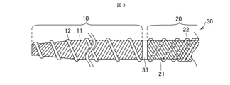
- FIG. 3 is a diagram showing a tip end side portion of the dilator according to the modified example.
- the "tip side” is a direction along the longitudinal direction of the dilator (a direction along the axial direction of the dilator), and is a direction in which the tip side coil portion is located with respect to the base end side coil portion.
- the “base end side” means a direction along the longitudinal direction of the dilator and a direction opposite to the tip end side.
- the "tip” indicates an end portion on the distal end side in any member or portion
- the “base end” indicates an end portion on the proximal end side in any member or portion.
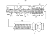
- FIG. 1 is an overall configuration diagram of the dilator 1 according to the embodiment of the present disclosure.
- the left side in the drawing is the distal end side (distal side) inserted into the body, and the right side is the proximal end side (hand side, proximal side) operated by a technician such as a doctor.
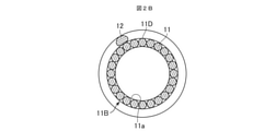
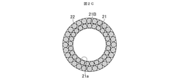
- 2A is a cross-sectional view taken along the line IIA-IIA of the dilator 1 of FIG.
- FIG. 2B is a cross-sectional view taken along the line IIB-IIB of the dilator 1 of FIG. 1 is a cross-sectional view taken along the line IIC-IIC.
- the dilator 1 includes a tip side coil portion 10, a base end side coil portion 20, and a connector 2.
- the tip side coil portion 10 is located on the most tip side in the axial direction of the dilator 1 and has a first coil 11 and a second coil 12.
- the second coil 12 is wound around the outer peripheral surface of the first coil 11.
- the strands constituting the first coil 11 and the second coil 12 are, for example, metal strands such as stainless steel and superelastic alloys such as nickel-titanium, or resin strands.
- the first coil 11 is formed in a hollow shape by winding a plurality of (for example, 12) strands.
- the plurality of strands constituting the first coil 11 are wound in the first winding direction.
- the first coil 11 has a lumen 11a penetrating from the proximal end to the distal end.
- the first coil 11 has a straight portion 11B and a tapered portion 11C.
- the straight portion 11B is located on the proximal end side of the first coil 11, and the proximal end side coil portion 20 is connected to the proximal end.
- the straight portion 11B has a substantially constant outer diameter from its base end to the tip end.
- the tapered portion 11C is located on the tip end side of the straight portion 11B, extends from the tip end of the straight portion 11B toward the tip end side, and is configured such that the outer diameter decreases toward the tip end side.
- the second coil 12 for example, one wire is wound around the outer peripheral surface 11D of the first coil 11 in the second winding direction opposite to the first winding direction.
- the first winding direction is S winding and the second winding direction is Z winding.
- the strands constituting the second coil 12 are wound apart from each other.
- the outer peripheral surface 11D of the first coil 11 is provided with a spiral convex portion that protrudes to the outside (outermost surface and outermost surface of the dilator 1).
- This spiral convex portion has a gap in a portion (adjacent metal strand) adjacent to each other along the axis of the first coil 11. Due to the screwing action of the spiral convex portion, the dilator 1 can be advanced even by the rotation operation of the dilator 1.
- the proximal end side coil portion 20 is located on the proximal end side of the distal end side coil portion 10 and has a third coil 21 and a fourth coil 22.
- the fourth coil 22 is wound around the outer peripheral surface of the third coil 21.
- a connector 2 is connected to the base end of the base end side coil portion 20.
- the strands constituting the third coil 21 and the fourth coil 22 are, for example, metal strands such as stainless steel and superelastic alloys such as nickel-titanium, or resin strands.
- the third coil 21 is formed in a hollow shape by winding a plurality of (for example, 14) metal strands.
- the plurality of strands constituting the third coil 21 are wound in the second winding direction.
- the third coil 21 has a lumen 21a penetrating from the proximal end to the distal end, and has a substantially constant outer diameter from the proximal end to the distal end.
- the lumen 11a of the first coil 11 and the lumen 21a of the third coil 21 communicate with each other.
- a plurality of (for example, 14) strands are wound around the outer peripheral surface 21B of the third coil 21 in the first winding direction.
- the diameter of the wire constituting the fourth coil 22 is larger than the diameter of the wire constituting the third coil.
- the outer diameter of the fourth coil 22 is substantially equal to or slightly larger than the outer diameter of the second coil 12.
- the plurality of strands constituting the tip end portion and the base end portion thereof are arranged in the entire circumferential direction so as not to be separated. It has been welded across.
- the second coil 12 is welded to the first coil 11, for example, at its tip and proximal end.
- the first coil 11 and the third coil 21 are each composed of separate wires, and the second coil 12 and the fourth coil 22 are each composed of separate wires.
- the base end portion 10A of the tip end side coil portion 10 and the tip end portion 20A of the base end side coil portion 20 are welded to each other on the entire circumference thereof.
- the welded portion 3 is formed at the connection portion between the tip side coil portion 10 and the tip side coil portion 10.
- the welded portion 3 has a tapered shape that tapers toward the tip side.
- the length of the dilator 1 in this embodiment and other embodiments described thereafter is, for example, 2000 mm, and may be 1650 mm to 2350 mm.
- the length of the tip side coil portion 10 is, for example, 200 mm, and may be 50 to 400 mm.
- the length of the base end side coil portion 20 is, for example, 1800 mm, and may be 1600 to 1950 mm.
- the inner diameter at the tip of the first coil 11 is, for example, 0.7 mm, and may be 0.4 to 1.0 mm.
- the inner diameters at the base end of the first coil 11 and the tip end of the third coil 21 are, for example, 1.5 mm, and may be 1.0 to 3.0 mm.
- the outer diameter at the tip of the second coil 12 is, for example, 1.84 mm, and may be 0.8 to 3.0 mm.
- the outer diameter at the base end of the second coil 12 is, for example, 2.64 mm, and may be 1.4 mm to 5.0 mm.
- the diameter of the metal wire of the first coil 11 and the third coil 21 is, for example, 0.21 mm, and may be 0.1 to 0.5 mm.
- the diameter of the metal wire of the second coil 12 and the fourth coil 22 is, for example, 0.36 mm, and may be 0.1 to 0.5 mm.
- the connector 2 is a part where a technician performs a rotation operation such as pushing the dilator 1 into the body or pulling it out.
- the tip of the connector 2 is connected to the base end of the base end side coil portion 20.
- the connector 2 is made of resin, for example, and has a hollow shape having a lumen communicating with the lumen 21a of the third coil 21.
- the dilator 1 is pushed forward while rotating the shaft (tip side coil portion 10 and proximal end side coil portion 20) clockwise to expand the hole of the puncture portion.
- the shaft tip side coil portion 10 and proximal end side coil portion 20
- the hole can be smoothly expanded by the tapered portion 11C.
- the tip side coil portion 10 is provided on the outer periphery of the first coil 11 and the first coil 11 in which the wire is wound in a hollow shape in the first winding direction, and the wire is first wound.
- the second coil 12 is wound in the second winding direction, which is the opposite winding direction to the winding direction, and the base end side coil portion 20 winds the wire in a hollow shape in the second winding direction.
- It has a third coil 21 and a fourth coil 22 provided on the outer periphery of the third coil 21 and wound with a wire in the first winding direction.
- the first winding direction is S winding
- the second winding direction is Z winding.
- the pitch of the first coil 11 is tightened at the tip side coil portion 10.
- the outer diameter of the first coil 11 becomes smaller.
- the pitch of the second coil 12 opens, the outer diameter of the second coil 12 increases.
- the pitch of the third coil 21 is widened, so that the outer diameter of the third coil 21 becomes large. Further, as the pitch of the fourth coil 22 is tightened, the inner diameter of the fourth coil 22 becomes smaller. As a result, the force that the third coil 21 tends to expand in the radial direction and the force that the fourth coil 22 tries to contract in the radial direction interact with each other, and the third coil 21 and the fourth coil 22 respectively. The strands of are in close contact with each other. Therefore, the torque transmissibility in the base end side coil portion 20 can be improved. From the above, when the dilator 1 is rotated clockwise, the tip of the dilator 1 expands the narrowed portion in the radial direction, so that the expanding force of the narrowed portion can be increased. High torque transmission can be obtained.
- the pitch of the third coil 21 is tightened and the outer diameter of the third coil 21 is reduced in the base end side coil 20.
- the pitch of the fourth coil 22 opens, the outer diameter of the fourth coil 22 increases.
- the pitch of the first coil 11 is widened and the outer diameter of the first coil 11 is increased.
- the pitch of the second coil 12 is tightened, the inner diameter of the second coil 12 becomes smaller.
- the torque transmission in the tip side coil portion 10 can be increased, and in addition, by increasing the rigidity of the tip side coil portion 10, the performance of expanding the narrowed portion of the dilator 1 can be enhanced. From the above, when the dilator 1 is rotated counterclockwise, the performance of expanding the narrowed portion can be improved by increasing the rigidity of the tip side, and the torque transmission property is relatively high as a whole. Obtainable.
- the performance of expanding the narrowed portion can be enhanced regardless of the rotation direction thereof, and a relatively high torque transmission property can be obtained. Further, since the first winding direction is S winding and the second winding direction is Z winding, high torque transmission can be obtained in the normal usage mode of the dilator 1.
- the diameter of the wire constituting the fourth coil 22 is larger than the diameter of the wire constituting the third coil.
- the base end portion 10A of the tip end side coil portion 10 and the tip end portion 20A of the base end side coil portion 20 are welded to each other on the entire circumference thereof. As a result, the force applied to the connector 2 of the dilator 1 can be reliably transmitted to the tip side coil portion 10.
- the first coil 11 and the third coil 21 are each composed of separate wires, and the second coil 12 and the fourth coil 22 are each composed of separate wires.
- the tip end side coil portion 10 and the base end side coil portion 11 are separately formed, and by connecting these, the dilator 1 can be easily manufactured.
- the strands constituting the fourth coil 22 are wound so as to be separated from each other without being in close contact with the tip end side, and the separation amount is gradually reduced toward the base end side. It may be wound so as to be in close contact with the base end side. As a result, the rigidity of the dilator 30 can be gradually changed from the base end to the tip end.
- the welded portion 33 may be configured such that the outer peripheral surface thereof is substantially parallel to the axial direction instead of having a tapered shape.
- the first coil 11 and the third coil 21 were each composed of separate wires, and the second coil 12 and the fourth coil 22 were each composed of separate wires, but the third coil 21 and the first coil 21 were composed of separate wires.
- the coil 11 may be configured with the same wire, or the fourth coil 22 and the second coil 12 may be configured with the same wire.
- the diameter of the metal wire constituting the fourth coil 22 was larger than the diameter of the metal wire constituting the third coil, but the diameter of the metal wire constituting the fourth coil 22 was set to the diameter of the third coil. It may be the same as the diameter of the metal wire constituting the above, or it may be smaller.
- the base end portion 10A of the tip end side coil portion 10 and the tip end portion 20A of the base end side coil portion 20 were welded to each other on the entire circumference thereof, but only a few places (for example, four places) on the outer periphery were welded. It may be a thing.
- the tip side coil portion 10 includes a straight portion 11B and a tapered portion 11C, but the straight portion 11B does not have to be provided. Further, the tip side coil portion 10 may be provided with a tip portion having a substantially constant outer diameter from the base end to the tip on the tip end side of the tapered portion 11C.
- the first coil 11 and the fourth coil 22 were wound in the first winding direction (S winding), and the second coil 12 and the third coil 21 were wound in the second winding direction (Z winding).
- the first coil 11 and the fourth coil 22 are wound in the second winding direction (Z winding), and the second coil 12 and the third coil 21 are wound in the first winding direction (S winding). May be good.
- the pitch of the first coil 11 is tightened in the tip side coil portion 10 and the first coil is tightened.
- the outer diameter of 11 becomes smaller.
- the pitch of the second coil 12 opens, the outer diameter of the second coil 12 increases.
- the second coil 12 expands in the radial direction and expands the narrowed portion to expand the narrowed portion of the dilator 1.
- the outer diameter of the third coil 21 becomes larger due to the opening of the pitch of the third coil 21.
- the inner diameter of the fourth coil 22 becomes smaller.
- the force that the third coil 21 tends to expand in the radial direction and the force that the fourth coil 22 tries to contract in the radial direction interact with each other, and the third coil 21 and the fourth coil 22 respectively.
- the strands of are in close contact with each other. Therefore, the torque transmissibility in the base end side coil portion 20 can be improved.
- the tip portion of the dilator 1 expands the narrowed portion in the radial direction, so that the expanding force of the narrowed portion can be increased, and further, as a whole, the dilator 1 can be expanded. A relatively high torque transmission can be obtained.
- the pitch of the third coil 21 is tightened and the outer diameter of the third coil 21 is reduced in the base end side coil 20.
- the pitch of the fourth coil 22 opens, the outer diameter of the fourth coil 22 increases.
- the pitch of the first coil 11 is widened and the outer diameter of the first coil 11 is increased.
- the pitch of the second coil 12 is tightened, the inner diameter of the second coil 12 becomes smaller.
- the torque transmission in the tip side coil portion 10 can be increased, and in addition, by increasing the rigidity of the tip side coil portion 10, the performance of expanding the narrowed portion of the dilator 1 can be enhanced. From the above, when the dilator 1 is rotated clockwise, the performance of expanding the narrowed portion can be improved by increasing the rigidity of the tip side, and further, relatively high torque transmission is obtained as a whole. be able to.
- the number of strands of the first coil 11 and the third coil 21 is not limited to the above-mentioned number, and may be one or a plurality of strands. Further, the number of strands of the second coil 12 may be a plurality of strands. Further, the number of strands of the fourth coil 22 is not limited to the above-mentioned number, and may be one or a plurality of strands.
- Dilator 10 Tip side coil part 10A: Tip side coil part base end part 11: First coil 12: Second coil 20: Base end side coil part 20A: Base end side coil part tip end part 21: 3rd coil 22: 4th coil
Landscapes
- Health & Medical Sciences (AREA)
- Life Sciences & Earth Sciences (AREA)
- General Health & Medical Sciences (AREA)
- Biomedical Technology (AREA)
- Heart & Thoracic Surgery (AREA)
- Animal Behavior & Ethology (AREA)
- Engineering & Computer Science (AREA)
- Public Health (AREA)
- Veterinary Medicine (AREA)
- Hematology (AREA)
- Anesthesiology (AREA)
- Surgery (AREA)
- Pulmonology (AREA)
- Biophysics (AREA)
- Pathology (AREA)
- Nuclear Medicine, Radiotherapy & Molecular Imaging (AREA)
- Medical Informatics (AREA)
- Molecular Biology (AREA)
- Media Introduction/Drainage Providing Device (AREA)
Abstract
Provided is a dilator that can maintain high torque transmission characteristics regardless of the rotation direction thereof. The dilator comprises a distal end side coil part 10 and a proximal end side coil part 20 that is disposed on the proximal end side of the distal end side coil part 10 and has a distal end section 20A that is connected to a proximal end section 10A of the distal end side coil part 10. The distal end side coil part 10 has a first coil 11 obtained by winding an element wire in a first winding direction into a hollow shape, and a second coil 12 that is provided to the outer circumference of the first coil 11 and is obtained by winding an element wire in a second winding direction that is a winding direction opposite to the first winding direction. The proximal end side coil part 20 has a third coil 21 obtained by winding an element wire in the second winding direction into a hollow shape, and a fourth coil 22 that is provided to the outer circumference of the third coil 21 and is obtained by winding an element wire in the first winding direction.
Description
本開示は、ダイレータに関する。
This disclosure relates to dilators.
内視鏡検査等の医療処置に、体腔内に挿入される医療機器が用いられている。特許文献1には、中空撚線により構成された医療機器が開示されている。この中空撚線は、第一層と第二層とを有し、第一層の素線と第二層の素線との撚り方向が逆になるように構成されている。
Medical equipment inserted into the body cavity is used for medical procedures such as endoscopy. Patent Document 1 discloses a medical device composed of hollow stranded wires. This hollow stranded wire has a first layer and a second layer, and is configured so that the strands of the first layer and the strands of the second layer are twisted in opposite directions.
ところで、治療のために、患者の消化管等の壁に形成された孔を拡張するダイレータが知られている。壁に形成された孔にダイレータの先端を挿入してテーパ部を孔に押し込んでいくことで、孔を拡張する。ダイレータに特許文献1に記載された2層からなる中空撚線を適用した場合に、ダイレータを回転させる方向によっては、内側の層が締まり、外側の層が開くことになり、2層が互いに接触せず、十分なトルク伝達性が得られない可能性がある。
By the way, a dilator that expands a hole formed in the wall of a patient's digestive tract or the like for treatment is known. The hole is expanded by inserting the tip of the dilator into the hole formed in the wall and pushing the tapered portion into the hole. When the hollow stranded wire composed of two layers described in Patent Document 1 is applied to the dilator, the inner layer is tightened and the outer layer is opened depending on the direction in which the dilator is rotated, and the two layers are in contact with each other. It may not be possible to obtain sufficient torque transmission.
本開示は、回転方向に関わらず高いトルク伝達性を得ることができるダイレータを提供することを目的とする。
The present disclosure aims to provide a dilator capable of obtaining high torque transmissibility regardless of the rotation direction.
かかる目的を達成するために、本開示の一態様に係るダイレータは、先端側コイル部と、前記先端側コイル部の基端側に位置し、先端部が前記先端側コイル部の基端部に接続される基端側コイル部と、を備え、前記先端側コイル部は、素線を中空形状に第1巻き方向に巻回した第1コイルと、前記第1コイルの外周に設けられ、素線を前記第1巻き方向に対して反対の巻き方向である第2巻き方向に巻回した第2コイルと、を有し、前記基端側コイル部は、素線を中空形状に前記第2巻き方向に巻回した第3コイルと、前記第3コイルの外周に設けられ、素線を前記第1巻き方向に巻回した第4コイルと、を有する。
In order to achieve such an object, the dilator according to one aspect of the present disclosure is located on the distal end side coil portion and the proximal end side of the distal end side coil portion, and the distal end portion is located on the proximal end portion of the distal end side coil portion. A base end side coil portion to be connected is provided, and the tip end side coil portion is provided on a first coil in which a wire is wound in a hollow shape in the first winding direction and an outer periphery of the first coil. It has a second coil in which a wire is wound in a second winding direction which is the opposite winding direction to the first winding direction, and the base end side coil portion has the second coil in which the wire is hollow. It has a third coil wound in the winding direction and a fourth coil provided on the outer periphery of the third coil and wound with a wire in the first winding direction.
前記第1巻き方向はS巻きであり、前記第2巻き方向はZ巻きであってもよい。
The first winding direction may be S winding, and the second winding direction may be Z winding.
前記第3コイルの素線の直径は、前記第4コイルの素線の直径よりも小さくてもよい。
The diameter of the wire of the third coil may be smaller than the diameter of the wire of the fourth coil.
前記先端側コイル部の基端部と、前記基端側コイル部の先端部とは、それらの全周で互いに溶接されていてもよい。
The base end portion of the tip end side coil portion and the tip end portion of the base end side coil portion may be welded to each other on the entire circumference thereof.
前記第1コイルおよび前記第3コイルは、それぞれ別々の素線により構成され、前記第2コイルおよび前記第4コイルは、それぞれ別々の素線により構成されていてもよい。
The first coil and the third coil may be composed of separate strands, and the second coil and the fourth coil may be configured by separate strands.
本開示によれば、回転方向に関わらず高いトルク伝達性を得ることができるダイレータを提供することができる。
According to the present disclosure, it is possible to provide a dilator capable of obtaining high torque transmissibility regardless of the rotation direction.
以下、本開示の実施形態について、図面を参照しつつ説明する。なお、図面に示したダイレータの寸法は、実施内容の理解を容易にするために示した寸法であり、実際の寸法に対応するものではない。
Hereinafter, embodiments of the present disclosure will be described with reference to the drawings. It should be noted that the dimensions of the dilator shown in the drawings are the dimensions shown for facilitating the understanding of the implementation contents, and do not correspond to the actual dimensions.
なお、本明細書において、「先端側」とは、ダイレータの長手方向に沿った方向(ダイレータの軸方向に沿う方向)であって、基端側コイル部に対する先端側コイル部が位置する方向を意味する。また、「基端側」とは、ダイレータの長手方向に沿った方向に沿う方向であって、先端側と反対側の方向を意味する。また、「先端」とは、任意の部材または部位における先端側の端部を示し、「基端」とは、任意の部材または部位における基端側の端部をそれぞれ示す。
In the present specification, the "tip side" is a direction along the longitudinal direction of the dilator (a direction along the axial direction of the dilator), and is a direction in which the tip side coil portion is located with respect to the base end side coil portion. means. Further, the "base end side" means a direction along the longitudinal direction of the dilator and a direction opposite to the tip end side. Further, the "tip" indicates an end portion on the distal end side in any member or portion, and the "base end" indicates an end portion on the proximal end side in any member or portion.
図1は、本開示の実施形態に係るダイレータ1の全体構成図である。図1において、図示左側が体内に挿入される先端側(遠位側)であり、右側が医師等の手技者によって操作される基端側(手元側、近位側)である。図2Aは、図1のダイレータ1のIIA-IIA線での断面図であり、図2Bは、図1のダイレータ1のIIB-IIB線での断面図であり、図2Cは、図1のダイレータ1のIIC-IIC線での断面図である。
FIG. 1 is an overall configuration diagram of the dilator 1 according to the embodiment of the present disclosure. In FIG. 1, the left side in the drawing is the distal end side (distal side) inserted into the body, and the right side is the proximal end side (hand side, proximal side) operated by a technician such as a doctor. 2A is a cross-sectional view taken along the line IIA-IIA of the dilator 1 of FIG. 1, FIG. 2B is a cross-sectional view taken along the line IIB-IIB of the dilator 1 of FIG. 1 is a cross-sectional view taken along the line IIC-IIC.
ダイレータ1は、先端側コイル部10と、基端側コイル部20と、コネクタ2とを備える。
The dilator 1 includes a tip side coil portion 10, a base end side coil portion 20, and a connector 2.
先端側コイル部10は、ダイレータ1の軸方向において最も先端側に位置し、第1コイル11と第2コイル12とを有する。第2コイル12は、第1コイル11の外周面に巻回されている。第1コイル11および第2コイル12を構成する素線は、例えば、ステンレス鋼およびニッケル-チタン等の超弾性合金等の金属素線、または、樹脂素線である。
The tip side coil portion 10 is located on the most tip side in the axial direction of the dilator 1 and has a first coil 11 and a second coil 12. The second coil 12 is wound around the outer peripheral surface of the first coil 11. The strands constituting the first coil 11 and the second coil 12 are, for example, metal strands such as stainless steel and superelastic alloys such as nickel-titanium, or resin strands.
図1、図2A、および図2Bに示すように、第1コイル11は、複数(例えば12本)の素線を巻回して中空状に形成されている。第1コイル11を構成する複数の素線は、第1巻き方向に巻回されている。第1コイル11は、基端から先端へ貫通する内腔11aを有している。第1コイル11は、ストレート部11Bと、テーパ部11Cとを有している。
As shown in FIGS. 1, 2A, and 2B, the first coil 11 is formed in a hollow shape by winding a plurality of (for example, 12) strands. The plurality of strands constituting the first coil 11 are wound in the first winding direction. The first coil 11 has a lumen 11a penetrating from the proximal end to the distal end. The first coil 11 has a straight portion 11B and a tapered portion 11C.
ストレート部11Bは、第1コイル11のうちの基端側に位置し、基端に基端側コイル部20が接続されている。ストレート部11Bは、その基端から先端にわたって略一定の外径を有する。テーパ部11Cは、ストレート部11Bの先端側に位置し、ストレート部11Bの先端から先端側に延び、先端側に向かうにつれて外径が小さくなるように構成されている。
The straight portion 11B is located on the proximal end side of the first coil 11, and the proximal end side coil portion 20 is connected to the proximal end. The straight portion 11B has a substantially constant outer diameter from its base end to the tip end. The tapered portion 11C is located on the tip end side of the straight portion 11B, extends from the tip end of the straight portion 11B toward the tip end side, and is configured such that the outer diameter decreases toward the tip end side.
第2コイル12は、例えば1本の素線が第1コイル11の外周面11Dに、第1巻き方向とは反対の第2巻き方向に巻回されている。本実施形態では、第1巻き方向はS巻きであり、第2巻き方向はZ巻きである。第2コイル12を構成する素線は、離間して巻回されている。これにより、第1コイル11の外周面11Dに、外部(ダイレータ1の最外面、最外部)に突出する螺旋状の凸部が設けられる。この螺旋状の凸部は、第1コイル11の軸に沿って隣り合う部分(隣接する金属素線)に隙間を有する。この螺旋状の凸部のネジ作用により、ダイレータ1の回転操作によってもダイレータ1を前進させることができる。
In the second coil 12, for example, one wire is wound around the outer peripheral surface 11D of the first coil 11 in the second winding direction opposite to the first winding direction. In the present embodiment, the first winding direction is S winding and the second winding direction is Z winding. The strands constituting the second coil 12 are wound apart from each other. As a result, the outer peripheral surface 11D of the first coil 11 is provided with a spiral convex portion that protrudes to the outside (outermost surface and outermost surface of the dilator 1). This spiral convex portion has a gap in a portion (adjacent metal strand) adjacent to each other along the axis of the first coil 11. Due to the screwing action of the spiral convex portion, the dilator 1 can be advanced even by the rotation operation of the dilator 1.
図1に示すように、基端側コイル部20は、先端側コイル部10の基端側に位置し、第3コイル21と第4コイル22とを有する。第4コイル22は、第3コイル21の外周面に巻回されている。基端側コイル部20の基端にはコネクタ2が接続されている。第3コイル21および第4コイル22を構成する素線は、例えば、ステンレス鋼およびニッケル-チタン等の超弾性合金等の金属素線、または、樹脂素線である。
As shown in FIG. 1, the proximal end side coil portion 20 is located on the proximal end side of the distal end side coil portion 10 and has a third coil 21 and a fourth coil 22. The fourth coil 22 is wound around the outer peripheral surface of the third coil 21. A connector 2 is connected to the base end of the base end side coil portion 20. The strands constituting the third coil 21 and the fourth coil 22 are, for example, metal strands such as stainless steel and superelastic alloys such as nickel-titanium, or resin strands.
図1および図2Cに示すように、第3コイル21は、複数(例えば14本)の金属素線を巻回して中空状に形成されている。第3コイル21を構成する複数の素線は、第2巻き方向に巻回されている。第3コイル21は、基端から先端へ貫通する内腔21aを有し、その基端から先端にわたって略一定の外径を有する。第1コイル11の内腔11aと第3コイル21の内腔21aとは互いに連通している。
As shown in FIGS. 1 and 2C, the third coil 21 is formed in a hollow shape by winding a plurality of (for example, 14) metal strands. The plurality of strands constituting the third coil 21 are wound in the second winding direction. The third coil 21 has a lumen 21a penetrating from the proximal end to the distal end, and has a substantially constant outer diameter from the proximal end to the distal end. The lumen 11a of the first coil 11 and the lumen 21a of the third coil 21 communicate with each other.
第4コイル22は、複数(例えば14本)の素線が第3コイル21の外周面21Bに、第1の巻き方向に巻回されている。第4コイル22を構成する素線の直径は、第3コイルを構成する素線の直径よりも大きい。第4コイル22の外径は、第2コイル12の外径とほぼ等しいかわずかに大きい。
In the fourth coil 22, a plurality of (for example, 14) strands are wound around the outer peripheral surface 21B of the third coil 21 in the first winding direction. The diameter of the wire constituting the fourth coil 22 is larger than the diameter of the wire constituting the third coil. The outer diameter of the fourth coil 22 is substantially equal to or slightly larger than the outer diameter of the second coil 12.
第1コイル11、第3コイル21、および第4コイル22において、それらの先端部および基端部を構成する複数の素線は、ばらけないようにするために、それらの円周方向全体に渡って溶接されている。第2コイル12は、例えば、その先端および基端において第1コイル11に対し溶接されている。第1コイル11および第3コイル21は、それぞれ別々の素線により構成され、第2コイル12および第4コイル22は、それぞれ別々の素線により構成されている。
In the first coil 11, the third coil 21, and the fourth coil 22, the plurality of strands constituting the tip end portion and the base end portion thereof are arranged in the entire circumferential direction so as not to be separated. It has been welded across. The second coil 12 is welded to the first coil 11, for example, at its tip and proximal end. The first coil 11 and the third coil 21 are each composed of separate wires, and the second coil 12 and the fourth coil 22 are each composed of separate wires.
先端側コイル部10の基端部10Aと、基端側コイル部20の先端部20Aとは、それらの全周で互いに溶接されている。これにより、先端側コイル部10と先端側コイル部10との接続部には溶接部3が形成されている。溶接部3は、先端側に向かって先細るテーパ形状をなしている。
The base end portion 10A of the tip end side coil portion 10 and the tip end portion 20A of the base end side coil portion 20 are welded to each other on the entire circumference thereof. As a result, the welded portion 3 is formed at the connection portion between the tip side coil portion 10 and the tip side coil portion 10. The welded portion 3 has a tapered shape that tapers toward the tip side.
本実施形態およびこれ以降に記載される他の実施形態におけるダイレータ1の長さは、例えば2000mmであり、1650mm~2350mmであってよい。先端側コイル部10の長さは、例えば200mmであり、50~400mmであってよい。基端側コイル部20の長さは、例えば1800mmであり、1600~1950mmであってよい。第1コイル11の先端における内径は、例えば0.7mmであり、0.4~1.0mmであってよい。第1コイル11の基端および第3コイル21の先端における内径は、例えば1.5mmであり、1.0~3.0mmであってよい。第2コイル12の先端における外径は、例えば1.84mmであり、0.8~3.0mmであってよい。第2コイル12の基端における外径は、例えば2.64mmであり、1.4mm~5.0mmであってよい。第1コイル11および第3コイル21の金属素線の直径は、例えば0.21mmであり、0.1~0.5mmであってよい。第2コイル12および第4コイル22の金属素線の直径は、例えば0.36mmであり、0.1~0.5mmであってよい。
The length of the dilator 1 in this embodiment and other embodiments described thereafter is, for example, 2000 mm, and may be 1650 mm to 2350 mm. The length of the tip side coil portion 10 is, for example, 200 mm, and may be 50 to 400 mm. The length of the base end side coil portion 20 is, for example, 1800 mm, and may be 1600 to 1950 mm. The inner diameter at the tip of the first coil 11 is, for example, 0.7 mm, and may be 0.4 to 1.0 mm. The inner diameters at the base end of the first coil 11 and the tip end of the third coil 21 are, for example, 1.5 mm, and may be 1.0 to 3.0 mm. The outer diameter at the tip of the second coil 12 is, for example, 1.84 mm, and may be 0.8 to 3.0 mm. The outer diameter at the base end of the second coil 12 is, for example, 2.64 mm, and may be 1.4 mm to 5.0 mm. The diameter of the metal wire of the first coil 11 and the third coil 21 is, for example, 0.21 mm, and may be 0.1 to 0.5 mm. The diameter of the metal wire of the second coil 12 and the fourth coil 22 is, for example, 0.36 mm, and may be 0.1 to 0.5 mm.
コネクタ2は、手技者がダイレータ1を体内に押し込んだり、引き抜いたり等の回転操作を行う部位である。コネクタ2は、その先端が基端側コイル部20の基端に接続されている。コネクタ2は、例えば樹脂からなり、第3コイル21の内腔21aに連通する内腔を有する中空形状である。
The connector 2 is a part where a technician performs a rotation operation such as pushing the dilator 1 into the body or pulling it out. The tip of the connector 2 is connected to the base end of the base end side coil portion 20. The connector 2 is made of resin, for example, and has a hollow shape having a lumen communicating with the lumen 21a of the third coil 21.
次に、ダイレータ1の使用態様の一例について説明する。
Next, an example of how to use the dilator 1 will be described.
まず、導入針を用いて対象物を穿刺して孔を開ける。次いで、導入針の内腔にガイドワイヤを挿入した後、導入針を抜き取る。
First, puncture the object with the introduction needle to make a hole. Then, after inserting the guide wire into the lumen of the introduction needle, the introduction needle is pulled out.
次に、ガイドワイヤの基端をダイレータ1の内腔に差し入れ、ダイレータ1を挿入する。次いで、シャフト(先端側コイル部10及び基端側コイル部20)を時計回りに回転させながらダイレータ1を押し進め、穿刺部の孔を拡張する。この際、シャフトの回転操作による螺旋状の凸部のネジ作用等によりテーパ部11Cが前進するため、テーパ部11Cによる孔の拡張を円滑に行うことができる。ダイレータ1を後退させる場合には、シャフトを反時計回りに回転させる。
Next, insert the base end of the guide wire into the lumen of the dilator 1 and insert the dilator 1. Next, the dilator 1 is pushed forward while rotating the shaft (tip side coil portion 10 and proximal end side coil portion 20) clockwise to expand the hole of the puncture portion. At this time, since the tapered portion 11C advances due to the screwing action of the spiral convex portion due to the rotational operation of the shaft, the hole can be smoothly expanded by the tapered portion 11C. When retracting the dilator 1, the shaft is rotated counterclockwise.
本実施形態のダイレータ1では、先端側コイル部10は、素線を中空形状に第1巻き方向に巻回した第1コイル11と、第1コイル11の外周に設けられ、素線を第1巻き方向に対して反対の巻き方向である第2巻き方向に巻回した第2コイル12と、を有し、基端側コイル部20は、素線を中空形状に第2巻き方向に巻回した第3コイル21と、第3コイル21の外周に設けられ、素線を第1巻き方向に巻回した第4コイル22と、を有する。そして、第1巻き方向はS巻きであり、第2巻き方向はZ巻きである。
In the dilator 1 of the present embodiment, the tip side coil portion 10 is provided on the outer periphery of the first coil 11 and the first coil 11 in which the wire is wound in a hollow shape in the first winding direction, and the wire is first wound. The second coil 12 is wound in the second winding direction, which is the opposite winding direction to the winding direction, and the base end side coil portion 20 winds the wire in a hollow shape in the second winding direction. It has a third coil 21 and a fourth coil 22 provided on the outer periphery of the third coil 21 and wound with a wire in the first winding direction. The first winding direction is S winding, and the second winding direction is Z winding.
この構成によると、ダイレータ1を第1コイル11のネジ作用により前進させる方向(時計回り:図中R方向)へ回転させた場合、先端側コイル部10では、第1コイル11のピッチが締まるとともに、第1コイル11の外径が小さくなる。また、第2コイル12のピッチが開くとともに、第2コイル12の外径が大きくなる。これにより、ダイレータ1を時計回りに回転させながら狭窄部を進ませる際に、第2コイル12が径方向に拡張し、狭窄部を押し広げることで、ダイレータ1の狭窄部を拡張する性能を高めることができる。反対に、基端側コイル部20では、第3コイル21のピッチが開くことにより、第3コイル21の外径が大きくなる。また、第4コイル22のピッチが締まるとともに、第4コイル22の内径が小さくなる。これにより、第3コイル21が径方向に拡大しようとする力と、第4コイル22が径方向に縮小しようとする力とが相互に作用しつつ、第3コイル21と第4コイル22のそれぞれの素線同士が互いに密着することとなる。従って、基端側コイル部20におけるトルク伝達性を高くすることができる。以上のことにより、ダイレータ1を時計回りに回転させた場合は、ダイレータ1の先端部が狭窄部を径方向に押し広げることで、狭窄部の拡張力を高めることができ、さらに、全体として比較的高いトルク伝達性を得ることができる。
According to this configuration, when the dilator 1 is rotated in the direction of advancing by the screw action of the first coil 11 (clockwise: R direction in the figure), the pitch of the first coil 11 is tightened at the tip side coil portion 10. , The outer diameter of the first coil 11 becomes smaller. Further, as the pitch of the second coil 12 opens, the outer diameter of the second coil 12 increases. As a result, when the dilator 1 is rotated clockwise to advance the narrowed portion, the second coil 12 expands in the radial direction and expands the narrowed portion, thereby enhancing the performance of expanding the narrowed portion of the dilator 1. be able to. On the contrary, in the base end side coil portion 20, the pitch of the third coil 21 is widened, so that the outer diameter of the third coil 21 becomes large. Further, as the pitch of the fourth coil 22 is tightened, the inner diameter of the fourth coil 22 becomes smaller. As a result, the force that the third coil 21 tends to expand in the radial direction and the force that the fourth coil 22 tries to contract in the radial direction interact with each other, and the third coil 21 and the fourth coil 22 respectively. The strands of are in close contact with each other. Therefore, the torque transmissibility in the base end side coil portion 20 can be improved. From the above, when the dilator 1 is rotated clockwise, the tip of the dilator 1 expands the narrowed portion in the radial direction, so that the expanding force of the narrowed portion can be increased. High torque transmission can be obtained.
一方、ダイレータ1を後退させる方向(反時計回り)へ回転させた場合、基端側コイル20では、第3コイル21のピッチが締まるとともに、第3コイル21の外径が小さくなる。また、第4コイル22のピッチが開くとともに、第4コイル22の外径が大きくなる。反対に、先端側コイル部10では、第1コイル11のピッチが開くとともに、第1コイル11の外径が大きくなる。また、第2コイル12のピッチが締まるとともに、第2コイル12の内径が小さくなる。これにより、第1コイル11が径方向に拡大しようとする力と、第2コイル12が径方向に縮小しようとする力とが相互に作用しつつ、第1コイル11と第2コイル12のそれぞれの素線同士が互いに密着することとなる。従って、先端側コイル部10におけるトルク伝達性を高くすることができ、加えて、先端側コイル部10の剛性を高くすることで、ダイレータ1の狭窄部を拡張する性能を高くすることができる。以上のことにより、ダイレータ1を反時計回りに回転させた場合は、先端側の剛性を高くすることで狭窄部を拡張する性能を高めることができ、さらに、全体として比較的高いトルク伝達性を得ることができる。
On the other hand, when the dilator 1 is rotated in the retracting direction (counterclockwise), the pitch of the third coil 21 is tightened and the outer diameter of the third coil 21 is reduced in the base end side coil 20. Further, as the pitch of the fourth coil 22 opens, the outer diameter of the fourth coil 22 increases. On the contrary, in the tip side coil portion 10, the pitch of the first coil 11 is widened and the outer diameter of the first coil 11 is increased. Further, as the pitch of the second coil 12 is tightened, the inner diameter of the second coil 12 becomes smaller. As a result, the force that the first coil 11 tries to expand in the radial direction and the force that the second coil 12 tries to shrink in the radial direction interact with each other, and the first coil 11 and the second coil 12 respectively. The strands of are in close contact with each other. Therefore, the torque transmission in the tip side coil portion 10 can be increased, and in addition, by increasing the rigidity of the tip side coil portion 10, the performance of expanding the narrowed portion of the dilator 1 can be enhanced. From the above, when the dilator 1 is rotated counterclockwise, the performance of expanding the narrowed portion can be improved by increasing the rigidity of the tip side, and the torque transmission property is relatively high as a whole. Obtainable.
このように、本実施形態のダイレータ1によれば、その回転方向に関わらず、狭窄部を拡張する性能を高めることができ、さらに、比較的高いトルク伝達性を得ることができる。また、第1巻き方向はS巻きであり、第2巻き方向はZ巻きであるので、ダイレータ1の通常の使用形態において、高いトルク伝達性を得ることができる。
As described above, according to the dilator 1 of the present embodiment, the performance of expanding the narrowed portion can be enhanced regardless of the rotation direction thereof, and a relatively high torque transmission property can be obtained. Further, since the first winding direction is S winding and the second winding direction is Z winding, high torque transmission can be obtained in the normal usage mode of the dilator 1.
また、第4コイル22を構成する素線の直径は、第3コイルを構成する素線の直径よりも大きい。これにより、基端側コイル部20のトルク力を増加させることができ、ひいてはダイレータ1のトルク力を増加させることができる。
Further, the diameter of the wire constituting the fourth coil 22 is larger than the diameter of the wire constituting the third coil. As a result, the torque force of the base end side coil portion 20 can be increased, and eventually the torque force of the dilator 1 can be increased.
先端側コイル部10の基端部10Aと、基端側コイル部20の先端部20Aとは、それらの全周で互いに溶接されている。これにより、ダイレータ1のコネクタ2に加えられた力を先端側コイル部10へ確実に伝えることができる。
The base end portion 10A of the tip end side coil portion 10 and the tip end portion 20A of the base end side coil portion 20 are welded to each other on the entire circumference thereof. As a result, the force applied to the connector 2 of the dilator 1 can be reliably transmitted to the tip side coil portion 10.
第1コイル11および第3コイル21は、それぞれ別々の素線により構成され、第2コイル12および第4コイル22は、それぞれ別々の素線により構成されている。これにより、先端側コイル部10と基端側コイル部11とを別々に形成し、これらを接続することにより、容易にダイレータ1を製造することができる。
The first coil 11 and the third coil 21 are each composed of separate wires, and the second coil 12 and the fourth coil 22 are each composed of separate wires. As a result, the tip end side coil portion 10 and the base end side coil portion 11 are separately formed, and by connecting these, the dilator 1 can be easily manufactured.
以上、本開示の実施形態について述べてきたが、本開示は、これらの実施形態に限られるものではなく、種々の変形が可能である。
Although the embodiments of the present disclosure have been described above, the present disclosure is not limited to these embodiments, and various modifications are possible.
例えば、図3に示す、ダイレータ30のように、第4コイル22を構成する素線を、先端側を密着せず離間して巻回し、基端側に向かって徐々に離間量を減少させ、基端側では密着するように巻回してもよい。これにより、ダイレータ30の剛性を、基端から先端に向かって徐変させることができる。溶接部33は、テーパ形状ではなく、その外周面を軸方向に略平行に構成してもよい。
For example, like the dilator 30 shown in FIG. 3, the strands constituting the fourth coil 22 are wound so as to be separated from each other without being in close contact with the tip end side, and the separation amount is gradually reduced toward the base end side. It may be wound so as to be in close contact with the base end side. As a result, the rigidity of the dilator 30 can be gradually changed from the base end to the tip end. The welded portion 33 may be configured such that the outer peripheral surface thereof is substantially parallel to the axial direction instead of having a tapered shape.
第1コイル11および第3コイル21は、それぞれ別々の素線により構成され、第2コイル12および第4コイル22は、それぞれ別々の素線により構成されていたが、第3コイル21と第1コイル11とを同一の素線により構成してもよいし、第4コイル22と第2コイル12とを同一の素線により構成してもよい。
The first coil 11 and the third coil 21 were each composed of separate wires, and the second coil 12 and the fourth coil 22 were each composed of separate wires, but the third coil 21 and the first coil 21 were composed of separate wires. The coil 11 may be configured with the same wire, or the fourth coil 22 and the second coil 12 may be configured with the same wire.
第4コイル22を構成する金属素線の直径は、第3コイルを構成する金属素線の直径よりも大きくしていたが、第4コイル22を構成する金属素線の直径を、第3コイルを構成する金属素線の直径と同じとしてもよいし、小さくしてもよい。
The diameter of the metal wire constituting the fourth coil 22 was larger than the diameter of the metal wire constituting the third coil, but the diameter of the metal wire constituting the fourth coil 22 was set to the diameter of the third coil. It may be the same as the diameter of the metal wire constituting the above, or it may be smaller.
先端側コイル部10の基端部10Aと、基端側コイル部20の先端部20Aとは、それらの全周で互いに溶接されていたが、外周の数箇所(例えば4箇所)のみを溶接したものであってもよい。
The base end portion 10A of the tip end side coil portion 10 and the tip end portion 20A of the base end side coil portion 20 were welded to each other on the entire circumference thereof, but only a few places (for example, four places) on the outer periphery were welded. It may be a thing.
先端側コイル部10は、ストレート部11Bと、テーパ部11Cとを備えていたが、ストレート部11Bを備えなくてもよい。また、先端側コイル部10は、テーパ部11Cの先端側に、基端から先端にわたって略一定の外径を有する先端部を備えていてもよい。
The tip side coil portion 10 includes a straight portion 11B and a tapered portion 11C, but the straight portion 11B does not have to be provided. Further, the tip side coil portion 10 may be provided with a tip portion having a substantially constant outer diameter from the base end to the tip on the tip end side of the tapered portion 11C.
第1コイル11および第4コイル22は、第1巻き方向(S巻き)に巻回され、第2コイル12および第3コイル21は、第2巻き方向(Z巻き)に巻回されていたが、第1コイル11および第4コイル22は、第2巻き方向(Z巻き)に巻回され、第2コイル12および第3コイル21は、第1巻き方向(S巻き)に巻回されていてもよい。
The first coil 11 and the fourth coil 22 were wound in the first winding direction (S winding), and the second coil 12 and the third coil 21 were wound in the second winding direction (Z winding). , The first coil 11 and the fourth coil 22 are wound in the second winding direction (Z winding), and the second coil 12 and the third coil 21 are wound in the first winding direction (S winding). May be good.
この構成によると、ダイレータ1を第1コイル11のネジ作用により前進させる方向(反時計回り)へ回転させた場合、先端側コイル部10では、第1コイル11のピッチが締まるとともに、第1コイル11の外径が小さくなる。また、第2コイル12のピッチが開くとともに、第2コイル12の外径が大きくなる。これにより、ダイレータ1を反時計回りに回転させながら狭窄部を進ませる際に、第2コイル12が径方向に拡張し、狭窄部を押し広げることで、ダイレータ1の狭窄部を拡張する性能を高めることができる。一方、基端側コイル部20では、第3コイル21のピッチが開くことにより、第3コイル21の外径が大きくなる。また、第4コイル22のピッチが締まるとともに、第4コイル22の内径が小さくなる。これにより、第3コイル21が径方向に拡大しようとする力と、第4コイル22が径方向に縮小しようとする力とが相互に作用しつつ、第3コイル21と第4コイル22のそれぞれの素線同士が互いに密着することとなる。従って、基端側コイル部20におけるトルク伝達性を高くすることができる。以上のことにより、ダイレータ1を反時計回りに回転させた場合は、ダイレータ1の先端部が狭窄部を径方向に押し広げることで、狭窄部の拡張力を高めることができ、さらに、全体として比較的高いトルク伝達性を得ることができる。
According to this configuration, when the dilator 1 is rotated in the direction of advancing (counterclockwise) by the screwing action of the first coil 11, the pitch of the first coil 11 is tightened in the tip side coil portion 10 and the first coil is tightened. The outer diameter of 11 becomes smaller. Further, as the pitch of the second coil 12 opens, the outer diameter of the second coil 12 increases. As a result, when the dilator 1 is rotated counterclockwise to advance the narrowed portion, the second coil 12 expands in the radial direction and expands the narrowed portion to expand the narrowed portion of the dilator 1. Can be enhanced. On the other hand, in the base end side coil portion 20, the outer diameter of the third coil 21 becomes larger due to the opening of the pitch of the third coil 21. Further, as the pitch of the fourth coil 22 is tightened, the inner diameter of the fourth coil 22 becomes smaller. As a result, the force that the third coil 21 tends to expand in the radial direction and the force that the fourth coil 22 tries to contract in the radial direction interact with each other, and the third coil 21 and the fourth coil 22 respectively. The strands of are in close contact with each other. Therefore, the torque transmissibility in the base end side coil portion 20 can be improved. As described above, when the dilator 1 is rotated counterclockwise, the tip portion of the dilator 1 expands the narrowed portion in the radial direction, so that the expanding force of the narrowed portion can be increased, and further, as a whole, the dilator 1 can be expanded. A relatively high torque transmission can be obtained.
一方、ダイレータ1を後退させる方向(時計回り)へ回転させた場合、基端側コイル20では、第3コイル21のピッチが締まるとともに、第3コイル21の外径が小さくなる。また、第4コイル22のピッチが開くとともに、第4コイル22の外径が大きくなる。反対に、先端側コイル部10では、第1コイル11のピッチが開くとともに、第1コイル11の外径が大きくなる。また、第2コイル12のピッチが締まるとともに、第2コイル12の内径が小さくなる。これにより、第1コイル11が径方向に拡大しようとする力と、第2コイル12が径方向に縮小しようとする力とが相互に作用しつつ、第1コイル11と第2コイル12のそれぞれの素線同士が互いに密着することとなる。従って、先端側コイル部10におけるトルク伝達性を高くすることができ、加えて、先端側コイル部10の剛性を高くすることで、ダイレータ1の狭窄部を拡張する性能を高くすることができる。以上のことにより、ダイレータ1を時計回りに回転させた場合は、先端側の剛性を高くすることで狭窄部を拡張する性能を高めることができ、さらに、全体として比較的高いトルク伝達性を得ることができる。
On the other hand, when the dilator 1 is rotated in the retracting direction (clockwise), the pitch of the third coil 21 is tightened and the outer diameter of the third coil 21 is reduced in the base end side coil 20. Further, as the pitch of the fourth coil 22 opens, the outer diameter of the fourth coil 22 increases. On the contrary, in the tip side coil portion 10, the pitch of the first coil 11 is widened and the outer diameter of the first coil 11 is increased. Further, as the pitch of the second coil 12 is tightened, the inner diameter of the second coil 12 becomes smaller. As a result, the force that the first coil 11 tries to expand in the radial direction and the force that the second coil 12 tries to shrink in the radial direction interact with each other, and the first coil 11 and the second coil 12 respectively. The strands of are in close contact with each other. Therefore, the torque transmission in the tip side coil portion 10 can be increased, and in addition, by increasing the rigidity of the tip side coil portion 10, the performance of expanding the narrowed portion of the dilator 1 can be enhanced. From the above, when the dilator 1 is rotated clockwise, the performance of expanding the narrowed portion can be improved by increasing the rigidity of the tip side, and further, relatively high torque transmission is obtained as a whole. be able to.
第1コイル11および第3コイル21の素線の本数は、上記した本数に限られるものではなく、1本または複数本であってよい。また、第2コイル12の素線の本数は、複数本であってもよい。また、第4コイル22の素線の本数は、上記した本数に限られるものではなく、1本または複数本であってよい。
The number of strands of the first coil 11 and the third coil 21 is not limited to the above-mentioned number, and may be one or a plurality of strands. Further, the number of strands of the second coil 12 may be a plurality of strands. Further, the number of strands of the fourth coil 22 is not limited to the above-mentioned number, and may be one or a plurality of strands.
1、30:ダイレータ
10:先端側コイル部
10A:先端側コイル部の基端部
11:第1コイル
12:第2コイル
20:基端側コイル部
20A:基端側コイル部の先端部
21:第3コイル
22:第4コイル
1, 30: Dilator 10: Tipside coil part 10A: Tip side coil part base end part 11: First coil 12: Second coil 20: Base end side coil part 20A: Base end side coil part tip end part 21: 3rd coil 22: 4th coil
10:先端側コイル部
10A:先端側コイル部の基端部
11:第1コイル
12:第2コイル
20:基端側コイル部
20A:基端側コイル部の先端部
21:第3コイル
22:第4コイル
1, 30: Dilator 10: Tip
Claims (4)
- 先端側コイル部と、
前記先端側コイル部の基端側に位置し、先端部が前記先端側コイル部の基端部に接続される基端側コイル部と、を備え、
前記先端側コイル部は、
素線を中空形状に第1巻き方向に巻回した第1コイルと、
前記第1コイルの外周に設けられ、素線を前記第1巻き方向に対して反対の巻き方向である第2巻き方向に巻回した第2コイルと、を有し、
前記基端側コイル部は、
素線を中空形状に前記第2巻き方向に巻回した第3コイルと、
前記第3コイルの外周に設けられ、素線を前記第1巻き方向に巻回した第4コイルと、を有するダイレータ。 Tip side coil part and
It is provided with a proximal end side coil portion located on the proximal end side of the distal end side coil portion and having the distal end portion connected to the proximal end portion of the distal end side coil portion.
The tip side coil portion is
The first coil, in which the wire is wound in a hollow shape in the first winding direction,
It has a second coil provided on the outer periphery of the first coil, and the wire is wound in the second winding direction, which is the winding direction opposite to the first winding direction.
The base end side coil portion is
A third coil in which the wire is wound in a hollow shape in the second winding direction, and
A dilator provided on the outer periphery of the third coil and having a fourth coil in which a wire is wound in the first winding direction. - 前記第1巻き方向はS巻きであり、前記第2巻き方向はZ巻きである、請求項1に記載のダイレータ。 The dilator according to claim 1, wherein the first winding direction is S winding and the second winding direction is Z winding.
- 前記先端側コイル部の基端部と、前記基端側コイル部の先端部とは、それらの全周で互いに溶接されている、請求項1または請求項2に記載のダイレータ。 The dilator according to claim 1 or 2, wherein the proximal end portion of the distal end side coil portion and the distal end portion of the proximal end side coil portion are welded to each other on the entire circumference thereof.
- 前記第1コイルおよび前記第3コイルは、それぞれ別々の素線により構成され、
前記第2コイルおよび前記第4コイルは、それぞれ別々の素線により構成されている、請求項1から請求項3のいずれか一項に記載のダイレータ。
The first coil and the third coil are each composed of separate strands.
The dilator according to any one of claims 1 to 3, wherein the second coil and the fourth coil are each composed of separate strands.
Priority Applications (5)
| Application Number | Priority Date | Filing Date | Title |
|---|---|---|---|
| PCT/JP2020/033397 WO2022049688A1 (en) | 2020-09-03 | 2020-09-03 | Dilator |
| JP2022546790A JP7368632B2 (en) | 2020-09-03 | 2020-09-03 | dilator |
| CN202080103777.4A CN115996685A (en) | 2020-09-03 | 2020-09-03 | Dilator |
| EP20952427.1A EP4209187A4 (en) | 2020-09-03 | 2020-09-03 | Dilator |
| US18/115,045 US20230201547A1 (en) | 2020-09-03 | 2023-02-28 | Dilator |
Applications Claiming Priority (1)
| Application Number | Priority Date | Filing Date | Title |
|---|---|---|---|
| PCT/JP2020/033397 WO2022049688A1 (en) | 2020-09-03 | 2020-09-03 | Dilator |
Related Child Applications (1)
| Application Number | Title | Priority Date | Filing Date |
|---|---|---|---|
| US18/115,045 Continuation US20230201547A1 (en) | 2020-09-03 | 2023-02-28 | Dilator |
Publications (1)
| Publication Number | Publication Date |
|---|---|
| WO2022049688A1 true WO2022049688A1 (en) | 2022-03-10 |
Family
ID=80491885
Family Applications (1)
| Application Number | Title | Priority Date | Filing Date |
|---|---|---|---|
| PCT/JP2020/033397 WO2022049688A1 (en) | 2020-09-03 | 2020-09-03 | Dilator |
Country Status (5)
| Country | Link |
|---|---|
| US (1) | US20230201547A1 (en) |
| EP (1) | EP4209187A4 (en) |
| JP (1) | JP7368632B2 (en) |
| CN (1) | CN115996685A (en) |
| WO (1) | WO2022049688A1 (en) |
Citations (3)
| Publication number | Priority date | Publication date | Assignee | Title |
|---|---|---|---|---|
| JPH0490355U (en) * | 1990-12-18 | 1992-08-06 | ||
| WO2018174243A1 (en) * | 2017-03-24 | 2018-09-27 | 朝日インテック株式会社 | Dilator |
| JP2019107326A (en) | 2017-12-20 | 2019-07-04 | トクセン工業株式会社 | Hollow twisted wire |
Family Cites Families (1)
| Publication number | Priority date | Publication date | Assignee | Title |
|---|---|---|---|---|
| CN112714634B (en) * | 2018-09-21 | 2024-04-19 | 朝日英达科株式会社 | Dilator |
-
2020
- 2020-09-03 EP EP20952427.1A patent/EP4209187A4/en active Pending
- 2020-09-03 CN CN202080103777.4A patent/CN115996685A/en active Pending
- 2020-09-03 JP JP2022546790A patent/JP7368632B2/en active Active
- 2020-09-03 WO PCT/JP2020/033397 patent/WO2022049688A1/en unknown
-
2023
- 2023-02-28 US US18/115,045 patent/US20230201547A1/en active Pending
Patent Citations (3)
| Publication number | Priority date | Publication date | Assignee | Title |
|---|---|---|---|---|
| JPH0490355U (en) * | 1990-12-18 | 1992-08-06 | ||
| WO2018174243A1 (en) * | 2017-03-24 | 2018-09-27 | 朝日インテック株式会社 | Dilator |
| JP2019107326A (en) | 2017-12-20 | 2019-07-04 | トクセン工業株式会社 | Hollow twisted wire |
Non-Patent Citations (1)
| Title |
|---|
| See also references of EP4209187A4 |
Also Published As
| Publication number | Publication date |
|---|---|
| CN115996685A (en) | 2023-04-21 |
| US20230201547A1 (en) | 2023-06-29 |
| JPWO2022049688A1 (en) | 2022-03-10 |
| JP7368632B2 (en) | 2023-10-24 |
| EP4209187A1 (en) | 2023-07-12 |
| EP4209187A4 (en) | 2024-05-29 |
Similar Documents
| Publication | Publication Date | Title |
|---|---|---|
| JP7431001B2 (en) | dilator | |
| WO2021064955A1 (en) | Medical tubular body | |
| US20210069480A1 (en) | Dilator | |
| JP6906104B2 (en) | Medical tube | |
| EP2845620A1 (en) | Coil body and medical apparatus using said coil body | |
| EP1955658A1 (en) | Endoscopic treatment tool | |
| WO2022049688A1 (en) | Dilator | |
| WO2020059121A1 (en) | Dilator | |
| WO2017077626A1 (en) | Medical wire and medical instrument | |
| WO2021246054A1 (en) | Dilator | |
| WO2017175373A1 (en) | Flexible manipulator | |
| JP6588679B1 (en) | Dilator | |
| JP2005118102A (en) | Snare for endoscope | |
| US20210244263A1 (en) | Coil sheath and medical device | |
| JP2010063558A (en) | Treatment implement for endoscope | |
| JPS60212142A (en) | Endoscope |
Legal Events
| Date | Code | Title | Description |
|---|---|---|---|
| 121 | Ep: the epo has been informed by wipo that ep was designated in this application |
Ref document number: 20952427 Country of ref document: EP Kind code of ref document: A1 |
|
| ENP | Entry into the national phase |
Ref document number: 2022546790 Country of ref document: JP Kind code of ref document: A |
|
| NENP | Non-entry into the national phase |
Ref country code: DE |
|
| ENP | Entry into the national phase |
Ref document number: 2020952427 Country of ref document: EP Effective date: 20230403 |