WO2022049665A1 - Axial flow fan, and indoor unit for air conditioner - Google Patents
Axial flow fan, and indoor unit for air conditioner Download PDFInfo
- Publication number
- WO2022049665A1 WO2022049665A1 PCT/JP2020/033229 JP2020033229W WO2022049665A1 WO 2022049665 A1 WO2022049665 A1 WO 2022049665A1 JP 2020033229 W JP2020033229 W JP 2020033229W WO 2022049665 A1 WO2022049665 A1 WO 2022049665A1
- Authority
- WO
- WIPO (PCT)
- Prior art keywords
- edge portion
- axial
- fan
- angle
- blade
- Prior art date
Links
- 230000002093 peripheral effect Effects 0.000 claims abstract description 254
- 238000010586 diagram Methods 0.000 claims abstract description 70
- 238000011144 upstream manufacturing Methods 0.000 claims description 24
- 230000000052 comparative effect Effects 0.000 description 18
- 230000000694 effects Effects 0.000 description 18
- 239000012530 fluid Substances 0.000 description 15
- 238000005192 partition Methods 0.000 description 14
- 239000003507 refrigerant Substances 0.000 description 9
- 230000007423 decrease Effects 0.000 description 3
- 230000004048 modification Effects 0.000 description 3
- 238000012986 modification Methods 0.000 description 3
- 238000007664 blowing Methods 0.000 description 2
- 238000001816 cooling Methods 0.000 description 2
- 238000010438 heat treatment Methods 0.000 description 2
- 239000000470 constituent Substances 0.000 description 1
- 238000000034 method Methods 0.000 description 1
Images


Classifications
-
- F—MECHANICAL ENGINEERING; LIGHTING; HEATING; WEAPONS; BLASTING
- F04—POSITIVE - DISPLACEMENT MACHINES FOR LIQUIDS; PUMPS FOR LIQUIDS OR ELASTIC FLUIDS
- F04D—NON-POSITIVE-DISPLACEMENT PUMPS
- F04D29/00—Details, component parts, or accessories
- F04D29/26—Rotors specially for elastic fluids
- F04D29/32—Rotors specially for elastic fluids for axial flow pumps
- F04D29/38—Blades
- F04D29/384—Blades characterised by form
-
- F—MECHANICAL ENGINEERING; LIGHTING; HEATING; WEAPONS; BLASTING
- F24—HEATING; RANGES; VENTILATING
- F24F—AIR-CONDITIONING; AIR-HUMIDIFICATION; VENTILATION; USE OF AIR CURRENTS FOR SCREENING
- F24F1/00—Room units for air-conditioning, e.g. separate or self-contained units or units receiving primary air from a central station
- F24F1/06—Separate outdoor units, e.g. outdoor unit to be linked to a separate room comprising a compressor and a heat exchanger
- F24F1/38—Fan details of outdoor units, e.g. bell-mouth shaped inlets or fan mountings
-
- F—MECHANICAL ENGINEERING; LIGHTING; HEATING; WEAPONS; BLASTING
- F05—INDEXING SCHEMES RELATING TO ENGINES OR PUMPS IN VARIOUS SUBCLASSES OF CLASSES F01-F04
- F05D—INDEXING SCHEME FOR ASPECTS RELATING TO NON-POSITIVE-DISPLACEMENT MACHINES OR ENGINES, GAS-TURBINES OR JET-PROPULSION PLANTS
- F05D2240/00—Components
- F05D2240/20—Rotors
- F05D2240/30—Characteristics of rotor blades, i.e. of any element transforming dynamic fluid energy to or from rotational energy and being attached to a rotor
- F05D2240/303—Characteristics of rotor blades, i.e. of any element transforming dynamic fluid energy to or from rotational energy and being attached to a rotor related to the leading edge of a rotor blade
-
- F—MECHANICAL ENGINEERING; LIGHTING; HEATING; WEAPONS; BLASTING
- F05—INDEXING SCHEMES RELATING TO ENGINES OR PUMPS IN VARIOUS SUBCLASSES OF CLASSES F01-F04
- F05D—INDEXING SCHEME FOR ASPECTS RELATING TO NON-POSITIVE-DISPLACEMENT MACHINES OR ENGINES, GAS-TURBINES OR JET-PROPULSION PLANTS
- F05D2240/00—Components
- F05D2240/20—Rotors
- F05D2240/30—Characteristics of rotor blades, i.e. of any element transforming dynamic fluid energy to or from rotational energy and being attached to a rotor
- F05D2240/304—Characteristics of rotor blades, i.e. of any element transforming dynamic fluid energy to or from rotational energy and being attached to a rotor related to the trailing edge of a rotor blade
-
- F—MECHANICAL ENGINEERING; LIGHTING; HEATING; WEAPONS; BLASTING
- F05—INDEXING SCHEMES RELATING TO ENGINES OR PUMPS IN VARIOUS SUBCLASSES OF CLASSES F01-F04
- F05D—INDEXING SCHEME FOR ASPECTS RELATING TO NON-POSITIVE-DISPLACEMENT MACHINES OR ENGINES, GAS-TURBINES OR JET-PROPULSION PLANTS
- F05D2250/00—Geometry
- F05D2250/70—Shape
- F05D2250/71—Shape curved
- F05D2250/711—Shape curved convex
-
- F—MECHANICAL ENGINEERING; LIGHTING; HEATING; WEAPONS; BLASTING
- F05—INDEXING SCHEMES RELATING TO ENGINES OR PUMPS IN VARIOUS SUBCLASSES OF CLASSES F01-F04
- F05D—INDEXING SCHEME FOR ASPECTS RELATING TO NON-POSITIVE-DISPLACEMENT MACHINES OR ENGINES, GAS-TURBINES OR JET-PROPULSION PLANTS
- F05D2250/00—Geometry
- F05D2250/70—Shape
- F05D2250/74—Shape given by a set or table of xyz-coordinates
Definitions
- the present disclosure relates to an axial fan and an outdoor unit of an air conditioner having an axial fan.
- the conventional axial fan is equipped with a plurality of blades along the peripheral surface of the cylindrical boss, and the blades rotate according to the rotational force applied to the boss to convey the fluid.
- the fluid existing between the blades collides with the blade surface due to the rotation of the blades.
- the pressure rises on the surface where the fluid collides, and the fluid is pushed out and moved in the direction of the rotation axis, which is the central axis when the blade rotates.
- the shape of the center warp line in the cross section when the blade is cut on the cylindrical surface centered on the rotation axis is the straight portion provided on the blade leading edge side and the blade trailing edge side.
- an axial flow fan having a shape provided with a curved portion provided in see, for example, Patent Document 1.
- This straight portion is formed so as to be substantially in the same direction as the non-collision inflow direction of gas to the blade surface, and the curved portion is formed so that the outflow direction of gas from the blade surface and the straight portion are continuous. Has been done.
- the linear portion and the curved portion have such a shape, so that the tangential direction of the blade front end portion almost coincides with the non-collision inflow direction in almost the entire radial direction from the rotation axis. It is said that. Therefore, in the axial flow fan of Patent Document 1, the gas flowing from the front end portion of the blade flows along the straight portion and is guided to the curved portion, so that the flow can be close to the ideal flow without loss. ..
- the blade load of the axial flow fan of Patent Document 1 cannot be adjusted in the radial direction, and the blade load on the inner peripheral side of the axial flow fan is not sufficiently increased with respect to the outer peripheral side of the axial flow fan.
- the air flow on the blade surface flows to the outer peripheral side of the axial fan under the influence of the partition plate of the machine. Therefore, the flow of air blown out from the axial flow fan is located so that the maximum value of the wind speed distribution in the radial direction is concentrated on the outermost circumference or near the outer circumference, and a structure such as a fan grill located on the downstream side of the axial flow fan.
- the noise of the outdoor unit of the air conditioner increases because the air concentrated in the air collides with the air conditioner.
- the present disclosure is for solving the above-mentioned problems, an axial fan in which noise generated when air is blown out by driving an axial fan is suppressed, and an outdoor unit of an air conditioner.
- the purpose is to provide.
- the axial flow fan according to the present disclosure is an axial flow fan used in an outdoor unit of an air conditioner, and includes a hub that is rotationally driven to form a rotating shaft, and a blade formed around the hub.
- It has an inner peripheral edge portion that is connected to and forms an edge portion on the inner peripheral side of the outermost periphery of the blade, and has a trailing edge portion in the cross section of the blade along the axial direction of the rotation axis and the circumferential direction of the axial flow fan.
- the angle between the virtual line parallel to the axis of rotation that intersects with the wing and the virtual line indicating the direction in which the trailing edge is facing is defined as the exit angle of the wing, and the horizontal axis is outside the inner peripheral edge of the trailing edge.
- the first line diagram shows the position of the size of the exit angle of the trailing edge portion in the inner peripheral edge portion and the exit angle of the trailing edge portion in the outer peripheral edge portion in the first diagram. It has a wing formed so as to have a lower convex portion that is convex downward from the first virtual line diagram represented by a linear straight line connecting the position of the size of.
- the outdoor unit of the air conditioner according to the present disclosure is provided at a housing in which an air outlet is formed on a wall portion, an axial fan having the above configuration arranged inside the housing, and an air outlet. It is equipped with a bell mouth that surrounds the outer circumference of the axial flow fan.
- the outdoor unit of the axial fan and the air conditioner is formed so that the first line diagram has a lower convex portion that is convex downward from the first virtual line diagram.
- the wing having the region has a portion having a smaller exit angle on the inner peripheral side of the wing by having the lower convex portion as compared with the wing forming the first virtual line. Therefore, the wing loading becomes large in the portion constituting the lower convex portion. Therefore, the axial flow fan can attract the air flow on the blade surface to the inner peripheral side by sufficiently increasing the blade load on the inner peripheral side by the lower convex portion with respect to the outer peripheral side.
- the air flow blown out from the air flow has a uniform wind speed distribution in the radial direction.
- a structure such as a fan grill located on the downstream side of the axial fan.
- FIG. 1 It is a schematic diagram of the air conditioner which concerns on Embodiment 1.
- FIG. It is a perspective view of the outdoor unit which concerns on Embodiment 1.
- FIG. It is a perspective view when the outdoor unit which concerns on Embodiment 1 is seen from the outlet side.
- FIG. It is a perspective view which shows the internal structure by removing the front wall part and the like from an outdoor unit.
- It is a conceptual diagram for demonstrating the internal structure of an outdoor unit from the top surface side.
- It is a front view which shows the schematic structure of the axial flow fan which concerns on Embodiment 1.
- FIG. It is a front view which shows the schematic structure of the blade of the axial flow fan which concerns on Embodiment 1.
- FIG. 7 is a cross-sectional view taken along the line AA of the wing of FIG. It is a cross-sectional view taken along the line AA of the blade when it has an exit angle ⁇ S. It is a cross-sectional view taken along the line AA of the blade when it has an exit angle ⁇ L.
- FIG. 3 is a top view conceptually showing an outdoor unit provided with an axial fan according to the first embodiment. It is a front view which shows the schematic structure of the blade of the axial flow fan which concerns on Embodiment 2.
- FIG. 7 is a cross-sectional view taken along the line AA of the blades of FIGS. 7 and 19. It is a cross-sectional view taken along the line AA of a wing when it has an entrance angle ⁇ S. It is a cross-sectional view taken along the line AA of a wing when it has an entrance angle ⁇ L. It is a figure which shows the relationship of the wing in FIG. 1 and FIG.
- FIG. 3 is a top view conceptually showing an outdoor unit provided with an axial fan according to the second embodiment.
- FIG. 3 is a top view conceptually showing an outdoor unit provided with an axial fan according to the third embodiment. It is a figure which shows the relationship of the blade in FIG. 1 and FIG. 2 of the axial flow fan which concerns on Embodiment 4.
- FIG. It is a figure which shows the relationship between the distance in the radial direction of the axial flow fan which concerns on Embodiment 5 and the size of the outlet angle ⁇ . It is a top view which conceptually showed the outdoor unit equipped with the axial flow fan which concerns on a comparative example.
- FIG. 3 is a top view conceptually showing an outdoor unit provided with an axial fan according to the fifth embodiment. It is a top view which conceptually showed the outdoor unit which concerns on Embodiment 6. It is a top view which conceptually showed the outdoor unit which concerns on Embodiment 7. It is a top view which conceptually showed the outdoor unit which concerns on Embodiment 8. It is a top view which conceptually showed the modification of the outdoor unit which concerns on Embodiment 8.
- FIG. 1 is a schematic diagram of the air conditioner 70 according to the first embodiment.
- the air conditioner 70 includes a refrigerant circuit 71 in which a compressor 64, a condenser 72, an expansion valve 74, and an evaporator 73 are connected in order by a refrigerant pipe.
- the condenser 72 is provided with a condenser fan 72a that blows heat exchange air to the condenser 72.
- the evaporator 73 is provided with an evaporator fan 73a that blows heat exchange air to the evaporator 73.
- the air conditioner 70 may be configured to provide a flow path switching device such as a four-way valve for switching the flow of the refrigerant in the refrigerant circuit 71 to switch between heating operation and cooling operation.
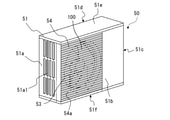
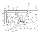
- FIG. 2 is a perspective view of the outdoor unit 50 according to the first embodiment.
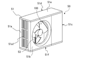
- FIG. 3 is a perspective view of the outdoor unit 50 according to the first embodiment when viewed from the outlet 53 side.
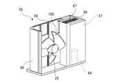
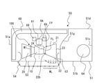
- FIG. 4 is a perspective view showing an internal configuration by removing the front wall portion 51b and the like from the outdoor unit 50.
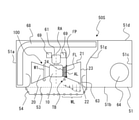
- FIG. 5 is a conceptual diagram for explaining the internal configuration of the outdoor unit 50 from the upper surface side. Note that FIG. 3 omits the illustration of the fan grill 54 provided in the outlet 53 in order to explain the configuration of the outdoor unit 50 in the outlet 53.
- the outdoor unit 50 has a housing 51 that constitutes the outer shell of the outdoor unit 50.
- the housing 51 is formed in the shape of a rectangular parallelepiped box.
- the housing 51 includes a front wall portion 51b that constitutes the front surface of the housing 51, a back wall portion 51d that constitutes the back surface of the housing 51, a top plate 51e that constitutes the upper surface of the housing 51, and the housing 51. It has a bottom plate 51f constituting the lower surface, and a pair of left and right side walls 51a and side walls 51c constituting the side surfaces of the housing 51.
- the side wall 51a of the housing 51 is formed with an opening 51a1 for sucking air from the outside, and the back wall portion 51d of the housing 51 has an opening for sucking air from the outside (not shown). Is formed. Further, the front wall portion 51b of the housing 51 is formed with an outlet 53 as an opening for blowing air from the inside of the housing 51 to the outside.
- the air outlet 53 is covered with a fan grill 54, whereby the outdoor unit 50 prevents an object or the like outside the housing 51 from coming into contact with the axial fan 100, and safety is achieved.
- the arrow AR in FIG. 3 indicates the flow of air.
- the fan grill 54 has a plurality of crosspieces 54a extending in the horizontal direction.
- the crosspiece 54a is a part of the crosspiece extending in the horizontal direction among the various types of crosspieces.
- the crosspiece 54a is formed in a plate shape extending between the side wall 51a side and the side wall 51c side.
- a plurality of crosspieces 54a are arranged so as to be spaced apart from each other in the vertical direction. Air discharged from the inside of the outdoor unit 50 to the outside by driving the axial fan 100 passes between the adjacent crosspieces 54a in the fan grill 54.
- a rotatable axial flow fan 100 and a motor 61 for rotating the axial flow fan 100 are housed inside the housing 51.
- the axial fan 100 rotates around the rotary shaft RS to form an air flow in which air flows from the outside of the housing 51 into the inside and the air flows out from the inside of the housing 51 to the outside.
- the axial flow fan 100 has a hub 10 connected to the rotating shaft 62 of the motor 61, and a plurality of blades 20 provided on the peripheral edge of the hub 10.
- the axial fan 100 is connected to the motor 61, which is a drive source arranged on the back wall portion 51d side with respect to the axial fan 100, via a rotary shaft 62, and is rotationally driven by the motor 61.
- the motor 61 applies a driving force to the axial fan 100.
- the motor 61 is attached to the motor support 69.
- the motor support 69 is arranged between the motor 61 and the heat exchanger 68.
- the inside of the housing 51 is divided into a blower chamber 56 in which the axial flow fan 100 is installed and a machine room 57 in which the compressor 64 and the like are installed by a partition plate 51 g which is a wall body.
- the blower chamber 56 is a space surrounded by a side wall 51a, a partition plate 51g, a front wall portion 51b, a top plate 51e, and a bottom plate 51f.
- the machine room 57 is a space surrounded by a side wall 51c, a partition plate 51g, a front wall portion 51b, a back wall portion 51d, a top plate 51e, and a bottom plate 51f.
- the side wall 51a faces the partition plate 51g with the axial fan 100 in between.
- the top plate 51e faces the bottom plate 51f with the axial fan 100 in between.
- the heat exchanger 68 provided on the suction side of the axial flow fan 100 has a plurality of fins arranged side by side so that the plate-shaped surfaces are parallel to each other, and each fin in the parallel arrangement direction. It is equipped with a heat transfer tube that penetrates through. A refrigerant circulating in the refrigerant circuit 71 circulates in the heat transfer tube.
- a plurality of heat transfer tubes provided in the vertical direction extend in an L shape toward the side wall 51a side and the back wall portion 51d side of the housing 51, respectively.
- the shape of the heat exchanger 68 is not limited to this shape.
- the heat exchanger 68 may be formed in a substantially I shape, for example, along the back surface side inside the blower chamber 56 in which the back wall portion 51d is formed. Further, the heat exchanger 68 may be a so-called finless heat exchanger having no fins through which the heat transfer tube penetrates.
- the heat exchanger 68 functions as an evaporator 73 during the heating operation and as a condenser 72 during the cooling operation.
- the heat exchanger 68 of the outdoor unit 50 is connected to the compressor 64 via piping or the like, and is further connected to the heat exchanger (not shown) on the indoor side and the expansion valve 74 or the like to form the air conditioner 70. It constitutes a refrigerant circuit 71.
- the heat exchanger 68 of the outdoor unit 50 constitutes the condenser 72 or the evaporator 73 shown in FIG. Further, as shown in FIG. 4, a board box 66 is arranged in the machine room 57, and the equipment mounted in the outdoor unit 50 is controlled by the control board 67 provided in the board box 66. ..
- a bell mouth 63 formed in a cylindrical shape is arranged inside the housing 51 on the radial outer side of the axial flow fan 100 arranged in the blower chamber 56. ing.
- the bell mouth 63 is provided at the outlet 53 and is arranged so as to surround the outer periphery of the axial flow fan 100.
- the bell mouth 63 surrounds the outer peripheral side of the axial flow fan 100 and regulates the flow of air formed by the axial flow fan 100 and the like.
- the bell mouth 63 is located outside the outer peripheral end of the blade 20, and is formed in an annular shape along the rotation direction of the axial fan 100.
- a partition plate 51g is located on one side of the bell mouth 63, and a part of the side wall 51a of the housing 51 is located on the other side.
- one end of the bell mouth 63 is connected to the front wall portion 51b of the outdoor unit 50 so as to surround the outer circumference of the outlet 53.
- the bell mouth 63 is integrally formed with the front wall portion 51b, but is not limited to the above configuration, but is formed as a separate body from the front wall portion 51b and connected to the front wall portion 51b. It may be prepared.
- the bell mouth 63 configures the air flow path between the suction side and the blow side of the bell mouth 63 as an air passage near the outlet 53. That is, the air passage in the vicinity of the air outlet 53 is separated from other spaces in the air blowing chamber 56 by the bell mouth 63.
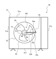
- FIG. 6 is a front view showing a schematic configuration of the axial flow fan 100 according to the first embodiment.
- the rotation direction DR indicated by the arrow in the figure indicates the direction in which the axial fan 100 rotates.
- the reverse rotation direction OD indicated by the arrow in the figure indicates a direction opposite to the direction in which the axial flow fan 100 rotates.
- the circumferential direction CD indicated by the double-headed arrow in the figure indicates the circumferential direction of the axial flow fan 100.
- the circumferential CD includes a rotational DR and a reverse rotational OD.
- the axial fan 100 is a device that forms a fluid flow. As described above, the axial fan 100 is used in the outdoor unit 50 of the air conditioner 70.
- the axial flow fan 100 forms a fluid flow by rotating in the rotation direction DR about the rotation axis RA.
- the fluid is, for example, a gas such as air.
- the back side with respect to the paper surface of FIG. 6 is the upstream side with respect to the axial flow fan 100 in the fluid flow direction, and the front side with respect to the paper surface of FIG. 6 is with respect to the axial flow fan 100 in the fluid flow direction. It is on the downstream side.
- the upstream side with respect to the axial fan 100 is the air suction side with respect to the axial fan 100, and the downstream side with respect to the axial fan 100 is the air outlet side with respect to the axial fan 100.
- the axial flow fan 100 includes a hub 10 provided on the rotary shaft RA, and a plurality of blades 20 connected to the hub 10.
- the axial fan 100 includes a so-called bossless type fan in which the front edge side and the trailing edge side of adjacent blades 20 of a plurality of blades 20 are connected so as to form a continuous surface without a boss.
- the hub 10 is connected to a rotating shaft of a drive source such as a motor (not shown).
- the hub 10 may be configured in a cylindrical shape or a plate shape, for example.
- the hub 10 may be connected to the rotation shaft of the drive source as described above, and its shape is not limited.
- the hub 10 is rotationally driven by a motor (not shown) or the like to form a rotary shaft RA.
- the hub 10 rotates about the rotation axis RA.
- the rotation direction DR of the axial fan 100 is a counterclockwise direction as shown by an arrow in FIG.
- the rotation direction DR of the axial fan 100 is not limited to the counterclockwise direction.
- the hub 10 may be rotated clockwise by changing the mounting angle of the blade 20 or the direction of the blade 20.
- the wings 20 are formed around the hub 10 and are formed so as to extend radially outward from the hub 10.
- the plurality of blades 20 are arranged radially outward from the hub 10.
- the plurality of wings 20 are provided apart from each other in the circumferential direction CD.
- the axial fan 100 having three blades 20 is exemplified, but the number of blades 20 is not limited to three.
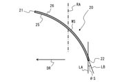
- the wing 20 has a leading edge portion 21, a trailing edge portion 22, an outer peripheral edge portion 23, and an inner peripheral edge portion 24.
- the leading edge portion 21 forms an edge portion on the forward side of the rotation direction DR in the wing 20. That is, the leading edge portion 21 is located forward with respect to the trailing edge portion 22 in the rotation direction DR.
- the leading edge portion 21 is located upstream of the trailing edge portion 22 in the direction in which the generated fluid flows.
- the trailing edge portion 22 forms an edge portion on the wing 20 opposite to the rotation direction DR. That is, the trailing edge portion 22 is located rearward with respect to the leading edge portion 21 in the rotation direction DR. The trailing edge portion 22 is located downstream of the leading edge portion 21 in the direction in which the generated fluid flows.
- the axial flow fan 100 has a leading edge portion 21 as a blade end portion facing the rotation direction DR of the axial flow fan 100, and a trailing edge portion 22 as a blade end portion opposite to the front edge portion 21 in the rotation direction DR. have.
- the outer peripheral edge portion 23 forms an edge portion on the outer peripheral side (Y2 side) of the wing 20.
- the outer peripheral edge portion 23 is a portion extending back and forth in the rotation direction DR so as to connect the outermost peripheral portion of the leading edge portion 21 and the outermost peripheral portion of the trailing edge portion 22.
- the outer peripheral edge portion 23 constitutes an end portion on the outer peripheral side in the radial direction (Y-axis direction) in the axial flow fan 100.
- the outer peripheral edge portion 23 is formed in an arc shape when viewed in a direction parallel to the rotation axis RA.
- the outer peripheral edge portion 23 is not limited to the configuration formed in an arc shape when viewed in a direction parallel to the rotation axis RA.
- the length of the outer peripheral edge portion 23 in the circumferential direction CD is longer than the length of the inner peripheral edge portion 24 in the circumferential direction CD.
- the relationship between the lengths of the outer peripheral edge portion 23 and the inner peripheral edge portion 24 in the circumferential direction CD is not limited to the configuration, and the length of the outer peripheral edge portion 23 and the length of the inner peripheral edge portion 24 are the same. In other words, the length of the inner peripheral edge portion 24 may be formed longer than the length of the outer peripheral edge portion 23.
- the inner peripheral edge portion 24 forms an edge portion on the inner peripheral side (Y1 side) of the outermost peripheral portion of the wing 20.
- the inner peripheral edge portion 24 is a portion extending back and forth in the rotation direction DR so as to connect the innermost peripheral portion of the leading edge portion 21 and the innermost peripheral portion of the trailing edge portion 22.
- the inner peripheral edge portion 24 constitutes an end portion on the inner peripheral side in the radial direction (Y-axis direction) in the axial flow fan 100.
- the inner peripheral edge portion 24 is formed in an arc shape when viewed in a direction parallel to the rotation axis RA.
- the inner peripheral edge portion 24 is not limited to the configuration formed in an arc shape when viewed in a direction parallel to the rotation axis RA.
- the inner peripheral edge portion 24 of the wing 20 is connected to the hub 10, such as being integrally formed with the hub 10.
- the inner peripheral edge portion 24 of the wing 20 is integrally formed with the outer peripheral wall of the hub 10 formed in a cylindrical shape.
- the wing 20 is formed so as to be inclined with respect to a plane perpendicular to the rotation axis RA.
- the blade 20 conveys the fluid by pushing the fluid existing between the blades 20 with the blade surface as the axial flow fan 100 rotates.
- the surface of the blade surface where the fluid is pushed and the pressure rises is referred to as the positive pressure surface 25, and the surface which is the back surface of the positive pressure surface 25 and the pressure decreases is referred to as the negative pressure surface 26.
- the surface on the upstream side of the blade 20 is the negative pressure surface 26 and the surface on the downstream side is the positive pressure surface 25 with respect to the flow direction of the fluid.
- the front surface of the wing 20 is the positive pressure surface 25, and the back surface of the wing 20 is the negative pressure surface 26.
- FIG. 7 is a front view showing a schematic configuration of the blade 20 of the axial fan 100 according to the first embodiment.
- FIG. 8 is a cross-sectional view taken along the line AA of the wing 20 of FIG. Note that FIG. 7 shows only one of the plurality of wings 20 and omits the other wings 20 in order to explain the configuration of the wings 20.
- the AA line cross section shown in FIG. 8 is the wing cross section WS of the wing 20 along the arc passing through the leading edge portion 21 and the trailing edge portion 22 at a specific position in the radial direction about the rotation axis RS. be.
- the white arrow F shown in FIG. 8 indicates the direction in which the air flows.
- the wing cross section WS is an arc-shaped cross section portion passing through the leading edge portion 21 and the trailing edge portion 22 in a plan view in which the wing 20 is viewed parallel to the axial direction of the rotation axis RS.
- the wing cross section WS shown in FIG. 8 is a cross-sectional view of the wing cross section WS as viewed in the radial direction of the wing 20. That is, the blade cross section WS shown in FIG. 8 is a cross section of the blade 20 in the axial direction of the rotating shaft RA and along the circumferential direction CD of the axial flow fan 100.
- the blade 20 is formed so that the positive pressure surface 25 side is concave and the negative pressure surface 26 side is convex. That is, the blade 20 is curved so as to be convex in the direction opposite to the rotation direction DR of the axial flow fan 100 and on the upstream side of the air flow, and is warped.
- the angle between the virtual line LA parallel to the rotation axis RA intersecting the trailing edge portion 22 and the virtual line LB indicating the direction in which the trailing edge portion 22 is facing is set to the angle of the wing 20. It is defined as the exit angle ⁇ .
- the outlet angle ⁇ is an angle between the virtual line LA and the virtual line LB in the blade cross section WS of the blade 20, is located on the downstream side of the airflow with respect to the virtual line LB, and is , The angle of the region located on the opposite side of the rotation direction DR with respect to the virtual line LA.
- the exit angle ⁇ forms an angle of 90 degrees or less.
- FIG. 9 is a sectional view taken along line AA of the blade 20 when the outlet angle ⁇ S is provided.
- FIG. 10 is a sectional view taken along line AA of the blade 20 when the blade 20 has an outlet angle ⁇ L.
- the wing loading is the pressure at which the wing 20 pushes out air.
- the exit angle ⁇ S is smaller than the exit angle ⁇ L, and the exit angle ⁇ L is larger than the exit angle ⁇ S (exit angle ⁇ S ⁇ exit angle ⁇ L).
- the blade cross section WS of the blade 20 forming the outlet angle ⁇ S is in a state where the positive pressure surface 25 of the blade 20 stands up with respect to the rotation direction DR as compared with the blade cross section WS of the blade 20 forming the outlet angle ⁇ L.
- the positive pressure surface 25 has an angle close to a right angle with respect to the rotation direction DR. Therefore, the portion of the blade 20 forming the outlet angle ⁇ S has a larger blade load than the portion of the blade 20 forming the outlet angle ⁇ L.
- the blade cross section WS of the blade 20 forming the outlet angle ⁇ L is in a state where the positive pressure surface 25 of the blade 20 lies down with respect to the rotation direction DR, as compared with the blade cross section WS of the blade 20 forming the outlet angle ⁇ S. That is, the positive pressure surface 25 has an angle close to parallel to the rotation direction DR. Therefore, the portion of the blade 20 forming the outlet angle ⁇ L has a smaller blade load than the portion of the blade 20 forming the outlet angle ⁇ S.
- FIG. 11 is a top view conceptually showing an outdoor unit 50L provided with an axial fan 100L according to a comparative example.
- FIG. 12 is a diagram showing the relationship between the radial distance of the axial flow fan 100L according to the comparative example and the size of the outlet angle ⁇ .
- the axial flow fan 100 is shown as a shape when rotationally projected onto a meridional surface including a rotation axis RA and a blade 20.
- the horizontal axis is the radial distance of the axial flow fan 100L from the inner peripheral edge portion 24 to the outer peripheral edge portion 23 of the trailing edge portion 22, and the vertical axis is the size of the exit angle ⁇ . It represents the magnitude of the exit angle ⁇ with respect to the radial distance from the inner peripheral edge portion 24 of 22.
- the axial flow fan 100L according to the comparative example is a conventional axial flow fan that is generally used.
- the solid line JL shown in FIG. 12 shows the relationship between the distance from the inner peripheral edge portion 24 to the outer peripheral edge portion 23 of the trailing edge portion 22 of the axial flow fan 100L and the size of the outlet angle ⁇ .
- the blade 20L of the axial flow fan 100L with respect to the comparative example shown in FIG. 11 is formed so that the outlet angle ⁇ increases with a constant magnitude from the inner peripheral edge portion 24 toward the outer peripheral edge portion 23.
- the solid line JL is represented to increase linearly.
- a partition plate 51g or the like that hinders the suction of air into the axial fan 100 is present near the axial fan 100L.
- the partition plate 51 g or the like includes the partition plate 51 g and the heat sink (not shown) protruding from the partition plate 51 g when the component is included.
- the outdoor unit 50L according to the comparative example has a relationship between the distance in the radial direction and the size of the exit angle ⁇ as shown in FIG.
- the inflow of air into the axial fan 100L is obstructed by the partition plate 51g or the like, so that the air from the side surface of the axial fan 100L is blocked. Not enough inflow. Therefore, in the outdoor unit 50L, the air flow FL having a radial component from the inner peripheral side to the outer peripheral side on the blade surface increases, and the blade load on the inner peripheral side with respect to the outer peripheral side of the axial flow fan 100L. Cannot be raised sufficiently. Therefore, as shown in FIG. 11, in the axial flow fan 100L, the air flow FL on the blade surface flows to the outer peripheral side under the influence of the partition plate 51g or the like.
- the largest part of the wind speed distribution WL in the radial direction is concentrated on the outermost circumference or the outer peripheral side of the axial flow fan 100L. That is, the axial flow fan 100L forms a state in which the wind speed on the inner peripheral side is slow and the wind speed on the outer peripheral side is high.
- the air flow concentrated on the outermost circumference or the outer periphery of the axial flow fan 100L collides with a structure such as a fan grill located on the downstream side of the outer peripheral portion of the axial flow fan 100L.
- the noise increases.
- FIG. 13 is a diagram showing the relationship between the radial distance of the axial fan 100 according to the first embodiment and the size of the outlet angle ⁇ .
- FIG. 13 is a first diagram in which the horizontal axis is the distance in the radial direction of the axial flow fan 100 from the inner peripheral edge portion 24 to the outer peripheral edge portion 23 of the trailing edge portion 22, and the vertical axis is the size of the outlet angle ⁇ .
- FIG. 13 shows the relationship between the magnitude of the outlet angle ⁇ and the radial distance of the trailing edge portion 22 from the inner peripheral edge portion 24 of the axial flow fan 100 as the first diagram L.
- the blade 20 of the axial fan 100 according to the first embodiment will be further described with reference to FIG.
- the position P1 having the size of the outlet angle ⁇ of the trailing edge portion 22 in the inner peripheral edge portion 24 of the axial flow fan 100 and the outlet angle of the trailing edge portion 22 in the outer peripheral edge portion 23 are shown. It is a virtual line represented by a linear straight line connecting the position P2 having the size of ⁇ .
- the position P1 of the size of the exit angle ⁇ of the trailing edge portion 22 in the inner peripheral edge portion 24 is the position of the innermost peripheral portion of the trailing edge portion 22.
- the position P2 of the size of the exit angle ⁇ of the trailing edge portion 22 in the outer peripheral edge portion 23 is the position of the innermost peripheral portion of the trailing edge portion 22. That is, the exit angle ⁇ at the position P1 is the exit angle ⁇ of the innermost peripheral portion of the trailing edge portion 22. Further, the exit angle ⁇ at the position P2 is the exit angle ⁇ of the outermost peripheral portion of the trailing edge portion 22.
- the magnitude of the outlet angle ⁇ increases with a constant magnitude from the inner peripheral edge portion 24 toward the outer peripheral edge portion 23, as in the axial flow fan 100L according to the above-mentioned comparative example. , Represented linearly.
- the first diagram L has a lower convex portion UD that is convex downward from the first virtual diagram VL.
- the lower convex portion UD may have a region D1 formed so that the size of the outlet angle ⁇ decreases toward the outer peripheral edge portion 23 side from the inner peripheral edge portion 24 side.
- the lower convex portion UD may have a minimum portion DN that forms a minimum value of the exit angle ⁇ in the lower convex portion UD.
- the wing 20 having the minimum portion DN is the portion where the exit angle ⁇ is in the middle of the radial distance in relation to the magnitude of the exit angle ⁇ with respect to the radial distance of the trailing edge portion 22 from the inner peripheral edge portion 24.
- the minimum portion DN forms the apex portion 22b1 in the second region 22b.
- the apex portion 22b1 is a portion having the smallest exit angle ⁇ in the second region 22b, and is a portion having the largest wing loading in the second region 22b.
- the lower convex portion UD is formed on the inner peripheral side of the outer peripheral edge portion 23. It is more effective that the lower convex portion UD is formed on the inner peripheral side of the central position CL of the blade 20 in the radial direction of the axial flow fan 100.
- the lower convex portion UD may be formed at the center position CL of the wing 20.
- FIG. 14 is a diagram of another example showing the relationship between the radial distance of the axial fan 100 according to the first embodiment and the size of the outlet angle ⁇ .
- FIG. 14 is a first diagram showing the relationship between the distance in the radial direction and the size of the exit angle ⁇ , as in FIG. 13.
- the lower convex portion UD has a linear portion D2 in which the size of the exit angle ⁇ is formed to be constant from the inner peripheral edge portion 24 side to the outer peripheral edge portion 23 side. May be.
- the blade 20 of the axial flow fan 100 has a first linear portion LI formed linearly between the inner peripheral edge portion 24 and the lower convex portion UD in the first diagram L. Further, the blade 20 of the axial flow fan 100 has a second linear portion LO formed linearly between the outer peripheral edge portion 23 and the lower convex portion UD in the first diagram L.
- the lower convex portion UD may be formed with a gentle inclination with respect to the inclination of the first linear portion LI, and may have a linear portion continuous with the first linear portion LI. That is, the lower convex portion UD may be formed so that the linear portion D2 in FIG. 14 described above has a gentle inclination with respect to the inclination of the first linear portion LI.
- the portion of the trailing edge portion 22 constituting the first linear portion LI of the first diagram L is defined as the first region 22a
- the trailing edge portion 22 constituting the lower convex portion UD of the first diagram L is defined as the first region 22a.
- the portion is referred to as a second region 22b
- the portion constituting the second linear portion LO of the first diagram L is referred to as a second region 22b.
- the trailing edge portion 22 of the axial flow fan 100 has a first region 22a, a second region 22b, and a third region from the inner peripheral side (Y1 side) to the outer peripheral side (Y2 side).
- the regions 22c are formed in this order.
- FIG. 15 is a diagram of the wing cross section WS1 of the A1-A1 line cross section passing through the first region 22a of FIG. 7.
- FIG. 16 is a view of the wing cross section WS3 of the A3-A3 line cross section passing through the third region 22c of FIG. 7.
- the exit angle ⁇ 1 of the first region 22a is smaller than the exit angle ⁇ 3 of the third region 22c, and the exit angle ⁇ 3 of the third region 22c is formed to be larger than the exit angle ⁇ 1 of the first region 22a (exit angle). ⁇ 1 ⁇ exit angle ⁇ 3).
- the blade cross section WS1 of the blade 20 forming the outlet angle ⁇ 1 is in a state where the positive pressure surface 25 of the blade 20 stands up with respect to the rotation direction DR as compared with the blade cross section WS3 of the blade 20 forming the outlet angle ⁇ 3.
- the positive pressure surface 25 has an angle close to a right angle with respect to the rotation direction DR. Therefore, the portion of the blade 20 forming the outlet angle ⁇ 1 has a larger blade load than the portion of the blade 20 forming the outlet angle ⁇ 3.
- the blade cross section WS3 of the blade 20 forming the outlet angle ⁇ 3 is in a state where the positive pressure surface 25 of the blade 20 lies down with respect to the rotation direction DR as compared with the blade cross section WS1 of the blade 20 forming the outlet angle ⁇ 1. That is, the positive pressure surface 25 has an angle close to parallel to the rotation direction DR. Therefore, the portion of the blade 20 forming the outlet angle ⁇ 3 has a smaller wing loading than the portion of the blade 20 forming the exit angle ⁇ 1.
- the axial fan 100 is formed so that the blade load is larger on the inner peripheral side than on the outer peripheral side of the lower convex portion UD from the viewpoint of the outlet angle ⁇ . That is, when viewed from the entire blade 20, the outlet angle ⁇ of the trailing edge portion 22 on the inner peripheral edge portion 24 side of the axial flow fan 100 is smaller than the outlet angle ⁇ of the trailing edge portion 22 on the outer peripheral edge portion 23 side. It is formed like this.
- the axial flow fan 100 is formed so that the outlet angle ⁇ increases from the inner peripheral side to the outer peripheral side in each of the first region 22a and the third region 22c. More specifically, the axial fan 100 is formed in the first region 22a so that the inner peripheral side of the first region 22a has an outlet angle ⁇ S and the outer peripheral side of the first region 22a has an outlet angle ⁇ L. Is formed in.
- the axial flow fan 100 is formed so that the inner peripheral side of the third region 22c has an outlet angle ⁇ S and the outer peripheral side of the third region 22c has an outlet angle ⁇ L.
- the axial flow fan 100 is formed so that the first region 22a located on the inner peripheral side of the axial flow fan 100 has an outlet angle ⁇ S as a whole, and is located on the outer peripheral side of the axial flow fan 100.
- the three regions 22c are formed so as to have an outlet angle ⁇ L.
- FIG. 17 is a diagram of the wing cross section WS2 of the A2-A2 line cross section passing through the second region 22b of FIG. 7.
- the exit angle ⁇ 2 of the second region 22b is smaller than the exit angle ⁇ 3 of the third region 22c, and the exit angle ⁇ 3 of the third region 22c is formed to be larger than the exit angle ⁇ 2 of the second region 22b (exit angle). ⁇ 2 ⁇ exit angle ⁇ 3).
- the blade cross section WS2 of the blade 20 forming the outlet angle ⁇ 2 is in a state where the positive pressure surface 25 of the blade 20 stands up with respect to the rotation direction DR as compared with the blade cross section WS3 of the blade 20 forming the outlet angle ⁇ 3.
- the positive pressure surface 25 has an angle close to a right angle with respect to the rotation direction DR. Therefore, the portion of the blade 20 forming the outlet angle ⁇ 2 has a larger blade load than the portion of the blade 20 forming the outlet angle ⁇ 3.
- the blade cross section WS3 of the blade 20 forming the outlet angle ⁇ 3 is in a state where the positive pressure surface 25 of the blade 20 lies down with respect to the rotation direction DR as compared with the blade cross section WS2 of the blade 20 forming the outlet angle ⁇ 2. That is, the positive pressure surface 25 has an angle close to parallel to the rotation direction DR. Therefore, the portion of the blade 20 forming the outlet angle ⁇ 3 has a smaller wing loading than the portion of the blade 20 forming the exit angle ⁇ 2.
- the exit angle ⁇ 2 of the second region 22b has a portion (exit angle ⁇ 2 ⁇ exit angle ⁇ 1) equal to or smaller than the exit angle ⁇ 1 of the first region 22a.
- the exit angle ⁇ 2 of the second region 22b of the blade 20 is smaller than the exit angle ⁇ 1 of the first region 22a.
- the blade cross section WS2 of the blade 20 forming the outlet angle ⁇ 2 is in a state where the positive pressure surface 25 of the blade 20 stands up with respect to the rotation direction DR, that is, the positive pressure surface, as compared with the blade cross section WS1 of the blade 20 forming the outlet angle ⁇ 1.
- 25 is an angle close to a right angle with respect to the rotation direction DR.
- the portion of the blade 20 in which the outlet angle ⁇ 2 of the second region 22b is smaller than the outlet angle ⁇ 1 of the first region 22a has a larger wing loading than the portion of the blade 20 forming the exit angle ⁇ 1 of the portion. ..
- the exit angle ⁇ 2 of the second region 22b has a portion equal to or smaller than the exit angle ⁇ 1 of the first region 22a (exit angle ⁇ 2 ⁇ exit angle ⁇ 1).
- the positive pressure surface 25 of the blade 20 stands up as compared with the blade 20L forming the first virtual diagram VL, that is, the positive pressure surface 25 is at an angle close to a right angle to the rotation direction DR. Therefore, when the outlet angle ⁇ 2 of the second region 22b has a portion equal to or smaller than the exit angle ⁇ 1 of the first region 22a, that is, when the lower convex portion UD is provided, the wing 20 having the region is provided. Has a larger blade load than the blade 20L forming the first virtual diagram VL.
- FIG. 18 is a top view conceptually showing the outdoor unit 50 provided with the axial fan 100 according to the first embodiment.
- the axial flow fan 100 is shown as a shape when rotationally projected onto a meridional surface including a rotation axis RA and a blade 20.
- the outdoor unit 50L is provided on the blade surface by a partition plate 51g or the like that inhibits the suction of air into the axial fan 100L.
- the air flow FL having a radial component from the inner peripheral side to the outer peripheral side increases.
- the blade load of the outdoor unit 50L according to the comparative example cannot be adjusted in the radial direction of the axial fan 100L, and the blade load on the inner peripheral side is sufficiently increased with respect to the outer peripheral side of the axial fan 100L. do not have. Therefore, in the outdoor unit 50L of the comparative example, the air flow concentrated on the outermost circumference or the outer periphery of the axial flow fan 100L collides with a structure such as a fan grill located on the downstream side of the outer peripheral portion of the axial flow fan 100L. , Noise increases.
- the axial fan 100 according to the first embodiment is formed so that the first diagram L has a lower convex portion UD that is convex downward from the first virtual diagram VL.
- Has wings 20 When having the lower convex portion UD, the wing 20 having the region concerned has the exit angle ⁇ of the wing 20 by having the lower convex portion UD as compared with the wing 20L forming the first virtual diagram VL. Has a small portion, so that the wing loading is large in the portion constituting the lower convex portion UD.
- the axial flow fan 100 can attract the air flow on the blade surface to the inner peripheral side by sufficiently increasing the blade load on the inner peripheral side with respect to the outer peripheral side, and is blown out from the axial flow fan 100.
- the air flow becomes a uniform wind speed distribution in the radial direction.
- the outdoor unit 50 can suppress the resistance due to the collision with the fan grill 54 by the uniform wind speed distribution of the air blown from the axial fan 100. Therefore, the outdoor unit 50 can reduce the load on the axial fan 100 and reduce the fan input.
- the lower convex portion UD is formed on the inner peripheral side of the central position CL of the blade 20 in the radial direction of the axial fan 100.
- the air flow on the blade surface is directed to the inner peripheral side even if the air flow on the blade surface is largely biased toward the outer peripheral side.
- the air flow blown out from the axial flow fan 100 can be uniformly distributed in the radial direction.
- the wing 20 has a first linear portion LI formed linearly between the inner peripheral edge portion 24 and the lower convex portion UD in the first diagram L. Further, the wing 20 has a second linear portion LO formed linearly between the outer peripheral edge portion 23 and the lower convex portion UD in the first diagram L. By having the portion, the blade 20 can have a different magnitude of the blade load between the portion constituting the lower convex portion UD and the first linear portion LI or the second linear portion LO.
- the lower convex portion UD is formed with a gentle inclination with respect to the inclination of the first linear portion LI, and has a linear portion D2 continuous with the first linear portion LI. Since the blade 20 having the region has a portion where the exit angle ⁇ of the blade 20 is small due to having the minimum portion DN as compared with the blade 20L forming the first virtual diagram VL, the minimum portion DN The wing loading is particularly large at the apex portion 22b1 of the wing 20 constituting the above.
- the axial flow fan 100 can attract the air flow on the blade surface to the inner peripheral side by sufficiently increasing the blade load on the inner peripheral side with respect to the outer peripheral side, and is blown out from the axial flow fan 100.
- the air flow becomes a uniform wind speed distribution in the radial direction.
- the axial flow fan 100 is mounted on the outdoor unit 50, it is possible to suppress noise when it collides with a structure such as a fan grill located on the downstream side of the axial flow fan 100, and as described above.
- the fan input can be reduced.
- the lower convex portion UD is formed so as to have a minimum portion DN that forms a minimum value of the exit angle ⁇ . Since the blade 20 has a portion where the exit angle ⁇ of the blade 20 is small due to having the minimum portion DN as compared with the blade 20L forming the first virtual diagram VL, the blade 20 constitutes the minimum portion DN.
- the wing loading is particularly large at 20 and the apex 22b1.
- the axial flow fan 100 can attract the air flow on the blade surface to the inner peripheral side by sufficiently increasing the blade load on the inner peripheral side with respect to the outer peripheral side, and is blown out from the axial flow fan 100.
- the air flow becomes a uniform wind speed distribution in the radial direction.
- the axial flow fan 100 is mounted on the outdoor unit 50, it is possible to suppress noise when it collides with a structure such as a fan grill located on the downstream side of the axial flow fan 100, and as described above.
- the fan input can be reduced.
- the outdoor unit 50 of the air conditioner 70 has an axial fan 100, and can exert the effect of the above-mentioned axial fan 100.
- FIG. 19 is a front view showing a schematic configuration of the blade 20 of the axial fan 100 according to the second embodiment.
- FIG. 20 is a sectional view taken along line AA of the wing 20 of FIGS. 7 and 19. Note that FIG. 19 shows only one of the plurality of wings 20 and omits the other wings 20 in order to explain the configuration of the wings 20. Further, the white arrow F shown in FIG. 20 indicates the direction in which the air flows. Parts having the same configuration as the axial fan 100 and the outdoor unit 50 of FIGS. 1 to 18 are designated by the same reference numerals, and the description thereof will be omitted.
- the axial fan 100 according to the second embodiment specifies the configuration of the inlet angle ⁇ of the blade 20 described later.
- the angle between the virtual line LC parallel to the rotation axis RA intersecting the leading edge portion 21 and the virtual line LD indicating the direction in which the leading edge portion 21 is facing is set to the angle of the wing 20. It is defined as the entrance angle ⁇ .
- the inlet angle ⁇ is an angle between the virtual line LC and the virtual line LD in the blade cross section WS of the blade 20, is located on the upstream side of the air flow with respect to the virtual line LD, and is , The angle of the region located on the DR side in the rotation direction with respect to the virtual line LC.
- the entrance angle ⁇ forms an angle of 90 degrees or less.
- FIG. 21 is a sectional view taken along line AA of the wing 20 when the inlet angle ⁇ S is provided.
- FIG. 22 is a sectional view taken along line AA of the blade 20 when the blade 20 has an inlet angle ⁇ L.
- the entrance angle ⁇ S is smaller than the entrance angle ⁇ L, and the entrance angle ⁇ L is larger than the entrance angle ⁇ S (entrance angle ⁇ S ⁇ entrance angle ⁇ L).
- the blade cross section WS of the blade 20 forming the inlet angle ⁇ S is in a state where the positive pressure surface 25 of the blade 20 stands up with respect to the rotation direction DR as compared with the blade cross section WS of the blade 20 forming the inlet angle ⁇ L.
- the positive pressure surface 25 has an angle close to a right angle with respect to the rotation direction DR. Therefore, the portion of the blade 20 forming the inlet angle ⁇ S has a larger wing loading than the portion of the blade 20 forming the inlet angle ⁇ L.
- the blade cross section WS of the blade 20 forming the inlet angle ⁇ L is in a state where the positive pressure surface 25 of the blade 20 lies down with respect to the rotation direction DR as compared with the blade cross section WS of the blade 20 forming the inlet angle ⁇ S. That is, the positive pressure surface 25 has an angle close to parallel to the rotation direction DR. Therefore, the portion of the blade 20 forming the inlet angle ⁇ L has a smaller wing loading than the portion of the blade 20 forming the inlet angle ⁇ S.
- FIG. 23 is a diagram showing the relationship between the wings 20 in FIGS. 1 and 2.
- FIG. 23 has the above-mentioned first figure as the upper figure, and shows the second figure described later as the lower figure.
- FIG. 2 is a diagram in which the horizontal axis is the distance in the radial direction of the axial flow fan 100 from the inner peripheral edge portion 24 to the outer peripheral edge portion 23 of the leading edge portion 21, and the vertical axis is the size of the inlet angle ⁇ . ..
- FIG. 2 shows the relationship between the magnitude of the inlet angle ⁇ and the radial distance of the leading edge portion 21 from the inner peripheral edge portion 24 of the axial flow fan 100 as the second diagram L2.
- the second diagram L2 shows the position Q1 of the size of the entrance angle ⁇ of the leading edge portion 21 in the inner peripheral edge portion 24 of the axial flow fan 100 and the size of the entrance angle ⁇ of the leading edge portion 21 in the outer peripheral edge portion 23. It is a line represented by a linear straight line connecting the position Q2 and the position Q2.
- the second virtual diagram VL2 is linearly represented so that the size of the entrance angle ⁇ increases with a constant size from the inner peripheral edge portion 24 of the leading edge portion 21 toward the outer peripheral edge portion 23.
- the position Q1 of the size of the entrance angle ⁇ of the leading edge portion 21 in the inner peripheral edge portion 24 is the position of the innermost peripheral portion of the leading edge portion 21.
- the position Q2 of the size of the entrance angle ⁇ of the leading edge portion 21 in the outer peripheral edge portion 23 is the position of the innermost peripheral portion of the leading edge portion 21. That is, the entrance angle ⁇ at the position Q1 is the entrance angle ⁇ of the innermost peripheral portion of the leading edge portion 21. Further, the entrance angle ⁇ at the position Q2 is the entrance angle ⁇ of the outermost peripheral portion of the leading edge portion 21.
- FIG. 1 and FIG. 2 are compared.
- the entrance angle ⁇ 1 of the partial GF of the second diagram L2 located at a distance equal to the radial distance of the minimum portion DN of the exit angle ⁇ in the first diagram L. Is formed to be smaller than the size of the entrance angle ⁇ 2 of the outer peripheral edge portion 23 of the leading edge portion 21.
- the portion of the leading edge portion 21 constituting the partial GF is referred to as a leading edge side load portion 21b.
- FIG. 24 is a top view conceptually showing the outdoor unit 50 provided with the axial fan 100 according to the second embodiment.
- the axial fan 100 is shown as a shape when rotationally projected onto the meridional surface including the rotary axis RA and the blade 20.
- the size of the inlet angle ⁇ in FIG. 2 of the portion GF located at a distance equal to the radial distance of the position of the minimum portion DN of the outlet angle ⁇ in FIG. 1 is the leading edge portion 21. It has a wing 20 formed to be smaller than the size of the entrance angle ⁇ of the outer peripheral edge portion 23. Therefore, the wing 20 is formed so that the wing loading of the leading edge side load portion 21b constituting the partial GF is larger than the wing loading of the outer peripheral edge portion 23 of the leading edge portion 21.
- the axial fan 100 can sufficiently increase the blade load at the radial position where the apex portion 22b1 constituting the minimum portion DN is located with respect to the outer peripheral side on the front edge side of the blade 20. can. Therefore, the axial fan 100 can attract the air flow to the second region 22b having the minimum DN of the trailing edge portion 22 as compared with the axial fan 100 according to the first embodiment, and the axial fan 100 can attract the air flow from the axial fan 100.
- the flow of the blown air has a uniform wind speed distribution WL in the radial direction.
- the minimum portion DN is a portion that constitutes the minimum value of the exit angle ⁇ at the trailing edge portion 22 of the blade 20.
- the outdoor unit 50 of the air conditioner 70 according to the second embodiment has an axial fan 100, and can exert the effect of the above-mentioned axial fan 100.
- FIG. 25 is a top view conceptually showing the outdoor unit 50 provided with the axial fan 100 according to the third embodiment.
- the axial flow fan 100 is shown as a shape when rotationally projected onto the meridional surface including the rotary axis RA and the blade 20. Parts having the same configuration as the axial fan 100 and the outdoor unit 50 of FIGS. 1 to 24 are designated by the same reference numerals, and the description thereof will be omitted.
- the axial fan 100 according to the third embodiment specifies the position of the front edge side load portion 21b constituting the partial GF.
- the axial fan 100 according to the third embodiment will be described with reference to FIGS. 19 to 25.
- the direction from the leading edge portion 21 to the trailing edge portion 22 along the axial direction of the rotation axis RA is defined as the direction in which air flows.
- the white arrow F shown in FIG. 25 indicates the direction in which air flows.
- the portion 21 is defined as the leading edge side load portion 21b.
- the outer peripheral edge portion 23 of the leading edge portion 21 is defined as the leading edge outer peripheral portion 21c.
- the leading edge side load portion 21b is formed on the downstream side of the leading edge outer peripheral portion 21c in the direction of air flow.
- the axial flow fan 100 can attract the air flow to the second region 22b having the minimum portion DN of the trailing edge portion 22 as compared with the axial flow fan 100 according to the first embodiment, and the axial flow fan 100 can be attracted.
- the air flow blown out from the air flow has a uniform wind speed distribution WL in the radial direction.
- the outdoor unit 50 of the air conditioner 70 according to the third embodiment has an axial fan 100, and can exert the effect of the above-mentioned axial fan 100.
- FIG. 26 is a diagram showing the relationship between the blades 20 in FIGS. 1 and 2 of the axial fan 100 according to the fourth embodiment.
- FIG. 26 has the above-mentioned first figure as the upper figure, and shows the second figure of the axial flow fan 100 according to the fourth embodiment described later as the lower figure.
- FIG. 2 is a diagram in which the horizontal axis is the distance in the radial direction of the axial flow fan 100 from the inner peripheral edge portion 24 to the outer peripheral edge portion 23 of the leading edge portion 21, and the vertical axis is the size of the inlet angle ⁇ . ..
- FIG. 2 of FIG. 26 shows the relationship between the magnitude of the inlet angle ⁇ and the radial distance of the leading edge portion 21 from the inner peripheral edge portion 24 of the axial flow fan 100 as the second diagram L2.
- the position Q1 of the size of the inlet angle ⁇ of the leading edge portion 21 in the inner peripheral edge portion 24 of the axial flow fan 100 and the leading edge portion in the outer peripheral edge portion 23 is a virtual line represented by a linear straight line connecting the position Q2 with the size of the entrance angle ⁇ of 21.
- the second virtual diagram VL2 is linearly represented so that the size of the entrance angle ⁇ increases with a constant size from the inner peripheral edge portion 24 of the leading edge portion 21 toward the outer peripheral edge portion 23.
- FIG. 26 FIG. 1 and FIG. 2 are compared.
- the entrance angle ⁇ 1 of the partial GF of the second diagram L2 located at a distance equal to the radial distance of the minimum portion DN of the exit angle ⁇ in the first diagram L. Is formed to be smaller than the size of the entrance angle ⁇ 2 of the outer peripheral edge portion 23 of the leading edge portion 21.
- the second diagram L2 has at least one upper convex portion UM that is convex upward from the second virtual diagram VL2.
- the upper convex portion UM may have a maximum portion MA that forms a maximum value of the entrance angle ⁇ in the upper convex portion UM.
- the maximum portion MA forms a leading edge apex portion 22 m on the leading edge portion 21.
- the leading edge apex portion 22m is the apex portion of the portion where the positive pressure surface 25 protrudes in the rotation direction RD.
- the wing 20 of the portion constituting the leading edge apex portion 22 m may be curved, or the wing 20 may be formed to be thicker.
- the convex portion 21r of the leading edge portion 21 constituting the upper convex portion UM is located on the outer peripheral side of the wing 20 in the radial direction with respect to the radial position of the apex portion 22b1 of the trailing edge portion 22 constituting the minimum portion DN. It is formed. That is, the convex portion 21r of the leading edge portion 21 constituting the upper convex portion UM is formed on the outer peripheral side of the position in the radial direction of the leading edge side load portion 21b constituting the partial GF of the second diagram L2. There is. In FIGS. 26 and 19, the leading edge apex portion 22m is formed at the center position CL of the wing 20, but the leading edge apex portion 22m may not be formed at the center position CL of the wing 20. ..
- the blade 20 of the axial flow fan 100 has a third linear portion LI1 formed linearly between the inner peripheral edge portion 24 of the leading edge portion 21 and the upper convex portion UM in the second diagram L2.
- the upper convex portion UM is formed to have a steep inclination with respect to the inclination of the third linear portion LI1.
- the blade 20 of the axial flow fan 100 has a fourth linear portion LO2 formed linearly between the outer peripheral edge portion 23 of the leading edge portion 21 and the upper convex portion UM in the second diagram L2. ..
- the portion of the leading edge portion 21 constituting the third linear portion LI1 of the second diagram L2 is defined as the region 21q
- the portion of the leading edge portion 21 constituting the upper convex portion UM of the second diagram L2 is convex.
- the shape portion 21r is defined
- the portion constituting the fourth linear portion LO2 in the second diagram L2 is defined as the region 21s.
- the leading edge portion 21 of the axial flow fan 100 has a region 21q, a convex portion 21r, and a region 21s in this order from the inner peripheral side (Y1 side) to the outer peripheral side (Y2 side). It is formed.
- the entrance angle ⁇ of the region 21q is smaller than the entrance angle ⁇ of the region 21s, and the entrance angle ⁇ of the region 21s is formed larger than the entrance angle ⁇ of the region 21q. Therefore, the axial fan 100 is formed so that the blade load is larger on the inner peripheral side than on the outer peripheral side of the upper convex portion UM from the viewpoint of the inlet angle ⁇ .
- the axial flow fan 100 is formed so that the inlet angle ⁇ increases from the inner peripheral side to the outer peripheral side in each of the region 21q and the region 21s.
- the convex portion 21r of the leading edge portion 21 constituting the upper convex portion UM is located on the outer peripheral side of the wing 20 in the radial direction with respect to the radial position of the apex portion 22b1 of the trailing edge portion 22 constituting the minimum portion DN. It is formed.
- the axial flow fan 100 can greatly change the radial blade load on the front edge side, and attracts the air flow to the radial position having the second region 22b of the trailing edge portion 22. can.
- the axial flow fan 100 can attract the air flow to the second region 22b having the minimum portion DN of the trailing edge portion 22 as compared with the axial flow fan 100 according to the first embodiment, and the axial flow fan 100 can be attracted.
- the air flow blown out from the air flow has a uniform wind speed distribution WL in the radial direction.
- the upper convex portion UM is formed so as to have a maximum portion MA forming a maximum value.
- the axial flow fan 100 can further significantly change the radial blade load on the front edge side, and causes the air flow to the radial position having the second region 22b of the trailing edge portion 22. Can be attracted.
- the axial flow fan 100 can attract the air flow to the second region 22b having the minimum portion DN of the trailing edge portion 22 as compared with the axial flow fan 100 according to the first embodiment, and the axial flow fan 100 can be attracted.
- the air flow blown out from the air flow has a uniform wind speed distribution WL in the radial direction.
- the outdoor unit 50 of the air conditioner 70 according to the fourth embodiment has an axial fan 100, and can exert the effect of the above-mentioned axial fan 100.
- FIG. 27 is a diagram showing the relationship between the radial distance of the axial fan 100 according to the fifth embodiment and the size of the outlet angle ⁇ .
- FIG. 1 is a diagram in which the horizontal axis is the distance in the radial direction of the axial flow fan 100 from the inner peripheral edge portion 24 to the outer peripheral edge portion 23 of the trailing edge portion 22, and the vertical axis is the size of the outlet angle ⁇ . ..
- the axial fan 100 of the fifth embodiment specifies the position of the minimum portion DN of the axial fan 100 according to the first embodiment shown in FIG.
- the parts having the same configuration as the axial fan 100 and the outdoor unit 50 in FIGS. 1 to 26 are designated by the same reference numerals, and the description thereof will be omitted.
- the outlet angle ⁇ n of the minimum portion DN forming the minimum value of the outlet angle ⁇ is the inner peripheral edge portion of the trailing edge portion 22. It is formed to be smaller than the exit angle ⁇ 1 of 24 (exit angle ⁇ n ⁇ exit angle ⁇ 1). That is, the axial fan 100 is formed so that the size of the outlet angle ⁇ n of the apex portion 22b1 of the trailing edge portion 22 is smaller than the outlet angle ⁇ 1 of the trailing edge inner peripheral portion 22d which is the inner peripheral edge portion 24 of the trailing edge portion 22. Has been done.
- FIG. 28 is a top view conceptually showing an outdoor unit 50R provided with an axial fan 100R according to a comparative example.
- FIG. 29 is a top view conceptually showing the outdoor unit 50 provided with the axial fan 100 according to the fifth embodiment.
- the axial fan 100 and the axial fan 100R are shown as shapes when rotationally projected onto the meridional surface including the rotary axis RA and the blade 20.
- the outlet angle ⁇ n of the minimum portion DN is formed to be smaller than the outlet angle ⁇ 1 of the inner peripheral edge portion 24 of the trailing edge portion 22.
- the exit angle ⁇ 1 is the exit angle of the innermost peripheral portion of the trailing edge portion 22. That is, the axial flow fan 100 has a minimum portion DN forming an outlet angle ⁇ smaller than the innermost peripheral portion of the fan on the outer peripheral side in the radial direction from the innermost peripheral portion of the fan.
- the axial flow fan 100 When the axial flow fan 100 attracts an air flow from the outer peripheral side of the fan to the apex portion 22b1 constituting the minimum portion DN, the axial flow fan 100 has such a configuration, so that the inner circumference of the axial flow fan 100 is larger than that of the apex portion 22b1 constituting the minimum portion DN. It is possible to suppress the attraction of air to the hub 10 located on the side. Therefore, as shown in FIG. 29, the axial flow fan 100 can suppress the air turbulence TB when the air flow around the hub 10 is separated from the downstream side of the hub 10 and is generated. As a result, the outdoor unit 50 can suppress the generation of noise due to the air turbulence TB, and can suppress the increase in the fan input due to the air turbulence TB.
- the axial flow fan 100 can attract an air flow to the apex portion 22b1 constituting the minimum portion DN of the trailing edge portion 22, and the axial flow fan 100 can be used from the axial flow fan 100.
- the flow of the blown air has a uniform wind speed distribution WL in the radial direction.
- the outdoor unit 50 of the air conditioner 70 according to the fifth embodiment has an axial fan 100, and can exert the effect of the above-mentioned axial fan 100.
- FIG. 30 is a top view conceptually showing the outdoor unit 50 according to the sixth embodiment.
- the axial fan 100 is shown as a shape when rotationally projected onto the meridional surface including the rotary axis RA and the blade 20.
- the parts having the same configuration as the axial fan 100 and the outdoor unit 50 in FIGS. 1 to 29 are designated by the same reference numerals and the description thereof will be omitted.
- the outdoor unit 50 of the sixth embodiment specifies the relationship between the axial fan 100 and the bell mouth 63.
- the arrow FS shown in FIG. 30 shows an example of the flow of air sucked into the bell mouth 63.
- the outdoor unit 50 includes a housing 51 in which an air outlet 53 is formed on a front wall portion 51b, an axial fan 100 according to the first to fifth embodiments arranged inside the housing 51, and an outlet. It has a bell mouth 63 provided in 53 and surrounds the outer periphery of the axial flow fan 100.
- the bell mouth 63 is formed so as to extend in the axial direction of the rotation axis RA.
- the bell mouth 63 has a suction portion from the upstream side to the downstream side in the first direction W1 in which the air flow generated by the axial flow fan 100 is directed from the inside to the outside of the housing 51 through the opening 63d of the bell mouth 63. It has a 63a, a straight pipe portion 63b, and a blowout portion 63c.
- the suction portion 63a is formed so that the opening diameter on the upstream side of the air flow is larger than the opening diameter on the downstream side in the first direction W1.
- the straight pipe portion 63b is formed in a straight tubular shape having a constant opening diameter in the first direction W1.
- the blowout portion 63c is formed so that the opening diameter on the downstream side of the air flow is larger than the opening diameter on the upstream side in the first direction W1.
- the outdoor unit 50 is arranged at a position where the second region 22b, which is a portion of the trailing edge portion 22 forming the lower convex portion UD, is covered with the straight pipe portion 63b in the axial direction of the rotation axis RA. That is, the second region 22b of the axial flow fan 100 is arranged in the opening formed by the straight pipe portion 63b. The second region 22b of the axial flow fan 100 is arranged between the rotary shaft RA and the straight pipe portion 63b of the bell mouth 63.
- the straight tube portion 63b of the bell mouth 63 is where the opening 63d is most narrowed down in the bell mouth 63. Therefore, the air flow sucked by the drive of the axial flow fan 100 is most concentrated in the straight pipe portion 63b in the bell mouth 63.
- the outdoor unit 50 according to the sixth embodiment is arranged at a position where the second region 22b, which is a portion of the trailing edge portion 22 forming the lower convex portion UD, is covered with the straight pipe portion 63b where the air flow is concentrated. Has been done. Therefore, the outdoor unit 50 according to the sixth embodiment has a wing loading on the inner peripheral side of the axial fan 100 as compared with an outdoor unit in which the second region 22b is not arranged at a position covered by the straight pipe portion 63b. It can be further increased.
- the outdoor unit 50 according to the sixth embodiment includes the axial fan 100 according to the first to fifth embodiments. Therefore, the outdoor unit 50 according to the sixth embodiment can exert the effect of the above-mentioned axial fan 100.
- FIG. 31 is a top view conceptually showing the outdoor unit 50 according to the seventh embodiment.
- the axial flow fan 100 is shown as a shape when rotationally projected onto the meridional surface including the rotation axis RA and the blade 20.
- the parts having the same configuration as the axial fan 100 and the outdoor unit 50 in FIGS. 1 to 30 are designated by the same reference numerals, and the description thereof will be omitted.
- the outdoor unit 50 of the seventh embodiment specifies the shape of the blade 20 of the axial fan 100.
- the second region 22b which is a portion of the trailing edge portion 22 forming the lower convex portion UD, is directed toward the downstream side through which air flows in the axial direction of the rotation shaft RA. It is formed in a convex shape so as to protrude.
- the apex portion 22b1 is formed in a convex shape so as to form the apex of the mountain in the axial direction.
- the second region 22b may be formed in a substantially triangular shape.
- the second region 22b formed in a convex shape is not limited to the shape formed in a substantially triangular shape, and may be projected so as to form an arcuate edge, for example, in a substantially polygonal shape. It may be formed.
- the outdoor unit 50 according to the seventh embodiment can blow out the air flow blown out from the axial fan 100 so as to have a uniform wind speed distribution WL in the radial direction.
- the outdoor unit 50 can suppress noise when colliding with a structure such as a fan grill located on the downstream side of the axial flow fan 100, and as described above, the fan input of the axial flow fan 100 is reduced. can.
- FIG. 32 is a top view conceptually showing the outdoor unit 50 according to the eighth embodiment.
- the axial flow fan 100 is shown as a shape when rotationally projected onto a meridional surface including a rotation axis RA and a blade 20.
- the parts having the same configuration as the axial fan 100 and the outdoor unit 50 in FIGS. 1 to 31 are designated by the same reference numerals, and the description thereof will be omitted.
- the outdoor unit 50 of the eighth embodiment specifies the shape of the blade 20 of the axial fan 100.
- the trailing edge portion 22 of the axial flow fan 100 is located on the outer peripheral side of the second region 22b, which is a portion forming the lower convex portion UD, from the second region 22b, which is a portion forming the lower convex portion, to the outer peripheral edge. It is formed so as to be located on the upstream side of the air flow toward the portion 23.
- the outer peripheral edge portion 23 of the trailing edge portion 22 is defined as the trailing edge outer peripheral portion 22e.
- the trailing edge outer peripheral portion 22e is the outermost peripheral portion of the trailing edge portion 22. As shown in FIG. 32, the trailing edge outer peripheral portion 22e is formed on the upstream side of the second region 22b in the direction of air flow.
- the trailing edge outer peripheral portion 22e is formed on the upstream side of the apex portion 22b1 in the direction of air flow.
- FIG. 33 is a top view conceptually showing a modified example of the outdoor unit 50 according to the eighth embodiment.
- the axial flow fan 100 is shown as a shape when rotationally projected onto the meridional surface including the rotation axis RA and the blade 20.
- the trailing edge portion 22 of the outdoor unit 50 may have a plurality of second regions 22b.
- the air flows from the second region 22b toward the outer peripheral edge portion 23 on the outer peripheral side of the second region 22b provided on the outermost circumference. It is formed so as to be located on the upstream side of the flow.
- the trailing edge outer peripheral portion 22e is provided on the outermost outer peripheral region 22b in the direction of air flow. It is formed on the upstream side of.
- the trailing edge portion 22 of the axial flow fan 100 is located on the outer peripheral side of the second region 22b, which is a portion forming the lower convex portion UD, from the second region 22b, which is a portion forming the lower convex portion, to the outer peripheral edge. It is formed so as to be located on the upstream side of the air flow toward the portion 23.
- the outdoor unit 50 is a portion where the wing loading on the outer peripheral side is relatively reduced by reducing the region arranged on the straight pipe portion 63b on the outer peripheral side of the axial flow fan 100, and a lower convex portion UD is formed. The wing loading of the second region 22b is increased.
- the axial fan 100 can further attract the air flow to the second region 22b forming the lower convex portion UD, and the outdoor unit 50 according to the eighth embodiment is the air blown from the axial fan 100. Can be blown out so that the flow of air becomes a uniform wind speed distribution WL in the radial direction.
- the outdoor unit 50 can suppress noise when colliding with a structure such as a fan grill located on the downstream side of the axial flow fan 100, and as described above, the fan input of the axial flow fan 100 is reduced. can.
- FIG. 34 is a top view conceptually showing the outdoor unit 50 according to the ninth embodiment.
- the axial flow fan 100 is shown as a shape when rotationally projected onto the meridional surface including the rotation axis RA and the blade 20.
- the parts having the same configuration as the axial fan 100 and the outdoor unit 50 in FIGS. 1 to 33 are designated by the same reference numerals, and the description thereof will be omitted.
- the outdoor unit 50 of the ninth embodiment specifies the relationship between the axial fan 100 and the bell mouth 63.
- the trailing edge portion 22 of the portion connected to the hub 10 is located upstream of the straight pipe portion 63b in the air flow direction, and in the axial direction of the rotary shaft RA, It is configured to be arranged at a position not covered by the straight pipe portion 63b.
- the inner peripheral edge portion 24 of the trailing edge portion 22 is defined as the trailing edge inner peripheral portion 22d.
- the trailing edge inner peripheral portion 22d is the innermost peripheral portion of the trailing edge portion 22, and is the trailing edge portion 22 of the portion connected to the hub 10. Therefore, the trailing edge inner peripheral portion 22d is located on the upstream side of the straight pipe portion 63b in the direction of air flow, and is arranged at a position not covered by the straight pipe portion 63b in the axial direction of the rotation axis RA. There is. That is, in the trailing edge inner peripheral portion 22d, the second region 22b of the axial flow fan 100 is not arranged in the opening formed by the straight pipe portion 63b.
- FIG. 35 is a top view conceptually showing a modified example of the outdoor unit 50 according to the ninth embodiment.
- the axial flow fan 100 is shown as a shape when rotationally projected onto a meridional surface including a rotation axis RA and a blade 20.
- the trailing edge portion 22 of the outdoor unit 50 may have a plurality of second regions 22b.
- the trailing edge portion 22 of the portion connected to the hub 10 is located upstream of the straight pipe portion 63b in the direction of air flow, and the rotary shaft RA It is configured to be arranged at a position not covered by the straight pipe portion 63b in the axial direction of the above.
- the outdoor unit 50 is a portion where the trailing edge portion 22 on the innermost circumference is not covered by the straight pipe portion 63b, so that the wing loading on the innermost circumference is relatively reduced and the lower convex portion UD is formed.
- the wing loading of a second region 22b can be increased.
- the axial fan 100 has such a configuration as that of the second region 22b when the air flow is attracted from the outer peripheral side of the axial fan 100 to the second region 22b forming the lower convex portion UD. It is possible to suppress the attraction of air to the hub 10 located on the inner peripheral side. Therefore, the axial flow fan 100 can suppress the air turbulence TB when the air flow around the hub 10 is separated from the downstream side of the hub 10. As a result, the outdoor unit 50 can suppress the generation of noise due to the air turbulence TB, and can suppress the increase in the fan input due to the air turbulence TB.
- FIG. 36 is a top view conceptually showing the outdoor unit 50 according to the tenth embodiment.
- the axial flow fan 100 is shown as a shape when rotationally projected onto a meridional surface including a rotation axis RA and a blade 20.
- the parts having the same configuration as the axial fan 100 and the outdoor unit 50 in FIGS. 1 to 35 are designated by the same reference numerals, and the description thereof will be omitted.
- the outdoor unit 50 of the tenth embodiment specifies the relationship between the axial fan 100 and the motor support 69.
- the motor 61 is attached to the motor support 69.
- the motor support 69 supports the motor 61 that rotates the hub 10.
- the motor support 69 is formed so as to extend in the vertical direction of the outdoor unit 50.
- the motor support 69 is formed, for example, in a plate shape or in a columnar shape.
- the motor support 69 is formed so that at least a part of the motor support 69 is located outside the motor 61 in the radial direction about the rotation axis RA. Further, the motor support 69 is formed so that at least a part thereof faces the blade 20 of the axial flow fan 100 in the axial direction of the rotary shaft RA.
- the motor support 69 is located on the upstream side of the blade 20 and the blade 20 is located on the downstream side of the motor support 69 in the direction in which the air flowing through the housing 51 by the axial flow fan 100 flows.
- FIG. 37 is a top view conceptually showing the outdoor unit 50S according to the comparative example.
- the axial flow fan 100 is shown as a shape when rotationally projected onto the meridional surface including the rotation axis RA and the blade 20.
- the air inflow FP is hindered by the motor support 69. Therefore, in the outdoor unit 50S, the air flow FL blown out from the axial fan 100 includes a large air turbulence TB.
- the second region 22b which is a portion of the trailing edge portion 22 forming the lower convex portion UD, is axially aligned with the motor support 69. It is formed at opposite positions.
- the second region 22b which is a portion of the trailing edge portion 22 forming the lower convex portion UD, is formed at a position facing the motor support 69 in the axial direction. Since the second region 22b faces the motor support 69, the outdoor unit 50 can allow the air flow to flow into the radial range AL of the blade 20 located downstream of the motor support 69, and the air is turbulent. TB can be suppressed. As a result, the outdoor unit 50 can suppress the generation of noise due to the air turbulence TB, and can suppress the increase in the fan input due to the air turbulence TB.
- FIG. 38 is a front view conceptually showing the outdoor unit 50 according to the eleventh embodiment.
- FIG. 39 is a top view conceptually showing the outdoor unit 50 according to the eleventh embodiment.
- the axial fan 100 is shown as a shape when rotationally projected onto the meridional surface including the rotary axis RA and the blade 20.
- FIG. 38 describes a part of the fan grill 54 and omits the other part of the fan grill 54 in order to explain the relationship between the blade 20 of the axial fan 100 and the crosspiece 54a of the fan grill 54.
- the parts having the same configuration as the axial fan 100 and the outdoor unit 50 of FIGS. 1 to 37 are designated by the same reference numerals, and the description thereof will be omitted.
- the outdoor unit 50 of the eleventh embodiment specifies the relationship between the axial fan 100 and the fan grill 54.
- the outdoor unit 50 has a fan grill 54 arranged at the outlet 53 in order to prevent human fingers from being inserted into the housing 51.
- the fan grill 54 has a plurality of crosspieces 54a extending in the horizontal direction in the vertical direction, and is arranged on the downstream side of the axial flow fan 100 in the direction of air flow.
- the outdoor unit 50 is located on the outer peripheral side of the second region 22b. It has a leading region 22g that passes through the crosspiece 54a of the fan grill 54 before the second region 22b. As described above, the second region 22b is a portion that forms the lower convex portion UD at the trailing edge portion 22.
- the wing 20 rotates, and when the trailing edge portion 22 passes through the crosspiece 54a of the fan grill 54, the trailing edge outer peripheral portion which is the outermost peripheral portion of the trailing edge portion 22.
- the 22e is configured to pass through the crosspiece 54a of the fan grill 54 before the second region 22b.
- FIG. 40 is a front view conceptually showing a modified example of the outdoor unit 50 according to the eleventh embodiment.
- the second region 22b which is a portion of the trailing edge portion 22 forming the lower convex portion UD, projects in the direction opposite to the rotation direction DR of the blade 20. It may be formed in a convex shape as described above.
- the air flow FD around the wing causes the trailing edge portion 22 passing through the rail 54a of the fan grill 54 due to the large resistance generated in the trailing edge portion 22 passing through the rail 54a of the fan grill 54. It will flow into the radial region other than 22.
- the outdoor unit 50 has a leading region 22g on the outer peripheral side of the second region 22b that passes through the crosspiece 54a of the fan grill 54 before the second region 22b, so that the second region 22b is driven by the axial flow fan 100.
- the outer peripheral side of the fan receives air resistance before the second region 22b. Therefore, in the outdoor unit 50, air flows into the second region 22b, and the air flow blown out from the axial fan 100 has a uniform wind speed distribution in the radial direction.
- the outdoor unit 50 can suppress noise when colliding with a structure such as a fan grill located on the downstream side of the axial flow fan 100, and can reduce the fan input as described above.
- the outdoor unit 50 has a convex shape so that the second region 22b, which is a portion of the trailing edge portion 22 forming the lower convex portion UD, protrudes in the direction opposite to the rotation direction DR of the blade 20. It is formed.
- the axial fan 100 can exhibit the viscosity of the blade surface and attract the air flow to the second region 22b forming the lower convex portion UD of the trailing edge portion 22. Therefore, the outdoor unit 50 can blow out the air flow blown out from the axial flow fan 100 so that the wind speed distribution WL becomes uniform in the radial direction.
- the outdoor unit 50 can suppress noise when colliding with a structure such as a fan grill located on the downstream side of the axial flow fan 100, and can reduce the fan input of the axial flow fan 100.
- FIG. 41 is a diagram showing the relationship between the radial distance of the axial fan 100 according to the twelfth embodiment and the size of the outlet angle ⁇ .
- the parts having the same configuration as the axial fan 100 and the outdoor unit 50 in FIGS. 1 to 40 are designated by the same reference numerals, and the description thereof will be omitted.
- the position P1 having the size of the exit angle ⁇ of the trailing edge portion 22 in the inner peripheral edge portion 24 of the axial flow fan 100 and the exit angle of the trailing edge portion 22 in the outer peripheral edge portion 23 are shown. It is a virtual line represented by a linear straight line connecting the position P2 having the size of ⁇ .
- the third virtual diagram VL3 is linearly represented so that the size of the exit angle ⁇ decreases with a constant size from the inner peripheral edge portion 24 toward the outer peripheral edge portion 23.
- the axial flow fan 100 of the first embodiment is formed so that the blade load is larger on the inner peripheral side than on the outer peripheral side of the lower convex portion UD from the viewpoint of the outlet angle ⁇ .
- the axial fan 100 of the twelfth embodiment is formed so that the blade load is larger on the outer peripheral side than on the inner peripheral side of the lower convex portion UD from the viewpoint of the outlet angle ⁇ .
- the outlet angle ⁇ of the trailing edge portion 22 on the outer peripheral edge portion 23 side is the outlet angle of the trailing edge portion 22 on the inner peripheral edge portion 24 side. It is formed so as to be smaller than ⁇ .
- the axial fan 100 may be formed by a blade 20 having an outlet angle ⁇ as shown in the twelfth embodiment.
- the axial fan 100 has a blade 20 forming a first diagram L as shown in FIG. 41 in FIG. As shown in FIG. 41, the first diagram L has a lower convex portion UD that is convex downward from the third virtual diagram VL3.
- the axial fan 100 has a blade 20 that forms a lower convex portion, so that the blade load on the inner peripheral side is sufficiently increased with respect to the outer peripheral side, so that the air flow on the blade surface is inside. Can be attracted to the peripheral side. Therefore, in the axial flow fan 100, the flow of air blown from the axial flow fan 100 has a uniform wind speed distribution in the radial direction. As a result, the axial flow fan 100 and the outdoor unit 50 can suppress noise when colliding with a structure such as a fan grill located on the downstream side of the axial flow fan 100, and can reduce fan input.
- the configuration shown in the above embodiments is an example, and it is also possible to combine the embodiments. Further, the configuration shown in the above embodiments can be combined with another known technique, or a part of the configuration can be omitted or changed without departing from the gist.
Landscapes
- Engineering & Computer Science (AREA)
- Mechanical Engineering (AREA)
- General Engineering & Computer Science (AREA)
- Chemical & Material Sciences (AREA)
- Combustion & Propulsion (AREA)
- Structures Of Non-Positive Displacement Pumps (AREA)
Abstract
An axial flow fan according to the present invention comprises a hub that is rotationally driven and forms a rotational shaft, and blades formed at the periphery of the hub. The blades each have a front edge part, a rear edge part, an outer peripheral edge part, and an inner peripheral edge part. When a first diagram is hypothesized such that in a cross section of a blade along the axial direction of the rotational shaft and the circumferential direction of the axial flow fan, the angle between a virtual line, which intersects the rear edge part and is parallel to the rotational shaft, and a virtual line indicating the direction in which the rear edge part is facing is defined as a blade exit angle, the horizontal axis is defined as the distance, in the radial direction of the axial flow fan, from the inner peripheral edge part at the rear edge part to the outer peripheral edge part, and the vertical axis is defined as the size of the exit angle, and when the relationship of the size of the exit angle with respect to the radial-direction distance from the inner peripheral edge part of the rear end part is represented as a first line, the fan has a blade formed such that in the first diagram, the first line has a downward protrusion that protrudes below a first virtual line represented by a straight line having a linear shape that connects a position for the size of the exit angle at the rear edge part on the inner circumferential edge part, and a position for the size of the exit angle at the rear edge part on the outer circumferential edge part.
Description
本開示は、軸流ファン、及び、軸流ファンを有する空気調和機の室外機に関するものである。
The present disclosure relates to an axial fan and an outdoor unit of an air conditioner having an axial fan.
従来の軸流ファンは、円筒状のボスの周面に沿って複数枚の翼を備えており、ボスに与えられる回転力にともなって翼が回転し、流体を搬送するものである。軸流ファンは、翼が回転することで、翼間に存在している流体が翼面に衝突する。流体が衝突する面は圧力が上昇し、流体を翼が回転する際の中心軸となる回転軸線方向に押し出して移動させる。
The conventional axial fan is equipped with a plurality of blades along the peripheral surface of the cylindrical boss, and the blades rotate according to the rotational force applied to the boss to convey the fluid. In the axial fan, the fluid existing between the blades collides with the blade surface due to the rotation of the blades. The pressure rises on the surface where the fluid collides, and the fluid is pushed out and moved in the direction of the rotation axis, which is the central axis when the blade rotates.
このような軸流ファンにおいて、回転軸を中心とする円筒面で羽根を切断したときの断面における中心そり線の形状を、羽根前縁部側に設けられた直線部と、羽根後縁部側に設けられた曲線部とを備えた形状とした軸流ファンが提案されている(例えば、特許文献1参照)。この直線部は、羽根面への気体の無衝突流入方向と略同方向となるように形成されており、曲線部は、羽根面からの気体の流出方向と直線部とを連続させるように形成されている。特許文献1の軸流ファンは、直線部と曲線部とをこのような形状とすることで、回転軸からの半径方向のほぼ全域において、羽根前端部の接線方向が無衝突流入方向とほぼ一致するとされている。そのため、特許文献1の軸流ファンは、羽根前端部から流入した気体が直線部に沿って流れて曲線部に案内されるので、損失の無い理想的な流れに近い流れにできるとされている。
In such an axial flow fan, the shape of the center warp line in the cross section when the blade is cut on the cylindrical surface centered on the rotation axis is the straight portion provided on the blade leading edge side and the blade trailing edge side. There has been proposed an axial flow fan having a shape provided with a curved portion provided in (see, for example, Patent Document 1). This straight portion is formed so as to be substantially in the same direction as the non-collision inflow direction of gas to the blade surface, and the curved portion is formed so that the outflow direction of gas from the blade surface and the straight portion are continuous. Has been done. In the axial flow fan of Patent Document 1, the linear portion and the curved portion have such a shape, so that the tangential direction of the blade front end portion almost coincides with the non-collision inflow direction in almost the entire radial direction from the rotation axis. It is said that. Therefore, in the axial flow fan of Patent Document 1, the gas flowing from the front end portion of the blade flows along the straight portion and is guided to the curved portion, so that the flow can be close to the ideal flow without loss. ..
しかし、特許文献1の軸流ファンは、径方向においてはその翼負荷が調整できておらず、軸流ファンの外周側に対し、内周側の翼負荷が充分に上げられていないため、室外機の仕切板等の影響を受けて翼面上の空気の流れが軸流ファンの外周側に流れる。そのため、軸流ファンから吹き出された空気の流れは径方向での風速分布の最大値が最外周または外周寄りに集中して位置し、軸流ファンの下流側に位置するファングリル等の構造物に集中した空気が衝突するため、空気調和機の室外機の騒音が増大する。
However, the blade load of the axial flow fan of Patent Document 1 cannot be adjusted in the radial direction, and the blade load on the inner peripheral side of the axial flow fan is not sufficiently increased with respect to the outer peripheral side of the axial flow fan. The air flow on the blade surface flows to the outer peripheral side of the axial fan under the influence of the partition plate of the machine. Therefore, the flow of air blown out from the axial flow fan is located so that the maximum value of the wind speed distribution in the radial direction is concentrated on the outermost circumference or near the outer circumference, and a structure such as a fan grill located on the downstream side of the axial flow fan. The noise of the outdoor unit of the air conditioner increases because the air concentrated in the air collides with the air conditioner.
本開示は、上述のような課題を解決するためのものであり、軸流ファンの駆動により空気が吹き出される際に発生する騒音が抑制される軸流ファン、及び、空気調和機の室外機の提供を目的とする。
The present disclosure is for solving the above-mentioned problems, an axial fan in which noise generated when air is blown out by driving an axial fan is suppressed, and an outdoor unit of an air conditioner. The purpose is to provide.
本開示に係る軸流ファンは、空気調和機の室外機に用いられる軸流ファンであって、回転駆動され回転軸を形成するハブと、ハブの周囲に形成された翼と、を備え、翼は、回転方向の前進側の縁部を形成する前縁部と、回転方向の反対側の縁部を形成する後縁部と、翼の外周側の縁部を形成する外周縁部と、ハブと接続され翼の最外周よりも内周側の縁部を形成する内周縁部と、を有し、回転軸の軸方向かつ軸流ファンの周方向に沿った翼の断面において、後縁部と交わる回転軸と平行な仮想線と、後縁部が向いている方向を示す仮想線と、の間の角度を翼の出口角と定義し、横軸を後縁部の内周縁部から外周縁部までの軸流ファンの半径方向における距離とし、縦軸を出口角の大きさとした第1図を想定し、後縁部の内周縁部からの半径方向の距離に対する出口角の大きさの関係を第1線図として表した場合に、第1線図が、第1図において、内周縁部における後縁部の出口角の大きさの位置と、外周縁部における後縁部の出口角の大きさの位置と、を結ぶ線形の直線で表された第1仮想線図よりも下側に凸となる下側凸状部を有するように形成されている翼を有するものである。
The axial flow fan according to the present disclosure is an axial flow fan used in an outdoor unit of an air conditioner, and includes a hub that is rotationally driven to form a rotating shaft, and a blade formed around the hub. Has a front edge that forms the forward edge in the direction of rotation, a trailing edge that forms the edge on the opposite side of the rotation, an outer edge that forms the outer edge of the wing, and a hub. It has an inner peripheral edge portion that is connected to and forms an edge portion on the inner peripheral side of the outermost periphery of the blade, and has a trailing edge portion in the cross section of the blade along the axial direction of the rotation axis and the circumferential direction of the axial flow fan. The angle between the virtual line parallel to the axis of rotation that intersects with the wing and the virtual line indicating the direction in which the trailing edge is facing is defined as the exit angle of the wing, and the horizontal axis is outside the inner peripheral edge of the trailing edge. Assuming Fig. 1, where the radial distance of the axial flow fan to the peripheral edge is taken and the vertical axis is the size of the exit angle, the size of the exit angle with respect to the radial distance from the inner peripheral edge of the trailing edge is assumed. When the relationship is represented as a first line diagram, the first line diagram shows the position of the size of the exit angle of the trailing edge portion in the inner peripheral edge portion and the exit angle of the trailing edge portion in the outer peripheral edge portion in the first diagram. It has a wing formed so as to have a lower convex portion that is convex downward from the first virtual line diagram represented by a linear straight line connecting the position of the size of.
本開示に係る空気調和機の室外機は、壁部に空気の吹出口が形成された筐体と、筐体の内部に配置された、上記構成の軸流ファンと、吹出口に設けられ、軸流ファンの外周を囲うベルマウスと、を備えたものである。
The outdoor unit of the air conditioner according to the present disclosure is provided at a housing in which an air outlet is formed on a wall portion, an axial fan having the above configuration arranged inside the housing, and an air outlet. It is equipped with a bell mouth that surrounds the outer circumference of the axial flow fan.
本開示によれば、軸流ファン及び空気調和機の室外機は、第1線図が、第1仮想線図よりも下側に凸となる下側凸状部を有するように形成されている翼を有する。下側凸部を有する場合、当該領域を有する翼は、第1仮想線を形成する翼と比較して、下側凸部を有することによって翼の内周側に出口角が小さい部分を有しているため、下側凸部を構成する部分において翼負荷が大きくなる。そのため、軸流ファンは、外周側に対し、下側凸部によって内周側の翼負荷を充分に増大させることで、翼面上での空気の流れを内周側へ誘引でき、軸流ファンから吹き出された空気の流れが径方向で均一な風速分布となる。その結果、軸流ファンは、室外機に搭載された場合、軸流ファンの下流側に位置するファングリル等の構造物に衝突した際の騒音を抑制できる。
According to the present disclosure, the outdoor unit of the axial fan and the air conditioner is formed so that the first line diagram has a lower convex portion that is convex downward from the first virtual line diagram. Has wings. When having a lower convex portion, the wing having the region has a portion having a smaller exit angle on the inner peripheral side of the wing by having the lower convex portion as compared with the wing forming the first virtual line. Therefore, the wing loading becomes large in the portion constituting the lower convex portion. Therefore, the axial flow fan can attract the air flow on the blade surface to the inner peripheral side by sufficiently increasing the blade load on the inner peripheral side by the lower convex portion with respect to the outer peripheral side. The air flow blown out from the air flow has a uniform wind speed distribution in the radial direction. As a result, when the axial fan is mounted on the outdoor unit, it can suppress noise when it collides with a structure such as a fan grill located on the downstream side of the axial fan.
以下、実施の形態に係る空気調和機70の室外機50等について図面を参照しながら説明する。なお、図1を含む以下の図面では、各構成部材の相対的な寸法の関係及び形状等が実際のものとは異なる場合がある。また、以下の図面において、同一の符号を付したものは、同一又はこれに相当するものであり、このことは明細書の全文において共通することとする。また、理解を容易にするために方向を表す用語(例えば「上」、「下」、「右」、「左」、「前」及び「後」等)を適宜用いるが、それらの表記は、説明の便宜上、そのように記載しているだけであって、装置あるいは部品の配置及び向きを限定するものではない。
Hereinafter, the outdoor unit 50 and the like of the air conditioner 70 according to the embodiment will be described with reference to the drawings. In the following drawings including FIG. 1, the relative dimensional relationships and shapes of the constituent members may differ from the actual ones. Further, in the following drawings, those having the same reference numerals are the same or equivalent thereof, and this shall be common to the entire text of the specification. In addition, terms indicating directions (for example, "upper", "lower", "right", "left", "front", "rear", etc.) are appropriately used for ease of understanding, but these notations are used. For convenience of explanation, it is described as such, and does not limit the arrangement and orientation of the device or component.
実施の形態1.
[空気調和機70]
図1は、実施の形態1に係る空気調和機70の概要図である。図1に示すように、空気調和機70は、圧縮機64と凝縮器72と膨張弁74と蒸発器73とを順番に冷媒配管で接続した冷媒回路71を備えている。凝縮器72には、熱交換用の空気を凝縮器72に送風する凝縮器用ファン72aが配置されている。また、蒸発器73には、熱交換用の空気を蒸発器73に送風する蒸発器用ファン73aが配置されている。なお、空気調和機70は、冷媒回路71に冷媒の流れを切り替える四方弁等の流路切替装置を設け、暖房運転と冷房運転とを切り替える構成としてもよい。Embodiment 1.
[Air conditioner 70]
FIG. 1 is a schematic diagram of theair conditioner 70 according to the first embodiment. As shown in FIG. 1, the air conditioner 70 includes a refrigerant circuit 71 in which a compressor 64, a condenser 72, an expansion valve 74, and an evaporator 73 are connected in order by a refrigerant pipe. The condenser 72 is provided with a condenser fan 72a that blows heat exchange air to the condenser 72. Further, the evaporator 73 is provided with an evaporator fan 73a that blows heat exchange air to the evaporator 73. The air conditioner 70 may be configured to provide a flow path switching device such as a four-way valve for switching the flow of the refrigerant in the refrigerant circuit 71 to switch between heating operation and cooling operation.
[空気調和機70]
図1は、実施の形態1に係る空気調和機70の概要図である。図1に示すように、空気調和機70は、圧縮機64と凝縮器72と膨張弁74と蒸発器73とを順番に冷媒配管で接続した冷媒回路71を備えている。凝縮器72には、熱交換用の空気を凝縮器72に送風する凝縮器用ファン72aが配置されている。また、蒸発器73には、熱交換用の空気を蒸発器73に送風する蒸発器用ファン73aが配置されている。なお、空気調和機70は、冷媒回路71に冷媒の流れを切り替える四方弁等の流路切替装置を設け、暖房運転と冷房運転とを切り替える構成としてもよい。
[Air conditioner 70]
FIG. 1 is a schematic diagram of the
[室外機50]
図2は、実施の形態1に係る室外機50の斜視図である。図3は、実施の形態1に係る室外機50を、吹出口53側から見たときの斜視図である。図4は、室外機50から前壁部51b等を除去して、内部構成を示す斜視図である。図5は、上面側から室外機50の内部構成を説明するための概念図である。なお、図3は、吹出口53内の室外機50の構成を説明するため、吹出口53に設けられたファングリル54の図示が省略されている。 [Outdoor unit 50]
FIG. 2 is a perspective view of theoutdoor unit 50 according to the first embodiment. FIG. 3 is a perspective view of the outdoor unit 50 according to the first embodiment when viewed from the outlet 53 side. FIG. 4 is a perspective view showing an internal configuration by removing the front wall portion 51b and the like from the outdoor unit 50. FIG. 5 is a conceptual diagram for explaining the internal configuration of the outdoor unit 50 from the upper surface side. Note that FIG. 3 omits the illustration of the fan grill 54 provided in the outlet 53 in order to explain the configuration of the outdoor unit 50 in the outlet 53.
図2は、実施の形態1に係る室外機50の斜視図である。図3は、実施の形態1に係る室外機50を、吹出口53側から見たときの斜視図である。図4は、室外機50から前壁部51b等を除去して、内部構成を示す斜視図である。図5は、上面側から室外機50の内部構成を説明するための概念図である。なお、図3は、吹出口53内の室外機50の構成を説明するため、吹出口53に設けられたファングリル54の図示が省略されている。 [Outdoor unit 50]
FIG. 2 is a perspective view of the
室外機50は、室外機50の外殻を構成する筐体51を有する。図2及び図3に示すように、筐体51は、直方体の箱状に形成されている。筐体51は、筐体51の前面を構成する前壁部51bと、筐体51の背面を構成する背面壁部51dと、筐体51の上面を構成する天板51eと、筐体51の下面を構成する底板51fと、筐体51の側面を構成する左右一対の側壁51a及び側壁51cとを有する。
The outdoor unit 50 has a housing 51 that constitutes the outer shell of the outdoor unit 50. As shown in FIGS. 2 and 3, the housing 51 is formed in the shape of a rectangular parallelepiped box. The housing 51 includes a front wall portion 51b that constitutes the front surface of the housing 51, a back wall portion 51d that constitutes the back surface of the housing 51, a top plate 51e that constitutes the upper surface of the housing 51, and the housing 51. It has a bottom plate 51f constituting the lower surface, and a pair of left and right side walls 51a and side walls 51c constituting the side surfaces of the housing 51.
筐体51の側壁51aには、外部から空気を吸込むための開口部51a1が形成されており、筐体51の背面壁部51dには、外部から空気を吸込むための開口部(図示は省略)が形成されている。また、筐体51の前壁部51bには、筐体51の内部から外部に空気を吹き出すための開口部として、吹出口53が形成されている。
The side wall 51a of the housing 51 is formed with an opening 51a1 for sucking air from the outside, and the back wall portion 51d of the housing 51 has an opening for sucking air from the outside (not shown). Is formed. Further, the front wall portion 51b of the housing 51 is formed with an outlet 53 as an opening for blowing air from the inside of the housing 51 to the outside.
吹出口53は、ファングリル54で覆われており、それにより、室外機50は、筐体51の外部の物体等と軸流ファン100との接触を防止し、安全が図られている。なお、図3の矢印ARは、空気の流れを示している。ファングリル54は、一部の水平方向に延びている桟54aを複数有している。桟54aは、さまざまな態様の桟で構成される中で、一部の水平方向に延びている部分の桟である。
The air outlet 53 is covered with a fan grill 54, whereby the outdoor unit 50 prevents an object or the like outside the housing 51 from coming into contact with the axial fan 100, and safety is achieved. The arrow AR in FIG. 3 indicates the flow of air. The fan grill 54 has a plurality of crosspieces 54a extending in the horizontal direction. The crosspiece 54a is a part of the crosspiece extending in the horizontal direction among the various types of crosspieces.
桟54aは、側壁51a側と側壁51c側との間に延びる板状に形成されている。ファングリル54は、複数の桟54aが上下方向に互いに間隔を空けて配置されている。ファングリル54は、隣り合う桟54a同士の間を軸流ファン100の駆動によって室外機50の内部から外部に排出される空気が通過する。
The crosspiece 54a is formed in a plate shape extending between the side wall 51a side and the side wall 51c side. In the fan grill 54, a plurality of crosspieces 54a are arranged so as to be spaced apart from each other in the vertical direction. Air discharged from the inside of the outdoor unit 50 to the outside by driving the axial fan 100 passes between the adjacent crosspieces 54a in the fan grill 54.
図4及び図5に示すように、筐体51の内部には、回転自在な軸流ファン100と、軸流ファン100を回転させるモーター61とが収容されている。軸流ファン100は、回転軸RSを中心として回転することによって、筐体51の外部から内部に空気を流入させ、筐体51の内部から外部へ空気を流出させる空気の流れを形成する。軸流ファン100は、モーター61の回転軸62と接続されるハブ10と、ハブ10の周縁に設けられている複数の翼20と、を有する。
As shown in FIGS. 4 and 5, a rotatable axial flow fan 100 and a motor 61 for rotating the axial flow fan 100 are housed inside the housing 51. The axial fan 100 rotates around the rotary shaft RS to form an air flow in which air flows from the outside of the housing 51 into the inside and the air flows out from the inside of the housing 51 to the outside. The axial flow fan 100 has a hub 10 connected to the rotating shaft 62 of the motor 61, and a plurality of blades 20 provided on the peripheral edge of the hub 10.
軸流ファン100は、軸流ファン100に対して背面壁部51d側に配置された駆動源であるモーター61と、回転軸62を介して接続されており、このモーター61によって回転駆動される。モーター61は、軸流ファン100に駆動力を付与する。モーター61は、モーターサポート69に取り付けられている。モーターサポート69は、モーター61と熱交換器68との間に配置されている。
The axial fan 100 is connected to the motor 61, which is a drive source arranged on the back wall portion 51d side with respect to the axial fan 100, via a rotary shaft 62, and is rotationally driven by the motor 61. The motor 61 applies a driving force to the axial fan 100. The motor 61 is attached to the motor support 69. The motor support 69 is arranged between the motor 61 and the heat exchanger 68.
室外機50は、軸流ファン100の回転に伴い、筐体51の側面及び背面から空気が吸い込まれ、吸い込まれた空気が熱交換器68を通過し、熱交換器68を通過する空気と熱交換器68の内部を流れる冷媒との間で熱交換が行われる。
In the outdoor unit 50, air is sucked from the side surface and the back surface of the housing 51 as the axial flow fan 100 rotates, and the sucked air passes through the heat exchanger 68, and the air and heat passing through the heat exchanger 68. Heat exchange is performed with the refrigerant flowing inside the exchanger 68.
筐体51の内部は、壁体である仕切板51gによって、軸流ファン100が設置されている送風室56と、圧縮機64等が設置されている機械室57とに分けられている。送風室56は、側壁51aと、仕切板51gと、前壁部51bと、天板51eと、底板51fとによって囲まれた空間である。機械室57は、側壁51cと、仕切板51gと、前壁部51bと、背面壁部51dと、天板51eと、底板51fとによって囲まれた空間である。側壁51aは、軸流ファン100を間において、仕切板51gと対向している。天板51eは、軸流ファン100を間において、底板51fと対向している。
The inside of the housing 51 is divided into a blower chamber 56 in which the axial flow fan 100 is installed and a machine room 57 in which the compressor 64 and the like are installed by a partition plate 51 g which is a wall body. The blower chamber 56 is a space surrounded by a side wall 51a, a partition plate 51g, a front wall portion 51b, a top plate 51e, and a bottom plate 51f. The machine room 57 is a space surrounded by a side wall 51c, a partition plate 51g, a front wall portion 51b, a back wall portion 51d, a top plate 51e, and a bottom plate 51f. The side wall 51a faces the partition plate 51g with the axial fan 100 in between. The top plate 51e faces the bottom plate 51f with the axial fan 100 in between.
筐体51内において、軸流ファン100の吸込側に設けられている熱交換器68は、板状の面が平行になるように並設された複数のフィンと、その並設方向に各フィンを貫通する伝熱管とを備えている。伝熱管内には、冷媒回路71を循環する冷媒が流通する。熱交換器68は、上下方向に複数設けられた伝熱管がそれぞれ筐体51の側壁51a側と背面壁部51d側とにかけてL字状に延びている。
In the housing 51, the heat exchanger 68 provided on the suction side of the axial flow fan 100 has a plurality of fins arranged side by side so that the plate-shaped surfaces are parallel to each other, and each fin in the parallel arrangement direction. It is equipped with a heat transfer tube that penetrates through. A refrigerant circulating in the refrigerant circuit 71 circulates in the heat transfer tube. In the heat exchanger 68, a plurality of heat transfer tubes provided in the vertical direction extend in an L shape toward the side wall 51a side and the back wall portion 51d side of the housing 51, respectively.
なお、熱交換器68の形状は、当該形状に限定されるものではない。熱交換器68は、例えば、背面壁部51dが形成されている送風室56の内部の背面側に沿って、略I字状に形成されてもよい。また、熱交換器68は、伝熱管が貫通するフィンを有さない所謂フィンレスの熱交換器でもよい。熱交換器68は、暖房運転時において蒸発器73として機能し、冷房運転時において凝縮器72として機能する。
The shape of the heat exchanger 68 is not limited to this shape. The heat exchanger 68 may be formed in a substantially I shape, for example, along the back surface side inside the blower chamber 56 in which the back wall portion 51d is formed. Further, the heat exchanger 68 may be a so-called finless heat exchanger having no fins through which the heat transfer tube penetrates. The heat exchanger 68 functions as an evaporator 73 during the heating operation and as a condenser 72 during the cooling operation.
室外機50の熱交換器68は、配管等を介して圧縮機64と接続され、さらに、室内側の熱交換器(図示は省略)及び膨張弁74等と接続されて、空気調和機70の冷媒回路71を構成する。室外機50の熱交換器68は、図1に示す凝縮器72又は蒸発器73を構成する。また、機械室57には、図4に示すように、基板箱66が配置されており、この基板箱66に設けられた制御基板67によって室外機50内に搭載された機器が制御されている。
The heat exchanger 68 of the outdoor unit 50 is connected to the compressor 64 via piping or the like, and is further connected to the heat exchanger (not shown) on the indoor side and the expansion valve 74 or the like to form the air conditioner 70. It constitutes a refrigerant circuit 71. The heat exchanger 68 of the outdoor unit 50 constitutes the condenser 72 or the evaporator 73 shown in FIG. Further, as shown in FIG. 4, a board box 66 is arranged in the machine room 57, and the equipment mounted in the outdoor unit 50 is controlled by the control board 67 provided in the board box 66. ..
室外機50は、図3及び図5に示すように、筐体51内において、送風室56に配置された軸流ファン100の径方向外側に、円筒状に形成されたベルマウス63が配置されている。ベルマウス63は、吹出口53に設けられ、軸流ファン100の外周を囲うように配置されている。ベルマウス63は、軸流ファン100の外周側を囲い、軸流ファン100等により形成される空気の流れを整える。ベルマウス63は、翼20の外周端よりも外側に位置し、軸流ファン100の回転方向に沿って環状に形成されている。ベルマウス63の一方側の側方には、仕切板51gが位置し、他方側の側方には、筐体51の側壁51aの一部が位置している。
As shown in FIGS. 3 and 5, in the outdoor unit 50, a bell mouth 63 formed in a cylindrical shape is arranged inside the housing 51 on the radial outer side of the axial flow fan 100 arranged in the blower chamber 56. ing. The bell mouth 63 is provided at the outlet 53 and is arranged so as to surround the outer periphery of the axial flow fan 100. The bell mouth 63 surrounds the outer peripheral side of the axial flow fan 100 and regulates the flow of air formed by the axial flow fan 100 and the like. The bell mouth 63 is located outside the outer peripheral end of the blade 20, and is formed in an annular shape along the rotation direction of the axial fan 100. A partition plate 51g is located on one side of the bell mouth 63, and a part of the side wall 51a of the housing 51 is located on the other side.
回転軸RSの軸方向において、ベルマウス63の一方の端部は、吹出口53の外周を囲むように室外機50の前壁部51bと接続されている。なお、ベルマウス63は、前壁部51bと一体に形成されているが、当該構成に限定されるものではなく、前壁部51bと別体として形成され、前壁部51bにつなげられる構成として用意されてもよい。室外機50は、このベルマウス63によって、ベルマウス63の吸込側と吹出側との間の空気の流路が、吹出口53近傍の風路として構成される。すなわち、吹出口53近傍の風路は、ベルマウス63によって、送風室56内の他の空間と区切られる。
In the axial direction of the rotation axis RS, one end of the bell mouth 63 is connected to the front wall portion 51b of the outdoor unit 50 so as to surround the outer circumference of the outlet 53. The bell mouth 63 is integrally formed with the front wall portion 51b, but is not limited to the above configuration, but is formed as a separate body from the front wall portion 51b and connected to the front wall portion 51b. It may be prepared. In the outdoor unit 50, the bell mouth 63 configures the air flow path between the suction side and the blow side of the bell mouth 63 as an air passage near the outlet 53. That is, the air passage in the vicinity of the air outlet 53 is separated from other spaces in the air blowing chamber 56 by the bell mouth 63.
[軸流ファン100]
図6は、実施の形態1に係る軸流ファン100の概略構成を示す正面図である。なお、図中の矢印で示す回転方向DRは、軸流ファン100が回転する方向を示している。また、図中の矢印で示す逆回転方向ODは、軸流ファン100が回転する方向と逆方向を示している。更に、図中の両向き矢印で示す周方向CDは、軸流ファン100の周方向を示している。周方向CDは、回転方向DR及び逆回転方向ODを含んでいる。 [Axial flow fan 100]
FIG. 6 is a front view showing a schematic configuration of theaxial flow fan 100 according to the first embodiment. The rotation direction DR indicated by the arrow in the figure indicates the direction in which the axial fan 100 rotates. Further, the reverse rotation direction OD indicated by the arrow in the figure indicates a direction opposite to the direction in which the axial flow fan 100 rotates. Further, the circumferential direction CD indicated by the double-headed arrow in the figure indicates the circumferential direction of the axial flow fan 100. The circumferential CD includes a rotational DR and a reverse rotational OD.
図6は、実施の形態1に係る軸流ファン100の概略構成を示す正面図である。なお、図中の矢印で示す回転方向DRは、軸流ファン100が回転する方向を示している。また、図中の矢印で示す逆回転方向ODは、軸流ファン100が回転する方向と逆方向を示している。更に、図中の両向き矢印で示す周方向CDは、軸流ファン100の周方向を示している。周方向CDは、回転方向DR及び逆回転方向ODを含んでいる。 [Axial flow fan 100]
FIG. 6 is a front view showing a schematic configuration of the
図6を用いて実施の形態1に係る軸流ファン100について説明する。軸流ファン100は、流体の流れを形成する装置である。軸流ファン100は、上述したように、空気調和機70の室外機50に用いられる。軸流ファン100は、回転軸RAを中心として回転方向DRに回転することで流体の流れを形成する。流体は、例えば、空気等の気体である。
The axial fan 100 according to the first embodiment will be described with reference to FIG. The axial fan 100 is a device that forms a fluid flow. As described above, the axial fan 100 is used in the outdoor unit 50 of the air conditioner 70. The axial flow fan 100 forms a fluid flow by rotating in the rotation direction DR about the rotation axis RA. The fluid is, for example, a gas such as air.
図6の紙面に対して奥側は、流体の流れる方向において軸流ファン100に対して上流側となり、図6の紙面に対して手前側は、流体の流れる方向において軸流ファン100に対して下流側となる。軸流ファン100に対して上流側は、軸流ファン100に対して空気の吸込側であり、軸流ファン100に対して下流側は、軸流ファン100に対して空気の吹出側である。
The back side with respect to the paper surface of FIG. 6 is the upstream side with respect to the axial flow fan 100 in the fluid flow direction, and the front side with respect to the paper surface of FIG. 6 is with respect to the axial flow fan 100 in the fluid flow direction. It is on the downstream side. The upstream side with respect to the axial fan 100 is the air suction side with respect to the axial fan 100, and the downstream side with respect to the axial fan 100 is the air outlet side with respect to the axial fan 100.
図6に示すように、軸流ファン100は、回転軸RA上に設けられたハブ10と、ハブ10に接続された複数の翼20と、を備える。軸流ファン100は、複数枚の翼20のうち隣り合う翼20の前縁側と後縁側とがボスを介さず連続面となるように接続されたいわゆるボスレス型のファンを含むものである。
As shown in FIG. 6, the axial flow fan 100 includes a hub 10 provided on the rotary shaft RA, and a plurality of blades 20 connected to the hub 10. The axial fan 100 includes a so-called bossless type fan in which the front edge side and the trailing edge side of adjacent blades 20 of a plurality of blades 20 are connected so as to form a continuous surface without a boss.
(ハブ10)
ハブ10は、モータ(図示は省略)等の駆動源の回転軸と接続される。ハブ10は、例えば、円筒状に構成されてもよく、あるいは、板状に構成されてもよい。ハブ10は、上述したように駆動源の回転軸と接続されるものであればよく、その形状は限定されるものではない。 (Hub 10)
Thehub 10 is connected to a rotating shaft of a drive source such as a motor (not shown). The hub 10 may be configured in a cylindrical shape or a plate shape, for example. The hub 10 may be connected to the rotation shaft of the drive source as described above, and its shape is not limited.
ハブ10は、モータ(図示は省略)等の駆動源の回転軸と接続される。ハブ10は、例えば、円筒状に構成されてもよく、あるいは、板状に構成されてもよい。ハブ10は、上述したように駆動源の回転軸と接続されるものであればよく、その形状は限定されるものではない。 (Hub 10)
The
ハブ10は、モータ(図示は省略)等によって回転駆動され回転軸RAを形成する。ハブ10は、回転軸RAを中心に回転する。軸流ファン100の回転方向DRは、図6中の矢印で示すように反時計回りの方向である。ただし、軸流ファン100の回転方向DRは、反時計回りに限定されるものではない。ハブ10は、翼20の取り付け角度、あるいは、翼20の向き等を変更した構成にすることによって、時計回りに回転してもよい。
The hub 10 is rotationally driven by a motor (not shown) or the like to form a rotary shaft RA. The hub 10 rotates about the rotation axis RA. The rotation direction DR of the axial fan 100 is a counterclockwise direction as shown by an arrow in FIG. However, the rotation direction DR of the axial fan 100 is not limited to the counterclockwise direction. The hub 10 may be rotated clockwise by changing the mounting angle of the blade 20 or the direction of the blade 20.
(翼20)
翼20は、ハブ10の周囲に形成されており、ハブ10から径方向外側に向かって延びるように形成されている。複数の翼20は、ハブ10から径方向外側に向かって放射状に配置されている。複数の翼20は、周方向CDにおいて、それぞれ相互に離隔して設けられている。なお、実施の形態1においては、3枚の翼20を有する軸流ファン100が例示されているが、翼20の枚数は3枚に限定されるものではない。 (Wings 20)
Thewings 20 are formed around the hub 10 and are formed so as to extend radially outward from the hub 10. The plurality of blades 20 are arranged radially outward from the hub 10. The plurality of wings 20 are provided apart from each other in the circumferential direction CD. In the first embodiment, the axial fan 100 having three blades 20 is exemplified, but the number of blades 20 is not limited to three.
翼20は、ハブ10の周囲に形成されており、ハブ10から径方向外側に向かって延びるように形成されている。複数の翼20は、ハブ10から径方向外側に向かって放射状に配置されている。複数の翼20は、周方向CDにおいて、それぞれ相互に離隔して設けられている。なお、実施の形態1においては、3枚の翼20を有する軸流ファン100が例示されているが、翼20の枚数は3枚に限定されるものではない。 (Wings 20)
The
翼20は、前縁部21と、後縁部22と、外周縁部23と、内周縁部24とを有している。前縁部21は、翼20において回転方向DRの前進側の縁部を形成する。すなわち、前縁部21は、回転方向DRにおいて、後縁部22に対して前方に位置している。前縁部21は、発生させる流体の流れる方向において、後縁部22に対して上流側に位置している。
The wing 20 has a leading edge portion 21, a trailing edge portion 22, an outer peripheral edge portion 23, and an inner peripheral edge portion 24. The leading edge portion 21 forms an edge portion on the forward side of the rotation direction DR in the wing 20. That is, the leading edge portion 21 is located forward with respect to the trailing edge portion 22 in the rotation direction DR. The leading edge portion 21 is located upstream of the trailing edge portion 22 in the direction in which the generated fluid flows.
後縁部22は、翼20において回転方向DRの反対側の縁部を形成する。すなわち、後縁部22は、回転方向DRにおいて、前縁部21に対して後方に位置している。後縁部22は、発生させる流体の流れる方向において、前縁部21に対して下流側に位置している。軸流ファン100は、軸流ファン100の回転方向DRを向く翼端部として前縁部21を有し、回転方向DRにおいて前縁部21に対して反対側の翼端部として後縁部22を有している。
The trailing edge portion 22 forms an edge portion on the wing 20 opposite to the rotation direction DR. That is, the trailing edge portion 22 is located rearward with respect to the leading edge portion 21 in the rotation direction DR. The trailing edge portion 22 is located downstream of the leading edge portion 21 in the direction in which the generated fluid flows. The axial flow fan 100 has a leading edge portion 21 as a blade end portion facing the rotation direction DR of the axial flow fan 100, and a trailing edge portion 22 as a blade end portion opposite to the front edge portion 21 in the rotation direction DR. have.
外周縁部23は、翼20の外周側(Y2側)の縁部を形成する。外周縁部23は、前縁部21の最外周部と後縁部22の最外周部とを接続するように回転方向DRにおいて前後に延びる部分である。外周縁部23は、軸流ファン100において、径方向(Y軸方向)の外周側の端部を構成している。
The outer peripheral edge portion 23 forms an edge portion on the outer peripheral side (Y2 side) of the wing 20. The outer peripheral edge portion 23 is a portion extending back and forth in the rotation direction DR so as to connect the outermost peripheral portion of the leading edge portion 21 and the outermost peripheral portion of the trailing edge portion 22. The outer peripheral edge portion 23 constitutes an end portion on the outer peripheral side in the radial direction (Y-axis direction) in the axial flow fan 100.
外周縁部23は、回転軸RAと平行な方向に見た場合に、弧状に形成されている。しかし、外周縁部23は、回転軸RAと平行な方向に見た場合に、弧状に形成されている構成に限定されるものではない。回転軸RAと平行な方向に見た場合に、周方向CDにおける外周縁部23の長さは、周方向CDにおける内周縁部24の長さよりも長い。ただし、周方向CDにおける外周縁部23と内周縁部24との長さの関係は、当該構成に限定されるものではなく、外周縁部23の長さと内周縁部24の長さとは同じ長さでもよく、内周縁部24の長さは外周縁部23の長さよりも長く形成されてもよい。
The outer peripheral edge portion 23 is formed in an arc shape when viewed in a direction parallel to the rotation axis RA. However, the outer peripheral edge portion 23 is not limited to the configuration formed in an arc shape when viewed in a direction parallel to the rotation axis RA. When viewed in a direction parallel to the rotation axis RA, the length of the outer peripheral edge portion 23 in the circumferential direction CD is longer than the length of the inner peripheral edge portion 24 in the circumferential direction CD. However, the relationship between the lengths of the outer peripheral edge portion 23 and the inner peripheral edge portion 24 in the circumferential direction CD is not limited to the configuration, and the length of the outer peripheral edge portion 23 and the length of the inner peripheral edge portion 24 are the same. In other words, the length of the inner peripheral edge portion 24 may be formed longer than the length of the outer peripheral edge portion 23.
内周縁部24は、翼20の最外周よりも内周側(Y1側)の縁部を形成する。内周縁部24は、前縁部21の最内周部と後縁部22の最内周部とを接続するように回転方向DRにおいて前後に延びる部分である。内周縁部24は、軸流ファン100において、径方向(Y軸方向)の内周側の端部を構成している。
The inner peripheral edge portion 24 forms an edge portion on the inner peripheral side (Y1 side) of the outermost peripheral portion of the wing 20. The inner peripheral edge portion 24 is a portion extending back and forth in the rotation direction DR so as to connect the innermost peripheral portion of the leading edge portion 21 and the innermost peripheral portion of the trailing edge portion 22. The inner peripheral edge portion 24 constitutes an end portion on the inner peripheral side in the radial direction (Y-axis direction) in the axial flow fan 100.
内周縁部24は、回転軸RAと平行な方向に見た場合に、弧状に形成されている。しかし、内周縁部24は、回転軸RAと平行な方向に見た場合に、弧状に形成されている構成に限定されるものではない。翼20の内周縁部24は、ハブ10と一体に形成されている等、ハブ10と接続されている。一例として、翼20の内周縁部24は、円筒形状に形成されたハブ10の外周壁と一体に形成されている。
The inner peripheral edge portion 24 is formed in an arc shape when viewed in a direction parallel to the rotation axis RA. However, the inner peripheral edge portion 24 is not limited to the configuration formed in an arc shape when viewed in a direction parallel to the rotation axis RA. The inner peripheral edge portion 24 of the wing 20 is connected to the hub 10, such as being integrally formed with the hub 10. As an example, the inner peripheral edge portion 24 of the wing 20 is integrally formed with the outer peripheral wall of the hub 10 formed in a cylindrical shape.
翼20は、回転軸RAに垂直な平面に対して傾いて形成されている。翼20は、軸流ファン100の回転に伴って翼20の間に存在している流体を翼面で押すことで流体を搬送する。この際、翼面のうち流体を押して圧力が上昇する面を正圧面25とし、正圧面25の裏面であり圧力が下降する面を負圧面26とする。翼20において、流体の流れる方向に対し、翼20の上流側の面が負圧面26となり、下流側の面が正圧面25となる。翼20は、図6において、翼20の手前側の面が正圧面25となり、翼20の裏側の面が負圧面26となる。
The wing 20 is formed so as to be inclined with respect to a plane perpendicular to the rotation axis RA. The blade 20 conveys the fluid by pushing the fluid existing between the blades 20 with the blade surface as the axial flow fan 100 rotates. At this time, the surface of the blade surface where the fluid is pushed and the pressure rises is referred to as the positive pressure surface 25, and the surface which is the back surface of the positive pressure surface 25 and the pressure decreases is referred to as the negative pressure surface 26. In the blade 20, the surface on the upstream side of the blade 20 is the negative pressure surface 26 and the surface on the downstream side is the positive pressure surface 25 with respect to the flow direction of the fluid. In FIG. 6, the front surface of the wing 20 is the positive pressure surface 25, and the back surface of the wing 20 is the negative pressure surface 26.
図7は、実施の形態1に係る軸流ファン100の翼20の概略構成を示す正面図である。図8は、図7の翼20のA-A線断面図である。なお、図7は、翼20の構成を説明するため、複数の翼20の内1つの翼20のみが図示されており、他の翼20の図示が省略されている。図8に示すA-A線断面は、回転軸RSを中心とした径方向におけるある特定の位置において、前縁部21と後縁部22とを通る弧に沿った翼20の翼断面WSである。また、図8に示す白抜き矢印Fは空気の流れる方向を示している。
FIG. 7 is a front view showing a schematic configuration of the blade 20 of the axial fan 100 according to the first embodiment. FIG. 8 is a cross-sectional view taken along the line AA of the wing 20 of FIG. Note that FIG. 7 shows only one of the plurality of wings 20 and omits the other wings 20 in order to explain the configuration of the wings 20. The AA line cross section shown in FIG. 8 is the wing cross section WS of the wing 20 along the arc passing through the leading edge portion 21 and the trailing edge portion 22 at a specific position in the radial direction about the rotation axis RS. be. Further, the white arrow F shown in FIG. 8 indicates the direction in which the air flows.
翼断面WSは、図7に示すように、翼20を回転軸RSの軸方向と平行に見た平面視における前縁部21と後縁部22とを通る弧状の断面部分である。図8に示す翼断面WSは、翼断面WSを翼20の径方向に見た断面図である。すなわち、図8に示す翼断面WSは、回転軸RAの軸方向かつ軸流ファン100の周方向CDに沿った翼20の断面である。
As shown in FIG. 7, the wing cross section WS is an arc-shaped cross section portion passing through the leading edge portion 21 and the trailing edge portion 22 in a plan view in which the wing 20 is viewed parallel to the axial direction of the rotation axis RS. The wing cross section WS shown in FIG. 8 is a cross-sectional view of the wing cross section WS as viewed in the radial direction of the wing 20. That is, the blade cross section WS shown in FIG. 8 is a cross section of the blade 20 in the axial direction of the rotating shaft RA and along the circumferential direction CD of the axial flow fan 100.
翼20は、図8に示すように正圧面25側が凹むように形成され、負圧面26側が凸となるように形成されている。すなわち、翼20は、軸流ファン100の回転方向DRとは反対方向及び気流の上流側に凸となるように湾曲しており、反っている。
As shown in FIG. 8, the blade 20 is formed so that the positive pressure surface 25 side is concave and the negative pressure surface 26 side is convex. That is, the blade 20 is curved so as to be convex in the direction opposite to the rotation direction DR of the axial flow fan 100 and on the upstream side of the air flow, and is warped.
図8に示す翼断面WSにおいて、後縁部22と交わる回転軸RAと平行な仮想線LAと、後縁部22が向いている方向を示す仮想線LBと、の間の角度を翼20の出口角θと定義する。出口角θは、図8に示すように、翼20の翼断面WSにおいて、仮想線LAと仮想線LBとの間の角度であり、仮想線LBに対して気流の下流側に位置し、かつ、仮想線LAに対して回転方向DRと反対側に位置する領域の角度である。出口角θは、90度以下の角度を形成する。
In the wing cross section WS shown in FIG. 8, the angle between the virtual line LA parallel to the rotation axis RA intersecting the trailing edge portion 22 and the virtual line LB indicating the direction in which the trailing edge portion 22 is facing is set to the angle of the wing 20. It is defined as the exit angle θ. As shown in FIG. 8, the outlet angle θ is an angle between the virtual line LA and the virtual line LB in the blade cross section WS of the blade 20, is located on the downstream side of the airflow with respect to the virtual line LB, and is , The angle of the region located on the opposite side of the rotation direction DR with respect to the virtual line LA. The exit angle θ forms an angle of 90 degrees or less.
図9は、出口角θSを有する場合の翼20のA-A線断面図である。図10は、出口角θLを有する場合の翼20のA-A線断面図である。ここで、図9及び図10を用いて翼20の出口角θと翼負荷との関係について説明する。なお、翼負荷とは、翼20が空気を押し出す圧力である。出口角θSは、出口角θLよりも小さく、出口角θLは、出口角θSよりも大きい(出口角θS<出口角θL)とする。
FIG. 9 is a sectional view taken along line AA of the blade 20 when the outlet angle θS is provided. FIG. 10 is a sectional view taken along line AA of the blade 20 when the blade 20 has an outlet angle θL. Here, the relationship between the outlet angle θ of the blade 20 and the blade load will be described with reference to FIGS. 9 and 10. The wing loading is the pressure at which the wing 20 pushes out air. The exit angle θS is smaller than the exit angle θL, and the exit angle θL is larger than the exit angle θS (exit angle θS <exit angle θL).
この場合、出口角θSを形成する翼20の翼断面WSは、出口角θLを形成する翼20の翼断面WSよりも、回転方向DRに対して翼20の正圧面25が立った状態、すなわち、正圧面25が回転方向DRに対して直角に近い角度になる。したがって、出口角θSを形成する翼20の部分は、出口角θLを形成する翼20の部分よりも、翼負荷が大きくなる。
In this case, the blade cross section WS of the blade 20 forming the outlet angle θS is in a state where the positive pressure surface 25 of the blade 20 stands up with respect to the rotation direction DR as compared with the blade cross section WS of the blade 20 forming the outlet angle θL. , The positive pressure surface 25 has an angle close to a right angle with respect to the rotation direction DR. Therefore, the portion of the blade 20 forming the outlet angle θS has a larger blade load than the portion of the blade 20 forming the outlet angle θL.
これに対し、出口角θLを形成する翼20の翼断面WSは、出口角θSを形成する翼20の翼断面WSよりも、回転方向DRに対して翼20の正圧面25が寝た状態、すなわち、正圧面25が回転方向DRに対して平行に近い角度になる。したがって、出口角θLを形成する翼20の部分は、出口角θSを形成する翼20の部分よりも、翼負荷が小さくなる。
On the other hand, the blade cross section WS of the blade 20 forming the outlet angle θL is in a state where the positive pressure surface 25 of the blade 20 lies down with respect to the rotation direction DR, as compared with the blade cross section WS of the blade 20 forming the outlet angle θS. That is, the positive pressure surface 25 has an angle close to parallel to the rotation direction DR. Therefore, the portion of the blade 20 forming the outlet angle θL has a smaller blade load than the portion of the blade 20 forming the outlet angle θS.
図11は、比較例に係る軸流ファン100Lを備えた室外機50Lを概念的に示した上面図である。図12は、比較例に係る軸流ファン100Lの半径方向の距離と出口角θの大きさとの関係を示す図である。図11では、軸流ファン100は、回転軸RAと翼20とを含む子午面に回転投影させた場合の形状として示されている。
FIG. 11 is a top view conceptually showing an outdoor unit 50L provided with an axial fan 100L according to a comparative example. FIG. 12 is a diagram showing the relationship between the radial distance of the axial flow fan 100L according to the comparative example and the size of the outlet angle θ. In FIG. 11, the axial flow fan 100 is shown as a shape when rotationally projected onto a meridional surface including a rotation axis RA and a blade 20.
図12は、横軸を後縁部22の内周縁部24から外周縁部23までの軸流ファン100Lの半径方向の距離とし、縦軸を出口角θの大きさとした図において、後縁部22の内周縁部24からの半径方向の距離に対する出口角θの大きさを表したものである。ここで、比較例に係る軸流ファン100Lの翼20Lの構成について説明する。なお、比較例に係る軸流ファン100Lは、従来、一般的に用いられている軸流ファンである。
In FIG. 12, the horizontal axis is the radial distance of the axial flow fan 100L from the inner peripheral edge portion 24 to the outer peripheral edge portion 23 of the trailing edge portion 22, and the vertical axis is the size of the exit angle θ. It represents the magnitude of the exit angle θ with respect to the radial distance from the inner peripheral edge portion 24 of 22. Here, the configuration of the blade 20L of the axial flow fan 100L according to the comparative example will be described. The axial flow fan 100L according to the comparative example is a conventional axial flow fan that is generally used.
図12に示す実線JLは、軸流ファン100Lの後縁部22の内周縁部24から外周縁部23までの距離と、出口角θの大きさとの関係を示している。図11に示す比較例に対する軸流ファン100Lの翼20Lは、内周縁部24から外周縁部23に向かうにつれて出口角θが一定の大きさで増加するように形成されている。図12に示すように、実線JLは、線形的に増加するように表される。
The solid line JL shown in FIG. 12 shows the relationship between the distance from the inner peripheral edge portion 24 to the outer peripheral edge portion 23 of the trailing edge portion 22 of the axial flow fan 100L and the size of the outlet angle θ. The blade 20L of the axial flow fan 100L with respect to the comparative example shown in FIG. 11 is formed so that the outlet angle θ increases with a constant magnitude from the inner peripheral edge portion 24 toward the outer peripheral edge portion 23. As shown in FIG. 12, the solid line JL is represented to increase linearly.
図11に示すように、室外機50Lは、一般的に、軸流ファン100Lの傍に、軸流ファン100への空気の吸い込みを阻害する仕切板51g等が存在している。なお、仕切板51g等とは、仕切板51g及び仕切板51gから突出するヒートシンク(図示は省略)等の部品を有している場合には当該部品を含むものである。
As shown in FIG. 11, in the outdoor unit 50L, generally, a partition plate 51g or the like that hinders the suction of air into the axial fan 100 is present near the axial fan 100L. The partition plate 51 g or the like includes the partition plate 51 g and the heat sink (not shown) protruding from the partition plate 51 g when the component is included.
比較例に係る室外機50Lは、図12に示すような半径方向の距離と出口角θの大きさとの関係を有する。当該関係を有する翼20Lを備えた室外機50Lは、上述したように、仕切板51g等によって軸流ファン100Lへの空気の流入が阻害されることにより、軸流ファン100Lの側面からの空気の流入が充分に得られない。そのため、室外機50Lは、翼面上にて内周側から外周側に向かう径方向成分を持った空気の流れFLが増大し、軸流ファン100Lの外周側に対し、内周側の翼負荷を充分に上げられない。そのため、図11に示すように、軸流ファン100Lは、仕切板51g等の影響を受けて翼面上の空気の流れFLが外周側に流れる。
The outdoor unit 50L according to the comparative example has a relationship between the distance in the radial direction and the size of the exit angle θ as shown in FIG. In the outdoor unit 50L provided with the blade 20L having the above relationship, as described above, the inflow of air into the axial fan 100L is obstructed by the partition plate 51g or the like, so that the air from the side surface of the axial fan 100L is blocked. Not enough inflow. Therefore, in the outdoor unit 50L, the air flow FL having a radial component from the inner peripheral side to the outer peripheral side on the blade surface increases, and the blade load on the inner peripheral side with respect to the outer peripheral side of the axial flow fan 100L. Cannot be raised sufficiently. Therefore, as shown in FIG. 11, in the axial flow fan 100L, the air flow FL on the blade surface flows to the outer peripheral side under the influence of the partition plate 51g or the like.
軸流ファン100Lから吹き出された空気の流れは、径方向での風速分布WLの最大の部分が軸流ファン100Lの最外周または外周寄りに集中する。すなわち、軸流ファン100Lは、内周側の風速が遅く、外周側の風速が速い状態を形成する。その結果、比較例の室外機50Lは、軸流ファン100Lの最外周または外周寄りに集中した空気の流れが、軸流ファン100Lの外周部分の下流側に位置するファングリル等の構造物に衝突し、騒音が増大する。
In the flow of air blown out from the axial flow fan 100L, the largest part of the wind speed distribution WL in the radial direction is concentrated on the outermost circumference or the outer peripheral side of the axial flow fan 100L. That is, the axial flow fan 100L forms a state in which the wind speed on the inner peripheral side is slow and the wind speed on the outer peripheral side is high. As a result, in the outdoor unit 50L of the comparative example, the air flow concentrated on the outermost circumference or the outer periphery of the axial flow fan 100L collides with a structure such as a fan grill located on the downstream side of the outer peripheral portion of the axial flow fan 100L. However, the noise increases.
図13は、実施の形態1に係る軸流ファン100の半径方向の距離と出口角θの大きさとの関係を示す図である。図13は、横軸を後縁部22の内周縁部24から外周縁部23までの軸流ファン100の半径方向における距離とし、縦軸を出口角θの大きさとした第1図である。図13は、軸流ファン100における後縁部22の内周縁部24からの半径方向の距離に対する出口角θの大きさの関係を第1線図Lとして表している。図13を用いて、実施の形態1に係る軸流ファン100の翼20について更に説明する。
FIG. 13 is a diagram showing the relationship between the radial distance of the axial fan 100 according to the first embodiment and the size of the outlet angle θ. FIG. 13 is a first diagram in which the horizontal axis is the distance in the radial direction of the axial flow fan 100 from the inner peripheral edge portion 24 to the outer peripheral edge portion 23 of the trailing edge portion 22, and the vertical axis is the size of the outlet angle θ. FIG. 13 shows the relationship between the magnitude of the outlet angle θ and the radial distance of the trailing edge portion 22 from the inner peripheral edge portion 24 of the axial flow fan 100 as the first diagram L. The blade 20 of the axial fan 100 according to the first embodiment will be further described with reference to FIG.
図13に示す第1仮想線図VLは、軸流ファン100の内周縁部24における後縁部22の出口角θの大きさの位置P1と、外周縁部23における後縁部22の出口角θの大きさの位置P2と、を結ぶ線形の直線で表された仮想線である。
In the first virtual diagram VL shown in FIG. 13, the position P1 having the size of the outlet angle θ of the trailing edge portion 22 in the inner peripheral edge portion 24 of the axial flow fan 100 and the outlet angle of the trailing edge portion 22 in the outer peripheral edge portion 23 are shown. It is a virtual line represented by a linear straight line connecting the position P2 having the size of θ.
内周縁部24における後縁部22の出口角θの大きさの位置P1は、後縁部22の最内周部の位置である。外周縁部23における後縁部22の出口角θの大きさの位置P2は、後縁部22の最内周部の位置である。すなわち、位置P1の出口角θは、後縁部22の最内周部の出口角θである。また、位置P2の出口角θは、後縁部22の最外周部の出口角θである。
The position P1 of the size of the exit angle θ of the trailing edge portion 22 in the inner peripheral edge portion 24 is the position of the innermost peripheral portion of the trailing edge portion 22. The position P2 of the size of the exit angle θ of the trailing edge portion 22 in the outer peripheral edge portion 23 is the position of the innermost peripheral portion of the trailing edge portion 22. That is, the exit angle θ at the position P1 is the exit angle θ of the innermost peripheral portion of the trailing edge portion 22. Further, the exit angle θ at the position P2 is the exit angle θ of the outermost peripheral portion of the trailing edge portion 22.
第1仮想線図VLは、上述した比較例に係る軸流ファン100Lのように、内周縁部24から外周縁部23に向かうにつれて出口角θの大きさが一定の大きさで増加するように、線形的に表されている。
In the first virtual diagram VL, the magnitude of the outlet angle θ increases with a constant magnitude from the inner peripheral edge portion 24 toward the outer peripheral edge portion 23, as in the axial flow fan 100L according to the above-mentioned comparative example. , Represented linearly.
図13に示すように、第1線図Lは、第1仮想線図VLよりも下側に凸となる下側凸状部UDを有する。下側凸状部UDは、内周縁部24側から外周縁部23側に向かうにつれて出口角θの大きさが小さくなるように形成された領域D1を有してもよい。また、下側凸状部UDは、下側凸状部UDにおいて出口角θの極小値を形成する極小部DNを有してもよい。極小部DNを有する翼20は、後縁部22の内周縁部24からの半径方向の距離に対する出口角θの大きさの関係において、出口角θが半径方向の距離の途中の部分で、当該途中の部分の前後よりも小さくなるように形成されている。極小部DNは、図7に示すように、第2領域22bに頂点部22b1を形成する。頂点部22b1は、第2領域22bで最も出口角θが小さい部分であり、第2領域22bで最も翼負荷の大きい部分である。
As shown in FIG. 13, the first diagram L has a lower convex portion UD that is convex downward from the first virtual diagram VL. The lower convex portion UD may have a region D1 formed so that the size of the outlet angle θ decreases toward the outer peripheral edge portion 23 side from the inner peripheral edge portion 24 side. Further, the lower convex portion UD may have a minimum portion DN that forms a minimum value of the exit angle θ in the lower convex portion UD. The wing 20 having the minimum portion DN is the portion where the exit angle θ is in the middle of the radial distance in relation to the magnitude of the exit angle θ with respect to the radial distance of the trailing edge portion 22 from the inner peripheral edge portion 24. It is formed so as to be smaller than the front and back of the middle part. As shown in FIG. 7, the minimum portion DN forms the apex portion 22b1 in the second region 22b. The apex portion 22b1 is a portion having the smallest exit angle θ in the second region 22b, and is a portion having the largest wing loading in the second region 22b.
下側凸状部UDは、外周縁部23よりも内周側に形成されている。下側凸状部UDは、軸流ファン100の径方向において、翼20の中央位置CLよりも内周側に形成されていることが更に効果的である。下側凸状部UDは、翼20の中央位置CLに形成されていてもよい。
The lower convex portion UD is formed on the inner peripheral side of the outer peripheral edge portion 23. It is more effective that the lower convex portion UD is formed on the inner peripheral side of the central position CL of the blade 20 in the radial direction of the axial flow fan 100. The lower convex portion UD may be formed at the center position CL of the wing 20.
図14は、実施の形態1に係る軸流ファン100の半径方向の距離と出口角θの大きさとの関係を示す他の例の図である。図14は、図13と同様に、半径方向の距離と出口角θの大きさとの関係を表す第1図である。図14に示すように、下側凸状部UDは、内周縁部24側から外周縁部23側に向かうにつれて出口角θの大きさが一定の大きさに形成された線形部分D2を有してもよい。
FIG. 14 is a diagram of another example showing the relationship between the radial distance of the axial fan 100 according to the first embodiment and the size of the outlet angle θ. FIG. 14 is a first diagram showing the relationship between the distance in the radial direction and the size of the exit angle θ, as in FIG. 13. As shown in FIG. 14, the lower convex portion UD has a linear portion D2 in which the size of the exit angle θ is formed to be constant from the inner peripheral edge portion 24 side to the outer peripheral edge portion 23 side. May be.
軸流ファン100の翼20は、第1線図Lにおいて、内周縁部24と下側凸状部UDとの間において線形に形成されている第1線形部分LIを有する。また、軸流ファン100の翼20は、第1線図Lにおいて、外周縁部23と下側凸状部UDとの間において線形に形成されている第2線形部分LOを有する。
The blade 20 of the axial flow fan 100 has a first linear portion LI formed linearly between the inner peripheral edge portion 24 and the lower convex portion UD in the first diagram L. Further, the blade 20 of the axial flow fan 100 has a second linear portion LO formed linearly between the outer peripheral edge portion 23 and the lower convex portion UD in the first diagram L.
下側凸状部UDは、第1線形部分LIの傾きに対して緩やかな傾きに形成され、第1線形部分LIと連続した線形部分を有してもよい。すなわち、下側凸状部UDは、上述した図14の線形部分D2が第1線形部分LIの傾きに対して緩やかな傾きを有するように形成されてもよい。
The lower convex portion UD may be formed with a gentle inclination with respect to the inclination of the first linear portion LI, and may have a linear portion continuous with the first linear portion LI. That is, the lower convex portion UD may be formed so that the linear portion D2 in FIG. 14 described above has a gentle inclination with respect to the inclination of the first linear portion LI.
ここで、第1線図Lの第1線形部分LIを構成する後縁部22の部分を第1領域22aとし、第1線図Lの下側凸状部UDを構成する後縁部22の部分を第2領域22bとし、第1線図Lの第2線形部分LOを構成する部分を第2領域22bとする。図7に示すように、軸流ファン100の後縁部22は、内周側(Y1側)から外周側(Y2側)に向かって、第1領域22a、第2領域22b、及び、第3領域22cの順に形成されている。
Here, the portion of the trailing edge portion 22 constituting the first linear portion LI of the first diagram L is defined as the first region 22a, and the trailing edge portion 22 constituting the lower convex portion UD of the first diagram L is defined as the first region 22a. The portion is referred to as a second region 22b, and the portion constituting the second linear portion LO of the first diagram L is referred to as a second region 22b. As shown in FIG. 7, the trailing edge portion 22 of the axial flow fan 100 has a first region 22a, a second region 22b, and a third region from the inner peripheral side (Y1 side) to the outer peripheral side (Y2 side). The regions 22c are formed in this order.
図15は、図7の第1領域22aを通る、A1-A1線断面の翼断面WS1の図である。図16は、図7の第3領域22cを通る、A3-A3線断面の翼断面WS3の図である。第1領域22aの出口角θ1は、第3領域22cの出口角θ3よりも小さく、第3領域22cの出口角θ3は、第1領域22aの出口角θ1よりも大きく形成されている(出口角θ1<出口角θ3)。
FIG. 15 is a diagram of the wing cross section WS1 of the A1-A1 line cross section passing through the first region 22a of FIG. 7. FIG. 16 is a view of the wing cross section WS3 of the A3-A3 line cross section passing through the third region 22c of FIG. 7. The exit angle θ1 of the first region 22a is smaller than the exit angle θ3 of the third region 22c, and the exit angle θ3 of the third region 22c is formed to be larger than the exit angle θ1 of the first region 22a (exit angle). θ1 <exit angle θ3).
この場合、出口角θ1を形成する翼20の翼断面WS1は、出口角θ3を形成する翼20の翼断面WS3よりも、回転方向DRに対して翼20の正圧面25が立った状態、すなわち、正圧面25が回転方向DRに対して直角に近い角度になる。したがって、出口角θ1を形成する翼20の部分は、出口角θ3を形成する翼20の部分よりも、翼負荷が大きくなる。
In this case, the blade cross section WS1 of the blade 20 forming the outlet angle θ1 is in a state where the positive pressure surface 25 of the blade 20 stands up with respect to the rotation direction DR as compared with the blade cross section WS3 of the blade 20 forming the outlet angle θ3. , The positive pressure surface 25 has an angle close to a right angle with respect to the rotation direction DR. Therefore, the portion of the blade 20 forming the outlet angle θ1 has a larger blade load than the portion of the blade 20 forming the outlet angle θ3.
これに対し、出口角θ3を形成する翼20の翼断面WS3は、出口角θ1を形成する翼20の翼断面WS1よりも、回転方向DRに対して翼20の正圧面25が寝た状態、すなわち、正圧面25が回転方向DRに対して平行に近い角度になる。したがって、出口角θ3を形成する翼20の部分は、出口角θ1を形成する翼20の部分よりも、翼負荷が小さくなる。
On the other hand, the blade cross section WS3 of the blade 20 forming the outlet angle θ3 is in a state where the positive pressure surface 25 of the blade 20 lies down with respect to the rotation direction DR as compared with the blade cross section WS1 of the blade 20 forming the outlet angle θ1. That is, the positive pressure surface 25 has an angle close to parallel to the rotation direction DR. Therefore, the portion of the blade 20 forming the outlet angle θ3 has a smaller wing loading than the portion of the blade 20 forming the exit angle θ1.
したがって、軸流ファン100は、出口角θの観点において、下側凸状部UDの外周側よりも内周側の方が、翼負荷が大きくなるように形成されている。すなわち、翼20の全体から見た場合、軸流ファン100は、内周縁部24側の後縁部22の出口角θが外周縁部23側の後縁部22の出口角θよりも小さくなるように形成されている。
Therefore, the axial fan 100 is formed so that the blade load is larger on the inner peripheral side than on the outer peripheral side of the lower convex portion UD from the viewpoint of the outlet angle θ. That is, when viewed from the entire blade 20, the outlet angle θ of the trailing edge portion 22 on the inner peripheral edge portion 24 side of the axial flow fan 100 is smaller than the outlet angle θ of the trailing edge portion 22 on the outer peripheral edge portion 23 side. It is formed like this.
また、軸流ファン100は、第1領域22a及び第3領域22cのそれぞれにおいて、内周側から外周側に向かって出口角θが大きくなるように形成されている。より詳細には、軸流ファン100は、第1領域22aにおいて、第1領域22aの内周側が出口角θSを有するように形成されており、第1領域22aの外周側が出口角θLを有するように形成されている。
Further, the axial flow fan 100 is formed so that the outlet angle θ increases from the inner peripheral side to the outer peripheral side in each of the first region 22a and the third region 22c. More specifically, the axial fan 100 is formed in the first region 22a so that the inner peripheral side of the first region 22a has an outlet angle θS and the outer peripheral side of the first region 22a has an outlet angle θL. Is formed in.
同様に、軸流ファン100は、第3領域22cにおいて、第3領域22cの内周側が出口角θSを有するように形成されており、第3領域22cの外周側が出口角θLを有するように形成されている。そして、軸流ファン100は、全体として、軸流ファン100の内周側に位置する第1領域22aが出口角θSを有するように形成されており、軸流ファン100の外周側に位置する第3領域22cが出口角θLを有するように形成されている。
Similarly, in the third region 22c, the axial flow fan 100 is formed so that the inner peripheral side of the third region 22c has an outlet angle θS and the outer peripheral side of the third region 22c has an outlet angle θL. Has been done. The axial flow fan 100 is formed so that the first region 22a located on the inner peripheral side of the axial flow fan 100 has an outlet angle θS as a whole, and is located on the outer peripheral side of the axial flow fan 100. The three regions 22c are formed so as to have an outlet angle θL.
図17は、図7の第2領域22bを通る、A2-A2線断面の翼断面WS2の図である。第2領域22bの出口角θ2は、第3領域22cの出口角θ3よりも小さく、第3領域22cの出口角θ3は、第2領域22bの出口角θ2よりも大きく形成されている(出口角θ2<出口角θ3)。
FIG. 17 is a diagram of the wing cross section WS2 of the A2-A2 line cross section passing through the second region 22b of FIG. 7. The exit angle θ2 of the second region 22b is smaller than the exit angle θ3 of the third region 22c, and the exit angle θ3 of the third region 22c is formed to be larger than the exit angle θ2 of the second region 22b (exit angle). θ2 <exit angle θ3).
この場合、出口角θ2を形成する翼20の翼断面WS2は、出口角θ3を形成する翼20の翼断面WS3よりも、回転方向DRに対して翼20の正圧面25が立った状態、すなわち、正圧面25が回転方向DRに対して直角に近い角度になる。したがって、出口角θ2を形成する翼20の部分は、出口角θ3を形成する翼20の部分よりも、翼負荷が大きくなる。
In this case, the blade cross section WS2 of the blade 20 forming the outlet angle θ2 is in a state where the positive pressure surface 25 of the blade 20 stands up with respect to the rotation direction DR as compared with the blade cross section WS3 of the blade 20 forming the outlet angle θ3. , The positive pressure surface 25 has an angle close to a right angle with respect to the rotation direction DR. Therefore, the portion of the blade 20 forming the outlet angle θ2 has a larger blade load than the portion of the blade 20 forming the outlet angle θ3.
これに対し、出口角θ3を形成する翼20の翼断面WS3は、出口角θ2を形成する翼20の翼断面WS2よりも、回転方向DRに対して翼20の正圧面25が寝た状態、すなわち、正圧面25が回転方向DRに対して平行に近い角度になる。したがって、出口角θ3を形成する翼20の部分は、出口角θ2を形成する翼20の部分よりも、翼負荷が小さくなる。
On the other hand, the blade cross section WS3 of the blade 20 forming the outlet angle θ3 is in a state where the positive pressure surface 25 of the blade 20 lies down with respect to the rotation direction DR as compared with the blade cross section WS2 of the blade 20 forming the outlet angle θ2. That is, the positive pressure surface 25 has an angle close to parallel to the rotation direction DR. Therefore, the portion of the blade 20 forming the outlet angle θ3 has a smaller wing loading than the portion of the blade 20 forming the exit angle θ2.
第2領域22bの出口角θ2は、第1領域22aの出口角θ1と等しいか小さい部分(出口角θ2≦出口角θ1)を有している。
The exit angle θ2 of the second region 22b has a portion (exit angle θ2 ≦ exit angle θ1) equal to or smaller than the exit angle θ1 of the first region 22a.
ここで、翼20の第2領域22bの出口角θ2が、第1領域22aの出口角θ1よりも小さい場合を考える。出口角θ2を形成する翼20の翼断面WS2は、出口角θ1を形成する翼20の翼断面WS1よりも、回転方向DRに対して翼20の正圧面25が立った状態、すなわち、正圧面25が回転方向DRに対して直角に近い角度になる。したがって、第2領域22bの出口角θ2が、第1領域22aの出口角θ1よりも小さい翼20の部分は、当該部分の出口角θ1を形成する翼20の部分よりも、翼負荷が大きくなる。
Here, consider a case where the exit angle θ2 of the second region 22b of the blade 20 is smaller than the exit angle θ1 of the first region 22a. The blade cross section WS2 of the blade 20 forming the outlet angle θ2 is in a state where the positive pressure surface 25 of the blade 20 stands up with respect to the rotation direction DR, that is, the positive pressure surface, as compared with the blade cross section WS1 of the blade 20 forming the outlet angle θ1. 25 is an angle close to a right angle with respect to the rotation direction DR. Therefore, the portion of the blade 20 in which the outlet angle θ2 of the second region 22b is smaller than the outlet angle θ1 of the first region 22a has a larger wing loading than the portion of the blade 20 forming the exit angle θ1 of the portion. ..
また、上述したように、第2領域22bの出口角θ2は、第1領域22aの出口角θ1と等しいか小さい部分(出口角θ2≦出口角θ1)を有している。当該部分は、第1仮想線図VLを形成する翼20Lと比較して、翼20の正圧面25が立った状態、すなわち、正圧面25が回転方向DRに対して直角に近い角度になる。したがって、第2領域22bの出口角θ2は、第1領域22aの出口角θ1と等しいか小さい部分を有している場合、すなわち、下側凸状部UDを有する場合、当該領域を有する翼20は、第1仮想線図VLを形成する翼20Lと比較して翼負荷が大きくなる。
Further, as described above, the exit angle θ2 of the second region 22b has a portion equal to or smaller than the exit angle θ1 of the first region 22a (exit angle θ2 ≦ exit angle θ1). In this portion, the positive pressure surface 25 of the blade 20 stands up as compared with the blade 20L forming the first virtual diagram VL, that is, the positive pressure surface 25 is at an angle close to a right angle to the rotation direction DR. Therefore, when the outlet angle θ2 of the second region 22b has a portion equal to or smaller than the exit angle θ1 of the first region 22a, that is, when the lower convex portion UD is provided, the wing 20 having the region is provided. Has a larger blade load than the blade 20L forming the first virtual diagram VL.
[軸流ファン100及び室外機50の作用効果]
図18は、実施の形態1に係る軸流ファン100を備えた室外機50を概念的に示した上面図である。図18では、軸流ファン100は、回転軸RAと翼20とを含む子午面に回転投影させた場合の形状として示されている。図11を用いて比較例に係る室外機50Lについて説明したように、一般的に、室外機50Lは、軸流ファン100Lへの空気の吸い込みを阻害する仕切板51g等によって、翼面上にて内周側から外周側に向かう径方向成分を持った空気の流れFLが増大する。 [Action and effect ofaxial fan 100 and outdoor unit 50]
FIG. 18 is a top view conceptually showing theoutdoor unit 50 provided with the axial fan 100 according to the first embodiment. In FIG. 18, the axial flow fan 100 is shown as a shape when rotationally projected onto a meridional surface including a rotation axis RA and a blade 20. As described with respect to the outdoor unit 50L according to the comparative example with reference to FIG. 11, in general, the outdoor unit 50L is provided on the blade surface by a partition plate 51g or the like that inhibits the suction of air into the axial fan 100L. The air flow FL having a radial component from the inner peripheral side to the outer peripheral side increases.
図18は、実施の形態1に係る軸流ファン100を備えた室外機50を概念的に示した上面図である。図18では、軸流ファン100は、回転軸RAと翼20とを含む子午面に回転投影させた場合の形状として示されている。図11を用いて比較例に係る室外機50Lについて説明したように、一般的に、室外機50Lは、軸流ファン100Lへの空気の吸い込みを阻害する仕切板51g等によって、翼面上にて内周側から外周側に向かう径方向成分を持った空気の流れFLが増大する。 [Action and effect of
FIG. 18 is a top view conceptually showing the
比較例に係る室外機50Lは、軸流ファン100Lの径方向においてはその翼負荷を調整できておらず、軸流ファン100Lの外周側に対し、内周側の翼負荷を充分に上げられていない。そのため、比較例の室外機50Lは、軸流ファン100Lの最外周または外周寄りに集中した空気の流れが、軸流ファン100Lの外周部分の下流側に位置するファングリル等の構造物に衝突し、騒音が増大する。
The blade load of the outdoor unit 50L according to the comparative example cannot be adjusted in the radial direction of the axial fan 100L, and the blade load on the inner peripheral side is sufficiently increased with respect to the outer peripheral side of the axial fan 100L. do not have. Therefore, in the outdoor unit 50L of the comparative example, the air flow concentrated on the outermost circumference or the outer periphery of the axial flow fan 100L collides with a structure such as a fan grill located on the downstream side of the outer peripheral portion of the axial flow fan 100L. , Noise increases.
これに対して、実施の形態1に係る軸流ファン100は、第1線図Lが、第1仮想線図VLよりも下側に凸となる下側凸状部UDを有するように形成されている翼20を有する。下側凸状部UDを有する場合、当該領域を有する翼20は、第1仮想線図VLを形成する翼20Lと比較して、下側凸状部UDを有することによって翼20の出口角θが小さい部分を有しているため、下側凸状部UDを構成する部分において翼負荷が大きくなる。
On the other hand, the axial fan 100 according to the first embodiment is formed so that the first diagram L has a lower convex portion UD that is convex downward from the first virtual diagram VL. Has wings 20 When having the lower convex portion UD, the wing 20 having the region concerned has the exit angle θ of the wing 20 by having the lower convex portion UD as compared with the wing 20L forming the first virtual diagram VL. Has a small portion, so that the wing loading is large in the portion constituting the lower convex portion UD.
そのため、軸流ファン100は、外周側に対し、内周側の翼負荷を充分に増大させることで、翼面上での空気の流れを内周側へ誘引でき、軸流ファン100から吹き出される空気の流れが径方向で均一な風速分布となる。その結果、軸流ファン100は、室外機50に搭載された場合に、軸流ファン100の下流側に位置するファングリル等の構造物に衝突した際の騒音を抑制できる。また、室外機50は、軸流ファン100から吹き出される空気の均一な風速分布によってファングリル54への衝突による抵抗を抑制することができる。そのため、室外機50は、軸流ファン100への負荷が低減し、ファン入力を低減できる。
Therefore, the axial flow fan 100 can attract the air flow on the blade surface to the inner peripheral side by sufficiently increasing the blade load on the inner peripheral side with respect to the outer peripheral side, and is blown out from the axial flow fan 100. The air flow becomes a uniform wind speed distribution in the radial direction. As a result, when the axial fan 100 is mounted on the outdoor unit 50, it is possible to suppress noise when it collides with a structure such as a fan grill located on the downstream side of the axial fan 100. Further, the outdoor unit 50 can suppress the resistance due to the collision with the fan grill 54 by the uniform wind speed distribution of the air blown from the axial fan 100. Therefore, the outdoor unit 50 can reduce the load on the axial fan 100 and reduce the fan input.
また、下側凸状部UDは、軸流ファン100の半径方向において、翼20の中央位置CLよりも内周側に形成されている。下側凸状部UDが当該位置に形成されている場合、翼面上を流れる空気の流れの外周側への偏りが大きい場合であっても、翼面上での空気の流れを内周側へ誘引でき、軸流ファン100から吹き出される空気の流れを径方向で均一な風速分布とすることができる。
Further, the lower convex portion UD is formed on the inner peripheral side of the central position CL of the blade 20 in the radial direction of the axial fan 100. When the lower convex portion UD is formed at the relevant position, the air flow on the blade surface is directed to the inner peripheral side even if the air flow on the blade surface is largely biased toward the outer peripheral side. The air flow blown out from the axial flow fan 100 can be uniformly distributed in the radial direction.
また、翼20は、第1線図Lにおいて、内周縁部24と下側凸状部UDとの間において線形に形成されている第1線形部分LIを有する。また、翼20は、第1線図Lにおいて、外周縁部23と下側凸状部UDとの間において線形に形成されている第2線形部分LOを有する。翼20は、当該部分を有することで、下側凸状部UDを構成する部分と、第1線形部分LI又は第2線形部分LOとの間で翼負荷の大きさを異ならせることができる。
Further, the wing 20 has a first linear portion LI formed linearly between the inner peripheral edge portion 24 and the lower convex portion UD in the first diagram L. Further, the wing 20 has a second linear portion LO formed linearly between the outer peripheral edge portion 23 and the lower convex portion UD in the first diagram L. By having the portion, the blade 20 can have a different magnitude of the blade load between the portion constituting the lower convex portion UD and the first linear portion LI or the second linear portion LO.
また、下側凸状部UDは、第1線形部分LIの傾きに対して緩やかな傾きに形成され、第1線形部分LIと連続した線形部分D2を有する。当該領域を有する翼20は、第1仮想線図VLを形成する翼20Lと比較して、極小部DNを有することによって翼20の出口角θが小さい部分を有しているため、極小部DNを構成する翼20の頂点部22b1において特に翼負荷が大きくなる。
Further, the lower convex portion UD is formed with a gentle inclination with respect to the inclination of the first linear portion LI, and has a linear portion D2 continuous with the first linear portion LI. Since the blade 20 having the region has a portion where the exit angle θ of the blade 20 is small due to having the minimum portion DN as compared with the blade 20L forming the first virtual diagram VL, the minimum portion DN The wing loading is particularly large at the apex portion 22b1 of the wing 20 constituting the above.
そのため、軸流ファン100は、外周側に対し、内周側の翼負荷を充分に増大させることで、翼面上での空気の流れを内周側へ誘引でき、軸流ファン100から吹き出される空気の流れが径方向で均一な風速分布となる。その結果、軸流ファン100は、室外機50に搭載された場合に、軸流ファン100の下流側に位置するファングリル等の構造物に衝突した際の騒音を抑制でき、また、上述したように、ファン入力を低減できる。
Therefore, the axial flow fan 100 can attract the air flow on the blade surface to the inner peripheral side by sufficiently increasing the blade load on the inner peripheral side with respect to the outer peripheral side, and is blown out from the axial flow fan 100. The air flow becomes a uniform wind speed distribution in the radial direction. As a result, when the axial flow fan 100 is mounted on the outdoor unit 50, it is possible to suppress noise when it collides with a structure such as a fan grill located on the downstream side of the axial flow fan 100, and as described above. In addition, the fan input can be reduced.
また、下側凸状部UDは、出口角θの極小値を形成する極小部DNを持つように形成されている。翼20は、第1仮想線図VLを形成する翼20Lと比較して、極小部DNを有することによって翼20の出口角θが小さい部分を有しているため、極小部DNを構成する翼20及び頂点部22b1において特に翼負荷が大きくなる。
Further, the lower convex portion UD is formed so as to have a minimum portion DN that forms a minimum value of the exit angle θ. Since the blade 20 has a portion where the exit angle θ of the blade 20 is small due to having the minimum portion DN as compared with the blade 20L forming the first virtual diagram VL, the blade 20 constitutes the minimum portion DN. The wing loading is particularly large at 20 and the apex 22b1.
そのため、軸流ファン100は、外周側に対し、内周側の翼負荷を充分に増大させることで、翼面上での空気の流れを内周側へ誘引でき、軸流ファン100から吹き出される空気の流れが径方向で均一な風速分布となる。その結果、軸流ファン100は、室外機50に搭載された場合に、軸流ファン100の下流側に位置するファングリル等の構造物に衝突した際の騒音を抑制でき、また、上述したように、ファン入力を低減できる。
Therefore, the axial flow fan 100 can attract the air flow on the blade surface to the inner peripheral side by sufficiently increasing the blade load on the inner peripheral side with respect to the outer peripheral side, and is blown out from the axial flow fan 100. The air flow becomes a uniform wind speed distribution in the radial direction. As a result, when the axial flow fan 100 is mounted on the outdoor unit 50, it is possible to suppress noise when it collides with a structure such as a fan grill located on the downstream side of the axial flow fan 100, and as described above. In addition, the fan input can be reduced.
空気調和機70の室外機50は、軸流ファン100を有しており、上述した軸流ファン100の効果を発揮することができる。
The outdoor unit 50 of the air conditioner 70 has an axial fan 100, and can exert the effect of the above-mentioned axial fan 100.
実施の形態2.
図19は、実施の形態2に係る軸流ファン100の翼20の概略構成を示す正面図である。図20は、図7及び図19の翼20のA-A線断面図である。なお、図19は、翼20の構成を説明するため、複数の翼20の内1つの翼20のみが図示されており、他の翼20の図示が省略されている。また、図20に示す白抜き矢印Fは空気の流れる方向を示している。図1~図18の軸流ファン100及び室外機50と同一の構成を有する部位には同一の符号を付してその説明を省略する。実施の形態2に係る軸流ファン100は、後述する翼20の入口角αの構成を特定するものである。 Embodiment 2.
FIG. 19 is a front view showing a schematic configuration of theblade 20 of the axial fan 100 according to the second embodiment. FIG. 20 is a sectional view taken along line AA of the wing 20 of FIGS. 7 and 19. Note that FIG. 19 shows only one of the plurality of wings 20 and omits the other wings 20 in order to explain the configuration of the wings 20. Further, the white arrow F shown in FIG. 20 indicates the direction in which the air flows. Parts having the same configuration as the axial fan 100 and the outdoor unit 50 of FIGS. 1 to 18 are designated by the same reference numerals, and the description thereof will be omitted. The axial fan 100 according to the second embodiment specifies the configuration of the inlet angle α of the blade 20 described later.
図19は、実施の形態2に係る軸流ファン100の翼20の概略構成を示す正面図である。図20は、図7及び図19の翼20のA-A線断面図である。なお、図19は、翼20の構成を説明するため、複数の翼20の内1つの翼20のみが図示されており、他の翼20の図示が省略されている。また、図20に示す白抜き矢印Fは空気の流れる方向を示している。図1~図18の軸流ファン100及び室外機50と同一の構成を有する部位には同一の符号を付してその説明を省略する。実施の形態2に係る軸流ファン100は、後述する翼20の入口角αの構成を特定するものである。 Embodiment 2.
FIG. 19 is a front view showing a schematic configuration of the
図20に示す翼断面WSにおいて、前縁部21と交わる回転軸RAと平行な仮想線LCと、前縁部21が向いている方向を示す仮想線LDと、の間の角度を翼20の入口角αと定義する。入口角αは、図20に示すように、翼20の翼断面WSにおいて、仮想線LCと仮想線LDとの間の角度であり、仮想線LDに対して気流の上流側に位置し、かつ、仮想線LCに対して回転方向DR側に位置する領域の角度である。入口角αは、90度以下の角度を形成する。
In the wing cross section WS shown in FIG. 20, the angle between the virtual line LC parallel to the rotation axis RA intersecting the leading edge portion 21 and the virtual line LD indicating the direction in which the leading edge portion 21 is facing is set to the angle of the wing 20. It is defined as the entrance angle α. As shown in FIG. 20, the inlet angle α is an angle between the virtual line LC and the virtual line LD in the blade cross section WS of the blade 20, is located on the upstream side of the air flow with respect to the virtual line LD, and is , The angle of the region located on the DR side in the rotation direction with respect to the virtual line LC. The entrance angle α forms an angle of 90 degrees or less.
図21は、入口角αSを有する場合の翼20のA-A線断面図である。図22は、入口角αLを有する場合の翼20のA-A線断面図である。ここで、図21及び図22を用いて翼20の入口角αと翼負荷との関係について説明する。入口角αSは、入口角αLよりも小さく、入口角αLは、入口角αSよりも大きい(入口角αS<入口角αL)とする。
FIG. 21 is a sectional view taken along line AA of the wing 20 when the inlet angle αS is provided. FIG. 22 is a sectional view taken along line AA of the blade 20 when the blade 20 has an inlet angle αL. Here, the relationship between the inlet angle α of the blade 20 and the blade load will be described with reference to FIGS. 21 and 22. The entrance angle αS is smaller than the entrance angle αL, and the entrance angle αL is larger than the entrance angle αS (entrance angle αS <entrance angle αL).
この場合、入口角αSを形成する翼20の翼断面WSは、入口角αLを形成する翼20の翼断面WSよりも、回転方向DRに対して翼20の正圧面25が立った状態、すなわち、正圧面25が回転方向DRに対して直角に近い角度になる。したがって、入口角αSを形成する翼20の部分は、入口角αLを形成する翼20の部分よりも、翼負荷が大きくなる。
In this case, the blade cross section WS of the blade 20 forming the inlet angle αS is in a state where the positive pressure surface 25 of the blade 20 stands up with respect to the rotation direction DR as compared with the blade cross section WS of the blade 20 forming the inlet angle αL. , The positive pressure surface 25 has an angle close to a right angle with respect to the rotation direction DR. Therefore, the portion of the blade 20 forming the inlet angle αS has a larger wing loading than the portion of the blade 20 forming the inlet angle αL.
これに対し、入口角αLを形成する翼20の翼断面WSは、入口角αSを形成する翼20の翼断面WSよりも、回転方向DRに対して翼20の正圧面25が寝た状態、すなわち、正圧面25が回転方向DRに対して平行に近い角度になる。したがって、入口角αLを形成する翼20の部分は、入口角αSを形成する翼20の部分よりも、翼負荷が小さくなる。
On the other hand, the blade cross section WS of the blade 20 forming the inlet angle αL is in a state where the positive pressure surface 25 of the blade 20 lies down with respect to the rotation direction DR as compared with the blade cross section WS of the blade 20 forming the inlet angle αS. That is, the positive pressure surface 25 has an angle close to parallel to the rotation direction DR. Therefore, the portion of the blade 20 forming the inlet angle αL has a smaller wing loading than the portion of the blade 20 forming the inlet angle αS.
図23は、第1図と第2図とにおける翼20の関係を表す図である。図23は、上図として上述した第1図を有し、下図として後述する第2図を表している。第2図は、横軸を前縁部21の内周縁部24から外周縁部23までの軸流ファン100の半径方向における距離とし、縦軸を入口角αの大きさとして表した図である。第2図は、軸流ファン100における前縁部21の内周縁部24からの半径方向の距離に対する入口角αの大きさの関係を第2線図L2として表している。
FIG. 23 is a diagram showing the relationship between the wings 20 in FIGS. 1 and 2. FIG. 23 has the above-mentioned first figure as the upper figure, and shows the second figure described later as the lower figure. FIG. 2 is a diagram in which the horizontal axis is the distance in the radial direction of the axial flow fan 100 from the inner peripheral edge portion 24 to the outer peripheral edge portion 23 of the leading edge portion 21, and the vertical axis is the size of the inlet angle α. .. FIG. 2 shows the relationship between the magnitude of the inlet angle α and the radial distance of the leading edge portion 21 from the inner peripheral edge portion 24 of the axial flow fan 100 as the second diagram L2.
第2線図L2は、軸流ファン100の内周縁部24における前縁部21の入口角αの大きさの位置Q1と、外周縁部23における前縁部21の入口角αの大きさの位置Q2と、を結ぶ線形の直線で表された線である。第2仮想線図VL2は、前縁部21の内周縁部24から外周縁部23に向かうにつれて入口角αの大きさが一定の大きさで増加するように、線形的に表されている。
The second diagram L2 shows the position Q1 of the size of the entrance angle α of the leading edge portion 21 in the inner peripheral edge portion 24 of the axial flow fan 100 and the size of the entrance angle α of the leading edge portion 21 in the outer peripheral edge portion 23. It is a line represented by a linear straight line connecting the position Q2 and the position Q2. The second virtual diagram VL2 is linearly represented so that the size of the entrance angle α increases with a constant size from the inner peripheral edge portion 24 of the leading edge portion 21 toward the outer peripheral edge portion 23.
内周縁部24における前縁部21の入口角αの大きさの位置Q1は、前縁部21の最内周部の位置である。外周縁部23における前縁部21の入口角αの大きさの位置Q2は、前縁部21の最内周部の位置である。すなわち、位置Q1の入口角αは、前縁部21の最内周部の入口角αである。また、位置Q2の入口角αは、前縁部21の最外周部の入口角αである。
The position Q1 of the size of the entrance angle α of the leading edge portion 21 in the inner peripheral edge portion 24 is the position of the innermost peripheral portion of the leading edge portion 21. The position Q2 of the size of the entrance angle α of the leading edge portion 21 in the outer peripheral edge portion 23 is the position of the innermost peripheral portion of the leading edge portion 21. That is, the entrance angle α at the position Q1 is the entrance angle α of the innermost peripheral portion of the leading edge portion 21. Further, the entrance angle α at the position Q2 is the entrance angle α of the outermost peripheral portion of the leading edge portion 21.
図23に示すように、第1図と第2図とを比較する。第1図と第2図とを比較した場合に、第1線図Lにおいて出口角θの極小部DNの半径方向の距離と等しい距離に位置する第2線図L2の部分GFの入口角α1の大きさが、前縁部21の外周縁部23の入口角α2の大きさよりも小さく形成されている。なお、図19に示すように、部分GFを構成する前縁部21の部分を前縁側負荷部21bと称する。
As shown in FIG. 23, FIG. 1 and FIG. 2 are compared. When FIG. 1 and FIG. 2 are compared, the entrance angle α1 of the partial GF of the second diagram L2 located at a distance equal to the radial distance of the minimum portion DN of the exit angle θ in the first diagram L. Is formed to be smaller than the size of the entrance angle α2 of the outer peripheral edge portion 23 of the leading edge portion 21. As shown in FIG. 19, the portion of the leading edge portion 21 constituting the partial GF is referred to as a leading edge side load portion 21b.
[軸流ファン100及び室外機50の作用効果]
図24は、実施の形態2に係る軸流ファン100を備えた室外機50を概念的に示した上面図である。図24では、軸流ファン100は、回転軸RAと翼20とを含む子午面に回転投影させた場合の形状として示されている。 [Action and effect ofaxial fan 100 and outdoor unit 50]
FIG. 24 is a top view conceptually showing theoutdoor unit 50 provided with the axial fan 100 according to the second embodiment. In FIG. 24, the axial fan 100 is shown as a shape when rotationally projected onto the meridional surface including the rotary axis RA and the blade 20.
図24は、実施の形態2に係る軸流ファン100を備えた室外機50を概念的に示した上面図である。図24では、軸流ファン100は、回転軸RAと翼20とを含む子午面に回転投影させた場合の形状として示されている。 [Action and effect of
FIG. 24 is a top view conceptually showing the
軸流ファン100は、第1図において出口角θの極小部DNの位置の半径方向の距離に等しい距離に位置する部分GFの第2図の入口角αの大きさが、前縁部21の外周縁部23の入口角αの大きさよりも小さく形成されている翼20を有する。そのため、翼20は、部分GFを構成する前縁側負荷部21bの翼負荷が、前縁部21の外周縁部23の翼負荷よりも大きくなるように形成されている。
In the axial flow fan 100, the size of the inlet angle α in FIG. 2 of the portion GF located at a distance equal to the radial distance of the position of the minimum portion DN of the outlet angle θ in FIG. 1 is the leading edge portion 21. It has a wing 20 formed to be smaller than the size of the entrance angle α of the outer peripheral edge portion 23. Therefore, the wing 20 is formed so that the wing loading of the leading edge side load portion 21b constituting the partial GF is larger than the wing loading of the outer peripheral edge portion 23 of the leading edge portion 21.
軸流ファン100は、当該構成を有することによって、翼20の前縁側で外周側に対し、極小部DNを構成する頂点部22b1が位置する径方向の位置において翼負荷を充分に増大させることができる。そのため、軸流ファン100は、実施の形態1に係る軸流ファン100よりも後縁部22の極小部DNを有する第2領域22bへ空気の流れを誘引することができ、軸流ファン100から吹き出される空気の流れは径方向で均一な風速分布WLとなる。
By having this configuration, the axial fan 100 can sufficiently increase the blade load at the radial position where the apex portion 22b1 constituting the minimum portion DN is located with respect to the outer peripheral side on the front edge side of the blade 20. can. Therefore, the axial fan 100 can attract the air flow to the second region 22b having the minimum DN of the trailing edge portion 22 as compared with the axial fan 100 according to the first embodiment, and the axial fan 100 can attract the air flow from the axial fan 100. The flow of the blown air has a uniform wind speed distribution WL in the radial direction.
その結果、軸流ファン100は、室外機50に搭載された場合に、軸流ファン100の下流側に位置するファングリル等の構造物に衝突した際の騒音を抑制でき、また、上述したように、ファン入力を低減できる。なお、極小部DNは、上述したように、翼20の後縁部22において出口角θの極小値を構成する部分である。
As a result, when the axial flow fan 100 is mounted on the outdoor unit 50, it is possible to suppress noise when it collides with a structure such as a fan grill located on the downstream side of the axial flow fan 100, and as described above. In addition, the fan input can be reduced. As described above, the minimum portion DN is a portion that constitutes the minimum value of the exit angle θ at the trailing edge portion 22 of the blade 20.
実施の形態2に係る空気調和機70の室外機50は、軸流ファン100を有しており、上述した軸流ファン100の効果を発揮することができる。
The outdoor unit 50 of the air conditioner 70 according to the second embodiment has an axial fan 100, and can exert the effect of the above-mentioned axial fan 100.
実施の形態3.
図25は、実施の形態3に係る軸流ファン100を備えた室外機50を概念的に示した上面図である。図25では、軸流ファン100は、回転軸RAと翼20とを含む子午面に回転投影させた場合の形状として示されている。図1~図24の軸流ファン100及び室外機50と同一の構成を有する部位には同一の符号を付してその説明を省略する。実施の形態3に係る軸流ファン100は、部分GFを構成する前縁側負荷部21bの位置を特定するものである。図19~図25を用いて実施の形態3に係る軸流ファン100について説明する。 Embodiment 3.
FIG. 25 is a top view conceptually showing theoutdoor unit 50 provided with the axial fan 100 according to the third embodiment. In FIG. 25, the axial flow fan 100 is shown as a shape when rotationally projected onto the meridional surface including the rotary axis RA and the blade 20. Parts having the same configuration as the axial fan 100 and the outdoor unit 50 of FIGS. 1 to 24 are designated by the same reference numerals, and the description thereof will be omitted. The axial fan 100 according to the third embodiment specifies the position of the front edge side load portion 21b constituting the partial GF. The axial fan 100 according to the third embodiment will be described with reference to FIGS. 19 to 25.
図25は、実施の形態3に係る軸流ファン100を備えた室外機50を概念的に示した上面図である。図25では、軸流ファン100は、回転軸RAと翼20とを含む子午面に回転投影させた場合の形状として示されている。図1~図24の軸流ファン100及び室外機50と同一の構成を有する部位には同一の符号を付してその説明を省略する。実施の形態3に係る軸流ファン100は、部分GFを構成する前縁側負荷部21bの位置を特定するものである。図19~図25を用いて実施の形態3に係る軸流ファン100について説明する。 Embodiment 3.
FIG. 25 is a top view conceptually showing the
回転軸RAの軸方向に沿って、前縁部21から後縁部22に向かう方向を空気の流れる方向と定義する。図25に示す、白抜き矢印Fは、空気の流れる方向を表している。また、図23に示すように、第1線図Lにおいて出口角θの極小部DNの半径方向の距離と等しい距離に位置する第2線図L2の部分GFの入口角を形成する前縁部21の部分を前縁側負荷部21bと定義する。
The direction from the leading edge portion 21 to the trailing edge portion 22 along the axial direction of the rotation axis RA is defined as the direction in which air flows. The white arrow F shown in FIG. 25 indicates the direction in which air flows. Further, as shown in FIG. 23, the leading edge portion forming the entrance angle of the partial GF of the second diagram L2 located at a distance equal to the radial distance of the minimum portion DN of the exit angle θ in the first diagram L. The portion 21 is defined as the leading edge side load portion 21b.
更に、図23及び図25に示すように前縁部21の外周縁部23を前縁外周部21cと定義する。図25に示すように、前縁側負荷部21bは、空気の流れる方向において、前縁外周部21cよりも下流側に形成されている。
Further, as shown in FIGS. 23 and 25, the outer peripheral edge portion 23 of the leading edge portion 21 is defined as the leading edge outer peripheral portion 21c. As shown in FIG. 25, the leading edge side load portion 21b is formed on the downstream side of the leading edge outer peripheral portion 21c in the direction of air flow.
[軸流ファン100及び室外機50の作用効果]
空気の流れは翼面の粘性の影響を受けるため、前縁部21の軸方向の位置が径方向で変化する場合、空気の流れは前縁部21においてより下流側に形成されている部分に流入する傾向にある。そのため、前縁側負荷部21bが、空気の流れる方向において、前縁外周部21cよりも下流側に形成されていることによって、軸流ファン100は、翼面の粘性を発揮させ、後縁部22の第2領域22bを持つ径方向の位置へ空気の流れを誘引できる。その結果、軸流ファン100は、実施の形態1に係る軸流ファン100よりも後縁部22の極小部DNを有する第2領域22bへ空気の流れを誘引することができ、軸流ファン100から吹き出される空気の流れは径方向で均一な風速分布WLとなる。 [Action and effect ofaxial fan 100 and outdoor unit 50]
Since the air flow is affected by the viscosity of the blade surface, when the axial position of theleading edge portion 21 changes in the radial direction, the air flow is formed in the portion formed on the downstream side of the leading edge portion 21. It tends to flow in. Therefore, the leading edge side load portion 21b is formed on the downstream side of the leading edge outer peripheral portion 21c in the air flow direction, so that the axial flow fan 100 exhibits the viscosity of the blade surface and the trailing edge portion 22. The air flow can be attracted to the radial position having the second region 22b of the above. As a result, the axial flow fan 100 can attract the air flow to the second region 22b having the minimum portion DN of the trailing edge portion 22 as compared with the axial flow fan 100 according to the first embodiment, and the axial flow fan 100 can be attracted. The air flow blown out from the air flow has a uniform wind speed distribution WL in the radial direction.
空気の流れは翼面の粘性の影響を受けるため、前縁部21の軸方向の位置が径方向で変化する場合、空気の流れは前縁部21においてより下流側に形成されている部分に流入する傾向にある。そのため、前縁側負荷部21bが、空気の流れる方向において、前縁外周部21cよりも下流側に形成されていることによって、軸流ファン100は、翼面の粘性を発揮させ、後縁部22の第2領域22bを持つ径方向の位置へ空気の流れを誘引できる。その結果、軸流ファン100は、実施の形態1に係る軸流ファン100よりも後縁部22の極小部DNを有する第2領域22bへ空気の流れを誘引することができ、軸流ファン100から吹き出される空気の流れは径方向で均一な風速分布WLとなる。 [Action and effect of
Since the air flow is affected by the viscosity of the blade surface, when the axial position of the
実施の形態3に係る空気調和機70の室外機50は、軸流ファン100を有しており、上述した軸流ファン100の効果を発揮することができる。
The outdoor unit 50 of the air conditioner 70 according to the third embodiment has an axial fan 100, and can exert the effect of the above-mentioned axial fan 100.
実施の形態4.
図26は、実施の形態4に係る軸流ファン100の第1図と第2図とにおける翼20の関係を表す図である。図26は、上図として上述した第1図を有し、下図として後述する実施の形態4に係る軸流ファン100の第2図を表している。第2図は、横軸を前縁部21の内周縁部24から外周縁部23までの軸流ファン100の半径方向における距離とし、縦軸を入口角αの大きさとして表した図である。 Embodiment 4.
FIG. 26 is a diagram showing the relationship between theblades 20 in FIGS. 1 and 2 of the axial fan 100 according to the fourth embodiment. FIG. 26 has the above-mentioned first figure as the upper figure, and shows the second figure of the axial flow fan 100 according to the fourth embodiment described later as the lower figure. FIG. 2 is a diagram in which the horizontal axis is the distance in the radial direction of the axial flow fan 100 from the inner peripheral edge portion 24 to the outer peripheral edge portion 23 of the leading edge portion 21, and the vertical axis is the size of the inlet angle α. ..
図26は、実施の形態4に係る軸流ファン100の第1図と第2図とにおける翼20の関係を表す図である。図26は、上図として上述した第1図を有し、下図として後述する実施の形態4に係る軸流ファン100の第2図を表している。第2図は、横軸を前縁部21の内周縁部24から外周縁部23までの軸流ファン100の半径方向における距離とし、縦軸を入口角αの大きさとして表した図である。 Embodiment 4.
FIG. 26 is a diagram showing the relationship between the
図26の第2図は、軸流ファン100における前縁部21の内周縁部24からの半径方向の距離に対する入口角αの大きさの関係を第2線図L2として表している。
FIG. 2 of FIG. 26 shows the relationship between the magnitude of the inlet angle α and the radial distance of the leading edge portion 21 from the inner peripheral edge portion 24 of the axial flow fan 100 as the second diagram L2.
図26の第2図に示す第2仮想線図VL2は、軸流ファン100の内周縁部24における前縁部21の入口角αの大きさの位置Q1と、外周縁部23における前縁部21の入口角αの大きさの位置Q2と、を結ぶ線形の直線で表された仮想線である。
In the second virtual diagram VL2 shown in FIG. 26 of FIG. 26, the position Q1 of the size of the inlet angle α of the leading edge portion 21 in the inner peripheral edge portion 24 of the axial flow fan 100 and the leading edge portion in the outer peripheral edge portion 23. It is a virtual line represented by a linear straight line connecting the position Q2 with the size of the entrance angle α of 21.
第2仮想線図VL2は、前縁部21の内周縁部24から外周縁部23に向かうにつれて入口角αの大きさが一定の大きさで増加するように、線形的に表されている。
The second virtual diagram VL2 is linearly represented so that the size of the entrance angle α increases with a constant size from the inner peripheral edge portion 24 of the leading edge portion 21 toward the outer peripheral edge portion 23.
図26に示すように、第1図と第2図とを比較する。第1図と第2図とを比較した場合に、第1線図Lにおいて出口角θの極小部DNの半径方向の距離と等しい距離に位置する第2線図L2の部分GFの入口角α1の大きさが、前縁部21の外周縁部23の入口角α2の大きさよりも小さく形成されている。
As shown in FIG. 26, FIG. 1 and FIG. 2 are compared. When FIG. 1 and FIG. 2 are compared, the entrance angle α1 of the partial GF of the second diagram L2 located at a distance equal to the radial distance of the minimum portion DN of the exit angle θ in the first diagram L. Is formed to be smaller than the size of the entrance angle α2 of the outer peripheral edge portion 23 of the leading edge portion 21.
図26に示すように、第2線図L2は、第2仮想線図VL2よりも上側に凸となる上側凸状部UMを少なくとも1つ有する。上側凸状部UMは、上側凸状部UMにおいて入口角αの極大値を形成する極大部MAを有してもよい。
As shown in FIG. 26, the second diagram L2 has at least one upper convex portion UM that is convex upward from the second virtual diagram VL2. The upper convex portion UM may have a maximum portion MA that forms a maximum value of the entrance angle α in the upper convex portion UM.
極大部MAは、図26及び図19に示すように、前縁部21に前縁頂点部22mを形成する。前縁頂点部22mは、正圧面25が、回転方向RDに突出している部分の頂点部分である。前縁頂点部22mを構成する部分の翼20は、湾曲していてもよく、翼20の厚さが厚く形成されてもよい。
As shown in FIGS. 26 and 19, the maximum portion MA forms a leading edge apex portion 22 m on the leading edge portion 21. The leading edge apex portion 22m is the apex portion of the portion where the positive pressure surface 25 protrudes in the rotation direction RD. The wing 20 of the portion constituting the leading edge apex portion 22 m may be curved, or the wing 20 may be formed to be thicker.
上側凸状部UMを構成する前縁部21の凸状部分21rは、半径方向において、極小部DNを構成する後縁部22の頂点部22b1の半径方向の位置よりも翼20の外周側に形成されている。すなわち、上側凸状部UMを構成する前縁部21の凸状部分21rは、第2線図L2の部分GFを構成する前縁側負荷部21bの半径方向の位置よりも外周側に形成されている。なお、図26及び図19では、前縁頂点部22mは、翼20の中央位置CLに形成されているが、前縁頂点部22mは、翼20の中央位置CLに形成されていなくてもよい。
The convex portion 21r of the leading edge portion 21 constituting the upper convex portion UM is located on the outer peripheral side of the wing 20 in the radial direction with respect to the radial position of the apex portion 22b1 of the trailing edge portion 22 constituting the minimum portion DN. It is formed. That is, the convex portion 21r of the leading edge portion 21 constituting the upper convex portion UM is formed on the outer peripheral side of the position in the radial direction of the leading edge side load portion 21b constituting the partial GF of the second diagram L2. There is. In FIGS. 26 and 19, the leading edge apex portion 22m is formed at the center position CL of the wing 20, but the leading edge apex portion 22m may not be formed at the center position CL of the wing 20. ..
軸流ファン100の翼20は、第2線図L2において、前縁部21の内周縁部24と上側凸状部UMとの間において線形に形成されている第3線形部分LI1を有する。上側凸状部UMは、第3線形部分LI1の傾きに対して急な傾きに形成されている。また、軸流ファン100の翼20は、第2線図L2において、前縁部21の外周縁部23と上側凸状部UMとの間において線形に形成されている第4線形部分LO2を有する。
The blade 20 of the axial flow fan 100 has a third linear portion LI1 formed linearly between the inner peripheral edge portion 24 of the leading edge portion 21 and the upper convex portion UM in the second diagram L2. The upper convex portion UM is formed to have a steep inclination with respect to the inclination of the third linear portion LI1. Further, the blade 20 of the axial flow fan 100 has a fourth linear portion LO2 formed linearly between the outer peripheral edge portion 23 of the leading edge portion 21 and the upper convex portion UM in the second diagram L2. ..
ここで、第2線図L2の第3線形部分LI1を構成する前縁部21の部分を領域21qとし、第2線図L2の上側凸状部UMを構成する前縁部21の部分を凸状部分21rとし、第2線図L2の第4線形部分LO2を構成する部分を領域21sとする。図19に示すように、軸流ファン100の前縁部21は、内周側(Y1側)から外周側(Y2側)に向かって、領域21q、凸状部分21r、及び、領域21sの順に形成されている。
Here, the portion of the leading edge portion 21 constituting the third linear portion LI1 of the second diagram L2 is defined as the region 21q, and the portion of the leading edge portion 21 constituting the upper convex portion UM of the second diagram L2 is convex. The shape portion 21r is defined, and the portion constituting the fourth linear portion LO2 in the second diagram L2 is defined as the region 21s. As shown in FIG. 19, the leading edge portion 21 of the axial flow fan 100 has a region 21q, a convex portion 21r, and a region 21s in this order from the inner peripheral side (Y1 side) to the outer peripheral side (Y2 side). It is formed.
領域21qの入口角αは、領域21sの入口角αよりも小さく、領域21sの入口角αは、領域21qの入口角αよりも大きく形成されている。したがって、軸流ファン100は、入口角αの観点において、上側凸状部UMの外周側よりも内周側の方が、翼負荷が大きくなるように形成されている。
The entrance angle α of the region 21q is smaller than the entrance angle α of the region 21s, and the entrance angle α of the region 21s is formed larger than the entrance angle α of the region 21q. Therefore, the axial fan 100 is formed so that the blade load is larger on the inner peripheral side than on the outer peripheral side of the upper convex portion UM from the viewpoint of the inlet angle α.
また、軸流ファン100は、領域21q及び領域21sのそれぞれにおいて、内周側から外周側に向かって入口角αが大きくなるように形成されている。
Further, the axial flow fan 100 is formed so that the inlet angle α increases from the inner peripheral side to the outer peripheral side in each of the region 21q and the region 21s.
[軸流ファン100及び室外機50の作用効果]
上側凸状部UMを構成する前縁部21の凸状部分21rは、半径方向において、極小部DNを構成する後縁部22の頂点部22b1の半径方向の位置よりも翼20の外周側に形成されている。軸流ファン100は、当該構成を有することによって、前縁側における径方向の翼負荷を大きく変化させることができ、後縁部22の第2領域22bを持つ径方向の位置へ空気の流れを誘引できる。その結果、軸流ファン100は、実施の形態1に係る軸流ファン100よりも後縁部22の極小部DNを有する第2領域22bへ空気の流れを誘引することができ、軸流ファン100から吹き出される空気の流れは径方向で均一な風速分布WLとなる。 [Action and effect ofaxial fan 100 and outdoor unit 50]
Theconvex portion 21r of the leading edge portion 21 constituting the upper convex portion UM is located on the outer peripheral side of the wing 20 in the radial direction with respect to the radial position of the apex portion 22b1 of the trailing edge portion 22 constituting the minimum portion DN. It is formed. By having this configuration, the axial flow fan 100 can greatly change the radial blade load on the front edge side, and attracts the air flow to the radial position having the second region 22b of the trailing edge portion 22. can. As a result, the axial flow fan 100 can attract the air flow to the second region 22b having the minimum portion DN of the trailing edge portion 22 as compared with the axial flow fan 100 according to the first embodiment, and the axial flow fan 100 can be attracted. The air flow blown out from the air flow has a uniform wind speed distribution WL in the radial direction.
上側凸状部UMを構成する前縁部21の凸状部分21rは、半径方向において、極小部DNを構成する後縁部22の頂点部22b1の半径方向の位置よりも翼20の外周側に形成されている。軸流ファン100は、当該構成を有することによって、前縁側における径方向の翼負荷を大きく変化させることができ、後縁部22の第2領域22bを持つ径方向の位置へ空気の流れを誘引できる。その結果、軸流ファン100は、実施の形態1に係る軸流ファン100よりも後縁部22の極小部DNを有する第2領域22bへ空気の流れを誘引することができ、軸流ファン100から吹き出される空気の流れは径方向で均一な風速分布WLとなる。 [Action and effect of
The
また、上側凸状部UMは、極大値を形成する極大部MAを持つように形成されている。軸流ファン100は、当該構成を有することによって、更に前縁側における径方向の翼負荷を大きく変化させることができ、後縁部22の第2領域22bを持つ径方向の位置へ空気の流れを誘引できる。その結果、軸流ファン100は、実施の形態1に係る軸流ファン100よりも後縁部22の極小部DNを有する第2領域22bへ空気の流れを誘引することができ、軸流ファン100から吹き出される空気の流れは径方向で均一な風速分布WLとなる。
Further, the upper convex portion UM is formed so as to have a maximum portion MA forming a maximum value. By having this configuration, the axial flow fan 100 can further significantly change the radial blade load on the front edge side, and causes the air flow to the radial position having the second region 22b of the trailing edge portion 22. Can be attracted. As a result, the axial flow fan 100 can attract the air flow to the second region 22b having the minimum portion DN of the trailing edge portion 22 as compared with the axial flow fan 100 according to the first embodiment, and the axial flow fan 100 can be attracted. The air flow blown out from the air flow has a uniform wind speed distribution WL in the radial direction.
実施の形態4に係る空気調和機70の室外機50は、軸流ファン100を有しており、上述した軸流ファン100の効果を発揮することができる。
The outdoor unit 50 of the air conditioner 70 according to the fourth embodiment has an axial fan 100, and can exert the effect of the above-mentioned axial fan 100.
実施の形態5.
図27は、実施の形態5に係る軸流ファン100の半径方向の距離と出口角θの大きさとの関係を示す図である。第1図は、横軸を後縁部22の内周縁部24から外周縁部23までの軸流ファン100の半径方向における距離とし、縦軸を出口角θの大きさとして表した図である。実施の形態5の軸流ファン100は、図13で示した実施の形態1に係る軸流ファン100の極小部DNの位置を特定するものである。なお、図1~図26の軸流ファン100及び室外機50と同一の構成を有する部位には同一の符号を付してその説明を省略する。 Embodiment 5.
FIG. 27 is a diagram showing the relationship between the radial distance of theaxial fan 100 according to the fifth embodiment and the size of the outlet angle θ. FIG. 1 is a diagram in which the horizontal axis is the distance in the radial direction of the axial flow fan 100 from the inner peripheral edge portion 24 to the outer peripheral edge portion 23 of the trailing edge portion 22, and the vertical axis is the size of the outlet angle θ. .. The axial fan 100 of the fifth embodiment specifies the position of the minimum portion DN of the axial fan 100 according to the first embodiment shown in FIG. The parts having the same configuration as the axial fan 100 and the outdoor unit 50 in FIGS. 1 to 26 are designated by the same reference numerals, and the description thereof will be omitted.
図27は、実施の形態5に係る軸流ファン100の半径方向の距離と出口角θの大きさとの関係を示す図である。第1図は、横軸を後縁部22の内周縁部24から外周縁部23までの軸流ファン100の半径方向における距離とし、縦軸を出口角θの大きさとして表した図である。実施の形態5の軸流ファン100は、図13で示した実施の形態1に係る軸流ファン100の極小部DNの位置を特定するものである。なお、図1~図26の軸流ファン100及び室外機50と同一の構成を有する部位には同一の符号を付してその説明を省略する。 Embodiment 5.
FIG. 27 is a diagram showing the relationship between the radial distance of the
実施の形態5に係る軸流ファン100は、図27に示すように、第1図において、出口角θの極小値を形成する極小部DNの出口角θnが、後縁部22の内周縁部24の出口角θ1よりも小さく形成されている(出口角θn<出口角θ1)。すなわち、軸流ファン100は、後縁部22の頂点部22b1の出口角θnの大きさが、後縁部22の内周縁部24である後縁内周部22dの出口角θ1よりも小さく形成されている。
In the axial flow fan 100 according to the fifth embodiment, as shown in FIG. 27, in FIG. 1, the outlet angle θn of the minimum portion DN forming the minimum value of the outlet angle θ is the inner peripheral edge portion of the trailing edge portion 22. It is formed to be smaller than the exit angle θ1 of 24 (exit angle θn <exit angle θ1). That is, the axial fan 100 is formed so that the size of the outlet angle θn of the apex portion 22b1 of the trailing edge portion 22 is smaller than the outlet angle θ1 of the trailing edge inner peripheral portion 22d which is the inner peripheral edge portion 24 of the trailing edge portion 22. Has been done.
[軸流ファン100及び室外機50の作用効果]
図28は、比較例に係る軸流ファン100Rを備えた室外機50Rを概念的に示した上面図である。図29は、実施の形態5に係る軸流ファン100を備えた室外機50を概念的に示した上面図である。図28及び図29では、軸流ファン100及び軸流ファン100Rは、回転軸RAと翼20とを含む子午面に回転投影させた場合の形状として示されている。 [Action and effect ofaxial fan 100 and outdoor unit 50]
FIG. 28 is a top view conceptually showing anoutdoor unit 50R provided with an axial fan 100R according to a comparative example. FIG. 29 is a top view conceptually showing the outdoor unit 50 provided with the axial fan 100 according to the fifth embodiment. In FIGS. 28 and 29, the axial fan 100 and the axial fan 100R are shown as shapes when rotationally projected onto the meridional surface including the rotary axis RA and the blade 20.
図28は、比較例に係る軸流ファン100Rを備えた室外機50Rを概念的に示した上面図である。図29は、実施の形態5に係る軸流ファン100を備えた室外機50を概念的に示した上面図である。図28及び図29では、軸流ファン100及び軸流ファン100Rは、回転軸RAと翼20とを含む子午面に回転投影させた場合の形状として示されている。 [Action and effect of
FIG. 28 is a top view conceptually showing an
図28に示す比較例に係る軸流ファン100Rのように、空気の流れを軸流ファン100の内周側に呼び寄せすぎてしまうと、ハブ10の周りの空気の流れがハブ10の下流から離脱する際に空気の乱れTBを発生させてしまう。
If the air flow is attracted too much to the inner peripheral side of the axial fan 100 as in the axial fan 100R according to the comparative example shown in FIG. 28, the air flow around the hub 10 is separated from the downstream side of the hub 10. When doing so, air turbulence TB is generated.
実施の形態5に係る軸流ファン100は、上述したように、第1図において、極小部DNの出口角θnが、後縁部22の内周縁部24の出口角θ1よりも小さく形成されている。出口角θ1は、後縁部22の最内周部の出口角である。すなわち、軸流ファン100は、ファンの最内周部よりも径方向の外周側に、ファンの最内周部よりも小さい出口角θを形成する極小部DNを有する。
In the axial flow fan 100 according to the fifth embodiment, as described above, in FIG. 1, the outlet angle θn of the minimum portion DN is formed to be smaller than the outlet angle θ1 of the inner peripheral edge portion 24 of the trailing edge portion 22. There is. The exit angle θ1 is the exit angle of the innermost peripheral portion of the trailing edge portion 22. That is, the axial flow fan 100 has a minimum portion DN forming an outlet angle θ smaller than the innermost peripheral portion of the fan on the outer peripheral side in the radial direction from the innermost peripheral portion of the fan.
軸流ファン100は、極小部DNを構成する頂点部22b1にファンの外周側から空気の流れを誘引する際に、当該構成を有することによって、極小部DNを構成する頂点部22b1よりも内周側に位置するハブ10への空気の誘引を抑えることができる。そのため、軸流ファン100は、図29に示すように、ハブ10の周りの空気の流れがハブ10の下流から離脱して発生する際の空気の乱れTBを抑制できる。その結果、室外機50は、空気の乱れTBに起因する騒音の発生を抑制でき、また、空気の乱れTBに起因するファン入力の増加を抑制することができる。
When the axial flow fan 100 attracts an air flow from the outer peripheral side of the fan to the apex portion 22b1 constituting the minimum portion DN, the axial flow fan 100 has such a configuration, so that the inner circumference of the axial flow fan 100 is larger than that of the apex portion 22b1 constituting the minimum portion DN. It is possible to suppress the attraction of air to the hub 10 located on the side. Therefore, as shown in FIG. 29, the axial flow fan 100 can suppress the air turbulence TB when the air flow around the hub 10 is separated from the downstream side of the hub 10 and is generated. As a result, the outdoor unit 50 can suppress the generation of noise due to the air turbulence TB, and can suppress the increase in the fan input due to the air turbulence TB.
また、実施の形態5に係る軸流ファン100は、図29に示すように後縁部22の極小部DNを構成する頂点部22b1へ空気の流れを誘引することができ、軸流ファン100から吹き出される空気の流れは、径方向で均一な風速分布WLとなる。
Further, as shown in FIG. 29, the axial flow fan 100 according to the fifth embodiment can attract an air flow to the apex portion 22b1 constituting the minimum portion DN of the trailing edge portion 22, and the axial flow fan 100 can be used from the axial flow fan 100. The flow of the blown air has a uniform wind speed distribution WL in the radial direction.
実施の形態5に係る空気調和機70の室外機50は、軸流ファン100を有しており、上述した軸流ファン100の効果を発揮することができる。
The outdoor unit 50 of the air conditioner 70 according to the fifth embodiment has an axial fan 100, and can exert the effect of the above-mentioned axial fan 100.
実施の形態6.
図30は、実施の形態6に係る室外機50を概念的に示した上面図である。図30では、軸流ファン100は、回転軸RAと翼20とを含む子午面に回転投影させた場合の形状として示されている。なお、図1~図29の軸流ファン100及び室外機50と同一の構成を有する部位には同一の符号を付してその説明を省略する。実施の形態6の室外機50は、軸流ファン100とベルマウス63との関係を特定したものである。なお、図30に示す矢印FSは、ベルマウス63に吸い込まれる空気の流れの一例を示したものである。 Embodiment 6.
FIG. 30 is a top view conceptually showing theoutdoor unit 50 according to the sixth embodiment. In FIG. 30, the axial fan 100 is shown as a shape when rotationally projected onto the meridional surface including the rotary axis RA and the blade 20. The parts having the same configuration as the axial fan 100 and the outdoor unit 50 in FIGS. 1 to 29 are designated by the same reference numerals and the description thereof will be omitted. The outdoor unit 50 of the sixth embodiment specifies the relationship between the axial fan 100 and the bell mouth 63. The arrow FS shown in FIG. 30 shows an example of the flow of air sucked into the bell mouth 63.
図30は、実施の形態6に係る室外機50を概念的に示した上面図である。図30では、軸流ファン100は、回転軸RAと翼20とを含む子午面に回転投影させた場合の形状として示されている。なお、図1~図29の軸流ファン100及び室外機50と同一の構成を有する部位には同一の符号を付してその説明を省略する。実施の形態6の室外機50は、軸流ファン100とベルマウス63との関係を特定したものである。なお、図30に示す矢印FSは、ベルマウス63に吸い込まれる空気の流れの一例を示したものである。 Embodiment 6.
FIG. 30 is a top view conceptually showing the
室外機50は、前壁部51bに空気の吹出口53が形成された筐体51と、筐体51の内部に配置された、実施の形態1~5に係る軸流ファン100と、吹出口53に設けられ、軸流ファン100の外周を囲うベルマウス63と、を有する。
The outdoor unit 50 includes a housing 51 in which an air outlet 53 is formed on a front wall portion 51b, an axial fan 100 according to the first to fifth embodiments arranged inside the housing 51, and an outlet. It has a bell mouth 63 provided in 53 and surrounds the outer periphery of the axial flow fan 100.
ベルマウス63は、回転軸RAの軸方向に延びるように形成されている。ベルマウス63は、軸流ファン100によって生じる空気の流れがベルマウス63の開口部63dを介して筐体51の内部から外部へ向かう第1方向W1において、上流側から下流側に向かって吸込部63aと、直管部63bと、吹出部63cと、を有する。
The bell mouth 63 is formed so as to extend in the axial direction of the rotation axis RA. The bell mouth 63 has a suction portion from the upstream side to the downstream side in the first direction W1 in which the air flow generated by the axial flow fan 100 is directed from the inside to the outside of the housing 51 through the opening 63d of the bell mouth 63. It has a 63a, a straight pipe portion 63b, and a blowout portion 63c.
吸込部63aは、第1方向W1において、空気の流れの、上流側の開口径が下流側の開口径よりも大きく形成されている。直管部63bは、第1方向W1において、開口径が一定な直管状に形成されている。吹出部63cは、第1方向W1において、空気の流れの、下流側の開口径が上流側の開口径よりも大きく形成されている。
The suction portion 63a is formed so that the opening diameter on the upstream side of the air flow is larger than the opening diameter on the downstream side in the first direction W1. The straight pipe portion 63b is formed in a straight tubular shape having a constant opening diameter in the first direction W1. The blowout portion 63c is formed so that the opening diameter on the downstream side of the air flow is larger than the opening diameter on the upstream side in the first direction W1.
室外機50は、下側凸状部UDを形成する後縁部22の部分である第2領域22bが、回転軸RAの軸方向において、直管部63bに覆われる位置に配置されている。すなわち、軸流ファン100の第2領域22bは、直管部63bによって形成される開口内に配置されている。軸流ファン100の第2領域22bは、回転軸RAとベルマウス63の直管部63bとの間に配置されている。
The outdoor unit 50 is arranged at a position where the second region 22b, which is a portion of the trailing edge portion 22 forming the lower convex portion UD, is covered with the straight pipe portion 63b in the axial direction of the rotation axis RA. That is, the second region 22b of the axial flow fan 100 is arranged in the opening formed by the straight pipe portion 63b. The second region 22b of the axial flow fan 100 is arranged between the rotary shaft RA and the straight pipe portion 63b of the bell mouth 63.
[軸流ファン100及び室外機50の作用効果]
ベルマウス63の直管部63bは、ベルマウス63において開口部63dが最も絞り込まれているところである。そのため、軸流ファン100の駆動により吸い込まれる空気の流れは、ベルマウス63の中で直管部63bにおいて最も集中する。 [Action and effect ofaxial fan 100 and outdoor unit 50]
Thestraight tube portion 63b of the bell mouth 63 is where the opening 63d is most narrowed down in the bell mouth 63. Therefore, the air flow sucked by the drive of the axial flow fan 100 is most concentrated in the straight pipe portion 63b in the bell mouth 63.
ベルマウス63の直管部63bは、ベルマウス63において開口部63dが最も絞り込まれているところである。そのため、軸流ファン100の駆動により吸い込まれる空気の流れは、ベルマウス63の中で直管部63bにおいて最も集中する。 [Action and effect of
The
実施の形態6に係る室外機50は、下側凸状部UDを形成する後縁部22の部分である第2領域22bが、空気の流れが集中する直管部63bに覆われる位置に配置されている。そのため、実施の形態6に係る室外機50は、第2領域22bが直管部63bに覆われる位置に配置されていない室外機と比較して、軸流ファン100の内周側の翼負荷を更に増大させることができる。
The outdoor unit 50 according to the sixth embodiment is arranged at a position where the second region 22b, which is a portion of the trailing edge portion 22 forming the lower convex portion UD, is covered with the straight pipe portion 63b where the air flow is concentrated. Has been done. Therefore, the outdoor unit 50 according to the sixth embodiment has a wing loading on the inner peripheral side of the axial fan 100 as compared with an outdoor unit in which the second region 22b is not arranged at a position covered by the straight pipe portion 63b. It can be further increased.
また、実施の形態6に係る室外機50は、実施の形態1~5に係る軸流ファン100を備えるものである。したがって、実施の形態6に係る室外機50は、上述した軸流ファン100の効果を発揮することができる。
Further, the outdoor unit 50 according to the sixth embodiment includes the axial fan 100 according to the first to fifth embodiments. Therefore, the outdoor unit 50 according to the sixth embodiment can exert the effect of the above-mentioned axial fan 100.
実施の形態7.
図31は、実施の形態7に係る室外機50を概念的に示した上面図である。図31では、軸流ファン100は、回転軸RAと翼20とを含む子午面に回転投影させた場合の形状として示されている。なお、図1~図30の軸流ファン100及び室外機50と同一の構成を有する部位には同一の符号を付してその説明を省略する。実施の形態7の室外機50は、軸流ファン100の翼20の形状を特定したものである。 Embodiment 7.
FIG. 31 is a top view conceptually showing theoutdoor unit 50 according to the seventh embodiment. In FIG. 31, the axial flow fan 100 is shown as a shape when rotationally projected onto the meridional surface including the rotation axis RA and the blade 20. The parts having the same configuration as the axial fan 100 and the outdoor unit 50 in FIGS. 1 to 30 are designated by the same reference numerals, and the description thereof will be omitted. The outdoor unit 50 of the seventh embodiment specifies the shape of the blade 20 of the axial fan 100.
図31は、実施の形態7に係る室外機50を概念的に示した上面図である。図31では、軸流ファン100は、回転軸RAと翼20とを含む子午面に回転投影させた場合の形状として示されている。なお、図1~図30の軸流ファン100及び室外機50と同一の構成を有する部位には同一の符号を付してその説明を省略する。実施の形態7の室外機50は、軸流ファン100の翼20の形状を特定したものである。 Embodiment 7.
FIG. 31 is a top view conceptually showing the
実施の形態7に係る室外機50は、下側凸状部UDを形成する後縁部22の部分である第2領域22bが、回転軸RAの軸方向において、空気の流れる下流側に向かって突出するように凸形状に形成されている。
In the outdoor unit 50 according to the seventh embodiment, the second region 22b, which is a portion of the trailing edge portion 22 forming the lower convex portion UD, is directed toward the downstream side through which air flows in the axial direction of the rotation shaft RA. It is formed in a convex shape so as to protrude.
凸形状に形成された第2領域22bが、上述した極小部DNを構成する頂点部22b1を有する場合、例えば、頂点部22b1が軸方向における山の頂点を形成するように、凸形状に形成された第2領域22bが略三角形状に形成されてもよい。なお、凸形状に形成された第2領域22bは、略三角形状に形成された形状に限定されるものではなく、例えば、円弧状の縁を形成するように突出してもよく、略多角形状に形成されてもよい。
When the second region 22b formed in a convex shape has the apex portion 22b1 constituting the above-mentioned minimum portion DN, for example, the apex portion 22b1 is formed in a convex shape so as to form the apex of the mountain in the axial direction. The second region 22b may be formed in a substantially triangular shape. The second region 22b formed in a convex shape is not limited to the shape formed in a substantially triangular shape, and may be projected so as to form an arcuate edge, for example, in a substantially polygonal shape. It may be formed.
[軸流ファン100及び室外機50の作用効果]
空気の流れは翼面の粘性の影響を受けるため、後縁部22の軸方向の位置が径方向で変化する場合、空気の流れは後縁部22においてより下流側に形成されている部分に流入する傾向にある。下側凸状部UDを形成する第2領域22bが、空気の流れる下流側に向かって突出するように凸形状に形成されていることによって、軸流ファン100は、翼面の粘性を発揮させ、後縁部22の下側凸状部UDを形成する第2領域22bへ空気の流れを誘引できる。 [Action and effect ofaxial fan 100 and outdoor unit 50]
Since the air flow is affected by the viscosity of the blade surface, when the axial position of the trailingedge portion 22 changes in the radial direction, the air flow is directed to the portion formed on the downstream side of the trailing edge portion 22. It tends to flow in. The second region 22b forming the lower convex portion UD is formed in a convex shape so as to project toward the downstream side through which air flows, so that the axial flow fan 100 exhibits the viscosity of the blade surface. , The air flow can be attracted to the second region 22b forming the lower convex portion UD of the trailing edge portion 22.
空気の流れは翼面の粘性の影響を受けるため、後縁部22の軸方向の位置が径方向で変化する場合、空気の流れは後縁部22においてより下流側に形成されている部分に流入する傾向にある。下側凸状部UDを形成する第2領域22bが、空気の流れる下流側に向かって突出するように凸形状に形成されていることによって、軸流ファン100は、翼面の粘性を発揮させ、後縁部22の下側凸状部UDを形成する第2領域22bへ空気の流れを誘引できる。 [Action and effect of
Since the air flow is affected by the viscosity of the blade surface, when the axial position of the trailing
そのため、実施の形態7に係る室外機50は、軸流ファン100から吹き出される空気の流れが径方向で均一な風速分布WLとなるように吹き出すことができる。その結果、室外機50は、軸流ファン100の下流側に位置するファングリル等の構造物に衝突した際の騒音を抑制でき、また、上述したように、軸流ファン100のファン入力を低減できる。
Therefore, the outdoor unit 50 according to the seventh embodiment can blow out the air flow blown out from the axial fan 100 so as to have a uniform wind speed distribution WL in the radial direction. As a result, the outdoor unit 50 can suppress noise when colliding with a structure such as a fan grill located on the downstream side of the axial flow fan 100, and as described above, the fan input of the axial flow fan 100 is reduced. can.
実施の形態8.
図32は、実施の形態8に係る室外機50を概念的に示した上面図である。図32では、軸流ファン100は、回転軸RAと翼20とを含む子午面に回転投影させた場合の形状として示されている。なお、図1~図31の軸流ファン100及び室外機50と同一の構成を有する部位には同一の符号を付してその説明を省略する。実施の形態8の室外機50は、軸流ファン100の翼20の形状を特定したものである。 Embodiment 8.
FIG. 32 is a top view conceptually showing theoutdoor unit 50 according to the eighth embodiment. In FIG. 32, the axial flow fan 100 is shown as a shape when rotationally projected onto a meridional surface including a rotation axis RA and a blade 20. The parts having the same configuration as the axial fan 100 and the outdoor unit 50 in FIGS. 1 to 31 are designated by the same reference numerals, and the description thereof will be omitted. The outdoor unit 50 of the eighth embodiment specifies the shape of the blade 20 of the axial fan 100.
図32は、実施の形態8に係る室外機50を概念的に示した上面図である。図32では、軸流ファン100は、回転軸RAと翼20とを含む子午面に回転投影させた場合の形状として示されている。なお、図1~図31の軸流ファン100及び室外機50と同一の構成を有する部位には同一の符号を付してその説明を省略する。実施の形態8の室外機50は、軸流ファン100の翼20の形状を特定したものである。 Embodiment 8.
FIG. 32 is a top view conceptually showing the
軸流ファン100の後縁部22は、下側凸状部UDを形成する部分である第2領域22bの外周側において、下側凸状部を形成する部分である第2領域22bから外周縁部23に向かうにつれて空気の流れの上流側に位置するように形成されている。
The trailing edge portion 22 of the axial flow fan 100 is located on the outer peripheral side of the second region 22b, which is a portion forming the lower convex portion UD, from the second region 22b, which is a portion forming the lower convex portion, to the outer peripheral edge. It is formed so as to be located on the upstream side of the air flow toward the portion 23.
ここで、後縁部22の外周縁部23を後縁外周部22eと定義する。後縁外周部22eは、後縁部22の最外周部である。図32に示すように、後縁外周部22eは、空気の流れる方向において、第2領域22bよりも上流側に形成されている。第2領域22bが、上述した極小部DNを構成する頂点部22b1を有する場合、後縁外周部22eは、空気の流れる方向において、頂点部22b1よりも上流側に形成されている。
Here, the outer peripheral edge portion 23 of the trailing edge portion 22 is defined as the trailing edge outer peripheral portion 22e. The trailing edge outer peripheral portion 22e is the outermost peripheral portion of the trailing edge portion 22. As shown in FIG. 32, the trailing edge outer peripheral portion 22e is formed on the upstream side of the second region 22b in the direction of air flow. When the second region 22b has the apex portion 22b1 constituting the above-mentioned minimum portion DN, the trailing edge outer peripheral portion 22e is formed on the upstream side of the apex portion 22b1 in the direction of air flow.
図33は、実施の形態8に係る室外機50の変形例を概念的に示した上面図である。図33では、軸流ファン100は、回転軸RAと翼20とを含む子午面に回転投影させた場合の形状として示されている。図33に示すように、室外機50の後縁部22は、複数の第2領域22bを有してもよい。軸流ファン100の後縁部22は、複数の第2領域22bを有する場合、最外周に設けられた第2領域22bの外周側において、第2領域22bから外周縁部23に向かうにつれて空気の流れの上流側に位置するように形成されている。
FIG. 33 is a top view conceptually showing a modified example of the outdoor unit 50 according to the eighth embodiment. In FIG. 33, the axial flow fan 100 is shown as a shape when rotationally projected onto the meridional surface including the rotation axis RA and the blade 20. As shown in FIG. 33, the trailing edge portion 22 of the outdoor unit 50 may have a plurality of second regions 22b. When the trailing edge portion 22 of the axial flow fan 100 has a plurality of second regions 22b, the air flows from the second region 22b toward the outer peripheral edge portion 23 on the outer peripheral side of the second region 22b provided on the outermost circumference. It is formed so as to be located on the upstream side of the flow.
図33に示すように、軸流ファン100の後縁部22が複数の第2領域22bを有する場合、後縁外周部22eは、空気の流れる方向において、最外周に設けられた第2領域22bよりも上流側に形成されている。
As shown in FIG. 33, when the trailing edge portion 22 of the axial flow fan 100 has a plurality of second regions 22b, the trailing edge outer peripheral portion 22e is provided on the outermost outer peripheral region 22b in the direction of air flow. It is formed on the upstream side of.
[軸流ファン100及び室外機50の作用効果]
上述したように、軸流ファン100の駆動により吸い込まれる空気の流れは、ベルマウス63の中で直管部63bにおいて最も集中する。また、室外機50は、ベルマウス63の直管部63bに存在している翼20の翼面積が大きい部分ほど翼負荷が大きくなる。 [Action and effect ofaxial fan 100 and outdoor unit 50]
As described above, the air flow sucked by the drive of theaxial flow fan 100 is most concentrated in the straight pipe portion 63b in the bell mouth 63. Further, in the outdoor unit 50, the larger the wing area of the wing 20 existing in the straight pipe portion 63b of the bell mouth 63, the larger the wing loading.
上述したように、軸流ファン100の駆動により吸い込まれる空気の流れは、ベルマウス63の中で直管部63bにおいて最も集中する。また、室外機50は、ベルマウス63の直管部63bに存在している翼20の翼面積が大きい部分ほど翼負荷が大きくなる。 [Action and effect of
As described above, the air flow sucked by the drive of the
軸流ファン100の後縁部22は、下側凸状部UDを形成する部分である第2領域22bの外周側において、下側凸状部を形成する部分である第2領域22bから外周縁部23に向かうにつれて空気の流れの上流側に位置するように形成されている。室外機50は、軸流ファン100の外周側で直管部63bに配置された領域を小さくすることによって、相対的に外周側の翼負荷が小さくなり、下側凸状部UDを形成する部分である第2領域22bの翼負荷が高まる。
The trailing edge portion 22 of the axial flow fan 100 is located on the outer peripheral side of the second region 22b, which is a portion forming the lower convex portion UD, from the second region 22b, which is a portion forming the lower convex portion, to the outer peripheral edge. It is formed so as to be located on the upstream side of the air flow toward the portion 23. The outdoor unit 50 is a portion where the wing loading on the outer peripheral side is relatively reduced by reducing the region arranged on the straight pipe portion 63b on the outer peripheral side of the axial flow fan 100, and a lower convex portion UD is formed. The wing loading of the second region 22b is increased.
そのため、軸流ファン100は、下側凸状部UDを形成する第2領域22bへ空気の流れを更に誘引でき、実施の形態8に係る室外機50は、軸流ファン100から吹き出される空気の流れが径方向で均一な風速分布WLとなるように吹き出すことができる。その結果、室外機50は、軸流ファン100の下流側に位置するファングリル等の構造物に衝突した際の騒音を抑制でき、また、上述したように、軸流ファン100のファン入力を低減できる。
Therefore, the axial fan 100 can further attract the air flow to the second region 22b forming the lower convex portion UD, and the outdoor unit 50 according to the eighth embodiment is the air blown from the axial fan 100. Can be blown out so that the flow of air becomes a uniform wind speed distribution WL in the radial direction. As a result, the outdoor unit 50 can suppress noise when colliding with a structure such as a fan grill located on the downstream side of the axial flow fan 100, and as described above, the fan input of the axial flow fan 100 is reduced. can.
実施の形態9.
図34は、実施の形態9に係る室外機50を概念的に示した上面図である。図34では、軸流ファン100は、回転軸RAと翼20とを含む子午面に回転投影させた場合の形状として示されている。なお、図1~図33の軸流ファン100及び室外機50と同一の構成を有する部位には同一の符号を付してその説明を省略する。実施の形態9の室外機50は、軸流ファン100とベルマウス63との関係を特定したものである。 Embodiment 9.
FIG. 34 is a top view conceptually showing theoutdoor unit 50 according to the ninth embodiment. In FIG. 34, the axial flow fan 100 is shown as a shape when rotationally projected onto the meridional surface including the rotation axis RA and the blade 20. The parts having the same configuration as the axial fan 100 and the outdoor unit 50 in FIGS. 1 to 33 are designated by the same reference numerals, and the description thereof will be omitted. The outdoor unit 50 of the ninth embodiment specifies the relationship between the axial fan 100 and the bell mouth 63.
図34は、実施の形態9に係る室外機50を概念的に示した上面図である。図34では、軸流ファン100は、回転軸RAと翼20とを含む子午面に回転投影させた場合の形状として示されている。なお、図1~図33の軸流ファン100及び室外機50と同一の構成を有する部位には同一の符号を付してその説明を省略する。実施の形態9の室外機50は、軸流ファン100とベルマウス63との関係を特定したものである。 Embodiment 9.
FIG. 34 is a top view conceptually showing the
実施の形態9の室外機50は、ハブ10と接続する部分の後縁部22が、空気の流れる方向において直管部63bよりも上流側に位置しており、回転軸RAの軸方向において、直管部63bに覆われない位置に配置されているように構成されている。
In the outdoor unit 50 of the ninth embodiment, the trailing edge portion 22 of the portion connected to the hub 10 is located upstream of the straight pipe portion 63b in the air flow direction, and in the axial direction of the rotary shaft RA, It is configured to be arranged at a position not covered by the straight pipe portion 63b.
ここで、上述したように、後縁部22の内周縁部24を後縁内周部22dと定義する。後縁内周部22dは、後縁部22の最内周部であり、ハブ10と接続する部分の後縁部22である。したがって、後縁内周部22dは、空気の流れる方向において直管部63bよりも上流側に位置しており、回転軸RAの軸方向において、直管部63bに覆われない位置に配置されている。すなわち、後縁内周部22dは、軸流ファン100の第2領域22bは、直管部63bによって形成される開口内に配置されていない。
Here, as described above, the inner peripheral edge portion 24 of the trailing edge portion 22 is defined as the trailing edge inner peripheral portion 22d. The trailing edge inner peripheral portion 22d is the innermost peripheral portion of the trailing edge portion 22, and is the trailing edge portion 22 of the portion connected to the hub 10. Therefore, the trailing edge inner peripheral portion 22d is located on the upstream side of the straight pipe portion 63b in the direction of air flow, and is arranged at a position not covered by the straight pipe portion 63b in the axial direction of the rotation axis RA. There is. That is, in the trailing edge inner peripheral portion 22d, the second region 22b of the axial flow fan 100 is not arranged in the opening formed by the straight pipe portion 63b.
図35は、実施の形態9に係る室外機50の変形例を概念的に示した上面図である。図35では、軸流ファン100は、回転軸RAと翼20とを含む子午面に回転投影させた場合の形状として示されている。図35に示すように、室外機50の後縁部22は、複数の第2領域22bを有してもよい。
FIG. 35 is a top view conceptually showing a modified example of the outdoor unit 50 according to the ninth embodiment. In FIG. 35, the axial flow fan 100 is shown as a shape when rotationally projected onto a meridional surface including a rotation axis RA and a blade 20. As shown in FIG. 35, the trailing edge portion 22 of the outdoor unit 50 may have a plurality of second regions 22b.
[軸流ファン100及び室外機50の作用効果]
実施の形態5で説明したように、空気の流れを軸流ファン100の内周側に呼び寄せすぎてしまうと、ハブ10の周りの空気の流れがハブ10の下流から離脱する際に空気の乱れTBを発生させてしまう。また、実施の形態8で説明したように、軸流ファン100の駆動により吸い込まれる空気の流れは、ベルマウス63の中で直管部63bにおいて最も集中する。更に、室外機50は、ベルマウス63の直管部63bに存在している翼20の翼面積が大きい部分ほど翼負荷が大きくなる。 [Action and effect ofaxial fan 100 and outdoor unit 50]
As described in the fifth embodiment, if the air flow is attracted too much to the inner peripheral side of theaxial fan 100, the air turbulence when the air flow around the hub 10 separates from the downstream side of the hub 10. It will generate TB. Further, as described in the eighth embodiment, the air flow sucked by the drive of the axial flow fan 100 is most concentrated in the straight pipe portion 63b in the bell mouth 63. Further, in the outdoor unit 50, the larger the wing area of the wing 20 existing in the straight pipe portion 63b of the bell mouth 63, the larger the wing loading.
実施の形態5で説明したように、空気の流れを軸流ファン100の内周側に呼び寄せすぎてしまうと、ハブ10の周りの空気の流れがハブ10の下流から離脱する際に空気の乱れTBを発生させてしまう。また、実施の形態8で説明したように、軸流ファン100の駆動により吸い込まれる空気の流れは、ベルマウス63の中で直管部63bにおいて最も集中する。更に、室外機50は、ベルマウス63の直管部63bに存在している翼20の翼面積が大きい部分ほど翼負荷が大きくなる。 [Action and effect of
As described in the fifth embodiment, if the air flow is attracted too much to the inner peripheral side of the
上述したように、実施の形態9の室外機50は、ハブ10と接続する部分の後縁部22が、空気の流れる方向において直管部63bよりも上流側に位置しており、回転軸RAの軸方向において、直管部63bに覆われない位置に配置されているように構成されている。室外機50は、最内周の後縁部22が直管部63bに覆われていないことで、相対的に最内周の翼負荷を小さくし、下側凸状部UDを形成する部分である第2領域22bの翼負荷を高めることができる。
As described above, in the outdoor unit 50 of the ninth embodiment, the trailing edge portion 22 of the portion connected to the hub 10 is located upstream of the straight pipe portion 63b in the direction of air flow, and the rotary shaft RA It is configured to be arranged at a position not covered by the straight pipe portion 63b in the axial direction of the above. The outdoor unit 50 is a portion where the trailing edge portion 22 on the innermost circumference is not covered by the straight pipe portion 63b, so that the wing loading on the innermost circumference is relatively reduced and the lower convex portion UD is formed. The wing loading of a second region 22b can be increased.
軸流ファン100は、下側凸状部UDを形成する第2領域22bに軸流ファン100の外周側から空気の流れを誘引する際に、当該構成を有することによって、第2領域22bよりも内周側に位置するハブ10への空気の誘引を抑えることができる。そのため、軸流ファン100は、ハブ10の周りの空気の流れがハブ10の下流から離脱して発生する際の空気の乱れTBを抑制できる。その結果、室外機50は、空気の乱れTBに起因する騒音の発生を抑制でき、また、空気の乱れTBに起因するファン入力の増加を抑制することができる。
The axial fan 100 has such a configuration as that of the second region 22b when the air flow is attracted from the outer peripheral side of the axial fan 100 to the second region 22b forming the lower convex portion UD. It is possible to suppress the attraction of air to the hub 10 located on the inner peripheral side. Therefore, the axial flow fan 100 can suppress the air turbulence TB when the air flow around the hub 10 is separated from the downstream side of the hub 10. As a result, the outdoor unit 50 can suppress the generation of noise due to the air turbulence TB, and can suppress the increase in the fan input due to the air turbulence TB.
実施の形態10.
図36は、実施の形態10に係る室外機50を概念的に示した上面図である。図36では、軸流ファン100は、回転軸RAと翼20とを含む子午面に回転投影させた場合の形状として示されている。なお、図1~図35の軸流ファン100及び室外機50と同一の構成を有する部位には同一の符号を付してその説明を省略する。実施の形態10の室外機50は、軸流ファン100とモーターサポート69との関係を特定したものである。Embodiment 10.
FIG. 36 is a top view conceptually showing theoutdoor unit 50 according to the tenth embodiment. In FIG. 36, the axial flow fan 100 is shown as a shape when rotationally projected onto a meridional surface including a rotation axis RA and a blade 20. The parts having the same configuration as the axial fan 100 and the outdoor unit 50 in FIGS. 1 to 35 are designated by the same reference numerals, and the description thereof will be omitted. The outdoor unit 50 of the tenth embodiment specifies the relationship between the axial fan 100 and the motor support 69.
図36は、実施の形態10に係る室外機50を概念的に示した上面図である。図36では、軸流ファン100は、回転軸RAと翼20とを含む子午面に回転投影させた場合の形状として示されている。なお、図1~図35の軸流ファン100及び室外機50と同一の構成を有する部位には同一の符号を付してその説明を省略する。実施の形態10の室外機50は、軸流ファン100とモーターサポート69との関係を特定したものである。
FIG. 36 is a top view conceptually showing the
実施の形態1で説明したように、モーター61は、モーターサポート69に取り付けられている。モーターサポート69は、ハブ10を回転させるモーター61を支持する。モーターサポート69は、室外機50の上下方向に延びるように、形成されている。モーターサポート69は、例えば、板状に形成されており、また、柱状に形成されている。
As described in the first embodiment, the motor 61 is attached to the motor support 69. The motor support 69 supports the motor 61 that rotates the hub 10. The motor support 69 is formed so as to extend in the vertical direction of the outdoor unit 50. The motor support 69 is formed, for example, in a plate shape or in a columnar shape.
モーターサポート69は、回転軸RAを中心とした径方向において、少なくとも一部がモーター61よりも外側に位置するように形成されている。また、モーターサポート69は、回転軸RAの軸方向において、少なくとも一部が軸流ファン100の翼20と対向するように形成されている。
The motor support 69 is formed so that at least a part of the motor support 69 is located outside the motor 61 in the radial direction about the rotation axis RA. Further, the motor support 69 is formed so that at least a part thereof faces the blade 20 of the axial flow fan 100 in the axial direction of the rotary shaft RA.
軸流ファン100によって筐体51内を流れる空気の流れる方向において、モーターサポート69は、翼20の上流側に位置しており、翼20は、モーターサポート69の下流側に位置している。
The motor support 69 is located on the upstream side of the blade 20 and the blade 20 is located on the downstream side of the motor support 69 in the direction in which the air flowing through the housing 51 by the axial flow fan 100 flows.
図37は、比較例に係る室外機50Sを概念的に示した上面図である。図37では、軸流ファン100は、回転軸RAと翼20とを含む子午面に回転投影させた場合の形状として示されている。図37に示すように、一般的に室外機50Sは、モーターサポート69と対向している翼20の径方向範囲ALでは、モーターサポート69によって、空気の流入FPが阻害される。そのため、室外機50Sは、軸流ファン100から吹き出された空気の流れFLには大きな空気の乱れTBが含まれるようになる。
FIG. 37 is a top view conceptually showing the outdoor unit 50S according to the comparative example. In FIG. 37, the axial flow fan 100 is shown as a shape when rotationally projected onto the meridional surface including the rotation axis RA and the blade 20. As shown in FIG. 37, in the outdoor unit 50S, in the radial range AL of the blade 20 facing the motor support 69, the air inflow FP is hindered by the motor support 69. Therefore, in the outdoor unit 50S, the air flow FL blown out from the axial fan 100 includes a large air turbulence TB.
室外機50は、図36に示すように、室外機50の上面視において、下側凸状部UDを形成する後縁部22の部分である第2領域22bが、モーターサポート69と軸方向で対向する位置に形成されている。
As shown in FIG. 36, in the outdoor unit 50, in the top view of the outdoor unit 50, the second region 22b, which is a portion of the trailing edge portion 22 forming the lower convex portion UD, is axially aligned with the motor support 69. It is formed at opposite positions.
[軸流ファン100及び室外機50の作用効果]
室外機50は、上述したように、下側凸状部UDを形成する後縁部22の部分である第2領域22bが、モーターサポート69と軸方向で対向する位置に形成されている。室外機50は、第2領域22bがモーターサポート69と対向していることによって、モーターサポート69の下流に位置する翼20の径方向範囲ALに空気の流れを流入させることができ、空気の乱れTBを抑制できる。その結果、室外機50は、空気の乱れTBに起因する騒音の発生を抑制でき、また、空気の乱れTBに起因するファン入力の増加を抑制することができる。 [Action and effect ofaxial fan 100 and outdoor unit 50]
As described above, in theoutdoor unit 50, the second region 22b, which is a portion of the trailing edge portion 22 forming the lower convex portion UD, is formed at a position facing the motor support 69 in the axial direction. Since the second region 22b faces the motor support 69, the outdoor unit 50 can allow the air flow to flow into the radial range AL of the blade 20 located downstream of the motor support 69, and the air is turbulent. TB can be suppressed. As a result, the outdoor unit 50 can suppress the generation of noise due to the air turbulence TB, and can suppress the increase in the fan input due to the air turbulence TB.
室外機50は、上述したように、下側凸状部UDを形成する後縁部22の部分である第2領域22bが、モーターサポート69と軸方向で対向する位置に形成されている。室外機50は、第2領域22bがモーターサポート69と対向していることによって、モーターサポート69の下流に位置する翼20の径方向範囲ALに空気の流れを流入させることができ、空気の乱れTBを抑制できる。その結果、室外機50は、空気の乱れTBに起因する騒音の発生を抑制でき、また、空気の乱れTBに起因するファン入力の増加を抑制することができる。 [Action and effect of
As described above, in the
実施の形態11.
図38は、実施の形態11に係る室外機50を概念的に示した正面図である。図39は、実施の形態11に係る室外機50を概念的に示した上面図である。図39では、軸流ファン100は、回転軸RAと翼20とを含む子午面に回転投影させた場合の形状として示されている。なお、図38は、軸流ファン100の翼20とファングリル54の桟54aとの関係を説明するために、ファングリル54の一部を記載し、ファングリル54の他の部分を省略している。また、図1~図37の軸流ファン100及び室外機50と同一の構成を有する部位には同一の符号を付してその説明を省略する。実施の形態11の室外機50は、軸流ファン100とファングリル54との関係を特定したものである。 Embodiment 11.
FIG. 38 is a front view conceptually showing theoutdoor unit 50 according to the eleventh embodiment. FIG. 39 is a top view conceptually showing the outdoor unit 50 according to the eleventh embodiment. In FIG. 39, the axial fan 100 is shown as a shape when rotationally projected onto the meridional surface including the rotary axis RA and the blade 20. Note that FIG. 38 describes a part of the fan grill 54 and omits the other part of the fan grill 54 in order to explain the relationship between the blade 20 of the axial fan 100 and the crosspiece 54a of the fan grill 54. There is. Further, the parts having the same configuration as the axial fan 100 and the outdoor unit 50 of FIGS. 1 to 37 are designated by the same reference numerals, and the description thereof will be omitted. The outdoor unit 50 of the eleventh embodiment specifies the relationship between the axial fan 100 and the fan grill 54.
図38は、実施の形態11に係る室外機50を概念的に示した正面図である。図39は、実施の形態11に係る室外機50を概念的に示した上面図である。図39では、軸流ファン100は、回転軸RAと翼20とを含む子午面に回転投影させた場合の形状として示されている。なお、図38は、軸流ファン100の翼20とファングリル54の桟54aとの関係を説明するために、ファングリル54の一部を記載し、ファングリル54の他の部分を省略している。また、図1~図37の軸流ファン100及び室外機50と同一の構成を有する部位には同一の符号を付してその説明を省略する。実施の形態11の室外機50は、軸流ファン100とファングリル54との関係を特定したものである。 Embodiment 11.
FIG. 38 is a front view conceptually showing the
室外機50は、実施の形態1で説明したように、人の手指が筐体51内に挿入することを防止するために吹出口53に配置されたファングリル54を有する。ファングリル54は、一部の水平方向に延びている桟54aを上下方向に複数有し、空気の流れる方向において軸流ファン100の下流側に配置されている。
As described in the first embodiment, the outdoor unit 50 has a fan grill 54 arranged at the outlet 53 in order to prevent human fingers from being inserted into the housing 51. The fan grill 54 has a plurality of crosspieces 54a extending in the horizontal direction in the vertical direction, and is arranged on the downstream side of the axial flow fan 100 in the direction of air flow.
室外機50は、図38に示すように、正面視した場合に、翼20が回転し、ファングリル54の桟54aを後縁部22が通過する際に、第2領域22bの外周側において、第2領域22bよりも先にファングリル54の桟54aを通過する先行領域22gを有する。なお、第2領域22bは、上述したように、後縁部22において下側凸状部UDを形成する部分である。
As shown in FIG. 38, when the blade 20 rotates and the trailing edge portion 22 passes through the crosspiece 54a of the fan grill 54, the outdoor unit 50 is located on the outer peripheral side of the second region 22b. It has a leading region 22g that passes through the crosspiece 54a of the fan grill 54 before the second region 22b. As described above, the second region 22b is a portion that forms the lower convex portion UD at the trailing edge portion 22.
また、室外機50は、正面視した場合に、翼20が回転し、ファングリル54の桟54aを後縁部22が通過する際に、後縁部22の最外周部である後縁外周部22eが第2領域22bよりも先にファングリル54の桟54aを通過するように構成されている。
Further, when the outdoor unit 50 is viewed from the front, the wing 20 rotates, and when the trailing edge portion 22 passes through the crosspiece 54a of the fan grill 54, the trailing edge outer peripheral portion which is the outermost peripheral portion of the trailing edge portion 22. The 22e is configured to pass through the crosspiece 54a of the fan grill 54 before the second region 22b.
図40は、実施の形態11に係る室外機50の変形例を概念的に示した正面図である。室外機50は、図40に示すように、下側凸状部UDを形成する後縁部22の部分である第2領域22bが、翼20の回転方向DRとは反対方向に向かって突出するように凸形状に形成されてもよい。
FIG. 40 is a front view conceptually showing a modified example of the outdoor unit 50 according to the eleventh embodiment. As shown in FIG. 40, in the outdoor unit 50, the second region 22b, which is a portion of the trailing edge portion 22 forming the lower convex portion UD, projects in the direction opposite to the rotation direction DR of the blade 20. It may be formed in a convex shape as described above.
[軸流ファン100及び室外機50の作用効果]
一般的に室外機は、正面視した場合に翼20の後縁部22がファングリル54の桟54aを通過する際に、後縁部22から放出された空気の流れがファングリル54の桟54aに衝突することにより翼20に大きな抵抗が生じる。 [Action and effect ofaxial fan 100 and outdoor unit 50]
Generally, in an outdoor unit, when the trailingedge 22 of the wing 20 passes through the crosspiece 54a of the fan grill 54 when viewed from the front, the flow of air discharged from the trailing edge 22 passes through the crosspiece 54a of the fan grill 54. A large resistance is generated in the wing 20 by colliding with the wing 20.
一般的に室外機は、正面視した場合に翼20の後縁部22がファングリル54の桟54aを通過する際に、後縁部22から放出された空気の流れがファングリル54の桟54aに衝突することにより翼20に大きな抵抗が生じる。 [Action and effect of
Generally, in an outdoor unit, when the trailing
ファングリル54の桟54aを通過する後縁部22に大きな抵抗が生じることによって、図39に示すように翼周りの空気の流れFDは、ファングリル54の桟54aを通過している後縁部22以外の径方向の領域に流入するようになる。
As shown in FIG. 39, the air flow FD around the wing causes the trailing edge portion 22 passing through the rail 54a of the fan grill 54 due to the large resistance generated in the trailing edge portion 22 passing through the rail 54a of the fan grill 54. It will flow into the radial region other than 22.
室外機50は、第2領域22bの外周側において、第2領域22bよりも先にファングリル54の桟54aを通過する先行領域22gを有することによって、軸流ファン100の駆動によって第2領域22bの外周側が第2領域22bよりも先に空気の抵抗を受ける。そのため、室外機50は、第2領域22bに空気が流入するようになり、軸流ファン100から吹き出される空気の流れが径方向で均一な風速分布となる。その結果、室外機50は、軸流ファン100の下流側に位置するファングリル等の構造物に衝突した際の騒音を抑制でき、また、上述したように、ファン入力を低減できる。
The outdoor unit 50 has a leading region 22g on the outer peripheral side of the second region 22b that passes through the crosspiece 54a of the fan grill 54 before the second region 22b, so that the second region 22b is driven by the axial flow fan 100. The outer peripheral side of the fan receives air resistance before the second region 22b. Therefore, in the outdoor unit 50, air flows into the second region 22b, and the air flow blown out from the axial fan 100 has a uniform wind speed distribution in the radial direction. As a result, the outdoor unit 50 can suppress noise when colliding with a structure such as a fan grill located on the downstream side of the axial flow fan 100, and can reduce the fan input as described above.
また、室外機50は、下側凸状部UDを形成する後縁部22の部分である第2領域22bが、翼20の回転方向DRとは反対方向に向かって突出するように凸形状に形成されている。軸流ファン100は、当該構成によって、翼面の粘性を発揮させ、後縁部22の下側凸状部UDを形成する第2領域22bへ空気の流れを誘引できる。そのため、室外機50は、軸流ファン100から吹き出される空気の流れが径方向で均一な風速分布WLとなるように吹き出すことができる。その結果、室外機50は、軸流ファン100の下流側に位置するファングリル等の構造物に衝突した際の騒音を抑制でき、また、軸流ファン100のファン入力を低減できる。
Further, the outdoor unit 50 has a convex shape so that the second region 22b, which is a portion of the trailing edge portion 22 forming the lower convex portion UD, protrudes in the direction opposite to the rotation direction DR of the blade 20. It is formed. With this configuration, the axial fan 100 can exhibit the viscosity of the blade surface and attract the air flow to the second region 22b forming the lower convex portion UD of the trailing edge portion 22. Therefore, the outdoor unit 50 can blow out the air flow blown out from the axial flow fan 100 so that the wind speed distribution WL becomes uniform in the radial direction. As a result, the outdoor unit 50 can suppress noise when colliding with a structure such as a fan grill located on the downstream side of the axial flow fan 100, and can reduce the fan input of the axial flow fan 100.
実施の形態12.
図41は、実施の形態12に係る軸流ファン100の半径方向の距離と出口角θの大きさとの関係を示す図である。なお、図1~図40の軸流ファン100及び室外機50と同一の構成を有する部位には同一の符号を付してその説明を省略する。 Embodiment 12.
FIG. 41 is a diagram showing the relationship between the radial distance of theaxial fan 100 according to the twelfth embodiment and the size of the outlet angle θ. The parts having the same configuration as the axial fan 100 and the outdoor unit 50 in FIGS. 1 to 40 are designated by the same reference numerals, and the description thereof will be omitted.
図41は、実施の形態12に係る軸流ファン100の半径方向の距離と出口角θの大きさとの関係を示す図である。なお、図1~図40の軸流ファン100及び室外機50と同一の構成を有する部位には同一の符号を付してその説明を省略する。 Embodiment 12.
FIG. 41 is a diagram showing the relationship between the radial distance of the
図41に示す第3仮想線図VL3は、軸流ファン100の内周縁部24における後縁部22の出口角θの大きさの位置P1と、外周縁部23における後縁部22の出口角θの大きさの位置P2と、を結ぶ線形の直線で表された仮想線である。第3仮想線図VL3は、内周縁部24から外周縁部23に向かうにつれて出口角θの大きさが一定の大きさで減少するように、線形的に表されている。
In the third virtual diagram VL3 shown in FIG. 41, the position P1 having the size of the exit angle θ of the trailing edge portion 22 in the inner peripheral edge portion 24 of the axial flow fan 100 and the exit angle of the trailing edge portion 22 in the outer peripheral edge portion 23 are shown. It is a virtual line represented by a linear straight line connecting the position P2 having the size of θ. The third virtual diagram VL3 is linearly represented so that the size of the exit angle θ decreases with a constant size from the inner peripheral edge portion 24 toward the outer peripheral edge portion 23.
実施の形態1の軸流ファン100は、出口角θの観点において、下側凸状部UDの外周側よりも内周側の方が、翼負荷が大きくなるように形成されている。これに対し、実施の形態12の軸流ファン100は、出口角θの観点において、下側凸状部UDの内周側よりも外周側の方が、翼負荷が大きくなるように形成されている。すなわち、翼20の全体から見た場合、実施の形態12の軸流ファン100は、外周縁部23側の後縁部22の出口角θが内周縁部24側の後縁部22の出口角θよりも小さくなるように形成されている。軸流ファン100は、実施の形態12に示すような出口角θを有する翼20によって形成されてもよい。
The axial flow fan 100 of the first embodiment is formed so that the blade load is larger on the inner peripheral side than on the outer peripheral side of the lower convex portion UD from the viewpoint of the outlet angle θ. On the other hand, the axial fan 100 of the twelfth embodiment is formed so that the blade load is larger on the outer peripheral side than on the inner peripheral side of the lower convex portion UD from the viewpoint of the outlet angle θ. There is. That is, when viewed from the entire blade 20, in the axial flow fan 100 of the twelfth embodiment, the outlet angle θ of the trailing edge portion 22 on the outer peripheral edge portion 23 side is the outlet angle of the trailing edge portion 22 on the inner peripheral edge portion 24 side. It is formed so as to be smaller than θ. The axial fan 100 may be formed by a blade 20 having an outlet angle θ as shown in the twelfth embodiment.
実施の形態12に係る軸流ファン100は、第1図において図41に示すような第1線図Lを形成する翼20を有する。図41に示すように、第1線図Lは、第3仮想線図VL3よりも下側に凸となる下側凸状部UDを有する。
The axial fan 100 according to the twelfth embodiment has a blade 20 forming a first diagram L as shown in FIG. 41 in FIG. As shown in FIG. 41, the first diagram L has a lower convex portion UD that is convex downward from the third virtual diagram VL3.
[軸流ファン100及び室外機50の作用効果]
軸流ファン100は、下側凸状部を形成する翼20を有することにより、外周側に対し、内周側の翼負荷を充分に増大させることで、翼面上での空気の流れを内周側へ誘引できる。そのため、軸流ファン100は、軸流ファン100から吹き出される空気の流れが径方向で均一な風速分布となる。その結果、軸流ファン100及び室外機50は、軸流ファン100の下流側に位置するファングリル等の構造物に衝突した際の騒音を抑制でき、また、ファン入力を低減できる。 [Action and effect ofaxial fan 100 and outdoor unit 50]
Theaxial fan 100 has a blade 20 that forms a lower convex portion, so that the blade load on the inner peripheral side is sufficiently increased with respect to the outer peripheral side, so that the air flow on the blade surface is inside. Can be attracted to the peripheral side. Therefore, in the axial flow fan 100, the flow of air blown from the axial flow fan 100 has a uniform wind speed distribution in the radial direction. As a result, the axial flow fan 100 and the outdoor unit 50 can suppress noise when colliding with a structure such as a fan grill located on the downstream side of the axial flow fan 100, and can reduce fan input.
軸流ファン100は、下側凸状部を形成する翼20を有することにより、外周側に対し、内周側の翼負荷を充分に増大させることで、翼面上での空気の流れを内周側へ誘引できる。そのため、軸流ファン100は、軸流ファン100から吹き出される空気の流れが径方向で均一な風速分布となる。その結果、軸流ファン100及び室外機50は、軸流ファン100の下流側に位置するファングリル等の構造物に衝突した際の騒音を抑制でき、また、ファン入力を低減できる。 [Action and effect of
The
以上の実施の形態に示した構成は、一例を示すものであり、実施の形態同士を組み合わせることも可能である。また、以上の実施の形態に示した構成は、別の公知の技術と組み合わせることも可能であるし、要旨を逸脱しない範囲で、構成の一部を省略、変更することも可能である。
The configuration shown in the above embodiments is an example, and it is also possible to combine the embodiments. Further, the configuration shown in the above embodiments can be combined with another known technique, or a part of the configuration can be omitted or changed without departing from the gist.
10 ハブ、20 翼、20L 翼、21 前縁部、21b 前縁側負荷部、21c 前縁外周部、21q 領域、21r 凸状部分、21s 領域、22 後縁部、22a 第1領域、22b 第2領域、22b1 頂点部、22c 第3領域、22d 後縁内周部、22e 後縁外周部、22g 先行領域、22m 前縁頂点部、23 外周縁部、24 内周縁部、25 正圧面、26 負圧面、50 室外機、50L 室外機、50R 室外機、50S 室外機、51 筐体、51a 側壁、51a1 開口部、51b 前壁部、51c 側壁、51d 背面壁部、51e 天板、51f 底板、51g 仕切板、53 吹出口、54 ファングリル、54a 桟、56 送風室、57 機械室、61 モーター、62 回転軸、63 ベルマウス、63a 吸込部、63b 直管部、63c 吹出部、63d 開口部、64 圧縮機、66 基板箱、67 制御基板、68 熱交換器、69 モーターサポート、70 空気調和機、71 冷媒回路、72 凝縮器、72a 凝縮器用ファン、73 蒸発器、73a 蒸発器用ファン、74 膨張弁、100 軸流ファン、100L 軸流ファン、100R 軸流ファン、AL 径方向範囲、AR 矢印、CD 周方向、CL 中央位置、D1 領域、D2 線形部分、DN 極小部、DR 回転方向、F 白抜き矢印、FP 流入、FS 矢印、GF 部分、JL 実線、L 第1線図、L2 第2線図、LA 仮想線、LB 仮想線、LC 仮想線、LD 仮想線、LI 第1線形部分、LI1 第3線形部分、LO 第2線形部分、LO2 第4線形部分、MA 極大部、OD 逆回転方向、RA 回転軸、RD 回転方向、RS 回転軸、UD 下側凸状部、UM 上側凸状部、VL 第1仮想線図、VL2 第2仮想線図、VL3 第3仮想線図、W1 第1方向、WL 風速分布、WS 翼断面、WS1 翼断面、WS2 翼断面、WS3 翼断面、α 入口角、α1 入口角、α2 入口角、αL 入口角、αS 入口角、θ 出口角、θ1 出口角、θ2 出口角、θ3 出口角、θL 出口角、θS 出口角、θn 出口角。
10 hub, 20 wing, 20L wing, 21 leading edge part, 21b leading edge side load part, 21c leading edge outer peripheral part, 21q area, 21r convex part, 21s area, 22 trailing edge part, 22a first area, 22b second Region, 22b1 apex, 22c third region, 22d trailing edge inner peripheral, 22e trailing edge outer circumference, 22g leading region, 22m leading edge apex, 23 outer peripheral, 24 inner peripheral, 25 positive pressure surface, 26 negative Compressor surface, 50 outdoor unit, 50L outdoor unit, 50R outdoor unit, 50S outdoor unit, 51 housing, 51a side wall, 51a1 opening, 51b front wall part, 51c side wall, 51d back wall part, 51e top plate, 51f bottom plate, 51g Partition plate, 53 outlet, 54 fan grill, 54a crosspiece, 56 blower chamber, 57 machine chamber, 61 motor, 62 rotary shaft, 63 bell mouth, 63a suction part, 63b straight pipe part, 63c outlet part, 63d opening, 64 compressor, 66 board box, 67 control board, 68 heat exchanger, 69 motor support, 70 air conditioner, 71 refrigerant circuit, 72 condenser, 72a condenser fan, 73 evaporator, 73a evaporator fan, 74 expansion Valve, 100 axial flow fan, 100L axial flow fan, 100R axial flow fan, AL radial range, AR arrow, CD circumferential direction, CL center position, D1 area, D2 linear part, DN minimum part, DR rotation direction, F white Pulling arrow, FP inflow, FS arrow, GF part, JL solid line, L 1st line diagram, L2 2nd line diagram, LA virtual line, LB virtual line, LC virtual line, LD virtual line, LI 1st linear part, LI1 3rd linear part, LO 2nd linear part, LO2 4th linear part, MA maximum part, OD reverse rotation direction, RA rotation axis, RD rotation direction, RS rotation axis, UD lower convex part, UM upper convex part , VL 1st virtual diagram, VL2 2nd virtual diagram, VL3 3rd virtual diagram, W1 1st direction, WL wind velocity distribution, WS wing cross section, WS1 wing cross section, WS2 wing cross section, WS3 wing cross section, α entrance angle , Α1 entrance angle, α2 entrance angle, αL entrance angle, αS entrance angle, θ exit angle, θ1 exit angle, θ2 exit angle, θ3 exit angle, θL exit angle, θS exit angle, θn exit angle.
Claims (19)
- 空気調和機の室外機に用いられる軸流ファンであって、
回転駆動され回転軸を形成するハブと、
前記ハブの周囲に形成された翼と、
を備え、
前記翼は、
回転方向の前進側の縁部を形成する前縁部と、
前記回転方向の反対側の縁部を形成する後縁部と、
前記翼の外周側の縁部を形成する外周縁部と、
前記ハブと接続され前記翼の最外周よりも内周側の縁部を形成する内周縁部と、
を有し、
前記回転軸の軸方向かつ軸流ファンの周方向に沿った前記翼の断面において、
前記後縁部と交わる前記回転軸と平行な仮想線と、前記後縁部が向いている方向を示す仮想線と、の間の角度を前記翼の出口角と定義し、
横軸を前記後縁部の前記内周縁部から前記外周縁部までの軸流ファンの半径方向における距離とし、縦軸を前記出口角の大きさとした第1図を想定し、前記後縁部の前記内周縁部からの半径方向の距離に対する前記出口角の大きさの関係を第1線図として表した場合に、
前記第1線図が、前記第1図において、前記内周縁部における前記後縁部の前記出口角の大きさの位置と、前記外周縁部における前記後縁部の前記出口角の大きさの位置と、を結ぶ線形の直線で表された第1仮想線図よりも下側に凸となる下側凸状部を有するように形成されている前記翼を有する軸流ファン。 An axial fan used in the outdoor unit of an air conditioner.
A hub that is driven to rotate and forms a axis of rotation,
The wings formed around the hub and
Equipped with
The wings
The leading edge that forms the forward edge in the direction of rotation,
A trailing edge portion forming the edge portion on the opposite side in the rotation direction,
The outer peripheral edge portion forming the outer peripheral edge portion of the wing and the outer peripheral edge portion
An inner peripheral edge portion connected to the hub and forming an edge portion on the inner peripheral side of the outermost circumference of the wing, and an inner peripheral edge portion.
Have,
In the cross section of the blade along the axial direction of the rotating shaft and the circumferential direction of the axial flow fan.
The angle between the virtual line parallel to the axis of rotation intersecting the trailing edge and the virtual line indicating the direction in which the trailing edge is facing is defined as the exit angle of the wing.
Assuming FIG. 1, the horizontal axis is the distance in the radial direction of the axial flow fan from the inner peripheral edge portion of the trailing edge portion to the outer peripheral edge portion, and the vertical axis is the size of the outlet angle, the trailing edge portion is assumed. When the relationship between the magnitude of the exit angle and the radial distance from the inner peripheral edge of the above is represented as a first diagram,
In the first diagram, the position of the outlet angle of the trailing edge portion in the inner peripheral edge portion and the size of the outlet angle of the trailing edge portion in the outer peripheral edge portion are shown in the first diagram. An axial fan having the wing formed so as to have a lower convex portion that is convex downward from the first virtual line diagram represented by a linear straight line connecting the position and the position. - 前記下側凸状部は、
前記軸流ファンの半径方向において、翼の中央位置よりも内周側に形成されている請求項1に記載の軸流ファン。 The lower convex portion is
The axial flow fan according to claim 1, which is formed on the inner peripheral side of the center position of the blade in the radial direction of the axial flow fan. - 前記翼は、
前記第1線図において、前記内周縁部と前記下側凸状部との間において線形に形成されている第1線形部分を有する請求項1又は2に記載の軸流ファン。 The wings
The axial flow fan according to claim 1 or 2, which has a first linear portion linearly formed between the inner peripheral edge portion and the lower convex portion in the first diagram. - 前記翼は、
前記第1線図において、前記外周縁部と前記下側凸状部との間において線形に形成されている第2線形部分を有する請求項1~3のいずれか1項に記載の軸流ファン。 The wings
The axial flow fan according to any one of claims 1 to 3, which has a second linear portion linearly formed between the outer peripheral edge portion and the lower convex portion in the first diagram. .. - 前記下側凸状部は、
前記第1線形部分の傾きに対して緩やかな傾きに形成され、前記第1線形部分と連続した線形部分を有する請求項3に記載の軸流ファン。 The lower convex portion is
The axial flow fan according to claim 3, which is formed with a gentle inclination with respect to the inclination of the first linear portion and has a linear portion continuous with the first linear portion. - 前記下側凸状部は、
前記出口角の極小値を形成する極小部を持つように形成されている請求項1~4のいずれか1項に記載の軸流ファン。 The lower convex portion is
The axial flow fan according to any one of claims 1 to 4, which is formed so as to have a minimum portion forming the minimum value of the outlet angle. - 前記回転軸の軸方向かつ前記軸流ファンの周方向に沿った前記翼の断面において、
前記前縁部と交わる前記回転軸と平行な仮想線と、前記前縁部が向いている方向を示す仮想線と、の間の角度を前記翼の入口角と定義し、
横軸を前記前縁部の前記内周縁部から前記外周縁部までの前記軸流ファンの半径方向における距離とし、縦軸を前記入口角の大きさとした第2図を想定し、前記前縁部の前記内周縁部からの半径方向の距離に対する前記入口角の大きさの関係を第2線図として表した場合に、
前記第1線図において前記出口角の前記極小部の半径方向の距離と等しい距離に位置する前記第2線図の部分の前記入口角の大きさが、前記前縁部の前記外周縁部の前記入口角の大きさよりも小さく形成されている前記翼を有する請求項6に記載の軸流ファン。 In the cross section of the blade in the axial direction of the rotating shaft and along the circumferential direction of the axial flow fan.
The angle between the virtual line parallel to the axis of rotation intersecting the leading edge portion and the virtual line indicating the direction in which the leading edge portion is facing is defined as the inlet angle of the wing.
Assuming FIG. 2, where the horizontal axis is the distance in the radial direction of the axial flow fan from the inner peripheral edge portion of the leading edge portion to the outer peripheral edge portion, and the vertical axis is the size of the inlet angle, the leading edge is assumed. When the relationship between the size of the entrance angle and the radial distance of the portion from the inner peripheral edge portion is represented as a second diagram,
The size of the entrance angle of the portion of the second diagram located at a distance equal to the radial distance of the minimum portion of the exit angle in the first diagram is the outer peripheral edge portion of the leading edge portion. The axial flow fan according to claim 6, which has the blade formed to be smaller than the size of the inlet angle. - 前記軸方向に沿って、前記前縁部から前記後縁部に向かう方向を空気の流れる方向と定義し、
前記第1線図において前記出口角の前記極小部の前記半径方向の距離と等しい距離に位置する前記第2線図の部分の前記入口角を形成する前記前縁部の部分を前縁側負荷部と定義し、
前記前縁部の前記外周縁部を前縁外周部と定義した場合に、
前記前縁側負荷部は、
空気の流れる方向において、前記前縁外周部よりも下流側に形成されている請求項7に記載の軸流ファン。 The direction from the leading edge portion to the trailing edge portion along the axial direction is defined as the direction in which air flows.
In the first diagram, the portion of the leading edge portion forming the inlet angle of the portion of the second diagram located at a distance equal to the radial distance of the minimum portion of the outlet angle is the leading edge side load portion. Defined as
When the outer peripheral edge portion of the leading edge portion is defined as the leading edge outer peripheral portion,
The front edge side load portion is
The axial flow fan according to claim 7, which is formed on the downstream side of the outer peripheral portion of the leading edge in the direction of air flow. - 前記第2線図が、前記第2図において、前記内周縁部における前記前縁部の前記入口角の大きさの位置と、前記外周縁部における前記前縁部の前記入口角の大きさの位置と、を結ぶ線形の直線で表された第2仮想線図よりも上側に凸となる上側凸状部を少なくとも1つ有するように前記翼は形成されており、
前記半径方向において、前記上側凸状部を構成する前記前縁部の凸状部分は、前記極小部を構成する後縁部の部分よりも前記翼の外周側に形成されている請求項7又は8に記載の軸流ファン。 The second diagram shows the position of the entrance angle of the leading edge portion on the inner peripheral edge portion and the size of the entrance angle of the leading edge portion on the outer peripheral edge portion in the second diagram. The wing is formed so as to have at least one upper convex portion that is convex upward from the second virtual line diagram represented by a linear straight line connecting the position and the position.
7. The axial flow fan according to 8. - 前記上側凸状部は、
極大値を形成する極大部を持つように形成されている請求項9に記載の軸流ファン。 The upper convex portion is
The axial flow fan according to claim 9, which is formed so as to have a maximum portion forming a maximum value. - 前記第1図において、前記出口角の極小値を形成する前記極小部の前記出口角が、前記前縁部の前記内周縁部の前記出口角よりも小さく形成されている前記翼を有する請求項6~10のいずれか1項に記載の軸流ファン。 In the first aspect of the present invention, claim having the wing having the wing formed so that the outlet angle of the minimum portion forming the minimum value of the outlet angle is smaller than the outlet angle of the inner peripheral edge portion of the leading edge portion. The axial flow fan according to any one of 6 to 10.
- 壁部に空気の吹出口が形成された筐体と、
前記筐体の内部に配置された、請求項1~11のいずれか1項に記載の軸流ファンと、
前記吹出口に設けられ、前記軸流ファンの外周を囲うベルマウスと、
を備えた空気調和機の室外機。 A housing with an air outlet formed on the wall,
The axial fan according to any one of claims 1 to 11, which is arranged inside the housing.
A bell mouth provided at the outlet and surrounding the outer circumference of the axial fan,
The outdoor unit of the air conditioner equipped with. - 前記ベルマウスは、
前記回転軸の軸方向に延びるように形成されており、前記軸流ファンによって生じる空気の流れが前記ベルマウスの開口部を介して前記筐体の内部から外部へ向かう第1方向において、空気の流れの上流側から下流側に向かって吸込部と、直管部と、吹出部と、を有し、
前記吸込部は、
前記第1方向において、空気の流れの上流側の開口径が下流側の開口径よりも大きく形成されており、
前記直管部は、
前記第1方向において、開口径が一定な直管状に形成されており、
前記吹出部は、
前記第1方向において、空気の流れの下流側の開口径が上流側の開口径よりも大きく形成されており、
前記下側凸状部を形成する前記後縁部の部分が、前記回転軸の軸方向において、前記直管部に覆われる位置に配置されている請求項12に記載の空気調和機の室外機。 The bell mouth
It is formed so as to extend in the axial direction of the rotating shaft, and in a first direction in which the air flow generated by the axial flow fan is directed from the inside to the outside of the housing through the opening of the bell mouth, the air flow. It has a suction part, a straight pipe part, and a blowout part from the upstream side to the downstream side of the flow.
The suction part is
In the first direction, the opening diameter on the upstream side of the air flow is formed to be larger than the opening diameter on the downstream side.
The straight pipe portion is
In the first direction, it is formed in a straight tubular shape with a constant opening diameter.
The outlet is
In the first direction, the opening diameter on the downstream side of the air flow is formed to be larger than the opening diameter on the upstream side.
The outdoor unit of the air conditioner according to claim 12, wherein the portion of the trailing edge portion forming the lower convex portion is arranged at a position covered by the straight pipe portion in the axial direction of the rotation axis. .. - 前記ハブと接続する部分の前記後縁部は、空気の流れる方向において前記直管部よりも上流側に位置しており、前記軸方向において前記直管部に覆われない位置に配置されている請求項13に記載の空気調和機の室外機。 The trailing edge portion of the portion connected to the hub is located upstream of the straight pipe portion in the air flow direction, and is arranged at a position not covered by the straight pipe portion in the axial direction. The outdoor unit of the air conditioner according to claim 13.
- 前記下側凸状部を形成する前記後縁部の部分が、前記軸方向において、空気の流れる下流側に向かって突出するように凸形状に形成されている請求項12~14のいずれか1項に記載の空気調和機の室外機。 Any one of claims 12 to 14, wherein the portion of the trailing edge portion forming the lower convex portion is formed in a convex shape so as to project toward the downstream side through which air flows in the axial direction. The outdoor unit of the air conditioner described in the section.
- 前記後縁部は、
前記下側凸状部を形成する部分の外周側において、前記下側凸状部を形成する部分から前記外周縁部に向かうにつれて空気の流れの上流側に位置するように形成されている請求項12~15のいずれか1項に記載の空気調和機の室外機。 The trailing edge
A claim that the outer peripheral side of the portion forming the lower convex portion is formed so as to be located on the upstream side of the air flow from the portion forming the lower convex portion toward the outer peripheral edge portion. The outdoor unit of the air conditioner according to any one of 12 to 15. - 前記ハブを回転させるモーターを支持するモーターサポートを更に備え、
前記モーターサポートの少なくとも一部と前記翼とが前記軸方向において対向するように配置されており、
室外機の上面視において、前記下側凸状部を形成する前記後縁部の部分は、前記モーターサポートと前記軸方向で対向する位置に形成されている請求項12~16のいずれか1項に記載の空気調和機の室外機。 Further equipped with a motor support to support the motor that rotates the hub,
At least a part of the motor support and the wing are arranged so as to face each other in the axial direction.
One of claims 12 to 16, wherein the trailing edge portion forming the lower convex portion is formed at a position facing the motor support in the axial direction in a top view of the outdoor unit. The outdoor unit of the air conditioner described in. - 人の手指が前記筐体内に挿入することを防止するために前記吹出口に配置されたファングリルを更に有し、
前記ファングリルは、
一部の水平方向に延びている桟を上下方向に複数有し、空気の流れる方向において前記軸流ファンの下流側に配置されており、
前記室外機を正面視した場合に、
前記翼が回転し、前記ファングリルの前記桟を前記後縁部が通過する際に、
前記下側凸状部を形成する部分の外周側において、前記下側凸状部を形成する部分よりも先に前記ファングリルの前記桟を通過する領域を有する請求項12~17のいずれか1項に記載の空気調和機の室外機。 It also has a fan grill located at the outlet to prevent human fingers from being inserted into the housing.
The fan grill
It has a plurality of crosspieces extending in the horizontal direction in the vertical direction, and is arranged on the downstream side of the axial flow fan in the direction of air flow.
When the outdoor unit is viewed from the front
When the wing rotates and the trailing edge passes through the crosspiece of the fan grill,
One of claims 12 to 17, which has a region on the outer peripheral side of the portion forming the lower convex portion, which has a region passing through the crosspiece of the fan grill before the portion forming the lower convex portion. The outdoor unit of the air conditioner described in the section. - 前記下側凸状部を形成する前記後縁部の部分が、前記翼の回転方向とは反対方向に向かって突出するように凸形状に形成されている請求項18に記載の空気調和機の室外機。 The air conditioner according to claim 18, wherein the portion of the trailing edge portion forming the lower convex portion is formed in a convex shape so as to project in a direction opposite to the rotation direction of the blade. Outdoor unit.
Priority Applications (5)
| Application Number | Priority Date | Filing Date | Title |
|---|---|---|---|
| PCT/JP2020/033229 WO2022049665A1 (en) | 2020-09-02 | 2020-09-02 | Axial flow fan, and indoor unit for air conditioner |
| EP20952405.7A EP4209682A4 (en) | 2020-09-02 | 2020-09-02 | Axial flow fan, and indoor unit for air conditioner |
| CN202080103353.8A CN115885112A (en) | 2020-09-02 | 2020-09-02 | Axial fan and outdoor unit of air conditioner |
| US18/002,677 US11873833B2 (en) | 2020-09-02 | 2020-09-02 | Axial-flow fan, and outdoor unit for air-conditioning apparatus |
| JP2022546773A JP7387012B2 (en) | 2020-09-02 | 2020-09-02 | Axial fan and outdoor unit of air conditioner |
Applications Claiming Priority (1)
| Application Number | Priority Date | Filing Date | Title |
|---|---|---|---|
| PCT/JP2020/033229 WO2022049665A1 (en) | 2020-09-02 | 2020-09-02 | Axial flow fan, and indoor unit for air conditioner |
Publications (1)
| Publication Number | Publication Date |
|---|---|
| WO2022049665A1 true WO2022049665A1 (en) | 2022-03-10 |
Family
ID=80490802
Family Applications (1)
| Application Number | Title | Priority Date | Filing Date |
|---|---|---|---|
| PCT/JP2020/033229 WO2022049665A1 (en) | 2020-09-02 | 2020-09-02 | Axial flow fan, and indoor unit for air conditioner |
Country Status (5)
| Country | Link |
|---|---|
| US (1) | US11873833B2 (en) |
| EP (1) | EP4209682A4 (en) |
| JP (1) | JP7387012B2 (en) |
| CN (1) | CN115885112A (en) |
| WO (1) | WO2022049665A1 (en) |
Citations (5)
| Publication number | Priority date | Publication date | Assignee | Title |
|---|---|---|---|---|
| JPH09144697A (en) | 1995-11-21 | 1997-06-03 | Kurita Denki Seisakusho:Kk | Axial flow fan |
| JP2001227498A (en) * | 2000-02-14 | 2001-08-24 | Hitachi Ltd | Propeller fan |
| JP2008111383A (en) * | 2006-10-31 | 2008-05-15 | Japan Servo Co Ltd | Axial fan |
| JP2014058902A (en) * | 2012-09-18 | 2014-04-03 | Daikin Ind Ltd | Propeller fan |
| JP2014080970A (en) * | 2012-09-28 | 2014-05-08 | Daikin Ind Ltd | Propeller fan and air conditioner including the same |
Family Cites Families (5)
| Publication number | Priority date | Publication date | Assignee | Title |
|---|---|---|---|---|
| JP3528285B2 (en) | 1994-12-14 | 2004-05-17 | 株式会社日立製作所 | Axial blower |
| ITBO20040417A1 (en) | 2004-07-06 | 2004-10-06 | Spal Srl | AXIAL FLOW FAN |
| JP2007113474A (en) | 2005-10-20 | 2007-05-10 | Mitsubishi Electric Corp | Blower |
| CN106151105B (en) | 2016-08-03 | 2018-07-06 | 华中科技大学 | A kind of axis stream blade profile |
| JP6373439B1 (en) | 2017-03-31 | 2018-08-15 | テラル株式会社 | Axial fan |
-
2020
- 2020-09-02 CN CN202080103353.8A patent/CN115885112A/en active Pending
- 2020-09-02 EP EP20952405.7A patent/EP4209682A4/en active Pending
- 2020-09-02 US US18/002,677 patent/US11873833B2/en active Active
- 2020-09-02 JP JP2022546773A patent/JP7387012B2/en active Active
- 2020-09-02 WO PCT/JP2020/033229 patent/WO2022049665A1/en unknown
Patent Citations (5)
| Publication number | Priority date | Publication date | Assignee | Title |
|---|---|---|---|---|
| JPH09144697A (en) | 1995-11-21 | 1997-06-03 | Kurita Denki Seisakusho:Kk | Axial flow fan |
| JP2001227498A (en) * | 2000-02-14 | 2001-08-24 | Hitachi Ltd | Propeller fan |
| JP2008111383A (en) * | 2006-10-31 | 2008-05-15 | Japan Servo Co Ltd | Axial fan |
| JP2014058902A (en) * | 2012-09-18 | 2014-04-03 | Daikin Ind Ltd | Propeller fan |
| JP2014080970A (en) * | 2012-09-28 | 2014-05-08 | Daikin Ind Ltd | Propeller fan and air conditioner including the same |
Non-Patent Citations (1)
| Title |
|---|
| See also references of EP4209682A4 |
Also Published As
| Publication number | Publication date |
|---|---|
| EP4209682A4 (en) | 2023-10-18 |
| JP7387012B2 (en) | 2023-11-27 |
| US11873833B2 (en) | 2024-01-16 |
| EP4209682A1 (en) | 2023-07-12 |
| US20230235750A1 (en) | 2023-07-27 |
| CN115885112A (en) | 2023-03-31 |
| JPWO2022049665A1 (en) | 2022-03-10 |
Similar Documents
| Publication | Publication Date | Title |
|---|---|---|
| WO2017042877A1 (en) | Propeller fan, propeller fan device and outdoor unit for air conditioning device | |
| JP7130136B2 (en) | Axial fan, air blower, and refrigeration cycle device | |
| JP6811866B2 (en) | Propeller fan, blower, and refrigeration cycle device | |
| WO2022049665A1 (en) | Axial flow fan, and indoor unit for air conditioner | |
| JP7378611B2 (en) | Axial fans, blowers, and refrigeration cycle equipment | |
| WO2022091225A1 (en) | Axial-flow fan, blowing device, and refrigeration cycle device | |
| WO2021255882A1 (en) | Outdoor unit for air conditioner | |
| JP7292405B2 (en) | Axial fan, air blower, and refrigeration cycle device | |
| JP7258225B2 (en) | Axial fan, air blower, and refrigeration cycle device | |
| WO2024089808A1 (en) | Axial flow fan, air blower, and air conditioner | |
| JP7258136B2 (en) | Axial fan, air blower, and refrigeration cycle device | |
| JP7275312B2 (en) | Axial fan, air blower, and refrigeration cycle device | |
| WO2024009490A1 (en) | Axial flow fan, air blower, and air conditioner | |
| WO2023135782A1 (en) | Centrifugal blower, and indoor unit | |
| WO2023084652A1 (en) | Cross-flow fan, blowing device, and refrigeration cycle device | |
| JP6692456B2 (en) | Outdoor unit of propeller fan and air conditioner |
Legal Events
| Date | Code | Title | Description |
|---|---|---|---|
| 121 | Ep: the epo has been informed by wipo that ep was designated in this application |
Ref document number: 20952405 Country of ref document: EP Kind code of ref document: A1 |
|
| ENP | Entry into the national phase |
Ref document number: 2022546773 Country of ref document: JP Kind code of ref document: A |
|
| NENP | Non-entry into the national phase |
Ref country code: DE |
|
| ENP | Entry into the national phase |
Ref document number: 2020952405 Country of ref document: EP Effective date: 20230403 |