WO2022044885A1 - Travel assistance device - Google Patents
Travel assistance device Download PDFInfo
- Publication number
- WO2022044885A1 WO2022044885A1 PCT/JP2021/030029 JP2021030029W WO2022044885A1 WO 2022044885 A1 WO2022044885 A1 WO 2022044885A1 JP 2021030029 W JP2021030029 W JP 2021030029W WO 2022044885 A1 WO2022044885 A1 WO 2022044885A1
- Authority
- WO
- WIPO (PCT)
- Prior art keywords
- vehicle
- target
- steering
- collision
- primary
- Prior art date
Links
- 238000001514 detection method Methods 0.000 claims abstract description 50
- 238000000034 method Methods 0.000 description 24
- 230000008569 process Effects 0.000 description 19
- 238000010586 diagram Methods 0.000 description 16
- 230000006870 function Effects 0.000 description 11
- 230000008859 change Effects 0.000 description 7
- 238000009434 installation Methods 0.000 description 3
- 230000005540 biological transmission Effects 0.000 description 2
- 238000004590 computer program Methods 0.000 description 2
- 230000000694 effects Effects 0.000 description 2
- 240000004050 Pentaglottis sempervirens Species 0.000 description 1
- 235000004522 Pentaglottis sempervirens Nutrition 0.000 description 1
- 230000002708 enhancing effect Effects 0.000 description 1
- 239000000284 extract Substances 0.000 description 1
- 238000003384 imaging method Methods 0.000 description 1
- 230000007246 mechanism Effects 0.000 description 1
- 230000000116 mitigating effect Effects 0.000 description 1
- 230000004048 modification Effects 0.000 description 1
- 238000012986 modification Methods 0.000 description 1
- 239000013589 supplement Substances 0.000 description 1
Images


Classifications
-
- B—PERFORMING OPERATIONS; TRANSPORTING
- B62—LAND VEHICLES FOR TRAVELLING OTHERWISE THAN ON RAILS
- B62D—MOTOR VEHICLES; TRAILERS
- B62D15/00—Steering not otherwise provided for
- B62D15/02—Steering position indicators ; Steering position determination; Steering aids
- B62D15/025—Active steering aids, e.g. helping the driver by actively influencing the steering system after environment evaluation
- B62D15/0265—Automatic obstacle avoidance by steering
-
- B—PERFORMING OPERATIONS; TRANSPORTING
- B60—VEHICLES IN GENERAL
- B60W—CONJOINT CONTROL OF VEHICLE SUB-UNITS OF DIFFERENT TYPE OR DIFFERENT FUNCTION; CONTROL SYSTEMS SPECIALLY ADAPTED FOR HYBRID VEHICLES; ROAD VEHICLE DRIVE CONTROL SYSTEMS FOR PURPOSES NOT RELATED TO THE CONTROL OF A PARTICULAR SUB-UNIT
- B60W30/00—Purposes of road vehicle drive control systems not related to the control of a particular sub-unit, e.g. of systems using conjoint control of vehicle sub-units
- B60W30/08—Active safety systems predicting or avoiding probable or impending collision or attempting to minimise its consequences
- B60W30/09—Taking automatic action to avoid collision, e.g. braking and steering
-
- B—PERFORMING OPERATIONS; TRANSPORTING
- B60—VEHICLES IN GENERAL
- B60W—CONJOINT CONTROL OF VEHICLE SUB-UNITS OF DIFFERENT TYPE OR DIFFERENT FUNCTION; CONTROL SYSTEMS SPECIALLY ADAPTED FOR HYBRID VEHICLES; ROAD VEHICLE DRIVE CONTROL SYSTEMS FOR PURPOSES NOT RELATED TO THE CONTROL OF A PARTICULAR SUB-UNIT
- B60W30/00—Purposes of road vehicle drive control systems not related to the control of a particular sub-unit, e.g. of systems using conjoint control of vehicle sub-units
- B60W30/08—Active safety systems predicting or avoiding probable or impending collision or attempting to minimise its consequences
- B60W30/095—Predicting travel path or likelihood of collision
- B60W30/0956—Predicting travel path or likelihood of collision the prediction being responsive to traffic or environmental parameters
-
- B—PERFORMING OPERATIONS; TRANSPORTING
- B60—VEHICLES IN GENERAL
- B60W—CONJOINT CONTROL OF VEHICLE SUB-UNITS OF DIFFERENT TYPE OR DIFFERENT FUNCTION; CONTROL SYSTEMS SPECIALLY ADAPTED FOR HYBRID VEHICLES; ROAD VEHICLE DRIVE CONTROL SYSTEMS FOR PURPOSES NOT RELATED TO THE CONTROL OF A PARTICULAR SUB-UNIT
- B60W50/00—Details of control systems for road vehicle drive control not related to the control of a particular sub-unit, e.g. process diagnostic or vehicle driver interfaces
- B60W50/08—Interaction between the driver and the control system
- B60W50/12—Limiting control by the driver depending on vehicle state, e.g. interlocking means for the control input for preventing unsafe operation
-
- B—PERFORMING OPERATIONS; TRANSPORTING
- B62—LAND VEHICLES FOR TRAVELLING OTHERWISE THAN ON RAILS
- B62D—MOTOR VEHICLES; TRAILERS
- B62D6/00—Arrangements for automatically controlling steering depending on driving conditions sensed and responded to, e.g. control circuits
-
- G—PHYSICS
- G08—SIGNALLING
- G08G—TRAFFIC CONTROL SYSTEMS
- G08G1/00—Traffic control systems for road vehicles
- G08G1/16—Anti-collision systems
-
- B—PERFORMING OPERATIONS; TRANSPORTING
- B60—VEHICLES IN GENERAL
- B60W—CONJOINT CONTROL OF VEHICLE SUB-UNITS OF DIFFERENT TYPE OR DIFFERENT FUNCTION; CONTROL SYSTEMS SPECIALLY ADAPTED FOR HYBRID VEHICLES; ROAD VEHICLE DRIVE CONTROL SYSTEMS FOR PURPOSES NOT RELATED TO THE CONTROL OF A PARTICULAR SUB-UNIT
- B60W10/00—Conjoint control of vehicle sub-units of different type or different function
- B60W10/18—Conjoint control of vehicle sub-units of different type or different function including control of braking systems
-
- B—PERFORMING OPERATIONS; TRANSPORTING
- B60—VEHICLES IN GENERAL
- B60W—CONJOINT CONTROL OF VEHICLE SUB-UNITS OF DIFFERENT TYPE OR DIFFERENT FUNCTION; CONTROL SYSTEMS SPECIALLY ADAPTED FOR HYBRID VEHICLES; ROAD VEHICLE DRIVE CONTROL SYSTEMS FOR PURPOSES NOT RELATED TO THE CONTROL OF A PARTICULAR SUB-UNIT
- B60W10/00—Conjoint control of vehicle sub-units of different type or different function
- B60W10/20—Conjoint control of vehicle sub-units of different type or different function including control of steering systems
-
- B—PERFORMING OPERATIONS; TRANSPORTING
- B60—VEHICLES IN GENERAL
- B60W—CONJOINT CONTROL OF VEHICLE SUB-UNITS OF DIFFERENT TYPE OR DIFFERENT FUNCTION; CONTROL SYSTEMS SPECIALLY ADAPTED FOR HYBRID VEHICLES; ROAD VEHICLE DRIVE CONTROL SYSTEMS FOR PURPOSES NOT RELATED TO THE CONTROL OF A PARTICULAR SUB-UNIT
- B60W50/00—Details of control systems for road vehicle drive control not related to the control of a particular sub-unit, e.g. process diagnostic or vehicle driver interfaces
- B60W50/08—Interaction between the driver and the control system
- B60W50/14—Means for informing the driver, warning the driver or prompting a driver intervention
- B60W2050/143—Alarm means
-
- B—PERFORMING OPERATIONS; TRANSPORTING
- B60—VEHICLES IN GENERAL
- B60W—CONJOINT CONTROL OF VEHICLE SUB-UNITS OF DIFFERENT TYPE OR DIFFERENT FUNCTION; CONTROL SYSTEMS SPECIALLY ADAPTED FOR HYBRID VEHICLES; ROAD VEHICLE DRIVE CONTROL SYSTEMS FOR PURPOSES NOT RELATED TO THE CONTROL OF A PARTICULAR SUB-UNIT
- B60W50/00—Details of control systems for road vehicle drive control not related to the control of a particular sub-unit, e.g. process diagnostic or vehicle driver interfaces
- B60W50/08—Interaction between the driver and the control system
- B60W50/14—Means for informing the driver, warning the driver or prompting a driver intervention
- B60W2050/146—Display means
-
- B—PERFORMING OPERATIONS; TRANSPORTING
- B60—VEHICLES IN GENERAL
- B60W—CONJOINT CONTROL OF VEHICLE SUB-UNITS OF DIFFERENT TYPE OR DIFFERENT FUNCTION; CONTROL SYSTEMS SPECIALLY ADAPTED FOR HYBRID VEHICLES; ROAD VEHICLE DRIVE CONTROL SYSTEMS FOR PURPOSES NOT RELATED TO THE CONTROL OF A PARTICULAR SUB-UNIT
- B60W2554/00—Input parameters relating to objects
- B60W2554/40—Dynamic objects, e.g. animals, windblown objects
- B60W2554/404—Characteristics
- B60W2554/4044—Direction of movement, e.g. backwards
Definitions
- a traveling support device that executes collision avoidance control of the own vehicle when it is determined that an object around the own vehicle may collide with the own vehicle.
- a traveling support device that executes collision avoidance control such as braking or steering the own vehicle when it is determined that an object around the own vehicle may collide with the own vehicle is known.
- the own vehicle when the object detected in front and the own vehicle are likely to collide, the own vehicle is braked by automatic braking, and when there is a high possibility of collision by braking, the own vehicle is further applied. Is automatically steered. Whether or not to execute the automatic steering is determined based on the comparison with the predetermined threshold value of the collision prediction speed at the collision prediction position where the detected object and the own vehicle collide.
- the present disclosure is a technique for suppressing the possibility of collision with another object different from the primary object existing in the avoidance path as a result of avoiding the collision with the primary object by automatic steering.
- the purpose is to provide.
- the present disclosure provides a running support device that executes running support for avoiding a collision between the own vehicle and the object based on detection information of an object existing around the own vehicle.
- This travel support device has a primary target determination unit that determines an object that is a primary target for avoiding a collision with the own vehicle based on the detection information, and the primary target based on the detection information.
- the secondary determination area setting unit for setting the secondary determination area for determining the object to be the secondary target for avoiding the collision with the own vehicle.
- the secondary target determination unit that determines the object to be the secondary target in the secondary determination region based on the detection information, and the steering of the own vehicle in order to avoid collision between the own vehicle and the object. It is equipped with a steering support unit that executes support.
- the steering support unit steers the own vehicle when the primary target determination unit determines that the primary target exists and the secondary target determination unit determines that the secondary target exists. Suppress avoidance.
- the secondary determination area setting unit avoids a collision with the primary target.
- a secondary determination area for determining a secondary target for avoiding a collision with the own vehicle is set in the route for avoiding steering of the own vehicle. Then, the secondary target determination unit executes the determination of the secondary target in the secondary determination area.
- the steering support unit determines that the secondary target exists when the secondary target determination unit determines that the secondary target exists. Suppress steering avoidance of own vehicle to avoid collision. Therefore, as a result of avoiding a collision with the primary target by the automatic steering of the steering support unit, it is possible to suppress an increase in the possibility of collision with another object different from the primary target existing in the avoidance path. ..
- FIG. 1 is a diagram showing a travel support system including a travel support device according to the first embodiment.
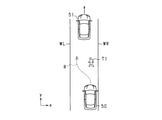
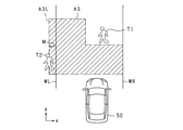
- FIG. 2 is a diagram illustrating a primary object.
- FIG. 3 is a diagram showing a steering avoidance route of the own vehicle for avoiding a collision with a primary target.
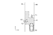
- FIG. 4 is a diagram illustrating a secondary determination region.
- FIG. 5 is a diagram showing a state in which a secondary object exists in the secondary determination area.
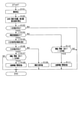
- FIG. 6 is a flowchart of the traveling support control according to the embodiment.
- FIG. 7 is a diagram illustrating the setting of the steering avoidance path R.
- FIG. 8 is a diagram illustrating the setting of the secondary determination area.
- FIG. 9 is a diagram illustrating determination of a secondary object in the secondary determination area.
- FIG. 10 is a diagram illustrating determination of a secondary object in the secondary determination area.
- FIG. 11 is a diagram illustrating a secondary determination region and a margin when the secondary target according to the modified example is the preceding vehicle.
- FIG. 12 is a diagram illustrating a secondary determination region and a margin when the secondary target according to the modified example is an oncoming vehicle.
- FIG. 13 is a diagram illustrating a secondary determination region and a margin when the secondary target according to the modified example is a pedestrian.
- FIG. 14 is a diagram illustrating a secondary determination region and a margin when the secondary object according to the modified example is a stationary object.
- FIG. 15 is a diagram for explaining the positional relationship between the secondary object and the secondary determination region according to the modified example.
- FIG. 16 is a diagram illustrating the setting of the secondary determination region according to the modified example.
- FIG. 17 is a diagram illustrating the setting of the secondary determination region according to the modified example.
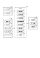
- FIG. 1 shows a driving support system according to the present embodiment.
- the travel support system is mounted on the vehicle and includes an ECU 10, an object detection device 20, a travel state sensor 30, and a controlled device 40.
- the object detection device 20 includes a camera sensor 21 and a radar sensor 22.
- the camera sensor 21 and the radar sensor 22 are examples of object detection sensors that detect objects around the vehicle.
- the object detection sensor may include a sensor that transmits an ultrasonic sensor, a sensor that transmits an exploration wave such as a LIDAR (Light Detection and Ranger / Laser Imaging Detection and Ringing).
- LIDAR Light Detection and Ranger / Laser Imaging Detection and Ringing
- the camera sensor 21 may be a monocular camera such as a CCD camera, a CMOS image sensor, or a near-infrared camera, or may be a stereo camera. Only one camera sensor 21 may be installed in the own vehicle, or a plurality of camera sensors 21 may be installed.
- the camera sensor 21 is attached to, for example, a predetermined height in the center of the vehicle width direction of the vehicle, and captures an image of a region extending in a predetermined angle range toward the front of the vehicle from a bird's-eye view.
- the camera sensor 21 extracts feature points indicating the presence of an object in the captured image. Specifically, edge points are extracted based on the luminance information of the captured image, and the Hough transform is performed on the extracted edge points.
- the camera sensor 21 sequentially outputs the captured images to be sequentially captured to the ECU 10 as sensing information.
- the radar sensor 22 is, for example, a known millimeter wave radar whose transmission wave is a high frequency signal in the millimeter wave band. Only one radar sensor 22 may be installed in the own vehicle, or a plurality of radar sensors 22 may be installed in the own vehicle.
- the radar sensor 22 is provided at the front end of the vehicle, for example, and has a detection range in which an object can be detected in a region within a predetermined detection angle, and detects the position of the object within the detection range.
- the exploration wave is transmitted at a predetermined cycle, and the reflected wave is received by a plurality of antennas. The distance to the object can be calculated from the transmission time of the exploration wave and the reception time of the reflected wave.
- the relative velocity of the reflected wave reflected by the object is calculated from the frequency changed by the Doppler effect.
- the orientation of the object can be calculated from the phase difference of the reflected waves received by the plurality of antennas. If the position and orientation of the object can be calculated, the relative position of the object with respect to the own vehicle can be specified.
- the sensor that transmits the millimeter wave radar such as the radar sensor 22 and the exploration wave such as sonar and LIDAR sequentially feeds the ECU 10 the scanning result based on the received signal obtained when the reflected wave reflected by the obstacle is received. Output.
- the traveling state sensor 30 includes a vehicle speed sensor 31, a steering sensor 32, a yaw rate sensor 33, a brake sensor 34, and an accelerator sensor 35.
- the traveling state sensor 30 is a sensor mounted on a vehicle and capable of detecting traveling information (for example, vehicle speed, yaw rate, steering angle, etc.) which is various parameters indicating the traveling state of the own vehicle.
- the ECU 310 acquires the detection value of the traveling state sensor 30.
- the vehicle speed sensor 31 is provided on a rotating shaft that transmits power to the wheels of the own vehicle, and obtains the speed of the own vehicle based on the number of rotations of the rotating shaft.
- the steering sensor 32 is provided on the steering wheel and detects the direction of the steering operation by the driver and the operation amount thereof.
- the yaw rate sensor 33 outputs a yaw rate signal according to the change speed of the steering amount of the own vehicle to the ECU 10.
- the brake sensor 34 is provided on the brake pedal and detects whether or not the driver has operated the brake pedal and the amount of operation thereof.
- the accelerator sensor 35 is provided on the accelerator pedal, and detects whether or not the accelerator pedal is operated by the driver and the amount of operation thereof.
- the controlled device 40 includes an alarm device 41, a brake device 42, and a steering device 43.
- the alarm device 41, the brake device 42, and the steering device 43 are driven by a control command from the ECU 10.
- the alarm device 41 is, for example, a speaker or a display installed in the passenger compartment of the own vehicle.
- the alarm device 41 outputs an alarm sound, an alarm message, or the like based on a control command from the ECU 10 to notify the driver that there is a danger of collision with an object.
- the brake device 42 is a braking device that brakes the own vehicle.
- the ECU 10 does not have a brake assist function for enhancing and assisting the braking force by the driver's brake operation and a driver's brake operation as a brake function for avoiding a collision with an object or reducing collision damage. It has an automatic braking function that performs automatic braking in some cases.
- the brake device 42 performs brake control by these functions based on the control command from the ECU 10.
- the steering device 43 is a device for steering the own vehicle, and is controlled by a steering operation of the driver or a command from the ECU 10.
- the ECU 10 has a function of automatically controlling the steering device 43 for collision avoidance or lane change.
- the controlled device 40 may include a device controlled by the ECU 10 other than the above.
- a safety device or the like for ensuring the safety of the driver may be included.
- Specific examples of the safety device include a seatbelt device provided with a pretensioner mechanism for pulling in a seatbelt provided in each seat of the own vehicle.
- the ECU 10 includes an object recognition unit 11, a primary target determination unit 12, a primary avoidance determination unit 13, a secondary determination area setting unit 14, a secondary target determination unit 15, a steering support unit 16, and braking support.
- a unit 17 and a notification unit 18 are provided.
- the ECU 10 is provided with a CPU, ROM, RAM, I / O, etc., and the CPU realizes each of these functions by executing a program installed in the ROM. As a result, the ECU 10 creates and outputs a control command to the controlled device 40 based on the information acquired from the object detection device 20 and the running state sensor 30, and thereby executes the running support of the own vehicle. Functions as.
- the object recognition unit 11 acquires the detection information of the object from the camera sensor 21 and the radar sensor 22, and uses the feature points obtained from the camera sensor 21 and the position information of the object obtained from the radar sensor 22 at the position. Recognize the existence of an object. Further, the object recognition unit 11 associates a relative position and a relative speed with respect to the own vehicle for each object, and based on the associated relative position and the relative speed, the relative speed in a direction orthogonal to the traveling direction of the own vehicle. The lateral speed, which is, and the vertical speed, which is the relative speed with respect to the traveling direction of the own vehicle, are calculated.
- the object recognition unit 11 may be configured to recognize an object detected in the determination area set in a predetermined area around the own vehicle as a target object for collision avoidance. Further, the object recognition unit 11 is configured to be able to recognize the position and size of the road structure and the white line.
- the primary target determination unit 12 determines an object to be the primary target to avoid a collision with the own vehicle from a plurality of detection information acquired by the object recognition unit 11. Specifically, the object recognition unit 11 detects one or a plurality of objects existing in front of the traveling direction of the own vehicle, and among the detected objects, (1) the existence probability of the object is high, and (2). ) It is an object existing in the path of the own vehicle, and (3) the collision prediction time (TTC: Time to Collection), which is the time until the own vehicle and the object collide, is the minimum. Identify the primary target object that should avoid a collision with the vehicle.
- TTC Time to Collection
- the object existing in the path of the own vehicle may be specified by using a known technique, for example, based on the high probability of the own lane or the lateral position of the object.
- the object B is the object.
- the object B is specified as the primary target object.
- the primary target is a target object that is a target of collision avoidance in the current traveling path of the own vehicle.
- the type of the target object is, for example, a stationary object such as a vehicle, a bicycle, a pedestrian, a road cone, or a moving object.
- the vehicle 50 when the vehicle 50 travels in the positive direction of the y-axis in the traveling lane between the left white line WL and the right white line WR that are orthogonal to the y direction, the vehicle 50 is in front of the vehicle 50 (y).
- the primary avoidance determination unit 13 determines whether to avoid a collision with a primary target or execute control related to mitigation of collision damage. Specifically, based on the relative distance between the own vehicle and the primary target, the collision prediction time, which is the time until the own vehicle and the primary target collide, is calculated. Then, from the comparison between the collision prediction time and the operation timing, it is determined whether or not to operate the controlled device 40 such as the alarm device 41, the brake device 42, and the steering device 43 in order to avoid the collision.
- the operation timing is the timing at which the alarm device 41, the brake device 42, and the steering device 43 are desired to be operated, and may be set depending on the target to be operated.
- the primary avoidance determination unit 13 has 1 prior to executing collision avoidance with the primary target T1.
- the route R for avoiding steering of the own vehicle 50 for avoiding a collision with the next target T1 is set.
- the steering avoidance route R is a future travel route when the own vehicle 50 executes steering avoidance to the left.
- the steering avoidance route R is set in the traveling lane between the left white line WL and the right white line WR.
- the secondary determination area setting unit 14 sets a secondary determination area for determining an object to be a secondary target for avoiding a collision with the own vehicle in the steering avoidance route set by the primary avoidance determination unit 13. .
- the secondary target is a target object that is a target of collision avoidance in a future traveling route (steering avoidance route) when the own vehicle executes steering avoidance.
- the secondary determination area setting unit 14 sets the secondary determination area A1 around the steering avoidance path R.
- the secondary determination region A1 may be set to include the entire steering avoidance path R in the region, and may be set to a wider region than the steering avoidance path R.
- the secondary determination region A1 is set.
- the primary target T1 is selected to have a high probability of existence of an object, so that if the probability of existence of an object is low, it may be excluded from the primary target T1. be. Therefore, by setting the secondary determination area A1 between the own vehicle 50 and the primary target T1, the object excluded from the primary target T1 is placed between the own vehicle 50 and the primary target T1. Even if it exists, the object can be used as a target for determining whether or not control can be executed.
- the secondary target determination unit 15 determines an object to be a secondary target in the secondary determination region based on the detection information acquired by the object recognition unit 11. More specifically, based on the detection information acquired by the object recognition unit 11, it is determined whether or not an object to be a secondary target for avoiding a collision with the own vehicle exists in the secondary determination area. do. For example, as shown in FIG. 5, a pedestrian (T2) existing in the secondary determination region A1 collides with the own vehicle 50 when the own vehicle 50 travels on the steering avoidance route R. This pedestrian is recognized as the secondary target T2, and the secondary target determination unit 15 determines that the secondary target T2 exists.
- the secondary target determination unit 15 may be configured to set an existing area in which the secondary target exists based on the detection information. For example, a margin may be set around the secondary object, and an existing area including the margin may be set. Further, the secondary target determination unit 15 may be configured to determine that the secondary target exists when the existing region exists in the secondary determination region. By setting a margin around the secondary target and determining whether or not the existing area set to include the margin exists in the secondary judgment area, regardless of the type of the secondary target and the detection accuracy. However, the collision between the secondary target and the own vehicle can be avoided more reliably.
- the steering support unit 16 creates and outputs a control command for the steering device 43 when the primary avoidance determination unit 13 determines that the steering device 43 is to be operated to avoid a collision with the primary target. ..
- the primary target determination unit 12 determines that the primary target exists and the primary avoidance determination unit 13 determines that the steering device 43 is operated to avoid a collision with the primary target, steering is performed.
- the support unit 16 creates a control command for executing steering avoidance on condition that the secondary target determination unit 15 determines that the secondary target does not exist, and outputs the control command to the steering device 43.
- the steering support unit 16 is determined by the primary target determination unit 12 that the primary target T1 exists, and the primary avoidance determination unit 13 avoids collision with the primary target T1. Even when it is determined that the steering device 43 is to be operated, as shown in FIG. 5, when the secondary target determination unit 15 determines that the secondary target T2 exists, the vehicle 50 Suppress the creation of control commands to execute steering avoidance. Note that "suppressing the creation of a control command” may mean not creating a control command or suspending the creation of a control command.
- the determination of whether or not the predetermined condition is satisfied is further executed within the predetermined time, and based on the determination result, it is determined whether or not the control command is created. You may do it. Further, as another example, the steering control may be weakened so that steering avoidance is hardly executed.
- the braking support unit 17 creates a control command for operating the brake device 42 when the primary avoidance determination unit 13 determines that the brake device 42 is to be operated to avoid a collision with the primary target. Output to the brake device 42.
- the notification unit 18 creates a control command for operating the alarm device 41 when it is determined by the primary avoidance determination unit 13 to operate the alarm device 41 to warn of a collision with the primary target. Output to the alarm device 41.
- the traveling support control executed by the ECU 10 will be described with reference to the flowchart shown in FIG.
- the process shown in FIG. 6 is repeatedly executed at a predetermined cycle.
- step S101 the detection information of the objects around the own vehicle by the camera sensor 21 and the radar sensor 22 is acquired, and the process proceeds to step S102.
- step S102 object recognition is executed based on the object detection information acquired in step S101. Specifically, the distance between the own vehicle and the object, the lateral position of the object, the relative speed of the object with respect to the own vehicle, and the like are calculated. After that, the process proceeds to step S103.
- step S103 it is determined whether or not an object to be the primary target exists among the objects recognized in step S102. If, among the objects recognized in step S102, there is a target object to be subject to collision avoidance in the current traveling path of the own vehicle, that object is recognized as the primary target, and it is determined that the primary target exists.
- the process proceeds to step S104. For example, if the primary target T1 as shown in FIG. 2 exists, the process proceeds to step S104. If, among the objects recognized in step S102, there is no target object to be subject to collision avoidance in the current traveling path of the own vehicle, it is determined that the primary target does not exist, and the process ends.
- step S104 it is determined whether or not there is a steering avoidance route for the own vehicle to avoid a collision with the primary target. For example, when it is possible to set the steering avoidance path R as shown in FIG. 3, it is determined that the steering avoidance path exists. More specifically, there is a steering avoidance route R when there is a sufficient area between the left white line WL and the right white line WR for the vehicle 50 to avoid the primary target T1 and proceed. Then it is determined. For example, as shown in FIG. 7, when the own vehicle 50 can secure a predetermined lateral distance (distance in the x-axis direction) from the primary target T1 when the own vehicle 50 passes by the side of the position y1 of the primary target T1.
- the route R can be set as a region in which both ends thereof are the left end RL of the route and the right end RW of the route.
- the route R exists at the position y1 when the distance dxR between the position x1 at the left end of the primary target T1 and the position xR at the right end RW of the path on the side close to the primary target T1 can be secured.
- the distance between the position xWL of the left end RL of the route far from the primary target T1 and the position xWL of the left white line WL which is the white line near the left end RL of the route at the position y1 is defined as the distance dxL.
- Step S105 If it is determined that there is a steering avoidance route, the process proceeds to step S105. If it is determined that the steering avoidance route does not exist, the process proceeds to step S110. Steps S110 and S111 are processes for avoiding or reducing the collision between the primary target and the own vehicle by braking or warning instead of steering avoidance.
- the secondary determination area is set based on the steering avoidance route.
- the distances L1 to L5 are set as shown in FIG. do.
- the distance L1 is the distance (longitudinal distance) between the own vehicle 50 and the primary target T1 in the y-axis direction.
- the distance in the y-axis direction from the position y0 at the front end of the own vehicle 50 to the position y1 at the rear end of the primary target T1 can be set as the distance L1.
- the distance L2 is a vertical distance from the primary target T1 to the upper limit in the depth direction of the secondary determination region A1.
- the distance in the y-axis direction from the position y1 at the rear end of the primary target T1 to the upper limit position y2 in the depth direction of the secondary determination region A1 can be set as the distance L2.
- the distance L3 is the distance between the left white line WL and the right white line WR in the x-axis direction (horizontal distance).
- the distance between the position xWL of the left white line WL and the position xWR of the right white line WR in the x-axis direction can be set as the distance L3.
- the x-axis is orthogonal to the y-axis, and the vertical distance and the horizontal distance indicate distances in directions orthogonal to each other.
- the distance L4 is a lateral distance between the white line (left white line WL) located in the left direction, which is the steering direction of the own vehicle 50, and the primary target T1.
- the distance in the x-axis direction between the position xWL of the left white line WL and the position x1 of the left end of the primary target T1 can be set as the distance L4.
- the distance L5 is a region offset, which is a lateral distance between the primary target T1 and the secondary determination region A1 in the left direction, which is the steering direction of the own vehicle 50.
- the distance in the x-axis direction between the left end position x1 of the primary target T1 and the right end position x2 in the region deeper than y1 of the secondary determination region A1 can be set as the distance L5.
- the distances L1 to L5 can be set based on the distance between the own vehicle and the primary target calculated in step S102, the lateral position of the primary target, the relative speed of the primary target with respect to the own vehicle, the position of the white line, and the like. Then, the process proceeds to step S106.
- step S106 it is determined whether or not a secondary target exists in the secondary determination area set in step S105.
- margins S1 and S2 are set on both sides of the secondary target T2 in the lateral direction (x-axis direction).
- the margin S1 is a left margin which is the steering direction of the own vehicle 50
- the margin S2 is a right margin in the direction opposite to the steering direction of the own vehicle 50.
- the region including the margins S1 and S2 is recognized as the region where the secondary target T2 exists. Then, when a part or all of the recognized secondary target T2 exists in the secondary determination area A1, it is determined that the secondary target exists in the secondary determination area.
- step S106 when the right end of the margin S1 of the secondary target T2 is on the left side of the left white line WL, the existing region of the secondary target T2 including the margins S1 and S2 is the secondary determination region A1. It is determined that it does not exist inside. As a result, a negative determination is made in step S106, the process proceeds to step S109, and steering support is executed. Specifically, a control signal for executing steering avoidance is output to the steering device 43 according to the steering avoidance route set in step S104. After that, the process ends.
- step S106 when the right end of the margin S1 of the secondary target T2 is on the right side of the left white line WL, the existing region of the secondary target T2 including the margins S1 and S2 is the secondary determination region A1. It is determined that it exists inside. As a result, an affirmative determination is made in step S106, and the process proceeds to step S107.
- Steps S107 and S108 are processes for avoiding or reducing the collision between the primary target and the own vehicle by braking or warning instead of steering avoidance.
- step S107 it is determined whether or not to execute automatic braking or notification by an alarm for the primary target. Specifically, it is determined whether or not to operate the alarm device 41 and the brake device 42 in order to avoid the collision from the comparison between the collision prediction time and the operation timing. If an affirmative determination is made in step S107, the process ends after the alarm command to the alarm device 41 and the automatic braking command by the brake device 42 are executed in step S108. If a negative determination is made in step S107, the process ends as it is. Since the processes shown in steps S110 and S111 are the same as the processes shown in steps S107 and S108, the description thereof will be omitted.
- the ECU 10 determines that there is a primary target for avoiding a collision with the own vehicle as shown in step S103, and as shown in step S104, the primary target is determined.
- a secondary determination area is set based on the steering avoidance path as shown in S105.
- steering support is executed along the steering avoidance path.
- steps S106 to S108 when it is determined that the secondary object exists in the secondary determination region, the steering support is not executed, and the collision avoidance process by automatic braking or warning is executed.
- the ECU 10 is for avoiding a collision with the primary object when it is determined that the secondary object exists. Do not perform steering avoidance of the own vehicle. Therefore, by avoiding a collision with a primary object by automatic steering, it is possible to suppress an increase in the possibility of collision with another object different from the primary object existing in the avoidance path. Further, when steering avoidance is not executed, collision with the primary target can be avoided by means other than automatic steering.
- the secondary determination area setting unit 14 may be configured to change the size and installation position of the secondary determination area based on the type, speed, size, position, and the like of the secondary object.
- the secondary target determination unit 15 may be configured to change the margin of the secondary target and change the existing area based on the type, speed, size, position, etc. of the secondary target. ..
- the type, speed, and size of the secondary object can be acquired as detection information from the object detection device 20 by the object recognition unit 11.
- 11 to 14 show the secondary determination area and the margin when the secondary target is a preceding vehicle, an oncoming vehicle, a pedestrian, or a stationary object, respectively.
- the oncoming vehicle is a vehicle traveling in a direction opposite to the traveling direction of the own vehicle.
- the distance L2 is longer than when the secondary target T2 is the preceding vehicle, and the margins S1 and S2 are set. May be set to a large value.
- the distance L2 is 10 m and the margins S1 and S2 are 1 m, respectively, whereas in the case of the oncoming vehicle shown in FIG. 12, the distance L2 is.
- the secondary determination region A2 having a larger distance L2 than when the secondary target T2 is a preceding vehicle is set. Further, by setting the margins S1 and S2 to be large, the existing area is set to be large. As a result, it becomes easier to make an affirmative determination in step S106, and a collision between the secondary target T2 and the own vehicle 50 can be more reliably avoided.
- the secondary object T2 when the secondary object T2 is a road structure such as a road cone and has a low rank as a collision avoidance target, the secondary object T2 is a secondary object as shown in FIG.
- the margins S1 and S2 may be set larger than when the target T2 is an object having a high rank as a collision avoidance target such as a pedestrian. Specifically, for example, in the case of the pedestrian shown in FIG. 13, the margins S1 and S2 are 1 m each, whereas in the case of the oncoming vehicle shown in FIG. 14, the margins S1 and S2 are 1. It may be set to 3 m.
- the distance L2 in FIGS. 13 and 14 is set to the same 10 m.
- the existence probability is set according to the object type, and the size of the object may not be detected for an object with a low existence probability.
- an object such as a pedestrian whose existence probability is set to be high is detected by the size of the object such as the width (size in the x-axis direction), while the existence probability is high like a road structure.
- An object set to be low may be detected as a point, and the size of the object such as the width may not be detected.
- the margins S1 and S2 are made larger than the secondary target T2 having a high existence probability such as a pedestrian. The collision with the own vehicle 50 can be avoided more reliably.
- the margin S1L is provided for the secondary target T2L existing in the left direction, which is the direction of steering avoidance of the own vehicle 50, and the secondary target T2R existing in the right direction, which is the opposite direction of steering avoidance.
- S2L, S1R, S2R may be changed in size.
- the secondary target T2L existing in the direction of steering avoidance has a higher risk of colliding with the own vehicle 50 than the secondary target T2R existing in the direction opposite to the steering avoidance. It may be set larger than S2R.
- the margins S2L and S2R set on the opposite side of the secondary determination area A1 may be set smaller than the margins S1L and S1R set on the side of the secondary determination area A1, or may be set to zero. May be good.
- the secondary determination region A3 includes a region A3L that exceeds the left white line WL by the lateral length M corresponding to the margin set in the secondary target T2. For example, if the lateral length M is set to the same value as the margin S1L shown in FIG. 15, the existence of the secondary target is determined to the same extent as in FIG. 15 without setting the margin for the secondary target T2. It will be easier.
- the secondary determination area setting unit 14 may be configured to be set based on the type of the primary target T1 in the setting of the area offset L5, or may be detected when detecting an object around the own vehicle 50. It may be configured to be set based on accuracy, or it may be configured to be set based on a region in which the primary object T1 may exist after the collision prediction time TTC. For example, depending on the detection accuracy of an object, it may be possible to obtain a detection result in which a plurality of objects exist for one primary target T1. In such a case, the object detected at a position where the lateral distance from the primary target T1 is closer than the region offset L5 is treated as the same object as the primary target T1 to supplement the detection accuracy of the object.
- the secondary determination area can be appropriately set.
- the ECU 10 functions as a running support device that executes running support for avoiding a collision between the own vehicle and the object based on the detection information of an object existing around the own vehicle.
- the ECU 10 includes a primary target determination unit 12, a secondary determination area setting unit 14, a secondary target determination unit 15, and a steering support unit 16.
- the primary target determination unit 12 determines an object to be the primary target to avoid a collision with the own vehicle based on the detection information.
- the secondary determination area setting unit 14 is a secondary target object that should avoid a collision with the own vehicle in the steering avoidance route of the own vehicle for avoiding the collision with the primary target.
- the secondary judgment area for judging is set.
- the secondary target determination unit 15 determines an object to be a secondary target in the secondary determination region based on the detection information.
- the steering support unit 16 has a function of executing steering support of the own vehicle. Then, when the primary target determination unit 12 determines that the primary target exists and the secondary target determination unit 15 determines that the secondary target exists, the steering support unit 16 avoids steering of the own vehicle. Suppress. That is, even if the steering support unit 16 determines that the primary target exists by the primary target determination unit 12, if the secondary target determination unit 15 determines that the secondary target exists, the steering support unit 16 may determine that the secondary target exists. Suppresses steering avoidance of the own vehicle to avoid collision with the primary target. Therefore, as a result of avoiding a collision with a primary object by automatic steering of the steering support unit 16, it is possible to suppress an increase in the possibility of collision with another object different from the primary object existing in the avoidance path. can.
- the secondary determination area setting unit 14 may be configured to change the secondary determination area based on the type, speed, size, or position of the secondary target acquired as detection information.
- the size and installation position of the secondary judgment area should be changed appropriately. It is possible to more appropriately determine the possibility of collision between the secondary target and the own vehicle, and to execute appropriate driving support.
- the secondary target determination unit 15 may be configured to set an existing area in which the secondary target exists based on the detection information. Further, the secondary target determination unit 15 may be configured to determine that the secondary target exists when the existing region exists in the secondary determination region. By setting a margin around the secondary target and determining whether or not the existing area set to include the margin exists in the secondary judgment area, regardless of the type of the secondary target and the detection accuracy. However, the collision between the secondary target and the own vehicle can be avoided more reliably.
- the secondary target determination unit 15 may be configured to change the existing area based on the type, speed, size, or position of the secondary target acquired as detection information.
- the size and installation position of the existing area of the secondary target are appropriately changed. It is possible to more appropriately determine the possibility of collision between the secondary target and the own vehicle, and to execute appropriate driving support.
- the type of the secondary target is a vehicle (oncoming vehicle) traveling in a direction opposite to the traveling direction of the own vehicle
- the secondary target determination unit 15 has its own type of secondary target. It may be configured to have a larger existing area than a vehicle traveling in the same direction as the traveling direction of the vehicle (for example, a preceding vehicle).
- the steering support unit 16 is configured to suppress steering avoidance when it is determined that a secondary object exists in the secondary determination region in the steering avoidance determination.
- the vehicle may be configured to suppress steering avoidance of the own vehicle. .. If there is an oncoming vehicle in the direction of avoiding steering, the vehicle behaves as if the own vehicle and the oncoming vehicle approach each other, and collision avoidance by braking may be activated for the oncoming vehicle. Situations can be avoided.
- the distance L2 the distance in the y-axis direction from the position y1 at the rear end of the primary target T1 to the upper limit position y2 in the depth direction of the secondary determination region A1 is set.
- the distance L2 may be set according to the speed of the own vehicle. For example, as the speed of the own vehicle increases, the distance L2 can be set longer to set an appropriate determination area according to the speed of the own vehicle.
- the margins S1 and S2 are set for the existing region of the secondary target, but the margins S1 and S2 may be changed according to the traveling direction of the secondary target. Specifically, the margin on the traveling direction side of the secondary object may be changed to be larger than the margin on the opposite side of the traveling direction.
- the margins S1 and S2 may be changed by themselves, or the margins may be changed as a whole by adding a correction margin to the margins S1 and S2. Further, the margin may be changed according to the speed of progress.
- the margins S1 and S2 may be changed according to the distance between the own vehicle and the secondary target. Specifically, the margins S1 and S2 may be set small when the secondary target is close to the own vehicle and large when the secondary target is far from the own vehicle. Further, the margins S1 and S2 are set large when the secondary target exists behind the point where the vehicle is predicted to start steering avoidance, and the secondary target is on the front side from the point where the steering avoidance is started. If it exists, it may be set small. By setting in this way, it is possible to prevent the steering avoidance from being unnecessarily executed due to the secondary target existing before the steering avoidance is started. When margins are set for the own vehicle in the horizontal direction and the vertical direction, only the horizontal margins S1 and S2 may be changed.
- a region A3L having a lateral length M beyond the left white line WL is set in the secondary determination region A3.
- the present invention is not limited to this, and the region A3L may be added and a margin may be set in the secondary target T2.
- the region A3L not limited to the region A3L shown in FIG. 16 may be set as the region A3La beyond the left white line WL as shown in FIG.
- the region A3La beyond the left white line WL is set so as to avoid a distance Y in which the vehicle 50 travels straight from the current position until it starts to turn by steering.
- the controls and methods thereof described in the present disclosure are realized by a dedicated computer provided by configuring a processor and memory programmed to perform one or more functions embodied by a computer program. May be done.
- the controls and methods thereof described in the present disclosure may be implemented by a dedicated computer provided by configuring the processor with one or more dedicated hardware logic circuits.
- the control unit and method thereof described in the present disclosure may be a combination of a processor and memory programmed to perform one or more functions and a processor configured by one or more hardware logic circuits. It may be realized by one or more dedicated computers configured.
- the computer program may be stored in a computer-readable non-transitional tangible recording medium as an instruction executed by the computer.
Landscapes
- Engineering & Computer Science (AREA)
- Transportation (AREA)
- Mechanical Engineering (AREA)
- Automation & Control Theory (AREA)
- Chemical & Material Sciences (AREA)
- Combustion & Propulsion (AREA)
- Human Computer Interaction (AREA)
- Physics & Mathematics (AREA)
- General Physics & Mathematics (AREA)
- Traffic Control Systems (AREA)
Abstract
A travel assistance device (10) includes a primary object determining unit (12) that executes travel assistance for avoiding collision of an own vehicle with an object, on the basis of detection information of an object present in the vicinity of the own vehicle, and determines an object that is a primary object regarding which collision with the own vehicle is to be avoided on the basis of the detection information, a secondary determining region setting unit (14) that sets a secondary determining region in which determination is made with respect to an object that is a secondary object regarding which collision with the own vehicle is to be avoided on a route of steering avoidance of the own vehicle for avoiding collision with the primary object, on the basis of the detection information, a secondary object determining unit (15) that determines the object that is the secondary object in the secondary determining region, on the basis of the detection information, and a steering assistance unit (16) that executes steering assistance of the own vehicle. The steering assistance unit suppresses steering avoidance of the own vehicle in a case in which the primary object determining unit determines that the primary object is present, and the secondary object determining unit determines that the secondary object is present.
Description
本出願は、2020年8月25日に出願された日本出願番号2020-141756号に基づくもので、ここにその記載内容を援用する。
This application is based on Japanese Application No. 2020-141756 filed on August 25, 2020, and the contents of the description are incorporated herein by reference.
自車の周囲の物体が、自車に対して衝突する可能性があると判定された場合に、自車の衝突回避制御を実行する走行支援装置に関する。
Regarding a traveling support device that executes collision avoidance control of the own vehicle when it is determined that an object around the own vehicle may collide with the own vehicle.
自車の周囲の物体が、自車に対して衝突する可能性があると判定された場合に、自車を制動または操舵する等の衝突回避制御を実行する走行支援装置が知られている。特許文献1では、前方に検出された物体と自車とが衝突する可能性が高い場合に自動制動により自車を制動し、制動によっても衝突する可能性が高い場合には、さらに、自車を自動操舵する。自動操舵を実行するか否かについては、検出された物体と自車とが衝突する衝突予測位置における衝突予測速度が所定の閾値との比較に基づいて、判断される。
A traveling support device that executes collision avoidance control such as braking or steering the own vehicle when it is determined that an object around the own vehicle may collide with the own vehicle is known. In Patent Document 1, when the object detected in front and the own vehicle are likely to collide, the own vehicle is braked by automatic braking, and when there is a high possibility of collision by braking, the own vehicle is further applied. Is automatically steered. Whether or not to execute the automatic steering is determined based on the comparison with the predetermined threshold value of the collision prediction speed at the collision prediction position where the detected object and the own vehicle collide.
特許文献1では、自車の周囲の物体のうち、自車との衝突可能性が高い物体である1次対象との衝突を回避することのみを考慮して、自動制動や自動操舵を行う。しかしながら、1次対象との衝突を回避するため自動操舵を実行すると、自動操舵による回避経路に存在する、1次対象とは異なる他の物体との衝突可能性が高まることがある。
In Patent Document 1, automatic braking and automatic steering are performed only in consideration of avoiding a collision with a primary object, which is an object having a high possibility of collision with the own vehicle among the objects around the own vehicle. However, when automatic steering is executed to avoid a collision with the primary target, the possibility of collision with another object different from the primary target existing in the avoidance path by the automatic steering may increase.
上記に鑑み、本開示は、自動操舵により1次対象との衝突を回避した結果、その回避経路に存在する1次対象とは異なる他の物体との衝突可能性が高まることを抑制する技術を提供することを目的とする。
In view of the above, the present disclosure is a technique for suppressing the possibility of collision with another object different from the primary object existing in the avoidance path as a result of avoiding the collision with the primary object by automatic steering. The purpose is to provide.
本開示は、自車の周囲に存在する物体の検出情報に基づいて、前記自車と前記物体との衝突を回避するための走行支援を実行する走行支援装置を提供する。この走行支援装置は、前記検出情報に基づいて、前記自車との衝突を回避すべき1次対象となる物体を判定する1次対象判定部と、前記検出情報に基づいて、前記1次対象との衝突を回避するための前記自車の操舵回避の経路において、自車との衝突を回避すべき2次対象となる物体を判定する2次判定領域を設定する2次判定領域設定部と、前記検出情報に基づいて、前記2次判定領域において前記2次対象となる物体を判定する2次対象判定部と、前記自車と前記物体との衝突を回避するために前記自車の操舵支援を実行する操舵支援部と、を備える。前記操舵支援部は、前記1次対象判定部により前記1次対象が存在すると判定され、かつ、前記2次対象判定部により前記2次対象が存在すると判定された場合に、前記自車の操舵回避を抑制する。
The present disclosure provides a running support device that executes running support for avoiding a collision between the own vehicle and the object based on detection information of an object existing around the own vehicle. This travel support device has a primary target determination unit that determines an object that is a primary target for avoiding a collision with the own vehicle based on the detection information, and the primary target based on the detection information. In the steering avoidance route of the own vehicle for avoiding the collision with the own vehicle, the secondary determination area setting unit for setting the secondary determination area for determining the object to be the secondary target for avoiding the collision with the own vehicle. , The secondary target determination unit that determines the object to be the secondary target in the secondary determination region based on the detection information, and the steering of the own vehicle in order to avoid collision between the own vehicle and the object. It is equipped with a steering support unit that executes support. The steering support unit steers the own vehicle when the primary target determination unit determines that the primary target exists and the secondary target determination unit determines that the secondary target exists. Suppress avoidance.
本開示によれば、1次対象判定部により、自車との衝突を回避すべき1次対象が判定された場合に、2次判定領域設定部により、1次対象との衝突を回避するために自車の操舵回避の経路において自車との衝突を回避すべき2次対象を判定するための2次判定領域が設定される。そして、2次対象判定部により、2次判定領域内において2次対象の判定が実行される。操舵支援部は、1次対象判定部により1次対象が存在すると判定された場合であっても、2次対象判定部により2次対象が存在すると判定された場合には、1次対象との衝突を回避するための自車の操舵回避を抑制する。このため、操舵支援部の自動操舵により1次対象との衝突を回避した結果、その回避経路に存在する1次対象とは異なる他の物体との衝突可能性が高まることを抑制することができる。
According to the present disclosure, when the primary target determination unit determines a primary target to avoid a collision with the own vehicle, the secondary determination area setting unit avoids a collision with the primary target. A secondary determination area for determining a secondary target for avoiding a collision with the own vehicle is set in the route for avoiding steering of the own vehicle. Then, the secondary target determination unit executes the determination of the secondary target in the secondary determination area. Even if the primary target determination unit determines that the primary target exists, the steering support unit determines that the secondary target exists when the secondary target determination unit determines that the secondary target exists. Suppress steering avoidance of own vehicle to avoid collision. Therefore, as a result of avoiding a collision with the primary target by the automatic steering of the steering support unit, it is possible to suppress an increase in the possibility of collision with another object different from the primary target existing in the avoidance path. ..
本開示についての上記目的およびその他の目的、特徴や利点は、添付の図面を参照しながら下記の詳細な記述により、より明確になる。その図面は、
図1は、第1実施形態に係る走行支援装置を含む走行支援システムを示す図であり、
図2は、1次対象について説明する図であり、
図3は、1次対象との衝突を回避するための自車の操舵回避の経路を示す図であり、
図4は、2次判定領域について説明する図であり、
図5は、2次判定領域内に2次対象が存在する状態を示す図であり、
図6は、実施形態に係る走行支援制御のフローチャートであり、
図7は、操舵回避の経路Rの設定について説明する図であり、
図8は、2次判定領域の設定について説明する図であり、
図9は、2次判定領域内における2次対象の判定について説明する図であり、
図10は、2次判定領域内における2次対象の判定について説明する図であり、
図11は、変形例に係る2次対象が先行車である場合の2次判定領域およびマージンについて説明する図であり、
図12は、変形例に係る2次対象が対向車である場合の2次判定領域およびマージンについて説明する図であり、
図13は、変形例に係る2次対象が歩行者である場合の2次判定領域およびマージンについて説明する図であり、
図14は、変形例に係る2次対象が静止物である場合の2次判定領域およびマージンについて説明する図であり、
図15は、変形例に係る2次対象と2次判定領域との位置関係について説明する図であり、
図16は、変形例に係る2次判定領域の設定について説明する図である。
図17は、変形例に係る2次判定領域の設定について説明する図である。
The above objectives and other objectives, features and advantages of the present disclosure will be further clarified by the following detailed description with reference to the accompanying drawings. The drawing is
FIG. 1 is a diagram showing a travel support system including a travel support device according to the first embodiment. FIG. 2 is a diagram illustrating a primary object. FIG. 3 is a diagram showing a steering avoidance route of the own vehicle for avoiding a collision with a primary target. FIG. 4 is a diagram illustrating a secondary determination region. FIG. 5 is a diagram showing a state in which a secondary object exists in the secondary determination area. FIG. 6 is a flowchart of the traveling support control according to the embodiment. FIG. 7 is a diagram illustrating the setting of the steering avoidance path R. FIG. 8 is a diagram illustrating the setting of the secondary determination area. FIG. 9 is a diagram illustrating determination of a secondary object in the secondary determination area. FIG. 10 is a diagram illustrating determination of a secondary object in the secondary determination area. FIG. 11 is a diagram illustrating a secondary determination region and a margin when the secondary target according to the modified example is the preceding vehicle. FIG. 12 is a diagram illustrating a secondary determination region and a margin when the secondary target according to the modified example is an oncoming vehicle. FIG. 13 is a diagram illustrating a secondary determination region and a margin when the secondary target according to the modified example is a pedestrian. FIG. 14 is a diagram illustrating a secondary determination region and a margin when the secondary object according to the modified example is a stationary object. FIG. 15 is a diagram for explaining the positional relationship between the secondary object and the secondary determination region according to the modified example. FIG. 16 is a diagram illustrating the setting of the secondary determination region according to the modified example. FIG. 17 is a diagram illustrating the setting of the secondary determination region according to the modified example.
(第1実施形態)
図1に、本実施形態に係る走行支援システムを示す。走行支援システムは、車両に搭載されており、ECU10と、物体検出装置20と、走行状態センサ30と、被制御装置40とを備えている。 (First Embodiment)
FIG. 1 shows a driving support system according to the present embodiment. The travel support system is mounted on the vehicle and includes anECU 10, an object detection device 20, a travel state sensor 30, and a controlled device 40.
図1に、本実施形態に係る走行支援システムを示す。走行支援システムは、車両に搭載されており、ECU10と、物体検出装置20と、走行状態センサ30と、被制御装置40とを備えている。 (First Embodiment)
FIG. 1 shows a driving support system according to the present embodiment. The travel support system is mounted on the vehicle and includes an
物体検出装置20は、カメラセンサ21と、レーダセンサ22とを含んでいる。カメラセンサ21およびレーダセンサ22は、自車の周囲の物体を検出する物体検出センサの一例である。物体検出センサとしては、上記の他に、超音波センサ、LIDAR(Light Detection and Ranging/Laser Imaging Detection and Ranging)等の探査波を送信するセンサを備えていてもよい。
The object detection device 20 includes a camera sensor 21 and a radar sensor 22. The camera sensor 21 and the radar sensor 22 are examples of object detection sensors that detect objects around the vehicle. In addition to the above, the object detection sensor may include a sensor that transmits an ultrasonic sensor, a sensor that transmits an exploration wave such as a LIDAR (Light Detection and Ranger / Laser Imaging Detection and Ringing).
カメラセンサ21は、例えばCCDカメラ、CMOSイメージセンサ、近赤外線カメラ等の単眼カメラであってもよいし、ステレオカメラであってもよい。カメラセンサ21は、自車に1つのみ設置されていてもよいし、複数設置されていてもよい。カメラセンサ21は、例えば、車両の車幅方向中央の所定高さに取り付けられており、車両前方へ向けて所定角度範囲で広がる領域を俯瞰視点から撮像する。カメラセンサ21は、撮像した画像における、物体の存在を示す特徴点を抽出する。具体的には、撮像した画像の輝度情報に基づきエッジ点を抽出し、抽出したエッジ点に対してハフ変換を行う。ハフ変換では、例えば、エッジ点が複数個連続して並ぶ直線上の点や、直線どうしが直交する点が特徴点として抽出される。カメラセンサ21は、逐次撮像する撮像画像をセンシング情報としてECU10へ逐次出力する。
The camera sensor 21 may be a monocular camera such as a CCD camera, a CMOS image sensor, or a near-infrared camera, or may be a stereo camera. Only one camera sensor 21 may be installed in the own vehicle, or a plurality of camera sensors 21 may be installed. The camera sensor 21 is attached to, for example, a predetermined height in the center of the vehicle width direction of the vehicle, and captures an image of a region extending in a predetermined angle range toward the front of the vehicle from a bird's-eye view. The camera sensor 21 extracts feature points indicating the presence of an object in the captured image. Specifically, edge points are extracted based on the luminance information of the captured image, and the Hough transform is performed on the extracted edge points. In the Hough transform, for example, points on a straight line in which a plurality of edge points are continuously arranged or points in which the straight lines are orthogonal to each other are extracted as feature points. The camera sensor 21 sequentially outputs the captured images to be sequentially captured to the ECU 10 as sensing information.
レーダセンサ22は、例えば、ミリ波帯の高周波信号を送信波とする公知のミリ波レーダである。レーダセンサ22は、自車に1つのみ設置されていてもよいし、複数設置されていてもよい。レーダセンサ22は、例えば、自車の前端部に設けられ、所定の検出角に入る領域を物体検出可能な検出範囲とし、検出範囲内の物体の位置を検出する。具体的には、所定周期で探査波を送信し、複数のアンテナにより反射波を受信する。この探査波の送信時刻と反射波の受信時刻とにより、物体との距離を算出することができる。また、物体に反射された反射波の、ドップラー効果により変化した周波数により、相対速度を算出する。加えて、複数のアンテナが受信した反射波の位相差により、物体の方位を算出することができる。なお、物体の位置および方位が算出できれば、その物体の、自車に対する相対位置を特定することができる。
The radar sensor 22 is, for example, a known millimeter wave radar whose transmission wave is a high frequency signal in the millimeter wave band. Only one radar sensor 22 may be installed in the own vehicle, or a plurality of radar sensors 22 may be installed in the own vehicle. The radar sensor 22 is provided at the front end of the vehicle, for example, and has a detection range in which an object can be detected in a region within a predetermined detection angle, and detects the position of the object within the detection range. Specifically, the exploration wave is transmitted at a predetermined cycle, and the reflected wave is received by a plurality of antennas. The distance to the object can be calculated from the transmission time of the exploration wave and the reception time of the reflected wave. In addition, the relative velocity of the reflected wave reflected by the object is calculated from the frequency changed by the Doppler effect. In addition, the orientation of the object can be calculated from the phase difference of the reflected waves received by the plurality of antennas. If the position and orientation of the object can be calculated, the relative position of the object with respect to the own vehicle can be specified.
レーダセンサ22等のミリ波レーダ、ソナー、LIDAR等の探査波を送信するセンサは、障害物によって反射された反射波を受信した場合に得られる受信信号に基づく走査結果をセンシング情報としてECU10へ逐次出力する。
The sensor that transmits the millimeter wave radar such as the radar sensor 22 and the exploration wave such as sonar and LIDAR sequentially feeds the ECU 10 the scanning result based on the received signal obtained when the reflected wave reflected by the obstacle is received. Output.
走行状態センサ30は、車速センサ31と、ステアセンサ32と、ヨーレートセンサ33と、ブレーキセンサ34と、アクセルセンサ35とを備えている。走行状態センサ30は、車両に搭載され、自車の走行状態を示す各種パラメータである走行情報(例えば、車速、ヨーレート、操舵角等)を検出可能なセンサ類である。ECU310は、走行状態センサ30の検出値を取得する。
The traveling state sensor 30 includes a vehicle speed sensor 31, a steering sensor 32, a yaw rate sensor 33, a brake sensor 34, and an accelerator sensor 35. The traveling state sensor 30 is a sensor mounted on a vehicle and capable of detecting traveling information (for example, vehicle speed, yaw rate, steering angle, etc.) which is various parameters indicating the traveling state of the own vehicle. The ECU 310 acquires the detection value of the traveling state sensor 30.
車速センサ31は、自車の車輪に動力を伝達する回転軸に設けられており、その回転軸の回転数に基づいて、自車の速度を求める。ステアセンサ32は、ステアリングに設けられており、運転者による操舵操作の方向、およびその操作量を検出する。ヨーレートセンサ33は、自車の操舵量の変化速度に応じたヨーレート信号をECU10に出力する。
The vehicle speed sensor 31 is provided on a rotating shaft that transmits power to the wheels of the own vehicle, and obtains the speed of the own vehicle based on the number of rotations of the rotating shaft. The steering sensor 32 is provided on the steering wheel and detects the direction of the steering operation by the driver and the operation amount thereof. The yaw rate sensor 33 outputs a yaw rate signal according to the change speed of the steering amount of the own vehicle to the ECU 10.
ブレーキセンサ34は、ブレーキペダルに設けられており、運転者によるブレーキペダルの操作の有無、およびその操作量を検出する。アクセルセンサ35は、アクセルペダルに設けられており、運転者によるアクセルペダルの操作の有無、およびその操作量を検出する。
The brake sensor 34 is provided on the brake pedal and detects whether or not the driver has operated the brake pedal and the amount of operation thereof. The accelerator sensor 35 is provided on the accelerator pedal, and detects whether or not the accelerator pedal is operated by the driver and the amount of operation thereof.
被制御装置40は、警報装置41と、ブレーキ装置42と、操舵装置43とを備えている。警報装置41、ブレーキ装置42、および操舵装置43は、ECU10からの制御指令により駆動する。
The controlled device 40 includes an alarm device 41, a brake device 42, and a steering device 43. The alarm device 41, the brake device 42, and the steering device 43 are driven by a control command from the ECU 10.
警報装置41は、例えば自車の車室内に設置されたスピーカやディスプレイである。警報装置41は、ECU10からの制御指令に基づき警報音や警報メッセージ等を出力することにより、運転者に対し、物体との衝突の危険が及んでいることを報知する。
The alarm device 41 is, for example, a speaker or a display installed in the passenger compartment of the own vehicle. The alarm device 41 outputs an alarm sound, an alarm message, or the like based on a control command from the ECU 10 to notify the driver that there is a danger of collision with an object.
ブレーキ装置42は、自車を制動する制動装置である。本実施形態においてECU10は、物体との衝突回避又は衝突被害の軽減のためのブレーキ機能として、運転者のブレーキ操作による制動力を増強して補助するブレーキアシスト機能、及び運転者のブレーキ操作がない場合に自動制動を行う自動ブレーキ機能を有している。ブレーキ装置42は、ECU10からの制御指令に基づき、これらの機能によるブレーキ制御を実施する。
The brake device 42 is a braking device that brakes the own vehicle. In the present embodiment, the ECU 10 does not have a brake assist function for enhancing and assisting the braking force by the driver's brake operation and a driver's brake operation as a brake function for avoiding a collision with an object or reducing collision damage. It has an automatic braking function that performs automatic braking in some cases. The brake device 42 performs brake control by these functions based on the control command from the ECU 10.
操舵装置43は、自車両を操舵するための装置であり、運転者の操舵操作またはECU10からの指令によって制御される。ECU10は、衝突回避または車線変更のために、操舵装置43を自動で制御する機能を有している。
The steering device 43 is a device for steering the own vehicle, and is controlled by a steering operation of the driver or a command from the ECU 10. The ECU 10 has a function of automatically controlling the steering device 43 for collision avoidance or lane change.
被制御装置40は、上記以外のECU10により制御される装置を含んでいてもよい。例えば、運転者の安全を確保するための安全装置等が含まれていてもよい。安全装置としては、具体的には、自車両の各座席に設けられたシートベルトを引き込むプリテンショナ機構を備えたシートベルト装置等を例示できる。
The controlled device 40 may include a device controlled by the ECU 10 other than the above. For example, a safety device or the like for ensuring the safety of the driver may be included. Specific examples of the safety device include a seatbelt device provided with a pretensioner mechanism for pulling in a seatbelt provided in each seat of the own vehicle.
ECU10は、物体認識部11と、1次対象判定部12と、1次回避判定部13と、2次判定領域設定部14と、2次対象判定部15と、操舵支援部16と、制動支援部17と、報知部18とを備えている。ECU10は、CPU、ROM、RAM、I/O等を備えた、CPUが、ROMにインストールされているプログラムを実行することでこれら各機能を実現する。これによって、ECU10は、物体検出装置20および走行状態センサ30から取得した情報に基づいて、被制御装置40に制御指令を作成し、出力することにより、自車の走行支援を実行する走行支援装置として機能する。
The ECU 10 includes an object recognition unit 11, a primary target determination unit 12, a primary avoidance determination unit 13, a secondary determination area setting unit 14, a secondary target determination unit 15, a steering support unit 16, and braking support. A unit 17 and a notification unit 18 are provided. The ECU 10 is provided with a CPU, ROM, RAM, I / O, etc., and the CPU realizes each of these functions by executing a program installed in the ROM. As a result, the ECU 10 creates and outputs a control command to the controlled device 40 based on the information acquired from the object detection device 20 and the running state sensor 30, and thereby executes the running support of the own vehicle. Functions as.
物体認識部11は、カメラセンサ21およびレーダセンサ22から物体の検出情報を取得し、カメラセンサ21から得られる特徴点と、レーダセンサ22から得られる物体の位置情報とを用いて、その位置に物体が存在していることを認識する。また、物体認識部11は、物体ごとに、自車に対する相対位置及び相対速度を対応付け、対応付けた相対位置と相対速度とに基づいて、自車の進行方向に直交する方向についての相対速度である横速度と、自車の進行方向についての相対速度である縦速度とを算出する。物体認識部11は、自車の周囲の所定の領域に設定された判定領域内に検出された物体を、衝突回避の対象となる対象物体として認識するように構成されていてもよい。また、物体認識部11は、路上構造物や白線の位置や大きさなどについても認識可能に構成されている。
The object recognition unit 11 acquires the detection information of the object from the camera sensor 21 and the radar sensor 22, and uses the feature points obtained from the camera sensor 21 and the position information of the object obtained from the radar sensor 22 at the position. Recognize the existence of an object. Further, the object recognition unit 11 associates a relative position and a relative speed with respect to the own vehicle for each object, and based on the associated relative position and the relative speed, the relative speed in a direction orthogonal to the traveling direction of the own vehicle. The lateral speed, which is, and the vertical speed, which is the relative speed with respect to the traveling direction of the own vehicle, are calculated. The object recognition unit 11 may be configured to recognize an object detected in the determination area set in a predetermined area around the own vehicle as a target object for collision avoidance. Further, the object recognition unit 11 is configured to be able to recognize the position and size of the road structure and the white line.
1次対象判定部12は、物体認識部11が取得した複数の検出情報の中から、自車との衝突を回避すべき1次対象となる物体を判定する。具体的には、物体認識部11は、自車の進行方向前方に存在する物体を1又は複数検出しており、検出された物体の中から、(1)物体の存在確率が高く、(2)自車進路内に存在する物体であり、且つ、(3)自車と物体とが衝突するまでの時間である衝突予測時間(TTC:Time to Collision)が最小である、との条件により、自車との衝突を回避すべき1次対象となる物体を特定する。ここで、自車進路内に存在する物体は、既知の技術を使い、例えば、自車線確率が高いこと、或いは、物体の横位置、に基づいて特定するとよい。これにより、例えば、進行方向において、自車の経路上に、自車に近い側にいる物体Aと、自車に遠い側にいる物体Bとが存在する場合においても、物体Bの方が物体Aに比べて衝突予測時間が小さいときには、物体Bが、1次対象となる物体として特定される。1次対象は、現在の自車の走行経路において衝突回避の対象となる対象物体である。対象物体の種別としては、例えば、車両、自転車、歩行者、ロードコーン等の静止物または移動体である。
The primary target determination unit 12 determines an object to be the primary target to avoid a collision with the own vehicle from a plurality of detection information acquired by the object recognition unit 11. Specifically, the object recognition unit 11 detects one or a plurality of objects existing in front of the traveling direction of the own vehicle, and among the detected objects, (1) the existence probability of the object is high, and (2). ) It is an object existing in the path of the own vehicle, and (3) the collision prediction time (TTC: Time to Collection), which is the time until the own vehicle and the object collide, is the minimum. Identify the primary target object that should avoid a collision with the vehicle. Here, the object existing in the path of the own vehicle may be specified by using a known technique, for example, based on the high probability of the own lane or the lateral position of the object. As a result, for example, even when an object A on the side closer to the own vehicle and an object B on the side farther from the own vehicle exist on the path of the own vehicle in the traveling direction, the object B is the object. When the collision prediction time is shorter than that of A, the object B is specified as the primary target object. The primary target is a target object that is a target of collision avoidance in the current traveling path of the own vehicle. The type of the target object is, for example, a stationary object such as a vehicle, a bicycle, a pedestrian, a road cone, or a moving object.
例えば、図2に示すように、y方向に直行する左白線WLと右白線WRとの間の走行車線を自車50がy軸の正方向に走行する場合に、自車50の前方(y軸の正方向)となる位置に存在する歩行者(T1)は、自車50が現在の走行経路を変更することなく直進すると、自車50と衝突する。この歩行者は、1次対象T1として認識され、1次対象判定部12は、1次対象T1が存在すると判定する。
For example, as shown in FIG. 2, when the vehicle 50 travels in the positive direction of the y-axis in the traveling lane between the left white line WL and the right white line WR that are orthogonal to the y direction, the vehicle 50 is in front of the vehicle 50 (y). A pedestrian (T1) existing at a position (in the positive direction of the axis) collides with the own vehicle 50 when the own vehicle 50 goes straight without changing the current traveling route. This pedestrian is recognized as the primary target T1, and the primary target determination unit 12 determines that the primary target T1 exists.
1次回避判定部13は、1次対象との衝突回避、もしくは衝突被害の軽減に関する制御の実行について判定する。具体的には、自車と1次対象との相対距離に基づいて、自車と1次対象とが衝突するまでの時間である衝突予測時間を算出する。そして、衝突予測時間と作動タイミングとの比較から、衝突を回避するために警報装置41、ブレーキ装置42、操舵装置43等の被制御装置40を作動させるか否かを判定する。なお、作動タイミングとは、警報装置41、ブレーキ装置42、操舵装置43を作動させたいタイミングであり、作動させる対象によってそれぞれ設定されていてもよい。
The primary avoidance determination unit 13 determines whether to avoid a collision with a primary target or execute control related to mitigation of collision damage. Specifically, based on the relative distance between the own vehicle and the primary target, the collision prediction time, which is the time until the own vehicle and the primary target collide, is calculated. Then, from the comparison between the collision prediction time and the operation timing, it is determined whether or not to operate the controlled device 40 such as the alarm device 41, the brake device 42, and the steering device 43 in order to avoid the collision. The operation timing is the timing at which the alarm device 41, the brake device 42, and the steering device 43 are desired to be operated, and may be set depending on the target to be operated.
図3に示すように、1次回避判定部13は、1次対象判定部12により1次対象T1が存在すると判定された場合に、1次対象T1との衝突回避の実行に先立って、1次対象T1との衝突を回避するための自車50の操舵回避の経路Rを設定する。操舵回避の経路Rは、自車50が左方向に操舵回避を実行した場合の将来の走行経路である。なお、操舵回避の経路Rは、左白線WLと右白線WRとの間の走行車線内において設定される。
As shown in FIG. 3, when the primary target determination unit 12 determines that the primary target T1 exists, the primary avoidance determination unit 13 has 1 prior to executing collision avoidance with the primary target T1. The route R for avoiding steering of the own vehicle 50 for avoiding a collision with the next target T1 is set. The steering avoidance route R is a future travel route when the own vehicle 50 executes steering avoidance to the left. The steering avoidance route R is set in the traveling lane between the left white line WL and the right white line WR.
2次判定領域設定部14は、1次回避判定部13によって設定された操舵回避の経路において、自車との衝突を回避すべき2次対象となる物体を判定する2次判定領域を設定する。2次対象は、自車が操舵回避を実行した場合の将来の走行経路(操舵回避の経路)において衝突回避の対象となる対象物体である。
The secondary determination area setting unit 14 sets a secondary determination area for determining an object to be a secondary target for avoiding a collision with the own vehicle in the steering avoidance route set by the primary avoidance determination unit 13. .. The secondary target is a target object that is a target of collision avoidance in a future traveling route (steering avoidance route) when the own vehicle executes steering avoidance.
図4に示すように、2次判定領域設定部14は、操舵回避の経路Rの周囲に2次判定領域A1を設定する。2次判定領域A1は、その領域内に操舵回避の経路Rの全体を含むように設定され、操舵回避の経路Rよりも広い領域に設定されていてもよい。図4に示すように、自車50と先行車51との間に1次対象T1が存在し、操舵回避の経路Rが左方向に操舵する経路である場合には、2次判定領域A1は、左白線WLと右白線WRとを両端とする走行車線内の1次対象T1と自車50との間の全領域と、1次対象T1と左白線WLとの間の領域とを含む略L字形状の領域となる。
As shown in FIG. 4, the secondary determination area setting unit 14 sets the secondary determination area A1 around the steering avoidance path R. The secondary determination region A1 may be set to include the entire steering avoidance path R in the region, and may be set to a wider region than the steering avoidance path R. As shown in FIG. 4, when the primary target T1 exists between the own vehicle 50 and the preceding vehicle 51 and the steering avoidance path R is a path for steering to the left, the secondary determination region A1 is set. , Abbreviation including the entire area between the primary target T1 and the own vehicle 50 in the traveling lane having the left white line WL and the right white line WR at both ends, and the area between the primary target T1 and the left white line WL. It is an L-shaped area.
1次対象T1は、前述したように、物体の存在確率が高いものを選択するようにしているため、物体の存在確率が低いような場合には、1次対象T1から除外される可能性がある。このため、自車50と1次対象T1との間にも2次判定領域A1を設定することで、1次対象T1から除外された物体が、自車50と1次対象T1との間に存在していたとしても、その物体を制御の実行可否を判断するための対象とすることができる。
As described above, the primary target T1 is selected to have a high probability of existence of an object, so that if the probability of existence of an object is low, it may be excluded from the primary target T1. be. Therefore, by setting the secondary determination area A1 between the own vehicle 50 and the primary target T1, the object excluded from the primary target T1 is placed between the own vehicle 50 and the primary target T1. Even if it exists, the object can be used as a target for determining whether or not control can be executed.
2次対象判定部15は、物体認識部11が取得した検出情報に基づいて、2次判定領域において2次対象となる物体を判定する。より具体的には、物体認識部11が取得した検出情報に基づいて、自車との衝突を回避すべき2次対象となる物体が、2次判定領域内に存在しているか否かを判定する。例えば、図5に示すように、2次判定領域A1内に存在する歩行者(T2)は、自車50が操舵回避の経路Rを進行すると、自車50と衝突する。この歩行者は、2次対象T2として認識され、2次対象判定部15は、2次対象T2が存在すると判定する。
The secondary target determination unit 15 determines an object to be a secondary target in the secondary determination region based on the detection information acquired by the object recognition unit 11. More specifically, based on the detection information acquired by the object recognition unit 11, it is determined whether or not an object to be a secondary target for avoiding a collision with the own vehicle exists in the secondary determination area. do. For example, as shown in FIG. 5, a pedestrian (T2) existing in the secondary determination region A1 collides with the own vehicle 50 when the own vehicle 50 travels on the steering avoidance route R. This pedestrian is recognized as the secondary target T2, and the secondary target determination unit 15 determines that the secondary target T2 exists.
2次対象判定部15は、検出情報に基づいて、2次対象が存在する存在領域を設定するように構成されていてもよい。例えば、2次対象の周囲にマージンを設定して、そのマージンを含むような存在領域を設定してもよい。さらには、2次対象判定部15は、存在領域が2次判定領域内に存在する場合に、2次対象が存在すると判定するように構成されていてもよい。2次対象の周囲にマージンを設定して、そのマージンを含むように設定した存在領域が2次判定領域内に存在するか否かを判定することにより、2次対象の種別や検出精度に関わらず、2次対象と自車との衝突をより確実に回避できる。
The secondary target determination unit 15 may be configured to set an existing area in which the secondary target exists based on the detection information. For example, a margin may be set around the secondary object, and an existing area including the margin may be set. Further, the secondary target determination unit 15 may be configured to determine that the secondary target exists when the existing region exists in the secondary determination region. By setting a margin around the secondary target and determining whether or not the existing area set to include the margin exists in the secondary judgment area, regardless of the type of the secondary target and the detection accuracy. However, the collision between the secondary target and the own vehicle can be avoided more reliably.
操舵支援部16は、1次回避判定部13により、1次対象との衝突回避のために操舵装置43を作動させることが判定された場合に、操舵装置43に対する制御指令を作成し、出力する。1次対象判定部12により1次対象が存在すると判定され、1次回避判定部13により、1次対象との衝突回避のために操舵装置43を作動させることが判定された場合には、操舵支援部16は、2次対象判定部15により2次対象が存在しないと判定されたことを条件として、操舵回避を実行する制御指令を作成し、操舵装置43に出力する。
The steering support unit 16 creates and outputs a control command for the steering device 43 when the primary avoidance determination unit 13 determines that the steering device 43 is to be operated to avoid a collision with the primary target. .. When the primary target determination unit 12 determines that the primary target exists and the primary avoidance determination unit 13 determines that the steering device 43 is operated to avoid a collision with the primary target, steering is performed. The support unit 16 creates a control command for executing steering avoidance on condition that the secondary target determination unit 15 determines that the secondary target does not exist, and outputs the control command to the steering device 43.
すなわち、操舵支援部16は、図2に示すように、1次対象判定部12により1次対象T1が存在すると判定され、1次回避判定部13により、1次対象T1との衝突回避のために操舵装置43を作動させることが判定された場合であっても、図5に示すように、2次対象判定部15により2次対象T2が存在すると判定された場合には、自車50について操舵回避を実行する制御指令の作成を抑制する。なお、「制御指令の作成を抑制する」とは、制御指令を作成しないことであってもよいし、制御指令の作成を保留することであってもよい。また、制御指令の作成を保留した状態において、所定時間内に所定の条件を満たすか否かの判定をさらに実行し、その判定結果に基づいて、制御指令を作成するか否かを判定するようにしてもよい。また、別の例としては、ほとんど操舵回避が実行されないように操舵制御を弱めるようにしてもよい。
That is, as shown in FIG. 2, the steering support unit 16 is determined by the primary target determination unit 12 that the primary target T1 exists, and the primary avoidance determination unit 13 avoids collision with the primary target T1. Even when it is determined that the steering device 43 is to be operated, as shown in FIG. 5, when the secondary target determination unit 15 determines that the secondary target T2 exists, the vehicle 50 Suppress the creation of control commands to execute steering avoidance. Note that "suppressing the creation of a control command" may mean not creating a control command or suspending the creation of a control command. Further, in the state where the creation of the control command is suspended, the determination of whether or not the predetermined condition is satisfied is further executed within the predetermined time, and based on the determination result, it is determined whether or not the control command is created. You may do it. Further, as another example, the steering control may be weakened so that steering avoidance is hardly executed.
制動支援部17は、1次回避判定部13により、1次対象との衝突回避のためにブレーキ装置42を作動させることが判定された場合に、ブレーキ装置42を作動させる制御指令を作成し、ブレーキ装置42に出力する。
The braking support unit 17 creates a control command for operating the brake device 42 when the primary avoidance determination unit 13 determines that the brake device 42 is to be operated to avoid a collision with the primary target. Output to the brake device 42.
報知部18は、1次回避判定部13により、1次対象との衝突を警告するために警報装置41を作動させることが判定された場合に、警報装置41を作動させる制御指令を作成し、警報装置41に出力する。
The notification unit 18 creates a control command for operating the alarm device 41 when it is determined by the primary avoidance determination unit 13 to operate the alarm device 41 to warn of a collision with the primary target. Output to the alarm device 41.
ECU10が実行する走行支援制御について、図6に示すフローチャートを用いて説明する。図6に示す処理は、所定の周期で繰り返し実行される。
The traveling support control executed by the ECU 10 will be described with reference to the flowchart shown in FIG. The process shown in FIG. 6 is repeatedly executed at a predetermined cycle.
まず、ステップS101では、カメラセンサ21およびレーダセンサ22による自車の周辺の物体の検出情報が取得され、ステップS102に進む。
First, in step S101, the detection information of the objects around the own vehicle by the camera sensor 21 and the radar sensor 22 is acquired, and the process proceeds to step S102.
ステップS102では、ステップS101において取得された物体の検出情報に基づいて、物体認識を実行する。具体的には、自車と物体との距離、物体の横位置、自車に対する物体の相対速度などを算出する。その後、ステップS103に進む。
In step S102, object recognition is executed based on the object detection information acquired in step S101. Specifically, the distance between the own vehicle and the object, the lateral position of the object, the relative speed of the object with respect to the own vehicle, and the like are calculated. After that, the process proceeds to step S103.
ステップS103では、ステップS102において認識した物体のうちに、1次対象となる物体が存在するか否かを判定する。ステップS102において認識した物体のうち、現在の自車の走行経路において衝突回避の対象となる対象物体が存在する場合、その物体を1次対象として認定し、1次対象が存在すると判定して、ステップS104に進む。例えば、図2に示すような1次対象T1が存在する場合には、ステップS104に進む。ステップS102において認識した物体のうちに、現在の自車の走行経路において衝突回避の対象となる対象物体が存在しない場合、1次対象が存在しないと判定して、処理を終了する。
In step S103, it is determined whether or not an object to be the primary target exists among the objects recognized in step S102. If, among the objects recognized in step S102, there is a target object to be subject to collision avoidance in the current traveling path of the own vehicle, that object is recognized as the primary target, and it is determined that the primary target exists. The process proceeds to step S104. For example, if the primary target T1 as shown in FIG. 2 exists, the process proceeds to step S104. If, among the objects recognized in step S102, there is no target object to be subject to collision avoidance in the current traveling path of the own vehicle, it is determined that the primary target does not exist, and the process ends.
ステップS104では、1次対象との衝突を回避するための自車の操舵回避の経路が存在するか否かを判定する。例えば、図3に示すような操舵回避の経路Rの設定が可能である場合には、操舵回避の経路が存在すると判定する。より具体的には、左白線WLと右白線WRとの間に、自車50が1次対象T1を回避して進行するのに十分な領域が存在する場合に、操舵回避の経路Rが存在すると判定する。例えば、図7に示すように、自車50が1次対象T1の位置y1の側方を通過する際に、1次対象T1と所定の横距離(x軸方向の距離)を確保できる場合に、経路Rが存在すると判定するようにしてもよい。より具体的には、図7において、経路Rは、その両端を経路左端RLと経路右端RWとする領域として設定できる。位置y1において、1次対象T1の左端の位置x1と、1次対象T1に近い側である経路右端RWの位置xRとの距離dxRを確保できる場合に、経路Rが存在すると判定する。なお、位置y1において、1次対象T1に遠い側である経路左端RLの位置xWLと、経路左端RLに近い側の白線である左白線WLの位置xWLとの距離を距離dxLとするとき、上記の距離dxRは、距離dxLと同程度に確保可能であることが好ましい。操舵回避の経路が存在すると判定した場合には、ステップS105に進む。操舵回避の経路が存在しないと判定した場合には、ステップS110に進む。ステップS110,S111は、操舵回避ではなく、制動や警報によって、1次対象と自車との衝突を回避または軽減するための処理である。
In step S104, it is determined whether or not there is a steering avoidance route for the own vehicle to avoid a collision with the primary target. For example, when it is possible to set the steering avoidance path R as shown in FIG. 3, it is determined that the steering avoidance path exists. More specifically, there is a steering avoidance route R when there is a sufficient area between the left white line WL and the right white line WR for the vehicle 50 to avoid the primary target T1 and proceed. Then it is determined. For example, as shown in FIG. 7, when the own vehicle 50 can secure a predetermined lateral distance (distance in the x-axis direction) from the primary target T1 when the own vehicle 50 passes by the side of the position y1 of the primary target T1. , It may be determined that the path R exists. More specifically, in FIG. 7, the route R can be set as a region in which both ends thereof are the left end RL of the route and the right end RW of the route. At the position y1, it is determined that the path R exists when the distance dxR between the position x1 at the left end of the primary target T1 and the position xR at the right end RW of the path on the side close to the primary target T1 can be secured. When the distance between the position xWL of the left end RL of the route far from the primary target T1 and the position xWL of the left white line WL which is the white line near the left end RL of the route at the position y1 is defined as the distance dxL. It is preferable that the distance dxR can be secured to the same extent as the distance dxL. If it is determined that there is a steering avoidance route, the process proceeds to step S105. If it is determined that the steering avoidance route does not exist, the process proceeds to step S110. Steps S110 and S111 are processes for avoiding or reducing the collision between the primary target and the own vehicle by braking or warning instead of steering avoidance.
ステップS105では、操舵回避の経路に基づいて、2次判定領域を設定する。例えば、図3に示す操舵回避の経路Rのように、自車50を左方向に操舵することにより1次対象T1を回避する場合には、図8に示すように、距離L1~L5を設定する。距離L1は、自車50と1次対象T1とのy軸方向の距離(縦距離)である。具体的には、例えば、自車50の前端の位置y0から1次対象T1の後端の位置y1までのy軸方向の距離を、距離L1として設定できる。距離L2は、1次対象T1から2次判定領域A1の奥行き方向の上限までの縦距離である。具体的には、例えば、1次対象T1の後端の位置y1から2次判定領域A1の奥行き方向の上限の位置y2までのy軸方向の距離を、距離L2として設定できる。距離L3は、左白線WLと右白線WRとのx軸方向の距離で(横距離)である。具体的には、例えば、左白線WLの位置xWLと右白線WRの位置xWRとのx軸方向の距離を距離L3として設定できる。なお、x軸はy軸と直交し、縦距離と横距離とは、互いに直交する方向の距離を示す。距離L4は、自車50の操舵方向である左方向に位置する白線(左白線WL)と1次対象T1との横距離である。具体的には、例えば、左白線WLの位置xWLと1次対象T1の左端の位置x1とのx軸方向の距離を、距離L4として設定できる。距離L5は、領域オフセットであり、自車50の操舵方向である左方向における1次対象T1と2次判定領域A1との横距離である。具体的には、例えば、1次対象T1の左端の位置x1と2次判定領域A1のy1よりも奥側の領域における右端の位置x2とのx軸方向の距離を、距離L5として設定できる。距離L1~L5は、ステップS102において算出した自車と1次対象との距離、1次対象の横位置、自車に対する1次対象の相対速度、白線の位置等に基づいて、設定できる。その後、ステップS106に進む。
In step S105, the secondary determination area is set based on the steering avoidance route. For example, when avoiding the primary target T1 by steering the own vehicle 50 to the left as in the steering avoidance path R shown in FIG. 3, the distances L1 to L5 are set as shown in FIG. do. The distance L1 is the distance (longitudinal distance) between the own vehicle 50 and the primary target T1 in the y-axis direction. Specifically, for example, the distance in the y-axis direction from the position y0 at the front end of the own vehicle 50 to the position y1 at the rear end of the primary target T1 can be set as the distance L1. The distance L2 is a vertical distance from the primary target T1 to the upper limit in the depth direction of the secondary determination region A1. Specifically, for example, the distance in the y-axis direction from the position y1 at the rear end of the primary target T1 to the upper limit position y2 in the depth direction of the secondary determination region A1 can be set as the distance L2. The distance L3 is the distance between the left white line WL and the right white line WR in the x-axis direction (horizontal distance). Specifically, for example, the distance between the position xWL of the left white line WL and the position xWR of the right white line WR in the x-axis direction can be set as the distance L3. The x-axis is orthogonal to the y-axis, and the vertical distance and the horizontal distance indicate distances in directions orthogonal to each other. The distance L4 is a lateral distance between the white line (left white line WL) located in the left direction, which is the steering direction of the own vehicle 50, and the primary target T1. Specifically, for example, the distance in the x-axis direction between the position xWL of the left white line WL and the position x1 of the left end of the primary target T1 can be set as the distance L4. The distance L5 is a region offset, which is a lateral distance between the primary target T1 and the secondary determination region A1 in the left direction, which is the steering direction of the own vehicle 50. Specifically, for example, the distance in the x-axis direction between the left end position x1 of the primary target T1 and the right end position x2 in the region deeper than y1 of the secondary determination region A1 can be set as the distance L5. The distances L1 to L5 can be set based on the distance between the own vehicle and the primary target calculated in step S102, the lateral position of the primary target, the relative speed of the primary target with respect to the own vehicle, the position of the white line, and the like. Then, the process proceeds to step S106.
ステップS106では、ステップS105において設定した2次判定領域に、2次対象が存在するか否かを判定する。ステップS106では、図8に示すように、2次対象T2の横方向(x軸方向)の両側に、マージンS1,S2が設定される。マージンS1は、自車50の操舵方向である左方向マージンであり、マージンS2は、自車50の操舵方向と逆方向の右方向マージンである。2次対象T2が検出されている領域に加えて、マージンS1,S2を含めた領域が、2次対象T2の存在領域として認定される。そして、認定された2次対象T2の存在領域の一部または全部が、2次判定領域A1内に存在している場合に、2次判定領域に2次対象が存在すると判定する。
In step S106, it is determined whether or not a secondary target exists in the secondary determination area set in step S105. In step S106, as shown in FIG. 8, margins S1 and S2 are set on both sides of the secondary target T2 in the lateral direction (x-axis direction). The margin S1 is a left margin which is the steering direction of the own vehicle 50, and the margin S2 is a right margin in the direction opposite to the steering direction of the own vehicle 50. In addition to the region where the secondary target T2 is detected, the region including the margins S1 and S2 is recognized as the region where the secondary target T2 exists. Then, when a part or all of the recognized secondary target T2 exists in the secondary determination area A1, it is determined that the secondary target exists in the secondary determination area.
図9に示すように、2次対象T2のマージンS1の右端が左白線WLよりも左側である場合には、マージンS1,S2も含めた2次対象T2の存在領域が、2次判定領域A1の内部には存在しないと判定される。その結果、ステップS106において否定判定されて、ステップS109に進み、操舵支援を実行する。具体的には、ステップS104において設定した操舵回避の経路に従って、操舵回避を実行する制御信号を操舵装置43に出力する。その後、処理を終了する。
As shown in FIG. 9, when the right end of the margin S1 of the secondary target T2 is on the left side of the left white line WL, the existing region of the secondary target T2 including the margins S1 and S2 is the secondary determination region A1. It is determined that it does not exist inside. As a result, a negative determination is made in step S106, the process proceeds to step S109, and steering support is executed. Specifically, a control signal for executing steering avoidance is output to the steering device 43 according to the steering avoidance route set in step S104. After that, the process ends.
図10に示すように、2次対象T2のマージンS1の右端が左白線WLよりも右側である場合には、マージンS1,S2も含めた2次対象T2の存在領域が、2次判定領域A1の内部に存在すると判定される。その結果、ステップS106において肯定判定されて、ステップS107に進む。
As shown in FIG. 10, when the right end of the margin S1 of the secondary target T2 is on the right side of the left white line WL, the existing region of the secondary target T2 including the margins S1 and S2 is the secondary determination region A1. It is determined that it exists inside. As a result, an affirmative determination is made in step S106, and the process proceeds to step S107.
ステップS107,S108は、操舵回避ではなく、制動や警報によって、1次対象と自車との衝突を回避または軽減するための処理である。ステップS107では、1次対象に対して、自動制動や警報による報知を実行するか否かについて判定する。具体的には、衝突予測時間と作動タイミングとの比較から、衝突を回避するために警報装置41、ブレーキ装置42を作動させるか否かを判定する。ステップS107において、肯定判定された場合には、ステップS108において、警報装置41に対する警報指令やブレーキ装置42による自動制動指令を実行した後、処理を終了する。ステップS107において、否定判定された場合には、そのまま処理を終了する。なお、ステップS110,S111に示す処理は、ステップS107,S108に示す処理と同様の処理であるため、説明を省略する。
Steps S107 and S108 are processes for avoiding or reducing the collision between the primary target and the own vehicle by braking or warning instead of steering avoidance. In step S107, it is determined whether or not to execute automatic braking or notification by an alarm for the primary target. Specifically, it is determined whether or not to operate the alarm device 41 and the brake device 42 in order to avoid the collision from the comparison between the collision prediction time and the operation timing. If an affirmative determination is made in step S107, the process ends after the alarm command to the alarm device 41 and the automatic braking command by the brake device 42 are executed in step S108. If a negative determination is made in step S107, the process ends as it is. Since the processes shown in steps S110 and S111 are the same as the processes shown in steps S107 and S108, the description thereof will be omitted.
上記のとおり、第1実施形態によれば、ECU10は、ステップS103に示すように、自車との衝突を回避すべき1次対象が存在すると判定され、ステップS104に示すように、1次対象との衝突を回避するための操舵回避の経路が存在すると判定された場合に、S105に示すように、操舵回避の経路に基づいて2次判定領域を設定する。そして、ステップS106,S109に示すように、2次判定領域内において2次対象が存在しないと判定された場合には、操舵回避の経路に沿って操舵支援が実行される。また、ステップS106~S108に示すように、2次判定領域内において2次対象が存在すると判定された場合には、操舵支援が実行されず、自動制動や警報による衝突回避処理が実行される。第1実施形態によれば、ECU10は、1次対象が存在すると判定された場合であっても、2次対象が存在すると判定された場合には、1次対象との衝突を回避するための自車の操舵回避を実行しない。このため、自動操舵により1次対象との衝突を回避することにより、その回避経路に存在する1次対象とは異なる他の物体との衝突可能性が高まることを抑制することができる。また、操舵回避を実行しない場合には、自動操舵以外の手段により、1次対象との衝突を回避することができる。
As described above, according to the first embodiment, the ECU 10 determines that there is a primary target for avoiding a collision with the own vehicle as shown in step S103, and as shown in step S104, the primary target is determined. When it is determined that there is a steering avoidance path for avoiding a collision with the vehicle, a secondary determination area is set based on the steering avoidance path as shown in S105. Then, as shown in steps S106 and S109, when it is determined that the secondary target does not exist in the secondary determination region, steering support is executed along the steering avoidance path. Further, as shown in steps S106 to S108, when it is determined that the secondary object exists in the secondary determination region, the steering support is not executed, and the collision avoidance process by automatic braking or warning is executed. According to the first embodiment, even if it is determined that the primary object exists, the ECU 10 is for avoiding a collision with the primary object when it is determined that the secondary object exists. Do not perform steering avoidance of the own vehicle. Therefore, by avoiding a collision with a primary object by automatic steering, it is possible to suppress an increase in the possibility of collision with another object different from the primary object existing in the avoidance path. Further, when steering avoidance is not executed, collision with the primary target can be avoided by means other than automatic steering.
(変形例)
2次判定領域設定部14は、2次対象の種別、速度、大きさ、位置等に基づいて、2次判定領域の大きさや設置位置を変更するように構成されていてもよい。同様に、2次対象判定部15は、2次対象の種別、速度、大きさ、位置等に基づいて、2次対象のマージンを変更し、存在領域を変更するように構成されていてもよい。2次対象の種別、速度、大きさは、物体認識部11により、物体検出装置20からの検出情報として取得することができる。 (Modification example)
The secondary determination area setting unit 14 may be configured to change the size and installation position of the secondary determination area based on the type, speed, size, position, and the like of the secondary object. Similarly, the secondarytarget determination unit 15 may be configured to change the margin of the secondary target and change the existing area based on the type, speed, size, position, etc. of the secondary target. .. The type, speed, and size of the secondary object can be acquired as detection information from the object detection device 20 by the object recognition unit 11.
2次判定領域設定部14は、2次対象の種別、速度、大きさ、位置等に基づいて、2次判定領域の大きさや設置位置を変更するように構成されていてもよい。同様に、2次対象判定部15は、2次対象の種別、速度、大きさ、位置等に基づいて、2次対象のマージンを変更し、存在領域を変更するように構成されていてもよい。2次対象の種別、速度、大きさは、物体認識部11により、物体検出装置20からの検出情報として取得することができる。 (Modification example)
The secondary determination area setting unit 14 may be configured to change the size and installation position of the secondary determination area based on the type, speed, size, position, and the like of the secondary object. Similarly, the secondary
図11~図14は、それぞれ、2次対象が先行車、対向車、歩行者、静止物である場合の2次判定領域およびマージンを示している。なお、対向車とは、自車の進行方向に対向する方向に走行する車両である。図12に示すように、2次対象T2が対向車である場合には、図11に示すように、2次対象T2が先行車である場合よりも、距離L2を長くし、マージンS1,S2を大きく設定するようにしてもよい。具体的には、例えば、図11に示す先行車の場合には、距離L2が10m、マージンS1,S2がそれぞれ1mであるのに対し、図12に示す対向車の場合には、距離L2が100m、マージンS1,S2がそれぞれ4.5mであるように設定してもよい。2次対象T2が対向車である場合には、2次対象T2が先行車である場合よりも、2次対象T2と自車50とが衝突する危険性が高い。このため、2次対象T2が対向車である場合には、2次対象T2が先行車である場合よりも、距離L2が大きい2次判定領域A2を設定する。また、マージンS1,S2を大きく設定することにより存在領域を大きく設定する。これにより、ステップS106において肯定判定され易くなり、2次対象T2と自車50との衝突をより確実に回避できる。
11 to 14 show the secondary determination area and the margin when the secondary target is a preceding vehicle, an oncoming vehicle, a pedestrian, or a stationary object, respectively. The oncoming vehicle is a vehicle traveling in a direction opposite to the traveling direction of the own vehicle. As shown in FIG. 12, when the secondary target T2 is an oncoming vehicle, as shown in FIG. 11, the distance L2 is longer than when the secondary target T2 is the preceding vehicle, and the margins S1 and S2 are set. May be set to a large value. Specifically, for example, in the case of the preceding vehicle shown in FIG. 11, the distance L2 is 10 m and the margins S1 and S2 are 1 m, respectively, whereas in the case of the oncoming vehicle shown in FIG. 12, the distance L2 is. It may be set so that 100 m and margins S1 and S2 are each 4.5 m. When the secondary target T2 is an oncoming vehicle, there is a higher risk of the secondary target T2 colliding with the own vehicle 50 than when the secondary target T2 is a preceding vehicle. Therefore, when the secondary target T2 is an oncoming vehicle, the secondary determination region A2 having a larger distance L2 than when the secondary target T2 is a preceding vehicle is set. Further, by setting the margins S1 and S2 to be large, the existing area is set to be large. As a result, it becomes easier to make an affirmative determination in step S106, and a collision between the secondary target T2 and the own vehicle 50 can be more reliably avoided.
また、図14に示すように、2次対象T2が、ロードコーン等の路上構造物であり、衝突回避の対象としての順位が低い物体である場合には、図13に示すように、2次対象T2が歩行者等の衝突回避の対象としての順位が高い物体である場合よりも、マージンS1,S2を大きく設定するようにしてもよい。具体的には、例えば、図13に示す歩行者の場合には、マージンS1,S2がそれぞれ1mであるのに対し、図14に示す対向車の場合には、マージンS1,S2がそれぞれ1.3mであるように設定してもよい。なお、図13,14における距離L2は、いずれも同じ10mに設定している。
Further, as shown in FIG. 14, when the secondary object T2 is a road structure such as a road cone and has a low rank as a collision avoidance target, the secondary object T2 is a secondary object as shown in FIG. The margins S1 and S2 may be set larger than when the target T2 is an object having a high rank as a collision avoidance target such as a pedestrian. Specifically, for example, in the case of the pedestrian shown in FIG. 13, the margins S1 and S2 are 1 m each, whereas in the case of the oncoming vehicle shown in FIG. 14, the margins S1 and S2 are 1. It may be set to 3 m. The distance L2 in FIGS. 13 and 14 is set to the same 10 m.
走行支援装置においては、物体種別により存在確率が設定され、存在確率が低い物体は物体の大きさが検出されない場合がある。例えば、歩行者のように存在確率が高いと設定された物体は、横幅(x軸方向の大きさ)等の物体の大きさについても検出される一方で、路上構造物のように存在確率が低いと設定された物体は、点として検出され、横幅等の物体の大きさについては検出されない場合がある。路上構造物のように存在確率の低い2次対象T2について横幅が検出されない場合であっても、歩行者のように存在確率が高い2次対象T2よりもマージンS1,S2を大きくすることにより、自車50との衝突をより確実に回避できる。
In the driving support device, the existence probability is set according to the object type, and the size of the object may not be detected for an object with a low existence probability. For example, an object such as a pedestrian whose existence probability is set to be high is detected by the size of the object such as the width (size in the x-axis direction), while the existence probability is high like a road structure. An object set to be low may be detected as a point, and the size of the object such as the width may not be detected. Even when the width is not detected for the secondary target T2 having a low existence probability such as a road structure, the margins S1 and S2 are made larger than the secondary target T2 having a high existence probability such as a pedestrian. The collision with the own vehicle 50 can be avoided more reliably.
また、図15に示すように、自車50の操舵回避の方向である左方向に存在する2次対象T2Lと、操舵回避と逆方向である右方向に存在する2次対象T2Rについて、マージンS1L,S2L,S1R,S2Rの大きさを変更してもよい。例えば、操舵回避の方向に存在する2次対象T2Lは、操舵回避と逆方向に存在する2次対象T2Rよりも自車50と衝突する危険性が高いため、マージンS1L,S2Lを、マージンS1R,S2Rよりも大きく設定してもよい。また、2次判定領域A1と逆側に設定されるマージンS2L,S2Rは、2次判定領域A1の側に設定されるマージンS1L,S1Rよりも小さく設定してもよいし、零に設定してもよい。
Further, as shown in FIG. 15, the margin S1L is provided for the secondary target T2L existing in the left direction, which is the direction of steering avoidance of the own vehicle 50, and the secondary target T2R existing in the right direction, which is the opposite direction of steering avoidance. , S2L, S1R, S2R may be changed in size. For example, the secondary target T2L existing in the direction of steering avoidance has a higher risk of colliding with the own vehicle 50 than the secondary target T2R existing in the direction opposite to the steering avoidance. It may be set larger than S2R. Further, the margins S2L and S2R set on the opposite side of the secondary determination area A1 may be set smaller than the margins S1L and S1R set on the side of the secondary determination area A1, or may be set to zero. May be good.
また、図11~図15において説明したマージンの大きさを変更することに替えて、図16に示すように、2次判定領域の横方向の大きさや位置を変更してもよい。2次判定領域A3は、2次対象T2に設定するマージンに相当する横方向長さMだけ左白線WLを超えた領域A3Lを含んでいる。例えば、横方向長さMを、図15に示すマージンS1Lと同じ値に設定すれば、2次対象T2についてマージンを設定しなくても、図15と同程度に2次対象の存在が判定され易くなる。
Further, instead of changing the size of the margin described in FIGS. 11 to 15, the lateral size and position of the secondary determination region may be changed as shown in FIG. The secondary determination region A3 includes a region A3L that exceeds the left white line WL by the lateral length M corresponding to the margin set in the secondary target T2. For example, if the lateral length M is set to the same value as the margin S1L shown in FIG. 15, the existence of the secondary target is determined to the same extent as in FIG. 15 without setting the margin for the secondary target T2. It will be easier.
2次判定領域設定部14は、領域オフセットL5の設定において、1次対象T1の種別に基づいて設定するように構成されていてもよいし、自車50の周囲の物体を検出する際の検出精度に基づいて設定するように構成されていてもよいし、1次対象T1が衝突予測時間TTC後に存在し得る領域に基づいて設定するように構成されていてもよい。例えば、物体の検出精度によっては、1つの1次対象T1について複数の物体が存在するような検出結果が得られる場合がある。このような場合に、1次対象T1からの横距離が領域オフセットL5よりも近い位置に検出された物体を、1次対象T1と同一物体として取り扱うことにより、物体の検出精度を補って、より適切に、2次判定領域を設定することができる。
The secondary determination area setting unit 14 may be configured to be set based on the type of the primary target T1 in the setting of the area offset L5, or may be detected when detecting an object around the own vehicle 50. It may be configured to be set based on accuracy, or it may be configured to be set based on a region in which the primary object T1 may exist after the collision prediction time TTC. For example, depending on the detection accuracy of an object, it may be possible to obtain a detection result in which a plurality of objects exist for one primary target T1. In such a case, the object detected at a position where the lateral distance from the primary target T1 is closer than the region offset L5 is treated as the same object as the primary target T1 to supplement the detection accuracy of the object. The secondary determination area can be appropriately set.
上記の各実施形態によれば、下記の効果を得ることができる。
According to each of the above embodiments, the following effects can be obtained.
ECU10は、自車の周囲に存在する物体の検出情報に基づいて、自車と物体との衝突を回避するための走行支援を実行する走行支援装置として機能する。ECU10は、1次対象判定部12と、2次判定領域設定部14と、2次対象判定部15と、操舵支援部16とを備える。1次対象判定部12は、検出情報に基づいて、自車との衝突を回避すべき1次対象となる物体を判定する。2次判定領域設定部14は、検出情報に基づいて、1次対象との衝突を回避するための自車の操舵回避の経路において、自車との衝突を回避すべき2次対象となる物体を判定する2次判定領域を設定する。2次対象判定部15は、検出情報に基づいて、2次判定領域において2次対象となる物体を判定する。操舵支援部16は、自車の操舵支援を実行する機能を有する。そして操舵支援部16は、1次対象判定部12により1次対象が存在すると判定され、かつ、2次対象判定部15により2次対象が存在すると判定された場合に、自車の操舵回避を抑制する。すなわち、操舵支援部16は、1次対象判定部12により1次対象が存在すると判定された場合であっても、2次対象判定部15により2次対象が存在すると判定された場合には、1次対象との衝突を回避するための自車の操舵回避を抑制する。このため、操舵支援部16の自動操舵により1次対象との衝突を回避した結果、その回避経路に存在する1次対象とは異なる他の物体との衝突可能性が高まることを抑制することができる。
The ECU 10 functions as a running support device that executes running support for avoiding a collision between the own vehicle and the object based on the detection information of an object existing around the own vehicle. The ECU 10 includes a primary target determination unit 12, a secondary determination area setting unit 14, a secondary target determination unit 15, and a steering support unit 16. The primary target determination unit 12 determines an object to be the primary target to avoid a collision with the own vehicle based on the detection information. Based on the detection information, the secondary determination area setting unit 14 is a secondary target object that should avoid a collision with the own vehicle in the steering avoidance route of the own vehicle for avoiding the collision with the primary target. The secondary judgment area for judging is set. The secondary target determination unit 15 determines an object to be a secondary target in the secondary determination region based on the detection information. The steering support unit 16 has a function of executing steering support of the own vehicle. Then, when the primary target determination unit 12 determines that the primary target exists and the secondary target determination unit 15 determines that the secondary target exists, the steering support unit 16 avoids steering of the own vehicle. Suppress. That is, even if the steering support unit 16 determines that the primary target exists by the primary target determination unit 12, if the secondary target determination unit 15 determines that the secondary target exists, the steering support unit 16 may determine that the secondary target exists. Suppresses steering avoidance of the own vehicle to avoid collision with the primary target. Therefore, as a result of avoiding a collision with a primary object by automatic steering of the steering support unit 16, it is possible to suppress an increase in the possibility of collision with another object different from the primary object existing in the avoidance path. can.
2次判定領域設定部14は、検出情報として取得した2次対象の種別、速度、大きさ、または位置に基づいて、2次判定領域を変更するように構成されていてもよい。2次対象の種別、速度、大きさ、または位置により、2次対象と自車との衝突の危険性が変わることに対して、適切に2次判定領域の大きさや設置位置等を変更することができ、2次対象と自車との衝突可能性をより適切に判定して、適切な走行支援を実行できる。
The secondary determination area setting unit 14 may be configured to change the secondary determination area based on the type, speed, size, or position of the secondary target acquired as detection information. When the risk of collision between the secondary target and the own vehicle changes depending on the type, speed, size, or position of the secondary target, the size and installation position of the secondary judgment area should be changed appropriately. It is possible to more appropriately determine the possibility of collision between the secondary target and the own vehicle, and to execute appropriate driving support.
2次対象判定部15は、検出情報に基づいて、2次対象が存在する存在領域を設定するように構成されていてもよい。さらには、2次対象判定部15は、存在領域が2次判定領域内に存在する場合に、2次対象が存在すると判定するように構成されていてもよい。2次対象の周囲にマージンを設定して、そのマージンを含むように設定した存在領域が2次判定領域内に存在するか否かを判定することにより、2次対象の種別や検出精度に関わらず、2次対象と自車との衝突をより確実に回避できる。
The secondary target determination unit 15 may be configured to set an existing area in which the secondary target exists based on the detection information. Further, the secondary target determination unit 15 may be configured to determine that the secondary target exists when the existing region exists in the secondary determination region. By setting a margin around the secondary target and determining whether or not the existing area set to include the margin exists in the secondary judgment area, regardless of the type of the secondary target and the detection accuracy. However, the collision between the secondary target and the own vehicle can be avoided more reliably.
2次対象判定部15は、検出情報として取得した2次対象の種別、速度、大きさ、または位置に基づいて、存在領域を変更するように構成されていてもよい。2次対象の種別、速度、大きさ、または位置により、2次対象と自車との衝突の危険性が変わることに対して、適切に2次対象の存在領域の大きさや設置位置等を変更することができ、2次対象と自車との衝突可能性をより適切に判定して、適切な走行支援を実行できる。具体的には、例えば、2次対象判定部15は、2次対象の種別が自車の進行方向に対向する方向に走行する車両(対向車)の場合には、2次対象の種別が自車の進行方向と同方向に走行する車両(例えば、先行車)である場合に比べ、存在領域を大きくするように構成されていてもよい。
The secondary target determination unit 15 may be configured to change the existing area based on the type, speed, size, or position of the secondary target acquired as detection information. When the risk of collision between the secondary target and the own vehicle changes depending on the type, speed, size, or position of the secondary target, the size and installation position of the existing area of the secondary target are appropriately changed. It is possible to more appropriately determine the possibility of collision between the secondary target and the own vehicle, and to execute appropriate driving support. Specifically, for example, when the type of the secondary target is a vehicle (oncoming vehicle) traveling in a direction opposite to the traveling direction of the own vehicle, the secondary target determination unit 15 has its own type of secondary target. It may be configured to have a larger existing area than a vehicle traveling in the same direction as the traveling direction of the vehicle (for example, a preceding vehicle).
その他の実施形態として、上記の実施形態では、操舵支援部16は、操舵回避の判断において、2次判定領域内に2次対象が存在すると判断したときには、操舵回避を抑制するように構成されていたが、それに代えて、操舵回避する方向(操舵方向先)に存在する対向車線を走行する対向車が検出された場合には、自車の操舵回避を抑制するように構成されていてもよい。操舵回避する方向に、対向車が存在した場合には、自車と対向車とが接近するような振る舞いとなり、対向車に対してブレーキによる衝突回避が作動する可能性があるため、このようなシチュエーションを回避することができる。
As another embodiment, in the above embodiment, the steering support unit 16 is configured to suppress steering avoidance when it is determined that a secondary object exists in the secondary determination region in the steering avoidance determination. However, instead of this, when an oncoming vehicle traveling in an oncoming lane existing in a direction for avoiding steering (ahead in the steering direction) is detected, the vehicle may be configured to suppress steering avoidance of the own vehicle. .. If there is an oncoming vehicle in the direction of avoiding steering, the vehicle behaves as if the own vehicle and the oncoming vehicle approach each other, and collision avoidance by braking may be activated for the oncoming vehicle. Situations can be avoided.
その他の実施形態として、上記の実施形態では、距離L2として、1次対象T1の後端の位置y1から2次判定領域A1の奥行き方向の上限の位置y2までのy軸方向の距離を設定する例を挙げたが、その他に、自車の速度に応じて距離L2を設定するようにしてもよい。例えば、自車の速度が大きくなるほど、距離L2を長く設定することで、自車の速度に応じた適切な判定領域を設定することができる。
As another embodiment, in the above embodiment, as the distance L2, the distance in the y-axis direction from the position y1 at the rear end of the primary target T1 to the upper limit position y2 in the depth direction of the secondary determination region A1 is set. Although an example is given, the distance L2 may be set according to the speed of the own vehicle. For example, as the speed of the own vehicle increases, the distance L2 can be set longer to set an appropriate determination area according to the speed of the own vehicle.
また、上記の実施形態では、2次対象の存在領域についてマージンS1,S2を設定したが、このマージンS1とマージンS2は、2次対象の進行方向に応じて変更するようにしてもよい。具体的には、2次対象の進行方向側のマージンが、進行方向の逆側のマージンよりも大きくなるように変更するようにしてもよい。なお、マージンS1,S2は、それ自体を変更してもよいし、マージンS1,S2に補正マージンを加えることにより全体としてマージンを変更してもよい。また、進行の速度に応じてマージンを変更するようにしてもよい。
Further, in the above embodiment, the margins S1 and S2 are set for the existing region of the secondary target, but the margins S1 and S2 may be changed according to the traveling direction of the secondary target. Specifically, the margin on the traveling direction side of the secondary object may be changed to be larger than the margin on the opposite side of the traveling direction. The margins S1 and S2 may be changed by themselves, or the margins may be changed as a whole by adding a correction margin to the margins S1 and S2. Further, the margin may be changed according to the speed of progress.
また、マージンS1、S2は自車と2次対象との距離に応じて変更するようにしてもよい。具体的には、マージンS1,S2は、自車から2次対象が近い場合には小さくし、自車から2次対象が遠い場合には大きく設定してもよい。また、マージンS1,S2は、自車が操舵回避を開始すると予測される地点より奥側に2次対象が存在する場合は大きく設定し、操舵回避を開始する地点より2次対象が手前側に存在する場合には小さく設定してもよい。このように設定することで、操舵回避を開始する前に存在する2次対象により、不要に操舵回避が実行されなくなることを抑制することができる。なお、自車に対して、横方向と縦方向とについてマージンをそれぞれ設定している場合には、横方向のマージンS1,S2のみを変更するようにしてもよい。
Further, the margins S1 and S2 may be changed according to the distance between the own vehicle and the secondary target. Specifically, the margins S1 and S2 may be set small when the secondary target is close to the own vehicle and large when the secondary target is far from the own vehicle. Further, the margins S1 and S2 are set large when the secondary target exists behind the point where the vehicle is predicted to start steering avoidance, and the secondary target is on the front side from the point where the steering avoidance is started. If it exists, it may be set small. By setting in this way, it is possible to prevent the steering avoidance from being unnecessarily executed due to the secondary target existing before the steering avoidance is started. When margins are set for the own vehicle in the horizontal direction and the vertical direction, only the horizontal margins S1 and S2 may be changed.
また、上記の実施形態では、図16に示すように、2次対象T2にマージンを設定することに替えて、2次判定領域A3に横方向長さMを左白線WLを超えた領域A3Lを追加してもよいと説明したが、これに限定されず、領域A3Lを追加すると共に、2次対象T2にマージンを設定してもよい。また、図16に示す領域A3Lに限らず、図17のように、左白線WLを超えた領域A3Laを設定してもよい。この左白線WLを超えた領域A3Laは、自車50が現在の位置から操舵により曲がり始めるまでに直進する距離Yの間を避けて設定されている。自車50が直進する区間では左白線WLに存在する2次対象との衝突可能性は極めて低く、この区間に左白線WLを超えた領域を設定すると、必要以上に1次対象T1に対する操舵回避を抑制することになる。領域A3Laのように、自車50が直進する区間では左白線WLを超えた領域を設定しないようにすることで、必要以上に1次対象T1に対する操舵回避が実行されなくなることを抑制することができる。
Further, in the above embodiment, as shown in FIG. 16, instead of setting a margin in the secondary target T2, a region A3L having a lateral length M beyond the left white line WL is set in the secondary determination region A3. Although it has been explained that it may be added, the present invention is not limited to this, and the region A3L may be added and a margin may be set in the secondary target T2. Further, the region A3L not limited to the region A3L shown in FIG. 16 may be set as the region A3La beyond the left white line WL as shown in FIG. The region A3La beyond the left white line WL is set so as to avoid a distance Y in which the vehicle 50 travels straight from the current position until it starts to turn by steering. In the section where the vehicle 50 goes straight, the possibility of collision with the secondary target existing in the left white line WL is extremely low, and if a region beyond the left white line WL is set in this section, steering avoidance for the primary target T1 is avoided more than necessary. Will be suppressed. By not setting the area beyond the left white line WL in the section where the own vehicle 50 goes straight like the area A3La, it is possible to prevent the steering avoidance for the primary target T1 from being executed more than necessary. can.
本開示に記載の制御部及びその手法は、コンピュータプログラムにより具体化された一つ乃至は複数の機能を実行するようにプログラムされたプロセッサ及びメモリを構成することによって提供された専用コンピュータにより、実現されてもよい。あるいは、本開示に記載の制御部及びその手法は、一つ以上の専用ハードウエア論理回路によってプロセッサを構成することによって提供された専用コンピュータにより、実現されてもよい。もしくは、本開示に記載の制御部及びその手法は、一つ乃至は複数の機能を実行するようにプログラムされたプロセッサ及びメモリと一つ以上のハードウエア論理回路によって構成されたプロセッサとの組み合わせにより構成された一つ以上の専用コンピュータにより、実現されてもよい。また、コンピュータプログラムは、コンピュータにより実行されるインストラクションとして、コンピュータ読み取り可能な非遷移有形記録媒体に記憶されていてもよい。
The controls and methods thereof described in the present disclosure are realized by a dedicated computer provided by configuring a processor and memory programmed to perform one or more functions embodied by a computer program. May be done. Alternatively, the controls and methods thereof described in the present disclosure may be implemented by a dedicated computer provided by configuring the processor with one or more dedicated hardware logic circuits. Alternatively, the control unit and method thereof described in the present disclosure may be a combination of a processor and memory programmed to perform one or more functions and a processor configured by one or more hardware logic circuits. It may be realized by one or more dedicated computers configured. Further, the computer program may be stored in a computer-readable non-transitional tangible recording medium as an instruction executed by the computer.
本開示は、実施例に準拠して記述されたが、本開示は当該実施例や構造に限定されるものではないと理解される。本開示は、様々な変形例や均等範囲内の変形をも包含する。加えて、様々な組み合わせや形態、さらには、それらに一要素のみ、それ以上、あるいはそれ以下、を含む他の組み合わせや形態をも、本開示の範疇や思想範囲に入るものである。
Although the present disclosure has been described in accordance with the examples, it is understood that the present disclosure is not limited to the examples and structures. The present disclosure also includes various variations and variations within a uniform range. In addition, various combinations and forms, as well as other combinations and forms that include only one element, more, or less, are within the scope and scope of the present disclosure.
Claims (6)
- 自車の周囲に存在する物体の検出情報に基づいて、前記自車と前記物体との衝突を回避するための走行支援を実行する走行支援装置(10)であって、
前記検出情報に基づいて、前記自車との衝突を回避すべき1次対象となる物体を判定する1次対象判定部(12)と、
前記検出情報に基づいて、前記1次対象との衝突を回避するための前記自車の操舵回避の経路において、自車との衝突を回避すべき2次対象となる物体を判定する2次判定領域を設定する2次判定領域設定部(14)と、
前記検出情報に基づいて、前記2次判定領域において前記2次対象となる物体を判定する2次対象判定部(15)と、
前記自車の操舵支援を実行する操舵支援部(16)と、を備え、
前記操舵支援部は、前記1次対象判定部により前記1次対象が存在すると判定され、かつ、前記2次対象判定部により前記2次対象が存在すると判定された場合に、前記自車の操舵回避を抑制する走行支援装置。 A travel support device (10) that executes travel support for avoiding a collision between the vehicle and the object based on detection information of an object existing around the vehicle.
Based on the detection information, a primary target determination unit (12) that determines an object that is a primary target for avoiding a collision with the own vehicle, and a primary target determination unit (12).
Based on the detection information, a secondary determination is made to determine an object to be a secondary target to avoid a collision with the own vehicle in the steering avoidance route of the own vehicle for avoiding a collision with the primary target. The secondary judgment area setting unit (14) that sets the area, and
Based on the detection information, the secondary target determination unit (15) that determines the object to be the secondary target in the secondary determination region, and
A steering support unit (16) that executes steering support of the own vehicle is provided.
The steering support unit steers the own vehicle when the primary target determination unit determines that the primary target exists and the secondary target determination unit determines that the secondary target exists. A driving support device that suppresses avoidance. - 前記2次判定領域設定部は、前記検出情報として取得した前記2次対象の種別、速度、大きさ、または位置に基づいて、前記2次判定領域を変更する請求項1に記載の走行支援装置。 The travel support device according to claim 1, wherein the secondary determination area setting unit changes the secondary determination area based on the type, speed, size, or position of the secondary target acquired as the detection information. ..
- 前記2次対象判定部は、前記検出情報に基づいて、前記2次対象が存在する存在領域を設定し、
前記存在領域が前記2次判定領域内に存在する場合に、前記2次対象が存在すると判定する請求項1または2に記載の走行支援装置。 The secondary target determination unit sets an existence region in which the secondary target exists based on the detection information.
The driving support device according to claim 1 or 2, wherein when the existing region exists in the secondary determination region, it is determined that the secondary target exists. - 前記2次対象判定部は、前記検出情報として取得した前記2次対象の種別、速度、大きさ、または位置に基づいて、前記存在領域を変更する請求項3に記載の走行支援装置。 The traveling support device according to claim 3, wherein the secondary target determination unit changes the existing area based on the type, speed, size, or position of the secondary target acquired as the detection information.
- 前記2次対象判定部は、前記2次対象の種別が前記自車の進行方向に対向する方向に走行する車両である対向車の場合には、前記2次対象の種別が前記自車の進行方向と同方向に走行する車両である場合に比べ、前記存在領域を大きく設定する請求項4に記載の走行支援装置。 In the case of an oncoming vehicle in which the type of the secondary target is a vehicle traveling in a direction facing the traveling direction of the own vehicle, the type of the secondary target is the traveling of the own vehicle. The traveling support device according to claim 4, wherein the existing area is set larger than that in the case of a vehicle traveling in the same direction as the vehicle.
- 自車の周囲に存在する物体の検出情報に基づいて、前記自車と前記物体との衝突を回避するための走行支援を実行する走行支援装置(10)であって、
前記検出情報に基づいて、前記自車との衝突を回避すべき1次対象となる物体を判定する1次対象判定部(12)と、
前記1次対象との衝突を操舵制御により回避すると判断する場合において、前記検出情報に基づいて、操舵方向先に存在する対向車線を走行する対向車を検出した場合には、前記自車の操舵回避を抑制する操舵支援部(16)とを備える走行支援装置。 A travel support device (10) that executes travel support for avoiding a collision between the vehicle and the object based on detection information of an object existing around the vehicle.
Based on the detection information, a primary target determination unit (12) that determines an object that is a primary target for avoiding a collision with the own vehicle, and a primary target determination unit (12).
When it is determined that the collision with the primary target is avoided by steering control, when an oncoming vehicle traveling in the oncoming lane existing in the steering direction is detected based on the detection information, the steering of the own vehicle is performed. A driving support device including a steering support unit (16) that suppresses avoidance.
Priority Applications (3)
| Application Number | Priority Date | Filing Date | Title |
|---|---|---|---|
| CN202180052377.XA CN115989165A (en) | 2020-08-25 | 2021-08-17 | Driving assistance device |
| JP2022544476A JP7413548B2 (en) | 2020-08-25 | 2021-08-17 | Driving support device |
| US18/173,474 US20230192192A1 (en) | 2020-08-25 | 2023-02-23 | Driving assistance device |
Applications Claiming Priority (2)
| Application Number | Priority Date | Filing Date | Title |
|---|---|---|---|
| JP2020-141756 | 2020-08-25 | ||
| JP2020141756 | 2020-08-25 |
Related Child Applications (1)
| Application Number | Title | Priority Date | Filing Date |
|---|---|---|---|
| US18/173,474 Continuation US20230192192A1 (en) | 2020-08-25 | 2023-02-23 | Driving assistance device |
Publications (1)
| Publication Number | Publication Date |
|---|---|
| WO2022044885A1 true WO2022044885A1 (en) | 2022-03-03 |
Family
ID=80354240
Family Applications (1)
| Application Number | Title | Priority Date | Filing Date |
|---|---|---|---|
| PCT/JP2021/030029 WO2022044885A1 (en) | 2020-08-25 | 2021-08-17 | Travel assistance device |
Country Status (4)
| Country | Link |
|---|---|
| US (1) | US20230192192A1 (en) |
| JP (1) | JP7413548B2 (en) |
| CN (1) | CN115989165A (en) |
| WO (1) | WO2022044885A1 (en) |
Citations (2)
| Publication number | Priority date | Publication date | Assignee | Title |
|---|---|---|---|---|
| JP2019064336A (en) * | 2017-09-29 | 2019-04-25 | トヨタ自動車株式会社 | Collision avoidance support apparatus |
| JP2020100362A (en) * | 2018-12-25 | 2020-07-02 | 株式会社デンソー | Drive assistance device |
-
2021
- 2021-08-17 CN CN202180052377.XA patent/CN115989165A/en active Pending
- 2021-08-17 WO PCT/JP2021/030029 patent/WO2022044885A1/en active Application Filing
- 2021-08-17 JP JP2022544476A patent/JP7413548B2/en active Active
-
2023
- 2023-02-23 US US18/173,474 patent/US20230192192A1/en active Pending
Patent Citations (2)
| Publication number | Priority date | Publication date | Assignee | Title |
|---|---|---|---|---|
| JP2019064336A (en) * | 2017-09-29 | 2019-04-25 | トヨタ自動車株式会社 | Collision avoidance support apparatus |
| JP2020100362A (en) * | 2018-12-25 | 2020-07-02 | 株式会社デンソー | Drive assistance device |
Also Published As
| Publication number | Publication date |
|---|---|
| JP7413548B2 (en) | 2024-01-15 |
| CN115989165A (en) | 2023-04-18 |
| US20230192192A1 (en) | 2023-06-22 |
| JPWO2022044885A1 (en) | 2022-03-03 |
Similar Documents
| Publication | Publication Date | Title |
|---|---|---|
| CN107408345B (en) | Method and device for determining presence of target object | |
| JP6561584B2 (en) | Vehicle control apparatus and vehicle control method | |
| JP6453695B2 (en) | Driving support device and driving support method | |
| CN108541325B (en) | Driving support device and driving support method | |
| US9650040B2 (en) | Collision mitigation apparatus | |
| JP4788778B2 (en) | Deviation warning device and deviation warning program | |
| CN109204311B (en) | Automobile speed control method and device | |
| JP4531621B2 (en) | Vehicle travel safety device | |
| WO2016158944A1 (en) | Vehicle control device and vehicle control method | |
| WO2016190103A1 (en) | Vehicle control device and vehicle control method | |
| CN107408346B (en) | Vehicle control device and vehicle control method | |
| WO2016186124A1 (en) | Device and method for controlling vehicle | |
| US10787170B2 (en) | Vehicle control method and apparatus | |
| CN108602494B (en) | Vehicle control device and vehicle control method | |
| JP6432538B2 (en) | Collision prediction device | |
| JP2016037203A (en) | Drive assist device | |
| JP6311628B2 (en) | Collision avoidance control device | |
| JP2010079472A (en) | Vehicle traveling controller | |
| JP4872517B2 (en) | Obstacle recognition device | |
| JP6520783B2 (en) | Vehicle detection device | |
| US20230166730A1 (en) | Vehicle control device | |
| JP6720954B2 (en) | Vehicle target detection device | |
| WO2022044885A1 (en) | Travel assistance device | |
| JP2019012322A (en) | Vehicle control device | |
| WO2021070882A1 (en) | Control device |
Legal Events
| Date | Code | Title | Description |
|---|---|---|---|
| 121 | Ep: the epo has been informed by wipo that ep was designated in this application |
Ref document number: 21861313 Country of ref document: EP Kind code of ref document: A1 |
|
| ENP | Entry into the national phase |
Ref document number: 2022544476 Country of ref document: JP Kind code of ref document: A |
|
| NENP | Non-entry into the national phase |
Ref country code: DE |
|
| 122 | Ep: pct application non-entry in european phase |
Ref document number: 21861313 Country of ref document: EP Kind code of ref document: A1 |