WO2022044654A1 - Ultrasonic diagnostic device and method for controlling ultrasonic diagnostic device - Google Patents
Ultrasonic diagnostic device and method for controlling ultrasonic diagnostic device Download PDFInfo
- Publication number
- WO2022044654A1 WO2022044654A1 PCT/JP2021/027704 JP2021027704W WO2022044654A1 WO 2022044654 A1 WO2022044654 A1 WO 2022044654A1 JP 2021027704 W JP2021027704 W JP 2021027704W WO 2022044654 A1 WO2022044654 A1 WO 2022044654A1
- Authority
- WO
- WIPO (PCT)
- Prior art keywords
- mammary gland
- breast
- ultrasonic
- ratio
- velocity value
- Prior art date
Links
- 238000000034 method Methods 0.000 title claims description 22
- 210000005075 mammary gland Anatomy 0.000 claims abstract description 197
- 210000000481 breast Anatomy 0.000 claims abstract description 115
- 239000000523 sample Substances 0.000 claims abstract description 51
- 210000003205 muscle Anatomy 0.000 claims description 26
- 238000000605 extraction Methods 0.000 claims description 21
- 238000004364 calculation method Methods 0.000 claims description 16
- 210000004907 gland Anatomy 0.000 claims description 7
- 230000005540 biological transmission Effects 0.000 abstract description 30
- 238000002604 ultrasonography Methods 0.000 abstract description 5
- 238000004891 communication Methods 0.000 description 54
- 238000003384 imaging method Methods 0.000 description 10
- 230000005855 radiation Effects 0.000 description 10
- 238000006243 chemical reaction Methods 0.000 description 6
- 230000003321 amplification Effects 0.000 description 4
- 238000010586 diagram Methods 0.000 description 4
- 238000009607 mammography Methods 0.000 description 4
- 238000003199 nucleic acid amplification method Methods 0.000 description 4
- 229910052451 lead zirconate titanate Inorganic materials 0.000 description 3
- 230000010363 phase shift Effects 0.000 description 3
- 230000006835 compression Effects 0.000 description 2
- 238000007906 compression Methods 0.000 description 2
- 238000002592 echocardiography Methods 0.000 description 2
- 239000000284 extract Substances 0.000 description 2
- HFGPZNIAWCZYJU-UHFFFAOYSA-N lead zirconate titanate Chemical compound [O-2].[O-2].[O-2].[O-2].[O-2].[Ti+4].[Zr+4].[Pb+2] HFGPZNIAWCZYJU-UHFFFAOYSA-N 0.000 description 2
- 238000010801 machine learning Methods 0.000 description 2
- 230000001902 propagating effect Effects 0.000 description 2
- 210000001519 tissue Anatomy 0.000 description 2
- BQCIDUSAKPWEOX-UHFFFAOYSA-N 1,1-Difluoroethene Chemical compound FC(F)=C BQCIDUSAKPWEOX-UHFFFAOYSA-N 0.000 description 1
- FYYHWMGAXLPEAU-UHFFFAOYSA-N Magnesium Chemical compound [Mg] FYYHWMGAXLPEAU-UHFFFAOYSA-N 0.000 description 1
- 230000032683 aging Effects 0.000 description 1
- 230000002238 attenuated effect Effects 0.000 description 1
- 239000000919 ceramic Substances 0.000 description 1
- 239000000470 constituent Substances 0.000 description 1
- 239000013078 crystal Substances 0.000 description 1
- 238000013135 deep learning Methods 0.000 description 1
- 230000001934 delay Effects 0.000 description 1
- 238000001514 detection method Methods 0.000 description 1
- 230000006866 deterioration Effects 0.000 description 1
- 238000005401 electroluminescence Methods 0.000 description 1
- 239000004973 liquid crystal related substance Substances 0.000 description 1
- 210000004185 liver Anatomy 0.000 description 1
- 235000019557 luminance Nutrition 0.000 description 1
- 229910052749 magnesium Inorganic materials 0.000 description 1
- 239000011777 magnesium Substances 0.000 description 1
- 239000000203 mixture Substances 0.000 description 1
- 230000003387 muscular Effects 0.000 description 1
- 229920000642 polymer Polymers 0.000 description 1
- 229920000131 polyvinylidene Polymers 0.000 description 1
- 210000004003 subcutaneous fat Anatomy 0.000 description 1
- 238000012706 support-vector machine Methods 0.000 description 1
- 238000003325 tomography Methods 0.000 description 1
- 238000002834 transmittance Methods 0.000 description 1
- 230000000007 visual effect Effects 0.000 description 1
Images


Classifications
-
- A—HUMAN NECESSITIES
- A61—MEDICAL OR VETERINARY SCIENCE; HYGIENE
- A61B—DIAGNOSIS; SURGERY; IDENTIFICATION
- A61B8/00—Diagnosis using ultrasonic, sonic or infrasonic waves
- A61B8/52—Devices using data or image processing specially adapted for diagnosis using ultrasonic, sonic or infrasonic waves
- A61B8/5207—Devices using data or image processing specially adapted for diagnosis using ultrasonic, sonic or infrasonic waves involving processing of raw data to produce diagnostic data, e.g. for generating an image
-
- A—HUMAN NECESSITIES
- A61—MEDICAL OR VETERINARY SCIENCE; HYGIENE
- A61B—DIAGNOSIS; SURGERY; IDENTIFICATION
- A61B6/00—Apparatus or devices for radiation diagnosis; Apparatus or devices for radiation diagnosis combined with radiation therapy equipment
- A61B6/50—Apparatus or devices for radiation diagnosis; Apparatus or devices for radiation diagnosis combined with radiation therapy equipment specially adapted for specific body parts; specially adapted for specific clinical applications
- A61B6/502—Apparatus or devices for radiation diagnosis; Apparatus or devices for radiation diagnosis combined with radiation therapy equipment specially adapted for specific body parts; specially adapted for specific clinical applications for diagnosis of breast, i.e. mammography
-
- A—HUMAN NECESSITIES
- A61—MEDICAL OR VETERINARY SCIENCE; HYGIENE
- A61B—DIAGNOSIS; SURGERY; IDENTIFICATION
- A61B8/00—Diagnosis using ultrasonic, sonic or infrasonic waves
- A61B8/08—Detecting organic movements or changes, e.g. tumours, cysts, swellings
- A61B8/0825—Detecting organic movements or changes, e.g. tumours, cysts, swellings for diagnosis of the breast, e.g. mammography
-
- A—HUMAN NECESSITIES
- A61—MEDICAL OR VETERINARY SCIENCE; HYGIENE
- A61B—DIAGNOSIS; SURGERY; IDENTIFICATION
- A61B8/00—Diagnosis using ultrasonic, sonic or infrasonic waves
- A61B8/08—Detecting organic movements or changes, e.g. tumours, cysts, swellings
- A61B8/0833—Detecting organic movements or changes, e.g. tumours, cysts, swellings involving detecting or locating foreign bodies or organic structures
- A61B8/085—Detecting organic movements or changes, e.g. tumours, cysts, swellings involving detecting or locating foreign bodies or organic structures for locating body or organic structures, e.g. tumours, calculi, blood vessels, nodules
-
- A—HUMAN NECESSITIES
- A61—MEDICAL OR VETERINARY SCIENCE; HYGIENE
- A61B—DIAGNOSIS; SURGERY; IDENTIFICATION
- A61B8/00—Diagnosis using ultrasonic, sonic or infrasonic waves
- A61B8/08—Detecting organic movements or changes, e.g. tumours, cysts, swellings
- A61B8/0858—Detecting organic movements or changes, e.g. tumours, cysts, swellings involving measuring tissue layers, e.g. skin, interfaces
-
- A—HUMAN NECESSITIES
- A61—MEDICAL OR VETERINARY SCIENCE; HYGIENE
- A61B—DIAGNOSIS; SURGERY; IDENTIFICATION
- A61B8/00—Diagnosis using ultrasonic, sonic or infrasonic waves
- A61B8/13—Tomography
- A61B8/14—Echo-tomography
-
- A—HUMAN NECESSITIES
- A61—MEDICAL OR VETERINARY SCIENCE; HYGIENE
- A61B—DIAGNOSIS; SURGERY; IDENTIFICATION
- A61B8/00—Diagnosis using ultrasonic, sonic or infrasonic waves
- A61B8/52—Devices using data or image processing specially adapted for diagnosis using ultrasonic, sonic or infrasonic waves
- A61B8/5215—Devices using data or image processing specially adapted for diagnosis using ultrasonic, sonic or infrasonic waves involving processing of medical diagnostic data
- A61B8/5223—Devices using data or image processing specially adapted for diagnosis using ultrasonic, sonic or infrasonic waves involving processing of medical diagnostic data for extracting a diagnostic or physiological parameter from medical diagnostic data
-
- A—HUMAN NECESSITIES
- A61—MEDICAL OR VETERINARY SCIENCE; HYGIENE
- A61B—DIAGNOSIS; SURGERY; IDENTIFICATION
- A61B8/00—Diagnosis using ultrasonic, sonic or infrasonic waves
- A61B8/54—Control of the diagnostic device
-
- G—PHYSICS
- G01—MEASURING; TESTING
- G01S—RADIO DIRECTION-FINDING; RADIO NAVIGATION; DETERMINING DISTANCE OR VELOCITY BY USE OF RADIO WAVES; LOCATING OR PRESENCE-DETECTING BY USE OF THE REFLECTION OR RERADIATION OF RADIO WAVES; ANALOGOUS ARRANGEMENTS USING OTHER WAVES
- G01S7/00—Details of systems according to groups G01S13/00, G01S15/00, G01S17/00
- G01S7/52—Details of systems according to groups G01S13/00, G01S15/00, G01S17/00 of systems according to group G01S15/00
- G01S7/52017—Details of systems according to groups G01S13/00, G01S15/00, G01S17/00 of systems according to group G01S15/00 particularly adapted to short-range imaging
- G01S7/52046—Techniques for image enhancement involving transmitter or receiver
- G01S7/52049—Techniques for image enhancement involving transmitter or receiver using correction of medium-induced phase aberration
-
- A—HUMAN NECESSITIES
- A61—MEDICAL OR VETERINARY SCIENCE; HYGIENE
- A61B—DIAGNOSIS; SURGERY; IDENTIFICATION
- A61B6/00—Apparatus or devices for radiation diagnosis; Apparatus or devices for radiation diagnosis combined with radiation therapy equipment
- A61B6/52—Devices using data or image processing specially adapted for radiation diagnosis
- A61B6/5211—Devices using data or image processing specially adapted for radiation diagnosis involving processing of medical diagnostic data
- A61B6/5217—Devices using data or image processing specially adapted for radiation diagnosis involving processing of medical diagnostic data extracting a diagnostic or physiological parameter from medical diagnostic data
-
- A—HUMAN NECESSITIES
- A61—MEDICAL OR VETERINARY SCIENCE; HYGIENE
- A61B—DIAGNOSIS; SURGERY; IDENTIFICATION
- A61B8/00—Diagnosis using ultrasonic, sonic or infrasonic waves
- A61B8/44—Constructional features of the ultrasonic, sonic or infrasonic diagnostic device
- A61B8/4427—Device being portable or laptop-like
-
- A—HUMAN NECESSITIES
- A61—MEDICAL OR VETERINARY SCIENCE; HYGIENE
- A61B—DIAGNOSIS; SURGERY; IDENTIFICATION
- A61B8/00—Diagnosis using ultrasonic, sonic or infrasonic waves
- A61B8/44—Constructional features of the ultrasonic, sonic or infrasonic diagnostic device
- A61B8/4444—Constructional features of the ultrasonic, sonic or infrasonic diagnostic device related to the probe
- A61B8/4472—Wireless probes
-
- A—HUMAN NECESSITIES
- A61—MEDICAL OR VETERINARY SCIENCE; HYGIENE
- A61B—DIAGNOSIS; SURGERY; IDENTIFICATION
- A61B8/00—Diagnosis using ultrasonic, sonic or infrasonic waves
- A61B8/46—Ultrasonic, sonic or infrasonic diagnostic devices with special arrangements for interfacing with the operator or the patient
- A61B8/467—Ultrasonic, sonic or infrasonic diagnostic devices with special arrangements for interfacing with the operator or the patient characterised by special input means
-
- A—HUMAN NECESSITIES
- A61—MEDICAL OR VETERINARY SCIENCE; HYGIENE
- A61B—DIAGNOSIS; SURGERY; IDENTIFICATION
- A61B8/00—Diagnosis using ultrasonic, sonic or infrasonic waves
- A61B8/56—Details of data transmission or power supply
Definitions
- the propagation time of ultrasonic waves is calculated based on the length of the ultrasonic path and the speed of sound in the medium in the subject. It is known that the difference between the sound velocity value used in this calculation and the actual sound velocity value in the medium causes deterioration of the resolution of the ultrasonic image. In the human body, the speed of sound is about 1550 m / s for the liver and the like, whereas it is 1420 m / s for fat, and has different values depending on the tissue. Therefore, in order to improve the resolution of the ultrasonic image, for example, as disclosed in Patent Document 1, a technique for changing the sound velocity value used for calculation in the fat layer and other layers has been developed.
- the ultrasonic diagnostic apparatus comprises an ultrasonic probe, an image acquisition unit that generates an ultrasonic image by transmitting and receiving an ultrasonic beam to a subject using the ultrasonic probe, and a breast of the subject. It is equipped with an initial condition setting unit that sets the basic sound velocity value for generating an ultrasonic image of the breast based on the ratio of breast glands in the breast calculated by analyzing the captured radiographic image, and the image acquisition unit is basic. It is characterized by generating an ultrasonic image of the breast using the sound velocity value.
- the ultrasonic diagnostic apparatus may include an input device for inputting the proportion of the mammary gland calculated by analyzing the radiographic image, and in this case, the initial condition setting unit is input via the input device.
- the basic sound velocity value can be set using the ratio of the mammary gland.
- the ultrasonic diagnostic apparatus can include an input device for inputting a radiographic image and a mammary gland ratio calculation unit that calculates the ratio of the mammary gland by analyzing the radiographic image input via the input device.
- the initial condition setting unit can set the basic sound velocity value using the mammary gland ratio calculated by the mammary gland ratio calculation unit.
- the ratio of the mammary gland the ratio of the volume of the mammary gland in the breast region to the volume of the breast in the breast region can be used. Further, the ratio of the mammary gland is preferably the ratio of the volume of the mammary gland in the mammary gland region to the volume of the breast in the mammary gland region.
- the ratio of the mammary gland may be expressed by the ratio R1 of the volume of the mammary gland in the breast region to the volume of the breast in the breast region and the ratio R2 of the thickness of the mammary layer in the breast region to the breast thickness in the breast region obtained by tomosynthesis.
- the initial condition setting unit determines the basic sound velocity value V1 (m / s) for the mammary gland as the ratio R1 (%) of the volume of the mammary gland and the ratio R2 (%) of the thickness of the mammary gland layer.
- the control method of the ultrasonic diagnostic apparatus of the present invention sets a basic sound velocity value for generating an ultrasonic image based on the ratio of breast glands in the breast calculated by analyzing a radiographic image obtained by photographing the breast of a subject. However, it is characterized in that an ultrasonic image of the breast is generated using the basic sound velocity value.
- the ultrasonic diagnostic apparatus is a basic sound velocity value for generating an ultrasonic image of a breast based on the ratio of breast glands in the breast calculated by analyzing a radiographic image of the breast of a subject. Since the image acquisition unit generates an ultrasonic image of the breast using the basic sound velocity value, the resolution of the ultrasonic image of the breast layer can be improved.
- Embodiment 1 of this invention It is a block diagram which shows the structure of the ultrasonic diagnostic apparatus which concerns on Embodiment 1 of this invention. It is a block diagram which shows the structure of the transmission / reception circuit in Embodiment 1 of this invention. It is a block diagram which shows the structure of the image generation part in Embodiment 1 of this invention. It is a figure which shows typically the example of the radiographic image used for the calculation of the ratio of a mammary gland. It is a figure which shows typically the example of the ultrasonic image generated in Embodiment 1 of this invention. It is a figure which shows typically the breast examined using the method of tomosynthesis. It is a block diagram which shows the structure of the ultrasonic diagnostic apparatus which concerns on Embodiment 2 of this invention.
- FIG. 1 shows the configuration of the ultrasonic diagnostic apparatus 1 according to the first embodiment of the present invention.
- the ultrasonic diagnostic apparatus 1 includes an ultrasonic probe 2 and a diagnostic apparatus main body 3.
- the ultrasonic probe 2 and the diagnostic device main body 3 are connected to each other by wireless communication.
- the ultrasonic probe 2 includes an oscillator array 11, and a transmission / reception circuit 12 and a probe-side wireless communication unit 13 are sequentially connected to the oscillator array 11. Further, the transmission / reception circuit 12 and the probe-side wireless communication unit 13 are connected to the probe control unit 16.
- main body control unit 29 is connected to the main body side wireless communication unit 21, the image generation unit 22, the display control unit 23, the initial condition setting unit 25, and the extraction unit 26.
- the input device 30 is connected to the main body control unit 29.
- main body side processor 31 is configured by the image generation unit 22, the display control unit 23, the initial condition setting unit 25, the extraction unit 26, and the main body control unit 29.
- the vibrator array 11 of the ultrasonic probe 2 shown in FIG. 1 has a plurality of ultrasonic vibrators arranged one-dimensionally or two-dimensionally. Each of these ultrasonic transducers transmits ultrasonic waves according to a drive signal supplied from the transmission / reception circuit 12, receives ultrasonic echoes from a subject, and outputs a signal based on the ultrasonic echoes.
- Each ultrasonic transducer is, for example, a piezoelectric ceramic represented by PZT (Lead Zirconate Titanate), a polymer piezoelectric element represented by PVDF (Poly Vinylidene Di Fluoride), and PMN-.
- PT Lead Magnesium Niobate-Lead Titanate: lead magnesiumidene fluoride-lead zirconate titanate
- the transmission / reception circuit 12 transmits ultrasonic waves from the vibrator array 11 under the control of the probe control unit 16 and generates a sound line signal based on the received signal acquired by the vibrator array 11.
- the transmission / reception circuit 12 includes a pulser 32 connected to the oscillator array 11, an amplification unit 33 sequentially connected in series from the oscillator array 11, an AD (Analog Digital) conversion unit 34, and a beam. It has a former 35.
- the pulsar 32 includes, for example, a plurality of pulse generators, and transmits from a plurality of ultrasonic oscillators of the oscillator array 11 based on a transmission delay pattern selected according to a control signal from the probe control unit 16.
- Each drive signal is supplied to a plurality of ultrasonic transducers by adjusting the delay amount so that the ultrasonic waves to be generated form an ultrasonic beam.
- the piezoelectric body expands and contracts, and the pulsed or continuous wave ultrasonic waves are generated from each ultrasonic vibrator. Is generated, and an ultrasonic beam is formed from the combined waves of those ultrasonic waves.
- the transmitted ultrasonic beam is reflected by, for example, a target such as a site of a subject, and propagates toward the vibrator array 11 of the ultrasonic probe 2.
- the ultrasonic echo propagating toward the oscillator array 11 in this way is received by each ultrasonic oscillator constituting the oscillator array 11.
- each ultrasonic vibrator constituting the vibrator array 11 expands and contracts by receiving the propagating ultrasonic echo, generates a received signal which is an electric signal, and amplifies these received signals. Output to 33.
- the amplification unit 33 amplifies the signal input from each ultrasonic vibrator constituting the vibrator array 11, and transmits the amplified signal to the AD conversion unit 34.
- the AD conversion unit 34 converts the signal transmitted from the amplification unit 33 into digital reception data.
- the beam former 35 gives a delay to each received data received from the main body side wireless communication unit 21 according to the basic sound velocity value V1 set by the initial condition setting unit 25, and adds the so-called reception focus. Perform processing. In the process of adding the respective delays to each received data, the ultrasonic waves emitted from the ultrasonic oscillators pass through the reflection points in the subject in each ultrasonic oscillator constituting the oscillator array 11.
- each received data converted by the AD conversion unit 34 is phase-adjusted and added, and a sound line signal in which the focus of the ultrasonic echo is narrowed down is acquired.
- the probe-side wireless communication unit 13 is composed of a circuit or the like including an antenna for transmitting and receiving radio waves, and under the control of the probe control unit 16, the probe-side wireless communication unit 13 and the main body-side wireless communication unit 21 of the diagnostic device main body 3 Perform wireless communication. At this time, the probe-side wireless communication unit 13 generates a transmission signal representing the sound line signal by modulating the carrier based on the sound line signal generated by the transmission / reception circuit 12, and diagnoses the generated transmission signal. Wireless transmission is performed to the main body side wireless communication unit 21 of the main body 3.
- the probe control unit 16 controls each unit of the ultrasonic probe 2 based on a program stored in advance. Further, although not shown, the ultrasonic probe 2 has a built-in battery that supplies electric power to each part of the ultrasonic probe 2.
- the main body side wireless communication unit 21 of the diagnostic apparatus main body 3 is configured by a circuit or the like including an antenna for transmitting and receiving radio waves like the probe side wireless communication unit 13, and is under the control of the main body control unit 29. Then, wireless communication is performed with the probe-side wireless communication unit 13 of the ultrasonic probe 2. At this time, the main body side wireless communication unit 21 demodulates the transmission signal wirelessly transmitted from the probe side wireless communication unit 13 to obtain a sound line signal. The main body side wireless communication unit 21 sends the obtained sound line signal to the image generation unit 22.
- the main body side wireless communication unit 21 generates a transmission signal representing the control information or the like by modulating the carrier based on the control information or the like for controlling the ultrasonic probe 2, and the generated transmission signal is used on the probe side. Wireless transmission is performed to the wireless communication unit 13.
- the carrier modulation method for example, ASK, PSK, QPSK, 16QAM and the like are used in the same manner as the modulation method used by the probe-side wireless communication unit 13.
- the image generation unit 22 has a configuration in which a signal processing unit 36, a DSC (Digital Scan Converter) 37, and an image processing unit 38 are sequentially connected in series.
- a signal processing unit 36 a DSC (Digital Scan Converter) 37
- an image processing unit 38 is sequentially connected in series.
- the signal processing unit 36 attenuates the sound line signal received from the main body side wireless communication unit 21 by a distance according to the depth of the ultrasonic reflection position using the basic sound velocity value V1 set by the initial condition setting unit 25. After the correction of the above, the envelope detection process is performed to generate a B-mode image signal which is tomographic image information about the tissue in the subject.
- the DSC 37 converts the B-mode image signal generated by the signal processing unit 36 into an image signal according to a normal television signal scanning method (raster conversion).
- the image processing unit 38 performs various necessary image processing such as gradation processing on the B mode image signal input from the DSC 37, and then sends the B mode image signal to the display control unit 23 and the extraction unit 26.
- the B-mode image signal that has been image-processed by the image processing unit 38 is simply referred to as an ultrasonic image.
- the display control unit 23 Under the control of the main body control unit 29, the display control unit 23 performs predetermined processing on the ultrasonic image or the like generated by the image generation unit 22 and displays it on the monitor 24.
- the monitor 24 performs various displays under the control of the display control unit 23.
- the monitor 24 includes, for example, a display device such as an LCD (Liquid Crystal Display) and an organic EL display (Organic Electroluminescence Display).
- the input device 30 inputs information on the proportion of breast glands in the breast, which is calculated by analyzing a radiographic image of the breast of the subject, to the diagnostic device main body 3 from an external device (not shown) such as a radiographic image diagnostic device. Is for.
- the input device 30 is composed of, for example, a device for a user to perform an input operation such as a keyboard, a mouse, a trackball, a touch pad, and a touch panel, and a connection terminal for inputting data from an external device (not shown). ..
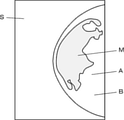
- a radiographic image S in which the breast B of the subject is photographed by so-called mammography imaging as shown in FIG. 4 is used.
- mammography imaging the breast B of the subject is usually placed between the detector for detecting radiation and the radiation source, and the radiation emitted from the radiation source and attenuated through the breast B is emitted by the detector.
- a radiation image S composed of pixels corresponding to the intensity of the detected radiation is generated.
- the breast B of the subject differs in the proportion of mammary glands and the proportion of fat depending on the location. Therefore, each pixel in the radiographic image S has different luminances corresponding to the local transmittance of the breast B due to the proportion of mammary glands present and the proportion of fat present.
- the radiation image S is analyzed by the method disclosed in Japanese Patent Application Laid-Open No. 2010-253245, and the ratio of the presence of the mammary gland in the corresponding imaging location for each pixel of the radiation image S and the imaging location thereof.
- the thickness of the breast B calculating the volume of the mammary gland, and dividing the calculated volume of the mammary gland by the volume of the breast B, the proportion of the mammary gland in the breast B can be calculated.
- the volume of the breast B is the volume of the breast B in the breast region A, which is the entire region of the breast B shown in the radiographic image S.
- the initial condition setting unit 25 sets the basic sound velocity value V1 for generating an ultrasonic image of the breast B based on the information of the ratio of the mammary gland in the breast B of the subject input via the input device 30. ..
- the initial condition setting unit 25 stores the mammary gland sound velocity value V11 (m / s) determined for the mammary gland and the fat sound velocity value V12 (m / s) determined for the fat, for example, the subject.
- the proportion R (%) of the mammary gland in the breast B the mammary gland sound velocity value V11 (m / s) and the fat sound velocity value V12 (m / s)
- V1 [R1 x V11 + (100-R1) x V12] / 100 ... (1) Can be set by.
- breast B has a fat layer, a mammary gland layer, and a muscle layer.
- the mammary gland layer is a mixture of mammary glands and fat, and the abundance ratio of mammary glands and fat in the mammary gland layer varies from subject to individual. Therefore, the speed of sound in the mammary gland layer also varies from subject to subject. Therefore, in the conventional ultrasonic diagnostic apparatus, it may be difficult to generate an ultrasonic image in which the mammary gland layer is clearly depicted by using a sound velocity suitable for the mammary gland layer.
- the image generation unit 22 According to the initial condition setting unit 25, in order to calculate the basic sound velocity value V1 in consideration of the ratio R of the mammary gland in the breast B of the subject, the image generation unit 22 generates an ultrasonic image in which the mammary gland layer is clearly shown. be able to.
- the extraction unit 26 analyzes the ultrasonic image generated by the image generation unit 22, and as shown in FIG. 5, processes to extract the fat layer L1, the mammary gland layer L2, and the muscle layer L3 existing in the ultrasonic image U. I do.
- the extraction unit 26 is a method for extracting the fat layer L1, the breast layer L2 and the muscle layer L3 from the ultrasonic image U, for example, a deep learning method such as so-called U-net, a so-called template matching method, SVM (Support vector).
- machine Machine learning method using support vector machine) and adaboost, Csurka et al .: Visual Categorization with Bags of Keypoints, Proc. Of ECCV Workshop on Statistical Learning in Computer Vision, pp.59-74 (2004) ) Can be used, such as the machine learning method described in.
- the information of the fat layer L1, the mammary gland layer L2 or the muscle layer L3 extracted by the extraction unit 26 in this way is transmitted from the main body side wireless communication unit 21 to the probe side wireless communication unit 13 via the main body control unit 29. After that, it is input from the probe side wireless communication unit 13 to the probe control unit 16, and under the control of the probe control unit 16, the transmission / reception circuit 12 focuses on the depth of the fat layer L1, the mammary gland layer L2, or the muscle layer L3. It is used when transmitting and receiving ultrasonic beams.
- the image generation unit 22, the display control unit 23, the initial condition setting unit 25, the extraction unit 26, and the main body control unit 29 are used to cause the CPU (Central Processing Unit) and the CPU to perform various processes. It is composed of the control programs of FPGA (Field Programmable Gate Array), DSP (Digital Signal Processor: Digital Signal Processor), ASIC (Application Specific Integrated Circuit), GPU (Graphics). It may be configured by using a Processing Unit (graphics processing unit) or another IC (Integrated Circuit), or may be configured by combining them.
- FPGA Field Programmable Gate Array
- DSP Digital Signal Processor: Digital Signal Processor
- ASIC Application Specific Integrated Circuit
- GPU Graphics
- the image generation unit 22, the display control unit 23, the initial condition setting unit 25, the extraction unit 26, and the main unit control unit 29 of the main body side processor 31 are configured to be partially or wholly integrated into one CPU or the like. You can also.
- the operation of the ultrasonic diagnostic apparatus 1 according to the first embodiment of the present invention to generate an ultrasonic image U according to the basic sound velocity value V1 will be described.
- information representing the ratio R of the mammary glands in the breast B of the subject is input to the diagnostic device main body 3 from an external device such as a radiographic image diagnostic device or a user.
- Information representing the ratio R of the mammary gland is sent to the initial condition setting unit 25 via the main body control unit 29.
- the initial condition setting unit 25 sets the basic sound velocity value V1 used for generating the ultrasonic image U by using the information representing the ratio R of the mammary glands in the breast B of the subject.
- the initial condition setting unit 25 stores, for example, the mammary gland sound velocity value V11 (m / s) defined for the mammary gland and the fat sound velocity value V12 (m / s) defined for the fat, and is a subject.
- the ratio R (%) of the mammary gland in the breast B the mammary gland sound velocity value V11 (m / s) and the fat sound velocity value V12 (m / s)
- the basic sound velocity value V1 (m / s) is calculated by the equation (1). Can be set by.
- the mammary gland layer L2 of the breast B of the subject is a layer in which mammary glands and fat are mixed, and in general, there are individual differences in the abundance ratio of mammary glands and fat. exist.
- the initial condition setting unit 25 can accurately calculate the basic sound velocity value V1 corresponding to the sound velocity value in the mammary gland layer L2 of the breast B of the subject in consideration of the ratio R of the mammary glands in the breast B of the subject. ..
- the information of the basic sound velocity value V1 set by the initial condition setting unit 25 is transmitted to the probe side wireless communication unit 13 via the main body side wireless communication unit 21, and further transmitted to the probe control unit 16.
- the transmission / reception circuit 12 performs reception focus processing using the basic sound velocity value V1 set by the initial condition setting unit 25, and generates a sound line signal.
- the sound line signal generated by the transmission / reception circuit 12 in this way is transmitted to the main body side wireless communication unit 21 via the probe side wireless communication unit 13, and further transmitted to the image generation unit 22.
- the image generation unit 22 generates an ultrasonic image U as shown in FIG. 5 by using the basic sound velocity value V1 set by the initial condition setting unit 25 and the sound wave signal received from the main body side wireless communication unit 21.
- a deviation between the sound velocity value used for generating the ultrasonic image U and the actual sound velocity value in the corresponding portion causes a decrease in the resolution of the ultrasonic image U. It has been known.
- a constant sound velocity value stored in advance is often used as the sound velocity value in the mammary gland layer where individual differences are large, and this sound velocity value and the actual sound velocity value in the mammary gland layer are There was a gap between them.
- the ratio of the mammary gland in the mammary gland layer L2 is calculated in the ultrasonic image U. Regardless of R, the entire mammary gland layer L2 is visualized with high brightness, so it is difficult to calculate the ratio R of the mammary glands based on the ultrasonic image U.
- the basic sound velocity value V1 is calculated by using the ratio R of the mammary glands calculated based on the radiation image S, and since it accurately represents the actual sound velocity value in the mammary gland layer L2 of the subject, the image.
- the ultrasonic image U generated by the generation unit 22 using the basic sound velocity value V1 the mammary gland layer L2 is clearly depicted.
- the ultrasonic image U generated by the image generation unit 22 in this way is sent to the display control unit 23, subjected to various processing, and then displayed on the monitor 24. As described above, the basic operation of the ultrasonic diagnostic apparatus 1 according to the first embodiment of the present invention is completed.
- the ultrasonic image U generated by the image generation unit 22 is also sent to the extraction unit 26.
- the extraction unit 26 analyzes the ultrasonic image U and extracts the fat layer L1, the mammary gland layer L2, and the muscle layer L3 of the breast B of the subject from the ultrasonic image U, as shown in FIG.
- the depth information in the ultrasonic image U of the fat layer L1, the mammary gland layer L2, and the muscle layer L3 extracted in this way is transmitted to the main body control unit 29.
- the depth information in the ultrasonic image U of the fat layer L1, the mammary gland layer L2, or the muscle layer L3 is transmitted from the main body control unit 29 to the main body side wireless communication unit 21 by a user input operation via the input device 30. It is transmitted to the probe side wireless communication unit 13 via the probe side, and further transmitted to the probe control unit 16.
- the transmission / reception circuit 12 under the control of the probe control unit 16, based on the depth information in the ultrasonic image U of the fat layer L1, the mammary gland layer L2 or the muscle layer L3, the fat layer L1, the mammary gland layer L2 or the muscle layer L3. Sends and receives ultrasonic beams to focus on the depth of.
- the transmission / reception circuit 12 newly generates received data, and the image generation unit 22 newly generates an ultrasonic image U focused on the depth of the fat layer L1, the mammary gland layer L2, or the muscle layer L3.
- the depth information in the ultrasonic image U of the mammary gland layer L2 is transmitted from the main body control unit 29 to the main body side wireless communication unit. It is transmitted to the probe side wireless communication unit 13 via 21 and further transmitted to the probe control unit 16.
- the probe control unit 16 controls the transmission / reception circuit 12 so as to focus on the mammary gland layer L2.
- a sound line signal is newly generated in the transmission / reception circuit 12, and an ultrasonic image U is newly generated by the image generation unit 22 based on the sound line signal.
- the ultrasonic image U thus generated the depth of the mammary gland layer L2 is focused, so that the mammary gland layer L2 is more clearly depicted.
- the initial condition setting unit 25 sets the basic sound velocity value V1 based on the ratio R of the breast glands in the breast B of the subject. Since the sound line signal is generated by the transmission / reception circuit 12 using the basic sound velocity value V1 and the ultrasonic image U is generated by the image generation unit 22 using this sound line signal, the ultrasonic image U of the breast layer L2 is generated. The resolution can be improved.
- the image generation unit 22 is provided in the diagnostic apparatus main body 3, but may be provided in the ultrasonic probe 2 instead of being provided in the diagnostic apparatus main body 3.
- the information of the basic sound velocity value V1 set by the initial condition setting unit 25 is transmitted to the probe side wireless communication unit 13 via the main body side wireless communication unit 21, and further, the image in the ultrasonic probe 2 is obtained. It is sent to the generation unit 22. Further, the ultrasonic image U generated by the image generation unit 22 is transmitted to the main body side wireless communication unit 21 via the probe side wireless communication unit 13, and further transmitted to the display control unit 23 and the extraction unit 26.
- the ultrasonic probe 2 and the diagnostic device main body 3 are connected to each other by wireless communication, they can also be connected to each other by wired communication.
- the diagnostic device main body 3 may be a portable so-called handheld type composed of a tablet type terminal or the like, or may be a stationary type installed in a medical field such as a hospital.
- an ultrasonic image U focused on the depth of the mammary gland layer L2 is generated, an ultrasonic image U focused on the fat layer L1 or the muscle layer L3 may be generated. ..
- the depth information in the ultrasonic image U of the fat layer L1 is transmitted via the main body side wireless communication unit 21. It is transmitted to the probe-side wireless communication unit 13, and is transmitted from the probe-side wireless communication unit 13 to the probe control unit 16.
- the main body control unit 29 stores the fat sound velocity value V12, and based on the information indicating the instruction to focus on the depth of the fat layer L1 input by the user, the information representing the fat sound velocity value V12 is wirelessly transmitted to the main body side. Transmission is performed to the probe-side wireless communication unit 13 via the communication unit 21. The information representing the fat sound velocity value V12 is transmitted from the probe-side wireless communication unit 13 to the transmission / reception circuit 12 via the probe control unit 16.
- the transmission / reception circuit 12 transmits / receives an ultrasonic beam so as to focus on the depth of the fat layer L1 under the control of the probe control unit 16, and performs reception focus processing using the fat sound velocity value V12 to perform sound. Generate a new line signal.
- the sound line signal generated in this way is transmitted from the probe-side wireless communication unit 13 to the main body-side wireless communication unit 21, and further transmitted to the image generation unit 22.
- the image generation unit 22 generates an ultrasonic image U based on a sound line signal received from the main body side wireless communication unit 21. In this ultrasonic image U, the fat layer L1 is clearly depicted.
- the main body control unit 29 stores a muscle sound wave value V13 different from the basic sound wave value V1 and the fat sound wave value V12 and determined for the muscle, and the muscle layer is stored by the user via the input device 30.
- a muscle sound wave value V13 different from the basic sound wave value V1 and the fat sound wave value V12 and determined for the muscle
- the muscle layer is stored by the user via the input device 30.
- the ratio R of the mammary gland in the breast B of the subject is calculated as the ratio of the volume of the mammary gland to the volume of the breast region A is used
- the ratio R is calculated by another method. May be used.
- a region having a brightness higher than a certain value that is, a region having a high density of the mammary gland is recognized as a mammary gland region M, and is disclosed in Japanese Patent Application Laid-Open No. 2010-253245. It is also possible to calculate the ratio R of the mammary gland by calculating the volume of the mammary gland region M and the volume of the mammary gland and dividing the calculated volume of the mammary gland by the volume of the mammary gland region M. As a result, the influence of the region consisting almost exclusively of fat existing around the mammary gland region M can be excluded.
- the ratio R of the mammary gland is calculated from the ratio of the volume of the mammary gland to the volume of the breast region A. Also, it is possible to calculate the value of the ratio R of the mammary gland having a higher correlation with the ratio of the mammary gland in the mammary gland layer L2 shown in the ultrasonic image U. Therefore, the initial condition setting unit 25 can calculate the basic sound velocity value V1 that more accurately represents the sound velocity value in the mammary gland layer L2.
- so-called tomosynthesis imaging is performed on the breast B with the breast B of the subject sandwiched between the compression plate P1 and the imaging table P2, and the breast thickness T1 and the mammary gland in the mammary gland region M are performed. It is also possible to calculate the thickness T2 of the mammary gland layer L4 in the region M and calculate the ratio of the thickness T2 of the mammary gland layer L4 to the breast thickness T1 as the ratio R of the mammary gland.
- the mammary gland layer L4 is a layer extracted from a region depicted with high brightness in the tomosynthesis image obtained by tomosynthesis imaging.
- the mammary gland layer L4 is a region in which fat and a mammary gland are mixed, but the proportion of the mammary gland is relatively high, and the region other than the mammary gland layer L4 is a region composed of substantially fat such as subcutaneous fat.
- This mammary gland layer L4 does not exactly match the mammary gland layer L2 in the ultrasonic image U, but has a high correlation with the mammary gland layer L2 in the ultrasonic image U.
- the region depicted with high brightness in the tomosynthesis image is, for example, a region having high brightness equal to or higher than a predetermined brightness threshold value.
- the ratio R of the mammary gland is the ratio R1 (%) of the mammary gland calculated by the ratio of the volume of the mammary gland to the volume of the mammary gland region M, and the ratio R2 of the thickness T2 of the mammary gland layer L4 to the breast thickness T1 obtained by tomosynthesis. %)
- the initial condition setting unit 25 includes a mammary gland ratio R1 (%), a mammary gland layer L4 thickness T2 ratio R2 (%), and a mammary gland sound velocity value V11 (m / s).
- V1 (R1 / R2) x V11 + (1-R1 / R2) x V12 It is also possible to set the basic sound velocity value V1.
- the ratio of the volume of the mammary gland to the volume of the mammary gland region M is present in the mammary gland layer L4 with respect to the breast thickness T1 obtained by tomosynthesis. It can be approximated as the proportion of mammary glands. Therefore, by dividing the ratio R1 by the ratio R2, the ratio of the mammary gland in the mammary gland layer L4 can be calculated. As a result, the initial condition setting unit 25 can calculate the basic sound velocity value V1 that more accurately represents the sound velocity value in the mammary gland layer L2.
- the ratio R of the breast gland is input to the ultrasonic diagnostic apparatus 1 from an external device (not shown) or a user via the input device 30, but the radiographic image S is analyzed in the ultrasonic diagnostic apparatus 1. It is also possible to calculate the ratio R of the mammary gland.
- FIG. 7 shows the configuration of the ultrasonic diagnostic apparatus 1A according to the second embodiment of the present invention.
- the ultrasonic diagnostic apparatus 1A includes the diagnostic apparatus main body 3A instead of the diagnostic apparatus main body 3 in the ultrasonic diagnostic apparatus 1 of the first embodiment shown in FIG.
- the diagnostic device main body 3A is the diagnostic device main body 3 in the first embodiment, in which the mammary gland ratio calculation unit 39 is added and the main body control unit 29A is provided instead of the main body control unit 29.
- the mammary gland ratio calculation unit 39 is connected to the initial condition setting unit 25. Further, instead of the main body side processor 31, the main body side processor 31A including the mammary gland ratio calculation unit 39 is configured.
- the input device 30 is used to input a radiographic image S in which the breast B of the subject is photographed by mammography or the like to the diagnostic device main body 3A from an external device (not shown) such as a radiographic image diagnostic device.
- the mammary gland ratio calculation unit 39 recognizes a region of the breast region A whose brightness is higher than a certain value, that is, a region where the density of the mammary gland is high as the mammary gland region M, and is disclosed in Japanese Patent Application Laid-Open No. 2010-253245. It is also possible to calculate the ratio R of the mammary gland by calculating the volume of the mammary gland region M and the volume of the mammary gland and dividing the calculated volume of the mammary gland by the volume of the mammary gland region M.
- the radiographic image S obtained by tomosynthesis imaging as shown in FIG. 6 is analyzed to calculate the breast thickness T1 in the mammary gland region M and the thickness T2 of the mammary gland layer L4 in the mammary gland region M, and the mammary gland layer with respect to the breast thickness T1.
- the ratio of the thickness T2 of L4 can also be calculated as the ratio R of the mammary gland.
- the ultrasonic diagnostic apparatus 1 is converted from an external device or a user (not shown) via the input device 30 in the first embodiment.
- the initial condition setting unit 25 sets the basic sound wave value V1 based on the ratio R of the mammary gland in the breast B of the subject, and the basic sound wave value V1 is used. Since the sound line signal is generated by the transmission / reception circuit 12 and the ultrasonic image U is generated by the image generation unit 22 using this sound line signal, the resolution of the ultrasonic image U of the mammary gland layer L2 can be improved. ..
- 1,1A ultrasonic diagnostic device 1,1A ultrasonic diagnostic device, 2 ultrasonic probe, 3,3A diagnostic device main body, 11 oscillator array, 12 transmission / reception circuit, 13 probe side wireless communication unit, 16 probe control unit, 21 main unit side wireless communication unit, 22 image Generation unit, 23 display control unit, 24 monitor, 25 initial condition setting unit, 26 extraction unit, 29, 29A main unit control unit, 30 input device, 31, 31A main unit side processor, 32 pulser, 33 amplification unit, 34 AD conversion unit , 35 beam former, 36 signal processing unit, 37 DSC, 38 image processing unit, 39 breast ratio calculation unit, A breast region, B breast, L1 fat layer, L2 breast layer, L3 muscle layer, M breast region, P1 compression plate , P2 imaging table, S radiation image, T1 breast thickness, T2 thickness, U ultrasound image.
Landscapes
- Health & Medical Sciences (AREA)
- Life Sciences & Earth Sciences (AREA)
- Engineering & Computer Science (AREA)
- Medical Informatics (AREA)
- Physics & Mathematics (AREA)
- Animal Behavior & Ethology (AREA)
- Public Health (AREA)
- Pathology (AREA)
- Radiology & Medical Imaging (AREA)
- Biomedical Technology (AREA)
- Heart & Thoracic Surgery (AREA)
- Biophysics (AREA)
- Molecular Biology (AREA)
- Surgery (AREA)
- Veterinary Medicine (AREA)
- General Health & Medical Sciences (AREA)
- Nuclear Medicine, Radiotherapy & Molecular Imaging (AREA)
- Computer Vision & Pattern Recognition (AREA)
- Vascular Medicine (AREA)
- Dentistry (AREA)
- Oral & Maxillofacial Surgery (AREA)
- High Energy & Nuclear Physics (AREA)
- Optics & Photonics (AREA)
- Computer Networks & Wireless Communication (AREA)
- General Physics & Mathematics (AREA)
- Radar, Positioning & Navigation (AREA)
- Remote Sensing (AREA)
- Physiology (AREA)
- Ultra Sonic Daignosis Equipment (AREA)
Abstract
This ultrasonic diagnostic device (1) comprises: an ultrasonic probe (2); an image acquisition unit which generates an ultrasound image through transmission and reception of an ultrasonic beam with respect to a test subject using the ultrasonic probe (2); and an initial condition setting unit (25) which sets a basic acoustic velocity value in order to generate an ultrasound image of the test subject's breasts on the basis of the proportion of mammary glands occupying the breasts, calculated by analyzing a radiographic image captured of the breasts. The image acquisition unit generates an ultrasound image of the breasts using the basic acoustic velocity value.
Description
本発明は、被検体の乳房を検査するための超音波診断装置および超音波診断装置の制御方法に関する。
The present invention relates to an ultrasonic diagnostic apparatus for inspecting the breast of a subject and a control method of the ultrasonic diagnostic apparatus.
従来から、超音波診断装置を用いて被検体の断層を表す超音波画像を生成することにより、被検体の内部の観察が行われている。超音波画像が生成される際には、まず、複数の超音波振動子からなる振動子アレイから被検体内に超音波ビームを送信し、その超音波ビームが被検体内で反射されることにより、超音波エコーが振動子アレイに受信される。このようにして振動子アレイのそれぞれの超音波振動子が受信したエコー信号に対して、超音波振動子から発せられた超音波が被検体内の反射点を経由して同一の超音波振動子に戻るまでの伝搬時間の差を補正した上で、それぞれのエコー信号を加算することにより、超音波画像が生成される。
Conventionally, the inside of a subject has been observed by generating an ultrasonic image showing a tomography of the subject using an ultrasonic diagnostic device. When an ultrasonic image is generated, first, an ultrasonic beam is transmitted into a subject from an oscillator array composed of a plurality of ultrasonic transducers, and the ultrasonic beam is reflected in the subject. , The ultrasonic echo is received by the oscillator array. In this way, for the echo signal received by each ultrasonic oscillator of the oscillator array, the ultrasonic wave emitted from the ultrasonic oscillator passes through the reflection point in the subject and is the same ultrasonic oscillator. An ultrasonic image is generated by correcting the difference in propagation time until returning to, and then adding each echo signal.
超音波の伝搬時間は、超音波の経路の長さと被検体内の媒質中の音速に基づいて計算される。この計算に用いられる音速の値と、媒質中の実際の音速の値との差は、超音波画像の分解能の劣化の原因となることが知られている。人体において、音速は、肝臓等では1550m/s程度であるのに対し、脂肪では1420m/sであり、組織によって異なる値を有する。そのため、超音波画像の分解能を向上させるために、例えば、特許文献1に開示されているように、脂肪層とその他の層で、計算に使用する音速値を変更する技術が開発されている。
The propagation time of ultrasonic waves is calculated based on the length of the ultrasonic path and the speed of sound in the medium in the subject. It is known that the difference between the sound velocity value used in this calculation and the actual sound velocity value in the medium causes deterioration of the resolution of the ultrasonic image. In the human body, the speed of sound is about 1550 m / s for the liver and the like, whereas it is 1420 m / s for fat, and has different values depending on the tissue. Therefore, in order to improve the resolution of the ultrasonic image, for example, as disclosed in Patent Document 1, a technique for changing the sound velocity value used for calculation in the fat layer and other layers has been developed.
ところで、超音波診断装置を用いて、被検体の乳房の検査が行われることがある。乳房は、一般的に、脂肪層と、乳腺層と、筋肉層を含んでいることが知られている。このうち、乳腺層では、乳腺と脂肪が混在しており、個人差および加齢に伴う脂肪の増加等にしたがって、乳腺層中の脂肪の割合が被検体によって異なるため、特許文献1に開示される技術のように、一定の音速値を乳腺層に適用しても、適用された音速値が最適値とは限らず、乳腺層を鮮明に写した超音波画像が得られないことがあった。
By the way, the breast of the subject may be inspected using an ultrasonic diagnostic device. The breast is generally known to contain a fat layer, a mammary gland layer, and a muscular layer. Of these, in the mammary gland layer, the mammary gland and fat are mixed, and the proportion of fat in the mammary gland layer varies depending on the subject according to individual differences and an increase in fat with aging, and thus is disclosed in Patent Document 1. Even if a certain sound velocity value is applied to the mammary gland layer, the applied sound velocity value is not always the optimum value, and an ultrasonic image that clearly shows the mammary gland layer may not be obtained. ..
また、乳腺層における乳腺と脂肪の存在割合を超音波画像から算出して、乳腺層に対して最適な音速値を算出しようとしても、超音波画像では、乳腺層における乳腺の割合に関わらず、乳腺層の全体が高輝度に描出されてしまうため、乳腺層における乳腺と脂肪の存在割合を超音波画像から算出することが困難であった。
Further, even if an attempt is made to calculate the optimum sound velocity value for the mammary gland layer by calculating the abundance ratio of the mammary gland and fat in the mammary gland layer from the ultrasonic image, in the ultrasonic image, regardless of the ratio of the mammary gland in the mammary gland layer, Since the entire mammary gland layer is visualized with high brightness, it is difficult to calculate the abundance ratio of the mammary gland and fat in the mammary gland layer from the ultrasonic image.
本発明は、このような従来の問題点を解決するためになされたものであり、乳腺層の超音波画像の解像度を向上させることができる超音波診断装置および超音波診断装置の制御方法を提供することを目的とする。
The present invention has been made to solve such a conventional problem, and provides an ultrasonic diagnostic apparatus and a control method of an ultrasonic diagnostic apparatus capable of improving the resolution of an ultrasonic image of a mammary gland layer. The purpose is to do.
本発明に係る超音波診断装置は、超音波プローブと、被検体に対し超音波プローブを用いて超音波ビームの送受信を行うことにより超音波画像を生成する画像取得部と、被検体の乳房を撮影した放射線画像を解析することにより算出された乳房における乳腺の割合に基づいて乳房の超音波画像を生成するための基本音速値を設定する初期条件設定部とを備え、画像取得部は、基本音速値を用いて乳房の超音波画像を生成することを特徴とする。
The ultrasonic diagnostic apparatus according to the present invention comprises an ultrasonic probe, an image acquisition unit that generates an ultrasonic image by transmitting and receiving an ultrasonic beam to a subject using the ultrasonic probe, and a breast of the subject. It is equipped with an initial condition setting unit that sets the basic sound velocity value for generating an ultrasonic image of the breast based on the ratio of breast glands in the breast calculated by analyzing the captured radiographic image, and the image acquisition unit is basic. It is characterized by generating an ultrasonic image of the breast using the sound velocity value.
初期条件設定部は、基本音速値V1(m/s)を、乳腺の割合R1(%)と、乳腺に対して定められた乳腺音速値V11(m/s)および脂肪に対して定められた脂肪音速値V12(m/s)とを用いて、
V1=[R1×V11+(100-R1)×V12]/100
により設定することができる。 The initial condition setting unit defines the basic sound velocity value V1 (m / s) for the mammary gland ratio R1 (%), the mammary gland sound velocity value V11 (m / s) defined for the mammary gland, and fat. Using the fat sound velocity value V12 (m / s),
V1 = [R1 x V11 + (100-R1) x V12] / 100
Can be set by.
超音波診断装置は、乳房の超音波画像を解析して脂肪層と乳腺層を抽出する抽出部を備えることができる。
この場合に、画像取得部は、抽出部により抽出された乳腺層に対し、基本音速値を用いて超音波画像を生成することができる。
もしくは、画像取得部は、抽出部により抽出された脂肪層に対し、基本音速値とは異なる脂肪音速値を用いて超音波画像を生成することができる。
また、抽出部は、乳房の超音波画像を解析して筋肉層を抽出し、画像取得部は、抽出された筋肉層に対し、基本音速値および脂肪音速値とは異なり且つ筋肉に対して定められた筋肉音速値を用いて超音波画像を生成することができる。 The ultrasonic diagnostic apparatus can include an extraction unit that analyzes an ultrasonic image of the breast and extracts a fat layer and a mammary gland layer.
In this case, the image acquisition unit can generate an ultrasonic image for the mammary gland layer extracted by the extraction unit using the basic sound velocity value.
Alternatively, the image acquisition unit can generate an ultrasonic image for the fat layer extracted by the extraction unit using a fat sound velocity value different from the basic sound velocity value.
In addition, the extraction unit analyzes the ultrasonic image of the breast to extract the muscle layer, and the image acquisition unit determines the extracted muscle layer for the muscle, which is different from the basic sound velocity value and the fat sound velocity value. Ultrasound images can be generated using the obtained muscle sound velocity values.
超音波診断装置は、放射線画像を解析することにより算出された乳腺の割合を入力するための入力装置を備えることができ、この場合に、初期条件設定部は、入力装置を介して入力された乳腺の割合を用いて基本音速値を設定することができる。
もしくは、超音波診断装置は、放射線画像を入力するための入力装置と、入力装置を介して入力された放射線画像を解析することにより乳腺の割合を算出する乳腺割合算出部とを備えることができ、この場合に、初期条件設定部は、乳腺割合算出部により算出された乳腺の割合を用いて基本音速値を設定することができる。 The ultrasonic diagnostic apparatus may include an input device for inputting the proportion of the mammary gland calculated by analyzing the radiographic image, and in this case, the initial condition setting unit is input via the input device. The basic sound velocity value can be set using the ratio of the mammary gland.
Alternatively, the ultrasonic diagnostic apparatus can include an input device for inputting a radiographic image and a mammary gland ratio calculation unit that calculates the ratio of the mammary gland by analyzing the radiographic image input via the input device. In this case, the initial condition setting unit can set the basic sound velocity value using the mammary gland ratio calculated by the mammary gland ratio calculation unit.
乳腺の割合は、乳房領域における乳房の体積に対する乳房領域における乳腺の体積の割合を用いることができる。
さらに、乳腺の割合は、乳腺領域における乳房の体積に対する乳腺領域における乳腺の体積の割合であることが好ましい。 As the ratio of the mammary gland, the ratio of the volume of the mammary gland in the breast region to the volume of the breast in the breast region can be used.
Further, the ratio of the mammary gland is preferably the ratio of the volume of the mammary gland in the mammary gland region to the volume of the breast in the mammary gland region.
もしくは、乳腺の割合は、乳腺領域における乳房の体積に対する乳腺領域における乳腺の体積の割合R1およびトモシンセシスにより得られる乳腺領域における乳房厚みに対する乳腺領域における乳腺層の厚みの割合R2により表されることもできる。
この場合に、初期条件設定部は、基本音速値V1(m/s)を、乳腺の体積の割合R1(%)と、乳腺層の厚みの割合R2(%)と、乳腺に対して定められた乳腺音速値V11(m/s)および脂肪に対して定められた脂肪音速値V12(m/s)とを用いて、
V1=(R1/R2)×V11+(1-R1/R2)×V12
により設定することができる。 Alternatively, the ratio of the mammary gland may be expressed by the ratio R1 of the volume of the mammary gland in the breast region to the volume of the breast in the breast region and the ratio R2 of the thickness of the mammary layer in the breast region to the breast thickness in the breast region obtained by tomosynthesis. can.
In this case, the initial condition setting unit determines the basic sound velocity value V1 (m / s) for the mammary gland as the ratio R1 (%) of the volume of the mammary gland and the ratio R2 (%) of the thickness of the mammary gland layer. Using the mammary gland sound velocity value V11 (m / s) and the fat sound velocity value V12 (m / s) defined for fat,
V1 = (R1 / R2) x V11 + (1-R1 / R2) x V12
Can be set by.
本発明の超音波診断装置の制御方法は、被検体の乳房を撮影した放射線画像を解析することにより算出された乳房における乳腺の割合に基づいて超音波画像を生成するための基本音速値を設定し、基本音速値を用いて乳房の超音波画像を生成することを特徴とする。
The control method of the ultrasonic diagnostic apparatus of the present invention sets a basic sound velocity value for generating an ultrasonic image based on the ratio of breast glands in the breast calculated by analyzing a radiographic image obtained by photographing the breast of a subject. However, it is characterized in that an ultrasonic image of the breast is generated using the basic sound velocity value.
本発明によれば、超音波診断装置が、被検体の乳房を撮影した放射線画像を解析することにより算出された乳房における乳腺の割合に基づいて乳房の超音波画像を生成するための基本音速値を設定する初期条件設定部を備え、画像取得部が、基本音速値を用いて乳房の超音波画像を生成するため、乳腺層の超音波画像の解像度を向上させることができる。
According to the present invention, the ultrasonic diagnostic apparatus is a basic sound velocity value for generating an ultrasonic image of a breast based on the ratio of breast glands in the breast calculated by analyzing a radiographic image of the breast of a subject. Since the image acquisition unit generates an ultrasonic image of the breast using the basic sound velocity value, the resolution of the ultrasonic image of the breast layer can be improved.
以下、この発明の実施の形態を添付図面に基づいて説明する。
以下に記載する構成要件の説明は、本発明の代表的な実施態様に基づいてなされるが、本発明はそのような実施態様に限定されるものではない。
なお、本明細書において、「~」を用いて表される数値範囲は、「~」の前後に記載される数値を下限値および上限値として含む範囲を意味する。
本明細書において、「同一」、「同じ」は、技術分野で一般的に許容される誤差範囲を含むものとする。 Hereinafter, embodiments of the present invention will be described with reference to the accompanying drawings.
The description of the constituent elements described below is based on the representative embodiments of the present invention, but the present invention is not limited to such embodiments.
In the present specification, the numerical range represented by using "-" means a range including the numerical values before and after "-" as the lower limit value and the upper limit value.
In the present specification, "same" and "same" include an error range generally accepted in the technical field.
実施の形態1
図1に、本発明の実施の形態1に係る超音波診断装置1の構成を示す。超音波診断装置1は、超音波プローブ2と、診断装置本体3を備えている。超音波プローブ2と診断装置本体3は、無線通信により互いに接続されている。Embodiment 1
FIG. 1 shows the configuration of the ultrasonicdiagnostic apparatus 1 according to the first embodiment of the present invention. The ultrasonic diagnostic apparatus 1 includes an ultrasonic probe 2 and a diagnostic apparatus main body 3. The ultrasonic probe 2 and the diagnostic device main body 3 are connected to each other by wireless communication.
図1に、本発明の実施の形態1に係る超音波診断装置1の構成を示す。超音波診断装置1は、超音波プローブ2と、診断装置本体3を備えている。超音波プローブ2と診断装置本体3は、無線通信により互いに接続されている。
FIG. 1 shows the configuration of the ultrasonic
超音波プローブ2は、振動子アレイ11を備えており、振動子アレイ11に、送受信回路12およびプローブ側無線通信部13が順次接続されている。また、送受信回路12とプローブ側無線通信部13は、プローブ制御部16に接続されている。
The ultrasonic probe 2 includes an oscillator array 11, and a transmission / reception circuit 12 and a probe-side wireless communication unit 13 are sequentially connected to the oscillator array 11. Further, the transmission / reception circuit 12 and the probe-side wireless communication unit 13 are connected to the probe control unit 16.
診断装置本体3は、本体側無線通信部21を有しており、本体側無線通信部21に、画像生成部22、表示制御部23およびモニタ24が順次接続されている。また、本体側無線通信部21および画像生成部22に、初期条件設定部25が接続されている。また、画像生成部22に、抽出部26が接続されている。また、画像生成部22と、超音波プローブ2の送受信回路12により、画像取得部が構成されている。
The diagnostic device main body 3 has a main body side wireless communication unit 21, and an image generation unit 22, a display control unit 23, and a monitor 24 are sequentially connected to the main body side wireless communication unit 21. Further, the initial condition setting unit 25 is connected to the main body side wireless communication unit 21 and the image generation unit 22. Further, the extraction unit 26 is connected to the image generation unit 22. Further, the image acquisition unit is composed of the image generation unit 22 and the transmission / reception circuit 12 of the ultrasonic probe 2.
また、本体側無線通信部21、画像生成部22、表示制御部23、初期条件設定部25および抽出部26に、本体制御部29が接続されている。また、本体制御部29に、入力装置30が接続されている。
また、画像生成部22、表示制御部23、初期条件設定部25、抽出部26および本体制御部29により、本体側プロセッサ31が構成されている。 Further, the mainbody control unit 29 is connected to the main body side wireless communication unit 21, the image generation unit 22, the display control unit 23, the initial condition setting unit 25, and the extraction unit 26. Further, the input device 30 is connected to the main body control unit 29.
Further, the mainbody side processor 31 is configured by the image generation unit 22, the display control unit 23, the initial condition setting unit 25, the extraction unit 26, and the main body control unit 29.
また、画像生成部22、表示制御部23、初期条件設定部25、抽出部26および本体制御部29により、本体側プロセッサ31が構成されている。 Further, the main
Further, the main
図1に示す超音波プローブ2の振動子アレイ11は、1次元または2次元に配列された複数の超音波振動子を有している。これらの超音波振動子は、それぞれ送受信回路12から供給される駆動信号にしたがって超音波を送信すると共に、被検体からの超音波エコーを受信して、超音波エコーに基づく信号を出力する。各超音波振動子は、例えば、PZT(Lead Zirconate Titanate:チタン酸ジルコン酸鉛)に代表される圧電セラミック、PVDF(Poly Vinylidene Di Fluoride:ポリフッ化ビニリデン)に代表される高分子圧電素子およびPMN-PT(Lead Magnesium Niobate-Lead Titanate:マグネシウムニオブ酸鉛-チタン酸鉛固溶体)に代表される圧電単結晶等からなる圧電体の両端に電極を形成することにより構成される。
The vibrator array 11 of the ultrasonic probe 2 shown in FIG. 1 has a plurality of ultrasonic vibrators arranged one-dimensionally or two-dimensionally. Each of these ultrasonic transducers transmits ultrasonic waves according to a drive signal supplied from the transmission / reception circuit 12, receives ultrasonic echoes from a subject, and outputs a signal based on the ultrasonic echoes. Each ultrasonic transducer is, for example, a piezoelectric ceramic represented by PZT (Lead Zirconate Titanate), a polymer piezoelectric element represented by PVDF (Poly Vinylidene Di Fluoride), and PMN-. It is configured by forming electrodes at both ends of a piezoelectric body made of a piezoelectric single crystal or the like represented by PT (Lead Magnesium Niobate-Lead Titanate: lead magnesiumidene fluoride-lead zirconate titanate).
送受信回路12は、プローブ制御部16による制御の下で、振動子アレイ11から超音波を送信し且つ振動子アレイ11により取得された受信信号に基づいて音線信号を生成する。送受信回路12は、図2に示すように、振動子アレイ11に接続されるパルサ32と、振動子アレイ11から順次直列に接続される増幅部33、AD(Analog Digital)変換部34、およびビームフォーマ35を有している。
The transmission / reception circuit 12 transmits ultrasonic waves from the vibrator array 11 under the control of the probe control unit 16 and generates a sound line signal based on the received signal acquired by the vibrator array 11. As shown in FIG. 2, the transmission / reception circuit 12 includes a pulser 32 connected to the oscillator array 11, an amplification unit 33 sequentially connected in series from the oscillator array 11, an AD (Analog Digital) conversion unit 34, and a beam. It has a former 35.
パルサ32は、例えば、複数のパルス発生器を含んでおり、プローブ制御部16からの制御信号に応じて選択された送信遅延パターンに基づいて、振動子アレイ11の複数の超音波振動子から送信される超音波が超音波ビームを形成するようにそれぞれの駆動信号を、遅延量を調節して複数の超音波振動子に供給する。このように、振動子アレイ11の超音波振動子の電極にパルス状または連続波状の電圧が印加されると、圧電体が伸縮し、それぞれの超音波振動子からパルス状または連続波状の超音波が発生して、それらの超音波の合成波から、超音波ビームが形成される。
The pulsar 32 includes, for example, a plurality of pulse generators, and transmits from a plurality of ultrasonic oscillators of the oscillator array 11 based on a transmission delay pattern selected according to a control signal from the probe control unit 16. Each drive signal is supplied to a plurality of ultrasonic transducers by adjusting the delay amount so that the ultrasonic waves to be generated form an ultrasonic beam. In this way, when a pulsed or continuous wave voltage is applied to the electrodes of the ultrasonic vibrator of the vibrator array 11, the piezoelectric body expands and contracts, and the pulsed or continuous wave ultrasonic waves are generated from each ultrasonic vibrator. Is generated, and an ultrasonic beam is formed from the combined waves of those ultrasonic waves.
送信された超音波ビームは、例えば、被検体の部位等の対象において反射され、超音波プローブ2の振動子アレイ11に向かって伝搬する。このように振動子アレイ11に向かって伝搬する超音波エコーは、振動子アレイ11を構成するそれぞれの超音波振動子により受信される。この際に、振動子アレイ11を構成するそれぞれの超音波振動子は、伝搬する超音波エコーを受信することにより伸縮して、電気信号である受信信号を発生させ、これらの受信信号を増幅部33に出力する。
The transmitted ultrasonic beam is reflected by, for example, a target such as a site of a subject, and propagates toward the vibrator array 11 of the ultrasonic probe 2. The ultrasonic echo propagating toward the oscillator array 11 in this way is received by each ultrasonic oscillator constituting the oscillator array 11. At this time, each ultrasonic vibrator constituting the vibrator array 11 expands and contracts by receiving the propagating ultrasonic echo, generates a received signal which is an electric signal, and amplifies these received signals. Output to 33.
増幅部33は、振動子アレイ11を構成するそれぞれの超音波振動子から入力された信号を増幅し、増幅した信号をAD変換部34に送信する。AD変換部34は、増幅部33から送信された信号をデジタルの受信データに変換する。ビームフォーマ35は、初期条件設定部25により設定された基本音速値V1にしたがって、本体側無線通信部21から受け取った各受信データに対してそれぞれの遅延を与えて加算することにより、いわゆる受信フォーカス処理を行う。各受信データに対してそれぞれの遅延を加算する処理は、振動子アレイ11を構成するそれぞれの超音波振動子において、超音波振動子から発せられた超音波が被検体内の反射点を経由して同一の超音波振動子に到着するまでの伝搬時間の差を補正することに相当する。この受信フォーカス処理により、AD変換部34で変換された各受信データが整相加算され且つ超音波エコーの焦点が絞り込まれた音線信号が取得される。
The amplification unit 33 amplifies the signal input from each ultrasonic vibrator constituting the vibrator array 11, and transmits the amplified signal to the AD conversion unit 34. The AD conversion unit 34 converts the signal transmitted from the amplification unit 33 into digital reception data. The beam former 35 gives a delay to each received data received from the main body side wireless communication unit 21 according to the basic sound velocity value V1 set by the initial condition setting unit 25, and adds the so-called reception focus. Perform processing. In the process of adding the respective delays to each received data, the ultrasonic waves emitted from the ultrasonic oscillators pass through the reflection points in the subject in each ultrasonic oscillator constituting the oscillator array 11. It corresponds to correcting the difference in propagation time until it arrives at the same ultrasonic oscillator. By this reception focus processing, each received data converted by the AD conversion unit 34 is phase-adjusted and added, and a sound line signal in which the focus of the ultrasonic echo is narrowed down is acquired.
プローブ側無線通信部13は、電波の送信および受信を行うためのアンテナを含む回路等により構成されており、プローブ制御部16の制御の下で、診断装置本体3の本体側無線通信部21と無線通信を行う。この際に、プローブ側無線通信部13は、送受信回路12により生成された音線信号に基づいてキャリアを変調することにより音線信号を表す伝送信号を生成し、生成された伝送信号を、診断装置本体3の本体側無線通信部21に無線送信する。
The probe-side wireless communication unit 13 is composed of a circuit or the like including an antenna for transmitting and receiving radio waves, and under the control of the probe control unit 16, the probe-side wireless communication unit 13 and the main body-side wireless communication unit 21 of the diagnostic device main body 3 Perform wireless communication. At this time, the probe-side wireless communication unit 13 generates a transmission signal representing the sound line signal by modulating the carrier based on the sound line signal generated by the transmission / reception circuit 12, and diagnoses the generated transmission signal. Wireless transmission is performed to the main body side wireless communication unit 21 of the main body 3.
キャリアの変調方式としては、例えば、ASK(Amplitude Shift Keying:振幅偏移変調)、PSK(Phase Shift Keying:位相偏移変調)、QPSK(Quadrature Phase Shift Keying:四位相偏移変調)および16QAM(16 Quadrature Amplitude Modulation:16直角位相振幅変調)等が用いられる。
Carrier modulation methods include, for example, ASK (Amplitude Shift Keying), PSK (Phase Shift Keying), QPSK (Quadrature Phase Shift Keying) and 16QAM (16). Quadrature Amplitude Modulation: 16 quadrature phase shift modulation) and the like are used.
プローブ制御部16は、予め記憶しているプログラムに基づいて超音波プローブ2の各部の制御を行う。
また、図示しないが、超音波プローブ2には、超音波プローブ2の各部に電力を供給するバッテリが内蔵されている。 Theprobe control unit 16 controls each unit of the ultrasonic probe 2 based on a program stored in advance.
Further, although not shown, theultrasonic probe 2 has a built-in battery that supplies electric power to each part of the ultrasonic probe 2.
また、図示しないが、超音波プローブ2には、超音波プローブ2の各部に電力を供給するバッテリが内蔵されている。 The
Further, although not shown, the
診断装置本体3の本体側無線通信部21は、プローブ側無線通信部13と同様に電波の送信および受信を行うためのアンテナを含む回路等により構成されており、本体制御部29の制御の下で、超音波プローブ2のプローブ側無線通信部13と無線通信を行う。この際に、本体側無線通信部21は、プローブ側無線通信部13から無線送信された伝送信号を復調して音線信号を得る。本体側無線通信部21は、得られた音線信号を画像生成部22に送出する。
The main body side wireless communication unit 21 of the diagnostic apparatus main body 3 is configured by a circuit or the like including an antenna for transmitting and receiving radio waves like the probe side wireless communication unit 13, and is under the control of the main body control unit 29. Then, wireless communication is performed with the probe-side wireless communication unit 13 of the ultrasonic probe 2. At this time, the main body side wireless communication unit 21 demodulates the transmission signal wirelessly transmitted from the probe side wireless communication unit 13 to obtain a sound line signal. The main body side wireless communication unit 21 sends the obtained sound line signal to the image generation unit 22.
また、本体側無線通信部21は、超音波プローブ2を制御するための制御情報等に基づいてキャリアを変調することにより制御情報等を表す伝送信号を生成し、生成された伝送信号をプローブ側無線通信部13に無線送信する。キャリアの変調方式としては、プローブ側無線通信部13により用いられる変調方式と同様に、例えば、ASK、PSK、QPSKおよび16QAM等が用いられる。
Further, the main body side wireless communication unit 21 generates a transmission signal representing the control information or the like by modulating the carrier based on the control information or the like for controlling the ultrasonic probe 2, and the generated transmission signal is used on the probe side. Wireless transmission is performed to the wireless communication unit 13. As the carrier modulation method, for example, ASK, PSK, QPSK, 16QAM and the like are used in the same manner as the modulation method used by the probe-side wireless communication unit 13.
画像生成部22は、図3に示すように、信号処理部36、DSC(Digital Scan Converter:デジタルスキャンコンバータ)37および画像処理部38が順次直列に接続された構成を有している。
As shown in FIG. 3, the image generation unit 22 has a configuration in which a signal processing unit 36, a DSC (Digital Scan Converter) 37, and an image processing unit 38 are sequentially connected in series.
信号処理部36は、本体側無線通信部21から受信した音線信号に対し、初期条件設定部25により設定される基本音速値V1を用いて超音波の反射位置の深度に応じて距離による減衰の補正を施した後、包絡線検波処理を施すことにより、被検体内の組織に関する断層画像情報であるBモード画像信号を生成する。
The signal processing unit 36 attenuates the sound line signal received from the main body side wireless communication unit 21 by a distance according to the depth of the ultrasonic reflection position using the basic sound velocity value V1 set by the initial condition setting unit 25. After the correction of the above, the envelope detection process is performed to generate a B-mode image signal which is tomographic image information about the tissue in the subject.
DSC37は、信号処理部36で生成されたBモード画像信号を通常のテレビジョン信号の走査方式に従う画像信号に変換(ラスター変換)する。
画像処理部38は、DSC37から入力されるBモード画像信号に階調処理等の各種の必要な画像処理を施した後、Bモード画像信号を表示制御部23および抽出部26に送出する。以降は、画像処理部38により画像処理が施されたBモード画像信号を、単に、超音波画像と呼ぶ。 TheDSC 37 converts the B-mode image signal generated by the signal processing unit 36 into an image signal according to a normal television signal scanning method (raster conversion).
Theimage processing unit 38 performs various necessary image processing such as gradation processing on the B mode image signal input from the DSC 37, and then sends the B mode image signal to the display control unit 23 and the extraction unit 26. Hereinafter, the B-mode image signal that has been image-processed by the image processing unit 38 is simply referred to as an ultrasonic image.
画像処理部38は、DSC37から入力されるBモード画像信号に階調処理等の各種の必要な画像処理を施した後、Bモード画像信号を表示制御部23および抽出部26に送出する。以降は、画像処理部38により画像処理が施されたBモード画像信号を、単に、超音波画像と呼ぶ。 The
The
表示制御部23は、本体制御部29の制御の下、画像生成部22により生成された超音波画像等に対して所定の処理を施して、モニタ24に表示する。
モニタ24は、表示制御部23による制御の下、種々の表示を行う。モニタ24は、例えば、LCD(Liquid Crystal Display:液晶ディスプレイ)、有機ELディスプレイ(Organic Electroluminescence Display)等のディスプレイ装置を含む。 Under the control of the mainbody control unit 29, the display control unit 23 performs predetermined processing on the ultrasonic image or the like generated by the image generation unit 22 and displays it on the monitor 24.
Themonitor 24 performs various displays under the control of the display control unit 23. The monitor 24 includes, for example, a display device such as an LCD (Liquid Crystal Display) and an organic EL display (Organic Electroluminescence Display).
モニタ24は、表示制御部23による制御の下、種々の表示を行う。モニタ24は、例えば、LCD(Liquid Crystal Display:液晶ディスプレイ)、有機ELディスプレイ(Organic Electroluminescence Display)等のディスプレイ装置を含む。 Under the control of the main
The
入力装置30は、被検体の乳房を撮影した放射線画像を解析することにより算出された、乳房における乳腺の割合に関する情報を、放射線画像診断装置等の図示しない外部機器から診断装置本体3に入力するためのものである。入力装置30は、例えば、キーボード、マウス、トラックボール、タッチパッドおよびタッチパネル等のユーザが入力操作を行うための装置、および、図示しない外部機器からデータを入力するための接続端子等により構成される。
The input device 30 inputs information on the proportion of breast glands in the breast, which is calculated by analyzing a radiographic image of the breast of the subject, to the diagnostic device main body 3 from an external device (not shown) such as a radiographic image diagnostic device. Is for. The input device 30 is composed of, for example, a device for a user to perform an input operation such as a keyboard, a mouse, a trackball, a touch pad, and a touch panel, and a connection terminal for inputting data from an external device (not shown). ..
乳房における乳腺の割合の算出には、例えば、図4に示すような、いわゆるマンモグラフィ撮影により被検体の乳房Bを撮影した放射線画像Sが使用される。ここでマンモグラフィ撮影では、通常、放射線を検出するための検出器と放射線源との間に被検体の乳房Bが配置され、放射線源から発せられ且つ乳房Bを通って減衰した放射線が検出器により検出されることにより、検出された放射線の強度に応じた画素で構成される放射線画像Sが生成される。被検体の乳房Bは、場所によって乳腺が存在する割合と脂肪が存在する割合が異なる。そのため、放射線画像Sにおける各画素は、乳腺が存在する割合と脂肪が存在する割合に起因する乳房Bの局所的な透過率に対応して互いに異なる輝度を有する。
For the calculation of the proportion of the mammary gland in the breast, for example, a radiographic image S in which the breast B of the subject is photographed by so-called mammography imaging as shown in FIG. 4 is used. Here, in mammography imaging, the breast B of the subject is usually placed between the detector for detecting radiation and the radiation source, and the radiation emitted from the radiation source and attenuated through the breast B is emitted by the detector. By being detected, a radiation image S composed of pixels corresponding to the intensity of the detected radiation is generated. The breast B of the subject differs in the proportion of mammary glands and the proportion of fat depending on the location. Therefore, each pixel in the radiographic image S has different luminances corresponding to the local transmittance of the breast B due to the proportion of mammary glands present and the proportion of fat present.
そのため、例えば、特開2010-253245号公報に開示されている方法により放射線画像Sを解析して、放射線画像Sの画素毎に、対応する撮影箇所において乳腺が存在する割合と、その撮影箇所における乳房Bの厚みを算出し、乳腺の体積を算出し、算出された乳腺の体積を乳房Bの体積で除することにより、乳房Bにおける乳腺の割合を算出することができる。ここで、乳房Bの体積とは、放射線画像Sに写っている乳房Bの全体の領域である乳房領域Aにおける乳房Bの体積である。
Therefore, for example, the radiation image S is analyzed by the method disclosed in Japanese Patent Application Laid-Open No. 2010-253245, and the ratio of the presence of the mammary gland in the corresponding imaging location for each pixel of the radiation image S and the imaging location thereof. By calculating the thickness of the breast B, calculating the volume of the mammary gland, and dividing the calculated volume of the mammary gland by the volume of the breast B, the proportion of the mammary gland in the breast B can be calculated. Here, the volume of the breast B is the volume of the breast B in the breast region A, which is the entire region of the breast B shown in the radiographic image S.
初期条件設定部25は、入力装置30を介して入力された、被検体の乳房Bにおける乳腺の割合の情報に基づいて、乳房Bの超音波画像を生成するための基本音速値V1を設定する。初期条件設定部25は、乳腺に対して定められた乳腺音速値V11(m/s)と脂肪に対して定められた脂肪音速値V12(m/s)を記憶しており、例えば、被検体の乳房Bにおける乳腺の割合R(%)、乳腺音速値V11(m/s)および脂肪音速値V12(m/s)を用いて、基本音速値V1(m/s)を、
V1=[R1×V11+(100-R1)×V12]/100・・・(1)
により設定することができる。 The initialcondition setting unit 25 sets the basic sound velocity value V1 for generating an ultrasonic image of the breast B based on the information of the ratio of the mammary gland in the breast B of the subject input via the input device 30. .. The initial condition setting unit 25 stores the mammary gland sound velocity value V11 (m / s) determined for the mammary gland and the fat sound velocity value V12 (m / s) determined for the fat, for example, the subject. Using the proportion R (%) of the mammary gland in the breast B, the mammary gland sound velocity value V11 (m / s) and the fat sound velocity value V12 (m / s), the basic sound velocity value V1 (m / s) was determined.
V1 = [R1 x V11 + (100-R1) x V12] / 100 ... (1)
Can be set by.
V1=[R1×V11+(100-R1)×V12]/100・・・(1)
により設定することができる。 The initial
V1 = [R1 x V11 + (100-R1) x V12] / 100 ... (1)
Can be set by.
ここで、一般的に、乳房Bは、脂肪層、乳腺層および筋肉層を有していることが知られている。このうち、乳腺層は、乳腺と脂肪が混在しており、乳腺層における乳腺と脂肪の存在割合は被検体毎に個人差があるため、乳腺層中の音速も被検体によって個人差がある。そのため、従来の超音波診断装置では、乳腺層に適した音速を用いて、乳腺層が鮮明に描出された超音波画像を生成することが困難なことがあった。
Here, it is generally known that breast B has a fat layer, a mammary gland layer, and a muscle layer. Of these, the mammary gland layer is a mixture of mammary glands and fat, and the abundance ratio of mammary glands and fat in the mammary gland layer varies from subject to individual. Therefore, the speed of sound in the mammary gland layer also varies from subject to subject. Therefore, in the conventional ultrasonic diagnostic apparatus, it may be difficult to generate an ultrasonic image in which the mammary gland layer is clearly depicted by using a sound velocity suitable for the mammary gland layer.
初期条件設定部25によれば、被検体の乳房Bにおける乳腺の割合Rを考慮して基本音速値V1を算出するため、画像生成部22において、乳腺層が鮮明に写る超音波画像を生成することができる。
According to the initial condition setting unit 25, in order to calculate the basic sound velocity value V1 in consideration of the ratio R of the mammary gland in the breast B of the subject, the image generation unit 22 generates an ultrasonic image in which the mammary gland layer is clearly shown. be able to.
抽出部26は、画像生成部22により生成された超音波画像を解析して、図5に示すように、超音波画像Uに存在する脂肪層L1、乳腺層L2および筋肉層L3を抽出する処理を行う。抽出部26は、超音波画像Uから脂肪層L1、乳腺層L2および筋肉層L3を抽出する方法として、例えば、いわゆるU-net等のディープラーニングの方法、いわゆるテンプレートマッチングの方法、SVM(Support vector machine:サポートベクターマシン)およびadaboost(アダブースト)等を用いた機械学習手法、Csurka et al.: Visual Categorization with Bags of Keypoints, Proc. of ECCV Workshop on Statistical Learning in Computer Vision, pp.59-74 (2004)に記載されている機械学習手法等を用いることができる。
The extraction unit 26 analyzes the ultrasonic image generated by the image generation unit 22, and as shown in FIG. 5, processes to extract the fat layer L1, the mammary gland layer L2, and the muscle layer L3 existing in the ultrasonic image U. I do. The extraction unit 26 is a method for extracting the fat layer L1, the breast layer L2 and the muscle layer L3 from the ultrasonic image U, for example, a deep learning method such as so-called U-net, a so-called template matching method, SVM (Support vector). machine: Machine learning method using support vector machine) and adaboost, Csurka et al .: Visual Categorization with Bags of Keypoints, Proc. Of ECCV Workshop on Statistical Learning in Computer Vision, pp.59-74 (2004) ) Can be used, such as the machine learning method described in.
このようにして抽出部26により抽出された脂肪層L1、乳腺層L2または筋肉層L3の情報は、本体制御部29を経由して本体側無線通信部21からプローブ側無線通信部13に送信された後に、プローブ側無線通信部13からプローブ制御部16に入力されて、プローブ制御部16の制御の下で、送受信回路12が脂肪層L1、乳腺層L2または筋肉層L3の深度に焦点を合わせるように超音波ビームの送受信を行う際に使用される。
The information of the fat layer L1, the mammary gland layer L2 or the muscle layer L3 extracted by the extraction unit 26 in this way is transmitted from the main body side wireless communication unit 21 to the probe side wireless communication unit 13 via the main body control unit 29. After that, it is input from the probe side wireless communication unit 13 to the probe control unit 16, and under the control of the probe control unit 16, the transmission / reception circuit 12 focuses on the depth of the fat layer L1, the mammary gland layer L2, or the muscle layer L3. It is used when transmitting and receiving ultrasonic beams.
なお、画像生成部22、表示制御部23、初期条件設定部25、抽出部26および本体制御部29は、CPU(Central Processing Unit:中央処理装置)、および、CPUに各種の処理を行わせるための制御プログラムから構成されるが、FPGA(Field Programmable Gate Array:フィードプログラマブルゲートアレイ)、DSP(Digital Signal Processor:デジタルシグナルプロセッサ)、ASIC(Application Specific Integrated Circuit:アプリケーションスペシフィックインテグレイテッドサーキット)、GPU(Graphics Processing Unit:グラフィックスプロセッシングユニット)、その他のIC(Integrated Circuit:集積回路)を用いて構成されてもよく、もしくはそれらを組み合わせて構成されてもよい。
The image generation unit 22, the display control unit 23, the initial condition setting unit 25, the extraction unit 26, and the main body control unit 29 are used to cause the CPU (Central Processing Unit) and the CPU to perform various processes. It is composed of the control programs of FPGA (Field Programmable Gate Array), DSP (Digital Signal Processor: Digital Signal Processor), ASIC (Application Specific Integrated Circuit), GPU (Graphics). It may be configured by using a Processing Unit (graphics processing unit) or another IC (Integrated Circuit), or may be configured by combining them.
また、本体側プロセッサ31の画像生成部22、表示制御部23、初期条件設定部25、抽出部26および本体制御部29は、部分的にあるいは全体的に1つのCPU等に統合させて構成されることもできる。
Further, the image generation unit 22, the display control unit 23, the initial condition setting unit 25, the extraction unit 26, and the main unit control unit 29 of the main body side processor 31 are configured to be partially or wholly integrated into one CPU or the like. You can also.
以下では、本発明の実施の形態1に係る超音波診断装置1が、基本音速値V1にしたがって超音波画像Uを生成する動作を説明する。
まず、入力装置30を介して、放射線画像診断装置等の外部機器またはユーザから、被検体の乳房Bにおける乳腺の割合Rを表す情報が診断装置本体3に入力される。乳腺の割合Rを表す情報は、本体制御部29を経由して初期条件設定部25に送出される。 Hereinafter, the operation of the ultrasonicdiagnostic apparatus 1 according to the first embodiment of the present invention to generate an ultrasonic image U according to the basic sound velocity value V1 will be described.
First, through theinput device 30, information representing the ratio R of the mammary glands in the breast B of the subject is input to the diagnostic device main body 3 from an external device such as a radiographic image diagnostic device or a user. Information representing the ratio R of the mammary gland is sent to the initial condition setting unit 25 via the main body control unit 29.
まず、入力装置30を介して、放射線画像診断装置等の外部機器またはユーザから、被検体の乳房Bにおける乳腺の割合Rを表す情報が診断装置本体3に入力される。乳腺の割合Rを表す情報は、本体制御部29を経由して初期条件設定部25に送出される。 Hereinafter, the operation of the ultrasonic
First, through the
次に、初期条件設定部25は、被検体の乳房Bにおける乳腺の割合Rを表す情報を用いて、超音波画像Uの生成に使用される基本音速値V1を設定する。初期条件設定部25は、例えば、乳腺に対して定められた乳腺音速値V11(m/s)と脂肪に対して定められた脂肪音速値V12(m/s)を記憶しており、被検体の乳房Bにおける乳腺の割合R(%)、乳腺音速値V11(m/s)および脂肪音速値V12(m/s)を用いて、基本音速値V1(m/s)を、式(1)により設定することができる。
Next, the initial condition setting unit 25 sets the basic sound velocity value V1 used for generating the ultrasonic image U by using the information representing the ratio R of the mammary glands in the breast B of the subject. The initial condition setting unit 25 stores, for example, the mammary gland sound velocity value V11 (m / s) defined for the mammary gland and the fat sound velocity value V12 (m / s) defined for the fat, and is a subject. Using the ratio R (%) of the mammary gland in the breast B, the mammary gland sound velocity value V11 (m / s) and the fat sound velocity value V12 (m / s), the basic sound velocity value V1 (m / s) is calculated by the equation (1). Can be set by.
被検体の乳房Bの乳腺層L2は乳腺と脂肪が混在する層であり、一般的に、乳腺と脂肪の存在割合は個人差が存在するため、乳腺層L2中の音速値についても個人差が存在する。初期条件設定部25は、被検体の乳房Bにおける乳腺の割合Rを考慮して、被検体の乳房Bの乳腺層L2中の音速値に対応する基本音速値V1を精度良く算出することができる。
The mammary gland layer L2 of the breast B of the subject is a layer in which mammary glands and fat are mixed, and in general, there are individual differences in the abundance ratio of mammary glands and fat. exist. The initial condition setting unit 25 can accurately calculate the basic sound velocity value V1 corresponding to the sound velocity value in the mammary gland layer L2 of the breast B of the subject in consideration of the ratio R of the mammary glands in the breast B of the subject. ..
初期条件設定部25により設定された基本音速値V1の情報は、本体側無線通信部21を介してプローブ側無線通信部13に送信され、さらに、プローブ制御部16に送出される。
送受信回路12は、プローブ制御部16の制御の下で、初期条件設定部25により設定された基本音速値V1を用いて受信フォーカス処理を行って、音線信号を生成する。このようにして送受信回路12により生成された音線信号は、プローブ側無線通信部13を介して本体側無線通信部21に送信され、さらに、画像生成部22に送出される。画像生成部22は、初期条件設定部25により設定された基本音速値V1と本体側無線通信部21から受信した音線信号を用いて図5に示すような超音波画像Uを生成する。 The information of the basic sound velocity value V1 set by the initialcondition setting unit 25 is transmitted to the probe side wireless communication unit 13 via the main body side wireless communication unit 21, and further transmitted to the probe control unit 16.
Under the control of theprobe control unit 16, the transmission / reception circuit 12 performs reception focus processing using the basic sound velocity value V1 set by the initial condition setting unit 25, and generates a sound line signal. The sound line signal generated by the transmission / reception circuit 12 in this way is transmitted to the main body side wireless communication unit 21 via the probe side wireless communication unit 13, and further transmitted to the image generation unit 22. The image generation unit 22 generates an ultrasonic image U as shown in FIG. 5 by using the basic sound velocity value V1 set by the initial condition setting unit 25 and the sound wave signal received from the main body side wireless communication unit 21.
送受信回路12は、プローブ制御部16の制御の下で、初期条件設定部25により設定された基本音速値V1を用いて受信フォーカス処理を行って、音線信号を生成する。このようにして送受信回路12により生成された音線信号は、プローブ側無線通信部13を介して本体側無線通信部21に送信され、さらに、画像生成部22に送出される。画像生成部22は、初期条件設定部25により設定された基本音速値V1と本体側無線通信部21から受信した音線信号を用いて図5に示すような超音波画像Uを生成する。 The information of the basic sound velocity value V1 set by the initial
Under the control of the
ここで、一般的に、超音波画像Uの生成に使用される音速値と、対応する部位中の実際の音速値との間にズレは、超音波画像Uの解像度を低下させる原因となることが知られている。従来の超音波診断装置では、個人差が大きい乳腺層中の音速値として、予め記憶された一定の音速値が用いられることが多く、この音速値と、乳腺層中の実際の音速値との間にズレが生じていることがあった。
Here, in general, a deviation between the sound velocity value used for generating the ultrasonic image U and the actual sound velocity value in the corresponding portion causes a decrease in the resolution of the ultrasonic image U. It has been known. In conventional ultrasonic diagnostic equipment, a constant sound velocity value stored in advance is often used as the sound velocity value in the mammary gland layer where individual differences are large, and this sound velocity value and the actual sound velocity value in the mammary gland layer are There was a gap between them.
また、例えば、乳腺層L2における乳腺と脂肪の存在割合を超音波画像Uから算出して乳腺層L2に対する最適な音速値を算出しようとしても、超音波画像Uでは、乳腺層L2における乳腺の割合Rに関わらず、乳腺層L2の全体が高輝度に描出されてしまうため、乳腺の割合Rを超音波画像Uに基づいて算出することが困難であった。
Further, for example, even if the abundance ratio of the mammary gland and the fat in the mammary gland layer L2 is calculated from the ultrasonic image U to calculate the optimum sound velocity value for the mammary gland layer L2, the ratio of the mammary gland in the mammary gland layer L2 is calculated in the ultrasonic image U. Regardless of R, the entire mammary gland layer L2 is visualized with high brightness, so it is difficult to calculate the ratio R of the mammary glands based on the ultrasonic image U.
基本音速値V1は、放射線画像Sに基づいて算出された乳腺の割合Rを用いて算出されたものであり、被検体の乳腺層L2中の実際の音速値を精度良く表しているため、画像生成部22により基本音速値V1を用いて生成された超音波画像Uでは、乳腺層L2が鮮明に描出される。
The basic sound velocity value V1 is calculated by using the ratio R of the mammary glands calculated based on the radiation image S, and since it accurately represents the actual sound velocity value in the mammary gland layer L2 of the subject, the image. In the ultrasonic image U generated by the generation unit 22 using the basic sound velocity value V1, the mammary gland layer L2 is clearly depicted.
このようにして画像生成部22により生成された超音波画像Uは、表示制御部23に送出されて各種の処理が施された後、モニタ24に表示される。
以上により、本発明の実施の形態1に係る超音波診断装置1の基本的な動作が完了する。 The ultrasonic image U generated by theimage generation unit 22 in this way is sent to the display control unit 23, subjected to various processing, and then displayed on the monitor 24.
As described above, the basic operation of the ultrasonicdiagnostic apparatus 1 according to the first embodiment of the present invention is completed.
以上により、本発明の実施の形態1に係る超音波診断装置1の基本的な動作が完了する。 The ultrasonic image U generated by the
As described above, the basic operation of the ultrasonic
以上の動作に加えて、例えば、乳腺層L2の深度に焦点を合わせて超音波ビームの送受信をすることにより、乳腺層L2をさらに鮮明に描出した超音波画像Uを生成することができる。この場合に、画像生成部22により生成された超音波画像Uは、抽出部26にも送出される。
In addition to the above operation, for example, by transmitting and receiving an ultrasonic beam focusing on the depth of the mammary gland layer L2, it is possible to generate an ultrasonic image U in which the mammary gland layer L2 is more clearly depicted. In this case, the ultrasonic image U generated by the image generation unit 22 is also sent to the extraction unit 26.
抽出部26は、超音波画像Uを解析して、図5に示すように、超音波画像Uから、被検体の乳房Bの脂肪層L1、乳腺層L2および筋肉層L3を抽出する。このようにして抽出された脂肪層L1、乳腺層L2および筋肉層L3の超音波画像Uにおける深度の情報は、本体制御部29に送出される。また、例えば、入力装置30を介したユーザの入力操作により、脂肪層L1、乳腺層L2または筋肉層L3の超音波画像Uにおける深度の情報は、本体制御部29から本体側無線通信部21を介してプローブ側無線通信部13に送信され、さらに、プローブ制御部16に送出される。
The extraction unit 26 analyzes the ultrasonic image U and extracts the fat layer L1, the mammary gland layer L2, and the muscle layer L3 of the breast B of the subject from the ultrasonic image U, as shown in FIG. The depth information in the ultrasonic image U of the fat layer L1, the mammary gland layer L2, and the muscle layer L3 extracted in this way is transmitted to the main body control unit 29. Further, for example, the depth information in the ultrasonic image U of the fat layer L1, the mammary gland layer L2, or the muscle layer L3 is transmitted from the main body control unit 29 to the main body side wireless communication unit 21 by a user input operation via the input device 30. It is transmitted to the probe side wireless communication unit 13 via the probe side, and further transmitted to the probe control unit 16.
送受信回路12は、プローブ制御部16の制御の下で、脂肪層L1、乳腺層L2または筋肉層L3の超音波画像Uにおける深度の情報に基づいて、脂肪層L1、乳腺層L2または筋肉層L3の深度に焦点を合わせるように超音波ビームを送受信する。送受信回路12は、新たに受信データを生成し、画像生成部22は、脂肪層L1、乳腺層L2または筋肉層L3の深度に焦点が合わされた超音波画像Uを新たに生成する。
The transmission / reception circuit 12, under the control of the probe control unit 16, based on the depth information in the ultrasonic image U of the fat layer L1, the mammary gland layer L2 or the muscle layer L3, the fat layer L1, the mammary gland layer L2 or the muscle layer L3. Sends and receives ultrasonic beams to focus on the depth of. The transmission / reception circuit 12 newly generates received data, and the image generation unit 22 newly generates an ultrasonic image U focused on the depth of the fat layer L1, the mammary gland layer L2, or the muscle layer L3.
例えば、入力装置30を介してユーザにより、乳腺層L2に焦点を合わせる指示が入力された場合に、乳腺層L2の超音波画像Uにおける深度の情報が、本体制御部29から本体側無線通信部21を介してプローブ側無線通信部13に送信され、さらに、プローブ制御部16に送出される。プローブ制御部16は、乳腺層L2に焦点を合わせるように送受信回路12を制御する。これにより、送受信回路12で新たに音線信号が生成され、その音線信号に基づいて、画像生成部22により新たに超音波画像Uが生成される。こうして生成された超音波画像Uでは、乳腺層L2の深度に焦点が合わされているため、乳腺層L2がより鮮明に描出されている。
For example, when an instruction to focus on the mammary gland layer L2 is input by the user via the input device 30, the depth information in the ultrasonic image U of the mammary gland layer L2 is transmitted from the main body control unit 29 to the main body side wireless communication unit. It is transmitted to the probe side wireless communication unit 13 via 21 and further transmitted to the probe control unit 16. The probe control unit 16 controls the transmission / reception circuit 12 so as to focus on the mammary gland layer L2. As a result, a sound line signal is newly generated in the transmission / reception circuit 12, and an ultrasonic image U is newly generated by the image generation unit 22 based on the sound line signal. In the ultrasonic image U thus generated, the depth of the mammary gland layer L2 is focused, so that the mammary gland layer L2 is more clearly depicted.
以上のように、本発明の実施の形態1に係る超音波診断装置1によれば、初期条件設定部25により、被検体の乳房Bにおける乳腺の割合Rに基づいて基本音速値V1が設定され、基本音速値V1を用いて送受信回路12により音線信号が生成され、この音線信号を用いて画像生成部22により超音波画像Uが生成されるため、乳腺層L2の超音波画像Uの解像度を向上させることができる。
As described above, according to the ultrasonic diagnostic apparatus 1 according to the first embodiment of the present invention, the initial condition setting unit 25 sets the basic sound velocity value V1 based on the ratio R of the breast glands in the breast B of the subject. Since the sound line signal is generated by the transmission / reception circuit 12 using the basic sound velocity value V1 and the ultrasonic image U is generated by the image generation unit 22 using this sound line signal, the ultrasonic image U of the breast layer L2 is generated. The resolution can be improved.
なお、超音波診断装置1において、画像生成部22は、診断装置本体3に備えられているが、診断装置本体3に備えられる代わりに超音波プローブ2に備えられていてもよい。その場合には、初期条件設定部25により設定される基本音速値V1の情報は、本体側無線通信部21を介してプローブ側無線通信部13に送信され、さらに、超音波プローブ2内の画像生成部22に送出される。また、画像生成部22により生成された超音波画像Uは、プローブ側無線通信部13を介して本体側無線通信部21に送信され、さらに、表示制御部23と抽出部26に送出される。
In the ultrasonic diagnostic apparatus 1, the image generation unit 22 is provided in the diagnostic apparatus main body 3, but may be provided in the ultrasonic probe 2 instead of being provided in the diagnostic apparatus main body 3. In that case, the information of the basic sound velocity value V1 set by the initial condition setting unit 25 is transmitted to the probe side wireless communication unit 13 via the main body side wireless communication unit 21, and further, the image in the ultrasonic probe 2 is obtained. It is sent to the generation unit 22. Further, the ultrasonic image U generated by the image generation unit 22 is transmitted to the main body side wireless communication unit 21 via the probe side wireless communication unit 13, and further transmitted to the display control unit 23 and the extraction unit 26.
また、超音波プローブ2と診断装置本体3は、無線通信により互いに接続されることが説明されているが、有線通信により互いに接続されることもできる。
また、診断装置本体3は、タブレット型端末等からなる、携帯可能ないわゆるハンドヘルド型であってもよく、病院等の医療現場に設置される据え置き型であってもよい。 Further, although it is explained that theultrasonic probe 2 and the diagnostic device main body 3 are connected to each other by wireless communication, they can also be connected to each other by wired communication.
Further, the diagnostic device main body 3 may be a portable so-called handheld type composed of a tablet type terminal or the like, or may be a stationary type installed in a medical field such as a hospital.
また、診断装置本体3は、タブレット型端末等からなる、携帯可能ないわゆるハンドヘルド型であってもよく、病院等の医療現場に設置される据え置き型であってもよい。 Further, although it is explained that the
Further, the diagnostic device main body 3 may be a portable so-called handheld type composed of a tablet type terminal or the like, or may be a stationary type installed in a medical field such as a hospital.
また、乳腺層L2の深度に焦点を合わせた超音波画像Uが生成される例が説明されているが、脂肪層L1または筋肉層L3に焦点を合わせた超音波画像Uが生成されてもよい。
Further, although an example in which an ultrasonic image U focused on the depth of the mammary gland layer L2 is generated, an ultrasonic image U focused on the fat layer L1 or the muscle layer L3 may be generated. ..
例えば、入力装置30を介してユーザにより脂肪層L1の深度に焦点を合わせる指示が入力された場合に、脂肪層L1の超音波画像Uにおける深度の情報が、本体側無線通信部21を介してプローブ側無線通信部13に送信され、プローブ側無線通信部13からプローブ制御部16に送出される。
For example, when an instruction to focus on the depth of the fat layer L1 is input by the user via the input device 30, the depth information in the ultrasonic image U of the fat layer L1 is transmitted via the main body side wireless communication unit 21. It is transmitted to the probe-side wireless communication unit 13, and is transmitted from the probe-side wireless communication unit 13 to the probe control unit 16.
本体制御部29は、脂肪音速値V12を記憶しており、ユーザにより入力された脂肪層L1の深度に焦点を合わせる指示を表す情報に基づいて、脂肪音速値V12を表す情報を、本体側無線通信部21を介してプローブ側無線通信部13に送信する。脂肪音速値V12を表す情報は、プローブ側無線通信部13から、プローブ制御部16を経由して送受信回路12に送出される。
The main body control unit 29 stores the fat sound velocity value V12, and based on the information indicating the instruction to focus on the depth of the fat layer L1 input by the user, the information representing the fat sound velocity value V12 is wirelessly transmitted to the main body side. Transmission is performed to the probe-side wireless communication unit 13 via the communication unit 21. The information representing the fat sound velocity value V12 is transmitted from the probe-side wireless communication unit 13 to the transmission / reception circuit 12 via the probe control unit 16.
送受信回路12は、プローブ制御部16の制御の下で、脂肪層L1の深度に焦点を合わせるように超音波ビームの送受信を行い、脂肪音速値V12を用いて受信フォーカス処理を行うことにより、音線信号を新たに生成する。このようにして生成された音線信号は、プローブ側無線通信部13から本体側無線通信部21に送信され、さらに、画像生成部22に送出される。画像生成部22は、本体側無線通信部21から受信した音線信号に基づいて超音波画像Uを生成する。この超音波画像Uでは、脂肪層L1が鮮明に描出されている。
The transmission / reception circuit 12 transmits / receives an ultrasonic beam so as to focus on the depth of the fat layer L1 under the control of the probe control unit 16, and performs reception focus processing using the fat sound velocity value V12 to perform sound. Generate a new line signal. The sound line signal generated in this way is transmitted from the probe-side wireless communication unit 13 to the main body-side wireless communication unit 21, and further transmitted to the image generation unit 22. The image generation unit 22 generates an ultrasonic image U based on a sound line signal received from the main body side wireless communication unit 21. In this ultrasonic image U, the fat layer L1 is clearly depicted.
また、例えば、本体制御部29が、基本音速値V1および脂肪音速値V12とは異なり且つ筋肉に対して定められた筋肉音速値V13を記憶しており、入力装置30を介してユーザにより筋肉層L3に焦点を合わせる指示が入力された場合に、筋肉音速値V13を用いつつ、筋肉層L3の深度に焦点が合わされた超音波画像Uが生成されることもできる。
Further, for example, the main body control unit 29 stores a muscle sound wave value V13 different from the basic sound wave value V1 and the fat sound wave value V12 and determined for the muscle, and the muscle layer is stored by the user via the input device 30. When an instruction to focus on L3 is input, an ultrasonic image U focused on the depth of the muscle layer L3 can be generated while using the muscle sound velocity value V13.
また、被検体の乳房Bにおける乳腺の割合Rは、乳房領域Aの体積に対する乳腺の体積の割合として算出されたものが使用される例が説明されているが、その他の方法で算出されたものが使用されてもよい。
Further, although an example is described in which the ratio R of the mammary gland in the breast B of the subject is calculated as the ratio of the volume of the mammary gland to the volume of the breast region A is used, the ratio R is calculated by another method. May be used.
例えば、図4に示すように、乳房領域Aのうち、輝度が一定の値よりも高い領域すなわち乳腺の密度が高い領域を乳腺領域Mとして認識し、特開2010-253245号公報に開示されている方法により、乳腺領域Mの体積と乳腺の体積とを算出し、算出された乳腺の体積を乳腺領域Mの体積で除することにより、乳腺の割合Rを算出することもできる。これにより、乳腺領域Mの周囲に存在する、ほぼ脂肪だけで構成される領域の影響を除外することができるため、乳房領域Aの体積に対する乳腺の体積の割合により乳腺の割合Rを算出するよりも、超音波画像Uに写っている乳腺層L2における乳腺の割合に対して、より相関性の高い乳腺の割合Rの値を算出することができる。そのため、初期条件設定部25は、乳腺層L2中の音速値をさらに高精度に表す基本音速値V1を算出することができる。
For example, as shown in FIG. 4, among the breast regions A, a region having a brightness higher than a certain value, that is, a region having a high density of the mammary gland is recognized as a mammary gland region M, and is disclosed in Japanese Patent Application Laid-Open No. 2010-253245. It is also possible to calculate the ratio R of the mammary gland by calculating the volume of the mammary gland region M and the volume of the mammary gland and dividing the calculated volume of the mammary gland by the volume of the mammary gland region M. As a result, the influence of the region consisting almost exclusively of fat existing around the mammary gland region M can be excluded. Therefore, the ratio R of the mammary gland is calculated from the ratio of the volume of the mammary gland to the volume of the breast region A. Also, it is possible to calculate the value of the ratio R of the mammary gland having a higher correlation with the ratio of the mammary gland in the mammary gland layer L2 shown in the ultrasonic image U. Therefore, the initial condition setting unit 25 can calculate the basic sound velocity value V1 that more accurately represents the sound velocity value in the mammary gland layer L2.
また、例えば図6に示すように、被検体の乳房Bを圧迫板P1と撮影台P2で挟んだ状態で、乳房Bに対していわゆるトモシンセシス撮影を行って、乳腺領域Mにおける乳房厚みT1と乳腺領域Mにおける乳腺層L4の厚みT2を算出し、乳房厚みT1に対する乳腺層L4の厚みT2の割合を、乳腺の割合Rとして算出することもできる。
Further, for example, as shown in FIG. 6, so-called tomosynthesis imaging is performed on the breast B with the breast B of the subject sandwiched between the compression plate P1 and the imaging table P2, and the breast thickness T1 and the mammary gland in the mammary gland region M are performed. It is also possible to calculate the thickness T2 of the mammary gland layer L4 in the region M and calculate the ratio of the thickness T2 of the mammary gland layer L4 to the breast thickness T1 as the ratio R of the mammary gland.
ここで、乳腺層L4は、トモシンセシス撮影によって得られるトモシンセシス画像において高輝度に描出される領域を抽出した層である。乳腺層L4は、脂肪と乳腺が混在しているが、乳腺の割合が比較的高い領域であり、乳腺層L4以外の領域は、皮下脂肪等の、ほぼ脂肪で構成される領域である。この乳腺層L4は、超音波画像Uにおける乳腺層L2とは、厳密には一致しないが、超音波画像Uにおける乳腺層L2と高い相関性を有している。
なお、トモシンセシス画像において高輝度に描出される領域とは、例えば、定められた輝度しきい値以上の高い輝度を有する領域である。 Here, the mammary gland layer L4 is a layer extracted from a region depicted with high brightness in the tomosynthesis image obtained by tomosynthesis imaging. The mammary gland layer L4 is a region in which fat and a mammary gland are mixed, but the proportion of the mammary gland is relatively high, and the region other than the mammary gland layer L4 is a region composed of substantially fat such as subcutaneous fat. This mammary gland layer L4 does not exactly match the mammary gland layer L2 in the ultrasonic image U, but has a high correlation with the mammary gland layer L2 in the ultrasonic image U.
The region depicted with high brightness in the tomosynthesis image is, for example, a region having high brightness equal to or higher than a predetermined brightness threshold value.
また、乳腺の割合Rが、乳腺領域Mの体積に対する乳腺の体積の割合により算出された乳腺の割合R1(%)と、トモシンセシスにより得られる乳房厚みT1に対する乳腺層L4の厚みT2の割合R2(%)により表される場合に、初期条件設定部25は、乳腺の割合R1(%)と、乳腺層L4の厚みT2の割合R2(%)と、乳腺音速値V11(m/s)と、脂肪音速値V12(m/s)を用いて、
V1=(R1/R2)×V11+(1-R1/R2)×V12
により、基本音速値V1を設定することもできる。 Further, the ratio R of the mammary gland is the ratio R1 (%) of the mammary gland calculated by the ratio of the volume of the mammary gland to the volume of the mammary gland region M, and the ratio R2 of the thickness T2 of the mammary gland layer L4 to the breast thickness T1 obtained by tomosynthesis. %), The initialcondition setting unit 25 includes a mammary gland ratio R1 (%), a mammary gland layer L4 thickness T2 ratio R2 (%), and a mammary gland sound velocity value V11 (m / s). Using the fat sound velocity value V12 (m / s),
V1 = (R1 / R2) x V11 + (1-R1 / R2) x V12
It is also possible to set the basic sound velocity value V1.
V1=(R1/R2)×V11+(1-R1/R2)×V12
により、基本音速値V1を設定することもできる。 Further, the ratio R of the mammary gland is the ratio R1 (%) of the mammary gland calculated by the ratio of the volume of the mammary gland to the volume of the mammary gland region M, and the ratio R2 of the thickness T2 of the mammary gland layer L4 to the breast thickness T1 obtained by tomosynthesis. %), The initial
V1 = (R1 / R2) x V11 + (1-R1 / R2) x V12
It is also possible to set the basic sound velocity value V1.
ここで、乳腺領域M中の乳腺は、通常、ほとんど乳腺層L4中に存在するため、乳腺領域Mの体積に対する乳腺の体積の割合は、トモシンセシスにより得られる乳房厚みT1に対する乳腺層L4中に存在する乳腺の割合として近似できる。したがって、割合R1を割合R2で除することで、乳腺層L4における乳腺の割合を算出することができる。
これにより、初期条件設定部25は、乳腺層L2中の音速値をさらに高精度に表す基本音速値V1を算出することができる。 Here, since the mammary gland in the mammary gland region M is usually mostly present in the mammary gland layer L4, the ratio of the volume of the mammary gland to the volume of the mammary gland region M is present in the mammary gland layer L4 with respect to the breast thickness T1 obtained by tomosynthesis. It can be approximated as the proportion of mammary glands. Therefore, by dividing the ratio R1 by the ratio R2, the ratio of the mammary gland in the mammary gland layer L4 can be calculated.
As a result, the initialcondition setting unit 25 can calculate the basic sound velocity value V1 that more accurately represents the sound velocity value in the mammary gland layer L2.
これにより、初期条件設定部25は、乳腺層L2中の音速値をさらに高精度に表す基本音速値V1を算出することができる。 Here, since the mammary gland in the mammary gland region M is usually mostly present in the mammary gland layer L4, the ratio of the volume of the mammary gland to the volume of the mammary gland region M is present in the mammary gland layer L4 with respect to the breast thickness T1 obtained by tomosynthesis. It can be approximated as the proportion of mammary glands. Therefore, by dividing the ratio R1 by the ratio R2, the ratio of the mammary gland in the mammary gland layer L4 can be calculated.
As a result, the initial
実施の形態2
実施の形態1では、入力装置30を介して図示しない外部機器またはユーザから超音波診断装置1に乳腺の割合Rが入力されているが、超音波診断装置1内で放射線画像Sを解析することにより、乳腺の割合Rを算出することもできる。
図7に、本発明の実施の形態2に係る超音波診断装置1Aの構成を示す。超音波診断装置1Aは、図1に示す実施の形態1の超音波診断装置1において、診断装置本体3の代わりに診断装置本体3Aを備えたものである。Embodiment 2
In the first embodiment, the ratio R of the breast gland is input to the ultrasonicdiagnostic apparatus 1 from an external device (not shown) or a user via the input device 30, but the radiographic image S is analyzed in the ultrasonic diagnostic apparatus 1. It is also possible to calculate the ratio R of the mammary gland.
FIG. 7 shows the configuration of the ultrasonicdiagnostic apparatus 1A according to the second embodiment of the present invention. The ultrasonic diagnostic apparatus 1A includes the diagnostic apparatus main body 3A instead of the diagnostic apparatus main body 3 in the ultrasonic diagnostic apparatus 1 of the first embodiment shown in FIG.
実施の形態1では、入力装置30を介して図示しない外部機器またはユーザから超音波診断装置1に乳腺の割合Rが入力されているが、超音波診断装置1内で放射線画像Sを解析することにより、乳腺の割合Rを算出することもできる。
図7に、本発明の実施の形態2に係る超音波診断装置1Aの構成を示す。超音波診断装置1Aは、図1に示す実施の形態1の超音波診断装置1において、診断装置本体3の代わりに診断装置本体3Aを備えたものである。
In the first embodiment, the ratio R of the breast gland is input to the ultrasonic
FIG. 7 shows the configuration of the ultrasonic
診断装置本体3Aは、実施の形態1における診断装置本体3において、乳腺割合算出部39が追加され、本体制御部29の代わりに本体制御部29Aを備えたものである。乳腺割合算出部39は、初期条件設定部25に接続されている。また、本体側プロセッサ31の代わりに、乳腺割合算出部39を含む本体側プロセッサ31Aが構成されている。
The diagnostic device main body 3A is the diagnostic device main body 3 in the first embodiment, in which the mammary gland ratio calculation unit 39 is added and the main body control unit 29A is provided instead of the main body control unit 29. The mammary gland ratio calculation unit 39 is connected to the initial condition setting unit 25. Further, instead of the main body side processor 31, the main body side processor 31A including the mammary gland ratio calculation unit 39 is configured.
入力装置30は、マンモグラフィ撮影等により被検体の乳房Bが撮影された放射線画像Sを、放射線画像診断装置等の図示しない外部機器から診断装置本体3Aに入力するために使用される。
The input device 30 is used to input a radiographic image S in which the breast B of the subject is photographed by mammography or the like to the diagnostic device main body 3A from an external device (not shown) such as a radiographic image diagnostic device.
乳腺割合算出部39は、入力装置30を介して入力された放射線画像Sを解析することにより、乳腺の割合Rを算出する。乳腺割合算出部39は、例えば、図4に示すようなマンモグラフィ撮影で取得された放射線画像Sに対して、特開2010-253245号公報に開示されている方法を用いることにより、乳房領域Aの体積と乳腺の体積とを算出し、算出された乳腺の体積を乳房領域Aの体積で除することにより、乳腺の割合Rを算出することができる。
The mammary gland ratio calculation unit 39 calculates the mammary gland ratio R by analyzing the radiographic image S input via the input device 30. The mammary gland ratio calculation unit 39 uses, for example, the method disclosed in Japanese Patent Application Laid-Open No. 2010-253245 for the radiographic image S acquired by mammography imaging as shown in FIG. The mammary gland ratio R can be calculated by calculating the volume and the volume of the mammary gland and dividing the calculated volume of the mammary gland by the volume of the breast region A.
また、乳腺割合算出部39は、乳房領域Aのうち、輝度が一定の値よりも高い領域すなわち乳腺の密度が高い領域を乳腺領域Mとして認識し、特開2010-253245号公報に開示されている方法により、乳腺領域Mの体積と乳腺の体積とを算出し、算出された乳腺の体積を乳腺領域Mの体積で除することにより、乳腺の割合Rを算出することもできる。
Further, the mammary gland ratio calculation unit 39 recognizes a region of the breast region A whose brightness is higher than a certain value, that is, a region where the density of the mammary gland is high as the mammary gland region M, and is disclosed in Japanese Patent Application Laid-Open No. 2010-253245. It is also possible to calculate the ratio R of the mammary gland by calculating the volume of the mammary gland region M and the volume of the mammary gland and dividing the calculated volume of the mammary gland by the volume of the mammary gland region M.
また、図6に示すようなトモシンセシス撮影により得られた放射線画像Sを解析して、乳腺領域Mにおける乳房厚みT1と乳腺領域Mにおける乳腺層L4の厚みT2を算出し、乳房厚みT1に対する乳腺層L4の厚みT2の割合を、乳腺の割合Rとして算出することもできる。
Further, the radiographic image S obtained by tomosynthesis imaging as shown in FIG. 6 is analyzed to calculate the breast thickness T1 in the mammary gland region M and the thickness T2 of the mammary gland layer L4 in the mammary gland region M, and the mammary gland layer with respect to the breast thickness T1. The ratio of the thickness T2 of L4 can also be calculated as the ratio R of the mammary gland.
以上のように、診断装置本体3Aの乳腺割合算出部39により乳腺の割合Rを算出する場合でも、実施の形態1において入力装置30を介して図示しない外部機器またはユーザから超音波診断装置1に対して乳腺の割合Rが入力される場合と同様にして、初期条件設定部25により、被検体の乳房Bにおける乳腺の割合Rに基づいて基本音速値V1が設定され、基本音速値V1を用いて送受信回路12により音線信号が生成され、この音線信号を用いて画像生成部22により超音波画像Uが生成されるため、乳腺層L2の超音波画像Uの解像度を向上させることができる。
As described above, even when the mammary gland ratio R is calculated by the mammary gland ratio calculation unit 39 of the diagnostic apparatus main body 3A, the ultrasonic diagnostic apparatus 1 is converted from an external device or a user (not shown) via the input device 30 in the first embodiment. On the other hand, in the same manner as when the ratio R of the mammary gland is input, the initial condition setting unit 25 sets the basic sound wave value V1 based on the ratio R of the mammary gland in the breast B of the subject, and the basic sound wave value V1 is used. Since the sound line signal is generated by the transmission / reception circuit 12 and the ultrasonic image U is generated by the image generation unit 22 using this sound line signal, the resolution of the ultrasonic image U of the mammary gland layer L2 can be improved. ..
1,1A 超音波診断装置、2 超音波プローブ、3,3A 診断装置本体、11 振動子アレイ、12 送受信回路、13 プローブ側無線通信部、16 プローブ制御部、21 本体側無線通信部、22 画像生成部、23 表示制御部、24 モニタ、25 初期条件設定部、26 抽出部、29,29A 本体制御部、30 入力装置、31,31A 本体側プロセッサ、32 パルサ、33 増幅部、34 AD変換部、35 ビームフォーマ、36 信号処理部、37 DSC、38 画像処理部、39 乳腺割合算出部、A 乳房領域、B 乳房、L1 脂肪層、L2 乳腺層、L3 筋肉層、M 乳腺領域、P1 圧迫板、P2 撮影台、S 放射線画像、T1 乳房厚み、T2 厚み、U 超音波画像。
1,1A ultrasonic diagnostic device, 2 ultrasonic probe, 3,3A diagnostic device main body, 11 oscillator array, 12 transmission / reception circuit, 13 probe side wireless communication unit, 16 probe control unit, 21 main unit side wireless communication unit, 22 image Generation unit, 23 display control unit, 24 monitor, 25 initial condition setting unit, 26 extraction unit, 29, 29A main unit control unit, 30 input device, 31, 31A main unit side processor, 32 pulser, 33 amplification unit, 34 AD conversion unit , 35 beam former, 36 signal processing unit, 37 DSC, 38 image processing unit, 39 breast ratio calculation unit, A breast region, B breast, L1 fat layer, L2 breast layer, L3 muscle layer, M breast region, P1 compression plate , P2 imaging table, S radiation image, T1 breast thickness, T2 thickness, U ultrasound image.
Claims (13)
- 超音波プローブと、
被検体に対し前記超音波プローブを用いて超音波ビームの送受信を行うことにより超音波画像を生成する画像取得部と、
前記被検体の乳房を撮影した放射線画像を解析することにより算出された前記乳房における乳腺の割合に基づいて前記乳房の前記超音波画像を生成するための基本音速値を設定する初期条件設定部と
を備え、前記画像取得部は、前記基本音速値を用いて前記乳房の前記超音波画像を生成する超音波診断装置。 With an ultrasonic probe,
An image acquisition unit that generates an ultrasonic image by transmitting and receiving an ultrasonic beam to a subject using the ultrasonic probe, and an image acquisition unit.
An initial condition setting unit that sets a basic sound velocity value for generating the ultrasonic image of the breast based on the ratio of the breast glands in the breast calculated by analyzing the radiographic image of the breast of the subject. The image acquisition unit is an ultrasonic diagnostic apparatus that generates the ultrasonic image of the breast using the basic sound velocity value. - 前記初期条件設定部は、前記基本音速値V1(m/s)を、前記乳腺の割合R1(%)と、乳腺に対して定められた乳腺音速値V11(m/s)および脂肪に対して定められた脂肪音速値V12(m/s)とを用いて、
V1=[R1×V11+(100-R1)×V12]/100
により設定する請求項1に記載の超音波診断装置。 The initial condition setting unit sets the basic sound velocity value V1 (m / s) with respect to the ratio R1 (%) of the mammary gland, the mammary sound velocity value V11 (m / s) determined for the mammary gland, and fat. Using the defined fat sound velocity value V12 (m / s),
V1 = [R1 x V11 + (100-R1) x V12] / 100
The ultrasonic diagnostic apparatus according to claim 1, which is set by the above method. - 前記乳房の前記超音波画像を解析して脂肪層と乳腺層を抽出する抽出部を備える請求項2に記載の超音波診断装置。 The ultrasonic diagnostic apparatus according to claim 2, further comprising an extraction unit for extracting the fat layer and the mammary gland layer by analyzing the ultrasonic image of the breast.
- 前記画像取得部は、前記抽出部により抽出された前記乳腺層に対し、前記基本音速値を用いて前記超音波画像を生成する請求項3に記載の超音波診断装置。 The ultrasonic diagnostic apparatus according to claim 3, wherein the image acquisition unit generates an ultrasonic image of the mammary gland layer extracted by the extraction unit using the basic sound velocity value.
- 前記画像取得部は、前記抽出部により抽出された前記脂肪層に対し、前記基本音速値とは異なる前記脂肪音速値を用いて前記超音波画像を生成する請求項3に記載の超音波診断装置。 The ultrasonic diagnostic apparatus according to claim 3, wherein the image acquisition unit generates an ultrasonic image of the fat layer extracted by the extraction unit using the fat sound velocity value different from the basic sound velocity value. ..
- 前記抽出部は、前記乳房の前記超音波画像を解析して筋肉層を抽出し、
前記画像取得部は、抽出された前記筋肉層に対し、前記基本音速値および前記脂肪音速値とは異なり且つ筋肉に対して定められた筋肉音速値を用いて前記超音波画像を生成する請求項3~5のいずれか一項に記載の超音波診断装置。 The extraction unit analyzes the ultrasonic image of the breast to extract the muscle layer.
The image acquisition unit generates an ultrasonic image for the extracted muscle layer using a muscle sound velocity value different from the basic sound velocity value and the fat sound velocity value and determined for the muscle. The ultrasonic diagnostic apparatus according to any one of 3 to 5. - 前記放射線画像を解析することにより算出された前記乳腺の割合を入力するための入力装置を備え、
前記初期条件設定部は、入力装置を介して入力された前記乳腺の割合を用いて前記基本音速値を設定する請求項1~6のいずれか一項に記載の超音波診断装置。 An input device for inputting the ratio of the mammary gland calculated by analyzing the radiographic image is provided.
The ultrasonic diagnostic apparatus according to any one of claims 1 to 6, wherein the initial condition setting unit sets the basic sound velocity value using the ratio of the mammary gland input via the input device. - 前記放射線画像を入力するための入力装置と、
前記入力装置を介して入力された前記放射線画像を解析することにより前記乳腺の割合を算出する乳腺割合算出部と
を備え、
前記初期条件設定部は、前記乳腺割合算出部により算出された前記乳腺の割合を用いて前記基本音速値を設定する請求項1~6のいずれか一項に記載の超音波診断装置。 An input device for inputting the radiographic image and
It is provided with a mammary gland ratio calculation unit that calculates the ratio of the mammary gland by analyzing the radiographic image input via the input device.
The ultrasonic diagnostic apparatus according to any one of claims 1 to 6, wherein the initial condition setting unit sets the basic sound velocity value using the mammary gland ratio calculated by the mammary gland ratio calculation unit. - 前記乳腺の割合は、乳房領域における前記乳房の体積に対する前記乳房領域における前記乳腺の体積の割合である請求項1~8のいずれか一項に記載の超音波診断装置。 The ultrasonic diagnostic apparatus according to any one of claims 1 to 8, wherein the ratio of the mammary gland is the ratio of the volume of the mammary gland in the breast region to the volume of the breast in the breast region.
- 前記乳腺の割合は、乳腺領域における前記乳房の体積に対する前記乳腺領域における前記乳腺の体積の割合である請求項1~8のいずれか一項に記載の超音波診断装置。 The ultrasonic diagnostic apparatus according to any one of claims 1 to 8, wherein the ratio of the mammary gland is the ratio of the volume of the breast in the breast region to the volume of the breast in the breast region.
- 前記乳腺の割合は、乳腺領域における前記乳房の体積に対する前記乳腺領域における前記乳腺の体積の割合R1およびトモシンセシスにより得られる乳腺領域における乳房厚みに対する乳腺領域における乳腺層の厚みの割合R2により表される請求項1~8のいずれか一項に記載の超音波診断装置。 The ratio of the mammary gland is represented by the ratio R1 of the volume of the breast in the breast region to the volume of the breast in the breast region and the ratio R2 of the thickness of the breast layer in the breast region to the breast thickness in the breast region obtained by tomosynthesis. The ultrasonic diagnostic apparatus according to any one of claims 1 to 8.
- 前記初期条件設定部は、前記基本音速値V1(m/s)を、前記乳腺の体積の割合R1(%)と、前記乳腺層の厚みの割合R2(%)と、乳腺に対して定められた乳腺音速値V11(m/s)および脂肪に対して定められた脂肪音速値V12(m/s)とを用いて、
V1=(R1/R2)×V11+(1-R1/R2)×V12
により設定する請求項11に記載の超音波診断装置。 The initial condition setting unit determines the basic sound velocity value V1 (m / s) with respect to the mammary gland as a ratio R1 (%) of the volume of the mammary gland and a ratio R2 (%) of the thickness of the mammary gland layer. Using the mammary gland sound velocity value V11 (m / s) and the fat sound velocity value V12 (m / s) defined for fat,
V1 = (R1 / R2) x V11 + (1-R1 / R2) x V12
11. The ultrasonic diagnostic apparatus according to claim 11. - 被検体の乳房を撮影した放射線画像を解析することにより算出された前記乳房における乳腺の割合に基づいて超音波画像を生成するための基本音速値を設定し、
前記基本音速値を用いて前記乳房の前記超音波画像を生成する
超音波診断装置の制御方法。 The basic sound velocity value for generating an ultrasonic image is set based on the ratio of the mammary gland in the breast calculated by analyzing the radiographic image of the breast of the subject.
A method for controlling an ultrasonic diagnostic apparatus that generates an ultrasonic image of the breast using the basic sound velocity value.
Priority Applications (3)
| Application Number | Priority Date | Filing Date | Title |
|---|---|---|---|
| EP21861082.2A EP4205665A4 (en) | 2020-08-27 | 2021-07-27 | Ultrasonic diagnostic device and method for controlling ultrasonic diagnostic device |
| JP2022545558A JPWO2022044654A1 (en) | 2020-08-27 | 2021-07-27 | |
| US18/170,243 US20230190237A1 (en) | 2020-08-27 | 2023-02-16 | Ultrasound diagnostic apparatus and control method of ultrasound diagnostic apparatus |
Applications Claiming Priority (2)
| Application Number | Priority Date | Filing Date | Title |
|---|---|---|---|
| JP2020143275 | 2020-08-27 | ||
| JP2020-143275 | 2020-08-27 |
Related Child Applications (1)
| Application Number | Title | Priority Date | Filing Date |
|---|---|---|---|
| US18/170,243 Continuation US20230190237A1 (en) | 2020-08-27 | 2023-02-16 | Ultrasound diagnostic apparatus and control method of ultrasound diagnostic apparatus |
Publications (1)
| Publication Number | Publication Date |
|---|---|
| WO2022044654A1 true WO2022044654A1 (en) | 2022-03-03 |
Family
ID=80353077
Family Applications (1)
| Application Number | Title | Priority Date | Filing Date |
|---|---|---|---|
| PCT/JP2021/027704 WO2022044654A1 (en) | 2020-08-27 | 2021-07-27 | Ultrasonic diagnostic device and method for controlling ultrasonic diagnostic device |
Country Status (4)
| Country | Link |
|---|---|
| US (1) | US20230190237A1 (en) |
| EP (1) | EP4205665A4 (en) |
| JP (1) | JPWO2022044654A1 (en) |
| WO (1) | WO2022044654A1 (en) |
Citations (7)
| Publication number | Priority date | Publication date | Assignee | Title |
|---|---|---|---|---|
| JP2009089940A (en) * | 2007-10-10 | 2009-04-30 | Toshiba Corp | Ultrasonic diagnostic apparatus |
| JP2010253245A (en) | 2009-03-31 | 2010-11-11 | Fujifilm Corp | Mammary gland content rate estimating apparatus and method |
| JP2015136449A (en) | 2014-01-21 | 2015-07-30 | 日立アロカメディカル株式会社 | Ultrasonic diagnostic apparatus and beam forming method |
| US20150265251A1 (en) * | 2014-03-18 | 2015-09-24 | Samsung Electronics Co., Ltd. | Apparatus and method for visualizing anatomical elements in a medical image |
| JP2017113095A (en) * | 2015-12-21 | 2017-06-29 | キヤノン株式会社 | Photoacoustic apparatus, information acquisition apparatus, information acquisition method, and program |
| JP2018102923A (en) * | 2016-12-22 | 2018-07-05 | キヤノン株式会社 | Display control device, image display method and program |
| JP2020022523A (en) * | 2016-12-01 | 2020-02-13 | 国立大学法人 東京大学 | Ultrasonic imaging apparatus, ultrasonic imaging method, ultrasonic imaging program, and ultrasonic CT apparatus |
-
2021
- 2021-07-27 JP JP2022545558A patent/JPWO2022044654A1/ja active Pending
- 2021-07-27 WO PCT/JP2021/027704 patent/WO2022044654A1/en unknown
- 2021-07-27 EP EP21861082.2A patent/EP4205665A4/en active Pending
-
2023
- 2023-02-16 US US18/170,243 patent/US20230190237A1/en active Pending
Patent Citations (7)
| Publication number | Priority date | Publication date | Assignee | Title |
|---|---|---|---|---|
| JP2009089940A (en) * | 2007-10-10 | 2009-04-30 | Toshiba Corp | Ultrasonic diagnostic apparatus |
| JP2010253245A (en) | 2009-03-31 | 2010-11-11 | Fujifilm Corp | Mammary gland content rate estimating apparatus and method |
| JP2015136449A (en) | 2014-01-21 | 2015-07-30 | 日立アロカメディカル株式会社 | Ultrasonic diagnostic apparatus and beam forming method |
| US20150265251A1 (en) * | 2014-03-18 | 2015-09-24 | Samsung Electronics Co., Ltd. | Apparatus and method for visualizing anatomical elements in a medical image |
| JP2017113095A (en) * | 2015-12-21 | 2017-06-29 | キヤノン株式会社 | Photoacoustic apparatus, information acquisition apparatus, information acquisition method, and program |
| JP2020022523A (en) * | 2016-12-01 | 2020-02-13 | 国立大学法人 東京大学 | Ultrasonic imaging apparatus, ultrasonic imaging method, ultrasonic imaging program, and ultrasonic CT apparatus |
| JP2018102923A (en) * | 2016-12-22 | 2018-07-05 | キヤノン株式会社 | Display control device, image display method and program |
Non-Patent Citations (2)
| Title |
|---|
| CSURKA ET AL.: "Visual Categorization with Bags of Keypoints", PROC. OF ECCV WORKSHOP ON STATISTICAL LEARNING IN COMPUTER VISION, 2004, pages 59 - 74 |
| See also references of EP4205665A4 |
Also Published As
| Publication number | Publication date |
|---|---|
| EP4205665A4 (en) | 2024-02-21 |
| US20230190237A1 (en) | 2023-06-22 |
| JPWO2022044654A1 (en) | 2022-03-03 |
| EP4205665A1 (en) | 2023-07-05 |
Similar Documents
| Publication | Publication Date | Title |
|---|---|---|
| US10342514B2 (en) | Ultrasonic diagnostic apparatus and method of ultrasonic imaging | |
| CN106539596B (en) | Ultrasonic probe, ultrasonic imaging apparatus including the same, and control method thereof | |
| WO2012176837A1 (en) | Ultrasonic diagnostic device and method | |
| JP7163402B2 (en) | ULTRASOUND DIAGNOSTIC SYSTEM AND CONTROL METHOD OF ULTRASOUND DIAGNOSTIC SYSTEM | |
| WO2017033502A1 (en) | Ultrasonic diagnostic device and method for controlling ultrasonic diagnostic device | |
| US20210219960A1 (en) | Ultrasound diagnostic apparatus and control method of ultrasound diagnostic apparatus | |
| JP6114663B2 (en) | Ultrasonic diagnostic apparatus and ultrasonic image generation method | |
| JP2011072566A (en) | Ultrasound diagnostic apparatus and signal processing method thereof | |
| WO2021014926A1 (en) | Ultrasonic diagnosis device and control method for ultrasonic diagnosis device | |
| KR20170033222A (en) | Ultrasound Probe, Ultrasound imaging apparatus including the same, and control method for the same | |
| WO2022044654A1 (en) | Ultrasonic diagnostic device and method for controlling ultrasonic diagnostic device | |
| US11051789B2 (en) | Ultrasound image diagnostic apparatus | |
| WO2023281987A1 (en) | Ultrasonic system and method for controlling ultrasonic system | |
| WO2023008155A1 (en) | Ultrasonic diagnostic device and method for controlling ultrasonic diagnostic device | |
| WO2022113585A1 (en) | Ultrasonic diagnostic device and method for controlling ultrasonic diagnostic device | |
| JP2020048968A (en) | Ultrasound diagnostic apparatus and method of controlling ultrasound diagnostic apparatus | |
| WO2022201969A1 (en) | Ultrasonic system and method for controlling ultrasonic system | |
| WO2023276501A1 (en) | Ultrasonic diagnostic device and method for controlling ultrasonic diagnostic device | |
| EP4166980A1 (en) | Ultrasound system, ultrasound probe, control method of ultrasound system, and control method of ultrasound probe | |
| US20240081779A1 (en) | Ultrasound diagnostic apparatus and control method for ultrasound diagnostic apparatus | |
| EP4195146A1 (en) | Ultrasound diagnostic apparatus and control method of ultrasound diagnostic apparatus | |
| US20240081788A1 (en) | Ultrasound diagnostic apparatus and control method for ultrasound diagnostic apparatus | |
| JP2024025865A (en) | Control method of ultrasonic diagnostic apparatus and ultrasonic diagnostic apparatus | |
| EP4218601A1 (en) | Ultrasonic system and method for controlling ultrasonic system | |
| JP2006149701A (en) | Tomographic image measuring instrument and ultrasonic diagnostic apparatus |
Legal Events
| Date | Code | Title | Description |
|---|---|---|---|
| 121 | Ep: the epo has been informed by wipo that ep was designated in this application |
Ref document number: 21861082 Country of ref document: EP Kind code of ref document: A1 |
|
| ENP | Entry into the national phase |
Ref document number: 2022545558 Country of ref document: JP Kind code of ref document: A |
|
| NENP | Non-entry into the national phase |
Ref country code: DE |
|
| ENP | Entry into the national phase |
Ref document number: 2021861082 Country of ref document: EP Effective date: 20230327 |