WO2022030563A1 - Laminate, card, card manufacturing method, card production method, information recording sheet for card, and card using same - Google Patents
Laminate, card, card manufacturing method, card production method, information recording sheet for card, and card using same Download PDFInfo
- Publication number
- WO2022030563A1 WO2022030563A1 PCT/JP2021/029029 JP2021029029W WO2022030563A1 WO 2022030563 A1 WO2022030563 A1 WO 2022030563A1 JP 2021029029 W JP2021029029 W JP 2021029029W WO 2022030563 A1 WO2022030563 A1 WO 2022030563A1
- Authority
- WO
- WIPO (PCT)
- Prior art keywords
- layer
- region
- reflective layer
- relief
- information recording
- Prior art date
Links
- 238000004519 manufacturing process Methods 0.000 title claims description 30
- 239000010410 layer Substances 0.000 claims abstract description 810
- 238000012546 transfer Methods 0.000 claims abstract description 214
- 239000011888 foil Substances 0.000 claims abstract description 181
- 230000001681 protective effect Effects 0.000 claims abstract description 163
- 239000012790 adhesive layer Substances 0.000 claims abstract description 141
- 239000000758 substrate Substances 0.000 claims abstract description 51
- 239000000463 material Substances 0.000 claims description 163
- 239000000853 adhesive Substances 0.000 claims description 124
- 230000001070 adhesive effect Effects 0.000 claims description 124
- 238000000034 method Methods 0.000 claims description 116
- 229920005989 resin Polymers 0.000 claims description 73
- 239000011347 resin Substances 0.000 claims description 73
- 239000000945 filler Substances 0.000 claims description 41
- 230000003287 optical effect Effects 0.000 claims description 39
- 229920000515 polycarbonate Polymers 0.000 claims description 39
- 239000004417 polycarbonate Substances 0.000 claims description 39
- 239000000126 substance Substances 0.000 claims description 24
- 239000002245 particle Substances 0.000 claims description 22
- 238000005530 etching Methods 0.000 claims description 20
- 239000007788 liquid Substances 0.000 claims description 18
- 125000000524 functional group Chemical group 0.000 claims description 17
- 229920005992 thermoplastic resin Polymers 0.000 claims description 16
- 239000011248 coating agent Substances 0.000 claims description 13
- 238000000576 coating method Methods 0.000 claims description 13
- 229920000728 polyester Polymers 0.000 claims description 12
- 239000001257 hydrogen Substances 0.000 claims description 9
- 229910052739 hydrogen Inorganic materials 0.000 claims description 9
- 125000002887 hydroxy group Chemical group [H]O* 0.000 claims description 9
- 125000003178 carboxy group Chemical group [H]OC(*)=O 0.000 claims description 7
- 238000010030 laminating Methods 0.000 claims description 7
- 229920001187 thermosetting polymer Polymers 0.000 claims description 7
- 125000002915 carbonyl group Chemical group [*:2]C([*:1])=O 0.000 claims description 5
- 238000007718 adhesive strength test Methods 0.000 claims description 4
- 230000009477 glass transition Effects 0.000 claims description 4
- 230000005660 hydrophilic surface Effects 0.000 claims description 2
- 230000005661 hydrophobic surface Effects 0.000 claims description 2
- 230000003993 interaction Effects 0.000 claims description 2
- 230000010399 physical interaction Effects 0.000 claims description 2
- 239000000976 ink Substances 0.000 description 60
- 229910052751 metal Inorganic materials 0.000 description 45
- 239000002184 metal Substances 0.000 description 45
- VYPSYNLAJGMNEJ-UHFFFAOYSA-N Silicium dioxide Chemical compound O=[Si]=O VYPSYNLAJGMNEJ-UHFFFAOYSA-N 0.000 description 43
- GWEVSGVZZGPLCZ-UHFFFAOYSA-N Titan oxide Chemical compound O=[Ti]=O GWEVSGVZZGPLCZ-UHFFFAOYSA-N 0.000 description 27
- 239000007787 solid Substances 0.000 description 27
- 230000000694 effects Effects 0.000 description 22
- 239000010408 film Substances 0.000 description 22
- 150000001875 compounds Chemical class 0.000 description 21
- 238000010147 laser engraving Methods 0.000 description 21
- ZWEHNKRNPOVVGH-UHFFFAOYSA-N 2-Butanone Chemical compound CCC(C)=O ZWEHNKRNPOVVGH-UHFFFAOYSA-N 0.000 description 18
- 230000008569 process Effects 0.000 description 18
- 238000007639 printing Methods 0.000 description 17
- -1 polypropylene Polymers 0.000 description 16
- 239000000377 silicon dioxide Substances 0.000 description 16
- XLYOFNOQVPJJNP-UHFFFAOYSA-N water Substances O XLYOFNOQVPJJNP-UHFFFAOYSA-N 0.000 description 16
- 230000004075 alteration Effects 0.000 description 15
- 230000000052 comparative effect Effects 0.000 description 15
- 239000002904 solvent Substances 0.000 description 14
- 239000002585 base Substances 0.000 description 13
- 238000000151 deposition Methods 0.000 description 13
- YXFVVABEGXRONW-UHFFFAOYSA-N Toluene Chemical compound CC1=CC=CC=C1 YXFVVABEGXRONW-UHFFFAOYSA-N 0.000 description 12
- 229920000098 polyolefin Polymers 0.000 description 12
- 238000000926 separation method Methods 0.000 description 12
- 230000008859 change Effects 0.000 description 11
- 239000000843 powder Substances 0.000 description 11
- 229910052814 silicon oxide Inorganic materials 0.000 description 11
- 239000000243 solution Substances 0.000 description 11
- 238000012986 modification Methods 0.000 description 10
- 230000004048 modification Effects 0.000 description 10
- 238000005289 physical deposition Methods 0.000 description 10
- 239000005871 repellent Substances 0.000 description 10
- 239000004408 titanium dioxide Substances 0.000 description 10
- 229910052782 aluminium Inorganic materials 0.000 description 9
- XAGFODPZIPBFFR-UHFFFAOYSA-N aluminium Chemical compound [Al] XAGFODPZIPBFFR-UHFFFAOYSA-N 0.000 description 9
- 230000001678 irradiating effect Effects 0.000 description 9
- 230000007246 mechanism Effects 0.000 description 9
- 230000008018 melting Effects 0.000 description 9
- 238000002844 melting Methods 0.000 description 9
- 229920001225 polyester resin Polymers 0.000 description 9
- 239000004645 polyester resin Substances 0.000 description 9
- 238000012545 processing Methods 0.000 description 9
- 230000000007 visual effect Effects 0.000 description 9
- 239000004743 Polypropylene Substances 0.000 description 8
- 239000002253 acid Substances 0.000 description 8
- 238000011161 development Methods 0.000 description 8
- 238000001035 drying Methods 0.000 description 8
- 239000012071 phase Substances 0.000 description 8
- 239000002985 plastic film Substances 0.000 description 8
- 229920006255 plastic film Polymers 0.000 description 8
- 229920001634 Copolyester Polymers 0.000 description 7
- 229920004142 LEXAN™ Polymers 0.000 description 7
- 239000004418 Lexan Substances 0.000 description 7
- 239000000654 additive Substances 0.000 description 7
- 230000001788 irregular Effects 0.000 description 7
- 150000002736 metal compounds Chemical class 0.000 description 7
- 229920003229 poly(methyl methacrylate) Polymers 0.000 description 7
- 239000004926 polymethyl methacrylate Substances 0.000 description 7
- 229920000877 Melamine resin Polymers 0.000 description 6
- 229920002125 Sokalan® Polymers 0.000 description 6
- 230000000996 additive effect Effects 0.000 description 6
- 238000003851 corona treatment Methods 0.000 description 6
- 150000002148 esters Chemical class 0.000 description 6
- 239000005038 ethylene vinyl acetate Substances 0.000 description 6
- 230000001965 increasing effect Effects 0.000 description 6
- JDSHMPZPIAZGSV-UHFFFAOYSA-N melamine Chemical compound NC1=NC(N)=NC(N)=N1 JDSHMPZPIAZGSV-UHFFFAOYSA-N 0.000 description 6
- 239000000203 mixture Substances 0.000 description 6
- 239000000049 pigment Substances 0.000 description 6
- 238000009832 plasma treatment Methods 0.000 description 6
- 229920003207 poly(ethylene-2,6-naphthalate) Polymers 0.000 description 6
- 229920001200 poly(ethylene-vinyl acetate) Polymers 0.000 description 6
- 239000004584 polyacrylic acid Substances 0.000 description 6
- 239000011112 polyethylene naphthalate Substances 0.000 description 6
- 229920000139 polyethylene terephthalate Polymers 0.000 description 6
- 239000005020 polyethylene terephthalate Substances 0.000 description 6
- 239000004800 polyvinyl chloride Substances 0.000 description 6
- 229920000915 polyvinyl chloride Polymers 0.000 description 6
- 229920003002 synthetic resin Polymers 0.000 description 6
- 239000000057 synthetic resin Substances 0.000 description 6
- OGIDPMRJRNCKJF-UHFFFAOYSA-N titanium oxide Inorganic materials [Ti]=O OGIDPMRJRNCKJF-UHFFFAOYSA-N 0.000 description 6
- 239000003513 alkali Substances 0.000 description 5
- 239000012670 alkaline solution Substances 0.000 description 5
- 238000005234 chemical deposition Methods 0.000 description 5
- 238000013461 design Methods 0.000 description 5
- 230000001771 impaired effect Effects 0.000 description 5
- 238000005259 measurement Methods 0.000 description 5
- 239000007769 metal material Substances 0.000 description 5
- 239000003921 oil Substances 0.000 description 5
- 239000000123 paper Substances 0.000 description 5
- 229920000642 polymer Polymers 0.000 description 5
- 229920001155 polypropylene Polymers 0.000 description 5
- 239000002356 single layer Substances 0.000 description 5
- 238000004544 sputter deposition Methods 0.000 description 5
- 238000004381 surface treatment Methods 0.000 description 5
- XLOMVQKBTHCTTD-UHFFFAOYSA-N Zinc monoxide Chemical compound [Zn]=O XLOMVQKBTHCTTD-UHFFFAOYSA-N 0.000 description 4
- 239000006096 absorbing agent Substances 0.000 description 4
- 238000003763 carbonization Methods 0.000 description 4
- 125000004122 cyclic group Chemical group 0.000 description 4
- 239000006185 dispersion Substances 0.000 description 4
- 238000005187 foaming Methods 0.000 description 4
- 238000007646 gravure printing Methods 0.000 description 4
- 230000002209 hydrophobic effect Effects 0.000 description 4
- 230000001976 improved effect Effects 0.000 description 4
- 239000001301 oxygen Substances 0.000 description 4
- 229910052760 oxygen Inorganic materials 0.000 description 4
- 230000010287 polarization Effects 0.000 description 4
- 229940094537 polyester-10 Drugs 0.000 description 4
- 239000004814 polyurethane Substances 0.000 description 4
- 229920002635 polyurethane Polymers 0.000 description 4
- 230000003362 replicative effect Effects 0.000 description 4
- 229910052709 silver Inorganic materials 0.000 description 4
- 239000004332 silver Substances 0.000 description 4
- 230000003068 static effect Effects 0.000 description 4
- 229920001169 thermoplastic Polymers 0.000 description 4
- 239000004416 thermosoftening plastic Substances 0.000 description 4
- 238000011282 treatment Methods 0.000 description 4
- 238000001771 vacuum deposition Methods 0.000 description 4
- 229910052984 zinc sulfide Inorganic materials 0.000 description 4
- 241000251468 Actinopterygii Species 0.000 description 3
- 241000238421 Arthropoda Species 0.000 description 3
- OKTJSMMVPCPJKN-UHFFFAOYSA-N Carbon Chemical compound [C] OKTJSMMVPCPJKN-UHFFFAOYSA-N 0.000 description 3
- 241000938605 Crocodylia Species 0.000 description 3
- YCKRFDGAMUMZLT-UHFFFAOYSA-N Fluorine atom Chemical compound [F] YCKRFDGAMUMZLT-UHFFFAOYSA-N 0.000 description 3
- 241000124008 Mammalia Species 0.000 description 3
- 239000004698 Polyethylene Substances 0.000 description 3
- 238000005411 Van der Waals force Methods 0.000 description 3
- 239000005083 Zinc sulfide Substances 0.000 description 3
- 230000002776 aggregation Effects 0.000 description 3
- QVGXLLKOCUKJST-UHFFFAOYSA-N atomic oxygen Chemical compound [O] QVGXLLKOCUKJST-UHFFFAOYSA-N 0.000 description 3
- 239000000356 contaminant Substances 0.000 description 3
- 238000005520 cutting process Methods 0.000 description 3
- 230000007423 decrease Effects 0.000 description 3
- 230000007547 defect Effects 0.000 description 3
- 230000032798 delamination Effects 0.000 description 3
- 230000006866 deterioration Effects 0.000 description 3
- 238000010586 diagram Methods 0.000 description 3
- 238000002845 discoloration Methods 0.000 description 3
- 238000005516 engineering process Methods 0.000 description 3
- 238000011156 evaluation Methods 0.000 description 3
- 239000000835 fiber Substances 0.000 description 3
- 229910052731 fluorine Inorganic materials 0.000 description 3
- 239000011737 fluorine Substances 0.000 description 3
- 230000006870 function Effects 0.000 description 3
- 238000005286 illumination Methods 0.000 description 3
- 239000011159 matrix material Substances 0.000 description 3
- 229910044991 metal oxide Inorganic materials 0.000 description 3
- 150000004706 metal oxides Chemical class 0.000 description 3
- 125000004430 oxygen atom Chemical group O* 0.000 description 3
- 229920003023 plastic Polymers 0.000 description 3
- 239000004033 plastic Substances 0.000 description 3
- 239000004431 polycarbonate resin Substances 0.000 description 3
- 229920005668 polycarbonate resin Polymers 0.000 description 3
- 229920000573 polyethylene Polymers 0.000 description 3
- 238000007788 roughening Methods 0.000 description 3
- 230000001629 suppression Effects 0.000 description 3
- 238000005406 washing Methods 0.000 description 3
- DRDVZXDWVBGGMH-UHFFFAOYSA-N zinc;sulfide Chemical compound [S-2].[Zn+2] DRDVZXDWVBGGMH-UHFFFAOYSA-N 0.000 description 3
- IJGRMHOSHXDMSA-UHFFFAOYSA-N Atomic nitrogen Chemical compound N#N IJGRMHOSHXDMSA-UHFFFAOYSA-N 0.000 description 2
- 229920002799 BoPET Polymers 0.000 description 2
- 241000196324 Embryophyta Species 0.000 description 2
- 239000004593 Epoxy Substances 0.000 description 2
- 150000001252 acrylic acid derivatives Chemical class 0.000 description 2
- 230000009471 action Effects 0.000 description 2
- 238000004220 aggregation Methods 0.000 description 2
- 238000004873 anchoring Methods 0.000 description 2
- 230000005540 biological transmission Effects 0.000 description 2
- 230000015572 biosynthetic process Effects 0.000 description 2
- 238000005266 casting Methods 0.000 description 2
- 229920002678 cellulose Polymers 0.000 description 2
- 239000001913 cellulose Substances 0.000 description 2
- 229920002301 cellulose acetate Polymers 0.000 description 2
- 238000006243 chemical reaction Methods 0.000 description 2
- 239000002131 composite material Substances 0.000 description 2
- 230000008021 deposition Effects 0.000 description 2
- 238000001514 detection method Methods 0.000 description 2
- 230000002542 deteriorative effect Effects 0.000 description 2
- 230000005611 electricity Effects 0.000 description 2
- 238000010894 electron beam technology Methods 0.000 description 2
- 238000009713 electroplating Methods 0.000 description 2
- 238000001704 evaporation Methods 0.000 description 2
- 230000008020 evaporation Effects 0.000 description 2
- 239000007789 gas Substances 0.000 description 2
- 239000010439 graphite Substances 0.000 description 2
- 229910002804 graphite Inorganic materials 0.000 description 2
- FFUAGWLWBBFQJT-UHFFFAOYSA-N hexamethyldisilazane Chemical compound C[Si](C)(C)N[Si](C)(C)C FFUAGWLWBBFQJT-UHFFFAOYSA-N 0.000 description 2
- 150000002484 inorganic compounds Chemical class 0.000 description 2
- 239000011256 inorganic filler Substances 0.000 description 2
- 229910003475 inorganic filler Inorganic materials 0.000 description 2
- 229910010272 inorganic material Inorganic materials 0.000 description 2
- 239000010954 inorganic particle Substances 0.000 description 2
- 239000008206 lipophilic material Substances 0.000 description 2
- 229910001512 metal fluoride Inorganic materials 0.000 description 2
- 229910052976 metal sulfide Inorganic materials 0.000 description 2
- 150000002739 metals Chemical class 0.000 description 2
- 125000002496 methyl group Chemical group [H]C([H])([H])* 0.000 description 2
- 239000000178 monomer Substances 0.000 description 2
- HFLAMWCKUFHSAZ-UHFFFAOYSA-N niobium dioxide Chemical compound O=[Nb]=O HFLAMWCKUFHSAZ-UHFFFAOYSA-N 0.000 description 2
- 239000012766 organic filler Substances 0.000 description 2
- 230000001590 oxidative effect Effects 0.000 description 2
- 230000035515 penetration Effects 0.000 description 2
- 230000002093 peripheral effect Effects 0.000 description 2
- 238000000206 photolithography Methods 0.000 description 2
- 229920000058 polyacrylate Polymers 0.000 description 2
- 238000006116 polymerization reaction Methods 0.000 description 2
- 238000003825 pressing Methods 0.000 description 2
- 230000005855 radiation Effects 0.000 description 2
- 230000002940 repellent Effects 0.000 description 2
- 239000004065 semiconductor Substances 0.000 description 2
- 235000012239 silicon dioxide Nutrition 0.000 description 2
- 230000002195 synergetic effect Effects 0.000 description 2
- 239000010409 thin film Substances 0.000 description 2
- 238000007740 vapor deposition Methods 0.000 description 2
- 239000011800 void material Substances 0.000 description 2
- 239000011787 zinc oxide Substances 0.000 description 2
- MYWOJODOMFBVCB-UHFFFAOYSA-N 1,2,6-trimethylphenanthrene Chemical compound CC1=CC=C2C3=CC(C)=CC=C3C=CC2=C1C MYWOJODOMFBVCB-UHFFFAOYSA-N 0.000 description 1
- FDSUVTROAWLVJA-UHFFFAOYSA-N 2-[[3-hydroxy-2,2-bis(hydroxymethyl)propoxy]methyl]-2-(hydroxymethyl)propane-1,3-diol;prop-2-enoic acid Chemical compound OC(=O)C=C.OC(=O)C=C.OC(=O)C=C.OC(=O)C=C.OC(=O)C=C.OCC(CO)(CO)COCC(CO)(CO)CO FDSUVTROAWLVJA-UHFFFAOYSA-N 0.000 description 1
- 239000004925 Acrylic resin Substances 0.000 description 1
- 229920000178 Acrylic resin Polymers 0.000 description 1
- NLHHRLWOUZZQLW-UHFFFAOYSA-N Acrylonitrile Chemical compound C=CC#N NLHHRLWOUZZQLW-UHFFFAOYSA-N 0.000 description 1
- 241000271566 Aves Species 0.000 description 1
- 229920000298 Cellophane Polymers 0.000 description 1
- PEDCQBHIVMGVHV-UHFFFAOYSA-N Glycerine Chemical compound OCC(O)CO PEDCQBHIVMGVHV-UHFFFAOYSA-N 0.000 description 1
- 241000233805 Phoenix Species 0.000 description 1
- 239000004952 Polyamide Substances 0.000 description 1
- 239000004962 Polyamide-imide Substances 0.000 description 1
- 239000004642 Polyimide Substances 0.000 description 1
- 239000004793 Polystyrene Substances 0.000 description 1
- 229910017435 S2 In Inorganic materials 0.000 description 1
- 229910008051 Si-OH Inorganic materials 0.000 description 1
- 239000006087 Silane Coupling Agent Substances 0.000 description 1
- 229910006358 Si—OH Inorganic materials 0.000 description 1
- 239000004809 Teflon Substances 0.000 description 1
- 229920006362 Teflon® Polymers 0.000 description 1
- RTAQQCXQSZGOHL-UHFFFAOYSA-N Titanium Chemical group [Ti] RTAQQCXQSZGOHL-UHFFFAOYSA-N 0.000 description 1
- DAKWPKUUDNSNPN-UHFFFAOYSA-N Trimethylolpropane triacrylate Chemical compound C=CC(=O)OCC(CC)(COC(=O)C=C)COC(=O)C=C DAKWPKUUDNSNPN-UHFFFAOYSA-N 0.000 description 1
- 241000377209 Unicorn Species 0.000 description 1
- HVVWZTWDBSEWIH-UHFFFAOYSA-N [2-(hydroxymethyl)-3-prop-2-enoyloxy-2-(prop-2-enoyloxymethyl)propyl] prop-2-enoate Chemical compound C=CC(=O)OCC(CO)(COC(=O)C=C)COC(=O)C=C HVVWZTWDBSEWIH-UHFFFAOYSA-N 0.000 description 1
- MPIAGWXWVAHQBB-UHFFFAOYSA-N [3-prop-2-enoyloxy-2-[[3-prop-2-enoyloxy-2,2-bis(prop-2-enoyloxymethyl)propoxy]methyl]-2-(prop-2-enoyloxymethyl)propyl] prop-2-enoate Chemical compound C=CC(=O)OCC(COC(=O)C=C)(COC(=O)C=C)COCC(COC(=O)C=C)(COC(=O)C=C)COC(=O)C=C MPIAGWXWVAHQBB-UHFFFAOYSA-N 0.000 description 1
- 238000005299 abrasion Methods 0.000 description 1
- 230000002378 acidificating effect Effects 0.000 description 1
- 150000007513 acids Chemical class 0.000 description 1
- 230000010062 adhesion mechanism Effects 0.000 description 1
- 238000005054 agglomeration Methods 0.000 description 1
- 238000000149 argon plasma sintering Methods 0.000 description 1
- 239000012298 atmosphere Substances 0.000 description 1
- 125000004429 atom Chemical group 0.000 description 1
- 229910052799 carbon Inorganic materials 0.000 description 1
- 238000007385 chemical modification Methods 0.000 description 1
- YGZSVWMBUCGDCV-UHFFFAOYSA-N chloro(methyl)silane Chemical compound C[SiH2]Cl YGZSVWMBUCGDCV-UHFFFAOYSA-N 0.000 description 1
- CRQQGFGUEAVUIL-UHFFFAOYSA-N chlorothalonil Chemical compound ClC1=C(Cl)C(C#N)=C(Cl)C(C#N)=C1Cl CRQQGFGUEAVUIL-UHFFFAOYSA-N 0.000 description 1
- 238000004140 cleaning Methods 0.000 description 1
- 239000003086 colorant Substances 0.000 description 1
- 238000012790 confirmation Methods 0.000 description 1
- 230000008602 contraction Effects 0.000 description 1
- 238000012937 correction Methods 0.000 description 1
- 230000006378 damage Effects 0.000 description 1
- 239000004205 dimethyl polysiloxane Substances 0.000 description 1
- 238000007599 discharging Methods 0.000 description 1
- MAHNFPMIPQKPPI-UHFFFAOYSA-N disulfur Chemical compound S=S MAHNFPMIPQKPPI-UHFFFAOYSA-N 0.000 description 1
- 235000013399 edible fruits Nutrition 0.000 description 1
- 238000004049 embossing Methods 0.000 description 1
- 239000003822 epoxy resin Substances 0.000 description 1
- UHESRSKEBRADOO-UHFFFAOYSA-N ethyl carbamate;prop-2-enoic acid Chemical class OC(=O)C=C.CCOC(N)=O UHESRSKEBRADOO-UHFFFAOYSA-N 0.000 description 1
- 230000001815 facial effect Effects 0.000 description 1
- 239000010419 fine particle Substances 0.000 description 1
- 239000003574 free electron Substances 0.000 description 1
- 239000011521 glass Substances 0.000 description 1
- XXMIOPMDWAUFGU-UHFFFAOYSA-N hexane-1,6-diol Chemical compound OCCCCCCO XXMIOPMDWAUFGU-UHFFFAOYSA-N 0.000 description 1
- 125000004435 hydrogen atom Chemical group [H]* 0.000 description 1
- 238000010191 image analysis Methods 0.000 description 1
- 230000006872 improvement Effects 0.000 description 1
- 230000001939 inductive effect Effects 0.000 description 1
- 150000002500 ions Chemical class 0.000 description 1
- 239000004922 lacquer Substances 0.000 description 1
- 230000031700 light absorption Effects 0.000 description 1
- ORUIBWPALBXDOA-UHFFFAOYSA-L magnesium fluoride Chemical compound [F-].[F-].[Mg+2] ORUIBWPALBXDOA-UHFFFAOYSA-L 0.000 description 1
- 230000005389 magnetism Effects 0.000 description 1
- 238000000691 measurement method Methods 0.000 description 1
- 239000000155 melt Substances 0.000 description 1
- YDKNBNOOCSNPNS-UHFFFAOYSA-N methyl 1,3-benzoxazole-2-carboxylate Chemical compound C1=CC=C2OC(C(=O)OC)=NC2=C1 YDKNBNOOCSNPNS-UHFFFAOYSA-N 0.000 description 1
- UIUXUFNYAYAMOE-UHFFFAOYSA-N methylsilane Chemical compound [SiH3]C UIUXUFNYAYAMOE-UHFFFAOYSA-N 0.000 description 1
- 238000000465 moulding Methods 0.000 description 1
- 229910052757 nitrogen Inorganic materials 0.000 description 1
- 239000011368 organic material Substances 0.000 description 1
- 239000003960 organic solvent Substances 0.000 description 1
- 230000001151 other effect Effects 0.000 description 1
- 238000010422 painting Methods 0.000 description 1
- 239000008188 pellet Substances 0.000 description 1
- 230000000737 periodic effect Effects 0.000 description 1
- 239000011941 photocatalyst Substances 0.000 description 1
- 230000000704 physical effect Effects 0.000 description 1
- 229920000435 poly(dimethylsiloxane) Polymers 0.000 description 1
- 229920002647 polyamide Polymers 0.000 description 1
- 229920002312 polyamide-imide Polymers 0.000 description 1
- 229920000647 polyepoxide Polymers 0.000 description 1
- 229920001721 polyimide Polymers 0.000 description 1
- 229920002223 polystyrene Polymers 0.000 description 1
- 239000011148 porous material Substances 0.000 description 1
- 239000002243 precursor Substances 0.000 description 1
- 230000002265 prevention Effects 0.000 description 1
- 230000003014 reinforcing effect Effects 0.000 description 1
- 239000011435 rock Substances 0.000 description 1
- 238000005096 rolling process Methods 0.000 description 1
- 238000007789 sealing Methods 0.000 description 1
- 125000005372 silanol group Chemical group 0.000 description 1
- 230000003075 superhydrophobic effect Effects 0.000 description 1
- 230000008093 supporting effect Effects 0.000 description 1
- 239000012756 surface treatment agent Substances 0.000 description 1
- 239000004094 surface-active agent Substances 0.000 description 1
- 238000010998 test method Methods 0.000 description 1
- 229910052719 titanium Inorganic materials 0.000 description 1
- 238000013518 transcription Methods 0.000 description 1
- 230000035897 transcription Effects 0.000 description 1
- 238000002834 transmittance Methods 0.000 description 1
- 229920006352 transparent thermoplastic Polymers 0.000 description 1
- 239000012808 vapor phase Substances 0.000 description 1
- 238000001947 vapour-phase growth Methods 0.000 description 1
- 210000003462 vein Anatomy 0.000 description 1
- 238000012795 verification Methods 0.000 description 1
- 238000011179 visual inspection Methods 0.000 description 1
- 238000012800 visualization Methods 0.000 description 1
- 238000009736 wetting Methods 0.000 description 1
- 239000012463 white pigment Substances 0.000 description 1
- 239000002023 wood Substances 0.000 description 1
Images


Classifications
-
- B—PERFORMING OPERATIONS; TRANSPORTING
- B42—BOOKBINDING; ALBUMS; FILES; SPECIAL PRINTED MATTER
- B42D—BOOKS; BOOK COVERS; LOOSE LEAVES; PRINTED MATTER CHARACTERISED BY IDENTIFICATION OR SECURITY FEATURES; PRINTED MATTER OF SPECIAL FORMAT OR STYLE NOT OTHERWISE PROVIDED FOR; DEVICES FOR USE THEREWITH AND NOT OTHERWISE PROVIDED FOR; MOVABLE-STRIP WRITING OR READING APPARATUS
- B42D25/00—Information-bearing cards or sheet-like structures characterised by identification or security features; Manufacture thereof
- B42D25/30—Identification or security features, e.g. for preventing forgery
- B42D25/324—Reliefs
-
- B—PERFORMING OPERATIONS; TRANSPORTING
- B32—LAYERED PRODUCTS
- B32B—LAYERED PRODUCTS, i.e. PRODUCTS BUILT-UP OF STRATA OF FLAT OR NON-FLAT, e.g. CELLULAR OR HONEYCOMB, FORM
- B32B27/00—Layered products comprising a layer of synthetic resin
- B32B27/06—Layered products comprising a layer of synthetic resin as the main or only constituent of a layer, which is next to another layer of the same or of a different material
- B32B27/08—Layered products comprising a layer of synthetic resin as the main or only constituent of a layer, which is next to another layer of the same or of a different material of synthetic resin
-
- B—PERFORMING OPERATIONS; TRANSPORTING
- B32—LAYERED PRODUCTS
- B32B—LAYERED PRODUCTS, i.e. PRODUCTS BUILT-UP OF STRATA OF FLAT OR NON-FLAT, e.g. CELLULAR OR HONEYCOMB, FORM
- B32B27/00—Layered products comprising a layer of synthetic resin
- B32B27/18—Layered products comprising a layer of synthetic resin characterised by the use of special additives
- B32B27/20—Layered products comprising a layer of synthetic resin characterised by the use of special additives using fillers, pigments, thixotroping agents
-
- B—PERFORMING OPERATIONS; TRANSPORTING
- B32—LAYERED PRODUCTS
- B32B—LAYERED PRODUCTS, i.e. PRODUCTS BUILT-UP OF STRATA OF FLAT OR NON-FLAT, e.g. CELLULAR OR HONEYCOMB, FORM
- B32B27/00—Layered products comprising a layer of synthetic resin
- B32B27/30—Layered products comprising a layer of synthetic resin comprising vinyl (co)polymers; comprising acrylic (co)polymers
- B32B27/304—Layered products comprising a layer of synthetic resin comprising vinyl (co)polymers; comprising acrylic (co)polymers comprising vinyl halide (co)polymers, e.g. PVC, PVDC, PVF, PVDF
-
- B—PERFORMING OPERATIONS; TRANSPORTING
- B32—LAYERED PRODUCTS
- B32B—LAYERED PRODUCTS, i.e. PRODUCTS BUILT-UP OF STRATA OF FLAT OR NON-FLAT, e.g. CELLULAR OR HONEYCOMB, FORM
- B32B27/00—Layered products comprising a layer of synthetic resin
- B32B27/36—Layered products comprising a layer of synthetic resin comprising polyesters
- B32B27/365—Layered products comprising a layer of synthetic resin comprising polyesters comprising polycarbonates
-
- B—PERFORMING OPERATIONS; TRANSPORTING
- B32—LAYERED PRODUCTS
- B32B—LAYERED PRODUCTS, i.e. PRODUCTS BUILT-UP OF STRATA OF FLAT OR NON-FLAT, e.g. CELLULAR OR HONEYCOMB, FORM
- B32B37/00—Methods or apparatus for laminating, e.g. by curing or by ultrasonic bonding
- B32B37/12—Methods or apparatus for laminating, e.g. by curing or by ultrasonic bonding characterised by using adhesives
-
- B—PERFORMING OPERATIONS; TRANSPORTING
- B32—LAYERED PRODUCTS
- B32B—LAYERED PRODUCTS, i.e. PRODUCTS BUILT-UP OF STRATA OF FLAT OR NON-FLAT, e.g. CELLULAR OR HONEYCOMB, FORM
- B32B7/00—Layered products characterised by the relation between layers; Layered products characterised by the relative orientation of features between layers, or by the relative values of a measurable parameter between layers, i.e. products comprising layers having different physical, chemical or physicochemical properties; Layered products characterised by the interconnection of layers
- B32B7/04—Interconnection of layers
- B32B7/12—Interconnection of layers using interposed adhesives or interposed materials with bonding properties
-
- B—PERFORMING OPERATIONS; TRANSPORTING
- B42—BOOKBINDING; ALBUMS; FILES; SPECIAL PRINTED MATTER
- B42D—BOOKS; BOOK COVERS; LOOSE LEAVES; PRINTED MATTER CHARACTERISED BY IDENTIFICATION OR SECURITY FEATURES; PRINTED MATTER OF SPECIAL FORMAT OR STYLE NOT OTHERWISE PROVIDED FOR; DEVICES FOR USE THEREWITH AND NOT OTHERWISE PROVIDED FOR; MOVABLE-STRIP WRITING OR READING APPARATUS
- B42D25/00—Information-bearing cards or sheet-like structures characterised by identification or security features; Manufacture thereof
- B42D25/30—Identification or security features, e.g. for preventing forgery
- B42D25/328—Diffraction gratings; Holograms
-
- B—PERFORMING OPERATIONS; TRANSPORTING
- B42—BOOKBINDING; ALBUMS; FILES; SPECIAL PRINTED MATTER
- B42D—BOOKS; BOOK COVERS; LOOSE LEAVES; PRINTED MATTER CHARACTERISED BY IDENTIFICATION OR SECURITY FEATURES; PRINTED MATTER OF SPECIAL FORMAT OR STYLE NOT OTHERWISE PROVIDED FOR; DEVICES FOR USE THEREWITH AND NOT OTHERWISE PROVIDED FOR; MOVABLE-STRIP WRITING OR READING APPARATUS
- B42D25/00—Information-bearing cards or sheet-like structures characterised by identification or security features; Manufacture thereof
- B42D25/40—Manufacture
- B42D25/405—Marking
- B42D25/41—Marking using electromagnetic radiation
-
- B—PERFORMING OPERATIONS; TRANSPORTING
- B42—BOOKBINDING; ALBUMS; FILES; SPECIAL PRINTED MATTER
- B42D—BOOKS; BOOK COVERS; LOOSE LEAVES; PRINTED MATTER CHARACTERISED BY IDENTIFICATION OR SECURITY FEATURES; PRINTED MATTER OF SPECIAL FORMAT OR STYLE NOT OTHERWISE PROVIDED FOR; DEVICES FOR USE THEREWITH AND NOT OTHERWISE PROVIDED FOR; MOVABLE-STRIP WRITING OR READING APPARATUS
- B42D25/00—Information-bearing cards or sheet-like structures characterised by identification or security features; Manufacture thereof
- B42D25/40—Manufacture
- B42D25/405—Marking
- B42D25/43—Marking by removal of material
- B42D25/445—Marking by removal of material using chemical means, e.g. etching
-
- B—PERFORMING OPERATIONS; TRANSPORTING
- B42—BOOKBINDING; ALBUMS; FILES; SPECIAL PRINTED MATTER
- B42D—BOOKS; BOOK COVERS; LOOSE LEAVES; PRINTED MATTER CHARACTERISED BY IDENTIFICATION OR SECURITY FEATURES; PRINTED MATTER OF SPECIAL FORMAT OR STYLE NOT OTHERWISE PROVIDED FOR; DEVICES FOR USE THEREWITH AND NOT OTHERWISE PROVIDED FOR; MOVABLE-STRIP WRITING OR READING APPARATUS
- B42D25/00—Information-bearing cards or sheet-like structures characterised by identification or security features; Manufacture thereof
- B42D25/40—Manufacture
- B42D25/45—Associating two or more layers
- B42D25/465—Associating two or more layers using chemicals or adhesives
- B42D25/47—Associating two or more layers using chemicals or adhesives using adhesives
-
- G—PHYSICS
- G02—OPTICS
- G02B—OPTICAL ELEMENTS, SYSTEMS OR APPARATUS
- G02B5/00—Optical elements other than lenses
- G02B5/02—Diffusing elements; Afocal elements
- G02B5/0205—Diffusing elements; Afocal elements characterised by the diffusing properties
- G02B5/021—Diffusing elements; Afocal elements characterised by the diffusing properties the diffusion taking place at the element's surface, e.g. by means of surface roughening or microprismatic structures
-
- B—PERFORMING OPERATIONS; TRANSPORTING
- B32—LAYERED PRODUCTS
- B32B—LAYERED PRODUCTS, i.e. PRODUCTS BUILT-UP OF STRATA OF FLAT OR NON-FLAT, e.g. CELLULAR OR HONEYCOMB, FORM
- B32B2250/00—Layers arrangement
- B32B2250/24—All layers being polymeric
-
- B—PERFORMING OPERATIONS; TRANSPORTING
- B32—LAYERED PRODUCTS
- B32B—LAYERED PRODUCTS, i.e. PRODUCTS BUILT-UP OF STRATA OF FLAT OR NON-FLAT, e.g. CELLULAR OR HONEYCOMB, FORM
- B32B2255/00—Coating on the layer surface
- B32B2255/10—Coating on the layer surface on synthetic resin layer or on natural or synthetic rubber layer
-
- B—PERFORMING OPERATIONS; TRANSPORTING
- B32—LAYERED PRODUCTS
- B32B—LAYERED PRODUCTS, i.e. PRODUCTS BUILT-UP OF STRATA OF FLAT OR NON-FLAT, e.g. CELLULAR OR HONEYCOMB, FORM
- B32B2255/00—Coating on the layer surface
- B32B2255/26—Polymeric coating
-
- B—PERFORMING OPERATIONS; TRANSPORTING
- B32—LAYERED PRODUCTS
- B32B—LAYERED PRODUCTS, i.e. PRODUCTS BUILT-UP OF STRATA OF FLAT OR NON-FLAT, e.g. CELLULAR OR HONEYCOMB, FORM
- B32B2255/00—Coating on the layer surface
- B32B2255/28—Multiple coating on one surface
-
- B—PERFORMING OPERATIONS; TRANSPORTING
- B32—LAYERED PRODUCTS
- B32B—LAYERED PRODUCTS, i.e. PRODUCTS BUILT-UP OF STRATA OF FLAT OR NON-FLAT, e.g. CELLULAR OR HONEYCOMB, FORM
- B32B2264/00—Composition or properties of particles which form a particulate layer or are present as additives
- B32B2264/10—Inorganic particles
-
- B—PERFORMING OPERATIONS; TRANSPORTING
- B32—LAYERED PRODUCTS
- B32B—LAYERED PRODUCTS, i.e. PRODUCTS BUILT-UP OF STRATA OF FLAT OR NON-FLAT, e.g. CELLULAR OR HONEYCOMB, FORM
- B32B2264/00—Composition or properties of particles which form a particulate layer or are present as additives
- B32B2264/30—Particles characterised by physical dimension
- B32B2264/302—Average diameter in the range from 100 nm to 1000 nm
-
- B—PERFORMING OPERATIONS; TRANSPORTING
- B32—LAYERED PRODUCTS
- B32B—LAYERED PRODUCTS, i.e. PRODUCTS BUILT-UP OF STRATA OF FLAT OR NON-FLAT, e.g. CELLULAR OR HONEYCOMB, FORM
- B32B2270/00—Resin or rubber layer containing a blend of at least two different polymers
-
- B—PERFORMING OPERATIONS; TRANSPORTING
- B32—LAYERED PRODUCTS
- B32B—LAYERED PRODUCTS, i.e. PRODUCTS BUILT-UP OF STRATA OF FLAT OR NON-FLAT, e.g. CELLULAR OR HONEYCOMB, FORM
- B32B2307/00—Properties of the layers or laminate
- B32B2307/40—Properties of the layers or laminate having particular optical properties
- B32B2307/412—Transparent
-
- B—PERFORMING OPERATIONS; TRANSPORTING
- B32—LAYERED PRODUCTS
- B32B—LAYERED PRODUCTS, i.e. PRODUCTS BUILT-UP OF STRATA OF FLAT OR NON-FLAT, e.g. CELLULAR OR HONEYCOMB, FORM
- B32B2367/00—Polyesters, e.g. PET, i.e. polyethylene terephthalate
-
- B—PERFORMING OPERATIONS; TRANSPORTING
- B32—LAYERED PRODUCTS
- B32B—LAYERED PRODUCTS, i.e. PRODUCTS BUILT-UP OF STRATA OF FLAT OR NON-FLAT, e.g. CELLULAR OR HONEYCOMB, FORM
- B32B2369/00—Polycarbonates
-
- B—PERFORMING OPERATIONS; TRANSPORTING
- B32—LAYERED PRODUCTS
- B32B—LAYERED PRODUCTS, i.e. PRODUCTS BUILT-UP OF STRATA OF FLAT OR NON-FLAT, e.g. CELLULAR OR HONEYCOMB, FORM
- B32B2425/00—Cards, e.g. identity cards, credit cards
-
- B—PERFORMING OPERATIONS; TRANSPORTING
- B32—LAYERED PRODUCTS
- B32B—LAYERED PRODUCTS, i.e. PRODUCTS BUILT-UP OF STRATA OF FLAT OR NON-FLAT, e.g. CELLULAR OR HONEYCOMB, FORM
- B32B2519/00—Labels, badges
- B32B2519/02—RFID tags
-
- B—PERFORMING OPERATIONS; TRANSPORTING
- B42—BOOKBINDING; ALBUMS; FILES; SPECIAL PRINTED MATTER
- B42D—BOOKS; BOOK COVERS; LOOSE LEAVES; PRINTED MATTER CHARACTERISED BY IDENTIFICATION OR SECURITY FEATURES; PRINTED MATTER OF SPECIAL FORMAT OR STYLE NOT OTHERWISE PROVIDED FOR; DEVICES FOR USE THEREWITH AND NOT OTHERWISE PROVIDED FOR; MOVABLE-STRIP WRITING OR READING APPARATUS
- B42D25/00—Information-bearing cards or sheet-like structures characterised by identification or security features; Manufacture thereof
- B42D25/20—Information-bearing cards or sheet-like structures characterised by identification or security features; Manufacture thereof characterised by a particular use or purpose
- B42D25/23—Identity cards
-
- B—PERFORMING OPERATIONS; TRANSPORTING
- B42—BOOKBINDING; ALBUMS; FILES; SPECIAL PRINTED MATTER
- B42D—BOOKS; BOOK COVERS; LOOSE LEAVES; PRINTED MATTER CHARACTERISED BY IDENTIFICATION OR SECURITY FEATURES; PRINTED MATTER OF SPECIAL FORMAT OR STYLE NOT OTHERWISE PROVIDED FOR; DEVICES FOR USE THEREWITH AND NOT OTHERWISE PROVIDED FOR; MOVABLE-STRIP WRITING OR READING APPARATUS
- B42D25/00—Information-bearing cards or sheet-like structures characterised by identification or security features; Manufacture thereof
- B42D25/20—Information-bearing cards or sheet-like structures characterised by identification or security features; Manufacture thereof characterised by a particular use or purpose
- B42D25/24—Passports
-
- G—PHYSICS
- G02—OPTICS
- G02B—OPTICAL ELEMENTS, SYSTEMS OR APPARATUS
- G02B5/00—Optical elements other than lenses
- G02B5/18—Diffraction gratings
- G02B5/1842—Gratings for image generation
-
- G—PHYSICS
- G02—OPTICS
- G02B—OPTICAL ELEMENTS, SYSTEMS OR APPARATUS
- G02B5/00—Optical elements other than lenses
- G02B5/32—Holograms used as optical elements
Definitions
- An embodiment of the present invention relates to a laminate having a relief structure, a card, a method for manufacturing a card, a method for manufacturing a card, an information recording sheet for a card, and a card using the same.
- This application applies to Japanese Patent Application No. 2020-132592 filed in Japan on August 4, 2020, Japanese Patent Application No. 2021-067112 filed in Japan on April 12, 2021, and Japan on June 7, 2021. The priority is claimed based on Japanese Patent Application No. 2021-095146 filed in Japan, and the contents thereof are incorporated herein by reference.
- a relief structure is known that is contained in a card that records authentication information such as an identity verification card (ID card), passport, and driver's license, and has characteristics such as diffraction, scattering, and reflection.
- the relief structure is composed of periodic or random uneven structures of micro to nanometer size.
- the form in which such a relief structure is enclosed in a card has chemical resistance, abrasion resistance, and tamper resistance (see, for example, Patent Document 1) as compared with a configuration in which the relief structure is located on the outer surface of the card.
- the structure in which the relief structure is contained in the card can be such that the transfer foil for anti-counterfeiting including the relief structure is sandwiched between two sheets and is located inside the outer edge of each sheet.
- the identification article or valuable article having the relief structure can enhance the forgery tampering prevention effect and show the value of the article itself. This guarantees the value of the goods.
- thermosetting resin that is cured by irradiation in a broad sense such as ultraviolet rays (UV) and electron beams (EB), a mold for replicating a relief structure, a plastic film, and the like.
- the produced relief structure has higher mechanical strength, excellent heat resistance and chemical resistance, and constitutes a relief structure, as compared with the relief structure produced by the pressing method and the casting method.
- the molding accuracy of the uneven shape is good.
- pigments and additives that develop color by irradiating a base material mainly made of polycarbonate with laser light are kneaded into the base material, and individual information is laser engraved for each ID card.
- a laser engraving method is known as a method of preventing forgery or falsification of an ID card by graving. Laser engraving is said to be more difficult to tamper with than inkjet because the inside of the card substrate is colored (Patent Document 5).
- the relief structure produced by the photopolymer method using a radiation curable resin has excellent strength, it can be taken out from the card while maintaining the shape of the relief structure.
- Cards of the same type often use transfer foils that display the same image on each other.
- the removed transfer foil or the laminate was tampered with.
- It may be reused to manufacture fake cards that contain information for authentication.
- the authentication of a fake card is determined based on the reused transfer foil, it is difficult to identify the fake card because the transfer foil itself is derived from the genuine card. Therefore, there is a possibility that the information for authentication is falsified and the relief structure is returned to the medium again forgery. Considering these circumstances, there is a demand for cards with anti-counterfeiting and tampering measures for the relief structure.
- Patent Document 5 falsification has occurred in which the surface of the card base material is scraped to erase individual information and another information is printed.
- alterations such as overwriting another image using a laser engraving device or overwriting information with gravure printing, inkjet, laser printer, etc.
- falsification is detected by mounting personal information displayed on the ID card in the IC chip, encrypting the digital data in the IC chip, reading it with a reader device, analyzing the information itself, and collating it. , How to prevent it is also known.
- this method requires a reader device and requires time for processing, so that it takes time and effort for discrimination.
- a surface relief type diffraction grating having a relief structure or a hologram foil or seal is widely used as an anti-counterfeiting means.
- a surface relief type diffraction grating or hologram is transferred to a card or a transparent substrate inside the card and laminated, the foil exists inside the card and is not easily tampered with.
- This relief-type diffraction grating structure or hologram can be mass-produced by making an original plate in which image information is recorded with irregularities and embossing it, and it can be made into a seal or a foil. It is used for many purposes.
- this relief-type diffractive structure and hologram have not completely eliminated tampering such as peeling off the foil or sealing part from the base material and reusing it.
- the embodiment of the present invention comprises a medium in which unauthorized reuse of the relief structure is difficult, a laminate having a relief structure in which unauthorized reuse is difficult, a card, and a method for manufacturing the card.
- the purpose is to provide.
- the security patch made of a relief type or the like can be peeled off or separated by improving the adhesion between the relief type diffraction grating or hologram structure and the card substrate. It is to provide a more difficult information recording sheet.
- the laminate is composed of a transfer foil in which at least a patch substrate, a relief forming layer, a reflection layer, and an adhesive layer are laminated in this order along the thickness direction, and the transfer.
- a protective sheet provided on the first side of the foil in the thickness direction and an information recording sheet provided on the second side of the transfer foil opposite to the protective sheet in the thickness direction are provided.
- the relief forming layer has an uneven relief structure formed by concave portions and convex portions on at least a part of the first surface in contact with the reflective layer, and the second surface of the reflective layer in contact with the first surface is the relief.
- the relief forming layer is formed in a shape corresponding to the uneven shape of the structure, and the relief forming layer is formed by any one or a combination of a thermoplastic resin, a thermosetting resin, and an ultraviolet curable resin, and is formed in the thickness direction.
- the relief structure has a plurality of island regions and sea regions formed in a predetermined pattern on the first surface, and hydroxyl groups, carboxyl groups, and carbonyl groups are formed in the island regions of the relief forming layer. It is provided with any one or a plurality of combinations of the functional group containing the above and the rough surface, and the sea region does not have the functional group and the rough surface, or the functional group is more than the island region.
- the content of the rough surface is small, or the degree and area of the rough surface are small.
- the relief forming layer is formed in which each of the concave portion and the convex portion extends in the first direction along the thickness direction, and the concave portion and the convex portion are formed by the first portion.
- the first relief region having a first relief structure alternately formed in the second direction orthogonal to the direction, and the first direction as seen from the direction orthogonal to the plane in the first direction and the second direction. It comprises a second relief region having a second relief structure that is formed with directivity in a direction different from one direction by at least 30 degrees or more, or in which the recesses and protrusions are irregularly formed.
- the first relief region may be arranged so as to overlap the sea region and the second relief region may overlap the island region.
- the laminated body includes a transfer foil in which at least a patch substrate, a relief forming layer, a reflective layer, and an adhesive layer are sequentially laminated along the thickness direction, and the transfer.
- a protective sheet provided on the first side of the foil in the thickness direction and an information recording sheet provided on the second side of the transfer foil opposite to the protective sheet in the thickness direction are provided.
- the relief forming layer has an uneven relief structure formed by concave portions and convex portions on at least a part of the first surface in contact with the reflective layer, and the second surface of the reflective layer in contact with the first surface is the relief.
- the relief structure is formed in a shape corresponding to the uneven shape of the structure, and the relief structure is formed by any one or a combination of a thermoplastic resin, a thermosetting resin, and an ultraviolet curable resin, and is formed from the thickness direction.
- the relief structure has a plurality of island regions and sea regions formed in a predetermined pattern on the first surface, and the contact angle of the coating liquid of the adhesive layer with respect to the reflective layer in the island region is. It is smaller than the contact angle of the coating liquid of the adhesive layer with respect to the reflective layer in the sea region, and the breaking strength of the adhesive layer is larger than the interfacial adhesive strength and the breaking strength of the patch substrate and the relief forming layer. ..
- the relief forming layer is formed in which each of the concave portion and the convex portion extends in the first direction along the thickness direction, and the concave portion and the convex portion are formed by the first portion.
- the first relief region having a first relief structure alternately formed in the second direction orthogonal to the direction, and the first direction as seen from the direction orthogonal to the plane in the first direction and the second direction. It comprises a second relief region having a second relief structure that is formed with directivity in a direction different from one direction by at least 30 degrees or more, or in which the recesses and protrusions are irregularly formed.
- the first relief region may be arranged so as to overlap the sea region and the second relief region may overlap the island region.
- the area occupied by the island region may be 50% or more and 80% or less with respect to the total area of the entire region provided with the island region and the sea region.
- the island regions may have similar shapes to each other and are regularly arranged, and the distance between the centers of the adjacent island regions may be 40 ⁇ m or more and 400 ⁇ m or less.
- the laminated body is configured by laminating at least a patch substrate, a relief forming layer, a first reflective layer, a second reflective layer, and an adhesive layer in order along the thickness direction.
- a recording sheet is provided, and at least one of the first reflective layer and the second reflective layer is composed of a light-transmitting material having a higher refractive index than the relief forming layer and the adhesive layer, and the relief is provided.
- the forming layer has a concave-convex relief structure formed by concave portions and convex portions on at least a part of the first surface in contact with the first reflective layer, and the second surface of the first reflective layer in contact with the first surface is formed.
- the surface shape corresponding to the uneven shape of the relief structure is formed, and the surface shapes corresponding to each other are formed at the interface where the first reflective layer and the second reflective layer are in contact with each other.
- the transfer foil has a plurality of first regions and second regions formed in a predetermined pattern. In the first region, the first reflective layer and the second reflective layer are provided, and in the second region, the transfer foil is provided.
- one region having a relatively high interfacial adhesion strength at the interface with the adhesive layer is an island region scattered in the other region, and is an island region at the interface with the adhesive layer.
- the region having a relatively low interfacial adhesive strength is a sea region surrounding the region having a relatively large interfacial adhesive strength at the interface with the adhesive layer.
- the interfacial adhesive strength at the interface of each layer of the transfer foil is smaller than the interfacial adhesive strength between the transfer foil and the protective sheet or the information recording sheet, and the patch substrate and the relief forming layer are formed.
- the interfacial adhesive strength between the two and the relief forming layer and the breaking strength of the relief forming layer are the interface adhesive strength between the first reflective layer and the second reflective layer and the interface between the relief forming layer and the first reflective layer. It may be less than the bond strength.
- the first reflective layer or the second reflective layer and the adhesive layer both have hydrophilic or hydrophobic surface properties in the island region, and different surfaces in the sea region.
- the island region may have the same surface characteristics as the island region, and the contact angle of the coating liquid of the adhesive layer with respect to the first reflective layer or the second reflective layer may be smaller in the island region. ..
- the first reflective layer or the second reflective layer and the adhesive layer are bonded by at least one chemical interaction of an ionic bond, a covalent bond, and a hydrogen bond, and the said.
- the first reflective layer or the second reflective layer and the adhesive layer may be adhered by physical interaction due to intramolecular force.
- the area occupied by the island region may be 50% or more and 80% or less with respect to the total area of the entire region provided with the island region and the sea region.
- the island regions may have similar shapes to each other and are regularly arranged, and the distance between the centers of the adjacent island regions may be 40 ⁇ m or more and 400 ⁇ m or less.
- the card further includes the above-mentioned laminate and a support layer provided on the first side of the transfer foil.
- the method for manufacturing a card includes a transfer foil including at least a patch substrate, a relief forming layer, a first reflective layer, a second reflective layer, and an adhesive layer along the thickness direction. , A protective sheet and a support layer provided on the first side of the transfer foil in the thickness direction, and provided on the second side of the transfer foil opposite to the protective sheet in the thickness direction of the transfer foil.
- a method for manufacturing a card including an information recording sheet, wherein the patch substrate, the relief forming layer, the first reflective layer, the second reflective layer, and the adhesive layer are laminated in this order.
- a step of producing the transferred foil a step of transferring the transfer foil to the protective sheet or the information recording sheet, and an adhesion for laminating a transferred material containing the information recording sheet on the protective sheet and the support layer.
- the steps for producing the transfer foil include a step of forming a relief structure having recesses and protrusions in at least a part of the surface of the relief forming layer in contact with the first reflective layer, and a step of forming the relief structure.
- the step of forming the first reflective layer having an uneven shape following the above and the second reflective layer having an uneven shape corresponding to the surface shape of the first reflective layer, and the transfer foil from the thickness direction.
- the first region includes the first reflective layer and the second reflective layer, and the second region is only the first reflective layer.
- a step of removing the second reflective layer in the second region is provided.
- the steps for producing the transfer foil include a step of forming the second reflective layer and then providing an etching mask layer in the first region, and a step of providing the second reflective layer in the second region.
- a step of further removing the etching mask layer after removing the above-mentioned etching mask layer may be provided.
- the medium is a security in which an adhesive layer, a break layer, and a proof layer are laminated in order along the thickness direction, and a relief structure is provided between the break layer and the proof layer.
- An information recording sheet to be adhered is provided, the security patch is encapsulated by the protective sheet and the information recording sheet, and the breaking layer has a breaking strength of 15 N / 25 mm or more and less than 45 N / 25 mm in a 90-degree peel adhesive strength test.
- the adhesive strength between the security patch and the information recording sheet and the adhesive strength between the security patch and the protective sheet are 5N / 25 mm or more larger than the breaking strength of the breaking layer, and the adhesive strength of the breaking layer is larger than that of the breaking layer. It is 5 times or less of the breaking strength.
- the break layer may be composed of a resin having optical transparency and a filler formed of particles having an average particle size of 1 ⁇ m or less.
- the card comprises the medium described above and another material layer provided for storing information.
- the method for producing a medium is the method for producing a medium for producing the above-mentioned medium, and the security patch is applied to the surface of either the information recording sheet or the protective sheet. It has a step of transferring and adhering, and a step of applying an external force to the other side of the information recording sheet and the protective sheet and the security patch so as to cover the security patch.
- the card information recording sheet is a card information recording sheet used for the above-mentioned laminate or the above-mentioned medium, and the information recording sheet is a polycarbonate blended with polyester. Is.
- the polyester may have a glass transition temperature Tg of ⁇ 20 ° C. to 110 ° C.
- the card uses the above-mentioned information recording sheet for cards.
- FIG. 5 is a plan view schematically illustrating other examples of the shape and arrangement of island regions.
- FIG. 5 is a plan view schematically illustrating other examples of the shape and arrangement of island regions.
- FIG. 5 is a plan view schematically illustrating other examples of the shape and arrangement of island regions.
- FIG. 5 is a plan view schematically illustrating other examples of the shape and arrangement of island regions. It is a plan view and a cross-sectional view schematically showing one example of a relief structure. It is a plan view and a cross-sectional view schematically showing other examples of a relief structure. It is a plan view and a cross-sectional view schematically showing other examples of a relief structure. It is a plan view and a cross-sectional view schematically showing other examples of a relief structure. It is a plan view and a cross-sectional view schematically showing other examples of a relief structure. It is a plan view and a cross-sectional view schematically showing other examples of a relief structure.
- FIG. 22 is a cross-sectional view taken along the line AA of the medium according to FIG. 22.
- FIG. 23 is a cross-sectional view schematically illustrating a state in which the security patch is separated from the protective sheet in the cross section described with reference to FIG. 23. It is a top view which outlines the structure of the card of this invention.
- FIG. 5 is a cross-sectional view taken along the line BB of the card according to FIG.
- the embodiment of the present invention is a group of embodiments based on a single invention unique from the background. Further, each aspect of the present invention is an aspect of a group of embodiments based on a single invention.
- Each configuration of the present invention may have each aspect of the present invention.
- Each feature of the invention can be combined to form each configuration. Therefore, each feature of the present invention, each configuration of the present invention, each aspect of the present invention, and each embodiment of the present invention can be combined, and the combination has a synergistic function and a synergistic effect. Can be demonstrated.
- FIG. 1 is a plan view schematically illustrating the configuration of the laminated body 10.
- the laminated body 10 is formed in a sheet shape.
- the contour shape of the laminated body 10 is shown as an example of a rectangular shape with rounded corners, but may be circular or elliptical in addition to the rectangular shape.
- the laminated body 10 includes the transfer foil 11 inside the outer edge of the laminated body 10 in a plan view facing the surface 10S, that is, when viewed from the thickness direction of the laminated body 10.
- An image 12 is recorded on the transfer foil 11 as authentication information.
- FIG. 1 an example in which the outer shape of the transfer foil 11 is circular is shown, but it may be rectangular or elliptical in addition to the circular shape.
- FIG. 2 is a cross-sectional view of the laminated body 10 along the AI-AI line in FIG.
- the transfer foil 11 has a structure in which a patch substrate 13, a relief forming layer 14, a reflective layer 16, and an adhesive layer 17 are laminated in this order.
- a relief structure 15 is formed on the surface of the relief forming layer 14, and the relief structure 15 is formed.
- the reflective layer 16 is provided following the uneven shape.
- the transfer foil 11 is provided with at least the above layers in the order described, but may be configured to include other layers in between.
- the transfer foil 11 is laminated with a protective sheet 18 and an information recording sheet 19, and is included so that the transfer foil 11 is not exposed to the outside of the laminated body 10.
- FIG. 2A and 2B show that the layer structure of the transfer foil 11 incorporated in the laminated body 10 is reversed, but either structure may be used.
- the transfer foil 11 is transferred to the protective sheet 18 via the adhesive layer 17 and then laminated.
- the transfer foil 11 is transferred to the information recording sheet 19 via the adhesive layer 17 and then laminated.
- Breaking layers 108 and 202 may be provided between the adhesive layer and the relief forming layer 14. Thereby, it can be provided to adjust the adhesive strength between the transfer foil 11 and the protective sheet 18 and the information recording sheet 106.
- the security patch 102 described later may be a transfer foil 11.
- the protective sheet 18 is described as a protective base material layer 18 in Japanese Patent Application No. 2021-095146.
- the patch substrate 13 is described as a release layer 13 in Japanese Patent Application No. 2021-095146.
- Image 12 which is star-shaped in the example of FIG. 1, has a portrait, a landmark motif, a natural motif, calligraphy, a geometric pattern, letters, numbers, a sign, a symbol, an emblem, and the like. It can be a coat of arms, a code, or a combination of these. Examples of symbols are flags, shields, swords, spears, crowns, flowers, leaves, plants, birds, fish, arthropods, mammals, reptiles, amphibians, legendary creatures, mythical gods, and mythical goddesses. .. Examples of natural motifs are creatures, stars, moon, sky, mountains, valleys, and rocks.
- Examples of biological motifs are flowers, leaves, grains, fruits, birds, wings, fish, arthropods, mammals, reptiles, and amphibian motifs.
- the code can be a one-dimensional code or a two-dimensional code. Examples of one-dimensional codes can be barcodes, serial numbers, or a combination of both. An example of a two-dimensional code can be a QR code (registered trademark). An example of a geometric pattern is Guilloche. Examples of legendary creatures are unicorns, dragons, and phoenixes. Examples of symbols are symbols that represent countries, regions, states, groups, legislations, treaties, alliances, unions, and axes.
- FIG. 3 is a plan view showing the structure of the transfer foil 11.
- the transfer foil 11 is provided with an island region R1 and a sea region R2.
- the island region R1 and the sea region R2 are spread over the entire surface of the transfer foil, but they may be provided only on a part of the transfer foil 11.
- FIG. 4 is a part of a cross-sectional view taken along the line 1A-1A of FIG. 3, and shows an aspect of the relief forming layer 14 and the relief structure 15 corresponding to the island region R1 and the sea region R2.
- the surface of the relief forming layer 14 is roughened.
- the sea region R2 does not have these functional groups and rough surfaces, or has a smaller content of functional groups present on the surface of the relief forming layer 14 than the island region R1, or the degree and area of the rough surfaces are smaller. ..
- the generated plasma electrons, ions, and radicals break the chemical bonds of the molecules on the surface of the resin, and hydrophilic functional groups such as hydroxyl groups, carboxyl groups, and carbonyl groups are generated depending on the type of resin. This makes it easier to bond with other materials, and is expected to improve adhesion.
- the surface of the resin is physically roughened by electric discharge to roughen the surface, and a sufficient surface area can be secured to obtain the effect of improving the adhesion of the adhesive, ink, and the like.
- Other effects of corona treatment and plasma treatment include cleaning of organic contaminants on the resin surface.
- polar functional groups are generated on the surface by surface modification by corona treatment, plasma treatment, or the like. This makes it possible to improve the adhesion between the relief forming layer 14 and the reflective layer 16.
- an object of the present invention is to prevent unauthorized reuse of the transfer foil 11, but as a work when a counterfeiter tries to take out the transfer foil 11, the area of the transfer foil 11 including the image 12 is covered.
- a notch is made from the surface of the laminate 10 and peeled off with cellophane tape or with a tool such as tweezers.
- a test method capable of measuring the adhesive strength including interfacial fracture and cohesive fracture
- 90 degree peeling specified by JIS K 6854-1 ISO 8510-1.
- An adhesive strength test method can be mentioned.
- the interfacial adhesive strength can be measured by a method based on this.
- the transfer foil 11 When the transfer foil 11 is illegally taken out from the laminated body 10 even if the interfacial adhesive strength between the relief forming layer 14 and the reflective layer 16 is different between the island region R1 and the sea region R2 as described above, the relief is relieved. It is possible to prevent separation while maintaining the shape of the structure 15. Therefore, the above effect can be obtained even if the relief structure 15 having the same shape and arrangement direction is formed in the island region R1 and the sea region R2.
- FIGS. 5A to 5F show an example of the shape and arrangement of the island region R1. More specifically, FIGS. 5A to 5E show an example in which the island region R1 is regularly arranged. FIG. 5F shows an example in which the island region R1 is irregularly arranged. Further, the area where the island area R1 is irregularly arranged may be arranged regularly.
- the adjacent island regions R1 are arranged so that the center distance D1 is in the X direction and the center distance D2 is in the Y direction.
- the center-to-center distance D1 and the center-to-center distance D2 of the adjacent island regions R1 may be equal to or different from each other.
- 5B and 5C show modified examples of the configuration shown in FIG. 5A. In FIGS.
- two axes in which the island regions R1 are regularly arranged are shown by alternate long and short dash lines.
- 5B and 5C show the distances D1 and D2 between the centers in the biaxial direction in which the adjacent island regions R1 are lined up.
- the center-to-center distances D1 and D2 are the shortest distances between the adjacent island regions R1.
- the island regions R1 are close to each other via the sea region R2, but in FIG. 5C, a part of the island regions R1 is in contact with each other on the above two axes.
- the island region R1 is discrete within the sea region R2.
- the island regions R1 may be separated from each other, may be partially in contact with each other, and may have both an island region R1 separated from each other and an island region R1 partially in contact with each other.
- the shape of the island region R1 is shown as a rectangular shape with rounded corners in FIGS. 5A to 5C, but is not limited to this, and is not limited to this, and is an ellipse or a circle as shown in FIG. 5D, or a polygon as shown in FIG. 5E. It may be in shape.
- the island region R1 may be arranged randomly.
- the random arrangement means an arrangement in which the island regions R1 do not have two axes that are regularly arranged, as shown in FIGS. 5A to 5E. Therefore, in FIG. 5F, only two distances between the centers of the adjacent island regions R1 are illustrated, D1 and D2, but there are two or more types of distances between the centers of each island region R1.
- the island region R1 preferably has center-to-center distances D1 and D2 of 40 ⁇ m to 400 ⁇ m and a size of 20 ⁇ m to 300 ⁇ m.
- the "magnitude" is the length between the two farthest sides on the outer circumference of the island region R1 when the island region R1 has sides in the X and Y directions, and the sides in the X and Y directions. In the case of a shape that does not have, it is defined as the length between the two most distant points on the outer circumference of the island region R1. Therefore, as shown in FIG.
- the length of the sides in the X direction (or the longer side in the Y direction) has a size L, and as shown in FIG. 5D.
- the length between the two farthest points is the magnitude L.
- the average area occupied by the island region R1 is 50% to 80% with respect to the total area of the entire region where the island region R1 and the sea region R2 are provided.
- the area occupied by the island region R1 is determined by the size L of the island region R1 and the distance between the centers of the adjacent island regions R1.
- the area of the sea region R2 existing between the adjacent island regions R1 and whether the arrangement of the island regions R1 is regular or random also depends on the area. The surface condition of is affected.
- the relief structure 15 has a plurality of fine uneven shapes having a height difference between the bottom surface of the concave portion and the upper surface of the convex portion in the thickness direction of the transfer foil 11 of 0.02 ⁇ m to 5 ⁇ m, and has a width direction (thickness) of the transfer foil 11. In the direction orthogonal to the radial direction), they are configured with a gap of 0.1 ⁇ m to 20 ⁇ m from each other.
- the distance between the centers of adjacent concave portions and the distance between the centers of adjacent convex portions will be referred to as "period".
- the first relief structure 15a formed in the first relief region SR1 extends in the first direction (Y direction) shown in FIG. 3 and is orthogonal to the first direction. It has a shape in which concave portions and convex portions are alternately arranged in two directions (X direction).
- the second relief structure 15b formed in the second relief region SR2 extends in a third direction different from the first direction and has a recess in the fourth direction orthogonal to the third direction. It has a shape in which convex parts are arranged alternately. Since FIG.
- the direction 3 is different from the first direction (Y direction) by 30 degrees or more.
- the first relief region SR1 is arranged corresponding to the sea region R2, and the second relief region SR2 is arranged corresponding to the island region R1. That is, the first relief region SR1 can be the sea region R2, and the second relief region SR2 can be the island region R1.
- the first relief region SR1 is included in the sea region R2 and the second relief region SR2 is included in the island region R1, and in particular, the sea region R2 is bordered by the first relief region SR1. It is preferable that the island region R1 is bordered by the second relief region SR2.
- the transfer foil 11 when the transfer foil 11 is to be taken out from the laminated body 10 along the first direction, in the island region R1, in addition to the large interfacial adhesive strength between the relief forming layer 14 and the reflective layer 16, the force is applied. Since the resistance force (anchor effect) is exerted by the second relief structure 15b extending in the direction (third direction) different from the direction in which the above two layers are applied (the first direction), the interfacial adhesive strength between the two layers is further increased. Increased and less likely to separate at the interface between the two layers.
- the interfacial adhesive strength between the relief forming layer 14 and the reflective layer 16 is smaller than that in the island region R1, and the first relief structure 15a has the same first direction as the direction in which the force is applied.
- the anchor effect of the first relief structure 15a is small, and the possibility of separation at the interface between the relief forming layer 14 and the reflective layer 16 is high. Therefore, the layers separated or broken when the transfer foil 11 is to be taken out from the laminated body 10 are different between the island region R1 and the sea region R2, and the shape of the relief structure 15 is not maintained. Therefore, the optical effect of the image 12 is apparent. Is impaired and reuse becomes difficult.
- the relief structure 15 is formed in all of the plurality of island regions R1 and the sea region R2, and a part of each region may be a flat surface without a structure.
- the region where the relief structure 15 is formed may be determined according to the design of the image 12.
- the relief structure 15 provided in the island region R1 and the sea region R2 has been described above with reference to FIG. 4, but in the present invention, the optical diffraction structure, the non-reflective structure, the isotropic or anisotropic scattering structure, and the lens structure have been described.
- a polarization selective antireflection structure and the like may be formed from a plurality of optical structures by one or a combination of a plurality of optical structures, and the structures shown in FIGS. 6A to 6F are also included.
- FIGS. 6A to 6F are views showing an example of the relief structure 15. More specifically, it is a plan view and a cross-sectional view, where FIGS. 6A and 6B are examples of the first relief structure 15a, and FIGS. 6C to 6F are examples of the second relief structure 15b.
- the part shown in black is a concave part
- the part shown in white is a convex part.
- the concave portion and the convex portion are shown in a rectangular shape or a pyramid shape for convenience, but the shape is not limited to this, and the shape is a tapered shape such as a wavy shape, a serrated shape, or a trapezoidal shape. May be good.
- the first relief structure 15a may have a structure in which recesses and protrusions extend in the first direction, and in the example of FIG. 6A, recesses having a constant width in the second direction are irregularly spaced. It is lined up alternately with the convex parts. The width of the recess does not have to be constant. Further, the concave portions and the convex portions arranged in the second direction may be arranged alternately in a specific region at irregular intervals, and the regions may be arranged at a constant cycle. Further, as in the example of FIG. 6B, if the configuration has directivity in the first direction, rectangular recesses may be partially connected in a plan view to form a polygonal recess. Further, the recesses and protrusions may extend discontinuously (intermittently). The ratio of the length extending in the first direction to the width of the recess is preferably 2 or more.
- the second relief structure 15b does not have to be a structure extending in the same first direction as the first relief structure 15a, and in the example of FIG. 6C, the recess and the recess in the third direction different from the first direction. It is a structure in which the convex portion extends.
- the third direction differs from the first direction by 30 degrees or more. The larger the angle difference from the first direction, the higher the effect of suppressing unauthorized use of the transfer foil 11, and the case where the angle difference is 90 degrees (extending in the second direction) is most preferable.
- the second relief structure 15b may have a configuration in which a plurality of recesses are irregularly arranged as shown in FIG. 6D.
- the outer shape of the recess is shown to be square in a plan view, but the present invention is not limited thereto.
- the outer shape of the concave portion may be rectangular or circular in a plan view. Further, by arranging the concave portions irregularly, it is possible to suppress the diffracted light.
- the recesses may have the same shape. Further, the concave portions and the convex portions arranged in the second direction may be arranged alternately at irregular intervals in a specific region, and the regions may be arranged at a constant cycle.
- the period of the adjacent recesses is preferably 0.2 ⁇ m or more.
- the depth of the recess may be set to a predetermined value from the range of 0.05 ⁇ m to 5 ⁇ m, or may not be a constant value.
- recesses composed of one or a combination of a plurality of squares or rectangles in a plan view are randomly arranged. As shown in FIG. 6E, the sizes of the plurality of squares or rectangles may not be constant, or may partially overlap.
- the depth of the recesses can be 0.05 ⁇ m to 1 ⁇ m, and the variation in the depths of all the recesses is preferably 0.05 ⁇ m or less.
- the relief structure 15b is a cross grating in which a recess extending in the first direction and a recess extending in the second direction intersect in a plan view.
- the structure has convex portions formed at regular intervals.
- a cross-sectional view taken along the second direction is shown, but the shape is the same in the first direction, and a quadrangular pyramid or a conical convex portion with rounded corners is formed at regular intervals. ..
- the bottom of the convex portion is rectangular and the shape is conical, but the present invention is not limited to this.
- the bottom of the convex portion may be circular or polygonal, and may be columnar or bell-shaped.
- the period of the concave portion and the convex portion can be 0.1 ⁇ m to 2 ⁇ m, and particularly in the case of a sub-wavelength, it functions as a moth-eye structure.
- FIGS. 7A and 7B are cross-sectional views schematically showing a state in which the transfer foil 11 is separated.
- the laminate 10 is destroyed and the transfer foil 11 is attempted to be taken out by an improper means, delamination occurs between layers having a low interfacial adhesive strength in the laminate 10, or cohesive fracture occurs in a layer having a low breaking strength.
- the transfer foil 11 is separated.
- the interfacial adhesive strength between the patch substrate 13 and the information recording sheet 19 and the interfacial adhesive strength between the adhesive layer 17 and the protective sheet 18 are larger than the interfacial adhesive strength between the protective sheet 18 and the information recording sheet 19.
- the adhesive layer 17 and the protective sheet 18, the patch substrate 13 and the information recording sheet 19 are in contact with each other, but as shown in FIG. 2, the transfer foil 11 is upside down. You may.
- the protective sheet 18 and the information recording sheet 19 are first separated.
- the layers are separated in the layers or layers having the lowest interfacial adhesive strength or breaking strength in the transfer foil 11.
- the island region R1 and the sea region R2 differ in the surface characteristics (presence / absence and degree of functional groups and / or rough surfaces) of the relief forming layer 14 in contact with the reflective layer 16. ..
- the adhesion between the relief forming layer 14 and the reflective layer 16 that is, the interfacial adhesive strength between the island region R1 and the sea region R2.
- the interface between the relief forming layer 14 and the reflective layer 16 in the sea region R2 is transferred.
- the interfacial adhesive strength of the foil 11 is the smallest, and separation is facilitated here.
- the island region R1 has high wettability and anchoring effect due to corona treatment, plasma treatment, and the like, so that the relief forming layer 14 and the reflective layer 16 have high adhesion. Therefore, in the island region R1, cohesive failure in the adhesive layer 17 as shown in FIG. 7A or cohesive failure in the relief forming layer 14 as shown in FIG. 7B may occur.
- the layers to be separated differ depending on the magnitude relationship between the interfacial adhesive strength and the breaking strength of each layer, and delamination between the relief forming layer 14 and the patch substrate 13 and cohesive fracture in the patch substrate 13 may occur.
- the transfer foil 11 remaining on the protective sheet 18 side maintains the shape of the reflective layer 16 equivalent to the shape of the relief structure 15 over the entire island region R1 and sea region R2. .. Therefore, it is theoretically possible to reproduce the optical effect of the relief structure 15 by applying a resin to the surface.
- the island region R1 is a region having a side or a diameter of 20 ⁇ m to 300 ⁇ m, and is provided in a wide range of the transfer foil 11 together with the sea region R2 as shown in FIG. Therefore, a large number of uneven surfaces formed by the separation or fracture surface of the island region R1 and the sea region R2 as shown in FIG. 7B are actually formed.
- the interfacial adhesive strength between specific layers can be changed. Therefore, when the transfer foil 11 is to be separated, the forces acting on the island region R1 and the sea region R2 are different in a specific layer (relief forming layer 14 and reflective layer 16 in the example of the first embodiment). Since both regions that are close to each other are affected by each other, the force of separation or breaking becomes non-uniform even within each region. As a result, in FIGS.
- spots in which the relief forming layer 14 is locally taken on the protective sheet 18 side and spots in which the reflective layer 16 is taken on the information recording sheet 19 side are alternately generated in the sea region R2. Therefore, the separated surface of the transfer foil 11 becomes rough, and the same optical effect as before the separation cannot be obtained.
- FIG. 8 is a plan view schematically illustrating the laminated body 10 according to the second embodiment.
- the structure of the laminated body 10 is the same as that of the first embodiment.
- the first embodiment and the second embodiment are the same in that the layer structure and the interfacial adhesive strength are different between the island region R1 and the sea region R2, but the layers having different interfacial adhesive strengths are different.
- the interfacial adhesive strength between the relief forming layer 14 and the reflective layer 16 was targeted, but in the second embodiment, the interfacial adhesive strength between the reflective layer 16 and the adhesive layer 17 is targeted.
- Mechanical adhesion means that when an adhesive is applied to an adherend that has many small holes on its surface, the adhesive enters the holes and solidifies, so that it does not come off and bonds. It has an anchoring effect and an anchor effect. , Called the fastener effect.
- the porous material can be paper, wood, or fiber, but it may also be an etched or chemical-treated metal surface.
- Chemical adhesion means that the functional group on the surface of the adherend and the functional group of the adhesive are bonded by a chemical bond.
- This chemical bond is known as a primary bond, and corresponds to a covalent bond or an ionic bond that is expected to have the strongest bonding force.
- Physical adhesion is the adhesion between polar molecules by electrically attracting each other and exerting an intermolecular force. This physical bond is also called a secondary bond, and the higher the polarity, the stronger the bond.
- intermolecular forces include hydrogen bonds and van der Waals forces.
- a hydrogen bond is a force that attracts a highly polar hydrogen atom to an atom having a high electronegativity, and is generally larger than a van der Waals force.
- van der Waals forces include alignment force (force generated by charge bias generated between polar molecules), induced force (force generated by polar molecule inducing bipolar in non-polar molecule), and dispersion force (force).
- FIG. 9 is a part of a cross-sectional view taken along the line 2A-2A of FIG. 8, and shows a reflective layer 16 and an adhesive layer 17 corresponding to an island region R1 and a sea region R2.
- the wettability of the reflective layer 16 and the adhesive layer 17 is different between the island region R1 and the sea region R2.
- the state is schematically shown by the presence or absence of a broken line provided at the interface between the two.
- the wettability is a property that contributes to the intermolecular force
- the difference in the wettability causes the difference in the adhesive force.
- the wettability between the reflective layer 16 and the adhesive layer 17 in the island region R1 is higher than that in the sea region R2. The factors that determine the wettability of solids and liquids will be described below.
- FIG. 10A to 10C are cross-sectional views schematically explaining the shape of the liquid dropped on the solid surface.
- the surface tensions ⁇ S and ⁇ L of the solid and the liquid are respectively at the contact boundary of the three phases (the former is called “surface free energy”).
- the interfacial tension ⁇ LS between solid / liquid works. Wetting property is determined by these balances, and this relationship is known as Young's formula shown below.
- ⁇ is called the contact angle, which is the angle formed by the solid surface and the liquid surface dropped on the solid surface.
- ⁇ is called the contact angle, which is the angle formed by the solid surface and the liquid surface dropped on the solid surface.
- the surface tension and the surface free energy are the sum of the components of the intermolecular force, that is, the dispersion component, the polar component, the induced component, and the hydrogen bond component, which are the four components of the dispersion force, the alignment force, the induced force, and the hydrogen bond force. It is composed. Of these, the induced component is so weak that it can be ignored, and the hydrogen bond component is often combined with the polar component. The closer the ratio of the dispersion component and the polar component of the solid and the liquid is, the lower the interfacial tension ⁇ LS between the solid and the liquid (the higher the affinity).
- the wettability between a solid and a liquid can be quantitatively grasped by the contact angle ⁇ shown in FIGS. 10A to 10C.
- 10A to 10C show three examples having different contact angles ⁇ . In the range of the contact angle ⁇ from 0 to 180 °, the closer it is to 0 °, the higher the wettability, and the closer it is to 180 °, the lower the wettability. That is, in the example shown in FIG. 10A, the wettability is the highest, and the droplets are wet and spread on the solid. On the other hand, in the example shown in FIG. 10C, the wettability is the lowest, the droplet does not spread on the solid, and the original shape of the droplet is maintained. In the example shown in FIG.
- the degree to which the droplet wets and spreads on the solid is intermediate between the examples shown in FIGS. 10A and 10C.
- Hydrophilicity can be defined as the case where the contact angle ⁇ ⁇ 90 °
- water repellency can be defined as the case where ⁇ ⁇ 90 °.
- the case where the contact angle ⁇ ⁇ 10 ° can be defined as superhydrophilic
- the case where ⁇ ⁇ 150 ° can be defined as superhydrophobic.
- glass and metal oxide-based materials have ⁇ ⁇ 90 °
- Teflon (registered trademark) and fluorine-based materials have ⁇ > 90 °.
- the method of increasing the wettability is either a method of reducing the surface tension ⁇ _L of the liquid or a method of increasing the surface free energy ⁇ S of the solid.
- To reduce the surface tension of the liquid there is a method of adding a surfactant to the liquid.
- In order to increase the surface free energy ⁇ S of a solid there is a method of improving the wettability by chemically or physically modifying the surface of the solid.
- the local surface modification of the reflective layer 16 will be described as an example.
- Physical modification of the solid surface specifically means roughening of the surface, and is a treatment required in combination with chemical hydrophilization in order to develop superhydrophilicity and superhydrophobicity.
- the Wenzel model and the Cassie-Baxter model are known as models that represent the relationship between fine irregularities on the surface and wettability.
- the former is based on the premise that the droplets penetrate into the concave and convex recesses and the surface of the entire solid is wet, and the unevenness increases the surface area of the interface between the solid and the droplet by r times. It is represented as 3.
- ⁇ w is an apparent contact angle on the uneven surface.
- the Cassie-Baxter model is based on the premise that air does not enter into the concave and convex recesses, but air enters.
- the unevenness on the solid surface reduces the actual area where the droplet and the solid surface are in contact, so that the contact angle with the droplet is larger than when there is no unevenness.
- the theory is that it is effective in constructing a water-repellent solid surface.
- the static contact angle measurement is a method for grasping only the contact angle.
- the generally used sessile drop method, the Vr method for measuring the surface of a large area sample, or the minimum contact angle meter is used.
- the dynamic contact angle measurement is a method for knowing the moving speed of the droplet, the adhesive force of the droplet, and the like, and examples thereof include a sliding method, an expansion contraction method, and a Wilhelmy method.
- the method of making the wettability of the island region R1 higher than that of the sea region R2 on the surface of the reflective layer 16 will be described below.
- chemical or physical modification can be mentioned as a method for changing the wettability of a solid surface.
- the strongest hydrogen bond among the intermolecular forces is formed between them, and a strong bond can be formed.
- the hydroxyl group on the surface of this hydrophilic silica can be made hydrophobic by substituting it with methylsilane or the like.
- Examples of surface treatment agents for hydrophobization are polydimethylsiloxane, methylchlorosilane, and hexamethyldisilazane.
- the wettability (contact angle) can be changed between the two regions by selectively hydrophobizing the sea region R2 while maintaining the hydrophilicity of the island region R1.
- the reflective layer 16 may be titanium dioxide (TiO 2 ). Titanium dioxide is easy to get wet with oil (lipophilic) and does not get very wet with water (hydrophobic). However, titanium dioxide is known to become hydrophilic when irradiated with ultraviolet rays in the presence of oxygen, and is used in various fields as a photocatalyst. The mechanism is that the holes generated by irradiating the surface of titanium dioxide with ultraviolet rays break the chemical bond (Ti—O—Ti) between the titanium atom and the oxygen atom, and the oxygen atom reacts with water to form a hydroxyl group. Is believed to be due to the formation of.
- the surface of titanium dioxide becomes superhydrophilic immediately after irradiation with light, but when the irradiation with ultraviolet rays is stopped and the surface is left in a dark place, the surface gradually returns to the original surface state and loses hydrophilicity.
- the reflective layer 16 is titanium dioxide, after the reflective layer 16 is formed, the island region R1 is made hydrophilic by irradiating only the island region R1 with ultraviolet rays while physically covering the sea region R2.
- the sea region R2 can be hydrophobic. In this case, it is necessary to apply the adhesive layer 17 before the hydrophilicity is lost as described above.
- the reflective layer 16 is made of aluminum
- the metal surface is covered with an oxide layer, so that water and other contaminants are adsorbed on the metal surface. For this reason, sufficient adhesion cannot be obtained in the state as it is, so it is preferable to perform surface treatment.
- the surface treatment can be (1) removal of contaminants by irradiation with an organic solvent or ultraviolet rays, (2) formation of an oxide film suitable for adhesion by treatment with acids or alkalis, and (3) application of a silane coupling agent.
- the relief structure 15 will be described below.
- the relief structure is the same as that of the first embodiment described with reference to FIGS. 6A to 6F, the description thereof will be omitted.
- the second embodiment is different from the above-mentioned first embodiment in that the first relief region SR1 is arranged so as to overlap the island region R1 and the second relief region SR2 is arranged so as to overlap the sea region R2.
- the relief structure 15 in the second embodiment also has this effect.
- the chemical bond state is the same between the layers in contact with each other, it is expected that the force against the peeling differs between the structure parallel to the direction in which the force is applied to be peeled off and the structure in which the force is not applied. This can also be expressed as a difference in the anchor effect of the relief structure 15.
- the linear first relief structure 15a aligned in one direction. Is placed. Therefore, especially when the transfer foil 11 is to be peeled off from the laminated body 10 along the first direction, the adhesive force due to the first relief structure 15a, that is, the relief forming layer 14 having a weak anchor effect and the reflection in the island region R1. It becomes easy to separate at the interface with the layer 16.
- the interfacial adhesive strength between the relief forming layer 14 and the reflective layer 16 is higher than that in the case of the first relief structure 15a, and the reflection with weak interfacial adhesive strength It becomes easy to separate between the layer 16 and the adhesive layer 17.
- the relief forming layer 14 remains on the information recording sheet 19 side, and the adhesive layer 17 and the information recording sheet 19 are in contact with each other (see FIG. 2A).
- the relief forming layer 14 remains on the protective sheet 18 side.
- the relief forming layer 14 and the patch substrate 13 are remarkably thin as several ⁇ m in total with respect to the information recording sheet 19 (thickness 50 ⁇ m to 800 ⁇ m), they can be separated from the information recording sheet 19 without destroying the relief structure 15.
- the relief structure 15 since the relief structure 15 remains on the protective sheet 18 side, it may be illegally reused depending on the surface condition thereof. Specifically, in each of the island region R1 and the sea region R2, when the relief forming layer 14 and the reflective layer 16 are cleanly peeled off at the interface and the reflective layer 16 and the adhesive layer 17 are separated, they are separated. Although the presence or absence of the reflective layer 16 is different on the surface, the shape of the relief structure 15 is maintained, so that it may be diverted.
- the island region R1 is a minute region having a side or a diameter of 20 ⁇ m to 300 ⁇ m, and as shown in FIG. 8, the sea region R2 covers a wide range of the transfer foil 11. It is scattered around.
- the forces acting on the island region R1 and the sea region R2 in a specific layer are different, and both are close to each other. Since the regions are influenced by each other to a considerable extent, the force of separation or breaking becomes non-uniform even within each region.
- the reflective layer 16 is actually locally taken to the protective sheet 18 side, or the adhesive layer 17 is taken to the information recording sheet 19 side, and the separated surface of the transfer foil 11 becomes rough. , The same optical effect as before separation cannot be obtained.
- the reflective layer 16 is used. Since the optical effect of the island region R1 in which is lost is not exhibited, it can be easily determined from the appearance that it is a fake. Further, even when the optical effect of the island region R1 is to be reproduced by providing the reflective layer again on the relief structure 15 side of the separated transfer foil 11, the island region R1 without the reflective layer 16 and the reflective layer 16 are also provided. Since there is a difference in the thickness of the reflective layer from the sea region R2 in which the above remains, it is difficult to completely reproduce the original state such as uneven optical effect and reduced brightness.
- the reflective layer 16 is a light-transmitting material
- substantially two reflective layers are formed in the sea region R2 unless the refractive index of the original material and the material of the newly provided reflective layer are the same.
- multi-layer film interference occurs, so that an optical effect different from that of the island region R1 is exhibited.
- changes such as displaying a color different from that in the case of a single layer and reducing the brightness can be caused.
- the transfer foil 11 is taken out from the laminated body 10 and illegally reused by making the interfacial adhesive strengths of the reflective layer 16 and the adhesive layer 17 in the island region R1 and the sea region R2 different. Since the original optical effect cannot be reproduced, it can be easily identified as a fake even if it acts as a deterrent to such an act or is reused.
- FIG. 11 is a plan view schematically illustrating the laminated body 10 of the third embodiment. Similar to the first and second embodiments, the laminate 10 is partially provided with a transfer foil 11 for displaying the image 12.
- FIG. 12 is a cross-sectional view taken along the line AII-AII of FIG.
- the laminated body 10 has a structure in which a patch substrate 13, a relief forming layer 14, a first reflective layer 161, a second reflective layer 162, and an adhesive layer 17 are laminated in this order, and a relief structure 15 is provided on the surface of the relief forming layer 14.
- the first reflective layer 161 is formed in the relief structure 15, and the second reflective layer 162 is provided in an uneven shape following the first reflective layer 161.
- the transfer foil 11 is provided with at least the above layers in the order described, but may be configured to include other layers in between.
- the transfer foil 11 is laminated with a protective sheet 18 and an information recording sheet 19, and is included so that the transfer foil 11 is not exposed to the outside of the laminated body 10.
- 12A and 12B show that the layer structure of the transfer foil 11 incorporated in the laminated body 10 is reversed, but either structure may be used. In the case of the configuration of FIG. 12A, the transfer foil 11 is transferred to the protective sheet 18 via the adhesive layer 17 and then laminated. On the other hand, in the case of the configuration of FIG. 12B, the transfer foil 11 is transferred to the information recording sheet 19 via the adhesive layer 17 and then laminated.
- FIG. 13 is a plan view showing the structure of the transfer foil 11.
- the transfer foil 11 is provided with a first region S1 and a second region S2.
- the first region S1 and the second region S2 are spread over the entire surface of the transfer foil, but they may be provided on a part of the transfer foil 11.
- FIG. 14 is a part of a cross-sectional view taken along the line 3A-3A of FIG. 13, and the relief forming layer 14, the first reflective layer 161 and the second reflective layer 162 corresponding to the first region S1 and the second region S2. And the aspect of the adhesive layer 17 is shown.
- the first region S1 has a configuration in which two layers of the first reflective layer 161 and the second reflective layer 162 are laminated, but the second region S2 includes only the first reflective layer 161.
- at least one of the first reflective layer 161 and the second reflective layer 162 has a higher refractive index than the relief forming layer 14 and the adhesive layer 17 at a typical wavelength in the visible light region, for example, 532 nm. Consists of materials.
- the configuration of the transfer foil 11 is not limited to that shown in FIG. 14, and may be in the manner shown in FIG.
- the first region S1 is configured by laminating the first reflective layer 161 and the second reflective layer 162, but unlike the example shown in FIG. 14, the second region S2 is the second reflective layer. Only 162 is provided.
- the second reflective layer 162 is in contact with the adhesive layer 17, while the layer in contact with the relief forming layer 14 is different. More specifically, in the first region S1, the first reflective layer 161 is in contact with the relief forming layer 14, and in the second region S2, the second reflective layer 162 is in contact with the relief forming layer 14.
- the first reflective layer 161 does not have to be a light-transmitting material, and may be a metal material. Examples of metallic materials are aluminum and silver.
- T1 and T2. Is different.
- T1 is larger than T2
- the second region S2 corresponds to the island region R1
- the first region S1 corresponds to the sea region R2.
- T1 is smaller than T2
- the first region S1 corresponds to the island region R1 and the second region S2 corresponds to the sea region R2.
- the interface at which the interface adhesive strength differs between the first region S1 and the second region S2 is different.
- the difference in the interfacial adhesive strength generated between the reflective layers 161 and 162 and the adhesive layer 17 or the relief forming layer 14 is both the first reflective layer 161 and the second reflective layer 162. Due to the material of. This will be described below.
- the first reflective layer 161 and the second reflective layer 162 Three examples are shown below as the characteristics of the first reflective layer 161 and the second reflective layer 162, that is, the method of causing the difference in the interfacial adhesive strength between the island region R1 and the sea region R2 as described above.
- the method is not limited to the following three methods, and the mechanism is not limited as long as it is a reflective layer 161 or 162 that realizes a difference in interfacial adhesive strength.
- the interfacial adhesive strength between the reflective layers 161 and 162 and the adhesive layer 17 will be described by taking the configuration of FIG. 14 as an example. However, in the case of the configuration of FIG. 15, the “adhesive layer 17” is referred to as “relief”. It may be considered in place of the forming layer 14 ”.
- the second reflective layer 162 (the first reflective layer 161 in the case of the configuration of FIG. 15) is an inorganic compound having water repellency or oil repellency.
- a material having water repellency and when it is lipophilic a material having oil repellency may be selected.
- it may be a material having both properties.
- the adhesive layer 17 has both hydrophilic and lipophilic properties, either a water-repellent or oil-repellent material may be used, but the interfacial adhesive strength between the second reflective layer 162 and the adhesive layer 17 is high. It is preferable to select the smaller one.
- the material having water-repellent and oil-repellent properties can be a fluorine-based compound.
- An example of a fluorine-based compound is magnesium fluoride (MgF 2 ).
- the interfacial adhesive strength between the first reflective layer 161 and the adhesive layer 17 is larger than that in the first region S1 (island region R1).
- the second reflective layer 162 does not sufficiently adhere to the first reflective layer 161 and the layer is not formed. Is a concern.
- this can be solved by a method of continuously depositing and forming the first reflective layer 161 and the second reflective layer 162 in a vacuum environment.
- the first region S1 will be described as an island region R1, and the second region S2 will be described as a sea region R2.
- the surface of the second reflective layer 162 in contact with the adhesive layer 17 is surface-modified. This makes it possible to increase the interfacial adhesive strength between the second reflective layer 162 and the adhesive layer 17.
- surface modification as described in the first embodiment and the second embodiment, 1) improvement of hydrophilicity by corona treatment and plasma treatment, removal of organic substances on the surface of an object, removal of oxide film, and 2) adhesive layer 17 It is possible to impart a functional group capable of binding to 3) roughening to enhance the anchor effect, and the like.
- the first reflective layer 161 is an inorganic compound having a smaller interfacial adhesive strength with the adhesive layer 17 than at least the second reflective layer 162 after surface modification, and the reason why the interfacial adhesive strength is small is the material itself. It may be a characteristic, for example, a difference in wettability with respect to the adhesive layer 17 or an intramolecular force with the adhesive layer 17, or it may be an oxide film naturally formed on the surface.
- the first region S1 corresponds to the island region R1 and the second region S2 corresponds to the sea region R2
- the first region S1 may correspond to the sea region R2
- the second region S2 may correspond to the island region R1.
- the difference in the interfacial adhesive strength between the reflective layers 161 and 162 and the adhesive layer 17 is caused by the difference in the bonding force between each reflective layer and the adhesive layer 17.
- the adhesion mechanisms described in the second embodiment particular attention is paid to physical adhesion and chemical adhesion, and the first reflective layer 161 and the second reflective layer 162 have wettability (or contact angle) with respect to the adhesive layer 17.
- the adhesive layer 17 is a lipophilic material
- the first reflective layer 161 is an oil-repellent material
- the second reflective layer 162 is a lipophilic material, so that the reflective layers 161 and 162 are formed in the first region S1 and the second region S2. It is possible to make a difference in the interfacial adhesive strength with the adhesive layer 17. Further, the above characteristics can also be realized by applying a material such that the first reflective layer 161 and the adhesive layer 17 are ionic bonded and the second reflective layer 162 and the adhesive layer 17 are bonded by an intermolecular force. Is.
- the interfacial adhesive strength between the reflective layers 161 and 162 and the adhesive layer 17 can be made different between the first region S1 and the second region S2.
- the transfer foil 11 is illegally taken out from the laminated body 10
- the sea region R2 having a low interfacial adhesive strength it is easy to separate between the reflective layer (161 or 162) and the adhesive layer 17.
- the layers to be separated or destroyed differ between the island region R1 and the sea region R2, and the relief structure 15 is formed in a state where the shape is completely maintained on either one of the separation surfaces of the transfer foil 11 divided into two. It does not appear, that is, it is possible to prevent reuse.
- the configuration of the image 12 is also applicable to any of the first to third embodiments described above.
- the image 12 displayed as the optical effect of the relief structure 15 may be one kind of motif or two kinds of motifs that can be observed at different angles.
- FIG. 16 shows how the relief structure 15 formed in the island region R1 and the sea region R2 emits reflected light at a specific angle to form the first motif 121 when light is incident on the transfer foil 11 from a light source. Is shown.
- the relief structure 15 has a uniform design having the same period, height, shape, orientation, etc. over the entire area regardless of the island region R1 and the sea region R2, provided that the first motif 121 is formed at a specific angle.
- One or more of these designs may be locally different within the first motif 121.
- the design may be different between the island region R1 and the sea region R2.
- the island region R1 and the sea as described in the first to third embodiments are used.
- the relief structure 15 is not completely maintained in the separated transfer foil 11 because separation in different layers or breakage in the layer occurs in the region R2, and the optical effect of the first motif 121 (for example, brightness and color development). Becomes weaker and the original visual effect cannot be obtained even if it is reused.
- the first relief structure 15a formed in the island region R1 when light is incident on the transfer foil 11 from a light source, the first relief structure 15a formed in the island region R1 emits reflected light at a specific angle ⁇ to form the first motif 121.
- the second relief structure 15b formed in the sea region R2 emits reflected light at a specific angle ⁇ different from ⁇ to form the second motif 122.
- the first relief structure 15a and the second relief structure 15b do not necessarily have to be arranged only in the island region R1 and the sea region R2, respectively, but with the above configuration, the transfer foil 11 can be removed from the laminated body 10.
- the first relief structure 15a and the second relief structure 15b may be selected from the structures as described with reference to FIG. 6, or any structure may be used as long as the angle ⁇ ⁇ ⁇ of the reflected light is satisfied. ..
- the former can be a sub-wavelength grid and the latter can be a directional scattering structure.
- the first motif 121 can be a chromatic image and the second motif 122 can be an achromatic image.
- the chromatic color due to the sub-wavelength lattice is exhibited when the reflective layer 16 has a higher refractive index than the relief forming layer 14 and the adhesive layer 17, and is positively reflected depending on the period and orientation of the lattice and the refractive index of the reflective layer 16. Colors can be displayed in the direction.
- the directional scattering structure includes a structure as shown in FIG. 6C. When the direction of the grid is uniform, an achromatic image having a specific gradation is displayed, and the direction of the grid matches the shade of the motif. When it changes locally, a three-dimensional achromatic image with shading like a painting is displayed.
- the correspondence between the island region R1 and the sea region R2 and the first relief structure 15a and the second relief structure 15b can be different from the above-mentioned correspondence.
- the shape of the sub-wavelength grid is formed on the surface of the transfer foil 11 remaining on the protective sheet 18 side when the transfer foil 11 is to be taken out from the laminated body 10. It is preferable that the above is not maintained because the chromatic color development due to the sub-wavelength grid is lost and the effect of suppressing unauthorized reuse is high.
- the decrease in color development that is, the decrease in saturation is easy to visually recognize, so it is easy to distinguish when forged. Therefore, even in the case of the configuration shown in FIG. 16, by using the sub-wavelength grid for the relief structure 15, the color development of the first motif 121 is reduced when the transfer foil 11 is taken out, and the transfer foil 11 is illegally used. The effect of deterrence is high.
- FIGS. 16 and 17 are diagrams schematically showing the state in which the observer observes the card 20 having the laminated body shown in FIGS. 16 and 17, and the appearance visually recognized at that time.
- the observer observes the card 20 at an angle that allows the light source to enter the card 20 and capture the reflected light.
- the first motif 121 is observed in the state A in which the card 20 is tilted by the angle ⁇ 1 with respect to the horizontal plane Ph1.
- the first motif 121 is observed in the state A
- the second motif 122 is observed in the state B in which the card 20 is tilted by the angle ⁇ 2 from the horizontal plane Ph1.
- FIG. 18 shows the operation of tilting the card 20 back and forth with respect to the observer, but the operation is limited to this. It's not something.
- Rotate the medium 90 degrees from state A for example, depending on the reflection direction of the first and second relief structures (15a, 15b) forming the first motif 121 and the second motif 122 and the direction in which the desired optical effect appears. , Etc., may be observed in the state A and the state B by another operation. Further, in the example of FIG.
- the card 20 is observed under the condition that the light from the light source is vertically incident on the horizontal plane Ph1, but the light source does not necessarily have to have this positional relationship, and the light source does not necessarily have this positional relationship with respect to the horizontal plane Ph1.
- the card 20 may be observed under conditions of oblique incidence.
- FIG. 20 is an example of the card 20 in which the transfer foil 11 described in the first to third embodiments is incorporated.
- the card 20 is described as a medium or a personal information medium 20 in Japanese Patent Application No. 2021-095146.
- a schematic diagram of the card 20 is shown.
- the card 20 is an identification card, an ID card, a driver's license, or the like. Further, the card 20 can be used as a passport or visa data page with the same configuration. Further, the card 20 may be a tag or a gift card. Identification information is recorded on these cards.
- the identification information is described as personal information in Japanese Patent Application No. 2020-132592, Japanese Patent Application No. 2021-067112, and Japanese Patent Application No. 2021-095146.
- the identification information is biological information, a hash value of a biological feature amount, a name, an ID number, a code, or the like.
- biometric information are facial images and signatures.
- the hash value of the biological feature amount can be the hash value of the data of the feature points of the face, fingerprint, iris, and vein.
- the code can be a barcode or a two-dimensional code.
- the code may be an encryption code.
- the code may include an error correction code.
- An example of a two-dimensional code is a QR code (registered trademark).
- FIG. 21 shows a cross-sectional view taken along the BI-BI line in FIG.
- the card 20 has a configuration in which a support layer 21 for reinforcing the laminated body 10 is laminated on the side of the laminated body 10 in contact with the information recording sheet 19.
- the above-mentioned identification information can be recorded on the information recording sheet 19 as the alteration zone 22 with a laser beam.
- the support layer 21 can be white.
- the support layer 21 may be partially or completely non-white.
- the support layer 21 may be provided with a printed body 23 on the surface in contact with the information recording sheet 19.
- the printing body 23 can be formed by printing ink.
- the card 20 has a front surface 20a and a back surface 20b with some information shown by the alteration zone 22 and the printed body 23. In the case of a card having information only on the front surface 20a, a part or all of the layer shown on the back surface 20b can be omitted.
- the material of each layer will be described below.
- the protective sheet 18 needs to have transparency in the visible light wavelength range or the wavelength of the observed light. As a result, the optical effect of the transfer foil 11 and the identification information recorded on the information recording sheet 19 can be visually recognized or photographed from the protective sheet 18 side.
- the material of the protective sheet 18 can be thermoplastic.
- the thermoplastic is preferably made of polycarbonate or amorphous copolyester as a base material.
- the thickness of the protective sheet 18 is preferably 50 ⁇ m or more and 800 ⁇ m or less. If the thickness of the protective sheet 18 is thinner than 50 ⁇ m, the physical strength becomes insufficient and handling becomes difficult. On the other hand, if the thickness of the protective sheet 18 is thicker than 800 ⁇ m, when the protective sheet 18 is processed, the influence of thickness variation and deflection becomes large and the processing becomes difficult.
- the information recording sheet 19 When the information recording sheet 19 is irradiated with a laser beam having a specific wavelength, the laser beam is absorbed and the material is altered. This alteration is a phenomenon of foaming, carbonization, discoloration of a material, or a combination thereof.
- the information recording sheet 19 can record information due to deterioration of the material by irradiating with a laser beam adjusted to a certain range of intensity and irradiation spot size.
- the laser that records information can be a solid-state laser.
- An example of a solid-state laser is a semiconductor laser.
- the laser can be a pulsed laser.
- the wavelength of the laser beam can be a single wavelength or multiple wavelengths.
- the information recorded on the information recording sheet 19 can be used as identification information.
- the identification information can be personal information or attribute information.
- the material of the information recording sheet 19 can be polycarbonate to which an energy absorber that absorbs a laser beam for recording information is added. In such an information recording sheet 19, the polycarbonate is denatured by the heat generated by absorbing the laser beam. This modification can be carbonization or foaming.
- a specific example of the information recording sheet 19 is SD8B94 of SABIC's LEXAN series (registered trademark).
- the material of the information recording sheet 19 may be polyvinyl chloride or amorphous copolyester in addition to the above polycarbonate.
- polycarbonate tends to increase the durability of the information recording sheet 19 and the contrast at the time of color development as compared with the case where other materials are used.
- the information recording sheet 19 preferably has a thickness of 50 ⁇ m or more and 800 ⁇ m or less. If the thickness of the information recording sheet 19 is thinner than 50 ⁇ m, the color development becomes insufficient due to the insufficient thickness, and the contrast between the colored portion and the uncolored portion deteriorates. On the other hand, when the thickness of the information recording sheet 19 is thicker than 800 ⁇ m, the transparency is impaired and the appearance becomes black strongly, and the contrast between the modified portion and the unmodified portion deteriorates.
- the relief forming layer 14 can be a thermoplastic resin, a thermosetting resin, or a photocurable resin.
- These synthetic resins include polyester, polyurethane, polyacrylic acid ester, acid-modified polyolefin, ethylene-vinyl acetate copolymer resin material, polyimide, polyethylene, polypropylene, polymethyl methacrylate, polystyrene, polycarbonate, polyamide, polyamideimide, and cyclic polyolefin.
- Melamine, inorganic particles, epoxy-based resin, and cellulose-based resin, and these materials can be mixed, composited, or copolymerized.
- polymethyl methacrylate, acid-modified polyolefin, and melamine are excellent in moldability.
- the relief forming layer 14 is not limited to a single layer, but may be a multi-layered layer.
- the multi-layer relief forming layer 14 can be a laminate of a curable resin and a thermoplastic resin.
- the thermoplastic resin can be a resin containing polymethyl methacrylate and an acid-modified polyolefin.
- the multi-layer relief forming layer 14 can include a layer of a thermoplastic resin having different physical properties.
- the relief forming layer 14 may contain an inorganic powder or a polymer powder. By containing the powder, the interfacial adhesive strength between the relief forming layer 14 and the patch substrate 13 can be adjusted.
- the relief structure 15 side of the relief forming layer 14 may be a layer of a curable resin, and the opposite side may be a layer of a thermoplastic resin containing an inorganic powder or a polymer powder.
- the relief cambium 14 can contain a resin having a melting point higher than that of polycarbonate.
- the material of the protective sheet 18 can contain at least one substance in the second substance group composed of polyurethane, methyl polyacrylate, polyester, acid-modified polyolefin, and ethylene-vinyl acetate copolymer resin.
- the material of the reflective layer 16 can be a metal or a dielectric, in the former case a concealing reflective layer and in the latter case a translucent reflective layer.
- metals can be aluminum or silver.
- the dielectric can be a metal compound and silicon oxide.
- the metal compound can be a metal oxide, a metal sulfide, and a metal fluoride. Examples of metal compounds are zinc oxide, titanium oxide, niobium oxide (NbO 2 ), and zinc sulfide.
- the first reflective layer 161 and the second reflective layer 162 as in the third embodiment, two types are selected from the above materials, for example, the first reflective layer 161.
- the second reflective layer 162 can be titanium dioxide.
- the reflective layer 16 can be formed by a deposition method. As the deposition method, either a physical deposition method, a chemical deposition method, or both can be adopted.
- the physical deposition method can be a vacuum deposition method or a sputtering method.
- the reflective layer 16 is preferably formed with a film thickness of 10 nm or more and 200 nm or less.
- a material for forming the relief forming layer 14 can be used as the material of the adhesive layer 17.
- a material for forming the relief forming layer 14 can be used.
- at least one of polymethyl methacrylate, polyester, cyclic polyolefin, melamine, and ethylene-vinyl acetate copolymer resin can be contained. These materials tend to obtain sufficient interfacial adhesive strength between the adhesive layer 17 and the layer containing polycarbonate in contact with the adhesive layer 17.
- the material for forming the adhesive layer 17 is a resin having a carbonate bond (-O-CO-O-), a urethane bond (-NH-CO-), or an ester bond (-O-CO-). Can be used.
- the interfacial adhesive strength between the resin having an ester bond or urethane bond having a structure similar to that of a carbonate bond and the polycarbonate tends to be high.
- the reflective layer 16 is combined with the reflective layer 16 by a mechanism as described in the second embodiment and the third embodiment.
- the material of the adhesive layer 17 may be selected according to the material characteristics of the reflective layer 16 or the characteristics after surface modification so that the interfacial adhesive strength with the adhesive layer 17 is high.
- the adhesive layer 17 can contain a resin having a melting point lower than that of polycarbonate.
- the material for forming the support layer 21 can be a material containing a white material such as titanium oxide in polyvinyl chloride, amorphous copolyester and polycarbonate.
- the thickness of the support layer 21 can be 200 ⁇ m or more and 800 ⁇ m or less. When the thickness is 200 ⁇ m or more, the circuits such as the chip, the antenna, and the wiring included in the card 20 can be concealed from the observer.
- the identification information may be recorded as digital data on the chip of the circuit included in the card 20.
- the digital data to be recorded can include personal information recorded on the information recording sheet 19 as identification information.
- the digital data to be recorded may be encrypted. Further, when the thickness of the support layer 21 is 800 ⁇ m or less, it is possible to reduce variations and deflections in the thickness of the support layer 21, which is useful for preventing defects such as warpage during laminating.
- the print body 23 can be colored. Further, the printed body 23 may be monochrome. Further, the printed body 23 may be black. The printed body 23 may be located on the entire surface of the support layer 21, or characters, patterns, geometric patterns, numbers, symbols, codes, and the like may be locally located.
- the material for forming the printed body 23 can be ink. As the ink, the ink of the above-described embodiment can be applied. A functional ink whose color changes according to an illumination angle or an observation angle of light may be used for the print body 23. As such a functional ink, the ink of the above-described embodiment can be applied.
- the printed matter 23 formed by using the functional ink can improve the anti-counterfeiting resistance of the card 20.
- the printed body 23 may be formed by an electrophotographic method using toner.
- a toner in which colored particles such as graphite and pigment are attached to chargeable plastic particles is prepared, and the toner is transferred to an object to be printed by using static electricity due to the charge, and this is heated and fixed. This makes it possible to form the printed body 23.
- each layer and the protective sheet 18 constituting the transfer foil 11 may transmit wavelengths in a part or all of the infrared rays so as to transmit the infrared laser beam.
- the transmitted infrared band can include the wavelength of the infrared laser.
- the transmitted infrared band can include wavelengths of 900 nm or more and 1100 nm or less.
- the light beam of the YAG laser can be transmitted.
- the information recording sheet 19 can be irradiated with an infrared laser beam through the transfer foil 11, and the alteration zone 22 can be formed on the information recording sheet 19.
- the transfer foil 11 has a carrier 24 (not shown), a patch substrate 13, a relief forming layer 14, and a reflective layer 16 (in the case of a two-layer reflective layer as in the third embodiment, the first reflective layer 161 and the reflective layer 16).
- the second reflective layer 162) and the adhesive layer 17 are laminated in this order.
- the reflective layer 16 can be formed by the deposition method as described above.
- As the deposition method either a physical deposition method, a chemical deposition method, or both can be adopted.
- the physical deposition method can be a vacuum deposition method or a sputtering method.
- the other layers can be formed by applying a coating solution and drying in an oven.
- the relief structure 15 is formed on the relief forming layer 14.
- the uneven shape of the stamper (embossed plate) on which the relief structure 15 is formed is transferred to the coating film. Can be obtained by.
- the embossed plate for transferring the relief structure 15 to the relief forming layer 14 can be obtained by the following method. First, a photosensitive resist is applied to one surface of a flat substrate, the photosensitive resist is irradiated with a beam to expose a part of the photosensitive resist, and then the original plate is developed by photolithography to develop the photosensitive resist. Is obtained. Furthermore, a metal stamper is manufactured from the original plate by electroplating or the like. This metal stamper is an embossed plate and serves as a mother mold when replicating the relief structure 15 on the relief forming layer 14. The metal stamper can also be obtained by cutting a metal substrate using lathe technology, but the relief structure 15 may have a complicated shape or a very fine fine structure on the order of sub-wavelength. In some cases, cutting is difficult and is produced by the photolithography described above.
- the adhesive layer 17 is adhered to the information recording sheet 19 by applying an appropriate external force (heat, pressure, etc.) from the carrier 24 side, and at the same time, the patch substrate 13 and the carrier 24 are separated.
- the transfer foil 11 composed of the layers of the patch substrate 13 and below is transferred to the information recording sheet 19.
- the transfer foil 11 may be transferred to the surface of the protective sheet 18 instead of the surface of the information recording sheet 19, and in this case, the positional relationship of the layers is inverted. ..
- the carrier 24 is a layer provided for holding the transfer foil 11 before transfer, and is preferably a plastic film. Specifically, it may be formed by using a plastic film such as PET (polyethylene terephthalate), PEN (polyethylene naphthalate), and PP (polypropylene). However, it is preferable that the carrier 24 is made of a material that is less likely to be deformed or deteriorated by the external force of heat or pressure applied when the transfer foil 11 is supported by the carrier 24. According to the present embodiment, the carrier 24 preferably has a thickness of 4 ⁇ m or more. More preferably, the thickness of the carrier 24 is 12 ⁇ m or more and 50 ⁇ m or less. If the thickness of the carrier 24 is less than 4 ⁇ m, it is difficult to handle because the physical strength is insufficient.
- the transfer step is performed using a stamper made of metal or resin under transfer conditions of a stamper surface temperature of about 80 ° C. to 150 ° C., a stamper contact time of 0.1 seconds to 3 seconds, and a transfer pressure of 100 to 500 kg / cm 2 . be able to.
- a stamper surface temperature of about 80 ° C. to 150 ° C.
- a stamper contact time of 0.1 seconds to 3 seconds
- a transfer pressure 100 to 500 kg / cm 2 .
- the information recording sheet 19 on which the transfer foil 11 is transferred is provided with a support layer 21 having at least a printed body 23 on the surface opposite to the transfer foil 11.
- a support layer 21 having at least a printed body 23 on the surface opposite to the transfer foil 11.
- the layers constituting the card 20 differ depending on whether the card 20 has only the front surface 20a or the back surface 20b, and whether each surface of the front surface 20a and the back surface 20b includes the alteration zone 22 and the printed body 23. It is not always necessary to include all the layers shown in FIG.
- the protective sheet 18 to which the transfer foil 11 is transferred may be covered with the information recording sheet 19 in the bonding step.
- a card in which each layer is integrated is formed.
- the surface of the card that is, an arbitrary part of the information recording sheet 19 is irradiated with a laser beam through the protective sheet 18.
- the alteration zone 22 can be formed on the information recording sheet 19 by the irradiation step of the child.
- the area to be irradiated is determined by the information displayed in the alteration zone 22, and may be characters or numbers indicating personal information such as a name, date of birth, or personal identification number, or an image such as a face image or a two-dimensional code. ..
- the card 20 is formed by the above steps.
- the surface of the relief forming layer 14 is physically covered with a mesh mask.
- a method of performing the treatment can be mentioned, and the manufacturing process can be carried out most easily.
- the surface treatment may be performed with the mask layer provided with the resin on the surface of the relief forming layer 14, and then the mask layer may be removed. If the resin used for the mask layer is water-soluble, it can be removed by washing with water, and if it is a resin having low resistance to acid / alkali, it can be removed by washing with an acid / alkali solution. However, when the latter is carried out, the relief forming layer 14 and the patch substrate 13 need to have resistance to the acid / alkaline solution used.
- the first is a method utilizing the orientation of the relief structure 15 and the material properties of the first reflective layer 161 and the second reflective layer 162, and the methods described in the following publicly known documents may be referred to.
- a first region having a concavo-convex structure extending in a first direction or a direction extending from the first direction to 10 degrees to the left and right, and a second region orthogonal to the first direction According to Japanese Patent Application No. 2017-521701, a first region having a concavo-convex structure extending in a first direction or a direction extending from the first direction to 10 degrees to the left and right, and a second region orthogonal to the first direction.
- a laminated body having a second region having a concavo-convex structure extending in a direction extending from a direction or a second direction to the left and right up to 65 degrees two types of a first material and a second material are provided on a surface including the concavo-convex structure.
- the reflective layer of the above is deposited in this order while being conveyed by a roll-to-roll method.
- a material having a low resistance to an alkaline solution for example, aluminum as a first material
- a material having a high resistance to an alkaline solution to a second material and forming a columnar structure or a void structure by oblique deposition, for example.
- the transport direction of the film is made to coincide with the first direction, and the vapor phase is deposited in the order of the first material and the second material.
- the second material In the first region parallel to the film transport direction, the second material has a columnar structure or void structure, while in the second region orthogonal to or not parallel to the film transport direction, the second material almost forms voids. It is deposited along the uneven structure. Due to this difference in the deposition state, when the laminate on which the first material and the second material are deposited is etched with an alkaline solution, the first material and the second material are removed in the first region, and the second material is removed in the second region. It is possible to realize a state in which the first material and the second material remain.
- a lattice structure for example, a sub-wavelength grid
- a grid structure extending in the second direction may be provided.
- the first reflective layer 161 is provided on the entire surface of the relief forming layer 14 on which the relief structure 15 is formed, and then the second reflective layer 162 is provided on the entire surface of the first reflective layer 161 opposite to the relief forming layer 14. ..
- the second reflective layer 162 is formed by using a material having higher resistance to an acid or alkaline solution than silicon oxide (for example, titanium dioxide) for the first reflective layer 161 and silicon oxide for the second reflective layer 162.
- the second reflective layer 162 can be removed earlier than the first region S1 in the second region S2 having a large area of contact with the etching solution.
- the balance between the removal speed and the amount of the second reflective layer 162 removed in the first region S1 and the second region S2 can be adjusted by adjusting the concentration of the etching solution, the temperature, the etching processing time, and the like. Since this method can control the etching region by the orientation of the relief structure 15, it is possible to perform etching with higher definition and higher accuracy (small deviation between the etching position and the second region S2) than the following two methods.
- a mask layer resistant to the etching solution is provided in the first region S1 and the transfer foil 11 is immersed in the etching solution.
- the second reflective layer 162 may be removed only in the second region S2.
- a solution that is resistant to the first reflective layer 161 and the mask layer and is not resistant to the second reflective layer 162 may be used, regardless of the characteristics of the first reflective layer 161.
- the etching process may be stopped at the timing when the second reflective layer 162 of the second region S2 is removed. After etching, the mask layer is removed to form the configuration shown in FIG.
- the second reflective layer 162 may be removed only in the second region S2 by irradiating the second reflective layer 162 in a pattern.
- this method is effective only when the second reflective layer 162 is a material that melts, evaporates, or sublimates when irradiated with a laser beam, and is not suitable for a light-transmitting dielectric that transmits a laser beam. .. Therefore, for example, titanium dioxide is used for the first reflective layer 161 and aluminum is used for the second reflective layer 162.
- a dielectric and metal reflective layer is formed in the first region S1, and a dielectric reflective layer is formed in the second region S2.
- a transfer foil 11 in which metal reflection is partially visible at the time of observation is suitable.
- the following two methods can be mentioned as a method for locally forming or locally removing the first reflective layer 161.
- a method for locally forming or locally removing the first reflective layer 161. As the first method, after the first reflective layer 161 is provided on the surface of the relief forming layer 14, a mask layer resistant to an etching solution is provided in the first region S1 and the first reflective layer 161 in the second region S2 is provided.
- the second reflective layer 162 may be provided after removing the mask layer.
- the first reflective layer 161 is removed by irradiating only the second region S2 with a laser beam, and then the second reflective layer 162 is provided. It may be provided.
- This method is an effective method when the first reflective layer 161 is a material that reacts with a laser beam. Therefore, it is suitable for a configuration in which the first reflective layer 161 is made of a metal material such as aluminum or silver and the second reflective layer 162 is made of a light-transmitting dielectric.
- the method using the relief structure 15 described in the configuration of FIG. 14 is effective.
- both the first reflective layer 161 and the second reflective layer 162 are desired to be transparent reflective layers
- the relief structure 15 extending in the first region S1 is formed with the relief structure 15 extending in a direction orthogonal to the transport direction.
- the reflective layer in the second region S2 is removed by etching after forming silicon oxide as the first reflective layer 161. After that, the configuration of FIG. 15 can be realized by forming the second reflective layer 162.
- a metallic material in the reflective layer aluminum is provided in the first reflective layer and silicon oxide is provided in the second reflective layer in accordance with Japanese Patent Application No. 2017-521701, and the first reflective layer and the second reflective layer in the second region S2 are provided.
- a dielectric having a light transmittance to be a third reflective layer is further vapor-deposited to form a first region S1 having a reflective layer having a three-layer structure consisting of one metal material layer and two dielectric layers.
- a second region S2 having a reflective layer of one dielectric layer can be formed (not shown).
- the optical effect in the second region S2 is high, so that the visibility of the displayed image 12 is high. Further, by controlling the difference in refractive index between the second reflective layer and the third reflective layer, the optical effect (for example, color value and brightness) in the first region S1 can be changed.
- FIG. 22 is a plan view schematically illustrating the configuration of the laminated body (medium) 101 according to the fourth embodiment of the present invention.
- FIG. 23 is a cross-sectional view of the laminated body 101 along the line AA in FIG. 22.
- FIG. 24 is a cross-sectional view schematically illustrating a state in which the security patch 102 is separated from the protective sheet 105 in the cross section of the laminated body 101 described in FIG. 23.
- the transfer foil 11 described above may be used as a security patch 102.
- the laminate 101 of the fourth embodiment includes a protective sheet 105, an information recording sheet 106, a security patch 102, a star-shaped surface relief 104, and a laser engraving. It is configured to have a bing 113. As described in FIG. 23, the protective sheet 105 and the information recording sheet 106 are adhered to each other at their respective boundaries. Therefore, the security patch 102 in the laminated body 101 is configured to be sandwiched between the protective sheet 105 and the information recording sheet 106. That is, the security patch 102 is included in the protective sheet 105 and the information recording sheet 106 so as not to be exposed to the outside atmosphere of the laminated body 101.
- the above-mentioned laser engraving layer 19 may be an information recording sheet 106.
- the protective sheet 105 has transparency in the visible light wavelength stage, the security patch 102 and the surface relief 104 can be directly observed from the protective sheet 105 side.
- the protective sheet 105 is provided to protect the included security patch 102 and the information recording sheet 106.
- the protective sheet 105 can be configured as a layer of thermoplastic.
- the thermoplastic is preferably composed of a polyvinyl chloride material, an amorphous copolyester material, or a polycarbonate material as a base material.
- the thickness of the protective sheet 105 is preferably 50 ⁇ m or more and 800 ⁇ m or less. If the thickness of the protective sheet 105 is thinner than 50 ⁇ m, the physical strength becomes insufficient and handling becomes difficult. On the other hand, if the thickness of the protective sheet 105 is thicker than 800 ⁇ m, when the protective sheet 105 is processed, the influence of thickness variation and deflection becomes large and the processing becomes difficult.
- the information recording sheet 106 is made of a material having a property of deteriorating when it absorbs the wavelength of the laser for recording information. Alteration is a phenomenon of foaming, carbonization, discoloration of a material, or a combination thereof.
- the information recording sheet 106 can record information due to deterioration of the material by irradiating with a laser whose intensity and the size of the irradiation spot are adjusted to predetermined values.
- the laser that records information can be a solid-state laser.
- the laser can be a pulsed laser.
- the wavelength of the laser can be single wavelength or multiple wavelengths.
- the information recorded on the information recording sheet 106 is, for example, identification information.
- the information recording sheet 106 can be made of polycarbonate to which an energy absorber that absorbs a laser for recording information is added. In such an information recording sheet 106, the polycarbonate undergoes a chemical change due to the heat generated by absorbing the laser, and the quality is changed.
- a specific example of the information recording sheet 106 is SD8B94 of SABIC's LEXAN series (registered trademark).
- As the material used for the information recording sheet 106 polyvinyl chloride or amorphous copolyester may be used in addition to the above-mentioned polycarbonate material.
- the information recording sheet 106 preferably has a thickness of 50 ⁇ m or more and 800 ⁇ m or less. If the thickness of the information recording sheet 106 is thinner than 50 ⁇ m, the color development is insufficient due to insufficient thickness, and the contrast between the altered zone and the unaltered non-altered portion deteriorates. On the other hand, if the thickness of the information recording sheet 106 is thicker than 800 ⁇ m, the transparency is impaired and the appearance becomes strong black, and the contrast between the altered portion and the non-altered portion deteriorates.
- the security patch 102 includes an adhesive layer 109, a break layer 108, and a certification layer along the direction from the protective sheet 105 to the information recording sheet 106, that is, the thickness direction of the laminated body 101.
- the 107s are laminated in order and have a relief structure 103 between the fracture layer 108 and the certification layer 107.
- the relief structure 103 is described as a relief structure layer 103 in Japanese Patent Application No. 2020-132592. Therefore, the relief structure 103 can be referred to as a relief structure layer 103.
- the break layer 108 and the adhesive layer 109 are formed in contact with the protective sheet 105.
- the certification layer 107 is formed in contact with the information recording sheet 106.
- the relief structure 103 is composed of a surface relief 104 and a reflective layer 110. As described in FIG. 23, the relief structure 103 is formed at the boundary between the fracture layer 108 and the certification layer 107.
- the protective sheet 105 is adhered to the adhesive layer 109 of the security patch 102 in the thickness direction of the laminated body 101. In the thickness direction of the laminate 101, the information recording sheet 106 is adhered to the certification layer 107 formed on the opposite side of the adhesive layer 109 in the security patch 102.
- the laminated body 101 has a structure in which the protective sheet 105, the adhesive layer 109 of the security patch 102, the break layer 108, the relief structure 103, the certification layer 107, and the information recording sheet 106 are formed in this order in the thickness direction. have.
- the stacking of the relief forming layer 14 and the patch substrate 13 described above may be used as the certification layer 107.
- the above-mentioned information recording sheet may be the information recording sheet 107.
- the relief structure 103 is composed of a surface relief 104 and a reflective layer 110.
- a plurality of fine uneven shapes having a height difference of 0.1 ⁇ m to 10 ⁇ m in the thickness direction of the laminate 101 are spaced 0.1 ⁇ m from each other in the width direction of the laminate 101 (direction orthogonal to the thickness direction). It is configured with an opening of ⁇ 20 ⁇ m.
- the surface relief 104 is formed from a plurality of optical structures such as a light diffraction structure, a non-reflective structure, an isotropic or anisotropic scattering structure, a lens structure, and a polarization selective reflection structure by a combination of one or a plurality of optical structures. Has been done.
- the surface relief 104 Since the surface relief 104 has the above-mentioned structure, it is possible to detect forgery or falsification of the information recorded on the information recording sheet 106 visually or by a detection device or the like.
- the surface relief 104 brings decorativeness to the laminated body 101.
- the surface relief 104 can form a motif and an image of the motif according to the arrangement of the above-mentioned structure.
- the observer can observe the form in which the motif is displayed. That is, the motif is formed into a visualization by the observer. Information such as authentication information may be recorded in the motif. Examples of motifs can be formed from portraits, landmark motifs, art, natural motifs, calligraphy, text, marks, symbols, signals, signs, codes, geometric patterns and the like.
- the code can be a barcode and a two-dimensional code.
- An example of a geometric pattern is Saibun.
- An example of text is microtext.
- Examples of calligraphy are Western calligraphy, Islamic calligraphy, Georgian calligraphy, Chinese calligraphy, Japanese calligraphy, Korean calligraphy, Philippine Calligraphy, Thai calligraphy, Indian Oriya calligraphy, and Nepalese calligraphy. ..
- the relief structure 103 can easily observe the motif of the surface relief 104 by providing the reflective layer 110.
- the reflective layer 110 can be produced by using a material that is easy to handle, inexpensive, and capable of producing a high-gloss opaque film.
- the reflective layer 110 can be formed of aluminum or a compound such as zinc sulfide or titanium dioxide, which has a high refractive index in visible light and is easy to process.
- the reflective layer 110 can be formed by a deposition method. As the deposition method, either a physical deposition method, a chemical deposition method, or both can be adopted.
- the physical deposition method can be a vacuum vapor deposition method or a sputtering method.
- the reflective layer 110 is preferably formed with a film thickness of 10 nm or more and 200 nm or less.
- a metal or a compound can be used as the material of the reflective layer 110.
- the compound can be a metal compound and silicon oxide.
- the reflective layer 110 When the reflective layer 110 is made of metal, it has a concealing property.
- the reflective layer 110 When formed of a compound, the reflective layer 110 can be formed as a translucent reflective layer.
- the reflective layer 110 can be formed of a single layer or multiple layers. When the reflective layer 110 is formed in multiple layers, it can be formed by laminating a plurality of metal layers and a dielectric layer of a compound. When the reflective layer 110 is formed in multiple layers, the metal layer can be formed so as to partially cover the surface relief 104, while the dielectric layer of the compound can be formed so as to completely cover the surface relief 104.
- the metal layer may be formed so as to partially cover the surface relief 104, and the dielectric layer of the compound may be formed so as to partially cover the surface relief 104. good.
- the metal layer and the dielectric layer of the compound may be provided so as to cover the entire surface of the surface relief 104 or may be partially provided.
- the reflective layer 110 is formed so that either the metal layer and / or the dielectric layer of the compound partially covers the surface relief 104, the metal layer and the portion where the dielectric layer of the compound is formed are formed. There is a difference between the peel strength between the metal layer and the portion where the dielectric layer of the compound is not formed.
- the contours of the partially formed metal layer and / and the dielectric layer of the compound in the reflective layer 110 can form a motif.
- Information may be recorded in the motif.
- the information recorded in the motif may be either authentication information, identification information, or a combination thereof.
- the information of the reflective layer 110 can be recorded by a laser beam.
- the laser used for the laser beam can be a solid-state laser.
- the solid-state laser can be a semiconductor laser.
- the laser can be a pulsed laser.
- the wavelength of the laser is a single wavelength or multiple wavelengths.
- the recording of the information of the reflective layer 110 can be performed in the same process as the recording of the information on the information recording sheet 106.
- the identification information recorded as the contour of the metal layer and / and the dielectric layer of the compound may include a part or all of the identification information recorded by the alteration of the information recording sheet 106.
- the identification information recorded as the outline of the metal layer and / or the dielectric layer of the compound may be information in which a part or all of the identification information recorded by the alteration of the information recording sheet 106 is encrypted.
- the information described above is, for example, text, marks, symbols, signals, signs, codes, geometric patterns, and calligraphy.
- symbols are flags, shields, swords, spears, crowns, stars, moons, flowers, leaves, plants, birds, wings, fish, arthropods, mammals, reptiles, amphibians, legendary creatures, mythical gods, And the goddess of myth.
- the code is, for example, a barcode and a two-dimensional code.
- An example of a geometric pattern is a colored pattern.
- the text can be microtext.
- calligraphy examples are Western calligraphy, Islamic calligraphy, Georgian calligraphy, Chinese calligraphy, Japanese calligraphy, Korean calligraphy, Philippine Calligraphy, Thai calligraphy, Indian Oriya script, and Nepalese calligraphy. ..
- the mixed-form reflective layer 110 formed by laminating a metal layer and a dielectric layer of a compound can be formed by the following three methods.
- the first method is to form a soluble resin only in a desired portion, then form a metal layer, a dielectric layer or both, and then wash to remove the soluble resin, the metal layer, and the dielectric layer. How to do it.
- the soluble resin can be partially provided by printing. This allows the dielectric layer to be partially formed.
- the second method is a method in which an acid-resistant or alkali-resistant resin is partially provided on the metal layer, and then the metal layer is etched with an acid or an alkali.
- the acid-resistant or alkali-resistant resin can be partially provided by printing.
- the third method is a method in which a resin material that dissolves or becomes difficult to dissolve by exposure is applied, exposed through a mask having a desired pattern, and then unnecessary portions are removed by washing or etching.
- the contour shape of the partially formed metal layer can be obtained in high definition.
- Each of the above-mentioned methods is an example of a method for forming a reflective layer 110 in a mixed form in which a metal layer and a dielectric layer of a compound are laminated, and the embodiment of the present invention is not limited to these, and the metal layer and the above-mentioned methods are used.
- Various known techniques can be appropriately used as long as the reflective layer 110 in a mixed form in which the dielectric layer of the compound is laminated can be formed.
- the certification layer 107 is in contact with the breaking layer 108 directly or via the reflective layer 110 in the thickness direction of the laminate 101, and the certification layer 107 is in contact with the information recording sheet 106.
- the information recording sheet 106 and the protective sheet 105 are adhered to the certification layer 107 of the security patch 102 with high adhesion strength.
- the adhesion strength between the security patch 102 and the information recording sheet 106 and the adhesion strength between the security patch 102 and the protective sheet 105 are preferably larger than 50 N / 25 mm, respectively.
- the adhesion strength between the security patch 102 and the information recording sheet 106 is larger than 50 N / 25 mm width, when the relief structure 103 is taken out by an unauthorized means, the security patch 102 and the information recording sheet 106 It is easy to prevent peeling from the relief structure 103, and it is easy to reduce the possibility that the relief structure 103 is tampered with and reused.
- the breaking layer 108 in contact with the protective sheet 105 and the certification layer 107 in contact with the information recording sheet 106 form a surface relief 104 and can protect the surface relief 104.
- the certification layer 107, the breaking layer 108, and the adhesive layer 109 are provided to adjust the adhesive strength between the security patch 102 and the protective sheet 105 and the information recording sheet 106.
- Materials for forming these configurations include polyester, polyurethane, polyacrylic acid ester, acid-modified polyolefin, ethylene-vinyl acetate copolymer resin, polymethyl methacrylate, cyclic polyolefin, melamine, inorganic particles, epoxy resin, and the like. And cellulose-based resin etc. can be applied.
- an ultraviolet curable resin having an ethylenically unsaturated bond or a monomer, oligomer, polymer or the like having an ethylenically unsaturated group as a precursor can also be applied.
- Examples of monomers are 1,6-hexanediol, neopentyl glycol diacrylate, trimethylolpropane triacrylate, pentaerythritol triacrylate, pentaerythritol tetraacrylate, dipentaerythritol pentaacrylate, and dipentaerythritol hexaacrylate.
- Examples of oligomers are epoxy acrylates, urethane acrylates, and polyester acrylates.
- the breaking layer 108 has a breaking strength of 15 N / 25 mm or more and less than 45 N / 25 mm in the 90-degree peeling adhesive strength test, and the adhesive strength of the security patch 102 and the information recording sheet 106 and the security patch 102.
- the adhesive strength of the protective sheet 105 is preferably 5N / 25 mm or more larger than the breaking strength of the breaking layer 108.
- the adhesiveness between the reflective layer 110 formed on the surface relief 104 and the resin of the fractured layer 108 is low, and the adhesiveness tends to be non-uniform due to the unevenness of the surface relief 104 and the variation in the surface state of the reflective layer 110.
- Stress concentration at the time of fracture is likely to occur in the vicinity of the surface relief 104, and fracture can occur in the vicinity of the surface relief 104 as well as fracture in the fracture layer 108.
- the fractured portion at this time does not have to be in the fractured layer 108, and may be in the certification layer 107 as long as it is in the vicinity of the surface relief 104. Further, it is preferable to include both a fractured portion in the fractured layer 108 and a fractured portion in the certification layer 107.
- the breaking strength of the breaking layer 108 is 45 N / 25 mm or more, and the adhesive strength of the security patch 102 and the information recording sheet 106 and the adhesive strength of the security patch 102 protective sheet 105 are 5 N / 25 mm higher than the breaking strength of the broken layer 108. If it is larger than this, it does not break in the vicinity of the surface relief 104, and breaks are likely to occur in the adhesive layer 109 and the certification layer 107. If the adhesive layer 109 breaks, the shape of the surface relief 104 may be duplicated by utilizing the remaining adhesive layer 109.
- the certification layer 107 may be illegally taken out together with the protective sheet 105 and used for a card or the like in which the certification layer 107 is tampered with together with the protective sheet 105.
- the breaking strength of the breaking layer 108 is less than 15 N / 25 mm, the transfer is not properly performed in the step of forming the security patch 102 described later on the surface of the protective sheet 105 by transfer, and transfer failure is likely to occur.
- the adhesive strength of the security patch 102 and the information recording sheet 106 and the adhesive strength of the security patch 102 protective sheet 105 are 5 N / 25 mm or more larger than the breaking strength of the breaking layer 108, and the breaking layer It is preferably 5 times or less of the value of 5N / 25 mm than the breaking strength of 108.
- the fracture layer 108 is formed by having a transparent resin and a filler having an average particle size of particles of 1 ⁇ m or less.
- the average particle size of the filler in the fractured layer 108 is larger than 1 ⁇ m, the light applied to the laminate 101 may be scattered by the filler, which may hinder the reading of the information stored in the relief structure 103. ..
- the average particle size of the filler may be 10 nm or more. When the average particle size of the filler is 10 nm or more, defects due to aggregation of the filler are unlikely to occur.
- the filler in the broken layer 108 is provided to prevent the proof layer 107 from being taken out and reused when the laminated body 101 is broken by an unauthorized means.
- the fracture strength of the fracture layer 108 can be controlled by including a filler.
- the content of the filler in the fractured layer 108 may be in the range of 10% or more and 50% or less. When the content of the filler in the fracture layer 108 is within this range, it is easy to control the fracture strength.
- the filler material can be a silica filler.
- the silica filler may be formed so as to be appropriately unevenly distributed in the fracture layer 108 in the step of coating film.
- the silica filler is appropriately unevenly distributed in the fracture layer 108, so that when the certification layer 107 is taken out by an unauthorized means, the fracture layer 108 is irregular. Aggregate fracture occurs, resulting in an irregular fracture surface in the fracture layer 108. More specifically, in the state as shown in the SEM photograph described in FIG.
- the adhesive layer 109 has a large amount of silica filler in a part (adhesive layer 1 in FIG. 28A), whereas the other (in FIG. 28A). It is formed so that the amount of silica filler in the adhesive layer 2) is small or absent. According to this configuration, it is possible to prevent the information stored in the relief structure 103 from being read out due to the irregular fracture surface formed when the fracture layer 108 is fractured. Further, the certification layer 107 cannot be illegally reused. On the other hand, as shown in the SEM photograph described in FIG. 28B, when the adhesive layer 109 does not contain the silica filler, the irregular fracture surface formed on the fracture layer 108 cannot be observed.
- the shape of the silica filler may be a fixed shape or an irregular shape.
- the shape of the standard filler can be spherical, needle-shaped, and flat.
- a filler different from the filler used for the break layer 108 may be used in each of the adhesive layer 109 in contact with the protective sheet 105 and the certification layer 107 in contact with the information recording sheet 106.
- the filler By incorporating the filler into each configuration of the security patch 102, it is possible to prevent peeling other than a desired range and generation of burrs in the step of forming the security patch 102 on the surface of the protective sheet 105 by transfer, which will be described later.
- the material and shape of the filler contained in the adhesive layer 109 and the certification layer 107 may be different from the material and shape of the filler contained in the fracture layer 108.
- the silica filler has been described as an example of the filler contained in the breaking layer 108, but the filler contained in the breaking layer 108 is not limited thereto.
- the filler may be formed of either an organic filler or an inorganic filler, or a mixture thereof.
- the filler may be formed as a mixture of particles having different average particle sizes, or may contain particles having different shapes.
- the filler may be formed of an organic material such as polyethylene powder and acrylonitrile-based fine particles.
- the filler contained in the adhesive layer 109 and the certification layer 107 may be either an organic filler or an inorganic filler, or a mixture thereof, as in the filler contained in the fracture layer 108.
- the adhesive layer 109, the break layer 108, and the certification layer 107 do not necessarily have to be a single layer, and may have a multi-layer structure in which an intermediate layer or the like is provided between them.
- FIG. 24 is a cross-sectional view schematically illustrating a state in which the security patch 102 is separated from the protective sheet 105 in the cross section described in FIG. 23.
- the above-mentioned breaking strength is small (strength). Is 15 N / 25 mm or more and less than 45 N / 25 mm) Aggregate fracture occurs in the vicinity of the fracture layer 108 and the surface relief 104.
- the partially broken broken layer 108, the certification layer 107, and the partially broken broken layer 108 and the relief structure 103 contained by the certification layer 107 are integrally formed on the information recording sheet 106. It remains pasted.
- the security patch 102 is significantly thinner than the information recording sheet 106, it is difficult to separate the security patch 102 from the information recording sheet 106 having a thickness of 50 ⁇ m to 800 ⁇ m without destroying the relief structure 103 of the security patch 102. .. Therefore, as described in FIG. 24, even if the laminated body 101 is destroyed by an unauthorized means, the certification layer 107 on which the information is recorded is separated from the security patch 102 and the information recording sheet 106 and reused. Can be prevented.
- the certification layer 107 when fraudulently falsifying personal information on a card having a relief structure in which personal information is stored, the certification layer 107 is completely separated from the genuine personal information display part and taken out, and the falsification is performed. A method of re-pasting on the personal information that has been created is used. In order to prevent such a method, it is conceivable to take measures to form a structure in which the laser color-developing material in which personal information is written and the relief structure are firmly adhered to each other and cannot be separated. Then, in general, when the certification layer 107 is taken out from the card by an unauthorized means, the security patch containing the relief structure peels off from the interface having a low adhesive strength or breaks from a portion having a low breaking strength.
- the breaking strength in the breaking layer 108 is 15 N / 25 mm or more and less than 45 N / 25 mm. Therefore, as described above, when the laminated body 101 is broken, cohesive failure occurs in the vicinity of the broken layer 108 and the surface relief 104. Further, according to the laminated body 101 of the fourth embodiment, the adhesive strength between the security patch 102 and the information recording sheet 106 and the adhesive strength between the security patch 102 and the protective sheet 105 are the fracture of the fracture layer 108. It is preferable that the strength is 5 N / 25 mm or more and the breaking strength of the breaking layer 108 is 5 times or less of the value of 5 N / 25 mm.
- the security patch 102 when the security patch 102 is to be taken out from the laminated body 101, the security patch 102 can be broken in the vicinity of the breaking layer 108 or the surface relief 104 of the security patch 102. Further, the broken layer 108 of the laminated body 101 described as the fourth embodiment is formed by having a transparent resin and a filler having an average particle size of particles of 1 ⁇ m or less. Therefore, even if the fracture layer 108 is fractured, it is difficult to extract the information stored in the relief structure 103 of the security patch 102 from the fracture surface.
- the laminated body 101 of the fourth embodiment there is a possibility that the adhesive structure is broken at the interface between the security patch and the protective sheet (protective material) as in the conventional case, and the security patch and the information recording sheet ( It is possible to eliminate the possibility that the adhesive structure is destroyed at the interface of the laser color-developing material).
- FIG. 25 is a plan view schematically illustrating the configuration of the card 111.
- the card 111 can be a passport or visa data page with the same configuration.
- FIG. 26 is a cross-sectional view taken along the line BB of the card 111 according to FIG. 25.
- the card 111 described in the fifth embodiment has a card-shaped protective sheet 105, an information recording sheet 106, a white material layer 114, and protection along the thickness direction of the card 111.
- the sheet 105 is configured in this order.
- the card 111 of the fifth embodiment is further white material layer 114 on the back side of the information recording sheet 106 along the thickness direction of the card 111 as compared with the laminated body 101 according to the fourth embodiment described above.
- the protective sheet 105 are formed in order.
- the security patch 102 is a break layer along the direction from the protective sheet 105 toward the information recording sheet 106, that is, the thickness direction of the card 111.
- the security patch 102 Since the configuration of the security patch 102 is the same as that of the fourth embodiment described above, the detailed description thereof will be omitted.
- the card 111 has a relief structure 103 of a security patch 102, and a print layer 112 and a laser engraving 113 are formed for recording information.
- the security patch 102 and the laser engraving 113 are formed at the boundary portion formed by adhering the protective sheet 105 and the information recording sheet 106.
- the print layer 112 is formed at the boundary portion formed by adhering the information recording sheet 106 and the white material layer 114. That is, in the card 111 of the fifth embodiment, the security patch 102 and the laser engraving 113 are included by the protective sheet 105 and the information recording sheet 106.
- the print layer 112 is configured by being encapsulated by the information recording sheet 106 and the white material layer 114.
- the protective sheet 105 and the information recording sheet 106 are used to confirm the laser engraving 113 and the print layer 112 by a visual or machine recognition method. It has at least optical transparency to visible light.
- the information recording sheet 106 may have translucency.
- the print layer 112 is a layer provided on the entire surface or in a pattern such as a character or a pattern with a desired arbitrary color in order to give information to be transmitted.
- the print layer 112 can be formed by using ink.
- the printing of the print layer 112 can affect the broken state of the broken layer 108.
- the ink used here may be offset ink, letterpress ink, gravure ink, or the like, depending on the printing method.
- the ink can be a resin ink, an oil-based ink, or a water-based ink, depending on the difference in composition.
- oxidative polymerization type ink penetration drying type ink, evaporation drying type ink, and ultraviolet curable type ink can be used.
- the print layer 112 may use a functional ink whose color changes depending on the illumination angle or the observation angle of light.
- Such functional inks can be optical variable inks, color shift inks and pearl inks.
- the print layer 112 formed by using each of the above-mentioned functional inks can improve the anti-counterfeiting resistance of the card 111.
- the print layer 112 may be formed by an electrophotographic method using toner.
- a toner in which colored particles such as graphite and pigment are attached to chargeable plastic particles is prepared, and the toner is transferred to an object to be printed by using the static electricity generated by the charge, and this is heated and fixed. This makes it possible to form the print layer 112.
- the white material layer 114 is formed to impart white opacity to the card 111.
- the white opacity is a characteristic for easily observing the print layer 112 and the laser engraving 113 and concealing a configuration for storing information such as an IC chip.
- the white material layer 114 is preferably composed of a material containing a white material such as titanium oxide with respect to a polyvinyl chloride material, an amorphous copolyester material or a polycarbonate material.
- the white material layer 114 preferably has a thickness of 200 ⁇ m or more and 800 ⁇ m or less. If the thickness of the white material layer 114 is less than 200 ⁇ m, the white opacity becomes insufficient and it is difficult to achieve the desired performance. On the other hand, if the thickness of the white material layer 114 is larger than 800 ⁇ m, the influence of the thickness variation and the deflection of the white material layer 114 during processing becomes large and the processing becomes difficult, which is not preferable.
- the card 111 according to the present invention When the card 111 according to the present invention is destroyed by an unauthorized means and the security patch 102 including the relief structure 103 is taken out, cohesive fracture occurs in the fracture layer 108 having a small fracture strength or in the vicinity of the surface relief 104. Therefore, the state in which the relief structure 103 is attached to the information recording sheet 106 is maintained. Further, according to the card 111 of the fifth embodiment, since the print layer 112 and the laser engraving 113 on which the information is recorded are also formed on the information recording sheet 106 side, the information recorded on the card 111 is falsified. However, in the case of unauthorized use, it is necessary to separate the security patch 102 and the information recording sheet 106.
- FIGS. 27A to 27C are cross-sectional views schematically illustrating a method for producing a laminated body 101 according to a fourth embodiment of the present invention.
- FIG. 27A shows a process in which the security patch 102 is formed on the surface of the protective sheet 105 by transfer. More specifically, in the security patch 102 held by the carrier 116, the adhesive layer 109 of the security patch 102 is adhered to the protective sheet 105 by applying an appropriate external force (heat, pressure, etc.) 115 from the carrier 116 side. , A part of the security patch 102 is separated from the carrier 116 and transferred to the surface side of the protective sheet 105.
- FIG. 27A shows the process of transferring the security patch 102 to the surface of the protective sheet 105, but in the sixth embodiment, the security patch 102 may be transferred to the surface of the information recording sheet 106.
- a stamper made of metal or resin In the process of transferring the security patch 102 to the surface of the protective sheet 105, a stamper made of metal or resin is used, the surface temperature of the stamper is about 80 ° C. to 150 ° C., the stamper contact time is 0.1 seconds to 3 seconds, and the transfer pressure. It is preferable to carry out the transfer under transfer conditions of 100 to 500 kg / cm 2 . If the temperature is higher than this condition for a long time or the pressure is excessive, the excess heat may induce transcription of an unintended portion of the security patch 102. In addition, an excessive amount of heat may cause unintended thermal deformation of the surface of the protective sheet 105 to be transferred.
- the security patch 102 can be satisfactorily transferred to the surface of the protective sheet 105 under the above-mentioned transfer conditions.
- the carrier 116 is configured to hold the security patch 102 before transfer.
- the carrier 116 is preferably a plastic film. More specifically, the carrier 116 may be a plastic film such as PET (polyethylene terephthalate), PEN (polyethylene naphthalate), and PP (polypropylene). However, it is preferable that the carrier 116 is made of a material that is less likely to be deformed or deteriorated by the external force 115 of heat or pressure applied when the security patch 102 is supported by the carrier 116. Further, depending on the intended use and purpose, the carrier 116 may be formed by using paper, synthetic paper, plastic multilayer paper, resin-impregnated paper, or the like.
- the carrier 116 preferably has a thickness of 4 ⁇ m or more. More preferably, the thickness of the carrier 116 is 12 ⁇ m or more and 50 ⁇ m or less. If the thickness of the carrier 116 is less than 4 ⁇ m, it is difficult to handle because the physical strength is insufficient.
- the security patch 102 and the carrier 116 do not need to be in direct contact with each other, and an intermediate layer may be further provided between the carrier 116 and the security patch 102. In this case, it is possible to adjust the magnitude of the force for peeling the security patch 102 and the carrier 116 depending on the conditions such as the thickness of the intermediate layer and the material.
- FIG. 27B shows a step of adhering the configuration in which the security patch 102 produced in the step shown in FIG. 27A is transferred to the protective sheet 105 to the information recording sheet 106 by applying an appropriate external force 115. ..
- the security patch 102 has the protective sheet 105, the security patch 102, and the information recording sheet 106 adhered so as to be sandwiched between the protective sheet 105 and the information recording sheet 106.
- the protective sheet 105, the security patch 102, and the information recording sheet 106 in order to sufficiently bond the protective sheet 105, the security patch 102, and the information recording sheet 106, at least a heat amount sufficient to soften and deform these configurations is required.
- the amount of heat applied to bond the protective sheet 105, the security patch 102, and the information recording sheet 106 is sufficiently larger than the amount of heat in the transfer process shown in FIG. 27A. More specifically, when these configurations are composed of a material containing polycarbonate, it takes about 1 to 30 minutes for the polycarbonate to soften and deform, and the amount of heat due to the heat source temperature of 170 ° C to 200 ° C. Is.
- the laminated body 101 according to each embodiment of the present invention does not break under the conditions of the bonding process and functions well even after the bonding process.
- FIG. 27B shows a configuration consisting only of the security patch 102, the protective sheet 105, and the information recording sheet 106.
- the white material layer 114 or the like provided with the print layer 112 is further laminated on the information recording sheet 106 side. Then, by applying an external force 115, a method of adhering each configuration is possible.
- the security patch 102 is transferred to the information recording sheet 106
- the protective sheet sandwiches the security patch 102 with respect to the information recording sheet 106 to which the security patch 102 is transferred. It is also possible to apply an external force 115 to the 105.
- the security patch 102 is included in the protective sheet 105 and the information recording sheet 106 to form an integrated configuration as described in FIG. 27C.
- the laser engraving 113 is formed by irradiating the information recording sheet 106 with the laser beam 117.
- the laminated body 101 according to the fourth embodiment of the present invention can be formed.
- the card 111 according to the fifth embodiment of the present invention can also be formed by the same method.
- the adhesive strength between the security patch 102, the protective sheet 105, and the information recording sheet 106 may be adjusted to be larger than 50 N / 25 mm. Therefore, when only the relief structure 103 is taken out by an illegal means, the security patch 102 having the relief structure 103 falsifies the relief structure 103 by an illegal means due to the cohesive breakage that occurs in the fracture layer 108 or in the vicinity of the surface relief 104. It is difficult to reuse it.
- FIG. 29 is a schematic cross-sectional view of the information recording sheet 201 for a card of the present invention.
- a protective sheet 206 is laminated on the information recording sheet 207, and a security patch 205 is included between the information recording sheet 207 and the protective sheet 206.
- the laser engraving layer 19 described above may be an information recording sheet 206.
- the relief structure layer 103 described later may be the relief forming layer 14.
- the protective sheet 206 described later may be the protective base material layer 18.
- the information recording sheets 106 and 207 described later may be used as the information recording sheet 19.
- the information recording sheet 207 is made of a material having a property of deteriorating when it absorbs the wavelength light of a laser having a specific wavelength for recording information. This alteration is direct or indirect alteration due to heat generated by absorbing the light of the laser, and is a phenomenon of foaming, carbonization, discoloration, etc. of the material, or a combination thereof.
- the information recording sheet 207 can record information as a denatured zone 208, which is discolored due to deterioration of the material by irradiating with a laser beam whose intensity and irradiation spot size are adjusted to predetermined values.
- the laser that records information can be a solid-state laser. Further, the laser can be a pulse laser or a continuous laser. Further, the wavelength of the laser may be a single wavelength or may be multiple wavelengths.
- An Nd-YAG wavelength conversion type ultraviolet laser (wavelength 380 nm), a Faber laser (wavelength 1064 nm), or a YAG laser (wavelength 1064 nm) may be used.
- the information recorded on the information recording sheet 207 can be used as identification information.
- the laser recording material can be a polycarbonate material to which an energy absorber that absorbs a laser beam for recording information is added. Such materials are altered by absorbing a laser beam and causing a chemical change in the polycarbonate due to the heat generated.
- a specific example of the laser recording material is SD8B94 of SABIC's LEXAN series (registered trademark).
- the information recording sheet 207 is composed of a matrix phase made of polycarbonate, which is a heat-resistant base material, and a dispersed phase made of polyester resin, which is easier to soften than polycarbonate.
- a matrix phase made of polycarbonate, which is a heat-resistant base material
- a dispersed phase made of polyester resin, which is easier to soften than polycarbonate.
- the ratio of the dispersed phase made of the polyester resin is preferably 5 wt% or more and 30 wt% or less. If it is 5 wt% or less, a substantial effect cannot be obtained, and if it is 30 wt% or more, peeling may occur when stress such as deflection occurs.
- the average particle size of the domain of the dispersed phase is preferably 0.1 ⁇ m or more and 10 ⁇ m or less.
- the adhesiveness with the polyester resin in the dispersed phase decreases. If the laser engraving layer is peeled off for the purpose of falsification, the information recording sheet itself is destroyed and falsification cannot be performed. On the other hand, since the laser is not applied to the portion where the security patch 205 is arranged, the adhesiveness with the information recording sheet does not change, which makes peeling difficult.
- the information recording sheet 207 preferably has a thickness of 50 ⁇ m or more and 800 ⁇ m or less. If it is thinner than 50 ⁇ m, the color development of the laser engraving becomes insufficient, and the contrast between the altered zone and the non-altered portion deteriorates. On the other hand, if the thickness is thicker than 800 ⁇ m, the transparency is impaired, the appearance becomes black, and the contrast between the altered zone and the non-altered portion deteriorates.
- the protective sheet 206 may be transparent in the visible light wavelength range so that the security patch 205 and the modified zone 208 arranged in the lower layer can be visually confirmed.
- a transparent thermoplastic such as a polycarbonate sheet can be used.
- the thickness of the protective sheet 206 is preferably 50 ⁇ m or more and 800 ⁇ m or less. If it is less than 50 ⁇ m, the physical strength becomes insufficient, and if it is thicker than 800 ⁇ m, when the protective sheet 206 is processed, the influence of thickness variation and deflection becomes large and the processing becomes difficult.
- the security patch 205 can be configured as a laminated body in which, for example, a patch substrate 204, a relief forming layer 203, and a breaking layer 202 are laminated.
- a relief forming layer 203 made of a diffraction grating or a hologram is arranged on the patch substrate 204, and a broken layer 202 is further laminated.
- a metal thin film or an oxide thin film having a high refractive index may be laminated on the relief forming layer 203 in order to enhance the visibility of the relief.
- the broken layer 202 may use an adhesive, for example, and may have an action of breaking the relief forming layer 203 at the time of falsification, such as taking out a security patch.
- the relief forming layer 203 can be a thermoplastic resin, a thermosetting resin, or a photocurable resin.
- the synthetic resin that forms the relief forming layer 203 the synthetic resin that forms the relief forming layer 14 according to the above-described embodiment can be used.
- the relief forming layer 203 is not limited to a single layer, but may be a multi-layered layer. In the case of a multilayer, it can be a laminate of a curable resin and a thermoplastic resin.
- the thermoplastic resin can be a resin containing polymethyl methacrylate and an acid-modified polyolefin. Alternatively, in the case of a multi-layer structure, a layer of thermoplastic resin having different physical characteristics can be included.
- the relief forming layer 203 may contain an inorganic powder or a polymer powder. By containing the powder, the interfacial adhesive strength between the relief forming layer 203 and the patch substrate 204 can be adjusted. Therefore, the side of the relief forming layer 203 on which the relief structure is formed may be a layer of a curable resin, and the opposite side may be a layer of a thermoplastic resin containing an inorganic powder or a polymer powder.
- the relief forming layer 203 can contain a resin having a melting point higher than that of the protective sheet.
- the relief forming layer 203 has concave or convex portions, concave portions and convex portions, and has diffraction, light reflection suppression, isotropic or anisotropic light scattering, refraction, polarization / wavelength selective reflection, transmission, and light reflection. It has optical properties such as suppression as a laminated optical structure. For example, by providing a lacquer layer and providing a region of a diffraction grating structure at a pitch of 0.5 ⁇ m or more and 2 ⁇ m or less and a depth of 0.05 ⁇ m or more and 0.5 ⁇ m or less, the relief structure has a property of diffracting light. ..
- the relief forming layer 203 By providing the relief forming layer 203 with a moth-eye structure or a deep lattice structure at a pitch of 0.1 ⁇ m or more and 0.5 ⁇ m or less, a depth of 0.25 ⁇ m or more and 0.75 ⁇ m or less, the relief forming layer 203 suppresses light reflection. It has properties, polarization / wavelength selectivity reflection, transmission, and light reflection suppression.
- a relief structure is provided by providing the relief forming layer 203 with an anisotropic linear or dot-shaped repeating structure region having an average pitch of 0.5 ⁇ m or more and 3 ⁇ m or less and a depth of 0.05 ⁇ m or more and 0.5 ⁇ m or less. Has the property of emitting isotropic or anisotropic scattered light.
- the relief forming layer 203 has a refraction property by providing the relief forming layer 203 with an average pitch larger than 3 ⁇ m and a region having a structure deeper than 0.5 ⁇ m and having a refractive index different from that of the adjacent layer.
- the optical properties of the relief cambium 203 can be perceived and detected by visual inspection or mechanical detection. As a result, it is possible to prevent counterfeiting and tampering and improve the design.
- the optical effect of the relief structure displays an image that is visible to the observer. Examples of images can be portraits, landmark motifs, natural motifs, calligraphy, geometric patterns, letters, numbers, signs, signs, symbols, emblems, coats of arms or codes, or a combination thereof. ..
- the example of the symbol can be that of the embodiment described above.
- the material of the fracture layer 202 can include at least one substance in the second substance group composed of polyurethane, methyl polyacrylate, polyester, acid-modified polyolefin, and ethylene-vinyl acetate copolymer resin.
- the relief forming layer 203 may be provided with a reflective layer between the relief forming layer 203 and the breaking layer 202.
- the material of the reflective layer can be a metal or a dielectric, in the former case a concealing reflective layer and in the latter case a translucent reflective layer. Examples of metals are aluminum and silver.
- the dielectric can be a metal compound, silicon oxide, or the like.
- the metal compound can be a metal oxide, a metal sulfide, and a metal fluoride. Examples of metal compounds are zinc oxide, titanium oxide, niobium oxide (NbO 2 ), and zinc sulfide.
- the reflective layer is composed of two layers, a first reflective layer and a second reflective layer, two types are selected from the above materials, for example, the first reflective layer is silicon dioxide and the second reflective layer is titanium dioxide. be able to.
- the reflective layer can be formed by the deposition method.
- the deposition method either a physical deposition method, a chemical deposition method, or both can be adopted.
- the physical deposition method can be a vacuum deposition method or a sputtering method.
- the reflective layer is preferably formed with a film thickness of 10 nm or more and 200 nm or less.
- a material for forming the relief forming layer 203 can be used as the material of the patch substrate 204.
- a material for forming the relief forming layer 203 can be used.
- at least one of polymethyl methacrylate, polyester, cyclic polyolefin, melamine, and ethylene-vinyl acetate copolymer resin can be contained. These materials form an adhesive layer on the patch substrate, and it is easy to obtain sufficient interfacial adhesive strength with a layer containing polycarbonate that is in contact with the patch substrate.
- a resin having a carbonate bond (-O-CO-O-), a urethane bond (-NH-CO-), or an ester bond (-O-CO-) is used as the material for forming the adhesive layer.
- the interfacial adhesive strength between the resin having an ester bond or urethane bond having a structure similar to that of a carbonate bond and the polycarbonate tends to be high.
- FIG. 30 is a schematic cross-sectional view of an example of a card 212 using a card sheet according to the present invention.
- the white material layer 209 provided with the printing portion 211 and the back surface protective sheet 210 are laminated with the card sheet 201.
- the white material layer 209 is formed to impart white opacity to the card 212.
- the white opacity is a characteristic for easily observing the printing unit 211 and the laser engraving 208 and hiding the configuration for storing information such as an IC chip.
- the white material layer 209 is preferably composed of, for example, a material containing a white material such as titanium oxide and an appropriate amount added to the polyvinyl chloride material, the amorphous copolyester material, or the polycarbonate material.
- the white material layer 209 preferably has a thickness of 200 ⁇ m or more and 800 ⁇ m or less. If the thickness of the white material layer 209 is less than 200 ⁇ m, the white opacity becomes insufficient and it is difficult to achieve the desired performance. Further, if it is thicker than 800 ⁇ m, the influence of thickness variation and deflection during processing becomes large, which is not preferable.
- the printing unit 211 can have any color.
- the printing unit 211 may be located as a whole, or characters, patterns, geometric patterns, numbers, symbols, codes, and the like may be locally located.
- Ink can be used as a material for forming the printing unit 211.
- As the ink offset ink, letterpress ink, gravure ink and the like can be used depending on the printing method.
- the ink may be a resin ink, an oil-based ink, or a water-based ink, depending on the composition. Further, depending on the difference in the drying method, oxidative polymerization type ink, penetration drying type ink, evaporation drying type ink, and ultraviolet curable type ink can be used.
- the printing unit 211 may use a functional ink whose color changes according to the illumination angle or the observation angle of the light.
- functional inks include optical variable inks, color shift inks, and pearl inks.
- the functional ink may have magnetism.
- the printing unit 211 formed by using each of the above-mentioned functional inks can improve the anti-counterfeiting resistance of the card 212.
- the same one as the protective sheet 206 can be used.
- the configuration shown in FIG. 29 can be applied to the first to sixth embodiments described above.
- the information recording sheet 106 described above can be applied in place of the information recording sheet 207, and the protection sheet 105 described above can be applied in place of the protection sheet 206.
- the material constituting the information recording sheet 207 can be applied to the information recording sheet 106.
- the above-mentioned information recording sheet 19 can be applied instead of the information recording sheet 207, and the above-mentioned protection sheet 18 can be applied instead of the protection sheet 206.
- the material constituting the information recording sheet 207 can be applied to the information recording sheet 19.
- the security patch 205 is made of a transfer foil in which a patch substrate 204, a relief forming layer 203, a reflective layer, and a breaking layer 202 are laminated in this order on a carrier film.
- the reflective layer can be formed by the deposition method as described above.
- As the deposition method either a physical deposition method, a chemical deposition method, or both can be adopted.
- the physical deposition method can be a vacuum deposition method or a sputtering method.
- the other layers can be formed by applying a coating solution and drying in an oven.
- unevenness is formed on the relief forming layer 203.
- the unevenness can be obtained by applying a coating film containing a synthetic resin for forming the relief forming layer 203 and then transferring the uneven shape of the stamper (embossed plate) on which the unevenness is formed to the coating film. can.
- the embossed plate for transferring the unevenness to the relief forming layer 203 can be obtained by the following method. First, a photosensitive resist is applied to one surface of a flat substrate, the photosensitive resist is irradiated with a beam to expose a part of the photosensitive resist, and then the original plate is developed by photolithography to develop the photosensitive resist. Is obtained. Furthermore, a metal stamper is manufactured from the original plate by electroplating or the like. This metal stamper is an embossed version and serves as a base for replicating reliefs. The metal stamper can also be obtained by cutting a metal substrate using lathe technology, but when the relief has a complicated shape or has a very fine fine structure on the order of sub-wavelength. Is difficult to cut and is produced by the photolithography described above.
- the breaking layer is adhered to the protective sheet by applying an appropriate external force (heat, pressure, etc.) from the carrier side, and at the same time, the patch substrate 204 and the carrier are separated. Thereby, the security patch consisting of the patch substrate 204 or less is transferred to the protective sheet.
- the carrier is a film provided to hold the security patch before transfer, and is preferably a plastic film. Specifically, it may be formed by using a plastic film such as PET (polyethylene terephthalate), PEN (polyethylene naphthalate), and PP (polypropylene).
- the carrier preferably has a thickness of 4 ⁇ m or more. More preferably, the thickness of the carrier is 12 ⁇ m or more and 50 ⁇ m or less. If the carrier thickness is less than 4 ⁇ m, it is difficult to handle because the physical strength is insufficient.
- the transfer step is performed using a stamper made of metal or resin under transfer conditions of a stamper surface temperature of about 80 ° C. to 150 ° C., a stamper contact time of 0.1 seconds to 3 seconds, and a transfer pressure of 100 to 500 kg / cm 2 . Can be done.
- a stamper surface temperature of about 80 ° C. to 150 ° C.
- a stamper contact time of 0.1 seconds to 3 seconds
- a transfer pressure 100 to 500 kg / cm 2 .
- the information recording sheet 207 to which the security patch 205 made of the transfer foil is transferred is provided with a supporting white material layer 209 having at least a printing portion 211 on the surface opposite to the security patch 205.
- a supporting white material layer 209 having at least a printing portion 211 on the surface opposite to the security patch 205.
- a card in which each layer is integrated is formed.
- a laser beam is applied to the surface of the card, that is, any part of the information recording sheet 207 via the protective sheet.
- the modified zone 208 can be formed on the information recording sheet 207.
- the area to be irradiated is determined by the information displayed in the denatured zone 208, for example, characters or numbers indicating personal information such as name, date of birth, personal identification number, or an image such as a face image or a two-dimensional code. do.
- the card 212 is formed by the above steps.
- the same effect as that of the seventh embodiment can be obtained even in the structure including the information recording sheet 106. Further, by applying the material constituting the information recording sheet 207 to the above-mentioned information recording sheet 19, the same effect as that of the seventh embodiment can be obtained even in the structure including the information recording sheet 19.
- the press pressure is 2 Kgf / cm 2
- the press temperature is 240 ° C
- the press speed is set.
- the roll was formed by pressing at 10 m / min.
- the reflective layer 110 was laminated on one surface of the surface relief 104 molded on the certification layer 107 by a vacuum vapor deposition method. Then, the ink B in which the broken layer 108 was dissolved in a solvent was coated by a gravure printing method. The solvent contained in the ink B was volatilized and removed so that the thickness became 4 ⁇ m. Next, the ink C in which the adhesive layer 109 was dissolved in a solvent was coated by a gravure printing method. The security patch 102 with the carrier 116 was manufactured by setting the thickness after volatilizing and removing the solvent contained in the ink to 1 ⁇ m.
- the prepared security patch 102 with a carrier 116 is transferred to a protective sheet 105 (LEXAN SD8B14 100 ⁇ m thick melting point about 190 ° C. (manufactured by SABIC Co., Ltd.)) using a hot stamp transfer machine.
- the carrier 116 was removed.
- the transfer conditions were a transfer temperature of 140 ° C., a pressure of 200 kg / cm 2 , and a transfer time of 1 second.
- the information recording sheet 106 (LEXAN SD8B94 100 ⁇ m thick melting point about 190 ° C. (SABIC Co., Ltd.)) and the protective sheet 105 to which the security patch 102 is transferred so as to have the laminated structure described in FIG. 26.
- a white material layer 114 (LEXAN SD8B24 400 ⁇ m thick, melting point of about 190 ° C. (manufactured by SABIC Co., Ltd.)) subjected to laser engraving 113 was adhered.
- the bonding conditions were to apply heat at a temperature of 190 ° C. and a pressure of 80 N / cm 2 for 15 minutes.
- the protective sheet 105, the information recording sheet 106, and the white material layer 114 were adhered to each other.
- the card mold was punched and laser engraving 113 was performed using a laser engraving machine (fiber laser type emission wavelength 1064 nm) to produce a card 111.
- Example 2 When the security patch 102 was produced, the security patch 102 and the card 111 were produced by the same configuration and process as in Example 1 except that the ink in which the breaking layer 108 was dissolved in the solvent was changed to the following ink D.
- Ink D in which the broken layer 108 is dissolved in a solvent Polyacrylic acid ester 20 parts Polyester 10 parts Silica filler (average particle size 100 nm) 10 parts Methyl ethyl ketone 50 parts Toluene 50 parts
- the cards 111 produced in Examples 1 and 2 and Comparative Example 1 described above were evaluated according to the following items.
- the 90 ° peeling adhesive strength of the adhesive layer 109 and the protective sheet 105, the 90 ° peeling adhesive strength of the security patch 102 and the information recording sheet 106, and the 90 ° peeling adhesive strength of the adhesive layer 109 and the breaking layer 108. was measured.
- the difficulty of unauthorized reuse of the card 111 was evaluated by evaluating whether or not each boundary surface could be separated without destruction.
- the adhesive strength of the adhesive layer 109 and the protective sheet 105 and the adhesive strength of the security patch 102 and the information recording sheet 106 are 5N more than the breaking strength of the breaking layer 108. / 25 mm wide and could not be separated at the interface.
- the fractured layer 108 had a fracture strength of 17 N / 25 mm and caused cohesive fracture.
- the adhesive strength of the adhesive layer 109 and the protective sheet 105 and the adhesive strength of the security patch 102 and the information recording sheet 106 are 5 N / 25 mm wider than the fracture strength of the fracture layer 108, and are at the boundary surface. Separation was impossible.
- the fractured layer 108 caused agglomeration fracture with a fracture strength of 42 N / 25 mm width. From the above results, it is difficult to separate the security patch 102 from the card 111, and it is difficult to reuse it illegally (displayed as the symbol " ⁇ " in Table 1). Further, the card 111 of the second embodiment did not show any change in the visual effect (displayed as the symbol " ⁇ " in Table 1).
- the adhesive strength of the adhesive layer 109 and the protective sheet 105 was 5 N / 25 mm wider than the fracture strength of the fracture layer 108, and separation at the boundary surface was impossible.
- the adhesive strength between the security patch 102 and the information recording sheet 106 was 4.6 N / 25 mm width, and it was possible to separate them at the interface between them.
- the fractured layer 108 had a fracture strength of 42 N / 25 mm and caused cohesive fracture. From the above results, it is assumed that the security patch 102 can be easily separated from the card 111 and can be easily reused (indicated by the symbol "x" in Table 1). Further, the card 111 of Comparative Example 1 did not show any visual change (displayed as the symbol " ⁇ " in Table 1).
- the adhesive strength of the security patch 102 and the protective sheet 105 and the adhesive strength of the security patch 102 and the information recording sheet 106 If the fracture layer 108 is larger than 50 N / 25 mm and the fracture strength of the fracture layer 108 is 15 N / 25 mm or more and less than 45 N / 25 mm, aggregation fracture occurs in the fracture layer 108. It is difficult for the included security patch 102 to be separated from the card 111. Therefore, it is difficult to illegally reuse the cards 111 of the first and second embodiments.
- the adhesive strength between the security patch 102 and the information recording sheet 106 is 4.6 N / 25 mm width, and the security patch 102 and the information recording sheet 106 may be separated at this boundary surface. It was possible. Therefore, the card 111 of Comparative Example 1 may be illegally reused. For this reason, the card 111 of Comparative Example 1 was totally rejected because the possibility of unauthorized reuse cannot be ruled out.
- Example 3 A polycarbonate sheet LEXAN SD8B14 (manufactured by SABIC), 100 ⁇ m, was used as a protective sheet for the card sheet according to the present invention.
- the following was prepared as an information recording sheet.
- polyester resin examples include amorphous polyester resins having high heat resistance, for example, Byron GK-360 (manufactured by Toyobo Co., Ltd.) (number average molecular weight 16000, glass transition temperature 56 ° C., amorphous). The amount of such polyester resin was 10 wt parts.
- a composite oxide pigment for example, Tomattec Color, manufactured by TOMATEC Co., Ltd. was used as a laser light absorbing additive and a laser light absorbing pigment.
- the amount of such a composite oxide pigment was 1 wt part.
- an eposter-based additive for example, manufactured by Nippon Shokubai Co., Ltd.
- the amount of such a refractive index modulation additive was 1 wt part.
- the above materials were dry-blended and then kneaded at a temperature of 180 ° C. and a temperature of 10 m / min at a speed to obtain a blended pellet resin. This blended resin was extruded at 180 ° C. to obtain a sheet having a thickness of 100 ⁇ m.
- a hologram transfer foil composed of a patch substrate (Lumirror 50 ⁇ m, T60T PET film) and a breaking layer (Dianal BR grade) was used.
- the protective sheet, information recording sheet, white material layer, and protective sheet are laminated and laminated under the conditions of 190 ° C, 2 kgf / cm 2 , and 5 minutes. And got the card.
- Nd-YAG wavelength conversion type ultraviolet laser (wavelength 380 nm) Output 0.05W Scan interval 40 ⁇ m
- a Fiber laser (wavelength 1064 nm) and a YAG laser (wavelength 1064 nm) can also be applied.
- Example 2 As the information recording sheet, the same material as in Example 3 was used, and the card was used in the same manner as in Example 3 except that the composition was 98% polycarbonate, 1% laser light absorption additive, and 1% refractive index modulation additive. Made.
- Example 3 When the security patch was peeled off from the laser-engraved card using a cutter, in Example 3, the security patch was destroyed due to the high adhesiveness between the security patch and the information recording sheet, but in Comparative Example. In No. 2, since the adhesiveness was low, it could be peeled off cleanly. Further, when the protective sheet and the information recording sheet were peeled off, the information recording sheet for the modified zone was destroyed in Example 3, whereas the modified zone was not destroyed in Comparative Example 2 and could be peeled off.
Abstract
A laminate of the present invention comprising: a transfer foil configured with at least a patch substrate, a relief forming layer, a reflecting layer, and an adhesive layer being laminated in said order in the thickness direction thereof; a protective sheet provided on a first side in the thickness direction of the transfer foil; and an information recording sheet provided on a second side of the transfer foil, which is the opposite side from the protective sheet, in the thickness direction.
Description
本発明の実施形態は、レリーフ構造を有する積層体、カード、カードの製造方法、カードの作製方法、カード用情報記録シートおよびそれを用いたカードに関する。
本願は、2020年8月4日に日本に出願された特願2020-132592号、2021年4月12日に日本に出願された特願2021-067112号、及び2021年6月7日に日本に出願された特願2021-095146号に基づき優先権を主張し、その内容をここに援用する。 An embodiment of the present invention relates to a laminate having a relief structure, a card, a method for manufacturing a card, a method for manufacturing a card, an information recording sheet for a card, and a card using the same.
This application applies to Japanese Patent Application No. 2020-132592 filed in Japan on August 4, 2020, Japanese Patent Application No. 2021-067112 filed in Japan on April 12, 2021, and Japan on June 7, 2021. The priority is claimed based on Japanese Patent Application No. 2021-095146 filed in Japan, and the contents thereof are incorporated herein by reference.
本人確認証(IDカード)、パスポート、運転免許証等の認証用の情報が記録されたカードに内包され、回折、散乱、反射などの特性を有するレリーフ構造が知られている。レリーフ構造は、マイクロ~ナノメートルサイズの周期的又はランダムな凹凸構造で構成される。このようなレリーフ構造をカードに内包される形態は、レリーフ構造がカードの外面に位置される構成と比べて、化学薬品耐性、磨耗耐性および改ざん耐性(例えば、特許文献1参照)がある。
A relief structure is known that is contained in a card that records authentication information such as an identity verification card (ID card), passport, and driver's license, and has characteristics such as diffraction, scattering, and reflection. The relief structure is composed of periodic or random uneven structures of micro to nanometer size. The form in which such a relief structure is enclosed in a card has chemical resistance, abrasion resistance, and tamper resistance (see, for example, Patent Document 1) as compared with a configuration in which the relief structure is located on the outer surface of the card.
レリーフ構造がカードに内包される構造は、カードにおいて、レリーフ構造を含む偽造防止用の転写箔が2つのシートに挟まれ、かつ、各シートの外縁よりも内側に位置する構成とできる。
The structure in which the relief structure is contained in the card can be such that the transfer foil for anti-counterfeiting including the relief structure is sandwiched between two sheets and is located inside the outer edge of each sheet.
レリーフ構造は真贋確認用素子として用いられる場合、レリーフ構造を備えた身分証明用物品や有価物品は、偽造改ざん防止効果を高めることと、物品自体の価値を示すことができる。これにより、物品の価値を担保する。
When the relief structure is used as an authenticity confirmation element, the identification article or valuable article having the relief structure can enhance the forgery tampering prevention effect and show the value of the article itself. This guarantees the value of the goods.
従来、レリーフ構造を連続的に複製する量産方法として、熱可塑性樹脂を使用する「プレス法」(特許文献2参照)および「キャスティング法」(特許文献3参照)と、「フォトポリマー法」(特許文献4参照)とが開示されている。特許文献4に開示されたように、フォトポリマー法は、紫外線(UV)や電子線(EB)等の広義の放射線照射により硬化する放射線硬化性樹脂を、レリーフ構造複製用金型とプラスチックフィルム等の平坦な基材との間に流し込み、放射線照射によって硬化させて硬化膜を作製してから、この硬化膜をプラスチックフィルム等の平坦な基材ごとを複製用金型から剥離する方法である。このフォトポリマー法によれば、作製されたレリーフ構造は、プレス法およびキャスティング法により作製されたレリーフ構造に比べて、機械強度が高く、耐熱性や耐薬品性に優れ、かつ、レリーフ構造を構成する凹凸形状の成形精度が良い。
Conventionally, as mass production methods for continuously replicating a relief structure, a "press method" (see Patent Document 2), a "casting method" (see Patent Document 3), and a "photopolymer method" (patent) using a thermoplastic resin are used. (See Document 4) and is disclosed. As disclosed in Patent Document 4, the photopolymer method uses a thermosetting resin that is cured by irradiation in a broad sense such as ultraviolet rays (UV) and electron beams (EB), a mold for replicating a relief structure, a plastic film, and the like. This is a method in which a cured film is produced by pouring it between a flat substrate and the cured film by irradiation with radiation, and then peeling the cured film together with a flat substrate such as a plastic film from a duplication mold. According to this photopolymer method, the produced relief structure has higher mechanical strength, excellent heat resistance and chemical resistance, and constitutes a relief structure, as compared with the relief structure produced by the pressing method and the casting method. The molding accuracy of the uneven shape is good.
さらに、ポリカーボネートを主体とした基材にレーザー光(YAG、CO2など)を照射することにより発色が起きる顔料や添加剤が基材に練りこまれており、IDカードごとに個別情報をレーザーエングレービングすることでIDカードの偽造・改竄防止する方法として、レーザーエングレービング方法が知られている。レーザーエングレービングは、カード基材の内部が発色しているため、インクジェットなより、改竄が困難とされている(特許文献5)。
Furthermore, pigments and additives that develop color by irradiating a base material mainly made of polycarbonate with laser light (YAG, CO 2 , etc.) are kneaded into the base material, and individual information is laser engraved for each ID card. A laser engraving method is known as a method of preventing forgery or falsification of an ID card by graving. Laser engraving is said to be more difficult to tamper with than inkjet because the inside of the card substrate is colored (Patent Document 5).
しかしながら、放射線硬化性樹脂を用いてフォトポリマー法で作製されたレリーフ構造は、強度に優れているが、レリーフ構造の形状を維持したままカードから取り出せることが可能となる。同じ種類のカードでは、互いに同じ画像を表示する転写箔が用いられることが多い。このようなカードにおいて、真正のカードから転写箔全体、もしくは少なくとも形状が維持された状態のレリーフ構造を含む積層体を取り出すことが可能となると、取り出された転写箔あるいは積層体が、改ざんされた認証用の情報を含む偽のカードを製造するために再利用される可能性がある。偽のカードの認証が再利用された転写箔に基づいて判断される場合、転写箔自体が真正のカードに由来するものであるため、偽のカードの判別が困難である。そのため、認証用の情報を改竄した上、再度レリーフ構造を媒体内に戻す偽造が行われる可能性がある。このような事情を考慮すると、レリーフ構造に対する偽造や改竄防止対策が講じられたカードが求められている。
However, although the relief structure produced by the photopolymer method using a radiation curable resin has excellent strength, it can be taken out from the card while maintaining the shape of the relief structure. Cards of the same type often use transfer foils that display the same image on each other. In such a card, when it became possible to take out the entire transfer foil, or at least the laminate containing the relief structure in a state where the shape was maintained, from the genuine card, the removed transfer foil or the laminate was tampered with. It may be reused to manufacture fake cards that contain information for authentication. When the authentication of a fake card is determined based on the reused transfer foil, it is difficult to identify the fake card because the transfer foil itself is derived from the genuine card. Therefore, there is a possibility that the information for authentication is falsified and the relief structure is returned to the medium again forgery. Considering these circumstances, there is a demand for cards with anti-counterfeiting and tampering measures for the relief structure.
さらに、特許文献5においては、カード基材表面を削って個別情報を消去し、別情報を印刷する改ざんが発生している。レーザーエングレーブ装置を使って、別画像を上書きするとか、グラビア印刷やインクジェット、レーザープリンタなどで情報を上書きする改ざんがある。
Further, in Patent Document 5, falsification has occurred in which the surface of the card base material is scraped to erase individual information and another information is printed. There are alterations such as overwriting another image using a laser engraving device or overwriting information with gravure printing, inkjet, laser printer, etc.
また、IDカードに表示された個人情報等をICチップ内に搭載し、ICチップ内のデジタルデータを暗号化し、リーダ機器によって読取、情報自体の解析を行い、照合することで、改竄を検知し、防止する方法も知られている。しかしながら、この方法では、リーダ機器を必要とし、処理のための時間を要することから、判別のための手間を要する。
In addition, falsification is detected by mounting personal information displayed on the ID card in the IC chip, encrypting the digital data in the IC chip, reading it with a reader device, analyzing the information itself, and collating it. , How to prevent it is also known. However, this method requires a reader device and requires time for processing, so that it takes time and effort for discrimination.
さらに、レリーフ構造を有した表面レリーフ型の回折格子やホログラムの箔やシールを物品に取り付けることが偽造防止手段として広く使われている。表面レリーフ型の回折格子やホログラムをカード、カード内部の透明基材に転写してラミネートすると、箔がカード内部に存在し、改竄されにくくなる。
Furthermore, attaching a surface relief type diffraction grating having a relief structure or a hologram foil or seal to an article is widely used as an anti-counterfeiting means. When a surface relief type diffraction grating or hologram is transferred to a card or a transparent substrate inside the card and laminated, the foil exists inside the card and is not easily tampered with.
このカードの透明基材の内部に存在するレリーフ層に光を当てると、透明基材を通って入射光がこの凹凸によって干渉を起こし、入射光に対してある一定の角度もしくはある一定の範囲内の角度に画像情報を再生することができる。
When light is applied to the relief layer existing inside the transparent base material of this card, the incident light passes through the transparent base material and causes interference due to this unevenness, and the incident light is at a certain angle or within a certain range. Image information can be reproduced at the angle of.
このレリーフ型の回折格子構造物やホログラムは、画像情報を凹凸で記録した原版を作製し、これをエンボス加工することによって量産することが可能であり、シール状にしたり、箔状にしたりすることにより、多用途に用いられている。
This relief-type diffraction grating structure or hologram can be mass-produced by making an original plate in which image information is recorded with irregularities and embossing it, and it can be made into a seal or a foil. It is used for many purposes.
しかしながら、このレリーフ型の回折構造物やホログラムは、箔やシール部を基材から切りはがして再使用するなどの改竄を完全になくすまでには至っていない。
However, this relief-type diffractive structure and hologram have not completely eliminated tampering such as peeling off the foil or sealing part from the base material and reusing it.
上記事情を踏まえ、本発明の実施形態は、レリーフ構造に対する不正な再利用が困難な媒体、レリーフ構造を備えた転写箔の不正な再利用が困難な積層体、カード、およびカードの製造方法を提供することを目的とする。
さらに、本発明の実施形態は、レリーフ型の回折格子やホログラムの構造物と、カード基材との密着性を上げることで、レリーフ型などからなるセキュリティパッチを剥離したり、切り離したりすることがより困難な情報記録シートを提供することである。 In view of the above circumstances, the embodiment of the present invention comprises a medium in which unauthorized reuse of the relief structure is difficult, a laminate having a relief structure in which unauthorized reuse is difficult, a card, and a method for manufacturing the card. The purpose is to provide.
Further, in the embodiment of the present invention, the security patch made of a relief type or the like can be peeled off or separated by improving the adhesion between the relief type diffraction grating or hologram structure and the card substrate. It is to provide a more difficult information recording sheet.
本発明の第1の態様によれば、積層体は、厚さ方向に沿って、少なくともパッチ基体、レリーフ形成層、反射層、および接着層が順に積層されて構成される転写箔と、前記転写箔の前記厚さ方向における第一側に設けられる保護シートと、前記厚さ方向において、前記保護シートの反対側である前記転写箔の第二側に設けられる情報記録シートと、を備え、前記レリーフ形成層は、前記反射層に接する第1面の少なくとも一部に、凹部及び凸部による凹凸形状のレリーフ構造が形成され、前記第1面に接する前記反射層の第2面は、前記レリーフ構造の前記凹凸形状に対応する形状に形成され、前記レリーフ形成層は、熱可塑性樹脂、熱硬化性樹脂、紫外線硬化性樹脂のいずれか一つ、または複数の組み合わせにより形成され、前記厚さ方向から見ると、前記レリーフ構造は、前記第1面において、所定のパターンに形成する複数の島領域および海領域を有し、前記レリーフ形成層の前記島領域に、水酸基、カルボキシル基、およびカルボニル基を含む官能基と、粗面とのいずれか一つ、または複数の組み合わせを備え、前記海領域に、前記官能基および前記粗面を有しておらず、あるいは前記島領域よりも前記官能基の含有量が少ない、あるいは前記粗面の程度および面積が小さい。
According to the first aspect of the present invention, the laminate is composed of a transfer foil in which at least a patch substrate, a relief forming layer, a reflection layer, and an adhesive layer are laminated in this order along the thickness direction, and the transfer. A protective sheet provided on the first side of the foil in the thickness direction and an information recording sheet provided on the second side of the transfer foil opposite to the protective sheet in the thickness direction are provided. The relief forming layer has an uneven relief structure formed by concave portions and convex portions on at least a part of the first surface in contact with the reflective layer, and the second surface of the reflective layer in contact with the first surface is the relief. The relief forming layer is formed in a shape corresponding to the uneven shape of the structure, and the relief forming layer is formed by any one or a combination of a thermoplastic resin, a thermosetting resin, and an ultraviolet curable resin, and is formed in the thickness direction. From the viewpoint, the relief structure has a plurality of island regions and sea regions formed in a predetermined pattern on the first surface, and hydroxyl groups, carboxyl groups, and carbonyl groups are formed in the island regions of the relief forming layer. It is provided with any one or a plurality of combinations of the functional group containing the above and the rough surface, and the sea region does not have the functional group and the rough surface, or the functional group is more than the island region. The content of the rough surface is small, or the degree and area of the rough surface are small.
上述の積層体において、前記レリーフ形成層は、前記凹部および前記凸部のそれぞれが前記厚さ方向に沿う第1の方向に延びて形成され、かつ、前記凹部および前記凸部が前記第1の方向に直交する第2の方向に交互に形成される第1のレリーフ構造を有する第1レリーフ領域と、前記第1の方向および前記第2の方向による面に直交する方向から見ると、前記第1の方向から少なくとも30度以上異なる方向に指向性を有して形成され、あるいは前記凹部および前記凸部が不規則に形成される第2のレリーフ構造を有する第2レリーフ領域と、を備え、前記厚さ方向から見ると、前記第1レリーフ領域が前記海領域と重なり、前記第2レリーフ領域が前記島領域と重なるよう配置されてもよい。
In the above-mentioned laminated body, the relief forming layer is formed in which each of the concave portion and the convex portion extends in the first direction along the thickness direction, and the concave portion and the convex portion are formed by the first portion. The first relief region having a first relief structure alternately formed in the second direction orthogonal to the direction, and the first direction as seen from the direction orthogonal to the plane in the first direction and the second direction. It comprises a second relief region having a second relief structure that is formed with directivity in a direction different from one direction by at least 30 degrees or more, or in which the recesses and protrusions are irregularly formed. When viewed from the thickness direction, the first relief region may be arranged so as to overlap the sea region and the second relief region may overlap the island region.
本発明の第2の態様によれば、積層体は、厚さ方向に沿って、少なくともパッチ基体、レリーフ形成層、反射層、および接着層が順に積層されて構成される転写箔と、前記転写箔の前記厚さ方向における第一側に設けられる保護シートと、前記厚さ方向において、前記保護シートの反対側である前記転写箔の第二側に設けられる情報記録シートと、を備え、前記レリーフ形成層は、前記反射層に接する第1面の少なくとも一部に、凹部及び凸部による凹凸形状のレリーフ構造が形成され、前記第1面に接する前記反射層の第2面は、前記レリーフ構造の前記凹凸形状に対応する形状に形成され、前記レリーフ構造は、熱可塑性樹脂、熱硬化性樹脂、紫外線硬化性樹脂のいずれか一つ、または複数の組み合わせにより形成され、前記厚さ方向から見ると、前記レリーフ構造は、前記第1面において、所定のパターンに形成する複数の島領域および海領域を有し、前記島領域における前記反射層に対する前記接着層の塗液の接触角は、前記海領域における前記反射層に対する前記接着層の前記塗液の前記接触角よりも小さく、前記接着層の破断強度が、前記パッチ基体と前記レリーフ形成層との界面接着強度および破断強度よりも大きい。
According to the second aspect of the present invention, the laminated body includes a transfer foil in which at least a patch substrate, a relief forming layer, a reflective layer, and an adhesive layer are sequentially laminated along the thickness direction, and the transfer. A protective sheet provided on the first side of the foil in the thickness direction and an information recording sheet provided on the second side of the transfer foil opposite to the protective sheet in the thickness direction are provided. The relief forming layer has an uneven relief structure formed by concave portions and convex portions on at least a part of the first surface in contact with the reflective layer, and the second surface of the reflective layer in contact with the first surface is the relief. The relief structure is formed in a shape corresponding to the uneven shape of the structure, and the relief structure is formed by any one or a combination of a thermoplastic resin, a thermosetting resin, and an ultraviolet curable resin, and is formed from the thickness direction. As seen, the relief structure has a plurality of island regions and sea regions formed in a predetermined pattern on the first surface, and the contact angle of the coating liquid of the adhesive layer with respect to the reflective layer in the island region is. It is smaller than the contact angle of the coating liquid of the adhesive layer with respect to the reflective layer in the sea region, and the breaking strength of the adhesive layer is larger than the interfacial adhesive strength and the breaking strength of the patch substrate and the relief forming layer. ..
上述の積層体において、前記レリーフ形成層は、前記凹部および前記凸部のそれぞれが前記厚さ方向に沿う第1の方向に延びて形成され、かつ、前記凹部および前記凸部が前記第1の方向に直交する第2の方向に交互に形成される第1のレリーフ構造を有する第1レリーフ領域と、前記第1の方向および前記第2の方向による面に直交する方向から見ると、前記第1の方向から少なくとも30度以上異なる方向に指向性を有して形成され、あるいは前記凹部および前記凸部が不規則に形成される第2のレリーフ構造を有する第2レリーフ領域と、を備え、前記厚さ方向から見ると、前記第1レリーフ領域が前記海領域と重なり、前記第2レリーフ領域が前記島領域と重なるよう配置されてもよい。
In the above-mentioned laminated body, the relief forming layer is formed in which each of the concave portion and the convex portion extends in the first direction along the thickness direction, and the concave portion and the convex portion are formed by the first portion. The first relief region having a first relief structure alternately formed in the second direction orthogonal to the direction, and the first direction as seen from the direction orthogonal to the plane in the first direction and the second direction. It comprises a second relief region having a second relief structure that is formed with directivity in a direction different from one direction by at least 30 degrees or more, or in which the recesses and protrusions are irregularly formed. When viewed from the thickness direction, the first relief region may be arranged so as to overlap the sea region and the second relief region may overlap the island region.
上述の積層体において、前記島領域と前記海領域とが設けられた領域全体の総面積に対して、前記島領域の占める面積が50%以上80%以下であってもよい。
In the above-mentioned laminated body, the area occupied by the island region may be 50% or more and 80% or less with respect to the total area of the entire region provided with the island region and the sea region.
上述の積層体において、前記島領域が互いに同様の形状を有し、かつ規則的に配置され、隣接する前記島領域の中心間距離が40μm以上400μm以下であってもよい。
In the above-mentioned laminated body, the island regions may have similar shapes to each other and are regularly arranged, and the distance between the centers of the adjacent island regions may be 40 μm or more and 400 μm or less.
本発明の第3の態様によれば、積層体は、厚さ方向に沿って、少なくともパッチ基体、レリーフ形成層、第1反射層、第2反射層、および接着層が順に積層されて構成される転写箔と、前記転写箔の前記厚さ方向における第一側に設けられる保護シートと、前記厚さ方向において、前記第一側の反対側である前記転写箔の第二側に設けられる情報記録シートと、を備え、前記第1反射層と前記第2反射層の少なくとも一方は、前記レリーフ形成層および前記接着層よりも高い屈折率を有した光透過性の材料で構成され、前記レリーフ形成層は、前記第1反射層に接する第1面の少なくとも一部に、凹部及び凸部による凹凸形状のレリーフ構造が形成され、前記第1面に接する前記第1反射層の第2面は、前記レリーフ構造の前記凹凸形状に対応する形状に形成され、前記第1反射層および前記第2反射層が接する界面において、互いに対応する表面形状が形成され、前記厚さ方向から見ると、前記転写箔は、所定のパターンに形成する複数の第1領域および第2領域を有し、前記第1領域において、前記第1反射層および前記第2反射層が設けられ、前記第2領域において、前記第1反射層のみが設けられ、前記第1反射層と前記接着層との間における界面接着強度と、前記第2反射層と前記接着層との間における界面接着強度とが異なり、前記第1領域および前記第2領域のうち、前記接着層との界面における界面接着強度が相対的に大きい一方の領域は、もう一方の領域に点在する島領域であり、前記接着層との界面における界面接着強度が相対的に小さい領域は、前記接着層との界面における界面接着強度が相対的に大きい前記領域を囲む海領域である。
According to the third aspect of the present invention, the laminated body is configured by laminating at least a patch substrate, a relief forming layer, a first reflective layer, a second reflective layer, and an adhesive layer in order along the thickness direction. Information provided on the transfer foil, the protective sheet provided on the first side of the transfer foil in the thickness direction, and the information provided on the second side of the transfer foil, which is the opposite side of the first side in the thickness direction. A recording sheet is provided, and at least one of the first reflective layer and the second reflective layer is composed of a light-transmitting material having a higher refractive index than the relief forming layer and the adhesive layer, and the relief is provided. The forming layer has a concave-convex relief structure formed by concave portions and convex portions on at least a part of the first surface in contact with the first reflective layer, and the second surface of the first reflective layer in contact with the first surface is formed. , The surface shape corresponding to the uneven shape of the relief structure is formed, and the surface shapes corresponding to each other are formed at the interface where the first reflective layer and the second reflective layer are in contact with each other. The transfer foil has a plurality of first regions and second regions formed in a predetermined pattern. In the first region, the first reflective layer and the second reflective layer are provided, and in the second region, the transfer foil is provided. Only the first reflective layer is provided, and the interfacial adhesive strength between the first reflective layer and the adhesive layer differs from the interfacial adhesive strength between the second reflective layer and the adhesive layer. Of the one region and the second region, one region having a relatively high interfacial adhesion strength at the interface with the adhesive layer is an island region scattered in the other region, and is an island region at the interface with the adhesive layer. The region having a relatively low interfacial adhesive strength is a sea region surrounding the region having a relatively large interfacial adhesive strength at the interface with the adhesive layer.
上述の積層体において、前記転写箔の各層の界面における界面接着強度は、前記転写箔と前記保護シートまたは前記情報記録シートとの間の界面接着強度よりも小さく、前記パッチ基体と前記レリーフ形成層との間の界面接着強度および前記レリーフ形成層の破断強度は、前記第1反射層および前記第2反射層の間の界面接着強度と、前記レリーフ形成層および前記第1反射層の間の界面接着強度とよりも小さくてもよい。
In the above-mentioned laminated body, the interfacial adhesive strength at the interface of each layer of the transfer foil is smaller than the interfacial adhesive strength between the transfer foil and the protective sheet or the information recording sheet, and the patch substrate and the relief forming layer are formed. The interfacial adhesive strength between the two and the relief forming layer and the breaking strength of the relief forming layer are the interface adhesive strength between the first reflective layer and the second reflective layer and the interface between the relief forming layer and the first reflective layer. It may be less than the bond strength.
上述の積層体において、前記第1反射層または前記第2反射層と前記接着層とが、前記島領域においては共に親水性または疎水性の表面特性を有し、前記海領域においては互いに異なる表面特性を有するか、前記島領域と同様の表面特性を有し、かつ前記第1反射層または前記第2反射層に対する前記接着層の塗液の接触角が前記島領域の方が小さくてもよい。
In the above-mentioned laminate, the first reflective layer or the second reflective layer and the adhesive layer both have hydrophilic or hydrophobic surface properties in the island region, and different surfaces in the sea region. The island region may have the same surface characteristics as the island region, and the contact angle of the coating liquid of the adhesive layer with respect to the first reflective layer or the second reflective layer may be smaller in the island region. ..
上述の積層体において、前記島領域において、前記第1反射層または前記第2反射層と前記接着層とが、イオン結合、共有結合、水素結合の少なくとも1つの化学的相互作用により接着され、前記海領域において、前記第1反射層または前記第2反射層と前記接着層とが、分子間力による物理的相互作用により接着してもよい。
In the above-mentioned laminated body, in the island region, the first reflective layer or the second reflective layer and the adhesive layer are bonded by at least one chemical interaction of an ionic bond, a covalent bond, and a hydrogen bond, and the said. In the sea region, the first reflective layer or the second reflective layer and the adhesive layer may be adhered by physical interaction due to intramolecular force.
上述の積層体において、前記島領域と前記海領域とが設けられた領域全体の総面積に対して、前記島領域が占める面積が50%以上80%以下であってもよい。
In the above-mentioned laminated body, the area occupied by the island region may be 50% or more and 80% or less with respect to the total area of the entire region provided with the island region and the sea region.
上述の積層体において、前記島領域が互いに同様の形状を有し、かつ規則的に配置され、隣接する前記島領域の中心間距離が40μm以上400μm以下であってもよい。
In the above-mentioned laminated body, the island regions may have similar shapes to each other and are regularly arranged, and the distance between the centers of the adjacent island regions may be 40 μm or more and 400 μm or less.
本発明の第4の態様によれば、カードは、上述した積層体と、前記転写箔の第一側に設けられる支持層とをさらに備える。
According to the fourth aspect of the present invention, the card further includes the above-mentioned laminate and a support layer provided on the first side of the transfer foil.
本発明の第5の態様によれば、カードの製造方法は、厚さ方向に沿って、少なくともパッチ基体、レリーフ形成層、第1反射層、第2反射層、および接着層を備える転写箔と、前記転写箔の前記厚さ方向における第一側に設けられる保護シートおよび支持層と、前記転写箔の前記厚さ方向における前記保護シートの反対側である前記転写箔の第二側に設けられる情報記録シートと、を備えるカードの製造方法であって、前記カードの製造方法は、前記パッチ基体、前記レリーフ形成層、前記第1反射層、前記第2反射層、および前記接着層が順に積層された前記転写箔を作製する工程と、前記転写箔を前記保護シートまたは前記情報記録シートに転写する工程と、前記情報記録シートを含む被転写物を前記保護シートおよび前記支持層にラミネートする接着工程と、を備え、前記転写箔を作製する工程は、前記レリーフ形成層の前記第1反射層と接する表面の少なくとも一部に凹部および凸部を有するレリーフ構造を形成する工程と、前記レリーフ構造に追従した凹凸状を有する前記第1反射層、および前記第1反射層の表面形状に対応した凹凸状を有する前記第2反射層を形成する工程と、前記転写箔が、前記厚さ方向から見ると、所定のパターンに形成する複数の第1領域および第2領域において、前記第1領域は前記第1反射層および前記第2反射層を備え、前記第2領域は前記第1反射層のみを備えるよう、前記第2領域において前記第2反射層を除去する工程と、を備える。
According to a fifth aspect of the present invention, the method for manufacturing a card includes a transfer foil including at least a patch substrate, a relief forming layer, a first reflective layer, a second reflective layer, and an adhesive layer along the thickness direction. , A protective sheet and a support layer provided on the first side of the transfer foil in the thickness direction, and provided on the second side of the transfer foil opposite to the protective sheet in the thickness direction of the transfer foil. A method for manufacturing a card including an information recording sheet, wherein the patch substrate, the relief forming layer, the first reflective layer, the second reflective layer, and the adhesive layer are laminated in this order. A step of producing the transferred foil, a step of transferring the transfer foil to the protective sheet or the information recording sheet, and an adhesion for laminating a transferred material containing the information recording sheet on the protective sheet and the support layer. The steps for producing the transfer foil include a step of forming a relief structure having recesses and protrusions in at least a part of the surface of the relief forming layer in contact with the first reflective layer, and a step of forming the relief structure. The step of forming the first reflective layer having an uneven shape following the above and the second reflective layer having an uneven shape corresponding to the surface shape of the first reflective layer, and the transfer foil from the thickness direction. As seen, in a plurality of first regions and second regions formed in a predetermined pattern, the first region includes the first reflective layer and the second reflective layer, and the second region is only the first reflective layer. A step of removing the second reflective layer in the second region is provided.
上述のカードの製造方法において、前記転写箔を作製する工程は、前記第2反射層を形成した後、前記第1領域にエッチングマスク層を設ける工程と、前記第2領域における前記第2反射層を除去した後、さらに上記エッチングマスク層を除去する工程と、を備えてもよい。
In the method for manufacturing a card described above, the steps for producing the transfer foil include a step of forming the second reflective layer and then providing an etching mask layer in the first region, and a step of providing the second reflective layer in the second region. A step of further removing the etching mask layer after removing the above-mentioned etching mask layer may be provided.
本発明の第6の態様によれば、媒体は、厚さ方向に沿って、接着層、破断層、および証明層が順に積層され、前記破断層と証明層の間にレリーフ構造を有したセキュリティパッチと、前記セキュリティパッチの前記厚さ方向における前記接着層に接着される保護シートと、前記セキュリティパッチの前記厚さ方向における前記接着層の反対側に設けられ、前記セキュリティパッチの前記証明層に接着される情報記録シートと、を備え、前記セキュリティパッチが前記保護シートおよび前記情報記録シートにより内包され、前記破断層は、90度剥離接着強度試験で破断強度が15N/25mm以上45N/25mm未満であり、前記セキュリティパッチおよび前記情報記録シートの接着強度と、前記セキュリティパッチおよび前記保護シートの接着強度とは、前記破断層の前記破断強度よりも5N/25mm以上大きく、かつ、前記破断層の前記破断強度の5倍以下である。
According to the sixth aspect of the present invention, the medium is a security in which an adhesive layer, a break layer, and a proof layer are laminated in order along the thickness direction, and a relief structure is provided between the break layer and the proof layer. The patch, the protective sheet adhered to the adhesive layer in the thickness direction of the security patch, and the certification layer of the security patch provided on the opposite side of the adhesive layer in the thickness direction of the security patch. An information recording sheet to be adhered is provided, the security patch is encapsulated by the protective sheet and the information recording sheet, and the breaking layer has a breaking strength of 15 N / 25 mm or more and less than 45 N / 25 mm in a 90-degree peel adhesive strength test. The adhesive strength between the security patch and the information recording sheet and the adhesive strength between the security patch and the protective sheet are 5N / 25 mm or more larger than the breaking strength of the breaking layer, and the adhesive strength of the breaking layer is larger than that of the breaking layer. It is 5 times or less of the breaking strength.
上述の媒体において、前記破断層は、光学透明性を有する樹脂と、平均粒径が1μm以下である粒子より形成されたフィラーとを有して構成されてもよい。
In the above-mentioned medium, the break layer may be composed of a resin having optical transparency and a filler formed of particles having an average particle size of 1 μm or less.
本発明の第7の態様によれば、カードは、上述した媒体と、情報が保存されるために設けられる他の材料層と、を備える。
According to a seventh aspect of the invention, the card comprises the medium described above and another material layer provided for storing information.
本発明の第8の態様によれば、媒体の作製方法は、上述した媒体を作製する媒体の作製方法であって、前記セキュリティパッチを前記情報記録シートおよび前記保護シートのいずれか一方の表面に転写して接着する工程と、前記セキュリティパッチを覆うように、前記情報記録シートおよび前記保護シートの他方および前記セキュリティパッチに外力を加えて接着する工程と、を有する。
According to the eighth aspect of the present invention, the method for producing a medium is the method for producing a medium for producing the above-mentioned medium, and the security patch is applied to the surface of either the information recording sheet or the protective sheet. It has a step of transferring and adhering, and a step of applying an external force to the other side of the information recording sheet and the protective sheet and the security patch so as to cover the security patch.
本発明の第9の態様によれば、カード用情報記録シートは、上述した積層体又は上述した媒体に用いられるカード用情報記録シートであって、前記情報記録シートが、ポリエステルがブレンドされたポリカーボネートである。
According to the ninth aspect of the present invention, the card information recording sheet is a card information recording sheet used for the above-mentioned laminate or the above-mentioned medium, and the information recording sheet is a polycarbonate blended with polyester. Is.
上述のカード用情報記録シートにおいて、前記ポリエステルが、ガラス転移温度Tgが-20℃~110℃であってもよい。
In the above-mentioned information recording sheet for cards, the polyester may have a glass transition temperature Tg of −20 ° C. to 110 ° C.
本発明の第10の態様によれば、カードは、上述したカード用情報記録シートを用いている。
According to the tenth aspect of the present invention, the card uses the above-mentioned information recording sheet for cards.
上述の態様によれば、レリーフ構造を備えた転写箔の不正な再利用が困難な積層体、カード、およびカードの製造方法を提供することができる。さらに、レリーフ構造に対する不正な再利用が困難な媒体およびカードを提供できる。また、このような媒体を作製する媒体の作製方法を提供できる。製造工程を複雑化、煩雑化することなく、偽造、変造防止のために施されているセキュリティパッチを切りはがして再利用することが困難なカードを提供することが可能となる。
According to the above-described aspect, it is possible to provide a laminate, a card, and a method for manufacturing the card, in which the transfer foil having a relief structure is difficult to be illegally reused. Further, it is possible to provide a medium and a card that are difficult to be illegally reused for the relief structure. Further, it is possible to provide a method for producing a medium for producing such a medium. It is possible to provide a card that is difficult to reuse by peeling off the security patch applied to prevent forgery and alteration without complicating or complicated the manufacturing process.
本発明の実施形態は、背景からの独自の単一の発明を元とする一群の実施形態である。また、本発明の各側面は、単一の発明を元とした一群の実施形態の側面である。本発明の各構成は、本発明の各側面を有しうる。発明の各特徴(feature)は組合せ可能であり、各構成をなせる。したがって、本発明の各特徴、本発明の各構成、本発明の各側面、本発明の各実施形態は、組合せることが可能であり、その組合せは相乗的機能を有し、相乗的な効果を発揮しうる。
The embodiment of the present invention is a group of embodiments based on a single invention unique from the background. Further, each aspect of the present invention is an aspect of a group of embodiments based on a single invention. Each configuration of the present invention may have each aspect of the present invention. Each feature of the invention can be combined to form each configuration. Therefore, each feature of the present invention, each configuration of the present invention, each aspect of the present invention, and each embodiment of the present invention can be combined, and the combination has a synergistic function and a synergistic effect. Can be demonstrated.
本明細書において、図面は本発明の構成を説明するために用いられる。各図面に示される寸法は、各層の厚さや、その比率など、実際の構成と異なることがあり、図面中の寸法比は、それらに示される比に限定されるものと解釈すべきではない。また、説明の便宜を図るために、各実施形態における同様な構成については同一の符号を付して説明し、重複する説明は省略する。
また、第1から第7の各実施形態は、本発明の実施形態を明瞭に説明するために、それぞれに記載されているが、別々の発明を記載したものではない。また、媒体、層、各部材、各構造、各形状などの各物理的要素と手段は、説明のため、異なる命名とすることがある。 In the present specification, the drawings are used to explain the structure of the present invention. The dimensions shown in each drawing may differ from the actual configuration, such as the thickness of each layer and its ratio, and the dimensional ratios in the drawings should not be construed as being limited to the ratios shown in them. Further, for convenience of explanation, similar configurations in each embodiment will be described with the same reference numerals, and duplicate description will be omitted.
Further, although each of the first to seventh embodiments is described in order to clearly explain the embodiment of the present invention, it does not describe different inventions. In addition, each physical element and means such as a medium, a layer, each member, each structure, and each shape may be given different names for the sake of explanation.
(第1の実施形態)
以下、図1から図7を参照して、本発明の実施形態の積層体およびカードを第1の実施形態として説明する。ここで記載される実施形態は、本発明のひとつの好ましい実施形態であり、以下の説明において特に限定する旨の記載がない限り、本発明の実施形態は、これらの形態に限定されない。また、以下に説明する実施形態は、当業者であれば、その設計を適宜変更することが可能である。 (First Embodiment)
Hereinafter, the laminate and the card of the embodiment of the present invention will be described as the first embodiment with reference to FIGS. 1 to 7. The embodiments described here are one preferred embodiment of the present invention, and the embodiments of the present invention are not limited to these embodiments unless otherwise specified in the following description. Further, the embodiments described below can be appropriately modified by those skilled in the art.
(積層体)
図1は積層体10の構成を概略的に説明する平面図である。図1に示すように、積層体10は、シート状に形成されている。積層体10の輪郭形状は、角の丸い矩形状の例が示されるが、矩形状以外に、円状または楕円状などであってもよい。積層体10は、表面10Sと対向する平面視、すなわち、積層体10の厚さ方向から見ると、積層体10の外縁よりも内側に転写箔11を備えている。転写箔11には認証情報として画像12が記録されている。図1において、転写箔11の外形は円状の例が示されるが、円状以外に、矩形状または楕円状などであってもよい。 (Laminated body)
FIG. 1 is a plan view schematically illustrating the configuration of thelaminated body 10. As shown in FIG. 1, the laminated body 10 is formed in a sheet shape. The contour shape of the laminated body 10 is shown as an example of a rectangular shape with rounded corners, but may be circular or elliptical in addition to the rectangular shape. The laminated body 10 includes the transfer foil 11 inside the outer edge of the laminated body 10 in a plan view facing the surface 10S, that is, when viewed from the thickness direction of the laminated body 10. An image 12 is recorded on the transfer foil 11 as authentication information. In FIG. 1, an example in which the outer shape of the transfer foil 11 is circular is shown, but it may be rectangular or elliptical in addition to the circular shape.
図1は積層体10の構成を概略的に説明する平面図である。図1に示すように、積層体10は、シート状に形成されている。積層体10の輪郭形状は、角の丸い矩形状の例が示されるが、矩形状以外に、円状または楕円状などであってもよい。積層体10は、表面10Sと対向する平面視、すなわち、積層体10の厚さ方向から見ると、積層体10の外縁よりも内側に転写箔11を備えている。転写箔11には認証情報として画像12が記録されている。図1において、転写箔11の外形は円状の例が示されるが、円状以外に、矩形状または楕円状などであってもよい。 (Laminated body)
FIG. 1 is a plan view schematically illustrating the configuration of the
図2は、図1におけるAI-AI線に沿う積層体10の断面図である。転写箔11はパッチ基体13、レリーフ形成層14、反射層16、接着層17が順に積層された構成であり、レリーフ形成層14の表面にはレリーフ構造15が形成されており、レリーフ構造15の凹凸形状に追従して反射層16が設けられている。なお、転写箔11は少なくとも上記の層を記載した順に備えるが、これ以外の層を間に含む構成であってもよい。転写箔11は、保護シート18と情報記録シート19とでラミネートされ、転写箔11が積層体10の外部に露出しないように内包されている。図2Aと図2Bとは、積層体10に内装される転写箔11の層構成が逆転したものであるが、どちらの構成であってもよい。図2Aの構成の場合は、転写箔11が接着層17を介して保護シート18に転写された後にラミネートされる。一方、図2Bの構成の場合は、転写箔11が接着層17を介して情報記録シート19に転写された後にラミネートされる。
接着層とレリーフ形成層14との間に、破断層108、202を有してもよい。
これにより転写箔11と保護シート18および情報記録シート106との接着強度を調整するために設けることができる。後に記載のセキュリティパッチ102は、転写箔11としてもよい。保護シート18は、特願2021-095146号で保護基材層18と記載されている。パッチ基体13は、特願2021-095146号で剥離層13と記載されている。 FIG. 2 is a cross-sectional view of thelaminated body 10 along the AI-AI line in FIG. The transfer foil 11 has a structure in which a patch substrate 13, a relief forming layer 14, a reflective layer 16, and an adhesive layer 17 are laminated in this order. A relief structure 15 is formed on the surface of the relief forming layer 14, and the relief structure 15 is formed. The reflective layer 16 is provided following the uneven shape. The transfer foil 11 is provided with at least the above layers in the order described, but may be configured to include other layers in between. The transfer foil 11 is laminated with a protective sheet 18 and an information recording sheet 19, and is included so that the transfer foil 11 is not exposed to the outside of the laminated body 10. 2A and 2B show that the layer structure of the transfer foil 11 incorporated in the laminated body 10 is reversed, but either structure may be used. In the case of the configuration of FIG. 2A, the transfer foil 11 is transferred to the protective sheet 18 via the adhesive layer 17 and then laminated. On the other hand, in the case of the configuration of FIG. 2B, the transfer foil 11 is transferred to the information recording sheet 19 via the adhesive layer 17 and then laminated.
Breaking layers 108 and 202 may be provided between the adhesive layer and the relief forming layer 14.
Thereby, it can be provided to adjust the adhesive strength between thetransfer foil 11 and the protective sheet 18 and the information recording sheet 106. The security patch 102 described later may be a transfer foil 11. The protective sheet 18 is described as a protective base material layer 18 in Japanese Patent Application No. 2021-095146. The patch substrate 13 is described as a release layer 13 in Japanese Patent Application No. 2021-095146.
接着層とレリーフ形成層14との間に、破断層108、202を有してもよい。
これにより転写箔11と保護シート18および情報記録シート106との接着強度を調整するために設けることができる。後に記載のセキュリティパッチ102は、転写箔11としてもよい。保護シート18は、特願2021-095146号で保護基材層18と記載されている。パッチ基体13は、特願2021-095146号で剥離層13と記載されている。 FIG. 2 is a cross-sectional view of the
Breaking
Thereby, it can be provided to adjust the adhesive strength between the
レリーフ構造15の光学効果によって、積層体10の観察者が視認可能な画像12が表示される。画像12は、図1の例では星形としているが、肖像、ランドマークのモチーフ、自然のモチーフ、カリグラフィー、幾何学模様、文字、数字、記号(signal)、しるし(sign)、シンボル、エンブレム、紋章もしくはコード、またはこれらの組み合わせとできる。シンボルの実例は、旗、盾、剣、槍、王冠、花、葉、植物、鳥、魚、節足動物、哺乳類、爬虫類、両生類、伝説上の生物、神話の神、および神話の女神である。自然のモチーフの実例は、生物、星、月、空、山、谷、および岩である。生物のモチーフの実例は、花、葉、穀物、果物、鳥、翼、魚、節足動物、哺乳類、爬虫類、および両生類のモチーフである。コードは、一次元コード、二次元コードとできる。一次元コードの実例は、バーコード、シリアルナンバーまたは双方の組み合わせとできる。二次元コードの実例は、QRコード(登録商標)とできる。幾何学模様の実例は、彩文(Guilloche)である。伝説上の生物の実例は、ユニコーン、ドラゴン、およびフェニックスである。シンボルの実例は、国、地域、ステート、グループ、議会、条約、アライアンス、ユニオン、および枢軸を示すシンボルである。
Due to the optical effect of the relief structure 15, the image 12 that can be visually recognized by the observer of the laminated body 10 is displayed. Image 12, which is star-shaped in the example of FIG. 1, has a portrait, a landmark motif, a natural motif, calligraphy, a geometric pattern, letters, numbers, a sign, a symbol, an emblem, and the like. It can be a coat of arms, a code, or a combination of these. Examples of symbols are flags, shields, swords, spears, crowns, flowers, leaves, plants, birds, fish, arthropods, mammals, reptiles, amphibians, legendary creatures, mythical gods, and mythical goddesses. .. Examples of natural motifs are creatures, stars, moon, sky, mountains, valleys, and rocks. Examples of biological motifs are flowers, leaves, grains, fruits, birds, wings, fish, arthropods, mammals, reptiles, and amphibian motifs. The code can be a one-dimensional code or a two-dimensional code. Examples of one-dimensional codes can be barcodes, serial numbers, or a combination of both. An example of a two-dimensional code can be a QR code (registered trademark). An example of a geometric pattern is Guilloche. Examples of legendary creatures are unicorns, dragons, and phoenixes. Examples of symbols are symbols that represent countries, regions, states, groups, parliaments, treaties, alliances, unions, and axes.
(島領域・海領域)
以下、積層体10を構成する島領域R1、海領域R2、およびレリーフ構造15について説明する。
図3は転写箔11の構成を示す平面図である。転写箔11には、島領域R1と海領域R2が設けられている。図の例では、転写箔全面に島領域R1と海領域R2が広がっているが、転写箔11の一部のみに設けられていてもよい。 (Island area / sea area)
Hereinafter, the island region R1, the sea region R2, and therelief structure 15 constituting the laminated body 10 will be described.
FIG. 3 is a plan view showing the structure of thetransfer foil 11. The transfer foil 11 is provided with an island region R1 and a sea region R2. In the example of the figure, the island region R1 and the sea region R2 are spread over the entire surface of the transfer foil, but they may be provided only on a part of the transfer foil 11.
以下、積層体10を構成する島領域R1、海領域R2、およびレリーフ構造15について説明する。
図3は転写箔11の構成を示す平面図である。転写箔11には、島領域R1と海領域R2が設けられている。図の例では、転写箔全面に島領域R1と海領域R2が広がっているが、転写箔11の一部のみに設けられていてもよい。 (Island area / sea area)
Hereinafter, the island region R1, the sea region R2, and the
FIG. 3 is a plan view showing the structure of the
図4は、図3の1A-1A線に沿う断面図の一部であり、島領域R1と海領域R2に対応するレリーフ形成層14およびレリーフ構造15の態様を示している。島領域R1では、レリーフ形成層14のレリーフ構造15が形成された表面が、少なくとも水酸基(-OH)、カルボキシル基(-COOH)、カルボニル基(C=O)のいずれかの官能基を側鎖に備える熱可塑性樹脂または紫外線硬化性樹脂で構成される。あるいは、レリーフ形成層14の表面が粗面化されている。一方、海領域R2では、これらの官能基および粗面を備えないか、島領域R1よりもレリーフ形成層14の表面に存在する官能基の含有量が少ない、あるいは粗面の程度や面積が小さい。
FIG. 4 is a part of a cross-sectional view taken along the line 1A-1A of FIG. 3, and shows an aspect of the relief forming layer 14 and the relief structure 15 corresponding to the island region R1 and the sea region R2. In the island region R1, the surface on which the relief structure 15 of the relief forming layer 14 is formed has at least one of a hydroxyl group (-OH), a carboxyl group (-COOH), and a carbonyl group (C = O) as a side chain. It is composed of a thermoplastic resin or an ultraviolet curable resin to prepare for. Alternatively, the surface of the relief forming layer 14 is roughened. On the other hand, the sea region R2 does not have these functional groups and rough surfaces, or has a smaller content of functional groups present on the surface of the relief forming layer 14 than the island region R1, or the degree and area of the rough surfaces are smaller. ..
一般に、樹脂の多く、特にポリプロピレン、ポリエチレンなどポリオレフィン系の合成樹脂は表面に極性基を持たず、疎水性であるため、接着剤やインク等に対して親和性がないことが知られている。そのため、樹脂の二次加工においては、コロナ処理やプラズマ処理などにより、樹脂表面に上記のような極性官能基を導入させることで親水性を向上させる表面改質が行われる。コロナ処理やプラズマ処理では、空気中で放電することにより、空気中の酸素分子が解離し、酸素原子が励起して酸素イオンや自由電子を含むプラズマが発生する。発生したプラズマの電子やイオン、ラジカルが樹脂表面の分子の化学結合を切断し、樹脂の種類に応じて水酸基、カルボキシル基、カルボニル基等の親水性官能基が生成される。これにより、他の材料と結合しやすくなるため密着性の向上が期待される。また、放電により樹脂の表面を物理的に荒らして粗面化し、表面積を十分に確保することによっても接着剤やインク等の密着性向上の効果が得られる。コロナ処理およびプラズマ処理のその他の効果として、樹脂表面の有機汚染物質の洗浄も挙げられる。第1の実施形態に係る転写箔11において、レリーフ形成層14を構成する樹脂に極性官能基が含まれない場合に、コロナ処理やプラズマ処理等による表面改質により表面に極性官能基を生成することで、レリーフ形成層14と反射層16との密着性を高めることができる。
In general, it is known that many resins, especially polyolefin-based synthetic resins such as polypropylene and polyethylene, do not have polar groups on the surface and are hydrophobic, and therefore have no affinity for adhesives, inks, and the like. Therefore, in the secondary processing of the resin, surface modification for improving hydrophilicity is performed by introducing the above-mentioned polar functional groups into the resin surface by corona treatment, plasma treatment, or the like. In corona treatment and plasma treatment, by discharging in the air, oxygen molecules in the air are dissociated, oxygen atoms are excited, and plasma containing oxygen ions and free electrons is generated. The generated plasma electrons, ions, and radicals break the chemical bonds of the molecules on the surface of the resin, and hydrophilic functional groups such as hydroxyl groups, carboxyl groups, and carbonyl groups are generated depending on the type of resin. This makes it easier to bond with other materials, and is expected to improve adhesion. In addition, the surface of the resin is physically roughened by electric discharge to roughen the surface, and a sufficient surface area can be secured to obtain the effect of improving the adhesion of the adhesive, ink, and the like. Other effects of corona treatment and plasma treatment include cleaning of organic contaminants on the resin surface. In the transfer foil 11 according to the first embodiment, when the resin constituting the relief forming layer 14 does not contain polar functional groups, polar functional groups are generated on the surface by surface modification by corona treatment, plasma treatment, or the like. This makes it possible to improve the adhesion between the relief forming layer 14 and the reflective layer 16.
レリーフ形成層14の表面の島領域R1のみにおいて、官能基の付与、あるいは粗面化が行われ、海領域R2においては、これらの処理が行われない。これにより、島領域R1と海領域R2とにおいて、レリーフ形成層14と反射層16との界面接着強度に差を与えることができる。ここで、「界面接着強度」は2層間の界面における結合の強さと定義できる。本発明は、転写箔11の不正な再利用を防止することを目的としているが、偽造者が転写箔11を取り出そうとする際の作業として、転写箔11のうち画像12を包括する領域について、積層体10の表面から切れ込みを入れ、セロハンテープで剥がす、あるいはピンセット等の工具で剥がすことが想定される。その際に転写箔11に作用する力に近い状況で接着強度(界面破壊、凝集破壊を含む)を測定できる試験方法として、JIS K 6854-1(ISO 8510-1)によって規定された90度はく離接着強さ試験方法が挙げられる。上記界面接着強度は、これに準拠する方法により測定することができる。
Functional groups are added or roughened only in the island region R1 on the surface of the relief forming layer 14, and these treatments are not performed in the sea region R2. As a result, it is possible to give a difference in the interfacial adhesive strength between the relief forming layer 14 and the reflective layer 16 between the island region R1 and the sea region R2. Here, the "interface adhesive strength" can be defined as the strength of the bond at the interface between the two layers. An object of the present invention is to prevent unauthorized reuse of the transfer foil 11, but as a work when a counterfeiter tries to take out the transfer foil 11, the area of the transfer foil 11 including the image 12 is covered. It is assumed that a notch is made from the surface of the laminate 10 and peeled off with cellophane tape or with a tool such as tweezers. At that time, as a test method capable of measuring the adhesive strength (including interfacial fracture and cohesive fracture) in a situation close to the force acting on the transfer foil 11, 90 degree peeling specified by JIS K 6854-1 (ISO 8510-1). An adhesive strength test method can be mentioned. The interfacial adhesive strength can be measured by a method based on this.
上記のように島領域R1と海領域R2とで、レリーフ形成層14と反射層16との界面接着強度を異ならせるだけでも、積層体10から転写箔11を不正に取り出そうとした場合に、レリーフ構造15の形状を維持したまま分離できないようにすることができる。そのため、島領域R1と海領域R2とで、形状および配置される方向の同じレリーフ構造15が形成されていても上記の効果は得られる。
When the transfer foil 11 is illegally taken out from the laminated body 10 even if the interfacial adhesive strength between the relief forming layer 14 and the reflective layer 16 is different between the island region R1 and the sea region R2 as described above, the relief is relieved. It is possible to prevent separation while maintaining the shape of the structure 15. Therefore, the above effect can be obtained even if the relief structure 15 having the same shape and arrangement direction is formed in the island region R1 and the sea region R2.
図5Aから図5Fには、島領域R1の形状および配置の例を示している。より具体的に、図5Aから図5Eは、島領域R1が規則的に配置された例を示している。図5Fは、島領域R1が不規則に配置された例を示している。また、島領域R1が不規則に配置された領域を、規則的に配置してもよい。図5Aでは、隣接する島領域R1がX方向に中心間距離D1、Y方向に中心間距離D2となるよう配置されている。隣接する島領域R1の中心間距離D1と中心間距離D2とは、等しくてもよいし、異なっていてもよい。図5Bおよび図5Cは、図5Aに示す構成の変形例を示している。図5Bおよび図5Cには、島領域R1が規則的に並ぶ2軸を一点鎖線で示している。図5Bおよび図5Cには、近接する島領域R1が並ぶ2軸方向における中心間距離D1とD2とを示している。また、図5Bおよび図5Cにおいて、中心間距離D1とD2とは、近接する島領域R1の間の最短距離である。図5Bでは、島領域R1同士が海領域R2を介して近接しているが、図5Cでは、島領域R1の一部が上記2軸上で接している。島領域R1は海領域R2内に離散していている。島領域R1は、互いに離れていても良いし、互いに一部が接していてもよく、互いに離れた島領域R1と互いに一部が接した島領域R1との双方があってもよい。
FIGS. 5A to 5F show an example of the shape and arrangement of the island region R1. More specifically, FIGS. 5A to 5E show an example in which the island region R1 is regularly arranged. FIG. 5F shows an example in which the island region R1 is irregularly arranged. Further, the area where the island area R1 is irregularly arranged may be arranged regularly. In FIG. 5A, the adjacent island regions R1 are arranged so that the center distance D1 is in the X direction and the center distance D2 is in the Y direction. The center-to-center distance D1 and the center-to-center distance D2 of the adjacent island regions R1 may be equal to or different from each other. 5B and 5C show modified examples of the configuration shown in FIG. 5A. In FIGS. 5B and 5C, two axes in which the island regions R1 are regularly arranged are shown by alternate long and short dash lines. 5B and 5C show the distances D1 and D2 between the centers in the biaxial direction in which the adjacent island regions R1 are lined up. Further, in FIGS. 5B and 5C, the center-to-center distances D1 and D2 are the shortest distances between the adjacent island regions R1. In FIG. 5B, the island regions R1 are close to each other via the sea region R2, but in FIG. 5C, a part of the island regions R1 is in contact with each other on the above two axes. The island region R1 is discrete within the sea region R2. The island regions R1 may be separated from each other, may be partially in contact with each other, and may have both an island region R1 separated from each other and an island region R1 partially in contact with each other.
島領域R1の形状は、図5Aから図5Cでは角の丸い矩形状で示しているが、これに限定されるものではなく、図5Dのような楕円状や円状、図5Eのような多角形状であってもよい。
The shape of the island region R1 is shown as a rectangular shape with rounded corners in FIGS. 5A to 5C, but is not limited to this, and is not limited to this, and is an ellipse or a circle as shown in FIG. 5D, or a polygon as shown in FIG. 5E. It may be in shape.
図5Fに示すように、島領域R1は、ランダムな配置であってもよい。ここで、ランダムな配置とは、図5Aから図5Eに示すように、島領域R1が規則的に並ぶ2軸を持たない配置を意味する。そのため、図5Fには、近接する島領域R1の中心間距離としてD1とD2の2つのみ例示しているが、各島領域R1間の中心間距離が2種以上存在する。
As shown in FIG. 5F, the island region R1 may be arranged randomly. Here, the random arrangement means an arrangement in which the island regions R1 do not have two axes that are regularly arranged, as shown in FIGS. 5A to 5E. Therefore, in FIG. 5F, only two distances between the centers of the adjacent island regions R1 are illustrated, D1 and D2, but there are two or more types of distances between the centers of each island region R1.
島領域R1は、中心間距離D1、D2が40μm~400μm、大きさが20μm~300μmであることが好ましい。ここで「大きさ」は、島領域R1がX方向およびY方向に辺を有する形状の場合には、島領域R1の外周において最も離れた2辺間の長さとし、X方向およびY方向に辺を有さない形状の場合には、島領域R1の外周において最も離れた2点間の長さと定義する。したがって、図5Aに示すように、X方向とY方向に辺を有する矩形状であれば、X方向(またはY方向の長い方)の辺の長さが大きさLとなり、図5Dに示すように、X方向とY方向に辺を有さない楕円形状であれば、最も離れた2点間の長さが大きさLとなる。
The island region R1 preferably has center-to-center distances D1 and D2 of 40 μm to 400 μm and a size of 20 μm to 300 μm. Here, the "magnitude" is the length between the two farthest sides on the outer circumference of the island region R1 when the island region R1 has sides in the X and Y directions, and the sides in the X and Y directions. In the case of a shape that does not have, it is defined as the length between the two most distant points on the outer circumference of the island region R1. Therefore, as shown in FIG. 5A, in the case of a rectangular shape having sides in the X and Y directions, the length of the sides in the X direction (or the longer side in the Y direction) has a size L, and as shown in FIG. 5D. In addition, in the case of an elliptical shape having no sides in the X and Y directions, the length between the two farthest points is the magnitude L.
島領域R1と海領域R2とが設けられた領域全体の総面積に対して、島領域R1の占める面積の平均は50%~80%であることが好ましい。島領域R1の占める面積をこのように設定することにより、積層体10から転写箔11を分離した際の表面の半分以上に、島領域R1における分離状態が反映されることとなり、転写箔11を不正に取り出そうした場合に、レリーフ構造15に由来する光学効果が損なわれるため、再利用を防止する効果が高まる。
It is preferable that the average area occupied by the island region R1 is 50% to 80% with respect to the total area of the entire region where the island region R1 and the sea region R2 are provided. By setting the area occupied by the island region R1 in this way, the separated state in the island region R1 is reflected on more than half of the surface when the transfer foil 11 is separated from the laminated body 10, and the transfer foil 11 is formed. If it is illegally taken out, the optical effect derived from the relief structure 15 is impaired, so that the effect of preventing reuse is enhanced.
島領域R1の占める面積は、島領域R1の大きさLと近接する島領域R1の中心間距離によって決まる。この2つのパラメータに加えて、近接する島領域R1の間に存在する海領域R2の面積や、島領域R1の配置が規則的であるかランダムあるかによっても、上記転写箔11を分離した際の表面状態は影響を受ける。
The area occupied by the island region R1 is determined by the size L of the island region R1 and the distance between the centers of the adjacent island regions R1. In addition to these two parameters, when the transfer foil 11 is separated, the area of the sea region R2 existing between the adjacent island regions R1 and whether the arrangement of the island regions R1 is regular or random also depends on the area. The surface condition of is affected.
(レリーフ構造)
レリーフ構造15は、転写箔11の厚さ方向における凹部の底面と凸部の上面との高低差が0.02μm~5μmの複数の微細な凹凸形状であって、転写箔11の幅方向(厚さ方向に直交する方向)において、互いに0.1μm~20μmの間隔を開けて構成されている。以下では、隣り合う凹部の中心間距離および隣り合う凸部の中心間距離を「周期」と記載する。 (Relief structure)
Therelief structure 15 has a plurality of fine uneven shapes having a height difference between the bottom surface of the concave portion and the upper surface of the convex portion in the thickness direction of the transfer foil 11 of 0.02 μm to 5 μm, and has a width direction (thickness) of the transfer foil 11. In the direction orthogonal to the radial direction), they are configured with a gap of 0.1 μm to 20 μm from each other. In the following, the distance between the centers of adjacent concave portions and the distance between the centers of adjacent convex portions will be referred to as "period".
レリーフ構造15は、転写箔11の厚さ方向における凹部の底面と凸部の上面との高低差が0.02μm~5μmの複数の微細な凹凸形状であって、転写箔11の幅方向(厚さ方向に直交する方向)において、互いに0.1μm~20μmの間隔を開けて構成されている。以下では、隣り合う凹部の中心間距離および隣り合う凸部の中心間距離を「周期」と記載する。 (Relief structure)
The
図4に示すように、第1レリーフ領域SR1に形成される第1のレリーフ構造15aは、図3に示す第1の方向(Y方向)に延在し、かつ第1の方向と直交する第2の方向(X方向)に凹部と凸部が交互に並んだ形状をしている。一方、第2レリーフ領域SR2に形成される第2のレリーフ構造15bは、第1の方向とは異なる第3の方向に延在し、かつ第3の方向と直交する第4の方向に凹部と凸部が交互に並んだ形状をしている。図4は断面図のため、第1のレリーフ構造15aと第2のレリーフ構造15bとで延在している方向が異なる様子を見て取ることが難しいが、第2のレリーフ構造15bの延在する第3の方向は、第1の方向(Y方向)と30度以上異なる。
As shown in FIG. 4, the first relief structure 15a formed in the first relief region SR1 extends in the first direction (Y direction) shown in FIG. 3 and is orthogonal to the first direction. It has a shape in which concave portions and convex portions are alternately arranged in two directions (X direction). On the other hand, the second relief structure 15b formed in the second relief region SR2 extends in a third direction different from the first direction and has a recess in the fourth direction orthogonal to the third direction. It has a shape in which convex parts are arranged alternately. Since FIG. 4 is a cross-sectional view, it is difficult to see how the first relief structure 15a and the second relief structure 15b extend in different directions, but it is difficult to see how the second relief structure 15b extends. The direction 3 is different from the first direction (Y direction) by 30 degrees or more.
図4では、第1レリーフ領域SR1が海領域R2に、第2レリーフ領域SR2が島領域R1に対応して配置されている。つまり、第1レリーフ領域SR1を海領域R2とし、第2レリーフ領域SR2を島領域R1とできる。両者が一致していない場合、第1レリーフ領域SR1が海領域R2に、第2レリーフ領域SR2が島領域R1に含まれる構成が好ましく、特に海領域R2が、第1レリーフ領域SR1で縁取られ、島領域R1が第2レリーフ領域SR2で縁取られる構成が好ましい。この構成により、第1の方向に沿って積層体10から転写箔11を取り出そうとした場合に、島領域R1ではレリーフ形成層14と反射層16との界面接着強度が大きいことに加えて、力の加わる方向(第1の方向)とは異なる方向(第3の方向)に延在する第2のレリーフ構造15bによって抵抗力(アンカー効果)が働くため、上記2つの層の界面接着強度がさらに高まり、2つの層の界面で分離する可能性が低くなる。一方、海領域R2ではレリーフ形成層14と反射層16との界面接着強度が島領域R1に比べて小さいことに加えて、第1のレリーフ構造15aが、力の加わる方向と同じ第1の方向に延在しているため、第1のレリーフ構造15aによるアンカー効果は小さく、レリーフ形成層14と反射層16との界面で分離する可能性が高くなる。したがって、島領域R1と海領域R2とで、積層体10から転写箔11を取り出そうとした場合に分離または破断する層が異なり、レリーフ構造15の形状が維持されないため、外観上画像12の光学効果が損なわれ、再利用が難しくなる。
In FIG. 4, the first relief region SR1 is arranged corresponding to the sea region R2, and the second relief region SR2 is arranged corresponding to the island region R1. That is, the first relief region SR1 can be the sea region R2, and the second relief region SR2 can be the island region R1. When the two do not match, it is preferable that the first relief region SR1 is included in the sea region R2 and the second relief region SR2 is included in the island region R1, and in particular, the sea region R2 is bordered by the first relief region SR1. It is preferable that the island region R1 is bordered by the second relief region SR2. With this configuration, when the transfer foil 11 is to be taken out from the laminated body 10 along the first direction, in the island region R1, in addition to the large interfacial adhesive strength between the relief forming layer 14 and the reflective layer 16, the force is applied. Since the resistance force (anchor effect) is exerted by the second relief structure 15b extending in the direction (third direction) different from the direction in which the above two layers are applied (the first direction), the interfacial adhesive strength between the two layers is further increased. Increased and less likely to separate at the interface between the two layers. On the other hand, in the sea region R2, the interfacial adhesive strength between the relief forming layer 14 and the reflective layer 16 is smaller than that in the island region R1, and the first relief structure 15a has the same first direction as the direction in which the force is applied. The anchor effect of the first relief structure 15a is small, and the possibility of separation at the interface between the relief forming layer 14 and the reflective layer 16 is high. Therefore, the layers separated or broken when the transfer foil 11 is to be taken out from the laminated body 10 are different between the island region R1 and the sea region R2, and the shape of the relief structure 15 is not maintained. Therefore, the optical effect of the image 12 is apparent. Is impaired and reuse becomes difficult.
複数の島領域R1および海領域R2すべてにレリーフ構造15が形成されている必要はなく、各領域の一部は構造のない平坦面であってもよい。レリーフ構造15が形成される領域については、画像12のデザインに応じて決定されてもよい。
It is not necessary that the relief structure 15 is formed in all of the plurality of island regions R1 and the sea region R2, and a part of each region may be a flat surface without a structure. The region where the relief structure 15 is formed may be determined according to the design of the image 12.
以上、島領域R1および海領域R2に設けられるレリーフ構造15について図4を参照して説明したが、本発明では、光回折構造、無反射構造、等方性または異方性散乱構造、レンズ構造、偏光選択制反射構造など、複数の光学構造から一つあるいは複数の光学構造の組み合わせで形成されてよく、図6Aから図6Fに示す構造も含まれる。
The relief structure 15 provided in the island region R1 and the sea region R2 has been described above with reference to FIG. 4, but in the present invention, the optical diffraction structure, the non-reflective structure, the isotropic or anisotropic scattering structure, and the lens structure have been described. , A polarization selective antireflection structure and the like may be formed from a plurality of optical structures by one or a combination of a plurality of optical structures, and the structures shown in FIGS. 6A to 6F are also included.
図6Aから図6Fは、レリーフ構造15の例を示す図である。より具体的に、平面図および断面図であり、図6Aおよび図6Bが第1のレリーフ構造15a、図6C~Fが第2のレリーフ構造15bの例である。図中において黒色で示した部分は凹部、白色で示した部分は凸部とする。なお、断面図では便宜上、凹部および凸部を矩形状あるいは角錐状で図示しているが、形状はこれに限定されるものではなく、波状や鋸歯状、および台形状等の先細り形状であってもよい。
6A to 6F are views showing an example of the relief structure 15. More specifically, it is a plan view and a cross-sectional view, where FIGS. 6A and 6B are examples of the first relief structure 15a, and FIGS. 6C to 6F are examples of the second relief structure 15b. In the figure, the part shown in black is a concave part, and the part shown in white is a convex part. In the cross-sectional view, the concave portion and the convex portion are shown in a rectangular shape or a pyramid shape for convenience, but the shape is not limited to this, and the shape is a tapered shape such as a wavy shape, a serrated shape, or a trapezoidal shape. May be good.
第1のレリーフ構造15aは、第1の方向に凹部および凸部が延在する構成であればよく、図6Aの例では、第2の方向に一定の幅を有する凹部が不規則な間隔で凸部と交互に並んでいる。凹部の幅は一定でなくてもよい。また、第2の方向に並ぶ凹部および凸部は、特定の領域で不規則な間隔で交互に並びつつ、その領域が一定の周期で配置してもよい。また、図6Bの例のように、第1の方向に指向性を有した構成であれば、平面視で長方形の凹部が部分的につながり、多角形の凹部を形成してもよい。さらに、凹部および凸部は不連続に(断続的に)延在していてもよい。凹部の幅に対する第1の方向に延在する長さの比は2以上であることが好ましい。
The first relief structure 15a may have a structure in which recesses and protrusions extend in the first direction, and in the example of FIG. 6A, recesses having a constant width in the second direction are irregularly spaced. It is lined up alternately with the convex parts. The width of the recess does not have to be constant. Further, the concave portions and the convex portions arranged in the second direction may be arranged alternately in a specific region at irregular intervals, and the regions may be arranged at a constant cycle. Further, as in the example of FIG. 6B, if the configuration has directivity in the first direction, rectangular recesses may be partially connected in a plan view to form a polygonal recess. Further, the recesses and protrusions may extend discontinuously (intermittently). The ratio of the length extending in the first direction to the width of the recess is preferably 2 or more.
第2のレリーフ構造15bは、第1のレリーフ構造15aと同じ第1の方向に延在する構造でなければよく、図6Cの例では、第1の方向とは異なる第3の方向に凹部および凸部が延在する構成である。ここで、第3の方向は第1の方向と30度以上異なる。第1の方向との角度差が大きいほど上記転写箔11の不正利用の抑制効果が高く、角度差が90度である(第2の方向に延在する)場合が最も好ましい。
The second relief structure 15b does not have to be a structure extending in the same first direction as the first relief structure 15a, and in the example of FIG. 6C, the recess and the recess in the third direction different from the first direction. It is a structure in which the convex portion extends. Here, the third direction differs from the first direction by 30 degrees or more. The larger the angle difference from the first direction, the higher the effect of suppressing unauthorized use of the transfer foil 11, and the case where the angle difference is 90 degrees (extending in the second direction) is most preferable.
第2のレリーフ構造15bは、図6Dのように複数の凹部が不規則に配置された構成であってもよい。図6Dに示す例では、凹部の外形が平面視で正方形であると示されるが、本発明はこれに限定されることはない。凹部の外形は、平面視で長方形や円形などであってもよい。また、凹部を不規則に配置することにより、回折光を抑えることもできる。凹部は同一形状でもよい。また、第2の方向に並ぶ凹部および凸部は、特定の領域では不規則な間隔で交互に並びつつ、その領域が一定の周期で配置されていてもよい。
The second relief structure 15b may have a configuration in which a plurality of recesses are irregularly arranged as shown in FIG. 6D. In the example shown in FIG. 6D, the outer shape of the recess is shown to be square in a plan view, but the present invention is not limited thereto. The outer shape of the concave portion may be rectangular or circular in a plan view. Further, by arranging the concave portions irregularly, it is possible to suppress the diffracted light. The recesses may have the same shape. Further, the concave portions and the convex portions arranged in the second direction may be arranged alternately at irregular intervals in a specific region, and the regions may be arranged at a constant cycle.
隣接する凹部の周期は0.2μm以上であることが好ましい。また、凹部の深さは、0.05μm~5μmの範囲より、所定の値に設定してもよいし、一定の値でなくてもよい。図6Dに示す構造では、凹部の深さによって発現する光学効果、特に色相を変化させることが可能であり、一定の領域において凹部の深さを一定とした場合には特定の色を表示することができ、凹部の深さをランダムにした場合には白色を表示することができる。
The period of the adjacent recesses is preferably 0.2 μm or more. Further, the depth of the recess may be set to a predetermined value from the range of 0.05 μm to 5 μm, or may not be a constant value. In the structure shown in FIG. 6D, it is possible to change the optical effect exhibited by the depth of the recess, especially the hue, and when the depth of the recess is constant in a certain region, a specific color is displayed. When the depth of the recess is randomized, white color can be displayed.
図6Eに示す構造では、平面視で一つ、あるいは複数の正方形または長方形の組み合わせで構成された凹部がランダムに配置されている。図6Eに示すように、複数の正方形または長方形の大きさは一定でなくてもよく、また、一部において重なっていてもよい。凹部の深さは0.05μm~1μmとすることができ、すべての凹部の深さのばらつきは0.05μm以下であることが好ましい。
In the structure shown in FIG. 6E, recesses composed of one or a combination of a plurality of squares or rectangles in a plan view are randomly arranged. As shown in FIG. 6E, the sizes of the plurality of squares or rectangles may not be constant, or may partially overlap. The depth of the recesses can be 0.05 μm to 1 μm, and the variation in the depths of all the recesses is preferably 0.05 μm or less.
図6Fの(A)に示す構造では、レリーフ構造15bは、平面視で第1の方向に延在する凹部と、第2の方向に延在する凹部とが交差したクロスグレーティングである。1G-1G線に沿う図6Fの(B)の断面図に示すように、凸部が一定の間隔で形成された構造である。この例では、第2の方向に沿う断面図を示しているが、第1の方向でも同様の形状となっており、四角錐あるいは角が丸まった円錐状の凸部が一定間隔で形成される。図6Fの例では、凸部の底部を矩形状とし、形状を錐状とした例を示したが、本発明においては、これに限定されることはい。凸部の底部は、円状や多角形状であってもよく、形状も柱状や釣鐘状であってもよい。凹部および凸部の周期は0.1μm~2μmとすることができ、特にサブ波長の場合にはモスアイ構造として機能する。
In the structure shown in FIG. 6F (A), the relief structure 15b is a cross grating in which a recess extending in the first direction and a recess extending in the second direction intersect in a plan view. As shown in the cross-sectional view of FIG. 6F (B) along the 1G-1G line, the structure has convex portions formed at regular intervals. In this example, a cross-sectional view taken along the second direction is shown, but the shape is the same in the first direction, and a quadrangular pyramid or a conical convex portion with rounded corners is formed at regular intervals. .. In the example of FIG. 6F, the bottom of the convex portion is rectangular and the shape is conical, but the present invention is not limited to this. The bottom of the convex portion may be circular or polygonal, and may be columnar or bell-shaped. The period of the concave portion and the convex portion can be 0.1 μm to 2 μm, and particularly in the case of a sub-wavelength, it functions as a moth-eye structure.
(積層体の作用)
以下、図7Aおよび図7Bを参照して、積層体10の作用を説明する。図7Aおよび図7Bは、転写箔11が分離された状態を概略的に示した断面図である。積層体10を破壊し、転写箔11を不正な手段で取り出そうとした場合に、積層体10において界面接着強度の小さい層間で層間剥離、あるいは、破断強度の小さい層内で凝集破壊が起きることで、転写箔11が分離される。以下では、パッチ基体13と情報記録シート19の界面接着強度、および接着層17と保護シート18の界面接着強度とが、保護シート18と情報記録シート19の界面接着強度よりも大きいことを前提に説明する。なお、図7の例では接着層17と保護シート18、パッチ基体13と情報記録シート19が接した構成であるが、図2で示したように、転写箔11の上下が反転した構成であってもよい。 (Action of laminated body)
Hereinafter, the operation of thelaminated body 10 will be described with reference to FIGS. 7A and 7B. 7A and 7B are cross-sectional views schematically showing a state in which the transfer foil 11 is separated. When the laminate 10 is destroyed and the transfer foil 11 is attempted to be taken out by an improper means, delamination occurs between layers having a low interfacial adhesive strength in the laminate 10, or cohesive fracture occurs in a layer having a low breaking strength. , The transfer foil 11 is separated. In the following, it is assumed that the interfacial adhesive strength between the patch substrate 13 and the information recording sheet 19 and the interfacial adhesive strength between the adhesive layer 17 and the protective sheet 18 are larger than the interfacial adhesive strength between the protective sheet 18 and the information recording sheet 19. explain. In the example of FIG. 7, the adhesive layer 17 and the protective sheet 18, the patch substrate 13 and the information recording sheet 19 are in contact with each other, but as shown in FIG. 2, the transfer foil 11 is upside down. You may.
以下、図7Aおよび図7Bを参照して、積層体10の作用を説明する。図7Aおよび図7Bは、転写箔11が分離された状態を概略的に示した断面図である。積層体10を破壊し、転写箔11を不正な手段で取り出そうとした場合に、積層体10において界面接着強度の小さい層間で層間剥離、あるいは、破断強度の小さい層内で凝集破壊が起きることで、転写箔11が分離される。以下では、パッチ基体13と情報記録シート19の界面接着強度、および接着層17と保護シート18の界面接着強度とが、保護シート18と情報記録シート19の界面接着強度よりも大きいことを前提に説明する。なお、図7の例では接着層17と保護シート18、パッチ基体13と情報記録シート19が接した構成であるが、図2で示したように、転写箔11の上下が反転した構成であってもよい。 (Action of laminated body)
Hereinafter, the operation of the
積層体10から転写箔11を取り出そうとした場合に、まず保護シート18と情報記録シート19とが分離される。このとき、転写箔11を含む領域においては、転写箔11内で最も界面接着強度あるいは破断強度の小さい層間あるいは層内で分離される。上述したように、第1の実施形態において、島領域R1と海領域R2とでは、レリーフ形成層14の反射層16と接する表面の特性(官能基および/または粗面の有無や程度)が異なる。これにより、島領域R1と海領域R2とで、レリーフ形成層14と反射層16の密着性、すなわち界面接着強度に差が生じる。上述したように、一般に多くの樹脂は表面の濡れ性が低く、そのままの状態では他の材料との密着が弱いことから、海領域R2におけるレリーフ形成層14と反射層16との界面が、転写箔11において最も界面接着強度が小さくなり、ここで分離しやすくなる。一方、島領域R1は上述したように、コロナ処理やプラズマ処理等によって濡れ性やアンカー効果が向上するため、レリーフ形成層14と反射層16との密着性が高い。そのため、島領域R1では、図7Aに示すような接着層17における凝集破壊、あるいは、図7Bに示すようなレリーフ形成層14における凝集破壊が生じ得る。各層の界面接着強度および破断強度の大小関係によって分離される層は異なり、レリーフ形成層14とパッチ基体13の間における層間剥離や、パッチ基体13における凝集破壊も起こり得る。
When the transfer foil 11 is to be taken out from the laminated body 10, the protective sheet 18 and the information recording sheet 19 are first separated. At this time, in the region including the transfer foil 11, the layers are separated in the layers or layers having the lowest interfacial adhesive strength or breaking strength in the transfer foil 11. As described above, in the first embodiment, the island region R1 and the sea region R2 differ in the surface characteristics (presence / absence and degree of functional groups and / or rough surfaces) of the relief forming layer 14 in contact with the reflective layer 16. .. As a result, there is a difference in the adhesion between the relief forming layer 14 and the reflective layer 16, that is, the interfacial adhesive strength between the island region R1 and the sea region R2. As described above, since most resins generally have low surface wettability and poor adhesion to other materials as they are, the interface between the relief forming layer 14 and the reflective layer 16 in the sea region R2 is transferred. The interfacial adhesive strength of the foil 11 is the smallest, and separation is facilitated here. On the other hand, as described above, the island region R1 has high wettability and anchoring effect due to corona treatment, plasma treatment, and the like, so that the relief forming layer 14 and the reflective layer 16 have high adhesion. Therefore, in the island region R1, cohesive failure in the adhesive layer 17 as shown in FIG. 7A or cohesive failure in the relief forming layer 14 as shown in FIG. 7B may occur. The layers to be separated differ depending on the magnitude relationship between the interfacial adhesive strength and the breaking strength of each layer, and delamination between the relief forming layer 14 and the patch substrate 13 and cohesive fracture in the patch substrate 13 may occur.
図7Aおよび図7Bに示したように、分離された転写箔11の一部は保護シート18側に、一部は情報記録シート19側に残る。転写箔11を不正に再利用する手段として、保護シート18ごと転写箔11を取り出し、それを偽のカードに埋め込むという方法がある。そのため、レリーフ構造15の形状が維持された状態で分離された転写箔11が保護シート18側に残る場合が最も好ましくなく、図7Aのようにレリーフ構造15の形状が少なくとも一部で損なわれていることが好ましい。
As shown in FIGS. 7A and 7B, a part of the separated transfer foil 11 remains on the protective sheet 18 side, and a part remains on the information recording sheet 19 side. As a means for illegally reusing the transfer foil 11, there is a method of taking out the transfer foil 11 together with the protective sheet 18 and embedding it in a fake card. Therefore, it is most unfavorable that the transferred transfer foil 11 separated while maintaining the shape of the relief structure 15 remains on the protective sheet 18 side, and the shape of the relief structure 15 is damaged at least in part as shown in FIG. 7A. It is preferable to have.
図7Bに示すように、保護シート18側に残った転写箔11が、島領域R1と海領域R2の全体に渡って、レリーフ構造15の形状と同等の反射層16の形状が維持されている。このため、表面に樹脂を塗布することによってレリーフ構造15による光学効果を再現することが理論上は可能である。しかしながら、上述したように、島領域R1は一辺あるいは直径が20μm~300μmの領域であり、図3に示したように転写箔11の広い範囲に、海領域R2とともに設けられる。したがって、図7Bに示したような島領域R1と海領域R2の分離あるいは破断面で形成される凹凸状の表面が、実際には多数形成されることとなる。このように数十~数百μmの細かな凹凸状の表面に樹脂を塗布すると、樹脂が底部の細かな部分まで完全に入り込まなかったり、気泡が含まれたりしやすい。その結果、樹脂の未充填部分によって光学効果が再現されない、転写箔11に入射した光が散乱される、などの現象が生じ、再利用したとしても、転写箔11全体としての光学効果が著しく低下し、容易に偽物であると判別することができる。
As shown in FIG. 7B, the transfer foil 11 remaining on the protective sheet 18 side maintains the shape of the reflective layer 16 equivalent to the shape of the relief structure 15 over the entire island region R1 and sea region R2. .. Therefore, it is theoretically possible to reproduce the optical effect of the relief structure 15 by applying a resin to the surface. However, as described above, the island region R1 is a region having a side or a diameter of 20 μm to 300 μm, and is provided in a wide range of the transfer foil 11 together with the sea region R2 as shown in FIG. Therefore, a large number of uneven surfaces formed by the separation or fracture surface of the island region R1 and the sea region R2 as shown in FIG. 7B are actually formed. When the resin is applied to the fine uneven surface of several tens to several hundreds of μm in this way, the resin does not completely penetrate to the fine parts of the bottom, and bubbles are likely to be contained. As a result, phenomena such as the optical effect not being reproduced by the unfilled portion of the resin and the light incident on the transfer foil 11 being scattered occur, and even if the transfer foil 11 is reused, the optical effect of the entire transfer foil 11 is significantly reduced. However, it can be easily determined to be a fake.
微小な島領域R1と海領域R2とを設けることにより、特定の層間(第1の実施形態によれば、レリーフ形成層14と反射層16との間)の界面接着強度を変えられる。このため、転写箔11を分離しようとした際に、特定の層(第1の実施形態の例ではレリーフ形成層14と反射層16)において島領域R1と海領域R2に作用する力が異なり、近接した両領域では互いの影響を受けるため、各領域内においても分離あるいは破断する力が不均一となる。その結果、図7Aおよび図7Bでは海領域R2において、局所的にレリーフ形成層14が保護シート18側に取られるスポットと、反射層16が情報記録シート19側に取られるスポットが交互に生じる。このため、転写箔11の分離された表面は荒れた状態となり、分離前と同等の光学効果は得られない。
By providing the minute island region R1 and the sea region R2, the interfacial adhesive strength between specific layers (between the relief forming layer 14 and the reflective layer 16 according to the first embodiment) can be changed. Therefore, when the transfer foil 11 is to be separated, the forces acting on the island region R1 and the sea region R2 are different in a specific layer (relief forming layer 14 and reflective layer 16 in the example of the first embodiment). Since both regions that are close to each other are affected by each other, the force of separation or breaking becomes non-uniform even within each region. As a result, in FIGS. 7A and 7B, spots in which the relief forming layer 14 is locally taken on the protective sheet 18 side and spots in which the reflective layer 16 is taken on the information recording sheet 19 side are alternately generated in the sea region R2. Therefore, the separated surface of the transfer foil 11 becomes rough, and the same optical effect as before the separation cannot be obtained.
(第2の実施形態)
以下、図8~10を参照して、本発明の実施形態を第2の実施形態として説明する。
図8は第2の実施形態に係る積層体10を概略的に説明する平面図である。積層体10の構成は第1の実施形態と同じである。第1の実施形態と第2の実施形態とは、層構成、および島領域R1と海領域R2とで界面接着強度が異なるという点において同じであるが、界面接着強度の異なる層が異なる。第1の実施形態ではレリーフ形成層14と反射層16の界面接着強度が対象であったが、第2の実施形態では反射層16と接着層17の界面接着強度が対象である。 (Second embodiment)
Hereinafter, embodiments of the present invention will be described as the second embodiment with reference to FIGS. 8 to 10.
FIG. 8 is a plan view schematically illustrating thelaminated body 10 according to the second embodiment. The structure of the laminated body 10 is the same as that of the first embodiment. The first embodiment and the second embodiment are the same in that the layer structure and the interfacial adhesive strength are different between the island region R1 and the sea region R2, but the layers having different interfacial adhesive strengths are different. In the first embodiment, the interfacial adhesive strength between the relief forming layer 14 and the reflective layer 16 was targeted, but in the second embodiment, the interfacial adhesive strength between the reflective layer 16 and the adhesive layer 17 is targeted.
以下、図8~10を参照して、本発明の実施形態を第2の実施形態として説明する。
図8は第2の実施形態に係る積層体10を概略的に説明する平面図である。積層体10の構成は第1の実施形態と同じである。第1の実施形態と第2の実施形態とは、層構成、および島領域R1と海領域R2とで界面接着強度が異なるという点において同じであるが、界面接着強度の異なる層が異なる。第1の実施形態ではレリーフ形成層14と反射層16の界面接着強度が対象であったが、第2の実施形態では反射層16と接着層17の界面接着強度が対象である。 (Second embodiment)
Hereinafter, embodiments of the present invention will be described as the second embodiment with reference to FIGS. 8 to 10.
FIG. 8 is a plan view schematically illustrating the
接着剤と被着材(接着される材料)とが互いに接着するメカニズムとして、機械的接着、化学的接着、および物理的接着と3種類が知られている。以下、3種類の接着メカニズムのそれぞれの特徴を説明する。
There are three known mechanisms for the adhesive and the adherend (material to be adhered) to adhere to each other: mechanical adhesion, chemical adhesion, and physical adhesion. Hereinafter, the characteristics of each of the three types of bonding mechanisms will be described.
機械的接着とは、表面に小さな孔を多数有する被着材に接着剤を塗布した場合に、接着剤が孔に入り込んで固化することで抜けなくなり、結合するというもので、投錨効果やアンカー効果、ファスナー効果と呼ばれる。多孔質材料は、紙や木材、繊維とできるが、エッチングや化成処理された金属表面としてもよい。
Mechanical adhesion means that when an adhesive is applied to an adherend that has many small holes on its surface, the adhesive enters the holes and solidifies, so that it does not come off and bonds. It has an anchoring effect and an anchor effect. , Called the fastener effect. The porous material can be paper, wood, or fiber, but it may also be an etched or chemical-treated metal surface.
化学的接着とは、被着材表面の官能基と接着剤の官能基とが化学結合で接着するものである。この化学結合は一次結合として知られ、最も強い結合力が期待される共有結合やイオン結合が該当する。
Chemical adhesion means that the functional group on the surface of the adherend and the functional group of the adhesive are bonded by a chemical bond. This chemical bond is known as a primary bond, and corresponds to a covalent bond or an ionic bond that is expected to have the strongest bonding force.
物理的接着とは、極性を有する分子同士が電気的に引き合って分子間力が働くことで接着するものである。この物理結合は二次結合とも言われ、極性が高いほど結合力は強くなる。分子間力として、水素結合やファンデルワールス力が挙げられる。水素結合は、電気陰性度の大きな原子が、極性の強い水素原子を引き付ける力であり、一般的にファンデルワールス力より大きい。一方、ファンデルワールス力には、配向力(極性分子間で生じる電荷の偏りによって生じる力)、誘起力(極性分子が無極性分子に双極子を誘起することで生じる力)、および分散力(すべての分子間に生じる瞬間的な電荷の偏りにより生じる力)の3種類があるが、これらは被着材表面の分子と接着剤の分子が非常に近づいている場合に働き、強い分子間力を得るためには3~5Å以下の距離まで近づける必要があるといわれている。一般の接着剤は粘度が高く、塗布しただけでは被着材料の表面の細かい凹凸の内部まで接着剤が入り込むことができないため、塗布する際に圧力や温度を掛けるか、あるいは接着剤を溶剤で希釈してプライマーとして塗布し、凹凸を浅くする、等の工夫が施される。その他にも、両者の親和性、すなわち濡れ性を高くすることで、分子間力を作用させることが可能である。
Physical adhesion is the adhesion between polar molecules by electrically attracting each other and exerting an intermolecular force. This physical bond is also called a secondary bond, and the higher the polarity, the stronger the bond. Examples of intermolecular forces include hydrogen bonds and van der Waals forces. A hydrogen bond is a force that attracts a highly polar hydrogen atom to an atom having a high electronegativity, and is generally larger than a van der Waals force. On the other hand, van der Waals forces include alignment force (force generated by charge bias generated between polar molecules), induced force (force generated by polar molecule inducing bipolar in non-polar molecule), and dispersion force (force). There are three types of forces (forces generated by the instantaneous charge bias generated between all molecules), but these work when the molecules on the surface of the adherend and the molecules of the adhesive are very close to each other, and they are strong intramolecular forces. It is said that it is necessary to bring it closer to a distance of 3 to 5 Å or less in order to obtain it. Since general adhesives have a high viscosity and the adhesive cannot penetrate into the fine irregularities on the surface of the adherend material just by applying it, apply pressure or temperature when applying it, or use a solvent to apply the adhesive. It is diluted and applied as a primer to make the unevenness shallower. In addition, it is possible to exert an intermolecular force by increasing the affinity between the two, that is, the wettability.
実際の接着で作用しているメカニズムは、上述の3つの接着メカニズムのいずれか一つのみではなく、これらの接着メカニズムの組み合わせであると知られている。その中でも特に物理的接着による影響が大きい。
It is known that the mechanism acting in actual bonding is not only one of the above three bonding mechanisms, but a combination of these bonding mechanisms. Among them, the influence of physical adhesion is particularly large.
以下、第2の実施形態に係る島領域R1と海領域R2とにおける物理的接着の強さについて説明する。
Hereinafter, the strength of physical adhesion between the island region R1 and the sea region R2 according to the second embodiment will be described.
(島領域・海領域)
図9は、図8の2A-2A線に沿う断面図の一部であり、島領域R1と海領域R2とに対応する反射層16と接着層17とを示している。島領域R1と海領域R2とにおいて、反射層16と接着層17との濡れ性が異なる。図9において、両者の界面に設けた破線の有無で、その様子を模式的に示している。上述したように、濡れ性は分子間力に寄与する特性であるため、濡れ性の差異は、接着力の差異を生む。第2の実施形態においては、島領域R1における反射層16と接着層17との濡れ性が、海領域R2よりも高い。以下に、固体と液体における濡れ性を決定する要因について説明する。 (Island area / sea area)
FIG. 9 is a part of a cross-sectional view taken along theline 2A-2A of FIG. 8, and shows a reflective layer 16 and an adhesive layer 17 corresponding to an island region R1 and a sea region R2. The wettability of the reflective layer 16 and the adhesive layer 17 is different between the island region R1 and the sea region R2. In FIG. 9, the state is schematically shown by the presence or absence of a broken line provided at the interface between the two. As described above, since the wettability is a property that contributes to the intermolecular force, the difference in the wettability causes the difference in the adhesive force. In the second embodiment, the wettability between the reflective layer 16 and the adhesive layer 17 in the island region R1 is higher than that in the sea region R2. The factors that determine the wettability of solids and liquids will be described below.
図9は、図8の2A-2A線に沿う断面図の一部であり、島領域R1と海領域R2とに対応する反射層16と接着層17とを示している。島領域R1と海領域R2とにおいて、反射層16と接着層17との濡れ性が異なる。図9において、両者の界面に設けた破線の有無で、その様子を模式的に示している。上述したように、濡れ性は分子間力に寄与する特性であるため、濡れ性の差異は、接着力の差異を生む。第2の実施形態においては、島領域R1における反射層16と接着層17との濡れ性が、海領域R2よりも高い。以下に、固体と液体における濡れ性を決定する要因について説明する。 (Island area / sea area)
FIG. 9 is a part of a cross-sectional view taken along the
図10Aから図10Cは、固体表面に滴下された液体の形状を概略的に説明した断面図である。図10Aに示すように、固体表面が液体および気体と接触しているとき、この3相の接触する境界において、固体と液体それぞれの表面張力γS、γL(前者は「表面自由エネルギー」と呼ばれる)、および固体/液体間の界面張力γLSが働く。濡れ性は、これらのバランスによって決まり、この関係は、以下に示すYoungの式として知られている。

10A to 10C are cross-sectional views schematically explaining the shape of the liquid dropped on the solid surface. As shown in FIG. 10A, when the surface of a solid is in contact with a liquid and a gas, the surface tensions γS and γL of the solid and the liquid are respectively at the contact boundary of the three phases (the former is called “surface free energy”). , And the interfacial tension γLS between solid / liquid works. Wetting property is determined by these balances, and this relationship is known as Young's formula shown below.
ここで、θは固体表面と固体表面に滴下された液体面とが成す角である、接触角といわれる。一般的には、表面張力γLが小さく、表面自由エネルギーγSが大きいほど濡れ性が高くなるといわれているが、上述の数式が示すように、液体と固体の単独の濡れ性だけでなく、液体と固体の相性、すなわち両者の界面張力γLSによっても影響される。
Here, θ is called the contact angle, which is the angle formed by the solid surface and the liquid surface dropped on the solid surface. Generally, it is said that the smaller the surface tension γL and the larger the surface free energy γS, the higher the wettability. It is also affected by the compatibility of solids, that is, the interfacial tension γLS of both.
表面張力と表面自由エネルギーは、分子間力の成分、すなわち分散力、配向力、誘起力、および水素結合力の4つの成分である分散成分、極性成分、誘起成分、および水素結合成分の和で構成される。このうち、誘起成分は非常に弱いため無視することができ、水素結合成分はしばしば極性成分とまとめられる。固体と液体の分散成分と極性成分の比率が近しいほど、固体/液体間の界面張力γLSは低くなる(親和性が高くなる)。
The surface tension and the surface free energy are the sum of the components of the intermolecular force, that is, the dispersion component, the polar component, the induced component, and the hydrogen bond component, which are the four components of the dispersion force, the alignment force, the induced force, and the hydrogen bond force. It is composed. Of these, the induced component is so weak that it can be ignored, and the hydrogen bond component is often combined with the polar component. The closer the ratio of the dispersion component and the polar component of the solid and the liquid is, the lower the interfacial tension γLS between the solid and the liquid (the higher the affinity).
固体と液体との濡れ性は、図10Aから図10Cに示す接触角θによって定量的に把握することができる。図10Aから図10Cには、接触角θの異なる3つの例を示している。接触角θは、0~180°までの範囲において、0°に近いほど濡れ性が高く、180°に近いほど濡れ性が低い。すなわち、図10Aに示す例では、最も濡れ性が高く、液滴が固体上で濡れ広がっている。一方、図10Cに示す例では、最も濡れ性が低く、液滴が固体上で広がることがなく、液滴本来の形状を保っている。図10Bに示す例では、液滴が固体上で濡れ広がる程度は、図10Aおよび図10Cに示す例の中間程度である。固体表面が水に濡れやすい場合、その固体は親水性を有するといい、反対に水をはじく場合、撥水性を有するという。
親水性は接触角θ<90°の場合と定義でき、撥水性は、θ≧90°の場合と定義できる。さらに、接触角θ<10°の場合を超親水性とし、θ≧150°の場合を超撥水性と定義できる。一例として、ガラスや金属酸化物系の材料はθ<90°、炭素やシリカ系の材料はθ=90°、テフロン(登録商標)やフッ素系の材料はθ>90°である。 The wettability between a solid and a liquid can be quantitatively grasped by the contact angle θ shown in FIGS. 10A to 10C. 10A to 10C show three examples having different contact angles θ. In the range of the contact angle θ from 0 to 180 °, the closer it is to 0 °, the higher the wettability, and the closer it is to 180 °, the lower the wettability. That is, in the example shown in FIG. 10A, the wettability is the highest, and the droplets are wet and spread on the solid. On the other hand, in the example shown in FIG. 10C, the wettability is the lowest, the droplet does not spread on the solid, and the original shape of the droplet is maintained. In the example shown in FIG. 10B, the degree to which the droplet wets and spreads on the solid is intermediate between the examples shown in FIGS. 10A and 10C. When the surface of a solid is easily wetted with water, the solid is said to be hydrophilic, while when it repels water, it is said to be water repellent.
Hydrophilicity can be defined as the case where the contact angle θ <90 °, and water repellency can be defined as the case where θ ≧ 90 °. Further, the case where the contact angle θ <10 ° can be defined as superhydrophilic, and the case where θ ≧ 150 ° can be defined as superhydrophobic. As an example, glass and metal oxide-based materials have θ <90 °, carbon and silica-based materials have θ = 90 °, and Teflon (registered trademark) and fluorine-based materials have θ> 90 °.
ここで、数1を変形すると数2のようになる。
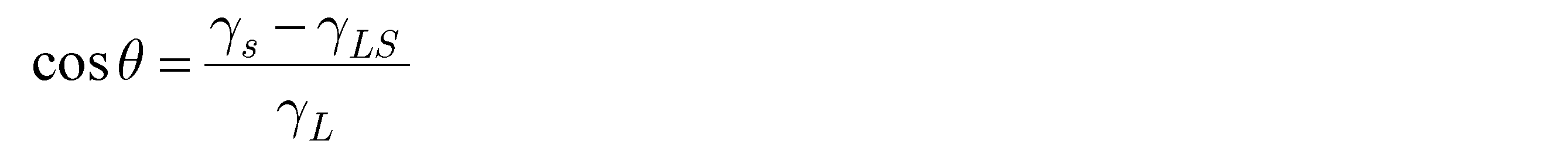
Here, when the number 1 is transformed, it becomes the number 2.
上述の数2より、濡れ性を高くする方法、すなわち接触角θを0°に近づける方法は、液体の表面張力γ_Lを小さくする方法と、固体の表面自由エネルギーγSを大きくする方法とのいずれか一つが考えられる。液体の表面張力を小さくには、液体に界面活性剤を添加する方法がある。固体の表面自由エネルギーγSを大きくするには、固体表面を化学的あるいは物理的に改質することにより、濡れ性を高める方法がある。第2の実施形態では、反射層16の局所の表面改質を一例として説明する。
From the above-mentioned number 2, the method of increasing the wettability, that is, the method of bringing the contact angle θ close to 0 °, is either a method of reducing the surface tension γ_L of the liquid or a method of increasing the surface free energy γS of the solid. One can be considered. To reduce the surface tension of the liquid, there is a method of adding a surfactant to the liquid. In order to increase the surface free energy γS of a solid, there is a method of improving the wettability by chemically or physically modifying the surface of the solid. In the second embodiment, the local surface modification of the reflective layer 16 will be described as an example.
固体表面の物理的な改質とは、具体的には表面の粗面化を意味し、超親水性、超撥水性を発現させるために化学的親水化と併せて必要な処理である。表面の微細な凹凸と濡れ性の関係を表すモデルとして、WenzelモデルとCassie-Baxterモデルが知られている。前者は、凹凸の凹部まで液滴が入り込み、全固体表面が濡れていることを前提としており、凹凸によって固体と液滴の界面の表面積がr倍に増えるという考えかたであり、以下の数3として表される。ここで、θwは凹凸表面における見かけの接触角である。
Physical modification of the solid surface specifically means roughening of the surface, and is a treatment required in combination with chemical hydrophilization in order to develop superhydrophilicity and superhydrophobicity. The Wenzel model and the Cassie-Baxter model are known as models that represent the relationship between fine irregularities on the surface and wettability. The former is based on the premise that the droplets penetrate into the concave and convex recesses and the surface of the entire solid is wet, and the unevenness increases the surface area of the interface between the solid and the droplet by r times. It is represented as 3. Here, θw is an apparent contact angle on the uneven surface.

この数3において、r>1のため、粗面化により、親水性を有する表面がより親水性になり、撥水性を有する表面がより撥水性になる。
In this number 3, since r> 1, the surface having hydrophilicity becomes more hydrophilic and the surface having water repellency becomes more water repellent due to the roughening.
これに対して、Cassie-Baxterモデルは、凹凸の凹部まで液滴が入り込まずに空気が入り込んでいることを前提とする。ここでは詳細には言及しないが、固体表面上に凹凸があることで液滴と固体表面の接している実面積が小さくなることで、凹凸がない場合に比べて液滴との接触角が大きくなるという理論で、撥水性の固体表面の構築に有効であると考えられている。
On the other hand, the Cassie-Baxter model is based on the premise that air does not enter into the concave and convex recesses, but air enters. Although not described in detail here, the unevenness on the solid surface reduces the actual area where the droplet and the solid surface are in contact, so that the contact angle with the droplet is larger than when there is no unevenness. The theory is that it is effective in constructing a water-repellent solid surface.
上記どちらのモデルが適用されるかは、液滴の大きさや固体表面の凹凸形状、材料の濡れ性が影響するが、液滴の大きさ、あるいは重さを大きくして凹部に入り込む圧力を増すと、Wenzelモデルが優勢となることが報告されている。
Which of the above models is applied depends on the size of the droplet, the uneven shape of the solid surface, and the wettability of the material, but the size or weight of the droplet is increased to increase the pressure to enter the recess. It is reported that the Wenzel model becomes dominant.
上述のように、親水性および撥水性について述べてきたが、その評価指標である接触角の測定方法は、静的接触角測定および動的接触角測定がある。静的接触角測定は、接触角のみを把握する方法であり、例えば、一般的に用いる液滴法と、その他の、大面積試料表面の測定ではV-r法や、極小接触角計を用いる極小液滴法とがある。動的接触角測定は、液滴の動く速度、液滴の付着力等が分かる方法であり、滑落法、拡張収縮法、Wilhelmy法等が挙げられる。ソフトウェアによる画像解析技術が進歩した現在では、より正確な測定ができるヤングプラス法や楕円法が一般的である。
As mentioned above, hydrophilicity and water repellency have been described, but there are static contact angle measurement and dynamic contact angle measurement as the measurement method of the contact angle which is the evaluation index. The static contact angle measurement is a method for grasping only the contact angle. For example, the generally used sessile drop method, the Vr method for measuring the surface of a large area sample, or the minimum contact angle meter is used. There is a very small sessile drop method. The dynamic contact angle measurement is a method for knowing the moving speed of the droplet, the adhesive force of the droplet, and the like, and examples thereof include a sliding method, an expansion contraction method, and a Wilhelmy method. Now that software-based image analysis technology has advanced, the Young Plus method and ellipsoid method, which enable more accurate measurement, are common.
反射層16の表面において、島領域R1の濡れ性を海領域R2よりも高くする方法を以下に説明する。先に述べたように、固体表面の濡れ性を変化させる方法として化学的、あるいは物理的な改質が挙げられる。化学的改質として、例えば反射層16が酸化ケイ素より成る場合を考える。酸化ケイ素は表面が水酸基で覆われたシラノール基(≡Si-OH)を有し、親水性を示す。水酸基があることで、接着剤の水酸基(-OH)や水(H-O-H)、酸素(O)、窒素(N)、カルボキシル基(-COOH)、カルボニル基(C=O)などとの間で、分子間力の中で最も強い水素結合が形成され、強固に結合することができる。この親水性シリカ表面の水酸基は、メチルシラン等で置換することにより疎水化することができる。疎水化のための表面処理剤の実例は、ポリジメチルシロキサン、メチルクロロシラン、ヘキサメチルジシラザンである。島領域R1は親水性を保持させたまま、海領域R2に対して選択的に疎水化処理を行なうことにより、2つの領域で濡れ性(接触角)を変えることができる。
The method of making the wettability of the island region R1 higher than that of the sea region R2 on the surface of the reflective layer 16 will be described below. As mentioned above, chemical or physical modification can be mentioned as a method for changing the wettability of a solid surface. As a chemical modification, for example, consider the case where the reflective layer 16 is made of silicon oxide. Silicon oxide has a silanol group (≡Si—OH) whose surface is covered with a hydroxyl group and exhibits hydrophilicity. Due to the presence of hydroxyl groups, the hydroxyl groups (-OH), water (HOH), oxygen (O), nitrogen (N), carboxyl groups (-COOH), carbonyl groups (C = O), etc. of the adhesive can be used. The strongest hydrogen bond among the intermolecular forces is formed between them, and a strong bond can be formed. The hydroxyl group on the surface of this hydrophilic silica can be made hydrophobic by substituting it with methylsilane or the like. Examples of surface treatment agents for hydrophobization are polydimethylsiloxane, methylchlorosilane, and hexamethyldisilazane. The wettability (contact angle) can be changed between the two regions by selectively hydrophobizing the sea region R2 while maintaining the hydrophilicity of the island region R1.
また、反射層16は二酸化チタン(TiO2)でもよい。二酸化チタンは油に濡れやすく(親油性)、水にあまり濡れない(疎水性)性質を持つ。しかし、二酸化チタンは酸素共存下にて紫外線を照射すると親水性となることが知られており、光触媒として様々な分野で利用されている。メカニズムとしては、二酸化チタン表面に紫外線が照射されることで生じた正孔によって、チタン原子と酸素原子の化学結合(Ti-O-Ti)が切断され、その酸素原子と水が反応して水酸基が形成されるためと考えられている。二酸化チタン表面は、光照射直後は超親水性となるが、紫外線照射を止めて暗所に放置されると、徐々に元の表面状態に戻り親水性が失われる。反射層16が二酸化チタンである場合に、反射層16を形成した後に、物理的に海領域R2を覆った状態で島領域R1のみに紫外線照射を行なうことで、島領域R1は親水性とすることができ、海領域R2は疎水性とすることができる。この場合、上記のように親水性が失われる前に、接着層17を塗布する必要がある。
Further, the reflective layer 16 may be titanium dioxide (TiO 2 ). Titanium dioxide is easy to get wet with oil (lipophilic) and does not get very wet with water (hydrophobic). However, titanium dioxide is known to become hydrophilic when irradiated with ultraviolet rays in the presence of oxygen, and is used in various fields as a photocatalyst. The mechanism is that the holes generated by irradiating the surface of titanium dioxide with ultraviolet rays break the chemical bond (Ti—O—Ti) between the titanium atom and the oxygen atom, and the oxygen atom reacts with water to form a hydroxyl group. Is believed to be due to the formation of. The surface of titanium dioxide becomes superhydrophilic immediately after irradiation with light, but when the irradiation with ultraviolet rays is stopped and the surface is left in a dark place, the surface gradually returns to the original surface state and loses hydrophilicity. When the reflective layer 16 is titanium dioxide, after the reflective layer 16 is formed, the island region R1 is made hydrophilic by irradiating only the island region R1 with ultraviolet rays while physically covering the sea region R2. The sea region R2 can be hydrophobic. In this case, it is necessary to apply the adhesive layer 17 before the hydrophilicity is lost as described above.
さらに、反射層16がアルミニウムより構成される場合、金属表面は酸化物層に覆われるため、その上に水やその他の汚染物質が吸着する。このため、そのままの状態では十分な接着が得られないため、表面処理を行なうことが好ましい。表面処理は、(1)有機溶剤や紫外線照射による汚染物質の除去、(2)酸やアルカリなどの処理による接着に適した酸化皮膜の形成、(3)シランカップリング剤の塗布とできる。このような表面処理を第1の実施形態で説明した島領域R1のみに行なうことにより、島領域R1の濡れ性を海領域R2よりも高くすることが可能である。
Furthermore, when the reflective layer 16 is made of aluminum, the metal surface is covered with an oxide layer, so that water and other contaminants are adsorbed on the metal surface. For this reason, sufficient adhesion cannot be obtained in the state as it is, so it is preferable to perform surface treatment. The surface treatment can be (1) removal of contaminants by irradiation with an organic solvent or ultraviolet rays, (2) formation of an oxide film suitable for adhesion by treatment with acids or alkalis, and (3) application of a silane coupling agent. By performing such surface treatment only on the island region R1 described in the first embodiment, it is possible to make the wettability of the island region R1 higher than that of the sea region R2.
(レリーフ構造)
以下に、レリーフ構造15について説明する。
ここでレリーフ構造は、図6A~6Fを用いて説明した第1の実施形態と同様であるため、説明を省略する。しかしながら、第2の実施形態において、第1レリーフ領域SR1が島領域R1に重なり、第2レリーフ領域SR2が海領域R2に重なるよう配置される点において上述の第1の実施形態と異なる。 (Relief structure)
Therelief structure 15 will be described below.
Here, since the relief structure is the same as that of the first embodiment described with reference to FIGS. 6A to 6F, the description thereof will be omitted. However, the second embodiment is different from the above-mentioned first embodiment in that the first relief region SR1 is arranged so as to overlap the island region R1 and the second relief region SR2 is arranged so as to overlap the sea region R2.
以下に、レリーフ構造15について説明する。
ここでレリーフ構造は、図6A~6Fを用いて説明した第1の実施形態と同様であるため、説明を省略する。しかしながら、第2の実施形態において、第1レリーフ領域SR1が島領域R1に重なり、第2レリーフ領域SR2が海領域R2に重なるよう配置される点において上述の第1の実施形態と異なる。 (Relief structure)
The
Here, since the relief structure is the same as that of the first embodiment described with reference to FIGS. 6A to 6F, the description thereof will be omitted. However, the second embodiment is different from the above-mentioned first embodiment in that the first relief region SR1 is arranged so as to overlap the island region R1 and the second relief region SR2 is arranged so as to overlap the sea region R2.
積層体10を破壊し、転写箔11を不正な手段で取り出そうとした場合に、積層体10において界面接着強度の小さい層間で層間剥離、あるいは、破断強度の小さい層内で凝集破壊が起きることで、転写箔11が分離される。以下、パッチ基体13および情報記録シート19の界面接着強度と、接着層17および保護シート18の界面接着強度とが、保護シート18および情報記録シート19の界面接着強度よりも大きいことを前提に説明する。
When the laminate 10 is destroyed and the transfer foil 11 is attempted to be taken out by an improper means, delamination occurs between layers having a low interfacial adhesive strength in the laminate 10, or cohesive fracture occurs in a layer having a low breaking strength. , The transfer foil 11 is separated. Hereinafter, the description will be made on the premise that the interfacial adhesive strength of the patch substrate 13 and the information recording sheet 19 and the interfacial adhesive strength of the adhesive layer 17 and the protective sheet 18 are larger than the interfacial adhesive strength of the protective sheet 18 and the information recording sheet 19. do.
上述した微細な凹凸が濡れ性、ひいては接着力に寄与することを説明したが、第2の実施形態におけるレリーフ構造15もこの効果を有している。ただし、互いに接する層間において化学的な結合状態が同じ場合、剥離しようと力を加える方向に対して平行な構造とそうでない構造とでは、剥離に対抗する力が異なることが予想される。これは、レリーフ構造15のアンカー効果に差がある、と表現することもできる。
It has been explained that the above-mentioned fine unevenness contributes to wettability and, by extension, adhesive strength, but the relief structure 15 in the second embodiment also has this effect. However, when the chemical bond state is the same between the layers in contact with each other, it is expected that the force against the peeling differs between the structure parallel to the direction in which the force is applied to be peeled off and the structure in which the force is not applied. This can also be expressed as a difference in the anchor effect of the relief structure 15.
第2の実施形態では、海領域R2に比べて反射層16と接着層17の濡れ性が高く、界面接着強度が高い島領域R1において、一方向に整列した線状の第1のレリーフ構造15aが配置される。そのため、特に第1の方向に沿って積層体10から転写箔11を剥がそうとした場合に、島領域R1では第1のレリーフ構造15aによる接着力、すなわちアンカー効果の弱いレリーフ形成層14と反射層16との界面で分離されやすくなる。一方、海領域R2では第2のレリーフ構造15bによるアンカー効果により、レリーフ形成層14と反射層16の界面接着強度が第1のレリーフ構造15aの場合と比べて大きくなり、界面接着強度の弱い反射層16と接着層17との間で分離されやすくなる。
In the second embodiment, in the island region R1 where the reflective layer 16 and the adhesive layer 17 have higher wettability and the interfacial adhesive strength is higher than that of the sea region R2, the linear first relief structure 15a aligned in one direction. Is placed. Therefore, especially when the transfer foil 11 is to be peeled off from the laminated body 10 along the first direction, the adhesive force due to the first relief structure 15a, that is, the relief forming layer 14 having a weak anchor effect and the reflection in the island region R1. It becomes easy to separate at the interface with the layer 16. On the other hand, in the sea region R2, due to the anchor effect of the second relief structure 15b, the interfacial adhesive strength between the relief forming layer 14 and the reflective layer 16 is higher than that in the case of the first relief structure 15a, and the reflection with weak interfacial adhesive strength It becomes easy to separate between the layer 16 and the adhesive layer 17.
分離された際、接着層17と保護シート18が接する構成(図2A参照)の場合には、レリーフ形成層14は情報記録シート19側に残り、接着層17と情報記録シート19が接する構成(図2B参照)の場合には、レリーフ形成層14は保護シート18側に残る。前者の場合、分離された転写箔11を不正に再利用するには、情報記録シート19からレリーフ形成層14を分離する必要がある。しかしながら、情報記録シート19(厚さ50μm~800μm)に対して、レリーフ形成層14およびパッチ基体13は合わせても数μmと著しく薄いため、レリーフ構造15を破壊することなく情報記録シート19から分離することは難しく、再利用は困難である。一方、後者の場合、保護シート18側にレリーフ構造15が残るため、その表面状態によっては不正に再利用される可能性がある。具体的には、島領域R1と海領域R2とのそれぞれにおいて、レリーフ形成層14と反射層16との界面、および反射層16と接着層17との界面できれいに剥離された場合には、分離された面において、反射層16の有無は異なるものの、レリーフ構造15の形状は維持された状態となるため、転用できる可能性がある。
In the case of the configuration in which the adhesive layer 17 and the protective sheet 18 are in contact with each other when separated (see FIG. 2A), the relief forming layer 14 remains on the information recording sheet 19 side, and the adhesive layer 17 and the information recording sheet 19 are in contact with each other (see FIG. 2A). In the case of FIG. 2B), the relief forming layer 14 remains on the protective sheet 18 side. In the former case, in order to illegally reuse the separated transfer foil 11, it is necessary to separate the relief forming layer 14 from the information recording sheet 19. However, since the relief forming layer 14 and the patch substrate 13 are remarkably thin as several μm in total with respect to the information recording sheet 19 (thickness 50 μm to 800 μm), they can be separated from the information recording sheet 19 without destroying the relief structure 15. It is difficult to do and difficult to reuse. On the other hand, in the latter case, since the relief structure 15 remains on the protective sheet 18 side, it may be illegally reused depending on the surface condition thereof. Specifically, in each of the island region R1 and the sea region R2, when the relief forming layer 14 and the reflective layer 16 are cleanly peeled off at the interface and the reflective layer 16 and the adhesive layer 17 are separated, they are separated. Although the presence or absence of the reflective layer 16 is different on the surface, the shape of the relief structure 15 is maintained, so that it may be diverted.
上述の第1の実施形態で説明したように、島領域R1は、一辺あるいは直径が20μm~300μmの微小な領域であり、図8に示したように転写箔11の広い範囲に、海領域R2に点在して設けられる。転写箔11を分離しようとした際に、特定の層(第2の実施形態の説明では反射層16および接着層17)において島領域R1と海領域R2とに作用する力は異なり、近接した両領域では互いの影響を少なからず受けるため、各領域内においても分離あるいは破断する力が不均一となる。その結果、実際には局所的に反射層16が保護シート18側に取られたり、接着層17が情報記録シート19側に取られたりし、転写箔11の分離された表面は荒れた状態となり、分離前と同等の光学効果は得られない。
As described in the first embodiment described above, the island region R1 is a minute region having a side or a diameter of 20 μm to 300 μm, and as shown in FIG. 8, the sea region R2 covers a wide range of the transfer foil 11. It is scattered around. When the transfer foil 11 is to be separated, the forces acting on the island region R1 and the sea region R2 in a specific layer (the reflective layer 16 and the adhesive layer 17 in the description of the second embodiment) are different, and both are close to each other. Since the regions are influenced by each other to a considerable extent, the force of separation or breaking becomes non-uniform even within each region. As a result, the reflective layer 16 is actually locally taken to the protective sheet 18 side, or the adhesive layer 17 is taken to the information recording sheet 19 side, and the separated surface of the transfer foil 11 becomes rough. , The same optical effect as before separation cannot be obtained.
仮に、分離された表面にレリーフ構造15がきれいに維持されている場合でも、反射層16の有無が異なるため、分離された転写箔11を保護シート18ごとそのまま偽のカードに使用すると、反射層16が失われた島領域R1の光学効果が発現しないため、外観から偽物であることが容易に判別される。また、分離された転写箔11のレリーフ構造15側に再度反射層を設けることで、島領域R1の光学効果を再現しようとした場合にも、反射層16の無い島領域R1と、反射層16が残っている海領域R2とでは、反射層の厚みに差が生じるため、光学効果にムラが発生する、輝度が下がるなど、元の状態を完全に再現することは難しい。特に、反射層16が光透過性の材料である場合、元の材料と新たに設ける反射層の材料の屈折率が同じでなければ、海領域R2に反射層が実質的に2層形成されることとなり、多層膜干渉が起こるため、島領域R1と異なる光学効果を発現することになる。これにより、単層の場合とは異なる色が表示されたり、輝度が低下したりするなどの変化を生じさせられる。
Even if the relief structure 15 is kept clean on the separated surface, the presence or absence of the reflective layer 16 is different. Therefore, if the separated transfer foil 11 is used as it is for a fake card together with the protective sheet 18, the reflective layer 16 is used. Since the optical effect of the island region R1 in which is lost is not exhibited, it can be easily determined from the appearance that it is a fake. Further, even when the optical effect of the island region R1 is to be reproduced by providing the reflective layer again on the relief structure 15 side of the separated transfer foil 11, the island region R1 without the reflective layer 16 and the reflective layer 16 are also provided. Since there is a difference in the thickness of the reflective layer from the sea region R2 in which the above remains, it is difficult to completely reproduce the original state such as uneven optical effect and reduced brightness. In particular, when the reflective layer 16 is a light-transmitting material, substantially two reflective layers are formed in the sea region R2 unless the refractive index of the original material and the material of the newly provided reflective layer are the same. As a result, multi-layer film interference occurs, so that an optical effect different from that of the island region R1 is exhibited. As a result, changes such as displaying a color different from that in the case of a single layer and reducing the brightness can be caused.
第2の実施形態では、島領域R1と海領域R2における反射層16と接着層17の界面接着強度を異ならせることにより、積層体10から転写箔11を取り出して不正に再利用しようとしても、本来の光学効果を再現できないため、そのような行為に対して抑止力が働く、もしくは再利用されても容易に偽物と判別できる。
In the second embodiment, even if the transfer foil 11 is taken out from the laminated body 10 and illegally reused by making the interfacial adhesive strengths of the reflective layer 16 and the adhesive layer 17 in the island region R1 and the sea region R2 different. Since the original optical effect cannot be reproduced, it can be easily identified as a fake even if it acts as a deterrent to such an act or is reused.
(第3の実施形態)
(積層体)
以下、図11~13を参照して、本発明の実施形態を第3の実施形態として説明する。
図11は、第3の実施形態の積層体10を概略的に説明する平面図である。第1、第2の実施形態と同様に、積層体10は画像12を表示する転写箔11を一部に備える。図12は、図11のAII-AII線に沿う断面図である。積層体10は、パッチ基体13、レリーフ形成層14、第1反射層161、第2反射層162、接着層17が順に積層された構成であり、レリーフ形成層14の表面にはレリーフ構造15が形成されており、第1反射層161はレリーフ構造15に、第2反射層162は第1反射層161に追従した凹凸状に設けられている。なお、転写箔11は少なくとも上記の層を記載した順に備えるが、これ以外の層を間に含む構成であってもよい。転写箔11は、保護シート18と情報記録シート19とでラミネートされ、転写箔11が積層体10の外部に露出しないように内包されている。図12Aと図12Bとは、積層体10に内装される転写箔11の層構成が逆転したものであるが、どちらの構成であってもよい。図12Aの構成の場合は、転写箔11が接着層17を介して保護シート18に転写された後にラミネートされる。一方、図12Bの構成の場合は、転写箔11が接着層17を介して情報記録シート19に転写された後にラミネートされる。 (Third embodiment)
(Laminated body)
Hereinafter, embodiments of the present invention will be described as a third embodiment with reference to FIGS. 11 to 13.
FIG. 11 is a plan view schematically illustrating thelaminated body 10 of the third embodiment. Similar to the first and second embodiments, the laminate 10 is partially provided with a transfer foil 11 for displaying the image 12. FIG. 12 is a cross-sectional view taken along the line AII-AII of FIG. The laminated body 10 has a structure in which a patch substrate 13, a relief forming layer 14, a first reflective layer 161, a second reflective layer 162, and an adhesive layer 17 are laminated in this order, and a relief structure 15 is provided on the surface of the relief forming layer 14. The first reflective layer 161 is formed in the relief structure 15, and the second reflective layer 162 is provided in an uneven shape following the first reflective layer 161. The transfer foil 11 is provided with at least the above layers in the order described, but may be configured to include other layers in between. The transfer foil 11 is laminated with a protective sheet 18 and an information recording sheet 19, and is included so that the transfer foil 11 is not exposed to the outside of the laminated body 10. 12A and 12B show that the layer structure of the transfer foil 11 incorporated in the laminated body 10 is reversed, but either structure may be used. In the case of the configuration of FIG. 12A, the transfer foil 11 is transferred to the protective sheet 18 via the adhesive layer 17 and then laminated. On the other hand, in the case of the configuration of FIG. 12B, the transfer foil 11 is transferred to the information recording sheet 19 via the adhesive layer 17 and then laminated.
(積層体)
以下、図11~13を参照して、本発明の実施形態を第3の実施形態として説明する。
図11は、第3の実施形態の積層体10を概略的に説明する平面図である。第1、第2の実施形態と同様に、積層体10は画像12を表示する転写箔11を一部に備える。図12は、図11のAII-AII線に沿う断面図である。積層体10は、パッチ基体13、レリーフ形成層14、第1反射層161、第2反射層162、接着層17が順に積層された構成であり、レリーフ形成層14の表面にはレリーフ構造15が形成されており、第1反射層161はレリーフ構造15に、第2反射層162は第1反射層161に追従した凹凸状に設けられている。なお、転写箔11は少なくとも上記の層を記載した順に備えるが、これ以外の層を間に含む構成であってもよい。転写箔11は、保護シート18と情報記録シート19とでラミネートされ、転写箔11が積層体10の外部に露出しないように内包されている。図12Aと図12Bとは、積層体10に内装される転写箔11の層構成が逆転したものであるが、どちらの構成であってもよい。図12Aの構成の場合は、転写箔11が接着層17を介して保護シート18に転写された後にラミネートされる。一方、図12Bの構成の場合は、転写箔11が接着層17を介して情報記録シート19に転写された後にラミネートされる。 (Third embodiment)
(Laminated body)
Hereinafter, embodiments of the present invention will be described as a third embodiment with reference to FIGS. 11 to 13.
FIG. 11 is a plan view schematically illustrating the
(島領域・海領域)
以下、積層体10を構成する第1領域S1、第2領域S2、およびレリーフ構造15について説明する。図13は転写箔11の構成を示す平面図である。転写箔11には、第1領域S1と第2領域S2が設けられている。図の例では、転写箔全面に第1領域S1と第2領域S2が広がっているが、転写箔11の一部に設けられていてもよい。 (Island area / sea area)
Hereinafter, the first region S1, the second region S2, and therelief structure 15 constituting the laminated body 10 will be described. FIG. 13 is a plan view showing the structure of the transfer foil 11. The transfer foil 11 is provided with a first region S1 and a second region S2. In the example of the figure, the first region S1 and the second region S2 are spread over the entire surface of the transfer foil, but they may be provided on a part of the transfer foil 11.
以下、積層体10を構成する第1領域S1、第2領域S2、およびレリーフ構造15について説明する。図13は転写箔11の構成を示す平面図である。転写箔11には、第1領域S1と第2領域S2が設けられている。図の例では、転写箔全面に第1領域S1と第2領域S2が広がっているが、転写箔11の一部に設けられていてもよい。 (Island area / sea area)
Hereinafter, the first region S1, the second region S2, and the
図14は、図13の3A-3A線に沿う断面図の一部であり、第1領域S1と第2領域S2に対応するレリーフ形成層14、第1反射層161、第2反射層162、および接着層17の態様を示している。第1領域S1は第1反射層161と第2反射層162の2層が積層された構成であるが、第2領域S2は第1反射層161のみを備える。加えて、第1反射層161および第2反射層162の少なくとも一方は、可視光域の代表的な波長、例えば532nmにおいてレリーフ形成層14および接着層17よりも高い屈折率を有した光透過性の材料で構成される。これにより、第1反射層161と第2反射層162の屈折率が共にレリーフ形成層14および接着層17より低い場合よりも高い反射効果が得られるため、第1領域S1と第2領域S2の両方で、光学効果として表示される画像12を観察者が視認しやすくなる。
FIG. 14 is a part of a cross-sectional view taken along the line 3A-3A of FIG. 13, and the relief forming layer 14, the first reflective layer 161 and the second reflective layer 162 corresponding to the first region S1 and the second region S2. And the aspect of the adhesive layer 17 is shown. The first region S1 has a configuration in which two layers of the first reflective layer 161 and the second reflective layer 162 are laminated, but the second region S2 includes only the first reflective layer 161. In addition, at least one of the first reflective layer 161 and the second reflective layer 162 has a higher refractive index than the relief forming layer 14 and the adhesive layer 17 at a typical wavelength in the visible light region, for example, 532 nm. Consists of materials. As a result, a higher reflection effect can be obtained than when the refractive indexes of the first reflective layer 161 and the second reflective layer 162 are both lower than those of the relief forming layer 14 and the adhesive layer 17, so that the first region S1 and the second region S2 In both cases, the observer can easily see the image 12 displayed as an optical effect.
図14において、第1反射層161と接着層17との間の界面接着強度をT1、第2反射層162と接着層17との間の界面接着強度をT2としたとき、T1とT2とは異なる。より具体的に、T1がT2より大きい場合は、第2領域S2が島領域R1に対応し、第1領域S1が海領域R2に対応する。一方、T1がT2より小さい場合は、第1領域S1が島領域R1に対応し、第2領域S2が海領域R2に対応する。図13および図14において、T1がT2より小さく、第1領域S1が島領域R1に対応し、第2領域S2が海領域R2に対応する例が示されているが、上述のように界面接着強度T1およびT2の関係によって、第1領域S1および第2領域S2と、島領域R1および海領域R2との対応関係は変わる場合がある。
In FIG. 14, when the interfacial adhesive strength between the first reflective layer 161 and the adhesive layer 17 is T1 and the interfacial adhesive strength between the second reflective layer 162 and the adhesive layer 17 is T2, what are T1 and T2? different. More specifically, when T1 is larger than T2, the second region S2 corresponds to the island region R1 and the first region S1 corresponds to the sea region R2. On the other hand, when T1 is smaller than T2, the first region S1 corresponds to the island region R1 and the second region S2 corresponds to the sea region R2. 13 and 14, T1 is smaller than T2, the first region S1 corresponds to the island region R1, and the second region S2 corresponds to the sea region R2. As described above, interfacial adhesion is shown. Depending on the relationship between the intensities T1 and T2, the correspondence between the first region S1 and the second region S2 and the island region R1 and the sea region R2 may change.
転写箔11の構成は図14に限られるものでなく、図15に示すような態様であってもよい。図15の例では、第1領域S1が第1反射層161と第2反射層162とが積層されて構成されるが、第2領域S2が図14に示す例とは異なり、第2反射層162のみが設けられている。この場合、第1領域S1と第2領域S2とのどちらにおいても、第2反射層162が接着層17と接する一方、レリーフ形成層14と接する層が異なる。より具体的に、第1領域S1では第1反射層161がレリーフ形成層14と接し、第2領域S2では第2反射層162がレリーフ形成層14と接する。第1反射層161は光透過性の材料でなくてもよく、金属材料であってもよい。金属材料の実例は、アルミニウムや銀である。
The configuration of the transfer foil 11 is not limited to that shown in FIG. 14, and may be in the manner shown in FIG. In the example of FIG. 15, the first region S1 is configured by laminating the first reflective layer 161 and the second reflective layer 162, but unlike the example shown in FIG. 14, the second region S2 is the second reflective layer. Only 162 is provided. In this case, in both the first region S1 and the second region S2, the second reflective layer 162 is in contact with the adhesive layer 17, while the layer in contact with the relief forming layer 14 is different. More specifically, in the first region S1, the first reflective layer 161 is in contact with the relief forming layer 14, and in the second region S2, the second reflective layer 162 is in contact with the relief forming layer 14. The first reflective layer 161 does not have to be a light-transmitting material, and may be a metal material. Examples of metallic materials are aluminum and silver.
図15において、第1反射層161とレリーフ形成層14との間の界面接着強度をT1、第2反射層162とレリーフ形成層14との間の界面接着強度をT2としたとき、T1とT2とは異なる。T1がT2より大きい場合は、第2領域S2が島領域R1に対応し、第1領域S1が海領域R2に対応する。一方、T1がT2より小さい場合は、第1領域S1が島領域R1に対応し、第2領域S2が海領域R2に対応する。
In FIG. 15, when the interfacial adhesive strength between the first reflective layer 161 and the relief forming layer 14 is T1, and the interfacial adhesive strength between the second reflective layer 162 and the relief forming layer 14 is T2, T1 and T2. Is different. When T1 is larger than T2, the second region S2 corresponds to the island region R1 and the first region S1 corresponds to the sea region R2. On the other hand, when T1 is smaller than T2, the first region S1 corresponds to the island region R1 and the second region S2 corresponds to the sea region R2.
図14および図15に示す構成では、第1領域S1と第2領域S2とにおいて、界面接着強度に差が生じる界面は異なる。しかしながら、島領域R1と海領域R2において、反射層161、162と接着層17、あるいはレリーフ形成層14との間に生じる界面接着強度の差は、共に第1反射層161および第2反射層162の材料に起因する。これについて、以下で説明する。
In the configurations shown in FIGS. 14 and 15, the interface at which the interface adhesive strength differs between the first region S1 and the second region S2 is different. However, in the island region R1 and the sea region R2, the difference in the interfacial adhesive strength generated between the reflective layers 161 and 162 and the adhesive layer 17 or the relief forming layer 14 is both the first reflective layer 161 and the second reflective layer 162. Due to the material of. This will be described below.
(反射層)
上述したような、島領域R1と海領域R2との界面接着強度の違いを生じさせる方法、すなわち第1反射層161と第2反射層162の特性として、以下に例を3つ示す。なお、方法は以下の3つに限定されるものではなく、界面接着強度の差を実現するような反射層161、162であれば、そのメカニズムは問わない。また、以下の説明では図14の構成を例に、反射層161、162と接着層17との間の界面接着強度について記載するが、図15の構成であれば「接着層17」を「レリーフ形成層14」と置き換えて考えればよい。 (Reflective layer)
Three examples are shown below as the characteristics of the firstreflective layer 161 and the second reflective layer 162, that is, the method of causing the difference in the interfacial adhesive strength between the island region R1 and the sea region R2 as described above. The method is not limited to the following three methods, and the mechanism is not limited as long as it is a reflective layer 161 or 162 that realizes a difference in interfacial adhesive strength. Further, in the following description, the interfacial adhesive strength between the reflective layers 161 and 162 and the adhesive layer 17 will be described by taking the configuration of FIG. 14 as an example. However, in the case of the configuration of FIG. 15, the “adhesive layer 17” is referred to as “relief”. It may be considered in place of the forming layer 14 ”.
上述したような、島領域R1と海領域R2との界面接着強度の違いを生じさせる方法、すなわち第1反射層161と第2反射層162の特性として、以下に例を3つ示す。なお、方法は以下の3つに限定されるものではなく、界面接着強度の差を実現するような反射層161、162であれば、そのメカニズムは問わない。また、以下の説明では図14の構成を例に、反射層161、162と接着層17との間の界面接着強度について記載するが、図15の構成であれば「接着層17」を「レリーフ形成層14」と置き換えて考えればよい。 (Reflective layer)
Three examples are shown below as the characteristics of the first
一例として、第1領域S1が海領域R2に対応し、第2領域S2が島領域R1に対応する構成を説明する。第1領域S1において、第2反射層162(図15の構成の場合は第1反射層161)を撥水性あるいは撥油性を備えた無機化合物とする。接着層17の第2反射層162と接する表面が親水性の場合には撥水性、親油性の場合には撥油性を有する材料を選択すればよい。あるいは、両方の性質を備えた材料であってもよい。さらに、接着層17が親水性と親油性両方の性質を有している場合には、撥水性と撥油性どちらの材料でもよいが、第2反射層162と接着層17との界面接着強度がより小さくなる方を選択することが好ましい。撥水・撥油の性質を有する材料は、フッ素系化合物とできる。フッ素系化合物の実例は、フッ化マグネシウム(MgF2)である。撥水性/撥油性の材料を第2反射層162に用いることにより、第1領域S1においては、第2反射層162と接着層17との密着性、すなわち界面接着強度が小さくなる(海領域R2)。一方、接着層17と親和性の高い材料を備えた第2領域S2では、第1領域S1よりも第1反射層161と接着層17との界面接着強度が大きい(島領域R1)。図14のように、レリーフ形成層14に第1反射層161および第2反射層162を形成する場合に、第2反射層162が第1反射層161に十分に密着せず、層が形成されないことが懸念される。しかしながら、第1反射層161および第2反射層162を真空環境下で連続して蒸着して形成するといった方法により、これを解消することが可能である。
As an example, a configuration in which the first region S1 corresponds to the sea region R2 and the second region S2 corresponds to the island region R1 will be described. In the first region S1, the second reflective layer 162 (the first reflective layer 161 in the case of the configuration of FIG. 15) is an inorganic compound having water repellency or oil repellency. When the surface of the adhesive layer 17 in contact with the second reflective layer 162 is hydrophilic, a material having water repellency and when it is lipophilic, a material having oil repellency may be selected. Alternatively, it may be a material having both properties. Further, when the adhesive layer 17 has both hydrophilic and lipophilic properties, either a water-repellent or oil-repellent material may be used, but the interfacial adhesive strength between the second reflective layer 162 and the adhesive layer 17 is high. It is preferable to select the smaller one. The material having water-repellent and oil-repellent properties can be a fluorine-based compound. An example of a fluorine-based compound is magnesium fluoride (MgF 2 ). By using a water-repellent / oil-repellent material for the second reflective layer 162, the adhesiveness between the second reflective layer 162 and the adhesive layer 17, that is, the interfacial adhesive strength is reduced in the first region S1 (sea region R2). ). On the other hand, in the second region S2 provided with a material having a high affinity with the adhesive layer 17, the interfacial adhesive strength between the first reflective layer 161 and the adhesive layer 17 is larger than that in the first region S1 (island region R1). As shown in FIG. 14, when the first reflective layer 161 and the second reflective layer 162 are formed on the relief forming layer 14, the second reflective layer 162 does not sufficiently adhere to the first reflective layer 161 and the layer is not formed. Is a concern. However, this can be solved by a method of continuously depositing and forming the first reflective layer 161 and the second reflective layer 162 in a vacuum environment.
その他の例として、第1領域S1を島領域R1、第2領域S2を海領域R2として説明する。この例では、第2反射層162の接着層17と接する面に対して表面改質を行なう。これにより、第2反射層162と接着層17との間の界面接着強度を高めることが可能である。表面改質として、第1の実施形態および第2の実施形態で説明したような、1)コロナ処理やプラズマ処理による親水性の改善や物体表面の有機物除去、酸化膜除去、2)接着層17との結合を可能とする官能基の付与、3)アンカー効果を高める粗面化、等とできる。一方、第1反射層161は、少なくとも表面改質後の第2反射層162よりも接着層17との間の界面接着強度が小さい無機化合物であって、界面接着強度が小さい要因は材料自体の特性、例えば接着層17に対する濡れ性や接着層17との分子間力の差であってもよいし、表面に自然に形成される酸化膜であってもよい。
As another example, the first region S1 will be described as an island region R1, and the second region S2 will be described as a sea region R2. In this example, the surface of the second reflective layer 162 in contact with the adhesive layer 17 is surface-modified. This makes it possible to increase the interfacial adhesive strength between the second reflective layer 162 and the adhesive layer 17. As surface modification, as described in the first embodiment and the second embodiment, 1) improvement of hydrophilicity by corona treatment and plasma treatment, removal of organic substances on the surface of an object, removal of oxide film, and 2) adhesive layer 17 It is possible to impart a functional group capable of binding to 3) roughening to enhance the anchor effect, and the like. On the other hand, the first reflective layer 161 is an inorganic compound having a smaller interfacial adhesive strength with the adhesive layer 17 than at least the second reflective layer 162 after surface modification, and the reason why the interfacial adhesive strength is small is the material itself. It may be a characteristic, for example, a difference in wettability with respect to the adhesive layer 17 or an intramolecular force with the adhesive layer 17, or it may be an oxide film naturally formed on the surface.
以下、説明の便宜上、第1領域S1が島領域R1に対応し、第2領域S2が海領域R2に対応する例を説明する。ただし、第1領域S1が海領域R2に対応し、第2領域S2が島領域R1に対応してもよい。この例は、反射層161、162と接着層17との界面接着強度の差を、各反射層と接着層17との結合力の違いによって生じさせる。第2の実施形態で説明した接着のメカニズムのなかでも特に物理的接着と化学的接着に注目し、第1反射層161と第2反射層162とで、接着層17に対する濡れ性(あるいは接触角)や2層間に働く結合力(分子間力、イオン結合力、共有結合、水素結合)の有無や大小などが異なることを想定している。接着層17が親油性材料の場合、第1反射層161を撥油性材料、第2反射層162を親油性材料とすることで、第1領域S1と第2領域S2において反射層161、162と接着層17との界面接着強度に差を生じさせることが可能である。また、第1反射層161と接着層17がイオン結合、第2反射層162と接着層17が分子間力によって結合するような材料を適用することによっても、上記の特性を実現することが可能である。
Hereinafter, for convenience of explanation, an example in which the first region S1 corresponds to the island region R1 and the second region S2 corresponds to the sea region R2 will be described. However, the first region S1 may correspond to the sea region R2, and the second region S2 may correspond to the island region R1. In this example, the difference in the interfacial adhesive strength between the reflective layers 161 and 162 and the adhesive layer 17 is caused by the difference in the bonding force between each reflective layer and the adhesive layer 17. Among the adhesion mechanisms described in the second embodiment, particular attention is paid to physical adhesion and chemical adhesion, and the first reflective layer 161 and the second reflective layer 162 have wettability (or contact angle) with respect to the adhesive layer 17. ) And the presence / absence and magnitude of the bonding force (intermolecular force, ionic bonding force, covalent bond, hydrogen bond) acting between the two layers are assumed to be different. When the adhesive layer 17 is a lipophilic material, the first reflective layer 161 is an oil-repellent material and the second reflective layer 162 is a lipophilic material, so that the reflective layers 161 and 162 are formed in the first region S1 and the second region S2. It is possible to make a difference in the interfacial adhesive strength with the adhesive layer 17. Further, the above characteristics can also be realized by applying a material such that the first reflective layer 161 and the adhesive layer 17 are ionic bonded and the second reflective layer 162 and the adhesive layer 17 are bonded by an intermolecular force. Is.
上述の方法によって、第1領域S1と第2領域S2とで、反射層161、162と接着層17の界面接着強度を異ならせることができる。このような構成とすることで、積層体10から転写箔11を不正に取り出そうとした場合に、上記の層間における界面接着強度の大きい島領域R1では、パッチ基体13またはレリーフ形成層14の層間で分離するか、この2つもしくは接着層17の内部で凝集破壊することが想定される。一方、界面接着強度の小さい海領域R2では、反射層(161または162)と接着層17の層間で分離しやすい。その結果、島領域R1と海領域R2とで、分離あるいは破壊される層が異なり、2つに分かれた転写箔11の分離面のどちらか一方に形状を完全に維持した状態でレリーフ構造15が現れない、すなわち再利用を防止することが可能となる。
By the above method, the interfacial adhesive strength between the reflective layers 161 and 162 and the adhesive layer 17 can be made different between the first region S1 and the second region S2. With such a configuration, when the transfer foil 11 is illegally taken out from the laminated body 10, in the island region R1 having a large interfacial adhesive strength between the above layers, between the layers of the patch substrate 13 or the relief forming layer 14. It is assumed that they will separate or coagulate and break inside the two or the adhesive layer 17. On the other hand, in the sea region R2 having a low interfacial adhesive strength, it is easy to separate between the reflective layer (161 or 162) and the adhesive layer 17. As a result, the layers to be separated or destroyed differ between the island region R1 and the sea region R2, and the relief structure 15 is formed in a state where the shape is completely maintained on either one of the separation surfaces of the transfer foil 11 divided into two. It does not appear, that is, it is possible to prevent reuse.
(画像)
以下、画像12の構成を説明する。画像12の構成は、上述した第1~3の実施形態のいずれかの実施形態にも適用可能である。転写箔11において、レリーフ構造15の光学効果として表示される画像12は1種類のモチーフであってもよいし、異なる角度で観察可能な2種類のモチーフであってもよい。図16は、転写箔11に光源から光が入射した際に、島領域R1および海領域R2に形成されたレリーフ構造15が特定の角度に反射光を射出し、第1モチーフ121を形成する様子を示している。レリーフ構造15は、特定の角度に第1モチーフ121を形成することを満たせば、島領域R1と海領域R2に関係なく全域で周期や高さ、形状、方位などが同じ一様な設計であってもよいし、これらのうち1つあるいは複数の設計が第1モチーフ121内で局所的に異なっていてもよい。後者の場合には、島領域R1と海領域R2とで設計が異なっていてもよい。図16のような構成の場合、本発明における実施形態において、積層体10から転写箔11を不正に取り出そうとした場合に、第1~第3の実施形態で述べたような島領域R1と海領域R2とで異なる層での分離または層内での破壊が生じるため、分離された転写箔11にはレリーフ構造15が完全に維持されず、第1モチーフ121の光学効果(例えば輝度や発色)が弱くなり、再利用しても元の視覚効果が得られない。 (image)
Hereinafter, the configuration of theimage 12 will be described. The configuration of the image 12 is also applicable to any of the first to third embodiments described above. In the transfer foil 11, the image 12 displayed as the optical effect of the relief structure 15 may be one kind of motif or two kinds of motifs that can be observed at different angles. FIG. 16 shows how the relief structure 15 formed in the island region R1 and the sea region R2 emits reflected light at a specific angle to form the first motif 121 when light is incident on the transfer foil 11 from a light source. Is shown. The relief structure 15 has a uniform design having the same period, height, shape, orientation, etc. over the entire area regardless of the island region R1 and the sea region R2, provided that the first motif 121 is formed at a specific angle. One or more of these designs may be locally different within the first motif 121. In the latter case, the design may be different between the island region R1 and the sea region R2. In the case of the configuration as shown in FIG. 16, in the embodiment of the present invention, when the transfer foil 11 is illegally taken out from the laminated body 10, the island region R1 and the sea as described in the first to third embodiments are used. The relief structure 15 is not completely maintained in the separated transfer foil 11 because separation in different layers or breakage in the layer occurs in the region R2, and the optical effect of the first motif 121 (for example, brightness and color development). Becomes weaker and the original visual effect cannot be obtained even if it is reused.
以下、画像12の構成を説明する。画像12の構成は、上述した第1~3の実施形態のいずれかの実施形態にも適用可能である。転写箔11において、レリーフ構造15の光学効果として表示される画像12は1種類のモチーフであってもよいし、異なる角度で観察可能な2種類のモチーフであってもよい。図16は、転写箔11に光源から光が入射した際に、島領域R1および海領域R2に形成されたレリーフ構造15が特定の角度に反射光を射出し、第1モチーフ121を形成する様子を示している。レリーフ構造15は、特定の角度に第1モチーフ121を形成することを満たせば、島領域R1と海領域R2に関係なく全域で周期や高さ、形状、方位などが同じ一様な設計であってもよいし、これらのうち1つあるいは複数の設計が第1モチーフ121内で局所的に異なっていてもよい。後者の場合には、島領域R1と海領域R2とで設計が異なっていてもよい。図16のような構成の場合、本発明における実施形態において、積層体10から転写箔11を不正に取り出そうとした場合に、第1~第3の実施形態で述べたような島領域R1と海領域R2とで異なる層での分離または層内での破壊が生じるため、分離された転写箔11にはレリーフ構造15が完全に維持されず、第1モチーフ121の光学効果(例えば輝度や発色)が弱くなり、再利用しても元の視覚効果が得られない。 (image)
Hereinafter, the configuration of the
図17は、転写箔11に光源から光が入射した際に、島領域R1に形成された第1のレリーフ構造15aが、特定の角度αに反射光を射出して第1モチーフ121を形成し、海領域R2に形成された第2のレリーフ構造15bが、αとは異なる特定の角度βに反射光を射出して第2モチーフ122を形成する様子を示している。第1のレリーフ構造15aと第2のレリーフ構造15bは必ずしもそれぞれ島領域R1と海領域R2に限定して配置されなくてもよいが、上記構成とすることにより、積層体10から転写箔11を取り出そうとした際に、第1モチーフ121あるいは第2モチーフ122の一方の光学効果が顕著に弱くなるため、仮に分離された転写箔11が再利用された場合にも偽造品であることを容易に判別することができるため好ましい。第1のレリーフ構造15aと第2のレリーフ構造15bは、図6で説明したような構造から選択してもよいし、反射光の角度α≠βを満たせばどのような構造を用いてもよい。
In FIG. 17, when light is incident on the transfer foil 11 from a light source, the first relief structure 15a formed in the island region R1 emits reflected light at a specific angle α to form the first motif 121. , The second relief structure 15b formed in the sea region R2 emits reflected light at a specific angle β different from α to form the second motif 122. The first relief structure 15a and the second relief structure 15b do not necessarily have to be arranged only in the island region R1 and the sea region R2, respectively, but with the above configuration, the transfer foil 11 can be removed from the laminated body 10. Since the optical effect of either the first motif 121 or the second motif 122 is remarkably weakened when an attempt is made to take it out, it is easy to make it a counterfeit product even if the separated transfer foil 11 is reused. It is preferable because it can be discriminated. The first relief structure 15a and the second relief structure 15b may be selected from the structures as described with reference to FIG. 6, or any structure may be used as long as the angle α ≠ β of the reflected light is satisfied. ..
第1のレリーフ構造15aおよび第2のレリーフ構造15bは、前者をサブ波長格子、後者を指向性散乱構造とできる。このような構成の場合、第1モチーフ121は有彩色の画像、第2モチーフ122は無彩色の画像とすることができる。サブ波長格子による有彩色が発現するのは、反射層16がレリーフ形成層14および接着層17よりも高い屈折率を有する場合であり、格子の周期や方位、反射層16の屈折率によって正反射方向に色を表示することができる。また、指向性散乱構造は図6Cに示すような構造が挙げられるが、格子の方向が一様な場合には特定の階調の無彩色画像が表示され、格子の方向がモチーフの濃淡に合わせて局所的に変化している場合には、絵画のように陰影のついた立体的な無彩色画像が表示される。
In the first relief structure 15a and the second relief structure 15b, the former can be a sub-wavelength grid and the latter can be a directional scattering structure. In such a configuration, the first motif 121 can be a chromatic image and the second motif 122 can be an achromatic image. The chromatic color due to the sub-wavelength lattice is exhibited when the reflective layer 16 has a higher refractive index than the relief forming layer 14 and the adhesive layer 17, and is positively reflected depending on the period and orientation of the lattice and the refractive index of the reflective layer 16. Colors can be displayed in the direction. The directional scattering structure includes a structure as shown in FIG. 6C. When the direction of the grid is uniform, an achromatic image having a specific gradation is displayed, and the direction of the grid matches the shade of the motif. When it changes locally, a three-dimensional achromatic image with shading like a painting is displayed.
島領域R1および海領域R2と、第1のレリーフ構造15aおよび第2のレリーフ構造15bとの対応関係は上述の対応関係と異なることも可能である。しかしながら、第1のレリーフ構造15aにサブ波長格子を用いる場合には、積層体10から転写箔11を取り出そうとした場合に、保護シート18側に残った転写箔11の表面にサブ波長格子の形状が維持されていない方が、サブ波長格子に起因する有彩色の発色が失われるため、不正な再利用の抑止効果が高くなり、好ましい。
The correspondence between the island region R1 and the sea region R2 and the first relief structure 15a and the second relief structure 15b can be different from the above-mentioned correspondence. However, when a sub-wavelength grid is used for the first relief structure 15a, the shape of the sub-wavelength grid is formed on the surface of the transfer foil 11 remaining on the protective sheet 18 side when the transfer foil 11 is to be taken out from the laminated body 10. It is preferable that the above is not maintained because the chromatic color development due to the sub-wavelength grid is lost and the effect of suppressing unauthorized reuse is high.
発色の低下、すなわち彩度の低下は視覚的に認識しやすいため、偽造した場合に判別が容易になる。したがって、図16に示した構成の場合でも、レリーフ構造15にサブ波長格子を利用することで、転写箔11を取り出した際に第1モチーフ121の発色を低下させ、転写箔11の不正利用を抑止する効果が高くなる。
The decrease in color development, that is, the decrease in saturation is easy to visually recognize, so it is easy to distinguish when forged. Therefore, even in the case of the configuration shown in FIG. 16, by using the sub-wavelength grid for the relief structure 15, the color development of the first motif 121 is reduced when the transfer foil 11 is taken out, and the transfer foil 11 is illegally used. The effect of deterrence is high.
図18および図19は、図16と図17に示した積層体を有するカード20を観察者が観察した様子とその時に視認される外観を模式的に示した図である。図18に示すように、観察者は、光源からカード20に入射し、反射された光を捉えられるような角度でカード20を観察する。図16の構成の場合は、水平面Ph1を基準に角度θ1だけカード20を傾けた状態Aで第1モチーフ121が観察される。一方、図17の構成の場合は、状態Aで第1モチーフ121、さらに水平面Ph1から角度θ2だけカード20を傾けた状態Bで第2モチーフ122が観察される。なお、後者のように状態Aと状態Bが観察されるようなカード20において、図18の例ではカード20を観察者に対して前後に傾ける動作を示しているが、動作はこれに限定されるものではない。第1モチーフ121および第2モチーフ122を形成する第1、第2のレリーフ構造(15a、15b)の反射方向や見せたい光学効果が現れる方向に応じて、例えば状態Aから媒体を90度回転させる、など別の動作によって状態Aと状態Bが観察されてもよい。また、図18の例では、光源からの光が水平面Ph1に対して垂直に入射する条件でカード20が観察されているが、光源は必ずしもこの位置関係でなくてもよく、水平面Ph1に対して斜めに入射する条件でカード20が観察されてもよい。
18 and 19 are diagrams schematically showing the state in which the observer observes the card 20 having the laminated body shown in FIGS. 16 and 17, and the appearance visually recognized at that time. As shown in FIG. 18, the observer observes the card 20 at an angle that allows the light source to enter the card 20 and capture the reflected light. In the case of the configuration of FIG. 16, the first motif 121 is observed in the state A in which the card 20 is tilted by the angle θ1 with respect to the horizontal plane Ph1. On the other hand, in the case of the configuration of FIG. 17, the first motif 121 is observed in the state A, and the second motif 122 is observed in the state B in which the card 20 is tilted by the angle θ2 from the horizontal plane Ph1. In the card 20 in which the states A and B are observed as in the latter case, the example of FIG. 18 shows the operation of tilting the card 20 back and forth with respect to the observer, but the operation is limited to this. It's not something. Rotate the medium 90 degrees from state A, for example, depending on the reflection direction of the first and second relief structures (15a, 15b) forming the first motif 121 and the second motif 122 and the direction in which the desired optical effect appears. , Etc., may be observed in the state A and the state B by another operation. Further, in the example of FIG. 18, the card 20 is observed under the condition that the light from the light source is vertically incident on the horizontal plane Ph1, but the light source does not necessarily have to have this positional relationship, and the light source does not necessarily have this positional relationship with respect to the horizontal plane Ph1. The card 20 may be observed under conditions of oblique incidence.
(カード)
図20には、第1~3の実施形態で説明した転写箔11が内装されたカード20の例である。カード20は、特願2021-095146では、媒体、または個人情報媒体20として記載されている。カード20の概略図を示している。カード20は、身分証明書、IDカード、運転免許証などである。また、カード20は、同様の構成でパスポートや査証のデータページとできる。また、カード20はタグ、ギフトカードとしてもよい。これらのカードには、識別情報が記録されている。なお、識別情報は、特願2020-132592、特願2021-067112、特願2021-095146に個人情報として記載されている。識別情報は、生体情報、生体特徴量のハッシュ値、氏名、ID番号、コード等である。生体情報の実例は顔画像、サイン(Signature)である。生体特徴量のハッシュ値は、顔、指紋、虹彩、静脈の特徴点のデータのハッシュ値とできる。コードは、バーコード、二次元コードとできる。コードは暗号コードでもよい。コードは、誤り訂正符号を含んでも良い。二次元コードの実例は、QRコード(登録商標)である。レリーフ構造を有した転写箔11を、これらの個人情報の少なくとも一部に重なるように貼ることで個別情報の改ざんを防止できる。 (card)
FIG. 20 is an example of thecard 20 in which the transfer foil 11 described in the first to third embodiments is incorporated. The card 20 is described as a medium or a personal information medium 20 in Japanese Patent Application No. 2021-095146. A schematic diagram of the card 20 is shown. The card 20 is an identification card, an ID card, a driver's license, or the like. Further, the card 20 can be used as a passport or visa data page with the same configuration. Further, the card 20 may be a tag or a gift card. Identification information is recorded on these cards. The identification information is described as personal information in Japanese Patent Application No. 2020-132592, Japanese Patent Application No. 2021-067112, and Japanese Patent Application No. 2021-095146. The identification information is biological information, a hash value of a biological feature amount, a name, an ID number, a code, or the like. Examples of biometric information are facial images and signatures. The hash value of the biological feature amount can be the hash value of the data of the feature points of the face, fingerprint, iris, and vein. The code can be a barcode or a two-dimensional code. The code may be an encryption code. The code may include an error correction code. An example of a two-dimensional code is a QR code (registered trademark). By attaching the transfer foil 11 having a relief structure so as to overlap at least a part of the personal information, falsification of the individual information can be prevented.
図20には、第1~3の実施形態で説明した転写箔11が内装されたカード20の例である。カード20は、特願2021-095146では、媒体、または個人情報媒体20として記載されている。カード20の概略図を示している。カード20は、身分証明書、IDカード、運転免許証などである。また、カード20は、同様の構成でパスポートや査証のデータページとできる。また、カード20はタグ、ギフトカードとしてもよい。これらのカードには、識別情報が記録されている。なお、識別情報は、特願2020-132592、特願2021-067112、特願2021-095146に個人情報として記載されている。識別情報は、生体情報、生体特徴量のハッシュ値、氏名、ID番号、コード等である。生体情報の実例は顔画像、サイン(Signature)である。生体特徴量のハッシュ値は、顔、指紋、虹彩、静脈の特徴点のデータのハッシュ値とできる。コードは、バーコード、二次元コードとできる。コードは暗号コードでもよい。コードは、誤り訂正符号を含んでも良い。二次元コードの実例は、QRコード(登録商標)である。レリーフ構造を有した転写箔11を、これらの個人情報の少なくとも一部に重なるように貼ることで個別情報の改ざんを防止できる。 (card)
FIG. 20 is an example of the
図21は、図20におけるBI-BI線に沿う断面図を示している。図21に示すように、カード20は、積層体10のなかで情報記録シート19と接する側に、積層体10を補強する支持層21が積層された構成である。上記のような識別情報は、情報記録シート19にレーザー光線で変質ゾーン22として記録することができる。支持層21は、白色とできる。支持層21は、一部または全部が白色以外でもよい。
FIG. 21 shows a cross-sectional view taken along the BI-BI line in FIG. As shown in FIG. 21, the card 20 has a configuration in which a support layer 21 for reinforcing the laminated body 10 is laminated on the side of the laminated body 10 in contact with the information recording sheet 19. The above-mentioned identification information can be recorded on the information recording sheet 19 as the alteration zone 22 with a laser beam. The support layer 21 can be white. The support layer 21 may be partially or completely non-white.
カード20において、支持層21は、情報記録シート19と接する表面に印刷体23を備えてもよい。印刷体23は、インキを印刷して形成できる。図の例は、カード20が、変質ゾーン22および印刷体23で示された何らかの情報を、表面20aと裏面20bを有した構成である。表面20aにのみ情報を備えるカードの場合、裏面20bに示した層の一部または全部を省くことができる。
In the card 20, the support layer 21 may be provided with a printed body 23 on the surface in contact with the information recording sheet 19. The printing body 23 can be formed by printing ink. In the example of the figure, the card 20 has a front surface 20a and a back surface 20b with some information shown by the alteration zone 22 and the printed body 23. In the case of a card having information only on the front surface 20a, a part or all of the layer shown on the back surface 20b can be omitted.
(積層体の材料)
以下に、各層の材料について説明する。
保護シート18は、可視光波長域あるいは観察光の波長に対して透過性を有する必要がある。これにより、転写箔11の光学効果や、情報記録シート19に記録された識別情報を、保護シート18側から視認または撮影できる。保護シート18の材料は、熱可塑性のプラスチックとできる。熱可塑性のプラスチックは、ポリカーボネートや非晶質コポリエステルを母材としたものが好ましい。 (Material of laminated body)
The material of each layer will be described below.
Theprotective sheet 18 needs to have transparency in the visible light wavelength range or the wavelength of the observed light. As a result, the optical effect of the transfer foil 11 and the identification information recorded on the information recording sheet 19 can be visually recognized or photographed from the protective sheet 18 side. The material of the protective sheet 18 can be thermoplastic. The thermoplastic is preferably made of polycarbonate or amorphous copolyester as a base material.
以下に、各層の材料について説明する。
保護シート18は、可視光波長域あるいは観察光の波長に対して透過性を有する必要がある。これにより、転写箔11の光学効果や、情報記録シート19に記録された識別情報を、保護シート18側から視認または撮影できる。保護シート18の材料は、熱可塑性のプラスチックとできる。熱可塑性のプラスチックは、ポリカーボネートや非晶質コポリエステルを母材としたものが好ましい。 (Material of laminated body)
The material of each layer will be described below.
The
保護シート18の厚さは50μm以上、かつ、800μm以下であることが好ましい。保護シート18の厚さが50μmよりも薄いと、物理的な強度が不十分となって取り扱いが難くなる。一方、保護シート18の厚さが800μmよりも厚いと、保護シート18を加工する際、厚みのバラツキやたわみの影響が大きくなり加工が難しくなる。
The thickness of the protective sheet 18 is preferably 50 μm or more and 800 μm or less. If the thickness of the protective sheet 18 is thinner than 50 μm, the physical strength becomes insufficient and handling becomes difficult. On the other hand, if the thickness of the protective sheet 18 is thicker than 800 μm, when the protective sheet 18 is processed, the influence of thickness variation and deflection becomes large and the processing becomes difficult.
情報記録シート19は、特定の波長を有したレーザー光線が照射されることによって、そのレーザー光線を吸収し、材料が変質する。この変質は、材料の発泡、炭化、変色の何れかまたはこれらの組合せた現象である。情報記録シート19は、強度や照射スポットのサイズがある範囲に調整されたレーザー光線で照射することによって、材料の変質で情報を記録することができる。情報を記録するレーザーは、固体レーザーとできる。固体レーザーの実例は、半導体レーザーである。レーザーはパルスレーザーとできる。レーザー光線の波長は、単一波長または、多波長とできる。情報記録シート19に記録される情報は、識別情報とできる。識別情報は、個人情報や属性情報とできる。個人情報の実例は、所有者名、所有者の誕生日、所有者のシグネチャ、所有者の肖像である。属性情報の実例は、性別、国籍、所属等である。情報記録シート19の材料は、情報を記録するレーザー光線を吸収するエネルギー吸収体が添加されたポリカーボネートとできる。このような情報記録シート19は、レーザー光線を吸収して発生した熱によってポリカーボネートが変性する。この変性は、炭化や発泡とできる。情報記録シート19の具体例は、SABIC社のLEXANシリーズ(登録商標)のSD8B94である。
When the information recording sheet 19 is irradiated with a laser beam having a specific wavelength, the laser beam is absorbed and the material is altered. This alteration is a phenomenon of foaming, carbonization, discoloration of a material, or a combination thereof. The information recording sheet 19 can record information due to deterioration of the material by irradiating with a laser beam adjusted to a certain range of intensity and irradiation spot size. The laser that records information can be a solid-state laser. An example of a solid-state laser is a semiconductor laser. The laser can be a pulsed laser. The wavelength of the laser beam can be a single wavelength or multiple wavelengths. The information recorded on the information recording sheet 19 can be used as identification information. The identification information can be personal information or attribute information. Examples of personal information are the owner's name, the owner's birthday, the owner's signature, and the owner's portrait. Examples of attribute information are gender, nationality, affiliation, etc. The material of the information recording sheet 19 can be polycarbonate to which an energy absorber that absorbs a laser beam for recording information is added. In such an information recording sheet 19, the polycarbonate is denatured by the heat generated by absorbing the laser beam. This modification can be carbonization or foaming. A specific example of the information recording sheet 19 is SD8B94 of SABIC's LEXAN series (registered trademark).
情報記録シート19の材料は、上記ポリカーボネートの他に、ポリ塩化ビニルや非晶質コポリエステルでもよい。これらのなかでも、ポリカーボネートは、他の材料を用いる場合と比べて、情報記録シート19の耐久性、および発色時のコントラストを高めやすい。
The material of the information recording sheet 19 may be polyvinyl chloride or amorphous copolyester in addition to the above polycarbonate. Among these, polycarbonate tends to increase the durability of the information recording sheet 19 and the contrast at the time of color development as compared with the case where other materials are used.
情報記録シート19は、厚さが50μm以上、かつ、800μm以下であることが好ましい。情報記録シート19の厚さが50μmよりも薄いと、厚み不足によって発色が不十分となる為に発色部分と未発色部分とのコントラストが悪くなる。一方、情報記録シート19の厚さが800μmよりも厚いと、透明性が損なわれで黒色が強い外観となり、変性部分と未変性部分とのコントラストが悪くなる。
The information recording sheet 19 preferably has a thickness of 50 μm or more and 800 μm or less. If the thickness of the information recording sheet 19 is thinner than 50 μm, the color development becomes insufficient due to the insufficient thickness, and the contrast between the colored portion and the uncolored portion deteriorates. On the other hand, when the thickness of the information recording sheet 19 is thicker than 800 μm, the transparency is impaired and the appearance becomes black strongly, and the contrast between the modified portion and the unmodified portion deteriorates.
レリーフ形成層14は熱可塑性樹脂、熱硬化性樹脂、光硬化性樹脂とすることができる。これら合成樹脂は、ポリエステル、ポリウレタン、ポリアクリル酸エステル、酸変性ポリオレフィン、エチレン-酢酸ビニル共重合樹脂材料、ポリイミド、ポリエチレン、ポリプロピレン、ポリメタクリル酸メチル、ポリスチレン、ポリカーボネート、ポリアミド、ポリアミドイミド、環状ポリオレフィン、メラミン、無機物粒子、エポキシ系樹脂、およびセルロース系樹脂、および、これらの材料の混合、複合、共重合とできる。なお、上記材料のうち、ポリメタクリル酸メチル、酸変性ポリオレフィン、およびメラミンは成形性に優れる。なお、レリーフ形成層14は単層に限らず、多層であってもより。多層のレリーフ形成層14は、硬化性樹脂と熱可塑性樹脂の積層体とできる。熱可塑性樹脂は、ポリメタクリル酸メチル、酸変性ポリオレフィンを含む樹脂とできる。あるいは、多層のレリーフ形成層14は、物性の異なる熱可塑性樹脂の層を含むことができる。または、レリーフ形成層14は無機パウダーまたはポリマーパウダーを含有してもよい。パウダーを含有することで、レリーフ形成層14とパッチ基体13との間の界面接着強度を調整することができる。そのため、レリーフ形成層14のレリーフ構造15側を硬化性樹脂の層とし、その反対側を無機パウダーまたはポリマーパウダーを含有する熱可塑性樹脂の層としてもよい。積層体10において、レリーフ形成層14はポリカーボネートよりも高い融点を有する樹脂を含むことができる。
The relief forming layer 14 can be a thermoplastic resin, a thermosetting resin, or a photocurable resin. These synthetic resins include polyester, polyurethane, polyacrylic acid ester, acid-modified polyolefin, ethylene-vinyl acetate copolymer resin material, polyimide, polyethylene, polypropylene, polymethyl methacrylate, polystyrene, polycarbonate, polyamide, polyamideimide, and cyclic polyolefin. Melamine, inorganic particles, epoxy-based resin, and cellulose-based resin, and these materials can be mixed, composited, or copolymerized. Among the above materials, polymethyl methacrylate, acid-modified polyolefin, and melamine are excellent in moldability. The relief forming layer 14 is not limited to a single layer, but may be a multi-layered layer. The multi-layer relief forming layer 14 can be a laminate of a curable resin and a thermoplastic resin. The thermoplastic resin can be a resin containing polymethyl methacrylate and an acid-modified polyolefin. Alternatively, the multi-layer relief forming layer 14 can include a layer of a thermoplastic resin having different physical properties. Alternatively, the relief forming layer 14 may contain an inorganic powder or a polymer powder. By containing the powder, the interfacial adhesive strength between the relief forming layer 14 and the patch substrate 13 can be adjusted. Therefore, the relief structure 15 side of the relief forming layer 14 may be a layer of a curable resin, and the opposite side may be a layer of a thermoplastic resin containing an inorganic powder or a polymer powder. In the laminate 10, the relief cambium 14 can contain a resin having a melting point higher than that of polycarbonate.
保護シート18の材料は、ポリウレタン、ポリアクリル酸メチル、ポリエステル、酸変性ポリオレフィン、および、エチレン-酢酸ビニル共重合樹脂から構成される第2の物質群のうち少なくとも1つの物質を含むことができる。
The material of the protective sheet 18 can contain at least one substance in the second substance group composed of polyurethane, methyl polyacrylate, polyester, acid-modified polyolefin, and ethylene-vinyl acetate copolymer resin.
反射層16の材料は、金属または誘電体とでき、前者の場合は隠蔽性の反射層、後者の場合は透光性の反射層とできる。金属の実例は、アルミニウムや銀とできる。誘電体は、金属化合物および酸化ケイ素とできる。金属化合物は、金属酸化物、金属硫化物、および、フッ化金属とできる。金属化合物の実例は、酸化亜鉛、酸化チタン、酸化ニオブ(NbO2)、および、硫化亜鉛である。第3の実施形態のように、反射層16が第1反射層161と第2反射層162の2層で構成される場合には、上記材料から2種類が選択され、例えば第1反射層161を二酸化ケイ素、第2反射層162を二酸化チタンとすることができる。
The material of the reflective layer 16 can be a metal or a dielectric, in the former case a concealing reflective layer and in the latter case a translucent reflective layer. Examples of metals can be aluminum or silver. The dielectric can be a metal compound and silicon oxide. The metal compound can be a metal oxide, a metal sulfide, and a metal fluoride. Examples of metal compounds are zinc oxide, titanium oxide, niobium oxide (NbO 2 ), and zinc sulfide. When the reflective layer 16 is composed of two layers, the first reflective layer 161 and the second reflective layer 162, as in the third embodiment, two types are selected from the above materials, for example, the first reflective layer 161. Can be silicon dioxide, and the second reflective layer 162 can be titanium dioxide.
誘電体の可視光での屈折率が2.0以上であると、レリーフ形成層14との屈折率差が得やすく、レリーフ構造15の形状に応じて発生する反射光の反射率が向上するため、観察者が画像12を視認しやすくなる。反射層16は、堆積法により形成できる。堆積法は、物理堆積法、化学堆積法の何れか、またはその両方を採用できる。物理堆積法は、真空蒸着法およびスパッタ法とすることができる。反射層16は、膜厚が10nm以上、かつ、200nm以下で形成されることが好ましい。
When the refractive index of the dielectric in visible light is 2.0 or more, it is easy to obtain a difference in the refractive index from the relief forming layer 14, and the reflectance of the reflected light generated according to the shape of the relief structure 15 is improved. , The observer can easily see the image 12. The reflective layer 16 can be formed by a deposition method. As the deposition method, either a physical deposition method, a chemical deposition method, or both can be adopted. The physical deposition method can be a vacuum deposition method or a sputtering method. The reflective layer 16 is preferably formed with a film thickness of 10 nm or more and 200 nm or less.
接着層17の材料には、レリーフ形成層14を形成するための材料を用いることができる。なかでも、ポリメタクリル酸メチル、ポリエステル、環状ポリオレフィン、メラミン、およびエチレン-酢酸ビニル共重合樹脂の少なくとも1つを含むことができる。これらの材料は、接着層17と接着層17に接するポリカーボネートを含む層との間で十分な界面接着強度を得やすい。また、接着層17を形成するための材料には、カーボネート結合(-O-CO-O-)、ウレタン結合(-NH-CO-)、またはエステル結合(-O-CO-)を有する樹脂を用いることができる。ポリカーボネートとの接着においては、カーボネート結合と類似の構造を有するエステル結合やウレタン結合を有する樹脂とポリカーボネートとの間の界面接着強度が高い傾向がある。また、積層体10が、第2の実施形態および第3の実施形態で説明した構成である場合には、第2の実施形態および第3の実施形態で説明したようなメカニズムによって反射層16と接着層17との間の界面接着強度が高くなるように、反射層16の材料特性あるいは表面改質後の特性に応じて接着層17の材料を選択してもよい。積層体10において、接着層17はポリカーボネートよりも低い融点を有する樹脂を含むことができる。
As the material of the adhesive layer 17, a material for forming the relief forming layer 14 can be used. Among them, at least one of polymethyl methacrylate, polyester, cyclic polyolefin, melamine, and ethylene-vinyl acetate copolymer resin can be contained. These materials tend to obtain sufficient interfacial adhesive strength between the adhesive layer 17 and the layer containing polycarbonate in contact with the adhesive layer 17. The material for forming the adhesive layer 17 is a resin having a carbonate bond (-O-CO-O-), a urethane bond (-NH-CO-), or an ester bond (-O-CO-). Can be used. In the adhesion with polycarbonate, the interfacial adhesive strength between the resin having an ester bond or urethane bond having a structure similar to that of a carbonate bond and the polycarbonate tends to be high. Further, when the laminated body 10 has the configurations described in the second embodiment and the third embodiment, the reflective layer 16 is combined with the reflective layer 16 by a mechanism as described in the second embodiment and the third embodiment. The material of the adhesive layer 17 may be selected according to the material characteristics of the reflective layer 16 or the characteristics after surface modification so that the interfacial adhesive strength with the adhesive layer 17 is high. In the laminate 10, the adhesive layer 17 can contain a resin having a melting point lower than that of polycarbonate.
支持層21を形成するための材料は、ポリ塩化ビニル、非晶質コポリエステルおよびポリカーボネートに、酸化チタンなどの白色の材料を含有した材料とできる。
支持層21の厚さは、200μm以上800μm以下とできる。厚さが200μm以上であることによって、カード20に含まれるチップやアンテナ、配線等の回路を、観察者から隠蔽することができる。カード20に含まれる回路のチップに識別情報をデジタルデータとして記録してもよい。記録するデジタルデータには、情報記録シート19に記録した個人情報を識別情報として含めることができる。なお、記録するデジタルデータは暗号化してもよい。また、支持層21の厚さが800μm以下であることによって、支持層21の厚さにおけるばらつきやたわみを減らすことができ、ラミネート加工時の反りなどの欠陥防止に役立つ。 The material for forming thesupport layer 21 can be a material containing a white material such as titanium oxide in polyvinyl chloride, amorphous copolyester and polycarbonate.
The thickness of thesupport layer 21 can be 200 μm or more and 800 μm or less. When the thickness is 200 μm or more, the circuits such as the chip, the antenna, and the wiring included in the card 20 can be concealed from the observer. The identification information may be recorded as digital data on the chip of the circuit included in the card 20. The digital data to be recorded can include personal information recorded on the information recording sheet 19 as identification information. The digital data to be recorded may be encrypted. Further, when the thickness of the support layer 21 is 800 μm or less, it is possible to reduce variations and deflections in the thickness of the support layer 21, which is useful for preventing defects such as warpage during laminating.
支持層21の厚さは、200μm以上800μm以下とできる。厚さが200μm以上であることによって、カード20に含まれるチップやアンテナ、配線等の回路を、観察者から隠蔽することができる。カード20に含まれる回路のチップに識別情報をデジタルデータとして記録してもよい。記録するデジタルデータには、情報記録シート19に記録した個人情報を識別情報として含めることができる。なお、記録するデジタルデータは暗号化してもよい。また、支持層21の厚さが800μm以下であることによって、支持層21の厚さにおけるばらつきやたわみを減らすことができ、ラミネート加工時の反りなどの欠陥防止に役立つ。 The material for forming the
The thickness of the
印刷体23は、有色とできる。また、印刷体23は、モノクロでもよい。さらに、印刷体23は黒色でもよい。印刷体23は、支持層21の表面全体に位置してもよいし、文字や絵柄、幾何学模様、数字、記号、コード等が局所的に位置してもよい。印刷体23を形成するための材料は、インキとできる。インキは、上述した実施形態のインキを適用できる。印刷体23には、光の照明角度または観察角度に応じて色が変化する機能性インキを使用してもよい。このような機能性インキとして、上述した実施形態のインキが適用できる。機能性インキを用いて形成された印刷体23は、カード20の偽造防止耐性を向上することができる。
The print body 23 can be colored. Further, the printed body 23 may be monochrome. Further, the printed body 23 may be black. The printed body 23 may be located on the entire surface of the support layer 21, or characters, patterns, geometric patterns, numbers, symbols, codes, and the like may be locally located. The material for forming the printed body 23 can be ink. As the ink, the ink of the above-described embodiment can be applied. A functional ink whose color changes according to an illumination angle or an observation angle of light may be used for the print body 23. As such a functional ink, the ink of the above-described embodiment can be applied. The printed matter 23 formed by using the functional ink can improve the anti-counterfeiting resistance of the card 20.
印刷体23は、トナーを用いて電子写真法により形成してもよい。この場合、帯電性を持ったプラスチック粒子に黒鉛及び顔料等の色粒子を付着させたトナーを準備し、帯電による静電気を利用して、トナーを被印刷体に転写させ、これを加熱し定着させることで印刷体23を形成することができる。
The printed body 23 may be formed by an electrophotographic method using toner. In this case, a toner in which colored particles such as graphite and pigment are attached to chargeable plastic particles is prepared, and the toner is transferred to an object to be printed by using static electricity due to the charge, and this is heated and fixed. This makes it possible to form the printed body 23.
本実施形態において、転写箔11を構成する各層および保護シート18は、赤外線のレーザー光線を透過するよう赤外線の一部の帯域または全帯域の波長を透過してもよい。透過する赤外線の帯域は、赤外レーザーの波長を含むことができる。特に、透過する赤外線の帯域は、900nm以上1100nm以下の波長を含むことができる。これにより、YAGレーザーの光線を透過できる。この場合、転写箔11越しに、赤外線のレーザー光線を情報記録シート19に照射し、情報記録シート19に変質ゾーン22を形成することができる。
In the present embodiment, each layer and the protective sheet 18 constituting the transfer foil 11 may transmit wavelengths in a part or all of the infrared rays so as to transmit the infrared laser beam. The transmitted infrared band can include the wavelength of the infrared laser. In particular, the transmitted infrared band can include wavelengths of 900 nm or more and 1100 nm or less. As a result, the light beam of the YAG laser can be transmitted. In this case, the information recording sheet 19 can be irradiated with an infrared laser beam through the transfer foil 11, and the alteration zone 22 can be formed on the information recording sheet 19.
(カードの製造方法)
図21を用いて、転写箔11および転写箔11を備えたカード20の製造方法を述べる。転写箔11は、キャリア24(図示なし)にパッチ基体13、レリーフ形成層14、反射層16(第3の実施形態のように反射層が2層の構成の場合は、第1反射層161および第2反射層162)、接着層17が、この順に積層されて作製される。反射層16は、上述のように、堆積法により形成できる。堆積法は、物理堆積法、化学堆積法の何れか、またはその両方を採用できる。物理堆積法は、真空蒸着法およびスパッタ法とすることができる。その他の層は、それぞれ塗液を塗布し、オーブンで乾燥させることによって形成できる。 (Card manufacturing method)
A method of manufacturing thetransfer foil 11 and the card 20 provided with the transfer foil 11 will be described with reference to FIG. 21. The transfer foil 11 has a carrier 24 (not shown), a patch substrate 13, a relief forming layer 14, and a reflective layer 16 (in the case of a two-layer reflective layer as in the third embodiment, the first reflective layer 161 and the reflective layer 16). The second reflective layer 162) and the adhesive layer 17 are laminated in this order. The reflective layer 16 can be formed by the deposition method as described above. As the deposition method, either a physical deposition method, a chemical deposition method, or both can be adopted. The physical deposition method can be a vacuum deposition method or a sputtering method. The other layers can be formed by applying a coating solution and drying in an oven.
図21を用いて、転写箔11および転写箔11を備えたカード20の製造方法を述べる。転写箔11は、キャリア24(図示なし)にパッチ基体13、レリーフ形成層14、反射層16(第3の実施形態のように反射層が2層の構成の場合は、第1反射層161および第2反射層162)、接着層17が、この順に積層されて作製される。反射層16は、上述のように、堆積法により形成できる。堆積法は、物理堆積法、化学堆積法の何れか、またはその両方を採用できる。物理堆積法は、真空蒸着法およびスパッタ法とすることができる。その他の層は、それぞれ塗液を塗布し、オーブンで乾燥させることによって形成できる。 (Card manufacturing method)
A method of manufacturing the
本実施形態において、レリーフ形成層14にはレリーフ構造15が形成される。レリーフ構造15は、レリーフ形成層14を形成するための合成樹脂を含む塗膜を塗布した後に、塗膜に対してレリーフ構造15が形成されたスタンパー(エンボス版)が有する凹凸形状を転写することによって得ることができる。
In the present embodiment, the relief structure 15 is formed on the relief forming layer 14. In the relief structure 15, after applying a coating film containing a synthetic resin for forming the relief forming layer 14, the uneven shape of the stamper (embossed plate) on which the relief structure 15 is formed is transferred to the coating film. Can be obtained by.
レリーフ構造15をレリーフ形成層14に転写するためのエンボス版は、以下の方法で得ることができる。まず平板状の基板が有する一方の面に感光性レジストを塗布した後、感光性レジストにビームを照射して感光性レジストの一部を露光し、次いで、感光性レジストを現像するフォトリソグラフィによって原版が得られる。さらに、電気めっきなどによって、原版から金属製のスタンパを製造する。この金属製のスタンパがエンボス版であり、レリーフ形成層14にレリーフ構造15を複製する際の母型となる。なお、金属製のスタンパは、旋盤技術を用いた金属基板の切削加工などによっても得られるが、レリーフ構造15が複雑な形状であったり、サブ波長オーダーの非常に細かな微細構造であったりする場合には、切削加工は困難であり、前述のフォトリソグラフィによって作製される。
The embossed plate for transferring the relief structure 15 to the relief forming layer 14 can be obtained by the following method. First, a photosensitive resist is applied to one surface of a flat substrate, the photosensitive resist is irradiated with a beam to expose a part of the photosensitive resist, and then the original plate is developed by photolithography to develop the photosensitive resist. Is obtained. Furthermore, a metal stamper is manufactured from the original plate by electroplating or the like. This metal stamper is an embossed plate and serves as a mother mold when replicating the relief structure 15 on the relief forming layer 14. The metal stamper can also be obtained by cutting a metal substrate using lathe technology, but the relief structure 15 may have a complicated shape or a very fine fine structure on the order of sub-wavelength. In some cases, cutting is difficult and is produced by the photolithography described above.
キャリア24を含む転写箔11は、キャリア24側から適切な外力(熱や圧力など)が加えられることによって、接着層17が情報記録シート19に接着され、同時にパッチ基体13とキャリア24とが分離することによって、パッチ基体13以下の層より成る転写箔11が情報記録シート19に転写される。なお、図2Aおよび図2Bで示したように、転写箔11は情報記録シート19表面でなく、保護シート18の表面に転写されてもよく、この場合、層の位置関係は反転した構成となる。
In the transfer foil 11 including the carrier 24, the adhesive layer 17 is adhered to the information recording sheet 19 by applying an appropriate external force (heat, pressure, etc.) from the carrier 24 side, and at the same time, the patch substrate 13 and the carrier 24 are separated. By doing so, the transfer foil 11 composed of the layers of the patch substrate 13 and below is transferred to the information recording sheet 19. As shown in FIGS. 2A and 2B, the transfer foil 11 may be transferred to the surface of the protective sheet 18 instead of the surface of the information recording sheet 19, and in this case, the positional relationship of the layers is inverted. ..
キャリア24は、転写前の転写箔11を保持するために設けられる層であり、プラスチックフィルムであることが好ましい。具体的には、PET(ポリエチレンテレフタレート)、PEN(ポリエチレンナフタレート)、およびPP(ポリプロピレン)などのプラスチックフィルムを用いて形成されてもよい。ただし、キャリア24は、転写箔11がキャリア24に支持される際に掛かる熱や圧力の外力によって変形や変質などの発生が少ない材料で形成されることが好ましい。本実施形態によれば、キャリア24は、厚さが4μm以上であることが好ましい。より好ましくは、キャリア24の厚さが12μm以上、かつ、50μm以下である。キャリア24の厚さが4μm未満であると、物理的強度が不十分であるため取り扱いが難しい。
The carrier 24 is a layer provided for holding the transfer foil 11 before transfer, and is preferably a plastic film. Specifically, it may be formed by using a plastic film such as PET (polyethylene terephthalate), PEN (polyethylene naphthalate), and PP (polypropylene). However, it is preferable that the carrier 24 is made of a material that is less likely to be deformed or deteriorated by the external force of heat or pressure applied when the transfer foil 11 is supported by the carrier 24. According to the present embodiment, the carrier 24 preferably has a thickness of 4 μm or more. More preferably, the thickness of the carrier 24 is 12 μm or more and 50 μm or less. If the thickness of the carrier 24 is less than 4 μm, it is difficult to handle because the physical strength is insufficient.
転写工程は、金属あるいは樹脂製のスタンパを用いて、スタンパの表面温度80℃~150℃程度、スタンパ接触時間0.1秒~3秒、転写圧100~500kg/cm2の転写条件にて行なうことができる。温度、接触時間、転写圧の各々が各上限値以下に設定されることによって、過剰な熱量が転写箔11の周囲の部分を被転写体に転写させること、また、過剰な熱量が被転写体の表面を変形させることを抑えられる。また、温度、接触時間、転写圧の各々が各下限値以上に設定されることによって、被転写体に対する転写箔11の接着性の不十分さによって、転写箔11の一部が被転写体に転写されないことを抑えられる。
The transfer step is performed using a stamper made of metal or resin under transfer conditions of a stamper surface temperature of about 80 ° C. to 150 ° C., a stamper contact time of 0.1 seconds to 3 seconds, and a transfer pressure of 100 to 500 kg / cm 2 . be able to. By setting each of the temperature, the contact time, and the transfer pressure to the upper limit or less, an excessive amount of heat transfers the peripheral portion of the transfer foil 11 to the transferred body, and the excessive amount of heat transfers the transferred body. It is possible to suppress the deformation of the surface of the. Further, when each of the temperature, the contact time, and the transfer pressure is set to the lower limit values or more, a part of the transfer foil 11 becomes the transferred body due to insufficient adhesiveness of the transfer foil 11 to the transferred body. It is possible to prevent it from being transferred.
転写箔11が転写された情報記録シート19は、転写箔11とは反対側の面に少なくとも印刷体23を表面に有した支持層21を備える。これら積層体の最上面と最下面を保護シート18で覆い、全体に熱と圧力を加えることによって、すべての層が接着し、転写箔11が情報記録シート19と保護シート18との間に内装される。この接着工程では、情報記録シート19および保護シート18がポリカーボネートを含む場合には、これらに熱を与える熱源の温度を170℃以上200℃以下に設定し、かつ、熱源がこれらに接する時間を1分以上30分以下に設定することができる。これにより、ポリカーボネートを含む情報記録シート19および保護シート18を確実に接着できる。カード20が表面20aのみを有するか、裏面20bも有するかによって、また、表面20aおよび裏面20bの各面が変質ゾーン22、印刷体23を備えるかによって、カード20を構成する層は異なるため、必ずしも図21に示した層をすべて含む必要はない。
The information recording sheet 19 on which the transfer foil 11 is transferred is provided with a support layer 21 having at least a printed body 23 on the surface opposite to the transfer foil 11. By covering the uppermost surface and the lowermost surface of these laminates with the protective sheet 18 and applying heat and pressure to the whole, all the layers are adhered, and the transfer foil 11 is installed between the information recording sheet 19 and the protective sheet 18. Will be done. In this bonding step, when the information recording sheet 19 and the protective sheet 18 contain polycarbonate, the temperature of the heat source that gives heat to them is set to 170 ° C. or higher and 200 ° C. or lower, and the time for the heat source to come into contact with them is 1. It can be set to 30 minutes or more and 30 minutes or less. This makes it possible to reliably bond the information recording sheet 19 and the protective sheet 18 containing polycarbonate. Since the layers constituting the card 20 differ depending on whether the card 20 has only the front surface 20a or the back surface 20b, and whether each surface of the front surface 20a and the back surface 20b includes the alteration zone 22 and the printed body 23. It is not always necessary to include all the layers shown in FIG.
なお、転写工程において、保護シート18に転写箔11を転写した場合には、接着工程において、転写箔11が転写された保護シート18を情報記録シート19によって覆えばよい。
When the transfer foil 11 is transferred to the protective sheet 18 in the transfer step, the protective sheet 18 to which the transfer foil 11 is transferred may be covered with the information recording sheet 19 in the bonding step.
接着工程が完了すると、各層が一体化したカードが形成される。このカードの表面、すなわち保護シート18を介して情報記録シート19の任意の箇所にレーザー光線を照射する。子の照射工程によって、情報記録シート19に変質ゾーン22を形成できる。照射する領域は、変質ゾーン22で表示する情報によって決まり、氏名や生年月日、個人識別番号等の個人情報を示す文字や数字であったり、顔画像や二次元コード等の画像であったりする。以上の工程により、カード20が形成される。
When the bonding process is completed, a card in which each layer is integrated is formed. The surface of the card, that is, an arbitrary part of the information recording sheet 19 is irradiated with a laser beam through the protective sheet 18. The alteration zone 22 can be formed on the information recording sheet 19 by the irradiation step of the child. The area to be irradiated is determined by the information displayed in the alteration zone 22, and may be characters or numbers indicating personal information such as a name, date of birth, or personal identification number, or an image such as a face image or a two-dimensional code. .. The card 20 is formed by the above steps.
以下、転写箔11を作製する工程において、第1の実施形態から第3の実施形態での島領域R1および海領域R2を形成する方法を説明する。
Hereinafter, in the step of producing the transfer foil 11, a method of forming the island region R1 and the sea region R2 in the first to third embodiments will be described.
レリーフ形成層14の表面において、局所的に表面改質する、すなわち島領域R1と海領域R2を設ける方法として、レリーフ形成層14の表面を、網目状のマスクで物理的に覆った状態で表面処理を行なう方法が挙げられ、製造工程としては最も簡便に行なうことができる。また、レリーフ形成層14の表面に樹脂でマスク層を設けた状態で表面処理を行ない、その後マスク層を除去してもよい。なお、マスク層に用いる樹脂は水溶性であれば水洗により除去することができ、酸/アルカリに耐性の低い樹脂であれば、酸/アルカリ溶液で洗浄することにより除去することができる。ただし、後者で実施する場合には、使用する酸/アルカリ溶液に対してレリーフ形成層14およびパッチ基体13が耐性を有する必要がある。
As a method of locally modifying the surface of the relief forming layer 14, that is, providing the island region R1 and the sea region R2, the surface of the relief forming layer 14 is physically covered with a mesh mask. A method of performing the treatment can be mentioned, and the manufacturing process can be carried out most easily. Further, the surface treatment may be performed with the mask layer provided with the resin on the surface of the relief forming layer 14, and then the mask layer may be removed. If the resin used for the mask layer is water-soluble, it can be removed by washing with water, and if it is a resin having low resistance to acid / alkali, it can be removed by washing with an acid / alkali solution. However, when the latter is carried out, the relief forming layer 14 and the patch substrate 13 need to have resistance to the acid / alkaline solution used.
反射層16の表面において、局所的に表面改質する、すなわち島領域R1と海領域R2を設ける方法として、反射層16の表面を、網目状のマスクで物理的に覆った状態で表面処理を行なう方法とできる。
As a method of locally modifying the surface of the reflective layer 16, that is, providing the island region R1 and the sea region R2, surface treatment is performed with the surface of the reflective layer 16 physically covered with a mesh mask. It can be done.
図14のように、第2反射層162を局所的に形成する、あるいは局所的に除去するための方法として、以下3つの方法が挙げられる。1つ目は、レリーフ構造15の方位と第1反射層161および第2反射層162の材料特性を利用した方法であり、次の公知文献に記載の方法を参考にしてもよい。特願2017-521701によると、第1の方向または第1の方向から左右に10度までの方向に延在している凹凸構造を有する第1領域と、第1の方向に直交する第2の方向または第2の方向から左右に65度までの方向に延在している凹凸構造を有する第2領域とを有する積層体において、凹凸構造を含む面に第1材料と第2材料の2種類の反射層をロールツーロール方式で搬送しながらこの順に蒸着する。当該特許では、第1材料にアルカリ性の溶液に対する耐性が低い材料、例えばアルミニウムを、第2材料にアルカリ性の溶液に対する耐性が高く、かつ、斜方蒸着によって柱状構造や空隙構造を形成する材料、例えば酸化ケイ素(SiOx)を使用し、フィルムの搬送方向を上記第1の方向と一致させて第1材料、第2材料の順に気相堆積させる。フィルムの搬送方向と平行な第1領域では、第2材料は柱状構造や空隙構造となる一方で、フィルムの搬送方向と直交、あるいは平行でない第2領域では第2材料は空隙をほとんど形成することなく凹凸構造に沿って堆積される。この堆積状態の違いによって、第1材料および第2材料が堆積された積層体をアルカリ性の溶液でエッチングした場合には、第1領域では第1材料および第2材料が除去され、第2領域では第1材料と第2材料が残存するという状態を実現できる。
As shown in FIG. 14, as a method for locally forming or locally removing the second reflective layer 162, the following three methods can be mentioned. The first is a method utilizing the orientation of the relief structure 15 and the material properties of the first reflective layer 161 and the second reflective layer 162, and the methods described in the following publicly known documents may be referred to. According to Japanese Patent Application No. 2017-521701, a first region having a concavo-convex structure extending in a first direction or a direction extending from the first direction to 10 degrees to the left and right, and a second region orthogonal to the first direction. In a laminated body having a second region having a concavo-convex structure extending in a direction extending from a direction or a second direction to the left and right up to 65 degrees, two types of a first material and a second material are provided on a surface including the concavo-convex structure. The reflective layer of the above is deposited in this order while being conveyed by a roll-to-roll method. In the patent, a material having a low resistance to an alkaline solution, for example, aluminum as a first material, and a material having a high resistance to an alkaline solution to a second material, and forming a columnar structure or a void structure by oblique deposition, for example. Using silicon oxide (SiOx), the transport direction of the film is made to coincide with the first direction, and the vapor phase is deposited in the order of the first material and the second material. In the first region parallel to the film transport direction, the second material has a columnar structure or void structure, while in the second region orthogonal to or not parallel to the film transport direction, the second material almost forms voids. It is deposited along the uneven structure. Due to this difference in the deposition state, when the laminate on which the first material and the second material are deposited is etched with an alkaline solution, the first material and the second material are removed in the first region, and the second material is removed in the second region. It is possible to realize a state in which the first material and the second material remain.
上記のメカニズムを利用して、レリーフ構造15として、第2領域S2に第1の方向に延在している格子構造(例えばサブ波長格子)を、第1領域S1に第1の方向と直交する第2の方向に延在している格子構造を設けてもよい。レリーフ形成層14においてレリーフ構造15が形成された面全体に第1反射層161を設け、続いて第1反射層161のレリーフ形成層14とは反対側の面全体に第2反射層162を設ける。第1反射層161に酸化ケイ素よりも酸、アルカリ性の溶液に対する耐性の高い材料(例えば二酸化チタン)を、第2反射層162に酸化ケイ素を用いることで、第2反射層162が形成された後の転写箔11を酸性あるいはアルカリ性のエッチング液に浸漬した場合に、エッチング液と触れる面積の大きい第2領域S2において、第1領域S1よりも早く第2反射層162を除去できる。除去される速さや第1領域S1および第2領域S2で第2反射層162が除去される量のバランスは、エッチング液の濃度、温度、およびエッチングの処理時間等によって調整することができる。この方法は、レリーフ構造15の方位によってエッチング領域を制御できるため、以下の2つの方法よりも高精細かつ高精度(エッチング位置と第2領域S2のズレが小さい)にエッチングすることができる。
Using the above mechanism, as the relief structure 15, a lattice structure (for example, a sub-wavelength grid) extending in the first direction in the second region S2 is orthogonal to the first direction in the first region S1. A grid structure extending in the second direction may be provided. The first reflective layer 161 is provided on the entire surface of the relief forming layer 14 on which the relief structure 15 is formed, and then the second reflective layer 162 is provided on the entire surface of the first reflective layer 161 opposite to the relief forming layer 14. .. After the second reflective layer 162 is formed by using a material having higher resistance to an acid or alkaline solution than silicon oxide (for example, titanium dioxide) for the first reflective layer 161 and silicon oxide for the second reflective layer 162. When the transfer foil 11 of No. 11 is immersed in an acidic or alkaline etching solution, the second reflective layer 162 can be removed earlier than the first region S1 in the second region S2 having a large area of contact with the etching solution. The balance between the removal speed and the amount of the second reflective layer 162 removed in the first region S1 and the second region S2 can be adjusted by adjusting the concentration of the etching solution, the temperature, the etching processing time, and the like. Since this method can control the etching region by the orientation of the relief structure 15, it is possible to perform etching with higher definition and higher accuracy (small deviation between the etching position and the second region S2) than the following two methods.
2つ目の方法として、第1反射層161と第2反射層162を形成した後に、第1領域S1にエッチング液に耐性のあるマスク層を設け、転写箔11をエッチング液に浸漬させることで第2領域S2のみ第2反射層162を除去してもよい。この場合、エッチング液として、第1反射層161およびマスク層には耐性があり、第2反射層162には耐性のない溶液を利用してもよいし、第1反射層161の特性に関係なく、第2領域S2の第2反射層162が除去されるタイミングでエッチング処理を止めることで制御してもよい。エッチング後、マスク層を除去することで図14の構成が形成される。
As a second method, after forming the first reflective layer 161 and the second reflective layer 162, a mask layer resistant to the etching solution is provided in the first region S1 and the transfer foil 11 is immersed in the etching solution. The second reflective layer 162 may be removed only in the second region S2. In this case, as the etching solution, a solution that is resistant to the first reflective layer 161 and the mask layer and is not resistant to the second reflective layer 162 may be used, regardless of the characteristics of the first reflective layer 161. , The etching process may be stopped at the timing when the second reflective layer 162 of the second region S2 is removed. After etching, the mask layer is removed to form the configuration shown in FIG.
3つ目の方法として、第1反射層161と第2反射層162を形成した後に、レーザー光線をパターン状に照射することで、第2領域S2のみ第2反射層162を除去してもよい。ただし、この方法は第2反射層162が、レーザー光線を照射された際に溶融、蒸発あるいは昇華する材料である場合のみに有効であり、レーザー光線を透過する光透過性の誘電体には適していない。そのため、例えば第1反射層161に二酸化チタン、第2反射層162にアルミニウムを用いるなど、第1領域S1は誘電体と金属の反射層が、第2領域S2は誘電体の反射層が形成され、観察時に部分的に金属反射が視認される転写箔11が好適である。
As a third method, after forming the first reflective layer 161 and the second reflective layer 162, the second reflective layer 162 may be removed only in the second region S2 by irradiating the second reflective layer 162 in a pattern. However, this method is effective only when the second reflective layer 162 is a material that melts, evaporates, or sublimates when irradiated with a laser beam, and is not suitable for a light-transmitting dielectric that transmits a laser beam. .. Therefore, for example, titanium dioxide is used for the first reflective layer 161 and aluminum is used for the second reflective layer 162. A dielectric and metal reflective layer is formed in the first region S1, and a dielectric reflective layer is formed in the second region S2. A transfer foil 11 in which metal reflection is partially visible at the time of observation is suitable.
図15に示すように、第1反射層161を局所的に形成する、あるいは局所的に除去する方法として、以下の2つが挙げられる。1つ目の方法として、第1反射層161をレリーフ形成層14の表面に設けた後に、第1領域S1にエッチング液に耐性のあるマスク層を設け、第2領域S2の第1反射層161を除去し、さらにマスク層を除去した後に、第2反射層162を設けてもよい。
As shown in FIG. 15, the following two methods can be mentioned as a method for locally forming or locally removing the first reflective layer 161. As the first method, after the first reflective layer 161 is provided on the surface of the relief forming layer 14, a mask layer resistant to an etching solution is provided in the first region S1 and the first reflective layer 161 in the second region S2 is provided. The second reflective layer 162 may be provided after removing the mask layer.
2つ目の方法として、第1反射層161をレリーフ形成層14の表面に設けた後に、第2領域S2のみレーザー光線を照射して第1反射層161を除去し、その後第2反射層162を設けてもよい。この方法は、第1反射層161がレーザー光線に反応する材料である場合に有効な方法である。このため、第1反射層161をアルミニウムや銀などの金属材料とし、第2反射層162を光透過性の誘電体とする構成などに適している。
As a second method, after the first reflective layer 161 is provided on the surface of the relief forming layer 14, the first reflective layer 161 is removed by irradiating only the second region S2 with a laser beam, and then the second reflective layer 162 is provided. It may be provided. This method is an effective method when the first reflective layer 161 is a material that reacts with a laser beam. Therefore, it is suitable for a configuration in which the first reflective layer 161 is made of a metal material such as aluminum or silver and the second reflective layer 162 is made of a light-transmitting dielectric.
上記2つの方法よりも、高精細かつ高精度に第1反射層161を除去したい場合には、図14の構成で説明したレリーフ構造15を利用した方法が有効である。第1反射層161および第2反射層162を共に透明反射層としたい場合には、第2領域S2に、反射層161、162を気相堆積法によって設ける際のフィルムの搬送方向と平行な方向に延在しているレリーフ構造15を、第1領域S1に、搬送方向と直交する方向に延在しているレリーフ構造15を形成する。第1反射層161として酸化ケイ素を形成した後にエッチングすることで、第2領域S2の反射層が除去される。その後、第2反射層162を形成することで図15の構成を実現することができる。
When it is desired to remove the first reflective layer 161 with higher definition and higher accuracy than the above two methods, the method using the relief structure 15 described in the configuration of FIG. 14 is effective. When both the first reflective layer 161 and the second reflective layer 162 are desired to be transparent reflective layers, the direction parallel to the film transport direction when the reflective layers 161 and 162 are provided in the second region S2 by the vapor phase deposition method. The relief structure 15 extending in the first region S1 is formed with the relief structure 15 extending in a direction orthogonal to the transport direction. The reflective layer in the second region S2 is removed by etching after forming silicon oxide as the first reflective layer 161. After that, the configuration of FIG. 15 can be realized by forming the second reflective layer 162.
反射層に金属材料を含めたい場合には、特願2017-521701に倣って第1反射層にアルミニウムを、第2反射層に酸化ケイ素を設け、第2領域S2の第1反射層および第2反射層を除去した後に、第3反射層となる光透過性を有する誘電体をさらに蒸着することで、金属材料1層と誘電体2層の3層構成の反射層を有する第1領域S1と、誘電体1層の反射層を有する第2領域S2を形成することができる(図示なし)。この場合、第3反射層の屈折率が高ければ、第2領域S2における光学効果が高くなるため、表示される画像12の視認性が高くなる。また、第2反射層と第3反射層の屈折率差を制御することによって、第1領域S1における光学効果(例えば色彩値や輝度)を変化させることができる。
When it is desired to include a metallic material in the reflective layer, aluminum is provided in the first reflective layer and silicon oxide is provided in the second reflective layer in accordance with Japanese Patent Application No. 2017-521701, and the first reflective layer and the second reflective layer in the second region S2 are provided. After removing the reflective layer, a dielectric having a light transmittance to be a third reflective layer is further vapor-deposited to form a first region S1 having a reflective layer having a three-layer structure consisting of one metal material layer and two dielectric layers. , A second region S2 having a reflective layer of one dielectric layer can be formed (not shown). In this case, if the refractive index of the third reflective layer is high, the optical effect in the second region S2 is high, so that the visibility of the displayed image 12 is high. Further, by controlling the difference in refractive index between the second reflective layer and the third reflective layer, the optical effect (for example, color value and brightness) in the first region S1 can be changed.
(第4の実施形態)
以下、本発明の実施形態を、第4の実施形態として、図22~図24を参照しながら説明する。図22は、本発明の第4の実施形態の積層体(媒体)101の構成を概略的に説明する平面図である。図23は、図22におけるA-A線に沿う積層体101の断面図である。図24は、図23に説明される積層体101の断面において、セキュリティパッチ102が保護シート105から分離された状態を概略的に説明する断面図である。前述の転写箔11は、セキュリティパッチ102としてもよい。 (Fourth Embodiment)
Hereinafter, embodiments of the present invention will be described as the fourth embodiment with reference to FIGS. 22 to 24. FIG. 22 is a plan view schematically illustrating the configuration of the laminated body (medium) 101 according to the fourth embodiment of the present invention. FIG. 23 is a cross-sectional view of thelaminated body 101 along the line AA in FIG. 22. FIG. 24 is a cross-sectional view schematically illustrating a state in which the security patch 102 is separated from the protective sheet 105 in the cross section of the laminated body 101 described in FIG. 23. The transfer foil 11 described above may be used as a security patch 102.
以下、本発明の実施形態を、第4の実施形態として、図22~図24を参照しながら説明する。図22は、本発明の第4の実施形態の積層体(媒体)101の構成を概略的に説明する平面図である。図23は、図22におけるA-A線に沿う積層体101の断面図である。図24は、図23に説明される積層体101の断面において、セキュリティパッチ102が保護シート105から分離された状態を概略的に説明する断面図である。前述の転写箔11は、セキュリティパッチ102としてもよい。 (Fourth Embodiment)
Hereinafter, embodiments of the present invention will be described as the fourth embodiment with reference to FIGS. 22 to 24. FIG. 22 is a plan view schematically illustrating the configuration of the laminated body (medium) 101 according to the fourth embodiment of the present invention. FIG. 23 is a cross-sectional view of the
図22および図23に説明されるように、第4の実施形態の積層体101は、保護シート105と、情報記録シート106と、セキュリティパッチ102と、星型の表面レリーフ104と、レーザーエングレービング113とを有して構成されている。図23に説明されるように、保護シート105および情報記録シート106は、それぞれの境界において互いに接着されている。このため、積層体101におけるセキュリティパッチ102は、保護シート105および情報記録シート106に挟まれて構成されている。すなわち、セキュリティパッチ102は、積層体101の外部大気に露出しないように保護シート105および情報記録シート106に内包されている。前述のレーザーエングレービング層19は、情報記録シート106としてもよい。
As described in FIGS. 22 and 23, the laminate 101 of the fourth embodiment includes a protective sheet 105, an information recording sheet 106, a security patch 102, a star-shaped surface relief 104, and a laser engraving. It is configured to have a bing 113. As described in FIG. 23, the protective sheet 105 and the information recording sheet 106 are adhered to each other at their respective boundaries. Therefore, the security patch 102 in the laminated body 101 is configured to be sandwiched between the protective sheet 105 and the information recording sheet 106. That is, the security patch 102 is included in the protective sheet 105 and the information recording sheet 106 so as not to be exposed to the outside atmosphere of the laminated body 101. The above-mentioned laser engraving layer 19 may be an information recording sheet 106.
保護シート105は、可視光波長段において透明性を有することにより、セキュリティパッチ102および表面レリーフ104が保護シート105側から直接観察することが可能である。保護シート105は、内包されるセキュリティパッチ102および情報記録シート106を保護するために設けられている。保護シート105は、熱可塑性のプラスチックの層として構成できる。熱可塑性のプラスチックは、ポリ塩化ビニル材料や非晶質コポリエステル材料或いはポリカーボネート材料を母材として構成されることが好ましい。
Since the protective sheet 105 has transparency in the visible light wavelength stage, the security patch 102 and the surface relief 104 can be directly observed from the protective sheet 105 side. The protective sheet 105 is provided to protect the included security patch 102 and the information recording sheet 106. The protective sheet 105 can be configured as a layer of thermoplastic. The thermoplastic is preferably composed of a polyvinyl chloride material, an amorphous copolyester material, or a polycarbonate material as a base material.
保護シート105の厚さは、50μm以上、かつ、800μm以下であることが好ましい。保護シート105の厚さが50μmよりも薄いと、物理的な強度が不十分となって取り扱いが難くなる。一方、保護シート105の厚さが800μmよりも厚いと、保護シート105を加工する際、厚みのバラツキやたわみの影響が大きくなり加工が難しくなる。
The thickness of the protective sheet 105 is preferably 50 μm or more and 800 μm or less. If the thickness of the protective sheet 105 is thinner than 50 μm, the physical strength becomes insufficient and handling becomes difficult. On the other hand, if the thickness of the protective sheet 105 is thicker than 800 μm, when the protective sheet 105 is processed, the influence of thickness variation and deflection becomes large and the processing becomes difficult.
情報記録シート106は、情報を記録するレーザーの波長を吸収すると変質する特性を持った材料からなる。変質は、材料の発泡、炭化、変色の何れかまたはこれらの組合せた現象である。情報記録シート106は、強度や照射スポットのサイズが所定の値に調整されたレーザーで照射することによって、材料の変質で情報を記録することができる。情報を記録するレーザーは、固体レーザーとできる。レーザーは、パルスレーザーとできる。レーザーの波長は、単一波長または、多波長であることが可能である。情報記録シート106に記録される情報は、例えば、識別情報である。情報記録シート106は、に、情報を記録するレーザーを吸収するエネルギー吸収体を添加したポリカーボネートとできる。このような情報記録シート106は、レーザーを吸収して発生した熱によってポリカーボネートが化学変化を生じ、変質する。情報記録シート106の具体例は、SABIC社のLEXANシリーズ(登録商標)のSD8B94である。情報記録シート106に用いられる材料としては、上記ポリカーボネート材料の他に、ポリ塩化ビニルや非晶質コポリエステルとしてもよい。
The information recording sheet 106 is made of a material having a property of deteriorating when it absorbs the wavelength of the laser for recording information. Alteration is a phenomenon of foaming, carbonization, discoloration of a material, or a combination thereof. The information recording sheet 106 can record information due to deterioration of the material by irradiating with a laser whose intensity and the size of the irradiation spot are adjusted to predetermined values. The laser that records information can be a solid-state laser. The laser can be a pulsed laser. The wavelength of the laser can be single wavelength or multiple wavelengths. The information recorded on the information recording sheet 106 is, for example, identification information. The information recording sheet 106 can be made of polycarbonate to which an energy absorber that absorbs a laser for recording information is added. In such an information recording sheet 106, the polycarbonate undergoes a chemical change due to the heat generated by absorbing the laser, and the quality is changed. A specific example of the information recording sheet 106 is SD8B94 of SABIC's LEXAN series (registered trademark). As the material used for the information recording sheet 106, polyvinyl chloride or amorphous copolyester may be used in addition to the above-mentioned polycarbonate material.
情報記録シート106は、厚さが50μm以上、かつ、800μm以下であることが好ましい。情報記録シート106の厚さが50μmよりも薄いと、厚み不足によって発色が不十分となる為に変質ゾーンと変質していない非変質部分とのコントラストが悪くなる。一方、情報記録シート106の厚さが800μmよりも厚いと、透明性が損なわれで黒色が強い外観となり、変質部分と非変質部分とのコントラストが悪くなる。
The information recording sheet 106 preferably has a thickness of 50 μm or more and 800 μm or less. If the thickness of the information recording sheet 106 is thinner than 50 μm, the color development is insufficient due to insufficient thickness, and the contrast between the altered zone and the unaltered non-altered portion deteriorates. On the other hand, if the thickness of the information recording sheet 106 is thicker than 800 μm, the transparency is impaired and the appearance becomes strong black, and the contrast between the altered portion and the non-altered portion deteriorates.
図23に説明されるように、セキュリティパッチ102は、保護シート105から情報記録シート106へ向かう方向、すなわち、積層体101の厚さ方向に沿って、接着層109、破断層108、および証明層107が順に積層されて構成され、破断層108と証明層107の間にレリーフ構造103を有している。なお、レリーフ構造103は特願2020-132592号でレリーフ構造層103と記載されている。このため、レリーフ構造103をレリーフ構造層103と称することができる。セキュリティパッチ102において、破断層108および接着層109は、保護シート105と接して形成されている。証明層107は、情報記録シート106と接して形成されている。レリーフ構造103は、表面レリーフ104と反射層110とで構成されている。図23に説明されるように、レリーフ構造103は、破断層108と証明層107との境界に形成されている。第4の実施形態によれば、積層体101の厚さ方向において、保護シート105は、セキュリティパッチ102の接着層109に接着されている。積層体101の厚さ方向において、情報記録シート106は、セキュリティパッチ102における接着層109の反対側に形成された証明層107に接着されている。言い換えれば、積層体101は、その厚さ方向において、保護シート105、セキュリティパッチ102の接着層109、破断層108、レリーフ構造103、証明層107、そして情報記録シート106がこの順に形成される構造を有している。前述のレリーフ形成層14とパッチ基体13との積層を証明層107としてもよい。前述の情報記録シートは情報記録シート107としてもよい。
As described in FIG. 23, the security patch 102 includes an adhesive layer 109, a break layer 108, and a certification layer along the direction from the protective sheet 105 to the information recording sheet 106, that is, the thickness direction of the laminated body 101. The 107s are laminated in order and have a relief structure 103 between the fracture layer 108 and the certification layer 107. The relief structure 103 is described as a relief structure layer 103 in Japanese Patent Application No. 2020-132592. Therefore, the relief structure 103 can be referred to as a relief structure layer 103. In the security patch 102, the break layer 108 and the adhesive layer 109 are formed in contact with the protective sheet 105. The certification layer 107 is formed in contact with the information recording sheet 106. The relief structure 103 is composed of a surface relief 104 and a reflective layer 110. As described in FIG. 23, the relief structure 103 is formed at the boundary between the fracture layer 108 and the certification layer 107. According to the fourth embodiment, the protective sheet 105 is adhered to the adhesive layer 109 of the security patch 102 in the thickness direction of the laminated body 101. In the thickness direction of the laminate 101, the information recording sheet 106 is adhered to the certification layer 107 formed on the opposite side of the adhesive layer 109 in the security patch 102. In other words, the laminated body 101 has a structure in which the protective sheet 105, the adhesive layer 109 of the security patch 102, the break layer 108, the relief structure 103, the certification layer 107, and the information recording sheet 106 are formed in this order in the thickness direction. have. The stacking of the relief forming layer 14 and the patch substrate 13 described above may be used as the certification layer 107. The above-mentioned information recording sheet may be the information recording sheet 107.
図23に説明されるように、レリーフ構造103は、表面レリーフ104と反射層110とで構成される。表面レリーフ104は、積層体101の厚さ方向における高低差0.1μm~10μmの複数の微細な凹凸形状が積層体101の幅方向(厚さ方向に直交する方向)において、互いに間隔0.1μm~20μmを開けて構成されている。表面レリーフ104は、光回折構造、無反射構造、等方性または異方性散乱構造、レンズ構造、偏光選択性反射構造などの複数の光学構造から、一つあるいは複数の光学構造の組合せで形成されている。表面レリーフ104は、上述の構造を有することにより、情報記録シート106に記録された情報を目視や検知装置などで偽造や改ざんを検知できる。表面レリーフ104は、上述の構造を有することにより、積層体101に装飾性をもたらす。表面レリーフ104は、上述の構造の配置に応じたモチーフおよびモチーフの画像を形成できる。観察者は、モチーフが表示された形態を観察できる。すなわち、モチーフは、観察者によって可視化に形成される。モチーフには、認証情報などのような情報が記録されてもよい。モチーフの実例は、肖像、ランドマークのモチーフ、アート、自然のモチーフ、カリグラフィー、テキスト、マーク、シンボル、シグナル、しるし(sign)、コード、幾何学パターンなどで形成できる。コードは、バーコードおよび2次元コードとできる。幾何学パターンの実例は、彩文である。テキストの実例は、マイクロテキストである。カリグラフィーの実例は、西洋カリグラフィー、イスラムカリグラフィー、ジョージアのカリグラフィー、中国の書法、日本の書道、朝鮮の書芸、フィリピンのスヤット(Suyat)、タイのカリグラフィー、インドのオリヤー文字、およびネパールのカリグラフィーである。
As described in FIG. 23, the relief structure 103 is composed of a surface relief 104 and a reflective layer 110. In the surface relief 104, a plurality of fine uneven shapes having a height difference of 0.1 μm to 10 μm in the thickness direction of the laminate 101 are spaced 0.1 μm from each other in the width direction of the laminate 101 (direction orthogonal to the thickness direction). It is configured with an opening of ~ 20 μm. The surface relief 104 is formed from a plurality of optical structures such as a light diffraction structure, a non-reflective structure, an isotropic or anisotropic scattering structure, a lens structure, and a polarization selective reflection structure by a combination of one or a plurality of optical structures. Has been done. Since the surface relief 104 has the above-mentioned structure, it is possible to detect forgery or falsification of the information recorded on the information recording sheet 106 visually or by a detection device or the like. By having the above-mentioned structure, the surface relief 104 brings decorativeness to the laminated body 101. The surface relief 104 can form a motif and an image of the motif according to the arrangement of the above-mentioned structure. The observer can observe the form in which the motif is displayed. That is, the motif is formed into a visualization by the observer. Information such as authentication information may be recorded in the motif. Examples of motifs can be formed from portraits, landmark motifs, art, natural motifs, calligraphy, text, marks, symbols, signals, signs, codes, geometric patterns and the like. The code can be a barcode and a two-dimensional code. An example of a geometric pattern is Saibun. An example of text is microtext. Examples of calligraphy are Western calligraphy, Islamic calligraphy, Georgian calligraphy, Chinese calligraphy, Japanese calligraphy, Korean calligraphy, Philippine Calligraphy, Thai calligraphy, Indian Oriya calligraphy, and Nepalese calligraphy. ..
レリーフ構造103は、反射層110を設けることにより、表面レリーフ104のモチーフを容易に観察することができる。反射層110を設けることにより、レリーフ構造103の視認性を向上できる。反射層110を設けることにより、レリーフ構造103の光学特性による複雑な視覚効果を実現できる。反射層110は、取り扱いが容易で、安価で高光沢不透明膜を作製できる材料を用いて作製することができる。反射層110は、アルミニウムや、可視光における屈折率が高く、加工が容易である硫化亜鉛或いは二酸化チタンのような化合物で形成できる。反射層110は、堆積法により形成できる。堆積法は、物理堆積法、化学堆積法の何れか、またはその両方を採用できる。物理堆積法は、真空蒸着法およびスパッタ法とできる。反射層110は、膜厚が10nm以上、かつ、200nm以下で形成されることが好ましい。
The relief structure 103 can easily observe the motif of the surface relief 104 by providing the reflective layer 110. By providing the reflective layer 110, the visibility of the relief structure 103 can be improved. By providing the reflective layer 110, it is possible to realize a complicated visual effect due to the optical characteristics of the relief structure 103. The reflective layer 110 can be produced by using a material that is easy to handle, inexpensive, and capable of producing a high-gloss opaque film. The reflective layer 110 can be formed of aluminum or a compound such as zinc sulfide or titanium dioxide, which has a high refractive index in visible light and is easy to process. The reflective layer 110 can be formed by a deposition method. As the deposition method, either a physical deposition method, a chemical deposition method, or both can be adopted. The physical deposition method can be a vacuum vapor deposition method or a sputtering method. The reflective layer 110 is preferably formed with a film thickness of 10 nm or more and 200 nm or less.
反射層110の材料は、金属または化合物を用いることができる。化合物は、金属化合物および酸化ケイ素とできる。反射層110は、金属で形成される場合、隠蔽性を有する。反射層110は、化合物で形成される場合、透光性を有する反射層として形成できる。反射層110は、単層または多層で形成されることが可能である。反射層110を多層に形成される場合、複数の金属層と化合物の誘電体層とを積層して形成されることができる。反射層110を多層に形成する場合、表面レリーフ104を部分的に覆うように金属層を形成する一方、表面レリーフ104を全面的に覆うように化合物の誘電体層を形成することができる。また、反射層110を多層に形成する場合、表面レリーフ104を部分的に覆うように金属層を形成し、かつ、表面レリーフ104を部分的に覆うように化合物の誘電体層を形成してもよい。言い換えれば、反射層110を多層に形成する場合、金属層と化合物の誘電体層とは、表面レリーフ104の全面を覆うように設けてもよいし、部分的に設けてもよい。反射層110は、金属層および化合物の誘電体層のいずれか、またはその両方が表面レリーフ104を部分的に覆うよう形成される場合、金属層と化合物の誘電体層が形成された部分との間における剥離強度と、金属層と化合物の誘電体層が形成されていない部分との間における剥離強度とは、差が生じる。このため、不正な手段で積層体101を破壊した際に、破断層108における破断の態様がより複雑となり、セキュリティパッチ102を不当に取り出して、他の物品に貼り替えることがより困難になる。反射層110における部分的に形成された金属層又は/及び化合物の誘電体層の輪郭は、モチーフを形成できる。モチーフには、情報が記録されてもよい。モチーフに記録される情報は、認証情報または識別情報のいずれか、あるいはその組み合わせであってもよい。
As the material of the reflective layer 110, a metal or a compound can be used. The compound can be a metal compound and silicon oxide. When the reflective layer 110 is made of metal, it has a concealing property. When formed of a compound, the reflective layer 110 can be formed as a translucent reflective layer. The reflective layer 110 can be formed of a single layer or multiple layers. When the reflective layer 110 is formed in multiple layers, it can be formed by laminating a plurality of metal layers and a dielectric layer of a compound. When the reflective layer 110 is formed in multiple layers, the metal layer can be formed so as to partially cover the surface relief 104, while the dielectric layer of the compound can be formed so as to completely cover the surface relief 104. Further, when the reflective layer 110 is formed in multiple layers, the metal layer may be formed so as to partially cover the surface relief 104, and the dielectric layer of the compound may be formed so as to partially cover the surface relief 104. good. In other words, when the reflective layer 110 is formed in multiple layers, the metal layer and the dielectric layer of the compound may be provided so as to cover the entire surface of the surface relief 104 or may be partially provided. When the reflective layer 110 is formed so that either the metal layer and / or the dielectric layer of the compound partially covers the surface relief 104, the metal layer and the portion where the dielectric layer of the compound is formed are formed. There is a difference between the peel strength between the metal layer and the portion where the dielectric layer of the compound is not formed. Therefore, when the laminated body 101 is broken by an illegal means, the mode of breaking in the broken layer 108 becomes more complicated, and it becomes more difficult to unreasonably take out the security patch 102 and replace it with another article. The contours of the partially formed metal layer and / and the dielectric layer of the compound in the reflective layer 110 can form a motif. Information may be recorded in the motif. The information recorded in the motif may be either authentication information, identification information, or a combination thereof.
反射層110の情報は、レーザー光線で記録できる。レーザー光線に使用されるレーザーは、固体レーザーとできる。固体レーザーは、半導体レーザーとできる。
レーザーは、パルスレーザーとできる。レーザーの波長は、単一波長または、多波長である。反射層110の情報の記録は、情報記録シート106への情報の記録と同じ工程で行うことができる。金属層又は/及び化合物の誘電体層の輪郭として記録された識別情報は、情報記録シート106の変質で記録された識別情報の一部または全部を含んでもよい。また、金属層又は/及び化合物の誘電体層の輪郭として記録された識別情報は、情報記録シート106が変質することにより記録された識別情報の一部または全部を暗号化した情報でもよい。レーザー光線により、金属層又は/及び化合物の誘電体層の輪郭として情報記録シート106の情報を記録することで、情報記録シート106に対する改ざんや、媒体の貼り替えによる改ざんなどを検知することができる。破断層108の破断形状について、金属層又は/及び化合物の誘電体層の輪郭の痕跡が残るため、改ざんが行われたことを検知できる。 The information of thereflective layer 110 can be recorded by a laser beam. The laser used for the laser beam can be a solid-state laser. The solid-state laser can be a semiconductor laser.
The laser can be a pulsed laser. The wavelength of the laser is a single wavelength or multiple wavelengths. The recording of the information of thereflective layer 110 can be performed in the same process as the recording of the information on the information recording sheet 106. The identification information recorded as the contour of the metal layer and / and the dielectric layer of the compound may include a part or all of the identification information recorded by the alteration of the information recording sheet 106. Further, the identification information recorded as the outline of the metal layer and / or the dielectric layer of the compound may be information in which a part or all of the identification information recorded by the alteration of the information recording sheet 106 is encrypted. By recording the information of the information recording sheet 106 as the contour of the metal layer and / or the dielectric layer of the compound by the laser beam, it is possible to detect falsification of the information recording sheet 106, falsification due to reattachment of the medium, and the like. It can be detected that the fractured layer 108 has been tampered with because the trace of the contour of the metal layer and / or the dielectric layer of the compound remains.
レーザーは、パルスレーザーとできる。レーザーの波長は、単一波長または、多波長である。反射層110の情報の記録は、情報記録シート106への情報の記録と同じ工程で行うことができる。金属層又は/及び化合物の誘電体層の輪郭として記録された識別情報は、情報記録シート106の変質で記録された識別情報の一部または全部を含んでもよい。また、金属層又は/及び化合物の誘電体層の輪郭として記録された識別情報は、情報記録シート106が変質することにより記録された識別情報の一部または全部を暗号化した情報でもよい。レーザー光線により、金属層又は/及び化合物の誘電体層の輪郭として情報記録シート106の情報を記録することで、情報記録シート106に対する改ざんや、媒体の貼り替えによる改ざんなどを検知することができる。破断層108の破断形状について、金属層又は/及び化合物の誘電体層の輪郭の痕跡が残るため、改ざんが行われたことを検知できる。 The information of the
The laser can be a pulsed laser. The wavelength of the laser is a single wavelength or multiple wavelengths. The recording of the information of the
上述した情報は、例えば、テキスト、マーク、シンボル、シグナル、しるし(sign)、コード、幾何学パターン、およびカリグラフィーである。シンボルの実例は、旗、盾、剣、槍、王冠、星、月、花、葉、植物、鳥、翼、魚、節足動物、哺乳類、爬虫類、両生類、伝説上の生物、神話の神、および神話の女神である。コードは、例えば、バーコードおよび2次元コードである。幾何学パターンの実例は、彩紋である。テキストは、マイクロテキストとできる。カリグラフィーの実例は、西洋カリグラフィー、イスラムカリグラフィー、ジョージアのカリグラフィー、中国の書法、日本の書道、朝鮮の書芸、フィリピンのスヤット(Suyat)、タイのカリグラフィー、インドのオリヤー文字、およびネパールのカリグラフィーである。
The information described above is, for example, text, marks, symbols, signals, signs, codes, geometric patterns, and calligraphy. Examples of symbols are flags, shields, swords, spears, crowns, stars, moons, flowers, leaves, plants, birds, wings, fish, arthropods, mammals, reptiles, amphibians, legendary creatures, mythical gods, And the goddess of myth. The code is, for example, a barcode and a two-dimensional code. An example of a geometric pattern is a colored pattern. The text can be microtext. Examples of calligraphy are Western calligraphy, Islamic calligraphy, Georgian calligraphy, Chinese calligraphy, Japanese calligraphy, Korean calligraphy, Philippine Calligraphy, Thai calligraphy, Indian Oriya script, and Nepalese calligraphy. ..
金属層と化合物の誘電体層とを積層して形成された混合形態の反射層110は、以下の三つの方法で形成できる。一つ目の方法は、溶解性の樹脂を所望の部分のみに形成してから金属層、誘電体層またはその両方を形成し、洗浄する方法で溶解性樹脂および金属層、誘電体層を除去する方法である。溶解性樹脂は、印刷により部分的に設けることができる。これにより、誘電体層を部分的に形成することができる。二つ目の方法は、金属層の上に耐酸或いは耐アルカリ性樹脂を用いて部分的に設けてから、金属層を酸やアルカリでエッチングする方法である。耐酸或いは耐アルカリ性樹脂は、印刷により部分的に設けることができる。この方法は、生産性に優れ、かつ、部分的に形成された金属層の輪郭形状もシャープである。三つ目の方法は、露光する事によって、溶解する或いは溶解し難くなる樹脂材料を塗布し、所望のパターン状のマスク越しに露光した後、不要部分を洗浄或いはエッチングで除去する方法である。この方法では、部分的に形成された金属層の輪郭形状を高精細に得られる。上述の各方法は、金属層と化合物の誘電体層とを積層した混合形態の反射層110を形成するための方法の一例であり、本発明の実施形態はこれらに限定されなく、金属層と化合物の誘電体層とを積層した混合形態の反射層110を形成できれば、各種公知の技術が適宜利用可能である。
The mixed-form reflective layer 110 formed by laminating a metal layer and a dielectric layer of a compound can be formed by the following three methods. The first method is to form a soluble resin only in a desired portion, then form a metal layer, a dielectric layer or both, and then wash to remove the soluble resin, the metal layer, and the dielectric layer. How to do it. The soluble resin can be partially provided by printing. This allows the dielectric layer to be partially formed. The second method is a method in which an acid-resistant or alkali-resistant resin is partially provided on the metal layer, and then the metal layer is etched with an acid or an alkali. The acid-resistant or alkali-resistant resin can be partially provided by printing. This method is excellent in productivity and the contour shape of the partially formed metal layer is also sharp. The third method is a method in which a resin material that dissolves or becomes difficult to dissolve by exposure is applied, exposed through a mask having a desired pattern, and then unnecessary portions are removed by washing or etching. In this method, the contour shape of the partially formed metal layer can be obtained in high definition. Each of the above-mentioned methods is an example of a method for forming a reflective layer 110 in a mixed form in which a metal layer and a dielectric layer of a compound are laminated, and the embodiment of the present invention is not limited to these, and the metal layer and the above-mentioned methods are used. Various known techniques can be appropriately used as long as the reflective layer 110 in a mixed form in which the dielectric layer of the compound is laminated can be formed.
図23に説明されるように、証明層107は、積層体101の厚さ方向において、直接または反射層110を介して破断層108と接しており、証明層107は情報記録シート106と接している。第4の実施形態において、セキュリティパッチ102の証明層107は、情報記録シート106および保護シート105が高い密着強度で接着されることが好ましい。セキュリティパッチ102と情報記録シート106との密着強度、およびセキュリティパッチ102と保護シート105との密着強度は、それぞれ50N/25mmよりも大きいことが好ましい。
As described in FIG. 23, the certification layer 107 is in contact with the breaking layer 108 directly or via the reflective layer 110 in the thickness direction of the laminate 101, and the certification layer 107 is in contact with the information recording sheet 106. There is. In the fourth embodiment, it is preferable that the information recording sheet 106 and the protective sheet 105 are adhered to the certification layer 107 of the security patch 102 with high adhesion strength. The adhesion strength between the security patch 102 and the information recording sheet 106 and the adhesion strength between the security patch 102 and the protective sheet 105 are preferably larger than 50 N / 25 mm, respectively.
第4の実施形態において、セキュリティパッチ102と情報記録シート106との間の密着強度が50N/25mm幅よりも大きい場合、不正な手段でレリーフ構造103を取り出す場合、セキュリティパッチ102と情報記録シート106との間での剥離を防止しやすく、レリーフ構造103を改竄し再利用される可能性を低減しやすい。
In the fourth embodiment, when the adhesion strength between the security patch 102 and the information recording sheet 106 is larger than 50 N / 25 mm width, when the relief structure 103 is taken out by an unauthorized means, the security patch 102 and the information recording sheet 106 It is easy to prevent peeling from the relief structure 103, and it is easy to reduce the possibility that the relief structure 103 is tampered with and reused.
第4の実施形態において、セキュリティパッチ102において、保護シート105に接する破断層108と、情報記録シート106に接する証明層107とは、表面レリーフ104を形成し、表面レリーフ104を保護できる。第4の実施形態において、証明層107、破断層108、および接着層109は、セキュリティパッチ102と保護シート105および情報記録シート106との接着強度を調整するために設けられる。
In the fourth embodiment, in the security patch 102, the breaking layer 108 in contact with the protective sheet 105 and the certification layer 107 in contact with the information recording sheet 106 form a surface relief 104 and can protect the surface relief 104. In the fourth embodiment, the certification layer 107, the breaking layer 108, and the adhesive layer 109 are provided to adjust the adhesive strength between the security patch 102 and the protective sheet 105 and the information recording sheet 106.
これらの構成を形成するための材料としては、ポリエステル、ポリウレタン、ポリアクリル酸エステル、酸変性ポリオレフィン、エチレン-酢酸ビニル共重合樹脂、ポリメタクリル酸メチル、環状ポリオレフィン、メラミン、無機物粒子、エポキシ系樹脂、およびセルロース系樹脂等が適用できる。これらの構成を形成するための材料としては、エチレン性不飽和結合、又はエチレン性不飽和基を持つモノマー、オリゴマー、ポリマー等を前駆体とした紫外線硬化性樹脂も適用できる。モノマーの実例は、1,6-ヘキサンジオール、ネオペンチルグリコールジアクリレート、トリメチロールプロパントリアクリレート、ペンタエリスリトールトリアクリレート、ペンタエリスリトールテトラアクリレート、ジペンタエリスリトールペンタアクリレート、およびジペンタエリスリトールヘキサアクリレートである。オリゴマーの実例は、エポキシアクリレート、ウレタンアクリレート、およびポリエステルアクリレートである。
Materials for forming these configurations include polyester, polyurethane, polyacrylic acid ester, acid-modified polyolefin, ethylene-vinyl acetate copolymer resin, polymethyl methacrylate, cyclic polyolefin, melamine, inorganic particles, epoxy resin, and the like. And cellulose-based resin etc. can be applied. As a material for forming these configurations, an ultraviolet curable resin having an ethylenically unsaturated bond or a monomer, oligomer, polymer or the like having an ethylenically unsaturated group as a precursor can also be applied. Examples of monomers are 1,6-hexanediol, neopentyl glycol diacrylate, trimethylolpropane triacrylate, pentaerythritol triacrylate, pentaerythritol tetraacrylate, dipentaerythritol pentaacrylate, and dipentaerythritol hexaacrylate. Examples of oligomers are epoxy acrylates, urethane acrylates, and polyester acrylates.
第4の実施形態において、破断層108は、90度剥離接着強度試験における破断強度が15N/25mm以上45N/25mm未満であり、セキュリティパッチ102および情報記録シート106の接着強度と、セキュリティパッチ102と保護シート105の接着強度とは、破断層108の破断強度よりも5N/25mm以上大きいことが好ましい。これにより、セキュリティパッチ102を不正に取り出そうとした場合、破断層108中や表面レリーフ104の近傍で破断が発生させ、セキュリティパッチ102の不正利用を防止できる。表面レリーフ104に形成されている反射層110と破断層108の樹脂との接着性は低く、また表面レリーフ104の凹凸や反射層110の表面状態のバラツキにより接着性が不均一になりやすいため、表面レリーフ104近傍では破断時の応力の集中が起きやすく、破断層108中での破断と同様に表面レリーフ104近傍でも破断を起こせる。なおこの際の破断部は、破断層108中にある必要はなく、表面レリーフ104の近傍であれば、証明層107中にあってもよい。また、破断層108中で破断した部分と、証明層107で破断した部分の両方の部分を含むことが好ましい。これにより、表面レリーフ104が確実に破壊される。破断層108の破断強度が45N/25mm以上であり、セキュリティパッチ102および情報記録シート106の接着強度と、セキュリティパッチ102保護シート105の接着強度とは、破断層108の破断強度よりも5N/25mm以上大きい場合、表面レリーフ104近傍で破断せず、接着層109および証明層107で破断が起きやすい。接着層109で破断が起こった場合、残存した接着層109を利用して表面レリーフ104の形状を複製される可能性がある。また、証明層107で破断した場合には、保護シート105とともに証明層107が不正に取り出され、保護シート105とともに証明層107を改ざんしたカード等に流用される可能性がある。一方、破断層108の破断強度が15N/25mm未満であると、後述するセキュリティパッチ102が転写によって保護シート105の表面に形成される工程において、転写が適切に行われず、転写不良が生じやすい。第4の実施形態において、セキュリティパッチ102および情報記録シート106の接着強度と、セキュリティパッチ102保護シート105の接着強度とは、破断層108の破断強度よりも5N/25mm以上大きく、かつ、破断層108の破断強度よりも5N/25mmの数値の5倍以下であることが好ましい。
In the fourth embodiment, the breaking layer 108 has a breaking strength of 15 N / 25 mm or more and less than 45 N / 25 mm in the 90-degree peeling adhesive strength test, and the adhesive strength of the security patch 102 and the information recording sheet 106 and the security patch 102. The adhesive strength of the protective sheet 105 is preferably 5N / 25 mm or more larger than the breaking strength of the breaking layer 108. As a result, when the security patch 102 is attempted to be taken out illegally, the security patch 102 is broken in the broken layer 108 or in the vicinity of the surface relief 104, and the security patch 102 can be prevented from being used illegally. The adhesiveness between the reflective layer 110 formed on the surface relief 104 and the resin of the fractured layer 108 is low, and the adhesiveness tends to be non-uniform due to the unevenness of the surface relief 104 and the variation in the surface state of the reflective layer 110. Stress concentration at the time of fracture is likely to occur in the vicinity of the surface relief 104, and fracture can occur in the vicinity of the surface relief 104 as well as fracture in the fracture layer 108. The fractured portion at this time does not have to be in the fractured layer 108, and may be in the certification layer 107 as long as it is in the vicinity of the surface relief 104. Further, it is preferable to include both a fractured portion in the fractured layer 108 and a fractured portion in the certification layer 107. This ensures that the surface relief 104 is destroyed. The breaking strength of the breaking layer 108 is 45 N / 25 mm or more, and the adhesive strength of the security patch 102 and the information recording sheet 106 and the adhesive strength of the security patch 102 protective sheet 105 are 5 N / 25 mm higher than the breaking strength of the broken layer 108. If it is larger than this, it does not break in the vicinity of the surface relief 104, and breaks are likely to occur in the adhesive layer 109 and the certification layer 107. If the adhesive layer 109 breaks, the shape of the surface relief 104 may be duplicated by utilizing the remaining adhesive layer 109. Further, if the certification layer 107 is broken, the certification layer 107 may be illegally taken out together with the protective sheet 105 and used for a card or the like in which the certification layer 107 is tampered with together with the protective sheet 105. On the other hand, if the breaking strength of the breaking layer 108 is less than 15 N / 25 mm, the transfer is not properly performed in the step of forming the security patch 102 described later on the surface of the protective sheet 105 by transfer, and transfer failure is likely to occur. In the fourth embodiment, the adhesive strength of the security patch 102 and the information recording sheet 106 and the adhesive strength of the security patch 102 protective sheet 105 are 5 N / 25 mm or more larger than the breaking strength of the breaking layer 108, and the breaking layer It is preferably 5 times or less of the value of 5N / 25 mm than the breaking strength of 108.
第4の実施形態において、破断層108は、透明な樹脂と、粒子の平均粒径が1μm以下であるフィラーとを有して形成されている。破断層108において、フィラーの平均粒径が1μmより大きい場合、積層体101に照射される光がフィラーにより散乱して、レリーフ構造103に保存された情報を読み出すことが阻害される可能性がある。フィラーの平均粒径は、10nm以上であってもよい。フィラーの平均粒径が10nm以上である場合、フィラーの凝集による欠陥が生じにくい。
In the fourth embodiment, the fracture layer 108 is formed by having a transparent resin and a filler having an average particle size of particles of 1 μm or less. When the average particle size of the filler in the fractured layer 108 is larger than 1 μm, the light applied to the laminate 101 may be scattered by the filler, which may hinder the reading of the information stored in the relief structure 103. .. The average particle size of the filler may be 10 nm or more. When the average particle size of the filler is 10 nm or more, defects due to aggregation of the filler are unlikely to occur.
破断層108におけるフィラーは、後述するように、不正な手段で積層体101を破壊した場合、証明層107を取り出して再利用されることを防止するために設けられている。また、破断層108では、フィラーを含むことによって破断層108の破断強度を制御することができる。破断層108におけるフィラーの含有量は、10%以上、かつ、50%以下の範囲であってもよい。破断層108におけるフィラーの含有量がこの範囲であれば、破断強度を制御しやすい。
As will be described later, the filler in the broken layer 108 is provided to prevent the proof layer 107 from being taken out and reused when the laminated body 101 is broken by an unauthorized means. Further, in the fracture layer 108, the fracture strength of the fracture layer 108 can be controlled by including a filler. The content of the filler in the fractured layer 108 may be in the range of 10% or more and 50% or less. When the content of the filler in the fracture layer 108 is within this range, it is easy to control the fracture strength.
第4の実施形態において、フィラーの材料は、シリカフィラーとすることができる。シリカフィラーを含む樹脂を用いてセキュリティパッチ102を形成する際、塗膜の工程において、シリカフィラーが破断層108内に適度に偏在するように形成されてもよい。図28Aに説明された走査型電子顕微鏡(SEM)による写真のように、シリカフィラーが破断層108内に適度に偏在することにより、不正な手段で証明層107を取り出す際、破断層108において不整な凝集破壊が起こり、破断層108において不整な破断面が生じる。より具体的に、図28Aに説明されたSEM写真のような状態では、接着層109は、一部(図28Aにおける接着層1)におけるシリカフィラーの量が多いのに対し、その他(図28Aにおける接着層2)におけるシリカフィラーの量が少ないまたはないように形成される。この構成によれば、破断層108が破断される際に形成された不整な破断面が生じるにより、レリーフ構造103に保存された情報を読み出すことが防止できる。また、証明層107を不正に再利用することもできない。一方、図28Bに説明されたSEM写真のように、接着層109がシリカフィラーを含有しない状態では、破断層108に形成された不整な破断面が観察できない。シリカフィラーの形状は、一定の形状である定形、または不定形であってもよい。定形のフィラーの形状は、球状、針状、および扁平状とできる。
In the fourth embodiment, the filler material can be a silica filler. When the security patch 102 is formed using the resin containing the silica filler, the silica filler may be formed so as to be appropriately unevenly distributed in the fracture layer 108 in the step of coating film. As shown in the photograph taken by the scanning electron microscope (SEM) described in FIG. 28A, the silica filler is appropriately unevenly distributed in the fracture layer 108, so that when the certification layer 107 is taken out by an unauthorized means, the fracture layer 108 is irregular. Aggregate fracture occurs, resulting in an irregular fracture surface in the fracture layer 108. More specifically, in the state as shown in the SEM photograph described in FIG. 28A, the adhesive layer 109 has a large amount of silica filler in a part (adhesive layer 1 in FIG. 28A), whereas the other (in FIG. 28A). It is formed so that the amount of silica filler in the adhesive layer 2) is small or absent. According to this configuration, it is possible to prevent the information stored in the relief structure 103 from being read out due to the irregular fracture surface formed when the fracture layer 108 is fractured. Further, the certification layer 107 cannot be illegally reused. On the other hand, as shown in the SEM photograph described in FIG. 28B, when the adhesive layer 109 does not contain the silica filler, the irregular fracture surface formed on the fracture layer 108 cannot be observed. The shape of the silica filler may be a fixed shape or an irregular shape. The shape of the standard filler can be spherical, needle-shaped, and flat.
セキュリティパッチ102において、保護シート105と接する接着層109と、情報記録シート106と接する証明層107とのそれぞれにおいて、破断層108に用いられるフィラーと異なるフィラーを使用してもよい。フィラーをセキュリティパッチ102の各構成に入れることにより、後述する、転写によって保護シート105の表面にセキュリティパッチ102を形成する工程において、所望の範囲以外がはがれ、バリが発生することを防止できる。また、接着層109および証明層107が含有するフィラーの材質および形状は、破断層108が含有するフィラーの材質および形状と異なってもよい。接着層109および証明層107が含有するフィラーの性質と、破断層108が含有するフィラーの性質とに差を生じさせることにより、より確実に破断層108で破断を生じさせることができる。
In the security patch 102, a filler different from the filler used for the break layer 108 may be used in each of the adhesive layer 109 in contact with the protective sheet 105 and the certification layer 107 in contact with the information recording sheet 106. By incorporating the filler into each configuration of the security patch 102, it is possible to prevent peeling other than a desired range and generation of burrs in the step of forming the security patch 102 on the surface of the protective sheet 105 by transfer, which will be described later. Further, the material and shape of the filler contained in the adhesive layer 109 and the certification layer 107 may be different from the material and shape of the filler contained in the fracture layer 108. By making a difference between the properties of the filler contained in the adhesive layer 109 and the certification layer 107 and the properties of the filler contained in the fracture layer 108, the fracture layer 108 can be more reliably fractured.
第4の実施形態において、シリカフィラーを破断層108が含有するフィラーの一例として説明したが、破断層108が含有するフィラーは、これに制限されない。フィラーは、有機フィラーおよび無機フィラーのいずれか、またはこれらの混合で形成されてもよい。フィラーは、異なる平均粒径を有する粒子の混合として形成されてもよいし、異なる形状の粒子を含んでもよい。ポリエチレンパウダー、およびアクリロニトリル系微粒子等の有機材料でフィラーを形成してもよい。接着層109および証明層107が含有するフィラーは、破断層108が含有するフィラー同様、有機フィラーおよび無機フィラーのいずれか、またはこれらの混合を適用してもよい。
In the fourth embodiment, the silica filler has been described as an example of the filler contained in the breaking layer 108, but the filler contained in the breaking layer 108 is not limited thereto. The filler may be formed of either an organic filler or an inorganic filler, or a mixture thereof. The filler may be formed as a mixture of particles having different average particle sizes, or may contain particles having different shapes. The filler may be formed of an organic material such as polyethylene powder and acrylonitrile-based fine particles. The filler contained in the adhesive layer 109 and the certification layer 107 may be either an organic filler or an inorganic filler, or a mixture thereof, as in the filler contained in the fracture layer 108.
セキュリティパッチ102において、接着層109、破断層108、および証明層107は、必ずしも単層である必要はなく、間に中間層等を設けた複層構成であってもよい。
In the security patch 102, the adhesive layer 109, the break layer 108, and the certification layer 107 do not necessarily have to be a single layer, and may have a multi-layer structure in which an intermediate layer or the like is provided between them.
図24は、図23に説明される断面において、セキュリティパッチ102が保護シート105から分離された状態を概略的に説明される断面図である。図24に説明されるように、第4の実施形態の積層体101を破壊し、不正な手段でセキュリティパッチ102に内包された証明層107を取り出そうとする場合、上述した破断強度の小さい(強度が15N/25mm以上45N/25mm未満)破断層108や表面レリーフ104近傍で凝集破壊が起きる。この際、破断された一部の破断層108と、証明層107と、破断された一部の破断層108および証明層107によって内包されたレリーフ構造103とは、一体的に情報記録シート106に貼り付けられたままである。第4の実施形態において、セキュリティパッチ102は、情報記録シート106に比べ著しく薄いため、セキュリティパッチ102のレリーフ構造103を破壊せず、厚さ50μm~800μmの情報記録シート106から分離することが難しい。このため、図24に説明されるように、不正手段を用いて積層体101を破壊しても、情報が記録された証明層107をセキュリティパッチ102および情報記録シート106から分離して再利用することを防止できる。
FIG. 24 is a cross-sectional view schematically illustrating a state in which the security patch 102 is separated from the protective sheet 105 in the cross section described in FIG. 23. As will be described in FIG. 24, when the laminate 101 of the fourth embodiment is destroyed and the certification layer 107 contained in the security patch 102 is to be taken out by an unauthorized means, the above-mentioned breaking strength is small (strength). Is 15 N / 25 mm or more and less than 45 N / 25 mm) Aggregate fracture occurs in the vicinity of the fracture layer 108 and the surface relief 104. At this time, the partially broken broken layer 108, the certification layer 107, and the partially broken broken layer 108 and the relief structure 103 contained by the certification layer 107 are integrally formed on the information recording sheet 106. It remains pasted. In the fourth embodiment, since the security patch 102 is significantly thinner than the information recording sheet 106, it is difficult to separate the security patch 102 from the information recording sheet 106 having a thickness of 50 μm to 800 μm without destroying the relief structure 103 of the security patch 102. .. Therefore, as described in FIG. 24, even if the laminated body 101 is destroyed by an unauthorized means, the certification layer 107 on which the information is recorded is separated from the security patch 102 and the information recording sheet 106 and reused. Can be prevented.
従来では、個人情報が保存されたレリーフ構造を備えるカードに対して、不正な個人情報の改竄を行う際、正規品の個人情報表示部分から証明層107を完全に分離して取り出し、これを改竄した個人情報の上に再度貼り付ける手法が用いられる。このような手法を防止する為には、個人情報が書き込まれたレーザー発色性材料およびレリーフ構造が強固に接着され、分離できない構造を構成する対策が考えられる。そして、一般的に、不正な手段で証明層107をカードより取り出す場合、レリーフ構造が内包されたセキュリティパッチは、接着強度の小さい界面から剥離、あるいは破断強度の小さい部位から破断を起こす。
Conventionally, when fraudulently falsifying personal information on a card having a relief structure in which personal information is stored, the certification layer 107 is completely separated from the genuine personal information display part and taken out, and the falsification is performed. A method of re-pasting on the personal information that has been created is used. In order to prevent such a method, it is conceivable to take measures to form a structure in which the laser color-developing material in which personal information is written and the relief structure are firmly adhered to each other and cannot be separated. Then, in general, when the certification layer 107 is taken out from the card by an unauthorized means, the security patch containing the relief structure peels off from the interface having a low adhesive strength or breaks from a portion having a low breaking strength.
第4の実施形態の積層体101によれば、破断層108における破断強度が15N/25mm以上45N/25mm未満である。このため、上述したように、積層体101を破壊する場合、破断層108や表面レリーフ104近傍における凝集破壊が起きる。また、第4の実施形態の積層体101によれば、セキュリティパッチ102および情報記録シート106の間の接着強度と、セキュリティパッチ102および保護シート105の間の接着強度とは、破断層108の破断強度よりも5N/25mm以上大きく、かつ、破断層108の破断強度よりも5N/25mmの数値の5倍以下であることが好ましい。これにより、積層体101からセキュリティパッチ102を取り出そうとした際に、セキュリティパッチ102の破断層108や表面レリーフ104近傍で破断されることができる。さらに、第4の実施形態として説明された積層体101の破断層108は、透明な樹脂と粒子の平均粒径が1μm以下であるフィラーとを有して形成されている。このため、たとえ破断層108が破壊された場合であっても、破断面よりセキュリティパッチ102のレリーフ構造103に保存されている情報を取り出すことが困難である。すなわち、第4の実施形態の積層体101によれば、従来のように、セキュリティパッチおよび保護シート(保護用材料)の界面で接着構造が破壊される可能性と、セキュリティパッチおよび情報記録シート(レーザー発色性材料)の界面で接着構造が破壊される可能性とを排除できる。
According to the laminated body 101 of the fourth embodiment, the breaking strength in the breaking layer 108 is 15 N / 25 mm or more and less than 45 N / 25 mm. Therefore, as described above, when the laminated body 101 is broken, cohesive failure occurs in the vicinity of the broken layer 108 and the surface relief 104. Further, according to the laminated body 101 of the fourth embodiment, the adhesive strength between the security patch 102 and the information recording sheet 106 and the adhesive strength between the security patch 102 and the protective sheet 105 are the fracture of the fracture layer 108. It is preferable that the strength is 5 N / 25 mm or more and the breaking strength of the breaking layer 108 is 5 times or less of the value of 5 N / 25 mm. As a result, when the security patch 102 is to be taken out from the laminated body 101, the security patch 102 can be broken in the vicinity of the breaking layer 108 or the surface relief 104 of the security patch 102. Further, the broken layer 108 of the laminated body 101 described as the fourth embodiment is formed by having a transparent resin and a filler having an average particle size of particles of 1 μm or less. Therefore, even if the fracture layer 108 is fractured, it is difficult to extract the information stored in the relief structure 103 of the security patch 102 from the fracture surface. That is, according to the laminated body 101 of the fourth embodiment, there is a possibility that the adhesive structure is broken at the interface between the security patch and the protective sheet (protective material) as in the conventional case, and the security patch and the information recording sheet ( It is possible to eliminate the possibility that the adhesive structure is destroyed at the interface of the laser color-developing material).
(第5の実施形態)
以下、図25および図26を用いて、本発明の実施形態について第5の実施形態として、カードの詳細を説明する。図25は、カード111の構成を概略的に説明される平面図である。カード111は、同様の構成でパスポートや査証のデータページとできる。図26は、図25に係るカード111のB-B線に沿う断面図である。 (Fifth Embodiment)
Hereinafter, the details of the card will be described as a fifth embodiment of the embodiment of the present invention with reference to FIGS. 25 and 26. FIG. 25 is a plan view schematically illustrating the configuration of thecard 111. The card 111 can be a passport or visa data page with the same configuration. FIG. 26 is a cross-sectional view taken along the line BB of the card 111 according to FIG. 25.
以下、図25および図26を用いて、本発明の実施形態について第5の実施形態として、カードの詳細を説明する。図25は、カード111の構成を概略的に説明される平面図である。カード111は、同様の構成でパスポートや査証のデータページとできる。図26は、図25に係るカード111のB-B線に沿う断面図である。 (Fifth Embodiment)
Hereinafter, the details of the card will be described as a fifth embodiment of the embodiment of the present invention with reference to FIGS. 25 and 26. FIG. 25 is a plan view schematically illustrating the configuration of the
図26に説明されるように、第5の実施形態で説明するカード111は、カード111の厚さ方向に沿って、カード形状の保護シート105、情報記録シート106、白色材料層114、および保護シート105がこの順に構成されている。第5の実施形態のカード111は、上述の第4の実施形態に係る積層体101と比較すると、カード111の厚さ方向に沿って、情報記録シート106よりも裏側において、さらに白色材料層114および保護シート105が順に形成されている。また、上述の第4の実施形態で説明された積層体101と同様、セキュリティパッチ102は、保護シート105から情報記録シート106へ向かう方向、すなわち、カード111の厚さ方向に沿って、破断層108、接着層109、および証明層107が順に積層されて構成され、レリーフ構造103を接着層109と証明層107の間に有する。セキュリティパッチ102の構成が上述の第4の実施形態と同様であるため、その詳細の説明を省略する。
As described in FIG. 26, the card 111 described in the fifth embodiment has a card-shaped protective sheet 105, an information recording sheet 106, a white material layer 114, and protection along the thickness direction of the card 111. The sheet 105 is configured in this order. The card 111 of the fifth embodiment is further white material layer 114 on the back side of the information recording sheet 106 along the thickness direction of the card 111 as compared with the laminated body 101 according to the fourth embodiment described above. And the protective sheet 105 are formed in order. Further, similarly to the laminated body 101 described in the fourth embodiment described above, the security patch 102 is a break layer along the direction from the protective sheet 105 toward the information recording sheet 106, that is, the thickness direction of the card 111. 108, the adhesive layer 109, and the certification layer 107 are laminated in this order, and the relief structure 103 is provided between the adhesive layer 109 and the certification layer 107. Since the configuration of the security patch 102 is the same as that of the fourth embodiment described above, the detailed description thereof will be omitted.
カード111は、セキュリティパッチ102のレリーフ構造103の他、印刷層112およびレーザーエングレービング113は、情報を記録するために形成されている。図26に説明されるように、セキュリティパッチ102およびレーザーエングレービング113は、保護シート105および情報記録シート106が接着されて形成された境界部に形成されている。一方、印刷層112は、情報記録シート106および白色材料層114が接着されて形成された境界部に形成されている。すなわち、第5の実施形態のカード111において、セキュリティパッチ102およびレーザーエングレービング113は、保護シート105および情報記録シート106によって内包されて構成されている。一方、印刷層112は、情報記録シート106および白色材料層114によって内包されて構成されている。図25に説明されるように、第5の実施形態のカード111では、目視または機械認識の方式でレーザーエングレービング113および印刷層112を確認するために、保護シート105と情報記録シート106は少なくとも可視光に対して光学透明性を有する。情報記録シート106は、透光性を有してもよい。
The card 111 has a relief structure 103 of a security patch 102, and a print layer 112 and a laser engraving 113 are formed for recording information. As described in FIG. 26, the security patch 102 and the laser engraving 113 are formed at the boundary portion formed by adhering the protective sheet 105 and the information recording sheet 106. On the other hand, the print layer 112 is formed at the boundary portion formed by adhering the information recording sheet 106 and the white material layer 114. That is, in the card 111 of the fifth embodiment, the security patch 102 and the laser engraving 113 are included by the protective sheet 105 and the information recording sheet 106. On the other hand, the print layer 112 is configured by being encapsulated by the information recording sheet 106 and the white material layer 114. As described in FIG. 25, in the card 111 of the fifth embodiment, the protective sheet 105 and the information recording sheet 106 are used to confirm the laser engraving 113 and the print layer 112 by a visual or machine recognition method. It has at least optical transparency to visible light. The information recording sheet 106 may have translucency.
カード111において、印刷層112は、伝えるべき情報を付与する為に、所望の任意の色みで、全面又は文字や絵柄等のパターン状に設けられる層である。印刷層112は、インキを用いて形成することができる。印刷層112の印刷は、破断層108の破断状態に影響を与えることができる。ここで使用するインキとしては、印刷方式に応じて、オフセットインキ、活版インキ、及びグラビアインキなどである。インキは、組成の違いに応じて、樹脂インキ、油性インキ、及び水性インキとできる。さらに、乾燥方式の違いに応じて、酸化重合型インキ、浸透乾燥型インキ、蒸発乾燥型インキ、及び紫外線硬化型インキとできる。印刷層112は、光の照明角度又は観察角度に応じて色が変化する機能性インキを使用してもよい。このような機能性インキは、光学的変化インキ(Optical Variable Ink)、カラーシフトインキ及びパールインキとできる。上述の各機能性インキを用いて形成された印刷層112は、カード111の偽造防止耐性を向上できる。
In the card 111, the print layer 112 is a layer provided on the entire surface or in a pattern such as a character or a pattern with a desired arbitrary color in order to give information to be transmitted. The print layer 112 can be formed by using ink. The printing of the print layer 112 can affect the broken state of the broken layer 108. The ink used here may be offset ink, letterpress ink, gravure ink, or the like, depending on the printing method. The ink can be a resin ink, an oil-based ink, or a water-based ink, depending on the difference in composition. Further, depending on the difference in the drying method, oxidative polymerization type ink, penetration drying type ink, evaporation drying type ink, and ultraviolet curable type ink can be used. The print layer 112 may use a functional ink whose color changes depending on the illumination angle or the observation angle of light. Such functional inks can be optical variable inks, color shift inks and pearl inks. The print layer 112 formed by using each of the above-mentioned functional inks can improve the anti-counterfeiting resistance of the card 111.
印刷層112は、トナーを用いて電子写真法により形成してもよい。この場合、帯電性を持ったプラスチック粒子に黒鉛及び顔料等の色粒子を付着させたトナーを準備し、帯電による静電気を利用して、トナーを被印刷体に転写させ、これを加熱し定着させることで印刷層112を形成することができる。
The print layer 112 may be formed by an electrophotographic method using toner. In this case, a toner in which colored particles such as graphite and pigment are attached to chargeable plastic particles is prepared, and the toner is transferred to an object to be printed by using the static electricity generated by the charge, and this is heated and fixed. This makes it possible to form the print layer 112.
白色材料層114は、カード111に白色不透明性を付与する為に形成されている。白色不透明性は、印刷層112およびレーザーエングレービング113を容易に観察し、かつ、ICチップ等の情報を保存する構成を隠すための特性である。白色材料層114は、ポリ塩化ビニル材料や非晶質コポリエステル材料或いはポリカーボネート材料に対し、酸化チタンなどの白色材料を含有した材料で構成されることが好ましい。
The white material layer 114 is formed to impart white opacity to the card 111. The white opacity is a characteristic for easily observing the print layer 112 and the laser engraving 113 and concealing a configuration for storing information such as an IC chip. The white material layer 114 is preferably composed of a material containing a white material such as titanium oxide with respect to a polyvinyl chloride material, an amorphous copolyester material or a polycarbonate material.
白色材料層114は、厚さが200μm以上、かつ、800μm以下であることが好ましい。白色材料層114の厚さが200μm未満であると、白色不透明性が不十分となって所望の性能を実現することが難しい。一方、白色材料層114の厚さが800μmよりも大きいと、加工の際の、白色材料層114が有する厚みのバラツキやたわみの影響が大きくなり加工が難しくなる為、好ましくない。
The white material layer 114 preferably has a thickness of 200 μm or more and 800 μm or less. If the thickness of the white material layer 114 is less than 200 μm, the white opacity becomes insufficient and it is difficult to achieve the desired performance. On the other hand, if the thickness of the white material layer 114 is larger than 800 μm, the influence of the thickness variation and the deflection of the white material layer 114 during processing becomes large and the processing becomes difficult, which is not preferable.
本発明に係るカード111を不正な手段で破壊し、レリーフ構造103を含むセキュリティパッチ102を取り出す場合、破断強度の小さい破断層108中や表面レリーフ104近傍で凝集破壊が起きる。このため、レリーフ構造103が情報記録シート106に貼り付けられた状態が維持される。そして、第5の実施形態のカード111によれば、情報が記録される印刷層112およびレーザーエングレービング113も情報記録シート106側に形成されているため、カード111に記録された情報を改竄し、不正利用する場合、セキュリティパッチ102と情報記録シート106とを分離する必要がある。しかしながら、上述の第4の実施形態に係る積層体101と同様、薄いセキュリティパッチ102内のレリーフ構造103を維持したまま、セキュリティパッチ102を厚い情報記録シート106から分離する事は、著しく困難である。一方、セキュリティパッチ102から分離された保護シート105には、情報が記録されていないか、不完全な情報しか残存しないため、不正に流用される危険性はない。
When the card 111 according to the present invention is destroyed by an unauthorized means and the security patch 102 including the relief structure 103 is taken out, cohesive fracture occurs in the fracture layer 108 having a small fracture strength or in the vicinity of the surface relief 104. Therefore, the state in which the relief structure 103 is attached to the information recording sheet 106 is maintained. Further, according to the card 111 of the fifth embodiment, since the print layer 112 and the laser engraving 113 on which the information is recorded are also formed on the information recording sheet 106 side, the information recorded on the card 111 is falsified. However, in the case of unauthorized use, it is necessary to separate the security patch 102 and the information recording sheet 106. However, it is extremely difficult to separate the security patch 102 from the thick information recording sheet 106 while maintaining the relief structure 103 in the thin security patch 102, as in the laminate 101 according to the fourth embodiment described above. .. On the other hand, since the information is not recorded or only incomplete information remains on the protective sheet 105 separated from the security patch 102, there is no risk of unauthorized diversion.
(第6の実施形態)
以下、図27Aから図27Cを参照し、上述の第4の実施形態に係る積層体101および第5の実施形態のカード111を作製する方法を説明する。図27Aから図27Cは、本発明の第4の実施形態に係る積層体101の作製方法を概略的に説明される断面図である。 (Sixth Embodiment)
Hereinafter, a method of manufacturing thelaminated body 101 according to the fourth embodiment and the card 111 of the fifth embodiment will be described with reference to FIGS. 27A to 27C. 27A to 27C are cross-sectional views schematically illustrating a method for producing a laminated body 101 according to a fourth embodiment of the present invention.
以下、図27Aから図27Cを参照し、上述の第4の実施形態に係る積層体101および第5の実施形態のカード111を作製する方法を説明する。図27Aから図27Cは、本発明の第4の実施形態に係る積層体101の作製方法を概略的に説明される断面図である。 (Sixth Embodiment)
Hereinafter, a method of manufacturing the
図27Aでは、セキュリティパッチ102が転写によって保護シート105の表面に形成される工程が示されている。より具体的に、キャリア116によって保持されたセキュリティパッチ102は、キャリア116側から適切な外力(熱や圧力など)115が加えられることによって、セキュリティパッチ102の接着層109が保護シート105に接着され、セキュリティパッチ102の一部がキャリア116から分離して保護シート105表面側に転写される。図27Aでは、セキュリティパッチ102が保護シート105の表面に転写される工程が示されているが、第6の実施形態では、セキュリティパッチ102は、情報記録シート106の表面に転写されてもよい。
FIG. 27A shows a process in which the security patch 102 is formed on the surface of the protective sheet 105 by transfer. More specifically, in the security patch 102 held by the carrier 116, the adhesive layer 109 of the security patch 102 is adhered to the protective sheet 105 by applying an appropriate external force (heat, pressure, etc.) 115 from the carrier 116 side. , A part of the security patch 102 is separated from the carrier 116 and transferred to the surface side of the protective sheet 105. FIG. 27A shows the process of transferring the security patch 102 to the surface of the protective sheet 105, but in the sixth embodiment, the security patch 102 may be transferred to the surface of the information recording sheet 106.
セキュリティパッチ102が保護シート105の表面に転写される工程では、金属あるいは樹脂製のスタンパを用いて、スタンパの表面温度80℃~150℃程度、スタンパ接触時間0.1秒~3秒、転写圧100~500Kg/cm2の転写条件にて行うことが好ましい。この条件よりさらに高温長時間または過剰圧力となる場合は、過剰となった熱量がセキュリティパッチ102の意図しない部分の転写を誘起する可能性がある。また、過剰な熱量は被転写体となる保護シート105表面の意図しない熱変形を引き起こす可能性がある。一方、低温短時間或いは圧力不足の場合は、セキュリティパッチ102の保護シート105へ適切に接着転移ができない可能性がある。このため、転写工程での部分または全体的な転写不良の発生を抑制するために、適切な転写条件を適時選択する必要がある。本発明の上述各実施形態に係るセキュリティパッチ102は、上述した転写の条件により、保護シート105の表面に良好に転写できる。
In the process of transferring the security patch 102 to the surface of the protective sheet 105, a stamper made of metal or resin is used, the surface temperature of the stamper is about 80 ° C. to 150 ° C., the stamper contact time is 0.1 seconds to 3 seconds, and the transfer pressure. It is preferable to carry out the transfer under transfer conditions of 100 to 500 kg / cm 2 . If the temperature is higher than this condition for a long time or the pressure is excessive, the excess heat may induce transcription of an unintended portion of the security patch 102. In addition, an excessive amount of heat may cause unintended thermal deformation of the surface of the protective sheet 105 to be transferred. On the other hand, if the temperature is low for a short time or the pressure is insufficient, there is a possibility that the adhesive transfer to the protective sheet 105 of the security patch 102 cannot be performed properly. Therefore, it is necessary to timely select appropriate transfer conditions in order to suppress the occurrence of partial or overall transfer defects in the transfer process. The security patch 102 according to each of the above-described embodiments of the present invention can be satisfactorily transferred to the surface of the protective sheet 105 under the above-mentioned transfer conditions.
キャリア116は、転写前のセキュリティパッチ102を保持する為に設けられる構成である。キャリア116は、プラスチックフィルムであることが好ましい。より具体的に、キャリア116は、PET(ポリエチレンテレフタレート)、PEN(ポリエチレンナフタレート)、およびPP(ポリプロピレン)などのプラスチックフィルムでもよい。ただし、キャリア116は、セキュリティパッチ102がキャリア116に支持される際掛かる熱や圧力の外力115によって変形や変質などの発生が少ない材料で形成されることが好ましい。また、用途や目的によって、キャリア116は、紙や合成紙、プラスチック複層紙や樹脂含浸紙等を用いて形成されてもよい。第6の実施形態によれば、キャリア116は、厚さが4μm以上であることが好ましい。より好ましいは、キャリア116の厚さが12μm以上、かつ、50μm以下である。キャリア116の厚さが4μm未満であると、物理的強度が不十分であるため取り扱いが難しい。
The carrier 116 is configured to hold the security patch 102 before transfer. The carrier 116 is preferably a plastic film. More specifically, the carrier 116 may be a plastic film such as PET (polyethylene terephthalate), PEN (polyethylene naphthalate), and PP (polypropylene). However, it is preferable that the carrier 116 is made of a material that is less likely to be deformed or deteriorated by the external force 115 of heat or pressure applied when the security patch 102 is supported by the carrier 116. Further, depending on the intended use and purpose, the carrier 116 may be formed by using paper, synthetic paper, plastic multilayer paper, resin-impregnated paper, or the like. According to the sixth embodiment, the carrier 116 preferably has a thickness of 4 μm or more. More preferably, the thickness of the carrier 116 is 12 μm or more and 50 μm or less. If the thickness of the carrier 116 is less than 4 μm, it is difficult to handle because the physical strength is insufficient.
図27Aから図27Cに示されていないが、セキュリティパッチ102とキャリア116とは直接的に接する必要がなく、キャリア116とセキュリティパッチ102との間に、中間層をさらに設けてもよい。この場合、中間層の厚さや材料などの条件により、セキュリティパッチ102とキャリア116とを剥離させるための力量の大きさを調整することが可能である。
Although not shown in FIGS. 27A to 27C, the security patch 102 and the carrier 116 do not need to be in direct contact with each other, and an intermediate layer may be further provided between the carrier 116 and the security patch 102. In this case, it is possible to adjust the magnitude of the force for peeling the security patch 102 and the carrier 116 depending on the conditions such as the thickness of the intermediate layer and the material.
図27Bは、適切な外力115を加えることにより、図27Aで示された工程で作製されたセキュリティパッチ102が保護シート105に転写された構成を情報記録シート106に接着させる工程が示されている。図27Bに説明されるように、セキュリティパッチ102は、保護シート105および情報記録シート106に挟まれるように、保護シート105、セキュリティパッチ102、および情報記録シート106が接着されている。
FIG. 27B shows a step of adhering the configuration in which the security patch 102 produced in the step shown in FIG. 27A is transferred to the protective sheet 105 to the information recording sheet 106 by applying an appropriate external force 115. .. As described in FIG. 27B, the security patch 102 has the protective sheet 105, the security patch 102, and the information recording sheet 106 adhered so as to be sandwiched between the protective sheet 105 and the information recording sheet 106.
図27Bに説明された工程において、保護シート105、セキュリティパッチ102、および情報記録シート106を十分に接着させるために、少なくともこれらの構成が軟化し変形させる程度の熱量が必要である。図27Bに説明される接着工程において、保護シート105、セキュリティパッチ102、および情報記録シート106を接着させるために加える熱量は、図27Aに示された転写工程における熱量と比較して十分に大きい。より具体的にこれらの構成がポリカーボネートを含む材料で構成される場合、ポリカーボネートが軟化し変形する為には1分~30分程度の時間と、170℃~200℃の熱源温度による熱量とが必要である。本発明の各実施形態に係る積層体101は、接着工程の条件下で破壊せず、接着工程後も良好に機能する。
In the process described in FIG. 27B, in order to sufficiently bond the protective sheet 105, the security patch 102, and the information recording sheet 106, at least a heat amount sufficient to soften and deform these configurations is required. In the bonding process described in FIG. 27B, the amount of heat applied to bond the protective sheet 105, the security patch 102, and the information recording sheet 106 is sufficiently larger than the amount of heat in the transfer process shown in FIG. 27A. More specifically, when these configurations are composed of a material containing polycarbonate, it takes about 1 to 30 minutes for the polycarbonate to soften and deform, and the amount of heat due to the heat source temperature of 170 ° C to 200 ° C. Is. The laminated body 101 according to each embodiment of the present invention does not break under the conditions of the bonding process and functions well even after the bonding process.
第6の実施形態において、図27Bでは、セキュリティパッチ102、保護シート105、および情報記録シート106のみによる構成を示している。一方、図25から図26に説明された本発明の第5の実施形態に係るカード111を作製する場合、印刷層112が設けられた白色材料層114等を更に情報記録シート106側に積層してから、外力115を加えることにより、各構成を接着させる方法が可能である。また、第6の実施形態によれば、セキュリティパッチ102が情報記録シート106に転写される場合、セキュリティパッチ102が転写された情報記録シート106に対して、セキュリティパッチ102を挟むように、保護シート105に外力115を加えることも可能である。図27Bに説明された接着工程が完了すると、図27Cに説明されるように、セキュリティパッチ102が保護シート105および情報記録シート106により内包されて一体化した構成が形成される。
In the sixth embodiment, FIG. 27B shows a configuration consisting only of the security patch 102, the protective sheet 105, and the information recording sheet 106. On the other hand, when the card 111 according to the fifth embodiment of the present invention described in FIGS. 25 to 26 is manufactured, the white material layer 114 or the like provided with the print layer 112 is further laminated on the information recording sheet 106 side. Then, by applying an external force 115, a method of adhering each configuration is possible. Further, according to the sixth embodiment, when the security patch 102 is transferred to the information recording sheet 106, the protective sheet sandwiches the security patch 102 with respect to the information recording sheet 106 to which the security patch 102 is transferred. It is also possible to apply an external force 115 to the 105. When the bonding process described in FIG. 27B is completed, the security patch 102 is included in the protective sheet 105 and the information recording sheet 106 to form an integrated configuration as described in FIG. 27C.
次に、図27Cに説明される工程では、レーザーエングレービング113は、レーザー光線117を情報記録シート106に照射することにより形成される。このように、本発明の第4の実施形態に係る積層体101を形成することができる。図示しないが、同じ方法で、本発明の第5の実施形態に係るカード111を形成することもできる。
Next, in the process described in FIG. 27C, the laser engraving 113 is formed by irradiating the information recording sheet 106 with the laser beam 117. In this way, the laminated body 101 according to the fourth embodiment of the present invention can be formed. Although not shown, the card 111 according to the fifth embodiment of the present invention can also be formed by the same method.
第6の実施形態によれば、セキュリティパッチ102と、保護シート105と、情報記録シート106との間の接着強度は、50N/25mmより大きくなるように調整してもよい。このため、不正な手段によってレリーフ構造103のみを取り出す場合、レリーフ構造103を有するセキュリティパッチ102は、破断層108中や表面レリーフ104近傍で発生する凝集破壊によって、レリーフ構造103を不正な手段で改竄して再利用することが困難である。
According to the sixth embodiment, the adhesive strength between the security patch 102, the protective sheet 105, and the information recording sheet 106 may be adjusted to be larger than 50 N / 25 mm. Therefore, when only the relief structure 103 is taken out by an illegal means, the security patch 102 having the relief structure 103 falsifies the relief structure 103 by an illegal means due to the cohesive breakage that occurs in the fracture layer 108 or in the vicinity of the surface relief 104. It is difficult to reuse it.
(第7の実施形態)
以下、図29及び図30を参照して、本発明の実施形態を第7の実施形態として、カード用情報記録シートおよびそれを用いたカードを説明する。
図29は、本発明のカード用情報記録シート201の断面模式図である。情報記録シート207には、保護シート206が積層されており、前記情報記録シート207と前記保護シート206との間には、セキュリティパッチ205が内包されている。前述のレーザーエングレービング層19は、情報記録シート206としてもよい。後に記載のレリーフ構造層103は、レリーフ形成層14としてもよい。後に記載の保護シート206は、保護基材層18としてもよい。後に記載の情報記録シート106、207は、情報記録シート19としてもよい。 (7th Embodiment)
Hereinafter, with reference to FIGS. 29 and 30, a card information recording sheet and a card using the same will be described with the embodiment of the present invention as the seventh embodiment.
FIG. 29 is a schematic cross-sectional view of theinformation recording sheet 201 for a card of the present invention. A protective sheet 206 is laminated on the information recording sheet 207, and a security patch 205 is included between the information recording sheet 207 and the protective sheet 206. The laser engraving layer 19 described above may be an information recording sheet 206. The relief structure layer 103 described later may be the relief forming layer 14. The protective sheet 206 described later may be the protective base material layer 18. The information recording sheets 106 and 207 described later may be used as the information recording sheet 19.
以下、図29及び図30を参照して、本発明の実施形態を第7の実施形態として、カード用情報記録シートおよびそれを用いたカードを説明する。
図29は、本発明のカード用情報記録シート201の断面模式図である。情報記録シート207には、保護シート206が積層されており、前記情報記録シート207と前記保護シート206との間には、セキュリティパッチ205が内包されている。前述のレーザーエングレービング層19は、情報記録シート206としてもよい。後に記載のレリーフ構造層103は、レリーフ形成層14としてもよい。後に記載の保護シート206は、保護基材層18としてもよい。後に記載の情報記録シート106、207は、情報記録シート19としてもよい。 (7th Embodiment)
Hereinafter, with reference to FIGS. 29 and 30, a card information recording sheet and a card using the same will be described with the embodiment of the present invention as the seventh embodiment.
FIG. 29 is a schematic cross-sectional view of the
情報記録シート207は、情報を記録する特定波長のレーザーの波長光を吸収すると変質する特性をもった材料からなる。この変質は、レーザーの光による直接、または、レーザーの光を吸収して生じる熱による間接的な変質であり、材料の発泡、炭化、変色など、またはこれらが組み合わさった現象である。情報記録シート207は、強度や照射スポットのサイズが所定の値に調製されたレーザー光で照射することによって、材料の変質で変色して変性ゾーン208として情報を記録できる。
The information recording sheet 207 is made of a material having a property of deteriorating when it absorbs the wavelength light of a laser having a specific wavelength for recording information. This alteration is direct or indirect alteration due to heat generated by absorbing the light of the laser, and is a phenomenon of foaming, carbonization, discoloration, etc. of the material, or a combination thereof. The information recording sheet 207 can record information as a denatured zone 208, which is discolored due to deterioration of the material by irradiating with a laser beam whose intensity and irradiation spot size are adjusted to predetermined values.
情報を記録するレーザーは、固体レーザーとできる。また、レーザーは、パルスレーザー、連続レーザーをとできる。さらにレーザーの波長は、単一波長でよく、多波長であってもよい。Nd-YAG波長変換型紫外レーザー(波長380nm)、他に、Fiberレーザー(波長1064nm)、YAGレーザー(波長1064nm)としてもよい。
The laser that records information can be a solid-state laser. Further, the laser can be a pulse laser or a continuous laser. Further, the wavelength of the laser may be a single wavelength or may be multiple wavelengths. An Nd-YAG wavelength conversion type ultraviolet laser (wavelength 380 nm), a Faber laser (wavelength 1064 nm), or a YAG laser (wavelength 1064 nm) may be used.
情報記録シート207に記録される情報は、識別情報とできる。レーザー記録材料は、情報を記録するレーザー光線を吸収するエネルギー吸収体を添加したポリカーボネート材料とできる。このような材料は、レーザー光線を吸収して発生した熱によってポリカーボネートの化学変化を生じさせることによって変質する。レーザー記録材料の具体例は、SABIC社のLEXANシリーズ(登録商標)のSD8B94である。
The information recorded on the information recording sheet 207 can be used as identification information. The laser recording material can be a polycarbonate material to which an energy absorber that absorbs a laser beam for recording information is added. Such materials are altered by absorbing a laser beam and causing a chemical change in the polycarbonate due to the heat generated. A specific example of the laser recording material is SD8B94 of SABIC's LEXAN series (registered trademark).
情報記録シート207は、耐熱母材であるポリカーボネートからなるマトリックス相とポリカーボネートよりも軟化しやすいポリエステル樹脂による分散相とからなる。前記ポリカーボネート中に情報を記録するレーザーを吸収するエネルギー吸収体を添加しておくことにより、レーザーを吸収して発生した熱によってポリカーボネート自体の化学変化を生じさせることによって変色する。前記ポリエステル樹脂は、前記マトリックス相との接着性が得られるガラス転移点Tgが-20℃~110℃となる非晶性のポリエステル樹脂を用いることができる。また、非晶性ポリエステル樹脂を用いることにより、セキュリティパッチとの接着性も向上する。
The information recording sheet 207 is composed of a matrix phase made of polycarbonate, which is a heat-resistant base material, and a dispersed phase made of polyester resin, which is easier to soften than polycarbonate. By adding an energy absorber that absorbs a laser that records information to the polycarbonate, the color changes by causing a chemical change of the polycarbonate itself due to the heat generated by absorbing the laser. As the polyester resin, an amorphous polyester resin having a glass transition point Tg at which adhesion to the matrix phase can be obtained is −20 ° C. to 110 ° C. can be used. Further, by using the amorphous polyester resin, the adhesiveness with the security patch is also improved.
前記ポリエステル樹脂からなる分散相の割合は、5wt%以上30wt%以下が好ましい。5wt%以下では、実質的な効果が得られず、30wt%以上では、たわみなどの応力が生じたときに剥離が生じたりする。また、分散相のドメインの平均粒径は、0.1μm以上10μm以下が好ましい。
The ratio of the dispersed phase made of the polyester resin is preferably 5 wt% or more and 30 wt% or less. If it is 5 wt% or less, a substantial effect cannot be obtained, and if it is 30 wt% or more, peeling may occur when stress such as deflection occurs. The average particle size of the domain of the dispersed phase is preferably 0.1 μm or more and 10 μm or less.
レーザー照射によってマトリックス相のポリカーボネート樹脂が変質すると、分散相のポリエステル樹脂との接着性が低下する。これによって改竄目的でレーザーエングレービング層を剥離すると、情報記録シート自体が破壊され、改竄ができなくなる。一方、セキュリティパッチ205が配された箇所は、レーザーが照射されないため、情報記録シートとの接着性は変化せず、剥離を困難にさせる。
When the polycarbonate resin in the matrix phase is altered by laser irradiation, the adhesiveness with the polyester resin in the dispersed phase decreases. If the laser engraving layer is peeled off for the purpose of falsification, the information recording sheet itself is destroyed and falsification cannot be performed. On the other hand, since the laser is not applied to the portion where the security patch 205 is arranged, the adhesiveness with the information recording sheet does not change, which makes peeling difficult.
情報記録シート207は、厚さが50μm以上、800μm以下であることが好ましい。50μmよりも薄いと、レーザーエングレービングの発色が不十分となるために変質ゾーンと非変質部とのコントラストが悪くなる。一方、厚さが800μmよりも厚いと、透明性が損なわれ、黒色が強い外観となり、変質ゾーンと非変質部とのコントラストが悪くなる。
The information recording sheet 207 preferably has a thickness of 50 μm or more and 800 μm or less. If it is thinner than 50 μm, the color development of the laser engraving becomes insufficient, and the contrast between the altered zone and the non-altered portion deteriorates. On the other hand, if the thickness is thicker than 800 μm, the transparency is impaired, the appearance becomes black, and the contrast between the altered zone and the non-altered portion deteriorates.
保護シート206は、下層に配置されているセキュリティパッチ205、変性ゾーン208が肉眼にて確認できるよう、可視光波長域において透明であればよい。ポリカーボネートシートなど、透明な熱可塑性プラスチックを用いることができる。保護シート206の厚さは、50μm以上、800μm以下であることが好ましい。50μm未満であると物理的な強度が不十分となり、800μmより厚いと保護シート206を加工する際、厚みのばらつきやたわみの影響が大きくなり加工が難しくなる。
The protective sheet 206 may be transparent in the visible light wavelength range so that the security patch 205 and the modified zone 208 arranged in the lower layer can be visually confirmed. A transparent thermoplastic such as a polycarbonate sheet can be used. The thickness of the protective sheet 206 is preferably 50 μm or more and 800 μm or less. If it is less than 50 μm, the physical strength becomes insufficient, and if it is thicker than 800 μm, when the protective sheet 206 is processed, the influence of thickness variation and deflection becomes large and the processing becomes difficult.
セキュリティパッチ205は、たとえばパッチ基体204、レリーフ形成層203、破断層202が積層された積層体として構成することができる。パッチ基体204上に回折格子やホログラムからなるレリーフ形成層203を配置し、さらに破断層202を積層させる。レリーフ形成層203には、レリーフの視認性を高めるために金属薄膜や高屈折率の酸化物薄膜を積層してもよい。破断層202は、たとえば接着剤を用いることが可能で、セキュリティパッチを取出すなど、改竄時にレリーフ形成層203を破壊できる作用を持てばよい。
The security patch 205 can be configured as a laminated body in which, for example, a patch substrate 204, a relief forming layer 203, and a breaking layer 202 are laminated. A relief forming layer 203 made of a diffraction grating or a hologram is arranged on the patch substrate 204, and a broken layer 202 is further laminated. A metal thin film or an oxide thin film having a high refractive index may be laminated on the relief forming layer 203 in order to enhance the visibility of the relief. The broken layer 202 may use an adhesive, for example, and may have an action of breaking the relief forming layer 203 at the time of falsification, such as taking out a security patch.
レリーフ形成層203は熱可塑性樹脂、熱硬化性樹脂、光硬化性樹脂とすることができる。レリーフ形成層203を形成する合成樹脂としては、上述した実施形態に係るレリーフ形成層14を形成する合成樹脂を用いることができる。なお、レリーフ形成層203は単層に限らず、多層であってもよい。多層の場合は、硬化性樹脂と熱可塑性樹脂の積層体とできる。熱可塑性樹脂は、ポリメタクリル酸メチル、酸変性ポリオレフィンを含む樹脂とできる。あるいは、多層の場合は、物性の異なる熱可塑性樹脂の層を含むことができる。または、レリーフ形成層203は無機パウダーまたはポリマーパウダーを含有してもよい。パウダーを含有することで、レリーフ形成層203とパッチ基体204との間の界面接着強度を調整することができる。そのため、レリーフ形成層203のレリーフ構造が形成された側を硬化性樹脂の層とし、その反対側を無機パウダーまたはポリマーパウダーを含有する熱可塑性樹脂の層としてもよい。レリーフ形成層203は保護シートよりも高い融点を有する樹脂を含むことができる。
The relief forming layer 203 can be a thermoplastic resin, a thermosetting resin, or a photocurable resin. As the synthetic resin that forms the relief forming layer 203, the synthetic resin that forms the relief forming layer 14 according to the above-described embodiment can be used. The relief forming layer 203 is not limited to a single layer, but may be a multi-layered layer. In the case of a multilayer, it can be a laminate of a curable resin and a thermoplastic resin. The thermoplastic resin can be a resin containing polymethyl methacrylate and an acid-modified polyolefin. Alternatively, in the case of a multi-layer structure, a layer of thermoplastic resin having different physical characteristics can be included. Alternatively, the relief forming layer 203 may contain an inorganic powder or a polymer powder. By containing the powder, the interfacial adhesive strength between the relief forming layer 203 and the patch substrate 204 can be adjusted. Therefore, the side of the relief forming layer 203 on which the relief structure is formed may be a layer of a curable resin, and the opposite side may be a layer of a thermoplastic resin containing an inorganic powder or a polymer powder. The relief forming layer 203 can contain a resin having a melting point higher than that of the protective sheet.
レリーフ形成層203は、凹部または凸部、凹部と凸部を有し、回折、光反射抑制、等方性または異方性の光散乱、屈折、偏光・波長選択性の反射、透過、光反射抑制などの光学的性質を積層光学構造体として備える。たとえばラッカー層を設け、これに0.5μm以上2μm以下のピッチ、0.05μm以上0.5μm以下の深さで、回折格子構造の領域を設けることで、レリーフ構造は光を回折させる性質を備える。レリーフ形成層203に、0.1μm以上0.5μm以下のピッチ、0.25μm以上、0.75μm以下の深さで、モスアイ構造や深い格子構造を設けることでレリーフ形成層203は光反射抑制の性質や、偏光・波長選択性の反射、透過、光反射抑制を備える。レリーフ形成層203に、0.5μm以上3μm以下の平均ピッチ、0.05μm以上0.5μm以下の深さで、非周期的な線状またはドット状の繰り返し構造の領域を設けることで、レリーフ構造は等方的なあるいは異方的な散乱光を射出する性質を備える。レリーフ形成層203に、3μmより大きい平均ピッチ、0.5μmより深い構造の領域を設け、隣接する層と異なる屈折率とすることで、レリーフ形成層203は屈折の性質を備える。
The relief forming layer 203 has concave or convex portions, concave portions and convex portions, and has diffraction, light reflection suppression, isotropic or anisotropic light scattering, refraction, polarization / wavelength selective reflection, transmission, and light reflection. It has optical properties such as suppression as a laminated optical structure. For example, by providing a lacquer layer and providing a region of a diffraction grating structure at a pitch of 0.5 μm or more and 2 μm or less and a depth of 0.05 μm or more and 0.5 μm or less, the relief structure has a property of diffracting light. .. By providing the relief forming layer 203 with a moth-eye structure or a deep lattice structure at a pitch of 0.1 μm or more and 0.5 μm or less, a depth of 0.25 μm or more and 0.75 μm or less, the relief forming layer 203 suppresses light reflection. It has properties, polarization / wavelength selectivity reflection, transmission, and light reflection suppression. A relief structure is provided by providing the relief forming layer 203 with an anisotropic linear or dot-shaped repeating structure region having an average pitch of 0.5 μm or more and 3 μm or less and a depth of 0.05 μm or more and 0.5 μm or less. Has the property of emitting isotropic or anisotropic scattered light. The relief forming layer 203 has a refraction property by providing the relief forming layer 203 with an average pitch larger than 3 μm and a region having a structure deeper than 0.5 μm and having a refractive index different from that of the adjacent layer.
レリーフ形成層203の光学的性質は、目視や機械検知によって、知覚、検知することができる。これにより偽造改ざん防防止や意匠性を向上することができる。レリーフ構造の光学効果によって、観察者が視認可能な画像が表示される。画像の実例は、肖像、ランドマークのモチーフ、自然のモチーフ、カリグラフィー、幾何学模様、文字、数字、記号(signal)、しるし(sign)、シンボル、エンブレム、紋章もしくはコード、またはこれらの組み合わせとできる。シンボルの実例は、上述した実施形態のものとできる。
The optical properties of the relief cambium 203 can be perceived and detected by visual inspection or mechanical detection. As a result, it is possible to prevent counterfeiting and tampering and improve the design. The optical effect of the relief structure displays an image that is visible to the observer. Examples of images can be portraits, landmark motifs, natural motifs, calligraphy, geometric patterns, letters, numbers, signs, signs, symbols, emblems, coats of arms or codes, or a combination thereof. .. The example of the symbol can be that of the embodiment described above.
破断層202の材料は、ポリウレタン、ポリアクリル酸メチル、ポリエステル、酸変性ポリオレフィン、および、エチレン-酢酸ビニル共重合樹脂から構成される第2の物質群のうち少なくとも1つの物質を含むことができる。
The material of the fracture layer 202 can include at least one substance in the second substance group composed of polyurethane, methyl polyacrylate, polyester, acid-modified polyolefin, and ethylene-vinyl acetate copolymer resin.
また、レリーフ形成層203は、破断層202との間に反射層を備えてもよい。反射層の材料は、金属または誘電体とでき、前者の場合は隠蔽性の反射層、後者の場合は透光性の反射層とできる。金属の実例は、アルミニウムや銀である。誘電体は、金属化合物および酸化ケイ素などとすることができる。金属化合物は、金属酸化物、金属硫化物、および、フッ化金属とすることができる。また金属化合物の実例は、酸化亜鉛、酸化チタン、酸化ニオブ(NbO2)、および、硫化亜鉛である。反射層を第1反射層と第2反射層の2層で構成される場合には、上記材料から2種類が選択され、例えば第1反射層を二酸化ケイ素、第2反射層を二酸化チタンとすることができる。
Further, the relief forming layer 203 may be provided with a reflective layer between the relief forming layer 203 and the breaking layer 202. The material of the reflective layer can be a metal or a dielectric, in the former case a concealing reflective layer and in the latter case a translucent reflective layer. Examples of metals are aluminum and silver. The dielectric can be a metal compound, silicon oxide, or the like. The metal compound can be a metal oxide, a metal sulfide, and a metal fluoride. Examples of metal compounds are zinc oxide, titanium oxide, niobium oxide (NbO 2 ), and zinc sulfide. When the reflective layer is composed of two layers, a first reflective layer and a second reflective layer, two types are selected from the above materials, for example, the first reflective layer is silicon dioxide and the second reflective layer is titanium dioxide. be able to.
誘電体の可視光での屈折率が2.0以上であると、レリーフ形成層203との屈折率差が得やすく、レリーフ構造の形状に応じて発生する反射光の反射率が向上するため、観察者が画像を視認しやすくなる。反射層は、堆積法により形成できる。堆積法は、物理堆積法、化学堆積法の何れか、またはその両方を採用できる。物理堆積法は、真空蒸着法およびスパッタ法とすることができる。反射層は、膜厚が10nm以上、かつ、200nm以下で形成されることが好ましい。
When the refractive index of the dielectric in visible light is 2.0 or more, it is easy to obtain a difference in the refractive index from the relief forming layer 203, and the reflectance of the reflected light generated according to the shape of the relief structure is improved. It makes it easier for the observer to see the image. The reflective layer can be formed by the deposition method. As the deposition method, either a physical deposition method, a chemical deposition method, or both can be adopted. The physical deposition method can be a vacuum deposition method or a sputtering method. The reflective layer is preferably formed with a film thickness of 10 nm or more and 200 nm or less.
パッチ基体204の材料には、レリーフ形成層203を形成するための材料を用いることができる。なかでも、ポリメタクリル酸メチル、ポリエステル、環状ポリオレフィン、メラミン、およびエチレン-酢酸ビニル共重合樹脂の少なくとも1つを含むことができる。これらの材料は、パッチ基体に接着層を形成し、接するポリカーボネートを含む層との間で十分な界面接着強度を得やすい。また、前記接着層を形成するための材料には、カーボネート結合(-O-CO-O-)、ウレタン結合(-NH-CO-)、またはエステル結合(-O-CO-)を有する樹脂を用いることができる。ポリカーボネートとの接着においては、カーボネート結合と類似の構造を有するエステル結合やウレタン結合を有する樹脂とポリカーボネートとの間の界面接着強度が高い傾向がある。
As the material of the patch substrate 204, a material for forming the relief forming layer 203 can be used. Among them, at least one of polymethyl methacrylate, polyester, cyclic polyolefin, melamine, and ethylene-vinyl acetate copolymer resin can be contained. These materials form an adhesive layer on the patch substrate, and it is easy to obtain sufficient interfacial adhesive strength with a layer containing polycarbonate that is in contact with the patch substrate. Further, as the material for forming the adhesive layer, a resin having a carbonate bond (-O-CO-O-), a urethane bond (-NH-CO-), or an ester bond (-O-CO-) is used. Can be used. In the adhesion with polycarbonate, the interfacial adhesive strength between the resin having an ester bond or urethane bond having a structure similar to that of a carbonate bond and the polycarbonate tends to be high.
図30は、本発明からなるカード用シートを用いたカード212の一例の断面模式図である。印刷部211が設けられた白色材料層209と裏面保護シート210とがカード用シート201と積層されてなる。
FIG. 30 is a schematic cross-sectional view of an example of a card 212 using a card sheet according to the present invention. The white material layer 209 provided with the printing portion 211 and the back surface protective sheet 210 are laminated with the card sheet 201.
白色材料層209は、カード212に白色不透明性を付与するために形成されている。白色不透明性は、印刷部211、レーザーエングレービング208を容易に観察し、かつ、ICチップ等の情報を保存する構成を隠すための特性である。白色材料層209は、例えば、ポリ塩化ビニル材料や非晶質コポリエステル材料あるいはポリカーボネート材料に対し、酸化チタンなどの白色材料を含有し適量添加された材料で構成されることが好ましい。
The white material layer 209 is formed to impart white opacity to the card 212. The white opacity is a characteristic for easily observing the printing unit 211 and the laser engraving 208 and hiding the configuration for storing information such as an IC chip. The white material layer 209 is preferably composed of, for example, a material containing a white material such as titanium oxide and an appropriate amount added to the polyvinyl chloride material, the amorphous copolyester material, or the polycarbonate material.
白色材料層209は、厚さが200μm以上、800μm以下であることが好ましい。白色材料層209の厚さが200μm未満であると、白色不透明性が不十分となって所望の性能を実現することが難しい。また、800μmより厚いと、加工の際に厚みのばらつきやたわみの影響が大きくなり好ましくない。
The white material layer 209 preferably has a thickness of 200 μm or more and 800 μm or less. If the thickness of the white material layer 209 is less than 200 μm, the white opacity becomes insufficient and it is difficult to achieve the desired performance. Further, if it is thicker than 800 μm, the influence of thickness variation and deflection during processing becomes large, which is not preferable.
印刷部211は、任意の色を有することができる。印刷部211は、全体に位置してもよいし、文字や絵柄、幾何学模様、数字、記号、コード等が局所的に位置してもよい。印刷部211を形成するための材料として、インキを用いることができる。インキには、印刷方式に応じて、オフセットインキ、活版インキ、およびグラビアインキなどを用いることができる。インキには、組成の違いに応じて、樹脂インキ、油性インキ、および水性インキとできる。さらに、乾燥方式の違いに応じて、酸化重合型インキ、浸透乾燥型インキ、蒸発乾燥型インキ、および紫外線硬化型インキとできる。また、印刷部211には、光の照明角度または観察角度に応じて色が変化する機能性インキを使用してもよい。このような機能性インキとして、光学的変化インキ(Optical Variable Ink)、カラーシフトインキおよびパールインキが挙げられる。機能性インキは、磁性を有してもよい。上述の各機能性インキを用いて形成された印刷部211は、カード212の偽造防止耐性を向上することができる。
The printing unit 211 can have any color. The printing unit 211 may be located as a whole, or characters, patterns, geometric patterns, numbers, symbols, codes, and the like may be locally located. Ink can be used as a material for forming the printing unit 211. As the ink, offset ink, letterpress ink, gravure ink and the like can be used depending on the printing method. The ink may be a resin ink, an oil-based ink, or a water-based ink, depending on the composition. Further, depending on the difference in the drying method, oxidative polymerization type ink, penetration drying type ink, evaporation drying type ink, and ultraviolet curable type ink can be used. Further, the printing unit 211 may use a functional ink whose color changes according to the illumination angle or the observation angle of the light. Examples of such functional inks include optical variable inks, color shift inks, and pearl inks. The functional ink may have magnetism. The printing unit 211 formed by using each of the above-mentioned functional inks can improve the anti-counterfeiting resistance of the card 212.
裏面保護シート210は、保護シート206と同じものを用いることができる。
図29に示す構成は、上述した第1の実施形態~第6の実施形態に適用することが可能である。情報記録シート207に代えて、上述した情報記録シート106を適用し、かつ、保護シート206に代えて、上述した保護シート105を適用することができる。この場合において、情報記録シート207を構成する材料を情報記録シート106に適用することが可能である。
さらに、情報記録シート207に代えて、上述した情報記録シート19を適用し、かつ、保護シート206に代えて、上述した保護シート18を適用することができる。この場合において、情報記録シート207を構成する材料を情報記録シート19に適用することが可能である。 As the back surfaceprotective sheet 210, the same one as the protective sheet 206 can be used.
The configuration shown in FIG. 29 can be applied to the first to sixth embodiments described above. Theinformation recording sheet 106 described above can be applied in place of the information recording sheet 207, and the protection sheet 105 described above can be applied in place of the protection sheet 206. In this case, the material constituting the information recording sheet 207 can be applied to the information recording sheet 106.
Further, the above-mentionedinformation recording sheet 19 can be applied instead of the information recording sheet 207, and the above-mentioned protection sheet 18 can be applied instead of the protection sheet 206. In this case, the material constituting the information recording sheet 207 can be applied to the information recording sheet 19.
図29に示す構成は、上述した第1の実施形態~第6の実施形態に適用することが可能である。情報記録シート207に代えて、上述した情報記録シート106を適用し、かつ、保護シート206に代えて、上述した保護シート105を適用することができる。この場合において、情報記録シート207を構成する材料を情報記録シート106に適用することが可能である。
さらに、情報記録シート207に代えて、上述した情報記録シート19を適用し、かつ、保護シート206に代えて、上述した保護シート18を適用することができる。この場合において、情報記録シート207を構成する材料を情報記録シート19に適用することが可能である。 As the back surface
The configuration shown in FIG. 29 can be applied to the first to sixth embodiments described above. The
Further, the above-mentioned
(製造方法)
セキュリティパッチ205は、キャリアフィルム上にパッチ基体204、レリーフ形成層203、反射層、破断層202をこの順に積層した転写箔から作製される。反射層は、上述のように、堆積法により形成できる。堆積法は、物理堆積法、化学堆積法の何れか、またはその両方を採用できる。物理堆積法は、真空蒸着法およびスパッタ法とすることができる。その他の層は、それぞれ塗液を塗布し、オーブンで乾燥させることによって形成できる。 (Production method)
Thesecurity patch 205 is made of a transfer foil in which a patch substrate 204, a relief forming layer 203, a reflective layer, and a breaking layer 202 are laminated in this order on a carrier film. The reflective layer can be formed by the deposition method as described above. As the deposition method, either a physical deposition method, a chemical deposition method, or both can be adopted. The physical deposition method can be a vacuum deposition method or a sputtering method. The other layers can be formed by applying a coating solution and drying in an oven.
セキュリティパッチ205は、キャリアフィルム上にパッチ基体204、レリーフ形成層203、反射層、破断層202をこの順に積層した転写箔から作製される。反射層は、上述のように、堆積法により形成できる。堆積法は、物理堆積法、化学堆積法の何れか、またはその両方を採用できる。物理堆積法は、真空蒸着法およびスパッタ法とすることができる。その他の層は、それぞれ塗液を塗布し、オーブンで乾燥させることによって形成できる。 (Production method)
The
本実施形態において、レリーフ形成層203には凹凸が形成される。凹凸は、レリーフ形成層203を形成するための合成樹脂を含む塗膜を塗布した後に、塗膜に対して凹凸が形成されたスタンパ(エンボス版)が有する凹凸形状を転写することによって得ることができる。
In the present embodiment, unevenness is formed on the relief forming layer 203. The unevenness can be obtained by applying a coating film containing a synthetic resin for forming the relief forming layer 203 and then transferring the uneven shape of the stamper (embossed plate) on which the unevenness is formed to the coating film. can.
凹凸をレリーフ形成層203に転写するためのエンボス版は、以下の方法で得ることができる。まず平板状の基板が有する一方の面に感光性レジストを塗布した後、感光性レジストにビームを照射して感光性レジストの一部を露光し、次いで、感光性レジストを現像するフォトリソグラフィによって原版が得られる。さらに、電気めっきなどによって、原版から金属製のスタンパを製造する。この金属製のスタンパがエンボス版であり、レリーフを複製する際の母型となる。なお、金属製のスタンパは、旋盤技術を用いた金属基板の切削加工などによっても得られるが、レリーフが複雑な形状であったり、サブ波長オーダーの非常に細かな微細構造であったりする場合には、切削加工は困難であり、前述のフォトリソグラフィによって作製される。
The embossed plate for transferring the unevenness to the relief forming layer 203 can be obtained by the following method. First, a photosensitive resist is applied to one surface of a flat substrate, the photosensitive resist is irradiated with a beam to expose a part of the photosensitive resist, and then the original plate is developed by photolithography to develop the photosensitive resist. Is obtained. Furthermore, a metal stamper is manufactured from the original plate by electroplating or the like. This metal stamper is an embossed version and serves as a base for replicating reliefs. The metal stamper can also be obtained by cutting a metal substrate using lathe technology, but when the relief has a complicated shape or has a very fine fine structure on the order of sub-wavelength. Is difficult to cut and is produced by the photolithography described above.
キャリア上にセキュリティパッチが形成された転写箔は、キャリア側から適切な外力(熱や圧力など)が加えられることによって、破断層が保護シートに接着され、同時にパッチ基体204とキャリアとが分離することによって、パッチ基体204以下の層より成るセキィリティパッチが保護シートに転写される。
In the transfer foil on which the security patch is formed on the carrier, the breaking layer is adhered to the protective sheet by applying an appropriate external force (heat, pressure, etc.) from the carrier side, and at the same time, the patch substrate 204 and the carrier are separated. Thereby, the security patch consisting of the patch substrate 204 or less is transferred to the protective sheet.
キャリアは、転写前のセキュリティパッチを保持するために設けられるフィルムであり、プラスチックフィルムであることが好ましい。具体的には、PET(ポリエチレンテレフタレート)、PEN(ポリエチレンナフタレート)、およびPP(ポリプロピレン)などのプラスチックフィルムを用いて形成されてもよい。キャリアは、厚さが4μm以上であることが好ましい。より好ましくは、キャリアの厚さが12μm以上、かつ、50μm以下である。キャリア厚さが4μm未満であると、物理的強度が不十分であるため取り扱いが難しい。
The carrier is a film provided to hold the security patch before transfer, and is preferably a plastic film. Specifically, it may be formed by using a plastic film such as PET (polyethylene terephthalate), PEN (polyethylene naphthalate), and PP (polypropylene). The carrier preferably has a thickness of 4 μm or more. More preferably, the thickness of the carrier is 12 μm or more and 50 μm or less. If the carrier thickness is less than 4 μm, it is difficult to handle because the physical strength is insufficient.
転写工程は、金属あるいは樹脂製のスタンパを用いて、スタンパ表面温度80℃~150℃程度、スタンパ接触時間0.1秒~3秒、転写圧100~500kg/cm2の転写条件にて行なうことができる。温度、接触時間、転写圧の各々が各上限値以下に設定されることによって、過剰な熱量が転写箔の周囲の部分を被転写体に転写させること、また、過剰な熱量が被転写体の表面を変形させることを抑えられる。また、温度、接触時間、転写圧の各々が各下限値以上に設定されることによって、被転写体に対する転写箔の接着性の不十分さによって、転写箔の一部が被転写体に転写されないことを抑えられる。
The transfer step is performed using a stamper made of metal or resin under transfer conditions of a stamper surface temperature of about 80 ° C. to 150 ° C., a stamper contact time of 0.1 seconds to 3 seconds, and a transfer pressure of 100 to 500 kg / cm 2 . Can be done. By setting each of the temperature, contact time, and transfer pressure to the upper limit or less, an excessive amount of heat transfers the peripheral portion of the transfer foil to the transferred body, and an excessive amount of heat transfers the transferred body. It is possible to suppress the deformation of the surface. Further, when each of the temperature, the contact time, and the transfer pressure is set to the lower limit values or more, a part of the transfer foil is not transferred to the transfer target due to insufficient adhesion of the transfer foil to the transfer target. It can be suppressed.
転写箔からなるセキュリティパッチ205が転写された情報記録シート207は、セキュリティパッチ205とは反対側の面に少なくとも印刷部211を表面に有した支持となる白色材料層209を備える。これら積層体の最上面と最下面を保護シート206および裏面保護シート210で覆い、全体に熱と圧力を加えることによって、すべての層が接着し、セキュリティパッチ205が情報記録シート207と保護シート206との間に内装される。この接着工程では、これらに熱を与える熱源の温度を170℃以上200℃以下に設定し、かつ、熱源がこれらに接する時間を1分以上30分以下に設定することができる。これにより、ポリカーボネートを含む情報記録シート207よび保護シート206を確実に接着できる。
The information recording sheet 207 to which the security patch 205 made of the transfer foil is transferred is provided with a supporting white material layer 209 having at least a printing portion 211 on the surface opposite to the security patch 205. By covering the uppermost surface and the lowermost surface of these laminates with the protective sheet 206 and the back surface protective sheet 210 and applying heat and pressure to the whole, all the layers are adhered, and the security patch 205 is attached to the information recording sheet 207 and the protective sheet 206. It is decorated between and. In this bonding step, the temperature of the heat source that gives heat to them can be set to 170 ° C. or higher and 200 ° C. or lower, and the time that the heat source is in contact with them can be set to 1 minute or longer and 30 minutes or shorter. As a result, the information recording sheet 207 and the protective sheet 206 containing polycarbonate can be reliably adhered.
接着工程が完了すると、各層が一体化したカードが形成される。このカードの表面、すなわち保護シートを介して情報記録シート207の任意の箇所にレーザー光線を照射する。この照射工程によって、情報記録シート207に変性ゾーン208を形成できる。照射する領域は、変性ゾーン208で表示する情報によって決まり、例えば氏名や生年月日、個人識別番号等の個人情報を示す文字や数字であったり、顔画像や二次元コード等の画像であったりする。以上の工程により、カード212が形成される。
When the bonding process is completed, a card in which each layer is integrated is formed. A laser beam is applied to the surface of the card, that is, any part of the information recording sheet 207 via the protective sheet. By this irradiation step, the modified zone 208 can be formed on the information recording sheet 207. The area to be irradiated is determined by the information displayed in the denatured zone 208, for example, characters or numbers indicating personal information such as name, date of birth, personal identification number, or an image such as a face image or a two-dimensional code. do. The card 212 is formed by the above steps.
さらに、情報記録シート207を構成する材料を上述した情報記録シート106に適用することで、情報記録シート106を備える構造においても、第7の実施形態と同様の効果を得ることができる。
また、情報記録シート207を構成する材料を上述した情報記録シート19に適用することで、情報記録シート19を備える構造においても、第7の実施形態と同様の効果を得ることができる。 Further, by applying the material constituting theinformation recording sheet 207 to the above-mentioned information recording sheet 106, the same effect as that of the seventh embodiment can be obtained even in the structure including the information recording sheet 106.
Further, by applying the material constituting theinformation recording sheet 207 to the above-mentioned information recording sheet 19, the same effect as that of the seventh embodiment can be obtained even in the structure including the information recording sheet 19.
また、情報記録シート207を構成する材料を上述した情報記録シート19に適用することで、情報記録シート19を備える構造においても、第7の実施形態と同様の効果を得ることができる。 Further, by applying the material constituting the
Further, by applying the material constituting the
以下、本発明の第4の実施形態に係る積層体101および第5の実施形態に係るカード111について、実施例および比較例を示してさらに説明する。本発明は、以降に記載された実施例の具体的内容のみによって限定されることはない。以降の記載において、特にことわりのない限り、「部」は、質量部を意味し、「比」は、質量比を意味する。
Hereinafter, the laminated body 101 according to the fourth embodiment of the present invention and the card 111 according to the fifth embodiment will be further described with reference to Examples and Comparative Examples. The present invention is not limited solely to the specific content of the examples described below. In the following description, unless otherwise specified, "parts" means parts by mass, and "ratio" means mass ratio.
(実施例1)
図27Aから図27Cに説明される各工程に沿って、図25および図26に示された第5の実施形態に係るカード111を作製した。
(キャリア付き積層体)
以下、キャリア付き積層体の作製方法を説明する。キャリア116は、25μm厚のPETフィルムを用いた。キャリア116の一方の面に、情報記録シート106と接する証明層107を溶剤で溶解させたインキAをグラビア印刷法にてコートした。証明層107の厚みが3μmになるよう、インキAに含まれる溶剤を揮発除去させた。次に、証明層107に対し、所定の高さやピッチを有する凹凸形状からなるレリーフ構造が設けられた金属円筒版を用いて、プレス圧力を2Kgf/cm2、プレス温度を240℃、プレススピードを10m/minにて押し当ててロール形成加工を行った。 (Example 1)
Cards 111 according to the fifth embodiment shown in FIGS. 25 and 26 were produced according to the steps described in FIGS. 27A to 27C.
(Laminate with carrier)
Hereinafter, a method for producing a laminated body with a carrier will be described. As thecarrier 116, a PET film having a thickness of 25 μm was used. Ink A in which the certification layer 107 in contact with the information recording sheet 106 was dissolved in a solvent was coated on one surface of the carrier 116 by a gravure printing method. The solvent contained in the ink A was volatilized and removed so that the thickness of the certification layer 107 was 3 μm. Next, using a metal cylindrical plate provided with a relief structure having a concave-convex shape having a predetermined height and pitch on the certification layer 107, the press pressure is 2 Kgf / cm 2 , the press temperature is 240 ° C, and the press speed is set. The roll was formed by pressing at 10 m / min.
図27Aから図27Cに説明される各工程に沿って、図25および図26に示された第5の実施形態に係るカード111を作製した。
(キャリア付き積層体)
以下、キャリア付き積層体の作製方法を説明する。キャリア116は、25μm厚のPETフィルムを用いた。キャリア116の一方の面に、情報記録シート106と接する証明層107を溶剤で溶解させたインキAをグラビア印刷法にてコートした。証明層107の厚みが3μmになるよう、インキAに含まれる溶剤を揮発除去させた。次に、証明層107に対し、所定の高さやピッチを有する凹凸形状からなるレリーフ構造が設けられた金属円筒版を用いて、プレス圧力を2Kgf/cm2、プレス温度を240℃、プレススピードを10m/minにて押し当ててロール形成加工を行った。 (Example 1)
(Laminate with carrier)
Hereinafter, a method for producing a laminated body with a carrier will be described. As the
次に、証明層107上に成型された表面レリーフ104の一面に、反射層110を真空蒸着法にて積層した。その後、破断層108を溶剤溶解させたインキBをグラビア印刷法にてコートした。厚みが4μmになるよう、インキBに含まれる溶剤を揮発除去させた。次に、接着層109を溶剤溶解させたインキCをグラビア印刷法にてコートした。インキに含まれる溶剤を揮発除去させた後の厚みを1μmとすることで、キャリア116付きのセキュリティパッチ102を作製した。
Next, the reflective layer 110 was laminated on one surface of the surface relief 104 molded on the certification layer 107 by a vacuum vapor deposition method. Then, the ink B in which the broken layer 108 was dissolved in a solvent was coated by a gravure printing method. The solvent contained in the ink B was volatilized and removed so that the thickness became 4 μm. Next, the ink C in which the adhesive layer 109 was dissolved in a solvent was coated by a gravure printing method. The security patch 102 with the carrier 116 was manufactured by setting the thickness after volatilizing and removing the solvent contained in the ink to 1 μm.
(キャリア116)
ルミラー25T60(東レ株式会社製)
(情報記録シート106と接する証明層107を溶剤溶解させたインキA)
アクリル樹脂 20部
酢酸セルロース 20部
メチルエチルケトン 60部
(反射層110)
硫化硫黄(ZnS) 厚み600Å
(破断層108を溶剤溶解させたインキB)
ポリアクリル酸エステル 20部
ポリエステル 10部
シリカフィラー(平均粒径20nm) 30部
メチルエチルケトン 50部
トルエン 50部
(接着層109を溶剤溶解させたインキC)
ポリアクリル酸エステル 20部
ポリエステル 10部
メチルエチルケトン 50部
トルエン 50部 (Carrier 116)
Lumirror 25T60 (manufactured by Toray Industries, Inc.)
(Ink A in which thecertification layer 107 in contact with the information recording sheet 106 is dissolved in a solvent)
Acrylic resin 20 parts Cellulose acetate 20 parts Methyl ethyl ketone 60 parts (Reflective layer 110)
Sulfur sulfide (ZnS) Thickness 600Å
(Ink B in which thebroken layer 108 is dissolved in a solvent)
Polyacrylic acid ester 20 parts Polyester 10 parts Silica filler (average particle size 20 nm) 30 parts Methyl ethyl ketone 50 parts Toluene 50 parts (Ink C in which the adhesive layer 109 is dissolved in a solvent)
Polyacrylic acid ester 20 parts Polyester 10 parts Methyl ethyl ketone 50 parts Toluene 50 parts
ルミラー25T60(東レ株式会社製)
(情報記録シート106と接する証明層107を溶剤溶解させたインキA)
アクリル樹脂 20部
酢酸セルロース 20部
メチルエチルケトン 60部
(反射層110)
硫化硫黄(ZnS) 厚み600Å
(破断層108を溶剤溶解させたインキB)
ポリアクリル酸エステル 20部
ポリエステル 10部
シリカフィラー(平均粒径20nm) 30部
メチルエチルケトン 50部
トルエン 50部
(接着層109を溶剤溶解させたインキC)
ポリアクリル酸エステル 20部
ポリエステル 10部
メチルエチルケトン 50部
トルエン 50部 (Carrier 116)
Lumirror 25T60 (manufactured by Toray Industries, Inc.)
(Ink A in which the
Sulfur sulfide (ZnS) Thickness 600Å
(Ink B in which the
図27Aに説明されるように、作製したキャリア116付きセキュリティパッチ102を、ホットスタンプ転写機を用いて、保護シート105(LEXAN SD8B14 100μm厚 融点約190℃(SABIC株式会社製))に転写し、キャリア116を取り除いた。転写条件は、転写温度140℃、圧力200Kg/cm2、転写時間1秒間であった。
As described in FIG. 27A, the prepared security patch 102 with a carrier 116 is transferred to a protective sheet 105 (LEXAN SD8B14 100 μm thick melting point about 190 ° C. (manufactured by SABIC Co., Ltd.)) using a hot stamp transfer machine. The carrier 116 was removed. The transfer conditions were a transfer temperature of 140 ° C., a pressure of 200 kg / cm 2 , and a transfer time of 1 second.
次に、図26に説明される積層構造となるように、セキュリティパッチ102が転写された保護シート105に対し、情報記録シート106(LEXAN SD8B94 100μm厚 融点約190℃(SABIC株式会社))、およびレーザーエングレービング113が施された白色材料層114(LEXAN SD8B24 400μm厚 融点約190℃(SABIC株式会社製))を接着させた。接着条件は、温度190℃の熱と、圧力80N/cm2の圧力とを15分間を加えることであった。これにより、保護シート105と、情報記録シート106と、白色材料層114とを接着させた。そして、カード型に抜き加工を行い、レーザーエングレービング機(ファイバーレーザー型 射出波長1064nm)を用いてレーザーエングレービング113を施し、カード111を作製した。
Next, the information recording sheet 106 (LEXAN SD8B94 100 μm thick melting point about 190 ° C. (SABIC Co., Ltd.)) and the protective sheet 105 to which the security patch 102 is transferred so as to have the laminated structure described in FIG. 26. A white material layer 114 (LEXAN SD8B24 400 μm thick, melting point of about 190 ° C. (manufactured by SABIC Co., Ltd.)) subjected to laser engraving 113 was adhered. The bonding conditions were to apply heat at a temperature of 190 ° C. and a pressure of 80 N / cm 2 for 15 minutes. As a result, the protective sheet 105, the information recording sheet 106, and the white material layer 114 were adhered to each other. Then, the card mold was punched and laser engraving 113 was performed using a laser engraving machine (fiber laser type emission wavelength 1064 nm) to produce a card 111.
(実施例2)
セキュリティパッチ102を作製する際における、破断層108を溶剤溶解させたインキを以下のインキDに変更する以外は実施例1と同様の構成、工程にてセキュリティパッチ102およびカード111を作製した。
(破断層108を溶剤溶解させたインキD)
ポリアクリル酸エステル 20部
ポリエステル 10部
シリカフィラー(平均粒径100nm) 10部
メチルエチルケトン 50部
トルエン 50部 (Example 2)
When thesecurity patch 102 was produced, the security patch 102 and the card 111 were produced by the same configuration and process as in Example 1 except that the ink in which the breaking layer 108 was dissolved in the solvent was changed to the following ink D.
(Ink D in which thebroken layer 108 is dissolved in a solvent)
Polyacrylic acid ester 20 parts Polyester 10 parts Silica filler (average particle size 100 nm) 10 parts Methyl ethyl ketone 50 parts Toluene 50 parts
セキュリティパッチ102を作製する際における、破断層108を溶剤溶解させたインキを以下のインキDに変更する以外は実施例1と同様の構成、工程にてセキュリティパッチ102およびカード111を作製した。
(破断層108を溶剤溶解させたインキD)
ポリアクリル酸エステル 20部
ポリエステル 10部
シリカフィラー(平均粒径100nm) 10部
メチルエチルケトン 50部
トルエン 50部 (Example 2)
When the
(Ink D in which the
(比較例1)
セキュリティパッチ102を作製する際における、破断層108を溶剤溶解させたインキを以下のインキEに変更し、接着層109を溶剤溶解させたインキを以下のインキFに変更する以外は実施例2と同様の構成、工程にてセキュリティパッチ102およびカード111を作製した。
(破断層108を溶剤溶解させたインキE)
ポリアクリル酸エステル 20部
ポリエステル 10部
シリカフィラー(平均粒径20nm) 30部
メチルエチルケトン 50部
トルエン 50部
(接着層109を溶剤溶解させたインキF)
メラミン(融点345℃) 20部
酢酸セルロース(融点200℃) 10部
ポリエステル(融点70℃) 30部
メチルエチルケトン 80部 (Comparative Example 1)
In the case of producing thesecurity patch 102, the ink in which the breaking layer 108 is solvent-dissolved is changed to the following ink E, and the ink in which the adhesive layer 109 is solvent-dissolved is changed to the following ink F. The security patch 102 and the card 111 were manufactured by the same configuration and process.
(Ink E in which thebroken layer 108 is dissolved in a solvent)
Polyacrylic acid ester 20 parts Polyester 10 parts Silica filler (average particle size 20 nm) 30 parts Methyl ethyl ketone 50 parts Toluene 50 parts (Ink F in which the adhesive layer 109 is dissolved in a solvent)
Melamine (melting point 345 ° C) 20 parts Cellulose acetate (melting point 200 ° C) 10 parts Polyester (melting point 70 ° C) 30 parts Methyl ethyl ketone 80 parts
セキュリティパッチ102を作製する際における、破断層108を溶剤溶解させたインキを以下のインキEに変更し、接着層109を溶剤溶解させたインキを以下のインキFに変更する以外は実施例2と同様の構成、工程にてセキュリティパッチ102およびカード111を作製した。
(破断層108を溶剤溶解させたインキE)
ポリアクリル酸エステル 20部
ポリエステル 10部
シリカフィラー(平均粒径20nm) 30部
メチルエチルケトン 50部
トルエン 50部
(接着層109を溶剤溶解させたインキF)
メラミン(融点345℃) 20部
酢酸セルロース(融点200℃) 10部
ポリエステル(融点70℃) 30部
メチルエチルケトン 80部 (Comparative Example 1)
In the case of producing the
(Ink E in which the
Melamine (melting point 345 ° C) 20 parts Cellulose acetate (melting point 200 ° C) 10 parts Polyester (melting point 70 ° C) 30 parts Methyl ethyl ketone 80 parts
上述の実施例1および実施例2と、比較例1とで作製したカード111について、以下の項目で評価した。これらのカードについて、接着層109および保護シート105の90°剥離接着強度と、セキュリティパッチ102および情報記録シート106の90°剥離接着強度と、接着層109および破断層108の90°剥離接着強度とを測定した。また、各境界面で破壊なく分離可能か否かの評価を行うことによって、カード111に関する不正な再利用の困難さについて評価した。さらに、カード111におけるレリーフ構造103の光学特性による視覚効果の変化の有無を確認した。
結果について表1を参照し説明する。 Thecards 111 produced in Examples 1 and 2 and Comparative Example 1 described above were evaluated according to the following items. For these cards, the 90 ° peeling adhesive strength of the adhesive layer 109 and the protective sheet 105, the 90 ° peeling adhesive strength of the security patch 102 and the information recording sheet 106, and the 90 ° peeling adhesive strength of the adhesive layer 109 and the breaking layer 108. Was measured. In addition, the difficulty of unauthorized reuse of the card 111 was evaluated by evaluating whether or not each boundary surface could be separated without destruction. Furthermore, it was confirmed whether or not there was a change in the visual effect due to the optical characteristics of the relief structure 103 in the card 111.
The results will be described with reference to Table 1.
結果について表1を参照し説明する。 The
The results will be described with reference to Table 1.
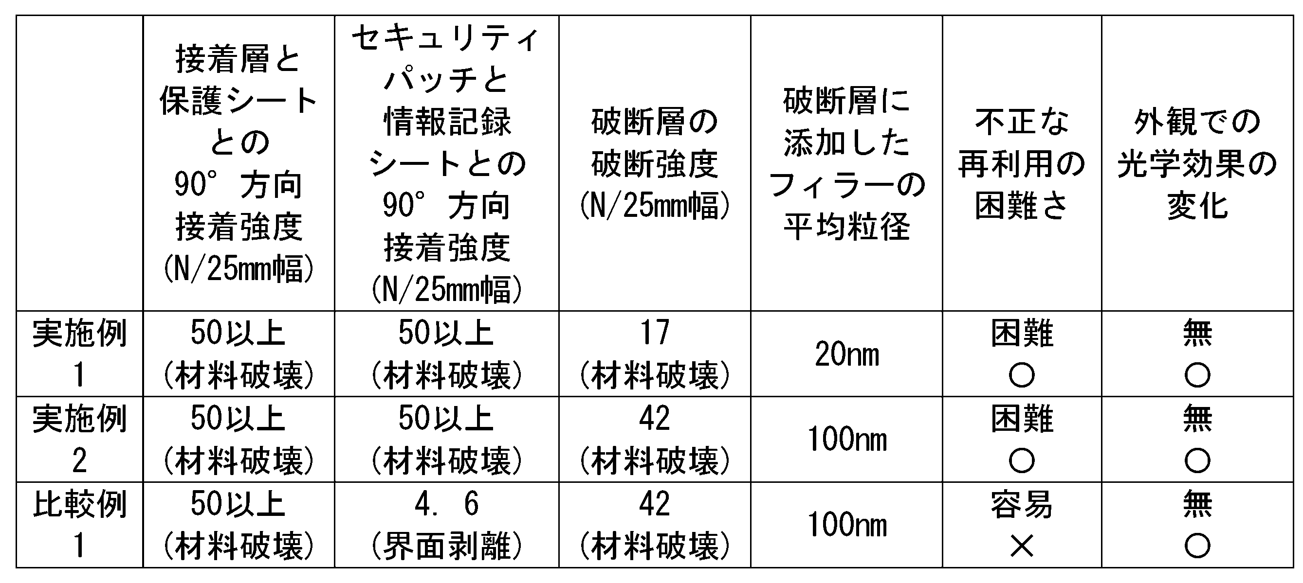
表1に説明されるように、実施例1の場合、接着層109および保護シート105の接着強度と、セキュリティパッチ102および情報記録シート106の接着強度とは、破断層108の破断強度よりも5N/25mm幅大きく、境界面での分離は不可能であった。破断層108は、破断強度が17N/25mm幅であり、凝集破壊を起こした。以上の結果から、実施例1の場合、セキュリティパッチ102をカード111から分離することは困難であり、不正な再利用は難しいとした(表1において記号「〇」と表示される)。また実施例1のカード111は、視覚効果の変化は見られなかった(表1において記号「〇」と表示される)。
As described in Table 1, in the case of Example 1, the adhesive strength of the adhesive layer 109 and the protective sheet 105 and the adhesive strength of the security patch 102 and the information recording sheet 106 are 5N more than the breaking strength of the breaking layer 108. / 25 mm wide and could not be separated at the interface. The fractured layer 108 had a fracture strength of 17 N / 25 mm and caused cohesive fracture. From the above results, in the case of the first embodiment, it is difficult to separate the security patch 102 from the card 111, and it is difficult to illegally reuse it (indicated by the symbol "○" in Table 1). Further, the card 111 of the first embodiment did not show any change in the visual effect (displayed as the symbol "○" in Table 1).
実施例2の場合、接着層109および保護シート105の接着強度と、セキュリティパッチ102および情報記録シート106の接着強度とは、破断層108の破断強度よりも5N/25mm幅大きく、境界面での分離は不可能であった。破断層108は、破断強度42N/25mm幅で凝集破壊を起こした。以上の結果から、セキュリティパッチ102をカード111から分離することは困難であり、不正な再利用は難しいとした(表1において記号「〇」と表示される)。また実施例2のカード111は、視覚効果の変化は見られなかった(表1において記号「〇」と表示される)。
In the case of Example 2, the adhesive strength of the adhesive layer 109 and the protective sheet 105 and the adhesive strength of the security patch 102 and the information recording sheet 106 are 5 N / 25 mm wider than the fracture strength of the fracture layer 108, and are at the boundary surface. Separation was impossible. The fractured layer 108 caused agglomeration fracture with a fracture strength of 42 N / 25 mm width. From the above results, it is difficult to separate the security patch 102 from the card 111, and it is difficult to reuse it illegally (displayed as the symbol "○" in Table 1). Further, the card 111 of the second embodiment did not show any change in the visual effect (displayed as the symbol "○" in Table 1).
比較例1の場合、接着層109および保護シート105の接着強度は、破断層108の破断強度よりも5N/25mm幅大きく、境界面での分離は不可能であった。一方、セキュリティパッチ102と情報記録シート106との接着強度は、4.6N/25mm幅であり、これらの境界面で分離することが可能であった。破断層108は、破断強度が42N/25mm幅であり、凝集破壊を起こした。以上の結果から、セキュリティパッチ102をカード111から分離することは容易であり、不正な再利用を行い易いとした(表1において記号「×」と表示される)。また比較例1のカード111は、視覚変化は見られなかった(表1において記号「〇」と表示される)。
In the case of Comparative Example 1, the adhesive strength of the adhesive layer 109 and the protective sheet 105 was 5 N / 25 mm wider than the fracture strength of the fracture layer 108, and separation at the boundary surface was impossible. On the other hand, the adhesive strength between the security patch 102 and the information recording sheet 106 was 4.6 N / 25 mm width, and it was possible to separate them at the interface between them. The fractured layer 108 had a fracture strength of 42 N / 25 mm and caused cohesive fracture. From the above results, it is assumed that the security patch 102 can be easily separated from the card 111 and can be easily reused (indicated by the symbol "x" in Table 1). Further, the card 111 of Comparative Example 1 did not show any visual change (displayed as the symbol "○" in Table 1).
上述の実施例1、2、および比較例1のカード111を評価する際、不正な再利用の困難さとレリーフ構造の光学特性による視覚効果の変化との二つの指標で総合評価した。すなわち、これらのカード111について、この二つの指標ともが合格(表1において記号「〇」と表示される)の場合のみ、カード111が総合的に合格と評価した。一方、不正な再利用が可能であり、または視覚効果の変化が見られた場合、カード111が総合的に不合格と評価した。このため、実施例1および実施例2の各カード111は、総合的に合格と評価した。一方、比較例1のカード111は、総合的に不合格と評価した。
When evaluating the cards 111 of Examples 1 and 2 and Comparative Example 1 described above, a comprehensive evaluation was made using two indexes: the difficulty of unauthorized reuse and the change in the visual effect due to the optical characteristics of the relief structure. That is, with respect to these cards 111, only when both of these two indexes passed (displayed as the symbol “◯” in Table 1), the card 111 was comprehensively evaluated as passing. On the other hand, if fraudulent reuse is possible or changes in visual effects are observed, Card 111 was evaluated as totally unacceptable. Therefore, each card 111 of Example 1 and Example 2 was comprehensively evaluated as acceptable. On the other hand, the card 111 of Comparative Example 1 was comprehensively evaluated as rejected.
上述の実施例1、2、および比較例1のカード111の評価結果について考察する。本発明の第4の実施形態に係る積層体101および第5の実施形態に係るカード111によれば、セキュリティパッチ102および保護シート105の接着強度と、セキュリティパッチ102および情報記録シート106の接着強度とが50N/25mmよりも大きく、かつ、破断層108の破断強度が15N/25mm以上45N/25mm未満であれば、破断層108で凝集破壊が起きるため、情報が記録されているレリーフ構造103を含むセキュリティパッチ102がカード111から分離されることが困難である。このため、実施例1および実施例2のカード111については、不正に再利用されることが困難であった。
Consider the evaluation results of the cards 111 of Examples 1 and 2 and Comparative Example 1 described above. According to the laminated body 101 according to the fourth embodiment of the present invention and the card 111 according to the fifth embodiment, the adhesive strength of the security patch 102 and the protective sheet 105 and the adhesive strength of the security patch 102 and the information recording sheet 106 If the fracture layer 108 is larger than 50 N / 25 mm and the fracture strength of the fracture layer 108 is 15 N / 25 mm or more and less than 45 N / 25 mm, aggregation fracture occurs in the fracture layer 108. It is difficult for the included security patch 102 to be separated from the card 111. Therefore, it is difficult to illegally reuse the cards 111 of the first and second embodiments.
一方、比較例1のカード111では、セキュリティパッチ102および情報記録シート106の接着強度は、4.6N/25mm幅であり、この境界面でセキュリティパッチ102と情報記録シート106とが分離することが可能であった。このため、比較例1のカード111は、不正に再利用される可能性があった。このため、比較例1のカード111については、不正に再利用される可能性が排除できない点より、総合的に不合格とされた。
On the other hand, in the card 111 of Comparative Example 1, the adhesive strength between the security patch 102 and the information recording sheet 106 is 4.6 N / 25 mm width, and the security patch 102 and the information recording sheet 106 may be separated at this boundary surface. It was possible. Therefore, the card 111 of Comparative Example 1 may be illegally reused. For this reason, the card 111 of Comparative Example 1 was totally rejected because the possibility of unauthorized reuse cannot be ruled out.
次に、本発明の第7の実施形態に係るカード用シートについて、実施例3および比較例2を示してさらに説明する。以降の記載において、特にことわりのない限り、「wt部」は、質量部を意味する。
Next, the card sheet according to the seventh embodiment of the present invention will be further described with reference to Example 3 and Comparative Example 2. In the following description, unless otherwise specified, "wt part" means a mass part.
(実施例3)
本発明からなるカード用シートの保護シートとしてポリカーボネートシートLEXAN SD8B14(SABIC社製)、100μmを用いた。 (Example 3)
A polycarbonate sheet LEXAN SD8B14 (manufactured by SABIC), 100 μm, was used as a protective sheet for the card sheet according to the present invention.
本発明からなるカード用シートの保護シートとしてポリカーボネートシートLEXAN SD8B14(SABIC社製)、100μmを用いた。 (Example 3)
A polycarbonate sheet LEXAN SD8B14 (manufactured by SABIC), 100 μm, was used as a protective sheet for the card sheet according to the present invention.
情報記録シートとして以下を調製した。
The following was prepared as an information recording sheet.
ポリカーボネート樹脂はTg=140℃、例えば、ユーピロン(三菱ガス化学(株)社製)があげられる。このようなポリカーボネート樹脂の量は、80wt部とした。
ポリエステル樹脂は非晶性ポリエステル樹脂で高耐熱のもの、例えば、バイロンGK-360(東洋紡(株)社製)(数平均分子量16000、ガラス転移温度56℃、非晶性)があげられる。このようなポリエステル樹脂の量は、10wt部とした。
レーザー光吸収添加剤、レーザー光吸収顔料として複合酸化物顔料(例えば、トマッテクカラー、TOMATEC(株)社製)を用いた。このような複合酸化物顔料の量は、1wt部とした。
屈折率変調添加剤として、エポスター系添加剤(例えば、日本触媒(株)社製)を用いた。このような屈折率変調添加剤の量は、1wt部とした。
上記材料をドライブレンドしてから、温度180℃、10m/minの温度、スピードで混錬し、ブレンドしたペレット樹脂を得た。このブレンド樹脂を180℃で押し出し成型、により厚さ100μmのシートを得た。 Examples of the polycarbonate resin include Tg = 140 ° C., for example, Upiron (manufactured by Mitsubishi Gas Chemical Company, Inc.). The amount of such polycarbonate resin was 80 wt parts.
Examples of the polyester resin include amorphous polyester resins having high heat resistance, for example, Byron GK-360 (manufactured by Toyobo Co., Ltd.) (number average molecular weight 16000, glass transition temperature 56 ° C., amorphous). The amount of such polyester resin was 10 wt parts.
A composite oxide pigment (for example, Tomattec Color, manufactured by TOMATEC Co., Ltd.) was used as a laser light absorbing additive and a laser light absorbing pigment. The amount of such a composite oxide pigment was 1 wt part.
As the refractive index modulation additive, an eposter-based additive (for example, manufactured by Nippon Shokubai Co., Ltd.) was used. The amount of such a refractive index modulation additive was 1 wt part.
The above materials were dry-blended and then kneaded at a temperature of 180 ° C. and a temperature of 10 m / min at a speed to obtain a blended pellet resin. This blended resin was extruded at 180 ° C. to obtain a sheet having a thickness of 100 μm.
白色材料層として白色顔料である酸化チタン5wt%含有のポリカーボネートシート(厚み400μm)を用いた。
A polycarbonate sheet (thickness 400 μm) containing 5 wt% of titanium oxide, which is a white pigment, was used as the white material layer.
セキュリティパッチとしてパッチ基体(ルミラー50μm、T60T PETフィルム)、破断層(ダイヤナールBRグレード)からなるホログラム転写箔を用いた。
As a security patch, a hologram transfer foil composed of a patch substrate (Lumirror 50 μm, T60T PET film) and a breaking layer (Dianal BR grade) was used.
上記にて用意した情報記録シートに転写箔からセキュリティパッチを転写後、保護シート、情報記録シート、白色材料層、保護シートを重ねて、190℃、2Kgf/cm2、5分の条件にてラミネートし、カードを得た。
After transferring the security patch from the transfer foil to the information recording sheet prepared above, the protective sheet, information recording sheet, white material layer, and protective sheet are laminated and laminated under the conditions of 190 ° C, 2 kgf / cm 2 , and 5 minutes. And got the card.
次いで、前期カードの保護シート側から以下の条件にてレーザーエングレービングを行った。
Next, laser engraving was performed from the protective sheet side of the previous term card under the following conditions.
Nd-YAG波長変換型紫外レーザー(波長380nm)
出力 0.05W
スキャン間隔 40μm
他に、Fiberレーザー(波長1064nm)、YAGレーザー(波長1064nm)も適用できる。 Nd-YAG wavelength conversion type ultraviolet laser (wavelength 380 nm)
Output 0.05W
Scan interval 40 μm
In addition, a Fiber laser (wavelength 1064 nm) and a YAG laser (wavelength 1064 nm) can also be applied.
出力 0.05W
スキャン間隔 40μm
他に、Fiberレーザー(波長1064nm)、YAGレーザー(波長1064nm)も適用できる。 Nd-YAG wavelength conversion type ultraviolet laser (wavelength 380 nm)
Output 0.05W
Scan interval 40 μm
In addition, a Fiber laser (wavelength 1064 nm) and a YAG laser (wavelength 1064 nm) can also be applied.
(比較例2)
情報記録シートとして、実施例3と同様の材料を用い、組成をポリカーボネート98%、レーザー光吸収添加剤1%、屈折率変調添加剤1%としたほかは、実施例3と同様にしてカードを作製した。 (Comparative Example 2)
As the information recording sheet, the same material as in Example 3 was used, and the card was used in the same manner as in Example 3 except that the composition was 98% polycarbonate, 1% laser light absorption additive, and 1% refractive index modulation additive. Made.
レーザーエングレービングされたカードからセキュリティパッチを取出すためにカッターを用いて剥離したところ、実施例3ではセキュリティパッチと情報記録シートとの接着性が高いためにセキュリティパッチが破壊されたが、比較例2では接着性が低いためにきれいに剥離することができた。また、保護シートと情報記録シートとを剥離すると、実施例3では変性ゾーン分の情報記録シートが破壊されたのに対し、比較例2では変性ゾーン分が破壊されず剥離することができた。
When the security patch was peeled off from the laser-engraved card using a cutter, in Example 3, the security patch was destroyed due to the high adhesiveness between the security patch and the information recording sheet, but in Comparative Example. In No. 2, since the adhesiveness was low, it could be peeled off cleanly. Further, when the protective sheet and the information recording sheet were peeled off, the information recording sheet for the modified zone was destroyed in Example 3, whereas the modified zone was not destroyed in Comparative Example 2 and could be peeled off.
以上、本発明の各実施形態および複数の実施例について説明したが、本発明の技術範囲は上記実施の形態に限定されるものではなく、本発明の趣旨を逸脱しない範囲において各構成要素に種々の変更を加えたり、削除したり、実施形態と従来技術との構成を組み合わせたりすることが可能である。
Although each embodiment and a plurality of examples of the present invention have been described above, the technical scope of the present invention is not limited to the above-described embodiment, and various components thereof are used without departing from the spirit of the present invention. It is possible to make or remove changes to, and to combine configurations of embodiments with prior art.
10、101・・・積層体
10S・・・表面
11・・・転写箔
12・・・画像
121・・・第1モチーフ
122・・・第2モチーフ
13・・・パッチ基体
14、203・・・レリーフ形成層
15・・・レリーフ構造
15a・・・第1のレリーフ構造
15b・・・第2のレリーフ構造
16、110・・・反射層
161・・・第1反射層
162・・・第2反射層
17、109・・・接着層
18・・・保護シート
19・・・情報記録シート
20・・・カード
20a・・・表面
20b・・・裏面
21・・・支持層
22・・・変質ゾーン
23・・・印刷体
24・・・キャリア
102・・・セキュリティパッチ
103・・・レリーフ構造層
104・・・表面レリーフ
105、206・・・保護シート
106、207・・・情報記録シート
107・・・証明層
108、202・・・破断層
111・・・カード
112・・・印刷層
113・・・レーザーエングレービング
114、209・・・白色材料層
115・・・外力
116・・・キャリア
117・・・レーザー光線
201・・・カード用シート
204・・・パッチ基体
205・・・セキュリティパッチ
208・・・変性ゾーン
210・・・裏面保護シート
211・・・印刷部
212・・・カード
R1・・・島領域
R2・・・海領域
SR1・・・第1レリーフ領域
SR2・・・第2レリーフ領域
S1・・・第1領域
S2・・・第2領域
T1,T2・・・界面接着強度 10, 101 ...Laminated body 10S ... Surface 11 ... Transfer foil 12 ... Image 121 ... First motif 122 ... Second motif 13 ... Patch substrate 14, 203 ... Relief forming layer 15 ... Relief structure 15a ... First relief structure 15b ... Second relief structure 16, 110 ... Reflective layer 161 ... First reflective layer 162 ... Second reflection Layers 17, 109 ... Adhesive layer 18 ... Protective sheet 19 ... Information recording sheet 20 ... Card 20a ... Front surface 20b ... Back surface 21 ... Support layer 22 ... Alteration zone 23 ... Print body 24 ... Carrier 102 ... Security patch 103 ... Relief structure layer 104 ... Surface relief 105, 206 ... Protective sheet 106, 207 ... Information recording sheet 107 ... Certification layer 108, 202 ... Breaking layer 111 ... Card 112 ... Printing layer 113 ... Laser engraving 114, 209 ... White material layer 115 ... External force 116 ... Carrier 117.・ ・ Laser beam 201 ・ ・ ・ Card sheet 204 ・ ・ ・ Patch base 205 ・ ・ ・ Security patch 208 ・ ・ ・ Modification zone 210 ・ ・ ・ Backside protection sheet 211 ・ ・ ・ Printing part 212 ・ ・ ・ Card R1 ・ ・ ・Island region R2 ... sea region SR1 ... first relief region SR2 ... second relief region S1 ... first region S2 ... second region T1, T2 ... interfacial adhesion strength
10S・・・表面
11・・・転写箔
12・・・画像
121・・・第1モチーフ
122・・・第2モチーフ
13・・・パッチ基体
14、203・・・レリーフ形成層
15・・・レリーフ構造
15a・・・第1のレリーフ構造
15b・・・第2のレリーフ構造
16、110・・・反射層
161・・・第1反射層
162・・・第2反射層
17、109・・・接着層
18・・・保護シート
19・・・情報記録シート
20・・・カード
20a・・・表面
20b・・・裏面
21・・・支持層
22・・・変質ゾーン
23・・・印刷体
24・・・キャリア
102・・・セキュリティパッチ
103・・・レリーフ構造層
104・・・表面レリーフ
105、206・・・保護シート
106、207・・・情報記録シート
107・・・証明層
108、202・・・破断層
111・・・カード
112・・・印刷層
113・・・レーザーエングレービング
114、209・・・白色材料層
115・・・外力
116・・・キャリア
117・・・レーザー光線
201・・・カード用シート
204・・・パッチ基体
205・・・セキュリティパッチ
208・・・変性ゾーン
210・・・裏面保護シート
211・・・印刷部
212・・・カード
R1・・・島領域
R2・・・海領域
SR1・・・第1レリーフ領域
SR2・・・第2レリーフ領域
S1・・・第1領域
S2・・・第2領域
T1,T2・・・界面接着強度 10, 101 ...
Claims (22)
- 厚さ方向に沿って、少なくともパッチ基体、レリーフ形成層、反射層、および接着層が順に積層されて構成される転写箔と、
前記転写箔の前記厚さ方向における第一側に設けられる保護シートと、
前記厚さ方向において、前記保護シートの反対側である前記転写箔の第二側に設けられる情報記録シートと、
を備え、
前記レリーフ形成層は、前記反射層に接する第1面の少なくとも一部に、凹部及び凸部による凹凸形状のレリーフ構造が形成され、
前記第1面に接する前記反射層の第2面は、前記レリーフ構造の前記凹凸形状に対応する形状に形成され、
前記レリーフ形成層は、熱可塑性樹脂、熱硬化性樹脂、紫外線硬化性樹脂のいずれか一つ、または複数の組み合わせにより形成され、
前記厚さ方向から見ると、前記レリーフ構造は、前記第1面において、所定のパターンに形成する複数の島領域および海領域を有し、
前記レリーフ形成層の前記島領域に、水酸基、カルボキシル基、およびカルボニル基を含む官能基と、粗面とのいずれか一つ、または複数の組み合わせを備え、
前記海領域に、前記官能基および前記粗面を有しておらず、あるいは前記島領域よりも前記官能基の含有量が少ない、あるいは前記粗面の程度および面積が小さい、
積層体。 A transfer foil composed of at least a patch substrate, a relief forming layer, a reflective layer, and an adhesive layer laminated in this order along the thickness direction.
A protective sheet provided on the first side of the transfer foil in the thickness direction,
An information recording sheet provided on the second side of the transfer foil, which is the opposite side of the protective sheet in the thickness direction, and
Equipped with
In the relief forming layer, an uneven relief structure having concave portions and convex portions is formed on at least a part of the first surface in contact with the reflective layer.
The second surface of the reflective layer in contact with the first surface is formed in a shape corresponding to the uneven shape of the relief structure.
The relief forming layer is formed of any one or a combination of a thermoplastic resin, a thermosetting resin, and an ultraviolet curable resin.
Seen from the thickness direction, the relief structure has a plurality of island regions and sea regions that form a predetermined pattern on the first surface.
The island region of the relief forming layer is provided with one or more combinations of a functional group containing a hydroxyl group, a carboxyl group, and a carbonyl group and a rough surface.
The sea region does not have the functional group and the rough surface, or the content of the functional group is smaller than that of the island region, or the degree and area of the rough surface are small.
Laminated body. - 前記レリーフ形成層は、
前記凹部および前記凸部のそれぞれが前記厚さ方向に沿う第1の方向に延びて形成され、かつ、前記凹部および前記凸部が前記第1の方向に直交する第2の方向に交互に形成される第1のレリーフ構造を有する第1レリーフ領域と、
前記第1の方向および前記第2の方向による面に直交する方向から見ると、前記第1の方向から少なくとも30度以上異なる方向に指向性を有して形成され、あるいは前記凹部および前記凸部が不規則に形成される第2のレリーフ構造を有する第2レリーフ領域と、
を備え、
前記厚さ方向から見ると、前記第1レリーフ領域が前記海領域と重なり、前記第2レリーフ領域が前記島領域と重なるよう配置される、
請求項1に記載の積層体。 The relief forming layer is
Each of the concave portion and the convex portion is formed so as to extend in a first direction along the thickness direction, and the concave portion and the convex portion are alternately formed in a second direction orthogonal to the first direction. A first relief region having a first relief structure to be
When viewed from a direction orthogonal to the plane according to the first direction and the second direction, the concave portion and the convex portion are formed with directivity in a direction different from the first direction by at least 30 degrees or more. A second relief region with a second relief structure in which is irregularly formed,
Equipped with
When viewed from the thickness direction, the first relief region overlaps the sea region, and the second relief region overlaps the island region.
The laminate according to claim 1. - 厚さ方向に沿って、少なくともパッチ基体、レリーフ形成層、反射層、および接着層が順に積層されて構成される転写箔と、
前記転写箔の前記厚さ方向における第一側に設けられる保護シートと、
前記厚さ方向において、前記保護シートの反対側である前記転写箔の第二側に設けられる情報記録シートと、
を備え、
前記レリーフ形成層は、前記反射層に接する第1面の少なくとも一部に、凹部及び凸部による凹凸形状のレリーフ構造が形成され、
前記第1面に接する前記反射層の第2面は、前記レリーフ構造の前記凹凸形状に対応する形状に形成され、
前記レリーフ構造は、熱可塑性樹脂、熱硬化性樹脂、紫外線硬化性樹脂のいずれか一つ、または複数の組み合わせにより形成され、
前記厚さ方向から見ると、前記レリーフ構造は、前記第1面において、所定のパターンに形成する複数の島領域および海領域を有し、
前記島領域における前記反射層に対する前記接着層の塗液の接触角は、前記海領域における前記反射層に対する前記接着層の前記塗液の前記接触角よりも小さく、
前記接着層の破断強度が、前記パッチ基体と前記レリーフ形成層との界面接着強度および破断強度よりも大きい、
積層体。 A transfer foil composed of at least a patch substrate, a relief forming layer, a reflective layer, and an adhesive layer laminated in this order along the thickness direction.
A protective sheet provided on the first side of the transfer foil in the thickness direction,
An information recording sheet provided on the second side of the transfer foil, which is the opposite side of the protective sheet in the thickness direction, and
Equipped with
In the relief forming layer, an uneven relief structure having concave portions and convex portions is formed on at least a part of the first surface in contact with the reflective layer.
The second surface of the reflective layer in contact with the first surface is formed in a shape corresponding to the uneven shape of the relief structure.
The relief structure is formed of any one or a combination of a thermoplastic resin, a thermosetting resin, and an ultraviolet curable resin.
Seen from the thickness direction, the relief structure has a plurality of island regions and sea regions that form a predetermined pattern on the first surface.
The contact angle of the coating liquid of the adhesive layer with respect to the reflective layer in the island region is smaller than the contact angle of the coating liquid of the adhesive layer with respect to the reflective layer in the sea region.
The breaking strength of the adhesive layer is larger than the interfacial adhesive strength and the breaking strength of the patch substrate and the relief forming layer.
Laminated body. - 前記レリーフ形成層は、
前記凹部および前記凸部のそれぞれが前記厚さ方向に沿う第1の方向に延びて形成され、かつ、前記凹部および前記凸部が前記第1の方向に直交する第2の方向に交互に形成される第1のレリーフ構造を有する第1レリーフ領域と、
前記第1の方向および前記第2の方向による面に直交する方向から見ると、前記第1の方向から少なくとも30度以上異なる方向に指向性を有して形成され、あるいは前記凹部および前記凸部が不規則に形成される第2のレリーフ構造を有する第2レリーフ領域と、
を備え、
前記厚さ方向から見ると、前記第1レリーフ領域が前記海領域と重なり、前記第2レリーフ領域が前記島領域と重なるよう配置される、
請求項3に記載の積層体。 The relief forming layer is
Each of the concave portion and the convex portion is formed so as to extend in a first direction along the thickness direction, and the concave portion and the convex portion are alternately formed in a second direction orthogonal to the first direction. A first relief region having a first relief structure to be
When viewed from a direction orthogonal to the plane according to the first direction and the second direction, the concave portion and the convex portion are formed with directivity in a direction different from the first direction by at least 30 degrees or more. A second relief region with a second relief structure in which is irregularly formed,
Equipped with
When viewed from the thickness direction, the first relief region overlaps the sea region, and the second relief region overlaps the island region.
The laminate according to claim 3. - 前記島領域と前記海領域とが設けられた領域全体の総面積に対して、前記島領域の占める面積が50%以上80%以下である、
請求項1から請求項4のいずれか一項に記載の積層体。 The area occupied by the island region is 50% or more and 80% or less with respect to the total area of the entire region provided with the island region and the sea region.
The laminate according to any one of claims 1 to 4. - 前記島領域が互いに同様の形状を有し、かつ規則的に配置され、隣接する前記島領域の中心間距離が40μm以上400μm以下である、
請求項1から請求項5のいずれか一項に記載の積層体。 The island regions have similar shapes to each other and are regularly arranged, and the distance between the centers of the adjacent island regions is 40 μm or more and 400 μm or less.
The laminate according to any one of claims 1 to 5. - 厚さ方向に沿って、少なくともパッチ基体、レリーフ形成層、第1反射層、第2反射層、および接着層が順に積層されて構成される転写箔と、
前記転写箔の前記厚さ方向における第一側に設けられる保護シートと、
前記厚さ方向において、前記第一側の反対側である前記転写箔の第二側に設けられる情報記録シートと、
を備え、
前記第1反射層と前記第2反射層の少なくとも一方は、前記レリーフ形成層および前記接着層よりも高い屈折率を有した光透過性の材料で構成され、
前記レリーフ形成層は、前記第1反射層に接する第1面の少なくとも一部に、凹部及び凸部による凹凸形状のレリーフ構造が形成され、
前記第1面に接する前記第1反射層の第2面は、前記レリーフ構造の前記凹凸形状に対応する形状に形成され、
前記第1反射層および前記第2反射層が接する界面において、互いに対応する表面形状が形成され、
前記厚さ方向から見ると、前記転写箔は、所定のパターンに形成する複数の第1領域および第2領域を有し、
前記第1領域において、前記第1反射層および前記第2反射層が設けられ、
前記第2領域において、前記第1反射層のみが設けられ、
前記第1反射層と前記接着層との間における界面接着強度と、前記第2反射層と前記接着層との間における界面接着強度とが異なり、
前記第1領域および前記第2領域のうち、前記接着層との界面における界面接着強度が相対的に大きい一方の領域は、もう一方の領域に点在する島領域であり、前記接着層との界面における界面接着強度が相対的に小さい領域は、前記接着層との界面における界面接着強度が相対的に大きい前記領域を囲む海領域である、
積層体。 A transfer foil composed of at least a patch substrate, a relief forming layer, a first reflective layer, a second reflective layer, and an adhesive layer laminated in this order along the thickness direction.
A protective sheet provided on the first side of the transfer foil in the thickness direction,
An information recording sheet provided on the second side of the transfer foil, which is the opposite side of the first side in the thickness direction, and
Equipped with
At least one of the first reflective layer and the second reflective layer is made of a light-transmitting material having a higher refractive index than the relief forming layer and the adhesive layer.
In the relief forming layer, an uneven relief structure formed by concave portions and convex portions is formed on at least a part of the first surface in contact with the first reflective layer.
The second surface of the first reflective layer in contact with the first surface is formed in a shape corresponding to the uneven shape of the relief structure.
At the interface where the first reflective layer and the second reflective layer are in contact with each other, surface shapes corresponding to each other are formed.
Seen from the thickness direction, the transfer foil has a plurality of first and second regions formed in a predetermined pattern.
In the first region, the first reflective layer and the second reflective layer are provided.
In the second region, only the first reflective layer is provided.
The interfacial adhesive strength between the first reflective layer and the adhesive layer is different from the interfacial adhesive strength between the second reflective layer and the adhesive layer.
Of the first region and the second region, one region having a relatively large interfacial adhesive strength at the interface with the adhesive layer is an island region scattered in the other region, and is a region with the adhesive layer. The region having a relatively low interfacial adhesive strength at the interface is a sea region surrounding the region having a relatively high interfacial adhesive strength at the interface with the adhesive layer.
Laminated body. - 前記転写箔の各層の界面における界面接着強度は、前記転写箔と前記保護シートまたは前記情報記録シートとの間の界面接着強度よりも小さく、
前記パッチ基体と前記レリーフ形成層との間の界面接着強度および前記レリーフ形成層の破断強度は、前記第1反射層および前記第2反射層の間の界面接着強度と、前記レリーフ形成層および前記第1反射層の間の界面接着強度とよりも小さい、
請求項7に記載の積層体。 The interfacial adhesive strength at the interface of each layer of the transfer foil is smaller than the interfacial adhesive strength between the transfer foil and the protective sheet or the information recording sheet.
The interfacial adhesive strength between the patch substrate and the relief forming layer and the breaking strength of the relief forming layer are the interfacial adhesive strength between the first reflective layer and the second reflective layer, and the relief forming layer and the said. Less than the interfacial adhesion strength between the first reflective layers,
The laminate according to claim 7. - 前記第1反射層または前記第2反射層と前記接着層とが、前記島領域においては共に親水性または疎水性の表面特性を有し、前記海領域においては互いに異なる表面特性を有するか、前記島領域と同様の表面特性を有し、かつ前記第1反射層または前記第2反射層に対する前記接着層の塗液の接触角が前記島領域の方が小さい、
請求項7又は請求項8に記載の積層体。 Whether the first reflective layer or the second reflective layer and the adhesive layer both have hydrophilic or hydrophobic surface properties in the island region and have different surface properties from each other in the sea region, or said. The island region has the same surface characteristics as the island region, and the contact angle of the coating liquid of the adhesive layer with respect to the first reflective layer or the second reflective layer is smaller in the island region.
The laminate according to claim 7 or 8. - 前記島領域において、前記第1反射層または前記第2反射層と前記接着層とが、イオン結合、共有結合、水素結合の少なくとも1つの化学的相互作用により接着され、
前記海領域において、前記第1反射層または前記第2反射層と前記接着層とが、分子間力による物理的相互作用により接着している、
請求項7から請求項9のいずれか一項に記載の積層体。 In the island region, the first reflective layer or the second reflective layer and the adhesive layer are bonded by at least one chemical interaction of an ionic bond, a covalent bond, and a hydrogen bond.
In the sea region, the first reflective layer or the second reflective layer and the adhesive layer are adhered by a physical interaction due to an intermolecular force.
The laminate according to any one of claims 7 to 9. - 前記島領域と前記海領域とが設けられた領域全体の総面積に対して、前記島領域が占める面積が50%以上80%以下である、
請求項7から請求項10のいずれか一項に記載の積層体。 The area occupied by the island region is 50% or more and 80% or less with respect to the total area of the entire region provided with the island region and the sea region.
The laminate according to any one of claims 7 to 10. - 前記島領域が互いに同様の形状を有し、かつ規則的に配置され、隣接する前記島領域の中心間距離が40μm以上400μm以下である、
請求項7から請求項11のいずれか一項に記載の積層体。 The island regions have similar shapes to each other and are regularly arranged, and the distance between the centers of the adjacent island regions is 40 μm or more and 400 μm or less.
The laminate according to any one of claims 7 to 11. - 請求項7から請求項12のいずれか一項に記載の積層体と、前記転写箔の第一側に設けられる支持層とをさらに備える、
カード。 A laminate according to any one of claims 7 to 12, further comprising a support layer provided on the first side of the transfer foil.
card. - 厚さ方向に沿って、少なくともパッチ基体、レリーフ形成層、第1反射層、第2反射層、および接着層を備える転写箔と、前記転写箔の前記厚さ方向における第一側に設けられる保護シートおよび支持層と、前記転写箔の前記厚さ方向における前記保護シートの反対側である前記転写箔の第二側に設けられる情報記録シートと、を備えるカードの製造方法であって、前記カードの製造方法は、
前記パッチ基体、前記レリーフ形成層、前記第1反射層、前記第2反射層、および前記接着層が順に積層された前記転写箔を作製する工程と、
前記転写箔を前記保護シートまたは前記情報記録シートに転写する工程と、
前記情報記録シートを含む被転写物を前記保護シートおよび前記支持層にラミネートする接着工程と、
を備え、
前記転写箔を作製する工程は、
前記レリーフ形成層の前記第1反射層と接する表面の少なくとも一部に凹部および凸部を有するレリーフ構造を形成する工程と、
前記レリーフ構造に追従した凹凸状を有する前記第1反射層、および前記第1反射層の表面形状に対応した凹凸状を有する前記第2反射層を形成する工程と、
前記転写箔が、前記厚さ方向から見ると、所定のパターンに形成する複数の第1領域および第2領域において、前記第1領域は前記第1反射層および前記第2反射層を備え、前記第2領域は前記第1反射層のみを備えるよう、前記第2領域において前記第2反射層を除去する工程と、
を備える、
カードの製造方法。 A transfer foil comprising at least a patch substrate, a relief forming layer, a first reflective layer, a second reflective layer, and an adhesive layer along the thickness direction and protection provided on the first side of the transfer foil in the thickness direction. A method of manufacturing a card comprising a sheet and a support layer, and an information recording sheet provided on the second side of the transfer foil, which is the opposite side of the protective sheet in the thickness direction of the transfer foil. The manufacturing method of
A step of producing the transfer foil in which the patch substrate, the relief forming layer, the first reflective layer, the second reflective layer, and the adhesive layer are laminated in this order.
The step of transferring the transfer foil to the protective sheet or the information recording sheet, and
An adhesive step of laminating a transfer material containing the information recording sheet to the protective sheet and the support layer, and
Equipped with
The step of producing the transfer foil is
A step of forming a relief structure having recesses and protrusions in at least a part of the surface of the relief forming layer in contact with the first reflective layer.
A step of forming the first reflective layer having an uneven shape following the relief structure and the second reflective layer having an uneven shape corresponding to the surface shape of the first reflective layer.
When the transfer foil is viewed from the thickness direction, in a plurality of first regions and second regions formed in a predetermined pattern, the first region includes the first reflective layer and the second reflective layer. A step of removing the second reflective layer in the second region so that the second region includes only the first reflective layer,
To prepare
How to make a card. - 前記転写箔を作製する工程は、
前記第2反射層を形成した後、前記第1領域にエッチングマスク層を設ける工程と、
前記第2領域における前記第2反射層を除去した後、さらに上記エッチングマスク層を除去する工程と、
を備える、
請求項14に記載のカードの製造方法。 The step of producing the transfer foil is
After forming the second reflective layer, a step of providing an etching mask layer in the first region and
A step of removing the second reflective layer in the second region and then further removing the etching mask layer.
To prepare
The method for manufacturing a card according to claim 14. - 厚さ方向に沿って、接着層、破断層、および証明層が順に積層され、前記破断層と証明層の間にレリーフ構造を有したセキュリティパッチと、
前記セキュリティパッチの前記厚さ方向における前記接着層に接着される保護シートと、
前記セキュリティパッチの前記厚さ方向における前記接着層の反対側に設けられ、前記セキュリティパッチの前記証明層に接着される情報記録シートと、
を備え、
前記セキュリティパッチが前記保護シートおよび前記情報記録シートにより内包され、
前記破断層は、90度剥離接着強度試験で破断強度が15N/25mm以上45N/25mm未満であり、
前記セキュリティパッチおよび前記情報記録シートの接着強度と、前記セキュリティパッチおよび前記保護シートの接着強度とは、前記破断層の前記破断強度よりも5N/25mm以上大きく、かつ、前記破断層の前記破断強度の5倍以下である、
媒体。 A security patch in which an adhesive layer, a break layer, and a proof layer are laminated in order along the thickness direction and has a relief structure between the break layer and the proof layer.
A protective sheet adhered to the adhesive layer in the thickness direction of the security patch, and
An information recording sheet provided on the opposite side of the adhesive layer in the thickness direction of the security patch and adhered to the certification layer of the security patch.
Equipped with
The security patch is included by the protective sheet and the information recording sheet.
The breaking layer has a breaking strength of 15 N / 25 mm or more and less than 45 N / 25 mm in a 90-degree peeling adhesive strength test.
The adhesive strength between the security patch and the information recording sheet and the adhesive strength between the security patch and the protective sheet are 5 N / 25 mm or more larger than the breaking strength of the breaking layer, and the breaking strength of the breaking layer. Is less than 5 times
Medium. - 前記破断層は、光学透明性を有する樹脂と、平均粒径が1μm以下である粒子より形成されたフィラーとを有して構成される、
請求項16に記載の媒体。 The break layer is composed of a resin having optical transparency and a filler formed of particles having an average particle size of 1 μm or less.
The medium according to claim 16. - 請求項16又は請求項17に記載の媒体と、情報が保存されるために設けられる他の材料層と、を備える、
カード。 16. The medium according to claim 16 or 17, and another material layer provided for storing information.
card. - 請求項16又は請求項17に記載の媒体を作製する媒体の作製方法であって、
前記セキュリティパッチを前記情報記録シートおよび前記保護シートのいずれか一方の表面に転写して接着する工程と、
前記セキュリティパッチを覆うように、前記情報記録シートおよび前記保護シートの他方および前記セキュリティパッチに外力を加えて接着する工程と、を有する、
媒体の作製方法。 A method for producing a medium for producing the medium according to claim 16 or 17.
A step of transferring the security patch to the surface of either the information recording sheet or the protective sheet and adhering the patch.
It comprises a step of applying an external force to the other of the information recording sheet and the protective sheet and the security patch so as to cover the security patch.
How to make a medium. - 請求項1から請求項12のいずれか一項に記載の積層体、又は、請求項16又は請求項17に記載の媒体に用いられるカード用情報記録シートであって、
前記情報記録シートが、ポリエステルがブレンドされたポリカーボネートである、
カード用情報記録シート。 A card information recording sheet used for the laminate according to any one of claims 1 to 12 or the medium according to claim 16 or 17.
The information recording sheet is polycarbonate blended with polyester.
Information recording sheet for cards. - 前記ポリエステルが、ガラス転移温度Tgが-20℃~110℃である、
請求項20に記載のカード用情報記録シート。 The polyester has a glass transition temperature Tg of −20 ° C. to 110 ° C.
The information recording sheet for a card according to claim 20. - 請求項20又は請求項21に記載のカード用情報記録シートを用いた、
カード。 The card information recording sheet according to claim 20 or 21 is used.
card.
Priority Applications (4)
| Application Number | Priority Date | Filing Date | Title |
|---|---|---|---|
| CN202180060886.7A CN116194293A (en) | 2020-08-04 | 2021-08-04 | Laminate, card, method for producing card, information recording sheet for card, and card using the information recording sheet for card |
| JP2022541595A JPWO2022030563A1 (en) | 2020-08-04 | 2021-08-04 | |
| EP21854065.6A EP4194909A4 (en) | 2020-08-04 | 2021-08-04 | Laminate, card, card manufacturing method, card production method, information recording sheet for card, and card using same |
| US17/944,499 US20230021631A1 (en) | 2020-08-04 | 2022-09-14 | Laminate, card, method of manufacturing card, method of producing card, card information recording sheet and card including the same |
Applications Claiming Priority (6)
| Application Number | Priority Date | Filing Date | Title |
|---|---|---|---|
| JP2020132592 | 2020-08-04 | ||
| JP2020-132592 | 2020-08-04 | ||
| JP2021-067112 | 2021-04-12 | ||
| JP2021067112 | 2021-04-12 | ||
| JP2021095146 | 2021-06-07 | ||
| JP2021-095146 | 2021-06-07 |
Related Child Applications (1)
| Application Number | Title | Priority Date | Filing Date |
|---|---|---|---|
| US17/944,499 Continuation US20230021631A1 (en) | 2020-08-04 | 2022-09-14 | Laminate, card, method of manufacturing card, method of producing card, card information recording sheet and card including the same |
Publications (1)
| Publication Number | Publication Date |
|---|---|
| WO2022030563A1 true WO2022030563A1 (en) | 2022-02-10 |
Family
ID=80117480
Family Applications (1)
| Application Number | Title | Priority Date | Filing Date |
|---|---|---|---|
| PCT/JP2021/029029 WO2022030563A1 (en) | 2020-08-04 | 2021-08-04 | Laminate, card, card manufacturing method, card production method, information recording sheet for card, and card using same |
Country Status (5)
| Country | Link |
|---|---|
| US (1) | US20230021631A1 (en) |
| EP (1) | EP4194909A4 (en) |
| JP (1) | JPWO2022030563A1 (en) |
| CN (1) | CN116194293A (en) |
| WO (1) | WO2022030563A1 (en) |
Cited By (2)
| Publication number | Priority date | Publication date | Assignee | Title |
|---|---|---|---|---|
| DE102022109850A1 (en) | 2022-04-25 | 2023-10-26 | Ovd Kinegram Ag | Laminate and process for producing a laminate |
| DE102022115901A1 (en) | 2022-06-27 | 2023-12-28 | Ovd Kinegram Ag | Security document, system for producing a security document and method for producing a security document |
Citations (13)
| Publication number | Priority date | Publication date | Assignee | Title |
|---|---|---|---|---|
| JPH08152842A (en) * | 1994-03-31 | 1996-06-11 | Toppan Printing Co Ltd | Hologram brittle seal |
| JP2003326824A (en) * | 2002-05-15 | 2003-11-19 | Dainippon Printing Co Ltd | Card with photodiffraction layer and method for manufacture thereof |
| JP2005106857A (en) * | 2003-09-26 | 2005-04-21 | Dainippon Printing Co Ltd | Hologram brittle sticker |
| US20080078492A1 (en) * | 2006-10-03 | 2008-04-03 | American Bank Note Holographics, Inc. | Tamper evident and resisting informational article and method of producing same |
| WO2011090030A1 (en) * | 2010-01-19 | 2011-07-28 | 大日本印刷株式会社 | Volume hologram sheet to be embedded, forgery prevention paper, and card |
| JP2012173430A (en) * | 2011-02-18 | 2012-09-10 | Dainippon Printing Co Ltd | Hologram label |
| JP2013076802A (en) * | 2011-09-30 | 2013-04-25 | Dainippon Printing Co Ltd | Hologram label |
| JP2014188989A (en) * | 2013-03-28 | 2014-10-06 | Dainippon Printing Co Ltd | Scratch transfer sheet |
| JP2017521701A (en) | 2014-06-27 | 2017-08-03 | イー インク カリフォルニア, エルエルシー | Anisotropically conductive dielectric layers for electrophoretic display devices |
| WO2017200030A1 (en) * | 2016-05-20 | 2017-11-23 | 凸版印刷株式会社 | Counterfeit-preventing structure |
| JP2020132592A (en) | 2019-02-22 | 2020-08-31 | 国立大学法人 琉球大学 | Method for protecting dopamine neurocyte in living body |
| JP2021067112A (en) | 2019-10-25 | 2021-04-30 | 株式会社Pasio | Building with aerial pool, and construction method of the same |
| JP2021095146A (en) | 2019-12-13 | 2021-06-24 | 上六印刷株式会社 | Packing box |
Family Cites Families (2)
| Publication number | Priority date | Publication date | Assignee | Title |
|---|---|---|---|---|
| JPWO2016194385A1 (en) * | 2015-06-02 | 2018-06-07 | 凸版印刷株式会社 | Laminated body and method for producing the same |
| JPWO2017204168A1 (en) * | 2016-05-23 | 2019-03-22 | 凸版印刷株式会社 | Anti-counterfeit media |
-
2021
- 2021-08-04 WO PCT/JP2021/029029 patent/WO2022030563A1/en active Application Filing
- 2021-08-04 JP JP2022541595A patent/JPWO2022030563A1/ja active Pending
- 2021-08-04 EP EP21854065.6A patent/EP4194909A4/en active Pending
- 2021-08-04 CN CN202180060886.7A patent/CN116194293A/en active Pending
-
2022
- 2022-09-14 US US17/944,499 patent/US20230021631A1/en active Pending
Patent Citations (13)
| Publication number | Priority date | Publication date | Assignee | Title |
|---|---|---|---|---|
| JPH08152842A (en) * | 1994-03-31 | 1996-06-11 | Toppan Printing Co Ltd | Hologram brittle seal |
| JP2003326824A (en) * | 2002-05-15 | 2003-11-19 | Dainippon Printing Co Ltd | Card with photodiffraction layer and method for manufacture thereof |
| JP2005106857A (en) * | 2003-09-26 | 2005-04-21 | Dainippon Printing Co Ltd | Hologram brittle sticker |
| US20080078492A1 (en) * | 2006-10-03 | 2008-04-03 | American Bank Note Holographics, Inc. | Tamper evident and resisting informational article and method of producing same |
| WO2011090030A1 (en) * | 2010-01-19 | 2011-07-28 | 大日本印刷株式会社 | Volume hologram sheet to be embedded, forgery prevention paper, and card |
| JP2012173430A (en) * | 2011-02-18 | 2012-09-10 | Dainippon Printing Co Ltd | Hologram label |
| JP2013076802A (en) * | 2011-09-30 | 2013-04-25 | Dainippon Printing Co Ltd | Hologram label |
| JP2014188989A (en) * | 2013-03-28 | 2014-10-06 | Dainippon Printing Co Ltd | Scratch transfer sheet |
| JP2017521701A (en) | 2014-06-27 | 2017-08-03 | イー インク カリフォルニア, エルエルシー | Anisotropically conductive dielectric layers for electrophoretic display devices |
| WO2017200030A1 (en) * | 2016-05-20 | 2017-11-23 | 凸版印刷株式会社 | Counterfeit-preventing structure |
| JP2020132592A (en) | 2019-02-22 | 2020-08-31 | 国立大学法人 琉球大学 | Method for protecting dopamine neurocyte in living body |
| JP2021067112A (en) | 2019-10-25 | 2021-04-30 | 株式会社Pasio | Building with aerial pool, and construction method of the same |
| JP2021095146A (en) | 2019-12-13 | 2021-06-24 | 上六印刷株式会社 | Packing box |
Non-Patent Citations (1)
| Title |
|---|
| See also references of EP4194909A4 |
Cited By (2)
| Publication number | Priority date | Publication date | Assignee | Title |
|---|---|---|---|---|
| DE102022109850A1 (en) | 2022-04-25 | 2023-10-26 | Ovd Kinegram Ag | Laminate and process for producing a laminate |
| DE102022115901A1 (en) | 2022-06-27 | 2023-12-28 | Ovd Kinegram Ag | Security document, system for producing a security document and method for producing a security document |
Also Published As
| Publication number | Publication date |
|---|---|
| EP4194909A1 (en) | 2023-06-14 |
| CN116194293A (en) | 2023-05-30 |
| EP4194909A4 (en) | 2023-12-27 |
| US20230021631A1 (en) | 2023-01-26 |
| JPWO2022030563A1 (en) | 2022-02-10 |
Similar Documents
| Publication | Publication Date | Title |
|---|---|---|
| EP2043874B1 (en) | Method for producing a data carrier and data carrier produced therefrom | |
| US20130082458A1 (en) | Ovd containing device | |
| KR101536335B1 (en) | A security device formed by a hologram and a color shifting ink | |
| US10259256B2 (en) | Process for securing an identification document and secure identification document | |
| JP2010527809A (en) | Film element for detecting authenticity and method for manufacturing the same | |
| US20230021631A1 (en) | Laminate, card, method of manufacturing card, method of producing card, card information recording sheet and card including the same | |
| CN113879024B (en) | Identification certificate | |
| JP5256751B2 (en) | Diffraction structure transfer foil and diffraction structure transfer medium | |
| JP2023113602A (en) | Laminate, certificate, and method for manufacturing laminate | |
| CN110944847B (en) | Information recording medium, label, card and method for determining authenticity | |
| JP5565251B2 (en) | Personal authentication medium | |
| JP7120224B2 (en) | Information record body and personal proof body | |
| KR100874068B1 (en) | Security paper and its manufacturing method which has forgery-free fuction | |
| US11741327B2 (en) | Optical assembly and method of producing optical assembly | |
| JP7461496B2 (en) | Data carriers protected against subsequent laser marking | |
| JP5581665B2 (en) | Laminated display | |
| JP2011039336A (en) | Personal authentication medium | |
| JP2013091203A (en) | Image organizer, personal authentification medium, and method for manufacturing personal authentification medium | |
| JP5621308B2 (en) | Anti-counterfeit media | |
| JP2024066184A (en) | Information recording medium, its processing method, and method for observing information recorded on the information recording medium |
Legal Events
| Date | Code | Title | Description |
|---|---|---|---|
| 121 | Ep: the epo has been informed by wipo that ep was designated in this application |
Ref document number: 21854065 Country of ref document: EP Kind code of ref document: A1 |
|
| ENP | Entry into the national phase |
Ref document number: 2022541595 Country of ref document: JP Kind code of ref document: A |
|
| WWE | Wipo information: entry into national phase |
Ref document number: 2021854065 Country of ref document: EP |
|
| NENP | Non-entry into the national phase |
Ref country code: DE |