WO2022004568A1 - Control system, control method, and program - Google Patents
Control system, control method, and program Download PDFInfo
- Publication number
- WO2022004568A1 WO2022004568A1 PCT/JP2021/024049 JP2021024049W WO2022004568A1 WO 2022004568 A1 WO2022004568 A1 WO 2022004568A1 JP 2021024049 W JP2021024049 W JP 2021024049W WO 2022004568 A1 WO2022004568 A1 WO 2022004568A1
- Authority
- WO
- WIPO (PCT)
- Prior art keywords
- command value
- control
- control system
- virtual object
- physical quantity
- Prior art date
Links
Images


Classifications
-
- B—PERFORMING OPERATIONS; TRANSPORTING
- B25—HAND TOOLS; PORTABLE POWER-DRIVEN TOOLS; MANIPULATORS
- B25J—MANIPULATORS; CHAMBERS PROVIDED WITH MANIPULATION DEVICES
- B25J3/00—Manipulators of master-slave type, i.e. both controlling unit and controlled unit perform corresponding spatial movements
- B25J3/04—Manipulators of master-slave type, i.e. both controlling unit and controlled unit perform corresponding spatial movements involving servo mechanisms
-
- B—PERFORMING OPERATIONS; TRANSPORTING
- B25—HAND TOOLS; PORTABLE POWER-DRIVEN TOOLS; MANIPULATORS
- B25J—MANIPULATORS; CHAMBERS PROVIDED WITH MANIPULATION DEVICES
- B25J13/00—Controls for manipulators
- B25J13/02—Hand grip control means
-
- B—PERFORMING OPERATIONS; TRANSPORTING
- B25—HAND TOOLS; PORTABLE POWER-DRIVEN TOOLS; MANIPULATORS
- B25J—MANIPULATORS; CHAMBERS PROVIDED WITH MANIPULATION DEVICES
- B25J9/00—Programme-controlled manipulators
- B25J9/16—Programme controls
- B25J9/1679—Programme controls characterised by the tasks executed
- B25J9/1689—Teleoperation
Definitions
- the present invention relates to a control system, a control method and a program for controlling the operation of a robot or the like.
- Patent Document 1 describes a technique for a robot that performs compliance control.
- a robot control technology applying a master / slave system As one of the methods for realizing adaptive physical interaction of a robot, a robot control technology applying a master / slave system is used.
- a robot control technique applying a master / slave system various methods have been proposed for reproducing the mechanical impedance of the surrounding environment between the master / slave and improving the operability of the robot.
- the robot using the conventional technique does not have sufficiently high reproducibility and operability of the mechanical impedance of the surrounding environment. Therefore, it has been difficult to realize appropriate physical interaction of the robot with the conventional technology.
- An object of the present invention is to realize more appropriate physical interaction of a robot.
- the control system is The first device that accepts input for operation, the second device that performs an operation on an object, and the second device that controls the second device according to the operation input to the first device, and the first device.
- the device 2 includes a control device that executes control to transmit the reaction force received from the object to the first device.
- the control device is A data acquisition means for acquiring physical quantity data representing the operation of the movable portion of the first device and physical quantity data representing the operation of the movable portion of the second device.
- a virtual object including the first device and the second device is virtualized, and input to the first device and the second device based on the physical quantity data acquired by the data acquisition means.
- a command value calculating means for calculating a command value for causing the first device and the second device to follow the behavior appearing in the virtual object. It is characterized by having.
- FIG. 1 is a schematic diagram showing the concept of the present invention.
- a virtual object including a master device and a slave device is assumed in a robot to which a master / slave system is applied, and an input to the master device and the slave device is an input to the virtual object.
- the operation of the master device and the slave device is controlled to follow the behavior of the virtual object in the case of.
- a parameter representing the speed is calculated by multiplying the force response input from the master device and the slave device by admittance, and is given to the position control system of the master device and the slave device as a speed command value together with the current speed.
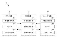
- FIG. 2 is a schematic diagram showing the overall configuration of the control system 1 according to the embodiment of the present invention.
- the control system 1 according to the present embodiment includes a control device 10, a master device 20, and a slave device 30, and includes the control device 10, the master device 20, and the slave device 30.
- Is connected by wired communication or wireless communication such as a public network such as the Internet, a dedicated line or a direct connection by a communication cable.
- the control device 10 is composed of an information processing device including a processor and a memory such as a PC (Personal Computer) or a programmable controller, and physical quantities acquired by the master device 20 and the slave device 30 (here, the master device 20 and the slave device 30).
- the command value of the speed (or position) in each of the master device 20 and the slave device 30 is calculated based on the position of the movable portion in the above.
- the control device 10 transmits the command value of the calculated speed (or position) to the master device 20 and the slave device 30.
- the control device 10 assumes a virtual object including the master device 20 and the slave device 30, and the behavior of the virtual object when the input to the master device 20 and the slave device 30 is an input to the virtual object.
- the command value of the speed (or position) to make the master device 20 and the slave device 30 follow is calculated.
- the master device 20 receives an input for operating the slave device 30 and outputs a reaction force to the input. Specifically, the master device 20 acquires the physical quantity (here, the position) of the movable portion changed by the input for operating the slave device 30, and transmits it to the control device 10. Further, the master device 20 controls the actuator based on the speed command value (or position command value) transmitted from the control device 10, and causes the speed of the movable portion to follow the target speed (or target position).
- the slave device 30 outputs to the environment (object) according to the operation by the master device 20, and the reaction force from the environment according to the output is input. Specifically, the slave device 30 controls the actuator based on the speed command value (or position command value) transmitted from the control device 10, and causes the speed of the movable portion to follow the target speed (or target position). .. Further, the slave device 30 acquires the physical quantity (here, the position) of the movable portion that has received the reaction force from the environment and transmits it to the control device 10.
- FIG. 3 is a block diagram showing a specific configuration example of the control system 1.
- the control device 10 includes a response value acquisition unit 151, a command value calculation unit 152, and a command value transmission unit 153.
- the response value acquisition unit 151 acquires the physical quantities acquired by the master device 20 and the slave device 30 (here, the positions of the movable units in the master device 20 and the slave device 30).
- the command value calculation unit 152 is a virtual object (virtual object having a mass m) that is virtualized to include the master device 20 and the slave device 30 based on the physical quantities of the master device 20 and the slave device 30 acquired by the response value acquisition unit 151. ),
- the speed command value (or the position command value) that causes the master device 20 and the slave device 30 to follow is calculated.
- the command value calculation unit 152 calculates the speed command value for the master device 20 and the speed command value for the slave device 30 according to the following equations (1) and (2), for example.
- V 1 ref is the speed command value to the master device 20
- V 2 ref is the speed command value to the slave device 30
- C v is the speed controller
- Y is admittance
- F. 1 is the force response value of the master device
- F 2 is the force response value of the slave device
- V 1 is the speed of the moving part of the master device 20
- V 2 is the speed of the moving part of the slave device 30.
- F 1 and F 2 are estimated from various force estimation methods (converted to acceleration and multiplied by mass) from physical quantities (positions in this case) acquired from the master device 20 and the slave device 30 or estimated by an observer. Etc.) can be obtained. Further, V 1 and V 2 can be acquired by differentiating the physical quantities (here, positions) acquired from the master device 20 and the slave device 30. However, the control device 10 may acquire a force as a physical quantity from the master device 20 and the slave device 30 and use it for the calculation of the equations (1) and (2).
- the equation for calculating the speed command value is shown, but the position command value can be calculated and the master device 20 and the slave device 30 can be controlled by the position command value. It is possible. It is also possible to calculate the acceleration command value (see, for example, equations (3) and (4) described later) and control the master device 20 and the slave device 30 by the acceleration command value. Further, it is also possible to calculate the current command value or the voltage command value of the actuator and control the master device 20 and the slave device 30 by the current command value or the voltage command value of the actuator.
- the command value transmission unit 153 sets the command value of the master device 20 (here, the speed command value) calculated by the command value calculation unit 152 and the command value of the slave device 30 (here, the speed command value) to the master device 20 and the slave device. Send to 30.
- the master device 20 includes a physical quantity acquisition unit 251, a driver 252, and an actuator 253.
- the physical quantity acquisition unit 251 includes a position sensor that detects the position of the movable portion of the master device 20 (for example, the output shaft of the actuator 253), and transmits the position of the movable portion detected by the position sensor to the control device 10.
- the physical quantity acquisition unit 251 includes a force sensor that detects the force received by the movable portion of the master device 20, and transmits the force received by the movable portion detected by the force sensor to the control device 10. May be.
- the physical quantity acquisition unit 251 is provided with a speed sensor (or acceleration sensor) for detecting the speed (or acceleration) of the movable part (for example, the output shaft of the actuator 253) of the master device 20 instead of the position sensor.
- the speed (or acceleration) of the movable portion detected by (or the acceleration sensor) may be transmitted to the control device 10.
- the driver 252 outputs a drive current (or drive voltage) according to the command value of the master device 20 transmitted by the control device 10 to the actuator 253.
- the actuator 253 outputs a reaction force in response to an operation input to the master device 20 according to a drive current (or drive voltage) input from the driver 252.
- the slave device 30 includes a physical quantity acquisition unit 351, a driver 352, and an actuator 353.
- the physical quantity acquisition unit 351 includes a position sensor that detects the position of the movable portion of the slave device 30 (for example, the output shaft of the actuator 353), and transmits the position of the movable portion detected by the position sensor to the control device 10.
- the physical quantity acquisition unit 351 includes a force sensor that detects the force received by the movable portion of the slave device 30, and transmits the force received by the movable portion detected by the force sensor to the control device 10. May be.
- the physical quantity acquisition unit 351 is provided with a speed sensor (or acceleration sensor) for detecting the speed (or acceleration) of the movable part (for example, the output shaft of the actuator 353) of the slave device 30 instead of the position sensor.
- the speed (or acceleration) of the movable portion detected by (or the acceleration sensor) may be transmitted to the control device 10.
- the driver 352 outputs a drive current (or drive voltage) according to the command value of the slave device 30 transmitted by the control device 10 to the actuator 353.
- the actuator 353 outputs a force to the environment (object) according to the drive current (or drive voltage) input from the driver 352.
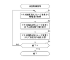
- FIG. 4 is a flowchart illustrating a flow of speed control processing executed by the control system 1.
- the speed control process is started in response to an instruction to execute the speed control process in the control device 10.
- step S1 the response value acquisition unit 151 of the control device 10 acquires physical quantities from the master device 20 and the slave device 30. Specifically, in step S1, the response value acquisition unit 151 acquires the position of the movable unit from the physical quantity acquisition unit 251 of the master device 20 and the physical quantity acquisition unit 351 of the slave device 30. At this time, the response value acquisition unit 151 may acquire the speed or acceleration of the movable unit or the force received by the movable unit from the physical quantity acquisition unit 251 of the master device 20 and the physical quantity acquisition unit 351 of the slave device 30. ..
- step S2 the command value calculation unit 152 of the control device 10 calculates the speed command value for the master device 20 and the slave device 30. Specifically, the command value calculation unit 152 calculates the speed command value for the master device 20 and the speed command value for the slave device 30 according to the equations (1) and (2). At this time, it is also possible to calculate the position command value and control the master device 20 and the slave device 30 by the position command value. At this time, it is also possible to calculate the acceleration command value and control the master device 20 and the slave device 30 by the acceleration command value.
- step S3 the command value transmission unit 153 of the control device 10 transmits the speed command value of the master device 20 and the speed command value of the slave device 30 calculated by the command value calculation unit 152 to the master device 20 and the slave device 30. ..
- step S4 the command value calculation unit 152 of the control device 10 determines whether or not the end of the speed control process is instructed. If the end of the speed control process is not instructed, NO is determined in step S4, and the process returns to step S1. On the other hand, when the end of the speed control process is instructed, YES is determined in step S4, and the speed control process ends.
- s is the Laplace operator
- X 1 ref is the position command value to the master device 20 (that is, s 2 X 1 ref is the command value of the acceleration to the master device 20).
- X 2 ref is the speed command value to the slave device 30 (that is, s 2 X 2 ref is the command value of the acceleration to the slave device 30)
- C p is the position controller
- Y is the admittance
- F 1 is the force of the master device.
- the response value, F 2 is the force response value of the slave device 30
- X 1 is the position of the movable part of the master device 20
- X 2 is the position of the movable part of the slave device 30.
- the right side coefficients of V 1 in the first term is referred to as an index a is reproducible Pr indicating the degree of mechanical impedance of the environment is reproduced.
- the coefficient of V 1 in the second term on the right side is an index indicating the degree of force occurring during operation, is called the operability Po.
- F 1 can be expressed as in the equation (8).
- F 1 ( Pr Z 2 + Po) V 2 (8)
- the acceleration command value is expressed by the following equations (17) and (18).
- CPID represents a PID controller
- M represents motor inertia
- the master device 20 and the slave device 30 are actually connected and controlled thereof, but the present invention is not limited thereto. That is, one or both of the master device 20 and the slave device 30 are configured as a virtual device (a model of a virtual device that executes various operations in a virtual space), and the control device 10 sets the master device 20 and the slave device 30. It may be controlled. Further, in this case, it is assumed that the virtual device executes a specific operation model (a model of an operation that draws a circle, a model that operates according to a specific routine, etc.), and the control device 10 corresponds to the specific operation model. Control may be performed so that the master device 20 or the slave device 30 follows the behavior of the virtual object.
- a virtual device a model of a virtual device that executes various operations in a virtual space
- the control device 10 sets the master device 20 and the slave device 30. It may be controlled.
- the virtual device executes a specific operation model (a model of an operation that draws a circle, a model that operates according to a specific routine,
- [Modification 2] it is possible to increase or decrease (scale) the force, position, speed, or the like processed by the control system 1.
- the control device 10 controls, the physical quantity (position, force, etc.) input to the virtual object is scaled, or the command value to the master device 20 or the command value to the slave device 30 is scaled. be able to.
- the operation of the master device 20 or the slave device 30 can be scaled by increasing or decreasing the drive current (or drive voltage) output by the driver 252 of the master device 20 or the driver 352 of the slave device 30. This makes it possible to convert minute movements and huge movements into a size that is easy for humans to perceive.
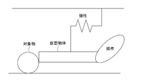
- the physical characteristics of the object can be measured by analyzing the control parameters during operation in the control system 1. For example, the inertia, viscosity, elasticity, etc. of the object can be calculated from the detected response value from the object to the input for operation. As a result, by contacting the object with the control system 1, the physical characteristics of the object can be grasped without using a special measuring instrument.
- FIG. 5 is a schematic diagram showing a state in which a mass m (inertia) is assumed for a virtual object.
- FIG. 6 is a schematic diagram showing a state in which a viscosity coefficient D (viscosity) is assumed for a virtual object. Further, FIG.
- FIG. 7 is a schematic diagram showing a state in which an elastic modulus K (elasticity) is assumed for a virtual object.
- an elastic modulus K elasticity
- FIGS. 5 to 7 it is possible to assume inertia, viscosity and elasticity for the virtual object.
- the inertia, viscosity and elasticity of the virtual object can be assumed alone or in combination.
- the following equation (27) can be set as the admittance Y of the virtual object.
- the viscosity set in the virtual object is a third force due to the setting of admittance Y in addition to the operating force input to the master device 20 and the reaction force from the environment (object) input to the slave device 30. Represents the addition of.
- the viscosity set for the virtual object has an effect such as suppressing the fluctuation of the operating force.
- the elasticity set in the virtual object represents the characteristic that the virtual object tries to return to its original shape with respect to the deformation due to the applied force. By setting the elasticity of the virtual object, it is possible to perform control such as moving the virtual object to a specific position. By making the physical characteristics assumed for the virtual object different in this way, it is possible to control the master device 20 and the slave device 30 in various operation modes.
- the control system 1 includes a control device 10, a master device 20, and a slave device 30.
- the master device 20 receives an input for operation.
- the slave device 30 operates on the object.
- the control device 10 controls the slave device 30 according to the operation input to the master device 20, and also executes control to transmit the reaction force received from the object by the slave device 30 to the master device 20.
- the control device 10 includes a response value acquisition unit 151, a command value calculation unit 152, and a command value transmission unit 153.
- the response value acquisition unit 151 acquires physical quantity data representing the operation of the movable portion of the master device 20 and physical quantity data representing the operation of the movable portion of the slave device 30.
- the command value calculation unit 152 virtualizes a virtual object including the master device 20 and the slave device 30, and inputs to the master device 20 and the slave device 30 based on the physical quantity data acquired by the response value acquisition unit 151. A command value for making the master device 20 and the slave device 30 follow the behavior appearing in the virtual object is calculated. As a result, by adopting a control method for following a virtual object, it is possible to obtain performance equal to or higher than the conventional one in terms of reproducibility and operability of operations in the master device 20 and the slave device 30. Therefore, it is possible to realize more appropriate physical interaction of the robot.
- the command value calculation unit 152 multiplies the force input to the master device 20 and the slave device 30 by a multiplication element that converts the force into at least one of velocity, position, and acceleration, and the velocity, position, and speed of the virtual object obtained.
- the command value of the master device 20 or the slave device 30 is calculated based on the difference between at least one of the accelerations and at least one of the speed, position, and acceleration of the master device 20 or the slave device 30.
- high-precision bilateral control can be performed by acquiring at least one of the force input to the virtual object from the master device 20 and the slave device 30 and the speed, position, and acceleration of the master device 20 and the slave device 30. Can be done.
- the command value calculation unit 152 determines at least one of the speed, position, and acceleration of the virtual object obtained by multiplying the force input to the master device 20 and the slave device 30 by admittance, and the speed of the master device 20 or the slave device 30.
- the command value of the master device 20 or the slave device 30 is calculated based on the difference from at least one of the position and the acceleration. This allows the force to be appropriately converted to velocity or position to perform highly accurate bilateral control.
- the command value calculation unit 152 calculates the command value by adding the feed forward components based on the forces input from the master device 20 and the slave device 30. As a result, the master device 20 and the slave device 30 can be made to follow the behavior of the virtual object with higher accuracy.
- At least one of the master device 20 and the slave device 30 is configured as a virtual device.
- the command value calculation unit 152 calculates a command value for making the master device 20 and the slave device 30 follow the behavior of the virtual object based on the operation of the virtual device. This makes it possible to control the single device to follow the behavior of the virtual object according to the behavior of the virtual master / slave system.
- At least one of the master device 20 and the slave device 30 is configured as a virtual device that executes a specific operation model.
- the command value calculation unit 152 calculates a command value for making the master device 20 and the slave device 30 follow the behavior of the virtual object based on the specific operation model. This makes it possible to control the master device 20 or the slave device 30 according to the operation of a virtual device that executes a specific operation model.
- At least one of the outputs of the master device 20 and the slave device 30 is scaled to scale at least one of the forces, positions or velocities. This makes it possible to convert minute movements and huge movements into a size that is easy for humans to perceive.
- the parameters related to the control of at least one of the master device 20 and the slave device 30 are recorded in chronological order. This makes it possible to save the actions performed in the past.
- the operation is reproduced by reading out the recorded parameters related to the control of at least one of the master device 20 and the slave device 30 in chronological order and controlling the master device 20 or the slave device 30 based on the parameters. This makes it possible to reproduce an operation performed in the past or to repeatedly execute a specific operation.
- Information on the physical characteristics of the object is acquired based on the parameters related to the control of at least one of the master device 20 and the slave device 30.
- the present invention is not limited to the above-described embodiment, and modifications, improvements, and the like to the extent that the object of the present invention can be achieved are included in the present invention.
- Y (F 1 + F 2 ) is added as the second term on the right side of the equations (1) and (2).
- the speed command value may be calculated without adding the second term on the right side of the equation (1) and the equation (2). That is, since the second term on the right side of the equations (1) and (2) is a feedforward term for further improving the control accuracy, the equation (1) is according to the control accuracy required by the control system 1. It is also possible to calculate the speed command value without adding the second term on the right side of the equation (2). The same applies to the second term Y (F 1 + F 2 ) s on the right side of the equation (3) and the equation (4).
- the case where the master device 20 and the slave device 30 are controlled by the same type of command value has been described as an example, but the present invention is not limited to this. That is, the types of command values given to the master device 20 and the slave device 30 may be different from each other.
- the case where the same type of physical quantity (for example, the position of the movable portion) is acquired by the master device 20 and the slave device 30 has been described as an example, but the present invention is not limited to this. That is, the types of physical quantities acquired by the master device 20 and the slave device 30 may be different from each other.
- control device 10 for controlling the master device 20 and the slave device 30 has been described as an example, but the present invention is not limited to this. That is, the control device 10 for controlling the master device 20 and the control device 10 for controlling the slave device 30 may be installed respectively.
- the processing in the above-described embodiment can be executed by either hardware or software. That is, it is sufficient that the control system 1 is provided with a function capable of executing the above-mentioned processing, and what kind of functional configuration and hardware configuration are used to realize this function is not limited to the above-mentioned example.
- the above-mentioned processing is executed by software, the programs constituting the software are installed in the computer from a network or a storage medium.
- the storage medium for storing the program is composed of a removable medium distributed separately from the main body of the device, a storage medium preliminarily incorporated in the main body of the device, or the like.
- the removable media is composed of, for example, a semiconductor memory, a magnetic disk, an optical disk, a magneto-optical disk, or the like.
- the optical disc is composed of, for example, a CD-ROM (Compact Disk-Read Only Memory), a DVD (Digital Versaille Disc), a Blu-ray Disc (registered trademark), or the like.
- the magneto-optical disk is composed of MD (Mini-Disc) or the like.
- the storage medium preliminarily incorporated in the apparatus main body is composed of, for example, a ROM (Read Only Memory) or a hard disk in which a program is stored, a hard disk, a semiconductor memory, or the like.
- control system 10 control device, 20 master device, 30 slave device, 151 response value acquisition unit, 152 command value calculation unit, 153 command value transmission unit, 251,351 physical quantity acquisition unit, 252,352 driver, 253,353 actuators.
Landscapes
- Engineering & Computer Science (AREA)
- Robotics (AREA)
- Mechanical Engineering (AREA)
- Manipulator (AREA)
Abstract
[Problem] To realize a more suitable physical interaction between robots. [Solution] This control system 1 comprises a master device 30, a slave device 30, and a control device 10 that controls the master device 30 and the slave device 30. In the control device 10, a response value acquisition unit 151 acquires physical quantity data representing an action of a movable part of the master device 20 and physical quantity data representing an action of a movable part of the slave device 30. A command value calculation unit 152 hypothesizes a virtual object including the master device 20 and the slave device 30 and, on the basis of the physical quantity data acquired by the response value acquisition unit 151, calculates a command value for causing the master device 20 and the slave device 30 to follow behavior represented by the virtual object through input to the master device 20 and the slave device 30.
Description
本発明は、ロボット等の動作を制御する制御システム、制御方法及びプログラムに関する。
The present invention relates to a control system, a control method and a program for controlling the operation of a robot or the like.
近年、ロボットによる多様な作業を実現するため、人や環境との安全な接触を実現するロボット制御技術が求められている。
特に、対象物の位置や大きさ、硬さのバラつき等、モデル化が困難で不確定な要素に柔軟に対応するためには、機械的インピーダンスの適応的な調整と、コンプライアントな動作の実現が不可欠である。
なお、ロボットの動作を制御する技術として、例えば、特許文献1には、コンプライアンス制御を行うロボットに関する技術が記載されている。 In recent years, in order to realize various tasks by robots, robot control technology that realizes safe contact with people and the environment is required.
In particular, in order to flexibly deal with uncertain factors that are difficult to model, such as the position, size, and hardness of objects, adaptive adjustment of mechanical impedance and realization of compliant operation are realized. Is indispensable.
As a technique for controlling the operation of the robot, for example,Patent Document 1 describes a technique for a robot that performs compliance control.
特に、対象物の位置や大きさ、硬さのバラつき等、モデル化が困難で不確定な要素に柔軟に対応するためには、機械的インピーダンスの適応的な調整と、コンプライアントな動作の実現が不可欠である。
なお、ロボットの動作を制御する技術として、例えば、特許文献1には、コンプライアンス制御を行うロボットに関する技術が記載されている。 In recent years, in order to realize various tasks by robots, robot control technology that realizes safe contact with people and the environment is required.
In particular, in order to flexibly deal with uncertain factors that are difficult to model, such as the position, size, and hardness of objects, adaptive adjustment of mechanical impedance and realization of compliant operation are realized. Is indispensable.
As a technique for controlling the operation of the robot, for example,
ロボットの適応的な物理的インタラクションを実現する方法の1つとして、マスタ・スレーブシステムを応用したロボットの制御技術が用いられている。マスタ・スレーブシステムを応用したロボットの制御技術として、マスタ・スレーブ間で、周辺環境の機械的インピーダンスを再現したり、ロボットの操作性を高めたりする手法が種々提案されている。
しかしながら、従来の技術を用いたロボットは、周辺環境の機械的インピーダンスの再現性や操作性が十分に高いものではなかった。
そのため、従来の技術においては、ロボットの適切な物理的インタラクションを実現することが困難であった。
本発明の課題は、より適切なロボットの物理的インタラクションを実現することである。 As one of the methods for realizing adaptive physical interaction of a robot, a robot control technology applying a master / slave system is used. As a robot control technique applying a master / slave system, various methods have been proposed for reproducing the mechanical impedance of the surrounding environment between the master / slave and improving the operability of the robot.
However, the robot using the conventional technique does not have sufficiently high reproducibility and operability of the mechanical impedance of the surrounding environment.
Therefore, it has been difficult to realize appropriate physical interaction of the robot with the conventional technology.
An object of the present invention is to realize more appropriate physical interaction of a robot.
上記課題を解決するため、本発明の一態様に係る制御システムは、
操作のための入力を受け付ける第1の装置と、対象物に対する動作を行う第2の装置と、前記第1の装置に入力された操作に応じて前記第2の装置を制御すると共に、前記第2の装置が対象物から受けた反力を前記第1の装置に伝達する制御を実行する制御装置と、を備え、
前記制御装置は、
前記第1の装置の可動部の動作を表す物理量のデータ及び前記第2の装置の可動部の動作を表す物理量のデータを取得するデータ取得手段と、
前記第1の装置と前記第2の装置とを含む仮想物体を仮想し、前記データ取得手段によって取得された前記物理量のデータに基づいて、前記第1の装置及び前記第2の装置への入力によって前記仮想物体に表れる挙動に、前記第1の装置と前記第2の装置とを追従させるための指令値を算出する指令値算出手段と、
を備えることを特徴とする。 In order to solve the above problems, the control system according to one aspect of the present invention is
The first device that accepts input for operation, the second device that performs an operation on an object, and the second device that controls the second device according to the operation input to the first device, and the first device. The device 2 includes a control device that executes control to transmit the reaction force received from the object to the first device.
The control device is
A data acquisition means for acquiring physical quantity data representing the operation of the movable portion of the first device and physical quantity data representing the operation of the movable portion of the second device.
A virtual object including the first device and the second device is virtualized, and input to the first device and the second device based on the physical quantity data acquired by the data acquisition means. A command value calculating means for calculating a command value for causing the first device and the second device to follow the behavior appearing in the virtual object.
It is characterized by having.
本発明によれば、より適切なロボットの物理的インタラクションを実現することができる。
According to the present invention, more appropriate physical interaction of the robot can be realized.
以下、本発明の実施形態について、図面を参照して説明する。
初めに、本発明に適用される基本的原理について説明する。 Hereinafter, embodiments of the present invention will be described with reference to the drawings.
First, the basic principle applied to the present invention will be described.
初めに、本発明に適用される基本的原理について説明する。 Hereinafter, embodiments of the present invention will be described with reference to the drawings.
First, the basic principle applied to the present invention will be described.
[基本的原理]
図1は、本発明の概念を示す模式図である。
図1に示すように、本発明においては、マスタ・スレーブシステムを応用したロボットにおいてマスタ装置及びスレーブ装置を含む仮想物体を想定し、マスタ装置及びスレーブ装置への入力が仮想物体への入力であるとした場合の仮想物体の挙動にマスタ装置及びスレーブ装置の動作を追従させる制御を行う。このとき、マスタ装置及びスレーブ装置から入力される力応答にアドミタンスを乗じて速度を表すパラメータを算出し、現在の速度と共に、速度指令値としてマスタ装置及びスレーブ装置の位置制御系に与える。
これにより、マスタ装置及びスレーブ装置における動作の再現性及び操作性として、従来と同等以上の性能を得ることができる。
したがって、より適切なロボットの物理的インタラクションを実現することが可能となる。
また、本発明においては、速度指令値に基づく制御を行うことができるため、既存の位置(または速度)制御系のシステム(加速度制御を想定していないシステム)との親和性が高いものとなる。ただし、本発明において、加速度指令値に基づく制御を行うことも可能である。
なお、位置と速度(または加速度)あるいは角度と角速度(または角加速度)は、微積分演算により置換可能なパラメータであるため、位置あるいは角度に関する処理を行う場合、適宜、速度あるいは角速度等に置換することが可能である。 [Basic principle]
FIG. 1 is a schematic diagram showing the concept of the present invention.
As shown in FIG. 1, in the present invention, a virtual object including a master device and a slave device is assumed in a robot to which a master / slave system is applied, and an input to the master device and the slave device is an input to the virtual object. The operation of the master device and the slave device is controlled to follow the behavior of the virtual object in the case of. At this time, a parameter representing the speed is calculated by multiplying the force response input from the master device and the slave device by admittance, and is given to the position control system of the master device and the slave device as a speed command value together with the current speed.
As a result, it is possible to obtain performance equal to or higher than the conventional one in terms of reproducibility and operability of operations in the master device and the slave device.
Therefore, it is possible to realize more appropriate physical interaction of the robot.
Further, in the present invention, since the control can be performed based on the speed command value, the affinity with the existing position (or speed) control system (system not assuming acceleration control) is high. .. However, in the present invention, it is also possible to perform control based on the acceleration command value.
Note that position and velocity (or acceleration) or angle and angular velocity (or angular velocity) are parameters that can be replaced by fine integral calculation. Therefore, when processing related to position or angle, replace them with velocity or angular velocity as appropriate. Is possible.
[構成]
次に、本発明のシステム構成について説明する。
図2は、本発明の一実施形態に係る制御システム1の全体構成を示す模式図である。
図2に示すように、本実施形態に係る制御システム1は、制御装置10と、マスタ装置20と、スレーブ装置30と、を含んで構成され、制御装置10とマスタ装置20及びスレーブ装置30とは、インターネット等の公衆網、専用線あるいは通信ケーブルによる直接接続等、有線通信または無線通信によって接続されている。 [composition]
Next, the system configuration of the present invention will be described.
FIG. 2 is a schematic diagram showing the overall configuration of thecontrol system 1 according to the embodiment of the present invention.
As shown in FIG. 2, thecontrol system 1 according to the present embodiment includes a control device 10, a master device 20, and a slave device 30, and includes the control device 10, the master device 20, and the slave device 30. Is connected by wired communication or wireless communication such as a public network such as the Internet, a dedicated line or a direct connection by a communication cable.
次に、本発明のシステム構成について説明する。
図2は、本発明の一実施形態に係る制御システム1の全体構成を示す模式図である。
図2に示すように、本実施形態に係る制御システム1は、制御装置10と、マスタ装置20と、スレーブ装置30と、を含んで構成され、制御装置10とマスタ装置20及びスレーブ装置30とは、インターネット等の公衆網、専用線あるいは通信ケーブルによる直接接続等、有線通信または無線通信によって接続されている。 [composition]
Next, the system configuration of the present invention will be described.
FIG. 2 is a schematic diagram showing the overall configuration of the
As shown in FIG. 2, the
制御装置10は、PC(Personal Computer)あるいはプログラマブルコントローラ等、プロセッサ及びメモリを備える情報処理装置によって構成され、マスタ装置20及びスレーブ装置30において取得された物理量(ここでは、マスタ装置20及びスレーブ装置30における可動部の位置とする)に基づいて、マスタ装置20及びスレーブ装置30それぞれにおける速度(または位置)の指令値を算出する。そして、制御装置10は、算出した速度(または位置)の指令値をマスタ装置20及びスレーブ装置30に送信する。
このとき、制御装置10は、マスタ装置20及びスレーブ装置30を含む仮想物体を想定し、マスタ装置20及びスレーブ装置30への入力が仮想物体への入力であるとした場合の仮想物体の挙動にマスタ装置20及びスレーブ装置30を追従させる速度(または位置)の指令値を算出する。 Thecontrol device 10 is composed of an information processing device including a processor and a memory such as a PC (Personal Computer) or a programmable controller, and physical quantities acquired by the master device 20 and the slave device 30 (here, the master device 20 and the slave device 30). The command value of the speed (or position) in each of the master device 20 and the slave device 30 is calculated based on the position of the movable portion in the above. Then, the control device 10 transmits the command value of the calculated speed (or position) to the master device 20 and the slave device 30.
At this time, thecontrol device 10 assumes a virtual object including the master device 20 and the slave device 30, and the behavior of the virtual object when the input to the master device 20 and the slave device 30 is an input to the virtual object. The command value of the speed (or position) to make the master device 20 and the slave device 30 follow is calculated.
このとき、制御装置10は、マスタ装置20及びスレーブ装置30を含む仮想物体を想定し、マスタ装置20及びスレーブ装置30への入力が仮想物体への入力であるとした場合の仮想物体の挙動にマスタ装置20及びスレーブ装置30を追従させる速度(または位置)の指令値を算出する。 The
At this time, the
マスタ装置20は、スレーブ装置30を操作するための入力を受け付けると共に、入力に対する反力を出力する。具体的には、マスタ装置20は、スレーブ装置30を操作するための入力によって変化した可動部の物理量(ここでは位置)を取得し、制御装置10に送信する。また、マスタ装置20は、制御装置10から送信された速度指令値(または位置指令値)に基づいて、アクチュエータを制御し、可動部の速度を目標速度(または目標位置)に追従させる。
The master device 20 receives an input for operating the slave device 30 and outputs a reaction force to the input. Specifically, the master device 20 acquires the physical quantity (here, the position) of the movable portion changed by the input for operating the slave device 30, and transmits it to the control device 10. Further, the master device 20 controls the actuator based on the speed command value (or position command value) transmitted from the control device 10, and causes the speed of the movable portion to follow the target speed (or target position).
スレーブ装置30は、マスタ装置20による操作に応じて環境(対象物)に対する出力を行うと共に、出力に応じた環境からの反力が入力される。具体的には、スレーブ装置30は、制御装置10から送信された速度指令値(または位置指令値)に基づいて、アクチュエータを制御し、可動部の速度を目標速度(または目標位置)に追従させる。また、スレーブ装置30は、環境からの反力を受けた可動部の物理量(ここでは位置)を取得し、制御装置10に送信する。
The slave device 30 outputs to the environment (object) according to the operation by the master device 20, and the reaction force from the environment according to the output is input. Specifically, the slave device 30 controls the actuator based on the speed command value (or position command value) transmitted from the control device 10, and causes the speed of the movable portion to follow the target speed (or target position). .. Further, the slave device 30 acquires the physical quantity (here, the position) of the movable portion that has received the reaction force from the environment and transmits it to the control device 10.
[具体的構成]
次に、制御システム1の具体的構成について説明する。
図3は、制御システム1の具体的構成例を示すブロック図である。
図3に示すように、制御装置10は、応答値取得部151と、指令値算出部152と、指令値送信部153と、を備えている。 [Concrete configuration]
Next, a specific configuration of thecontrol system 1 will be described.
FIG. 3 is a block diagram showing a specific configuration example of thecontrol system 1.
As shown in FIG. 3, thecontrol device 10 includes a response value acquisition unit 151, a command value calculation unit 152, and a command value transmission unit 153.
次に、制御システム1の具体的構成について説明する。
図3は、制御システム1の具体的構成例を示すブロック図である。
図3に示すように、制御装置10は、応答値取得部151と、指令値算出部152と、指令値送信部153と、を備えている。 [Concrete configuration]
Next, a specific configuration of the
FIG. 3 is a block diagram showing a specific configuration example of the
As shown in FIG. 3, the
応答値取得部151は、マスタ装置20及びスレーブ装置30において取得された物理量(ここでは、マスタ装置20及びスレーブ装置30における可動部の位置)を取得する。
指令値算出部152は、応答値取得部151によって取得されたマスタ装置20及びスレーブ装置30の物理量に基づいて、マスタ装置20及びスレーブ装置30を含むと仮想した仮想物体(質量mを有する仮想物体)の挙動にマスタ装置20及びスレーブ装置30を追従させる速度指令値(または位置指令値)を算出する。具体的には、指令値算出部152は、例えば、以下の式(1)及び(2)に従って、マスタ装置20に対する速度指令値及びスレーブ装置30に対する速度指令値を算出する。 The responsevalue acquisition unit 151 acquires the physical quantities acquired by the master device 20 and the slave device 30 (here, the positions of the movable units in the master device 20 and the slave device 30).
The commandvalue calculation unit 152 is a virtual object (virtual object having a mass m) that is virtualized to include the master device 20 and the slave device 30 based on the physical quantities of the master device 20 and the slave device 30 acquired by the response value acquisition unit 151. ), The speed command value (or the position command value) that causes the master device 20 and the slave device 30 to follow is calculated. Specifically, the command value calculation unit 152 calculates the speed command value for the master device 20 and the speed command value for the slave device 30 according to the following equations (1) and (2), for example.
指令値算出部152は、応答値取得部151によって取得されたマスタ装置20及びスレーブ装置30の物理量に基づいて、マスタ装置20及びスレーブ装置30を含むと仮想した仮想物体(質量mを有する仮想物体)の挙動にマスタ装置20及びスレーブ装置30を追従させる速度指令値(または位置指令値)を算出する。具体的には、指令値算出部152は、例えば、以下の式(1)及び(2)に従って、マスタ装置20に対する速度指令値及びスレーブ装置30に対する速度指令値を算出する。 The response
The command

なお、F1及びF2は、マスタ装置20及びスレーブ装置30から取得された物理量(ここでは位置)から、各種力推定手法(加速度に変換して質量との乗算値として推定するあるいはオブザーバにより推定する等)を用いて取得することができる。また、V1及びV2は、マスタ装置20及びスレーブ装置30から取得された物理量(ここでは位置)の微分により取得することができる。ただし、制御装置10がマスタ装置20及びスレーブ装置30から物理量として力を取得し、式(1)及び(2)の演算に用いることとしてもよい。
Note that F 1 and F 2 are estimated from various force estimation methods (converted to acceleration and multiplied by mass) from physical quantities (positions in this case) acquired from the master device 20 and the slave device 30 or estimated by an observer. Etc.) can be obtained. Further, V 1 and V 2 can be acquired by differentiating the physical quantities (here, positions) acquired from the master device 20 and the slave device 30. However, the control device 10 may acquire a force as a physical quantity from the master device 20 and the slave device 30 and use it for the calculation of the equations (1) and (2).
また、式(1)及び(2)においては、速度指令値を算出する場合の式を示したが、位置指令値を算出し、位置指令値によってマスタ装置20及びスレーブ装置30を制御することも可能である。また、加速度指令値(例えば、後述する式(3)及び(4)参照)を算出し、加速度指令値によってマスタ装置20及びスレーブ装置30を制御することも可能である。さらに、アクチュエータの電流指令値あるいは電圧指令値を算出し、アクチュエータの電流指令値あるいは電圧指令値によってマスタ装置20及びスレーブ装置30を制御することも可能である。
Further, in the equations (1) and (2), the equation for calculating the speed command value is shown, but the position command value can be calculated and the master device 20 and the slave device 30 can be controlled by the position command value. It is possible. It is also possible to calculate the acceleration command value (see, for example, equations (3) and (4) described later) and control the master device 20 and the slave device 30 by the acceleration command value. Further, it is also possible to calculate the current command value or the voltage command value of the actuator and control the master device 20 and the slave device 30 by the current command value or the voltage command value of the actuator.
指令値送信部153は、指令値算出部152によって算出されたマスタ装置20の指令値(ここでは速度指令値)及びスレーブ装置30の指令値(ここでは速度指令値)をマスタ装置20及びスレーブ装置30に送信する。
The command value transmission unit 153 sets the command value of the master device 20 (here, the speed command value) calculated by the command value calculation unit 152 and the command value of the slave device 30 (here, the speed command value) to the master device 20 and the slave device. Send to 30.
また、図3に示すように、マスタ装置20は、物理量取得部251と、ドライバ252と、アクチュエータ253と、を備えている。
物理量取得部251は、マスタ装置20の可動部(例えば、アクチュエータ253の出力軸)の位置を検出する位置センサを備え、位置センサによって検出された可動部の位置を制御装置10に送信する。なお、物理量取得部251が、位置センサに加えて、マスタ装置20の可動部が受ける力を検出する力センサを備え、力センサによって検出された可動部が受ける力を制御装置10に送信することとしてもよい。また、物理量取得部251が、位置センサに代えて、マスタ装置20の可動部(例えば、アクチュエータ253の出力軸)の速度(または加速度)を検出する速度センサ(または加速度センサ)を備え、速度センサ(または加速度センサ)によって検出された可動部の速度(または加速度)を制御装置10に送信することとしてもよい。
ドライバ252は、制御装置10によって送信されたマスタ装置20の指令値に応じた駆動電流(または駆動電圧)をアクチュエータ253に出力する。
アクチュエータ253は、マスタ装置20に入力される操作に対して、ドライバ252から入力された駆動電流(または駆動電圧)に従って、反力を出力する。 Further, as shown in FIG. 3, themaster device 20 includes a physical quantity acquisition unit 251, a driver 252, and an actuator 253.
The physicalquantity acquisition unit 251 includes a position sensor that detects the position of the movable portion of the master device 20 (for example, the output shaft of the actuator 253), and transmits the position of the movable portion detected by the position sensor to the control device 10. In addition to the position sensor, the physical quantity acquisition unit 251 includes a force sensor that detects the force received by the movable portion of the master device 20, and transmits the force received by the movable portion detected by the force sensor to the control device 10. May be. Further, the physical quantity acquisition unit 251 is provided with a speed sensor (or acceleration sensor) for detecting the speed (or acceleration) of the movable part (for example, the output shaft of the actuator 253) of the master device 20 instead of the position sensor. The speed (or acceleration) of the movable portion detected by (or the acceleration sensor) may be transmitted to the control device 10.
Thedriver 252 outputs a drive current (or drive voltage) according to the command value of the master device 20 transmitted by the control device 10 to the actuator 253.
Theactuator 253 outputs a reaction force in response to an operation input to the master device 20 according to a drive current (or drive voltage) input from the driver 252.
物理量取得部251は、マスタ装置20の可動部(例えば、アクチュエータ253の出力軸)の位置を検出する位置センサを備え、位置センサによって検出された可動部の位置を制御装置10に送信する。なお、物理量取得部251が、位置センサに加えて、マスタ装置20の可動部が受ける力を検出する力センサを備え、力センサによって検出された可動部が受ける力を制御装置10に送信することとしてもよい。また、物理量取得部251が、位置センサに代えて、マスタ装置20の可動部(例えば、アクチュエータ253の出力軸)の速度(または加速度)を検出する速度センサ(または加速度センサ)を備え、速度センサ(または加速度センサ)によって検出された可動部の速度(または加速度)を制御装置10に送信することとしてもよい。
ドライバ252は、制御装置10によって送信されたマスタ装置20の指令値に応じた駆動電流(または駆動電圧)をアクチュエータ253に出力する。
アクチュエータ253は、マスタ装置20に入力される操作に対して、ドライバ252から入力された駆動電流(または駆動電圧)に従って、反力を出力する。 Further, as shown in FIG. 3, the
The physical
The
The
また、図3に示すように、スレーブ装置30は、物理量取得部351と、ドライバ352と、アクチュエータ353と備えている。
物理量取得部351は、スレーブ装置30の可動部(例えば、アクチュエータ353の出力軸)の位置を検出する位置センサを備え、位置センサによって検出された可動部の位置を制御装置10に送信する。なお、物理量取得部351が、位置センサに加えて、スレーブ装置30の可動部が受ける力を検出する力センサを備え、力センサによって検出された可動部が受ける力を制御装置10に送信することとしてもよい。また、物理量取得部351が、位置センサに代えて、スレーブ装置30の可動部(例えば、アクチュエータ353の出力軸)の速度(または加速度)を検出する速度センサ(または加速度センサ)を備え、速度センサ(または加速度センサ)によって検出された可動部の速度(または加速度)を制御装置10に送信することとしてもよい。 Further, as shown in FIG. 3, theslave device 30 includes a physical quantity acquisition unit 351, a driver 352, and an actuator 353.
The physical quantity acquisition unit 351 includes a position sensor that detects the position of the movable portion of the slave device 30 (for example, the output shaft of the actuator 353), and transmits the position of the movable portion detected by the position sensor to thecontrol device 10. In addition to the position sensor, the physical quantity acquisition unit 351 includes a force sensor that detects the force received by the movable portion of the slave device 30, and transmits the force received by the movable portion detected by the force sensor to the control device 10. May be. Further, the physical quantity acquisition unit 351 is provided with a speed sensor (or acceleration sensor) for detecting the speed (or acceleration) of the movable part (for example, the output shaft of the actuator 353) of the slave device 30 instead of the position sensor. The speed (or acceleration) of the movable portion detected by (or the acceleration sensor) may be transmitted to the control device 10.
物理量取得部351は、スレーブ装置30の可動部(例えば、アクチュエータ353の出力軸)の位置を検出する位置センサを備え、位置センサによって検出された可動部の位置を制御装置10に送信する。なお、物理量取得部351が、位置センサに加えて、スレーブ装置30の可動部が受ける力を検出する力センサを備え、力センサによって検出された可動部が受ける力を制御装置10に送信することとしてもよい。また、物理量取得部351が、位置センサに代えて、スレーブ装置30の可動部(例えば、アクチュエータ353の出力軸)の速度(または加速度)を検出する速度センサ(または加速度センサ)を備え、速度センサ(または加速度センサ)によって検出された可動部の速度(または加速度)を制御装置10に送信することとしてもよい。 Further, as shown in FIG. 3, the
The physical quantity acquisition unit 351 includes a position sensor that detects the position of the movable portion of the slave device 30 (for example, the output shaft of the actuator 353), and transmits the position of the movable portion detected by the position sensor to the
ドライバ352は、制御装置10によって送信されたスレーブ装置30の指令値に応じた駆動電流(または駆動電圧)をアクチュエータ353に出力する。
アクチュエータ353は、ドライバ352から入力された駆動電流(または駆動電圧)に従って、環境(対象物)への力を出力する。 Thedriver 352 outputs a drive current (or drive voltage) according to the command value of the slave device 30 transmitted by the control device 10 to the actuator 353.
Theactuator 353 outputs a force to the environment (object) according to the drive current (or drive voltage) input from the driver 352.
アクチュエータ353は、ドライバ352から入力された駆動電流(または駆動電圧)に従って、環境(対象物)への力を出力する。 The
The
[動作]
次に、制御システム1の動作を説明する。
[速度制御処理]
図4は、制御システム1が実行する速度制御処理の流れを説明するフローチャートである。
速度制御処理は、制御装置10において、速度制御処理の実行が指示されることに対応して開始される。 [motion]
Next, the operation of thecontrol system 1 will be described.
[Speed control processing]
FIG. 4 is a flowchart illustrating a flow of speed control processing executed by thecontrol system 1.
The speed control process is started in response to an instruction to execute the speed control process in thecontrol device 10.
次に、制御システム1の動作を説明する。
[速度制御処理]
図4は、制御システム1が実行する速度制御処理の流れを説明するフローチャートである。
速度制御処理は、制御装置10において、速度制御処理の実行が指示されることに対応して開始される。 [motion]
Next, the operation of the
[Speed control processing]
FIG. 4 is a flowchart illustrating a flow of speed control processing executed by the
The speed control process is started in response to an instruction to execute the speed control process in the
ステップS1において、制御装置10の応答値取得部151は、マスタ装置20及びスレーブ装置30から物理量を取得する。具体的には、ステップS1において、応答値取得部151は、マスタ装置20の物理量取得部251及びスレーブ装置30の物理量取得部351から可動部の位置を取得する。なお、このとき、応答値取得部151は、マスタ装置20の物理量取得部251及びスレーブ装置30の物理量取得部351から可動部の速度あるいは加速度や、可動部が受ける力を取得することとしてもよい。
In step S1, the response value acquisition unit 151 of the control device 10 acquires physical quantities from the master device 20 and the slave device 30. Specifically, in step S1, the response value acquisition unit 151 acquires the position of the movable unit from the physical quantity acquisition unit 251 of the master device 20 and the physical quantity acquisition unit 351 of the slave device 30. At this time, the response value acquisition unit 151 may acquire the speed or acceleration of the movable unit or the force received by the movable unit from the physical quantity acquisition unit 251 of the master device 20 and the physical quantity acquisition unit 351 of the slave device 30. ..
ステップS2において、制御装置10の指令値算出部152は、マスタ装置20及びスレーブ装置30に対する速度指令値を算出する。具体的には、指令値算出部152は、式(1)及び(2)に従って、マスタ装置20に対する速度指令値及びスレーブ装置30に対する速度指令値を算出する。なお、このとき、位置指令値を算出し、位置指令値によってマスタ装置20及びスレーブ装置30を制御することも可能である。また、このとき、加速度指令値を算出し、加速度指令値によってマスタ装置20及びスレーブ装置30を制御することも可能である。
In step S2, the command value calculation unit 152 of the control device 10 calculates the speed command value for the master device 20 and the slave device 30. Specifically, the command value calculation unit 152 calculates the speed command value for the master device 20 and the speed command value for the slave device 30 according to the equations (1) and (2). At this time, it is also possible to calculate the position command value and control the master device 20 and the slave device 30 by the position command value. At this time, it is also possible to calculate the acceleration command value and control the master device 20 and the slave device 30 by the acceleration command value.
ステップS3において、制御装置10の指令値送信部153は、指令値算出部152によって算出されたマスタ装置20の速度指令値及びスレーブ装置30の速度指令値をマスタ装置20及びスレーブ装置30に送信する。これにより、マスタ装置20及びスレーブ装置30におけるバイラテラル制御が実現される。
ステップS4において、制御装置10の指令値算出部152は、速度制御処理の終了が指示されたか否かの判定を行う。
速度制御処理の終了が指示されていない場合、ステップS4においてNOと判定されて、処理はステップS1に戻る。
一方、速度制御処理の終了が指示された場合、ステップS4においてYESと判定されて、速度制御処理は終了する。 In step S3, the commandvalue transmission unit 153 of the control device 10 transmits the speed command value of the master device 20 and the speed command value of the slave device 30 calculated by the command value calculation unit 152 to the master device 20 and the slave device 30. .. As a result, bilateral control in the master device 20 and the slave device 30 is realized.
In step S4, the commandvalue calculation unit 152 of the control device 10 determines whether or not the end of the speed control process is instructed.
If the end of the speed control process is not instructed, NO is determined in step S4, and the process returns to step S1.
On the other hand, when the end of the speed control process is instructed, YES is determined in step S4, and the speed control process ends.
ステップS4において、制御装置10の指令値算出部152は、速度制御処理の終了が指示されたか否かの判定を行う。
速度制御処理の終了が指示されていない場合、ステップS4においてNOと判定されて、処理はステップS1に戻る。
一方、速度制御処理の終了が指示された場合、ステップS4においてYESと判定されて、速度制御処理は終了する。 In step S3, the command
In step S4, the command
If the end of the speed control process is not instructed, NO is determined in step S4, and the process returns to step S1.
On the other hand, when the end of the speed control process is instructed, YES is determined in step S4, and the speed control process ends.
このような処理により、マスタ装置20及びスレーブ装置30における動作の再現性及び操作性として、従来と同等以上の性能を得ることができる。
したがって、より適切なロボットの物理的インタラクションを実現することが可能となる。
また、上述の制御によってマスタ装置20及びスレーブ装置30を制御する場合、制御のために必要なパラメータが低減されることから、装置間で送受信されるデータ量を減少させることができる。 By such processing, it is possible to obtain performance equal to or higher than the conventional one in terms of reproducibility and operability of operations in themaster device 20 and the slave device 30.
Therefore, it is possible to realize more appropriate physical interaction of the robot.
Further, when themaster device 20 and the slave device 30 are controlled by the above-mentioned control, the parameters required for the control are reduced, so that the amount of data transmitted / received between the devices can be reduced.
したがって、より適切なロボットの物理的インタラクションを実現することが可能となる。
また、上述の制御によってマスタ装置20及びスレーブ装置30を制御する場合、制御のために必要なパラメータが低減されることから、装置間で送受信されるデータ量を減少させることができる。 By such processing, it is possible to obtain performance equal to or higher than the conventional one in terms of reproducibility and operability of operations in the
Therefore, it is possible to realize more appropriate physical interaction of the robot.
Further, when the
[効果の検証]
次に、上述の制御システム1と従来手法とにおける制御性能を比較した検証結果について説明する。
従来手法との比較を行うために、上述の式(1)及び(2)を加速度指令値に換算すると、以下の式(3)及び(4)のように表される。 [Verification of effect]
Next, the verification result comparing the control performance between the above-mentionedcontrol system 1 and the conventional method will be described.
When the above equations (1) and (2) are converted into acceleration command values in order to make a comparison with the conventional method, they are expressed as the following equations (3) and (4).
次に、上述の制御システム1と従来手法とにおける制御性能を比較した検証結果について説明する。
従来手法との比較を行うために、上述の式(1)及び(2)を加速度指令値に換算すると、以下の式(3)及び(4)のように表される。 [Verification of effect]
Next, the verification result comparing the control performance between the above-mentioned
When the above equations (1) and (2) are converted into acceleration command values in order to make a comparison with the conventional method, they are expressed as the following equations (3) and (4).

直感的なロボットの操作においては機械的インピーダンスの伝送が重要となる。電気系とのアナロジーより、機械的インピーダンスの伝送は二端子対回路を用いて表現され得る。二端子対回路におけるABCDパラメータは、式(5)によって表される。
Transmission of mechanical impedance is important for intuitive robot operation. From the analogy with the electrical system, the transmission of mechanical impedance can be expressed using a two-terminal pair circuit. The ABCD parameter in the two-terminal pair circuit is expressed by the equation (5).

接触環境の機械的インピーダンスをZ2とすると、スレーブ装置30における速度V2と力F2との関係は、
F2=-Z2V2 (6)
となる。 When the mechanical impedance of the contact environment and Z 2, the relationship between the speed V 2 and the force F 2 in theslave device 30,
F 2 = -Z 2 V 2 (6)
Will be.
F2=-Z2V2 (6)
となる。 When the mechanical impedance of the contact environment and Z 2, the relationship between the speed V 2 and the force F 2 in the
F 2 = -Z 2 V 2 (6)
Will be.
式(5)及び(6)より、以下の式(7)が得られる。

From the formulas (5) and (6), the following formula (7) can be obtained.
ここで、右辺第1項におけるV1の係数は、環境の機械的インピーダンスが再現される程度を示す指標であり再現性Prと呼ばれている。また、右辺第2項におけるV1の係数は操作時に生じる力の程度を示す指標であり、操作性Poと呼ばれている。これらを用いることで、F1は、式(8)のように表すことができる。
F1=(PrZ2+Po)V2 (8)
スレーブ装置30が接触する環境の機械的インピーダンスを操作者が操作を入力するマスタ装置20で再現するためには、
F1=Z2V1 (9)
となる必要がある。 Here, the right side coefficients of V 1 in the first term is referred to as an index a is reproducible Pr indicating the degree of mechanical impedance of the environment is reproduced. The coefficient of V 1 in the second term on the right side is an index indicating the degree of force occurring during operation, is called the operability Po. By using these, F 1 can be expressed as in the equation (8).
F 1 = ( Pr Z 2 + Po) V 2 (8)
In order to reproduce the mechanical impedance of the environment in which theslave device 30 is in contact with the master device 20 in which the operator inputs the operation,
F 1 = Z 2 V 1 (9)
Must be.
F1=(PrZ2+Po)V2 (8)
スレーブ装置30が接触する環境の機械的インピーダンスを操作者が操作を入力するマスタ装置20で再現するためには、
F1=Z2V1 (9)
となる必要がある。 Here, the right side coefficients of V 1 in the first term is referred to as an index a is reproducible Pr indicating the degree of mechanical impedance of the environment is reproduced. The coefficient of V 1 in the second term on the right side is an index indicating the degree of force occurring during operation, is called the operability Po. By using these, F 1 can be expressed as in the equation (8).
F 1 = ( Pr Z 2 + Po) V 2 (8)
In order to reproduce the mechanical impedance of the environment in which the
F 1 = Z 2 V 1 (9)
Must be.
これを実現する理想的なABCDパラメータの1つは、以下の式(10)のように表すことができる。

One of the ideal ABCD parameters to realize this can be expressed by the following equation (10).
このときの再現性Prおよび操作性Poは理想的な値をとり、
Pr=1 (11)
Po=0 (12)
となる。
上述の制御システム1においては、マスタ装置20及びスレーブ装置30が共に接触する仮想物体を想定し、制御装置10は、この仮想物体の挙動にマスタ装置20及びスレーブ装置30の動作を追従させる制御を行うものとしている。 At this time, the reproducibility Pr and the operability Po take ideal values, and
Pr = 1 (11)
Po = 0 (12)
Will be.
In the above-mentionedcontrol system 1, assuming a virtual object in which the master device 20 and the slave device 30 come into contact with each other, the control device 10 controls to make the behavior of the master device 20 and the slave device 30 follow the behavior of the virtual object. It is supposed to be done.
Pr=1 (11)
Po=0 (12)
となる。
上述の制御システム1においては、マスタ装置20及びスレーブ装置30が共に接触する仮想物体を想定し、制御装置10は、この仮想物体の挙動にマスタ装置20及びスレーブ装置30の動作を追従させる制御を行うものとしている。 At this time, the reproducibility Pr and the operability Po take ideal values, and
Pr = 1 (11)
Po = 0 (12)
Will be.
In the above-mentioned
このとき、式(3)及び(4)を理想的な加速度制御系に与えたとすると、
s2Xref=s2Xres (13)
が成り立つ。
したがって、ABCDパラメータは、以下の式(14)のように求められる。

また、再現性Pr及び操作性Poは、
Pr=1 (15)
Po=1/Y (16)
となる。 At this time, assuming that the equations (3) and (4) are given to the ideal acceleration control system,
s 2 X ref = s 2 X res (13)
Is true.
Therefore, the ABCD parameter is obtained by the following equation (14).
In addition, reproducibility Pr and operability Po are
Pr = 1 (15)
Po = 1 / Y (16)
Will be.
s2Xref=s2Xres (13)
が成り立つ。
したがって、ABCDパラメータは、以下の式(14)のように求められる。
Pr=1 (15)
Po=1/Y (16)
となる。 At this time, assuming that the equations (3) and (4) are given to the ideal acceleration control system,
s 2 X ref = s 2 X res (13)
Is true.
Therefore, the ABCD parameter is obtained by the following equation (14).
Pr = 1 (15)
Po = 1 / Y (16)
Will be.
これに対し、従来手法(加速度ベースのバイラテラル制御)においては、加速度指令値が、以下の式(17)及び(18)のように表される。

On the other hand, in the conventional method (acceleration-based bilateral control), the acceleration command value is expressed by the following equations (17) and (18).
ここで、理想的な加速度制御系を仮定し、式(13)が成り立つとすると、従来手法のABCDパラメータは、以下の式(19)のように求められる。

また、再現性Pr及び操作性Poは、
Pr=1 (20)
Po=s/Cf (21)
となる。ただし、Cfは力制御器である。 Here, assuming an ideal acceleration control system and the equation (13) holds, the ABCD parameters of the conventional method can be obtained as the following equation (19).
In addition, reproducibility Pr and operability Po are
Pr = 1 (20)
Po = s / C f (21)
Will be. However, C f is a force controller.
Pr=1 (20)
Po=s/Cf (21)
となる。ただし、Cfは力制御器である。 Here, assuming an ideal acceleration control system and the equation (13) holds, the ABCD parameters of the conventional method can be obtained as the following equation (19).
Pr = 1 (20)
Po = s / C f (21)
Will be. However, C f is a force controller.
[操作性の比較]
本発明と従来手法とを操作性について比較すると、本発明におけるアドミタンスYを慣性Myによるもののみとした場合、
Y=1/Mys (22)
と表される。
一方、従来手法における力制御器CfをゲインKfの比例制御器と仮定すると、
1/Kf=My (23)
において、本発明と従来手法とで同一の操作性を得られることがわかる。 [Comparison of operability]
Comparing the operability between the present invention and the conventional method, when the admittance Y in the present invention is only due to inertia My,
Y = 1 / M y s ( 22)
It is expressed as.
On the other hand, assuming that the force controller C f in the conventional method is a proportional controller with a gain K f,
1 / K f = M y ( 23)
It can be seen that the same operability can be obtained between the present invention and the conventional method.
[マイナーループの影響の比較]
次に、本発明と従来手法とのマイナーループの影響について比較する。
ここでは、現在普及している産業用マニピュレータを仮定し、比較を行う。従来の位置制御に基づく産業用マニピュレータを模擬するため、マイナーループとしてPIDの位置制御器を仮定する。このとき、加速度指令値から加速度応答値までの伝達関数は、以下の式(24)のように求められる。

[Comparison of the effects of minor loops]
Next, the influence of the minor loop between the present invention and the conventional method will be compared.
Here, we assume the industrial manipulators that are currently in widespread use and make comparisons. In order to simulate an industrial manipulator based on conventional position control, a PID position controller is assumed as a minor loop. At this time, the transfer function from the acceleration command value to the acceleration response value is obtained by the following equation (24).
次に、本発明と従来手法とのマイナーループの影響について比較する。
ここでは、現在普及している産業用マニピュレータを仮定し、比較を行う。従来の位置制御に基づく産業用マニピュレータを模擬するため、マイナーループとしてPIDの位置制御器を仮定する。このとき、加速度指令値から加速度応答値までの伝達関数は、以下の式(24)のように求められる。
Next, the influence of the minor loop between the present invention and the conventional method will be compared.
Here, we assume the industrial manipulators that are currently in widespread use and make comparisons. In order to simulate an industrial manipulator based on conventional position control, a PID position controller is assumed as a minor loop. At this time, the transfer function from the acceleration command value to the acceleration response value is obtained by the following equation (24).
ここで、CPIDはPID制御器、Mはモータ慣性をそれぞれ表している。比較のため、式(23)のように仮定すると、従来手法の操作性は、以下の式(25)で表されることがわかる。

Here, CPID represents a PID controller, and M represents motor inertia. For comparison, assuming the formula (23), it can be seen that the operability of the conventional method is expressed by the following formula (25).
一方、本発明の操作性は、以下の式(26)で表されることがわかる。

したがって、右辺第1項より、低域において、本発明の操作性が優位であることがわかる。
On the other hand, it can be seen that the operability of the present invention is expressed by the following equation (26).
Therefore, from the first term on the right side, it can be seen that the operability of the present invention is superior in the low frequency range.
[変形例1]
上述の実施形態においては、マスタ装置20及びスレーブ装置30を実際に接続し、これらを制御する例について説明したが、これに限られない。即ち、マスタ装置20及びスレーブ装置30の一方または両方を仮想の装置(仮想空間で各種動作を実行する仮想的な装置のモデル)として構成し、制御装置10が、マスタ装置20及びスレーブ装置30を制御することとしてもよい。また、この場合、仮想の装置が、特定の動作モデル(円を描く動作のモデルや、特定のルーチンに従って動作するモデル等)を実行するものとし、制御装置10が、特定の動作モデルに対応する仮想物体の挙動に、マスタ装置20またはスレーブ装置30を追従させる制御を行うこととしてもよい。
これにより、単体の装置において、仮想的なマスタ・スレーブシステムの動作に従って、上述の制御を行うことが可能となる。また、特定の動作モデルを実行する仮想の装置の動作に従って、マスタ装置20またはスレーブ装置30を制御することが可能となる。 [Modification 1]
In the above-described embodiment, an example in which themaster device 20 and the slave device 30 are actually connected and controlled thereof has been described, but the present invention is not limited thereto. That is, one or both of the master device 20 and the slave device 30 are configured as a virtual device (a model of a virtual device that executes various operations in a virtual space), and the control device 10 sets the master device 20 and the slave device 30. It may be controlled. Further, in this case, it is assumed that the virtual device executes a specific operation model (a model of an operation that draws a circle, a model that operates according to a specific routine, etc.), and the control device 10 corresponds to the specific operation model. Control may be performed so that the master device 20 or the slave device 30 follows the behavior of the virtual object.
This makes it possible to perform the above-mentioned control in a single device according to the operation of the virtual master / slave system. Further, it becomes possible to control themaster device 20 or the slave device 30 according to the operation of a virtual device that executes a specific operation model.
上述の実施形態においては、マスタ装置20及びスレーブ装置30を実際に接続し、これらを制御する例について説明したが、これに限られない。即ち、マスタ装置20及びスレーブ装置30の一方または両方を仮想の装置(仮想空間で各種動作を実行する仮想的な装置のモデル)として構成し、制御装置10が、マスタ装置20及びスレーブ装置30を制御することとしてもよい。また、この場合、仮想の装置が、特定の動作モデル(円を描く動作のモデルや、特定のルーチンに従って動作するモデル等)を実行するものとし、制御装置10が、特定の動作モデルに対応する仮想物体の挙動に、マスタ装置20またはスレーブ装置30を追従させる制御を行うこととしてもよい。
これにより、単体の装置において、仮想的なマスタ・スレーブシステムの動作に従って、上述の制御を行うことが可能となる。また、特定の動作モデルを実行する仮想の装置の動作に従って、マスタ装置20またはスレーブ装置30を制御することが可能となる。 [Modification 1]
In the above-described embodiment, an example in which the
This makes it possible to perform the above-mentioned control in a single device according to the operation of the virtual master / slave system. Further, it becomes possible to control the
[変形例2]
上述の実施形態において、制御システム1で処理される力、位置または速度等を拡大または縮小(スケーリング)することが可能である。
例えば、制御装置10が制御を行う際に、仮想物体に入力される物理量(位置あるいは力等)をスケーリングしたり、マスタ装置20への指令値あるいはスレーブ装置30への指令値をスケーリングしたりすることができる。また、マスタ装置20のドライバ252やスレーブ装置30のドライバ352が出力する駆動電流(または駆動電圧)を増加あるいは減少させることにより、マスタ装置20あるいはスレーブ装置30の動作をスケーリングすることができる。
これにより、微細な動作や巨大な動作を人間が感知し易い大きさに変換することが可能となる。 [Modification 2]
In the above-described embodiment, it is possible to increase or decrease (scale) the force, position, speed, or the like processed by thecontrol system 1.
For example, when thecontrol device 10 controls, the physical quantity (position, force, etc.) input to the virtual object is scaled, or the command value to the master device 20 or the command value to the slave device 30 is scaled. be able to. Further, the operation of the master device 20 or the slave device 30 can be scaled by increasing or decreasing the drive current (or drive voltage) output by the driver 252 of the master device 20 or the driver 352 of the slave device 30.
This makes it possible to convert minute movements and huge movements into a size that is easy for humans to perceive.
上述の実施形態において、制御システム1で処理される力、位置または速度等を拡大または縮小(スケーリング)することが可能である。
例えば、制御装置10が制御を行う際に、仮想物体に入力される物理量(位置あるいは力等)をスケーリングしたり、マスタ装置20への指令値あるいはスレーブ装置30への指令値をスケーリングしたりすることができる。また、マスタ装置20のドライバ252やスレーブ装置30のドライバ352が出力する駆動電流(または駆動電圧)を増加あるいは減少させることにより、マスタ装置20あるいはスレーブ装置30の動作をスケーリングすることができる。
これにより、微細な動作や巨大な動作を人間が感知し易い大きさに変換することが可能となる。 [Modification 2]
In the above-described embodiment, it is possible to increase or decrease (scale) the force, position, speed, or the like processed by the
For example, when the
This makes it possible to convert minute movements and huge movements into a size that is easy for humans to perceive.
[変形例3]
上述の実施形態において、制御システム1における動作時の制御パラメータ(速度指令値あるいは取得した物理量等)を記録することが可能である。また、記録された制御パラメータを読み出し、これら制御パラメータに従って、マスタ装置20あるいはスレーブ装置30を制御することで、記録された動作を再現することが可能である。
これにより、過去に行われた動作を保存したり、特定の動作を繰り返して実行したりすることが可能となる。 [Modification 3]
In the above-described embodiment, it is possible to record control parameters (speed command value, acquired physical quantity, etc.) during operation in thecontrol system 1. Further, by reading out the recorded control parameters and controlling the master device 20 or the slave device 30 according to these control parameters, it is possible to reproduce the recorded operation.
This makes it possible to save actions performed in the past or to repeatedly execute a specific action.
上述の実施形態において、制御システム1における動作時の制御パラメータ(速度指令値あるいは取得した物理量等)を記録することが可能である。また、記録された制御パラメータを読み出し、これら制御パラメータに従って、マスタ装置20あるいはスレーブ装置30を制御することで、記録された動作を再現することが可能である。
これにより、過去に行われた動作を保存したり、特定の動作を繰り返して実行したりすることが可能となる。 [Modification 3]
In the above-described embodiment, it is possible to record control parameters (speed command value, acquired physical quantity, etc.) during operation in the
This makes it possible to save actions performed in the past or to repeatedly execute a specific action.
[変形例4]
上述の実施形態において、制御システム1における動作時の制御パラメータを分析することにより、対象物の物理特性を測定することができる。
例えば、操作のための入力に対して、検出された対象物からの応答値により、対象物の慣性、粘性、弾性等を算出することができる。
これにより、制御システム1によって対象物に接触することで、特別な測定器を用いることなく、対象物の物理特性を把握することができる。 [Modification 4]
In the above-described embodiment, the physical characteristics of the object can be measured by analyzing the control parameters during operation in thecontrol system 1.
For example, the inertia, viscosity, elasticity, etc. of the object can be calculated from the detected response value from the object to the input for operation.
As a result, by contacting the object with thecontrol system 1, the physical characteristics of the object can be grasped without using a special measuring instrument.
上述の実施形態において、制御システム1における動作時の制御パラメータを分析することにより、対象物の物理特性を測定することができる。
例えば、操作のための入力に対して、検出された対象物からの応答値により、対象物の慣性、粘性、弾性等を算出することができる。
これにより、制御システム1によって対象物に接触することで、特別な測定器を用いることなく、対象物の物理特性を把握することができる。 [Modification 4]
In the above-described embodiment, the physical characteristics of the object can be measured by analyzing the control parameters during operation in the
For example, the inertia, viscosity, elasticity, etc. of the object can be calculated from the detected response value from the object to the input for operation.
As a result, by contacting the object with the
[変形例5]
上述の実施形態において、マスタ装置20及びスレーブ装置30を含む仮想物体は、質量m(慣性)を有することを想定したが、これに限られない。即ち、質量m(慣性)のみならず、粘性あるいは弾性(剛性)等、物体が有する種々の物理特性を仮想物体に想定することが可能である。
図5は、仮想物体に質量m(慣性)を想定した状態を示す模式図である。また、図6は、仮想物体に粘性係数D(粘性)を想定した状態を示す模式図である。また、図7は、仮想物体に弾性係数K(弾性)を想定した状態を示す模式図である。
図5~図7に示すように、仮想物体には、慣性、粘性及び弾性を想定することが可能である。また、仮想物体の慣性、粘性及び弾性は、単独で、あるいは、組み合わせて想定することができる。仮想物体の慣性、粘性及び弾性を想定する場合、仮想物体のアドミタンスYとして、以下の式(27)を設定することができる。
Y=1/(ms+D+K(1/s)) (27)
また、この場合、仮想物体(即ち、マスタ装置20及びスレーブ装置30)に働く力fと速度vとの関係は、以下の式(28)のように表される。
v=Yf=f/(ms+D+K(1/s)) (28)
仮想物体に設定される慣性は、仮想物体の加速のし難さを表している。マスタ装置20とスレーブ装置30とで鋭敏な力の伝達を行う場合には、慣性を極力小さくすることが望ましい。
また、仮想物体に設定される粘性は、マスタ装置20に入力される操作力及びスレーブ装置30に入力される環境(対象物)からの反力に加えて、アドミタンスYの設定による第三の力が加わることを表している。仮想物体に設定される粘性は、操作力のブレを抑制する等の効果を有する。
さらに、仮想物体に設定される弾性は、加えられた力による変形に対して仮想物体が元に戻ろうとする特性を表している。仮想物体に弾性を設定することで、仮想物体を特定の位置に動かす等の制御を行うことができる。
このように、仮想物体に想定する物理特性を異なるものとすることにより、マスタ装置20及びスレーブ装置30を種々の動作形態で制御することが可能となる。 [Modification 5]
In the above-described embodiment, it is assumed that the virtual object including themaster device 20 and the slave device 30 has a mass m (inertia), but the present invention is not limited to this. That is, it is possible to assume various physical characteristics of an object, such as viscosity or elasticity (rigidity), as well as mass m (inertia).
FIG. 5 is a schematic diagram showing a state in which a mass m (inertia) is assumed for a virtual object. Further, FIG. 6 is a schematic diagram showing a state in which a viscosity coefficient D (viscosity) is assumed for a virtual object. Further, FIG. 7 is a schematic diagram showing a state in which an elastic modulus K (elasticity) is assumed for a virtual object.
As shown in FIGS. 5 to 7, it is possible to assume inertia, viscosity and elasticity for the virtual object. In addition, the inertia, viscosity and elasticity of the virtual object can be assumed alone or in combination. When the inertia, viscosity and elasticity of the virtual object are assumed, the following equation (27) can be set as the admittance Y of the virtual object.
Y = 1 / (ms + D + K (1 / s)) (27)
Further, in this case, the relationship between the force f acting on the virtual object (that is, themaster device 20 and the slave device 30) and the velocity v is expressed by the following equation (28).
v = Yf = f / (ms + D + K (1 / s)) (28)
The inertia set in the virtual object represents the difficulty of accelerating the virtual object. When sensitive force is transmitted between themaster device 20 and the slave device 30, it is desirable to make the inertia as small as possible.
Further, the viscosity set in the virtual object is a third force due to the setting of admittance Y in addition to the operating force input to themaster device 20 and the reaction force from the environment (object) input to the slave device 30. Represents the addition of. The viscosity set for the virtual object has an effect such as suppressing the fluctuation of the operating force.
Furthermore, the elasticity set in the virtual object represents the characteristic that the virtual object tries to return to its original shape with respect to the deformation due to the applied force. By setting the elasticity of the virtual object, it is possible to perform control such as moving the virtual object to a specific position.
By making the physical characteristics assumed for the virtual object different in this way, it is possible to control themaster device 20 and the slave device 30 in various operation modes.
上述の実施形態において、マスタ装置20及びスレーブ装置30を含む仮想物体は、質量m(慣性)を有することを想定したが、これに限られない。即ち、質量m(慣性)のみならず、粘性あるいは弾性(剛性)等、物体が有する種々の物理特性を仮想物体に想定することが可能である。
図5は、仮想物体に質量m(慣性)を想定した状態を示す模式図である。また、図6は、仮想物体に粘性係数D(粘性)を想定した状態を示す模式図である。また、図7は、仮想物体に弾性係数K(弾性)を想定した状態を示す模式図である。
図5~図7に示すように、仮想物体には、慣性、粘性及び弾性を想定することが可能である。また、仮想物体の慣性、粘性及び弾性は、単独で、あるいは、組み合わせて想定することができる。仮想物体の慣性、粘性及び弾性を想定する場合、仮想物体のアドミタンスYとして、以下の式(27)を設定することができる。
Y=1/(ms+D+K(1/s)) (27)
また、この場合、仮想物体(即ち、マスタ装置20及びスレーブ装置30)に働く力fと速度vとの関係は、以下の式(28)のように表される。
v=Yf=f/(ms+D+K(1/s)) (28)
仮想物体に設定される慣性は、仮想物体の加速のし難さを表している。マスタ装置20とスレーブ装置30とで鋭敏な力の伝達を行う場合には、慣性を極力小さくすることが望ましい。
また、仮想物体に設定される粘性は、マスタ装置20に入力される操作力及びスレーブ装置30に入力される環境(対象物)からの反力に加えて、アドミタンスYの設定による第三の力が加わることを表している。仮想物体に設定される粘性は、操作力のブレを抑制する等の効果を有する。
さらに、仮想物体に設定される弾性は、加えられた力による変形に対して仮想物体が元に戻ろうとする特性を表している。仮想物体に弾性を設定することで、仮想物体を特定の位置に動かす等の制御を行うことができる。
このように、仮想物体に想定する物理特性を異なるものとすることにより、マスタ装置20及びスレーブ装置30を種々の動作形態で制御することが可能となる。 [Modification 5]
In the above-described embodiment, it is assumed that the virtual object including the
FIG. 5 is a schematic diagram showing a state in which a mass m (inertia) is assumed for a virtual object. Further, FIG. 6 is a schematic diagram showing a state in which a viscosity coefficient D (viscosity) is assumed for a virtual object. Further, FIG. 7 is a schematic diagram showing a state in which an elastic modulus K (elasticity) is assumed for a virtual object.
As shown in FIGS. 5 to 7, it is possible to assume inertia, viscosity and elasticity for the virtual object. In addition, the inertia, viscosity and elasticity of the virtual object can be assumed alone or in combination. When the inertia, viscosity and elasticity of the virtual object are assumed, the following equation (27) can be set as the admittance Y of the virtual object.
Y = 1 / (ms + D + K (1 / s)) (27)
Further, in this case, the relationship between the force f acting on the virtual object (that is, the
v = Yf = f / (ms + D + K (1 / s)) (28)
The inertia set in the virtual object represents the difficulty of accelerating the virtual object. When sensitive force is transmitted between the
Further, the viscosity set in the virtual object is a third force due to the setting of admittance Y in addition to the operating force input to the
Furthermore, the elasticity set in the virtual object represents the characteristic that the virtual object tries to return to its original shape with respect to the deformation due to the applied force. By setting the elasticity of the virtual object, it is possible to perform control such as moving the virtual object to a specific position.
By making the physical characteristics assumed for the virtual object different in this way, it is possible to control the
以上のように、本実施形態に係る制御システム1は、制御装置10と、マスタ装置20と、スレーブ装置30と、を備える。
マスタ装置20は、操作のための入力を受け付ける。
スレーブ装置30は、対象物に対する動作を行う。
制御装置10は、マスタ装置20に入力された操作に応じてスレーブ装置30を制御すると共に、スレーブ装置30が対象物から受けた反力をマスタ装置20に伝達する制御を実行する。
制御装置10は、応答値取得部151と、指令値算出部152と、指令値送信部153と、を備えている。
応答値取得部151は、マスタ装置20の可動部の動作を表す物理量のデータ及びスレーブ装置30の可動部の動作を表す物理量のデータを取得する。
指令値算出部152は、マスタ装置20とスレーブ装置30とを含む仮想物体を仮想し、応答値取得部151によって取得された物理量のデータに基づいて、マスタ装置20及びスレーブ装置30への入力によって仮想物体に表れる挙動に、マスタ装置20とスレーブ装置30とを追従させるための指令値を算出する。
これにより、仮想物体に追従させる制御手法としたことで、マスタ装置20及びスレーブ装置30における動作の再現性及び操作性として、従来と同等以上の性能を得ることができる。
したがって、より適切なロボットの物理的インタラクションを実現することが可能となる。 As described above, thecontrol system 1 according to the present embodiment includes a control device 10, a master device 20, and a slave device 30.
Themaster device 20 receives an input for operation.
Theslave device 30 operates on the object.
Thecontrol device 10 controls the slave device 30 according to the operation input to the master device 20, and also executes control to transmit the reaction force received from the object by the slave device 30 to the master device 20.
Thecontrol device 10 includes a response value acquisition unit 151, a command value calculation unit 152, and a command value transmission unit 153.
The responsevalue acquisition unit 151 acquires physical quantity data representing the operation of the movable portion of the master device 20 and physical quantity data representing the operation of the movable portion of the slave device 30.
The commandvalue calculation unit 152 virtualizes a virtual object including the master device 20 and the slave device 30, and inputs to the master device 20 and the slave device 30 based on the physical quantity data acquired by the response value acquisition unit 151. A command value for making the master device 20 and the slave device 30 follow the behavior appearing in the virtual object is calculated.
As a result, by adopting a control method for following a virtual object, it is possible to obtain performance equal to or higher than the conventional one in terms of reproducibility and operability of operations in themaster device 20 and the slave device 30.
Therefore, it is possible to realize more appropriate physical interaction of the robot.
マスタ装置20は、操作のための入力を受け付ける。
スレーブ装置30は、対象物に対する動作を行う。
制御装置10は、マスタ装置20に入力された操作に応じてスレーブ装置30を制御すると共に、スレーブ装置30が対象物から受けた反力をマスタ装置20に伝達する制御を実行する。
制御装置10は、応答値取得部151と、指令値算出部152と、指令値送信部153と、を備えている。
応答値取得部151は、マスタ装置20の可動部の動作を表す物理量のデータ及びスレーブ装置30の可動部の動作を表す物理量のデータを取得する。
指令値算出部152は、マスタ装置20とスレーブ装置30とを含む仮想物体を仮想し、応答値取得部151によって取得された物理量のデータに基づいて、マスタ装置20及びスレーブ装置30への入力によって仮想物体に表れる挙動に、マスタ装置20とスレーブ装置30とを追従させるための指令値を算出する。
これにより、仮想物体に追従させる制御手法としたことで、マスタ装置20及びスレーブ装置30における動作の再現性及び操作性として、従来と同等以上の性能を得ることができる。
したがって、より適切なロボットの物理的インタラクションを実現することが可能となる。 As described above, the
The
The
The
The
The response
The command
As a result, by adopting a control method for following a virtual object, it is possible to obtain performance equal to or higher than the conventional one in terms of reproducibility and operability of operations in the
Therefore, it is possible to realize more appropriate physical interaction of the robot.
指令値算出部152は、マスタ装置20及びスレーブ装置30に入力された力に、力を速度、位置及び加速度の少なくともいずれかに変換する乗算要素を乗算して得られる仮想物体の速度、位置及び加速度の少なくともいずれかと、マスタ装置20またはスレーブ装置30の速度、位置及び加速度の少なくともいずれかとの差分に基づいて、マスタ装置20またはスレーブ装置30の指令値を算出する。
これにより、マスタ装置20及びスレーブ装置30から仮想物体に入力される力と、マスタ装置20及びスレーブ装置30の速度、位置及び加速度の少なくともいずれかを取得することで、高精度なバイラテラル制御を実行することができる。 The commandvalue calculation unit 152 multiplies the force input to the master device 20 and the slave device 30 by a multiplication element that converts the force into at least one of velocity, position, and acceleration, and the velocity, position, and speed of the virtual object obtained. The command value of the master device 20 or the slave device 30 is calculated based on the difference between at least one of the accelerations and at least one of the speed, position, and acceleration of the master device 20 or the slave device 30.
As a result, high-precision bilateral control can be performed by acquiring at least one of the force input to the virtual object from themaster device 20 and the slave device 30 and the speed, position, and acceleration of the master device 20 and the slave device 30. Can be done.
これにより、マスタ装置20及びスレーブ装置30から仮想物体に入力される力と、マスタ装置20及びスレーブ装置30の速度、位置及び加速度の少なくともいずれかを取得することで、高精度なバイラテラル制御を実行することができる。 The command
As a result, high-precision bilateral control can be performed by acquiring at least one of the force input to the virtual object from the
指令値算出部152は、マスタ装置20及びスレーブ装置30に入力された力にアドミタンスを乗算して得られる仮想物体の速度、位置及び加速度の少なくともいずれかと、マスタ装置20またはスレーブ装置30の速度、位置及び加速度の少なくともいずれかとの差分に基づいて、マスタ装置20またはスレーブ装置30の指令値を算出する。
これにより、力を適切に速度または位置に変換して、高精度なバイラテラル制御を実行することができる。 The commandvalue calculation unit 152 determines at least one of the speed, position, and acceleration of the virtual object obtained by multiplying the force input to the master device 20 and the slave device 30 by admittance, and the speed of the master device 20 or the slave device 30. The command value of the master device 20 or the slave device 30 is calculated based on the difference from at least one of the position and the acceleration.
This allows the force to be appropriately converted to velocity or position to perform highly accurate bilateral control.
これにより、力を適切に速度または位置に変換して、高精度なバイラテラル制御を実行することができる。 The command
This allows the force to be appropriately converted to velocity or position to perform highly accurate bilateral control.
指令値算出部152は、マスタ装置20及びスレーブ装置30から入力された力に基づくフィードフォワード成分を加算して指令値を算出する。
これにより、マスタ装置20及びスレーブ装置30をより高精度に仮想物体の挙動に追従させることができる。 The commandvalue calculation unit 152 calculates the command value by adding the feed forward components based on the forces input from the master device 20 and the slave device 30.
As a result, themaster device 20 and the slave device 30 can be made to follow the behavior of the virtual object with higher accuracy.
これにより、マスタ装置20及びスレーブ装置30をより高精度に仮想物体の挙動に追従させることができる。 The command
As a result, the
マスタ装置20及びスレーブ装置30の少なくともいずれかは、仮想の装置として構成される。
指令値算出部152は、当該仮想の装置の動作に基づく仮想物体の挙動に、マスタ装置20とスレーブ装置30とを追従させるための指令値を算出する。
これにより、単体の装置において、仮想的なマスタ・スレーブシステムの動作に従って、仮想物体の挙動に動作を追従させる制御を行うことが可能となる。 At least one of themaster device 20 and the slave device 30 is configured as a virtual device.
The commandvalue calculation unit 152 calculates a command value for making the master device 20 and the slave device 30 follow the behavior of the virtual object based on the operation of the virtual device.
This makes it possible to control the single device to follow the behavior of the virtual object according to the behavior of the virtual master / slave system.
指令値算出部152は、当該仮想の装置の動作に基づく仮想物体の挙動に、マスタ装置20とスレーブ装置30とを追従させるための指令値を算出する。
これにより、単体の装置において、仮想的なマスタ・スレーブシステムの動作に従って、仮想物体の挙動に動作を追従させる制御を行うことが可能となる。 At least one of the
The command
This makes it possible to control the single device to follow the behavior of the virtual object according to the behavior of the virtual master / slave system.
マスタ装置20及びスレーブ装置30の少なくともいずれかは、特定の動作モデルを実行する仮想の装置として構成される。
指令値算出部152は、当該特定の動作モデルに基づく仮想物体の挙動に、マスタ装置20とスレーブ装置30とを追従させるための指令値を算出する。
これにより、特定の動作モデルを実行する仮想の装置の動作に従って、マスタ装置20またはスレーブ装置30を制御することが可能となる。 At least one of themaster device 20 and the slave device 30 is configured as a virtual device that executes a specific operation model.
The commandvalue calculation unit 152 calculates a command value for making the master device 20 and the slave device 30 follow the behavior of the virtual object based on the specific operation model.
This makes it possible to control themaster device 20 or the slave device 30 according to the operation of a virtual device that executes a specific operation model.
指令値算出部152は、当該特定の動作モデルに基づく仮想物体の挙動に、マスタ装置20とスレーブ装置30とを追従させるための指令値を算出する。
これにより、特定の動作モデルを実行する仮想の装置の動作に従って、マスタ装置20またはスレーブ装置30を制御することが可能となる。 At least one of the
The command
This makes it possible to control the
マスタ装置20及びスレーブ装置30の少なくともいずれかの出力において、力、位置または速度の少なくともいずれかを拡大または縮小するスケーリングを行う。
これにより、微細な動作や巨大な動作を人間が感知し易い大きさに変換することが可能となる。 At least one of the outputs of themaster device 20 and the slave device 30 is scaled to scale at least one of the forces, positions or velocities.
This makes it possible to convert minute movements and huge movements into a size that is easy for humans to perceive.
これにより、微細な動作や巨大な動作を人間が感知し易い大きさに変換することが可能となる。 At least one of the outputs of the
This makes it possible to convert minute movements and huge movements into a size that is easy for humans to perceive.
マスタ装置20及びスレーブ装置30の少なくともいずれかの制御に関するパラメータを時系列に記録する。
これにより、過去に行われた動作を保存することが可能となる。 The parameters related to the control of at least one of themaster device 20 and the slave device 30 are recorded in chronological order.
This makes it possible to save the actions performed in the past.
これにより、過去に行われた動作を保存することが可能となる。 The parameters related to the control of at least one of the
This makes it possible to save the actions performed in the past.
記録されたマスタ装置20及びスレーブ装置30の少なくともいずれかの制御に関するパラメータを時系列に読み出し、当該パラメータに基づいてマスタ装置20またはスレーブ装置30を制御することにより、動作の再現を行う。
これにより、過去に行われた動作を再現したり、特定の動作を繰り返して実行したりすることが可能となる。 The operation is reproduced by reading out the recorded parameters related to the control of at least one of themaster device 20 and the slave device 30 in chronological order and controlling the master device 20 or the slave device 30 based on the parameters.
This makes it possible to reproduce an operation performed in the past or to repeatedly execute a specific operation.
これにより、過去に行われた動作を再現したり、特定の動作を繰り返して実行したりすることが可能となる。 The operation is reproduced by reading out the recorded parameters related to the control of at least one of the
This makes it possible to reproduce an operation performed in the past or to repeatedly execute a specific operation.
マスタ装置20及びスレーブ装置30の少なくともいずれかの制御に関するパラメータに基づいて、対象物の物理特性に関する情報を取得する。
これにより、制御システム1によって対象物に接触することで、特別な測定器を用いることなく、対象物の物理特性を把握することができる。 Information on the physical characteristics of the object is acquired based on the parameters related to the control of at least one of themaster device 20 and the slave device 30.
As a result, by contacting the object with thecontrol system 1, the physical characteristics of the object can be grasped without using a special measuring instrument.
これにより、制御システム1によって対象物に接触することで、特別な測定器を用いることなく、対象物の物理特性を把握することができる。 Information on the physical characteristics of the object is acquired based on the parameters related to the control of at least one of the
As a result, by contacting the object with the
なお、本発明は、上述の実施形態に限定されるものではなく、本発明の目的を達成できる範囲での変形、改良等は本発明に含まれるものである。
例えば、上述の実施形態においては、式(1)及び(2)の右辺第2項として、Y(F1+F2)を加算するものとした。これに対し、式(1)及び式(2)の右辺第2項を加算することなく、速度指令値を算出することとしてもよい。即ち、式(1)及び式(2)の右辺第2項は、制御精度をより高めるためのフィードフォワード項であるため、制御システム1で必要とされる制御精度に応じて、式(1)及び式(2)の右辺第2項を加算することなく、速度指令値を算出することも可能である。なお、式(3)及び式(4)の右辺第2項Y(F1+F2)sについても同様である。 The present invention is not limited to the above-described embodiment, and modifications, improvements, and the like to the extent that the object of the present invention can be achieved are included in the present invention.
For example, in the above-described embodiment, Y (F 1 + F 2 ) is added as the second term on the right side of the equations (1) and (2). On the other hand, the speed command value may be calculated without adding the second term on the right side of the equation (1) and the equation (2). That is, since the second term on the right side of the equations (1) and (2) is a feedforward term for further improving the control accuracy, the equation (1) is according to the control accuracy required by thecontrol system 1. It is also possible to calculate the speed command value without adding the second term on the right side of the equation (2). The same applies to the second term Y (F 1 + F 2 ) s on the right side of the equation (3) and the equation (4).
例えば、上述の実施形態においては、式(1)及び(2)の右辺第2項として、Y(F1+F2)を加算するものとした。これに対し、式(1)及び式(2)の右辺第2項を加算することなく、速度指令値を算出することとしてもよい。即ち、式(1)及び式(2)の右辺第2項は、制御精度をより高めるためのフィードフォワード項であるため、制御システム1で必要とされる制御精度に応じて、式(1)及び式(2)の右辺第2項を加算することなく、速度指令値を算出することも可能である。なお、式(3)及び式(4)の右辺第2項Y(F1+F2)sについても同様である。 The present invention is not limited to the above-described embodiment, and modifications, improvements, and the like to the extent that the object of the present invention can be achieved are included in the present invention.
For example, in the above-described embodiment, Y (F 1 + F 2 ) is added as the second term on the right side of the equations (1) and (2). On the other hand, the speed command value may be calculated without adding the second term on the right side of the equation (1) and the equation (2). That is, since the second term on the right side of the equations (1) and (2) is a feedforward term for further improving the control accuracy, the equation (1) is according to the control accuracy required by the
また、上述の実施形態において、式(1)及び(2)では、マスタ装置20及びスレーブ装置30の力応答値に対して、アドミタンスYを乗算して速度を算出する例について説明したが、これに限られない。即ち、マスタ装置20及びスレーブ装置30の力応答値に対して、力を速度または位置に変換する各種乗算要素を乗算し、速度または位置の指令値を算出することが可能である。力を速度または位置に変換する各種乗算要素は、固定値とすることの他、その内容(力を速度または位置に変換する変換特性)を設計可能な行列あるいは関数等とすることができる。
Further, in the above-described embodiment, in the equations (1) and (2), an example of multiplying the force response values of the master device 20 and the slave device 30 by the admittance Y to calculate the speed has been described. Not limited to. That is, it is possible to multiply the force response values of the master device 20 and the slave device 30 by various multiplication elements that convert the force into speed or position, and calculate the command value of speed or position. The various multiplication elements that convert a force into a velocity or a position can be a fixed value, or can be a matrix or a function whose contents (conversion characteristics that convert a force into a velocity or a position) can be designed.
また、上述の実施形態において、マスタ装置20及びスレーブ装置30を同種の指令値(例えば、速度指令値)によって制御する場合を例に挙げて説明したが、これに限られない。即ち、マスタ装置20及びスレーブ装置30に与える指令値の種類は、それぞれ異なるものとしてもよい。
同様に、上述の実施形態において、マスタ装置20及びスレーブ装置30で同種の物理量(例えば、可動部の位置)を取得する場合を例に挙げて説明したが、これに限られない。即ち、マスタ装置20及びスレーブ装置30で取得する物理量の種類は、それぞれ異なるものとしてもよい。
また、上述の実施形態において、マスタ装置20及びスレーブ装置30を制御する制御装置10を備える場合を例に挙げて説明したが、これに限られない。即ち、マスタ装置20を制御する制御装置10及びスレーブ装置30を制御する制御装置10をそれぞれ設置することとしてもよい。 Further, in the above-described embodiment, the case where themaster device 20 and the slave device 30 are controlled by the same type of command value (for example, a speed command value) has been described as an example, but the present invention is not limited to this. That is, the types of command values given to the master device 20 and the slave device 30 may be different from each other.
Similarly, in the above-described embodiment, the case where the same type of physical quantity (for example, the position of the movable portion) is acquired by themaster device 20 and the slave device 30 has been described as an example, but the present invention is not limited to this. That is, the types of physical quantities acquired by the master device 20 and the slave device 30 may be different from each other.
Further, in the above-described embodiment, the case where thecontrol device 10 for controlling the master device 20 and the slave device 30 is provided has been described as an example, but the present invention is not limited to this. That is, the control device 10 for controlling the master device 20 and the control device 10 for controlling the slave device 30 may be installed respectively.
同様に、上述の実施形態において、マスタ装置20及びスレーブ装置30で同種の物理量(例えば、可動部の位置)を取得する場合を例に挙げて説明したが、これに限られない。即ち、マスタ装置20及びスレーブ装置30で取得する物理量の種類は、それぞれ異なるものとしてもよい。
また、上述の実施形態において、マスタ装置20及びスレーブ装置30を制御する制御装置10を備える場合を例に挙げて説明したが、これに限られない。即ち、マスタ装置20を制御する制御装置10及びスレーブ装置30を制御する制御装置10をそれぞれ設置することとしてもよい。 Further, in the above-described embodiment, the case where the
Similarly, in the above-described embodiment, the case where the same type of physical quantity (for example, the position of the movable portion) is acquired by the
Further, in the above-described embodiment, the case where the
また、上述の実施形態及び変形例等を組み合わせた実施形態とすることが可能である。
また、上述の実施形態における処理は、ハードウェア及びソフトウェアのいずれにより実行させることも可能である。
即ち、上述の処理を実行できる機能が制御システム1に備えられていればよく、この機能を実現するためにどのような機能構成及びハードウェア構成とするかは上述の例に限定されない。
上述の処理をソフトウェアにより実行させる場合には、そのソフトウェアを構成するプログラムが、コンピュータにネットワークや記憶媒体からインストールされる。 Further, it is possible to make an embodiment in which the above-described embodiment and modifications are combined.
Further, the processing in the above-described embodiment can be executed by either hardware or software.
That is, it is sufficient that thecontrol system 1 is provided with a function capable of executing the above-mentioned processing, and what kind of functional configuration and hardware configuration are used to realize this function is not limited to the above-mentioned example.
When the above-mentioned processing is executed by software, the programs constituting the software are installed in the computer from a network or a storage medium.
また、上述の実施形態における処理は、ハードウェア及びソフトウェアのいずれにより実行させることも可能である。
即ち、上述の処理を実行できる機能が制御システム1に備えられていればよく、この機能を実現するためにどのような機能構成及びハードウェア構成とするかは上述の例に限定されない。
上述の処理をソフトウェアにより実行させる場合には、そのソフトウェアを構成するプログラムが、コンピュータにネットワークや記憶媒体からインストールされる。 Further, it is possible to make an embodiment in which the above-described embodiment and modifications are combined.
Further, the processing in the above-described embodiment can be executed by either hardware or software.
That is, it is sufficient that the
When the above-mentioned processing is executed by software, the programs constituting the software are installed in the computer from a network or a storage medium.
プログラムを記憶する記憶媒体は、装置本体とは別に配布されるリムーバブルメディア、あるいは、装置本体に予め組み込まれた記憶媒体等で構成される。リムーバブルメディアは、例えば、半導体メモリ、磁気ディスク、光ディスク、または光磁気ディスク等により構成される。光ディスクは、例えば、CD-ROM(Compact Disk-Read Only Memory),DVD(Digital Versatile Disk),Blu-ray Disc(登録商標)等により構成される。光磁気ディスクは、MD(Mini-Disk)等により構成される。また、装置本体に予め組み込まれた記憶媒体は、例えば、プログラムが記憶されているROM(Read Only Memory)やハードディスク、あるいは、半導体メモリ等で構成される。
The storage medium for storing the program is composed of a removable medium distributed separately from the main body of the device, a storage medium preliminarily incorporated in the main body of the device, or the like. The removable media is composed of, for example, a semiconductor memory, a magnetic disk, an optical disk, a magneto-optical disk, or the like. The optical disc is composed of, for example, a CD-ROM (Compact Disk-Read Only Memory), a DVD (Digital Versaille Disc), a Blu-ray Disc (registered trademark), or the like. The magneto-optical disk is composed of MD (Mini-Disc) or the like. Further, the storage medium preliminarily incorporated in the apparatus main body is composed of, for example, a ROM (Read Only Memory) or a hard disk in which a program is stored, a hard disk, a semiconductor memory, or the like.
なお、上記実施形態は、本発明を適用した一例を示しており、本発明の技術的範囲を限定するものではない。即ち、本発明は、本発明の要旨を逸脱しない範囲で、省略や置換等種々の変更を行うことができ、上記実施形態以外の各種実施形態を取ることが可能である。本発明が取ることができる各種実施形態及びその変形は、特許請求の範囲に記載された発明とその均等の範囲に含まれる。
Note that the above embodiment shows an example to which the present invention is applied, and does not limit the technical scope of the present invention. That is, the present invention can be modified in various ways such as omission and substitution without departing from the gist of the present invention, and various embodiments other than the above-described embodiment can be taken. Various embodiments and variations thereof that can be taken by the present invention are included in the scope of the invention described in the claims and the equivalent scope thereof.
1 制御システム、10 制御装置、20 マスタ装置、30 スレーブ装置、151 応答値取得部、152 指令値算出部、153 指令値送信部、251,351 物理量取得部、252,352 ドライバ、253,353 アクチュエータ
1 control system, 10 control device, 20 master device, 30 slave device, 151 response value acquisition unit, 152 command value calculation unit, 153 command value transmission unit, 251,351 physical quantity acquisition unit, 252,352 driver, 253,353 actuators.
Claims (12)
- 操作のための入力を受け付ける第1の装置と、対象物に対する動作を行う第2の装置と、前記第1の装置に入力された操作に応じて前記第2の装置を制御すると共に、前記第2の装置が対象物から受けた反力を前記第1の装置に伝達する制御を実行する制御装置と、を備え、
前記制御装置は、
前記第1の装置の可動部の動作を表す物理量のデータ及び前記第2の装置の可動部の動作を表す物理量のデータを取得するデータ取得手段と、
前記第1の装置と前記第2の装置とを含む仮想物体を仮想し、前記データ取得手段によって取得された前記物理量のデータに基づいて、前記第1の装置及び前記第2の装置への入力によって前記仮想物体に表れる挙動に、前記第1の装置と前記第2の装置とを追従させるための指令値を算出する指令値算出手段と、
を備えることを特徴とする制御システム。 The first device that accepts input for operation, the second device that performs an operation on an object, and the second device that controls the second device according to the operation input to the first device, and the first device. The device 2 includes a control device that executes control to transmit the reaction force received from the object to the first device.
The control device is
A data acquisition means for acquiring physical quantity data representing the operation of the movable portion of the first device and physical quantity data representing the operation of the movable portion of the second device.
A virtual object including the first device and the second device is virtualized, and input to the first device and the second device based on the physical quantity data acquired by the data acquisition means. A command value calculating means for calculating a command value for causing the first device and the second device to follow the behavior appearing in the virtual object.
A control system characterized by being equipped with. - 前記指令値算出手段は、前記第1の装置及び前記第2の装置に入力された力に、力を速度、位置及び加速度の少なくともいずれかに変換する乗算要素を乗算して得られる前記仮想物体の速度、位置及び加速度の少なくともいずれかと、前記第1の装置または前記第2の装置の速度、位置及び加速度の少なくともいずれかとの差分に基づいて、前記第1の装置または前記第2の装置の前記指令値を算出することを特徴とする請求項1に記載の制御システム。 The command value calculating means is the virtual object obtained by multiplying the force input to the first device and the second device by a multiplication element that converts the force into at least one of velocity, position, and acceleration. Of the first device or the second device, based on the difference between at least one of the speed, position and acceleration of the first device or at least one of the speed, position and acceleration of the first device or the second device. The control system according to claim 1, wherein the command value is calculated.
- 前記指令値算出手段は、前記第1の装置及び前記第2の装置に入力された力にアドミタンスを乗算して得られる前記仮想物体の速度、位置及び加速度の少なくともいずれかと、前記第1の装置または前記第2の装置の速度、位置及び加速度の少なくともいずれかとの差分に基づいて、前記第1の装置または前記第2の装置の前記指令値を算出することを特徴とする請求項1に記載の制御システム。 The command value calculating means includes at least one of the speed, position, and acceleration of the virtual object obtained by multiplying the force input to the first device and the second device by admittance, and the first device. 1 Control system.
- 前記指令値算出手段は、前記第1の装置及び前記第2の装置から入力された力に基づくフィードフォワード成分を加算して前記指令値を算出することを特徴とする請求項1から3のいずれか1項に記載の制御システム。 Any of claims 1 to 3, wherein the command value calculating means calculates the command value by adding a feed forward component based on a force input from the first device and the second device. The control system according to item 1.
- 前記第1の装置及び前記第2の装置の少なくともいずれかは、仮想の装置として構成され、
前記指令値算出手段は、当該仮想の装置の動作に基づく前記仮想物体の挙動に、前記第1の装置と前記第2の装置とを追従させるための前記指令値を算出することを特徴とする請求項1から4のいずれか1項に記載の制御システム。 At least one of the first device and the second device is configured as a virtual device.
The command value calculating means is characterized in that the command value for causing the first device and the second device to follow the behavior of the virtual object based on the operation of the virtual device is calculated. The control system according to any one of claims 1 to 4. - 前記第1の装置及び前記第2の装置の少なくともいずれかは、特定の動作モデルを実行する仮想の装置として構成され、
前記指令値算出手段は、当該特定の動作モデルに基づく前記仮想物体の挙動に、前記第1の装置と前記第2の装置とを追従させるための前記指令値を算出することを特徴とする請求項1から5のいずれか1項に記載の制御システム。 At least one of the first device and the second device is configured as a virtual device that executes a specific operation model.
The claim value calculating means is characterized in that the command value for causing the first device and the second device to follow the behavior of the virtual object based on the specific operation model is calculated. Item 5. The control system according to any one of Items 1 to 5. - 前記第1の装置及び前記第2の装置の少なくともいずれかの出力において、力、位置または速度の少なくともいずれかを拡大または縮小するスケーリングを行うことを特徴とする請求項1から6のいずれか1項に記載の制御システム。 1 The control system described in the section.
- 前記第1の装置及び前記第2の装置の少なくともいずれかの制御に関するパラメータを時系列に記録することを特徴とする請求項1から7のいずれか1項に記載の制御システム。 The control system according to any one of claims 1 to 7, wherein parameters related to control of at least one of the first device and the second device are recorded in time series.
- 記録された前記第1の装置及び前記第2の装置の少なくともいずれかの制御に関するパラメータを時系列に読み出し、当該パラメータに基づいて前記第1の装置または前記第2の装置を制御することにより、動作の再現を行うことを特徴とする請求項1から8のいずれか1項に記載の制御システム。 By reading out the recorded parameters related to the control of at least one of the first device and the second device in chronological order and controlling the first device or the second device based on the parameters. The control system according to any one of claims 1 to 8, wherein the operation is reproduced.
- 前記第1の装置及び前記第2の装置の少なくともいずれかの制御に関するパラメータに基づいて、前記対象物の物理特性に関する情報を取得することを特徴とする請求項1から9のいずれか1項に記載の制御システム。 13. The control system described.
- 操作のための入力を受け付ける第1の装置と、対象物に対する動作を行う第2の装置と、前記第1の装置に入力された操作に応じて前記第2の装置を制御すると共に、前記第2の装置が対象物から受けた反力を前記第1の装置に伝達する制御を実行する制御装置と、を含む制御システムにおける制御装置が実行する制御方法であって、
前記第1の装置の可動部の動作を表す物理量のデータ及び前記第2の装置の可動部の動作を表す物理量のデータを取得するデータ取得ステップと、
前記第1の装置と前記第2の装置とを含む仮想物体を仮想し、前記データ取得ステップにおいて取得された前記物理量のデータに基づいて、前記第1の装置及び前記第2の装置への入力によって前記仮想物体に表れる挙動に、前記第1の装置と前記第2の装置とを追従させるための指令値を算出する指令値算出ステップと、
を含むことを特徴とする制御方法。 The first device that accepts input for operation, the second device that performs an operation on an object, and the second device are controlled according to the operation input to the first device, and the second device is controlled. A control method executed by a control device in a control system including a control device that executes control for transmitting a reaction force received from an object by the second device to the first device.
A data acquisition step of acquiring physical quantity data representing the operation of the movable portion of the first device and physical quantity data representing the operation of the movable portion of the second device, and
A virtual object including the first device and the second device is virtualized, and input to the first device and the second device based on the physical quantity data acquired in the data acquisition step. A command value calculation step for calculating a command value for causing the first device and the second device to follow the behavior appearing in the virtual object.
A control method characterized by including. - 操作のための入力を受け付ける第1の装置と、対象物に対する動作を行う第2の装置と、前記第1の装置に入力された操作に応じて前記第2の装置を制御すると共に、前記第2の装置が対象物から受けた反力を前記第1の装置に伝達する制御を実行する制御装置と、を含む制御システムにおける制御装置を構成するコンピュータに、
前記第1の装置の可動部の動作を表す物理量のデータ及び前記第2の装置の可動部の動作を表す物理量のデータを取得するデータ取得機能と、
前記第1の装置と前記第2の装置とを含む仮想物体を仮想し、前記データ取得機能によって取得された前記物理量のデータに基づいて、前記第1の装置及び前記第2の装置への入力によって前記仮想物体に表れる挙動に、前記第1の装置と前記第2の装置とを追従させるための指令値を算出する指令値算出機能と、
を実現させることを特徴とするプログラム。 The first device that accepts input for operation, the second device that performs an operation on an object, and the second device are controlled according to the operation input to the first device, and the second device is controlled. To the computer constituting the control device in the control system including the control device that executes the control of transmitting the reaction force received from the object by the second device to the first device.
A data acquisition function for acquiring physical quantity data representing the operation of the movable part of the first device and physical quantity data representing the operation of the movable part of the second device, and
A virtual object including the first device and the second device is virtualized, and input to the first device and the second device based on the physical quantity data acquired by the data acquisition function. A command value calculation function for calculating a command value for causing the first device and the second device to follow the behavior appearing in the virtual object.
A program characterized by realizing.
Priority Applications (2)
| Application Number | Priority Date | Filing Date | Title |
|---|---|---|---|
| JP2022533942A JPWO2022004568A1 (en) | 2020-06-30 | 2021-06-25 | |
| US18/014,116 US20230264342A1 (en) | 2020-06-30 | 2021-06-25 | Control system, control method, and storage medium |
Applications Claiming Priority (2)
| Application Number | Priority Date | Filing Date | Title |
|---|---|---|---|
| JP2020-113633 | 2020-06-30 | ||
| JP2020113633 | 2020-06-30 |
Publications (1)
| Publication Number | Publication Date |
|---|---|
| WO2022004568A1 true WO2022004568A1 (en) | 2022-01-06 |
Family
ID=79316025
Family Applications (1)
| Application Number | Title | Priority Date | Filing Date |
|---|---|---|---|
| PCT/JP2021/024049 WO2022004568A1 (en) | 2020-06-30 | 2021-06-25 | Control system, control method, and program |
Country Status (3)
| Country | Link |
|---|---|
| US (1) | US20230264342A1 (en) |
| JP (1) | JPWO2022004568A1 (en) |
| WO (1) | WO2022004568A1 (en) |
Citations (5)
| Publication number | Priority date | Publication date | Assignee | Title |
|---|---|---|---|---|
| JPS62124886A (en) * | 1985-11-26 | 1987-06-06 | 工業技術院長 | Dynamic compliance reverse-feed type bilateral remote controller |
| JPS62297080A (en) * | 1986-06-13 | 1987-12-24 | 古田 勝久 | Master/slave manipulator |
| JPH0741560B2 (en) * | 1989-11-16 | 1995-05-10 | 工業技術院長 | Master / slave robot control method |
| JP2009279699A (en) * | 2008-05-21 | 2009-12-03 | Nagaoka Univ Of Technology | Position-force reproducing method and position-force reproducing device |
| JP2019030960A (en) * | 2013-09-19 | 2019-02-28 | 学校法人慶應義塾 | Position and force control device, position and force control method and program |
-
2021
- 2021-06-25 JP JP2022533942A patent/JPWO2022004568A1/ja active Pending
- 2021-06-25 US US18/014,116 patent/US20230264342A1/en active Pending
- 2021-06-25 WO PCT/JP2021/024049 patent/WO2022004568A1/en active Application Filing
Patent Citations (5)
| Publication number | Priority date | Publication date | Assignee | Title |
|---|---|---|---|---|
| JPS62124886A (en) * | 1985-11-26 | 1987-06-06 | 工業技術院長 | Dynamic compliance reverse-feed type bilateral remote controller |
| JPS62297080A (en) * | 1986-06-13 | 1987-12-24 | 古田 勝久 | Master/slave manipulator |
| JPH0741560B2 (en) * | 1989-11-16 | 1995-05-10 | 工業技術院長 | Master / slave robot control method |
| JP2009279699A (en) * | 2008-05-21 | 2009-12-03 | Nagaoka Univ Of Technology | Position-force reproducing method and position-force reproducing device |
| JP2019030960A (en) * | 2013-09-19 | 2019-02-28 | 学校法人慶應義塾 | Position and force control device, position and force control method and program |
Non-Patent Citations (1)
| Title |
|---|
| YOKOKOHJI, YASUYOSHI ET AL.: "Bilateral Control of Master-Slave Manipulators for Ideal Kinesthetic Coupling", TRANSACTIONS OF THE SOCIETY OF INSTRUMENT AND CONTROL ENGINEERS, vol. 27, no. 1, pages 56 - 63, XP000300565 * |
Also Published As
| Publication number | Publication date |
|---|---|
| JPWO2022004568A1 (en) | 2022-01-06 |
| US20230264342A1 (en) | 2023-08-24 |
Similar Documents
| Publication | Publication Date | Title |
|---|---|---|
| Shimono et al. | Abstraction and reproduction of force sensation from real environment by bilateral control | |
| WO2019012040A1 (en) | Vibration control of systems with configuration dependent dynamics | |
| CN114442490B (en) | Main end control method of vascular intervention robot system based on adaptive force feedback | |
| JP6032811B2 (en) | Force control device and position control device using admittance control | |
| Boukhnifer et al. | $ H_ {\infty} $ Loop Shaping Bilateral Controller for a Two-Fingered Tele-Micromanipulation System | |
| Calanca et al. | On the role of compliance in force control | |
| WO2022004568A1 (en) | Control system, control method, and program | |
| Clarke et al. | Prediction-based methods for teleoperation across delayed networks | |
| Baser et al. | Utilization of motor current based torque feedback to improve the transparency of haptic interfaces | |
| Miura et al. | High-stiff motion reproduction using position-based motion-copying system with acceleration-based bilateral control | |
| CN107748496B (en) | Impedance controller algorithm based on parameter self-adaptive adjustment | |
| Tsunashima et al. | Reproduction of human motion using motion-copying system based on coordinate modification | |
| Kirchhoff et al. | Velocity estimation for ultralightweight tendon-driven series elastic robots | |
| Aksman et al. | Force estimation based compliance control of harmonically driven manipulators | |
| MKC et al. | Inertia compensation of motion copying system for dexterous object handling | |
| CN107807553B (en) | Control device, control method, and storage medium | |
| CN113043269B (en) | Robot contact force observation system based on robot model | |
| Baran et al. | Performance improvement of bilateral control systems using derivative of force | |
| WO2021025087A1 (en) | Position/force controller, and position/force control method and program | |
| Kokuryu et al. | Wide-bandwidth bilateral control using two stage actuator systems: Evaluation results of a prototype | |
| JP2906255B2 (en) | Servo control device | |
| Zhou et al. | Linear velocity and acceleration estimation of 3 DOF haptic interfaces | |
| WO2023074336A1 (en) | Compensation system, compensation device, compensation method, and program | |
| Shimono et al. | Bilateral motion control for abstraction and reproduction of real world force sensation | |
| WO2022145150A1 (en) | Control system and control method |
Legal Events
| Date | Code | Title | Description |
|---|---|---|---|
| 121 | Ep: the epo has been informed by wipo that ep was designated in this application |
Ref document number: 21834282 Country of ref document: EP Kind code of ref document: A1 |
|
| DPE1 | Request for preliminary examination filed after expiration of 19th month from priority date (pct application filed from 20040101) | ||
| ENP | Entry into the national phase |
Ref document number: 2022533942 Country of ref document: JP Kind code of ref document: A |
|
| NENP | Non-entry into the national phase |
Ref country code: DE |
|
| 122 | Ep: pct application non-entry in european phase |
Ref document number: 21834282 Country of ref document: EP Kind code of ref document: A1 |