WO2021200002A1 - Microscope system, projection unit, and egg testing assistance method - Google Patents
Microscope system, projection unit, and egg testing assistance method Download PDFInfo
- Publication number
- WO2021200002A1 WO2021200002A1 PCT/JP2021/009684 JP2021009684W WO2021200002A1 WO 2021200002 A1 WO2021200002 A1 WO 2021200002A1 JP 2021009684 W JP2021009684 W JP 2021009684W WO 2021200002 A1 WO2021200002 A1 WO 2021200002A1
- Authority
- WO
- WIPO (PCT)
- Prior art keywords
- image
- egg
- microscope system
- microscope
- auxiliary
- Prior art date
Links
- 238000000034 method Methods 0.000 title claims description 138
- 238000012360 testing method Methods 0.000 title description 6
- 238000012545 processing Methods 0.000 claims abstract description 96
- 230000003287 optical effect Effects 0.000 claims abstract description 82
- 210000001733 follicular fluid Anatomy 0.000 claims abstract description 46
- 238000003384 imaging method Methods 0.000 claims abstract description 20
- 235000013601 eggs Nutrition 0.000 claims description 303
- 238000007689 inspection Methods 0.000 claims description 83
- 238000001514 detection method Methods 0.000 claims description 52
- 238000010191 image analysis Methods 0.000 claims description 44
- 230000008685 targeting Effects 0.000 claims description 4
- 210000001161 mammalian embryo Anatomy 0.000 description 18
- 238000010586 diagram Methods 0.000 description 14
- 238000012549 training Methods 0.000 description 13
- 210000001771 cumulus cell Anatomy 0.000 description 10
- 210000004027 cell Anatomy 0.000 description 7
- 238000004891 communication Methods 0.000 description 6
- 230000004720 fertilization Effects 0.000 description 4
- 230000006870 function Effects 0.000 description 4
- 210000001672 ovary Anatomy 0.000 description 4
- 238000000338 in vitro Methods 0.000 description 3
- 239000004973 liquid crystal related substance Substances 0.000 description 3
- 230000000007 visual effect Effects 0.000 description 3
- 238000005516 engineering process Methods 0.000 description 2
- 239000012530 fluid Substances 0.000 description 2
- 230000036512 infertility Effects 0.000 description 2
- 208000000509 infertility Diseases 0.000 description 2
- 231100000535 infertility Toxicity 0.000 description 2
- 238000005259 measurement Methods 0.000 description 2
- 238000002834 transmittance Methods 0.000 description 2
- 238000010200 validation analysis Methods 0.000 description 2
- 238000012795 verification Methods 0.000 description 2
- 210000004340 zona pellucida Anatomy 0.000 description 2
- 230000002159 abnormal effect Effects 0.000 description 1
- 239000008186 active pharmaceutical agent Substances 0.000 description 1
- 239000003990 capacitor Substances 0.000 description 1
- 230000035606 childbirth Effects 0.000 description 1
- 238000012790 confirmation Methods 0.000 description 1
- 238000002790 cross-validation Methods 0.000 description 1
- 238000013136 deep learning model Methods 0.000 description 1
- 230000035558 fertility Effects 0.000 description 1
- 238000002347 injection Methods 0.000 description 1
- 239000007924 injection Substances 0.000 description 1
- 239000011159 matrix material Substances 0.000 description 1
- 230000003340 mental effect Effects 0.000 description 1
- 239000002245 particle Substances 0.000 description 1
- 230000001850 reproductive effect Effects 0.000 description 1
- 239000004065 semiconductor Substances 0.000 description 1
- 239000007787 solid Substances 0.000 description 1
- 230000003068 static effect Effects 0.000 description 1
- 210000004291 uterus Anatomy 0.000 description 1
- 210000001215 vagina Anatomy 0.000 description 1
Images


Classifications
-
- G—PHYSICS
- G02—OPTICS
- G02B—OPTICAL ELEMENTS, SYSTEMS OR APPARATUS
- G02B21/00—Microscopes
- G02B21/18—Arrangements with more than one light path, e.g. for comparing two specimens
- G02B21/20—Binocular arrangements
- G02B21/22—Stereoscopic arrangements
-
- G—PHYSICS
- G02—OPTICS
- G02B—OPTICAL ELEMENTS, SYSTEMS OR APPARATUS
- G02B21/00—Microscopes
- G02B21/36—Microscopes arranged for photographic purposes or projection purposes or digital imaging or video purposes including associated control and data processing arrangements
- G02B21/365—Control or image processing arrangements for digital or video microscopes
Definitions
- the disclosure of this specification relates to a microscope system, a projection unit, and an egg inspection support method.
- ART is a general term for techniques for in vitro fertilization of eggs and sperms taken out from humans, such as in vitro fertilization (IVF: In vitro fertilization) and microfertilization represented by intraesophageal sperm injection (ICSI). It is distinguished from general artificial fertilization in which the collected sperm is injected into the uterus and fertilized with an egg in the body.
- IVF In vitro fertilization
- ICSI intraesophageal sperm injection
- Patent Document 1 describes a microscope suitable for microinsemination, which is a kind of ART.
- the follicular fluid containing eggs is taken out of the incubator during egg inspection and exposed in an indoor atmosphere. The shorter the period of exposure of the egg, the better, so the embryo cultivator is required to perform the egg inspection as quickly and reliably as possible.
- an object of one aspect of the present invention is to provide a technique for supporting the search for an egg in egg inspection.
- the microscope system includes a microscope, a photographing device that acquires a photographed image of follicle fluid contained in a container placed on the stage of the microscope, and the photographed image acquired by the photographing device. Based on this image, on an image processing device that generates an auxiliary image containing information that identifies a region where the presence of an egg is presumed, and on an optical image of the follicular fluid formed on the image plane on the optical path of the microscope.
- a superimposing device for superimposing the auxiliary image generated by the processing device is provided.
- the projection unit is a projection unit used by being mounted on a microscope, and is based on a photographed image of follicular fluid contained in a container placed on the stage of the microscope.
- An image processing device that generates an auxiliary image containing information that identifies a region where the presence is presumed, and an optical image of the follicular fluid formed on the image plane on the optical path of the microscope, which is generated by the image processing device.
- a superimposing device for superimposing the auxiliary image is provided.
- the egg inspection support method acquires a photographed image of follicular fluid contained in a container placed on a stage of a microscope, and based on the photographed image acquired by the photographing apparatus, of an egg.
- To generate an auxiliary image containing information that identifies a region where the presence is presumed, and to superimpose the generated auxiliary image on an optical image of the follicular fluid formed on an image plane on the optical path of the microscope. include.
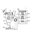
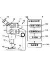
- FIG. 1 is a diagram showing the configuration of the microscope system 1.
- FIG. 2 is a diagram illustrating the configuration of the image processing device 100.
- FIG. 3 is a diagram illustrating the configuration of the optical system of the microscope 10.
- the microscope system 1 is a system for observing a sample by looking through the eyepiece lens 19.
- the sample to be observed by the microscope system 1 is, for example, the follicular fluid 50 contained in the container 40, and the microscope system 1 is used, for example, for egg inspection, which is one step of fertility treatment.
- the microscope system 1 includes at least a microscope 10, a photographing device 15, a projection device 17, which is an example of a superimposing device, and an image processing device 100.
- the microscope system 1 superimposes an auxiliary image on the optical image by projecting the auxiliary image on the image plane on which the optical image of the follicular fluid 50 is formed by the optical system of the microscope 10 using the projection device 17.
- the auxiliary image contains information that identifies the region where the presence of the egg is presumed (hereinafter referred to as the presumed region).
- the auxiliary image is created by the image processing device 100 based on the captured image of the follicular fluid captured by the imaging device 15.
- the user of the microscope system 1 observing the follicular fluid by looking through the eyepiece 19 can obtain information on the estimated region without taking his eyes off the eyepiece 19, so that the eggs can be compared in a short time. It becomes possible to find out easily. Therefore, according to the microscope system 1, it is possible to support the work of searching for an egg in the user's egg inspection.
- the microscope system 1 includes a microscope 10 including a photographing device 15 and a projection device 17, and an image processing device 100.
- the microscope 10 includes a stage 11 on which a container 40 containing a follicular fluid 50 is placed, an objective lens 12 mounted on a revolver 13, an imaging lens 18, and an eyepiece lens 19.
- the objective lens 12 and the imaging lens 18 form an optical image of the follicular fluid 50 on the image plane.
- the eyepiece 19 further magnifies the optical image formed on the image plane.
- the user of the microscope system 1 observes a virtual image in which the optical image is magnified by using the eyepiece lens 19.
- the microscope 10 also includes a splitter 14 arranged on the optical path between the objective lens 12 and the imaging lens 18, and a photographing device 15 arranged on the optical path branched by the splitter 14.
- the splitter 14 is, for example, a half mirror, but a variable beam splitter that varies the transmittance and the reflectance may be used.
- the photographing device 15 is, for example, a digital camera provided with an image pickup device, and acquires a photographed image of the follicular fluid 50.
- the image sensor is, for example, a two-dimensional image sensor such as a CCD image sensor or a CMOS image sensor.
- the microscope 10 further includes a splitter 16 arranged on the optical path between the objective lens 12 and the imaging lens 18, and a projection device 17 arranged on the optical path branched by the splitter 16.
- the splitter 16 is, for example, a half mirror, but a variable beam splitter that changes the transmittance and the reflectance may be used.
- the projection device 17 is, for example, a projector using a reflective liquid crystal device, a projector using a transmissive liquid crystal device, a projector using a digital mirror device, and the like.
- the projection device 17 projects an auxiliary image generated by the image processing device 100 on the image plane on the optical path of the microscope 10.
- the projection device 17 is an example of a superimposition device that superimposes an auxiliary image on an optical image of the follicular fluid 50 formed on the image plane by projecting the auxiliary image on the image plane.
- the image processing device 100 generates an auxiliary image based on the captured image acquired by the photographing device 15.
- the image processing device 100 includes an image analysis unit 110, an image generation unit 120, and a storage unit 130 as functional components related to the generation of an auxiliary image.
- the image analysis unit 110 performs image analysis including detection of an object targeting an egg on a captured image. Specifically, the image analysis unit 110 detects an object using, for example, a learned model stored in the storage unit 130.
- the algorithm of the trained model is not particularly limited, but may be, for example, a deep learning model such as SSD, YOLO, or FasterR-CNN.
- the image generation unit 120 generates an auxiliary image including information for specifying a region (estimated region) where the presence of an egg is estimated based on the result of image analysis of the image analysis unit 110. Specifically, the image generation unit 120 generates an image having a bounding box in the estimation region as an auxiliary image.
- the storage unit 130 stores a learned model that has learned the position of the egg with respect to the input image. That is, the trained model detects the target classified as an egg and outputs at least the position information of the egg. More specifically, the trained model outputs the position information of the egg and the probability of classification (classification confidence) indicating the certainty of the egg.
- the image processing device 100 may be a general-purpose computer or a dedicated computer.
- the image processing device 100 is not particularly limited to this configuration, but may have, for example, a physical configuration as shown in FIG.
- the image processing device 100 may include a processor 101, a storage device 102, an input device 103, an output device 104, and a communication device 105, which are connected to each other by a bus 106. May be good.
- the processor 101 may include hardware, which may include, for example, at least one of a circuit for processing digital signals and a circuit for processing analog signals.
- the processor 101 can include, for example, one or more circuit devices (eg, ICs) or one or more circuit elements (eg, resistors, capacitors) on a circuit board.
- the processor 101 may be a CPU (central processing unit). Further, various types of processors including GPU (Graphics processing unit) and DSP (Digital Signal Processor) may be used for the processor 101.
- the processor 101 may be a hardware circuit having an ASIC (Application Specific Integrated Circuit) or an FPGA (Field-Programmable Gate Array).
- the processor 101 can include an amplifier circuit, a filter circuit, and the like for processing an analog signal.
- the processor 101 functions as the image analysis unit 110 and the image generation unit 120 described above by executing the program stored in the storage device 102.
- the storage device 102 may include a memory and / or other storage device.
- the memory may be, for example, a random access memory (RAM).
- the memory may be a semiconductor memory such as SRAM (Static Random Access Memory) or DRAM (Dynamic Random Access Memory).
- the storage device 102 may include, for example, a register, a magnetic storage device such as a hard disk device, an optical storage device such as an optical disk device, an internal or external hard disk drive, a solid state storage device, a CD-ROM, a DVD, or other optical or magnetic. It may be a disk storage device or another storage device.
- the storage device 102 stores programs, trained models, and other data executed by the processor 101, and functions as the storage unit 130 described above.
- the storage device 102 is an example of a non-temporary computer-readable storage medium.
- the input device 103 is a device operated by a user of the microscope system 1 (for example, an embryo culture person).
- the input device 103 is, for example, a keyboard, a mouse, a touch panel, a voice input device, a foot pedal, or the like, and outputs an operation signal corresponding to an operation on the input device 103 to the processor 101.
- the output device 104 is, for example, a display device such as a liquid crystal display, a plasma display, an organic EL display, a CRT display, or an LED matrix panel.
- the output device 104 may further include an audio output device such as a speaker that outputs audio, a light emitting device such as a lamp or a light that outputs light, and a vibration device such as a vibrator that outputs vibration.
- the communication device 105 is a device that exchanges data with the microscope 10 and other devices.
- the communication device 105 may be a communication device that exchanges data by wire, or may be a communication device that exchanges data wirelessly.
- the program or learned model stored in the storage device 102 may be acquired by the communication device 105 from another device via the Internet.
- the egg inspection performed using the microscope 10 is a work performed by an embryo culture person while looking into the eyepiece lens 19 at a relatively low observation magnification. Therefore, it is desirable that the microscope 10 is a stereomicroscope capable of observing an object three-dimensionally at a low magnification. More specifically, for example, as shown in FIG. 3, the left eye system including the splitter 14a, the photographing device 15a, the splitter 16a, the projection device 17a, the imaging lens 18a, and the eyepiece 19a, the splitter 14b, and the photographing device 15b. It is desirable to have a binocular stereomicroscope having a splitter 16b, a projection device 17b, an imaging lens 18b, and a right eye system including an eyepiece 19b.
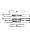
- FIG. 4 is a flowchart showing an example of the learning process according to the present embodiment.
- FIG. 5 is a diagram showing an example of a screen for creating a learning data set.
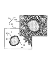
- FIG. 6 is a diagram illustrating an image included in the learning data set.
- the learning process shown in FIG. 4 may be performed by a computer different from the image processing device 100, and the image processing device 100 may acquire the completed trained model via a network or a recording medium. ..
- the window W1 shown in FIG. 5 is displayed.
- the window W1 shown in FIG. 5 is a screen for creating a learning data set, and the window W1 has an area R1 for selecting an image file of the follicular fluid and an image of the follicular fluid corresponding to the image file selected in the area R1.
- the area R2 for displaying the above is included.
- Step S1 When the worker building the trained model selects one image file from the plurality of image files listed in the area R1, the computer displays the still image of the follicular fluid corresponding to the selected image file in the area R2.
- the worker is, for example, an experienced embryo incubator. After that, the operator finds the egg from the still image displayed in the area R2, attaches a rectangular box B to the area containing the egg, and saves the file as shown in FIG.
- the computer creates a learning data set (step S2). Specifically, the computer cuts out the area surrounded by the rectangular box B from the image displayed in the area R2 and adds it to the learning data set. By repeating step S1 and step S2 on a plurality of still images, a sufficient amount of training data set is prepared.
- the cumulus cells may come off during egg collection when the egg is sucked from the follicle. Therefore, some of the eggs found at the time of egg inspection are surrounded by cumulus cells, while others have the cumulus cells peeled off and the corona radiata surrounding the egg is exposed. Therefore, it is desirable that the images included in the training data set include both an image of an egg surrounded by cumulus cells and an image of an egg detached from the cumulus cells.
- the data D1 included in the data set DS shown in FIG. 6 is an example of an image of an egg from which cumulus cells have been peeled off.
- a zona pellucida E2 and a corona radiata E3 surround the egg E1.
- data D2 is an example of an image of an egg surrounded by cumulus cells. It shows that the egg E1 (zona pellucida E2, corona radiata E3) is surrounded by cumulus cells E4.
- the computer trains the model that performs object detection on the egg using the training data set (step S3). That is, train, validate, and test the model.
- the data set created in step S2 may be divided into training data / verification data and test data. In that case, it is desirable that the training and validation data be used for both training and validation using cross-validation.
- the training data is data used for training the model
- the verification data is data used for verifying the model.
- the test data is data used for testing the model.
- the computer repeats the above processing until the model clears the test, and when it clears, that is, when learning is completed, the processing in FIG. 4 ends.
- the obtained trained model is stored in the storage unit 130 of the image processing device 100.
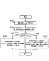
- FIG. 7 is a flowchart showing an example of the egg inspection support process according to the present embodiment.
- FIG. 8 is a flowchart showing an example of the auxiliary image generation process according to the present embodiment.
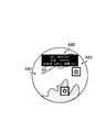
- FIG. 9 is an example of an image seen from the eyepiece lens 19.
- the egg inspection support method performed by the microscope system 1 will be described with reference to FIGS. 7 to 9.
- the egg inspection support process shown in FIG. 7 is started when the user of the microscope system 1 places a container 40 containing the follicular fluid 50 in the stage 11 and starts egg inspection.
- the microscope system 1 first projects an optical image onto the image plane (step S11).
- the optical system including the objective lens 12 and the imaging lens 18 is placed on the optical path of the microscope 10 based on the light from the follicular fluid 50, for example, the optical image O1 of the follicular fluid 50 as shown in FIG. To form.
- the microscope system 1 acquires a captured image at the same time as step S11 (step S12).
- the photographing device 15 acquires a photographed image of the follicular fluid based on the light from the follicular fluid 50, and outputs the photographed image to the image processing device 100.
- the microscope system 1 performs the auxiliary image generation process shown in FIG. 8 (step S13).
- the image processing device 100 first detects an egg from the captured image (step S21).
- the image analysis unit 110 detects an object targeting an egg by inputting a captured image as an input image into the trained model.
- the image processing device 100 After that, the image processing device 100 generates an image having a bounding box in the region where the egg is detected as an auxiliary image (step S22), and ends the auxiliary image generation process.
- the image generation unit 120 generates the auxiliary image A1 based on the object detection result by the image analysis unit 110. More specifically, the image generation unit 120 may determine only an object whose classification probability output from the image analysis unit 110 together with the position information of the object in object detection is equal to or greater than the threshold value, and classifies the object above the threshold value.
- Auxiliary image A1 having a bounding box in an area where an object having a probability of is present may be generated.
- the auxiliary image A1 shown in FIG. 9 shows a state in which a bounding box is formed in two regions where an egg is presumed to be present by object detection.
- the microscope system 1 When the auxiliary image generation process is completed, the microscope system 1 superimposes the auxiliary image on the optical image (step S14), and ends the process shown in FIG. 7.
- the projection device 17 projects the auxiliary image A1 generated in step S13 on the image plane on which the optical image O1 is formed, thereby superimposing the auxiliary image A1 on the optical image O1.
- the embryo culture person who is the user of the microscope system 1 searches for the egg while looking into the eyepiece lens 19 and looking at the image in which the optical image O1 and the auxiliary image A1 are superimposed as shown in FIG. be able to. Therefore, even an inexperienced embryo culture person can surely find an egg that is often overlooked, such as an egg isolated from the cumulus cells. Therefore, according to the microscope system 1, it is possible to support the search for an egg in egg inspection.
- FIG. 9 illustrates an auxiliary image A1 having a bounding box in an estimated region where an egg is estimated to be present by object detection, but the auxiliary image may include information for specifying the estimated region. Therefore, instead of the rectangular bounding box, the estimated area may be surrounded by an arbitrary shape such as a circle. Further, instead of surrounding the estimated region, the region where the egg exists may be specified by another method such as pointing to the estimated region with an arrow or the like.
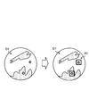
- FIG. 10 is another example of the image seen from the eyepiece lens 19.
- the auxiliary image A1 including only the information for specifying the estimation area is illustrated, but the information output from the image analysis unit 110 usually includes the probability of classification in addition to the position information of the target. Is. Therefore, the image generation unit 120 may generate an auxiliary image by using the probability of classification in addition to the position information of the target, and the auxiliary image is information that specifies an estimated region, for example, as shown in FIG. In addition to the (bounding box), information on the probability of being classified as an egg may be included.
- the egg in the first bounding box was classified as an egg with a 95% probability
- the egg in the second bounding box was classified as an egg with an 80% probability. It is shown that it was done.
- the embryo cultivator makes a final decision as to whether or not the egg is an egg based on his or her initial opinion and the probability of classification when searching for an egg. You can make a good decision.
- the egg inspection time will be shortened by prioritizing the confirmation from the one with the highest classification probability.
- FIG. 11 is a flowchart showing an example of the auxiliary image generation process according to the present embodiment.
- FIG. 12 is yet another example of the image seen from the eyepiece lens 19.
- the image analysis unit 110 detects an egg in another captured image acquired before the captured image. It differs from the microscope system 1 shown in FIG. 1 in that the object tracking for estimating the current position of the image is performed. That is, in the present embodiment, the image analysis unit 110 performs image analysis including object detection and object tracking.
- the egg inspection support process according to the present embodiment is the same as the egg inspection support process shown in FIG.
- step S12 the microscope system performs the auxiliary image generation process shown in FIG.
- the image processing device 100 first detects an egg from the captured image (step S31). This process is the same as in step S21 of FIG.
- the image processing device 100 estimates the current position of the previously detected egg (step 32).
- the image analysis unit 110 tracks an object targeting an egg. Specifically, the image analysis unit 110 estimates the current position of the egg based on a plurality of frames of captured images including the latest captured image. Further, the image analysis unit 110 may determine only the target whose classification probability output in the object detection is equal to or greater than the threshold value as an egg, or may set only the target determined to be an egg as the object tracking target.
- the specific method of object tracking is not particularly limited, but it is desirable to adopt a robust method for occlusion in which the tracking target is hidden behind other objects.
- the current position of the egg may be estimated using a Kalman filter, a particle filter, or the like.
- the optical flow of the container may be calculated, and the current position of the egg may be estimated from the calculated optical flow.
- the image processing apparatus 100 After that, the image processing apparatus 100 generates an image having a bounding box in the region where the egg is detected and a second bounding box in the region including the estimated current position as an auxiliary image (step S33).
- the auxiliary image generation process is terminated.
- the image generation unit 120 generates an auxiliary image based on the object detection result and the object tracking result by the image analysis unit 110. Specifically, as shown in FIG.
- the image generation unit 120 has an auxiliary image having only a rectangular bounding box while all the eggs in the visual field are detected by object detection (auxiliary image A11, Auxiliary image A12) is generated, and if some eggs are hidden behind other cells, even if an auxiliary image (auxiliary image A13) having a rectangular bounding box and a fan-shaped bounding box is generated. good.
- the rectangular bounding box indicates the estimated region estimated by the object detection
- the fan-shaped bounding box indicates the region including the current position of the egg estimated by the object tracking.
- the microscope system When the auxiliary image generation process is completed, the microscope system superimposes the auxiliary image on the optical image (step S14), and ends the process shown in FIG. 7.
- the auxiliary image projected on the image plane is the auxiliary image. It shows how the image has changed as A11, the auxiliary image A12, and the auxiliary image A13.
- the microscope system according to the present embodiment can also support the search for an egg in egg inspection, as in the case of the microscope system 1.
- the embryo cultivator may move the container to move the field of view to another place, shake the container to move the egg hidden behind other cells, and so on. While such work may allow the egg to move in the container and detect a new egg by object detection, the previously detected egg is hidden behind other cells and disappears. It may end up.
- the microscope system according to the present embodiment since the object tracking is performed on the egg, the existence of the hidden egg can also be notified to the user. Therefore, according to the microscope system according to the present embodiment, it is possible to more strongly support the search for an egg in egg inspection.
- FIG. 13 is a flowchart showing an example of the auxiliary image generation process according to the present embodiment.
- FIG. 14 is yet another example of the image seen from the eyepiece lens 19.
- the microscope system according to the present embodiment (hereinafter, simply referred to as a microscope system) is similar to the microscope system according to the second actual embodiment in that the image analysis unit 110 performs object tracking in addition to object detection. ..
- the microscope system differs from the microscope system according to the second embodiment in that it notifies the user of the presence of eggs that have moved out of the field of view in addition to the presence of eggs in the field of view. More specifically, the microscope system performs egg inspection support processing including the auxiliary image generation processing shown in FIG. 13 instead of the auxiliary image generation processing shown in FIG.
- the egg inspection support method performed by the microscope system according to the present embodiment will be described with reference to FIGS. 13 and 14, focusing on the auxiliary image generation process.
- the microscope system performs the auxiliary image generation process shown in FIG.
- the image processing apparatus 100 first detects an egg from the captured image (step S41) and estimates the current position of the previously detected egg (step 42).
- the image processing apparatus 100 has a bounding box in the region where the egg is detected, has a second bounding box in the region including the estimated current position in the field of view, and has an estimated current position outside the field of view.
- An image having information indicating the direction of is generated as an auxiliary image (step S43), and the auxiliary image generation process is completed.
- the image generation unit 120 generates an auxiliary image based on the object detection result and the object tracking result by the image analysis unit 110. Specifically, as shown in FIG. 14, the image generation unit 120 has an auxiliary image (auxiliary image A21, auxiliary image A22) having only a rectangular bounding box while all the eggs are detected by object detection.
- auxiliary image A23 having a rectangular bounding box and a fan-shaped bounding box is generated, and some eggs are generated.
- an auxiliary image (auxiliary image A24) having a rectangular bounding box and an arrow mark is generated. Note that.
- the arrow mark is an example of information indicating the direction of the current position outside the field of view estimated by object tracking, and is an example of information indicating the direction in which the egg outside the field of view exists.
- FIG. 14 shows an auxiliary projected on the image plane when the optical image formed on the image plane by moving the container changes like the optical image O21, the optical image O22, the optical image O23, and the optical image O24. It shows how the image has changed like the auxiliary image A21, the auxiliary image A22, the auxiliary image A23, and the auxiliary image A24.
- the embryo cultivator can surely find the egg that is often overlooked. Further, according to the microscope system according to the present embodiment, since the object tracking is performed on the egg, it is possible to notify the user of the existence of the hidden egg or the existence of the egg that has moved out of the field of view. Therefore, according to the microscope system according to the present embodiment, it is possible to more strongly support the search for an egg in egg inspection.
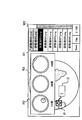
- FIG. 15 is a diagram showing another example of the screen for creating the learning data set.
- FIG. 16 is a diagram showing still another example of the screen for creating the learning data set.
- FIG. 17 is a flowchart showing an example of the auxiliary image generation process according to the present embodiment.
- FIG. 18 is yet another example of the image seen through the eyepiece 19.
- the image analysis unit 110 detects eggs by dividing them into a plurality of classes having different recommendations as collection targets in egg inspection by object detection. This is different from the microscope system 1 shown in FIG.
- the egg inspection support process according to the present embodiment is the same as the egg inspection support process shown in FIG. 7, except that the auxiliary image generation process shown in FIG. 8 is included instead of the auxiliary image generation process shown in FIG. be.
- the operator finds an egg from the still image displayed in the area R2 on the window W2 shown in FIG. 15, attaches a rectangular box B to the area containing the egg, and then further examines the egg. Judge the recommendation level as a collection target in the above and enter the recommendation level information in the input field C. Then, when the save operation of the worker is detected, the computer cuts out the area surrounded by the rectangular box B from the image displayed in the area R2 and learns it as an image of the class according to the input recommendation degree information. Add to the dataset for.
- the recommendation level information input by the worker may be egg maturity information, for example, "GV” indicating a degenerated egg which is a GV stage egg and "GV” indicating an immature egg which is an MI stage egg. MI ",” MII "indicating a mature egg which is a MII stage egg may be included. Further, the operator may input the recommendation degree information by distinguishing, for example, overripe eggs, moderately mature eggs, abnormal eggs and the like.
- the storage device 102 stores a trained model that has learned at least the position of the egg and the plurality of classes of the egg with respect to the input image.
- a sample image of the egg having a different maturity is displayed on the learning data set creation screen (window W2).
- the region R3 including the above may be displayed.
- step S12 the microscope system performs the auxiliary image generation process shown in FIG.
- the image processing device 100 first detects an egg from the captured image (step S51). This process is the same as the process of step S21 of FIG.
- the image processing device 100 After that, the image processing device 100 generates an image having a bounding box with an egg class in the estimation area as an auxiliary image (step S52), and ends the auxiliary image generation process.
- the image generation unit 120 generates an auxiliary image based on the object detection result by the image analysis unit 110. Specifically, the image generation unit 120 generates an auxiliary image A31 having information (GV, MI, MII) for identifying an egg class near a rectangular bounding box, for example, as shown in FIG.
- the microscope system When the auxiliary image generation process is completed, the microscope system superimposes the auxiliary image on the optical image (step S14), and ends the process shown in FIG. 7.
- the projection device 17 superimposes the auxiliary image A31 on the optical image O31, for example, as shown in FIG.
- the user can be notified of the recommendation level of the egg existing in the estimated region as well as the estimated region. Therefore, for example, when it is not necessary to collect all the eggs, it is possible to easily select the eggs to be collected.
- an example of notifying the user of the recommendation level by displaying character information that identifies the egg class is shown.
- a bounding box is created with a color corresponding to the egg class. You may notify the user of the recommendation level with.
- the recommendation level may be notified to the user by creating a bounding box having a shape corresponding to the egg class.
- FIG. 19 is a flowchart showing an example of the auxiliary image generation process according to the present embodiment.
- FIG. 20 is yet another example of the image seen through the eyepiece 19.
- the microscope system according to the fourth embodiment is different from the microscope system according to the fourth embodiment in that the image analysis unit 110 calculates the size of the egg detected by the object detection in the microscope system (hereinafter, simply referred to as a microscope system) according to the present embodiment. Is different. Further, the microscope system performs egg inspection support processing including the auxiliary image generation processing shown in FIG. 19 instead of the auxiliary image generation processing shown in FIG.
- the egg inspection support method performed by the microscope system according to the present embodiment will be described with reference to FIGS. 19 and 20, paying attention to the auxiliary image generation process.
- step S12 the microscope system performs the auxiliary image generation process shown in FIG.
- the image processing device 100 first detects an egg from the captured image (step S61). This process is the same as the process of step S21 of FIG.
- the image processing device 100 calculates the size of the egg (step S62).
- the image analysis unit 110 may calculate the size of the egg from the area of the recommended region detected by the object detection, for example.
- the size of the egg may be calculated from the size of the bounding box surrounding the recommended area. The size may be calculated in units of length such as diameter, or in units of area.
- the image processing device 100 After that, the image processing device 100 generates an image having a bounding box with an egg class and size in the estimated region as an auxiliary image (step S63), and ends the auxiliary image generation process.
- the image generation unit 120 has information for specifying the egg class (GV, MI, MII) and information for specifying the egg size (90 ⁇ m) near the rectangular bounding box. , 100 ⁇ m, 120 ⁇ m) to generate an auxiliary image A41.
- the microscope system When the auxiliary image generation process is completed, the microscope system superimposes the auxiliary image on the optical image (step S14), and ends the process shown in FIG. 7.
- the projection device 17 superimposes the auxiliary image A41 on the optical image O41, for example, as shown in FIG.
- the microscope system it is possible to notify the user of the recommended degree and size of the egg existing in the estimated region as well as the estimated region. Therefore, for example, when it is not necessary to collect all the eggs, it is possible to easily select the eggs to be collected.
- the microscope system may further perform object tracking.
- the display mode may be different between the egg detected by the object detection and the egg whose current position is estimated by the object tracking.
- the recommendation level information (class) and size may be displayed for the egg detected by the object detection, and the recommendation level for the egg whose current position is estimated by the object tracking. Only information (class) may be displayed.
- FIG. 21 shows a state in which the auxiliary image A51 is superimposed on the optical image O51. Further, in the auxiliary image A51, an egg detected by object detection is assigned a class and a size, and an egg whose existence is presumed by object tracking is assigned only a class.
- FIG. 22 is a diagram showing the configuration of the microscope system 2.
- FIG. 23 is a flowchart showing an example of the egg inspection support process according to the present embodiment.
- the microscope system 2 is different from the microscope system 1 in that it includes a notification device 200 for notifying the detection of an egg in object detection.
- the notification device 200 is, for example, an audio output device such as a speaker that outputs audio, a light emitting device such as a lamp or a light that outputs light, or a vibration device such as a vibrator that outputs vibration.
- the microscope system 2 performs the egg inspection support process shown in FIG. 23 instead of the egg inspection support process shown in FIG. 7.
- the egg inspection support method performed by the microscope system 2 will be described with reference to FIGS. 22 and 23.
- steps S71 to S74 shown in FIG. 23 is the same as the processing of steps S11 to S14 shown in FIG.
- the image processing apparatus 100 determines whether or not an egg is detected in the object detection in step S73 (step S75), and if it is determined that the egg is detected (step S75YES). ),
- the notification device 200 notifies the detection of the egg in the object detection (step S76).
- the notification method is not particularly limited, but the notification device 200 may, for example, emit a warning sound or the like to call attention, or may emit light to call attention. In addition, the detection of the egg may be notified by voice.
- the output device 104 of the image processing device 100 may also serve as the notification device 200.
- the microscope system 2 according to the present embodiment can also support the search for an egg in egg inspection, similarly to the microscope system 1 according to the first embodiment. Further, in addition to visually notifying the user of the existence of the egg by projecting an auxiliary image, the notification device 200 notifies the user of the existence of the egg more reliably. Can be done.
- FIG. 24 is a diagram showing the configuration of the microscope system 3.
- FIG. 25 is a flowchart showing an example of the egg inspection support process according to the present embodiment.
- FIG. 26 is yet another example of the image seen through the eyepiece 19.
- the microscope system 3 differs from the microscope system 1 in that the microscope 20 is provided instead of the microscope 10. Further, the microscope 20 is different from the microscope 10 in that the imaging device 21 is provided.
- the photographing device 21 is a device for acquiring and recording a moving image of a photographed image (second photographed image) of the space above the stage 11 including the container 40, and is a second photographing device.
- the imaging device 21 is installed mainly for the purpose of photographing the work of the embryo incubator on the stage 11.
- the microscope system 3 performs the egg inspection support process shown in FIG. 25 instead of the egg inspection support process shown in FIG. 7.
- the egg inspection support method performed by the microscope system 3 according to the present embodiment will be described with reference to FIGS. 24 to 26.
- steps S81, S82, and S84 shown in FIG. 25 is the same as the processing of steps S11 to S13 shown in FIG.
- step S83 the microscope system 3 acquires a second captured image of the space above the stage 11 with the photographing device 21. Here, a moving image is taken instead of a still image.
- the image processing apparatus 100 determines whether or not an egg is detected in the object detection in step S84 (step S85), and determines that no egg is detected. (Step S85NO), the projection device 17 is controlled, and the projection device 17 superimposes an auxiliary image on the optical image (step S86).
- the process of step S86 is the same as the process of step S14 shown in FIG.
- the image processing device 100 controls the projection device 17, and the projection device 17 superimposes the auxiliary image and the moving image of the second captured image on the optical image.
- Step S87 That is, under the control of the image processing device 100, the photographing device 21 records a moving image of the second captured image including the frame at the time when the egg is detected by the object detection, and the projection device 17 records the moving image as shown in FIG.
- the recorded moving image A62 is superimposed on the optical image O62 together with the auxiliary image A61.
- the work of the embryo cultivator immediately before the egg detection was recorded when the optical image formed on the image plane changed from the optical image O61 in which the egg was not detected to the optical image O62 in which the egg was detected. It shows how the moving image A62 is displayed together with the auxiliary image A61.
- the microscope system 3 according to the present embodiment can also support the search for an egg in egg inspection, similarly to the microscope system 1 according to the first embodiment. Further, in the microscope system 3, details of the work performed by the embryo cultivator to detect the egg, for example, information such as how to tilt and move the container are provided to the embryo cultivator using a moving image. Therefore, according to the microscope system 3, it is possible to provide an embryo cultivator with an opportunity to learn a desirable work procedure for discovering an egg.
- FIG. 27 is a flowchart showing an example of the auxiliary image generation process according to the present embodiment.
- FIG. 28 is yet another example of the image seen through the eyepiece 19.
- the image analysis unit 110 performs a process of recognizing that an egg has been collected from the follicular fluid 50 in addition to object detection and object tracking. The point is different from the microscope system according to the third actual form. Further, the microscope system performs egg inspection support processing including the auxiliary image generation processing shown in FIG. 27 instead of the auxiliary image generation processing shown in FIG.
- the egg inspection support method performed by the microscope system according to the present embodiment will be described with reference to FIGS. 27 and 28, focusing on the auxiliary image generation process.
- step S91 shown in FIG. 27 is the same as the process of step S41 shown in FIG.
- the image processing device 100 detects the collection of eggs (step S92). Specifically, the image analysis unit 110 performs a process of recognizing that an egg has been collected from the follicular fluid 50 based on a moving image of a captured image captured by the imaging device 15. Further, the image processing apparatus 100 estimates the current position of the previously detected egg (step S93).
- the process of step S93 is the same as the process of step S42 shown in FIG. 13, except that the egg collected in step S92 is excluded from the tracking target.
- the image processing apparatus 100 has a bounding box in the region where the egg is detected, has a second bounding box in the region including the estimated current position in the visual field, and has an estimated direction of the current position outside the visual field.
- An image having an arrow mark pointing to and containing information indicating the egg inspection status is generated as an auxiliary image (step S94), and the auxiliary image generation process is completed. It is desirable that the information indicating the egg inspection status included in the auxiliary image includes, for example, the number of detected eggs and the number of collected eggs, as shown in FIG. 28.
- FIG. 28 shows the state before and after collecting the egg with a pipette.
- the optical image O71 before egg collection is superposed with the auxiliary image A71 showing the number of detected eggs 4 and the number of collected eggs 0, whereas the optical image O72 after egg collection has 3 detected eggs.
- An auxiliary image A72 showing the number of collected eggs 1 is superimposed.
- FIG. 29 is a diagram showing the configuration of the microscope system 4.
- FIG. 30 is a flowchart showing an example of the egg inspection support process according to the present embodiment.
- FIG. 31 is yet another example of the image seen from the eyepiece lens 19.
- the microscope system 4 is different from the microscope system 1 in that the identification device 300 is provided. Further, the identification device 300 is, for example, a QR code (registered trademark) reader or the like, and is a device for acquiring identification information added to the container 40.
- the microscope system 4 performs the egg inspection support process shown in FIG. 30 instead of the egg inspection support process shown in FIG. 7.
- the egg inspection support method performed by the microscope system 4 according to the present embodiment will be described with reference to FIGS. 29 to 31.
- the microscope system 4 first acquires identification information (step S101).
- the embryo cultivator brings the identification label (QR code) attached to the container 40 closer to the identification device 300 before arranging the container 40 on the stage 11.
- the identification device 300 reads the identification label and acquires the identification information.
- the identification information includes information on the provider of the follicular fluid 50 in the container 40, or link information indicating a place where the information on the donor is stored.
- the acquired identification information is output from the identification device 300 to the image processing device 100.
- the microscope system 4 performs the processes from step S102 to step S104.
- the processing of steps S102 to S104 is the same as the processing of steps S11 to S13 shown in FIG.
- the microscope system 4 generates a second auxiliary image (step S105).
- the image generation unit 120 generates a second auxiliary image A82 including information on the donor of the follicular fluid 50, as shown in FIG. 31, for example, based on the identification information acquired in step S101.
- the second auxiliary image A82 is different from the auxiliary image generated based on the captured image in that it is generated based on the identification information.
- the second auxiliary image A82 includes information such as the ID and name of the provider of the follicular fluid 50, the position of the follicle (ovary) from which the follicular fluid 50 was collected, the order of collecting the follicular fluid 50, and the amount of collection. There is.
- FIG. 31 shows a state in which the optical image O81, the auxiliary image A81, and the second auxiliary image A82 are superimposed.
- FIG. 32 is a diagram showing the configuration of the microscope system 5.
- FIG. 33 is a flowchart showing an example of the egg inspection support process according to the present embodiment.
- FIG. 34 is yet another example of the image seen from the eyepiece lens 19.
- the microscope system 5 is different from the microscope system 1 in that it includes a detection device 400.
- the detection device 400 is, for example, a sensor that detects that the container 40 is placed on the stage 11, and is a device that detects the start of egg inspection.
- the microscope system 5 performs the egg inspection support process shown in FIG. 33 instead of the egg inspection support process shown in FIG. 7.
- the egg inspection support method performed by the microscope system 5 according to the present embodiment will be described with reference to FIGS. 32 to 34.
- the microscope system 5 starts the measurement with the timer (step S111).
- the timer may be included in the processor 101, for example, and measures the elapsed time after detecting a predetermined event. In this example, the timer measures the elapsed time after detecting the detection signal from the detection device 400.
- step S112 performs the processes from step S112 to step S114.
- the processing of steps S112 and S113 is the same as the processing of steps S11 and S12 shown in FIG.
- step S114 is the same as the auxiliary image generation process shown in FIG. 27.
- the microscope system 5 generates a third auxiliary image (step S115).
- the image generation unit 120 generates, for example, a third auxiliary image A92 including the elapsed time measured by the timer, as shown in FIG. 34.
- the third auxiliary image A92 is different from the auxiliary image generated based on the captured image in that it is generated based on the measurement result of the timer.
- the microscope system 5 (projection device 17) superimposes the auxiliary image and the third auxiliary image on the optical image (step S116), and ends the process shown in FIG. 33.
- FIG. 34 shows a state in which the optical image O91, the auxiliary image A91, and the third auxiliary image A92 are superimposed.
- the user can perform the egg inspection work while constantly checking the elapsed time from the start of the egg inspection.
- the start of egg inspection may be detected based on, for example, an operation signal from the input device 103. .. That is, the input device 103 may function as the detection device 400.
- FIG. 35 is a diagram showing the configuration of the microscope system 6.
- FIG. 36 is a flowchart showing an example of the auxiliary image generation process according to the present embodiment.
- Each of FIGS. 37 to 39 is yet another example of the image seen through the eyepiece 19.
- the microscope system 6 includes a notification device 200 (first notification device) for notifying the detection of eggs and a second notification device 500 for notifying the recommended operation, and the image analysis unit 110 adds to the object detection. It differs from the microscope system 2 in that the process of estimating the recommended operation is performed.
- the second notification device 500 is, for example, an audio output device such as a speaker that outputs audio.
- the microscope system 6 is different from the microscope system 2 in that the auxiliary image generation process shown in FIG. 36 is performed in the egg inspection support process shown in FIG. 23.
- the egg inspection support method performed by the microscope system 6 will be described with reference to FIGS. 35 to 39.
- the microscope system 6 performs the auxiliary image generation process shown in FIG. 36.
- the image processing device 100 first detects an egg from the captured image (step S121). This process is the same as the process of step S21 of FIG.
- the image processing device 100 estimates the recommended operation from the captured image (step S122).
- the image analysis unit 110 estimates a recommended operation to be performed during egg inspection based on the captured image. This process may be implemented, for example, by a trained model. For example, in a situation where the optical image O101 as shown in FIG. 37 can be obtained, it is difficult to find an egg because there are many bubbles. Therefore, the image analysis unit 110 may estimate the operation of shaking the container 40 as a recommended operation. Further, for example, in a situation where the optical image O111 as shown in FIG. 38 can be obtained, the contrast of the image is low and it is difficult to find the egg. Therefore, the image analysis unit 110 may estimate the operation of operating the focusing unit to adjust the focus as a recommended operation.
- the image analysis unit 110 recommends stopping the egg inspection with the current follicular fluid 50. You may estimate.
- step S123 the image processing device 100 determines whether or not the recommended operation is estimated in step S122 (step S123). If the recommended operation was not estimated, that is, if there was no recommended operation (step S123NO), the image processing apparatus 100 generated an image having a bounding box in the region where the egg was detected as an auxiliary image (step S124). , Ends the auxiliary image generation process.
- step S124 is the same as the process of step S22 of FIG.
- the image processing apparatus 100 When the recommended operation is estimated, that is, when there is a recommended operation (step S123YES), the image processing apparatus 100 has a bounding box in the region where the egg is detected, and the image contains information representing the recommended operation. Is generated as an auxiliary image (step S125), and the auxiliary image generation process is completed.
- the image generation unit 120 if the operation of shaking the container 40 is estimated as a recommended operation, the image generation unit 120 generates, for example, the auxiliary image A101 shown in FIG. 37. Further, if the operation of adjusting the focus is estimated as a recommended operation, the image generation unit 120 generates, for example, the auxiliary image A111 shown in FIG. 38. Further, if the operation of stopping the egg inspection is estimated as a recommended operation, the image generation unit 120 generates, for example, the auxiliary image A122 shown in FIG. 39.
- the microscope system 6 (projection device 17) superimposes an auxiliary image on the optical image.
- the microscope system 6 notifies the detection of the egg by using the notification device 200 when the egg is detected, and notifies the recommended operation by using the second notification device 500 when the recommended operation is estimated. do. As a result, the user can more reliably recognize the recommended operation.
- FIG. 40 is a diagram showing the configuration of the microscope system 7.
- the projection device 17 arranged on the optical path branched from the optical path between the objective lens 12 and the eyepiece lens 19 is illustrated, but the device for superimposing the auxiliary image is an objective as shown in FIG. 40. It may be arranged on the optical path between the lens 12 and the eyepiece 19.
- the microscope system 7 includes a microscope 30 including a display device 31 on an image plane on which an optical image is formed, and an image processing device 100.
- the display device 31 is a transmissive image display device, and is an example of a superimposition device that superimposes an auxiliary image on an optical image by displaying the auxiliary image directly on the image plane. Similar to the microscope system 1, the microscope system 7 can also support the user's search for eggs in egg inspection.
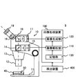
- FIG. 41 is a diagram showing the configuration of the microscope system 8.
- the photographing device 15 and the projection device 17 are provided in the microscope 10, and the image processing device 100 independent of the microscope 10 exchanges data between the photographing device 15 and the projection device 17, thereby forming an auxiliary image as an optical image.
- the photographing device, the projection device, and the image processing device may be integrally configured as shown in FIG. 41.
- the projection unit 600 mounted between the microscope main body 70 and the lens barrel 80 of the microscope 60 includes an imaging device 15, a projection device 17, and an image processing device (image analysis unit 110, image generation unit 120, A storage unit 130) may be provided.
- an image processing device image analysis unit 110, image generation unit 120, A storage unit 130
- Microscope system 10, 20, 30, 60 ... Microscope, 11 ... Stage, 12 ... Objective lens, 15, 15a, 15b, 21 ... Imaging device, 17, 17a , 17b ... Projection device, 18, 18a, 18b ... Imaging lens, 19 ... Eyepiece, 31 ... Display device, 40 ... Container, 50 ... Follicle fluid, 70 ... Microscope body, 80 ... lens barrel, 100 ... image processing device, 101 ... processor, 102 ... storage device, 110 ... image analysis unit, 120 ... image generation unit, 130. .. Storage unit, 200 ... Notification device, 300 ... Identification device, 400 ... Detection device, 500 ... Second notification device, 600 ... Projection unit
Landscapes
- Physics & Mathematics (AREA)
- Chemical & Material Sciences (AREA)
- Analytical Chemistry (AREA)
- General Physics & Mathematics (AREA)
- Optics & Photonics (AREA)
- Engineering & Computer Science (AREA)
- Multimedia (AREA)
- Computer Vision & Pattern Recognition (AREA)
- Microscoopes, Condenser (AREA)
Abstract
A microscope system 1 is provided with: a microscope 10; an imaging device 15 that acquires a captured image of a follicular fluid 50 housed in a container 40 placed on a stage 11; an image processing device 100 that, on the basis of the captured image acquired by the imaging device 15, generates an auxiliary image including information specifying a region in which the presence of an egg is estimated; and a projection device 17 that is a superimposition device for superimposing the auxiliary image generated by the image processing device 100 on an optical image of the follicular fluid 50 formed on an image plane on the optical path of the microscope 10.
Description
本明細書の開示は、顕微鏡システム、投影ユニット、及び、検卵支援方法に関する。
The disclosure of this specification relates to a microscope system, a projection unit, and an egg inspection support method.
晩婚化・晩産化が進む現在、不妊治療を受ける患者の数は年々増加しており、生殖補助医療(ART:Assisted Reproductive Technology)の需要もますます高まっている。
With the progress of late marriage and late childbirth, the number of patients receiving infertility treatment is increasing year by year, and the demand for assisted reproductive technology (ART) is also increasing.
ARTは、体外受精(IVF:In vitro fertilization)や、卵細胞質内精子注入法(ICSI:Intracytoplasmic sperm injection)に代表される顕微授精など、ヒトから取り出した卵子と精子を体外で受精させる技術の総称であり、採取した精子を子宮に注入し体内で卵子と受精させる一般的な人工授精とは区別される。
ART is a general term for techniques for in vitro fertilization of eggs and sperms taken out from humans, such as in vitro fertilization (IVF: In vitro fertilization) and microfertilization represented by intraesophageal sperm injection (ICSI). It is distinguished from general artificial fertilization in which the collected sperm is injected into the uterus and fertilized with an egg in the body.
ARTに関連する技術は、例えば、特許文献1に記載されている。特許文献1には、ARTの一種である顕微授精に好適な顕微鏡が記載されている。
The technology related to ART is described in, for example, Patent Document 1. Patent Document 1 describes a microscope suitable for microinsemination, which is a kind of ART.
ところで、卵子と精子を体外で受精させるARTでは、予め母体から卵子を取り出す必要がある。このため、医師が卵巣内の卵胞から卵胞液を採取し(これを採卵という。)、胚培養士が採取された卵胞液から卵子を見つけ出して回収する(これを検卵という)、といった作業が行われる。
By the way, in ART where an egg and a sperm are fertilized outside the body, it is necessary to take out the egg from the mother in advance. For this reason, the doctor collects follicular fluid from the follicles in the ovary (this is called egg collection), and the embryo cultivator finds and collects the eggs from the collected follicular fluid (this is called egg inspection). Will be done.
採卵のためには、患者は医療機関へ通院しなければならない。さらに、医療機関では、膣から卵巣に採卵針が穿刺され、それによって卵巣から卵胞液が採取される。このように、採卵は、患者に肉体的にも精神的にも大きな負担を強いることになる。また、一回当たりの採卵で採取可能な卵子数も限られている。このため、不妊治療患者にとって卵子は貴重であり、医療機関には、採卵において採取された卵胞液から卵子を見逃すことなく回収することが求められる。
Patients must go to a medical institution for egg collection. In addition, medical institutions puncture the ovaries with egg-collecting needles from the vagina, thereby collecting follicular fluid from the ovaries. In this way, egg collection imposes a heavy physical and mental burden on the patient. In addition, the number of eggs that can be collected at one time is limited. For this reason, eggs are valuable to infertility treatment patients, and medical institutions are required to collect eggs from the follicular fluid collected during egg collection without missing them.
その一方で、採卵において採取された卵胞液中の卵子を見逃すことなく見つけ出して回収することは容易ではない。これは、卵胞から採取された卵胞液には卵子以外にも様々な細胞が含まれているためである。このため、卵子を正しく認識して回収することは熟練者であっても必ずしも容易ではなく、経験の浅い胚培養士にとっては困難な作業である。
On the other hand, it is not easy to find and collect the eggs in the follicular fluid collected during egg collection without missing them. This is because the follicular fluid collected from the follicle contains various cells other than the egg. Therefore, it is not always easy for an expert to correctly recognize and collect an egg, and it is a difficult task for an inexperienced embryo cultivator.
また、検卵には実体顕微鏡が用いられるため、卵子を含む卵胞液は、検卵中インキュベータから取り出されて室内の雰囲気下で暴露される。卵子が暴露される期間は短ければ短いほどよいため、胚培養士には、検卵を可能な限り素早く、且つ、確実に行うことが求められる。
In addition, since a stereomicroscope is used for egg inspection, the follicular fluid containing eggs is taken out of the incubator during egg inspection and exposed in an indoor atmosphere. The shorter the period of exposure of the egg, the better, so the embryo cultivator is required to perform the egg inspection as quickly and reliably as possible.
以上のような実情を踏まえ、本発明の一側面に係る目的は、検卵における卵子の探索を支援する技術を提供することである。
Based on the above circumstances, an object of one aspect of the present invention is to provide a technique for supporting the search for an egg in egg inspection.
本発明の一態様に係る顕微鏡システムは、顕微鏡と、前記顕微鏡のステージに置かれた容器内に収容された卵胞液の撮影画像を取得する撮影装置と、前記撮影装置で取得した前記撮影画像に基づいて、卵子の存在が推定される領域を特定する情報を含む補助画像を生成する画像処理装置と、前記顕微鏡の光路上の像面に形成される前記卵胞液の光学画像上に、前記画像処理装置で生成された前記補助画像を重畳する重畳装置と、を備える。
The microscope system according to one aspect of the present invention includes a microscope, a photographing device that acquires a photographed image of follicle fluid contained in a container placed on the stage of the microscope, and the photographed image acquired by the photographing device. Based on this image, on an image processing device that generates an auxiliary image containing information that identifies a region where the presence of an egg is presumed, and on an optical image of the follicular fluid formed on the image plane on the optical path of the microscope. A superimposing device for superimposing the auxiliary image generated by the processing device is provided.
本発明の一態様に係る投影ユニットは、顕微鏡に装着して使用される投影ユニットであって、前記顕微鏡のステージに置かれた容器内に収容された卵胞液の撮影画像に基づいて、卵子の存在が推定される領域を特定する情報を含む補助画像を生成する画像処理装置と、前記顕微鏡の光路上の像面に形成される前記卵胞液の光学画像上に、前記画像処理装置で生成された前記補助画像を重畳する重畳装置と、を備える。
The projection unit according to one aspect of the present invention is a projection unit used by being mounted on a microscope, and is based on a photographed image of follicular fluid contained in a container placed on the stage of the microscope. An image processing device that generates an auxiliary image containing information that identifies a region where the presence is presumed, and an optical image of the follicular fluid formed on the image plane on the optical path of the microscope, which is generated by the image processing device. A superimposing device for superimposing the auxiliary image is provided.
本発明の一態様に係る検卵支援方法は、顕微鏡のステージに置かれた容器内に収容された卵胞液の撮影画像を取得し、前記撮影装置で取得した前記撮影画像に基づいて、卵子の存在が推定される領域を特定する情報を含む補助画像を生成し、前記顕微鏡の光路上の像面に形成される前記卵胞液の光学画像上に、生成された前記補助画像を重畳することを含む。
The egg inspection support method according to one aspect of the present invention acquires a photographed image of follicular fluid contained in a container placed on a stage of a microscope, and based on the photographed image acquired by the photographing apparatus, of an egg. To generate an auxiliary image containing information that identifies a region where the presence is presumed, and to superimpose the generated auxiliary image on an optical image of the follicular fluid formed on an image plane on the optical path of the microscope. include.
上記の態様によれば、検卵における卵子の探索を支援することができる。
According to the above aspect, it is possible to support the search for an egg in egg inspection.
[第1の実施形態]
図1は、顕微鏡システム1の構成を示した図である。図2は、画像処理装置100の構成を例示した図である。図3は、顕微鏡10の光学系の構成を例示した図である。顕微鏡システム1は、接眼レンズ19を覗いて試料を観察するためのシステムである。顕微鏡システム1が観察対象とする試料は、例えば、容器40に収容された卵胞液50であり、顕微鏡システム1は、例えば、不妊治療の一工程である検卵に用いられる。 [First Embodiment]
FIG. 1 is a diagram showing the configuration of themicroscope system 1. FIG. 2 is a diagram illustrating the configuration of the image processing device 100. FIG. 3 is a diagram illustrating the configuration of the optical system of the microscope 10. The microscope system 1 is a system for observing a sample by looking through the eyepiece lens 19. The sample to be observed by the microscope system 1 is, for example, the follicular fluid 50 contained in the container 40, and the microscope system 1 is used, for example, for egg inspection, which is one step of fertility treatment.
図1は、顕微鏡システム1の構成を示した図である。図2は、画像処理装置100の構成を例示した図である。図3は、顕微鏡10の光学系の構成を例示した図である。顕微鏡システム1は、接眼レンズ19を覗いて試料を観察するためのシステムである。顕微鏡システム1が観察対象とする試料は、例えば、容器40に収容された卵胞液50であり、顕微鏡システム1は、例えば、不妊治療の一工程である検卵に用いられる。 [First Embodiment]
FIG. 1 is a diagram showing the configuration of the
顕微鏡システム1は、少なくとも、顕微鏡10と、撮影装置15と、重畳装置の一例である投影装置17と、画像処理装置100と、を備えている。顕微鏡システム1は、顕微鏡10の光学系によって卵胞液50の光学画像が形成されている像面に、投影装置17を用いて補助画像を投影することによって、光学画像上に補助画像を重畳する。補助画像には、卵子の存在が推定される領域(以降、推定領域と記す。)を特定する情報が含まれている。なお、補助画像は、撮影装置15が撮影した卵胞液の撮影画像に基づいて画像処理装置100によって作成される。
The microscope system 1 includes at least a microscope 10, a photographing device 15, a projection device 17, which is an example of a superimposing device, and an image processing device 100. The microscope system 1 superimposes an auxiliary image on the optical image by projecting the auxiliary image on the image plane on which the optical image of the follicular fluid 50 is formed by the optical system of the microscope 10 using the projection device 17. The auxiliary image contains information that identifies the region where the presence of the egg is presumed (hereinafter referred to as the presumed region). The auxiliary image is created by the image processing device 100 based on the captured image of the follicular fluid captured by the imaging device 15.
これにより、接眼レンズ19を覗いて卵胞液を観察している顕微鏡システム1の利用者は、接眼レンズ19から目を離すことなく推定領域の情報を得ることができるため、卵子を短時間で比較的容易に探し出すことが可能となる。従って、顕微鏡システム1によれば、利用者の検卵における卵子を探索する作業を支援することができる。
As a result, the user of the microscope system 1 observing the follicular fluid by looking through the eyepiece 19 can obtain information on the estimated region without taking his eyes off the eyepiece 19, so that the eggs can be compared in a short time. It becomes possible to find out easily. Therefore, according to the microscope system 1, it is possible to support the work of searching for an egg in the user's egg inspection.
以下、図1から図3を参照しながら、顕微鏡システム1の構成の具体例について詳細に説明する。顕微鏡システム1は、図1に示すように、撮影装置15と投影装置17とを備える顕微鏡10と、画像処理装置100と、を備えている。
Hereinafter, a specific example of the configuration of the microscope system 1 will be described in detail with reference to FIGS. 1 to 3. As shown in FIG. 1, the microscope system 1 includes a microscope 10 including a photographing device 15 and a projection device 17, and an image processing device 100.
顕微鏡10は、卵胞液50が収容された容器40が載置されるステージ11と、レボルバ13に装着された対物レンズ12と、結像レンズ18と、接眼レンズ19を備えている。対物レンズ12と結像レンズ18は、卵胞液50の光学画像を像面に形成する。接眼レンズ19は、像面に形成された光学画像をさらに拡大する。顕微鏡システム1の利用者は、接眼レンズ19を用いることで光学画像が拡大された虚像を観察する。
The microscope 10 includes a stage 11 on which a container 40 containing a follicular fluid 50 is placed, an objective lens 12 mounted on a revolver 13, an imaging lens 18, and an eyepiece lens 19. The objective lens 12 and the imaging lens 18 form an optical image of the follicular fluid 50 on the image plane. The eyepiece 19 further magnifies the optical image formed on the image plane. The user of the microscope system 1 observes a virtual image in which the optical image is magnified by using the eyepiece lens 19.
顕微鏡10は、また、対物レンズ12と結像レンズ18の間の光路上に配置されたスプリッタ14と、スプリッタ14で分岐した光路上に配置された撮影装置15と、を備えている。スプリッタ14は、例えば、ハーフミラーなどであるが、透過率と反射率を可変する可変ビームスプリッタが用いられても良い。撮影装置15は、例えば、撮像素子を備えるデジタルカメラであり、卵胞液50の撮影画像を取得する。撮像素子は、例えば、CCDイメージセンサ、CMOSイメージセンサなどの二次元イメージセンサである。
The microscope 10 also includes a splitter 14 arranged on the optical path between the objective lens 12 and the imaging lens 18, and a photographing device 15 arranged on the optical path branched by the splitter 14. The splitter 14 is, for example, a half mirror, but a variable beam splitter that varies the transmittance and the reflectance may be used. The photographing device 15 is, for example, a digital camera provided with an image pickup device, and acquires a photographed image of the follicular fluid 50. The image sensor is, for example, a two-dimensional image sensor such as a CCD image sensor or a CMOS image sensor.
顕微鏡10は、さらに、対物レンズ12と結像レンズ18の間の光路上に配置されたスプリッタ16と、スプリッタ16で分岐した光路上に配置された投影装置17と、を備えている。スプリッタ16は、例えば、ハーフミラーなどであるが、透過率と反射率を可変する可変ビームスプリッタが用いられても良い。投影装置17は、例えば、反射型の液晶デバイスを用いたプロジェクタ、透過型の液晶デバイスを用いたプロジェクタ、デジタルミラーデバイスを用いたプロジェクタなどである。投影装置17は、顕微鏡10の光路上の像面に画像処理装置100で生成された補助画像を投影する。なお、投影装置17は、像面に補助画像を投影することで、像面に形成される卵胞液50の光学画像上に補助画像を重畳する重畳装置の一例である。
The microscope 10 further includes a splitter 16 arranged on the optical path between the objective lens 12 and the imaging lens 18, and a projection device 17 arranged on the optical path branched by the splitter 16. The splitter 16 is, for example, a half mirror, but a variable beam splitter that changes the transmittance and the reflectance may be used. The projection device 17 is, for example, a projector using a reflective liquid crystal device, a projector using a transmissive liquid crystal device, a projector using a digital mirror device, and the like. The projection device 17 projects an auxiliary image generated by the image processing device 100 on the image plane on the optical path of the microscope 10. The projection device 17 is an example of a superimposition device that superimposes an auxiliary image on an optical image of the follicular fluid 50 formed on the image plane by projecting the auxiliary image on the image plane.
画像処理装置100は、撮影装置15で取得した撮影画像に基づいて補助画像を生成する。画像処理装置100は、補助画像の生成に関連する機能的構成要素として、画像解析部110と、画像生成部120と、記憶部130を備えている。
The image processing device 100 generates an auxiliary image based on the captured image acquired by the photographing device 15. The image processing device 100 includes an image analysis unit 110, an image generation unit 120, and a storage unit 130 as functional components related to the generation of an auxiliary image.
画像解析部110は、撮影画像に対して卵子を対象とする物体検出を含む画像解析を行う。具体的には、画像解析部110は、例えば、記憶部130に記憶されている学習済みモデルを用いて物体検出を行う。学習済みモデルのアルゴリズムは、特に限定しないが、例えば、SSD、YOLO、FasterR-CNNなどの深層学習モデルであってもよい。
The image analysis unit 110 performs image analysis including detection of an object targeting an egg on a captured image. Specifically, the image analysis unit 110 detects an object using, for example, a learned model stored in the storage unit 130. The algorithm of the trained model is not particularly limited, but may be, for example, a deep learning model such as SSD, YOLO, or FasterR-CNN.
画像生成部120は、画像解析部110の画像解析の結果に基づいて、卵子の存在が推定される領域(推定領域)を特定する情報を含む補助画像を生成する。具体的には、画像生成部120は、推定領域にバウンディングボックスを有する画像を補助画像として生成する。
The image generation unit 120 generates an auxiliary image including information for specifying a region (estimated region) where the presence of an egg is estimated based on the result of image analysis of the image analysis unit 110. Specifically, the image generation unit 120 generates an image having a bounding box in the estimation region as an auxiliary image.
記憶部130は、入力画像に対する卵子の位置を学習した学習済みモデルを記憶する。即ち、学習済みモデルは、卵子に分類された対象を検出し、少なくとも卵子の位置情報を出力する。より具体的には、学習済みモデルは、卵子の位置情報と、卵子の確からしさを示す分類の確率(classification confidence)と、を出力する。
The storage unit 130 stores a learned model that has learned the position of the egg with respect to the input image. That is, the trained model detects the target classified as an egg and outputs at least the position information of the egg. More specifically, the trained model outputs the position information of the egg and the probability of classification (classification confidence) indicating the certainty of the egg.
画像処理装置100は、汎用のコンピュータであっても、専用のコンピュータであってもよい。画像処理装置100は、特にこの構成に限定されるものではないが、例えば、図2に示すような物理構成を有してもよい。具体的には、画像処理装置100は、プロセッサ101と、記憶装置102と、入力装置103と、出力装置104と、通信装置105と、を備えてもよく、それらが互いにバス106によって接続されてもよい。
The image processing device 100 may be a general-purpose computer or a dedicated computer. The image processing device 100 is not particularly limited to this configuration, but may have, for example, a physical configuration as shown in FIG. Specifically, the image processing device 100 may include a processor 101, a storage device 102, an input device 103, an output device 104, and a communication device 105, which are connected to each other by a bus 106. May be good.
プロセッサ101は、ハードウェアを含んでもよく、ハードウェアは例えば、デジタル信号を処理するための回路およびアナログ信号を処理するための回路のうちの少なくとも1つを含んでもよい。プロセッサ101は、例えば、回路基板上に、1つまたは複数の回路デバイス(例えば、IC)または1つまたは複数の回路素子(例えば、抵抗器、コンデンサ)を含むことができる。プロセッサ101は、CPU(central processing unit)であってもよい。また、プロセッサ101には、GPU(Graphics processing unit)及びDSP(Digital Signal Processor)を含む様々なタイプのプロセッサが使用されてもよい。プロセッサ101は、ASIC(Application Specific Integrated Circuit)またはFPGA(Field-Programmable Gate Array)を有するハードウェア回路であってもよい。プロセッサ101は、アナログ信号を処理するための増幅回路、フィルタ回路などを含むことができる。プロセッサ101は、記憶装置102に記憶されているプログラムを実行することで、上述した画像解析部110及び画像生成部120として機能する。
The processor 101 may include hardware, which may include, for example, at least one of a circuit for processing digital signals and a circuit for processing analog signals. The processor 101 can include, for example, one or more circuit devices (eg, ICs) or one or more circuit elements (eg, resistors, capacitors) on a circuit board. The processor 101 may be a CPU (central processing unit). Further, various types of processors including GPU (Graphics processing unit) and DSP (Digital Signal Processor) may be used for the processor 101. The processor 101 may be a hardware circuit having an ASIC (Application Specific Integrated Circuit) or an FPGA (Field-Programmable Gate Array). The processor 101 can include an amplifier circuit, a filter circuit, and the like for processing an analog signal. The processor 101 functions as the image analysis unit 110 and the image generation unit 120 described above by executing the program stored in the storage device 102.
記憶装置102は、メモリ及び/又はその他の記憶装置を含んでもよい。メモリは、例えば、ランダムアクセスメモリ(RAM)であってもよい。メモリは、SRAM(Static Randam Access Memory)やDRAM(Dynamic Random Access Memory)などの半導体メモリであってもよい。記憶装置102は、例えば、レジスタ、ハードディスク装置のような磁気記憶装置、光学ディスク装置のような光学記憶装置、内部または外部ハードディスクドライブ、ソリッドステート記憶装置、CD-ROM、DVD、他の光学または磁気ディスク記憶装置、または、他の記憶装置であってもよい。記憶装置102は、プロセッサ101によって実行されるプログラム、学習済みモデル、その他のデータを記憶し、上述した記憶部130として機能する。なお、記憶装置102は、非一時的なコンピュータ可読記憶媒体の一例である。
The storage device 102 may include a memory and / or other storage device. The memory may be, for example, a random access memory (RAM). The memory may be a semiconductor memory such as SRAM (Static Random Access Memory) or DRAM (Dynamic Random Access Memory). The storage device 102 may include, for example, a register, a magnetic storage device such as a hard disk device, an optical storage device such as an optical disk device, an internal or external hard disk drive, a solid state storage device, a CD-ROM, a DVD, or other optical or magnetic. It may be a disk storage device or another storage device. The storage device 102 stores programs, trained models, and other data executed by the processor 101, and functions as the storage unit 130 described above. The storage device 102 is an example of a non-temporary computer-readable storage medium.
入力装置103は、顕微鏡システム1の利用者(例えば、胚培養士)が操作する装置である。入力装置103は、例えば、キーボード、マウス、タッチパネル、音声入力装置、フットペダルなどであり、入力装置103に対する操作に応じた操作信号をプロセッサ101へ出力する。
The input device 103 is a device operated by a user of the microscope system 1 (for example, an embryo culture person). The input device 103 is, for example, a keyboard, a mouse, a touch panel, a voice input device, a foot pedal, or the like, and outputs an operation signal corresponding to an operation on the input device 103 to the processor 101.
出力装置104は、例えば、液晶ディスプレイ、プラズマディスプレイ、有機ELディスプレイ、CRTディスプレイ、LEDマトリクスパネルなどの表示装置である。出力装置104は、さらに、音声を出力するスピーカーなどの音声出力装置、光を出力するランプやライトなどの発光装置、振動を出力するバイブレータなどの振動装置などを含んでもよい。
The output device 104 is, for example, a display device such as a liquid crystal display, a plasma display, an organic EL display, a CRT display, or an LED matrix panel. The output device 104 may further include an audio output device such as a speaker that outputs audio, a light emitting device such as a lamp or a light that outputs light, and a vibration device such as a vibrator that outputs vibration.
通信装置105は、顕微鏡10やその他の装置とデータをやり取りする装置である。通信装置105は、有線でデータをやり取りする通信装置であってもよく、無線でデータをやり取りする通信装置であってもよい。記憶装置102に記憶されるプログラムや学習済みモデルは、通信装置105がインターネット経由で他の装置から取得したものであってもよい。
The communication device 105 is a device that exchanges data with the microscope 10 and other devices. The communication device 105 may be a communication device that exchanges data by wire, or may be a communication device that exchanges data wirelessly. The program or learned model stored in the storage device 102 may be acquired by the communication device 105 from another device via the Internet.
なお、顕微鏡10を用いて行う検卵は、比較的低い観察倍率で胚培養士が接眼レンズ19を覗き込みながら行う作業である。このため、顕微鏡10は、低倍率下で対象を立体的に観察可能な実体顕微鏡であることが望ましい。より具体的には、例えば、図3に示すように、スプリッタ14aと撮影装置15aとスプリッタ16aと投影装置17aと結像レンズ18aと接眼レンズ19aを含む左目系と、スプリッタ14bと撮影装置15bとスプリッタ16bと投影装置17bと結像レンズ18bと接眼レンズ19bを含む右目系と、を有する双眼実体顕微鏡であることが望ましい。
The egg inspection performed using the microscope 10 is a work performed by an embryo culture person while looking into the eyepiece lens 19 at a relatively low observation magnification. Therefore, it is desirable that the microscope 10 is a stereomicroscope capable of observing an object three-dimensionally at a low magnification. More specifically, for example, as shown in FIG. 3, the left eye system including the splitter 14a, the photographing device 15a, the splitter 16a, the projection device 17a, the imaging lens 18a, and the eyepiece 19a, the splitter 14b, and the photographing device 15b. It is desirable to have a binocular stereomicroscope having a splitter 16b, a projection device 17b, an imaging lens 18b, and a right eye system including an eyepiece 19b.
図4は、本実施形態に係る学習処理の一例を示したフローチャートである。図5は、学習用データセットの作成画面の一例を示した図である。図6は、学習用データセットに含まれる画像を例示した図である。以下、図4から図6を参照しながら、記憶部130に記憶されている学習済みモデルを構築するための学習処理について説明する。なお、図4に示す学習処理は、画像処理装置100とは別のコンピュータで行われてもよく、画像処理装置100は、完成した学習済みモデルをネットワーク経由や記録媒体経由で取得してもよい。
FIG. 4 is a flowchart showing an example of the learning process according to the present embodiment. FIG. 5 is a diagram showing an example of a screen for creating a learning data set. FIG. 6 is a diagram illustrating an image included in the learning data set. Hereinafter, the learning process for constructing the trained model stored in the storage unit 130 will be described with reference to FIGS. 4 to 6. The learning process shown in FIG. 4 may be performed by a computer different from the image processing device 100, and the image processing device 100 may acquire the completed trained model via a network or a recording medium. ..
図4に示す処理が開始されると、図5に示すウィンドウW1が表示される。図5に示すウィンドウW1は、学習用データセットの作成画面であり、ウィンドウW1には、卵胞液の画像ファイルを選択する領域R1と、領域R1で選択された画像ファイルに対応する卵胞液の画像を表示する領域R2と、が含まれている。
When the process shown in FIG. 4 is started, the window W1 shown in FIG. 5 is displayed. The window W1 shown in FIG. 5 is a screen for creating a learning data set, and the window W1 has an area R1 for selecting an image file of the follicular fluid and an image of the follicular fluid corresponding to the image file selected in the area R1. The area R2 for displaying the above is included.
学習済みモデルを構築する作業者が領域R1にリストされている複数の画像ファイルから1つの画像ファイルを選択すると、コンピュータは、選択した画像ファイルに対応する卵胞液の静止画を領域R2に表示する(ステップS1)。なお、作業者は、例えば、経験豊富な胚培養士などである。その後、作業者は、領域R2に表示されている静止画から卵子を見つけ出して、図5に示すように、卵子を含む領域に矩形のボックスBを付して、ファイルを保存する操作を行う。作業者の保存操作を検出すると、コンピュータは、学習用データセットを作成する(ステップS2)。具体的には、コンピュータは、領域R2に表示されている画像から矩形のボックスBで囲まれた領域を切り出して、学習用データセットに追加する。ステップS1とステップS2が複数の静止画に対して繰り返し行われることで、十分な量の学習用データセットが準備される。
When the worker building the trained model selects one image file from the plurality of image files listed in the area R1, the computer displays the still image of the follicular fluid corresponding to the selected image file in the area R2. (Step S1). The worker is, for example, an experienced embryo incubator. After that, the operator finds the egg from the still image displayed in the area R2, attaches a rectangular box B to the area containing the egg, and saves the file as shown in FIG. When the worker's save operation is detected, the computer creates a learning data set (step S2). Specifically, the computer cuts out the area surrounded by the rectangular box B from the image displayed in the area R2 and adds it to the learning data set. By repeating step S1 and step S2 on a plurality of still images, a sufficient amount of training data set is prepared.
なお、卵子は卵胞内では卵丘細胞に取り囲まれているが、卵胞内から吸引される採卵時などに卵丘細胞が剥がれ落ちてしまうことがある。従って、検卵時に見つかる卵子は、卵丘細胞に取り囲まれているものもあれば、卵丘細胞が剥がれ落ち卵子を取り囲む放射冠がむき出しになっているものもある。このため、学習用データセットに含まれる画像には、卵丘細胞に取り囲まれた卵子の画像と、卵丘細胞から剥がれた卵子の画像と、の両方が含まれていることが望ましい。
Although the egg is surrounded by cumulus cells in the follicle, the cumulus cells may come off during egg collection when the egg is sucked from the follicle. Therefore, some of the eggs found at the time of egg inspection are surrounded by cumulus cells, while others have the cumulus cells peeled off and the corona radiata surrounding the egg is exposed. Therefore, it is desirable that the images included in the training data set include both an image of an egg surrounded by cumulus cells and an image of an egg detached from the cumulus cells.
なお、図6に示すデータセットDSに含まれるデータD1は、卵丘細胞が剥がれた卵子の画像の一例である。卵子E1の周りを透明帯E2と放射冠E3が取り囲んでいる様子が写っている。一方、データD2は、卵丘細胞に取り囲まれた卵子の画像の一例である。卵子E1(透明帯E2、放射冠E3)が卵丘細胞E4に取り囲まれている様子が写っている。
The data D1 included in the data set DS shown in FIG. 6 is an example of an image of an egg from which cumulus cells have been peeled off. A zona pellucida E2 and a corona radiata E3 surround the egg E1. On the other hand, data D2 is an example of an image of an egg surrounded by cumulus cells. It shows that the egg E1 (zona pellucida E2, corona radiata E3) is surrounded by cumulus cells E4.
十分な量の学習用データセットが準備されると、コンピュータは、学習用データセットを用いて、卵子を対象として物体検出を行うモデルに学習させる(ステップS3)。つまり、モデルを訓練し、検証し、テストする。なお、ステップS2で作成されたデータセットは、訓練データ兼検証データと、テストデータと、に分けてもよい。その場合、訓練データ兼検証データを、クロスバリデーション(交差検証)を用いて訓練と検証の両方に使用されることが望ましい。なお、訓練データとは、モデルの訓練に使用されるデータであり、検証データとは、モデルの検証に使用されるデータである。また、テストデータとは、モデルのテストに使用されるデータである。
When a sufficient amount of training data set is prepared, the computer trains the model that performs object detection on the egg using the training data set (step S3). That is, train, validate, and test the model. The data set created in step S2 may be divided into training data / verification data and test data. In that case, it is desirable that the training and validation data be used for both training and validation using cross-validation. The training data is data used for training the model, and the verification data is data used for verifying the model. The test data is data used for testing the model.
コンピュータは、以上の処理をモデルがテストをクリアするまで繰り返し、クリアすると、つまり、学習が終了すると、図4の処理を終了する。図4の処理が行われることで、十分に訓練され、一定の性能が保証された学習済みモデルを得ることができる。得られた学習済みモデルは、画像処理装置100の記憶部130に記憶される。
The computer repeats the above processing until the model clears the test, and when it clears, that is, when learning is completed, the processing in FIG. 4 ends. By performing the process of FIG. 4, it is possible to obtain a trained model that is sufficiently trained and whose constant performance is guaranteed. The obtained trained model is stored in the storage unit 130 of the image processing device 100.
図7は、本実施形態に係る検卵支援処理の一例を示したフローチャートである。図8は、本実施形態に係る補助画像生成処理の一例を示したフローチャートである。図9は、接眼レンズ19から見える画像の一例である。以下、図7から図9を参照しながら、顕微鏡システム1で行われる検卵支援方法について説明する。
FIG. 7 is a flowchart showing an example of the egg inspection support process according to the present embodiment. FIG. 8 is a flowchart showing an example of the auxiliary image generation process according to the present embodiment. FIG. 9 is an example of an image seen from the eyepiece lens 19. Hereinafter, the egg inspection support method performed by the microscope system 1 will be described with reference to FIGS. 7 to 9.
図7に示す検卵支援処理は、顕微鏡システム1の利用者が、ステージ11に卵胞液50が収容された容器40を配置し、検卵を開始することによって開始される。
The egg inspection support process shown in FIG. 7 is started when the user of the microscope system 1 places a container 40 containing the follicular fluid 50 in the stage 11 and starts egg inspection.
図7に示す検卵支援処理が開始されると、顕微鏡システム1は、まず、光学画像を像面に投影する(ステップS11)。ここでは、対物レンズ12と結像レンズ18を含む光学系が、卵胞液50からの光に基づいて、顕微鏡10の光路上に、例えば、図9に示すような、卵胞液50の光学画像O1を形成する。
When the egg inspection support process shown in FIG. 7 is started, the microscope system 1 first projects an optical image onto the image plane (step S11). Here, the optical system including the objective lens 12 and the imaging lens 18 is placed on the optical path of the microscope 10 based on the light from the follicular fluid 50, for example, the optical image O1 of the follicular fluid 50 as shown in FIG. To form.
顕微鏡システム1は、ステップS11と同時に、撮影画像を取得する(ステップS12)。ここでは、撮影装置15は、卵胞液50からの光に基づいて卵胞液の撮影画像を取得し、撮影画像を画像処理装置100へ出力する。
The microscope system 1 acquires a captured image at the same time as step S11 (step S12). Here, the photographing device 15 acquires a photographed image of the follicular fluid based on the light from the follicular fluid 50, and outputs the photographed image to the image processing device 100.
その後、顕微鏡システム1は、図8に示す補助画像生成処理を行う(ステップS13)。補助画像生成処理では、画像処理装置100は、まず、撮影画像から卵子を検出する(ステップS21)。ここでは、画像解析部110が、撮影画像を入力画像として学習済みモデルに入力することで、卵子を対象とする物体検出を行う。
After that, the microscope system 1 performs the auxiliary image generation process shown in FIG. 8 (step S13). In the auxiliary image generation process, the image processing device 100 first detects an egg from the captured image (step S21). Here, the image analysis unit 110 detects an object targeting an egg by inputting a captured image as an input image into the trained model.
その後、画像処理装置100は、卵子が検出された領域にバウンディングボックスを有する画像を補助画像として生成し(ステップS22)、補助画像生成処理を終了する。ここでは、画像生成部120は、画像解析部110による物体検出結果に基づいて、補助画像A1を生成する。より具体的には、画像生成部120は、物体検出において対象の位置情報とともに画像解析部110から出力される分類の確率が閾値以上の対象のみを卵子と判断してもよく、閾値以上の分類の確率を有する対象が存在する領域にバウンディングボックスを有する補助画像A1を生成してもよい。図9に示す補助画像A1には、物体検出による卵子が存在すると推定された2つの領域にバウンディングボックスが形成された様子が示されている。
After that, the image processing device 100 generates an image having a bounding box in the region where the egg is detected as an auxiliary image (step S22), and ends the auxiliary image generation process. Here, the image generation unit 120 generates the auxiliary image A1 based on the object detection result by the image analysis unit 110. More specifically, the image generation unit 120 may determine only an object whose classification probability output from the image analysis unit 110 together with the position information of the object in object detection is equal to or greater than the threshold value, and classifies the object above the threshold value. Auxiliary image A1 having a bounding box in an area where an object having a probability of is present may be generated. The auxiliary image A1 shown in FIG. 9 shows a state in which a bounding box is formed in two regions where an egg is presumed to be present by object detection.
補助画像生成処理を終了すると、顕微鏡システム1は、光学画像上に補助画像を重畳し(ステップS14)、図7に示す処理を終了する。ここでは、投影装置17は、光学画像O1が形成された像面にステップS13で生成された補助画像A1を投影し、それによって、光学画像O1上に補助画像A1を重畳する。
When the auxiliary image generation process is completed, the microscope system 1 superimposes the auxiliary image on the optical image (step S14), and ends the process shown in FIG. 7. Here, the projection device 17 projects the auxiliary image A1 generated in step S13 on the image plane on which the optical image O1 is formed, thereby superimposing the auxiliary image A1 on the optical image O1.
これにより、顕微鏡システム1の利用者である胚培養士は、接眼レンズ19を覗くことで、図9に示すような、光学画像O1と補助画像A1が重畳した画像を見ながら、卵子を探索することができる。このため、経験の浅い胚培養士であっても、卵丘細胞から離れて孤立した卵子など、見落としがちな卵子を確実に発見することができる。従って、顕微鏡システム1によれば、検卵における卵子の探索を支援することができる。
As a result, the embryo culture person who is the user of the microscope system 1 searches for the egg while looking into the eyepiece lens 19 and looking at the image in which the optical image O1 and the auxiliary image A1 are superimposed as shown in FIG. be able to. Therefore, even an inexperienced embryo culture person can surely find an egg that is often overlooked, such as an egg isolated from the cumulus cells. Therefore, according to the microscope system 1, it is possible to support the search for an egg in egg inspection.
なお、図9では、物体検出により卵子が存在すると推定された推定領域にバウンディングボックスを有する補助画像A1を例示したが、補助画像は、推定領域を特定する情報を含んでいればよい。そのため、矩形のバウンディングボックスの代わりに、推定領域を、例えば丸など任意の形状で囲んでもよい。また、推定領域を囲む代わりに、矢印などで推定領域を指し示すなど、その他の方法で、卵子が存在する領域を特定してもよい。
Note that FIG. 9 illustrates an auxiliary image A1 having a bounding box in an estimated region where an egg is estimated to be present by object detection, but the auxiliary image may include information for specifying the estimated region. Therefore, instead of the rectangular bounding box, the estimated area may be surrounded by an arbitrary shape such as a circle. Further, instead of surrounding the estimated region, the region where the egg exists may be specified by another method such as pointing to the estimated region with an arrow or the like.
図10は、接眼レンズ19から見える画像の別の例である。図9では、推定領域を特定する情報のみを含む補助画像A1を例示したが、画像解析部110から出力される情報には、対象の位置情報に加えて、分類の確率が含まれるのが通常である。このため、画像生成部120は、対象の位置情報に加えて分類の確率を用いて補助画像を生成してもよく、補助画像は、例えば、図10に示すように、推定領域を特定する情報(バウンディングボックス)に加えて、卵子として分類された確率の情報を含んでもよい。図10に示す補助画像A2の場合、1つ目のバウンディングボックス内の卵子は95%の確率で卵子に分類されたこと、2つ目のバウンディングボックス内の卵子は80%の確率で卵子に分類されたことが示されている。図10に示すように、分類の確率が表示されることで、胚培養士は、卵子を探索するときに、自身の初期の見解と分類の確率とを踏まえて卵子か否かについての最終的な判断を下すことができる。また、分類の確率の高いものから優先して確認することで、検卵時間の短縮も期待できる。
FIG. 10 is another example of the image seen from the eyepiece lens 19. In FIG. 9, the auxiliary image A1 including only the information for specifying the estimation area is illustrated, but the information output from the image analysis unit 110 usually includes the probability of classification in addition to the position information of the target. Is. Therefore, the image generation unit 120 may generate an auxiliary image by using the probability of classification in addition to the position information of the target, and the auxiliary image is information that specifies an estimated region, for example, as shown in FIG. In addition to the (bounding box), information on the probability of being classified as an egg may be included. In the case of the auxiliary image A2 shown in FIG. 10, the egg in the first bounding box was classified as an egg with a 95% probability, and the egg in the second bounding box was classified as an egg with an 80% probability. It is shown that it was done. As shown in FIG. 10, by displaying the probability of classification, the embryo cultivator makes a final decision as to whether or not the egg is an egg based on his or her initial opinion and the probability of classification when searching for an egg. You can make a good decision. In addition, it can be expected that the egg inspection time will be shortened by prioritizing the confirmation from the one with the highest classification probability.
[第2の実施形態]
図11は、本実施形態に係る補助画像生成処理の一例を示したフローチャートである。図12は、接眼レンズ19から見える画像の更に別の例である。本実施形態に係る顕微鏡システム(以降、単に顕微鏡システムと記す。)は、画像解析部110が、物体検出に加えて、撮影画像よりも前に取得された別の撮像画像内で検出された卵子の現在位置を推定する物体追跡を行う点が、図1に示す顕微鏡システム1とは異なっている。即ち、本実施形態では、画像解析部110は、物体検出と物体追跡とを含む画像解析を行う。また、本実施形態に係る検卵支援処理は、図8に示す補助画像生成処理の代わりに、図11に示す補助画像生成処理を含む点を除き、図7に示す検卵支援処理と同様である。以下、図11及び図12を参照しながら、本実施形態に係る顕微鏡システムで行われる検卵支援方法について、補助画像生成処理に注目して説明する。 [Second Embodiment]
FIG. 11 is a flowchart showing an example of the auxiliary image generation process according to the present embodiment. FIG. 12 is yet another example of the image seen from theeyepiece lens 19. In the microscope system according to the present embodiment (hereinafter, simply referred to as a microscope system), in addition to object detection, the image analysis unit 110 detects an egg in another captured image acquired before the captured image. It differs from the microscope system 1 shown in FIG. 1 in that the object tracking for estimating the current position of the image is performed. That is, in the present embodiment, the image analysis unit 110 performs image analysis including object detection and object tracking. Further, the egg inspection support process according to the present embodiment is the same as the egg inspection support process shown in FIG. 7, except that the auxiliary image generation process shown in FIG. 11 is included instead of the auxiliary image generation process shown in FIG. be. Hereinafter, the egg inspection support method performed by the microscope system according to the present embodiment will be described with reference to FIGS. 11 and 12, focusing on the auxiliary image generation process.
図11は、本実施形態に係る補助画像生成処理の一例を示したフローチャートである。図12は、接眼レンズ19から見える画像の更に別の例である。本実施形態に係る顕微鏡システム(以降、単に顕微鏡システムと記す。)は、画像解析部110が、物体検出に加えて、撮影画像よりも前に取得された別の撮像画像内で検出された卵子の現在位置を推定する物体追跡を行う点が、図1に示す顕微鏡システム1とは異なっている。即ち、本実施形態では、画像解析部110は、物体検出と物体追跡とを含む画像解析を行う。また、本実施形態に係る検卵支援処理は、図8に示す補助画像生成処理の代わりに、図11に示す補助画像生成処理を含む点を除き、図7に示す検卵支援処理と同様である。以下、図11及び図12を参照しながら、本実施形態に係る顕微鏡システムで行われる検卵支援方法について、補助画像生成処理に注目して説明する。 [Second Embodiment]
FIG. 11 is a flowchart showing an example of the auxiliary image generation process according to the present embodiment. FIG. 12 is yet another example of the image seen from the
顕微鏡システムは、図7に示すステップS12の処理を終了すると、図11に示す補助画像生成処理を行う。補助画像生成処理では、画像処理装置100は、まず、撮影画像から卵子を検出する(ステップS31)。この処理は、図8のステップS21と同様である。
When the process of step S12 shown in FIG. 7 is completed, the microscope system performs the auxiliary image generation process shown in FIG. In the auxiliary image generation process, the image processing device 100 first detects an egg from the captured image (step S31). This process is the same as in step S21 of FIG.
次に、画像処理装置100は、以前に検出された卵子の現在位置を推定する(ステップ32)。ここでは、画像解析部110は、卵子を対象とする物体追跡を行う。具体的には、画像解析部110は、最新の撮影画像を含む複数フレームの撮影画像に基づいて、卵子の現在位置を推定する。また、画像解析部110は、物体検出において出力された分類の確率が閾値以上の対象のみを卵子と判断してもよく、卵子と判断された対象のみを物体追跡の対象としてもよい。なお、物体追跡の具体的方法は特に限定しないが、追跡対象が他の物体の背後に隠れてしまうオクルージョンに対してロバストな方法が採用されることが望ましい。例えば、カルマンフィルタやパーティクルフィルタなどを用いて卵子の現在位置を推定してもよい。また、容器のオプティカルフローを算出し、算出したオプティカルフローから卵子の現在位置を推定してもよい。
Next, the image processing device 100 estimates the current position of the previously detected egg (step 32). Here, the image analysis unit 110 tracks an object targeting an egg. Specifically, the image analysis unit 110 estimates the current position of the egg based on a plurality of frames of captured images including the latest captured image. Further, the image analysis unit 110 may determine only the target whose classification probability output in the object detection is equal to or greater than the threshold value as an egg, or may set only the target determined to be an egg as the object tracking target. The specific method of object tracking is not particularly limited, but it is desirable to adopt a robust method for occlusion in which the tracking target is hidden behind other objects. For example, the current position of the egg may be estimated using a Kalman filter, a particle filter, or the like. Alternatively, the optical flow of the container may be calculated, and the current position of the egg may be estimated from the calculated optical flow.
その後、画像処理装置100は、卵子が検出された領域にバウンディングボックスを有し、且つ、推定した現在位置を含む領域に第2のバウンディングボックスを有する画像を補助画像として生成し(ステップS33)、補助画像生成処理を終了する。ここでは、画像生成部120は、画像解析部110による物体検出結果と物体追跡結果とに基づいて、補助画像を生成する。具体的には、画像生成部120は、例えば、図12に示すように、視野内の卵子が全て物体検出で検出されている間は、矩形のバウンディングボックスのみを有する補助画像(補助画像A11、補助画像A12)を生成し、一部の卵子が他の細胞の背後に隠れてしまった場合には、矩形のバウンディングボックスと扇形のバウンディングボックスを有する補助画像(補助画像A13)を生成してもよい。なお、矩形のバウンディングボックスは、物体検出で推定された推定領域を示し、扇形のバウンディングボックスは、物体追跡で推定された卵子の現在位置を含む領域を示している。
After that, the image processing apparatus 100 generates an image having a bounding box in the region where the egg is detected and a second bounding box in the region including the estimated current position as an auxiliary image (step S33). The auxiliary image generation process is terminated. Here, the image generation unit 120 generates an auxiliary image based on the object detection result and the object tracking result by the image analysis unit 110. Specifically, as shown in FIG. 12, the image generation unit 120 has an auxiliary image having only a rectangular bounding box while all the eggs in the visual field are detected by object detection (auxiliary image A11, Auxiliary image A12) is generated, and if some eggs are hidden behind other cells, even if an auxiliary image (auxiliary image A13) having a rectangular bounding box and a fan-shaped bounding box is generated. good. The rectangular bounding box indicates the estimated region estimated by the object detection, and the fan-shaped bounding box indicates the region including the current position of the egg estimated by the object tracking.
補助画像生成処理を終了すると、顕微鏡システムは、光学画像上に補助画像を重畳し(ステップS14)、図7に示す処理を終了する。これにより、利用者が容器を動かした結果、一部の卵子が他の細胞の背後に隠れてしまった場合であっても、例えば、図12に示すように、隠れた卵子の存在を見逃すことなく利用者に通知することができる。なお、図12は、容器を動かすことで像面に形成される光学画像が光学画像O11、光学画像O12、光学画像O13のように変化したときに、像面に投影される補助画像が補助画像A11、補助画像A12、補助画像A13のように変化した様子を示している。
When the auxiliary image generation process is completed, the microscope system superimposes the auxiliary image on the optical image (step S14), and ends the process shown in FIG. 7. As a result, even if some eggs are hidden behind other cells as a result of the user moving the container, the presence of the hidden eggs can be overlooked, for example, as shown in FIG. It is possible to notify the user without any information. In FIG. 12, when the optical image formed on the image plane by moving the container changes like the optical image O11, the optical image O12, and the optical image O13, the auxiliary image projected on the image plane is the auxiliary image. It shows how the image has changed as A11, the auxiliary image A12, and the auxiliary image A13.
本実施形態においても、補助画像が投影されるため、胚培養士は、見落としがちな卵子を確実に発見することができる。従って、本実施形態に係る顕微鏡システムによっても、顕微鏡システム1と同様に、検卵における卵子の探索を支援することができる。
Also in this embodiment, since the auxiliary image is projected, the embryo cultivator can surely find the egg that is often overlooked. Therefore, the microscope system according to the present embodiment can also support the search for an egg in egg inspection, as in the case of the microscope system 1.
また、検卵中、胚培養士は、容器を動かして視野を別の場所へ移動する、容器を振って他の細胞の背後に隠れた卵子を動かす、などの作業を行うことがある。このような作業によって卵子が容器内で移動することで新たに卵子を物体検出によって検出することができる場合がある一方で、これまで検出されていた卵子が他の細胞の背後に隠れて見えなくなってしまうこともある。本実施形態に係る顕微鏡システムによれば、卵子を対象とした物体追跡が行われるため、隠れた卵子の存在も利用者に通知することができる。このため、本実施形態に係る顕微鏡システムによれば、検卵における卵子の探索をさらに強力に支援することができる。
Also, during egg inspection, the embryo cultivator may move the container to move the field of view to another place, shake the container to move the egg hidden behind other cells, and so on. While such work may allow the egg to move in the container and detect a new egg by object detection, the previously detected egg is hidden behind other cells and disappears. It may end up. According to the microscope system according to the present embodiment, since the object tracking is performed on the egg, the existence of the hidden egg can also be notified to the user. Therefore, according to the microscope system according to the present embodiment, it is possible to more strongly support the search for an egg in egg inspection.
[第3の実施形態]
図13は、本実施形態に係る補助画像生成処理の一例を示したフローチャートである。図14は、接眼レンズ19から見える画像の更に別の例である。本実施形態に係る顕微鏡システム(以降、単に顕微鏡システムと記す。)は、画像解析部110が、物体検出に加えて物体追跡を行う点は、第2の実態形態に係る顕微鏡システムと同様である。顕微鏡システムは、視野内の卵子の存在に加えて、視野外に移動した卵子の存在も利用者に通知する点が、第2の実施形態に係る顕微鏡システムとは異なっている。より具体的には、顕微鏡システムは、図11に示す補助画像生成処理の代わりに、図13に示す補助画像生成処理を含む検卵支援処理を行う。以下、図13及び図14を参照しながら、本実施形態に係る顕微鏡システムで行われる検卵支援方法について、補助画像生成処理に注目して説明する。 [Third Embodiment]
FIG. 13 is a flowchart showing an example of the auxiliary image generation process according to the present embodiment. FIG. 14 is yet another example of the image seen from theeyepiece lens 19. The microscope system according to the present embodiment (hereinafter, simply referred to as a microscope system) is similar to the microscope system according to the second actual embodiment in that the image analysis unit 110 performs object tracking in addition to object detection. .. The microscope system differs from the microscope system according to the second embodiment in that it notifies the user of the presence of eggs that have moved out of the field of view in addition to the presence of eggs in the field of view. More specifically, the microscope system performs egg inspection support processing including the auxiliary image generation processing shown in FIG. 13 instead of the auxiliary image generation processing shown in FIG. Hereinafter, the egg inspection support method performed by the microscope system according to the present embodiment will be described with reference to FIGS. 13 and 14, focusing on the auxiliary image generation process.
図13は、本実施形態に係る補助画像生成処理の一例を示したフローチャートである。図14は、接眼レンズ19から見える画像の更に別の例である。本実施形態に係る顕微鏡システム(以降、単に顕微鏡システムと記す。)は、画像解析部110が、物体検出に加えて物体追跡を行う点は、第2の実態形態に係る顕微鏡システムと同様である。顕微鏡システムは、視野内の卵子の存在に加えて、視野外に移動した卵子の存在も利用者に通知する点が、第2の実施形態に係る顕微鏡システムとは異なっている。より具体的には、顕微鏡システムは、図11に示す補助画像生成処理の代わりに、図13に示す補助画像生成処理を含む検卵支援処理を行う。以下、図13及び図14を参照しながら、本実施形態に係る顕微鏡システムで行われる検卵支援方法について、補助画像生成処理に注目して説明する。 [Third Embodiment]
FIG. 13 is a flowchart showing an example of the auxiliary image generation process according to the present embodiment. FIG. 14 is yet another example of the image seen from the
顕微鏡システムは、図7に示すステップS12の処理を終了すると、図13に示す補助画像生成処理を行う。補助画像生成処理では、画像処理装置100は、まず、撮影画像から卵子を検出し(ステップS41)、以前に検出された卵子の現在位置を推定する(ステップ42)。これらの処理は、図11のステップS31とステップS32の処理と同様である。
When the process of step S12 shown in FIG. 7 is completed, the microscope system performs the auxiliary image generation process shown in FIG. In the auxiliary image generation process, the image processing apparatus 100 first detects an egg from the captured image (step S41) and estimates the current position of the previously detected egg (step 42). These processes are the same as the processes of steps S31 and S32 of FIG.
その後、画像処理装置100は、卵子が検出された領域にバウンディングボックスを有し、推定した視野内の現在位置を含む領域に第2のバウンディングボックスを有し、且つ、推定した視野外の現在位置の方向を指す情報を有する画像を補助画像として生成し(ステップS43)、補助画像生成処理を終了する。ここでは、画像生成部120は、画像解析部110による物体検出結果と物体追跡結果とに基づいて、補助画像を生成する。具体的には、画像生成部120は、例えば、図14に示すように、卵子が全て物体検出で検出されている間は、矩形のバウンディングボックスのみを有する補助画像(補助画像A21、補助画像A22)を生成し、一部の卵子が他の細胞の背後に隠れてしまった場合には、矩形のバウンディングボックスと扇形のバウンディングボックスを有する補助画像(補助画像A23)を生成し、一部の卵子が視野外へ移動してしまった場合には、矩形のバウンディングボックスと矢印マークを有する補助画像(補助画像A24)を生成する。なお。矢印マークは、物体追跡で推定された視野外の現在位置の方向を指す情報の一例であり、視野外の卵子が存在する方向を表す情報の一例である。
After that, the image processing apparatus 100 has a bounding box in the region where the egg is detected, has a second bounding box in the region including the estimated current position in the field of view, and has an estimated current position outside the field of view. An image having information indicating the direction of is generated as an auxiliary image (step S43), and the auxiliary image generation process is completed. Here, the image generation unit 120 generates an auxiliary image based on the object detection result and the object tracking result by the image analysis unit 110. Specifically, as shown in FIG. 14, the image generation unit 120 has an auxiliary image (auxiliary image A21, auxiliary image A22) having only a rectangular bounding box while all the eggs are detected by object detection. ) Is generated, and when some eggs are hidden behind other cells, an auxiliary image (auxiliary image A23) having a rectangular bounding box and a fan-shaped bounding box is generated, and some eggs are generated. When is moved out of the field of view, an auxiliary image (auxiliary image A24) having a rectangular bounding box and an arrow mark is generated. note that. The arrow mark is an example of information indicating the direction of the current position outside the field of view estimated by object tracking, and is an example of information indicating the direction in which the egg outside the field of view exists.
補助画像生成処理を終了すると、顕微鏡システムは、光学画像上に補助画像を重畳し(ステップS14)、図7に示す処理を終了する。これにより、利用者が容器を動かした結果、一部の卵子が他の細胞の背後に隠れてしまった場合や視野外に移動してしまった場合であっても、例えば、図14に示すように、隠れた卵子や視野外の卵子の存在を見逃すことなく利用者に通知することができる。なお、図14は、容器を動かすことで像面に形成される光学画像が光学画像O21、光学画像O22、光学画像O23、光学画像O24のように変化したときに、像面に投影される補助画像が補助画像A21、補助画像A22、補助画像A23、補助画像A24のように変化した様子を示している。
When the auxiliary image generation process is completed, the microscope system superimposes the auxiliary image on the optical image (step S14), and ends the process shown in FIG. 7. As a result, even if some eggs are hidden behind other cells or moved out of the field of view as a result of the user moving the container, for example, as shown in FIG. In addition, it is possible to notify the user without overlooking the existence of hidden eggs or eggs outside the field of view. Note that FIG. 14 shows an auxiliary projected on the image plane when the optical image formed on the image plane by moving the container changes like the optical image O21, the optical image O22, the optical image O23, and the optical image O24. It shows how the image has changed like the auxiliary image A21, the auxiliary image A22, the auxiliary image A23, and the auxiliary image A24.
本実施形態においても、補助画像が投影されるため、胚培養士は、見落としがちな卵子を確実に発見することができる。また、本実施形態に係る顕微鏡システムによれば、卵子を対象とした物体追跡が行われるため、隠れた卵子の存在や視野外へ移動した卵子の存在も利用者に通知することができる。このため、本実施形態に係る顕微鏡システムによれば、検卵における卵子の探索をさらに強力に支援することができる。
Also in this embodiment, since the auxiliary image is projected, the embryo cultivator can surely find the egg that is often overlooked. Further, according to the microscope system according to the present embodiment, since the object tracking is performed on the egg, it is possible to notify the user of the existence of the hidden egg or the existence of the egg that has moved out of the field of view. Therefore, according to the microscope system according to the present embodiment, it is possible to more strongly support the search for an egg in egg inspection.
[第4の実施形態]
図15は、学習用データセットの作成画面の別の例を示した図である。図16は、学習用データセットの作成画面の更に別の例を示した図である。図17は、本実施形態に係る補助画像生成処理の一例を示したフローチャートである。図18は、接眼レンズ19から見える画像の更に別の例である。本実施形態に係る顕微鏡システム(以降、単に顕微鏡システムと記す。)は、画像解析部110が、物体検出によって、卵子を、検卵における採取対象としての推奨度が異なる複数のクラスに分けて検出する点が、図1に示す顕微鏡システム1とは異なっている。また、本実施形態に係る検卵支援処理は、図8に示す補助画像生成処理の代わりに、図17に示す補助画像生成処理を含む点を除き、図7に示す検卵支援処理と同様である。 [Fourth Embodiment]
FIG. 15 is a diagram showing another example of the screen for creating the learning data set. FIG. 16 is a diagram showing still another example of the screen for creating the learning data set. FIG. 17 is a flowchart showing an example of the auxiliary image generation process according to the present embodiment. FIG. 18 is yet another example of the image seen through theeyepiece 19. In the microscope system according to the present embodiment (hereinafter, simply referred to as a microscope system), the image analysis unit 110 detects eggs by dividing them into a plurality of classes having different recommendations as collection targets in egg inspection by object detection. This is different from the microscope system 1 shown in FIG. Further, the egg inspection support process according to the present embodiment is the same as the egg inspection support process shown in FIG. 7, except that the auxiliary image generation process shown in FIG. 8 is included instead of the auxiliary image generation process shown in FIG. be.
図15は、学習用データセットの作成画面の別の例を示した図である。図16は、学習用データセットの作成画面の更に別の例を示した図である。図17は、本実施形態に係る補助画像生成処理の一例を示したフローチャートである。図18は、接眼レンズ19から見える画像の更に別の例である。本実施形態に係る顕微鏡システム(以降、単に顕微鏡システムと記す。)は、画像解析部110が、物体検出によって、卵子を、検卵における採取対象としての推奨度が異なる複数のクラスに分けて検出する点が、図1に示す顕微鏡システム1とは異なっている。また、本実施形態に係る検卵支援処理は、図8に示す補助画像生成処理の代わりに、図17に示す補助画像生成処理を含む点を除き、図7に示す検卵支援処理と同様である。 [Fourth Embodiment]
FIG. 15 is a diagram showing another example of the screen for creating the learning data set. FIG. 16 is a diagram showing still another example of the screen for creating the learning data set. FIG. 17 is a flowchart showing an example of the auxiliary image generation process according to the present embodiment. FIG. 18 is yet another example of the image seen through the
まず、図15及び図16を参照しながら、本実施形態に係る顕微鏡システムの記憶部130に記憶されている学習済みモデルを構築するための学習処理について説明する。学習処理の手順は、基本的には、図4に示す手順と同様である。このため、図4に示す手順との相違点に注目して学習処理について説明する。
First, with reference to FIGS. 15 and 16, a learning process for constructing a learned model stored in the storage unit 130 of the microscope system according to the present embodiment will be described. The procedure of the learning process is basically the same as the procedure shown in FIG. Therefore, the learning process will be described by paying attention to the difference from the procedure shown in FIG.
本実施形態では、作業者は、図15に示すウィンドウW2上で、領域R2に表示されている静止画から卵子を見つけ出して卵子を含む領域に矩形のボックスBを付した後に、さらに、検卵における採取対象としての推奨度を判断して推奨度情報を入力欄Cに入力する。そして、作業者の保存操作を検出すると、コンピュータは、領域R2に表示されている画像から矩形のボックスBで囲まれた領域を切り出し、入力された推奨度情報に応じたクラスの画像として、学習用データセットに追加する。なお、作業者によって入力される推奨度情報は、卵子の成熟度情報であってもよく、例えば、GV期卵である変性卵を示す“GV”、MI期卵である未成熟卵を示す“MI”、MII期卵である成熟卵を示す“MII”を含んでもよい。さらに、作業者は、例えば、過熟卵、中等度成熟卵、異常卵などを区別して、推奨度情報を入力してもよい。
In the present embodiment, the operator finds an egg from the still image displayed in the area R2 on the window W2 shown in FIG. 15, attaches a rectangular box B to the area containing the egg, and then further examines the egg. Judge the recommendation level as a collection target in the above and enter the recommendation level information in the input field C. Then, when the save operation of the worker is detected, the computer cuts out the area surrounded by the rectangular box B from the image displayed in the area R2 and learns it as an image of the class according to the input recommendation degree information. Add to the dataset for. The recommendation level information input by the worker may be egg maturity information, for example, "GV" indicating a degenerated egg which is a GV stage egg and "GV" indicating an immature egg which is an MI stage egg. MI "," MII "indicating a mature egg which is a MII stage egg may be included. Further, the operator may input the recommendation degree information by distinguishing, for example, overripe eggs, moderately mature eggs, abnormal eggs and the like.
このようにして得られたデータセットを用いて学習することで、卵子を、検卵における採取対象としての推奨度が異なる複数のクラスに分けて検出する学習済みモデルを構築することができる。これにより、記憶装置102には、入力画像に対する少なくとも卵子の位置と卵子の複数のクラスとを学習した学習済みモデルが記憶される。なお、図16に示すように、卵子を含む領域に矩形のボックスBを付したことが検出されると、学習用データセットの作成画面(ウィンドウW2)上に、成熟度の異なる卵子のサンプル画像を含む領域R3が表示されてもよい。このようなサンプル画像を表示することで、作業者による卵子の推奨度の判断を支援してもよい。
By learning using the data set obtained in this way, it is possible to construct a trained model in which eggs are divided into a plurality of classes having different recommendations as collection targets in egg inspection and detected. As a result, the storage device 102 stores a trained model that has learned at least the position of the egg and the plurality of classes of the egg with respect to the input image. As shown in FIG. 16, when it is detected that a rectangular box B is attached to the area containing the egg, a sample image of the egg having a different maturity is displayed on the learning data set creation screen (window W2). The region R3 including the above may be displayed. By displaying such a sample image, it may be possible to assist the operator in determining the recommendation level of the egg.
次に、図17及び図18を参照しながら、本実施形態に係る顕微鏡システムで行われる検卵支援方法について、補助画像生成処理に注目して説明する。
Next, with reference to FIGS. 17 and 18, the egg inspection support method performed by the microscope system according to the present embodiment will be described with a focus on the auxiliary image generation process.
顕微鏡システムは、図7に示すステップS12の処理を終了すると、図17に示す補助画像生成処理を行う。補助画像生成処理では、画像処理装置100は、まず、撮影画像から卵子を検出する(ステップS51)。この処理は、図8のステップS21の処理と同様である。
When the process of step S12 shown in FIG. 7 is completed, the microscope system performs the auxiliary image generation process shown in FIG. In the auxiliary image generation process, the image processing device 100 first detects an egg from the captured image (step S51). This process is the same as the process of step S21 of FIG.
その後、画像処理装置100は、推定領域に卵子のクラスが付されたバウンディングボックスを有する画像を補助画像として生成し(ステップS52)、補助画像生成処理を終了する。ここでは、画像生成部120は、画像解析部110による物体検出結果に基づいて、補助画像を生成する。具体的には、画像生成部120は、例えば、図18に示すように、矩形のバウンディングボックスの近くに卵子のクラスを特定する情報(GV、MI、MII)を有する補助画像A31を生成する。
After that, the image processing device 100 generates an image having a bounding box with an egg class in the estimation area as an auxiliary image (step S52), and ends the auxiliary image generation process. Here, the image generation unit 120 generates an auxiliary image based on the object detection result by the image analysis unit 110. Specifically, the image generation unit 120 generates an auxiliary image A31 having information (GV, MI, MII) for identifying an egg class near a rectangular bounding box, for example, as shown in FIG.
補助画像生成処理を終了すると、顕微鏡システムは、光学画像上に補助画像を重畳し(ステップS14)、図7に示す処理を終了する。ここでは、投影装置17は、例えば、図18に示すように、光学画像O31上に補助画像A31を重畳する。これにより、顕微鏡システムによれば、推定領域とともにその領域に存在する卵子の推奨度も利用者に通知することができる。このため、例えば、全ての卵子を採取する必要がない場合などに、採取すべき卵子の選別を容易に行うことが可能となる。
When the auxiliary image generation process is completed, the microscope system superimposes the auxiliary image on the optical image (step S14), and ends the process shown in FIG. 7. Here, the projection device 17 superimposes the auxiliary image A31 on the optical image O31, for example, as shown in FIG. Thereby, according to the microscope system, the user can be notified of the recommendation level of the egg existing in the estimated region as well as the estimated region. Therefore, for example, when it is not necessary to collect all the eggs, it is possible to easily select the eggs to be collected.
なお、本実施形態では、卵子のクラスを特定する文字情報を表示することで推奨度を利用者に通知する例を示したが、例えば、卵子のクラスに応じた色でバウンディングボックスを作成することで推奨度を利用者に通知してもよい。また、卵子のクラスに応じた形状でバウンディングボックスを作成することで推奨度を利用者に通知してもよい。
In the present embodiment, an example of notifying the user of the recommendation level by displaying character information that identifies the egg class is shown. For example, a bounding box is created with a color corresponding to the egg class. You may notify the user of the recommendation level with. In addition, the recommendation level may be notified to the user by creating a bounding box having a shape corresponding to the egg class.
[第5の実施形態]
図19は、本実施形態に係る補助画像生成処理の一例を示したフローチャートである。図20は、接眼レンズ19から見える画像の更に別の例である。本実施形態に係る顕微鏡システム(以降、単に顕微鏡システムと記す。)は、画像解析部110が物体検出で検出された卵子の大きさを算出する点が、第4の実施形態に係る顕微鏡システムとは異なる。また、顕微鏡システムは、図17に示す補助画像生成処理の代わりに、図19に示す補助画像生成処理を含む検卵支援処理を行う。以下、図19及び図20を参照しながら、本実施形態に係る顕微鏡システムで行われる検卵支援方法について、補助画像生成処理に注目して説明する。 [Fifth Embodiment]
FIG. 19 is a flowchart showing an example of the auxiliary image generation process according to the present embodiment. FIG. 20 is yet another example of the image seen through theeyepiece 19. The microscope system according to the fourth embodiment is different from the microscope system according to the fourth embodiment in that the image analysis unit 110 calculates the size of the egg detected by the object detection in the microscope system (hereinafter, simply referred to as a microscope system) according to the present embodiment. Is different. Further, the microscope system performs egg inspection support processing including the auxiliary image generation processing shown in FIG. 19 instead of the auxiliary image generation processing shown in FIG. Hereinafter, the egg inspection support method performed by the microscope system according to the present embodiment will be described with reference to FIGS. 19 and 20, paying attention to the auxiliary image generation process.
図19は、本実施形態に係る補助画像生成処理の一例を示したフローチャートである。図20は、接眼レンズ19から見える画像の更に別の例である。本実施形態に係る顕微鏡システム(以降、単に顕微鏡システムと記す。)は、画像解析部110が物体検出で検出された卵子の大きさを算出する点が、第4の実施形態に係る顕微鏡システムとは異なる。また、顕微鏡システムは、図17に示す補助画像生成処理の代わりに、図19に示す補助画像生成処理を含む検卵支援処理を行う。以下、図19及び図20を参照しながら、本実施形態に係る顕微鏡システムで行われる検卵支援方法について、補助画像生成処理に注目して説明する。 [Fifth Embodiment]
FIG. 19 is a flowchart showing an example of the auxiliary image generation process according to the present embodiment. FIG. 20 is yet another example of the image seen through the
顕微鏡システムは、図7に示すステップS12の処理を終了すると、図19に示す補助画像生成処理を行う。補助画像生成処理では、画像処理装置100は、まず、撮影画像から卵子を検出する(ステップS61)。この処理は、図8のステップS21の処理と同様である。
When the process of step S12 shown in FIG. 7 is completed, the microscope system performs the auxiliary image generation process shown in FIG. In the auxiliary image generation process, the image processing device 100 first detects an egg from the captured image (step S61). This process is the same as the process of step S21 of FIG.
次に、画像処理装置100は、卵子の大きさを算出する(ステップS62)。ここでは、画像解析部110は、例えば、物体検出で検出した推奨領域の面積から卵子の大きさを算出してもよい。また、推奨領域を取り囲むバウンディングボックスの大きさから卵子の大きさを算出してもよい。なお、大きさは、直径など長さの単位で算出されてもよく、面積の単位で算出されてもよい。
Next, the image processing device 100 calculates the size of the egg (step S62). Here, the image analysis unit 110 may calculate the size of the egg from the area of the recommended region detected by the object detection, for example. In addition, the size of the egg may be calculated from the size of the bounding box surrounding the recommended area. The size may be calculated in units of length such as diameter, or in units of area.
その後、画像処理装置100は、推定領域に卵子のクラスと大きさが付されたバウンディングボックスを有する画像を補助画像として生成し(ステップS63)、補助画像生成処理を終了する。ここでは、画像生成部120は、例えば、図20に示すように、矩形のバウンディングボックスの近くに卵子のクラスを特定する情報(GV、MI、MII)と卵子の大きさを特定する情報(90μm、100μm、120μm)を有する補助画像A41を生成する。
After that, the image processing device 100 generates an image having a bounding box with an egg class and size in the estimated region as an auxiliary image (step S63), and ends the auxiliary image generation process. Here, for example, as shown in FIG. 20, the image generation unit 120 has information for specifying the egg class (GV, MI, MII) and information for specifying the egg size (90 μm) near the rectangular bounding box. , 100 μm, 120 μm) to generate an auxiliary image A41.
補助画像生成処理を終了すると、顕微鏡システムは、光学画像上に補助画像を重畳し(ステップS14)、図7に示す処理を終了する。ここでは、投影装置17は、例えば、図20に示すように、光学画像O41上に補助画像A41を重畳する。これにより、顕微鏡システムによれば、推定領域とともにその領域に存在する卵子の推奨度と大きさを利用者に通知することができる。このため、例えば、全ての卵子を採取する必要がない場合などに、採取すべき卵子の選別を容易に行うことが可能となる。
When the auxiliary image generation process is completed, the microscope system superimposes the auxiliary image on the optical image (step S14), and ends the process shown in FIG. 7. Here, the projection device 17 superimposes the auxiliary image A41 on the optical image O41, for example, as shown in FIG. As a result, according to the microscope system, it is possible to notify the user of the recommended degree and size of the egg existing in the estimated region as well as the estimated region. Therefore, for example, when it is not necessary to collect all the eggs, it is possible to easily select the eggs to be collected.
なお、本実施形態に係る顕微鏡システムは、さらに、物体追跡を行ってもよい。その場合、物体検出で検出された卵子と物体追跡で現在位置が推定された卵子で表示態様を異ならせてもよい。例えば、図21に示すように、物体検出で検出された卵子については、推奨度情報(クラス)と大きさを表示してもよく、物体追跡によって現在位置が推定された卵子については、推奨度情報(クラス)のみを表示してもよい。なお、図21には、光学画像O51上に補助画像A51が重畳された様子が示されている。また、補助画像A51には、物体検出で検出された卵子にはクラスと大きさが付され、物体追跡で存在が推定された卵子にはクラスのみが付されている。
Note that the microscope system according to this embodiment may further perform object tracking. In that case, the display mode may be different between the egg detected by the object detection and the egg whose current position is estimated by the object tracking. For example, as shown in FIG. 21, the recommendation level information (class) and size may be displayed for the egg detected by the object detection, and the recommendation level for the egg whose current position is estimated by the object tracking. Only information (class) may be displayed. Note that FIG. 21 shows a state in which the auxiliary image A51 is superimposed on the optical image O51. Further, in the auxiliary image A51, an egg detected by object detection is assigned a class and a size, and an egg whose existence is presumed by object tracking is assigned only a class.
[第6の実施形態]
図22は、顕微鏡システム2の構成を示した図である。図23は、本実施形態に係る検卵支援処理の一例を示したフローチャートである。顕微鏡システム2は、物体検出での卵子の検出を報知する報知装置200を備える点が、顕微鏡システム1とは異なっている。報知装置200は、例えば、音声を出力するスピーカーなどの音声出力装置、光を出力するランプやライトなどの発光装置、振動を出力するバイブレータなどの振動装置などである。また、顕微鏡システム2は、図7に示す検卵支援処理の代わりに、図23に示す検卵支援処理を行う。以下、図22及び図23を参照しながら、顕微鏡システム2で行われる検卵支援方法について説明する。 [Sixth Embodiment]
FIG. 22 is a diagram showing the configuration of themicroscope system 2. FIG. 23 is a flowchart showing an example of the egg inspection support process according to the present embodiment. The microscope system 2 is different from the microscope system 1 in that it includes a notification device 200 for notifying the detection of an egg in object detection. The notification device 200 is, for example, an audio output device such as a speaker that outputs audio, a light emitting device such as a lamp or a light that outputs light, or a vibration device such as a vibrator that outputs vibration. Further, the microscope system 2 performs the egg inspection support process shown in FIG. 23 instead of the egg inspection support process shown in FIG. 7. Hereinafter, the egg inspection support method performed by the microscope system 2 will be described with reference to FIGS. 22 and 23.
図22は、顕微鏡システム2の構成を示した図である。図23は、本実施形態に係る検卵支援処理の一例を示したフローチャートである。顕微鏡システム2は、物体検出での卵子の検出を報知する報知装置200を備える点が、顕微鏡システム1とは異なっている。報知装置200は、例えば、音声を出力するスピーカーなどの音声出力装置、光を出力するランプやライトなどの発光装置、振動を出力するバイブレータなどの振動装置などである。また、顕微鏡システム2は、図7に示す検卵支援処理の代わりに、図23に示す検卵支援処理を行う。以下、図22及び図23を参照しながら、顕微鏡システム2で行われる検卵支援方法について説明する。 [Sixth Embodiment]
FIG. 22 is a diagram showing the configuration of the
図23に示すステップS71からステップS74の処理は、図7に示すステップS11からステップS14の処理と同様である。ステップS74で補助画像が重畳されると、画像処理装置100は、ステップS73の物体検出において卵子が検出されたか否かを判定し(ステップS75)、卵子が検出されたと判定されると(ステップS75YES)、報知装置200が物体検出での卵子の検出を報知する(ステップS76)。報知方法は、特に限定しないが、報知装置200は、例えば、注意を喚起するために警告音などを発してもよく、注意を喚起するために光を発光してもよい。また、音声で卵子の検出を報知してもよい。なお、画像処理装置100の出力装置104が報知装置200を兼ねてもよい。
The processing of steps S71 to S74 shown in FIG. 23 is the same as the processing of steps S11 to S14 shown in FIG. When the auxiliary image is superimposed in step S74, the image processing apparatus 100 determines whether or not an egg is detected in the object detection in step S73 (step S75), and if it is determined that the egg is detected (step S75YES). ), The notification device 200 notifies the detection of the egg in the object detection (step S76). The notification method is not particularly limited, but the notification device 200 may, for example, emit a warning sound or the like to call attention, or may emit light to call attention. In addition, the detection of the egg may be notified by voice. The output device 104 of the image processing device 100 may also serve as the notification device 200.
本実施形態に係る顕微鏡システム2によっても、第1の実施形態に係る顕微鏡システム1と同様に、検卵における卵子の探索を支援することができる。また、補助画像を投影することによって利用者へ視覚的に卵子の存在を報知することに加えて、報知装置200で卵子検出を報知することで、より確実に利用者に卵子の存在を知らせることができる。
The microscope system 2 according to the present embodiment can also support the search for an egg in egg inspection, similarly to the microscope system 1 according to the first embodiment. Further, in addition to visually notifying the user of the existence of the egg by projecting an auxiliary image, the notification device 200 notifies the user of the existence of the egg more reliably. Can be done.
[第7の実施形態]
図24は、顕微鏡システム3の構成を示した図である。図25は、本実施形態に係る検卵支援処理の一例を示したフローチャートである。図26は、接眼レンズ19から見える画像の更に別の例である。顕微鏡システム3は、顕微鏡10の代わりに顕微鏡20を備える点が顕微鏡システム1とは異なっている。また、顕微鏡20は、撮影装置21を備える点が顕微鏡10とは異なっている。なお、撮影装置21は、容器40を含むステージ11上方の空間の撮影画像(第2の撮影画像)の動画を取得し録画する装置であり、第2の撮影装置である。撮影装置21は、主に胚培養士のステージ11上での作業を撮影する目的で設置されている。顕微鏡システム3は、図7に示す検卵支援処理の代わりに、図25に示す検卵支援処理を行う。以下、図24から図26を参照しながら、本実施形態に係る顕微鏡システム3で行われる検卵支援方法について説明する。 [7th Embodiment]
FIG. 24 is a diagram showing the configuration of themicroscope system 3. FIG. 25 is a flowchart showing an example of the egg inspection support process according to the present embodiment. FIG. 26 is yet another example of the image seen through the eyepiece 19. The microscope system 3 differs from the microscope system 1 in that the microscope 20 is provided instead of the microscope 10. Further, the microscope 20 is different from the microscope 10 in that the imaging device 21 is provided. The photographing device 21 is a device for acquiring and recording a moving image of a photographed image (second photographed image) of the space above the stage 11 including the container 40, and is a second photographing device. The imaging device 21 is installed mainly for the purpose of photographing the work of the embryo incubator on the stage 11. The microscope system 3 performs the egg inspection support process shown in FIG. 25 instead of the egg inspection support process shown in FIG. 7. Hereinafter, the egg inspection support method performed by the microscope system 3 according to the present embodiment will be described with reference to FIGS. 24 to 26.
図24は、顕微鏡システム3の構成を示した図である。図25は、本実施形態に係る検卵支援処理の一例を示したフローチャートである。図26は、接眼レンズ19から見える画像の更に別の例である。顕微鏡システム3は、顕微鏡10の代わりに顕微鏡20を備える点が顕微鏡システム1とは異なっている。また、顕微鏡20は、撮影装置21を備える点が顕微鏡10とは異なっている。なお、撮影装置21は、容器40を含むステージ11上方の空間の撮影画像(第2の撮影画像)の動画を取得し録画する装置であり、第2の撮影装置である。撮影装置21は、主に胚培養士のステージ11上での作業を撮影する目的で設置されている。顕微鏡システム3は、図7に示す検卵支援処理の代わりに、図25に示す検卵支援処理を行う。以下、図24から図26を参照しながら、本実施形態に係る顕微鏡システム3で行われる検卵支援方法について説明する。 [7th Embodiment]
FIG. 24 is a diagram showing the configuration of the
図25に示すステップS81、ステップS82、ステップS84の処理は、図7に示すステップS11からステップS13の処理と同様である。顕微鏡システム3は、ステップS83において、撮影装置21でステージ11上方の空間の第2の撮影画像を取得する。なお、ここでは、静止画ではなく動画を撮影する。ステップS84で補助画像が生成されると、画像処理装置100は、ステップS84での物体検出において卵子が検出されたか否かを判定し(ステップS85)、卵子が検出されていないと判定されると(ステップS85NO)、投影装置17を制御して、投影装置17が光学画像上に補助画像を重畳する(ステップS86)。なお、ステップS86の処理は、図7に示すステップS14の処理と同様である。一方、画像処理装置100は、卵子が検出されたと判定されると(ステップS85YES)、投影装置17を制御して、投影装置17が光学画像上に補助画像と第2の撮影画像の動画を重畳する(ステップS87)。つまり、画像処理装置100の制御下で、撮影装置21が、物体検出で卵子が検出された時刻のフレームを含む第2の撮影画像の動画を録画し、投影装置17が、図26に示すように、録画した動画A62を補助画像A61とともに光学画像O62に重畳する。なお、図26は、卵子が検出されない光学画像O61から卵子が検出された光学画像O62に像面に形成される光学画像が変化したときに、卵子検出直前の胚培養士の作業が記録された動画A62が補助画像A61とともに表示されている様子を示している。
The processing of steps S81, S82, and S84 shown in FIG. 25 is the same as the processing of steps S11 to S13 shown in FIG. In step S83, the microscope system 3 acquires a second captured image of the space above the stage 11 with the photographing device 21. Here, a moving image is taken instead of a still image. When the auxiliary image is generated in step S84, the image processing apparatus 100 determines whether or not an egg is detected in the object detection in step S84 (step S85), and determines that no egg is detected. (Step S85NO), the projection device 17 is controlled, and the projection device 17 superimposes an auxiliary image on the optical image (step S86). The process of step S86 is the same as the process of step S14 shown in FIG. On the other hand, when it is determined that the egg is detected (step S85YES), the image processing device 100 controls the projection device 17, and the projection device 17 superimposes the auxiliary image and the moving image of the second captured image on the optical image. (Step S87). That is, under the control of the image processing device 100, the photographing device 21 records a moving image of the second captured image including the frame at the time when the egg is detected by the object detection, and the projection device 17 records the moving image as shown in FIG. The recorded moving image A62 is superimposed on the optical image O62 together with the auxiliary image A61. In FIG. 26, the work of the embryo cultivator immediately before the egg detection was recorded when the optical image formed on the image plane changed from the optical image O61 in which the egg was not detected to the optical image O62 in which the egg was detected. It shows how the moving image A62 is displayed together with the auxiliary image A61.
本実施形態に係る顕微鏡システム3によっても、第1の実施形態に係る顕微鏡システム1と同様に、検卵における卵子の探索を支援することができる。また、顕微鏡システム3では、卵子を検出するために胚培養士が行った作業の詳細、例えば、容器の傾け方や動かし方などの情報が動画を用いて胚培養士に提供される。このため、顕微鏡システム3によれば、胚培養士に卵子を発見するための望ましい作業手順などを学ぶ機会を提供することができる。
The microscope system 3 according to the present embodiment can also support the search for an egg in egg inspection, similarly to the microscope system 1 according to the first embodiment. Further, in the microscope system 3, details of the work performed by the embryo cultivator to detect the egg, for example, information such as how to tilt and move the container are provided to the embryo cultivator using a moving image. Therefore, according to the microscope system 3, it is possible to provide an embryo cultivator with an opportunity to learn a desirable work procedure for discovering an egg.
[第8の実施形態]
図27は、本実施形態に係る補助画像生成処理の一例を示したフローチャートである。図28は、接眼レンズ19から見える画像の更に別の例である。本実施形態に係る顕微鏡システム(以降、単に顕微鏡システムと記す。)は、画像解析部110が、物体検出と物体追跡に加えて、卵胞液50から卵子が採取されたことを認識する処理を行う点が、第3の実態形態に係る顕微鏡システムと異なっている。また、顕微鏡システムは、図13に示す補助画像生成処理の代わりに、図27に示す補助画像生成処理を含む検卵支援処理を行う。以下、図27及び図28を参照しながら、本実施形態に係る顕微鏡システムで行われる検卵支援方法について、補助画像生成処理に注目して説明する。 [8th Embodiment]
FIG. 27 is a flowchart showing an example of the auxiliary image generation process according to the present embodiment. FIG. 28 is yet another example of the image seen through theeyepiece 19. In the microscope system according to the present embodiment (hereinafter, simply referred to as a microscope system), the image analysis unit 110 performs a process of recognizing that an egg has been collected from the follicular fluid 50 in addition to object detection and object tracking. The point is different from the microscope system according to the third actual form. Further, the microscope system performs egg inspection support processing including the auxiliary image generation processing shown in FIG. 27 instead of the auxiliary image generation processing shown in FIG. Hereinafter, the egg inspection support method performed by the microscope system according to the present embodiment will be described with reference to FIGS. 27 and 28, focusing on the auxiliary image generation process.
図27は、本実施形態に係る補助画像生成処理の一例を示したフローチャートである。図28は、接眼レンズ19から見える画像の更に別の例である。本実施形態に係る顕微鏡システム(以降、単に顕微鏡システムと記す。)は、画像解析部110が、物体検出と物体追跡に加えて、卵胞液50から卵子が採取されたことを認識する処理を行う点が、第3の実態形態に係る顕微鏡システムと異なっている。また、顕微鏡システムは、図13に示す補助画像生成処理の代わりに、図27に示す補助画像生成処理を含む検卵支援処理を行う。以下、図27及び図28を参照しながら、本実施形態に係る顕微鏡システムで行われる検卵支援方法について、補助画像生成処理に注目して説明する。 [8th Embodiment]
FIG. 27 is a flowchart showing an example of the auxiliary image generation process according to the present embodiment. FIG. 28 is yet another example of the image seen through the
図27に示すステップS91の処理は、図13に示すステップS41の処理と同様である。次に、画像処理装置100は、卵子の採取を検出する(ステップS92)。具体的には、画像解析部110は、撮影装置15で撮影された撮影画像の動画に基づいて、卵胞液50から卵子が採取されたことを認識する処理を行う。さらに、画像処理装置100は、以前に検出された卵子の現在位置を推定する(ステップS93)。ステップS93の処理は、ステップS92で採取された卵子を追跡対象から除外する点を除き、図13に示すステップS42の処理と同様である。
The process of step S91 shown in FIG. 27 is the same as the process of step S41 shown in FIG. Next, the image processing device 100 detects the collection of eggs (step S92). Specifically, the image analysis unit 110 performs a process of recognizing that an egg has been collected from the follicular fluid 50 based on a moving image of a captured image captured by the imaging device 15. Further, the image processing apparatus 100 estimates the current position of the previously detected egg (step S93). The process of step S93 is the same as the process of step S42 shown in FIG. 13, except that the egg collected in step S92 is excluded from the tracking target.
その後、画像処理装置100は、卵子が検出された領域にバウンディングボックスを有し、推定した視野内の現在位置を含む領域に第2のバウンディングボックスを有し、推定した視野外の現在位置の方向を指す矢印マークを有し、且つ、検卵状況を表す情報を含む画像を補助画像として生成し(ステップS94)、補助画像生成処理を終了する。補助画像に含まれる検卵状況を表す情報は、例えば、図28に示すように、検出された卵子数と採取済み卵子数を含むことが望ましい。
After that, the image processing apparatus 100 has a bounding box in the region where the egg is detected, has a second bounding box in the region including the estimated current position in the visual field, and has an estimated direction of the current position outside the visual field. An image having an arrow mark pointing to and containing information indicating the egg inspection status is generated as an auxiliary image (step S94), and the auxiliary image generation process is completed. It is desirable that the information indicating the egg inspection status included in the auxiliary image includes, for example, the number of detected eggs and the number of collected eggs, as shown in FIG. 28.
補助画像生成処理を終了すると、顕微鏡システムは、光学画像上に補助画像を重畳し(ステップS14)、図7に示す処理を終了する。なお、図28には、ピペットで卵子を採取する前後の様子が示されている。卵子採取前の光学画像O71には、検出卵子数4、採取済み卵子数0を示す補助画像A71が重畳されているのに対して、卵子採取後の光学画像O72には、検出卵子数3、採取済み卵子数1を示す補助画像A72が重畳されている。このように、顕微鏡システムによれば、採取された卵子数が自動的にカウントされて検卵状況が補助画像を用いて利用者の視野内に提供される。このため、利用者は、採取すべき卵子数(つまり、検出された卵子数)と現在までに採取済みの卵子数とを、常に確認しながら検卵作業を行うことができる。
When the auxiliary image generation process is completed, the microscope system superimposes the auxiliary image on the optical image (step S14), and ends the process shown in FIG. 7. In addition, FIG. 28 shows the state before and after collecting the egg with a pipette. The optical image O71 before egg collection is superposed with the auxiliary image A71 showing the number of detected eggs 4 and the number of collected eggs 0, whereas the optical image O72 after egg collection has 3 detected eggs. An auxiliary image A72 showing the number of collected eggs 1 is superimposed. In this way, according to the microscope system, the number of collected eggs is automatically counted and the egg inspection status is provided in the user's field of view using an auxiliary image. Therefore, the user can perform the egg inspection work while constantly checking the number of eggs to be collected (that is, the number of detected eggs) and the number of eggs collected so far.
[第9の実施形態]
図29は、顕微鏡システム4の構成を示した図である。図30は、本実施形態に係る検卵支援処理の一例を示したフローチャートである。図31は、接眼レンズ19から見える画像の更に別の例である。顕微鏡システム4は、識別装置300を備える点が顕微鏡システム1とは異なっている。また、識別装置300は、例えば、QRコード(登録商標)リーダーなどであり、容器40に付加された識別情報を取得する装置である。顕微鏡システム4は、図7に示す検卵支援処理の代わりに、図30に示す検卵支援処理を行う。以下、図29から図31を参照しながら、本実施形態に係る顕微鏡システム4で行われる検卵支援方法について説明する。 [9th Embodiment]
FIG. 29 is a diagram showing the configuration of themicroscope system 4. FIG. 30 is a flowchart showing an example of the egg inspection support process according to the present embodiment. FIG. 31 is yet another example of the image seen from the eyepiece lens 19. The microscope system 4 is different from the microscope system 1 in that the identification device 300 is provided. Further, the identification device 300 is, for example, a QR code (registered trademark) reader or the like, and is a device for acquiring identification information added to the container 40. The microscope system 4 performs the egg inspection support process shown in FIG. 30 instead of the egg inspection support process shown in FIG. 7. Hereinafter, the egg inspection support method performed by the microscope system 4 according to the present embodiment will be described with reference to FIGS. 29 to 31.
図29は、顕微鏡システム4の構成を示した図である。図30は、本実施形態に係る検卵支援処理の一例を示したフローチャートである。図31は、接眼レンズ19から見える画像の更に別の例である。顕微鏡システム4は、識別装置300を備える点が顕微鏡システム1とは異なっている。また、識別装置300は、例えば、QRコード(登録商標)リーダーなどであり、容器40に付加された識別情報を取得する装置である。顕微鏡システム4は、図7に示す検卵支援処理の代わりに、図30に示す検卵支援処理を行う。以下、図29から図31を参照しながら、本実施形態に係る顕微鏡システム4で行われる検卵支援方法について説明する。 [9th Embodiment]
FIG. 29 is a diagram showing the configuration of the
顕微鏡システム4は、まず、識別情報を取得する(ステップS101)。ここでは、胚培養士は例えば、容器40をステージ11に配置する前に、容器40に付された識別ラベル(QRコード)を識別装置300に近づける。これにより、識別装置300が識別ラベルを読み取って、識別情報を取得する。なお、識別情報には、容器40内の卵胞液50の提供者の情報、又は、提供者の情報が格納されている場所を示すリンク情報が含まれている。取得した識別情報は、識別装置300から画像処理装置100へ出力される。
The microscope system 4 first acquires identification information (step S101). Here, for example, the embryo cultivator brings the identification label (QR code) attached to the container 40 closer to the identification device 300 before arranging the container 40 on the stage 11. As a result, the identification device 300 reads the identification label and acquires the identification information. The identification information includes information on the provider of the follicular fluid 50 in the container 40, or link information indicating a place where the information on the donor is stored. The acquired identification information is output from the identification device 300 to the image processing device 100.
次に、顕微鏡システム4は、ステップS102からステップS104の処理を行う。なお、ステップS102からステップS104の処理は、図7に示すステップS11からステップS13の処理と同様である。
Next, the microscope system 4 performs the processes from step S102 to step S104. The processing of steps S102 to S104 is the same as the processing of steps S11 to S13 shown in FIG.
さらに、顕微鏡システム4は、第2の補助画像を生成する(ステップS105)。ここでは、画像生成部120は、ステップS101で取得した識別情報に基づいて、例えば、図31に示すような、卵胞液50の提供者の情報を含む第2の補助画像A82を生成する。なお、第2の補助画像A82は、識別情報に基づいて生成される点が、撮影画像に基づいて生成される補助画像とは異なっている。第2の補助画像A82には、卵胞液50の提供者のID、氏名、卵胞液50を採取した卵胞(卵巣)の位置、卵胞液50の採取の順番、採取量などの情報が含まれている。
Further, the microscope system 4 generates a second auxiliary image (step S105). Here, the image generation unit 120 generates a second auxiliary image A82 including information on the donor of the follicular fluid 50, as shown in FIG. 31, for example, based on the identification information acquired in step S101. The second auxiliary image A82 is different from the auxiliary image generated based on the captured image in that it is generated based on the identification information. The second auxiliary image A82 includes information such as the ID and name of the provider of the follicular fluid 50, the position of the follicle (ovary) from which the follicular fluid 50 was collected, the order of collecting the follicular fluid 50, and the amount of collection. There is.
最後に、顕微鏡システム4は、光学画像上に補助画像と第2の補助画像を重畳し(ステップS106)、図30に示す処理を終了する。なお、図31には、光学画像O81と補助画像A81と第2の補助画像A82が重畳した様子が示されている。このように、顕微鏡システム4によれば、検卵中に患者情報を確認することができるため、試料の取り違えなどを未然に防止することができる。
Finally, the microscope system 4 superimposes the auxiliary image and the second auxiliary image on the optical image (step S106), and ends the process shown in FIG. Note that FIG. 31 shows a state in which the optical image O81, the auxiliary image A81, and the second auxiliary image A82 are superimposed. As described above, according to the microscope system 4, the patient information can be confirmed during the egg inspection, so that it is possible to prevent the sample from being mistaken.
[第10の実施形態]
図32は、顕微鏡システム5の構成を示した図である。図33は、本実施形態に係る検卵支援処理の一例を示したフローチャートである。図34は、接眼レンズ19から見える画像の更に別の例である。顕微鏡システム5は、検出装置400を備える点が顕微鏡システム1とは異なっている。また、検出装置400は、例えば、容器40がステージ11に置かれたことを検出するセンサなどであり、検卵の開始を検出する装置である。顕微鏡システム5は、図7に示す検卵支援処理の代わりに、図33に示す検卵支援処理を行う。以下、図32から図34を参照しながら、本実施形態に係る顕微鏡システム5で行われる検卵支援方法について説明する。 [10th Embodiment]
FIG. 32 is a diagram showing the configuration of themicroscope system 5. FIG. 33 is a flowchart showing an example of the egg inspection support process according to the present embodiment. FIG. 34 is yet another example of the image seen from the eyepiece lens 19. The microscope system 5 is different from the microscope system 1 in that it includes a detection device 400. Further, the detection device 400 is, for example, a sensor that detects that the container 40 is placed on the stage 11, and is a device that detects the start of egg inspection. The microscope system 5 performs the egg inspection support process shown in FIG. 33 instead of the egg inspection support process shown in FIG. 7. Hereinafter, the egg inspection support method performed by the microscope system 5 according to the present embodiment will be described with reference to FIGS. 32 to 34.
図32は、顕微鏡システム5の構成を示した図である。図33は、本実施形態に係る検卵支援処理の一例を示したフローチャートである。図34は、接眼レンズ19から見える画像の更に別の例である。顕微鏡システム5は、検出装置400を備える点が顕微鏡システム1とは異なっている。また、検出装置400は、例えば、容器40がステージ11に置かれたことを検出するセンサなどであり、検卵の開始を検出する装置である。顕微鏡システム5は、図7に示す検卵支援処理の代わりに、図33に示す検卵支援処理を行う。以下、図32から図34を参照しながら、本実施形態に係る顕微鏡システム5で行われる検卵支援方法について説明する。 [10th Embodiment]
FIG. 32 is a diagram showing the configuration of the
まず、容器40がステージ11に置かれたことを検出装置400が検出すると、顕微鏡システム5は、タイマでの測定を開始する(ステップS111)。なお、タイマは、例えば、プロセッサ101に含まれていてもよく、所定のイベントを検知してからの経過時間を計測する。この例では、タイマは、検出装置400からの検出信号を検知してからの経過時間を計測する。
First, when the detection device 400 detects that the container 40 is placed on the stage 11, the microscope system 5 starts the measurement with the timer (step S111). The timer may be included in the processor 101, for example, and measures the elapsed time after detecting a predetermined event. In this example, the timer measures the elapsed time after detecting the detection signal from the detection device 400.
次に、顕微鏡システム5は、ステップS112からステップS114の処理を行う。なお、ステップS112及びステップS113の処理は、図7に示すステップS11及びステップS12の処理と同様である。また、ステップS114の処理は、図27に示す補助画像生成処理と同様である。
Next, the microscope system 5 performs the processes from step S112 to step S114. The processing of steps S112 and S113 is the same as the processing of steps S11 and S12 shown in FIG. Further, the process of step S114 is the same as the auxiliary image generation process shown in FIG. 27.
さらに、顕微鏡システム5は、第3の補助画像を生成する(ステップS115)。ここでは、画像生成部120は、例えば、図34に示すような、タイマで計測された経過時間を含む第3の補助画像A92を生成する。なお、第3の補助画像A92は、タイマでの計測結果に基づいて生成される点が、撮影画像に基づいて生成される補助画像とは異なっている。
Further, the microscope system 5 generates a third auxiliary image (step S115). Here, the image generation unit 120 generates, for example, a third auxiliary image A92 including the elapsed time measured by the timer, as shown in FIG. 34. The third auxiliary image A92 is different from the auxiliary image generated based on the captured image in that it is generated based on the measurement result of the timer.
最後に、顕微鏡システム5(投影装置17)は、光学画像上に補助画像と第3の補助画像を重畳し(ステップS116)、図33に示す処理を終了する。なお、図34には、光学画像O91と補助画像A91と第3の補助画像A92が重畳した様子が示されている。このように、顕微鏡システムによれば、利用者は、検卵開始からの経過時間を常に確認しながら検卵作業を行うことができる。
Finally, the microscope system 5 (projection device 17) superimposes the auxiliary image and the third auxiliary image on the optical image (step S116), and ends the process shown in FIG. 33. Note that FIG. 34 shows a state in which the optical image O91, the auxiliary image A91, and the third auxiliary image A92 are superimposed. As described above, according to the microscope system, the user can perform the egg inspection work while constantly checking the elapsed time from the start of the egg inspection.
なお、本実施形態では、検卵の開始を検出装置400で自動的に検出する例を示したが、検卵の開始は、例えば、入力装置103からの操作信号に基づいて検出されてもよい。即ち、入力装置103が検出装置400として機能としてもよい。
In the present embodiment, an example in which the start of egg inspection is automatically detected by the detection device 400 is shown, but the start of egg inspection may be detected based on, for example, an operation signal from the input device 103. .. That is, the input device 103 may function as the detection device 400.
[第11の実施形態]
図35は、顕微鏡システム6の構成を示した図である。図36は、本実施形態に係る補助画像生成処理の一例を示したフローチャートである。図37から図39のそれぞれは、接眼レンズ19から見える画像の更に別の例である。顕微鏡システム6は、卵子の検出を報知する報知装置200(第1の報知装置)に加えて推奨操作を報知する第2の報知装置500を備える点と、画像解析部110が物体検出に加えて推奨操作を推定する処理を行う点が顕微鏡システム2とは異なっている。第2の報知装置500は、例えば、音声を出力するスピーカーなどの音声出力装置である。また、顕微鏡システム6は、図23に示す検卵支援処理において、図36に示す補助画像生成処理を行う点が、顕微鏡システム2とは異なる。以下、図35から図39を参照しながら、顕微鏡システム6で行われる検卵支援方法について説明する。 [11th Embodiment]
FIG. 35 is a diagram showing the configuration of themicroscope system 6. FIG. 36 is a flowchart showing an example of the auxiliary image generation process according to the present embodiment. Each of FIGS. 37 to 39 is yet another example of the image seen through the eyepiece 19. The microscope system 6 includes a notification device 200 (first notification device) for notifying the detection of eggs and a second notification device 500 for notifying the recommended operation, and the image analysis unit 110 adds to the object detection. It differs from the microscope system 2 in that the process of estimating the recommended operation is performed. The second notification device 500 is, for example, an audio output device such as a speaker that outputs audio. Further, the microscope system 6 is different from the microscope system 2 in that the auxiliary image generation process shown in FIG. 36 is performed in the egg inspection support process shown in FIG. 23. Hereinafter, the egg inspection support method performed by the microscope system 6 will be described with reference to FIGS. 35 to 39.
図35は、顕微鏡システム6の構成を示した図である。図36は、本実施形態に係る補助画像生成処理の一例を示したフローチャートである。図37から図39のそれぞれは、接眼レンズ19から見える画像の更に別の例である。顕微鏡システム6は、卵子の検出を報知する報知装置200(第1の報知装置)に加えて推奨操作を報知する第2の報知装置500を備える点と、画像解析部110が物体検出に加えて推奨操作を推定する処理を行う点が顕微鏡システム2とは異なっている。第2の報知装置500は、例えば、音声を出力するスピーカーなどの音声出力装置である。また、顕微鏡システム6は、図23に示す検卵支援処理において、図36に示す補助画像生成処理を行う点が、顕微鏡システム2とは異なる。以下、図35から図39を参照しながら、顕微鏡システム6で行われる検卵支援方法について説明する。 [11th Embodiment]
FIG. 35 is a diagram showing the configuration of the
顕微鏡システム6は、図23に示すステップS72の処理を終了すると、図36に示す補助画像生成処理を行う。補助画像生成処理では、画像処理装置100は、まず、撮影画像から卵子を検出する(ステップS121)。この処理は、図8のステップS21の処理と同様である。
When the process of step S72 shown in FIG. 23 is completed, the microscope system 6 performs the auxiliary image generation process shown in FIG. 36. In the auxiliary image generation process, the image processing device 100 first detects an egg from the captured image (step S121). This process is the same as the process of step S21 of FIG.
次に、画像処理装置100は、撮影画像から推奨操作を推定する(ステップS122)。ここでは、画像解析部110が、撮影画像に基づいて検卵中に行うべき推奨操作を推定する。この処理は、例えば、学習済みモデルによって実現されてもよい。例えば、図37に示すような光学画像O101が得られる状況では、泡が多く卵子を見つけ出すことが難しい。このため、画像解析部110は、容器40を振る操作を推奨操作として推定してもよい。また、例えば、図38に示すような光学画像O111が得られる状況では、画像のコントラストが低く卵子を見つけ出すことが難しい。このため、画像解析部110は、焦準部を操作してフォーカスを調整する操作を推奨操作として推定してもよい。また、例えば、検卵開始から所定時間以上経過している状況では、許容される検卵時間を超えているため、画像解析部110は、現在の卵胞液50での検卵中止を推奨操作として推定してもよい。
Next, the image processing device 100 estimates the recommended operation from the captured image (step S122). Here, the image analysis unit 110 estimates a recommended operation to be performed during egg inspection based on the captured image. This process may be implemented, for example, by a trained model. For example, in a situation where the optical image O101 as shown in FIG. 37 can be obtained, it is difficult to find an egg because there are many bubbles. Therefore, the image analysis unit 110 may estimate the operation of shaking the container 40 as a recommended operation. Further, for example, in a situation where the optical image O111 as shown in FIG. 38 can be obtained, the contrast of the image is low and it is difficult to find the egg. Therefore, the image analysis unit 110 may estimate the operation of operating the focusing unit to adjust the focus as a recommended operation. Further, for example, in a situation where a predetermined time or more has passed from the start of egg inspection, the permissible egg inspection time has been exceeded, so that the image analysis unit 110 recommends stopping the egg inspection with the current follicular fluid 50. You may estimate.
その後、画像処理装置100は、ステップS122で推奨操作が推定されたか否かを判定する(ステップS123)。推奨操作が推定されなかった、つまり、推奨操作がない場合には(ステップS123NO)、画像処理装置100は、卵子が検出された領域にバウンディングボックスを有する画像を補助画像として生成し(ステップS124)、補助画像生成処理を終了する。なお、ステップS124の処理は、図8のステップS22の処理と同様である。
After that, the image processing device 100 determines whether or not the recommended operation is estimated in step S122 (step S123). If the recommended operation was not estimated, that is, if there was no recommended operation (step S123NO), the image processing apparatus 100 generated an image having a bounding box in the region where the egg was detected as an auxiliary image (step S124). , Ends the auxiliary image generation process. The process of step S124 is the same as the process of step S22 of FIG.
推奨操作が推定された、つまり、推奨操作がある場合には(ステップS123YES)、画像処理装置100は、卵子が検出された領域にバウンディングボックスを有し、且つ、推奨操作を表す情報を含む画像を補助画像として生成し(ステップS125)、補助画像生成処理を終了する。ここでは、画像生成部120は、容器40を振る操作が推奨操作として推定されている場合であれば、例えば、図37に示す補助画像A101を生成する。また、画像生成部120は、フォーカスを調整する操作が推奨操作として推定されている場合であれば、例えば、図38に示す補助画像A111を生成する。また、画像生成部120は、検卵を中止する操作が推奨操作として推定されている場合であれば、例えば、図39に示す補助画像A122を生成する。
When the recommended operation is estimated, that is, when there is a recommended operation (step S123YES), the image processing apparatus 100 has a bounding box in the region where the egg is detected, and the image contains information representing the recommended operation. Is generated as an auxiliary image (step S125), and the auxiliary image generation process is completed. Here, if the operation of shaking the container 40 is estimated as a recommended operation, the image generation unit 120 generates, for example, the auxiliary image A101 shown in FIG. 37. Further, if the operation of adjusting the focus is estimated as a recommended operation, the image generation unit 120 generates, for example, the auxiliary image A111 shown in FIG. 38. Further, if the operation of stopping the egg inspection is estimated as a recommended operation, the image generation unit 120 generates, for example, the auxiliary image A122 shown in FIG. 39.
その後、顕微鏡システム6(投影装置17)は、光学画像上に補助画像を重畳する。これにより、図37から図39に示すように、推奨操作が利用者に通知される。さらに、顕微鏡システム6は、卵子が検出された場合には報知装置200を用いて卵子の検出を報知し、推奨操作が推定された場合には第2の報知装置500を用いて推奨操作を報知する。これにより、利用者は、より確実に推奨操作を認識することができる。
After that, the microscope system 6 (projection device 17) superimposes an auxiliary image on the optical image. As a result, as shown in FIGS. 37 to 39, the recommended operation is notified to the user. Further, the microscope system 6 notifies the detection of the egg by using the notification device 200 when the egg is detected, and notifies the recommended operation by using the second notification device 500 when the recommended operation is estimated. do. As a result, the user can more reliably recognize the recommended operation.
上述した実施形態は、発明の理解を容易にするための具体例を示したものであり、本発明の実施形態はこれらに限定されるものではない。顕微鏡システム、投影ユニット、及び、検卵支援方法は、特許請求の範囲の記載を逸脱しない範囲において、さまざまな変形、変更が可能である。
The above-described embodiments show specific examples for facilitating the understanding of the invention, and the embodiments of the present invention are not limited thereto. The microscope system, projection unit, and egg inspection support method can be variously modified and modified without departing from the description of the claims.
図40は、顕微鏡システム7の構成を示した図である。上述した実施形態では、対物レンズ12と接眼レンズ19の間の光路から分岐した光路上に配置された投影装置17を例示したが、補助画像を重畳する装置は、図40に示すように、対物レンズ12と接眼レンズ19の間の光路上に配置されてもよい。顕微鏡システム7は、光学画像が形成される像面上に表示装置31を含む顕微鏡30と、画像処理装置100と、を備えている。表示装置31は、透過型の画像表示装置であり、像面上に直接補助画像を表示することで、光学画像上に補助画像を重畳する重畳装置の一例である。顕微鏡システム7によっても、顕微鏡システム1と同様に、検卵における利用者による卵子の探索を支援することができる。
FIG. 40 is a diagram showing the configuration of the microscope system 7. In the above-described embodiment, the projection device 17 arranged on the optical path branched from the optical path between the objective lens 12 and the eyepiece lens 19 is illustrated, but the device for superimposing the auxiliary image is an objective as shown in FIG. 40. It may be arranged on the optical path between the lens 12 and the eyepiece 19. The microscope system 7 includes a microscope 30 including a display device 31 on an image plane on which an optical image is formed, and an image processing device 100. The display device 31 is a transmissive image display device, and is an example of a superimposition device that superimposes an auxiliary image on an optical image by displaying the auxiliary image directly on the image plane. Similar to the microscope system 1, the microscope system 7 can also support the user's search for eggs in egg inspection.
図41は、顕微鏡システム8の構成を示した図である。上述した実施形態では、撮影装置15と投影装置17が顕微鏡10に設けられ、顕微鏡10から独立した画像処理装置100が撮影装置15と投影装置17とデータをやり取りすることで、補助画像を光学画像上に重畳する例を示したが、撮影装置と投影装置と画像処理装置は、図41に示すように、一体に構成されてもよい。
FIG. 41 is a diagram showing the configuration of the microscope system 8. In the above-described embodiment, the photographing device 15 and the projection device 17 are provided in the microscope 10, and the image processing device 100 independent of the microscope 10 exchanges data between the photographing device 15 and the projection device 17, thereby forming an auxiliary image as an optical image. Although the example of superimposing on the above is shown, the photographing device, the projection device, and the image processing device may be integrally configured as shown in FIG. 41.
図41に示すように、顕微鏡60の顕微鏡本体70と鏡筒80との間に装着される投影ユニット600が撮影装置15と投影装置17と画像処理装置(画像解析部110、画像生成部120、記憶部130)を備えてもよい。このような投影ユニット600を用いることで、既存の顕微鏡に補助画像を重畳する機能を容易に追加することが可能となる。
As shown in FIG. 41, the projection unit 600 mounted between the microscope main body 70 and the lens barrel 80 of the microscope 60 includes an imaging device 15, a projection device 17, and an image processing device (image analysis unit 110, image generation unit 120, A storage unit 130) may be provided. By using such a projection unit 600, it is possible to easily add a function of superimposing an auxiliary image on an existing microscope.
1~8・・・顕微鏡システム、10、20、30、60・・・顕微鏡、11・・・ステージ
、12・・・対物レンズ、15、15a、15b、21・・・撮影装置、17、17a、17b・・・投影装置、18、18a、18b・・・結像レンズ、19・・・接眼レンズ、31・・・表示装置、40・・・容器、50・・・卵胞液、70・・・顕微鏡本体、80・・・鏡筒、100・・・画像処理装置、101・・・プロセッサ、102・・・記憶装置、110・・・画像解析部、120・・・画像生成部、130・・・記憶部、200・・・報知装置、300・・・識別装置、400・・・検出装置、500・・・第2の報知装置、600・・・投影ユニット 1-8 ... Microscope system, 10, 20, 30, 60 ... Microscope, 11 ... Stage, 12 ... Objective lens, 15, 15a, 15b, 21 ... Imaging device, 17, 17a , 17b ... Projection device, 18, 18a, 18b ... Imaging lens, 19 ... Eyepiece, 31 ... Display device, 40 ... Container, 50 ... Follicle fluid, 70 ... Microscope body, 80 ... lens barrel, 100 ... image processing device, 101 ... processor, 102 ... storage device, 110 ... image analysis unit, 120 ... image generation unit, 130. .. Storage unit, 200 ... Notification device, 300 ... Identification device, 400 ... Detection device, 500 ... Second notification device, 600 ... Projection unit
、12・・・対物レンズ、15、15a、15b、21・・・撮影装置、17、17a、17b・・・投影装置、18、18a、18b・・・結像レンズ、19・・・接眼レンズ、31・・・表示装置、40・・・容器、50・・・卵胞液、70・・・顕微鏡本体、80・・・鏡筒、100・・・画像処理装置、101・・・プロセッサ、102・・・記憶装置、110・・・画像解析部、120・・・画像生成部、130・・・記憶部、200・・・報知装置、300・・・識別装置、400・・・検出装置、500・・・第2の報知装置、600・・・投影ユニット 1-8 ... Microscope system, 10, 20, 30, 60 ... Microscope, 11 ... Stage, 12 ... Objective lens, 15, 15a, 15b, 21 ... Imaging device, 17, 17a , 17b ... Projection device, 18, 18a, 18b ... Imaging lens, 19 ... Eyepiece, 31 ... Display device, 40 ... Container, 50 ... Follicle fluid, 70 ... Microscope body, 80 ... lens barrel, 100 ... image processing device, 101 ... processor, 102 ... storage device, 110 ... image analysis unit, 120 ... image generation unit, 130. .. Storage unit, 200 ... Notification device, 300 ... Identification device, 400 ... Detection device, 500 ... Second notification device, 600 ... Projection unit
Claims (20)
- 顕微鏡と、
前記顕微鏡のステージに置かれた容器内に収容された卵胞液の撮影画像を取得する撮影装置と、
前記撮影装置で取得した前記撮影画像に基づいて、卵子の存在が推定される領域を特定する情報を含む補助画像を生成する画像処理装置と、
前記顕微鏡の光路上の像面に形成される前記卵胞液の光学画像上に、前記画像処理装置で生成された前記補助画像を重畳する重畳装置と、を備える
ことを特徴とする顕微鏡システム。 With a microscope
An imaging device that acquires a captured image of follicular fluid contained in a container placed on the stage of the microscope, and an imaging device.
An image processing device that generates an auxiliary image including information for identifying a region where the presence of an egg is presumed based on the captured image acquired by the imaging device.
A microscope system comprising: a superimposing device for superimposing the auxiliary image generated by the image processing device on an optical image of the follicular fluid formed on an image plane on an optical path of the microscope. - 請求項1に記載の顕微鏡システムにおいて、
前記画像処理装置は、
前記撮影画像に対して卵子を対象とする物体検出を含む画像解析を行う画像解析部と、
前記画像解析の結果に基づいて、前記補助画像を生成する画像生成部と、を備える
ことを特徴とする顕微鏡システム。 In the microscope system according to claim 1,
The image processing device is
An image analysis unit that performs image analysis including detection of an object targeting an egg on the captured image,
A microscope system including an image generation unit that generates the auxiliary image based on the result of the image analysis. - 請求項1に記載の顕微鏡システムにおいて、
前記画像処理装置は、
前記撮影画像に対して卵子を対象とする物体検出と、前記撮影画像よりも前に取得された別の撮像画像内で検出された卵子の現在位置を推定する物体追跡と、を含む画像解析を行う画像解析部と、
前記画像解析の結果に基づいて、前記補助画像を生成する画像生成部と、を備える
ことを特徴とする顕微鏡システム。 In the microscope system according to claim 1,
The image processing device is
Image analysis including object detection for an egg with respect to the captured image and object tracking for estimating the current position of the egg detected in another captured image acquired prior to the captured image. Image analysis department to perform and
A microscope system including an image generation unit that generates the auxiliary image based on the result of the image analysis. - 請求項3に記載の顕微鏡システムにおいて、
前記補助画像は、前記物体追跡で推定された卵子の現在位置が前記顕微鏡の視野外にあるとき、さらに、前記視野外の卵子の存在を表す情報を含む
ことを特徴とする顕微鏡システム。 In the microscope system according to claim 3,
The auxiliary image is a microscope system comprising information indicating the presence of an egg outside the field of view when the current position of the egg estimated by the object tracking is outside the field of view of the microscope. - 請求項4に記載の顕微鏡システムにおいて、
前記視野外の卵子の存在を表す情報は、前記視野外の卵子が存在する方向を表す情報を含む
ことを特徴とする顕微鏡システム。 In the microscope system according to claim 4,
A microscope system characterized in that the information indicating the presence of an egg outside the field of view includes information indicating the direction in which the egg outside the field of view exists. - 請求項2乃至請求項5のいずれか1項に記載の顕微鏡システムにおいて、
前記画像解析部は、前記物体検出によって、卵子を、検卵における採取対象としての推奨度が異なる複数のクラスに分けて検出し、
前記補助画像は、さらに、前記存在が推定される卵子のクラスを特定する情報を含む
ことを特徴とする顕微鏡システム。 In the microscope system according to any one of claims 2 to 5.
By the object detection, the image analysis unit detects eggs by dividing them into a plurality of classes having different recommendations as collection targets in egg inspection.
The auxiliary image is a microscope system that further contains information that identifies the class of egg whose presence is presumed. - 請求項6に記載の顕微鏡システムにおいて、
前記複数のクラスは、成熟卵を示すクラスと、未成熟卵を示すクラスと、変性卵を示すクラスを含む
ことを特徴とする顕微鏡システム。 In the microscope system according to claim 6,
The microscope system, wherein the plurality of classes include a class showing a mature egg, a class showing an immature egg, and a class showing a denatured egg. - 請求項2乃至請求項7のいずれか1項に記載の顕微鏡システムにおいて、さらに、
前記物体検出での卵子の検出を報知する第1の報知装置を備える
ことを特徴とする顕微鏡システム。 In the microscope system according to any one of claims 2 to 7, further
A microscope system including a first notification device for notifying the detection of an egg in the object detection. - 請求項2乃至請求項8のいずれか1項に記載の顕微鏡システムにおいて、
前記画像解析は、さらに、前記撮影画像に基づいて検卵中に行うべき推奨操作を推定する処理を含み、
前記顕微鏡システムは、さらに、推定された推奨操作を報知する第2の報知装置を備える
ことを特徴とする顕微鏡システム。 In the microscope system according to any one of claims 2 to 8.
The image analysis further includes a process of estimating a recommended operation to be performed during egg inspection based on the captured image.
The microscope system further comprises a second notification device that notifies the estimated recommended operation. - 請求項2乃至請求項9のいずれか1項に記載の顕微鏡システムにおいて、
前記画像解析は、さらに、前記撮影装置で撮影された撮影画像の動画に基づいて、前記卵胞液から卵子が採取されたことを認識する処理を含む
ことを特徴とする顕微鏡システム。 In the microscope system according to any one of claims 2 to 9.
The image analysis further comprises a process of recognizing that an egg has been collected from the follicular fluid based on a moving image of a captured image captured by the imaging device. - 請求項10に記載の顕微鏡システムにおいて、
前記補助画像は、さらに、検出された卵子数と、採取済み卵子数と、を含む検卵状況を表す情報を含む
ことを特徴とする顕微鏡システム。 In the microscope system according to claim 10,
The auxiliary image is a microscope system that further includes information representing an egg inspection status including the number of detected eggs and the number of collected eggs. - 請求項2乃至請求項11のいずれか1項に記載の顕微鏡システムにおいて、さらに、
前記容器を含む前記ステージ上方の空間の第2の撮影画像の動画であって、前記物体検出で卵子が検出された時刻のフレームを含む第2の撮影画像の動画を録画する第2の撮影装置を備える
ことを特徴とする顕微鏡システム。 In the microscope system according to any one of claims 2 to 11, further
A second photographing device that records a moving image of the second photographed image of the space above the stage including the container and includes a frame of the time when the egg is detected by the object detection. A microscope system characterized by comprising. - 請求項12に記載の顕微鏡システムにおいて、
前記重畳装置は、前記光学画像上に前記補助画像と前記第2の撮影画像の動画とを重畳する
ことを特徴とする顕微鏡システム。 In the microscope system according to claim 12,
The superimposing device is a microscope system characterized by superimposing the auxiliary image and a moving image of the second captured image on the optical image. - 請求項2乃至請求項13のいずれか1項に記載の顕微鏡システムにおいて、さらに、
前記容器に付加された識別情報を取得する識別装置と、を備え、
前記画像生成部は、前記識別情報に基づいて前記卵胞液の提供者の情報を含む第2の補助画像を生成し、
前記重畳装置は、前記光学画像上に前記補助画像と前記第2の補助画像とを重畳する
ことを特徴とする顕微鏡システム。 In the microscope system according to any one of claims 2 to 13, further
An identification device for acquiring the identification information added to the container is provided.
The image generation unit generates a second auxiliary image including information on the provider of the follicular fluid based on the identification information.
The superimposing device is a microscope system characterized by superimposing the auxiliary image and the second auxiliary image on the optical image. - 請求項2乃至請求項14のいずれか1項に記載の顕微鏡システムにおいて、さらに、
所定のイベントを検知してからの経過時間を計測するタイマを備え、
前記画像生成部は、前記タイマで計測された経過時間を含む第3の補助画像を生成し、
前記重畳装置は、前記光学画像上に前記補助画像と前記第3の補助画像とを重畳する
ことを特徴とする顕微鏡システム。 In the microscope system according to any one of claims 2 to 14, further
Equipped with a timer that measures the elapsed time since detecting a predetermined event
The image generation unit generates a third auxiliary image including the elapsed time measured by the timer.
The superimposing device is a microscope system characterized by superimposing the auxiliary image and the third auxiliary image on the optical image. - 請求項2乃至請求項15のいずれか1項に記載の顕微鏡システムにおいて、
前記画像処理装置は、さらに、入力画像に対する少なくとも卵子の位置を学習した学習済みモデルを記憶する記憶部を備え、
前記画像解析部は、前記記憶部に記憶されている前記学習済みモデルを用いて前記物体検出を行う
ことを特徴とする顕微鏡システム。 In the microscope system according to any one of claims 2 to 15.
The image processing device further includes a storage unit that stores a trained model that has learned at least the position of the egg with respect to the input image.
The image analysis unit is a microscope system characterized in that the object detection is performed using the trained model stored in the storage unit. - 請求項2乃至請求項15のいずれか1項に記載の顕微鏡システムにおいて、
前記画像処理装置は、さらに、入力画像に対する少なくとも卵子の位置と前記卵子の複数のクラスとを学習した学習済みモデルを記憶する記憶部を備え、
前記画像解析部は、前記記憶部に記憶されている前記学習済みモデルを用いて前記物体検出を行う
ことを特徴とする顕微鏡システム。 In the microscope system according to any one of claims 2 to 15.
The image processing device further includes a storage unit that stores a trained model that has learned at least the position of the egg with respect to the input image and a plurality of classes of the egg.
The image analysis unit is a microscope system characterized in that the object detection is performed using the trained model stored in the storage unit. - 請求項1乃至請求項17のいずれか1項に記載の顕微鏡システムにおいて、
前記顕微鏡は、接眼レンズを備える実体顕微鏡である
ことを特徴とする顕微鏡システム。 In the microscope system according to any one of claims 1 to 17.
The microscope is a stereomicroscope provided with an eyepiece.
A microscope system characterized by that. - 顕微鏡に装着して使用される投影ユニットであって、
前記顕微鏡のステージに置かれた容器内に収容された卵胞液の撮影画像に基づいて、卵子の存在が推定される領域を特定する情報を含む補助画像を生成する画像処理装置と、
前記顕微鏡の光路上の像面に形成される前記卵胞液の光学画像上に、前記画像処理装置で生成された前記補助画像を重畳する重畳装置と、を備える
ことを特徴とする投影ユニット。 A projection unit that is used by attaching it to a microscope.
An image processing device that generates an auxiliary image containing information for identifying a region where the presence of an egg is presumed based on a photographed image of follicular fluid contained in a container placed on the stage of the microscope.
A projection unit comprising: a superimposing device for superimposing the auxiliary image generated by the image processing device on an optical image of the follicular fluid formed on an image plane on an optical path of the microscope. - 顕微鏡のステージに置かれた容器内に収容された卵胞液の撮影画像を取得し、
取得した前記撮影画像に基づいて、卵子の存在が推定される領域を特定する情報を含む補助画像を生成し、
前記顕微鏡の光路上の像面に形成される前記卵胞液の光学画像上に、生成された前記補助画像を重畳する
ことを特徴とする検卵支援方法。
Obtain a photographed image of the follicular fluid contained in a container placed on the stage of the microscope.
Based on the acquired image, an auxiliary image including information for identifying a region where the presence of an egg is presumed is generated.
An egg inspection support method comprising superimposing the generated auxiliary image on an optical image of the follicular fluid formed on an image plane on an optical path of the microscope.
Priority Applications (3)
| Application Number | Priority Date | Filing Date | Title |
|---|---|---|---|
| EP21779247.2A EP4130842A4 (en) | 2020-03-31 | 2021-03-10 | Microscope system, projection unit, and egg testing assistance method |
| CN202180025339.5A CN115552309A (en) | 2020-03-31 | 2021-03-10 | Microscope system, projection unit, and ovum examination support method |
| JP2022511750A JPWO2021200002A1 (en) | 2020-03-31 | 2021-03-10 |
Applications Claiming Priority (2)
| Application Number | Priority Date | Filing Date | Title |
|---|---|---|---|
| JP2020063283 | 2020-03-31 | ||
| JP2020-063283 | 2020-03-31 |
Publications (1)
| Publication Number | Publication Date |
|---|---|
| WO2021200002A1 true WO2021200002A1 (en) | 2021-10-07 |
Family
ID=77928713
Family Applications (1)
| Application Number | Title | Priority Date | Filing Date |
|---|---|---|---|
| PCT/JP2021/009684 WO2021200002A1 (en) | 2020-03-31 | 2021-03-10 | Microscope system, projection unit, and egg testing assistance method |
Country Status (4)
| Country | Link |
|---|---|
| EP (1) | EP4130842A4 (en) |
| JP (1) | JPWO2021200002A1 (en) |
| CN (1) | CN115552309A (en) |
| WO (1) | WO2021200002A1 (en) |
Citations (6)
| Publication number | Priority date | Publication date | Assignee | Title |
|---|---|---|---|---|
| JP2008109552A (en) * | 2006-10-27 | 2008-05-08 | Sanyo Electric Co Ltd | Imaging device with chasing function |
| WO2012150689A1 (en) | 2011-05-02 | 2012-11-08 | オリンパス株式会社 | Microscope and micro-insemination method using microscope |
| JP2016526949A (en) * | 2013-05-31 | 2016-09-08 | ラブマン オートメーション リミテッドLabman Automation Limited | In vitro fertilization egg collection chamber |
| WO2018231204A1 (en) * | 2017-06-13 | 2018-12-20 | Google Llc | Augmented reality microscope for pathology |
| JP2019533847A (en) * | 2016-08-12 | 2019-11-21 | ヴェリリー ライフ サイエンシズ エルエルシー | Advanced pathological diagnosis |
| WO2020138279A1 (en) * | 2018-12-28 | 2020-07-02 | オリンパス株式会社 | Microscope system |
Family Cites Families (2)
| Publication number | Priority date | Publication date | Assignee | Title |
|---|---|---|---|---|
| IL251134B (en) * | 2016-05-17 | 2018-03-29 | Sheena Haim | System and method for following and conducting laboratory procedures |
| US20210018742A1 (en) * | 2018-04-12 | 2021-01-21 | Google Llc | Augmented reality microscope for pathology with overlay of quantitative biomarker data |
-
2021
- 2021-03-10 WO PCT/JP2021/009684 patent/WO2021200002A1/en unknown
- 2021-03-10 EP EP21779247.2A patent/EP4130842A4/en active Pending
- 2021-03-10 CN CN202180025339.5A patent/CN115552309A/en active Pending
- 2021-03-10 JP JP2022511750A patent/JPWO2021200002A1/ja active Pending
Patent Citations (6)
| Publication number | Priority date | Publication date | Assignee | Title |
|---|---|---|---|---|
| JP2008109552A (en) * | 2006-10-27 | 2008-05-08 | Sanyo Electric Co Ltd | Imaging device with chasing function |
| WO2012150689A1 (en) | 2011-05-02 | 2012-11-08 | オリンパス株式会社 | Microscope and micro-insemination method using microscope |
| JP2016526949A (en) * | 2013-05-31 | 2016-09-08 | ラブマン オートメーション リミテッドLabman Automation Limited | In vitro fertilization egg collection chamber |
| JP2019533847A (en) * | 2016-08-12 | 2019-11-21 | ヴェリリー ライフ サイエンシズ エルエルシー | Advanced pathological diagnosis |
| WO2018231204A1 (en) * | 2017-06-13 | 2018-12-20 | Google Llc | Augmented reality microscope for pathology |
| WO2020138279A1 (en) * | 2018-12-28 | 2020-07-02 | オリンパス株式会社 | Microscope system |
Non-Patent Citations (1)
| Title |
|---|
| See also references of EP4130842A4 |
Also Published As
| Publication number | Publication date |
|---|---|
| EP4130842A4 (en) | 2024-05-15 |
| CN115552309A (en) | 2022-12-30 |
| JPWO2021200002A1 (en) | 2021-10-07 |
| EP4130842A1 (en) | 2023-02-08 |
Similar Documents
| Publication | Publication Date | Title |
|---|---|---|
| JP2021047911A (en) | Enhanced pathology diagnosis | |
| RU2714264C2 (en) | Systems, methods and computer-readable media for detecting probable effect of medical condition on patient | |
| US20210236227A1 (en) | Instrument tracking machine | |
| JP2019532352A (en) | System for histological examination of tissue specimens | |
| WO2021200003A1 (en) | Microscope system, projection unit, and sperm sorting assistance method | |
| US20210192181A1 (en) | Microscope system and projection unit | |
| CN112784672A (en) | Computer vision based surgical scene assessment | |
| US20200074647A1 (en) | Smart glasses and method of selectively tracking target of visual cognition | |
| US11169079B2 (en) | Captured image evaluation apparatus, captured image evaluation method, and captured image evaluation program | |
| JP2020507071A (en) | Portable digital diagnostic device | |
| WO2021200002A1 (en) | Microscope system, projection unit, and egg testing assistance method | |
| CN112543940A (en) | Dominant tool detection system for surgical video | |
| WO2014210121A2 (en) | Digital microscope and image recognition method | |
| WO2020152953A1 (en) | Discerning device, cell mass discerning method, and computer program | |
| US20200074628A1 (en) | Image processing apparatus, imaging system, image processing method and computer readable recoding medium | |
| Soliz et al. | Comparison of the effectiveness of three retinal camera technologies for malarial retinopathy detection in Malawi | |
| WO2022202693A1 (en) | Inspection system and inspection method | |
| CN116235223A (en) | Annotation data collection using gaze-based tracking | |
| JP6790734B2 (en) | Equipment, methods, and programs | |
| Deng et al. | Automated detection of surgical wounds in videos of open neck procedures using a mask R-CNN | |
| Kauppi et al. | A framework for constructing benchmark databases and protocols for retinopathy in medical image analysis | |
| JP2003030638A (en) | Image display device, image display method and control program therefor | |
| JP2019180264A (en) | Bacterium examination device and method | |
| Thompson et al. | On pattern selection for laparoscope calibration | |
| EP3797730A1 (en) | Surgery information processing device, information processing method, and program |
Legal Events
| Date | Code | Title | Description |
|---|---|---|---|
| 121 | Ep: the epo has been informed by wipo that ep was designated in this application |
Ref document number: 21779247 Country of ref document: EP Kind code of ref document: A1 |
|
| ENP | Entry into the national phase |
Ref document number: 2022511750 Country of ref document: JP Kind code of ref document: A |
|
| NENP | Non-entry into the national phase |
Ref country code: DE |
|
| ENP | Entry into the national phase |
Ref document number: 2021779247 Country of ref document: EP Effective date: 20221031 |