WO2021199205A1 - Image data transfer apparatus, image display system, and image data transfer method - Google Patents
Image data transfer apparatus, image display system, and image data transfer method Download PDFInfo
- Publication number
- WO2021199205A1 WO2021199205A1 PCT/JP2020/014681 JP2020014681W WO2021199205A1 WO 2021199205 A1 WO2021199205 A1 WO 2021199205A1 JP 2020014681 W JP2020014681 W JP 2020014681W WO 2021199205 A1 WO2021199205 A1 WO 2021199205A1
- Authority
- WO
- WIPO (PCT)
- Prior art keywords
- image
- unit
- compression
- map
- image data
- Prior art date
Links
- 238000012546 transfer Methods 0.000 title claims description 62
- 238000000034 method Methods 0.000 title claims description 49
- 238000007906 compression Methods 0.000 claims abstract description 266
- 238000012545 processing Methods 0.000 claims abstract description 255
- 230000006835 compression Effects 0.000 claims abstract description 253
- 230000006866 deterioration Effects 0.000 claims abstract description 41
- 238000003860 storage Methods 0.000 claims abstract description 40
- 238000009826 distribution Methods 0.000 claims abstract description 22
- 238000004891 communication Methods 0.000 claims abstract description 20
- 230000008569 process Effects 0.000 claims description 25
- 230000006837 decompression Effects 0.000 claims description 22
- 230000009467 reduction Effects 0.000 claims description 11
- 230000003287 optical effect Effects 0.000 claims description 5
- 238000004590 computer program Methods 0.000 claims description 2
- 230000001186 cumulative effect Effects 0.000 description 32
- 210000001508 eye Anatomy 0.000 description 21
- 238000006243 chemical reaction Methods 0.000 description 19
- 230000006870 function Effects 0.000 description 19
- 230000008859 change Effects 0.000 description 17
- 230000033001 locomotion Effects 0.000 description 17
- 238000012937 correction Methods 0.000 description 16
- 210000003128 head Anatomy 0.000 description 16
- 238000009877 rendering Methods 0.000 description 15
- 230000005540 biological transmission Effects 0.000 description 12
- 238000013139 quantization Methods 0.000 description 11
- 239000000872 buffer Substances 0.000 description 8
- 230000000694 effects Effects 0.000 description 8
- 230000015654 memory Effects 0.000 description 8
- 230000000007 visual effect Effects 0.000 description 8
- 238000005516 engineering process Methods 0.000 description 6
- 230000015556 catabolic process Effects 0.000 description 5
- 230000007423 decrease Effects 0.000 description 5
- 238000006731 degradation reaction Methods 0.000 description 5
- 238000010586 diagram Methods 0.000 description 5
- 230000003068 static effect Effects 0.000 description 5
- 230000007246 mechanism Effects 0.000 description 4
- 230000010365 information processing Effects 0.000 description 3
- 239000004973 liquid crystal related substance Substances 0.000 description 3
- 230000036632 reaction speed Effects 0.000 description 3
- 238000012935 Averaging Methods 0.000 description 2
- 238000013459 approach Methods 0.000 description 2
- 230000000740 bleeding effect Effects 0.000 description 2
- 238000004364 calculation method Methods 0.000 description 2
- 238000009499 grossing Methods 0.000 description 2
- 238000012986 modification Methods 0.000 description 2
- 230000004048 modification Effects 0.000 description 2
- 210000001747 pupil Anatomy 0.000 description 2
- 125000002066 L-histidyl group Chemical group [H]N1C([H])=NC(C([H])([H])[C@](C(=O)[*])([H])N([H])[H])=C1[H] 0.000 description 1
- 241000406668 Loxodonta cyclotis Species 0.000 description 1
- 230000005856 abnormality Effects 0.000 description 1
- 230000001133 acceleration Effects 0.000 description 1
- 230000003044 adaptive effect Effects 0.000 description 1
- 230000002411 adverse Effects 0.000 description 1
- 230000004075 alteration Effects 0.000 description 1
- 230000003190 augmentative effect Effects 0.000 description 1
- 230000002457 bidirectional effect Effects 0.000 description 1
- 210000005252 bulbus oculi Anatomy 0.000 description 1
- 239000003086 colorant Substances 0.000 description 1
- 238000013144 data compression Methods 0.000 description 1
- 238000013135 deep learning Methods 0.000 description 1
- 230000007547 defect Effects 0.000 description 1
- 230000003111 delayed effect Effects 0.000 description 1
- 230000001419 dependent effect Effects 0.000 description 1
- 238000009795 derivation Methods 0.000 description 1
- 238000009792 diffusion process Methods 0.000 description 1
- 238000011156 evaluation Methods 0.000 description 1
- 230000004424 eye movement Effects 0.000 description 1
- 239000010419 fine particle Substances 0.000 description 1
- 238000007429 general method Methods 0.000 description 1
- 230000004807 localization Effects 0.000 description 1
- 238000010801 machine learning Methods 0.000 description 1
- 238000012423 maintenance Methods 0.000 description 1
- 206010025482 malaise Diseases 0.000 description 1
- 238000013507 mapping Methods 0.000 description 1
- 239000003550 marker Substances 0.000 description 1
- 238000005259 measurement Methods 0.000 description 1
- 238000002360 preparation method Methods 0.000 description 1
- 230000002035 prolonged effect Effects 0.000 description 1
- 238000005549 size reduction Methods 0.000 description 1
- 230000001629 suppression Effects 0.000 description 1
- 230000002194 synthesizing effect Effects 0.000 description 1
- 230000007704 transition Effects 0.000 description 1
- 230000004304 visual acuity Effects 0.000 description 1
- 230000004382 visual function Effects 0.000 description 1
Images


Classifications
-
- G—PHYSICS
- G02—OPTICS
- G02B—OPTICAL ELEMENTS, SYSTEMS OR APPARATUS
- G02B27/00—Optical systems or apparatus not provided for by any of the groups G02B1/00 - G02B26/00, G02B30/00
- G02B27/01—Head-up displays
- G02B27/017—Head mounted
- G02B27/0172—Head mounted characterised by optical features
-
- G—PHYSICS
- G06—COMPUTING; CALCULATING OR COUNTING
- G06F—ELECTRIC DIGITAL DATA PROCESSING
- G06F3/00—Input arrangements for transferring data to be processed into a form capable of being handled by the computer; Output arrangements for transferring data from processing unit to output unit, e.g. interface arrangements
- G06F3/01—Input arrangements or combined input and output arrangements for interaction between user and computer
- G06F3/011—Arrangements for interaction with the human body, e.g. for user immersion in virtual reality
- G06F3/013—Eye tracking input arrangements
-
- G—PHYSICS
- G06—COMPUTING; CALCULATING OR COUNTING
- G06T—IMAGE DATA PROCESSING OR GENERATION, IN GENERAL
- G06T3/00—Geometric image transformations in the plane of the image
- G06T3/40—Scaling of whole images or parts thereof, e.g. expanding or contracting
-
- G—PHYSICS
- G06—COMPUTING; CALCULATING OR COUNTING
- G06T—IMAGE DATA PROCESSING OR GENERATION, IN GENERAL
- G06T7/00—Image analysis
- G06T7/10—Segmentation; Edge detection
- G06T7/11—Region-based segmentation
-
- G—PHYSICS
- G06—COMPUTING; CALCULATING OR COUNTING
- G06T—IMAGE DATA PROCESSING OR GENERATION, IN GENERAL
- G06T9/00—Image coding
-
- G—PHYSICS
- G06—COMPUTING; CALCULATING OR COUNTING
- G06V—IMAGE OR VIDEO RECOGNITION OR UNDERSTANDING
- G06V10/00—Arrangements for image or video recognition or understanding
- G06V10/20—Image preprocessing
- G06V10/25—Determination of region of interest [ROI] or a volume of interest [VOI]
-
- G—PHYSICS
- G06—COMPUTING; CALCULATING OR COUNTING
- G06V—IMAGE OR VIDEO RECOGNITION OR UNDERSTANDING
- G06V10/00—Arrangements for image or video recognition or understanding
- G06V10/40—Extraction of image or video features
- G06V10/50—Extraction of image or video features by performing operations within image blocks; by using histograms, e.g. histogram of oriented gradients [HoG]; by summing image-intensity values; Projection analysis
-
- G—PHYSICS
- G06—COMPUTING; CALCULATING OR COUNTING
- G06V—IMAGE OR VIDEO RECOGNITION OR UNDERSTANDING
- G06V10/00—Arrangements for image or video recognition or understanding
- G06V10/98—Detection or correction of errors, e.g. by rescanning the pattern or by human intervention; Evaluation of the quality of the acquired patterns
- G06V10/993—Evaluation of the quality of the acquired pattern
-
- G—PHYSICS
- G06—COMPUTING; CALCULATING OR COUNTING
- G06V—IMAGE OR VIDEO RECOGNITION OR UNDERSTANDING
- G06V20/00—Scenes; Scene-specific elements
- G06V20/20—Scenes; Scene-specific elements in augmented reality scenes
-
- G—PHYSICS
- G06—COMPUTING; CALCULATING OR COUNTING
- G06V—IMAGE OR VIDEO RECOGNITION OR UNDERSTANDING
- G06V40/00—Recognition of biometric, human-related or animal-related patterns in image or video data
- G06V40/10—Human or animal bodies, e.g. vehicle occupants or pedestrians; Body parts, e.g. hands
- G06V40/18—Eye characteristics, e.g. of the iris
-
- H—ELECTRICITY
- H04—ELECTRIC COMMUNICATION TECHNIQUE
- H04N—PICTORIAL COMMUNICATION, e.g. TELEVISION
- H04N19/00—Methods or arrangements for coding, decoding, compressing or decompressing digital video signals
- H04N19/10—Methods or arrangements for coding, decoding, compressing or decompressing digital video signals using adaptive coding
- H04N19/102—Methods or arrangements for coding, decoding, compressing or decompressing digital video signals using adaptive coding characterised by the element, parameter or selection affected or controlled by the adaptive coding
- H04N19/115—Selection of the code volume for a coding unit prior to coding
-
- H—ELECTRICITY
- H04—ELECTRIC COMMUNICATION TECHNIQUE
- H04N—PICTORIAL COMMUNICATION, e.g. TELEVISION
- H04N19/00—Methods or arrangements for coding, decoding, compressing or decompressing digital video signals
- H04N19/10—Methods or arrangements for coding, decoding, compressing or decompressing digital video signals using adaptive coding
- H04N19/134—Methods or arrangements for coding, decoding, compressing or decompressing digital video signals using adaptive coding characterised by the element, parameter or criterion affecting or controlling the adaptive coding
- H04N19/167—Position within a video image, e.g. region of interest [ROI]
-
- G—PHYSICS
- G02—OPTICS
- G02B—OPTICAL ELEMENTS, SYSTEMS OR APPARATUS
- G02B27/00—Optical systems or apparatus not provided for by any of the groups G02B1/00 - G02B26/00, G02B30/00
- G02B27/01—Head-up displays
- G02B27/0101—Head-up displays characterised by optical features
- G02B2027/0138—Head-up displays characterised by optical features comprising image capture systems, e.g. camera
-
- G—PHYSICS
- G02—OPTICS
- G02B—OPTICAL ELEMENTS, SYSTEMS OR APPARATUS
- G02B27/00—Optical systems or apparatus not provided for by any of the groups G02B1/00 - G02B26/00, G02B30/00
- G02B27/01—Head-up displays
- G02B27/0101—Head-up displays characterised by optical features
- G02B2027/014—Head-up displays characterised by optical features comprising information/image processing systems
-
- G—PHYSICS
- G02—OPTICS
- G02B—OPTICAL ELEMENTS, SYSTEMS OR APPARATUS
- G02B27/00—Optical systems or apparatus not provided for by any of the groups G02B1/00 - G02B26/00, G02B30/00
- G02B27/01—Head-up displays
- G02B27/0179—Display position adjusting means not related to the information to be displayed
- G02B2027/0187—Display position adjusting means not related to the information to be displayed slaved to motion of at least a part of the body of the user, e.g. head, eye
-
- G—PHYSICS
- G06—COMPUTING; CALCULATING OR COUNTING
- G06T—IMAGE DATA PROCESSING OR GENERATION, IN GENERAL
- G06T2207/00—Indexing scheme for image analysis or image enhancement
- G06T2207/30—Subject of image; Context of image processing
- G06T2207/30168—Image quality inspection
Definitions
- the present invention relates to an image data transfer device, an image display system, and an image data transfer method for processing moving image data to be displayed.
- the delay time due to communication can be a problem.
- the user operation is reflected in the display image, it is necessary to transfer data such as transmission of the operation content to the transfer source and transmission of image data from the transfer source, which may cause a delay time that cannot be overlooked.
- the display may be delayed with respect to the movement of the user's head, which may impair the sense of presence or cause image sickness. This problem is more likely to become apparent as the pursuit of higher image quality is pursued.
- the present invention has been made in view of these problems, and an object of the present invention is to provide a technique capable of achieving both image quality and reduction of delay time in image display accompanied by data transmission.
- an aspect of the present invention relates to an image data transfer device.
- This image data transfer device refers to an image generator that draws a moving image to be displayed and a rate control map in which the tolerance for image quality deterioration is set for each compression unit with respect to the plane of the frame constituting the moving image. It is equipped with a compression coding unit that compresses and encodes moving image data while setting a corresponding target value and controlling the data size, and a communication unit that streams and transfers the compressed and encoded moving image data. It is characterized by.
- the image generation unit acquires and displays the above-mentioned drawing image data transfer device that draws an image with different resolutions on the plane of the frame and the moving image data stream-transferred by the image data transfer device.
- the image processing device includes an image data acquisition unit that acquires a map representing the resolution distribution on the plane of the frame, which is adopted by the image generation unit in drawing the frame, together with the data of the frame, and the frame. It is characterized by including a decoding / decompression unit that decodes and decompresses data and then converts it into data having a uniform resolution based on a map.
- the image generation unit provides an area for calculating a pixel value for a group of a plurality of pixels according to the content of the image, and a moving image stream-transferred by the image data transfer device.
- the image processing device includes an image data acquisition unit that acquires and displays the data of the frame, and the image processing device acquires the pixel map adopted by the image generation unit in drawing the frame together with the data of the frame, and the frame data. It is characterized in that it is provided with a decoding / decompression unit that decodes and decompresses the data and converts it into data having a uniform resolution based on a pixel map.
- Yet another aspect of the present invention also relates to an image display system.
- the communication unit divides the plane of the frame according to a predetermined rule, transfers the data after compression coding for each partial image composed of a plurality of compression units, and the compression coding unit transfers the data after compression coding.
- the image data transfer device that determines the compression coding order of the compression unit in the partial image according to the tolerance of image quality deterioration, and the image processing that the image data transfer device acquires and displays the moving image data stream-transferred.
- the image processing apparatus includes an image data acquisition unit that acquires a processing order map that represents the compression coding order of the compression unit adopted by the compression coding unit together with the partial image data, and the partial image data. It is characterized by including a decoding / decompression unit that decodes and decompresses each compression unit and then restores the original order on the image.
- This image data transfer method refers to a step of drawing a moving image to be displayed and a rate control map in which the tolerance for image quality deterioration is set for each compression unit with respect to the plane of the frame constituting the moving image, and corresponds to the step. It is characterized by including a step of compressing and coding the moving image data while setting a target value and controlling the data size, and a step of streaming transfer of the compressed and coded moving image data.
- both image quality and reduction of delay time can be achieved at the same time.
- FIG. 1 It is a figure which shows the configuration example of the image processing system in this embodiment. It is a figure which shows the appearance example of the head-mounted display of this embodiment. It is a figure which shows the basic structure of the server and the image processing apparatus in this embodiment. It is a figure which conceptually shows the state of the process from drawing to display of an image in this embodiment. It is a figure which shows an example of the rate control map in this embodiment. It is a figure which shows the functional block of the server and the image processing apparatus of this embodiment. It is a figure which shows the functional block of the compression coding processing part which has a feedback control function in this embodiment. It is a figure for demonstrating the effect of performing feedback control using a rate control map in this embodiment.
- this embodiment it is a figure for demonstrating the principle of generating a rate control map based on a user's gaze point. In this embodiment, it is a figure for demonstrating the effect when the rate control map is corrected based on the content of an image and the gaze point of a user. In this embodiment, it is a figure which illustrates the change of the cumulative data size when the processing order of compression coding is made variable in a partial image. In this embodiment, it is a figure which shows typically the setting example of the processing order at the time of making the order of compression coding processing variable in a partial image. It is a figure which shows another example of the functional block of the server and the image processing apparatus of this embodiment.
- FIG. 1 shows a configuration example of an image processing system according to the present embodiment.
- the image display system 1 includes an image processing device 200, a head-mounted display 100, a flat plate display 302, and a server 400.
- the image processing device 200 is connected to the head-mounted display 100 and the flat-plate display 302 by wireless communication or an interface 300 such as USB Type-C or HDMI (registered trademark).
- the image processing device 200 is further connected to the server 400 via a network 306 such as the Internet or a LAN (Local Area Network).
- a network 306 such as the Internet or a LAN (Local Area Network).
- the server 400 As an image data transfer device, the server 400 generates at least a part of the image to be displayed and transmits it to the image processing device 200.
- the server 400 may be a server of a company or the like that provides various distribution services such as a cloud game, or a home server that transmits data to an arbitrary terminal. Therefore, the scale of the network 306 is not limited, such as a public network such as the Internet or a LAN (Local Area Network).
- the network 306 may be via a mobile phone carrier network, a Wi-Fi spot in the city, or a Wi-Fi access point at home.
- the image processing device 200 and the server 400 may be directly connected by a video interface.
- the image processing device 200 performs necessary processing on the image data transmitted from the server 400, and outputs the data to at least one of the head-mounted display 100 and the flat plate display 302.
- the server 400 receives the movements of the heads and user operations of a plurality of users who each wear the head-mounted display 100 from the plurality of image processing devices 200 connected to the head-mounted display 100. Then, the virtual world changed according to the user operation is drawn in the field of view corresponding to the movement of the head of each user, and then transmitted to each image processing device 200.
- the image processing device 200 converts the transmitted image data into a format suitable for the head-mounted display 100 and the flat-plate display 302 as necessary, and then converts the transmitted image data into the head-mounted display 100 and the flat-plate display 302 at an appropriate timing. Output. By repeating such processing for each frame of the moving image, it is possible to realize a cloud gaming system in which a plurality of users participate.
- the image processing device 200 uses the image transmitted from the server 400 as a separately prepared UI (User Interface) plain image (also referred to as an OSD (On Screen Display) plain image) or a camera included in the head mount display 100. After synthesizing the images captured by the above, the images may be output to the head mount display 100 or the flat plate display 302.
- UI User Interface
- OSD On Screen Display
- the image processing device 200 may also improve the followability of the display with respect to the movement of the head by correcting the image transmitted from the server 400 based on the position and posture immediately before the display of the head-mounted display 100.
- the image processing device 200 displays an image on the flat plate display 302 in the same field of view so that another person can see what kind of image the user wearing the head-mounted display 100 is viewing. You may do so.
- the server 400 may display an image taken by a camera (not shown) as a display target and deliver it live to the image processing device 200.
- the server 400 acquires multi-viewpoint images taken by a plurality of cameras at an event venue such as a sports competition or a concert, and uses the images to create an image in a field of view corresponding to the movement of the head-mounted display 100.
- a free-viewpoint live image may be generated and distributed to each image processing device 200.
- the configuration of the system to which this embodiment can be applied is not limited to the one shown in the figure.
- the display device connected to the image processing device 200 may be either the head-mounted display 100 or the flat plate display 302, or may be a plurality of head-mounted displays 100.
- the image processing device 200 may be built in the head-mounted display 100 or the flat plate display 302.
- a flat-plate display and an image processing device may be used as a personal computer or a mobile terminal (portable game machine, high-performance mobile phone, tablet terminal) having them integrally.
- At least one of the head-mounted display 100 and the flat plate display 302 may be connected to these devices as needed.
- An input device (not shown) may be built in or connected to the image processing device 200 or these terminals.
- the number of image processing devices 200 connected to the server 400 is not limited.
- the server 400 receives the operation contents of the plurality of users who are viewing the flat plate display 302 from the plurality of image processing devices 200 connected to the flat plate display 302, and generates an image corresponding to the operation contents. Moreover, it may be transmitted to each image processing apparatus 200.
- the present embodiment is not limited to the combination of the server 400 and the image processing device 200, and can be applied to any device that transfers image data and a device that receives and outputs the image data to the display panel.
- the former may be a game device, an image processing device, or the like, and the latter may be a display device integrally provided with a display panel, and both may be placed in a local environment where a user is present.
- it may be a terminal or a display device equipped with all the devices integrally.
- the image data is transmitted on a bus or the like built inside the device.
- the transmission path of the image data is not limited.
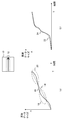
- FIG. 2 shows an example of the appearance of the head-mounted display 100.
- the head-mounted display 100 is composed of an output mechanism unit 102 and a mounting mechanism unit 104.
- the mounting mechanism unit 104 includes a mounting band 106 that goes around the head and realizes fixing of the device when the user wears it.
- the output mechanism 102 includes a housing 108 having a shape that covers the left and right eyes when the head-mounted display 100 is worn by the user, and includes a display panel inside so as to face the eyes when the head-mounted display 100 is worn.
- the inside of the housing 108 is further provided with an eyepiece located between the display panel and the user's eyes when the head-mounted display 100 is attached to magnify the image.
- the head-mounted display 100 may further include a speaker or earphone at a position corresponding to the user's ear when worn.
- the head-mounted display 100 further includes a stereo camera 110 on the front surface of the housing 108, a monocular camera 111 with a wide viewing angle in the center, and four cameras 112 with a wide viewing angle at the four corners of the upper left, upper right, lower left, and lower right. Take a video of the real space in the direction corresponding to the direction of the face.
- the head-mounted display 100 provides a see-through mode in which a moving image captured by the stereo camera 110 is immediately displayed to show the state of the real space in the direction in which the user is facing.
- At least one of the images captured by the stereo camera 110, the monocular camera 111, and the four cameras 112 may be used to generate the display image.
- SLAM Simultaneous Localization and Mapping
- the image may be corrected in the device 200.
- the captured image may be combined with the image transmitted from the server 400 to form a display image.
- the head-mounted display 100 may be provided with any of motion sensors for deriving the position, posture, and movement of the head-mounted display 100, such as an acceleration sensor, a gyro sensor, and a geomagnetic sensor.
- the image processing device 200 acquires information on the position and posture of the user's head at a predetermined rate based on the measured values of the motion sensor. This information can be used to determine the field of view of the image generated by the server 400 and to correct the image in the image processing device 200.
- FIG. 3 shows the basic configuration of the server 400 and the image processing device 200 according to the present embodiment.
- the server 400 and the image processing device 200 according to the present embodiment are provided with a local memory for storing a partial image smaller than one frame of the displayed image at a key point. Then, compression coding and transmission of image data in the server 400, data reception in the image processing device 200, decoding / decompression, various image processing, and output to the display device are pipelined in units of the partial image. As a result, the delay time from the drawing of the image on the server 400 to the display on the display device connected to the image processing device 200 is reduced.
- the drawing control unit 402 is realized by the CPU (Central Processing Unit) and controls the drawing of the image in the image drawing unit 404.
- the content of the image to be displayed in the present embodiment is not particularly limited, but the drawing control unit 402 advances the cloud game, for example, and causes the image drawing unit 404 to draw a frame of a moving image representing the result.
- the drawing control unit 402 may acquire information related to the position and posture of the user's head from the image processing device 200 and control to draw each frame in the corresponding visual field.
- the image drawing unit 404 is realized by a GPU (Graphics Processing Unit), draws a frame of a moving image at a predetermined or variable rate under the control of the drawing control unit 402, and stores the result in the frame buffer 406.
- the frame buffer 406 is realized by RAM (Random Access Memory).
- the video encoder 408 compresses and encodes the image data stored in the frame buffer 406 in units of partial images smaller than one frame.
- the partial image is an image of each region formed by dividing the image plane of the frame by, for example, a boundary line set in the horizontal direction, the vertical direction, the vertical / horizontal bidirectional direction, or the diagonal direction.
- the video encoder 408 may start the compression coding of the frame as soon as the image required for the compression coding is drawn by the image drawing unit 404 without waiting for the vertical synchronization signal of the server.
- the conventional technology that synchronizes various processes such as frame drawing and compression coding with reference to the vertical synchronization signal
- the time given to each process from image drawing to display is aligned in frame units to manage the frame order. Is easy.
- the drawing process ends early depending on the contents of the frame, it is necessary to wait for the compression coding process until the next vertical synchronization signal.
- unnecessary waiting time is prevented from occurring.
- the coding method used by the video encoder 408 for compression coding is H.I. 264 / AVC and H. A general one such as 265 / HEVC may be used.
- the video encoder 408 stores the data of the compressed and encoded image in the partial image storage unit 410.
- the partial image storage unit 410 is a local memory realized by SRAM (Static Random Access Memory) or the like, and has a storage area corresponding to a data size of a partial image smaller than one frame. The same applies to the "partial image storage unit" described later.
- the video stream control unit 414 reads the data, includes audio data, control information, and the like as necessary, and then packets the data. do.
- the control unit 412 constantly monitors the data writing status of the video encoder 408 for the partial image storage unit 410, the data reading status of the video stream control unit 414, and the like, and appropriately controls the operations of both. For example, the control unit 412 controls the partial image storage unit 410 so that data shortage, that is, buffer underrun, or data overflow, that is, buffer overrun does not occur.
- the input / output interface 416 establishes communication with the image processing device 200, and the video stream control unit 414 sequentially transmits packetized data via the network 306.
- the input / output interface 416 may appropriately transmit audio data and the like in addition to image data.
- the input / output interface 416 further acquires information related to user operations, the position and orientation of the user's head, information related to the user's gazing point, and the like from the image processing device 200, and supplies the information to the drawing control unit 402, the video encoder 408, and the like. You may.
- the input / output interface 202 sequentially acquires image and audio data transmitted from the server 400.
- the input / output interface 202 further appropriately acquires information related to the user operation, the position and posture of the user's head, information related to the user's gaze point, and the like from the head-mounted display 100, an input device (not shown), and the like, and transmits the information to the server 400. You may.
- the input / output interface 202 decodes the packet acquired from the server 400, and stores the extracted image data in the partial image storage unit 204.
- the partial image storage unit 204 is a local memory provided between the input / output interface 202 and the video decoder 208.
- the control unit 206 constantly monitors the data writing status of the input / output interface 202 to the partial image storage unit 204, the data reading status of the video decoder 208, and the like, and appropriately controls the operations of both.
- the video decoder 208 reads the data, decodes and decompresses the data according to the procedure according to the coding method, and sequentially stores the data in the partial image storage unit 210.
- the partial image storage unit 210 is a local memory provided between the video decoder 208 and the image processing unit 214.
- the control unit 212 constantly monitors the data writing status of the video decoder 208 for the partial image storage unit 210, the data reading status of the image processing unit 214, and the like, and appropriately controls the operations of both.
- the image processing unit 214 reads the data and performs processing necessary for display. For example, in the head-mounted display 100, in order to visually recognize an image without distortion when viewed through the eyepiece, a correction process of giving distortion opposite to the distortion caused by the eyepiece is performed.
- the image processing unit 214 may refer to the separately prepared UI plane image and combine (superimpose) it with the image transmitted from the server 400. Further, the image processing unit 214 may combine the image captured by the camera included in the head-mounted display 100 with the image transmitted from the server 400. The image processing unit 214 may also correct the image transmitted from the server 400 so that the field of view corresponds to the position and posture of the user's head at the time of processing. The image processing unit 214 may also perform image processing suitable for output to the flat plate display 302, such as super-resolution processing.
- the image processing unit 214 performs processing in units of partial images stored in the partial image storage unit 210, and sequentially stores them in the partial image storage unit 216.
- the partial image storage unit 216 is a local memory provided between the image processing unit 214 and the display controller 220.
- the control unit 218 constantly monitors the data writing status of the image processing unit 214 for the partial image storage unit 216, the data reading status of the display controller 220, and the like, and appropriately controls the operations of both.
- the display controller 220 reads the data and outputs the data to the head-mounted display 100 or the flat plate display 302 at an appropriate timing. Specifically, the data of the uppermost partial image of each frame is output at the timing corresponding to the vertical synchronization signal of those displays, and then the data of the partial image is sequentially output downward.
- FIG. 4 conceptually shows the state of processing from drawing to display of an image in the present embodiment.
- the server 400 generates the moving image frame 90 at a predetermined or variable rate.
- the frame 90 has a configuration in which images for the left eye and an image for the right eye are represented in a region divided into two equal parts on the left and right, but the configuration of the image generated by the server 400 is not limited to this.
- the server 400 compresses and encodes the frame 90 for each partial image.
- the image plane is divided into five in the horizontal direction to obtain partial images 92a, 92b, 92c, 92d, and 92e.
- the partial images are compressed and coded one after another in this order, transmitted to the image processing apparatus 200 and displayed as shown by the arrows. That is, while the uppermost partial image 92a is subjected to processing such as compression coding, transmission, decoding / decompression, and output to the display panel 94, the lower partial image 92b and the lower partial image 92c are referred to.
- the partial images are sequentially transmitted and displayed as described above. As a result, various processes required from image drawing to display can be performed in parallel, and the display can be advanced with the minimum delay even if the transfer time intervenes.
- the height of the displayed image is high. Higher resolution, higher frame rate, and higher bit depth are required. Therefore, compression coding of image data is required to suppress the required transfer bandwidth.
- the transfer path is wired or wireless, the data size (bit rate) that can be transferred per unit time is determined by the technology used, so it is necessary to keep the compressed data size within this range.
- rate control may be performed in the compression coding process for the purpose of suppressing the size of the compressed data to be transmitted per unit time to a predetermined value or less.
- rate control includes feedback control and feedforward control.
- the size of the compressed data actually generated as a result of image compression (encoding processing) with a grain size smaller than the unit time that defines the allowable bit rate (hereinafter referred to as "compression unit") is set as the target value.
- the process of comparing, adjusting the parameters so that the difference becomes small, and compressing the next compression unit is repeated.
- the parameters to be adjusted include, for example, a quantization parameter (QP), a bit depth, an image resolution, and the like.
- QP quantization parameter
- the adjustment range of the parameter becomes large, and there is a possibility that the image quality greatly fluctuates for each compression unit.
- the compression unit of an image with a low compression rate it is difficult to reduce the data size even if compressed
- the upper limit of the bit rate per unit time may be exceeded
- the image quality will be improved at the end of the unit time. Control is done to increase the compression rate at the expense.
- the compression unit of the image having a high compression rate continues in the early stage of the unit time, the image quality may be changed to a good state only in the final stage. In any case, the adjustment of the data size is concentrated toward the end of the unit time, and the image quality balance in the entire frame may not be uniform.
- the target frame is temporarily compressed in advance, the compression rate is estimated in advance, and the parameters of this compression process are systematically adjusted to adjust the data size per unit time, so-called multipath. It is encoded.
- the main compression process cannot be started until the temporary compression process is completed, the time until the compression coding process is completed becomes long. As a result, the delay time until display increases, and it is difficult to apply it to real-time applications such as virtual reality and augmented reality.
- a rate control map indicating a region in which the compression rate may be increased that is, a region that allows a certain degree of deterioration in image quality is prepared in advance with respect to the plane of the frame constituting the moving image, if necessary.
- the compression ratio is adjusted according to the map.
- FIG. 5 shows an example of a rate control map.
- the head-mounted display 100 is set as the display destination, and the rate control map 6 for compressing and coding the images for the left eye and the right eye is shown.
- the rate control map 6 is composed of an area 8a for the left eye and an area 8b for the right eye. Further, the degree to which the image quality deterioration is allowed for each compression unit in which the plane of one frame consisting of the images for the left eye and the right eye is divided into 32 in the vertical direction and 16 in the horizontal direction (hereinafter, "tolerance of image quality deterioration"). ") Is set as an integer from 0 to 10. That is, it is said that the larger the numerical value of the compression unit, the greater the tolerance for image quality deterioration due to the increase in the compression rate.
- the tolerance for image quality deterioration is set to "0" near the center near the optical axis, and the tolerance is increased as it approaches the periphery. There is.
- the change in tolerance in this case is determined based on optical parameters such as aberration of the eyepiece. Further, since the vicinity of the outermost circumference in each region is outside the field of view of the eyepiece, the tolerance is set to the maximum value of "10".
- the format of the rate control map 6 is not limited to the one shown in the figure.
- the numerical value indicating the tolerance for image quality deterioration may be a binary value indicating allowable / unacceptable, or any other arbitrary number of steps may be provided.
- the compression unit for setting the tolerance for image quality deterioration is preferably a minimum unit for compression coding (for example, a macro block) or an area having an area that is an integral multiple of the minimum unit (for example, a macro block).
- the display destination is not limited to the head-mounted display 100. Therefore, the configuration of the rate control map 6 is not limited to the provision of the two regions as shown in the figure, and may be appropriately changed according to the structure of the display panel.
- the rate control map 6 can be generated in advance when the optical parameters of the eyepiece are used or when the part that the user is likely to gaze at can be limited to the center of the image or the like.
- the rate control map 6 may be used as dynamic data based on the situation at the time of image generation, the content of the image, the user's gaze point, and the like.
- the data size is adjusted using the rate control map 6 as needed. For example, for an image in which the data size after compression is suppressed to a small size even by a normal compression coding process and does not exceed the upper limit of the bit rate, adjustment using the rate control map 6 is not performed. An image that does not deviate significantly from the target value in the feedback control may be processed as usual. By performing the adjustment using the rate control map 6 as necessary in this way, it is possible to avoid unnecessarily lowering the image quality and increasing the processing load.
- the compression process may be executed while the feedback control using the rate control map 6 is not switched on / off, but is always turned on.
- the rate control map 6 when the cumulative data size up to the last minute is less than the target value, or when the quantization parameter can be compressed with sufficient image quality and data amount even if the quantization parameter is normal in the area where image quality is important, the rate control map Even in the region where image quality is important in 6, the rate control functions effectively, so that unnecessary reduction of quantization parameters is not performed. This is because the rate control map 6 is a guidance hint for rate control and does not specify a fixed quantization parameter value.
- FIG. 6 shows the functional blocks of the server 400 and the image processing device 200 of this embodiment.
- Each functional block shown in FIG. 18 and FIG. 18 described later can be realized by a CPU, GPU, encoder, decoder, arithmetic unit, various memories, etc. in terms of hardware, and is loaded into memory from a recording medium in terms of software. It is realized by a program that exerts various functions such as information processing function, image drawing function, data input / output function, and communication function. Therefore, it is understood by those skilled in the art that these functional blocks can be realized in various forms by hardware only, software only, or a combination thereof, and is not limited to any of them. The same applies to the functional blocks described later.
- the server 400 includes an image generation unit 420, a compression coding unit 422, a packetization unit 424, and a communication unit 426.
- the image generation unit 420 is composed of the drawing control unit 402, the image drawing unit 404, and the frame buffer 406 of FIG. 3, and generates a frame of a moving image such as a game image to be transmitted to the image processing device 200 at a predetermined or variable rate. ..
- the image generation unit 420 may acquire moving image data from a camera, a storage device, or the like (not shown). In this case, the image generation unit 420 can be read as an image acquisition unit. The same applies to the following description.
- the compression coding unit 422 is composed of the video encoder 408, the partial image storage unit 410, and the control unit 412 of FIG. 3, and compresses and encodes the image data generated by the image generation unit 420 for each partial image.
- the compression coding unit 422 performs motion compensation and coding using an area of a predetermined number of lines such as one line and two lines and a rectangular area of a predetermined size such as 16 ⁇ 16 pixels and 64 ⁇ 64 pixels as a compression unit. Therefore, the compression coding unit 422 may start the compression coding when the image generation unit 420 generates data in the minimum unit region required for the compression coding.
- the partial image which is a unit of pipeline processing in compression coding and transmission, may be the same as the area of the minimum unit, or may be a larger area.
- the compression coding unit 422 includes a rate control map storage unit 430, a status acquisition unit 432, a map generation unit 434, and a compression coding processing unit 436.
- the rate control map storage unit 430 stores a rate control map in which the tolerance for image quality deterioration is represented for each compression unit.
- the rate control map storage unit 430 stores the rate control map in association with the model of the display device and the like.
- the situation acquisition unit 432 acquires information related to various situations that can affect the distribution of the tolerance for image quality deterioration.
- the situation acquisition unit 432 acquires, for example, the information generated or used when the image generation unit 420 generates a moving image. For example, when the image generation unit 420 controls to lower the resolution of the image from the center of the field of view toward the periphery, a resolution map showing the resolution distribution with respect to the plane of the frame is acquired. In this case, the status acquisition unit 432 acquires the resolution map.
- the image generation unit 420 when the image generation unit 420 collectively calculates the pixel value (pixel shading) for the edge of the field of view, the region where the movement of the object is small, the region where the density is low, etc., with a plurality of nearby pixels, the group of pixels is combined.
- the pixel map represented on the plane of the frame is acquired.
- the status acquisition unit 432 acquires the pixel map.
- the image generation unit 420 performs Foveated Rendering that changes the resolution of the displayed image according to the distance from the user's gazing point
- the situation acquisition unit 432 determines the distribution of the resolution. get.
- the status acquisition unit 432 may acquire information related to the user's gaze point with respect to the displayed image from the image processing device 200.
- the status acquisition unit 432 acquires status information at an appropriate frequency according to the type of information, such as at the start of moving image transfer processing, for each partial image, for each frame, and for each scene.
- the map generation unit 434 generates a rate control map based on the information acquired by the status acquisition unit 432. Qualitatively, the lower the image resolution and the farther away from the gazing point, the greater the tolerance for image quality degradation in the rate control map. According to such a standard, a rate control map can be generated individually from each situation information, so that the map generation unit 434 creates one rate control map based on any of the situation information acquired by the situation acquisition unit 432. It may be generated.
- the map generation unit 434 may generate one rate control map by combining a plurality of situation information.
- the map generator 434 creates a rate control map using at least one of a resolution map and a pixel map, and then calculates an offset according to the resolution distribution by forbidden rendering and the distance from the user's gazing point.
- the final rate control map may be obtained by adding the value to each tolerance set in the rate control map.
- the map generation unit 434 may read the rate control map stored in advance in the rate control map storage unit 430 and correct it based on the information acquired by the situation acquisition unit 432 to obtain the final rate control map. ..
- the offset value of the tolerance may be calculated from at least one of the various information acquired by the status acquisition unit 432 and added to each tolerance set in the original rate control map.
- the formula for calculating the tolerance is not limited to simply adding the tolerances obtained from each viewpoint, but may be a linear combination after performing the weighting set for each viewpoint.
- the formula for calculating the tolerance is not limited to simply adding the tolerances obtained from each viewpoint, but may be a linear combination after performing the weighting set for each viewpoint.
- the compression coding processing unit 436 compresses and encodes the moving image data generated by the image generation unit 420.
- the compression coding processing unit 436 basically uses a general method of feedback control to adjust the compression rate so that the cumulative value of the data size after compression coding per unit time approaches the target value. While proceeding with the compression coding of the compression unit.
- a predetermined condition for significantly reducing the data size such as the cumulative value of the data size exceeds the target value and the difference exceeds a predetermined threshold value
- the compression coding processing unit 436 performs a rate control map. Refer to and adjust to increase the compression ratio in the appropriate area on the image.
- the compression coding processing unit 436 may refer to the static rate control map stored in the rate control map storage unit 430, or the dynamic rate control map generated or corrected by the map generation unit 434. May be referred to. Then, the compression coding processing unit 436 resets the target value of the data size for each compression unit according to the rate control map, and then performs feedback control. As a result, the target value of the data size is lowered in the region where the deterioration of the image quality is allowed, and as a result, the compression ratio of the region is controlled to increase.
- the compression coding processing unit 436 may temporarily perform a temporary compression process of the image and reflect the result in the rate control map. That is, the ease of compression for each compression unit is estimated by performing compression coding using temporary parameters and acquiring the data size.
- the compression coding processing unit 436 carries out the actual compression coding processing using the rate control map generated or corrected based on the result of the temporary compression processing.
- the compression coding processing unit 436 is not limited to repeating the compression coding in the compression unit in order from the edge of the partial image, and progresses the compression coding in order from the part where the tolerance for image quality deterioration is small and, by extension, the important part. You may let me.
- the compression coding processing unit 436 may use the rate control map to determine the processing order. By compressing and coding the important part with priority in time, the important part is adjusted in the situation where the cumulative value of the data size is likely to reach the upper limit of the bit rate at the end of the unit time as described above. You can avoid the part being used.
- the data size can be kept within an appropriate value without affecting the compression result of the important part regardless of the image of the other area of the partial image.
- the compression coding processing unit 436 allows the data size to deviate from the target value at the beginning of the unit time so that the compression rate does not change significantly, and converges to the target value at high speed toward the end. Then, the compression result of the important part may be made more stable.
- the compression coding unit 422 sequentially supplies the data of the partial image after compression coding to the packetization unit 424.
- the packetizing unit 424 is composed of the video stream control unit 414 and the control unit 412 of FIG. 3, and packetizes the compressed and encoded partial image data in a format according to the communication protocol to be used. At this time, data such as the time when the partial image was drawn (hereinafter referred to as "generation time"), the distribution of resolution on the image plane, the quantization parameter used for compression coding, and the above-mentioned resolution map or pixel map. Is obtained from the image generation unit 420 or the compression coding unit 422, and is associated with the partial image data.
- the communication unit 426 is composed of the input / output interface 416 of FIG. 3, and transmits a packet including compression-encoded partial image data and various data associated therewith to the image processing device 200.
- the server 400 performs compression coding, packetization, and transmission in parallel by pipeline processing in units of partial images smaller than one frame.
- the image processing device 200 includes an image data acquisition unit 240, a decoding / decompression unit 242, an image processing unit 244, a display control unit 246, and a gazing point acquisition unit 248.
- the decoding / stretching unit 242 and the image processing unit 244 have a common function in that the partial image data is subjected to predetermined processing to generate the partial image data for display, and at least one of them is referred to as "image”. It can also be collectively referred to as "processing unit”.
- the image data acquisition unit 240 is composed of the input / output interface 202, the partial image storage unit 204, and the control unit 206 of FIG. Get from.
- the decoding / decompression unit 242 is composed of the video decoder 208, the partial image storage unit 210, the control unit 206, and the control unit 212 of FIG. 3, and decodes and decompresses the data of the compression-encoded partial image.
- the decoding / decompression unit 242 may start the decoding / decompression processing when the image data acquisition unit 240 acquires data in the smallest unit region required for compression coding such as motion compensation and coding.
- the decoding / decompression unit 242 appropriately decodes / decompresses each compression unit using the distribution of the quantization parameters used at the time of compression coding transmitted from the server 400. Further, the decoding / stretching unit 242 restores the original pixel sequence by interpolating the pixels using the information related to the resolution distribution on the image plane, that is, the above-mentioned resolution map and pixel map, and the image having a uniform resolution. May be converted to.
- the image processing unit 244 is composed of the image processing unit 214, the partial image storage unit 216, the control unit 212, and the control unit 218 of FIG. 3, and performs predetermined processing on the partial image data to generate the partial image data for display. do. For example, as described above, the image processing unit 244 makes a correction that gives the opposite distortion in consideration of the distortion of the eyepiece included in the head-mounted display 100.
- the image processing unit 244 synthesizes an image to be displayed together with a moving image, such as a UI plain image, in units of partial images.
- the image processing unit 244 acquires the position and posture of the user's head at that time, and corrects the image generated by the server 400 so that the field of view at the time of display is correct. This makes it possible to minimize the time lag between the movement of the user's head and the displayed image due to the transfer time from the server 400.
- the image processing unit 244 may also perform any or a combination of commonly performed image processing.
- the image processing unit 244 may perform gun marker correction, tone curve correction, contrast enhancement, and the like. That is, necessary offset correction may be performed on the pixel value / luminance value of the decoded / decompressed image data based on the characteristics of the display device or the user's specification.
- the image processing unit 244 may perform noise removal processing that performs processing such as superimposition, weighted averaging, and smoothing with reference to neighboring pixels.
- the image processing unit 244 may match the resolution of the image data with the resolution of the display panel, refer to neighboring pixels, and perform weighted averaging / oversampling such as bilinear / trilinear. Further, the image processing unit 244 may refer to neighboring pixels, determine the type of image texture, and selectively process denoising, edge enhancement, smoothing, tone / gamma / contrast correction accordingly. At this time, the image processing unit 244 may process the image together with the upscaler / downscaler of the image size.
- the image processing unit 244 may perform format conversion when the pixel format of the image data and the pixel format of the display panel are different. For example, conversion between YUV to RGB, RGB to YUV, conversion between 444, 422, and 420 in YUV, conversion between 8, 10 and 12-bit colors in RGB, and the like may be performed. Further, when the decoded image data is in the HDR (High Dynamic Range) brightness range compatible format, the image processing unit 244 has a narrow HDR brightness range compatible range of the display display (the displayable brightness dynamic range is defined in the HDR format). Pseudo-HDR processing (color space change) may be performed to convert the HDR image into a brightness range format in a range compatible with the display panel while retaining the features of the HDR image as much as possible (such as narrower).
- HDR High Dynamic Range
- the image processing unit 244 uses an HDR-compatible format for the decoded image data, but when the display display supports only SDR (Standard Dynamic Range), the color space is changed to the SDR format while retaining the features of the HDR image as much as possible. It may be converted.
- the decoded image data is in an SDR compatible format, but when the display display is compatible with HDR, the image processing unit 244 may enhance conversion to the HDR format according to the characteristics of the HDR panel as much as possible.
- the image processing unit 244 may add error diffusion or perform a dithering process that is processed together with the pixel format conversion. Further, the image processing unit 244 may correct the region when there is a partial loss or abnormality in the decoded image data due to lack of network transfer data or garbled bits. Further, the image processing unit 244 may perform correction with pixels estimated from the periphery of the past frame or the current frame by filling with a single color, correction by duplication of nearby pixels, correction by pixels near the previous frame, and adaptive defect correction.
- the image processing unit 244 may perform image compression in order to reduce the required band of the interface output from the image processing device 200 to the display device.
- the image processing unit 244 may perform lightweight entropy coding by reference to neighboring pixels, index value reference coding, Huffman coding, and the like.
- the resolution can be increased, but the reaction speed is slow.
- an organic EL panel is used as the display device, the reaction speed is high, but it is difficult to increase the resolution, and a phenomenon called Black Smearing, in which color bleeding occurs in and around the black region, may occur.
- the image processing unit 244 may make corrections so as to eliminate various adverse effects of such a display panel. For example, in the case of a liquid crystal panel, the image processing unit 244 resets the liquid crystal by inserting a black image between the frames to improve the reaction speed. Further, in the case of the organic EL panel, the image processing unit 244 offsets the luminance value and the gamma value in the gamma correction to make the color bleeding due to Black Smearing less noticeable.
- the image processing unit 244 may perform super-resolution processing (SuperResolution) on the image to improve the definition and restore or reconstruct the high-frequency component.
- SuperResolution super-resolution processing
- the image processing unit 244 may convert the image by inputting the image data into the database or network model constructed in advance by using machine learning or deep learning.
- the image processing unit 244 may reduce the delay by performing conversion in units of partial images. By matching the partial image unit at this time with the partial image unit determined based on the scanning order and the division configuration of the display panel, a series of processes can be made into a pipeline, and further reduction in delay can be realized.
- the display control unit 246 is composed of the display controller 220 and the control unit 218 of FIG. 3, and sequentially displays partial image data for display on the display panel of the head-mounted display 100 or the flat plate display 302.
- the acquisition order may be changed depending on the communication status, or the partial image data itself may not be acquired due to packet loss. Conceivable.
- the display control unit 246 derives the elapsed time from the drawing of the partial image from the generation time of each partial image, and outputs the partial image to the display panel so as to reproduce the drawing timing on the server 400. Adjust the timing. That is, the display control unit 246 data such as the original display order and display timing of the partial image data, the amount of missing partial image data, and the like based on the generation time of the partial image data and / or the elapsed time from the generation time. Identify the acquisition status.
- the display control unit 246 changes the output target to the display panel according to the data acquisition status, and appropriately adjusts the output order and output timing. For example, the display control unit 246 determines whether to output the data of the original partial image included in the next frame or to output the data of the partial image included in the previous frame again according to the data acquisition status. .. At this time, the display control unit 246 determines such an output target by the timing of the vertical synchronization signal, which is the display start time of the next frame.
- the display control unit 246 responds to the amount (ratio) of the acquired partial image, such as replacing the output target with the data of the previous frame when the partial image is missing in the frame at a ratio of a predetermined value or more.
- the output target may be changed.
- the display control unit 246 may change the output target of the next frame display period according to the past output record of the frame and the elapsed time from the generation time. Then, the display control unit 246 outputs the data of the partial image determined as the output target to the display panel in the determined order and timing.
- the gazing point acquisition unit 248 acquires the position information of the gazing point of the user with respect to the drawn moving image displayed on the display device connected to the image processing device 200 such as the head-mounted display 100 and the flat plate display 302.
- a gaze point detector is provided inside the head-mounted display 100, or a gaze point detector is attached to a user who is looking at the flat plate display 302, and the measurement result by the gaze point detector is acquired.
- the image data acquisition unit 240 of the image processing device 200 transmits the position coordinate information of the gazing point to the communication unit 426 of the server 400 at a predetermined rate, so that the image generation unit 420 and the compression coding unit 422 are required. Get it.
- the gazing point detector may be a general device that irradiates the user's eyeball with reference light such as infrared rays and identifies the gazing point from the direction of the pupil obtained by detecting the reflected light with a sensor.
- the gazing point acquisition unit 248 may transmit a predetermined number of historical values as well as the latest value of the gazing point position information to the server 400 in preparation for a transmission failure from the image processing device 200. Further, when the processing using the gazing point is not performed in the server 400, the function of the gazing point acquisition unit 248 in the image processing device 200 can be omitted.
- FIG. 7 shows a functional block of the compression coding processing unit 436 having a feedback control function.
- the compression coding processing unit 436 includes a target value setting unit 440, a comparison unit 442, a compression unit 444, and a post-compression data size acquisition unit 446.
- the target value setting unit 440 sets a change in the target value of the compressed data size for each compression unit, and by extension, the cumulative value of the target data size.
- the latter is mainly referred to as a "target value”.
- the target value is basically determined so as to reach the upper limit of the bit rate required from the available transfer band and the like in a unit time.
- the target value setting unit 440 sets the target value according to the tolerance of image quality deterioration set in the map. That is, the target value setting unit 440 sets the rate of change of the target value to be smaller as the tolerance for image quality deterioration is larger, so that the data size can be suppressed.
- the compression unit 444 compresses and encodes the image data generated by the image generation unit 420 as described above.
- the post-compression data size acquisition unit 446 acquires the size of the data after compression coding obtained as a result of the compression coding actually performed by the compression unit 444 for each compression unit.
- the comparison unit 442 compares the target value set by the target value setting unit 440 with the cumulative value of the data size after the actual compression coding, and adjusts the quantization parameter based on the difference.
- the compression unit 444 when the cumulative data size after compression is much smaller than the target value, the compression unit 444 is controlled so as to lower the quantization parameter and perform the subsequent compression processing. When the cumulative data size after compression exceeds the target value, the compression unit 444 is controlled so as to raise the quantization parameter and perform the subsequent compression processing.
- a general control method such as PID control can be used for this process. By such feedback control, the cumulative value of the compressed data size converges to the target value, and the size of the data to be transferred per unit time can be kept below the upper limit of the bit rate.
- the target value setting unit 440 includes a switching unit 441.
- the switching unit 441 acquires information related to the difference between the target value and the actual cumulative data size from the comparison unit 442. Then, as described above, when the difference satisfies a predetermined condition for significantly reducing the data size, the control is switched from the normal control to the control using the rate control map. That is, the general linear target value is switched to a target value indicating a position-dependent change that reflects the tolerance for image quality deterioration.
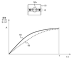
- FIG. 8 is a diagram for explaining the effect of performing feedback control using the rate control map in the present embodiment.
- Both figures (a) and (b) show changes in the cumulative value of the data size after compression coding in the unit time T in the passage of time on the horizontal axis.
- the unit time T compresses and encodes the compression unit in the sliced partial image 12 on the image plane 10 as shown in the upper part of the figure from the left end to the right end.
- the cumulative data size "A" indicates the bandwidth (upper limit of the bit rate) that can be used for communication between the server 400 and the image processing device 200 in the unit time T.
- (A) is a compression coding result by normal feedback control. In the illustrated example, it is assumed that the data size is equalized in all compression units, and as a result, the target value 14 shown by the broken line becomes linear with respect to time. On the other hand, the actual data size varies depending on the content of the image. By trying to converge this to the target value 14 by feedback control, overshoot 18 and undershoot 20 are generated as in the cumulative data size 16 shown by the solid line.
- the compression unit after falling below the target value is likely to overshoot due to feedback.
- the compression unit after exceeding the target value is likely to undershoot due to feedback.
- the overshoot state is prolonged due to a complicated image continuing at the beginning of the unit time T, the compression rate is suddenly increased at the end of the unit time T in order to keep it below the upper limit A, which is the constraint condition of the cumulative data size. Need arises. As a result, it is conceivable that an unintended change in image quality occurs depending on the position on the image, and eventually the image quality of an important part is deteriorated.
- (B) is the compression coding result when feedback control is performed using the rate control map in the present embodiment.
- a rate control map in which the tolerance for image quality degradation is set low near the center is used, and compression coding is performed from the edge of the partial image 12 that crosses the center of the image plane 10.
- the target value 22 of the cumulative data size shown by the broken line has a shape that shows a remarkable increase in a finite period in the middle of the unit time T.
- the actual cumulative data size 24 shown by the solid line can also cause overshoots and undershoots by feedback control, but even so, it increases significantly in a finite period in the middle of the unit time T. It will be a change like this. As a result, the allocation of the data size near the center of the image plane can be made larger than the other areas.
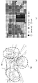
- FIG. 9 is a diagram for explaining the processing content of the image generation unit 420 that can be used to generate the rate control map.
- a unit area having the same area formed by evenly dividing an image plane is used as a pixel, and values representing each color are calculated to obtain image data.
- the illustrated example shows an area 25 of, for example, 1440 ⁇ 1440 pixels, which is one of the images for the left eye and the right eye displayed on the head-mounted display 100.
- the numerical values shown in the 25 rectangular areas indicate the reduction ratios in the horizontal and vertical directions.
- the region 30 indicated as "1x1" in the central portion is the same size in both vertical and horizontal directions, that is, the image is not reduced.
- the area 26 shown as "0.25 x 0.25" in the upper left reduces the image to 1/4 in both vertical and horizontal directions.
- the area 28 to the right of which is indicated as "0.5 x 0.25" reduces the image to 1/2 in the horizontal direction and 1/4 in the vertical direction.
- such reduction processing can be regarded as changing the area included in one pixel in the image plane in which the color values are actually obtained evenly. .. That is, the pixel value is determined in the finest unit in the "1 x 1" region, and the pixel value is determined in the area unit of 2 x 2 times in the "0.5 x 0.5" region, for example.
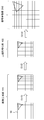
- FIG. 10 conceptually shows the change on the image by changing the area of the pixel.
- the image 34 is an image having an original size, and it is assumed that the area of the pixel is different for each region divided so as to be represented by a line in the rectangle.
- the image 38 is an image on the data when pixels having different areas depending on the area are represented as the same area.
- the image 36 drawn in the original image is deformed like the image 40 as a result of being reduced by a different ratio depending on the position.
- the image generation unit 420 (that is, GPU) internally holds a resolution map in which the image plane is divided according to a predetermined rule and the reduction ratio (resolution) is set as shown in FIG. 9, and the drawing target area is divided based on the resolution map. Then, by drawing each area with different resolutions, data such as image 38 is generated. As a result, the amount of calculation, the amount of memory access, and the processing time required for drawing can be reduced.
- FIG. 11 illustrates a flow of data conversion up to display of images having different resolutions depending on the area.
- the data such as the image 38 of FIG. 10 generated by the image generation unit 420 of the server 400 is compressed and encoded in that state and transferred to the image processing device 200. That is, the image generation unit 420 outputs the image 38 as it is with the number of pixels, the resolution, and the aspect ratio of the pixel area (S10), and the compression coding unit 422 compresses and encodes the image 38 as it is (S12).
- the server 400 transmits the data compressed and encoded in this way and the resolution map to the image processing device 200.
- the image data acquisition unit 240 of the image processing device 200 acquires them, and the decoding / decompression unit 242 decodes and decompresses the data and complements the pixels based on the resolution map, so that the original array of pixels, that is, the original Data with a uniform resolution having the number of pixels, the resolution, and the aspect ratio of the pixel area is generated (S14).
- the number of pixels to be transmitted from the server 400 to the image processing device 200 can be reduced.
- FIG. 12 shows another example of the flow of data conversion up to display of images having different resolutions depending on the area.
- the image generation unit 420 of the server 400 generates data as shown in the image 38 of FIG. 10, and then interpolates the pixels based on the resolution map to obtain the original pixel arrangement, that is, the number of pixels, the resolution, and the like.
- An image 41 having a uniform resolution having an aspect ratio of a pixel region is generated (S16).
- the compression coding unit 422 compresses and encodes the image 41 (S18).
- the decoding / decompression unit 242 of the image processing device 200 only decodes / decompresses the data transmitted from the server 400 to obtain an image having a uniform resolution (S20).
- the rate control map used by the compression coding unit 422 reflects the resolution map, as in the case of FIG. It can be compressed and coded with the same image quality at the same bit rate.
- the server 400 determines whether the processing procedure is as shown in FIG. 11 or as shown in FIG. 12, depending on whether or not the decoding / stretching unit 242 of the image processing device 200 supports data conversion based on the resolution map.
- the resolution map may be fixed, or the image generation unit 420 may dynamically generate it according to the content of the image. For example, the image generation unit 420 identifies the size and position of the region to be shown in detail by analyzing a moving image, maintains the resolution of the region, and sets the resolution to decrease as the distance from the region increases. May be good.
- a rate control map that reflects it may be generated in advance and stored in the rate control map storage unit 430.
- the resolution map is variable, each time the image generation unit 420 generates a resolution map, the status acquisition unit 432 of the compression coding unit 422 acquires the data, and the map generation unit 434 converts the data into a rate control map. To reflect. At this time, the map generation unit 434 corrects the rate control map prepared in advance by adding the tolerance for image quality deterioration calculated from the resolution map or multiplying the weighted value obtained from the resolution map. May be good.
- the map generation unit 434 may newly generate a rate control map from the resolution map.
- the image generation unit 420 can reduce the compression rate of the portion where the resolution is maintained, and maintain the image quality even after undergoing the compression coding process.
- FIG. 13 is a diagram for explaining another example of the processing content of the image generation unit 420 that can be used to generate the rate control map.
- the resolution distribution that is, the pixel area distribution is determined based on the actual image content.
- the image generation unit 420 first shows in (b) based on at least one of the distance from the center of the visual field, the magnitude of the movement of the object, the detail of the image, and the like. After generating such a pixel map, the pixel value is calculated accordingly.
- the pixel map shown in the figure represents the original pixel area on the image plane in a grid pattern, and as shown in the legend below, the higher the resolution (the smaller the pixel area), the darker the color.
- the pixel value is set to be calculated in units of "1 x 1" pixels, that is, for each original pixel.
- the pixel values should be calculated in units of "1x2" or "2x1" pixels depending on the array. Set.
- the image generation unit 420 analyzes the moving image of the drawing target, and determines the importance of the object, the size of the image, the importance of the presentation content, the precision, the color, the size of the movement, the type of texture, and whether or not it is the operation target of the user. Or, etc., to generate a pixel map. Qualitatively, the higher the importance or the higher the detail of the image, the finer the pixel unit.
- the image generation unit 420 generates a pixel map at the start of drawing a moving image, and updates the pixel map as appropriate for each partial image, each frame, every predetermined number of frames, when a scene is switched, and the like.
- the same procedure as shown in FIG. 11 or 12 is used to convert the data into data having a uniform pixel area and a uniform resolution at any stage. That is, when the decoding / stretching unit 242 of the image processing device 200 corresponds to the data conversion based on the pixel map, the server 400 compresses and encodes the image whose pixel unit differs depending on the position as it is and transfers it to the image processing device 200. Then, the decoding / stretching unit 242 of the image processing device 200 decodes / stretches the data and interpolates the pixels based on the pixel map to obtain uniform resolution data having the original number of pixels, resolution, and aspect ratio of the pixel region. To generate.
- the number of pixels to be transmitted from the server 400 to the image processing device 200 can be reduced.
- the image generation unit 420 of the server 400 originally interpolates the pixels of the image having different pixel units depending on the position based on the pixel map.
- An array of pixels that is, an image having a uniform resolution having the number of pixels, the resolution, and the aspect ratio of the pixel area is generated.
- the decoding / decompression unit 242 of the image processing device 200 acquires an image having a uniform resolution only by decoding / decompressing the data transmitted from the server 400.
- the number of pixels to be transmitted to the image processing device 200 cannot be reduced, but the number of pixels is reduced by making the rate control map used by the compression coding unit 422 reflect the pixel map. It can be compressed and coded with the same image quality at the same bit rate as when transferring image data.
- the rate control map used by the compression coding unit 422 reflects the pixel map. It can be a map.
- the situation acquisition unit 432 acquires the data each time the image generation unit 420 generates a pixel map, and the map generation unit 434 reflects the data in the rate control map.
- the method of reflection may be the same as in the case of the resolution map.
- the map generation unit 434 may further add a resolution map to generate or correct a rate control map. As a result, it is possible to set the tolerance for image quality deterioration for the combination of the area separated by the resolution map and the image distinguished by the pixel map.
- FIG. 14 is a diagram for explaining the principle of generating a rate control map based on the user's gaze point.
- the user's gaze point 292 is assumed to exist near the center in the illustrated example. Since the user wearing the head-mounted display 100 usually turns his / her face in the desired direction, the center of the display screen 290 can be regarded as the gazing point 292. However, by introducing a gazing point detector, the gazing point 292 at an arbitrary position can be detected.
- the region 294 corresponding within 5 ° with the line of sight from the pupil to the gazing point as the central axis is called a discriminative visual field, and has excellent visual functions such as visual acuity.
- the region 296 corresponding within about 30 ° in the horizontal direction and about 20 ° in the vertical direction is called an effective visual field, and information can be instantly received only by eye movement.
- the area 298 corresponding to 60 to 90 ° in the horizontal direction and 45 to 70 ° in the vertical direction is a stable gaze
- the area 299 corresponding to 100 to 200 ° in the horizontal direction and 85 to 130 ° in the vertical direction is auxiliary. The farther away from the gazing point 292, such as the visual field, the lower the ability to discriminate information.
- the discriminating power is represented by the functions 320a and 320b such that the closer to the gazing point 292, the larger the value on the plane of the display screen 290.
- the functions 320a and 320b are represented with respect to the one-dimensional positions in the horizontal and vertical directions on the plane of the display screen 290, but the actual distribution is based on the two-dimensional position coordinates on the plane. .. The lower the user's discriminating power, the smaller the effect on the visual impression even if the image quality is lowered. It should be set to.
- the status acquisition unit 432 in the compression coding unit 422 of the server 400 sequentially acquires the position coordinates of the actual gazing point on the display screen. Then, the map generation unit 434 reflects the position coordinates in the rate control map. In this case as well, the map generation unit 434 may correct the rate control map prepared in advance by adding the tolerance for image quality deterioration depending on the distance from the gazing point, or the rate control map is newly added. May be generated in. Further, it may be used as a final rate control map in combination with the tolerance of image quality deterioration obtained from the other viewpoints described above.
- the map generation unit 434 may refer to the information and reflect it in the rate control map.
- Forbidden rendering is a technology that reduces the load of drawing processing and data size by drawing the center of the field of view, which has high user identification ability, at a high resolution and at a lower resolution as the distance from the field of view is higher, as in the above-mentioned discriminant field of view. Is known (see, for example, "Foveated 3D graphics", Brian Guenter, et. Al., ACM Transactions on Graphics, Vol. 31, No. 6, Article 164, November 2012).
- the image generation unit 420 sets the resolution boundary on the image plane and the resolution reduction rate based on the position coordinates of the gazing point obtained from the gazing point acquisition unit 248 of the image processing device 200.
- a map representing the resolution distribution determined in this way on an image plane is called a forbidden rendering map.
- the status acquisition unit 432 of the compression coding unit 422 acquires the forbidden rendering map from the image generation unit 420, and the map generation unit 434 reflects the forbidden rendering map in the rate control map.
- the method of reflecting may be the same as described above.
- the same procedure as shown in FIG. 11 or 12 is used to convert the data into data having a uniform pixel area and a uniform resolution at any stage. That is, when the decoding / decompression unit 242 of the image processing device 200 supports data conversion based on the forbidden rendering map, the server 400 compresses and encodes the forbidden rendered image as it is, and causes the image processing device 200 to perform compression coding. Forward. Then, the decoding / stretching unit 242 of the image processing device 200 decodes / stretches the data and interpolates the pixels based on the forbidden rendering map to uniformly have the original number of pixels, resolution, and aspect ratio of the pixel area. Generate data of various resolutions.
- the number of pixels to be transmitted from the server 400 to the image processing device 200 can be reduced.
- the image generation unit 420 of the server 400 interpolates the pixels of the forbidden rendered image based on the pixel map. As a result, an image having an original pixel arrangement, that is, an image having a uniform resolution having the number of pixels, the resolution, and the aspect ratio of the pixel area is generated.
- the decoding / decompression unit 242 of the image processing device 200 acquires an image having a uniform resolution only by decoding / decompressing the data transmitted from the server 400. According to this procedure, the number of pixels to be transmitted to the image processing device 200 cannot be reduced, but the rate control map used by the compression coding unit 422 reflects the forbidden rendering map, so that the pixels can be transmitted. It is possible to perform compression coding with the same image quality at the same bit rate as when transferring a reduced number of image data.
- the image generation unit 420 of the server 400 may independently perform any of the resolution switching for each area, the calculation of the pixel value for a group of a plurality of pixels, and the forbidden rendering described above. One or more may be combined and carried out. When the combination is performed, the same processing as described above is performed based on the map in which the resolution map, the pixel map, and the forbidden rendering map are appropriately combined.
- FIG. 15 is a diagram for explaining the effect when the rate control map is corrected based on the content of the image and the gazing point of the user.
- the representation of the figure is the same as that of FIG. Similar to FIG. 8B, (a) is a compression coding of the sliced partial image 12 sequentially from the left end using a rate control map in which the tolerance for image quality deterioration is set low at 50a near the center of the image plane 10. Shows the cumulative value of the data size when That is, as a result of feedback control using the target value 22 based on the rate control map, the actual cumulative data size 24 is obtained as shown in the figure.
- (B) and (c) show the cumulative value of the data size when compression coding is performed using the rate control map corrected based on the content of the image and the user's gaze point as described above. However, the same target value 22 as in (a) is shown for comparison.
- (B) shows a case where the important part does not change in the vicinity of the center 50a of the image plane 10, but the importance is found to be higher in the vicinity of the center 50a in consideration of the content of the image and the gazing point. ..
- the map generation unit 434 makes a correction in the rate control map to further reduce the tolerance for image quality deterioration in the vicinity of the center 50a.
- the data size allocated to other areas can be relatively suppressed.
- the cumulative data size 52 is obtained so that the amount of increase in the cumulative data size is small at the beginning and the end of the unit time T and increases sharply in the middle finite period.
- (C) shows, for example, a case where an important object or a user's gazing point is at a position 50b to the right of the center of the image plane 10.
- the map generation unit 434 corrects the rate control map so that the region where the tolerance for image quality deterioration is low is shifted to the right side of the image plane.
- a cumulative data size 54 is obtained that increases sharply after the middle of the unit time T. In either case, it is possible to easily allocate a larger data size to an important area after suppressing the cumulative value of the data size per unit time T to the upper limit A or less.
- the map generation unit 434 estimates the data size for each compression unit by having the compression coding processing unit 436 actually compress and encode the image as a temporary compression process, and based on the result, the rate control map. May be corrected.
- the compression coding processing unit 436 may speed up the estimation of the data size by simply performing the compression coding by the following method. That is, the compression coding processing unit 436 may perform the temporary compression processing after lowering the resolution of the image generated by the image generation unit 420.
- the compression coding processing unit 436 prepares a plurality of reduced images in which the resolution of the image generated by the image generation unit 420 is reduced by a ratio of 1/2, 1/4, 1/8, etc., and has the lowest resolution. Temporary compression processing may be performed in order from the side. The lower the image resolution, the faster the estimation of the data size by temporary compression. The compression coding processing unit 436 repeats the estimation of the data size in order from the low resolution side, and the difference between the data size estimated at a certain resolution and the data size estimated at the immediately preceding resolution is equal to or less than a predetermined threshold value. For example, the temporary compression process may be terminated.
- the compression coding processing unit 436 may use a rectangular region cut out from each compression unit as a sample region and perform temporary compression processing of the sample region without lowering the resolution. In this case, it is possible to prevent the data size estimation accuracy from being lowered due to the loss of features such as fineness and high frequency components by lowering the resolution.
- the compression coding processing unit 436 samples the number of samples in the region where the tolerance for image quality deterioration is equal to or less than a predetermined value in the rate control map, that is, the compression unit determined to be important from the viewpoint of the image content and the user's gazing point. May be increased.
- the compression rate can be kept low and the data size can be estimated accurately for the parts that easily affect the data size.
- the compression coding processing unit 436 may omit the temporary compression processing in the region where the deterioration of the image quality is allowed to be a predetermined value or more in the rate control map.
- the map generation unit 434 refers to the estimation of the data size for each compression unit thus obtained, and corrects the rate control map.
- the map generation unit 434 relatively increases the tolerance for image quality deterioration in the areas other than those in the rate control map. As a result, the same state as in (b) and (c) in the figure can be obtained. As a result, as described above, the cumulative value of the data size per unit time T can be suppressed to the upper limit A or less, and more data size can be allocated to the required area.
- the correction of the rate control map by the temporary compression processing can also be combined with the correction from the other viewpoints described above.
- the time change of the cumulative data size shown in FIGS. 8 and 15 was premised on the progress of compression coding so as to traverse from the left end to the right end of the sliced partial image obtained by dividing the image plane in the horizontal direction. ..
- the area to which a large amount of data size is to be allocated may be compressed and coded first in the unit time T so as to be excluded from the target of data size adjustment at the end of the unit time T.
- the data size can be allocated to the area where the image quality maintenance is prioritized more reliably and stably.
- FIG. 16 illustrates a change in the cumulative data size when the processing order of compression coding is variable in the partial image.
- the representation of the figure is the same as in FIGS. 8 and 15.
- the compression coding processing unit 436 moves in the left-right direction from the vicinity of the center 50a as shown by an arrow in the upper part of the figure.
- Advance compression coding In this case, even if the same rate control map as before is used, the target value 56 shown by the broken line has a shape in which the amount of change is large from the beginning of the unit time T and gradually becomes gentle.
- the actual cumulative data size 58 shown by the solid line also changes in the same way.
- the cumulative data size is likely to exceed the upper limit A of the bit rate, and even if the compression rate is controlled to be increased, the processing target at that time is an area in which image quality is not emphasized. The effect on the appearance can be reduced.
- the compression coding processing unit 436 buffers the compression unit for which compression coding has been completed by a maximum of one partial image, restores the order on the original image, and then packets the compression unit as partial image data 424. Output to.
- the server 400 may transmit the partial image data in the compressed coded order, and the image processing apparatus 200 may return the data to the original order.
- the server 400 transmits a processing order map showing the compression processing order of the compression unit in each partial image, and thus the transmission order, together with the data of the partial image.
- the decoding / decompression unit 242 of the image processing device 200 decodes / decompresses each compression unit in the order of transmission from the server 400, and buffers up to one partial image to return to the original order on the image. ..
- the decoding / decompression unit 242 of the image processing device 200 decodes / decompresses each compression unit in the order of transmission from the server 400, and buffers up to one partial image to return to the original order on the image. ..
- 50a near the center of the image plane 10 is set as an important region, and the compression coding is progressed in the left-right direction with that as the starting point, but the starting point and the progress direction of the compression coding process are not particularly limited.
- the compression unit with the lower tolerance for image quality deterioration shown in the rate control map is basically to give higher priority in the processing order, and the compression processing order is set in consideration of the processing efficiency. You just have to decide.
- the constraint of the feedback control may be relaxed in the early stage of the unit time T, and the control parameter may be changed with time so as to tighten the constraint toward the final stage. For example, when PID control is performed, the P parameter (proportional component) and the D parameter (differential component) are increased with the passage of time.
- control parameter may be continuously changed with the passage of time, or the unit time T may be divided into a plurality of periods such as the early stage, the middle stage, and the final stage, and the control parameter may be set for each period. It may be changed discontinuously.
- FIG. 17 schematically shows an example of setting the processing order when the order of the compression coding processing is variable in the partial image.
- the head-mounted display 100 is used as the display destination, and the frame including the images for the left eye and the right eye is compressed and encoded. That is, the processing order map 60 compresses and encodes the plane of one frame composed of the area 62a for the left eye and the area 62b for the right eye with respect to the compression unit formed by dividing the plane into 11 in the vertical direction and 6 in the horizontal direction.
- the processing order is indicated by a number.
- the compression unit for one horizontal row is used as a partial image.
- the areas 64a and 64b surrounded by the dotted lines indicate the user's visible area in the head-mounted display 100, and the unit area not included in the area 64a and 64b is excluded from the compression process.
- the compression coding processing unit 436 skips the compression processing for the first partial image in the uppermost stage, and performs the compression processing for the second partial image below it only in the compression units numbered in the order of the numbers. ..
- the compression coding processing unit 436 restores the order of the buffered data and outputs the data to the packetization unit 424. ..
- the third partial image, the fourth partial image, and the fifth partial image below it are compressed and encoded in numerical order and then output in units of partial images.
- the sixth partial image at the bottom skips the compression process.
- the data in the unit area of "2" can be composed of a difference image in which the unit area of "1" having a high similarity to it is used as a reference image, and the data size can be remarkably suppressed.
- the compression coding processing unit 436 refers to the rate control map, gives a high priority to the compression unit having a low tolerance for image quality deterioration for each partial image, and gives high priority to the image similarity and the efficiency of the processing order.
- the processing order map 60 is created in consideration of the above viewpoints, and then compression coding is performed.
- the compression coding processing unit 436 may generate the processing order map 60 by referring to the rate control map finally obtained from various viewpoints.
- the rate control map showing the tolerance for image quality deterioration is referred to, and the compression ratio is preferentially set for the region with high tolerance. Control to raise.
- the rate control map deteriorates the image quality in parts that are easily visible to the user, parts that are important as the content of the image, parts that include the actual gazing point, and parts that are estimated to be difficult to reduce the data size due to temporary compression processing. Set to lower the tolerance of.
- the cumulative data size per unit time can be kept below a certain value while maintaining the image quality by preferentially allocating a large amount of data size to those parts.
- the control of the data size using the rate control map is performed when a predetermined condition for significantly reducing the data size is satisfied in the normal control that does not refer to the map. As a result, it is possible to prevent the image quality from being unnecessarily deteriorated due to excessive data compression, and to reduce the influence on the load of the compression coding process.
- the delay time until display can be reduced by pipeline processing the data after compression coding in units of partial images formed by dividing one frame.
- the cumulative data size per unit time is kept below the upper limit of the bit rate, and the data size is stabilized for the important region. Assigned to.
- the stability of data size allocation can be further improved.
- the server 400 compresses and encodes the frame data with the distribution based on the rate control map, thereby achieving both image quality and data size reduction.
- the data size to be transmitted can be reduced while suppressing the influence on the visually recognized image quality.
- FIG. 18 shows the functional blocks of the server 400a and the image processing device 200a of the present embodiment. The basic configuration of these devices and the configuration of the image display system configured by the devices are the same as those in the first embodiment. Further, in the figure, the blocks having the same functions as those in FIG. 6 are designated by the same reference numerals, and the description thereof will be omitted as appropriate.
- the server 400 includes an image generation unit 420a, a compression coding unit 422, a packetization unit 424, and a communication unit 426.
- the image generation unit 420a draws an image by changing the resolution with respect to the position of the moving image on the frame plane.
- the image generation unit 420a includes a resolution map storage unit 450, a situation acquisition unit 452, a map generation unit 454, and a drawing unit 456.
- the resolution map storage unit 450 stores a resolution map showing the distribution of resolution with respect to the plane of the frame as shown in FIG.
- the situation acquisition unit 452 acquires information related to various situations that can affect the distribution of resolution.
- the situation acquisition unit 452 acquires, for example, information related to the position of the user's gazing point, which is used when performing forbidden rendering.
- the situation acquisition unit 452 identifies an edge of the field of view, a region where the movement of the object is small, a region with low precision, etc. by analyzing the image to be drawn.
- the map generation unit 454 generates a map showing the distribution of resolution with respect to the plane of the frame based on the information acquired by the situation acquisition unit 452. For example, the map generation unit 454 generates a forbidden rendering map whose resolution decreases as the distance from the user's gazing point increases.
- the map generation unit 454 sets a group of pixels for calculating one pixel value as shown in FIG. 13 based on the edge of the field of view, the region where the movement of the object is small, the region where the density is low, and the like. Generate a pixel map represented on a plane.
- the drawing unit 456 changes the resolution depending on the position in the frame plane based on at least one of the resolution map stored in the resolution map storage unit 450, the forbidden rendering map generated by the map generation unit 454, and the pixel map. Draw an image.
- these maps are collectively referred to as "resolution maps”.
- the map generation unit 454 reads out the static resolution map stored in the resolution map storage unit 450, and corrects the resolution so as to reflect the distribution of the resolution and the group of pixels determined from other viewpoints, so as to be final. Resolution map may be generated.
- the compression coding unit 422a compresses and encodes the image data generated by the image generation unit 420.
- the compression rate control function based on the rate control map in the compression coding unit 422 of the first embodiment can be omitted.
- the functions of the packetizing unit 424 and the communication unit 426 are the same as those in the first embodiment. However, the packetization unit 424 associates the resolution map adopted by the image generation unit 420a for drawing the image with the frame data.
- the communication unit 426 sequentially transmits the data to the image processing device 200a in units of partial images.
- the image processing device 200a includes an image data acquisition unit 240, a decoding / decompression unit 242a, an image processing unit 244, a display control unit 246, and a gazing point acquisition unit 248.
- the function of the image data acquisition unit 240 is the same as that of the first embodiment.
- the image data acquisition unit 240 acquires a resolution map from the server 400 together with the compressed coded partial image data.
- the decoding / decompression unit 242a decodes / decompresses the data of the compression-encoded partial image as in the first embodiment.
- the decoding / stretching unit 242a includes a resolution conversion unit 243.
- the resolution conversion unit 243 restores the original pixel sequence by interpolating the pixels using the resolution map transmitted from the server 400, and converts the image into an image having a uniform resolution.
- the decoding / stretching unit 242a decodes and stretches the data that has been compressed and encoded while changing the resolution on the image plane, and then decodes and stretches the data, and then interpolates the pixels based on the resolution map. , Generates data with a uniform resolution having the original number of pixels, resolution, and aspect ratio of the pixel area.
- the functions of the image processing unit 244, the display control unit 246, and the gaze point acquisition unit 248 may be the same as those in the first embodiment.
- the server draws an image by changing the resolution depending on the position of the moving image on the frame plane, and then streams and transfers the image together with the resolution map showing the distribution of the resolution.
- the image processing device on the client side converts the frame resolution to the original uniform state based on the resolution map, and then outputs the image to the display panel.
- the server maintains the drawing resolution and the image quality for the center of the image that the user can easily gaze at, the actual gaze point, or the part that is conspicuous in the content of the image.
- the influence on the visual image quality is small, and the number of pixels to be transmitted from the server to the image processing device, and eventually the data size can be reduced.
- the present invention can be used for various information processing devices such as servers, image display devices, head-mounted displays, game devices, mobile terminals, and personal computers, and image display systems including any of them.
- 1 image display system 100 head mount display, 200 image processing device, 240 image data acquisition unit, 242 decoding / decompression unit, 244 image processing unit, 246 display control unit, 248 gaze point acquisition unit, 302 flat plate display, 400 server, 420 image generation unit, 422 compression coding unit, 424 packetization unit, 426 communication unit, 430 rate control map storage unit, 432 status acquisition unit, 434 map generation unit, 436 compression coding processing unit, 440 target value setting unit, 441 switching unit, 442 comparison unit, 444 compression unit, 446 compressed data size acquisition unit, 452 status acquisition unit, 454 map generation unit, 456 drawing unit.
Landscapes
- Engineering & Computer Science (AREA)
- Physics & Mathematics (AREA)
- Theoretical Computer Science (AREA)
- General Physics & Mathematics (AREA)
- Multimedia (AREA)
- General Engineering & Computer Science (AREA)
- Human Computer Interaction (AREA)
- Optics & Photonics (AREA)
- Signal Processing (AREA)
- Quality & Reliability (AREA)
- Computer Vision & Pattern Recognition (AREA)
- Health & Medical Sciences (AREA)
- General Health & Medical Sciences (AREA)
- Ophthalmology & Optometry (AREA)
- Compression Or Coding Systems Of Tv Signals (AREA)
- Controls And Circuits For Display Device (AREA)
Abstract
In a server 400, a rate control map storage unit 430 of a compression encoding unit 422 stores a rate control map in which the tolerance of deterioration in picture quality is set in units of compression. A state acquisition unit 432 acquires distribution of resolutions of an image and positional coordinates of a gazing point of a user, and a map generation unit 434 generates or corrects the rate control map on the basis of the acquired information. A compression encoding processing unit 436 sets a target value of a data size on the basis of the rate control map, and compresses and encodes image data while performing feedback control. A communication unit 426 transmits compressed data in units of partial images obtained by dividing each frame.
Description
この発明は、表示対象の動画像のデータを処理する画像データ転送装置、画像表示システム、および画像データ転送方法に関する。
The present invention relates to an image data transfer device, an image display system, and an image data transfer method for processing moving image data to be displayed.
近年の情報処理技術や画像表示技術の向上により、様々な形態で映像世界を体験することができるようになってきた。例えばヘッドマウントディスプレイにパノラマ映像を表示し、ユーザの視線に対応する画像を表示させることにより、映像世界への没入感を高めたり、ゲームなどのアプリケーションの操作性を向上させたりできる。また、潤沢なリソースを有するサーバからストリーミング転送された画像データを表示させることにより、ユーザは場所や規模によらず高精細な動画像やゲーム画面を楽しむことができる。
With the recent improvements in information processing technology and image display technology, it has become possible to experience the video world in various forms. For example, by displaying a panoramic image on a head-mounted display and displaying an image corresponding to the user's line of sight, it is possible to enhance the immersive feeling in the image world and improve the operability of applications such as games. In addition, by displaying the image data streamed and transferred from the server having abundant resources, the user can enjoy high-definition moving images and game screens regardless of the location and scale.
システム構成によらず、画像のデータを転送させ表示させる技術においては、通信による遅延時間が問題となり得る。例えばユーザ操作を表示画像に反映させる場合、転送元への操作内容の送信と、転送元からの画像データの送信といったデータの行き来が必要になり、看過できない遅延時間を生むことがある。ヘッドマウントディスプレイを表示先とする場合は、ユーザの頭部の動きに対し表示が遅れることにより、臨場感が損なわれたり映像酔いを引き起こしたりすることも考えられる。この問題は、高い画質を追求するほど顕在化しやすい。
In the technology of transferring and displaying image data regardless of the system configuration, the delay time due to communication can be a problem. For example, when the user operation is reflected in the display image, it is necessary to transfer data such as transmission of the operation content to the transfer source and transmission of image data from the transfer source, which may cause a delay time that cannot be overlooked. When the head-mounted display is used as the display destination, the display may be delayed with respect to the movement of the user's head, which may impair the sense of presence or cause image sickness. This problem is more likely to become apparent as the pursuit of higher image quality is pursued.
本発明はこうした課題に鑑みてなされたものであり、その目的は、データ伝送を伴う画像表示において、画質と遅延時間の低減を両立させることのできる技術を提供することにある。
The present invention has been made in view of these problems, and an object of the present invention is to provide a technique capable of achieving both image quality and reduction of delay time in image display accompanied by data transmission.
上記課題を解決するために、本発明のある態様は画像データ転送装置に関する。この画像データ転送装置は、表示対象の動画像を描画する画像生成部と、動画像を構成するフレームの平面に対し画質低下の許容度を圧縮単位ごとに設定したレート制御マップを参照し、それに対応する目標値を設定してデータサイズを制御しながら動画像のデータを圧縮符号化する圧縮符号化部と、圧縮符号化された動画像のデータをストリーミング転送する通信部と、を備えたことを特徴とする。
In order to solve the above problems, an aspect of the present invention relates to an image data transfer device. This image data transfer device refers to an image generator that draws a moving image to be displayed and a rate control map in which the tolerance for image quality deterioration is set for each compression unit with respect to the plane of the frame constituting the moving image. It is equipped with a compression coding unit that compresses and encodes moving image data while setting a corresponding target value and controlling the data size, and a communication unit that streams and transfers the compressed and encoded moving image data. It is characterized by.
本発明の別の態様は画像表示システムに関する。この画像表示システムは、画像生成部が、フレームの平面において解像度を異ならせて画像を描画する上記描画画像データ転送装置と、画像データ転送装置がストリーミング転送した動画像のデータを取得し表示させる画像処理装置と、を含み、画像処理装置は、画像生成部がフレームの描画において採用した、フレームの平面における解像度の分布を表すマップを、当該フレームのデータとともに取得する画像データ取得部と、フレームのデータを復号伸張したうえ、マップに基づき、一律な解像度のデータに変換する復号伸張部と、を備えたことを特徴とする。
Another aspect of the present invention relates to an image display system. In this image display system, the image generation unit acquires and displays the above-mentioned drawing image data transfer device that draws an image with different resolutions on the plane of the frame and the moving image data stream-transferred by the image data transfer device. The image processing device includes an image data acquisition unit that acquires a map representing the resolution distribution on the plane of the frame, which is adopted by the image generation unit in drawing the frame, together with the data of the frame, and the frame. It is characterized by including a decoding / decompression unit that decodes and decompresses data and then converts it into data having a uniform resolution based on a map.
本発明のさらに別の態様も画像表示システムに関する。この画像表示システムは、画像生成部が、画像の内容に応じて、複数の画素のまとまりに対し画素値を計算する領域を設ける上記画像データ転送装置と、画像データ転送装置がストリーミング転送した動画像のデータを取得し表示させる画像処理装置と、を含み、画像処理装置は、画像生成部がフレームの描画において採用した画素マップを、当該フレームのデータとともに取得する画像データ取得部と、フレームのデータを復号伸張したうえ、画素マップに基づき、一律な解像度のデータに変換する復号伸張部と、を備えたことを特徴とする。
Yet another aspect of the present invention also relates to an image display system. In this image display system, the image generation unit provides an area for calculating a pixel value for a group of a plurality of pixels according to the content of the image, and a moving image stream-transferred by the image data transfer device. The image processing device includes an image data acquisition unit that acquires and displays the data of the frame, and the image processing device acquires the pixel map adopted by the image generation unit in drawing the frame together with the data of the frame, and the frame data. It is characterized in that it is provided with a decoding / decompression unit that decodes and decompresses the data and converts it into data having a uniform resolution based on a pixel map.
本発明のさらに別の態様も画像表示システムに関する。この画像表示システムは、通信部が、フレームの平面を所定規則で分割してなり、複数の圧縮単位で構成される部分画像ごとに、圧縮符号化後のデータを転送し、圧縮符号化部が、画質低下の許容度に応じて、部分画像での圧縮単位の圧縮符号化順を決定する上記画像データ転送装置と、画像データ転送装置がストリーミング転送した動画像のデータを取得し表示させる画像処理装置と、を含み、画像処理装置は、圧縮符号化部が採用した、圧縮単位の圧縮符号化順表す処理順マップを、部分画像のデータとともに取得する画像データ取得部と、部分画像のデータを圧縮単位ごとに復号伸張したうえ、本来の画像上の順序に戻す復号伸張部と、を備えたことを特徴とする。
Yet another aspect of the present invention also relates to an image display system. In this image display system, the communication unit divides the plane of the frame according to a predetermined rule, transfers the data after compression coding for each partial image composed of a plurality of compression units, and the compression coding unit transfers the data after compression coding. The image data transfer device that determines the compression coding order of the compression unit in the partial image according to the tolerance of image quality deterioration, and the image processing that the image data transfer device acquires and displays the moving image data stream-transferred. The image processing apparatus includes an image data acquisition unit that acquires a processing order map that represents the compression coding order of the compression unit adopted by the compression coding unit together with the partial image data, and the partial image data. It is characterized by including a decoding / decompression unit that decodes and decompresses each compression unit and then restores the original order on the image.
本発明のさらに別の態様は画像データ転送方法に関する。この画像データ転送方法は、表示対象の動画像を描画するステップと、動画像を構成するフレームの平面に対し画質低下の許容度を圧縮単位ごとに設定したレート制御マップを参照し、それに対応する目標値を設定してデータサイズを制御しながら動画像のデータを圧縮符号化するステップと、圧縮符号化された動画像のデータをストリーミング転送するステップと、を含むことを特徴とする。
Yet another aspect of the present invention relates to an image data transfer method. This image data transfer method refers to a step of drawing a moving image to be displayed and a rate control map in which the tolerance for image quality deterioration is set for each compression unit with respect to the plane of the frame constituting the moving image, and corresponds to the step. It is characterized by including a step of compressing and coding the moving image data while setting a target value and controlling the data size, and a step of streaming transfer of the compressed and coded moving image data.
なお、以上の構成要素の任意の組合せ、本発明の表現を方法、装置、システム、コンピュータプログラム、データ構造、記録媒体などの間で変換したものもまた、本発明の態様として有効である。
It should be noted that any combination of the above components and the conversion of the expression of the present invention between methods, devices, systems, computer programs, data structures, recording media, etc. are also effective as aspects of the present invention.
本発明によれば、データ伝送を伴う画像表示において、画質と遅延時間の低減を両立させることができる。
According to the present invention, in image display accompanied by data transmission, both image quality and reduction of delay time can be achieved at the same time.
第1実施形態
図1は、本実施の形態における画像処理システムの構成例を示す。画像表示システム1は、画像処理装置200、ヘッドマウントディスプレイ100、平板型ディスプレイ302、およびサーバ400を含む。画像処理装置200は、ヘッドマウントディスプレイ100および平板型ディスプレイ302と、無線通信またはUSB Type-C、HDMI(登録商標)などのインターフェース300により接続される。画像処理装置200はさらに、インターネットやLAN(Local Area Network)などのネットワーク306を介してサーバ400に接続される。 First Embodiment FIG. 1 shows a configuration example of an image processing system according to the present embodiment. Theimage display system 1 includes an image processing device 200, a head-mounted display 100, a flat plate display 302, and a server 400. The image processing device 200 is connected to the head-mounted display 100 and the flat-plate display 302 by wireless communication or an interface 300 such as USB Type-C or HDMI (registered trademark). The image processing device 200 is further connected to the server 400 via a network 306 such as the Internet or a LAN (Local Area Network).
図1は、本実施の形態における画像処理システムの構成例を示す。画像表示システム1は、画像処理装置200、ヘッドマウントディスプレイ100、平板型ディスプレイ302、およびサーバ400を含む。画像処理装置200は、ヘッドマウントディスプレイ100および平板型ディスプレイ302と、無線通信またはUSB Type-C、HDMI(登録商標)などのインターフェース300により接続される。画像処理装置200はさらに、インターネットやLAN(Local Area Network)などのネットワーク306を介してサーバ400に接続される。 First Embodiment FIG. 1 shows a configuration example of an image processing system according to the present embodiment. The
サーバ400は、画像データ転送装置として、表示対象の画像の少なくとも一部を生成して画像処理装置200に送信する。ここでサーバ400は、クラウドゲームなど各種配信サービスを提供する企業などのサーバでもよいし、任意の端末にデータを送信する家庭内サーバなどでもよい。したがってネットワーク306は、インターネットなどの公衆ネットワークやLAN(Local Area Network)など、その規模は限定されない。例えばネットワーク306は携帯電話キャリアネットワークや、街中にあるWi-Fiスポット、家庭にあるWi-Fiアクセスポイントを経由したものでもよい。あるいは画像処理装置200とサーバ400は、ビデオインターフェースにより直接接続されてもよい。
As an image data transfer device, the server 400 generates at least a part of the image to be displayed and transmits it to the image processing device 200. Here, the server 400 may be a server of a company or the like that provides various distribution services such as a cloud game, or a home server that transmits data to an arbitrary terminal. Therefore, the scale of the network 306 is not limited, such as a public network such as the Internet or a LAN (Local Area Network). For example, the network 306 may be via a mobile phone carrier network, a Wi-Fi spot in the city, or a Wi-Fi access point at home. Alternatively, the image processing device 200 and the server 400 may be directly connected by a video interface.
画像処理装置200は、サーバ400から送信された画像のデータに必要な処理を施し、ヘッドマウントディスプレイ100および平板型ディスプレイ302の少なくともいずれかに出力する。例えばサーバ400は、各自ヘッドマウントディスプレイ100を装着した複数のユーザの頭部の動きやユーザ操作を、各ヘッドマウントディスプレイ100に接続された複数の画像処理装置200から受信する。そして、ユーザ操作に応じて変化させた仮想世界を、各ユーザの頭部の動きに対応する視野で描画したうえ、それぞれの画像処理装置200に送信する。
The image processing device 200 performs necessary processing on the image data transmitted from the server 400, and outputs the data to at least one of the head-mounted display 100 and the flat plate display 302. For example, the server 400 receives the movements of the heads and user operations of a plurality of users who each wear the head-mounted display 100 from the plurality of image processing devices 200 connected to the head-mounted display 100. Then, the virtual world changed according to the user operation is drawn in the field of view corresponding to the movement of the head of each user, and then transmitted to each image processing device 200.
画像処理装置200は送信された画像のデータを、必要に応じて、ヘッドマウントディスプレイ100や平板型ディスプレイ302に適した形式に変換したうえ、適切なタイミングでヘッドマウントディスプレイ100や平板型ディスプレイ302に出力する。このような処理を、動画像のフレームごとに繰り返せば、複数のユーザが参加するクラウドゲームシステムを実現できる。この際、画像処理装置200は、サーバ400から送信された画像に、別途準備したUI(User Interface)プレーン画像(あるいはOSD(On Screen Display)プレーン画像とも呼ぶ)や、ヘッドマウントディスプレイ100が備えるカメラによる撮影画像を合成してから、ヘッドマウントディスプレイ100や平板型ディスプレイ302に出力してもよい。
The image processing device 200 converts the transmitted image data into a format suitable for the head-mounted display 100 and the flat-plate display 302 as necessary, and then converts the transmitted image data into the head-mounted display 100 and the flat-plate display 302 at an appropriate timing. Output. By repeating such processing for each frame of the moving image, it is possible to realize a cloud gaming system in which a plurality of users participate. At this time, the image processing device 200 uses the image transmitted from the server 400 as a separately prepared UI (User Interface) plain image (also referred to as an OSD (On Screen Display) plain image) or a camera included in the head mount display 100. After synthesizing the images captured by the above, the images may be output to the head mount display 100 or the flat plate display 302.
画像処理装置200はまた、サーバ400から送信された画像を、ヘッドマウントディスプレイ100の表示直前の位置や姿勢に基づき補正することにより、頭部の動きに対する表示の追随性を高めてもよい。画像処理装置200は、平板型ディスプレイ302にも同様の視野で画像を表示させることにより、ヘッドマウントディスプレイ100を装着しているユーザがどのような画像を見ているかを、その他の人が見られるようにしてもよい。
The image processing device 200 may also improve the followability of the display with respect to the movement of the head by correcting the image transmitted from the server 400 based on the position and posture immediately before the display of the head-mounted display 100. The image processing device 200 displays an image on the flat plate display 302 in the same field of view so that another person can see what kind of image the user wearing the head-mounted display 100 is viewing. You may do so.
ただし本実施の形態において表示対象とする動画像の内容や、その表示先は特に限定されない。例えばサーバ400は、図示しないカメラによって撮影された画像を表示対象とし、画像処理装置200にライブ配信してもよい。このときサーバ400は、スポーツ競技やコンサートなどのイベント会場を複数のカメラで撮影した多視点画像を取得し、それを用いてヘッドマウントディスプレイ100の動きに応じた視野での画像を作り出すことにより、自由視点のライブ映像を生成し、各画像処理装置200に配信してもよい。
However, the content of the moving image to be displayed in the present embodiment and the display destination thereof are not particularly limited. For example, the server 400 may display an image taken by a camera (not shown) as a display target and deliver it live to the image processing device 200. At this time, the server 400 acquires multi-viewpoint images taken by a plurality of cameras at an event venue such as a sports competition or a concert, and uses the images to create an image in a field of view corresponding to the movement of the head-mounted display 100. A free-viewpoint live image may be generated and distributed to each image processing device 200.
また本実施の形態を適用できるシステムの構成は図示するものに限定されない。例えば画像処理装置200に接続する表示装置はヘッドマウントディスプレイ100と平板型ディスプレイ302のどちらか一方でもよいし、複数のヘッドマウントディスプレイ100であってもよい。また画像処理装置200はヘッドマウントディスプレイ100や平板型ディスプレイ302に内蔵されていてもよい。例えば平板型のディスプレイと画像処理装置を、それらを一体的に備えたパーソナルコンピュータや携帯端末(ポータブルゲーム機、高機能携帯電話、タブレット端末)としてもよい。
Further, the configuration of the system to which this embodiment can be applied is not limited to the one shown in the figure. For example, the display device connected to the image processing device 200 may be either the head-mounted display 100 or the flat plate display 302, or may be a plurality of head-mounted displays 100. Further, the image processing device 200 may be built in the head-mounted display 100 or the flat plate display 302. For example, a flat-plate display and an image processing device may be used as a personal computer or a mobile terminal (portable game machine, high-performance mobile phone, tablet terminal) having them integrally.
これらの装置にさらにヘッドマウントディスプレイ100および平板型ディスプレイ302の少なくともいずれかを必要に応じて接続できるようにしてもよい。画像処理装置200やこれらの端末に、図示しない入力装置を内蔵もしくは接続してもよい。またサーバ400に接続される画像処理装置200の数も限定されない。さらにサーバ400は、各自の平板型ディスプレイ302を視聴している複数のユーザの操作内容を、各平板型ディスプレイ302に接続された複数の画像処理装置200から受信し、それに対応する画像を生成したうえ、それぞれの画像処理装置200に送信してもよい。
At least one of the head-mounted display 100 and the flat plate display 302 may be connected to these devices as needed. An input device (not shown) may be built in or connected to the image processing device 200 or these terminals. Further, the number of image processing devices 200 connected to the server 400 is not limited. Further, the server 400 receives the operation contents of the plurality of users who are viewing the flat plate display 302 from the plurality of image processing devices 200 connected to the flat plate display 302, and generates an image corresponding to the operation contents. Moreover, it may be transmitted to each image processing apparatus 200.
さらに本実施の形態はサーバ400と画像処理装置200の組み合わせに限らず、画像データを転送する装置と、それを受信して表示パネルに出力する装置であれば適用できる。例えば前者をゲーム装置や画像処理装置などとし、後者を表示パネルと一体的に設けた表示装置として、ユーザのいるローカルな環境に双方を置いてもよい。あるいは全ての装置を一体的に備えた端末や表示装置などとしてもよい。この場合、画像のデータは装置内部で構築されたバスなどを伝送することになる。このように本実施の形態において、画像データの伝送経路は限定されない。
Further, the present embodiment is not limited to the combination of the server 400 and the image processing device 200, and can be applied to any device that transfers image data and a device that receives and outputs the image data to the display panel. For example, the former may be a game device, an image processing device, or the like, and the latter may be a display device integrally provided with a display panel, and both may be placed in a local environment where a user is present. Alternatively, it may be a terminal or a display device equipped with all the devices integrally. In this case, the image data is transmitted on a bus or the like built inside the device. As described above, in the present embodiment, the transmission path of the image data is not limited.
図2は、ヘッドマウントディスプレイ100の外観例を示す。この例においてヘッドマウントディスプレイ100は、出力機構部102および装着機構部104で構成される。装着機構部104は、ユーザが被ることにより頭部を一周し装置の固定を実現する装着バンド106を含む。出力機構部102は、ヘッドマウントディスプレイ100をユーザが装着した状態において左右の目を覆うような形状の筐体108を含み、内部には装着時に目に正対するように表示パネルを備える。
FIG. 2 shows an example of the appearance of the head-mounted display 100. In this example, the head-mounted display 100 is composed of an output mechanism unit 102 and a mounting mechanism unit 104. The mounting mechanism unit 104 includes a mounting band 106 that goes around the head and realizes fixing of the device when the user wears it. The output mechanism 102 includes a housing 108 having a shape that covers the left and right eyes when the head-mounted display 100 is worn by the user, and includes a display panel inside so as to face the eyes when the head-mounted display 100 is worn.
筐体108内部にはさらに、ヘッドマウントディスプレイ100の装着時に表示パネルとユーザの目との間に位置し、画像を拡大して見せる接眼レンズを備える。またヘッドマウントディスプレイ100はさらに、装着時にユーザの耳に対応する位置にスピーカーやイヤホンを備えてよい。
The inside of the housing 108 is further provided with an eyepiece located between the display panel and the user's eyes when the head-mounted display 100 is attached to magnify the image. Further, the head-mounted display 100 may further include a speaker or earphone at a position corresponding to the user's ear when worn.
ヘッドマウントディスプレイ100はさらに、筐体108の前面にステレオカメラ110、中央に広視野角の単眼カメラ111、左上、右上、左下、右下の四隅に広視野角の4つのカメラ112を備え、ユーザの顔の向きに対応する方向の実空間を動画撮影する。ある態様においてヘッドマウントディスプレイ100は、ステレオカメラ110が撮影した動画像を即時表示させることにより、ユーザが向いた方向の実空間の様子をそのまま見せるシースルーモードを提供する。
The head-mounted display 100 further includes a stereo camera 110 on the front surface of the housing 108, a monocular camera 111 with a wide viewing angle in the center, and four cameras 112 with a wide viewing angle at the four corners of the upper left, upper right, lower left, and lower right. Take a video of the real space in the direction corresponding to the direction of the face. In one embodiment, the head-mounted display 100 provides a see-through mode in which a moving image captured by the stereo camera 110 is immediately displayed to show the state of the real space in the direction in which the user is facing.
またステレオカメラ110、単眼カメラ111、4つのカメラ112による撮影画像の少なくともいずれかを、表示画像の生成に利用してもよい。例えばSLAM(Simultaneous Localization and Mapping)により周囲の空間に対するヘッドマウントディスプレイ100、ひいてはユーザの頭部の位置や姿勢を所定のレートで取得し、サーバ400において生成する画像の視野を決定したり、画像処理装置200において当該画像を補正したりしてもよい。あるいは画像処理装置200において、サーバ400から送信された画像に撮影画像を合成し表示画像としてもよい。
Further, at least one of the images captured by the stereo camera 110, the monocular camera 111, and the four cameras 112 may be used to generate the display image. For example, SLAM (Simultaneous Localization and Mapping) is used to acquire the position and posture of the head-mounted display 100 and the user's head with respect to the surrounding space at a predetermined rate, determine the field of view of the image generated by the server 400, and perform image processing. The image may be corrected in the device 200. Alternatively, in the image processing device 200, the captured image may be combined with the image transmitted from the server 400 to form a display image.
またヘッドマウントディスプレイ100は、内部に加速度センサ、ジャイロセンサ、地磁気センサなど、ヘッドマウントディスプレイ100の位置、姿勢、動きを導出するためのモーションセンサのいずれかを備えてよい。この場合、画像処理装置200は、当該モーションセンサの計測値に基づき、ユーザ頭部の位置や姿勢の情報を所定のレートで取得する。この情報は、サーバ400において生成する画像の視野を決定したり、画像処理装置200において当該画像を補正したりするのに用いることができる。
Further, the head-mounted display 100 may be provided with any of motion sensors for deriving the position, posture, and movement of the head-mounted display 100, such as an acceleration sensor, a gyro sensor, and a geomagnetic sensor. In this case, the image processing device 200 acquires information on the position and posture of the user's head at a predetermined rate based on the measured values of the motion sensor. This information can be used to determine the field of view of the image generated by the server 400 and to correct the image in the image processing device 200.
図3は、本実施の形態におけるサーバ400と画像処理装置200の基本的な構成を示している。本実施の形態におけるサーバ400および画像処理装置200は、表示画像の1フレームより小さい部分画像を記憶するローカルメモリを要所に備える。そしてサーバ400における画像データの圧縮符号化および送信、画像処理装置200におけるデータの受信、復号伸張、各種画像処理、表示装置への出力を、当該部分画像の単位でパイプライン処理する。これにより、サーバ400での画像の描画から、画像処理装置200に接続された表示装置への表示までの遅延時間を軽減させる。
FIG. 3 shows the basic configuration of the server 400 and the image processing device 200 according to the present embodiment. The server 400 and the image processing device 200 according to the present embodiment are provided with a local memory for storing a partial image smaller than one frame of the displayed image at a key point. Then, compression coding and transmission of image data in the server 400, data reception in the image processing device 200, decoding / decompression, various image processing, and output to the display device are pipelined in units of the partial image. As a result, the delay time from the drawing of the image on the server 400 to the display on the display device connected to the image processing device 200 is reduced.
サーバ400において、描画制御部402はCPU(Central Processing Unit)で実現され、画像描画部404における画像の描画を制御する。上述のとおり本実施の形態において表示させる画像の内容は特に限定されないが、描画制御部402は例えば、クラウドゲームを進捗させ、その結果を表す動画像のフレームを画像描画部404に描画させる。この際、描画制御部402は、画像処理装置200からユーザの頭部の位置や姿勢に係る情報を取得し、それに対応する視野で各フレームを描画するように制御してもよい。
In the server 400, the drawing control unit 402 is realized by the CPU (Central Processing Unit) and controls the drawing of the image in the image drawing unit 404. As described above, the content of the image to be displayed in the present embodiment is not particularly limited, but the drawing control unit 402 advances the cloud game, for example, and causes the image drawing unit 404 to draw a frame of a moving image representing the result. At this time, the drawing control unit 402 may acquire information related to the position and posture of the user's head from the image processing device 200 and control to draw each frame in the corresponding visual field.
画像描画部404はGPU(Graphics Processing Unit)で実現され、描画制御部402の制御のもと、所定または可変のレートで動画像のフレームを描画し、その結果をフレームバッファ406に格納する。フレームバッファ406はRAM(Random Access Memory)によって実現される。ビデオエンコーダ408は、描画制御部402の制御のもと、フレームバッファ406に格納された画像のデータを、1フレームより小さい部分画像の単位で圧縮符号化する。部分画像は、フレームの画像平面を例えば横方向、縦方向、縦横双方向、または斜め方向に設定した境界線で分割してなる、各領域の画像である。
The image drawing unit 404 is realized by a GPU (Graphics Processing Unit), draws a frame of a moving image at a predetermined or variable rate under the control of the drawing control unit 402, and stores the result in the frame buffer 406. The frame buffer 406 is realized by RAM (Random Access Memory). Under the control of the drawing control unit 402, the video encoder 408 compresses and encodes the image data stored in the frame buffer 406 in units of partial images smaller than one frame. The partial image is an image of each region formed by dividing the image plane of the frame by, for example, a boundary line set in the horizontal direction, the vertical direction, the vertical / horizontal bidirectional direction, or the diagonal direction.
ビデオエンコーダ408はこの際、圧縮符号化に必要な画像が画像描画部404により描画され次第、サーバの垂直同期信号を待たずに、当該フレームの圧縮符号化を開始してよい。フレームの描画や圧縮符号化など各種処理を、垂直同期信号を基準として同期させる従来技術によれば、画像の描画から表示までの各処理に与える時間をフレーム単位で揃えることにより、フレーム順の管理が容易である。しかしながらこの場合、フレームの内容によって描画処理が早く終了しても、圧縮符号化処理を次の垂直同期信号まで待機する必要がある。本実施の形態では後に述べるように、部分画像単位でその生成時刻を管理することにより、無駄な待機時間が生じないようにする。
At this time, the video encoder 408 may start the compression coding of the frame as soon as the image required for the compression coding is drawn by the image drawing unit 404 without waiting for the vertical synchronization signal of the server. According to the conventional technology that synchronizes various processes such as frame drawing and compression coding with reference to the vertical synchronization signal, the time given to each process from image drawing to display is aligned in frame units to manage the frame order. Is easy. However, in this case, even if the drawing process ends early depending on the contents of the frame, it is necessary to wait for the compression coding process until the next vertical synchronization signal. In the present embodiment, as will be described later, by managing the generation time for each partial image, unnecessary waiting time is prevented from occurring.
ビデオエンコーダ408が圧縮符号化に用いる符号化方式は、H.264/AVCやH.265/HEVCなど一般的なものでよい。ビデオエンコーダ408は、圧縮符号化した画像のデータを部分画像記憶部410に格納する。部分画像記憶部410はSRAM(Static Random Access Memory)などで実現されるローカルメモリであり、1フレームより小さい部分画像のデータサイズに対応する記憶領域を有する。以後に述べる「部分画像記憶部」も同様である。ビデオストリーム制御部414は、圧縮符号化された部分画像のデータが部分画像記憶部410に格納される都度、当該データを読み出し、オーディオデータや制御情報などを必要に応じて含めたうえでパケット化する。
The coding method used by the video encoder 408 for compression coding is H.I. 264 / AVC and H. A general one such as 265 / HEVC may be used. The video encoder 408 stores the data of the compressed and encoded image in the partial image storage unit 410. The partial image storage unit 410 is a local memory realized by SRAM (Static Random Access Memory) or the like, and has a storage area corresponding to a data size of a partial image smaller than one frame. The same applies to the "partial image storage unit" described later. Each time the compressed coded partial image data is stored in the partial image storage unit 410, the video stream control unit 414 reads the data, includes audio data, control information, and the like as necessary, and then packets the data. do.
制御部412は、部分画像記憶部410に対するビデオエンコーダ408のデータ書き込み状況や、ビデオストリーム制御部414のデータを読み出し状況などを常に監視し、両者の動作を適切に制御する。例えば制御部412は、部分画像記憶部410にデータ欠乏、すなわちバッファアンダーランや、データ溢れ、すなわちバッファオーバーランが起きないように制御する。
The control unit 412 constantly monitors the data writing status of the video encoder 408 for the partial image storage unit 410, the data reading status of the video stream control unit 414, and the like, and appropriately controls the operations of both. For example, the control unit 412 controls the partial image storage unit 410 so that data shortage, that is, buffer underrun, or data overflow, that is, buffer overrun does not occur.
入出力インターフェース416は画像処理装置200と通信を確立し、ビデオストリーム制御部414がパケット化したデータを、ネットワーク306を介して順次送信する。入出力インターフェース416は画像データのほか、オーディオデータなども適宜送信してよい。入出力インターフェース416はさらに、ユーザ操作やユーザの頭部の位置や姿勢に係る情報、ユーザの注視点に係る情報などを画像処理装置200から取得し、描画制御部402やビデオエンコーダ408などに供給してもよい。
The input / output interface 416 establishes communication with the image processing device 200, and the video stream control unit 414 sequentially transmits packetized data via the network 306. The input / output interface 416 may appropriately transmit audio data and the like in addition to image data. The input / output interface 416 further acquires information related to user operations, the position and orientation of the user's head, information related to the user's gazing point, and the like from the image processing device 200, and supplies the information to the drawing control unit 402, the video encoder 408, and the like. You may.
画像処理装置200において入出力インターフェース202は、サーバ400から送信された画像やオーディオのデータを順次取得する。入出力インターフェース202はさらに、ユーザ操作やユーザの頭部の位置や姿勢に係る情報、ユーザの注視点に係る情報などをヘッドマウントディスプレイ100や図示しない入力装置などから適宜取得し、サーバ400に送信してもよい。入出力インターフェース202は、サーバ400から取得したパケットを復号のうえ、取り出した画像のデータを部分画像記憶部204に格納する。
In the image processing device 200, the input / output interface 202 sequentially acquires image and audio data transmitted from the server 400. The input / output interface 202 further appropriately acquires information related to the user operation, the position and posture of the user's head, information related to the user's gaze point, and the like from the head-mounted display 100, an input device (not shown), and the like, and transmits the information to the server 400. You may. The input / output interface 202 decodes the packet acquired from the server 400, and stores the extracted image data in the partial image storage unit 204.
部分画像記憶部204は入出力インターフェース202とビデオデコーダ208の間に設けたローカルメモリである。制御部206は、部分画像記憶部204に対する入出力インターフェース202のデータ書き込み状況や、ビデオデコーダ208のデータを読み出し状況などを常に監視し、両者の動作を適切に制御する。ビデオデコーダ208は、部分画像のデータが部分画像記憶部204に格納される都度、当該データを読み出し、符号化方式に応じた手順で復号伸張したうえ、部分画像記憶部210に順次格納する。
The partial image storage unit 204 is a local memory provided between the input / output interface 202 and the video decoder 208. The control unit 206 constantly monitors the data writing status of the input / output interface 202 to the partial image storage unit 204, the data reading status of the video decoder 208, and the like, and appropriately controls the operations of both. Each time the partial image data is stored in the partial image storage unit 204, the video decoder 208 reads the data, decodes and decompresses the data according to the procedure according to the coding method, and sequentially stores the data in the partial image storage unit 210.
部分画像記憶部210はビデオデコーダ208と画像処理部214の間に設けたローカルメモリである。制御部212は、部分画像記憶部210に対するビデオデコーダ208のデータ書き込み状況や、画像処理部214のデータを読み出し状況などを常に監視し、両者の動作を適切に制御する。画像処理部214は、復号伸張された部分画像のデータが部分画像記憶部210に格納される都度、当該データを読み出し、表示に必要な処理を施す。例えばヘッドマウントディスプレイ100において、接眼レンズを介して見たときに歪みのない画像を視認させるために、接眼レンズによる歪みと逆の歪みを与える補正処理を実施する。
The partial image storage unit 210 is a local memory provided between the video decoder 208 and the image processing unit 214. The control unit 212 constantly monitors the data writing status of the video decoder 208 for the partial image storage unit 210, the data reading status of the image processing unit 214, and the like, and appropriately controls the operations of both. Each time the decrypted and decompressed partial image data is stored in the partial image storage unit 210, the image processing unit 214 reads the data and performs processing necessary for display. For example, in the head-mounted display 100, in order to visually recognize an image without distortion when viewed through the eyepiece, a correction process of giving distortion opposite to the distortion caused by the eyepiece is performed.
あるいは画像処理部214は、別途準備したUIプレーン画像を参照し、サーバ400から送信された画像に合成(スーパーインポーズ)してもよい。また画像処理部214は、ヘッドマウントディスプレイ100が備えるカメラによる撮影画像を、サーバ400から送信された画像に合成してもよい。画像処理部214はまた、処理の時点におけるユーザの頭部の位置や姿勢に対応する視野となるように、サーバ400から送信された画像を補正してもよい。画像処理部214はまた、超解像処理など平板型ディスプレイ302へ出力するのに適した画像処理を行ってもよい。
Alternatively, the image processing unit 214 may refer to the separately prepared UI plane image and combine (superimpose) it with the image transmitted from the server 400. Further, the image processing unit 214 may combine the image captured by the camera included in the head-mounted display 100 with the image transmitted from the server 400. The image processing unit 214 may also correct the image transmitted from the server 400 so that the field of view corresponds to the position and posture of the user's head at the time of processing. The image processing unit 214 may also perform image processing suitable for output to the flat plate display 302, such as super-resolution processing.
いずれにしろ画像処理部214は、部分画像記憶部210に格納された部分画像の単位で処理を施し、部分画像記憶部216に順次格納していく。部分画像記憶部216は画像処理部214とディスプレイコントローラ220の間に設けたローカルメモリである。制御部218は、部分画像記憶部216に対する画像処理部214のデータ書き込み状況や、ディスプレイコントローラ220のデータを読み出し状況などを常に監視し、両者の動作を適切に制御する。
In any case, the image processing unit 214 performs processing in units of partial images stored in the partial image storage unit 210, and sequentially stores them in the partial image storage unit 216. The partial image storage unit 216 is a local memory provided between the image processing unit 214 and the display controller 220. The control unit 218 constantly monitors the data writing status of the image processing unit 214 for the partial image storage unit 216, the data reading status of the display controller 220, and the like, and appropriately controls the operations of both.
ディスプレイコントローラ220は、画像処理後の部分画像のデータが部分画像記憶部216に格納される都度、当該データを読み出し、ヘッドマウントディスプレイ100や平板型ディスプレイ302に適切なタイミングで出力する。具体的には、それらのディスプレイの垂直同期信号に合致するタイミングで、各フレームの最上段の部分画像のデータを出力し、その後、下方に向けて部分画像のデータを順次出力していく。
Each time the partial image data after image processing is stored in the partial image storage unit 216, the display controller 220 reads the data and outputs the data to the head-mounted display 100 or the flat plate display 302 at an appropriate timing. Specifically, the data of the uppermost partial image of each frame is output at the timing corresponding to the vertical synchronization signal of those displays, and then the data of the partial image is sequentially output downward.
次に、画像の描画から表示までにサーバ400および画像処理装置200において実現される、部分画像のパイプライン処理について説明する。図4は、本実施の形態における、画像の描画から表示までの処理の様子を概念的に示している。上述のとおりサーバ400は、動画像のフレーム90を所定または可変のレートで生成する。図示する例でフレーム90は、左右に二等分した領域に左目用、右目用の画像をそれぞれ表した構成を有するが、サーバ400で生成する画像の構成をこれに限る趣旨ではない。
Next, the pipeline processing of the partial image realized in the server 400 and the image processing device 200 from the drawing to the display of the image will be described. FIG. 4 conceptually shows the state of processing from drawing to display of an image in the present embodiment. As described above, the server 400 generates the moving image frame 90 at a predetermined or variable rate. In the illustrated example, the frame 90 has a configuration in which images for the left eye and an image for the right eye are represented in a region divided into two equal parts on the left and right, but the configuration of the image generated by the server 400 is not limited to this.
サーバ400は上述のとおり、フレーム90を部分画像ごとに圧縮符号化する。図では画像平面を水平方向に5分割し、部分画像92a、92b、92c、92d、92eとしている。これにより、部分画像はこの順で次々に圧縮符号化され、矢印に示すように画像処理装置200へ伝送され表示される。すなわち最上段の部分画像92aに対し、圧縮符号化、送信、復号伸張、表示パネル94への出力といった処理が施されている間に、その下の部分画像92b、さらに下の部分画像92c、というように順次部分画像が伝送され表示される。これにより、画像の描画から表示までに必要な各種処理を並列に実施でき、転送時間が介在しても最低限の遅延で表示を進捗させることができる。
As described above, the server 400 compresses and encodes the frame 90 for each partial image. In the figure, the image plane is divided into five in the horizontal direction to obtain partial images 92a, 92b, 92c, 92d, and 92e. As a result, the partial images are compressed and coded one after another in this order, transmitted to the image processing apparatus 200 and displayed as shown by the arrows. That is, while the uppermost partial image 92a is subjected to processing such as compression coding, transmission, decoding / decompression, and output to the display panel 94, the lower partial image 92b and the lower partial image 92c are referred to. The partial images are sequentially transmitted and displayed as described above. As a result, various processes required from image drawing to display can be performed in parallel, and the display can be advanced with the minimum delay even if the transfer time intervenes.
これまで述べた構成において、サーバ400から画像処理装置200へ、低遅延で安定的にデータを送信するには、送信対象のデータのサイズを極力小さくすることが望ましい。一方で、表示世界への臨場感や没入感など高いレベルでのユーザ体験を提供するには、解像度やフレームレートをある程度維持するため、圧縮率を上げないようにすることが望ましく、ジレンマが生じる。
In the configuration described so far, in order to stably transmit data from the server 400 to the image processing device 200 with low delay, it is desirable to make the size of the data to be transmitted as small as possible. On the other hand, in order to provide a high level of user experience such as immersiveness and immersiveness in the display world, it is desirable not to increase the compression rate in order to maintain the resolution and frame rate to some extent, which creates a dilemma. ..
特にサーバ400や画像処理装置200のほか、図示しない携帯端末やヘッドマウントディスプレイ100に内蔵されているシステムなどから、ヘッドマウントディスプレイ100の表示パネルに動画データを伝送する態様においては、表示画像の高解像度化、高フレームレート化、高ビット深度化が要求される。そのため必要な転送帯域幅を抑制するには、画像データの圧縮符号化が必要となる。転送経路が有線か無線かに関わらず、単位時間あたりに転送可能なデータサイズ(ビットレート)は用いるテクノロジによって決まっているため、圧縮後のデータサイズをこの範囲に収める必要がある。
In particular, in a mode in which moving image data is transmitted from a server 400, an image processing device 200, a mobile terminal (not shown), a system built in the head-mounted display 100, or the like to the display panel of the head-mounted display 100, the height of the displayed image is high. Higher resolution, higher frame rate, and higher bit depth are required. Therefore, compression coding of image data is required to suppress the required transfer bandwidth. Regardless of whether the transfer path is wired or wireless, the data size (bit rate) that can be transferred per unit time is determined by the technology used, so it is necessary to keep the compressed data size within this range.
一方、動画像を構成する各フレームの圧縮率は、その画像の内容に依存して変動する。一般に、圧縮しようとする画像が、動きが激しい、高精細、高周波数成分が多い、などの特徴を持つと圧縮率が低下する。そのため、単位時間あたりに伝送すべき圧縮後データのサイズを所定値以下に抑制する目的で、圧縮符号化処理においてレート制御を行うことがある。一般にレート制御には、フィードバック制御とフィードフォワード制御がある。
On the other hand, the compression ratio of each frame constituting the moving image varies depending on the content of the image. In general, if the image to be compressed has features such as vigorous movement, high definition, and many high frequency components, the compression rate decreases. Therefore, rate control may be performed in the compression coding process for the purpose of suppressing the size of the compressed data to be transmitted per unit time to a predetermined value or less. Generally, rate control includes feedback control and feedforward control.
フィードバック制御では、許容ビットレートを規定する単位時間より小さな粒度(以後、「圧縮単位」と呼ぶ)で画像圧縮(エンコード処理)した結果、実際に生成された圧縮後のデータのサイズを目標値と比較し、その差分が小さくなるようにパラメータを調整して次の圧縮単位を圧縮する、という処理を繰り返す。ここで調整対象のパラメータは、例えば量子化パラメータ(QP)、ビット深度、画像の解像度などである。この方式では、目標値との差分が大きいとき、パラメータの調整幅が大きくなり、ひいては圧縮単位ごとに画質が大きく揺れる恐れがある。
In feedback control, the size of the compressed data actually generated as a result of image compression (encoding processing) with a grain size smaller than the unit time that defines the allowable bit rate (hereinafter referred to as "compression unit") is set as the target value. The process of comparing, adjusting the parameters so that the difference becomes small, and compressing the next compression unit is repeated. Here, the parameters to be adjusted include, for example, a quantization parameter (QP), a bit depth, an image resolution, and the like. In this method, when the difference from the target value is large, the adjustment range of the parameter becomes large, and there is a possibility that the image quality greatly fluctuates for each compression unit.
さらにフィードバック制御では、圧縮率が低い(圧縮してもデータサイズを下げにくい)画像の圧縮単位が続き、単位時間あたりのビットレートの上限を上回りかねない状態になると、単位時間の終盤において画質を犠牲にして圧縮率を上げる制御がなされる。逆に単位時間の序盤で圧縮率が高い画像の圧縮単位が続くと、終盤のみ画質がよい状態に振れることもあり得る。いずれにしろ単位時間の終盤にかけてデータサイズのつじつま合わせが集中し、フレーム全体での画質バランスが均一にならない場合がある。
Furthermore, in feedback control, if the compression unit of an image with a low compression rate (it is difficult to reduce the data size even if compressed) continues and the upper limit of the bit rate per unit time may be exceeded, the image quality will be improved at the end of the unit time. Control is done to increase the compression rate at the expense. On the contrary, if the compression unit of the image having a high compression rate continues in the early stage of the unit time, the image quality may be changed to a good state only in the final stage. In any case, the adjustment of the data size is concentrated toward the end of the unit time, and the image quality balance in the entire frame may not be uniform.
フィードフォワード制御では、あらかじめ対象フレームの仮圧縮を行い、圧縮率を事前に見積もることにより、本圧縮処理のパラメータを計画的に調整することで、単位時間あたりのデータサイズを調整する、いわゆるマルチパスエンコードがなされる。この方式の場合、仮圧縮処理が完了するまで本圧縮処理を開始できないため、圧縮符号化処理が完了するまでの時間が長くなる。その結果、表示までの遅延時間が増加し、例えば仮想現実や拡張現実などリアルタイム・アプリケーションへの適用が難しい。
In feedforward control, the target frame is temporarily compressed in advance, the compression rate is estimated in advance, and the parameters of this compression process are systematically adjusted to adjust the data size per unit time, so-called multipath. It is encoded. In the case of this method, since the main compression process cannot be started until the temporary compression process is completed, the time until the compression coding process is completed becomes long. As a result, the delay time until display increases, and it is difficult to apply it to real-time applications such as virtual reality and augmented reality.
そこで本実施の形態では、動画像を構成するフレームの平面に対し、圧縮率を上げてもよい、すなわちある程度の画質の低下を許容する領域を示すレート制御マップを事前に準備し、必要に応じて当該マップに従い圧縮率が調整されるようにする。図5は、レート制御マップの一例を示している。この例は、ヘッドマウントディスプレイ100を表示先とし、左目用、右目用の画像を圧縮符号化するためのレート制御マップ6を示している。
Therefore, in the present embodiment, a rate control map indicating a region in which the compression rate may be increased, that is, a region that allows a certain degree of deterioration in image quality is prepared in advance with respect to the plane of the frame constituting the moving image, if necessary. The compression ratio is adjusted according to the map. FIG. 5 shows an example of a rate control map. In this example, the head-mounted display 100 is set as the display destination, and the rate control map 6 for compressing and coding the images for the left eye and the right eye is shown.
すなわちレート制御マップ6は、左目用の領域8aと右目用の領域8bで構成される。また左目用、右目用の画像からなる1フレームの平面を、縦方向に32分割、横方向に16分割してなる圧縮単位ごとに、画質低下を許容する度合い(以後、「画質低下の許容度」と呼ぶ)を、0から10までの整数で設定している。すなわち数値が大きい圧縮単位ほど、圧縮率を上げることによる画質低下の許容度が大きいとしている。
That is, the rate control map 6 is composed of an area 8a for the left eye and an area 8b for the right eye. Further, the degree to which the image quality deterioration is allowed for each compression unit in which the plane of one frame consisting of the images for the left eye and the right eye is divided into 32 in the vertical direction and 16 in the horizontal direction (hereinafter, "tolerance of image quality deterioration"). ") Is set as an integer from 0 to 10. That is, it is said that the larger the numerical value of the compression unit, the greater the tolerance for image quality deterioration due to the increase in the compression rate.
ヘッドマウントディスプレイ100の場合、接眼レンズの光軸に近いほど画像が拡大され、ユーザにより詳細に視認される傾向となる。したがってこの例では、左目用の領域8aと右目用の領域8bのそれぞれにおいて、光軸近傍である中央付近で、画質低下の許容度を「0」とし、周縁へ近づくほど許容度を大きくしている。この場合の許容度の変化は、例えば接眼レンズの収差など光学パラメータに基づき決定する。またそれぞれの領域における最外周近傍は接眼レンズの視野外にあるため、許容度を最大値の「10」としている。
In the case of the head-mounted display 100, the closer to the optical axis of the eyepiece, the larger the image, and the more detailed the image tends to be visually recognized by the user. Therefore, in this example, in each of the area 8a for the left eye and the area 8b for the right eye, the tolerance for image quality deterioration is set to "0" near the center near the optical axis, and the tolerance is increased as it approaches the periphery. There is. The change in tolerance in this case is determined based on optical parameters such as aberration of the eyepiece. Further, since the vicinity of the outermost circumference in each region is outside the field of view of the eyepiece, the tolerance is set to the maximum value of "10".
ただしレート制御マップ6の形式は図示するものに限らない。例えば画質低下の許容度を表す数値は、許容する/許容しないを表す2値でもよいし、それ以外の任意数の段階を設けてもよい。またレート制御マップ6において画質低下の許容度を設定する圧縮単位は好適には、圧縮符号化を行う最小単位(例えばマクロブロック)や、その整数倍の面積の領域とする。なお表示先はヘッドマウントディスプレイ100に限らない。したがってレート制御マップ6の構成は、図示するように2つの領域を設けるのに限らず、表示パネルの構造に応じて適宜変化させてよい。
However, the format of the rate control map 6 is not limited to the one shown in the figure. For example, the numerical value indicating the tolerance for image quality deterioration may be a binary value indicating allowable / unacceptable, or any other arbitrary number of steps may be provided. Further, in the rate control map 6, the compression unit for setting the tolerance for image quality deterioration is preferably a minimum unit for compression coding (for example, a macro block) or an area having an area that is an integral multiple of the minimum unit (for example, a macro block). The display destination is not limited to the head-mounted display 100. Therefore, the configuration of the rate control map 6 is not limited to the provision of the two regions as shown in the figure, and may be appropriately changed according to the structure of the display panel.
いずれにしろ、接眼レンズの光学パラメータを利用する場合や、ユーザが注視する可能性が高い箇所を画像中心などに限定できる場合は、レート制御マップ6をあらかじめ生成しておくことができる。ただし画像生成時の状況、画像の内容、ユーザの注視点などに基づき、レート制御マップ6を動的なデータとしてもよい。
In any case, the rate control map 6 can be generated in advance when the optical parameters of the eyepiece are used or when the part that the user is likely to gaze at can be limited to the center of the image or the like. However, the rate control map 6 may be used as dynamic data based on the situation at the time of image generation, the content of the image, the user's gaze point, and the like.
また本実施の形態では、レート制御マップ6を用いたデータサイズの調整を、必要に応じて実施する。例えば通常の圧縮符号化処理によっても、圧縮後のデータサイズが小さく抑えられ、ビットレートの上限を上回るようなことがない画像については、レート制御マップ6を用いた調整を行わないようにする。フィードバック制御において目標値からの大きな乖離がない画像についても通常通りの処理としてよい。このようにレート制御マップ6を用いた調整を必要に応じて行うことで、無駄に画質を低下させたり処理の負荷を上げたりするのを回避できる。
Further, in the present embodiment, the data size is adjusted using the rate control map 6 as needed. For example, for an image in which the data size after compression is suppressed to a small size even by a normal compression coding process and does not exceed the upper limit of the bit rate, adjustment using the rate control map 6 is not performed. An image that does not deviate significantly from the target value in the feedback control may be processed as usual. By performing the adjustment using the rate control map 6 as necessary in this way, it is possible to avoid unnecessarily lowering the image quality and increasing the processing load.
従来技術では、画質を重視する領域を示す静的マップや、動的ROI(Region of Interest)指定により、視野中心領域では画質を重視する圧縮処理を指定する方法があるが、対象画像の内容に依存して変動する圧縮後データ量の生成経過に基づいて、動的に調整パラメータを変えることはできない。よって、画質抑制が不要な場合も実行されるなどの課題がある。すなわち画質を重視する領域が指定されていると、レート制御の過去推移や現状に連携せず、指定に基づき画一的な処理がなされる場合がある。
In the prior art, there is a method of specifying a static map showing an area where image quality is important and a compression process which emphasizes image quality in the center of the field of view by specifying a dynamic ROI (Region of Interest). It is not possible to dynamically change the adjustment parameters based on the generation process of the amount of compressed data that fluctuates depending on the situation. Therefore, there is a problem that the image quality suppression is executed even when it is not necessary. That is, if an area in which image quality is important is designated, uniform processing may be performed based on the designation without linking with the past transition or the current state of rate control.
本実施の形態においては、レート制御マップ6を用いたフィードバック制御のオン/オフを切り替えるのではなく、常にオンにしたまま圧縮処理を実行してよい。本実施の形態では、直前までの累計データサイズが目標値未満であったり、画質を重視する領域で量子化パラメータが通常のままでも十分な画質とデータ量で圧縮できたりする場合、レート制御マップ6における画質を重視する領域においても、レート制御が有効に機能することで、不要な量子化パラメータの引き下げなどはなされない。レート制御マップ6は、レート制御に対するガイダンス・ヒントであり、固定された量子化パラメータ値の指定ではないからである。
In the present embodiment, the compression process may be executed while the feedback control using the rate control map 6 is not switched on / off, but is always turned on. In the present embodiment, when the cumulative data size up to the last minute is less than the target value, or when the quantization parameter can be compressed with sufficient image quality and data amount even if the quantization parameter is normal in the area where image quality is important, the rate control map Even in the region where image quality is important in 6, the rate control functions effectively, so that unnecessary reduction of quantization parameters is not performed. This is because the rate control map 6 is a guidance hint for rate control and does not specify a fixed quantization parameter value.
図6は、本実施の形態のサーバ400および画像処理装置200の機能ブロックを示している。同図および後述する図18に示す各機能ブロックは、ハードウェア的にはCPU、GPU、エンコーダ、デコーダ、演算器、各種メモリなどで実現でき、ソフトウェア的には、記録媒体からメモリにロードした、情報処理機能、画像描画機能、データ入出力機能、通信機能などの諸機能を発揮するプログラムで実現される。したがって、これらの機能ブロックがハードウェアのみ、ソフトウェアのみ、またはそれらの組合せによっていろいろな形で実現できることは当業者には理解されるところであり、いずれかに限定されるものではない。後述する機能ブロックも同様である。
FIG. 6 shows the functional blocks of the server 400 and the image processing device 200 of this embodiment. Each functional block shown in FIG. 18 and FIG. 18 described later can be realized by a CPU, GPU, encoder, decoder, arithmetic unit, various memories, etc. in terms of hardware, and is loaded into memory from a recording medium in terms of software. It is realized by a program that exerts various functions such as information processing function, image drawing function, data input / output function, and communication function. Therefore, it is understood by those skilled in the art that these functional blocks can be realized in various forms by hardware only, software only, or a combination thereof, and is not limited to any of them. The same applies to the functional blocks described later.
サーバ400は、画像生成部420、圧縮符号化部422、パケット化部424、および通信部426を備える。画像生成部420は図3の描画制御部402、画像描画部404、フレームバッファ406で構成され、ゲーム画像など画像処理装置200に送信すべき動画像のフレームを、所定または可変のレートで生成する。あるいは画像生成部420は、図示しないカメラや記憶装置などから動画像のデータを取得してもよい。この場合、画像生成部420は、画像取得部と読み替えることができる。以後の説明でも同様である。
The server 400 includes an image generation unit 420, a compression coding unit 422, a packetization unit 424, and a communication unit 426. The image generation unit 420 is composed of the drawing control unit 402, the image drawing unit 404, and the frame buffer 406 of FIG. 3, and generates a frame of a moving image such as a game image to be transmitted to the image processing device 200 at a predetermined or variable rate. .. Alternatively, the image generation unit 420 may acquire moving image data from a camera, a storage device, or the like (not shown). In this case, the image generation unit 420 can be read as an image acquisition unit. The same applies to the following description.
圧縮符号化部422は、図3のビデオエンコーダ408、部分画像記憶部410、制御部412で構成され、画像生成部420が生成した画像のデータを、部分画像ごとに圧縮符号化する。ここで圧縮符号化部422は、1行、2行など所定数の行の領域や、16×16画素、64×64画素など所定サイズの矩形領域を圧縮単位として動き補償や符号化を行う。したがって圧縮符号化部422は、圧縮符号化に必要な最小単位の領域のデータが画像生成部420により生成されたら、圧縮符号化を開始してよい。
The compression coding unit 422 is composed of the video encoder 408, the partial image storage unit 410, and the control unit 412 of FIG. 3, and compresses and encodes the image data generated by the image generation unit 420 for each partial image. Here, the compression coding unit 422 performs motion compensation and coding using an area of a predetermined number of lines such as one line and two lines and a rectangular area of a predetermined size such as 16 × 16 pixels and 64 × 64 pixels as a compression unit. Therefore, the compression coding unit 422 may start the compression coding when the image generation unit 420 generates data in the minimum unit region required for the compression coding.
なお圧縮符号化や送信におけるパイプライン処理の単位である部分画像は、当該最小単位の領域と同じでもよいしそれより大きな領域としてもよい。詳細には圧縮符号化部422は、レート制御マップ記憶部430、状況取得部432、マップ生成部434、および圧縮符号化処理部436を備える。レート制御マップ記憶部430は、図5で例示したように、画質低下の許容度を圧縮単位ごとに表したレート制御マップを格納する。画像処理装置200が画像を表示させる表示装置によって適切なレート制御マップが異なる場合、レート制御マップ記憶部430は、表示装置の型格などに対応づけてレート制御マップを格納する。
The partial image, which is a unit of pipeline processing in compression coding and transmission, may be the same as the area of the minimum unit, or may be a larger area. Specifically, the compression coding unit 422 includes a rate control map storage unit 430, a status acquisition unit 432, a map generation unit 434, and a compression coding processing unit 436. As illustrated in FIG. 5, the rate control map storage unit 430 stores a rate control map in which the tolerance for image quality deterioration is represented for each compression unit. When an appropriate rate control map differs depending on the display device on which the image processing device 200 displays an image, the rate control map storage unit 430 stores the rate control map in association with the model of the display device and the like.
状況取得部432は、画質低下の許容度の分布に影響を与え得る、様々な状況に係る情報を取得する。状況取得部432は例えば、画像生成部420が動画像を生成する際に生成、あるいは用いた情報を取得する。例えば画像生成部420が、視野中心から周縁へ向かうにつれ画像の解像度を下げる制御を行う場合、フレームの平面に対し解像度の分布を表した解像度マップが取得されている。この場合、状況取得部432は、当該解像度マップを取得する。
The situation acquisition unit 432 acquires information related to various situations that can affect the distribution of the tolerance for image quality deterioration. The situation acquisition unit 432 acquires, for example, the information generated or used when the image generation unit 420 generates a moving image. For example, when the image generation unit 420 controls to lower the resolution of the image from the center of the field of view toward the periphery, a resolution map showing the resolution distribution with respect to the plane of the frame is acquired. In this case, the status acquisition unit 432 acquires the resolution map.
あるいは画像生成部420が、視野の端、オブジェクトの動きが小さい領域、緻密度が低い領域などについて、画素値の計算(ピクセルシェーディング)を近傍の複数画素でまとめて行う場合、当該画素のまとまりをフレームの平面に表した画素マップが取得される。この場合、状況取得部432は、当該画素マップを取得する。または画像生成部420が、表示された画像に対するユーザの注視点からの距離に応じて解像度を変化させるフォービエイテッド・レンダリング(Foveated Rendering)を行う場合、状況取得部432は、当該解像度の分布を取得する。
Alternatively, when the image generation unit 420 collectively calculates the pixel value (pixel shading) for the edge of the field of view, the region where the movement of the object is small, the region where the density is low, etc., with a plurality of nearby pixels, the group of pixels is combined. The pixel map represented on the plane of the frame is acquired. In this case, the status acquisition unit 432 acquires the pixel map. Alternatively, when the image generation unit 420 performs Foveated Rendering that changes the resolution of the displayed image according to the distance from the user's gazing point, the situation acquisition unit 432 determines the distribution of the resolution. get.
あるいは状況取得部432は、表示された画像に対するユーザの注視点に係る情報を画像処理装置200から取得してもよい。状況取得部432は、例えば動画像の転送処理開始時、部分画像ごと、フレームごと、シーンごとなど、情報の種類に応じた適切な頻度で状況情報を取得する。
Alternatively, the status acquisition unit 432 may acquire information related to the user's gaze point with respect to the displayed image from the image processing device 200. The status acquisition unit 432 acquires status information at an appropriate frequency according to the type of information, such as at the start of moving image transfer processing, for each partial image, for each frame, and for each scene.
マップ生成部434は、状況取得部432が取得した情報に基づき、レート制御マップを生成する。定性的には、画像の解像度が低いほど、また注視点から離れているほど、レート制御マップにおける画質低下の許容度を大きくする。このような基準によれば、それぞれの状況情報から個別にレート制御マップを生成できるため、マップ生成部434は、状況取得部432が取得したいずれかの状況情報に基づき、1つのレート制御マップを生成してもよい。
The map generation unit 434 generates a rate control map based on the information acquired by the status acquisition unit 432. Qualitatively, the lower the image resolution and the farther away from the gazing point, the greater the tolerance for image quality degradation in the rate control map. According to such a standard, a rate control map can be generated individually from each situation information, so that the map generation unit 434 creates one rate control map based on any of the situation information acquired by the situation acquisition unit 432. It may be generated.
あるいはマップ生成部434は、複数の状況情報を組み合わせて1つのレート制御マップを生成してもよい。例えばマップ生成部434は、解像度マップおよび画素マップの少なくともいずれかを用いてレート制御マップを作成したうえ、フォービエイテッド・レンダリングによる解像度の分布やユーザの注視点からの距離に応じて計算したオフセット値を、当該レート制御マップに設定した各許容度に加算することで、最終的なレート制御マップとしてもよい。
Alternatively, the map generation unit 434 may generate one rate control map by combining a plurality of situation information. For example, the map generator 434 creates a rate control map using at least one of a resolution map and a pixel map, and then calculates an offset according to the resolution distribution by forbidden rendering and the distance from the user's gazing point. The final rate control map may be obtained by adding the value to each tolerance set in the rate control map.
あるいはマップ生成部434は、レート制御マップ記憶部430にあらかじめ格納されたレート制御マップを読み出し、それを状況取得部432が取得した情報に基づき補正することにより、最終的なレート制御マップとしてもよい。この場合も、状況取得部432が取得した各種情報の少なくともいずれかから許容度のオフセット値を計算し、元のレート制御マップに設定された各許容度に加算すればよい。
Alternatively, the map generation unit 434 may read the rate control map stored in advance in the rate control map storage unit 430 and correct it based on the information acquired by the situation acquisition unit 432 to obtain the final rate control map. .. In this case as well, the offset value of the tolerance may be calculated from at least one of the various information acquired by the status acquisition unit 432 and added to each tolerance set in the original rate control map.
ただし許容度の計算式は各観点から得られた許容度を単純に加算するのに限らず、各観点に対し設定された重みづけを行ったうえでの線形結合などでもよい。多次元のパラメータから何らかの評価値を算出する手法にはそのほか様々なものがあり、本実施の形態ではそのいずれを採用してもよい。
However, the formula for calculating the tolerance is not limited to simply adding the tolerances obtained from each viewpoint, but may be a linear combination after performing the weighting set for each viewpoint. There are various other methods for calculating some evaluation value from multidimensional parameters, and any of them may be adopted in the present embodiment.
圧縮符号化処理部436は上述のとおり、画像生成部420が生成した動画像のデータを圧縮符号化する。この際、圧縮符号化処理部436は基本的には、フィードバック制御による一般的な手法で、圧縮符号化後のデータサイズの単位時間あたりの累積値が目標値に近づくように、圧縮率を調整しながら圧縮単位の圧縮符号化を進める。ここでデータサイズの累積値が目標値を上回り、その差が所定のしきい値以上となるなど、データサイズを大きく下げるべき所定の条件を満たしたとき、圧縮符号化処理部436はレート制御マップを参照し、画像上の適切な領域で圧縮率を上げるように調整する。
As described above, the compression coding processing unit 436 compresses and encodes the moving image data generated by the image generation unit 420. At this time, the compression coding processing unit 436 basically uses a general method of feedback control to adjust the compression rate so that the cumulative value of the data size after compression coding per unit time approaches the target value. While proceeding with the compression coding of the compression unit. Here, when a predetermined condition for significantly reducing the data size is satisfied, such as the cumulative value of the data size exceeds the target value and the difference exceeds a predetermined threshold value, the compression coding processing unit 436 performs a rate control map. Refer to and adjust to increase the compression ratio in the appropriate area on the image.
この際、圧縮符号化処理部436は、レート制御マップ記憶部430に格納された静的なレート制御マップを参照してもよいし、マップ生成部434が生成または補正した動的なレート制御マップを参照してもよい。そして圧縮符号化処理部436は、レート制御マップに従い圧縮単位ごとにデータサイズの目標値を設定し直したうえで、フィードバック制御を行う。これにより画質の低下が許容される領域においてデータサイズの目標値を下げ、結果として当該領域の圧縮率が上がる方向に制御される。
At this time, the compression coding processing unit 436 may refer to the static rate control map stored in the rate control map storage unit 430, or the dynamic rate control map generated or corrected by the map generation unit 434. May be referred to. Then, the compression coding processing unit 436 resets the target value of the data size for each compression unit according to the rate control map, and then performs feedback control. As a result, the target value of the data size is lowered in the region where the deterioration of the image quality is allowed, and as a result, the compression ratio of the region is controlled to increase.
このように画質低下の許容度が大きい領域の圧縮率を優先して上げることにより、画質を維持したい領域への影響を抑えつつ、全体としてのデータサイズを下げることができる。なお圧縮符号化処理部436は、一旦、画像の仮圧縮処理を実施して、その結果をレート制御マップに反映させてもよい。すなわち仮のパラメータを用いて圧縮符号化し、そのデータサイズを取得することで、圧縮単位ごとの圧縮のしやすさを見積もる。
By giving priority to increasing the compression rate in the region where the tolerance for image quality degradation is large in this way, it is possible to reduce the overall data size while suppressing the effect on the region where the image quality is desired to be maintained. The compression coding processing unit 436 may temporarily perform a temporary compression process of the image and reflect the result in the rate control map. That is, the ease of compression for each compression unit is estimated by performing compression coding using temporary parameters and acquiring the data size.
圧縮によりデータサイズが低下しにくい圧縮単位については、レート制御マップにおいて画質低下の許容度を低く設定することで、不当な圧縮により画像が大きく劣化してしまうのを防止できる。この場合、圧縮符号化処理部436は、仮圧縮処理の結果に基づき生成または補正したレート制御マップを用いて、圧縮符号化処理の本番を実施する。
For compression units whose data size is unlikely to decrease due to compression, by setting a low tolerance for image quality deterioration in the rate control map, it is possible to prevent the image from being significantly deteriorated due to improper compression. In this case, the compression coding processing unit 436 carries out the actual compression coding processing using the rate control map generated or corrected based on the result of the temporary compression processing.
また圧縮符号化処理部436は、部分画像の端から順に、圧縮単位での圧縮符号化を繰り返すのに限らず、画質低下の許容度が小さい、ひいては重要な部分から順に、圧縮符号化を進捗させてもよい。ここで圧縮符号化処理部436は、処理順を決定するのにレート制御マップを利用してよい。重要な部分を時間的に優先して圧縮符号化することにより、上述のように単位時間の終盤において、データサイズの累積値がビットレートの上限に達しそうな状況におけるつじつま合わせに、当該重要な部分が使われるのを回避できる。
Further, the compression coding processing unit 436 is not limited to repeating the compression coding in the compression unit in order from the edge of the partial image, and progresses the compression coding in order from the part where the tolerance for image quality deterioration is small and, by extension, the important part. You may let me. Here, the compression coding processing unit 436 may use the rate control map to determine the processing order. By compressing and coding the important part with priority in time, the important part is adjusted in the situation where the cumulative value of the data size is likely to reach the upper limit of the bit rate at the end of the unit time as described above. You can avoid the part being used.
これにより、部分画像のその他の領域の画像がどのようなものであっても、重要な部分の圧縮結果への影響を与えることなく、データサイズを適正値に収めることができる。このとき圧縮符号化処理部436は、単位時間の序盤はデータサイズと目標値との乖離を許容することで圧縮率が大きく変化しないようにし、終盤にかけて高速に目標値に収束するようにすることで、重要な部分の圧縮結果がより安定するようにしてもよい。圧縮符号化部422は、圧縮符号化後の部分画像のデータを順次、パケット化部424に供給する。
As a result, the data size can be kept within an appropriate value without affecting the compression result of the important part regardless of the image of the other area of the partial image. At this time, the compression coding processing unit 436 allows the data size to deviate from the target value at the beginning of the unit time so that the compression rate does not change significantly, and converges to the target value at high speed toward the end. Then, the compression result of the important part may be made more stable. The compression coding unit 422 sequentially supplies the data of the partial image after compression coding to the packetization unit 424.
パケット化部424は、図3のビデオストリーム制御部414、制御部412で構成され、圧縮符号化された部分画像のデータを、利用する通信のプロトコルに応じた形式でパケット化する。この際、当該部分画像が描画された時刻(以下、「生成時刻」と呼ぶ)、画像平面での解像度の分布、圧縮符号化に用いた量子化パラメータ、上述の解像度マップあるいは画素マップなどのデータを、画像生成部420または圧縮符号化部422から取得することにより、部分画像のデータと対応づけておく。
The packetizing unit 424 is composed of the video stream control unit 414 and the control unit 412 of FIG. 3, and packetizes the compressed and encoded partial image data in a format according to the communication protocol to be used. At this time, data such as the time when the partial image was drawn (hereinafter referred to as "generation time"), the distribution of resolution on the image plane, the quantization parameter used for compression coding, and the above-mentioned resolution map or pixel map. Is obtained from the image generation unit 420 or the compression coding unit 422, and is associated with the partial image data.
通信部426は、図3の入出力インターフェース416で構成され、圧縮符号化された部分画像のデータとそれに対応づけられた各種データを含めたパケットを、画像処理装置200に送信する。これらの構成によりサーバ400は、圧縮符号化、パケット化、送信を、1フレームより小さい部分画像単位でパイプライン処理することにより並列に行う。
The communication unit 426 is composed of the input / output interface 416 of FIG. 3, and transmits a packet including compression-encoded partial image data and various data associated therewith to the image processing device 200. With these configurations, the server 400 performs compression coding, packetization, and transmission in parallel by pipeline processing in units of partial images smaller than one frame.
画像処理装置200は、画像データ取得部240、復号伸張部242、画像処理部244、表示制御部246、および注視点取得部248を備える。なお復号伸張部242と画像処理部244は、部分画像のデータに所定の処理を施し表示用の部分画像のデータを生成するという意味で共通の機能を有し、それらの少なくともいずれかを「画像処理部」と総称することもできる。
The image processing device 200 includes an image data acquisition unit 240, a decoding / decompression unit 242, an image processing unit 244, a display control unit 246, and a gazing point acquisition unit 248. The decoding / stretching unit 242 and the image processing unit 244 have a common function in that the partial image data is subjected to predetermined processing to generate the partial image data for display, and at least one of them is referred to as "image". It can also be collectively referred to as "processing unit".
画像データ取得部240は、図3の入出力インターフェース202、部分画像記憶部204、および制御部206で構成され、圧縮符号化された部分画像のデータを、それに対応づけられた各種データとともにサーバ400から取得する。復号伸張部242は、図3のビデオデコーダ208、部分画像記憶部210、制御部206、制御部212で構成され、圧縮符号化された部分画像のデータを復号伸張する。ここで復号伸張部242は、動き補償や符号化など圧縮符号化に必要な最小単位の領域のデータが画像データ取得部240により取得されたら、復号伸張処理を開始してよい。
The image data acquisition unit 240 is composed of the input / output interface 202, the partial image storage unit 204, and the control unit 206 of FIG. Get from. The decoding / decompression unit 242 is composed of the video decoder 208, the partial image storage unit 210, the control unit 206, and the control unit 212 of FIG. 3, and decodes and decompresses the data of the compression-encoded partial image. Here, the decoding / decompression unit 242 may start the decoding / decompression processing when the image data acquisition unit 240 acquires data in the smallest unit region required for compression coding such as motion compensation and coding.
この際、復号伸張部242は、サーバ400から送信された、圧縮符号化時に用いられた量子化パラメータの分布を用いて、圧縮単位ごとに適切に復号伸張する。さらに復号伸張部242は、画像平面での解像度の分布に係る情報、すなわち上述の解像度マップや画素マップを用いて、画素を補間するなどして元の画素列を復元し、一律の解像度の画像に変換してよい。画像処理部244は図3の画像処理部214、部分画像記憶部216、制御部212、制御部218で構成され、部分画像のデータに所定の処理を施し、表示用の部分画像のデータを生成する。例えば上述のとおり画像処理部244は、ヘッドマウントディスプレイ100が備える接眼レンズの歪みを考慮して逆の歪みを与える補正を施す。
At this time, the decoding / decompression unit 242 appropriately decodes / decompresses each compression unit using the distribution of the quantization parameters used at the time of compression coding transmitted from the server 400. Further, the decoding / stretching unit 242 restores the original pixel sequence by interpolating the pixels using the information related to the resolution distribution on the image plane, that is, the above-mentioned resolution map and pixel map, and the image having a uniform resolution. May be converted to. The image processing unit 244 is composed of the image processing unit 214, the partial image storage unit 216, the control unit 212, and the control unit 218 of FIG. 3, and performs predetermined processing on the partial image data to generate the partial image data for display. do. For example, as described above, the image processing unit 244 makes a correction that gives the opposite distortion in consideration of the distortion of the eyepiece included in the head-mounted display 100.
あるいは画像処理部244は、UIプレーン画像など、動画像とともに表示させるべき画像を、部分画像単位で合成する。または画像処理部244は、その時点でのユーザ頭部の位置や姿勢を取得し、サーバ400が生成した画像を、正しく表示時の視野になるように補正する。これにより、サーバ400からの転送時間によって、ユーザの頭部の動きと表示画像の間に生じる時間的なずれを最小限にすることができる。
Alternatively, the image processing unit 244 synthesizes an image to be displayed together with a moving image, such as a UI plain image, in units of partial images. Alternatively, the image processing unit 244 acquires the position and posture of the user's head at that time, and corrects the image generated by the server 400 so that the field of view at the time of display is correct. This makes it possible to minimize the time lag between the movement of the user's head and the displayed image due to the transfer time from the server 400.
画像処理部244はそのほか、一般的になされる画像処理のいずれかまたは組み合わせを実施してもよい。例えば画像処理部244は、ガンマーカーブ補正、トーンカーブ補正、コントラスト強調などを行ってもよい。すなわち表示装置の特性やユーザ指定に基づき、復号伸張した画像データの画素値・輝度値について必要なオフセット補正をしてもよい。また画像処理部244は、近傍画素を参照し、重畳・加重平均・平滑化などの処理を行うノイズ除去処理を行ってもよい。
The image processing unit 244 may also perform any or a combination of commonly performed image processing. For example, the image processing unit 244 may perform gun marker correction, tone curve correction, contrast enhancement, and the like. That is, necessary offset correction may be performed on the pixel value / luminance value of the decoded / decompressed image data based on the characteristics of the display device or the user's specification. Further, the image processing unit 244 may perform noise removal processing that performs processing such as superimposition, weighted averaging, and smoothing with reference to neighboring pixels.
また画像処理部244は、画像データの解像度と、表示パネルの解像度を合わせたり、近傍画素を参照し、バイリニア・トライリニアなど、加重平均・オーバーサンプリングなどを行ったりしてもよい。また画像処理部244は、近傍画素を参照し、画像テクスチャの種類を判定し、それに応じた、デノイズ・エッジ強調・平滑化・トーン/ガンマ/コントラスト補正を選択的に処理してもよい。このとき画像処理部244は、画像サイズのアップスケーラ・ダウンスケーラと合わせて処理してもよい。
Further, the image processing unit 244 may match the resolution of the image data with the resolution of the display panel, refer to neighboring pixels, and perform weighted averaging / oversampling such as bilinear / trilinear. Further, the image processing unit 244 may refer to neighboring pixels, determine the type of image texture, and selectively process denoising, edge enhancement, smoothing, tone / gamma / contrast correction accordingly. At this time, the image processing unit 244 may process the image together with the upscaler / downscaler of the image size.
また画像処理部244は、画像データの画素フォーマットと、表示パネルの画素フォーマットが異なる場合にフォーマット変換を行ってもよい。例えばYUVからRGB、RGBからYUV、YUVにおける444、422、420間の変換、RGBにおける8、10、12ビットカラー間の変換などを行ってもよい。また画像処理部244は、デコードした画像データがHDR(High Dynamic Range)の輝度レンジ対応フォーマットである一方、表示ディスプレイのHDRの輝度レンジ対応範囲が狭い場合(表示可能な輝度ダイナミックレンジがHDRフォーマット規定より狭いなど)、できるだけHDR画像の特徴を残しながら、表示パネル対応可能な範囲のHDRの輝度レンジフォーマットへ変換する疑似HDR処理(色空間変更)を行ってもよい。
Further, the image processing unit 244 may perform format conversion when the pixel format of the image data and the pixel format of the display panel are different. For example, conversion between YUV to RGB, RGB to YUV, conversion between 444, 422, and 420 in YUV, conversion between 8, 10 and 12-bit colors in RGB, and the like may be performed. Further, when the decoded image data is in the HDR (High Dynamic Range) brightness range compatible format, the image processing unit 244 has a narrow HDR brightness range compatible range of the display display (the displayable brightness dynamic range is defined in the HDR format). Pseudo-HDR processing (color space change) may be performed to convert the HDR image into a brightness range format in a range compatible with the display panel while retaining the features of the HDR image as much as possible (such as narrower).
また画像処理部244は、デコードした画像データがHDR対応フォーマットだったが、表示ディスプレイがSDR(Standard Dynamic Range)のみに対応している場合、できるだけHDR画像の特徴を残しながら、SDRフォーマットへ色空間変換してもよい。デコードした画像データがSDR対応フォーマットだったが、表示ディスプレイがHDRに対応している場合、画像処理部244はできるだけHDRパネルの特性にあわせて、HDRフォーマットへエンハンス変換してもよい。
In addition, the image processing unit 244 uses an HDR-compatible format for the decoded image data, but when the display display supports only SDR (Standard Dynamic Range), the color space is changed to the SDR format while retaining the features of the HDR image as much as possible. It may be converted. The decoded image data is in an SDR compatible format, but when the display display is compatible with HDR, the image processing unit 244 may enhance conversion to the HDR format according to the characteristics of the HDR panel as much as possible.
また画像処理部244は、表示ディスプレイの階調表現能力が低い場合、誤差拡散付加をしてもよいし、画素フォーマット変換とあわせて処理するディザリング処理を実施してもよい。また画像処理部244は、ネットワーク転送データの欠落やビット化けにより、デコードした画像データに部分的な欠損や異常がある場合に、その領域を補正処理してもよい。また画像処理部244は、単色塗りつぶし、近傍画素複製による補正、前フレーム近傍画素による補正、適応型欠損補正により過去フレームや現フレームの周辺から推測した画素による補正をしてもよい。
Further, when the gradation expression ability of the display display is low, the image processing unit 244 may add error diffusion or perform a dithering process that is processed together with the pixel format conversion. Further, the image processing unit 244 may correct the region when there is a partial loss or abnormality in the decoded image data due to lack of network transfer data or garbled bits. Further, the image processing unit 244 may perform correction with pixels estimated from the periphery of the past frame or the current frame by filling with a single color, correction by duplication of nearby pixels, correction by pixels near the previous frame, and adaptive defect correction.
また画像処理部244は、画像処理装置200から表示装置へ出力するインターフェースの必要帯域を削減するために画像圧縮を行ってもよい。この際、画像処理部244は、近傍画素参照によるライトウェイトなエントロピー符号化、インデックス値参照符号化、ハフマン符号化などを行ってもよい。また表示装置が液晶パネルを採用した場合、高解像度化が可能な反面、反応速度が遅い。表示装置が有機ELパネルを採用した場合は反応速度が速い反面、高解像度化が難しく、また黒色領域とその周辺で色にじみが発生するBlack Smearingと呼ばれる現象が生じ得る。
Further, the image processing unit 244 may perform image compression in order to reduce the required band of the interface output from the image processing device 200 to the display device. At this time, the image processing unit 244 may perform lightweight entropy coding by reference to neighboring pixels, index value reference coding, Huffman coding, and the like. When a liquid crystal panel is used as the display device, the resolution can be increased, but the reaction speed is slow. When an organic EL panel is used as the display device, the reaction speed is high, but it is difficult to increase the resolution, and a phenomenon called Black Smearing, in which color bleeding occurs in and around the black region, may occur.
そこで画像処理部244は、このような表示パネルによる様々な悪影響を解消するように補正を行ってもよい。例えば液晶パネルの場合、画像処理部244はフレーム間に黒い画像を挿入することにより液晶をリセットし、反応速度を向上させる。また有機ELパネルの場合、画像処理部244は輝度値や、ガンマ補正におけるガンマ値にオフセットをかけBlack Smearingによる色にじみを目立ちにくくする。
Therefore, the image processing unit 244 may make corrections so as to eliminate various adverse effects of such a display panel. For example, in the case of a liquid crystal panel, the image processing unit 244 resets the liquid crystal by inserting a black image between the frames to improve the reaction speed. Further, in the case of the organic EL panel, the image processing unit 244 offsets the luminance value and the gamma value in the gamma correction to make the color bleeding due to Black Smearing less noticeable.
画像処理部244は画像に対し、高精細度化や、高周波数成分の復元や再構築を行う超解像処理(Super Resolution)を行ってもよい。画像処理部244はこのとき、機械学習や深層学習を用いてあらかじめ構築したデータベースやネットワークモデルへ画像データを入力することにより画像を変換してもよい。ここで画像処理部244は、部分画像単位で変換を実施することにより低遅延化を図ってよい。このときの部分画像単位を、表示パネルの走査順序や分割構成に基づいて決定された部分画像単位と一致させることで、一連の処理をパイプライン化でき、さらなる低遅延化を実現できる。
The image processing unit 244 may perform super-resolution processing (SuperResolution) on the image to improve the definition and restore or reconstruct the high-frequency component. At this time, the image processing unit 244 may convert the image by inputting the image data into the database or network model constructed in advance by using machine learning or deep learning. Here, the image processing unit 244 may reduce the delay by performing conversion in units of partial images. By matching the partial image unit at this time with the partial image unit determined based on the scanning order and the division configuration of the display panel, a series of processes can be made into a pipeline, and further reduction in delay can be realized.
表示制御部246は、図3のディスプレイコントローラ220と制御部218で構成され、表示用の部分画像のデータを順次、ヘッドマウントディスプレイ100や平板型ディスプレイ302の表示パネルに表示させる。ただし本実施の形態では、部分画像の圧縮符号化データをサーバ400から個別に取得するため、通信状況によっては取得順が入れ替わったり、パケットロスにより部分画像のデータ自体が取得できなかったりすることが考えられる。
The display control unit 246 is composed of the display controller 220 and the control unit 218 of FIG. 3, and sequentially displays partial image data for display on the display panel of the head-mounted display 100 or the flat plate display 302. However, in the present embodiment, since the compressed coded data of the partial image is individually acquired from the server 400, the acquisition order may be changed depending on the communication status, or the partial image data itself may not be acquired due to packet loss. Conceivable.
そこで表示制御部246は、部分画像が描画されてからの経過時間を、各部分画像の生成時刻から導出したうえ、サーバ400での描画タイミングを再現するように、表示パネルへの部分画像の出力タイミングを調整する。すなわち表示制御部246は、部分画像のデータの生成時刻、および/または生成時刻からの経過時間に基づき、部分画像のデータの本来の表示順や表示タイミング、部分画像のデータの欠落量などのデータ取得状況を特定する。
Therefore, the display control unit 246 derives the elapsed time from the drawing of the partial image from the generation time of each partial image, and outputs the partial image to the display panel so as to reproduce the drawing timing on the server 400. Adjust the timing. That is, the display control unit 246 data such as the original display order and display timing of the partial image data, the amount of missing partial image data, and the like based on the generation time of the partial image data and / or the elapsed time from the generation time. Identify the acquisition status.
そして表示制御部246はデータ取得状況に応じて、表示パネルへの出力対象を変化させたり、出力順や出力タイミングを適切に調整したりする。例えば表示制御部246はデータ取得状況に応じて、次のフレームに含まれる本来の部分画像のデータを出力するか、それより前のフレームに含まれる部分画像のデータを再度出力するかを決定する。このとき表示制御部246は、次のフレームの表示開始時刻である垂直同期信号のタイミングまでにそのような出力対象を決定する。
Then, the display control unit 246 changes the output target to the display panel according to the data acquisition status, and appropriately adjusts the output order and output timing. For example, the display control unit 246 determines whether to output the data of the original partial image included in the next frame or to output the data of the partial image included in the previous frame again according to the data acquisition status. .. At this time, the display control unit 246 determines such an output target by the timing of the vertical synchronization signal, which is the display start time of the next frame.
例えば表示制御部246は、フレーム中、所定値以上の割合で部分画像が欠落している場合に、出力対象を前のフレームのデータに置き換えるなど、取得された部分画像の量(割合)に応じて出力対象を変化させてもよい。また表示制御部246は、過去のフレームの出力実績や、生成時刻からの経過時間に応じて、次のフレーム表示期間の出力対象を変化させてもよい。そして表示制御部246は、決定した順序およびタイミングで、出力対象として決定された部分画像のデータを表示パネルに出力する。
For example, the display control unit 246 responds to the amount (ratio) of the acquired partial image, such as replacing the output target with the data of the previous frame when the partial image is missing in the frame at a ratio of a predetermined value or more. The output target may be changed. Further, the display control unit 246 may change the output target of the next frame display period according to the past output record of the frame and the elapsed time from the generation time. Then, the display control unit 246 outputs the data of the partial image determined as the output target to the display panel in the determined order and timing.
注視点取得部248は、ヘッドマウントディスプレイ100や平板型ディスプレイ302など、画像処理装置200に接続された表示装置に表示された、描画済みの動画像に対するユーザの注視点の位置情報を取得する。例えばヘッドマウントディスプレイ100の内部に注視点検出器を設けたり、平板型ディスプレイ302を見ているユーザに注視点検出器を装着させたりし、当該注視点検出器による計測結果を取得する。
The gazing point acquisition unit 248 acquires the position information of the gazing point of the user with respect to the drawn moving image displayed on the display device connected to the image processing device 200 such as the head-mounted display 100 and the flat plate display 302. For example, a gaze point detector is provided inside the head-mounted display 100, or a gaze point detector is attached to a user who is looking at the flat plate display 302, and the measurement result by the gaze point detector is acquired.
そして画像処理装置200の画像データ取得部240からサーバ400の通信部426に、注視点の位置座標情報を所定のレートで送信することにより、必要に応じて画像生成部420や圧縮符号化部422がそれを取得する。注視点検出器は、例えば赤外線などの参照光をユーザの眼球に照射し、その反射光をセンサにより検出して得られる瞳孔の方向から注視点を特定する一般的な装置でよい。
Then, the image data acquisition unit 240 of the image processing device 200 transmits the position coordinate information of the gazing point to the communication unit 426 of the server 400 at a predetermined rate, so that the image generation unit 420 and the compression coding unit 422 are required. Get it. The gazing point detector may be a general device that irradiates the user's eyeball with reference light such as infrared rays and identifies the gazing point from the direction of the pupil obtained by detecting the reflected light with a sensor.
なお注視点取得部248は、画像処理装置200からの送信失敗に備え、注視点の位置情報の最新値とともに、所定数の履歴値もサーバ400へ送信するようにしてもよい。またサーバ400において注視点を用いた処理を実施しない場合、画像処理装置200において注視点取得部248の機能を省略することもできる。
Note that the gazing point acquisition unit 248 may transmit a predetermined number of historical values as well as the latest value of the gazing point position information to the server 400 in preparation for a transmission failure from the image processing device 200. Further, when the processing using the gazing point is not performed in the server 400, the function of the gazing point acquisition unit 248 in the image processing device 200 can be omitted.
図7は、フィードバック制御機能を有する圧縮符号化処理部436の機能ブロックを示している。圧縮符号化処理部436は、目標値設定部440、比較部442、圧縮部444、および圧縮後データサイズ取得部446を備える。目標値設定部440は、圧縮後のデータサイズの圧縮単位ごとの目標値、ひいては目標とするデータサイズの累積値の変化を設定する。以後、主に後者を「目標値」と呼ぶ。目標値は基本的に、単位時間において、利用可能な転送帯域などから求められるビットレートの上限に達するように決定する。
FIG. 7 shows a functional block of the compression coding processing unit 436 having a feedback control function. The compression coding processing unit 436 includes a target value setting unit 440, a comparison unit 442, a compression unit 444, and a post-compression data size acquisition unit 446. The target value setting unit 440 sets a change in the target value of the compressed data size for each compression unit, and by extension, the cumulative value of the target data size. Hereinafter, the latter is mainly referred to as a "target value". The target value is basically determined so as to reach the upper limit of the bit rate required from the available transfer band and the like in a unit time.
ここでレート制御マップを用いない通常制御においては、例えば、単位時間に処理する圧縮単位の数でビットレートを均等に分配することにより、目標値は時間に対し正比例の関数となる。ただし通常制御をこれに限る主旨ではない。一方で、レート制御マップを用いる場合、目標値設定部440は、当該マップに設定されている、画質低下の許容度に合わせて目標値を設定する。すなわち目標値設定部440は、画質低下の許容度が大きいほど目標値の変化の割合を小さく設定することで、データサイズが抑えられるようにする。
Here, in normal control that does not use a rate control map, for example, by evenly distributing the bit rate by the number of compression units processed in a unit time, the target value becomes a function that is directly proportional to the time. However, the purpose of normal control is not limited to this. On the other hand, when the rate control map is used, the target value setting unit 440 sets the target value according to the tolerance of image quality deterioration set in the map. That is, the target value setting unit 440 sets the rate of change of the target value to be smaller as the tolerance for image quality deterioration is larger, so that the data size can be suppressed.
圧縮部444は、画像生成部420が生成した画像データを上述のとおり圧縮符号化する。圧縮後データサイズ取得部446は、圧縮部444が実際に圧縮符号化を行った結果、得られた圧縮符号化後のデータのサイズを圧縮単位ごとに取得する。比較部442は、目標値設定部440が設定した目標値と、実際の圧縮符号化後のデータサイズの累積値を比較し、その差に基づき量子化パラメータを調整する。
The compression unit 444 compresses and encodes the image data generated by the image generation unit 420 as described above. The post-compression data size acquisition unit 446 acquires the size of the data after compression coding obtained as a result of the compression coding actually performed by the compression unit 444 for each compression unit. The comparison unit 442 compares the target value set by the target value setting unit 440 with the cumulative value of the data size after the actual compression coding, and adjusts the quantization parameter based on the difference.
すなわち圧縮後の累積データサイズが目標値より大きく下回っている場合、量子化パラメータを下げて以後の圧縮処理を行うよう圧縮部444を制御する。圧縮後の累積データサイズが目標値より大きく上回っている場合は、量子化パラメータを上げて以後の圧縮処理を行うよう圧縮部444を制御する。この処理は実際には、PID制御など一般的な制御手法を用いることができる。このようなフィードバック制御により、圧縮後のデータサイズの累積値が目標値に収束していき、単位時間あたりに転送すべきデータのサイズを、ビットレートの上限以下に収めることができる。
That is, when the cumulative data size after compression is much smaller than the target value, the compression unit 444 is controlled so as to lower the quantization parameter and perform the subsequent compression processing. When the cumulative data size after compression exceeds the target value, the compression unit 444 is controlled so as to raise the quantization parameter and perform the subsequent compression processing. In practice, a general control method such as PID control can be used for this process. By such feedback control, the cumulative value of the compressed data size converges to the target value, and the size of the data to be transferred per unit time can be kept below the upper limit of the bit rate.
ここで目標値設定部440は、切り替え部441を備える。切り替え部441は比較部442から、目標値と実際の累積データサイズとの差に係る情報を取得する。そして上述のとおりその差が、データサイズを大きく下げるべき所定の条件を満たしたとき、通常制御からレート制御マップを用いた制御に切り替える。すなわち一般的な線形の目標値から、画質低下の許容度を反映させた、位置依存の変化を示す目標値へ切り替える。
Here, the target value setting unit 440 includes a switching unit 441. The switching unit 441 acquires information related to the difference between the target value and the actual cumulative data size from the comparison unit 442. Then, as described above, when the difference satisfies a predetermined condition for significantly reducing the data size, the control is switched from the normal control to the control using the rate control map. That is, the general linear target value is switched to a target value indicating a position-dependent change that reflects the tolerance for image quality deterioration.
図8は、本実施の形態においてレート制御マップを用いてフィードバック制御を行う効果を説明するための図である。同図(a)、(b)はいずれも、横軸の時間経過のうち単位時間Tにおける、圧縮符号化後のデータサイズの累積値の変化を表している。一例として、単位時間Tは、図の上段に示されるような画像平面10におけるスライス状の部分画像12内の圧縮単位を、左端から右端へ圧縮符号化していくとする。
FIG. 8 is a diagram for explaining the effect of performing feedback control using the rate control map in the present embodiment. Both figures (a) and (b) show changes in the cumulative value of the data size after compression coding in the unit time T in the passage of time on the horizontal axis. As an example, it is assumed that the unit time T compresses and encodes the compression unit in the sliced partial image 12 on the image plane 10 as shown in the upper part of the figure from the left end to the right end.
累積データサイズ「A」は、単位時間Tにおいて、サーバ400と画像処理装置200との通信に利用できる帯域幅(ビットレートの上限)を示している。(a)は通常のフィードバック制御による圧縮符号化結果である。図示する例では全ての圧縮単位でデータサイズを均等にすることを前提としており、結果として破線で示す目標値14は時間に対し線形となる。一方、実際のデータサイズは画像の内容によって変動する。これをフィードバック制御により目標値14に収束させようとすることにより、実線で示す累積データサイズ16のように、オーバーシュート18やアンダーシュート20が発生する。
The cumulative data size "A" indicates the bandwidth (upper limit of the bit rate) that can be used for communication between the server 400 and the image processing device 200 in the unit time T. (A) is a compression coding result by normal feedback control. In the illustrated example, it is assumed that the data size is equalized in all compression units, and as a result, the target value 14 shown by the broken line becomes linear with respect to time. On the other hand, the actual data size varies depending on the content of the image. By trying to converge this to the target value 14 by feedback control, overshoot 18 and undershoot 20 are generated as in the cumulative data size 16 shown by the solid line.
すなわち目標値を下回った後の圧縮単位は、フィードバックによりオーバーシュートしやすい。目標値を超過した後の圧縮単位は、フィードバックによりアンダーシュートしやすい。また単位時間Tの序盤に複雑な画像が続くなどしてオーバーシュートの状態が長引くと、単位時間Tにおける累積データサイズの拘束条件である上限A以下に収めるため、終盤に急に圧縮率を上げる必要が生じる。その結果、画像上の位置に依存して、意図しない画質の変化が生じ、ひいては重要な部分の画質が下がってしまうことが考えられる。
That is, the compression unit after falling below the target value is likely to overshoot due to feedback. The compression unit after exceeding the target value is likely to undershoot due to feedback. In addition, if the overshoot state is prolonged due to a complicated image continuing at the beginning of the unit time T, the compression rate is suddenly increased at the end of the unit time T in order to keep it below the upper limit A, which is the constraint condition of the cumulative data size. Need arises. As a result, it is conceivable that an unintended change in image quality occurs depending on the position on the image, and eventually the image quality of an important part is deteriorated.
(b)は本実施の形態において、レート制御マップを用いてフィードバック制御を行った場合の圧縮符号化結果である。例えば図5の領域8aあるいは領域8bのように、中央付近において画質低下の許容度を低く設定したレート制御マップを用い、画像平面10の中央を横切る部分画像12の端から圧縮符号化を行った場合、破線で示した累積データサイズの目標値22は、単位時間Tの半ばの有限期間で顕著な増加を見せる形状となる。
(B) is the compression coding result when feedback control is performed using the rate control map in the present embodiment. For example, as in region 8a or region 8b of FIG. 5, a rate control map in which the tolerance for image quality degradation is set low near the center is used, and compression coding is performed from the edge of the partial image 12 that crosses the center of the image plane 10. In this case, the target value 22 of the cumulative data size shown by the broken line has a shape that shows a remarkable increase in a finite period in the middle of the unit time T.
これに対し実線で示した実際の累積データサイズ24は、フィードバック制御により、やはりオーバーシュートやアンダーシュートを発生させ得るが、そのようであっても単位時間Tの半ばの有限期間で大幅に増加するような変化となる。結果として、画像平面の中央付近へのデータサイズの割り当てを、その他の領域より大きくできることになる。
On the other hand, the actual cumulative data size 24 shown by the solid line can also cause overshoots and undershoots by feedback control, but even so, it increases significantly in a finite period in the middle of the unit time T. It will be a change like this. As a result, the allocation of the data size near the center of the image plane can be made larger than the other areas.
図9は、レート制御マップの生成に利用できる、画像生成部420の処理内容について説明するための図である。一般的な画像描画処理では、画像平面を均等に分割してなる同面積の単位領域を画素として、それぞれの色を表す値を計算することで画像データとする。一方、画素領域の面積やアスペクト比を画像平面での位置に対し異ならせることで、データサイズを削減することが考えられる。
FIG. 9 is a diagram for explaining the processing content of the image generation unit 420 that can be used to generate the rate control map. In general image drawing processing, a unit area having the same area formed by evenly dividing an image plane is used as a pixel, and values representing each color are calculated to obtain image data. On the other hand, it is conceivable to reduce the data size by making the area and aspect ratio of the pixel area different from the position on the image plane.
図示する例はヘッドマウントディスプレイ100に表示させる左目用、右目用の画像のうち一方の、例えば1440×1440画素の領域25を示している。この領域を、192画素、256画素、544画素、256画素、192画素の幅で縦横双方向に5分割することにより、5×5=25個の領域を形成している。そして一部の領域について解像度を下げる、すなわち画像を縮小することでデータサイズを軽減させる。
The illustrated example shows an area 25 of, for example, 1440 × 1440 pixels, which is one of the images for the left eye and the right eye displayed on the head-mounted display 100. By dividing this region into five in both vertical and horizontal directions with a width of 192 pixels, 256 pixels, 544 pixels, 256 pixels, and 192 pixels, 5 × 5 = 25 regions are formed. Then, the data size is reduced by lowering the resolution for a part of the area, that is, reducing the image.
図示する例で、25個の矩形領域内に示された数値は、横方向、縦方向の縮小割合を示している。例えば中央部の「1×1」と示された領域30は縦横双方向に同倍、すなわち画像を縮小しない。左上の「0.25×0.25」と示された領域26は、画像を縦横双方向に1/4に縮小する。その右隣の「0.5×0.25」と示された領域28は、画像を横方向に1/2、縦方向に1/4に縮小する。
In the illustrated example, the numerical values shown in the 25 rectangular areas indicate the reduction ratios in the horizontal and vertical directions. For example, the region 30 indicated as "1x1" in the central portion is the same size in both vertical and horizontal directions, that is, the image is not reduced. The area 26 shown as "0.25 x 0.25" in the upper left reduces the image to 1/4 in both vertical and horizontal directions. The area 28 to the right of which is indicated as "0.5 x 0.25" reduces the image to 1/2 in the horizontal direction and 1/4 in the vertical direction.
このような縮小処理は、一部の拡大図32に示すように、実際には色の値が均等に得られている画像平面において、1画素に含める面積を変化させていると捉えることができる。すなわち「1×1」の領域は最も細かい単位で画素値が決定され、例えば「0.5×0.5」の領域は2×2倍の面積単位で画素値が決定される。
As shown in a part of the enlarged view 32, such reduction processing can be regarded as changing the area included in one pixel in the image plane in which the color values are actually obtained evenly. .. That is, the pixel value is determined in the finest unit in the "1 x 1" region, and the pixel value is determined in the area unit of 2 x 2 times in the "0.5 x 0.5" region, for example.
図10は、画素の面積を変化させることによる画像上の変化を概念的に示している。画像34は本来の大きさを有する画像であり、矩形内に線で表されるように分割してなる領域ごとに画素の面積を異ならせるとする。画像38は、そのように領域によって面積の異なる画素を同じ面積として表した場合のデータ上の画像である。本来の画像において描画された像36は、位置によって異なる割合で縮小された結果、像40のように変形する。
FIG. 10 conceptually shows the change on the image by changing the area of the pixel. The image 34 is an image having an original size, and it is assumed that the area of the pixel is different for each region divided so as to be represented by a line in the rectangle. The image 38 is an image on the data when pixels having different areas depending on the area are represented as the same area. The image 36 drawn in the original image is deformed like the image 40 as a result of being reduced by a different ratio depending on the position.
例えば図9で示したように、領域の外周に近いほど画素面積を大きくする(縮小率を上げる)場合、像40は外周に近いほど小さく歪んだ象になる。画像生成部420(すなわちGPU)は、図9で示したような、画像平面を所定規則で分割して縮小率(解像度)を設定した解像度マップを内部で保持し、それに基づき描画対象エリアを分割して、それぞれのエリアを異なる解像度にて描画することで、画像38のようなデータを生成する。その結果、描画に要する演算量、メモリアクセス量、処理時間を削減できる。
For example, as shown in FIG. 9, when the pixel area is increased (increasing the reduction ratio) as it is closer to the outer circumference of the region, the image 40 becomes a smaller and distorted elephant as it is closer to the outer circumference. The image generation unit 420 (that is, GPU) internally holds a resolution map in which the image plane is divided according to a predetermined rule and the reduction ratio (resolution) is set as shown in FIG. 9, and the drawing target area is divided based on the resolution map. Then, by drawing each area with different resolutions, data such as image 38 is generated. As a result, the amount of calculation, the amount of memory access, and the processing time required for drawing can be reduced.
このようにエリアごとに画素の面積を異ならせた場合、表示までのいずれかの段階で、表示パネルの画素配列に合わせて画素の面積を統一した、一律な解像度のデータに変換する必要がある。図11は、エリアによって解像度が異なる画像の、表示までのデータ変換の流れを例示している。この例では、サーバ400の画像生成部420が生成した、図10の画像38のようなデータを、その状態で圧縮符号化し、画像処理装置200に転送する。すなわち画像生成部420は画像38をそのままの画素数、解像度、画素領域のアスペクト比で出力し(S10)、圧縮符号化部422は当該画像38をそのまま圧縮符号化する(S12)。
When the pixel area is different for each area in this way, it is necessary to convert the data to uniform resolution data in which the pixel area is unified according to the pixel arrangement of the display panel at any stage until display. .. FIG. 11 illustrates a flow of data conversion up to display of images having different resolutions depending on the area. In this example, the data such as the image 38 of FIG. 10 generated by the image generation unit 420 of the server 400 is compressed and encoded in that state and transferred to the image processing device 200. That is, the image generation unit 420 outputs the image 38 as it is with the number of pixels, the resolution, and the aspect ratio of the pixel area (S10), and the compression coding unit 422 compresses and encodes the image 38 as it is (S12).
サーバ400は、そのように圧縮符号化したデータと解像度マップを画像処理装置200に送信する。画像処理装置200の画像データ取得部240はそれらを取得し、復号伸張部242は、当該データを復号伸張のうえ、解像度マップに基づき画素を補完することにより、本来の画素の配列、すなわち本来の画素数、解像度、画素領域のアスペクト比を有する一律な解像度のデータを生成する(S14)。このような処理により、サーバ400から画像処理装置200へ送信すべき画素数を削減できる。
The server 400 transmits the data compressed and encoded in this way and the resolution map to the image processing device 200. The image data acquisition unit 240 of the image processing device 200 acquires them, and the decoding / decompression unit 242 decodes and decompresses the data and complements the pixels based on the resolution map, so that the original array of pixels, that is, the original Data with a uniform resolution having the number of pixels, the resolution, and the aspect ratio of the pixel area is generated (S14). By such processing, the number of pixels to be transmitted from the server 400 to the image processing device 200 can be reduced.
図12は、エリアによって解像度が異なる画像の、表示までのデータ変換の流れの別の例を示している。この例では、サーバ400の画像生成部420は、図10の画像38のようなデータを生成したあと、解像度マップに基づき画素を補間することにより、本来の画素の配列、すなわち画素数、解像度、画素領域のアスペクト比を有する一律な解像度の画像41を生成する(S16)。そして圧縮符号化部422は当該画像41を圧縮符号化する(S18)。
FIG. 12 shows another example of the flow of data conversion up to display of images having different resolutions depending on the area. In this example, the image generation unit 420 of the server 400 generates data as shown in the image 38 of FIG. 10, and then interpolates the pixels based on the resolution map to obtain the original pixel arrangement, that is, the number of pixels, the resolution, and the like. An image 41 having a uniform resolution having an aspect ratio of a pixel region is generated (S16). Then, the compression coding unit 422 compresses and encodes the image 41 (S18).
この場合、画像処理装置200の復号伸張部242は、サーバ400から送信されたデータを復号伸張するのみで、一律な解像度の画像が得られる(S20)。この手順によれば、画像処理装置200へ送信すべき画素数は削減できないが、圧縮符号化部422が用いるレート制御マップを、解像度マップを反映させたものとすることで、図11の場合と同等のビットレートにおいて同等の画質で圧縮符号化することができる。サーバ400は、画像処理装置200の復号伸張部242が、解像度マップに基づくデータ変換に対応するか否かで、処理手順を図11のようにするか図12のようにするかを決定する。
In this case, the decoding / decompression unit 242 of the image processing device 200 only decodes / decompresses the data transmitted from the server 400 to obtain an image having a uniform resolution (S20). According to this procedure, the number of pixels to be transmitted to the image processing device 200 cannot be reduced, but the rate control map used by the compression coding unit 422 reflects the resolution map, as in the case of FIG. It can be compressed and coded with the same image quality at the same bit rate. The server 400 determines whether the processing procedure is as shown in FIG. 11 or as shown in FIG. 12, depending on whether or not the decoding / stretching unit 242 of the image processing device 200 supports data conversion based on the resolution map.
なお解像度マップは固定としてもよいし、画像の内容に応じて画像生成部420が動的に生成してもよい。例えば画像生成部420は、動画像を解析するなどして、詳細に示したい領域の大きさや位置を特定し、当該領域の解像度は維持したうえ、そこから離れるほど解像度を下げるように設定してもよい。
The resolution map may be fixed, or the image generation unit 420 may dynamically generate it according to the content of the image. For example, the image generation unit 420 identifies the size and position of the region to be shown in detail by analyzing a moving image, maintains the resolution of the region, and sets the resolution to decrease as the distance from the region increases. May be good.
解像度マップを固定とする場合、それを反映させたレート制御マップを事前に生成し、レート制御マップ記憶部430に格納しておいてもよい。解像度マップを可変とする場合、画像生成部420が解像度マップを生成する都度、圧縮符号化部422の状況取得部432がそのデータを取得し、マップ生成部434が、当該データをレート制御マップに反映させる。この際、マップ生成部434は、あらかじめ準備されたレート制御マップに、解像度マップから計算した画質低下の許容度を加算したり、解像度マップから得られる重みづけ値を乗算したりして補正してもよい。
When the resolution map is fixed, a rate control map that reflects it may be generated in advance and stored in the rate control map storage unit 430. When the resolution map is variable, each time the image generation unit 420 generates a resolution map, the status acquisition unit 432 of the compression coding unit 422 acquires the data, and the map generation unit 434 converts the data into a rate control map. To reflect. At this time, the map generation unit 434 corrects the rate control map prepared in advance by adding the tolerance for image quality deterioration calculated from the resolution map or multiplying the weighted value obtained from the resolution map. May be good.
あるいはマップ生成部434は、解像度マップからレート制御マップを新たに生成してもよい。いずれにしろ解像度マップを反映させる場合、設定される解像度が低いほど(縮小率が高いほど)、レート制御マップにおける画質低下の許容度が大きな値となるように、あらかじめ導出規則を準備しておく。これにより、画像生成部420が解像度を維持した部分について圧縮率を下げ、圧縮符号化処理を経ても画質を保つことができる。
Alternatively, the map generation unit 434 may newly generate a rate control map from the resolution map. In any case, when reflecting the resolution map, prepare a derivation rule in advance so that the lower the set resolution (the higher the reduction ratio), the larger the tolerance for image quality degradation in the rate control map. .. As a result, the image generation unit 420 can reduce the compression rate of the portion where the resolution is maintained, and maintain the image quality even after undergoing the compression coding process.
図13は、レート制御マップの生成に利用できる、画像生成部420の処理内容の別の例を説明するための図である。この例では、実際の画像の内容に基づき解像度の分布、すなわち画素の面積分布を決定している。図の(a)に示す画像を描画する場合、画像生成部420はまず、視野中心からの距離、オブジェクトの動きの大きさ、像の詳細度などの少なくともいずれかに基づき、(b)に示すような画素マップを生成したうえで、それに従い画素値を計算する。
FIG. 13 is a diagram for explaining another example of the processing content of the image generation unit 420 that can be used to generate the rate control map. In this example, the resolution distribution, that is, the pixel area distribution is determined based on the actual image content. When drawing the image shown in (a) of the figure, the image generation unit 420 first shows in (b) based on at least one of the distance from the center of the visual field, the magnitude of the movement of the object, the detail of the image, and the like. After generating such a pixel map, the pixel value is calculated accordingly.
同図に示す画素マップは、画像平面における本来の画素領域をマス目状に表しており、下に凡例を示すように、解像度が高い(画素領域が小さい)ほど濃い色としている。例えば主たるオブジェクト42が表される領域については「1×1」個の画素単位、すなわち本来の画素ごとに画素値を計算するように設定する。画像世界で進行方向の左右にある、比較的重要なオブジェクト44が表される領域については、配列によって「1×2」個または「2×1」個の画素単位で画素値を計算するように設定する。
The pixel map shown in the figure represents the original pixel area on the image plane in a grid pattern, and as shown in the legend below, the higher the resolution (the smaller the pixel area), the darker the color. For example, for the area where the main object 42 is represented, the pixel value is set to be calculated in units of "1 x 1" pixels, that is, for each original pixel. For the areas on the left and right of the image world where relatively important objects 44 are represented, the pixel values should be calculated in units of "1x2" or "2x1" pixels depending on the array. Set.
画像生成部420は描画対象の動画像を解析し、オブジェクトの重要性、像の大きさ、提示内容の重要性、緻密さ、色、動きの大きさ、テクスチャの種類、ユーザの操作対象か否か、などに基づき画素マップを生成する。定性的には、重要性が高いほど、あるいは像の詳細度が高いほど、画素の単位を細かくする。画像生成部420は、動画像の描画開始時に画素マップを生成するほか、部分画像ごと、フレームごと、所定数のフレームごと、シーンの切り替わり時などに画素マップを適宜更新する。
The image generation unit 420 analyzes the moving image of the drawing target, and determines the importance of the object, the size of the image, the importance of the presentation content, the precision, the color, the size of the movement, the type of texture, and whether or not it is the operation target of the user. Or, etc., to generate a pixel map. Qualitatively, the higher the importance or the higher the detail of the image, the finer the pixel unit. The image generation unit 420 generates a pixel map at the start of drawing a moving image, and updates the pixel map as appropriate for each partial image, each frame, every predetermined number of frames, when a scene is switched, and the like.
このケースにおいても、図11または図12で示したのと同様の手順により、いずれかの段階で、画素の面積を統一した、一律な解像度のデータに変換する。すなわち画像処理装置200の復号伸張部242が、画素マップに基づくデータ変換に対応する場合、サーバ400は、位置によって画素の単位が異なる画像をそのまま圧縮符号化し、画像処理装置200に転送する。そして画像処理装置200の復号伸張部242は、当該データを復号伸張のうえ、画素マップに基づき画素を補間することにより、本来の画素数、解像度、画素領域のアスペクト比を有する一律な解像度のデータを生成する。
In this case as well, the same procedure as shown in FIG. 11 or 12 is used to convert the data into data having a uniform pixel area and a uniform resolution at any stage. That is, when the decoding / stretching unit 242 of the image processing device 200 corresponds to the data conversion based on the pixel map, the server 400 compresses and encodes the image whose pixel unit differs depending on the position as it is and transfers it to the image processing device 200. Then, the decoding / stretching unit 242 of the image processing device 200 decodes / stretches the data and interpolates the pixels based on the pixel map to obtain uniform resolution data having the original number of pixels, resolution, and aspect ratio of the pixel region. To generate.
このような処理により、サーバ400から画像処理装置200へ送信すべき画素数を削減できる。一方、復号伸張部242が、画素マップに基づくデータ変換に対応しない場合、サーバ400の画像生成部420は、位置によって画素の単位が異なる画像の画素を、画素マップに基づき補間することにより、本来の画素の配列、すなわち画素数、解像度、画素領域のアスペクト比を有する一律な解像度の画像を生成する。そして画像処理装置200の復号伸張部242は、サーバ400から送信されたデータを復号伸張するのみで、一律な解像度の画像を取得する。
By such processing, the number of pixels to be transmitted from the server 400 to the image processing device 200 can be reduced. On the other hand, when the decoding / stretching unit 242 does not support data conversion based on the pixel map, the image generation unit 420 of the server 400 originally interpolates the pixels of the image having different pixel units depending on the position based on the pixel map. An array of pixels, that is, an image having a uniform resolution having the number of pixels, the resolution, and the aspect ratio of the pixel area is generated. Then, the decoding / decompression unit 242 of the image processing device 200 acquires an image having a uniform resolution only by decoding / decompressing the data transmitted from the server 400.
この手順によれば、画像処理装置200へ送信すべき画素数は削減できないが、圧縮符号化部422が用いるレート制御マップを、画素マップを反映させたものとすることで、画素数を削減した画像データを転送する場合と同等のビットレートにおいて同等の画質で圧縮符号化することができる。このように、画像生成部420が画素マップにより、一部領域において複数の画素をまとめて1つの画素とし画像を描画する場合、圧縮符号化部422が用いるレート制御マップは、画素マップを反映させたものとすることができる。
According to this procedure, the number of pixels to be transmitted to the image processing device 200 cannot be reduced, but the number of pixels is reduced by making the rate control map used by the compression coding unit 422 reflect the pixel map. It can be compressed and coded with the same image quality at the same bit rate as when transferring image data. In this way, when the image generation unit 420 draws an image by combining a plurality of pixels into one pixel in a part area by the pixel map, the rate control map used by the compression coding unit 422 reflects the pixel map. It can be a map.
すなわち状況取得部432は、画像生成部420が画素マップを生成する都度、そのデータを取得し、マップ生成部434が、当該データをレート制御マップに反映させる。反映のさせ方は解像度マップの場合と同様でよい。これにより、画像生成部420が細かい粒度で描画した部分について圧縮率を下げ、圧縮符号化処理を経ても画質を保つことができる。なおマップ生成部434は、さらに解像度マップを加味してレート制御マップを生成したり補正したりしてもよい。これにより、解像度マップで区切られた領域と、画素マップで区別された像の組み合わせに対し、画質低下の許容度を設定できる。
That is, the situation acquisition unit 432 acquires the data each time the image generation unit 420 generates a pixel map, and the map generation unit 434 reflects the data in the rate control map. The method of reflection may be the same as in the case of the resolution map. As a result, the compression rate of the portion drawn by the image generation unit 420 with a fine particle size can be lowered, and the image quality can be maintained even after the compression coding process. The map generation unit 434 may further add a resolution map to generate or correct a rate control map. As a result, it is possible to set the tolerance for image quality deterioration for the combination of the area separated by the resolution map and the image distinguished by the pixel map.
図14は、ユーザの注視点に基づきレート制御マップを生成する原理を説明するための図である。画像処理装置200に接続された表示装置の表示画面290において、ユーザの注視点292は、図示する例では中央付近に存在するとしている。ヘッドマウントディスプレイ100を装着しているユーザは通常、見たい方向に顔を向けるため、表示画面290の中央を注視点292と見なすこともできる。ただし注視点検出器を導入することにより、任意の位置の注視点292を検出できる。
FIG. 14 is a diagram for explaining the principle of generating a rate control map based on the user's gaze point. In the display screen 290 of the display device connected to the image processing device 200, the user's gaze point 292 is assumed to exist near the center in the illustrated example. Since the user wearing the head-mounted display 100 usually turns his / her face in the desired direction, the center of the display screen 290 can be regarded as the gazing point 292. However, by introducing a gazing point detector, the gazing point 292 at an arbitrary position can be detected.
一般的な人の視覚特性として、瞳孔から注視点へ向かう視線を中心軸として5°以内に対応する領域294は弁別視野と呼ばれ、視力などの視機能が優れている。また水平方向に約30°、垂直方向に約20°以内に対応する領域296は有効視野と呼ばれ、眼球運動だけで瞬時に情報を受容できる。さらに水平方向に60~90°、垂直方向に45~70°以内に対応する領域298は安定注視野、水平方向に100~200°、垂直方向に85~130°以内に対応する領域299は補助視野、というように、注視点292から離れるほど情報の識別能力が低くなる。
As a general human visual characteristic, the region 294 corresponding within 5 ° with the line of sight from the pupil to the gazing point as the central axis is called a discriminative visual field, and has excellent visual functions such as visual acuity. Further, the region 296 corresponding within about 30 ° in the horizontal direction and about 20 ° in the vertical direction is called an effective visual field, and information can be instantly received only by eye movement. Furthermore, the area 298 corresponding to 60 to 90 ° in the horizontal direction and 45 to 70 ° in the vertical direction is a stable gaze, and the area 299 corresponding to 100 to 200 ° in the horizontal direction and 85 to 130 ° in the vertical direction is auxiliary. The farther away from the gazing point 292, such as the visual field, the lower the ability to discriminate information.
すなわち図の上と左に示すように、識別力は、表示画面290の平面において注視点292に近いほど大きな値を示すような関数320a、320bで表される。なおこの図では、表示画面290の平面における水平方向、垂直方向の1次元での位置に対し関数320a、320bを表しているが、実際には当該平面上の2次元の位置座標に対する分布となる。ユーザの識別力が低い領域ほど、画質を低下させても見た目の印象への影響は小さいことから、画質低下の許容度は、定性的には関数320a、320bと増減が逆の分布となるように設定すればよい。
That is, as shown on the upper and left sides of the figure, the discriminating power is represented by the functions 320a and 320b such that the closer to the gazing point 292, the larger the value on the plane of the display screen 290. In this figure, the functions 320a and 320b are represented with respect to the one-dimensional positions in the horizontal and vertical directions on the plane of the display screen 290, but the actual distribution is based on the two-dimensional position coordinates on the plane. .. The lower the user's discriminating power, the smaller the effect on the visual impression even if the image quality is lowered. It should be set to.
画像処理装置200に注視点取得部248を設ける場合、サーバ400の圧縮符号化部422における状況取得部432は、表示画面における実際の注視点の位置座標を逐次取得する。そしてマップ生成部434は、当該位置座標をレート制御マップに反映させる。この場合もマップ生成部434は、あらかじめ準備されたレート制御マップに、注視点からの距離に依存させた画質低下の許容度を加算するなどして補正してもよいし、レート制御マップを新たに生成してもよい。また上述した他の観点で得られた画質低下の許容度と組み合わせて最終的なレート制御マップとしてもよい。
When the gazing point acquisition unit 248 is provided in the image processing device 200, the status acquisition unit 432 in the compression coding unit 422 of the server 400 sequentially acquires the position coordinates of the actual gazing point on the display screen. Then, the map generation unit 434 reflects the position coordinates in the rate control map. In this case as well, the map generation unit 434 may correct the rate control map prepared in advance by adding the tolerance for image quality deterioration depending on the distance from the gazing point, or the rate control map is newly added. May be generated in. Further, it may be used as a final rate control map in combination with the tolerance of image quality deterioration obtained from the other viewpoints described above.
画像生成部420が注視点に基づく描画を行う場合、マップ生成部434はその情報を参照してレート制御マップに反映させてもよい。上述の弁別視野のように、ユーザの識別能力が高い視野中心を高解像度で、そこから離れるほど低い解像度で描画することにより、描画処理の負荷やデータサイズを抑える技術として、フォービエイテッド・レンダリングが知られている(例えば"Foveated 3D graphics", Brian Guenter, et. al., ACM Transactions on Graphics, Vol. 31, No. 6, Article 164, November 2012参照) 。
When the image generation unit 420 draws based on the gazing point, the map generation unit 434 may refer to the information and reflect it in the rate control map. Forbidden rendering is a technology that reduces the load of drawing processing and data size by drawing the center of the field of view, which has high user identification ability, at a high resolution and at a lower resolution as the distance from the field of view is higher, as in the above-mentioned discriminant field of view. Is known (see, for example, "Foveated 3D graphics", Brian Guenter, et. Al., ACM Transactions on Graphics, Vol. 31, No. 6, Article 164, November 2012).
この場合、画像生成部420は、画像処理装置200の注視点取得部248から得られる注視点の位置座標に基づき、画像平面上での解像度の境界および、解像度の低減率を設定する。そのようにして決定した解像度の分布を、画像平面に表したマップをフォービエイテッド・レンダリングマップと呼ぶ。圧縮符号化部422の状況取得部432は、画像生成部420からフォービエイテッド・レンダリングマップを取得し、マップ生成部434は、フォービエイテッド・レンダリングマップをレート制御マップに反映させる。反映のさせ方は上述と同様でよい。
In this case, the image generation unit 420 sets the resolution boundary on the image plane and the resolution reduction rate based on the position coordinates of the gazing point obtained from the gazing point acquisition unit 248 of the image processing device 200. A map representing the resolution distribution determined in this way on an image plane is called a forbidden rendering map. The status acquisition unit 432 of the compression coding unit 422 acquires the forbidden rendering map from the image generation unit 420, and the map generation unit 434 reflects the forbidden rendering map in the rate control map. The method of reflecting may be the same as described above.
このケースにおいても、図11または図12で示したのと同様の手順により、いずれかの段階で、画素の面積を統一した、一律な解像度のデータに変換する。すなわち画像処理装置200の復号伸張部242が、フォービエイテッド・レンダリングマップに基づくデータ変換に対応する場合、サーバ400は、フォービエイテッド・レンダリングされた画像をそのまま圧縮符号化し、画像処理装置200に転送する。そして画像処理装置200の復号伸張部242は、当該データを復号伸張のうえ、フォービエイテッド・レンダリングマップに基づき画素を補間することにより、本来の画素数、解像度、画素領域のアスペクト比を有する一律な解像度のデータを生成する。
In this case as well, the same procedure as shown in FIG. 11 or 12 is used to convert the data into data having a uniform pixel area and a uniform resolution at any stage. That is, when the decoding / decompression unit 242 of the image processing device 200 supports data conversion based on the forbidden rendering map, the server 400 compresses and encodes the forbidden rendered image as it is, and causes the image processing device 200 to perform compression coding. Forward. Then, the decoding / stretching unit 242 of the image processing device 200 decodes / stretches the data and interpolates the pixels based on the forbidden rendering map to uniformly have the original number of pixels, resolution, and aspect ratio of the pixel area. Generate data of various resolutions.
このような処理により、サーバ400から画像処理装置200へ送信すべき画素数を削減できる。一方、復号伸張部242が、フォービエイテッド・レンダリングマップに基づくデータ変換に対応しない場合、サーバ400の画像生成部420は、フォービエイテッド・レンダリングされた画像の画素を、画素マップに基づき補間することにより、本来の画素の配列、すなわち画素数、解像度、画素領域のアスペクト比を有する一律な解像度の画像を生成する。
By such processing, the number of pixels to be transmitted from the server 400 to the image processing device 200 can be reduced. On the other hand, when the decoding / stretching unit 242 does not support data conversion based on the forbidden rendering map, the image generation unit 420 of the server 400 interpolates the pixels of the forbidden rendered image based on the pixel map. As a result, an image having an original pixel arrangement, that is, an image having a uniform resolution having the number of pixels, the resolution, and the aspect ratio of the pixel area is generated.
そして画像処理装置200の復号伸張部242は、サーバ400から送信されたデータを復号伸張するのみで、一律な解像度の画像を取得する。この手順によれば、画像処理装置200へ送信すべき画素数は削減できないが、圧縮符号化部422が用いるレート制御マップを、フォービエイテッド・レンダリングマップを反映させたものとすることで、画素数を削減した画像データを転送する場合と同等のビットレートにおいて同等の画質で圧縮符号化することができる。
Then, the decoding / decompression unit 242 of the image processing device 200 acquires an image having a uniform resolution only by decoding / decompressing the data transmitted from the server 400. According to this procedure, the number of pixels to be transmitted to the image processing device 200 cannot be reduced, but the rate control map used by the compression coding unit 422 reflects the forbidden rendering map, so that the pixels can be transmitted. It is possible to perform compression coding with the same image quality at the same bit rate as when transferring a reduced number of image data.
なおサーバ400の画像生成部420は、これまで述べたエリアごとの解像度切り替え、複数の画素のまとまりに対する画素値の計算、フォービエイテッド・レンダリングのいずれかを単独で実施してもよいし、2つ以上を組み合わせて実施してもよい。組み合わせて実施する場合、解像度マップ、画素マップ、フォービエイテッド・レンダリングマップを適宜組み合わせたマップに基づき、上述と同様に処理する。
The image generation unit 420 of the server 400 may independently perform any of the resolution switching for each area, the calculation of the pixel value for a group of a plurality of pixels, and the forbidden rendering described above. One or more may be combined and carried out. When the combination is performed, the same processing as described above is performed based on the map in which the resolution map, the pixel map, and the forbidden rendering map are appropriately combined.
図15は、画像の内容やユーザの注視点に基づきレート制御マップを補正した場合の効果を説明するための図である。図の表し方は図8と同様である。(a)は図8の(b)と同様、画像平面10の中央付近50aで画質低下の許容度を低く設定したレート制御マップを用いて、スライス状の部分画像12を左端から順次圧縮符号化したときの、データサイズの累積値を示している。すなわち当該レート制御マップに基づく目標値22を用いてフィードバック制御がなされた結果、実際の累積データサイズ24が図のように得られる。
FIG. 15 is a diagram for explaining the effect when the rate control map is corrected based on the content of the image and the gazing point of the user. The representation of the figure is the same as that of FIG. Similar to FIG. 8B, (a) is a compression coding of the sliced partial image 12 sequentially from the left end using a rate control map in which the tolerance for image quality deterioration is set low at 50a near the center of the image plane 10. Shows the cumulative value of the data size when That is, as a result of feedback control using the target value 22 based on the rate control map, the actual cumulative data size 24 is obtained as shown in the figure.
(b)、(c)は、上述のとおり画像の内容やユーザの注視点に基づき補正したレート制御マップを用いて圧縮符号化を実施したときの、データサイズの累積値を示している。ただし(a)と同じ目標値22を比較のために示している。(b)は、重要な箇所は画像平面10の中央付近50aで変化しないが、画像の内容や注視点を考慮すると、中央付近50aでの重要度がより高いことが判明した場合を示している。このときマップ生成部434はレート制御マップにおいて、中央付近50aでの画質低下の許容度をさらに低める補正をする。
(B) and (c) show the cumulative value of the data size when compression coding is performed using the rate control map corrected based on the content of the image and the user's gaze point as described above. However, the same target value 22 as in (a) is shown for comparison. (B) shows a case where the important part does not change in the vicinity of the center 50a of the image plane 10, but the importance is found to be higher in the vicinity of the center 50a in consideration of the content of the image and the gazing point. .. At this time, the map generation unit 434 makes a correction in the rate control map to further reduce the tolerance for image quality deterioration in the vicinity of the center 50a.
これにより、他の領域に割り当てられるデータサイズが相対的に抑えられる。その結果、図示するように、単位時間Tの序盤や終盤は累積データサイズの増加量が小さく、半ばの有限期間において急激に増加するような累積データサイズ52が得られる。(c)は、例えば重要なオブジェクトやユーザの注視点が、画像平面10の中央より右寄りの位置50bにある場合を示している。
As a result, the data size allocated to other areas can be relatively suppressed. As a result, as shown in the figure, the cumulative data size 52 is obtained so that the amount of increase in the cumulative data size is small at the beginning and the end of the unit time T and increases sharply in the middle finite period. (C) shows, for example, a case where an important object or a user's gazing point is at a position 50b to the right of the center of the image plane 10.
このときマップ生成部434は、画質低下の許容度が低い領域を、画像平面の右寄りにずらすようにレート制御マップを補正する。その結果、図示するように、単位時間Tの半ばを過ぎてから急激に増加するような累積データサイズ54が得られる。いずれの場合も、単位時間Tあたりのデータサイズの累積値を上限A以下に抑えたうえで、重要な領域に、より多くのデータサイズを割り当てることが容易にできる。
At this time, the map generation unit 434 corrects the rate control map so that the region where the tolerance for image quality deterioration is low is shifted to the right side of the image plane. As a result, as shown, a cumulative data size 54 is obtained that increases sharply after the middle of the unit time T. In either case, it is possible to easily allocate a larger data size to an important area after suppressing the cumulative value of the data size per unit time T to the upper limit A or less.
なお上述のとおりマップ生成部434は、圧縮符号化処理部436に、仮圧縮処理として画像を実際に圧縮符号化させることで、圧縮単位ごとにデータサイズを見積もり、その結果に基づいてレート制御マップを補正してもよい。この場合、圧縮符号化処理部436は、次のような手法で簡易的に圧縮符号化を行うことにより、データサイズの見積もりを高速化してもよい。すなわち圧縮符号化処理部436は、画像生成部420が生成した画像の解像度を低下させたうえで仮圧縮処理を行ってよい。
As described above, the map generation unit 434 estimates the data size for each compression unit by having the compression coding processing unit 436 actually compress and encode the image as a temporary compression process, and based on the result, the rate control map. May be corrected. In this case, the compression coding processing unit 436 may speed up the estimation of the data size by simply performing the compression coding by the following method. That is, the compression coding processing unit 436 may perform the temporary compression processing after lowering the resolution of the image generated by the image generation unit 420.
このとき圧縮符号化処理部436は、画像生成部420が生成した画像の解像度を、1/2、1/4、1/8といった比率で低下させた複数の縮小画像を用意し、最も低い解像度側から順に仮圧縮処理を行ってよい。画像の解像度が低いほど、仮圧縮によるデータサイズの見積もりが高速化される。圧縮符号化処理部436は、低解像度側から順に、データサイズの見積もりを繰り返し、ある解像度で見積もったデータサイズと、直前の解像度で見積もったデータサイズとの差が所定のしきい値以下であれば、仮圧縮処理を打ち切ってもよい。
At this time, the compression coding processing unit 436 prepares a plurality of reduced images in which the resolution of the image generated by the image generation unit 420 is reduced by a ratio of 1/2, 1/4, 1/8, etc., and has the lowest resolution. Temporary compression processing may be performed in order from the side. The lower the image resolution, the faster the estimation of the data size by temporary compression. The compression coding processing unit 436 repeats the estimation of the data size in order from the low resolution side, and the difference between the data size estimated at a certain resolution and the data size estimated at the immediately preceding resolution is equal to or less than a predetermined threshold value. For example, the temporary compression process may be terminated.
あるいは圧縮符号化処理部436は、各圧縮単位から切り出した矩形領域をサンプル領域とし、解像度を低下させずに当該サンプル領域の仮圧縮処理を行ってもよい。この場合、解像度を低下させることにより精細さや高周波成分などの特徴が失われ、データサイズの見積もり精度が低下するのを防止できる。ここで圧縮符号化処理部436は、レート制御マップにおいて画質低下の許容度が所定値以下の領域、すなわち画像の内容やユーザの注視点の観点から重要と判定される圧縮単位については、サンプリング数を増やしてもよい。
Alternatively, the compression coding processing unit 436 may use a rectangular region cut out from each compression unit as a sample region and perform temporary compression processing of the sample region without lowering the resolution. In this case, it is possible to prevent the data size estimation accuracy from being lowered due to the loss of features such as fineness and high frequency components by lowering the resolution. Here, the compression coding processing unit 436 samples the number of samples in the region where the tolerance for image quality deterioration is equal to or less than a predetermined value in the rate control map, that is, the compression unit determined to be important from the viewpoint of the image content and the user's gazing point. May be increased.
これにより、圧縮率を低く抑えデータサイズに影響を与えやすい部分について、データサイズの見積もりを正確に行える。また圧縮符号化処理部436は、レート制御マップにおいて画質の低下を所定値以上許容する領域については、仮圧縮処理を省略してもよい。マップ生成部434は、このようにして得られた圧縮単位ごとのデータサイズの見積もりを参照し、レート制御マップを補正する。
As a result, the compression rate can be kept low and the data size can be estimated accurately for the parts that easily affect the data size. Further, the compression coding processing unit 436 may omit the temporary compression processing in the region where the deterioration of the image quality is allowed to be a predetermined value or more in the rate control map. The map generation unit 434 refers to the estimation of the data size for each compression unit thus obtained, and corrects the rate control map.
例えば、画像平面10の中央付近50aに画質を重視したい領域がある一方、それより右寄りの位置50bに、圧縮してもデータサイズが下がりにくい像があることが見積もりから判明したとする。この場合、マップ生成部434は、レート制御マップにおいてそれら以外の領域の画質低下の許容度を相対的に大きくする。これにより、図の(b)や(c)と同様の状態が得られる。結果として上述同様、単位時間Tあたりのデータサイズの累積値を上限A以下に抑えたうえで、必要な領域により多くのデータサイズを割り当てることができる。なお仮圧縮処理によるレート制御マップの補正も、上述したその他の観点での補正と組み合わせることができる。
For example, suppose that there is an area in the vicinity of the center 50a of the image plane 10 where image quality is to be emphasized, but there is an image in a position 50b to the right of that area where the data size does not easily decrease even if compressed. In this case, the map generation unit 434 relatively increases the tolerance for image quality deterioration in the areas other than those in the rate control map. As a result, the same state as in (b) and (c) in the figure can be obtained. As a result, as described above, the cumulative value of the data size per unit time T can be suppressed to the upper limit A or less, and more data size can be allocated to the required area. The correction of the rate control map by the temporary compression processing can also be combined with the correction from the other viewpoints described above.
図8、図15に示す累積データサイズの時間変化は、画像平面を水平方向に分割したスライス状の部分画像の左端から右端までを横断するように、圧縮符号化を進捗させることを前提としていた。一方、データサイズを多く割り当てたい領域を、単位時間Tにおいて先に圧縮符号化することで、単位時間Tの終盤におけるデータサイズのつじつま合わせの対象から外すようにしてもよい。これにより、より確実かつ安定的に、画質維持を優先する領域にデータサイズを割り当てることができる。
The time change of the cumulative data size shown in FIGS. 8 and 15 was premised on the progress of compression coding so as to traverse from the left end to the right end of the sliced partial image obtained by dividing the image plane in the horizontal direction. .. On the other hand, the area to which a large amount of data size is to be allocated may be compressed and coded first in the unit time T so as to be excluded from the target of data size adjustment at the end of the unit time T. As a result, the data size can be allocated to the area where the image quality maintenance is prioritized more reliably and stably.
図16は、部分画像内で圧縮符号化の処理順を可変とした場合の累積データサイズの変化を例示している。図の表し方は図8、15と同様である。例えば画像平面10のの中央付近50aにおいて画質低下の許容度が低く設定されている場合、圧縮符号化処理部436は図の上段に矢印で示すように、当該中央付近50aから、左右の方向に圧縮符号化を進捗させる。この場合、これまでと同じレート制御マップを用いても、破線で示す目標値56は、単位時間Tの序盤から変化量が大きく、徐々に緩やかになっていく形状となる。
FIG. 16 illustrates a change in the cumulative data size when the processing order of compression coding is variable in the partial image. The representation of the figure is the same as in FIGS. 8 and 15. For example, when the tolerance for image quality deterioration is set low in the vicinity of the center 50a of the image plane 10, the compression coding processing unit 436 moves in the left-right direction from the vicinity of the center 50a as shown by an arrow in the upper part of the figure. Advance compression coding. In this case, even if the same rate control map as before is used, the target value 56 shown by the broken line has a shape in which the amount of change is large from the beginning of the unit time T and gradually becomes gentle.
当該目標値に対しフィードバック制御を行うことにより、実線で示した実際の累積データサイズ58も同様の変化となる。結果として、画質が重視される中央付近50aに対しデータサイズの割り当てを潤沢にできる。また単位時間Tの終盤で、累積データサイズがビットレートの上限Aを超えそうな状態となり、圧縮率を上げる制御がなされたとしても、そのときの処理対象は画質を重視しない領域であるため、見た目への影響を小さくできる。
By performing feedback control on the target value, the actual cumulative data size 58 shown by the solid line also changes in the same way. As a result, it is possible to abundantly allocate the data size to the 50a near the center where the image quality is important. Further, at the end of the unit time T, the cumulative data size is likely to exceed the upper limit A of the bit rate, and even if the compression rate is controlled to be increased, the processing target at that time is an area in which image quality is not emphasized. The effect on the appearance can be reduced.
圧縮符号化処理部436は、圧縮符号化が終了した圧縮単位を、最大で部分画像1つ分バッファリングし、本来の画像上での順序に戻したうえで部分画像のデータとしてパケット化部424へ出力する。あるいはサーバ400は、圧縮符号化した順番のまま部分画像のデータを送信し、画像処理装置200側で、本来の順序に戻してもよい。この場合、サーバ400は、各部分画像における圧縮単位の圧縮処理順、ひいては送信順を表した処理順マップを、部分画像のデータとともに送信する。
The compression coding processing unit 436 buffers the compression unit for which compression coding has been completed by a maximum of one partial image, restores the order on the original image, and then packets the compression unit as partial image data 424. Output to. Alternatively, the server 400 may transmit the partial image data in the compressed coded order, and the image processing apparatus 200 may return the data to the original order. In this case, the server 400 transmits a processing order map showing the compression processing order of the compression unit in each partial image, and thus the transmission order, together with the data of the partial image.
そして画像処理装置200の復号伸張部242は、各圧縮単位を、サーバ400から送信された順に復号伸張したうえ、最大で部分画像1つ分バッファリングすることにより、本来の画像上の順序に戻す。どちらの場合も、圧縮符号化の処理順の入れ替えを部分画像内で完結させることにより、上述した、部分画像単位でのパイプライン処理を阻害することなく、低遅延での表示を実現できる。なお図では画像平面10の中央付近50aを重要な領域とし、そこを始点として左右の方向に圧縮符号化を進捗させたが、圧縮符号化処理の始点や進捗方向は特に限定されない。
Then, the decoding / decompression unit 242 of the image processing device 200 decodes / decompresses each compression unit in the order of transmission from the server 400, and buffers up to one partial image to return to the original order on the image. .. In either case, by completing the replacement of the processing order of the compression coding in the partial image, it is possible to realize the display with low delay without disturbing the above-mentioned pipeline processing for each partial image. In the figure, 50a near the center of the image plane 10 is set as an important region, and the compression coding is progressed in the left-right direction with that as the starting point, but the starting point and the progress direction of the compression coding process are not particularly limited.
いずれにしろ部分画像において、レート制御マップに表された画質低下の許容度が低い圧縮単位ほど、処理順での優先度を高くすることを基本とし、さらに処理効率などを踏まえて圧縮処理順を決定すればよい。上述のとおりこの態様では、単位時間Tの序盤においてフィードバック制御の拘束を緩め、終盤にかけて拘束を厳しくするように制御パラメータを時間変化させてもよい。例えばPID制御を行う場合、Pパラメータ(比例成分)、Dパラメータ(微分成分)を時間経過に対し増加させていく。
In any case, in the partial image, the compression unit with the lower tolerance for image quality deterioration shown in the rate control map is basically to give higher priority in the processing order, and the compression processing order is set in consideration of the processing efficiency. You just have to decide. As described above, in this embodiment, the constraint of the feedback control may be relaxed in the early stage of the unit time T, and the control parameter may be changed with time so as to tighten the constraint toward the final stage. For example, when PID control is performed, the P parameter (proportional component) and the D parameter (differential component) are increased with the passage of time.
これにより、序盤で処理される、画質を重視する領域において大きなオーバーシュートやアンダーシュートが発生し、量子化パラメータが変動した結果、圧縮単位ごとに画質が揺れるような状態を回避できる。なおこの場合、制御化パラメータを時間経過に対し連続的に変化させてもよいし、序盤、中盤、終盤といったように単位時間Tを複数の期間に分割し、それぞれに制御パラメータを設定することで不連続に変化させてもよい。
As a result, a large overshoot or undershoot occurs in the region where image quality is important, which is processed in the early stage, and as a result of fluctuations in the quantization parameters, it is possible to avoid a state in which the image quality fluctuates for each compression unit. In this case, the control parameter may be continuously changed with the passage of time, or the unit time T may be divided into a plurality of periods such as the early stage, the middle stage, and the final stage, and the control parameter may be set for each period. It may be changed discontinuously.
図17は、部分画像内で圧縮符号化処理の順序を可変とする場合の処理順の設定例を模式的に示している。この例は、ヘッドマウントディスプレイ100を表示先とし、左目用、右目用の画像を含むフレームを圧縮符号化することを想定している。すなわち処理順マップ60は、左目用の領域62aと右目用の領域62bで構成される1フレームの平面を、縦方向に11分割、横方向に6分割してなる圧縮単位に対し、圧縮符号化処理の順序を番号で示している。ここで横一列分の圧縮単位を部分画像とする。
FIG. 17 schematically shows an example of setting the processing order when the order of the compression coding processing is variable in the partial image. In this example, it is assumed that the head-mounted display 100 is used as the display destination, and the frame including the images for the left eye and the right eye is compressed and encoded. That is, the processing order map 60 compresses and encodes the plane of one frame composed of the area 62a for the left eye and the area 62b for the right eye with respect to the compression unit formed by dividing the plane into 11 in the vertical direction and 6 in the horizontal direction. The processing order is indicated by a number. Here, the compression unit for one horizontal row is used as a partial image.
また点線で囲われた領域64a、64bはヘッドマウントディスプレイ100におけるユーザの可視領域を示しており、それに含まれない単位領域は圧縮処理の対象外とする。結果として圧縮符号化処理部436は、最上段の第1部分画像は圧縮処理をスキップし、その下の第2部分画像は番号が付されている圧縮単位のみ、当該番号順に圧縮処理を実施する。第2部分画像の8つの圧縮単位の圧縮符号化が完了したら、圧縮符号化処理部436はバッファリングしておいたそれらのデータの順序を元に戻したうえで、パケット化部424へ出力する。
The areas 64a and 64b surrounded by the dotted lines indicate the user's visible area in the head-mounted display 100, and the unit area not included in the area 64a and 64b is excluded from the compression process. As a result, the compression coding processing unit 436 skips the compression processing for the first partial image in the uppermost stage, and performs the compression processing for the second partial image below it only in the compression units numbered in the order of the numbers. .. When the compression coding of the eight compression units of the second partial image is completed, the compression coding processing unit 436 restores the order of the buffered data and outputs the data to the packetization unit 424. ..
その下の第3部分画像、第4部分画像、第5部分画像についても同様に、番号順に圧縮符号化したうえ部分画像単位で出力する。そして最下段の第6部分画像は圧縮処理をスキップする。これにより、部分画像ごとのパイプライン処理の構成を崩すことなく、また、画質を重視する領域については累積データサイズのつじつま合わせに使われることなく、安定的にデータサイズを割り当てられる。
Similarly, the third partial image, the fourth partial image, and the fifth partial image below it are compressed and encoded in numerical order and then output in units of partial images. Then, the sixth partial image at the bottom skips the compression process. As a result, the data size can be stably allocated without breaking the structure of the pipeline processing for each partial image and without being used for adjusting the cumulative data size in the area where image quality is important.
なお図示するヘッドマウントディスプレイ用の画像のように、類似性の高い複数の画像を1フレームに含む画像を圧縮符号化する場合、当該類似性を利用した予測符号化を圧縮単位で効率的に行えるように、圧縮処理の順序を設定することが望ましい。図示する例では、左目用の領域62aにおいて最初に圧縮符号化される「1」の単位領域の次に、右目用の領域62bの対応する位置にある「2」の単位領域を圧縮符号化する。
When an image containing a plurality of images having high similarity in one frame, such as an image for a head-mounted display shown in the figure, is compressed and coded, predictive coding using the similarity can be efficiently performed in a compression unit. Therefore, it is desirable to set the order of compression processing. In the illustrated example, the unit area of "1" that is first compressed and coded in the area 62a for the left eye is then compressed and coded in the unit area of "2" at the corresponding position in the area 62b for the right eye. ..
このようにすると、「2」の単位領域のデータを、それと類似性の高い「1」の単位領域を参照画像とする差分画像で構成することができ、データサイズを格段に抑えることができる。ここで直前に圧縮符号化された領域を参照画像とすることにより、差分画像の圧縮処理を効率よく行える。いずれにしろ圧縮符号化処理部436は、レート制御マップを参照し、部分画像ごとに画質低下の許容度が低い圧縮単位に高い優先順位を与えるとともに、画像の類似性や処理順の効率性などの観点を加味して処理順マップ60を作成したうえで圧縮符号化を実施する。
In this way, the data in the unit area of "2" can be composed of a difference image in which the unit area of "1" having a high similarity to it is used as a reference image, and the data size can be remarkably suppressed. Here, by using the area compressed and encoded immediately before as the reference image, the compression process of the difference image can be efficiently performed. In any case, the compression coding processing unit 436 refers to the rate control map, gives a high priority to the compression unit having a low tolerance for image quality deterioration for each partial image, and gives high priority to the image similarity and the efficiency of the processing order. The processing order map 60 is created in consideration of the above viewpoints, and then compression coding is performed.
なお画質低下の許容度に基づく圧縮処理の順序づけは、上述した様々な観点でのレート制御マップの生成や補正と適宜組み合わせることができる。すなわち圧縮符号化処理部436は、様々な観点から最終的に得られたレート制御マップを参照し処理順マップ60を生成すればよい。
Note that the ordering of compression processing based on the tolerance for image quality degradation can be appropriately combined with the generation and correction of rate control maps from the various viewpoints described above. That is, the compression coding processing unit 436 may generate the processing order map 60 by referring to the rate control map finally obtained from various viewpoints.
以上述べた本実施の形態によれば、動画像のデータを圧縮符号化する処理において、画質低下の許容度を表したレート制御マップを参照し、許容度の高い領域について優先的に圧縮率を上げるよう制御する。ここでレート制御マップは、ユーザに視認されやすい部分、画像の内容として重要な部分、実際の注視点を含む部分、仮圧縮処理によりデータサイズが下がりにくいと見積もられた部分などにおいて、画質低下の許容度を低くするように設定する。
According to the present embodiment described above, in the process of compressing and coding the moving image data, the rate control map showing the tolerance for image quality deterioration is referred to, and the compression ratio is preferentially set for the region with high tolerance. Control to raise. Here, the rate control map deteriorates the image quality in parts that are easily visible to the user, parts that are important as the content of the image, parts that include the actual gazing point, and parts that are estimated to be difficult to reduce the data size due to temporary compression processing. Set to lower the tolerance of.
これにより、それらの部分については優先的に多くのデータサイズを割り当てて画質を維持しつつ、単位時間あたりの累積データサイズを一定値以下に収めることができる。レート制御マップを用いたデータサイズの制御は、それを参照しない通常制御においてデータサイズを大きく下げるべき所定の条件を満たしたときに実施する。これにより、過度なデータ圧縮により無駄に画質が低下するのを防ぐとともに、圧縮符号化処理の負荷への影響を小さくできる。
As a result, the cumulative data size per unit time can be kept below a certain value while maintaining the image quality by preferentially allocating a large amount of data size to those parts. The control of the data size using the rate control map is performed when a predetermined condition for significantly reducing the data size is satisfied in the normal control that does not refer to the map. As a result, it is possible to prevent the image quality from being unnecessarily deteriorated due to excessive data compression, and to reduce the influence on the load of the compression coding process.
また圧縮符号化後のデータを、1フレームを分割してなる部分画像の単位でパイプライン処理することにより、表示までの遅延時間を低減させることができる。この際、部分画像の内部で、画質を優先すべき領域から圧縮符号化を進捗させることにより、単位時間あたりの累積データサイズをビットレートの上限以下に収めつつ、重要領域に対しデータサイズを安定的に割り当てられる。さらにフィードバック制御のパラメータを時間変化させることにより、データサイズの割り当ての安定性をより高められる。
Further, the delay time until display can be reduced by pipeline processing the data after compression coding in units of partial images formed by dividing one frame. At this time, by advancing the compression coding from the region where the image quality should be prioritized inside the partial image, the cumulative data size per unit time is kept below the upper limit of the bit rate, and the data size is stabilized for the important region. Assigned to. Furthermore, by changing the parameters of the feedback control over time, the stability of data size allocation can be further improved.
第2実施形態
第1実施形態ではサーバ400が、レート制御マップに基づく分布でフレームのデータを圧縮符号化することにより、画質とデータサイズ削減を両立させた。一方、そのような圧縮符号化処理の制御をせず、画像平面での解像度を変化させたデータを送信するのみでも、視認される画質への影響を抑えながら送信すべきデータサイズを削減できる。図18は、本実施の形態のサーバ400aおよび画像処理装置200aの機能ブロックを示している。なおこれらの装置の基本的な構成や、それによって構成される画像表示システムの構成は、第1実施形態と同様である。また同図において、図6と同様の機能を有するブロックには同じ符号を付し、適宜説明を省略する。 Second Embodiment In the first embodiment, theserver 400 compresses and encodes the frame data with the distribution based on the rate control map, thereby achieving both image quality and data size reduction. On the other hand, even if the data whose resolution on the image plane is changed is transmitted without controlling such compression coding processing, the data size to be transmitted can be reduced while suppressing the influence on the visually recognized image quality. FIG. 18 shows the functional blocks of the server 400a and the image processing device 200a of the present embodiment. The basic configuration of these devices and the configuration of the image display system configured by the devices are the same as those in the first embodiment. Further, in the figure, the blocks having the same functions as those in FIG. 6 are designated by the same reference numerals, and the description thereof will be omitted as appropriate.
第1実施形態ではサーバ400が、レート制御マップに基づく分布でフレームのデータを圧縮符号化することにより、画質とデータサイズ削減を両立させた。一方、そのような圧縮符号化処理の制御をせず、画像平面での解像度を変化させたデータを送信するのみでも、視認される画質への影響を抑えながら送信すべきデータサイズを削減できる。図18は、本実施の形態のサーバ400aおよび画像処理装置200aの機能ブロックを示している。なおこれらの装置の基本的な構成や、それによって構成される画像表示システムの構成は、第1実施形態と同様である。また同図において、図6と同様の機能を有するブロックには同じ符号を付し、適宜説明を省略する。 Second Embodiment In the first embodiment, the
サーバ400は、画像生成部420a、圧縮符号化部422、パケット化部424、および通信部426を備える。ここで画像生成部420aは、動画像のフレーム平面における位置対し解像度を変化させて画像を描画する。詳細には画像生成部420aは、解像度マップ記憶部450、状況取得部452、マップ生成部454、および描画部456を備える。解像度マップ記憶部450は、図9で示したような、フレームの平面に対し解像度の分布を表した解像度マップを記憶する。状況取得部452は、解像度の分布に対し影響を与え得る、様々な状況に係る情報を取得する。状況取得部452は例えば、フォービエイテッド・レンダリングを実施する際に用いる、ユーザの注視点の位置に係る情報を取得する。
The server 400 includes an image generation unit 420a, a compression coding unit 422, a packetization unit 424, and a communication unit 426. Here, the image generation unit 420a draws an image by changing the resolution with respect to the position of the moving image on the frame plane. Specifically, the image generation unit 420a includes a resolution map storage unit 450, a situation acquisition unit 452, a map generation unit 454, and a drawing unit 456. The resolution map storage unit 450 stores a resolution map showing the distribution of resolution with respect to the plane of the frame as shown in FIG. The situation acquisition unit 452 acquires information related to various situations that can affect the distribution of resolution. The situation acquisition unit 452 acquires, for example, information related to the position of the user's gazing point, which is used when performing forbidden rendering.
あるいは状況取得部452は、描画対象の画像を解析するなどして、視野の端、オブジェクトの動きが小さい領域、緻密度が低い領域などを特定する。マップ生成部454は、状況取得部452が取得した情報に基づき、フレームの平面に対し解像度の分布を表したマップを生成する。例えばマップ生成部454は、ユーザの注視点から離れるほど解像度が低減するようなフォービエイテッド・レンダリングマップを生成する。あるいはマップ生成部454は、視野の端、オブジェクトの動きが小さい領域、緻密度が低い領域などに基づいて、図13で示したような、1つの画素値の計算を行う画素のまとまりをフレームの平面に表した画素マップを生成する。
Alternatively, the situation acquisition unit 452 identifies an edge of the field of view, a region where the movement of the object is small, a region with low precision, etc. by analyzing the image to be drawn. The map generation unit 454 generates a map showing the distribution of resolution with respect to the plane of the frame based on the information acquired by the situation acquisition unit 452. For example, the map generation unit 454 generates a forbidden rendering map whose resolution decreases as the distance from the user's gazing point increases. Alternatively, the map generation unit 454 sets a group of pixels for calculating one pixel value as shown in FIG. 13 based on the edge of the field of view, the region where the movement of the object is small, the region where the density is low, and the like. Generate a pixel map represented on a plane.
描画部456は、解像度マップ記憶部450に格納された解像度マップ、マップ生成部454が生成したフォービエイテッド・レンダリングマップ、画素マップの少なくともいずれかに基づき、フレーム平面における位置によって解像度を変化させて画像を描画する。なお以後の説明では、それらのマップを「解像度マップ」と総称する。解像度マップ記憶部450に格納された静的な解像度マップのみを用いて画像を描画する場合、状況取得部452、マップ生成部454の機能を省略できる。またマップ生成部454は、解像度マップ記憶部450に格納された静的な解像度マップを読み出し、それ以外の観点で決定した解像度や画素のまとまりの分布を反映させるように補正することで、最終的な解像度マップを生成してもよい。
The drawing unit 456 changes the resolution depending on the position in the frame plane based on at least one of the resolution map stored in the resolution map storage unit 450, the forbidden rendering map generated by the map generation unit 454, and the pixel map. Draw an image. In the following description, these maps are collectively referred to as "resolution maps". When drawing an image using only the static resolution map stored in the resolution map storage unit 450, the functions of the situation acquisition unit 452 and the map generation unit 454 can be omitted. Further, the map generation unit 454 reads out the static resolution map stored in the resolution map storage unit 450, and corrects the resolution so as to reflect the distribution of the resolution and the group of pixels determined from other viewpoints, so as to be final. Resolution map may be generated.
圧縮符号化部422aは、画像生成部420が生成した画像のデータを圧縮符号化する。ここでは上述のとおり、第1実施形態の圧縮符号化部422における、レート制御マップに基づく圧縮率の制御機能を省略できる。パケット化部424、および通信部426の機能は、第1実施形態と同様である。ただしパケット化部424は、画像生成部420aが画像の描画に採用した解像度マップを、フレームのデータに対応づける。通信部426はそれらのデータを、部分画像の単位で画像処理装置200aに順次送信する。
The compression coding unit 422a compresses and encodes the image data generated by the image generation unit 420. Here, as described above, the compression rate control function based on the rate control map in the compression coding unit 422 of the first embodiment can be omitted. The functions of the packetizing unit 424 and the communication unit 426 are the same as those in the first embodiment. However, the packetization unit 424 associates the resolution map adopted by the image generation unit 420a for drawing the image with the frame data. The communication unit 426 sequentially transmits the data to the image processing device 200a in units of partial images.
画像処理装置200aは、画像データ取得部240、復号伸張部242a、画像処理部244、表示制御部246、および注視点取得部248を備える。画像データ取得部240の機能は、第1実施形態と同様である。ただし画像データ取得部240は、圧縮符号化された部分画像のデータとともに、解像度マップをサーバ400から取得する。復号伸張部242aは、第1実施形態と同様、圧縮符号化された部分画像のデータを復号伸張する。ただし本実施形態において復号伸張部242aは、解像度変換部243を備える。解像度変換部243は、サーバ400から送信された解像度マップを用いて、画素を補間するなどして元の画素列を復元し、一律の解像度の画像に変換する。
The image processing device 200a includes an image data acquisition unit 240, a decoding / decompression unit 242a, an image processing unit 244, a display control unit 246, and a gazing point acquisition unit 248. The function of the image data acquisition unit 240 is the same as that of the first embodiment. However, the image data acquisition unit 240 acquires a resolution map from the server 400 together with the compressed coded partial image data. The decoding / decompression unit 242a decodes / decompresses the data of the compression-encoded partial image as in the first embodiment. However, in the present embodiment, the decoding / stretching unit 242a includes a resolution conversion unit 243. The resolution conversion unit 243 restores the original pixel sequence by interpolating the pixels using the resolution map transmitted from the server 400, and converts the image into an image having a uniform resolution.
これにより復号伸張部242aは、図11に例示されるように、画像平面で解像度を変化させたまま圧縮符号化され送信されたデータを復号伸張のうえ、解像度マップに基づき画素を補間することにより、本来の画素数、解像度、画素領域のアスペクト比を有する一律な解像度のデータを生成する。画像処理部244、表示制御部246、および注視点取得部248の機能は、第1実施形態と同様でよい。
As a result, as illustrated in FIG. 11, the decoding / stretching unit 242a decodes and stretches the data that has been compressed and encoded while changing the resolution on the image plane, and then decodes and stretches the data, and then interpolates the pixels based on the resolution map. , Generates data with a uniform resolution having the original number of pixels, resolution, and aspect ratio of the pixel area. The functions of the image processing unit 244, the display control unit 246, and the gaze point acquisition unit 248 may be the same as those in the first embodiment.
以上述べた本実施の形態によれば、サーバは、動画像のフレーム平面における位置によって解像度を変化させて画像を描画したうえ、当該解像度の分布を表した解像度マップとともにストリーミング転送する。クライアント側である画像処理装置は、解像度マップに基づき、フレームの解像度を本来の一律な状態に変換したうえ、表示パネルに出力する。このときサーバは、ユーザが注視しやすい画像中央や、実際の注視点、あるいは画像の内容上、目立ちやすい部分などについては描画の解像度、ひいては画質を維持する。これにより、視認上の画質への影響を少なく、サーバから画像処理装置へ送信すべき画素数、ひいてはデータサイズを削減できる。
According to the present embodiment described above, the server draws an image by changing the resolution depending on the position of the moving image on the frame plane, and then streams and transfers the image together with the resolution map showing the distribution of the resolution. The image processing device on the client side converts the frame resolution to the original uniform state based on the resolution map, and then outputs the image to the display panel. At this time, the server maintains the drawing resolution and the image quality for the center of the image that the user can easily gaze at, the actual gaze point, or the part that is conspicuous in the content of the image. As a result, the influence on the visual image quality is small, and the number of pixels to be transmitted from the server to the image processing device, and eventually the data size can be reduced.
以上、本発明を実施の形態をもとに説明した。実施の形態は例示であり、それらの各構成要素や各処理プロセスの組合せにいろいろな変形例が可能なこと、またそうした変形例も本発明の範囲にあることは当業者に理解されるところである。
The present invention has been described above based on the embodiments. Embodiments are examples, and it will be understood by those skilled in the art that various modifications are possible for each of these components and combinations of each processing process, and that such modifications are also within the scope of the present invention. ..
以上のように本発明は、サーバ、画像表示装置、ヘッドマウントディスプレイ、ゲーム装置、携帯端末、パーソナルコンピュータなど各種情報処理装置や、それらのいずれかを含む画像表示システムなどに利用可能である。
As described above, the present invention can be used for various information processing devices such as servers, image display devices, head-mounted displays, game devices, mobile terminals, and personal computers, and image display systems including any of them.
1 画像表示システム、 100 ヘッドマウントディスプレイ、 200 画像処理装置、 240 画像データ取得部、 242 復号伸張部、 244 画像処理部、 246 表示制御部、 248 注視点取得部、 302 平板型ディスプレイ、 400 サーバ、 420 画像生成部、 422 圧縮符号化部、 424 パケット化部、 426 通信部、 430 レート制御マップ記憶部、 432 状況取得部、 434 マップ生成部、 436 圧縮符号化処理部、 440 目標値設定部、 441 切り替え部、 442 比較部、 444 圧縮部、 446 圧縮後データサイズ取得部、 452 状況取得部、 454 マップ生成部、 456 描画部。
1 image display system, 100 head mount display, 200 image processing device, 240 image data acquisition unit, 242 decoding / decompression unit, 244 image processing unit, 246 display control unit, 248 gaze point acquisition unit, 302 flat plate display, 400 server, 420 image generation unit, 422 compression coding unit, 424 packetization unit, 426 communication unit, 430 rate control map storage unit, 432 status acquisition unit, 434 map generation unit, 436 compression coding processing unit, 440 target value setting unit, 441 switching unit, 442 comparison unit, 444 compression unit, 446 compressed data size acquisition unit, 452 status acquisition unit, 454 map generation unit, 456 drawing unit.
Claims (23)
- 表示対象の動画像を描画する画像生成部と、
前記動画像を構成するフレームの平面に対し画質低下の許容度を圧縮単位ごとに設定したレート制御マップを参照し、それに対応する目標値を設定してデータサイズを制御しながら前記動画像のデータを圧縮符号化する圧縮符号化部と、
圧縮符号化された動画像のデータをストリーミング転送する通信部と、
を備えたことを特徴とする画像データ転送装置。 An image generator that draws the moving image to be displayed, and
The data of the moving image is controlled by referring to the rate control map in which the tolerance for image quality deterioration is set for each compression unit with respect to the plane of the frame constituting the moving image, and setting the corresponding target value to control the data size. With a compression coding unit that compresses and encodes
A communication unit that streams and transfers compressed and coded video data,
An image data transfer device characterized by being equipped with. - 前記圧縮符号化部は、前記レート制御マップを参照した目標値を設定しない圧縮符号化処理と、当該目標値を設定した圧縮符号化処理とを、所定の条件で切り替えることを特徴とする請求項1に記載の画像データ転送装置。 The claim is characterized in that the compression coding unit switches between a compression coding process in which a target value is not set with reference to the rate control map and a compression coding process in which the target value is set under a predetermined condition. The image data transfer device according to 1.
- 前記圧縮符号化部は、あらかじめ生成された前記レート制御マップを格納するレート制御マップ記憶部を備えたことを特徴とする請求項1または2に記載の画像データ転送装置。 The image data transfer device according to claim 1 or 2, wherein the compression coding unit includes a rate control map storage unit that stores the rate control map generated in advance.
- 前記画像生成部は、前記フレームの平面において解像度を異ならせて画像を描画し、
前記圧縮符号化部は、前記画像の解像度の分布に基づき、前記画質低下の許容度を変化させることを特徴とする請求項1から3のいずれかに記載の画像データ転送装置。 The image generation unit draws an image on the plane of the frame at different resolutions.
The image data transfer device according to any one of claims 1 to 3, wherein the compression coding unit changes the tolerance for image quality deterioration based on the distribution of the resolution of the image. - 前記画像生成部は、前記フレームの平面を分割してなる領域ごとに、画像の縮小率を設定した解像度マップに従い画像を描画し、
前記圧縮符号化部は、前記解像度マップに基づき前記画質低下の許容度を変化させることを特徴とする請求項1から4のいずれかに記載の画像データ転送装置。 The image generation unit draws an image according to a resolution map in which the reduction ratio of the image is set for each region formed by dividing the plane of the frame.
The image data transfer device according to any one of claims 1 to 4, wherein the compression coding unit changes the tolerance for image quality deterioration based on the resolution map. - 前記画像生成部は、画像の内容に応じて、複数の画素のまとまりに対し画素値を計算する領域を設け、
前記圧縮符号化部は、前記フレームの平面において前記画素のまとまりを表した画素マップに基づき前記画質低下の許容度を変化させることを特徴とする請求項1から5のいずれかに記載の画像データ転送装置。 The image generation unit provides an area for calculating a pixel value for a group of a plurality of pixels according to the content of the image.
The image data according to any one of claims 1 to 5, wherein the compression coding unit changes the tolerance for image quality deterioration based on a pixel map representing a group of pixels on the plane of the frame. Transfer device. - 前記画像生成部は、前記フレームの平面において、前記動画像に対するユーザの注視点からの距離に応じて解像度を異ならせることを特徴とする請求項4から6のいずれかに記載の画像データ転送装置。 The image data transfer device according to any one of claims 4 to 6, wherein the image generation unit has a different resolution in the plane of the frame according to a distance from the user's gazing point with respect to the moving image. ..
- 前記圧縮符号化部は、前記フレームの平面における、前記動画像に対するユーザの注視点からの距離に応じて、前記画質低下の許容度を変化させることを特徴とする請求項1から7のいずれかに記載の画像データ転送装置。 Any of claims 1 to 7, wherein the compression coding unit changes the tolerance for image quality deterioration according to the distance from the user's gazing point to the moving image on the plane of the frame. The image data transfer device described in 1.
- 前記レート制御マップ記憶部は、前記動画像の表示先のヘッドマウントディスプレイに対応づけて、当該ヘッドマウントディスプレイが備える接眼レンズの光学パラメータに基づき生成された前記レート制御マップを格納することを特徴とする請求項3に記載の画像データ転送装置。 The rate control map storage unit is characterized by storing the rate control map generated based on the optical parameters of the eyepiece included in the head-mounted display in association with the head-mounted display on which the moving image is displayed. The image data transfer device according to claim 3.
- 前記圧縮符号化部は、前記フレームのデータを仮に圧縮符号化し、その結果得られる圧縮単位ごとのデータサイズの見積もり値に基づき、前記レート制御マップを補正することを特徴とする請求項1から9のいずれかに記載の画像データ転送装置。 The compression coding unit tentatively compresses and encodes the data of the frame, and corrects the rate control map based on the estimated value of the data size for each compression unit obtained as a result. The image data transfer device according to any one of.
- 前記圧縮符号化部は、前記フレームを低解像度化したうえで、仮の圧縮符号化を行うことにより前記見積もり値を取得することを特徴とする請求項10に記載の画像データ転送装置。 The image data transfer device according to claim 10, wherein the compression coding unit acquires the estimated value by performing temporary compression coding after lowering the resolution of the frame.
- 前記圧縮符号化部は、各圧縮単位における一部領域をサンプル領域として仮の圧縮符号化を行うことにより、前記見積もり値を取得することを特徴とする請求項10に記載の画像データ転送装置。 The image data transfer device according to claim 10, wherein the compression coding unit obtains the estimated value by performing provisional compression coding using a part of a region in each compression unit as a sample region.
- 前記圧縮符号化部は、前記レート制御マップに基づき、各圧縮単位におけるサンプル領域の数を異ならせることを特徴とする請求項12に記載の画像データ転送装置。 The image data transfer device according to claim 12, wherein the compression coding unit has a different number of sample regions in each compression unit based on the rate control map.
- 前記通信部は、前記フレームの平面を所定規則で分割してなり、複数の圧縮単位で構成される部分画像ごとに、圧縮符号化後のデータを転送することを特徴とする請求項1から13のいずれかに記載の画像データ転送装置。 Claims 1 to 13 characterized in that the communication unit divides the plane of the frame according to a predetermined rule, and transfers data after compression coding for each partial image composed of a plurality of compression units. The image data transfer device according to any one of.
- 前記圧縮符号化部は、前記画質低下の許容度に応じて、前記部分画像での圧縮単位の圧縮符号化順を決定することを特徴とする請求項14に記載の画像データ転送装置。 The image data transfer device according to claim 14, wherein the compression coding unit determines a compression coding order of compression units in the partial image according to the tolerance for image quality deterioration.
- 前記圧縮符号化部は、圧縮符号化順を変化させて圧縮符号化した前記圧縮単位を、本来の画像上の順序に戻してなる前記部分画像のデータを、前記通信部に転送させることを特徴とする請求項15に記載の画像データ転送装置。 The compression coding unit is characterized in that the data of the partial image obtained by changing the compression coding order and returning the compression coded compression units to the original order on the image is transferred to the communication unit. The image data transfer device according to claim 15.
- 前記圧縮符号化部は、前記目標値を用いて前記データサイズのフィードバック制御を行うとともに、前記部分画像の圧縮符号化において、制御パラメータを時間変化させることを特徴とする請求項15または16に記載の画像データ転送装置。 The 15 or 16 claim, wherein the compression coding unit performs feedback control of the data size using the target value, and changes the control parameter with time in the compression coding of the partial image. Image data transfer device.
- 前記圧縮符号化部は、1フレームに含まれる左目用画像および右目用画像のうち一方を、他方を参照画像とする差分画像として圧縮符号化し、双方の対応する位置にある圧縮単位を連続して圧縮符号化することを特徴とする請求項15から17のいずれかに記載の画像データ転送装置。 The compression coding unit compresses and encodes one of the left-eye image and the right-eye image included in one frame as a difference image with the other as a reference image, and continuously compresses the compression units at the corresponding positions of both. The image data transfer device according to any one of claims 15 to 17, wherein the image data transfer device is compressed and encoded.
- 請求項4から7のいずれかに記載の画像データ転送装置と、
前記画像データ転送装置がストリーミング転送した動画像のデータを取得し表示させる画像処理装置と、を含み、
前記画像処理装置は、
前記画像生成部がフレームの描画において採用した、前記フレームの平面における解像度の分布を表すマップを、当該フレームのデータとともに取得する画像データ取得部と、
前記フレームのデータを復号伸張したうえ、前記マップに基づき、一律な解像度のデータに変換する復号伸張部と、
を備えたことを特徴とする画像表示システム。 The image data transfer device according to any one of claims 4 to 7.
The image processing device includes an image processing device that acquires and displays moving image data stream-transferred by the image data transfer device.
The image processing device is
An image data acquisition unit that acquires a map representing the resolution distribution on the plane of the frame, which is adopted by the image generation unit in drawing the frame, together with the data of the frame.
A decoding / decompression unit that decodes and decompresses the data in the frame and then converts it into data with a uniform resolution based on the map.
An image display system characterized by being equipped with. - 請求項6に記載の画像データ転送装置と、
前記画像データ転送装置がストリーミング転送した動画像のデータを取得し表示させる画像処理装置と、を含み、
前記画像処理装置は、
前記画像生成部がフレームの描画において採用した前記画素マップを、当該フレームのデータとともに取得する画像データ取得部と、
前記フレームのデータを復号伸張したうえ、前記画素マップに基づき、一律な解像度のデータに変換する復号伸張部と、
を備えたことを特徴とする画像表示システム。 The image data transfer device according to claim 6 and
The image processing device includes an image processing device that acquires and displays moving image data stream-transferred by the image data transfer device.
The image processing device is
An image data acquisition unit that acquires the pixel map adopted by the image generation unit in drawing a frame together with the data of the frame, and an image data acquisition unit.
A decoding / decompression unit that decodes and decompresses the data in the frame and then converts it into data with a uniform resolution based on the pixel map.
An image display system characterized by being equipped with. - 請求項15に記載の画像データ転送装置と、
前記画像データ転送装置がストリーミング転送した動画像のデータを取得し表示させる画像処理装置と、を含み、
前記画像処理装置は、
前記圧縮符号化部が採用した、圧縮単位の圧縮符号化順表す処理順マップを、前記部分画像のデータとともに取得する画像データ取得部と、
前記部分画像のデータを圧縮単位ごとに復号伸張したうえ、本来の画像上の順序に戻す復号伸張部と、
を備えたことを特徴とする画像表示システム。 The image data transfer device according to claim 15,
The image processing device includes an image processing device that acquires and displays moving image data stream-transferred by the image data transfer device.
The image processing device is
An image data acquisition unit that acquires a processing order map that represents the compression coding order of the compression unit, which is adopted by the compression coding unit, together with the partial image data.
A decoding / decompression unit that decodes and decompresses the partial image data for each compression unit and then restores the original order on the image.
An image display system characterized by being equipped with. - 表示対象の動画像を描画するステップと、
前記動画像を構成するフレームの平面に対し画質低下の許容度を圧縮単位ごとに設定したレート制御マップを参照し、それに対応する目標値を設定してデータサイズを制御しながら前記動画像のデータを圧縮符号化するステップと、
圧縮符号化された動画像のデータをストリーミング転送するステップと、
を含むことを特徴とする画像データ転送装置による画像データ転送方法。 Steps to draw the moving image to be displayed and
The data of the moving image is controlled by referring to the rate control map in which the tolerance for image quality deterioration is set for each compression unit with respect to the plane of the frame constituting the moving image, and setting the corresponding target value to control the data size. And the steps to compress and code
Steps to stream and transfer compressed encoded video data,
An image data transfer method by an image data transfer device, which comprises. - 表示対象の動画像を描画する機能と、
前記動画像を構成するフレームの平面に対し画質低下の許容度を圧縮単位ごとに設定したレート制御マップを参照し、それに対応する目標値を設定してデータサイズを制御しながら前記動画像のデータを圧縮符号化する機能と、
圧縮符号化された動画像のデータをストリーミング転送する機能と、
をコンピュータに実現させることを特徴とするコンピュータプログラム。 The function to draw the moving image to be displayed and
The data of the moving image is controlled by referring to the rate control map in which the tolerance for image quality deterioration is set for each compression unit with respect to the plane of the frame constituting the moving image, and setting the corresponding target value to control the data size. With the function of compressing and coding
A function to stream and transfer compressed and encoded video data,
A computer program characterized by realizing a computer.
Priority Applications (3)
| Application Number | Priority Date | Filing Date | Title |
|---|---|---|---|
| JP2022512938A JP7362903B2 (en) | 2020-03-30 | 2020-03-30 | Image data transfer device, image display system, and image data transfer method |
| PCT/JP2020/014681 WO2021199205A1 (en) | 2020-03-30 | 2020-03-30 | Image data transfer apparatus, image display system, and image data transfer method |
| US17/911,256 US20230099405A1 (en) | 2020-03-30 | 2020-03-30 | Image data transfer apparatus, image display system, and image data transfer method |
Applications Claiming Priority (1)
| Application Number | Priority Date | Filing Date | Title |
|---|---|---|---|
| PCT/JP2020/014681 WO2021199205A1 (en) | 2020-03-30 | 2020-03-30 | Image data transfer apparatus, image display system, and image data transfer method |
Publications (1)
| Publication Number | Publication Date |
|---|---|
| WO2021199205A1 true WO2021199205A1 (en) | 2021-10-07 |
Family
ID=77929800
Family Applications (1)
| Application Number | Title | Priority Date | Filing Date |
|---|---|---|---|
| PCT/JP2020/014681 WO2021199205A1 (en) | 2020-03-30 | 2020-03-30 | Image data transfer apparatus, image display system, and image data transfer method |
Country Status (3)
| Country | Link |
|---|---|
| US (1) | US20230099405A1 (en) |
| JP (1) | JP7362903B2 (en) |
| WO (1) | WO2021199205A1 (en) |
Families Citing this family (2)
| Publication number | Priority date | Publication date | Assignee | Title |
|---|---|---|---|---|
| US20230237730A1 (en) * | 2022-01-21 | 2023-07-27 | Meta Platforms Technologies, Llc | Memory structures to support changing view direction |
| CN116743180B (en) * | 2023-08-08 | 2024-02-13 | 东莞市欧派奇电子科技有限公司 | Intelligent storage method for energy storage power supply data |
Citations (3)
| Publication number | Priority date | Publication date | Assignee | Title |
|---|---|---|---|---|
| JP2002247602A (en) * | 2001-02-15 | 2002-08-30 | Mixed Reality Systems Laboratory Inc | Image generator and control method therefor, and its computer program |
| JP2002300581A (en) * | 2001-03-29 | 2002-10-11 | Matsushita Electric Ind Co Ltd | Image-coding apparatus and image-coding program |
| WO2018125579A1 (en) * | 2016-12-29 | 2018-07-05 | Sony Interactive Entertainment Inc. | Foveated video link for vr, low latency wireless hmd video streaming with gaze tracking |
Family Cites Families (1)
| Publication number | Priority date | Publication date | Assignee | Title |
|---|---|---|---|---|
| JP4898589B2 (en) | 2007-07-26 | 2012-03-14 | 株式会社日立製作所 | Image compression method and image processing apparatus |
-
2020
- 2020-03-30 WO PCT/JP2020/014681 patent/WO2021199205A1/en active Application Filing
- 2020-03-30 US US17/911,256 patent/US20230099405A1/en active Pending
- 2020-03-30 JP JP2022512938A patent/JP7362903B2/en active Active
Patent Citations (3)
| Publication number | Priority date | Publication date | Assignee | Title |
|---|---|---|---|---|
| JP2002247602A (en) * | 2001-02-15 | 2002-08-30 | Mixed Reality Systems Laboratory Inc | Image generator and control method therefor, and its computer program |
| JP2002300581A (en) * | 2001-03-29 | 2002-10-11 | Matsushita Electric Ind Co Ltd | Image-coding apparatus and image-coding program |
| WO2018125579A1 (en) * | 2016-12-29 | 2018-07-05 | Sony Interactive Entertainment Inc. | Foveated video link for vr, low latency wireless hmd video streaming with gaze tracking |
Non-Patent Citations (3)
| Title |
|---|
| GEISLER W S , PERRY J S: "A real-time foveated multiresolution system for low-bandwidth video communication", PROCEEDINGS OF SPIE, vol. 3299, 1 January 1998 (1998-01-01), US , pages 294 - 305, XP002636639, ISBN: 978-1-62841-730-2, DOI: 10.1117/12.320120 * |
| JIHOON RYOO, KIWON YUN, DIMITRIS SAMARAS, SAMIR R. DAS, GREGORY ZELINSKY: "Design and evaluation of a foveated video streaming service for commodity client devices", PROCEEDINGS OF THE 7TH INTERNATIONAL CONFERENCE ON MULTIMEDIA SYSTEMS, MMSYS , 1 January 2016 (2016-01-01) - 13 May 2016 (2016-05-13), New York, New York, USA , pages 1 - 11, XP055523235, ISBN: 978-1-4503-4297-1, DOI: 10.1145/2910017.2910592 * |
| ROMERO-RONDON, M. F. ET AL.: "Foveated streaming ofvirtual reality videos", MMSYS, 18 June 2018 (2018-06-18), pages 494 - 497, XP055914785 * |
Also Published As
| Publication number | Publication date |
|---|---|
| US20230099405A1 (en) | 2023-03-30 |
| JPWO2021199205A1 (en) | 2021-10-07 |
| JP7362903B2 (en) | 2023-10-17 |
Similar Documents
| Publication | Publication Date | Title |
|---|---|---|
| US11290699B2 (en) | View direction based multilevel low bandwidth techniques to support individual user experiences of omnidirectional video | |
| US11330262B2 (en) | Local image enhancing method and apparatus | |
| WO2021065629A1 (en) | Image display system, video distribution server, image processing device, and video distribution method | |
| WO2021065628A1 (en) | Image processing device, image data transfer device, image processing method, and image data transfer method | |
| CN112655210A (en) | Fast target region coding using multi-segment resampling | |
| WO2021065630A1 (en) | Image data transfer device and image data transfer method | |
| US11582384B2 (en) | Methods and apparatus for encoding, communicating and/or using images | |
| WO2021199205A1 (en) | Image data transfer apparatus, image display system, and image data transfer method | |
| WO2021065632A1 (en) | Image data transfer device, image display system, and image compression method | |
| WO2021065633A1 (en) | Image data transfer device and image compression method | |
| JP2014176017A (en) | Image reproduction apparatus, image distribution apparatus, image reproduction method, and image distribution method | |
| WO2021193361A1 (en) | Image data transfer device, image display system, and image transfer method | |
| WO2021065627A1 (en) | Image processing device, image display system, image data transfer device, and image processing method | |
| WO2021065631A1 (en) | Image data transfer device and image compression method | |
| WO2021199184A1 (en) | Image display system, image processing device, image display method, and computer program | |
| JP2022113550A (en) | Image display system and image display method | |
| WO2021199128A1 (en) | Image data transfer device, image generation method and computer program | |
| WO2021193362A1 (en) | Image processing device and image processing method | |
| JP7491676B2 (en) | Image data transfer device and image compression method | |
| WO2022259632A1 (en) | Information processing device and information processing method | |
| TW202218421A (en) | Content display process |
Legal Events
| Date | Code | Title | Description |
|---|---|---|---|
| 121 | Ep: the epo has been informed by wipo that ep was designated in this application |
Ref document number: 20929444 Country of ref document: EP Kind code of ref document: A1 |
|
| ENP | Entry into the national phase |
Ref document number: 2022512938 Country of ref document: JP Kind code of ref document: A |
|
| NENP | Non-entry into the national phase |
Ref country code: DE |
|
| 122 | Ep: pct application non-entry in european phase |
Ref document number: 20929444 Country of ref document: EP Kind code of ref document: A1 |