WO2021193059A1 - Information processing method and information processing system - Google Patents
Information processing method and information processing system Download PDFInfo
- Publication number
- WO2021193059A1 WO2021193059A1 PCT/JP2021/009486 JP2021009486W WO2021193059A1 WO 2021193059 A1 WO2021193059 A1 WO 2021193059A1 JP 2021009486 W JP2021009486 W JP 2021009486W WO 2021193059 A1 WO2021193059 A1 WO 2021193059A1
- Authority
- WO
- WIPO (PCT)
- Prior art keywords
- emergency stop
- situation
- moving body
- information processing
- control
- Prior art date
Links
- 230000010365 information processing Effects 0.000 title claims abstract description 62
- 238000003672 processing method Methods 0.000 title claims abstract description 31
- 238000000034 method Methods 0.000 claims abstract description 100
- 230000008569 process Effects 0.000 claims abstract description 84
- 238000001514 detection method Methods 0.000 claims description 65
- 238000012545 processing Methods 0.000 claims description 49
- 238000010586 diagram Methods 0.000 description 20
- 230000033001 locomotion Effects 0.000 description 14
- 230000001133 acceleration Effects 0.000 description 12
- 238000004590 computer program Methods 0.000 description 10
- 238000005516 engineering process Methods 0.000 description 9
- 230000005856 abnormality Effects 0.000 description 8
- 230000005540 biological transmission Effects 0.000 description 8
- 230000008859 change Effects 0.000 description 8
- 238000013473 artificial intelligence Methods 0.000 description 7
- 238000004364 calculation method Methods 0.000 description 7
- 230000004044 response Effects 0.000 description 7
- 238000004891 communication Methods 0.000 description 5
- 238000012790 confirmation Methods 0.000 description 4
- 230000002159 abnormal effect Effects 0.000 description 3
- 230000006870 function Effects 0.000 description 3
- 230000007246 mechanism Effects 0.000 description 3
- 238000012986 modification Methods 0.000 description 3
- 230000004048 modification Effects 0.000 description 3
- 230000010354 integration Effects 0.000 description 2
- 241001465754 Metazoa Species 0.000 description 1
- 238000013459 approach Methods 0.000 description 1
- 230000006399 behavior Effects 0.000 description 1
- 238000011161 development Methods 0.000 description 1
- 238000009826 distribution Methods 0.000 description 1
- 238000000605 extraction Methods 0.000 description 1
- 238000003384 imaging method Methods 0.000 description 1
- 230000006872 improvement Effects 0.000 description 1
- 239000004973 liquid crystal related substance Substances 0.000 description 1
- 238000004519 manufacturing process Methods 0.000 description 1
- 239000000463 material Substances 0.000 description 1
- 230000000116 mitigating effect Effects 0.000 description 1
- 238000002360 preparation method Methods 0.000 description 1
- 239000004065 semiconductor Substances 0.000 description 1
- 238000004088 simulation Methods 0.000 description 1
- 239000013589 supplement Substances 0.000 description 1
- 238000012795 verification Methods 0.000 description 1
Images


Classifications
-
- G—PHYSICS
- G05—CONTROLLING; REGULATING
- G05D—SYSTEMS FOR CONTROLLING OR REGULATING NON-ELECTRIC VARIABLES
- G05D1/00—Control of position, course, altitude or attitude of land, water, air or space vehicles, e.g. using automatic pilots
- G05D1/0011—Control of position, course, altitude or attitude of land, water, air or space vehicles, e.g. using automatic pilots associated with a remote control arrangement
- G05D1/0038—Control of position, course, altitude or attitude of land, water, air or space vehicles, e.g. using automatic pilots associated with a remote control arrangement by providing the operator with simple or augmented images from one or more cameras located onboard the vehicle, e.g. tele-operation
-
- B—PERFORMING OPERATIONS; TRANSPORTING
- B60—VEHICLES IN GENERAL
- B60W—CONJOINT CONTROL OF VEHICLE SUB-UNITS OF DIFFERENT TYPE OR DIFFERENT FUNCTION; CONTROL SYSTEMS SPECIALLY ADAPTED FOR HYBRID VEHICLES; ROAD VEHICLE DRIVE CONTROL SYSTEMS FOR PURPOSES NOT RELATED TO THE CONTROL OF A PARTICULAR SUB-UNIT
- B60W60/00—Drive control systems specially adapted for autonomous road vehicles
- B60W60/001—Planning or execution of driving tasks
- B60W60/0015—Planning or execution of driving tasks specially adapted for safety
-
- B—PERFORMING OPERATIONS; TRANSPORTING
- B60—VEHICLES IN GENERAL
- B60W—CONJOINT CONTROL OF VEHICLE SUB-UNITS OF DIFFERENT TYPE OR DIFFERENT FUNCTION; CONTROL SYSTEMS SPECIALLY ADAPTED FOR HYBRID VEHICLES; ROAD VEHICLE DRIVE CONTROL SYSTEMS FOR PURPOSES NOT RELATED TO THE CONTROL OF A PARTICULAR SUB-UNIT
- B60W30/00—Purposes of road vehicle drive control systems not related to the control of a particular sub-unit, e.g. of systems using conjoint control of vehicle sub-units
- B60W30/08—Active safety systems predicting or avoiding probable or impending collision or attempting to minimise its consequences
- B60W30/09—Taking automatic action to avoid collision, e.g. braking and steering
-
- B—PERFORMING OPERATIONS; TRANSPORTING
- B60—VEHICLES IN GENERAL
- B60W—CONJOINT CONTROL OF VEHICLE SUB-UNITS OF DIFFERENT TYPE OR DIFFERENT FUNCTION; CONTROL SYSTEMS SPECIALLY ADAPTED FOR HYBRID VEHICLES; ROAD VEHICLE DRIVE CONTROL SYSTEMS FOR PURPOSES NOT RELATED TO THE CONTROL OF A PARTICULAR SUB-UNIT
- B60W30/00—Purposes of road vehicle drive control systems not related to the control of a particular sub-unit, e.g. of systems using conjoint control of vehicle sub-units
- B60W30/08—Active safety systems predicting or avoiding probable or impending collision or attempting to minimise its consequences
- B60W30/095—Predicting travel path or likelihood of collision
-
- B—PERFORMING OPERATIONS; TRANSPORTING
- B60—VEHICLES IN GENERAL
- B60W—CONJOINT CONTROL OF VEHICLE SUB-UNITS OF DIFFERENT TYPE OR DIFFERENT FUNCTION; CONTROL SYSTEMS SPECIALLY ADAPTED FOR HYBRID VEHICLES; ROAD VEHICLE DRIVE CONTROL SYSTEMS FOR PURPOSES NOT RELATED TO THE CONTROL OF A PARTICULAR SUB-UNIT
- B60W50/00—Details of control systems for road vehicle drive control not related to the control of a particular sub-unit, e.g. process diagnostic or vehicle driver interfaces
- B60W50/02—Ensuring safety in case of control system failures, e.g. by diagnosing, circumventing or fixing failures
- B60W50/0205—Diagnosing or detecting failures; Failure detection models
-
- B—PERFORMING OPERATIONS; TRANSPORTING
- B60—VEHICLES IN GENERAL
- B60W—CONJOINT CONTROL OF VEHICLE SUB-UNITS OF DIFFERENT TYPE OR DIFFERENT FUNCTION; CONTROL SYSTEMS SPECIALLY ADAPTED FOR HYBRID VEHICLES; ROAD VEHICLE DRIVE CONTROL SYSTEMS FOR PURPOSES NOT RELATED TO THE CONTROL OF A PARTICULAR SUB-UNIT
- B60W50/00—Details of control systems for road vehicle drive control not related to the control of a particular sub-unit, e.g. process diagnostic or vehicle driver interfaces
- B60W50/08—Interaction between the driver and the control system
- B60W50/14—Means for informing the driver, warning the driver or prompting a driver intervention
-
- G—PHYSICS
- G08—SIGNALLING
- G08G—TRAFFIC CONTROL SYSTEMS
- G08G1/00—Traffic control systems for road vehicles
- G08G1/16—Anti-collision systems
- G08G1/166—Anti-collision systems for active traffic, e.g. moving vehicles, pedestrians, bikes
-
- G—PHYSICS
- G08—SIGNALLING
- G08G—TRAFFIC CONTROL SYSTEMS
- G08G1/00—Traffic control systems for road vehicles
- G08G1/16—Anti-collision systems
- G08G1/167—Driving aids for lane monitoring, lane changing, e.g. blind spot detection
-
- B—PERFORMING OPERATIONS; TRANSPORTING
- B60—VEHICLES IN GENERAL
- B60W—CONJOINT CONTROL OF VEHICLE SUB-UNITS OF DIFFERENT TYPE OR DIFFERENT FUNCTION; CONTROL SYSTEMS SPECIALLY ADAPTED FOR HYBRID VEHICLES; ROAD VEHICLE DRIVE CONTROL SYSTEMS FOR PURPOSES NOT RELATED TO THE CONTROL OF A PARTICULAR SUB-UNIT
- B60W50/00—Details of control systems for road vehicle drive control not related to the control of a particular sub-unit, e.g. process diagnostic or vehicle driver interfaces
- B60W50/08—Interaction between the driver and the control system
- B60W50/14—Means for informing the driver, warning the driver or prompting a driver intervention
- B60W2050/146—Display means
-
- B—PERFORMING OPERATIONS; TRANSPORTING
- B60—VEHICLES IN GENERAL
- B60W—CONJOINT CONTROL OF VEHICLE SUB-UNITS OF DIFFERENT TYPE OR DIFFERENT FUNCTION; CONTROL SYSTEMS SPECIALLY ADAPTED FOR HYBRID VEHICLES; ROAD VEHICLE DRIVE CONTROL SYSTEMS FOR PURPOSES NOT RELATED TO THE CONTROL OF A PARTICULAR SUB-UNIT
- B60W2420/00—Indexing codes relating to the type of sensors based on the principle of their operation
- B60W2420/40—Photo, light or radio wave sensitive means, e.g. infrared sensors
- B60W2420/403—Image sensing, e.g. optical camera
-
- B—PERFORMING OPERATIONS; TRANSPORTING
- B60—VEHICLES IN GENERAL
- B60W—CONJOINT CONTROL OF VEHICLE SUB-UNITS OF DIFFERENT TYPE OR DIFFERENT FUNCTION; CONTROL SYSTEMS SPECIALLY ADAPTED FOR HYBRID VEHICLES; ROAD VEHICLE DRIVE CONTROL SYSTEMS FOR PURPOSES NOT RELATED TO THE CONTROL OF A PARTICULAR SUB-UNIT
- B60W2540/00—Input parameters relating to occupants
- B60W2540/215—Selection or confirmation of options
-
- B—PERFORMING OPERATIONS; TRANSPORTING
- B60—VEHICLES IN GENERAL
- B60W—CONJOINT CONTROL OF VEHICLE SUB-UNITS OF DIFFERENT TYPE OR DIFFERENT FUNCTION; CONTROL SYSTEMS SPECIALLY ADAPTED FOR HYBRID VEHICLES; ROAD VEHICLE DRIVE CONTROL SYSTEMS FOR PURPOSES NOT RELATED TO THE CONTROL OF A PARTICULAR SUB-UNIT
- B60W2556/00—Input parameters relating to data
- B60W2556/10—Historical data
Definitions
- This disclosure relates to an information processing method, etc., which is executed when an emergency stop of an autonomously traveling mobile body occurs.
- Patent Document 1 has neither disclosure nor suggestion regarding confirmation of the reason.
- the display method for a mobile body described in Patent Document 2 is useful for a remote operator to understand the processing status of the automatic driving system that has led to a sudden operation. However, it is up to the operator to determine if there is actually a problem with the resumption of travel of the moving object. Therefore, it is difficult to surely improve the safety of resuming running.
- the present disclosure provides an information processing method and an information processing system that can more reliably improve the safety of resuming driving when an autonomously traveling moving object makes an emergency stop in order to avoid a collision with an obstacle.
- the information processing method is an information processing method executed by a processor, and determines whether or not an emergency stop has occurred in order to avoid a collision of an autonomously traveling moving body with an obstacle. Then, when it is determined that the emergency stop has occurred, the moving body autonomously travels so as to avoid a collision with the obstacle without performing the emergency stop based on the traveling status history of the moving body.
- the safety control which is the autonomous driving control of the above, is simulated, the log of the automatic driving system that executes the autonomous driving control of the moving body is acquired, and based on the autonomous driving control indicated by the log and the simulated safety control, The process that is the cause of the emergency stop is identified from the processes for autonomous driving control shown in the log, and the situation candidates corresponding to the specified process are acquired from the database regarding the situation in which the emergency stop can occur.
- An interface for causing the operator to input the situation candidate corresponding to the situation indicated by the log is presented, and it is determined whether or not the autonomous driving control can be restarted by the automatic driving system according to the input situation candidate. Including processing.
- the information processing system is an information processing system including one or more computers equipped with a processor, and the processor is for avoiding a collision of an autonomously traveling moving object with an obstacle.
- the moving body does not perform the emergency stop and is associated with the obstacle based on the traveling status history of the moving body.
- safety control which is autonomous driving control for autonomous driving so as to avoid a collision, acquires a log of an automatic driving system that executes the autonomous driving control of the moving body, and obtains the autonomous driving control and the autonomous driving control indicated by the log.
- the process that is the cause of the emergency stop is identified from the processes for autonomous driving control shown in the log, and the identified process is specified from the database regarding the situation where the emergency stop can occur.
- the situation candidate corresponding to the processing is acquired, the operator is presented with an interface for inputting the situation candidate corresponding to the situation indicated by the log, and the said situation candidate by the automatic driving system is provided according to the input situation candidate. It is determined whether or not the autonomous driving control can be restarted.
- a computer-readable recording medium such as a device, an integrated circuit, a computer program or a CD-ROM, and the device, system, integrated circuit, method, computer program. And any combination of recording media may be realized.
- FIG. 1 is an overall configuration diagram of a mechanism including a mobile body including an automatic driving system and a remote server according to the embodiment.
- FIG. 2A is a schematic diagram for explaining an image generated by the remote server when a process by the detection unit is specified as a cause of an emergency stop.
- FIG. 2B is a schematic diagram for explaining an image generated by the remote server when a process by the detection unit is specified as a cause of the emergency stop of the moving body.
- FIG. 3A is an image generated by the remote server when the processing by the detection unit is specified as the cause of the emergency stop of the moving body.
- FIG. 3B is a schematic diagram for explaining an image generated by the remote server when a process by the detection unit is specified as a cause of the emergency stop of the moving body.
- FIG. 4A is an example of an image generated by the remote server when the processing by the prediction unit is specified as the cause of the emergency stop of the moving body.
- FIG. 4B is a schematic diagram for explaining an image generated by the remote server when the processing by the prediction unit is specified as the cause of the emergency stop of the moving body.
- FIG. 5A is a schematic diagram for explaining an image generated by the remote server when the processing by the prediction unit is specified as the cause of the emergency stop of the moving body.
- FIG. 5B is a schematic diagram for explaining an image generated by the image generation unit when the processing by the prediction unit is specified as the cause of the emergency stop of the moving body.
- FIG. 6A is a schematic diagram for explaining an image generated by the remote server when a process by the determination unit is specified as the cause of the emergency stop of the moving body.
- FIG. 6B is a schematic diagram for explaining an image generated by the remote server when a process by the determination unit is specified as the cause of the emergency stop of the moving body.
- FIG. 7A is a schematic diagram for explaining an image generated by the remote server when a process by the determination unit is specified as the cause of the emergency stop of the moving body.
- FIG. 7B is a schematic diagram for explaining an image generated by the remote server when a process by the determination unit is specified as the cause of the emergency stop of the moving body.
- FIG. 8 is an example of a UI controlled by a user interface (hereinafter referred to as UI) control unit on the remote server and presented to the operator.
- FIG. 9 is an example of a UI presented in response to input by an operator.
- FIG. 10 is an example of a UI presented in response to input by an operator.
- FIG. 11 is a flowchart for explaining a series of flows of the information processing method according to the embodiment.
- UI user interface
- the information processing method is an information processing method executed by a processor, and is an emergency for an autonomously traveling moving body to avoid a collision with an obstacle.
- safety control which is autonomous driving control for autonomous driving so as to avoid
- the process that is the cause of the emergency stop is identified from the processes for autonomous driving control indicated by the log, and the specified process is specified from the database relating to the situation where the emergency stop may occur.
- the situation candidate corresponding to the above is acquired, the operator is presented with an interface for inputting the situation candidate corresponding to the situation indicated by the log, and the autonomous driving system is used according to the input situation candidate. It is determined whether or not the driving control can be restarted.
- the safety control is compared with the autonomous driving control indicated by the log, and the safety control for executing the safety control in the autonomous driving control of the moving body is performed.
- the safety control time which is the start time of the control, may be obtained, and the result of the process required for executing the safety control may be determined based on the result of determining whether or not the result of the process is output before the safety control time.
- the process required to execute the safety control is a detection process for acquiring a detection result indicating the surrounding situation of the moving body, and the surrounding situation of the moving body is predicted by using the detection result. It may be at least one of the prediction process for determining the traveling route and the determination process for determining the traveling route according to the predicted surrounding situation.
- the interface may include an image generated by using the output of the specified process and the observation data input to the automatic driving system. Further, the interface may include an image generated by further using the output at the safety control time in the safety control. Further, the interface may be an interface for inputting the situation candidate corresponding to the situation indicated by the log to a time point after the safety control time.
- whether or not the autonomous driving control can be restarted may be determined based on the value of the parameter indicating the safety level or the risk level of the execution of the autonomous driving control set for the input situation candidate. Further, the parameter may be based on the delay time length from the safety control time of the output of the specified process. Further, the parameter may be input with respect to the time when the input situation candidate corresponds, and the situation candidate may be input with respect to the time until the safety control time.
- the safety control may be a control for stopping the moving body at a stop position due to the emergency stop or a position before the stop position. Further, for example, the safety control may be a control for causing the moving body to travel while avoiding the obstacle.
- the information processing system is an information processing system including one or more computers equipped with a processor, and the processor is an obstacle in a moving body traveling autonomously.
- the moving body makes the emergency stop based on the traveling status history of the moving body.
- the safety control which is an autonomous driving control for autonomous driving so as to avoid a collision with the obstacle, is simulated, and the log of the automatic driving system that executes the autonomous driving control of the moving body is acquired.
- the process that is the cause of the emergency stop is identified from the processes for autonomous driving control indicated by the log, and the emergency stop can occur.
- the situation candidate corresponding to the specified process is acquired from the database related to the above, the operator is presented with an interface for inputting the situation candidate corresponding to the situation indicated by the log, and the situation candidate is input according to the input situation candidate. , It is determined whether or not the autonomous driving control can be restarted by the automatic driving system.
- a computer-readable recording medium such as a device, an integrated circuit, a computer program or a CD-ROM, and the device, system, integrated circuit, method, computer program. And any combination of recording media may be realized.
- FIG. 1 is an overall configuration diagram of a mechanism including a mobile body and a remote server provided with an automatic driving system according to the present embodiment.
- the information processing method according to the present disclosure is executed by a processor in a mechanism including a mobile body 100 that autonomously travels as shown in FIG. 1 and a remote server 200 that is wirelessly connected to the mobile body 100.
- the moving body 100 includes an automatic driving system 110, a receiving unit 120, an observing unit 11, and a moving body control unit 12.
- the observation unit 11 observes by sensing the surroundings of the moving body 100.
- the observation unit 11 is realized by using, for example, a camera, Radar (Radio detecting and ranging) or LiDAR (Light detection and ranging or Laser imaging detection and ranging). Observation data showing the result of this observation is provided from the observation unit 11 to the automatic operation system 110.
- the moving body control unit 12 controls the running of the moving body 100 according to an instruction regarding operation control from the automatic driving system 110.
- the moving body control unit 12 is realized by using a circuit that controls the steering angle and acceleration / deceleration of the moving body. Further, information indicating the content of this control (hereinafter, also referred to as steering / acceleration / deceleration information) is provided from the moving body control unit 12 to the automatic driving system 110.
- the automatic operation system 110 has a detection unit 111, a prediction unit 112, and a determination unit 113 as functional components.
- the detection unit 111 detects an obstacle by processing the observation data such as an image or a point cloud acquired by the observation unit 11, and obtains information on the type and size of the obstacle, the relative position with respect to the moving body 100, and the relative speed. Get and output.
- the prediction unit 112 predicts and outputs the movement route of the detected obstacle by processing the information acquired from the detection unit 111 and the behavior prediction technology.
- the determination unit 113 dynamically plans the route of the moving body 100 by processing the predicted moving path of the obstacle acquired from the predicting unit 112 and the steering / acceleration / deceleration information of the moving body 100 acquired from the moving body control unit 12. .. Then, the determination unit 113 determines and determines the content of the operation control including at least one of the next steering control and acceleration / deceleration control for traveling the planned route (hereinafter, also referred to as a planned route) on the moving body 100. An instruction including the content of the operation control is output to the mobile control unit 12.
- the steering and acceleration / deceleration control amounts instructed by the determination unit 113 have a predetermined upper limit as a normal traveling limit.
- the determination unit 113 instructs braking for an emergency stop.
- the mobile body 100 is driven by the mobile body control unit 12 in response to the instruction from the determination unit 113 until the predetermined procedure involving the remote server 200 is performed. Operation control is not executed.
- the receiving unit 120 receives the travel resumption availability signal by wireless communication with the transmitting unit 240 included in the remote server 200.
- the travel resumption enable / fail signal received by the receiving unit 120 indicates that travel can be resumed
- the mobile body 100 returns to a state in which the mobile body control unit 12 executes operation control in accordance with an instruction from the determination unit 113.
- the mobile control unit 12, the automatic driving system 110, and the receiving unit 120 are one or more ECUs (Electronic Control Units) included in various operation control systems included in the vehicle-mounted network system constructed on the vehicle-mounted network included in the mobile body 100. ) Can be realized.
- the ECU is, for example, a device including a processor (microprocessor), a digital circuit such as a memory, an analog circuit, a communication circuit, and the like.
- the memory is a ROM (Read-Only Memory) and a RAM (Random Access Memory), and can store a control program (computer program) executed by the processor.
- the ECU provides the functions of each of the above-mentioned components by operating the processor according to the control program.
- a computer program is a combination of a plurality of instruction codes for a processor in order to realize a predetermined function.
- the remote server 200 is an example of an information processing system including one or more computers including a processor.
- the remote server 200 determines whether the emergency stop occurs due to an abnormality in the automatic driving system 110 or is unavoidable due to circumstances. Provide the operator with available information. Further, it is determined whether or not autonomous driving can be resumed in response to the input from the operator, and a signal indicating the result of determining whether or not the autonomous driving can be resumed is transmitted to the moving body 100.
- the remote server 200 is a device including, for example, a processor, a memory, a communication circuit, and the like.
- the memory is a ROM and a RAM, and can store a control program (computer program) executed by the processor.
- the remote server 200 includes a log recording unit 210, a first information processing unit 220, a second information processing unit 230, a transmission unit 240, an output device 21, and an input device 22.
- An information processing system may be configured by arranging each component of the remote server 200 in a distributed manner on a plurality of servers.
- the output device 21 outputs information to the outside of the remote server 200.
- Examples of the output device 21 include a liquid crystal display and a speaker.
- the input device 22 receives an input from the outside of the remote server 200. Examples of the input device 22 include a keyboard, a mouse and a microphone. Further, the output device 21 and the input device 22 may be provided by a touch screen.
- the log recording unit 210 acquires and records the sensor log 211, the travel log 212, and the processing log 213 by wireless communication with the automatic operation system 110.
- the sensor log 211 is a history of observation data indicating an image, a point cloud, or the like input to the detection unit 111.
- the travel log 212 is a history of speed or position information of the moving body 100 input to the determination unit 113.
- the travel log 212 may include an operation history of an actuator (for example, a brake, an accelerator, or a steering actuator) related to the travel of the moving body 100.
- the processing log 213 is a history of processing results of the detection unit 111, the prediction unit 112, and the determination unit 113. Regarding the determination unit 113, the history of the planned route is also included in the processing log 213.
- the first information processing unit 220 has an operation detection unit 221 and a time calculation unit 222 and a cause identification unit 223 as functional components. These components are realized by a processor or the like.
- the operation detection unit 221 monitors the issuance of an emergency stop instruction for the moving body 100 by the determination unit 113 of the automatic operation system 110 with reference to the processing log 213, and detects the occurrence of an emergency stop. When the occurrence of an emergency stop is detected, this detection result is output as a trigger for subsequent processing by the time calculation unit 222 or the like.
- the emergency stop instruction may be indicated by, for example, a flag given to the instruction, or may be judged from the content of the braking control instruction (brake force magnitude, braking force distribution, etc.). .. If the moving body 100 is equipped with an emergency stop means such as a collision damage mitigation brake that operates separately from the emergency stop for which an instruction is issued by the determination unit 113, the operation detection unit 221 refers to the travel log 212. Then, the operation of the emergency stop means may be detected, and the detection result may be output as the trigger.
- the time calculation unit 222 calculates the safety control limit time from the travel log 212.
- the safety control in the present embodiment means a control in which the moving body 100 stops at a position where the moving body 100 has stopped due to an emergency stop by a normal autonomous driving control (that is, does not make an emergency stop), and the moving body by the time calculation unit 222. 100 simulation controls.
- ⁇ t indicates the processing delay time from the output of the moving body control of the emergency stop by the automatic driving system 110 to the actual start of the emergency stop of the moving body 100.
- distance (l k , l k + 1 ) indicates the distance from the position l k to the position l k + 1 , and for example, the Euclidean distance can be used.
- the safety control limit time calculated as described above is an example of the safety control time which is the start time of the safety control for executing the safety control in the autonomous driving control of the moving body 100.
- the safety control limit time can be said to be the latest time in which the safety control can be started as a feasible control in the autonomous driving control of the moving body 100.
- the safety control limit time will be used for explanation, but the safety control start time does not necessarily have to be the latest time (that is, the safety control limit time), and even if it is earlier than the latest time. good.
- the cause identification unit 223 uses the time T 0 calculated by the time calculation unit 222 and the processing log 213 to determine the cause of the emergency stop that occurred in the processing for autonomous driving control executed in the automatic driving system 110. Identify. Specifically, the cause identification unit 223 is processed by the detection unit 111 (hereinafter, also referred to as detection processing) based on the time from the time T 0 to the time T when the moving body 100 is stopped due to the emergency stop, and the prediction unit 112. The process that is the cause of the emergency stop is identified from the process by (hereinafter, also referred to as prediction process) and the process by the determination unit 113 (hereinafter, also referred to as determination process). This process will be described below.
- the emergency stop is executed to avoid a collision with an obstacle, and at least the obstacle related to the emergency stop is detected by the automatic driving system 110 at the time T'when the emergency stop is started. ..
- an object tracking technique for associating an obstacle with a time series is used for detecting the speed of an obstacle and predicting a movement path.
- the automatic driving system 110 according to the present embodiment also adopts this object tracking technology and detects it at a certain time based on the information acquired by the prediction unit 112 or the information acquired from the outside using the technology.
- the obstacle related to the emergency stop is equated with the obstacle detected at another time.
- the obstacle related to the emergency stop will be referred to as a target.
- Whether the detection process, the prediction process, or the judgment process is the cause of the emergency stop is determined from the result of the process for the target.
- the position of the target at time t output by the detection unit 111 is represented by detection (target, t).
- detection (target, t) NULL And.
- the cause identification unit 223 identifies the process by the detection unit 111 as the cause leading to the emergency stop.
- the process by the prediction unit 112 may be the cause of the emergency stop.
- the probability that the target at time t output by the prediction unit 112 moves to the position of the target at the time T'when the emergency stop is started is represented by prediction (target, t).
- the cause identification unit 223 identifies the process by the prediction unit 112 as the cause of the emergency stop of the moving body 100.
- the output detection (target, T') of the detection unit 111 which is the processing in the previous stage, can be used.
- the processing by the determination unit 113 may be the cause of the emergency stop.
- the maximum deceleration in normal autonomous driving control if the position of the target at the time T'when the emergency stop was started can be predicted.
- the speed is reduced below, and the moving body 100 can be stopped without making an emergency stop. Therefore, it is determined whether or not the processing by the determination unit 113 is the cause of the emergency stop depending on whether or not the determination unit 113 has output an instruction for deceleration at a deceleration that satisfies the above.
- the deceleration of the moving body 100 at time t which is output by the determination unit 113, is represented by a t.
- a t NULL And.
- the cause identification unit 223 identifies the process by the determination unit 113 as the cause leading to the emergency stop. Equation 2, the stopping distance of the moving body 100 in the deceleration a t indicates that the moving body 100 is greater than the distance to the position where the vehicle stops by an emergency stop.
- the automatic driving system 110 reduces the number of vehicles so that the determination unit 113 can stop before the actual stop position without executing the emergency stop. It means that the instruction of braking by speed was output. Nevertheless, the fact that the emergency stop was executed means that the cause of the emergency stop is other than the processing by the automatic operation system 110. In other words, it can be said that the moving body 100 is in a situation where it is impossible to continue traveling under the driving control by the automatic driving system 110. In the present embodiment, the mobile body 100 in such a situation is treated as if a system error has occurred, and the cause identification unit 223 outputs information indicating "autonomous driving restart impossible" to the transmission unit 240. ..
- the first information processing unit 220 has detected the occurrence of an emergency stop, and has reached the emergency stop from the processing for autonomous driving control executed by each functional component in the automatic driving system 110. Identify the causative process. The process identified as the cause is notified from the first information processing unit 220 to the second information processing unit 230.
- the second information processing unit 230 has an image generation unit 231, a status database (also referred to as a status DB in FIG. 11 described later) 232, a UI control unit 233, and a travel restartability determination unit 234 as functional components. These components are realized by a processor or the like.
- the image generation unit 231 generates an image according to the process identified as the cause of the emergency stop by the first information processing unit 220. For example, the image generation unit 231 uses the information extracted from the log recording unit 210 to generate an image showing the situation in which the moving body 100 has reached an emergency stop. The image generation unit 231 generates such an image corresponding to, for example, the time from the safety control limit time to the time when the moving body stops due to an emergency stop. The generated image is presented to the operator involved in determining whether or not the autonomous traveling of the moving body 100 can be resumed via the output device 21 described above. This image will be described later with reference to FIGS. 2A to 7B.
- the following is an example of a candidate for the above situation regarding processing by the detection unit 111.
- the candidate for the situation is listed in advance by the developer or the servicer and registered in the situation database 232.
- the situation database 232 When a large number of candidates are registered, it becomes difficult for the operator to make an appropriate selection.
- there are few candidates or there is an omission in the list in advance there is a possibility that there will be many selections of situations that do not correspond to any of the candidates.
- narrowing down of candidates or provisional selection of candidates as described later may be executed.
- the number of candidates when the number of candidates is less than the second threshold value, the number of selections of "not applicable", which is a situation that does not correspond to any candidate, becomes the third threshold value or more, or selection within a predetermined period. If there is a candidate whose number of times is less than the fourth threshold value, an alert may be notified to the operator.
- the video or system log of the case in which "Not applicable" is selected may be stored so as not to be deleted for the update of the candidate. Further, if possible, a free description by the operator and the like may be stored. By using the information stored in this way, the selection of new candidates can be made more efficient.
- the automated driving system may be improved based on the stored information. This makes it possible for developers or service designers to understand the scenes where emergency stops are often made, the automatic driving system is updated to avoid emergency stops, and the service route is changed to a route that is less likely to cause emergency stops. Or the speed limit is reset to a speed at which emergency stops are unlikely to occur. As a result, improvement of services by the automatic driving system can be expected.
- the UI control unit 233 uses the output device 21 to present to the operator the processing in the automatic operation system 110 identified as the cause of the emergency stop. The details of the UI will be described later using an example.
- the travel resumption possibility determination unit 234 determines whether or not the travel can be resumed based on the input result from the operator for the candidate of the situation where the emergency stop may occur.
- the travel resumption possibility determination unit 234 is realized by an AI (artificial intelligence) model that outputs, for example, the occurrence status of an emergency stop and outputs the determination result of the resumption of travel by autonomous driving of an autonomously traveling vehicle. The method of determining whether or not to resume running will be described later using an example.
- the transmission unit 240 transmits a travel resumption availability signal by wireless communication with the reception unit 120 included in the mobile body 100.
- FIGS. 2A to 7B are schematic views of image examples generated according to the type of processing identified as the cause of the emergency stop in the first information processing unit 220.
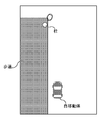
- FIGS. 2A and 2B the stop detection processing as the cause that led to is identified from the safety control limit time T 0, the observation unit 11 to the time until the time T a to the detection unit 111 starts the detection of the target
- FIG. 2A is a schematic diagram of an image generated by the image generation unit 231 based on the data output by the vehicle-mounted camera which is the observation unit 11 of the moving body 100 (FIGS. 3A, 4A and 4A described later). The same applies to 5A, FIG. 6A, and FIG. 7A). Further, FIG.
- 2B is a schematic diagram of an image generated by the image generation unit 231 based on the data (object extraction processed) output by the LiDAR which is the observation unit 11 of the moving body 100 (FIGS. 3B and 4B described later). , 5B, 6B, 7B).
- FIGS. 2A and 2B are based on the data acquired by the observation unit 11 at the safety control limit time T 0.
- FIG. 2B is drawn from a viewpoint above the moving body 100 (the same applies to FIGS. 3B, 4B, 5B, 6B, and 7B described later).
- Transmission image of humanoid with dotted outline in FIGS. 2A and 2B are images of time T a to the sensed target (human in this example), the image generation unit 231 to the log recording unit 210 Sensarogu 211 It is superimposed based on.
- FIG. 2A in the area to the left of the image, the figure of a person on the sidewalk when viewed from the moving body 100 (observation unit 11) is almost entirely hidden by a columnar object (“pillar” in the figure).
- pillar in the figure
- FIG. 2B it can be seen that this person on the sidewalk does not appear in the data output by LiDAR.
- the operator refers to these images in chronological order including the safety control limit time T 0 in order to understand the situation in which the moving body 100 has reached an emergency stop. For example, the operator said that the detection unit 111 could not acquire the position of the target by the safety control limit time T 0 because the target was hidden behind the moving body 100 before the emergency stop of the moving body 100. Look at these images to understand that the situation has occurred.
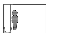
- the detection unit 111 from the time T a which has started detection of the target, the observed portion 11 produced by the data and automatic operation system 110 to the time until the time T of the moving body 100 is stopped by the emergency stop
- Image humanoid in FIGS. 3A and 3B is an image of a person is a target which is the object of the detection process at time T a
- the outline in FIGS. 2A and 2B are represented only by dashed lines.
- the outline of the alternate long and short dash line is superimposed on this image of the target by the image generation unit 231 as being consistent with the image on which the determination unit 113 determines the execution of the emergency stop.
- the detection unit 111 determines in the automatic operation system 110 that the operator who sees the images of FIGS. 3A and 3B as a continuation of the images of FIGS. 2A and 2B executes an emergency stop of the moving body 100 by the detection unit 111. It can be understood that this was done for the target that started detection at a time after time T 0.
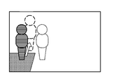
- Emergency case diagram 4A and 4B the stop prediction process as a cause that led to is specified, the detection unit 111 via the safety control limit time T 0 from the time T a which has started detection of the target, the prediction unit 112 of the predetermined
- humanoid images reflected in the image of FIG. 4A and 4B is only an image which is located leftmost What originally captured, represented in the observation data obtained by the observation unit 11, for example, time T a It is an image of target.
- the other two humanoid images are superimposed based on the information acquired from the log recording unit 210 by the image generation unit 231.
- the humanoid image having the outline of the dotted line located at a place off the sidewalk to the right is an image indicating the position of the target after a predetermined time, which is output by the prediction unit 112 at time T b.
- a prediction unit 112 the time after a predetermined predicted time (time T a subsequent to the image which is located the origin of the arrow Time Indicates the position of the target before T b). That is, the arrow indicates the direction and magnitude of the movement of the target predicted by the prediction unit 112 from the image located at the starting point.
- the operator looking at the images of FIGS. 4A and 4B takes into account, for example, the surrounding conditions of the moving body 100 and the target grasped from the images, or the time difference from the safety control limit time T 0 and the predicted position of the target. Therefore, it is possible to determine whether or not there is a problem in the prediction process by the prediction unit 112. If it is determined that there is a problem in the prediction process by the prediction unit 112, the operator may determine that the traveling body 100 cannot be restarted by autonomous driving.
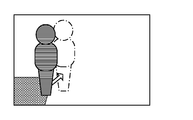
- 5A and 5B show data and automatic data generated by the observation unit 11 from the time T b when the prediction unit 112 outputs the prediction result related to the emergency stop to the time T when the moving body 100 stops due to the emergency stop. It is a schematic diagram for demonstrating the image generated by the image generation unit 231 using the log of the data generated by the operation system 110.
- the humanoid image shown by the solid line in FIGS. 5A and 5B is the image of the target represented by the observation data acquired by the observation unit 11 at time T b.
- the arrow indicates the direction and magnitude of the movement of the target predicted by the prediction unit 112 from this image located at the starting point.
- the humanoid image with the outline of the alternate long and short dash line located off the sidewalk to the right is the position of the target related to this prediction, and is also the image that was the basis for the judgment of the execution of the emergency stop by the judgment unit 113. For example, in the continuation of the images of FIGS.
- the image of the target, the arrow and the dashed humanoid move over time, and the dashed humanoid shows the outline of the image on which the decision to execute the emergency stop was based.
- the broken line changes to a dash-dotted line.
- an operator who sees the images of FIGS. 5A and 5B as a continuation of the images of FIGS. 4A and 4B can easily set the time difference between the time corresponding to the image in which the broken line is changed to the alternate long and short dash line and the safety control limit time T 0. Can be grasped.
- the judgment unit 113 changes the judgment result related to the emergency stop from the time T b when the prediction unit 112 outputs the prediction result related to the emergency stop.
- the image generated by the image generation unit 231 will be described using the log of the data generated by the observation unit 11 and the data generated by the automatic operation system 110 up to the time T c when the instruction for the based control is output. It is a schematic diagram for.
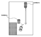
- Each of the images of FIGS. 6A and 6B is a moving body (“other moving body” in the figure) which is a target located in front of the moving body 100 based on the data acquired by the observation unit 11 at time T b. Contains the image at time T b.
- the broken line arrow and the dotted line segment seen at the lower right of the image of the other moving body in FIGS. 6A and 6B are superimposed based on the information acquired from the log recording unit 210 by the image generation unit 231.
- the broken line arrow indicates the route of the moving body 100 planned by the determination unit 113 by the time T b.
- the dotted line segment indicates the planned stop position related to the emergency stop instruction output by the determination unit 113 at time T c.
- the operator who sees the images of FIGS. 6A and 6B can confirm, for example, the situation around the planned stop position, the moving body 100, and the target grasped from the images.
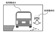
- FIGS. 7A and 7B show the observation unit 11 from the time T c when the determination unit 113 outputs an instruction for control based on the determination result related to the emergency stop to the time T when the moving body 100 is stopped due to the emergency stop.
- It is a schematic diagram for demonstrating the image generated by the image generation unit 231 using the log of the data generated in 1 and the data generated by the automatic operation system 110.
- Each of the images of FIGS. 7A and 7B is based on the data acquired by the observation unit 11 at time T c , and is a target of two mobile bodies located in front of the mobile body 100 (“other movement” in the figure. Includes images of "body A" and "other mobile B") at time T c.
- the band and line segment of the alternate long and short dash line seen in the lower right of the image of the other moving body A in FIGS. 7A and 7B, and the arrow seen under the other moving body B are acquired by the image generation unit 231 from the log recording unit 210. It is superimposed based on the information obtained.
- the belt and line segment of the alternate long and short dash line are the planned route and stop position of the moving body 100 determined by the determination unit 113 in the determination regarding the emergency stop, and the route and the stop position at the time T that the moving body 100 traveled by the time T. Is shown. That is, the plan by the determination unit 113 and the control result of the mobile body 100 by the mobile body control unit 12 are in agreement.
- the arrow indicates the prediction path of the other mobile body B output by the prediction unit 112, which is related to the control instruction output by the determination unit 113 by the time T c.
- the operator looking at the images of FIGS. 7A and 7B can see, for example, align the route and stop position planned for the emergency stop with the travel path and stop position of the moving body 100 as a control result, and for the emergency stop. It is possible to check the situation around the target when the control instruction is output.
- UI configuration The configuration of the UI provided by the UI control unit 233 to the operator via the output device 21 and the input device 22 will be described below with reference to an example.
- the UI includes a component that presents to the operator the processing in the automatic driving system 110 identified by the cause identification unit 223 as the cause of the moving body 100 reaching the emergency stop.
- the UI further includes a component obtained from the status database 232 that presents to the operator a candidate for a situation in which an emergency stop may occur according to the above process identified as the cause of the emergency stop.
- the UI is an image for allowing the operator to confirm the actual situation in which the emergency stop has occurred in order to select an appropriate one from the above candidates, and is a component for presenting the image generated by the image generation unit 231. include.
- the UI further includes a configuration in which the operator is presented with the possibility of resuming the autonomous driving of the moving body 100 determined by the traveling resumption possibility determination unit 234.
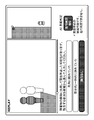
- the UI presented to the operator when the process by the detection unit 111 is specified as the cause of the moving body 100 reaching the emergency stop is as shown in FIGS. 8 to 10.
- UIs are a series of screens including examples of each component listed above.
- the operator can operate the seek bar in the middle of the screen to see an image of the surroundings of the moving body 100 before and after the time when the moving body 100 reaches an emergency stop.
- This image is an image generated by the image generation unit 231.
- FIG. 8 is a screen that presents this image and a candidate for a situation in which an emergency stop may occur as an option. On this screen, the operator has not yet entered the selected status.
- the two images arranged side by side above the sentence indicating the identified cause are presented to the operator for confirmation of the occurrence status of the emergency stop generated by the image generation unit 231 from the log held in the log recording unit 210. It is an example of the image to be made.
- the images illustrated in FIGS. 2A and 2B include images presented for confirmation of the occurrence of this emergency stop.
- the result of the judgment of whether or not the running can be resumed by the running restart possibility judgment unit 234 is entered. This determination is based on the operator's input results regarding the situation in which an emergency stop has occurred.
- the wording "travel restart OK” indicating the result of the determination of whether or not the travel can be resumed by the travel restart possibility determination unit 234 is displayed.
- the phrase "emergency stop has worked normally” is also displayed to indicate that the autonomous driving system 110 is normal.
- the wording "travel restart NG” indicating the result of the determination of whether or not the travel can be resumed by the travel restart possibility determination unit 234 is displayed.
- the phrase "abnormal operation of emergency stop. Cannot resume running.” Is also displayed to indicate that the automatic driving system 110 may be abnormal.
- buttons that accept operator input.
- a travel restart enable / disable signal indicating whether or not the travel is resumed is transmitted from the transmission unit 240 to the moving body 100 according to the result of this determination.
- the operator only confirms the determination result, but the present invention is not limited to this.
- the UI may include a component that allows the operator to select approval or denial of the determination result (and redo the situation selection).
- the travel resumption possibility determination unit 234 determines whether or not the travel of the moving body 100 can be resumed by autonomous driving in response to the input of the situation selected by the operator from the candidates for the situation where the emergency stop may occur.
- An example of the method of determining whether or not the traveling can be resumed by the traveling resuming possibility determination unit 234 for each process of the automatic driving system 110 identified as having an abnormality will be described below.
- a parameter indicating the safety level or the risk level of the execution of the autonomous driving control is used for the situation selected and input by the operator as the corresponding situation.
- a parameter is used in which a value of 1 is used when the restart is safe, and 0 is used when the restart is unsafe or dangerous.
- each candidate for the situation presented to the operator may be given the value of the parameter in advance in the situation database.
- a candidate "assimilated with the background" is newly registered in the database 232. If the detection process can detect up to the class of the object, separate candidates are registered according to the class. Measures such as keeping it can be considered.
- the server determines whether or not the overlapping area between the obstacle and the other obstacle or the blind spot area exceeds the threshold value, and if the threshold value is exceeded, the obstacle and the other obstacle are displayed in the video at that time.
- Information indicating the overlap with the object or the blind spot area or information indicating the degree of the overlap may be superimposed, and the superimposed image may be presented to the operator. In this way, ambiguity can be efficiently eliminated by having the operator confirm the image on which information useful for judgment is superimposed.
- the candidates may be narrowed down in advance and the narrowed down candidates may be presented.
- the result of provisional selection by the server may be presented and approved by the operator. For example, based on the state of overlap between past obstacles and other obstacles or blind spot areas, and the situation selected by the operator at that time, the candidates are narrowed down to two or more situations, and the narrowed down candidates are narrowed down. It may be presented to the operator. Further, instead of narrowing down, one situation candidate may be tentatively selected, and the tentatively selected situation candidate may be presented to the operator.
- the operator says that the obstacle related to the emergency stop has "started moving”, “moved but stopped”, or “changed the direction of travel while moving”. It is assumed that one or more situations are selected and input. In this case, it is difficult to predict the obstacle because the obstacle has suddenly started or stopped moving, or the orientation information that is difficult to predict has changed. Therefore, in the autonomous driving by the automatic driving system 110, the occurrence of an emergency stop is unavoidable, that is, 1 is given as a parameter value assuming that it is safe to restart the driving rather than an abnormality of the automatic driving system 110.
- ambiguity can be expressed numerically by associating the detection results of the positions of the obstacles in chronological order. Therefore, the server may detect acceleration / deceleration of movement exceeding the threshold value or change in direction, superimpose the detection result on the image at that time, and present the superimposed image to the operator. In this way, ambiguity can be efficiently eliminated by having the operator confirm the image on which information useful for judgment is superimposed.
- the candidates may be narrowed down in advance and the narrowed down candidates may be presented.
- a separate process may be performed on the server side to make a selection in advance, and then the operator may confirm the selection result. For example, based on the acceleration / deceleration or change of direction of the movement of the obstacle in the past and the situation selected by the operator at that time, the candidates are narrowed down to two or more situations, and the narrowed down candidates are presented to the operator. May be good.
- one situation candidate may be tentatively selected, and the tentatively selected situation candidate may be presented to the operator.
- the above is the case where the processing result on the server side of the above candidate selection can be sufficiently trusted. This is because it is considered that the server can estimate the situation based on the contents confirmed by the operator so far in the case of occurrence of the above.
- the deceleration control should have been executed by making a decision to decelerate so as not to get too close to the obstacle in front of the obstacle, and no emergency stop should have occurred. That is, there is a possibility that the automatic driving system 110 has an abnormality, and it is unsafe to resume driving. Therefore, 0 is given as the value of the parameter.
- the server may detect acceleration / deceleration of movement exceeding the threshold value or change in direction, superimpose the detection result on the image at that time, and present the superimposed image to the operator. In this way, ambiguity can be efficiently eliminated by having the operator confirm the image on which information useful for judgment is superimposed.
- a separate process may be performed on the server side to make a selection in advance, and then the operator may confirm the selection result. For example, based on the acceleration / deceleration or change of direction of the movement of the obstacle in the past and the situation selected by the operator at that time, the candidate of the situation is tentatively selected, and the candidate of the tentatively selected situation is presented to the operator. May be good.
- situation candidates are registered for each obstacle class, and two or more situations are based on the acceleration / deceleration or change of orientation of the obstacle movement for each class in the past and the situation selected by the operator at that time.
- the narrowed down candidates may be presented to the operator. Further, instead of narrowing down, one situation candidate may be tentatively selected, and the tentatively selected situation candidate may be presented to the operator.
- the cause identification unit 223 identifies the "other obstacle" as a cause due to the processing by the detection unit 111 or the prediction unit 112, in each case, input the selection from the candidates of the above situation.
- the value of the parameter may be given by the operator performing again.
- the travel resumption possibility determination unit 234 determines that the travel can be resumed if the value given to the parameter with respect to the operator's input is 1, and that the travel cannot be resumed if the parameter is 0.
- the determination result is output to the UI control unit 233.
- the UI control unit 233 controls the display in the "AI automatic determination" column according to the determination result input from the travel restart possibility determination unit 234.
- the emergency stop may be unavoidable.
- the image generation unit 231 acquires from the identification result of the cause identification unit 223 how much time difference the identified process is expected to output from the safety control limit time T 0 , as described above. Generate an image in.
- the operator follows the image generated by the image generation unit 231 in chronological order via the input device 22, and inputs which situation candidate the image at each time corresponds to.
- the travel resumption possibility determination unit 234 determines whether or not the travel can be resumed depending on whether or not the time from the change of the situation until the obstacle is detected exceeds the allowable value of the processing delay. can do. It should be noted that the time from when the situation changes (or after the obstacle is detected after the situation changes) until the position of the obstacle is predicted, or after the situation changes (or after the situation changes), the obstacle The time from the predicted position to the determination of an emergency stop may be compared to the permissible value.
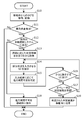
- FIG. 11 is a flowchart showing a procedure example of the information processing method according to the present embodiment.
- step S10 When the remote server 200 acquires any of the sensor log 211, the traveling log 212, and the processing log 213 transmitted from the automatic driving system 110 of the mobile body 100, these logs are recorded in the log recording unit 210 (step S10). ..
- the operation detection unit 221 of the first information processing unit 220 refers to the processing log 213 or the travel log 212 in order to detect the occurrence of an emergency stop in the moving body 100 (step S11). If no emergency stop has occurred (No in step S11), the processing for the log acquired in step S10 ends.
- step S11 When the occurrence of an emergency stop is detected (Yes in step S11), the time calculation unit 222 and the cause identification unit 223 of the first information processing unit 220 indicate that the cause of the emergency stop is the detection unit 111 of the automatic operation system 110. , It is determined whether the process is specified by either the prediction unit 112 or the determination unit 113, or whether it is a system error (step S12). If it is determined that the cause of the emergency stop is a system error (No in step S12), a travel restart enable / fail signal indicating that autonomous driving cannot be resumed from the cause identification unit 223 through the transmission unit 240. Is transmitted to the moving body 100 (step S18).
- step S12 When the cause of the emergency stop is the process in the automatic operation system 110 (Yes in step S12), the UI control unit 233 of the second information processing unit 230 has identified the cause of the emergency stop. In response to this, a candidate for a situation in which an emergency stop may occur is acquired from the situation database 232 (step S13).
- the UI control unit 233 includes an image showing the actual situation in which the moving body 100 generated by the image generation unit 231 using the information extracted from the log recording unit 210 has reached an emergency stop, and a candidate for the situation acquired in step S13.
- the UI including the above is presented to the operator via the output device 21 (step S14).
- the UI presented here is, for example, a screen as shown in FIG. 8 in which the operator selects and inputs an appropriate one as an explanation of the situation leading to the emergency stop.
- the travel resumption possibility determination unit 234 determines whether or not the travel of the moving body 100 can be resumed by autonomous driving according to the input result of the situation corresponding to the actual situation selected by the operator from the situation candidates via the input device 22. (Step S15).
- the determination here may be a tentative determination, or the determination may be made after further input regarding the situation is obtained from the operator. If there is a UI for asking the operator for further input about the situation (Yes in step S16), the UI control unit 233 repeats the procedure from step S14.
- the UI control unit 233 uses the UI control unit 233 to provide information on the determination result of the travel restartability determination unit 234 by the travel restartability determination unit 234.
- the UI reflected in the above is presented to the operator via the output device 21 to request approval (or confirmation) (step S17). For example, a screen as shown in FIG. 9 or FIG. 10 is presented.
- step S17 When it is detected by the UI control unit 233 that the operator approves the determination result of whether or not to resume traveling via the input device 22 (Yes in step S17), whether or not traveling can be resumed according to the approved determination result.
- the signal is transmitted from the transmission unit 240 to the mobile body 100 (step S19). If the operator refuses to approve the determination result of whether or not to resume running (No in step S17), the procedure returns to step S14 in this procedure example. In step S14 and subsequent steps in this case, the UI once presented may be presented again, for example, in order to make the operator reconfirm and reselect the corresponding situation.
- the safety control has been described as a control for stopping the vehicle at a position stopped by an emergency stop by a normal autonomous driving control, but the mode of the safety control is not limited to this.
- the safety control may be, for example, steering and acceleration / deceleration as necessary, and may be a control that keeps driving while avoiding obstacles related to an emergency stop in actual driving.
- the value of the parameter indicating the safety level or the risk level is determined according to the situation selected from the candidates as the corresponding situation by the operator and input, but is not limited to this.
- the value of the above parameter may be a value related to the time corresponding to the candidate of the situation input for the time until the safety control limit time. More specifically, the closer the unexpected course entry of another moving object is to the safety control limit time, the less likely the emergency stop is to be abnormal for the operation of the autonomous driving system, and the degree of safety is low. high.
- Another example of a parameter value is one that contains a safety or risk value based on the length of the delay from the safety control limit time of the output of the process identified as the cause of the emergency stop. There may be.
- the frequent occurrence of emergency stops in a specific candidate is considered to be dangerous driving, so each time there is a certain number of inputs to the candidate, the safety level or risk level is indicated. You may update the value.
- the values of the parameters listed here are not limited to binary values such as 0 and 1, and more multi-step values can be used.
- a part or all of the functional components included in each of the above-mentioned information processing systems may be composed of one system LSI (Large Scale Integration).
- a system LSI is an ultra-multifunctional LSI manufactured by integrating a plurality of components on one chip, and specifically, is a computer system including a microprocessor, a ROM, a RAM, and the like. ..
- a computer program is stored in the ROM. When the microprocessor operates according to this computer program, the system LSI achieves the function of each component.
- system LSI Although it is referred to as a system LSI here, it may be referred to as an IC, an LSI, a super LSI, or an ultra LSI due to the difference in the degree of integration. Further, the method of making an integrated circuit is not limited to LSI, and may be realized by a dedicated circuit or a general-purpose processor. An FPGA (Field Programmable Gate Array) that can be programmed after the LSI is manufactured, or a reconfigurable processor that can reconfigure the connection and settings of the circuit cells inside the LSI may be used.
- FPGA Field Programmable Gate Array
- One aspect of the present disclosure is not limited to the information processing method described above using the flow chart of FIG. 11, and may be a program executed by a computer and an information processing system including the computer. Also, one aspect of the present disclosure may be a computer-readable, non-temporary recording medium on which such a computer program is recorded.
- the technology according to the present disclosure is an information processing method executed when an emergency stop of an autonomously traveling moving body occurs, an information processing device that executes such an information processing device, or an information processing device that executes such an information processing method. It can be used as a program to process information.
Landscapes
- Engineering & Computer Science (AREA)
- Automation & Control Theory (AREA)
- Transportation (AREA)
- Mechanical Engineering (AREA)
- Human Computer Interaction (AREA)
- Physics & Mathematics (AREA)
- General Physics & Mathematics (AREA)
- Radar, Positioning & Navigation (AREA)
- Remote Sensing (AREA)
- Aviation & Aerospace Engineering (AREA)
- Traffic Control Systems (AREA)
- Control Of Position, Course, Altitude, Or Attitude Of Moving Bodies (AREA)
Abstract
This information processing method comprises a process for: determining whether or not an emergency stop of a moving body that autonomously travels has occurred (S11); if it is determined that the emergency stop has occurred (Yes in S11), simulating safety control on the basis of a traveling situation history of the moving body, and identifies the process that caused the emergency stop, from among the processes for autonomous travel control indicated by a log of an automated driving system, and on the basis of the simulated safety control and the autonomous travel control indicated by the log (S12); acquiring situation candidates associated with the identified process from a database relating to situations in which an emergency stop may occur (S13); presenting, to an operator, an interface for entering a situation candidate corresponding to the situation indicated by the log (S14); and determining, in accordance with the entered situation candidate, whether or not to permit the automated driving system to resume the autonomous travel control (S15).
Description
本開示は、自律走行する移動体の緊急停止発生時に実行される情報処理方法等に関する。
This disclosure relates to an information processing method, etc., which is executed when an emergency stop of an autonomously traveling mobile body occurs.
近年の自動運転技術の発展に伴い、自律走行する移動体によるドライバレスでの搬送サービスの実現が期待される。このようなサービスの実運用では、緊急時に遠隔からオペレータが対応できることが要求される。特に、緊急停止した移動体の復帰は事故発生の危険が高いため、対応するオペレータが遠隔で状況を理解し、問題があるかないかに応じてサービスを停止させるか走行を再開させるかを決定できる仕組みが必要である。例えば、従来、車載カメラの映像を確認することにより移動体の外部の状況を遠隔で把握する方法がある(特許文献1参照)。
With the development of autonomous driving technology in recent years, it is expected that a driverless transportation service will be realized by an autonomously traveling mobile body. In the actual operation of such a service, it is required that the operator can respond remotely in an emergency. In particular, since there is a high risk of accidents when returning a moving object that has stopped in an emergency, the corresponding operator can remotely understand the situation and decide whether to stop the service or restart the operation depending on whether there is a problem or not. is required. For example, conventionally, there is a method of remotely grasping the external situation of a moving body by checking an image of an in-vehicle camera (see Patent Document 1).
また、自動運転システムの処理に着目した発明として、自動運転システムが検知していた障害物や、実行した移動体の制御を可視化することで、自動制御による急動作の発生原因を乗員に把握させて安心させる移動体用表示方法がある(特許文献2参照)。
In addition, as an invention focusing on the processing of the automatic driving system, by visualizing the obstacles detected by the automatic driving system and the control of the executed moving body, the occupants can understand the cause of the sudden operation by the automatic control. There is a display method for mobile objects that reassures people (see Patent Document 2).
しかし、特許文献1に記載の方法で提供されるような映像が示す周囲の様子だけでは、自動運転システムが緊急停止した理由は不明である。なお、特許文献1にはその理由の確認についての開示も示唆もない。
However, the reason why the automatic driving system has stopped urgently is unknown only from the surroundings shown by the image provided by the method described in Patent Document 1. It should be noted that Patent Document 1 has neither disclosure nor suggestion regarding confirmation of the reason.
また、特許文献2に記載の移動体用表示方法は、急動作に至った自動運転システムの処理の状況を遠隔のオペレータが理解するためには役立つ。しかし、移動体の走行再開に問題が実際にあるかないかの判断はオペレータに依存する。そのため、走行再開の安全性を確実に高めることが困難である。
Further, the display method for a mobile body described in Patent Document 2 is useful for a remote operator to understand the processing status of the automatic driving system that has led to a sudden operation. However, it is up to the operator to determine if there is actually a problem with the resumption of travel of the moving object. Therefore, it is difficult to surely improve the safety of resuming running.
本開示は、自律走行する移動体が障害物との衝突を回避するために緊急停止した際、走行再開の安全性をより確実に向上させることができる情報処理方法及び情報処理システムを提供する。
The present disclosure provides an information processing method and an information processing system that can more reliably improve the safety of resuming driving when an autonomously traveling moving object makes an emergency stop in order to avoid a collision with an obstacle.
本開示の一態様に係る情報処理方法は、プロセッサにより実行される情報処理方法であって、自律走行する移動体が障害物との衝突を回避するための緊急停止が発生したか否かを判定し、前記緊急停止が発生したと判定した場合、前記移動体の走行状況履歴に基づいて、前記移動体が前記緊急停止を行わずに前記障害物との衝突を回避するように自律走行するための自律走行制御である安全制御をシミュレーションし、前記移動体の前記自律走行制御を実行する自動運転システムのログを取得し、前記ログが示す自律走行制御及びシミュレーションされた前記安全制御に基づいて、前記ログが示す自律走行制御のための処理の中から前記緊急停止の原因である処理を特定し、緊急停止が発生し得る状況に関するデータベースから、特定した前記処理に応じた状況候補を取得し、オペレータに、前記ログが示す状況に該当する前記状況候補を入力させるためのインタフェースを提示し、入力された前記状況候補に応じて、前記自動運転システムによる前記自律走行制御の再開の可否を判定する処理を含む。
The information processing method according to one aspect of the present disclosure is an information processing method executed by a processor, and determines whether or not an emergency stop has occurred in order to avoid a collision of an autonomously traveling moving body with an obstacle. Then, when it is determined that the emergency stop has occurred, the moving body autonomously travels so as to avoid a collision with the obstacle without performing the emergency stop based on the traveling status history of the moving body. The safety control, which is the autonomous driving control of the above, is simulated, the log of the automatic driving system that executes the autonomous driving control of the moving body is acquired, and based on the autonomous driving control indicated by the log and the simulated safety control, The process that is the cause of the emergency stop is identified from the processes for autonomous driving control shown in the log, and the situation candidates corresponding to the specified process are acquired from the database regarding the situation in which the emergency stop can occur. An interface for causing the operator to input the situation candidate corresponding to the situation indicated by the log is presented, and it is determined whether or not the autonomous driving control can be restarted by the automatic driving system according to the input situation candidate. Including processing.
また、本開示の一態様に係る情報処理システムは、プロセッサを備える一台以上のコンピュータを含む情報処理システムであって、前記プロセッサは、自律走行する移動体が障害物との衝突を回避するための緊急停止が発生したか否かを判定し、緊急停止が発生したと判定した場合、前記移動体の走行状況履歴に基づいて、前記移動体が前記緊急停止を行わずに前記障害物との衝突を回避するように自律走行するための自律走行制御である安全制御をシミュレーションし、前記移動体の前記自律走行制御を実行する自動運転システムのログを取得し、前記ログが示す自律走行制御及びシミュレーションされた前記安全制御に基づいて、前記ログが示す自律走行制御のための処理の中から前記緊急停止の原因である処理を特定し、緊急停止が発生し得る状況に関するデータベースから、特定した前記処理に応じた状況候補を取得し、オペレータに、前記ログが示す状況に該当する前記状況候補を入力させるためのインタフェースを提示し、入力された前記状況候補に応じて、前記自動運転システムによる前記自律走行制御の再開の可否を判定する。
Further, the information processing system according to one aspect of the present disclosure is an information processing system including one or more computers equipped with a processor, and the processor is for avoiding a collision of an autonomously traveling moving object with an obstacle. When it is determined whether or not an emergency stop has occurred and it is determined that an emergency stop has occurred, the moving body does not perform the emergency stop and is associated with the obstacle based on the traveling status history of the moving body. It simulates safety control, which is autonomous driving control for autonomous driving so as to avoid a collision, acquires a log of an automatic driving system that executes the autonomous driving control of the moving body, and obtains the autonomous driving control and the autonomous driving control indicated by the log. Based on the simulated safety control, the process that is the cause of the emergency stop is identified from the processes for autonomous driving control shown in the log, and the identified process is specified from the database regarding the situation where the emergency stop can occur. The situation candidate corresponding to the processing is acquired, the operator is presented with an interface for inputting the situation candidate corresponding to the situation indicated by the log, and the said situation candidate by the automatic driving system is provided according to the input situation candidate. It is determined whether or not the autonomous driving control can be restarted.
なお、これらの包括的又は具体的な態様は、装置、集積回路、コンピュータプログラム又はCD-ROMなどのコンピュータ読み取り可能な記録媒体で実現されてもよく、装置、システム、集積回路、方法、コンピュータプログラム及び記録媒体の任意な組み合わせで実現されてもよい。
It should be noted that these comprehensive or specific embodiments may be realized in a computer-readable recording medium such as a device, an integrated circuit, a computer program or a CD-ROM, and the device, system, integrated circuit, method, computer program. And any combination of recording media may be realized.
本開示に係る情報処理方法及び情報処理システムでは、自律走行する移動体が障害物との衝突を回避するために緊急停止した際の走行再開の安全性をより確実に向上させることができる。
In the information processing method and information processing system according to the present disclosure, it is possible to more reliably improve the safety of resuming traveling when an autonomously traveling moving object makes an emergency stop in order to avoid a collision with an obstacle.
上記の課題を解決するために、本開示の一態様に係る情報処理方法は、プロセッサにより実行される情報処理方法であって、自律走行する移動体が障害物との衝突を回避するための緊急停止が発生したか否かを判定し、前記緊急停止が発生したと判定した場合、前記移動体の走行状況履歴に基づいて、前記移動体が前記緊急停止を行わずに前記障害物との衝突を回避するように自律走行するための自律走行制御である安全制御をシミュレーションし、前記移動体の前記自律走行制御を実行する自動運転システムのログを取得し、前記ログが示す自律走行制御及びシミュレーションされた前記安全制御に基づいて、前記ログが示す自律走行制御のための処理の中から前記緊急停止の原因である処理を特定し、緊急停止が発生し得る状況に関するデータベースから、特定した前記処理に応じた状況候補を取得し、オペレータに、前記ログが示す状況に該当する前記状況候補を入力させるためのインタフェースを提示し、入力された前記状況候補に応じて、前記自動運転システムによる前記自律走行制御の再開の可否を判定する。
In order to solve the above problems, the information processing method according to one aspect of the present disclosure is an information processing method executed by a processor, and is an emergency for an autonomously traveling moving body to avoid a collision with an obstacle. When it is determined whether or not a stop has occurred and it is determined that the emergency stop has occurred, the moving body collides with the obstacle without performing the emergency stop based on the traveling status history of the moving body. Simulates safety control, which is autonomous driving control for autonomous driving so as to avoid Based on the safety control, the process that is the cause of the emergency stop is identified from the processes for autonomous driving control indicated by the log, and the specified process is specified from the database relating to the situation where the emergency stop may occur. The situation candidate corresponding to the above is acquired, the operator is presented with an interface for inputting the situation candidate corresponding to the situation indicated by the log, and the autonomous driving system is used according to the input situation candidate. It is determined whether or not the driving control can be restarted.
これにより、自律走行する移動体が障害物との衝突を回避するために緊急停止した際、走行再開の安全性をより確実に向上させることが可能である。
This makes it possible to more reliably improve the safety of resuming driving when an autonomously traveling moving body makes an emergency stop in order to avoid a collision with an obstacle.
また例えば、前記緊急停止の原因である処理の特定は、前記安全制御と前記ログが示す自律走行制御とを比較し、前記移動体の前記自律走行制御において前記安全制御を実行するための前記安全制御の開始時刻である安全制御時刻を求め、前記安全制御の実行に要する処理の結果が、前記安全制御時刻よりも前に出力されたか否かの判定の結果に基づいて行ってもよい。より具体的には、例えば、前記安全制御の実行に要する処理は、前記移動体の周囲状況を示す検知結果を取得するための検知処理、前記検知結果を用いて前記移動体の周囲状況を予測するための予測処理、及び予測された前記周囲状況に応じた走行経路を決定するための判断処理の少なくとも1つであってもよい。
Further, for example, in identifying the process that is the cause of the emergency stop, the safety control is compared with the autonomous driving control indicated by the log, and the safety control for executing the safety control in the autonomous driving control of the moving body is performed. The safety control time, which is the start time of the control, may be obtained, and the result of the process required for executing the safety control may be determined based on the result of determining whether or not the result of the process is output before the safety control time. More specifically, for example, the process required to execute the safety control is a detection process for acquiring a detection result indicating the surrounding situation of the moving body, and the surrounding situation of the moving body is predicted by using the detection result. It may be at least one of the prediction process for determining the traveling route and the determination process for determining the traveling route according to the predicted surrounding situation.
これにより、自律走行で可能であった安全制御又は理想的な安全制御との差異に応じて自律走行制御の再開の可否が判定され、走行再開の安全性をより確実に向上させることが可能である。
As a result, whether or not the autonomous driving control can be restarted is determined according to the difference from the safety control or the ideal safety control that was possible in the autonomous driving, and it is possible to more reliably improve the safety of the restarting of the driving. be.
また例えば、前記インタフェースは、特定した前記処理の出力と、前記自動運転システムに入力された観測データとを用いて生成した画像を含んでいてもよい。また、前記インタフェースは、前記安全制御での前記安全制御時刻における出力をさらに用いて生成した画像を含んでいてもよい。また、前記インタフェースは、前記ログが示す状況に該当する前記状況候補を、前記安全制御時刻以降の時点に対して入力させるためのインタフェースであってもよい。
Further, for example, the interface may include an image generated by using the output of the specified process and the observation data input to the automatic driving system. Further, the interface may include an image generated by further using the output at the safety control time in the safety control. Further, the interface may be an interface for inputting the situation candidate corresponding to the situation indicated by the log to a time point after the safety control time.
これにより、自律走行する移動体が緊急停止したときの周囲の状況、又はその周囲の状況を示す観測データに対する自動運転システムの処理の適否をオペレータに判定させることができる。
This makes it possible for the operator to determine the suitability of the processing of the automatic driving system with respect to the surrounding conditions when the autonomously traveling moving body makes an emergency stop, or the observation data indicating the surrounding conditions.
また例えば、前記自律走行制御の再開の可否は、入力された前記状況候補について設定されている、自律走行制御の実行の安全度又は危険度を示すパラメータの値に基づいて決定されてもよい。また、前記パラメータは、特定した前記処理の出力の前記安全制御時刻からの遅延時間長に基づいていてもよい。また、前記パラメータは、入力された前記状況候補が該当する時間に関し、前記状況候補は、前記安全制御時刻までの時間に対して入力されてもよい。
Further, for example, whether or not the autonomous driving control can be restarted may be determined based on the value of the parameter indicating the safety level or the risk level of the execution of the autonomous driving control set for the input situation candidate. Further, the parameter may be based on the delay time length from the safety control time of the output of the specified process. Further, the parameter may be input with respect to the time when the input situation candidate corresponds, and the situation candidate may be input with respect to the time until the safety control time.
これにより、緊急停止後の自律走行の再開の可否をオペレータに依存しないで判定することが容易になり、走行再開の安全性をより確実に向上させることができる。
This makes it easier to determine whether or not autonomous driving can be resumed after an emergency stop without depending on the operator, and the safety of restarting driving can be improved more reliably.
また例えば、前記安全制御は、前記移動体を前記緊急停止による停車位置又は前記停車位置よりも手前の位置に停車させる制御であってもよい。また例えば、前記安全制御は、前記移動体を前記障害物を避けて走行させる制御であってもよい。
Further, for example, the safety control may be a control for stopping the moving body at a stop position due to the emergency stop or a position before the stop position. Further, for example, the safety control may be a control for causing the moving body to travel while avoiding the obstacle.
上記の課題を解決するために、本開示の一態様に係る情報処理システムは、プロセッサを備える一台以上のコンピュータを含む情報処理システムであって、前記プロセッサは、自律走行する移動体が障害物との衝突を回避するための緊急停止が発生したか否かを判定し、緊急停止が発生したと判定した場合、前記移動体の走行状況履歴に基づいて、前記移動体が前記緊急停止を行わずに前記障害物との衝突を回避するように自律走行するための自律走行制御である安全制御をシミュレーションし、前記移動体の前記自律走行制御を実行する自動運転システムのログを取得し、前記ログが示す自律走行制御及びシミュレーションされた前記安全制御に基づいて、前記ログが示す自律走行制御のための処理の中から前記緊急停止の原因である処理を特定し、緊急停止が発生し得る状況に関するデータベースから、特定した前記処理に応じた状況候補を取得し、オペレータに、前記ログが示す状況に該当する前記状況候補を入力させるためのインタフェースを提示し、入力された前記状況候補に応じて、前記自動運転システムによる前記自律走行制御の再開の可否を判定する。
In order to solve the above problems, the information processing system according to one aspect of the present disclosure is an information processing system including one or more computers equipped with a processor, and the processor is an obstacle in a moving body traveling autonomously. When it is determined whether or not an emergency stop has occurred to avoid a collision with the moving body and it is determined that an emergency stop has occurred, the moving body makes the emergency stop based on the traveling status history of the moving body. The safety control, which is an autonomous driving control for autonomous driving so as to avoid a collision with the obstacle, is simulated, and the log of the automatic driving system that executes the autonomous driving control of the moving body is acquired. Based on the autonomous driving control indicated by the log and the simulated safety control, the process that is the cause of the emergency stop is identified from the processes for autonomous driving control indicated by the log, and the emergency stop can occur. The situation candidate corresponding to the specified process is acquired from the database related to the above, the operator is presented with an interface for inputting the situation candidate corresponding to the situation indicated by the log, and the situation candidate is input according to the input situation candidate. , It is determined whether or not the autonomous driving control can be restarted by the automatic driving system.
これにより、自律走行する移動体が障害物との衝突を回避するために緊急停止した際、安全性をより確実に向上させての走行再開が可能である。
As a result, when an autonomously traveling moving object makes an emergency stop in order to avoid a collision with an obstacle, it is possible to restart the traveling with improved safety more reliably.
なお、これらの包括的又は具体的な態様は、装置、集積回路、コンピュータプログラム又はCD-ROMなどのコンピュータ読み取り可能な記録媒体で実現されてもよく、装置、システム、集積回路、方法、コンピュータプログラム及び記録媒体の任意な組み合わせで実現されてもよい。
It should be noted that these comprehensive or specific embodiments may be realized in a computer-readable recording medium such as a device, an integrated circuit, a computer program or a CD-ROM, and the device, system, integrated circuit, method, computer program. And any combination of recording media may be realized.
以下、図面を参照して、本開示に係る情報処理方法及び情報処理システムの実施形態について説明する。
Hereinafter, the information processing method and the embodiment of the information processing system according to the present disclosure will be described with reference to the drawings.
なお、以下で説明する実施の形態は、いずれも包括的又は具体的な例を示すものである。実施の形態で示される数値、形状、材料、構成要素、構成要素の配置位置及び接続形態、ステップ、ステップの順序等は一例であり、本発明を限定する趣旨ではない。
Note that all of the embodiments described below show comprehensive or specific examples. The numerical values, shapes, materials, components, arrangement positions and connection forms of the components, steps, the order of steps, etc. shown in the embodiments are examples, and are not intended to limit the present invention.
[構成]
図1は、本実施の形態に係る、自動運転システムを備える移動体及び遠隔サーバを含む仕組みの全体構成図である。 [composition]
FIG. 1 is an overall configuration diagram of a mechanism including a mobile body and a remote server provided with an automatic driving system according to the present embodiment.
図1は、本実施の形態に係る、自動運転システムを備える移動体及び遠隔サーバを含む仕組みの全体構成図である。 [composition]
FIG. 1 is an overall configuration diagram of a mechanism including a mobile body and a remote server provided with an automatic driving system according to the present embodiment.
本開示に係る情報処理方法は、図1に示す自律走行する移動体100と、移動体100と無線接続される遠隔サーバ200とを含む仕組みの中でプロセッサにより実行される。
The information processing method according to the present disclosure is executed by a processor in a mechanism including a mobile body 100 that autonomously travels as shown in FIG. 1 and a remote server 200 that is wirelessly connected to the mobile body 100.
(移動体)
移動体100は、自動運転システム110、受信部120、観測部11、移動体制御部12を備える。 (Mobile)
The movingbody 100 includes an automatic driving system 110, a receiving unit 120, an observing unit 11, and a moving body control unit 12.
移動体100は、自動運転システム110、受信部120、観測部11、移動体制御部12を備える。 (Mobile)
The moving
観測部11は、移動体100の周囲をセンシングすることにより観測する。観測部11は、例えばカメラ、Radar(Radio detecting and ranging)又はLiDAR(Light detection and ranging又はLaser imaging detection and ranging)を用いて実現される。この観測の結果を示す観測データは、観測部11から自動運転システム110に提供される。
The observation unit 11 observes by sensing the surroundings of the moving body 100. The observation unit 11 is realized by using, for example, a camera, Radar (Radio detecting and ranging) or LiDAR (Light detection and ranging or Laser imaging detection and ranging). Observation data showing the result of this observation is provided from the observation unit 11 to the automatic operation system 110.
移動体制御部12は、自動運転システム110からの運転制御に関する指示に従って移動体100の走行を制御する。例えば移動体制御部12は、移動体の操舵角及び加減速を制御する回路を用いて実現される。また、この制御の内容を示す情報(以下、操舵/加減速情報ともいう)が、移動体制御部12から自動運転システム110に提供される。
The moving body control unit 12 controls the running of the moving body 100 according to an instruction regarding operation control from the automatic driving system 110. For example, the moving body control unit 12 is realized by using a circuit that controls the steering angle and acceleration / deceleration of the moving body. Further, information indicating the content of this control (hereinafter, also referred to as steering / acceleration / deceleration information) is provided from the moving body control unit 12 to the automatic driving system 110.
自動運転システム110は、検知部111、予測部112及び判断部113を機能的な構成要素として有する。
The automatic operation system 110 has a detection unit 111, a prediction unit 112, and a determination unit 113 as functional components.
検知部111は、観測部11により取得される画像又は点群等の観測データに対する処理によって障害物の検知及び当該障害物の種別、大きさ、移動体100との相対位置及び相対速度に関する情報を取得して出力する。
The detection unit 111 detects an obstacle by processing the observation data such as an image or a point cloud acquired by the observation unit 11, and obtains information on the type and size of the obstacle, the relative position with respect to the moving body 100, and the relative speed. Get and output.
予測部112は、検知部111から取得する情報及び行動予測技術に対する処理によって、検知された障害物の移動経路を予測し出力する。
The prediction unit 112 predicts and outputs the movement route of the detected obstacle by processing the information acquired from the detection unit 111 and the behavior prediction technology.
判断部113は、予測部112から取得する障害物の予測移動経路及び移動体制御部12から取得する移動体100の操舵/加減速情報に対する処理によって、動的に移動体100の経路を計画する。そして判断部113は、移動体100にその計画した経路(以下、計画経路ともいう)を走行させるための次の操舵制御及び加減速制御の少なくとも一方を含む運転制御の内容を決定し、決定した運転制御の内容を含む指示を移動体制御部12に出力する。なお、判断部113が指示する操舵及び加減速の制御量については、通常の走行の限度として予め定められた上限がある。この上限を超える制御量、例えば所定の減速度を超える制御が必要な状況が発生した場合、判断部113は緊急停止のための制動を指示する。このような緊急停止のための指示が発行されると、遠隔サーバ200が関与する所定の手続を経るまで、判断部113からの指示に応じた移動体制御部12による移動体100の走行のための運転制御は実行されない。
The determination unit 113 dynamically plans the route of the moving body 100 by processing the predicted moving path of the obstacle acquired from the predicting unit 112 and the steering / acceleration / deceleration information of the moving body 100 acquired from the moving body control unit 12. .. Then, the determination unit 113 determines and determines the content of the operation control including at least one of the next steering control and acceleration / deceleration control for traveling the planned route (hereinafter, also referred to as a planned route) on the moving body 100. An instruction including the content of the operation control is output to the mobile control unit 12. The steering and acceleration / deceleration control amounts instructed by the determination unit 113 have a predetermined upper limit as a normal traveling limit. When a control amount exceeding this upper limit, for example, a situation requiring control exceeding a predetermined deceleration occurs, the determination unit 113 instructs braking for an emergency stop. When such an instruction for emergency stop is issued, the mobile body 100 is driven by the mobile body control unit 12 in response to the instruction from the determination unit 113 until the predetermined procedure involving the remote server 200 is performed. Operation control is not executed.
受信部120は、遠隔サーバ200が備える送信部240との無線通信により走行再開可否信号を受信する。受信部120が受信した走行再開可否信号が走行再開可能を示す場合には、移動体100は、移動体制御部12が判断部113からの指示に従って運転制御を実行する状態に戻る。
The receiving unit 120 receives the travel resumption availability signal by wireless communication with the transmitting unit 240 included in the remote server 200. When the travel resumption enable / fail signal received by the receiving unit 120 indicates that travel can be resumed, the mobile body 100 returns to a state in which the mobile body control unit 12 executes operation control in accordance with an instruction from the determination unit 113.
移動体制御部12、自動運転システム110及び受信部120は、移動体100が備える車載ネットワーク上に構築される車載ネットワークシステムが含む各種の運転制御系統に含まれる一台以上のECU(Electronic Control Unit)を用いて実現され得る。ECUは、例えば、プロセッサ(マイクロプロセッサ)、メモリ等のデジタル回路、アナログ回路、通信回路等を含む装置である。メモリは、ROM(Read-Only Memory)及びRAM(Random Access Memory)であり、プロセッサにより実行される制御プログラム(コンピュータプログラム)を記憶することができる。ECUは、プロセッサが制御プログラムに従って動作することによって上述の各構成要素の機能を提供する。コンピュータプログラムとは、所定の機能を実現するために、プロセッサに対する命令コードが複数個組み合わされたものである。
The mobile control unit 12, the automatic driving system 110, and the receiving unit 120 are one or more ECUs (Electronic Control Units) included in various operation control systems included in the vehicle-mounted network system constructed on the vehicle-mounted network included in the mobile body 100. ) Can be realized. The ECU is, for example, a device including a processor (microprocessor), a digital circuit such as a memory, an analog circuit, a communication circuit, and the like. The memory is a ROM (Read-Only Memory) and a RAM (Random Access Memory), and can store a control program (computer program) executed by the processor. The ECU provides the functions of each of the above-mentioned components by operating the processor according to the control program. A computer program is a combination of a plurality of instruction codes for a processor in order to realize a predetermined function.
(遠隔サーバ)
遠隔サーバ200は、プロセッサを備える一台以上のコンピュータを含む情報処理システムの一例である。遠隔サーバ200は、自律走行している移動体100で緊急停止が発生した場合に、その緊急停止の発生は、自動運転システム110の異常によるものか、状況上やむを得なかったものであるかの判断に利用可能な情報をオペレータに提供する。また、このオペレータからの入力に応じて自律走行の再開の可否を判定し、走行再開の可否の判定結果を示す信号を移動体100に送信する。 (Remote server)
The remote server 200 is an example of an information processing system including one or more computers including a processor. When an emergency stop occurs in the autonomously travelingmobile body 100, the remote server 200 determines whether the emergency stop occurs due to an abnormality in the automatic driving system 110 or is unavoidable due to circumstances. Provide the operator with available information. Further, it is determined whether or not autonomous driving can be resumed in response to the input from the operator, and a signal indicating the result of determining whether or not the autonomous driving can be resumed is transmitted to the moving body 100.
遠隔サーバ200は、プロセッサを備える一台以上のコンピュータを含む情報処理システムの一例である。遠隔サーバ200は、自律走行している移動体100で緊急停止が発生した場合に、その緊急停止の発生は、自動運転システム110の異常によるものか、状況上やむを得なかったものであるかの判断に利用可能な情報をオペレータに提供する。また、このオペレータからの入力に応じて自律走行の再開の可否を判定し、走行再開の可否の判定結果を示す信号を移動体100に送信する。 (Remote server)
The remote server 200 is an example of an information processing system including one or more computers including a processor. When an emergency stop occurs in the autonomously traveling
遠隔サーバ200は、例えば、プロセッサ、メモリ及び通信回路等を含む装置である。メモリは、ROM及びRAMであり、プロセッサにより実行される制御プログラム(コンピュータプログラム)を記憶することができる。遠隔サーバ200は、ログ記録部210、第一情報処理部220、第二情報処理部230、送信部240、出力装置21及び入力装置22を備える。なお、遠隔サーバ200が備える各構成要素が複数のサーバに分散して配置されることで、情報処理システムを構成してもよい。
The remote server 200 is a device including, for example, a processor, a memory, a communication circuit, and the like. The memory is a ROM and a RAM, and can store a control program (computer program) executed by the processor. The remote server 200 includes a log recording unit 210, a first information processing unit 220, a second information processing unit 230, a transmission unit 240, an output device 21, and an input device 22. An information processing system may be configured by arranging each component of the remote server 200 in a distributed manner on a plurality of servers.
出力装置21は、遠隔サーバ200の外部に情報を出力する。出力装置21の例として、液晶ディスプレイ及びスピーカーが挙げられる。入力装置22は、遠隔サーバ200の外部からの入力を受け付ける。入力装置22の例としてはキーボード、マウス及びマイクが挙げられる。また、出力装置21と入力装置22とがタッチスクリーンで提供されてもよい。
The output device 21 outputs information to the outside of the remote server 200. Examples of the output device 21 include a liquid crystal display and a speaker. The input device 22 receives an input from the outside of the remote server 200. Examples of the input device 22 include a keyboard, a mouse and a microphone. Further, the output device 21 and the input device 22 may be provided by a touch screen.
ログ記録部210は、自動運転システム110との無線通信によりセンサログ211、走行ログ212及び処理ログ213を取得して記録する。センサログ211は、検知部111に入力された画像又は点群等を示す観測データの履歴である。走行ログ212は、判断部113に入力された移動体100の速度又は位置情報の履歴である。走行ログ212は、移動体100の走行に関わるアクチュエータ(例えばブレーキ、アクセル、又はステアリングのアクチュエータ)の動作履歴を含んでもよい。処理ログ213は、検知部111、予測部112、及び判断部113の処理結果の履歴である。なお、判断部113については、計画経路の履歴も処理ログ213に含まれる。
The log recording unit 210 acquires and records the sensor log 211, the travel log 212, and the processing log 213 by wireless communication with the automatic operation system 110. The sensor log 211 is a history of observation data indicating an image, a point cloud, or the like input to the detection unit 111. The travel log 212 is a history of speed or position information of the moving body 100 input to the determination unit 113. The travel log 212 may include an operation history of an actuator (for example, a brake, an accelerator, or a steering actuator) related to the travel of the moving body 100. The processing log 213 is a history of processing results of the detection unit 111, the prediction unit 112, and the determination unit 113. Regarding the determination unit 113, the history of the planned route is also included in the processing log 213.
第一情報処理部220は、作動検出部221、時刻算出部222及び原因特定部223を機能的な構成要素として有する。なお、これらの構成要素は、プロセッサ等によって実現される。
The first information processing unit 220 has an operation detection unit 221 and a time calculation unit 222 and a cause identification unit 223 as functional components. These components are realized by a processor or the like.
作動検出部221は、処理ログ213を参照して、自動運転システム110の判断部113による移動体100の緊急停止の指示の発行を監視して緊急停止の発生を検出する。緊急停止の発生が検出すると、この検出結果を時刻算出部222などによる以降の処理のトリガーとして出力する。緊急停止の指示は、例えばその指示に付与されるフラグによって示されてもよいし、制動制御の指示の内容(ブレーキ力の大きさ、ブレーキ力配分等)から判断されるものであってもよい。なお、移動体100が、判断部113によって指示が発行される緊急停止とは別に作動する衝突被害軽減ブレーキ等の緊急停止手段を搭載していれば、作動検出部221は、走行ログ212を参照して当該緊急停止手段の作動を検出し、この検出結果を上記トリガーとして出力してもよい。
The operation detection unit 221 monitors the issuance of an emergency stop instruction for the moving body 100 by the determination unit 113 of the automatic operation system 110 with reference to the processing log 213, and detects the occurrence of an emergency stop. When the occurrence of an emergency stop is detected, this detection result is output as a trigger for subsequent processing by the time calculation unit 222 or the like. The emergency stop instruction may be indicated by, for example, a flag given to the instruction, or may be judged from the content of the braking control instruction (brake force magnitude, braking force distribution, etc.). .. If the moving body 100 is equipped with an emergency stop means such as a collision damage mitigation brake that operates separately from the emergency stop for which an instruction is issued by the determination unit 113, the operation detection unit 221 refers to the travel log 212. Then, the operation of the emergency stop means may be detected, and the detection result may be output as the trigger.
時刻算出部222は、走行ログ212から安全制御限界時刻を算出する。本実施の形態における安全制御とは、移動体100が緊急停止により停車した位置に通常の(つまり緊急停止をしない)自律走行制御で停車するような制御を意味し、時刻算出部222による移動体100のシミュレーション上の制御である。
The time calculation unit 222 calculates the safety control limit time from the travel log 212. The safety control in the present embodiment means a control in which the moving body 100 stops at a position where the moving body 100 has stopped due to an emergency stop by a normal autonomous driving control (that is, does not make an emergency stop), and the moving body by the time calculation unit 222. 100 simulation controls.
時刻tにおける移動体の速度vtとし、移動体の位置ltとし、緊急停止により移動体が停車した時刻Tとし、通常の自律走行制御における最大の減速度を
And velocity v t of the moving body at the time t, the position l t of the moving body, and the time T in which the moving body is stopped by emergency stop, a maximum deceleration in the normal autonomous control
なお、Δtは、自動運転システム110が緊急停止の移動体制御を出力してから実際に移動体100が緊急停止を開始するまでの処理遅延時間を示す。また、distance(lk,lk+1)は、位置lkから位置lk+1までの距離を示し、例えば、ユークリッド距離を用いることができる。
In addition, Δt indicates the processing delay time from the output of the moving body control of the emergency stop by the automatic driving system 110 to the actual start of the emergency stop of the moving body 100. Further, distance (l k , l k + 1 ) indicates the distance from the position l k to the position l k + 1 , and for example, the Euclidean distance can be used.
上記のように算出される安全制御限界時刻は、移動体100の自律走行制御において安全制御を実行するための安全制御の開始時刻である安全制御時刻の一例である。安全制御限界時刻について別の表現をすると、移動体100の自律走行制御において、安全制御を実現可能な制御として開始することができた最遅の時刻とも言える。以下では、安全制御限界時刻を用いて説明するが、安全制御の開始時刻は必ずしも最遅の時刻(すなわち安全制御限界時刻)でなくてもよく、最遅の時刻よりも早い時刻であってもよい。
The safety control limit time calculated as described above is an example of the safety control time which is the start time of the safety control for executing the safety control in the autonomous driving control of the moving body 100. In other words, the safety control limit time can be said to be the latest time in which the safety control can be started as a feasible control in the autonomous driving control of the moving body 100. In the following, the safety control limit time will be used for explanation, but the safety control start time does not necessarily have to be the latest time (that is, the safety control limit time), and even if it is earlier than the latest time. good.
原因特定部223は、時刻算出部222が算出した時刻T0及び処理ログ213を用いて、自動運転システム110において実行される自律走行制御のための処理のなかから、発生した緊急停止の原因を特定する。具体的には、原因特定部223は、時刻T0から緊急停止により移動体100が停車した時刻Tまでの時刻に基づいて、検知部111による処理(以下、検知処理ともいう)、予測部112による処理(以下、予測処理ともいう)、及び判断部113による処理(以下、判断処理ともいう)から緊急停止の原因である処理を特定する。この処理について下記に説明する。
The cause identification unit 223 uses the time T 0 calculated by the time calculation unit 222 and the processing log 213 to determine the cause of the emergency stop that occurred in the processing for autonomous driving control executed in the automatic driving system 110. Identify. Specifically, the cause identification unit 223 is processed by the detection unit 111 (hereinafter, also referred to as detection processing) based on the time from the time T 0 to the time T when the moving body 100 is stopped due to the emergency stop, and the prediction unit 112. The process that is the cause of the emergency stop is identified from the process by (hereinafter, also referred to as prediction process) and the process by the determination unit 113 (hereinafter, also referred to as determination process). This process will be described below.
前提として、緊急停止は障害物との衝突を回避するために実行されるのであって、緊急停止を開始した時刻T′では、少なくとも緊急停止に係る障害物が自動運転システム110に検知されている。また、一般的に障害物の速度の検知及び移動経路の予測には、その障害物に関して時系列に関連付けるための物体追跡技術が利用される。本実施の形態に係る自動運転システム110も、この物体追跡技術を採用して予測部112で取得するか、又は同技術を利用する外部から取得する情報に基づいて、ある時刻で検知している緊急停止に係る障害物を他の時刻で検知している当該障害物と同一視する。以降、説明の為、緊急停止に係る障害物をtargetと呼ぶ。
As a premise, the emergency stop is executed to avoid a collision with an obstacle, and at least the obstacle related to the emergency stop is detected by the automatic driving system 110 at the time T'when the emergency stop is started. .. Further, in general, an object tracking technique for associating an obstacle with a time series is used for detecting the speed of an obstacle and predicting a movement path. The automatic driving system 110 according to the present embodiment also adopts this object tracking technology and detects it at a certain time based on the information acquired by the prediction unit 112 or the information acquired from the outside using the technology. The obstacle related to the emergency stop is equated with the obstacle detected at another time. Hereinafter, for the sake of explanation, the obstacle related to the emergency stop will be referred to as a target.
検知処理、予測処理及び判断処理のいずれが緊急停止の原因であるか否かについては、targetに対する処理の結果から判定される。
Whether the detection process, the prediction process, or the judgment process is the cause of the emergency stop is determined from the result of the process for the target.
検知部111が出力する、時刻tでのtargetの位置をdetection(target,t)で表す。ここで、検知部111がtargetの位置を未取得の場合、
detection(target,t) = NULL
とする。 The position of the target at time t output by thedetection unit 111 is represented by detection (target, t). Here, when the detection unit 111 has not acquired the target position,
detection (target, t) = NULL
And.
detection(target,t) = NULL
とする。 The position of the target at time t output by the
detection (target, t) = NULL
And.
detection(target,t)が安全制御限界時刻T0以降にNULLを返す場合、原因特定部223は、検知部111による処理を緊急停止に至った原因として特定する。
When detection (target, t) returns NULL after the safety control limit time T 0 , the cause identification unit 223 identifies the process by the detection unit 111 as the cause leading to the emergency stop.
移動体100が緊急停止に至った原因として検知部111による処理が特定されなかった場合、予測部112による処理が緊急停止に至った原因となり得る。予測部112が出力する、時刻tでのtargetが、緊急停止を開始した時刻T′でのtargetの位置に移動する確率をprediction(target,t)で表す。
If the process by the detection unit 111 is not specified as the cause of the moving body 100 leading to the emergency stop, the process by the prediction unit 112 may be the cause of the emergency stop. The probability that the target at time t output by the prediction unit 112 moves to the position of the target at the time T'when the emergency stop is started is represented by prediction (target, t).
prediction(target,t)が安全制御限界時刻T0以降に閾値を下回る場合、原因特定部223は、予測部112による処理を移動体100が緊急停止に至った原因として特定する。緊急停止を開始した時刻T′でのtargetの位置としては、例えば前段の処理である検知部111の出力detection(target,T′)を利用できる。
When the prediction (target, t) falls below the threshold value after the safety control limit time T 0 , the cause identification unit 223 identifies the process by the prediction unit 112 as the cause of the emergency stop of the moving body 100. As the position of the target at the time T'when the emergency stop is started, for example, the output detection (target, T') of the detection unit 111, which is the processing in the previous stage, can be used.
移動体100が緊急停止に至った原因として検知部111による処理も予測部112による処理も特定されなかった場合、判断部113による処理が緊急停止に至った原因となり得る。緊急停止を開始した時刻T′でのtargetの位置が予測できているならば、理想的には、通常の自律走行制御における最大の減速度
If neither the processing by the detection unit 111 nor the processing by the prediction unit 112 is specified as the cause of the moving body 100 leading to the emergency stop, the processing by the determination unit 113 may be the cause of the emergency stop. Ideally, the maximum deceleration in normal autonomous driving control if the position of the target at the time T'when the emergency stop was started can be predicted.
判断部113が出力する、時刻tでの移動体100の減速度をatで表す。ここで、移動体100が加速する場合、
at = NULL
とする。 The deceleration of the movingbody 100 at time t, which is output by the determination unit 113, is represented by a t. Here, when the moving body 100 accelerates,
a t = NULL
And.
at = NULL
とする。 The deceleration of the moving
a t = NULL
And.
atが安全制御限界時刻T0以降にNULLを返す場合、又は下記の式2で表す条件
When a t returns NULL after the safety control limit time T 0 , or the condition expressed by the following equation 2
ここで、緊急停止に至った原因として判断部113による処理が特定されなかった場合、自動運転システム110は、判断部113が緊急停止を実行しないで実際の停車位置より手前に停車できるような減速度による制動の指示を出力していたことになる。それにもかかわらず緊急停止が実行されたということは緊急停止に至った原因は自動運転システム110による処理以外にある。言い換えると、移動体100は、自動運転システム110による運転制御下での走行の継続が不可能な状況にあるといえる。本実施の形態においては、このような状況にある移動体100は、システムエラーが発生しているものとして扱い、原因特定部223から送信部240に“自律走行再開不可”を示す情報を出力する。
Here, if the processing by the determination unit 113 is not specified as the cause of the emergency stop, the automatic driving system 110 reduces the number of vehicles so that the determination unit 113 can stop before the actual stop position without executing the emergency stop. It means that the instruction of braking by speed was output. Nevertheless, the fact that the emergency stop was executed means that the cause of the emergency stop is other than the processing by the automatic operation system 110. In other words, it can be said that the moving body 100 is in a situation where it is impossible to continue traveling under the driving control by the automatic driving system 110. In the present embodiment, the mobile body 100 in such a situation is treated as if a system error has occurred, and the cause identification unit 223 outputs information indicating "autonomous driving restart impossible" to the transmission unit 240. ..
以上のように、第一情報処理部220は、緊急停止の発生を検出し、自動運転システム110における各機能的構成要素が実行する自律走行制御のための処理のなかから当該緊急停止に至った原因である処理を特定する。原因として特定された処理は、第一情報処理部220から第二情報処理部230に通知される。
As described above, the first information processing unit 220 has detected the occurrence of an emergency stop, and has reached the emergency stop from the processing for autonomous driving control executed by each functional component in the automatic driving system 110. Identify the causative process. The process identified as the cause is notified from the first information processing unit 220 to the second information processing unit 230.
第二情報処理部230は、画像生成部231、状況データベース(後述する図11中では状況DBとも表記する)232、UI制御部233及び走行再開可否判定部234を機能的な構成要素として有する。なお、これらの構成要素は、プロセッサ等によって実現される。
The second information processing unit 230 has an image generation unit 231, a status database (also referred to as a status DB in FIG. 11 described later) 232, a UI control unit 233, and a travel restartability determination unit 234 as functional components. These components are realized by a processor or the like.
画像生成部231は、第一情報処理部220で緊急停止に至った原因として特定された処理に応じて画像を生成する。例えば、画像生成部231は、ログ記録部210から抽出する情報を用いて、移動体100が緊急停止に至った状況を表す画像を生成する。画像生成部231は、例えば安全制御限界時刻から移動体が緊急停止により停車した時刻までの時間に対応するこのような画像を生成する。生成された画像は上述の出力装置21を介して、移動体100の自律走行の再開可否の判定に関与するオペレータに提示される。この画像については、図2A~図7Bを用いて後述する。
The image generation unit 231 generates an image according to the process identified as the cause of the emergency stop by the first information processing unit 220. For example, the image generation unit 231 uses the information extracted from the log recording unit 210 to generate an image showing the situation in which the moving body 100 has reached an emergency stop. The image generation unit 231 generates such an image corresponding to, for example, the time from the safety control limit time to the time when the moving body stops due to an emergency stop. The generated image is presented to the operator involved in determining whether or not the autonomous traveling of the moving body 100 can be resumed via the output device 21 described above. This image will be described later with reference to FIGS. 2A to 7B.
状況データベース232には、自動運転システム110の処理に応じて緊急停止が発生し得る状況の候補が登録されている。
In the status database 232, candidates for situations in which an emergency stop may occur according to the processing of the automatic operation system 110 are registered.
次に挙げるのは、検知部111による処理に関する前記状況の候補の例である。
The following is an example of a candidate for the above situation regarding processing by the detection unit 111.
「緊急停止に係る障害物が移動体からの死角に隠れていた」
「緊急停止に係る障害物が他の障害物で部分的/一時的に隠れていた」
また、次に挙げるのは、予測部112による処理に関する前記状況の候補の例である。 "An obstacle related to the emergency stop was hidden in the blind spot from the moving body."
"Emergency stop obstacles were partially / temporarily hidden by other obstacles."
Further, the following is an example of a candidate for the above situation regarding the processing by theprediction unit 112.
「緊急停止に係る障害物が他の障害物で部分的/一時的に隠れていた」
また、次に挙げるのは、予測部112による処理に関する前記状況の候補の例である。 "An obstacle related to the emergency stop was hidden in the blind spot from the moving body."
"Emergency stop obstacles were partially / temporarily hidden by other obstacles."
Further, the following is an example of a candidate for the above situation regarding the processing by the
「緊急停止に係る障害物が移動を開始した」
「緊急停止に係る障害物が移動中であったが停止した」
「緊急停止に係る障害物が移動中、進行方向を変えた」
また、次に挙げるのは、判断部113による処理に関する前記状況の候補の例である。 "Obstacles related to emergency stop have started moving"
"The obstacle related to the emergency stop was moving, but it stopped."
"The obstacle related to the emergency stop changed the direction of travel while moving."
Further, the following is an example of a candidate for the above situation regarding the processing by thedetermination unit 113.
「緊急停止に係る障害物が移動中であったが停止した」
「緊急停止に係る障害物が移動中、進行方向を変えた」
また、次に挙げるのは、判断部113による処理に関する前記状況の候補の例である。 "Obstacles related to emergency stop have started moving"
"The obstacle related to the emergency stop was moving, but it stopped."
"The obstacle related to the emergency stop changed the direction of travel while moving."
Further, the following is an example of a candidate for the above situation regarding the processing by the
「他の障害物が移動体の走行予定経路上に進入してきた」
前記状況の候補は、自動運転システム110の処理能力に基づいて、開発者又はサービサが事前にリストアップして、状況データベース232への登録を行う。多数の候補を登録すると、オペレータが適切に選択することが難しくなる。一方で候補が少ない、あるいは、事前のリストアップに漏れがある場合、いずれの候補にも該当しない状況の選択が多発する可能性もある。 "Other obstacles have entered the planned route of the moving object."
Based on the processing capacity of theautomatic driving system 110, the candidate for the situation is listed in advance by the developer or the servicer and registered in the situation database 232. When a large number of candidates are registered, it becomes difficult for the operator to make an appropriate selection. On the other hand, if there are few candidates or there is an omission in the list in advance, there is a possibility that there will be many selections of situations that do not correspond to any of the candidates.
前記状況の候補は、自動運転システム110の処理能力に基づいて、開発者又はサービサが事前にリストアップして、状況データベース232への登録を行う。多数の候補を登録すると、オペレータが適切に選択することが難しくなる。一方で候補が少ない、あるいは、事前のリストアップに漏れがある場合、いずれの候補にも該当しない状況の選択が多発する可能性もある。 "Other obstacles have entered the planned route of the moving object."
Based on the processing capacity of the
例えば、候補数が第1閾値以上である場合、後述するような候補の絞り込み又は候補の仮選択が実行されてもよい。
For example, when the number of candidates is equal to or greater than the first threshold value, narrowing down of candidates or provisional selection of candidates as described later may be executed.
また、例えば、候補数が第2閾値未満である場合、いずれの候補にも該当しない状況である「該当なし」の選択回数が第3閾値以上となった場合、又は、所定期間内での選択回数が第4閾値未満である候補が存在する場合、オペレータに対してアラートが通知されてもよい。
Further, for example, when the number of candidates is less than the second threshold value, the number of selections of "not applicable", which is a situation that does not correspond to any candidate, becomes the third threshold value or more, or selection within a predetermined period. If there is a candidate whose number of times is less than the fourth threshold value, an alert may be notified to the operator.
上記のような問題が事前の検証をどれだけ入念に行っても発生すると考えられるため、上記アラートの通知によりアップデートを促すことができる。また、候補のアップデートのために、「該当なし」が選択されたケースの映像又はシステムのログが削除されないように保管されてもよい。また、可能であれば、オペレータによる自由記述等も保管されてもよい。このように保管された情報を用いることで、新しい候補の選定を効率化できる。さらに、保管された情報に基づいて自動運転システムが改善されてもよい。これにより、よく緊急停止が行われるシーンを開発者又はサービス設計者が把握できるようになり、緊急停止を回避するように自動運転システムがアップデートされたり、サービスルートが緊急停止の起きにくいルートに変更されたり、制限速度が緊急停止が起きにくい速度に再設定されたりする。それにより、自動運転システムによるサービスの改善が期待できる。
Because it is thought that the above problems will occur no matter how carefully the preliminary verification is performed, it is possible to prompt the update by the notification of the above alert. In addition, the video or system log of the case in which "Not applicable" is selected may be stored so as not to be deleted for the update of the candidate. Further, if possible, a free description by the operator and the like may be stored. By using the information stored in this way, the selection of new candidates can be made more efficient. In addition, the automated driving system may be improved based on the stored information. This makes it possible for developers or service designers to understand the scenes where emergency stops are often made, the automatic driving system is updated to avoid emergency stops, and the service route is changed to a route that is less likely to cause emergency stops. Or the speed limit is reset to a speed at which emergency stops are unlikely to occur. As a result, improvement of services by the automatic driving system can be expected.
上記に例を挙げて説明した緊急停止が発生し得る状況は、出力装置21及び入力装置22を用いて実現される、後述するUIの構成要素として用いられる。
The situation in which an emergency stop described above with an example can occur is used as a component of the UI described later, which is realized by using the output device 21 and the input device 22.
UI制御部233は、出力装置21を用いて、緊急停止に至った原因として特定された自動運転システム110での処理をオペレータに提示する。UIの詳細については、例を用いて後述する。
The UI control unit 233 uses the output device 21 to present to the operator the processing in the automatic operation system 110 identified as the cause of the emergency stop. The details of the UI will be described later using an example.
走行再開可否判定部234は、緊急停止が発生し得る状況の候補に対するオペレータからの入力結果に対して、走行再開の可否を判定する。走行再開可否判定部234は、例えば緊急停止の発生状況を入力として、自律走行する自動車の自律走行による走行の再開の可否の判定結果を出力するAI(artificial intelligence)のモデルで実現される。この走行再開の可否の決定方法については、例を用いて後述する。
The travel resumption possibility determination unit 234 determines whether or not the travel can be resumed based on the input result from the operator for the candidate of the situation where the emergency stop may occur. The travel resumption possibility determination unit 234 is realized by an AI (artificial intelligence) model that outputs, for example, the occurrence status of an emergency stop and outputs the determination result of the resumption of travel by autonomous driving of an autonomously traveling vehicle. The method of determining whether or not to resume running will be described later using an example.
送信部240は、移動体100が備える受信部120との無線通信により走行再開可否信号を送信する。
The transmission unit 240 transmits a travel resumption availability signal by wireless communication with the reception unit 120 included in the mobile body 100.
(UIで提示される画面)
次に、画像生成部231が生成してUIとしてオペレータに提示される画面について図2A~図7Bを参照して説明する。図2A~図7Bに示す画像は、第一情報処理部220で緊急停止に至った原因として特定された処理の種類に応じて生成される画像例の模式図である。 (Screen presented by UI)
Next, the screen generated by theimage generation unit 231 and presented to the operator as a UI will be described with reference to FIGS. 2A to 7B. The images shown in FIGS. 2A to 7B are schematic views of image examples generated according to the type of processing identified as the cause of the emergency stop in the first information processing unit 220.
次に、画像生成部231が生成してUIとしてオペレータに提示される画面について図2A~図7Bを参照して説明する。図2A~図7Bに示す画像は、第一情報処理部220で緊急停止に至った原因として特定された処理の種類に応じて生成される画像例の模式図である。 (Screen presented by UI)
Next, the screen generated by the
1.緊急停止に至った原因として検知処理が特定された場合
図2A及び図2Bは、安全制御限界時刻T0から、検知部111がtargetの検知を開始した時刻Taまでの時間に観測部11で生成されたデータ及び自動運転システム110で生成されたデータのログを用いて画像生成部231が生成する画像を説明するための模式図である。より詳細には、図2Aは、移動体100の観測部11である車載カメラが出力したデータに基づいて画像生成部231が生成する画像の模式図である(後述の図3A、図4A、図5A、図6A、図7Aも同じ)。また、図2Bは、移動体100の観測部11であるLiDARが出力したデータ(オブジェクト抽出処理済み)に基づいて画像生成部231が生成する画像の模式図である(後述の図3B、図4B、図5B、図6B、図7Bも同じ)。 1. 1. Emergency case FIGS. 2A and 2B the stop detection processing as the cause that led to is identified from the safety control limit time T 0, theobservation unit 11 to the time until the time T a to the detection unit 111 starts the detection of the target It is a schematic diagram for demonstrating the image generated by the image generation unit 231 using the generated data and the log of the data generated by the automatic operation system 110. More specifically, FIG. 2A is a schematic diagram of an image generated by the image generation unit 231 based on the data output by the vehicle-mounted camera which is the observation unit 11 of the moving body 100 (FIGS. 3A, 4A and 4A described later). The same applies to 5A, FIG. 6A, and FIG. 7A). Further, FIG. 2B is a schematic diagram of an image generated by the image generation unit 231 based on the data (object extraction processed) output by the LiDAR which is the observation unit 11 of the moving body 100 (FIGS. 3B and 4B described later). , 5B, 6B, 7B).
図2A及び図2Bは、安全制御限界時刻T0から、検知部111がtargetの検知を開始した時刻Taまでの時間に観測部11で生成されたデータ及び自動運転システム110で生成されたデータのログを用いて画像生成部231が生成する画像を説明するための模式図である。より詳細には、図2Aは、移動体100の観測部11である車載カメラが出力したデータに基づいて画像生成部231が生成する画像の模式図である(後述の図3A、図4A、図5A、図6A、図7Aも同じ)。また、図2Bは、移動体100の観測部11であるLiDARが出力したデータ(オブジェクト抽出処理済み)に基づいて画像生成部231が生成する画像の模式図である(後述の図3B、図4B、図5B、図6B、図7Bも同じ)。 1. 1. Emergency case FIGS. 2A and 2B the stop detection processing as the cause that led to is identified from the safety control limit time T 0, the
図2A及び図2Bの各画像は、いずれも安全制御限界時刻T0に観測部11で取得されたデータに基づく。なお、図2Bは、移動体100の上方にある視点で描画されている(後述の図3B、図4B、図5B、図6B、図7Bも同じ)。図2A及び図2B中で点線の輪郭を持つ人型の透過像は、時刻Taに検知されたtarget(この例では人)の像を、画像生成部231がログ記録部210にあるセンサログ211に基づいて重畳したものである。
Each of the images of FIGS. 2A and 2B is based on the data acquired by the observation unit 11 at the safety control limit time T 0. Note that FIG. 2B is drawn from a viewpoint above the moving body 100 (the same applies to FIGS. 3B, 4B, 5B, 6B, and 7B described later). Transmission image of humanoid with dotted outline in FIGS. 2A and 2B are images of time T a to the sensed target (human in this example), the image generation unit 231 to the log recording unit 210 Sensarogu 211 It is superimposed based on.
図2Aを参照すると、画像の左寄りの領域で、移動体100(の観測部11)から見て歩道にいる人の姿が柱状の物体(図中「柱」)にほぼ全体が隠れている。しかしながら、図2Bを参照すると、歩道にいるこの人はLiDARが出力したデータには表れていないことが分かる。上記のオペレータは、移動体100が緊急停止に至った状況の理解のために、これらの画像を、安全制御限界時刻T0を含む時系列に沿って参照する。例えばオペレータは、移動体100の緊急停止の前に、targetが移動体100から見て物陰に隠れていたために、検知部111は安全制御限界時刻T0までにtargetの位置を取得できなかったという状況が発生したことを、これらの画像を見て理解する。
Referring to FIG. 2A, in the area to the left of the image, the figure of a person on the sidewalk when viewed from the moving body 100 (observation unit 11) is almost entirely hidden by a columnar object (“pillar” in the figure). However, referring to FIG. 2B, it can be seen that this person on the sidewalk does not appear in the data output by LiDAR. The operator refers to these images in chronological order including the safety control limit time T 0 in order to understand the situation in which the moving body 100 has reached an emergency stop. For example, the operator said that the detection unit 111 could not acquire the position of the target by the safety control limit time T 0 because the target was hidden behind the moving body 100 before the emergency stop of the moving body 100. Look at these images to understand that the situation has occurred.
なお、図2A及び図2Bで画像に写る物体を示す文字は説明の便宜上付したもので、以下で参照する図では、このような説明の文字を省略することがある。
The characters indicating the objects shown in the images in FIGS. 2A and 2B are added for convenience of explanation, and the characters of such explanation may be omitted in the figures referred to below.
図3A及び図3Bは、検知部111がtargetの検知を開始した時刻Taから、緊急停止により移動体100が停車した時刻Tまでの時間に観測部11で生成されたデータ及び自動運転システム110で生成されたデータのログを用いて画像生成部231が生成する画像を説明するための模式図である。
3A and 3B, the detection unit 111 from the time T a which has started detection of the target, the observed portion 11 produced by the data and automatic operation system 110 to the time until the time T of the moving body 100 is stopped by the emergency stop It is a schematic diagram for demonstrating the image generated by the image generation unit 231 using the log of the data generated in 1.
図3A及び図3Bにおける人型の像は、時刻Taにおける検知処理の対象となったtargetである人の像であり、図2A及び図2Bではその輪郭が点線のみで表されている。図3A及び図3Bでは、判断部113による緊急停止の実行の判断の根拠となった像と一致するものとして、targetのこの像に一点鎖線の輪郭が画像生成部231によって重畳されている。
Image humanoid in FIGS. 3A and 3B is an image of a person is a target which is the object of the detection process at time T a, the outline in FIGS. 2A and 2B are represented only by dashed lines. In FIGS. 3A and 3B, the outline of the alternate long and short dash line is superimposed on this image of the target by the image generation unit 231 as being consistent with the image on which the determination unit 113 determines the execution of the emergency stop.
例えば図2A及び図2Bの画像の続きとして図3A及び図3Bの画像を見たオペレータは、移動体100の緊急停止を実行するという自動運転システム110での判断は、検知部111が安全制御限界時刻T0より後の時刻に検知を開始したtargetに対してなされたと理解することができる。
For example, the detection unit 111 determines in the automatic operation system 110 that the operator who sees the images of FIGS. 3A and 3B as a continuation of the images of FIGS. 2A and 2B executes an emergency stop of the moving body 100 by the detection unit 111. It can be understood that this was done for the target that started detection at a time after time T 0.
2.緊急停止に至った原因として予測処理が特定された場合
図4A及び図4Bは、検知部111がtargetの検知を開始した時刻Taから安全制御限界時刻T0を経て、予測部112が所定の閾値以上の確率で緊急停止に係るtargetの位置の予測結果を出力した時刻Tbまでの時間に観測部11で取得されたデータを用いて画像生成部231が生成する画像の説明するための模式図である。 2. Emergency case diagram 4A and 4B the stop prediction process as a cause that led to is specified, thedetection unit 111 via the safety control limit time T 0 from the time T a which has started detection of the target, the prediction unit 112 of the predetermined A schematic for explaining the image generated by the image generation unit 231 using the data acquired by the observation unit 11 until the time T b when the prediction result of the target position related to the emergency stop is output with a probability equal to or higher than the threshold value. It is a figure.
図4A及び図4Bは、検知部111がtargetの検知を開始した時刻Taから安全制御限界時刻T0を経て、予測部112が所定の閾値以上の確率で緊急停止に係るtargetの位置の予測結果を出力した時刻Tbまでの時間に観測部11で取得されたデータを用いて画像生成部231が生成する画像の説明するための模式図である。 2. Emergency case diagram 4A and 4B the stop prediction process as a cause that led to is specified, the
図4A及び図4Bの画像に写る人型の像のうち、元々写っているのは最も左に位置する像のみであり、例えば時刻Taに観測部11で取得された観測データに表されるtargetの像である。その他の二つの人型の像は画像生成部231がログ記録部210から取得した情報に基づいて重畳したものである。各画像において、歩道から右に外れた場所に位置する点線の輪郭を持つ人型の像は、時刻Tbに予測部112が出力した、所定時間後のtargetの位置を示す像である。元々写っている像を起点とする矢印の先に位置する破線の輪郭を持つ像は、矢印の起点に位置する像から予測部112が予測した所定時間後の時刻(時刻Ta以降であり時刻Tbより前)のtargetの位置を示す。つまり矢印は、その起点に位置する像から予測部112が予測したtargetの移動の方向と大きさを示す。
Of humanoid images reflected in the image of FIG. 4A and 4B, is only an image which is located leftmost What originally captured, represented in the observation data obtained by the observation unit 11, for example, time T a It is an image of target. The other two humanoid images are superimposed based on the information acquired from the log recording unit 210 by the image generation unit 231. In each image, the humanoid image having the outline of the dotted line located at a place off the sidewalk to the right is an image indicating the position of the target after a predetermined time, which is output by the prediction unit 112 at time T b. Originally statue with dashed outline, located ahead of the arrow originating from the is reflected image, a prediction unit 112 the time after a predetermined predicted time (time T a subsequent to the image which is located the origin of the arrow Time Indicates the position of the target before T b). That is, the arrow indicates the direction and magnitude of the movement of the target predicted by the prediction unit 112 from the image located at the starting point.
図4A及び図4Bの画像を見たオペレータは、例えば画像から把握される移動体100及びtargetの周囲の状況、又は安全制御限界時刻T0との時間差及び予測されたtargetの位置を考慮に入れて、予測部112による予測処理の問題の有無を判断することができる。予測部112による予測処理に問題があると判断すれば、オペレータは移動体100の自律運転による走行の再開はできないと判定してもよい。
The operator looking at the images of FIGS. 4A and 4B takes into account, for example, the surrounding conditions of the moving body 100 and the target grasped from the images, or the time difference from the safety control limit time T 0 and the predicted position of the target. Therefore, it is possible to determine whether or not there is a problem in the prediction process by the prediction unit 112. If it is determined that there is a problem in the prediction process by the prediction unit 112, the operator may determine that the traveling body 100 cannot be restarted by autonomous driving.
図5A及び図5Bは、予測部112が緊急停止に係る予測結果を出力した時刻Tbから、緊急停止により移動体100が停車した時刻Tまでの時間に観測部11で生成されたデータ及び自動運転システム110で生成されたデータのログを用いて画像生成部231が生成する画像を説明するための模式図である。
5A and 5B show data and automatic data generated by the observation unit 11 from the time T b when the prediction unit 112 outputs the prediction result related to the emergency stop to the time T when the moving body 100 stops due to the emergency stop. It is a schematic diagram for demonstrating the image generated by the image generation unit 231 using the log of the data generated by the operation system 110.
図5A及び図5Bにおいて実線で示される人型の像は、時刻Tbに観測部11で取得された観測データに表されるtargetの像である。矢印は、その起点に位置するこの像から予測部112が予測したtargetの移動の方向と大きさを示す。歩道から右に外れた場所に位置する一点鎖線の輪郭を持つ人型の像はこの予測に係るtargetの位置であり、判断部113による緊急停止の実行の判断の根拠となった像でもある。例えば図4A及び図4Bの画像の続きにおいて、targetの像、矢印及び破線の人型は時間経過とともに移動し、破線の人型が緊急停止の実行の判断の根拠となった像の輪郭を示す点線の人型と一致すると、その破線が一点鎖線に変わる。
The humanoid image shown by the solid line in FIGS. 5A and 5B is the image of the target represented by the observation data acquired by the observation unit 11 at time T b. The arrow indicates the direction and magnitude of the movement of the target predicted by the prediction unit 112 from this image located at the starting point. The humanoid image with the outline of the alternate long and short dash line located off the sidewalk to the right is the position of the target related to this prediction, and is also the image that was the basis for the judgment of the execution of the emergency stop by the judgment unit 113. For example, in the continuation of the images of FIGS. 4A and 4B, the image of the target, the arrow and the dashed humanoid move over time, and the dashed humanoid shows the outline of the image on which the decision to execute the emergency stop was based. When it matches the human shape of the dotted line, the broken line changes to a dash-dotted line.
例えば図4A及び図4Bの画像の続きとして図5A及び図5Bの画像を見たオペレータは、破線が一点鎖線に変わった画像に対応する時刻と、安全制御限界時刻T0との時間差を容易に把握することができる。
For example, an operator who sees the images of FIGS. 5A and 5B as a continuation of the images of FIGS. 4A and 4B can easily set the time difference between the time corresponding to the image in which the broken line is changed to the alternate long and short dash line and the safety control limit time T 0. Can be grasped.
3.緊急停止に至った原因として判断部が特定された場合
図6A及び図6Bは、予測部112が緊急停止に係る予測結果を出力した時刻Tbから、判断部113が緊急停止に係る判断結果に基づく制御のための指示を出力した時刻Tcまでの時間に観測部11で生成されたデータ及び自動運転システム110で生成されたデータのログを用いて画像生成部231が生成する画像を説明するための模式図である。図6A及び図6Bの各画像は、いずれも時刻Tbに観測部11で取得されたデータに基づき、移動体100の前方に位置するtargetである移動体(図中の「他移動体」)の時刻Tbの時点の像を含む。また、図6A及び図6Bで他移動体の像の右下に見える破線の矢印及び点線の線分は、画像生成部231がログ記録部210から取得した情報に基づいて重畳したものである。破線の矢印は、判断部113が時刻Tbまでに計画した移動体100の経路を示す。また、点線の線分は、時刻Tcに判断部113が出力した緊急停止の指示に係る、計画上の停止位置を示す。 3. 3. When the judgment unit is identified as the cause of the emergency stop In FIGS. 6A and 6B, thejudgment unit 113 changes the judgment result related to the emergency stop from the time T b when the prediction unit 112 outputs the prediction result related to the emergency stop. The image generated by the image generation unit 231 will be described using the log of the data generated by the observation unit 11 and the data generated by the automatic operation system 110 up to the time T c when the instruction for the based control is output. It is a schematic diagram for. Each of the images of FIGS. 6A and 6B is a moving body (“other moving body” in the figure) which is a target located in front of the moving body 100 based on the data acquired by the observation unit 11 at time T b. Contains the image at time T b. Further, the broken line arrow and the dotted line segment seen at the lower right of the image of the other moving body in FIGS. 6A and 6B are superimposed based on the information acquired from the log recording unit 210 by the image generation unit 231. The broken line arrow indicates the route of the moving body 100 planned by the determination unit 113 by the time T b. The dotted line segment indicates the planned stop position related to the emergency stop instruction output by the determination unit 113 at time T c.
図6A及び図6Bは、予測部112が緊急停止に係る予測結果を出力した時刻Tbから、判断部113が緊急停止に係る判断結果に基づく制御のための指示を出力した時刻Tcまでの時間に観測部11で生成されたデータ及び自動運転システム110で生成されたデータのログを用いて画像生成部231が生成する画像を説明するための模式図である。図6A及び図6Bの各画像は、いずれも時刻Tbに観測部11で取得されたデータに基づき、移動体100の前方に位置するtargetである移動体(図中の「他移動体」)の時刻Tbの時点の像を含む。また、図6A及び図6Bで他移動体の像の右下に見える破線の矢印及び点線の線分は、画像生成部231がログ記録部210から取得した情報に基づいて重畳したものである。破線の矢印は、判断部113が時刻Tbまでに計画した移動体100の経路を示す。また、点線の線分は、時刻Tcに判断部113が出力した緊急停止の指示に係る、計画上の停止位置を示す。 3. 3. When the judgment unit is identified as the cause of the emergency stop In FIGS. 6A and 6B, the
図6A及び図6Bの画像を見たオペレータは、例えば、画像から把握されるこの計画上の停止位置、移動体100及びtargetの周囲の状況を確認することができる。
The operator who sees the images of FIGS. 6A and 6B can confirm, for example, the situation around the planned stop position, the moving body 100, and the target grasped from the images.
図7A及び図7Bは、判断部113が緊急停止に係る判断結果に基づく制御のための指示を出力した時刻Tcから、緊急停止により移動体100が停止した時刻Tまでの時間に観測部11で生成されたデータ及び自動運転システム110で生成されたデータのログを用いて画像生成部231が生成する画像を説明するための模式図である。図7A及び図7Bの各画像は、いずれも時刻Tcに観測部11で取得されたデータに基づき、移動体100の前方に位置するtargetである2台の移動体(図中の「他移動体A」及び「他移動体B」)の時刻Tcの時点の像を含む。また、図7A及び図7Bで他移動体Aの像の右下に見える一点鎖線の帯及び線分、並びに他移動体Bの下に見える矢印は、画像生成部231がログ記録部210から取得した情報に基づいて重畳したものである。一点鎖線の帯及び線分は、緊急停止に係る判断において判断部113が決定した移動体100の計画経路及び停止位置、並びに時刻Tまでに移動体100が走行した経路及び時刻Tでの停止位置を示す。つまり、判断部113による計画と、移動体制御部12による移動体100の制御結果とが一致している。また、矢印は、判断部113が時刻Tcまでに出力した制御のための指示に係る、予測部112が出力した他移動体Bの予測経路を示す。
7A and 7B show the observation unit 11 from the time T c when the determination unit 113 outputs an instruction for control based on the determination result related to the emergency stop to the time T when the moving body 100 is stopped due to the emergency stop. It is a schematic diagram for demonstrating the image generated by the image generation unit 231 using the log of the data generated in 1 and the data generated by the automatic operation system 110. Each of the images of FIGS. 7A and 7B is based on the data acquired by the observation unit 11 at time T c , and is a target of two mobile bodies located in front of the mobile body 100 (“other movement” in the figure. Includes images of "body A" and "other mobile B") at time T c. Further, the band and line segment of the alternate long and short dash line seen in the lower right of the image of the other moving body A in FIGS. 7A and 7B, and the arrow seen under the other moving body B are acquired by the image generation unit 231 from the log recording unit 210. It is superimposed based on the information obtained. The belt and line segment of the alternate long and short dash line are the planned route and stop position of the moving body 100 determined by the determination unit 113 in the determination regarding the emergency stop, and the route and the stop position at the time T that the moving body 100 traveled by the time T. Is shown. That is, the plan by the determination unit 113 and the control result of the mobile body 100 by the mobile body control unit 12 are in agreement. Further, the arrow indicates the prediction path of the other mobile body B output by the prediction unit 112, which is related to the control instruction output by the determination unit 113 by the time T c.
図7A及び図7Bの画像を見たオペレータは、例えば、緊急停止のために計画された経路及び停止位置と制御結果としての移動体100の走行経路及び停止位置の整合、並びに緊急停止のための制御の指示の出力時におけるtargetの周囲の状況を確認することができる。
The operator looking at the images of FIGS. 7A and 7B can see, for example, align the route and stop position planned for the emergency stop with the travel path and stop position of the moving body 100 as a control result, and for the emergency stop. It is possible to check the situation around the target when the control instruction is output.
図2A~図7Bに例を挙げて説明した画像は、上述の状況データベース232に登録されている緊急停止が発生し得る状況の候補と合わせて、次に説明するUIの構成要素として用いられる。
The images described with reference to FIGS. 2A to 7B are used as the components of the UI described below together with the candidates for situations in which an emergency stop may occur, which are registered in the above-mentioned situation database 232.
(UIの構成)
UI制御部233が出力装置21及び入力装置22を介してオペレータに提供するUIの構成について、例を用いて以下に説明する。 (UI configuration)
The configuration of the UI provided by theUI control unit 233 to the operator via the output device 21 and the input device 22 will be described below with reference to an example.
UI制御部233が出力装置21及び入力装置22を介してオペレータに提供するUIの構成について、例を用いて以下に説明する。 (UI configuration)
The configuration of the UI provided by the
UIは、移動体100が緊急停止に至った原因として原因特定部223が特定した自動運転システム110での処理をオペレータに提示する構成要素を含む。
The UI includes a component that presents to the operator the processing in the automatic driving system 110 identified by the cause identification unit 223 as the cause of the moving body 100 reaching the emergency stop.
UIはさらに、状況データベース232から取得される、緊急停止に至った原因として特定された上記処理に応じた緊急停止が発生し得る状況の候補を、オペレータに提示する構成要素を含む。
The UI further includes a component obtained from the status database 232 that presents to the operator a candidate for a situation in which an emergency stop may occur according to the above process identified as the cause of the emergency stop.
UIはさらに、上記候補から適切なものを選択するために緊急停止が発生した実際の状況をオペレータに確認させるための画像であって、画像生成部231によって生成された画像を提示する構成要素を含む。
The UI is an image for allowing the operator to confirm the actual situation in which the emergency stop has occurred in order to select an appropriate one from the above candidates, and is a component for presenting the image generated by the image generation unit 231. include.
UIはさらに、走行再開可否判定部234が判定した移動体100の自律走行の再開の可否をオペレータに提示する構成を含む。
The UI further includes a configuration in which the operator is presented with the possibility of resuming the autonomous driving of the moving body 100 determined by the traveling resumption possibility determination unit 234.
例えば、移動体100が緊急停止に至った原因として検知部111による処理が特定された場合にオペレータに提示されるUIは、図8~図10のようになる。
For example, the UI presented to the operator when the process by the detection unit 111 is specified as the cause of the moving body 100 reaching the emergency stop is as shown in FIGS. 8 to 10.
これらのUIは、上記に挙げた各構成要素の例を含む一連の画面である。オペレータは、画面中程のシークバーを操作して、移動体100が緊急停止に至った時間の前後の移動体100周辺の様子を捉えた画像を見ることができる。この画像は画像生成部231によって生成された画像である。
These UIs are a series of screens including examples of each component listed above. The operator can operate the seek bar in the middle of the screen to see an image of the surroundings of the moving body 100 before and after the time when the moving body 100 reaches an emergency stop. This image is an image generated by the image generation unit 231.
図8は、この画像と、選択肢としての緊急停止が発生し得る状況の候補とを提示する画面である。この画面では、オペレータによる選択した状況の入力はまだ行われていない。
FIG. 8 is a screen that presents this image and a candidate for a situation in which an emergency stop may occur as an option. On this screen, the operator has not yet entered the selected status.
図9及び図10に示すUIの画面では、それぞれオペレータによる入力の結果に応じて走行再開可否判定部234が判定した走行再開可否についての結果がオペレータに提示されている(画面、右下「AI自動判定」欄参照)。
On the UI screens shown in FIGS. 9 and 10, the operator is presented with the result of whether or not the vehicle can be restarted, which is determined by the driving restartability determination unit 234 according to the result of the input by the operator (screen, lower right "AI"). See "Automatic judgment" column).
以下、各図における構成要素についてより詳しく説明する。
The components in each figure will be described in more detail below.
図8~図10でシークバーの下に見られる「障害物の検知に失敗して緊急停止した可能性があります。」の一文は、移動体100が緊急停止に至った原因として原因特定部223が特定した自動運転システム110での処理が「検知」であることをオペレータに提示する構成要素である。
The sentence "There is a possibility that the obstacle detection failed and the emergency stop was made." Seen under the seek bar in FIGS. 8 to 10 is caused by the cause identification unit 223 as the cause of the emergency stop of the moving body 100. It is a component that presents to the operator that the processing in the specified automatic driving system 110 is "detection".
また、この文の下に並ぶ「移動体の死角に隠れていた」及び「部分的/一時的に隠れていた」は、緊急停止が発生し得る状況の候補の例であり、緊急停止に至った原因として特定された「検知」の処理に応じてUI制御部233が状況データベース232から取得したものである。なお、これらの下にさらにある「該当なし」は、状況データベース232から取得された上記二つの候補が実際の状況に当てはまらないとオペレータが考える場合に選択される候補である。
In addition, "hidden in the blind spot of the moving body" and "partially / temporarily hidden" lined up below this sentence are examples of candidates for situations where an emergency stop may occur, leading to an emergency stop. This is obtained from the status database 232 by the UI control unit 233 in response to the "detection" process identified as the cause. Further below these, "Not applicable" is a candidate selected when the operator thinks that the above two candidates acquired from the situation database 232 do not correspond to the actual situation.
また、特定された原因を示す文より上方で左右に並ぶ二つの画像は、画像生成部231がログ記録部210に保持されるログから生成した、緊急停止の発生状況の確認用にオペレータに提示される画像の例である。図8及び図9の例では、図2A及び図2Bで例示した画像がこの緊急停止の発生状況の確認用に提示される画像が含まれている。
In addition, the two images arranged side by side above the sentence indicating the identified cause are presented to the operator for confirmation of the occurrence status of the emergency stop generated by the image generation unit 231 from the log held in the log recording unit 210. It is an example of the image to be made. In the examples of FIGS. 8 and 9, the images illustrated in FIGS. 2A and 2B include images presented for confirmation of the occurrence of this emergency stop.
AI自動判定の欄には、走行再開可否判定部234による走行再開可否の判定の結果がされる。この判定は、緊急停止が発生した状況についてのオペレータの入力結果に基づくものである。
In the AI automatic judgment column, the result of the judgment of whether or not the running can be resumed by the running restart possibility judgment unit 234 is entered. This determination is based on the operator's input results regarding the situation in which an emergency stop has occurred.
図9は、画像生成部231が生成した画像を見て、障害物である人が柱状の工作物に隠れていた状況を把握したオペレータが、表示された状況の候補から「死角に隠れていた」の選択を入力した場合に提示されるUIの例である。この例では、AI自動判定の欄に、走行再開可否判定部234による走行再開可否の判定の結果を示す「走行再開OK」の文言が表示される。この例ではさらに、自動運転システム110が正常であることを示す「緊急停止は正常に作動しました。」という文言も表示される。
In FIG. 9, the operator who saw the image generated by the image generation unit 231 and grasped the situation where the person who was an obstacle was hiding in the columnar workpiece was "hidden in the blind spot" from the displayed situation candidates. This is an example of the UI presented when the selection of "" is input. In this example, in the AI automatic determination column, the wording "travel restart OK" indicating the result of the determination of whether or not the travel can be resumed by the travel restart possibility determination unit 234 is displayed. In this example, the phrase "emergency stop has worked normally" is also displayed to indicate that the autonomous driving system 110 is normal.
図10は、画像生成部231が生成した画像を見て、障害物である人は十分に手前から隠れていなかったことを把握したオペレータが、表示された状況の候補から「該当なし」を選択して入力した場合に提示されるUIの例である。この例では、AI自動判定の欄に、走行再開可否判定部234による走行再開可否の判定の結果を示す「走行再開NG」の文言が表示される。この例ではさらに、自動運転システム110が異常である可能性があることを示す「緊急停止の異常作動です。走行再開できません。」という文言も表示される。
In FIG. 10, the operator who saw the image generated by the image generation unit 231 and grasped that the person who was an obstacle was not sufficiently hidden from the front selected "Not applicable" from the displayed situation candidates. This is an example of the UI that is presented when you enter. In this example, in the AI automatic determination column, the wording "travel restart NG" indicating the result of the determination of whether or not the travel can be resumed by the travel restart possibility determination unit 234 is displayed. In this example, the phrase "abnormal operation of emergency stop. Cannot resume running." Is also displayed to indicate that the automatic driving system 110 may be abnormal.
これらの「走行再開OK」又は「走行再開NG」といった表示は、オペレータの入力を受け付けるボタンになっている。この判定結果を確認したオペレータがこれらのボタンを押すと、この判定の結果に応じて走行再開の可否を示す走行再開可否信号が送信部240から移動体100に送信される。なお、図示のこれらの例では、オペレータは判定結果を確認するのみであるが、これに限定されない。例えば、判定結果の承認又は否認(さらには状況選択のやり直し)の選択をオペレータにさせる構成要素がUIに含まれていてもよい。
These displays such as "Running resume OK" or "Running restart NG" are buttons that accept operator input. When the operator who has confirmed the determination result presses these buttons, a travel restart enable / disable signal indicating whether or not the travel is resumed is transmitted from the transmission unit 240 to the moving body 100 according to the result of this determination. In these illustrated examples, the operator only confirms the determination result, but the present invention is not limited to this. For example, the UI may include a component that allows the operator to select approval or denial of the determination result (and redo the situation selection).
(走行再開可否の判定方法)
走行再開可否判定部234は、緊急停止が発生し得る状況の候補からオペレータが選択した状況の入力に対して、移動体100の自律走行による走行再開の可否を判定する。走行再開可否判定部234によるこの走行再開の可否の判定方法について、異常があると特定された自動運転システム110の処理ごとの例を以下に説明する。 (Method of determining whether or not to resume driving)
The travel resumptionpossibility determination unit 234 determines whether or not the travel of the moving body 100 can be resumed by autonomous driving in response to the input of the situation selected by the operator from the candidates for the situation where the emergency stop may occur. An example of the method of determining whether or not the traveling can be resumed by the traveling resuming possibility determination unit 234 for each process of the automatic driving system 110 identified as having an abnormality will be described below.
走行再開可否判定部234は、緊急停止が発生し得る状況の候補からオペレータが選択した状況の入力に対して、移動体100の自律走行による走行再開の可否を判定する。走行再開可否判定部234によるこの走行再開の可否の判定方法について、異常があると特定された自動運転システム110の処理ごとの例を以下に説明する。 (Method of determining whether or not to resume driving)
The travel resumption
なお、この説明では、判定の準備として、オペレータが該当する状況として選択し入力した状況についての、自律走行制御の実行の安全度又は危険度を示すパラメータが用いられる。例えば走行再開が安全であることを示すものである場合には1、安全でない又は危険であることを示すものである場合には0の値が入るパラメータが用いられる。または、オペレータに提示される状況の各候補に、状況データベースにおいて予め当該パラメータの値が与えられていてもよい。
In this explanation, as a preparation for the judgment, a parameter indicating the safety level or the risk level of the execution of the autonomous driving control is used for the situation selected and input by the operator as the corresponding situation. For example, a parameter is used in which a value of 1 is used when the restart is safe, and 0 is used when the restart is unsafe or dangerous. Alternatively, each candidate for the situation presented to the operator may be given the value of the parameter in advance in the situation database.
1.緊急停止に至った原因として検知処理が特定された場合
オペレータの選択として入力された状況が、緊急停止に係る障害物が「死角に隠れていた」か、「部分的/一時的に隠れていた」であるとする(図9参照)。これらの状況では、カメラ又はLiDARといった観測部11からの観測データには障害物が表れにくいために、検知は困難である。したがって、自動運転システム110による自律走行では緊急停止の発生がやむを得ない状況であった、つまり自動運転システム110の異常ではなく走行再開は安全であるとしてパラメータの値として1が与えられる。 1. 1. When the detection process is identified as the cause of the emergency stop The situation entered as an operator's choice is that the obstacle related to the emergency stop is "hidden in the blind spot" or "partially / temporarily hidden". (See FIG. 9). In these situations, it is difficult to detect because obstacles are unlikely to appear in the observation data from theobservation unit 11 such as a camera or LiDAR. Therefore, in the autonomous driving by the automatic driving system 110, the occurrence of an emergency stop is unavoidable, that is, 1 is given as a parameter value assuming that it is safe to restart the driving rather than an abnormality of the automatic driving system 110.
オペレータの選択として入力された状況が、緊急停止に係る障害物が「死角に隠れていた」か、「部分的/一時的に隠れていた」であるとする(図9参照)。これらの状況では、カメラ又はLiDARといった観測部11からの観測データには障害物が表れにくいために、検知は困難である。したがって、自動運転システム110による自律走行では緊急停止の発生がやむを得ない状況であった、つまり自動運転システム110の異常ではなく走行再開は安全であるとしてパラメータの値として1が与えられる。 1. 1. When the detection process is identified as the cause of the emergency stop The situation entered as an operator's choice is that the obstacle related to the emergency stop is "hidden in the blind spot" or "partially / temporarily hidden". (See FIG. 9). In these situations, it is difficult to detect because obstacles are unlikely to appear in the observation data from the
また、上記の二つの状況のいずれにも該当しない、つまり「該当なし」が入力されたとする(図10参照)。この場合、自動運転システム110が正常であれば、十分に手前で当該障害物が検知され、緊急停止は発生しなかったはずである。つまり、自動運転システム110に異常がある可能性があり、走行再開は不安全である。したがって、パラメータの値として0が与えられる。ただし、現実的には、「死角に隠れていた」や「部分的/一時的に隠れていた」状況でなくても、検出が難しい状況は存在する。例えば、カメラ画像から障害物を検知する場合、障害物が背景と同化していると検出が難しく、障害物が歩行者であればしゃがんでいると検出が難しい。このような問題については、例えば、「背景と同化している」という候補を新たにデータベース232に登録する、検知処理が物体のクラスまで検知できるなら、クラスに合わせて、別々の候補を登録しておくといった対策が考えられる。
Also, it is assumed that neither of the above two situations is applicable, that is, "not applicable" is input (see FIG. 10). In this case, if the automatic driving system 110 is normal, the obstacle should have been detected sufficiently in front of the vehicle and no emergency stop should have occurred. That is, there is a possibility that the automatic driving system 110 has an abnormality, and it is unsafe to resume driving. Therefore, 0 is given as the value of the parameter. However, in reality, there are situations that are difficult to detect, even if they are not "hidden in the blind spot" or "partially / temporarily hidden". For example, when detecting an obstacle from a camera image, it is difficult to detect if the obstacle is assimilated with the background, and if the obstacle is a pedestrian, it is difficult to detect when crouching. For such a problem, for example, a candidate "assimilated with the background" is newly registered in the database 232. If the detection process can detect up to the class of the object, separate candidates are registered according to the class. Measures such as keeping it can be considered.
文言上、「死角に隠れていた」と「部分的/一時的に隠れていた」をどう仕分けるかはオペレータに依存する。このような曖昧性については、当該障害物とそれ以外に検知されていた他の障害物との位置関係、又は当該障害物と地図情報から取得できる死角領域との位置関係を数値で表現できる。そのため、サーバは、当該障害物と他の障害物又は死角領域との重複領域がしきい値を超えるか否かを判定し、閾値を越える場合は、当時の映像に当該障害物と他の障害物又は死角領域との重複を示す情報又は当該重複の程度を示す情報を重畳させ、重畳後の映像をオペレータに提示してもよい。このように、判断に有用な情報が重畳された映像をオペレータに確認してもらうことで曖昧性を効率的に排除できる。
In terms of wording, how to distinguish between "hidden in the blind spot" and "partially / temporarily hidden" depends on the operator. With respect to such ambiguity, the positional relationship between the obstacle and other obstacles detected other than the obstacle, or the positional relationship between the obstacle and the blind spot area that can be obtained from the map information can be expressed numerically. Therefore, the server determines whether or not the overlapping area between the obstacle and the other obstacle or the blind spot area exceeds the threshold value, and if the threshold value is exceeded, the obstacle and the other obstacle are displayed in the video at that time. Information indicating the overlap with the object or the blind spot area or information indicating the degree of the overlap may be superimposed, and the superimposed image may be presented to the operator. In this way, ambiguity can be efficiently eliminated by having the operator confirm the image on which information useful for judgment is superimposed.
また、候補の選択においては、予め候補が絞り込まれ、絞り込まれた候補が提示されてもよい。また、サーバが仮選択した結果が提示され、オペレータが承認するとしてもよい。例えば、過去の障害物と他の障害物又は死角領域との重複の状態と、その際にオペレータが選択した状況とに基づいて、2つ以上の状況の候補に絞り込まれ、絞り込まれた候補がオペレータに提示されてもよい。また、絞り込みの代わりに1つの状況の候補が仮選択され、仮選択された状況の候補がオペレータに提示されてもよい。
Further, in the selection of candidates, the candidates may be narrowed down in advance and the narrowed down candidates may be presented. In addition, the result of provisional selection by the server may be presented and approved by the operator. For example, based on the state of overlap between past obstacles and other obstacles or blind spot areas, and the situation selected by the operator at that time, the candidates are narrowed down to two or more situations, and the narrowed down candidates are narrowed down. It may be presented to the operator. Further, instead of narrowing down, one situation candidate may be tentatively selected, and the tentatively selected situation candidate may be presented to the operator.
2.緊急停止に至った原因として予測処理が特定された場合
オペレータが、緊急停止に係る障害物が「移動を開始した」、「移動中であったが停止した」、「移動中に進行方向を変えた」のうち、1つ以上の状況を選択して入力したとする。この場合、障害物は急遽移動を開始又は終了している、もしくは、予測が困難な向き情報が変化しているため、予測が困難である。したがって、自動運転システム110による自律走行では緊急停止の発生がやむを得ない状況であった、つまり自動運転システム110の異常ではなく走行再開は安全であるとしてパラメータの値として1が与えられる。 2. When the prediction process is identified as the cause of the emergency stop, the operator says that the obstacle related to the emergency stop has "started moving", "moved but stopped", or "changed the direction of travel while moving". It is assumed that one or more situations are selected and input. In this case, it is difficult to predict the obstacle because the obstacle has suddenly started or stopped moving, or the orientation information that is difficult to predict has changed. Therefore, in the autonomous driving by theautomatic driving system 110, the occurrence of an emergency stop is unavoidable, that is, 1 is given as a parameter value assuming that it is safe to restart the driving rather than an abnormality of the automatic driving system 110.
オペレータが、緊急停止に係る障害物が「移動を開始した」、「移動中であったが停止した」、「移動中に進行方向を変えた」のうち、1つ以上の状況を選択して入力したとする。この場合、障害物は急遽移動を開始又は終了している、もしくは、予測が困難な向き情報が変化しているため、予測が困難である。したがって、自動運転システム110による自律走行では緊急停止の発生がやむを得ない状況であった、つまり自動運転システム110の異常ではなく走行再開は安全であるとしてパラメータの値として1が与えられる。 2. When the prediction process is identified as the cause of the emergency stop, the operator says that the obstacle related to the emergency stop has "started moving", "moved but stopped", or "changed the direction of travel while moving". It is assumed that one or more situations are selected and input. In this case, it is difficult to predict the obstacle because the obstacle has suddenly started or stopped moving, or the orientation information that is difficult to predict has changed. Therefore, in the autonomous driving by the
また、「該当なし」が選択されて入力されたとする。この場合、障害物は移動していない、もしくは、一方向に移動しているため、自動運転システム110が正常であれば、十分に手前で当該障害物の移動経路を予測し、緊急停止は発生しなかったはずである。つまり、自動運転システム110に異常がある可能性があり、走行再開は不安全である。したがって、パラメータの値として0が与えられる。
Also, assume that "Not applicable" is selected and entered. In this case, since the obstacle is not moving or is moving in one direction, if the automatic driving system 110 is normal, the movement route of the obstacle is predicted sufficiently in front, and an emergency stop occurs. I shouldn't have done it. That is, there is a possibility that the automatic driving system 110 has an abnormality, and it is unsafe to resume driving. Therefore, 0 is given as the value of the parameter.
現実世界では、全く向きが変わらない移動というのはほとんど存在せず、移動の開始や停止と急な加速や減速をどう仕分けるかはオペレータに依存する。このような曖昧性については、当該障害物の位置の検知結果を時系列で紐づければ、数値で表現できる。そのため、サーバは、しきい値を超える移動の加減速や向きの変化を検出し、検出結果を当時の映像に重畳させ、重畳後の映像をオペレータに提示してもよい。このように、判断に有用な情報が重畳された映像をオペレータに確認してもらうことで曖昧性を効率的に排除できる。
In the real world, there is almost no movement that does not change direction at all, and how to distinguish between the start and stop of movement and sudden acceleration and deceleration depends on the operator. Such ambiguity can be expressed numerically by associating the detection results of the positions of the obstacles in chronological order. Therefore, the server may detect acceleration / deceleration of movement exceeding the threshold value or change in direction, superimpose the detection result on the image at that time, and present the superimposed image to the operator. In this way, ambiguity can be efficiently eliminated by having the operator confirm the image on which information useful for judgment is superimposed.
また、候補の選択においては、予め候補が絞り込まれ、絞り込まれた候補が提示されてもよい。また、サーバ側で別途処理が行われ、事前に選択を行ってから、選択結果をオペレータに確認してもらってもよい。例えば、過去の障害物の移動の加減速又は向きの変化とその際にオペレータが選択した状況とに基づいて、2つ以上の状況の候補に絞り込まれ、絞り込まれた候補がオペレータに提示されてもよい。また、絞り込みの代わりに1つの状況の候補が仮選択され、仮選択された状況の候補がオペレータに提示されてもよい。
Further, in the selection of candidates, the candidates may be narrowed down in advance and the narrowed down candidates may be presented. In addition, a separate process may be performed on the server side to make a selection in advance, and then the operator may confirm the selection result. For example, based on the acceleration / deceleration or change of direction of the movement of the obstacle in the past and the situation selected by the operator at that time, the candidates are narrowed down to two or more situations, and the narrowed down candidates are presented to the operator. May be good. Further, instead of narrowing down, one situation candidate may be tentatively selected, and the tentatively selected situation candidate may be presented to the operator.
上記は、上記候補選択のサーバ側での処理結果を十分信頼して良い場合、例えば、これまでのサービス運用を通して、死角領域の存在を確認できているスポットで、該当障害物の飛び出しによる緊急停止が発生した等の場合、今までオペレータが確認してきた内容に基づいてサーバが状況を推定可能と考えられるからである。
The above is the case where the processing result on the server side of the above candidate selection can be sufficiently trusted. This is because it is considered that the server can estimate the situation based on the contents confirmed by the operator so far in the case of occurrence of the above.
3.緊急停止に至った原因として判断処理が特定された場合
オペレータが、「他の障害物が自移動体の走行予定経路上に不意に進入してきた」という状況を選択して入力したとする。この場合、この障害物に過度に近づかないよう減速度での速度制御をするという判断は困難である。したがって、自動運転システム110による自律走行では緊急停止の発生がやむを得ない状況であった、つまり自動運転システム110の異常ではなく走行再開は安全であるとしてパラメータの値として1が与えられる。 3. 3. When the judgment process is identified as the cause of the emergency stop It is assumed that the operator selects and inputs the situation that "another obstacle has suddenly entered the planned travel route of the moving body". In this case, it is difficult to determine that the speed is controlled by deceleration so as not to approach the obstacle excessively. Therefore, in the autonomous driving by theautomatic driving system 110, the occurrence of an emergency stop is unavoidable, that is, 1 is given as a parameter value assuming that it is safe to restart the driving rather than an abnormality of the automatic driving system 110.
オペレータが、「他の障害物が自移動体の走行予定経路上に不意に進入してきた」という状況を選択して入力したとする。この場合、この障害物に過度に近づかないよう減速度での速度制御をするという判断は困難である。したがって、自動運転システム110による自律走行では緊急停止の発生がやむを得ない状況であった、つまり自動運転システム110の異常ではなく走行再開は安全であるとしてパラメータの値として1が与えられる。 3. 3. When the judgment process is identified as the cause of the emergency stop It is assumed that the operator selects and inputs the situation that "another obstacle has suddenly entered the planned travel route of the moving body". In this case, it is difficult to determine that the speed is controlled by deceleration so as not to approach the obstacle excessively. Therefore, in the autonomous driving by the
また、上記のようなやむを得ない状況に該当しなければ、十分に手前で当該障害物と近づき過ぎない減速する判断をして減速制御を実行し、緊急停止は発生しなかったはずである。つまり、自動運転システム110に異常がある可能性があり、走行再開は不安全である。したがって、パラメータの値として0が与えられる。
In addition, if the above unavoidable situation does not apply, the deceleration control should have been executed by making a decision to decelerate so as not to get too close to the obstacle in front of the obstacle, and no emergency stop should have occurred. That is, there is a possibility that the automatic driving system 110 has an abnormality, and it is unsafe to resume driving. Therefore, 0 is given as the value of the parameter.
他の障害物が自移動体の走行予定経路上に進入してきたのが、不意なのか不意でないのかの判断はオペレータに依存する。このような曖昧性については、当該他の障害物の位置の検知結果を時系列で紐づければ、数値で表現できる。
It depends on the operator whether it is unexpected or not that another obstacle has entered the planned travel route of the moving body. Such ambiguity can be expressed numerically by associating the detection results of the positions of the other obstacles in chronological order.
そのため、サーバは、しきい値を超える移動の加減速や向きの変化を検出し、検出結果を当時の映像に重畳させ、重畳後の映像をオペレータに提示してもよい。このように、判断に有用な情報が重畳された映像をオペレータに確認してもらうことで曖昧性を効率的に排除できる。
Therefore, the server may detect acceleration / deceleration of movement exceeding the threshold value or change in direction, superimpose the detection result on the image at that time, and present the superimposed image to the operator. In this way, ambiguity can be efficiently eliminated by having the operator confirm the image on which information useful for judgment is superimposed.
また、サーバ側で別途処理が行われ、事前に選択を行ってから、選択結果をオペレータに確認してもらってもよい。例えば、過去の障害物の移動の加減速又は向きの変化とその際にオペレータが選択した状況とに基づいて、状況の候補が仮選択され、仮選択された状況の候補がオペレータに提示されてもよい。
In addition, a separate process may be performed on the server side to make a selection in advance, and then the operator may confirm the selection result. For example, based on the acceleration / deceleration or change of direction of the movement of the obstacle in the past and the situation selected by the operator at that time, the candidate of the situation is tentatively selected, and the candidate of the tentatively selected situation is presented to the operator. May be good.
また、不意なのか不意でないのかの判断において、走行予定経路上に進入してきた障害物がどのような物体なのか(例えば、車なのか、ヒトなのか、動物なのか)で、再開可否が変わる可能性がある。そのため、状況の候補が障害物のクラスごとに登録され、過去のクラスごとの障害物の移動の加減速又は向きの変化とその際にオペレータが選択した状況とに基づいて、2つ以上の状況の候補に絞り込まれ、絞り込まれた候補がオペレータに提示されてもよい。また、絞り込みの代わりに1つの状況の候補が仮選択され、仮選択された状況の候補がオペレータに提示されてもよい。
Also, in determining whether it is unexpected or not, whether or not it can be restarted depends on what kind of object the obstacle that has entered on the planned travel route is (for example, a car, a human, or an animal). there is a possibility. Therefore, situation candidates are registered for each obstacle class, and two or more situations are based on the acceleration / deceleration or change of orientation of the obstacle movement for each class in the past and the situation selected by the operator at that time. The narrowed down candidates may be presented to the operator. Further, instead of narrowing down, one situation candidate may be tentatively selected, and the tentatively selected situation candidate may be presented to the operator.
なお、「他の障害物」について、原因特定部223によって、検知部111又は予測部112による処理も原因として特定された場合、それぞれの場合について、上記のような状況の候補からの選択の入力を改めてオペレータが行うことで、パラメータの値が与えられてもよい。
When the cause identification unit 223 identifies the "other obstacle" as a cause due to the processing by the detection unit 111 or the prediction unit 112, in each case, input the selection from the candidates of the above situation. The value of the parameter may be given by the operator performing again.
走行再開可否判定部234は、オペレータの入力に対してパラメータに与えられた値が1であれば、走行再開が可能であるという判定結果、パラメータが0であれば、走行再開が不可であるという判定結果をUI制御部233に出力する。UI制御部233は、走行再開可否判定部234から入力を受けたこの判定結果に応じて、「AI自動判定」の欄における表示を制御する。
The travel resumption possibility determination unit 234 determines that the travel can be resumed if the value given to the parameter with respect to the operator's input is 1, and that the travel cannot be resumed if the parameter is 0. The determination result is output to the UI control unit 233. The UI control unit 233 controls the display in the "AI automatic determination" column according to the determination result input from the travel restart possibility determination unit 234.
なお、さらに発展的に、走行再開の可否は、より厳密に判定されてもよい。
In addition, further developmentally, the possibility of resuming driving may be determined more strictly.
例えば、検知処理が原因である場合に、緊急停止に係る障害物が死角に隠れていたのであれば、緊急停止はやむを得ないかもしれない。しかしながら、緊急停止に係る障害物が死角に隠れていた状況から、緊急停止に係る障害物が観測可能な状況に変わってから、どれくらい早く検知部111がこの障害物を検知できているかで、緊急停止等の事故に繋がる制御の発生確率は大きく変わると考えられる。
For example, if the cause is the detection process and the obstacle related to the emergency stop is hidden in the blind spot, the emergency stop may be unavoidable. However, it is urgent to determine how quickly the detection unit 111 can detect this obstacle after the situation where the obstacle related to the emergency stop is hidden in the blind spot changes to the situation where the obstacle related to the emergency stop can be observed. It is thought that the probability of occurrence of control that leads to an accident such as a stop will change significantly.
この場合、画像生成部231は、原因特定部223の特定結果から、特定された処理が、安全制御限界時刻T0からどの程度の時間差で期待する出力をしていたかを取得し、上述のように画像を生成する。
In this case, the image generation unit 231 acquires from the identification result of the cause identification unit 223 how much time difference the identified process is expected to output from the safety control limit time T 0 , as described above. Generate an image in.
そして、オペレータが入力装置22を介して、画像生成部231によって生成された画像を時系列に沿って追い、各時刻の画像がどの状況の候補に該当するかを入力する。
Then, the operator follows the image generated by the image generation unit 231 in chronological order via the input device 22, and inputs which situation candidate the image at each time corresponds to.
この入力を受けた走行再開可否判定部234は、状況が変わってから障害物が検知されるまでの時間が、処理遅延の許容値を超えているか否かに応じて、走行再開の可否を判定することができる。なお、状況が変わってから(又は状況が変わった後に障害物が検知されてから)障害物の位置が予測されるまでの時間、又は状況が変わってから(又は状況が変わった後に障害物の位置が予測されてから)緊急停止が判断されるまでの時間が許容値と比較されてもよい。
Upon receiving this input, the travel resumption possibility determination unit 234 determines whether or not the travel can be resumed depending on whether or not the time from the change of the situation until the obstacle is detected exceeds the allowable value of the processing delay. can do. It should be noted that the time from when the situation changes (or after the obstacle is detected after the situation changes) until the position of the obstacle is predicted, or after the situation changes (or after the situation changes), the obstacle The time from the predicted position to the determination of an emergency stop may be compared to the permissible value.
[動作]
次に、移動体100と通信する遠隔サーバ200で実行される、本実施形態に係る情報処理方法の手順について説明する。図11は、本実施形態に係る情報処理方法の手順例を示すフローチャートである。 [motion]
Next, the procedure of the information processing method according to the present embodiment, which is executed by the remote server 200 that communicates with themobile body 100, will be described. FIG. 11 is a flowchart showing a procedure example of the information processing method according to the present embodiment.
次に、移動体100と通信する遠隔サーバ200で実行される、本実施形態に係る情報処理方法の手順について説明する。図11は、本実施形態に係る情報処理方法の手順例を示すフローチャートである。 [motion]
Next, the procedure of the information processing method according to the present embodiment, which is executed by the remote server 200 that communicates with the
遠隔サーバ200では、移動体100の自動運転システム110から送信されたセンサログ211、走行ログ212及び処理ログ213のいずれかを取得すると、これらのログがログ記録部210に記録される(ステップS10)。
When the remote server 200 acquires any of the sensor log 211, the traveling log 212, and the processing log 213 transmitted from the automatic driving system 110 of the mobile body 100, these logs are recorded in the log recording unit 210 (step S10). ..
第一情報処理部220の作動検出部221が、移動体100での緊急停止の発生を検出するために、処理ログ213又は走行ログ212を参照する(ステップS11)。緊急停止が発生していなければ(ステップS11でNo)、ステップS10で取得したログに対する処理は終了する。
The operation detection unit 221 of the first information processing unit 220 refers to the processing log 213 or the travel log 212 in order to detect the occurrence of an emergency stop in the moving body 100 (step S11). If no emergency stop has occurred (No in step S11), the processing for the log acquired in step S10 ends.
緊急停止の発生が検出された場合(ステップS11でYes)、第一情報処理部220の時刻算出部222及び原因特定部223が、この緊急停止に至った原因が自動運転システム110の検知部111、予測部112又は判断部113のいずれかによる処理と特定されたか、システムエラーであるかを判定する(ステップS12)。緊急停止に至った原因はシステムエラーであると判定された場合には(ステップS12でNo)、原因特定部223から送信部240を通じて、自律走行の再開は不可であることを示す走行再開可否信号が移動体100に送信される(ステップS18)。
When the occurrence of an emergency stop is detected (Yes in step S11), the time calculation unit 222 and the cause identification unit 223 of the first information processing unit 220 indicate that the cause of the emergency stop is the detection unit 111 of the automatic operation system 110. , It is determined whether the process is specified by either the prediction unit 112 or the determination unit 113, or whether it is a system error (step S12). If it is determined that the cause of the emergency stop is a system error (No in step S12), a travel restart enable / fail signal indicating that autonomous driving cannot be resumed from the cause identification unit 223 through the transmission unit 240. Is transmitted to the moving body 100 (step S18).
緊急停止に至った原因は自動運転システム110での処理である場合には(ステップS12でYes)、第二情報処理部230のUI制御部233が、緊急停止に至った原因として特定された処理に応じて、状況データベース232から緊急停止が発生し得る状況の候補を取得する(ステップS13)。
When the cause of the emergency stop is the process in the automatic operation system 110 (Yes in step S12), the UI control unit 233 of the second information processing unit 230 has identified the cause of the emergency stop. In response to this, a candidate for a situation in which an emergency stop may occur is acquired from the situation database 232 (step S13).
UI制御部233は、画像生成部231がログ記録部210から抽出する情報を用いて生成する移動体100が緊急停止に至った実際の状況を表す画像と、ステップS13で取得した状況の候補とを含むUIを、出力装置21を介してオペレータに提示する(ステップS14)。ここで提示されるUIは、例えば図8に示すような、オペレータに緊急停止に至った状況の説明として適切なものを選択して入力させる画面である。
The UI control unit 233 includes an image showing the actual situation in which the moving body 100 generated by the image generation unit 231 using the information extracted from the log recording unit 210 has reached an emergency stop, and a candidate for the situation acquired in step S13. The UI including the above is presented to the operator via the output device 21 (step S14). The UI presented here is, for example, a screen as shown in FIG. 8 in which the operator selects and inputs an appropriate one as an explanation of the situation leading to the emergency stop.
走行再開可否判定部234が、入力装置22を介してオペレータが状況の候補から選択した実際の状況に該当する状況の入力結果に応じて、移動体100の自律走行による走行再開の可否を判定する(ステップS15)。なお、ここでの判定は仮の判定であったり、状況に関する入力をさらにオペレータから得てから判定を行う場合もある。状況に関するさらなる入力をオペレータに求めるためのUIがある場合には(ステップS16でYes)、UI制御部233によってステップS14からの手順が繰り返される。
The travel resumption possibility determination unit 234 determines whether or not the travel of the moving body 100 can be resumed by autonomous driving according to the input result of the situation corresponding to the actual situation selected by the operator from the situation candidates via the input device 22. (Step S15). The determination here may be a tentative determination, or the determination may be made after further input regarding the situation is obtained from the operator. If there is a UI for asking the operator for further input about the situation (Yes in step S16), the UI control unit 233 repeats the procedure from step S14.
オペレータに提示すべきUIをひととおり提示して入力を得た場合(ステップS16でNo)、UI制御部233は、走行再開可否判定部234による走行再開可否の判定結果の情報をUI制御部233に反映したUIを出力装置21を介してオペレータに提示して承認(又は確認)を求める(ステップS17)。例えば図9又は図10に示したような画面が提示される。
When all the UIs to be presented to the operator are presented and input is obtained (No in step S16), the UI control unit 233 uses the UI control unit 233 to provide information on the determination result of the travel restartability determination unit 234 by the travel restartability determination unit 234. The UI reflected in the above is presented to the operator via the output device 21 to request approval (or confirmation) (step S17). For example, a screen as shown in FIG. 9 or FIG. 10 is presented.
UI制御部233によって、オペレータが入力装置22を介して、走行再開の可否の判定結果を承認したことが検出されると(ステップS17でYes)、この承認された判定結果に応じた走行再開可否信号が、送信部240から移動体100に送信される(ステップS19)。なお、オペレータが走行再開の可否の判定結果の承認を拒否した場合(ステップS17でNo)、この手順例ではステップS14に戻るとしている。この場合のステップS14以降では、例えば、該当する状況の再確認及び再選択をオペレータにさせるために、いったん提示したUIが再度提示されてもよい。
When it is detected by the UI control unit 233 that the operator approves the determination result of whether or not to resume traveling via the input device 22 (Yes in step S17), whether or not traveling can be resumed according to the approved determination result. The signal is transmitted from the transmission unit 240 to the mobile body 100 (step S19). If the operator refuses to approve the determination result of whether or not to resume running (No in step S17), the procedure returns to step S14 in this procedure example. In step S14 and subsequent steps in this case, the UI once presented may be presented again, for example, in order to make the operator reconfirm and reselect the corresponding situation.
(変形例及び補足事項)
本開示の一又は複数の態様に係る情報処理方法は、上記実施の形態の説明に限定されるものではない。本開示の趣旨を逸脱しない限り、当業者が想到する各種の変形を上記の実施の形態に施したものも本開示の態様に含まれる。下記にそのような変形の例、及び実施の形態の説明へのその他の補足事項を挙げる。 (Modification example and supplementary items)
The information processing method according to one or more aspects of the present disclosure is not limited to the description of the above embodiment. As long as the gist of the present disclosure is not deviated, various modifications conceived by those skilled in the art are also included in the embodiment of the present disclosure. Examples of such modifications and other supplements to the description of embodiments are given below.
(1)上記実施の形態では、安全制御を緊急停止により停車した位置に通常の自律走行制御で停車させる制御として説明したが、安全制御の態様はこれに限定されない。安全制御は、例えば操舵と、必要に応じての加減速とで、実際の走行では緊急停止に係った障害物を避けながら走行し続ける制御であってもよい。
(1) In the above embodiment, the safety control has been described as a control for stopping the vehicle at a position stopped by an emergency stop by a normal autonomous driving control, but the mode of the safety control is not limited to this. The safety control may be, for example, steering and acceleration / deceleration as necessary, and may be a control that keeps driving while avoiding obstacles related to an emergency stop in actual driving.
(2)上記実施の形態では、安全度又は危険度を示すパラメータの値はオペレータが該当する状況として候補から選択し入力した状況に応じて決定されているがこれに限定されない。例えば、上記パラメータの値は、安全制御限界時刻までの時間に対して入力された状況の候補が該当する時間に関する値であってもよい。より具体的には、他の移動体の不意の進路侵入が、安全制御限界時刻により近い時間帯であるほど、緊急停止は自動運転システムの動作としては異常である可能性は低く、安全度は高い。パラメータの値のまた別の例として、緊急停止の原因として特定された処理の出力の、安全制御限界時刻からの遅延時間の長さに基づいて安全度又は危険度を示す値が入れられるものであってもよい。
(2) In the above embodiment, the value of the parameter indicating the safety level or the risk level is determined according to the situation selected from the candidates as the corresponding situation by the operator and input, but is not limited to this. For example, the value of the above parameter may be a value related to the time corresponding to the candidate of the situation input for the time until the safety control limit time. More specifically, the closer the unexpected course entry of another moving object is to the safety control limit time, the less likely the emergency stop is to be abnormal for the operation of the autonomous driving system, and the degree of safety is low. high. Another example of a parameter value is one that contains a safety or risk value based on the length of the delay from the safety control limit time of the output of the process identified as the cause of the emergency stop. There may be.
他にも、特定の候補での緊急停止の発生が多発することは、危険な走行を行っていると考えられるので、同候補への入力が一定数あるごとに、安全度又は危険度を示す値を更新してもよい。そして、ここに挙げたようなパラメータの値は、0及び1のような二値に限定されず、より多段階の値が用いられ得る。
In addition, the frequent occurrence of emergency stops in a specific candidate is considered to be dangerous driving, so each time there is a certain number of inputs to the candidate, the safety level or risk level is indicated. You may update the value. The values of the parameters listed here are not limited to binary values such as 0 and 1, and more multi-step values can be used.
さらに、0から1の連続値でパラメータを設定することも考えられる。緊急停止が起きた際、移動体の速度が大きいほど、障害物との距離が近いほど、同候補での緊急停止が多く発生するほど、危険が大きいと考えられる。これらのデータを基に、安全度又は危険度への正解データを作成し、上記パラメータを重みとして、学習することも考えられる。勿論、正解データとして、オペレータが人手で与えてもよい。
Furthermore, it is conceivable to set the parameter with a continuous value from 0 to 1. When an emergency stop occurs, the greater the speed of the moving object, the closer it is to the obstacle, and the more emergency stops that occur with the same candidate, the greater the risk. Based on these data, it is also conceivable to create correct answer data for the safety level or the risk level and learn by using the above parameters as weights. Of course, the operator may manually give the correct answer data.
(3)上述の各情報処理システムが備える機能的な構成要素の一部又は全部は、1個のシステムLSI(Large Scale Integration:大規模集積回路)で構成されてもよい。システムLSIは、複数の構成部を1個のチップ上に集積して製造された超多機能LSIであり、具体的には、マイクロプロセッサ、ROM、RAMなどを含んで構成されるコンピュータシステムである。ROMには、コンピュータプログラムが記憶されている。マイクロプロセッサがこのコンピュータプログラムに従って動作することにより、システムLSIは各構成要素の機能を達成する。
(3) A part or all of the functional components included in each of the above-mentioned information processing systems may be composed of one system LSI (Large Scale Integration). A system LSI is an ultra-multifunctional LSI manufactured by integrating a plurality of components on one chip, and specifically, is a computer system including a microprocessor, a ROM, a RAM, and the like. .. A computer program is stored in the ROM. When the microprocessor operates according to this computer program, the system LSI achieves the function of each component.
なお、ここでは、システムLSIとしたが、集積度の違いにより、IC、LSI、スーパーLSI、ウルトラLSIと呼称されることもある。また、集積回路化の手法はLSIに限るものではなく、専用回路又は汎用プロセッサで実現してもよい。LSI製造後に、プログラムすることが可能なFPGA(Field Programmable Gate Array)、あるいはLSI内部の回路セルの接続や設定を再構成可能なリコンフィギュラブル・プロセッサを利用してもよい。
Although it is referred to as a system LSI here, it may be referred to as an IC, an LSI, a super LSI, or an ultra LSI due to the difference in the degree of integration. Further, the method of making an integrated circuit is not limited to LSI, and may be realized by a dedicated circuit or a general-purpose processor. An FPGA (Field Programmable Gate Array) that can be programmed after the LSI is manufactured, or a reconfigurable processor that can reconfigure the connection and settings of the circuit cells inside the LSI may be used.
さらには、半導体技術の進歩又は派生する別技術によりLSIに置き換わる集積回路化の技術が登場すれば、その技術を用いて機能ブロックの集積化を行ってもよい。バイオ技術の適用等が可能性としてあり得る。
Furthermore, if an integrated circuit technology that replaces an LSI appears due to advances in semiconductor technology or another technology derived from it, functional blocks may be integrated using that technology. The application of biotechnology, etc. is possible.
(4)本開示の一態様は、図11のフロー図を用いて上述した情報処理方法に限定されず、コンピュータによって実行されるプログラム、及びコンピュータを含む情報処理システムであってもよい。また、本開示の一態様は、そのようなコンピュータプログラムが記録された、コンピュータ読み取り可能な非一時的な記録媒体であってもよい。
(4) One aspect of the present disclosure is not limited to the information processing method described above using the flow chart of FIG. 11, and may be a program executed by a computer and an information processing system including the computer. Also, one aspect of the present disclosure may be a computer-readable, non-temporary recording medium on which such a computer program is recorded.
本開示に係る技術は、自律走行する移動体の緊急停止発生時に実行される情報処理方法、このような情報処理装置を実行する情報処理装置、又は情報処理装置にこのような情報処理方法を実行させるプログラムとして利用可能である。
The technology according to the present disclosure is an information processing method executed when an emergency stop of an autonomously traveling moving body occurs, an information processing device that executes such an information processing device, or an information processing device that executes such an information processing method. It can be used as a program to process information.
11 観測部
12 移動体制御部
21 出力装置
22 入力装置
100 移動体
110 自動運転システム
111 検知部
112 予測部
113 判断部
120 受信部
200 遠隔サーバ
210 ログ記録部
211 センサログ
212 走行ログ
213 処理ログ
220 第一情報処理部
221 作動検出部
222 時刻算出部
223 原因特定部
230 第二情報処理部
231 画像生成部
232 状況データベース
233 UI制御部
234 走行再開可否判定部
240 送信部 11Observation unit 12 Mobile control unit 21 Output device 22 Input device 100 Mobile unit 110 Automatic operation system 111 Detection unit 112 Prediction unit 113 Judgment unit 120 Reception unit 200 Remote server 210 Log recording unit 211 Sensor log 212 Travel log 213 Processing log 220 1 Information processing unit 221 Operation detection unit 222 Time calculation unit 223 Cause identification unit 230 Second information processing unit 231 Image generation unit 232 Status database 233 UI control unit 234 Judgment unit 240 Transmission unit
12 移動体制御部
21 出力装置
22 入力装置
100 移動体
110 自動運転システム
111 検知部
112 予測部
113 判断部
120 受信部
200 遠隔サーバ
210 ログ記録部
211 センサログ
212 走行ログ
213 処理ログ
220 第一情報処理部
221 作動検出部
222 時刻算出部
223 原因特定部
230 第二情報処理部
231 画像生成部
232 状況データベース
233 UI制御部
234 走行再開可否判定部
240 送信部 11
Claims (12)
- プロセッサにより実行される情報処理方法であって、
自律走行する移動体が障害物との衝突を回避するための緊急停止が発生したか否かを判定し、
前記緊急停止が発生したと判定した場合、前記移動体の走行状況履歴に基づいて、前記移動体が前記緊急停止を行わずに前記障害物との衝突を回避するように自律走行するための自律走行制御である安全制御をシミュレーションし、
前記移動体の前記自律走行制御を実行する自動運転システムのログを取得し、前記ログが示す自律走行制御及びシミュレーションされた前記安全制御に基づいて、前記ログが示す自律走行制御のための処理の中から前記緊急停止の原因である処理を特定し、
緊急停止が発生し得る状況に関するデータベースから、特定した前記処理に応じた状況候補を取得し、オペレータに、前記ログが示す状況に該当する前記状況候補を入力させるためのインタフェースを提示し、
入力された前記状況候補に応じて、前記自動運転システムによる前記自律走行制御の再開の可否を判定する
情報処理方法。 An information processing method executed by a processor
Determine if an emergency stop has occurred to avoid a collision of an autonomously traveling vehicle with an obstacle.
When it is determined that the emergency stop has occurred, the moving body autonomously travels so as to avoid a collision with the obstacle without performing the emergency stop based on the traveling status history of the moving body. Simulate safety control, which is driving control,
The log of the automatic driving system that executes the autonomous driving control of the moving body is acquired, and the process for the autonomous driving control indicated by the log is performed based on the autonomous driving control indicated by the log and the simulated safety control. Identify the process that is the cause of the emergency stop from the inside,
From the database related to the situation where an emergency stop may occur, the situation candidate corresponding to the specified process is acquired, and the operator is presented with an interface for inputting the situation candidate corresponding to the situation indicated by the log.
An information processing method for determining whether or not the autonomous driving control can be restarted by the automatic driving system according to the input situation candidate. - 前記緊急停止の原因である処理の特定は、
前記安全制御と前記ログが示す自律走行制御とを比較し、前記移動体の前記自律走行制御において前記安全制御を実行するための前記安全制御の開始時刻である安全制御時刻を求め、
前記安全制御の実行に要する処理の結果が、前記安全制御時刻よりも前に出力されたか否かの判定の結果に基づいて行う
請求項1に記載の情報処理方法。 The identification of the process that is the cause of the emergency stop is
The safety control is compared with the autonomous driving control indicated by the log, and the safety control time, which is the start time of the safety control for executing the safety control in the autonomous driving control of the moving body, is obtained.
The information processing method according to claim 1, wherein the information processing method is performed based on the result of determination as to whether or not the result of the processing required for executing the safety control is output before the safety control time. - 前記安全制御の実行に要する処理は、前記移動体の周囲状況を示す検知結果を取得するための検知処理、前記検知結果を用いて前記移動体の周囲状況を予測するための予測処理、及び予測された前記周囲状況に応じた走行経路を決定するための判断処理の少なくとも1つである
請求項2に記載の情報処理方法。 The processes required to execute the safety control include a detection process for acquiring a detection result indicating the surrounding situation of the moving body, a prediction process for predicting the surrounding situation of the moving body using the detection result, and a prediction process. The information processing method according to claim 2, which is at least one of the determination processes for determining the traveling route according to the surrounding conditions. - 前記インタフェースは、
特定した前記処理の出力と、前記自動運転システムに入力された観測データとを用いて生成した画像を含む
請求項2又は3に記載の情報処理方法。 The interface
The information processing method according to claim 2 or 3, which includes an image generated by using the output of the specified process and the observation data input to the automatic driving system. - 前記インタフェースは、
前記安全制御での前記安全制御時刻における出力をさらに用いて生成した画像を含む
請求項4に記載の情報処理方法。 The interface
The information processing method according to claim 4, further comprising an image generated by further using the output at the safety control time in the safety control. - 前記インタフェースは、
前記ログが示す状況に該当する前記状況候補を、前記安全制御時刻以降の時点に対して入力させるためのインタフェースである
請求項5に記載の情報処理方法。 The interface
The information processing method according to claim 5, which is an interface for inputting the situation candidate corresponding to the situation indicated by the log to a time point after the safety control time. - 前記自律走行制御の再開の可否は、
入力された前記状況候補について設定されている、自律走行制御の実行の安全度又は危険度を示すパラメータの値に基づいて決定される
請求項2~6のいずれか一項に記載の情報処理方法。 Whether or not the autonomous driving control can be restarted is determined.
The information processing method according to any one of claims 2 to 6, which is determined based on the value of a parameter indicating the safety level or the risk level of execution of autonomous driving control, which is set for the input situation candidate. .. - 前記パラメータは、
特定した前記処理の出力の前記安全制御時刻からの遅延時間長に基づく
請求項7に記載の情報処理方法。 The parameters are
The information processing method according to claim 7, based on the delay time length from the safety control time of the output of the specified process. - 前記パラメータは、
入力された前記状況候補が該当する時間に関し、
前記状況候補は、前記安全制御時刻までの時間に対して入力される
請求項7に記載の情報処理方法。 The parameters are
Regarding the time when the entered situation candidate corresponds
The information processing method according to claim 7, wherein the situation candidate is input for the time until the safety control time. - 前記安全制御は、
前記移動体を前記緊急停止による停車位置又は前記停車位置よりも手前の位置に停車させる制御である
請求項1~9のいずれか一項に記載の情報処理方法。 The safety control is
The information processing method according to any one of claims 1 to 9, wherein the moving body is controlled to stop at a stop position due to the emergency stop or a position before the stop position. - 前記安全制御は、
前記移動体を前記障害物を避けて走行させる制御である
請求項1~9のいずれか一項に記載の情報処理方法。 The safety control is
The information processing method according to any one of claims 1 to 9, wherein the moving body is controlled to avoid the obstacle. - プロセッサを備える一台以上のコンピュータを含む情報処理システムであって、
前記プロセッサは、
自律走行する移動体が障害物との衝突を回避するための緊急停止が発生したか否かを判定し、
緊急停止が発生したと判定した場合、前記移動体の走行状況履歴に基づいて、前記移動体が前記緊急停止を行わずに前記障害物との衝突を回避するように自律走行するための自律走行制御である安全制御をシミュレーションし、
前記移動体の前記自律走行制御を実行する自動運転システムのログを取得し、前記ログが示す自律走行制御及びシミュレーションされた前記安全制御に基づいて、前記ログが示す自律走行制御のための処理の中から前記緊急停止の原因である処理を特定し、
緊急停止が発生し得る状況に関するデータベースから、特定した前記処理に応じた状況候補を取得し、オペレータに、前記ログが示す状況に該当する前記状況候補を入力させるためのインタフェースを提示し、
入力された前記状況候補に応じて、前記自動運転システムによる前記自律走行制御の再開の可否を判定する
情報処理システム。 An information processing system that includes one or more computers equipped with a processor.
The processor
Determine if an emergency stop has occurred to avoid a collision of an autonomously traveling vehicle with an obstacle.
When it is determined that an emergency stop has occurred, based on the travel status history of the moving body, the moving body autonomously travels so as to avoid a collision with the obstacle without performing the emergency stop. Simulate safety control, which is control,
The log of the automatic driving system that executes the autonomous driving control of the moving body is acquired, and the process for the autonomous driving control indicated by the log is performed based on the autonomous driving control indicated by the log and the simulated safety control. Identify the process that is the cause of the emergency stop from the inside,
From the database related to the situation where an emergency stop may occur, the situation candidate corresponding to the specified process is acquired, and the operator is presented with an interface for inputting the situation candidate corresponding to the situation indicated by the log.
An information processing system that determines whether or not the autonomous driving control can be restarted by the automatic driving system according to the input situation candidate.
Priority Applications (4)
| Application Number | Priority Date | Filing Date | Title |
|---|---|---|---|
| JP2021543438A JPWO2021193059A1 (en) | 2020-03-26 | 2021-03-10 | |
| EP21775655.0A EP4131201A4 (en) | 2020-03-26 | 2021-03-10 | Information processing method and information processing system |
| CN202180006829.0A CN114762022A (en) | 2020-03-26 | 2021-03-10 | Information processing method and information processing system |
| US17/846,346 US20220324487A1 (en) | 2020-03-26 | 2022-06-22 | Information processing method and information processing system |
Applications Claiming Priority (2)
| Application Number | Priority Date | Filing Date | Title |
|---|---|---|---|
| JP2020055906 | 2020-03-26 | ||
| JP2020-055906 | 2020-03-26 |
Related Child Applications (1)
| Application Number | Title | Priority Date | Filing Date |
|---|---|---|---|
| US17/846,346 Continuation US20220324487A1 (en) | 2020-03-26 | 2022-06-22 | Information processing method and information processing system |
Publications (1)
| Publication Number | Publication Date |
|---|---|
| WO2021193059A1 true WO2021193059A1 (en) | 2021-09-30 |
Family
ID=77891484
Family Applications (1)
| Application Number | Title | Priority Date | Filing Date |
|---|---|---|---|
| PCT/JP2021/009486 WO2021193059A1 (en) | 2020-03-26 | 2021-03-10 | Information processing method and information processing system |
Country Status (5)
| Country | Link |
|---|---|
| US (1) | US20220324487A1 (en) |
| EP (1) | EP4131201A4 (en) |
| JP (1) | JPWO2021193059A1 (en) |
| CN (1) | CN114762022A (en) |
| WO (1) | WO2021193059A1 (en) |
Cited By (1)
| Publication number | Priority date | Publication date | Assignee | Title |
|---|---|---|---|---|
| JP7446526B1 (en) | 2023-01-25 | 2024-03-08 | 三菱電機株式会社 | Remote operation support device |
Citations (5)
| Publication number | Priority date | Publication date | Assignee | Title |
|---|---|---|---|---|
| JP4861158B2 (en) | 2006-12-27 | 2012-01-25 | セコム株式会社 | Remote monitoring system |
| JP2017187839A (en) | 2016-04-01 | 2017-10-12 | 日産自動車株式会社 | Vehicular display method and vehicular display apparatus |
| JP2018113938A (en) * | 2017-01-20 | 2018-07-26 | 株式会社クボタ | Travel control device |
| WO2018155159A1 (en) * | 2017-02-24 | 2018-08-30 | パナソニックIpマネジメント株式会社 | Remote video output system and remote video output device |
| JP2019087015A (en) * | 2017-11-07 | 2019-06-06 | トヨタ自動車株式会社 | Remote monitoring system, autonomous travel vehicle and remote monitoring method |
Family Cites Families (2)
| Publication number | Priority date | Publication date | Assignee | Title |
|---|---|---|---|---|
| US9997077B2 (en) * | 2014-09-04 | 2018-06-12 | Honda Motor Co., Ltd. | Vehicle operation assistance |
| US11654936B2 (en) * | 2018-02-05 | 2023-05-23 | Sony Corporation | Movement device for control of a vehicle based on driver information and environmental information |
-
2021
- 2021-03-10 JP JP2021543438A patent/JPWO2021193059A1/ja active Pending
- 2021-03-10 EP EP21775655.0A patent/EP4131201A4/en active Pending
- 2021-03-10 WO PCT/JP2021/009486 patent/WO2021193059A1/en unknown
- 2021-03-10 CN CN202180006829.0A patent/CN114762022A/en active Pending
-
2022
- 2022-06-22 US US17/846,346 patent/US20220324487A1/en active Pending
Patent Citations (5)
| Publication number | Priority date | Publication date | Assignee | Title |
|---|---|---|---|---|
| JP4861158B2 (en) | 2006-12-27 | 2012-01-25 | セコム株式会社 | Remote monitoring system |
| JP2017187839A (en) | 2016-04-01 | 2017-10-12 | 日産自動車株式会社 | Vehicular display method and vehicular display apparatus |
| JP2018113938A (en) * | 2017-01-20 | 2018-07-26 | 株式会社クボタ | Travel control device |
| WO2018155159A1 (en) * | 2017-02-24 | 2018-08-30 | パナソニックIpマネジメント株式会社 | Remote video output system and remote video output device |
| JP2019087015A (en) * | 2017-11-07 | 2019-06-06 | トヨタ自動車株式会社 | Remote monitoring system, autonomous travel vehicle and remote monitoring method |
Non-Patent Citations (1)
| Title |
|---|
| See also references of EP4131201A4 |
Cited By (1)
| Publication number | Priority date | Publication date | Assignee | Title |
|---|---|---|---|---|
| JP7446526B1 (en) | 2023-01-25 | 2024-03-08 | 三菱電機株式会社 | Remote operation support device |
Also Published As
| Publication number | Publication date |
|---|---|
| JPWO2021193059A1 (en) | 2021-09-30 |
| US20220324487A1 (en) | 2022-10-13 |
| CN114762022A (en) | 2022-07-15 |
| EP4131201A4 (en) | 2023-09-06 |
| EP4131201A1 (en) | 2023-02-08 |
Similar Documents
| Publication | Publication Date | Title |
|---|---|---|
| CN111373335B (en) | Method and system for driving mode switching based on self-awareness performance parameters in hybrid driving | |
| EP3091370B1 (en) | Method and arrangement for determining safe vehicle trajectories | |
| US9212926B2 (en) | In-vehicle path verification | |
| JP6822752B2 (en) | Driving assistance technology for active vehicle control | |
| JP6668814B2 (en) | Automatic traveling control device and automatic traveling control system | |
| JP2018152056A (en) | Risk-based driver assistance for approaching intersections with limited visibility | |
| CN108349490B (en) | Method for avoiding a collision of a motor vehicle with an emergency vehicle, system and motor vehicle relating thereto | |
| EP3577528B1 (en) | Enabling remote control of a vehicle | |
| KR20160075607A (en) | Method and system of driving assistance for collision avoidance | |
| JPWO2018062477A1 (en) | In-vehicle device, control method and program | |
| EP3552909A1 (en) | Apparatus and method for managing control authority transition in vehicle | |
| CN113734163A (en) | Control method and device for unmanned vehicle, storage medium and electronic equipment | |
| CN114829185A (en) | Quantitative driving assessment and vehicle safety limits | |
| CN111413973A (en) | Lane change decision method and device for vehicle, electronic equipment and storage medium | |
| CN112585550A (en) | Driving function monitoring based on neural network | |
| CN112537318A (en) | Method for remotely controlling a motor vehicle | |
| WO2021193059A1 (en) | Information processing method and information processing system | |
| CN112540555A (en) | Method for remotely controlling a motor vehicle | |
| JP7035204B2 (en) | Vehicle control devices, self-driving car development systems, vehicle control methods, and programs | |
| CN114834443A (en) | Vehicle control method and device, controller and intelligent automobile | |
| CN110843769A (en) | Method, assembly and storage medium for adapting a detection region of a sensor | |
| CN107458337B (en) | Control of a motor vehicle protection device | |
| Huang et al. | A safety analysis and verification framework for autonomous vehicles based on the identification of triggering events | |
| CN112537311A (en) | Method for safely and reliably guiding a motor vehicle at least partially automatically | |
| CN117584964A (en) | Vehicle control device, vehicle control method, and storage medium |
Legal Events
| Date | Code | Title | Description |
|---|---|---|---|
| ENP | Entry into the national phase |
Ref document number: 2021543438 Country of ref document: JP Kind code of ref document: A |
|
| 121 | Ep: the epo has been informed by wipo that ep was designated in this application |
Ref document number: 21775655 Country of ref document: EP Kind code of ref document: A1 |
|
| NENP | Non-entry into the national phase |
Ref country code: DE |
|
| ENP | Entry into the national phase |
Ref document number: 2021775655 Country of ref document: EP Effective date: 20221026 |