WO2021177135A1 - Automated warehouse system, and control method for automated warehouse system - Google Patents
Automated warehouse system, and control method for automated warehouse system Download PDFInfo
- Publication number
- WO2021177135A1 WO2021177135A1 PCT/JP2021/007101 JP2021007101W WO2021177135A1 WO 2021177135 A1 WO2021177135 A1 WO 2021177135A1 JP 2021007101 W JP2021007101 W JP 2021007101W WO 2021177135 A1 WO2021177135 A1 WO 2021177135A1
- Authority
- WO
- WIPO (PCT)
- Prior art keywords
- traveling
- automated warehouse
- area
- automated
- automatic guided
- Prior art date
Links
- 238000000034 method Methods 0.000 title claims description 19
- 230000032258 transport Effects 0.000 description 25
- 238000012546 transfer Methods 0.000 description 7
- 238000010586 diagram Methods 0.000 description 5
- 230000004048 modification Effects 0.000 description 5
- 238000012986 modification Methods 0.000 description 5
- 238000012545 processing Methods 0.000 description 5
- 230000008859 change Effects 0.000 description 4
- 230000008569 process Effects 0.000 description 4
- 238000009825 accumulation Methods 0.000 description 2
- 238000004891 communication Methods 0.000 description 2
- 230000006698 induction Effects 0.000 description 1
- 239000011159 matrix material Substances 0.000 description 1
- 230000000717 retained effect Effects 0.000 description 1
Images


Classifications
-
- B—PERFORMING OPERATIONS; TRANSPORTING
- B65—CONVEYING; PACKING; STORING; HANDLING THIN OR FILAMENTARY MATERIAL
- B65G—TRANSPORT OR STORAGE DEVICES, e.g. CONVEYORS FOR LOADING OR TIPPING, SHOP CONVEYOR SYSTEMS OR PNEUMATIC TUBE CONVEYORS
- B65G1/00—Storing articles, individually or in orderly arrangement, in warehouses or magazines
- B65G1/02—Storage devices
- B65G1/04—Storage devices mechanical
- B65G1/0492—Storage devices mechanical with cars adapted to travel in storage aisles
-
- G—PHYSICS
- G05—CONTROLLING; REGULATING
- G05D—SYSTEMS FOR CONTROLLING OR REGULATING NON-ELECTRIC VARIABLES
- G05D1/00—Control of position, course, altitude or attitude of land, water, air or space vehicles, e.g. using automatic pilots
- G05D1/02—Control of position or course in two dimensions
- G05D1/021—Control of position or course in two dimensions specially adapted to land vehicles
- G05D1/0287—Control of position or course in two dimensions specially adapted to land vehicles involving a plurality of land vehicles, e.g. fleet or convoy travelling
- G05D1/0291—Fleet control
- G05D1/0297—Fleet control by controlling means in a control room
Definitions
- the present invention relates to an automated warehouse system including an automated warehouse, a station, and a plurality of automatic guided vehicles traveling between the automated warehouse and the station, and a control method of the automated warehouse system.
- an automated warehouse system including an automated warehouse, a station, and an automatic guided vehicle that transports cargo between the automated warehouse and the station is known (see, for example, Patent Document 1). Further, in the above-mentioned automated warehouse system, a large number of automated warehouses and stations are provided, and a large number of automatic guided vehicles are being used to transport cargo between the automated warehouses and the stations.
- the operating status of the automated warehouse and / or the station may change.
- the area where the automatic guided vehicle travels is predetermined and fixed. Therefore, if a transport command exceeding the load transport capacity of an automatic guided vehicle in a certain area is issued in that area, the load transport command requested in that area remains unprocessed. On the contrary, when the number of cargo transport commands in a certain area is small, the number of automatic guided vehicles that are not in operation increases, and the cargo transport capacity of the automated warehouse system cannot be utilized.
- the route is not the shortest.
- the efficiency of transporting luggage between the automated warehouse and the station is reduced because it is necessary to move between the automated warehouse and the station, and it is necessary to wait for the passage of other automatic guided vehicles.
- the automated warehouse system cannot be operated with high efficiency.
- An object of the present invention is an automated warehouse and / or station for the operating status of an automated guided vehicle in an automated warehouse system including an automated warehouse, a station, and an automated guided vehicle that transports luggage between the automated guided vehicle and the station.
- the purpose is to reduce the impact of the operating status of.
- the seemingly automatic warehouse system of the present invention includes a plurality of automated warehouses, a plurality of work stations, a traveling route, a plurality of automatic guided vehicles, and a controller.
- the travel route is provided so as to be accessible to a plurality of automated warehouses and a plurality of work stations.
- the automatic guided vehicle travels on the traveling route.
- the controller determines the area including at least a part of the travel route as the travel area on which the automatic guided vehicle travels, and sets the automated guided vehicle so as to transport the cargo between the automated warehouse and the work station belonging to the travel area. Control.
- the controller determines the size of the traveling area in which the automatic guided vehicle travels based on the operating status of at least one of the automated warehouse or the work station.
- the size of the traveling area is determined based on the operating status of at least one of the automated warehouse or the work station.
- the influence on the operating status of the automated guided vehicle can be reduced depending on the operating status of the automated warehouse and / or the work station of the automated warehouse system.
- the area defined by the controller may have a plurality of reference areas.
- the controller resizes the travel area by consolidating or segmenting adjacent reference areas based on at least one operating status of the automated warehouse or work station. You may. As a result, the size of the traveling area can be changed by a simple process.
- the controller may determine the size of the travel areas so that at least one operating status of the automated warehouse or work station belonging to each travel area is close to each other. By making the operating status of the automated warehouse and / or the work station close to each other in all the traveling areas, the operating status of the automatic guided vehicle can be made uniform in all the traveling areas.
- the controller determines the ratio of the number of automated warehouses to the number of work stations that transport loads to and from automated guided vehicles belonging to the travel area in the larger travel area before and after changing the size of the travel area. It may be set to be large. As a result, when a large traveling area is set due to the low operating rate of the automated warehouse and / or the work station, the number of working stations in the operating state can be reduced according to the low operating rate.
- the traveling area may include an adjacent first traveling area and a second traveling area.
- the controller sets the work station on the second travel area side of the work stations belonging to the first travel area and the work station on the first travel area side of the work stations belonging to the second travel area, respectively.
- the first work station and the second work station may be determined, and the automatic guided vehicle may be controlled to carry the load between the first work station and the second work station and the automated warehouse.
- the work stations belonging to the two traveling areas can be operated by the same worker.
- the number of workers assigned to the automated warehouse system can be reduced.
- Each automated warehouse may have a transport device for transporting luggage in the automated warehouse.
- the controller may reduce the traveling area when the operating rate of the transport device in the plurality of automated warehouses is high, and increase the traveling area when the operating rate of the transport device in the plurality of automated warehouses is low. As a result, the influence of the operating status of the automated warehouse can be reduced, and the efficiency of loading and unloading in the automated warehouse system can be improved.
- the controller may reduce the traveling area when the operating rate of the plurality of automatic guided vehicles is high, and may increase the traveling area when the operating rate of the plurality of automatic guided vehicles is low. As a result, the efficiency of transporting luggage by the automatic guided vehicle can be improved, and the efficiency of loading and unloading in the automated warehouse system can be improved.
- the automated warehouse system includes a plurality of automated warehouses, a plurality of work stations, a travel route provided so as to be accessible to the plurality of automated warehouses and the plurality of work stations, and a plurality of automatic guided vehicles traveling on the travel route. ..
- the control method of the automated warehouse system includes the following steps. ⁇ A step to determine the area including at least a part of the travel route as the travel area on which the automatic guided vehicle travels. ⁇ A step to control an automatic guided vehicle so that cargo is transported between the automated warehouse belonging to the traveling area and the work station.
- the size of the traveling area is determined based on the operating status of at least one of the automated warehouse or the work station.
- the size of the traveling area is determined based on the operating status of at least one of the automated warehouse or the work station. As a result, the influence on the operating status of the automated guided vehicle can be reduced depending on the operating status of the automated warehouse and / or the work station of the automated warehouse system.
- the automated warehouse system can be operated with the same high efficiency even if the operating status of the automated warehouse and / or the station changes.
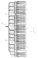
- FIG. 1 is a schematic plan view of the entire automated warehouse system 100 according to the first embodiment.
- FIG. 2 is an enlarged plan view of a part of the automated warehouse system 100.
- the automated warehouse system 100 is a system including a plurality of automated warehouses 1, a plurality of work stations 3, and a plurality of automatic guided vehicles 5.
- the automated warehouse system 100 is arranged in, for example, various factories, distribution bases, and the like.
- the storage of the luggage from the work station 3 to the automatic warehouse 1 and the delivery of the luggage from the automatic warehouse 1 to the work station 3 are performed.
- the cargo is transported between the work station 3 and the automated warehouse 1.
- the transportation of the luggage is carried out by a plurality of automatic guided vehicles 5.
- the X direction (direction of arrow X) is the arrangement direction of the plurality of automatic warehouses 1
- the Y direction direction perpendicular to the X direction in the horizontal plane.
- the Z direction (arrow Z) is the vertical direction.
- the automated warehouse 1 automatically stores the cargo transported by the automatic guided vehicle 5 and automatically carries out the stored cargo.
- the automated warehouse 1 has a rack 11, a stacker crane 13, a warehousing conveyor 15, and a warehousing conveyor 17.
- the racks 11 are arranged in pairs so that the Y direction is the longitudinal direction and the racks 11 face each other with a gap in the X direction.
- the rack 11 has a plurality of loading portions for loading and storing the luggage in the X direction and the Z direction. As a result, the rack 11 can store the cargo in a matrix in the X direction and the Z direction.
- the stacker crane 13 (an example of a transport device) transports cargo in the automated warehouse 1.
- the stacker crane 13 includes a traveling carriage that can travel along the traveling rail 13A, and an elevator that can move up and down along the mast on the traveling carriage and is provided with a transfer device.
- the traveling rail 13A extends along the Y direction between two racks 11 facing each other in the X direction in the automated warehouse 1.
- the stacker crane 13 can convey the load between the loading portion of the rack 11 and the warehousing conveyor 15 and the unloading conveyor 17, which will be described later. Further, the stacker crane 13 can transfer the load to the loading section of the rack 11, the warehousing conveyor 15, and the unloading conveyor 17 by using the transfer device provided on the lift.
- the stacker crane 13 is not particularly limited, and various known stacker cranes can be used.
- a transfer device provided on the elevator platform for transferring luggage for example, a rear hook type that hooks a hook at the rear end of the luggage to take in, a clamp type that holds and transfers both sides of the luggage, and a slide fork.
- a device such as a fork type that scoops up the luggage and transfers it, or a front hook type that hooks a hook on the front end of the luggage and takes it in can be used.
- the warehousing conveyor 15 is a device that conveys the cargo conveyed by the automatic guided vehicle 5 to the vicinity of the rack 11.
- the warehousing conveyor 15 has a main conveyor 15A and a sub-conveyor 15B.
- the main conveyor 15A carries the load conveyed by the sub-conveyor 15B and conveys the load toward the vicinity of the rack 11.
- the load transported in the vicinity of the rack 11 is transported by the stacker crane 13, and is placed in a predetermined loading section and stored.
- the type or configuration of the main conveyor 15A is not particularly limited.
- As the main conveyor 15A various conveyors such as a belt conveyor, a chain conveyor, and a roller conveyor can be used.
- the sub-conveyor 15B is arranged at the Y-direction end of the main conveyor 15A, and conveys the load transferred from the automatic guided vehicle 5 to the main conveyor 15A.
- the automatic guided vehicle 5 sneaks into the lower part of the sub-conveyor 15B, and the conveyor body of the sub-conveyor 15B scoops the luggage from the automatic guided vehicle 5, so that the luggage is between the automatic guided vehicle 5 and the main conveyor 15A. Will be reprinted.
- the sub-conveyor 15B moves up and down to scoop up the load placed on the automatic guided vehicle 5, or the lifter provided on the automatic guided vehicle 5 on which the load is placed descends from the lifter to the sub-conveyor 15B. You can transfer your luggage to.
- the warehousing conveyor 17 is a device that transports the cargo transported for warehousing by the stacker crane 13 to the arrival position of the automatic guided vehicle 5.
- the delivery conveyor 17 has a main conveyor 17A and a sub-conveyor 17B.
- the load carried by the stacker crane 13 is transferred and placed on the main conveyor 17A.
- the main conveyor 17A conveys the loaded load toward the sub-conveyor 17B.
- various conveyors such as a belt conveyor, a chain conveyor, and a roller conveyor can be used.
- the sub-conveyor 17B is arranged at the Y-direction end of the main conveyor 17A, and the load conveyed by the main conveyor 17A is transferred to the automatic guided vehicle 5.
- the automatic guided vehicle 5 slips into the lower part of the sub-conveyor 17B, and the sub-conveyor 17B lowers the conveyor body on which the cargo is placed toward the automatic guided vehicle 5, thereby causing the automatic guided vehicle from the sub-conveyor 17B.
- the luggage will be transferred to 5.
- the plurality of work stations 3 are arranged with respect to the plurality of automated warehouses 1 at predetermined intervals in the Y direction, and are arranged side by side in the X direction.
- the work station 3 is a station for picking luggage to be received or delivered.
- a worker or a picking robot that performs a cargo picking operation is arranged at the work station 3.
- a space is provided in the vicinity of the work station 3 for an automatic guided vehicle 5 waiting to be carried into the work station 3.
- a conveyor 33 is provided on the side of each work station 3.
- the conveyor 33 joins at a position separated from the work station 3 in the Y direction.
- the conveyor 33 conveys the load picked at the work station 3 to the outside.
- a method of transporting the load picked at the work station 3 by the conveyor 33 for example, there is a method of picking the load at each destination at the work station 3 and transporting it to the outside by the conveyor 33.
- the plurality of automatic guided vehicles 5 are trolleys for transporting luggage and can travel unmanned.
- the automatic guided vehicle 5 travels on a predetermined travel route R.
- the automatic guided vehicle 5 transports the luggage by placing the luggage on the luggage storage portion provided on the upper portion of the automatic guided vehicle 5 and moving the luggage.
- the traveling route R is formed in a grid pattern by a plurality of routes extending in the X direction and a plurality of routes extending between the automated warehouse 1 and the work station 3 in the Y direction. ing. Further, the traveling path R extends through the sub-conveyors 15B and 17B. In the traveling route R, at the intersection of the route extending in the X direction and the route extending in the Y direction, a tag or the like displaying an identification code such as a QR code (registered trademark) is arranged.
- QR code registered trademark
- the automatic guided vehicle 5 moves between the automated warehouse 1 and the work station 3 while detecting the above identification code.
- the automatic guided vehicle 5 determines from the detected identification code whether or not the moving direction should be changed at the intersection where the identification code is arranged.
- the travel command of the automatic guided vehicle 5 is associated with, for example, the identification code arranged on the travel path R and information indicating in which direction the vehicle should move from the intersection where the identification code is arranged. .. Further, the determination as to whether or not the moving direction should be changed at the intersection may be executed by the automatic guided vehicle 5, and whether or not the moving direction is changed to the controller 50 described later each time the automatic guided vehicle 5 reaches the intersection. You may inquire.
- the automatic guided vehicle 5 If it is determined that the moving direction is changed at the intersection, the automatic guided vehicle 5 turns at the intersection and starts going straight after changing the moving direction. On the other hand, if it is determined that the moving direction is not changed at the intersection, the vehicle goes straight. In this way, the automatic guided vehicle 5 can move between the automated guided vehicle 1 and the work station 3 in a grid-like traveling path R while going straight and turning as necessary.
- the automatic guided vehicle 5 that transports the warehousing load from the work station 3 enters the sub-conveyor 15B of the warehousing conveyor 15 from the front by moving along the traveling path R in the sub-conveyor 15B. After that, the cargo to be stored is scooped up by the sub-conveyor 15B.
- the automatic guided vehicle 5 from which the luggage has been scooped enters from the sub-conveyor 15B of the warehousing conveyor 15 to the sub-conveyor 17B of the warehousing conveyor 17 from the front or the side along the traveling path R. After that, the cargo to be delivered by the sub-conveyor 17B is placed on the automatic guided vehicle 5.
- the automatic guided vehicle 5 on which the cargo is placed exits from the front of the sub-conveyor 17B and transports the cargo toward the work station 3.
- the transportation of the cargo by the automatic guided vehicle 5 can be efficiently executed.
- Each of the plurality of automatic guided vehicles 5 can move only on the traveling route within a predetermined area (referred to as traveling areas A1 and A2 (FIGS. 5 and 6)) in the entire traveling route R.
- traveling areas A1 and A2 referred to as traveling areas A1 and A2 (FIGS. 5 and 6)
- the determination of the traveling areas A1 and A2 will be described in detail later.
- the automatic guided vehicle 5 is an AGV (Automatic Guided Vehicle) that travels by rotating wheels by a traveling motor 5B (FIG. 3).
- the automatic guided vehicle 5 may be, for example, a ceiling traveling vehicle or a tracked carriage.
- the traveling route R is, for example, a method in which the traveling route R is composed of magnetic tape (magnetic induction type) and a method in which the traveling route R is composed of rails (with track). Equation), etc. may be configured by other methods.
- FIG. 3 is a block diagram showing a control configuration of the automated warehouse system 100.
- the automated warehouse system 100 has a controller 50 as a control configuration of the automated warehouse system 100.
- the controller 50 is a computer having a processor (for example, a CPU), a storage device (for example, ROM, RAM, HDD, SSD, etc.) and various interfaces (for example, an A / D converter, a D / A converter, a communication interface, etc.). It is a system.
- the controller 50 performs various control operations in the automated warehouse system 100 by executing a program stored in the storage unit (corresponding to a part or all of the storage area of the storage device).
- the controller 50 may be composed of a single processor, or may be composed of a plurality of independent processors for each control. Some or all of the functions of the controller 50 may be realized as a program that can be executed by the computer system constituting the controller 50. In addition, a part of the function of each element of the control unit may be configured by a custom IC.
- the controller 50 can wirelessly communicate with the travel control unit 5A of each automatic guided vehicle 5, and transmits a travel command of each automatic guided vehicle 5 to the travel control unit 5A.
- the travel control unit 5A controls the travel motor 5B of the automatic guided vehicle 5 based on the travel command to control the movement of the automatic guided vehicle 5.
- the travel control unit 5A includes a processor (for example, a CPU), a storage device (for example, ROM, RAM, HDD, SSD, etc.), and various interfaces (for example, an A / D converter, a D / A converter, a communication interface, etc.). It is a computer system that has.
- the controller 50 can communicate with each warehousing conveyor 15 (main conveyor 15A, sub-conveyor 15B) and each warehousing conveyor 17 (main conveyor 17A, sub-conveyor 17B) wirelessly or by wire. Controls the transportation of the load by the conveyor 17.
- controller 50 can communicate with the stacker crane 13 wirelessly or by wire, and controls the loading and unloading of the luggage into the rack 11 by the stacker crane 13 and the unloading of the luggage from the rack 11.
- FIG. 4 is a flowchart showing the operation of the automated warehouse system 100.
- the process shown in the flowchart of FIG. 4 is executed by the controller 50. All of the processes shown in the flowchart of FIG. 4 may be executed by the program stored in the storage device of the controller 50, or a part of the processes is executed by the program and the remaining part is the hardware constituting the controller 50. Therefore, it may be executed.
- a part of the processing (and related processing) shown in the flowchart of FIG. 4 may be executed by the controller 50, and the remaining part may be executed by another controller.
- the traveling areas A1 and A2 of the automatic guided vehicle 5 are determined.
- the traveling areas A1 and A2 include at least a part of the traveling route R, and define a range in which the automatic guided vehicle 5 belonging to the traveling areas A1 and A2 can move.
- any one of the plurality of automated warehouses 1 and one of the plurality of work stations 3 belong to the determined traveling areas A1 and A2. That is, in the present embodiment, all the automated warehouses 1 belong to any of the traveling areas A1 and A2, and there is no automated warehouse 1 that does not belong to any of the traveling areas A1 and A2.
- the traveling areas A1 and A2 are defined as follows.
- the controller 50 determines the operating status of the automated warehouse system 100 when determining the traveling areas A1 and A2.
- the operating status of the automated warehouse system 100 is the operating rate of the stacker crane 13 in the automated warehouse 1.
- the operating rate of the stacker crane 13 can be determined, for example, based on schedule data for recording information regarding the loading and unloading of luggage. For example, when a large number of information regarding warehousing / delivery is recorded in the schedule data within a predetermined time range, it is determined that the operating rate of the stacker crane 13 in the automated warehouse 1 is high. On the other hand, if a small number of information regarding warehousing / delivery is recorded within the above-mentioned predetermined time range, it is determined that the operating rate of the stacker crane 13 is low.
- the operating status of the automated warehouse system 100 is not limited to the operating rate of the stacker crane 13 in the automated warehouse 1, and may be, for example, the operating rate of the automatic guided vehicle 5 in the traveling areas A1 and A2.
- the criteria for determining whether the operating rate of the stacker crane 13 or the automatic guided vehicle 5 in the automated warehouse system 100 is high or low is determined by the automated warehouse system 100. It can be appropriately determined according to the scale of the stacker crane 13 or the transport capacity of the automatic guided vehicle 5.
- FIG. 5 is a diagram showing an example of a case where a small traveling area A1 is defined in the automated warehouse system 100. In this case, workers are assigned to all of the plurality of work stations 3.
- the operating rate is high as a whole means that most of the stacker cranes 13 or automatic guided vehicles 5 perform operations for transporting cargo relatively frequently, and perform the operations at all.
- the stacker crane 13 or the automatic guided vehicle 5 which is not used or the frequency of the operation is infrequent is almost absent or does not exist at all.
- the travel path R is divided into four small travel areas A1, and each of the small travel areas A1 has three work stations 3 and 7 or 8 sets of automated warehouses 1.
- the number of automatic guided vehicles 5 belonging to each traveling area A1 is almost the same.
- the automated warehouse 1 belonging to one traveling area A1 is surrounded by a dashed line, and the work station 3 belonging to one traveling area A1 is surrounded by a broken line.
- step S1 when the operating rate of the stacker crane 13 in the plurality of automated warehouses 1 is low as a whole (or when the operating rate of the automatic guided vehicle 5 in the traveling areas A1 and A2 is evenly low) (in step S1, "low operating rate”. ”),
- the controller 50 divides the traveling path R into a large traveling area A2 in step S3 as shown in FIG.
- FIG. 6 is a diagram showing an example of a case where a large traveling area A2 is defined in the automated warehouse system 100.
- “the operating rate is low as a whole” means that most of the stacker cranes 13 or automatic guided vehicles 5 perform operations for transporting cargo infrequently or not at all.
- the stacker crane 13 or the automatic guided vehicle 5 that frequently performs the operation is almost absent or does not exist at all.
- the traveling path R is divided into two large traveling areas A2, and each of the large traveling areas A2 includes 14 or 15 sets of automated warehouses 1.
- the number of automatic guided vehicles 5 belonging to each traveling area A2 is almost the same before and after the change of the traveling area.
- an automated warehouse 1 belonging to one traveling area A2 is surrounded by a dashed line, and a work station belonging to one traveling area A2 and used (that is, luggage is transported by an automatic guided vehicle 5). 3 is surrounded by a broken line.
- the automatic guided vehicle 5 is subjected to a large travel including more automated warehouses 1.
- the controller 50 sets the ratio of the number of automated warehouses 1 to the number of work stations 3 in which cargo is transported to and from the automatic guided vehicles 5 belonging to the traveling areas A1 and A2 in the traveling areas A1 and A2. Before and after changing the size, it is set to be larger in the larger traveling area A2. As a result, when a large traveling area A2 is set because the operating rate of the automated warehouse 1 and / or the working station 3 is low, the number of working stations 3 in the operating state is reduced according to the low operating rate. Can be done.
- the controller 50 integrates two adjacent small traveling areas A1 to generate the large traveling area A2. Specifically, in FIG. 5, two adjacent traveling areas A1 on the left side in the X direction are integrated to generate a traveling area A2, and two adjacent traveling areas A1 on the right side in the X direction are integrated to generate a traveling area A2. doing.
- three or more adjacent small driving areas may be integrated. That is, the number of small travel areas to be integrated when creating a large travel area can be arbitrary.
- the small traveling area A1 is the reference area. Since the reference area is the traveling area A1, when the traveling area to be set is switched from the large traveling area A2 to the small traveling area A2, the controller 50 divides the large traveling area A2 into the reference area and sets the traveling area A1.
- the number of automated warehouses 1 and work stations 3 belonging to the above reference area is determined based on, for example, how many automated warehouses 1 can transport a number of packages that can be processed without delay in one work station 3.
- the controller 50 commands the automated warehouse system 100 to start loading and unloading the luggage in step S4. Specifically, the controller 50 permits the automatic guided vehicle 5 belonging to the set traveling areas A1 and A2 to transport the luggage in the set traveling areas A1 and A2, and the automated warehouse belonging to the set traveling areas A1 and A2. Command the loading and unloading of luggage between 1 and the work station 3.
- the sizes of the traveling areas A1 and A2 are determined based on the operating status of the stacker crane 13 of the automated warehouse 1 in the automated warehouse system 100, and the size of the traveling areas A1 and A2 is determined with respect to the operating status of the automatic guided vehicle 5.
- the influence of the operating status of the automated warehouse 1 can be reduced. As a result, even if the operating status of the automated warehouse 1 changes, the automated warehouse system 100 can be operated with high efficiency in the same manner.
- the sizes of the traveling areas A1 and A2 are determined based on the operating status of the stacker crane 13 of the automated warehouse 1, but as a modification 1, the sub-conveyors 15B and 17B of the automated warehouse 1 are operated. It is also possible to determine the size of the traveling areas A1 and A2 based on the situation. For example, when the cargo is accumulated in the sub-conveyor 17B for delivery, the traveling area to which the automated warehouse 1 including the sub-conveyor 17B belongs is reduced to improve the loading capacity of the cargo in the traveling area. By doing so, it is possible to eliminate the stagnation of the cargo to be delivered.
- the sizes of the traveling areas A1 and A2 are determined based on the operating status of the automated warehouse 1, but as the modified example 2, the traveling area is determined based on the operating status of the work station 3.
- the sizes of A1 and A2 can also be determined.
- the sizes of the traveling areas A1 and A2 can be determined based on the number of operating work stations 3 (the number of work stations 3 in which workers are assigned). For example, when the number of working stations 3 is large, the size of the traveling areas A1 and A2 can be reduced to improve the ability to load and unload luggage.
- the sizes of the traveling areas A1 and A2 can be determined based on the status of processing the luggage at the work station 3. For example, when unprocessed luggage is accumulated in the work station 3, the size of the traveling areas A1 and A2 to which the work station 3 belongs can be increased to eliminate the accumulation of the luggage. Further, for example, when the sizes of the traveling areas A1 and A2 are not changed, or even when the traveling area is enlarged, if there is another work station 3 belonging to the traveling area, the other work is performed. By transferring the processing of the luggage to the station 3, it is possible to prevent the accumulation of the luggage.
- the sizes of the traveling areas A1 and A2 can be determined based on both the operating status of the automated warehouse 1 and the operating status of the work station 3. In this case, depending on whether the operating status of the automated warehouse 1 is emphasized or the operating status of the work station 3 is emphasized, the operating status of the automated warehouse 1 and the operating status of the work station 3 contribute to the sizes of the traveling areas A1 and A2. The rate may be adjusted.
- the traveling areas A1 and A2 may be determined based on the number of workers performing the work in the automated warehouse system 100, that is, based on the number of work stations 3 that can be operated.
- the sizes of the traveling areas A1 and A2 to be set are substantially the same based on the premise that the operating rates of the plurality of automated warehouses 1 are substantially equal as a whole. ..
- the present invention is not limited to this, and when a plurality of traveling areas are set and the operating rates are different for each automated warehouse 1, at least one operating status of the automated warehouse 1 or the work station 3 belonging to each traveling area is close.
- the size of the traveling area may be determined so as to be.
- the above-mentioned "determining the size of the traveling area so that the operating conditions are close to each other” means simply determining the size of one traveling area so that the operating conditions are the same or almost the same. It includes both meanings of making the difference in operating conditions small in each of a plurality of traveling areas generated after integrating the small traveling areas A1.
- the size of the traveling area to which the automated warehouse 1 and / or the work station 3 having a high operating rate belongs can be reduced, while the traveling area to which the automated warehouse 1 and / or the working station 3 having a low operating rate belongs can be increased.
- the controller 50 sets the travel areas adjacent to each other as the first travel area A21 and the second travel area A22, and the first The first work of the work station 3 on the second driving area side of the work stations 3 belonging to the traveling area A21 and the work station 3 on the first traveling area side of the work stations 3 belonging to the second traveling area A22, respectively.
- the stations 31 and the second work station 32 may be determined, and the automatic guided vehicle 5 may be allowed to carry the load between the first work station 31 and the second work station 32 and the automated warehouse 1. .
- FIG. 7 is a diagram showing an example of determination of the work station according to the third embodiment.
- the work stations 3 belonging to the two traveling areas can be operated by, for example, one worker or one picking robot.
- the number of workers or picking robots assigned to the automated warehouse system 100 can be reduced. For example, while working at one work station, the load is retained in the other work station, and when a certain amount of load is accumulated in the other work station, the worker or the picking robot moves to the other work station. By repeating this, one worker or one picking robot can operate work stations belonging to different traveling areas.
- the automated warehouse system 100 (an example of an automated warehouse system) includes a plurality of automated warehouses 1 (an example of a plurality of automated warehouses), a plurality of work stations 3 (an example of a plurality of work stations), and a traveling route R (an example of a traveling route).
- An example a plurality of automatic guided vehicles 5 (an example of a plurality of automatic guided vehicles), and a controller 50 (an example of a controller) are provided.
- the travel route R is provided so as to be accessible to the plurality of automated warehouses 1 and the plurality of work stations 3.
- the automatic guided vehicle 5 travels on the travel path R.
- the controller 50 determines an area including at least a part of the travel path R as travel areas A1 and A2 (an example of the travel area) on which the automatic guided vehicle 5 travels, and works with the automated warehouse 1 belonging to the travel areas A1 and A2.
- the automatic guided vehicle 5 is controlled so as to transport the cargo to and from the station 3. Further, the controller 50 determines the sizes of the traveling areas A1 and A2 in which the automatic guided vehicle 5 travels based on the operating status of at least one of the automated warehouse 1 or the work station 3.
- the sizes of the traveling areas A1 and A2 are determined based on the operating status of at least one of the automated warehouse 1 or the work station 3. As a result, the influence of the operating status of the automated warehouse 1 and / or the work station 3 of the automated warehouse system 100 on the operating status of the automatic guided vehicle 5 can be reduced.
- the present invention is not limited to the above embodiments, and various modifications can be made without departing from the gist of the invention.
- the plurality of embodiments and modifications described herein can be arbitrarily combined as needed.
- the size of the reference area which is the minimum unit of the traveling area, is the same as the size of the small traveling area A1.
- the present invention is not limited to this, and the reference area may be made smaller than the small traveling area A1.
- the size of the traveling area may be changed in real time based on the operation status of the automated warehouse system 100 over time.
- the automated warehouse 1 may be, for example, a shuttle warehouse provided for each stage of the rack 11 and having a shuttle carriage that moves in the length direction of the rack 11 to transport luggage.
- (E) There may be an automated warehouse 1 that does not belong to any of the traveling areas A1 and A2.
- the automated warehouse 1 having an operating rate of almost 0 may not belong to any of the traveling areas A1 and A2.
- the travel path R in the vicinity of the work station 3 that is not used in the automated warehouse system 100 may not be included in any of the travel areas A1 and A2.
- the present invention can be widely applied to an automated warehouse system.
Landscapes
- Engineering & Computer Science (AREA)
- Mechanical Engineering (AREA)
- Aviation & Aerospace Engineering (AREA)
- Radar, Positioning & Navigation (AREA)
- Remote Sensing (AREA)
- Physics & Mathematics (AREA)
- General Physics & Mathematics (AREA)
- Automation & Control Theory (AREA)
- Warehouses Or Storage Devices (AREA)
- Control Of Position, Course, Altitude, Or Attitude Of Moving Bodies (AREA)
Abstract
An automated warehouse system, wherein the influence of the operating status of an automated warehouse and/or a station on the operating status of an automated guided vehicle is reduced. An automated warehouse system (100) comprises a plurality of automated warehouses (1), a plurality of work stations (3), a route (R), a plurality of automated guided vehicles (5), and a controller (50). The route (R) is provided so as to be accessible to the automated warehouses (1) and the work stations (3). The automated guided vehicles (5) travel along the route (R). The controller (50) determines an area including at least a portion of the route (R) as a travel area (A1, A2) in which the automated guided vehicles (5) travel, and controls the automated guided vehicles (5) to transport packages between the automated warehouses (1) and work stations (3) that belong to the travel area (A1, A2). The controller (50) determines the size of the travel area (A1, A2) in which the automated guided vehicles (5) travel on the basis of the operating status of the automated warehouses (1) and/or the work stations (3).
Description
本発明は、自動倉庫と、ステーションと、自動倉庫とステーションとの間を走行する複数の無人搬送車と、を備える自動倉庫システム、及び、当該自動倉庫システムの制御方法に関する。
The present invention relates to an automated warehouse system including an automated warehouse, a station, and a plurality of automatic guided vehicles traveling between the automated warehouse and the station, and a control method of the automated warehouse system.
従来、自動倉庫と、ステーションと、自動倉庫とステーションとの間で荷物を搬送する無人搬送車と、を備える自動倉庫システムが知られている(例えば、特許文献1を参照)。また、上記の自動倉庫システムにおいて、多数の自動倉庫とステーションとを設け、多数の無人搬送車により自動倉庫とステーションとの間で荷物の搬送をすることが進められている。
Conventionally, an automated warehouse system including an automated warehouse, a station, and an automatic guided vehicle that transports cargo between the automated warehouse and the station is known (see, for example, Patent Document 1). Further, in the above-mentioned automated warehouse system, a large number of automated warehouses and stations are provided, and a large number of automatic guided vehicles are being used to transport cargo between the automated warehouses and the stations.
上記の自動倉庫システムにおいては、自動倉庫及び/又はステーションでの稼働状況が変化する場合がある。従来の自動倉庫システムでは無人搬送車が走行するエリアが予め決められ固定されている。そのため、あるエリア内での無人搬送車による荷物の搬送能力を超えた搬送指令がそのエリア内でなされると、そのエリア内で要求された荷物の搬送指令が未処理のまま残ることになる。その逆に、あるエリア内における荷物の搬送指令が少ない場合には、稼働していない無人搬送車が増加し、自動倉庫システムにおける荷物の搬送能力を生かせなくなる。
In the above-mentioned automated warehouse system, the operating status of the automated warehouse and / or the station may change. In the conventional automated warehouse system, the area where the automatic guided vehicle travels is predetermined and fixed. Therefore, if a transport command exceeding the load transport capacity of an automatic guided vehicle in a certain area is issued in that area, the load transport command requested in that area remains unprocessed. On the contrary, when the number of cargo transport commands in a certain area is small, the number of automatic guided vehicles that are not in operation increases, and the cargo transport capacity of the automated warehouse system cannot be utilized.
また、多数の無人搬送車が自動倉庫とステーションとの間を移動し、1台の無人搬送車あたりの移動頻度が高くなると、例えば、無人搬送車同士の衝突を避けるべく、最短ではない経路で自動倉庫とステーションとの間を移動する必要があり、また、他の無人搬送車の通過のために待機する必要があるなどして、自動倉庫とステーションとの間の荷物の搬送効率が低下することがある。
その結果、自動倉庫及び/又はステーションの稼働率が高い場合と低い場合とで無人搬送車の稼働状況及び荷物の搬送効率に差が生じ、自動倉庫及び/又はステーションの稼働率が高い場合と低い場合で同じように高効率に自動倉庫システムの運用ができない。 In addition, when a large number of automatic guided vehicles move between the automated warehouse and the station and the frequency of movement per automatic guided vehicle increases, for example, in order to avoid collisions between the automatic guided vehicles, the route is not the shortest. The efficiency of transporting luggage between the automated warehouse and the station is reduced because it is necessary to move between the automated warehouse and the station, and it is necessary to wait for the passage of other automatic guided vehicles. Sometimes.
As a result, there is a difference in the operating status of the automated guided vehicle and the efficiency of transporting luggage between the case where the operating rate of the automated warehouse and / or the station is high and the case where the operating rate is low, and the operating rate of the automated warehouse and / or the station is low when the operating rate is high. In some cases, the automated warehouse system cannot be operated with high efficiency.
本発明の目的は、自動倉庫と、ステーションと、自動倉庫とステーションとの間で荷物を搬送する無人搬送車と、を備える自動倉庫システムにおいて、無人搬送車の稼働状況に対する自動倉庫及び/又はステーションの稼働状況の影響を小さくすることにある。
An object of the present invention is an automated warehouse and / or station for the operating status of an automated guided vehicle in an automated warehouse system including an automated warehouse, a station, and an automated guided vehicle that transports luggage between the automated guided vehicle and the station. The purpose is to reduce the impact of the operating status of.
以下に、課題を解決するための手段として複数の態様を説明する。これら態様は、必要に応じて任意に組み合せることができる。
本発明の一見地に係る自動倉庫システムは、複数の自動倉庫と、複数の作業ステーションと、走行経路と、複数の無人搬送車と、コントローラと、を備える。
走行経路は、複数の自動倉庫及び複数の作業ステーションにアクセス可能に設けられる。無人搬送車は、走行経路を走行する。
コントローラは、走行経路の少なくとも一部を含むエリアを無人搬送車が走行する走行エリアとして決定し、当該走行エリアに属する自動倉庫と作業ステーションとの間で荷物の搬送を行うように無人搬送車を制御する。
また、コントローラは、自動倉庫又は作業ステーションの少なくとも1つの稼働状況に基づき、無人搬送車が走行する走行エリアの大きさを決定する。 Hereinafter, a plurality of aspects will be described as means for solving the problem. These aspects can be arbitrarily combined as needed.
The seemingly automatic warehouse system of the present invention includes a plurality of automated warehouses, a plurality of work stations, a traveling route, a plurality of automatic guided vehicles, and a controller.
The travel route is provided so as to be accessible to a plurality of automated warehouses and a plurality of work stations. The automatic guided vehicle travels on the traveling route.
The controller determines the area including at least a part of the travel route as the travel area on which the automatic guided vehicle travels, and sets the automated guided vehicle so as to transport the cargo between the automated warehouse and the work station belonging to the travel area. Control.
In addition, the controller determines the size of the traveling area in which the automatic guided vehicle travels based on the operating status of at least one of the automated warehouse or the work station.
上記の自動倉庫システムでは、自動倉庫又は作業ステーションの少なくとも1つの稼働状況に基づいて走行エリアの大きさが決定される。これにより、無人搬送車の稼働状況に対する自動倉庫システムの自動倉庫及び/又は作業ステーションの稼働状況により影響を小さくできる。
In the above-mentioned automated warehouse system, the size of the traveling area is determined based on the operating status of at least one of the automated warehouse or the work station. As a result, the influence on the operating status of the automated guided vehicle can be reduced depending on the operating status of the automated warehouse and / or the work station of the automated warehouse system.
コントローラが定めるエリアは複数の基準エリアを有してもよい。この場合、コントローラは、自動倉庫又は作業ステーションの少なくとも1つの稼働状況に基づいて、隣接する複数の基準エリアを統合するか、又は、基準エリアに分節することで、走行エリアの大きさを変更してもよい。
これにより、走行エリアの大きさの変更を容易な処理で実行できる。 The area defined by the controller may have a plurality of reference areas. In this case, the controller resizes the travel area by consolidating or segmenting adjacent reference areas based on at least one operating status of the automated warehouse or work station. You may.
As a result, the size of the traveling area can be changed by a simple process.
コントローラは、走行エリアを複数設定するときに、各走行エリアに属する自動倉庫又は作業ステーションの少なくとも1つの稼働状況が近くなるように走行エリアの大きさを決定してもよい。
自動倉庫及び/又は作業ステーションの稼働状況を全ての走行エリアで近くなるようにすることで、全ての走行エリアで無人搬送車の稼働状況をそろえることができる。 When setting a plurality of travel areas, the controller may determine the size of the travel areas so that at least one operating status of the automated warehouse or work station belonging to each travel area is close to each other.
By making the operating status of the automated warehouse and / or the work station close to each other in all the traveling areas, the operating status of the automatic guided vehicle can be made uniform in all the traveling areas.
コントローラは、走行エリアに属する無人搬送車との間で荷の搬送が行われる作業ステーションの数に対する自動倉庫の数の割合を、走行エリアの大きさを変更する前後において、大きい方の走行エリアで大きくなるように定めてもよい。
これにより、自動倉庫及び/又は作業ステーションの稼働率が低いために大きな走行エリアを設定した場合に、稼働状態の作業ステーションの数を稼働率が低くなったことに応じて減らすことができる。 The controller determines the ratio of the number of automated warehouses to the number of work stations that transport loads to and from automated guided vehicles belonging to the travel area in the larger travel area before and after changing the size of the travel area. It may be set to be large.
As a result, when a large traveling area is set due to the low operating rate of the automated warehouse and / or the work station, the number of working stations in the operating state can be reduced according to the low operating rate.
走行エリアは、隣接する第1走行エリアと第2走行エリアとを含んでもよい。
この場合、コントローラは、第1走行エリアに属する作業ステーションのうち最も第2走行エリア側の作業ステーションと、第2走行エリアに属する作業ステーションのうち最も第1走行エリア側の作業ステーションとをそれぞれ第1作業ステーション及び第2作業ステーションと決定し、無人搬送車に対して、第1作業ステーション及び第2作業ステーションと自動倉庫との間で荷の搬送を行わせるように制御してもよい。
これにより、2つの走行エリアに属する作業ステーションを、同じ作業者で稼働させることができる。その結果、自動倉庫システムに配置する作業者の数を減少できる。 The traveling area may include an adjacent first traveling area and a second traveling area.
In this case, the controller sets the work station on the second travel area side of the work stations belonging to the first travel area and the work station on the first travel area side of the work stations belonging to the second travel area, respectively. The first work station and the second work station may be determined, and the automatic guided vehicle may be controlled to carry the load between the first work station and the second work station and the automated warehouse.
As a result, the work stations belonging to the two traveling areas can be operated by the same worker. As a result, the number of workers assigned to the automated warehouse system can be reduced.
各自動倉庫は、当該自動倉庫において荷物を搬送する搬送装置を有してもよい。この場合、コントローラは、複数の自動倉庫における搬送装置の稼働率が高いときに走行エリアを小さくし、複数の自動倉庫における搬送装置の稼働率が低いときに走行エリアを大きくしてもよい。
これにより、自動倉庫の稼働状況による影響を小さくして、自動倉庫システムにおける入出庫の効率を向上できる。 Each automated warehouse may have a transport device for transporting luggage in the automated warehouse. In this case, the controller may reduce the traveling area when the operating rate of the transport device in the plurality of automated warehouses is high, and increase the traveling area when the operating rate of the transport device in the plurality of automated warehouses is low.
As a result, the influence of the operating status of the automated warehouse can be reduced, and the efficiency of loading and unloading in the automated warehouse system can be improved.
コントローラは、複数の無人搬送車の稼働率が高いときに走行エリアを小さくし、複数の無人搬送車の稼働率が低いときに走行エリアを大きくしてもよい。
これにより、無人搬送車による荷物の搬送効率を向上させて、自動倉庫システムにおける入出庫の効率を向上できる。 The controller may reduce the traveling area when the operating rate of the plurality of automatic guided vehicles is high, and may increase the traveling area when the operating rate of the plurality of automatic guided vehicles is low.
As a result, the efficiency of transporting luggage by the automatic guided vehicle can be improved, and the efficiency of loading and unloading in the automated warehouse system can be improved.
本発明の他の見地に係る方法は、自動倉庫システムの制御方法である。自動倉庫システムは、複数の自動倉庫と、複数の作業ステーションと、複数の自動倉庫及び複数の作業ステーションにアクセス可能に設けられる走行経路と、走行経路を走行する複数の無人搬送車と、を備える。自動倉庫システムの制御方法は、以下のステップを備える。
◎走行経路の少なくとも一部を含むエリアを無人搬送車が走行する走行エリアとして決定するステップ。
◎走行エリアに属する自動倉庫と作業ステーションとの間で荷物の搬送を行うように無人搬送車を制御するステップ。
上記の制御方法において、走行エリアの大きさは、自動倉庫又は作業ステーションの少なくとも1つの稼働状況に基づき決定される。 Another method according to the present invention is a method for controlling an automated warehouse system. The automated warehouse system includes a plurality of automated warehouses, a plurality of work stations, a travel route provided so as to be accessible to the plurality of automated warehouses and the plurality of work stations, and a plurality of automatic guided vehicles traveling on the travel route. .. The control method of the automated warehouse system includes the following steps.
◎ A step to determine the area including at least a part of the travel route as the travel area on which the automatic guided vehicle travels.
◎ A step to control an automatic guided vehicle so that cargo is transported between the automated warehouse belonging to the traveling area and the work station.
In the above control method, the size of the traveling area is determined based on the operating status of at least one of the automated warehouse or the work station.
上記の制御方法では、自動倉庫又は作業ステーションの少なくとも1つの稼働状況に基づいて走行エリアの大きさが決定される。これにより、無人搬送車の稼働状況に対する自動倉庫システムの自動倉庫及び/又は作業ステーションの稼働状況により影響を小さくできる。
In the above control method, the size of the traveling area is determined based on the operating status of at least one of the automated warehouse or the work station. As a result, the influence on the operating status of the automated guided vehicle can be reduced depending on the operating status of the automated warehouse and / or the work station of the automated warehouse system.
無人搬送車の稼働状況に対する自動倉庫及び/又はステーションの稼働状況の影響を小さくできるので、自動倉庫及び/又はステーションの稼働状況が変化しても同じように高効率に自動倉庫システムを運用できる。
Since the influence of the operating status of the automated guided vehicle and / or the station on the operating status of the automatic guided vehicle can be reduced, the automated warehouse system can be operated with the same high efficiency even if the operating status of the automated warehouse and / or the station changes.
1.第1実施形態
(1)自動倉庫システムの全体構成
図1及び図2を用いて、自動倉庫システム100を説明する。図1は、第1実施形態に係る自動倉庫システム100の全体の概略平面図である。図2は、自動倉庫システム100の一部を拡大した平面図である。
自動倉庫システム100は、複数の自動倉庫1と、複数の作業ステーション3と、複数の無人搬送車5、とを含むシステムである。自動倉庫システム100は、例えば、各種の工場、物流拠点などに配置される。自動倉庫システム100では、作業ステーション3から自動倉庫1への荷物の入庫、及び、自動倉庫1から作業ステーション3への荷物の出庫が行われる。荷物の入庫及び出庫の際には、作業ステーション3と自動倉庫1との間で荷物の搬送が行われる。この荷物の搬送は、複数の無人搬送車5により実行される。 1. 1. First Embodiment (1) Overall Configuration of Automated Warehouse System Theautomated warehouse system 100 will be described with reference to FIGS. 1 and 2. FIG. 1 is a schematic plan view of the entire automated warehouse system 100 according to the first embodiment. FIG. 2 is an enlarged plan view of a part of the automated warehouse system 100.
Theautomated warehouse system 100 is a system including a plurality of automated warehouses 1, a plurality of work stations 3, and a plurality of automatic guided vehicles 5. The automated warehouse system 100 is arranged in, for example, various factories, distribution bases, and the like. In the automated warehouse system 100, the storage of the luggage from the work station 3 to the automatic warehouse 1 and the delivery of the luggage from the automatic warehouse 1 to the work station 3 are performed. At the time of loading and unloading of the cargo, the cargo is transported between the work station 3 and the automated warehouse 1. The transportation of the luggage is carried out by a plurality of automatic guided vehicles 5.
(1)自動倉庫システムの全体構成
図1及び図2を用いて、自動倉庫システム100を説明する。図1は、第1実施形態に係る自動倉庫システム100の全体の概略平面図である。図2は、自動倉庫システム100の一部を拡大した平面図である。
自動倉庫システム100は、複数の自動倉庫1と、複数の作業ステーション3と、複数の無人搬送車5、とを含むシステムである。自動倉庫システム100は、例えば、各種の工場、物流拠点などに配置される。自動倉庫システム100では、作業ステーション3から自動倉庫1への荷物の入庫、及び、自動倉庫1から作業ステーション3への荷物の出庫が行われる。荷物の入庫及び出庫の際には、作業ステーション3と自動倉庫1との間で荷物の搬送が行われる。この荷物の搬送は、複数の無人搬送車5により実行される。 1. 1. First Embodiment (1) Overall Configuration of Automated Warehouse System The
The
以下の説明において、X方向(矢印Xの方向)は、複数の自動倉庫1の配置方向とし、Y方向(矢印Yの方向)は、X方向とは水平面において垂直な方向とする。また、Z方向(矢印Z)は、鉛直方向とする。
In the following description, the X direction (direction of arrow X) is the arrangement direction of the plurality of automatic warehouses 1, and the Y direction (direction of arrow Y) is the direction perpendicular to the X direction in the horizontal plane. The Z direction (arrow Z) is the vertical direction.
(2)自動倉庫
自動倉庫1は、無人搬送車5によって搬送されてきた荷物を自動的に保管すると共に、保管している荷物を自動的に搬出する。自動倉庫1は、ラック11と、スタッカクレーン13と、入庫コンベヤ15と、出庫コンベヤ17と、を有する。 (2) Automated warehouse The automated warehouse 1 automatically stores the cargo transported by the automatic guidedvehicle 5 and automatically carries out the stored cargo. The automated warehouse 1 has a rack 11, a stacker crane 13, a warehousing conveyor 15, and a warehousing conveyor 17.
自動倉庫1は、無人搬送車5によって搬送されてきた荷物を自動的に保管すると共に、保管している荷物を自動的に搬出する。自動倉庫1は、ラック11と、スタッカクレーン13と、入庫コンベヤ15と、出庫コンベヤ17と、を有する。 (2) Automated warehouse The automated warehouse 1 automatically stores the cargo transported by the automatic guided
ラック11は、Y方向を長手方向とし、X方向に間隔をあけて対向するように一対配置されている。ラック11は、荷物が載置されて収納される荷載置部をX方向及びZ方向に複数有している。これにより、ラック11は、荷物をX方向及びZ方向にマトリクス状に保管できる。
The racks 11 are arranged in pairs so that the Y direction is the longitudinal direction and the racks 11 face each other with a gap in the X direction. The rack 11 has a plurality of loading portions for loading and storing the luggage in the X direction and the Z direction. As a result, the rack 11 can store the cargo in a matrix in the X direction and the Z direction.
スタッカクレーン13(搬送装置の一例)は、自動倉庫1において、荷物の搬送を行う。スタッカクレーン13は、走行レール13Aに沿って走行可能な走行台車と、この走行台車上のマストに沿って昇降自在で且つ移載装置が設けられた昇降台と、を含む。走行レール13Aは、自動倉庫1において、X方向に対向する2つのラック11の間にY方向に沿って延設される。走行台車が走行レール13Aに沿って走行することで、スタッカクレーン13は、ラック11の荷載置部と後述の入庫コンベヤ15及び出庫コンベヤ17との間で荷物を搬送できる。また、スタッカクレーン13は、昇降台に設けられた移載装置を用いて、ラック11の荷載置部、入庫コンベヤ15及び出庫コンベヤ17に対して、荷物の移載を行うことができる。
The stacker crane 13 (an example of a transport device) transports cargo in the automated warehouse 1. The stacker crane 13 includes a traveling carriage that can travel along the traveling rail 13A, and an elevator that can move up and down along the mast on the traveling carriage and is provided with a transfer device. The traveling rail 13A extends along the Y direction between two racks 11 facing each other in the X direction in the automated warehouse 1. When the traveling carriage travels along the traveling rail 13A, the stacker crane 13 can convey the load between the loading portion of the rack 11 and the warehousing conveyor 15 and the unloading conveyor 17, which will be described later. Further, the stacker crane 13 can transfer the load to the loading section of the rack 11, the warehousing conveyor 15, and the unloading conveyor 17 by using the transfer device provided on the lift.
スタッカクレーン13としては、特に限定されず、種々の公知のスタッカクレーンを用いることができる。昇降台に設けられ、荷物の移載を行う移載装置としては、例えば、荷物の後端にフックを引っ掛けて取り込むリアフック式、荷物の両側を挟んで保持し移載するクランプ式、スライドフォークで荷物をすくい上げて移載するフォーク式、又は、荷物の前端にフックを引っ掛けて取り込むフロントフック式等の装置を用いることができる。
The stacker crane 13 is not particularly limited, and various known stacker cranes can be used. As a transfer device provided on the elevator platform for transferring luggage, for example, a rear hook type that hooks a hook at the rear end of the luggage to take in, a clamp type that holds and transfers both sides of the luggage, and a slide fork. A device such as a fork type that scoops up the luggage and transfers it, or a front hook type that hooks a hook on the front end of the luggage and takes it in can be used.
入庫コンベヤ15は、無人搬送車5により搬送されてきた荷物を、ラック11の近傍まで搬送する装置である。入庫コンベヤ15は、メインコンベヤ15Aと、サブコンベヤ15Bとを有している。
メインコンベヤ15Aは、サブコンベヤ15Bにて搬送された荷物を載置すると共に、当該荷物をラック11の近傍に向けて搬送する。ラック11の近傍に搬送された荷物は、スタッカクレーン13により搬送され、所定の荷載置部に載置され入庫される。メインコンベヤ15Aの種類又は構成等は特に限定されない。メインコンベヤ15Aとしては、例えばベルトコンベヤ、チェーンコンベヤ又はローラコンベヤ等の種々のコンベヤを用いることができる。 Thewarehousing conveyor 15 is a device that conveys the cargo conveyed by the automatic guided vehicle 5 to the vicinity of the rack 11. The warehousing conveyor 15 has a main conveyor 15A and a sub-conveyor 15B.
Themain conveyor 15A carries the load conveyed by the sub-conveyor 15B and conveys the load toward the vicinity of the rack 11. The load transported in the vicinity of the rack 11 is transported by the stacker crane 13, and is placed in a predetermined loading section and stored. The type or configuration of the main conveyor 15A is not particularly limited. As the main conveyor 15A, various conveyors such as a belt conveyor, a chain conveyor, and a roller conveyor can be used.
メインコンベヤ15Aは、サブコンベヤ15Bにて搬送された荷物を載置すると共に、当該荷物をラック11の近傍に向けて搬送する。ラック11の近傍に搬送された荷物は、スタッカクレーン13により搬送され、所定の荷載置部に載置され入庫される。メインコンベヤ15Aの種類又は構成等は特に限定されない。メインコンベヤ15Aとしては、例えばベルトコンベヤ、チェーンコンベヤ又はローラコンベヤ等の種々のコンベヤを用いることができる。 The
The
サブコンベヤ15Bは、メインコンベヤ15AのY方向端部に配置され、無人搬送車5から移載された荷物をメインコンベヤ15Aへと搬送する。
本実施形態では、無人搬送車5がサブコンベヤ15Bの下部に潜り込み、サブコンベヤ15Bのコンベヤ本体が無人搬送車5から荷物をすくい取ることで、無人搬送車5とメインコンベヤ15Aとの間で荷物の移載が行われる。例えば、サブコンベヤ15Bが昇降して無人搬送車5に載置された荷物をすくい取る方法、又は、無人搬送車5に設けられ荷物を載置したリフターが下降することで、リフターからサブコンベヤ15Bに荷物を移載できる。 The sub-conveyor 15B is arranged at the Y-direction end of themain conveyor 15A, and conveys the load transferred from the automatic guided vehicle 5 to the main conveyor 15A.
In the present embodiment, the automatic guidedvehicle 5 sneaks into the lower part of the sub-conveyor 15B, and the conveyor body of the sub-conveyor 15B scoops the luggage from the automatic guided vehicle 5, so that the luggage is between the automatic guided vehicle 5 and the main conveyor 15A. Will be reprinted. For example, the sub-conveyor 15B moves up and down to scoop up the load placed on the automatic guided vehicle 5, or the lifter provided on the automatic guided vehicle 5 on which the load is placed descends from the lifter to the sub-conveyor 15B. You can transfer your luggage to.
本実施形態では、無人搬送車5がサブコンベヤ15Bの下部に潜り込み、サブコンベヤ15Bのコンベヤ本体が無人搬送車5から荷物をすくい取ることで、無人搬送車5とメインコンベヤ15Aとの間で荷物の移載が行われる。例えば、サブコンベヤ15Bが昇降して無人搬送車5に載置された荷物をすくい取る方法、又は、無人搬送車5に設けられ荷物を載置したリフターが下降することで、リフターからサブコンベヤ15Bに荷物を移載できる。 The sub-conveyor 15B is arranged at the Y-direction end of the
In the present embodiment, the automatic guided
出庫コンベヤ17は、スタッカクレーン13により出庫のため搬送されてきた荷物を、無人搬送車5の到達位置まで搬送する装置である。出庫コンベヤ17は、メインコンベヤ17Aと、サブコンベヤ17Bとを有している。
メインコンベヤ17Aには、スタッカクレーン13が搬送してきた荷物が移載され載置される。メインコンベヤ17Aは、載置された荷物をサブコンベヤ17Bに向けて搬送する。メインコンベヤ17Aとしては、例えばベルトコンベヤ、チェーンコンベヤ又はローラコンベヤ等の種々のコンベヤを用いることができる。 Thewarehousing conveyor 17 is a device that transports the cargo transported for warehousing by the stacker crane 13 to the arrival position of the automatic guided vehicle 5. The delivery conveyor 17 has a main conveyor 17A and a sub-conveyor 17B.
The load carried by thestacker crane 13 is transferred and placed on the main conveyor 17A. The main conveyor 17A conveys the loaded load toward the sub-conveyor 17B. As the main conveyor 17A, various conveyors such as a belt conveyor, a chain conveyor, and a roller conveyor can be used.
メインコンベヤ17Aには、スタッカクレーン13が搬送してきた荷物が移載され載置される。メインコンベヤ17Aは、載置された荷物をサブコンベヤ17Bに向けて搬送する。メインコンベヤ17Aとしては、例えばベルトコンベヤ、チェーンコンベヤ又はローラコンベヤ等の種々のコンベヤを用いることができる。 The
The load carried by the
サブコンベヤ17Bは、メインコンベヤ17AのY方向端部に配置され、メインコンベヤ17Aにより搬送された荷物を無人搬送車5へと移載する。
本実施形態では、無人搬送車5がサブコンベヤ17Bの下部に潜り込み、サブコンベヤ17Bが、荷物を載置したコンベヤ本体を無人搬送車5に向けて降下させることで、サブコンベヤ17Bから無人搬送車5への荷物の移載が行われる。 The sub-conveyor 17B is arranged at the Y-direction end of themain conveyor 17A, and the load conveyed by the main conveyor 17A is transferred to the automatic guided vehicle 5.
In the present embodiment, the automatic guidedvehicle 5 slips into the lower part of the sub-conveyor 17B, and the sub-conveyor 17B lowers the conveyor body on which the cargo is placed toward the automatic guided vehicle 5, thereby causing the automatic guided vehicle from the sub-conveyor 17B. The luggage will be transferred to 5.
本実施形態では、無人搬送車5がサブコンベヤ17Bの下部に潜り込み、サブコンベヤ17Bが、荷物を載置したコンベヤ本体を無人搬送車5に向けて降下させることで、サブコンベヤ17Bから無人搬送車5への荷物の移載が行われる。 The sub-conveyor 17B is arranged at the Y-direction end of the
In the present embodiment, the automatic guided
(3)作業ステーション
複数の作業ステーション3は、複数の自動倉庫1に対して、Y方向に所定の間隔を空けて配置され、X方向に並んで配置されている。作業ステーション3は、入庫又は出庫する荷物のピッキング作業を行うステーションである。作業ステーション3には、荷物のピッキング作業を行う作業者又はピッキングロボットが配置される。
なお、作業ステーション3の近傍には、作業ステーション3への搬入待ちの無人搬送車5が待機するスペースが設けられている。 (3) Work Stations The plurality ofwork stations 3 are arranged with respect to the plurality of automated warehouses 1 at predetermined intervals in the Y direction, and are arranged side by side in the X direction. The work station 3 is a station for picking luggage to be received or delivered. A worker or a picking robot that performs a cargo picking operation is arranged at the work station 3.
A space is provided in the vicinity of thework station 3 for an automatic guided vehicle 5 waiting to be carried into the work station 3.
複数の作業ステーション3は、複数の自動倉庫1に対して、Y方向に所定の間隔を空けて配置され、X方向に並んで配置されている。作業ステーション3は、入庫又は出庫する荷物のピッキング作業を行うステーションである。作業ステーション3には、荷物のピッキング作業を行う作業者又はピッキングロボットが配置される。
なお、作業ステーション3の近傍には、作業ステーション3への搬入待ちの無人搬送車5が待機するスペースが設けられている。 (3) Work Stations The plurality of
A space is provided in the vicinity of the
図1に示すように、各作業ステーション3の側方にはコンベヤ33が設けられている。このコンベヤ33は、作業ステーション3からY方向に離れた位置で合流する。コンベヤ33は、作業ステーション3にてピッキングした荷物を外部に搬送する。
As shown in FIG. 1, a conveyor 33 is provided on the side of each work station 3. The conveyor 33 joins at a position separated from the work station 3 in the Y direction. The conveyor 33 conveys the load picked at the work station 3 to the outside.
作業ステーション3にてピッキングした荷物をコンベヤ33で搬送する方法としては、例えば、作業ステーション3で宛先毎に荷物をピッキングし、それをコンベヤ33により外部に搬送する方法がある。
その他、例えば、同一宛先の複数の荷物の一部を複数の作業ステーション3にてピッキングしてコンベヤ33により外部に搬送し、その後、搬送先の外部において上記の複数の荷物を同一宛先としてまとめる方法がある。 As a method of transporting the load picked at thework station 3 by the conveyor 33, for example, there is a method of picking the load at each destination at the work station 3 and transporting it to the outside by the conveyor 33.
In addition, for example, a method of picking a part of a plurality of packages having the same destination at a plurality ofwork stations 3 and transporting them to the outside by a conveyor 33, and then collecting the above-mentioned plurality of packages as the same destination outside the transport destination. There is.
その他、例えば、同一宛先の複数の荷物の一部を複数の作業ステーション3にてピッキングしてコンベヤ33により外部に搬送し、その後、搬送先の外部において上記の複数の荷物を同一宛先としてまとめる方法がある。 As a method of transporting the load picked at the
In addition, for example, a method of picking a part of a plurality of packages having the same destination at a plurality of
(4)無人搬送車
複数の無人搬送車5は、荷物を搬送するための台車であり、無人走行可能である。無人搬送車5は、予め定められた走行経路Rを走行する。無人搬送車5は、その上部に設けられた荷物の載置部に荷物を載置して移動することで、当該荷物を搬送する。 (4) Automatic guided vehicle The plurality of automatic guidedvehicles 5 are trolleys for transporting luggage and can travel unmanned. The automatic guided vehicle 5 travels on a predetermined travel route R. The automatic guided vehicle 5 transports the luggage by placing the luggage on the luggage storage portion provided on the upper portion of the automatic guided vehicle 5 and moving the luggage.
複数の無人搬送車5は、荷物を搬送するための台車であり、無人走行可能である。無人搬送車5は、予め定められた走行経路Rを走行する。無人搬送車5は、その上部に設けられた荷物の載置部に荷物を載置して移動することで、当該荷物を搬送する。 (4) Automatic guided vehicle The plurality of automatic guided
図1及び図2に示すように、走行経路Rは、X方向に延びる複数の経路と、Y方向において自動倉庫1と作業ステーション3との間に延びる複数の経路とにより、格子状に形成されている。また、走行経路Rは、サブコンベヤ15B、17B内を通って延びている。走行経路Rにおいて、X方向に延びる経路とY方向に延びる経路との交点には、QRコード(登録商標)などの識別コードを表示した札などが配置されている。
As shown in FIGS. 1 and 2, the traveling route R is formed in a grid pattern by a plurality of routes extending in the X direction and a plurality of routes extending between the automated warehouse 1 and the work station 3 in the Y direction. ing. Further, the traveling path R extends through the sub-conveyors 15B and 17B. In the traveling route R, at the intersection of the route extending in the X direction and the route extending in the Y direction, a tag or the like displaying an identification code such as a QR code (registered trademark) is arranged.
無人搬送車5は、自動倉庫1と作業ステーション3との間を上記の識別コードを検知しつつ移動する。無人搬送車5は、移動中に識別コードを検知したら、検知した識別コードから、当該識別コードが配置された交点において移動方向を変更すべきか否かを判定する。
無人搬送車5の走行指令には、例えば、走行経路Rに配置された上記識別コードと、当該識別コードが配置された交点からはどの方向に移動すべきかを示す情報と、が関連付けられている。また、交点において移動方向を変更すべきか否かの判定は無人搬送車5で実行されてもよいし、無人搬送車5が交点に到達する毎に後述するコントローラ50に移動方向を変更するか否かを問い合わせてもよい。 The automatic guidedvehicle 5 moves between the automated warehouse 1 and the work station 3 while detecting the above identification code. When the automatic guided vehicle 5 detects the identification code during movement, it determines from the detected identification code whether or not the moving direction should be changed at the intersection where the identification code is arranged.
The travel command of the automatic guidedvehicle 5 is associated with, for example, the identification code arranged on the travel path R and information indicating in which direction the vehicle should move from the intersection where the identification code is arranged. .. Further, the determination as to whether or not the moving direction should be changed at the intersection may be executed by the automatic guided vehicle 5, and whether or not the moving direction is changed to the controller 50 described later each time the automatic guided vehicle 5 reaches the intersection. You may inquire.
無人搬送車5の走行指令には、例えば、走行経路Rに配置された上記識別コードと、当該識別コードが配置された交点からはどの方向に移動すべきかを示す情報と、が関連付けられている。また、交点において移動方向を変更すべきか否かの判定は無人搬送車5で実行されてもよいし、無人搬送車5が交点に到達する毎に後述するコントローラ50に移動方向を変更するか否かを問い合わせてもよい。 The automatic guided
The travel command of the automatic guided
交点で移動方向を変更すると判定した場合には、無人搬送車5は、当該交点においてターンして移動方向を変更後に直進を開始する。一方、交点で移動方向を変更しないと判定した場合には、そのまま直進する。このようにして、無人搬送車5は、自動倉庫1と作業ステーション3との間において、必要に応じて直進とターンとをしながら、格子状の走行経路Rを移動できる。
If it is determined that the moving direction is changed at the intersection, the automatic guided vehicle 5 turns at the intersection and starts going straight after changing the moving direction. On the other hand, if it is determined that the moving direction is not changed at the intersection, the vehicle goes straight. In this way, the automatic guided vehicle 5 can move between the automated guided vehicle 1 and the work station 3 in a grid-like traveling path R while going straight and turning as necessary.
本実施形態においては、一台の無人搬送車5により入庫する荷物と出庫する荷物の搬送とを両方実行することもできる。
具体的には、入庫する荷物を作業ステーション3から搬送する無人搬送車5は、サブコンベヤ15B内の走行経路Rに沿って移動することで、入庫コンベヤ15のサブコンベヤ15Bに正面から進入する。その後、サブコンベヤ15Bにより入庫する荷物がすくい取られる。
その後、荷物をすくい取られた無人搬送車5は、走行経路Rに沿って、入庫コンベヤ15のサブコンベヤ15Bから、出庫コンベヤ17のサブコンベヤ17Bに正面又は側方から進入する。その後、サブコンベヤ17Bにより出庫する荷物が無人搬送車5に載置される。荷物を載置された無人搬送車5は、サブコンベヤ17Bの正面から退出して作業ステーション3に向けて荷物を搬送する。 In the present embodiment, it is also possible to carry out both the transportation of the cargo to be stored and the transportation of the cargo to be delivered by one automatic guidedvehicle 5.
Specifically, the automatic guidedvehicle 5 that transports the warehousing load from the work station 3 enters the sub-conveyor 15B of the warehousing conveyor 15 from the front by moving along the traveling path R in the sub-conveyor 15B. After that, the cargo to be stored is scooped up by the sub-conveyor 15B.
After that, the automatic guidedvehicle 5 from which the luggage has been scooped enters from the sub-conveyor 15B of the warehousing conveyor 15 to the sub-conveyor 17B of the warehousing conveyor 17 from the front or the side along the traveling path R. After that, the cargo to be delivered by the sub-conveyor 17B is placed on the automatic guided vehicle 5. The automatic guided vehicle 5 on which the cargo is placed exits from the front of the sub-conveyor 17B and transports the cargo toward the work station 3.
具体的には、入庫する荷物を作業ステーション3から搬送する無人搬送車5は、サブコンベヤ15B内の走行経路Rに沿って移動することで、入庫コンベヤ15のサブコンベヤ15Bに正面から進入する。その後、サブコンベヤ15Bにより入庫する荷物がすくい取られる。
その後、荷物をすくい取られた無人搬送車5は、走行経路Rに沿って、入庫コンベヤ15のサブコンベヤ15Bから、出庫コンベヤ17のサブコンベヤ17Bに正面又は側方から進入する。その後、サブコンベヤ17Bにより出庫する荷物が無人搬送車5に載置される。荷物を載置された無人搬送車5は、サブコンベヤ17Bの正面から退出して作業ステーション3に向けて荷物を搬送する。 In the present embodiment, it is also possible to carry out both the transportation of the cargo to be stored and the transportation of the cargo to be delivered by one automatic guided
Specifically, the automatic guided
After that, the automatic guided
上記のように、一台の無人搬送車5が入庫する荷物の搬送と出庫する荷物の搬送とを両方実行することにより、無人搬送車5による荷物の搬送を効率よく実行できる。
As described above, by executing both the transportation of the cargo entering and the transportation of the cargo leaving the automatic guided vehicle 5, the transportation of the cargo by the automatic guided vehicle 5 can be efficiently executed.
複数の無人搬送車5のそれぞれは、走行経路R全体のうち予め決められたエリア(走行エリアA1、A2(図5、図6)と呼ぶ)内の走行経路のみを移動可能となっている。この走行エリアA1、A2の決定については、後ほど詳しく説明する。
Each of the plurality of automatic guided vehicles 5 can move only on the traveling route within a predetermined area (referred to as traveling areas A1 and A2 (FIGS. 5 and 6)) in the entire traveling route R. The determination of the traveling areas A1 and A2 will be described in detail later.
本実施形態では、無人搬送車5は、走行モータ5B(図3)により車輪を回転させて走行するAGV(Automatic Guided Vehicle)である。その他、無人搬送車5は、例えば天井走行車又は有軌道台車等であってもよい。
In the present embodiment, the automatic guided vehicle 5 is an AGV (Automatic Guided Vehicle) that travels by rotating wheels by a traveling motor 5B (FIG. 3). In addition, the automatic guided vehicle 5 may be, for example, a ceiling traveling vehicle or a tracked carriage.
なお、走行経路Rは、経路の交点に識別コードを配置する方式以外にも、例えば走行経路Rを磁気テープで構成する方式(磁気誘導式)、走行経路Rをレールで構成する方式(有軌道式)、等他の方式により構成されてもよい。
In addition to the method of arranging the identification code at the intersection of the routes, the traveling route R is, for example, a method in which the traveling route R is composed of magnetic tape (magnetic induction type) and a method in which the traveling route R is composed of rails (with track). Equation), etc. may be configured by other methods.
(5)制御構成
図3を用いて、自動倉庫システム100の制御構成を説明する。図3は、自動倉庫システム100の制御構成を示すブロック図である。
自動倉庫システム100は、自動倉庫システム100の制御構成としてコントローラ50を有している。コントローラ50は、プロセッサ(例えば、CPU)と、記憶装置(例えば、ROM、RAM、HDD、SSDなど)と、各種インターフェース(例えば、A/Dコンバータ、D/Aコンバータ、通信インターフェースなど)を有するコンピュータシステムである。コントローラ50は、記憶部(記憶装置の記憶領域の一部又は全部に対応)に保存されたプログラムを実行することで、自動倉庫システム100における各種制御動作を行う。 (5) Control Configuration The control configuration of theautomated warehouse system 100 will be described with reference to FIG. FIG. 3 is a block diagram showing a control configuration of the automated warehouse system 100.
Theautomated warehouse system 100 has a controller 50 as a control configuration of the automated warehouse system 100. The controller 50 is a computer having a processor (for example, a CPU), a storage device (for example, ROM, RAM, HDD, SSD, etc.) and various interfaces (for example, an A / D converter, a D / A converter, a communication interface, etc.). It is a system. The controller 50 performs various control operations in the automated warehouse system 100 by executing a program stored in the storage unit (corresponding to a part or all of the storage area of the storage device).
図3を用いて、自動倉庫システム100の制御構成を説明する。図3は、自動倉庫システム100の制御構成を示すブロック図である。
自動倉庫システム100は、自動倉庫システム100の制御構成としてコントローラ50を有している。コントローラ50は、プロセッサ(例えば、CPU)と、記憶装置(例えば、ROM、RAM、HDD、SSDなど)と、各種インターフェース(例えば、A/Dコンバータ、D/Aコンバータ、通信インターフェースなど)を有するコンピュータシステムである。コントローラ50は、記憶部(記憶装置の記憶領域の一部又は全部に対応)に保存されたプログラムを実行することで、自動倉庫システム100における各種制御動作を行う。 (5) Control Configuration The control configuration of the
The
コントローラ50は、単一のプロセッサで構成されていてもよいが、各制御のために独立した複数のプロセッサから構成されていてもよい。
コントローラ50の機能は、一部又は全てが、コントローラ50を構成するコンピュータシステムにて実行可能なプログラムとして実現されてもよい。その他、制御部の各要素の機能の一部は、カスタムICにより構成されていてもよい。 Thecontroller 50 may be composed of a single processor, or may be composed of a plurality of independent processors for each control.
Some or all of the functions of thecontroller 50 may be realized as a program that can be executed by the computer system constituting the controller 50. In addition, a part of the function of each element of the control unit may be configured by a custom IC.
コントローラ50の機能は、一部又は全てが、コントローラ50を構成するコンピュータシステムにて実行可能なプログラムとして実現されてもよい。その他、制御部の各要素の機能の一部は、カスタムICにより構成されていてもよい。 The
Some or all of the functions of the
コントローラ50は、各無人搬送車5の走行制御部5Aと無線で通信可能となっており、走行制御部5Aに各無人搬送車5の走行指令を送信する。走行制御部5Aは、走行指令に基づいて無人搬送車5の走行モータ5Bを制御して、無人搬送車5の移動を制御する。
走行制御部5Aは、プロセッサ(例えば、CPU)と、記憶装置(例えば、ROM、RAM、HDD、SSDなど)と、各種インターフェース(例えば、A/Dコンバータ、D/Aコンバータ、通信インターフェースなど)を有するコンピュータシステムである。 Thecontroller 50 can wirelessly communicate with the travel control unit 5A of each automatic guided vehicle 5, and transmits a travel command of each automatic guided vehicle 5 to the travel control unit 5A. The travel control unit 5A controls the travel motor 5B of the automatic guided vehicle 5 based on the travel command to control the movement of the automatic guided vehicle 5.
Thetravel control unit 5A includes a processor (for example, a CPU), a storage device (for example, ROM, RAM, HDD, SSD, etc.), and various interfaces (for example, an A / D converter, a D / A converter, a communication interface, etc.). It is a computer system that has.
走行制御部5Aは、プロセッサ(例えば、CPU)と、記憶装置(例えば、ROM、RAM、HDD、SSDなど)と、各種インターフェース(例えば、A/Dコンバータ、D/Aコンバータ、通信インターフェースなど)を有するコンピュータシステムである。 The
The
コントローラ50は、各入庫コンベヤ15(メインコンベヤ15A、サブコンベヤ15B)、及び、各出庫コンベヤ17(メインコンベヤ17A、サブコンベヤ17B)と無線又は有線で通信可能となっており、入庫コンベヤ15及び出庫コンベヤ17による荷物の搬送を制御する。
The controller 50 can communicate with each warehousing conveyor 15 (main conveyor 15A, sub-conveyor 15B) and each warehousing conveyor 17 (main conveyor 17A, sub-conveyor 17B) wirelessly or by wire. Controls the transportation of the load by the conveyor 17.
さらに、コントローラ50は、スタッカクレーン13と無線又は有線で通信可能となっており、スタッカクレーン13によるラック11への荷物の入庫、及び、ラック11からの荷物の出庫を制御する。
Further, the controller 50 can communicate with the stacker crane 13 wirelessly or by wire, and controls the loading and unloading of the luggage into the rack 11 by the stacker crane 13 and the unloading of the luggage from the rack 11.
(6)自動倉庫システムの動作
以下、図4を用いて、上記の構成を有する自動倉庫システム100の動作を説明する。図4は、自動倉庫システム100の動作を示すフローチャートである。
図4のフローチャートに示す処理は、コントローラ50により実行される。図4のフローチャートに示す処理の全部がコントローラ50の記憶装置に記憶されたプログラムにより実行されてもよいし、当該処理の一部がプログラムにより実行され残りの一部がコントローラ50を構成するハードウェアよって実行されてもよい。 (6) Operation of Automated Warehouse System The operation of theautomated warehouse system 100 having the above configuration will be described below with reference to FIG. FIG. 4 is a flowchart showing the operation of the automated warehouse system 100.
The process shown in the flowchart of FIG. 4 is executed by thecontroller 50. All of the processes shown in the flowchart of FIG. 4 may be executed by the program stored in the storage device of the controller 50, or a part of the processes is executed by the program and the remaining part is the hardware constituting the controller 50. Therefore, it may be executed.
以下、図4を用いて、上記の構成を有する自動倉庫システム100の動作を説明する。図4は、自動倉庫システム100の動作を示すフローチャートである。
図4のフローチャートに示す処理は、コントローラ50により実行される。図4のフローチャートに示す処理の全部がコントローラ50の記憶装置に記憶されたプログラムにより実行されてもよいし、当該処理の一部がプログラムにより実行され残りの一部がコントローラ50を構成するハードウェアよって実行されてもよい。 (6) Operation of Automated Warehouse System The operation of the
The process shown in the flowchart of FIG. 4 is executed by the
また、図4のフローチャートに示す処理(及び関連する処理)の一部がコントローラ50によって実行され、残りの一部が他のコントローラにより実行されてもよい。
Further, a part of the processing (and related processing) shown in the flowchart of FIG. 4 may be executed by the controller 50, and the remaining part may be executed by another controller.
自動倉庫システム100が動作を開始すると、まず、無人搬送車5の走行エリアA1、A2が決定される。走行エリアA1、A2は、走行経路Rの少なくとも一部を含み、当該走行エリアA1、A2に属する無人搬送車5が移動できる範囲を定める。また、決められた走行エリアA1、A2には、複数の自動倉庫1のうちいずれか、及び、複数の作業ステーション3のいずれかが属する。すなわち、本実施形態では、全ての自動倉庫1がいずれかの走行エリアA1、A2に属しており、いずれの走行エリアA1、A2にも属さない自動倉庫1は存在しない。具体的には、以下のようにして走行エリアA1、A2が定められる。
When the automated warehouse system 100 starts operation, first, the traveling areas A1 and A2 of the automatic guided vehicle 5 are determined. The traveling areas A1 and A2 include at least a part of the traveling route R, and define a range in which the automatic guided vehicle 5 belonging to the traveling areas A1 and A2 can move. Further, any one of the plurality of automated warehouses 1 and one of the plurality of work stations 3 belong to the determined traveling areas A1 and A2. That is, in the present embodiment, all the automated warehouses 1 belong to any of the traveling areas A1 and A2, and there is no automated warehouse 1 that does not belong to any of the traveling areas A1 and A2. Specifically, the traveling areas A1 and A2 are defined as follows.
コントローラ50は、ステップS1において、走行エリアA1、A2を定めるに際して自動倉庫システム100の稼働状況を判断する。本実施形態において、自動倉庫システム100の稼働状況は、自動倉庫1におけるスタッカクレーン13の稼働率である。このスタッカクレーン13の稼働率は、例えば、荷物の入出庫に関する情報を記録するスケジュールデータに基づいて決定できる。
例えば、スケジュールデータにおいて所定の時間範囲内に多数の入出庫に関する情報が記録されている場合には、自動倉庫1におけるスタッカクレーン13の稼働率が高くなると判断する。一方で、上記の所定の時間範囲内に少数の入出庫に関する情報が記録されている場合には、当該スタッカクレーン13の稼働率は低いと判断する。 In step S1, thecontroller 50 determines the operating status of the automated warehouse system 100 when determining the traveling areas A1 and A2. In the present embodiment, the operating status of the automated warehouse system 100 is the operating rate of the stacker crane 13 in the automated warehouse 1. The operating rate of the stacker crane 13 can be determined, for example, based on schedule data for recording information regarding the loading and unloading of luggage.
For example, when a large number of information regarding warehousing / delivery is recorded in the schedule data within a predetermined time range, it is determined that the operating rate of thestacker crane 13 in the automated warehouse 1 is high. On the other hand, if a small number of information regarding warehousing / delivery is recorded within the above-mentioned predetermined time range, it is determined that the operating rate of the stacker crane 13 is low.
例えば、スケジュールデータにおいて所定の時間範囲内に多数の入出庫に関する情報が記録されている場合には、自動倉庫1におけるスタッカクレーン13の稼働率が高くなると判断する。一方で、上記の所定の時間範囲内に少数の入出庫に関する情報が記録されている場合には、当該スタッカクレーン13の稼働率は低いと判断する。 In step S1, the
For example, when a large number of information regarding warehousing / delivery is recorded in the schedule data within a predetermined time range, it is determined that the operating rate of the
自動倉庫システム100の稼働状況は、自動倉庫1におけるスタッカクレーン13の稼働率に限られず、例えば、走行エリアA1、A2における無人搬送車5の稼働率であってもよい。
The operating status of the automated warehouse system 100 is not limited to the operating rate of the stacker crane 13 in the automated warehouse 1, and may be, for example, the operating rate of the automatic guided vehicle 5 in the traveling areas A1 and A2.
自動倉庫システム100におけるスタッカクレーン13又は無人搬送車5の稼働率が高いか低いかの判断基準(例えば、「高い」又は「低い」を判断するための稼働率の閾値)は、自動倉庫システム100の規模、スタッカクレーン13又は無人搬送車5の搬送能力などに応じて適宜決定できる。
The criteria for determining whether the operating rate of the stacker crane 13 or the automatic guided vehicle 5 in the automated warehouse system 100 is high or low (for example, the threshold of the operating rate for determining "high" or "low") is determined by the automated warehouse system 100. It can be appropriately determined according to the scale of the stacker crane 13 or the transport capacity of the automatic guided vehicle 5.
複数の自動倉庫1におけるスタッカクレーン13の稼働率が全体的に高い場合(又は走行エリアA1、A2における無人搬送車5の稼働率が全体的に高い場合)(ステップS1で「高稼働率」)、コントローラ50は、ステップS2において、図5に示すように、走行経路Rを多数の小さな走行エリアA1に分割する。図5は、自動倉庫システム100において小さい走行エリアA1を定めた場合の一例を示す図である。この場合、複数の作業ステーション3の全てに対して作業者が配置される。
なお、「稼働率が全体的に高い」とは、大部分のスタッカクレーン13又は無人搬送車5が荷物の搬送のための動作を比較的高頻度に実行しており、当該動作を全く実行していないか又は当該動作の頻度が低いスタッカクレーン13又は無人搬送車5がほとんど存在していないか、又は、全く存在していない状態である。 When the operating rate of thestacker crane 13 in the plurality of automated warehouses 1 is high overall (or when the operating rate of the automatic guided vehicle 5 in the traveling areas A1 and A2 is high overall) (“high operating rate” in step S1) In step S2, the controller 50 divides the traveling path R into a large number of small traveling areas A1 as shown in FIG. FIG. 5 is a diagram showing an example of a case where a small traveling area A1 is defined in the automated warehouse system 100. In this case, workers are assigned to all of the plurality of work stations 3.
In addition, "the operating rate is high as a whole" means that most of thestacker cranes 13 or automatic guided vehicles 5 perform operations for transporting cargo relatively frequently, and perform the operations at all. The stacker crane 13 or the automatic guided vehicle 5 which is not used or the frequency of the operation is infrequent is almost absent or does not exist at all.
なお、「稼働率が全体的に高い」とは、大部分のスタッカクレーン13又は無人搬送車5が荷物の搬送のための動作を比較的高頻度に実行しており、当該動作を全く実行していないか又は当該動作の頻度が低いスタッカクレーン13又は無人搬送車5がほとんど存在していないか、又は、全く存在していない状態である。 When the operating rate of the
In addition, "the operating rate is high as a whole" means that most of the
図5に示す例では、走行経路Rは4つの小さな走行エリアA1に分割されており、小さな走行エリアA1のそれぞれには、3つの作業ステーション3と、7又は8組の自動倉庫1と、が含まれている。各走行エリアA1に属する無人搬送車5の数は、ほぼ同じとする。図5においては、1つの走行エリアA1に属する自動倉庫1を一点鎖線にて囲んであり、1つの走行エリアA1に属する作業ステーション3を破線にて囲んである。
In the example shown in FIG. 5, the travel path R is divided into four small travel areas A1, and each of the small travel areas A1 has three work stations 3 and 7 or 8 sets of automated warehouses 1. include. The number of automatic guided vehicles 5 belonging to each traveling area A1 is almost the same. In FIG. 5, the automated warehouse 1 belonging to one traveling area A1 is surrounded by a dashed line, and the work station 3 belonging to one traveling area A1 is surrounded by a broken line.
このように、複数の自動倉庫1におけるスタッカクレーン13の稼働率が全体的に高い場合、すなわち、荷物の入出庫の頻度が高い場合に、小さな走行エリアA1のみで移動可能とすることで、多数の入出庫を、小さな走行エリアA1に属する自動倉庫1、作業ステーション3、及び無人搬送車5に担当させて、自動倉庫システム100における入出庫の効率を向上できる。
また、無人搬送車5を小さな走行エリアA1のみで移動可能とすることで、無人搬送車5が自動倉庫1と作業ステーション3との間を移動する距離、及び、無人搬送車5が経路の交点においてターンする数を減少できる。その結果、無人搬送車5による荷物の搬送効率を向上させて、自動倉庫システム100における入出庫の効率を向上できる。 In this way, when the operating rate of thestacker cranes 13 in the plurality of automated warehouses 1 is high as a whole, that is, when the frequency of loading and unloading of cargo is high, it is possible to move only in the small traveling area A1. It is possible to improve the efficiency of warehousing and unloading in the automated warehouse system 100 by assigning the warehousing and unloading to the automated warehouse 1, the work station 3, and the automatic guided vehicle 5 belonging to the small traveling area A1.
Further, by making the automatic guidedvehicle 5 movable only in the small traveling area A1, the distance that the automatic guided vehicle 5 moves between the automated guided vehicle 1 and the work station 3 and the intersection of the routes of the automatic guided vehicle 5 You can reduce the number of turns in. As a result, the efficiency of transporting the luggage by the automatic guided vehicle 5 can be improved, and the efficiency of loading and unloading in the automated warehouse system 100 can be improved.
また、無人搬送車5を小さな走行エリアA1のみで移動可能とすることで、無人搬送車5が自動倉庫1と作業ステーション3との間を移動する距離、及び、無人搬送車5が経路の交点においてターンする数を減少できる。その結果、無人搬送車5による荷物の搬送効率を向上させて、自動倉庫システム100における入出庫の効率を向上できる。 In this way, when the operating rate of the
Further, by making the automatic guided
その一方、複数の自動倉庫1におけるスタッカクレーン13の稼働率が全体的に低い場合(又は走行エリアA1、A2における無人搬送車5の稼働率が均等に低い場合)(ステップS1で「低稼働率」)、コントローラ50は、ステップS3において、図6に示すように、走行経路Rを大きな走行エリアA2に分割する。図6は、自動倉庫システム100において大きな走行エリアA2を定めた場合の一例を示す図である。
なお、「稼働率が全体的に低い」とは、大部分のスタッカクレーン13又は無人搬送車5が荷物の搬送のための動作を低頻度に実行しているか又は全く実行しておらず、当該動作を高頻度に実行しているスタッカクレーン13又は無人搬送車5がほとんど存在していないか、又は、全く存在していない状態である。 On the other hand, when the operating rate of thestacker crane 13 in the plurality of automated warehouses 1 is low as a whole (or when the operating rate of the automatic guided vehicle 5 in the traveling areas A1 and A2 is evenly low) (in step S1, "low operating rate". ”), The controller 50 divides the traveling path R into a large traveling area A2 in step S3 as shown in FIG. FIG. 6 is a diagram showing an example of a case where a large traveling area A2 is defined in the automated warehouse system 100.
In addition, "the operating rate is low as a whole" means that most of thestacker cranes 13 or automatic guided vehicles 5 perform operations for transporting cargo infrequently or not at all. The stacker crane 13 or the automatic guided vehicle 5 that frequently performs the operation is almost absent or does not exist at all.
なお、「稼働率が全体的に低い」とは、大部分のスタッカクレーン13又は無人搬送車5が荷物の搬送のための動作を低頻度に実行しているか又は全く実行しておらず、当該動作を高頻度に実行しているスタッカクレーン13又は無人搬送車5がほとんど存在していないか、又は、全く存在していない状態である。 On the other hand, when the operating rate of the
In addition, "the operating rate is low as a whole" means that most of the
図6に示す例では、走行経路Rは2つの大きな走行エリアA2に分割されており、大きな走行エリアA2のそれぞれには、14又は15組の自動倉庫1が含まれている。各走行エリアA2に属する無人搬送車5の数は、走行エリアの変更前後でほぼ同じとする。図6においては、1つの走行エリアA2に属する自動倉庫1を一点鎖線にて囲んであり、1つの走行エリアA2に属し使用される(すなわち、無人搬送車5により荷物が搬送される)作業ステーション3を破線にて囲んである。
このように、複数の自動倉庫1におけるスタッカクレーン13の稼働率が均等に低い場合、すなわち、荷物の入出庫の頻度が低い場合に、無人搬送車5をより多くの自動倉庫1を含む大きな走行エリアA2で移動可能とすることで、荷物の入出庫の頻度(自動倉庫システム100の稼働状況)による無人搬送車5の稼働状況に対する影響を小さくできる。 In the example shown in FIG. 6, the traveling path R is divided into two large traveling areas A2, and each of the large traveling areas A2 includes 14 or 15 sets of automated warehouses 1. The number of automatic guidedvehicles 5 belonging to each traveling area A2 is almost the same before and after the change of the traveling area. In FIG. 6, an automated warehouse 1 belonging to one traveling area A2 is surrounded by a dashed line, and a work station belonging to one traveling area A2 and used (that is, luggage is transported by an automatic guided vehicle 5). 3 is surrounded by a broken line.
In this way, when the operating rate of thestacker cranes 13 in the plurality of automated warehouses 1 is evenly low, that is, when the frequency of loading and unloading of luggage is low, the automatic guided vehicle 5 is subjected to a large travel including more automated warehouses 1. By making it movable in the area A2, it is possible to reduce the influence of the frequency of loading and unloading of luggage (operating status of the automated warehouse system 100) on the operating status of the automatic guided vehicle 5.
このように、複数の自動倉庫1におけるスタッカクレーン13の稼働率が均等に低い場合、すなわち、荷物の入出庫の頻度が低い場合に、無人搬送車5をより多くの自動倉庫1を含む大きな走行エリアA2で移動可能とすることで、荷物の入出庫の頻度(自動倉庫システム100の稼働状況)による無人搬送車5の稼働状況に対する影響を小さくできる。 In the example shown in FIG. 6, the traveling path R is divided into two large traveling areas A2, and each of the large traveling areas A2 includes 14 or 15 sets of automated warehouses 1. The number of automatic guided
In this way, when the operating rate of the
図6の破線で示すように、大きな走行エリアA2を設定する場合に、1つの走行エリアA2に対して隣接する3つの作業ステーション3に作業者が配置される。つまり、走行エリアの変更前後で1つの走行エリアに属する作業ステーション3の数はほとんど変化しない方、1つの走行エリアA2に属する自動倉庫1の数は増加している。
As shown by the broken line in FIG. 6, when a large traveling area A2 is set, workers are arranged at three work stations 3 adjacent to one traveling area A2. That is, the number of work stations 3 belonging to one traveling area hardly changes before and after the change of traveling area, while the number of automated warehouses 1 belonging to one traveling area A2 is increasing.
さらに言い換えると、コントローラ50は、走行エリアA1、A2に属する無人搬送車5との間で荷物の搬送が行われる作業ステーション3の数に対する自動倉庫1の数の割合を、走行エリアA1、A2の大きさを変更する前後において、大きい方の走行エリアA2で大きくなるように定めている。
これにより、自動倉庫1及び/又は作業ステーション3の稼働率が低いために大きな走行エリアA2を設定した場合に、稼働状態の作業ステーション3の数を稼働率が低くなったことに応じて減らすことができる。 In other words, thecontroller 50 sets the ratio of the number of automated warehouses 1 to the number of work stations 3 in which cargo is transported to and from the automatic guided vehicles 5 belonging to the traveling areas A1 and A2 in the traveling areas A1 and A2. Before and after changing the size, it is set to be larger in the larger traveling area A2.
As a result, when a large traveling area A2 is set because the operating rate of the automated warehouse 1 and / or the workingstation 3 is low, the number of working stations 3 in the operating state is reduced according to the low operating rate. Can be done.
これにより、自動倉庫1及び/又は作業ステーション3の稼働率が低いために大きな走行エリアA2を設定した場合に、稼働状態の作業ステーション3の数を稼働率が低くなったことに応じて減らすことができる。 In other words, the
As a result, when a large traveling area A2 is set because the operating rate of the automated warehouse 1 and / or the working
なお、図6に示す例では、各走行エリアA2に属する6つの作業ステーション3のうち3つの作業ステーション3を使用することにしているが、これに限られず、使用する作業ステーション3の数(割合)は任意とできる。
In the example shown in FIG. 6, three work stations 3 out of the six work stations 3 belonging to each traveling area A2 are used, but the number (ratio) of the work stations 3 to be used is not limited to this. ) Can be arbitrary.
さらに、本実施形態において、コントローラ50は、2つの隣接する小さい走行エリアA1を統合して、上記の大きな走行エリアA2を生成している。具体的には、図5においてX方向左側の2つの隣接する走行エリアA1を統合して走行エリアA2を生成し、X方向右側の2つの隣接する走行エリアA1を統合して走行エリアA2を生成している。
Further, in the present embodiment, the controller 50 integrates two adjacent small traveling areas A1 to generate the large traveling area A2. Specifically, in FIG. 5, two adjacent traveling areas A1 on the left side in the X direction are integrated to generate a traveling area A2, and two adjacent traveling areas A1 on the right side in the X direction are integrated to generate a traveling area A2. doing.
小さな走行エリアを統合して大きな走行エリアを生成する際に、隣接する3以上の小さな走行エリアを統合してもよい。すなわち、大きな走行エリアを生成する際に統合する小さな走行エリアの数は任意とできる。
When integrating small driving areas to generate a large driving area, three or more adjacent small driving areas may be integrated. That is, the number of small travel areas to be integrated when creating a large travel area can be arbitrary.
このように、小さい走行エリアA1を統合して大きな走行エリアA2を生成することで、走行エリアA1、A2の大きさの変更を容易な処理により実行できる。大きな走行エリアA2の生成に用いられる最小単位の走行エリアを、特に「基準エリア」と呼ぶ。本実施形態において、小さな走行エリアA1が基準エリアである。
基準エリアが走行エリアA1であるので、設定する走行エリアを大きな走行エリアA2から小さな走行エリアA2に切り替える場合、コントローラ50は、大きな走行エリアA2を基準エリアに分節して走行エリアA1を設定する。 By integrating the small traveling areas A1 and generating the large traveling area A2 in this way, it is possible to change the sizes of the traveling areas A1 and A2 by simple processing. The smallest unit of travel area used to generate the large travel area A2 is particularly referred to as the "reference area". In the present embodiment, the small traveling area A1 is the reference area.
Since the reference area is the traveling area A1, when the traveling area to be set is switched from the large traveling area A2 to the small traveling area A2, thecontroller 50 divides the large traveling area A2 into the reference area and sets the traveling area A1.
基準エリアが走行エリアA1であるので、設定する走行エリアを大きな走行エリアA2から小さな走行エリアA2に切り替える場合、コントローラ50は、大きな走行エリアA2を基準エリアに分節して走行エリアA1を設定する。 By integrating the small traveling areas A1 and generating the large traveling area A2 in this way, it is possible to change the sizes of the traveling areas A1 and A2 by simple processing. The smallest unit of travel area used to generate the large travel area A2 is particularly referred to as the "reference area". In the present embodiment, the small traveling area A1 is the reference area.
Since the reference area is the traveling area A1, when the traveling area to be set is switched from the large traveling area A2 to the small traveling area A2, the
上記の基準エリアに属する自動倉庫1と作業ステーション3の数は、例えば、1つの作業ステーション3で滞りなく処理できる数の荷物をいくつの自動倉庫1で搬送できるかに基づいて定められる。
The number of automated warehouses 1 and work stations 3 belonging to the above reference area is determined based on, for example, how many automated warehouses 1 can transport a number of packages that can be processed without delay in one work station 3.
走行エリアA1、A2を設定後、コントローラ50は、ステップS4において、自動倉庫システム100において荷物の入出庫を開始するよう指令する。具体的には、コントローラ50は、設定した走行エリアA1、A2内で当該走行エリアA1、A2に属する無人搬送車5による荷物の搬送を許可しつつ、設定した走行エリアA1、A2に属する自動倉庫1と作業ステーション3との間で荷物を入出庫するよう指令する。
After setting the traveling areas A1 and A2, the controller 50 commands the automated warehouse system 100 to start loading and unloading the luggage in step S4. Specifically, the controller 50 permits the automatic guided vehicle 5 belonging to the set traveling areas A1 and A2 to transport the luggage in the set traveling areas A1 and A2, and the automated warehouse belonging to the set traveling areas A1 and A2. Command the loading and unloading of luggage between 1 and the work station 3.
上記のステップS1~S4を実行することにより、自動倉庫システム100における自動倉庫1のスタッカクレーン13の稼働状況に基づいて走行エリアA1、A2の大きさを決定し、無人搬送車5の稼働状況に対する自動倉庫1の稼働状況の影響を小さくできる。その結果、自動倉庫1の稼働状況が変化しても同じように高効率に自動倉庫システム100を運用できる。
By executing the above steps S1 to S4, the sizes of the traveling areas A1 and A2 are determined based on the operating status of the stacker crane 13 of the automated warehouse 1 in the automated warehouse system 100, and the size of the traveling areas A1 and A2 is determined with respect to the operating status of the automatic guided vehicle 5. The influence of the operating status of the automated warehouse 1 can be reduced. As a result, even if the operating status of the automated warehouse 1 changes, the automated warehouse system 100 can be operated with high efficiency in the same manner.
(7)変形例1
上記の実施形態では、自動倉庫1のスタッカクレーン13の稼働状況に基づいて走行エリアA1、A2の大きさが決定されていたが、変形例1として、自動倉庫1のサブコンベヤ15B、17Bの稼働状況に基づいて走行エリアA1、A2の大きさを決定することもできる。
例えば、出庫用のサブコンベヤ17Bにおいて荷物の滞留が発生している場合には、そのサブコンベヤ17Bを含む自動倉庫1が属する走行エリアを小さくして、当該走行エリアにおける荷物の出庫の能力を向上させて、出庫する荷物の滞留を解消できる。 (7) Modification 1
In the above embodiment, the sizes of the traveling areas A1 and A2 are determined based on the operating status of thestacker crane 13 of the automated warehouse 1, but as a modification 1, the sub-conveyors 15B and 17B of the automated warehouse 1 are operated. It is also possible to determine the size of the traveling areas A1 and A2 based on the situation.
For example, when the cargo is accumulated in the sub-conveyor 17B for delivery, the traveling area to which the automated warehouse 1 including the sub-conveyor 17B belongs is reduced to improve the loading capacity of the cargo in the traveling area. By doing so, it is possible to eliminate the stagnation of the cargo to be delivered.
上記の実施形態では、自動倉庫1のスタッカクレーン13の稼働状況に基づいて走行エリアA1、A2の大きさが決定されていたが、変形例1として、自動倉庫1のサブコンベヤ15B、17Bの稼働状況に基づいて走行エリアA1、A2の大きさを決定することもできる。
例えば、出庫用のサブコンベヤ17Bにおいて荷物の滞留が発生している場合には、そのサブコンベヤ17Bを含む自動倉庫1が属する走行エリアを小さくして、当該走行エリアにおける荷物の出庫の能力を向上させて、出庫する荷物の滞留を解消できる。 (7) Modification 1
In the above embodiment, the sizes of the traveling areas A1 and A2 are determined based on the operating status of the
For example, when the cargo is accumulated in the sub-conveyor 17B for delivery, the traveling area to which the automated warehouse 1 including the sub-conveyor 17B belongs is reduced to improve the loading capacity of the cargo in the traveling area. By doing so, it is possible to eliminate the stagnation of the cargo to be delivered.
(8)変形例2
上記の実施形態及び変形例1では、自動倉庫1の稼働状況に基づいて走行エリアA1、A2の大きさが決定されていたが、変形例2として、作業ステーション3の稼働状況に基づいて走行エリアA1、A2の大きさを決定することもできる。
例えば、作業ステーション3の稼働数(作業者が配置された作業ステーション3の数)に基づいて走行エリアA1、A2の大きさを決定できる。例えば、作業ステーション3の稼働数が多い場合には、走行エリアA1、A2の大きさを小さくして、荷物の入出庫の能力を向上できる。 (8) Modification example 2
In the above embodiment and the modified example 1, the sizes of the traveling areas A1 and A2 are determined based on the operating status of the automated warehouse 1, but as the modified example 2, the traveling area is determined based on the operating status of thework station 3. The sizes of A1 and A2 can also be determined.
For example, the sizes of the traveling areas A1 and A2 can be determined based on the number of operating work stations 3 (the number ofwork stations 3 in which workers are assigned). For example, when the number of working stations 3 is large, the size of the traveling areas A1 and A2 can be reduced to improve the ability to load and unload luggage.
上記の実施形態及び変形例1では、自動倉庫1の稼働状況に基づいて走行エリアA1、A2の大きさが決定されていたが、変形例2として、作業ステーション3の稼働状況に基づいて走行エリアA1、A2の大きさを決定することもできる。
例えば、作業ステーション3の稼働数(作業者が配置された作業ステーション3の数)に基づいて走行エリアA1、A2の大きさを決定できる。例えば、作業ステーション3の稼働数が多い場合には、走行エリアA1、A2の大きさを小さくして、荷物の入出庫の能力を向上できる。 (8) Modification example 2
In the above embodiment and the modified example 1, the sizes of the traveling areas A1 and A2 are determined based on the operating status of the automated warehouse 1, but as the modified example 2, the traveling area is determined based on the operating status of the
For example, the sizes of the traveling areas A1 and A2 can be determined based on the number of operating work stations 3 (the number of
また、作業ステーション3における荷物の処理の状況に基づいて走行エリアA1、A2の大きさを決定できる。例えば、作業ステーション3において未処理の荷物が滞留している場合には、その作業ステーション3が属する走行エリアA1、A2の大きさを大きくして、荷物の滞留を解消できる。
さらに、例えば、走行エリアA1、A2の大きさを変化させない場合、又は、走行エリアを大きくする場合であっても、走行エリアに属する作業ステーション3が他に存在していれば、当該他の作業ステーション3に荷物の処理を振り替えることによっても、荷物の滞留を防止できる。 Further, the sizes of the traveling areas A1 and A2 can be determined based on the status of processing the luggage at thework station 3. For example, when unprocessed luggage is accumulated in the work station 3, the size of the traveling areas A1 and A2 to which the work station 3 belongs can be increased to eliminate the accumulation of the luggage.
Further, for example, when the sizes of the traveling areas A1 and A2 are not changed, or even when the traveling area is enlarged, if there is anotherwork station 3 belonging to the traveling area, the other work is performed. By transferring the processing of the luggage to the station 3, it is possible to prevent the accumulation of the luggage.
さらに、例えば、走行エリアA1、A2の大きさを変化させない場合、又は、走行エリアを大きくする場合であっても、走行エリアに属する作業ステーション3が他に存在していれば、当該他の作業ステーション3に荷物の処理を振り替えることによっても、荷物の滞留を防止できる。 Further, the sizes of the traveling areas A1 and A2 can be determined based on the status of processing the luggage at the
Further, for example, when the sizes of the traveling areas A1 and A2 are not changed, or even when the traveling area is enlarged, if there is another
さらに、自動倉庫1の稼働状況と作業ステーション3の稼働状況の両方に基づいて走行エリアA1、A2の大きさを決定できる。この場合、自動倉庫1の稼働状況を重視するか、作業ステーション3の稼働状況を重視するかにより、走行エリアA1、A2の大きさに対する自動倉庫1の稼働状況及び作業ステーション3の稼働状況の寄与率を調整してもよい。
Furthermore, the sizes of the traveling areas A1 and A2 can be determined based on both the operating status of the automated warehouse 1 and the operating status of the work station 3. In this case, depending on whether the operating status of the automated warehouse 1 is emphasized or the operating status of the work station 3 is emphasized, the operating status of the automated warehouse 1 and the operating status of the work station 3 contribute to the sizes of the traveling areas A1 and A2. The rate may be adjusted.
また、例えば、自動倉庫システム100において作業を行う作業員の数に基づいて、すなわち、稼働できる作業ステーション3の数に基づいて走行エリアA1、A2を定めてもよい。
Further, for example, the traveling areas A1 and A2 may be determined based on the number of workers performing the work in the automated warehouse system 100, that is, based on the number of work stations 3 that can be operated.
2.第2実施形態
上記の第1実施形態では、複数の自動倉庫1の稼働率が全体的にほぼ均等であるとの前提に基づいて、設定する走行エリアA1、A2の大きさをほぼ同一としていた。
しかし、これに限られず、複数の走行エリアを設定する場合に、自動倉庫1毎に稼働率が異なる場合には、各走行エリアに属する自動倉庫1又は作業ステーション3の少なくとも1つの稼働状況が近くなるように走行エリアの大きさを決定してもよい。
なお、上記の「稼働状況が近くなるように走行エリアの大きさを決定する」とは、単に稼働状況が同一であるか又はほぼ同一となるように1つの走行エリアの大きさを定めることと、小さい走行エリアA1を統合した後に生成される複数の走行エリアのぞれぞれで稼働状況の差が小さくなるようにすること、との両方の意味を含む。 2. Second Embodiment In the first embodiment described above, the sizes of the traveling areas A1 and A2 to be set are substantially the same based on the premise that the operating rates of the plurality of automated warehouses 1 are substantially equal as a whole. ..
However, the present invention is not limited to this, and when a plurality of traveling areas are set and the operating rates are different for each automated warehouse 1, at least one operating status of the automated warehouse 1 or thework station 3 belonging to each traveling area is close. The size of the traveling area may be determined so as to be.
In addition, the above-mentioned "determining the size of the traveling area so that the operating conditions are close to each other" means simply determining the size of one traveling area so that the operating conditions are the same or almost the same. It includes both meanings of making the difference in operating conditions small in each of a plurality of traveling areas generated after integrating the small traveling areas A1.
上記の第1実施形態では、複数の自動倉庫1の稼働率が全体的にほぼ均等であるとの前提に基づいて、設定する走行エリアA1、A2の大きさをほぼ同一としていた。
しかし、これに限られず、複数の走行エリアを設定する場合に、自動倉庫1毎に稼働率が異なる場合には、各走行エリアに属する自動倉庫1又は作業ステーション3の少なくとも1つの稼働状況が近くなるように走行エリアの大きさを決定してもよい。
なお、上記の「稼働状況が近くなるように走行エリアの大きさを決定する」とは、単に稼働状況が同一であるか又はほぼ同一となるように1つの走行エリアの大きさを定めることと、小さい走行エリアA1を統合した後に生成される複数の走行エリアのぞれぞれで稼働状況の差が小さくなるようにすること、との両方の意味を含む。 2. Second Embodiment In the first embodiment described above, the sizes of the traveling areas A1 and A2 to be set are substantially the same based on the premise that the operating rates of the plurality of automated warehouses 1 are substantially equal as a whole. ..
However, the present invention is not limited to this, and when a plurality of traveling areas are set and the operating rates are different for each automated warehouse 1, at least one operating status of the automated warehouse 1 or the
In addition, the above-mentioned "determining the size of the traveling area so that the operating conditions are close to each other" means simply determining the size of one traveling area so that the operating conditions are the same or almost the same. It includes both meanings of making the difference in operating conditions small in each of a plurality of traveling areas generated after integrating the small traveling areas A1.
例えば、稼働率が高い自動倉庫1及び/又は作業ステーション3が属する走行エリアの大きさは小さくしつつ、稼働率が高くない自動倉庫1及び/又は作業ステーション3が属する走行エリアを大きくできる。このように、自動倉庫1及び/又は作業ステーション3の稼働状況を全ての走行エリアで近くなるようにすることで、全ての走行エリアで無人搬送車5の稼働状況をそろえることができる。
For example, the size of the traveling area to which the automated warehouse 1 and / or the work station 3 having a high operating rate belongs can be reduced, while the traveling area to which the automated warehouse 1 and / or the working station 3 having a low operating rate belongs can be increased. By making the operating status of the automated warehouse 1 and / or the work station 3 close to each other in all the traveling areas in this way, the operating status of the automatic guided vehicle 5 can be made uniform in all the traveling areas.
3.第3実施形態
走行経路Rを複数の走行エリアに分割する場合に、図7に示すように、コントローラ50は、互いに隣接する走行エリアを第1走行エリアA21と第2走行エリアA22とし、第1走行エリアA21に属する作業ステーション3のうち最も第2走行エリア側の作業ステーション3と、第2走行エリアA22に属する作業ステーション3のうち最も第1走行エリア側の作業ステーション3とをそれぞれ第1作業ステーション31及び第2作業ステーション32と決定し、無人搬送車5に対して、第1作業ステーション31及び第2作業ステーション32と自動倉庫1との間で荷の搬送を行わせるようにしてもよい。
図7は、第3実施形態に係る作業ステーションの決定の一例を示す図である。 3. 3. Third Embodiment When the travel path R is divided into a plurality of travel areas, as shown in FIG. 7, thecontroller 50 sets the travel areas adjacent to each other as the first travel area A21 and the second travel area A22, and the first The first work of the work station 3 on the second driving area side of the work stations 3 belonging to the traveling area A21 and the work station 3 on the first traveling area side of the work stations 3 belonging to the second traveling area A22, respectively. The stations 31 and the second work station 32 may be determined, and the automatic guided vehicle 5 may be allowed to carry the load between the first work station 31 and the second work station 32 and the automated warehouse 1. ..
FIG. 7 is a diagram showing an example of determination of the work station according to the third embodiment.
走行経路Rを複数の走行エリアに分割する場合に、図7に示すように、コントローラ50は、互いに隣接する走行エリアを第1走行エリアA21と第2走行エリアA22とし、第1走行エリアA21に属する作業ステーション3のうち最も第2走行エリア側の作業ステーション3と、第2走行エリアA22に属する作業ステーション3のうち最も第1走行エリア側の作業ステーション3とをそれぞれ第1作業ステーション31及び第2作業ステーション32と決定し、無人搬送車5に対して、第1作業ステーション31及び第2作業ステーション32と自動倉庫1との間で荷の搬送を行わせるようにしてもよい。
図7は、第3実施形態に係る作業ステーションの決定の一例を示す図である。 3. 3. Third Embodiment When the travel path R is divided into a plurality of travel areas, as shown in FIG. 7, the
FIG. 7 is a diagram showing an example of determination of the work station according to the third embodiment.
これにより、2つの走行エリアに属する作業ステーション3を、例えば、1人の作業者又は1台のピッキングロボットで稼働させることができる。その結果、自動倉庫システム100に配置する作業者又はピッキングロボットの数を減少できる。
例えば、一方の作業ステーションにて作業している間に他方の作業ステーションに荷物を滞留させ、当該他方の作業ステーションにある程度の荷物が滞留したところで作業者又はピッキングロボットが当該他方の作業ステーションに移動することを繰り返すことで、1人の作業者又は1台のピッキングロボットで、異なる走行エリアに属する作業ステーションを稼働できる。 Thereby, thework stations 3 belonging to the two traveling areas can be operated by, for example, one worker or one picking robot. As a result, the number of workers or picking robots assigned to the automated warehouse system 100 can be reduced.
For example, while working at one work station, the load is retained in the other work station, and when a certain amount of load is accumulated in the other work station, the worker or the picking robot moves to the other work station. By repeating this, one worker or one picking robot can operate work stations belonging to different traveling areas.
例えば、一方の作業ステーションにて作業している間に他方の作業ステーションに荷物を滞留させ、当該他方の作業ステーションにある程度の荷物が滞留したところで作業者又はピッキングロボットが当該他方の作業ステーションに移動することを繰り返すことで、1人の作業者又は1台のピッキングロボットで、異なる走行エリアに属する作業ステーションを稼働できる。 Thereby, the
For example, while working at one work station, the load is retained in the other work station, and when a certain amount of load is accumulated in the other work station, the worker or the picking robot moves to the other work station. By repeating this, one worker or one picking robot can operate work stations belonging to different traveling areas.
4.実施形態の共通事項
上記第1~第3実施形態は、下記の構成及び機能を共通に有している。
自動倉庫システム100(自動倉庫システムの一例)は、複数の自動倉庫1(複数の自動倉庫の一例)と、複数の作業ステーション3(複数の作業ステーションの一例)と、走行経路R(走行経路の一例)と、複数の無人搬送車5(複数の無人搬送車の一例)と、コントローラ50(コントローラの一例)と、を備える。
走行経路Rは、複数の自動倉庫1及び複数の作業ステーション3にアクセス可能に設けられる。無人搬送車5は、走行経路Rを走行する。
コントローラ50は、走行経路Rの少なくとも一部を含むエリアを無人搬送車5が走行する走行エリアA1、A2(走行エリアの一例)として決定し、当該走行エリアA1、A2に属する自動倉庫1と作業ステーション3との間で荷物の搬送を行うように無人搬送車5を制御する。
また、コントローラ50は、自動倉庫1又は作業ステーション3の少なくとも1つの稼働状況に基づき、無人搬送車5が走行する走行エリアA1、A2の大きさを決定する。 4. Common items of the embodiment
The first to third embodiments have the following configurations and functions in common.
The automated warehouse system 100 (an example of an automated warehouse system) includes a plurality of automated warehouses 1 (an example of a plurality of automated warehouses), a plurality of work stations 3 (an example of a plurality of work stations), and a traveling route R (an example of a traveling route). An example), a plurality of automatic guided vehicles 5 (an example of a plurality of automatic guided vehicles), and a controller 50 (an example of a controller) are provided.
The travel route R is provided so as to be accessible to the plurality of automated warehouses 1 and the plurality ofwork stations 3. The automatic guided vehicle 5 travels on the travel path R.
Thecontroller 50 determines an area including at least a part of the travel path R as travel areas A1 and A2 (an example of the travel area) on which the automatic guided vehicle 5 travels, and works with the automated warehouse 1 belonging to the travel areas A1 and A2. The automatic guided vehicle 5 is controlled so as to transport the cargo to and from the station 3.
Further, thecontroller 50 determines the sizes of the traveling areas A1 and A2 in which the automatic guided vehicle 5 travels based on the operating status of at least one of the automated warehouse 1 or the work station 3.
上記第1~第3実施形態は、下記の構成及び機能を共通に有している。
自動倉庫システム100(自動倉庫システムの一例)は、複数の自動倉庫1(複数の自動倉庫の一例)と、複数の作業ステーション3(複数の作業ステーションの一例)と、走行経路R(走行経路の一例)と、複数の無人搬送車5(複数の無人搬送車の一例)と、コントローラ50(コントローラの一例)と、を備える。
走行経路Rは、複数の自動倉庫1及び複数の作業ステーション3にアクセス可能に設けられる。無人搬送車5は、走行経路Rを走行する。
コントローラ50は、走行経路Rの少なくとも一部を含むエリアを無人搬送車5が走行する走行エリアA1、A2(走行エリアの一例)として決定し、当該走行エリアA1、A2に属する自動倉庫1と作業ステーション3との間で荷物の搬送を行うように無人搬送車5を制御する。
また、コントローラ50は、自動倉庫1又は作業ステーション3の少なくとも1つの稼働状況に基づき、無人搬送車5が走行する走行エリアA1、A2の大きさを決定する。 4. Common items of the embodiment
The first to third embodiments have the following configurations and functions in common.
The automated warehouse system 100 (an example of an automated warehouse system) includes a plurality of automated warehouses 1 (an example of a plurality of automated warehouses), a plurality of work stations 3 (an example of a plurality of work stations), and a traveling route R (an example of a traveling route). An example), a plurality of automatic guided vehicles 5 (an example of a plurality of automatic guided vehicles), and a controller 50 (an example of a controller) are provided.
The travel route R is provided so as to be accessible to the plurality of automated warehouses 1 and the plurality of
The
Further, the
上記の自動倉庫システム100では、自動倉庫1又は作業ステーション3の少なくとも1つの稼働状況に基づいて走行エリアA1、A2の大きさが決定されている。これにより、無人搬送車5の稼働状況に対する自動倉庫システム100の自動倉庫1及び/又は作業ステーション3の稼働状況による影響を小さくできる。
In the above-mentioned automated warehouse system 100, the sizes of the traveling areas A1 and A2 are determined based on the operating status of at least one of the automated warehouse 1 or the work station 3. As a result, the influence of the operating status of the automated warehouse 1 and / or the work station 3 of the automated warehouse system 100 on the operating status of the automatic guided vehicle 5 can be reduced.
5.他の実施形態
以上、本発明の複数の実施形態について説明したが、本発明は上記実施形態に限定されるものではなく、発明の要旨を逸脱しない範囲で種々の変更が可能である。特に、本明細書に書かれた複数の実施形態及び変形例は必要に応じて任意に組み合せ可能である。
(A)上記の第1実施形態では、走行エリアの最小単位である基準エリアの大きさが、小さい走行エリアA1の大きさと同じであった。しかし、これに限られず、基準エリアを小さい走行エリアA1より小さくしてもよい。 5. Other Embodiments Although the plurality of embodiments of the present invention have been described above, the present invention is not limited to the above embodiments, and various modifications can be made without departing from the gist of the invention. In particular, the plurality of embodiments and modifications described herein can be arbitrarily combined as needed.
(A) In the above first embodiment, the size of the reference area, which is the minimum unit of the traveling area, is the same as the size of the small traveling area A1. However, the present invention is not limited to this, and the reference area may be made smaller than the small traveling area A1.
(B)走行エリアの大きさの変更を、自動倉庫システム100における経時的な稼働状況に基づいてリアルタイムに実行してもよい。
(B) The size of the traveling area may be changed in real time based on the operation status of the automated warehouse system 100 over time.
(C)特定の無人搬送車5が、走行エリアの大きさの変更前後で異なる走行エリアに属することとなった場合に、当該無人搬送車5は、走行エリアの大きさの変更後に自身が属する走行エリアへと自動的に移動してもよい。
(C) When a specific automatic guided vehicle 5 belongs to a different traveling area before and after the size of the traveling area is changed, the automatic guided vehicle 5 belongs to itself after the size of the traveling area is changed. It may automatically move to the driving area.
(D)自動倉庫1は、例えば、ラック11の段毎に設けられラック11の長さ方向に移動して荷物を搬送するシャトル台車を有するシャトル倉庫であってもよい。
(D) The automated warehouse 1 may be, for example, a shuttle warehouse provided for each stage of the rack 11 and having a shuttle carriage that moves in the length direction of the rack 11 to transport luggage.
(E)いずれの走行エリアA1、A2にも属さない自動倉庫1が存在してもよい。例えば、稼働率がほぼ0である自動倉庫1は、走行エリアA1、A2のいずれにも属さないようにしてもよい。
(E) There may be an automated warehouse 1 that does not belong to any of the traveling areas A1 and A2. For example, the automated warehouse 1 having an operating rate of almost 0 may not belong to any of the traveling areas A1 and A2.
(F)自動倉庫システム100において使用しない作業ステーション3の近傍の走行経路Rを、いずれの走行エリアA1、A2にも含めないようにしてもよい。
(F) The travel path R in the vicinity of the work station 3 that is not used in the automated warehouse system 100 may not be included in any of the travel areas A1 and A2.
本発明は、自動倉庫システムに広く適用できる。
The present invention can be widely applied to an automated warehouse system.
100 自動倉庫システム
1 自動倉庫
3 作業ステーション
31 第1作業ステーション
32 第2作業ステーション
33 コンベヤ
5 無人搬送車
5A 走行制御部
5B 走行モータ
11 ラック
13 スタッカクレーン
13A 走行レール
15 入庫コンベヤ
15A メインコンベヤ
15B サブコンベヤ
17 出庫コンベヤ
17A メインコンベヤ
17B サブコンベヤ
50 コントローラ
A1、A2 走行エリア
A21 第1走行エリア
A22 第2走行エリア
R 走行経路 100 Automated Warehouse System 1Automatic Warehouse 3 Work Station 31 1st Work Station 32 2nd Work Station 33 Conveyor 5 Unmanned Conveyor 5A Travel Control Unit 5B Travel Motor 11 Rack 13 Stacker Crane 13A Travel Rail 15 Storage Conveyor 15A Main Conveyor 15B Sub Conveyor 17 Outgoing conveyor 17A Main conveyor 17B Sub-conveyor 50 Controllers A1, A2 Travel area A21 First travel area A22 Second travel area R Travel route
1 自動倉庫
3 作業ステーション
31 第1作業ステーション
32 第2作業ステーション
33 コンベヤ
5 無人搬送車
5A 走行制御部
5B 走行モータ
11 ラック
13 スタッカクレーン
13A 走行レール
15 入庫コンベヤ
15A メインコンベヤ
15B サブコンベヤ
17 出庫コンベヤ
17A メインコンベヤ
17B サブコンベヤ
50 コントローラ
A1、A2 走行エリア
A21 第1走行エリア
A22 第2走行エリア
R 走行経路 100 Automated Warehouse System 1
Claims (8)
- 複数の自動倉庫と、
複数の作業ステーションと、
前記複数の自動倉庫及び前記複数の作業ステーションにアクセス可能に設けられる走行経路と、
前記走行経路を走行する複数の無人搬送車と、
前記走行経路の少なくとも一部を含むエリアを前記無人搬送車が走行する走行エリアとして決定し、当該走行エリアに属する前記自動倉庫と前記作業ステーションとの間で荷物の搬送を行うように前記無人搬送車を制御するコントローラと、を備え、
前記コントローラは、前記自動倉庫又は前記作業ステーションの少なくとも1つの稼働状況に基づき、前記走行エリアの大きさを決定する、
自動倉庫システム。 With multiple automated warehouses
With multiple work stations
Travel routes provided so as to be accessible to the plurality of automated warehouses and the plurality of work stations,
A plurality of automatic guided vehicles traveling on the traveling route,
The area including at least a part of the traveling route is determined as the traveling area on which the automatic guided vehicle travels, and the unmanned transport is carried out so as to transport the cargo between the automated warehouse belonging to the traveling area and the work station. Equipped with a controller to control the car,
The controller determines the size of the traveling area based on the operating status of at least one of the automated warehouse or the work station.
Automated warehouse system. - 前記エリアは複数の基準エリアを有しており、
前記コントローラは、前記自動倉庫又は前記作業ステーションの少なくとも1つの稼働状況に基づいて、隣接する複数の前記基準エリアを統合するか、又は、前記基準エリアに分節することで、前記走行エリアの大きさを変更する、請求項1に記載の自動倉庫システム。 The area has a plurality of reference areas.
The controller integrates a plurality of adjacent reference areas based on the operating status of at least one of the automated warehouse or the work station, or divides the reference areas into the size of the traveling area. The automated warehouse system according to claim 1. - 前記コントローラは、前記走行エリアを複数設定するときに、各走行エリアに属する前記自動倉庫又は前記作業ステーションの少なくとも1つの稼働状況が近くなるように前記走行エリアの大きさを決定する、請求項1に記載の自動倉庫システム。 The controller determines the size of the traveling area so that at least one operating status of the automated warehouse or the work station belonging to each traveling area is close to each other when a plurality of the traveling areas are set. The automated warehouse system described in.
- 前記コントローラは、前記走行エリアに属する前記無人搬送車との間で荷物の搬送が行われる作業ステーションの数に対する前記自動倉庫の数の割合を、前記走行エリアの大きさを変更する前後において大きい方の前記走行エリアで大きくなるように定める、請求項1に記載の自動倉庫システム。 The controller sets the ratio of the number of automated warehouses to the number of work stations where cargo is transported to and from the automatic guided vehicle belonging to the traveling area, whichever is larger before and after changing the size of the traveling area. The automated warehouse system according to claim 1, wherein the size is determined to be large in the traveling area of the above.
- 前記走行エリアは、隣接する第1走行エリアと第2走行エリアとを含み、
前記コントローラは、前記第1走行エリアに属する前記作業ステーションのうち最も前記第2走行エリア側の作業ステーションと、前記第2走行エリアに属する前記作業ステーションのうち最も前記第1走行エリア側の作業ステーションとをそれぞれ第1作業ステーション及び第2作業ステーションと決定し、前記無人搬送車に対して前記第1作業ステーション及び前記第2作業ステーションと前記自動倉庫との間で荷物の搬送を行わせるように制御する、請求項1に記載の自動倉庫システム。 The traveling area includes an adjacent first traveling area and a second traveling area.
The controller is the work station on the second travel area side of the work stations belonging to the first travel area and the work station on the first travel area side of the work stations belonging to the second travel area. Are determined as the first work station and the second work station, respectively, and the automatic guided vehicle is allowed to carry the cargo between the first work station and the second work station and the automated warehouse. The automated warehouse system according to claim 1, which is controlled. - 各自動倉庫は、当該自動倉庫において荷物を搬送する搬送装置を有し、
前記コントローラは、前記複数の自動倉庫における前記搬送装置の稼働率が高いときに前記走行エリアを小さくし、前記複数の自動倉庫における前記搬送装置の稼働率が低いときに前記走行エリアを大きくする、請求項1に記載の自動倉庫システム。 Each automated warehouse has a transport device for transporting luggage in the automated warehouse.
The controller reduces the traveling area when the operating rate of the transport device in the plurality of automated warehouses is high, and increases the traveling area when the operating rate of the transport device in the plurality of automated warehouses is low. The automated warehouse system according to claim 1. - 前記コントローラは、前記複数の無人搬送車の稼働率が高いときに前記走行エリアを小さくし、前記複数の無人搬送車の稼働率が低いときに前記走行エリアを大きくする、請求項1に記載の自動倉庫システム。 The controller according to claim 1, wherein the traveling area is reduced when the operating rate of the plurality of automatic guided vehicles is high, and the traveling area is increased when the operating rate of the plurality of automatic guided vehicles is low. Automated warehouse system.
- 複数の自動倉庫と、複数の作業ステーションと、前記複数の自動倉庫及び前記複数の作業ステーションにアクセス可能に設けられる走行経路と、前記走行経路を走行する複数の無人搬送車と、を備える自動倉庫システムの制御方法であって、
前記走行経路の少なくとも一部を含むエリアを前記無人搬送車が走行する走行エリアとして決定するステップと、
前記走行エリアに属する前記自動倉庫と前記作業ステーションとの間で荷物の搬送を行うように前記無人搬送車を制御するステップと、を備え、
前記走行エリアの大きさは、前記自動倉庫又は前記作業ステーションの少なくとも1つの稼働状況に基づき決定される、
自動倉庫システムの制御方法。
An automated warehouse including a plurality of automated warehouses, a plurality of work stations, a traveling route provided so as to be accessible to the plurality of automated warehouses and the plurality of working stations, and a plurality of automatic guided vehicles traveling on the traveling route. It ’s a system control method.
A step of determining an area including at least a part of the travel route as a travel area on which the automatic guided vehicle travels, and
A step of controlling the automatic guided vehicle so as to transport cargo between the automated warehouse belonging to the traveling area and the work station is provided.
The size of the traveling area is determined based on the operating status of at least one of the automated warehouse or the work station.
How to control an automated warehouse system.
Priority Applications (3)
| Application Number | Priority Date | Filing Date | Title |
|---|---|---|---|
| US17/907,999 US20230089547A1 (en) | 2020-03-02 | 2021-02-25 | Automated warehouse system, and control method for automated warehouse system |
| JP2022505155A JP7276595B2 (en) | 2020-03-02 | 2021-02-25 | AUTOMATED WAREHOUSE SYSTEM AND AUTOMATED WAREHOUSE SYSTEM CONTROL METHOD |
| CN202180016012.1A CN115151494A (en) | 2020-03-02 | 2021-02-25 | Automated warehouse system and control method for automated warehouse system |
Applications Claiming Priority (2)
| Application Number | Priority Date | Filing Date | Title |
|---|---|---|---|
| JP2020-034896 | 2020-03-02 | ||
| JP2020034896 | 2020-03-02 |
Publications (1)
| Publication Number | Publication Date |
|---|---|
| WO2021177135A1 true WO2021177135A1 (en) | 2021-09-10 |
Family
ID=77613068
Family Applications (1)
| Application Number | Title | Priority Date | Filing Date |
|---|---|---|---|
| PCT/JP2021/007101 WO2021177135A1 (en) | 2020-03-02 | 2021-02-25 | Automated warehouse system, and control method for automated warehouse system |
Country Status (4)
| Country | Link |
|---|---|
| US (1) | US20230089547A1 (en) |
| JP (1) | JP7276595B2 (en) |
| CN (1) | CN115151494A (en) |
| WO (1) | WO2021177135A1 (en) |
Cited By (2)
| Publication number | Priority date | Publication date | Assignee | Title |
|---|---|---|---|---|
| GB2598202A (en) * | 2020-07-16 | 2022-02-23 | Ocado Innovation Ltd | A controller and method for transporting devices |
| JP2023047031A (en) * | 2021-09-24 | 2023-04-05 | トーヨーカネツ株式会社 | Multistage picking system using unmanned transfer vehicle |
Citations (4)
| Publication number | Priority date | Publication date | Assignee | Title |
|---|---|---|---|---|
| JP2007200205A (en) * | 2006-01-30 | 2007-08-09 | Murata Mach Ltd | Guided vehicle system |
| JP2012017188A (en) * | 2010-07-08 | 2012-01-26 | Murata Machinery Ltd | Automatic warehouse |
| JP2013061736A (en) * | 2011-09-12 | 2013-04-04 | Daifuku Co Ltd | Article handling equipment |
| WO2018168060A1 (en) * | 2017-03-13 | 2018-09-20 | 株式会社日立製作所 | Picking management system and picking management method |
Family Cites Families (15)
| Publication number | Priority date | Publication date | Assignee | Title |
|---|---|---|---|---|
| JP2563053B2 (en) * | 1992-12-03 | 1996-12-11 | 村田機械株式会社 | Picking system |
| JPH11116005A (en) * | 1997-10-17 | 1999-04-27 | Murata Mach Ltd | Automatic warehouse system |
| AT511141A1 (en) * | 2011-02-03 | 2012-09-15 | Tgw Logistics Group Gmbh | METHOD AND APPENDIX FOR PICKING ARTICLES |
| CN103708226A (en) * | 2013-12-25 | 2014-04-09 | 上海集成电路研发中心有限公司 | Automatic material handling system |
| DE102014111396B4 (en) * | 2014-08-11 | 2021-08-12 | Ssi Schäfer Automation Gmbh | System for unloading piece goods |
| WO2017029873A1 (en) * | 2015-08-14 | 2017-02-23 | 村田機械株式会社 | Conveyor car system |
| CN107215600B (en) * | 2016-03-22 | 2019-06-14 | 安徽省一一通信息科技有限公司 | Automatic transportation radio frequency |
| JP6495874B2 (en) * | 2016-09-08 | 2019-04-03 | 株式会社東芝 | Automated vehicle control system |
| CN110603209B (en) * | 2017-07-07 | 2021-04-27 | 村田机械株式会社 | Automated warehouse system |
| CN109596132A (en) * | 2017-09-30 | 2019-04-09 | 北京京东尚科信息技术有限公司 | Vehicle dispatching method and device |
| JP6928312B2 (en) * | 2017-12-12 | 2021-09-01 | 村田機械株式会社 | Transport vehicle system and how to deploy transport vehicles in the transport vehicle system |
| CN108455156B (en) * | 2018-01-26 | 2020-08-14 | 温州大学瓯江学院 | Intelligent goods loading and unloading system for unmanned warehouse and control method thereof |
| CN108469786B (en) * | 2018-01-26 | 2020-12-08 | 西安电子科技大学 | Large-scale intelligent storage distributed sorting system |
| CN108438688A (en) * | 2018-03-07 | 2018-08-24 | 合肥佳田自动化工程科技有限公司 | A kind of intelligent three-dimensional warehouse of automated storing |
| CN110717699A (en) * | 2018-07-13 | 2020-01-21 | 阿里巴巴集团控股有限公司 | Warehouse operation control method, device and system |
-
2021
- 2021-02-25 CN CN202180016012.1A patent/CN115151494A/en active Pending
- 2021-02-25 WO PCT/JP2021/007101 patent/WO2021177135A1/en active Application Filing
- 2021-02-25 US US17/907,999 patent/US20230089547A1/en active Pending
- 2021-02-25 JP JP2022505155A patent/JP7276595B2/en active Active
Patent Citations (4)
| Publication number | Priority date | Publication date | Assignee | Title |
|---|---|---|---|---|
| JP2007200205A (en) * | 2006-01-30 | 2007-08-09 | Murata Mach Ltd | Guided vehicle system |
| JP2012017188A (en) * | 2010-07-08 | 2012-01-26 | Murata Machinery Ltd | Automatic warehouse |
| JP2013061736A (en) * | 2011-09-12 | 2013-04-04 | Daifuku Co Ltd | Article handling equipment |
| WO2018168060A1 (en) * | 2017-03-13 | 2018-09-20 | 株式会社日立製作所 | Picking management system and picking management method |
Cited By (4)
| Publication number | Priority date | Publication date | Assignee | Title |
|---|---|---|---|---|
| GB2598202A (en) * | 2020-07-16 | 2022-02-23 | Ocado Innovation Ltd | A controller and method for transporting devices |
| GB2598202B (en) * | 2020-07-16 | 2022-12-28 | Ocado Innovation Ltd | A controller and method for transporting devices |
| JP2023047031A (en) * | 2021-09-24 | 2023-04-05 | トーヨーカネツ株式会社 | Multistage picking system using unmanned transfer vehicle |
| JP7271822B2 (en) | 2021-09-24 | 2023-05-12 | トーヨーカネツ株式会社 | Picking system by unmanned transfer vehicle |
Also Published As
| Publication number | Publication date |
|---|---|
| CN115151494A (en) | 2022-10-04 |
| US20230089547A1 (en) | 2023-03-23 |
| JP7276595B2 (en) | 2023-05-18 |
| JPWO2021177135A1 (en) | 2021-09-10 |
Similar Documents
| Publication | Publication Date | Title |
|---|---|---|
| KR100855594B1 (en) | Transportation system | |
| KR101329120B1 (en) | Automated warehouse | |
| WO2021177135A1 (en) | Automated warehouse system, and control method for automated warehouse system | |
| KR20200003847A (en) | Automatic warehouse system | |
| TWI503268B (en) | Trolley system and pallet truck system control method | |
| US10948905B2 (en) | High volume autonomous material handling system to improve IC factory throughput and cycle time | |
| WO2020235186A1 (en) | Automatic warehouse system | |
| CN216470134U (en) | Stereoscopic warehouse scheduling system | |
| JP2006290542A (en) | Conveying system and conveyance control method | |
| CN115630895A (en) | Cargo management method and device, carrying equipment and computer readable storage medium | |
| JP5796300B2 (en) | Automatic warehouse | |
| JP2005206272A (en) | Article carrying method and article carrying system | |
| JP6579492B2 (en) | Automatic warehouse system | |
| JP7371519B2 (en) | Automatic warehouse | |
| JP2002087547A (en) | Carrying-in and carrying-out control device and automated storage and retrieval warehouse having this carrying-in and carrying-out control device | |
| JP7444138B2 (en) | Goods storage equipment | |
| JP7302536B2 (en) | CONTROL SYSTEM AND CONTROL METHOD FOR WAREHOUSE FACILITIES | |
| JP2751416B2 (en) | Automatic warehouse exit control method | |
| JP7416287B2 (en) | Picking system and picking system control method | |
| JP2022076874A (en) | Automatic warehouse | |
| JP2018002324A (en) | Picking system | |
| JP2011162329A (en) | Cargo carrying method of cargo carrying system | |
| JP3619900B2 (en) | Transport control method, transport control device, and transport device | |
| JP2022063999A (en) | Conveyance system and conveyance method | |
| JPH11353022A (en) | Automatic carriage system |
Legal Events
| Date | Code | Title | Description |
|---|---|---|---|
| 121 | Ep: the epo has been informed by wipo that ep was designated in this application |
Ref document number: 21764602 Country of ref document: EP Kind code of ref document: A1 |
|
| ENP | Entry into the national phase |
Ref document number: 2022505155 Country of ref document: JP Kind code of ref document: A |
|
| NENP | Non-entry into the national phase |
Ref country code: DE |
|
| 122 | Ep: pct application non-entry in european phase |
Ref document number: 21764602 Country of ref document: EP Kind code of ref document: A1 |