WO2021176877A1 - Image processing device, image processing method, and image processing program - Google Patents
Image processing device, image processing method, and image processing program Download PDFInfo
- Publication number
- WO2021176877A1 WO2021176877A1 PCT/JP2021/002200 JP2021002200W WO2021176877A1 WO 2021176877 A1 WO2021176877 A1 WO 2021176877A1 JP 2021002200 W JP2021002200 W JP 2021002200W WO 2021176877 A1 WO2021176877 A1 WO 2021176877A1
- Authority
- WO
- WIPO (PCT)
- Prior art keywords
- image
- image processing
- images
- processor
- dimensional model
- Prior art date
Links
Images


Classifications
-
- G—PHYSICS
- G06—COMPUTING; CALCULATING OR COUNTING
- G06T—IMAGE DATA PROCESSING OR GENERATION, IN GENERAL
- G06T7/00—Image analysis
- G06T7/0002—Inspection of images, e.g. flaw detection
- G06T7/0004—Industrial image inspection
-
- G—PHYSICS
- G06—COMPUTING; CALCULATING OR COUNTING
- G06Q—INFORMATION AND COMMUNICATION TECHNOLOGY [ICT] SPECIALLY ADAPTED FOR ADMINISTRATIVE, COMMERCIAL, FINANCIAL, MANAGERIAL OR SUPERVISORY PURPOSES; SYSTEMS OR METHODS SPECIALLY ADAPTED FOR ADMINISTRATIVE, COMMERCIAL, FINANCIAL, MANAGERIAL OR SUPERVISORY PURPOSES, NOT OTHERWISE PROVIDED FOR
- G06Q10/00—Administration; Management
- G06Q10/06—Resources, workflows, human or project management; Enterprise or organisation planning; Enterprise or organisation modelling
- G06Q10/063—Operations research, analysis or management
- G06Q10/0635—Risk analysis of enterprise or organisation activities
-
- G—PHYSICS
- G06—COMPUTING; CALCULATING OR COUNTING
- G06Q—INFORMATION AND COMMUNICATION TECHNOLOGY [ICT] SPECIALLY ADAPTED FOR ADMINISTRATIVE, COMMERCIAL, FINANCIAL, MANAGERIAL OR SUPERVISORY PURPOSES; SYSTEMS OR METHODS SPECIALLY ADAPTED FOR ADMINISTRATIVE, COMMERCIAL, FINANCIAL, MANAGERIAL OR SUPERVISORY PURPOSES, NOT OTHERWISE PROVIDED FOR
- G06Q10/00—Administration; Management
- G06Q10/06—Resources, workflows, human or project management; Enterprise or organisation planning; Enterprise or organisation modelling
- G06Q10/063—Operations research, analysis or management
- G06Q10/0639—Performance analysis of employees; Performance analysis of enterprise or organisation operations
- G06Q10/06395—Quality analysis or management
-
- G—PHYSICS
- G06—COMPUTING; CALCULATING OR COUNTING
- G06Q—INFORMATION AND COMMUNICATION TECHNOLOGY [ICT] SPECIALLY ADAPTED FOR ADMINISTRATIVE, COMMERCIAL, FINANCIAL, MANAGERIAL OR SUPERVISORY PURPOSES; SYSTEMS OR METHODS SPECIALLY ADAPTED FOR ADMINISTRATIVE, COMMERCIAL, FINANCIAL, MANAGERIAL OR SUPERVISORY PURPOSES, NOT OTHERWISE PROVIDED FOR
- G06Q10/00—Administration; Management
- G06Q10/10—Office automation; Time management
- G06Q10/103—Workflow collaboration or project management
-
- G—PHYSICS
- G06—COMPUTING; CALCULATING OR COUNTING
- G06Q—INFORMATION AND COMMUNICATION TECHNOLOGY [ICT] SPECIALLY ADAPTED FOR ADMINISTRATIVE, COMMERCIAL, FINANCIAL, MANAGERIAL OR SUPERVISORY PURPOSES; SYSTEMS OR METHODS SPECIALLY ADAPTED FOR ADMINISTRATIVE, COMMERCIAL, FINANCIAL, MANAGERIAL OR SUPERVISORY PURPOSES, NOT OTHERWISE PROVIDED FOR
- G06Q10/00—Administration; Management
- G06Q10/20—Administration of product repair or maintenance
-
- G—PHYSICS
- G06—COMPUTING; CALCULATING OR COUNTING
- G06Q—INFORMATION AND COMMUNICATION TECHNOLOGY [ICT] SPECIALLY ADAPTED FOR ADMINISTRATIVE, COMMERCIAL, FINANCIAL, MANAGERIAL OR SUPERVISORY PURPOSES; SYSTEMS OR METHODS SPECIALLY ADAPTED FOR ADMINISTRATIVE, COMMERCIAL, FINANCIAL, MANAGERIAL OR SUPERVISORY PURPOSES, NOT OTHERWISE PROVIDED FOR
- G06Q50/00—Systems or methods specially adapted for specific business sectors, e.g. utilities or tourism
- G06Q50/08—Construction
-
- G—PHYSICS
- G06—COMPUTING; CALCULATING OR COUNTING
- G06Q—INFORMATION AND COMMUNICATION TECHNOLOGY [ICT] SPECIALLY ADAPTED FOR ADMINISTRATIVE, COMMERCIAL, FINANCIAL, MANAGERIAL OR SUPERVISORY PURPOSES; SYSTEMS OR METHODS SPECIALLY ADAPTED FOR ADMINISTRATIVE, COMMERCIAL, FINANCIAL, MANAGERIAL OR SUPERVISORY PURPOSES, NOT OTHERWISE PROVIDED FOR
- G06Q50/00—Systems or methods specially adapted for specific business sectors, e.g. utilities or tourism
- G06Q50/10—Services
- G06Q50/16—Real estate
- G06Q50/163—Property management
-
- G—PHYSICS
- G06—COMPUTING; CALCULATING OR COUNTING
- G06Q—INFORMATION AND COMMUNICATION TECHNOLOGY [ICT] SPECIALLY ADAPTED FOR ADMINISTRATIVE, COMMERCIAL, FINANCIAL, MANAGERIAL OR SUPERVISORY PURPOSES; SYSTEMS OR METHODS SPECIALLY ADAPTED FOR ADMINISTRATIVE, COMMERCIAL, FINANCIAL, MANAGERIAL OR SUPERVISORY PURPOSES, NOT OTHERWISE PROVIDED FOR
- G06Q50/00—Systems or methods specially adapted for specific business sectors, e.g. utilities or tourism
- G06Q50/10—Services
- G06Q50/26—Government or public services
-
- G—PHYSICS
- G06—COMPUTING; CALCULATING OR COUNTING
- G06T—IMAGE DATA PROCESSING OR GENERATION, IN GENERAL
- G06T11/00—2D [Two Dimensional] image generation
- G06T11/60—Editing figures and text; Combining figures or text
-
- G—PHYSICS
- G06—COMPUTING; CALCULATING OR COUNTING
- G06T—IMAGE DATA PROCESSING OR GENERATION, IN GENERAL
- G06T17/00—Three dimensional [3D] modelling, e.g. data description of 3D objects
- G06T17/10—Constructive solid geometry [CSG] using solid primitives, e.g. cylinders, cubes
-
- G—PHYSICS
- G06—COMPUTING; CALCULATING OR COUNTING
- G06T—IMAGE DATA PROCESSING OR GENERATION, IN GENERAL
- G06T5/00—Image enhancement or restoration
- G06T5/50—Image enhancement or restoration by the use of more than one image, e.g. averaging, subtraction
-
- G—PHYSICS
- G06—COMPUTING; CALCULATING OR COUNTING
- G06T—IMAGE DATA PROCESSING OR GENERATION, IN GENERAL
- G06T7/00—Image analysis
- G06T7/70—Determining position or orientation of objects or cameras
-
- G—PHYSICS
- G06—COMPUTING; CALCULATING OR COUNTING
- G06T—IMAGE DATA PROCESSING OR GENERATION, IN GENERAL
- G06T2200/00—Indexing scheme for image data processing or generation, in general
- G06T2200/24—Indexing scheme for image data processing or generation, in general involving graphical user interfaces [GUIs]
-
- G—PHYSICS
- G06—COMPUTING; CALCULATING OR COUNTING
- G06T—IMAGE DATA PROCESSING OR GENERATION, IN GENERAL
- G06T2207/00—Indexing scheme for image analysis or image enhancement
- G06T2207/10—Image acquisition modality
- G06T2207/10016—Video; Image sequence
-
- G—PHYSICS
- G06—COMPUTING; CALCULATING OR COUNTING
- G06T—IMAGE DATA PROCESSING OR GENERATION, IN GENERAL
- G06T2207/00—Indexing scheme for image analysis or image enhancement
- G06T2207/20—Special algorithmic details
- G06T2207/20084—Artificial neural networks [ANN]
-
- G—PHYSICS
- G06—COMPUTING; CALCULATING OR COUNTING
- G06T—IMAGE DATA PROCESSING OR GENERATION, IN GENERAL
- G06T2207/00—Indexing scheme for image analysis or image enhancement
- G06T2207/30—Subject of image; Context of image processing
- G06T2207/30108—Industrial image inspection
Definitions
- the present invention relates to an image of a building, a three-dimensional model of the building, and a technique for handling damage information.
- Patent Document 1 describes a device for creating a management drawing of a structure (building, building) such as a bridge.
- One embodiment according to the technique of the present disclosure provides an image of a building, a three-dimensional model of the building, an image processing device capable of easily handling damage information, an image processing method, and an image processing program. do.
- the image processing apparatus is a memory in which a processor, a plurality of images of a building, and a three-dimensional model of a structure in which a member constituting the structure is specified are stored. It is an image processing device including a memory in which a plurality of images and members are stored in association with each other, and the processor is an extraction process for extracting damage information of a building based on a plurality of images and a plurality of extraction processes. Output that selects the image corresponding to the specified member according to the specified criteria from the images of, and outputs the specified member, the selected image, and the damage information in association with each other. Process and perform.
- the image processing apparatus constitutes a building in a generation process for generating a three-dimensional model of the building based on a plurality of images and a generated three-dimensional model.
- a specific process for specifying a member and a storage control process for storing a three-dimensional model in a memory in association with a plurality of images and the specified member are performed.
- the image processing apparatus performs the specifying process without the operation of the user specifying the member.
- the image processing apparatus is one of the first to third aspects, and the processor performs a reception process for accepting the designation of the reference.
- the image processing apparatus is in any one of the first to fourth aspects, and the processor is at least one of the type, number, magnitude, degree of damage, and time variation of the damage in the extraction process. Extract one as damage information.
- the image processing apparatus is one of the first to fifth aspects, and the processor selects an image for each type of damage in the selection process.
- the image processing apparatus is in any one of the first to sixth aspects, and the processor selects a specified number of images in the selection process.
- the image processing apparatus arranges the selected image in the area designated as the image area in the document file of the specified format. Perform image placement processing.
- the processor performs information input processing for inputting damage information into an area designated as an information area in a document file.
- the image processing apparatus associates the three-dimensional model with the position information indicating the position of the selected image in the three-dimensional model.
- the first display process for displaying on the display device and the second display process for displaying the selected image on the display device with respect to the designated position information among the displayed position information are performed.
- the image processing apparatus associates the three-dimensional model with the position information indicating the position of the selected image in the three-dimensional model.
- the first display process for displaying on the display device and the third display process for displaying the selected image on the display device with respect to the displayed position information are performed.
- the image processing apparatus identifies and displays the position information in the tenth or eleventh aspect, and at least in the first display process, the position information is identified and displayed in the manner corresponding to the damage information.
- the image processing apparatus is in any one of the tenth to twelfth aspects, and the processor synthesizes an image corresponding to a specified member among a plurality of images in at least the first display processing. Then, the synthesized image is mapped to the specified member and displayed on the display device.
- the image processing apparatus is in any one of the tenth to thirteenth aspects, and the processor highlights the damage information on the three-dimensional model at least in the first display process.
- the image processing apparatus is one of the first to the fourteenth aspects, wherein the processor is a plurality of images of a building, and the plurality of images stored in the memory and the shooting date and time.
- the acquisition process of acquiring a plurality of images having different values, and the association process of associating the acquired plurality of images with the members of the three-dimensional model stored in the memory are performed.
- the processor performs associative processing based on the correlation between the acquired plurality of images and the plurality of images stored in the memory.
- the image processing method is a memory in which a processor, a plurality of images of a building, and a three-dimensional model of the building are stored, and the plurality of images and 3
- the image processing method according to the seventeenth aspect may further have the same configuration as the second to sixteenth aspects.
- the image processing program according to the eighteenth aspect of the present invention causes a computer to execute the image processing method according to the seventeenth aspect.
- a non-temporary recording medium on which a computer-readable code of the image processing program according to the eighteenth aspect is recorded can also be mentioned as an aspect of the present invention.
- FIG. 1 is a diagram showing a schematic configuration of an image processing system according to the first embodiment.
- FIG. 2 is a diagram showing a functional configuration of the processing unit.
- FIG. 3 is a diagram showing information stored in the storage device.
- FIG. 4 is a flowchart showing the processing of the image processing method.
- FIG. 5 is a diagram showing a state of acquiring an image group.
- FIG. 6 is a diagram showing an example of three-dimensional point cloud data.
- FIG. 7 is a diagram showing an example of a three-dimensional model.
- FIG. 8 is a diagram showing an example of damage information.
- FIG. 9 is a diagram showing how a selection criterion for a representative image is set.
- FIG. 10 is a diagram showing how the output mode of the processing result is set.
- FIG. 11 is a diagram showing a state in which a representative image and damage information are input to the two-dimensional inspection record.
- FIG. 12 is a diagram showing a state of displaying position information on a three-dimensional model.
- FIG. 13 is a diagram showing a state in which a representative image at a designated position is displayed.
- FIG. 14 is a diagram showing how the representative image is displayed from the beginning.
- FIG. 15 is a diagram showing a state in which a portion of the two-dimensional inspection record including a representative image at a designated position is displayed.
- FIG. 16 is a diagram showing a state in which a composite image is mapped to a three-dimensional model.
- FIG. 1 is a block diagram showing a schematic configuration of an image processing system 1 (image processing apparatus).
- the image processing system 1 includes an image processing device 10 (image processing device) and a display device 20 (display device, monitor), extracts damage information from a plurality of images acquired by dividing and photographing a subject, and creates a three-dimensional model. It is a system that supports the creation of two-dimensional inspection records.
- the image processing system 1 can be configured by using a device (information terminal) such as a personal computer, a tablet terminal, or a smartphone.
- a device information terminal
- Each element of the image processing system 1 may be housed in one housing or may be housed in an independent housing. Further, each element may be arranged at a distant place and connected via a network.
- the image processing device 10 includes a processing unit 100, a storage device 200, and an operation unit 300, and these units are connected to each other to transmit and receive necessary information.
- FIG. 2 is a diagram showing a configuration of a processing unit 100 (processor).
- the processing unit 100 includes an input processing unit 102, an acquisition processing unit 103, an extraction processing unit 104, a generation processing unit 105, a specific processing unit 106, an association processing unit 107, a selection processing unit 108, a storage control processing unit 109, and a reception processing unit 109. It includes 110, an image arrangement processing unit 112, an information input unit 114, a display processing unit 116, and a communication control unit 118, and supports acquisition of captured images, creation of a three-dimensional model, creation of a two-dimensional inspection record, and the like. Details of the processing by each of these parts will be described later.
- the function of the processing unit 100 described above can be realized by using various processors and recording media.
- Various processors include, for example, a CPU (Central Processing Unit), which is a general-purpose processor that executes software (programs) to realize various functions, and a GPU (Graphics Processing Unit), which is a processor specialized in image processing.
- a programmable logic device (PLD) which is a processor whose circuit configuration can be changed after manufacturing such as an FPGA (Field Programmable Gate Array), is also included.
- Each function may be realized by one processor, or may be realized by a plurality of processors of the same type or different types (for example, a plurality of FPGAs, or a combination of a CPU and an FPGA, or a combination of a CPU and a GPU). Further, a plurality of functions may be realized by one processor. More specifically, the hardware structure of these various processors is an electric circuit (circuitry) in which circuit elements such as semiconductor elements are combined.
- a code readable by a computer of the software to be executed for example, various processors and electric circuits constituting the processing unit 100, and / or a combination thereof.
- a non-temporary recording medium such as a ROM
- the computer refers to the software.
- the information stored in the storage device is used as needed.
- RAM Random Access Memory
- the processing unit 100 may be realized by a server on the network, and the image processing device 10 may input data, control communication, display the result, and the like.
- the Application Service Provider type system is constructed including the server on the network.
- the storage device 200 (storage device, memory) is composed of a non-temporary recording medium such as a CD (Compact Disk), a DVD (Digital Versatile Disk), a hard disk (Hard Disk), various semiconductor memories, and a control unit thereof.
- the information shown is stored in association with each other.
- the photographed image 202 is a plurality of images of a building, and the composite image 204 is (a set of) images corresponding to a specific member, which are synthesized from the photographed images.
- the three-dimensional model data 206 (three-dimensional model) is a three-dimensional model of a building created based on a photographed image, and members constituting the building are specified.
- the three-dimensional model data 206 is associated with a photographed image, a representative image, a two-dimensional record, and the like, and as will be described in detail later, the user can specify the position information on the three-dimensional model to represent the three-dimensional model data 206.
- Images and 2D inspection records can be displayed.
- Damage information 208 (damage information) is information indicating damage to a building extracted from a photographed image.
- the inspection record data 210 is a two-dimensional inspection record template (document file in a designated format), or data in which representative images and damage information are arranged and input in the template (described later).
- the template may be in a format specified by the Ministry of Land, Infrastructure, Transport and Tourism or the local government.
- the operation unit 300 includes a keyboard 310 and a mouse 320, and the user can perform operations necessary for image processing according to the present invention by using these devices.
- the display device 20 may be used as an operation unit.
- the display device 20 is, for example, a device such as a liquid crystal display, and can display information such as acquired captured images, damage information, a three-dimensional model, a two-dimensional inspection record, and a representative image.
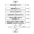
- FIG. 4 is a flowchart showing the procedure of the image processing method according to the present invention.
- the input processing unit 102 inputs a plurality of images of a building as a subject (step S100: input processing, input step). Buildings (buildings, structures) are, for example, bridges, roads, etc., but other structures may also be used. Further, the input processing unit 102 may input an image stored in the storage device 200 as a captured image 202, or may input an image via a recording medium or a network (not shown). These images can be taken while moving the viewpoint by a flying object such as a drone or a robot having a moving function (the user may take a picture). The image to be captured does not have to be a stereo image.
- FIG. 5 is a diagram showing how the camera 30 captures such overlapping images.
- the extraction processing unit 104 extracts damage information of the building based on the plurality of input images (step S110: extraction processing, extraction step).
- the extraction processing unit 104 can extract at least one of the type, number, size, degree of damage, and time change of damage as damage information.
- the extraction processing unit 104 can extract damage information by using various methods. For example, the crack detection method described in Japanese Patent No. 4006007 and the rust and peeling detection method described in Japanese Patent Publication No. 2010-538258 can be used. In addition, the extraction processing unit 104 can extract damage information by using a machine learning method. For example, an image with the type and size of damage as a label is given as teacher data, a learning device such as DNN (Deep Neural Network) is generated by machine learning, and the damage is detected using the generated learning device. Can be done.
- DNN Deep Neural Network
- the extraction processing unit 104 may extract damage information from individual captured images and combine the corresponding information into one, or may extract damage information from one image obtained by synthesizing a plurality of captured images. ..
- the damage can be represented as a vector having a start point and an end point, and in this case, a hierarchical structure between the vectors may be considered as described in WO2017 / 110279A.
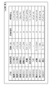
- FIG. 8 is a diagram showing an example of extracted damage information.
- the extraction processing unit 104 can store the extracted damage information in the storage device 200 as damage information 208.
- the generation processing unit 105 creates a three-dimensional model of the building based on the plurality of input images (step S120: generation processing, generation step).
- There are various models such as a 3D point cloud model, a 3D surface model created based on the 3D point cloud model, a 3D polygon model, and a texture-mapped image.
- the generation processing unit 105 can create a three-dimensional model by using, for example, a method of SfM (Structure from Motion).
- SfM is a method for restoring a three-dimensional shape from a multi-viewpoint image.
- FIG. 6 is a diagram showing a point cloud 500 (an example of a point cloud).
- the size is not calculated by SfM, for example, by installing a scaler with known dimensions on the subject and taking a picture, it is possible to associate it with the actual scale.
- the generation processing unit 105 applies, for example, a TIN model (TIN: triangulated irregular network) to the point cloud data obtained in this way to approximate the surface of the building with a triangle, and based on the result, a solid model (solid model).
- a solid model (three-dimensional model) can be obtained.
- the three-dimensional shape of the building is configured as a combination of three-dimensional members such as solid blocks and blocks.
- the generation processing unit 105 may use the result.
- the generation processing unit 105 may automatically generate a solid model by using an algorithm such as RANSAC (RandomSampleConsensus) without any operation of the user.
- RANSAC RandomSampleConsensus
- the generation processing unit 105 may calculate the change of these information by using the information of the three-dimensional position, the color (R, G, B) and the brightness of the point cloud.
- the generation processing unit 105 may read the model.
- the acquisition processing unit 103 is a plurality of images of the building, and the shooting date and time are different from the plurality of images stored in the storage device 200 (memory).
- a plurality of images (for example, images whose shooting date and time are newer than the stored images and which are not used for generating the three-dimensional model) can be acquired (acquisition processing, acquisition step).
- the association processing unit 107 can associate the acquired plurality of images with the members of the three-dimensional model stored in the storage device 200 (association process, association step).
- the association processing unit 107 can perform the association process (association step) based on the correlation between the acquired plurality of images and the plurality of images stored in the storage device 200, for example.
- the specific processing unit 106 specifies the members constituting the building in the three-dimensional model (step S130: specific processing, specific step). That is, the specific processing unit 106 specifies "which member of the building each region of the three-dimensional model corresponds to".
- the specifying processing unit 106 may specify the member based on the operation of the user, or may specify the member without the operation of specifying the member by the user.
- the specific processing unit 106 may use information on the shape and dimensions of the member when specifying the member.
- FIG. 7 is a diagram showing an example of a three-dimensional model in which members are specified.
- the three-dimensional model 510 of the bridge is composed of each member of the floor slab 512, the wall portion 514, and the leg portion 516.
- the memory control processing unit 109 can store the generated data indicating the three-dimensional model in the storage device 200 as the three-dimensional model data 206 (memory control processing, storage control step).
- the above-mentioned point cloud is information indicating the position of the feature point included in the photographed image, and since the member is specified in step S130, the photographed image corresponding to each member can be specified.
- the reception processing unit 110 receives the designation of the image selection criteria (step S140: reception processing, reception process), and the selection processing unit 108 (processor) takes an image according to the criteria.
- An image (representative image) corresponding to the specified member is selected from the images (step S140: selection process, selection step).
- FIG. 9 is a diagram showing how a selection criterion for a representative image is set, and the reception processing unit 110 displays such a screen on the display device 20.
- the reception processing unit 110 sets the priority of the information included in the damage information (number of damages, magnitude, degree (degree) of damages, time change) according to the user's operation. Further, the reception processing unit 110 sets the number of representative images to be selected (one image or a plurality of images) according to the operation of the user. According to such a setting, the selection processing unit 108 selects a specified number of images according to the set priority. This allows the user to quickly and easily select a representative image.
- the aspect shown in FIG. 9 is an example of setting the selection criteria, and the representative image may be selected based on other criteria (for example, the image quality of the captured image, the type of the member, the identification number of the member, etc.).
- FIG. 10 is a diagram showing how the output mode of the processing result is set.
- the user selects a radio button via the operation unit 300 and inputs a numerical value to display a two-dimensional inspection record, display a three-dimensional model, display a representative image, and have a composite image mapped. , It is possible to select whether or not to highlight the damage and display the 2D inspection record on the 3D model.
- the image arrangement processing unit 112, the information input unit 114, and the display processing unit 116 correspond to the specified member, the selected image, and the damage information independently or in cooperation with each other. Attach and output (step S150: output processing, output process).
- steps S110 to S150 can be repeated until the end determination is affirmed in step S160.
- the setting of the output mode and the output in the set mode can be performed at the timing desired by the user. For example, after displaying the processing result in one mode, it can be displayed again in another mode. The specific contents of each output mode will be described below.
- FIG. 11 shows a representative image (representative image) in an area (image area) designated as an area in which an image is arranged by the image arrangement processing unit 112 in a two-dimensional inspection record (an example of a “document file in a specified format”). This is an example in which 552,554,556,558) are arranged.
- the representative image 552 shows the uki 552A
- the representative image 554 shows the peeling 554A.
- the record in this format may span multiple pages.
- the information input unit 114 further inputs damage information such as a photo number, a member name, an element number, a type of damage, and a degree of damage to an area designated as an information area in the document file ( Information input processing, information input process).
- damage information such as a photo number, a member name, an element number, a type of damage, and a degree of damage to an area designated as an information area in the document file ( Information input processing, information input process).
- the content of the "memo" field may be automatically input by the information input unit 114 based on the damage information, or may be input based on the user's operation.
- the display processing unit 116 causes the display device 20 to display such a screen when the "two-dimensional inspection record display mode" is on on the screen of FIG. Further, the display processing unit 116 stores the information corresponding to this screen as the inspection record data 210.
- a document such as an inspection record may be in a format specified by the Ministry of Land, Infrastructure, Transport and Tourism, a local government, or the like, or may be in another format. Documents in other specified formats other than inspection records may be used.
- the representative images may be sorted and arranged in the document by using the member as a key, or the representative images of each member may be sorted and arranged by using the type of damage as a key (for each type of damage). good.
- the user can quickly and easily select a representative image and create an inspection record. That is, the user can easily handle an image of the building, a three-dimensional model of the building, and damage information.
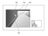
- FIG. 12 shows a state in which the 3D model 520 and the pins 532 and 534 (position information) indicating the positions of the selected image (representative image) in the 3D model are associated and displayed on the display device (first). It is a figure which shows the result of display processing).
- the display timing of the representative image is "when the pin is specified" in FIG. 10
- the pin is displayed at the position of the representative image in this way.
- the three-dimensional model displays the vicinity of the wall surface of the leg of the bridge, and the display processing unit 116 enlarges or reduces the three-dimensional model according to the user's operation via the operation unit 300.
- the viewpoint can be moved and the line-of-sight direction can be changed.
- the display processing unit 116 may turn on or off the display of a specific member (for example, a member instructed by the user) when displaying the three-dimensional model.
- the display processing unit 116 performs such a display when the "three-dimensional model display mode" is on in FIG.
- the three-dimensional models without textures are shown in FIGS. 12 to 15, the same processing can be performed on the three-dimensional models with textures (see FIGS. 16 and the description related to the same figure).
- the display processing unit 116 may highlight the damage information on the three-dimensional model. For example, it may be displayed by tracing the damage or its outline with a thick line or a line of a conspicuous color, such as cracking, peeling, or peeling.
- the display processing unit 116 identifies and displays the pins in a manner corresponding to the damage information. Specifically, the display processing unit 116 displays by changing the pin symbol according to the type of damage, but the color or number may be changed in addition to the symbol, or it may be displayed in the form of an icon. .. Moreover, the display mode may be changed according to the degree of damage. In the example of FIG. 12, the user can select (click, etc.) a pin by moving the cursor 540 on the screen with, for example, the mouse 320.
- FIG. 13 shows a state (result of the second display processing) in which the display processing unit 116 displays a representative image of the specified pin (position information) displayed on the screen on the display device 20. It is a figure.
- the part (a) in FIG. 13 is a state in which the representative image 552 of "Uki” is displayed by the designation of the pin 532, and the part (b) in the figure is the representative image 554 of the "peeling" by the designation of the pin 534. It is in the displayed state.
- the display processing unit 116 may display the representative image on a region different from the three-dimensional model, a different screen, or a different display device.
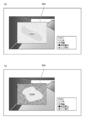
- FIG. 14 is a diagram showing a state in which a representative image is displayed on the three-dimensional model from the beginning (results of the first display process and the third display process).
- the display processing unit 116 performs such a display when the display of the representative image is set to "from the beginning" in FIG.
- the pin and the representative image are connected by a leader line, the user can easily grasp the relationship between the pin and the representative image.
- a representative image may be displayed on a balloon-shaped figure connected to a pin.
- FIG. 15 is a diagram showing a state (result of the fourth display process) in which a portion of the two-dimensional inspection record including the representative image corresponding to the selected pin is displayed.
- the display processing unit 116 can perform such a display when the "two-dimensional inspection record display on the three-dimensional model" is turned on in FIG.
- the display processing unit 116 may display such a partial two-dimensional inspection record on a different area, a different screen, or a different display device from the three-dimensional model.
- the user can quickly and easily browse the creation of the representative image and the inspection record. That is, the user can easily handle an image of the building, a three-dimensional model of the building, and damage information.
- FIG. 16 is a diagram showing a state in which the three-dimensional model 522 in which the composite image is mapped to the three-dimensional model 520 (see FIG. 12) is displayed on the display device 20. Such a display is performed when "Mapping of composite image" is turned on in FIG. 10.
- the image synthesizing unit 117 (processor) synthesizes an image corresponding to the specified member among the plurality of captured images, and the display processing unit 116 maps the combined image to the specified member and displays it. Display on the device 20 (fifth display process). Image composition and mapping may be performed on some members of the building or on all members. In the example shown in FIG.
- the display processing unit 116 performs identification display of position information (pins 532, 534, 536 are displayed with symbols according to the type of damage) in the same manner as described above, and the position is displayed.
- a representative image or a two-dimensional inspection record may be displayed depending on the selection of information.
- the damage information may be highlighted.
- FIG. 16 shows an example in which a separately generated composite image is mapped to a three-dimensional model having only a three-dimensional shape
- the generation processing unit 105 uses the above-mentioned SfM or the like to create a textured three-dimensional model. May be generated directly.
- the generation processing unit 105 may use another algorithm such as MVS (Multi-View Stereo). MVS can generate a finer three-dimensional model in that it has more information than a monocular.
- MVS Multi-View Stereo
- the user can easily handle the image of the building, the three-dimensional model of the building, and the damage information.
- Image processing system 10 Image processing device 20 Display device 30 Camera 100 Processing unit 102 Input processing unit 103 Acquisition processing unit 104 Extraction processing unit 105 Generation processing unit 106 Specific processing unit 107 Correspondence processing unit 108 Selection processing unit 109 Storage control processing unit 110 Reception processing unit 112 Image placement processing unit 114 Information input unit 116 Display processing unit 117 Image composition unit 118 Communication control unit 200 Storage device 202 Captured image 204 Composite image 206 Three-dimensional model data 208 Damage information 210 Inspection record data 300 Operation unit 310 Keyboard 320 Mouse 500 Point group 510 3D model 512 Floor slab 514 Wall 516 Leg 520 3D model 522 3D model 532 pin 534 pin 536 pin 540 cursor 552 representative image 552A Uki 554 representative image 554A peeling 556 representative image 558 representative Images S100 to S160 Each step of the image processing method
Landscapes
- Engineering & Computer Science (AREA)
- Business, Economics & Management (AREA)
- Human Resources & Organizations (AREA)
- Physics & Mathematics (AREA)
- Theoretical Computer Science (AREA)
- General Physics & Mathematics (AREA)
- Strategic Management (AREA)
- Tourism & Hospitality (AREA)
- Economics (AREA)
- General Business, Economics & Management (AREA)
- Entrepreneurship & Innovation (AREA)
- Marketing (AREA)
- Quality & Reliability (AREA)
- Operations Research (AREA)
- Development Economics (AREA)
- Educational Administration (AREA)
- Computer Vision & Pattern Recognition (AREA)
- Health & Medical Sciences (AREA)
- General Health & Medical Sciences (AREA)
- Primary Health Care (AREA)
- Geometry (AREA)
- Game Theory and Decision Science (AREA)
- Software Systems (AREA)
- Computer Graphics (AREA)
- Data Mining & Analysis (AREA)
- Processing Or Creating Images (AREA)
Abstract
One embodiment of the present invention provides an image processing device, an image processing method, and an image processing program that facilitate the handling of a three-dimensional model of a building and damage information thereof on the basis of images obtained by photographing the building. According to one embodiment, the image processing device comprises: a processor; and a memory that stores a plurality of images obtained by photographing the building and a three-dimensional model of the building in which components constituting the building are specified, the plurality of images and the components being stored in association with one another, wherein the processor performs extraction processing in which building damage information is extracted on the basis of the plurality of images, selection processing in which an image corresponding to a designated component is selected from the plurality of images according to a designated criterion; and output processing in which the designated component, the selected image, and the damage information are outputted in association with one another.
Description
本発明は、建造物を撮影した画像、建造物の3次元モデル、及び損傷情報を取り扱う技術に関する。
The present invention relates to an image of a building, a three-dimensional model of the building, and a technique for handling damage information.
建造物の3次元モデル及び損傷情報を取り扱う技術に関し、例えば特許文献1には、橋梁等の構造物(建造物、建築物)の管理用図面を作成する装置が記載されている。
Regarding a three-dimensional model of a building and a technique for handling damage information, for example, Patent Document 1 describes a device for creating a management drawing of a structure (building, building) such as a bridge.
本開示の技術に係る一つの実施形態は、建造物を撮影した画像、建造物の3次元モデル、及び損傷情報を容易に取り扱うことができる画像処理装置、画像処理方法、及び画像処理プログラムを提供する。
One embodiment according to the technique of the present disclosure provides an image of a building, a three-dimensional model of the building, an image processing device capable of easily handling damage information, an image processing method, and an image processing program. do.
本発明の第1の態様に係る画像処理装置は、プロセッサと、建造物を撮影した複数の画像と、造物を構成する部材が特定された建造物の3次元モデルと、が記憶されたメモリであって、複数の画像と部材とが対応付けて記憶されたメモリと、を備える画像処理装置であって、プロセッサは、複数の画像に基づいて建造物の損傷情報を抽出する抽出処理と、複数の画像の中から、指定された基準に従って、指定された部材に対応する画像を選択する選択処理と、指定された部材と、選択された画像と、損傷情報と、を対応付けて出力する出力処理と、を行う。
The image processing apparatus according to the first aspect of the present invention is a memory in which a processor, a plurality of images of a building, and a three-dimensional model of a structure in which a member constituting the structure is specified are stored. It is an image processing device including a memory in which a plurality of images and members are stored in association with each other, and the processor is an extraction process for extracting damage information of a building based on a plurality of images and a plurality of extraction processes. Output that selects the image corresponding to the specified member according to the specified criteria from the images of, and outputs the specified member, the selected image, and the damage information in association with each other. Process and perform.
第2の態様に係る画像処理装置は第1の態様において、プロセッサは、複数の画像に基づいて建造物の3次元モデルを生成する生成処理と、生成した3次元モデルにおいて、建造物を構成する部材を特定する特定処理と、3次元モデルを、複数の画像と特定された部材とを対応付けてメモリに記憶させる記憶制御処理と、を行う。
In the first aspect, the image processing apparatus according to the second aspect constitutes a building in a generation process for generating a three-dimensional model of the building based on a plurality of images and a generated three-dimensional model. A specific process for specifying a member and a storage control process for storing a three-dimensional model in a memory in association with a plurality of images and the specified member are performed.
第3の態様に係る画像処理装置は第2の態様において、プロセッサは、ユーザが部材を特定する操作によらずに特定処理を行う。
In the second aspect, the image processing apparatus according to the third aspect performs the specifying process without the operation of the user specifying the member.
第4の態様に係る画像処理装置は第1から第3の態様のいずれか1つにおいて、プロセッサは、基準の指定を受け付ける受付処理を行う。
The image processing apparatus according to the fourth aspect is one of the first to third aspects, and the processor performs a reception process for accepting the designation of the reference.
第5の態様に係る画像処理装置は第1から第4の態様のいずれか1つにおいて、プロセッサは、抽出処理において、損傷の種類、数、大きさ、損傷度合い、及び時間変化のうち少なくとも1つを損傷情報として抽出する。
The image processing apparatus according to the fifth aspect is in any one of the first to fourth aspects, and the processor is at least one of the type, number, magnitude, degree of damage, and time variation of the damage in the extraction process. Extract one as damage information.
第6の態様に係る画像処理装置は第1から第5の態様のいずれか1つにおいて、プロセッサは、選択処理において、損傷の種類ごとに画像を選択する。
The image processing apparatus according to the sixth aspect is one of the first to fifth aspects, and the processor selects an image for each type of damage in the selection process.
第7の態様に係る画像処理装置は第1から第6の態様のいずれか1つにおいて、プロセッサは、選択処理において、指定された数の画像を選択する。
The image processing apparatus according to the seventh aspect is in any one of the first to sixth aspects, and the processor selects a specified number of images in the selection process.
第8の態様に係る画像処理装置は第1から第7の態様のいずれか1つにおいて、プロセッサは、指定された書式の文書ファイルにおいて画像領域として指定された領域に選択された画像を配置する画像配置処理を行う。
In any one of the first to seventh aspects, the image processing apparatus according to the eighth aspect arranges the selected image in the area designated as the image area in the document file of the specified format. Perform image placement processing.
第9の態様に係る画像処理装置は第8の態様において、プロセッサは、文書ファイルにおいて情報領域として指定された領域に損傷情報を入力する情報入力処理を行う。
In the eighth aspect of the image processing apparatus according to the ninth aspect, the processor performs information input processing for inputting damage information into an area designated as an information area in a document file.
第10の態様に係る画像処理装置は第1から第9の態様のいずれか1つにおいて、プロセッサは、3次元モデルと、選択された画像の3次元モデルにおける位置を示す位置情報と、を関連付けて表示装置に表示させる第1の表示処理と、表示された位置情報のうち指定された位置情報について、選択された画像を表示装置に表示させる第2の表示処理と、を行う。
In any one of the first to ninth aspects, the image processing apparatus according to the tenth aspect associates the three-dimensional model with the position information indicating the position of the selected image in the three-dimensional model. The first display process for displaying on the display device and the second display process for displaying the selected image on the display device with respect to the designated position information among the displayed position information are performed.
第11の態様に係る画像処理装置は第1から第10の態様のいずれか1つにおいて、プロセッサは、3次元モデルと、選択された画像の3次元モデルにおける位置を示す位置情報と、を関連付けて表示装置に表示させる第1の表示処理と、表示された位置情報について、選択された画像を表示装置に表示させる第3の表示処理と、を行う。
In any one of the first to tenth aspects, the image processing apparatus according to the eleventh aspect associates the three-dimensional model with the position information indicating the position of the selected image in the three-dimensional model. The first display process for displaying on the display device and the third display process for displaying the selected image on the display device with respect to the displayed position information are performed.
第12の態様に係る画像処理装置は第10または第11の態様において、プロセッサは、少なくとも第1の表示処理において、位置情報を損傷情報に応じた態様で識別表示させる。
The image processing apparatus according to the twelfth aspect identifies and displays the position information in the tenth or eleventh aspect, and at least in the first display process, the position information is identified and displayed in the manner corresponding to the damage information.
第13の態様に係る画像処理装置は第10から第12の態様のいずれか1つにおいて、プロセッサは、少なくとも第1の表示処理において、複数の画像のうち特定された部材に対応する画像を合成し、合成された画像を特定された部材にマッピングして表示装置に表示させる。
The image processing apparatus according to the thirteenth aspect is in any one of the tenth to twelfth aspects, and the processor synthesizes an image corresponding to a specified member among a plurality of images in at least the first display processing. Then, the synthesized image is mapped to the specified member and displayed on the display device.
第14の態様に係る画像処理装置は第10から第13の態様のいずれか1つにおいて、プロセッサは、少なくとも第1の表示処理において、損傷情報を3次元モデルに強調表示する。
The image processing apparatus according to the fourteenth aspect is in any one of the tenth to thirteenth aspects, and the processor highlights the damage information on the three-dimensional model at least in the first display process.
第15の態様に係る画像処理装置は第1から第14の態様のいずれか1つにおいて、プロセッサは、建造物を撮影した複数の画像であって、メモリに記憶された複数の画像と撮影日時が異なる複数の画像を取得する取得処理と、取得した複数の画像と、メモリに記憶された3次元モデルの部材と、を対応付ける対応付け処理と、を行う。
The image processing apparatus according to the fifteenth aspect is one of the first to the fourteenth aspects, wherein the processor is a plurality of images of a building, and the plurality of images stored in the memory and the shooting date and time. The acquisition process of acquiring a plurality of images having different values, and the association process of associating the acquired plurality of images with the members of the three-dimensional model stored in the memory are performed.
第16の態様に係る画像処理装置は第15の態様において、プロセッサは、取得した複数の画像と、メモリに記憶された複数と、の相関に基づいて対応付け処理を行う。
In the fifteenth aspect of the image processing apparatus according to the sixteenth aspect, the processor performs associative processing based on the correlation between the acquired plurality of images and the plurality of images stored in the memory.
本発明の第17の態様に係る画像処理方法は、プロセッサと、建造物を撮影した複数の画像と、建造物の3次元モデルと、が記憶されたメモリであって、複数の画像と、3次元モデルにおいて建造物を構成する部材と、が対応付けて記憶されたメモリと、を備える画像処理装置による画像処理方法であって、プロセッサが行う処理は、複数の画像に基づいて建造物の損傷情報を抽出する抽出工程と、複数の画像の中から、指定された基準に従って、3次元モデルにおいて指定された部材に対応する画像を選択する選択工程と、指定された部材と、選択された画像と、損傷情報と、を対応付けて出力する出力工程と、を含む。第17の態様に係る画像処理方法は、第2から第16の態様と同様の構成をさらに有していてもよい。
The image processing method according to the seventeenth aspect of the present invention is a memory in which a processor, a plurality of images of a building, and a three-dimensional model of the building are stored, and the plurality of images and 3 An image processing method by an image processing device including a member constituting a building in a dimensional model and a memory stored in association with the member, and the processing performed by the processor is damage to the building based on a plurality of images. An extraction process for extracting information, a selection process for selecting an image corresponding to a specified member in a three-dimensional model from a plurality of images according to a specified standard, a specified member, and a selected image. And an output process for outputting the damage information in association with each other. The image processing method according to the seventeenth aspect may further have the same configuration as the second to sixteenth aspects.
本発明の第18の態様に係る画像処理プログラムは、第17の態様に係る画像処理方法をコンピュータに実行させる。第18の態様に係る画像処理プログラムのコンピュータ読み取り可能なコードを記録した非一時的記録媒体も、本発明の態様として挙げることができる。
The image processing program according to the eighteenth aspect of the present invention causes a computer to execute the image processing method according to the seventeenth aspect. A non-temporary recording medium on which a computer-readable code of the image processing program according to the eighteenth aspect is recorded can also be mentioned as an aspect of the present invention.
本発明に係る画像処理装置、画像処理方法、及び画像処理プログラムの一つの実施形態は以下の通りである。説明においては、必要に応じて添付図面が参照される。
One embodiment of the image processing apparatus, the image processing method, and the image processing program according to the present invention is as follows. In the description, the accompanying drawings will be referred to as necessary.
[第1の実施形態]
[画像処理システムの構成]
図1は、画像処理システム1(画像処理装置)の概略構成を示すブロック図である。画像処理システム1は画像処理装置10(画像処理装置)及び表示装置20(表示装置、モニタ)を備え、被写体を分割撮影して取得した複数の画像について損傷情報の抽出、3次元モデルの作成、2次元点検調書の作成支援等を行うシステムである。画像処理システム1は、パーソナルコンピュータ、タブレット端末、スマートフォン等の機器(情報端末)を用いて構成することができる。画像処理システム1の各要素は1つの筐体に収納されていてもよいし、独立した筐体に収納されていてもよい。また、各要素が離れた場所に配置されネットワークを介して接続されていてもよい。 [First Embodiment]
[Image processing system configuration]
FIG. 1 is a block diagram showing a schematic configuration of an image processing system 1 (image processing apparatus). Theimage processing system 1 includes an image processing device 10 (image processing device) and a display device 20 (display device, monitor), extracts damage information from a plurality of images acquired by dividing and photographing a subject, and creates a three-dimensional model. It is a system that supports the creation of two-dimensional inspection records. The image processing system 1 can be configured by using a device (information terminal) such as a personal computer, a tablet terminal, or a smartphone. Each element of the image processing system 1 may be housed in one housing or may be housed in an independent housing. Further, each element may be arranged at a distant place and connected via a network.
[画像処理システムの構成]
図1は、画像処理システム1(画像処理装置)の概略構成を示すブロック図である。画像処理システム1は画像処理装置10(画像処理装置)及び表示装置20(表示装置、モニタ)を備え、被写体を分割撮影して取得した複数の画像について損傷情報の抽出、3次元モデルの作成、2次元点検調書の作成支援等を行うシステムである。画像処理システム1は、パーソナルコンピュータ、タブレット端末、スマートフォン等の機器(情報端末)を用いて構成することができる。画像処理システム1の各要素は1つの筐体に収納されていてもよいし、独立した筐体に収納されていてもよい。また、各要素が離れた場所に配置されネットワークを介して接続されていてもよい。 [First Embodiment]
[Image processing system configuration]
FIG. 1 is a block diagram showing a schematic configuration of an image processing system 1 (image processing apparatus). The
[画像処理装置の構成]
画像処理装置10は処理部100、記憶装置200、及び操作部300を備え、これら各部は互いに接続されて必要な情報が送受信される。 [Configuration of image processing device]
Theimage processing device 10 includes a processing unit 100, a storage device 200, and an operation unit 300, and these units are connected to each other to transmit and receive necessary information.
画像処理装置10は処理部100、記憶装置200、及び操作部300を備え、これら各部は互いに接続されて必要な情報が送受信される。 [Configuration of image processing device]
The
[処理部の構成]
図2は処理部100(プロセッサ)の構成を示す図である。処理部100は、入力処理部102、取得処理部103、抽出処理部104、生成処理部105、特定処理部106、対応付け処理部107、選択処理部108、記憶制御処理部109、受付処理部110、画像配置処理部112、情報入力部114、表示処理部116、及び通信制御部118を備え、撮影画像の取得、3次元モデルの作成、2次元点検調書の作成支援等を行う。これら各部による処理の詳細は後述する。 [Configuration of processing unit]
FIG. 2 is a diagram showing a configuration of a processing unit 100 (processor). Theprocessing unit 100 includes an input processing unit 102, an acquisition processing unit 103, an extraction processing unit 104, a generation processing unit 105, a specific processing unit 106, an association processing unit 107, a selection processing unit 108, a storage control processing unit 109, and a reception processing unit 109. It includes 110, an image arrangement processing unit 112, an information input unit 114, a display processing unit 116, and a communication control unit 118, and supports acquisition of captured images, creation of a three-dimensional model, creation of a two-dimensional inspection record, and the like. Details of the processing by each of these parts will be described later.
図2は処理部100(プロセッサ)の構成を示す図である。処理部100は、入力処理部102、取得処理部103、抽出処理部104、生成処理部105、特定処理部106、対応付け処理部107、選択処理部108、記憶制御処理部109、受付処理部110、画像配置処理部112、情報入力部114、表示処理部116、及び通信制御部118を備え、撮影画像の取得、3次元モデルの作成、2次元点検調書の作成支援等を行う。これら各部による処理の詳細は後述する。 [Configuration of processing unit]
FIG. 2 is a diagram showing a configuration of a processing unit 100 (processor). The
上述した処理部100の機能は、各種のプロセッサ(processor)及び記録媒体を用いて実現できる。各種のプロセッサには、例えばソフトウェア(プログラム)を実行して各種の機能を実現する汎用的なプロセッサであるCPU(Central Processing Unit)、画像処理に特化したプロセッサであるGPU(Graphics Processing Unit)、FPGA(Field Programmable Gate Array)などの製造後に回路構成を変更可能なプロセッサであるプログラマブルロジックデバイス(Programmable Logic Device:PLD)も含まれる。
各機能は1つのプロセッサにより実現されてもよいし、同種または異種の複数のプロセッサ(例えば、複数のFPGA、あるいはCPUとFPGAの組み合わせ、またはCPUとGPUの組み合わせ)で実現されてもよい。また、複数の機能を1つのプロセッサで実現してもよい。これらの各種のプロセッサのハードウェア的な構造は、より具体的には、半導体素子などの回路素子を組み合わせた電気回路(circuitry)である。 The function of theprocessing unit 100 described above can be realized by using various processors and recording media. Various processors include, for example, a CPU (Central Processing Unit), which is a general-purpose processor that executes software (programs) to realize various functions, and a GPU (Graphics Processing Unit), which is a processor specialized in image processing. A programmable logic device (PLD), which is a processor whose circuit configuration can be changed after manufacturing such as an FPGA (Field Programmable Gate Array), is also included.
Each function may be realized by one processor, or may be realized by a plurality of processors of the same type or different types (for example, a plurality of FPGAs, or a combination of a CPU and an FPGA, or a combination of a CPU and a GPU). Further, a plurality of functions may be realized by one processor. More specifically, the hardware structure of these various processors is an electric circuit (circuitry) in which circuit elements such as semiconductor elements are combined.
各機能は1つのプロセッサにより実現されてもよいし、同種または異種の複数のプロセッサ(例えば、複数のFPGA、あるいはCPUとFPGAの組み合わせ、またはCPUとGPUの組み合わせ)で実現されてもよい。また、複数の機能を1つのプロセッサで実現してもよい。これらの各種のプロセッサのハードウェア的な構造は、より具体的には、半導体素子などの回路素子を組み合わせた電気回路(circuitry)である。 The function of the
Each function may be realized by one processor, or may be realized by a plurality of processors of the same type or different types (for example, a plurality of FPGAs, or a combination of a CPU and an FPGA, or a combination of a CPU and a GPU). Further, a plurality of functions may be realized by one processor. More specifically, the hardware structure of these various processors is an electric circuit (circuitry) in which circuit elements such as semiconductor elements are combined.
上述したプロセッサあるいは電気回路がソフトウェア(プログラム)を実行する際は、実行するソフトウェアのコンピュータ(例えば、処理部100を構成する各種のプロセッサや電気回路、及び/またはそれらの組み合わせ)で読み取り可能なコードをROM等の非一時的記録媒体(メモリ)に記憶しておき、コンピュータがそのソフトウェアを参照する。実行の際は、必要に応じて記憶装置に記憶された情報が使用される。また、実行の際は、例えばRAM(Random Access Memory;メモリ)が一時的記憶領域として用いられる。
When the above-mentioned processor or electric circuit executes software (program), a code readable by a computer of the software to be executed (for example, various processors and electric circuits constituting the processing unit 100, and / or a combination thereof). Is stored in a non-temporary recording medium (memory) such as a ROM, and the computer refers to the software. At the time of execution, the information stored in the storage device is used as needed. Further, at the time of execution, for example, RAM (Random Access Memory; memory) is used as a temporary storage area.
なお、処理部100の機能の一部または全部をネットワーク上のサーバで実現して、画像処理装置10はデータの入力、通信制御、結果の表示等を行ってもよい。この場合、ネットワーク上のサーバを含めてApplication Service Provider型システムが構築される。
Note that a part or all of the functions of the processing unit 100 may be realized by a server on the network, and the image processing device 10 may input data, control communication, display the result, and the like. In this case, the Application Service Provider type system is constructed including the server on the network.
[記憶部の構成]
記憶装置200(記憶装置、メモリ)はCD(Compact Disk)、DVD(Digital Versatile Disk)、ハードディスク(Hard Disk)、各種半導体メモリ等の非一時的記録媒体及びその制御部により構成され、図3に示す情報が互いに関連づけて記憶される。撮影画像202は建造物を撮影した複数の画像であり、合成画像204は、撮影画像から合成された、特定の部材に対応する画像(の集合)である。3次元モデルデータ206(3次元モデル)は、撮影画像に基づいて作成された建造物の3次元モデルであり、建造物を構成する部材が特定されている。なお、3次元モデルデータ206は撮影画像、代表画像、2次元調書等との対応付けがされており、詳細を後述するように、ユーザは3次元モデル上で位置情報を指定することにより、代表画像や2次元点検調書を表示させることができる。損傷情報208(損傷情報)は、撮影画像から抽出された、建造物の損傷を示す情報である。点検調書データ210は、2次元点検調書のひな形(指定された形式の文書ファイル)、あるいは、ひな形に代表画像や損傷情報が配置、入力されたデータである(後述)。ひな形は、国土交通省や地方自治体の定める形式でもよい。 [Structure of storage unit]
The storage device 200 (storage device, memory) is composed of a non-temporary recording medium such as a CD (Compact Disk), a DVD (Digital Versatile Disk), a hard disk (Hard Disk), various semiconductor memories, and a control unit thereof. The information shown is stored in association with each other. The photographedimage 202 is a plurality of images of a building, and the composite image 204 is (a set of) images corresponding to a specific member, which are synthesized from the photographed images. The three-dimensional model data 206 (three-dimensional model) is a three-dimensional model of a building created based on a photographed image, and members constituting the building are specified. The three-dimensional model data 206 is associated with a photographed image, a representative image, a two-dimensional record, and the like, and as will be described in detail later, the user can specify the position information on the three-dimensional model to represent the three-dimensional model data 206. Images and 2D inspection records can be displayed. Damage information 208 (damage information) is information indicating damage to a building extracted from a photographed image. The inspection record data 210 is a two-dimensional inspection record template (document file in a designated format), or data in which representative images and damage information are arranged and input in the template (described later). The template may be in a format specified by the Ministry of Land, Infrastructure, Transport and Tourism or the local government.
記憶装置200(記憶装置、メモリ)はCD(Compact Disk)、DVD(Digital Versatile Disk)、ハードディスク(Hard Disk)、各種半導体メモリ等の非一時的記録媒体及びその制御部により構成され、図3に示す情報が互いに関連づけて記憶される。撮影画像202は建造物を撮影した複数の画像であり、合成画像204は、撮影画像から合成された、特定の部材に対応する画像(の集合)である。3次元モデルデータ206(3次元モデル)は、撮影画像に基づいて作成された建造物の3次元モデルであり、建造物を構成する部材が特定されている。なお、3次元モデルデータ206は撮影画像、代表画像、2次元調書等との対応付けがされており、詳細を後述するように、ユーザは3次元モデル上で位置情報を指定することにより、代表画像や2次元点検調書を表示させることができる。損傷情報208(損傷情報)は、撮影画像から抽出された、建造物の損傷を示す情報である。点検調書データ210は、2次元点検調書のひな形(指定された形式の文書ファイル)、あるいは、ひな形に代表画像や損傷情報が配置、入力されたデータである(後述)。ひな形は、国土交通省や地方自治体の定める形式でもよい。 [Structure of storage unit]
The storage device 200 (storage device, memory) is composed of a non-temporary recording medium such as a CD (Compact Disk), a DVD (Digital Versatile Disk), a hard disk (Hard Disk), various semiconductor memories, and a control unit thereof. The information shown is stored in association with each other. The photographed
これらの情報の他に、後述するSfM(Structure from Motion)を適用する場合に必要なカメラのパラメータ(焦点距離、イメージセンサの画像サイズ、画素ピッチ等)が、記憶装置200に記憶されていてもよい。
In addition to this information, even if the camera parameters (focal length, image sensor image size, pixel pitch, etc.) required when applying SfM (Structure from Motion), which will be described later, are stored in the storage device 200. good.
[操作部の構成]
操作部300はキーボード310及びマウス320を含み、ユーザはこれらのデバイスにより本発明に係る画像処理に必要な操作を行うことができる。タッチパネル型のデバイスを用いることにより、表示装置20を操作部として用いてもよい。 [Configuration of operation unit]
Theoperation unit 300 includes a keyboard 310 and a mouse 320, and the user can perform operations necessary for image processing according to the present invention by using these devices. By using a touch panel type device, the display device 20 may be used as an operation unit.
操作部300はキーボード310及びマウス320を含み、ユーザはこれらのデバイスにより本発明に係る画像処理に必要な操作を行うことができる。タッチパネル型のデバイスを用いることにより、表示装置20を操作部として用いてもよい。 [Configuration of operation unit]
The
[表示装置]
表示装置20(表示装置)は、例えば液晶ディスプレイ等のデバイスであり、取得した撮影画像、損傷情報、3次元モデル、2次元点検調書、代表画像等の情報を表示させることができる。 [Display device]
The display device 20 (display device) is, for example, a device such as a liquid crystal display, and can display information such as acquired captured images, damage information, a three-dimensional model, a two-dimensional inspection record, and a representative image.
[画像処理の手順]
図4は、本発明に係る画像処理方法の手順を示すフローチャートである。 [Image processing procedure]
FIG. 4 is a flowchart showing the procedure of the image processing method according to the present invention.
図4は、本発明に係る画像処理方法の手順を示すフローチャートである。 [Image processing procedure]
FIG. 4 is a flowchart showing the procedure of the image processing method according to the present invention.
[画像の入力]
入力処理部102(プロセッサ)は、被写体としての建造物を撮影した複数の画像を入力する(ステップS100:入力処理、入力工程)。建造物(建築物、構造物)は例えば橋梁、道路等であるが、他の建造物でもよい。また、入力処理部102は、撮影画像202として記憶装置200に記憶されている画像を入力してもよいし、図示せぬ記録媒体やネットワークを介して画像を入力してもよい。これらの画像は、ドローン等の飛翔体や移動機能のあるロボット等により、視点を移動させながら撮影することができる(ユーザが撮影してもよい)。撮影する画像はステレオ画像でなくて良い。なお、3次元モデルの作成及び画像合成のためには、画像間で特徴点が多数共通することが好ましいので、隣接する画像同士が十分に(例えば、面積の80%以上)オーバーラップしていることが好ましい。図5は、カメラ30により、そのようにオーバーラップした画像を撮影する様子を示す図である。 [Image input]
The input processing unit 102 (processor) inputs a plurality of images of a building as a subject (step S100: input processing, input step). Buildings (buildings, structures) are, for example, bridges, roads, etc., but other structures may also be used. Further, theinput processing unit 102 may input an image stored in the storage device 200 as a captured image 202, or may input an image via a recording medium or a network (not shown). These images can be taken while moving the viewpoint by a flying object such as a drone or a robot having a moving function (the user may take a picture). The image to be captured does not have to be a stereo image. For creating a three-dimensional model and synthesizing images, it is preferable that many feature points are common between the images, so that adjacent images sufficiently overlap (for example, 80% or more of the area). Is preferable. FIG. 5 is a diagram showing how the camera 30 captures such overlapping images.
入力処理部102(プロセッサ)は、被写体としての建造物を撮影した複数の画像を入力する(ステップS100:入力処理、入力工程)。建造物(建築物、構造物)は例えば橋梁、道路等であるが、他の建造物でもよい。また、入力処理部102は、撮影画像202として記憶装置200に記憶されている画像を入力してもよいし、図示せぬ記録媒体やネットワークを介して画像を入力してもよい。これらの画像は、ドローン等の飛翔体や移動機能のあるロボット等により、視点を移動させながら撮影することができる(ユーザが撮影してもよい)。撮影する画像はステレオ画像でなくて良い。なお、3次元モデルの作成及び画像合成のためには、画像間で特徴点が多数共通することが好ましいので、隣接する画像同士が十分に(例えば、面積の80%以上)オーバーラップしていることが好ましい。図5は、カメラ30により、そのようにオーバーラップした画像を撮影する様子を示す図である。 [Image input]
The input processing unit 102 (processor) inputs a plurality of images of a building as a subject (step S100: input processing, input step). Buildings (buildings, structures) are, for example, bridges, roads, etc., but other structures may also be used. Further, the
[損傷の抽出]
抽出処理部104(プロセッサ)は、入力した複数の画像に基づいて、建造物の損傷情報を抽出する(ステップS110:抽出処理、抽出工程)。抽出処理部104は、抽出処理において、損傷の種類、数、大きさ、損傷度合い、及び時間変化のうち少なくとも1つを損傷情報として抽出することができる。 [Damage extraction]
The extraction processing unit 104 (processor) extracts damage information of the building based on the plurality of input images (step S110: extraction processing, extraction step). In the extraction process, theextraction processing unit 104 can extract at least one of the type, number, size, degree of damage, and time change of damage as damage information.
抽出処理部104(プロセッサ)は、入力した複数の画像に基づいて、建造物の損傷情報を抽出する(ステップS110:抽出処理、抽出工程)。抽出処理部104は、抽出処理において、損傷の種類、数、大きさ、損傷度合い、及び時間変化のうち少なくとも1つを損傷情報として抽出することができる。 [Damage extraction]
The extraction processing unit 104 (processor) extracts damage information of the building based on the plurality of input images (step S110: extraction processing, extraction step). In the extraction process, the
抽出処理部104は、種々の手法を用いて損傷情報を抽出することができる。例えば、特許4006007号公報に記載されたひび割れ検出方法や、特表2010-538258号公報に記載された錆及び剥離の検出方法を用いることができる。また、抽出処理部104は、機械学習の手法を用いて損傷情報を抽出することができる。例えば、損傷の種類や大きさ等をラベルとして付与した画像を教師データとして与えて機械学習によりDNN(Deep Neural Network)等の学習器を生成し、生成した学習器を用いて損傷を検出することができる。
The extraction processing unit 104 can extract damage information by using various methods. For example, the crack detection method described in Japanese Patent No. 4006007 and the rust and peeling detection method described in Japanese Patent Publication No. 2010-538258 can be used. In addition, the extraction processing unit 104 can extract damage information by using a machine learning method. For example, an image with the type and size of damage as a label is given as teacher data, a learning device such as DNN (Deep Neural Network) is generated by machine learning, and the damage is detected using the generated learning device. Can be done.
抽出処理部104は、個々の撮影画像から損傷情報を抽出して対応する情報を1つに合成してもよいし、複数の撮影画像を合成した1つの画像から損傷情報を抽出してもよい。損傷は始点及び終点を持ったベクトルとして表すことができ、この場合、WO2017/110279号公報に記載されているようにベクトル同士の階層構造を考慮してもよい。
The extraction processing unit 104 may extract damage information from individual captured images and combine the corresponding information into one, or may extract damage information from one image obtained by synthesizing a plurality of captured images. .. The damage can be represented as a vector having a start point and an end point, and in this case, a hierarchical structure between the vectors may be considered as described in WO2017 / 110279A.
図8は抽出した損傷情報の例を示す図である。抽出処理部104は、抽出した損傷情報を、損傷情報208として記憶装置200に記憶させることができる。
FIG. 8 is a diagram showing an example of extracted damage information. The extraction processing unit 104 can store the extracted damage information in the storage device 200 as damage information 208.
[3次元モデルの作成]
生成処理部105(プロセッサ)は、入力した複数の画像に基づいて、建造物の3次元モデルを作成する(ステップS120:生成処理、生成工程)。3次元モデルには、3次元点群モデル、3次元点群モデルに基づいて作成される3次元サーフェスモデルや3次元ポリゴンモデル、あるいは画像がテクスチャーマッピングされたものなど、各種のモデルが存在し、生成処理部105は、例えばSfM(Structure from Motion)の手法を用いて3次元モデルを作成することができる。SfMは、多視点画像から3次元形状を復元する手法であり、例えばSIFT(Scale-Invariant Feature Transform)等のアルゴリズムにより特徴点を算出し、この特徴点を手掛かりとして、三角測量の原理を用いて点群(point cloud)の3次元位置を算出する。具体的には、三角測量の原理を用いてカメラから特徴点へ直線を引き,対応する特徴点を通る2本の直線の交点が、復元した3次元点となる。そして、検出した特徴点ごとにこの作業を行うことにより、点群の3次元位置を得ることができる。図6は、点群500(点群の例)を示す図である。 [Creating a 3D model]
The generation processing unit 105 (processor) creates a three-dimensional model of the building based on the plurality of input images (step S120: generation processing, generation step). There are various models such as a 3D point cloud model, a 3D surface model created based on the 3D point cloud model, a 3D polygon model, and a texture-mapped image. Thegeneration processing unit 105 can create a three-dimensional model by using, for example, a method of SfM (Structure from Motion). SfM is a method for restoring a three-dimensional shape from a multi-viewpoint image. For example, feature points are calculated by an algorithm such as SIFT (Scale-Invariant Feature Transform), and the feature points are used as clues to use the principle of triangular surveying. Calculate the three-dimensional position of the point cloud. Specifically, a straight line is drawn from the camera to the feature point using the principle of triangulation, and the intersection of the two straight lines passing through the corresponding feature point becomes the restored three-dimensional point. Then, by performing this operation for each detected feature point, the three-dimensional position of the point cloud can be obtained. FIG. 6 is a diagram showing a point cloud 500 (an example of a point cloud).
生成処理部105(プロセッサ)は、入力した複数の画像に基づいて、建造物の3次元モデルを作成する(ステップS120:生成処理、生成工程)。3次元モデルには、3次元点群モデル、3次元点群モデルに基づいて作成される3次元サーフェスモデルや3次元ポリゴンモデル、あるいは画像がテクスチャーマッピングされたものなど、各種のモデルが存在し、生成処理部105は、例えばSfM(Structure from Motion)の手法を用いて3次元モデルを作成することができる。SfMは、多視点画像から3次元形状を復元する手法であり、例えばSIFT(Scale-Invariant Feature Transform)等のアルゴリズムにより特徴点を算出し、この特徴点を手掛かりとして、三角測量の原理を用いて点群(point cloud)の3次元位置を算出する。具体的には、三角測量の原理を用いてカメラから特徴点へ直線を引き,対応する特徴点を通る2本の直線の交点が、復元した3次元点となる。そして、検出した特徴点ごとにこの作業を行うことにより、点群の3次元位置を得ることができる。図6は、点群500(点群の例)を示す図である。 [Creating a 3D model]
The generation processing unit 105 (processor) creates a three-dimensional model of the building based on the plurality of input images (step S120: generation processing, generation step). There are various models such as a 3D point cloud model, a 3D surface model created based on the 3D point cloud model, a 3D polygon model, and a texture-mapped image. The
なお、SfMでは大きさは算出されないが、例えば、寸法が既知のスケーラ-(scaler)を被写体に設置して撮影を行うことで、実スケールとの対応付けを行うことができる。
Although the size is not calculated by SfM, for example, by installing a scaler with known dimensions on the subject and taking a picture, it is possible to associate it with the actual scale.
生成処理部105は、このようにして得た点群のデータに対し例えばTINモデル(TIN:triangulated irregular network)を適用して建造物の面を三角形で近似し、その結果に基づいてソリッドモデル(solidモデル;3次元モデル)を得ることができる。ソリッドモデルでは、建造物の3次元形状が、中身の詰まった積み木やブロックのような3次元の部材の組合せとして構成される。なお、ソリッドモデルを得る際に、ユーザが操作部300を介して「点群のどの範囲が同一の面に属するか」を指定し、生成処理部105がその結果を利用してもよい。また、生成処理部105が、RANSAC(Random Sample Consensus)等のアルゴリズムを用いて、ユーザの操作によらずに自動的にソリッドモデルを生成してもよい。ソリッドモデルを生成する際、生成処理部105は、点群の3次元位置、色(R,G,B)、輝度の情報を利用して、これらの情報の変化を算出してもよい。
The generation processing unit 105 applies, for example, a TIN model (TIN: triangulated irregular network) to the point cloud data obtained in this way to approximate the surface of the building with a triangle, and based on the result, a solid model (solid model). A solid model (three-dimensional model) can be obtained. In the solid model, the three-dimensional shape of the building is configured as a combination of three-dimensional members such as solid blocks and blocks. When obtaining the solid model, the user may specify "which range of the point cloud belongs to the same surface" via the operation unit 300, and the generation processing unit 105 may use the result. Further, the generation processing unit 105 may automatically generate a solid model by using an algorithm such as RANSAC (RandomSampleConsensus) without any operation of the user. When generating the solid model, the generation processing unit 105 may calculate the change of these information by using the information of the three-dimensional position, the color (R, G, B) and the brightness of the point cloud.
[生成済みの3次元モデルの利用]
なお、過去の検査等により既に3次元モデルが生成あるいは取得されている場合は、生成処理部105がそのモデルを読み込んでもよい。このような生成済みの3次元モデルを利用する場合、取得処理部103は、建造物を撮影した複数の画像であって、記憶装置200(メモリ)に記憶された複数の画像と撮影日時が異なる複数の画像(例えば、記憶されている画像よりも撮影日時が新しく、3次元モデルの生成に用いられていない画像)を取得することができる(取得処理、取得工程)。また、対応付け処理部107は、取得した複数の画像と、記憶装置200に記憶された3次元モデルの部材と、を対応付けることができる(対応付け処理、対応付け工程)。対応付け処理部107は、例えば、取得した複数の画像と、記憶装置200に記憶された複数の画像と、の相関に基づいて対応付け処理(対応付け工程)を行うことができる。 [Use of generated 3D model]
If the three-dimensional model has already been generated or acquired by past inspection or the like, thegeneration processing unit 105 may read the model. When using such a generated three-dimensional model, the acquisition processing unit 103 is a plurality of images of the building, and the shooting date and time are different from the plurality of images stored in the storage device 200 (memory). A plurality of images (for example, images whose shooting date and time are newer than the stored images and which are not used for generating the three-dimensional model) can be acquired (acquisition processing, acquisition step). Further, the association processing unit 107 can associate the acquired plurality of images with the members of the three-dimensional model stored in the storage device 200 (association process, association step). The association processing unit 107 can perform the association process (association step) based on the correlation between the acquired plurality of images and the plurality of images stored in the storage device 200, for example.
なお、過去の検査等により既に3次元モデルが生成あるいは取得されている場合は、生成処理部105がそのモデルを読み込んでもよい。このような生成済みの3次元モデルを利用する場合、取得処理部103は、建造物を撮影した複数の画像であって、記憶装置200(メモリ)に記憶された複数の画像と撮影日時が異なる複数の画像(例えば、記憶されている画像よりも撮影日時が新しく、3次元モデルの生成に用いられていない画像)を取得することができる(取得処理、取得工程)。また、対応付け処理部107は、取得した複数の画像と、記憶装置200に記憶された3次元モデルの部材と、を対応付けることができる(対応付け処理、対応付け工程)。対応付け処理部107は、例えば、取得した複数の画像と、記憶装置200に記憶された複数の画像と、の相関に基づいて対応付け処理(対応付け工程)を行うことができる。 [Use of generated 3D model]
If the three-dimensional model has already been generated or acquired by past inspection or the like, the
[部材の特定]
特定処理部106(プロセッサ)は、3次元モデルにおいて、建造物を構成する部材を特定する(ステップS130:特定処理、特定工程)。すなわち、特定処理部106は、「3次元モデルの各領域が建造物のどの部材に対応するか」を特定する。特定処理部106は、ユーザの操作に基づいて部材を特定してもよいし、ユーザが部材を特定する操作によらずに特定してもよい。特定処理部106は、部材を特定する際に、部材の形状や寸法に関する情報を用いてもよい。例えば「水平面内で2次元状に広がり、面積がしきい値以上である部材は床版である」、「床版に付着し、1次元状に延伸する部材は主桁である」等の情報を用いることができる。また、特定処理部106は、3次元モデルを構成する部材を正解ラベルとして与えた機械学習により構成された、DNN等の学習器を用いて部材を特定してもよい。図7は、部材が特定された3次元モデルの例を示す図である。同図の例では、橋梁の3次元モデル510は、床版512、壁部514、及び脚部516の各部材から構成されている。 [Specification of parts]
The specific processing unit 106 (processor) specifies the members constituting the building in the three-dimensional model (step S130: specific processing, specific step). That is, thespecific processing unit 106 specifies "which member of the building each region of the three-dimensional model corresponds to". The specifying processing unit 106 may specify the member based on the operation of the user, or may specify the member without the operation of specifying the member by the user. The specific processing unit 106 may use information on the shape and dimensions of the member when specifying the member. For example, information such as "a member that spreads two-dimensionally in a horizontal plane and has an area equal to or larger than a threshold value is a floor slab" and "a member that adheres to the floor slab and extends one-dimensionally is a main girder". Can be used. Further, the specific processing unit 106 may specify the member by using a learning device such as DNN, which is configured by machine learning in which the member constituting the three-dimensional model is given as the correct answer label. FIG. 7 is a diagram showing an example of a three-dimensional model in which members are specified. In the example of the figure, the three-dimensional model 510 of the bridge is composed of each member of the floor slab 512, the wall portion 514, and the leg portion 516.
特定処理部106(プロセッサ)は、3次元モデルにおいて、建造物を構成する部材を特定する(ステップS130:特定処理、特定工程)。すなわち、特定処理部106は、「3次元モデルの各領域が建造物のどの部材に対応するか」を特定する。特定処理部106は、ユーザの操作に基づいて部材を特定してもよいし、ユーザが部材を特定する操作によらずに特定してもよい。特定処理部106は、部材を特定する際に、部材の形状や寸法に関する情報を用いてもよい。例えば「水平面内で2次元状に広がり、面積がしきい値以上である部材は床版である」、「床版に付着し、1次元状に延伸する部材は主桁である」等の情報を用いることができる。また、特定処理部106は、3次元モデルを構成する部材を正解ラベルとして与えた機械学習により構成された、DNN等の学習器を用いて部材を特定してもよい。図7は、部材が特定された3次元モデルの例を示す図である。同図の例では、橋梁の3次元モデル510は、床版512、壁部514、及び脚部516の各部材から構成されている。 [Specification of parts]
The specific processing unit 106 (processor) specifies the members constituting the building in the three-dimensional model (step S130: specific processing, specific step). That is, the
記憶制御処理部109は、生成した3次元モデルを示すデータを、3次元モデルデータ206として記憶装置200に記憶させることができる(記憶制御処理、記憶制御工程)。
The memory control processing unit 109 can store the generated data indicating the three-dimensional model in the storage device 200 as the three-dimensional model data 206 (memory control processing, storage control step).
[代表画像の選択]
上述した点群は撮影画像に含まれる特徴点の位置を示す情報であり、またステップS130で部材が特定されているので、各部材に対応する撮影画像を特定することができる。しかしながら、3次元モデルを作成するため、通常は各部材について非常に多くの画像を取得しているので、ユーザが画像を選択するのは手間が掛かる作業である。そこで画像処理システム1において、受付処理部110(プロセッサ)は画像の選択基準の指定を受け付け(ステップS140:受付処理、受付工程)、選択処理部108(プロセッサ)は、その基準に従って、撮影された画像の中から、特定された部材に対応する画像(代表画像)を選択する(ステップS140:選択処理、選択工程)。 [Selection of representative image]
The above-mentioned point cloud is information indicating the position of the feature point included in the photographed image, and since the member is specified in step S130, the photographed image corresponding to each member can be specified. However, since a three-dimensional model is created, usually a large number of images are acquired for each member, so it is a laborious task for the user to select an image. Therefore, in theimage processing system 1, the reception processing unit 110 (processor) receives the designation of the image selection criteria (step S140: reception processing, reception process), and the selection processing unit 108 (processor) takes an image according to the criteria. An image (representative image) corresponding to the specified member is selected from the images (step S140: selection process, selection step).
上述した点群は撮影画像に含まれる特徴点の位置を示す情報であり、またステップS130で部材が特定されているので、各部材に対応する撮影画像を特定することができる。しかしながら、3次元モデルを作成するため、通常は各部材について非常に多くの画像を取得しているので、ユーザが画像を選択するのは手間が掛かる作業である。そこで画像処理システム1において、受付処理部110(プロセッサ)は画像の選択基準の指定を受け付け(ステップS140:受付処理、受付工程)、選択処理部108(プロセッサ)は、その基準に従って、撮影された画像の中から、特定された部材に対応する画像(代表画像)を選択する(ステップS140:選択処理、選択工程)。 [Selection of representative image]
The above-mentioned point cloud is information indicating the position of the feature point included in the photographed image, and since the member is specified in step S130, the photographed image corresponding to each member can be specified. However, since a three-dimensional model is created, usually a large number of images are acquired for each member, so it is a laborious task for the user to select an image. Therefore, in the
図9は、代表画像の選択基準を設定する様子を示す図であり、受付処理部110は、このような画面を表示装置20に表示させる。図9の例では、受付処理部110は、損傷情報に含まれる情報(損傷の数、大きさ、損傷の程度(度合い)、時間変化)について、ユーザの操作に応じて優先度を設定する。また、受付処理部110は、ユーザの操作に応じて、選択する代表画像の枚数(1枚でもよいし、複数枚でもよい)を設定する。このような設定に応じて、選択処理部108は、設定された優先度に従って、指定された数の画像を選択する。これにより、ユーザは代表画像を迅速かつ容易に選択することができる。なお、図9に示す態様は選択基準設定の一例であり、他の基準(例えば、撮影画像の画質、部材の種類、部材の識別番号等)に基づいて代表画像を選択してもよい。
FIG. 9 is a diagram showing how a selection criterion for a representative image is set, and the reception processing unit 110 displays such a screen on the display device 20. In the example of FIG. 9, the reception processing unit 110 sets the priority of the information included in the damage information (number of damages, magnitude, degree (degree) of damages, time change) according to the user's operation. Further, the reception processing unit 110 sets the number of representative images to be selected (one image or a plurality of images) according to the operation of the user. According to such a setting, the selection processing unit 108 selects a specified number of images according to the set priority. This allows the user to quickly and easily select a representative image. The aspect shown in FIG. 9 is an example of setting the selection criteria, and the representative image may be selected based on other criteria (for example, the image quality of the captured image, the type of the member, the identification number of the member, etc.).
[処理結果の出力]
図10は、処理結果の出力態様を設定する様子を示す図である。同図に示す例では、ユーザは、操作部300を介したラジオボタンの選択及び数値入力により、2次元点検調書の表示、3次元モデルの表示、代表画像の表示タイミング、合成画像のマッピングの有無、損傷の強調表示、3次元モデルへの2次元点検調書の表示の有無を選択することができる。そして、設定された内容に従い、画像配置処理部112、情報入力部114、表示処理部116が単独で、または協調して、特定された部材と、選択された画像と、損傷情報と、を対応付けて出力する(ステップS150:出力処理、出力工程)。ステップS110からS150までの処理は、ステップS160で終了の判断が肯定されるまで、繰り返し行うことができる。なお、出力態様の設定、及び設定した態様での出力は、ユーザが希望するタイミングで行うことができる。例えば、あるモードで処理結果を表示させた後、別のモードで再度表示させることができる。各出力態様の具体的な内容は、以下で説明する。 [Output of processing result]
FIG. 10 is a diagram showing how the output mode of the processing result is set. In the example shown in the figure, the user selects a radio button via theoperation unit 300 and inputs a numerical value to display a two-dimensional inspection record, display a three-dimensional model, display a representative image, and have a composite image mapped. , It is possible to select whether or not to highlight the damage and display the 2D inspection record on the 3D model. Then, according to the set contents, the image arrangement processing unit 112, the information input unit 114, and the display processing unit 116 correspond to the specified member, the selected image, and the damage information independently or in cooperation with each other. Attach and output (step S150: output processing, output process). The processes from steps S110 to S150 can be repeated until the end determination is affirmed in step S160. It should be noted that the setting of the output mode and the output in the set mode can be performed at the timing desired by the user. For example, after displaying the processing result in one mode, it can be displayed again in another mode. The specific contents of each output mode will be described below.
図10は、処理結果の出力態様を設定する様子を示す図である。同図に示す例では、ユーザは、操作部300を介したラジオボタンの選択及び数値入力により、2次元点検調書の表示、3次元モデルの表示、代表画像の表示タイミング、合成画像のマッピングの有無、損傷の強調表示、3次元モデルへの2次元点検調書の表示の有無を選択することができる。そして、設定された内容に従い、画像配置処理部112、情報入力部114、表示処理部116が単独で、または協調して、特定された部材と、選択された画像と、損傷情報と、を対応付けて出力する(ステップS150:出力処理、出力工程)。ステップS110からS150までの処理は、ステップS160で終了の判断が肯定されるまで、繰り返し行うことができる。なお、出力態様の設定、及び設定した態様での出力は、ユーザが希望するタイミングで行うことができる。例えば、あるモードで処理結果を表示させた後、別のモードで再度表示させることができる。各出力態様の具体的な内容は、以下で説明する。 [Output of processing result]
FIG. 10 is a diagram showing how the output mode of the processing result is set. In the example shown in the figure, the user selects a radio button via the
[その1:2次元点検調書を用いた出力]
図11は、画像配置処理部112が、2次元点検調書(「指定された書式の文書ファイル」の一例)において、画像を配置する領域として指定された領域(画像領域)に代表画像(代表画像552,554,556,558)を配置した例である。同図中、代表画像552にはうき552Aが写っており、代表画像554には剥離554Aが写っている。このような形式の調書は複数ページに渡っていてもよい。図11の例では、さらに、情報入力部114が、写真番号、部材名、要素番号、損傷の種類、程度等の損傷情報を、文書ファイルにおいて情報領域として指定された領域に入力している(情報入力処理、情報入力工程)。「メモ」欄の内容は、情報入力部114が損傷情報に基づいて自動的に入力してもよいし、ユーザの操作に基づいて入力してもよい。表示処理部116は、図10の画面で「2次元点検調書表示モード」がオンの場合に、このような画面を表示装置20に表示させる。また、表示処理部116は、この画面に対応する情報を点検調書データ210として記憶させる。 [Part 1: Output using 2D inspection record]
FIG. 11 shows a representative image (representative image) in an area (image area) designated as an area in which an image is arranged by the imagearrangement processing unit 112 in a two-dimensional inspection record (an example of a “document file in a specified format”). This is an example in which 552,554,556,558) are arranged. In the figure, the representative image 552 shows the uki 552A, and the representative image 554 shows the peeling 554A. The record in this format may span multiple pages. In the example of FIG. 11, the information input unit 114 further inputs damage information such as a photo number, a member name, an element number, a type of damage, and a degree of damage to an area designated as an information area in the document file ( Information input processing, information input process). The content of the "memo" field may be automatically input by the information input unit 114 based on the damage information, or may be input based on the user's operation. The display processing unit 116 causes the display device 20 to display such a screen when the "two-dimensional inspection record display mode" is on on the screen of FIG. Further, the display processing unit 116 stores the information corresponding to this screen as the inspection record data 210.
図11は、画像配置処理部112が、2次元点検調書(「指定された書式の文書ファイル」の一例)において、画像を配置する領域として指定された領域(画像領域)に代表画像(代表画像552,554,556,558)を配置した例である。同図中、代表画像552にはうき552Aが写っており、代表画像554には剥離554Aが写っている。このような形式の調書は複数ページに渡っていてもよい。図11の例では、さらに、情報入力部114が、写真番号、部材名、要素番号、損傷の種類、程度等の損傷情報を、文書ファイルにおいて情報領域として指定された領域に入力している(情報入力処理、情報入力工程)。「メモ」欄の内容は、情報入力部114が損傷情報に基づいて自動的に入力してもよいし、ユーザの操作に基づいて入力してもよい。表示処理部116は、図10の画面で「2次元点検調書表示モード」がオンの場合に、このような画面を表示装置20に表示させる。また、表示処理部116は、この画面に対応する情報を点検調書データ210として記憶させる。 [Part 1: Output using 2D inspection record]
FIG. 11 shows a representative image (representative image) in an area (image area) designated as an area in which an image is arranged by the image
なお、文書のフォーマットや代表画像のレイアウトは各種考えられる。例えば、点検調書等の文書は、国土交通省、地方自治体等の定める書式でもよいし、他の書式でもよい。点検調書以外の、他の指定された書式の文書を用いてもよい。また、部材をキーにして代表画像がソートされて文書に配置されていてもよいし、損傷の種類をキーとして(損傷の種類ごとに)各部材の代表画像がソートされて配置されていてもよい。
There are various possible document formats and representative image layouts. For example, a document such as an inspection record may be in a format specified by the Ministry of Land, Infrastructure, Transport and Tourism, a local government, or the like, or may be in another format. Documents in other specified formats other than inspection records may be used. Further, the representative images may be sorted and arranged in the document by using the member as a key, or the representative images of each member may be sorted and arranged by using the type of damage as a key (for each type of damage). good.
このような処理により、画像処理システム1では、ユーザは代表画像の選択及び点検調書の作成を迅速かつ容易に行うことができる。すなわち、ユーザは建造物を撮影した画像、建造物の3次元モデル、及び損傷情報を容易に取り扱うことができる。
By such processing, in the image processing system 1, the user can quickly and easily select a representative image and create an inspection record. That is, the user can easily handle an image of the building, a three-dimensional model of the building, and damage information.
[その2:3次元モデルを用いた出力]
図12は、3次元モデル520と、選択された画像(代表画像)の3次元モデルにおける位置を示すピン532,534(位置情報)と、を関連付けて表示装置に表示させた状態(第1の表示処理の結果)を示す図である。図10で代表画像の表示タイミングが「ピン指定時」となっている場合に、このように代表画像の位置にピンが表示される。図12の例は、3次元モデルは橋梁の脚部の壁面付近を表示したものであり、表示処理部116は、操作部300を介したユーザの操作に応じて3次元モデルを拡大または縮小し、また視点の移動や視線方向の変更を行うことができる。また、表示処理部116は、3次元モデルを表示する際に、特定の部材(例えば、ユーザが指示した部材)の表示をオンまたはオフにしてもよい。表示処理部116は、図10で「3次元モデル表示モード」がオンの場合に、このような表示を行う。なお、図12~15ではテクスチャなしの3次元モデルを示しているが、テクスチャありの3次元モデルについても同様の処理を行うことができる(図16及び同図に関連する記載を参照)。 [Part 2: Output using 3D model]
FIG. 12 shows a state in which the3D model 520 and the pins 532 and 534 (position information) indicating the positions of the selected image (representative image) in the 3D model are associated and displayed on the display device (first). It is a figure which shows the result of display processing). When the display timing of the representative image is "when the pin is specified" in FIG. 10, the pin is displayed at the position of the representative image in this way. In the example of FIG. 12, the three-dimensional model displays the vicinity of the wall surface of the leg of the bridge, and the display processing unit 116 enlarges or reduces the three-dimensional model according to the user's operation via the operation unit 300. Also, the viewpoint can be moved and the line-of-sight direction can be changed. Further, the display processing unit 116 may turn on or off the display of a specific member (for example, a member instructed by the user) when displaying the three-dimensional model. The display processing unit 116 performs such a display when the "three-dimensional model display mode" is on in FIG. Although the three-dimensional models without textures are shown in FIGS. 12 to 15, the same processing can be performed on the three-dimensional models with textures (see FIGS. 16 and the description related to the same figure).
図12は、3次元モデル520と、選択された画像(代表画像)の3次元モデルにおける位置を示すピン532,534(位置情報)と、を関連付けて表示装置に表示させた状態(第1の表示処理の結果)を示す図である。図10で代表画像の表示タイミングが「ピン指定時」となっている場合に、このように代表画像の位置にピンが表示される。図12の例は、3次元モデルは橋梁の脚部の壁面付近を表示したものであり、表示処理部116は、操作部300を介したユーザの操作に応じて3次元モデルを拡大または縮小し、また視点の移動や視線方向の変更を行うことができる。また、表示処理部116は、3次元モデルを表示する際に、特定の部材(例えば、ユーザが指示した部材)の表示をオンまたはオフにしてもよい。表示処理部116は、図10で「3次元モデル表示モード」がオンの場合に、このような表示を行う。なお、図12~15ではテクスチャなしの3次元モデルを示しているが、テクスチャありの3次元モデルについても同様の処理を行うことができる(図16及び同図に関連する記載を参照)。 [Part 2: Output using 3D model]
FIG. 12 shows a state in which the
表示処理部116は、損傷情報を3次元モデルに強調表示してもよい。例えば、ひび割れ、あるいはうきや剥離等、損傷もしくはその輪郭を太い線や目立つ色の線でなぞって表示する、等の態様で表示してもよい。
The display processing unit 116 may highlight the damage information on the three-dimensional model. For example, it may be displayed by tracing the damage or its outline with a thick line or a line of a conspicuous color, such as cracking, peeling, or peeling.
なお、図11の例では、表示処理部116はピンを損傷情報に応じた態様で識別表示している。具体的には、表示処理部116は損傷の種類に応じてピンの記号を変えて表示しているが、記号の他に色や数字を変えてもよいし、アイコン状に表示してもよい。また、損傷の程度に応じて表示態様を変えてもよい。ユーザは、図12の例において、例えばマウス320により画面上でカーソル540を移動させてピンを選択(クリック等)することができる。
In the example of FIG. 11, the display processing unit 116 identifies and displays the pins in a manner corresponding to the damage information. Specifically, the display processing unit 116 displays by changing the pin symbol according to the type of damage, but the color or number may be changed in addition to the symbol, or it may be displayed in the form of an icon. .. Moreover, the display mode may be changed according to the degree of damage. In the example of FIG. 12, the user can select (click, etc.) a pin by moving the cursor 540 on the screen with, for example, the mouse 320.
図13は、表示処理部116が、画面に表示されたピン(位置情報)のうち指定されたものについて、代表画像を表示装置20に表示させた状態(第2の表示処理の結果)を示す図である。図13の(a)部分は、ピン532の指定により「うき」の代表画像552が表示された状態であり、同図の(b)部分はピン534の指定により「剥離」の代表画像554が表示された状態である。表示処理部116は、3次元モデルとは別の領域、別の画面、あるいは別の表示装置に代表画像を表示させてもよい。
FIG. 13 shows a state (result of the second display processing) in which the display processing unit 116 displays a representative image of the specified pin (position information) displayed on the screen on the display device 20. It is a figure. The part (a) in FIG. 13 is a state in which the representative image 552 of "Uki" is displayed by the designation of the pin 532, and the part (b) in the figure is the representative image 554 of the "peeling" by the designation of the pin 534. It is in the displayed state. The display processing unit 116 may display the representative image on a region different from the three-dimensional model, a different screen, or a different display device.
図14は、3次元モデルに代表画像を最初から表示した状態(第1の表示処理及び第3の表示処理の結果)を示す図である。表示処理部116は、図10で代表画像の表示が「最初から」に設定されている場合にこのような表示を行う。図14に示す例では、ピンと代表画像が引き出し線で結ばれているので、ユーザはピンと代表画像との関係を容易に把握することができる。ピンに結ばれた吹き出し状の図形に代表画像を表示してもよい。
FIG. 14 is a diagram showing a state in which a representative image is displayed on the three-dimensional model from the beginning (results of the first display process and the third display process). The display processing unit 116 performs such a display when the display of the representative image is set to "from the beginning" in FIG. In the example shown in FIG. 14, since the pin and the representative image are connected by a leader line, the user can easily grasp the relationship between the pin and the representative image. A representative image may be displayed on a balloon-shaped figure connected to a pin.
図15は、2次元点検調書のうち、選択されたピンに対応する代表画像を含む部分を表示した様子(第4の表示処理の結果)を示す図である。表示処理部116は、図10で「3次元モデルへの2次元点検調書表示」がオンである場合に、このような表示を行うことができる。表示処理部116は、このような部分的な2次元点検調書を、3次元モデルと別の領域、別の画面、別の表示装置に表示させてもよい。
FIG. 15 is a diagram showing a state (result of the fourth display process) in which a portion of the two-dimensional inspection record including the representative image corresponding to the selected pin is displayed. The display processing unit 116 can perform such a display when the "two-dimensional inspection record display on the three-dimensional model" is turned on in FIG. The display processing unit 116 may display such a partial two-dimensional inspection record on a different area, a different screen, or a different display device from the three-dimensional model.
このような処理により、画像処理システム1では、ユーザは代表画像や点検調書の作成を迅速かつ容易に閲覧することができる。すなわち、ユーザは建造物を撮影した画像、建造物の3次元モデル、及び損傷情報を容易に取り扱うことができる。
By such processing, in the image processing system 1, the user can quickly and easily browse the creation of the representative image and the inspection record. That is, the user can easily handle an image of the building, a three-dimensional model of the building, and damage information.
[その3:3次元モデルへの合成画像のマッピング]
図16は、3次元モデル520(図12参照)に合成画像をマッピングした3次元モデル522を、表示装置20に表示した様子を示す図である。図10で「合成画像のマッピング」がオンの場合に、このような表示が行われる。この態様では、画像合成部117(プロセッサ)が複数の撮影画像のうち特定された部材に対応する画像を合成し、表示処理部116が、合成された画像を特定された部材にマッピングして表示装置20に表示させる(第5の表示処理)。画像の合成及びマッピングは、建造物の一部の部材について行ってもよいし、全ての部材について行ってもよい。なお、図16に示す例では、表示処理部116は、上述した態様と同様に位置情報の識別表示(ピン532,534,536を損傷の種類に応じた記号で表示)を行っており、位置情報の選択に応じて代表画像や2次元点検調書を表示してもよい。また、損傷情報の強調表示を行ってもよい。 [Part 3: Mapping of composite image to 3D model]
FIG. 16 is a diagram showing a state in which the three-dimensional model 522 in which the composite image is mapped to the three-dimensional model 520 (see FIG. 12) is displayed on the display device 20. Such a display is performed when "Mapping of composite image" is turned on in FIG. 10. In this aspect, the image synthesizing unit 117 (processor) synthesizes an image corresponding to the specified member among the plurality of captured images, and the display processing unit 116 maps the combined image to the specified member and displays it. Display on the device 20 (fifth display process). Image composition and mapping may be performed on some members of the building or on all members. In the example shown in FIG. 16, the display processing unit 116 performs identification display of position information (pins 532, 534, 536 are displayed with symbols according to the type of damage) in the same manner as described above, and the position is displayed. A representative image or a two-dimensional inspection record may be displayed depending on the selection of information. In addition, the damage information may be highlighted.
図16は、3次元モデル520(図12参照)に合成画像をマッピングした3次元モデル522を、表示装置20に表示した様子を示す図である。図10で「合成画像のマッピング」がオンの場合に、このような表示が行われる。この態様では、画像合成部117(プロセッサ)が複数の撮影画像のうち特定された部材に対応する画像を合成し、表示処理部116が、合成された画像を特定された部材にマッピングして表示装置20に表示させる(第5の表示処理)。画像の合成及びマッピングは、建造物の一部の部材について行ってもよいし、全ての部材について行ってもよい。なお、図16に示す例では、表示処理部116は、上述した態様と同様に位置情報の識別表示(ピン532,534,536を損傷の種類に応じた記号で表示)を行っており、位置情報の選択に応じて代表画像や2次元点検調書を表示してもよい。また、損傷情報の強調表示を行ってもよい。 [Part 3: Mapping of composite image to 3D model]
FIG. 16 is a diagram showing a state in which the three-
なお、図16では、立体形状のみの3次元モデルに別途生成した合成画像をマッピングした例を示しているが、生成処理部105(プロセッサ)は、上述したSfM等により、テクスチャ付きの3次元モデルを直接生成してもよい。この際、生成処理部105は、MVS(Multi-View Stereo:多眼ステレオ)等の他のアルゴリズムを用いてもよい。MVSは、単眼より情報量が多いという点で、より精細な3次元モデルを生成することができる。このようなテクスチャ付きの3次元モデルについても、図12~15について上述した態様と同様に、位置情報や代表画像の表示、部分的な2次元点検調書の表示、損傷情報の強調表示を行ってもよい。
Although FIG. 16 shows an example in which a separately generated composite image is mapped to a three-dimensional model having only a three-dimensional shape, the generation processing unit 105 (processor) uses the above-mentioned SfM or the like to create a textured three-dimensional model. May be generated directly. At this time, the generation processing unit 105 may use another algorithm such as MVS (Multi-View Stereo). MVS can generate a finer three-dimensional model in that it has more information than a monocular. For such a textured 3D model, the position information and the representative image are displayed, the partial 2D inspection record is displayed, and the damage information is highlighted in the same manner as in the above-described aspects of FIGS. 12 to 15. May be good.
このような処理により、画像処理システム1では、ユーザは建造物を撮影した画像、建造物の3次元モデル、及び損傷情報を容易に取り扱うことができる。
By such processing, in the image processing system 1, the user can easily handle the image of the building, the three-dimensional model of the building, and the damage information.
以上で本発明の実施形態について説明してきたが、本発明は上述した態様に限定されず、本発明の精神を逸脱しない範囲で種々の変形が可能である。
Although the embodiments of the present invention have been described above, the present invention is not limited to the above-described aspects, and various modifications can be made without departing from the spirit of the present invention.
1 画像処理システム
10 画像処理装置
20 表示装置
30 カメラ
100 処理部
102 入力処理部
103 取得処理部
104 抽出処理部
105 生成処理部
106 特定処理部
107 対応付け処理部
108 選択処理部
109 記憶制御処理部
110 受付処理部
112 画像配置処理部
114 情報入力部
116 表示処理部
117 画像合成部
118 通信制御部
200 記憶装置
202 撮影画像
204 合成画像
206 3次元モデルデータ
208 損傷情報
210 点検調書データ
300 操作部
310 キーボード
320 マウス
500 点群
510 3次元モデル
512 床版
514 壁部
516 脚部
520 3次元モデル
522 3次元モデル
532 ピン
534 ピン
536 ピン
540 カーソル
552 代表画像
552A うき
554 代表画像
554A 剥離
556 代表画像
558 代表画像
S100~S160 画像処理方法の各ステップ 1Image processing system 10 Image processing device 20 Display device 30 Camera 100 Processing unit 102 Input processing unit 103 Acquisition processing unit 104 Extraction processing unit 105 Generation processing unit 106 Specific processing unit 107 Correspondence processing unit 108 Selection processing unit 109 Storage control processing unit 110 Reception processing unit 112 Image placement processing unit 114 Information input unit 116 Display processing unit 117 Image composition unit 118 Communication control unit 200 Storage device 202 Captured image 204 Composite image 206 Three-dimensional model data 208 Damage information 210 Inspection record data 300 Operation unit 310 Keyboard 320 Mouse 500 Point group 510 3D model 512 Floor slab 514 Wall 516 Leg 520 3D model 522 3D model 532 pin 534 pin 536 pin 540 cursor 552 representative image 552A Uki 554 representative image 554A peeling 556 representative image 558 representative Images S100 to S160 Each step of the image processing method
10 画像処理装置
20 表示装置
30 カメラ
100 処理部
102 入力処理部
103 取得処理部
104 抽出処理部
105 生成処理部
106 特定処理部
107 対応付け処理部
108 選択処理部
109 記憶制御処理部
110 受付処理部
112 画像配置処理部
114 情報入力部
116 表示処理部
117 画像合成部
118 通信制御部
200 記憶装置
202 撮影画像
204 合成画像
206 3次元モデルデータ
208 損傷情報
210 点検調書データ
300 操作部
310 キーボード
320 マウス
500 点群
510 3次元モデル
512 床版
514 壁部
516 脚部
520 3次元モデル
522 3次元モデル
532 ピン
534 ピン
536 ピン
540 カーソル
552 代表画像
552A うき
554 代表画像
554A 剥離
556 代表画像
558 代表画像
S100~S160 画像処理方法の各ステップ 1
Claims (18)
- プロセッサと、
建造物を撮影した複数の画像と、前記建造物を構成する部材が特定された前記建造物の3次元モデルと、が記憶されたメモリであって、前記複数の画像と前記部材とが対応付けて記憶されたメモリと、
を備える画像処理装置であって、
前記プロセッサは、
前記複数の画像に基づいて前記建造物の損傷情報を抽出する抽出処理と、
前記複数の画像の中から、指定された基準に従って、指定された部材に対応する画像を選択する選択処理と、
前記指定された部材と、前記選択された画像と、前記損傷情報と、を対応付けて出力する出力処理と、
を行う画像処理装置。 With the processor
A memory in which a plurality of images of a building and a three-dimensional model of the building in which members constituting the building are specified are stored, and the plurality of images and the members are associated with each other. And the stored memory
An image processing device equipped with
The processor
Extraction processing that extracts damage information of the building based on the plurality of images, and
A selection process for selecting an image corresponding to a designated member from the plurality of images according to a designated criterion, and
An output process that outputs the designated member, the selected image, and the damage information in association with each other.
Image processing device that performs. - 前記プロセッサは、
前記複数の画像に基づいて前記建造物の3次元モデルを生成する生成処理と、
前記生成した前記3次元モデルにおいて、前記建造物を構成する部材を特定する特定処理と、
前記3次元モデルを、前記複数の画像と前記特定された部材とを対応付けて前記メモリに記憶させる記憶制御処理と、
を行う請求項1に記載の画像処理装置。 The processor
A generation process for generating a three-dimensional model of the building based on the plurality of images, and
In the generated three-dimensional model, specific processing for specifying the members constituting the building and specific processing
A storage control process for storing the three-dimensional model in the memory in association with the plurality of images and the specified member.
The image processing apparatus according to claim 1. - 前記プロセッサは、ユーザが前記部材を特定する操作によらずに前記特定処理を行う請求項2に記載の画像処理装置。 The image processing device according to claim 2, wherein the processor performs the specifying process without the user performing an operation of specifying the member.
- 前記プロセッサは、前記基準の指定を受け付ける受付処理を行う請求項1から3のいずれか1項に記載の画像処理装置。 The image processing device according to any one of claims 1 to 3, wherein the processor performs a reception process for accepting the designation of the standard.
- 前記プロセッサは、前記抽出処理において、損傷の種類、数、大きさ、損傷度合い、及び時間変化のうち少なくとも1つを前記損傷情報として抽出する請求項1から4のいずれか1項に記載の画像処理装置。 The image according to any one of claims 1 to 4, wherein the processor extracts at least one of the type, number, size, degree of damage, and time change of damage as the damage information in the extraction process. Processing equipment.
- 前記プロセッサは、前記選択処理において、損傷の種類ごとに画像を選択する請求項1から5のいずれか1項に記載の画像処理装置。 The image processing device according to any one of claims 1 to 5, wherein the processor selects an image for each type of damage in the selection process.
- 前記プロセッサは、前記選択処理において、指定された数の画像を選択する請求項1から6のいずれか1項に記載の画像処理装置。 The image processing device according to any one of claims 1 to 6, wherein the processor selects a specified number of images in the selection process.
- 前記プロセッサは、指定された書式の文書ファイルにおいて画像領域として指定された領域に前記選択された画像を配置する画像配置処理を行う請求項1から7のいずれか1項に記載の画像処理装置。 The image processing device according to any one of claims 1 to 7, wherein the processor performs an image arrangement process for arranging the selected image in an area designated as an image area in a document file having a specified format.
- 前記プロセッサは、前記文書ファイルにおいて情報領域として指定された領域に前記損傷情報を入力する情報入力処理を行う請求項8に記載の画像処理装置。 The image processing device according to claim 8, wherein the processor performs an information input process for inputting the damage information into an area designated as an information area in the document file.
- 前記プロセッサは、
前記3次元モデルと、前記選択された画像の前記3次元モデルにおける位置を示す位置情報と、を関連付けて表示装置に表示させる第1の表示処理と、
前記表示された位置情報のうち指定された位置情報について、前記選択された画像を前記表示装置に表示させる第2の表示処理と、
を行う請求項1から9のいずれか1項に記載の画像処理装置。 The processor
The first display process of associating the three-dimensional model with the position information indicating the position of the selected image in the three-dimensional model and displaying them on the display device.
A second display process for displaying the selected image on the display device with respect to the designated position information among the displayed position information.
The image processing apparatus according to any one of claims 1 to 9. - 前記プロセッサは、
前記3次元モデルと、前記選択された画像の前記3次元モデルにおける位置を示す位置情報と、を関連付けて表示装置に表示させる第1の表示処理と、
前記表示された位置情報について、前記選択された画像を前記表示装置に表示させる第3の表示処理と、
を行う請求項1から10のいずれか1項に記載の画像処理装置。 The processor
The first display process of associating the three-dimensional model with the position information indicating the position of the selected image in the three-dimensional model and displaying them on the display device.
With respect to the displayed position information, a third display process for displaying the selected image on the display device, and
The image processing apparatus according to any one of claims 1 to 10. - 前記プロセッサは、少なくとも前記第1の表示処理において、前記位置情報を前記損傷情報に応じた態様で識別表示させる請求項10または11に記載の画像処理装置。 The image processing device according to claim 10 or 11, wherein the processor identifies and displays the position information in an manner corresponding to the damage information in at least the first display process.
- 前記プロセッサは、少なくとも前記第1の表示処理において、前記複数の画像のうち前記特定された部材に対応する画像を合成し、前記合成された画像を前記特定された部材にマッピングして前記表示装置に表示させる請求項10から12のいずれか1項に記載の画像処理装置。 In at least the first display process, the processor synthesizes an image corresponding to the specified member among the plurality of images, maps the synthesized image to the specified member, and displays the display device. The image processing device according to any one of claims 10 to 12 to be displayed on the screen.
- 前記プロセッサは、少なくとも前記第1の表示処理において、前記損傷情報を前記3次元モデルに強調表示する請求項10から13のいずれか1項に記載の画像処理装置。 The image processing device according to any one of claims 10 to 13, wherein the processor highlights the damage information on the three-dimensional model at least in the first display processing.
- 前記プロセッサは、
前記建造物を撮影した複数の画像であって、前記メモリに記憶された前記複数の画像と撮影日時が異なる複数の画像を取得する取得処理と、
前記取得した前記複数の画像と、前記メモリに記憶された前記3次元モデルの前記部材と、を対応付ける対応付け処理と、
を行う請求項1から14のいずれか1項に記載の画像処理装置。 The processor
Acquisition processing for acquiring a plurality of images obtained by photographing the building and having a different shooting date and time from the plurality of images stored in the memory.
An association process for associating the acquired plurality of images with the member of the three-dimensional model stored in the memory.
The image processing apparatus according to any one of claims 1 to 14. - 前記プロセッサは、前記取得した前記複数の画像と、前記メモリに記憶された前記複数の画像と、の相関に基づいて前記対応付け処理を行う請求項15に記載の画像処理装置。 The image processing apparatus according to claim 15, wherein the processor performs the association processing based on the correlation between the acquired plurality of images and the plurality of images stored in the memory.
- プロセッサと、
建造物を撮影した複数の画像と、前記建造物の3次元モデルと、が記憶されたメモリであって、前記複数の画像と、前記3次元モデルにおいて前記建造物を構成する部材と、が対応付けて記憶されたメモリと、
を備える画像処理装置による画像処理方法であって、
前記プロセッサが行う処理は、
前記複数の画像に基づいて前記建造物の損傷情報を抽出する抽出工程と、
前記複数の画像の中から、指定された基準に従って、前記3次元モデルにおいて指定された部材に対応する画像を選択する選択工程と、
前記指定された部材と、前記選択された画像と、前記損傷情報と、を対応付けて出力する出力工程と、
を含む画像処理方法。 With the processor
A memory in which a plurality of images of a building and a three-dimensional model of the building are stored, and the plurality of images correspond to the members constituting the building in the three-dimensional model. The memory that was attached and stored,
It is an image processing method by an image processing apparatus provided with
The processing performed by the processor is
An extraction step of extracting damage information of the building based on the plurality of images, and
A selection step of selecting an image corresponding to a member specified in the three-dimensional model according to a specified criterion from the plurality of images.
An output process for outputting the designated member, the selected image, and the damage information in association with each other.
Image processing method including. - 請求項17に記載の画像処理方法をコンピュータに実行させる画像処理プログラム。 An image processing program that causes a computer to execute the image processing method according to claim 17.
Priority Applications (4)
| Application Number | Priority Date | Filing Date | Title |
|---|---|---|---|
| JP2022505021A JPWO2021176877A1 (en) | 2020-03-02 | 2021-01-22 | |
| CN202180013765.7A CN115104128A (en) | 2020-03-02 | 2021-01-22 | Image processing apparatus, image processing method, and image processing program |
| EP21765299.9A EP4116931A4 (en) | 2020-03-02 | 2021-01-22 | Image processing device, image processing method, and image processing program |
| US17/819,388 US20220383487A1 (en) | 2020-03-02 | 2022-08-12 | Image processing apparatus, image processing method, and image processing program |
Applications Claiming Priority (2)
| Application Number | Priority Date | Filing Date | Title |
|---|---|---|---|
| JP2020035172 | 2020-03-02 | ||
| JP2020-035172 | 2020-03-02 |
Related Child Applications (1)
| Application Number | Title | Priority Date | Filing Date |
|---|---|---|---|
| US17/819,388 Continuation US20220383487A1 (en) | 2020-03-02 | 2022-08-12 | Image processing apparatus, image processing method, and image processing program |
Publications (1)
| Publication Number | Publication Date |
|---|---|
| WO2021176877A1 true WO2021176877A1 (en) | 2021-09-10 |
Family
ID=77613397
Family Applications (1)
| Application Number | Title | Priority Date | Filing Date |
|---|---|---|---|
| PCT/JP2021/002200 WO2021176877A1 (en) | 2020-03-02 | 2021-01-22 | Image processing device, image processing method, and image processing program |
Country Status (5)
| Country | Link |
|---|---|
| US (1) | US20220383487A1 (en) |
| EP (1) | EP4116931A4 (en) |
| JP (1) | JPWO2021176877A1 (en) |
| CN (1) | CN115104128A (en) |
| WO (1) | WO2021176877A1 (en) |
Citations (13)
| Publication number | Priority date | Publication date | Assignee | Title |
|---|---|---|---|---|
| JP4006007B2 (en) | 2004-11-10 | 2007-11-14 | 大成建設株式会社 | Crack detection method |
| JP2010538258A (en) | 2007-09-03 | 2010-12-09 | コリア エクスプレスウェイ コーポレイション | Steel bridge coating film inspection system using image processing method and processing method thereof |
| JP2011070632A (en) * | 2009-08-27 | 2011-04-07 | Fujifilm Corp | Inspection system, mobile terminal, inspection method, and program |
| JP2011192270A (en) | 2010-02-19 | 2011-09-29 | West Japan Railway Co | Structure administrative drawing preparing device and processing program |
| JP2014115915A (en) * | 2012-12-11 | 2014-06-26 | Hitachi Ltd | Three-dimensional model generation device, three-dimensional model generation method, and three-dimensional model generation program |
| WO2017010279A1 (en) | 2015-07-13 | 2017-01-19 | 横浜ゴム株式会社 | Rubber composition for flame-retardant hose, and flame-retardant hose |
| WO2017119202A1 (en) * | 2016-01-06 | 2017-07-13 | 富士フイルム株式会社 | Structure member specifying device and method |
| JP2017167969A (en) * | 2016-03-17 | 2017-09-21 | 首都高技術株式会社 | Damage extraction system |
| JP2017168077A (en) * | 2016-03-09 | 2017-09-21 | 株式会社リコー | Image processing method, display device, and inspection system |
| JP2018181235A (en) * | 2017-04-21 | 2018-11-15 | 古河電気工業株式会社 | Report generator, wind power generation equipment inspection system, program, and method for generating inspection report of wind power generation equipment |
| JP2019082933A (en) * | 2017-10-31 | 2019-05-30 | 株式会社日本ソフト | Report preparation system |
| JP2019174982A (en) * | 2018-03-27 | 2019-10-10 | 富士通株式会社 | Model display control method and model display control program and model display control system |
| JP2020030519A (en) * | 2018-08-21 | 2020-02-27 | 株式会社日本ソフト | Process management system, process management method and program |
-
2021
- 2021-01-22 JP JP2022505021A patent/JPWO2021176877A1/ja active Pending
- 2021-01-22 CN CN202180013765.7A patent/CN115104128A/en active Pending
- 2021-01-22 WO PCT/JP2021/002200 patent/WO2021176877A1/en unknown
- 2021-01-22 EP EP21765299.9A patent/EP4116931A4/en active Pending
-
2022
- 2022-08-12 US US17/819,388 patent/US20220383487A1/en active Pending
Patent Citations (13)
| Publication number | Priority date | Publication date | Assignee | Title |
|---|---|---|---|---|
| JP4006007B2 (en) | 2004-11-10 | 2007-11-14 | 大成建設株式会社 | Crack detection method |
| JP2010538258A (en) | 2007-09-03 | 2010-12-09 | コリア エクスプレスウェイ コーポレイション | Steel bridge coating film inspection system using image processing method and processing method thereof |
| JP2011070632A (en) * | 2009-08-27 | 2011-04-07 | Fujifilm Corp | Inspection system, mobile terminal, inspection method, and program |
| JP2011192270A (en) | 2010-02-19 | 2011-09-29 | West Japan Railway Co | Structure administrative drawing preparing device and processing program |
| JP2014115915A (en) * | 2012-12-11 | 2014-06-26 | Hitachi Ltd | Three-dimensional model generation device, three-dimensional model generation method, and three-dimensional model generation program |
| WO2017010279A1 (en) | 2015-07-13 | 2017-01-19 | 横浜ゴム株式会社 | Rubber composition for flame-retardant hose, and flame-retardant hose |
| WO2017119202A1 (en) * | 2016-01-06 | 2017-07-13 | 富士フイルム株式会社 | Structure member specifying device and method |
| JP2017168077A (en) * | 2016-03-09 | 2017-09-21 | 株式会社リコー | Image processing method, display device, and inspection system |
| JP2017167969A (en) * | 2016-03-17 | 2017-09-21 | 首都高技術株式会社 | Damage extraction system |
| JP2018181235A (en) * | 2017-04-21 | 2018-11-15 | 古河電気工業株式会社 | Report generator, wind power generation equipment inspection system, program, and method for generating inspection report of wind power generation equipment |
| JP2019082933A (en) * | 2017-10-31 | 2019-05-30 | 株式会社日本ソフト | Report preparation system |
| JP2019174982A (en) * | 2018-03-27 | 2019-10-10 | 富士通株式会社 | Model display control method and model display control program and model display control system |
| JP2020030519A (en) * | 2018-08-21 | 2020-02-27 | 株式会社日本ソフト | Process management system, process management method and program |
Also Published As
| Publication number | Publication date |
|---|---|
| US20220383487A1 (en) | 2022-12-01 |
| JPWO2021176877A1 (en) | 2021-09-10 |
| EP4116931A4 (en) | 2023-09-06 |
| CN115104128A (en) | 2022-09-23 |
| EP4116931A1 (en) | 2023-01-11 |
Similar Documents
| Publication | Publication Date | Title |
|---|---|---|
| US8487926B2 (en) | Method and apparatus for generating 3D image using 2D photograph images | |
| US9208607B2 (en) | Apparatus and method of producing 3D model | |
| JP6723748B2 (en) | Image management apparatus, image management method and program | |
| JP6144364B2 (en) | Work support data creation program | |
| CN108876706B (en) | Thumbnail generation from panoramic images | |
| JP6293386B2 (en) | Data processing apparatus, data processing method, and data processing program | |
| JP6882868B2 (en) | Image processing equipment, image processing method, system | |
| KR101992044B1 (en) | Information processing apparatus, method, and computer program | |
| JP7480066B2 (en) | SYSTEMS AND METHODS FOR AUGMENTED REALITY OVERLAYS - Patent application | |
| US20220405878A1 (en) | Image processing apparatus, image processing method, and image processing program | |
| JP2016071682A (en) | Object arrangement device, object arrangement method, and program | |
| JP5987114B2 (en) | High resolution image generation apparatus, high resolution image generation method, and high resolution image generation program | |
| WO2021176877A1 (en) | Image processing device, image processing method, and image processing program | |
| CN112634439B (en) | 3D information display method and device | |
| CN112652056B (en) | 3D information display method and device | |
| Saran et al. | Augmented annotations: Indoor dataset generation with augmented reality | |
| JP6405539B2 (en) | Label information processing apparatus for multi-viewpoint image and label information processing method | |
| JP2003087550A (en) | Device and method for compositing image and computer readable recording medium having image composite processing program recorded thereon | |
| KR100943451B1 (en) | System for manufacturing ortho image using tiff format of dem-tiff and method therefor | |
| CN113167568A (en) | Coordinate calculation device, coordinate calculation method, and computer-readable recording medium | |
| CN111521127A (en) | Measuring method, measuring apparatus, and recording medium | |
| JP2019175350A (en) | Structure inspection system, structure inspection device, and structure inspection method | |
| JP4380376B2 (en) | Image processing apparatus, image processing method, and image processing program | |
| JP7268560B2 (en) | Stone wall placement support program, stone wall placement support method, and stone wall placement support device | |
| JP6962242B2 (en) | Information processing device, superimposition display program, superimposition display method |
Legal Events
| Date | Code | Title | Description |
|---|---|---|---|
| 121 | Ep: the epo has been informed by wipo that ep was designated in this application |
Ref document number: 21765299 Country of ref document: EP Kind code of ref document: A1 |
|
| ENP | Entry into the national phase |
Ref document number: 2022505021 Country of ref document: JP Kind code of ref document: A |
|
| NENP | Non-entry into the national phase |
Ref country code: DE |
|
| ENP | Entry into the national phase |
Ref document number: 2021765299 Country of ref document: EP Effective date: 20221004 |