WO2021171049A1 - Vehicle control method and vehicle control device - Google Patents
Vehicle control method and vehicle control device Download PDFInfo
- Publication number
- WO2021171049A1 WO2021171049A1 PCT/IB2020/000136 IB2020000136W WO2021171049A1 WO 2021171049 A1 WO2021171049 A1 WO 2021171049A1 IB 2020000136 W IB2020000136 W IB 2020000136W WO 2021171049 A1 WO2021171049 A1 WO 2021171049A1
- Authority
- WO
- WIPO (PCT)
- Prior art keywords
- vehicle
- score
- speed
- oncoming
- oncoming vehicle
- Prior art date
Links
- 238000000034 method Methods 0.000 title claims description 52
- 230000001133 acceleration Effects 0.000 claims abstract description 126
- 238000013459 approach Methods 0.000 claims description 23
- 230000008859 change Effects 0.000 claims description 4
- 230000009467 reduction Effects 0.000 claims description 2
- 230000007423 decrease Effects 0.000 claims 1
- 238000004364 calculation method Methods 0.000 description 70
- 230000004048 modification Effects 0.000 description 24
- 238000012986 modification Methods 0.000 description 24
- 230000008569 process Effects 0.000 description 18
- 238000010586 diagram Methods 0.000 description 12
- 238000012545 processing Methods 0.000 description 8
- 230000006870 function Effects 0.000 description 7
- 230000010365 information processing Effects 0.000 description 6
- 230000000694 effects Effects 0.000 description 4
- 238000004891 communication Methods 0.000 description 3
- 230000009471 action Effects 0.000 description 2
- 238000004590 computer program Methods 0.000 description 2
- 238000002474 experimental method Methods 0.000 description 2
- 238000010606 normalization Methods 0.000 description 2
- 238000004088 simulation Methods 0.000 description 2
- 230000010354 integration Effects 0.000 description 1
- 230000002452 interceptive effect Effects 0.000 description 1
- 230000004044 response Effects 0.000 description 1
Images


Classifications
-
- B—PERFORMING OPERATIONS; TRANSPORTING
- B60—VEHICLES IN GENERAL
- B60W—CONJOINT CONTROL OF VEHICLE SUB-UNITS OF DIFFERENT TYPE OR DIFFERENT FUNCTION; CONTROL SYSTEMS SPECIALLY ADAPTED FOR HYBRID VEHICLES; ROAD VEHICLE DRIVE CONTROL SYSTEMS FOR PURPOSES NOT RELATED TO THE CONTROL OF A PARTICULAR SUB-UNIT
- B60W30/00—Purposes of road vehicle drive control systems not related to the control of a particular sub-unit, e.g. of systems using conjoint control of vehicle sub-units
- B60W30/18—Propelling the vehicle
- B60W30/18009—Propelling the vehicle related to particular drive situations
- B60W30/18163—Lane change; Overtaking manoeuvres
-
- B—PERFORMING OPERATIONS; TRANSPORTING
- B60—VEHICLES IN GENERAL
- B60W—CONJOINT CONTROL OF VEHICLE SUB-UNITS OF DIFFERENT TYPE OR DIFFERENT FUNCTION; CONTROL SYSTEMS SPECIALLY ADAPTED FOR HYBRID VEHICLES; ROAD VEHICLE DRIVE CONTROL SYSTEMS FOR PURPOSES NOT RELATED TO THE CONTROL OF A PARTICULAR SUB-UNIT
- B60W30/00—Purposes of road vehicle drive control systems not related to the control of a particular sub-unit, e.g. of systems using conjoint control of vehicle sub-units
- B60W30/08—Active safety systems predicting or avoiding probable or impending collision or attempting to minimise its consequences
- B60W30/09—Taking automatic action to avoid collision, e.g. braking and steering
-
- B—PERFORMING OPERATIONS; TRANSPORTING
- B60—VEHICLES IN GENERAL
- B60W—CONJOINT CONTROL OF VEHICLE SUB-UNITS OF DIFFERENT TYPE OR DIFFERENT FUNCTION; CONTROL SYSTEMS SPECIALLY ADAPTED FOR HYBRID VEHICLES; ROAD VEHICLE DRIVE CONTROL SYSTEMS FOR PURPOSES NOT RELATED TO THE CONTROL OF A PARTICULAR SUB-UNIT
- B60W30/00—Purposes of road vehicle drive control systems not related to the control of a particular sub-unit, e.g. of systems using conjoint control of vehicle sub-units
- B60W30/08—Active safety systems predicting or avoiding probable or impending collision or attempting to minimise its consequences
- B60W30/095—Predicting travel path or likelihood of collision
- B60W30/0953—Predicting travel path or likelihood of collision the prediction being responsive to vehicle dynamic parameters
-
- B—PERFORMING OPERATIONS; TRANSPORTING
- B60—VEHICLES IN GENERAL
- B60W—CONJOINT CONTROL OF VEHICLE SUB-UNITS OF DIFFERENT TYPE OR DIFFERENT FUNCTION; CONTROL SYSTEMS SPECIALLY ADAPTED FOR HYBRID VEHICLES; ROAD VEHICLE DRIVE CONTROL SYSTEMS FOR PURPOSES NOT RELATED TO THE CONTROL OF A PARTICULAR SUB-UNIT
- B60W30/00—Purposes of road vehicle drive control systems not related to the control of a particular sub-unit, e.g. of systems using conjoint control of vehicle sub-units
- B60W30/08—Active safety systems predicting or avoiding probable or impending collision or attempting to minimise its consequences
- B60W30/095—Predicting travel path or likelihood of collision
- B60W30/0956—Predicting travel path or likelihood of collision the prediction being responsive to traffic or environmental parameters
-
- B—PERFORMING OPERATIONS; TRANSPORTING
- B60—VEHICLES IN GENERAL
- B60W—CONJOINT CONTROL OF VEHICLE SUB-UNITS OF DIFFERENT TYPE OR DIFFERENT FUNCTION; CONTROL SYSTEMS SPECIALLY ADAPTED FOR HYBRID VEHICLES; ROAD VEHICLE DRIVE CONTROL SYSTEMS FOR PURPOSES NOT RELATED TO THE CONTROL OF A PARTICULAR SUB-UNIT
- B60W40/00—Estimation or calculation of non-directly measurable driving parameters for road vehicle drive control systems not related to the control of a particular sub unit, e.g. by using mathematical models
- B60W40/10—Estimation or calculation of non-directly measurable driving parameters for road vehicle drive control systems not related to the control of a particular sub unit, e.g. by using mathematical models related to vehicle motion
- B60W40/107—Longitudinal acceleration
-
- B—PERFORMING OPERATIONS; TRANSPORTING
- B60—VEHICLES IN GENERAL
- B60W—CONJOINT CONTROL OF VEHICLE SUB-UNITS OF DIFFERENT TYPE OR DIFFERENT FUNCTION; CONTROL SYSTEMS SPECIALLY ADAPTED FOR HYBRID VEHICLES; ROAD VEHICLE DRIVE CONTROL SYSTEMS FOR PURPOSES NOT RELATED TO THE CONTROL OF A PARTICULAR SUB-UNIT
- B60W2554/00—Input parameters relating to objects
- B60W2554/20—Static objects
-
- B—PERFORMING OPERATIONS; TRANSPORTING
- B60—VEHICLES IN GENERAL
- B60W—CONJOINT CONTROL OF VEHICLE SUB-UNITS OF DIFFERENT TYPE OR DIFFERENT FUNCTION; CONTROL SYSTEMS SPECIALLY ADAPTED FOR HYBRID VEHICLES; ROAD VEHICLE DRIVE CONTROL SYSTEMS FOR PURPOSES NOT RELATED TO THE CONTROL OF A PARTICULAR SUB-UNIT
- B60W2554/00—Input parameters relating to objects
- B60W2554/40—Dynamic objects, e.g. animals, windblown objects
- B60W2554/404—Characteristics
- B60W2554/4041—Position
-
- B—PERFORMING OPERATIONS; TRANSPORTING
- B60—VEHICLES IN GENERAL
- B60W—CONJOINT CONTROL OF VEHICLE SUB-UNITS OF DIFFERENT TYPE OR DIFFERENT FUNCTION; CONTROL SYSTEMS SPECIALLY ADAPTED FOR HYBRID VEHICLES; ROAD VEHICLE DRIVE CONTROL SYSTEMS FOR PURPOSES NOT RELATED TO THE CONTROL OF A PARTICULAR SUB-UNIT
- B60W2554/00—Input parameters relating to objects
- B60W2554/40—Dynamic objects, e.g. animals, windblown objects
- B60W2554/404—Characteristics
- B60W2554/4045—Intention, e.g. lane change or imminent movement
-
- B—PERFORMING OPERATIONS; TRANSPORTING
- B60—VEHICLES IN GENERAL
- B60W—CONJOINT CONTROL OF VEHICLE SUB-UNITS OF DIFFERENT TYPE OR DIFFERENT FUNCTION; CONTROL SYSTEMS SPECIALLY ADAPTED FOR HYBRID VEHICLES; ROAD VEHICLE DRIVE CONTROL SYSTEMS FOR PURPOSES NOT RELATED TO THE CONTROL OF A PARTICULAR SUB-UNIT
- B60W2554/00—Input parameters relating to objects
- B60W2554/80—Spatial relation or speed relative to objects
- B60W2554/802—Longitudinal distance
-
- B—PERFORMING OPERATIONS; TRANSPORTING
- B60—VEHICLES IN GENERAL
- B60W—CONJOINT CONTROL OF VEHICLE SUB-UNITS OF DIFFERENT TYPE OR DIFFERENT FUNCTION; CONTROL SYSTEMS SPECIALLY ADAPTED FOR HYBRID VEHICLES; ROAD VEHICLE DRIVE CONTROL SYSTEMS FOR PURPOSES NOT RELATED TO THE CONTROL OF A PARTICULAR SUB-UNIT
- B60W2554/00—Input parameters relating to objects
- B60W2554/80—Spatial relation or speed relative to objects
- B60W2554/804—Relative longitudinal speed
Definitions
- vehicle control that reflects the intention of the driver of the oncoming vehicle is possible.
- the sensor 11 is a device mounted on the own vehicle and detecting an object around the own vehicle.
- the sensor 11 includes a camera, a rider, a radar, a millimeter wave radar, a laser range finder, a sonar, and the like.
- the sensor 11 detects moving objects including other vehicles, motorcycles, bicycles, and pedestrians, and stationary objects including obstacles, falling objects, and parked vehicles as objects around the own vehicle. Further, the sensor 11 detects the position, posture (yaw angle), size, speed, acceleration, deceleration, and yaw rate of the moving object and the stationary object with respect to the own vehicle.
- the sensor 11 may include a wheel speed sensor (second sensor), a steering angle sensor, a gyro sensor, and the like.
- the wheel speed sensor detects the rotational speed of the wheels of the own vehicle. The vehicle speed can be obtained by this rotation speed.
- the sensor 11 outputs the detected information to the controller 20.
- the passing position calculation unit 22 determines whether or not the position where the own vehicle and the oncoming vehicle pass each other exists in the passing prohibition area set by the passing prohibition area setting unit 21. Specifically, the passing position calculation unit 22 calculates the position where the own vehicle and the oncoming vehicle pass each other based on the relative distance between the own vehicle and the oncoming vehicle, the speed of the own vehicle, and the speed of the oncoming vehicle. .. Then, the passing position calculation unit 22 determines whether or not the calculated passing position exists in the passing prohibition area. The relative distance between the own vehicle and the oncoming vehicle, the speed of the own vehicle, and the speed of the oncoming vehicle are detected by the sensor 11.
- the first score calculation unit 23 calculates the first score based on the speed of the oncoming vehicle when the passing position calculation unit 22 determines that the passing position exists in the passing prohibited area.
- the first score may be calculated regardless of whether or not the passing position exists in the passing prohibition area by the passing position calculation unit 22.
- the stationary object will be described as the parked vehicle 52, but the stationary object is not limited to the parked vehicle 52.
- stationary objects include falling objects, pylon (also called road cones), and the like.
- the parked vehicle 52 is parked in the oncoming lane.
- the horizontal axis of FIG. 5 is the acceleration of the oncoming vehicle 51, and the vertical axis is the second score.
- the second score is proportional to the acceleration of the oncoming vehicle 51.
- the value of the second score is not particularly limited as in the first score, and may be any value.
- the second score s 2, when the acceleration of the oncoming vehicle 51 and a t, s 2 is represented by the following formula (3).
- s 2 f 2 (a t ) ⁇ (3)
- f 2 is a function for normalization.
- step S127 When the integrated score is equal to or higher than a predetermined value (YES in step S127), the process proceeds to step S129, and the speed determination unit 26 determines the side of the parked vehicle 52 without waiting for the own vehicle 50 by the driver's intention of the oncoming vehicle 51. It is presumed that it will pass through.
- the speed determination unit 26 determines the deceleration of the own vehicle 50 so that the own vehicle 50 can stop smoothly at a position where the approach to the oncoming vehicle 51 can be avoided (a position outside the passing prohibition area R).
- the vehicle control unit 27 decelerates the own vehicle 50 at a deceleration determined by the speed determination unit 26, and smoothly stops the own vehicle 50 at a position outside the passing prohibition area R.
- step S131 the process proceeds to step S131, and the speed determination unit 26 estimates that the driver's intention of the oncoming vehicle 51 is to wait for the passage of the own vehicle 50. do.
- the speed determination unit 26 determines to maintain the speed of the own vehicle 50 or accelerate the own vehicle 50.
- the vehicle control unit 27 maintains the speed of the own vehicle 50 or accelerates the own vehicle 50 at an acceleration determined by the speed determination unit 26. Since the process of step S133 is the same as the process of step S119, the description thereof will be omitted.
- the acceleration has a greater influence on the estimation accuracy than the speed of the oncoming vehicle 51 depending on the position of the oncoming vehicle 51. Further, when the acceleration of the oncoming vehicle 51 is used, using the acceleration of the oncoming vehicle 51 at a position closer to the parked vehicle 52 has a greater effect on the estimation accuracy. This is because if the acceleration of the oncoming vehicle 51 increases at a position close to the parked vehicle 52, there is a high possibility that the driver of the oncoming vehicle 51 will pass by the side of the parked vehicle 52 without waiting for the own vehicle 50. ..
- the contribution of the second score to the integrated score increases at a position close to the parked vehicle 52, and the contribution of the first score to the integrated score increases at a position far from the parked vehicle 52.
- the contribution of the first score and the second score to the integrated score is controlled by using the first weight ⁇ 1 and the second weight ⁇ 2. Is possible.
- the reduction rate of the second weight ⁇ 2 with respect to the change in distance in the direction in which the oncoming vehicle 51 approaches the parked vehicle 52 increases as the oncoming vehicle 51 approaches the parked vehicle 52.
- the contribution of the first score to the integrated score is relatively reduced, and the contribution of the second score to the integrated score is relatively increased.
- the acceleration with respect to the traveling direction of the oncoming vehicle 51 is defined as the forward acceleration
- the acceleration in the direction opposite to the traveling direction of the vehicle is defined as the negative acceleration
- “large acceleration” means the acceleration. It means that it is large in the positive direction.
- a margin is set in the vehicle speed threshold value described in the modified example 3.
- the margin set in the vehicle speed threshold value will be described with reference to FIG.
Landscapes
- Engineering & Computer Science (AREA)
- Automation & Control Theory (AREA)
- Transportation (AREA)
- Mechanical Engineering (AREA)
- Physics & Mathematics (AREA)
- Mathematical Physics (AREA)
- Control Of Driving Devices And Active Controlling Of Vehicle (AREA)
- Traffic Control Systems (AREA)
Abstract
A vehicle control device (1) sets an area on a road, the area encompassing a prescribed distance range along the extending direction of the road from a stationary object, and including the stationary object. On the basis of the speed of a host vehicle and the position and speed of an oncoming vehicle, the vehicle control device calculates a position where the host vehicle and the oncoming vehicle will pass each other. The vehicle control device calculates a first score having a value that increases commensurately with any increases in the speed of the oncoming vehicle, calculates a second score having a value that increases commensurately with any increases in the acceleration rate of the oncoming vehicle, and integrates the first score and the second score to calculate an integrated score. When the position where the vehicles will pass each other is within the area, the vehicle control device causes the host vehicle to decelerate if the integrated score is equal to or greater than a prescribed value, and maintains the host vehicle speed or causes the host vehicle to accelerate if the integrated score is less than the prescribed value.
Description
本発明は、車両制御方法及び車両制御装置に関する。
The present invention relates to a vehicle control method and a vehicle control device.
従来より、対向車両が対向レーンからはみ出してくる可能性がある場合に、その対向車両を回避するための運転支援装置が知られている(特許文献1)。特許文献1に記載された発明は、対向レーン側の駐車車両とセンターラインとの距離とに基づいて、対向車両の通過経路が自車線側に干渉するか否かを判定する。そして、対向車両の通過経路が自車線側に干渉すると判定された場合、特許文献1に記載された発明は自車両を停車させる、または減速させる。
Conventionally, a driving support device for avoiding an oncoming vehicle when there is a possibility that the oncoming vehicle may protrude from the oncoming lane has been known (Patent Document 1). The invention described in Patent Document 1 determines whether or not the passing path of the oncoming vehicle interferes with the own lane side based on the distance between the parked vehicle on the oncoming lane side and the center line. Then, when it is determined that the passing path of the oncoming vehicle interferes with the own lane side, the invention described in Patent Document 1 stops or decelerates the own vehicle.
しかしながら、特許文献1に記載された発明は、対向車両の運転者の意図を反映していないため、自車両と対向車両が干渉することなくすれ違うことができる場合でも、自車両を不要に減速させたり、あるいは停車させたりしてしまうおそれがある。
However, since the invention described in Patent Document 1 does not reflect the intention of the driver of the oncoming vehicle, the own vehicle is unnecessarily decelerated even when the own vehicle and the oncoming vehicle can pass each other without interfering with each other. Or it may stop the vehicle.
本発明は、上記問題に鑑みて成されたものであり、その目的は、対向車両の運転者の意図を反映した車両制御方法及び車両制御装置を提供することである。
The present invention has been made in view of the above problems, and an object of the present invention is to provide a vehicle control method and a vehicle control device that reflect the intentions of the driver of an oncoming vehicle.
本発明の一態様に係る車両制御方法は、道路上の領域で、かつ、静止物体から道路の延在方向に沿った所定距離範囲の、静止物体を含んで形成される領域を設定し、自車両の速度と対向車両の位置及び速度とに基づいて、自車両と対向車両がすれ違う位置を算出し、対向車両の速度が大きいほど大きな値となる第1スコアを算出し、対向車両の加速度が大きいほど大きな値となる第2スコアを算出し、第1スコアと第2スコアとを統合して統合スコアを算出し、すれ違う位置が領域内に存在する場合において、統合スコアが所定値以上の場合には自車両を減速させ、統合スコアが所定値未満の場合には自車両の速度を維持または自車両を加速させる。
The vehicle control method according to one aspect of the present invention sets an area on the road and a predetermined distance range from the stationary object along the extending direction of the road, and sets the area formed including the stationary object. Based on the speed of the vehicle and the position and speed of the oncoming vehicle, the position where the own vehicle and the oncoming vehicle pass each other is calculated, and the first score, which becomes a larger value as the speed of the oncoming vehicle increases, is calculated, and the acceleration of the oncoming vehicle increases. The larger the value, the larger the second score is calculated, the first score and the second score are integrated to calculate the integrated score, and when the passing position exists in the area, the integrated score is equal to or greater than the predetermined value. Decelerates the own vehicle, and if the integrated score is less than the predetermined value, the speed of the own vehicle is maintained or the own vehicle is accelerated.
本発明によれば、対向車両の運転者の意図を反映した車両制御が可能となる。
According to the present invention, vehicle control that reflects the intention of the driver of the oncoming vehicle is possible.
以下、本発明の実施形態について、図面を参照して説明する。図面の記載において同一部分には同一符号を付して説明を省略する。
Hereinafter, embodiments of the present invention will be described with reference to the drawings. In the description of the drawings, the same parts are designated by the same reference numerals and the description thereof will be omitted.
(本実施形態)
(装置の構成例)
(車両制御装置の構成例)
図1を参照して、本実施形態に係る車両制御装置1の構成例について説明する。図1に示すように、車両制御装置1は、GPS受信機10と、センサ11と、地図データベース12と、コントローラ20と、アクチュエータ30を備える。 (The present embodiment)
(Device configuration example)
(Configuration example of vehicle control device)
A configuration example of thevehicle control device 1 according to the present embodiment will be described with reference to FIG. As shown in FIG. 1, the vehicle control device 1 includes a GPS receiver 10, a sensor 11, a map database 12, a controller 20, and an actuator 30.
(装置の構成例)
(車両制御装置の構成例)
図1を参照して、本実施形態に係る車両制御装置1の構成例について説明する。図1に示すように、車両制御装置1は、GPS受信機10と、センサ11と、地図データベース12と、コントローラ20と、アクチュエータ30を備える。 (The present embodiment)
(Device configuration example)
(Configuration example of vehicle control device)
A configuration example of the
車両制御装置1は、自動運転機能を有する車両に搭載されてもよく、自動運転機能を有しない車両に搭載されてもよい。また、車両制御装置1は、自動運転と手動運転とを切り替えることが可能な車両に搭載されてもよい。なお、本実施形態における自動運転とは、例えば、ブレーキ、アクセル、ステアリングなどのアクチュエータの内、少なくとも何れかのアクチュエータが乗員の操作なしに制御されている状態を指す。そのため、その他のアクチュエータが乗員の操作により作動していたとしても構わない。また、自動運転とは、加減速制御、横位置制御などのいずれかの制御が実行されている状態であればよい。また、本実施形態における手動運転とは、例えば、ブレーキ、アクセル、ステアリングを乗員が操作している状態を指す。
The vehicle control device 1 may be mounted on a vehicle having an automatic driving function, or may be mounted on a vehicle not having an automatic driving function. Further, the vehicle control device 1 may be mounted on a vehicle capable of switching between automatic driving and manual driving. The automatic driving in the present embodiment refers to a state in which at least one of the actuators such as the brake, the accelerator, and the steering is controlled without the operation of the occupant. Therefore, other actuators may be operated by the operation of the occupant. Further, the automatic operation may be a state in which any control such as acceleration / deceleration control or lateral position control is executed. Further, the manual operation in the present embodiment refers to a state in which the occupant is operating the brake, the accelerator, and the steering, for example.
GPS受信機10は、人工衛星からの電波を受信することにより、地上における自車両の位置情報を検出する。GPS受信機10が検出する自車両の位置情報には、緯度情報、及び経度情報が含まれる。GPS受信機10は、検出した自車両の位置情報をコントローラ20に出力する。なお、自車両の位置情報を検出する方法は、GPS受信機10に限定されない。例えば、オドメトリと呼ばれる方法を用いて位置を推定してもよい。オドメトリとは、車両の回転角、回転角速度に応じて車両の移動量及びと移動方向を求めることにより、車両の位置を推定する方法である。
The GPS receiver 10 detects the position information of its own vehicle on the ground by receiving radio waves from an artificial satellite. The position information of the own vehicle detected by the GPS receiver 10 includes latitude information and longitude information. The GPS receiver 10 outputs the detected position information of the own vehicle to the controller 20. The method of detecting the position information of the own vehicle is not limited to the GPS receiver 10. For example, the position may be estimated using a method called odometry. The odometry is a method of estimating the position of a vehicle by obtaining the amount of movement and the direction of movement of the vehicle according to the rotation angle and the rotation angular velocity of the vehicle.
センサ11は、自車両に搭載され、自車両の周囲の物体を検出する装置である。センサ11には、カメラ、ライダ、レーダ、ミリ波レーダ、レーザレンジファインダ、ソナーなどが含まれる。センサ11は、自車両の周囲の物体として、他車両、バイク、自転車、歩行者を含む移動物体、及び、障害物、落下物、駐車車両を含む静止物体を検出する。また、センサ11は、移動物体及び静止物体の自車両に対する位置、姿勢(ヨー角)、大きさ、速度、加速度、減速度、ヨーレートを検出する。さらに、センサ11は、車輪速センサ(第2センサ)、操舵角センサ、及びジャイロセンサなどを含んでもよい。車輪速センサは、自車両の車輪の回転速度を検出する。この回転速度により車速が得られる。センサ11は、検出した情報をコントローラ20に出力する。
The sensor 11 is a device mounted on the own vehicle and detecting an object around the own vehicle. The sensor 11 includes a camera, a rider, a radar, a millimeter wave radar, a laser range finder, a sonar, and the like. The sensor 11 detects moving objects including other vehicles, motorcycles, bicycles, and pedestrians, and stationary objects including obstacles, falling objects, and parked vehicles as objects around the own vehicle. Further, the sensor 11 detects the position, posture (yaw angle), size, speed, acceleration, deceleration, and yaw rate of the moving object and the stationary object with respect to the own vehicle. Further, the sensor 11 may include a wheel speed sensor (second sensor), a steering angle sensor, a gyro sensor, and the like. The wheel speed sensor detects the rotational speed of the wheels of the own vehicle. The vehicle speed can be obtained by this rotation speed. The sensor 11 outputs the detected information to the controller 20.
地図データベース12は、カーナビゲーション装置などに記憶されているデータベースであって、道路情報、施設情報など経路案内に必要となる地図情報が記憶されている。道路情報とは、例えば、道路の車線数、道路境界線、車線の接続関係などに関する情報である。地図データベース12は、コントローラ20の要求に応じて地図情報をコントローラ20に出力する。本実施形態では、車両制御装置1が地図データベース12を有するものとして説明するが、必ずしも車両制御装置1が地図データベース12を有する必要はない。地図情報は、センサ11により取得されてもよく、また車車間通信、路車間通信を用いて取得されてもよい。また、地図情報が外部に設置されたサーバに記憶されている場合、車両制御装置1は、通信により随時地図情報などをサーバから取得してもよい。また、車両制御装置1は、サーバから定期的に最新の地図情報を入手して、保有する地図情報を更新してもよい。
The map database 12 is a database stored in a car navigation device or the like, and stores map information necessary for route guidance such as road information and facility information. The road information is, for example, information on the number of lanes on the road, road boundaries, lane connection relationships, and the like. The map database 12 outputs map information to the controller 20 in response to a request from the controller 20. In the present embodiment, the vehicle control device 1 will be described as having the map database 12, but the vehicle control device 1 does not necessarily have the map database 12. The map information may be acquired by the sensor 11, or may be acquired by using vehicle-to-vehicle communication or road-to-vehicle communication. Further, when the map information is stored in the server installed outside, the vehicle control device 1 may acquire the map information or the like from the server at any time by communication. Further, the vehicle control device 1 may periodically obtain the latest map information from the server and update the map information it holds.
コントローラ20は、CPU(中央処理装置)、メモリ、及び入出力部を備える汎用のマイクロコンピュータである。マイクロコンピュータには、車両制御装置1として機能させるためのコンピュータプログラムがインストールされている。コンピュータプログラムを実行することにより、マイクロコンピュータは、車両制御装置1が備える複数の情報処理回路として機能する。なお、ここでは、ソフトウェアによって車両制御装置1が備える複数の情報処理回路を実現する例を示すが、もちろん、以下に示す各情報処理を実行するための専用のハードウェアを用意して、情報処理回路を構成することも可能である。また、複数の情報処理回路を個別のハードウェアにより構成してもよい。コントローラ20は、複数の情報処理回路の一例として、すれ違い禁止領域設定部21と、すれ違い位置算出部22と、第1スコア算出部23と、第2スコア算出部24と、統合スコア算出部25と、速度決定部26と、車両制御部27と、を備える。
The controller 20 is a general-purpose microcomputer including a CPU (central processing unit), a memory, and an input / output unit. A computer program for functioning as the vehicle control device 1 is installed in the microprocessor. By executing the computer program, the microprocessor functions as a plurality of information processing circuits included in the vehicle control device 1. Here, an example of realizing a plurality of information processing circuits included in the vehicle control device 1 by software is shown. Of course, information processing is performed by preparing dedicated hardware for executing each of the following information processing. It is also possible to configure a circuit. Further, a plurality of information processing circuits may be configured by individual hardware. As an example of a plurality of information processing circuits, the controller 20 includes a passing prohibition area setting unit 21, a passing position calculation unit 22, a first score calculation unit 23, a second score calculation unit 24, and an integrated score calculation unit 25. A speed determination unit 26 and a vehicle control unit 27 are provided.
すれ違い禁止領域設定部21は、道路上の領域で、かつ、駐車車両から道路の延在方向に沿った所定の距離範囲の、駐車車両を含んで形成される領域をすれ違い禁止領域として設定する。すれ違い禁止領域とは、駐車車両を除く道路幅が自車両と対向車両とがすれ違うために充分な道路幅未満である場合に、自車両と対向車両とのすれ違いが困難となるような、駐車車両から道路の延在方向に沿った所定の距離範囲の領域であり、自車両と対向車両とのすれ違いを禁止する領域である。
The passing prohibited area setting unit 21 sets an area on the road and a predetermined distance range from the parked vehicle along the extending direction of the road, which is formed including the parked vehicle, as the passing prohibited area. The no-passing area is a parked vehicle in which it becomes difficult for the own vehicle and the oncoming vehicle to pass each other when the road width excluding the parked vehicle is less than sufficient for the own vehicle and the oncoming vehicle to pass each other. It is an area within a predetermined distance range along the extending direction of the road, and is an area where the passing of the own vehicle and the oncoming vehicle is prohibited.
すれ違い位置算出部22は、自車両と対向車両とがすれ違う位置が、すれ違い禁止領域設定部21によって設定されたすれ違い禁止領域内に存在するか否かを判定する。具体的には、すれ違い位置算出部22は、自車両と対向車両との相対距離と、自車両の速度と、対向車両の速度とに基づいて、自車両と対向車両とがすれ違う位置を算出する。そして、すれ違い位置算出部22は、算出したすれ違う位置がすれ違い禁止領域内に存在するか否かを判定する。なお、自車両と対向車両との相対距離、自車両の速度、及び対向車両の速度は、センサ11によって検出される。
The passing position calculation unit 22 determines whether or not the position where the own vehicle and the oncoming vehicle pass each other exists in the passing prohibition area set by the passing prohibition area setting unit 21. Specifically, the passing position calculation unit 22 calculates the position where the own vehicle and the oncoming vehicle pass each other based on the relative distance between the own vehicle and the oncoming vehicle, the speed of the own vehicle, and the speed of the oncoming vehicle. .. Then, the passing position calculation unit 22 determines whether or not the calculated passing position exists in the passing prohibition area. The relative distance between the own vehicle and the oncoming vehicle, the speed of the own vehicle, and the speed of the oncoming vehicle are detected by the sensor 11.
第1スコア算出部23は、すれ違い位置算出部22によってすれ違う位置がすれ違い禁止領域内に存在すると判定された場合、対向車両の速度に基づいて第1スコアを算出する。なお、第1スコアは、すれ違い位置算出部22によってすれ違う位置がすれ違い禁止領域内に存在するか否か判定されたことと関係なく、算出されてもよい。
The first score calculation unit 23 calculates the first score based on the speed of the oncoming vehicle when the passing position calculation unit 22 determines that the passing position exists in the passing prohibited area. The first score may be calculated regardless of whether or not the passing position exists in the passing prohibition area by the passing position calculation unit 22.
第2スコア算出部24は、すれ違い位置算出部22によってすれ違う位置がすれ違い禁止領域内に存在すると判定された場合、対向車両の加速度に基づいて第2スコアを算出する。なお、第2スコアは、すれ違い位置算出部22によってすれ違う位置がすれ違い禁止領域内に存在するか否か判定されたことと関係なく、算出されてもよい。
The second score calculation unit 24 calculates the second score based on the acceleration of the oncoming vehicle when the passing position calculation unit 22 determines that the passing position exists in the passing prohibited area. The second score may be calculated regardless of whether or not the passing position exists in the passing prohibition area by the passing position calculation unit 22.
統合スコア算出部25は、第1スコア算出部23によって算出された第1スコアと第2スコア算出部24によって算出された第2スコアとを統合して、統合スコアを算出する。本実施形態において統合とは加算を意味する。
The integrated score calculation unit 25 integrates the first score calculated by the first score calculation unit 23 and the second score calculated by the second score calculation unit 24 to calculate the integrated score. In this embodiment, integration means addition.
速度決定部26は、すれ違い位置算出部22によってすれ違う位置がすれ違い禁止領域内に存在すると判定された場合、統合スコアを用いて対向車両の運転者の意図を推定する。そして、速度決定部26は、推定した意図に基づいて自車両の速度を決定する。なお、本実施形態では、対向車両は運転者による手動運転が行われる車両として説明するが、これに限定されない。対向車両は自動運転車両であってもよい。対向車両が自動運転車両である場合、速度決定部26が推定する意図は、対向車両に搭載された走行制御装置が予定している行動内容となる。なお、速度決定部26は、すれ違い位置算出部22によってすれ違う位置がすれ違い禁止領域内に存在するか否か判定されたことと関係なく、統合スコアを用いた対向車両の運転者の意図の推定を行ってもよい。
When the passing position calculation unit 22 determines that the passing position exists in the passing prohibition area, the speed determination unit 26 estimates the intention of the driver of the oncoming vehicle by using the integrated score. Then, the speed determination unit 26 determines the speed of the own vehicle based on the estimated intention. In the present embodiment, the oncoming vehicle will be described as a vehicle in which the driver manually drives the vehicle, but the present invention is not limited to this. The oncoming vehicle may be an autonomous vehicle. When the oncoming vehicle is an autonomous driving vehicle, the intention estimated by the speed determination unit 26 is the action content planned by the travel control device mounted on the oncoming vehicle. The speed determination unit 26 estimates the intention of the driver of the oncoming vehicle using the integrated score regardless of whether or not the passing position exists in the passing prohibited area by the passing position calculation unit 22. You may go.
車両制御部27は、速度決定部26によって決定された速度で自車両が走行するように、アクチュエータ30を制御する。アクチュエータ30には、ブレーキアクチュエータ、アクセルペダルアクチュエータ、ステアリングアクチュエータなどが含まれる。
The vehicle control unit 27 controls the actuator 30 so that the own vehicle travels at a speed determined by the speed determination unit 26. The actuator 30 includes a brake actuator, an accelerator pedal actuator, a steering actuator and the like.
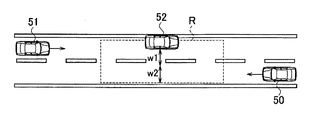
次に図2を参照して、すれ違い禁止領域設定部21によって設定されるすれ違い禁止領域について説明する。図2に示す道路は、片側一車線の対面通行を示す道路である。図2において自車両50は、左に向かって走行しており、対向車両51は、右に向かって走行している。つまり、自車両50の進行方向は、対向車両51の進行方向とは逆方向である。以下では、自車両50が走行する車線を走行車線と呼び、対向車両51が走行する車線を対向車線と呼ぶ。対向車線は、走行車線に隣接する。
Next, with reference to FIG. 2, the passing prohibited area set by the passing prohibited area setting unit 21 will be described. The road shown in FIG. 2 is a road showing two-way traffic with one lane on each side. In FIG. 2, the own vehicle 50 is traveling to the left, and the oncoming vehicle 51 is traveling to the right. That is, the traveling direction of the own vehicle 50 is opposite to the traveling direction of the oncoming vehicle 51. Hereinafter, the lane in which the own vehicle 50 travels is referred to as a traveling lane, and the lane in which the oncoming vehicle 51 travels is referred to as an oncoming lane. The oncoming lane is adjacent to the driving lane.
図2に示すシーンにおいて、駐車車両52及び対向車両51は、センサ11によって検出されているものとする。具体的には、駐車車両52の位置情報及び速度、対向車両51の位置情報及び速度が、センサ11によって検出されているものとする。駐車車両52の位置情報、及び対向車両51の位置情報については、一例としてレーザレンジファインダ(第1センサ、第3センサ)によって検出される。レーザレンジファインダは、電波を物体(ここでは駐車車両52及び対向車両51)に向けて走査し、その反射波を測定することにより、物体までの距離、方向を測定する。駐車車両52の位置、及び対向車両51の位置は、自車両50の位置に対する相対位置として検出されてもよく、自車両50の位置を原点とした座標上の位置として検出されてもよい。
In the scene shown in FIG. 2, it is assumed that the parked vehicle 52 and the oncoming vehicle 51 are detected by the sensor 11. Specifically, it is assumed that the position information and speed of the parked vehicle 52 and the position information and speed of the oncoming vehicle 51 are detected by the sensor 11. The position information of the parked vehicle 52 and the position information of the oncoming vehicle 51 are detected by the laser range finder (first sensor, third sensor) as an example. The laser range finder measures the distance and direction to the object by scanning the radio wave toward the object (here, the parked vehicle 52 and the oncoming vehicle 51) and measuring the reflected wave. The position of the parked vehicle 52 and the position of the oncoming vehicle 51 may be detected as a relative position with respect to the position of the own vehicle 50, or may be detected as a position on the coordinates with the position of the own vehicle 50 as the origin.
駐車車両52の速度、及び対向車両51の速度については、一例としてカメラによって検出される。カメラによって撮像された現在の画像と、1フレーム前の画像との差分を抽出することにより、駐車車両52の速度、及び対向車両51の速度が得られる。なお、カメラのフレームレートは、特に限定されないが、30fps(frames per second)または60fpsに設定されていればよい。本実施形態では駐車車両52の速度はゼロとして検出されているため、駐車車両52は静止物体であると判定される。換言すれば、自車両50の周囲で検出された物体の速度がゼロ、またはほぼゼロとみなせるほど小さい速度であれば、その物体は静止物体であると判定される。本実施形態では、静止物体を駐車車両52として説明するが、静止物体は駐車車両52に限定されない。例えば、静止物体には、落下物、パイロン(ロードコーンとも呼ばれる)などが含まれる。なお、駐車車両52は、対向車線上に駐車している。
The speed of the parked vehicle 52 and the speed of the oncoming vehicle 51 are detected by a camera as an example. By extracting the difference between the current image captured by the camera and the image one frame before, the speed of the parked vehicle 52 and the speed of the oncoming vehicle 51 can be obtained. The frame rate of the camera is not particularly limited, but may be set to 30 fps (frames per second) or 60 fps. In the present embodiment, the speed of the parked vehicle 52 is detected as zero, so that the parked vehicle 52 is determined to be a stationary object. In other words, if the speed of the object detected around the own vehicle 50 is zero or small enough to be regarded as almost zero, the object is determined to be a stationary object. In the present embodiment, the stationary object will be described as the parked vehicle 52, but the stationary object is not limited to the parked vehicle 52. For example, stationary objects include falling objects, pylon (also called road cones), and the like. The parked vehicle 52 is parked in the oncoming lane.
図2に示すように、すれ違い禁止領域設定部21は、道路上の領域で、かつ、道路の延在方向に沿って駐車車両52を含んで形成される所定の領域をすれ違い禁止領域Rとして設定する。すれ違い禁止領域Rの形状は、特に限定されないが、例えば四角形状である。すれ違い禁止領域Rを設定する理由は、対向車両51が駐車車両52を回避して自車両50とすれ違う際に、自車両50と対向車両51との接近により乗員が違和感を感じることを回避するためである。したがって、すれ違い禁止領域Rには、駐車車両52が存在する。
As shown in FIG. 2, the passing prohibition area setting unit 21 sets a predetermined area formed on the road and including the parked vehicle 52 along the extending direction of the road as the passing prohibition area R. do. The shape of the passing prohibition region R is not particularly limited, but is, for example, a quadrangular shape. The reason for setting the passing prohibition area R is to prevent the occupant from feeling uncomfortable due to the approach between the own vehicle 50 and the oncoming vehicle 51 when the oncoming vehicle 51 avoids the parked vehicle 52 and passes by the own vehicle 50. Is. Therefore, the parked vehicle 52 exists in the passing prohibited area R.
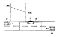
すれ違い禁止領域設定部21によってすれ違い禁止領域Rが設定された後、すれ違い位置算出部22は、自車両50と対向車両51とがすれ違う位置がすれ違い禁止領域R内に存在するか否かを判定する。具体的には、図3に示すように、すれ違い位置算出部22は、自車両50と対向車両51との相対距離L1(自車両50の位置を原点とした場合は、原点からの距離)と、自車両50の速度V1と、対向車両51の速度V2とを用いて、自車両50と対向車両51とがすれ違う位置Pを算出する。すれ違う位置Pを算出するための数式は、下記の式(1)で表される。
P=L1÷(1+V2÷V1)・・・(1) After the passing prohibition area R is set by the passing prohibitionarea setting unit 21, the passing position calculation unit 22 determines whether or not the position where the own vehicle 50 and the oncoming vehicle 51 pass each other exists in the passing prohibition area R. .. Specifically, as shown in FIG. 3, the passing position calculation unit 22 determines the relative distance L1 between the own vehicle 50 and the oncoming vehicle 51 (when the position of the own vehicle 50 is the origin, the distance from the origin). , The speed V1 of the own vehicle 50 and the speed V2 of the oncoming vehicle 51 are used to calculate the position P at which the own vehicle 50 and the oncoming vehicle 51 pass each other. The formula for calculating the passing position P is represented by the following formula (1).
P = L1 ÷ (1 + V2 ÷ V1) ... (1)
P=L1÷(1+V2÷V1)・・・(1) After the passing prohibition area R is set by the passing prohibition
P = L1 ÷ (1 + V2 ÷ V1) ... (1)
すれ違い位置算出部22は、算出したすれ違う位置Pがすれ違い禁止領域R内に存在するか否かを判定する。図3では、すれ違う位置Pがすれ違い禁止領域R内に存在する例が示される。
The passing position calculation unit 22 determines whether or not the calculated passing position P exists in the passing prohibition area R. FIG. 3 shows an example in which the passing position P exists in the passing prohibited area R.
図3に示すように、すれ違い位置算出部22によってすれ違う位置Pがすれ違い禁止領域R内に存在すると判定された場合、第1スコア算出部23は、対向車両51の速度に基づいて第1スコアを算出する。具体的には、第1スコア算出部23は、対向車両51の速度が大きいほど大きな値となる第1スコアを算出する。第1スコアの一例について図4を参照して説明する。
As shown in FIG. 3, when the passing position calculation unit 22 determines that the passing position P exists in the passing prohibition area R, the first score calculation unit 23 calculates the first score based on the speed of the oncoming vehicle 51. calculate. Specifically, the first score calculation unit 23 calculates the first score, which becomes a larger value as the speed of the oncoming vehicle 51 increases. An example of the first score will be described with reference to FIG.
図4の横軸は対向車両51の速度であり、縦軸は第1スコアである。第1スコアは対向車両51の速度に比例する。第1スコアの値は特に限定されず、任意の値でよい。第1スコアをs1、対向車両51の速度をvtとした場合、s1は下記の式(2)で表される。
s1=f1(vt)・・・(2)
f1は正規化のための関数である。 The horizontal axis of FIG. 4 is the speed of the oncomingvehicle 51, and the vertical axis is the first score. The first score is proportional to the speed of the oncoming vehicle 51. The value of the first score is not particularly limited and may be any value. The first score s 1, if the speed of the oncoming vehicle 51 and the v t, s 1 is represented by the following formula (2).
s 1 = f 1 (v t ) ... (2)
f 1 is a function for normalization.
s1=f1(vt)・・・(2)
f1は正規化のための関数である。 The horizontal axis of FIG. 4 is the speed of the oncoming
s 1 = f 1 (v t ) ... (2)
f 1 is a function for normalization.
また、図3に示すように、すれ違い位置算出部22によってすれ違う位置Pがすれ違い禁止領域R内に存在すると判定された場合、第2スコア算出部24は、対向車両51の加速度に基づいて第2スコアを算出する。具体的には、第2スコア算出部24は、対向車両51の加速度が大きいほど大きな値となる第2スコアを算出する。第2スコアの一例について図5を参照して説明する。
Further, as shown in FIG. 3, when the passing position P is determined by the passing position calculation unit 22 to exist in the passing prohibition region R, the second score calculation unit 24 performs the second based on the acceleration of the oncoming vehicle 51. Calculate the score. Specifically, the second score calculation unit 24 calculates the second score, which becomes a larger value as the acceleration of the oncoming vehicle 51 increases. An example of the second score will be described with reference to FIG.
図5の横軸は対向車両51の加速度であり、縦軸は第2スコアである。第2スコアは対向車両51の加速度に比例する。第2スコアの値も第1スコアと同様に特に限定されず、任意の値でよい。第2スコアをs2、対向車両51の加速度をatとした場合、s2は下記の式(3)で表される。
s2=f2(at)・・・(3)
f2はf1と同様に正規化のための関数である。 The horizontal axis of FIG. 5 is the acceleration of the oncomingvehicle 51, and the vertical axis is the second score. The second score is proportional to the acceleration of the oncoming vehicle 51. The value of the second score is not particularly limited as in the first score, and may be any value. The second score s 2, when the acceleration of the oncoming vehicle 51 and a t, s 2 is represented by the following formula (3).
s 2 = f 2 (a t ) ··· (3)
Like f 1 , f 2 is a function for normalization.
s2=f2(at)・・・(3)
f2はf1と同様に正規化のための関数である。 The horizontal axis of FIG. 5 is the acceleration of the oncoming
s 2 = f 2 (a t ) ··· (3)
Like f 1 , f 2 is a function for normalization.
統合スコア算出部25は、第1スコア算出部23によって算出された第1スコアs1と、第2スコア算出部24によって算出された第2スコアs2とを統合して、統合スコアを算出する。統合スコアをsとした場合、sは下記の式(4)で表される。
s=s1+s2・・・(4) The integratedscore calculation unit 25 integrates the first score s 1 calculated by the first score calculation unit 23 and the second score s 2 calculated by the second score calculation unit 24 to calculate the integrated score. .. When the integrated score is s, s is represented by the following equation (4).
s = s 1 + s 2 ... (4)
s=s1+s2・・・(4) The integrated
s = s 1 + s 2 ... (4)
速度決定部26は、統合スコア算出部25によって算出された統合スコアを用いて対向車両51の運転者の意図を推定して、自車両50の速度を決定する。図2に示すシーンにおいて、対向車両51の運転者の意図として、2つが想定される。対向車両51が自車両50より先に駐車車両52の側方を通過するか、自車両50が通過した後に対向車両51が駐車車両52の側方を通過するか、の2つである。換言すれば、対向車両51の運転者の意図は、自車両50の通過を待つか、待たないか、の2つである。
The speed determination unit 26 estimates the driver's intention of the oncoming vehicle 51 using the integrated score calculated by the integrated score calculation unit 25, and determines the speed of the own vehicle 50. In the scene shown in FIG. 2, two are assumed as the intentions of the driver of the oncoming vehicle 51. The oncoming vehicle 51 passes by the side of the parked vehicle 52 before the own vehicle 50, or the oncoming vehicle 51 passes by the side of the parked vehicle 52 after the own vehicle 50 has passed. In other words, the driver of the oncoming vehicle 51 has two intentions: to wait for the passage of the own vehicle 50 or not.
対向車両51の運転者の意図を推定する理由は、対向車両51の運転者の意図を推定して自車両50の速度を決定できれば、急ブレーキ、または不要な加減速が抑制されるからである。例えば、対向車両51の運転者の意図が自車両50の通過を待つことである場合、自車両50は速度を維持して、もしくは加速させて通過すればよい。一方、対向車両51の運転者の意図が自車両50を待たずに駐車車両52の側方を通過することである場合、自車両50は、駐車車両52を回避するために走行車線にはみ出す対向車両51との接近を回避できる位置(すれ違い禁止領域Rの外側の位置)でスムーズに停止できるように減速すればよい。
The reason for estimating the driver's intention of the oncoming vehicle 51 is that if the driver's intention of the oncoming vehicle 51 can be estimated and the speed of the own vehicle 50 can be determined, sudden braking or unnecessary acceleration / deceleration can be suppressed. .. For example, when the driver's intention of the oncoming vehicle 51 is to wait for the passage of the own vehicle 50, the own vehicle 50 may pass by maintaining the speed or accelerating. On the other hand, when the driver's intention of the oncoming vehicle 51 is to pass the side of the parked vehicle 52 without waiting for the own vehicle 50, the own vehicle 50 protrudes into the traveling lane in order to avoid the parked vehicle 52. The vehicle may decelerate so that it can stop smoothly at a position where it can avoid approaching the vehicle 51 (a position outside the passing prohibition area R).
対向車両51の運転者の意図を推定しない場合、自車両50が急ブレーキを行ったり、不要な加減速を行ったりすることが考えられる。例えば、駐車車両52による遮蔽領域が大きい場合、もしくは駐車車両52の周囲に横断歩道がある場合など、対向車両51が安全のため一時的に減速または停止した後に加速して駐車車両52の側方を通過する場合がある。このような場合、対向車両51の減速により一旦はすれ違い位置Pが対向車両51側に移動するため、自車両50は加速を開始する。しかし、その後、対向車両51が加速することによりすれ違い位置Pが自車両50側に移動するため、自車両50は減速することになる。つまり、対向車両51が自車両50より先に駐車車両52の側方を通過する場合として、対向車両51が一旦減速し、その後加速して駐車車両52の側方を通過するといった場合も含まれる。しかしながら、このような対向車両51の運転者の意図を推定しない場合、自車両50の加減速制御が切り替わってしまい、急ブレーキ、または不要な加減速が発生するおそれがある。本実施形態では、対向車両51の運転者の意図を推定して自車両50の速度を決定するため、急ブレーキ、または不要な加減速が抑制される。
If the intention of the driver of the oncoming vehicle 51 is not estimated, it is conceivable that the own vehicle 50 suddenly brakes or performs unnecessary acceleration / deceleration. For example, when the shielded area by the parked vehicle 52 is large, or when there is a pedestrian crossing around the parked vehicle 52, the oncoming vehicle 51 temporarily decelerates or stops for safety and then accelerates to the side of the parked vehicle 52. May pass through. In such a case, the deceleration of the oncoming vehicle 51 causes the passing position P to move to the oncoming vehicle 51 side, so that the own vehicle 50 starts accelerating. However, after that, as the oncoming vehicle 51 accelerates, the passing position P moves to the own vehicle 50 side, so that the own vehicle 50 decelerates. That is, as a case where the oncoming vehicle 51 passes by the side of the parked vehicle 52 before the own vehicle 50, a case where the oncoming vehicle 51 decelerates once and then accelerates and passes by the side of the parked vehicle 52 is also included. .. However, if the driver's intention of the oncoming vehicle 51 is not estimated, the acceleration / deceleration control of the own vehicle 50 may be switched, and sudden braking or unnecessary acceleration / deceleration may occur. In the present embodiment, since the intention of the driver of the oncoming vehicle 51 is estimated to determine the speed of the own vehicle 50, sudden braking or unnecessary acceleration / deceleration is suppressed.
次に、統合スコアを用いた対向車両51の運転者の意図の推定方法について説明する。統合スコアが所定値以上である場合、速度決定部26は、対向車両51の運転者の意図が自車両50を待たずに駐車車両52の側方を通過することであると推定する。この場合、速度決定部26は、対向車両51との接近を回避できる位置(すれ違い禁止領域Rの外側の位置)で自車両50がスムーズに停止できるように自車両50の減速度を決定する。
Next, a method of estimating the driver's intention of the oncoming vehicle 51 using the integrated score will be described. When the integrated score is equal to or higher than a predetermined value, the speed determination unit 26 estimates that the driver's intention of the oncoming vehicle 51 is to pass the side of the parked vehicle 52 without waiting for the own vehicle 50. In this case, the speed determination unit 26 determines the deceleration of the own vehicle 50 so that the own vehicle 50 can stop smoothly at a position where the approach to the oncoming vehicle 51 can be avoided (a position outside the passing prohibition area R).
一方、統合スコアが所定値未満である場合、速度決定部26は、対向車両51の運転者の意図が自車両50の通過を待つことであると推定する。この場合、自車両50を対向車両51より先に通過させるため、速度決定部26は、自車両50の速度を維持する、もしくは自車両50を加速させることを決定する。所定値については、実験、シミュレーションなどを通じて求めることができる。また、所定値は、対向車両51の運転者ごとに変更されてもよい。運転には個性、好みが表れるため、所定値を運転者ごとに変更することにより、運転者の意図が精度よく推定されうる。
On the other hand, when the integrated score is less than a predetermined value, the speed determination unit 26 estimates that the driver's intention of the oncoming vehicle 51 is to wait for the passage of the own vehicle 50. In this case, in order to pass the own vehicle 50 before the oncoming vehicle 51, the speed determination unit 26 decides to maintain the speed of the own vehicle 50 or accelerate the own vehicle 50. The predetermined value can be obtained through experiments, simulations, and the like. Further, the predetermined value may be changed for each driver of the oncoming vehicle 51. Since individuality and preference appear in driving, the driver's intention can be estimated accurately by changing a predetermined value for each driver.
速度決定部26によって自車両50の速度が決定された後、車両制御部27は、決定された速度で自車両50が走行するように、各種のアクチュエータ30(ブレーキアクチュエータ、アクセルペダルアクチュエータ、ステアリングアクチュエータなど)を制御する。具体的には、統合スコアが所定値以上である場合、車両制御部27は、速度決定部26によって決定された減速度で自車両50を減速させ、自車両50をすれ違い禁止領域Rの外側の位置にスムーズに停止させる。また、統合スコアが所定値未満である場合、車両制御部27は、自車両50の速度を維持する、または速度決定部26によって決定された加速度で自車両50を加速させる。このとき、車両制御部27は、すれ違い位置Pがすれ違い禁止領域Rの外側に移動するように徐々に自車両50を加速させる。このように、本実施形態に係る車両制御装置1は、統合スコアを用いて対向車両51の運転者の意図を推定し、推定した意図を反映して自車両50の速度を決定する。これにより、急ブレーキ、または不要な加減速が抑制される。
After the speed of the own vehicle 50 is determined by the speed determination unit 26, the vehicle control unit 27 determines various actuators 30 (brake actuator, accelerator pedal actuator, steering actuator) so that the own vehicle 50 travels at the determined speed. Etc.) to control. Specifically, when the integrated score is equal to or higher than a predetermined value, the vehicle control unit 27 decelerates the own vehicle 50 by the deceleration determined by the speed determination unit 26, and the own vehicle 50 is outside the passing prohibition area R. Stop smoothly at the position. When the integrated score is less than a predetermined value, the vehicle control unit 27 maintains the speed of the own vehicle 50 or accelerates the own vehicle 50 at an acceleration determined by the speed determination unit 26. At this time, the vehicle control unit 27 gradually accelerates the own vehicle 50 so that the passing position P moves to the outside of the passing prohibition area R. As described above, the vehicle control device 1 according to the present embodiment estimates the driver's intention of the oncoming vehicle 51 using the integrated score, and determines the speed of the own vehicle 50 by reflecting the estimated intention. As a result, sudden braking or unnecessary acceleration / deceleration is suppressed.
なお、上述した速度決定方法において、自車両50と対向車両51とが同時に駐車車両52の側方を通過できない状況、あるいは同時の通過は不可能ではないが、自車両50と対向車両51との接近により乗員が違和感を感じるの可能性があるため同時の通過は避けるべき状況であることを想定している。ところで、道路幅、駐車車両52の車幅、自車両50の車幅、対向車両51の車幅によっては、乗員が違和感を感じることなく駐車車両52の側方を同時に通過できる場合も有り得る。自車両50及び対向車両51が駐車車両52の側方を乗員が違和感を感じることなく同時に通過するための必要な条件は、対向車両51と駐車車両52との充分な距離、及び自車両50と対向車両51との充分な距離を確保するための十分なスペースである。この点について図6を参照して説明する。センサ11は、図6に示すように、対向車両51が駐車車両52を回避して走行するための幅W1を検出する。幅W1は、対向車両51の車幅と、対向車両51と駐車車両52との接近を回避するためのスペースとの足し算によって求めることができる。次に、センサ11は、道路幅から駐車車両52の車幅(道路に重なっている部分の車幅)と幅W1を引き算した残りの車線幅W2を検出する。すれ違い位置算出部22は、残りの車線幅W2が、自車両50と対向車両51がすれ違った際の乗員の違和感を防止するために十分か否かを判定する。残りの車線幅W2が、自車両50と対向車両51がすれ違った際の乗員の違和感を防止するために十分であれば、自車両50と対向車両51は速度を下げて、狭路でのすれ違いを行えばよい。
In the speed determination method described above, the situation where the own vehicle 50 and the oncoming vehicle 51 cannot pass by the side of the parked vehicle 52 at the same time, or the simultaneous passage is not impossible, but the own vehicle 50 and the oncoming vehicle 51 It is assumed that simultaneous passage should be avoided because the occupants may feel uncomfortable due to the approach. By the way, depending on the width of the road, the width of the parked vehicle 52, the width of the own vehicle 50, and the width of the oncoming vehicle 51, the occupant may be able to pass by the side of the parked vehicle 52 at the same time without feeling any discomfort. The necessary conditions for the own vehicle 50 and the oncoming vehicle 51 to pass by the side of the parked vehicle 52 at the same time without the occupant feeling discomfort are a sufficient distance between the oncoming vehicle 51 and the parked vehicle 52 and the own vehicle 50. This is a sufficient space for securing a sufficient distance from the oncoming vehicle 51. This point will be described with reference to FIG. As shown in FIG. 6, the sensor 11 detects the width W1 for the oncoming vehicle 51 to avoid the parked vehicle 52 and travel. The width W1 can be obtained by adding the width of the oncoming vehicle 51 and the space for avoiding the approach of the oncoming vehicle 51 and the parked vehicle 52. Next, the sensor 11 detects the remaining lane width W2 obtained by subtracting the vehicle width (vehicle width of the portion overlapping the road) and the width W1 from the road width. The passing position calculation unit 22 determines whether the remaining lane width W2 is sufficient to prevent the occupant from feeling uncomfortable when the own vehicle 50 and the oncoming vehicle 51 pass each other. If the remaining lane width W2 is sufficient to prevent the occupant from feeling uncomfortable when the own vehicle 50 and the oncoming vehicle 51 pass each other, the own vehicle 50 and the oncoming vehicle 51 slow down and pass each other on a narrow road. Just do.
次に、図7A~7Bのフローチャートを参照して、車両制御装置1の一動作例を説明する。この処理は、所定の周期で繰り返し実施される。
Next, an operation example of the vehicle control device 1 will be described with reference to the flowcharts of FIGS. 7A to 7B. This process is repeated at a predetermined cycle.
ステップS101において、コントローラ20は、地図データベース12から地図情報を取得する。処理はステップS103に進み、GPS受信機10は、自車両50の位置情報を検出する。
In step S101, the controller 20 acquires map information from the map database 12. The process proceeds to step S103, and the GPS receiver 10 detects the position information of the own vehicle 50.
センサ11によって駐車車両52及び対向車両51が検出された場合(ステップS105でYes)、処理はステップS107に進む。一方、駐車車両52及び対向車両51が検出されない場合(ステップS105でNo)、一連の処理は終了する。
When the parked vehicle 52 and the oncoming vehicle 51 are detected by the sensor 11 (Yes in step S105), the process proceeds to step S107. On the other hand, when the parked vehicle 52 and the oncoming vehicle 51 are not detected (No in step S105), the series of processes ends.
ステップS107において、すれ違い禁止領域設定部21は、道路上の領域で、かつ、道路の延在方向に沿って駐車車両52を含んで形成される所定の領域をすれ違い禁止領域Rとして設定する(図2参照)。処理はステップS109に進み、すれ違い位置算出部22は、自車両50と対向車両51とがすれ違う位置Pが、ステップS107で設定されたすれ違い禁止領域R内に存在するか否かを判定する。
In step S107, the passing prohibition area setting unit 21 sets a predetermined area formed on the road including the parked vehicle 52 along the extending direction of the road as the passing prohibition area R (FIG. FIG. 2). The process proceeds to step S109, and the passing position calculation unit 22 determines whether or not the position P where the own vehicle 50 and the oncoming vehicle 51 pass each other exists in the passing prohibition area R set in step S107.
自車両50と対向車両51とがすれ違う位置Pがすれ違い禁止領域R内に存在する場合(ステップS111でYes)、処理はステップS113に進む。一方、自車両50と対向車両51とがすれ違う位置Pがすれ違い禁止領域R内に存在しない場合(ステップS111でNo)、処理はステップS119に進む。
When the position P where the own vehicle 50 and the oncoming vehicle 51 pass each other exists in the passing prohibition area R (Yes in step S111), the process proceeds to step S113. On the other hand, when the position P where the own vehicle 50 and the oncoming vehicle 51 pass each other does not exist in the passing prohibition area R (No in step S111), the process proceeds to step S119.
ステップS113において、センサ11は、対向車両51が駐車車両52を回避して走行するための幅W1を検出する(図6参照)。次に、センサ11は、道路幅から駐車車両52の車幅と幅W1を引き算した残りの車線幅W2を検出する(図6参照)。処理は、ステップS115に進み、すれ違い位置算出部22は、ステップS113で検出された車線幅W2が、自車両50と対向車両51がすれ違った際の接近を回避するために十分か否かを判定する。ステップS115でYesの場合、処理はステップS117に進み、狭路でのすれ違いが実施される。自車両50と対向車両51とがすれ違った場合(ステップS119でYes)、一連の処理は終了する。一方、ステップS115でNoの場合、処理はステップS121に進む。
In step S113, the sensor 11 detects the width W1 for the oncoming vehicle 51 to avoid the parked vehicle 52 and travel (see FIG. 6). Next, the sensor 11 detects the remaining lane width W2 obtained by subtracting the vehicle width and width W1 of the parked vehicle 52 from the road width (see FIG. 6). The process proceeds to step S115, and the passing position calculation unit 22 determines whether the lane width W2 detected in step S113 is sufficient to avoid approaching when the own vehicle 50 and the oncoming vehicle 51 pass each other. do. In the case of Yes in step S115, the process proceeds to step S117, and the passing on the narrow road is carried out. When the own vehicle 50 and the oncoming vehicle 51 pass each other (Yes in step S119), a series of processes is completed. On the other hand, if No in step S115, the process proceeds to step S121.
ステップS121において、第1スコア算出部23は、対向車両51の速度が大きいほど大きな値となる第1スコアを算出する(図4参照)。処理はステップS123に進み、第2スコア算出部24は、対向車両51の加速度が大きいほど大きな値となる第2スコアを算出する(図5参照)。処理はステップS125に進み、統合スコア算出部25は、ステップS121で算出された第1スコアと、ステップS123で算出された第2スコアとを統合して、統合スコアを算出する。
In step S121, the first score calculation unit 23 calculates the first score, which becomes a larger value as the speed of the oncoming vehicle 51 increases (see FIG. 4). The process proceeds to step S123, and the second score calculation unit 24 calculates the second score, which becomes a larger value as the acceleration of the oncoming vehicle 51 increases (see FIG. 5). The process proceeds to step S125, and the integrated score calculation unit 25 integrates the first score calculated in step S121 and the second score calculated in step S123 to calculate the integrated score.
統合スコアが所定値以上である場合(ステップS127でYES)、処理はステップS129に進み、速度決定部26は、対向車両51の運転者の意図が自車両50を待たずに駐車車両52の側方を通過することであると推定する。速度決定部26は、対向車両51との接近を回避できる位置(すれ違い禁止領域Rの外側の位置)で自車両50がスムーズに停止できるように自車両50の減速度を決定する。車両制御部27は、速度決定部26によって決定された減速度で自車両50を減速させ、自車両50をすれ違い禁止領域Rの外側の位置にスムーズに停止させる。
When the integrated score is equal to or higher than a predetermined value (YES in step S127), the process proceeds to step S129, and the speed determination unit 26 determines the side of the parked vehicle 52 without waiting for the own vehicle 50 by the driver's intention of the oncoming vehicle 51. It is presumed that it will pass through. The speed determination unit 26 determines the deceleration of the own vehicle 50 so that the own vehicle 50 can stop smoothly at a position where the approach to the oncoming vehicle 51 can be avoided (a position outside the passing prohibition area R). The vehicle control unit 27 decelerates the own vehicle 50 at a deceleration determined by the speed determination unit 26, and smoothly stops the own vehicle 50 at a position outside the passing prohibition area R.
統合スコアが所定値未満である場合(ステップS127でNO)、処理はステップS131に進み、速度決定部26は、対向車両51の運転者の意図が自車両50の通過を待つことであると推定する。速度決定部26は、自車両50の速度を維持する、もしくは自車両50を加速させることを決定する。車両制御部27は、自車両50の速度を維持する、または速度決定部26によって決定された加速度で自車両50を加速させる。ステップS133の処理はステップS119の処理と同じため、説明を省略する。
If the integrated score is less than a predetermined value (NO in step S127), the process proceeds to step S131, and the speed determination unit 26 estimates that the driver's intention of the oncoming vehicle 51 is to wait for the passage of the own vehicle 50. do. The speed determination unit 26 determines to maintain the speed of the own vehicle 50 or accelerate the own vehicle 50. The vehicle control unit 27 maintains the speed of the own vehicle 50 or accelerates the own vehicle 50 at an acceleration determined by the speed determination unit 26. Since the process of step S133 is the same as the process of step S119, the description thereof will be omitted.
なお、上述の例では、自車両50と対向車両51とがすれ違う位置Pがすれ違い禁止領域R内に存在する場合(ステップS111でYES)に、すれ違い位置算出部22は残りの車線幅W2が十分か否かを判定する。そして残りの車線幅W2が十分でない場合(ステップS115でNO)に、第1スコア、第2スコア、及び統合スコアが算出される(ステップS121、ステップS123、ステップS125)が、これに限定されない。例えば、第1スコア、第2スコア、及び統合スコアはステップS111及びステップS115の判定に関係なく、常に算出されてもよい。また、ステップS111及びステップS115の判定結果に基づいて処理がステップS127に進み、統合スコアが所定値以上であるか否か判定されてもよい。また、ステップS113~117の処理を省略し、すれ違う位置Pがすれ違い禁止領域R内に存在する場合(ステップS111でYES)に、コントローラ20は常に処理をステップS127に進ませ、統合スコアが所定値以上であるか否かを判定してもよい。
In the above example, when the position P where the own vehicle 50 and the oncoming vehicle 51 pass each other exists in the passing prohibition area R (YES in step S111), the passing position calculation unit 22 has a sufficient remaining lane width W2. Judge whether or not. Then, when the remaining lane width W2 is not sufficient (NO in step S115), the first score, the second score, and the integrated score are calculated (step S121, step S123, step S125), but the present invention is not limited to this. For example, the first score, the second score, and the integrated score may always be calculated regardless of the determination in step S111 and step S115. Further, the process may proceed to step S127 based on the determination results of steps S111 and S115, and it may be determined whether or not the integrated score is equal to or higher than a predetermined value. Further, when the processing of steps S113 to 117 is omitted and the passing position P exists in the passing prohibition area R (YES in step S111), the controller 20 always advances the processing to step S127, and the integrated score is a predetermined value. It may be determined whether or not it is the above.
(作用効果)
以上説明したように、本実施形態に係る車両制御装置1によれば、以下の作用効果が得られる。 (Action effect)
As described above, according to thevehicle control device 1 according to the present embodiment, the following effects can be obtained.
以上説明したように、本実施形態に係る車両制御装置1によれば、以下の作用効果が得られる。 (Action effect)
As described above, according to the
車両制御装置1は、自車両50が走行する道路上の静止物体(例えば駐車車両52)の位置を検出する。車両制御装置1は、自車両50の速度を検出する。車両制御装置1は、自車両50が走行する走行車線に隣接する対向車線を自車両50の進行方向と逆方向に走行する対向車両51の位置及び速度を検出する。車両制御装置1は、道路上の領域で、かつ、道路の延在方向に沿って駐車車両52を含んで形成される領域(すれ違い禁止領域R)を設定する。
The vehicle control device 1 detects the position of a stationary object (for example, a parked vehicle 52) on the road on which the own vehicle 50 travels. The vehicle control device 1 detects the speed of the own vehicle 50. The vehicle control device 1 detects the position and speed of the oncoming vehicle 51 traveling in the oncoming lane adjacent to the traveling lane in which the own vehicle 50 is traveling in the direction opposite to the traveling direction of the own vehicle 50. The vehicle control device 1 sets an area on the road and is formed along the extending direction of the road including the parked vehicle 52 (passing prohibition area R).
車両制御装置1は、自車両50の速度と対向車両51の位置及び速度とに基づいて、自車両50と対向車両51がすれ違う位置を算出する。車両制御装置1は、対向車両51の速度が大きいほど大きな値となる第1スコアs1を算出する。車両制御装置1は、対向車両51の加速度が大きいほど大きな値となる第2スコアs2を算出する。車両制御装置1は、第1スコアs1と第2スコアs2とを統合して統合スコアsを算出する。車両制御装置1は、すれ違う位置が領域内に存在する場合において、統合スコアsが所定値以上の場合には自車両50を減速させ、統合スコアsが所定値未満の場合には自車両50の速度を維持または自車両50を加速させる。
The vehicle control device 1 calculates the position where the own vehicle 50 and the oncoming vehicle 51 pass each other based on the speed of the own vehicle 50 and the position and speed of the oncoming vehicle 51. The vehicle control device 1 calculates a first score s 1 that becomes a larger value as the speed of the oncoming vehicle 51 increases. The vehicle control device 1 calculates the second score s 2, which becomes a larger value as the acceleration of the oncoming vehicle 51 increases. The vehicle control device 1 integrates the first score s 1 and the second score s 2 to calculate the integrated score s. When the passing position exists in the area, the vehicle control device 1 decelerates the own vehicle 50 when the integrated score s is equal to or more than a predetermined value, and decelerates the own vehicle 50 when the integrated score s is less than the predetermined value. Maintain speed or accelerate own vehicle 50.
このように車両制御装置1は、統合スコアsを用いて対向車両51の運転者の意図を推定し、推定した意図を反映して自車両50の速度を決定する。これにより、急ブレーキ、または不要な加減速が抑制される。
In this way, the vehicle control device 1 estimates the driver's intention of the oncoming vehicle 51 using the integrated score s, and determines the speed of the own vehicle 50 by reflecting the estimated intention. As a result, sudden braking or unnecessary acceleration / deceleration is suppressed.
なお、第1スコア算出部23及び第2スコア算出部24は、すれ違い位置算出部22によってすれ違う位置Pがすれ違い禁止領域内に存在するか否か判定されたことと関係なく、第1スコア及び第2スコアを算出してもよいが、すれ違う位置Pがすれ違い禁止領域R内に存在すると判定された場合のみ、第1スコア及び第2スコアを算出することが好ましい。これにより、第1スコア及び第2スコアを常時算出する場合と比較して算出に係る負荷が低減する。
The first score calculation unit 23 and the second score calculation unit 24 have the first score and the first score regardless of whether or not the passing position P exists in the passing prohibition area by the passing position calculation unit 22. Although two scores may be calculated, it is preferable to calculate the first score and the second score only when it is determined that the passing position P exists in the passing prohibited area R. As a result, the load related to the calculation is reduced as compared with the case where the first score and the second score are constantly calculated.
(変形例1)
次に、本実施形態の変形例1について説明する。 (Modification example 1)
Next, amodification 1 of the present embodiment will be described.
次に、本実施形態の変形例1について説明する。 (Modification example 1)
Next, a
変形例1では、第2スコア算出部24は、第2スコアに、対向車両51が駐車車両52に近づくほど大きな値となる第1重みω1を乗算する。第1重みω1について図8を参照して説明する。
In the first modification, the second score calculation unit 24 multiplies the second score by the first weight ω 1, which becomes a larger value as the oncoming vehicle 51 approaches the parked vehicle 52. The first weight ω 1 will be described with reference to FIG.
図8に示すグラフの横軸の位置は、駐車車両52に対する対向車両51の位置を示す。なお、図8に示すグラフの横軸は、右方向に向かうほど駐車車両52に近い位置を表している。対向車両51が駐車車両52に近づくほど、グラフの横軸上における位置が右方向に進む。グラフの横軸は第1重みω1を示す。図8に示すように、第1重みω1は、対向車両51が駐車車両52に近づくほど大きな値となる。第2スコアs2に第1重みω1を掛けた場合の統合スコアsは、下記の式(5)で表される。
s=s1+s2ω1・・・(5) The position on the horizontal axis of the graph shown in FIG. 8 indicates the position of the oncomingvehicle 51 with respect to the parked vehicle 52. The horizontal axis of the graph shown in FIG. 8 represents a position closer to the parked vehicle 52 toward the right. As the oncoming vehicle 51 approaches the parked vehicle 52, the position on the horizontal axis of the graph advances to the right. The horizontal axis of the graph shows the first weight ω 1 . As shown in FIG. 8, the first weight ω 1 becomes larger as the oncoming vehicle 51 approaches the parked vehicle 52. The integrated score s when the second score s 2 is multiplied by the first weight ω 1 is expressed by the following equation (5).
s = s 1 + s 2 ω 1 ... (5)
s=s1+s2ω1・・・(5) The position on the horizontal axis of the graph shown in FIG. 8 indicates the position of the oncoming
s = s 1 + s 2 ω 1 ... (5)
ここで、第2スコアに第1重みω1を乗算する目的を説明する。対向車両51の運転者の意図を推定する場合において、対向車両51の位置によっては対向車両51の速度よりも加速度のほうが推定精度に及ぼす影響が大きい。また、対向車両51の加速度を用いる場合、駐車車両52から遠い位置と比較して近い位置における対向車両51の加速度を用いたほうが推定精度に及ぼす影響が大きい。駐車車両52に近い位置において、対向車両51の加速度が上昇した場合、対向車両51の運転者の意図として自車両50を待たずに駐車車両52の側方を通過する可能性が高いからである。そこで、第2スコア算出部24は、第2スコアに、対向車両51が駐車車両52に近づくほど大きな値となる第1重みω1を乗算する。これにより、駐車車両52に近い位置において、第2スコアの統合スコアへの寄与度が上昇する。このような統合スコアを用いることにより対向車両51の運転者の意図を精度よく推定することが可能となる。
Here, the purpose of multiplying the second score by the first weight ω 1 will be described. When estimating the driver's intention of the oncoming vehicle 51, the acceleration has a greater influence on the estimation accuracy than the speed of the oncoming vehicle 51 depending on the position of the oncoming vehicle 51. Further, when the acceleration of the oncoming vehicle 51 is used, using the acceleration of the oncoming vehicle 51 at a position closer to the parked vehicle 52 has a greater effect on the estimation accuracy. This is because if the acceleration of the oncoming vehicle 51 increases at a position close to the parked vehicle 52, there is a high possibility that the driver of the oncoming vehicle 51 will pass by the side of the parked vehicle 52 without waiting for the own vehicle 50. .. Therefore, the second score calculation unit 24 multiplies the second score by the first weight ω 1, which becomes a larger value as the oncoming vehicle 51 approaches the parked vehicle 52. As a result, the contribution of the second score to the integrated score increases at a position close to the parked vehicle 52. By using such an integrated score, it is possible to accurately estimate the driver's intention of the oncoming vehicle 51.
また、第1重みω1は、対向車両51が駐車車両52から遠い位置に存在する場合、小さな値となる。よって、第2スコアに第1重みω1を乗算することにより、対向車両51が駐車車両52から遠い位置に存在する場合、第2スコアの統合スコアへの寄与度が減少する。このように、第2スコアに第1重みω1を乗算することにより、第2スコアの統合スコアへの寄与度をコントロールすることが可能となる。
Further, the first weight ω 1 has a small value when the oncoming vehicle 51 exists at a position far from the parked vehicle 52. Therefore, by multiplying the second score by the first weight ω 1 , when the oncoming vehicle 51 exists at a position far from the parked vehicle 52, the contribution of the second score to the integrated score is reduced. In this way, by multiplying the second score by the first weight ω 1 , it is possible to control the degree of contribution of the second score to the integrated score.
図8に示すように、対向車両51が駐車車両52に近づく方向への距離変化に対する第1重みω1の増加率は、対向車両51が駐車車両52に近づくほど上昇する。上述したように、駐車車両52から遠い位置と比較して近い位置における対向車両51の加速度は推定精度に及ぼす影響が大きい。そこで、変形例1において、第1重みω1の増加率が、対向車両51が駐車車両52に近づくほど上昇するように設定した。これにより、駐車車両52に近い位置において、第2スコアの統合スコアへの寄与度が上昇する。このような統合スコアを用いることにより対向車両51の運転者の意図を精度よく推定することが可能となる。
As shown in FIG. 8, the rate of increase of the first weight ω 1 with respect to the change in distance in the direction in which the oncoming vehicle 51 approaches the parked vehicle 52 increases as the oncoming vehicle 51 approaches the parked vehicle 52. As described above, the acceleration of the oncoming vehicle 51 at a position closer to the parked vehicle 52 than at a position farther from the parked vehicle 52 has a large effect on the estimation accuracy. Therefore, in the first modification, the rate of increase of the first weight ω 1 is set so as to increase as the oncoming vehicle 51 approaches the parked vehicle 52. As a result, the contribution of the second score to the integrated score increases at a position close to the parked vehicle 52. By using such an integrated score, it is possible to accurately estimate the driver's intention of the oncoming vehicle 51.
なお、コントローラ20は第1重みω1を次の方法によって設定してもよい。コントローラ20は、駐車車両52に対する対向車両51の位置(すなわち駐車車両52と対向車両51との距離)に応じた第1重みω1を予めマップ等に記憶しておき、センサ11によって検出された駐車車両52に対する対向車両51の位置とマップとを参照することによって、第1重みω1を設定してもよい。
Note that the controller 20 may set the first weight ω1 by the following method. The controller 20 stores in advance a first weight ω1 corresponding to the position of the oncoming vehicle 51 with respect to the parked vehicle 52 (that is, the distance between the parked vehicle 52 and the oncoming vehicle 51) in a map or the like, and the parking detected by the sensor 11 The first weight ω1 may be set by referring to the position of the oncoming vehicle 51 with respect to the vehicle 52 and the map.
(変形例2)
次に、本実施形態の変形例2について説明する。 (Modification 2)
Next, a modification 2 of the present embodiment will be described.
次に、本実施形態の変形例2について説明する。 (Modification 2)
Next, a modification 2 of the present embodiment will be described.
上述の変形例1では、第2スコア算出部24は、第2スコアに第1重みω1を乗算すると説明した。変形例2では、これに加えてさらに第1スコア算出部23は、第1スコアに対向車両51が駐車車両52に近づくほど小さな値となる第2重みω2を乗算する。第2重みω2について図9を参照して説明する。
In the above-described modification 1, the second score calculation unit 24 has described that the second score is multiplied by the first weight ω 1. In the second modification, in addition to this, the first score calculation unit 23 multiplies the first score by the second weight ω 2, which becomes a smaller value as the oncoming vehicle 51 approaches the parked vehicle 52. The second weight ω 2 will be described with reference to FIG.
図9に示すグラフの横軸の位置は、図8と同様に対向車両51の位置を示す。なお、図9に示すグラフの横軸は図8と同様に、右方向に向かうほど駐車車両52に近い位置を表している。対向車両51が駐車車両52に近づくほど、グラフの横軸上における位置が右方向に進む。グラフの横軸は第1重みω1及び第2重みω2を示す。図9に示すように、第2重みω2は、対向車両51が駐車車両52に近づくほど小さな値となる。第1スコアs1に第2重みω2を掛けた場合の統合スコアsは、下記の式(6)で表される。
s=s1ω2+s2ω1・・・(6) The position on the horizontal axis of the graph shown in FIG. 9 indicates the position of the oncomingvehicle 51 as in FIG. As in FIG. 8, the horizontal axis of the graph shown in FIG. 9 represents a position closer to the parked vehicle 52 toward the right. As the oncoming vehicle 51 approaches the parked vehicle 52, the position on the horizontal axis of the graph advances to the right. The horizontal axis of the graph shows the first weight ω 1 and the second weight ω 2 . As shown in FIG. 9, the second weight ω 2 becomes smaller as the oncoming vehicle 51 approaches the parked vehicle 52. The integrated score s when the first score s 1 is multiplied by the second weight ω 2 is expressed by the following equation (6).
s = s 1 ω 2 + s 2 ω 1 ... (6)
s=s1ω2+s2ω1・・・(6) The position on the horizontal axis of the graph shown in FIG. 9 indicates the position of the oncoming
s = s 1 ω 2 + s 2 ω 1 ... (6)
変形例2において、駐車車両52に近い位置では第2スコアの統合スコアへの寄与度が上昇し、駐車車両52から遠い位置では第1スコアの統合スコアへの寄与度が上昇する。このように変形例2に係る車両制御装置1によれば、第1重みω1及び第2重みω2を用いることにより、第1スコア及び第2スコアの統合スコアへの寄与度をコントロールすることが可能となる。
In the second modification, the contribution of the second score to the integrated score increases at a position close to the parked vehicle 52, and the contribution of the first score to the integrated score increases at a position far from the parked vehicle 52. As described above, according to the vehicle control device 1 according to the modification 2, the contribution of the first score and the second score to the integrated score is controlled by using the first weight ω 1 and the second weight ω 2. Is possible.
また、図9に示すように、対向車両51が駐車車両52に近づく方向への距離変化に対する第2重みω2の減少率は、対向車両51が駐車車両52に近づくほど上昇する。これにより、駐車車両52に近い位置において、第1スコアの統合スコアへの寄与度が相対的に減少し、第2スコアの統合スコアへの寄与度が相対的に上昇する。このような統合スコアを用いることにより対向車両51の運転者の意図を精度よく推定することが可能となる。
Further, as shown in FIG. 9, the reduction rate of the second weight ω 2 with respect to the change in distance in the direction in which the oncoming vehicle 51 approaches the parked vehicle 52 increases as the oncoming vehicle 51 approaches the parked vehicle 52. As a result, at a position close to the parked vehicle 52, the contribution of the first score to the integrated score is relatively reduced, and the contribution of the second score to the integrated score is relatively increased. By using such an integrated score, it is possible to accurately estimate the driver's intention of the oncoming vehicle 51.
なお、第2重みω2は第1重みω1と同様の方法で設定されてもよい。コントローラ20は、駐車車両52に対する対向車両51の位置(すなわち駐車車両52と対向車両51との距離)に応じた第2重みω2を予めマップ等に記憶しておき、センサ11によって検出された駐車車両52に対する対向車両51の位置とマップとを参照することによって、第2重みω2を設定してもよい。
The second weight ω2 may be set in the same manner as the first weight ω1. The controller 20 stores in advance a second weight ω2 according to the position of the oncoming vehicle 51 with respect to the parked vehicle 52 (that is, the distance between the parked vehicle 52 and the oncoming vehicle 51) in a map or the like, and the parking detected by the sensor 11 The second weight ω2 may be set by referring to the position of the oncoming vehicle 51 with respect to the vehicle 52 and the map.
また、第1重みω1と第2重みω2との合計値は、一定値であってもよい。第1重みω1と第2重みω2との合計値が一定値であれば、どちらか一方を設定すればもう一方は自動的に設定される。これにより、第1重みω1と第2重みω2とをそれぞれ個別に設定する場合に比べて、重みを設定する際の算出コストは低減する。
Further, the total value of the first weight ω 1 and the second weight ω 2 may be a constant value. If the total value of the first weight ω 1 and the second weight ω 2 is a constant value, setting either one automatically sets the other. As a result, the calculation cost when setting the weights is reduced as compared with the case where the first weight ω1 and the second weight ω2 are set individually.
(変形例3)
次に、本実施形態の変形例3について説明する。 (Modification example 3)
Next, a modification 3 of the present embodiment will be described.
次に、本実施形態の変形例3について説明する。 (Modification example 3)
Next, a modification 3 of the present embodiment will be described.
変形例3では、駐車車両52と対向車両51との距離が長いほど大きくなる車速閾値を設定し、対向車両51の速度と車速閾値との差に基づいて第1スコアを算出する。
In the third modification, a vehicle speed threshold value that increases as the distance between the parked vehicle 52 and the oncoming vehicle 51 increases is set, and the first score is calculated based on the difference between the speed of the oncoming vehicle 51 and the vehicle speed threshold value.
車速閾値について図10を参照して説明する。コントローラ20は、図10に示すように、対向車両51の任意の位置(現在位置でもよい)から対向車両51が一定の減速度で減速して駐車車両52の手前で停止するための速度プロファイルを生成する。速度プロファイルに係る速度は、駐車車両52と対向車両51との距離が長いほど大きくなる。
The vehicle speed threshold value will be described with reference to FIG. As shown in FIG. 10, the controller 20 provides a speed profile for the oncoming vehicle 51 to decelerate from an arbitrary position (which may be the current position) of the oncoming vehicle 51 at a constant deceleration and stop in front of the parked vehicle 52. Generate. The speed related to the speed profile increases as the distance between the parked vehicle 52 and the oncoming vehicle 51 increases.
コントローラ20は、生成した速度プロファイルを用いて車速閾値を設定する。具体的には、コントローラ20は、図11に示すように、駐車車両52から所定距離(距離L2)離れた対向車両51の位置に対応する速度プロファイルに係る速度を車速閾値として設定する。図11に示す例では、車速閾値はV3となる。その他の例として、コントローラ20は、図12に示すように、駐車車両52から所定距離(距離L3)離れた対向車両51の位置に対応する速度プロファイルに係る速度を車速閾値として設定する。図12に示す例では、車速閾値はV4となる。ここで、L2>L3であり、V3>V4である。このように、車速閾値は、駐車車両52と対向車両51との距離が長いほど大きくなる。
The controller 20 sets the vehicle speed threshold value using the generated speed profile. Specifically, as shown in FIG. 11, the controller 20 sets the speed related to the speed profile corresponding to the position of the oncoming vehicle 51 separated from the parked vehicle 52 by a predetermined distance (distance L2) as the vehicle speed threshold value. In the example shown in FIG. 11, the vehicle speed threshold value is V3. As another example, as shown in FIG. 12, the controller 20 sets the speed related to the speed profile corresponding to the position of the oncoming vehicle 51 separated from the parked vehicle 52 by a predetermined distance (distance L3) as the vehicle speed threshold value. In the example shown in FIG. 12, the vehicle speed threshold value is V4. Here, L2> L3 and V3> V4. As described above, the vehicle speed threshold value increases as the distance between the parked vehicle 52 and the oncoming vehicle 51 increases.
コントローラ20は、車速閾値と、対向車両51の速度との差を算出する。図11に示す例では、コントローラ20は、すれ違う位置Pがすれ違い禁止領域R内に存在する場合において、駐車車両52から距離L2だけ離れた対向車両51の位置に対応する車速閾値V3と、駐車車両52から距離L2だけ離れた対向車両51の位置に対応する対向車両51の速度との差を算出する。
The controller 20 calculates the difference between the vehicle speed threshold value and the speed of the oncoming vehicle 51. In the example shown in FIG. 11, when the passing position P exists in the passing prohibition area R, the controller 20 has a vehicle speed threshold value V3 corresponding to the position of the oncoming vehicle 51 separated from the parked vehicle 52 by a distance L2, and the parked vehicle. The difference from the speed of the oncoming vehicle 51 corresponding to the position of the oncoming vehicle 51 separated from 52 by the distance L2 is calculated.
第1スコア算出部23は、駐車車両52から距離L2だけ離れた対向車両51の位置に対応する対向車両51の速度vtが、駐車車両52から距離L2だけ離れた対向車両51の位置に対応する車速閾値V3より大きいほど、第1スコアが大きくなるように第1スコアを算出する。汎用な車速閾値をvkとした場合、第1スコアs1は下記の式(7)で表される。
s1=f1(vt−vk)・・・(7) The firstscore calculation unit 23, the speed v t of the opposing vehicle 51 corresponding to the position of the oncoming vehicle 51 away from the parked vehicle 52 by the distance L2 is, corresponding to the position of the oncoming vehicle 51 away from the parked vehicle 52 by the distance L2 The first score is calculated so that the larger the vehicle speed threshold V3 is, the larger the first score is. When the general-purpose vehicle speed threshold value is v k , the first score s 1 is expressed by the following equation (7).
s 1 = f 1 (v t −v k ) ・ ・ ・ (7)
s1=f1(vt−vk)・・・(7) The first
s 1 = f 1 (v t −v k ) ・ ・ ・ (7)
対向車両51の速度が車速閾値より大きいということは、対向車両51の運転者は自車両50を待たずに駐車車両52の側方を通過する可能性が高い。よって、式(7)に示す第1スコアを算出し、この第1スコアを用いることにより、対向車両51の運転者の意図を精度よく推定することが可能となる。このように、変形例3に係る車両制御装置1は、対向車両51の速度と車速閾値との差に基づく第1スコアを用いて対向車両51の運転者の意図を推定し、推定した意図を反映して自車両50の速度を決定する。これにより、急ブレーキ、または不要な加減速が抑制される。
The fact that the speed of the oncoming vehicle 51 is higher than the vehicle speed threshold means that the driver of the oncoming vehicle 51 is likely to pass by the side of the parked vehicle 52 without waiting for the own vehicle 50. Therefore, by calculating the first score shown in the equation (7) and using this first score, it is possible to accurately estimate the intention of the driver of the oncoming vehicle 51. As described above, the vehicle control device 1 according to the modified example 3 estimates the driver's intention of the oncoming vehicle 51 using the first score based on the difference between the speed of the oncoming vehicle 51 and the vehicle speed threshold value, and estimates the estimated intention. The speed of the own vehicle 50 is determined by reflecting it. As a result, sudden braking or unnecessary acceleration / deceleration is suppressed.
対向車両51の速度と車速閾値との比較による第1スコアの算出方法の他の例を図13を参照して説明する。図13に示すように、コントローラ20は、駐車車両52と対向車両51との距離が長いほど大きくなる車速閾値を第1車速閾値Vth1として設定する。コントローラ20は、駐車車両52から所定距離だけ離れた対向車両51の位置に対応する第1車速閾値Vth1と、駐車車両52から所定距離だけ離れた対向車両51の位置に対応する対向車両51の速度と、を比較する。
Another example of the method of calculating the first score by comparing the speed of the oncoming vehicle 51 with the vehicle speed threshold value will be described with reference to FIG. As shown in FIG. 13, the controller 20 sets the vehicle speed threshold value, which increases as the distance between the parked vehicle 52 and the oncoming vehicle 51 increases, as the first vehicle speed threshold value Vth1. The controller 20 has a first vehicle speed threshold Vth1 corresponding to the position of the oncoming vehicle 51 separated from the parked vehicle 52 by a predetermined distance, and the speed of the oncoming vehicle 51 corresponding to the position of the oncoming vehicle 51 separated from the parked vehicle 52 by a predetermined distance. And compare.
図13に示すように、対向車両51の速度が第1車速閾値Vth1以上である場合、第1スコア算出部23は、第1スコアを1として算出する。一方、対向車両51の速度が第1車速閾値Vth1未満である場合、第1スコア算出部23は、第1スコアを0として算出する。すなわち、図13に示す例では、第1スコアは二値化される。上述のとおり、対向車両51の速度が第1車速閾値Vth1以上である場合、対向車両51の運転者は自車両50を待たずに駐車車両52の側方を通過する可能性が高い。よって、このように第1スコアを算出し、この第1スコアを用いることにより、対向車両51の運転者の意図を精度よく推定することが可能となる。
As shown in FIG. 13, when the speed of the oncoming vehicle 51 is equal to or higher than the first vehicle speed threshold value Vth1, the first score calculation unit 23 calculates the first score as 1. On the other hand, when the speed of the oncoming vehicle 51 is less than the first vehicle speed threshold value Vth1, the first score calculation unit 23 calculates the first score as 0. That is, in the example shown in FIG. 13, the first score is binarized. As described above, when the speed of the oncoming vehicle 51 is equal to or higher than the first vehicle speed threshold value Vth1, the driver of the oncoming vehicle 51 is likely to pass by the parked vehicle 52 without waiting for the own vehicle 50. Therefore, by calculating the first score in this way and using this first score, it is possible to accurately estimate the intention of the driver of the oncoming vehicle 51.
なお、第1スコアは三値化されてもよい。図14に示すように、コントローラ20は、第1車速閾値Vth1より小さい第2車速閾値Vth2を設定し、これらの閾値と対向車両51の速度とを比較してもよい。図14に示すように、対向車両51の速度が第1車速閾値Vth1以上である場合、第1スコア算出部23は、第1スコアを1として算出する。対向車両51の速度が第1車速閾値Vth1未満かつ、第2車速閾値Vth2以上である場合、第1スコア算出部23は、第1スコアを0として算出する。対向車両51の速度が第2車速閾値Vth2未満である場合、第1スコア算出部23は、第1スコアを−1として算出する。対向車両51の速度が第2車速閾値Vth2未満である場合、対向車両51の運転者は自車両50の通過を待つ可能性が高い。よって、このように第1スコアを算出し、この第1スコアを用いることにより、対向車両51の運転者の意図を精度よく推定することが可能となる。
The first score may be ternated. As shown in FIG. 14, the controller 20 may set a second vehicle speed threshold value Vth2 smaller than the first vehicle speed threshold value Vth1 and compare these threshold values with the speed of the oncoming vehicle 51. As shown in FIG. 14, when the speed of the oncoming vehicle 51 is equal to or higher than the first vehicle speed threshold value Vth1, the first score calculation unit 23 calculates the first score as 1. When the speed of the oncoming vehicle 51 is less than the first vehicle speed threshold value Vth1 and equal to or higher than the second vehicle speed threshold value Vth2, the first score calculation unit 23 calculates the first score as 0. When the speed of the oncoming vehicle 51 is less than the second vehicle speed threshold value Vth2, the first score calculation unit 23 calculates the first score as -1. When the speed of the oncoming vehicle 51 is less than the second vehicle speed threshold value Vth2, the driver of the oncoming vehicle 51 is likely to wait for the passage of the own vehicle 50. Therefore, by calculating the first score in this way and using this first score, it is possible to accurately estimate the intention of the driver of the oncoming vehicle 51.
(変形例4)
次に、本実施形態の変形例4について説明する。 (Modification example 4)
Next, a modification 4 of the present embodiment will be described.
次に、本実施形態の変形例4について説明する。 (Modification example 4)
Next, a modification 4 of the present embodiment will be described.
変形例4では、駐車車両52と対向車両51との距離が長いほど大きくなる加速度閾値を設定し、対向車両51の加速度と車速閾値との差に基づいて第2スコアを算出する。
In the modified example 4, an acceleration threshold value that increases as the distance between the parked vehicle 52 and the oncoming vehicle 51 increases is set, and the second score is calculated based on the difference between the acceleration of the oncoming vehicle 51 and the vehicle speed threshold value.
加速度閾値について図15を参照して説明する。コントローラ20は、図15に示すように、対向車両51の任意の位置(現在位置でもよい)において、駐車車両52の手前で停止するための加速度プロファイル(減速加速度であり、負の加速度プロファイル)を生成する。加速度プロファイルに係る加速度は、駐車車両52と対向車両51との距離が長いほど大きくなる。このような加速度プロファイルに係る加速度は、実験、シミュレーションなどを通じて求めることができる。ここで、図15に示すグラフの縦軸は上方向が正の方向に大きくなる方向を示す。図15に示す加速度プロファイルにおける加速度は、負の加速度(減速加速度)であるため、下方向に向かうほど小さな加速度(大きな減速加速度)を表している。以下の説明においては、対向車両51の進行方向に対する加速度を正方向の加速度、車両の進行方向とは逆方向の加速度(すなわち減速加速度)を負の加速度とし、「加速度が大きい」とは加速度が正方向に大きいことを意味する。
The acceleration threshold will be described with reference to FIG. As shown in FIG. 15, the controller 20 provides an acceleration profile (deceleration acceleration, which is a negative acceleration profile) for stopping in front of the parked vehicle 52 at an arbitrary position (which may be the current position) of the oncoming vehicle 51. Generate. The acceleration related to the acceleration profile increases as the distance between the parked vehicle 52 and the oncoming vehicle 51 increases. The acceleration related to such an acceleration profile can be obtained through experiments, simulations, and the like. Here, the vertical axis of the graph shown in FIG. 15 indicates a direction in which the upward direction increases in the positive direction. Since the acceleration in the acceleration profile shown in FIG. 15 is a negative acceleration (deceleration acceleration), it represents a smaller acceleration (larger deceleration acceleration) toward the downward direction. In the following description, the acceleration with respect to the traveling direction of the oncoming vehicle 51 is defined as the forward acceleration, the acceleration in the direction opposite to the traveling direction of the vehicle (that is, the deceleration acceleration) is defined as the negative acceleration, and "large acceleration" means the acceleration. It means that it is large in the positive direction.
コントローラ20は、生成した加速度プロファイルを用いて加速度閾値を設定する。加速度閾値の設定方法は、上述した車速閾値の設定方法と同様である。コントローラ20は、駐車車両52から所定距離だけ離れた対向車両51の位置に対応する加速度閾値と、駐車車両52から所定距離だけ離れた対向車両51の位置に対応する対向車両51の加速度との差を算出する。
The controller 20 sets the acceleration threshold value using the generated acceleration profile. The method for setting the acceleration threshold value is the same as the method for setting the vehicle speed threshold value described above. The controller 20 has a difference between the acceleration threshold corresponding to the position of the oncoming vehicle 51 separated from the parked vehicle 52 by a predetermined distance and the acceleration of the oncoming vehicle 51 corresponding to the position of the oncoming vehicle 51 separated from the parked vehicle 52 by a predetermined distance. Is calculated.
第2スコア算出部24は、駐車車両52から所定距離だけ離れた対向車両51の位置に対応する対向車両51の加速度atが、駐車車両52から所定距離だけ離れた対向車両51の位置に対応する加速度閾値より大きいほど、第2スコアが大きくなるように第2スコアを算出する。汎用な加速度閾値をakとした場合、第2スコアs2は下記の式(8)で表される。
s2=f2(at−ak)・・・(8) The secondscore calculation unit 24, the acceleration a t of the opposing vehicle 51 corresponding the parked vehicle 52 to a position at a predetermined distance away facing the vehicle 51, corresponding to the position of the oncoming vehicle 51 from the parked vehicle 52 separated by a predetermined distance The second score is calculated so that the larger the acceleration threshold is, the larger the second score is. When the general-purpose acceleration threshold value is ak , the second score s 2 is expressed by the following equation (8).
s 2 = f 2 (a t -a k) ··· (8)
s2=f2(at−ak)・・・(8) The second
s 2 = f 2 (a t -a k) ··· (8)
対向車両51の加速度が加速度閾値より大きいということは、対向車両51の運転者は自車両50を待たずに駐車車両52の側方を通過する可能性が高い。よって、式(8)に示す第2スコアを算出し、この第2スコアを用いることにより、対向車両51の運転者の意図を精度よく推定することが可能となる。このように、変形例4に係る車両制御装置1は、対向車両51の加速度と加速度閾値との差に基づく第2スコアを用いて対向車両51の運転者の意図を推定し、推定した意図を反映して自車両50の速度を決定する。これにより、急ブレーキ、または不要な加減速が抑制される。
The fact that the acceleration of the oncoming vehicle 51 is larger than the acceleration threshold means that the driver of the oncoming vehicle 51 is likely to pass by the parked vehicle 52 without waiting for the own vehicle 50. Therefore, by calculating the second score shown in the equation (8) and using this second score, it is possible to accurately estimate the intention of the driver of the oncoming vehicle 51. As described above, the vehicle control device 1 according to the modified example 4 estimates the driver's intention of the oncoming vehicle 51 using the second score based on the difference between the acceleration of the oncoming vehicle 51 and the acceleration threshold value, and estimates the estimated intention. The speed of the own vehicle 50 is determined by reflecting it. As a result, sudden braking or unnecessary acceleration / deceleration is suppressed.
対向車両51の加速度と加速度閾値との比較による第2スコアの算出方法の他の例を図16を参照して説明する。図16に示すように、コントローラ20は、駐車車両52と対向車両51との距離が長いほど大きくなる加速度閾値を第1加速度閾値ACCth1として設定する。コントローラ20は、駐車車両52から所定距離だけ離れた対向車両51の位置に対応する第1加速度閾値ACCth1と、駐車車両52から所定距離だけ離れた対向車両51の位置に対応する対向車両51の加速度と、を比較する。
Another example of the method of calculating the second score by comparing the acceleration of the oncoming vehicle 51 with the acceleration threshold value will be described with reference to FIG. As shown in FIG. 16, the controller 20 sets the acceleration threshold value, which increases as the distance between the parked vehicle 52 and the oncoming vehicle 51 increases, as the first acceleration threshold value ACCth1. The controller 20 has a first acceleration threshold ACCth1 corresponding to the position of the oncoming vehicle 51 separated from the parked vehicle 52 by a predetermined distance, and the acceleration of the oncoming vehicle 51 corresponding to the position of the oncoming vehicle 51 separated from the parked vehicle 52 by a predetermined distance. And compare.
図16に示すように、対向車両51の加速度が第1加速度閾値ACCth1以上である場合、第2スコア算出部24は、第2スコアを1として算出する。一方、対向車両51の加速度が第1加速度閾値ACCth1未満である場合、第2スコア算出部24は、第2スコアを0として算出する。すなわち、図16に示す例では、第2スコアは二値化される。上述のとおり、対向車両51の加速度が第1加速度閾値ACCth1以上である場合、対向車両51の運転者は自車両50を待たずに駐車車両52の側方を通過する可能性が高い。よって、このように第2スコアを算出し、この第2スコアを用いることにより、対向車両51の運転者の意図を精度よく推定することが可能となる。
As shown in FIG. 16, when the acceleration of the oncoming vehicle 51 is equal to or higher than the first acceleration threshold value ACCth1, the second score calculation unit 24 calculates the second score as 1. On the other hand, when the acceleration of the oncoming vehicle 51 is less than the first acceleration threshold value ACCth1, the second score calculation unit 24 calculates the second score as 0. That is, in the example shown in FIG. 16, the second score is binarized. As described above, when the acceleration of the oncoming vehicle 51 is equal to or higher than the first acceleration threshold value ACCth1, the driver of the oncoming vehicle 51 is likely to pass by the parked vehicle 52 without waiting for the own vehicle 50. Therefore, by calculating the second score in this way and using this second score, it is possible to accurately estimate the intention of the driver of the oncoming vehicle 51.
なお、第2スコアは三値化されてもよい。図17に示すように、コントローラ20は、第1加速度閾値ACCth1より小さい第2加速度閾値ACCth2を設定し、これらの閾値と対向車両51の加速度とを比較してもよい。図17に示すように、対向車両51の加速度が第1加速度閾値ACCth1以上である場合、第2スコア算出部24は、第2スコアを1として算出する。対向車両51の加速度が第1加速度閾値ACCth1未満かつ、第2加速度閾値ACCth2以上である場合、第2スコア算出部24は、第2スコアを0として算出する。対向車両51の加速度が第2加速度閾値ACCth2未満である場合、第2スコア算出部24は、第2スコアを−1として算出する。対向車両51の加速度が第2加速度閾値ACCth2未満である場合、対向車両51の運転者は自車両50の通過を待つ可能性が高い。よって、このように第2スコアを算出し、この第2スコアを用いることにより、対向車両51の運転者の意図を精度よく推定することが可能となる。
The second score may be ternated. As shown in FIG. 17, the controller 20 may set a second acceleration threshold value ACCth2 smaller than the first acceleration threshold value ACCth1 and compare these threshold values with the acceleration of the oncoming vehicle 51. As shown in FIG. 17, when the acceleration of the oncoming vehicle 51 is equal to or higher than the first acceleration threshold value ACCth1, the second score calculation unit 24 calculates the second score as 1. When the acceleration of the oncoming vehicle 51 is less than the first acceleration threshold value ACCth1 and equal to or higher than the second acceleration threshold value ACCth2, the second score calculation unit 24 calculates the second score as 0. When the acceleration of the oncoming vehicle 51 is less than the second acceleration threshold value ACCth2, the second score calculation unit 24 calculates the second score as -1. When the acceleration of the oncoming vehicle 51 is less than the second acceleration threshold value ACCth2, the driver of the oncoming vehicle 51 is likely to wait for the passage of the own vehicle 50. Therefore, by calculating the second score in this way and using this second score, it is possible to accurately estimate the intention of the driver of the oncoming vehicle 51.
(変形例5)
次に、本実施形態の変形例5について説明する。 (Modification 5)
Next, a modification 5 of the present embodiment will be described.
次に、本実施形態の変形例5について説明する。 (Modification 5)
Next, a modification 5 of the present embodiment will be described.
変形例5では、変形例3で説明した車速閾値にマージンを設定する。図18を参照して、車速閾値に設定されるマージンを説明する。
In the modified example 5, a margin is set in the vehicle speed threshold value described in the modified example 3. The margin set in the vehicle speed threshold value will be described with reference to FIG.
図18に示すように、コントローラ20は、車速閾値に対するマージンとして上限値と下限値を設定する。上限値は、一例として、車速閾値に対し+10%のマージンを持たせた値として設定される。同様に、下限値は、車速閾値に対し−10%のマージンを持たせた値として設定される。+10%、−10%の値については適宜変更可能である。
As shown in FIG. 18, the controller 20 sets an upper limit value and a lower limit value as a margin with respect to the vehicle speed threshold value. As an example, the upper limit value is set as a value having a margin of + 10% with respect to the vehicle speed threshold value. Similarly, the lower limit value is set as a value having a margin of -10% with respect to the vehicle speed threshold value. The values of + 10% and -10% can be changed as appropriate.
第1スコア算出部23は、対向車両51の速度が車速閾値の上限値よりも大きい場合には第1スコアを1として算出する。また、第1スコア算出部23は、対向車両51の速度が車速閾値の上限値以下、かつ下限値以上である場合には第1スコアを0として算出する。また、第1スコア算出部23は、対向車両51の速度が車速閾値の下限値未満である場合には第1スコアを−1として算出する。このように車速閾値に上限値と下限値を設定して対向車両51の速度を比較することにより、より慎重に対向車両51の運転者の意図を推定することが可能となる。
The first score calculation unit 23 calculates the first score as 1 when the speed of the oncoming vehicle 51 is larger than the upper limit of the vehicle speed threshold value. Further, the first score calculation unit 23 calculates the first score as 0 when the speed of the oncoming vehicle 51 is equal to or less than the upper limit value of the vehicle speed threshold value and equal to or more than the lower limit value. Further, the first score calculation unit 23 calculates the first score as -1 when the speed of the oncoming vehicle 51 is less than the lower limit of the vehicle speed threshold value. By setting the upper limit value and the lower limit value in the vehicle speed threshold value and comparing the speeds of the oncoming vehicle 51 in this way, it is possible to estimate the driver's intention of the oncoming vehicle 51 more carefully.
なお、変形例4で説明した加速度閾値にマージンを設定してもよい。設定方法は、車速閾値における設定方法と同様である。第2スコア算出部24は、対向車両51の加速度が加速度閾値の上限値よりも大きい場合には第2スコアを1として算出する。また、第2スコア算出部24は、対向車両51の加速度が加速度閾値の上限値以下、かつ下限値以上である場合には第2スコアを0として算出する。また、第2スコア算出部24は、対向車両51の加速度が加速度閾値の下限値未満である場合には第2スコアを−1として算出する。このように加速度閾値に上限値と下限値を設定して対向車両51の加速度を比較することにより、より慎重に対向車両51の運転者の意図を推定することが可能となる。
A margin may be set in the acceleration threshold value described in the modified example 4. The setting method is the same as the setting method for the vehicle speed threshold value. The second score calculation unit 24 calculates the second score as 1 when the acceleration of the oncoming vehicle 51 is larger than the upper limit of the acceleration threshold value. Further, the second score calculation unit 24 calculates the second score as 0 when the acceleration of the oncoming vehicle 51 is equal to or less than the upper limit value of the acceleration threshold value and equal to or more than the lower limit value. Further, the second score calculation unit 24 calculates the second score as -1 when the acceleration of the oncoming vehicle 51 is less than the lower limit of the acceleration threshold value. By setting the upper limit value and the lower limit value in the acceleration threshold value and comparing the accelerations of the oncoming vehicle 51 in this way, it is possible to more carefully estimate the intention of the driver of the oncoming vehicle 51.
(変形例6)
次に、本実施形態の変形例6について説明する。 (Modification 6)
Next, a modification 6 of the present embodiment will be described.
次に、本実施形態の変形例6について説明する。 (Modification 6)
Next, a modification 6 of the present embodiment will be described.
変形例6では、駐車車両52の幅(車幅)に応じた係数を統合スコアに乗算する。駐車車両52の車幅に応じた係数について図19を参照して説明する。
In the modification 6, the coefficient corresponding to the width (vehicle width) of the parked vehicle 52 is multiplied by the integrated score. The coefficient according to the width of the parked vehicle 52 will be described with reference to FIG.
図19に示すように、統合スコア算出部25は、駐車車両52の車幅W3に応じた係数を統合スコアに乗算して、最終的な統合スコアを算出する。駐車車両52の車幅W3はセンサ11によって取得される。係数の設定について、一例として、駐車車両52の車幅W3が大きいほど小さくなるように設定される。係数をkとした場合、最終的な統合スコアsは、下記の式(9)で表される。
s=k(s1ω2+s2ω1)・・・(9) As shown in FIG. 19, the integratedscore calculation unit 25 calculates the final integrated score by multiplying the integrated score by a coefficient corresponding to the vehicle width W3 of the parked vehicle 52. The vehicle width W3 of the parked vehicle 52 is acquired by the sensor 11. As an example, the coefficient is set so that the larger the vehicle width W3 of the parked vehicle 52, the smaller the coefficient. When the coefficient is k, the final integrated score s is expressed by the following equation (9).
s = k (s 1 ω 2 + s 2 ω 1 ) ... (9)
s=k(s1ω2+s2ω1)・・・(9) As shown in FIG. 19, the integrated
s = k (s 1 ω 2 + s 2 ω 1 ) ... (9)
駐車車両52の車幅W3が大きいほど、対向車両51の運転者は駐車車両52を回避するために走行車線に大きくはみ出す必要がある。さらに、駐車車両52の車幅W3が大きいほど、対向車両51の運転者は前方が見えにくく、駐車している車両の台数も把握しにくい。したがって、駐車車両52の車幅W3が大きいほど、対向車両51の運転者は自車両50の通過を待つ可能性が高い。よって、駐車車両52の車幅に応じた係数を乗算した統合スコアを用いることにより、対向車両51の運転者の意図を精度よく推定することが可能となる。
The larger the width W3 of the parked vehicle 52, the larger the driver of the oncoming vehicle 51 needs to go out into the traveling lane in order to avoid the parked vehicle 52. Further, the larger the vehicle width W3 of the parked vehicle 52, the more difficult it is for the driver of the oncoming vehicle 51 to see ahead and the more difficult it is to grasp the number of parked vehicles. Therefore, the larger the width W3 of the parked vehicle 52, the higher the possibility that the driver of the oncoming vehicle 51 waits for the passing of the own vehicle 50. Therefore, by using the integrated score obtained by multiplying the coefficient according to the width of the parked vehicle 52, it is possible to accurately estimate the driver's intention of the oncoming vehicle 51.
なお、係数kは、駐車車両52の車幅W3が所定値以上の場合、1未満に設定されてもよい。駐車車両52の車幅W3が反映された統合スコアを用いることにより、対向車両51の運転者の意図を精度よく推定することが可能となる。
The coefficient k may be set to less than 1 when the vehicle width W3 of the parked vehicle 52 is equal to or greater than a predetermined value. By using the integrated score that reflects the width W3 of the parked vehicle 52, it is possible to accurately estimate the driver's intention of the oncoming vehicle 51.
また、係数kは、駐車車両52の車幅W3が所定値未満の場合、1以上に設定されてもよい。上述したように、駐車車両52の車幅W3が大きいほど、対向車両51の運転者は駐車車両52を回避するために走行車線に大きくはみ出す必要がある。さらに、駐車車両52の車幅W3が大きいほど、対向車両51の運転者は前方が見えにくく、駐車している車両の台数も把握しにくい。これは、逆に言えば、駐車車両52の車幅W3が小さいほど、走行車線にはみ出す部分は少なくなり、対向車両51の運転者は前方が見えやすく、駐車している車両の台数も把握しやすい。つまり、駐車車両52の車幅W3が小さいほど、対向車両51の運転者は自車両50を待たずに駐車車両52の側方を通過する可能性が高い。そこで、車両制御装置1は、駐車車両52の車幅W3が所定値未満の場合、1以上の係数kを統合スコアに乗算してもよい。駐車車両52の車幅W3が反映された統合スコアを用いることにより、対向車両51の運転者の意図を精度よく推定することが可能となる。
Further, the coefficient k may be set to 1 or more when the vehicle width W3 of the parked vehicle 52 is less than a predetermined value. As described above, the larger the width W3 of the parked vehicle 52, the larger the driver of the oncoming vehicle 51 needs to protrude into the traveling lane in order to avoid the parked vehicle 52. Further, the larger the vehicle width W3 of the parked vehicle 52, the more difficult it is for the driver of the oncoming vehicle 51 to see ahead and the more difficult it is to grasp the number of parked vehicles. Conversely, the smaller the vehicle width W3 of the parked vehicle 52, the smaller the portion protruding into the traveling lane, the driver of the oncoming vehicle 51 can easily see the front, and the number of parked vehicles can be grasped. Cheap. That is, the smaller the width W3 of the parked vehicle 52, the more likely it is that the driver of the oncoming vehicle 51 will pass by the side of the parked vehicle 52 without waiting for the own vehicle 50. Therefore, when the vehicle width W3 of the parked vehicle 52 is less than a predetermined value, the vehicle control device 1 may multiply the integrated score by a coefficient k of 1 or more. By using the integrated score that reflects the width W3 of the parked vehicle 52, it is possible to accurately estimate the driver's intention of the oncoming vehicle 51.
なお、静止物体が駐車車両52ではなく、落下物、パイロンなどである場合おいて、静止物体の幅とは、道路の幅方向における前記静止物体の幅を意味する。
When the stationary object is not a parked vehicle 52 but a falling object, a pylon, or the like, the width of the stationary object means the width of the stationary object in the width direction of the road.
上述の実施形態に記載される各機能は、1または複数の処理回路により実装され得る。処理回路は、電気回路を含む処理装置等のプログラムされた処理装置を含む。処理回路は、また、記載された機能を実行するようにアレンジされた特定用途向け集積回路(ASIC)、回路部品等の装置を含む。
Each function described in the above-described embodiment can be implemented by one or more processing circuits. The processing circuit includes a programmed processing device such as a processing device including an electric circuit. Processing circuits also include devices such as application specific integrated circuits (ASICs), circuit components, etc. arranged to perform the described functions.
上記のように、本発明の実施形態を記載したが、この開示の一部をなす論述及び図面はこの発明を限定するものであると理解すべきではない。この開示から当業者には様々な代替実施の形態、実施例及び運用技術が明らかとなろう。
As described above, embodiments of the present invention have been described, but the statements and drawings that form part of this disclosure should not be understood to limit the invention. Various alternative embodiments, examples and operational techniques will be apparent to those skilled in the art from this disclosure.
例えば、上述した例では直線道路に例を説明したが、本発明はカーブにおいても適用できる。
For example, in the above example, the example was described for a straight road, but the present invention can also be applied to a curve.
1 車両制御装置
10 GPS受信機
11 センサ
12 地図データベース
20 コントローラ
21 すれ違い禁止領域設定部
22 すれ違い位置算出部
23 第1スコア算出部
24 第2スコア算出部
25 統合スコア算出部
26 速度決定部
27 車両制御部 1Vehicle control device 10 GPS receiver 11 Sensor 12 Map database 20 Controller 21 Passing prohibited area setting unit 22 Passing position calculation unit 23 First score calculation unit 24 Second score calculation unit 25 Integrated score calculation unit 26 Speed determination unit 27 Vehicle control Department
10 GPS受信機
11 センサ
12 地図データベース
20 コントローラ
21 すれ違い禁止領域設定部
22 すれ違い位置算出部
23 第1スコア算出部
24 第2スコア算出部
25 統合スコア算出部
26 速度決定部
27 車両制御部 1
Claims (18)
- 自車両が走行する道路上の静止物体の位置を検出し、
前記自車両の速度を検出し、
前記自車両が走行する走行車線に隣接する対向車線を前記自車両の進行方向と逆方向に走行する対向車両の位置及び速度を検出し、
前記道路上の領域で、かつ、前記静止物体から前記道路の延在方向に沿った所定距離範囲の、前記静止物体を含んで形成される領域を設定し、
前記自車両の速度と前記対向車両の位置及び速度とに基づいて、前記自車両と前記対向車両がすれ違う位置を算出し、
前記対向車両の速度が大きいほど大きな値となる第1スコアを算出し、
前記対向車両の加速度が大きいほど大きな値となる第2スコアを算出し、
前記第1スコアと前記第2スコアとを統合して統合スコアを算出し、
前記すれ違う位置が前記領域内に存在する場合において、前記統合スコアが所定値以上の場合には前記自車両を減速させ、前記統合スコアが所定値未満の場合には前記自車両の速度を維持または前記自車両を加速させる
ことを特徴とする車両制御方法。 Detects the position of a stationary object on the road on which the vehicle is traveling,
Detecting the speed of the own vehicle,
The position and speed of the oncoming vehicle traveling in the direction opposite to the traveling direction of the own vehicle in the oncoming lane adjacent to the traveling lane in which the own vehicle is traveling are detected.
A region formed by including the stationary object within a predetermined distance range from the stationary object along the extending direction of the road is set in the region on the road.
Based on the speed of the own vehicle and the position and speed of the oncoming vehicle, the position where the own vehicle and the oncoming vehicle pass each other is calculated.
The first score, which becomes a larger value as the speed of the oncoming vehicle increases, is calculated.
The second score, which becomes a larger value as the acceleration of the oncoming vehicle increases, is calculated.
The integrated score is calculated by integrating the first score and the second score.
When the passing position exists in the region, the own vehicle is decelerated when the integrated score is equal to or higher than a predetermined value, and the speed of the own vehicle is maintained or maintained when the integrated score is less than a predetermined value. A vehicle control method characterized by accelerating the own vehicle. - 前記第2スコアに、前記対向車両が前記静止物体に近づくほど大きな値となる第1重みを乗算する
ことを特徴とする請求項1に記載の車両制御方法。 The vehicle control method according to claim 1, wherein the second score is multiplied by a first weight that increases as the oncoming vehicle approaches the stationary object. - 前記対向車両が前記静止物体に近づく方向の距離変化に対する前記第1重みの増加率は、前記対向車両が前記静止物体に近づくほど上昇する
ことを特徴とする請求項2に記載の車両制御方法。 The vehicle control method according to claim 2, wherein the rate of increase of the first weight with respect to a change in distance in a direction in which the oncoming vehicle approaches the stationary object increases as the oncoming vehicle approaches the stationary object. - 前記第1スコアに、前記対向車両が前記静止物体に近づくほど小さな値となる第2重みを乗算する
ことを特徴とする請求項2または3に記載の車両制御方法。 The vehicle control method according to claim 2 or 3, wherein the first score is multiplied by a second weight that becomes smaller as the oncoming vehicle approaches the stationary object. - 前記対向車両が前記静止物体に近づく方向の距離変化に対する前記第2重みの減少率は、前記対向車両が前記静止物体に近づくほど上昇する
ことを特徴とする請求項4に記載の車両制御方法。 The vehicle control method according to claim 4, wherein the reduction rate of the second weight with respect to a change in distance in a direction in which the oncoming vehicle approaches the stationary object increases as the oncoming vehicle approaches the stationary object. - 前記第1重みと前記第2重みとの合計値は、一定値である
ことを特徴とする請求項4または5に記載の車両制御方法。 The vehicle control method according to claim 4 or 5, wherein the total value of the first weight and the second weight is a constant value. - 前記静止物体と前記対向車両との距離が長いほど大きくなる車速閾値を設定し、
前記対向車両の速度と前記車速閾値との差に基づいて前記第1スコアを算出する
ことを特徴とする請求項1~6のいずれか1項に記載の車両制御方法。 Set a vehicle speed threshold value that increases as the distance between the stationary object and the oncoming vehicle increases.
The vehicle control method according to any one of claims 1 to 6, wherein the first score is calculated based on the difference between the speed of the oncoming vehicle and the vehicle speed threshold value. - 前記静止物体と前記対向車両との距離が長いほど大きくなる車速閾値を第1車速閾値として設定し、
前記対向車両の速度が前記第1車速閾値以上である場合には前記第1スコアを1として算出し、
前記対向車両の速度が前記第1車速閾値未満である場合には前記第1スコアを0として算出する
ことを特徴とする請求項1~6のいずれか1項に記載の車両制御方法。 A vehicle speed threshold value that increases as the distance between the stationary object and the oncoming vehicle increases is set as the first vehicle speed threshold value.
When the speed of the oncoming vehicle is equal to or higher than the first vehicle speed threshold value, the first score is calculated as 1.
The vehicle control method according to any one of claims 1 to 6, wherein when the speed of the oncoming vehicle is less than the first vehicle speed threshold value, the first score is calculated as 0. - 前記第1車速閾値より小さい第2車速閾値を設定し、
前記対向車両の速度が前記第1車速閾値以上である場合には前記第1スコアを1として算出し、
前記対向車両の速度が前記第1車速閾値未満、かつ前記第2車速閾値以上である場合には前記第1スコアを0として算出し、
前記対向車両の速度が前記第2車速閾値未満である場合には前記第1スコアを−1として算出する
ことを特徴とする請求項8に記載の車両制御方法。 A second vehicle speed threshold smaller than the first vehicle speed threshold is set, and the second vehicle speed threshold is set.
When the speed of the oncoming vehicle is equal to or higher than the first vehicle speed threshold value, the first score is calculated as 1.
When the speed of the oncoming vehicle is less than the first vehicle speed threshold value and equal to or higher than the second vehicle speed threshold value, the first score is calculated as 0.
The vehicle control method according to claim 8, wherein when the speed of the oncoming vehicle is less than the second vehicle speed threshold value, the first score is calculated as -1. - 前記静止物体と前記対向車両との距離が長いほど大きくなる加速度閾値を設定し、
前記対向車両の加速度と前記加速度閾値との差に基づいて前記第2スコアを算出する
ことを特徴とする請求項1~6のいずれか1項に記載の車両制御方法。 An acceleration threshold value that increases as the distance between the stationary object and the oncoming vehicle increases is set.
The vehicle control method according to any one of claims 1 to 6, wherein the second score is calculated based on the difference between the acceleration of the oncoming vehicle and the acceleration threshold value. - 前記静止物体と前記対向車両との距離が長いほど大きくなる加速度閾値を第1加速度閾値として設定し、
前記対向車両の加速度が前記第1加速度閾値以上である場合には前記第2スコアを1として算出し、
前記対向車両の加速度が前記第1加速度閾値未満である場合には前記第2スコアを0として算出する
ことを特徴とする請求項1~6のいずれか1項に記載の車両制御方法。 An acceleration threshold value that increases as the distance between the stationary object and the oncoming vehicle increases is set as the first acceleration threshold value.
When the acceleration of the oncoming vehicle is equal to or higher than the first acceleration threshold value, the second score is calculated as 1.
The vehicle control method according to any one of claims 1 to 6, wherein when the acceleration of the oncoming vehicle is less than the first acceleration threshold value, the second score is calculated as 0. - 前記第1加速度閾値より小さい第2加速度閾値を設定し、
前記対向車両の加速度が前記第1加速度閾値以上である場合には前記第2スコアを1として算出し、
前記対向車両の加速度が前記第1加速度閾値未満、かつ前記第2加速度閾値以上である場合には前記第2スコアを0として算出し、
前記対向車両の加速度が前記第2加速度閾値未満である場合には前記第2スコアを−1として算出する
ことを特徴とする請求項11に記載の車両制御方法。 A second acceleration threshold smaller than the first acceleration threshold is set, and the second acceleration threshold is set.
When the acceleration of the oncoming vehicle is equal to or higher than the first acceleration threshold value, the second score is calculated as 1.
When the acceleration of the oncoming vehicle is less than the first acceleration threshold value and equal to or higher than the second acceleration threshold value, the second score is calculated as 0.
The vehicle control method according to claim 11, wherein when the acceleration of the oncoming vehicle is less than the second acceleration threshold value, the second score is calculated as -1. - 前記車速閾値に上限値及び下限値を設定し、
前記対向車両の速度が前記上限値より大きい場合には前記第1スコアを1として算出し、
前記対向車両の速度が前記上限値以下、かつ前記下限値以上である場合には前記第1スコアを0として算出し、
前記対向車両の速度が前記下限値未満である場合には前記第1スコアを−1として算出する
ことを特徴とする請求項1~6のいずれか1項に記載の車両制御方法。 An upper limit value and a lower limit value are set in the vehicle speed threshold value, and the vehicle speed threshold value is set.
When the speed of the oncoming vehicle is larger than the upper limit value, the first score is calculated as 1.
When the speed of the oncoming vehicle is equal to or less than the upper limit value and equal to or greater than the lower limit value, the first score is calculated as 0.
The vehicle control method according to any one of claims 1 to 6, wherein when the speed of the oncoming vehicle is less than the lower limit value, the first score is calculated as -1. - 前記加速度閾値に上限値及び下限値を設定し、
前記対向車両の加速度が前記上限値より大きい場合には前記第2スコアを1として算出し、
前記対向車両の加速度が前記上限値以下、かつ前記下限値以上である場合には前記第2スコアを0として算出し、
前記対向車両の加速度が前記下限値未満である場合には前記第2スコアを−1として算出する
ことを特徴とする請求項1~6のいずれか1項に記載の車両制御方法。 An upper limit value and a lower limit value are set in the acceleration threshold value, and the acceleration threshold value is set.
When the acceleration of the oncoming vehicle is larger than the upper limit value, the second score is calculated as 1.
When the acceleration of the oncoming vehicle is equal to or less than the upper limit value and equal to or greater than the lower limit value, the second score is calculated as 0.
The vehicle control method according to any one of claims 1 to 6, wherein when the acceleration of the oncoming vehicle is less than the lower limit value, the second score is calculated as -1. - 前記道路の幅方向における前記静止物体の幅が大きいほど小さくなる係数を前記統合スコアに乗算して、最終的な統合スコアを算出する
ことを特徴とする請求項1~14のいずれか1項に記載の車両制御方法。 The present invention according to any one of claims 1 to 14, wherein a final integrated score is calculated by multiplying the integrated score by a coefficient that decreases as the width of the stationary object increases in the width direction of the road. The vehicle control method described. - 前記道路の幅方向における前記静止物体の幅が所定値以上の場合、前記統合スコアに1未満の係数を乗算して、最終的な統合スコアを算出する
ことを特徴とする請求項1~14のいずれか1項に記載の車両制御方法。 Claims 1 to 14, wherein when the width of the stationary object in the width direction of the road is equal to or greater than a predetermined value, the integrated score is multiplied by a coefficient of less than 1 to calculate the final integrated score. The vehicle control method according to any one of the following items. - 前記道路の幅方向における前記静止物体の幅が所定値未満の場合、前記統合スコアに1以上の係数を乗算して、最終的な統合スコアを算出する
ことを特徴とする請求項1~14のいずれか1項に記載の車両制御方法。 Claims 1 to 14, wherein when the width of the stationary object in the width direction of the road is less than a predetermined value, the integrated score is multiplied by a coefficient of 1 or more to calculate the final integrated score. The vehicle control method according to any one of the following items. - 自車両が走行する道路上の静止物体の位置を検出する第1センサと、
前記自車両の速度を検出する第2センサと、
前記自車両が走行する走行車線に隣接する対向車線を前記自車両の進行方向と逆方向に走行する対向車両の位置及び速度を検出する第3センサと、
前記第1センサ、前記第2センサ、及び前記第3センサによって検出されたデータに基づいて、前記自車両の走行を制御するコントローラと、を備え、
前記コントローラは、
前記道路上の領域で、かつ、前記静止物体から前記道路の延在方向に沿った所定の距離範囲の、前記静止物体を含んで形成される領域を設定し、
前記自車両の速度と前記対向車両の位置及び速度とに基づいて、前記自車両と前記対向車両がすれ違う位置を算出し、
前記対向車両の速度が大きいほど大きな値となる第1スコアを算出し、
前記対向車両の加速度が大きいほど大きな値となる第2スコアを算出し、
前記第1スコアと前記第2スコアとを統合して統合スコアを算出し、
前記すれ違う位置が前記領域内に存在する場合において、前記統合スコアが所定値以上の場合には前記自車両を減速させ、前記統合スコアが所定値未満の場合には前記自車両の速度を維持または前記自車両を加速させる
ことを特徴とする車両制御装置。 The first sensor that detects the position of a stationary object on the road on which the own vehicle travels,
The second sensor that detects the speed of the own vehicle and
A third sensor that detects the position and speed of the oncoming vehicle traveling in the oncoming lane adjacent to the traveling lane in which the own vehicle travels in the direction opposite to the traveling direction of the own vehicle.
A controller for controlling the traveling of the own vehicle based on the data detected by the first sensor, the second sensor, and the third sensor is provided.
The controller
A region formed by including the stationary object within a predetermined distance range from the stationary object along the extending direction of the road is set in the region on the road.
Based on the speed of the own vehicle and the position and speed of the oncoming vehicle, the position where the own vehicle and the oncoming vehicle pass each other is calculated.
The first score, which becomes a larger value as the speed of the oncoming vehicle increases, is calculated.
The second score, which becomes a larger value as the acceleration of the oncoming vehicle increases, is calculated.
The integrated score is calculated by integrating the first score and the second score.
When the passing position exists in the region, the own vehicle is decelerated when the integrated score is equal to or more than a predetermined value, and the speed of the own vehicle is maintained or maintained when the integrated score is less than a predetermined value. A vehicle control device characterized by accelerating the own vehicle.
Priority Applications (5)
| Application Number | Priority Date | Filing Date | Title |
|---|---|---|---|
| US17/801,727 US11634140B2 (en) | 2020-02-24 | 2020-02-24 | Vehicle control method and vehicle control device |
| JP2022502325A JP7345043B2 (en) | 2020-02-24 | 2020-02-24 | Vehicle control method and vehicle control device |
| CN202080097465.7A CN115175838B (en) | 2020-02-24 | 2020-02-24 | Vehicle control method and vehicle control device |
| EP20922101.9A EP4112404A4 (en) | 2020-02-24 | 2020-02-24 | Vehicle control method and vehicle control device |
| PCT/IB2020/000136 WO2021171049A1 (en) | 2020-02-24 | 2020-02-24 | Vehicle control method and vehicle control device |
Applications Claiming Priority (1)
| Application Number | Priority Date | Filing Date | Title |
|---|---|---|---|
| PCT/IB2020/000136 WO2021171049A1 (en) | 2020-02-24 | 2020-02-24 | Vehicle control method and vehicle control device |
Publications (1)
| Publication Number | Publication Date |
|---|---|
| WO2021171049A1 true WO2021171049A1 (en) | 2021-09-02 |
Family
ID=77490962
Family Applications (1)
| Application Number | Title | Priority Date | Filing Date |
|---|---|---|---|
| PCT/IB2020/000136 WO2021171049A1 (en) | 2020-02-24 | 2020-02-24 | Vehicle control method and vehicle control device |
Country Status (5)
| Country | Link |
|---|---|
| US (1) | US11634140B2 (en) |
| EP (1) | EP4112404A4 (en) |
| JP (1) | JP7345043B2 (en) |
| CN (1) | CN115175838B (en) |
| WO (1) | WO2021171049A1 (en) |
Cited By (1)
| Publication number | Priority date | Publication date | Assignee | Title |
|---|---|---|---|---|
| CN113870556A (en) * | 2021-09-22 | 2021-12-31 | 驭势科技(北京)有限公司 | Collaborative obstacle avoidance method, device, system, equipment, medium and product |
Citations (5)
| Publication number | Priority date | Publication date | Assignee | Title |
|---|---|---|---|---|
| JP2005056372A (en) * | 2003-03-26 | 2005-03-03 | Fujitsu Ten Ltd | Vehicle control apparatus, vehicle control method, and vehicle control program |
| JP2008102690A (en) | 2006-10-18 | 2008-05-01 | Aisin Aw Co Ltd | Driving support method and driving support device |
| JP2009116790A (en) * | 2007-11-09 | 2009-05-28 | Nissan Motor Co Ltd | Vehicular driving support apparatus and driving support method |
| JP2010070069A (en) * | 2008-09-19 | 2010-04-02 | Hitachi Automotive Systems Ltd | Vehicle control apparatus |
| WO2015198426A1 (en) * | 2014-06-25 | 2015-12-30 | 日産自動車株式会社 | Vehicle control device |
Family Cites Families (29)
| Publication number | Priority date | Publication date | Assignee | Title |
|---|---|---|---|---|
| EP3091370B1 (en) * | 2015-05-05 | 2021-01-06 | Volvo Car Corporation | Method and arrangement for determining safe vehicle trajectories |
| DE102015213227A1 (en) * | 2015-07-15 | 2017-01-19 | Conti Temic Microelectronic Gmbh | Predictive control of a motor vehicle |
| DE102016203086B4 (en) * | 2016-02-26 | 2018-06-28 | Robert Bosch Gmbh | Method and device for driver assistance |
| WO2018016394A1 (en) * | 2016-07-22 | 2018-01-25 | 日立オートモティブシステムズ株式会社 | Traveling road boundary estimation apparatus and traveling assistance system using same |
| US10234864B2 (en) * | 2017-03-07 | 2019-03-19 | nuTonomy Inc. | Planning for unknown objects by an autonomous vehicle |
| JP6633588B2 (en) * | 2017-10-06 | 2020-01-22 | 本田技研工業株式会社 | Vehicle control device |
| WO2019077739A1 (en) * | 2017-10-20 | 2019-04-25 | 株式会社日立製作所 | Moving body control system |
| JP6676025B2 (en) * | 2017-10-23 | 2020-04-08 | 本田技研工業株式会社 | Vehicle control device, vehicle control method, and program |
| JP6880224B2 (en) * | 2017-11-06 | 2021-06-02 | 本田技研工業株式会社 | Vehicle control device |
| US10562538B2 (en) * | 2017-11-22 | 2020-02-18 | Uatc, Llc | Object interaction prediction systems and methods for autonomous vehicles |
| JP7132713B2 (en) * | 2017-12-28 | 2022-09-07 | 株式会社Soken | Vehicle cruise control device, vehicle cruise control system, and vehicle cruise control method |
| CN110352153A (en) * | 2018-02-02 | 2019-10-18 | 辉达公司 | It is analyzed in autonomous vehicle for the security procedure of Obstacle avoidance |
| JP6832421B2 (en) * | 2018-03-08 | 2021-02-24 | バイドゥドットコム タイムズ テクノロジー (ベイジン) カンパニー リミテッドBaidu.com Times Technology (Beijing) Co., Ltd. | Simulation-based evaluation method for sensing requirements of self-driving cars |
| US10564643B2 (en) * | 2018-05-31 | 2020-02-18 | Nissan North America, Inc. | Time-warping for autonomous driving simulation |
| US10569773B2 (en) * | 2018-05-31 | 2020-02-25 | Nissan North America, Inc. | Predicting behaviors of oncoming vehicles |
| JP7019259B2 (en) * | 2018-06-19 | 2022-02-15 | 日産自動車株式会社 | Driving support method and driving support device |
| US11001256B2 (en) * | 2018-09-19 | 2021-05-11 | Zoox, Inc. | Collision prediction and avoidance for vehicles |
| US11208096B2 (en) * | 2018-11-02 | 2021-12-28 | Zoox, Inc. | Cost scaling in trajectory generation |
| WO2020164021A1 (en) * | 2019-02-13 | 2020-08-20 | 北京百度网讯科技有限公司 | Driving control method and apparatus, device, medium, and system |
| US11643072B2 (en) * | 2019-09-27 | 2023-05-09 | Zoox, Inc. | Planning accommodations for particulate matter |
| US11420630B2 (en) * | 2019-10-24 | 2022-08-23 | Zoox, Inc. | Trajectory modifications based on a collision zone |
| US10928830B1 (en) * | 2019-11-23 | 2021-02-23 | Ha Q Tran | Smart vehicle |
| WO2021111164A1 (en) * | 2019-12-02 | 2021-06-10 | 日産自動車株式会社 | Vehicle control method and vehicle control device |
| US11465619B2 (en) * | 2020-05-27 | 2022-10-11 | Zoox, Inc. | Vehicle collision avoidance based on perturbed object trajectories |
| WO2021247081A1 (en) * | 2020-06-05 | 2021-12-09 | Gatikai Inc. | Method and system for data-driven and modular decision making and trajectory generation of an autonomous agent |
| US11433885B1 (en) * | 2020-08-20 | 2022-09-06 | Zoox, Inc. | Collision detection for vehicles |
| US11794732B2 (en) * | 2020-11-05 | 2023-10-24 | Zoox, Inc. | Allocation of safety system resources based on probability of intersection |
| JP7283463B2 (en) * | 2020-12-07 | 2023-05-30 | トヨタ自動車株式会社 | collision avoidance device |
| DE102021203353A1 (en) * | 2021-04-01 | 2022-10-06 | Volkswagen Aktiengesellschaft | Method for determining a trajectory of an at least partially assisted motor vehicle, computer program and assistance system |
-
2020
- 2020-02-24 JP JP2022502325A patent/JP7345043B2/en active Active
- 2020-02-24 EP EP20922101.9A patent/EP4112404A4/en active Pending
- 2020-02-24 CN CN202080097465.7A patent/CN115175838B/en active Active
- 2020-02-24 WO PCT/IB2020/000136 patent/WO2021171049A1/en unknown
- 2020-02-24 US US17/801,727 patent/US11634140B2/en active Active
Patent Citations (5)
| Publication number | Priority date | Publication date | Assignee | Title |
|---|---|---|---|---|
| JP2005056372A (en) * | 2003-03-26 | 2005-03-03 | Fujitsu Ten Ltd | Vehicle control apparatus, vehicle control method, and vehicle control program |
| JP2008102690A (en) | 2006-10-18 | 2008-05-01 | Aisin Aw Co Ltd | Driving support method and driving support device |
| JP2009116790A (en) * | 2007-11-09 | 2009-05-28 | Nissan Motor Co Ltd | Vehicular driving support apparatus and driving support method |
| JP2010070069A (en) * | 2008-09-19 | 2010-04-02 | Hitachi Automotive Systems Ltd | Vehicle control apparatus |
| WO2015198426A1 (en) * | 2014-06-25 | 2015-12-30 | 日産自動車株式会社 | Vehicle control device |
Cited By (1)
| Publication number | Priority date | Publication date | Assignee | Title |
|---|---|---|---|---|
| CN113870556A (en) * | 2021-09-22 | 2021-12-31 | 驭势科技(北京)有限公司 | Collaborative obstacle avoidance method, device, system, equipment, medium and product |
Also Published As
| Publication number | Publication date |
|---|---|
| US11634140B2 (en) | 2023-04-25 |
| JP7345043B2 (en) | 2023-09-14 |
| EP4112404A4 (en) | 2023-05-31 |
| JPWO2021171049A1 (en) | 2021-09-02 |
| EP4112404A1 (en) | 2023-01-04 |
| CN115175838B (en) | 2023-08-04 |
| CN115175838A (en) | 2022-10-11 |
| US20230084217A1 (en) | 2023-03-16 |
Similar Documents
| Publication | Publication Date | Title |
|---|---|---|
| JP6656601B2 (en) | Vehicle control device | |
| US11186275B2 (en) | Vehicle control system | |
| US10414394B2 (en) | Vehicle control system | |
| CN111247045A (en) | Vehicle control device | |
| CN111278706A (en) | Vehicle control device | |
| JP2019123377A (en) | Vehicle controller | |
| JP7266709B2 (en) | Vehicle control method and vehicle control device | |
| CN111712414A (en) | Vehicle control device | |
| US11661065B2 (en) | Vehicle travel control method and vehicle travel control apparatus | |
| US11247677B2 (en) | Vehicle control device for maintaining inter-vehicle spacing including during merging | |
| CN111527015A (en) | Vehicle control device | |
| JP6521487B2 (en) | Vehicle control device | |
| WO2019159724A1 (en) | Vehicle control device | |
| US10351130B2 (en) | Vehicle control system | |
| CN111587206B (en) | Vehicle control device, vehicle having the same, and control method | |
| JP7409204B2 (en) | Vehicle control device | |
| JP7397408B2 (en) | Vehicle control device | |
| WO2021171049A1 (en) | Vehicle control method and vehicle control device | |
| RU2781021C1 (en) | Vehicle control method and vehicle control device | |
| WO2023032092A1 (en) | Vehicle control method and vehicle control device | |
| JP2023537150A (en) | Method for automated management of vehicle longitudinal velocity | |
| JP2019142300A (en) | Vehicle control device |
Legal Events
| Date | Code | Title | Description |
|---|---|---|---|
| 121 | Ep: the epo has been informed by wipo that ep was designated in this application |
Ref document number: 20922101 Country of ref document: EP Kind code of ref document: A1 |
|
| ENP | Entry into the national phase |
Ref document number: 2022502325 Country of ref document: JP Kind code of ref document: A |
|
| NENP | Non-entry into the national phase |
Ref country code: DE |
|
| ENP | Entry into the national phase |
Ref document number: 2020922101 Country of ref document: EP Effective date: 20220926 |