WO2021124753A1 - Handwritten input device - Google Patents
Handwritten input device Download PDFInfo
- Publication number
- WO2021124753A1 WO2021124753A1 PCT/JP2020/042543 JP2020042543W WO2021124753A1 WO 2021124753 A1 WO2021124753 A1 WO 2021124753A1 JP 2020042543 W JP2020042543 W JP 2020042543W WO 2021124753 A1 WO2021124753 A1 WO 2021124753A1
- Authority
- WO
- WIPO (PCT)
- Prior art keywords
- handwriting input
- input device
- electronic data
- memory
- display surface
- Prior art date
Links
Images


Classifications
-
- G—PHYSICS
- G06—COMPUTING; CALCULATING OR COUNTING
- G06F—ELECTRIC DIGITAL DATA PROCESSING
- G06F3/00—Input arrangements for transferring data to be processed into a form capable of being handled by the computer; Output arrangements for transferring data from processing unit to output unit, e.g. interface arrangements
- G06F3/01—Input arrangements or combined input and output arrangements for interaction between user and computer
- G06F3/03—Arrangements for converting the position or the displacement of a member into a coded form
- G06F3/033—Pointing devices displaced or positioned by the user, e.g. mice, trackballs, pens or joysticks; Accessories therefor
- G06F3/0354—Pointing devices displaced or positioned by the user, e.g. mice, trackballs, pens or joysticks; Accessories therefor with detection of 2D relative movements between the device, or an operating part thereof, and a plane or surface, e.g. 2D mice, trackballs, pens or pucks
- G06F3/03545—Pens or stylus
-
- G—PHYSICS
- G06—COMPUTING; CALCULATING OR COUNTING
- G06F—ELECTRIC DIGITAL DATA PROCESSING
- G06F1/00—Details not covered by groups G06F3/00 - G06F13/00 and G06F21/00
- G06F1/26—Power supply means, e.g. regulation thereof
- G06F1/32—Means for saving power
- G06F1/3203—Power management, i.e. event-based initiation of a power-saving mode
- G06F1/3206—Monitoring of events, devices or parameters that trigger a change in power modality
- G06F1/3209—Monitoring remote activity, e.g. over telephone lines or network connections
-
- G—PHYSICS
- G06—COMPUTING; CALCULATING OR COUNTING
- G06F—ELECTRIC DIGITAL DATA PROCESSING
- G06F1/00—Details not covered by groups G06F3/00 - G06F13/00 and G06F21/00
- G06F1/26—Power supply means, e.g. regulation thereof
- G06F1/32—Means for saving power
- G06F1/3203—Power management, i.e. event-based initiation of a power-saving mode
- G06F1/3206—Monitoring of events, devices or parameters that trigger a change in power modality
- G06F1/3215—Monitoring of peripheral devices
- G06F1/3218—Monitoring of peripheral devices of display devices
-
- G—PHYSICS
- G06—COMPUTING; CALCULATING OR COUNTING
- G06F—ELECTRIC DIGITAL DATA PROCESSING
- G06F1/00—Details not covered by groups G06F3/00 - G06F13/00 and G06F21/00
- G06F1/26—Power supply means, e.g. regulation thereof
- G06F1/32—Means for saving power
- G06F1/3203—Power management, i.e. event-based initiation of a power-saving mode
- G06F1/3206—Monitoring of events, devices or parameters that trigger a change in power modality
- G06F1/3215—Monitoring of peripheral devices
- G06F1/3225—Monitoring of peripheral devices of memory devices
-
- G—PHYSICS
- G06—COMPUTING; CALCULATING OR COUNTING
- G06F—ELECTRIC DIGITAL DATA PROCESSING
- G06F1/00—Details not covered by groups G06F3/00 - G06F13/00 and G06F21/00
- G06F1/26—Power supply means, e.g. regulation thereof
- G06F1/32—Means for saving power
- G06F1/3203—Power management, i.e. event-based initiation of a power-saving mode
- G06F1/3234—Power saving characterised by the action undertaken
- G06F1/325—Power saving in peripheral device
- G06F1/3262—Power saving in digitizer or tablet
-
- G—PHYSICS
- G06—COMPUTING; CALCULATING OR COUNTING
- G06F—ELECTRIC DIGITAL DATA PROCESSING
- G06F1/00—Details not covered by groups G06F3/00 - G06F13/00 and G06F21/00
- G06F1/26—Power supply means, e.g. regulation thereof
- G06F1/32—Means for saving power
- G06F1/3203—Power management, i.e. event-based initiation of a power-saving mode
- G06F1/3234—Power saving characterised by the action undertaken
- G06F1/325—Power saving in peripheral device
- G06F1/3278—Power saving in modem or I/O interface
-
- G—PHYSICS
- G06—COMPUTING; CALCULATING OR COUNTING
- G06F—ELECTRIC DIGITAL DATA PROCESSING
- G06F1/00—Details not covered by groups G06F3/00 - G06F13/00 and G06F21/00
- G06F1/26—Power supply means, e.g. regulation thereof
- G06F1/32—Means for saving power
- G06F1/3203—Power management, i.e. event-based initiation of a power-saving mode
- G06F1/3234—Power saving characterised by the action undertaken
- G06F1/3287—Power saving characterised by the action undertaken by switching off individual functional units in the computer system
-
- G—PHYSICS
- G06—COMPUTING; CALCULATING OR COUNTING
- G06F—ELECTRIC DIGITAL DATA PROCESSING
- G06F3/00—Input arrangements for transferring data to be processed into a form capable of being handled by the computer; Output arrangements for transferring data from processing unit to output unit, e.g. interface arrangements
- G06F3/01—Input arrangements or combined input and output arrangements for interaction between user and computer
- G06F3/03—Arrangements for converting the position or the displacement of a member into a coded form
- G06F3/033—Pointing devices displaced or positioned by the user, e.g. mice, trackballs, pens or joysticks; Accessories therefor
- G06F3/038—Control and interface arrangements therefor, e.g. drivers or device-embedded control circuitry
- G06F3/0383—Signal control means within the pointing device
-
- G—PHYSICS
- G06—COMPUTING; CALCULATING OR COUNTING
- G06F—ELECTRIC DIGITAL DATA PROCESSING
- G06F3/00—Input arrangements for transferring data to be processed into a form capable of being handled by the computer; Output arrangements for transferring data from processing unit to output unit, e.g. interface arrangements
- G06F3/01—Input arrangements or combined input and output arrangements for interaction between user and computer
- G06F3/03—Arrangements for converting the position or the displacement of a member into a coded form
- G06F3/033—Pointing devices displaced or positioned by the user, e.g. mice, trackballs, pens or joysticks; Accessories therefor
- G06F3/039—Accessories therefor, e.g. mouse pads
- G06F3/0393—Accessories for touch pads or touch screens, e.g. mechanical guides added to touch screens for drawing straight lines, hard keys overlaying touch screens or touch pads
-
- G—PHYSICS
- G06—COMPUTING; CALCULATING OR COUNTING
- G06F—ELECTRIC DIGITAL DATA PROCESSING
- G06F3/00—Input arrangements for transferring data to be processed into a form capable of being handled by the computer; Output arrangements for transferring data from processing unit to output unit, e.g. interface arrangements
- G06F3/01—Input arrangements or combined input and output arrangements for interaction between user and computer
- G06F3/03—Arrangements for converting the position or the displacement of a member into a coded form
- G06F3/041—Digitisers, e.g. for touch screens or touch pads, characterised by the transducing means
- G06F3/046—Digitisers, e.g. for touch screens or touch pads, characterised by the transducing means by electromagnetic means
-
- G—PHYSICS
- G06—COMPUTING; CALCULATING OR COUNTING
- G06F—ELECTRIC DIGITAL DATA PROCESSING
- G06F3/00—Input arrangements for transferring data to be processed into a form capable of being handled by the computer; Output arrangements for transferring data from processing unit to output unit, e.g. interface arrangements
- G06F3/01—Input arrangements or combined input and output arrangements for interaction between user and computer
- G06F3/048—Interaction techniques based on graphical user interfaces [GUI]
- G06F3/0487—Interaction techniques based on graphical user interfaces [GUI] using specific features provided by the input device, e.g. functions controlled by the rotation of a mouse with dual sensing arrangements, or of the nature of the input device, e.g. tap gestures based on pressure sensed by a digitiser
- G06F3/0488—Interaction techniques based on graphical user interfaces [GUI] using specific features provided by the input device, e.g. functions controlled by the rotation of a mouse with dual sensing arrangements, or of the nature of the input device, e.g. tap gestures based on pressure sensed by a digitiser using a touch-screen or digitiser, e.g. input of commands through traced gestures
- G06F3/04883—Interaction techniques based on graphical user interfaces [GUI] using specific features provided by the input device, e.g. functions controlled by the rotation of a mouse with dual sensing arrangements, or of the nature of the input device, e.g. tap gestures based on pressure sensed by a digitiser using a touch-screen or digitiser, e.g. input of commands through traced gestures for inputting data by handwriting, e.g. gesture or text
-
- G—PHYSICS
- G06—COMPUTING; CALCULATING OR COUNTING
- G06F—ELECTRIC DIGITAL DATA PROCESSING
- G06F3/00—Input arrangements for transferring data to be processed into a form capable of being handled by the computer; Output arrangements for transferring data from processing unit to output unit, e.g. interface arrangements
- G06F3/14—Digital output to display device ; Cooperation and interconnection of the display device with other functional units
-
- G—PHYSICS
- G02—OPTICS
- G02F—OPTICAL DEVICES OR ARRANGEMENTS FOR THE CONTROL OF LIGHT BY MODIFICATION OF THE OPTICAL PROPERTIES OF THE MEDIA OF THE ELEMENTS INVOLVED THEREIN; NON-LINEAR OPTICS; FREQUENCY-CHANGING OF LIGHT; OPTICAL LOGIC ELEMENTS; OPTICAL ANALOGUE/DIGITAL CONVERTERS
- G02F1/00—Devices or arrangements for the control of the intensity, colour, phase, polarisation or direction of light arriving from an independent light source, e.g. switching, gating or modulating; Non-linear optics
- G02F1/01—Devices or arrangements for the control of the intensity, colour, phase, polarisation or direction of light arriving from an independent light source, e.g. switching, gating or modulating; Non-linear optics for the control of the intensity, phase, polarisation or colour
- G02F1/13—Devices or arrangements for the control of the intensity, colour, phase, polarisation or direction of light arriving from an independent light source, e.g. switching, gating or modulating; Non-linear optics for the control of the intensity, phase, polarisation or colour based on liquid crystals, e.g. single liquid crystal display cells
- G02F1/133—Constructional arrangements; Operation of liquid crystal cells; Circuit arrangements
- G02F1/1333—Constructional arrangements; Manufacturing methods
- G02F1/13338—Input devices, e.g. touch panels
-
- G—PHYSICS
- G02—OPTICS
- G02F—OPTICAL DEVICES OR ARRANGEMENTS FOR THE CONTROL OF LIGHT BY MODIFICATION OF THE OPTICAL PROPERTIES OF THE MEDIA OF THE ELEMENTS INVOLVED THEREIN; NON-LINEAR OPTICS; FREQUENCY-CHANGING OF LIGHT; OPTICAL LOGIC ELEMENTS; OPTICAL ANALOGUE/DIGITAL CONVERTERS
- G02F1/00—Devices or arrangements for the control of the intensity, colour, phase, polarisation or direction of light arriving from an independent light source, e.g. switching, gating or modulating; Non-linear optics
- G02F1/01—Devices or arrangements for the control of the intensity, colour, phase, polarisation or direction of light arriving from an independent light source, e.g. switching, gating or modulating; Non-linear optics for the control of the intensity, phase, polarisation or colour
- G02F1/13—Devices or arrangements for the control of the intensity, colour, phase, polarisation or direction of light arriving from an independent light source, e.g. switching, gating or modulating; Non-linear optics for the control of the intensity, phase, polarisation or colour based on liquid crystals, e.g. single liquid crystal display cells
- G02F1/137—Devices or arrangements for the control of the intensity, colour, phase, polarisation or direction of light arriving from an independent light source, e.g. switching, gating or modulating; Non-linear optics for the control of the intensity, phase, polarisation or colour based on liquid crystals, e.g. single liquid crystal display cells characterised by the electro-optical or magneto-optical effect, e.g. field-induced phase transition, orientation effect, guest-host interaction or dynamic scattering
- G02F1/13718—Devices or arrangements for the control of the intensity, colour, phase, polarisation or direction of light arriving from an independent light source, e.g. switching, gating or modulating; Non-linear optics for the control of the intensity, phase, polarisation or colour based on liquid crystals, e.g. single liquid crystal display cells characterised by the electro-optical or magneto-optical effect, e.g. field-induced phase transition, orientation effect, guest-host interaction or dynamic scattering based on a change of the texture state of a cholesteric liquid crystal
-
- G—PHYSICS
- G02—OPTICS
- G02F—OPTICAL DEVICES OR ARRANGEMENTS FOR THE CONTROL OF LIGHT BY MODIFICATION OF THE OPTICAL PROPERTIES OF THE MEDIA OF THE ELEMENTS INVOLVED THEREIN; NON-LINEAR OPTICS; FREQUENCY-CHANGING OF LIGHT; OPTICAL LOGIC ELEMENTS; OPTICAL ANALOGUE/DIGITAL CONVERTERS
- G02F1/00—Devices or arrangements for the control of the intensity, colour, phase, polarisation or direction of light arriving from an independent light source, e.g. switching, gating or modulating; Non-linear optics
- G02F1/01—Devices or arrangements for the control of the intensity, colour, phase, polarisation or direction of light arriving from an independent light source, e.g. switching, gating or modulating; Non-linear optics for the control of the intensity, phase, polarisation or colour
- G02F1/165—Devices or arrangements for the control of the intensity, colour, phase, polarisation or direction of light arriving from an independent light source, e.g. switching, gating or modulating; Non-linear optics for the control of the intensity, phase, polarisation or colour based on translational movement of particles in a fluid under the influence of an applied field
- G02F1/1675—Constructional details
- G02F1/16757—Microcapsules
-
- G—PHYSICS
- G06—COMPUTING; CALCULATING OR COUNTING
- G06F—ELECTRIC DIGITAL DATA PROCESSING
- G06F2203/00—Indexing scheme relating to G06F3/00 - G06F3/048
- G06F2203/041—Indexing scheme relating to G06F3/041 - G06F3/045
- G06F2203/04107—Shielding in digitiser, i.e. guard or shielding arrangements, mostly for capacitive touchscreens, e.g. driven shields, driven grounds
-
- G—PHYSICS
- G06—COMPUTING; CALCULATING OR COUNTING
- G06F—ELECTRIC DIGITAL DATA PROCESSING
- G06F3/00—Input arrangements for transferring data to be processed into a form capable of being handled by the computer; Output arrangements for transferring data from processing unit to output unit, e.g. interface arrangements
- G06F3/01—Input arrangements or combined input and output arrangements for interaction between user and computer
- G06F3/03—Arrangements for converting the position or the displacement of a member into a coded form
- G06F3/041—Digitisers, e.g. for touch screens or touch pads, characterised by the transducing means
- G06F3/0416—Control or interface arrangements specially adapted for digitisers
- G06F3/04162—Control or interface arrangements specially adapted for digitisers for exchanging data with external devices, e.g. smart pens, via the digitiser sensing hardware
-
- G—PHYSICS
- G09—EDUCATION; CRYPTOGRAPHY; DISPLAY; ADVERTISING; SEALS
- G09G—ARRANGEMENTS OR CIRCUITS FOR CONTROL OF INDICATING DEVICES USING STATIC MEANS TO PRESENT VARIABLE INFORMATION
- G09G2300/00—Aspects of the constitution of display devices
- G09G2300/04—Structural and physical details of display devices
- G09G2300/0469—Details of the physics of pixel operation
- G09G2300/0478—Details of the physics of pixel operation related to liquid crystal pixels
- G09G2300/0482—Use of memory effects in nematic liquid crystals
- G09G2300/0486—Cholesteric liquid crystals, including chiral-nematic liquid crystals, with transitions between focal conic, planar, and homeotropic states
-
- G—PHYSICS
- G09—EDUCATION; CRYPTOGRAPHY; DISPLAY; ADVERTISING; SEALS
- G09G—ARRANGEMENTS OR CIRCUITS FOR CONTROL OF INDICATING DEVICES USING STATIC MEANS TO PRESENT VARIABLE INFORMATION
- G09G2354/00—Aspects of interface with display user
-
- G—PHYSICS
- G09—EDUCATION; CRYPTOGRAPHY; DISPLAY; ADVERTISING; SEALS
- G09G—ARRANGEMENTS OR CIRCUITS FOR CONTROL OF INDICATING DEVICES USING STATIC MEANS TO PRESENT VARIABLE INFORMATION
- G09G2360/00—Aspects of the architecture of display systems
- G09G2360/18—Use of a frame buffer in a display terminal, inclusive of the display panel
-
- G—PHYSICS
- G09—EDUCATION; CRYPTOGRAPHY; DISPLAY; ADVERTISING; SEALS
- G09G—ARRANGEMENTS OR CIRCUITS FOR CONTROL OF INDICATING DEVICES USING STATIC MEANS TO PRESENT VARIABLE INFORMATION
- G09G2370/00—Aspects of data communication
- G09G2370/02—Networking aspects
- G09G2370/022—Centralised management of display operation, e.g. in a server instead of locally
-
- G—PHYSICS
- G09—EDUCATION; CRYPTOGRAPHY; DISPLAY; ADVERTISING; SEALS
- G09G—ARRANGEMENTS OR CIRCUITS FOR CONTROL OF INDICATING DEVICES USING STATIC MEANS TO PRESENT VARIABLE INFORMATION
- G09G2370/00—Aspects of data communication
- G09G2370/04—Exchange of auxiliary data, i.e. other than image data, between monitor and graphics controller
- G09G2370/042—Exchange of auxiliary data, i.e. other than image data, between monitor and graphics controller for monitor identification
-
- G—PHYSICS
- G09—EDUCATION; CRYPTOGRAPHY; DISPLAY; ADVERTISING; SEALS
- G09G—ARRANGEMENTS OR CIRCUITS FOR CONTROL OF INDICATING DEVICES USING STATIC MEANS TO PRESENT VARIABLE INFORMATION
- G09G2380/00—Specific applications
- G09G2380/14—Electronic books and readers
-
- G—PHYSICS
- G09—EDUCATION; CRYPTOGRAPHY; DISPLAY; ADVERTISING; SEALS
- G09G—ARRANGEMENTS OR CIRCUITS FOR CONTROL OF INDICATING DEVICES USING STATIC MEANS TO PRESENT VARIABLE INFORMATION
- G09G3/00—Control arrangements or circuits, of interest only in connection with visual indicators other than cathode-ray tubes
- G09G3/20—Control arrangements or circuits, of interest only in connection with visual indicators other than cathode-ray tubes for presentation of an assembly of a number of characters, e.g. a page, by composing the assembly by combination of individual elements arranged in a matrix no fixed position being assigned to or needed to be assigned to the individual characters or partial characters
- G09G3/34—Control arrangements or circuits, of interest only in connection with visual indicators other than cathode-ray tubes for presentation of an assembly of a number of characters, e.g. a page, by composing the assembly by combination of individual elements arranged in a matrix no fixed position being assigned to or needed to be assigned to the individual characters or partial characters by control of light from an independent source
- G09G3/36—Control arrangements or circuits, of interest only in connection with visual indicators other than cathode-ray tubes for presentation of an assembly of a number of characters, e.g. a page, by composing the assembly by combination of individual elements arranged in a matrix no fixed position being assigned to or needed to be assigned to the individual characters or partial characters by control of light from an independent source using liquid crystals
- G09G3/3611—Control of matrices with row and column drivers
- G09G3/3648—Control of matrices with row and column drivers using an active matrix
- G09G3/3651—Control of matrices with row and column drivers using an active matrix using multistable liquid crystals, e.g. ferroelectric liquid crystals
Definitions
- the present invention relates to a handwriting input device.
- a display panel is arranged so as to be superimposed on the position detection sensor and a display control circuit is provided, and the display control circuit displays a display corresponding to the coordinate data of the indicated position of the electronic pen detected by the position detection device unit. Control so that the image (writing trajectory, etc.) is confirmed and displayed on the display panel.
- an LCD Liquid Crystal Display
- an organic EL Electrode
- the tablet terminal as described above is costly because it is necessary to provide a display panel and a display control circuit for displaying handwritten writing information based on the coordinate information of the indicated position by the electronic pen detected by the position detection device unit. There was a problem that became.
- Patent Document 1 Japanese Unexamined Patent Publication No. 2018-37033
- a paper is provided so as to be superimposed on the position detection sensor on a plate-shaped board containing the position detection device unit including the position detection sensor.
- a handwriting input device including a board device configured to be able to clip and a writing instrument function such as a ballpoint pen function, and an electronic pen that interacts with a position detection sensor and a signal has been proposed.
- the coordinate information of the handwritten locus is detected by the position detection device unit through the position detection sensor, and the detected coordinate information is used. For example, it is output to a personal computer and used.
- the display panel for confirming and displaying the handwriting information as described above becomes unnecessary, and the cost Can be reduced, which is very convenient.
- the handwriting input device of Patent Document 1 it is necessary for the electronic pen to have a writing instrument function such as a ballpoint pen function separately in addition to the electronic pen function, which causes a problem that the configuration of the electronic pen is complicated and the cost is high. There is. Further, the handwriting input device of Patent Document 1 is convenient for storing paper on which handwriting marks are formed by handwriting input, but in the case of applications that do not require paper storage, the paper is replaced as appropriate. Is necessary, and there is a problem that it is troublesome.
- a display board using a pressure-sensitive cholesteric liquid crystal is already on the market (for example, a pressure-sensitive cholesteric liquid crystal tablet "Boogie Board (registered trademark)" manufactured by Improvisation Electrics, etc.).
- This display board has the advantage that the images displayed on the display surface can be erased all at once by pressing the button for applying the low voltage pulse voltage to the cholesteric liquid crystal layer. That is, by pressing the button, it is possible to obtain the same effect as changing the paper.
- this handwriting input device is provided with a memory for temporarily storing electronic data when writing or drawing on the display board with an electronic pen detected by the position detection sensor, and is stored in the memory at an appropriate timing. Transfer the stored electronic data to an external device such as a personal computer.
- the electronic data includes position coordinate data on the display surface when writing or drawing on the display surface with an electronic pen, pen pressure data, and the like.
- the above operation button for erasing the display information and the electronic data transmission button stored in the memory are provided separately, one page of the display information and the electronic data in the memory to be transmitted are provided. It may not be possible to respond. That is, if the operation button for erasing is operated to erase the display information on the display surface and then the handwritten input is started on the display board before the electronic data is transmitted, the input image is supported.
- the electronic data to be stored is stored in the memory, and is superimposed and stored on the electronic data corresponding to the image on the previous page.
- the information displayed on the display surface was erased by operating the operation button for erasing, but sometimes the send button is forgotten to be operated. Furthermore, I operated the send button and erased the contents of the memory with the intention of sending the electronic data stored in the memory, but there was a problem with the communication status or the communication connection with the other party was not established. It is also necessary to consider the case where the transmitted data does not reach the personal computer of the communication partner. In such a situation, the electronic data corresponding to the information displayed on the display board is lost, and restoration becomes impossible.
- the present invention provides a handwriting input device capable of reliably managing information displayed based on handwriting input and electronic data corresponding to the information in association with each other.
- the purpose is.
- a display unit having a display surface and displaying information handwritten on the display surface, A position detection sensor that detects a position corresponding to the handwritten information, which is arranged so that the position detection area overlaps with the display area of the display surface.
- a memory that stores electronic data based on the position corresponding to the handwritten information detected by the position detection sensor, and A transmission circuit that sends electronic data stored in the memory to an external device, and A handwriting input device including a control circuit that controls transmission of electronic data stored in the memory to the external device via the transmission circuit.
- the display unit is configured to display the handwritten input information on the display surface in response to the handwriting input operation on the display surface, and the handwritten input displayed on the display surface is input.
- the information is configured to be visually erasable in a batch in response to the user's predetermined operation.
- the control circuit confirms whether transmission to the external device via the transmission circuit is possible, and if transmission to the external device is possible, stores the data in the memory in response to the predetermined operation.
- a handwriting input device characterized in that the electronic data is transmitted to the external device via the transmission circuit, and after the transmission, the electronic data is erased from the memory. ..
- the handwritten input information displayed on the display surface when the user performs handwriting input on the display surface, the handwritten input information is displayed on the display surface. Then, the handwritten input information displayed on the display surface can be visually erased collectively based on a predetermined operation of the user.
- the position detection sensor Since the position detection sensor is arranged so as to overlap the display area of the display surface of the display unit, the position handwritten by the user is detected by the position detection sensor, and the information of the detected position is detected. Electronic data based on is stored in the memory.
- the control circuit may transmit the information to the external device through the transmission circuit.
- the electronic data stored in the memory is transmitted through the transmission circuit.
- the electronic data stored in the memory is erased.
- the electronic data in the memory is transmitted to the external device after the electronic data in the memory is transmitted based on the predetermined operation for visually erasing the information displayed on the display surface. It will be erased. Therefore, after that, when a new handwriting input is made on the display surface, the electronic data of the previous handwriting input information is erased and does not exist in the memory. It is possible to avoid superimposing electronic data of handwritten input information.
- the external device can easily manage the electronic data sent based on the predetermined operation of the handwriting input device as the electronic data of the information displayed on the display surface of the handwriting input device. ..
- electronic data can be managed on a page-by-page basis by assigning page numbers to the electronic data.
- FIG. 1 is a diagram showing an outline of a configuration example of an example of a handwriting information management system including an embodiment of a handwriting input device according to the present invention.
- This handwriting information management system communicates with the handwriting input device 1 of the first embodiment of the present invention, the electronic pen 2 for inputting handwriting information to the handwriting input device 1, and the handwriting input device 1.
- It is composed of a mobile terminal 3 capable of enabling communication and a personal computer (hereinafter referred to as a personal computer) 4 capable of communicating with the mobile terminal 3 and constituting a server device that manages handwritten input information.
- the handwriting input device 1 accepts handwriting input information by the user using the electronic pen 2, and visually presents (displays) the handwritten input information to the user as an image such as a writing trajectory image or a drawn image. At the same time, it has a function of generating electronic data of information input by handwriting, temporarily storing it in a memory, and transferring the electronic data stored in the memory to the mobile terminal 3 at a timely timing.
- the handwriting input device 1 is configured in a thin plate-like shape having a rectangular appearance.
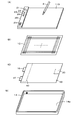
- FIG. 3 is an exploded configuration diagram for explaining a hardware configuration example of the handwriting input device 1 of this embodiment.
- the handwriting input device 1 has the display board unit 11 (FIG. 3 (A)) and the electronic devices in order from the top in the direction orthogonal to the upper surface, with the surface side on which the handwriting input is input as the upper surface side.
- a position detection sensor 12 (FIG. 3 (B)) for detecting a position indicated by the pen 2, a shield sheet 13 (FIG. 3 (C)), and a case 14 (FIG. 3 (D)) are provided.
- the case 14 is formed of, for example, synthetic resin or metal, and has a thin box shape having a storage space 14a whose upper surface is an opening.
- the display board portion 11, the position detection sensor 12, and the shield sheet 13 are housed in the storage space 14a of the case 14 so as to be overlapped with each other.
- the display board unit 11 is an example of a display unit, and is a display surface 11D that displays information such as writing information and drawing information handwritten by the user as an image by a physical phenomenon change according to the handwriting input. Be prepared.
- the information displayed on the display surface 11D is referred to as an image displayed on the display surface 11D.
- the images displayed on the display surface 11D of the display board unit 11 visually collectively display the images displayed in the entire display area of the display surface 11D when a predetermined operation is performed on the handwriting input device 1. It is configured so that it can be erased.
- the display board unit 11 is configured to use a pressure-sensitive cholesteric liquid crystal layer.
- FIG. 2 shows a partial cross-sectional view of the display board unit 11.
- two flexible transparent substrates 111 and 112 are arranged through predetermined gaps. Electrodes 113 and 114 are arranged on the surfaces of the two transparent substrates 111 and 112 facing each other, respectively.
- the pressure-sensitive cholesteric liquid crystal layer 115 is arranged in the gap between the electrodes 113 and 114 of the two transparent substrates 111 and 112.
- the display surface 11D is the upper surface of the transparent substrate 111 in this example. Therefore, the pressure-sensitive cholesteric liquid crystal layer 115 is arranged so as to face the display surface 11D.
- the flexible transparent substrates 111 and 112 are distorted to the applied pressure. Correspondingly, it causes a change in the arrangement of the liquid crystal molecules of the cholesteric liquid crystal layer 115. Then, the reflectance of the liquid crystal at the position where the pressure is applied and the arrangement change occurs changes, is formed and held on the display board portion 11 as a visible image, and is visually recognizable on the display surface 11D. appear. In this way, the reflectance of the liquid crystal at the portion where the pressure is applied changes on the display board unit 11, so that an image is formed without power consumption and displayed on the display surface 11D, due to the bistability of the liquid crystal. Be maintained.
- the display board unit 11 forms and displays an image even when pressure is applied to the display surface 11D by something other than the electronic pen 2.
- the display board portion 11 aligns the liquid crystal molecules of the pressure-sensitive cholesteric liquid crystal layer 115 in a predetermined arrangement, whereby the liquid crystal molecules are held on the display surface 11D. All the images are visually erased at once.
- the position detection sensor 12 is provided on the back side of the display board unit 11 so that the display area of the display surface 11D and the position detection sensor 12 position detection area overlap each other. Therefore, the display surface 11D of the display board unit 11 also serves as an input surface for inputting a position instruction to the position detection sensor 12.
- the position detection sensor 12 is configured to detect the position of the pen tip of the electronic pen 2 when handwritten input is performed, and to generate electronic data corresponding to the handwritten input information using the position detection coordinates as time series data. Has been done.
- the position detection sensor 12 in this example, an electromagnetic induction type position detection sensor is used. The details of the configuration of the position detection sensor 12 will be described later, but the position detection sensor 12 is configured to include a large number of loop coils for transmitting a signal to the electronic pen 2 and receiving a signal from the electronic pen 2.
- the shield sheet 13 is a conductive sheet formed of, for example, ITO (Indium Tin Oxide), zinc oxide, tin oxide, or the like, to which an electromagnetic sheet made of a magnetic material is bonded to the position detection sensor 12. It prevents unnecessary signals from being mixed in and also eliminates leakage of magnetic flux generated from the position detection sensor 12.
- the shield sheet 13 is provided so as to cover the entire surface of the position detection sensor 12 on the side opposite to the display surface 11D side that also serves as the instruction input surface.
- the position detection sensor 12 of the shield sheet 13 is provided with a position detection circuit 30 and a device control circuit 40 constituting an electronic circuit portion on the opposite side. Be done.
- the position detection circuit 30 forms electronic data including coordinate data of the position indicated by the electronic pen 2, pen pressure information, and the like, based on the output from the position detection sensor 12.
- the device control circuit 40 realizes a control function of temporarily storing the electronic data generated by the position detection circuit 30 in a memory and sending the stored electronic data to the mobile terminal 3 at a timely timing. Therefore, as will be described later, the device control circuit 40 includes a memory and a transmission circuit, and a transmission antenna AT is provided for the transmission circuit.
- the transmission circuit is configured as a communication unit that performs short-range wireless communication of the Bluetooth (registered trademark) standard, and the handwriting input device 1 and the mobile terminal 3 pass through a wireless communication path by this short-range wireless communication. Communicate.
- the transmission antenna AT is provided outside the area covered by the shield sheet 13 so that electronic data can be appropriately transmitted to the mobile terminal 3.
- the device control circuit 40 includes an erasing circuit that generates a low voltage pulse for erasing the image displayed on the display surface 11D of the display board unit 11, and displays by a point voltage pulse from the erasing circuit. The erasing timing of the image displayed on the surface 11D is controlled.
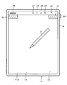
- the handwriting input device 1 of the first embodiment includes an operation button 21 as shown in FIGS. 1 and 3 (A).
- the operation button 21 visually performs a predetermined operation of collectively erasing the images displayed on the display surface 11D of the display board unit 11. Construct the means of.
- the operation button 21 also has a function as a power button of the handwriting input device 1, and each time the operation button 21 is pressed, the power of the handwriting input device 1 is repeatedly turned on and off. It is configured as follows.
- the operation button 21 is configured to also serve as a transfer button that generates a trigger for transmitting (transferring) electronic data stored in the memory to the mobile terminal 3. There is.
- the operation button 21 is provided on the panel 20 outside the display area of the display board unit 11, in this example, the upper area of the display board unit 11.
- the panel 20 has a power indicator 22 for notifying the user of power on / off, a communication indicator 23 for notifying the communication status with the mobile terminal 3, and a memory when the power is turned off. Is provided with a memory indicator 24 that notifies whether or not the electronic data is still stored in the memory.
- these indicators 22, 23, and 24 are composed of LEDs (Light Emmitting Diodes), which are examples of semiconductor light emitting elements that display the power on / off state by the light emission display.
- the panel 20 is provided with a beep speaker 25 as an example of a sound emitting means for notifying the communication status and the storage holding status of the memory by sound.
- the operation buttons 21, indicators 22, 23, 24 and the beep speaker 25 provided on the panel 20 are connected to the device control circuit 40 through the connection connector 15 (FIG. 3 (C)).
- the mobile terminal 3 has a function of receiving the electronic data transmitted from the handwriting input device 1 and transferring it to the personal computer 4.
- the mobile terminal 3 performs a predetermined process, for example, a process of assigning a page number to the electronic data based on the delimiter information, on the electronic data received from the handwriting input device 1. After that, it will be transferred to the personal computer 4.
- the mobile terminal 3 and the personal computer 4 are connected through the communication network 5.
- the communication network 5 can be configured to include a public network including the Internet and a mobile phone network. Further, the communication network 5 may be a wireless LAN using Wi-Fi (registered trademark). Further, the communication network 5 may be configured as a LAN that connects the personal computer 4 and the mobile terminal 3 by wire.
- the handwriting input device 1 may be configured to directly transmit electronic data to the personal computer 4.
- the processing function of the mobile terminal 3 may be provided by either the handwriting input device 1 or the personal computer 4.
- FIG. 4 is a diagram showing an equivalent circuit of the electronic pen 2 in this embodiment and an electronic circuit configuration example of the electronic pen 2 and a handwriting input device 1 that performs position detection and pen pressure detection by an electromagnetic induction method.
- the handwriting input device 1 of this embodiment is equipped with a battery (not shown in FIG. 4) as a power source, and as described above, the power is turned on and off alternately by pressing the operation button 21. It has a repeating configuration.
- the handwriting input device 1 of the example of FIG. 4 includes a display board unit 11, a position detection sensor 12, an operation button 21, indicators 22, 23, 24, and a beep speaker 25, and has a position. It includes a position detection circuit 30 connected to the detection sensor 12 and a device control circuit 40.
- the position detection sensor 12 is formed by stacking the X-axis direction loop coil group 121 and the Y-axis direction loop coil group 122, and sequentially connects the loop coil of one of the two loop coil groups 121 and 122.
- a selection circuit 123 for selection is provided.
- the electronic pen 2 includes a signal control circuit composed of an IC 200, and a drive voltage for driving the IC 200 is transmitted from an exciting coil 124 provided in the position detection sensor 12 of the handwriting input device 1. It is configured to be obtained from the excitation signal.
- the loop coils 121 and 122 of the position detection sensor 12 are described as being used only for receiving the electromagnetic coupling signal from the electronic pen 2, but are electromagnetically coupled with the electronic pen 2.
- the signal control circuit provided in the electronic pen 2 can be driven instead of the exciting coil 124.
- a signal such as predetermined control data is transmitted to the signal control circuit provided in the electronic pen 2.
- the exciting coil 124 is arranged so as to surround the X-axis direction loop coil group 121 and the Y-axis direction loop coil group 122.
- the exciting coil 124 has two turns, but in reality, it has a larger number of turns, for example, 8 to 10 turns.
- the exciting coil 124 is connected to the drive circuit 32, and the drive circuit 32 is connected to the oscillation circuit 31 that oscillates at a predetermined frequency fo.
- the drive circuit 32 is controlled by a position detection control unit 300 provided in the position detection circuit 30, for example, composed of a microprocessor.
- the position detection control unit 300 controls the drive circuit 32 to control the supply of the oscillation signal of the frequency fo from the oscillation circuit 31 to the exciting coil 124, and transmits the signal from the exciting coil 124 to the electronic pen 2. To control.
- the selection circuit 123 is selectively controlled by the position detection control unit 300 to select one loop coil.
- the induced voltage generated in the loop coil selected by the selection circuit 123 is supplied to the position detection circuit 30.
- the process of detecting the coordinates (X coordinate and Y coordinate) of the indicated position by the electronic pen 2 is performed under the control of the position detection control unit 300, and the position detection control unit 300 uses the electronic pen. Generate the coordinate data of the position indicated by 2.
- the position detection control unit 300 also detects the interruption and discontinuity of the signal from the electronic pen 2 as a digital signal of several bits in addition to the detection of the indicated position by the electronic pen 2 to detect the writing pressure. Then, the position detection control unit 300 generates electronic data by associating the detected position information by the electronic pen 2 with the detected pen pressure information, and supplies the electronic data to the device control circuit 40.
- the device control circuit 40 erases the image of the memory 41 that stores and holds the electronic data from the position detection circuit 30, the short-range communication unit 42 for wireless communication with the mobile terminal 3, and the display surface 11D of the display board unit 11. It includes an erasing circuit 43 that generates a low voltage pulse, and a control circuit 44 that is composed of, for example, a microprocessor. Then, as described above, the operation buttons 21, the indicators 22, 23, 24, and the beep speaker 25 are connected to the device control circuit 40.
- a power supply voltage is constantly supplied from the battery to the control circuit 44 of the device control circuit 40. However, when the power is turned off, the control circuit 44 is in the standby state, which saves power.
- the memory 41 is configured as a non-volatile memory that stores and holds stored electronic data unless it is erased.
- the memory 41 may be configured as a volatile memory so as to constantly back up the power supply from the battery.
- the control circuit 44 of the device control circuit 40 monitors the pressing operation of the operation button 21, and in response to the pressing operation, power on / off control, erasing control of the image on the display surface 11D of the display board unit 11, and the memory 41. Execute the process. In that case, the control circuit 44 also monitors the communication status with the mobile terminal 3 through the short-range communication unit 42 when the operation button 21 is pressed, and the storage status of the electronic data in the memory 41, and uses the monitoring result as the monitoring result. Depending on the situation, different processes are executed.
- the control circuit 44 controls the light emitting state of the power indicator 22 based on the monitoring result of the pressing operation of the operation button 21, and is based on the monitoring result of the communication status with the mobile terminal 3 through the short-range communication unit 42.
- the light emitting state of the communication indicator 23 is controlled.
- the control circuit 44 controls the light emitting mode of the memory indicator 24 based on the communication status with the mobile terminal 3 through the short-range communication unit 42 and the storage status of the electronic data of the memory 41.
- the control circuit 44 controls the light emitting modes of the indicators 22 to 24, and also controls to emit a beep sound from the beep speaker 25 at a necessary timing.
- the circuit configuration of the electronic pen 2 is as shown by being surrounded by a dotted line in FIG. That is, the capacitor 202 is connected in parallel with the coil 201 as the inductance element to form the resonance circuit 203. Then, the switch 204 is connected in parallel with the resonance circuit 203.
- the switch 204 is configured to be on / off controlled by the IC 200. When the switch 204 is off, the resonance circuit 203 resonates with respect to the signal from the position detection sensor 12. However, when the switch 204 is on, the capacitor 202 connected in parallel to the coil 201 is short-circuited, and the resonance operation with respect to the signal from the position detection sensor 12 by the resonance circuit 203 is turned off.
- the IC 200 obtains the AC signal received by electromagnetic induction from the position detection sensor 12 of the handwriting input device 1 in the resonance circuit 203 by rectifying it in the rectifier circuit (power supply circuit) 207 including the diode 205 and the capacitor 206. It is configured to operate according to the power supply voltage Vcc.
- the IC 200 is connected to the resonance circuit 203 via a capacitor 208, and monitors the operating status of the resonance circuit 203. By monitoring the operating status of the resonant circuit 203, the IC 200 uses the electromagnetic coupling status of the position detection sensor 12 with the exciting coil 124, or, although the description is omitted in this example, two loop coil groups 121 and 122 are used. Then, a signal such as control data transmitted from the position detection sensor 12 can be detected to perform desired operation control.
- the electronic pen 2 of this embodiment includes a pen pressure detection circuit including a pressure sensitive element that detects the pen pressure applied to the pen tip as, for example, the capacitance Cv of a variable capacitance capacitor. As shown in FIG. 4, this capacitance variable capacitor is connected to the IC 200, and the IC 200 is configured to be able to detect the capacitance Cv according to the writing pressure.
- the IC 200 detects the writing pressure in the electronic pen 2 from the value of the capacitance Cv. Then, the IC 200 converts the detected pen pressure into, for example, an 8-bit digital signal, and controls the switch 204 by the digital signal corresponding to the pen pressure, so that the pen pressure information is used as additional information by a handwriting input device. It is transmitted to the position detection sensor 12 of 1.
- the position detection control unit 300 drives the drive circuit 32 and transmits a signal from the exciting coil 124 to the electronic pen 2 for a predetermined time.
- the position detection control unit 300 sequentially selects one loop coil of the X-axis direction loop coil group 121 in the selection circuit 123, and transmits a burst-shaped signal to the electronic pen 2.
- the electronic pen 2 receives the burst-shaped signal in the resonance circuit 203 and returns it to the position detection sensor 12 of the handwriting input device 1.
- the position detection control unit 300 obtains the X coordinate value of the position indicated by the electronic pen 2 by detecting the returned burst-shaped signal as a position detection signal.
- the position detection control unit 300 performs the same processing on the Y-axis direction loop coil group 122 to obtain the Y coordinate value of the position indicated by the electronic pen 2.
- the position detection control unit 300 of the position detection circuit 30 continues from the exciting coil 124 for a predetermined time or longer in order to detect the pen pressure information as additional information from the electronic pen 2 after detecting the indicated position of the electronic pen 2.
- the transmission / reception is continuously performed a number of times according to the number of bits of the digital signal of the additional information at the same timing as when the coordinates are detected.
- the IC 200 of the electronic pen 2 detects the position of the handwriting input device 1 by the digital signal of the additional information consisting of the pen pressure information obtained corresponding to the capacitance Cv of the capacitance variable capacitor constituting the pen pressure detecting means.
- the switch 204 is on / off controlled in synchronization with the transmission / reception of the signal from the sensor 12.
- the resonant circuit 203 can return the signal transmitted from the position detection sensor 12 to the position detection sensor 12, so that the loop coil of the position detection sensor 12 receives this signal.
- the switch 204 when the switch 204 is on, the resonance circuit 203 is in a state in which the resonance operation is prohibited. Therefore, no signal is returned from the resonance circuit 203 to the position detection sensor 12, and the position detection sensor 12 The loop coil does not receive a signal.
- the position detection control unit 300 of the position detection circuit 30 receives a plurality of bits of digital signals according to the pen pressure information by determining the presence or absence of a received signal at a number of times corresponding to the number of bits of the digital signal of the additional information.
- the pen pressure information from the electronic pen 2 can be detected. Therefore, the electronic pen 2 transmits the pen pressure information as an ASK (Amplitude Shift Keying) modulated signal to the position detection sensor 12 of the handwriting input device 1.
- ASK Amplitude Shift Keying
- the handwriting input device 1 when the handwriting input is performed on the display surface 11D by the electronic pen 2 while the power is on, an image corresponding to the handwriting input is formed on the display surface 11D of the display board unit 11 and displayed.
- the position of the pen tip of the electronic pen 2 is detected by the position detection sensor 12, and the electronic data corresponding to the display image on the display surface 11D, which consists of the time-series data of the detected position information, is stored in the memory 41. It is stored in memory.
- the handwriting input device 1 determines whether or not the mobile terminal 3 and the own device can perform short-range wireless communication.
- the handwriting input device 1 is connected to the mobile terminal 3 depending on whether or not pairing is achieved during communication. Determine if short-range wireless communication is possible.
- the handwriting input device 1 determines that communication with the mobile terminal 3 is possible (confirms that communication with the mobile terminal 3 is possible)
- the electronic data stored in the memory 41 is stored.
- Delimited information for example, page breaks are added to the data and transmitted to the mobile terminal 3.
- the state in which short-range wireless communication is possible is notified to the user by turning on the communication indicator 23.
- the handwriting input device 1 completes the transmission of the electronic data stored and held in the memory 41, the communication indicator 23 is turned off and the electronic data in the memory 41 is erased.
- the handwriting input device 1 supplies a low voltage pulse from the erasing circuit 43 to the display board unit 11 to be formed on the display surface 11D for display. The images are visually erased at once for the entire display surface. Then, in this embodiment, the handwriting input device 1 turns off the power.
- the handwriting input device 1 determines that communication with the mobile terminal 3 is not possible in this embodiment (it cannot be confirmed that communication with the mobile terminal 3 is possible), the handwriting input device 1 cannot confirm that communication with the mobile terminal 3 is possible.
- the electronic data to which the delimiter information is added is not erased from the memory 41, but is kept in the memory 41. Then, in this embodiment, the handwriting input device 1 notifies by blinking the communication indicator 23 that short-range wireless communication with the mobile terminal 3 is impossible, and also blinks the memory indicator 24 to transmit. The user is notified that the electronic data is stored and held in the memory 41 without being stored.
- the handwriting input device 1 supplies a low voltage pulse from the erasing circuit 43 to the display board unit 11, and visually displays the images formed and displayed on the display surface 11D collectively for the entire display surface. To erase it. Then, the power is turned off, and the power supply to the position detection sensor 12, the position detection circuit 30, and the device control circuit 40 is turned off.
- the control circuit 44 may be configured to blink the communication indicator 23 and maintain the display control for blinking the memory indicator 24 even after the power is turned off.
- the electronic data held in the memory 41 is stored in the memory 41 when the operation button 21 is pressed after the new electronic data by the new handwriting input is additionally stored, or in the memory 41.
- the operation button 21 is pressed before the new electronic data is stored in the memory, if communication is possible, if there is new electronic data, the handwriting input device 1 to the mobile terminal 3 together with the new electronic data. Will be sent to. Then, after the transmission is completed, the memory 41 is configured to be erased.
- new delimiter information is also added to the electronic data of the image by the new handwriting input, and the data is stored in the memory without being transmitted. It is possible to distinguish it from the electronic data that was retained.
- the operation button 21 is set to accept an operation mode different from the normal operation mode, for example, a long press of the operation button 21 from the user, and the operation button 21 is notified.
- the long press operation is a press operation having a second time length longer than the first time length when the short press operation of the operation button 21 having a first time length or less is a predetermined operation. It is said that.
- the handwriting input device 1 of this embodiment when the operation button 21 is pressed and communication is not possible, the remaining capacity of the memory 41 is insufficient and it becomes difficult to store new electronic data.
- the image displayed on the display surface 11D of the display board unit 11 is not erased and is handwritten.
- the power of the input device 1 is left on, and the memory indicator 24 and the beep speaker 25 are used to notify the user to that effect.
- the user Upon receiving this notification, the user creates a situation in which communication between the handwriting input device 1 and the mobile terminal 3 is possible. Then, the handwriting input device 1 notifies the user that communication has become possible by the communication indicator 23. Therefore, when the user presses and holds the operation button 21 in this example, the handwriting input device 1 is stored and held in the memory 41. It is configured so that the electronic data can be transmitted to the mobile terminal 3.
- the power may be turned off without leaving the power on and without erasing the image on the display surface 11D.
- the memory indicator 24 notifies that the memory 41 holds electronic data. Therefore, when the operation button 21 is normally pressed to turn on the power, the display surface is displayed. Since it is known that it is necessary to transmit the electronic data of the memory 41 in combination with the fact that the image is displayed on the 11D, the user creates a communicable environment, presses and holds the operation button 21, and presses and holds the operation button 21 of the memory 41. The electronic data may be transmitted to the mobile terminal 3 so that the displayed image can be erased.
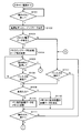
- FIGS. 5 to 8 shows the case where the power of the handwriting input device 1 is started from the off state.
- the control circuit 44 first determines whether or not the operation button 21 has been pressed (step S101), and when it determines that the operation button 21 has not been pressed, waits for the operation button 21 to be pressed. When it is determined in step S101 that the operation button 21 has been pressed, the control circuit 44 turns on the handwriting input device 1 and turns on the power indicator 22 (step S102).
- control circuit 44 determines whether or not the electronic data is stored and held in the memory 41 (step S103), and when it is determined that the electronic data is stored and held in the memory 41, the memory indicator 24 blinks. At the same time, a beep sound is emitted from the beep speaker 25 (step S104).
- control circuit 44 determines whether or not the operation button 21 has been pressed and held (step S105), and when it determines that the operation button 21 has not been pressed and held, the control circuit 44 displays on the display surface 11D by the electronic pen 2. It is determined whether or not the instruction input is detected (step S106). When it is determined in step S106 that the instruction input on the display surface 11D by the electronic pen 2 is not detected, the control circuit 44 returns the process to step S105.
- step S105 When it is determined in step S105 that the operation button 21 has been pressed and held for a long time, the control circuit 44 and the mobile terminal 3 depending on whether or not the pairing of the communication between the short-range communication unit 42 and the mobile terminal 3 can be confirmed. It is confirmed whether wireless communication between the two is possible (step S121 in FIG. 6), and it is determined whether or not wireless communication with the mobile terminal 3 is possible (step S122).
- step S122 when it is determined in step S122 that wireless communication with the mobile terminal 3 is possible, the control circuit 44 transmits the electronic data stored in the memory 41 to the mobile terminal 3 (step S123). .. Then, the control circuit 44 determines whether or not the transmission is completed (step S124), and when it is determined that the transmission is completed, erases the electronic data stored in the memory 41 (step S125). Further, the control circuit 44 turns off the blinking memory indicator 24 (step S126).
- step S124 determines whether or not a predetermined time or more has elapsed from the start of transmission (step S127), and the predetermined time or more from the start of transmission.
- step S127 determines whether or not a predetermined time or more has elapsed from the start of transmission.
- step S127 when it is determined in step S127 that a predetermined time or more has passed from the start of transmission, the control circuit 44 determines that the transmission of electronic data has failed, stops the transmission (step S128), and blinks the communication indicator 23. At the same time, a beep sound is emitted from the beep speaker 25 (step S129).
- step S122 Even when it is determined in step S122 that wireless communication with the mobile terminal 3 is not possible, the control circuit 44 determines that wireless communication with the mobile terminal 3 is not possible, and proceeds to step S129. Proceed, the communication indicator 23 blinks, and a beep sound is emitted from the beep speaker 25. Then, the control circuit 44 keeps the electronic data stored in the memory 41 (step S130).
- step S107 of FIG. 5 after step S126 and step S130, and determines whether or not the instruction input on the display surface 11D by the electronic pen 2 is detected. Further, when it is determined in step S103 of FIG. 5 that the electronic data is not stored and held in the memory 41, the control circuit 44 proceeds to step S107 and inputs an instruction input on the display surface 11D by the electronic pen 2. Determine if it has been detected.
- control is performed.
- the circuit 44 determines whether or not the instruction input by the electronic pen 2 is an erasure input such as a double line superimposed on the previously input portion (step S108).
- step S108 When it is determined in step S108 that the input is not erasure input, the control circuit 44 detects the coordinate data of the position indicated and input by the electronic pen 2, and stores the electronic data including the coordinate data and the pen pressure data in the memory 41. The memory is retained in (step S109). Further, when it is determined in step S108 that the erasure input is, the control circuit 44 deletes the electronic data of the instruction input before the erasure input such as the double line is overlapped from the memory 41 (step S110). ..
- step S111 the control circuit 44 determines whether or not the operation button 21 is pressed. Even when it is determined in step S107 that the instruction input on the display surface 11D by the electronic pen 2 is not detected, the process proceeds to step S111 to determine whether or not the operation button 21 has been pressed. Then, when it is determined in step S111 that the operation button 21 is not pressed, the control circuit 44 returns the process to step S107 and repeats the processes after this step S107.
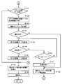
- step S111 when it is determined in step S111 that the operation button 21 is pressed, the control circuit 44 determines whether or not there is electronic data stored and held in the memory 41 (step S141 in FIG. 7). When it is determined in step S141 that there is no electronic data stored in the memory 41, the control circuit 44 proceeds to step S148 and supplies a low voltage pulse from the erasing circuit 43 to the display board unit 11. Then, the images displayed on the display surface 11D are collectively erased, and then the handwriting input device 1 is turned off (step S149).
- step S141 the image on the display surface 11D of the display board unit 11 is erased even when there is no stored data in the memory 41 because the erasure input is performed by the instruction input by the electronic pen 2. Occasionally, the electronic data at the position specified by the erasure input is erased from the memory 41, and even if the electronic data is not in the memory 41, the image instructed to be erased by the erasure input is displayed on the display surface 11D of the display board unit 11. This is because it may remain displayed.
- Step S141 when it is determined in step S141 that there is electronic data stored and held in the memory 41, the control circuit 44 newly stores and holds the electronic data after the operation button 21 is pressed and the power is turned on. (Step S142) is provided with delimiter information such as a page break mark.
- control circuit 44 confirms whether wireless communication with the mobile terminal 3 is possible depending on whether or not the pairing of communication between the short-range communication unit 42 and the mobile terminal 3 can be confirmed. Then (step S143), it is determined whether or not wireless communication with the mobile terminal 3 is possible (step S144).
- step S144 when it is determined in step S144 that wireless communication with the mobile terminal 3 is possible, the control circuit 44 transmits the electronic data stored in the memory 41 to the mobile terminal 3 (step S145). .. Then, the control circuit 44 determines whether or not the transmission is completed (step S146), and when it is determined that the transmission is completed, erases the electronic data stored in the memory 41 (step S147).
- control circuit 44 advances the process to step S148, supplies a low voltage pulse from the erasing circuit 43 to the display board unit 11, collectively erases the images displayed on the display surface 11D, and then collectively erases the images.
- the power of the handwriting input device 1 is turned off (step S149).
- step S146 determines whether or not a predetermined time or more has elapsed from the start of transmission (step S150), and the predetermined time or more from the start of transmission.
- step S150 determines whether or not a predetermined time or more has elapsed from the start of transmission.
- step S150 when it is determined in step S150 that a predetermined time or more has passed from the start of transmission, the control circuit 44 determines that the transmission of electronic data has failed, stops the transmission (step S151), and blinks the communication indicator 23. At the same time, a beep sound is emitted from the beep speaker 25 (step S152). Then, the control circuit 44 keeps the electronic data stored in the memory 41 (step S161 in FIG. 8), and blinks the memory indicator 24 (step S162).
- control circuit 44 determines whether or not there is a remaining capacity based on whether or not the remaining capacity of the memory 41 is equal to or less than a predetermined remaining capacity value (step S163).
- the predetermined remaining capacity value is a value that may cause the memory 41 to run out of capacity when new electronic data is added, and is set with a margin.
- step S163 When it is determined in step S163 that the remaining capacity of the memory 41 is not equal to or less than the predetermined remaining capacity value, the control circuit 44 proceeds to step S148 of FIG. 7 to generate a low voltage pulse from the erasing circuit 43.
- the image is supplied to the display board unit 11 to collectively erase the images displayed on the display surface 11D, and then the handwriting input device 1 is turned off (step S149).
- step S163 when it is determined in step S163 that the remaining capacity of the memory 41 is equal to or less than the predetermined remaining capacity value, the control circuit 44 does not erase the image of the display surface 11D of the display board unit 11, and the capacity of the memory 41 is not erased.
- Beep sound is emitted (step S164).
- the user is urged to transfer the electronic data of the memory 41 to the mobile terminal 3 because the remaining capacity of the memory 41 is insufficient, and the user communicates the handwriting input device 1 with the mobile terminal 3. Move to an environment where it is possible.
- the control circuit 44 determines whether or not the environment is capable of communicating with the mobile terminal 3 (step S165), and waits for the environment to be able to communicate with the mobile terminal 3. Then, when it is determined in step S165 that the environment is capable of communicating with the mobile terminal 3, the control circuit 44 turns on the communication indicator 23 and notifies the user of this (step S166). ..
- step S167 when the user's long-pressing operation of the operation button 21 is monitored (step S167) and the user's long-pressing operation of the operation button 21 is determined, all the electronic data stored and held in the memory 41 is stored in the mobile terminal. It is transmitted to 3 (step S168).
- the electronic data stored and held in the memory 41 is data for a plurality of pages separated by delimiter information.
- the electronic data stored and held in the memory 41 is for a plurality of pages, but since it is separated by the delimiter information, each page has a different page number on the mobile terminal 3 or the personal computer 4. Can be given to distinguish them.
- step S168 When the electronic data stored and held in the memory 41 is transmitted to the mobile terminal 3 in step S168, the control circuit 44 erases the electronic data stored and held in the memory 41 from the memory 41 (step S169). Then, the control circuit 44 turns off the memory indicator 24 (step S170). Following this step S170, the control circuit 44 proceeds with the process to step S148 of FIG. 7, supplies a low voltage pulse from the erasing circuit 43 to the display board unit 11, and displays the low voltage pulse on the display surface 11D. The existing images are erased all at once, and then the handwriting input device 1 is turned off (step S149).
- the electronic data sent from the handwriting input device 1 based on the operation of the operation button 21 is transmitted to the display surface 11D of the handwriting input device 1. It can be easily managed as electronic data of the image displayed on. That is, in the mobile terminal 3, even if the delimiter information is not added to the electronic data received from the handwriting input device 1, the display surface 11D of the handwriting input device 1 is given a page number to the received electronic data. It can be processed as data of the unit of the page corresponding to the image displayed in.
- the electronic data in the memory 41 is configured to be given delimiter information each time the operation button 21 is operated. Therefore, in the mobile terminal 3, this delimiter is provided. It is easy to assign page numbers by relying on information.
- the electronic data of the memory 41 is transmitted to the mobile terminal 3 which is an external device when there is a predetermined operation of pressing the operation button 21. Is possible, and then transmission is executed, and after the transmission, the electronic data is erased from the memory 41. Therefore, the electronic data corresponding to the handwritten input image is erased without being transmitted. Is avoided.
- the user visually erases the image displayed on the display surface 11D of the display board unit 11 by pressing the operation button 21.
- the above operation is executed only by performing a predetermined operation. Therefore, the user does not need to perform separate operations for erasing the image displayed on the display surface 11D of the display board unit 11 and transmitting the electronic data stored in the memory 41. .. Therefore, when a predetermined operation for visually erasing the image displayed on the display surface 11D of the display board unit 11 and an operation for transmitting electronic data stored in the memory are performed separately.
- a predetermined operation for visually erasing the image displayed on the display surface 11D of the display board unit 11 and an operation for transmitting electronic data stored in the memory are performed separately.
- a mistake such as forgetting to transmit the electronic data.
- a predetermined operation means for visually erasing the image displayed on the display surface 11D of the display board unit 11 and electronic data stored in the memory 41 Since it is not necessary to separately provide the operation means for the operation of the handwriting input device 1, there is also an effect that the configuration of the handwriting input device 1 is simplified.
- the handwriting input device 1 of the first embodiment described above when the electronic data of the memory 41 cannot be transmitted to the mobile terminal 3 which is an external device at the time of a predetermined operation by pressing the operation button 21, the electronic data of the memory 41 cannot be transmitted. Even if the image displayed on the display surface 11D of the display board unit 11 is erased, the electronic data in the memory 41 is not erased, but the delimiter information is added and the image is stored and held in the memory 41. There is. Then, the handwriting input device 1 uses the indicators 23 and 24 and the beep speaker 25 to notify the user of the situation in which communication was not possible at that time and that the electronic data is still stored in the memory 41. To.
- the user can grasp the communication status between the handwriting input device 1 and the mobile terminal 3 and the storage state of the memory 41, so that the communication status between the handwriting input device 1 and the mobile terminal 3 can be communicated. It is possible to take appropriate measures such as transmitting the electronic data of the memory 41 by pressing and holding the operation button 21 in addition to the state of.
- the handwriting input device 1 of the first embodiment described above cannot transmit the electronic data of the memory 41 to the mobile terminal 3 which is an external device at the time of a predetermined operation by pressing the operation button 21, and the memory
- the image displayed on the display surface 11D of the display board unit 11 cannot be erased and is used. It is designed to be a warning notification to the person.
- the indicators 23 and 24 are made to display a warning such as a blinking display, and the beep speaker 25 emits a beep sound to call attention. ing.
- the user when the user receives this warning notification, it is necessary to transmit the electronic data stored in the memory 41 to the external device to secure the remaining capacity of the memory 41 for new handwriting input. You can recognize that. Therefore, the user makes the communication status between the handwriting input device 1 and the mobile terminal 3 in a communicable state, and presses and holds the operation button 21 to transmit the electronic data of the memory 41. You can take action.
- the predetermined operation for erasing the image displayed on the display surface 11D of the display board unit 11 and transmitting the electronic data from the memory 41 is the pressing operation of the operation button 21.
- the operation of the operation button 21 as the operation of is also configured to be detected as a power on / off operation.
- the operation mode for the operation button 21 is configured so that a predetermined operation for erasing the image displayed on the display surface 11D of the display board unit 11 and a power on / off operation are different operation modes. You may.
- a short-time pressing operation of the operation button 21 having a first time length or less is a predetermined operation
- a pressing operation having a second time length longer than the first time length is a power on / off operation. You may do it.
- the operation for transmitting the stored electronic data without being transmitted to the memory 41 is not a long press as in the above-described embodiment in order to distinguish it from the power on / off operation.
- the pressing operation may be performed twice in succession for a short period of time equal to or less than the first time length.
- the operation button 21 for a predetermined operation for erasing the image displayed on the display surface 11D of the display board unit 11 is configured to also serve as the power button.
- the button may be another operation button.
- the memory 41 has a capacity for a plurality of pages of the image displayed on the display surface 11D of the display board unit 11 of the handwriting input device 1, but the storage capacity of the memory 41 is used.
- One page of the image displayed on the display surface 11D of the display board unit 11 of the handwriting input device 1 may be used.
- the electronic data of the memory 41 cannot be transmitted even though the operation button 21 is pressed, it is displayed on the display surface 11D of the display board unit 11 each time. Be careful by disabling the erasure of the image, making it a warning notification to the user, displaying warnings such as blinking indicators 23 and 24, and emitting a beep sound by the beep speaker 25. Try to arouse.
- the mobile terminal 3 is displayed on the display surface 11D. Since the electronic data for each page of the image is transmitted, the mobile terminal 3 delimits the page number and the like each time the electronic data is received, even if the delimiter information is not added to the electronic data. It is possible to add the indicated information. That is, the handwriting input device 1 has an advantage that it is not necessary to add delimiter information to the electronic data of the memory 41.
- the indicators 22 to 24 composed of the semiconductor light emitting element are monochromatic light emitting elements, and display the status notification depending on the difference in the light emitting mode such as lighting and blinking.
- a state notification display may be performed by changing the light emitting mode by changing the light emitting color.
- the predetermined operation for erasing the image displayed on the display surface is the pressing operation of the operation button 21.
- the handwriting input device of the second embodiment uses an instruction input operation by an electronic pen in a predetermined position range within the position detection area of the position detection sensor as a predetermined operation without providing such an operation button. This is an example of the case where it is configured as follows.
- FIG. 9 is a diagram for explaining the handwriting input device 1A of the second embodiment.
- the handwriting input device 1A of the second embodiment does not have an operation button 21 as a hardware configuration, and an instruction input by an electronic pen in a predetermined position range within the position detection area of the position detection sensor is provided.
- the operation is configured in the same manner as the handwriting input device 1 of the first embodiment, except that the operation is used as a predetermined operation. Therefore, in the following description, the same parts as the handwriting input device 1 of the first embodiment will be described using the same reference numerals.
- FIG. 9 is a view of the handwriting input device 1A of the second embodiment as viewed from above in the direction orthogonal to the display surface 11D. Also in the handwriting input device 1A of the second embodiment, the position detection sensor 12 is arranged on the back side of the display board portion 11 in a state where the display area of the display surface 11D and the position detection area overlap.
- a power button 26 is provided on the side of the case 14.
- the control circuit 44 of the device control circuit 40 controls each time the power button 26 is operated so as to alternately turn the power on and off of the handwriting input device 1A.
- the panel 20A is provided outside the display area of the display surface 11D and above the display surface 11D in FIG. 9, and the panel 20A is provided on the panel 20A in the same manner as in the first embodiment.
- a power indicator 22, a communication indicator 23, a memory indicator 24, and a beep speaker 25 are provided.
- the predetermined operation receiving area 51 is used to receive the predetermined operation for the purpose as an operation through the electronic pen 2.
- the image displayed on the display surface 11D is erased by the instruction input using the electronic pen 2 to instruct any position in the predetermined operation reception area 51 for a short time, that is, the one-tap operation by the electronic pen 2.
- the control circuit 44 of the device control circuit 40 is made to recognize.
- the control circuit 44 is electronic in the predetermined operation reception area 51.
- a plurality of short-time instruction inputs by the pen 2, for example, two consecutive inputs, that is, a double tap operation is recognized as a transmission instruction operation of electronic data held without being transmitted to the memory 41.
- the instruction operation by the electronic pen 2 in the predetermined operation reception area 51 is not limited to one tap or double tap, and any operation input can be used as long as the control circuit 44 is a distinguishable operation input. You may. Further, the power button 26 may not be provided, and the instruction operation distinguishable from other instruction operations by the electronic pen 2 in the predetermined operation reception area 51 may be recognized as the power on / off operation.
- the handwriting input device 1A of the second embodiment is configured to be able to control the operation and non-operation of the device control circuit 40. That is, in the handwriting input device 1A of the second embodiment, in order to receive the control instruction by the user who operates or does not operate the device control circuit 40, in this example, the upper part of the panel 20 side, for example, the leftmost rectangle.
- the area is a control instruction receiving area 52 that receives the control instruction by the user as an instruction operation through the electronic pen 2.
- the panel 20 is provided with an indicator 27 for notifying the operating state (on, off) of the device control circuit 40.
- the indicator 27 is also composed of a semiconductor light emitting element like the indicators 22 to 24.
- the control circuit 44 of the device control circuit 40 receives the power supply voltage to the device control circuit 40 each time the instruction input operation is performed by the electronic pen 2 in the control instruction receiving area 52.
- the supply is controlled so that the operation and non-operation of the device control circuit 40 are alternately repeated. Note that the control circuit 44 is in the standby state even when the device control circuit 40 is inactive, and the power supply voltage is always supplied as in the first embodiment.
- the indicator 27 is turned on by the control circuit 44 and the device control circuit 40 operates.
- the control circuit 44 turns off the indicator 27.
- the handwriting input device 1A of the second embodiment an image is formed and displayed on the display surface 11D of the display board unit 11, but it is not necessary to transfer the electronic data of the image to the external device. Can realize a usage mode that can reduce battery consumption.
- the display surface 11D of the display board unit 11 does not include the predetermined operation reception area 51 and the control instruction reception area 52, and only the position detection area of the position detection sensor 12 is included in the predetermined operation reception area 51 and the sensor control. It may be configured to include the instruction receiving area 52.
- the position detection sensor 12 is not configured to detect the instruction input to the predetermined operation reception area 51 or the control instruction reception area 52, but corresponds to the predetermined operation reception area 51 or the control instruction reception area 52. Therefore, a sensor for detecting an operation on the area, such as a pressure sensor or a touch sensor, may be separately provided. In that case, the operation input to the predetermined operation reception area 51 or the control instruction reception area 52 may be not only the operation input by the electronic pen 2 but also the operation input by the user's finger.
- the detection circuit 30 can also control the power supply to control the on / off of the operation, an image is formed and displayed on the display surface 11D of the display board unit 11, but the electronic data of the image is externally displayed.
- a transparent sheet on which a predetermined document form is printed is prepared, and the transparent sheet is placed on the display surface 11D of the handwriting input device 1 or 1A of the above-described embodiment and printed on the transparent sheet. It is convenient to use for handwriting input on the document form.
- FIG. 10 is a diagram showing a configuration example of a system that realizes this usage.
- the user of this system creates a desired document form FM and registers it in, for example, a server device 61 including a personal computer.
- the server device 61 accepts this registration, assigns identification information (paper ID) to the received document form, and stores the data of the document form in the database.
- identification information paper ID
- the server device 61 assigns unique identification information as a paper ID, for example, a barcode.
- the database of the server device 61 includes area coordinate data indicating an input area for handwritten information, attribute data of information to be input in the input area for handwritten information, and the like.
- the area coordinate data indicating the input area of the handwritten information included in the document form corresponds to the coordinate data of the position detection area of the position detection sensor 12 of the handwriting input device 1.
- the registered document form is printed on the transparent sheet 63 by the printer 62.
- a barcode as an example of the paper ID given by the server device 1 is printed at a predetermined position on the transparent sheet 63.
- the transparent sheet 63 is placed on the display surface 11D of the handwriting input device 1 or 1A.
- the handwriting input device 1 or 1A of this example is provided with a means for locking the transparent sheet 63 on the display surface 11D, for example, a clip member (not shown), and the transparent sheet is provided by the clip member. 63 is locked on the display surface 11D.
- the handwriting input device 1 or 1A of this example is further provided with a bar code reader (not shown) for reading the bar code printed on the transparent sheet 63, and the control circuit 44 of the device control circuit 40 is provided.
- the bar code information read by this bar code reader is stored in the memory 41 as a paper ID corresponding to electronic data.
- the user of the handwriting input device 1 or 1A uses the electronic pen 2 to perform handwriting input in the area where input is required in the document form of the transparent sheet 63. Then, the handwritten input image is formed and displayed on the display surface 11D of the display board unit 11, and the position of the pen tip of the electronic pen 2 is detected by the position detection sensor 12 and handwritten input is performed in the memory 41. Electronic data corresponding to the image is stored.
- the control circuit 44 of the device control circuit 40 of the handwriting input device 1 can communicate with the mobile terminal 3. After that, the electronic data stored in the memory 41 is transmitted to the mobile terminal 3 with a paper ID added. Then, the control circuit 44 performs a process of erasing the image displayed on the display surface 11D after the transmission is completed. Then, the handwritten input images written in each of the input fields of the document form of the transparent sheet 63 are deleted, and each of the input fields of the document form becomes blank. That is, the next user can input by handwriting in the blank of the same document form.
- the mobile terminal 3 is pre-installed with an application program for performing necessary processing in this system.
- the mobile terminal 3 receives the paper ID and electronic data from the handwriting input device 1 or 1A, it stores them in the buffer memory and transmits the received paper ID information to the server device 1 through the communication network 64.
- the mobile terminal 3 displays the document form based on the display data on the display screen and the handwritten input device 1 or 1A. Display the handwritten information in the blank of the document form based on the electronic data received from.
- the mobile terminal 3 adds a paper ID to the electronic data received from the handwriting input device 1 or 1A stored in the buffer memory, for example, based on the transfer instruction of the user of the mobile terminal 3. It sends to the server device 1 and requests the storage of the entered data. At this time, a page number and a time stamp are added to the electronic data transmitted from the mobile terminal 3 to the server device 1. As a result, the server device 61 can identify even the handwritten input information of the same document form based on the page number and the time stamp.
- the server device 1 stores the electronic data associated with the paper ID received from the mobile terminal 3 in the handwritten information storage unit in association with the received paper ID.
- the document is formed by placing the transparent sheet 63 on which the predetermined document form is printed on the display surface 11D.
- Handwritten input information in the required input fields in the form can be collected as electronic data.
- the document form can be recognized by the paper ID, and the electronic data can be managed by the delimiter information such as the page number. Therefore, this system is very useful for applications such as handwriting input in a predetermined input field of a specific document form such as a questionnaire in a hospital or a member registration sheet in a store.
- the display unit is composed of a display board unit using a pressure-sensitive cholesteric liquid crystal layer, but the display unit is not limited to this example. Absent.
- the display unit may be composed of the magnetic sheet 16 as shown in FIG.
- a position detection sensor 12 is arranged below the magnetic sheet 16 (on the back surface side) so as to overlap the magnetic sheet 16 in a direction orthogonal to the display surface. ..
- the magnetic sheet 16 is a microcapsule 163 in which a magnetic material powder such as iron powder 163Fe (shown as a black dot in FIGS. 11 (A) and 11 (B)) is mobilably confined.
- a magnetic material powder such as iron powder 163Fe (shown as a black dot in FIGS. 11 (A) and 11 (B)) is mobilably confined.
- a large number of them are confined in a gap between a sheet-shaped resin base material 161 made of, for example, PET (Polyethylene Terephthalate) and a sheet-shaped resin base material 162, and are formed in a sheet shape.
- at least the sheet-shaped resin base material 161 is a transparent material.
- the surface 161a of the sheet-shaped resin base material 161 of the magnetic sheet 16 serves as a display surface.
- the iron powder 163Fe in each microcapsule 163 exists at an irregular arbitrary position as shown in FIG. 11 (B).
- the surface of the magnetic sheet 16, that is, the display surface, is in a state of a predetermined ground color, for example, white.
- the iron powder 163Fe in the microcapsules 163 near the position where the magnetic poles are close to or come into contact is shown in FIG. ), It is attracted to the magnetic pole side. Therefore, at a position where the magnetic poles are close to each other or in contact with each other, the surface of the magnetic sheet 16, that is, the display surface exhibits the color of iron powder 163Fe, for example, black. The position of the iron powder 163Fe in the microcapsule 163 is maintained even when the magnetic poles are separated. Therefore, when the magnetic poles that are close to or in contact with the surface of the magnetic sheet 16 move, the movement locus becomes a black line and appears on the surface of the magnetic sheet 16.
- the core body 2T of the electronic pen 2 is configured to have a magnetic pole (for example, N pole) at least at the tip end portion. Therefore, when handwriting input is performed on the magnetic sheet 16 with the electronic pen 2, the movement locus appears on the surface (display surface) of the magnetic sheet 16, the handwriting input position is detected by the position detection sensor 12, and electronic data is generated. Will be done.
- a magnetic pole for example, N pole
- the state of the iron powder 163Fe in the microcapsules 163 magnetically attracted to the surface of the magnetic sheet 16 of the display unit is displayed at an irregular position shown in FIG. 11 (B). It comes with an eraser (not shown) that allows it to return to its original state.
- the eraser is configured to be able to erase the entire display area of the magnetic sheet 16 at once.
- a electrophoretic sheet-like member that encloses positively charged particles and negatively charged particles in a microcapsule and displays an image by an electrophoretic display method is used. You can also.
- the electrophoresis sheet member includes an upper electrode and a lower electrode, and a display image is formed according to the electric field applied between the upper electrode and the lower electrode. Then, in the case of this example, when the position indicated by the electronic pen is detected by the position detection sensor, the electric field at the position corresponding to the detected position of the electrophoresis sheet-like member is controlled. A display image is generated.
- an electric field for erasing is supplied between the upper electrode and the lower electrode in response to an input operation to the erasing operation button or the erasing instruction area in the detection area of the position detection sensor.
- the displayed images are configured to be erased all at once.
- the display information of the document form can be displayed separately in addition to displaying the image corresponding to the detection output of the position detection sensor. Then, by erasing the displayed images all at once and then displaying the document form prior to the handwriting input, the same usage mode as the system shown in FIG. 10 can be realized. In the case of this example, there is an advantage that the transparent sheet is also unnecessary.
- the position detection sensor uses the electromagnetic induction method, but it goes without saying that a sensor of another position detection method such as the active electrostatic coupling method can be used.
- 1,1A ... Handwriting input device 2 ... Electronic pen, 3 ... Mobile terminal, 4 ... PC, 11 ... Display board, 12 ... Position detection sensor, 21 ... Operation button, 22-24, 27 ... Indicator, 25 ... Beep Speaker, 26 ... power button, 30 ... position detection circuit, 40 ... device control circuit, 41 ... memory, 42 ... short-range communication unit, 43 ... erasing circuit, 44 ... control circuit
Landscapes
- Engineering & Computer Science (AREA)
- Theoretical Computer Science (AREA)
- General Engineering & Computer Science (AREA)
- Physics & Mathematics (AREA)
- General Physics & Mathematics (AREA)
- Human Computer Interaction (AREA)
- Nonlinear Science (AREA)
- Electromagnetism (AREA)
- Mathematical Physics (AREA)
- Chemical & Material Sciences (AREA)
- Crystallography & Structural Chemistry (AREA)
- Optics & Photonics (AREA)
- Computer Hardware Design (AREA)
- Computing Systems (AREA)
- Position Input By Displaying (AREA)
- User Interface Of Digital Computer (AREA)
Abstract
Provided is a handwritten input device capable of reliably managing, in association with one another, information displayed on the basis of a handwritten input, and electronic data corresponding to the displayed information. This handwritten input device is provided with: a display unit for displaying information input by handwriting on a display surface; a position detecting sensor for detecting a position corresponding to the handwritten input information; a memory for storing electronic data corresponding to the handwritten input information detected by the position detecting sensor; a transmitting circuit for transmitting the electronic data stored in the memory to an external device; and a control circuit for controlling the transmission of the electronic data to the external device. The display unit is configured to be capable of visually erasing, in one batch, the handwritten input information being displayed on the display surface, in accordance with a prescribed operation performed by a user. If transmission to the external device is possible, the control circuit transmits the electronic data stored in the memory to the external device, by means of the transmitting circuit, in accordance with the prescribed operation, and erases the electronic data from the memory after transmission.
Description
この発明は、手書き入力装置に関する。
The present invention relates to a handwriting input device.
用紙にボールペンや鉛筆などの筆記具で手書き入力を行う代わりに、電子ペンによる指示位置を検出する位置検出センサを備えた位置検出装置部を有するタブレット端末などの入力装置に、電子ペンを用いて入力することで、入力した手書き情報を電子データとして記憶することが、ペーパーレス化の要求に伴い、一般的になってきている。
Instead of inputting handwriting on paper with a writing instrument such as a ballpoint pen or pencil, input using an electronic pen to an input device such as a tablet terminal having a position detection device equipped with a position detection sensor that detects the indicated position by an electronic pen. By doing so, it has become common to store the input handwritten information as electronic data with the demand for paperless.
この場合に、電子ペンにより入力された手書き情報が、使用者により視認で確認できるようにすることが求められる。そのため、タブレット端末では、位置検出センサに重畳して表示パネルを配設すると共に表示制御回路を設け、表示制御回路が、位置検出装置部で検出した電子ペンの指示位置の座標データに対応する表示画像(筆記軌跡等)を表示パネルに確認表示するように制御する。
In this case, it is required that the handwritten information input by the electronic pen can be visually confirmed by the user. Therefore, in the tablet terminal, a display panel is arranged so as to be superimposed on the position detection sensor and a display control circuit is provided, and the display control circuit displays a display corresponding to the coordinate data of the indicated position of the electronic pen detected by the position detection device unit. Control so that the image (writing trajectory, etc.) is confirmed and displayed on the display panel.
この場合に、表示パネルとしては、LCD(Liquid Crystal Display)や有機EL(Electroluminescence)ディスプレイが用いられる。
In this case, an LCD (Liquid Crystal Display) or an organic EL (Electroluminescence) display is used as the display panel.
しかし、以上のようなタブレット端末は、手書き筆記情報を、位置検出装置部で検出した電子ペンによる指示位置の座標情報に基づいて表示する表示パネルと表示制御回路を設ける必要があるので、コスト高となるいう問題があった。
However, the tablet terminal as described above is costly because it is necessary to provide a display panel and a display control circuit for displaying handwritten writing information based on the coordinate information of the indicated position by the electronic pen detected by the position detection device unit. There was a problem that became.
一方、例えば特許文献1(特開2018-37033号公報)には、位置検出センサを備えた位置検出装置部を内部に収納した板状のボードの上に、位置検出センサと重畳するように用紙をクリップ止めできるように構成したボード装置と、ボールペン機能などの筆記具機能を備えると共に、位置検出センサと信号をインタラクションする電子ペンとからなる手書き入力装置が提案されている。
On the other hand, for example, in Patent Document 1 (Japanese Unexamined Patent Publication No. 2018-37033), a paper is provided so as to be superimposed on the position detection sensor on a plate-shaped board containing the position detection device unit including the position detection sensor. A handwriting input device including a board device configured to be able to clip and a writing instrument function such as a ballpoint pen function, and an electronic pen that interacts with a position detection sensor and a signal has been proposed.
この手書き入力装置においては、電子ペンの筆記具機能により用紙に手書き入力すると、その手書き入力された筆記軌跡の座標情報が、位置検出センサを通じて位置検出装置部で検出され、その検出された座標情報は、例えばパソコンなどに出力されて利用される。
In this handwriting input device, when handwriting is input on paper by the writing instrument function of an electronic pen, the coordinate information of the handwritten locus is detected by the position detection device unit through the position detection sensor, and the detected coordinate information is used. For example, it is output to a personal computer and used.
この手書き入力装置によれば、電子ペンの筆記具機能が用いられて手書き入力された筆記軌跡は用紙に描かれるので、上述したような手書き情報の確認表示のための表示パネルは不要になり、コストを低減することができて、非常に便利である。
According to this handwriting input device, since the handwriting trajectory input by handwriting using the writing instrument function of the electronic pen is drawn on the paper, the display panel for confirming and displaying the handwriting information as described above becomes unnecessary, and the cost Can be reduced, which is very convenient.
しかしながら、特許文献1の手書き入力装置では、電子ペンがボールペン機能などの筆記具の機能を、電子ペンの機能の他に別途備える必要があり、電子ペンの構成が複雑かつ、高コストになるという問題がある。また、特許文献1の手書き入力装置では、手書き入力による筆記跡が形成された用紙を保存する用途には便利であるが、用紙の保存を必要としない用途の場合には、適宜、用紙の交換が必要となり、面倒であるという問題がある。
However, in the handwriting input device of Patent Document 1, it is necessary for the electronic pen to have a writing instrument function such as a ballpoint pen function separately in addition to the electronic pen function, which causes a problem that the configuration of the electronic pen is complicated and the cost is high. There is. Further, the handwriting input device of Patent Document 1 is convenient for storing paper on which handwriting marks are formed by handwriting input, but in the case of applications that do not require paper storage, the paper is replaced as appropriate. Is necessary, and there is a problem that it is troublesome.
ところで、手書き入力された文字や描画像などの情報(画像情報)を表示面に表示することが可能であると共に、その表示されている情報を、電気的に消去可能な手書き入力対応の表示ボードが知られている。例えば、感圧コレステリック液晶を用いた表示ボードが既に市販されている(例えば、Improv Electrinics社製の感圧コレステリック液晶タブレット「Boogie Board(登録商標)」など)。
By the way, it is possible to display information (image information) such as handwritten characters and drawn images on the display surface, and the displayed information can be electrically erased. It has been known. For example, a display board using a pressure-sensitive cholesteric liquid crystal is already on the market (for example, a pressure-sensitive cholesteric liquid crystal tablet "Boogie Board (registered trademark)" manufactured by Improvisation Electrics, etc.).
この表示ボードは、コレステリック液晶層に低電圧パルス電圧を印可するボタンを押すことで、表示面に表示されている画像を、瞬時に一括して消去することができるという利点を有する。すなわち、ボタンを押下することで、用紙を交換したのと同様の効果を得ることが可能である。
This display board has the advantage that the images displayed on the display surface can be erased all at once by pressing the button for applying the low voltage pulse voltage to the cholesteric liquid crystal layer. That is, by pressing the button, it is possible to obtain the same effect as changing the paper.
そして、この表示ボードを用いれば、電子ペンに特許文献1のような筆記具の機能を設けなくなくても、電子ペンのペン先で第1の基板に圧力を加えることで、つまり、筆記入力あるいは描画入力をすることで、表示面に手書き入力された情報を表示することができる。
Then, by using this display board, even if the electronic pen is not provided with the function of a writing instrument as in Patent Document 1, by applying pressure to the first substrate with the pen tip of the electronic pen, that is, writing input or writing input or By inputting drawing, the information input by hand can be displayed on the display surface.
そこで、この種の表示ボードを、電子ペンによる指示位置を検出する位置検出センサと組み合わせることで、特許文献1の手書き入力装置のような用紙の交換が不要になり、また、電子ペンの構成として筆記具の機能を設けることが不要となる手書き入力装置を実現できる。
Therefore, by combining this type of display board with a position detection sensor that detects the indicated position by the electronic pen, it is not necessary to replace the paper as in the handwriting input device of Patent Document 1, and as a configuration of the electronic pen. It is possible to realize a handwriting input device that does not require the function of a writing instrument.
この場合に、この手書き入力装置は、位置検出センサで検出した電子ペンにより表示ボードに筆記したり描画したりしたときの電子データを一時的に記憶するメモリを備え、適宜のタイミングで、メモリに記憶している電子データを、パソコンなどの外部装置に転送するようにする。電子データには、電子ペンにより表示面上で筆記したり描画したりしたときの表示面上の位置座標データや、筆圧データなどが含まれる。
In this case, this handwriting input device is provided with a memory for temporarily storing electronic data when writing or drawing on the display board with an electronic pen detected by the position detection sensor, and is stored in the memory at an appropriate timing. Transfer the stored electronic data to an external device such as a personal computer. The electronic data includes position coordinate data on the display surface when writing or drawing on the display surface with an electronic pen, pen pressure data, and the like.
この種の手書き入力装置では、表示ボードの1ページ分の表示情報と、その表示情報に対応する電子データとを対応付けて管理できるようにすることが重要であるが、それをどのようにして実現するかが問題となる。
In this type of handwriting input device, it is important to be able to manage the display information for one page of the display board in association with the electronic data corresponding to the display information. The question is whether it will be realized.
例えば、上記の表示情報の消去用の操作ボタンと、メモリに記憶している電子データの送信ボタンとを別々に設けた場合、表示情報の1ページ分と、送信されるメモリの電子データとの対応が取れなくなる場合が生じる。すなわち、消去用の操作ボタンを操作して、表示面の表示情報を消去した後、その電子データを送信する前に、表示ボードに手書き入力を開始してしまうと、その入力された画像に対応する電子データが、メモリに記憶されて、前のページの画像に対応する電子データに重畳されて記憶されてしまう。
For example, when the above operation button for erasing the display information and the electronic data transmission button stored in the memory are provided separately, one page of the display information and the electronic data in the memory to be transmitted are provided. It may not be possible to respond. That is, if the operation button for erasing is operated to erase the display information on the display surface and then the handwritten input is started on the display board before the electronic data is transmitted, the input image is supported. The electronic data to be stored is stored in the memory, and is superimposed and stored on the electronic data corresponding to the image on the previous page.
また、消去用の操作ボタンを操作して、表示面に表示されていた情報を消去したが、送信ボタンの操作をし忘れてしまうこともある。さらに、送信ボタンを操作して、メモリに記憶していた電子データを送信したつもりで、メモリ内容を消去したが、通信状況に不具合があったり、送信相手との通信の接続ができておらず、通信相手のパソコンなどに送信データが届いていないという状況が生じる場合も考慮する必要がある。そのような事態になると、表示ボードに表示されていた情報に対応する電子データは消失してしまい、復元が不可能となってしまう。
Also, the information displayed on the display surface was erased by operating the operation button for erasing, but sometimes the send button is forgotten to be operated. Furthermore, I operated the send button and erased the contents of the memory with the intention of sending the electronic data stored in the memory, but there was a problem with the communication status or the communication connection with the other party was not established. It is also necessary to consider the case where the transmitted data does not reach the personal computer of the communication partner. In such a situation, the electronic data corresponding to the information displayed on the display board is lost, and restoration becomes impossible.
この発明は、以上の問題点に鑑み、手書き入力に基づいて表示される情報と、その情報に対応する電子データとを対応付けて確実に管理することができるようにした手書き入力装置を提供することを目的とする。
In view of the above problems, the present invention provides a handwriting input device capable of reliably managing information displayed based on handwriting input and electronic data corresponding to the information in association with each other. The purpose is.
上記の課題を解決するために、
表示面を備え、前記表示面上で手書き入力された情報を表示する表示部と、
位置検出領域が前記表示面の表示領域と重畳するように配置された、前記手書き入力された情報に対応した位置を検出する位置検出センサと、
前記位置検出センサで検出された前記手書き入力された情報に対応した位置に基づいた電子データを記憶するメモリと、
前記メモリに記憶された電子データを外部装置に送出する送信回路と、
前記メモリに記憶された電子データを前記送信回路を介して前記外部装置に送出する制御を行う制御回路を備えた手書き入力装置であって、
前記表示部は、前記表示面上での手書き入力操作に対応して前記手書き入力された情報を前記表示面に表示するように構成されているとともに、前記表示面に表示された前記手書き入力された情報は、使用者の所定の操作に対応して、一括して視覚的に消去可能に構成されており、
前記制御回路は、前記送信回路を介した前記外部装置への送信が可能かどうかを確認し、前記外部装置への送信が可能である場合に、前記所定の操作に対応して前記メモリに記憶されている電子データを、前記送信回路を介して前記外部装置に送信し、前記送信後、前記メモリから前記電子データを消去するように構成されている
ことを特徴とする手書き入力装置を提供する。 To solve the above problems
A display unit having a display surface and displaying information handwritten on the display surface,
A position detection sensor that detects a position corresponding to the handwritten information, which is arranged so that the position detection area overlaps with the display area of the display surface.
A memory that stores electronic data based on the position corresponding to the handwritten information detected by the position detection sensor, and
A transmission circuit that sends electronic data stored in the memory to an external device, and
A handwriting input device including a control circuit that controls transmission of electronic data stored in the memory to the external device via the transmission circuit.
The display unit is configured to display the handwritten input information on the display surface in response to the handwriting input operation on the display surface, and the handwritten input displayed on the display surface is input. The information is configured to be visually erasable in a batch in response to the user's predetermined operation.
The control circuit confirms whether transmission to the external device via the transmission circuit is possible, and if transmission to the external device is possible, stores the data in the memory in response to the predetermined operation. Provided is a handwriting input device characterized in that the electronic data is transmitted to the external device via the transmission circuit, and after the transmission, the electronic data is erased from the memory. ..
上述の構成の手書き入力装置においては、使用者が表示面で手書き入力を行うと、その手書き入力された情報が、表示面に表示される。そして、この表示面に表示された手書き入力情報は、使用者の所定の操作に基づいて、一括して視覚的に消去可能とされている。
In the handwriting input device having the above configuration, when the user performs handwriting input on the display surface, the handwritten input information is displayed on the display surface. Then, the handwritten input information displayed on the display surface can be visually erased collectively based on a predetermined operation of the user.
そして、表示部の表示面の表示領域と重畳するように位置検出センサが配設されているので、使用者により手書き入力された位置が当該位置検出センサで検出され、その検出された位置の情報に基づいた電子データがメモリに記憶される。
Since the position detection sensor is arranged so as to overlap the display area of the display surface of the display unit, the position handwritten by the user is detected by the position detection sensor, and the information of the detected position is detected. Electronic data based on is stored in the memory.
そして、使用者により、表示部に表示されている情報を視覚的に消去するための所定の操作がなされたときには、制御回路は、送信回路を通じた外部装置への送信が可能である場合には、メモリに記憶されている電子データを送信回路を通じて送信する。そして、送信後に、メモリに記憶されている電子データを消去する。
Then, when the user performs a predetermined operation for visually erasing the information displayed on the display unit, the control circuit may transmit the information to the external device through the transmission circuit. , The electronic data stored in the memory is transmitted through the transmission circuit. Then, after transmission, the electronic data stored in the memory is erased.
上述の構成の手書き入力装置によれば、表示面に表示されている情報を視覚的に消去するための所定の操作がなされたことに基づき、メモリの電子データは、外部装置に送信された後に消去される。したがって、その後、表示面に新たに手書き入力されたときには、メモリには、それ以前の手書き入力情報の電子データが消去されて存在しないので、前の手書き入力情報に対応する電子データに、新たな手書き入力情報の電子データが重畳されてしまうことが回避される。
According to the handwriting input device having the above configuration, the electronic data in the memory is transmitted to the external device after the electronic data in the memory is transmitted based on the predetermined operation for visually erasing the information displayed on the display surface. It will be erased. Therefore, after that, when a new handwriting input is made on the display surface, the electronic data of the previous handwriting input information is erased and does not exist in the memory. It is possible to avoid superimposing electronic data of handwritten input information.
そして、外部装置では、手書き入力装置での所定の操作に基づいて送られてくる電子データを、当該手書き入力装置の表示面に表示されていた情報の電子データとして、容易に管理することができる。例えば、外部装置では、電子データにページ番号を付与するなどして、ページ単位で管理することができる。
Then, the external device can easily manage the electronic data sent based on the predetermined operation of the handwriting input device as the electronic data of the information displayed on the display surface of the handwriting input device. .. For example, in an external device, electronic data can be managed on a page-by-page basis by assigning page numbers to the electronic data.
以下、この発明による手書き入力装置の実施形態を、図を参照しながら説明する。
Hereinafter, embodiments of the handwriting input device according to the present invention will be described with reference to the drawings.
[第1の実施形態]
図1は、この発明による手書き入力装置の実施形態を含む手書き情報管理システムの一例の構成例の概要を示す図である。この手書き情報管理システムは、この発明の第1の実施形態の手書き入力装置1と、この手書き入力装置1に対して手書き情報を入力するための電子ペン2と、手書き入力装置1と通信を行うことが可能なモバイル端末3と、モバイル端末3と通信が可能であり、手書き入力情報を管理するサーバ装置を構成するパーソナルコンピュータ(以下パソコンという)4とからなる。 [First Embodiment]
FIG. 1 is a diagram showing an outline of a configuration example of an example of a handwriting information management system including an embodiment of a handwriting input device according to the present invention. This handwriting information management system communicates with thehandwriting input device 1 of the first embodiment of the present invention, the electronic pen 2 for inputting handwriting information to the handwriting input device 1, and the handwriting input device 1. It is composed of a mobile terminal 3 capable of enabling communication and a personal computer (hereinafter referred to as a personal computer) 4 capable of communicating with the mobile terminal 3 and constituting a server device that manages handwritten input information.
図1は、この発明による手書き入力装置の実施形態を含む手書き情報管理システムの一例の構成例の概要を示す図である。この手書き情報管理システムは、この発明の第1の実施形態の手書き入力装置1と、この手書き入力装置1に対して手書き情報を入力するための電子ペン2と、手書き入力装置1と通信を行うことが可能なモバイル端末3と、モバイル端末3と通信が可能であり、手書き入力情報を管理するサーバ装置を構成するパーソナルコンピュータ(以下パソコンという)4とからなる。 [First Embodiment]
FIG. 1 is a diagram showing an outline of a configuration example of an example of a handwriting information management system including an embodiment of a handwriting input device according to the present invention. This handwriting information management system communicates with the
手書き入力装置1は、電子ペン2を用いた使用者による手書き入力情報を受け付けるもので、手書き入力された情報を、筆記軌跡画像や描画画像などの画像として使用者に視覚的に提示(表示)すると共に、手書き入力された情報の電子データを生成してメモリに一時記憶し、適時のタイミングでメモリに記憶されている電子データをモバイル端末3に転送する機能を備える。
The handwriting input device 1 accepts handwriting input information by the user using the electronic pen 2, and visually presents (displays) the handwritten input information to the user as an image such as a writing trajectory image or a drawn image. At the same time, it has a function of generating electronic data of information input by handwriting, temporarily storing it in a memory, and transferring the electronic data stored in the memory to the mobile terminal 3 at a timely timing.
手書き入力装置1は、外観が矩形の薄型の板状形状に構成されている。図3は、この実施形態の手書き入力装置1のハードウエア構成例を説明するための分解構成図である。図3に示すように、手書き入力装置1は、手書き入力される面側を上面側として、上面に直交する方向において、上から順番に、表示ボード部11(図3(A))と、電子ペン2によって指示される位置を検出するための位置検出センサ12(図3(B))と、シールドシート13(図3(C))と、ケース14(図3(D))とを備える。
The handwriting input device 1 is configured in a thin plate-like shape having a rectangular appearance. FIG. 3 is an exploded configuration diagram for explaining a hardware configuration example of the handwriting input device 1 of this embodiment. As shown in FIG. 3, the handwriting input device 1 has the display board unit 11 (FIG. 3 (A)) and the electronic devices in order from the top in the direction orthogonal to the upper surface, with the surface side on which the handwriting input is input as the upper surface side. A position detection sensor 12 (FIG. 3 (B)) for detecting a position indicated by the pen 2, a shield sheet 13 (FIG. 3 (C)), and a case 14 (FIG. 3 (D)) are provided.
ケース14は、例えば合成樹脂や金属などにより形成され、上面は開口部となっている収納空間14aを備える薄い箱型に構成される。このケース14の収納空間14a内に、表示ボード部11、位置検出センサ12及びシールドシート13が、互いに重ねられるように収納される。
The case 14 is formed of, for example, synthetic resin or metal, and has a thin box shape having a storage space 14a whose upper surface is an opening. The display board portion 11, the position detection sensor 12, and the shield sheet 13 are housed in the storage space 14a of the case 14 so as to be overlapped with each other.
表示ボード部11は、表示部の例であり、使用者により手書き入力された筆記情報や描画情報などの情報を、当該手書き入力に応じた物理的な現象変化により画像として表示する表示面11Dを備える。以下の説明では、表示面11Dに表示される情報は、表示面11Dに表示される画像と称する。
The display board unit 11 is an example of a display unit, and is a display surface 11D that displays information such as writing information and drawing information handwritten by the user as an image by a physical phenomenon change according to the handwriting input. Be prepared. In the following description, the information displayed on the display surface 11D is referred to as an image displayed on the display surface 11D.
この表示ボード部11の表示面11Dに表示されていた画像は、手書き入力装置1に対して所定の操作がなされると、表示面11Dの全表示領域に表示されていた画像を視覚的に一括して消去することができる構成とされている。
The images displayed on the display surface 11D of the display board unit 11 visually collectively display the images displayed in the entire display area of the display surface 11D when a predetermined operation is performed on the handwriting input device 1. It is configured so that it can be erased.
この実施形態では、表示ボード部11は、感圧コレステリック液晶層を用いた構成とされている。図2は、表示ボード部11の一部断面図を示すものである。表示ボード部11においては、2枚の可撓性の透明基板111及び112が所定の空隙を介して配設されている。これらその2枚の透明基板111及び112の互いに対向する面には、それぞれ、電極113及び114が配設されている。そして、2枚の透明基板111及び112の電極113及び114の間の空隙に、感圧コレステリック液晶層115が配設されて構成されている。表示面11Dは、この例では、透明基板111の上面となる。したがって、感圧コレステリック液晶層115は、表示面11Dに対向して配設されている。
In this embodiment, the display board unit 11 is configured to use a pressure-sensitive cholesteric liquid crystal layer. FIG. 2 shows a partial cross-sectional view of the display board unit 11. In the display board portion 11, two flexible transparent substrates 111 and 112 are arranged through predetermined gaps. Electrodes 113 and 114 are arranged on the surfaces of the two transparent substrates 111 and 112 facing each other, respectively. The pressure-sensitive cholesteric liquid crystal layer 115 is arranged in the gap between the electrodes 113 and 114 of the two transparent substrates 111 and 112. The display surface 11D is the upper surface of the transparent substrate 111 in this example. Therefore, the pressure-sensitive cholesteric liquid crystal layer 115 is arranged so as to face the display surface 11D.
この表示ボード部11において、表示面11Dに、図2に示すように電子ペン2のペン先などにより圧力が印可されると、可撓性の透明基板111及び112がひずみ、印可された圧力に対応してコレステリック液晶層115の液晶分子の配列変化を引き起こす。すると、圧力が印可されて配列変化が生じた位置の液晶の反射率が変化して、目に見える画像として表示ボード部11に形成及び保持され、表示面11Dに視覚的に視認可能な画像として現れる。こうして、表示ボード部11には、圧力が印可された部位の液晶の反射率が変化することで、電力消費無して、画像が形成されて、表示面11Dに表示され、液晶の双安定性により維持される。なお、表示ボード部11は、電子ペン2以外のもので表示面11Dに圧力が印可されることによっても、画像を形成して表示するものである。
In the display board portion 11, when pressure is applied to the display surface 11D by the pen tip of the electronic pen 2 or the like as shown in FIG. 2, the flexible transparent substrates 111 and 112 are distorted to the applied pressure. Correspondingly, it causes a change in the arrangement of the liquid crystal molecules of the cholesteric liquid crystal layer 115. Then, the reflectance of the liquid crystal at the position where the pressure is applied and the arrangement change occurs changes, is formed and held on the display board portion 11 as a visible image, and is visually recognizable on the display surface 11D. appear. In this way, the reflectance of the liquid crystal at the portion where the pressure is applied changes on the display board unit 11, so that an image is formed without power consumption and displayed on the display surface 11D, due to the bistability of the liquid crystal. Be maintained. The display board unit 11 forms and displays an image even when pressure is applied to the display surface 11D by something other than the electronic pen 2.
そして、この表示ボード部11は、電極113及び114間に低パルス電圧を印可すると、感圧コレステリック液晶層115の液晶分子が所定の配列に整列させられ、これにより、表示面11Dに保持されていた画像が一括して視覚的に消去される。
When a low pulse voltage is applied between the electrodes 113 and 114, the display board portion 11 aligns the liquid crystal molecules of the pressure-sensitive cholesteric liquid crystal layer 115 in a predetermined arrangement, whereby the liquid crystal molecules are held on the display surface 11D. All the images are visually erased at once.
位置検出センサ12は、この例では、表示ボード部11の裏側に、表示面11Dの表示領域と、位置検出センサ12位置検出領域が互いに重なる状態で重畳されて設けられる。したがって、表示ボード部11の表示面11Dは、位置検出センサ12に対する位置指示入力の入力面も兼用する。
In this example, the position detection sensor 12 is provided on the back side of the display board unit 11 so that the display area of the display surface 11D and the position detection sensor 12 position detection area overlap each other. Therefore, the display surface 11D of the display board unit 11 also serves as an input surface for inputting a position instruction to the position detection sensor 12.
位置検出センサ12は、手書き入力されたときの電子ペン2のペン先の位置を検出し、その位置検出座標を時系列データとして、手書き入力された情報に対応する電子データを生成するように構成されている。位置検出センサ12は、この例では、電磁誘導方式の位置検出センサが用いられる。この位置検出センサ12の構成の詳細については後述するが、電子ペン2に対して信号を送信したり、電子ペン2からの信号を受信したりする多数のループコイルを備えて構成されている。
The position detection sensor 12 is configured to detect the position of the pen tip of the electronic pen 2 when handwritten input is performed, and to generate electronic data corresponding to the handwritten input information using the position detection coordinates as time series data. Has been done. As the position detection sensor 12, in this example, an electromagnetic induction type position detection sensor is used. The details of the configuration of the position detection sensor 12 will be described later, but the position detection sensor 12 is configured to include a large number of loop coils for transmitting a signal to the electronic pen 2 and receiving a signal from the electronic pen 2.
シールドシート13は、例えば、ITO(Indium Tin Oxide)、酸化亜鉛、酸化錫などにより形成された導電性シートに磁性材料で構成される電磁シートが張り合わされているもので、位置検出センサ12への不要な信号の混入を防止すると共に、位置検出センサ12から発生する磁束の漏れをなくす役割をする。シールドシート13は、位置検出センサ12の、指示入力面を兼用する表示面11D側とは反対側の面の全面を覆うように設けられる。
The shield sheet 13 is a conductive sheet formed of, for example, ITO (Indium Tin Oxide), zinc oxide, tin oxide, or the like, to which an electromagnetic sheet made of a magnetic material is bonded to the position detection sensor 12. It prevents unnecessary signals from being mixed in and also eliminates leakage of magnetic flux generated from the position detection sensor 12. The shield sheet 13 is provided so as to cover the entire surface of the position detection sensor 12 on the side opposite to the display surface 11D side that also serves as the instruction input surface.
そして、図3(C)において、シールドシート13と共に示したように、シールドシート13の位置検出センサ12は反対側には、電子回路部を構成する位置検出回路30と装置コントロール回路40とが設けられる。位置検出回路30は、位置検出センサ12からの出力に基づいて、電子ペン2により指示された位置の座標データや筆圧情報等を含む電子データを形成するものである。
Then, as shown together with the shield sheet 13 in FIG. 3C, the position detection sensor 12 of the shield sheet 13 is provided with a position detection circuit 30 and a device control circuit 40 constituting an electronic circuit portion on the opposite side. Be done. The position detection circuit 30 forms electronic data including coordinate data of the position indicated by the electronic pen 2, pen pressure information, and the like, based on the output from the position detection sensor 12.
装置コントロール回路40は、位置検出回路30で生成された電子データを、メモリに一時格納し、適時のタイミングで、記憶している電子データをモバイル端末3に送出する制御機能を実現する。このため、装置コントロール回路40は、後述するように、メモリと送信回路とを含み、その送信回路に対して送信アンテナATが設けられている。送信回路は、この例では、ブルートゥース(登録商標)規格の近距離無線通信を行う通信部の構成とされ、手書き入力装置1とモバイル端末3とは、この近距離無線通信により無線通信路を通じた通信を行う。送信アンテナATは、モバイル端末3に対して電子データを適切に送信できるように、シールドシート13によって覆われる領域の外に設けられる。
The device control circuit 40 realizes a control function of temporarily storing the electronic data generated by the position detection circuit 30 in a memory and sending the stored electronic data to the mobile terminal 3 at a timely timing. Therefore, as will be described later, the device control circuit 40 includes a memory and a transmission circuit, and a transmission antenna AT is provided for the transmission circuit. In this example, the transmission circuit is configured as a communication unit that performs short-range wireless communication of the Bluetooth (registered trademark) standard, and the handwriting input device 1 and the mobile terminal 3 pass through a wireless communication path by this short-range wireless communication. Communicate. The transmission antenna AT is provided outside the area covered by the shield sheet 13 so that electronic data can be appropriately transmitted to the mobile terminal 3.
また、装置コントロール回路40は、表示ボード部11の表示面11Dに表示されている画像を消去するための低電圧パルスを発生する消去用回路を備え、この消去用回路からの点電圧パルスによる表示面11Dに表示されている画像の消去タイミングを制御する。
Further, the device control circuit 40 includes an erasing circuit that generates a low voltage pulse for erasing the image displayed on the display surface 11D of the display board unit 11, and displays by a point voltage pulse from the erasing circuit. The erasing timing of the image displayed on the surface 11D is controlled.
そして、この第1の実施形態の手書き入力装置1は、図1及び図3(A)に示すように、操作ボタン21を備える。この操作ボタン21は、この第1の実施形態の手書き入力装置1においては、表示ボード部11の表示面11Dに表示されている画像を視覚的に一括して消去を行う所定の操作をするための手段を構成する。
Then, the handwriting input device 1 of the first embodiment includes an operation button 21 as shown in FIGS. 1 and 3 (A). In the handwriting input device 1 of the first embodiment, the operation button 21 visually performs a predetermined operation of collectively erasing the images displayed on the display surface 11D of the display board unit 11. Construct the means of.
そして、この実施形態では、操作ボタン21は、手書き入力装置1の電源ボタンとしての機能をも有し、操作ボタン21を押下する毎に、手書き入力装置1の電源がオンと、オフとを繰り返すように構成されている。
Then, in this embodiment, the operation button 21 also has a function as a power button of the handwriting input device 1, and each time the operation button 21 is pressed, the power of the handwriting input device 1 is repeatedly turned on and off. It is configured as follows.
また、この実施形態の手書き入力装置1では、操作ボタン21は、メモリに記憶されている電子データをモバイル端末3に送信(転送)するトリガを発生する転送ボタンの役割も備えるように構成されている。
Further, in the handwriting input device 1 of this embodiment, the operation button 21 is configured to also serve as a transfer button that generates a trigger for transmitting (transferring) electronic data stored in the memory to the mobile terminal 3. There is.
この操作ボタン21は、図1及び図3(A)に示すように、表示ボード部11の表示領域外の、この例では、表示ボード部11の上部の領域のパネル20に設けられている。
As shown in FIGS. 1 and 3A, the operation button 21 is provided on the panel 20 outside the display area of the display board unit 11, in this example, the upper area of the display board unit 11.
そして、この実施形態では、このパネル20には、電源のオン、オフを使用者に報知するパワーインジケータ22と、モバイル端末3との通信状況を報知するための通信インジケータ23と、電源オフ時にメモリに電子データが記憶保持されたままとなっている否かを報知するメモリインジケータ24が設けられている。これらのインジケータ22,23及び24は、この例では、発光表示により電源オン、オフの状態の表示を行う半導体発光素子の例であるLED(Light Emmitting Diode)により構成されている。さらに、パネル20には、この例では、通信状況やメモリの記憶保持状況を音で報知するための放音手段の例としてのビープスピーカ25が設けられている。
Then, in this embodiment, the panel 20 has a power indicator 22 for notifying the user of power on / off, a communication indicator 23 for notifying the communication status with the mobile terminal 3, and a memory when the power is turned off. Is provided with a memory indicator 24 that notifies whether or not the electronic data is still stored in the memory. In this example, these indicators 22, 23, and 24 are composed of LEDs (Light Emmitting Diodes), which are examples of semiconductor light emitting elements that display the power on / off state by the light emission display. Further, in this example, the panel 20 is provided with a beep speaker 25 as an example of a sound emitting means for notifying the communication status and the storage holding status of the memory by sound.
そして、このパネル20に設けられた操作ボタン21、インジケータ22,23,24及びビープスピーカ25は、接続用コネクタ15を通じて装置コントロール回路40に接続されている(図3(C))。
The operation buttons 21, indicators 22, 23, 24 and the beep speaker 25 provided on the panel 20 are connected to the device control circuit 40 through the connection connector 15 (FIG. 3 (C)).
次に、モバイル端末3は、手書き入力装置1から送信されてくる電子データを受信し、パソコン4に転送する機能を備える。なお、この実施形態では、モバイル端末3では、予め定められた処理、例えば電子データに区切り情報に基づいて、ページ番号を付与するなどの処理を、手書き入力装置1から受け取った電子データに施した後、パソコン4に転送するようにする。モバイル端末3とパソコン4とは、通信ネットワーク5を通じて接続される。通信ネットワーク5は、インターネットや携帯電話網を含む公衆網を含むもので構成することができる。また、通信ネットワーク5は、Wi-Fi(登録商標)を用いる無線LANであってもよい。また、通信ネットワーク5は、パソコン4とモバイル端末3との間を有線で接続するLANの構成であってもよい。
Next, the mobile terminal 3 has a function of receiving the electronic data transmitted from the handwriting input device 1 and transferring it to the personal computer 4. In this embodiment, the mobile terminal 3 performs a predetermined process, for example, a process of assigning a page number to the electronic data based on the delimiter information, on the electronic data received from the handwriting input device 1. After that, it will be transferred to the personal computer 4. The mobile terminal 3 and the personal computer 4 are connected through the communication network 5. The communication network 5 can be configured to include a public network including the Internet and a mobile phone network. Further, the communication network 5 may be a wireless LAN using Wi-Fi (registered trademark). Further, the communication network 5 may be configured as a LAN that connects the personal computer 4 and the mobile terminal 3 by wire.
なお、手書き入力装置1からパソコン4に対して、直接に、電子データを送信するように構成してもよい。その場合には、モバイル端末3での処理機能は、手書き入力装置1あるいはパソコン4のいずれかが備えればよい。
Note that the handwriting input device 1 may be configured to directly transmit electronic data to the personal computer 4. In that case, the processing function of the mobile terminal 3 may be provided by either the handwriting input device 1 or the personal computer 4.
[手書き入力装置1の電気的な構成例]
図4は、この実施形態における電子ペン2の等価回路と、この電子ペン2と電磁誘導方式により位置検出及び筆圧検出を行う手書き入力装置1の電子回路構成例とを示す図である。なお、この実施形態の手書き入力装置1は、電源としてバッテリー(図4では、図示を省略)を搭載し、前述したように、操作ボタン21の押下操作により、電源オンと電源オフとを交互に繰り返す構成を備える。 [Example of electrical configuration of handwriting input device 1]
FIG. 4 is a diagram showing an equivalent circuit of theelectronic pen 2 in this embodiment and an electronic circuit configuration example of the electronic pen 2 and a handwriting input device 1 that performs position detection and pen pressure detection by an electromagnetic induction method. The handwriting input device 1 of this embodiment is equipped with a battery (not shown in FIG. 4) as a power source, and as described above, the power is turned on and off alternately by pressing the operation button 21. It has a repeating configuration.
図4は、この実施形態における電子ペン2の等価回路と、この電子ペン2と電磁誘導方式により位置検出及び筆圧検出を行う手書き入力装置1の電子回路構成例とを示す図である。なお、この実施形態の手書き入力装置1は、電源としてバッテリー(図4では、図示を省略)を搭載し、前述したように、操作ボタン21の押下操作により、電源オンと電源オフとを交互に繰り返す構成を備える。 [Example of electrical configuration of handwriting input device 1]
FIG. 4 is a diagram showing an equivalent circuit of the
この図4の例の手書き入力装置1は、上述したように、表示ボード部11と、位置検出センサ12と、操作ボタン21と、インジケータ22,23,24と、ビープスピーカ25を備えると共に、位置検出センサ12に接続される位置検出回路30と、装置コントロール回路40とを備えている。
As described above, the handwriting input device 1 of the example of FIG. 4 includes a display board unit 11, a position detection sensor 12, an operation button 21, indicators 22, 23, 24, and a beep speaker 25, and has a position. It includes a position detection circuit 30 connected to the detection sensor 12 and a device control circuit 40.
位置検出センサ12は、X軸方向ループコイル群121と、Y軸方向ループコイル群122とが積層されて形成されていると共に、2つのループコイル群121,122のうちの一のループコイルを順次選択する選択回路123を備えている。
The position detection sensor 12 is formed by stacking the X-axis direction loop coil group 121 and the Y-axis direction loop coil group 122, and sequentially connects the loop coil of one of the two loop coil groups 121 and 122. A selection circuit 123 for selection is provided.
電子ペン2は、IC200で構成される信号制御回路を備えていると共に、このIC200を駆動するための駆動電圧を、手書き入力装置1の位置検出センサ12に備えられた励磁コイル124から送信された励磁信号から取得するように構成されている。なお、図4では、一例として、位置検出センサ12のループコイル群121,122は電子ペン2からの電磁結合信号の受信にのみ用いられるものとして説明するが、電子ペン2との間で電磁結合することで、励磁コイル124に代えて電子ペン2に備えられた信号制御回路を駆動することもできる。また、電子ペン2に備えられた信号制御回路に対して所定の制御データなどの信号が送信される。
The electronic pen 2 includes a signal control circuit composed of an IC 200, and a drive voltage for driving the IC 200 is transmitted from an exciting coil 124 provided in the position detection sensor 12 of the handwriting input device 1. It is configured to be obtained from the excitation signal. In FIG. 4, as an example, the loop coils 121 and 122 of the position detection sensor 12 are described as being used only for receiving the electromagnetic coupling signal from the electronic pen 2, but are electromagnetically coupled with the electronic pen 2. By doing so, the signal control circuit provided in the electronic pen 2 can be driven instead of the exciting coil 124. Further, a signal such as predetermined control data is transmitted to the signal control circuit provided in the electronic pen 2.
この図4の例の位置検出センサ12においては、X軸方向ループコイル群121と、Y軸方向ループコイル群122とを取り囲むようにして、励磁コイル124が配設されている。図4の例においては、励磁コイル124は、2ターンとなっているが、実際的には、より多くのターン数、例えば8~10ターンとされている。図4に示すように、励磁コイル124は、ドライブ回路32に接続され、ドライブ回路32は、所定の周波数foで発振する発振回路31に接続されている。
In the position detection sensor 12 of the example of FIG. 4, the exciting coil 124 is arranged so as to surround the X-axis direction loop coil group 121 and the Y-axis direction loop coil group 122. In the example of FIG. 4, the exciting coil 124 has two turns, but in reality, it has a larger number of turns, for example, 8 to 10 turns. As shown in FIG. 4, the exciting coil 124 is connected to the drive circuit 32, and the drive circuit 32 is connected to the oscillation circuit 31 that oscillates at a predetermined frequency fo.
ドライブ回路32は、位置検出回路30に設けられる例えばマイクロプロセッサで構成される位置検出制御部300により制御される。位置検出制御部300は、ドライブ回路32を制御して、発振回路31からの周波数foの発振信号の、励磁コイル124への供給を制御して、励磁コイル124からの電子ペン2への信号送信を制御する。
The drive circuit 32 is controlled by a position detection control unit 300 provided in the position detection circuit 30, for example, composed of a microprocessor. The position detection control unit 300 controls the drive circuit 32 to control the supply of the oscillation signal of the frequency fo from the oscillation circuit 31 to the exciting coil 124, and transmits the signal from the exciting coil 124 to the electronic pen 2. To control.
選択回路123は、位置検出制御部300により選択制御されて一つのループコイルを選択する。この選択回路123により選択されたループコイルに発生する誘導電圧は、位置検出回路30に供給される。この位置検出回路30においては、電子ペン2による指示位置の座標(X座標及びY座標)を検出する処理を、位置検出制御部300の制御の下に行い、位置検出制御部300は、電子ペン2による指示位置の座標データを生成する。
The selection circuit 123 is selectively controlled by the position detection control unit 300 to select one loop coil. The induced voltage generated in the loop coil selected by the selection circuit 123 is supplied to the position detection circuit 30. In the position detection circuit 30, the process of detecting the coordinates (X coordinate and Y coordinate) of the indicated position by the electronic pen 2 is performed under the control of the position detection control unit 300, and the position detection control unit 300 uses the electronic pen. Generate the coordinate data of the position indicated by 2.
位置検出制御部300は、また、電子ペン2による指示位置の検出とは別に、電子ペン2からの信号の断続を、数ビットのデジタル信号として検出して、筆圧を検出する。そして、位置検出制御部300は、検出した電子ペン2による指示位置の情報と、検出した筆圧の情報とを、互いに対応付けて電子データを生成して、装置コントロール回路40に供給する。
The position detection control unit 300 also detects the interruption and discontinuity of the signal from the electronic pen 2 as a digital signal of several bits in addition to the detection of the indicated position by the electronic pen 2 to detect the writing pressure. Then, the position detection control unit 300 generates electronic data by associating the detected position information by the electronic pen 2 with the detected pen pressure information, and supplies the electronic data to the device control circuit 40.
装置コントロール回路40は、位置検出回路30からの電子データを記憶保持するメモリ41と、モバイル端末3と無線通信するための近距離通信部42と、表示ボード部11の表示面11Dの画像を消去する低電圧パルスを発生する消去用回路43と、例えばマイクロプロセッサで構成される制御回路44とを備える。そして、装置コントロール回路40には、上述したように、操作ボタン21と、インジケータ22,23,24と、ビープスピーカ25とが接続されている。
The device control circuit 40 erases the image of the memory 41 that stores and holds the electronic data from the position detection circuit 30, the short-range communication unit 42 for wireless communication with the mobile terminal 3, and the display surface 11D of the display board unit 11. It includes an erasing circuit 43 that generates a low voltage pulse, and a control circuit 44 that is composed of, for example, a microprocessor. Then, as described above, the operation buttons 21, the indicators 22, 23, 24, and the beep speaker 25 are connected to the device control circuit 40.
装置コントロール回路40の制御回路44には、バッテリーから常時電源電圧が供給されている。ただし、電源オフ時には、制御回路44はスタンバイ状態となっており、省電力化されている。また、メモリ41は、消去しない限り、記憶されている電子データを記憶保持する不揮発性メモリの構成とされている。なお、メモリ41は揮発性メモリとして、バッテリーから常時電源をバックアップするように構成してもよい。
A power supply voltage is constantly supplied from the battery to the control circuit 44 of the device control circuit 40. However, when the power is turned off, the control circuit 44 is in the standby state, which saves power. Further, the memory 41 is configured as a non-volatile memory that stores and holds stored electronic data unless it is erased. The memory 41 may be configured as a volatile memory so as to constantly back up the power supply from the battery.
装置コントロール回路40の制御回路44は、操作ボタン21の押下操作を監視し、その押下操作に応じて、電源オン・オフ制御、表示ボード部11の表示面11Dの画像の消去制御及びメモリ41た処理を実行する。その場合に、制御回路44は、操作ボタン21の押下操作時における近距離通信部42を通じたモバイル端末3との通信状況や、メモリ41の電子データの記憶状況をも監視し、その監視結果に応じて、異なる処理を実行するようにする。
The control circuit 44 of the device control circuit 40 monitors the pressing operation of the operation button 21, and in response to the pressing operation, power on / off control, erasing control of the image on the display surface 11D of the display board unit 11, and the memory 41. Execute the process. In that case, the control circuit 44 also monitors the communication status with the mobile terminal 3 through the short-range communication unit 42 when the operation button 21 is pressed, and the storage status of the electronic data in the memory 41, and uses the monitoring result as the monitoring result. Depending on the situation, different processes are executed.
そして、制御回路44は、操作ボタン21の押下操作の監視結果に基づいて、パワーインジケータ22の発光状態を制御すると共に、近距離通信部42を通じたモバイル端末3との通信状況の監視結果に基づいて、通信インジケータ23の発光状態を制御する。また、制御回路44は、近距離通信部42を通じたモバイル端末3との通信状況と、メモリ41の電子データの記憶状況とに基づいて、メモリインジケータ24の発光態様を制御する。さらに、制御回路44は、インジケータ22~24の発光態様の制御を行うと共に、必要なタイミングにおいてビープスピーカ25からビープ音を放音する制御も行う。
Then, the control circuit 44 controls the light emitting state of the power indicator 22 based on the monitoring result of the pressing operation of the operation button 21, and is based on the monitoring result of the communication status with the mobile terminal 3 through the short-range communication unit 42. The light emitting state of the communication indicator 23 is controlled. Further, the control circuit 44 controls the light emitting mode of the memory indicator 24 based on the communication status with the mobile terminal 3 through the short-range communication unit 42 and the storage status of the electronic data of the memory 41. Further, the control circuit 44 controls the light emitting modes of the indicators 22 to 24, and also controls to emit a beep sound from the beep speaker 25 at a necessary timing.
電子ペン2の回路構成は、図4において点線で囲んで示すようなものとなっている。すなわち、インダクタンス素子としてのコイル201に並列にコンデンサ202が接続されて、共振回路203が構成される。そして、この共振回路203に並列に、スイッチ204が接続されている。このスイッチ204は、IC200によりオン・オフ制御されるように構成されている。このスイッチ204がオフのときには、共振回路203による位置検出センサ12からの信号に対する共振動作がなされる。しかし、スイッチ204がオンのときには、コイル201に並列に接続されているコンデンサ202が短絡されて、共振回路203による位置検出センサ12からの信号に対する共振動作がオフとなる。
The circuit configuration of the electronic pen 2 is as shown by being surrounded by a dotted line in FIG. That is, the capacitor 202 is connected in parallel with the coil 201 as the inductance element to form the resonance circuit 203. Then, the switch 204 is connected in parallel with the resonance circuit 203. The switch 204 is configured to be on / off controlled by the IC 200. When the switch 204 is off, the resonance circuit 203 resonates with respect to the signal from the position detection sensor 12. However, when the switch 204 is on, the capacitor 202 connected in parallel to the coil 201 is short-circuited, and the resonance operation with respect to the signal from the position detection sensor 12 by the resonance circuit 203 is turned off.
そして、IC200は、共振回路203にて手書き入力装置1の位置検出センサ12から電磁誘導により受信した交流信号を、ダイオード205及びコンデンサ206からなる整流回路(電源供給回路)207にて整流して得られる電源電圧Vccにより動作するように構成されている。IC200は、共振回路203とはコンデンサ208を介して接続されており、共振回路203の動作状況をモニターしている。IC200は、共振回路203の動作状況をモニターすることで、位置検出センサ12の励磁コイル124との電磁結合状況、あるいは、この例では説明を省略するが、2つのループコイル群121,122を使用して位置検出センサ12から送信された制御データなどの信号を検出し、所望の動作制御を行うことができるようになっている。
Then, the IC 200 obtains the AC signal received by electromagnetic induction from the position detection sensor 12 of the handwriting input device 1 in the resonance circuit 203 by rectifying it in the rectifier circuit (power supply circuit) 207 including the diode 205 and the capacitor 206. It is configured to operate according to the power supply voltage Vcc. The IC 200 is connected to the resonance circuit 203 via a capacitor 208, and monitors the operating status of the resonance circuit 203. By monitoring the operating status of the resonant circuit 203, the IC 200 uses the electromagnetic coupling status of the position detection sensor 12 with the exciting coil 124, or, although the description is omitted in this example, two loop coil groups 121 and 122 are used. Then, a signal such as control data transmitted from the position detection sensor 12 can be detected to perform desired operation control.
この実施形態の電子ペン2は、そのペン先に印加される筆圧を、例えば、容量可変コンデンサの静電容量Cvとして検出する感圧素子からなる筆圧検出回路を備えている。IC200には、図4に示すように、この容量可変コンデンサが接続されており、IC200は筆圧に応じた静電容量Cvを検出することができるように構成されている。IC200は、静電容量Cvの値から電子ペン2における筆圧を検出する。そして、IC200は、検出した筆圧を、例えば8ビットのデジタル信号に変換し、その筆圧に対応するデジタル信号により、スイッチ204を制御することにより、筆圧の情報を付加情報として手書き入力装置1の位置検出センサ12に送信する。
The electronic pen 2 of this embodiment includes a pen pressure detection circuit including a pressure sensitive element that detects the pen pressure applied to the pen tip as, for example, the capacitance Cv of a variable capacitance capacitor. As shown in FIG. 4, this capacitance variable capacitor is connected to the IC 200, and the IC 200 is configured to be able to detect the capacitance Cv according to the writing pressure. The IC 200 detects the writing pressure in the electronic pen 2 from the value of the capacitance Cv. Then, the IC 200 converts the detected pen pressure into, for example, an 8-bit digital signal, and controls the switch 204 by the digital signal corresponding to the pen pressure, so that the pen pressure information is used as additional information by a handwriting input device. It is transmitted to the position detection sensor 12 of 1.
以上のように構成された電子ペン2及び手書き入力装置1の位置検出回路30の位置検出動作及び筆圧情報の検出動作について説明する。
The position detection operation and the pen pressure information detection operation of the position detection circuit 30 of the electronic pen 2 and the handwriting input device 1 configured as described above will be described.
位置検出制御部300は、先ず、ドライブ回路32を駆動して励磁コイル124から、所定時間、信号を電子ペン2に送信する。次に、位置検出制御部300は、選択回路123をX軸方向ループコイル群121のうちの一つのループコイルを順次に選択して、バースト状信号を電子ペン2に送信する。電子ペン2は、そのバースト状信号を共振回路203で受信し、手書き入力装置1の位置検出センサ12に返送するようにする。位置検出制御部300は、その返送されたバースト状信号を位置検出用信号として検出することで、電子ペン2により指示された位置のX座標値を求める。次に、位置検出制御部300は、Y軸方向ループコイル群122について同様の処理を行って、電子ペン2により指示された位置のY座標値を求める。
First, the position detection control unit 300 drives the drive circuit 32 and transmits a signal from the exciting coil 124 to the electronic pen 2 for a predetermined time. Next, the position detection control unit 300 sequentially selects one loop coil of the X-axis direction loop coil group 121 in the selection circuit 123, and transmits a burst-shaped signal to the electronic pen 2. The electronic pen 2 receives the burst-shaped signal in the resonance circuit 203 and returns it to the position detection sensor 12 of the handwriting input device 1. The position detection control unit 300 obtains the X coordinate value of the position indicated by the electronic pen 2 by detecting the returned burst-shaped signal as a position detection signal. Next, the position detection control unit 300 performs the same processing on the Y-axis direction loop coil group 122 to obtain the Y coordinate value of the position indicated by the electronic pen 2.
そして、位置検出回路30の位置検出制御部300は、電子ペン2の指示位置を検出した後に、電子ペン2からの付加情報としての筆圧情報を検出するため、励磁コイル124から所定時間以上継続した送信を行った後、座標検出の際と同様なタイミングで送受信を付加情報のデジタル信号のビット数に応じた回数継続して行う。
Then, the position detection control unit 300 of the position detection circuit 30 continues from the exciting coil 124 for a predetermined time or longer in order to detect the pen pressure information as additional information from the electronic pen 2 after detecting the indicated position of the electronic pen 2. After the transmission is performed, the transmission / reception is continuously performed a number of times according to the number of bits of the digital signal of the additional information at the same timing as when the coordinates are detected.
一方、電子ペン2のIC200は、筆圧検出手段を構成する容量可変コンデンサの静電容量Cvに対応して得られた筆圧情報からなる付加情報のデジタル信号により、手書き入力装置1の位置検出センサ12からの信号の送受信に同期してスイッチ204をオン・オフ制御する。スイッチ204がオフであるときには、共振回路203は、位置検出センサ12から送信された信号を位置検出センサ12に返送することができるので、位置検出センサ12のループコイルはこの信号を受信する。これに対して、スイッチ204がオンであるときには共振回路203は共振動作が禁止された状態にあり、このために、共振回路203から位置検出センサ12に信号は返送されず、位置検出センサ12のループコイルは信号を受信しない。
On the other hand, the IC 200 of the electronic pen 2 detects the position of the handwriting input device 1 by the digital signal of the additional information consisting of the pen pressure information obtained corresponding to the capacitance Cv of the capacitance variable capacitor constituting the pen pressure detecting means. The switch 204 is on / off controlled in synchronization with the transmission / reception of the signal from the sensor 12. When the switch 204 is off, the resonant circuit 203 can return the signal transmitted from the position detection sensor 12 to the position detection sensor 12, so that the loop coil of the position detection sensor 12 receives this signal. On the other hand, when the switch 204 is on, the resonance circuit 203 is in a state in which the resonance operation is prohibited. Therefore, no signal is returned from the resonance circuit 203 to the position detection sensor 12, and the position detection sensor 12 The loop coil does not receive a signal.
位置検出回路30の位置検出制御部300は、付加情報のデジタル信号のビット数に対応した回数で、受信信号の有無の判別を行うことにより、筆圧情報に応じた複数ビットのデジタル信号を受信し、電子ペン2からの筆圧情報を検出することができる。したがって、電子ペン2は、筆圧情報を、ASK(Amplitude Shift Keying)変調した信号として、手書き入力装置1の位置検出センサ12に送信する。
The position detection control unit 300 of the position detection circuit 30 receives a plurality of bits of digital signals according to the pen pressure information by determining the presence or absence of a received signal at a number of times corresponding to the number of bits of the digital signal of the additional information. However, the pen pressure information from the electronic pen 2 can be detected. Therefore, the electronic pen 2 transmits the pen pressure information as an ASK (Amplitude Shift Keying) modulated signal to the position detection sensor 12 of the handwriting input device 1.
[手書き入力装置1の処理動作例]
<動作の概要>
以上のような手書き情報管理システムにおける動作の概要について説明する。この実施形態の手書き入力装置1においては、電源がオフの状態で、操作ボタン21が押されると、電子回路に電源が投入され、電源投入がパワーインジケータ22により使用者に報知される。 [Example of processing operation of handwriting input device 1]
<Outline of operation>
The outline of the operation in the above-mentioned handwritten information management system will be described. In thehandwriting input device 1 of this embodiment, when the operation button 21 is pressed while the power is off, the power is turned on to the electronic circuit, and the power indicator 22 notifies the user of the power on.
<動作の概要>
以上のような手書き情報管理システムにおける動作の概要について説明する。この実施形態の手書き入力装置1においては、電源がオフの状態で、操作ボタン21が押されると、電子回路に電源が投入され、電源投入がパワーインジケータ22により使用者に報知される。 [Example of processing operation of handwriting input device 1]
<Outline of operation>
The outline of the operation in the above-mentioned handwritten information management system will be described. In the
そして、手書き入力装置1において、電源がオンの状態で、電子ペン2により表示面11Dにおいて手書き入力されると、その手書き入力に応じた画像が表示ボード部11の表示面11Dに形成されて表示されると共に、電子ペン2のペン先の位置が位置検出センサ12で検出されて、その検出された位置情報の時系列データからなる、表示面11Dの表示画像に対応する電子データがメモリ41に記憶保持される。
Then, in the handwriting input device 1, when the handwriting input is performed on the display surface 11D by the electronic pen 2 while the power is on, an image corresponding to the handwriting input is formed on the display surface 11D of the display board unit 11 and displayed. At the same time, the position of the pen tip of the electronic pen 2 is detected by the position detection sensor 12, and the electronic data corresponding to the display image on the display surface 11D, which consists of the time-series data of the detected position information, is stored in the memory 41. It is stored in memory.
使用者は、手書き入力が終了したと判断したときには、再度、手書き入力装置1の操作ボタン21を押下操作する。すると、手書き入力装置1は、この例では、モバイル端末3と、自装置とが近距離無線通信が可能であるか否か判別する。この例では、前述したように、ブルートゥース(登録商標)規格の近距離無線通信を用いているので、通信の際のペアリングが取れたか否かにより、手書き入力装置1は、モバイル端末3との近距離無線通信が可能であるか否か判別する。
When the user determines that the handwriting input is completed, the user presses the operation button 21 of the handwriting input device 1 again. Then, in this example, the handwriting input device 1 determines whether or not the mobile terminal 3 and the own device can perform short-range wireless communication. In this example, as described above, since the Bluetooth (registered trademark) standard short-range wireless communication is used, the handwriting input device 1 is connected to the mobile terminal 3 depending on whether or not pairing is achieved during communication. Determine if short-range wireless communication is possible.
手書き入力装置1は、モバイル端末3との間での通信が可能であると判別(モバイル端末3との間での通信が可能であることを確認)したときには、メモリ41に記憶している電子データに区切り情報、例えば改ページを情報を付与して、モバイル端末3に送信する。このとき、近距離無線通信が可能の状態は、通信インジケータ23を点灯させることで使用者に報知する。
When the handwriting input device 1 determines that communication with the mobile terminal 3 is possible (confirms that communication with the mobile terminal 3 is possible), the electronic data stored in the memory 41 is stored. Delimited information, for example, page breaks are added to the data and transmitted to the mobile terminal 3. At this time, the state in which short-range wireless communication is possible is notified to the user by turning on the communication indicator 23.
そして、手書き入力装置1は、メモリ41に記憶保持されていた電子データの送信が完了したら、通信インジケータ23を消灯し、メモリ41の電子データを消去する。この実施形態では、このメモリ41の電子データの消去の後、手書き入力装置1は、消去用回路43から低電圧パルスを表示ボード部11に供給して、表示面11Dに形成されて表示されていた画像を、当該表示面全体について一括して視覚的に消去するようにする。その後、この実施形態では、手書き入力装置1は、電源をオフにする。
Then, when the handwriting input device 1 completes the transmission of the electronic data stored and held in the memory 41, the communication indicator 23 is turned off and the electronic data in the memory 41 is erased. In this embodiment, after erasing the electronic data in the memory 41, the handwriting input device 1 supplies a low voltage pulse from the erasing circuit 43 to the display board unit 11 to be formed on the display surface 11D for display. The images are visually erased at once for the entire display surface. Then, in this embodiment, the handwriting input device 1 turns off the power.
また、手書き入力装置1は、この実施形態では、モバイル端末3との間での通信が可能ではないと判別した(モバイル端末3との間での通信が可能であることが確認できない)ときには、区切り情報を付与した電子データはメモリ41から消去せずに、メモリ41に保持したままとする。そして、この実施形態では、手書き入力装置1は、モバイル端末3との近距離無線通信が不可であることを、通信インジケータ23を点滅させることで報知すると共に、メモリインジケータ24を点滅させて、送信されずにメモリ41に電子データが記憶保持されていることとを使用者に報知する。
Further, when the handwriting input device 1 determines that communication with the mobile terminal 3 is not possible in this embodiment (it cannot be confirmed that communication with the mobile terminal 3 is possible), the handwriting input device 1 cannot confirm that communication with the mobile terminal 3 is possible. The electronic data to which the delimiter information is added is not erased from the memory 41, but is kept in the memory 41. Then, in this embodiment, the handwriting input device 1 notifies by blinking the communication indicator 23 that short-range wireless communication with the mobile terminal 3 is impossible, and also blinks the memory indicator 24 to transmit. The user is notified that the electronic data is stored and held in the memory 41 without being stored.
その後、手書き入力装置1は、消去用回路43から低電圧パルスを表示ボード部11に供給して、表示面11Dに形成されて表示されていた画像を、当該表示面全体について一括して視覚的に消去するようにする。そして、電源をオフとして、位置検出センサ12、位置検出回路30及び装置コントロール回路40への電源の供給をオフとする。なお、電源がオフされた後にも、通信インジケータ23を点滅させると共に、メモリインジケータ24を点滅させる表示制御を維持するように制御回路44を構成するようにしてもよい。
After that, the handwriting input device 1 supplies a low voltage pulse from the erasing circuit 43 to the display board unit 11, and visually displays the images formed and displayed on the display surface 11D collectively for the entire display surface. To erase it. Then, the power is turned off, and the power supply to the position detection sensor 12, the position detection circuit 30, and the device control circuit 40 is turned off. The control circuit 44 may be configured to blink the communication indicator 23 and maintain the display control for blinking the memory indicator 24 even after the power is turned off.
このメモリ41に保持されたままとなっている電子データは、メモリ41に、新たな手書き入力による新たな電子データが追加格納された後、操作ボタン21が押下されたときに、あるいは、メモリ41に新たな電子データが格納される前に操作ボタン21が押下されたときに、通信可能であれば、新たな電子データがあれば、その新たな電子データと共に、手書き入力装置1からモバイル端末3に送信される。そして、その送信完了後、メモリ41から消去されるように構成されている。
The electronic data held in the memory 41 is stored in the memory 41 when the operation button 21 is pressed after the new electronic data by the new handwriting input is additionally stored, or in the memory 41. When the operation button 21 is pressed before the new electronic data is stored in the memory, if communication is possible, if there is new electronic data, the handwriting input device 1 to the mobile terminal 3 together with the new electronic data. Will be sent to. Then, after the transmission is completed, the memory 41 is configured to be erased.
なお、この実施形態の手書き入力装置1では、操作ボタン21が押下されることに基づいて、新たな手書き入力による画像の電子データにも、新たな区切り情報が付与され、送信されずにメモリに保持されたままとなっていた電子データと区別することが可能となっている。
In the handwriting input device 1 of this embodiment, based on the operation button 21 being pressed, new delimiter information is also added to the electronic data of the image by the new handwriting input, and the data is stored in the memory without being transmitted. It is possible to distinguish it from the electronic data that was retained.
そして、メモリ41に電子データが保持されたままとなっている状態において操作ボタン21が押下されたときに、通信不可であるときには、メモリ41の残容量に余裕があれば、区切り情報が付与されている新たな電子データが、さらにメモリ41に保持される。このとき、メモリ41に、モバイル端末3に転送されずに、電子データが保持されたままであることは、前述したのと同様にして、通信インジケータ23及びメモリインジケータ24の点滅により表示される。
Then, when the operation button 21 is pressed while the electronic data is still held in the memory 41 and communication is not possible, if there is a margin in the remaining capacity of the memory 41, delimiter information is added. The new electronic data is further held in the memory 41. At this time, the fact that the electronic data is still held in the memory 41 without being transferred to the mobile terminal 3 is displayed by blinking the communication indicator 23 and the memory indicator 24 in the same manner as described above.
そして、この実施形態の手書き入力装置1では、操作ボタン21を押下操作して電源をオンとしたときに、メモリ41に古い電子データが保持されたままであるときには、その状態がメモリインジケータ24の点滅により報知されるので、新たな電子データが記憶される前に、操作ボタン21を通常の操作態様と異なる操作態様、例えば操作ボタン21の長押しを使用者から受け付けるようにし、当該操作ボタン21の長押しの操作があったときには、通信状況を確認した後、メモリ41に保持されている古い電子データをモバイル端末3に送信することができるように構成されている。この場合に長押し操作とは、操作ボタン21の第1の時間長以下の短時間の押下操作は所定の操作としたときに、第1の時間長よりも長い第2の時間長の押下操作とされる。この操作ボタン21の長押しのときには、表示ボード部11の画像の消去処理は不要であるので行わず、また、電源はオンのままを維持する。
Then, in the handwriting input device 1 of this embodiment, when the power is turned on by pressing the operation button 21, if the old electronic data is still held in the memory 41, the state is the blinking of the memory indicator 24. Before new electronic data is stored, the operation button 21 is set to accept an operation mode different from the normal operation mode, for example, a long press of the operation button 21 from the user, and the operation button 21 is notified. When there is a long press operation, after confirming the communication status, the old electronic data stored in the memory 41 can be transmitted to the mobile terminal 3. In this case, the long press operation is a press operation having a second time length longer than the first time length when the short press operation of the operation button 21 having a first time length or less is a predetermined operation. It is said that. When the operation button 21 is pressed and held for a long time, the image erasing process of the display board unit 11 is not necessary, so the operation button 21 is not performed, and the power is kept on.
また、この実施形態の手書き入力装置1では、操作ボタン21が押下されたときに、通信不可であるときには、メモリ41の残容量に余裕がなく、かつ、新たな電子データの記憶が困難となるような状況となっているかどうかを判別し、そのような状況になっていることを判別したときには、表示ボード部11の表示面11Dに表示されている画像は、消去しないようにすると共に、手書き入力装置1の電源はオンのままとし、メモリインジケータ24及びビープスピーカ25を用いて、その旨を使用者に報知する。
Further, in the handwriting input device 1 of this embodiment, when the operation button 21 is pressed and communication is not possible, the remaining capacity of the memory 41 is insufficient and it becomes difficult to store new electronic data. When it is determined whether or not such a situation occurs, and when it is determined that such a situation occurs, the image displayed on the display surface 11D of the display board unit 11 is not erased and is handwritten. The power of the input device 1 is left on, and the memory indicator 24 and the beep speaker 25 are used to notify the user to that effect.
使用者は、この報知を受けると、手書き入力装置1とモバイル端末3との間での通信が可能であるような状況を作る。すると、手書き入力装置1は、通信可能になったことを通信インジケータ23により、使用者に報知するので、使用者が操作ボタン21をこの例では長押しすることで、メモリ41に記憶保持されている電子データをモバイル端末3に送信することができるように構成している。
Upon receiving this notification, the user creates a situation in which communication between the handwriting input device 1 and the mobile terminal 3 is possible. Then, the handwriting input device 1 notifies the user that communication has become possible by the communication indicator 23. Therefore, when the user presses and holds the operation button 21 in this example, the handwriting input device 1 is stored and held in the memory 41. It is configured so that the electronic data can be transmitted to the mobile terminal 3.
なお、この場合に、操作ボタン21の長押しであっても、電源をオンのままにせずに、表示面11Dの画像を消去することなく、電源をオフとしてもよい。その場合には、メモリ41に電子データが保持されていることがメモリインジケータ24で報知されるので、次に、操作ボタン21を通常の押下操作をして電源をオンにしたときに、表示面11Dに画像が表示されてをいることと相まって、メモリ41の電子データを送信する必要があることが分かるので、使用者が、通信可能な環境を作り、操作ボタン21を長押して、メモリ41の電子データをモバイル端末3に送信して、表示画像を消去することができるように構成してもよい。
In this case, even if the operation button 21 is pressed and held for a long time, the power may be turned off without leaving the power on and without erasing the image on the display surface 11D. In that case, the memory indicator 24 notifies that the memory 41 holds electronic data. Therefore, when the operation button 21 is normally pressed to turn on the power, the display surface is displayed. Since it is known that it is necessary to transmit the electronic data of the memory 41 in combination with the fact that the image is displayed on the 11D, the user creates a communicable environment, presses and holds the operation button 21, and presses and holds the operation button 21 of the memory 41. The electronic data may be transmitted to the mobile terminal 3 so that the displayed image can be erased.
<第1の実施形態の手書き入力装置1の動作の流れの説明>
次に、第1の実施形態の手書き入力装置1の処理動作の流れの例を、図5~図8のフローチャートについて説明する。なお、この図5~図8の各ステップの処理は、装置コントロール回路40の制御回路44が、ソフトウェアプログラムに従って実行する場合として説明する。 <Explanation of the operation flow of thehandwriting input device 1 of the first embodiment>
Next, an example of the flow of the processing operation of thehandwriting input device 1 of the first embodiment will be described with reference to the flowcharts of FIGS. 5 to 8. The processing of each step of FIGS. 5 to 8 will be described as a case where the control circuit 44 of the device control circuit 40 executes the process according to the software program.
次に、第1の実施形態の手書き入力装置1の処理動作の流れの例を、図5~図8のフローチャートについて説明する。なお、この図5~図8の各ステップの処理は、装置コントロール回路40の制御回路44が、ソフトウェアプログラムに従って実行する場合として説明する。 <Explanation of the operation flow of the
Next, an example of the flow of the processing operation of the
図5~図8に示すフローチャートの例は、手書き入力装置1の電源がオフの状態からスタートする場合として示している。
The example of the flowchart shown in FIGS. 5 to 8 shows the case where the power of the handwriting input device 1 is started from the off state.
図5に示すように、制御回路44は、まず、操作ボタン21が押下されたか否か判別し(ステップS101)、押下されていないと判別したときには、押下されるのを待つ。ステップS101で、操作ボタン21が押下されたと判別したときには、制御回路44は、手書き入力装置1に電源を投入し、パワーインジケータ22を点灯させる(ステップS102)。
As shown in FIG. 5, the control circuit 44 first determines whether or not the operation button 21 has been pressed (step S101), and when it determines that the operation button 21 has not been pressed, waits for the operation button 21 to be pressed. When it is determined in step S101 that the operation button 21 has been pressed, the control circuit 44 turns on the handwriting input device 1 and turns on the power indicator 22 (step S102).
次に、制御回路44は、メモリ41に電子データが記憶保持されているか否か判別し(ステップS103)、メモリ41に電子データが記憶保持されていると判別したときには、メモリインジケータ24を点滅させると共に、ビープスピーカ25からビープ音を放音させる(ステップS104)。
Next, the control circuit 44 determines whether or not the electronic data is stored and held in the memory 41 (step S103), and when it is determined that the electronic data is stored and held in the memory 41, the memory indicator 24 blinks. At the same time, a beep sound is emitted from the beep speaker 25 (step S104).
次に、制御回路44は、操作ボタン21が長押しされたか否か判別し(ステップS105)、操作ボタン21が長押しされてはいないと判別したときには、電子ペン2による表示面11D上での指示入力を検知したか否か判別する(ステップS106)。このステップS106で、電子ペン2による表示面11D上での指示入力を検知してはいないと判別したときには、制御回路44は、処理をステップS105に戻す。
Next, the control circuit 44 determines whether or not the operation button 21 has been pressed and held (step S105), and when it determines that the operation button 21 has not been pressed and held, the control circuit 44 displays on the display surface 11D by the electronic pen 2. It is determined whether or not the instruction input is detected (step S106). When it is determined in step S106 that the instruction input on the display surface 11D by the electronic pen 2 is not detected, the control circuit 44 returns the process to step S105.
ステップS105で、操作ボタン21が長押しされたと判別したときには、制御回路44は、近距離通信部42とモバイル端末3との間の通信のペアリングを確認できたか否かにより、モバイル端末3との間の無線通信が可能となっているかを確認し(図6のステップS121)、モバイル端末3との間の無線通信が可能となっているか否かを判別する(ステップS122)。
When it is determined in step S105 that the operation button 21 has been pressed and held for a long time, the control circuit 44 and the mobile terminal 3 depending on whether or not the pairing of the communication between the short-range communication unit 42 and the mobile terminal 3 can be confirmed. It is confirmed whether wireless communication between the two is possible (step S121 in FIG. 6), and it is determined whether or not wireless communication with the mobile terminal 3 is possible (step S122).
そして、ステップS122で、モバイル端末3との間の無線通信が可能であると判別したときには、制御回路44は、メモリ41に記憶されている電子データを、モバイル端末3に送信する(ステップS123)。そして、制御回路44は、送信が完了したか否か判別し(ステップS124)、送信が完了したと判別したときには、メモリ41に記憶されていた電子データを消去する(ステップS125)。また、制御回路44は、点滅していたメモリインジケータ24を消灯する(ステップS126)。
Then, when it is determined in step S122 that wireless communication with the mobile terminal 3 is possible, the control circuit 44 transmits the electronic data stored in the memory 41 to the mobile terminal 3 (step S123). .. Then, the control circuit 44 determines whether or not the transmission is completed (step S124), and when it is determined that the transmission is completed, erases the electronic data stored in the memory 41 (step S125). Further, the control circuit 44 turns off the blinking memory indicator 24 (step S126).
また、ステップS124で、電子データの送信が完了してはいないと判別したときには、制御回路44は、送信開始から所定時間以上経過したか否か判別し(ステップS127)、送信開始から所定時間以上は経過してはいないと判別したときには、処理をステップS123に戻して、メモリ41に記憶されている電子データの送信を継続する。
Further, when it is determined in step S124 that the transmission of electronic data has not been completed, the control circuit 44 determines whether or not a predetermined time or more has elapsed from the start of transmission (step S127), and the predetermined time or more from the start of transmission. When it is determined that the elapse has not occurred, the process is returned to step S123, and the transmission of the electronic data stored in the memory 41 is continued.
そして、ステップS127で、送信開始から所定時間以上経過したと判別したときには、制御回路44は、電子データの送信を失敗したと判断して送信を停止し(ステップS128)、通信インジケータ23を点滅させると共に、ビープスピーカ25からビープ音を放音する(ステップS129)。
Then, when it is determined in step S127 that a predetermined time or more has passed from the start of transmission, the control circuit 44 determines that the transmission of electronic data has failed, stops the transmission (step S128), and blinks the communication indicator 23. At the same time, a beep sound is emitted from the beep speaker 25 (step S129).
ステップS122で、モバイル端末3との間の無線通信が可能ではないと判別したときにも、制御回路44は、モバイル端末3との間の無線通信が不可であると判断して、ステップS129に進み、通信インジケータ23を点滅させると共に、ビープスピーカ25からビープ音を放音する。そして、制御回路44は、メモリ41に記憶されている電子データを保持したままとする(ステップS130)。
Even when it is determined in step S122 that wireless communication with the mobile terminal 3 is not possible, the control circuit 44 determines that wireless communication with the mobile terminal 3 is not possible, and proceeds to step S129. Proceed, the communication indicator 23 blinks, and a beep sound is emitted from the beep speaker 25. Then, the control circuit 44 keeps the electronic data stored in the memory 41 (step S130).
そして、制御回路44は、ステップS126及びステップS130の次には、図5のステップS107に進み、電子ペン2による表示面11D上での指示入力を検知したか否か判別する。また、図5のステップS103で、メモリ41には電子データが記憶保持されてはいないと判別したときには、制御回路44は、ステップS107に進み、電子ペン2による表示面11D上での指示入力を検知したか否か判別する。
Then, the control circuit 44 proceeds to step S107 of FIG. 5 after step S126 and step S130, and determines whether or not the instruction input on the display surface 11D by the electronic pen 2 is detected. Further, when it is determined in step S103 of FIG. 5 that the electronic data is not stored and held in the memory 41, the control circuit 44 proceeds to step S107 and inputs an instruction input on the display surface 11D by the electronic pen 2. Determine if it has been detected.
そして、図5のステップS106で、電子ペン2による表示面11D上での指示入力を検知したとき、また、ステップS107で、電子ペン2による表示面11D上での指示入力を検知したときには、制御回路44は、当該電子ペン2による指示入力は、前に入力された部分に重ねた2重線などの抹消入力であるか否か判別する(ステップS108)。
Then, when the instruction input on the display surface 11D by the electronic pen 2 is detected in step S106 of FIG. 5, and when the instruction input on the display surface 11D by the electronic pen 2 is detected in step S107, control is performed. The circuit 44 determines whether or not the instruction input by the electronic pen 2 is an erasure input such as a double line superimposed on the previously input portion (step S108).
このステップS108で、抹消入力ではないと判別したときには、制御回路44は、電子ペン2により指示入力された位置の座標データを検出して、当該座標データ及び筆圧データを含む電子データをメモリ41に記憶保持する(ステップS109)。また、ステップS108で、抹消入力であると判別したときには、制御回路44は、2重線などの抹消入力が重ねられている前の指示入力についての電子データをメモリ41から削除する(ステップS110)。
When it is determined in step S108 that the input is not erasure input, the control circuit 44 detects the coordinate data of the position indicated and input by the electronic pen 2, and stores the electronic data including the coordinate data and the pen pressure data in the memory 41. The memory is retained in (step S109). Further, when it is determined in step S108 that the erasure input is, the control circuit 44 deletes the electronic data of the instruction input before the erasure input such as the double line is overlapped from the memory 41 (step S110). ..
そして、ステップS109あるいはステップS110の次には、制御回路44は、操作ボタン21が押下されたか否か判別する(ステップS111)。ステップS107で、電子ペン2による表示面11D上での指示入力を検知してはいないと判別したときにも、このステップS111に進んで、操作ボタン21が押下されたか否か判別する。そして、このステップS111で、操作ボタン21が押下されてはいない判別したときには、制御回路44は、処理をステップS107に戻して、このステップS107以降の処理を繰り返す。
Then, after step S109 or step S110, the control circuit 44 determines whether or not the operation button 21 is pressed (step S111). Even when it is determined in step S107 that the instruction input on the display surface 11D by the electronic pen 2 is not detected, the process proceeds to step S111 to determine whether or not the operation button 21 has been pressed. Then, when it is determined in step S111 that the operation button 21 is not pressed, the control circuit 44 returns the process to step S107 and repeats the processes after this step S107.
そして、ステップS111で、操作ボタン21が押下されたと判別したときには、制御回路44は、メモリ41に記憶保持されている電子データが有るか否か判別する(図7のステップS141)。このステップS141で、メモリ41には、記憶されている電子データは無いと判別したときには、制御回路44は、処理をステップS148に進め、消去用回路43から低電圧パルスを表示ボード部11に供給して、その表示面11Dに表示されている画像を一括消去し、その後、手書き入力装置1を電源オフの状態にする(ステップS149)。
Then, when it is determined in step S111 that the operation button 21 is pressed, the control circuit 44 determines whether or not there is electronic data stored and held in the memory 41 (step S141 in FIG. 7). When it is determined in step S141 that there is no electronic data stored in the memory 41, the control circuit 44 proceeds to step S148 and supplies a low voltage pulse from the erasing circuit 43 to the display board unit 11. Then, the images displayed on the display surface 11D are collectively erased, and then the handwriting input device 1 is turned off (step S149).
ここで、ステップS141で、メモリ41に記憶データが無いときにも表示ボード部11の表示面11Dの画像の消去を行うようにしたのは、電子ペン2による指示入力により、抹消入力があったときには、当該抹消入力で指示される位置の電子データがメモリ41から消去され、電子データがメモリ41に無くても、表示ボード部11の表示面11Dには、抹消入力で抹消指示された画像が表示されたままとなることがあるからである。
Here, in step S141, the image on the display surface 11D of the display board unit 11 is erased even when there is no stored data in the memory 41 because the erasure input is performed by the instruction input by the electronic pen 2. Occasionally, the electronic data at the position specified by the erasure input is erased from the memory 41, and even if the electronic data is not in the memory 41, the image instructed to be erased by the erasure input is displayed on the display surface 11D of the display board unit 11. This is because it may remain displayed.
次に、ステップS141で、メモリ41に記憶保持されている電子データが有ると判別したときには、制御回路44は、操作ボタン21が押下されて電源オンとされた後に新規に記憶保持された電子データについて改ページマークなどの区切り情報を付与する(ステップS142)。
Next, when it is determined in step S141 that there is electronic data stored and held in the memory 41, the control circuit 44 newly stores and holds the electronic data after the operation button 21 is pressed and the power is turned on. (Step S142) is provided with delimiter information such as a page break mark.
次に、制御回路44は、近距離通信部42とモバイル端末3との間の通信のペアリングを確認できたか否かにより、モバイル端末3との間の無線通信が可能となっているかを確認し(ステップS143)、モバイル端末3との間の無線通信が可能となっているか否かを判別する(ステップS144)。
Next, the control circuit 44 confirms whether wireless communication with the mobile terminal 3 is possible depending on whether or not the pairing of communication between the short-range communication unit 42 and the mobile terminal 3 can be confirmed. Then (step S143), it is determined whether or not wireless communication with the mobile terminal 3 is possible (step S144).
そして、ステップS144で、モバイル端末3との間の無線通信が可能であると判別したときには、制御回路44は、メモリ41に記憶されている電子データを、モバイル端末3に送信する(ステップS145)。そして、制御回路44は、送信が完了したか否か判別し(ステップS146)、送信が完了したと判別したときには、メモリ41に記憶されていた電子データを消去する(ステップS147)。
Then, when it is determined in step S144 that wireless communication with the mobile terminal 3 is possible, the control circuit 44 transmits the electronic data stored in the memory 41 to the mobile terminal 3 (step S145). .. Then, the control circuit 44 determines whether or not the transmission is completed (step S146), and when it is determined that the transmission is completed, erases the electronic data stored in the memory 41 (step S147).
次に、制御回路44は、処理をステップS148に進め、消去用回路43から低電圧パルスを表示ボード部11に供給して、その表示面11Dに表示されている画像を一括消去し、その後、手書き入力装置1を電源オフの状態にする(ステップS149)。
Next, the control circuit 44 advances the process to step S148, supplies a low voltage pulse from the erasing circuit 43 to the display board unit 11, collectively erases the images displayed on the display surface 11D, and then collectively erases the images. The power of the handwriting input device 1 is turned off (step S149).
また、ステップS146で、電子データの送信が完了してはいないと判別したときには、制御回路44は、送信開始から所定時間以上経過したか否か判別し(ステップS150)、送信開始から所定時間以上は経過してはいないと判別したときには、処理をステップS145に戻して、メモリ41に記憶されている電子データの送信を継続する。
Further, when it is determined in step S146 that the transmission of electronic data has not been completed, the control circuit 44 determines whether or not a predetermined time or more has elapsed from the start of transmission (step S150), and the predetermined time or more from the start of transmission. When it is determined that the elapse has not occurred, the process is returned to step S145, and the transmission of the electronic data stored in the memory 41 is continued.
そして、ステップS150で、送信開始から所定時間以上経過したと判別したときには、制御回路44は、電子データの送信を失敗したと判断して送信を停止し(ステップS151)、通信インジケータ23を点滅させると共に、ビープスピーカ25からビープ音を放音する(ステップS152)。そして、制御回路44は、メモリ41に記憶されている電子データを保持したままとし(図8のステップS161)、メモリインジケータ24を点滅させる(ステップS162)。
Then, when it is determined in step S150 that a predetermined time or more has passed from the start of transmission, the control circuit 44 determines that the transmission of electronic data has failed, stops the transmission (step S151), and blinks the communication indicator 23. At the same time, a beep sound is emitted from the beep speaker 25 (step S152). Then, the control circuit 44 keeps the electronic data stored in the memory 41 (step S161 in FIG. 8), and blinks the memory indicator 24 (step S162).
次に、制御回路44は、メモリ41の残容量が予め定めた残容量値以下かどうかにより、残容量が無いかどうか判別する(ステップS163)。ここで、予め定めた残容量値は、新たに電子データを追加すると、メモリ41の容量が足りなくなる恐れを生じる値であり、余裕を持って定められれている。
Next, the control circuit 44 determines whether or not there is a remaining capacity based on whether or not the remaining capacity of the memory 41 is equal to or less than a predetermined remaining capacity value (step S163). Here, the predetermined remaining capacity value is a value that may cause the memory 41 to run out of capacity when new electronic data is added, and is set with a margin.
このステップS163で、メモリ41の残容量が予め定めた残容量値以下ではないと判別したときには、制御回路44は、処理を図7のステップS148に進めて、消去用回路43から低電圧パルスを表示ボード部11に供給して、その表示面11Dに表示されている画像を一括消去し、その後、手書き入力装置1を電源オフの状態にする(ステップS149)。
When it is determined in step S163 that the remaining capacity of the memory 41 is not equal to or less than the predetermined remaining capacity value, the control circuit 44 proceeds to step S148 of FIG. 7 to generate a low voltage pulse from the erasing circuit 43. The image is supplied to the display board unit 11 to collectively erase the images displayed on the display surface 11D, and then the handwriting input device 1 is turned off (step S149).
また、ステップS163で、メモリ41の残容量が予め定めた残容量値以下であると判別したときには、制御回路44は、表示ボード部11の表示面11Dの画像を消去せず、メモリ41の容量不足を、例えばメモリインジケータ24を、メモリ41に電子データが記憶保持されていることを報知する点滅周期よりも早い点滅周期で点滅させると共に、ビープスピーカ25から、他の場合とは区別される態様のビープ音を放音させる(ステップS164)。これにより、使用者に、メモリ41の残容量が不足しているため、メモリ41の電子データをモバイル端末3に転送するように促され、使用者は、手書き入力装置1をモバイル端末3と通信が可能となる環境に移動させるようにする。
Further, when it is determined in step S163 that the remaining capacity of the memory 41 is equal to or less than the predetermined remaining capacity value, the control circuit 44 does not erase the image of the display surface 11D of the display board unit 11, and the capacity of the memory 41 is not erased. A mode in which, for example, the memory indicator 24 blinks at a blinking cycle earlier than the blinking cycle for notifying that electronic data is stored and held in the memory 41, and the beep speaker 25 distinguishes the shortage from other cases. Beep sound is emitted (step S164). As a result, the user is urged to transfer the electronic data of the memory 41 to the mobile terminal 3 because the remaining capacity of the memory 41 is insufficient, and the user communicates the handwriting input device 1 with the mobile terminal 3. Move to an environment where it is possible.
制御回路44は、モバイル端末3と通信することが可能な環境になったか否かを判別し(ステップS165)、モバイル端末3と通信することが可能な環境になるのを待つ。そして、ステップS165で、モバイル端末3と通信することが可能な環境になったと判別したときには、制御回路44は、通信インジケータ23を点灯状態にして、そのことを使用者に報知する(ステップS166)。
The control circuit 44 determines whether or not the environment is capable of communicating with the mobile terminal 3 (step S165), and waits for the environment to be able to communicate with the mobile terminal 3. Then, when it is determined in step S165 that the environment is capable of communicating with the mobile terminal 3, the control circuit 44 turns on the communication indicator 23 and notifies the user of this (step S166). ..
そして、使用者による操作ボタン21の長押し操作を監視し(ステップS167)、使用者による操作ボタン21の長押し操作を判別したときには、メモリ41に記憶保持されていた電子データの全てをモバイル端末3に送信する(ステップS168)。このとき、メモリ41に記憶保持されていた電子データは、区切り情報で区切られた複数ページ分のデータとなっている。換言すれば、メモリ41に記憶保持されていた電子データは、複数ページ分であるが、区切り情報により区切られているので、モバイル端末3で、あるいはパソコン4で、それぞれのページに別のページ番号を付与して、区別することができる。
Then, when the user's long-pressing operation of the operation button 21 is monitored (step S167) and the user's long-pressing operation of the operation button 21 is determined, all the electronic data stored and held in the memory 41 is stored in the mobile terminal. It is transmitted to 3 (step S168). At this time, the electronic data stored and held in the memory 41 is data for a plurality of pages separated by delimiter information. In other words, the electronic data stored and held in the memory 41 is for a plurality of pages, but since it is separated by the delimiter information, each page has a different page number on the mobile terminal 3 or the personal computer 4. Can be given to distinguish them.
ステップS168で、メモリ41に記憶保持されていた電子データをモバイル端末3に送信したら、制御回路44は、メモリ41に記憶保持されていた電子データをメモリ41から消去する(ステップS169)。そして、制御回路44は、メモリインジケータ24を消灯する(ステップS170)。このステップS170の次には、制御回路44は、処理を図7のステップS148に進めて、消去用回路43から低電圧パルスを表示ボード部11に供給して、その表示面11Dに表示されている画像を一括消去し、その後、手書き入力装置1を電源オフの状態にする(ステップS149)。
When the electronic data stored and held in the memory 41 is transmitted to the mobile terminal 3 in step S168, the control circuit 44 erases the electronic data stored and held in the memory 41 from the memory 41 (step S169). Then, the control circuit 44 turns off the memory indicator 24 (step S170). Following this step S170, the control circuit 44 proceeds with the process to step S148 of FIG. 7, supplies a low voltage pulse from the erasing circuit 43 to the display board unit 11, and displays the low voltage pulse on the display surface 11D. The existing images are erased all at once, and then the handwriting input device 1 is turned off (step S149).
[第1の実施形態の効果]
上述の第1の実施形態の手書き入力装置によれば、表示ボード部11の表示面11Dに表示されている画像が視覚的に消去される所定の操作が、操作ボタン21の操作としてなされたことに基づき、メモリ41に記憶されている電子データは、外部装置であるモバイル端末3に送信された後に消去される。したがって、その後、表示ボード部11の表示面11Dに対して、新たに手書き入力されたときには、メモリ41には、それ以前の手書き入力の画像の電子データが消去されて存在しないので、以前の手書き入力の画像に対応する電子データに、新たな手書き入力の画像の電子データが重畳されてしまうことが回避される。 [Effect of the first embodiment]
According to the handwriting input device of the first embodiment described above, a predetermined operation for visually erasing the image displayed on thedisplay surface 11D of the display board unit 11 is performed as the operation of the operation button 21. The electronic data stored in the memory 41 is erased after being transmitted to the mobile terminal 3 which is an external device. Therefore, after that, when a new handwriting input is made to the display surface 11D of the display board unit 11, the electronic data of the image of the previous handwriting input is erased and does not exist in the memory 41. It is possible to prevent the electronic data of the new handwritten input image from being superimposed on the electronic data corresponding to the input image.
上述の第1の実施形態の手書き入力装置によれば、表示ボード部11の表示面11Dに表示されている画像が視覚的に消去される所定の操作が、操作ボタン21の操作としてなされたことに基づき、メモリ41に記憶されている電子データは、外部装置であるモバイル端末3に送信された後に消去される。したがって、その後、表示ボード部11の表示面11Dに対して、新たに手書き入力されたときには、メモリ41には、それ以前の手書き入力の画像の電子データが消去されて存在しないので、以前の手書き入力の画像に対応する電子データに、新たな手書き入力の画像の電子データが重畳されてしまうことが回避される。 [Effect of the first embodiment]
According to the handwriting input device of the first embodiment described above, a predetermined operation for visually erasing the image displayed on the
そして、この第1の実施形態では、外部装置であるモバイル端末3では、手書き入力装置1から、操作ボタン21の操作に基づいて送られてくる電子データを、当該手書き入力装置1の表示面11Dに表示されていた画像の電子データとして、容易に管理することができる。すなわち、モバイル端末3では、手書き入力装置1から受信した電子データに区切り情報が付加されていなくても、当該受信した電子データにページ番号を付与するなどして、手書き入力装置1の表示面11Dに表示されていた画像に対応するページの単位のデータとして処理することができる。
Then, in the first embodiment, in the mobile terminal 3 which is an external device, the electronic data sent from the handwriting input device 1 based on the operation of the operation button 21 is transmitted to the display surface 11D of the handwriting input device 1. It can be easily managed as electronic data of the image displayed on. That is, in the mobile terminal 3, even if the delimiter information is not added to the electronic data received from the handwriting input device 1, the display surface 11D of the handwriting input device 1 is given a page number to the received electronic data. It can be processed as data of the unit of the page corresponding to the image displayed in.
もっとも、上述した第1の実施形態では、操作ボタン21が操作される毎に、メモリ41の電子データには、区切り情報が付与されるように構成されているので、モバイル端末3では、この区切り情報を頼りにページ番号を付与することが容易にできる。
However, in the first embodiment described above, the electronic data in the memory 41 is configured to be given delimiter information each time the operation button 21 is operated. Therefore, in the mobile terminal 3, this delimiter is provided. It is easy to assign page numbers by relying on information.
そして、上述の第1の実施形態の手書き入力装置1によれば、メモリ41の電子データは、操作ボタン21の押下という所定の操作があったときに、外部装置であるモバイル端末3への送信が可能であることを確認してから送信を実行し、その送信後、メモリ41から電子データを消去するように構成しているので、手書き入力画像に対応する電子データが送信されずに消去されてしまうことが回避される。
Then, according to the handwriting input device 1 of the first embodiment described above, the electronic data of the memory 41 is transmitted to the mobile terminal 3 which is an external device when there is a predetermined operation of pressing the operation button 21. Is possible, and then transmission is executed, and after the transmission, the electronic data is erased from the memory 41. Therefore, the electronic data corresponding to the handwritten input image is erased without being transmitted. Is avoided.
そして、上述の第1の実施形態の手書き入力装置1によれば、使用者が、操作ボタン21の押下操作により、表示ボード部11の表示面11Dに表示されている画像を視覚的に消去する所定の操作をするだけで、以上の動作を実行する。したがって、使用者は、表示ボード部11の表示面11Dに表示されている画像を消去するのと、メモリ41に記憶されている電子データを送信するのとを、別々の操作で行う必要がない。このため、表示ボード部11の表示面11Dに表示されている画像が視覚的に消去される所定の操作と、メモリに記憶されている電子データを送信するための操作とを別々に行う場合のように、表示面に表示されている手書き入力された画像を消去したが、電子データを送信し忘れるなどというミスを防止することができる。
Then, according to the handwriting input device 1 of the first embodiment described above, the user visually erases the image displayed on the display surface 11D of the display board unit 11 by pressing the operation button 21. The above operation is executed only by performing a predetermined operation. Therefore, the user does not need to perform separate operations for erasing the image displayed on the display surface 11D of the display board unit 11 and transmitting the electronic data stored in the memory 41. .. Therefore, when a predetermined operation for visually erasing the image displayed on the display surface 11D of the display board unit 11 and an operation for transmitting electronic data stored in the memory are performed separately. As described above, although the handwritten input image displayed on the display surface is erased, it is possible to prevent a mistake such as forgetting to transmit the electronic data.
また、手書き入力装置1に、表示ボード部11の表示面11Dに表示されている画像を視覚的に消去する所定の操作用の操作手段と、メモリ41に記憶されている電子データを送信するための操作用の操作手段とを別々に設ける必要がないため、手書き入力装置1の構成が簡単になるという効果もある。
Further, in order to transmit to the handwriting input device 1 a predetermined operation means for visually erasing the image displayed on the display surface 11D of the display board unit 11 and electronic data stored in the memory 41. Since it is not necessary to separately provide the operation means for the operation of the handwriting input device 1, there is also an effect that the configuration of the handwriting input device 1 is simplified.
また、上述の第1の実施形態の手書き入力装置1においては、操作ボタン21の押下操作による所定の操作時に、外部装置であるモバイル端末3に、メモリ41の電子データを送信できなかったときには、表示ボード部11の表示面11Dに表示されている画像の消去は実行しても、メモリ41の電子データを消去することなく、区切り情報を付与した上で、メモリ41に記憶保持するようにしている。そして、手書き入力装置1は、その時の通信が不可であった状況や、メモリ41に電子データが記憶されたままであることを、インジケータ23,24及びビープスピーカ25を用いて使用者に報知するようにする。
Further, in the handwriting input device 1 of the first embodiment described above, when the electronic data of the memory 41 cannot be transmitted to the mobile terminal 3 which is an external device at the time of a predetermined operation by pressing the operation button 21, the electronic data of the memory 41 cannot be transmitted. Even if the image displayed on the display surface 11D of the display board unit 11 is erased, the electronic data in the memory 41 is not erased, but the delimiter information is added and the image is stored and held in the memory 41. There is. Then, the handwriting input device 1 uses the indicators 23 and 24 and the beep speaker 25 to notify the user of the situation in which communication was not possible at that time and that the electronic data is still stored in the memory 41. To.
この報知により、使用者は、手書き入力装置1とモバイル端末3との通信状況や、メモリ41の記憶状態を把握することができるので、手書き入力装置1とモバイル端末3との通信状況を通信可の状態にすると共に、操作ボタン21を長押しするなどして、メモリ41の電子データを送信するなどの適切な処置をすることができる。
By this notification, the user can grasp the communication status between the handwriting input device 1 and the mobile terminal 3 and the storage state of the memory 41, so that the communication status between the handwriting input device 1 and the mobile terminal 3 can be communicated. It is possible to take appropriate measures such as transmitting the electronic data of the memory 41 by pressing and holding the operation button 21 in addition to the state of.
また、上述の第1の実施形態の手書き入力装置1は、操作ボタン21の押下操作による所定の操作時に、外部装置であるモバイル端末3に、メモリ41の電子データを送信できず、かつ、メモリ41の残容量が新たな手書き入力画像の電子データを記憶するには不足していると判断したときには、表示ボード部11の表示面11Dに表示されている画像の消去を不可として、それを使用者への警告報知とするようにしている。さらに、第1の実施形態の手書き入力装置1では、この時、インジケータ23及び24を点滅表示などの警告表示をさせると共に、ビープスピーカ25によりビープ音を放音して、注意喚起をするようにしている。
Further, the handwriting input device 1 of the first embodiment described above cannot transmit the electronic data of the memory 41 to the mobile terminal 3 which is an external device at the time of a predetermined operation by pressing the operation button 21, and the memory When it is determined that the remaining capacity of 41 is insufficient to store the electronic data of the new handwritten input image, the image displayed on the display surface 11D of the display board unit 11 cannot be erased and is used. It is designed to be a warning notification to the person. Further, in the handwriting input device 1 of the first embodiment, at this time, the indicators 23 and 24 are made to display a warning such as a blinking display, and the beep speaker 25 emits a beep sound to call attention. ing.
したがって、使用者は、この警告報知を受けたときには、メモリ41に記憶されている電子データを外部装置に送信して、新たな手書き入力のために、メモリ41の残容量を確保する必要があることを認識することができる。そこで、使用者は、手書き入力装置1とモバイル端末3との通信状況を通信可の状態にすると共に、操作ボタン21を長押しするなどして、メモリ41の電子データを送信するなどの適切な処置をすることができる。
Therefore, when the user receives this warning notification, it is necessary to transmit the electronic data stored in the memory 41 to the external device to secure the remaining capacity of the memory 41 for new handwriting input. You can recognize that. Therefore, the user makes the communication status between the handwriting input device 1 and the mobile terminal 3 in a communicable state, and presses and holds the operation button 21 to transmit the electronic data of the memory 41. You can take action.
[第1の実施形態の変形例]
上述の実施形態では、表示ボード部11の表示面11Dに表示されている画像を消去して、電子データをメモリ41から送信するための所定の操作は、操作ボタン21の押下操作とし、当該所定の操作としての操作ボタン21の操作は、電源オン、オフ操作としても検出するように構成した。しかし、操作ボタン21に対する操作態様を、表示ボード部11の表示面11Dに表示されている画像を消去するための所定の操作と、電源オン、オフ操作とを異なる操作態様とするように構成してもよい。 [Modified example of the first embodiment]
In the above-described embodiment, the predetermined operation for erasing the image displayed on thedisplay surface 11D of the display board unit 11 and transmitting the electronic data from the memory 41 is the pressing operation of the operation button 21. The operation of the operation button 21 as the operation of is also configured to be detected as a power on / off operation. However, the operation mode for the operation button 21 is configured so that a predetermined operation for erasing the image displayed on the display surface 11D of the display board unit 11 and a power on / off operation are different operation modes. You may.
上述の実施形態では、表示ボード部11の表示面11Dに表示されている画像を消去して、電子データをメモリ41から送信するための所定の操作は、操作ボタン21の押下操作とし、当該所定の操作としての操作ボタン21の操作は、電源オン、オフ操作としても検出するように構成した。しかし、操作ボタン21に対する操作態様を、表示ボード部11の表示面11Dに表示されている画像を消去するための所定の操作と、電源オン、オフ操作とを異なる操作態様とするように構成してもよい。 [Modified example of the first embodiment]
In the above-described embodiment, the predetermined operation for erasing the image displayed on the
例えば、操作ボタン21の第1の時間長以下の短時間の押下操作は所定の操作とし、第1の時間長よりも長い第2の時間長の押下操作を電源のオン、オフ操作とするようにしてもよい。その場合には、メモリ41に送信されずに記憶されていた電子データを送信するための操作は、電源のオン、オフ操作と区別するために、上述の実施形態のような長押しではなく、例えば、第1の時間長以下の短時間の2回連続の押下操作などとするようにしてもよい。
For example, a short-time pressing operation of the operation button 21 having a first time length or less is a predetermined operation, and a pressing operation having a second time length longer than the first time length is a power on / off operation. You may do it. In that case, the operation for transmitting the stored electronic data without being transmitted to the memory 41 is not a long press as in the above-described embodiment in order to distinguish it from the power on / off operation. For example, the pressing operation may be performed twice in succession for a short period of time equal to or less than the first time length.
また、上述の実施形態では、表示ボード部11の表示面11Dに表示されている画像を消去するための所定の操作用の操作ボタン21は、電源ボタンをも兼用するように構成したが、電源ボタンは、別の操作ボタンとしてもよい。
Further, in the above-described embodiment, the operation button 21 for a predetermined operation for erasing the image displayed on the display surface 11D of the display board unit 11 is configured to also serve as the power button. The button may be another operation button.
なお、上述の実施形態では、メモリ41は、手書き入力装置1の表示ボード部11の表示面11Dに表示されている画像の複数ページ分の容量を備えるものとしたが、メモリ41の記憶容量を、手書き入力装置1の表示ボード部11の表示面11Dに表示されている画像の1ページ分とするようにしてもよい。ただし、その場合には、操作ボタン21を押下操作したにも拘わらず、メモリ41の電子データを送信することができなかったときには、その都度、表示ボード部11の表示面11Dに表示されている画像の消去を不可として、それを使用者への警告報知とするようにすると共に、インジケータ23及び24を点滅表示などの警告表示をさせると共に、ビープスピーカ25によりビープ音を放音して、注意喚起をするようにする。
In the above-described embodiment, the memory 41 has a capacity for a plurality of pages of the image displayed on the display surface 11D of the display board unit 11 of the handwriting input device 1, but the storage capacity of the memory 41 is used. , One page of the image displayed on the display surface 11D of the display board unit 11 of the handwriting input device 1 may be used. However, in that case, when the electronic data of the memory 41 cannot be transmitted even though the operation button 21 is pressed, it is displayed on the display surface 11D of the display board unit 11 each time. Be careful by disabling the erasure of the image, making it a warning notification to the user, displaying warnings such as blinking indicators 23 and 24, and emitting a beep sound by the beep speaker 25. Try to arouse.
このように、メモリ41の記憶容量を手書き入力装置1の表示ボード部11の表示面11Dに表示されている画像の1ページ分とする場合には、モバイル端末3へは、表示面11Dに表示されている画像の1ページ分毎の電子データが送信されるので、モバイル端末3では、電子データに区切り情報が付加されていなくても、当該電子データを受信するごとにページ番号等の区切りを示す情報を付加することが可能である。つまり、手書き入力装置1では、メモリ41の電子データに区切り情報を付与する必要はなくなるというメリットがある。
In this way, when the storage capacity of the memory 41 is one page of the image displayed on the display surface 11D of the display board unit 11 of the handwriting input device 1, the mobile terminal 3 is displayed on the display surface 11D. Since the electronic data for each page of the image is transmitted, the mobile terminal 3 delimits the page number and the like each time the electronic data is received, even if the delimiter information is not added to the electronic data. It is possible to add the indicated information. That is, the handwriting input device 1 has an advantage that it is not necessary to add delimiter information to the electronic data of the memory 41.
なお、上述の実施形態では、半導体発光素子で構成されるインジケータ22~24は、単色の発光素子として、その点灯、点滅などの発光態様の違いにより、状態報知表示を行うしたが、複数の発光色が可能な発光素子の構成として、その発光色を異ならせることで発光態様を異ならせて、状態報知表示を行うようにしてもよい。
In the above-described embodiment, the indicators 22 to 24 composed of the semiconductor light emitting element are monochromatic light emitting elements, and display the status notification depending on the difference in the light emitting mode such as lighting and blinking. As a configuration of a light emitting element capable of color, a state notification display may be performed by changing the light emitting mode by changing the light emitting color.
[第2の実施形態]
上述の第1の実施形態では、表示面に表示されている画像を消去するための所定の操作は、操作ボタン21の押下操作とした。第2の実施形態の手書き入力装置は、このような操作ボタンを設けずに、位置検出センサの位置検出領域内の予め定められた位置範囲における電子ペンによる指示入力操作を、所定の操作として用いるように構成した場合の例である。 [Second Embodiment]
In the first embodiment described above, the predetermined operation for erasing the image displayed on the display surface is the pressing operation of theoperation button 21. The handwriting input device of the second embodiment uses an instruction input operation by an electronic pen in a predetermined position range within the position detection area of the position detection sensor as a predetermined operation without providing such an operation button. This is an example of the case where it is configured as follows.
上述の第1の実施形態では、表示面に表示されている画像を消去するための所定の操作は、操作ボタン21の押下操作とした。第2の実施形態の手書き入力装置は、このような操作ボタンを設けずに、位置検出センサの位置検出領域内の予め定められた位置範囲における電子ペンによる指示入力操作を、所定の操作として用いるように構成した場合の例である。 [Second Embodiment]
In the first embodiment described above, the predetermined operation for erasing the image displayed on the display surface is the pressing operation of the
図9は、この第2の実施形態の手書き入力装置1Aを説明するための図である。なお、この第2の実施形態の手書き入力装置1Aは、ハードウエア構成としては、操作ボタン21を設けずに、位置検出センサの位置検出領域内の予め定められた位置範囲における電子ペンによる指示入力操作を、所定の操作として用いるように構成を除くと、第1の実施形態の手書き入力装置1と同様に構成される。そのため、以下の説明においては、第1の実施形態の手書き入力装置1と同様の部分は、同一の参照符号を用いて説明する。
FIG. 9 is a diagram for explaining the handwriting input device 1A of the second embodiment. The handwriting input device 1A of the second embodiment does not have an operation button 21 as a hardware configuration, and an instruction input by an electronic pen in a predetermined position range within the position detection area of the position detection sensor is provided. The operation is configured in the same manner as the handwriting input device 1 of the first embodiment, except that the operation is used as a predetermined operation. Therefore, in the following description, the same parts as the handwriting input device 1 of the first embodiment will be described using the same reference numerals.
図9は、第2の実施形態の手書き入力装置1Aを、その表示面11Dに直交する方向の上方から見た図である。この第2の実施形態の手書き入力装置1Aも、表示ボード部11の裏側に、表示面11Dの表示領域と、位置検出領域とが重なる状態で、位置検出センサ12が配設されている。
FIG. 9 is a view of the handwriting input device 1A of the second embodiment as viewed from above in the direction orthogonal to the display surface 11D. Also in the handwriting input device 1A of the second embodiment, the position detection sensor 12 is arranged on the back side of the display board portion 11 in a state where the display area of the display surface 11D and the position detection area overlap.
この第2の実施形態では、図9に示すように、ケース14の側方に、電源ボタン26が設けられている。装置コントロール回路40の制御回路44は、この電源ボタン26が操作される毎に、手書き入力装置1Aの電源オン、電源オフとを交互に繰り替えるように制御する。
In this second embodiment, as shown in FIG. 9, a power button 26 is provided on the side of the case 14. The control circuit 44 of the device control circuit 40 controls each time the power button 26 is operated so as to alternately turn the power on and off of the handwriting input device 1A.
そして、この第2の実施形態においても、表示面11Dの表示領域外の、図9における表示面11Dの上方にパネル20Aが設けられ、このパネル20Aに、第1の実施形態と同様にして、パワーインジケータ22、通信インジケータ23、メモリインジケータ24及びビープスピーカ25が設けられている。
Further, also in this second embodiment, the panel 20A is provided outside the display area of the display surface 11D and above the display surface 11D in FIG. 9, and the panel 20A is provided on the panel 20A in the same manner as in the first embodiment. A power indicator 22, a communication indicator 23, a memory indicator 24, and a beep speaker 25 are provided.
そして、この第2の実施形態においては、表示面11Dの表示領域内の、この例では、パネル20側の上部の、例えば右端の長方形領域は、表示面11Dに表示されている画像を消去するための所定の操作を、電子ペン2を通じた操作として受け付ける所定の操作受付領域51とされる。この例では、電子ペン2による、所定の操作受付領域51内のいずれかの位置を短時間指示する指示入力、すなわち、電子ペン2によるワンタップ操作を、表示面11Dに表示されている画像を消去するための所定の操作として、装置コントロール回路40の制御回路44は、認識するようにする。
Then, in the second embodiment, in the display area of the display surface 11D, in this example, the upper portion of the panel 20 side, for example, the rightmost rectangular area erases the image displayed on the display surface 11D. The predetermined operation receiving area 51 is used to receive the predetermined operation for the purpose as an operation through the electronic pen 2. In this example, the image displayed on the display surface 11D is erased by the instruction input using the electronic pen 2 to instruct any position in the predetermined operation reception area 51 for a short time, that is, the one-tap operation by the electronic pen 2. As a predetermined operation for the operation, the control circuit 44 of the device control circuit 40 is made to recognize.
そして、この第2の実施形態の手書き入力装置1Aにおいては、上述した第1の実施形態における操作ボタン21の長押し操作に代えて、制御回路44は、所定の操作受付領域51内における、電子ペン2による短時間の指示入力の複数回、例えば2回の連続入力、すなわち、ダブルタップ操作を、メモリ41に送信されずに保持されていた電子データの送信指示操作として認識するようにする。
Then, in the handwriting input device 1A of the second embodiment, instead of the long press operation of the operation button 21 in the first embodiment described above, the control circuit 44 is electronic in the predetermined operation reception area 51. A plurality of short-time instruction inputs by the pen 2, for example, two consecutive inputs, that is, a double tap operation is recognized as a transmission instruction operation of electronic data held without being transmitted to the memory 41.
これらの電子ペン2が用いられた指示入力操作に基づく制御回路44の処理動作は、第1の実施形態と同様であるので、ここでは、その説明は省略する。
Since the processing operation of the control circuit 44 based on the instruction input operation using these electronic pens 2 is the same as that of the first embodiment, the description thereof will be omitted here.
なお、所定の操作受付領域51における電子ペン2による指示操作は、ワンタップやダブルタップに限られるものではなく、制御回路44が、区別が可能な操作入力であれば、どのような操作入力であってもよい。また、電源ボタン26を設けずに、所定の操作受付領域51における電子ペン2による他の指示操作とは区別可能な指示操作を、電源オン、オフ操作として認識するように構成してもよい。
The instruction operation by the electronic pen 2 in the predetermined operation reception area 51 is not limited to one tap or double tap, and any operation input can be used as long as the control circuit 44 is a distinguishable operation input. You may. Further, the power button 26 may not be provided, and the instruction operation distinguishable from other instruction operations by the electronic pen 2 in the predetermined operation reception area 51 may be recognized as the power on / off operation.
また、この第2の実施形態の手書き入力装置1Aでは、装置コントロール回路40の動作、非動作を制御することが可能なように構成されている。すなわち、この第2の実施形態の手書き入力装置1Aでは、装置コントロール回路40の動作、非動作の使用者による制御指示を受け付けるために、この例では、パネル20側の上部の、例えば左端の長方形領域は、前記使用者による制御指示を、電子ペン2を通じた指示操作として受け付ける制御指示受付領域52とされる。
Further, the handwriting input device 1A of the second embodiment is configured to be able to control the operation and non-operation of the device control circuit 40. That is, in the handwriting input device 1A of the second embodiment, in order to receive the control instruction by the user who operates or does not operate the device control circuit 40, in this example, the upper part of the panel 20 side, for example, the leftmost rectangle. The area is a control instruction receiving area 52 that receives the control instruction by the user as an instruction operation through the electronic pen 2.
そして、この第2の実施形態の手書き入力装置1Aでは、図9に示すように、パネル20に、装置コントロール回路40の動作状態(オン、オフ)を報知するインジケータ27が設けられている。このインジケータ27も、この例では、インジケータ22~24と同様に、半導体発光素子により構成されている。
Then, in the handwriting input device 1A of the second embodiment, as shown in FIG. 9, the panel 20 is provided with an indicator 27 for notifying the operating state (on, off) of the device control circuit 40. In this example, the indicator 27 is also composed of a semiconductor light emitting element like the indicators 22 to 24.
この第2の実施形態の手書き入力装置1Aでは、装置コントロール回路40の制御回路44は、制御指示受付領域52で電子ペン2により指示入力操作される毎に、装置コントロール回路40への電源電圧の供給を制御して、装置コントロール回路40の動作、非動作を交互に繰り替えるように制御する。なお、制御回路44は、装置コントロール回路40が非動作とされる状態でも、スタンバイ状態となって、常に、電源電圧が供給されているのは、第1の実施形態と同様である。
In the handwriting input device 1A of the second embodiment, the control circuit 44 of the device control circuit 40 receives the power supply voltage to the device control circuit 40 each time the instruction input operation is performed by the electronic pen 2 in the control instruction receiving area 52. The supply is controlled so that the operation and non-operation of the device control circuit 40 are alternately repeated. Note that the control circuit 44 is in the standby state even when the device control circuit 40 is inactive, and the power supply voltage is always supplied as in the first embodiment.
そして、この第2の実施形態の手書き入力装置1Aにおいては、装置コントロール回路40に電源電圧が供給されて動作オンとされるときには、制御回路44によりインジケータ27が点灯され、装置コントロール回路40が動作オフのときには、制御回路44によりインジケータ27が消灯される。
Then, in the handwriting input device 1A of the second embodiment, when the power supply voltage is supplied to the device control circuit 40 and the operation is turned on, the indicator 27 is turned on by the control circuit 44 and the device control circuit 40 operates. When off, the control circuit 44 turns off the indicator 27.
これにより、第2の実施形態の手書き入力装置1Aにおいては、表示ボード部11の表示面11Dに画像を形成して表示するが、その画像の電子データを外部装置に転送する必要はない場合には、バッテリーの消費を低減することができる使用態様を実現することができる。
As a result, in the handwriting input device 1A of the second embodiment, an image is formed and displayed on the display surface 11D of the display board unit 11, but it is not necessary to transfer the electronic data of the image to the external device. Can realize a usage mode that can reduce battery consumption.
[第2の実施形態の変形例]
なお、表示ボード部11の表示面11Dは、所定の操作受付領域51や制御指示受付領域52の部分まで含めず、位置検出センサ12の位置検出領域のみを、所定の操作受付領域51やセンサ制御指示受付領域52を含むように構成してもよい。 [Modified example of the second embodiment]
Thedisplay surface 11D of the display board unit 11 does not include the predetermined operation reception area 51 and the control instruction reception area 52, and only the position detection area of the position detection sensor 12 is included in the predetermined operation reception area 51 and the sensor control. It may be configured to include the instruction receiving area 52.
なお、表示ボード部11の表示面11Dは、所定の操作受付領域51や制御指示受付領域52の部分まで含めず、位置検出センサ12の位置検出領域のみを、所定の操作受付領域51やセンサ制御指示受付領域52を含むように構成してもよい。 [Modified example of the second embodiment]
The
また、所定の操作受付領域51や制御指示受付領域52への指示入力を位置検出センサ12で検出するように構成するのではなく、これら所定の操作受付領域51や制御指示受付領域52に対応して、圧力センサやタッチセンサなどの、領域に対する操作を検出するセンサを別途に設けるように構成してもよい。その場合には、これら所定の操作受付領域51や制御指示受付領域52への操作入力は、電子ペン2による操作入力だけではなく、使用者の指による操作入力であってもよい。
Further, the position detection sensor 12 is not configured to detect the instruction input to the predetermined operation reception area 51 or the control instruction reception area 52, but corresponds to the predetermined operation reception area 51 or the control instruction reception area 52. Therefore, a sensor for detecting an operation on the area, such as a pressure sensor or a touch sensor, may be separately provided. In that case, the operation input to the predetermined operation reception area 51 or the control instruction reception area 52 may be not only the operation input by the electronic pen 2 but also the operation input by the user's finger.
その場合には、操作入力を位置検出センサ12で検出する必要はないので、上述した制御指示受付領域52への制御指示に対応して、装置コントロール回路40のみではなく、位置検出センサ12及び位置検出回路30についても電源供給を制御して、動作のオン、オフを制御することができるので、表示ボード部11の表示面11Dに画像を形成して表示するが、その画像の電子データを外部装置に転送する必要はない場合には、バッテリーの消費を、さらに低減することができる使用態様を実現することができる。
In that case, since it is not necessary to detect the operation input by the position detection sensor 12, not only the device control circuit 40 but also the position detection sensor 12 and the position correspond to the control instruction to the control instruction reception area 52 described above. Since the detection circuit 30 can also control the power supply to control the on / off of the operation, an image is formed and displayed on the display surface 11D of the display board unit 11, but the electronic data of the image is externally displayed. When it is not necessary to transfer to the device, it is possible to realize a usage mode in which the battery consumption can be further reduced.
[手書き入力装置の利用態様の例]
所定の文書フォームが印刷されている透明のシートを用意し、当該透明シートを、上述の実施形態の手書き入力装置1または1Aの表示面11Dに載置して、当該透明シートに印刷されている文書フォームに手書き入力をする用途に用いると便利である。 [Example of usage of handwriting input device]
A transparent sheet on which a predetermined document form is printed is prepared, and the transparent sheet is placed on thedisplay surface 11D of the handwriting input device 1 or 1A of the above-described embodiment and printed on the transparent sheet. It is convenient to use for handwriting input on the document form.
所定の文書フォームが印刷されている透明のシートを用意し、当該透明シートを、上述の実施形態の手書き入力装置1または1Aの表示面11Dに載置して、当該透明シートに印刷されている文書フォームに手書き入力をする用途に用いると便利である。 [Example of usage of handwriting input device]
A transparent sheet on which a predetermined document form is printed is prepared, and the transparent sheet is placed on the
図10は、この利用用途を実現するシステムの構成例を示す図である。このシステムの利用者は、希望する文書フォームFMを作成して、例えばパソコンからなるサーバ装置61に登録する。
FIG. 10 is a diagram showing a configuration example of a system that realizes this usage. The user of this system creates a desired document form FM and registers it in, for example, a server device 61 including a personal computer.
サーバ装置61では、この登録を受け付けて、受け付けた文書フォームに識別情報(ペーパーID)を付与して、データベースに、文書フォームのデータを記憶する。この場合に、サーバ装置61は、ペーパーIDとしてユニークな識別情報、例えばバーコードを付与する。
The server device 61 accepts this registration, assigns identification information (paper ID) to the received document form, and stores the data of the document form in the database. In this case, the server device 61 assigns unique identification information as a paper ID, for example, a barcode.
文書フォームのデータとしてサーバ装置61のデータベースには、手書き情報の入力領域を示す領域座標データ、手書き情報の入力領域に入力すべき情報の属性データなどが含まれる。文書フォームに含まれる手書き情報の入力領域を示す領域座標データは、手書き入力装置1の位置検出センサ12の位置検出領域の座標データに対応するようにされている。
As document form data, the database of the server device 61 includes area coordinate data indicating an input area for handwritten information, attribute data of information to be input in the input area for handwritten information, and the like. The area coordinate data indicating the input area of the handwritten information included in the document form corresponds to the coordinate data of the position detection area of the position detection sensor 12 of the handwriting input device 1.
そして、登録された文書フォームは、プリンタ62で透明シート63に印刷される。この場合に、この例では、透明シート63には、サーバ装置1で付与されたペーパーIDの例としてのバーコードが所定の位置に印刷されている。この透明シート63は、手書き入力装置1又は1Aの表示面11D上に載置される。この場合に、この例の手書き入力装置1又は1Aには、透明シート63を表示面11D上に係止させる手段、例えばクリップ部材(図示は省略)が備えられており、このクリップ部材により透明シート63を表示面11D上に係止させられる。また、この例の手書き入力装置1又は1Aには、さらに、透明シート63をに印刷されているバーコードを読み取るバーコードリーダ(図示は省略)を設けられ、装置コントロール回路40の制御回路44は、このバーコードリーダで読み取ったバーコード情報を、ペーパーIDとして、メモリ41に、電子データに対応して記憶する。
Then, the registered document form is printed on the transparent sheet 63 by the printer 62. In this case, in this example, a barcode as an example of the paper ID given by the server device 1 is printed at a predetermined position on the transparent sheet 63. The transparent sheet 63 is placed on the display surface 11D of the handwriting input device 1 or 1A. In this case, the handwriting input device 1 or 1A of this example is provided with a means for locking the transparent sheet 63 on the display surface 11D, for example, a clip member (not shown), and the transparent sheet is provided by the clip member. 63 is locked on the display surface 11D. Further, the handwriting input device 1 or 1A of this example is further provided with a bar code reader (not shown) for reading the bar code printed on the transparent sheet 63, and the control circuit 44 of the device control circuit 40 is provided. The bar code information read by this bar code reader is stored in the memory 41 as a paper ID corresponding to electronic data.
この状態で、手書き入力装置1又は1Aの使用者は、電子ペン2を用いて、透明シート63の文書フォームにおける入力が必要な領域に手書き入力を実行する。すると、その手書き入力された画像が表示ボード部11の表示面11Dに形成されて表示されると共に、電子ペン2のペン先の位置が位置検出センサ12で検出されて、メモリ41に、手書き入力された画像に対応する電子データが格納される。
In this state, the user of the handwriting input device 1 or 1A uses the electronic pen 2 to perform handwriting input in the area where input is required in the document form of the transparent sheet 63. Then, the handwritten input image is formed and displayed on the display surface 11D of the display board unit 11, and the position of the pen tip of the electronic pen 2 is detected by the position detection sensor 12 and handwritten input is performed in the memory 41. Electronic data corresponding to the image is stored.
そして、使用者が必要な手書き入力を終了して操作ボタン21を押下操作すると、手書き入力装置1の装置コントロール回路40の制御回路44は、モバイル端末3との通信が可能であることを確認した後、メモリ41に記憶されている電子データを、ペーパーIDを付加して、モバイル端末3に送信する。そして、制御回路44は、送信完了後、表示面11Dに表示されている画像を消去する処理をする。すると、透明シート63の文書フォームの入力欄のそれぞれに書き込まれていた手書き入力の画像が消去されて、文書フォームの入力欄のそれぞれは、空欄となる。すなわち、次の使用者が、同じ文書フォームの空欄に手書き入力をすることができる状態となる。
Then, when the user finishes the necessary handwriting input and presses the operation button 21, it is confirmed that the control circuit 44 of the device control circuit 40 of the handwriting input device 1 can communicate with the mobile terminal 3. After that, the electronic data stored in the memory 41 is transmitted to the mobile terminal 3 with a paper ID added. Then, the control circuit 44 performs a process of erasing the image displayed on the display surface 11D after the transmission is completed. Then, the handwritten input images written in each of the input fields of the document form of the transparent sheet 63 are deleted, and each of the input fields of the document form becomes blank. That is, the next user can input by handwriting in the blank of the same document form.
モバイル端末3には、これ例では、予め、このシステムにおいて必要な処理をするためのアプリケーションプログラムがインストールされている。モバイル端末3は、手書き入力装置1又は1AからのペーパーID及び電子データを受け取ると、それらをバッファメモリに格納するとともに、受け取ったペーパーID情報を通信ネットワーク64を通じてサーバ装置1に送信する。
In this example, the mobile terminal 3 is pre-installed with an application program for performing necessary processing in this system. When the mobile terminal 3 receives the paper ID and electronic data from the handwriting input device 1 or 1A, it stores them in the buffer memory and transmits the received paper ID information to the server device 1 through the communication network 64.
すると、サーバ装置1からは、ペーパーIDに対応する文書フォームの表示データを送られてくるので、モバイル端末3は、その表示データによる文書フォームを表示画面に表示すると共に、手書き入力装置1又は1Aから受信した電子データに基づいて、文書フォームの空欄に手書き入力された情報を表示する。
Then, since the display data of the document form corresponding to the paper ID is sent from the server device 1, the mobile terminal 3 displays the document form based on the display data on the display screen and the handwritten input device 1 or 1A. Display the handwritten information in the blank of the document form based on the electronic data received from.
そして、モバイル端末3は、例えば、当該モバイル端末3の使用者の転送指示に基づいて、バッファメモリに格納している手書き入力装置1又は1Aから受信した電子データを、ペーパーIDを付加して、サーバ装置1に送信し、記入済みデータの格納要求をする。このとき、モバイル端末3からサーバ装置1に送信する電子データにはページ番号やタイムスタンプが付加されている。これにより、サーバ装置61では、同じ文書フォームの手書き入力情報であっても、ページ番号やタイムスタンプに基づいて識別することができる。サーバ装置1は、モバイル端末3から受け取ったペーパーIDに対応付けられた電子データを、手書き情報の格納部に、受信したペーパーIDに対応付けて記憶する。
Then, the mobile terminal 3 adds a paper ID to the electronic data received from the handwriting input device 1 or 1A stored in the buffer memory, for example, based on the transfer instruction of the user of the mobile terminal 3. It sends to the server device 1 and requests the storage of the entered data. At this time, a page number and a time stamp are added to the electronic data transmitted from the mobile terminal 3 to the server device 1. As a result, the server device 61 can identify even the handwritten input information of the same document form based on the page number and the time stamp. The server device 1 stores the electronic data associated with the paper ID received from the mobile terminal 3 in the handwritten information storage unit in association with the received paper ID.
以上のようにして、この実施形態の手書き入力装置を用いた図10のシステムによれば、表示面11Dの上に所定の文書フォームが印刷された透明シート63を載置することで、その文書フォームにおける必要な入力欄への手書き入力情報を電子データとして収集することができる。その場合に、文書フォームはペーパーIDで認識するようにすると共に、電子データは、ページ番号などの区切り情報で管理することができる。したがって、このシステムは、例えば病院での問診表や、店舗での会員登録用シートなど、特定の文書フォームの所定の入力欄に手書き入力をするような用途に非常に有益である。この場合に、従来は、文書フォームが印刷されていた用紙に記入するようにしていたので、記入用紙を交換する必要があったが、透明シートを用いることで、そのような必要がないというメリットがある。また、従来は、個人情報が記載された用紙の管理が必要となっているが、図10の例では、手書き入力情報は、表示ボード部の表示面11Dに表示されるが、それは消去されるので、従来の個人情報を保護するための用紙の管理は不要となるというメリットがある。
As described above, according to the system of FIG. 10 using the handwriting input device of this embodiment, the document is formed by placing the transparent sheet 63 on which the predetermined document form is printed on the display surface 11D. Handwritten input information in the required input fields in the form can be collected as electronic data. In that case, the document form can be recognized by the paper ID, and the electronic data can be managed by the delimiter information such as the page number. Therefore, this system is very useful for applications such as handwriting input in a predetermined input field of a specific document form such as a questionnaire in a hospital or a member registration sheet in a store. In this case, in the past, it was necessary to fill out the form on which the document form was printed, so it was necessary to replace the entry form, but by using a transparent sheet, there is no need to do so. There is. Further, conventionally, it is necessary to manage the paper on which the personal information is written, but in the example of FIG. 10, the handwritten input information is displayed on the display surface 11D of the display board unit, but it is deleted. Therefore, there is an advantage that the conventional paper management for protecting personal information becomes unnecessary.
[その他の実施形態又は変形例]
上述の第1の実施形態及び第2の実施形態の手書き入力装置では、表示部は、感圧コレステリック液晶層を用いた表示ボード部により構成したが、表示部は、この例に限られるわけではない。 [Other Embodiments or Modifications]
In the handwriting input device of the first embodiment and the second embodiment described above, the display unit is composed of a display board unit using a pressure-sensitive cholesteric liquid crystal layer, but the display unit is not limited to this example. Absent.
例えば、表示部は、図11に示すような磁性シート16で構成されるようにしてもよい。この場合に、図11に示すように、この磁性シート16の下方(裏面側)には、位置検出センサ12が、表示面に直交する方向において、磁性シート16と重畳するように配設される。
For example, the display unit may be composed of the magnetic sheet 16 as shown in FIG. In this case, as shown in FIG. 11, a position detection sensor 12 is arranged below the magnetic sheet 16 (on the back surface side) so as to overlap the magnetic sheet 16 in a direction orthogonal to the display surface. ..
磁性シート16は、図11(A)に示すように、磁性材料粉例えば鉄粉163Fe(図11(A)及び図11(B)では黒点として示す)が泳動可能に閉じ込められたマイクロカプセル163の多数個が、例えばPET(Polyethylene Terephthalate)からなるシート状樹脂基材161とシート状樹脂基材162との間の隙間に閉じ込められてシート状に構成されたものである。この場合に、少なくともシート状樹脂基材161は透明材料とされている。
As shown in FIG. 11 (A), the magnetic sheet 16 is a microcapsule 163 in which a magnetic material powder such as iron powder 163Fe (shown as a black dot in FIGS. 11 (A) and 11 (B)) is mobilably confined. A large number of them are confined in a gap between a sheet-shaped resin base material 161 made of, for example, PET (Polyethylene Terephthalate) and a sheet-shaped resin base material 162, and are formed in a sheet shape. In this case, at least the sheet-shaped resin base material 161 is a transparent material.
この実施形態では、この磁性シート16のシート状樹脂基材161の表面161aが、表示面となる。この磁性シート16は、当該磁性シート16に磁極が近接あるいは接触していないときには、各マイクロカプセル163内の鉄粉163Feは、図11(B)に示すように、不規則な任意の位置に存在する状態となり、磁性シート16の表面、すなわち、表示面は、全体が所定の地色、例えば白色の状態となる。
In this embodiment, the surface 161a of the sheet-shaped resin base material 161 of the magnetic sheet 16 serves as a display surface. In the magnetic sheet 16, when the magnetic poles are not close to or in contact with the magnetic sheet 16, the iron powder 163Fe in each microcapsule 163 exists at an irregular arbitrary position as shown in FIG. 11 (B). The surface of the magnetic sheet 16, that is, the display surface, is in a state of a predetermined ground color, for example, white.
そして、磁性シート16のシート状樹脂基材161の表面161a側に、磁極が近接あるいは接触すると、当該磁極が近接あるいは接触した位置の近傍のマイクロカプセル163内の鉄粉163Feは、図11(A)に示すように、磁極側に吸引される。このため、磁極が近接あるいは接触した位置においては、磁性シート16の表面、すなわち、表示面は、鉄粉163Feの色、例えば黒色を呈する。マイクロカプセル163内の鉄粉163Feの位置は、磁極が遠ざかっても保持される。したがって、磁性シート16の表面に近接あるいは接触している磁極が移動すると、その移動軌跡が黒色の線となって、磁性シート16の表面に表れることになる。
When the magnetic poles are close to or come into contact with the surface 161a side of the sheet-shaped resin base material 161 of the magnetic sheet 16, the iron powder 163Fe in the microcapsules 163 near the position where the magnetic poles are close to or come into contact is shown in FIG. ), It is attracted to the magnetic pole side. Therefore, at a position where the magnetic poles are close to each other or in contact with each other, the surface of the magnetic sheet 16, that is, the display surface exhibits the color of iron powder 163Fe, for example, black. The position of the iron powder 163Fe in the microcapsule 163 is maintained even when the magnetic poles are separated. Therefore, when the magnetic poles that are close to or in contact with the surface of the magnetic sheet 16 move, the movement locus becomes a black line and appears on the surface of the magnetic sheet 16.
そして、この例では、電子ペン2の芯体2Tは、少なくとも先端部に磁極(例えばN極)を有するもので構成されている。したがって、電子ペン2で、磁性シート16で手書き入力をすると、その移動軌跡が磁性シート16の表面(表示面)に表れ、位置検出センサ12で、その手書き入力位置が検出され、電子データが生成される。
Then, in this example, the core body 2T of the electronic pen 2 is configured to have a magnetic pole (for example, N pole) at least at the tip end portion. Therefore, when handwriting input is performed on the magnetic sheet 16 with the electronic pen 2, the movement locus appears on the surface (display surface) of the magnetic sheet 16, the handwriting input position is detected by the position detection sensor 12, and electronic data is generated. Will be done.
なお、この例の手書き入力装置は、表示部の磁性シート16の表面に磁気的に吸引されたマイクロカプセル163内の鉄粉163Feの状態を、図11(B)に示した不規則な位置の状態に戻すようにするイレーサ(図示は省略)が付属している。イレーサは、この例では、磁性シート16の表示領域の全体を一括して消去することが可能に構成されている。
In the handwriting input device of this example, the state of the iron powder 163Fe in the microcapsules 163 magnetically attracted to the surface of the magnetic sheet 16 of the display unit is displayed at an irregular position shown in FIG. 11 (B). It comes with an eraser (not shown) that allows it to return to its original state. In this example, the eraser is configured to be able to erase the entire display area of the magnetic sheet 16 at once.
また、図11の例のような磁性シートではなく、マイクロカプセルに、プラスに帯電した粒子とマイナスに帯電させた粒子を閉じ込め、電気泳動表示法で画像表示を行う電気泳動シート状部材を用いることもできる。
Further, instead of the magnetic sheet as in the example of FIG. 11, a electrophoretic sheet-like member that encloses positively charged particles and negatively charged particles in a microcapsule and displays an image by an electrophoretic display method is used. You can also.
この場合には、電気泳動シート部材は、上部電極と下部電極とを備え、それらの電極間に印可された電界に応じて表示画像が形成される。そして、この例の場合には、電子ペンによる指示位置が位置検出センサで検出されたときに、電気泳動シート状部材の、その検出された位置に対応する位置における電界が制御されることで、表示画像が生成される。
In this case, the electrophoresis sheet member includes an upper electrode and a lower electrode, and a display image is formed according to the electric field applied between the upper electrode and the lower electrode. Then, in the case of this example, when the position indicated by the electronic pen is detected by the position detection sensor, the electric field at the position corresponding to the detected position of the electrophoresis sheet-like member is controlled. A display image is generated.
そして、例えば、消去用の操作ボタンや、位置検出センサの検出領域内の消去用の指示領域への入力操作に応じて、上部電極と下部電極との間に消去用の電界が供給されることで、表示画像は、一括して消去されるように構成される。
Then, for example, an electric field for erasing is supplied between the upper electrode and the lower electrode in response to an input operation to the erasing operation button or the erasing instruction area in the detection area of the position detection sensor. The displayed images are configured to be erased all at once.
なお、この電気泳動シート部材を用いる場合には、位置検出センサの検出出力に応じた画像を表示するのとは別に、文書フォームの表示情報を別途表示するようにすることができる。そして、表示画像を一括して消去した後、手書き入力に先立ち、文書フォームを表示することにより、図10に示したシステムと同様の使用態様を実現することができる。この例の場合には、透明シートも不要となるというメリットがある。
When this electrophoresis sheet member is used, the display information of the document form can be displayed separately in addition to displaying the image corresponding to the detection output of the position detection sensor. Then, by erasing the displayed images all at once and then displaying the document form prior to the handwriting input, the same usage mode as the system shown in FIG. 10 can be realized. In the case of this example, there is an advantage that the transparent sheet is also unnecessary.
なお、以上の実施形態の説明では、位置検出センサは、電磁誘導方式を用いるようにしたが、アクティブ静電結合方式など、他の位置検出方法のセンサを用いることができることは言うまでもない。
In the above description of the embodiment, the position detection sensor uses the electromagnetic induction method, but it goes without saying that a sensor of another position detection method such as the active electrostatic coupling method can be used.
1,1A…手書き入力装置、2…電子ペン、3…モバイル端末、4…パソコン、11…表示ボード部、12…位置検出センサ、21…操作ボタン、22~24,27…インジケータ、25…ビープスピーカ、26…電源ボタン、30…位置検出回路、40…装置コントロール回路、41…メモリ、42…近距離通信部、43…消去用回路、44…制御回路
1,1A ... Handwriting input device, 2 ... Electronic pen, 3 ... Mobile terminal, 4 ... PC, 11 ... Display board, 12 ... Position detection sensor, 21 ... Operation button, 22-24, 27 ... Indicator, 25 ... Beep Speaker, 26 ... power button, 30 ... position detection circuit, 40 ... device control circuit, 41 ... memory, 42 ... short-range communication unit, 43 ... erasing circuit, 44 ... control circuit
Claims (20)
- 表示面を備え、前記表示面上で手書き入力された情報を表示する表示部と、
位置検出領域が前記表示面の表示領域と重畳するように配置された、前記手書き入力された情報に対応した位置を検出する位置検出センサと、
前記位置検出センサで検出された前記手書き入力された情報に対応した位置に基づいた電子データを記憶するメモリと、
前記メモリに記憶された電子データを外部装置に送出する送信回路と、
前記メモリに記憶された電子データを前記送信回路を介して前記外部装置に送出する制御を行う制御回路を備えた手書き入力装置であって、
前記表示部は、前記表示面上での手書き入力操作に対応して前記手書き入力された情報を前記表示面に表示するように構成されているとともに、前記表示面に表示された前記手書き入力された情報は、使用者の所定の操作に対応して、一括して視覚的に消去可能に構成されており、
前記制御回路は、前記送信回路を介した前記外部装置への送信が可能かどうかを確認し、前記外部装置への送信が可能である場合に、前記所定の操作に対応して前記メモリに記憶されている電子データを、前記送信回路を介して前記外部装置に送信し、前記送信後、前記メモリから前記電子データを消去するように構成されている
ことを特徴とする手書き入力装置。 A display unit having a display surface and displaying information handwritten on the display surface,
A position detection sensor that detects a position corresponding to the handwritten information, which is arranged so that the position detection area overlaps with the display area of the display surface.
A memory that stores electronic data based on the position corresponding to the handwritten information detected by the position detection sensor, and
A transmission circuit that sends electronic data stored in the memory to an external device, and
A handwriting input device including a control circuit that controls transmission of electronic data stored in the memory to the external device via the transmission circuit.
The display unit is configured to display the handwritten input information on the display surface in response to the handwriting input operation on the display surface, and the handwritten input displayed on the display surface is input. The information is configured to be visually erasable in a batch in response to the user's predetermined operation.
The control circuit confirms whether transmission to the external device via the transmission circuit is possible, and if transmission to the external device is possible, stores the data in the memory in response to the predetermined operation. A handwriting input device, characterized in that the electronic data is transmitted to the external device via the transmission circuit, and after the transmission, the electronic data is erased from the memory. - 前記所定の操作は、前記手書き入力装置に設けられた前記手書き入力装置への電源供給を制御する操作子に対する操作である
ことを特徴とする請求項1に記載の手書き入力装置。 The handwriting input device according to claim 1, wherein the predetermined operation is an operation for an operator that controls power supply to the handwriting input device provided in the handwriting input device. - 前記手書き入力装置への電源供給を制御する第1の操作子を備えており、
前記所定の操作は、前記電源供給を制御する前記第1の操作子とは異なる第2の操作子による前記表示部の前記表示面に表示された情報を視覚的に消去する操作である
ことを特徴とする請求項1に記載の手書き入力装置。 A first operator for controlling the power supply to the handwriting input device is provided.
The predetermined operation is an operation of visually erasing the information displayed on the display surface of the display unit by a second operator different from the first operator that controls the power supply. The handwriting input device according to claim 1. - 前記所定の操作は、前記位置検出センサによる位置検出領域の端部に対して実行される操作である
ことを特徴とする請求項1に記載の手書き入力装置。 The handwriting input device according to claim 1, wherein the predetermined operation is an operation executed with respect to an end portion of a position detection region by the position detection sensor. - 前記所定の操作は、ジェスチャ操作である
ことを特徴とする請求項4に記載の手書き入力装置。 The handwriting input device according to claim 4, wherein the predetermined operation is a gesture operation. - 前記手書き入力装置に電源が供給されている状態において、前記手書き入力装置への電源供給制御のための前記操作子の操作とは異なる前記操作子の操作によって前記所定の操作が実行される
ことを特徴とする請求項2に記載の手書き入力装置。 In a state where power is supplied to the handwriting input device, the predetermined operation is executed by an operation of the operator different from the operation of the operator for controlling the power supply to the handwriting input device. The handwriting input device according to claim 2. - 前記操作子を第1の時間長操作することで前記手書き入力装置への電源供給が制御されるように構成されており、
前記操作子を前記第1の時間長よりも短い第2の時間長操作することで前記所定の操作が実行される
ことを特徴とする請求項6に記載の手書き入力装置。 The power supply to the handwriting input device is controlled by operating the operator for the first time length.
The handwriting input device according to claim 6, wherein the predetermined operation is executed by operating the operator for a second time length shorter than the first time length. - 前記第2の操作子への操作は、前記位置検出センサによって検出される
ことを特徴とする請求項3に記載の手書き入力装置。 The handwriting input device according to claim 3, wherein the operation on the second operator is detected by the position detection sensor. - 前記位置検出センサは所定の圧力を検出可能なセンサであり、前記第2の操作子への操作は前記所定の圧力が検出されることで認識される
ことを特徴とする請求項8に記載の手書き入力装置。 The eighth aspect of the present invention, wherein the position detection sensor is a sensor capable of detecting a predetermined pressure, and the operation on the second operator is recognized by detecting the predetermined pressure. Handwriting input device. - 前記位置検出センサによって検出される前記第2の操作子への操作は、前記位置検出センサによる位置検出領域の端部に対して実行される
ことを特徴とする請求項8に記載の手書き入力装置。 The handwriting input device according to claim 8, wherein the operation on the second operator detected by the position detection sensor is performed on the end of the position detection region by the position detection sensor. .. - 前記表示部の前記表示面に対応して微小磁石が配設されており、
手書き入力操作に対応して前記微小磁石の配向を変化させることで前記表示面に表示された情報を視覚的に表示可能とするとともに、前記微小磁石の配向を同一の方向に変化させる表示消去操作子を備えており、
前記所定の操作とは、前記表示消去操作子による操作である
ことを特徴とする請求項1に記載の手書き入力装置。 A micro magnet is arranged corresponding to the display surface of the display unit.
By changing the orientation of the micro magnet in response to the handwriting input operation, the information displayed on the display surface can be visually displayed, and the display erasing operation of changing the orientation of the micro magnet in the same direction. Has a child,
The handwriting input device according to claim 1, wherein the predetermined operation is an operation by the display erasing operator. - 前記表示消去操作子とは異なる、前記位置検出センサへの電源供給を制御する操作子が備えられている
ことを特徴とする請求項11に記載の手書き入力装置。 The handwriting input device according to claim 11, further comprising an operator for controlling power supply to the position detection sensor, which is different from the display erasing operator. - 前記表示部には前記表示面に対向して液晶層が配設されており、
前記表示面に印加された圧力に対応した前記液晶層の液晶分子の配列変化によって前記情報が前記表示面に形成及び保持されるように構成されており、
前記液晶層に対して所定の電圧を印加することで前記液晶層の液晶分子を所定の配列に整列させて前記表示面に表示された情報を消去する情報消去操作子が備えられており、
前記操作子の操作とは、前記情報消去操作子による操作である
ことを特徴とする請求項1に記載の手書き入力装置。 A liquid crystal layer is disposed on the display unit so as to face the display surface.
The information is formed and held on the display surface by changing the arrangement of the liquid crystal molecules in the liquid crystal layer in response to the pressure applied to the display surface.
An information erasing operator for arranging the liquid crystal molecules of the liquid crystal layer in a predetermined arrangement and erasing the information displayed on the display surface by applying a predetermined voltage to the liquid crystal layer is provided.
The handwriting input device according to claim 1, wherein the operation of the operator is an operation by the information erasing operator. - 前記制御回路は、前記メモリに記憶されている電子データが前記送信回路を介して前記外部装置へ送信できない状態であるときには、前記所定の操作に対応して前記表示面に表示された情報を視覚的に保持するように制御する
ことを特徴とする請求項1に記載の手書き入力装置。 When the electronic data stored in the memory cannot be transmitted to the external device via the transmission circuit, the control circuit visually displays the information displayed on the display surface in response to the predetermined operation. The handwriting input device according to claim 1, wherein the handwriting input device is controlled so as to be held. - 前記送信回路を介した前記外部装置への送信が可能かどうかの確認は、前記送信回路と前記外部装置との間で行われるペアリング手続に基づいて行われる
ことを特徴とする請求項1に記載の手書き入力装置。 The first aspect of claim 1 is that confirmation of whether or not transmission to the external device via the transmission circuit is possible is performed based on a pairing procedure performed between the transmission circuit and the external device. The described handwriting input device. - 前記制御回路は、前記所定の操作に対応して、前記メモリに記憶されている電子データに区切り情報を設定する
ことを特徴とする請求項1に記載の手書き入力装置。 The handwriting input device according to claim 1, wherein the control circuit sets delimiter information in electronic data stored in the memory in response to the predetermined operation. - 前記制御回路は、前記送信回路を介して前記電子データが前記外部装置へ送信ができないときには、前記表示面上での手書き入力操作に対応した電子データに対して、前記所定の操作に対応した区切り情報を設定するように制御する
ことを特徴とする請求項1に記載の手書き入力装置。 When the electronic data cannot be transmitted to the external device via the transmission circuit, the control circuit divides the electronic data corresponding to the handwriting input operation on the display surface according to the predetermined operation. The handwriting input device according to claim 1, wherein the information is controlled to be set. - 前記手書き入力装置の状態を報知する少なくとも1個の半導体発光素子を含んで構成された状態報知回路を備えており、
前記1つの半導体発光素子は複数の発色が可能な構成及び複数種類の点灯態様が選択可能な構成の少なくとも1つの構成を備えており、
前記手書き入力装置の動作状態及び前記メモリに記憶される電子データの記憶状態を、前記半導体発光素子の互いに異なった呈示で行うように構成されている
ことを特徴とする請求項1に記載の手書き入力装置。 A state notification circuit configured to include at least one semiconductor light emitting element for notifying the state of the handwriting input device is provided.
The one semiconductor light emitting device has at least one configuration in which a plurality of colors can be developed and a configuration in which a plurality of types of lighting modes can be selected.
The handwriting according to claim 1, wherein the operating state of the handwriting input device and the storage state of electronic data stored in the memory are configured to be presented differently from each other of the semiconductor light emitting elements. Input device. - 前記状態報知回路は、前記送信回路を介した前記外部装置への送信が可能かどうかに対応して、前記手書き入力装置の動作状態及び前記メモリに記憶される電子データの記憶状態を、前記半導体発光素子の互いに異なった呈示で行うように構成されていることを特徴とする請求項19に記載の手書き入力装置。 The state notification circuit sets the operating state of the handwriting input device and the storage state of electronic data stored in the memory according to whether or not transmission to the external device is possible via the transmission circuit. The handwriting input device according to claim 19, wherein the light emitting elements are configured to be presented differently from each other.
- 前記状態報知回路で呈示される前記メモリに記憶される電子データの記憶状態とは、メモリに記憶された電子データが外部機器に送出された状態及び電子データがメモリに保持されている状態である
ことを特徴とする請求項18または請求項19に記載の手書き入力装置。 The storage state of the electronic data stored in the memory presented by the state notification circuit is a state in which the electronic data stored in the memory is sent to an external device and a state in which the electronic data is held in the memory. The handwriting input device according to claim 18 or 19.
Priority Applications (3)
| Application Number | Priority Date | Filing Date | Title |
|---|---|---|---|
| JP2021565375A JPWO2021124753A1 (en) | 2019-12-17 | 2020-11-16 | |
| US17/732,246 US11880563B2 (en) | 2019-12-17 | 2022-04-28 | Handwriting input device |
| US18/539,970 US20240111413A1 (en) | 2019-12-17 | 2023-12-14 | Handwriting input device |
Applications Claiming Priority (2)
| Application Number | Priority Date | Filing Date | Title |
|---|---|---|---|
| JP2019-227249 | 2019-12-17 | ||
| JP2019227249 | 2019-12-17 |
Related Child Applications (1)
| Application Number | Title | Priority Date | Filing Date |
|---|---|---|---|
| US17/732,246 Continuation US11880563B2 (en) | 2019-12-17 | 2022-04-28 | Handwriting input device |
Publications (1)
| Publication Number | Publication Date |
|---|---|
| WO2021124753A1 true WO2021124753A1 (en) | 2021-06-24 |
Family
ID=76477221
Family Applications (1)
| Application Number | Title | Priority Date | Filing Date |
|---|---|---|---|
| PCT/JP2020/042543 WO2021124753A1 (en) | 2019-12-17 | 2020-11-16 | Handwritten input device |
Country Status (3)
| Country | Link |
|---|---|
| US (2) | US11880563B2 (en) |
| JP (1) | JPWO2021124753A1 (en) |
| WO (1) | WO2021124753A1 (en) |
Families Citing this family (2)
| Publication number | Priority date | Publication date | Assignee | Title |
|---|---|---|---|---|
| JPWO2022123885A1 (en) * | 2020-12-10 | 2022-06-16 | ||
| TW202403524A (en) * | 2021-01-29 | 2024-01-16 | 南韓商希迪普公司 | Touch device, driving method the same and touch system |
Citations (4)
| Publication number | Priority date | Publication date | Assignee | Title |
|---|---|---|---|---|
| JP2009252048A (en) * | 2008-04-08 | 2009-10-29 | Canon Inc | Image processing system, image processing device, and image processing method |
| JP2015197795A (en) * | 2014-04-01 | 2015-11-09 | 日本電気株式会社 | Terminal device, electronic whiteboard system, method of assisting input to electronic whiteboard, and program |
| JP2017504814A (en) * | 2013-11-01 | 2017-02-09 | ケント ディスプレイズ インコーポレイテッド | Electronic writing device with dot pattern recognition system |
| JP2018037033A (en) * | 2016-09-02 | 2018-03-08 | 株式会社ワコム | Handwritten information input device and handwritten information input method |
Family Cites Families (4)
| Publication number | Priority date | Publication date | Assignee | Title |
|---|---|---|---|---|
| US5793360A (en) * | 1995-05-05 | 1998-08-11 | Wacom Co., Ltd. | Digitizer eraser system and method |
| US6625583B1 (en) * | 1999-10-06 | 2003-09-23 | Goldman, Sachs & Co. | Handheld trading system interface |
| US9134561B2 (en) * | 2011-11-01 | 2015-09-15 | Kent Displays Incorporated | Writing tablet information recording device |
| JP2015001751A (en) * | 2013-06-13 | 2015-01-05 | コニカミノルタ株式会社 | Handwriting input device, control program and control method |
-
2020
- 2020-11-16 WO PCT/JP2020/042543 patent/WO2021124753A1/en active Application Filing
- 2020-11-16 JP JP2021565375A patent/JPWO2021124753A1/ja active Pending
-
2022
- 2022-04-28 US US17/732,246 patent/US11880563B2/en active Active
-
2023
- 2023-12-14 US US18/539,970 patent/US20240111413A1/en active Pending
Patent Citations (4)
| Publication number | Priority date | Publication date | Assignee | Title |
|---|---|---|---|---|
| JP2009252048A (en) * | 2008-04-08 | 2009-10-29 | Canon Inc | Image processing system, image processing device, and image processing method |
| JP2017504814A (en) * | 2013-11-01 | 2017-02-09 | ケント ディスプレイズ インコーポレイテッド | Electronic writing device with dot pattern recognition system |
| JP2015197795A (en) * | 2014-04-01 | 2015-11-09 | 日本電気株式会社 | Terminal device, electronic whiteboard system, method of assisting input to electronic whiteboard, and program |
| JP2018037033A (en) * | 2016-09-02 | 2018-03-08 | 株式会社ワコム | Handwritten information input device and handwritten information input method |
Also Published As
| Publication number | Publication date |
|---|---|
| US20220253210A1 (en) | 2022-08-11 |
| US20240111413A1 (en) | 2024-04-04 |
| US11880563B2 (en) | 2024-01-23 |
| JPWO2021124753A1 (en) | 2021-06-24 |
Similar Documents
| Publication | Publication Date | Title |
|---|---|---|
| CN108241444B (en) | Handwritten information processing apparatus, handwritten information processing method, and computer-readable storage medium | |
| US20240111413A1 (en) | Handwriting input device | |
| US10073558B2 (en) | Position indicator, position detecting device, and input control method of position detecting device | |
| CN104423771B (en) | Drawing device | |
| TWI557627B (en) | Input apparatus | |
| JPH08314636A (en) | Image erasure method and stylus-type electronic writing system | |
| EP3579088B1 (en) | Pointing device and writing information processing device | |
| WO2021014701A1 (en) | Electronic pen and handwriting input apparatus | |
| JP6831661B2 (en) | Handwritten information input device and handwritten information input method | |
| TW200917098A (en) | Position detecting device and position detecting method | |
| JP6895869B2 (en) | Information processing device | |
| EP2339441A2 (en) | Touch-surface with mouse-over functionality | |
| US20190265809A1 (en) | Identification component, writing instrument, and handwriting input system | |
| US20070176937A1 (en) | Document processing operation system | |
| US20070084920A1 (en) | Reading from and writing to memory tags | |
| CN111045536A (en) | Touch input system | |
| US20240094833A1 (en) | Trajectory input system | |
| WO2022123885A1 (en) | Electronic stylus, handwritten input device, and core for electronic stylus | |
| US11681384B2 (en) | Processor for controlling input by electronic pen and method performed by computer used in conjunction with electronic pen | |
| JP4650689B2 (en) | Print page display system | |
| JP2008258879A (en) | Electronic printer system | |
| JPWO2018037656A1 (en) | Electronic pen, position detection device, and information processing device |
Legal Events
| Date | Code | Title | Description |
|---|---|---|---|
| 121 | Ep: the epo has been informed by wipo that ep was designated in this application |
Ref document number: 20903558 Country of ref document: EP Kind code of ref document: A1 |
|
| ENP | Entry into the national phase |
Ref document number: 2021565375 Country of ref document: JP Kind code of ref document: A |
|
| NENP | Non-entry into the national phase |
Ref country code: DE |
|
| 122 | Ep: pct application non-entry in european phase |
Ref document number: 20903558 Country of ref document: EP Kind code of ref document: A1 |