WO2021124730A1 - Information processing device, imaging device, information processing method, and program - Google Patents
Information processing device, imaging device, information processing method, and program Download PDFInfo
- Publication number
- WO2021124730A1 WO2021124730A1 PCT/JP2020/041849 JP2020041849W WO2021124730A1 WO 2021124730 A1 WO2021124730 A1 WO 2021124730A1 JP 2020041849 W JP2020041849 W JP 2020041849W WO 2021124730 A1 WO2021124730 A1 WO 2021124730A1
- Authority
- WO
- WIPO (PCT)
- Prior art keywords
- light
- distance
- distance measurement
- image
- information processing
- Prior art date
Links
Images


Classifications
-
- H—ELECTRICITY
- H04—ELECTRIC COMMUNICATION TECHNIQUE
- H04N—PICTORIAL COMMUNICATION, e.g. TELEVISION
- H04N23/00—Cameras or camera modules comprising electronic image sensors; Control thereof
- H04N23/60—Control of cameras or camera modules
- H04N23/67—Focus control based on electronic image sensor signals
- H04N23/671—Focus control based on electronic image sensor signals in combination with active ranging signals, e.g. using light or sound signals emitted toward objects
-
- G—PHYSICS
- G01—MEASURING; TESTING
- G01C—MEASURING DISTANCES, LEVELS OR BEARINGS; SURVEYING; NAVIGATION; GYROSCOPIC INSTRUMENTS; PHOTOGRAMMETRY OR VIDEOGRAMMETRY
- G01C3/00—Measuring distances in line of sight; Optical rangefinders
- G01C3/02—Details
- G01C3/06—Use of electric means to obtain final indication
-
- G—PHYSICS
- G01—MEASURING; TESTING
- G01S—RADIO DIRECTION-FINDING; RADIO NAVIGATION; DETERMINING DISTANCE OR VELOCITY BY USE OF RADIO WAVES; LOCATING OR PRESENCE-DETECTING BY USE OF THE REFLECTION OR RERADIATION OF RADIO WAVES; ANALOGOUS ARRANGEMENTS USING OTHER WAVES
- G01S17/00—Systems using the reflection or reradiation of electromagnetic waves other than radio waves, e.g. lidar systems
- G01S17/02—Systems using the reflection of electromagnetic waves other than radio waves
- G01S17/06—Systems determining position data of a target
- G01S17/08—Systems determining position data of a target for measuring distance only
- G01S17/10—Systems determining position data of a target for measuring distance only using transmission of interrupted, pulse-modulated waves
-
- G—PHYSICS
- G01—MEASURING; TESTING
- G01S—RADIO DIRECTION-FINDING; RADIO NAVIGATION; DETERMINING DISTANCE OR VELOCITY BY USE OF RADIO WAVES; LOCATING OR PRESENCE-DETECTING BY USE OF THE REFLECTION OR RERADIATION OF RADIO WAVES; ANALOGOUS ARRANGEMENTS USING OTHER WAVES
- G01S17/00—Systems using the reflection or reradiation of electromagnetic waves other than radio waves, e.g. lidar systems
- G01S17/87—Combinations of systems using electromagnetic waves other than radio waves
-
- G—PHYSICS
- G01—MEASURING; TESTING
- G01S—RADIO DIRECTION-FINDING; RADIO NAVIGATION; DETERMINING DISTANCE OR VELOCITY BY USE OF RADIO WAVES; LOCATING OR PRESENCE-DETECTING BY USE OF THE REFLECTION OR RERADIATION OF RADIO WAVES; ANALOGOUS ARRANGEMENTS USING OTHER WAVES
- G01S17/00—Systems using the reflection or reradiation of electromagnetic waves other than radio waves, e.g. lidar systems
- G01S17/88—Lidar systems specially adapted for specific applications
- G01S17/89—Lidar systems specially adapted for specific applications for mapping or imaging
-
- G—PHYSICS
- G02—OPTICS
- G02B—OPTICAL ELEMENTS, SYSTEMS OR APPARATUS
- G02B7/00—Mountings, adjusting means, or light-tight connections, for optical elements
- G02B7/28—Systems for automatic generation of focusing signals
-
- G—PHYSICS
- G02—OPTICS
- G02B—OPTICAL ELEMENTS, SYSTEMS OR APPARATUS
- G02B7/00—Mountings, adjusting means, or light-tight connections, for optical elements
- G02B7/28—Systems for automatic generation of focusing signals
- G02B7/30—Systems for automatic generation of focusing signals using parallactic triangle with a base line
- G02B7/32—Systems for automatic generation of focusing signals using parallactic triangle with a base line using active means, e.g. light emitter
-
- G—PHYSICS
- G02—OPTICS
- G02B—OPTICAL ELEMENTS, SYSTEMS OR APPARATUS
- G02B7/00—Mountings, adjusting means, or light-tight connections, for optical elements
- G02B7/28—Systems for automatic generation of focusing signals
- G02B7/34—Systems for automatic generation of focusing signals using different areas in a pupil plane
-
- G—PHYSICS
- G02—OPTICS
- G02B—OPTICAL ELEMENTS, SYSTEMS OR APPARATUS
- G02B7/00—Mountings, adjusting means, or light-tight connections, for optical elements
- G02B7/28—Systems for automatic generation of focusing signals
- G02B7/36—Systems for automatic generation of focusing signals using image sharpness techniques, e.g. image processing techniques for generating autofocus signals
-
- G—PHYSICS
- G03—PHOTOGRAPHY; CINEMATOGRAPHY; ANALOGOUS TECHNIQUES USING WAVES OTHER THAN OPTICAL WAVES; ELECTROGRAPHY; HOLOGRAPHY
- G03B—APPARATUS OR ARRANGEMENTS FOR TAKING PHOTOGRAPHS OR FOR PROJECTING OR VIEWING THEM; APPARATUS OR ARRANGEMENTS EMPLOYING ANALOGOUS TECHNIQUES USING WAVES OTHER THAN OPTICAL WAVES; ACCESSORIES THEREFOR
- G03B13/00—Viewfinders; Focusing aids for cameras; Means for focusing for cameras; Autofocus systems for cameras
- G03B13/32—Means for focusing
- G03B13/34—Power focusing
- G03B13/36—Autofocus systems
-
- H—ELECTRICITY
- H04—ELECTRIC COMMUNICATION TECHNIQUE
- H04N—PICTORIAL COMMUNICATION, e.g. TELEVISION
- H04N23/00—Cameras or camera modules comprising electronic image sensors; Control thereof
- H04N23/60—Control of cameras or camera modules
- H04N23/63—Control of cameras or camera modules by using electronic viewfinders
- H04N23/631—Graphical user interfaces [GUI] specially adapted for controlling image capture or setting capture parameters
-
- H—ELECTRICITY
- H04—ELECTRIC COMMUNICATION TECHNIQUE
- H04N—PICTORIAL COMMUNICATION, e.g. TELEVISION
- H04N23/00—Cameras or camera modules comprising electronic image sensors; Control thereof
- H04N23/60—Control of cameras or camera modules
- H04N23/63—Control of cameras or camera modules by using electronic viewfinders
- H04N23/633—Control of cameras or camera modules by using electronic viewfinders for displaying additional information relating to control or operation of the camera
-
- H—ELECTRICITY
- H04—ELECTRIC COMMUNICATION TECHNIQUE
- H04N—PICTORIAL COMMUNICATION, e.g. TELEVISION
- H04N23/00—Cameras or camera modules comprising electronic image sensors; Control thereof
- H04N23/60—Control of cameras or camera modules
- H04N23/67—Focus control based on electronic image sensor signals
- H04N23/672—Focus control based on electronic image sensor signals based on the phase difference signals
-
- H—ELECTRICITY
- H04—ELECTRIC COMMUNICATION TECHNIQUE
- H04N—PICTORIAL COMMUNICATION, e.g. TELEVISION
- H04N23/00—Cameras or camera modules comprising electronic image sensors; Control thereof
- H04N23/60—Control of cameras or camera modules
- H04N23/67—Focus control based on electronic image sensor signals
- H04N23/673—Focus control based on electronic image sensor signals based on contrast or high frequency components of image signals, e.g. hill climbing method
-
- H—ELECTRICITY
- H04—ELECTRIC COMMUNICATION TECHNIQUE
- H04N—PICTORIAL COMMUNICATION, e.g. TELEVISION
- H04N25/00—Circuitry of solid-state image sensors [SSIS]; Control thereof
- H04N25/10—Circuitry of solid-state image sensors [SSIS]; Control thereof for transforming different wavelengths into image signals
- H04N25/11—Arrangement of colour filter arrays [CFA]; Filter mosaics
- H04N25/13—Arrangement of colour filter arrays [CFA]; Filter mosaics characterised by the spectral characteristics of the filter elements
- H04N25/131—Arrangement of colour filter arrays [CFA]; Filter mosaics characterised by the spectral characteristics of the filter elements including elements passing infrared wavelengths
-
- H—ELECTRICITY
- H04—ELECTRIC COMMUNICATION TECHNIQUE
- H04N—PICTORIAL COMMUNICATION, e.g. TELEVISION
- H04N25/00—Circuitry of solid-state image sensors [SSIS]; Control thereof
- H04N25/70—SSIS architectures; Circuits associated therewith
- H04N25/703—SSIS architectures incorporating pixels for producing signals other than image signals
- H04N25/704—Pixels specially adapted for focusing, e.g. phase difference pixel sets
-
- H—ELECTRICITY
- H04—ELECTRIC COMMUNICATION TECHNIQUE
- H04N—PICTORIAL COMMUNICATION, e.g. TELEVISION
- H04N25/00—Circuitry of solid-state image sensors [SSIS]; Control thereof
- H04N25/70—SSIS architectures; Circuits associated therewith
- H04N25/703—SSIS architectures incorporating pixels for producing signals other than image signals
- H04N25/705—Pixels for depth measurement, e.g. RGBZ
-
- H—ELECTRICITY
- H04—ELECTRIC COMMUNICATION TECHNIQUE
- H04N—PICTORIAL COMMUNICATION, e.g. TELEVISION
- H04N23/00—Cameras or camera modules comprising electronic image sensors; Control thereof
- H04N23/56—Cameras or camera modules comprising electronic image sensors; Control thereof provided with illuminating means
Definitions
- the technology of the present disclosure relates to an information processing device, an imaging device, an information processing method, and a program.
- Patent Document 1 includes a laser light transmitting device and a laser ranging device including an optical system that transmits laser light emitted from the laser light transmitting device to a measurement target and collects the reflected light from the measurement target.
- the laser ranging device described in Patent Document 1 is provided with a visual field limiting mechanism that can arbitrarily change the transmission position and size of the optical system receiving visual field in the visual field, and is a measurement target of a position in the receiving visual field via the visual field limiting mechanism. Measure the distance to the measurement target inside.
- Patent Document 2 discloses an object detection device that emits an electromagnetic wave in the traveling direction of a vehicle and detects an object based on the reflected wave of the electromagnetic wave.
- the object detection device described in Patent Document 2 is received by an emitting means that emits an electromagnetic wave while scanning it in a scanning range in a horizontal direction and a vertical direction, a receiving means that receives a reflected wave of the electromagnetic wave, and a receiving means.
- the correction means for correcting the position of the center in the vertical direction of the scan range and measuring the distance from the object by the reflected wave is provided. .. Further, the emitting means of the object detection device described in Patent Document 2 scans in the first direction, which is a predetermined direction in the horizontal direction, in the central region centered on the position of the center in the vertical direction of the scan range. In the region above the central region, the first scanning process is performed while scanning in the second direction opposite to the first direction, and in the central region, the scan is performed in the first direction and below the central region. In the region of the above, the second scanning process of emitting while scanning in the second direction is performed.
- One embodiment according to the technique of the present disclosure is an information processing device, an imaging device, an information processing method, and a program capable of avoiding erroneous distance measurement due to reflected light from a glossy object that is not intended as a distance measurement target. I will provide a.
- the first aspect according to the technique of the present disclosure includes a processor and a memory connected to or built into the processor, and the irradiation timing at which the processor irradiates the light to the area to be measured by the light irradiator.
- the first distance to an object in the distance measurement target area is measured based on the light reception timing when the light receiver receives the reflected light from the distance measurement target area, and the first distance is the surface irradiation by the light irradiator.
- the light receiving timing and irradiation corresponding to the signal selected based on the relationship between the plurality of signals and the strength of the plurality of signals. It is an information processing device that is measured by a processor based on timing.
- the light receiving timing used for the measurement of the first distance is the timing at which the light receiving receiver receives the reflected light related to the signal having the second highest intensity among the plurality of signals.
- a third aspect according to the technique of the present disclosure is that the processor has a first intensity equal to or higher than the first threshold value and a second threshold value lower than the first threshold value and smaller than the first threshold value in the strength of a plurality of signals.
- the fourth aspect according to the technique of the present disclosure is the information processing apparatus according to the third aspect in which the first threshold value and the second threshold value are determined based on the noise component due to the ambient light.
- the fifth aspect according to the technique of the present disclosure is the information processing apparatus according to the third aspect or the fourth aspect, in which the first threshold value is a value that decreases as the light receiving timing is delayed.
- the sixth aspect according to the technique of the present disclosure is any one of the third to fifth aspects, which comprises a process of notifying that the specific process includes the first intensity in the intensity of the plurality of signals. It is an information processing apparatus according to one aspect.
- a seventh aspect according to the technique of the present disclosure includes an image-based distance measurement in which a specific process measures a second distance to an object based on an image obtained by capturing an image of a distance measurement target area.
- the information processing apparatus according to any one of the third to sixth aspects.
- An eighth aspect according to the technique of the present disclosure is an image obtained by capturing an image of a distance measurement target area in parallel with an operation in which a processor measures a first distance based on an irradiation timing and a light receiving timing.
- a processor measures a first distance based on an irradiation timing and a light receiving timing.
- a ninth aspect according to the technique of the present disclosure is an image in a phase difference image-based distance measurement or stereo imaging method in which an image-based distance measurement measures a second distance according to a phase difference image obtained as an image from a phase difference pixel.
- the information processing apparatus according to the seventh aspect or the eighth aspect, which is at least one of the distance measurement used.
- a tenth aspect according to the technique of the present disclosure includes, in a specific process, focus control on an imager based on the contrast of a subject image obtained by capturing a subject included in a distance measurement target area by the imager.
- the information processing apparatus according to any one of the third to ninth aspects.
- the eleventh aspect relates to any one of the first to tenth aspects, wherein the distance measurement target area is a specific real space area limited according to a given instruction. It is an information processing device.
- a twelfth aspect according to the technique of the present disclosure is the first aspect in which the distance measurement target region is a specific real space region corresponding to the target subject image detected by the processor from the captured image obtained by imaging.
- the information processing device according to any one of the eleventh aspects from the aspect.
- a thirteenth aspect according to the technique of the present disclosure is the first to twelfth aspects in which the processor controls the focus on the imager by using the first distance measured based on the irradiation timing and the light receiving timing. It is an information processing device according to any one aspect.
- a fourteenth aspect according to the technique of the present disclosure is an information processing apparatus according to any one of the first to thirteenth aspects, in which the intensities of a plurality of signals are adjusted according to the light receiving timing. ..
- the receiver has a plurality of photoelectric conversion elements arranged two-dimensionally, and the processor is based on the irradiation timing and the light receiving timing for the plurality of photoelectric conversion elements.
- the information processing unit according to any one of the first to fourteenth aspects for measuring the first distance.
- a sixteenth aspect according to the technique of the present disclosure includes an information processing device according to any one of the first to fifteenth aspects, a focus lens, and a processor defined according to a first distance.
- This is an imaging device that controls the focus by moving the focus lens to the in-focus position.
- a seventeenth aspect according to the technique of the present disclosure is that the light irradiator irradiates the light toward the distance measurement target area, the receiver receives the reflected light from the distance measurement target area, and the light.
- the first distance to an object in the distance measurement target area is measured based on the irradiation timing in which the irradiator irradiates the light toward the distance measurement target area and the light reception timing in which the light receiver receives the reflected light.
- the first distance is the relationship between the plurality of signals and the intensity of the plurality of signals among the plurality of signals generated by the light receiver at the plurality of light receiving timings within the light receiving period corresponding to the surface irradiation by the light irradiator. It is an information processing method that is measured based on a light receiving timing and an irradiation timing corresponding to a signal selected based on the above.
- An eighteenth aspect according to the technique of the present disclosure is a program for causing a computer to execute a process, in which the process is such that the light irradiator irradiates the light toward the area to be measured, and the distance of the light is measured. Measured based on the fact that the light receiver receives the reflected light from the target area, the irradiation timing that the light irradiator irradiates the light toward the distance measurement target area, and the light reception timing that the light receiver receives the reflected light. Multiple signals generated by the light receiver at multiple light receiving timings within the light receiving period corresponding to surface irradiation by the light irradiator, including measuring the first distance to an object within the distance target area. Among them, a program that measures based on the light receiving timing and the irradiation timing corresponding to the selected signal based on the relationship between the plurality of signals and the strength of the plurality of signals.
- FIG. 5 is a conceptual diagram showing an example of incident characteristics of subject light with respect to the first retardation pixel and the second retardation pixel included in the photoelectric conversion element shown in FIG.
- FIG. 5 is a schematic block diagram which shows an example of the structure of the non-phase difference pixel included in the photoelectric conversion element shown in FIG.
- FIG. 5 is a block diagram showing an example of processing contents of a first distance acquisition unit, a time series distribution acquisition unit, a determination unit, and an execution unit shown in FIG. It is explanatory drawing used for the explanation of the determination method by the determination unit shown in FIG. It is a block diagram which shows an example of the content of the 1st imaging process executed by the execution part shown in FIG. It is a block diagram which shows an example of the content of the specific processing executed by the execution part shown in FIG.
- FIG. 5 is a conceptual diagram showing an example of details of a specific process executed by the execution unit shown in FIG.
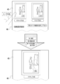
- FIG. 5 is a conceptual diagram showing an example of processing contents when a first visible light image in an image selection screen displayed on a display by a smart device according to a first embodiment is selected by a user via a touch panel.
- FIG. 5 is a conceptual diagram showing an example of processing contents when a second visible light image in an image selection screen displayed on a display by a smart device according to a first embodiment is selected by a user via a touch panel.
- FIG. 6 is a conceptual diagram showing an example of a time series distribution having a pattern different from that shown in FIG. It is a conceptual diagram which shows an example of the mode in which a filter is applied to a time series distribution. It is a conceptual diagram which shows an example of the time series distribution adjusted by applying a filter. It is a conceptual diagram which shows an example of the mode in which the distance measurement image processing program which concerns on 1st or 2nd Embodiment is installed in a smart device.
- CPU refers to the abbreviation of "Central Processing Unit”.
- RAM refers to the abbreviation of "Random Access Memory”.
- ASIC refers to the abbreviation of "Application Special Integrated Circuit”.
- PLD refers to the abbreviation of "Programmable Logical Device”.
- FPGA refers to the abbreviation of "Field-Programmable Gate Array”.
- SoC is an abbreviation for "System-on-a-chip”.
- SSD refers to the abbreviation of "Solid State Drive”.
- USB refers to the abbreviation of "Universal Serial Bus”.
- HDD refers to the abbreviation of "Hard Disk Drive”.
- EEPROM refers to the abbreviation of "Electrically Erasable and Programmable Read Only Memory”.
- EL refers to the abbreviation for "Electro-Luminescence”.
- a / D refers to the abbreviation of "Analog / Digital”.
- I / F refers to the abbreviation of "Interface”.
- UI refers to the abbreviation of "User Interface”.
- LTE is an abbreviation for "Long Term Evolution”.
- 5G refers to the abbreviation of "5th Generation”.
- LD refers to the abbreviation of "Laser Diode”.
- IR refers to the abbreviation for "Infrared”.
- APD refers to an abbreviation for "Avalanche Photodiode”. What is TOF? It refers to the abbreviation of "Time of Flight”.
- fps refers to the abbreviation of "frame per second”.
- LED refers to the abbreviation of "Light Emitting Diode”.
- ROI is an abbreviation for "Region of Interest”.
- LAN refers to the abbreviation of "Local Area Network”.
- AF refers to the abbreviation for "Auto Focus”.
- IC refers to the abbreviation of "Integrated Circuit”.
- horizontal refers to horizontal in the sense of including an error generally allowed in the technical field to which the technology of the present disclosure belongs, in addition to perfect horizontal.
- parallel refers to parallelism in the sense that it includes, in addition to perfect parallelism, errors that are generally acceptable in the art to which the techniques of the present disclosure belong.
- vertical refers to vertical in the sense of being perfectly vertical, as well as including errors that are generally tolerated in the art to which the technology of the present disclosure belongs.
- match refers to a match in the sense of including an error that is generally tolerated in the technical field to which the technology of the present disclosure belongs, in addition to the perfect match.
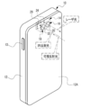
- the smart device 10 performs an imaging operation (hereinafter, also simply referred to as “imaging operation”) for imaging an imaging region defined by an angle of view ⁇ 1 and a distance measuring operation.
- imaging operation refers to a process of measuring the distance from the smart device 10 to the imaging region.
- the imaging region is an example of the “distance measurement target region” according to the technique of the present disclosure.
- the smart device 10 is an example of an "information processing device” and an "imaging device” according to the technology of the present disclosure. Examples of the smart device 10 include a smartphone or a tablet terminal which is an electronic device having an imaging function.
- the first distance measurement and the second distance measurement in which the distance measurement methods are different from each other are performed.
- the first distance measurement is performed up to an object in the imaging region based on the timing when the smart device 10 irradiates the laser beam toward the imaging region and the timing when the smart device 10 receives the reflected light from the imaging region of the laser beam.
- This is a method of measuring the distance of a light beam (hereinafter, also referred to as an “active method”).
- the laser beam is an example of "light” according to the technique of the present disclosure. Further, here, the laser beam is surface-irradiated toward the imaging region.
- the surface irradiation refers to irradiation in which the beam diameter of the laser beam expands toward the imaging region as compared with the spot irradiation.
- the beam diameter of the laser beam gradually expands along the irradiation direction of the laser light, and the degree to which the beam diameter expands per unit time is larger in surface irradiation than in spot irradiation. That is, in the spot irradiation, the laser beam is irradiated in a dot shape on a surface having an imaging region, whereas in the surface irradiation, the laser beam is irradiated in a plane shape on a surface having an imaging region.
- the laser beam irradiation may be single-shot, but may be performed intermittently (for example, every 0.1 seconds).
- the first distance measurement is performed for each laser beam irradiation. It may be performed and processing based on the distance measurement result may be performed.
- the second distance measurement is a method of measuring the distance to an object in the image pickup area (hereinafter, also referred to as "passive method") based on the image obtained by capturing the image pickup area by the smart device 10.
- the distance is an example of "image-based distance measurement” according to the technique of the present disclosure.
- a hybrid type distance measurement that combines an active type distance measurement and a passive type distance measurement is performed. Then, in the smart device 10, imaging with active focus control and imaging with passive focus control are performed.
- the active focus control refers to focus control based on the distance measurement result obtained by performing the active distance measurement.
- Passive focus control refers to focus control based on the distance measurement result obtained by performing passive distance measurement.
- the smart device 10 includes a housing 12.
- the distance measuring image pickup device 14 is housed in the housing 12.
- the distance measuring image pickup device 14 includes a light irradiator 16 and a light receiver 18.
- the light irradiator 16 includes an LD 24, and in the smart device 10, the imaging operation and the ranging operation are performed by the ranging imaging device 14.
- An instruction key 13 is arranged on the side surface of the smart device 10.
- the instruction key 13 receives various instructions.
- the "various instructions" referred to here are, for example, an instruction to display a menu screen on which various menus can be selected, an instruction to select one or more menus, an instruction to confirm the selected contents, and an instruction to delete the selected contents. Refers to instructions, etc.
- Translucent windows 20 and 22 are provided in the upper left portion of the back surface 12A of the housing 12 when the smart device 10 is placed vertically (the upper left portion of the rear view of the smart device 10 in the vertically installed state). ..
- the translucent windows 20 and 22 are optical elements (for example, lenses) having translucency, are arranged along the horizontal direction at predetermined intervals (for example, at intervals of several millimeters), and are exposed from the back surface 12A.
- the light irradiator 16 irradiates the laser beam emitted from the LD 24 toward the imaging region through the translucent window 20.
- the laser beam in the infrared wavelength region is irradiated toward the imaging region by the light irradiator 16.
- the wavelength range of the laser light is not limited to this, and may be laser light in another wavelength range.
- the receiver 18 takes in IR reflected light through the translucent window 22.
- the IR reflected light refers to the reflected light from the distance measuring target of the laser light irradiated to the distance measuring target by the light irradiator 16.
- the receiver 18 takes in visible light reflected light through the translucent window 22.
- the visible light reflected light refers to the reflected light from the imaging region of visible light (for example, visible light contained in sunlight) irradiated to the imaging region. In the following, for convenience of explanation, when it is not necessary to distinguish between IR reflected light and visible light reflected light, it is simply referred to as "reflected light".
- the receiver 18 is an example of an "imaging device” according to the technique of the present disclosure, and includes a photoelectric conversion element 26.
- the photoelectric conversion element 26 receives the reflected light taken into the light receiver 18 through the translucent window 22, and outputs an electric signal corresponding to the amount of the received reflected light.
- a touch panel display 59 is provided on the front surface 12B of the housing 12.
- the touch panel display 59 includes a display 46 and a touch panel 48.
- An example of the display 46 is an organic EL display.
- the display 46 may be another type of display such as a liquid crystal display instead of the organic EL display.
- the display 46 displays an image (for example, a live view image and a reproduced image), character information, and the like.
- the touch panel 48 is a transmissive touch panel and is superimposed on the surface of the display area of the display 46.
- the touch panel 48 receives an instruction from the user by detecting contact with an indicator such as a finger or a stylus pen.
- an out-cell type touch panel display in which the touch panel 48 is superimposed on the surface of the display area of the display 46 is mentioned, but this is only an example.
- an on-cell type or in-cell type touch panel display can be applied.
- the image pickup region is imaged by the receiver 18. That is, the receiver 18 receives visible light reflected light and generates a visible light image showing an imaging region as an image corresponding to the received visible light reflected light.
- the visible light image is an example of an "image”, a "subject image”, and a “captured image” according to the technique of the present disclosure.
- the visible light image is displayed on the display 46 as a live view image or a still image according to the instruction received by the touch panel 48.
- the imaging region is defined by the angle of view ⁇ 1.
- the angle of view ⁇ 1 is changed according to the instruction received by the touch panel 48.
- the light irradiator 16 emits laser light. Is irradiated.
- the angle at which the laser beam is irradiated (hereinafter, also referred to as “irradiation angle”) is ⁇ 2, and the irradiation angle ⁇ 2 is changed according to the instruction received by the touch panel 48.
- irradiation angle The angle at which the laser beam is irradiated (hereinafter, also referred to as “irradiation angle”) is ⁇ 2, and the irradiation angle ⁇ 2 is changed according to the instruction received by the touch panel 48.
- a mode example is given in which distance measurement is started in response to a distance measurement imaging start instruction received by the touch panel 48 while the visible light image is displayed as a live view image on the display 46.
- the technique of the present disclosure is not limited to this.
- the distance measurement may be started when the touch panel 48 receives the distance measurement image start instruction while the visible light image is not displayed on the display 46.
- the distance from the smart device 10 to the distance measurement target is based on the time required from the irradiation of the laser beam by the light irradiator 16 to the reception of the IR reflected light by the receiver 18 and the speed of light.
- the distance is measured.
- the distance to the distance measurement target is set to "L 0 "
- the speed of light is set to "c”
- the flight time of the laser light that is, the IR reflected light is emitted by the receiver 18 after the laser light is irradiated by the light irradiator 16.
- the photoelectric conversion element 26 has a plurality of photodiodes arranged in a matrix.
- An example of the plurality of photodiodes is a photodiode for "4896 x 3265" pixels.
- a color filter is arranged on each photodiode included in the photoelectric conversion element 26.
- the color filters include a G filter corresponding to the G (green) wavelength region, an R filter corresponding to the R (red) wavelength region, a B filter corresponding to the B (blue) wavelength region, and a B filter corresponding to the B (blue) wavelength region, which contributes most to obtaining a brightness signal.
- the G filter, the R filter, and the B filter also have a function as an infrared light cut filter that cuts infrared light.
- the photoelectric conversion element 26 is formed by two types of photosensitive pixels, a retardation pixel and a non-phase difference pixel N, which is a pixel different from the retardation pixel. Generally, the non-phase difference pixel N is also referred to as a normal pixel.
- the photoelectric conversion element 26 has four types of photosensitive pixels as non-phase difference pixels: R pixel, G pixel, B pixel, and IR pixel.
- the R pixel, G pixel, B pixel, IR pixel, and retardation pixel are regularly arranged in each of the row direction (horizontal direction) and the column direction (vertical direction) with a predetermined periodicity.
- the R pixel is a pixel corresponding to the photodiode in which the R filter is arranged
- the G pixel and the phase difference pixel are the pixels corresponding to the photodiode in which the G filter is arranged
- the B pixel is the pixel in which the B filter is arranged.
- It is a pixel corresponding to the photodiode
- the IR pixel is a pixel corresponding to the photodiode in which the IR filter is arranged.
- An example of an IR pixel is InGaAs APD.
- a plurality of retardation pixel lines 26A and a plurality of non-phase difference pixel lines 26B are arranged on the light receiving surface of the photoelectric conversion element 26.
- the retardation pixel line 26A is a horizontal line including a retardation pixel.
- the phase difference pixel line 26A is a horizontal line in which phase difference pixels and non-phase difference pixels N are mixed.
- the non-phase difference pixel line 26B is a horizontal line including only a plurality of non-phase difference pixels N.
- the retardation pixel lines 26A and the non-phase difference pixel lines 26B corresponding to the predetermined number of lines are alternately arranged along the column direction.
- the "default number of lines" referred to here refers to, for example, two lines.
- 2 lines are illustrated as the default number of lines, but the technique of the present disclosure is not limited to this, and the default number of lines may be several lines of 3 or more lines, or more than 10 lines. , Dozens of lines, hundreds of lines, and the like.
- the phase difference pixel line 26A is arranged by skipping two rows in the column direction from the first row to the last row. Some pixels of the phase difference pixel line 26A are phase difference pixels. Specifically, the phase difference pixel line 26A is a horizontal line in which phase difference pixels and non-phase difference pixels N are periodically arranged. The phase difference pixel is roughly classified into a first phase difference pixel L and a second phase difference pixel R. In the phase difference pixel line 26A, first phase difference pixels L and second phase difference pixels R are alternately arranged as G pixels at intervals of several pixels in the line direction.
- the first phase difference pixel L and the second phase difference pixel R are arranged so as to appear alternately in the column direction.
- the first phase difference pixel L, the second phase difference pixel R, the first phase difference pixel L, and the second phase difference pixel R are arranged along the column direction from the first row. They are arranged in order. That is, the first phase difference pixel L and the second phase difference pixel R are alternately arranged along the column direction from the first row.
- the second phase difference pixel R, the first phase difference pixel L, the second phase difference pixel R, and the first phase difference pixel along the column direction from the first row are arranged in the order of L. That is, the second phase difference pixel R and the first phase difference pixel L are alternately arranged along the column direction from the first row.
- the photoelectric conversion element 26 is divided into three regions. That is, the photoelectric conversion element 26 has a visible light image division region 26N1, a first distance measurement system division region 26N2, and a second distance measurement system division region 26N3.
- the visible light image division region 26N1 is a group of visible light pixels composed of a plurality of visible light pixels, and is used for generating a visible light image.
- the first ranging system division region 26N2 is an IR pixel group consisting of a plurality of IR pixels arranged two-dimensionally, and is used for the first ranging.
- the IR pixel is an example of a "specific pixel" according to the technique of the present disclosure.
- the second ranging system division region 26N3 is a phase difference pixel group consisting of a plurality of retardation pixels, and is used for the second ranging.
- the visible light image division region 26N1 and the second ranging system division region 26N3 receive visible reflected light and output an electric signal according to the amount of received light.
- the first ranging system division region 26N2 receives IR reflected light and outputs an electric signal according to the amount of received light.
- the first retardation pixel L includes a microlens 19, a light-shielding member 17A, and a photodiode PD.
- a light-shielding member 17A is arranged between the microlens 19 and the light-receiving surface of the photodiode PD.
- the left half of the light receiving surface of the photodiode PD in the row direction (the left side when facing the subject from the light receiving surface (in other words, the right side when facing the light receiving surface from the subject)) is shielded by the light shielding member 17A.
- the second phase difference pixel R includes a microlens 19, a light-shielding member 17B, and a photodiode PD.
- a light-shielding member 17B is arranged between the microlens 19 and the light-receiving surface of the photodiode PD.
- the right half of the light receiving surface of the photodiode PD in the row direction (the right side when facing the subject from the light receiving surface (in other words, the left side when facing the light receiving surface from the subject)) is shielded by the light shielding member 17B.
- the light shielding member 17B In the following, for convenience of explanation, when it is not necessary to distinguish between the light-shielding members 17A and 17B, they are referred to as "light-shielding members" without reference numerals.
- the luminous flux passing through the exit pupil of the image pickup lens 41 is roughly classified into left region passing light 300L and right region passing light 300R.
- the left region passing light 300L refers to the left half of the luminous flux passing through the exit pupil of the imaging lens 41 when facing the subject side from the phase difference pixel side
- the right region passing light 300R refers to the imaging lens 41.
- the luminous flux passing through the exit pupil of the above it refers to the luminous flux of the right half when facing the subject side from the phase difference pixel side.
- the luminous flux passing through the exit pupil of the imaging lens 41 is divided into left and right by the microlens 19, the light-shielding member 17A, and the light-shielding member 17B that function as the pupil dividing portion, and the first retardation pixel L is the light passing through the left region as the subject light.
- 300L is received
- the second phase difference pixel R receives the right region passing light 300R as the subject light.
- the photoelectric conversion element 26 generates a first phase difference image corresponding to the subject image corresponding to the left region passing light 300L and a second phase difference image corresponding to the subject image corresponding to the right region passing light 300R.
- the distance to the imaging region is measured based on the amount of deviation ⁇ between the first phase difference image for one line and the second phase difference image for one line. Will be done.
- the non-phase difference pixel N is different from the phase difference pixel in that it does not have a light-shielding member.
- the photodiode PD of the non-phase difference pixel N receives the left region passing light 300L and the right region passing light 300R as the subject light.
- the IR reflected light is received by each of the plurality of IR pixels included in the second ranging system division region 26N3 (see FIG. 5), so that the distance is measured for each IR pixel. Then, in the smart device 10, according to the instruction received by the touch panel 48, as shown in FIG. 8 as an example, the distance measurement result for each IR pixel is displayed on the display 46 as a distance image.
- the distance image refers to an image in which the distance to the distance measurement target measured for each IR pixel is expressed by color and / or shading.
- the distance measurement result is displayed on the display 46 as a distance image or a distance superimposition image (not shown) according to the instruction received by the touch panel 48.
- the distance superimposed image displayed on the display 46 is, for example, an image in which a numerical value indicating a distance measurement result is superimposed on a visible light image (for example, a live view image).
- a visible light image for example, a live view image.
- the distances from the smart device 10 to each of a plurality of typical locations (for example, three locations) in the imaging region are displayed on the display 46 in a visible light image.
- a plurality of specific subjects in the imaging region for example, a subject included in the center region of the screen and / or a human being
- a contrast difference is equal to or greater than a default value. The part of is mentioned.
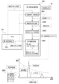
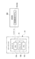
- the smart device 10 in addition to the light irradiator 16 and the receiver 18, the smart device 10 includes a controller 15, an input / output interface 40, an image memory 42, a UI device 44, an external I / F 52, and communication. It has an I / F 54.
- the controller 15 includes a CPU 15A, a storage 15B, and a memory 15C.
- the CPU 15A, the storage 15B, and the memory 15C are connected via the bus 50, and the bus 50 is connected to the input / output interface 40.
- one bus is shown as the bus 50 for convenience of illustration, but a plurality of buses may be used.
- the bus 50 may be a serial bus or a parallel bus including a data bus, an address bus, a control bus, and the like.
- the storage 15B stores various parameters and various programs.
- the storage 15B is a non-volatile storage device.
- a flash memory is adopted as an example of the storage 15B.
- the flash memory is merely an example, and examples of the storage 15B include various non-volatile memories such as a magnetoresistive memory and / or a ferroelectric memory instead of the flash memory or in combination with the flash memory. ..
- the non-volatile storage device may be EEPROM, HDD, and / or SSD or the like.
- the memory 15C temporarily stores various information and is used as a work memory.
- An example of the memory 15C is RAM, but the memory is not limited to this, and other types of storage devices may be used.
- the CPU 15A reads a necessary program from the storage 15B and executes the read program on the memory 15C.
- the CPU 15A controls the entire smart device 10 according to a program executed on the memory 15C.
- the storage 15B and the memory 15C are examples of the "memory" according to the technique of the present disclosure.
- a plurality of devices are connected to the input / output interface 40, and the input / output interface 40 controls the exchange of various information between the plurality of devices.
- a controller 15 As a plurality of devices connected to the input / output interface 40, a controller 15, a light irradiator 16, a receiver 18, an image memory 42, a UI device 44, an external I / F 52, and a communication I / F54 is shown.
- the external I / F 52 controls the exchange of various information with and from a device existing outside the smart device 10 (hereinafter, also referred to as an "external device").
- An example of the external I / F 52 is a USB interface.
- External devices such as smart devices, personal computers, servers, USB memory sticks, memory cards, and / or printers can be directly or indirectly connected to the USB interface.
- the communication I / F54 has communication functions such as LTE, 5G, wireless LAN, and / or Bluetooth (registered trademark), and controls the exchange of various information between the external device and the CPU 15A.
- the communication I / F 54 is communicably connected to the network 56 (for example, the Internet) via a base station (not shown), and various information is exchanged between the external device on the network 56 and the CPU 15A. Controls.
- the UI device 44 includes a display 46, and the CPU 15A causes the display 46 to display various information. Further, the UI device 44 includes a reception device 47.
- the reception device 47 includes a touch panel 48 and a hard key unit 53.
- the hard key unit 53 is at least one hard key including an instruction key 13 (see FIG. 2).
- the CPU 15A operates according to various instructions received by the touch panel 48.
- the hard key unit 53 is included in the UI device 44 here, the technique of the present disclosure is not limited to this, and for example, the hard key unit 53 may be connected to the external I / F 52. Good.
- the light irradiator 16 includes a transparent window 20, a beam expander 21, a collimating lens 23, an LD24, and an LD driver 25, and is transparent from the imaging region side (object side) to the LD24 along the optical axis L1.
- the light window 20, the beam expander 21, and the collimating lens 23 are arranged in this order.
- the LD driver 25 is connected to the LD 24 and the input / output interface 40, and drives the LD 24 according to the instruction of the CPU 15A to emit laser light from the LD 24.
- the laser light emitted from the LD 24 is converted into parallel light by the collimated lens 23, then the beam diameter is expanded by the beam expander 21, and the laser light is emitted from the translucent window 20 toward the distance measurement target.
- the light receiver 18 includes a translucent window 22, an objective lens 30A, a focus lens 30B, an aperture 30C, a photoelectric conversion element 26, a photoelectric conversion element driver 32, and a signal processing circuit 34.
- the CPU 15A and the signal processing circuit 34 are examples of the "processor" according to the technique of the present disclosure.
- the translucent window 22, the objective lens 30A, the focus lens 30B, and the aperture 30C are arranged in this order from the imaging region side (object side) to the photoelectric conversion element 26 along the optical axis L2.
- the photoelectric conversion element driver 32 is connected to the photoelectric conversion element 26 and the input / output interface 40, and drives the photoelectric conversion element 26 according to the instructions of the CPU 15A.
- the photoelectric conversion element driver 32 supplies the photoelectric conversion element 26 with an imaging timing signal that defines the timing of imaging performed by the photoelectric conversion element 26 under the control of the CPU 15A.
- the photoelectric conversion element 26 resets, exposes, and outputs an electric signal according to the imaging timing signal supplied from the photoelectric conversion element driver 32. Examples of the imaging timing signal include a vertical synchronization signal and a horizontal synchronization signal.
- the receiver 18 includes a focusing control mechanism 31.
- the focusing control mechanism 31 includes a focus lens 30B, a moving mechanism 60, a motor 62, and a motor driver 64.
- the focus lens 30B is slidably supported along the optical axis L2 by the moving mechanism 60.
- the motor 62 is connected to the moving mechanism 60 and the motor driver 64.
- the motor driver 64 is connected to the input / output interface 40 and drives the motor 62 according to an instruction from the CPU 15A.
- the moving mechanism 60 is connected to a drive shaft (not shown) of the motor 62, and receives power from the motor 62 to selectively move the focus lens 30B between the object side and the image side along the optical axis L2. Let me.
- the CPU 15A adjusts the focusing position by controlling the driving of the motor 62 via the motor driver 64.
- the "focus position" is the light of the focus lens 30B in a state of being in focus (for example, a state in which the contrast of the visible light image is maximized or a state in which a predetermined depth of field is achieved). Refers to the position on the axis L2.
- the control for aligning the focus lens 30B with the in-focus position is referred to as "focus control".
- the diaphragm 30C is a fixed diaphragm whose opening does not change. In the case of a fixed aperture, the exposure adjustment is performed by the electronic shutter of the photoelectric conversion element 26.
- the diaphragm 30C may be a variable diaphragm instead of a fixed diaphragm.
- the objective lens 30A, the focus lens 30B, and the diaphragm 30C included in the light receiver 18 are merely examples, and the technique of the present disclosure is established even if the configuration of the lens and / or the position of the diaphragm 30C is changed.
- Reflected light is incident on the receiver 18 from the translucent window 22.
- the reflected light incident on the translucent window 22 is imaged on the photoelectric conversion element 26 via the objective lens 30A, the focus lens 30B, and the diaphragm 30C.
- the photoelectric conversion element 26 is connected to the signal processing circuit 34, and outputs pixel data indicating a pixel value to the signal processing circuit 34 for each pixel of the visible light pixel and the IR pixel.
- the signal processing circuit 34 digitizes the pixel data by performing A / D conversion on the pixel data input from the photoelectric conversion element 26, and performs various signal processing on the digitized pixel data.
- the signal processing circuit 34 includes a visible light pixel data processing circuit 34A, a first ranging system processing circuit 34B, and a second ranging system processing circuit 34C.
- the visible light pixel data processing circuit 34A is known signal processing such as white balance adjustment, sharpness adjustment, gamma correction, color space conversion processing, and color difference correction for visible light pixel data which is pixel data for visible light pixels. Is applied to generate a visible light image. Then, the visible light pixel data processing circuit 34A stores the visible light image in the image memory 42. The visible light image in the image memory 42 is updated by overwriting and saving one frame of the visible light image in the image memory 42.
- the distance measuring image pickup device 14 includes a TOF camera 27.
- the TOF camera 27 includes a light irradiator 16, a first ranging system division region 26N2 (see FIG. 5) of the photoelectric conversion element 26, and a first ranging system processing circuit 34B.
- the first ranging system processing circuit 34B acquires an irradiation timing signal indicating an irradiation timing (hereinafter, also simply referred to as “irradiation timing”) in which the light irradiator 16 irradiates the laser beam toward the imaging region from the CPU 15A.
- the first distance measuring system processing circuit 34B is based on the irradiation timing indicated by the irradiation timing signal and the timing at which the IR reflected light is received by each IR pixel (hereinafter, also referred to as “light receiving timing”). The distance from the smart device 10 to an object in the imaging region is measured.
- the light receiving timing the timing at which the IR pixel data having an output value exceeding the reference threshold value (see FIG. 14) described later is received by the first ranging system processing circuit 34B is adopted.
- the noise component a noise component generated independently of the IR reflected light (for example, IR light contained in the ambient light) can be mentioned.
- the first ranging system processing circuit 34B measures the distance from the smart device 10 to the object in the imaging region for each IR pixel based on the irradiation timing and the light receiving timing. Further, the first distance measuring system processing circuit 34B generates a distance image based on the measurement result for each IR pixel, and stores the generated distance image in the image memory 42. The distance image in the image memory 42 is updated by overwriting and saving the distance image for one frame in the image memory 42.
- the second ranging system processing circuit 34C has a plurality of phase difference pixels in the second ranging system division region 26N3 (see FIG. 5) included in the region (so-called ROI) designated by the user or the like among the photoelectric conversion elements 26. From each of the above, the phase difference pixel data indicating the pixel value of the phase difference pixel is acquired. The second ranging system processing circuit 34C generates a first phase difference image and a second phase difference image (see FIG. 5) from the phase difference pixel data, and the generated first phase difference image and the second phase difference image are combined with each other. The deviation amount ⁇ (see FIG. 5) is calculated.
- the second ranging system processing circuit 34C calculates the distance from the smart device 10 to the imaging region based on the calculated deviation amount ⁇ . Specifically, the second ranging system processing circuit 34C uses an arithmetic expression with the deviation amount ⁇ as the independent variable and the distance as the dependent variable to determine the distance from the smart device 10 to the object in the imaging region. calculate.
- the technique of the present disclosure is not limited to this, and the second ranging system processing circuit 34C is smart by using a table in which the deviation amount ⁇ and the distance are associated with each other. The distance from the device 10 to the imaging region may be derived.
- the CPU 15A acquires the distance measured by the first distance measuring system processing circuit 34B (hereinafter referred to as “first distance”) from the first distance measuring system processing circuit 34B, and measures it by the second distance measuring system processing circuit 34C.
- the obtained distance (hereinafter, referred to as “second distance”) is acquired from the second distance measuring system processing circuit 34C.
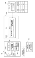
- the distance measuring image processing program 70 is stored in the storage 15B.
- the CPU 15A reads the distance measurement image processing program 70 from the storage 15B, and executes the read distance measurement image processing program 70 to execute the first distance measurement control unit 15A1, the first distance acquisition unit 15A2, and the time series distribution acquisition unit 15A3. It operates as a determination unit 15A4 and an execution unit 15A5.
- the target subject a person in the example shown in FIG. 11
- the imaging region including the entire mirror 100 hereinafter, also referred to as “mirror-included imaging region”.
- the first distance measurement control unit 15A1 sends the first distance measurement start signal to the light irradiator 38B and the receiver 18. Output to.
- the light irradiator 38B irradiates the laser beam when the first distance measurement start signal is input from the first distance measurement control unit 15A1.
- the first distance measurement system processing circuit 34B causes the irradiation timing and the light reception timing indicated by the irradiation timing signal acquired from the CPU 15A.
- the first distance is calculated based on.
- the irradiation timing the timing when a predetermined time elapses from the timing when the first ranging start signal is input from the first ranging control unit 15A1 to the receiver 18 is adopted.
- the predetermined time is, for example, the time required from the time when the first distance measurement start signal is output until the laser beam is irradiated from the light irradiator 38B, which is derived in advance by a test using an actual machine and / or a computer simulation or the like. Time has been adopted.
- the IR reflected light from the target subject 98 (hereinafter, also referred to as “target subject IR reflected light”).
- the IR reflected light from the full-length mirror 100 (hereinafter, also referred to as “mirror surface IR reflected light”) is received by the first ranging system division region 26N2 of the receiver 18.
- the target subject IR reflected light is received by a part of IR pixels (hereinafter, also referred to as “specific IR pixels”) in the first ranging system division region 26N2.
- the first distance measuring system processing circuit 34B uses the timing at which the target subject IR reflected light is received by the specific IR pixel as the above-mentioned light receiving timing. Therefore, the distance from the smart device 10 to the target subject 98 can be calculated as the first distance.
- the total reflected light of the laser beam with respect to the mirror surface 100A may also be present. It is received by a specific IR pixel as mirror surface IR reflected light.
- the intensity of the laser light emitted from the light irradiator 16 is "100"
- the intensity of the IR reflected light of the target subject is about 10 to 20
- the intensity of the total reflected light of the laser light with respect to the mirror surface 100A is It is about 40 to 50.
- the specific IR pixel differs depending on the specific IR pixel within a predetermined light receiving period (hereinafter, also simply referred to as “light receiving period”) as a period for receiving the IR reflected light corresponding to the irradiation of the laser light by the light irradiator 16.
- a predetermined light receiving period hereinafter, also simply referred to as “light receiving period” as a period for receiving the IR reflected light corresponding to the irradiation of the laser light by the light irradiator 16.
- the first distance measurement system processing circuit 34B has an IR pixel data acquisition unit 34B1, a time series distribution generation unit 34B2, and a light receiving timing determination. A unit 34B3 and a first distance measuring unit 34B4 are provided.
- the IR pixel data acquisition unit 34B1, the time series distribution generation unit 34B2, the light receiving timing determination unit 34B3, and the first distance measurement unit 34B4 are provided for each IR pixel.
- the first ranging will be described focusing on the specific IR pixels (see FIGS. 12 to 14).
- the first distance measurement control unit 15A1 outputs an irradiation timing signal to the IR pixel data acquisition unit 34B1, the time series distribution generation unit 34B2, and the first distance measurement unit 34B4. Further, the first distance measurement control unit 15A1 outputs an acquisition timing signal that defines the timing for causing the IR pixel data acquisition unit 34B1 to acquire IR pixel data from the photoelectric conversion element 26 to the IR pixel data acquisition unit 34B1.
- the acquisition timing signal is output to the IR pixel data acquisition unit 34B1 at a fixed time interval (for example, a time interval of about one tenth or one hundredth of the light receiving period).
- the IR pixel data acquisition unit 34B1 acquires IR pixel data from the photoelectric conversion element 26 when the irradiation timing signal is input from the first ranging control unit 15A1 and the acquisition timing signal is input.
- the time-series distribution generation unit 34B2 is an IR pixel data acquisition unit within the light receiving period from the time when the irradiation timing is input from the first distance measurement control unit 15A1.
- the intensity of the IR reflected light indicated by the plurality of IR pixel data acquired by 34B1 generates a time series distribution defined in time series. In the time series distribution, the horizontal axis shows time and the vertical axis shows intensity.
- the plurality of IR pixel data is an example of "a plurality of signals" according to the technique of the present disclosure. The details of the time series distribution will be described later.
- the intensity of IR reflected light is specified by the absolute value amount of the IR reflected light, but the technique of the present disclosure is not limited to this, and the intensity of the IR reflected light is noise due to ambient light. It may be offset by the intensity of the component (for example, IR light contained in the ambient light). In this case, for example, the entire time series distribution may be offset by the intensity of the noise component due to the ambient light.
- the intensity of the IR reflected light indicated by the IR pixel data obtained from the specific IR pixels is expressed in time series.
- the light receiving timing determination unit 34B3 determines the light receiving timing used for the first distance measurement (hereinafter, also referred to as “first distance measuring light receiving timing”) based on the time series distribution generated by the time series distribution generation unit 34B2. .. In the light receiving timing determination unit 34B3, a reference threshold value is applied to the time series distribution.
- the reference threshold is a value derived in advance by an actual machine and / or computer simulation as a lower limit of the intensity of IR reflected light from a standard subject (for example, a specific subject other than a mirror surface and a glossy surface). is there.
- the reference threshold value is a value that decreases as the light receiving timing is delayed. In the example shown in FIG. 13, the reference threshold gradually decreases (for example, exponentially) with the passage of time. If there is only one IR reflected light having an intensity exceeding the reference threshold in the time series distribution, the light receiving timing determining unit 34B3 determines the receiving timing of the IR reflected light having an intensity exceeding the reference threshold for the first distance measurement. To determine as.
- the light receiving timing determination unit 34B3 receives a plurality of IR pixel data acquired by the IR pixel data acquisition unit 34B1 within the light receiving period when a plurality of IR reflected lights having an intensity exceeding the reference threshold are present in the time series distribution. Among them, the light receiving timing corresponding to the selected IR pixel data based on the relationship between the plurality of IR pixel data and the intensity of the plurality of IR reflected light indicated by the plurality of IR pixel data is determined as the first ranging light receiving timing. To do. The relationship between the plurality of IR pixel data and the intensity of the plurality of IR reflected lights are specified by the light receiving timing determination unit 34B3 from the time series distribution generated by the time series distribution generation unit 34B2. The details of the method for determining the light receiving timing for the first ranging when there are a plurality of IR reflected lights having an intensity exceeding the reference threshold in the time series distribution will be described later.
- the first distance measuring unit 34B4 is based on the irradiation timing indicated by the irradiation timing signal input from the first distance measuring control unit 15A1 and the first distance measuring light receiving timing determined by the light receiving timing determining unit 34B3. 1 Measure the distance.
- the first distance is half the product of the speed of light and the flight time of the laser beam.
- the flight time of the laser beam is the time from the irradiation timing to the light receiving timing for the first distance measurement.
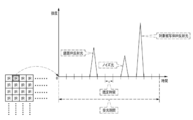
- the time-series distribution includes the intensity of each of the mirror surface IR reflected light, the target subject IR reflected light, and the noise light (for example, noise components such as IR light contained in the ambient light).
- the specific IR pixel On the time axis of the light receiving period, the specific IR pixel first receives the mirror surface IR reflected light, the second receives the noise light, and the third receives the target subject IR reflected light. Then, the intensity of the mirror surface IR reflected light and the target subject IR reflected light exceed the reference threshold value.
- the light receiving timing determination unit 34B3 determines the timing at which the IR reflected light having the second highest intensity in the time series distribution is received by the specific IR pixel as the first distance measuring light receiving timing. That is, in the example shown in FIG. 14, since the IR reflected light having the second highest intensity in the time series distribution is the target subject IR reflected light, the light receiving timing of the target subject IR reflected light is determined as the first ranging light receiving timing. Will be done. As a result, it is avoided that the first distance measurement is performed based on the light receiving timing of the mirror surface IR reflected light and that the first distance measurement is performed based on the noise light.
- the first distance acquisition unit 15A2 acquires the first distance measured by the first distance measurement unit 34B4. Further, the time series distribution acquisition unit 15A3 acquires the time series distribution from the time series distribution generation unit 34B2.
- the time-series distribution acquired by the time-series distribution acquisition unit 15A3 is the time-series distribution used in determining the light receiving timing for the first distance measurement used for the measurement of the first distance acquired by the first distance acquisition unit 15A2. Is.
- the determination unit 15A4 determines whether or not the time series distribution acquired by the time series distribution acquisition unit 15A3 is a specific time series distribution. The details of this determination method will be described later.
- the execution unit 15A5 is based on the first distance acquired by the first distance acquisition unit 15A2 when the determination unit 15A4 determines that the time series distribution acquired by the time series distribution acquisition unit 15A3 is not a specific time series distribution. Imaging with focus control (hereinafter, also referred to as "first imaging process”) is executed. Further, the execution unit 15A5 executes a specific process when it is determined that the time series distribution acquired by the time series distribution acquisition unit 15A3 is a specific time series distribution. The details of the first imaging process and the specific process will be described later.
- the determination unit 15A4 applies the first threshold value and the second threshold value to the time series distribution acquired by the time series distribution acquisition unit 15A3.
- the first threshold value is the lower limit of the intensity of the IR reflected light when the laser light radiated to the glossy surface (for example, a mirror surface predetermined as an average mirror surface) is totally reflected by the glossy surface. And / or a value derived in advance by computer simulation or the like.
- the first threshold like the reference threshold described above, gradually decreases (for example, exponentially) with the passage of time. Further, the first threshold value is a value that decreases as the light receiving timing is delayed, similar to the reference threshold value described above.
- the second threshold value is the same value as the above-mentioned reference threshold value (see FIGS. 13 and 14). Further, at the same time on the time axis of the light receiving period, the second threshold value is smaller than the first threshold value.
- the determination unit 15A4 determines whether or not the time series distribution acquired by the time series distribution acquisition unit 15A3 includes an intensity equal to or higher than the first threshold value and an intensity equal to or lower than the first threshold value and equal to or higher than the second threshold value. By determining whether or not the time series distribution acquired by the time series distribution acquisition unit 15A3 is a specific time series distribution. In the example shown in FIG. 16, since the intensity of the mirror surface IR reflected light is equal to or higher than the first threshold value and the intensity of the target subject IR reflected light is less than the first threshold value and equal to or higher than the second threshold value, the time series distribution acquisition unit 15A3 acquires the intensity. The determination unit 15A4 determines that the time-series distribution is a specific time-series distribution.
- the intensity of the mirror surface IR reflected light corresponds to the intensity of the IR pixel data (signal) generated by receiving the mirror surface IR reflected light.
- the intensity of the IR pixel data (signal) generated by receiving the mirror surface IR reflected light is an example of the "first intensity” according to the technique of the present disclosure.
- the intensity of the target subject IR reflected light corresponds to the intensity of the IR pixel data (signal) generated by receiving the target subject IR reflected light.
- the intensity of the IR pixel data (signal) generated by receiving the elephant subject IR reflected light is an example of the "second intensity" according to the technique of the present disclosure.
- the focusing position derivation table 72 is stored in the storage 15B.
- the distance from the smart device 10 to the imaging region and the focusing position are associated with each other.
- the execution unit 15A5 performs focus control (active focus control) on the receiver 18 by using the first distance. That is, the execution unit 15A5 derives the focusing position corresponding to the first distance from the focusing position derivation table 72, and the motor 62 of the receiver 18 controls the focus lens 30B to move to the derived focusing position. Will be done.
- the visible light image division region 26N1 of the receiver 18 is controlled by the execution unit 15A5, so that the image pickup region is imaged by the visible light image division region 26N1 and the visible light image data obtained by being imaged. Is output from the visible light image division region 26N1 to the visible light pixel data processing circuit 34A.
- the visible light pixel data processing circuit 34A generates a first visible light image indicating an imaging region based on the visible light image data input from the visible light image division region 26N1, and images the generated first visible light image. Output to memory 42.
- the first visible light image is stored in the image memory 42.
- the specific process is a process including, for example, a second distance measurement start process, a second distance acquisition process, a second imaging process, and an image selection screen display process.
- the specific processing is not limited to these, and the first distance is based on the light receiving timing in which the IR pixel receives the reflected light (target subject IR reflected light) having an intensity lower than the first threshold value and higher than the second threshold value. It may be a process of measuring.
- the execution unit 15A5 outputs the second distance measurement start signal to the receiver 18.
- the technique of the present disclosure is not limited to this, and is an imaging region other than the mirror-included imaging region. You may.
- the second distance measurement system division region 26N3 images the mirror-included imaging region and obtains the phase difference pixel data corresponding to the mirror inclusion imaging region. It is output to the second ranging system processing circuit 34C.
- the second ranging system processing circuit 34C generates a first retardation image and a second retardation image (see FIG. 6) based on the phase difference pixel data input from the second ranging system division region 26N3, and generates them.
- the deviation amount ⁇ (see FIG. 6) is calculated based on the first phase difference image and the second phase difference image.
- the second distance measuring system processing circuit 34C calculates the second distance from the calculated deviation amount ⁇ .
- the execution unit 15A5 acquires the second distance from the second distance measurement system processing circuit 34C.
- the second imaging process refers to imaging with focus control based on the second distance.
- the execution unit 15A5 derives the focusing position corresponding to the second distance from the focusing position derivation table 72, and moves the focus lens 30B to the derived focusing position.
- the motor 62 of the receiver 18 is controlled so as to cause the light receiver 18.
- the imaging region is imaged by the visible light image division region 26N1, and the visible light pixel data obtained by the imaging is the visible light pixel data processing from the visible light image division region 26N1. It is output to the circuit 34A.
- the visible light pixel data processing circuit 34A generates a second visible light image indicating an imaging region based on the visible light pixel data input from the visible light image division region 26N1, and images the generated second visible light image. Output to memory 42.
- the second visible light image is stored in the image memory 42.
- the execution unit 15A5 acquires the first visible light image and the second visible light image from the image memory 42. Then, the execution unit 15A5 includes the first visible light image, the second visible light image, the first distance acquired by the first distance acquisition unit 15A2 (see FIG. 15), and the execution unit 15A5 in the second distance acquisition process.
- An image selection screen is generated based on the second distance (see FIG. 19) acquired by the above and various messages, and the generated image selection screen is displayed on the display 46.
- the first visible light image and the second visible light image are displayed side by side on the image selection screen. Further, the message "active method" is displayed below the first visible light image.
- the message "active method” is a message indicating that the first visible light image is an image obtained by imaging with focus control based on the distance measurement result by the active method distance measurement (first distance measurement). Further, the message “passive method” is displayed below the second visible light image. The message “passive method” is a message indicating that the second visible light image is an image obtained by imaging with focus control based on the distance measurement result by the passive method distance measurement (second distance measurement).
- the first imaging process, the second imaging process, and the image selection screen display process are exemplified as the processes included in the specific process, but the technique of the present disclosure is limited to this. Instead, it may be one or two of the first imaging process, the second imaging process, and the image selection screen display process. Further, in the first embodiment, the display examples of "active method” and “passive method” are shown, but the display does not necessarily have to be “active method” and “passive method", and the user can use the distance measuring method. Any display may be used as long as the difference between the two can be understood.
- a display of "laser” and a display of "phase difference” may be displayed, or an icon or the like indicating a distance measurement method may be displayed.
- the focus position may be displayed instead of the distance measurement method display. For example, “focus position: front” and “focus position: back” may be displayed, or “focus position: object” and “focus position: image reflected on the object” may be displayed.
- two or more characters and icons indicating the distance measuring method and the focus position may be displayed in combination.
- the first visible light image is displayed in association with the numerical value "1.8 m” which is the result of the distance measurement by the first distance measurement
- the second visible light image is displayed by the second distance measurement.
- the numerical value "1.9 m" which is the result of distance measurement, is displayed in association with each other.
- the image selection screen as a message prompting the user to select one of the first visible light image and the second visible light image, "Please select one of the images" is displayed. A message is displayed.
- a strongly reflected light notification message is displayed on the image selection screen.
- the strongly reflected light notification message is when the time series distribution acquired by the time series distribution acquisition unit 15A3 (see FIG. 15) is determined by the determination unit 15A4 (see FIG. 15) to be a specific time series distribution (for example,).
- the time series distribution acquired by the time series distribution acquisition unit 15A3 includes the intensity of the first threshold value or more. Refers to a message that notifies the user that this is the case. In the example shown in FIG. 20, as the strongly reflected light notification message, the message "The strongly reflected light was detected, but the distance was measured using the reflected light other than the strongly reflected light.” Is shown.
- the strongly reflected light means IR reflected light having an intensity equal to or higher than the first threshold value.
- IR reflected light As an example of strongly reflected light, mirror surface IR reflected light (see FIGS. 12, 14 and 16) can be mentioned.
- a strongly reflected light notification message is displayed on the image selection screen.
- the image selection screen display process is an example of "a process of notifying that the intensity of a plurality of signals includes the first intensity" according to the technique of the present disclosure.
- the various messages displayed on the image selection screen are not limited to the above-mentioned messages, and for example, the distance measurement result by the first distance measurement (first distance) and the distance measurement result by the second distance measurement (second distance) are different. If so, a message notifying the user to that effect (for example, "distance measurement result is different") may be displayed.
- the description is given by giving an example of a form in which various messages are visually displayed, but the present invention is not limited to this, and various messages may be output by voice in parallel with the visible display.
- the image selection screen is displayed on the display 46, the user selects a first visible light image or a second visible light image via the touch panel 48.
- a mode in which the first visible light image is selected by the user's finger via the touch panel 48 is shown.
- the first distance measuring control unit 15A1 By controlling the distance measuring image pickup device 14, the first distance measuring system processing circuit 34B is made to perform the first distance measuring.
- the execution unit 15A5 executes the first imaging process and the first visible light image display process.
- the execution unit 15A5 executes the first imaging process using the new first distance obtained by performing the first distance measurement.
- the first visible light image display process is a process for displaying the latest first visible light image obtained by executing the first imaging process on the display 46.
- the first distance measurement and the first imaging process are performed again, and the latest first visible image obtained by performing the first imaging process is performed.
- An example of a form in which an optical image is displayed on the display 46 is given, but this is only an example.
- the selected first visible light image may be stored in a storage medium such as a storage 15B and / or a memory card on condition that the first visible light image is selected.
- the reception device 47 performs imaging with focus control based on the distance measured by the selected distance measuring method and storage of the selected image (for example, a first visible light image or a second visible light image). It may be selected according to the received instruction (instruction given by the user).
- the first visible light image display process is executed by the execution unit 15A5, the second visible light image, the numerical value "1.9 m”, the message “passive method”, and “any one of them” are displayed in the image selection screen.
- the message “Please select an image” and the strongly reflected light notification message are hidden from the screen.
- the first distance (a numerical value of "1.8 m” in the example shown in FIG. 21), which is the latest distance measurement result obtained by performing the latest first distance measurement, is displayed on the display 46, and the first distance is displayed. 1
- the first visible light image obtained by executing the imaging process is displayed on the display 46, and the message “active method” is also displayed below the first visible light image.
- the display area of the first distance, the first visible light image, and the message "active method” is from the display area of the first distance, the first visible light image, and the message “active method” in the image selection screen.
- the time series distribution acquired by the time series distribution acquisition unit 15A3 is a specific time series distribution by performing the first distance measurement (see FIG. 15).
- the strongly reflected light notification message may be displayed on the display 46.
- the execution unit 15A5 when the second visible light image is selected by the user's finger via the touch panel 48 while the image selection screen is displayed on the display 46, the execution unit 15A5 performs the second measurement.
- the second distance measurement system processing circuit 34C is made to perform the second distance measurement.
- the execution unit 15A5 executes the second imaging process and the second visible light image display process.
- the execution unit 15A5 executes the second imaging process using the new second distance obtained by performing the second distance measurement.
- the second visible light image display process is a process of displaying the latest second visible light image obtained by executing the second imaging process on the display 46.
- the second visible light image display process When the second visible light image display process is executed by the execution unit 15A5, the first visible light image, the numerical value “1.8 m”, the message “active method”, and the “distance measurement result” are displayed in the image selection screen. The message “Different” and the message “Please select one of the images” are hidden from the screen. Then, the second distance (a numerical value of "1.9 m” in the example shown in FIG. 22), which is the latest distance measurement result obtained by performing the latest second distance measurement, is displayed on the display 46, and the second distance is displayed. The second visible light image obtained by executing the two imaging processes is displayed on the display 46, and the message “passive method” is also displayed below the second visible light image. Further, the display area of the second distance, the second visible light image, and the message “passive method” is from the display area of the second distance, the second visible light image, and the message “passive method” in the image selection screen. Has also been expanded.
- FIG. 23 shows the first ranging system processing executed by the first ranging system processing circuit 34B when the irradiation timing signal is input from the first ranging control unit 15A1 to the first ranging system processing circuit 34B. It is a flowchart which shows an example of the flow of.
- step ST100 the IR pixel data acquisition unit 34B1 determines whether or not the acquisition timing signal is input from the first ranging control unit 15A1. If the acquisition timing signal is not input from the first ranging control unit 15A1 in step ST100, the determination is denied and the determination in step ST100 is performed again. When the acquisition timing signal is input from the first ranging control unit 15A1 in step ST100, the determination is affirmed, and the first ranging system processing shifts to step ST102.
- step ST102 the IR pixel data acquisition unit 34B1 acquires IR pixel data from the photoelectric conversion element 26, and then the first ranging system processing shifts to step ST104.
- a plurality of light receiving timings (for example, "time interval" shown in FIG. 14) generated by the first ranging system division region 26N2 within the light receiving period corresponding to the irradiation of the laser light by the light irradiator 16.
- the gloss is not intended as a distance measurement target. There is a risk that the distance based on the timing at which the IR pixel receives the IR reflected light from the sex object (mirror surface 100A in the example shown in FIG. 12) and the irradiation timing will be measured.
- step ST104 the time series distribution generation unit 34B2 determines whether or not the light receiving period has elapsed since the first ranging system processing was started. In step ST104, if the light receiving period has not elapsed since the first ranging system processing was started, the determination is denied and the first ranging system processing shifts to step ST100. In step ST104, when the light receiving period has elapsed since the first ranging system processing was started, the determination is affirmed, and the first ranging system processing shifts to step ST106.
- step ST106 the time series distribution generation unit 34B2 generates a time series distribution (see FIG. 14) based on the IR pixel data acquired by the IR pixel data acquisition unit by executing the processes of steps ST100 to ST104. To do. After step ST106 is executed, the first ranging system process shifts to step ST108.
- step ST108 the light receiving timing determination unit 34B3 determines the light receiving timing for the first distance measurement based on the time series distribution generated in step ST106. In this step ST108, if there is only one IR reflected light having an intensity exceeding the reference threshold in the time series distribution, the light receiving timing determining unit 34B3 first receives the receiving timing of the IR reflected light having an intensity exceeding the reference threshold. Determined as the light receiving timing for distance measurement. Further, in the light receiving timing determination unit 34B3, when there are a plurality of IR reflected lights having an intensity exceeding the reference threshold in the time series distribution, the IR reflected light having the second highest intensity in the time series distribution is received by the specific IR pixel. The timing is determined as the light receiving timing for the first distance measurement. After the process of step ST108 is executed, the first ranging system process shifts to step ST110.
- step ST110 the first distance measuring unit 34B4 is based on the irradiation timing indicated by the irradiation timing signal input from the first distance measuring control unit 15A1 and the first distance measuring light receiving timing determined in step ST108. Measure the first distance.
- the first ranging system process ends.
- FIGS. 24A to 24C are flowcharts showing an example of the flow of the distance measuring image processing executed by the CPU 15A according to the distance measuring image processing program 70.
- step ST200 the time series distribution acquisition unit 15A3 determines whether or not the time series distribution is generated by the time series distribution generation unit 34B2. If the time series distribution is not generated by the time series distribution generation unit 34B2 in step ST200, the determination is denied and the determination in step ST200 is performed again. When the time series distribution is generated by the time series distribution generation unit 34B2 in step ST200, the determination is affirmed, and the distance measurement imaging process shifts to step ST202.
- step ST202 the time series distribution acquisition unit 15A3 acquires the time series distribution from the time series distribution generation unit 34B2, and then the distance measurement imaging process shifts to step ST204.
- step ST204 the determination unit 15A4 determines whether or not the time series distribution acquired in step ST202 is a specific time series distribution. In step ST204, if the time-series distribution acquired in step ST202 is not a specific time-series distribution, the determination is denied and the ranging imaging process shifts to step ST218 shown in FIG. 24B. In step ST204, if the time-series distribution acquired in step ST202 is a specific time-series distribution, the determination is affirmed, and the ranging imaging process shifts to step ST205.
- step ST205 the first distance acquisition unit 15A2 acquires the first distance measured by step ST110 shown in FIG. After the process of step ST205 is executed, the distance measurement imaging process shifts to step ST206.
- step ST206 the execution unit 15A5 executes an image pickup with focus control (active focus control) based on the first distance acquired in step ST205, that is, a first image pickup process, and then the distance measurement image pickup process is stepped. Move to ST208.
- focus control active focus control
- steps ST208 to ST212 are the above-mentioned specific processes.
- the execution unit 15A5 executes the second distance measurement start processing and the second distance acquisition processing to cause the second distance measurement system processing circuit 34C to perform the second distance measurement, and the second distance measurement.
- the second distance which is the result of distance measurement by, is acquired.
- the distance measurement imaging process shifts to step ST210.
- step ST210 the execution unit 15A5 executes imaging with focus control (passive focus control) based on the second distance acquired in step ST208, that is, a second imaging process. After the process of step ST210 is executed, the distance measurement imaging process shifts to step ST212.
- focus control passive focus control
- step ST212 the execution unit 15A5 executes the image selection screen display process.
- the first distance acquired in step ST205 the first visible light image obtained by executing the first imaging process in step ST206, the second distance acquired in step ST208, and the second imaging in step ST210.
- An image selection screen (see FIG. 20) is generated based on the second visible light image obtained by executing the process and the various messages described above, and the image selection screen is displayed on the display 46.
- the distance measurement imaging process shifts to step T214.
- step ST214 the execution unit 15A5 determines whether or not any of the first visible light image and the second visible light image displayed in the image selection screen is selected by the user via the touch panel 48. judge.
- step ST214 if either the first visible light image or the second visible light image displayed in the image selection screen is not selected by the user via the touch panel 48, the determination is denied and the determination is denied. The determination in step ST214 is performed again.
- step ST214 when either the first visible light image or the second visible light image displayed in the image selection screen is selected by the user via the touch panel 48, the determination is affirmed and the measurement is performed.
- the distance imaging process proceeds to step ST216.
- step ST216 the execution unit 15A5 determines whether or not the image selected from the image selection screen is the first visible light image. In step ST216, if the image selected from the image selection screen is the second visible light image, the determination is denied and the ranging imaging process proceeds to step 226 shown in FIG. 24C. In step ST216, when the image selected from the image selection screen is the first visible light image, the determination is affirmed, and the ranging imaging process shifts to step ST216 shown in FIG. 24B.
- the imaging start timing refers to, for example, the timing at which imaging for one frame defined by the frame rate for a live view image is started. For example, if the frame rate for the live view image is 60 fps, the imaging start timing is every 1/60 second.
- the timing of starting the imaging for one frame defined by the frame rate for the live view image is illustrated as the imaging start timing, but the technique of the present disclosure is not limited to this.
- the imaging start timing may be the timing to start imaging for one frame defined by the frame rate for the recorded moving image, or the reception device 47 receives an instruction to start imaging for the still image. It may be the timing.
- step ST218 If the imaging start timing has not arrived in step ST218, the determination is denied and the distance measurement imaging process shifts to step ST222.
- the determination is affirmed, and the distance measurement imaging process shifts to step ST220.
- step ST220 the execution unit 15A5 executes the first imaging process using the latest first distance.
- the execution unit 15A5 executes the first visible light image display processing using the latest first visible light image obtained by executing the first imaging process.
- the latest first distance is the first distance measured by executing the process of step ST110 and the first distance measured by executing the process of step ST224 described later. Refers to our latest first distance.
- step ST222 the execution unit 15A5 determines whether or not the condition for ending the ranging imaging process (hereinafter, referred to as "end condition") is satisfied.
- end condition there is a condition that the instruction to end the distance measurement imaging process is received by the reception device 47. If the end condition is not satisfied in step ST222, the determination is denied and the ranging imaging process shifts to step ST224. If the end condition is satisfied in step ST222, the determination is affirmed and the distance measurement imaging process ends.
- step ST224 the execution unit 15A5 causes the first distance measurement system processing circuit 34B to perform the first distance measurement.
- the first distance measurement refers to, for example, the same processing as the processing of steps ST100 to ST110.
- step ST226 shown in FIG. 24C the execution unit 15A5 determines whether or not the imaging start timing has arrived. If the imaging start timing has not arrived in step ST226, the determination is denied and the ranging imaging process shifts to step ST232. When the imaging start timing arrives in step ST226, the determination is affirmed, and the distance measurement imaging process shifts to step ST228.
- step ST2208 the execution unit 15A5 executes the second distance measurement start processing and the second distance acquisition processing to cause the second distance measurement system processing circuit 34C to perform the second distance measurement, and the second distance measurement.
- the second distance which is the result of distance measurement by, is acquired.
- the distance measurement imaging process shifts to step ST230.
- step ST230 the execution unit 15A5 executes the second imaging process using the second distance obtained by performing the second distance measurement in step ST228.
- the execution unit 15A5 executes the second visible light image display processing using the latest second visible light image obtained by executing the second imaging process. After the process of step ST230 is executed, the distance measurement imaging process shifts to step ST232.
- step ST232 the execution unit 15A5 determines whether or not the end condition is satisfied. If the end condition is not satisfied in step ST232, the determination is denied and the ranging imaging process shifts to step ST226. If the end condition is satisfied in step ST232, the determination is affirmed and the distance measurement imaging process ends.
- the first ranging system processing (see FIG. 23) and the ranging imaging process (see FIGS. 24A to 24C) are executed. That is, a plurality of IRs generated by the first ranging system division region 26N2 at a plurality of light receiving timings (for example, "time interval" shown in FIG. 14) within the light receiving period corresponding to the irradiation of the laser light by the light irradiator 16.
- the IR pixel receives the IR reflected light indicated by the IR pixel data selected based on the relationship between the plurality of IR pixel data and the intensity of the plurality of IR reflected light indicated by the plurality of IR pixel data.
- the first distance is measured based on the timing (light receiving timing for the first distance measurement) and the irradiation timing. Therefore, according to this configuration, it is possible to avoid erroneous distance measurement due to reflected light from a glossy object (mirror surface 100A in the example shown in FIG. 12) that is not intended as a distance measurement target.
- the light receiving timing of the IR reflected light related to the IR pixel data having the second highest signal level among the plurality of IR pixel data is adopted. Therefore, according to this configuration, the light receiving timing of the IR reflected light relating to the IR pixel data having the second highest signal level among the plurality of IR pixel data is measured as compared with the case where the light receiving timing for the first distance measurement is adopted. It is possible to accurately avoid erroneous distance measurement due to reflected light from a glossy object that is not intended as a distance target.
- the execution unit 15A5 specifies. The process is executed. Therefore, according to this configuration, the distance measurement result based on the IR reflected light from the glossy object that the user does not intend as the distance measurement target and the object that the user intends as the distance measurement target (in the example shown in FIG. 12, the target subject 98). ) Problems when a distance measurement result based on IR reflected light is obtained (for example, a distance measurement result based on IR reflected light from a glossy object that the user does not intend as a distance measurement target is preferentially adopted. It can contribute to the solution of the problem).
- the smart device 10 a value that decreases as the light receiving timing is delayed is adopted as the first threshold value. Therefore, according to this configuration, it is possible to accurately specify the distance measurement result based on the reflected light from the glossy object as compared with the case where the first threshold value is fixed regardless of the light receiving timing.
- a strongly reflected light notification message is displayed on the image selection screen presented to the user. Therefore, according to this configuration, it is possible to make the user perceive that the user has received the IR reflected light from a glossy object that is not intended as the distance measurement target.
- the second distance measurement is performed as a specific process (see step ST208 in FIG. 24A). Therefore, according to this configuration, the distance measurement intended by the user is compared with the case where the first distance measurement is performed even though the time series distribution generated by the time series distribution generation unit 34B2 is a specific time series distribution.
- the distance to the target can be measured with high accuracy.
- active focus control is performed based on the first distance obtained by the first distance measurement. Therefore, according to this configuration, it is possible to meet the demands of users who prefer active focus control to passive focus control.
- the first distance is measured for each of the plurality of IR pixels included in the first distance measuring system division area 26N2 based on the irradiation timing and the light receiving timing for the first distance measuring. Therefore, according to this configuration, the first distance is measured over a wide range as compared with the case where the first distance is measured based on the irradiation timing and the light receiving timing for the first distance measurement for only a single IR pixel. It can be performed. A distance image can also be generated.
- the first visible light image obtained by performing imaging under focus control based on the first distance and the first visible light image obtained by performing imaging under focus control based on the second distance are obtained.
- An image selection screen including the second visible light image is displayed on the display 46. Then, on the image selection screen, a message prompting the user to select the first visible light image or the second visible light image is displayed. Therefore, according to this configuration, it is possible to contribute to the improvement of usability as compared with the case where there is no room for selecting the first visible light image and the second visible light image.
- the execution unit 15A5 prompts the user to select the first visible light image or the second visible light image through the image selection screen, but the technique of the present disclosure is not limited to this.
- Both the first visible light image and the second visible light image may be selected.
- the first imaging process and the second imaging process are alternately performed, and each of the first visible light image and the second visible light image obtained by performing each imaging process is a live view image or It may be displayed on the display 46 as a still image or the like.
- the first visible light image or the second visible light image is selected by the user from the image selection screen via the touch panel 48.
- active distance measurement that is, imaging with focus control based on the distance measurement result by the first distance measurement
- passive distance measurement that is, the second distance measurement.
- the user may select in advance which of the imaging with the focus control based on the distance measurement result by the distance measurement is prioritized.
- the light irradiator 16 exemplifies the laser beam as the light for distance measurement, but the technique of the present disclosure is not limited to this.
- the light for distance measurement may be light having directivity such as superluminescent light, light emitted from a xenon flash light source, or light emitted from an LED. May be good.
- the visible light image division area 26N1, the first distance measurement system division area 26N2, and the second distance measurement system division area 26N3 are integrated into one chip by the photoelectric conversion element 26.
- the disclosed technique is not limited to this, and a plurality of visible light pixels may be integrated into one chip, a plurality of retardation pixels may be integrated into one chip, and a plurality of IR pixels may be integrated into one chip. Further, a plurality of visible light pixels and a plurality of phase difference pixels may be integrated into a single chip, and a plurality of IR pixels may be integrated into a single chip. In this way, when different types of photosensitive pixels are chipped for each type and mounted on the smart device 10, optical systems such as an objective lens, a focus lens, and an aperture are provided on the subject side (object side) of each chip. It should be possible.
- the distance measuring image pickup device 14 has been described with reference to a form example built in the smart device 10, but the technique of the present disclosure is not limited to this.
- the range-finding image pickup device 14 may be externally attached to a general smart device, that is, a smart device in which the range-finding image pickup device 14 is not built.
- the UI device 44 is incorporated in the smart device 10 by way of example. However, at least a part of the plurality of components included in the UI device 44 is smart. It may be externally attached to the device 10. Further, at least a part of the plurality of components included in the UI device 44 may be used as a separate body by being connected to the external I / F 52.
- the smart device 10 is illustrated, but the technology of the present disclosure is not limited to this. That is, the technique of the present disclosure is also applied to various electronic devices (for example, interchangeable lens cameras, fixed lens cameras, personal computers, and / or wearable terminal devices, etc.) in which the distance measuring image pickup device 14 is built. It is possible, and even with these electronic devices, the same operations and effects as those of the smart device 10 can be obtained.
- various electronic devices for example, interchangeable lens cameras, fixed lens cameras, personal computers, and / or wearable terminal devices, etc.
- the display 46 is illustrated, but the technique of the present disclosure is not limited to this.
- a display externally attached to the smart device 10 may be used in combination with the display 46.
- the photoelectric conversion element 26 and the signal processing circuit 34 are separated from each other, but a stacked image sensor in which the photoelectric conversion element 26 and the signal processing circuit 34 are integrated into one chip is used. You may. Further, at least a part of the signal processing circuit 34 may be eliminated so that the CPU 15A can take charge of the function of the signal processing circuit 34.
- the technique of the present disclosure is not limited to this.
- the photoelectric conversion element driver 32 may not be provided.
- the function of the photoelectric conversion element driver 32 may be assigned to the CPU 15A.
- the second ranging that is, the phase difference image in which the distance is measured according to the phase difference image obtained from the phase difference pixel
- the technique of the present disclosure is not limited to this.
- distance measurement using a stereo camera that is, distance measurement using a stereo image that measures a distance according to a stereo image
- face detection may be used.
- the distance measurement may be performed, that is, the distance measurement using the object image for measuring the distance according to the object image indicating the object whose size is known.
- the distance to the subject is measured by using the parallax of a pair of images (stereo image obtained by capturing the image by the stereo imaging method) obtained from the stereo camera. Further, in distance measurement using face detection, the distance to the subject is measured by using the ratio of the size of the detected face image to the size of the image for one frame.
- the size of the face image is illustrated, but the technique of the present disclosure is not limited to this, and any object image showing an object whose size is known (for example, a specific automobile) may be used. Even when the stereo image-based distance measurement and / or the object image-based distance measurement is used in this way, the same effect as when the phase difference image-based distance measurement is used can be obtained.
- the G filter, the R filter, and the B filter have been described with reference to a form example in which the G filter, the R filter, and the B filter also have a function as an infrared light cut filter for cutting infrared light.
- each color filter corresponding to each of R pixel, G pixel, and B pixel is used as a color filter that also transmits infrared light, and one color filter is a photodiode and IR pixel for visible light pixels.
- a pair of photodiodes by a photodie auto for example, InGaAs APD) for the purpose may be arranged.
- the technique of the present disclosure is not limited to this.
- an area sensor may be used in which visible light pixel data and phase difference pixel data are selectively generated and read out.
- a plurality of photosensitive pixels are arranged two-dimensionally in the area sensor.
- a pair of independent photodiodes having no light-shielding member are used.
- photoelectric conversion is performed by the entire region of the photosensitive pixel (a pair of photodiodes), and phase difference pixel data is generated and read (for example, passive distance measurement). If done), photoelectric conversion is performed by one of the pair of photodiodes.
- one photodiode of the pair of photodiodes is a photodiode corresponding to the first phase difference pixel L described in the first embodiment
- one of the pair of photodiodes is a photodiode.
- the visible light pixel data and the phase difference pixel data may be selectively generated and read by all the photosensitive pixels included in the area sensor, but the present invention is not limited to this, and a part of the area sensor is included.
- the visible light pixel data and the phase difference pixel data may be selectively generated and read by the photosensitive pixels of the above.
- the timing in which the IR reflected light having the second highest intensity in the time series distribution is received by the specific IR pixel is adopted as the first distance measuring light receiving timing.
- the technique of the present disclosure is not limited to this.
- the light reception timing of the IR reflected light whose intensity exceeds the first threshold value (mirror surface IR reflected light in the example shown in FIG. 16) and the noise light having a strength less than the second threshold value is adopted as the light reception timing for the first distance measurement.
- the IR reflected light having an intensity less than the first threshold value and having an intensity equal to or higher than the second threshold value in the example shown in FIG. 16, the target subject IR reflected light
- the first distance measurement is performed based on the light receiving timing of the mirror surface IR reflected light and the first distance measurement is performed based on the noise light. ..
- the first distance measurement is performed, and then the second distance measurement in step ST208 of FIG. 24A is performed.
- the CPU 15A may perform the first distance measurement and the second distance measurement in parallel, and as a specific process, a process including a process based on the distance measurement result of the second distance measurement may be performed.
- a process including a process based on the distance measurement result of the second distance measurement may be performed.
- an image pickup with focus control based on the second distance obtained by performing the second distance measurement and / or a second distance is displayed.
- a process of displaying the display on the 46 can be mentioned.
- the first distance measurement and the second distance measurement are performed in parallel, and as a specific process, a process including a process based on the distance measurement result of the second distance measurement is performed, so that the first distance measurement can be performed.
- the distance measurement result of the second distance measurement that is, the processing based on the second distance can be performed earlier.
- the first threshold value and the second threshold value are not determined in consideration of the noise component due to the ambient light, but the technique of the present disclosure is not limited to this, and the first threshold value and the second threshold value are not limited to this. It may be determined based on the noise component due to the ambient light. In this case, for example, the first threshold value and the second threshold value are set to be higher than the values derived in advance by the test with the actual machine and / or the computer simulation as the upper limit value of the intensity of the IR light contained in the ambient light. It should be determined.
- the noise component due to the ambient light is erroneously detected as the target subject IR reflected light as compared with the case where the first threshold value and the second threshold value are set without considering the noise component due to the ambient light. Can be avoided.
- the second distance measurement that is, the second imaging process based on the distance measurement result of the image-using type distance measurement is executed, has been described.
- the second embodiment has been described.
- (2) A case where imaging with contrast AF is performed instead of the imaging process will be described.
- the same components as those described in the first embodiment are designated by the same reference numerals, the description thereof will be omitted, and the parts different from those in the first embodiment will be described.
- the distance measuring image processing program 570 is stored in the storage 15B.
- the CPU 15A reads the ranging imaging processing program 570 from the storage 15B. Then, the CPU 15A executes the distance measurement image processing program 570 read from the storage 15B to execute the first distance measurement control unit 15A1, the first distance acquisition unit 15A2, the time series distribution acquisition unit 15A3, the determination unit 15A4, and the execution unit. It operates as the 15A5, the focusing position calculation unit 15A6, and the contrast AF type imaging control unit 15A7.
- the contrast AF method imaging control unit 15A7 causes the receiver 18 to perform imaging by the contrast AF method
- the light receiver 18 and the focusing position calculation unit 15A6 start imaging. Output a signal.
- the contrast AF type image pickup control unit 15A7 outputs an image pickup start signal to the receiver 18 to take an image at a predetermined frame rate (for example, 60 fps) with respect to the visible light image division region 26N1 (see FIG. 5). Is performed, and the visible light pixel data processing circuit 34A is made to generate a third visible light image showing an imaging region.
- the visible light pixel data processing circuit 34A outputs a third visible light image to the image memory 42.
- the third visible light image is stored in the image memory 42, and the third visible light image in the image memory 42 is updated every time the third visible light image is input from the visible light pixel data processing circuit 34A.
- the third visible light image is an example of a "subject image" according to the technique of the present disclosure.
- the contrast AF method imaging control unit 15A7 outputs a motor control signal to the receiver 18 and the focusing position calculation unit 15A6 in parallel with the output of the imaging start signal.
- the motor control signal is a signal for causing the focus lens 30B to reciprocate (wobble) along the optical axis L2, and is input to the motor driver 64 of the receiver 18.
- the motor driver 64 causes the focus lens 30B to wobble by driving the motor 62 according to the input motor control signal (see FIG. 8).
- the focusing position calculation unit 15A6 uses the motor control signal input up to the present time after the image pickup start signal is input from the contrast AF method image pickup control unit 15A7 to the current position of the focus lens 30B on the optical axis L2. Is calculated.
- the contrast AF method imaging control unit 15A7 acquires a third visible light image from the image memory 42 each time the third visible light image in the image memory 42 is updated, and obtains a contrast value of the acquired third visible light image. calculate. Then, the contrast AF method imaging control unit 15A7 searches for the maximum value of the contrast of the third visible light image, and when the maximum value is found, outputs a maximum value arrival signal to the focusing position calculation unit 15A6. ..
- the maximum value arrival signal is a signal indicating that the contrast of the third visible light image has reached the maximum value.
- the focusing position calculation unit 15A6 uses the motor control signal input up to the present time after the input of the imaging start signal to present the focus lens 30B on the optical axis L2.
- the position is calculated as the in-focus position.
- the in-focus position refers to an in-focus position that focuses on a subject included in the imaging region (target subject 98 in the example shown in FIG. 26).
- the focusing position calculation unit 15A6 calculates the focusing position by using an arithmetic expression in which the motor control signal is used as an independent variable and the focusing position is used as a dependent variable.
- the focusing position calculation unit 15A6 uses a table in which the time series data of the motor control signal and the position of the focus lens 30B on the optical axis L2 are associated with each other.
- the focus position may be derived.
- the specific process is different from the first embodiment in that it includes a third imaging process instead of the second imaging process.
- the third imaging process refers to a process of performing imaging with focus control for the in-focus position (imaging with contrast AF).
- the execution unit 15A5 instructs the contrast AF method imaging control unit 15A7 to perform imaging with contrast AF
- the contrast AF method imaging control unit 15A7 instructs the execution unit 15A5 to perform imaging. Therefore, the receiver 18 is made to perform imaging with contrast AF.
- the image selection screen generated by executing the image selection screen display process included in the specific process by the execution unit 15A5 and displayed on the display 46 has some display contents as compared with the first embodiment. Is different. That is, on the image selection screen, instead of the second distance, the focusing position calculated by the focusing position calculation unit 15A6 (in the example shown in FIG. 27, "Xmm” indicating the distance from the reference position to the focus lens 30B ". Numerical value) is displayed.
- the reference position refers to, for example, the position of the imaging surface of the photoelectric conversion element 26 or the position of the focus lens 30B in a state of focusing at infinity.
- a third visible light image is displayed on the image selection screen instead of the second visible light image.
- the message “active AF method” is displayed instead of the message “active method”.
- the message “contrast AF method” is displayed instead of the message “passive method”.
- the first visible light image is displayed in association with the first distance of "1.8 m", but the technique of the present disclosure is not limited to this, and the first Instead of the distance or together with the first distance, the in-focus position derived based on the first distance, that is, the distance from the reference position to the focus lens 30B may be displayed.
- display examples of "active AF method” and “contrast AF method” are shown, but the display does not necessarily have to be “active AF method” and “passive AF method", and the user does not have to.
- any display may be used as long as the difference between the AF methods can be understood.
- the indications "AF using laser ranging” and “AF using contrast” may be displayed, or an icon or the like indicating the AF method may be displayed. You may.
- the focus position may be displayed instead of the AF method display. For example, “focus position: front” and “focus position: back” may be displayed, or “focus position: object” and “focus position: image reflected on the object” may be displayed.
- two or more characters and icons indicating the AF method and the focus position may be combined and displayed.
- imaging with contrast AF (third imaging process) is executed by the execution unit 15A5. Therefore, according to this configuration, the contrast AF method is preferred to the active AF method because imaging with contrast AF is performed when the time series distribution generated by the time series distribution generation unit 34B2 is a specific time series distribution. It is possible to meet the user's request.
- the imaging region within the angle of view ⁇ 1 is targeted for distance measurement, but the technique of the present disclosure is not limited to this.
- the imaging region to be distance measured may be a specific real space region limited according to an instruction given by the user via the reception device 47. This makes it possible to measure the distance to the real space area intended by the user.
- an example in which the imaging region is limited according to an instruction given by the user via the reception device 47 is given, but the technique of the present disclosure is not limited to this.
- the imaging area may be limited according to an instruction given from an external device (not shown) capable of communicating with the smart device 10.
- the distance measurement target area where the first distance measurement is performed and the distance measurement target area where the second distance measurement is performed are selectively limited by the CPU 15A. May be good.
- a method of limiting the range-finding target area where the first range-finding is performed a method of adjusting the irradiation angle ⁇ 2 and / or a method of limiting the range of IR pixels used in the first range-finding system division area 26N2. Can be mentioned.
- the method of adjusting the angle of view ⁇ 1 and / or the range of the phase difference pixels used in the second range-finding system division area 26N3 is defined. There is a method of limiting.
- the imaging region to be distance-measured may be a specific real space region corresponding to the target subject image (for example, an image showing the target subject 98) detected by the CPU 15A from the visible light image.
- the first distance measurement and / or the second distance measurement is performed on the real space region corresponding to the target subject image detected by performing the image recognition process using machine learning (for example, deep learning). May be done.
- the target subject image may be an image showing the face of a specific person, an image showing a vehicle such as an automobile or an aircraft, or an image showing an object.
- the user searches for the target subject with the naked eye and refers to the target subject. Compared with the case of performing distance measurement, it is possible to easily perform distance measurement on the target subject.
- the reception timing of the mirror surface IR reflected light is earlier than the reception timing of the target subject IR reflected light, but the present invention is not limited to this, and for example, FIG. 28.
- the technique of the present disclosure is established even when the light receiving timing of the target subject IR reflected light is earlier than the light receiving timing of the mirror surface IR reflected light. Even in this case, the light receiving timing of the IR reflected light having the second highest intensity in the time series distribution is adopted as the light receiving timing for the first distance measurement.
- the time series distribution is a specific time series distribution by using the first threshold value and the second threshold value (see FIG. 16).
- the intensity of the time series distribution may be adjusted according to the light receiving timing.
- a filter in the example shown in FIG. 29, a filter configured to gradually increase the intensity as the light receiving timing is delayed
- the time series distribution is adjusted.
- the first threshold value and the second threshold value applied to the time series distribution after filtering are changed according to the filter.
- the method of determining whether or not the time series distribution corresponds to the above-mentioned specific time series distribution is also changed.
- the magnitude relationship between the first threshold value and the second threshold value described in the first embodiment is “first threshold value ⁇ second threshold value”, and the first threshold value and the second threshold value are shown in FIG. 30 in a time series.
- the time-series distribution contains an intensity greater than the second threshold value (in the example shown in FIG. 30, the target subject IR reflected light), is less than the second threshold value, and is equal to or greater than the first threshold value.
- the determination unit 15A4 determines that the time-series distribution after filtering is a specific time-series distribution.
- the degree of removing the influence of the light receiving timing may be dispersed by the filter (see FIG. 29) and the first threshold value.
- the influence of the light receiving timing may be half removed by the filter, and the influence of the light receiving timing may be half removed by the first threshold value.
- the distance measuring image processing program 70 is stored in the storage 15B
- the distance measuring image processing program 570 is stored in the storage 15B.
- the techniques of the present disclosure are not limited to this.
- the “distance measuring image processing program” without a reference numeral. ”) May be stored in the storage medium 900.
- An example of the storage medium 900 is any portable storage medium such as an SSD or a USB memory.
- the ranging imaging processing program stored in the storage medium 900 is installed in the controller 15.
- the CPU 15A executes the distance measurement image processing according to the distance measurement image processing program.
- the distance measurement imaging processing program is stored in a storage unit of another computer or server device connected to the controller 15 via a communication network (not shown), and the distance measurement imaging processing program is measured in response to the above-mentioned request of the smart device 10.
- the distance imaging processing program may be downloaded and installed in the controller 15.
- controller 15 is built in the smart device 10
- the technique of the present disclosure is not limited to this, and for example, the controller 15 is provided outside the smart device 10. You may be able to do it.
- the CPU 15A is a single CPU, but may be a plurality of CPUs. Further, the GPU may be applied instead of the CPU 15A.
- controller 15 is illustrated, but the technique of the present disclosure is not limited to this, and a device including an ASIC, FPGA, and / or PLD may be applied instead of the controller 15. .. Further, instead of the controller 15, a combination of a hardware configuration and a software configuration may be used.
- the processor includes software, that is, a CPU, which is a general-purpose processor that functions as a hardware resource for executing distance measurement imaging processing by executing a program.
- examples of the processor include a dedicated electric circuit which is a processor having a circuit configuration specially designed for executing a specific process such as FPGA, PLD, or ASIC.
- a memory is built in or connected to each processor, and each processor executes distance measurement imaging processing by using the memory.
- the hardware resource that performs the ranging imaging process may consist of one of these various processors, or a combination of two or more processors of the same type or dissimilarity (eg, a combination of multiple FPGAs, etc.). Alternatively, it may be composed of a combination of a CPU and an FPGA). Further, the hardware resource for executing the distance measurement imaging process may be one processor.
- one processor is configured by a combination of one or more CPUs and software, and this processor functions as a hardware resource for executing distance measurement imaging processing. is there.
- this processor functions as a hardware resource for executing distance measurement imaging processing.
- SoC there is a form in which a processor that realizes the functions of the entire system including a plurality of hardware resources for executing distance measurement imaging processing with one IC chip is used.
- the range-finding imaging process is realized by using one or more of the above-mentioned various processors as a hardware resource.
- a and / or B is synonymous with "at least one of A and B". That is, “A and / or B” means that it may be only A, only B, or a combination of A and B. Further, in the present specification, when three or more matters are connected and expressed by "and / or", the same concept as “A and / or B" is applied.
- the processor Includes memory connected to or built into the processor, The processor is The reflected light is received by the receiver in a time-series distribution in which the intensity of the reflected light received by the receiver is defined in time series at predetermined time intervals within the light receiving period corresponding to the surface irradiation of light by the light irradiator.
- focus control was performed on the image pickup device by using the first distance measured based on the irradiation timing and the light receiving timing, and the reflected light was received by the light receiver in the time series distribution.
- An information processing device that controls the focus of an image pickup device by using a second distance measured based on an image obtained by capturing an image of a distance measurement target area when the number of times is a plurality of times.
- a light irradiator that irradiates light toward the area to be measured and Includes a receiver that receives reflected light from the area to be measured for light.
- the processor is Up to the object in the distance measurement target area based on the irradiation timing in which the light irradiator surface-irradiates the light toward the distance measurement target area and the light reception timing in which the light receiver receives the reflected light from the distance measurement target area.
- Measure the first distance of The first distance is based on the relationship between the plurality of signals and the intensities of the plurality of signals among the plurality of signals generated by the receiver at the plurality of light reception timings within the light reception period corresponding to the surface irradiation by the light irradiator.
- a distance measuring device that is measured by a processor based on the light reception timing and irradiation timing corresponding to the selected signal.
- the processor Includes memory connected to or built into the processor, The processor is Up to the object in the distance measurement target area based on the irradiation timing in which the light irradiator surface-irradiates the light toward the distance measurement target area and the light reception timing in which the light receiver receives the reflected light from the distance measurement target area. Measure the first distance of The first distance is based on the relationship between the plurality of signals and the intensities of the plurality of signals among the plurality of signals generated by the receiver at the plurality of light reception timings within the light reception period corresponding to the surface irradiation by the light irradiator. An information processing device that is measured by a processor based on the light receiving timing and irradiation timing corresponding to the selected signal.
Landscapes
- Physics & Mathematics (AREA)
- Engineering & Computer Science (AREA)
- Multimedia (AREA)
- Signal Processing (AREA)
- General Physics & Mathematics (AREA)
- Electromagnetism (AREA)
- Optics & Photonics (AREA)
- Radar, Positioning & Navigation (AREA)
- Remote Sensing (AREA)
- Computer Networks & Wireless Communication (AREA)
- Computer Vision & Pattern Recognition (AREA)
- Human Computer Interaction (AREA)
- Spectroscopy & Molecular Physics (AREA)
- Optical Radar Systems And Details Thereof (AREA)
- Measurement Of Optical Distance (AREA)
Abstract
Provided are an information processing device, an imaging device, an information processing method, and a program that can avoid erroneous ranging caused by light reflected from a glossy object not intended as a ranging target. This information processing device comprises a processor and a memory that is connected to the processor or built into the processor. The processor, on the basis of the emission time at which a light emitter surface-emits light toward a ranging target region and the reception time at which a receiver receives the light reflected from the ranging target region, measures a first distance to an object in the ranging target region and, if designated pixels included in the receiver generate a plurality of signals at different times during a light receiving period corresponding to the surface-emission by the light emitter, the processor measures the first distance on the basis of the relationship between the plurality of signals.
Description
本開示の技術は、情報処理装置、撮像装置、情報処理方法、及びプログラムに関する。
The technology of the present disclosure relates to an information processing device, an imaging device, an information processing method, and a program.
特許文献1には、レーザ光発信装置と、レーザ光発信装置から発射されたレーザ光を計測対象に対して送信し、計測対象からの反射光を集光する光学系を備えたレーザ測距装置が開示されている。特許文献1に記載にレーザ測距装置は、光学系受信視野の透過位置と大きさとを視野内で任意に変更可能な視野制限機構を備え、受信視野内の視野制限機構を経た位置の計測対象内の計測目標までの距離を計測する。
Patent Document 1 includes a laser light transmitting device and a laser ranging device including an optical system that transmits laser light emitted from the laser light transmitting device to a measurement target and collects the reflected light from the measurement target. Is disclosed. The laser ranging device described in Patent Document 1 is provided with a visual field limiting mechanism that can arbitrarily change the transmission position and size of the optical system receiving visual field in the visual field, and is a measurement target of a position in the receiving visual field via the visual field limiting mechanism. Measure the distance to the measurement target inside.
特許文献2には、車両の進行方向に向けて電磁波を出射し、電磁波の反射波に基づいて物体を検知する物体検知装置が開示されている。特許文献2に記載の物体検知装置は、電磁波を、水平方向と垂直方向に、スキャン範囲においてスキャンしつつ出射する出射手段と、電磁波の反射波を受信する受信手段と、受信手段により受信された反射波のレベルを取得する取得手段と、反射波のレベルが最大となる領域の垂直方向の位置と、スキャン範囲の垂直方向の中心の位置に基づいて第1のズレ補正量を演算する演算手段と、演算手段により演算された第1のズレ補正量に基づいて、スキャン範囲の垂直方向の中心の位置を補正するとともに、反射波により物体からの距離を計測する補正手段と、を備えている。また、特許文献2に記載の物体検知装置の出射手段は、スキャン範囲の垂直方向の中心の位置を中心とする中心領域において、水平方向のうちの所定の方向である第1の方向にスキャンし、中心領域の上の領域において、第1の方向と逆方向である第2の方向にスキャンしつつ出射する第1のスキャン処理と、中心領域において第1の方向にスキャンし、中心領域の下の領域において第2の方向にスキャンしつつ出射する第2のスキャン処理とを行う。
Patent Document 2 discloses an object detection device that emits an electromagnetic wave in the traveling direction of a vehicle and detects an object based on the reflected wave of the electromagnetic wave. The object detection device described in Patent Document 2 is received by an emitting means that emits an electromagnetic wave while scanning it in a scanning range in a horizontal direction and a vertical direction, a receiving means that receives a reflected wave of the electromagnetic wave, and a receiving means. An acquisition means for acquiring the reflected wave level, and a calculation means for calculating the first deviation correction amount based on the vertical position of the region where the reflected wave level is maximized and the vertical center position of the scan range. And, based on the first deviation correction amount calculated by the calculation means, the correction means for correcting the position of the center in the vertical direction of the scan range and measuring the distance from the object by the reflected wave is provided. .. Further, the emitting means of the object detection device described in Patent Document 2 scans in the first direction, which is a predetermined direction in the horizontal direction, in the central region centered on the position of the center in the vertical direction of the scan range. In the region above the central region, the first scanning process is performed while scanning in the second direction opposite to the first direction, and in the central region, the scan is performed in the first direction and below the central region. In the region of the above, the second scanning process of emitting while scanning in the second direction is performed.
本開示の技術に係る一つの実施形態は、測距対象として意図しない光沢性物体からの反射光に起因する誤測距を回避することができる情報処理装置、撮像装置、情報処理方法、及びプログラムを提供する。
One embodiment according to the technique of the present disclosure is an information processing device, an imaging device, an information processing method, and a program capable of avoiding erroneous distance measurement due to reflected light from a glossy object that is not intended as a distance measurement target. I will provide a.
本開示の技術に係る第1の態様は、プロセッサと、プロセッサに接続又は内蔵されたメモリと、を含み、プロセッサが、光照射器が光を測距対象領域に向けて面照射した照射タイミングと、光の測距対象領域からの反射光を受光器が受光した受光タイミングとに基づいて測距対象領域内の物体までの第1距離を測定し、第1距離が、光照射器による面照射に対応する受光期間内の複数の受光タイミングに受光器によって生成された複数の信号のうち、複数の信号の関係と複数の信号の強度とに基づいて選択された信号に対応する受光タイミングと照射タイミングとに基づいてプロセッサによって測定される情報処理装置である。
The first aspect according to the technique of the present disclosure includes a processor and a memory connected to or built into the processor, and the irradiation timing at which the processor irradiates the light to the area to be measured by the light irradiator. , The first distance to an object in the distance measurement target area is measured based on the light reception timing when the light receiver receives the reflected light from the distance measurement target area, and the first distance is the surface irradiation by the light irradiator. Among a plurality of signals generated by the receiver at a plurality of light receiving timings within the light receiving period corresponding to, the light receiving timing and irradiation corresponding to the signal selected based on the relationship between the plurality of signals and the strength of the plurality of signals. It is an information processing device that is measured by a processor based on timing.
本開示の技術に係る第2の態様は、第1距離の測定に用いられる受光タイミングが、複数の信号のうちの強度が2番目に大きな信号に関する反射光を受光器が受光したタイミングである第1の態様に係る情報処理装置である。
In the second aspect of the technique of the present disclosure, the light receiving timing used for the measurement of the first distance is the timing at which the light receiving receiver receives the reflected light related to the signal having the second highest intensity among the plurality of signals. This is an information processing device according to the first aspect.
本開示の技術に係る第3の態様は、プロセッサが、複数の信号の強度に、第1閾値以上の第1強度と、第1閾値未満であり、かつ、第1閾値よりも小さな第2閾値以上の第2強度とが含まれている場合に、特定の処理を実行する第1の態様又は第2の態様に係る情報処理装置である。
A third aspect according to the technique of the present disclosure is that the processor has a first intensity equal to or higher than the first threshold value and a second threshold value lower than the first threshold value and smaller than the first threshold value in the strength of a plurality of signals. The information processing unit according to the first aspect or the second aspect of executing a specific process when the above-mentioned second intensity is included.
本開示の技術に係る第4の態様は、第1閾値及び第2閾値が、環境光によるノイズ成分に基づいて定められている第3の態様に係る情報処理装置である。
The fourth aspect according to the technique of the present disclosure is the information processing apparatus according to the third aspect in which the first threshold value and the second threshold value are determined based on the noise component due to the ambient light.
本開示の技術に係る第5の態様は、第1閾値が、受光タイミングが遅くなるほど減少する値である第3の態様又は第4の態様に係る情報処理装置である。
The fifth aspect according to the technique of the present disclosure is the information processing apparatus according to the third aspect or the fourth aspect, in which the first threshold value is a value that decreases as the light receiving timing is delayed.
本開示の技術に係る第6の態様は、特定の処理が、複数の信号の強度に第1強度が含まれていることを通知する処理を含む第3の態様から第5の態様の何れか1つの態様に係る情報処理装置である。
The sixth aspect according to the technique of the present disclosure is any one of the third to fifth aspects, which comprises a process of notifying that the specific process includes the first intensity in the intensity of the plurality of signals. It is an information processing apparatus according to one aspect.
本開示の技術に係る第7の態様は、特定の処理が、測距対象領域が撮像されることで得られた画像に基づいて物体までの第2距離を測定する画像使用型測距を含む第3の態様から第6の態様の何れか1つの態様に係る情報処理装置である。
A seventh aspect according to the technique of the present disclosure includes an image-based distance measurement in which a specific process measures a second distance to an object based on an image obtained by capturing an image of a distance measurement target area. The information processing apparatus according to any one of the third to sixth aspects.
本開示の技術に係る第8の態様は、プロセッサが、照射タイミングと受光タイミングとに基づいて第1距離を測定する動作に並行して、測距対象領域が撮像されることで得られた画像に基づいて物体までの第2距離を測定する画像使用型測距を行い、特定の処理が、画像使用型測距の測距結果に基づく処理を含む第3の態様から第6の態様の何れか1つの態様に係る情報処理装置である。
An eighth aspect according to the technique of the present disclosure is an image obtained by capturing an image of a distance measurement target area in parallel with an operation in which a processor measures a first distance based on an irradiation timing and a light receiving timing. Any of the third to sixth aspects, wherein the image-based distance measurement for measuring the second distance to the object is performed based on the above, and the specific process includes the process based on the distance measurement result of the image-use type distance measurement. It is an information processing apparatus according to one aspect.
本開示の技術に係る第9の態様は、画像使用型測距が、位相差画素から画像として得られた位相差画像に従って第2距離を測定する位相差画像使用測距、ステレオ撮像方式で画像として得られたステレオ画像に従って第2距離を測定するステレオ画像使用測距、及び画像から検出された物画像であって、大きさが既知の物を示す物画像に従って第2距離を測定する物画像使用測距のうちの少なくとも1つである第7の態様又は第8の態様に係る情報処理装置である。
A ninth aspect according to the technique of the present disclosure is an image in a phase difference image-based distance measurement or stereo imaging method in which an image-based distance measurement measures a second distance according to a phase difference image obtained as an image from a phase difference pixel. Distance measurement using a stereo image that measures the second distance according to the stereo image obtained as, and an object image that measures the second distance according to an object image that indicates an object of known size, which is an object image detected from the image. The information processing apparatus according to the seventh aspect or the eighth aspect, which is at least one of the distance measurement used.
本開示の技術に係る第10の態様は、特定の処理が、測距対象領域に含まれる被写体が撮像器によって撮像されることで得られた被写体画像のコントラストに基づく撮像器に対するフォーカス制御を含む第3の態様から第9の態様の何れか1つの態様に係る情報処理装置である。
A tenth aspect according to the technique of the present disclosure includes, in a specific process, focus control on an imager based on the contrast of a subject image obtained by capturing a subject included in a distance measurement target area by the imager. The information processing apparatus according to any one of the third to ninth aspects.
本開示の技術に係る第11の態様は、測距対象領域が、与えられた指示に従って限定された特定の実空間領域である第1の態様から第10の態様の何れか1つの態様に係る情報処理装置である。
The eleventh aspect according to the technique of the present disclosure relates to any one of the first to tenth aspects, wherein the distance measurement target area is a specific real space area limited according to a given instruction. It is an information processing device.
本開示の技術に係る第12の態様は、測距対象領域が、撮像されることで得られた撮像画像からプロセッサによって検出された対象被写体画像に対応する特定の実空間領域である第1の態様から第11の態様の何れか1つの態様に係る情報処理装置である。
A twelfth aspect according to the technique of the present disclosure is the first aspect in which the distance measurement target region is a specific real space region corresponding to the target subject image detected by the processor from the captured image obtained by imaging. The information processing device according to any one of the eleventh aspects from the aspect.
本開示の技術に係る第13の態様は、プロセッサが、照射タイミングと受光タイミングとに基づいて測定した第1距離を用いることで撮像器に対してフォーカス制御を行う第1の態様から第12の態様の何れか1つの態様に係る情報処理装置である。
A thirteenth aspect according to the technique of the present disclosure is the first to twelfth aspects in which the processor controls the focus on the imager by using the first distance measured based on the irradiation timing and the light receiving timing. It is an information processing device according to any one aspect.
本開示の技術に係る第14の態様は、複数の信号の強度が、受光タイミングに応じて調整されている第1の態様から第13の態様の何れか1つの態様に係る情報処理装置である。
A fourteenth aspect according to the technique of the present disclosure is an information processing apparatus according to any one of the first to thirteenth aspects, in which the intensities of a plurality of signals are adjusted according to the light receiving timing. ..
本開示の技術に係る第15の態様は、受光器は、二次元状に配置された複数の光電変換素子を有し、プロセッサは、複数の光電変換素子について、照射タイミングと受光タイミングとに基づいて第1距離を測定する第1の態様から第14の態様の何れか1つの態様に係る情報処理装置である。
In a fifteenth aspect according to the technique of the present disclosure, the receiver has a plurality of photoelectric conversion elements arranged two-dimensionally, and the processor is based on the irradiation timing and the light receiving timing for the plurality of photoelectric conversion elements. The information processing unit according to any one of the first to fourteenth aspects for measuring the first distance.
本開示の技術に係る第16の態様は、第1の態様から第15の態様の何れか1つの態様に係る情報処理装置と、フォーカスレンズと、を含み、プロセッサが、第1距離に従って定められた合焦位置にフォーカスレンズを移動させるフォーカス制御を行う撮像装置である。
A sixteenth aspect according to the technique of the present disclosure includes an information processing device according to any one of the first to fifteenth aspects, a focus lens, and a processor defined according to a first distance. This is an imaging device that controls the focus by moving the focus lens to the in-focus position.
本開示の技術に係る第17の態様は、光照射器が光を測距対象領域に向けて面照射すること、光の測距対象領域からの反射光を受光器が受光すること、及び光照射器が光を測距対象領域に向けて面照射した照射タイミングと、反射光を受光器が受光した受光タイミングとに基づいて測距対象領域内の物体までの第1距離を測定することを含み、第1距離が、光照射器による面照射に対応する受光期間内の複数の受光タイミングに受光器によって生成された複数の信号のうち、複数の信号の関係と複数の信号の強度とに基づいて選択された信号に対応する受光タイミングと照射タイミングとに基づいて測定される情報処理方法である。
A seventeenth aspect according to the technique of the present disclosure is that the light irradiator irradiates the light toward the distance measurement target area, the receiver receives the reflected light from the distance measurement target area, and the light. The first distance to an object in the distance measurement target area is measured based on the irradiation timing in which the irradiator irradiates the light toward the distance measurement target area and the light reception timing in which the light receiver receives the reflected light. Including, the first distance is the relationship between the plurality of signals and the intensity of the plurality of signals among the plurality of signals generated by the light receiver at the plurality of light receiving timings within the light receiving period corresponding to the surface irradiation by the light irradiator. It is an information processing method that is measured based on a light receiving timing and an irradiation timing corresponding to a signal selected based on the above.
本開示の技術に係る第18の態様は、コンピュータに処理を実行させるためのプログラムであって、処理が、光照射器が光を測距対象領域に向けて面照射すること、光の測距対象領域からの反射光を受光器が受光すること、及び光照射器が光を測距対象領域に向けて面照射した照射タイミングと、反射光を受光器が受光した受光タイミングとに基づいて測距対象領域内の物体までの第1距離を測定することを含み、第1距離が、光照射器による面照射に対応する受光期間内の複数の受光タイミングに受光器によって生成された複数の信号のうち、複数の信号の関係と複数の信号の強度とに基づいて選択された信号に対応する受光タイミングと照射タイミングとに基づいて測定されるプログラム。
An eighteenth aspect according to the technique of the present disclosure is a program for causing a computer to execute a process, in which the process is such that the light irradiator irradiates the light toward the area to be measured, and the distance of the light is measured. Measured based on the fact that the light receiver receives the reflected light from the target area, the irradiation timing that the light irradiator irradiates the light toward the distance measurement target area, and the light reception timing that the light receiver receives the reflected light. Multiple signals generated by the light receiver at multiple light receiving timings within the light receiving period corresponding to surface irradiation by the light irradiator, including measuring the first distance to an object within the distance target area. Among them, a program that measures based on the light receiving timing and the irradiation timing corresponding to the selected signal based on the relationship between the plurality of signals and the strength of the plurality of signals.
以下、添付図面に従って本開示の技術に係る撮像装置の実施形態の一例について説明する。
Hereinafter, an example of an embodiment of the imaging device according to the technique of the present disclosure will be described with reference to the attached drawings.
先ず、以下の説明で使用される文言について説明する。
First, the wording used in the following explanation will be explained.
CPUとは、“Central Processing Unit”の略称を指す。RAMとは、“Random Access Memory”の略称を指す。ASICとは、“Application Specific Integrated Circuit”の略称を指す。PLDとは、“Programmable Logic Device”の略称を指す。FPGAとは、“Field-Programmable Gate Array”の略称を指す。SoCとは、“System-on-a-chip”の略称を指す。SSDとは、“Solid State Drive”の略称を指す。USBとは、“Universal Serial Bus”の略称を指す。HDDとは、“Hard Disk Drive”の略称を指す。EEPROMとは、“Electrically Erasable and Programmable Read Only Memory”の略称を指す。ELとは、“Electro-Luminescence”の略称を指す。A/Dとは、“Analog/Digital”の略称を指す。I/Fとは、“Interface”の略称を指す。UIとは、“User Interface”の略称を指す。LTEとは、“Long Term Evolution”の略称を指す。5Gとは、“5th Generation”の略称を指す。LDとは、“Laser Diode”の略称を指す。IRとは、“Infrared”の略称を指す。APDとは、“Avalanche Photodiode”の略称を指す。TOFとは、
“Time of Flight”の略称を指す。fpsとは、“frame per second”の略称を指す。LEDとは、“Light Emitting Diode”の略称を指す。ROIとは、“Region of Interest”の略称を指す。LANとは、“Local Area Network”の略称を指す。AFとは、“Auto Focus”の略称を指す。ICとは、“Integrated Circuit”の略称を指す。 CPU refers to the abbreviation of "Central Processing Unit". RAM refers to the abbreviation of "Random Access Memory". ASIC refers to the abbreviation of "Application Special Integrated Circuit". PLD refers to the abbreviation of "Programmable Logical Device". FPGA refers to the abbreviation of "Field-Programmable Gate Array". SoC is an abbreviation for "System-on-a-chip". SSD refers to the abbreviation of "Solid State Drive". USB refers to the abbreviation of "Universal Serial Bus". HDD refers to the abbreviation of "Hard Disk Drive". EEPROM refers to the abbreviation of "Electrically Erasable and Programmable Read Only Memory". EL refers to the abbreviation for "Electro-Luminescence". A / D refers to the abbreviation of "Analog / Digital". I / F refers to the abbreviation of "Interface". UI refers to the abbreviation of "User Interface". LTE is an abbreviation for "Long Term Evolution". 5G refers to the abbreviation of "5th Generation". LD refers to the abbreviation of "Laser Diode". IR refers to the abbreviation for "Infrared". APD refers to an abbreviation for "Avalanche Photodiode". What is TOF?
It refers to the abbreviation of "Time of Flight". fps refers to the abbreviation of "frame per second". LED refers to the abbreviation of "Light Emitting Diode". ROI is an abbreviation for "Region of Interest". LAN refers to the abbreviation of "Local Area Network". AF refers to the abbreviation for "Auto Focus". IC refers to the abbreviation of "Integrated Circuit".
本明細書の説明において、「水平」とは、完全な水平の他に、本開示の技術が属する技術分野で一般的に許容される誤差を含めた意味合いでの水平を指す。本明細書の説明において、「平行」とは、完全な平行の他に、本開示の技術が属する技術分野で一般的に許容される誤差を含めた意味合いでの平行を指す。本明細書の説明において、「垂直」とは、完全な垂直の他に、本開示の技術が属する技術分野で一般的に許容される誤差を含めた意味合いでの垂直を指す。本明細書の説明において、「一致」とは、完全な一致の他に、本開示の技術が属する技術分野で一般的に許容される誤差を含めた意味合いでの一致を指す。
In the description of the present specification, "horizontal" refers to horizontal in the sense of including an error generally allowed in the technical field to which the technology of the present disclosure belongs, in addition to perfect horizontal. As used herein, "parallel" refers to parallelism in the sense that it includes, in addition to perfect parallelism, errors that are generally acceptable in the art to which the techniques of the present disclosure belong. As used herein, "vertical" refers to vertical in the sense of being perfectly vertical, as well as including errors that are generally tolerated in the art to which the technology of the present disclosure belongs. As used herein, the term "match" refers to a match in the sense of including an error that is generally tolerated in the technical field to which the technology of the present disclosure belongs, in addition to the perfect match.
[第1実施形態]
一例として図1に示すように、スマートデバイス10は、画角θ1で規定された撮像領域を撮像する撮像動作(以下、単に「撮像動作」とも称する)と、測距動作とを行う。本第1実施形態において、「測距」とは、スマートデバイス10から撮像領域までの距離を測定する処理を指す。ここで、撮像領域は、本開示の技術に係る「測距対象領域」の一例である。また、スマートデバイス10は、本開示の技術に係る「情報処理装置」及び「撮像装置」の一例である。スマートデバイス10としては、例えば、撮像機能付きの電子機器であるスマートフォン又はタブレット端末等が挙げられる。 [First Embodiment]
As an example, as shown in FIG. 1, thesmart device 10 performs an imaging operation (hereinafter, also simply referred to as “imaging operation”) for imaging an imaging region defined by an angle of view θ1 and a distance measuring operation. In the first embodiment, the “distance measurement” refers to a process of measuring the distance from the smart device 10 to the imaging region. Here, the imaging region is an example of the “distance measurement target region” according to the technique of the present disclosure. The smart device 10 is an example of an "information processing device" and an "imaging device" according to the technology of the present disclosure. Examples of the smart device 10 include a smartphone or a tablet terminal which is an electronic device having an imaging function.
一例として図1に示すように、スマートデバイス10は、画角θ1で規定された撮像領域を撮像する撮像動作(以下、単に「撮像動作」とも称する)と、測距動作とを行う。本第1実施形態において、「測距」とは、スマートデバイス10から撮像領域までの距離を測定する処理を指す。ここで、撮像領域は、本開示の技術に係る「測距対象領域」の一例である。また、スマートデバイス10は、本開示の技術に係る「情報処理装置」及び「撮像装置」の一例である。スマートデバイス10としては、例えば、撮像機能付きの電子機器であるスマートフォン又はタブレット端末等が挙げられる。 [First Embodiment]
As an example, as shown in FIG. 1, the
スマートデバイス10では、測距方式が互いに異なる第1測距及び第2測距が行われる。第1測距は、スマートデバイス10がレーザ光を撮像領域に向けて照射したタイミングと、レーザ光の撮像領域からの反射光をスマートデバイス10が受光したタイミングとに基づいて撮像領域内の物体までの距離を測定する方式(以下、「アクティブ方式」とも称する)の測距である。ここで、レーザ光は、本開示の技術に係る「光」の一例である。また、ここでは、レーザ光が撮像領域に向けて面照射される。なお、面照射とは、レーザ光が撮像領域に向けてビーム径がスポット照射よりも拡がる照射を指す。面照射では、レーザ光のビーム径が、レーザ光の照射方向に沿って徐々に拡がり、ビーム径が単位時間あたりに拡がる度合いは、スポット照射よりも面照射の方が大きい。つまり、スポット照射では、撮像領域のある面に対して点状にレーザ光が照射されるのに対し、面照射では、撮像領域のある面に対して面状にレーザ光が照射される。また、レーザ光の照射は単発でもよいが、定期的に(例えば、0.1秒毎)に間欠的に行われるようにしてもよく、この場合、レーザ光の照射毎に第1測距が行われ、測距結果に基づく処理が行われるようにしてもよい。
In the smart device 10, the first distance measurement and the second distance measurement in which the distance measurement methods are different from each other are performed. The first distance measurement is performed up to an object in the imaging region based on the timing when the smart device 10 irradiates the laser beam toward the imaging region and the timing when the smart device 10 receives the reflected light from the imaging region of the laser beam. This is a method of measuring the distance of a light beam (hereinafter, also referred to as an “active method”). Here, the laser beam is an example of "light" according to the technique of the present disclosure. Further, here, the laser beam is surface-irradiated toward the imaging region. The surface irradiation refers to irradiation in which the beam diameter of the laser beam expands toward the imaging region as compared with the spot irradiation. In surface irradiation, the beam diameter of the laser beam gradually expands along the irradiation direction of the laser light, and the degree to which the beam diameter expands per unit time is larger in surface irradiation than in spot irradiation. That is, in the spot irradiation, the laser beam is irradiated in a dot shape on a surface having an imaging region, whereas in the surface irradiation, the laser beam is irradiated in a plane shape on a surface having an imaging region. Further, the laser beam irradiation may be single-shot, but may be performed intermittently (for example, every 0.1 seconds). In this case, the first distance measurement is performed for each laser beam irradiation. It may be performed and processing based on the distance measurement result may be performed.
第2測距は、スマートデバイス10によって撮像領域が撮像されることで得られた画像に基づいて、撮像領域内の物体までの距離を測定する方式(以下、「パッシブ方式」とも称する)の測距である。なお、第2測距は、本開示の技術に係る「画像使用型測距」の一例である。
The second distance measurement is a method of measuring the distance to an object in the image pickup area (hereinafter, also referred to as "passive method") based on the image obtained by capturing the image pickup area by the smart device 10. The distance. The second distance measurement is an example of "image-based distance measurement" according to the technique of the present disclosure.
スマートデバイス10では、アクティブ方式の測距とパッシブ方式の測距とを併用したハイブリッド方式の測距が行われる。そして、スマートデバイス10では、アクティブ方式フォーカス制御を伴う撮像と、パッシブ方式フォーカス制御を伴う撮像とが行われる。アクティブ方式フォーカス制御とは、アクティブ方式の測距が行われることによって得られた測距結果に基づくフォーカス制御を指す。パッシブ方式フォーカス制御とは、パッシブ方式の測距が行われることによって得られる測距結果に基づくフォーカス制御を指す。
In the smart device 10, a hybrid type distance measurement that combines an active type distance measurement and a passive type distance measurement is performed. Then, in the smart device 10, imaging with active focus control and imaging with passive focus control are performed. The active focus control refers to focus control based on the distance measurement result obtained by performing the active distance measurement. Passive focus control refers to focus control based on the distance measurement result obtained by performing passive distance measurement.
一例として図2に示すように、スマートデバイス10は、筐体12を備えている。筐体12には、測距撮像装置14が収容されている。測距撮像装置14は、光照射器16及び受光器18を備えている。光照射器16は、LD24を備えており、スマートデバイス10において、撮像動作及び測距動作は、測距撮像装置14によって行われる。
As an example, as shown in FIG. 2, the smart device 10 includes a housing 12. The distance measuring image pickup device 14 is housed in the housing 12. The distance measuring image pickup device 14 includes a light irradiator 16 and a light receiver 18. The light irradiator 16 includes an LD 24, and in the smart device 10, the imaging operation and the ranging operation are performed by the ranging imaging device 14.
スマートデバイス10の側面には、指示キー13が配置されている。指示キー13は、各種の指示を受け付ける。ここで言う「各種の指示」とは、例えば、各種メニューを選択可能なメニュー画面の表示の指示、1つ又は複数のメニューの選択の指示、選択内容の確定の指示、及び選択内容の消去の指示等を指す。
An instruction key 13 is arranged on the side surface of the smart device 10. The instruction key 13 receives various instructions. The "various instructions" referred to here are, for example, an instruction to display a menu screen on which various menus can be selected, an instruction to select one or more menus, an instruction to confirm the selected contents, and an instruction to delete the selected contents. Refers to instructions, etc.
スマートデバイス10を縦置きの状態にした場合の筐体12の背面12Aの左上部(縦置きの状態のスマートデバイス10の背面視左上部)には、透光窓20及び22が設けられている。透光窓20及び22は、透光性を有する光学素子(例えば、レンズ)であり、水平方向に沿って既定の間隔(例えば、数ミリの間隔)で配置されており、背面12Aから露出している。光照射器16は、LD24から出射されたレーザ光を、透光窓20を介して撮像領域に向けて照射する。本第1実施形態では、赤外波長域のレーザ光が光照射器16によって撮像領域に向けて照射されている。なお、レーザ光の波長域は、これに限らず、他の波長域のレーザ光であってもよい。
Translucent windows 20 and 22 are provided in the upper left portion of the back surface 12A of the housing 12 when the smart device 10 is placed vertically (the upper left portion of the rear view of the smart device 10 in the vertically installed state). .. The translucent windows 20 and 22 are optical elements (for example, lenses) having translucency, are arranged along the horizontal direction at predetermined intervals (for example, at intervals of several millimeters), and are exposed from the back surface 12A. ing. The light irradiator 16 irradiates the laser beam emitted from the LD 24 toward the imaging region through the translucent window 20. In the first embodiment, the laser beam in the infrared wavelength region is irradiated toward the imaging region by the light irradiator 16. The wavelength range of the laser light is not limited to this, and may be laser light in another wavelength range.
受光器18は、透光窓22を介してIR反射光を取り込む。IR反射光とは、光照射器16によって測距対象に照射されたレーザ光の測距対象からの反射光を指す。また、受光器18は、透光窓22を介して可視光反射光を取り込む。可視光反射光とは、撮像領域に対して照射された可視光(例えば、太陽光に含まれる可視光)の撮像領域からの反射光を指す。なお、以下では、説明の便宜上、IR反射光と可視光反射光とを区別して説明する必要がない場合、単に「反射光」と称する。
The receiver 18 takes in IR reflected light through the translucent window 22. The IR reflected light refers to the reflected light from the distance measuring target of the laser light irradiated to the distance measuring target by the light irradiator 16. Further, the receiver 18 takes in visible light reflected light through the translucent window 22. The visible light reflected light refers to the reflected light from the imaging region of visible light (for example, visible light contained in sunlight) irradiated to the imaging region. In the following, for convenience of explanation, when it is not necessary to distinguish between IR reflected light and visible light reflected light, it is simply referred to as "reflected light".
受光器18は、本開示の技術に係る「撮像器」の一例であり、光電変換素子26を備えている。光電変換素子26は、透光窓22を介して受光器18に取り込まれた反射光を受光し、受光した反射光の光量に応じた電気信号を出力する。
The receiver 18 is an example of an "imaging device" according to the technique of the present disclosure, and includes a photoelectric conversion element 26. The photoelectric conversion element 26 receives the reflected light taken into the light receiver 18 through the translucent window 22, and outputs an electric signal corresponding to the amount of the received reflected light.
一例として図3に示すように、筐体12の前面12Bには、タッチパネル・ディスプレイ59が設けられている。タッチパネル・ディスプレイ59は、ディスプレイ46及びタッチパネル48を備えている。ディスプレイ46の一例としては、有機ELディスプレイが挙げられる。ディスプレイ46は、有機ELディスプレイではなく、液晶ディスプレイなどの他種類のディスプレイであってもよい。
As an example, as shown in FIG. 3, a touch panel display 59 is provided on the front surface 12B of the housing 12. The touch panel display 59 includes a display 46 and a touch panel 48. An example of the display 46 is an organic EL display. The display 46 may be another type of display such as a liquid crystal display instead of the organic EL display.
ディスプレイ46は、画像(例えば、ライブビュー画像及び再生画像)及び文字情報等を表示する。タッチパネル48は、透過型のタッチパネルであり、ディスプレイ46の表示領域の表面に重ねられている。タッチパネル48は、指又はスタイラスペン等の指示体による接触を検知することで、ユーザからの指示を受け付ける。なお、ここでは、タッチパネル・ディスプレイ59の一例として、タッチパネル48がディスプレイ46の表示領域の表面に重ねられているアウトセル型のタッチパネル・ディスプレイを挙げているが、これはあくまでも一例に過ぎない。例えば、タッチパネル・ディスプレイ59として、オンセル型又はインセル型のタッチパネル・ディスプレイを適用することも可能である。
The display 46 displays an image (for example, a live view image and a reproduced image), character information, and the like. The touch panel 48 is a transmissive touch panel and is superimposed on the surface of the display area of the display 46. The touch panel 48 receives an instruction from the user by detecting contact with an indicator such as a finger or a stylus pen. Here, as an example of the touch panel display 59, an out-cell type touch panel display in which the touch panel 48 is superimposed on the surface of the display area of the display 46 is mentioned, but this is only an example. For example, as the touch panel display 59, an on-cell type or in-cell type touch panel display can be applied.
スマートデバイス10では、撮像を開始する指示がタッチパネル48によって受け付けられると、受光器18によって撮像領域が撮像される。すなわち、受光器18は、可視光反射光を受光し、受光した可視光反射光に応じた画像として、撮像領域を示す可視光画像を生成する。可視光画像は、本開示の技術に係る「画像」、「被写体画像」及び「撮像画像の一例である。
In the smart device 10, when the instruction to start imaging is received by the touch panel 48, the image pickup region is imaged by the receiver 18. That is, the receiver 18 receives visible light reflected light and generates a visible light image showing an imaging region as an image corresponding to the received visible light reflected light. The visible light image is an example of an "image", a "subject image", and a "captured image" according to the technique of the present disclosure.
可視光画像は、タッチパネル48によって受け付けられた指示に応じて、ライブビュー画像又は静止画像として、ディスプレイ46に表示される。図3に示す例では、撮像領域が画角θ1によって規定されている。画角θ1は、タッチパネル48によって受け付けられた指示に従って変更される。
The visible light image is displayed on the display 46 as a live view image or a still image according to the instruction received by the touch panel 48. In the example shown in FIG. 3, the imaging region is defined by the angle of view θ1. The angle of view θ1 is changed according to the instruction received by the touch panel 48.
一例として図4に示すように、スマートデバイス10では、測距及び撮像を開始する指示(以下、「測距撮像開始指示」とも称する)がタッチパネル48によって受け付けられると、光照射器16によってレーザ光が照射される。レーザ光が照射される角度(以下、「照射角度」とも称する)は、θ2であり、照射角度θ2は、タッチパネル48によって受け付けられた指示に従って変更される。なお、図4に示す例では、可視光画像がライブビュー画像としてディスプレイ46に表示されている状態でタッチパネル48によって受け付けられた測距撮像開始指示に応じて測距が開始される形態例を挙げて説明しているが、本開示の技術はこれに限定されない。例えば、可視光画像がディスプレイ46に表示されていない状態でタッチパネル48によって測距撮像開始指示が受け付けられた場合に測距が開始されるようにしてもよい。
As an example, as shown in FIG. 4, in the smart device 10, when an instruction to start distance measurement and imaging (hereinafter, also referred to as “distance measurement start imaging instruction”) is received by the touch panel 48, the light irradiator 16 emits laser light. Is irradiated. The angle at which the laser beam is irradiated (hereinafter, also referred to as “irradiation angle”) is θ2, and the irradiation angle θ2 is changed according to the instruction received by the touch panel 48. In the example shown in FIG. 4, a mode example is given in which distance measurement is started in response to a distance measurement imaging start instruction received by the touch panel 48 while the visible light image is displayed as a live view image on the display 46. However, the technique of the present disclosure is not limited to this. For example, the distance measurement may be started when the touch panel 48 receives the distance measurement image start instruction while the visible light image is not displayed on the display 46.
スマートデバイス10では、光照射器16によってレーザ光が照射されてから、受光器18によってIR反射光が受光されるまでに要する時間と、光速とに基づいて、スマートデバイス10から測距対象までの距離が測定される。例えば、測距対象までの距離を“L0”とし、光速を“c”とし、レーザ光の飛行時間、すなわち、光照射器16によってレーザ光が照射されてから受光器18よってIR反射光が受光されるまでに要する時間(以下、単に「飛行時間」とも称する)を“t”とすると、距離L0は、“L0=c×t×0.5”の式に従って算出される。
In the smart device 10, the distance from the smart device 10 to the distance measurement target is based on the time required from the irradiation of the laser beam by the light irradiator 16 to the reception of the IR reflected light by the receiver 18 and the speed of light. The distance is measured. For example, the distance to the distance measurement target is set to "L 0 ", the speed of light is set to "c", and the flight time of the laser light, that is, the IR reflected light is emitted by the receiver 18 after the laser light is irradiated by the light irradiator 16. Assuming that the time required for receiving light (hereinafter, also simply referred to as “flight time”) is “t”, the distance L 0 is calculated according to the formula “L 0 = c × t × 0.5”.
一例として図5に示すように、光電変換素子26は、マトリクス状に配置された複数のフォトダイオードを有している。複数のフォトダイオードの一例としては、“4896×3265”画素分のフォトダイオードが挙げられる。
As an example, as shown in FIG. 5, the photoelectric conversion element 26 has a plurality of photodiodes arranged in a matrix. An example of the plurality of photodiodes is a photodiode for "4896 x 3265" pixels.
光電変換素子26に含まれる各フォトダイオードには、カラーフィルタが配置されている。カラーフィルタは、輝度信号を得るために最も寄与するG(緑色)波長域に対応するGフィルタ、R(赤色)波長域に対応するRフィルタ、B(青色)波長域に対応するBフィルタ、及びIR(赤外)波長域に対応するIRフィルタを含む。なお、本第1実施形態において、Gフィルタ、Rフィルタ、及びBフィルタは、赤外光をカットする赤外光カットフィルタとしての機能も有する。
A color filter is arranged on each photodiode included in the photoelectric conversion element 26. The color filters include a G filter corresponding to the G (green) wavelength region, an R filter corresponding to the R (red) wavelength region, a B filter corresponding to the B (blue) wavelength region, and a B filter corresponding to the B (blue) wavelength region, which contributes most to obtaining a brightness signal. Includes IR filters corresponding to the IR (infrared) wavelength range. In the first embodiment, the G filter, the R filter, and the B filter also have a function as an infrared light cut filter that cuts infrared light.
光電変換素子26は、位相差画素と、位相差画素とは異なる画素である非位相差画素Nとの2種類の感光画素によって形成されている。一般的に、非位相差画素Nは、通常画素とも称される。光電変換素子26は、非位相差画素として、R画素、G画素、B画素、及びIR画素の4種類の感光画素を有する。R画素、G画素、B画素、IR画素、及び位相差画素は、行方向(水平方向)及び列方向(垂直方向)の各々に既定の周期性で規則的に配置されている。R画素は、Rフィルタが配置されたフォトダイオードに対応する画素であり、G画素及び位相差画素は、Gフィルタが配置されたフォトダイオードに対応する画素であり、B画素は、Bフィルタが配置されたフォトダイオードに対応する画素であり、IR画素は、IRフィルタが配置されたフォトダイオードに対応する画素である。IR画素の一例としては、InGaAs APDが挙げられる。
The photoelectric conversion element 26 is formed by two types of photosensitive pixels, a retardation pixel and a non-phase difference pixel N, which is a pixel different from the retardation pixel. Generally, the non-phase difference pixel N is also referred to as a normal pixel. The photoelectric conversion element 26 has four types of photosensitive pixels as non-phase difference pixels: R pixel, G pixel, B pixel, and IR pixel. The R pixel, G pixel, B pixel, IR pixel, and retardation pixel are regularly arranged in each of the row direction (horizontal direction) and the column direction (vertical direction) with a predetermined periodicity. The R pixel is a pixel corresponding to the photodiode in which the R filter is arranged, the G pixel and the phase difference pixel are the pixels corresponding to the photodiode in which the G filter is arranged, and the B pixel is the pixel in which the B filter is arranged. It is a pixel corresponding to the photodiode, and the IR pixel is a pixel corresponding to the photodiode in which the IR filter is arranged. An example of an IR pixel is InGaAs APD.
なお、以下では、説明の便宜上、Gフィルタ、Rフィルタ、及びBフィルタを区別して説明する必要がない場合、「可視光フィルタ」とも称する。また、以下では、説明の便宜上、R画素、G画素、及びB画素を区別して説明する必要がない場合、これらを「可視光画素」と称する。
In the following, for convenience of explanation, when it is not necessary to distinguish between the G filter, the R filter, and the B filter, it is also referred to as a "visible light filter". Further, in the following, for convenience of explanation, when it is not necessary to distinguish between the R pixel, the G pixel, and the B pixel, these are referred to as “visible light pixels”.
光電変換素子26の受光面には、複数の位相差画素ライン26Aと複数の非位相差画素ライン26Bとが配列されている。位相差画素ライン26Aは、位相差画素を含む水平ラインである。具体的には、位相差画素ライン26Aは、位相差画素と非位相差画素Nとが混在している水平ラインである。非位相差画素ライン26Bは、複数の非位相差画素Nのみを含む水平ラインである。
A plurality of retardation pixel lines 26A and a plurality of non-phase difference pixel lines 26B are arranged on the light receiving surface of the photoelectric conversion element 26. The retardation pixel line 26A is a horizontal line including a retardation pixel. Specifically, the phase difference pixel line 26A is a horizontal line in which phase difference pixels and non-phase difference pixels N are mixed. The non-phase difference pixel line 26B is a horizontal line including only a plurality of non-phase difference pixels N.
光電変換素子26の受光面には、位相差画素ライン26Aと、既定ライン数分の非位相差画素ライン26Bとが列方向に沿って交互に配置されている。ここで言う「既定ライン数」とは、例えば、2ラインを指す。なお、ここでは、既定ライン数として、2ラインを例示しているが、本開示の技術はこれに限らず、既定ライン数は、3ライン以上の数ラインであってもよいし、十数ライン、数十ライン、又は数百ライン等であってもよい。
On the light receiving surface of the photoelectric conversion element 26, the retardation pixel lines 26A and the non-phase difference pixel lines 26B corresponding to the predetermined number of lines are alternately arranged along the column direction. The "default number of lines" referred to here refers to, for example, two lines. Here, 2 lines are illustrated as the default number of lines, but the technique of the present disclosure is not limited to this, and the default number of lines may be several lines of 3 or more lines, or more than 10 lines. , Dozens of lines, hundreds of lines, and the like.
位相差画素ライン26Aは、1行目から最終行にかけて列方向に2行飛ばしで配列されている。位相差画素ライン26Aの一部の画素が位相差画素である。具体的には、位相差画素ライン26Aは、位相差画素と非位相差画素Nとが周期的に配列された水平ラインである。位相差画素は、第1位相差画素Lと第2位相差画素Rとに大別される。位相差画素ライン26Aには、G画素として第1位相差画素Lと第2位相差画素Rとがライン方向に数画素間隔で交互に配置されている。
The phase difference pixel line 26A is arranged by skipping two rows in the column direction from the first row to the last row. Some pixels of the phase difference pixel line 26A are phase difference pixels. Specifically, the phase difference pixel line 26A is a horizontal line in which phase difference pixels and non-phase difference pixels N are periodically arranged. The phase difference pixel is roughly classified into a first phase difference pixel L and a second phase difference pixel R. In the phase difference pixel line 26A, first phase difference pixels L and second phase difference pixels R are alternately arranged as G pixels at intervals of several pixels in the line direction.
第1位相差画素L及び第2位相差画素Rは、列方向で交互に現れるように配置されている。図5に示す例では、4列目において、1行目から列方向に沿って第1位相差画素L、第2位相差画素R、第1位相差画素L、及び第2位相差画素Rの順に配置されている。すなわち、第1位相差画素Lと第2位相差画素Rとが1行目から列方向に沿って交互に配置されている。また、図5に示す例では、10列目において、1行目から列方向に沿って第2位相差画素R、第1位相差画素L、第2位相差画素R、及び第1位相差画素Lの順に配置されている。すなわち、第2位相差画素Rと第1位相差画素Lとが1行目から列方向に沿って交互に配置されている。
The first phase difference pixel L and the second phase difference pixel R are arranged so as to appear alternately in the column direction. In the example shown in FIG. 5, in the fourth column, the first phase difference pixel L, the second phase difference pixel R, the first phase difference pixel L, and the second phase difference pixel R are arranged along the column direction from the first row. They are arranged in order. That is, the first phase difference pixel L and the second phase difference pixel R are alternately arranged along the column direction from the first row. Further, in the example shown in FIG. 5, in the tenth column, the second phase difference pixel R, the first phase difference pixel L, the second phase difference pixel R, and the first phase difference pixel along the column direction from the first row. They are arranged in the order of L. That is, the second phase difference pixel R and the first phase difference pixel L are alternately arranged along the column direction from the first row.
光電変換素子26は、3つの領域に区分される。すなわち、光電変換素子26は、可視光画像用区分領域26N1、第1測距系区分領域26N2、及び第2測距系区分領域26N3を有する。可視光画像用区分領域26N1は、複数の可視光画素による可視光画素群であり、可視光画像の生成に用いられる。第1測距系区分領域26N2は、二次元状に配置された複数のIR画素によるIR画素群であり、第1測距に用いられる。ここで、IR画素は、本開示の技術に係る「特定画素」の一例である。第2測距系区分領域26N3は、複数の位相差画素による位相差画素群であり、第2測距に用いられる。可視光画像用区分領域26N1及び第2測距系区分領域26N3は、可視反射光を受光し、受光量に応じた電気信号を出力する。第1測距系区分領域26N2は、IR反射光を受光し、受光量に応じた電気信号を出力する。
The photoelectric conversion element 26 is divided into three regions. That is, the photoelectric conversion element 26 has a visible light image division region 26N1, a first distance measurement system division region 26N2, and a second distance measurement system division region 26N3. The visible light image division region 26N1 is a group of visible light pixels composed of a plurality of visible light pixels, and is used for generating a visible light image. The first ranging system division region 26N2 is an IR pixel group consisting of a plurality of IR pixels arranged two-dimensionally, and is used for the first ranging. Here, the IR pixel is an example of a "specific pixel" according to the technique of the present disclosure. The second ranging system division region 26N3 is a phase difference pixel group consisting of a plurality of retardation pixels, and is used for the second ranging. The visible light image division region 26N1 and the second ranging system division region 26N3 receive visible reflected light and output an electric signal according to the amount of received light. The first ranging system division region 26N2 receives IR reflected light and outputs an electric signal according to the amount of received light.
一例として図6に示すように、第1位相差画素Lは、マイクロレンズ19、遮光部材17A、及びフォトダイオードPDを備えている。第1位相差画素Lでは、マイクロレンズ19とフォトダイオードPDの受光面との間に遮光部材17Aが配置されている。フォトダイオードPDの受光面における行方向の左半分(受光面から被写体を臨む場合の左側(換言すると、被写体から受光面を臨む場合の右側))は、遮光部材17Aによって遮光されている。
As an example, as shown in FIG. 6, the first retardation pixel L includes a microlens 19, a light-shielding member 17A, and a photodiode PD. In the first retardation pixel L, a light-shielding member 17A is arranged between the microlens 19 and the light-receiving surface of the photodiode PD. The left half of the light receiving surface of the photodiode PD in the row direction (the left side when facing the subject from the light receiving surface (in other words, the right side when facing the light receiving surface from the subject)) is shielded by the light shielding member 17A.
第2位相差画素Rは、マイクロレンズ19、遮光部材17B、及びフォトダイオードPDを備えている。第2位相差画素Rでは、マイクロレンズ19とフォトダイオードPDの受光面との間に遮光部材17Bが配置されている。フォトダイオードPDの受光面における行方向の右半分(受光面から被写体を臨む場合の右側(換言すると、被写体から受光面を臨む場合の左側))は、遮光部材17Bによって遮光されている。なお、以下では、説明の便宜上、遮光部材17A及び17Bを区別して説明する必要がない場合、符号を付さずに「遮光部材」と称する。
The second phase difference pixel R includes a microlens 19, a light-shielding member 17B, and a photodiode PD. In the second phase difference pixel R, a light-shielding member 17B is arranged between the microlens 19 and the light-receiving surface of the photodiode PD. The right half of the light receiving surface of the photodiode PD in the row direction (the right side when facing the subject from the light receiving surface (in other words, the left side when facing the light receiving surface from the subject)) is shielded by the light shielding member 17B. In the following, for convenience of explanation, when it is not necessary to distinguish between the light-shielding members 17A and 17B, they are referred to as "light-shielding members" without reference numerals.
撮像レンズ41の射出瞳を通過する光束は、左領域通過光300L及び右領域通過光300Rに大別される。左領域通過光300Lとは、撮像レンズ41の射出瞳を通過する光束のうち、位相差画素側から被写体側を臨む場合の左半分の光束を指し、右領域通過光300Rとは、撮像レンズ41の射出瞳を通過する光束のうち、位相差画素側から被写体側を臨む場合の右半分の光束を指す。撮像レンズ41の射出瞳を通過する光束は、瞳分割部として機能するマイクロレンズ19、遮光部材17A、及び遮光部材17Bにより左右に分割され、第1位相差画素Lが被写体光として左領域通過光300Lを受光し、第2位相差画素Rが被写体光として右領域通過光300Rを受光する。この結果、左領域通過光300Lに対応する被写体像に相当する第1位相差画像と、右領域通過光300Rに対応する被写体像に相当する第2位相差画像とが光電変換素子26によって生成される。
The luminous flux passing through the exit pupil of the image pickup lens 41 is roughly classified into left region passing light 300L and right region passing light 300R. The left region passing light 300L refers to the left half of the luminous flux passing through the exit pupil of the imaging lens 41 when facing the subject side from the phase difference pixel side, and the right region passing light 300R refers to the imaging lens 41. Of the luminous flux passing through the exit pupil of the above, it refers to the luminous flux of the right half when facing the subject side from the phase difference pixel side. The luminous flux passing through the exit pupil of the imaging lens 41 is divided into left and right by the microlens 19, the light-shielding member 17A, and the light-shielding member 17B that function as the pupil dividing portion, and the first retardation pixel L is the light passing through the left region as the subject light. 300L is received, and the second phase difference pixel R receives the right region passing light 300R as the subject light. As a result, the photoelectric conversion element 26 generates a first phase difference image corresponding to the subject image corresponding to the left region passing light 300L and a second phase difference image corresponding to the subject image corresponding to the right region passing light 300R. To.
スマートデバイス10では、例えば、同一の位相差画素ライン26Aにおいて、1ライン分の第1位相差画像と1ライン分の第2位相差画像とのずれ量αに基づいて撮像領域までの距離が測定される。
In the smart device 10, for example, in the same phase difference pixel line 26A, the distance to the imaging region is measured based on the amount of deviation α between the first phase difference image for one line and the second phase difference image for one line. Will be done.
一例として図7に示すように、非位相差画素Nは、位相差画素に比べ、遮光部材を有しない点が異なる。非位相差画素NのフォトダイオードPDは、被写体光として左領域通過光300L及び右領域通過光300Rを受光する。
As an example, as shown in FIG. 7, the non-phase difference pixel N is different from the phase difference pixel in that it does not have a light-shielding member. The photodiode PD of the non-phase difference pixel N receives the left region passing light 300L and the right region passing light 300R as the subject light.
なお、スマートデバイス10では、第2測距系区分領域26N3(図5参照)に含まれる複数のIR画素の各々によってIR反射光が受光されることで、IR画素毎に測距が行われる。そして、スマートデバイス10では、タッチパネル48によって受け付けられた指示に従って、一例として図8に示すように、IR画素毎の測距結果が距離画像としてディスプレイ46に表示される。ここで、距離画像とは、IR画素毎に測定された測距対象までの距離を色別及び/又は濃淡で表現した画像を指す。
In the smart device 10, the IR reflected light is received by each of the plurality of IR pixels included in the second ranging system division region 26N3 (see FIG. 5), so that the distance is measured for each IR pixel. Then, in the smart device 10, according to the instruction received by the touch panel 48, as shown in FIG. 8 as an example, the distance measurement result for each IR pixel is displayed on the display 46 as a distance image. Here, the distance image refers to an image in which the distance to the distance measurement target measured for each IR pixel is expressed by color and / or shading.
また、スマートデバイス10では、タッチパネル48によって受け付けられた指示に従って、測距結果が距離画像又は距離重畳画像(図示省略)でディスプレイ46に表示される。ディスプレイ46に表示される距離重畳画像は、例えば、可視光画像(例えば、ライブビュー画像)に対して、測距結果を示す数値を重畳させた画像である。例えば、スマートデバイス10から撮像領域内のうちの代表的な複数の箇所(例えば、3箇所)の各々までの距離が可視光画像に表示された状態でディスプレイ46に表示される。代表的な複数の箇所の一例としては、撮像領域内の特定の被写体(例えば、画面中央領域に含まれる被写体、及び/又は、人間等)のうち、互いのコントラストの差が既定値以上の複数の箇所が挙げられる。
Further, in the smart device 10, the distance measurement result is displayed on the display 46 as a distance image or a distance superimposition image (not shown) according to the instruction received by the touch panel 48. The distance superimposed image displayed on the display 46 is, for example, an image in which a numerical value indicating a distance measurement result is superimposed on a visible light image (for example, a live view image). For example, the distances from the smart device 10 to each of a plurality of typical locations (for example, three locations) in the imaging region are displayed on the display 46 in a visible light image. As an example of a plurality of typical locations, a plurality of specific subjects in the imaging region (for example, a subject included in the center region of the screen and / or a human being) whose contrast difference is equal to or greater than a default value. The part of is mentioned.
一例として図9に示すように、スマートデバイス10は、光照射器16及び受光器18の他に、コントローラ15、入出力インタフェース40、画像メモリ42、UI系デバイス44、外部I/F52、及び通信I/F54を備えている。
As an example, as shown in FIG. 9, in addition to the light irradiator 16 and the receiver 18, the smart device 10 includes a controller 15, an input / output interface 40, an image memory 42, a UI device 44, an external I / F 52, and communication. It has an I / F 54.
コントローラ15は、CPU15A、ストレージ15B、及びメモリ15Cを備えている。CPU15A、ストレージ15B、及びメモリ15Cは、バス50を介して接続されており、バス50は、入出力インタフェース40に接続されている。なお、図9に示す例では、図示の都合上、バス50として1本のバスが図示されているが、複数本のバスであってもよい。バス50は、シリアルバスであってもよいし、データバス、アドレスバス、及びコントロールバス等を含むパラレルバスであってもよい。
The controller 15 includes a CPU 15A, a storage 15B, and a memory 15C. The CPU 15A, the storage 15B, and the memory 15C are connected via the bus 50, and the bus 50 is connected to the input / output interface 40. In the example shown in FIG. 9, one bus is shown as the bus 50 for convenience of illustration, but a plurality of buses may be used. The bus 50 may be a serial bus or a parallel bus including a data bus, an address bus, a control bus, and the like.
ストレージ15Bは、各種パラメータ及び各種プログラムを記憶している。ストレージ15Bは、不揮発性の記憶装置である。ここでは、ストレージ15Bの一例として、フラッシュメモリが採用されている。フラッシュメモリはあくまでも一例に過ぎず、ストレージ15Bとしては、例えば、フラッシュメモリに代えて、又は、フラッシュメモリと併せて、磁気抵抗メモリ及び/又は強誘電体メモリなどの各種の不揮発性メモリが挙げられる。また、不揮発性の記憶装置は、EEPROM、HDD、及び/又はSSD等であってもよい。また、メモリ15Cは、各種情報を一時的に記憶し、ワークメモリとして用いられる。メモリ15Cの一例としては、RAMが挙げられるが、これに限らず、他の種類の記憶装置であってもよい。
The storage 15B stores various parameters and various programs. The storage 15B is a non-volatile storage device. Here, a flash memory is adopted as an example of the storage 15B. The flash memory is merely an example, and examples of the storage 15B include various non-volatile memories such as a magnetoresistive memory and / or a ferroelectric memory instead of the flash memory or in combination with the flash memory. .. Further, the non-volatile storage device may be EEPROM, HDD, and / or SSD or the like. Further, the memory 15C temporarily stores various information and is used as a work memory. An example of the memory 15C is RAM, but the memory is not limited to this, and other types of storage devices may be used.
ストレージ15Bには、各種プログラムが記憶されている。CPU15Aは、ストレージ15Bから必要なプログラムを読み出し、読み出したプログラムをメモリ15C上で実行する。CPU15Aは、メモリ15C上で実行するプログラムに従ってスマートデバイス10の全体を制御する。なお、ストレージ15B及びメモリ15Cは、本開示の技術に係る「メモリ」の一例である。
Various programs are stored in the storage 15B. The CPU 15A reads a necessary program from the storage 15B and executes the read program on the memory 15C. The CPU 15A controls the entire smart device 10 according to a program executed on the memory 15C. The storage 15B and the memory 15C are examples of the "memory" according to the technique of the present disclosure.
入出力インタフェース40には、複数のデバイスが接続されており、入出力インタフェース40は、複数のデバイス間での各種情報の授受を司る。図9に示す例では、入出力インタフェース40に接続されている複数のデバイスとして、コントローラ15、光照射器16、受光器18、画像メモリ42、UI系デバイス44、外部I/F52、及び通信I/F54が示されている。
A plurality of devices are connected to the input / output interface 40, and the input / output interface 40 controls the exchange of various information between the plurality of devices. In the example shown in FIG. 9, as a plurality of devices connected to the input / output interface 40, a controller 15, a light irradiator 16, a receiver 18, an image memory 42, a UI device 44, an external I / F 52, and a communication I / F54 is shown.
外部I/F52は、スマートデバイス10の外部に存在する装置(以下、「外部装置」とも称する)との間の各種情報の授受を司る。外部I/F52の一例としては、USBインタフェースが挙げられる。USBインタフェースには、スマートデバイス、パーソナル・コンピュータ、サーバ、USBメモリ、メモリカード、及び/又はプリンタ等の外部装置(図示省略)が直接または間接的に接続可能である。
The external I / F 52 controls the exchange of various information with and from a device existing outside the smart device 10 (hereinafter, also referred to as an "external device"). An example of the external I / F 52 is a USB interface. External devices (not shown) such as smart devices, personal computers, servers, USB memory sticks, memory cards, and / or printers can be directly or indirectly connected to the USB interface.
通信I/F54は、LTE、5G、無線LAN、及び/又はBluetooth(登録商標)等の通信機能を有しており、外部装置とCPU15Aとの間での各種情報の授受を司る。例えば、通信I/F54は、基地局(図示省略)を介してネットワーク56(例えば、インターネット)に通信可能に接続されており、ネットワーク56上の外部装置とCPU15Aとの間での各種情報の授受を司る。
The communication I / F54 has communication functions such as LTE, 5G, wireless LAN, and / or Bluetooth (registered trademark), and controls the exchange of various information between the external device and the CPU 15A. For example, the communication I / F 54 is communicably connected to the network 56 (for example, the Internet) via a base station (not shown), and various information is exchanged between the external device on the network 56 and the CPU 15A. Controls.
UI系デバイス44は、ディスプレイ46を備えており、CPU15Aは、ディスプレイ46に対して各種情報を表示させる。また、UI系デバイス44は、受付デバイス47を備えている。受付デバイス47は、タッチパネル48及びハードキー部53を備えている。ハードキー部53は、指示キー13(図2参照)を含む少なくとも1つのハードキーである。CPU15Aは、タッチパネル48によって受け付けられた各種指示に従って動作する。なお、ここでは、ハードキー部53がUI系デバイス44に含まれているが、本開示の技術はこれに限定されず、例えば、ハードキー部53は、外部I/F52に接続されていてもよい。
The UI device 44 includes a display 46, and the CPU 15A causes the display 46 to display various information. Further, the UI device 44 includes a reception device 47. The reception device 47 includes a touch panel 48 and a hard key unit 53. The hard key unit 53 is at least one hard key including an instruction key 13 (see FIG. 2). The CPU 15A operates according to various instructions received by the touch panel 48. Although the hard key unit 53 is included in the UI device 44 here, the technique of the present disclosure is not limited to this, and for example, the hard key unit 53 may be connected to the external I / F 52. Good.
光照射器16は、透光窓20、ビームエクスパンダ21、コリメートレンズ23、LD24、及びLDドライバ25を備えており、光軸L1に沿って、撮像領域側(物体側)からLD24にかけて、透光窓20、ビームエクスパンダ21、及びコリメートレンズ23が順に配置されている。LDドライバ25は、LD24及び入出力インタフェース40に接続されており、CPU15Aの指示に従ってLD24を駆動させてLD24からレーザ光を出射させる。
The light irradiator 16 includes a transparent window 20, a beam expander 21, a collimating lens 23, an LD24, and an LD driver 25, and is transparent from the imaging region side (object side) to the LD24 along the optical axis L1. The light window 20, the beam expander 21, and the collimating lens 23 are arranged in this order. The LD driver 25 is connected to the LD 24 and the input / output interface 40, and drives the LD 24 according to the instruction of the CPU 15A to emit laser light from the LD 24.
LD24から出射されたレーザ光は、コリメートレンズ23によって平行光に変換されてからビームエクスパンダ21によってビーム径が拡げられ、透光窓20から測距対象に向けて照射される。
The laser light emitted from the LD 24 is converted into parallel light by the collimated lens 23, then the beam diameter is expanded by the beam expander 21, and the laser light is emitted from the translucent window 20 toward the distance measurement target.
受光器18は、透光窓22、対物レンズ30A、フォーカスレンズ30B、絞り30C、光電変換素子26、光電変換素子ドライバ32、及び信号処理回路34を備えている。
なお、CPU15A及び信号処理回路34は、本開示の技術に係る「プロセッサ」の一例である。 Thelight receiver 18 includes a translucent window 22, an objective lens 30A, a focus lens 30B, an aperture 30C, a photoelectric conversion element 26, a photoelectric conversion element driver 32, and a signal processing circuit 34.
TheCPU 15A and the signal processing circuit 34 are examples of the "processor" according to the technique of the present disclosure.
なお、CPU15A及び信号処理回路34は、本開示の技術に係る「プロセッサ」の一例である。 The
The
受光器18では、光軸L2に沿って、撮像領域側(物体側)から光電変換素子26にかけて、透光窓22、対物レンズ30A、フォーカスレンズ30B、及び絞り30Cが順に配置されている。光電変換素子ドライバ32は、光電変換素子26及び入出力インタフェース40に接続されており、CPU15Aの指示に従って光電変換素子26を駆動させる。例えば、光電変換素子ドライバ32は、CPU15Aの制御下で、光電変換素子26によって行われる撮像のタイミングを規定する撮像タイミング信号を光電変換素子26に供給する。光電変換素子26は、光電変換素子ドライバ32から供給された撮像タイミング信号に従って、リセット、露光、及び電気信号の出力を行う。撮像タイミング信号としては、例えば、垂直同期信号及び水平同期信号が挙げられる。
In the light receiver 18, the translucent window 22, the objective lens 30A, the focus lens 30B, and the aperture 30C are arranged in this order from the imaging region side (object side) to the photoelectric conversion element 26 along the optical axis L2. The photoelectric conversion element driver 32 is connected to the photoelectric conversion element 26 and the input / output interface 40, and drives the photoelectric conversion element 26 according to the instructions of the CPU 15A. For example, the photoelectric conversion element driver 32 supplies the photoelectric conversion element 26 with an imaging timing signal that defines the timing of imaging performed by the photoelectric conversion element 26 under the control of the CPU 15A. The photoelectric conversion element 26 resets, exposes, and outputs an electric signal according to the imaging timing signal supplied from the photoelectric conversion element driver 32. Examples of the imaging timing signal include a vertical synchronization signal and a horizontal synchronization signal.
受光器18は、合焦制御機構31を備えている。合焦制御機構31は、フォーカスレンズ30B、移動機構60、モータ62、及びモータドライバ64を備えている。フォーカスレンズ30Bは、移動機構60によって光軸L2に沿ってスライド可能に支持されている。モータ62は、移動機構60及びモータドライバ64に接続されている。モータドライバ64は、入出力インタフェース40に接続されており、CPU15Aからの指示に従ってモータ62を駆動させる。移動機構60は、モータ62の駆動軸(図示省略)に接続されており、モータ62から動力を受けることで、フォーカスレンズ30Bを光軸L2に沿って物体側と像側とに選択的に移動させる。すなわち、CPU15Aは、モータドライバ64を介してモータ62の駆動を制御することで合焦位置を調整する。ここで、「合焦位置」とは、ピントが合っている状態(例えば、可視光画像のコントラストを最大値にした状態、又は、既定の被写体深度を実現した状態)でのフォーカスレンズ30Bの光軸L2上での位置を指す。なお、本第1実施形態では、フォーカスレンズ30Bを合焦位置に合わせる制御を「フォーカス制御」と称している。
The receiver 18 includes a focusing control mechanism 31. The focusing control mechanism 31 includes a focus lens 30B, a moving mechanism 60, a motor 62, and a motor driver 64. The focus lens 30B is slidably supported along the optical axis L2 by the moving mechanism 60. The motor 62 is connected to the moving mechanism 60 and the motor driver 64. The motor driver 64 is connected to the input / output interface 40 and drives the motor 62 according to an instruction from the CPU 15A. The moving mechanism 60 is connected to a drive shaft (not shown) of the motor 62, and receives power from the motor 62 to selectively move the focus lens 30B between the object side and the image side along the optical axis L2. Let me. That is, the CPU 15A adjusts the focusing position by controlling the driving of the motor 62 via the motor driver 64. Here, the "focus position" is the light of the focus lens 30B in a state of being in focus (for example, a state in which the contrast of the visible light image is maximized or a state in which a predetermined depth of field is achieved). Refers to the position on the axis L2. In the first embodiment, the control for aligning the focus lens 30B with the in-focus position is referred to as "focus control".
絞り30Cは、開口が変化しない固定絞りである。固定絞りの場合、露出調節は光電変換素子26の電子シャッタで行われる。絞り30Cは、固定絞りでなく、可変絞りであってもよい。なお、受光器18に含まれる対物レンズ30A、フォーカスレンズ30B、及び絞り30Cはあくまでも一例であり、レンズの構成及び/又は絞り30Cの位置が変わっても本開示の技術は成立する。
The diaphragm 30C is a fixed diaphragm whose opening does not change. In the case of a fixed aperture, the exposure adjustment is performed by the electronic shutter of the photoelectric conversion element 26. The diaphragm 30C may be a variable diaphragm instead of a fixed diaphragm. The objective lens 30A, the focus lens 30B, and the diaphragm 30C included in the light receiver 18 are merely examples, and the technique of the present disclosure is established even if the configuration of the lens and / or the position of the diaphragm 30C is changed.
受光器18には、透光窓22から反射光が入射される。透光窓22に入射された反射光は、対物レンズ30A、フォーカスレンズ30B、及び絞り30Cを介して光電変換素子26に結像される。
Reflected light is incident on the receiver 18 from the translucent window 22. The reflected light incident on the translucent window 22 is imaged on the photoelectric conversion element 26 via the objective lens 30A, the focus lens 30B, and the diaphragm 30C.
光電変換素子26は、信号処理回路34に接続されており、可視光画素及びIR画素の各画素について、画素値を示す画素データを信号処理回路34に出力する。信号処理回路34は、光電変換素子26から入力された画素データに対してA/D変換を行うことで画素データをデジタル化し、デジタル化した画素データに対して各種の信号処理を施す。
The photoelectric conversion element 26 is connected to the signal processing circuit 34, and outputs pixel data indicating a pixel value to the signal processing circuit 34 for each pixel of the visible light pixel and the IR pixel. The signal processing circuit 34 digitizes the pixel data by performing A / D conversion on the pixel data input from the photoelectric conversion element 26, and performs various signal processing on the digitized pixel data.
信号処理回路34は、可視光画素データ処理回路34A、第1測距系処理回路34B、及び第2測距系処理回路34Cを備えている。可視光画素データ処理回路34Aは、可視光画素についての画素データである可視光画素データに対して、ホワイトバランス調整、シャープネス調整、ガンマ補正、色空間変換処理、及び色差補正などの公知の信号処理を施すことで可視光画像を生成する。そして、可視光画素データ処理回路34Aは、可視光画像を画像メモリ42に格納する。なお、画像メモリ42には、1フレーム分の可視光画像が上書き保存されることで、画像メモリ42内の可視光画像が更新される。
The signal processing circuit 34 includes a visible light pixel data processing circuit 34A, a first ranging system processing circuit 34B, and a second ranging system processing circuit 34C. The visible light pixel data processing circuit 34A is known signal processing such as white balance adjustment, sharpness adjustment, gamma correction, color space conversion processing, and color difference correction for visible light pixel data which is pixel data for visible light pixels. Is applied to generate a visible light image. Then, the visible light pixel data processing circuit 34A stores the visible light image in the image memory 42. The visible light image in the image memory 42 is updated by overwriting and saving one frame of the visible light image in the image memory 42.
測距撮像装置14は、TOFカメラ27を備えている。TOFカメラ27は、光照射器16、光電変換素子26の第1測距系区分領域26N2(図5参照)、及び第1測距系処理回路34Bを備えている。第1測距系処理回路34Bは、光照射器16がレーザ光を撮像領域に向けて照射した照射タイミング(以下、単に「照射タイミング」とも称する)を示す照射タイミング信号をCPU15Aから取得する。
The distance measuring image pickup device 14 includes a TOF camera 27. The TOF camera 27 includes a light irradiator 16, a first ranging system division region 26N2 (see FIG. 5) of the photoelectric conversion element 26, and a first ranging system processing circuit 34B. The first ranging system processing circuit 34B acquires an irradiation timing signal indicating an irradiation timing (hereinafter, also simply referred to as “irradiation timing”) in which the light irradiator 16 irradiates the laser beam toward the imaging region from the CPU 15A.
第1測距系処理回路34Bは、照射タイミング信号により示される照射タイミングと、各IR画素によってIR反射光が受光されたタイミング(以下、「受光タイミング」とも称する)とに基づいて、各IR画素について、スマートデバイス10から撮像領域内の物体までの距離を測定する。ここでは、受光タイミングとして、後述の基準閾値(図14参照)を上回る出力値を有するIR画素データが第1測距系処理回路34Bによって受信されたタイミングが採用されている。なお、ノイズ成分の一例としては、IR反射光とは無関係に生じるノイズ成分(例えば、環境光に含まれるIR光)が挙げられる。
The first distance measuring system processing circuit 34B is based on the irradiation timing indicated by the irradiation timing signal and the timing at which the IR reflected light is received by each IR pixel (hereinafter, also referred to as “light receiving timing”). The distance from the smart device 10 to an object in the imaging region is measured. Here, as the light receiving timing, the timing at which the IR pixel data having an output value exceeding the reference threshold value (see FIG. 14) described later is received by the first ranging system processing circuit 34B is adopted. As an example of the noise component, a noise component generated independently of the IR reflected light (for example, IR light contained in the ambient light) can be mentioned.
第1測距系処理回路34Bは、IR画素毎に、照射タイミングと受光タイミングとに基づいてスマートデバイス10から撮像領域内の物体までの距離を測定する。また、第1測距系処理回路34Bは、IR画素毎の測定結果に基づいて距離画像を生成し、生成した距離画像を画像メモリ42に格納する。なお、画像メモリ42には、1フレーム分の距離画像が上書き保存されることで、画像メモリ42内の距離画像が更新される。
The first ranging system processing circuit 34B measures the distance from the smart device 10 to the object in the imaging region for each IR pixel based on the irradiation timing and the light receiving timing. Further, the first distance measuring system processing circuit 34B generates a distance image based on the measurement result for each IR pixel, and stores the generated distance image in the image memory 42. The distance image in the image memory 42 is updated by overwriting and saving the distance image for one frame in the image memory 42.
第2測距系処理回路34Cは、光電変換素子26ののうちのユーザ等が指定した領域(いわゆるROI)に含まれる第2測距系区分領域26N3(図5参照)の複数の位相差画素の各々から、位相差画素の画素値を示す位相差画素データを取得する。第2測距系処理回路34Cは、位相差画素データから第1位相差画像及び第2位相差画像(図5参照)を生成し、生成した第1位相差画像と第2位相差画像とのずれ量α(図5参照)を算出する。そして、第2測距系処理回路34Cは、算出したずれ量αに基づいて、スマートデバイス10から撮像領域までの距離を算出する。具体的に説明すると、第2測距系処理回路34Cは、ずれ量αを独立変数とし、距離を従属変数とした演算式を用いることで、スマートデバイス10から撮像領域内の物体までの距離を算出する。
The second ranging system processing circuit 34C has a plurality of phase difference pixels in the second ranging system division region 26N3 (see FIG. 5) included in the region (so-called ROI) designated by the user or the like among the photoelectric conversion elements 26. From each of the above, the phase difference pixel data indicating the pixel value of the phase difference pixel is acquired. The second ranging system processing circuit 34C generates a first phase difference image and a second phase difference image (see FIG. 5) from the phase difference pixel data, and the generated first phase difference image and the second phase difference image are combined with each other. The deviation amount α (see FIG. 5) is calculated. Then, the second ranging system processing circuit 34C calculates the distance from the smart device 10 to the imaging region based on the calculated deviation amount α. Specifically, the second ranging system processing circuit 34C uses an arithmetic expression with the deviation amount α as the independent variable and the distance as the dependent variable to determine the distance from the smart device 10 to the object in the imaging region. calculate.
なお、ここでは、演算式を例示したが、本開示の技術はこれに限らず、第2測距系処理回路34Cは、ずれ量αと距離とが対応付けられたテーブルを用いることで、スマートデバイス10から撮像領域までの距離を導出するようにしてもよい。
Although the calculation formula is illustrated here, the technique of the present disclosure is not limited to this, and the second ranging system processing circuit 34C is smart by using a table in which the deviation amount α and the distance are associated with each other. The distance from the device 10 to the imaging region may be derived.
CPU15Aは、第1測距系処理回路34Bによって測定された距離(以下、「第1距離」と称する)を第1測距系処理回路34Bから取得し、第2測距系処理回路34Cによって測定された距離(以下、「第2距離」と称する)を第2測距系処理回路34Cから取得する。
The CPU 15A acquires the distance measured by the first distance measuring system processing circuit 34B (hereinafter referred to as "first distance") from the first distance measuring system processing circuit 34B, and measures it by the second distance measuring system processing circuit 34C. The obtained distance (hereinafter, referred to as “second distance”) is acquired from the second distance measuring system processing circuit 34C.
一例として図10に示すように、ストレージ15Bには、測距撮像処理プログラム70が記憶されている。CPU15Aは、ストレージ15Bから測距撮像処理プログラム70を読み出し、読み出した測距撮像処理プログラム70を実行することで第1測距制御部15A1、第1距離取得部15A2、時系列分布取得部15A3、判定部15A4、及び実行部15A5として動作する。
As an example, as shown in FIG. 10, the distance measuring image processing program 70 is stored in the storage 15B. The CPU 15A reads the distance measurement image processing program 70 from the storage 15B, and executes the read distance measurement image processing program 70 to execute the first distance measurement control unit 15A1, the first distance acquisition unit 15A2, and the time series distribution acquisition unit 15A3. It operates as a determination unit 15A4 and an execution unit 15A5.
ここで、図11を参照して、対象被写体(図11に示す例では、人物)98と、姿見鏡100の全体を含む撮像領域(以下、「鏡包含撮像領域」とも称する)に対してスマートデバイス10によって第1測距が行われる場合について説明する。鏡包含撮像領域を照射角度θ2に収めた状態でタッチパネル48によって測距撮像開始指示が受け付けられると、第1測距制御部15A1は、第1測距開始信号を光照射器38B及び受光器18に出力する。光照射器38Bは、第1測距制御部15A1から第1測距開始信号が入力されると、レーザ光を照射する。受光器18では、第1測距制御部15A1から第1測距開始信号が入力されると、第1測距系処理回路34Bが、CPU15Aから取得した照射タイミング信号により示される照射タイミングと受光タイミングとに基づいて第1距離を算出する。
Here, with reference to FIG. 11, the target subject (a person in the example shown in FIG. 11) 98 and the imaging region including the entire mirror 100 (hereinafter, also referred to as “mirror-included imaging region”) are smart. The case where the first distance measurement is performed by the device 10 will be described. When the touch panel 48 receives the distance measurement image start instruction while the mirror-included image pickup area is contained in the irradiation angle θ2, the first distance measurement control unit 15A1 sends the first distance measurement start signal to the light irradiator 38B and the receiver 18. Output to. The light irradiator 38B irradiates the laser beam when the first distance measurement start signal is input from the first distance measurement control unit 15A1. In the light receiver 18, when the first distance measurement start signal is input from the first distance measurement control unit 15A1, the first distance measurement system processing circuit 34B causes the irradiation timing and the light reception timing indicated by the irradiation timing signal acquired from the CPU 15A. The first distance is calculated based on.
なお、ここでは、照射タイミングとして、第1測距制御部15A1から受光器18に第1測距開始信号が入力されたタイミングから既定時間経過した時点でのタイミングを採用している。ここで、既定時間とは、例えば、第1測距開始信号を出力した時点から光照射器38Bからレーザ光が照射されるまでに要する時間として実機による試験及び/又はコンピュータ・シミュレーション等によって予め導き出された時間が採用されている。
Here, as the irradiation timing, the timing when a predetermined time elapses from the timing when the first ranging start signal is input from the first ranging control unit 15A1 to the receiver 18 is adopted. Here, the predetermined time is, for example, the time required from the time when the first distance measurement start signal is output until the laser beam is irradiated from the light irradiator 38B, which is derived in advance by a test using an actual machine and / or a computer simulation or the like. Time has been adopted.
ところで、鏡包含撮像領域に対して光照射器38Bからレーザ光が照射されると、一例として図12に示すように、対象被写体98からのIR反射光(以下、「対象被写体IR反射光」とも称する)と、姿見鏡100からのIR反射光(以下、「鏡面IR反射光」とも称する)とが受光器18の第1測距系区分領域26N2によって受光される。対象被写体IR反射光は、第1測距系区分領域26N2内の一部のIR画素(以下、「特定IR画素」とも称する)によって受光される。対象被写体IR反射光のみが特定IR画素によって受光されるのであれば、第1測距系処理回路34Bは、特定IR画素によって対象被写体IR反射光が受光されたタイミングを上述した受光タイミングとして用いることで、スマートデバイス10から対象被写体98までの距離を第1距離として算出することができる。
By the way, when the mirror-included imaging region is irradiated with laser light from the light irradiator 38B, as shown in FIG. 12 as an example, the IR reflected light from the target subject 98 (hereinafter, also referred to as “target subject IR reflected light”). The IR reflected light from the full-length mirror 100 (hereinafter, also referred to as “mirror surface IR reflected light”) is received by the first ranging system division region 26N2 of the receiver 18. The target subject IR reflected light is received by a part of IR pixels (hereinafter, also referred to as “specific IR pixels”) in the first ranging system division region 26N2. If only the target subject IR reflected light is received by the specific IR pixel, the first distance measuring system processing circuit 34B uses the timing at which the target subject IR reflected light is received by the specific IR pixel as the above-mentioned light receiving timing. Therefore, the distance from the smart device 10 to the target subject 98 can be calculated as the first distance.
しかし、姿見鏡100の設置条件、すなわち、姿見鏡100が設置されている位置及、姿見鏡100の鏡面100Aの形状、及び鏡面100Aの角度等によっては、鏡面100Aに対するレーザ光の全反射光も鏡面IR反射光として特定IR画素によって受光される。光照射器16から照射されるレーザ光の強度を“100”とした場合、対象被写体IR反射光の強度は10~20程度であるのに対し、鏡面100Aに対するレーザ光の全反射光の強度は40~50程度である。
However, depending on the installation conditions of the mirror 100, that is, the position where the mirror 100 is installed, the shape of the mirror surface 100A of the mirror 100, the angle of the mirror surface 100A, and the like, the total reflected light of the laser beam with respect to the mirror surface 100A may also be present. It is received by a specific IR pixel as mirror surface IR reflected light. When the intensity of the laser light emitted from the light irradiator 16 is "100", the intensity of the IR reflected light of the target subject is about 10 to 20, whereas the intensity of the total reflected light of the laser light with respect to the mirror surface 100A is It is about 40 to 50.
ここで、仮に、光照射器16によるレーザ光の照射に対応してIR反射光を受光する期間として予め定められた受光期間(以下、単に「受光期間」とも称する)内に特定IR画素によって異なるタイミングで受光された複数のIR反射光のうち、最大の強度のIR反射光が特定IR画素によって受光されたタイミングに基づいて測距が行われる場合、鏡面IR反射光が特定IR画素によって受光されたタイミングに基づいて測距が行われてしまうことが考えられる。これは、ユーザが測距対象として意図している物体が対象被写体である場合、ユーザが意図していない測距、すなわち、誤測距が行われることを意味する。つまり、スマートデバイス10から対象被写体98までの距離ではなく、スマートデバイス10から測距対象の物体としてユーザが意図していない物体(図12に示す例では、鏡面100A)までの距離が測定されてしまう、ということである。
Here, tentatively, it differs depending on the specific IR pixel within a predetermined light receiving period (hereinafter, also simply referred to as “light receiving period”) as a period for receiving the IR reflected light corresponding to the irradiation of the laser light by the light irradiator 16. When distance measurement is performed based on the timing when the IR reflected light of the maximum intensity is received by the specific IR pixel among the plurality of IR reflected light received at the timing, the mirror surface IR reflected light is received by the specific IR pixel. It is conceivable that the distance measurement will be performed based on the timing. This means that when the object intended by the user as the object of distance measurement is the target subject, distance measurement not intended by the user, that is, erroneous distance measurement is performed. That is, not the distance from the smart device 10 to the target subject 98, but the distance from the smart device 10 to an object not intended by the user as an object to be measured (mirror surface 100A in the example shown in FIG. 12) is measured. It means that it will end up.
そこで、このような誤測距を回避するために、一例として図13に示すように、第1測距系処理回路34Bは、IR画素データ取得部34B1、時系列分布生成部34B2、受光タイミング決定部34B3、及び第1距離測定部34B4を備えている。なお、IR画素データ取得部34B1、時系列分布生成部34B2、受光タイミング決定部34B3、及び第1距離測定部34B4は、IR画素毎に設けられている。以下では、説明の便宜上、第1測距について、特定IR画素(図12~図14参照)に着目して説明する。
Therefore, in order to avoid such erroneous distance measurement, as shown in FIG. 13 as an example, the first distance measurement system processing circuit 34B has an IR pixel data acquisition unit 34B1, a time series distribution generation unit 34B2, and a light receiving timing determination. A unit 34B3 and a first distance measuring unit 34B4 are provided. The IR pixel data acquisition unit 34B1, the time series distribution generation unit 34B2, the light receiving timing determination unit 34B3, and the first distance measurement unit 34B4 are provided for each IR pixel. Hereinafter, for convenience of explanation, the first ranging will be described focusing on the specific IR pixels (see FIGS. 12 to 14).
第1測距制御部15A1は、IR画素データ取得部34B1、時系列分布生成部34B2、及び第1距離測定部34B4に照射タイミング信号を出力する。また、第1測距制御部15A1は、IR画素データ取得部34B1に対して光電変換素子26からIR画素データを取得させるタイミングを規定する取得タイミング信号をIR画素データ取得部34B1に出力する。取得タイミング信号は、例えば、一定の時間間隔(例えば、受光期間の数十分の1又は数百分の1程度の時間間隔)でIR画素データ取得部34B1に出力される。
The first distance measurement control unit 15A1 outputs an irradiation timing signal to the IR pixel data acquisition unit 34B1, the time series distribution generation unit 34B2, and the first distance measurement unit 34B4. Further, the first distance measurement control unit 15A1 outputs an acquisition timing signal that defines the timing for causing the IR pixel data acquisition unit 34B1 to acquire IR pixel data from the photoelectric conversion element 26 to the IR pixel data acquisition unit 34B1. The acquisition timing signal is output to the IR pixel data acquisition unit 34B1 at a fixed time interval (for example, a time interval of about one tenth or one hundredth of the light receiving period).
IR画素データ取得部34B1は、第1測距制御部15A1から照射タイミング信号が入力され、かつ、取得タイミング信号が入力されると、光電変換素子26からIR画素データを取得する。時系列分布生成部34B2は、第1測距制御部15A1から照射タイミングが入力されると、第1測距制御部15A1から照射タイミングが入力された時点からの受光期間内にIR画素データ取得部34B1によって取得された複数のIR画素データにより示されるIR反射光の強度が時系列で規定された時系列分布を生成する。時系列分布において、横軸は時間を示しており、縦軸は強度を示している。なお、ここで、複数のIR画素データは、本開示の技術に係る「複数の信号」の一例である。時系列分布の詳細については後述する。
The IR pixel data acquisition unit 34B1 acquires IR pixel data from the photoelectric conversion element 26 when the irradiation timing signal is input from the first ranging control unit 15A1 and the acquisition timing signal is input. When the irradiation timing is input from the first distance measurement control unit 15A1, the time-series distribution generation unit 34B2 is an IR pixel data acquisition unit within the light receiving period from the time when the irradiation timing is input from the first distance measurement control unit 15A1. The intensity of the IR reflected light indicated by the plurality of IR pixel data acquired by 34B1 generates a time series distribution defined in time series. In the time series distribution, the horizontal axis shows time and the vertical axis shows intensity. Here, the plurality of IR pixel data is an example of "a plurality of signals" according to the technique of the present disclosure. The details of the time series distribution will be described later.
IR反射光の強度とIR画素データの信号レベル(強度)とは1対1の関係にあり、IR反射光の強度は、IR画素データの信号レベルから特定される。従って、IR反射光の強度が時系列で規定された時系列分布は、IR画素データの信号レベルの時系列分布と同等である。また、本第1実施形態では、IR反射光の強度は、IR反射光の絶対値量で特定されるが、本開示の技術はこれに限らず、IR反射光の強度は、環境光によるノイズ成分(例えば、環境光に含まれるIR光)の強度の分だけオフセットされるようにしてもよい。この場合、例えば、時系列分布の全体が、環境光によるノイズ成分の強度の分だけオフセットされるようにすればよい。
There is a one-to-one relationship between the intensity of IR reflected light and the signal level (intensity) of IR pixel data, and the intensity of IR reflected light is specified from the signal level of IR pixel data. Therefore, the time-series distribution in which the intensity of the IR reflected light is defined in time-series is equivalent to the time-series distribution of the signal level of the IR pixel data. Further, in the first embodiment, the intensity of the IR reflected light is specified by the absolute value amount of the IR reflected light, but the technique of the present disclosure is not limited to this, and the intensity of the IR reflected light is noise due to ambient light. It may be offset by the intensity of the component (for example, IR light contained in the ambient light). In this case, for example, the entire time series distribution may be offset by the intensity of the noise component due to the ambient light.
時系列分布生成部34B2によって生成された時系列分布では、特定IR画素から得られたIR画素データにより示されるIR反射光の強度が時系列で表現されている。受光タイミング決定部34B3は、時系列分布生成部34B2によって生成された時系列分布に基づいて、第1測距に用いる受光タイミング(以下、「第1測距用受光タイミング」とも称する)を決定する。受光タイミング決定部34B3では、時系列分布に対して基準閾値が適用されている。基準閾値は、標準的な被写体(例えば、鏡面及び光沢面以外の特定の被写体)からのIR反射光の強度の下限値として、実機及び/又はコンピュータ・シミュ―レーション等によって予め導き出された値である。基準閾値は、受光タイミングが遅くなるほど減少する値である。図13に示す例では、基準閾値は、時間の経過に伴って漸次的(例えば、指数関数的)に減少している。受光タイミング決定部34B3は、時系列分布において基準閾値を上回る強度のIR反射光が1つのみ存在していれば、基準閾値を上回る強度のIR反射光の受光タイミングを第1測距用受光タイミングとして決定する。
In the time-series distribution generated by the time-series distribution generation unit 34B2, the intensity of the IR reflected light indicated by the IR pixel data obtained from the specific IR pixels is expressed in time series. The light receiving timing determination unit 34B3 determines the light receiving timing used for the first distance measurement (hereinafter, also referred to as “first distance measuring light receiving timing”) based on the time series distribution generated by the time series distribution generation unit 34B2. .. In the light receiving timing determination unit 34B3, a reference threshold value is applied to the time series distribution. The reference threshold is a value derived in advance by an actual machine and / or computer simulation as a lower limit of the intensity of IR reflected light from a standard subject (for example, a specific subject other than a mirror surface and a glossy surface). is there. The reference threshold value is a value that decreases as the light receiving timing is delayed. In the example shown in FIG. 13, the reference threshold gradually decreases (for example, exponentially) with the passage of time. If there is only one IR reflected light having an intensity exceeding the reference threshold in the time series distribution, the light receiving timing determining unit 34B3 determines the receiving timing of the IR reflected light having an intensity exceeding the reference threshold for the first distance measurement. To determine as.
また、受光タイミング決定部34B3は、時系列分布において基準閾値を上回る強度のIR反射光が複数存在している場合、受光期間内にIR画素データ取得部34B1によって取得された複数のIR画素データのうち、複数のIR画素データの関係と複数のIR画素データにより示される複数のIR反射光の強度とに基づいて選択されたIR画素データに対応する受光タイミングを第1測距用受光タイミングとして決定する。複数のIR画素データの関係及び複数のIR反射光の強度は、時系列分布生成部34B2によって生成された時系列分布から受光タイミング決定部34B3によって特定される。なお、時系列分布において基準閾値を上回る強度のIR反射光が複数存在している場合の第1測距用受光タイミングの決定方法の詳細については後述する。
Further, the light receiving timing determination unit 34B3 receives a plurality of IR pixel data acquired by the IR pixel data acquisition unit 34B1 within the light receiving period when a plurality of IR reflected lights having an intensity exceeding the reference threshold are present in the time series distribution. Among them, the light receiving timing corresponding to the selected IR pixel data based on the relationship between the plurality of IR pixel data and the intensity of the plurality of IR reflected light indicated by the plurality of IR pixel data is determined as the first ranging light receiving timing. To do. The relationship between the plurality of IR pixel data and the intensity of the plurality of IR reflected lights are specified by the light receiving timing determination unit 34B3 from the time series distribution generated by the time series distribution generation unit 34B2. The details of the method for determining the light receiving timing for the first ranging when there are a plurality of IR reflected lights having an intensity exceeding the reference threshold in the time series distribution will be described later.
第1距離測定部34B4は、第1測距制御部15A1から入力された照射タイミング信号により示される照射タイミングと、受光タイミング決定部34B3によって決定された第1測距用受光タイミングとに基づいて第1距離を測定する。第1距離は、光速とレーザ光の飛行時間との積の2分の1である。レーザ光の飛行時間は、照射タイミングから第1測距用受光タイミングまでの時間である。
The first distance measuring unit 34B4 is based on the irradiation timing indicated by the irradiation timing signal input from the first distance measuring control unit 15A1 and the first distance measuring light receiving timing determined by the light receiving timing determining unit 34B3. 1 Measure the distance. The first distance is half the product of the speed of light and the flight time of the laser beam. The flight time of the laser beam is the time from the irradiation timing to the light receiving timing for the first distance measurement.
図14に示す例では、時系列分布に、鏡面IR反射光、対象被写体IR反射光、及びノイズ光(例えば、環境光に含まれるIR光等のノイズ成分)の各強度が含まれており、受光期間の時間軸上において、特定IR画素によって、1番目に鏡面IR反射光が受光され、2番目にノイズ光が受光され、3番目に対象被写体IR反射光が受光されている。そして、鏡面IR反射光の強度及び対象被写体IR反射光が基準閾値を上回っている。
In the example shown in FIG. 14, the time-series distribution includes the intensity of each of the mirror surface IR reflected light, the target subject IR reflected light, and the noise light (for example, noise components such as IR light contained in the ambient light). On the time axis of the light receiving period, the specific IR pixel first receives the mirror surface IR reflected light, the second receives the noise light, and the third receives the target subject IR reflected light. Then, the intensity of the mirror surface IR reflected light and the target subject IR reflected light exceed the reference threshold value.
この場合、受光タイミング決定部34B3は、時系列分布において強度が2番目に大きなIR反射光が特定IR画素によって受光されたタイミングを第1測距用受光タイミングとして決定する。すなわち、図14に示す例では、時系列分布において強度が2番目に大きなIR反射光は対象被写体IR反射光であるので、対象被写体IR反射光の受光タイミングが第1測距用受光タイミングとして決定される。これにより、鏡面IR反射光の受光タイミングに基づいて第1測距が行われること、及びノイズ光に基づいて第1測距が行われることが回避される。
In this case, the light receiving timing determination unit 34B3 determines the timing at which the IR reflected light having the second highest intensity in the time series distribution is received by the specific IR pixel as the first distance measuring light receiving timing. That is, in the example shown in FIG. 14, since the IR reflected light having the second highest intensity in the time series distribution is the target subject IR reflected light, the light receiving timing of the target subject IR reflected light is determined as the first ranging light receiving timing. Will be done. As a result, it is avoided that the first distance measurement is performed based on the light receiving timing of the mirror surface IR reflected light and that the first distance measurement is performed based on the noise light.
一例として図15に示すように、第1距離取得部15A2は、第1距離測定部34B4によって測定された第1距離を取得する。また、時系列分布取得部15A3は、時系列分布生成部34B2から時系列分布を取得する。時系列分布取得部15A3によって取得される時系列分布は、第1距離取得部15A2によって取得された第1距離の測定に用いられた第1測距用受光タイミングの決定で使用された時系列分布である。
As an example, as shown in FIG. 15, the first distance acquisition unit 15A2 acquires the first distance measured by the first distance measurement unit 34B4. Further, the time series distribution acquisition unit 15A3 acquires the time series distribution from the time series distribution generation unit 34B2. The time-series distribution acquired by the time-series distribution acquisition unit 15A3 is the time-series distribution used in determining the light receiving timing for the first distance measurement used for the measurement of the first distance acquired by the first distance acquisition unit 15A2. Is.
判定部15A4は、時系列分布取得部15A3によって取得された時系列分布が特定の時系列分布か否かを判定する。この判定方法の詳細については後述する。
The determination unit 15A4 determines whether or not the time series distribution acquired by the time series distribution acquisition unit 15A3 is a specific time series distribution. The details of this determination method will be described later.
実行部15A5は、時系列分布取得部15A3によって取得された時系列分布が特定の時系列分布でないと判定部15A4によって判定された場合、第1距離取得部15A2によって取得された第1距離に基づくフォーカス制御を伴う撮像(以下、「第1撮像処理」とも称する)を実行する。また、実行部15A5は、時系列分布取得部15A3によって取得された時系列分布が特定の時系列分布であると判定された場合、特定の処理を実行する。なお、第1撮像処理及び特定の処理の詳細については後述する。
The execution unit 15A5 is based on the first distance acquired by the first distance acquisition unit 15A2 when the determination unit 15A4 determines that the time series distribution acquired by the time series distribution acquisition unit 15A3 is not a specific time series distribution. Imaging with focus control (hereinafter, also referred to as "first imaging process") is executed. Further, the execution unit 15A5 executes a specific process when it is determined that the time series distribution acquired by the time series distribution acquisition unit 15A3 is a specific time series distribution. The details of the first imaging process and the specific process will be described later.
ここで、判定部15A4による判定方法について説明する。一例として図16に示すように、判定部15A4は、時系列分布取得部15A3によって取得された時系列分布に対して、第1閾値及び第2閾値を適用する。第1閾値は、光沢面(例えば、平均的な鏡面として予め定められた鏡面)に対して照射されたレーザ光が光沢面で全反射された場合のIR反射光の強度の下限値として、実機及び/又はコンピュータ・シミュ―レーション等によって予め導き出された値である。第1閾値は、上述した基準閾値と同様に、時間の経過に伴って漸次的(例えば、指数関数的)に減少している。また、第1閾値は、上述した基準閾値と同様に、受光タイミングが遅くなるほど減少する値である。第2閾値は、上述した基準閾値(図13及び図14参照)と同一の値である。また、受光期間の時間軸上の同一時刻において、第2閾値は、第1閾値よりも小さな値である。
Here, the determination method by the determination unit 15A4 will be described. As an example, as shown in FIG. 16, the determination unit 15A4 applies the first threshold value and the second threshold value to the time series distribution acquired by the time series distribution acquisition unit 15A3. The first threshold value is the lower limit of the intensity of the IR reflected light when the laser light radiated to the glossy surface (for example, a mirror surface predetermined as an average mirror surface) is totally reflected by the glossy surface. And / or a value derived in advance by computer simulation or the like. The first threshold, like the reference threshold described above, gradually decreases (for example, exponentially) with the passage of time. Further, the first threshold value is a value that decreases as the light receiving timing is delayed, similar to the reference threshold value described above. The second threshold value is the same value as the above-mentioned reference threshold value (see FIGS. 13 and 14). Further, at the same time on the time axis of the light receiving period, the second threshold value is smaller than the first threshold value.
判定部15A4は、時系列分布取得部15A3によって取得された時系列分布に、第1閾値以上の強度と、第1閾値未満であり、かつ、第2閾値以上の強度とが含まれているか否かを判定することで、時系列分布取得部15A3によって取得された時系列分布が特定の時系列分布か否かを判定する。図16に示す例では、鏡面IR反射光の強度が第1閾値以上であり、対象被写体IR反射光の強度が第1閾値未満かつ第2閾値以上であるため、時系列分布取得部15A3によって取得された時系列分布が特定の時系列分布であると判定部15A4によって判定される。なお、図16に示す例において、鏡面IR反射光の強度は、鏡面IR反射光の受光によって生成されるIR画素データ(信号)の強度と対応する。鏡面IR反射光の受光によって生成されるIR画素データ(信号)の強度は、本開示の技術に係る「第1強度」の一例である。同様に、対象被写体IR反射光の強度は、対象被写体IR反射光の受光によって生成されるIR画素データ(信号)の強度と対応する。象被写体IR反射光の受光によって生成されるIR画素データ(信号)の強度は、本開示の技術に係る「第2強度」の一例である。
The determination unit 15A4 determines whether or not the time series distribution acquired by the time series distribution acquisition unit 15A3 includes an intensity equal to or higher than the first threshold value and an intensity equal to or lower than the first threshold value and equal to or higher than the second threshold value. By determining whether or not the time series distribution acquired by the time series distribution acquisition unit 15A3 is a specific time series distribution. In the example shown in FIG. 16, since the intensity of the mirror surface IR reflected light is equal to or higher than the first threshold value and the intensity of the target subject IR reflected light is less than the first threshold value and equal to or higher than the second threshold value, the time series distribution acquisition unit 15A3 acquires the intensity. The determination unit 15A4 determines that the time-series distribution is a specific time-series distribution. In the example shown in FIG. 16, the intensity of the mirror surface IR reflected light corresponds to the intensity of the IR pixel data (signal) generated by receiving the mirror surface IR reflected light. The intensity of the IR pixel data (signal) generated by receiving the mirror surface IR reflected light is an example of the "first intensity" according to the technique of the present disclosure. Similarly, the intensity of the target subject IR reflected light corresponds to the intensity of the IR pixel data (signal) generated by receiving the target subject IR reflected light. The intensity of the IR pixel data (signal) generated by receiving the elephant subject IR reflected light is an example of the "second intensity" according to the technique of the present disclosure.
一例として図17に示すように、ストレージ15Bには、合焦位置導出テーブル72が記憶されている。合焦位置導出テーブル72は、スマートデバイス10から撮像領域までの距離と合焦位置とが対応付けられている。第1撮像処理では、先ず、実行部15A5が、第1距離を用いることで受光器18に対してフォーカス制御(アクティブ方式フォーカス制御)を行う。すなわち、実行部15A5によって、第1距離に対応する合焦位置が合焦位置導出テーブル72から導出され、導出された合焦位置にフォーカスレンズ30Bを移動させるように受光器18のモータ62が制御される。そして、実行部15A5によって受光器18の可視光画像用区分領域26N1が制御されることで、可視光画像用区分領域26N1によって撮像領域が撮像され、撮像されることで得られた可視光画像データが可視光画像用区分領域26N1から可視光画素データ処理回路34Aに出力される。可視光画素データ処理回路34Aは、可視光画像用区分領域26N1から入力された可視光画像データに基づいて、撮像領域を示す第1可視光画像を生成し、生成した第1可視光画像を画像メモリ42に出力する。画像メモリ42には、第1可視光画像が記憶される。
As an example, as shown in FIG. 17, the focusing position derivation table 72 is stored in the storage 15B. In the focusing position derivation table 72, the distance from the smart device 10 to the imaging region and the focusing position are associated with each other. In the first imaging process, first, the execution unit 15A5 performs focus control (active focus control) on the receiver 18 by using the first distance. That is, the execution unit 15A5 derives the focusing position corresponding to the first distance from the focusing position derivation table 72, and the motor 62 of the receiver 18 controls the focus lens 30B to move to the derived focusing position. Will be done. Then, the visible light image division region 26N1 of the receiver 18 is controlled by the execution unit 15A5, so that the image pickup region is imaged by the visible light image division region 26N1 and the visible light image data obtained by being imaged. Is output from the visible light image division region 26N1 to the visible light pixel data processing circuit 34A. The visible light pixel data processing circuit 34A generates a first visible light image indicating an imaging region based on the visible light image data input from the visible light image division region 26N1, and images the generated first visible light image. Output to memory 42. The first visible light image is stored in the image memory 42.
ここで、実行部15A5によって実行される特定の処理について、図18を参照しながら説明する。一例として図18に示すように、特定の処理は、例えば、第2測距開始処理、第2距離取得処理、第2撮像処理、及び画像選択画面表示処理を含む処理である。なお、特定の処理は、これらに限らず、第1閾値未満であり、かつ、第2閾値以上の強度の反射光(対象被写体IR反射光)をIR画素が受光した受光タイミングに基づき第1距離を測定する処理であってもよい。
Here, a specific process executed by the execution unit 15A5 will be described with reference to FIG. As shown in FIG. 18 as an example, the specific process is a process including, for example, a second distance measurement start process, a second distance acquisition process, a second imaging process, and an image selection screen display process. The specific processing is not limited to these, and the first distance is based on the light receiving timing in which the IR pixel receives the reflected light (target subject IR reflected light) having an intensity lower than the first threshold value and higher than the second threshold value. It may be a process of measuring.
一例として図19に示すように、第2測距開始処理では、タッチパネル48によって測距撮像開始指示が受け付けられると、実行部15A5は、第2測距開始信号を受光器18に出力する。なお、図19に示す例では、鏡包含撮像領域が画角θ1に収められた状態が示されているが、本開示の技術はこれに限定されず、鏡包含撮像領域以外の撮像領域であってもよい。
As shown in FIG. 19 as an example, in the second distance measurement start process, when the touch panel 48 receives the distance measurement image start instruction, the execution unit 15A5 outputs the second distance measurement start signal to the receiver 18. In the example shown in FIG. 19, a state in which the mirror-included imaging region is contained in the angle of view θ1 is shown, but the technique of the present disclosure is not limited to this, and is an imaging region other than the mirror-included imaging region. You may.
第2測距系区分領域26N3は、実行部15A5から受光器18に第2測距開始信号が入力されると、鏡包含撮像領域を撮像し、鏡包含撮像領域に応じた位相差画素データを第2測距系処理回路34Cに出力する。第2測距系処理回路34Cは、第2測距系区分領域26N3から入力された位相差画素データに基づいて第1位相差画像及び第2位相差画像(図6参照)を生成し、生成した第1位相差画像及び第2位相差画像に基づいてずれ量α(図6参照)を算出する。第2測距系処理回路34Cは、算出したずれ量αから第2距離を算出する。第2距離取得処理では、実行部15A5は、第2測距系処理回路34Cから第2距離を取得する。
When the second distance measurement start signal is input from the execution unit 15A5 to the receiver 18, the second distance measurement system division region 26N3 images the mirror-included imaging region and obtains the phase difference pixel data corresponding to the mirror inclusion imaging region. It is output to the second ranging system processing circuit 34C. The second ranging system processing circuit 34C generates a first retardation image and a second retardation image (see FIG. 6) based on the phase difference pixel data input from the second ranging system division region 26N3, and generates them. The deviation amount α (see FIG. 6) is calculated based on the first phase difference image and the second phase difference image. The second distance measuring system processing circuit 34C calculates the second distance from the calculated deviation amount α. In the second distance acquisition process, the execution unit 15A5 acquires the second distance from the second distance measurement system processing circuit 34C.
一例として図20に示すように、第2撮像処理とは、第2距離に基づくフォーカス制御を伴う撮像を指す。第2撮像処理でも、第1撮像処理と同様に、実行部15A5によって合焦位置導出テーブル72から第2距離に対応する合焦位置が導出され、導出された合焦位置にフォーカスレンズ30Bを移動させるように受光器18のモータ62が制御される。そして、第1撮像処理と同様に、可視光画像用区分領域26N1によって撮像領域が撮像され、撮像されることで得られた可視光画素データが可視光画像用区分領域26N1から可視光画素データ処理回路34Aに出力される。可視光画素データ処理回路34Aは、可視光画像用区分領域26N1から入力された可視光画素データに基づいて、撮像領域を示す第2可視光画像を生成し、生成した第2可視光画像を画像メモリ42に出力する。画像メモリ42には、第2可視光画像が記憶される。
As shown in FIG. 20 as an example, the second imaging process refers to imaging with focus control based on the second distance. In the second imaging process, as in the first imaging process, the execution unit 15A5 derives the focusing position corresponding to the second distance from the focusing position derivation table 72, and moves the focus lens 30B to the derived focusing position. The motor 62 of the receiver 18 is controlled so as to cause the light receiver 18. Then, as in the first imaging process, the imaging region is imaged by the visible light image division region 26N1, and the visible light pixel data obtained by the imaging is the visible light pixel data processing from the visible light image division region 26N1. It is output to the circuit 34A. The visible light pixel data processing circuit 34A generates a second visible light image indicating an imaging region based on the visible light pixel data input from the visible light image division region 26N1, and images the generated second visible light image. Output to memory 42. The second visible light image is stored in the image memory 42.
画像選択画面表示処理では、実行部15A5が画像メモリ42から第1可視光画像及び第2可視光画像が取得する。そして、実行部15A5は、第1可視光画像と、第2可視光画像と、第1距離取得部15A2によって取得された第1距離(図15参照)と、第2距離取得処理において実行部15A5によって取得された第2距離(図19参照)と、各種メッセージとに基づいて画像選択画面を生成し、生成した画像選択画面をディスプレイ46に対して表示させる。画像選択画面には、第1可視光画像と第2可視光画像とが並べて表示されている。また、第1可視光画像の下には「アクティブ方式」というメッセージが表示されている。「アクティブ方式」というメッセージは、第1可視光画像がアクティブ方式の測距(第1測距)による測距結果に基づくフォーカス制御を伴う撮像によって得られた画像であることを示すメッセージである。また、第2可視光画像の下には「パッシブ方式」というメッセージが表示されている。「パッシブ方式」というメッセージは、第2可視光画像がパッシブ方式の測距(第2測距)による測距結果に基づくフォーカス制御を伴う撮像によって得られた画像であることを示すメッセージである。
In the image selection screen display process, the execution unit 15A5 acquires the first visible light image and the second visible light image from the image memory 42. Then, the execution unit 15A5 includes the first visible light image, the second visible light image, the first distance acquired by the first distance acquisition unit 15A2 (see FIG. 15), and the execution unit 15A5 in the second distance acquisition process. An image selection screen is generated based on the second distance (see FIG. 19) acquired by the above and various messages, and the generated image selection screen is displayed on the display 46. The first visible light image and the second visible light image are displayed side by side on the image selection screen. Further, the message "active method" is displayed below the first visible light image. The message "active method" is a message indicating that the first visible light image is an image obtained by imaging with focus control based on the distance measurement result by the active method distance measurement (first distance measurement). Further, the message "passive method" is displayed below the second visible light image. The message "passive method" is a message indicating that the second visible light image is an image obtained by imaging with focus control based on the distance measurement result by the passive method distance measurement (second distance measurement).
なお、本第1実施形態では、特定の処理に含まれる処理として、第1撮像処理、第2撮像処理、及び画像選択画面表示処理を例示しているが、本開示の技術はこれに限定されず、第1撮像処理、第2撮像処理、及び画像選択画面表示処理のうちの1つの処理又は2つの処理であってもよい。また、本第1実施形態では、「アクティブ方式」と「パッシブ方式」という表示例を示しているが、必ずしも「アクティブ方式」と「パッシブ方式」という表示でなくてもよく、ユーザが測距方式の違いを理解できればどのような表示であっても良い。例えば、レーザ測距と位相差測距を行う場合、「レーザ」という表示と「位相差」という表示でもよいし、測距方式を表すアイコン等を表示してもよい。また、測距方式の表示に代えて、ピント位置を表示してもよい。例えば、「ピント位置:手前」と「ピント位置:奥」でもよいし、「ピント位置:物体」と「ピント位置:物体に映った像」等と表示してもよい。あるいは、測距方式を示す文字及びアイコン並びにピント位置の2つ以上を組み合わせて表示してもよい。
In the first embodiment, the first imaging process, the second imaging process, and the image selection screen display process are exemplified as the processes included in the specific process, but the technique of the present disclosure is limited to this. Instead, it may be one or two of the first imaging process, the second imaging process, and the image selection screen display process. Further, in the first embodiment, the display examples of "active method" and "passive method" are shown, but the display does not necessarily have to be "active method" and "passive method", and the user can use the distance measuring method. Any display may be used as long as the difference between the two can be understood. For example, when performing laser distance measurement and phase difference distance measurement, a display of "laser" and a display of "phase difference" may be displayed, or an icon or the like indicating a distance measurement method may be displayed. Further, the focus position may be displayed instead of the distance measurement method display. For example, "focus position: front" and "focus position: back" may be displayed, or "focus position: object" and "focus position: image reflected on the object" may be displayed. Alternatively, two or more characters and icons indicating the distance measuring method and the focus position may be displayed in combination.
また、第1可視光画像には、第1測距による測距結果である「1.8m」という数値が対応付けられて表示されており、第2可視光画像には、第2測距による測距結果である「1.9m」という数値が対応付けられて表示されている。また、画像選択画面には、ユーザに対して、第1可視光画像及び第2可視光画像の何れか1つの選択をユーザに促すメッセージとして、「何れか1つの画像を選択して下さい」というメッセージが表示されている。
Further, the first visible light image is displayed in association with the numerical value "1.8 m" which is the result of the distance measurement by the first distance measurement, and the second visible light image is displayed by the second distance measurement. The numerical value "1.9 m", which is the result of distance measurement, is displayed in association with each other. In addition, on the image selection screen, as a message prompting the user to select one of the first visible light image and the second visible light image, "Please select one of the images" is displayed. A message is displayed.
更に、画像選択画面には、強反射光通知メッセージが表示されている。強反射光通知メッセージとは、時系列分布取得部15A3(図15参照)によって取得された時系列分布が特定の時系列分布であると判定部15A4(図15参照)によって判定された場合(例えば、図16に示すように、時系列分布に第1閾値以上の強度が含まれている場合)に、時系列分布取得部15A3によって取得された時系列分布に第1閾値以上の強度が含まれていることをユーザに対して通知するメッセージを指す。図20に示す例では、強反射光通知メッセージとして、「強反射光を検出しましたが、強反射光以外の反射光を用いて測距を行いました。」というメッセージが示されている。ここで、強反射光とは、第1閾値以上の強度のIR反射光を意味する。強反射光の一例としては、鏡面IR反射光(図12、図14及び図16参照)が挙げられる。この他にも、鏡面100A以外の光沢面からのIR反射光であっても、第1閾値以上の強度のIR反射光であれば、画像選択画面に強反射光通知メッセージが表示される。なお、画像選択画面表示処理は、本開示の技術に係る「複数の信号の強度に第1強度が含まれていることを通知する処理」の一例である。
Furthermore, a strongly reflected light notification message is displayed on the image selection screen. The strongly reflected light notification message is when the time series distribution acquired by the time series distribution acquisition unit 15A3 (see FIG. 15) is determined by the determination unit 15A4 (see FIG. 15) to be a specific time series distribution (for example,). , As shown in FIG. 16), the time series distribution acquired by the time series distribution acquisition unit 15A3 includes the intensity of the first threshold value or more. Refers to a message that notifies the user that this is the case. In the example shown in FIG. 20, as the strongly reflected light notification message, the message "The strongly reflected light was detected, but the distance was measured using the reflected light other than the strongly reflected light." Is shown. Here, the strongly reflected light means IR reflected light having an intensity equal to or higher than the first threshold value. As an example of strongly reflected light, mirror surface IR reflected light (see FIGS. 12, 14 and 16) can be mentioned. In addition to this, even if the IR reflected light is from a glossy surface other than the mirror surface 100A, if the IR reflected light has an intensity equal to or higher than the first threshold value, a strongly reflected light notification message is displayed on the image selection screen. The image selection screen display process is an example of "a process of notifying that the intensity of a plurality of signals includes the first intensity" according to the technique of the present disclosure.
画像選択画面に表示される各種メッセージは上述したメッセージに限定されず、例えば、第1測距による測距結果(第1距離)と第2測距による測距結果(第2距離)とが異なっている場合に、その旨をユーザに通知するメッセージ(例えば、「測距結果が異なっています」)というメッセージも表示されるようにしてもよい。
The various messages displayed on the image selection screen are not limited to the above-mentioned messages, and for example, the distance measurement result by the first distance measurement (first distance) and the distance measurement result by the second distance measurement (second distance) are different. If so, a message notifying the user to that effect (for example, "distance measurement result is different") may be displayed.
また、ここでは、各種メッセージが可視表示される形態例を挙げて説明しているが、これに限らず、可視表示と並行して各種メッセージが音声で出力されるようにしてもよい。画像選択画面がディスプレイ46に表示されると、ユーザは、タッチパネル48を介して第1可視光画像又は第2可視光画像を選択する。図20に示す例では、ユーザの指によってタッチパネル48を介して第1可視光画像が選択されている態様が示されている。
Further, here, the description is given by giving an example of a form in which various messages are visually displayed, but the present invention is not limited to this, and various messages may be output by voice in parallel with the visible display. When the image selection screen is displayed on the display 46, the user selects a first visible light image or a second visible light image via the touch panel 48. In the example shown in FIG. 20, a mode in which the first visible light image is selected by the user's finger via the touch panel 48 is shown.
一例として図21に示すように、ディスプレイ46に画像選択画面が表示されている状態でユーザの指によってタッチパネル48を介して第1可視光画像が選択された場合、第1測距制御部15A1は、測距撮像装置14を制御することで、第1測距系処理回路34Bに対して第1測距を行わせる。また、実行部15A5は、第1撮像処理及び第1可視光画像表示処理を実行する。ここで、実行部15A5は、第1測距が行われることによって得られた新たな第1距離を用いて第1撮像処理を実行する。第1可視光画像表示処理は、第1撮像処理が実行されることで得られた最新の第1可視光画像をディスプレイ46に対して表示させる処理である。
As an example, as shown in FIG. 21, when the first visible light image is selected by the user's finger via the touch panel 48 while the image selection screen is displayed on the display 46, the first distance measuring control unit 15A1 By controlling the distance measuring image pickup device 14, the first distance measuring system processing circuit 34B is made to perform the first distance measuring. In addition, the execution unit 15A5 executes the first imaging process and the first visible light image display process. Here, the execution unit 15A5 executes the first imaging process using the new first distance obtained by performing the first distance measurement. The first visible light image display process is a process for displaying the latest first visible light image obtained by executing the first imaging process on the display 46.
なお、ここでは、第1可視光画像が選択されたことを条件に、改めて第1測距及び第1撮像処理が行われ、第1撮像処理が行われることによって得られた最新の第1可視光画像がディスプレイ46に表示される形態例を挙げているが、これはあくまでも一例に過ぎない。例えば、第1可視光画像が選択されたことを条件に、選択された第1可視光画像をストレージ15B及び/又はメモリカード等の記憶媒体に記憶させてもよい。また、選択された測距方式で測定された距離に基づくフォーカス制御を伴う撮像と、選択された画像(例えば、第1可視光画像又は第2可視光画像)の保存とが、受付デバイス47によって受け付けられた指示(ユーザから与えられた指示)に従って選択されるようにしてもよい。
Here, on the condition that the first visible light image is selected, the first distance measurement and the first imaging process are performed again, and the latest first visible image obtained by performing the first imaging process is performed. An example of a form in which an optical image is displayed on the display 46 is given, but this is only an example. For example, the selected first visible light image may be stored in a storage medium such as a storage 15B and / or a memory card on condition that the first visible light image is selected. Further, the reception device 47 performs imaging with focus control based on the distance measured by the selected distance measuring method and storage of the selected image (for example, a first visible light image or a second visible light image). It may be selected according to the received instruction (instruction given by the user).
第1可視光画像表示処理が実行部15A5によって実行されると、画像選択画面内のうち、第2可視光画像、「1.9m」という数値、「パッシブ方式」というメッセージ、「何れか1つの画像を選択して下さい」というメッセージ、及び強反射光通知メッセージは画面内から非表示される。そして、最新の第1測距が行われることによって得られた最新の測距結果である第1距離(図21に示す例では、「1.8m」という数値)がディスプレイ46に表示され、第1撮像処理が実行されることで得られた第1可視光画像がディスプレイ46に表示され、かつ、「アクティブ方式」というメッセージも第1可視光画像の下に表示される。また、第1距離、第1可視光画像、及び「アクティブ方式」というメッセージの表示領域は、画像選択画面内の第1距離、第1可視光画像、及び「アクティブ方式」というメッセージの表示領域よりも拡大されている。なお、この場合も、第1測距が行われることで、時系列分布取得部15A3(図15参照)によって取得された時系列分布が特定の時系列分布であると判定部15A4(図15参照)によって判定された場合に、強反射光通知メッセージがディスプレイ46に表示されるようにしてもよい。
When the first visible light image display process is executed by the execution unit 15A5, the second visible light image, the numerical value "1.9 m", the message "passive method", and "any one of them" are displayed in the image selection screen. The message "Please select an image" and the strongly reflected light notification message are hidden from the screen. Then, the first distance (a numerical value of "1.8 m" in the example shown in FIG. 21), which is the latest distance measurement result obtained by performing the latest first distance measurement, is displayed on the display 46, and the first distance is displayed. 1 The first visible light image obtained by executing the imaging process is displayed on the display 46, and the message "active method" is also displayed below the first visible light image. Further, the display area of the first distance, the first visible light image, and the message "active method" is from the display area of the first distance, the first visible light image, and the message "active method" in the image selection screen. Has also been expanded. In this case as well, it is determined that the time series distribution acquired by the time series distribution acquisition unit 15A3 (see FIG. 15) is a specific time series distribution by performing the first distance measurement (see FIG. 15). ), The strongly reflected light notification message may be displayed on the display 46.
一例として図22に示すように、ディスプレイ46に画像選択画面が表示されている状態でユーザの指によってタッチパネル48を介して第2可視光画像が選択された場合、実行部15A5は、第2測距開始処理、第2距離取得処理、及び第2撮像処理を実行することで、第2測距系処理回路34Cに対して第2測距を行わせる。また、実行部15A5は、第2撮像処理及び第2可視光画像表示処理を実行する。ここで、実行部15A5は、第2測距が行われることによって得られた新たな第2距離を用いて第2撮像処理を実行する。第2可視光画像表示処理は、第2撮像処理が実行されることで得られた最新の第2可視光画像をディスプレイ46に対して表示させる処理である。
As an example, as shown in FIG. 22, when the second visible light image is selected by the user's finger via the touch panel 48 while the image selection screen is displayed on the display 46, the execution unit 15A5 performs the second measurement. By executing the distance start processing, the second distance acquisition processing, and the second image pickup processing, the second distance measurement system processing circuit 34C is made to perform the second distance measurement. In addition, the execution unit 15A5 executes the second imaging process and the second visible light image display process. Here, the execution unit 15A5 executes the second imaging process using the new second distance obtained by performing the second distance measurement. The second visible light image display process is a process of displaying the latest second visible light image obtained by executing the second imaging process on the display 46.
第2可視光画像表示処理が実行部15A5によって実行されると、画像選択画面内のうち、第1可視光画像、「1.8m」という数値、「アクティブ方式」というメッセージ、「測距結果が異なっています」というメッセージ、及び「何れか1つの画像を選択して下さい」というメッセージは画面内から非表示される。そして、最新の第2測距が行われることによって得られた最新の測距結果である第2距離(図22に示す例では、「1.9m」という数値)がディスプレイ46に表示され、第2撮像処理が実行されることで得られた第2可視光画像がディスプレイ46に表示され、かつ、「パッシブ方式」というメッセージも第2可視光画像の下に表示される。また、第2距離、第2可視光画像、及び「パッシブ方式」というメッセージの表示領域は、画像選択画面内の第2距離、第2可視光画像、及び「パッシブ方式」というメッセージの表示領域よりも拡大されている。
When the second visible light image display process is executed by the execution unit 15A5, the first visible light image, the numerical value "1.8 m", the message "active method", and the "distance measurement result" are displayed in the image selection screen. The message "Different" and the message "Please select one of the images" are hidden from the screen. Then, the second distance (a numerical value of "1.9 m" in the example shown in FIG. 22), which is the latest distance measurement result obtained by performing the latest second distance measurement, is displayed on the display 46, and the second distance is displayed. The second visible light image obtained by executing the two imaging processes is displayed on the display 46, and the message "passive method" is also displayed below the second visible light image. Further, the display area of the second distance, the second visible light image, and the message "passive method" is from the display area of the second distance, the second visible light image, and the message "passive method" in the image selection screen. Has also been expanded.
次に、スマートデバイス10の本開示の技術に係る部分の作用について説明する。
Next, the operation of the part of the smart device 10 related to the technology of the present disclosure will be described.
先ず、第1測距系処理回路34Bによって実行される第1測距系処理について図23を参照しながら説明する。なお、図23は、第1測距制御部15A1から第1測距系処理回路34Bに照射タイミング信号が入力された場合に第1測距系処理回路34Bによって実行される第1測距系処理の流れの一例を示すフローチャートである。
First, the first ranging system processing executed by the first ranging system processing circuit 34B will be described with reference to FIG. 23. Note that FIG. 23 shows the first ranging system processing executed by the first ranging system processing circuit 34B when the irradiation timing signal is input from the first ranging control unit 15A1 to the first ranging system processing circuit 34B. It is a flowchart which shows an example of the flow of.
図23に示す第1測距系処理では、先ず、ステップST100で、IR画素データ取得部34B1は、第1測距制御部15A1から取得タイミング信号が入力されたか否かを判定する。ステップST100において、第1測距制御部15A1から取得タイミング信号が入力されていない場合は、判定が否定されて、ステップST100の判定が再び行われる。ステップST100において、第1測距制御部15A1から取得タイミング信号が入力された場合は、判定が肯定されて、第1測距系処理はステップST102へ移行する。
In the first ranging system processing shown in FIG. 23, first, in step ST100, the IR pixel data acquisition unit 34B1 determines whether or not the acquisition timing signal is input from the first ranging control unit 15A1. If the acquisition timing signal is not input from the first ranging control unit 15A1 in step ST100, the determination is denied and the determination in step ST100 is performed again. When the acquisition timing signal is input from the first ranging control unit 15A1 in step ST100, the determination is affirmed, and the first ranging system processing shifts to step ST102.
ステップST102で、IR画素データ取得部34B1は、光電変換素子26からIR画素データを取得し、その後、第1測距系処理はステップST104へ移行する。
In step ST102, the IR pixel data acquisition unit 34B1 acquires IR pixel data from the photoelectric conversion element 26, and then the first ranging system processing shifts to step ST104.
ところで、仮に、光照射器16によるレーザ光の照射に対応する受光期間内の複数の受光タイミング(例えば、図14に示す「時間間隔」)に第1測距系区分領域26N2によって生成された複数のIR画素データのうち、最も信号レベルの高いIR画素データにより示されるIR反射光をIR画素が受光した受光タイミングと照射タイミングとに基づいて距離が測定される場合、測距対象として意図しない光沢性物体(図12に示す例では、鏡面100A)からのIR反射光をIR画素が受光したタイミングと照射タイミングとに基づく距離が測定されてしまう虞がある。
By the way, tentatively, a plurality of light receiving timings (for example, "time interval" shown in FIG. 14) generated by the first ranging system division region 26N2 within the light receiving period corresponding to the irradiation of the laser light by the light irradiator 16. When the distance is measured based on the light reception timing and the irradiation timing when the IR pixel receives the IR reflected light indicated by the IR pixel data having the highest signal level among the IR pixel data of the above, the gloss is not intended as a distance measurement target. There is a risk that the distance based on the timing at which the IR pixel receives the IR reflected light from the sex object (mirror surface 100A in the example shown in FIG. 12) and the irradiation timing will be measured.
そこで、第1測距系処理では、ステップST104~ステップST110の処理が実行される。先ず、ステップST104で、時系列分布生成部34B2は、第1測距系処理が開始されてから受光期間が経過したか否かを判定する。ステップST104において、第1測距系処理が開始されてから受光期間が経過していない場合、判定が否定されて、第1測距系処理はステップST100へ移行する。ステップST104において、第1測距系処理が開始されてから受光期間が経過した場合、判定が肯定されて、第1測距系処理はステップST106へ移行する。
Therefore, in the first ranging system processing, the processing of steps ST104 to ST110 is executed. First, in step ST104, the time series distribution generation unit 34B2 determines whether or not the light receiving period has elapsed since the first ranging system processing was started. In step ST104, if the light receiving period has not elapsed since the first ranging system processing was started, the determination is denied and the first ranging system processing shifts to step ST100. In step ST104, when the light receiving period has elapsed since the first ranging system processing was started, the determination is affirmed, and the first ranging system processing shifts to step ST106.
ステップST106で、時系列分布生成部34B2は、ステップST100~ステップST104の処理が実行されることでIR画素データ取得部によって取得されたIR画素データに基づいて時系列分布(図14参照)を生成する。ステップST106が実行された後、第1測距系処理はステップST108へ移行する。
In step ST106, the time series distribution generation unit 34B2 generates a time series distribution (see FIG. 14) based on the IR pixel data acquired by the IR pixel data acquisition unit by executing the processes of steps ST100 to ST104. To do. After step ST106 is executed, the first ranging system process shifts to step ST108.
ステップST108で、受光タイミング決定部34B3は、ステップST106で生成された時系列分布に基づいて第1測距用受光タイミングを決定する。本ステップST108において、受光タイミング決定部34B3は、時系列分布において基準閾値を上回る強度のIR反射光が1つのみ存在していれば、基準閾値を上回る強度のIR反射光の受光タイミングを第1測距用受光タイミングとして決定する。また、受光タイミング決定部34B3は、時系列分布において基準閾値を上回る強度のIR反射光が複数存在している場合、時系列分布において強度が2番目に大きなIR反射光が特定IR画素によって受光されたタイミングを第1測距用受光タイミングとして決定する。ステップST108の処理が実行された後、第1測距系処理はステップST110へ移行する。
In step ST108, the light receiving timing determination unit 34B3 determines the light receiving timing for the first distance measurement based on the time series distribution generated in step ST106. In this step ST108, if there is only one IR reflected light having an intensity exceeding the reference threshold in the time series distribution, the light receiving timing determining unit 34B3 first receives the receiving timing of the IR reflected light having an intensity exceeding the reference threshold. Determined as the light receiving timing for distance measurement. Further, in the light receiving timing determination unit 34B3, when there are a plurality of IR reflected lights having an intensity exceeding the reference threshold in the time series distribution, the IR reflected light having the second highest intensity in the time series distribution is received by the specific IR pixel. The timing is determined as the light receiving timing for the first distance measurement. After the process of step ST108 is executed, the first ranging system process shifts to step ST110.
ステップST110で、第1距離測定部34B4は、第1測距制御部15A1から入力された照射タイミング信号により示される照射タイミングと、ステップST108で決定された第1測距用受光タイミングとに基づいて第1距離を測定する。ステップST110の処理が実行された後、第1測距系処理が終了する。
In step ST110, the first distance measuring unit 34B4 is based on the irradiation timing indicated by the irradiation timing signal input from the first distance measuring control unit 15A1 and the first distance measuring light receiving timing determined in step ST108. Measure the first distance. After the process of step ST110 is executed, the first ranging system process ends.
次に、CPU15Aによって実行される測距撮像処理について図24A~図24Cを参照しながら説明する。なお、図24A~図24Cは、CPU15Aによって測距撮像処理プログラム70に従って実行される測距撮像処理の流れの一例を示すフローチャートである。
Next, the ranging imaging process executed by the CPU 15A will be described with reference to FIGS. 24A to 24C. 24A to 24C are flowcharts showing an example of the flow of the distance measuring image processing executed by the CPU 15A according to the distance measuring image processing program 70.
図24Aに示す測距撮像処理では、先ず、ステップST200で、時系列分布取得部15A3は、時系列分布生成部34B2によって時系列分布が生成されたか否かを判定する。ステップST200において、時系列分布生成部34B2によって時系列分布が生成されていない場合は、判定が否定されて、ステップST200の判定が再び行われる。ステップST200において、時系列分布生成部34B2によって時系列分布が生成された場合は、判定が肯定されて、測距撮像処理はステップST202へ移行する。
In the distance measurement imaging process shown in FIG. 24A, first, in step ST200, the time series distribution acquisition unit 15A3 determines whether or not the time series distribution is generated by the time series distribution generation unit 34B2. If the time series distribution is not generated by the time series distribution generation unit 34B2 in step ST200, the determination is denied and the determination in step ST200 is performed again. When the time series distribution is generated by the time series distribution generation unit 34B2 in step ST200, the determination is affirmed, and the distance measurement imaging process shifts to step ST202.
ステップST202で、時系列分布取得部15A3は、時系列分布生成部34B2から時系列分布を取得し、その後、測距撮像処理はステップST204へ移行する。
In step ST202, the time series distribution acquisition unit 15A3 acquires the time series distribution from the time series distribution generation unit 34B2, and then the distance measurement imaging process shifts to step ST204.
ステップST204で、判定部15A4は、ステップST202で取得された時系列分布が特定の時系列分布であるか否かを判定する。ステップST204において、ステップST202で取得された時系列分布が特定の時系列分布でない場合は、判定が否定されて、測距撮像処理は、図24Bに示すステップST218へ移行する。ステップST204において、ステップST202で取得された時系列分布が特定の時系列分布である場合は、判定が肯定されて、測距撮像処理はステップST205へ移行する。
In step ST204, the determination unit 15A4 determines whether or not the time series distribution acquired in step ST202 is a specific time series distribution. In step ST204, if the time-series distribution acquired in step ST202 is not a specific time-series distribution, the determination is denied and the ranging imaging process shifts to step ST218 shown in FIG. 24B. In step ST204, if the time-series distribution acquired in step ST202 is a specific time-series distribution, the determination is affirmed, and the ranging imaging process shifts to step ST205.
ステップST205で、第1距離取得部15A2は、図23に示すステップST110によって測定された第1距離を取得する。ステップST205の処理が実行された後、測距撮像処理はステップST206へ移行する。
In step ST205, the first distance acquisition unit 15A2 acquires the first distance measured by step ST110 shown in FIG. After the process of step ST205 is executed, the distance measurement imaging process shifts to step ST206.
ステップST206で、実行部15A5は、ステップST205で取得された第1距離に基づくフォーカス制御(アクティブ方式フォーカス制御)を伴う撮像、すなわち、第1撮像処理を実行し、その後、測距撮像処理はステップST208へ移行する。
In step ST206, the execution unit 15A5 executes an image pickup with focus control (active focus control) based on the first distance acquired in step ST205, that is, a first image pickup process, and then the distance measurement image pickup process is stepped. Move to ST208.
ステップST208~ステップST212の処理は、上述した特定の処理である。ステップST208で、実行部15A5は、第2測距開始処理及び第2距離取得処理を実行することで、第2測距系処理回路34Cに対して第2測距を行わせ、第2測距による測距結果である第2距離を取得する。ステップST208の処理が実行された後、測距撮像処理はステップST210へ移行する。
The processes of steps ST208 to ST212 are the above-mentioned specific processes. In step ST208, the execution unit 15A5 executes the second distance measurement start processing and the second distance acquisition processing to cause the second distance measurement system processing circuit 34C to perform the second distance measurement, and the second distance measurement. The second distance, which is the result of distance measurement by, is acquired. After the process of step ST208 is executed, the distance measurement imaging process shifts to step ST210.
ステップST210で、実行部15A5は、ステップST208で取得した第2距離に基づくフォーカス制御(パッシブ方式フォーカス制御)を伴う撮像、すなわち、第2撮像処理を実行する。ステップST210の処理が実行された後、測距撮像処理はステップST212へ移行する。
In step ST210, the execution unit 15A5 executes imaging with focus control (passive focus control) based on the second distance acquired in step ST208, that is, a second imaging process. After the process of step ST210 is executed, the distance measurement imaging process shifts to step ST212.
ステップST212で、実行部15A5は、画像選択画面表示処理を実行する。これにより、ステップST205で取得された第1距離、ステップST206の第1撮像処理が実行されることで得られた第1可視光画像、ステップST208で取得した第2距離、ステップST210の第2撮像処理が実行されることで得られた第2可視光画像、及び上述した各種メッセージに基づいて画像選択画面(図20参照)が生成され、ディスプレイ46に画像選択画面が表示される。ステップST212の処理が実行された後、測距撮像処理はステップT214へ移行する。
In step ST212, the execution unit 15A5 executes the image selection screen display process. As a result, the first distance acquired in step ST205, the first visible light image obtained by executing the first imaging process in step ST206, the second distance acquired in step ST208, and the second imaging in step ST210. An image selection screen (see FIG. 20) is generated based on the second visible light image obtained by executing the process and the various messages described above, and the image selection screen is displayed on the display 46. After the process of step ST212 is executed, the distance measurement imaging process shifts to step T214.
画像選択画面には、ステップST206の第1撮像処理が実行されることで得られた第1可視光画像とステップST210の第2撮像処理が実行されることで得られた第2可視光画像とが表示されている。そこで、ステップST214で、実行部15A5は、画像選択画面内に表示されている第1可視光画像及び第2可視光画像のうちの何れかがユーザによってタッチパネル48を介して選択された否かを判定する。ステップST214において、画像選択画面内に表示されている第1可視光画像及び第2可視光画像のうちの何れかがユーザによってタッチパネル48を介して選択されていない場合は、判定が否定されて、ステップST214の判定が再び行われる。ステップST214において、画像選択画面内に表示されている第1可視光画像及び第2可視光画像のうちの何れかがユーザによってタッチパネル48を介して選択された場合は、判定が肯定されて、測距撮像処理はステップST216へ移行する。
On the image selection screen, the first visible light image obtained by executing the first imaging process of step ST206 and the second visible light image obtained by executing the second imaging process of step ST210 are displayed. Is displayed. Therefore, in step ST214, the execution unit 15A5 determines whether or not any of the first visible light image and the second visible light image displayed in the image selection screen is selected by the user via the touch panel 48. judge. In step ST214, if either the first visible light image or the second visible light image displayed in the image selection screen is not selected by the user via the touch panel 48, the determination is denied and the determination is denied. The determination in step ST214 is performed again. In step ST214, when either the first visible light image or the second visible light image displayed in the image selection screen is selected by the user via the touch panel 48, the determination is affirmed and the measurement is performed. The distance imaging process proceeds to step ST216.
ステップST216で、実行部15A5は、画像選択画面内から選択された画像が第1可視光画像か否かを判定する。ステップST216において、画像選択画面内から選択された画像が第2可視光画像の場合は、判定が否定されて、測距撮像処理は図24Cに示すステップ226へ移行する。ステップST216において、画像選択画面内から選択された画像が第1可視光画像の場合は、判定が肯定されて、測距撮像処理は、図24Bに示すステップST216へ移行する。
In step ST216, the execution unit 15A5 determines whether or not the image selected from the image selection screen is the first visible light image. In step ST216, if the image selected from the image selection screen is the second visible light image, the determination is denied and the ranging imaging process proceeds to step 226 shown in FIG. 24C. In step ST216, when the image selected from the image selection screen is the first visible light image, the determination is affirmed, and the ranging imaging process shifts to step ST216 shown in FIG. 24B.
図24Bに示すステップST218で、実行部15A5は、撮像開始タイミングが到来したか否かを判定する。撮像開始タイミングとは、例えば、ライブビュー画像用のフレームレートによって規定される1フレーム分の撮像を開始するタイミングを指す。例えば、ライブビュー画像用のフレームレートが60fpsであれば、撮像開始タイミングは、60分の1秒毎のタイミングである。なお、ここでは、ライブビュー画像用のフレームレートによって規定される1フレーム分の撮像を開始するタイミングを撮像開始タイミングとして例示しているが、本開示の技術はこれに限定されない。例えば、撮像開始タイミングは、記録動画像用のフレームレートによって規定される1フレーム分の撮像を開始するタイミングであってもよいし、静止画像用の撮像を開始する指示が受付デバイス47によって受け付けられたタイミングであってもよい。
In step ST218 shown in FIG. 24B, the execution unit 15A5 determines whether or not the imaging start timing has arrived. The imaging start timing refers to, for example, the timing at which imaging for one frame defined by the frame rate for a live view image is started. For example, if the frame rate for the live view image is 60 fps, the imaging start timing is every 1/60 second. Here, the timing of starting the imaging for one frame defined by the frame rate for the live view image is illustrated as the imaging start timing, but the technique of the present disclosure is not limited to this. For example, the imaging start timing may be the timing to start imaging for one frame defined by the frame rate for the recorded moving image, or the reception device 47 receives an instruction to start imaging for the still image. It may be the timing.
ステップST218において、撮像開始タイミングが到来していない場合は、判定が否定されて、測距撮像処理はステップST222へ移行する。ステップST218において、撮像開始タイミングが到来した場合は、判定が肯定されて、測距撮像処理はステップST220へ移行する。
If the imaging start timing has not arrived in step ST218, the determination is denied and the distance measurement imaging process shifts to step ST222. When the imaging start timing arrives in step ST218, the determination is affirmed, and the distance measurement imaging process shifts to step ST220.
ステップST220で、実行部15A5は、最新の第1距離を用いて第1撮像処理を実行する。また、実行部15A5は、第1撮像処理を実行することで得た最新の第1可視光画像を用いて第1可視光画像表示処理を実行する。なお、ここで、最新の第1距離とは、ステップST110の処理が実行されることで測定された第1距離、及び後述のステップST224の処理が実行されることで測定された第1距離のうちの最新の第1距離を指す。
In step ST220, the execution unit 15A5 executes the first imaging process using the latest first distance. In addition, the execution unit 15A5 executes the first visible light image display processing using the latest first visible light image obtained by executing the first imaging process. Here, the latest first distance is the first distance measured by executing the process of step ST110 and the first distance measured by executing the process of step ST224 described later. Refers to our latest first distance.
ステップST222で、実行部15A5は、測距撮像処理を終了する条件(以下、「終了条件」と称する)を満足したか否かを判定する。終了条件の一例としては、測距撮像処理を終了する指示が受付デバイス47によって受け付けられた、との条件が挙げられる。ステップST222において、終了条件を満足していない場合は、判定が否定されて、測距撮像処理はステップST224へ移行する。ステップST222において、終了条件を満足した場合は、判定が肯定されて、測距撮像処理が終了する。
In step ST222, the execution unit 15A5 determines whether or not the condition for ending the ranging imaging process (hereinafter, referred to as "end condition") is satisfied. As an example of the end condition, there is a condition that the instruction to end the distance measurement imaging process is received by the reception device 47. If the end condition is not satisfied in step ST222, the determination is denied and the ranging imaging process shifts to step ST224. If the end condition is satisfied in step ST222, the determination is affirmed and the distance measurement imaging process ends.
ステップST224で、実行部15A5は、第1測距系処理回路34Bに対して第1測距を行わせる。ここで、第1測距とは、例えば、ステップST100~ステップST110の処理と同一の処理を指す。ステップST224の処理が実行された後、測距撮像処理はステップST218へ移行する。
In step ST224, the execution unit 15A5 causes the first distance measurement system processing circuit 34B to perform the first distance measurement. Here, the first distance measurement refers to, for example, the same processing as the processing of steps ST100 to ST110. After the process of step ST224 is executed, the distance measurement imaging process shifts to step ST218.
図24Cに示すステップST226で、実行部15A5は、撮像開始タイミングが到来したか否かを判定する。ステップST226において、撮像開始タイミングが到来していない場合は、判定が否定されて、測距撮像処理はステップST232へ移行する。ステップST226において、撮像開始タイミングが到来した場合は、判定が肯定されて、測距撮像処理はステップST228へ移行する。
In step ST226 shown in FIG. 24C, the execution unit 15A5 determines whether or not the imaging start timing has arrived. If the imaging start timing has not arrived in step ST226, the determination is denied and the ranging imaging process shifts to step ST232. When the imaging start timing arrives in step ST226, the determination is affirmed, and the distance measurement imaging process shifts to step ST228.
ステップST228で、実行部15A5は、第2測距開始処理及び第2距離取得処理を実行することで、第2測距系処理回路34Cに対して第2測距を行わせ、第2測距による測距結果である第2距離を取得する。ステップST228の処理が実行された後、測距撮像処理はステップST230へ移行する。
In step ST228, the execution unit 15A5 executes the second distance measurement start processing and the second distance acquisition processing to cause the second distance measurement system processing circuit 34C to perform the second distance measurement, and the second distance measurement. The second distance, which is the result of distance measurement by, is acquired. After the process of step ST228 is executed, the distance measurement imaging process shifts to step ST230.
ステップST230で、実行部15A5は、ステップST228の第2測距が行われることによって得られた第2距離を用いて第2撮像処理を実行する。また、実行部15A5は、第2撮像処理を実行することで得た最新の第2可視光画像を用いて第2可視光画像表示処理を実行する。ステップST230の処理が実行された後、測距撮像処理はステップST232へ移行する。
In step ST230, the execution unit 15A5 executes the second imaging process using the second distance obtained by performing the second distance measurement in step ST228. In addition, the execution unit 15A5 executes the second visible light image display processing using the latest second visible light image obtained by executing the second imaging process. After the process of step ST230 is executed, the distance measurement imaging process shifts to step ST232.
ステップST232で、実行部15A5は、終了条件を満足したか否かを判定する。ステップST232において、終了条件を満足していない場合は、判定が否定されて、測距撮像処理はステップST226へ移行する。ステップST232において、終了条件を満足した場合は、判定が肯定されて、測距撮像処理が終了する。
In step ST232, the execution unit 15A5 determines whether or not the end condition is satisfied. If the end condition is not satisfied in step ST232, the determination is denied and the ranging imaging process shifts to step ST226. If the end condition is satisfied in step ST232, the determination is affirmed and the distance measurement imaging process ends.
以上説明したように、スマートデバイス10では、第1測距系処理(図23参照)及び測距撮像処理(図24A~図24C参照)が実行される。すなわち、光照射器16によるレーザ光の照射に対応する受光期間内の複数の受光タイミング(例えば、図14に示す「時間間隔」)に第1測距系区分領域26N2によって生成された複数のIR画素データのうち、複数のIR画素データの関係と複数のIR画素データにより示される複数のIR反射光の強度とに基づいて選択されたIR画素データにより示されるIR反射光をIR画素が受光したタイミング(第1測距用受光タイミング)と照射タイミングとに基づいて第1距離が測定される。従って、本構成によれば、測距対象として意図しない光沢性物体(図12に示す例では、鏡面100A)からの反射光に起因する誤測距を回避することができる。
As described above, in the smart device 10, the first ranging system processing (see FIG. 23) and the ranging imaging process (see FIGS. 24A to 24C) are executed. That is, a plurality of IRs generated by the first ranging system division region 26N2 at a plurality of light receiving timings (for example, "time interval" shown in FIG. 14) within the light receiving period corresponding to the irradiation of the laser light by the light irradiator 16. Among the pixel data, the IR pixel receives the IR reflected light indicated by the IR pixel data selected based on the relationship between the plurality of IR pixel data and the intensity of the plurality of IR reflected light indicated by the plurality of IR pixel data. The first distance is measured based on the timing (light receiving timing for the first distance measurement) and the irradiation timing. Therefore, according to this configuration, it is possible to avoid erroneous distance measurement due to reflected light from a glossy object (mirror surface 100A in the example shown in FIG. 12) that is not intended as a distance measurement target.
また、スマートデバイス10では、第1測距用受光タイミングとして、複数のIR画素データのうちの信号レベルが2番目に大きなIR画素データに関するIR反射光の受光タイミングが採用されている。従って、本構成によれば、複数のIR画素データのうちの信号レベルが2番目に大きなIR画素データに関するIR反射光の受光タイミングが第1測距用受光タイミングとして採用される場合に比べ、測距対象として意図しない光沢性物体からの反射光に起因する誤測距を精度良く回避することができる。
Further, in the smart device 10, as the first distance measurement light receiving timing, the light receiving timing of the IR reflected light related to the IR pixel data having the second highest signal level among the plurality of IR pixel data is adopted. Therefore, according to this configuration, the light receiving timing of the IR reflected light relating to the IR pixel data having the second highest signal level among the plurality of IR pixel data is measured as compared with the case where the light receiving timing for the first distance measurement is adopted. It is possible to accurately avoid erroneous distance measurement due to reflected light from a glossy object that is not intended as a distance target.
また、スマートデバイス10では、時系列分布に、第1閾値以上の強度と、第1閾値未満であり、かつ、第2閾値以上の強度とが含まれている場合に、実行部15A5によって特定の処理が実行される。従って、本構成によれば、ユーザが測距対象として意図しない光沢性物体からのIR反射光に基づく測距結果とユーザが測距対象として意図する物体(図12に示す例では、対象被写体98)からのIR反射光に基づく測距結果とが得られた場合の諸問題(例えば、ユーザが測距対象として意図しない光沢性物体からのIR反射光に基づく測距結果が優先的に採用されてしまうという問題)の解決に寄与することができる。
Further, in the smart device 10, when the intensity of the first threshold value or more and the intensity of less than the first threshold value and the intensity of the second threshold value or more are included in the time series distribution, the execution unit 15A5 specifies. The process is executed. Therefore, according to this configuration, the distance measurement result based on the IR reflected light from the glossy object that the user does not intend as the distance measurement target and the object that the user intends as the distance measurement target (in the example shown in FIG. 12, the target subject 98). ) Problems when a distance measurement result based on IR reflected light is obtained (for example, a distance measurement result based on IR reflected light from a glossy object that the user does not intend as a distance measurement target is preferentially adopted. It can contribute to the solution of the problem).
また、スマートデバイス10では、第1閾値として、受光タイミングが遅くなるほど減少する値が採用されている。従って、本構成によれば、第1閾値が受光タイミングに関わらず固定されている場合に比べ、光沢性物体からの反射光に基づく測距結果を精度良く特定することができる。
Further, in the smart device 10, a value that decreases as the light receiving timing is delayed is adopted as the first threshold value. Therefore, according to this configuration, it is possible to accurately specify the distance measurement result based on the reflected light from the glossy object as compared with the case where the first threshold value is fixed regardless of the light receiving timing.
また、スマートデバイス10では、ユーザに対して提示される画像選択画面に強反射光通知メッセージが表示されている。従って、本構成によれば、ユーザが測距対象として意図しない光沢性物体からのIR反射光を受光したことをユーザに知覚させることができる。
Further, in the smart device 10, a strongly reflected light notification message is displayed on the image selection screen presented to the user. Therefore, according to this configuration, it is possible to make the user perceive that the user has received the IR reflected light from a glossy object that is not intended as the distance measurement target.
また、スマートデバイス10では、特定の処理として第2測距が行われる(図24AのステップST208参照)。従って、本構成によれば、時系列分布生成部34B2によって生成された時系列分布が特定の時系列分布であるにも関わらず第1測距が行われる場合に比べ、ユーザが意図する測距対象(図12に示す例では、対象被写体98)までの距離を精度良く測定することができる。
Further, in the smart device 10, the second distance measurement is performed as a specific process (see step ST208 in FIG. 24A). Therefore, according to this configuration, the distance measurement intended by the user is compared with the case where the first distance measurement is performed even though the time series distribution generated by the time series distribution generation unit 34B2 is a specific time series distribution. The distance to the target (target subject 98 in the example shown in FIG. 12) can be measured with high accuracy.
また、スマートデバイス10では、第1測距によって得られた第1距離に基づくアクティブ方式フォーカス制御が行われる。従って、本構成によれば、パッシブ方式フォーカス制御よりもアクティブ方式フォーカス制御を好むユーザの要求に応えることができる。
Further, in the smart device 10, active focus control is performed based on the first distance obtained by the first distance measurement. Therefore, according to this configuration, it is possible to meet the demands of users who prefer active focus control to passive focus control.
また、スマートデバイス10では、第1測距系区分領域26N2に含まれる複数のIR画素の各々について、照射タイミングと第1測距用受光タイミングとに基づいて第1距離の測定が行われる。従って、本構成によれば、単一のIR画素のみについて照射タイミングと第1測距用受光タイミングとに基づいて第1距離の測定が行われる場合に比べ、広範囲に対して第1距離の測定を行うことができる。また、距離画像も生成することができる。
Further, in the smart device 10, the first distance is measured for each of the plurality of IR pixels included in the first distance measuring system division area 26N2 based on the irradiation timing and the light receiving timing for the first distance measuring. Therefore, according to this configuration, the first distance is measured over a wide range as compared with the case where the first distance is measured based on the irradiation timing and the light receiving timing for the first distance measurement for only a single IR pixel. It can be performed. A distance image can also be generated.
また、スマートデバイス10では、第1距離に基づくフォーカス制御下で撮像が行われることによって得られた第1可視光画像と、第2距離に基づくフォーカス制御下で撮像が行われることによって得られた第2可視光画像とを含む画像選択画面がディスプレイ46に表示される。そして、画像選択画面には、第1可視光画像又は第2可視光画像の選択をユーザに促すメッセージが表示されている。従って、本構成によれば、第1可視光画像及び第2可視光画像を選択する余地がない場合に比べ、ユーザビリティの向上に寄与することができる。
Further, in the smart device 10, the first visible light image obtained by performing imaging under focus control based on the first distance and the first visible light image obtained by performing imaging under focus control based on the second distance are obtained. An image selection screen including the second visible light image is displayed on the display 46. Then, on the image selection screen, a message prompting the user to select the first visible light image or the second visible light image is displayed. Therefore, according to this configuration, it is possible to contribute to the improvement of usability as compared with the case where there is no room for selecting the first visible light image and the second visible light image.
なお、上記第1実施形態では、実行部15A5が画像選択画面を通して第1可視光画像又は第2可視光画像の選択をユーザに促すようにしているが、本開示の技術はこれに限定されず、第1可視光画像及び第2可視光画像の双方が選択されるようにしてもよい。この場合、例えば、第1撮像処理と第2撮像処理とが交互に行われ、各撮像処理が行われることによって得られた第1可視光画像及び第2可視光画像の各々がライブビュー画像又は静止画像等としてディスプレイ46に表示されるようにしてもよい。
In the first embodiment, the execution unit 15A5 prompts the user to select the first visible light image or the second visible light image through the image selection screen, but the technique of the present disclosure is not limited to this. , Both the first visible light image and the second visible light image may be selected. In this case, for example, the first imaging process and the second imaging process are alternately performed, and each of the first visible light image and the second visible light image obtained by performing each imaging process is a live view image or It may be displayed on the display 46 as a still image or the like.
また、上記第1実施形態では、画像選択画面から第1可視光画像又は第2可視光画像がユーザによってタッチパネル48を介して選択される形態例を挙げて説明したが、本開示の技術はこれに限定されない。例えば、第1距離と第2距離とが異なる場合に、アクティブ方式の測距、すなわち、第1測距による測距結果に基づくフォーカス制御を伴う撮像、及びパッシブ方式の測距、すなわち、第2測距による測距結果に基づくフォーカス制御を伴う撮像のうちの何れかを優先するかをユーザによって事前に選択させておくようにしてもよい。
Further, in the first embodiment, the first visible light image or the second visible light image is selected by the user from the image selection screen via the touch panel 48. Not limited to. For example, when the first distance and the second distance are different, active distance measurement, that is, imaging with focus control based on the distance measurement result by the first distance measurement, and passive distance measurement, that is, the second distance measurement. The user may select in advance which of the imaging with the focus control based on the distance measurement result by the distance measurement is prioritized.
また、上記第1実施形態では、光照射器16が測距用の光としてレーザ光を例示したが、本開示の技術はこれに限定されない。例えば、測距用の光は、スーパールミネッセント光等の指向性を有する光であってもよいし、キセノンフラッシュ光源から発せられる光であってもよいし、LEDから発せられる光であってもよい。
Further, in the first embodiment, the light irradiator 16 exemplifies the laser beam as the light for distance measurement, but the technique of the present disclosure is not limited to this. For example, the light for distance measurement may be light having directivity such as superluminescent light, light emitted from a xenon flash light source, or light emitted from an LED. May be good.
また、上記第1実施形態では、可視光画像用区分領域26N1、第1測距系区分領域26N2、及び第2測距系区分領域26N3が光電変換素子26によって1チップ化されているが、本開示の技術はこれに限定されず、複数の可視光画素が1チップ化され、複数の位相差画素が1チップ化され、複数のIR画素が1チップ化されていてもよい。また、複数の可視光画素と複数の位相差画素とが1チップ化され、複数のIR画素が1チップ化されていてもよい。このように、異なる種類の感光画素が種類毎にチップ化されてスマートデバイス10に搭載される場合、各チップについて被写体側(物体側)に対物レンズ、フォーカスレンズ、及び絞り等の光学系が設けられるようにすればよい。
Further, in the first embodiment, the visible light image division area 26N1, the first distance measurement system division area 26N2, and the second distance measurement system division area 26N3 are integrated into one chip by the photoelectric conversion element 26. The disclosed technique is not limited to this, and a plurality of visible light pixels may be integrated into one chip, a plurality of retardation pixels may be integrated into one chip, and a plurality of IR pixels may be integrated into one chip. Further, a plurality of visible light pixels and a plurality of phase difference pixels may be integrated into a single chip, and a plurality of IR pixels may be integrated into a single chip. In this way, when different types of photosensitive pixels are chipped for each type and mounted on the smart device 10, optical systems such as an objective lens, a focus lens, and an aperture are provided on the subject side (object side) of each chip. It should be possible.
また、上記第1実施形態では、測距撮像装置14がスマートデバイス10に内蔵されている形態例を挙げて説明したが、本開示の技術はこれに限定されない。例えば、一般的なスマートデバイス、すなわち、測距撮像装置14が内蔵されていないスマートデバイスに対して測距撮像装置14が外付けされていてもよい。
Further, in the first embodiment, the distance measuring image pickup device 14 has been described with reference to a form example built in the smart device 10, but the technique of the present disclosure is not limited to this. For example, the range-finding image pickup device 14 may be externally attached to a general smart device, that is, a smart device in which the range-finding image pickup device 14 is not built.
また、上記第1実施形態では、UI系デバイス44がスマートデバイス10に組み込まれている形態例を挙げて説明したが、UI系デバイス44に含まれる複数の構成要素のうちの少なくとも一部がスマートデバイス10に対して外付けされていてもよい。また、UI系デバイス44に含まれる複数の構成要素のうちの少なくとも一部が別体として外部I/F52に接続されることによって使用されるようにしてもよい。
Further, in the first embodiment, the UI device 44 is incorporated in the smart device 10 by way of example. However, at least a part of the plurality of components included in the UI device 44 is smart. It may be externally attached to the device 10. Further, at least a part of the plurality of components included in the UI device 44 may be used as a separate body by being connected to the external I / F 52.
また、図1に示す例では、スマートデバイス10を例示したが、本開示の技術はこれに限定されない。すなわち、測距撮像装置14が内蔵された各種の電子機器(例えば、レンズ交換式カメラ、レンズ固定式カメラ、パーソナル・コンピュータ、及び/又はウェアラブル端末装置等)に対しても本開示の技術は適用可能であり、これらの電子機器であっても、スマートデバイス10と同様の作用及び効果が得られる。
Further, in the example shown in FIG. 1, the smart device 10 is illustrated, but the technology of the present disclosure is not limited to this. That is, the technique of the present disclosure is also applied to various electronic devices (for example, interchangeable lens cameras, fixed lens cameras, personal computers, and / or wearable terminal devices, etc.) in which the distance measuring image pickup device 14 is built. It is possible, and even with these electronic devices, the same operations and effects as those of the smart device 10 can be obtained.
また、上記第1実施形態では、ディスプレイ46を例示したが、本開示の技術はこれに限定されない。例えば、スマートデバイス10に対して外付けされたディスプレイをディスプレイ46と併用してもよい。
Further, in the above-mentioned first embodiment, the display 46 is illustrated, but the technique of the present disclosure is not limited to this. For example, a display externally attached to the smart device 10 may be used in combination with the display 46.
また、上記第1実施形態では、光電変換素子26と信号処理回路34とが別体とされているが、光電変換素子26と信号処理回路34とが1チップ化された積層型撮像素子を用いても良い。また、信号処理回路34の少なくとも一部を無くし、信号処理回路34の機能をCPU15Aに担わせるようにしてもよい。
Further, in the first embodiment, the photoelectric conversion element 26 and the signal processing circuit 34 are separated from each other, but a stacked image sensor in which the photoelectric conversion element 26 and the signal processing circuit 34 are integrated into one chip is used. You may. Further, at least a part of the signal processing circuit 34 may be eliminated so that the CPU 15A can take charge of the function of the signal processing circuit 34.
また、上記第1実施形態では、光電変換素子ドライバ32から光電変換素子26に撮像タイミング信号が供給される形態例を挙げて説明したが、本開示の技術はこれに限定されない。例えば、光電変換素子ドライバ32は無くてもよく、この場合、光電変換素子ドライバ32の機能をCPU15Aに担わせるようにすればよい。
Further, in the first embodiment described above, an example in which an imaging timing signal is supplied from the photoelectric conversion element driver 32 to the photoelectric conversion element 26 has been described, but the technique of the present disclosure is not limited to this. For example, the photoelectric conversion element driver 32 may not be provided. In this case, the function of the photoelectric conversion element driver 32 may be assigned to the CPU 15A.
また、上記第1実施形態では、本開示の技術に係る「画像使用型測距」の一例として第2測距、すなわち、位相差画素から得られた位相差画像に従って距離を測定する位相差画像使用測距を例示したが、本開示の技術はこれに限定されない。例えば、位相差画素を用いた測距に代えて、ステレオカメラを用いた測距、すなわち、ステレオ画像に従って距離を測定するステレオ画像使用測距が行われるようにしてもよいし、顔検出を用いた測距、すなわち、大きさが既知の物を示す物画像に従って距離を測定する物画像使用測距が行われるようにしてもよい。ステレオカメラを用いた測距では、ステレオカメラから得られた一対の画像(ステレオ撮像方式で撮像されることで得られたステレオ画像)の視差を用いることで被写体までの距離が測定される。また、顔検出を用いた測距では、1フレーム分の画像の大きさに対する、検出された顔画像の大きさの割合等を用いることで被写体までの距離が測定される。ここでは、顔画像の大きさを例示しているが、本開示の技術はこれに限らず、大きさが既知の物(例えば、特定の自動車)を示す物画像であればよい。このようにステレオ画像使用測距及び/又は物画像使用測距を用いた場合であっても、位相差画像使用測距を用いた場合と同様の効果を得ることができる。
Further, in the first embodiment, as an example of the "image-using type ranging" according to the technique of the present disclosure, the second ranging, that is, the phase difference image in which the distance is measured according to the phase difference image obtained from the phase difference pixel Although the distance measurement used has been illustrated, the technique of the present disclosure is not limited to this. For example, instead of distance measurement using phase difference pixels, distance measurement using a stereo camera, that is, distance measurement using a stereo image that measures a distance according to a stereo image may be performed, or face detection may be used. The distance measurement may be performed, that is, the distance measurement using the object image for measuring the distance according to the object image indicating the object whose size is known. In distance measurement using a stereo camera, the distance to the subject is measured by using the parallax of a pair of images (stereo image obtained by capturing the image by the stereo imaging method) obtained from the stereo camera. Further, in distance measurement using face detection, the distance to the subject is measured by using the ratio of the size of the detected face image to the size of the image for one frame. Here, the size of the face image is illustrated, but the technique of the present disclosure is not limited to this, and any object image showing an object whose size is known (for example, a specific automobile) may be used. Even when the stereo image-based distance measurement and / or the object image-based distance measurement is used in this way, the same effect as when the phase difference image-based distance measurement is used can be obtained.
また、上記第1実施形態では、Gフィルタ、Rフィルタ、及びBフィルタが、赤外光をカットする赤外光カットフィルタとしての機能も有する形態例を挙げて説明したが、本開示の技術はこれに限らず、R画素、G画素、及びB画素の各々に対応する各カラーフィルタを、赤外光も透過させるカラーフィルタとし、1つのカラーフィルタにつき、可視光画素用のフォトダイオードとIR画素用のフォトダイオート(例えば、InGaAs APD)による一対のフォトダイオードが配置されるようにしてもよい。
Further, in the first embodiment, the G filter, the R filter, and the B filter have been described with reference to a form example in which the G filter, the R filter, and the B filter also have a function as an infrared light cut filter for cutting infrared light. Not limited to this, each color filter corresponding to each of R pixel, G pixel, and B pixel is used as a color filter that also transmits infrared light, and one color filter is a photodiode and IR pixel for visible light pixels. A pair of photodiodes by a photodie auto (for example, InGaAs APD) for the purpose may be arranged.
また、上記第1実施形態では、可視光画像用区分領域26N1と第2測距系区分領域26N3とを併用する形態例を挙げて説明したが、本開示の技術はこれに限定されない。例えば、可視光画像用区分領域26N1及び第2測距系区分領域26N3に代えて、可視光画素データと位相差画素データとが選択的に生成されて読み出されるエリアセンサとしてもよい。この場合、エリアセンサには、複数の感光画素が2次元状に配列されている。エリアセンサに含まれる感光画素には、例えば、遮光部材を有しない独立した一対のフォトダイオードが用いられる。可視光画素データが生成されて読み出される場合、感光画素の全領域(一対のフォトダイオード)によって光電変換が行われ、位相差画素データが生成されて読み出される場合(例えば、パッシブ方式の測距を行う場合)、一対のフォトダイオードのうちの一方のフォトダイオードによって光電変換が行われる。ここで、一対のフォトダイオードのうちの一方のフォトダイオードは、上記第1実施形態で説明した第1位相差画素Lに対応するフォトダイオードであり、一対のフォトダイオードのうちの一方のフォトダイオードは、上記第1実施形態で説明した第2位相差画素Rに対応するフォトダイオードである。なお、エリアセンサに含まれる全ての感光画素によって可視光画素データと位相差画素データとが選択的に生成されて読み出されるようにしてもよいが、これに限らず、エリアセンサに含まれる一部の感光画素によって可視光画素データと位相差画素データとが選択的に生成されて読み出されるようにしてもよい。
Further, in the above-mentioned first embodiment, the example in which the visible light image division region 26N1 and the second ranging system division region 26N3 are used in combination has been described, but the technique of the present disclosure is not limited to this. For example, instead of the visible light image division area 26N1 and the second ranging system division area 26N3, an area sensor may be used in which visible light pixel data and phase difference pixel data are selectively generated and read out. In this case, a plurality of photosensitive pixels are arranged two-dimensionally in the area sensor. For the photosensitive pixels included in the area sensor, for example, a pair of independent photodiodes having no light-shielding member are used. When visible light pixel data is generated and read, photoelectric conversion is performed by the entire region of the photosensitive pixel (a pair of photodiodes), and phase difference pixel data is generated and read (for example, passive distance measurement). If done), photoelectric conversion is performed by one of the pair of photodiodes. Here, one photodiode of the pair of photodiodes is a photodiode corresponding to the first phase difference pixel L described in the first embodiment, and one of the pair of photodiodes is a photodiode. , The photodiode corresponding to the second phase difference pixel R described in the first embodiment. It should be noted that the visible light pixel data and the phase difference pixel data may be selectively generated and read by all the photosensitive pixels included in the area sensor, but the present invention is not limited to this, and a part of the area sensor is included. The visible light pixel data and the phase difference pixel data may be selectively generated and read by the photosensitive pixels of the above.
また、上記第1実施形態では、時系列分布において強度が2番目に大きなIR反射光が特定IR画素によって受光されたタイミングが第1測距用受光タイミングとして採用される形態例を挙げて説明したが、本開示の技術はこれに限定されない。例えば、強度が第1閾値を超えたIR反射光(図16に示す例では、鏡面IR反射光)、及び第2閾値未満のノイズ光の受光タイミングは、第1測距用受光タイミングとして採用されず、第1閾値未満であり、かつ、第2閾値以上の強度のIR反射光(図16に示す例では、対象被写体IR反射光)が第1測距用受光タイミングとして採用されるようにしてもよい。この場合、上記第1実施形態と同様に、鏡面IR反射光の受光タイミングに基づいて第1測距が行われること、及び、ノイズ光に基づいて第1測距が行われることが回避される。
Further, in the first embodiment, the timing in which the IR reflected light having the second highest intensity in the time series distribution is received by the specific IR pixel is adopted as the first distance measuring light receiving timing. However, the technique of the present disclosure is not limited to this. For example, the light reception timing of the IR reflected light whose intensity exceeds the first threshold value (mirror surface IR reflected light in the example shown in FIG. 16) and the noise light having a strength less than the second threshold value is adopted as the light reception timing for the first distance measurement. Instead, the IR reflected light having an intensity less than the first threshold value and having an intensity equal to or higher than the second threshold value (in the example shown in FIG. 16, the target subject IR reflected light) is adopted as the light receiving timing for the first distance measurement. May be good. In this case, as in the first embodiment, it is avoided that the first distance measurement is performed based on the light receiving timing of the mirror surface IR reflected light and the first distance measurement is performed based on the noise light. ..
また、上記第1実施形態では、図23に示すように第1測距が行われてから、図24AのステップST208の第2測距が行われる形態例を挙げて説明したが、本開示の技術はこれに限定されない。例えば、CPU15Aが、第1測距と第2測距とを並行して行い、特定の処理として、第2測距の測距結果に基づく処理を含む処理が行われるようにしてもよい。ここで、第2測距の測距結果に基づく処理としては、例えば、第2測距が行われることによって得られた第2距離に基づくフォーカス制御を伴う撮像、及び/又は第2距離をディスプレイ46に対して表示させる処理等が挙げられる。このように、第1測距と第2測距とを並行して行い、特定の処理として、第2測距の測距結果に基づく処理を含む処理が行われることで、第1測距が行われた後に第2測距が行われる場合に比べ、第2測距の測距結果、すなわち、第2距離に基づく処理を早く行うことができる。
Further, in the first embodiment, as shown in FIG. 23, the first distance measurement is performed, and then the second distance measurement in step ST208 of FIG. 24A is performed. Technology is not limited to this. For example, the CPU 15A may perform the first distance measurement and the second distance measurement in parallel, and as a specific process, a process including a process based on the distance measurement result of the second distance measurement may be performed. Here, as the processing based on the distance measurement result of the second distance measurement, for example, an image pickup with focus control based on the second distance obtained by performing the second distance measurement and / or a second distance is displayed. A process of displaying the display on the 46 can be mentioned. In this way, the first distance measurement and the second distance measurement are performed in parallel, and as a specific process, a process including a process based on the distance measurement result of the second distance measurement is performed, so that the first distance measurement can be performed. Compared with the case where the second distance measurement is performed after the second distance measurement is performed, the distance measurement result of the second distance measurement, that is, the processing based on the second distance can be performed earlier.
また、上記第1実施形態では、第1閾値及び第2閾値は環境光によるノイズ成分を考慮して定められていないが、本開示の技術はこれに限らず、第1閾値及び第2閾値は環境光によるノイズ成分に基づいて定められていてもよい。この場合、例えば、環境光に含まれるIR光の強度の上限値として実機による試験及び/又はコンピュータ・シミュレーション等によって予め導き出された値よりも高い値になるように第1閾値及び第2閾値が定められるようにすればよい。従って、本構成によれば、第1閾値及び第2閾値が環境光によるノイズ成分が考慮されることなく定められている場合に比べ、環境光によるノイズ成分が対象被写体IR反射光として誤検出されることを回避することができる。
Further, in the first embodiment, the first threshold value and the second threshold value are not determined in consideration of the noise component due to the ambient light, but the technique of the present disclosure is not limited to this, and the first threshold value and the second threshold value are not limited to this. It may be determined based on the noise component due to the ambient light. In this case, for example, the first threshold value and the second threshold value are set to be higher than the values derived in advance by the test with the actual machine and / or the computer simulation as the upper limit value of the intensity of the IR light contained in the ambient light. It should be determined. Therefore, according to this configuration, the noise component due to the ambient light is erroneously detected as the target subject IR reflected light as compared with the case where the first threshold value and the second threshold value are set without considering the noise component due to the ambient light. Can be avoided.
[第2実施形態]
上記第1実施形態では、第2測距、すなわち、画像使用型測距の測距結果に基づく第2撮像処理が実行される形態例を挙げて説明したが、本第2実施形態では、第2撮像処理に代えて、コントラストAFを伴う撮像が行われる場合について説明する。なお、本第2実施形態では、上記第1実施形態で説明した構成要素と同一の構成要素については同一の符号を付して説明を省略し、上記第1実施形態と異なる部分について説明する。 [Second Embodiment]
In the first embodiment, the second distance measurement, that is, the second imaging process based on the distance measurement result of the image-using type distance measurement is executed, has been described. However, in the second embodiment, the second embodiment has been described. (2) A case where imaging with contrast AF is performed instead of the imaging process will be described. In the second embodiment, the same components as those described in the first embodiment are designated by the same reference numerals, the description thereof will be omitted, and the parts different from those in the first embodiment will be described.
一例として図25に示すように、本第2実施形態に係るスマートデバイス500では、ストレージ15Bに、測距撮像処理プログラム570が記憶されている。CPU15Aは、ストレージ15Bから測距撮像処理プログラム570を読み出す。そして、CPU15Aは、ストレージ15Bから読み出した測距撮像処理プログラム570を実行することで、第1測距制御部15A1、第1距離取得部15A2、時系列分布取得部15A3、判定部15A4、実行部15A5、合焦位置算出部15A6、及びコントラストAF方式撮像制御部15A7として動作する。
As an example, as shown in FIG. 25, in the smart device 500 according to the second embodiment, the distance measuring image processing program 570 is stored in the storage 15B. The CPU 15A reads the ranging imaging processing program 570 from the storage 15B. Then, the CPU 15A executes the distance measurement image processing program 570 read from the storage 15B to execute the first distance measurement control unit 15A1, the first distance acquisition unit 15A2, the time series distribution acquisition unit 15A3, the determination unit 15A4, and the execution unit. It operates as the 15A5, the focusing position calculation unit 15A6, and the contrast AF type imaging control unit 15A7.
一例として図26に示すように、コントラストAF方式撮像制御部15A7は、受光器18に対してコントラストAF方式での撮像を行わせる場合、受光器18及び合焦位置算出部15A6に対して撮像開始信号を出力する。コントラストAF方式撮像制御部15A7は、受光器18に対して撮像開始信号を出力することで、可視光画像用区分領域26N1(図5参照)に対して既定のフレームレート(例えば、60fps)で撮像を行わせ、可視光画素データ処理回路34Aに対して、撮像領域を示す第3可視光画像を生成させる。可視光画素データ処理回路34Aは、第3可視光画像を画像メモリ42に出力する。画像メモリ42には、第3可視光画像が記憶され、可視光画素データ処理回路34Aから第3可視光画像が入力される毎に画像メモリ42内の第3可視光画像が更新される。なお、第3可視光画像は、本開示の技術に係る「被写体画像」の一例である。
As an example, as shown in FIG. 26, when the contrast AF method imaging control unit 15A7 causes the receiver 18 to perform imaging by the contrast AF method, the light receiver 18 and the focusing position calculation unit 15A6 start imaging. Output a signal. The contrast AF type image pickup control unit 15A7 outputs an image pickup start signal to the receiver 18 to take an image at a predetermined frame rate (for example, 60 fps) with respect to the visible light image division region 26N1 (see FIG. 5). Is performed, and the visible light pixel data processing circuit 34A is made to generate a third visible light image showing an imaging region. The visible light pixel data processing circuit 34A outputs a third visible light image to the image memory 42. The third visible light image is stored in the image memory 42, and the third visible light image in the image memory 42 is updated every time the third visible light image is input from the visible light pixel data processing circuit 34A. The third visible light image is an example of a "subject image" according to the technique of the present disclosure.
また、コントラストAF方式撮像制御部15A7は、撮像開始信号の出力と並行して、受光器18及び合焦位置算出部15A6に対してモータ制御信号を出力する。モータ制御信号は、フォーカスレンズ30Bを光軸L2に沿って往復動作(ウォブリング)させるための信号であり、受光器18のモータドライバ64に入力される。モータドライバ64は、入力されたモータ制御信号に従ってモータ62を駆動させることでフォーカスレンズ30Bをウォブリングさせる(図8参照)。一方、合焦位置算出部15A6は、コントラストAF方式撮像制御部15A7から撮像開始信号が入力されてから現時点までに入力されたモータ制御信号を用いてフォーカスレンズ30Bの光軸L2上での現在位置を算出する。
Further, the contrast AF method imaging control unit 15A7 outputs a motor control signal to the receiver 18 and the focusing position calculation unit 15A6 in parallel with the output of the imaging start signal. The motor control signal is a signal for causing the focus lens 30B to reciprocate (wobble) along the optical axis L2, and is input to the motor driver 64 of the receiver 18. The motor driver 64 causes the focus lens 30B to wobble by driving the motor 62 according to the input motor control signal (see FIG. 8). On the other hand, the focusing position calculation unit 15A6 uses the motor control signal input up to the present time after the image pickup start signal is input from the contrast AF method image pickup control unit 15A7 to the current position of the focus lens 30B on the optical axis L2. Is calculated.
コントラストAF方式撮像制御部15A7は、画像メモリ42内の第3可視光画像が更新される毎に、画像メモリ42から第3可視光画像を取得し、取得した第3可視光画像のコントラスト値を算出する。そして、コントラストAF方式撮像制御部15A7は、第3可視光画像のコントラストの最大値を探索し、最大値が探察された時点で、合焦位置算出部15A6に対して最大値到達信号を出力する。最大値到達信号は、第3可視光画像のコントラストが最大値に到達したことを示す信号である。
The contrast AF method imaging control unit 15A7 acquires a third visible light image from the image memory 42 each time the third visible light image in the image memory 42 is updated, and obtains a contrast value of the acquired third visible light image. calculate. Then, the contrast AF method imaging control unit 15A7 searches for the maximum value of the contrast of the third visible light image, and when the maximum value is found, outputs a maximum value arrival signal to the focusing position calculation unit 15A6. .. The maximum value arrival signal is a signal indicating that the contrast of the third visible light image has reached the maximum value.
合焦位置算出部15A6は、最大値到達信号が入力されると、撮像開始信号が入力されてから現時点までに入力されたモータ制御信号を用いて、フォーカスレンズ30Bの光軸L2上での現在位置を合焦位置として算出する。合焦位置とは、撮像領域に含まれる被写体(図26に示す例では、対象被写体98)に合焦する合焦位置を指す。ここでは、合焦位置算出部15A6は、モータ制御信号を独立変数とし、合焦位置を従属変数とした演算式を用いて合焦位置を算出している。なお、本開示の技術はこれに限定されず、合焦位置算出部15A6は、モータ制御信号の時系列データと光軸L2上でのフォーカスレンズ30Bの位置とが対応付けられたテーブルを用いて合焦位置を導出するようにしてもよい。
When the maximum value arrival signal is input, the focusing position calculation unit 15A6 uses the motor control signal input up to the present time after the input of the imaging start signal to present the focus lens 30B on the optical axis L2. The position is calculated as the in-focus position. The in-focus position refers to an in-focus position that focuses on a subject included in the imaging region (target subject 98 in the example shown in FIG. 26). Here, the focusing position calculation unit 15A6 calculates the focusing position by using an arithmetic expression in which the motor control signal is used as an independent variable and the focusing position is used as a dependent variable. The technique of the present disclosure is not limited to this, and the focusing position calculation unit 15A6 uses a table in which the time series data of the motor control signal and the position of the focus lens 30B on the optical axis L2 are associated with each other. The focus position may be derived.
一例として図27に示すように、特定の処理は、上記第1実施形態に比べ、第2撮像処理に代えて第3撮像処理を含む点が異なる。第3撮像処理とは、合焦位置に対するフォーカス制御を伴う撮像(コントラストAFを伴う撮像)を行う処理を指す。具体的には、第3撮像処理において、実行部15A5は、コントラストAF方式撮像制御部15A7に対してコントラストAFを伴う撮像を指示し、コントラストAF方式撮像制御部15A7が、実行部15A5からの指示に従って受光器18に対してコントラストAFを伴う撮像を行わせる。
As shown in FIG. 27 as an example, the specific process is different from the first embodiment in that it includes a third imaging process instead of the second imaging process. The third imaging process refers to a process of performing imaging with focus control for the in-focus position (imaging with contrast AF). Specifically, in the third imaging process, the execution unit 15A5 instructs the contrast AF method imaging control unit 15A7 to perform imaging with contrast AF, and the contrast AF method imaging control unit 15A7 instructs the execution unit 15A5 to perform imaging. Therefore, the receiver 18 is made to perform imaging with contrast AF.
また、特定の処理に含まれる画像選択画面表示処理が実行部15A5によって実行されることで生成されてディスプレイ46に表示される画像選択画面は、上記第1実施形態に比べ、一部の表示内容が異なる。すなわち、画像選択画面には、第2距離に代えて、合焦位置算出部15A6によって算出された合焦位置(図27に示す例では、基準位置からフォーカスレンズ30Bまでの距離を示す「Xmm」という数値)が表示されている。基準位置とは、例えば、光電変換素子26の撮像面の位置、又は、無限遠にピントを合わせた状態でのフォーカスレンズ30Bの位置を指す。
Further, the image selection screen generated by executing the image selection screen display process included in the specific process by the execution unit 15A5 and displayed on the display 46 has some display contents as compared with the first embodiment. Is different. That is, on the image selection screen, instead of the second distance, the focusing position calculated by the focusing position calculation unit 15A6 (in the example shown in FIG. 27, "Xmm" indicating the distance from the reference position to the focus lens 30B ". Numerical value) is displayed. The reference position refers to, for example, the position of the imaging surface of the photoelectric conversion element 26 or the position of the focus lens 30B in a state of focusing at infinity.
また、図27に示す例において、画像選択画面には、第2可視光画像に代えて第3可視光画像が表示されている。また、画像選択画面には、「アクティブ方式」というメッセージに代えて、「アクティブAF方式」というメッセージが表示されている。更に、画像選択画面には、「パッシブ方式」というメッセージ代えて、「コントラストAF方式」というメッセージが表示されている。なお、図27に示す例では、第1可視光画像に対して「1.8m」という第1距離が対応付けられて表示されているが、本開示の技術はこれに限定されず、第1距離に代えて又は第1距離と共に、第1距離に基づいて導出された合焦位置、すなわち、基準位置からフォーカスレンズ30Bまでの距離が表示されるようにしてもよい。
Further, in the example shown in FIG. 27, a third visible light image is displayed on the image selection screen instead of the second visible light image. Further, on the image selection screen, the message "active AF method" is displayed instead of the message "active method". Further, on the image selection screen, the message "contrast AF method" is displayed instead of the message "passive method". In the example shown in FIG. 27, the first visible light image is displayed in association with the first distance of "1.8 m", but the technique of the present disclosure is not limited to this, and the first Instead of the distance or together with the first distance, the in-focus position derived based on the first distance, that is, the distance from the reference position to the focus lens 30B may be displayed.
なお、本第2実施形態では、「アクティブAF方式」と「コントラストAF方式」という表示例を示しているが、必ずしも「アクティブAF方式」と「パッシブAF方式」という表示でなくてもよく、ユーザがAF方式の違いを理解できればどのような表示であっても良い。例えば、レーザ測距を用いたAFとコントラストAFを行う場合、「レーザ測距を用いたAF」という表示と「コントラストを用いたAF」という表示でもよいし、AF方式を表すアイコン等を表示してもよい。また、AF方式の表示に代えて、ピント位置を表示してもよい。例えば、「ピント位置:手前」と「ピント位置:奥」でもよいし、「ピント位置:物体」と「ピント位置:物体に映った像」等と表示してもよい。あるいは、AF方式を示す文字及びアイコン並びにピント位置の2つ以上を組み合わせて表示してもよい。
In the second embodiment, display examples of "active AF method" and "contrast AF method" are shown, but the display does not necessarily have to be "active AF method" and "passive AF method", and the user does not have to. However, any display may be used as long as the difference between the AF methods can be understood. For example, when performing AF using laser ranging and contrast AF, the indications "AF using laser ranging" and "AF using contrast" may be displayed, or an icon or the like indicating the AF method may be displayed. You may. Further, the focus position may be displayed instead of the AF method display. For example, "focus position: front" and "focus position: back" may be displayed, or "focus position: object" and "focus position: image reflected on the object" may be displayed. Alternatively, two or more characters and icons indicating the AF method and the focus position may be combined and displayed.
以上説明したように、スマートデバイス500では、特定の処理として、コントラストAFを伴う撮像(第3撮像処理)が実行部15A5によって実行される。従って、本構成によれば、時系列分布生成部34B2によって生成された時系列分布が特定の時系列分布の場合にコントラストAFを伴う撮像が行われるので、アクティブAF方式よりもコントラストAF方式を好むユーザの要求に応えることができる。
As described above, in the smart device 500, as a specific process, imaging with contrast AF (third imaging process) is executed by the execution unit 15A5. Therefore, according to this configuration, the contrast AF method is preferred to the active AF method because imaging with contrast AF is performed when the time series distribution generated by the time series distribution generation unit 34B2 is a specific time series distribution. It is possible to meet the user's request.
なお、上記各実施形態では、画角θ1に収まる撮像領域が測距対象とされているが、本開示の技術はこれに限定されない。例えば、測距対象とされる撮像領域は、ユーザによって受付デバイス47を介して与えられた指示に従って限定された特定の実空間領域であってもよい。これにより、ユーザが意図する実空間領域に対して測距を行うことができる。なお、ここでは、ユーザによって受付デバイス47を介して与えられた指示に従って撮像領域が限定される形態例を挙げているが、本開示の技術はこれに限定されない。例えば、スマートデバイス10と通信可能な外部装置(図示省略)から与えられた指示に従って撮像領域が限定されるようにしてもよい。
In each of the above embodiments, the imaging region within the angle of view θ1 is targeted for distance measurement, but the technique of the present disclosure is not limited to this. For example, the imaging region to be distance measured may be a specific real space region limited according to an instruction given by the user via the reception device 47. This makes it possible to measure the distance to the real space area intended by the user. Here, an example in which the imaging region is limited according to an instruction given by the user via the reception device 47 is given, but the technique of the present disclosure is not limited to this. For example, the imaging area may be limited according to an instruction given from an external device (not shown) capable of communicating with the smart device 10.
また、ユーザ又は外部装置から与えられた指示に従って、第1測距が行われる測距対象領域と、第2測距が行われる測距対象領域とがCPU15Aによって選択的に限定されるようにしてもよい。第1測距が行われる測距対象領域を限定する方法としては、照射角度θ2を調節する方法、及び/又は、第1測距系区分領域26N2内で使用するIR画素の範囲を限定する方法が挙げられる。また、第2測距が行われる測距対象領域を限定する方法としては、画角θ1を調節する方法、及び/又は、第2測距系区分領域26N3内で使用する位相差画素の範囲を限定する方法が挙げられる。
Further, according to an instruction given by the user or an external device, the distance measurement target area where the first distance measurement is performed and the distance measurement target area where the second distance measurement is performed are selectively limited by the CPU 15A. May be good. As a method of limiting the range-finding target area where the first range-finding is performed, a method of adjusting the irradiation angle θ2 and / or a method of limiting the range of IR pixels used in the first range-finding system division area 26N2. Can be mentioned. Further, as a method of limiting the range-finding target area where the second range-finding is performed, the method of adjusting the angle of view θ1 and / or the range of the phase difference pixels used in the second range-finding system division area 26N3 is defined. There is a method of limiting.
また、測距対象とされる撮像領域は、可視光画像からCPU15Aによって検出された対象被写体画像(例えば、対象被写体98を示す画像)に対応する特定の実空間領域であってもよい。この場合、例えば、機械学習(例えば、ディープラーニング)を用いた画像認識処理が行われることによって検出された対象被写体画像に対応する実空間領域に対して第1測距及び/又は第2測距が行われるようにしてもよい。また、対象被写体画像は、特定の人物の顔を示す画像であってもよいし、自動車又は航空機等の乗り物を示す画像であってもよく、物体を示す画像であればよい。
Further, the imaging region to be distance-measured may be a specific real space region corresponding to the target subject image (for example, an image showing the target subject 98) detected by the CPU 15A from the visible light image. In this case, for example, the first distance measurement and / or the second distance measurement is performed on the real space region corresponding to the target subject image detected by performing the image recognition process using machine learning (for example, deep learning). May be done. Further, the target subject image may be an image showing the face of a specific person, an image showing a vehicle such as an automobile or an aircraft, or an image showing an object.
このように、可視光画像からCPU15Aによって検出された対象被写体画像に対応する特定の実空間領域に対して測距が行われるようにすることで、ユーザが肉眼で対象被写体を探して対象被写体に対する測距を行う場合に比べ、対象被写体に対する測距を容易に行うことができる。
In this way, by making the distance measurement performed on the specific real space area corresponding to the target subject image detected by the CPU 15A from the visible light image, the user searches for the target subject with the naked eye and refers to the target subject. Compared with the case of performing distance measurement, it is possible to easily perform distance measurement on the target subject.
また、上記各実施形態では、一例として図14に示す時系列分布では、鏡面IR反射光の受光タイミングが対象被写体IR反射光の受光タイミングよりも早いが、これに限らず、例えば、図28に示すように、対象被写体IR反射光の受光タイミングが鏡面IR反射光の受光タイミングよりも早い場合であっても本開示の技術は成立する。この場合であっても、時系列分布において強度が2番目に大きなIR反射光の受光タイミングが第1測距用受光タイミングとして採用される。
Further, in each of the above embodiments, in the time-series distribution shown in FIG. 14 as an example, the reception timing of the mirror surface IR reflected light is earlier than the reception timing of the target subject IR reflected light, but the present invention is not limited to this, and for example, FIG. 28. As shown, the technique of the present disclosure is established even when the light receiving timing of the target subject IR reflected light is earlier than the light receiving timing of the mirror surface IR reflected light. Even in this case, the light receiving timing of the IR reflected light having the second highest intensity in the time series distribution is adopted as the light receiving timing for the first distance measurement.
また、上記各実施形態では、第1閾値及び第2閾値(図16参照)を用いることによって時系列分布が特定の時系列分布であるか否かの判定が行われるようにしたが、本開示の技術はこれに限定されない。例えば、時系列分布の強度は、受光タイミングに応じて調整されていてもよい。この場合、一例として図29に示すように、時系列分布に対してフィルタ(図29に示す例では、受光タイミングが遅くなるほど強度を漸次的に高めるように構成されたフィルタ)が適用されることによって、一例として図30に示すように、時系列分布が調整される。これにより、時系列分布が受光タイミングの影響を受けている場合に比べ、時系列分布から、測距対象とされた物体の材質に起因する測距結果を精度良く特定することができる。
Further, in each of the above embodiments, it is determined whether or not the time series distribution is a specific time series distribution by using the first threshold value and the second threshold value (see FIG. 16). Technology is not limited to this. For example, the intensity of the time series distribution may be adjusted according to the light receiving timing. In this case, as shown in FIG. 29 as an example, a filter (in the example shown in FIG. 29, a filter configured to gradually increase the intensity as the light receiving timing is delayed) is applied to the time series distribution. As an example, as shown in FIG. 30, the time series distribution is adjusted. As a result, it is possible to accurately identify the distance measurement result due to the material of the object to be distance-measured from the time-series distribution, as compared with the case where the time-series distribution is affected by the light receiving timing.
なお、このように時系列分布がフィルタリングされる場合、フィルタリング後の時系列分布に対して適用される第1閾値及び第2閾値は、フィルタに応じて変更される。そして、これに伴って、時系列分布が上述した特定の時系列分布に該当するか否かの判定方法も変更される。例えば、上記第1実施形態で説明した第1閾値と第2閾値との大小関係は、“第1閾値<第2閾値”となり、これらの第1閾値及び第2閾値を図30に示す時系列分布に適用すると、時系列分布に、第2閾値よりも大きな強度(図30に示す例では、対象被写体IR反射光)が含まれ、第2閾値未満であり、かつ、第1閾値以上の強度(図30に示す例では、鏡面IR反射光)が含まれている場合に、判定部15A4によって、フィルタリング後の時系列分布が特定の時系列分布であると判定される。
When the time series distribution is filtered in this way, the first threshold value and the second threshold value applied to the time series distribution after filtering are changed according to the filter. Along with this, the method of determining whether or not the time series distribution corresponds to the above-mentioned specific time series distribution is also changed. For example, the magnitude relationship between the first threshold value and the second threshold value described in the first embodiment is “first threshold value <second threshold value”, and the first threshold value and the second threshold value are shown in FIG. 30 in a time series. When applied to the distribution, the time-series distribution contains an intensity greater than the second threshold value (in the example shown in FIG. 30, the target subject IR reflected light), is less than the second threshold value, and is equal to or greater than the first threshold value. When (mirror surface IR reflected light in the example shown in FIG. 30) is included, the determination unit 15A4 determines that the time-series distribution after filtering is a specific time-series distribution.
また、受光タイミングの影響を除去する度合いがフィルタ(図29参照)及び第1閾値とで分散されるようにしてもよい。例えば、フィルタによって、受光タイミングの影響が半分除去され、第1閾値によって、受光タイミングの影響が半分除去されるようにしてもよい。
Further, the degree of removing the influence of the light receiving timing may be dispersed by the filter (see FIG. 29) and the first threshold value. For example, the influence of the light receiving timing may be half removed by the filter, and the influence of the light receiving timing may be half removed by the first threshold value.
また、上記第1実施形態では、ストレージ15Bに測距撮像処理プログラム70が記憶されており、上記第2実施形態では、ストレージ15Bに測距撮像処理プログラム570が記憶されている形態例を挙げて説明したが、本開示の技術はこれに限定されない。例えば、図31に示すように、測距撮像処理プログラム70又は570(以下、測距撮像処理プログラム70及び570を区別して説明する必要がない場合、符号を付さずに「測距撮像処理プログラム」と称する)が記憶媒体900に記憶されていてもよい。記憶媒体900の一例としては、SSD又はUSBメモリなどの任意の可搬型の記憶媒体が挙げられる。
Further, in the first embodiment, the distance measuring image processing program 70 is stored in the storage 15B, and in the second embodiment, the distance measuring image processing program 570 is stored in the storage 15B. As described above, the techniques of the present disclosure are not limited to this. For example, as shown in FIG. 31, when it is not necessary to distinguish and explain the distance measuring image processing program 70 or 570 (hereinafter, the distance measuring image processing program 70 and 570), the “distance measuring image processing program” without a reference numeral. ”) May be stored in the storage medium 900. An example of the storage medium 900 is any portable storage medium such as an SSD or a USB memory.
記憶媒体900に記憶されている測距撮像処理プログラムは、コントローラ15にインストールされる。CPU15Aは、測距撮像処理プログラムに従って測距撮像処理を実行する。
The ranging imaging processing program stored in the storage medium 900 is installed in the controller 15. The CPU 15A executes the distance measurement image processing according to the distance measurement image processing program.
また、通信網(図示省略)を介してコントローラ15に接続される他のコンピュータ又はサーバ装置等の記憶部に測距撮像処理プログラムを記憶させておき、上述のスマートデバイス10の要求に応じて測距撮像処理プログラムがダウンロードされ、コントローラ15にインストールされるようにしてもよい。
Further, the distance measurement imaging processing program is stored in a storage unit of another computer or server device connected to the controller 15 via a communication network (not shown), and the distance measurement imaging processing program is measured in response to the above-mentioned request of the smart device 10. The distance imaging processing program may be downloaded and installed in the controller 15.
なお、コントローラ15に接続される他のコンピュータ又はサーバ装置等の記憶部、又はストレージ15Bに測距撮像処理プログラムの全てを記憶させておく必要はなく、測距撮像処理プログラムの一部を記憶させておいてもよい。
It is not necessary to store all of the distance measuring image processing program in the storage unit of another computer or server device connected to the controller 15 or the storage 15B, and a part of the distance measuring image processing program is stored. You may keep it.
図31に示す例では、スマートデバイス10にコントローラ15が内蔵されている態様例が示されているが、本開示の技術はこれに限定されず、例えば、コントローラ15がスマートデバイス10の外部に設けられるようにしてもよい。
In the example shown in FIG. 31, an example in which the controller 15 is built in the smart device 10 is shown, but the technique of the present disclosure is not limited to this, and for example, the controller 15 is provided outside the smart device 10. You may be able to do it.
図31に示す例では、CPU15Aは、単数のCPUであるが、複数のCPUであってもよい。また、CPU15Aに代えてGPUを適用してもよい。
In the example shown in FIG. 31, the CPU 15A is a single CPU, but may be a plurality of CPUs. Further, the GPU may be applied instead of the CPU 15A.
図31に示す例では、コントローラ15が例示されているが、本開示の技術はこれに限定されず、コントローラ15に代えて、ASIC、FPGA、及び/又はPLDを含むデバイスを適用してもよい。また、コントローラ15に代えて、ハードウェア構成及びソフトウェア構成の組み合わせを用いてもよい。
In the example shown in FIG. 31, the controller 15 is illustrated, but the technique of the present disclosure is not limited to this, and a device including an ASIC, FPGA, and / or PLD may be applied instead of the controller 15. .. Further, instead of the controller 15, a combination of a hardware configuration and a software configuration may be used.
上記各実施形態で説明した測距撮像処理を実行するハードウェア資源としては、次に示す各種のプロセッサを用いることができる。プロセッサとしては、例えば、ソフトウェア、すなわち、プログラムを実行することで、測距撮像処理を実行するハードウェア資源として機能する汎用的なプロセッサであるCPUが挙げられる。また、プロセッサとしては、例えば、FPGA、PLD、又はASICなどの特定の処理を実行させるために専用に設計された回路構成を有するプロセッサである専用電気回路が挙げられる。何れのプロセッサにもメモリが内蔵又は接続されており、何れのプロセッサもメモリを使用することで測距撮像処理を実行する。
As the hardware resource for executing the distance measurement imaging process described in each of the above embodiments, the following various processors can be used. Examples of the processor include software, that is, a CPU, which is a general-purpose processor that functions as a hardware resource for executing distance measurement imaging processing by executing a program. Further, examples of the processor include a dedicated electric circuit which is a processor having a circuit configuration specially designed for executing a specific process such as FPGA, PLD, or ASIC. A memory is built in or connected to each processor, and each processor executes distance measurement imaging processing by using the memory.
測距撮像処理を実行するハードウェア資源は、これらの各種のプロセッサのうちの1つで構成されてもよいし、同種または異種の2つ以上のプロセッサの組み合わせ(例えば、複数のFPGAの組み合わせ、又はCPUとFPGAとの組み合わせ)で構成されてもよい。また、測距撮像処理を実行するハードウェア資源は1つのプロセッサであってもよい。
The hardware resource that performs the ranging imaging process may consist of one of these various processors, or a combination of two or more processors of the same type or dissimilarity (eg, a combination of multiple FPGAs, etc.). Alternatively, it may be composed of a combination of a CPU and an FPGA). Further, the hardware resource for executing the distance measurement imaging process may be one processor.
1つのプロセッサで構成する例としては、第1に、1つ以上のCPUとソフトウェアの組み合わせで1つのプロセッサを構成し、このプロセッサが、測距撮像処理を実行するハードウェア資源として機能する形態がある。第2に、SoCなどに代表されるように、測距撮像処理を実行する複数のハードウェア資源を含むシステム全体の機能を1つのICチップで実現するプロセッサを使用する形態がある。このように、測距撮像処理は、ハードウェア資源として、上記各種のプロセッサの1つ以上を用いて実現される。
As an example of configuring with one processor, first, one processor is configured by a combination of one or more CPUs and software, and this processor functions as a hardware resource for executing distance measurement imaging processing. is there. Secondly, as typified by SoC, there is a form in which a processor that realizes the functions of the entire system including a plurality of hardware resources for executing distance measurement imaging processing with one IC chip is used. As described above, the range-finding imaging process is realized by using one or more of the above-mentioned various processors as a hardware resource.
更に、これらの各種のプロセッサのハードウェア的な構造としては、より具体的には、半導体素子などの回路素子を組み合わせた電気回路を用いることができる。また、上記の測距撮像処理はあくまでも一例である。従って、主旨を逸脱しない範囲内において不要なステップを削除したり、新たなステップを追加したり、処理順序を入れ替えたりしてもよいことは言うまでもない。
Further, as the hardware structure of these various processors, more specifically, an electric circuit in which circuit elements such as semiconductor elements are combined can be used. Further, the above-mentioned ranging imaging process is only an example. Therefore, it goes without saying that unnecessary steps may be deleted, new steps may be added, or the processing order may be changed within a range that does not deviate from the purpose.
以上に示した記載内容及び図示内容は、本開示の技術に係る部分についての詳細な説明であり、本開示の技術の一例に過ぎない。例えば、上記の構成、機能、作用、及び効果に関する説明は、本開示の技術に係る部分の構成、機能、作用、及び効果の一例に関する説明である。よって、本開示の技術の主旨を逸脱しない範囲内において、以上に示した記載内容及び図示内容に対して、不要な部分を削除したり、新たな要素を追加したり、置き換えたりしてもよいことは言うまでもない。また、錯綜を回避し、本開示の技術に係る部分の理解を容易にするために、以上に示した記載内容及び図示内容では、本開示の技術の実施を可能にする上で特に説明を要しない技術常識等に関する説明は省略されている。
The description and illustration shown above are detailed explanations of the parts related to the technology of the present disclosure, and are merely an example of the technology of the present disclosure. For example, the above description of the configuration, function, action, and effect is an example of the configuration, function, action, and effect of a portion according to the art of the present disclosure. Therefore, unnecessary parts may be deleted, new elements may be added, or replacements may be made to the described contents and illustrated contents shown above within a range that does not deviate from the gist of the technique of the present disclosure. Needless to say. In addition, in order to avoid complications and facilitate understanding of the parts related to the technology of the present disclosure, the description contents and the illustrated contents shown above require special explanation in order to enable the implementation of the technology of the present disclosure. The explanation about common technical knowledge is omitted.
本明細書において、「A及び/又はB」は、「A及びBのうちの少なくとも1つ」と同義である。つまり、「A及び/又はB」は、Aだけであってもよいし、Bだけであってもよいし、A及びBの組み合わせであってもよい、という意味である。また、本明細書において、3つ以上の事柄を「及び/又は」で結び付けて表現する場合も、「A及び/又はB」と同様の考え方が適用される。
In the present specification, "A and / or B" is synonymous with "at least one of A and B". That is, "A and / or B" means that it may be only A, only B, or a combination of A and B. Further, in the present specification, when three or more matters are connected and expressed by "and / or", the same concept as "A and / or B" is applied.
本明細書に記載された全ての文献、特許出願及び技術規格は、個々の文献、特許出願及び技術規格が参照により取り込まれることが具体的かつ個々に記された場合と同程度に、本明細書中に参照により取り込まれる。
All documents, patent applications and technical standards described herein are to the same extent as if the individual documents, patent applications and technical standards were specifically and individually stated to be incorporated by reference. Incorporated by reference in the book.
以上の実施形態に関し、更に以下の付記を開示する。
Regarding the above embodiments, the following additional notes will be further disclosed.
(付記1)
プロセッサと、
プロセッサに接続又は内蔵されたメモリと、を含み、
プロセッサは、
光照射器による光の面照射に対応する受光期間内において既定の時間間隔毎に受光器によって受光された反射光の強度が時系列で規定された時系列分布において反射光が受光器によって受光された回数が1回の場合に、照射タイミングと受光タイミングとに基づいて測定した第1距離を用いることで撮像装置に対してフォーカス制御を行い、時系列分布において反射光が受光器によって受光された回数が複数の場合に、測距対象領域が撮像されることで得られた画像に基づいて測定した第2距離を用いることで撮像装置に対してフォーカス制御を行う
情報処理装置。 (Appendix 1)
With the processor
Includes memory connected to or built into the processor,
The processor is
The reflected light is received by the receiver in a time-series distribution in which the intensity of the reflected light received by the receiver is defined in time series at predetermined time intervals within the light receiving period corresponding to the surface irradiation of light by the light irradiator. When the number of times was one, focus control was performed on the image pickup device by using the first distance measured based on the irradiation timing and the light receiving timing, and the reflected light was received by the light receiver in the time series distribution. An information processing device that controls the focus of an image pickup device by using a second distance measured based on an image obtained by capturing an image of a distance measurement target area when the number of times is a plurality of times.
(付記2)
プロセッサと、
光を測距対象領域に向けて面照射する光照射器と、
光の測距対象領域からの反射光を受光する受光器と、を含み、
プロセッサは、
光照射器が光を測距対象領域に向けて面照射した照射タイミングと、光の測距対象領域からの反射光を受光器が受光した受光タイミングとに基づいて測距対象領域内の物体までの第1距離を測定し、
第1距離は、光照射器による面照射に対応する受光期間内の複数の受光タイミングに受光器によって生成された複数の信号のうち、複数の信号の関係と複数の信号の強度とに基づいて選択された信号に対応する受光タイミングと照射タイミングとに基づいてプロセッサによって測定される
測距装置。 (Appendix 2)
With the processor
A light irradiator that irradiates light toward the area to be measured and
Includes a receiver that receives reflected light from the area to be measured for light.
The processor is
Up to the object in the distance measurement target area based on the irradiation timing in which the light irradiator surface-irradiates the light toward the distance measurement target area and the light reception timing in which the light receiver receives the reflected light from the distance measurement target area. Measure the first distance of
The first distance is based on the relationship between the plurality of signals and the intensities of the plurality of signals among the plurality of signals generated by the receiver at the plurality of light reception timings within the light reception period corresponding to the surface irradiation by the light irradiator. A distance measuring device that is measured by a processor based on the light reception timing and irradiation timing corresponding to the selected signal.
(付記3)
プロセッサと、
プロセッサに接続又は内蔵されたメモリと、を含み、
プロセッサは、
光照射器が光を測距対象領域に向けて面照射した照射タイミングと、光の測距対象領域からの反射光を受光器が受光した受光タイミングとに基づいて測距対象領域内の物体までの第1距離を測定し、
第1距離は、光照射器による面照射に対応する受光期間内の複数の受光タイミングに受光器によって生成された複数の信号のうち、複数の信号の関係と複数の信号の強度とに基づいて選択された信号に対応する受光タイミングと照射タイミングとに基づいてプロセッサによって測定される
情報処理装置。 (Appendix 3)
With the processor
Includes memory connected to or built into the processor,
The processor is
Up to the object in the distance measurement target area based on the irradiation timing in which the light irradiator surface-irradiates the light toward the distance measurement target area and the light reception timing in which the light receiver receives the reflected light from the distance measurement target area. Measure the first distance of
The first distance is based on the relationship between the plurality of signals and the intensities of the plurality of signals among the plurality of signals generated by the receiver at the plurality of light reception timings within the light reception period corresponding to the surface irradiation by the light irradiator. An information processing device that is measured by a processor based on the light receiving timing and irradiation timing corresponding to the selected signal.
10,500 スマートデバイス
12 筐体
12A 背面
12B 前面
13 指示キー
14 測距撮像装置
15 コントローラ
15A CPU
15A1 第1測距制御部
15A2 第1距離取得部
15A3 時系列分布生成部
15A4 判定部
15A5 実行部
15A6 第1合焦位置算出部
15A7 コントラストAF方式撮像制御部
15A8 合焦位置算出部
15B ストレージ
15C メモリ
16 光照射器
17A,17B 遮光部材
18 受光器
19 マイクロレンズ
20,22,352 透光窓
21 ビームエクスパンダ
23 コリメートレンズ
24 LD
25 LDドライバ
26,354 光電変換素子
26N1 可視光画像用区分領域
26N2 第1測距系区分領域
26N3 第2測距系区分領域
27 TOFカメラ
30A 対物レンズ
30B フォーカスレンズ
30C 絞り
31 合焦制御機構
32 光電変換素子ドライバ
34 信号処理回路
34A 可視光画素データ処理回路
34B 第1測距系処理回路
34B1 IR画素データ取得部
34B2 時系列分布生成部
34B3 受光タイミング決定部
34B4 第1距離測定部
34C 第2測距系処理回路
40 入出力インタフェース
41 撮像レンズ
42 画像メモリ
44 UI系デバイス
46 ディスプレイ
47 受付デバイス
48 タッチパネル
50 バス
52 外部I/F
53 ハードキー部
54 通信I/F
56 ネットワーク
59 タッチパネル・ディスプレイ
60 移動機構
62 モータ
64 モータドライバ
70,570 測距撮像処理プログラム
72 合焦位置導出テーブル
100 鏡
100A 鏡面
300L 左領域通過光
300R 右領域通過光
350 広角用受光器
900 記憶媒体
L 第1位相差画素
L1,L2 光軸
N 非位相差画素
PD フォトダイオード
R 第2位相差画素
α ずれ量
θ1 画角
θ2 照射角度 10,500Smart device 12 Housing 12A Back 12B Front 13 Instruction key 14 Distance measurement imager 15 Controller 15A CPU
15A1 1st ranging control unit 15A2 1st distance acquisition unit 15A3 Time series distribution generation unit 15A4 Judgment unit 15A5 Execution unit 15A6 1st focusing position calculation unit 15A7 Contrast AF method Imaging control unit 15A8 Focusingposition calculation unit 15B Storage 15C Memory 16 Light irradiator 17A, 17B Light-shielding member 18 Receiver 19 Microlens 20, 22, 352 Translucent window 21 Beam expander 23 Collimating lens 24 LD
25 LD driver 26,354 Photoelectric conversion element 26N1 Visible light image division area 26N2 First distance measurement system division area 26N3 Second distance measurementsystem division area 27 TOF camera 30A Objective lens 30B Focus lens 30C Aperture 31 Focus control mechanism 32 Photoelectric Conversion element driver 34 Signal processing circuit 34A Visible light pixel data processing circuit 34B 1st distance measurement system processing circuit 34B1 IR pixel data acquisition unit 34B2 Time series distribution generation unit 34B3 Light receiving timing determination unit 34B4 1st distance measurement unit 34C 2nd distance measurement System processing circuit 40 Input / output interface 41 Image pickup lens 42 Image memory 44 UI system device 46 Display 47 Reception device 48 Touch panel 50 Bus 52 External I / F
53 Hardkey part 54 Communication I / F
56Network 59 Touch panel display 60 Moving mechanism 62 Motor 64 Motor driver 70,570 Distance measurement imaging processing program 72 Focusing position derivation table 100 Mirror 100A Mirror surface 300L Left area passing light 300R Right area passing light 350 Wide angle receiver 900 Storage medium L First phase difference pixel L1, L2 Optical axis N Non-phase difference pixel PD Photodiode R Second phase difference pixel α Displacement amount θ1 Angle of view θ2 Irradiation angle
12 筐体
12A 背面
12B 前面
13 指示キー
14 測距撮像装置
15 コントローラ
15A CPU
15A1 第1測距制御部
15A2 第1距離取得部
15A3 時系列分布生成部
15A4 判定部
15A5 実行部
15A6 第1合焦位置算出部
15A7 コントラストAF方式撮像制御部
15A8 合焦位置算出部
15B ストレージ
15C メモリ
16 光照射器
17A,17B 遮光部材
18 受光器
19 マイクロレンズ
20,22,352 透光窓
21 ビームエクスパンダ
23 コリメートレンズ
24 LD
25 LDドライバ
26,354 光電変換素子
26N1 可視光画像用区分領域
26N2 第1測距系区分領域
26N3 第2測距系区分領域
27 TOFカメラ
30A 対物レンズ
30B フォーカスレンズ
30C 絞り
31 合焦制御機構
32 光電変換素子ドライバ
34 信号処理回路
34A 可視光画素データ処理回路
34B 第1測距系処理回路
34B1 IR画素データ取得部
34B2 時系列分布生成部
34B3 受光タイミング決定部
34B4 第1距離測定部
34C 第2測距系処理回路
40 入出力インタフェース
41 撮像レンズ
42 画像メモリ
44 UI系デバイス
46 ディスプレイ
47 受付デバイス
48 タッチパネル
50 バス
52 外部I/F
53 ハードキー部
54 通信I/F
56 ネットワーク
59 タッチパネル・ディスプレイ
60 移動機構
62 モータ
64 モータドライバ
70,570 測距撮像処理プログラム
72 合焦位置導出テーブル
100 鏡
100A 鏡面
300L 左領域通過光
300R 右領域通過光
350 広角用受光器
900 記憶媒体
L 第1位相差画素
L1,L2 光軸
N 非位相差画素
PD フォトダイオード
R 第2位相差画素
α ずれ量
θ1 画角
θ2 照射角度 10,500
15A1 1st ranging control unit 15A2 1st distance acquisition unit 15A3 Time series distribution generation unit 15A4 Judgment unit 15A5 Execution unit 15A6 1st focusing position calculation unit 15A7 Contrast AF method Imaging control unit 15A8 Focusing
25 LD driver 26,354 Photoelectric conversion element 26N1 Visible light image division area 26N2 First distance measurement system division area 26N3 Second distance measurement
53 Hard
56
Claims (20)
- プロセッサと、
前記プロセッサに接続又は内蔵されたメモリと、を含み、
前記プロセッサは、光照射器が光を測距対象領域に向けて面照射した照射タイミングと、前記光の前記測距対象領域からの反射光を受光器が受光した受光タイミングとに基づいて前記測距対象領域内の物体までの第1距離を測定し、
前記面照射に対応する受光期間に、前記受光器に含まれる特定画素が異なるタイミングで複数の信号を生成する場合、前記プロセッサは、前記特定画素によって生成された複数の信号の関係に基づいて前記第1距離を測定する
情報処理装置。 With the processor
Includes memory connected to or built into the processor
The processor measures the light based on the irradiation timing at which the light irradiator surface-irradiates the light toward the distance measurement target area and the light reception timing at which the light receiver receives the reflected light from the distance measurement target area. Measure the first distance to the object in the distance target area and
When the specific pixels included in the receiver generate a plurality of signals at different timings during the light receiving period corresponding to the surface irradiation, the processor may generate the plurality of signals based on the relationship of the plurality of signals generated by the specific pixels. An information processing device that measures the first distance. - 前記複数の信号の関係とは、前記複数の信号の強度の時系列分布である請求項1に記載の情報処理装置。 The information processing apparatus according to claim 1, wherein the relationship between the plurality of signals is a time-series distribution of the intensities of the plurality of signals.
- 前記複数の信号に、基準閾値を上回る強度を有する信号が複数含まれている場合、前記プロセッサは、前記複数の信号のうちの前記強度が2番目に大きな信号に対応する前記反射光を前記受光器が受光した前記受光タイミングに基づき前記第1距離を測定する請求項1に記載の情報処理装置。 When the plurality of signals include a plurality of signals having an intensity exceeding the reference threshold value, the processor receives the reflected light corresponding to the signal having the second highest intensity among the plurality of signals. The information processing device according to claim 1, wherein the first distance is measured based on the light reception timing received by the device.
- 前記プロセッサは、前記複数の信号に、第1閾値以上の第1強度を有する第1信号と、前記第1閾値未満であり、かつ、前記第1閾値よりも小さな第2閾値以上の第2強度を有する第2信号とが含まれている場合、特定の処理を実行する請求項1から請求項3のいずれか一項に記載の情報処理装置。 The processor has a first signal having a first intensity equal to or higher than the first threshold value and a second intensity equal to or higher than the second threshold value smaller than the first threshold value and smaller than the first threshold value in the plurality of signals. The information processing device according to any one of claims 1 to 3, which executes a specific process when the second signal having the above is included.
- 前記第1閾値及び前記第2閾値は、環境光によるノイズ成分に基づいて定められている請求項4に記載の情報処理装置。 The information processing device according to claim 4, wherein the first threshold value and the second threshold value are defined based on a noise component due to ambient light.
- 前記第1閾値は、前記受光タイミングが遅くなるほど減少する値である請求項4又は請求項5に記載の情報処理装置。 The information processing device according to claim 4 or 5, wherein the first threshold value is a value that decreases as the light receiving timing is delayed.
- 前記特定の処理は、前記第2信号に対応する前記反射光を前記特定画素が受光した前記受光タイミングに基づき前記第1距離を測定する処理である請求項4から請求項6の何れか一項に記載の情報処理装置。 The specific process is any one of claims 4 to 6, which is a process of measuring the first distance based on the light reception timing when the specific pixel receives the reflected light corresponding to the second signal. The information processing device described in.
- 前記特定の処理は、前記複数の信号の強度に前記第1強度が含まれていることを通知する処理を含む請求項4から請求項7の何れか一項に記載の情報処理装置。 The information processing apparatus according to any one of claims 4 to 7, wherein the specific process includes a process of notifying that the intensity of the plurality of signals includes the first intensity.
- 前記特定の処理は、前記測距対象領域が撮像されることで得られた画像に基づいて前記物体までの第2距離を測定する画像使用型測距を含む請求項4から請求項8の何れか一項に記載の情報処理装置。 Any of claims 4 to 8, wherein the specific process includes image-using distance measurement for measuring a second distance to the object based on an image obtained by capturing the distance measurement target area. The information processing device according to the first paragraph.
- 前記プロセッサは、前記照射タイミングと前記受光タイミングとに基づいて前記第1距離を測定する動作に並行して、前記測距対象領域が撮像されることで得られた画像に基づいて前記物体までの第2距離を測定する画像使用型測距を行い、
前記特定の処理は、前記画像使用型測距の測距結果に基づく処理を含む請求項4から請求項8の何れか一項に記載の情報処理装置。 The processor reaches the object based on an image obtained by imaging the distance measurement target region in parallel with the operation of measuring the first distance based on the irradiation timing and the light receiving timing. Perform image-based distance measurement to measure the second distance,
The information processing apparatus according to any one of claims 4 to 8, wherein the specific process includes a process based on a distance measurement result of the image-using type distance measurement. - 前記画像使用型測距は、位相差画素から前記画像として得られた位相差画像に従って前記第2距離を測定する位相差画像使用測距、ステレオ撮像方式で前記画像として得られたステレオ画像に従って前記第2距離を測定するステレオ画像使用測距、及び前記画像から検出された物画像であって、大きさが既知の物を示す物画像に従って前記第2距離を測定する物画像使用測距のうちの少なくとも1つである請求項9又は請求項10に記載の情報処理装置。 The image-using distance measurement is performed according to the phase-difference image-using distance measurement in which the second distance is measured according to the retardation image obtained as the image from the retardation pixel, and the stereo image obtained as the image by the stereo imaging method. Of the stereo image-based distance measurement for measuring the second distance, and the object image-based distance measurement for measuring the second distance according to an object image showing an object whose size is known, which is an object image detected from the image. The information processing apparatus according to claim 9 or 10, which is at least one of the above.
- 前記特定の処理は、前記測距対象領域に含まれる被写体が撮像器によって撮像されることで得られた被写体画像のコントラストに基づく前記撮像器に対するフォーカス制御を含む請求項4から請求項11の何れか一項に記載の情報処理装置。 Any of claims 4 to 11, wherein the specific process includes focus control on the imager based on the contrast of the subject image obtained by capturing the subject included in the distance measurement target area by the imager. The information processing device according to the first paragraph.
- 前記測距対象領域は、与えられた指示に従って限定された特定の実空間領域である請求項1から請求項12の何れか一項に記載の情報処理装置。 The information processing device according to any one of claims 1 to 12, wherein the distance measurement target area is a specific real space area limited according to a given instruction.
- 前記測距対象領域は、撮像されることで得られた撮像画像から前記プロセッサによって検出された対象被写体画像に対応する特定の実空間領域である請求項1から請求項13の何れか一項に記載の情報処理装置。 The distance measurement target region is any one of claims 1 to 13, which is a specific real space region corresponding to the target subject image detected by the processor from the captured image obtained by imaging. The information processing device described.
- 前記プロセッサは、前記照射タイミングと前記受光タイミングとに基づいて測定した前記第1距離を用いることで撮像器に対してフォーカス制御を行う請求項1から請求項14の何れか一項に記載の情報処理装置。 The information according to any one of claims 1 to 14, wherein the processor performs focus control on the imager by using the first distance measured based on the irradiation timing and the light receiving timing. Processing equipment.
- 前記複数の信号の強度は、前記受光タイミングに応じて調整されている請求項1から請求項15の何れか一項に記載の情報処理装置。 The information processing device according to any one of claims 1 to 15, wherein the strength of the plurality of signals is adjusted according to the light receiving timing.
- 前記受光器は、二次元状に配置された複数の前記特定画素を有し、
前記プロセッサは、前記複数の特定画素について、前記照射タイミングと前記受光タイミングとに基づいて前記第1距離を測定する請求項1から請求項16の何れか一項に記載の情報処理装置。 The receiver has a plurality of the specific pixels arranged in a two-dimensional manner.
The information processing device according to any one of claims 1 to 16, wherein the processor measures the first distance of the plurality of specific pixels based on the irradiation timing and the light receiving timing. - 請求項1から請求項17の何れか一項に記載の情報処理装置と、
フォーカスレンズと、を含み、
前記プロセッサは、前記第1距離に従って定められた合焦位置に前記フォーカスレンズを移動させるフォーカス制御を行う
撮像装置。 The information processing apparatus according to any one of claims 1 to 17,
Including focus lens and
The processor is an imaging device that performs focus control for moving the focus lens to a focusing position determined according to the first distance. - 光照射器が光を測距対象領域に向けて面照射すること、
前記光の前記測距対象領域からの反射光を受光器が受光すること、及び
前記光照射器が前記光を前記測距対象領域に向けて面照射した照射タイミングと、前記反射光を前記受光器が受光した受光タイミングとに基づいて前記測距対象領域内の物体までの第1距離を測定することを含み、
前記面照射に対応する受光期間に前記受光器に含まれる特定画素が異なるタイミングで複数の信号を生成する場合、前記複数の信号の関係に基づいて前記第1距離を測定する
情報処理方法。 The light irradiator irradiates the light toward the area to be measured.
The receiver receives the reflected light of the light from the distance measurement target region, the irradiation timing at which the light irradiator surface-irradiates the light toward the distance measurement target region, and the received light. Including measuring the first distance to an object in the distance measurement target area based on the light reception timing received by the device.
An information processing method for measuring the first distance based on the relationship between the plurality of signals when the specific pixels included in the receiver generate a plurality of signals at different timings during the light receiving period corresponding to the surface irradiation. - コンピュータに処理を実行させるためのプログラムであって、
前記処理は、
光照射器が光を測距対象領域に向けて面照射すること、
前記光の前記測距対象領域からの反射光を受光器が受光すること、及び
前記光照射器が前記光を前記測距対象領域に向けて面照射した照射タイミングと、前記反射光を前記受光器が受光した受光タイミングとに基づいて前記測距対象領域内の物体までの第1距離を測定することを含み、
前記面照射に対応する受光期間に前記受光器に含まれる特定画素が異なるタイミングで複数の信号を生成する場合、前記複数の信号の関係に基づいて前記第1距離を測定する
プログラム。 A program that lets a computer perform processing
The above processing
The light irradiator irradiates the light toward the area to be measured.
The receiver receives the reflected light of the light from the distance measurement target area, the irradiation timing at which the light irradiator surface-irradiates the light toward the distance measurement target area, and the received light. Including measuring the first distance to an object in the distance measurement target area based on the light reception timing received by the device.
A program that measures the first distance based on the relationship between the plurality of signals when the specific pixels included in the receiver generate a plurality of signals at different timings during the light receiving period corresponding to the surface irradiation.
Priority Applications (4)
| Application Number | Priority Date | Filing Date | Title |
|---|---|---|---|
| CN202080087482.2A CN114868037A (en) | 2019-12-17 | 2020-11-10 | Information processing device, imaging device, information processing method, and program |
| JP2021565366A JP7436509B2 (en) | 2019-12-17 | 2020-11-10 | Information processing device, imaging device, information processing method, and program |
| US17/829,078 US20220294990A1 (en) | 2019-12-17 | 2022-05-31 | Information processing device, imaging device, information processing method, and program |
| JP2024017961A JP2024063018A (en) | 2019-12-17 | 2024-02-08 | Information processing device, imaging device, information processing method, and program |
Applications Claiming Priority (2)
| Application Number | Priority Date | Filing Date | Title |
|---|---|---|---|
| JP2019227582 | 2019-12-17 | ||
| JP2019-227582 | 2019-12-17 |
Related Child Applications (1)
| Application Number | Title | Priority Date | Filing Date |
|---|---|---|---|
| US17/829,078 Continuation US20220294990A1 (en) | 2019-12-17 | 2022-05-31 | Information processing device, imaging device, information processing method, and program |
Publications (1)
| Publication Number | Publication Date |
|---|---|
| WO2021124730A1 true WO2021124730A1 (en) | 2021-06-24 |
Family
ID=76476598
Family Applications (1)
| Application Number | Title | Priority Date | Filing Date |
|---|---|---|---|
| PCT/JP2020/041849 WO2021124730A1 (en) | 2019-12-17 | 2020-11-10 | Information processing device, imaging device, information processing method, and program |
Country Status (4)
| Country | Link |
|---|---|
| US (1) | US20220294990A1 (en) |
| JP (2) | JP7436509B2 (en) |
| CN (1) | CN114868037A (en) |
| WO (1) | WO2021124730A1 (en) |
Families Citing this family (1)
| Publication number | Priority date | Publication date | Assignee | Title |
|---|---|---|---|---|
| KR20240007277A (en) * | 2021-05-18 | 2024-01-16 | 스냅 인코포레이티드 | Variable depth determination using stereo vision and phase detection autofocus (PDAF) |
Citations (4)
| Publication number | Priority date | Publication date | Assignee | Title |
|---|---|---|---|---|
| JP2003107159A (en) * | 2001-09-28 | 2003-04-09 | Honda Motor Co Ltd | Axial deviation adjusting device in object detection device for vehicle |
| JP2011013135A (en) * | 2009-07-03 | 2011-01-20 | Nippon Signal Co Ltd:The | Optical range finder |
| JP2017173298A (en) * | 2016-03-16 | 2017-09-28 | 株式会社リコー | Object detection device and mobile entity device |
| US20190310371A1 (en) * | 2018-04-04 | 2019-10-10 | Melexis Technologies Nv | Pulsed-light detection and ranging apparatus, system and method of detection and ranging of an object in a pulsed light detection and ranging system |
Family Cites Families (4)
| Publication number | Priority date | Publication date | Assignee | Title |
|---|---|---|---|---|
| JP6384762B2 (en) * | 2013-01-31 | 2018-09-05 | パナソニックIpマネジメント株式会社 | Ranging method and ranging system |
| JP7018022B2 (en) * | 2016-11-29 | 2022-02-09 | ヌヴォトンテクノロジージャパン株式会社 | Solid-state image sensor and range-finding image sensor |
| CN110312946B (en) | 2017-02-17 | 2023-07-04 | 北阳电机株式会社 | Object capturing device, object to be captured, and object capturing system |
| JP7100518B2 (en) * | 2017-08-31 | 2022-07-13 | キヤノン株式会社 | Solid-state image sensor and image sensor |
-
2020
- 2020-11-10 CN CN202080087482.2A patent/CN114868037A/en active Pending
- 2020-11-10 WO PCT/JP2020/041849 patent/WO2021124730A1/en active Application Filing
- 2020-11-10 JP JP2021565366A patent/JP7436509B2/en active Active
-
2022
- 2022-05-31 US US17/829,078 patent/US20220294990A1/en active Pending
-
2024
- 2024-02-08 JP JP2024017961A patent/JP2024063018A/en active Pending
Patent Citations (4)
| Publication number | Priority date | Publication date | Assignee | Title |
|---|---|---|---|---|
| JP2003107159A (en) * | 2001-09-28 | 2003-04-09 | Honda Motor Co Ltd | Axial deviation adjusting device in object detection device for vehicle |
| JP2011013135A (en) * | 2009-07-03 | 2011-01-20 | Nippon Signal Co Ltd:The | Optical range finder |
| JP2017173298A (en) * | 2016-03-16 | 2017-09-28 | 株式会社リコー | Object detection device and mobile entity device |
| US20190310371A1 (en) * | 2018-04-04 | 2019-10-10 | Melexis Technologies Nv | Pulsed-light detection and ranging apparatus, system and method of detection and ranging of an object in a pulsed light detection and ranging system |
Also Published As
| Publication number | Publication date |
|---|---|
| JPWO2021124730A1 (en) | 2021-06-24 |
| JP2024063018A (en) | 2024-05-10 |
| CN114868037A (en) | 2022-08-05 |
| US20220294990A1 (en) | 2022-09-15 |
| JP7436509B2 (en) | 2024-02-21 |
Similar Documents
| Publication | Publication Date | Title |
|---|---|---|
| US10121039B2 (en) | Depth sensor based auto-focus system for an indicia scanner | |
| WO2017213052A1 (en) | Ranging system and ranging method | |
| US10191356B2 (en) | Methods and apparatus relating to detection and/or indicating a dirty lens condition | |
| US10652513B2 (en) | Display device, display system and three-dimension display method | |
| US20240056682A1 (en) | Information processing apparatus, information processing method, and program | |
| KR102611080B1 (en) | Imaging devices with autofocus control | |
| JP6467516B2 (en) | Projector device with distance image acquisition device and projection method | |
| JP2024063018A (en) | Information processing device, imaging device, information processing method, and program | |
| KR101523046B1 (en) | Distance measurement apparatus of an image processing-based | |
| WO2014122713A1 (en) | Information acquisition device and object detection device | |
| JP2023175752A (en) | Processing apparatus, electronic equipment, processing method, and program | |
| JP2016009396A (en) | Input device | |
| JP6368593B2 (en) | Image processing program, information processing system, and image processing method | |
| JP7311617B2 (en) | Processing device, electronic device, processing method, and program | |
| US20210063850A1 (en) | Imaging device, method for controlling imaging device, and system including imaging device | |
| JPWO2021065175A5 (en) | ||
| JP6386837B2 (en) | Image processing program, information processing system, information processing apparatus, and image processing method | |
| JP2018006803A (en) | Imaging apparatus, control method for imaging apparatus, and program | |
| JP2012123613A (en) | Information processor, information processing method and information processing system | |
| JP2020513538A (en) | Portable scanner and scanning method thereof |
Legal Events
| Date | Code | Title | Description |
|---|---|---|---|
| 121 | Ep: the epo has been informed by wipo that ep was designated in this application |
Ref document number: 20900978 Country of ref document: EP Kind code of ref document: A1 |
|
| ENP | Entry into the national phase |
Ref document number: 2021565366 Country of ref document: JP Kind code of ref document: A |
|
| NENP | Non-entry into the national phase |
Ref country code: DE |
|
| 122 | Ep: pct application non-entry in european phase |
Ref document number: 20900978 Country of ref document: EP Kind code of ref document: A1 |