WO2021117859A1 - Image processing device and method - Google Patents
Image processing device and method Download PDFInfo
- Publication number
- WO2021117859A1 WO2021117859A1 PCT/JP2020/046249 JP2020046249W WO2021117859A1 WO 2021117859 A1 WO2021117859 A1 WO 2021117859A1 JP 2020046249 W JP2020046249 W JP 2020046249W WO 2021117859 A1 WO2021117859 A1 WO 2021117859A1
- Authority
- WO
- WIPO (PCT)
- Prior art keywords
- atlas
- information
- group
- spatial region
- style
- Prior art date
Links
Images


Classifications
-
- H—ELECTRICITY
- H04—ELECTRIC COMMUNICATION TECHNIQUE
- H04N—PICTORIAL COMMUNICATION, e.g. TELEVISION
- H04N19/00—Methods or arrangements for coding, decoding, compressing or decompressing digital video signals
- H04N19/50—Methods or arrangements for coding, decoding, compressing or decompressing digital video signals using predictive coding
- H04N19/597—Methods or arrangements for coding, decoding, compressing or decompressing digital video signals using predictive coding specially adapted for multi-view video sequence encoding
-
- H—ELECTRICITY
- H04—ELECTRIC COMMUNICATION TECHNIQUE
- H04N—PICTORIAL COMMUNICATION, e.g. TELEVISION
- H04N19/00—Methods or arrangements for coding, decoding, compressing or decompressing digital video signals
- H04N19/70—Methods or arrangements for coding, decoding, compressing or decompressing digital video signals characterised by syntax aspects related to video coding, e.g. related to compression standards
-
- H—ELECTRICITY
- H04—ELECTRIC COMMUNICATION TECHNIQUE
- H04N—PICTORIAL COMMUNICATION, e.g. TELEVISION
- H04N21/00—Selective content distribution, e.g. interactive television or video on demand [VOD]
- H04N21/20—Servers specifically adapted for the distribution of content, e.g. VOD servers; Operations thereof
- H04N21/23—Processing of content or additional data; Elementary server operations; Server middleware
- H04N21/238—Interfacing the downstream path of the transmission network, e.g. adapting the transmission rate of a video stream to network bandwidth; Processing of multiplex streams
- H04N21/2389—Multiplex stream processing, e.g. multiplex stream encrypting
-
- H—ELECTRICITY
- H04—ELECTRIC COMMUNICATION TECHNIQUE
- H04N—PICTORIAL COMMUNICATION, e.g. TELEVISION
- H04N21/00—Selective content distribution, e.g. interactive television or video on demand [VOD]
- H04N21/80—Generation or processing of content or additional data by content creator independently of the distribution process; Content per se
- H04N21/81—Monomedia components thereof
- H04N21/816—Monomedia components thereof involving special video data, e.g 3D video
-
- H—ELECTRICITY
- H04—ELECTRIC COMMUNICATION TECHNIQUE
- H04N—PICTORIAL COMMUNICATION, e.g. TELEVISION
- H04N21/00—Selective content distribution, e.g. interactive television or video on demand [VOD]
- H04N21/80—Generation or processing of content or additional data by content creator independently of the distribution process; Content per se
- H04N21/85—Assembly of content; Generation of multimedia applications
- H04N21/854—Content authoring
- H04N21/85406—Content authoring involving a specific file format, e.g. MP4 format
Definitions
- the present disclosure relates to an image processing device and a method, and more particularly to an image processing device and a method capable of associating a 3D spatial region with an atlas style group.
- ISOBMFF International Organization for Standardization Base Media File Format
- Non-Patent Document 4 a method of storing the V-PCC bitstream in ISOBMFF is being studied for the purpose of playing back the V-PCC-encoded bitstream from the local storage and improving the efficiency of network distribution (for example). See Non-Patent Document 4).
- Non-Patent Document 4 does not define signaling for identifying the atlas style group required to construct a partial point cloud of a specific 3D spatial region. Therefore, it was difficult for the decoding side to associate the 3D spatial region with the atlas style group.
- This disclosure was made in view of such a situation, and makes it possible to link the 3D spatial region and the atlas style group.
- the image processing device on one side of the present technology links the 3D spatial region of the point cloud and the atlas style group, which are stored in a file together with the bit stream of the point cloud that expresses a three-dimensional object as a set of points.
- the selection unit that selects the 3D spatial region and the atlas style group corresponding to the desired three-dimensional space based on the association information to be attached, and the atlas style group selected by the selection unit from the file.
- Atlas NAL unit an extraction unit that extracts the bit stream corresponding to the 3D spatial region selected by the selection unit, and the bit stream extracted by the extraction unit are decoded to obtain the desired three-dimensional space.
- the image processing method of one aspect of this technology links the 3D spatial region of the point cloud and the atlas style group, which are stored in a file together with the bit stream of the point cloud that expresses a three-dimensional object as a set of points.
- the 3D spatial region and the atlas style group corresponding to the desired three-dimensional space are selected based on the associative information to be attached, and the atlas NAL unit corresponding to the selected atlas style group is selected from the file.
- the bit stream corresponding to the 3D spatial region was extracted, the extracted bit stream was decoded, and 2D data corresponding to the 3D spatial region in the desired three-dimensional space was generated and extracted.
- the image processing device on the other side of the present technology has a coding unit that encodes 2D data corresponding to the 3D spatial region of the point cloud that expresses a three-dimensional object as a set of points and generates a bit stream.
- the linking information generation unit that generates linking information that links the 3D spatial region and the atlas style group, the bitstream generated by the coding section, and the linking information generation section that generates the linking information. It is an image processing device including a file generation unit that generates a file that stores the association information.
- the image processing method of the other aspect of the present technology encodes 2D data corresponding to the 3D spatial region of the point cloud that expresses a 3D-shaped object as a set of points, generates a bit stream, and generates the 3D spatial.
- This is an image processing method that generates linking information that links a region and an atlas style group, and generates a file that stores the generated bitstream and the linking information.
- the 3D spatial region and atlas style group of the point cloud are stored in a file together with the bit stream of the point cloud that represents the object of the three-dimensional shape as a set of points. Based on the association information associated with, the 3D spatial region and atlas style group corresponding to the desired 3D space are selected, and from that file, the atlas NAL unit corresponding to the selected atlas style group and the atlas NAL unit corresponding to the selected atlas style group are selected.
- the bit stream corresponding to the selected 3D spatial region is extracted, the extracted bit stream is decoded, 2D data corresponding to the 3D spatial region in the desired 3D space is generated, and the extracted bit stream is generated.
- the atlas NAL unit is decrypted and the atlas information corresponding to the 2D data is generated.
- 2D data corresponding to the 3D spatial region of the point cloud which represents a 3D shaped object as a set of points, is encoded to generate a bitstream.
- the association information that associates the 3D spatial region with the atlas style group is generated, and the generated bitstream and the file that stores the association information are generated.
- V-PCC It is a figure explaining the outline of V-PCC. It is a figure which shows the main configuration example of a V-PCC bit stream. It is a figure which shows the main configuration example of an atlas subbit stream. It is a figure which shows the example of a file structure. It is a figure explaining an example of partial access information. It is a figure which shows the example of a file structure. It is a figure which shows the example of SpatialRegionGroupBox and VPCCSpatialRegionsBox. It is a figure which shows the example of a file structure. It is a figure which shows the example of a file structure. It is a figure which shows the example of a file structure. It is a figure explaining the signaling of the association information. It is a figure explaining the association between the track group identification information and the tile group identification information.
- VPCCSpatialRegionsBox It is a figure which shows the example of VPCCSpatialRegionsBox. It is a figure explaining the association using the division information of a video subbit stream. It is a figure which shows the example of SpatialRegionGroupBox. It is a figure explaining the association using the group identification information. It is a figure explaining the association using the group identification information. It is a figure explaining the association using the tile of HEVC. It is a figure which shows the example of VPCCSpatialRegionsBox. It is a figure which shows the example of VPCCSpatialRegionsBox. It is a figure explaining the association using the group identification information in the case of a single track structure. It is a figure which shows the example of SubSampleToGroupBox.
- Non-Patent Document 1 (above)
- Non-Patent Document 2 (above)
- Non-Patent Document 3 (above)
- Non-Patent Document 4 (above)
- Non-Patent Document 5 https://www.matroska.org/index.html
- ⁇ Point cloud> Conventionally, there has been 3D data such as a point cloud that represents a three-dimensional structure based on point position information and attribute information.
- a three-dimensional structure (three-dimensional object) is expressed as a set of a large number of points.
- the point cloud is composed of position information (also referred to as geometry) and attribute information (also referred to as attribute) of each point.
- the attribute can contain any information.
- the color information, reflectance information, normal information, etc. of each point may be included in the attribute.
- the point cloud has a relatively simple data structure and can express an arbitrary three-dimensional structure with sufficient accuracy by using a sufficiently large number of points.
- V-PCC Video based Point Cloud Compression
- this small area may be referred to as a partial area.
- An image in which this geometry or attribute is projected on a two-dimensional plane is also called a projected image.
- the projected image for each small area is referred to as a patch.
- the object 1 (3D data) of A in FIG. 1 is decomposed into the patch 2 (2D data) as shown in B of FIG.
- each pixel value indicates the location of a point.
- the position information of the point is expressed as the position information (depth value (Depth)) in the direction perpendicular to the projection plane (depth direction).
- each patch generated in this way is placed in the frame image (also referred to as a video frame) of the video sequence.
- a frame image in which a geometry patch is placed is also called a geometry video frame.
- a frame image in which an attribute patch is placed is also referred to as an attribute video frame.
- the geometry video frame 11 in which the patch 3 of the geometry as shown in C of FIG. 1 is arranged, and the patch 4 of the attribute as shown in D of FIG. 1 are arranged.
- the attribute video frame 12 is generated.
- each pixel value of the geometry video frame 11 indicates the above-mentioned depth value.
- these video frames are encoded by a coding method for a two-dimensional image such as AVC (Advanced Video Coding) or HEVC (High Efficiency Video Coding). That is, point cloud data, which is 3D data representing a three-dimensional structure, can be encoded by using a codec for a two-dimensional image.
- AVC Advanced Video Coding
- HEVC High Efficiency Video Coding
- the occupancy map is map information indicating the presence or absence of a projected image (patch) for each NxN pixel of a geometry video frame or an attribute video frame. For example, in the occupancy map, a patch-existing region (NxN pixels) of a geometry video frame or an attribute video frame is indicated by a value of "1", and a patch-free region (NxN pixels) is indicated by a value of "0".
- the decoder can grasp whether or not it is in the area where the patch exists, so that it is possible to suppress the influence of noise and the like generated by coding / decoding, and it is more accurate. You can restore 3D data to. For example, even if the depth value changes due to coding / decoding, the decoder can ignore the depth value in the region where the patch does not exist by referring to the occupancy map. That is, the decoder can prevent the decoder from processing as the position information of the 3D data by referring to the occupancy map.
- the occupancy map 13 as shown in D of FIG. 1 may be generated for the geometry video frame 11 and the attribute video frame 12.
- the white part shows the value "1"
- the black part shows the value "0".
- Such an occupancy map can be encoded as data (video frame) different from the geometry video frame and the attribute video frame and transmitted to the decoding side. That is, the occupancy map can be encoded by a coding method for a two-dimensional image such as AVC or HEVC, like the geometry video frame and the attribute video frame.
- Encoded data (bitstream) generated by encoding a geometry video frame is also referred to as a geometry video sub-bitstream.
- Encoded data (bitstream) generated by encoding an attribute video frame is also referred to as an attribute video sub-bitstream.
- the encoded data (bitstream) generated by encoding the occupancy map is also referred to as an occupancy map video sub-bitstream.
- Atlas information which is information for reconstructing the point cloud (3D data) from the patch (2D data), is encoded and transmitted to the decoding side.
- the method of encoding (and decoding) the atlas information is arbitrary.
- Encoded data (bitstream) generated by encoding atlas information is also referred to as atlas sub-bitstream.
- the point cloud (object) can change in the time direction like a moving image of a two-dimensional image. That is, the geometry data and the attribute data have a concept in the time direction, and are sampled data at predetermined time intervals like a moving image of a two-dimensional image.
- data at each sampling time is referred to as a frame, such as a video frame of a two-dimensional image.
- the point cloud data (geometry data and attribute data) is composed of a plurality of frames like a moving image of a two-dimensional image.
- this point cloud frame is also referred to as a point cloud frame.
- V-PCC even in such a point cloud of moving images (multiple frames), by converting each point cloud frame into a video frame to form a video sequence, high efficiency is achieved by using the moving image coding method. Can be encoded in.
- V-PCC bitstream ⁇ Structure of V-PCC bitstream>
- the encoder multiplexes the encoded data of the geometry video frame, the attribute video frame, the occupancy map, and the atlas information as described above to generate one bitstream.
- This bitstream is also called a V-PCC bitstream.
- FIG. 2 is a diagram showing a main configuration example of the V-PCC bit stream.
- the V-PCC bitstream 21 includes a plurality of V-PCC units (V-PCC Units) 22.
- the V-PCC unit 22 includes a V-PCC unit header 23 and a V-PCC unit payload 24.
- the V-PCC unit header 23 includes information indicating the type of information stored in the V-PCC unit payload 24.
- the V-PCC unit payload 24 has a V-PCC parameter set (V-PCC Parameter Set) 25, a geometry video subbit stream 26 (Geometry Video Data), depending on the type signaled by the V-PCC unit header 23.
- An attribute video sub-bitstream 27 (Attribute VideoData), an occupancy map video sub-bitstream 28 (OccupancyVideoData), an atlas sub-bitstream 29 (AtlasData), and the like can be stored.
- the parameters related to the V-PCC unit 22 are stored in the V-PCC parameter set (V-PCCParameterSet) 25.
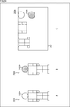
- FIG. 3A is a diagram showing a main configuration example of the atlas subbit stream.
- the atlas sub-bitstream 31 is composed of a series of atlas NAL units 32.
- Each square shown in A of FIG. 3 indicates an atlas NAL unit 32.
- Aud is the NAL unit of the access unit delimiter.
- atlas sps is a NAL unit of atlas sequence parameter set.
- atlas fps is a NAL unit of the atlas frame parameter set.
- Coded tile group is a NAL unit of coded tile group. This NAL unit is also referred to as a coded tile group NAL unit.
- the coordinated tile group NAL unit has atlas style group information. Atlas style group information is information about an atlas tile group.
- the Atlas style group has 2D3D conversion information corresponding to the patch in the corresponding rectangular area of the video subbit stream.
- 2D3D conversion information is information for converting a patch, which is 2D data, into a point cloud, which is 3D data.
- atlas information is grouped for each rectangular area separated by a dotted line. That is, the atlas style group 33 corresponding to each rectangular area is formed.
- the atlas style group 33 is composed of a plurality of atlas styles 34 as shown in C of FIG.
- Each atlas style group is configured to be decodable independently of each other.
- the coding of this atlas style group has the same restrictions as HEVC tiles. For example, it is configured so as not to depend on other atlas style groups of the same frame (same frame).
- the atlas frames having a reference relationship have the same atlas-style group partitioning (atlas tile group partitioning). Furthermore, only the atlas style group at the same position in the reference frame is referenced.
- the position information indicating the position in the frame corresponding to the atlas style group is signaled by the atlas frame parameter set (atlas fps).
- the location information is linked to the coordinated tile group NAL unit via id. That is, in the atlas frame parameter set, afti_tile_group_id is signaled as the atlas style group identification information that identifies the atlas style group.
- atgh_address is signaled as identification information that identifies the location information of the atlas style group.
- Non-Patent Document 4 describes two methods of storing a V-PCC bitstream in ISOBMFF (International Organization for Standardization Base Media File Format): a multi-track structure and a single track structure. The type is specified.
- the multitrack structure is a method of storing the geometry video subbitstream, the attribute video subbitstream, the occupancy map video subbitstream, and the atlas subbitstream in separate tracks. Since each video sub-bitstream is a conventional 2D video stream, it can be stored (managed) in the same manner as in the case of 2D.
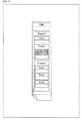
- FIG. 4 shows an example of file configuration when a multi-track structure is applied.
- the single track structure is a method of storing the V-PCC bitstream in one track. That is, in this case, the geometry video subbitstream, the attribute video subbitstream, the occupancy map video subbitstream, and the atlas subbitstream are stored on the same track.
- Non-Patent Document 4 defines partial access information for acquiring or decoding a part of a point cloud object. For example, by using this partial access information, it is possible to control such that only the information of the display part of the object of the point cloud is acquired at the time of streaming distribution. By such control, it is possible to obtain the effect of effectively utilizing the bandwidth and increasing the definition.
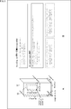
- a bounding box 51 which is a three-dimensional area containing the object, is set for the object of the point cloud. That is, in ISOBMFF, as shown in B of FIG. 5, the bounding box information (3DBoundingBoxStruct) which is the information about the bounding box 51 is set.
- a 3D spatial region 52 which is a partial region that can be independently decoded, can be set in the bounding box 51. it can. That is, as shown in B of FIG. 5, 3D spatial region information (3dSpatialRegionStruct), which is information about the 3D spatial region 52, is set as the partial access information in ISOBMFF.
- 3dSpatialRegionStruct 3D spatial region information
- the area is specified by the coordinates (anchor_x, anchor_y, anchor_z) and size (cuboid_delta_x, cuboid_delta_y, cuboid_delta_z) of the reference point.
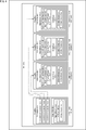
- ⁇ File structure example> For example, suppose that the bitstream of object 61 in FIG. 6 is divided into three 3D spatial regions (3D spatial region 61A, 3D spatial region 61B, 3D spatial region 61C) and stored in ISOBMFF. Also assume that the multitrack structure is applied and the 3D spatial region information is static (does not change over time).
- the video sub-bitstream is stored separately for each 3D spatial region (on different tracks). That is, each track that stores the geometry video subbitstream, attribute video subbitstream, and occupancy map video subbitstream corresponding to the same 3D spatial region is grouped (dotted frame in FIG. 6). This group is also called a spatial region track group.
- the video subbit stream of one 3D spatial region is stored in one or more spatial region track groups.
- three 3D spatial regions are configured, three or more spatial region track groups are formed.
- Each spatial region track group is assigned track_group_id as track group identification information, which is identification information for identifying the spatial region track group.
- This track_group_id is signaled to each track. That is, tracks belonging to the same spatial region track group are signaled with track_group_id having the same value. Therefore, the tracks belonging to the desired spatial region track group can be identified based on the value of this track_group_id.
- each track that contains the geometry video subbitstream, attribute video subbitstream, and occupancy map video subbitstream that correspond to the same 3D spatial region is signaled with the same value of track_group_id.
- each video subbit stream corresponding to the desired 3D spatial region can be identified based on the value of this track_group_id.
- SpatialRegionGroupBox having the same track_group_id is signaled to the tracks belonging to the same spatial region track group.
- track_group_id is signaled by the TrackGroupTypeBox inherited by SpatialRegionGroupBox.
- the atlas sub-bitstream is stored in one track regardless of the 3D spatial region. That is, this one atlas subbitstream has 2D3D conversion information for patches in multiple 3D spatial regions. More specifically, on the track where the atlas subbitstream is stored, the VPCCSpatialRegionsBox is signaled, where each track_group_id is signaled, as shown in FIG.
- a timed metadata track is used to use the 3D spatial track at each time.
- the decryption process for partial access is performed in the following procedure. 1. 1. Based on the information in the VPCCSpatialRegionBox, identify the track_group_id of the SpatialRegionGroupBox that corresponds to the 3D spatial region you want to access. 2. Decrypt the video subbitstream of the track belonging to the SpatialRegionGroupBox of that track_group_id. 3. 3. Extract the required coordinated tile group NAL unit from the atlas subbitstream and decrypt it. 4. Build a point cloud corresponding to the 3D spatial region.
- the atlas sub-bitstream corresponding to all 3D spatial regions is stored in one track.
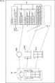
- the generic decoder decodes all atlas style groups contained in the input atlas subbitstream. That is, a general-purpose decoder cannot extract and decode some atlas style groups. Then, when building a point cloud, an error will occur if the video subbitstream corresponding to the atlas information is not available.
- the video frame subregions 71A and 71B corresponding to different 3D spatial regions exist in the video frame 71 of the video subbit stream.
- the video frame partial area 71A is decoded, only the coordinated tile group NAL unit of the atlas style group 72A corresponding to the video frame partial area 71A is input to the general-purpose decoder.
- the coordinated tile group NAL unit of the atlas style group 72B corresponding to the video frame partial area 71B is input to the general-purpose decoder.
- Non-Patent Document 4 the 3D spatial region and the atlas style group were not linked. That is, the video frame subregion of the video subbitstream was not associated with the coordinated tile group NAL unit. Therefore, it was difficult to carry out the above-mentioned procedure 3. That is, it was difficult to extract and decode the coordinated tile group NAL unit corresponding to the desired 3D spatial region (spatial region track group) from the atlas subbit stream. Therefore, it has been difficult to construct a point cloud (also referred to as a partial point cloud) of the desired 3D spatial region.
- a point cloud also referred to as a partial point cloud
- the information (also referred to as the linking information) that links the 3D spatial region and the atlas style group is transmitted (signaled) from the coding side to the decoding side.
- the linking information information for linking the spatial region track group and the atlas style group is signaled.
- 2D data corresponding to a 3D spatial region of a point cloud that expresses a 3D-shaped object as a set of points is encoded, a bit stream is generated, and a 3D spatial is generated.
- a coding unit that encodes 2D data corresponding to a 3D spatial region of a point cloud that represents a three-dimensional object as a set of points and generates a bit stream.
- the linking information generation unit that generates the linking information that links the 3D spatial region and the atlas style group, the bit stream generated by the coding section, and the linking information generated by the linking information generation section. It is provided with a file generator that generates a file that stores information.
- the 2D data corresponding to the 3D spatial region is, for example, the data of the partial region of the geometry video frame, the attribute video frame, and the occupancy map video frame, including the patch corresponding to the 3D spatial region.
- the bitstreams generated by encoding the 2D data are, for example, geometry video subbitstreams, attribute video subbitstreams, and occu that are stored in tracks belonging to the spatial region track group corresponding to the 3D spatial region. Pansy map video subbitstream.
- the file that stores the bitstream and association information is, for example, an ISOBMFF file.
- a 3D spatial region of a point cloud and an atlas style group which are stored in a file together with a bit stream of the point cloud that expresses a three-dimensional object as a set of points, are linked.
- Select the 3D spatial region and atlas style group corresponding to the desired 3D space based on the association information to be attached, and from the file, the atlas NAL unit corresponding to the selected atlas style group and the selected 3D.
- Extract the bit stream corresponding to the spatial region decode the extracted bit stream, generate the 2D data corresponding to the 3D spatial region in the desired 3D space, and decode the extracted atlas NAL unit.
- a 3D spatial region of a point cloud and an atlas style group which are stored in a file together with a bit stream of the point cloud that represents a three-dimensional object as a set of points, are linked.
- a selection unit that selects a 3D spatial region and an atlas style group corresponding to the desired 3D space based on the association information to be attached, and an atlas NAL unit corresponding to the atlas style group selected by the selection unit from the file.
- the extraction unit that extracts the bit stream corresponding to the 3D spatial region selected by the selection unit, and the bit stream extracted by the extraction unit is decoded to correspond to the 3D spatial region in the desired three-dimensional space. It is provided with a decoding unit that generates 2D data, decodes the atlas NAL unit extracted by the extraction unit, and generates atlas information corresponding to the 2D data.
- the file that stores the bitstream and association information is, for example, an ISOBMFF file.
- Bitstreams that correspond to a 3D spatial region are, for example, geometry video subbitstreams, attribute video subbitstreams, and occupancy map videos that are stored on tracks that belong to the spatial region track group that corresponds to that 3D spatial region. It is a subbit stream.
- the 2D data corresponding to the 3D spatial region is, for example, the data of a partial region of a geometry video frame, an attribute video frame, and an occupancy map video frame, including a patch corresponding to the 3D spatial region.
- the 3D spatial region and the atlas style group can be linked on the decoding side. Therefore, the coordinated tile group NAL unit and video subbitstream required to build a partial point cloud of the desired 3D spatial region can be extracted and input to a general purpose decoder. Therefore, only the partial point cloud of the desired 3D spatial region can be constructed and displayed.
- Such point cloud object distribution technology is expected to be used for 6DoF (Degree of Freedom) content distribution for AR (Augmented Reality) and VR (Virtual Reality) applications.
- a general-purpose decoder can be used, it is possible to extract and decode the coordinated tile group NAL unit required to build a partial point cloud of the desired 3D spatial region from the atlas subbitstream. Compared with the case of developing a dedicated decoder having a function capable of capable, it is possible to suppress an increase in cost.
- Method 1 For example, as shown at the top of the table shown in FIG. 10, in the multitrack structure, the spatial region track group and the atlas style group may be associated (method 1).
- association information in ⁇ Information for associating a 3D spatial region with an atlas style group> is a group of tracks that stores bitstreams corresponding to the same 3D spatial region in a multitrack structure.
- Information that associates the spatial region track group with the atlas style group may be included.
- the coding side device signals such association information.
- the decoding side device decodes the 3D spatial region based on the signaled association information. By doing so, the decoding side device can extract only the atlas NAL unit that constitutes the part corresponding to the 3D spatial region to be accessed from the atlas subbit stream. That is, the decoding side device can decode only the part corresponding to the 3D spatial region of the video subbit stream and the atlas subbit stream with a general-purpose decoder. That is, the decoding side device can construct only the part corresponding to the 3D spatial region of the point cloud.
- the tile_group_id may be associated with the track_group_id (method 1-1).
- the information for associating the spatial region track group and the atlas style group described above in ⁇ Method 1> includes track group identification information for identifying the track storing the bitstream and atlas style group identification for identifying the atlas style group. Information that associates with information may be included.
- the track group identification information is, for example, track_group_id.
- the atlas-style group identification information is, for example, tile_group_id. For example, as shown in FIG. 11, by associating the track_group_id and the tile_group_id, the spatial region track group and the atlas style group can be associated with each other.
- the coding side device signals the linking information including the information for linking the track group identification information and the atlas style group identification information.
- the decoding side device decodes the 3D spatial region based on the signaled association information. By doing so, the decoding side device can identify the atlas-style group identification information corresponding to the desired 3D spatial region (corresponding track group identification information) based on the association information. Then, the decoding side device can identify the atlas NAL unit corresponding to the desired 3D spatial region by using the identified atlas style group identification information.
- track_group_id and tile_group_id may be linked. That is, the information for associating the track group identification information with the atlas style group identification information may be associated with the track group identification information and the atlas style group identification information by using the VPCCSpatialRegionsBox of ISOBMFF.
- tile_group_id is associated with each track_group_id.
- This tile_group_id is equivalent to the atgh_address signaled in the atlas style group header (atlas_tile_group_header).
- atlas_tile_group_header the atlas style group header
- one or more atlas style groups can be associated with one spatial region track group.
- track_group_id and tile_group_id may be linked. That is, the information for associating the track group identification information with the atlas style group identification information may be associated with the track group identification information and the atlas style group identification information by using the SpatialRegionGroupBox of ISOBMFF.
- signaling of num_tile_groups may be omitted.
- one atlas style group corresponds to one spatial region track group.
- the sub-division information of the video subbit stream may be associated with the spatial region track group. That is, as shown in FIG. 13, the spatial region track group and the atlas style group are used by using the division information (division position and size (2d region pos / size)) of the video subbit stream instead of the atlas tile group id. And may be linked.
- the information for associating the above-mentioned spatial region track group and the atlas style group in ⁇ Method 1> is the spatial region track group and the atlas style using the partial area information of the video frame corresponding to the 3D spatial region.
- Information that associates with the group may be included.
- Figure 14 shows an extension example of the SpatialRegionGroupBox in that case.
- the position (offset_x, offset_y) and size (width, height, total_width, total_height) of the subregion of the video frame corresponding to the 3D spatial region (spatial region track group) are signals.
- the position and size of the atlas style group is signaled at atlas fps as described above with reference to FIG. By matching such position information and size, the spatial region track group and the atlas style group are linked.
- the coding side device signals the association information that links the spatial region track group and the atlas style group using the partial area information of the video frame corresponding to the 3D spatial region.
- the decoding side device decodes the 3D spatial region based on the signaled association information. By doing so, the decoding side device can identify the atlas NAL unit corresponding to the desired 3D spatial region based on the division information.
- VPCC SpatialRegionsBox may be extended instead of SpatialRegionGroupBox.
- parsing of the atlas subbit stream is required to identify the atlas style group corresponding to the desired spatial region track group.
- Method 1-2 Further, as shown in the third row from the top of the table shown in FIG. 10, a new group ID may be assigned and associated (method 1-2).
- the information for associating the spatial region track group and the atlas style group described above in ⁇ Method 1> identifies the track group identification information that identifies the track that stores the bitstream and the atlas style group to which the atlas NAL unit belongs.
- the information associated with the group identification information to be used may be included.
- the track group identification information is, for example, track_group_id.
- the group identification information is newly assigned identification information, for example, a groupID.
- This groupID is identification information that identifies the atlas style group to which the atlas NAL unit belongs, and is assigned to each atlas NAL unit.
- the coding side device signals the linking information including the information for linking the spatial region track group and the atlas style group.
- the decoding side device decodes the 3D spatial region based on the signaled association information. By doing so, the decoding side device can specify the group identification information corresponding to the desired 3D spatial region (corresponding track group identification information) based on the association information. Then, the decoding side device can identify the atlas NAL unit corresponding to the desired 3D spatial region by using the identified group identification information.
- this group identification information may be associated with the Atlas NAL unit and the Atlas style group for each sample by using the ISOBMFF SampleToGroupBox as shown in FIG.
- the spatial region track group and the atlas style group are combined. You may try to associate it.
- the above-mentioned group identification information may be associated with the Atlas NAL unit and the Atlas style group by using the NALUMapEntry and the TileRegionGroupEntry of ISOBMFF.
- the spatial region track group and the atlas style group are configured by using the sample_count [1] and group_description_index [1] of the SampleToGroupBox, the NALUMapEntry [1] of the SampleGroupDescriptionBox, and the TileRegionGroupEntry [1] of the SampleGroupDescriptionBox. Atlas NAL unit) is linked.
- the coding side device signals such association information.
- the decoding side device decodes the 3D spatial region based on the signaled association information. By doing so, the decoding side device can identify the atlas NAL unit corresponding to the desired 3D spatial region based on the association information.
- the track_group_id and the groupID may be linked by extending the VPCCSpatialRegionsBox of ISOBMFF.
- the above-mentioned information for associating the track group identification information with the group identification information may be associated with the track group identification information and the group identification information by using the VPCCSpatialRegionsBox of ISOBMFF.
- tile_group_id The syntax of the VPCC SpatialRegionsBox shown in FIG. 16 is the same as the example of FIG. 12 (method 1-1). However, the semantics of tile_group_id are set to the groupID of'nalm'.
- the tile_group_id semantics may be the same as in the case described above in ⁇ Method 1-1>, and may be set so that (groupID-1) is the tile_group_id of the atlas style group NAL unit.
- all video sub-bitstreams may be stored in one track as multiplex tracks. Also, the trif signal may be omitted.
- the atlas style group corresponding to the desired spatial region track group is identified without parsing all the atlas subbit streams. be able to.
- AtlasNALUMapEntry may be defined and used for the atlas subbit stream. Its syntax and semantics may be the same as NALUMapEntry. You may also extend NALUMapEntry to signal that you are referencing an atlas NAL unit. Since there is a difference in the syntax of the HEVC NAL unit and the Atlas NAL unit, it is possible to clearly indicate to the client that the parsing and decoding are different, and to facilitate the switching of processing.
- the video subbit stream is encoded by a coding method (HEVC tile) to which HEVC (High Efficiency Video Coding) tiles are applied, and the HEVC is encoded.
- the tiles may be associated with the Atlas style group (Method 1-3).
- each video sub-bitstream is encoded as a HEVC tile for each spatial region track group.
- the 2D position may be used to associate the HEVC tile (that is, the spatial region track group) with the atlas style group.
- the information for associating the above-mentioned spatial region track group and the atlas style group in ⁇ Method 1> links the atlas style group with the bitstream corresponding to the HEVC tile at the same position as the atlas style group. It may include information to be attached.
- the coding side device signals such association information.
- the decoding side device of each video subbit stream (geometry track / attribute track / occupancy map track) based on the position information of the signaled tile_group_id atlas style group. Decrypt only the tile at the corresponding position.
- the decoding side device can identify the tile region position of each of the geometry track, the attribute track, and the occupancy map track from the trif signaled by each track. Therefore, the decoding side device can extract and decode the NAL units that make up the tile region of each video subbit stream that matches the tile region of the atlas style group.
- the atlas style group may be associated with the bitstream corresponding to the HEVC tile at the same position as the atlas style group.
- the syntax in that case is the same as in the example of FIG. 16 (method 1-2). However, there is only one spatial region track group.
- Spatial Region Track Group may be made optional so that the SpatialRegionGroupBox does not require a signal.
- Each track of the geometry, attributes, and occupancy map and the V-PCC track are linked by a track reference, and the signal of SpatialRegionGroupBox can be omitted.
- An extension example of the VPCC Spatial RegionsBox in that case is shown in FIG.
- Method 2 For example, as shown in the fifth row from the top of the table shown in FIG. 10, the spatial region track group and the atlas style group may be associated in the single track structure (method 2).
- the linking information described above in ⁇ Information linking a 3D spatial region and an atlas style group> may include information linking a 3D spatial region and an atlas style group in a single track structure.
- the coding side device signals such association information.
- the decoding side device decodes the 3D spatial region based on the signaled association information. By doing so, the decoding side device can extract only the atlas NAL unit that constitutes the part corresponding to the 3D spatial region to be accessed from the atlas subbit stream. That is, the decoding side device can decode only the part corresponding to the 3D spatial region of the V-PCC bit stream with a general-purpose decoder. That is, the decoding side device can construct only the part corresponding to the 3D spatial region of the point cloud.
- Method 2-1 For example, as shown in the sixth row from the top of the table shown in FIG. 10, a new group ID may be assigned and associated (method 2-1).
- the information for associating the 3D spatial region and the atlas style group described above in ⁇ Method 2> is the information for associating the 3D spatial region with the group identification information for identifying the atlas style group to which the atlas NAL unit belongs. May be included.
- V-PCC bitstream (that is, geometry, attributes, occupancy map, and atlas information) is stored in one track
- the sample in method 1-2 is a sub-sample. Therefore, as shown in FIG. 20, a new Box (SubSampleToGroupBox) is defined so that the same mechanism as in Method 1-3 can be applied to this subsample. More specifically, in order to associate SampleGroupDescription (nalm, trif) with the subsample, subsampletogroup is newly defined and replaced with sampletogroup.
- a new subsample to group is defined. That is, it signals the SubSampleToGroupBox of the syntax as shown in FIG. In that case, the SubSampleInformationBox also signals.
- sample_count indicates the number of samples having subsamples.
- subsample_count indicates the number of consecutive subsamples associated with the same sample group descriptor (sample group descriptor). The semantics of the other fields are the same as the SubSampleInformationBox.
- the coding side device signals such association information.
- the decoding side device decodes the 3D spatial region based on the signaled association information. By doing so, the decoding side device can identify the subsample corresponding to the desired 3D spatial region based on the association information.
- Method 2-2 For example, as shown in the seventh row from the top of the table shown in FIG. 10, the V-PCC bit stream may be separated for each 3D spatial region (method 2-2). That is, as shown in FIG. 22, each V-PCC bit stream divided into 3D spatial regions may be stored in different tracks. Then, the 3D spatial region and the divided V-PCC bit stream (the track that stores the divided V-PCC bit stream) may be associated with the association information.
- the information for associating the above-mentioned 3D spatial region and the atlas style group in ⁇ Method 2> includes the track group identification information that identifies the track that stores the bitstream corresponding to the 3D spatial region and the atlas style.
- the information associated with the atlas-style group identification information that identifies the group may be included.
- each track stores geometry, attributes, occupancy maps, and atlas information.
- the 3D spatial region information for each track is signaled in the VPCCSpatialRegionsBox.
- FIG. 23 shows an example of the syntax of the VPCC Spatial Regions Box.
- signaling of the 3D spatial region for each track_group_id is not required, so it may be controlled by flags.
- the condition (flags & 1) is 1 (true).
- the coding side device signals such association information.
- the decoding side device decodes the 3D spatial region based on the signaled association information. By doing so, the decoding side device can identify the track (divided V-PCC bit stream) corresponding to the desired 3D spatial region based on the association information.
- Method 3 For example, as shown in the eighth row from the top of the table shown in FIG. 10, it may be possible to switch and display alternative 3D spatial regions at the same position in the three-dimensional space (method 3).
- the head of the object 201 can be displayed as the head 202A or as the head 202B. By doing so, for example, the display of the head can be switched according to the preference of the user.
- overlapping points in three-dimensional space are arranged in different rectangular areas on the 2D image of the video subbitstream.
- the patch of the head 202A and the patch of the head 202B are arranged at different positions of the same video frame 203.
- ⁇ Method 3-1> information that enables switching display of alternative 3D spatial regions at the same position in the three-dimensional space as described above may be signaled.
- the above-mentioned linking information in ⁇ Information for linking a 3D spatial region and an atlas style group> may include switching information which is information regarding switching of a 3D spatial region.
- the VPCCSpatialRegionsBox is expanded, and as switching information, an AlternativeRegionListStruct for the decoding side device to identify an alternative 3D spatial region is newly defined.
- the switching information may include information regarding display switching conditions.
- information regarding display switching conditions such as list_type, region_type_value, and ref_3d_region_id is signaled.
- List_type indicates the switching criteria for alternative regions. For example, the value “0" may indicate switching according to the language setting, and the value “1" may indicate switching according to the user's age setting. Of course, this is just an example, and the possible values for list_type are arbitrary. Moreover, the standard indicated by each value is arbitrary.
- Region_type_value indicates the type for each region. For example, when list_type is a value indicating switching according to the language setting, the value "0" of region_type_value may indicate Japanese (jpn) and the value "1" may indicate English (eng). Of course, this is just an example, and the possible values for region_type_value are arbitrary. Moreover, the type indicated by each value is arbitrary.
- DynamicRegionSample may be extended in the same way.
- the alternative 3D spatial region may be switched dynamically based on a trigger provided from the outside.
- the above-mentioned switching information may include information about an event that triggers switching.
- an event message of MPEG-DASH (Moving Picture Experts Group phase-Dynamic Adaptive Streaming over HTTP) may be applied.
- the event identification information (event_id) is signaled to message_data [], and the content distribution side sends an event message at a desired timing.
- the client receives the event message, it switches the display according to the event_id.
- event_id may be associated with the result of some interaction of the user.
- event_id may be associated with the result of some interaction of the user.
- node for example, bitwrapper
- the eventOut of the interaction node such as the touch sensor (TouchSensor) and the exposedField of the Switch node are linked.
- the display may be switched (using the scene description function) according to the user's interaction by using the scene description function.
- V-PCC bitstream may be stored in a Matroska Media Container, as shown at the bottom of the table shown in FIG. 10 (Method 4).
- FIG. 27 A main configuration example of the matryoshka media container is shown in FIG. 27.
- association information of the atlas style group may be signaled to the element having the same information as the VPCCSpatialRegionsBox under the TrackEntry element.
- the information that enables the switching display of the alternative 3D spatial region may be signaled as a newly defined element under the TrackEntry element.
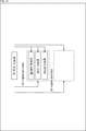
- FIG. 28 is a block diagram showing an example of the configuration of a coding device, which is an aspect of an image processing device (coding side device) to which the present technology is applied.
- the coding device 300 shown in FIG. 28 is a device that applies V-PCC and encodes point cloud data as a video frame by a coding method for a two-dimensional image. Further, the coding device 300 stores the V-PCC bit stream generated by the coding in ISOBMFF.
- the coding device 300 is ⁇ 1. By applying this technology explained in Signaling of linked information>, information is stored in ISOBMFF so as to enable partial access. That is, the coding device 300 signals the linking information that links the 3D spatial region and the atlas style group.
- FIG. 28 shows the main things such as the processing unit and the data flow, and not all of them are shown in FIG. 28. That is, in the coding apparatus 300, there may be a processing unit that is not shown as a block in FIG. 28, or there may be a processing or data flow that is not shown as an arrow or the like in FIG. 28.
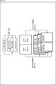
- the coding device 300 has a 3D2D conversion unit 301, a 2D coding unit 302, a metadata generation unit 303, a PC stream generation unit 304, and a file generation unit 305.
- the 3D2D conversion unit 301 decomposes the point cloud, which is the 3D data input to the coding device 300, into patches and packs them. That is, the 3D2D conversion unit 301 generates a geometry video frame, an attribute video frame, and an occupancy map video frame, and supplies them to the 2D coding unit 302. Further, the 3D2D conversion unit 301 generates atlas information and supplies it to the 2D coding unit 302.
- the 2D coding unit 302 performs processing related to coding. For example, the 2D coding unit 302 acquires geometry video frames, attribute video frames, occupancy map video frames, atlas information, and the like supplied from the 3D2D conversion unit 301. The 2D coding unit 302 encodes them and generates a bit stream. The 2D coding unit 302 supplies the generated bit stream to the metadata generation unit 303 and the PC stream generation unit 304.
- the 2D coding unit 302 has a coding unit 311 to a coding unit 314.
- the coding unit 311 encodes the geometry video frame to generate the geometry video subbit stream.
- the 2D coding unit 302 supplies the generated geometry video subbit stream to the metadata generation unit 303 and the PC stream generation unit 304.
- the coding unit 312 encodes the attribute video frame and generates the attribute video subbit stream.
- the coding unit 312 supplies the generated attribute video subbit stream to the metadata generation unit 303 and the PC stream generation unit 304.
- the coding unit 313 encodes the occupancy map video frame and generates the occupancy map video subbit stream.
- the coding unit 313 supplies the generated occupancy map video subbit stream to the metadata generation unit 303 and the PC stream generation unit 304.
- the coding unit 314 encodes the atlas information and generates an atlas subbit stream.
- the coding unit 314 supplies the generated atlas subbit stream to the metadata generation unit 303 and the PC stream generation unit 304.
- the metadata generation unit 303 performs processing related to metadata generation. For example, the metadata generation unit 303 acquires a video subbit stream or an atlas subbit stream supplied from the 2D coding unit 302. In addition, the metadata generation unit 303 generates metadata using those data.
- the metadata generation unit 303 can generate association information that links the 3D spatial region of the point cloud and the atlas style group as metadata. That is, the metadata generation unit 303 has ⁇ 1. Metadata can be generated by applying the technology described in Signaling Linkage Information>.
- the metadata generation unit 303 is, for example, ⁇ 1. Method 1, Method 1-1, Method 1-2, Method 1-3, Method 2, Method 2-1 and Method 2-2, Method 3, Method 3-1 and described above in Signaling of association information>. Any of the method 4, various modifications, and a combination of a plurality of methods (hereinafter referred to as various methods of the present technology) can be applied.
- the metadata generation unit 303 When the metadata generation unit 303 generates metadata including the association information that links the 3D spatial region of the point cloud and the atlas style group in this way, the metadata generation unit 303 supplies the metadata to the file generation unit 305.
- the PC stream generation unit 304 performs processing related to the generation of the V-PCC bit stream. For example, the PC stream generation unit 304 acquires a video subbit stream or an atlas subbit stream supplied from the 2D coding unit 302. In addition, the PC stream generator 304 uses them to perform V-PCC bitstreams (geometry video subbitstream, attribute video subbitstream, occupancy map video subbitstream, and atlas subbitstream, or aggregate them. Is generated and supplied to the file generation unit 305.
- V-PCC bitstreams geometry video subbitstream, attribute video subbitstream, occupancy map video subbitstream, and atlas subbitstream, or aggregate them. Is generated and supplied to the file generation unit 305.
- the file generation unit 305 performs processing related to file generation. For example, the file generation unit 305 acquires the metadata including the association information for associating the 3D spatial region of the point cloud with the atlas style group, which is supplied from the metadata generation unit 303. Further, the file generation unit 305 acquires the V-PCC bit stream supplied from the PC stream generation unit 304. The file generation unit 305 generates a file (for example, ISOBMFF or matryoshka media container) that stores the metadata including the association information and the V-PCC bitstream.
- a file for example, ISOBMFF or matryoshka media container
- the file generation unit 305 is ⁇ 1.
- Linking Information Signaling> a file that signals the linking information that links the 3D spatial region of the point cloud and the atlas style group is generated.
- the file generation unit 305 is described in ⁇ 1. Any of the various methods of the present technology described above in Signaling of association information> can be applied. Then, the file generation unit 305 outputs the generated file to the outside of the coding device 300.
- each processing unit may be configured by a logic circuit that realizes the above-mentioned processing.
- each processing unit has, for example, a CPU (Central Processing Unit), a ROM (Read Only Memory), a RAM (Random Access Memory), and the like, and the above-mentioned processing is realized by executing a program using them. You may do so.
- each processing unit may have both configurations, and a part of the above-mentioned processing may be realized by a logic circuit, and the other may be realized by executing a program.
- the configurations of the respective processing units may be independent of each other. For example, some processing units realize a part of the above-mentioned processing by a logic circuit, and some other processing units execute a program.
- the above-mentioned processing may be realized by the other processing unit by both the logic circuit and the execution of the program.
- the coding device 300 has ⁇ 1. Signaling the linking information> Applying this technology described in>, the linking information that links the 3D spatial region and the atlas style group is signaled.
- the decoding side device can extract only the Atlas NAL unit that constitutes the part corresponding to the 3D spatial region to be accessed from the Atlas subbit stream. That is, the decoding side device can decode only the portion of the V-PCC bitstream corresponding to the desired 3D spatial region. That is, the decoding side device can construct only the part of the point cloud corresponding to the desired 3D spatial region.
- the decoding side device can associate the 3D spatial region with the atlas style group. Therefore, the decoding side device can extract the coordinated tile group NAL unit and the video subbit stream necessary for constructing the partial point cloud of the desired 3D spatial region and input them to the general-purpose decoder. Therefore, the decoding side device can construct and display only the partial point cloud of the desired 3D spatial region.
- the decoding side device extracts the coordinated tile group NAL unit necessary for constructing the partial point cloud of the desired 3D spatial region from the atlas subbit stream. Compared with the case of developing a dedicated decoder having a function capable of decoding, it is possible to suppress an increase in cost.
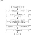
- the 3D2D conversion unit 301 of the coding device 300 decomposes the point cloud into patches in step S301 to generate patches of geometry and attributes. Then, the 3D2D conversion unit 301 packs the patch into the video frame. In addition, the 3D2D conversion unit 301 generates an occupancy map and atlas information.
- the 2D coding unit 302 encodes the geometry video frame, the attribute video frame, the occupancy map video frame, and the atlas information.
- the coding unit 311 encodes a geometry video frame using a coding method for arbitrary 2D data (for example, AVC, HEVC, etc.) to generate a geometry video subbit stream.
- the coding unit 312 encodes the attribute video frame using a coding method for arbitrary 2D data to generate an attribute video subbit stream.
- the coding unit 313 encodes the occupancy map video frame using an encoding method for arbitrary 2D data to generate an occupancy map video subbit stream.
- the coding unit 314 encodes the atlas information by an arbitrary coding method to generate an atlas sub-bit stream.
- the metadata generation unit 303 generates partial access information as metadata including the association information that links the spatial region track group and the atlas style group. That is, the metadata generation unit 303 has ⁇ 1. Metadata can be generated by applying the technology described in Signaling Linkage Information>.
- the metadata generation unit 303 is, for example, ⁇ 1. Any of the various methods of the present technology described above in Signaling of association information> can be applied.
- step S304 the PC stream generation unit 304 generates a V-PCC bit stream (point cloud stream) using the video sub-bit stream.
- the file generation unit 305 stores a file (for example, ISOBMFF or Matryoshka media) that stores the metadata including the association information that associates the 3D spatial region of the point cloud with the atlas style group and the V-PCC bitstream. Create a container).
- a file for example, ISOBMFF or Matryoshka media
- the file generation unit 305 is ⁇ 1.
- the present technology described in Signaling of association information> is applied. That is, the file generation unit 305 has ⁇ 1.
- Signaling the association information> Generates a file that signals the association information as described above.
- the file generation unit 305 is described in ⁇ 1. Any of the various methods of the present technology described above in Signaling of association information> can be applied.
- step S305 When the process of step S305 is completed, the coding process is completed.
- the coding apparatus 300 has ⁇ 1. Signaling the linking information> Applying this technology explained in>, the linking information that links the 3D spatial region and the atlas style group is signaled.
- the decoding side device can extract only the Atlas NAL unit that constitutes the part corresponding to the 3D spatial region to be accessed from the Atlas subbit stream. That is, the decoding side device can decode only the part corresponding to the 3D spatial region of the video subbit stream and the atlas subbit stream with a general-purpose decoder. That is, the decoding side device can construct only the part corresponding to the 3D spatial region of the point cloud.
- the decoding side device can associate the 3D spatial region with the atlas style group. Therefore, the decoding side device can extract the coordinated tile group NAL unit and the video subbit stream necessary for constructing the partial point cloud of the desired 3D spatial region and input them to the general-purpose decoder. Therefore, the decoding side device can construct and display only the partial point cloud of the desired 3D spatial region.
- the decoding side device extracts the coordinated tile group NAL unit necessary for constructing the partial point cloud of the desired 3D spatial region from the atlas subbit stream. Compared with the case of developing a dedicated decoder having a function capable of decoding, it is possible to suppress an increase in cost.
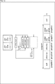
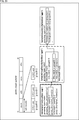
- FIG. 30 is a block diagram showing an example of the configuration of a decoding device, which is an aspect of an image processing device to which the present technology is applied.
- the decoding device 400 shown in FIG. 30 applies a V-PCC and uses the point cloud data as a video frame and encodes the V-PCC bitstream (geometry video subbitstream, attribute) by a coding method for a two-dimensional image.
- the decoding device 400 can extract a V-PCC bit stream from the file generated by the coding device 300 and decode it to generate a point cloud.
- the decoding device 400 is ⁇ 1. Partial access is realized by applying this technology explained in Signaling of linked information>. That is, the decoding device 400 determines the 3D spatial region corresponding to the desired 3D spatial region (that is, the desired 3D spatial region) based on the association information that links the signaled 3D spatial region and the atlas style group. ) Corresponding V-PCC bitstream can be decoded to build a partial point cloud.
- FIG. 30 shows the main things such as the processing unit and the data flow, and not all of them are shown in FIG. 30. That is, in the decoding device 400, there may be a processing unit that is not shown as a block in FIG. 30, or there may be a processing or data flow that is not shown as an arrow or the like in FIG.
- the decoding device 400 has a file processing unit 401, a 2D decoding unit 402, and a display information generation unit 403.
- the file processing unit 401 extracts the V-PCC bit stream from the file input to the decoding device 400 and supplies it to the 2D decoding unit 402. At that time, the file processing unit 401 has ⁇ 1. Applying this technology described in Linking Information Signaling>, the 3D spatial region corresponding to the desired 3D spatial region is applied based on the linking information that links the signaled 3D spatial region and the atlas style group. Extract the V-PCC bitstream corresponding to (ie the desired 3D spatial region). The file processing unit 401 has ⁇ 1. Any of the various methods of the present technology described above in Signaling of association information> can be applied. Then, the file processing unit 401 supplies the extracted V-PCC bit stream to the 2D decoding unit 402.
- the file processing unit 401 excludes the V-PCC bitstream unnecessary for reconstructing the point cloud of the desired 3D spatial region from the decoding target based on the signaled association information.
- the file processing unit 401 has an analysis unit 411 and an extraction unit 412.
- the analysis unit 411 performs processing related to analysis of a file (for example, ISOBMFF) input to the decoding device 400.
- a file for example, ISOBMFF
- the file processing unit 401 has ⁇ 1.
- Linking information signaling> Applying this technology explained in>, the file is analyzed, and the desired 3D space is supported based on the linking information that links the 3D spatial region of the point cloud and the atlas style group. Select a spatial region track group and an atlas style group.
- the analysis unit 411 has ⁇ 1. Any of the various methods of the present technology described above in Signaling of association information> can be applied.
- the analysis unit 411 links the 3D spatial region of the point cloud and the atlas style group, which are stored in a file together with the bit stream of the point cloud that expresses the object of the three-dimensional shape as a set of points. Select the 3D spatial region and atlas style group corresponding to the desired 3D space based on.
- the analysis unit 411 supplies the extraction unit 412 with information indicating the selected spatial region track group and the atlas style group.
- the extraction unit 412 extracts the data to be decoded from the V-PCC bit stream based on the analysis result by the analysis unit 411. That is, the extraction unit 412 extracts the atlas NAL unit corresponding to the atlas style group selected by the analysis unit 411 from the file. In addition, the extraction unit 412 extracts the video subbit stream corresponding to the spatial region track group selected by the analysis unit 411 from the file. The extraction unit 412 supplies the extracted data to the 2D decoding unit 402.
- the 2D decoding unit 402 performs processing related to decoding. For example, the 2D decoding unit 402 acquires a geometry video subbit stream, an attribute video subbit stream, an occupancy map video subbit stream, an atlas subbit stream, and the like supplied from the file processing unit 401. The 2D decoding unit 402 decodes them and generates video frames and atlas information. The 2D decoding unit 402 supplies the generated bit stream to the metadata generation unit 303 and the PC stream generation unit 304.
- the 2D decoding unit 402 has a decoding unit 421 to a decoding unit 424.
- the decoding unit 421 decodes the supplied geometry video subbit stream and generates a geometry video frame (2D data).
- the decoding unit 421 supplies the generated geometry video frame to the display information generation unit 403.
- the decoding unit 422 decodes the attribute video subbit stream and generates an attribute video frame (2D data).
- the decoding unit 422 supplies the generated attribute video frame to the display information generation unit 403.
- the decoding unit 423 decodes the occupancy map video sub-bitstream and generates an occupancy map video frame (2D data).
- the decoding unit 423 supplies the generated occupancy map video frame to the display information generation unit 403.
- the decoding unit 424 decodes the atlas sub-bit stream (extracted said atlas NAL unit) and generates atlas information corresponding to the above-mentioned video frame.
- the decoding unit 424 supplies the generated atlas information to the display information generation unit 403.
- the display information generation unit 403 performs processing related to the construction and rendering of the point cloud. For example, the display information generation unit 403 acquires video frames and atlas information supplied from the 2D decoding unit 402. Further, the display information generation unit 403 generates a point cloud from the patches packed in the acquired video frames based on the acquired atlas information. Then, the display information generation unit 403 renders the point cloud, generates a display image, and outputs the image to the outside of the decoding device 400.
- the display information generation unit 403 has, for example, a 2D3D conversion unit 431 and a display processing unit 433.
- the 2D3D conversion unit 431 converts the patch (2D data) arranged in the video frame supplied from the 2D decoding unit 402 into a point cloud (3D data).
- the 2D3D conversion unit 431 supplies the generated point cloud to the display processing unit 432.
- the display processing unit 432 performs processing related to rendering. For example, the display processing unit 432 acquires the point cloud supplied from the 2D3D conversion unit 431. In addition, the display processing unit 432 renders the acquired point cloud to generate a display image. The display processing unit 432 outputs the generated display image to the outside of the decoding device 400 (for example, a monitor or the like).
- the decoding device 400 has ⁇ 1.
- partial access is performed based on the linked information that links the signaled 3D spatial region and the Atlas style group.
- the decoding device 400 can extract only the Atlas NAL unit that constitutes the part corresponding to the 3D spatial region to be accessed from the Atlas subbit stream. That is, the decoding device 400 can decode only the portion of the V-PCC bitstream corresponding to the desired 3D spatial region. That is, the decoding device 400 can construct only the part of the point cloud corresponding to the desired 3D spatial region.
- the decoding device 400 can associate the 3D spatial region with the atlas style group. Therefore, the decoding device 400 can extract the coordinated tile group NAL unit and the video subbit stream necessary for constructing the partial point cloud of the desired 3D spatial region and input them to the general-purpose decoder. Therefore, the decoding device 400 can construct and display only the partial point cloud of the desired 3D spatial region.
- the decoding device 400 extracts the coordinated tile group NAL unit necessary for constructing the partial point cloud of the desired 3D spatial region from the atlas subbit stream. Compared with the case of developing a dedicated decoder having a function capable of decoding, it is possible to suppress an increase in cost.
- the analysis unit 411 of the decoding device 400 shifts to a desired three-dimensional space based on the partial access information including the information for associating the spatial region track group and the atlas style group in step S401. Select the corresponding spatial region track group and atlas style group.
- step S402 the extraction unit 412 extracts the atlas NAL unit corresponding to the atlas style group selected in step S401 and the video subbit stream corresponding to the spatial region track group.
- step S403 the 2D decoding unit 402 decodes the atlas NAL unit extracted in step S402 and the video subbit stream.
- step S404 the 2D3D conversion unit 431 constructs a point cloud using the video frame generated by the process of step S403 and the atlas information. That is, the 2D3D conversion unit 431 constructs a partial point cloud corresponding to a desired three-dimensional space.
- step S405 the display processing unit 432 renders the point cloud (that is, the partial point cloud corresponding to the desired three-dimensional space) generated in the process of step S404 to generate a display image. That is, the display processing unit 432 generates a display image corresponding to a desired three-dimensional space.
- step S405 When the process of step S405 is completed, the decoding process is completed.
- the decoding device 400 has ⁇ 1. Applying this technology explained in Signaling of Linked Information>, based on the linked information that links the signaled 3D spatial region and the Atlas style group, a partial point cloud corresponding to the desired 3D spatial region can be created. Can be built.
- the decoding device 400 extracts the coordinated tile group NAL unit necessary for constructing the partial point cloud of the desired 3D spatial region from the atlas subbit stream. Compared with the case of developing a dedicated decoder having a function capable of decoding, it is possible to suppress an increase in cost.
- FIG. 27 is a block diagram showing a configuration example of computer hardware that executes the above-mentioned series of processes programmatically.
- the CPU Central Processing Unit
- ROM Read Only Memory
- RAM Random Access Memory
- the input / output interface 910 is also connected to the bus 904.
- An input unit 911, an output unit 912, a storage unit 913, a communication unit 914, and a drive 915 are connected to the input / output interface 910.
- the input unit 911 includes, for example, a keyboard, a mouse, a microphone, a touch panel, an input terminal, and the like.
- the output unit 912 includes, for example, a display, a speaker, an output terminal, and the like.
- the storage unit 913 is composed of, for example, a hard disk, a RAM disk, a non-volatile memory, or the like.
- the communication unit 914 includes, for example, a network interface.
- the drive 915 drives a removable medium 921 such as a magnetic disk, an optical disk, a magneto-optical disk, or a semiconductor memory.
- the CPU 901 loads the program stored in the storage unit 913 into the RAM 903 via the input / output interface 910 and the bus 904 and executes the above-described series. Is processed.
- the RAM 903 also appropriately stores data and the like necessary for the CPU 901 to execute various processes.
- the program executed by the computer can be recorded and applied to the removable media 921 as a package media or the like, for example.
- the program can be installed in the storage unit 913 via the input / output interface 910 by mounting the removable media 921 in the drive 915.
- This program can also be provided via wired or wireless transmission media such as local area networks, the Internet, and digital satellite broadcasting. In that case, the program can be received by the communication unit 914 and installed in the storage unit 913.
- this program can be installed in advance in ROM 902 or storage unit 913.
- the coding device 300 and the decoding device 400 have been described as application examples of the present technology, but the present technology can be applied to any configuration.
- this technology is a transmitter or receiver (for example, a television receiver or mobile phone) for satellite broadcasting, cable broadcasting such as cable TV, distribution on the Internet, and distribution to terminals by cellular communication, or It can be applied to various electronic devices such as devices (for example, hard disk recorders and cameras) that record images on media such as optical disks, magnetic disks, and flash memories, and reproduce images from these storage media.
- devices for example, hard disk recorders and cameras
- a processor as a system LSI (Large Scale Integration) or the like (for example, a video processor), a module using a plurality of processors (for example, a video module), a unit using a plurality of modules (for example, a video unit)
- a processor as a system LSI (Large Scale Integration) or the like
- a module using a plurality of processors for example, a video module
- a unit using a plurality of modules for example, a video unit
- it can be implemented as a configuration of a part of the device, such as a set (for example, a video set) in which other functions are added to the unit.
- this technology can be applied to a network system composed of a plurality of devices.
- the present technology may be implemented as cloud computing that is shared and jointly processed by a plurality of devices via a network.
- this technology is implemented in a cloud service that provides services related to images (moving images) to arbitrary terminals such as computers, AV (AudioVisual) devices, portable information processing terminals, and IoT (Internet of Things) devices. You may try to do it.
- the system means a set of a plurality of components (devices, modules (parts), etc.), and it does not matter whether all the components are in the same housing. Therefore, a plurality of devices housed in separate housings and connected via a network, and a device in which a plurality of modules are housed in one housing are both systems. ..
- Systems, devices, processing units, etc. to which this technology is applied can be used in any field such as transportation, medical care, crime prevention, agriculture, livestock industry, mining, beauty, factories, home appliances, weather, nature monitoring, etc. .. Moreover, the use is arbitrary.
- this technology can be applied to systems and devices used for providing ornamental contents and the like.
- the present technology can be applied to systems and devices used for traffic such as traffic condition supervision and automatic driving control.
- the present technology can be applied to systems and devices used for security purposes.
- the present technology can be applied to a system or device used for automatic control of a machine or the like.
- the present technology can be applied to systems and devices used for agriculture and livestock industry.
- the present technology can also be applied to systems and devices for monitoring natural conditions such as volcanoes, forests and oceans, and wildlife. Further, for example, the present technology can be applied to systems and devices used for sports.
- the "flag” is information for identifying a plurality of states, and is not only information used for identifying two states of true (1) or false (0), but also three or more states. It also contains information that can identify the state. Therefore, the value that this "flag” can take may be, for example, 2 values of 1/0 or 3 or more values. That is, the number of bits constituting this "flag” is arbitrary, and may be 1 bit or a plurality of bits.
- the identification information (including the flag) is assumed to include not only the identification information in the bitstream but also the difference information of the identification information with respect to a certain reference information in the bitstream. In, the "flag” and “identification information” include not only the information but also the difference information with respect to the reference information.
- various information (metadata, etc.) related to the coded data may be transmitted or recorded in any form as long as it is associated with the coded data.
- the term "associate" means, for example, to make the other data available (linkable) when processing one data. That is, the data associated with each other may be combined as one data or may be individual data.
- the information associated with the coded data (image) may be transmitted on a transmission path different from the coded data (image).
- the information associated with the coded data (image) may be recorded on a recording medium (or another recording area of the same recording medium) different from the coded data (image). Good.
- this "association" may be a part of the data, not the entire data. For example, an image and information corresponding to the image may be associated with each other in an arbitrary unit such as a plurality of frames, one frame, or a part within the frame.
- the embodiment of the present technology is not limited to the above-described embodiment, and various changes can be made without departing from the gist of the present technology.
- the configuration described as one device (or processing unit) may be divided and configured as a plurality of devices (or processing units).
- the configurations described above as a plurality of devices (or processing units) may be collectively configured as one device (or processing unit).
- a configuration other than the above may be added to the configuration of each device (or each processing unit).
- a part of the configuration of one device (or processing unit) may be included in the configuration of another device (or other processing unit). ..
- the above-mentioned program may be executed in any device.
- the device may have necessary functions (functional blocks, etc.) so that necessary information can be obtained.
- each step of one flowchart may be executed by one device, or may be shared and executed by a plurality of devices.
- the plurality of processes may be executed by one device, or may be shared and executed by a plurality of devices.
- a plurality of processes included in one step can be executed as processes of a plurality of steps.
- the processes described as a plurality of steps can be collectively executed as one step.
- the processing of the steps for writing the program may be executed in chronological order in the order described in the present specification, and the calls may be made in parallel or in parallel. It may be executed individually at the required timing such as when it is broken. That is, as long as there is no contradiction, the processing of each step may be executed in an order different from the above-mentioned order. Further, the processing of the step for writing this program may be executed in parallel with the processing of another program, or may be executed in combination with the processing of another program.
- a plurality of technologies related to this technology can be independently implemented independently as long as there is no contradiction.
- any plurality of the present technologies can be used in combination.
- some or all of the techniques described in any of the embodiments may be combined with some or all of the techniques described in other embodiments. It is also possible to carry out a part or all of any of the above-mentioned techniques in combination with other techniques not described above.
- the present technology can also have the following configurations.
- (1) Based on the linking information that links the 3D spatial region of the point cloud and the atlas style group, which is stored in a file together with the bit stream of the point cloud that expresses a 3D shaped object as a set of points.
- the bitstream extracted by the extraction unit is decoded, 2D data corresponding to the 3D spatial region in the desired three-dimensional space is generated, and the atlas NAL unit extracted by the extraction unit is decoded.
- An image processing device including a decoding unit that generates atlas information corresponding to the 2D data.
- the association information associates the spatial region track group, which is a group of tracks storing bitstreams corresponding to the same 3D spatial region, with the atlas style group in the multitrack structure.
- the image processing apparatus according to (1), which includes information.
- the information linking the spatial region track group and the atlas style group identifies the track group identification information that identifies the track that stores the bitstream and the atlas style group to which the atlas NAL unit belongs.
- the image processing apparatus which includes information associated with group identification information.
- the file is an ISOBMFF (International Organization for Standardization base media file format) file.
- the image processing apparatus according to (3), wherein the information for associating the track group identification information with the group identification information is the information for associating the track group identification information with the group identification information using the VPCCSpatialRegionsBox of ISOBMFF.
- the file is an ISOBMFF (International Organization for Standardization base media file format) file.
- the image processing apparatus according to (3) or (4), wherein the group identification information is associated with the atlas NAL unit and the atlas style group by using NALUMapEntry of the ISOBMFF.
- the image processing apparatus according to (5), wherein the group identification information is associated with the atlas NAL unit and the atlas style group for each sample using the ISOBMFF SampleToGroupBox.
- the information for associating the spatial region track group with the atlas-style group includes track group identification information for identifying the track storing the bitstream and atlas-style group identification information for identifying the atlas-style group.
- the image processing apparatus according to any one of (2) to (6), which includes information for associating the tiles.
- the file is an ISOBMFF (International Organization for Standardization base media file format) file.
- the information for associating the track group identification information with the atlas style group identification information is the image according to (7) of associating the track group identification information with the atlas style group identification information using the VPCCSpatialRegionsBox of the ISOBMFF. Processing equipment. (9)
- the file is an ISOBMFF (International Organization for Standardization base media file format) file.
- the information for associating the track group identification information with the atlas style group identification information uses the SpatialRegionGroupBox of ISOBMFF to associate the track group identification information with the atlas style group identification information (7) or (8).
- the image processing apparatus according to.
- the information for associating the spatial region track group with the atlas style group is the information for associating the spatial region track group with the atlas style group by using the division information of the 3D spatial region.
- the information linking the spatial region track group and the atlas style group is the bit corresponding to the tile of HEVC (High Efficiency Video Coding) located at the same position as the atlas style group and the atlas style group.
- the image processing apparatus according to any one of (2) to (10) which includes information associated with a stream.
- the information for associating the 3D spatial region with the atlas style group includes information for associating the 3D spatial region with the group identification information for identifying the atlas style group to which the atlas NAL unit belongs.
- the information for associating the 3D spatial region with the atlas-style group identifies the track group identification information for identifying the track storing the bitstream corresponding to the 3D spatial region and the atlas-style group.
- the switching information includes information regarding the switching conditions.
- the switching information includes information regarding an event that triggers the switching.
- the extracted bitstream is decoded to generate 2D data corresponding to the 3D spatial region in the desired three-dimensional space, the extracted atlas NAL unit is decoded, and the atlas information corresponding to the 2D data is generated.
- Image processing method to generate to generate.
- An encoding unit that encodes 2D data corresponding to a 3D spatial region of a point cloud that expresses a three-dimensional object as a set of points and generates a bit stream.
- the linking information generation unit that generates the linking information that links the 3D spatial region and the atlas style group
- An image processing device including a file generation unit that generates a file that stores the bit stream generated by the coding unit and the association information generated by the association information generation unit.
- Generates the linking information that links the 3D spatial region and the atlas style group An image processing method for generating a file that stores the generated bitstream and the association information.
- 300 encoding device 301 3D3D conversion unit, 302 2D encoding unit, 303 metadata generation unit, 304 PC stream generation unit, 305 file generation unit, 311 to 314 encoding unit, 400 decoding device, 401 file processing unit, 402 2D decoding unit, 403 display information generation unit, 411 analysis unit, 412 extraction unit, 421 to 424 decoding unit, 431 2D3D conversion unit, 432 display processing unit
Landscapes
- Engineering & Computer Science (AREA)
- Multimedia (AREA)
- Signal Processing (AREA)
- Computer Security & Cryptography (AREA)
- Compression Or Coding Systems Of Tv Signals (AREA)
- Testing, Inspecting, Measuring Of Stereoscopic Televisions And Televisions (AREA)
Abstract
This disclosure relates to an image processing device and method that make it possible to link a 3D spatial region and an Atlas tile group. The present invention: generates and signals link information which is stored in a file together with a bitstream of a point cloud that expresses a three-dimensional shape object as a collection of points, and which links a 3D spatial region of the point cloud and an atlas tile group; and on the basis of the link information, selects an atlas tile group and a 3D spatial region corresponding to a desired three-dimensional space. The present disclosure may be applied, for example, to an image processing device, an information processing device, an image processing method, an information processing method, and the like.
Description
本開示は、画像処理装置および方法に関し、特に、3Dスペーシャルリージョンとアトラスタイルグループとを紐付けることができるようにした画像処理装置および方法に関する。
The present disclosure relates to an image processing device and a method, and more particularly to an image processing device and a method capable of associating a 3D spatial region with an atlas style group.
従来、3次元形状のオブジェクトをポイントの集合として表現するポイントクラウドデータ(Point cloud data)の符号化・復号の標準化がMPEG(Moving Picture Experts Group)で進められている。そして、そのポイントクラウドのジオメトリデータとアトリビュートデータとを小領域毎に2次元平面に投影し、その2次元平面に投影された画像(パッチ)をビデオのフレーム画像内に配置し、そのフレーム画像を2次元画像用の符号化方法で符号化する方法(以下、V-PCC(Video based Point Cloud Compression)とも称する)が提案された(例えば、非特許文献1参照)。
Conventionally, the standardization of encoding / decoding of point cloud data (Point cloud data), which expresses a three-dimensional object as a set of points, is being promoted by MPEG (Moving Picture Experts Group). Then, the geometry data and attribute data of the point cloud are projected onto a two-dimensional plane for each small area, the image (patch) projected on the two-dimensional plane is placed in the frame image of the video, and the frame image is placed. A method of encoding by a coding method for a two-dimensional image (hereinafter, also referred to as V-PCC (Video based Point Cloud Compression)) has been proposed (see, for example, Non-Patent Document 1).
また、動画圧縮の国際標準技術MPEG-4(Moving Picture Experts Group - 4)のファイルコンテナ仕様であるISOBMFF(International Organization for Standardization Base Media File Format)がある(例えば、非特許文献2および非特許文献3参照)。
In addition, there is ISOBMFF (International Organization for Standardization Base Media File Format), which is a file container specification of MPEG-4 (Moving Picture Experts Group-4), an international standard technology for video compression (for example, Non-Patent Document 2 and Non-Patent Document 3). reference).
そして、このV-PCCで符号化されたビットストリームのローカルストレージからの再生処理やネットワーク配信の効率化を目的とし、V-PCCビットストリームをISOBMFFに格納する方法の検討がなされている(例えば、非特許文献4参照)。
Then, a method of storing the V-PCC bitstream in ISOBMFF is being studied for the purpose of playing back the V-PCC-encoded bitstream from the local storage and improving the efficiency of network distribution (for example). See Non-Patent Document 4).
しかしながら、非特許文献4に記載の規定では、特定の3Dスペーシャルリージョンの部分ポイントクラウドを構築するために必要なアトラスタイルグループを識別するためのシグナリングが定義されていなかった。そのため、復号側において3Dスペーシャルリージョンとアトラスタイルグループとを紐付けることが困難であった。
However, the provision described in Non-Patent Document 4 does not define signaling for identifying the atlas style group required to construct a partial point cloud of a specific 3D spatial region. Therefore, it was difficult for the decoding side to associate the 3D spatial region with the atlas style group.
本開示は、このような状況に鑑みてなされたものであり、3Dスペーシャルリージョンとアトラスタイルグループとを紐付けることができるようにするものである。
This disclosure was made in view of such a situation, and makes it possible to link the 3D spatial region and the atlas style group.
本技術の一側面の画像処理装置は、3次元形状のオブジェクトをポイントの集合として表現するポイントクラウドのビットストリームとともにファイルに格納される、前記ポイントクラウドの3Dスペーシャルリージョンとアトラスタイルグループとを紐付ける紐付け情報に基づいて、所望の3次元空間に対応する前記3Dスペーシャルリージョンおよび前記アトラスタイルグループを選択する選択部と、前記ファイルから、前記選択部により選択された前記アトラスタイルグループに対応するアトラスNALユニットと、前記選択部により選択された前記3Dスペーシャルリージョンに対応するビットストリームを抽出する抽出部と、前記抽出部により抽出された前記ビットストリームを復号し、前記所望の3次元空間の前記3Dスペーシャルリージョンに対応する2Dデータを生成し、前記抽出部により抽出された前記アトラスNALユニットを復号し、前記2Dデータに対応するアトラス情報を生成する復号部とを備える画像処理装置である。
The image processing device on one side of the present technology links the 3D spatial region of the point cloud and the atlas style group, which are stored in a file together with the bit stream of the point cloud that expresses a three-dimensional object as a set of points. Corresponds to the selection unit that selects the 3D spatial region and the atlas style group corresponding to the desired three-dimensional space based on the association information to be attached, and the atlas style group selected by the selection unit from the file. Atlas NAL unit, an extraction unit that extracts the bit stream corresponding to the 3D spatial region selected by the selection unit, and the bit stream extracted by the extraction unit are decoded to obtain the desired three-dimensional space. An image processing device including a decoding unit that generates 2D data corresponding to the 3D spatial region, decodes the atlas NAL unit extracted by the extraction unit, and generates atlas information corresponding to the 2D data. is there.
本技術の一側面の画像処理方法は、3次元形状のオブジェクトをポイントの集合として表現するポイントクラウドのビットストリームとともにファイルに格納される、前記ポイントクラウドの3Dスペーシャルリージョンとアトラスタイルグループとを紐付ける紐付け情報に基づいて、所望の3次元空間に対応する前記3Dスペーシャルリージョンおよび前記アトラスタイルグループを選択し、前記ファイルから、選択された前記アトラスタイルグループに対応するアトラスNALユニットと、選択された前記3Dスペーシャルリージョンに対応するビットストリームを抽出し、抽出された前記ビットストリームを復号し、前記所望の3次元空間の前記3Dスペーシャルリージョンに対応する2Dデータを生成し、抽出された前記アトラスNALユニットを復号し、前記2Dデータに対応するアトラス情報を生成する画像処理方法である。
The image processing method of one aspect of this technology links the 3D spatial region of the point cloud and the atlas style group, which are stored in a file together with the bit stream of the point cloud that expresses a three-dimensional object as a set of points. The 3D spatial region and the atlas style group corresponding to the desired three-dimensional space are selected based on the associative information to be attached, and the atlas NAL unit corresponding to the selected atlas style group is selected from the file. The bit stream corresponding to the 3D spatial region was extracted, the extracted bit stream was decoded, and 2D data corresponding to the 3D spatial region in the desired three-dimensional space was generated and extracted. This is an image processing method that decodes the atlas NAL unit and generates atlas information corresponding to the 2D data.
本技術の他の側面の画像処理装置は、3次元形状のオブジェクトをポイントの集合として表現するポイントクラウドの3Dスペーシャルリージョンに対応する2Dデータを符号化し、ビットストリームを生成する符号化部と、前記3Dスペーシャルリージョンとアトラスタイルグループとを紐付ける紐付け情報を生成する紐付け情報生成部と、前記符号化部により生成された前記ビットストリームと、前記紐付け情報生成部により生成された前記紐付け情報とを格納するファイルを生成するファイル生成部とを備える画像処理装置である。
The image processing device on the other side of the present technology has a coding unit that encodes 2D data corresponding to the 3D spatial region of the point cloud that expresses a three-dimensional object as a set of points and generates a bit stream. The linking information generation unit that generates linking information that links the 3D spatial region and the atlas style group, the bitstream generated by the coding section, and the linking information generation section that generates the linking information. It is an image processing device including a file generation unit that generates a file that stores the association information.
本技術の他の側面の画像処理方法は、3次元形状のオブジェクトをポイントの集合として表現するポイントクラウドの3Dスペーシャルリージョンに対応する2Dデータを符号化し、ビットストリームを生成し、前記3Dスペーシャルリージョンとアトラスタイルグループとを紐付ける紐付け情報を生成し、生成された前記ビットストリームおよび前記紐付け情報を格納するファイルを生成する画像処理方法である。
The image processing method of the other aspect of the present technology encodes 2D data corresponding to the 3D spatial region of the point cloud that expresses a 3D-shaped object as a set of points, generates a bit stream, and generates the 3D spatial. This is an image processing method that generates linking information that links a region and an atlas style group, and generates a file that stores the generated bitstream and the linking information.
本技術の一側面の画像処理装置および方法においては、3次元形状のオブジェクトをポイントの集合として表現するポイントクラウドのビットストリームとともにファイルに格納される、そのポイントクラウドの3Dスペーシャルリージョンとアトラスタイルグループとを紐付ける紐付け情報に基づいて、所望の3次元空間に対応する3Dスペーシャルリージョンおよびアトラスタイルグループが選択され、そのファイルから、その選択されたアトラスタイルグループに対応するアトラスNALユニットと、その選択された3Dスペーシャルリージョンに対応するビットストリームが抽出され、その抽出されたビットストリームが復号され、所望の3次元空間の3Dスペーシャルリージョンに対応する2Dデータが生成され、その抽出されたアトラスNALユニットが復号され、その2Dデータに対応するアトラス情報が生成される。
In the image processing device and method of one aspect of the present technology, the 3D spatial region and atlas style group of the point cloud are stored in a file together with the bit stream of the point cloud that represents the object of the three-dimensional shape as a set of points. Based on the association information associated with, the 3D spatial region and atlas style group corresponding to the desired 3D space are selected, and from that file, the atlas NAL unit corresponding to the selected atlas style group and the atlas NAL unit corresponding to the selected atlas style group are selected. The bit stream corresponding to the selected 3D spatial region is extracted, the extracted bit stream is decoded, 2D data corresponding to the 3D spatial region in the desired 3D space is generated, and the extracted bit stream is generated. The atlas NAL unit is decrypted and the atlas information corresponding to the 2D data is generated.
本技術の他の側面の画像処理装置および方法においては、3次元形状のオブジェクトをポイントの集合として表現するポイントクラウドの3Dスペーシャルリージョンに対応する2Dデータが符号化され、ビットストリームが生成され、その3Dスペーシャルリージョンとアトラスタイルグループとを紐付ける紐付け情報が生成され、その生成されたビットストリームおよび紐付け情報を格納するファイルが生成される。
In image processing devices and methods of other aspects of the technology, 2D data corresponding to the 3D spatial region of the point cloud, which represents a 3D shaped object as a set of points, is encoded to generate a bitstream. The association information that associates the 3D spatial region with the atlas style group is generated, and the generated bitstream and the file that stores the association information are generated.
以下、本開示を実施するための形態(以下実施の形態とする)について説明する。なお、説明は以下の順序で行う。
1.紐付け情報のシグナリング
2.第1の実施の形態(符号化装置)
3.第2の実施の形態(復号装置)
4.付記 Hereinafter, embodiments for carrying out the present disclosure (hereinafter referred to as embodiments) will be described. The explanation will be given in the following order.
1. 1. Signaling ofassociation information 2. First Embodiment (coding device)
3. 3. Second Embodiment (decoding device)
4. Addendum
1.紐付け情報のシグナリング
2.第1の実施の形態(符号化装置)
3.第2の実施の形態(復号装置)
4.付記 Hereinafter, embodiments for carrying out the present disclosure (hereinafter referred to as embodiments) will be described. The explanation will be given in the following order.
1. 1. Signaling of
3. 3. Second Embodiment (decoding device)
4. Addendum
<1.紐付け情報のシグナリング>
<技術内容・技術用語をサポートする文献等>
本技術で開示される範囲は、実施の形態に記載されている内容だけではなく、出願当時において公知となっている以下の非特許文献等に記載されている内容や以下の非特許文献において参照されている他の文献の内容等も含まれる。 <1. Signaling of association information>
<Documents that support technical contents and terms>
The scope disclosed in the present technology is not limited to the contents described in the embodiments, but is referred to in the following non-patent documents and the like known at the time of filing and in the following non-patent documents. The contents of other documents that have been published are also included.
非特許文献1:(上述)
非特許文献2:(上述)
非特許文献3:(上述)
非特許文献4:(上述)
非特許文献5:https://www.matroska.org/index.html Non-Patent Document 1: (above)
Non-Patent Document 2: (above)
Non-Patent Document 3: (above)
Non-Patent Document 4: (above)
Non-Patent Document 5: https://www.matroska.org/index.html
非特許文献2:(上述)
非特許文献3:(上述)
非特許文献4:(上述)
非特許文献5:https://www.matroska.org/index.html Non-Patent Document 1: (above)
Non-Patent Document 2: (above)
Non-Patent Document 3: (above)
Non-Patent Document 4: (above)
Non-Patent Document 5: https://www.matroska.org/index.html
つまり、上述の非特許文献に記載されている内容や、上述の非特許文献において参照されている他の文献の内容等も、サポート要件を判断する際の根拠となる。
That is, the contents described in the above-mentioned non-patent documents and the contents of other documents referred to in the above-mentioned non-patent documents are also grounds for determining the support requirements.
<ポイントクラウド>
従来、点の位置情報や属性情報等により3次元構造を表すポイントクラウド(Point cloud)等の3Dデータが存在した。 <Point cloud>
Conventionally, there has been 3D data such as a point cloud that represents a three-dimensional structure based on point position information and attribute information.
従来、点の位置情報や属性情報等により3次元構造を表すポイントクラウド(Point cloud)等の3Dデータが存在した。 <Point cloud>
Conventionally, there has been 3D data such as a point cloud that represents a three-dimensional structure based on point position information and attribute information.
例えばポイントクラウドの場合、立体構造物(3次元形状のオブジェクト)を多数の点の集合として表現する。ポイントクラウドは、各点の位置情報(ジオメトリ(geometry)とも称する)と属性情報(アトリビュート(attribute)とも称する)とにより構成される。アトリビュートは任意の情報を含むことができる。例えば、各ポイントの色情報、反射率情報、法線情報等がアトリビュートに含まれるようにしてもよい。このようにポイントクラウドは、データ構造が比較的単純であるとともに、十分に多くの点を用いることにより任意の立体構造物を十分な精度で表現することができる。
For example, in the case of a point cloud, a three-dimensional structure (three-dimensional object) is expressed as a set of a large number of points. The point cloud is composed of position information (also referred to as geometry) and attribute information (also referred to as attribute) of each point. The attribute can contain any information. For example, the color information, reflectance information, normal information, etc. of each point may be included in the attribute. As described above, the point cloud has a relatively simple data structure and can express an arbitrary three-dimensional structure with sufficient accuracy by using a sufficiently large number of points.
<V-PCCの概要>
V-PCC(Video based Point Cloud Compression)では、このようなポイントクラウドのジオメトリやアトリビュートが、小領域毎に2次元平面に投影される。本開示において、この小領域を部分領域という場合がある。このジオメトリやアトリビュートが2次元平面に投影された画像を投影画像とも称する。また、この小領域(部分領域)毎の投影画像をパッチ(patch)と称する。例えば、図1のAのオブジェクト1(3Dデータ)が、図1のBに示されるようなパッチ2(2Dデータ)に分解される。ジオメトリのパッチの場合、各画素値は、ポイントの位置情報を示す。ただし、その場合、ポイントの位置情報は、その投影面に対して垂直方向(奥行方向)の位置情報(デプス値(Depth))として表現される。 <Overview of V-PCC>
In V-PCC (Video based Point Cloud Compression), such point cloud geometry and attributes are projected onto a two-dimensional plane for each small area. In the present disclosure, this small area may be referred to as a partial area. An image in which this geometry or attribute is projected on a two-dimensional plane is also called a projected image. Further, the projected image for each small area (partial area) is referred to as a patch. For example, the object 1 (3D data) of A in FIG. 1 is decomposed into the patch 2 (2D data) as shown in B of FIG. For geometry patches, each pixel value indicates the location of a point. However, in that case, the position information of the point is expressed as the position information (depth value (Depth)) in the direction perpendicular to the projection plane (depth direction).
そして、このように生成された各パッチがビデオシーケンスのフレーム画像(ビデオフレームとも称する)内に配置される。ジオメトリのパッチが配置されたフレーム画像をジオメトリビデオフレーム(Geometry video frame)とも称する。また、アトリビュートのパッチが配置されたフレーム画像をアトリビュートビデオフレーム(Attribute video frame)とも称する。例えば、図1のAのオブジェクト1から、図1のCに示されるようなジオメトリのパッチ3が配置されたジオメトリビデオフレーム11と、図1のDに示されるようなアトリビュートのパッチ4が配置されたアトリビュートビデオフレーム12が生成される。例えば、ジオメトリビデオフレーム11の各画素値は、上述のデプス値を示す。
Then, each patch generated in this way is placed in the frame image (also referred to as a video frame) of the video sequence. A frame image in which a geometry patch is placed is also called a geometry video frame. A frame image in which an attribute patch is placed is also referred to as an attribute video frame. For example, from the object 1 of A in FIG. 1, the geometry video frame 11 in which the patch 3 of the geometry as shown in C of FIG. 1 is arranged, and the patch 4 of the attribute as shown in D of FIG. 1 are arranged. The attribute video frame 12 is generated. For example, each pixel value of the geometry video frame 11 indicates the above-mentioned depth value.
そして、これらのビデオフレームが、例えばAVC(Advanced Video Coding)やHEVC(High Efficiency Video Coding)等といった2次元画像用の符号化方法で符号化される。つまり、3次元構造を表す3Dデータであるポイントクラウドデータを、2次元画像用のコーデックを用いて符号化することができる。
Then, these video frames are encoded by a coding method for a two-dimensional image such as AVC (Advanced Video Coding) or HEVC (High Efficiency Video Coding). That is, point cloud data, which is 3D data representing a three-dimensional structure, can be encoded by using a codec for a two-dimensional image.
なお、オキュパンシーマップを用いることもできる。オキュパンシーマップは、ジオメトリビデオフレームやアトリビュートビデオフレームのNxN画素毎に、投影画像(パッチ)の有無を示すマップ情報である。例えば、オキュパンシーマップは、ジオメトリビデオフレームやアトリビュートビデオフレームの、パッチが存在する領域(NxN画素)を値「1」で示し、パッチが存在しない領域(NxN画素)を値「0」で示す。
You can also use the Occupancy map. The occupancy map is map information indicating the presence or absence of a projected image (patch) for each NxN pixel of a geometry video frame or an attribute video frame. For example, in the occupancy map, a patch-existing region (NxN pixels) of a geometry video frame or an attribute video frame is indicated by a value of "1", and a patch-free region (NxN pixels) is indicated by a value of "0".
デコーダは、このオキュパンシーマップを参照することにより、パッチが存在する領域であるか否かを把握することができるので、符号化・復号により生じるノイズ等の影響を抑制することができ、より正確に3Dデータを復元することができる。例えば、符号化・復号によりデプス値が変化しても、デコーダは、オキュパンシーマップを参照することにより、パッチが存在しない領域のデプス値を無視することができる。つまり、デコーダは、オキュパンシーマップを参照することにより、3Dデータの位置情報として処理しないようにすることができる。
By referring to this occupancy map, the decoder can grasp whether or not it is in the area where the patch exists, so that it is possible to suppress the influence of noise and the like generated by coding / decoding, and it is more accurate. You can restore 3D data to. For example, even if the depth value changes due to coding / decoding, the decoder can ignore the depth value in the region where the patch does not exist by referring to the occupancy map. That is, the decoder can prevent the decoder from processing as the position information of the 3D data by referring to the occupancy map.
例えば、ジオメトリビデオフレーム11およびアトリビュートビデオフレーム12に対して、図1のDに示されるようなオキュパンシーマップ13を生成してもよい。オキュパンシーマップ13において、白の部分が値「1」を示し、黒の部分が値「0」を示している。
For example, the occupancy map 13 as shown in D of FIG. 1 may be generated for the geometry video frame 11 and the attribute video frame 12. In the occupancy map 13, the white part shows the value "1" and the black part shows the value "0".
このようなオキュパンシーマップが、ジオメトリビデオフレームやアトリビュートビデオフレームとは別のデータ(ビデオフレーム)として符号化され、復号側に伝送され得る。つまり、オキュパンシーマップも、ジオメトリビデオフレームやアトリビュートビデオフレームと同様に、AVCやHEVC等の2次元画像用の符号化方法で符号化することができる。
Such an occupancy map can be encoded as data (video frame) different from the geometry video frame and the attribute video frame and transmitted to the decoding side. That is, the occupancy map can be encoded by a coding method for a two-dimensional image such as AVC or HEVC, like the geometry video frame and the attribute video frame.
ジオメトリビデオフレームを符号化して生成される符号化データ(ビットストリーム)をジオメトリビデオサブビットストリーム(geometry video sub-bitstream)とも称する。アトリビュートビデオフレームを符号化して生成される符号化データ(ビットストリーム)をアトリビュートビデオサブビットストリーム(attribute video sub-bitstream)とも称する。オキュパンシーマップを符号化して生成される符号化データ(ビットストリーム)をオキュパンシーマップビデオサブビットストリーム(occupancy map video sub-bitstream)とも称する。なお、ジオメトリビデオサブビットストリーム、アトリビュートビデオサブビットストリーム、オキュパンシーマップビデオサブビットストリームを互いに区別して説明する必要が無い場合、ビデオサブビットストリーム(video sub-bitstream)と称する。
Encoded data (bitstream) generated by encoding a geometry video frame is also referred to as a geometry video sub-bitstream. Encoded data (bitstream) generated by encoding an attribute video frame is also referred to as an attribute video sub-bitstream. The encoded data (bitstream) generated by encoding the occupancy map is also referred to as an occupancy map video sub-bitstream. When it is not necessary to distinguish the geometry video sub-bitstream, the attribute video sub-bitstream, and the occupancy map video sub-bitstream from each other, they are referred to as a video sub-bitstream.
さらに、パッチ(2Dデータ)からポイントクラウド(3Dデータ)を再構成するための情報であるアトラス情報(atlas)が符号化され、復号側に伝送される。アトラス情報の符号化方法(および復号方法)は任意である。アトラス情報を符号化して生成される符号化データ(ビットストリーム)をアトラスサブビットストリーム(atlas sub-bitstream)とも称する。
Furthermore, atlas information (atlas), which is information for reconstructing the point cloud (3D data) from the patch (2D data), is encoded and transmitted to the decoding side. The method of encoding (and decoding) the atlas information is arbitrary. Encoded data (bitstream) generated by encoding atlas information is also referred to as atlas sub-bitstream.
なお、以下において、ポイントクラウド(のオブジェクト)は、2次元画像の動画像のように、時間方向に変化し得るものとする。つまり、ジオメトリデータやアトリビュートデータは、時間方向の概念を有し、2次元画像の動画像のように、所定の時間毎にサンプリングされたデータとする。なお、2次元画像のビデオフレームのように、各サンプリング時刻のデータをフレームと称する。つまり、ポイントクラウドデータ(ジオメトリデータやアトリビュートデータ)は、2次元画像の動画像のように、複数フレームにより構成されるものとする。本開示において、このポイントクラウドのフレームのことを、ポイントクラウドフレームとも称する。V-PCCの場合、このような動画像(複数フレーム)のポイントクラウドであっても、各ポイントクラウドフレームをビデオフレーム化してビデオシーケンスとすることで、動画像の符号化方式を用いて高効率に符号化することができる。
In the following, it is assumed that the point cloud (object) can change in the time direction like a moving image of a two-dimensional image. That is, the geometry data and the attribute data have a concept in the time direction, and are sampled data at predetermined time intervals like a moving image of a two-dimensional image. Note that data at each sampling time is referred to as a frame, such as a video frame of a two-dimensional image. That is, the point cloud data (geometry data and attribute data) is composed of a plurality of frames like a moving image of a two-dimensional image. In the present disclosure, this point cloud frame is also referred to as a point cloud frame. In the case of V-PCC, even in such a point cloud of moving images (multiple frames), by converting each point cloud frame into a video frame to form a video sequence, high efficiency is achieved by using the moving image coding method. Can be encoded in.
<V-PCCビットストリームの構造>
エンコーダは、上述したようなジオメトリビデオフレーム、アトリビュートビデオフレーム、オキュパンシーマップ、およびアトラス情報の符号化データを多重化し、1つのビットストリームを生成する。このビットストリームをV-PCCビットストリーム(V-PCC Bitstream)とも称する。 <Structure of V-PCC bitstream>
The encoder multiplexes the encoded data of the geometry video frame, the attribute video frame, the occupancy map, and the atlas information as described above to generate one bitstream. This bitstream is also called a V-PCC bitstream.
図2は、V-PCCビットストリームの主な構成例を示す図である。図2に示されるようにV-PCCビットストリーム21は、複数のV-PCCユニット(V-PCC Unit)22を含む。
FIG. 2 is a diagram showing a main configuration example of the V-PCC bit stream. As shown in FIG. 2, the V-PCC bitstream 21 includes a plurality of V-PCC units (V-PCC Units) 22.
V-PCCユニット22は、V-PCCユニットヘッダ(V-PCC unit header)23とV-PCCユニットペイロード(V-PCC unit payload)24を含む。V-PCCユニットヘッダ23は、V-PCCユニットペイロード24に格納される情報の種類(タイプ)を示す情報を含む。V-PCCユニットペイロード24は、そのV-PCCユニットヘッダ23でシグナルされるタイプに応じて、V-PCCパラメータセット(V-PCC Parameter Set)25、ジオメトリビデオサブビットストリーム26(Geometry Video Data)、アトリビュートビデオサブビットストリーム27(Attribute Video Data)、オキュパンシーマップビデオサブビットストリーム28(Occupancy Video Data)、アトラスサブビットストリーム29(Atlas Data)等が格納され得る。V-PCCパラメータセット(V-PCC Parameter Set)25には、V-PCCユニット22に関するパラメータが格納される。
The V-PCC unit 22 includes a V-PCC unit header 23 and a V-PCC unit payload 24. The V-PCC unit header 23 includes information indicating the type of information stored in the V-PCC unit payload 24. The V-PCC unit payload 24 has a V-PCC parameter set (V-PCC Parameter Set) 25, a geometry video subbit stream 26 (Geometry Video Data), depending on the type signaled by the V-PCC unit header 23. An attribute video sub-bitstream 27 (Attribute VideoData), an occupancy map video sub-bitstream 28 (OccupancyVideoData), an atlas sub-bitstream 29 (AtlasData), and the like can be stored. The parameters related to the V-PCC unit 22 are stored in the V-PCC parameter set (V-PCCParameterSet) 25.
<アトラスサブビットストリームの構造>
図3のAは、アトラスサブビットストリームの主な構成例を示す図である。図3のAに示されるようにアトラスサブビットストリーム31は、アトラスNALユニット(atlas NAL unit)32の連続で構成される。図3のAに示される各四角がアトラスNALユニット32を示している。 <Structure of atlas subbit stream>
FIG. 3A is a diagram showing a main configuration example of the atlas subbit stream. As shown in A of FIG. 3, theatlas sub-bitstream 31 is composed of a series of atlas NAL units 32. Each square shown in A of FIG. 3 indicates an atlas NAL unit 32.
図3のAは、アトラスサブビットストリームの主な構成例を示す図である。図3のAに示されるようにアトラスサブビットストリーム31は、アトラスNALユニット(atlas NAL unit)32の連続で構成される。図3のAに示される各四角がアトラスNALユニット32を示している。 <Structure of atlas subbit stream>
FIG. 3A is a diagram showing a main configuration example of the atlas subbit stream. As shown in A of FIG. 3, the
audは、アクセスユニットデリミタ(access unit delimiter)のNALユニットである。atlas spsは、アトラスシーケンスパラメータセット(atlas sequence parameter set)のNALユニットである。atlas fpsは、アトラスフレームパラメータセット(atlas frame parameter set)のNALユニットである。
Aud is the NAL unit of the access unit delimiter. atlas sps is a NAL unit of atlas sequence parameter set. atlas fps is a NAL unit of the atlas frame parameter set.
coded tile groupは、コーデドタイルグループのNALユニットである。このNALユニットのことをコーデドタイルグループNALユニット(coded tile group NAL unit)とも称する。コーデドタイルグループNALユニットは、アトラスタイルグループ情報を持つ。アトラスタイルグループ情報とは、アトラスタイルグループ(atlas tile group)に関する情報のことである。
Coded tile group is a NAL unit of coded tile group. This NAL unit is also referred to as a coded tile group NAL unit. The coordinated tile group NAL unit has atlas style group information. Atlas style group information is information about an atlas tile group.
アトラスタイルグループは、ビデオサブビットストリームの対応矩形領域のパッチに対応する2D3D変換情報を持つ。2D3D変換情報は、2Dデータであるパッチを3Dデータであるポイントクラウドに変換するための情報のことである。例えば、図3のBに示されるアトリビュートビデオフレーム12に対して、点線で区切られた矩形領域毎にアトラス情報がグループ化される。つまり、各矩形領域に対応するアトラスタイルグループ33が形成される。アトラスタイルグループ33は、図3のCに示されるように、複数のアトラスタイル34により構成される。
The Atlas style group has 2D3D conversion information corresponding to the patch in the corresponding rectangular area of the video subbit stream. 2D3D conversion information is information for converting a patch, which is 2D data, into a point cloud, which is 3D data. For example, with respect to the attribute video frame 12 shown in FIG. 3B, atlas information is grouped for each rectangular area separated by a dotted line. That is, the atlas style group 33 corresponding to each rectangular area is formed. The atlas style group 33 is composed of a plurality of atlas styles 34 as shown in C of FIG.
各アトラスタイルグループは、互いに独立に復号可能に構成される。このアトラスタイルグループの符号化には、HEVCのタイル(tile)と同等の制約がある。例えば、同一フレーム(same frame)の他のアトラスタイルグループには依存しないように構成される。また、参照関係のあるアトラスフレーム(atlas frame)は互いに同一のアトラスタイルグループパーティショニング(atlas tile group partitioning)を持つ。さらに、参照フレームの同一位置のアトラスタイルグループのみ参照する。
Each atlas style group is configured to be decodable independently of each other. The coding of this atlas style group has the same restrictions as HEVC tiles. For example, it is configured so as not to depend on other atlas style groups of the same frame (same frame). In addition, the atlas frames having a reference relationship have the same atlas-style group partitioning (atlas tile group partitioning). Furthermore, only the atlas style group at the same position in the reference frame is referenced.
アトラスタイルグループが対応するフレーム内位置を示す位置情報は、アトラスフレームパラメータセット(atlas fps)でシグナルされる。その位置情報がid経由でコーデドタイルグループNALユニットに紐づけられる。つまり、アトラスフレームパラメータセットにおいて、アトラスタイルグループを識別するアトラスタイルグループ識別情報としてafti_tile_group_idがシグナルされる。コーデドタイルグループNALユニットにおいて、アトラスタイルグループの位置情報を識別する識別情報としてatgh_addressがシグナルされる。これらの識別情報(id)が一致することにより、アトラスフレームパラメータセットの位置情報とコーデドタイルグループNALユニットに紐づけられる。なお、1つのコーデドタイルグループNALユニットは、1つのアトラスタイルグループの情報を持つ。つまり、コーデドタイルグループNALユニットとアトラスタイルグループは1対1に対応する。
The position information indicating the position in the frame corresponding to the atlas style group is signaled by the atlas frame parameter set (atlas fps). The location information is linked to the coordinated tile group NAL unit via id. That is, in the atlas frame parameter set, afti_tile_group_id is signaled as the atlas style group identification information that identifies the atlas style group. In the coordinated tile group NAL unit, atgh_address is signaled as identification information that identifies the location information of the atlas style group. When these identification information (ids) match, the position information of the atlas frame parameter set is associated with the coordinated tile group NAL unit. Note that one coordinated tile group NAL unit has information on one atlas style group. That is, there is a one-to-one correspondence between the coordinated tile group NAL unit and the atlas style group.
<ISOBMFFへの格納方法>
非特許文献4には、V-PCCビットストリームをISOBMFF(International Organization for Standardization Base Media File Format)に格納する方法として、マルチトラックストラクチャ(multi-track structure)とシングルトラックストラクチャ(single track structure)の2種類が規定されている。 <How to store in ISOBMFF>
Non-Patent Document 4 describes two methods of storing a V-PCC bitstream in ISOBMFF (International Organization for Standardization Base Media File Format): a multi-track structure and a single track structure. The type is specified.
非特許文献4には、V-PCCビットストリームをISOBMFF(International Organization for Standardization Base Media File Format)に格納する方法として、マルチトラックストラクチャ(multi-track structure)とシングルトラックストラクチャ(single track structure)の2種類が規定されている。 <How to store in ISOBMFF>
マルチトラックストラクチャは、ジオメトリビデオサブビットストリーム、アトリビュートビデオサブビットストリーム、オキュパンシーマップビデオサブビットストリーム、およびアトラスサブビットストリームをそれぞれ個別のトラック(track)に格納する方法である。各ビデオサブビットストリームは、従来の2Dビデオストリームであるので、2Dの場合と同様の手法で格納(管理)することができる。マルチトラックストラクチャを適用する場合のファイルの構成例を図4に示す。
The multitrack structure is a method of storing the geometry video subbitstream, the attribute video subbitstream, the occupancy map video subbitstream, and the atlas subbitstream in separate tracks. Since each video sub-bitstream is a conventional 2D video stream, it can be stored (managed) in the same manner as in the case of 2D. FIG. 4 shows an example of file configuration when a multi-track structure is applied.
シングルトラックストラクチャは、V-PCCビットストリームを1つのトラックに格納する方法である。つまりこの場合、ジオメトリビデオサブビットストリーム、アトリビュートビデオサブビットストリーム、オキュパンシーマップビデオサブビットストリーム、およびアトラスサブビットストリームが互いに同一のトラックに格納される。
The single track structure is a method of storing the V-PCC bitstream in one track. That is, in this case, the geometry video subbitstream, the attribute video subbitstream, the occupancy map video subbitstream, and the atlas subbitstream are stored on the same track.
<パーシャルアクセス>
ところで非特許文献4には、ポイントクラウドのオブジェクトの一部分を取得したり、復号したりするためのパーシャルアクセス(partial access)情報が規定されている。例えば、このパーシャルアクセス情報を利用することにより、ストリーミング配信時にポイントクラウドのオブジェクトの表示部分の情報のみを取得するといった制御が可能になる。このような制御により、帯域幅を有効活用して高精細化する、といった効果を得ることができる。 <Partial access>
By the way,Non-Patent Document 4 defines partial access information for acquiring or decoding a part of a point cloud object. For example, by using this partial access information, it is possible to control such that only the information of the display part of the object of the point cloud is acquired at the time of streaming distribution. By such control, it is possible to obtain the effect of effectively utilizing the bandwidth and increasing the definition.
ところで非特許文献4には、ポイントクラウドのオブジェクトの一部分を取得したり、復号したりするためのパーシャルアクセス(partial access)情報が規定されている。例えば、このパーシャルアクセス情報を利用することにより、ストリーミング配信時にポイントクラウドのオブジェクトの表示部分の情報のみを取得するといった制御が可能になる。このような制御により、帯域幅を有効活用して高精細化する、といった効果を得ることができる。 <Partial access>
By the way,
例えば、図5のAに示されるように、ポイントクラウドのオブジェクトに対して、そのオブジェクトを内包する3次元領域であるバウンディングボックス(Bounding box)51が設定されているとする。つまり、ISOBMFFにおいて、図5のBに示されるように、バウンディングボックス51に関する情報であるバウンディングボックス情報(3DBoundingBoxStruct)が設定されている。
For example, as shown in A of FIG. 5, it is assumed that a bounding box 51, which is a three-dimensional area containing the object, is set for the object of the point cloud. That is, in ISOBMFF, as shown in B of FIG. 5, the bounding box information (3DBoundingBoxStruct) which is the information about the bounding box 51 is set.
パーシャルアクセス情報を設定することにより、図5のAに示されるように、このバウンディングボックス51内に、独立に復号可能な部分領域である3Dスペーシャルリージョン(3D spatial region)52を設定することができる。つまり、図5のBに示されるように、ISOBMFFにおいてパーシャルアクセス情報として、3Dスペーシャルリージョン52に関する情報である3Dスペーシャルリージョン情報(3dSpatialRegionStruct)が設定される。
By setting the partial access information, as shown in A of FIG. 5, a 3D spatial region 52, which is a partial region that can be independently decoded, can be set in the bounding box 51. it can. That is, as shown in B of FIG. 5, 3D spatial region information (3dSpatialRegionStruct), which is information about the 3D spatial region 52, is set as the partial access information in ISOBMFF.
3Dスペーシャルリージョン情報において、その領域は、その基準点の座標(anchor_x, anchor_y, anchor_z)とサイズ(cuboid_delta_x, cuboid_delta_y, cuboid_delta_z)で指定される。
In the 3D spatial region information, the area is specified by the coordinates (anchor_x, anchor_y, anchor_z) and size (cuboid_delta_x, cuboid_delta_y, cuboid_delta_z) of the reference point.
<ファイル構造例>
例えば、図6のオブジェクト61のビットストリームが3つの3Dスペーシャルリージョン(3Dスペーシャルリージョン61A、3Dスペーシャルリージョン61B、3Dスペーシャルリージョン61C)に分割されてISOBMFFに格納されるとする。また、マルチトラックストラクチャが適用され、3Dスペーシャルリージョン情報が静的である(時間方向に変化しない)とする。 <File structure example>
For example, suppose that the bitstream ofobject 61 in FIG. 6 is divided into three 3D spatial regions (3D spatial region 61A, 3D spatial region 61B, 3D spatial region 61C) and stored in ISOBMFF. Also assume that the multitrack structure is applied and the 3D spatial region information is static (does not change over time).
例えば、図6のオブジェクト61のビットストリームが3つの3Dスペーシャルリージョン(3Dスペーシャルリージョン61A、3Dスペーシャルリージョン61B、3Dスペーシャルリージョン61C)に分割されてISOBMFFに格納されるとする。また、マルチトラックストラクチャが適用され、3Dスペーシャルリージョン情報が静的である(時間方向に変化しない)とする。 <File structure example>
For example, suppose that the bitstream of
その場合、図6の右側に示されるように、ビデオサブビットストリームは、3Dスペーシャルリージョン毎に分けて(互いに異なるトラックに)格納される。つまり、互いに同一の3Dスペーシャルリージョンに対応するジオメトリビデオサブビットストリーム、アトリビュートビデオサブビットストリーム、オキュパンシーマップビデオサブビットストリームを格納する各トラックがグループ化される(図6の点線枠)。このグループをスペーシャルリージョントラックグループ(spatial region track group)とも称する。
In that case, as shown on the right side of FIG. 6, the video sub-bitstream is stored separately for each 3D spatial region (on different tracks). That is, each track that stores the geometry video subbitstream, attribute video subbitstream, and occupancy map video subbitstream corresponding to the same 3D spatial region is grouped (dotted frame in FIG. 6). This group is also called a spatial region track group.
なお、1つの3Dスペーシャルリージョンのビデオサブビットストリームは、1つまたは複数のスペーシャルリージョントラックグループに格納される。図6の例の場合、3Dスペーシャルリージョンが3つ構成されるので、3つ以上のスペーシャルリージョントラックグループが形成される。
Note that the video subbit stream of one 3D spatial region is stored in one or more spatial region track groups. In the case of the example of FIG. 6, since three 3D spatial regions are configured, three or more spatial region track groups are formed.
各スペーシャルリージョントラックグループには、スペーシャルリージョントラックグループを識別する識別情報であるトラックグループ識別情報としてtrack_group_idが割り当てられる。このtrack_group_idは、各トラックにシグナルされる。つまり、互いに同一のスペーシャルリージョントラックグループに属するトラックには、互いに同一の値のtrack_group_idがシグナルされる。したがって、このtrack_group_idの値に基づいて、所望のスペーシャルリージョントラックグループに属するトラックを識別することができる。
Each spatial region track group is assigned track_group_id as track group identification information, which is identification information for identifying the spatial region track group. This track_group_id is signaled to each track. That is, tracks belonging to the same spatial region track group are signaled with track_group_id having the same value. Therefore, the tracks belonging to the desired spatial region track group can be identified based on the value of this track_group_id.
換言するに、互いに同一の3Dスペーシャルリージョンに対応するジオメトリビデオサブビットストリーム、アトリビュートビデオサブビットストリーム、オキュパンシーマップビデオサブビットストリームを格納する各トラックには、互いに同一の値のtrack_group_idがシグナルされる。したがって、このtrack_group_idの値に基づいて、所望の3Dスペーシャルリージョンに対応する各ビデオサブビットストリームを識別することができる。
In other words, each track that contains the geometry video subbitstream, attribute video subbitstream, and occupancy map video subbitstream that correspond to the same 3D spatial region is signaled with the same value of track_group_id. To. Therefore, each video subbit stream corresponding to the desired 3D spatial region can be identified based on the value of this track_group_id.
より具体的には、互いに同一のスペーシャルリージョントラックグループに属するトラックには、図7に示されるように、互いに同一のtrack_group_idを持つSpatialRegionGroupBoxがシグナルされる。track_group_idは、SpatialRegionGroupBoxが継承するTrackGroupTypeBoxでシグナルされる。
More specifically, as shown in FIG. 7, SpatialRegionGroupBox having the same track_group_id is signaled to the tracks belonging to the same spatial region track group. track_group_id is signaled by the TrackGroupTypeBox inherited by SpatialRegionGroupBox.
なお、アトラスサブビットストリームは、3Dスペーシャルリージョンに関わらず1つのトラックに格納される。つまり、この1つのアトラスサブビットストリームが複数の3Dスペーシャルリージョンのパッチに関する2D3D変換情報を持つ。より具体的には、アトラスサブビットストリームが格納されるトラックにおいて、図7に示されるように、VPCCSpatialRegionsBoxがシグナルされ、そこで各track_group_idがシグナルされる。
The atlas sub-bitstream is stored in one track regardless of the 3D spatial region. That is, this one atlas subbitstream has 2D3D conversion information for patches in multiple 3D spatial regions. More specifically, on the track where the atlas subbitstream is stored, the VPCCSpatialRegionsBox is signaled, where each track_group_id is signaled, as shown in FIG.
なお、3Dスペーシャルリージョン情報が動的である(時間方向に変化する)場合、図8のAに示されるように、タイムドメタデータトラック(timed metadata track)を用いて、各時刻の3Dスペーシャルリージョンを表現すればよい。つまり、図8のBに示されるように、Dynamic3DSpatialRegionSampleEntryやDynamicSpatialRegionSampleをシグナルする。
When the 3D spatial region information is dynamic (changes in the time direction), as shown in FIG. 8A, a timed metadata track is used to use the 3D spatial track at each time. You can express the char region. That is, as shown in B of FIG. 8, the Dynamic3D SpatialRegionSampleEntry and the DynamicSpatialRegionSample are signaled.
<パーシャルアクセスの復号処理>
パーシャルアクセスする場合の復号処理は、以下のような手順で行われる。
1.VPCCSpatialRegionBoxの情報に基づき、アクセスしたい3Dスペーシャルリージョンに対応するSpatialRegionGroupBoxのtrack_group_idを識別する。
2.そのtrack_group_idのSpatialRegionGroupBoxに属するトラックのビデオサブビットストリームを復号する。
3.アトラスサブビットストリームから必要なコーデドタイルグループNALユニットを抽出し、復号する。
4.3Dスペーシャルリージョンに対応するポイントクラウドを構築する。 <Decryption process of partial access>
The decryption process for partial access is performed in the following procedure.
1. 1. Based on the information in the VPCCSpatialRegionBox, identify the track_group_id of the SpatialRegionGroupBox that corresponds to the 3D spatial region you want to access.
2. Decrypt the video subbitstream of the track belonging to the SpatialRegionGroupBox of that track_group_id.
3. 3. Extract the required coordinated tile group NAL unit from the atlas subbitstream and decrypt it.
4. Build a point cloud corresponding to the 3D spatial region.
<ファイル構造例>において上述したように、全ての3Dスペーシャルリージョンに対応するアトラスサブビットストリームが1つのトラックに格納される。汎用のデコーダは、入力されたアトラスサブビットストリームに含まれるすべてのアトラスタイルグループを復号する。つまり、汎用のデコーダは、一部のアトラスタイルグループを抽出して復号することはできない。そして、ポイントクラウドを構築する際にアトラス情報に対応するビデオサブビットストリームが揃っていないとエラーになる。
As described above in <File structure example>, the atlas sub-bitstream corresponding to all 3D spatial regions is stored in one track. The generic decoder decodes all atlas style groups contained in the input atlas subbitstream. That is, a general-purpose decoder cannot extract and decode some atlas style groups. Then, when building a point cloud, an error will occur if the video subbitstream corresponding to the atlas information is not available.
つまり、上述の手順1、2のようにパーシャルアクセスして一部のスペーシャルリージョントラックグループのみを汎用のデコーダで復号する場合、アトラスサブビットストリーム全体を復号するとポイントクラウドを構築する際にビデオサブビットストリームが不足し、エラーになる。したがって、その場合は、手順3のように、アトラスサブビットストリームから、そのスペーシャルリージョントラックグループに対応するコーデドタイルグループNALユニットを抽出し、汎用のデコーダに入力する必要がある。つまり、不要なアトラスタイルグループの情報を復号対象から除外する必要がある。
In other words, when partial access is performed and only a part of the spatial region track group is decoded by a general-purpose decoder as in steps 1 and 2 above, decoding the entire atlas subbit stream will result in a video sub when building a point cloud. The bitstream is insufficient and an error occurs. Therefore, in that case, it is necessary to extract the coordinated tile group NAL unit corresponding to the spatial region track group from the atlas subbit stream and input it to the general-purpose decoder as in step 3. That is, it is necessary to exclude unnecessary atlas-style group information from the decryption target.
例えば、図9に示されるように、ビデオサブビットストリームのビデオフレーム71内に異なる3Dスペーシャルリージョンに対応するビデオフレーム部分領域71Aと71Bとが存在するとする。ビデオフレーム部分領域71Aのみを復号する場合、そのビデオフレーム部分領域71Aに対応するアトラスタイルグループ72AのコーデドタイルグループNALユニットのみが汎用のデコーダに入力される。また、ビデオフレーム部分領域71Bのみを復号する場合、そのビデオフレーム部分領域71Bに対応するアトラスタイルグループ72BのコーデドタイルグループNALユニットのみが汎用のデコーダに入力される。
For example, as shown in FIG. 9, it is assumed that the video frame subregions 71A and 71B corresponding to different 3D spatial regions exist in the video frame 71 of the video subbit stream. When only the video frame partial area 71A is decoded, only the coordinated tile group NAL unit of the atlas style group 72A corresponding to the video frame partial area 71A is input to the general-purpose decoder. Further, when decoding only the video frame partial area 71B, only the coordinated tile group NAL unit of the atlas style group 72B corresponding to the video frame partial area 71B is input to the general-purpose decoder.
しかしながら、非特許文献4では、3Dスペーシャルリージョンとアトラスタイルグループとが紐付けられていなかった。つまり、ビデオサブビットストリームのビデオフレーム部分領域とコーデドタイルグループNALユニットとが紐付けされていなかった。そのため、上述の手順3を行うことは困難であった。つまり、アトラスサブビットストリームから、所望の3Dスペーシャルリージョン(スペーシャルリージョントラックグループ)に対応するコーデドタイルグループNALユニットを抽出し、復号することは困難であった。そのため、その所望の3Dスペーシャルリージョンのポイントクラウド(部分ポイントクラウドとも称する)を構築することは困難であった。
However, in Non-Patent Document 4, the 3D spatial region and the atlas style group were not linked. That is, the video frame subregion of the video subbitstream was not associated with the coordinated tile group NAL unit. Therefore, it was difficult to carry out the above-mentioned procedure 3. That is, it was difficult to extract and decode the coordinated tile group NAL unit corresponding to the desired 3D spatial region (spatial region track group) from the atlas subbit stream. Therefore, it has been difficult to construct a point cloud (also referred to as a partial point cloud) of the desired 3D spatial region.
<3Dスペーシャルリージョンとアトラスタイルグループとを紐付ける情報>
そこで、3Dスペーシャルリージョンとアトラスタイルグループとを紐付ける情報(紐付け情報とも称する)を符号化側から復号側に伝送する(シグナリングする)。例えば、その紐付け情報として、スペーシャルリージョントラックグループとアトラスタイルグループとを紐付ける情報をシグナリングする。 <Information that links 3D spatial regions and atlas style groups>
Therefore, the information (also referred to as the linking information) that links the 3D spatial region and the atlas style group is transmitted (signaled) from the coding side to the decoding side. For example, as the linking information, information for linking the spatial region track group and the atlas style group is signaled.
例えば、画像処理方法(または符号化方法)において、3次元形状のオブジェクトをポイントの集合として表現するポイントクラウドの3Dスペーシャルリージョンに対応する2Dデータを符号化し、ビットストリームを生成し、3Dスペーシャルリージョンとアトラスタイルグループとを紐付ける紐付け情報を生成し、生成されたビットストリームおよび紐付け情報を格納するファイルを生成する。
For example, in an image processing method (or coding method), 2D data corresponding to a 3D spatial region of a point cloud that expresses a 3D-shaped object as a set of points is encoded, a bit stream is generated, and a 3D spatial is generated. Generates the association information that links the region and the atlas style group, and generates a file that stores the generated bitstream and the association information.
例えば、画像処理装置(または符号化装置)において、3次元形状のオブジェクトをポイントの集合として表現するポイントクラウドの3Dスペーシャルリージョンに対応する2Dデータを符号化し、ビットストリームを生成する符号化部と、3Dスペーシャルリージョンとアトラスタイルグループとを紐付ける紐付け情報を生成する紐付け情報生成部と、符号化部により生成されたビットストリームと、紐付け情報生成部により生成された紐付け情報とを格納するファイルを生成するファイル生成部とを備えるようにする。
For example, in an image processing device (or coding device), a coding unit that encodes 2D data corresponding to a 3D spatial region of a point cloud that represents a three-dimensional object as a set of points and generates a bit stream. , The linking information generation unit that generates the linking information that links the 3D spatial region and the atlas style group, the bit stream generated by the coding section, and the linking information generated by the linking information generation section. It is provided with a file generator that generates a file that stores information.
3Dスペーシャルリージョンに対応する2Dデータは、例えば、ジオメトリビデオフレーム、アトリビュートビデオフレーム、およびオキュパンシーマップビデオフレームの、その3Dスペーシャルリージョンに対応するパッチを含む部分領域のデータである。その2Dデータを符号化して生成されるビットストリームは、例えば、その3Dスペーシャルリージョンに対応するスペーシャルリージョントラックグループに属するトラックに格納されるジオメトリビデオサブビットストリーム、アトリビュートビデオサブビットストリーム、およびオキュパンシーマップビデオサブビットストリームである。ビットストリームおよび紐付け情報を格納するファイルは、例えば、ISOBMFFのファイルである。
The 2D data corresponding to the 3D spatial region is, for example, the data of the partial region of the geometry video frame, the attribute video frame, and the occupancy map video frame, including the patch corresponding to the 3D spatial region. The bitstreams generated by encoding the 2D data are, for example, geometry video subbitstreams, attribute video subbitstreams, and occu that are stored in tracks belonging to the spatial region track group corresponding to the 3D spatial region. Pansy map video subbitstream. The file that stores the bitstream and association information is, for example, an ISOBMFF file.
例えば、画像処理方法(または復号方法)において、3次元形状のオブジェクトをポイントの集合として表現するポイントクラウドのビットストリームとともにファイルに格納される、ポイントクラウドの3Dスペーシャルリージョンとアトラスタイルグループとを紐付ける紐付け情報に基づいて、所望の3次元空間に対応する3Dスペーシャルリージョンおよびアトラスタイルグループを選択し、そのファイルから、選択されたアトラスタイルグループに対応するアトラスNALユニットと、選択された3Dスペーシャルリージョンに対応するビットストリームを抽出し、その抽出されたビットストリームを復号し、所望の3次元空間の3Dスペーシャルリージョンに対応する2Dデータを生成し、抽出されたアトラスNALユニットを復号し、2Dデータに対応するアトラス情報を生成する。
For example, in an image processing method (or decoding method), a 3D spatial region of a point cloud and an atlas style group, which are stored in a file together with a bit stream of the point cloud that expresses a three-dimensional object as a set of points, are linked. Select the 3D spatial region and atlas style group corresponding to the desired 3D space based on the association information to be attached, and from the file, the atlas NAL unit corresponding to the selected atlas style group and the selected 3D. Extract the bit stream corresponding to the spatial region, decode the extracted bit stream, generate the 2D data corresponding to the 3D spatial region in the desired 3D space, and decode the extracted atlas NAL unit. , Generate atlas information corresponding to 2D data.
例えば、画像処理装置(または復号装置)において、3次元形状のオブジェクトをポイントの集合として表現するポイントクラウドのビットストリームとともにファイルに格納される、ポイントクラウドの3Dスペーシャルリージョンとアトラスタイルグループとを紐付ける紐付け情報に基づいて、所望の3次元空間に対応する3Dスペーシャルリージョンおよびアトラスタイルグループを選択する選択部と、そのファイルから、選択部により選択されたアトラスタイルグループに対応するアトラスNALユニットと、選択部により選択された3Dスペーシャルリージョンに対応するビットストリームを抽出する抽出部と、その抽出部により抽出されたビットストリームを復号し、所望の3次元空間の3Dスペーシャルリージョンに対応する2Dデータを生成し、その抽出部により抽出されたアトラスNALユニットを復号し、2Dデータに対応するアトラス情報を生成する復号部とを備えるようにする。
For example, in an image processing device (or decoding device), a 3D spatial region of a point cloud and an atlas style group, which are stored in a file together with a bit stream of the point cloud that represents a three-dimensional object as a set of points, are linked. A selection unit that selects a 3D spatial region and an atlas style group corresponding to the desired 3D space based on the association information to be attached, and an atlas NAL unit corresponding to the atlas style group selected by the selection unit from the file. And the extraction unit that extracts the bit stream corresponding to the 3D spatial region selected by the selection unit, and the bit stream extracted by the extraction unit is decoded to correspond to the 3D spatial region in the desired three-dimensional space. It is provided with a decoding unit that generates 2D data, decodes the atlas NAL unit extracted by the extraction unit, and generates atlas information corresponding to the 2D data.
ビットストリームおよび紐付け情報を格納するファイルは、例えば、ISOBMFFのファイルである。3Dスペーシャルリージョンに対応するビットストリームは、例えば、その3Dスペーシャルリージョンに対応するスペーシャルリージョントラックグループに属するトラックに格納されるジオメトリビデオサブビットストリーム、アトリビュートビデオサブビットストリーム、およびオキュパンシーマップビデオサブビットストリームである。3Dスペーシャルリージョンに対応する2Dデータは、例えば、ジオメトリビデオフレーム、アトリビュートビデオフレーム、およびオキュパンシーマップビデオフレームの、その3Dスペーシャルリージョンに対応するパッチを含む部分領域のデータである。
The file that stores the bitstream and association information is, for example, an ISOBMFF file. Bitstreams that correspond to a 3D spatial region are, for example, geometry video subbitstreams, attribute video subbitstreams, and occupancy map videos that are stored on tracks that belong to the spatial region track group that corresponds to that 3D spatial region. It is a subbit stream. The 2D data corresponding to the 3D spatial region is, for example, the data of a partial region of a geometry video frame, an attribute video frame, and an occupancy map video frame, including a patch corresponding to the 3D spatial region.
このようにすることにより、復号側において、3Dスペーシャルリージョンとアトラスタイルグループとを紐付けることができる。したがって、所望の3Dスペーシャルリージョンの部分ポイントクラウドを構築するために必要なコーデドタイルグループNALユニットおよびビデオサブビットストリームを抽出し、汎用のデコーダに入力することができる。よって、所望の3Dスペーシャルリージョンの部分ポイントクラウドのみを構築し、表示することができる。
By doing so, the 3D spatial region and the atlas style group can be linked on the decoding side. Therefore, the coordinated tile group NAL unit and video subbitstream required to build a partial point cloud of the desired 3D spatial region can be extracted and input to a general purpose decoder. Therefore, only the partial point cloud of the desired 3D spatial region can be constructed and displayed.
例えば、ストリーミング配信時にポイントクラウドのオブジェクトの視聴部分のみ取得することで帯域幅を有効活用して高精細化する、といった効果を得ることができる。このようなポイントクラウドのオブジェクトの配信技術は、AR(Augmented Reality)やVR(Virtual Reality)用途での6DoF(Degree of Freedom)コンテンツ配信への活用が期待される。
For example, it is possible to obtain the effect of effectively utilizing the bandwidth and increasing the definition by acquiring only the viewing part of the object of the point cloud at the time of streaming distribution. Such point cloud object distribution technology is expected to be used for 6DoF (Degree of Freedom) content distribution for AR (Augmented Reality) and VR (Virtual Reality) applications.
また、汎用のデコーダを利用することができるので、アトラスサブビットストリームから、所望の3Dスペーシャルリージョンの部分ポイントクラウドを構築するために必要なコーデドタイルグループNALユニットを抽出し、復号することができる機能を有する専用のデコーダを開発する場合に比べて、コストの増大を抑制することができる。
In addition, since a general-purpose decoder can be used, it is possible to extract and decode the coordinated tile group NAL unit required to build a partial point cloud of the desired 3D spatial region from the atlas subbitstream. Compared with the case of developing a dedicated decoder having a function capable of capable, it is possible to suppress an increase in cost.
<方法1>
例えば、図10に示される表の最上段に示されるように、マルチトラックストラクチャにおいて、スペーシャルリージョントラックグループとアトラスタイルグループとを紐付けるようにしてもよい(方法1)。 <Method 1>
For example, as shown at the top of the table shown in FIG. 10, in the multitrack structure, the spatial region track group and the atlas style group may be associated (method 1).
例えば、図10に示される表の最上段に示されるように、マルチトラックストラクチャにおいて、スペーシャルリージョントラックグループとアトラスタイルグループとを紐付けるようにしてもよい(方法1)。 <
For example, as shown at the top of the table shown in FIG. 10, in the multitrack structure, the spatial region track group and the atlas style group may be associated (method 1).
例えば、<3Dスペーシャルリージョンとアトラスタイルグループとを紐付ける情報>で上述した紐付け情報は、マルチトラックストラクチャにおいて、互いに同一の3Dスペーシャルリージョンに対応するビットストリームを格納するトラックのグループであるスペーシャルリージョントラックグループと、アトラスタイルグループとを紐付ける情報を含むようにしてもよい。
For example, the above-mentioned association information in <Information for associating a 3D spatial region with an atlas style group> is a group of tracks that stores bitstreams corresponding to the same 3D spatial region in a multitrack structure. Information that associates the spatial region track group with the atlas style group may be included.
符号化側装置は、このような紐付け情報をシグナリングする。復号側装置は、シグナリングされたその紐付け情報に基づいて3Dスペーシャルリージョンの復号を行う。このようにすることにより、復号側装置は、アトラスサブビットストリームのうち、アクセスしたい3Dスペーシャルリージョンに該当する部分を構成するアトラスNALユニットのみを抽出することができる。つまり、復号側装置は、ビデオサブビットストリームおよびアトラスサブビットストリームの、その3Dスペーシャルリージョンに対応する部分のみを汎用のデコーダで復号することができる。つまり、復号側装置は、ポイントクラウドの、その3Dスペーシャルリージョンに対応する部分のみを構築することができる。
The coding side device signals such association information. The decoding side device decodes the 3D spatial region based on the signaled association information. By doing so, the decoding side device can extract only the atlas NAL unit that constitutes the part corresponding to the 3D spatial region to be accessed from the atlas subbit stream. That is, the decoding side device can decode only the part corresponding to the 3D spatial region of the video subbit stream and the atlas subbit stream with a general-purpose decoder. That is, the decoding side device can construct only the part corresponding to the 3D spatial region of the point cloud.
<方法1-1>
また、図10に示される表の上から2段目に示されるように、track_group_idにtile_group_idを紐付けるようにしてもよい(方法1-1)。 <Method 1-1>
Further, as shown in the second row from the top of the table shown in FIG. 10, the tile_group_id may be associated with the track_group_id (method 1-1).
また、図10に示される表の上から2段目に示されるように、track_group_idにtile_group_idを紐付けるようにしてもよい(方法1-1)。 <Method 1-1>
Further, as shown in the second row from the top of the table shown in FIG. 10, the tile_group_id may be associated with the track_group_id (method 1-1).
例えば、<方法1>において上述したスペーシャルリージョントラックグループとアトラスタイルグループとを紐付ける情報は、ビットストリームを格納するトラックを識別するトラックグループ識別情報と、アトラスタイルグループを識別するアトラスタイルグループ識別情報とを紐付ける情報を含むようにしてもよい。
For example, the information for associating the spatial region track group and the atlas style group described above in <Method 1> includes track group identification information for identifying the track storing the bitstream and atlas style group identification for identifying the atlas style group. Information that associates with information may be included.
このビットストリームは、例えば、上述したビデオサブビットストリームである。トラックグループ識別情報は、例えばtrack_group_idである。アトラスタイルグループ識別情報は、例えばtile_group_idである。例えば図11に示されるように、track_group_idとtile_group_idとを紐付けることにより、スペーシャルリージョントラックグループとアトラスタイルグループとを紐付けることができる。
This bitstream is, for example, the video subbitstream described above. The track group identification information is, for example, track_group_id. The atlas-style group identification information is, for example, tile_group_id. For example, as shown in FIG. 11, by associating the track_group_id and the tile_group_id, the spatial region track group and the atlas style group can be associated with each other.
符号化側装置は、このようなトラックグループ識別情報とアトラスタイルグループ識別情報とを紐付ける情報を含む紐付け情報をシグナリングする。復号側装置は、シグナリングされたその紐付け情報に基づいて3Dスペーシャルリージョンの復号を行う。このようにすることにより、復号側装置は、その紐付け情報に基づいて、所望の3Dスペーシャルリージョン(に対応するトラックグループ識別情報)に対応するアトラスタイルグループ識別情報を特定することができる。そして、復号側装置は、その特定したアトラスタイルグループ識別情報を用いて、所望の3Dスペーシャルリージョンに対応するアトラスNALユニットを特定することができる。
The coding side device signals the linking information including the information for linking the track group identification information and the atlas style group identification information. The decoding side device decodes the 3D spatial region based on the signaled association information. By doing so, the decoding side device can identify the atlas-style group identification information corresponding to the desired 3D spatial region (corresponding track group identification information) based on the association information. Then, the decoding side device can identify the atlas NAL unit corresponding to the desired 3D spatial region by using the identified atlas style group identification information.
例えば、ISOBMFFのVPCCSpatialRegionsBoxを拡張することにより、track_group_idとtile_group_idとを紐付けるようにしてもよい。つまり、トラックグループ識別情報とアトラスタイルグループ識別情報とを紐付ける情報は、ISOBMFFのVPCCSpatialRegionsBoxを用いて、トラックグループ識別情報とアトラスタイルグループ識別情報とを紐付けるようにしてもよい。
For example, by extending the VPCCSpatialRegionsBox of ISOBMFF, track_group_id and tile_group_id may be linked. That is, the information for associating the track group identification information with the atlas style group identification information may be associated with the track group identification information and the atlas style group identification information by using the VPCCSpatialRegionsBox of ISOBMFF.
このようなVPCCSpatialRegionsBoxの拡張例を図12に示す。図12の例の場合、VPCCSpatialRegionsBoxにおいて、各track_group_idに対して、tile_group_idが紐付けられている。このtile_group_idはアトラスタイルグループヘッダ(atlas_tile_group_header)でシグナルされるatgh_addressと同値である。この場合、1つの1スペーシャルリージョントラックグループに対して、単数または複数のアトラスタイルグループを紐付けることができる。
An extension example of such a VPCC Spatial RegionsBox is shown in FIG. In the case of the example of FIG. 12, in the VPCCSpatialRegionsBox, the tile_group_id is associated with each track_group_id. This tile_group_id is equivalent to the atgh_address signaled in the atlas style group header (atlas_tile_group_header). In this case, one or more atlas style groups can be associated with one spatial region track group.
例えば、ISOBMFFのSpatialRegionGroupBoxを拡張することにより、track_group_idとtile_group_idとを紐付けるようにしてもよい。つまり、トラックグループ識別情報とアトラスタイルグループ識別情報とを紐付ける情報は、ISOBMFFのSpatialRegionGroupBoxを用いて、トラックグループ識別情報とアトラスタイルグループ識別情報とを紐付けるようにしてもよい。
For example, by extending the SpatialRegionGroupBox of ISOBMFF, track_group_id and tile_group_id may be linked. That is, the information for associating the track group identification information with the atlas style group identification information may be associated with the track group identification information and the atlas style group identification information by using the SpatialRegionGroupBox of ISOBMFF.
例えば、num_tile_groupsのシグナリングを省略してもよい。その場合、1つのアトラスタイルグループは、1つのスペーシャルリージョントラックグループに対応する。
For example, signaling of num_tile_groups may be omitted. In that case, one atlas style group corresponds to one spatial region track group.
また、スペーシャルリージョントラックグループにビデオサブビットストリームのサブディビジョン(sub-division)情報を紐付けるようにしてもよい。つまり、図13に示されるように、atlas tile group idの代わりにビデオサブビットストリームの分割情報(分割位置およびサイズ(2d region pos/size))を用いて、スペーシャルリージョントラックグループとアトラスタイルグループとを紐付けてもよい。
Alternatively, the sub-division information of the video subbit stream may be associated with the spatial region track group. That is, as shown in FIG. 13, the spatial region track group and the atlas style group are used by using the division information (division position and size (2d region pos / size)) of the video subbit stream instead of the atlas tile group id. And may be linked.
つまり、<方法1>において上述したスペーシャルリージョントラックグループとアトラスタイルグループとを紐付ける情報は、3Dスペーシャルリージョンに対応するビデオフレームの部分領域情報を用いて、スペーシャルリージョントラックグループとアトラスタイルグループとを紐付ける情報を含むようにしてもよい。
That is, the information for associating the above-mentioned spatial region track group and the atlas style group in <Method 1> is the spatial region track group and the atlas style using the partial area information of the video frame corresponding to the 3D spatial region. Information that associates with the group may be included.
その場合のSpatialRegionGroupBoxの拡張例を図14に示す。この例の場合、SpatialRegionGroupBoxのTrackGroupTypeBoxにおいて、3Dスペーシャルリージョン(スペーシャルリージョントラックグループ)に対応するビデオフレームの部分領域の位置(offset_x, offset_y)とサイズ(width, height, total_width, total_height)とがシグナルされている。また、アトラスタイルグループの位置およびサイズは、図3を参照して上述したようにatlas fpsでシグナルされる。このような位置情報およびサイズが一致することにより、スペーシャルリージョントラックグループとアトラスタイルグループとが紐付けられる。
Figure 14 shows an extension example of the SpatialRegionGroupBox in that case. In the case of this example, in the TrackGroupTypeBox of SpatialRegionGroupBox, the position (offset_x, offset_y) and size (width, height, total_width, total_height) of the subregion of the video frame corresponding to the 3D spatial region (spatial region track group) are signals. Has been done. Also, the position and size of the atlas style group is signaled at atlas fps as described above with reference to FIG. By matching such position information and size, the spatial region track group and the atlas style group are linked.
符号化側装置は、3Dスペーシャルリージョンに対応するビデオフレームの部分領域情報を用いてスペーシャルリージョントラックグループとアトラスタイルグループとを紐付ける紐付け情報をシグナリングする。復号側装置は、シグナリングされたその紐付け情報に基づいて3Dスペーシャルリージョンの復号を行う。このようにすることにより、復号側装置は、分割情報に基づいて、所望の3Dスペーシャルリージョンに対応するアトラスNALユニットを特定することができる。
The coding side device signals the association information that links the spatial region track group and the atlas style group using the partial area information of the video frame corresponding to the 3D spatial region. The decoding side device decodes the 3D spatial region based on the signaled association information. By doing so, the decoding side device can identify the atlas NAL unit corresponding to the desired 3D spatial region based on the division information.
なお、全ビデオサブビットストリームを、マルチプレクスドトラック(multiplexed track)として、1つのトラックに格納してもよい。また、SpatialRegionGroupBoxの代わりに、VPCC SpatialRegionsBoxを拡張してもよい。
Note that all video sub-bitstreams may be stored in one track as multiplexed tracks. Also, VPCC SpatialRegionsBox may be extended instead of SpatialRegionGroupBox.
なお、この方法1-1の場合、所望のスペーシャルリージョントラックグループに対応するアトラスタイルグループを識別するために、アトラスサブビットストリームのパースが必要になる。
Note that in the case of this method 1-1, parsing of the atlas subbit stream is required to identify the atlas style group corresponding to the desired spatial region track group.
<方法1-2>
また、図10に示される表の上から3段目に示されるように、新たにgroupIDを割り当てて紐付けるようにしてもよい(方法1-2)。 <Method 1-2>
Further, as shown in the third row from the top of the table shown in FIG. 10, a new group ID may be assigned and associated (method 1-2).
また、図10に示される表の上から3段目に示されるように、新たにgroupIDを割り当てて紐付けるようにしてもよい(方法1-2)。 <Method 1-2>
Further, as shown in the third row from the top of the table shown in FIG. 10, a new group ID may be assigned and associated (method 1-2).
例えば、<方法1>において上述したスペーシャルリージョントラックグループとアトラスタイルグループとを紐付ける情報は、ビットストリームを格納するトラックを識別するトラックグループ識別情報と、アトラスNALユニットが属するアトラスタイルグループを識別するグループ識別情報とを紐付ける情報を含むようにしてもよい。
For example, the information for associating the spatial region track group and the atlas style group described above in <Method 1> identifies the track group identification information that identifies the track that stores the bitstream and the atlas style group to which the atlas NAL unit belongs. The information associated with the group identification information to be used may be included.
このビットストリームは、例えば、上述したビデオサブビットストリームである。トラックグループ識別情報は、例えばtrack_group_idである。グループ識別情報は、新規に割り当てる識別情報であり、例えばgroupIDである。このgroupIDは、アトラスNALユニットが属するアトラスタイルグループを識別する識別情報であり、各アトラスNALユニットに割り当てられる。
This bitstream is, for example, the video subbitstream described above. The track group identification information is, for example, track_group_id. The group identification information is newly assigned identification information, for example, a groupID. This groupID is identification information that identifies the atlas style group to which the atlas NAL unit belongs, and is assigned to each atlas NAL unit.
したがって、例えば図15に示されるように、track_group_idとこのgroupIDとを紐付けることにより、スペーシャルリージョントラックグループとアトラスタイルグループとを紐付けることができる。図15の例の場合、track_group_id = 1のスペーシャルリージョントラックグループに対応するアトラスタイルグループ(そのアトラスNALユニット)に対してgroupID = 1が割り当てられ、track_group_id = 2のスペーシャルリージョントラックグループに対応するアトラスタイルグループ(そのアトラスNALユニット)に対してgroupID = 2が割り当てられている。なお、aud、atlas sps、およびatlas fpsのアトラスNALユニットには、groupID = 0が割り当てられている。groupID=0は全てのアトラスタイルグループの復号に必要なデータであることを示す。
Therefore, for example, as shown in FIG. 15, by associating track_group_id with this groupID, it is possible to associate the spatial region track group with the atlas style group. In the case of the example of FIG. 15, groupID = 1 is assigned to the atlas style group (the atlas NAL unit) corresponding to the spatial region track group of track_group_id = 1, and it corresponds to the spatial region track group of track_group_id = 2. GroupID = 2 is assigned to the atlas style group (its atlas NAL unit). GroupID = 0 is assigned to the atlas NAL units of aud, atlas sps, and atlas fps. groupID = 0 indicates that the data is necessary for decoding all atlas style groups.
符号化側装置は、このようなスペーシャルリージョントラックグループとアトラスタイルグループとを紐付ける情報を含む紐付け情報をシグナリングする。復号側装置は、シグナリングされたその紐付け情報に基づいて3Dスペーシャルリージョンの復号を行う。このようにすることにより、復号側装置は、その紐付け情報に基づいて、所望の3Dスペーシャルリージョン(に対応するトラックグループ識別情報)に対応するグループ識別情報を特定することができる。そして、復号側装置は、その特定したグループ識別情報を用いて、所望の3Dスペーシャルリージョンに対応するアトラスNALユニットを特定することができる。
The coding side device signals the linking information including the information for linking the spatial region track group and the atlas style group. The decoding side device decodes the 3D spatial region based on the signaled association information. By doing so, the decoding side device can specify the group identification information corresponding to the desired 3D spatial region (corresponding track group identification information) based on the association information. Then, the decoding side device can identify the atlas NAL unit corresponding to the desired 3D spatial region by using the identified group identification information.
なお、このグループ識別情報は、図16に示されるように、ISOBMFFのSampleToGroupBoxを用いて、サンプル毎に、アトラスNALユニットとアトラスタイルグループを紐付けるようにしてもよい。
Note that this group identification information may be associated with the Atlas NAL unit and the Atlas style group for each sample by using the ISOBMFF SampleToGroupBox as shown in FIG.
また、例えば、非特許文献3で規定されるNALUMapEntry (‘nalm’)とTileRegionGroupEntry (‘trif’)とを利用して、スペーシャルリージョントラックグループとアトラスタイルグループ(を構成するアトラスNALユニット)とを紐付けるようにしてもよい。例えば、上述したグループ識別情報は、図16の上側に示されるように、ISOBMFFのNALUMapEntryとTileRegionGroupEntryとを用いて、アトラスNALユニットとアトラスタイルグループを紐付けるようにしてもよい。
Further, for example, using NALUMapEntry ('nalm') and TileRegionGroupEntry ('trif') defined in Non-Patent Document 3, the spatial region track group and the atlas style group (the atlas NAL unit constituting the) are combined. You may try to associate it. For example, as shown in the upper part of FIG. 16, the above-mentioned group identification information may be associated with the Atlas NAL unit and the Atlas style group by using the NALUMapEntry and the TileRegionGroupEntry of ISOBMFF.
図16の例の場合、SampleToGroupBoxのsample_count[1]およびgroup_description_index[1]、SampleGroupDescriptionBoxのNALUMapEntry[1]、並びに、SampleGroupDescriptionBoxのTileRegionGroupEntry[1]を用いて、スペーシャルリージョントラックグループとアトラスタイルグループ(を構成するアトラスNALユニット)とが紐付けられている。
In the case of the example of FIG. 16, the spatial region track group and the atlas style group are configured by using the sample_count [1] and group_description_index [1] of the SampleToGroupBox, the NALUMapEntry [1] of the SampleGroupDescriptionBox, and the TileRegionGroupEntry [1] of the SampleGroupDescriptionBox. Atlas NAL unit) is linked.
符号化側装置は、このような紐付け情報をシグナリングする。復号側装置は、シグナリングされたその紐付け情報に基づいて3Dスペーシャルリージョンの復号を行う。このようにすることにより、復号側装置は、その紐付け情報に基づいて、所望の3Dスペーシャルリージョンに対応するアトラスNALユニットを特定することができる。
The coding side device signals such association information. The decoding side device decodes the 3D spatial region based on the signaled association information. By doing so, the decoding side device can identify the atlas NAL unit corresponding to the desired 3D spatial region based on the association information.
例えば、図16の下側に示されるように、ISOBMFFのVPCCSpatialRegionsBoxを拡張することにより、track_group_idとgroupIDとを紐付けるようにしてもよい。例えば、上述したトラックグループ識別情報とグループ識別情報とを紐付ける情報は、ISOBMFFのVPCCSpatialRegionsBoxを用いて、トラックグループ識別情報とグループ識別情報とを紐付けるようにしてもよい。
For example, as shown in the lower part of FIG. 16, the track_group_id and the groupID may be linked by extending the VPCCSpatialRegionsBox of ISOBMFF. For example, the above-mentioned information for associating the track group identification information with the group identification information may be associated with the track group identification information and the group identification information by using the VPCCSpatialRegionsBox of ISOBMFF.
図16に示されるVPCCSpatialRegionsBoxのシンタックスは、図12の例(方法1-1)と同様である。ただし、tile_group_idのセマンティクスを’nalm’のgroupIDとする。なお、tile_group_idのセマンティクスは、<方法1-1>において上述した場合と同一とし、(groupID - 1)がそのアトラスタイルグループNALユニットのtile_group_idとなるように設定してもよい。
The syntax of the VPCC SpatialRegionsBox shown in FIG. 16 is the same as the example of FIG. 12 (method 1-1). However, the semantics of tile_group_id are set to the groupID of'nalm'. The tile_group_id semantics may be the same as in the case described above in <Method 1-1>, and may be set so that (groupID-1) is the tile_group_id of the atlas style group NAL unit.
なお、全ビデオサブビットストリームをマルチプレクスドトラックとして、1つのトラックに格納してもよい。また、trifのシグナルを省略してもよい。
Note that all video sub-bitstreams may be stored in one track as multiplex tracks. Also, the trif signal may be omitted.
なお、この方法1-2の場合、アトラスNALユニットに対してgroupIDを新規に割り当てるので、全アトラスサブビットストリームをパースせずに、所望のスペーシャルリージョントラックグループに対応するアトラスタイルグループを識別することができる。
In the case of this method 1-2, since the groupID is newly assigned to the atlas NAL unit, the atlas style group corresponding to the desired spatial region track group is identified without parsing all the atlas subbit streams. be able to.
なお、アトラスサブビットストリーム用にAtlasNALUMapEntryを定義して使用してもよい。そのシンタックスおよびセマンティクスは、NALUMapEntryと同一としてもよい。また、NALUMapEntryを拡張して、アトラスNALユニットを参照していることをシグナルしてもよい。HEVC NALユニットとアトラスNALユニットのシンタックスには相違があるため、パースと復号が異なることをクライアントに明示し、処理の切り替えを容易にすることができる。
AtlasNALUMapEntry may be defined and used for the atlas subbit stream. Its syntax and semantics may be the same as NALUMapEntry. You may also extend NALUMapEntry to signal that you are referencing an atlas NAL unit. Since there is a difference in the syntax of the HEVC NAL unit and the Atlas NAL unit, it is possible to clearly indicate to the client that the parsing and decoding are different, and to facilitate the switching of processing.
<方法1-3>
また、図10に示される表の上から4段目に示されるように、ビデオサブビットストリームをHEVC(High Efficiency Video Coding)のタイルを適用した符号化方式(HEVC tile)で符号化し、そのHEVCのタイルをアトラスタイルグループと紐付けるようにしてもよい(方法1-3)。 <Method 1-3>
Further, as shown in the fourth row from the top of the table shown in FIG. 10, the video subbit stream is encoded by a coding method (HEVC tile) to which HEVC (High Efficiency Video Coding) tiles are applied, and the HEVC is encoded. The tiles may be associated with the Atlas style group (Method 1-3).
つまり、各ビデオサブビットストリームは、スペーシャルリージョントラックグループ毎にHEVCのタイルとして符号化される。そして、図17に示されるように、2D位置を用いて(すなわち互いに同位置にある)そのHEVCのタイル(つまりスペーシャルリージョントラックグループ)とアトラスタイルグループとを紐付けるようにしてもよい。
That is, each video sub-bitstream is encoded as a HEVC tile for each spatial region track group. Then, as shown in FIG. 17, the 2D position may be used to associate the HEVC tile (that is, the spatial region track group) with the atlas style group.
例えば、<方法1>において上述したスペーシャルリージョントラックグループとアトラスタイルグループとを紐付ける情報は、アトラスタイルグループと、そのアトラスタイルグループと同位置にあるHEVCのタイルに対応するビットストリームとを紐付ける情報を含むようにしてもよい。
For example, the information for associating the above-mentioned spatial region track group and the atlas style group in <Method 1> links the atlas style group with the bitstream corresponding to the HEVC tile at the same position as the atlas style group. It may include information to be attached.
符号化側装置は、このような紐付け情報をシグナリングする。復号側装置は、シグナルされたtile_group_idのアトラスタイルグループの位置情報に基づき、各ビデオサブビットストリーム(ジオメトリトラック(geometry track) / アトリビュートトラック(attribute track) / オキュパンシーマップトラック(occupancy map track))の対応する位置のタイルのみを復号する。
The coding side device signals such association information. The decoding side device of each video subbit stream (geometry track / attribute track / occupancy map track) based on the position information of the signaled tile_group_id atlas style group. Decrypt only the tile at the corresponding position.
その際、復号側装置は、各トラックでシグナリングされるtrifからジオメトリトラック、アトリビュートトラック、およびオキュパンシーマップトラックのそれぞれのタイルリージョン(tile region)位置を識別することができる。したがって、復号側装置は、アトラスタイルグループのタイルリージョンと一致する各ビデオサブビットストリームのタイルリージョンを構成するNALユニットを抽出し、復号することができる。
At that time, the decoding side device can identify the tile region position of each of the geometry track, the attribute track, and the occupancy map track from the trif signaled by each track. Therefore, the decoding side device can extract and decode the NAL units that make up the tile region of each video subbit stream that matches the tile region of the atlas style group.
図18に示されるように、ISOBMFFのVPCCSpatialRegionsBoxを拡張することにより、アトラスタイルグループと、そのアトラスタイルグループと同位置にあるHEVCのタイルに対応するビットストリームとを紐付けてもよい。その場合のシンタックスは、図16の例(方法1-2)と同様である。ただし、スペーシャルリージョントラックグループは1つである。
As shown in FIG. 18, by extending the VPCCSpatialRegionsBox of ISOBMFF, the atlas style group may be associated with the bitstream corresponding to the HEVC tile at the same position as the atlas style group. The syntax in that case is the same as in the example of FIG. 16 (method 1-2). However, there is only one spatial region track group.
なお、スペーシャルリージョントラックグループの利用をオプション化し、SpatialRegionGroupBoxをシグナル不要にしてもよい。ジオメトリ、アトリビュート、およびオキュパンシーマップの各トラックと、V-PCCトラックは、トラックリファレンス(track reference)で紐づけられており、SpatialRegionGroupBoxのシグナルを省略することができる。その場合のVPCCSpatialRegionsBoxの拡張例を図19に示す。
Note that the use of the Spatial Region Track Group may be made optional so that the SpatialRegionGroupBox does not require a signal. Each track of the geometry, attributes, and occupancy map and the V-PCC track are linked by a track reference, and the signal of SpatialRegionGroupBox can be omitted. An extension example of the VPCC Spatial RegionsBox in that case is shown in FIG.
<方法2>
例えば、図10に示される表の上から5段目に示されるように、シングルトラックストラクチャにおいて、スペーシャルリージョントラックグループとアトラスタイルグループとを紐付けるようにしてもよい(方法2)。 <Method 2>
For example, as shown in the fifth row from the top of the table shown in FIG. 10, the spatial region track group and the atlas style group may be associated in the single track structure (method 2).
例えば、図10に示される表の上から5段目に示されるように、シングルトラックストラクチャにおいて、スペーシャルリージョントラックグループとアトラスタイルグループとを紐付けるようにしてもよい(方法2)。 <
For example, as shown in the fifth row from the top of the table shown in FIG. 10, the spatial region track group and the atlas style group may be associated in the single track structure (method 2).
例えば、<3Dスペーシャルリージョンとアトラスタイルグループとを紐付ける情報>で上述した紐付け情報は、シングルトラックストラクチャにおいて3Dスペーシャルリージョンとアトラスタイルグループとを紐付ける情報を含むようにしてもよい。
For example, the linking information described above in <Information linking a 3D spatial region and an atlas style group> may include information linking a 3D spatial region and an atlas style group in a single track structure.
符号化側装置は、このような紐付け情報をシグナリングする。復号側装置は、シグナリングされたその紐付け情報に基づいて3Dスペーシャルリージョンの復号を行う。このようにすることにより、復号側装置は、アトラスサブビットストリームのうち、アクセスしたい3Dスペーシャルリージョンに該当する部分を構成するアトラスNALユニットのみを抽出することができる。つまり、復号側装置は、V-PCCビットストリームの、その3Dスペーシャルリージョンに対応する部分のみを汎用のデコーダで復号することができる。つまり、復号側装置は、ポイントクラウドの、その3Dスペーシャルリージョンに対応する部分のみを構築することができる。
The coding side device signals such association information. The decoding side device decodes the 3D spatial region based on the signaled association information. By doing so, the decoding side device can extract only the atlas NAL unit that constitutes the part corresponding to the 3D spatial region to be accessed from the atlas subbit stream. That is, the decoding side device can decode only the part corresponding to the 3D spatial region of the V-PCC bit stream with a general-purpose decoder. That is, the decoding side device can construct only the part corresponding to the 3D spatial region of the point cloud.
<方法2-1>
例えば、図10に示される表の上から6段目に示されるように、新たにgroupIDを割り当てて紐付けるようにしてもよい(方法2-1)。 <Method 2-1>
For example, as shown in the sixth row from the top of the table shown in FIG. 10, a new group ID may be assigned and associated (method 2-1).
例えば、図10に示される表の上から6段目に示されるように、新たにgroupIDを割り当てて紐付けるようにしてもよい(方法2-1)。 <Method 2-1>
For example, as shown in the sixth row from the top of the table shown in FIG. 10, a new group ID may be assigned and associated (method 2-1).
例えば、<方法2>において上述した3Dスペーシャルリージョンとアトラスタイルグループとを紐付ける情報は、その3Dスペーシャルリージョンと、アトラスNALユニットが属するアトラスタイルグループを識別するグループ識別情報とを紐付ける情報を含むようにしてもよい。
For example, the information for associating the 3D spatial region and the atlas style group described above in <Method 2> is the information for associating the 3D spatial region with the group identification information for identifying the atlas style group to which the atlas NAL unit belongs. May be included.
<方法1-2>では、非特許文献2で規定されるsample to group機能を利用し、アトラスサブビットストリームのサンプル(sample)毎にnalm, trifに紐付けを行うように説明した。
In <Method 1-2>, it was explained that the sample to group function specified in Non-Patent Document 2 is used to link each sample of the atlas subbit stream to nalm and trif.
V-PCCビットストリーム(つまり、ジオメトリ、アトリビュート、オキュパンシーマップ、およびアトラス情報)を1つのトラックに格納シングルトラックストラクチャでは、方法1-2におけるサンプルがサブサンプル(sub-sample)となる。そこで、図20に示されるように、方法1-3と同様の仕組みをこのサブサンプルに適用することができるように、新規Box(SubSampleToGroupBox)を定義する。より具体的には、サブサンプルにSampleGroupDescription (nalm, trif)を紐づけるため、sub sample to groupを新規定義し、sample to groupと置き換える。
V-PCC bitstream (that is, geometry, attributes, occupancy map, and atlas information) is stored in one track In a single track structure, the sample in method 1-2 is a sub-sample. Therefore, as shown in FIG. 20, a new Box (SubSampleToGroupBox) is defined so that the same mechanism as in Method 1-3 can be applied to this subsample. More specifically, in order to associate SampleGroupDescription (nalm, trif) with the subsample, subsampletogroup is newly defined and replaced with sampletogroup.
まずVPCCSpatialRegionBoxを拡張する。その際、スペーシャルリージョントラックグループの利用をオプション化する。つまり、図19の例(方法1-3)と同様のシンタックスを利用する。
First, expand the VPCC SpatialRegionBox. At that time, the use of the spatial region track group is made optional. That is, the same syntax as in the example of FIG. 19 (method 1-3) is used.
さらに、図21に示されるように、sub sample to groupを新規定義する。つまり、図21に示されるようなシンタックスのSubSampleToGroupBoxをシグナルする。その場合、SubSampleInformationBoxもシグナルする。なお、このSubSampleToGroupBoxにおいて、sample_countは、サブサンプルを持つサンプル数を示す。また、subsample_countは、同じサンプルグループディスクリプタ(sample group descriptor)に紐づく連続するサブサンプル数を示す。その他のフィールド(field)のセマンティクスはSubSampleInformationBoxと同一である。
Furthermore, as shown in FIG. 21, a new subsample to group is defined. That is, it signals the SubSampleToGroupBox of the syntax as shown in FIG. In that case, the SubSampleInformationBox also signals. In this SubSampleToGroupBox, sample_count indicates the number of samples having subsamples. In addition, subsample_count indicates the number of consecutive subsamples associated with the same sample group descriptor (sample group descriptor). The semantics of the other fields are the same as the SubSampleInformationBox.
符号化側装置は、このような紐付け情報をシグナリングする。復号側装置は、シグナリングされたその紐付け情報に基づいて3Dスペーシャルリージョンの復号を行う。このようにすることにより、復号側装置は、その紐付け情報に基づいて、所望の3Dスペーシャルリージョンに対応するサブサンプルを特定することができる。
The coding side device signals such association information. The decoding side device decodes the 3D spatial region based on the signaled association information. By doing so, the decoding side device can identify the subsample corresponding to the desired 3D spatial region based on the association information.
<方法2-2>
例えば、図10に示される表の上から7段目に示されるように、3Dスペーシャルリージョン毎にV-PCCビットストリームを分けるようにしてもよい(方法2-2)。つまり、図22に示されるように、3Dスペーシャルリージョン毎に分割した各V-PCCビットストリームを、互いに異なるトラックに格納してもよい。そして、紐付け情報によって、3Dスペーシャルリージョンと、その分割されたV-PCCビットストリーム(分割されたV-PCCビットストリームを格納するトラック)とを紐付けるようにしてもよい。 <Method 2-2>
For example, as shown in the seventh row from the top of the table shown in FIG. 10, the V-PCC bit stream may be separated for each 3D spatial region (method 2-2). That is, as shown in FIG. 22, each V-PCC bit stream divided into 3D spatial regions may be stored in different tracks. Then, the 3D spatial region and the divided V-PCC bit stream (the track that stores the divided V-PCC bit stream) may be associated with the association information.
例えば、<方法2>において上述した3Dスペーシャルリージョンとアトラスタイルグループとを紐付ける情報は、その3Dスペーシャルリージョンに対応するビットストリームを格納するトラックを識別するトラックグループ識別情報と、そのアトラスタイルグループを識別するアトラスタイルグループ識別情報とを紐付ける情報を含むようにしてもよい。
For example, the information for associating the above-mentioned 3D spatial region and the atlas style group in <Method 2> includes the track group identification information that identifies the track that stores the bitstream corresponding to the 3D spatial region and the atlas style. The information associated with the atlas-style group identification information that identifies the group may be included.
この場合、各トラックには、ジオメトリ、アトリビュート、オキュパンシーマップ、およびアトラス情報が格納される。各トラックの3Dスペーシャルリージョン情報は、VPCCSpatialRegionsBoxでシグナルされる。図23にそのVPCCSpatialRegionsBoxのシンタックスの例を示す。シングルトラック(single track)で使用するときはtrack_group_id毎の3Dスペーシャルリージョンのシグナリングは不要であるので、フラグ(flags)で制御してもよい。なお、シングルトラックにシグナルされる場合、条件(flags & 1)は、1(真)となる。
In this case, each track stores geometry, attributes, occupancy maps, and atlas information. The 3D spatial region information for each track is signaled in the VPCCSpatialRegionsBox. FIG. 23 shows an example of the syntax of the VPCC Spatial Regions Box. When used in a single track, signaling of the 3D spatial region for each track_group_id is not required, so it may be controlled by flags. When signaled to a single track, the condition (flags & 1) is 1 (true).
符号化側装置は、このような紐付け情報をシグナリングする。復号側装置は、シグナリングされたその紐付け情報に基づいて3Dスペーシャルリージョンの復号を行う。このようにすることにより、復号側装置は、その紐付け情報に基づいて、所望の3Dスペーシャルリージョンに対応するトラック(分割されたV-PCCビットストリーム)を特定することができる。
The coding side device signals such association information. The decoding side device decodes the 3D spatial region based on the signaled association information. By doing so, the decoding side device can identify the track (divided V-PCC bit stream) corresponding to the desired 3D spatial region based on the association information.
<方法3>
例えば、図10に示される表の上から8段目に示されるように、3次元空間において同一位置の代替3Dスペーシャルリージョンの切り替え表示を可能としてもよい(方法3)。 <Method 3>
For example, as shown in the eighth row from the top of the table shown in FIG. 10, it may be possible to switch and display alternative 3D spatial regions at the same position in the three-dimensional space (method 3).
例えば、図10に示される表の上から8段目に示されるように、3次元空間において同一位置の代替3Dスペーシャルリージョンの切り替え表示を可能としてもよい(方法3)。 <
For example, as shown in the eighth row from the top of the table shown in FIG. 10, it may be possible to switch and display alternative 3D spatial regions at the same position in the three-dimensional space (method 3).
1つのポイントクラウドのオブジェクトにおいて3次元空間の同じ位置に重複するように異なる部分データを符号化しておき、状況に応じてその重複部分データを切り替えるというユースケースを実現できる。例えば、図24のAおよびBに示されるように、オブジェクト201の頭部を、頭部202Aとして表示したり、頭部202Bとして表示したりすることができるようにする。このようにすることにより、例えばユーザの好みに応じて頭部の表示を切り替えることができる。
It is possible to realize a use case in which different partial data are encoded so as to overlap at the same position in the three-dimensional space in one point cloud object, and the overlapping partial data is switched according to the situation. For example, as shown in A and B of FIG. 24, the head of the object 201 can be displayed as the head 202A or as the head 202B. By doing so, for example, the display of the head can be switched according to the preference of the user.
このような機能を実現するために、1つのV-PCCビットストリーム中に、3次元空間で重複するポイントをビデオサブビットストリームの2D画像上の異なる矩形領域に配置する。図24の例の場合、図24のCに示されるように、頭部202Aのパッチと、頭部202Bのパッチを、互いに同一のビデオフレーム203の互いに異なる位置に配置する。
In order to realize such a function, in one V-PCC bitstream, overlapping points in three-dimensional space are arranged in different rectangular areas on the 2D image of the video subbitstream. In the case of the example of FIG. 24, as shown in C of FIG. 24, the patch of the head 202A and the patch of the head 202B are arranged at different positions of the same video frame 203.
<方法3-1>
<方法3>において上述したような、3次元空間において同一位置にある代替3Dスペーシャルリージョンの切り替え表示を可能にする情報をシグナルするようにしてもよい。 <Method 3-1>
In <Method 3>, information that enables switching display of alternative 3D spatial regions at the same position in the three-dimensional space as described above may be signaled.
<方法3>において上述したような、3次元空間において同一位置にある代替3Dスペーシャルリージョンの切り替え表示を可能にする情報をシグナルするようにしてもよい。 <Method 3-1>
In <
つまり、<3Dスペーシャルリージョンとアトラスタイルグループとを紐付ける情報>で上述した紐付け情報は、3Dスペーシャルリージョンの切り替えに関する情報である切替情報を含むようにしてもよい。
That is, the above-mentioned linking information in <Information for linking a 3D spatial region and an atlas style group> may include switching information which is information regarding switching of a 3D spatial region.
例えば、図25に示されるように、VPCCSpatialRegionsBoxを拡張し、切替情報として、復号側装置が代替3Dスペーシャルリージョンを識別するためのAlternativeRegionListStructを新規定義する。
For example, as shown in FIG. 25, the VPCCSpatialRegionsBox is expanded, and as switching information, an AlternativeRegionListStruct for the decoding side device to identify an alternative 3D spatial region is newly defined.
その切替情報は、表示の切り替えの条件に関する情報を含むようにしてもよい。例えば図25に示されるAlternativeRegionListStructにおいて、list_type、region_type_value、ref_3d_region_id等の表示の切り替えの条件に関する情報がシグナルされる。
The switching information may include information regarding display switching conditions. For example, in the AlternativeRegionListStruct shown in FIG. 25, information regarding display switching conditions such as list_type, region_type_value, and ref_3d_region_id is signaled.
list_typeは、alternative regionの切り替え基準を示す。例えば、値「0」が言語設定に応じて切り替えることを示し、値「1」がユーザの年齢設定に応じて切り替えることを示すようにしてもよい。もちろん、これは一例であり、list_typeが取り得る値は任意である。また、各値が示す基準は任意である。
List_type indicates the switching criteria for alternative regions. For example, the value "0" may indicate switching according to the language setting, and the value "1" may indicate switching according to the user's age setting. Of course, this is just an example, and the possible values for list_type are arbitrary. Moreover, the standard indicated by each value is arbitrary.
region_type_valueは、リージョン毎のタイプを示す。例えば、list_typeが言語設定に応じて切り替えることを示す値である場合、region_type_valueの値「0」が日本語(jpn)を示し、値「1」が英語(eng)を示すようにしてもよい。もちろん、これは一例であり、region_type_valueが取り得る値は任意である。また、各値が示すタイプは任意である。
Region_type_value indicates the type for each region. For example, when list_type is a value indicating switching according to the language setting, the value "0" of region_type_value may indicate Japanese (jpn) and the value "1" may indicate English (eng). Of course, this is just an example, and the possible values for region_type_value are arbitrary. Moreover, the type indicated by each value is arbitrary.
ref_3d_region_idは、alternative regionの3d_region_idを示す。この値は、例えばプリセットされたユーザの嗜好情報によって静的に決定されるようにしてもよい。例えば、ユーザが日本語を希望するなら、region_type=0のalternative regionが選択されるようにしてもよい。これらと同等の情報をV-PCC codecのSEIとしてシグナルしてもよい。
Ref_3d_region_id indicates the 3d_region_id of the alternative region. This value may be statically determined, for example, by preset user preference information. For example, if the user wants Japanese, the alternative region with region_type = 0 may be selected. Information equivalent to these may be signaled as the SEI of the V-PCC codec.
もちろん、これらはシグナルされる情報の一例であり、これら以外の情報がシグナルされてもよい。また、動的に変化する場合には、DynamicRegionSampleを同様に拡張するようにしてもよい。
Of course, these are examples of signaled information, and information other than these may be signaled. If it changes dynamically, the DynamicRegionSample may be extended in the same way.
また、動的に外部から提供されるトリガに基づき、代替3Dスペーシャルリージョンを切り替えるようにしてもよい。そして、例えば、上述した切替情報は、切り替えのトリガとなるイベントに関する情報を含むようにしてもよい。
Alternatively, the alternative 3D spatial region may be switched dynamically based on a trigger provided from the outside. Then, for example, the above-mentioned switching information may include information about an event that triggers switching.
例えば、MPEG-DASH(Moving Picture Experts Group phase - Dynamic Adaptive Streaming over HTTP)のイベントメッセージ(event message)を適用してもよい。例えば、message_data[]にイベント識別情報(event_id)をシグナルし、コンテンツ配信側が所望のタイミングでイベントメッセージを送付する。クライアントはそのイベントメッセージを受け取ったら、event_idに応じて表示を切り替える。
For example, an event message of MPEG-DASH (Moving Picture Experts Group phase-Dynamic Adaptive Streaming over HTTP) may be applied. For example, the event identification information (event_id) is signaled to message_data [], and the content distribution side sends an event message at a desired timing. When the client receives the event message, it switches the display according to the event_id.
また、シーンディスクリプション(Scene description)において、ユーザの何等かのインタラクション(interaction)の結果にevent_idを紐づけてもよい。例えば、MPEG-4 Scene Descriptionにおいて、同一V-PCCオブジェクトを参照する複数ノード(node(例えばbitwrapper))の参照URLクエリに異なるevent_idを設定し、これらのノードをSwitchノードでまとめる。さらに、タッチセンサ(TouchSensor)等のインタラクションのノードのeventOutとSwitchノードのexposedFieldを紐づける。このようにすることにより、シーンディスクリプションの機能を利用して、ユーザのインタラクションに応じて表示が切り替わる(シーンディスクリプションの機能を利用する)ようにしてもよい。
Also, in the scene description, event_id may be associated with the result of some interaction of the user. For example, in MPEG-4 Scene Description, set different event_ids in the reference URL query of multiple nodes (node (for example, bitwrapper)) that refer to the same V-PCC object, and group these nodes together in the Switch node. Furthermore, the eventOut of the interaction node such as the touch sensor (TouchSensor) and the exposedField of the Switch node are linked. By doing so, the display may be switched (using the scene description function) according to the user's interaction by using the scene description function.
<方法4>
以上においてはファイルフォーマットとしてISOBMFFを適用する例について説明したが、V-PCCビットストリームを格納するファイルは任意であり、ISOBMFF以外であってもよい。例えば、図10に示される表の最下段に示されるように、V-PCCビットストリームが、マトリョーシカメディアコンテナ(Matroska Media Container)に格納されるようにしてもよい(方法4)。マトリョーシカメディアコンテナの主な構成例を図27に示す。 <Method 4>
In the above, an example of applying ISOBMFF as the file format has been described, but the file that stores the V-PCC bitstream is arbitrary and may be other than ISOBMFF. For example, the V-PCC bitstream may be stored in a Matroska Media Container, as shown at the bottom of the table shown in FIG. 10 (Method 4). A main configuration example of the matryoshka media container is shown in FIG. 27.
以上においてはファイルフォーマットとしてISOBMFFを適用する例について説明したが、V-PCCビットストリームを格納するファイルは任意であり、ISOBMFF以外であってもよい。例えば、図10に示される表の最下段に示されるように、V-PCCビットストリームが、マトリョーシカメディアコンテナ(Matroska Media Container)に格納されるようにしてもよい(方法4)。マトリョーシカメディアコンテナの主な構成例を図27に示す。 <
In the above, an example of applying ISOBMFF as the file format has been described, but the file that stores the V-PCC bitstream is arbitrary and may be other than ISOBMFF. For example, the V-PCC bitstream may be stored in a Matroska Media Container, as shown at the bottom of the table shown in FIG. 10 (Method 4). A main configuration example of the matryoshka media container is shown in FIG. 27.
例えば、アトラスタイルグループの紐づけ情報が、Track Entry element下のVPCCSpatialRegionsBoxと同等の情報を持つelementにシグナルされるようにしてもよい。また、代替3Dスペーシャルリージョンの切替表示を可能にする情報は、Track Entry element下に新たに定義したelementとしてシグナルされるようにしてもよい。
For example, the association information of the atlas style group may be signaled to the element having the same information as the VPCCSpatialRegionsBox under the TrackEntry element. In addition, the information that enables the switching display of the alternative 3D spatial region may be signaled as a newly defined element under the TrackEntry element.
<組み合わせ>
上述した方法1乃至方法4は、それらの一部または全部を適宜組み合わせて適用することができる。 <Combination>
The above-mentionedmethods 1 to 4 can be applied by appropriately combining a part or all of them.
上述した方法1乃至方法4は、それらの一部または全部を適宜組み合わせて適用することができる。 <Combination>
The above-mentioned
<2.第1の実施の形態>
<符号化装置>
符号化側装置について説明する。<1.紐付け情報のシグナリング>において説明した本技術は、任意の装置において適用することができる。図28は、本技術を適用した画像処理装置(符号化側装置)の一態様である符号化装置の構成の一例を示すブロック図である。図28に示される符号化装置300は、V-PCCを適用してポイントクラウドデータをビデオフレームとして2次元画像用の符号化方法により符号化を行う装置である。また、符号化装置300は、その符号化により生成したV-PCCビットストリームをISOBMFFに格納する。 <2. First Embodiment>
<Coding device>
The coding side device will be described. <1. The present technology described in Signaling of association information> can be applied to any device. FIG. 28 is a block diagram showing an example of the configuration of a coding device, which is an aspect of an image processing device (coding side device) to which the present technology is applied. Thecoding device 300 shown in FIG. 28 is a device that applies V-PCC and encodes point cloud data as a video frame by a coding method for a two-dimensional image. Further, the coding device 300 stores the V-PCC bit stream generated by the coding in ISOBMFF.
<符号化装置>
符号化側装置について説明する。<1.紐付け情報のシグナリング>において説明した本技術は、任意の装置において適用することができる。図28は、本技術を適用した画像処理装置(符号化側装置)の一態様である符号化装置の構成の一例を示すブロック図である。図28に示される符号化装置300は、V-PCCを適用してポイントクラウドデータをビデオフレームとして2次元画像用の符号化方法により符号化を行う装置である。また、符号化装置300は、その符号化により生成したV-PCCビットストリームをISOBMFFに格納する。 <2. First Embodiment>
<Coding device>
The coding side device will be described. <1. The present technology described in Signaling of association information> can be applied to any device. FIG. 28 is a block diagram showing an example of the configuration of a coding device, which is an aspect of an image processing device (coding side device) to which the present technology is applied. The
符号化装置300は、<1.紐付け情報のシグナリング>において説明した本技術を適用し、パーシャルアクセスを可能とするようにISOBMFFに情報を格納する。つまり、符号化装置300は、3Dスペーシャルリージョンとアトラスタイルグループとを紐付ける紐付け情報をシグナリングする。
The coding device 300 is <1. By applying this technology explained in Signaling of linked information>, information is stored in ISOBMFF so as to enable partial access. That is, the coding device 300 signals the linking information that links the 3D spatial region and the atlas style group.
なお、図28においては、処理部やデータの流れ等の主なものを示しており、図28に示されるものが全てとは限らない。つまり、符号化装置300において、図28においてブロックとして示されていない処理部が存在したり、図28において矢印等として示されていない処理やデータの流れが存在したりしてもよい。
Note that FIG. 28 shows the main things such as the processing unit and the data flow, and not all of them are shown in FIG. 28. That is, in the coding apparatus 300, there may be a processing unit that is not shown as a block in FIG. 28, or there may be a processing or data flow that is not shown as an arrow or the like in FIG. 28.
図28に示されるように符号化装置300は、3D2D変換部301、2D符号化部302、メタデータ生成部303、PCストリーム生成部304、およびファイル生成部305を有する。
As shown in FIG. 28, the coding device 300 has a 3D2D conversion unit 301, a 2D coding unit 302, a metadata generation unit 303, a PC stream generation unit 304, and a file generation unit 305.
3D2D変換部301は、符号化装置300に入力された3Dデータであるポイントクラウドをパッチに分解し、パッキングする。つまり、3D2D変換部301は、ジオメトリビデオフレーム、アトリビュートビデオフレーム、オキュパンシーマップビデオフレームを生成し、それらを2D符号化部302に供給する。また、3D2D変換部301は、アトラス情報を生成し、それを2D符号化部302に供給する。
The 3D2D conversion unit 301 decomposes the point cloud, which is the 3D data input to the coding device 300, into patches and packs them. That is, the 3D2D conversion unit 301 generates a geometry video frame, an attribute video frame, and an occupancy map video frame, and supplies them to the 2D coding unit 302. Further, the 3D2D conversion unit 301 generates atlas information and supplies it to the 2D coding unit 302.
2D符号化部302は、符号化に関する処理を行う。例えば、2D符号化部302は、3D2D変換部301から供給されるジオメトリビデオフレーム、アトリビュートビデオフレーム、オキュパンシーマップビデオフレーム、およびアトラス情報等を取得する。2D符号化部302は、それらを符号化し、ビットストリームを生成する。2D符号化部302は、生成したビットストリームをメタデータ生成部303およびPCストリーム生成部304に供給する。
The 2D coding unit 302 performs processing related to coding. For example, the 2D coding unit 302 acquires geometry video frames, attribute video frames, occupancy map video frames, atlas information, and the like supplied from the 3D2D conversion unit 301. The 2D coding unit 302 encodes them and generates a bit stream. The 2D coding unit 302 supplies the generated bit stream to the metadata generation unit 303 and the PC stream generation unit 304.
2D符号化部302は、符号化部311乃至符号化部314を有する。符号化部311は、ジオメトリビデオフレームを符号化し、ジオメトリビデオサブビットストリームを生成する。2D符号化部302は、生成したジオメトリビデオサブビットストリームをメタデータ生成部303およびPCストリーム生成部304に供給する。
The 2D coding unit 302 has a coding unit 311 to a coding unit 314. The coding unit 311 encodes the geometry video frame to generate the geometry video subbit stream. The 2D coding unit 302 supplies the generated geometry video subbit stream to the metadata generation unit 303 and the PC stream generation unit 304.
符号化部312は、アトリビュートビデオフレームを符号化し、アトリビュートビデオサブビットストリームを生成する。符号化部312は、生成したアトリビュートビデオサブビットストリームをメタデータ生成部303およびPCストリーム生成部304に供給する。
The coding unit 312 encodes the attribute video frame and generates the attribute video subbit stream. The coding unit 312 supplies the generated attribute video subbit stream to the metadata generation unit 303 and the PC stream generation unit 304.
符号化部313は、オキュパンシーマップビデオフレームを符号化し、オキュパンシーマップビデオサブビットストリームを生成する。符号化部313は、生成したオキュパンシーマップビデオサブビットストリームをメタデータ生成部303およびPCストリーム生成部304に供給する。
The coding unit 313 encodes the occupancy map video frame and generates the occupancy map video subbit stream. The coding unit 313 supplies the generated occupancy map video subbit stream to the metadata generation unit 303 and the PC stream generation unit 304.
符号化部314は、アトラス情報を符号化し、アトラスサブビットストリームを生成する。符号化部314は、生成したアトラスサブビットストリームをメタデータ生成部303およびPCストリーム生成部304に供給する。
The coding unit 314 encodes the atlas information and generates an atlas subbit stream. The coding unit 314 supplies the generated atlas subbit stream to the metadata generation unit 303 and the PC stream generation unit 304.
メタデータ生成部303は、メタデータの生成に関する処理を行う。例えば、メタデータ生成部303は、2D符号化部302から供給されるビデオサブビットストリームやアトラスサブビットストリームを取得する。また、メタデータ生成部303は、それらのデータを用いてメタデータを生成する。
The metadata generation unit 303 performs processing related to metadata generation. For example, the metadata generation unit 303 acquires a video subbit stream or an atlas subbit stream supplied from the 2D coding unit 302. In addition, the metadata generation unit 303 generates metadata using those data.
例えば、メタデータ生成部303は、メタデータとして、ポイントクラウドの3Dスペーシャルリージョンとアトラスタイルグループとを紐付ける紐付け情報を生成しうる。つまり、メタデータ生成部303は、<1.紐付け情報のシグナリング>において説明した本技術を適用してメタデータを生成しうる。なお、メタデータ生成部303は、例えば、<1.紐付け情報のシグナリング>において上述した、方法1、方法1-1、方法1-2、方法1-3、方法2、方法2-1、方法2-2、方法3、方法3-1、および方法4、各種の変形例、並びに、複数方法の組み合わせ(以下、本技術の各種方法と称する)の内、いずれも適用することができる。
For example, the metadata generation unit 303 can generate association information that links the 3D spatial region of the point cloud and the atlas style group as metadata. That is, the metadata generation unit 303 has <1. Metadata can be generated by applying the technology described in Signaling Linkage Information>. The metadata generation unit 303 is, for example, <1. Method 1, Method 1-1, Method 1-2, Method 1-3, Method 2, Method 2-1 and Method 2-2, Method 3, Method 3-1 and described above in Signaling of association information>. Any of the method 4, various modifications, and a combination of a plurality of methods (hereinafter referred to as various methods of the present technology) can be applied.
メタデータ生成部303は、このように、ポイントクラウドの3Dスペーシャルリージョンとアトラスタイルグループとを紐付ける紐付け情報を含むメタデータを生成すると、そのメタデータをファイル生成部305に供給する。
When the metadata generation unit 303 generates metadata including the association information that links the 3D spatial region of the point cloud and the atlas style group in this way, the metadata generation unit 303 supplies the metadata to the file generation unit 305.
PCストリーム生成部304は、V-PCCビットストリームの生成に関する処理を行う。例えば、PCストリーム生成部304は、2D符号化部302から供給されるビデオサブビットストリームやアトラスサブビットストリームを取得する。また、PCストリーム生成部304は、それらを用いてV-PCCビットストリーム(ジオメトリビデオサブビットストリーム、アトリビュートビデオサブビットストリーム、オキュパンシーマップビデオサブビットストリーム、およびアトラスサブビットストリーム、または、それらをまとめたもの)を生成し、ファイル生成部305に供給する。
The PC stream generation unit 304 performs processing related to the generation of the V-PCC bit stream. For example, the PC stream generation unit 304 acquires a video subbit stream or an atlas subbit stream supplied from the 2D coding unit 302. In addition, the PC stream generator 304 uses them to perform V-PCC bitstreams (geometry video subbitstream, attribute video subbitstream, occupancy map video subbitstream, and atlas subbitstream, or aggregate them. Is generated and supplied to the file generation unit 305.
ファイル生成部305は、ファイルの生成に関する処理を行う。例えば、ファイル生成部305は、メタデータ生成部303から供給される、ポイントクラウドの3Dスペーシャルリージョンとアトラスタイルグループとを紐付ける紐付け情報を含むメタデータを取得する。また、ファイル生成部305は、PCストリーム生成部304から供給されるV-PCCビットストリームを取得する。ファイル生成部305は、その紐付け情報を含むメタデータやV-PCCビットストリームを格納するファイル(例えばISOBMFFやマトリョーシカメディアコンテナ)を生成する。
The file generation unit 305 performs processing related to file generation. For example, the file generation unit 305 acquires the metadata including the association information for associating the 3D spatial region of the point cloud with the atlas style group, which is supplied from the metadata generation unit 303. Further, the file generation unit 305 acquires the V-PCC bit stream supplied from the PC stream generation unit 304. The file generation unit 305 generates a file (for example, ISOBMFF or matryoshka media container) that stores the metadata including the association information and the V-PCC bitstream.
その際、ファイル生成部305は、<1.紐付け情報のシグナリング>において説明した本技術を適用し、ポイントクラウドの3Dスペーシャルリージョンとアトラスタイルグループとを紐付ける紐付け情報をシグナリングするファイルを生成する。なお、ファイル生成部305は、<1.紐付け情報のシグナリング>において上述した本技術の各種方法の内、いずれも適用することができる。そして、ファイル生成部305は、生成したファイルを符号化装置300の外部に出力する。
At that time, the file generation unit 305 is <1. By applying this technology explained in Linking Information Signaling>, a file that signals the linking information that links the 3D spatial region of the point cloud and the atlas style group is generated. The file generation unit 305 is described in <1. Any of the various methods of the present technology described above in Signaling of association information> can be applied. Then, the file generation unit 305 outputs the generated file to the outside of the coding device 300.
なお、これらの処理部(3D2D変換部301乃至ファイル生成部305、並びに、符号化部311乃至符号化部314)は、任意の構成を有する。例えば、各処理部が、上述の処理を実現する論理回路により構成されるようにしてもよい。また、各処理部が、例えばCPU(Central Processing Unit)、ROM(Read Only Memory)、RAM(Random Access Memory)等を有し、それらを用いてプログラムを実行することにより、上述の処理を実現するようにしてもよい。もちろん、各処理部が、その両方の構成を有し、上述の処理の一部を論理回路により実現し、他を、プログラムを実行することにより実現するようにしてもよい。各処理部の構成は互いに独立していてもよく、例えば、一部の処理部が上述の処理の一部を論理回路により実現し、他の一部の処理部がプログラムを実行することにより上述の処理を実現し、さらに他の処理部が論理回路とプログラムの実行の両方により上述の処理を実現するようにしてもよい。
Note that these processing units (3D2D conversion unit 301 to file generation unit 305, and coding unit 311 to coding unit 314) have an arbitrary configuration. For example, each processing unit may be configured by a logic circuit that realizes the above-mentioned processing. Further, each processing unit has, for example, a CPU (Central Processing Unit), a ROM (Read Only Memory), a RAM (Random Access Memory), and the like, and the above-mentioned processing is realized by executing a program using them. You may do so. Of course, each processing unit may have both configurations, and a part of the above-mentioned processing may be realized by a logic circuit, and the other may be realized by executing a program. The configurations of the respective processing units may be independent of each other. For example, some processing units realize a part of the above-mentioned processing by a logic circuit, and some other processing units execute a program. The above-mentioned processing may be realized by the other processing unit by both the logic circuit and the execution of the program.
以上のように、符号化装置300は、<1.紐付け情報のシグナリング>において説明した本技術を適用して、3Dスペーシャルリージョンとアトラスタイルグループとを紐付ける紐付け情報をシグナリングする。
As described above, the coding device 300 has <1. Signaling the linking information> Applying this technology described in>, the linking information that links the 3D spatial region and the atlas style group is signaled.
このようにすることにより、復号側装置は、アトラスサブビットストリームのうち、アクセスしたい3Dスペーシャルリージョンに該当する部分を構成するアトラスNALユニットのみを抽出することができる。つまり、復号側装置は、V-PCCビットストリームの内、その所望の3Dスペーシャルリージョンに対応する部分のみを復号することができる。つまり、復号側装置は、ポイントクラウドの、その所望の3Dスペーシャルリージョンに対応する部分のみを構築することができる。
By doing so, the decoding side device can extract only the Atlas NAL unit that constitutes the part corresponding to the 3D spatial region to be accessed from the Atlas subbit stream. That is, the decoding side device can decode only the portion of the V-PCC bitstream corresponding to the desired 3D spatial region. That is, the decoding side device can construct only the part of the point cloud corresponding to the desired 3D spatial region.
このようにすることにより、復号側装置は、3Dスペーシャルリージョンとアトラスタイルグループとを紐付けることができる。したがって、復号側装置は、所望の3Dスペーシャルリージョンの部分ポイントクラウドを構築するために必要なコーデドタイルグループNALユニットおよびビデオサブビットストリームを抽出し、汎用のデコーダに入力することができる。よって、復号側装置は、所望の3Dスペーシャルリージョンの部分ポイントクラウドのみを構築し、表示することができる。
By doing so, the decoding side device can associate the 3D spatial region with the atlas style group. Therefore, the decoding side device can extract the coordinated tile group NAL unit and the video subbit stream necessary for constructing the partial point cloud of the desired 3D spatial region and input them to the general-purpose decoder. Therefore, the decoding side device can construct and display only the partial point cloud of the desired 3D spatial region.
例えば、ストリーミング配信時にポイントクラウドのオブジェクトの視聴部分のみ取得することで帯域幅を有効活用して高精細化する、といった効果を得ることができる。このようなポイントクラウドのオブジェクトの配信技術は、ARやVR用途での6DoFコンテンツ配信への活用が期待される。
For example, it is possible to obtain the effect of effectively utilizing the bandwidth and increasing the definition by acquiring only the viewing part of the object of the point cloud at the time of streaming distribution. Such point cloud object distribution technology is expected to be used for 6DoF content distribution in AR and VR applications.
また、汎用のデコーダを利用することができるので、復号側装置は、アトラスサブビットストリームから、所望の3Dスペーシャルリージョンの部分ポイントクラウドを構築するために必要なコーデドタイルグループNALユニットを抽出し、復号することができる機能を有する専用のデコーダを開発する場合に比べて、コストの増大を抑制することができる。
In addition, since a general-purpose decoder can be used, the decoding side device extracts the coordinated tile group NAL unit necessary for constructing the partial point cloud of the desired 3D spatial region from the atlas subbit stream. Compared with the case of developing a dedicated decoder having a function capable of decoding, it is possible to suppress an increase in cost.
<符号化処理の流れ>
この符号化装置300により実行される符号化処理の流れの例を、図29のフローチャートを参照して説明する。 <Flow of coding process>
An example of the flow of the coding process executed by thecoding device 300 will be described with reference to the flowchart of FIG.
この符号化装置300により実行される符号化処理の流れの例を、図29のフローチャートを参照して説明する。 <Flow of coding process>
An example of the flow of the coding process executed by the
符号化処理が開始されると、符号化装置300の3D2D変換部301は、ステップS301において、ポイントクラウドをパッチに分解し、ジオメトリやアトリビュートのパッチを生成する。そして、3D2D変換部301は、そのパッチをビデオフレームにパッキングする。また、3D2D変換部301は、オキュパンシーマップやアトラス情報を生成する。
When the coding process is started, the 3D2D conversion unit 301 of the coding device 300 decomposes the point cloud into patches in step S301 to generate patches of geometry and attributes. Then, the 3D2D conversion unit 301 packs the patch into the video frame. In addition, the 3D2D conversion unit 301 generates an occupancy map and atlas information.
ステップS302において、2D符号化部302は、ジオメトリビデオフレーム、アトリビュートビデオフレーム、オキュパンシーマップビデオフレーム、およびアトラス情報を符号化する。例えば、符号化部311は、ジオメトリビデオフレームを任意の2Dデータ用の符号化方式(例えばAVCやHEVC等)を用いて符号化し、ジオメトリビデオサブビットストリームを生成する。また符号化部312は、アトリビュートビデオフレームを任意の2Dデータ用の符号化方式を用いて符号化し、アトリビュートビデオサブビットストリームを生成する。さらに符号化部313は、オキュパンシーマップビデオフレームを任意の2Dデータ用の符号化方式を用いて符号化し、オキュパンシーマップビデオサブビットストリームを生成する。また符号化部314は、アトラス情報を任意の符号化方式で符号化し、アトラスサブビットストリームを生成する。
In step S302, the 2D coding unit 302 encodes the geometry video frame, the attribute video frame, the occupancy map video frame, and the atlas information. For example, the coding unit 311 encodes a geometry video frame using a coding method for arbitrary 2D data (for example, AVC, HEVC, etc.) to generate a geometry video subbit stream. Further, the coding unit 312 encodes the attribute video frame using a coding method for arbitrary 2D data to generate an attribute video subbit stream. Further, the coding unit 313 encodes the occupancy map video frame using an encoding method for arbitrary 2D data to generate an occupancy map video subbit stream. Further, the coding unit 314 encodes the atlas information by an arbitrary coding method to generate an atlas sub-bit stream.
ステップS303において、メタデータ生成部303は、スペーシャルリージョントラックグループとアトラスタイルグループとを紐付ける紐付け情報を含むパーシャルアクセス情報をメタデータとして生成する。つまり、メタデータ生成部303は、<1.紐付け情報のシグナリング>において説明した本技術を適用してメタデータを生成しうる。なお、メタデータ生成部303は、例えば、<1.紐付け情報のシグナリング>において上述した本技術の各種方法の内、いずれも適用することができる。
In step S303, the metadata generation unit 303 generates partial access information as metadata including the association information that links the spatial region track group and the atlas style group. That is, the metadata generation unit 303 has <1. Metadata can be generated by applying the technology described in Signaling Linkage Information>. The metadata generation unit 303 is, for example, <1. Any of the various methods of the present technology described above in Signaling of association information> can be applied.
ステップS304において、PCストリーム生成部304は、ビデオサブビットストリームを用いてV-PCCビットストリーム(ポイントクラウドストリーム)を生成する。
In step S304, the PC stream generation unit 304 generates a V-PCC bit stream (point cloud stream) using the video sub-bit stream.
ステップS305において、ファイル生成部305は、ポイントクラウドの3Dスペーシャルリージョンとアトラスタイルグループとを紐付ける紐付け情報を含むメタデータと、V-PCCビットストリームとを格納するファイル(例えばISOBMFFやマトリョーシカメディアコンテナ)を生成する。
In step S305, the file generation unit 305 stores a file (for example, ISOBMFF or Matryoshka media) that stores the metadata including the association information that associates the 3D spatial region of the point cloud with the atlas style group and the V-PCC bitstream. Create a container).
その際、ファイル生成部305は、<1.紐付け情報のシグナリング>において説明した本技術を適用する。つまりファイル生成部305は、<1.紐付け情報のシグナリング>において上述したように紐付け情報をシグナリングするファイルを生成する。なお、ファイル生成部305は、<1.紐付け情報のシグナリング>において上述した本技術の各種方法の内、いずれも適用することができる。
At that time, the file generation unit 305 is <1. The present technology described in Signaling of association information> is applied. That is, the file generation unit 305 has <1. Signaling the association information> Generates a file that signals the association information as described above. The file generation unit 305 is described in <1. Any of the various methods of the present technology described above in Signaling of association information> can be applied.
ステップS305の処理が終了すると符号化処理が終了する。
When the process of step S305 is completed, the coding process is completed.
以上のように、符号化装置300は、符号化処理において、<1.紐付け情報のシグナリング>において説明した本技術を適用し、3Dスペーシャルリージョンとアトラスタイルグループとを紐付ける紐付け情報をシグナリングする。
As described above, the coding apparatus 300 has <1. Signaling the linking information> Applying this technology explained in>, the linking information that links the 3D spatial region and the atlas style group is signaled.
このようにすることにより、復号側装置は、アトラスサブビットストリームのうち、アクセスしたい3Dスペーシャルリージョンに該当する部分を構成するアトラスNALユニットのみを抽出することができる。つまり、復号側装置は、ビデオサブビットストリームおよびアトラスサブビットストリームの、その3Dスペーシャルリージョンに対応する部分のみを汎用のデコーダで復号することができる。つまり、復号側装置は、ポイントクラウドの、その3Dスペーシャルリージョンに対応する部分のみを構築することができる。
By doing so, the decoding side device can extract only the Atlas NAL unit that constitutes the part corresponding to the 3D spatial region to be accessed from the Atlas subbit stream. That is, the decoding side device can decode only the part corresponding to the 3D spatial region of the video subbit stream and the atlas subbit stream with a general-purpose decoder. That is, the decoding side device can construct only the part corresponding to the 3D spatial region of the point cloud.
このようにすることにより、復号側装置は、3Dスペーシャルリージョンとアトラスタイルグループとを紐付けることができる。したがって、復号側装置は、所望の3Dスペーシャルリージョンの部分ポイントクラウドを構築するために必要なコーデドタイルグループNALユニットおよびビデオサブビットストリームを抽出し、汎用のデコーダに入力することができる。よって、復号側装置は、所望の3Dスペーシャルリージョンの部分ポイントクラウドのみを構築し、表示することができる。
By doing so, the decoding side device can associate the 3D spatial region with the atlas style group. Therefore, the decoding side device can extract the coordinated tile group NAL unit and the video subbit stream necessary for constructing the partial point cloud of the desired 3D spatial region and input them to the general-purpose decoder. Therefore, the decoding side device can construct and display only the partial point cloud of the desired 3D spatial region.
例えば、ストリーミング配信時にポイントクラウドのオブジェクトの視聴部分のみ取得することで帯域幅を有効活用して高精細化する、といった効果を得ることができる。このようなポイントクラウドのオブジェクトの配信技術は、ARやVR用途での6DoFコンテンツ配信への活用が期待される。
For example, it is possible to obtain the effect of effectively utilizing the bandwidth and increasing the definition by acquiring only the viewing part of the object of the point cloud at the time of streaming distribution. Such point cloud object distribution technology is expected to be used for 6DoF content distribution in AR and VR applications.
また、汎用のデコーダを利用することができるので、復号側装置は、アトラスサブビットストリームから、所望の3Dスペーシャルリージョンの部分ポイントクラウドを構築するために必要なコーデドタイルグループNALユニットを抽出し、復号することができる機能を有する専用のデコーダを開発する場合に比べて、コストの増大を抑制することができる。
In addition, since a general-purpose decoder can be used, the decoding side device extracts the coordinated tile group NAL unit necessary for constructing the partial point cloud of the desired 3D spatial region from the atlas subbit stream. Compared with the case of developing a dedicated decoder having a function capable of decoding, it is possible to suppress an increase in cost.
<3.第2の実施の形態>
<復号装置>
<1.紐付け情報のシグナリング>において説明した本技術は、符号化側装置に限らず、復号側装置にも適用することができる。図30は、本技術を適用した画像処理装置の一態様である復号装置の構成の一例を示すブロック図である。図30に示される復号装置400は、V-PCCを適用し、ポイントクラウドデータをビデオフレームとして2次元画像用の符号化方法により符号化されたV-PCCビットストリーム(ジオメトリビデオサブビットストリーム、アトリビュートビデオサブビットストリーム、オキュパンシーマップビデオサブビットストリーム、およびアトラスサブビットストリーム、または、それらをまとめたもの)をファイルから取得し、2次元画像用の復号方法により復号し、ポイントクラウドを生成(再構築)する装置である。例えば、復号装置400は、符号化装置300が生成したファイルからV-PCCビットストリームを抽出し、復号してポイントクラウドを生成することができる。 <3. Second Embodiment>
<Decoding device>
<1. The present technology described in Signaling of association information> can be applied not only to the coding side device but also to the decoding side device. FIG. 30 is a block diagram showing an example of the configuration of a decoding device, which is an aspect of an image processing device to which the present technology is applied. Thedecoding device 400 shown in FIG. 30 applies a V-PCC and uses the point cloud data as a video frame and encodes the V-PCC bitstream (geometry video subbitstream, attribute) by a coding method for a two-dimensional image. Obtain video subbitstreams, occupancy map video subbitstreams, and atlas subbitstreams, or a collection of them) from a file and decode them using a decoding method for 2D images to generate a point cloud (re-). It is a device to build). For example, the decoding device 400 can extract a V-PCC bit stream from the file generated by the coding device 300 and decode it to generate a point cloud.
<復号装置>
<1.紐付け情報のシグナリング>において説明した本技術は、符号化側装置に限らず、復号側装置にも適用することができる。図30は、本技術を適用した画像処理装置の一態様である復号装置の構成の一例を示すブロック図である。図30に示される復号装置400は、V-PCCを適用し、ポイントクラウドデータをビデオフレームとして2次元画像用の符号化方法により符号化されたV-PCCビットストリーム(ジオメトリビデオサブビットストリーム、アトリビュートビデオサブビットストリーム、オキュパンシーマップビデオサブビットストリーム、およびアトラスサブビットストリーム、または、それらをまとめたもの)をファイルから取得し、2次元画像用の復号方法により復号し、ポイントクラウドを生成(再構築)する装置である。例えば、復号装置400は、符号化装置300が生成したファイルからV-PCCビットストリームを抽出し、復号してポイントクラウドを生成することができる。 <3. Second Embodiment>
<Decoding device>
<1. The present technology described in Signaling of association information> can be applied not only to the coding side device but also to the decoding side device. FIG. 30 is a block diagram showing an example of the configuration of a decoding device, which is an aspect of an image processing device to which the present technology is applied. The
その際、復号装置400は、<1.紐付け情報のシグナリング>において説明した本技術を適用し、パーシャルアクセスを実現する。つまり、復号装置400は、シグナリングされた3Dスペーシャルリージョンとアトラスタイルグループとを紐付ける紐付け情報に基づいて、所望の3次元空間領域に対応する3Dスペーシャルリージョン(つまり所望の3Dスペーシャルリージョン)に対応するV-PCCビットストリームのみを復号し、部分ポイントクラウドを構築することができる。
At that time, the decoding device 400 is <1. Partial access is realized by applying this technology explained in Signaling of linked information>. That is, the decoding device 400 determines the 3D spatial region corresponding to the desired 3D spatial region (that is, the desired 3D spatial region) based on the association information that links the signaled 3D spatial region and the atlas style group. ) Corresponding V-PCC bitstream can be decoded to build a partial point cloud.
なお、図30においては、処理部やデータの流れ等の主なものを示しており、図30に示されるものが全てとは限らない。つまり、復号装置400において、図30においてブロックとして示されていない処理部が存在したり、図30において矢印等として示されていない処理やデータの流れが存在したりしてもよい。
Note that FIG. 30 shows the main things such as the processing unit and the data flow, and not all of them are shown in FIG. 30. That is, in the decoding device 400, there may be a processing unit that is not shown as a block in FIG. 30, or there may be a processing or data flow that is not shown as an arrow or the like in FIG.
図30に示されるように復号装置400は、ファイル処理部401、2D復号部402、および表示情報生成部403を有する。
As shown in FIG. 30, the decoding device 400 has a file processing unit 401, a 2D decoding unit 402, and a display information generation unit 403.
ファイル処理部401は、復号装置400に入力されるファイルからV-PCCビットストリームを抽出し、2D復号部402に供給する。その際、ファイル処理部401は、<1.紐付け情報のシグナリング>において説明した本技術を適用し、シグナリングされた3Dスペーシャルリージョンとアトラスタイルグループとを紐付ける紐付け情報に基づいて、所望の3次元空間領域に対応する3Dスペーシャルリージョン(つまり所望の3Dスペーシャルリージョン)に対応するV-PCCビットストリームを抽出する。なお、ファイル処理部401は、<1.紐付け情報のシグナリング>において上述した本技術の各種方法の内、いずれも適用することができる。そして、ファイル処理部401は、抽出したV-PCCビットストリームを2D復号部402に供給する。
The file processing unit 401 extracts the V-PCC bit stream from the file input to the decoding device 400 and supplies it to the 2D decoding unit 402. At that time, the file processing unit 401 has <1. Applying this technology described in Linking Information Signaling>, the 3D spatial region corresponding to the desired 3D spatial region is applied based on the linking information that links the signaled 3D spatial region and the atlas style group. Extract the V-PCC bitstream corresponding to (ie the desired 3D spatial region). The file processing unit 401 has <1. Any of the various methods of the present technology described above in Signaling of association information> can be applied. Then, the file processing unit 401 supplies the extracted V-PCC bit stream to the 2D decoding unit 402.
つまり、抽出したV-PCCビットストリームのみが復号対象とされる。換言するに、ファイル処理部401は、シグナリングされたその紐付け情報に基づいて、所望の3Dスペーシャルリージョンのポイントクラウドの再構成に不要なV-PCCビットストリームを復号対象から除外する。
That is, only the extracted V-PCC bitstream is targeted for decoding. In other words, the file processing unit 401 excludes the V-PCC bitstream unnecessary for reconstructing the point cloud of the desired 3D spatial region from the decoding target based on the signaled association information.
ファイル処理部401は、解析部411および抽出部412を有する。
The file processing unit 401 has an analysis unit 411 and an extraction unit 412.
解析部411は、復号装置400に入力されるファイル(例えばISOBMFF等)の解析に関する処理を行う。例えば、ファイル処理部401は、<1.紐付け情報のシグナリング>において説明した本技術を適用してファイルを解析し、ポイントクラウドの3Dスペーシャルリージョンとアトラスタイルグループとを紐付ける紐付け情報に基づいて、所望の3次元空間に対応するスペーシャルリージョントラックグループおよびアトラスタイルグループを選択する。なお、解析部411は、<1.紐付け情報のシグナリング>において上述した本技術の各種方法の内、いずれも適用することができる。
The analysis unit 411 performs processing related to analysis of a file (for example, ISOBMFF) input to the decoding device 400. For example, the file processing unit 401 has <1. Linking information signaling> Applying this technology explained in>, the file is analyzed, and the desired 3D space is supported based on the linking information that links the 3D spatial region of the point cloud and the atlas style group. Select a spatial region track group and an atlas style group. The analysis unit 411 has <1. Any of the various methods of the present technology described above in Signaling of association information> can be applied.
つまり、解析部411は、3次元形状のオブジェクトをポイントの集合として表現するポイントクラウドのビットストリームとともにファイルに格納される、そのポイントクラウドの3Dスペーシャルリージョンとアトラスタイルグループとを紐付ける紐付け情報に基づいて、所望の3次元空間に対応する3Dスペーシャルリージョンおよびアトラスタイルグループを選択する。
That is, the analysis unit 411 links the 3D spatial region of the point cloud and the atlas style group, which are stored in a file together with the bit stream of the point cloud that expresses the object of the three-dimensional shape as a set of points. Select the 3D spatial region and atlas style group corresponding to the desired 3D space based on.
そして、解析部411は、選択したスペーシャルリージョントラックグループおよびアトラスタイルグループを示す情報を抽出部412に供給する。
Then, the analysis unit 411 supplies the extraction unit 412 with information indicating the selected spatial region track group and the atlas style group.
抽出部412は、解析部411による解析結果に基づいて、V-PCCビットストリームから、復号対象とするデータを抽出する。つまり、抽出部412は、解析部411により選択されたアトラスタイルグループに対応するアトラスNALユニットをファイルから抽出する。また、抽出部412は、解析部411により選択されたスペーシャルリージョントラックグループに対応するビデオサブビットストリームをファイルから抽出する。抽出部412は、抽出したデータを2D復号部402に供給する。
The extraction unit 412 extracts the data to be decoded from the V-PCC bit stream based on the analysis result by the analysis unit 411. That is, the extraction unit 412 extracts the atlas NAL unit corresponding to the atlas style group selected by the analysis unit 411 from the file. In addition, the extraction unit 412 extracts the video subbit stream corresponding to the spatial region track group selected by the analysis unit 411 from the file. The extraction unit 412 supplies the extracted data to the 2D decoding unit 402.
2D復号部402は、復号に関する処理を行う。例えば、2D復号部402は、ファイル処理部401から供給されるジオメトリビデオサブビットストリーム、アトリビュートビデオサブビットストリーム、オキュパンシーマップビデオサブビットストリーム、およびアトラスサブビットストリーム等を取得する。2D復号部402は、それらを復号し、ビデオフレームやアトラス情報を生成する。2D復号部402は、生成したビットストリームをメタデータ生成部303およびPCストリーム生成部304に供給する。
The 2D decoding unit 402 performs processing related to decoding. For example, the 2D decoding unit 402 acquires a geometry video subbit stream, an attribute video subbit stream, an occupancy map video subbit stream, an atlas subbit stream, and the like supplied from the file processing unit 401. The 2D decoding unit 402 decodes them and generates video frames and atlas information. The 2D decoding unit 402 supplies the generated bit stream to the metadata generation unit 303 and the PC stream generation unit 304.
2D復号部402は、復号部421乃至復号部424を有する。復号部421は、供給されたジオメトリビデオサブビットストリームを復号し、ジオメトリビデオフレーム(2Dデータ)を生成する。復号部421は、生成したジオメトリビデオフレームを表示情報生成部403に供給する。
The 2D decoding unit 402 has a decoding unit 421 to a decoding unit 424. The decoding unit 421 decodes the supplied geometry video subbit stream and generates a geometry video frame (2D data). The decoding unit 421 supplies the generated geometry video frame to the display information generation unit 403.
復号部422は、アトリビュートビデオサブビットストリームを復号し、アトリビュートビデオフレーム(2Dデータ)を生成する。復号部422は、生成したアトリビュートビデオフレームを表示情報生成部403に供給する。
The decoding unit 422 decodes the attribute video subbit stream and generates an attribute video frame (2D data). The decoding unit 422 supplies the generated attribute video frame to the display information generation unit 403.
復号部423は、オキュパンシーマップビデオサブビットストリームを復号し、オキュパンシーマップビデオフレーム(2Dデータ)を生成する。復号部423は、生成したオキュパンシーマップビデオフレームを表示情報生成部403に供給する。
The decoding unit 423 decodes the occupancy map video sub-bitstream and generates an occupancy map video frame (2D data). The decoding unit 423 supplies the generated occupancy map video frame to the display information generation unit 403.
復号部424は、アトラスサブビットストリーム(抽出された前記アトラスNALユニット)を復号し、上述のビデオフレームに対応するアトラス情報を生成する。復号部424は、生成したアトラス情報を表示情報生成部403に供給する。
The decoding unit 424 decodes the atlas sub-bit stream (extracted said atlas NAL unit) and generates atlas information corresponding to the above-mentioned video frame. The decoding unit 424 supplies the generated atlas information to the display information generation unit 403.
表示情報生成部403は、ポイントクラウドの構築やレンダリングに関する処理を行う。例えば、表示情報生成部403は、2D復号部402から供給されるビデオフレームやアトラス情報を取得する。また、表示情報生成部403は、取得したアトラス情報に基づいて、取得したビデオフレームにパッキングされたパッチからポイントクラウドを生成する。そして、表示情報生成部403は、そのポイントクラウドをレンダリングして、表示用画像を生成し、復号装置400の外部に出力する。
The display information generation unit 403 performs processing related to the construction and rendering of the point cloud. For example, the display information generation unit 403 acquires video frames and atlas information supplied from the 2D decoding unit 402. Further, the display information generation unit 403 generates a point cloud from the patches packed in the acquired video frames based on the acquired atlas information. Then, the display information generation unit 403 renders the point cloud, generates a display image, and outputs the image to the outside of the decoding device 400.
表示情報生成部403は、例えば、2D3D変換部431および表示処理部433を有する。
The display information generation unit 403 has, for example, a 2D3D conversion unit 431 and a display processing unit 433.
2D3D変換部431は、2D復号部402から供給されるビデオフレームに配置されたパッチ(2Dデータ)をポイントクラウド(3Dデータ)に変換する。2D3D変換部431は、生成したポイントクラウドを表示処理部432に供給する。
The 2D3D conversion unit 431 converts the patch (2D data) arranged in the video frame supplied from the 2D decoding unit 402 into a point cloud (3D data). The 2D3D conversion unit 431 supplies the generated point cloud to the display processing unit 432.
表示処理部432は、レンダリングに関する処理を行う。例えば、表示処理部432は、2D3D変換部431から供給されるポイントクラウドを取得する。また、表示処理部432は、取得したポイントクラウドをレンダリングして表示用画像を生成する。表示処理部432は、生成した表示用画像を復号装置400の外部(例えばモニタ等)に出力する。
The display processing unit 432 performs processing related to rendering. For example, the display processing unit 432 acquires the point cloud supplied from the 2D3D conversion unit 431. In addition, the display processing unit 432 renders the acquired point cloud to generate a display image. The display processing unit 432 outputs the generated display image to the outside of the decoding device 400 (for example, a monitor or the like).
以上のように、復号装置400は、<1.紐付け情報のシグナリング>において説明した本技術を適用して、シグナリングされた3Dスペーシャルリージョンとアトラスタイルグループとを紐付ける紐付け情報に基づいてパーシャルアクセスを行う。
As described above, the decoding device 400 has <1. By applying this technology explained in Signaling of Linked Information>, partial access is performed based on the linked information that links the signaled 3D spatial region and the Atlas style group.
このようにすることにより、復号装置400は、アトラスサブビットストリームのうち、アクセスしたい3Dスペーシャルリージョンに該当する部分を構成するアトラスNALユニットのみを抽出することができる。つまり、復号装置400は、V-PCCビットストリームの内、その所望の3Dスペーシャルリージョンに対応する部分のみを復号することができる。つまり、復号装置400は、ポイントクラウドの、その所望の3Dスペーシャルリージョンに対応する部分のみを構築することができる。
By doing so, the decoding device 400 can extract only the Atlas NAL unit that constitutes the part corresponding to the 3D spatial region to be accessed from the Atlas subbit stream. That is, the decoding device 400 can decode only the portion of the V-PCC bitstream corresponding to the desired 3D spatial region. That is, the decoding device 400 can construct only the part of the point cloud corresponding to the desired 3D spatial region.
このようにすることにより、復号装置400は、3Dスペーシャルリージョンとアトラスタイルグループとを紐付けることができる。したがって、復号装置400は、所望の3Dスペーシャルリージョンの部分ポイントクラウドを構築するために必要なコーデドタイルグループNALユニットおよびビデオサブビットストリームを抽出し、汎用のデコーダに入力することができる。よって、復号装置400は、所望の3Dスペーシャルリージョンの部分ポイントクラウドのみを構築し、表示することができる。
By doing so, the decoding device 400 can associate the 3D spatial region with the atlas style group. Therefore, the decoding device 400 can extract the coordinated tile group NAL unit and the video subbit stream necessary for constructing the partial point cloud of the desired 3D spatial region and input them to the general-purpose decoder. Therefore, the decoding device 400 can construct and display only the partial point cloud of the desired 3D spatial region.
例えば、ストリーミング配信時にポイントクラウドのオブジェクトの視聴部分のみ取得することで帯域幅を有効活用して高精細化する、といった効果を得ることができる。このようなポイントクラウドのオブジェクトの配信技術は、ARやVR用途での6DoFコンテンツ配信への活用が期待される。
For example, it is possible to obtain the effect of effectively utilizing the bandwidth and increasing the definition by acquiring only the viewing part of the object of the point cloud at the time of streaming distribution. Such point cloud object distribution technology is expected to be used for 6DoF content distribution in AR and VR applications.
また、汎用のデコーダを利用することができるので、復号装置400は、アトラスサブビットストリームから、所望の3Dスペーシャルリージョンの部分ポイントクラウドを構築するために必要なコーデドタイルグループNALユニットを抽出し、復号することができる機能を有する専用のデコーダを開発する場合に比べて、コストの増大を抑制することができる。
In addition, since a general-purpose decoder can be used, the decoding device 400 extracts the coordinated tile group NAL unit necessary for constructing the partial point cloud of the desired 3D spatial region from the atlas subbit stream. Compared with the case of developing a dedicated decoder having a function capable of decoding, it is possible to suppress an increase in cost.
<復号処理の流れ>
この復号装置400により実行される復号処理の流れの例を、図31のフローチャートを参照して説明する。 <Flow of decryption process>
An example of the flow of the decoding process executed by thedecoding device 400 will be described with reference to the flowchart of FIG.
この復号装置400により実行される復号処理の流れの例を、図31のフローチャートを参照して説明する。 <Flow of decryption process>
An example of the flow of the decoding process executed by the
復号処理が開始されると、復号装置400の解析部411は、ステップS401において、スペーシャルリージョントラックグループとアトラスタイルグループとを紐付ける情報を含むパーシャルアクセス情報に基づいて、所望の3次元空間に対応するスペーシャルリージョントラックグループとアトラスタイルグループとを選択する。
When the decoding process is started, the analysis unit 411 of the decoding device 400 shifts to a desired three-dimensional space based on the partial access information including the information for associating the spatial region track group and the atlas style group in step S401. Select the corresponding spatial region track group and atlas style group.
ステップS402において、抽出部412は、ステップS401において選択されたアトラスタイルグループに対応するアトラスNALユニットと、スペーシャルリージョントラックグループとに対応するビデオサブビットストリームとを抽出する。
In step S402, the extraction unit 412 extracts the atlas NAL unit corresponding to the atlas style group selected in step S401 and the video subbit stream corresponding to the spatial region track group.
ステップS403において、2D復号部402は、ステップS402において抽出されたアトラスNALユニットとビデオサブビットストリームとを復号する。
In step S403, the 2D decoding unit 402 decodes the atlas NAL unit extracted in step S402 and the video subbit stream.
ステップS404において、2D3D変換部431は、ステップS403の処理により生成されたビデオフレームとアトラス情報とを用いてポイントクラウドを構築する。つまり、2D3D変換部431は、所望の3次元空間に対応する部分ポイントクラウドを構築する。
In step S404, the 2D3D conversion unit 431 constructs a point cloud using the video frame generated by the process of step S403 and the atlas information. That is, the 2D3D conversion unit 431 constructs a partial point cloud corresponding to a desired three-dimensional space.
ステップS405において、表示処理部432は、ステップS404の処理において生成されたポイントクラウド(すなわち、所望の3次元空間に対応する部分ポイントクラウド)をレンダリングして表示用画像を生成する。つまり、表示処理部432は、所望の3次元空間に対応する表示用画像を生成する。
In step S405, the display processing unit 432 renders the point cloud (that is, the partial point cloud corresponding to the desired three-dimensional space) generated in the process of step S404 to generate a display image. That is, the display processing unit 432 generates a display image corresponding to a desired three-dimensional space.
ステップS405の処理が終了すると復号処理が終了する。
When the process of step S405 is completed, the decoding process is completed.
以上のように、復号装置400は、復号処理において、<1.紐付け情報のシグナリング>において説明した本技術を適用し、シグナリングされた3Dスペーシャルリージョンとアトラスタイルグループとを紐付ける紐付け情報に基づいて、所望の3Dスペーシャルリージョンに対応する部分ポイントクラウドを構築することができる。
As described above, the decoding device 400 has <1. Applying this technology explained in Signaling of Linked Information>, based on the linked information that links the signaled 3D spatial region and the Atlas style group, a partial point cloud corresponding to the desired 3D spatial region can be created. Can be built.
例えば、ストリーミング配信時にポイントクラウドのオブジェクトの視聴部分のみ取得することで帯域幅を有効活用して高精細化する、といった効果を得ることができる。このようなポイントクラウドのオブジェクトの配信技術は、ARやVR用途での6DoFコンテンツ配信への活用が期待される。
For example, it is possible to obtain the effect of effectively utilizing the bandwidth and increasing the definition by acquiring only the viewing part of the object of the point cloud at the time of streaming distribution. Such point cloud object distribution technology is expected to be used for 6DoF content distribution in AR and VR applications.
また、汎用のデコーダを利用することができるので、復号装置400は、アトラスサブビットストリームから、所望の3Dスペーシャルリージョンの部分ポイントクラウドを構築するために必要なコーデドタイルグループNALユニットを抽出し、復号することができる機能を有する専用のデコーダを開発する場合に比べて、コストの増大を抑制することができる。
In addition, since a general-purpose decoder can be used, the decoding device 400 extracts the coordinated tile group NAL unit necessary for constructing the partial point cloud of the desired 3D spatial region from the atlas subbit stream. Compared with the case of developing a dedicated decoder having a function capable of decoding, it is possible to suppress an increase in cost.
<4.付記>
<コンピュータ>
上述した一連の処理は、ハードウエアにより実行させることもできるし、ソフトウエアにより実行させることもできる。一連の処理をソフトウエアにより実行する場合には、そのソフトウエアを構成するプログラムが、コンピュータにインストールされる。ここでコンピュータには、専用のハードウエアに組み込まれているコンピュータや、各種のプログラムをインストールすることで、各種の機能を実行することが可能な、例えば汎用のパーソナルコンピュータ等が含まれる。 <4. Addendum>
<Computer>
The series of processes described above can be executed by hardware or software. When a series of processes are executed by software, the programs constituting the software are installed on the computer. Here, the computer includes a computer embedded in dedicated hardware, a general-purpose personal computer capable of executing various functions by installing various programs, and the like.
図27は、上述した一連の処理をプログラムにより実行するコンピュータのハードウエアの構成例を示すブロック図である。
FIG. 27 is a block diagram showing a configuration example of computer hardware that executes the above-mentioned series of processes programmatically.
図27に示されるコンピュータ900において、CPU(Central Processing Unit)901、ROM(Read Only Memory)902、RAM(Random Access Memory)903は、バス904を介して相互に接続されている。
In the computer 900 shown in FIG. 27, the CPU (Central Processing Unit) 901, the ROM (Read Only Memory) 902, and the RAM (Random Access Memory) 903 are connected to each other via the bus 904.
バス904にはまた、入出力インタフェース910も接続されている。入出力インタフェース910には、入力部911、出力部912、記憶部913、通信部914、およびドライブ915が接続されている。
The input / output interface 910 is also connected to the bus 904. An input unit 911, an output unit 912, a storage unit 913, a communication unit 914, and a drive 915 are connected to the input / output interface 910.
入力部911は、例えば、キーボード、マウス、マイクロホン、タッチパネル、入力端子などよりなる。出力部912は、例えば、ディスプレイ、スピーカ、出力端子などよりなる。記憶部913は、例えば、ハードディスク、RAMディスク、不揮発性のメモリなどよりなる。通信部914は、例えば、ネットワークインタフェースよりなる。ドライブ915は、磁気ディスク、光ディスク、光磁気ディスク、または半導体メモリなどのリムーバブルメディア921を駆動する。
The input unit 911 includes, for example, a keyboard, a mouse, a microphone, a touch panel, an input terminal, and the like. The output unit 912 includes, for example, a display, a speaker, an output terminal, and the like. The storage unit 913 is composed of, for example, a hard disk, a RAM disk, a non-volatile memory, or the like. The communication unit 914 includes, for example, a network interface. The drive 915 drives a removable medium 921 such as a magnetic disk, an optical disk, a magneto-optical disk, or a semiconductor memory.
以上のように構成されるコンピュータでは、CPU901が、例えば、記憶部913に記憶されているプログラムを、入出力インタフェース910およびバス904を介して、RAM903にロードして実行することにより、上述した一連の処理が行われる。RAM903にはまた、CPU901が各種の処理を実行する上において必要なデータなども適宜記憶される。
In the computer configured as described above, the CPU 901 loads the program stored in the storage unit 913 into the RAM 903 via the input / output interface 910 and the bus 904 and executes the above-described series. Is processed. The RAM 903 also appropriately stores data and the like necessary for the CPU 901 to execute various processes.
コンピュータが実行するプログラムは、例えば、パッケージメディア等としてのリムーバブルメディア921に記録して適用することができる。その場合、プログラムは、リムーバブルメディア921をドライブ915に装着することにより、入出力インタフェース910を介して、記憶部913にインストールすることができる。
The program executed by the computer can be recorded and applied to the removable media 921 as a package media or the like, for example. In that case, the program can be installed in the storage unit 913 via the input / output interface 910 by mounting the removable media 921 in the drive 915.
また、このプログラムは、ローカルエリアネットワーク、インターネット、デジタル衛星放送といった、有線または無線の伝送媒体を介して提供することもできる。その場合、プログラムは、通信部914で受信し、記憶部913にインストールすることができる。
This program can also be provided via wired or wireless transmission media such as local area networks, the Internet, and digital satellite broadcasting. In that case, the program can be received by the communication unit 914 and installed in the storage unit 913.
その他、このプログラムは、ROM902や記憶部913に、あらかじめインストールしておくこともできる。
In addition, this program can be installed in advance in ROM 902 or storage unit 913.
<本技術の適用対象>
以上においては、ポイントクラウドデータの符号化・復号に本技術を適用する場合について説明したが、本技術は、これらの例に限らず、任意の規格の3Dデータの符号化・復号に対して適用することができる。つまり、上述した本技術と矛盾しない限り、符号化・復号方式等の各種処理、並びに、3Dデータやメタデータ等の各種データの仕様は任意である。また、本技術と矛盾しない限り、上述した一部の処理や仕様を省略してもよい。 <Applicable target of this technology>
In the above, the case where this technology is applied to the coding / decoding of point cloud data has been described, but this technology is not limited to these examples, and is applied to the coding / decoding of 3D data of any standard. can do. That is, as long as it does not contradict the present technology described above, various processes such as coding / decoding methods and specifications of various data such as 3D data and metadata are arbitrary. In addition, some of the above-mentioned processes and specifications may be omitted as long as they do not conflict with the present technology.
また、以上においては、本技術の適用例として、符号化装置300および復号装置400について説明したが、本技術は、任意の構成に適用することができる。
Further, in the above, the coding device 300 and the decoding device 400 have been described as application examples of the present technology, but the present technology can be applied to any configuration.
例えば、本技術は、衛星放送、ケーブルTVなどの有線放送、インターネット上での配信、およびセルラー通信による端末への配信などにおける送信機や受信機(例えばテレビジョン受像機や携帯電話機)、または、光ディスク、磁気ディスクおよびフラッシュメモリなどの媒体に画像を記録したり、これら記憶媒体から画像を再生したりする装置(例えばハードディスクレコーダやカメラ)などの、様々な電子機器に応用され得る。
For example, this technology is a transmitter or receiver (for example, a television receiver or mobile phone) for satellite broadcasting, cable broadcasting such as cable TV, distribution on the Internet, and distribution to terminals by cellular communication, or It can be applied to various electronic devices such as devices (for example, hard disk recorders and cameras) that record images on media such as optical disks, magnetic disks, and flash memories, and reproduce images from these storage media.
また、例えば、本技術は、システムLSI(Large Scale Integration)等としてのプロセッサ(例えばビデオプロセッサ)、複数のプロセッサ等を用いるモジュール(例えばビデオモジュール)、複数のモジュール等を用いるユニット(例えばビデオユニット)、または、ユニットにさらにその他の機能を付加したセット(例えばビデオセット)等、装置の一部の構成として実施することもできる。
Further, for example, in the present technology, a processor as a system LSI (Large Scale Integration) or the like (for example, a video processor), a module using a plurality of processors (for example, a video module), a unit using a plurality of modules (for example, a video unit) Alternatively, it can be implemented as a configuration of a part of the device, such as a set (for example, a video set) in which other functions are added to the unit.
また、例えば、本技術は、複数の装置により構成されるネットワークシステムにも適用することもできる。例えば、本技術を、ネットワークを介して複数の装置で分担、共同して処理するクラウドコンピューティングとして実施するようにしてもよい。例えば、コンピュータ、AV(Audio Visual)機器、携帯型情報処理端末、IoT(Internet of Things)デバイス等の任意の端末に対して、画像(動画像)に関するサービスを提供するクラウドサービスにおいて本技術を実施するようにしてもよい。
Also, for example, this technology can be applied to a network system composed of a plurality of devices. For example, the present technology may be implemented as cloud computing that is shared and jointly processed by a plurality of devices via a network. For example, this technology is implemented in a cloud service that provides services related to images (moving images) to arbitrary terminals such as computers, AV (AudioVisual) devices, portable information processing terminals, and IoT (Internet of Things) devices. You may try to do it.
なお、本明細書において、システムとは、複数の構成要素(装置、モジュール(部品)等)の集合を意味し、全ての構成要素が同一筐体中にあるか否かは問わない。したがって、別個の筐体に収納され、ネットワークを介して接続されている複数の装置、および、1つの筐体の中に複数のモジュールが収納されている1つの装置は、いずれも、システムである。
In the present specification, the system means a set of a plurality of components (devices, modules (parts), etc.), and it does not matter whether all the components are in the same housing. Therefore, a plurality of devices housed in separate housings and connected via a network, and a device in which a plurality of modules are housed in one housing are both systems. ..
<本技術を適用可能な分野・用途>
本技術を適用したシステム、装置、処理部等は、例えば、交通、医療、防犯、農業、畜産業、鉱業、美容、工場、家電、気象、自然監視等、任意の分野に利用することができる。また、その用途も任意である。 <Fields and applications to which this technology can be applied>
Systems, devices, processing units, etc. to which this technology is applied can be used in any field such as transportation, medical care, crime prevention, agriculture, livestock industry, mining, beauty, factories, home appliances, weather, nature monitoring, etc. .. Moreover, the use is arbitrary.
例えば、本技術は、観賞用コンテンツ等の提供の用に供されるシステムやデバイスに適用することができる。また、例えば、本技術は、交通状況の監理や自動運転制御等、交通の用に供されるシステムやデバイスにも適用することができる。さらに、例えば、本技術は、セキュリティの用に供されるシステムやデバイスにも適用することができる。また、例えば、本技術は、機械等の自動制御の用に供されるシステムやデバイスに適用することができる。さらに、例えば、本技術は、農業や畜産業の用に供されるシステムやデバイスにも適用することができる。また、本技術は、例えば火山、森林、海洋等の自然の状態や野生生物等を監視するシステムやデバイスにも適用することができる。さらに、例えば、本技術は、スポーツの用に供されるシステムやデバイスにも適用することができる。
For example, this technology can be applied to systems and devices used for providing ornamental contents and the like. Further, for example, the present technology can be applied to systems and devices used for traffic such as traffic condition supervision and automatic driving control. Further, for example, the present technology can be applied to systems and devices used for security purposes. Further, for example, the present technology can be applied to a system or device used for automatic control of a machine or the like. Further, for example, the present technology can be applied to systems and devices used for agriculture and livestock industry. The present technology can also be applied to systems and devices for monitoring natural conditions such as volcanoes, forests and oceans, and wildlife. Further, for example, the present technology can be applied to systems and devices used for sports.
<その他>
なお、本明細書において「フラグ」とは、複数の状態を識別するための情報であり、真(1)または偽(0)の2状態を識別する際に用いる情報だけでなく、3以上の状態を識別することが可能な情報も含まれる。したがって、この「フラグ」が取り得る値は、例えば1/0の2値であってもよいし、3値以上であってもよい。すなわち、この「フラグ」を構成するbit数は任意であり、1bitでも複数bitでもよい。また、識別情報(フラグも含む)は、その識別情報をビットストリームに含める形だけでなく、ある基準となる情報に対する識別情報の差分情報をビットストリームに含める形も想定されるため、本明細書においては、「フラグ」や「識別情報」は、その情報だけではなく、基準となる情報に対する差分情報も包含する。 <Others>
In the present specification, the "flag" is information for identifying a plurality of states, and is not only information used for identifying two states of true (1) or false (0), but also three or more states. It also contains information that can identify the state. Therefore, the value that this "flag" can take may be, for example, 2 values of 1/0 or 3 or more values. That is, the number of bits constituting this "flag" is arbitrary, and may be 1 bit or a plurality of bits. Further, the identification information (including the flag) is assumed to include not only the identification information in the bitstream but also the difference information of the identification information with respect to a certain reference information in the bitstream. In, the "flag" and "identification information" include not only the information but also the difference information with respect to the reference information.
また、符号化データ(ビットストリーム)に関する各種情報(メタデータ等)は、符号化データに関連づけられていれば、どのような形態で伝送または記録されるようにしてもよい。ここで、「関連付ける」という用語は、例えば、一方のデータを処理する際に他方のデータを利用し得る(リンクさせ得る)ようにすることを意味する。つまり、互いに関連付けられたデータは、1つのデータとしてまとめられてもよいし、それぞれ個別のデータとしてもよい。例えば、符号化データ(画像)に関連付けられた情報は、その符号化データ(画像)とは別の伝送路上で伝送されるようにしてもよい。また、例えば、符号化データ(画像)に関連付けられた情報は、その符号化データ(画像)とは別の記録媒体(または同一の記録媒体の別の記録エリア)に記録されるようにしてもよい。なお、この「関連付け」は、データ全体でなく、データの一部であってもよい。例えば、画像とその画像に対応する情報とが、複数フレーム、1フレーム、またはフレーム内の一部分などの任意の単位で互いに関連付けられるようにしてもよい。
Further, various information (metadata, etc.) related to the coded data (bitstream) may be transmitted or recorded in any form as long as it is associated with the coded data. Here, the term "associate" means, for example, to make the other data available (linkable) when processing one data. That is, the data associated with each other may be combined as one data or may be individual data. For example, the information associated with the coded data (image) may be transmitted on a transmission path different from the coded data (image). Further, for example, the information associated with the coded data (image) may be recorded on a recording medium (or another recording area of the same recording medium) different from the coded data (image). Good. Note that this "association" may be a part of the data, not the entire data. For example, an image and information corresponding to the image may be associated with each other in an arbitrary unit such as a plurality of frames, one frame, or a part within the frame.
なお、本明細書において、「合成する」、「多重化する」、「付加する」、「一体化する」、「含める」、「格納する」、「入れ込む」、「差し込む」、「挿入する」等の用語は、例えば符号化データとメタデータとを1つのデータにまとめるといった、複数の物を1つにまとめることを意味し、上述の「関連付ける」の1つの方法を意味する。
In addition, in this specification, "synthesize", "multiplex", "add", "integrate", "include", "store", "insert", "insert", "insert". A term such as "" means combining a plurality of objects into one, for example, combining encoded data and metadata into one data, and means one method of "associating" described above.
また、本技術の実施の形態は、上述した実施の形態に限定されるものではなく、本技術の要旨を逸脱しない範囲において種々の変更が可能である。
Further, the embodiment of the present technology is not limited to the above-described embodiment, and various changes can be made without departing from the gist of the present technology.
例えば、1つの装置(または処理部)として説明した構成を分割し、複数の装置(または処理部)として構成するようにしてもよい。逆に、以上において複数の装置(または処理部)として説明した構成をまとめて1つの装置(または処理部)として構成されるようにしてもよい。また、各装置(または各処理部)の構成に上述した以外の構成を付加するようにしてももちろんよい。さらに、システム全体としての構成や動作が実質的に同じであれば、ある装置(または処理部)の構成の一部を他の装置(または他の処理部)の構成に含めるようにしてもよい。
For example, the configuration described as one device (or processing unit) may be divided and configured as a plurality of devices (or processing units). On the contrary, the configurations described above as a plurality of devices (or processing units) may be collectively configured as one device (or processing unit). Further, of course, a configuration other than the above may be added to the configuration of each device (or each processing unit). Further, if the configuration and operation of the entire system are substantially the same, a part of the configuration of one device (or processing unit) may be included in the configuration of another device (or other processing unit). ..
また、例えば、上述したプログラムは、任意の装置において実行されるようにしてもよい。その場合、その装置が、必要な機能(機能ブロック等)を有し、必要な情報を得ることができるようにすればよい。
Further, for example, the above-mentioned program may be executed in any device. In that case, the device may have necessary functions (functional blocks, etc.) so that necessary information can be obtained.
また、例えば、1つのフローチャートの各ステップを、1つの装置が実行するようにしてもよいし、複数の装置が分担して実行するようにしてもよい。さらに、1つのステップに複数の処理が含まれる場合、その複数の処理を、1つの装置が実行するようにしてもよいし、複数の装置が分担して実行するようにしてもよい。換言するに、1つのステップに含まれる複数の処理を、複数のステップの処理として実行することもできる。逆に、複数のステップとして説明した処理を1つのステップとしてまとめて実行することもできる。
Further, for example, each step of one flowchart may be executed by one device, or may be shared and executed by a plurality of devices. Further, when a plurality of processes are included in one step, the plurality of processes may be executed by one device, or may be shared and executed by a plurality of devices. In other words, a plurality of processes included in one step can be executed as processes of a plurality of steps. On the contrary, the processes described as a plurality of steps can be collectively executed as one step.
また、例えば、コンピュータが実行するプログラムは、プログラムを記述するステップの処理が、本明細書で説明する順序に沿って時系列に実行されるようにしても良いし、並列に、あるいは呼び出しが行われたとき等の必要なタイミングで個別に実行されるようにしても良い。つまり、矛盾が生じない限り、各ステップの処理が上述した順序と異なる順序で実行されるようにしてもよい。さらに、このプログラムを記述するステップの処理が、他のプログラムの処理と並列に実行されるようにしても良いし、他のプログラムの処理と組み合わせて実行されるようにしても良い。
Further, for example, in a program executed by a computer, the processing of the steps for writing the program may be executed in chronological order in the order described in the present specification, and the calls may be made in parallel or in parallel. It may be executed individually at the required timing such as when it is broken. That is, as long as there is no contradiction, the processing of each step may be executed in an order different from the above-mentioned order. Further, the processing of the step for writing this program may be executed in parallel with the processing of another program, or may be executed in combination with the processing of another program.
また、例えば、本技術に関する複数の技術は、矛盾が生じない限り、それぞれ独立に単体で実施することができる。もちろん、任意の複数の本技術を併用して実施することもできる。例えば、いずれかの実施の形態において説明した本技術の一部または全部を、他の実施の形態において説明した本技術の一部または全部と組み合わせて実施することもできる。また、上述した任意の本技術の一部または全部を、上述していない他の技術と併用して実施することもできる。
Also, for example, a plurality of technologies related to this technology can be independently implemented independently as long as there is no contradiction. Of course, any plurality of the present technologies can be used in combination. For example, some or all of the techniques described in any of the embodiments may be combined with some or all of the techniques described in other embodiments. It is also possible to carry out a part or all of any of the above-mentioned techniques in combination with other techniques not described above.
なお、本技術は以下のような構成も取ることができる。
(1) 3次元形状のオブジェクトをポイントの集合として表現するポイントクラウドのビットストリームとともにファイルに格納される、前記ポイントクラウドの3Dスペーシャルリージョンとアトラスタイルグループとを紐付ける紐付け情報に基づいて、所望の3次元空間に対応する前記3Dスペーシャルリージョンおよび前記アトラスタイルグループを選択する選択部と、
前記ファイルから、前記選択部により選択された前記アトラスタイルグループに対応するアトラスNALユニットと、前記選択部により選択された前記3Dスペーシャルリージョンに対応するビットストリームを抽出する抽出部と、
前記抽出部により抽出された前記ビットストリームを復号し、前記所望の3次元空間の前記3Dスペーシャルリージョンに対応する2Dデータを生成し、前記抽出部により抽出された前記アトラスNALユニットを復号し、前記2Dデータに対応するアトラス情報を生成する復号部と
を備える画像処理装置。
(2) 前記紐付け情報は、マルチトラックストラクチャにおいて、互いに同一の前記3Dスペーシャルリージョンに対応するビットストリームを格納するトラックのグループであるスペーシャルリージョントラックグループと、前記アトラスタイルグループとを紐付ける情報を含む
(1)に記載の画像処理装置。
(3) 前記スペーシャルリージョントラックグループと前記アトラスタイルグループとを紐付ける情報は、前記ビットストリームを格納するトラックを識別するトラックグループ識別情報と、前記アトラスNALユニットが属する前記アトラスタイルグループを識別するグループ識別情報とを紐付ける情報を含む
(2)に記載の画像処理装置。
(4) 前記ファイルは、ISOBMFF(International Organization for Standardization base media file format)のファイルであり、
前記トラックグループ識別情報と前記グループ識別情報とを紐付ける情報は、前記ISOBMFFのVPCCSpatialRegionsBoxを用いて、前記トラックグループ識別情報と前記グループ識別情報とを紐付ける
(3)に記載の画像処理装置。
(5) 前記ファイルは、ISOBMFF(International Organization for Standardization base media file format)のファイルであり、
前記グループ識別情報は、前記ISOBMFFのNALUMapEntryを用いて、前記アトラスNALユニットと前記アトラスタイルグループを紐付ける
(3)または(4)に記載の画像処理装置。
(6) 前記グループ識別情報は、前記ISOBMFFのSampleToGroupBoxを用いて、サンプル毎に、前記アトラスNALユニットと前記アトラスタイルグループを紐付ける
(5)に記載の画像処理装置。
(7) 前記スペーシャルリージョントラックグループと前記アトラスタイルグループとを紐付ける情報は、前記ビットストリームを格納するトラックを識別するトラックグループ識別情報と、前記アトラスタイルグループを識別するアトラスタイルグループ識別情報とを紐付ける情報を含む
(2)乃至(6)のいずれかに記載の画像処理装置。
(8) 前記ファイルは、ISOBMFF(International Organization for Standardization base media file format)のファイルであり、
前記トラックグループ識別情報と前記アトラスタイルグループ識別情報とを紐付ける情報は、前記ISOBMFFのVPCCSpatialRegionsBoxを用いて、前記トラックグループ識別情報と前記アトラスタイルグループ識別情報とを紐付ける
(7)に記載の画像処理装置。
(9) 前記ファイルは、ISOBMFF(International Organization for Standardization base media file format)のファイルであり、
前記トラックグループ識別情報と前記アトラスタイルグループ識別情報とを紐付ける情報は、前記ISOBMFFのSpatialRegionGroupBoxを用いて、前記トラックグループ識別情報と前記アトラスタイルグループ識別情報とを紐付ける
(7)または(8)に記載の画像処理装置。
(10) 前記スペーシャルリージョントラックグループと前記アトラスタイルグループとを紐付ける情報は、前記3Dスペーシャルリージョンの分割情報を用いて、前記スペーシャルリージョントラックグループと前記アトラスタイルグループとを紐付ける情報を含む
(2)乃至(9)のいずれかに記載の画像処理装置。
(11) 前記スペーシャルリージョントラックグループと前記アトラスタイルグループとを紐付ける情報は、前記アトラスタイルグループと、前記アトラスタイルグループと同位置にあるHEVC(High Efficiency Video Coding)のタイルに対応する前記ビットストリームとを紐付ける情報を含む
(2)乃至(10)のいずれかに記載の画像処理装置。
(12) 前記紐付け情報は、シングルトラックストラクチャにおいて前記3Dスペーシャルリージョンと前記アトラスタイルグループとを紐付ける情報を含む
(1)乃至(11)のいずれかに記載の画像処理装置。
(13) 前記3Dスペーシャルリージョンと前記アトラスタイルグループとを紐付ける情報は、前記3Dスペーシャルリージョンと、前記アトラスNALユニットが属する前記アトラスタイルグループを識別するグループ識別情報とを紐付ける情報を含む
(12)に記載の画像処理装置。
(14) 前記3Dスペーシャルリージョンと前記アトラスタイルグループとを紐付ける情報は、前記3Dスペーシャルリージョンに対応するビットストリームを格納するトラックを識別するトラックグループ識別情報と、前記アトラスタイルグループを識別するアトラスタイルグループ識別情報とを紐付ける情報を含む
(12)または(13)に記載の画像処理装置。
(15) 前記紐付け情報は、前記3Dスペーシャルリージョンの切り替えに関する情報である切替情報を含む
(1)乃至(14)のいずれかに記載の画像処理装置。
(16) 前記切替情報は、前記切り替えの条件に関する情報を含む
(15)に記載の画像処理装置。
(17) 前記切替情報は、前記切り替えのトリガとなるイベントに関する情報を含む
(15)または(16)に記載の画像処理装置。
(18) 3次元形状のオブジェクトをポイントの集合として表現するポイントクラウドのビットストリームとともにファイルに格納される、前記ポイントクラウドの3Dスペーシャルリージョンとアトラスタイルグループとを紐付ける紐付け情報に基づいて、所望の3次元空間に対応する前記3Dスペーシャルリージョンおよび前記アトラスタイルグループを選択し、
前記ファイルから、選択された前記アトラスタイルグループに対応するアトラスNALユニットと、選択された前記3Dスペーシャルリージョンに対応するビットストリームを抽出し、
抽出された前記ビットストリームを復号し、前記所望の3次元空間の前記3Dスペーシャルリージョンに対応する2Dデータを生成し、抽出された前記アトラスNALユニットを復号し、前記2Dデータに対応するアトラス情報を生成する
画像処理方法。 The present technology can also have the following configurations.
(1) Based on the linking information that links the 3D spatial region of the point cloud and the atlas style group, which is stored in a file together with the bit stream of the point cloud that expresses a 3D shaped object as a set of points. A selection unit for selecting the 3D spatial region and the atlas style group corresponding to a desired three-dimensional space, and
From the file, an atlas NAL unit corresponding to the atlas style group selected by the selection unit, an extraction unit that extracts a bit stream corresponding to the 3D spatial region selected by the selection unit, and an extraction unit.
The bitstream extracted by the extraction unit is decoded, 2D data corresponding to the 3D spatial region in the desired three-dimensional space is generated, and the atlas NAL unit extracted by the extraction unit is decoded. An image processing device including a decoding unit that generates atlas information corresponding to the 2D data.
(2) The association information associates the spatial region track group, which is a group of tracks storing bitstreams corresponding to the same 3D spatial region, with the atlas style group in the multitrack structure. The image processing apparatus according to (1), which includes information.
(3) The information linking the spatial region track group and the atlas style group identifies the track group identification information that identifies the track that stores the bitstream and the atlas style group to which the atlas NAL unit belongs. The image processing apparatus according to (2), which includes information associated with group identification information.
(4) The file is an ISOBMFF (International Organization for Standardization base media file format) file.
The image processing apparatus according to (3), wherein the information for associating the track group identification information with the group identification information is the information for associating the track group identification information with the group identification information using the VPCCSpatialRegionsBox of ISOBMFF.
(5) The file is an ISOBMFF (International Organization for Standardization base media file format) file.
The image processing apparatus according to (3) or (4), wherein the group identification information is associated with the atlas NAL unit and the atlas style group by using NALUMapEntry of the ISOBMFF.
(6) The image processing apparatus according to (5), wherein the group identification information is associated with the atlas NAL unit and the atlas style group for each sample using the ISOBMFF SampleToGroupBox.
(7) The information for associating the spatial region track group with the atlas-style group includes track group identification information for identifying the track storing the bitstream and atlas-style group identification information for identifying the atlas-style group. The image processing apparatus according to any one of (2) to (6), which includes information for associating the tiles.
(8) The file is an ISOBMFF (International Organization for Standardization base media file format) file.
The information for associating the track group identification information with the atlas style group identification information is the image according to (7) of associating the track group identification information with the atlas style group identification information using the VPCCSpatialRegionsBox of the ISOBMFF. Processing equipment.
(9) The file is an ISOBMFF (International Organization for Standardization base media file format) file.
The information for associating the track group identification information with the atlas style group identification information uses the SpatialRegionGroupBox of ISOBMFF to associate the track group identification information with the atlas style group identification information (7) or (8). The image processing apparatus according to.
(10) The information for associating the spatial region track group with the atlas style group is the information for associating the spatial region track group with the atlas style group by using the division information of the 3D spatial region. The image processing apparatus according to any one of (2) to (9).
(11) The information linking the spatial region track group and the atlas style group is the bit corresponding to the tile of HEVC (High Efficiency Video Coding) located at the same position as the atlas style group and the atlas style group. The image processing apparatus according to any one of (2) to (10), which includes information associated with a stream.
(12) The image processing apparatus according to any one of (1) to (11), wherein the linking information includes information for linking the 3D spatial region and the atlas style group in a single track structure.
(13) The information for associating the 3D spatial region with the atlas style group includes information for associating the 3D spatial region with the group identification information for identifying the atlas style group to which the atlas NAL unit belongs. The image processing apparatus according to (12).
(14) The information for associating the 3D spatial region with the atlas-style group identifies the track group identification information for identifying the track storing the bitstream corresponding to the 3D spatial region and the atlas-style group. The image processing apparatus according to (12) or (13), which includes information associated with the atlas-style group identification information.
(15) The image processing apparatus according to any one of (1) to (14), wherein the linking information includes switching information which is information regarding switching of the 3D spatial region.
(16) The image processing apparatus according to (15), wherein the switching information includes information regarding the switching conditions.
(17) The image processing apparatus according to (15) or (16), wherein the switching information includes information regarding an event that triggers the switching.
(18) Based on the linking information that links the 3D spatial region of the point cloud and the atlas style group, which is stored in a file together with the bitstream of the point cloud that expresses a three-dimensional object as a set of points. Select the 3D spatial region and the atlas style group corresponding to the desired 3D space,
From the file, the atlas NAL unit corresponding to the selected atlas style group and the bitstream corresponding to the selected 3D spatial region are extracted.
The extracted bitstream is decoded to generate 2D data corresponding to the 3D spatial region in the desired three-dimensional space, the extracted atlas NAL unit is decoded, and the atlas information corresponding to the 2D data is generated. Image processing method to generate.
(19) 3次元形状のオブジェクトをポイントの集合として表現するポイントクラウドの3Dスペーシャルリージョンに対応する2Dデータを符号化し、ビットストリームを生成する符号化部と、
前記3Dスペーシャルリージョンとアトラスタイルグループとを紐付ける紐付け情報を生成する紐付け情報生成部と、
前記符号化部により生成された前記ビットストリームと、前記紐付け情報生成部により生成された前記紐付け情報とを格納するファイルを生成するファイル生成部と
を備える画像処理装置。
(20) 3次元形状のオブジェクトをポイントの集合として表現するポイントクラウドの3Dスペーシャルリージョンに対応する2Dデータを符号化し、ビットストリームを生成し、
前記3Dスペーシャルリージョンとアトラスタイルグループとを紐付ける紐付け情報を生成し、
生成された前記ビットストリームおよび前記紐付け情報を格納するファイルを生成する
画像処理方法。 (19) An encoding unit that encodes 2D data corresponding to a 3D spatial region of a point cloud that expresses a three-dimensional object as a set of points and generates a bit stream.
The linking information generation unit that generates the linking information that links the 3D spatial region and the atlas style group,
An image processing device including a file generation unit that generates a file that stores the bit stream generated by the coding unit and the association information generated by the association information generation unit.
(20) Encoding the 2D data corresponding to the 3D spatial region of the point cloud that expresses a 3D-shaped object as a set of points to generate a bit stream.
Generates the linking information that links the 3D spatial region and the atlas style group,
An image processing method for generating a file that stores the generated bitstream and the association information.
300 符号化装置, 301 3D3D変換部, 302 2D符号化部, 303 メタデータ生成部, 304 PCストリーム生成部, 305 ファイル生成部, 311乃至314 符号化部, 400 復号装置, 401 ファイル処理部, 402 2D復号部, 403 表示情報生成部, 411 解析部, 412 抽出部, 421乃至424 復号部, 431 2D3D変換部, 432 表示処理部
300 encoding device, 301 3D3D conversion unit, 302 2D encoding unit, 303 metadata generation unit, 304 PC stream generation unit, 305 file generation unit, 311 to 314 encoding unit, 400 decoding device, 401 file processing unit, 402 2D decoding unit, 403 display information generation unit, 411 analysis unit, 412 extraction unit, 421 to 424 decoding unit, 431 2D3D conversion unit, 432 display processing unit
Claims (20)
- 3次元形状のオブジェクトをポイントの集合として表現するポイントクラウドのビットストリームとともにファイルに格納される、前記ポイントクラウドの3Dスペーシャルリージョンとアトラスタイルグループとを紐付ける紐付け情報に基づいて、所望の3次元空間に対応する前記3Dスペーシャルリージョンおよび前記アトラスタイルグループを選択する選択部と、
前記ファイルから、前記選択部により選択された前記アトラスタイルグループに対応するアトラスNALユニットと、前記選択部により選択された前記3Dスペーシャルリージョンに対応するビットストリームを抽出する抽出部と、
前記抽出部により抽出された前記ビットストリームを復号し、前記所望の3次元空間の前記3Dスペーシャルリージョンに対応する2Dデータを生成し、前記抽出部により抽出された前記アトラスNALユニットを復号し、前記2Dデータに対応するアトラス情報を生成する復号部と
を備える画像処理装置。 Based on the linking information that links the 3D spatial region of the point cloud and the atlas style group, which is stored in a file together with the bitstream of the point cloud that expresses a 3D shaped object as a set of points, the desired 3 A selection unit for selecting the 3D spatial region and the atlas style group corresponding to the three-dimensional space, and
From the file, an atlas NAL unit corresponding to the atlas style group selected by the selection unit, an extraction unit that extracts a bit stream corresponding to the 3D spatial region selected by the selection unit, and an extraction unit.
The bitstream extracted by the extraction unit is decoded, 2D data corresponding to the 3D spatial region in the desired three-dimensional space is generated, and the atlas NAL unit extracted by the extraction unit is decoded. An image processing device including a decoding unit that generates atlas information corresponding to the 2D data. - 前記紐付け情報は、マルチトラックストラクチャにおいて、互いに同一の前記3Dスペーシャルリージョンに対応するビットストリームを格納するトラックのグループであるスペーシャルリージョントラックグループと、前記アトラスタイルグループとを紐付ける情報を含む
請求項1に記載の画像処理装置。 The association information includes information for associating the spatial region track group, which is a group of tracks storing bitstreams corresponding to the same 3D spatial region, and the atlas style group in the multitrack structure. The image processing apparatus according to claim 1. - 前記スペーシャルリージョントラックグループと前記アトラスタイルグループとを紐付ける情報は、前記ビットストリームを格納するトラックを識別するトラックグループ識別情報と、前記アトラスNALユニットが属する前記アトラスタイルグループを識別するグループ識別情報とを紐付ける情報を含む
請求項2に記載の画像処理装置。 The information that associates the spatial region track group with the atlas style group includes track group identification information that identifies the track that stores the bitstream and group identification information that identifies the atlas style group to which the atlas NAL unit belongs. The image processing apparatus according to claim 2, which includes information for associating with. - 前記ファイルは、ISOBMFF(International Organization for Standardization base media file format)のファイルであり、
前記トラックグループ識別情報と前記グループ識別情報とを紐付ける情報は、前記ISOBMFFのVPCCSpatialRegionsBoxを用いて、前記トラックグループ識別情報と前記グループ識別情報とを紐付ける
請求項3に記載の画像処理装置。 The file is an ISOBMFF (International Organization for Standardization base media file format) file.
The image processing apparatus according to claim 3, wherein the information for associating the track group identification information with the group identification information is the information for associating the track group identification information with the group identification information using the VPCCSpatialRegionsBox of ISOBMFF. - 前記ファイルは、ISOBMFF(International Organization for Standardization base media file format)のファイルであり、
前記グループ識別情報は、前記ISOBMFFのNALUMapEntryを用いて、前記アトラスNALユニットと前記アトラスタイルグループを紐付ける
請求項3に記載の画像処理装置。 The file is an ISOBMFF (International Organization for Standardization base media file format) file.
The image processing apparatus according to claim 3, wherein the group identification information uses the NALUMapEntry of ISOBMFF to link the atlas NAL unit and the atlas style group. - 前記グループ識別情報は、前記ISOBMFFのSampleToGroupBoxを用いて、サンプル毎に、前記アトラスNALユニットと前記アトラスタイルグループを紐付ける
請求項5に記載の画像処理装置。 The image processing apparatus according to claim 5, wherein the group identification information is associated with the atlas NAL unit and the atlas style group for each sample using the ISOBMFF SampleToGroupBox. - 前記スペーシャルリージョントラックグループと前記アトラスタイルグループとを紐付ける情報は、前記ビットストリームを格納するトラックを識別するトラックグループ識別情報と、前記アトラスタイルグループを識別するアトラスタイルグループ識別情報とを紐付ける情報を含む
請求項2に記載の画像処理装置。 The information that associates the spatial region track group with the atlas-style group associates the track group identification information that identifies the track that stores the bitstream with the atlas-style group identification information that identifies the atlas-style group. The image processing apparatus according to claim 2, which includes information. - 前記ファイルは、ISOBMFF(International Organization for Standardization base media file format)のファイルであり、
前記トラックグループ識別情報と前記アトラスタイルグループ識別情報とを紐付ける情報は、前記ISOBMFFのVPCCSpatialRegionsBoxを用いて、前記トラックグループ識別情報と前記アトラスタイルグループ識別情報とを紐付ける
請求項7に記載の画像処理装置。 The file is an ISOBMFF (International Organization for Standardization base media file format) file.
The image according to claim 7, wherein the information for associating the track group identification information with the atlas-style group identification information is the information for associating the track group identification information with the atlas-style group identification information using the VPCCSpatialRegionsBox of ISOBMFF. Processing equipment. - 前記ファイルは、ISOBMFF(International Organization for Standardization base media file format)のファイルであり、
前記トラックグループ識別情報と前記アトラスタイルグループ識別情報とを紐付ける情報は、前記ISOBMFFのSpatialRegionGroupBoxを用いて、前記トラックグループ識別情報と前記アトラスタイルグループ識別情報とを紐付ける
請求項7に記載の画像処理装置。 The file is an ISOBMFF (International Organization for Standardization base media file format) file.
The image according to claim 7, wherein the information for associating the track group identification information with the atlas style group identification information is the information for associating the track group identification information with the atlas style group identification information using the SpatialRegionGroupBox of ISOBMFF. Processing equipment. - 前記スペーシャルリージョントラックグループと前記アトラスタイルグループとを紐付ける情報は、前記3Dスペーシャルリージョンの分割情報を用いて、前記スペーシャルリージョントラックグループと前記アトラスタイルグループとを紐付ける情報を含む
請求項2に記載の画像処理装置。 The information for associating the spatial region track group with the atlas style group includes information for associating the spatial region track group with the atlas style group using the divided information of the 3D spatial region. 2. The image processing apparatus according to 2. - 前記スペーシャルリージョントラックグループと前記アトラスタイルグループとを紐付ける情報は、前記アトラスタイルグループと、前記アトラスタイルグループと同位置にあるHEVC(High Efficiency Video Coding)のタイルに対応する前記ビットストリームとを紐付ける情報を含む
請求項2に記載の画像処理装置。 The information for associating the spatial region track group with the atlas style group includes the atlas style group and the bit stream corresponding to the HEVC (High Efficiency Video Coding) tile at the same position as the atlas style group. The image processing apparatus according to claim 2, which includes information to be linked. - 前記紐付け情報は、シングルトラックストラクチャにおいて前記3Dスペーシャルリージョンと前記アトラスタイルグループとを紐付ける情報を含む
請求項1に記載の画像処理装置。 The image processing apparatus according to claim 1, wherein the linking information includes information for linking the 3D spatial region and the atlas style group in a single track structure. - 前記3Dスペーシャルリージョンと前記アトラスタイルグループとを紐付ける情報は、前記3Dスペーシャルリージョンと、前記アトラスNALユニットが属する前記アトラスタイルグループを識別するグループ識別情報とを紐付ける情報を含む
請求項12に記載の画像処理装置。 The information for associating the 3D spatial region with the atlas style group includes information for associating the 3D spatial region with the group identification information for identifying the atlas style group to which the atlas NAL unit belongs. The image processing apparatus according to. - 前記3Dスペーシャルリージョンと前記アトラスタイルグループとを紐付ける情報は、前記3Dスペーシャルリージョンに対応するビットストリームを格納するトラックを識別するトラックグループ識別情報と、前記アトラスタイルグループを識別するアトラスタイルグループ識別情報とを紐付ける情報を含む
請求項12に記載の画像処理装置。 The information that associates the 3D spatial region with the atlas-style group includes track group identification information that identifies a track that stores a bitstream corresponding to the 3D spatial region, and an atlas-style group that identifies the atlas-style group. The image processing apparatus according to claim 12, which includes information associated with identification information. - 前記紐付け情報は、前記3Dスペーシャルリージョンの切り替えに関する情報である切替情報を含む
請求項1に記載の画像処理装置。 The image processing apparatus according to claim 1, wherein the linking information includes switching information which is information regarding switching of the 3D spatial region. - 前記切替情報は、前記切り替えの条件に関する情報を含む
請求項15に記載の画像処理装置。 The image processing apparatus according to claim 15, wherein the switching information includes information regarding the switching conditions. - 前記切替情報は、前記切り替えのトリガとなるイベントに関する情報を含む
請求項15に記載の画像処理装置。 The image processing apparatus according to claim 15, wherein the switching information includes information about an event that triggers the switching. - 3次元形状のオブジェクトをポイントの集合として表現するポイントクラウドのビットストリームとともにファイルに格納される、前記ポイントクラウドの3Dスペーシャルリージョンとアトラスタイルグループとを紐付ける紐付け情報に基づいて、所望の3次元空間に対応する前記3Dスペーシャルリージョンおよび前記アトラスタイルグループを選択し、
前記ファイルから、選択された前記アトラスタイルグループに対応するアトラスNALユニットと、選択された前記3Dスペーシャルリージョンに対応するビットストリームを抽出し、
抽出された前記ビットストリームを復号し、前記所望の3次元空間の前記3Dスペーシャルリージョンに対応する2Dデータを生成し、抽出された前記アトラスNALユニットを復号し、前記2Dデータに対応するアトラス情報を生成する
画像処理方法。 Based on the linking information that links the 3D spatial region of the point cloud and the atlas style group, which is stored in a file together with the bitstream of the point cloud that expresses a 3D-shaped object as a set of points, the desired 3 Select the 3D spatial region and the atlas style group corresponding to the dimensional space, and select
From the file, the atlas NAL unit corresponding to the selected atlas style group and the bitstream corresponding to the selected 3D spatial region are extracted.
The extracted bitstream is decoded to generate 2D data corresponding to the 3D spatial region in the desired three-dimensional space, the extracted atlas NAL unit is decoded, and the atlas information corresponding to the 2D data is generated. Image processing method to generate. - 3次元形状のオブジェクトをポイントの集合として表現するポイントクラウドの3Dスペーシャルリージョンに対応する2Dデータを符号化し、ビットストリームを生成する符号化部と、
前記3Dスペーシャルリージョンとアトラスタイルグループとを紐付ける紐付け情報を生成する紐付け情報生成部と、
前記符号化部により生成された前記ビットストリームと、前記紐付け情報生成部により生成された前記紐付け情報とを格納するファイルを生成するファイル生成部と
を備える画像処理装置。 A coding unit that encodes 2D data corresponding to the 3D spatial region of the point cloud that expresses a 3D-shaped object as a set of points, and generates a bitstream.
The linking information generation unit that generates the linking information that links the 3D spatial region and the atlas style group,
An image processing device including a file generation unit that generates a file that stores the bit stream generated by the coding unit and the association information generated by the association information generation unit. - 3次元形状のオブジェクトをポイントの集合として表現するポイントクラウドの3Dスペーシャルリージョンに対応する2Dデータを符号化し、ビットストリームを生成し、
前記3Dスペーシャルリージョンとアトラスタイルグループとを紐付ける紐付け情報を生成し、
生成された前記ビットストリームおよび前記紐付け情報を格納するファイルを生成する
画像処理方法。 Encodes 2D data corresponding to the 3D spatial region of the point cloud, which represents a 3D-shaped object as a set of points, generates a bitstream, and creates a bitstream.
Generates the linking information that links the 3D spatial region and the atlas style group,
An image processing method for generating a file that stores the generated bitstream and the association information.
Priority Applications (4)
| Application Number | Priority Date | Filing Date | Title |
|---|---|---|---|
| CN202080084580.0A CN114762356A (en) | 2019-12-13 | 2020-12-11 | Image processing apparatus and method |
| EP20897758.7A EP4057632A4 (en) | 2019-12-13 | 2020-12-11 | Image processing device and method |
| US17/782,175 US20230043987A1 (en) | 2019-12-13 | 2020-12-11 | Image processing apparatus and method |
| JP2021564056A JPWO2021117859A1 (en) | 2019-12-13 | 2020-12-11 |
Applications Claiming Priority (2)
| Application Number | Priority Date | Filing Date | Title |
|---|---|---|---|
| US201962947910P | 2019-12-13 | 2019-12-13 | |
| US62/947,910 | 2019-12-13 |
Publications (1)
| Publication Number | Publication Date |
|---|---|
| WO2021117859A1 true WO2021117859A1 (en) | 2021-06-17 |
Family
ID=76329992
Family Applications (1)
| Application Number | Title | Priority Date | Filing Date |
|---|---|---|---|
| PCT/JP2020/046249 WO2021117859A1 (en) | 2019-12-13 | 2020-12-11 | Image processing device and method |
Country Status (5)
| Country | Link |
|---|---|
| US (1) | US20230043987A1 (en) |
| EP (1) | EP4057632A4 (en) |
| JP (1) | JPWO2021117859A1 (en) |
| CN (1) | CN114762356A (en) |
| WO (1) | WO2021117859A1 (en) |
Cited By (6)
| Publication number | Priority date | Publication date | Assignee | Title |
|---|---|---|---|---|
| WO2022220255A1 (en) * | 2021-04-14 | 2022-10-20 | ソニーグループ株式会社 | Information processing device and method |
| WO2022220278A1 (en) * | 2021-04-14 | 2022-10-20 | ソニーグループ株式会社 | Information processing device and method |
| WO2023115489A1 (en) * | 2021-12-23 | 2023-06-29 | 浙江大学 | Encoding method and apparatus, decoding method and apparatus, and code stream, device and readable storage medium |
| JP7434577B2 (en) | 2020-01-09 | 2024-02-20 | エルジー エレクトロニクス インコーポレイティド | Point cloud data transmitting device, point cloud data transmitting method, point cloud data receiving device, and point cloud data receiving method |
| JP7434578B2 (en) | 2020-01-10 | 2024-02-20 | エルジー エレクトロニクス インコーポレイティド | Point cloud data transmitting device, point cloud data transmitting method, point cloud data receiving device, and point cloud data receiving method |
| JP7477617B2 (en) | 2020-01-08 | 2024-05-01 | エルジー エレクトロニクス インコーポレイティド | Point cloud data transmission device, point cloud data transmission method, point cloud data receiving device, and point cloud data receiving method |
Citations (5)
| Publication number | Priority date | Publication date | Assignee | Title |
|---|---|---|---|---|
| JP2018198421A (en) * | 2017-05-04 | 2018-12-13 | トムソン ライセンシングThomson Licensing | Method and apparatus for encoding and decoding two-dimension point clouds |
| WO2019094184A1 (en) * | 2017-11-07 | 2019-05-16 | Interdigital Vc Holdings, Inc. | Method, apparatus and stream for encoding/decoding volumetric video |
| WO2019142834A1 (en) * | 2018-01-19 | 2019-07-25 | パナソニック インテレクチュアル プロパティ コーポレーション オブ アメリカ | Three-dimensional data encoding method, three-dimensional data decoding method, three-dimensional data encoding device, and three-dimensional data decoding device |
| EP3540696A1 (en) * | 2018-03-16 | 2019-09-18 | Nokia Technologies Oy | A method and an apparatus for volumetric video rendering |
| US20190318488A1 (en) * | 2018-04-12 | 2019-10-17 | Samsung Electronics Co., Ltd. | 3d point cloud compression systems for delivery and access of a subset of a compressed 3d point cloud |
Family Cites Families (7)
| Publication number | Priority date | Publication date | Assignee | Title |
|---|---|---|---|---|
| US10447990B2 (en) * | 2012-02-28 | 2019-10-15 | Qualcomm Incorporated | Network abstraction layer (NAL) unit header design for three-dimensional video coding |
| US9584792B2 (en) * | 2013-01-04 | 2017-02-28 | Qualcomm Incorporated | Indication of current view dependency on reference view in multiview coding file format |
| WO2017116419A1 (en) * | 2015-12-29 | 2017-07-06 | Thomson Licensing | Method and apparatus for metadata insertion pipeline for streaming media |
| EP3340072B1 (en) * | 2016-12-23 | 2021-02-17 | Solute GmbH | Method for performing an automatic request for data and program product |
| US10503760B2 (en) * | 2018-03-29 | 2019-12-10 | Aurora Innovation, Inc. | Use of relative atlas in an autonomous vehicle |
| EP4047935A4 (en) * | 2020-01-09 | 2022-12-14 | LG Electronics Inc. | Point cloud data transmission device, point cloud data transmission method, point cloud data reception device, and point cloud data reception method |
| WO2021211665A1 (en) * | 2020-04-14 | 2021-10-21 | Interdigital Patent Holdings, Inc. | Partial access support in isobmff containers for video-based point cloud streams |
-
2020
- 2020-12-11 US US17/782,175 patent/US20230043987A1/en active Pending
- 2020-12-11 EP EP20897758.7A patent/EP4057632A4/en active Pending
- 2020-12-11 JP JP2021564056A patent/JPWO2021117859A1/ja active Pending
- 2020-12-11 WO PCT/JP2020/046249 patent/WO2021117859A1/en unknown
- 2020-12-11 CN CN202080084580.0A patent/CN114762356A/en active Pending
Patent Citations (5)
| Publication number | Priority date | Publication date | Assignee | Title |
|---|---|---|---|---|
| JP2018198421A (en) * | 2017-05-04 | 2018-12-13 | トムソン ライセンシングThomson Licensing | Method and apparatus for encoding and decoding two-dimension point clouds |
| WO2019094184A1 (en) * | 2017-11-07 | 2019-05-16 | Interdigital Vc Holdings, Inc. | Method, apparatus and stream for encoding/decoding volumetric video |
| WO2019142834A1 (en) * | 2018-01-19 | 2019-07-25 | パナソニック インテレクチュアル プロパティ コーポレーション オブ アメリカ | Three-dimensional data encoding method, three-dimensional data decoding method, three-dimensional data encoding device, and three-dimensional data decoding device |
| EP3540696A1 (en) * | 2018-03-16 | 2019-09-18 | Nokia Technologies Oy | A method and an apparatus for volumetric video rendering |
| US20190318488A1 (en) * | 2018-04-12 | 2019-10-17 | Samsung Electronics Co., Ltd. | 3d point cloud compression systems for delivery and access of a subset of a compressed 3d point cloud |
Non-Patent Citations (5)
| Title |
|---|
| "Information technology - Coding of audio-visual objects - Part 12: ISO base media file format", ISO/IEC 14496-12, 20 February 2015 (2015-02-20) |
| "Information technology - Coding of audio-visual objects - Part 15: Carriage of network abstraction layer (NAL) unit structured video in the ISO base media file format", ISO/IEC FDIS 14496-15: 2014(E), ISO/IEC JTC 1/SC 29/WG 11, 13 January 2014 (2014-01-13) |
| "Revised Text of ISO/IEC CD 23090-10 Carriage of Video-based Point Cloud Coding Data", ISO/IEC JTC 1/SC 29/WG 11 N18606, 8 November 2019 (2019-11-08) |
| "Text of ISO/IEC DIS 23090-5 Video-based Point Cloud Compression", ISO/IEC JTC 1/SC 29/WG 11 N18670, 10 October 2019 (2019-10-10) |
| See also references of EP4057632A1 |
Cited By (6)
| Publication number | Priority date | Publication date | Assignee | Title |
|---|---|---|---|---|
| JP7477617B2 (en) | 2020-01-08 | 2024-05-01 | エルジー エレクトロニクス インコーポレイティド | Point cloud data transmission device, point cloud data transmission method, point cloud data receiving device, and point cloud data receiving method |
| JP7434577B2 (en) | 2020-01-09 | 2024-02-20 | エルジー エレクトロニクス インコーポレイティド | Point cloud data transmitting device, point cloud data transmitting method, point cloud data receiving device, and point cloud data receiving method |
| JP7434578B2 (en) | 2020-01-10 | 2024-02-20 | エルジー エレクトロニクス インコーポレイティド | Point cloud data transmitting device, point cloud data transmitting method, point cloud data receiving device, and point cloud data receiving method |
| WO2022220255A1 (en) * | 2021-04-14 | 2022-10-20 | ソニーグループ株式会社 | Information processing device and method |
| WO2022220278A1 (en) * | 2021-04-14 | 2022-10-20 | ソニーグループ株式会社 | Information processing device and method |
| WO2023115489A1 (en) * | 2021-12-23 | 2023-06-29 | 浙江大学 | Encoding method and apparatus, decoding method and apparatus, and code stream, device and readable storage medium |
Also Published As
| Publication number | Publication date |
|---|---|
| EP4057632A4 (en) | 2023-01-04 |
| EP4057632A1 (en) | 2022-09-14 |
| US20230043987A1 (en) | 2023-02-09 |
| CN114762356A (en) | 2022-07-15 |
| JPWO2021117859A1 (en) | 2021-06-17 |
Similar Documents
| Publication | Publication Date | Title |
|---|---|---|
| WO2021117859A1 (en) | Image processing device and method | |
| US11962809B2 (en) | Image data encapsulation with referenced description information | |
| US10135952B2 (en) | Method and corresponding device for streaming video data | |
| US10567784B2 (en) | Description of image composition with HEVC still image file format | |
| KR102559862B1 (en) | Methods, devices, and computer programs for media content transmission | |
| WO2014111421A1 (en) | Method of displaying a region of interest in a video stream | |
| CN110800311A (en) | Method, apparatus and computer program for transmitting media content | |
| WO2021251173A1 (en) | Information processing device and method | |
| JP2024003189A (en) | Information processing device and method | |
| WO2022059495A1 (en) | Information processing device and method | |
| KR101944601B1 (en) | Method for identifying objects across time periods and corresponding device | |
| WO2019138928A1 (en) | Information processing device and method | |
| WO2021251141A1 (en) | Information processing device and method | |
| KR20200108420A (en) | Information processing apparatus and method | |
| GB2560649A (en) | Image data encapsulation with tile support |
Legal Events
| Date | Code | Title | Description |
|---|---|---|---|
| 121 | Ep: the epo has been informed by wipo that ep was designated in this application |
Ref document number: 20897758 Country of ref document: EP Kind code of ref document: A1 |
|
| ENP | Entry into the national phase |
Ref document number: 2021564056 Country of ref document: JP Kind code of ref document: A |
|
| ENP | Entry into the national phase |
Ref document number: 2020897758 Country of ref document: EP Effective date: 20220608 |
|
| NENP | Non-entry into the national phase |
Ref country code: DE |