WO2021111963A1 - Work machine and control method for work machine - Google Patents
Work machine and control method for work machine Download PDFInfo
- Publication number
- WO2021111963A1 WO2021111963A1 PCT/JP2020/043945 JP2020043945W WO2021111963A1 WO 2021111963 A1 WO2021111963 A1 WO 2021111963A1 JP 2020043945 W JP2020043945 W JP 2020043945W WO 2021111963 A1 WO2021111963 A1 WO 2021111963A1
- Authority
- WO
- WIPO (PCT)
- Prior art keywords
- period
- bucket
- turning
- boom
- work machine
- Prior art date
Links
Images


Classifications
-
- E—FIXED CONSTRUCTIONS
- E02—HYDRAULIC ENGINEERING; FOUNDATIONS; SOIL SHIFTING
- E02F—DREDGING; SOIL-SHIFTING
- E02F9/00—Component parts of dredgers or soil-shifting machines, not restricted to one of the kinds covered by groups E02F3/00 - E02F7/00
- E02F9/26—Indicating devices
-
- E—FIXED CONSTRUCTIONS
- E02—HYDRAULIC ENGINEERING; FOUNDATIONS; SOIL SHIFTING
- E02F—DREDGING; SOIL-SHIFTING
- E02F3/00—Dredgers; Soil-shifting machines
- E02F3/04—Dredgers; Soil-shifting machines mechanically-driven
- E02F3/28—Dredgers; Soil-shifting machines mechanically-driven with digging tools mounted on a dipper- or bucket-arm, i.e. there is either one arm or a pair of arms, e.g. dippers, buckets
- E02F3/36—Component parts
- E02F3/42—Drives for dippers, buckets, dipper-arms or bucket-arms
- E02F3/43—Control of dipper or bucket position; Control of sequence of drive operations
- E02F3/435—Control of dipper or bucket position; Control of sequence of drive operations for dipper-arms, backhoes or the like
- E02F3/437—Control of dipper or bucket position; Control of sequence of drive operations for dipper-arms, backhoes or the like providing automatic sequences of movements, e.g. linear excavation, keeping dipper angle constant
-
- E—FIXED CONSTRUCTIONS
- E02—HYDRAULIC ENGINEERING; FOUNDATIONS; SOIL SHIFTING
- E02F—DREDGING; SOIL-SHIFTING
- E02F3/00—Dredgers; Soil-shifting machines
- E02F3/04—Dredgers; Soil-shifting machines mechanically-driven
- E02F3/28—Dredgers; Soil-shifting machines mechanically-driven with digging tools mounted on a dipper- or bucket-arm, i.e. there is either one arm or a pair of arms, e.g. dippers, buckets
- E02F3/36—Component parts
- E02F3/42—Drives for dippers, buckets, dipper-arms or bucket-arms
- E02F3/43—Control of dipper or bucket position; Control of sequence of drive operations
-
- E—FIXED CONSTRUCTIONS
- E02—HYDRAULIC ENGINEERING; FOUNDATIONS; SOIL SHIFTING
- E02F—DREDGING; SOIL-SHIFTING
- E02F9/00—Component parts of dredgers or soil-shifting machines, not restricted to one of the kinds covered by groups E02F3/00 - E02F7/00
- E02F9/20—Drives; Control devices
- E02F9/22—Hydraulic or pneumatic drives
- E02F9/2221—Control of flow rate; Load sensing arrangements
- E02F9/2232—Control of flow rate; Load sensing arrangements using one or more variable displacement pumps
- E02F9/2235—Control of flow rate; Load sensing arrangements using one or more variable displacement pumps including an electronic controller
-
- E—FIXED CONSTRUCTIONS
- E02—HYDRAULIC ENGINEERING; FOUNDATIONS; SOIL SHIFTING
- E02F—DREDGING; SOIL-SHIFTING
- E02F9/00—Component parts of dredgers or soil-shifting machines, not restricted to one of the kinds covered by groups E02F3/00 - E02F7/00
- E02F9/20—Drives; Control devices
- E02F9/22—Hydraulic or pneumatic drives
- E02F9/2246—Control of prime movers, e.g. depending on the hydraulic load of work tools
-
- E—FIXED CONSTRUCTIONS
- E02—HYDRAULIC ENGINEERING; FOUNDATIONS; SOIL SHIFTING
- E02F—DREDGING; SOIL-SHIFTING
- E02F9/00—Component parts of dredgers or soil-shifting machines, not restricted to one of the kinds covered by groups E02F3/00 - E02F7/00
- E02F9/26—Indicating devices
- E02F9/264—Sensors and their calibration for indicating the position of the work tool
-
- G—PHYSICS
- G01—MEASURING; TESTING
- G01G—WEIGHING
- G01G19/00—Weighing apparatus or methods adapted for special purposes not provided for in the preceding groups
- G01G19/08—Weighing apparatus or methods adapted for special purposes not provided for in the preceding groups for incorporation in vehicles
- G01G19/10—Weighing apparatus or methods adapted for special purposes not provided for in the preceding groups for incorporation in vehicles having fluid weight-sensitive devices
-
- B—PERFORMING OPERATIONS; TRANSPORTING
- B60—VEHICLES IN GENERAL
- B60Y—INDEXING SCHEME RELATING TO ASPECTS CROSS-CUTTING VEHICLE TECHNOLOGY
- B60Y2200/00—Type of vehicle
- B60Y2200/40—Special vehicles
- B60Y2200/41—Construction vehicles, e.g. graders, excavators
- B60Y2200/412—Excavators
Definitions
- This disclosure relates to a work machine and a control method for the work machine.
- measuring the load inside the bucket is important for knowing the workload of the work machine.
- Patent Document 1 Japanese Unexamined Patent Publication No. 2018-485478 proposes a method of estimating the load in the bucket using the information of the pressure sensor of the hydraulic cylinder of the work machine, and the bucket is in a stationary state. A method of estimating the load inside has been proposed (Patent Document 1).
- the work cycle period may become longer because it is necessary to secure the relevant period.
- Patent Document 2 Japanese Patent Laid-Open No. 2011-516755 proposes a method of estimating the load in the bucket during the turning operation of the work machine.
- JP-A-2018-48548 Japanese Patent Publication No. 2011-516755
- the pressure of the hydraulic cylinder may become unstable during the turning operation of the work machine, and if the load in the bucket is estimated at that time, the load in the bucket cannot be measured accurately.
- An object of the present disclosure is to provide a work machine and a control method of the work machine capable of measuring the load in the bucket with high accuracy in the period after excavation and before soil removal.
- the work machine includes a work machine including a bucket and a boom, a swivel body on which the work machine is mounted and performs a swivel operation, and a large vertical movement of the boom in the period after excavation and before soil removal.
- a first operation setting unit that sets a first operation and a second operation in which the boom moves in a small vertical direction, and a first operation that controls at least one of a work machine and a swivel body to execute the first operation and the second operation. It includes one operation control unit and a load measurement processing unit that measures the load inside the bucket during the second operation period.
- the control method of the work machine includes the first operation in which the boom of the work machine including the bucket and the boom moves in the vertical direction in the period after excavation and before the soil is discharged, and the movement in the vertical direction of the boom.
- the work machine and the control method of the work machine of the present disclosure can measure the load in the bucket with high accuracy.
- Embodiment 1 It is an external view of the work machine 100 based on Embodiment 1. It is a figure which schematically explains the work machine 100 based on Embodiment 1. It is a schematic diagram of the working machine 2 for demonstrating the balance of moments according to Embodiment 1. It is a block diagram explaining the functional structure of the arithmetic unit 31 of the work machine 100 based on Embodiment 1. It is a conceptual diagram explaining the setting of the post-excavation operation of the work machine 100 according to the first embodiment. It is a figure explaining the bottom pressure of the boom cylinder 10 according to Embodiment 1. FIG. It is a block diagram explaining the functional structure of the arithmetic unit 31 # of the work machine 100 based on the modification 1 of Embodiment 1.
- FIG. It is a conceptual diagram explaining the setting of the operation after excretion of the work machine 100 according to the modification 3 of the first embodiment. It is a figure explaining the bottom pressure of the boom cylinder 10 according to the modification 3 of Embodiment 1.
- FIG. It is a figure explaining the structure of the hydraulic system of the work machine 100 according to Embodiment 2. It is a block diagram explaining the functional structure of the arithmetic unit 131 of the work machine 100 based on Embodiment 2. It is a figure explaining the guidance screen during the measurement period according to Embodiment 2.
- FIG. 1 is an external view of the work machine 100 based on the first embodiment.
- a hydraulic excavator including a work machine 2 operated by a flood control as a work machine to which the idea of the present disclosure can be applied will be described as an example.
- the work machine 100 includes a vehicle body 1 and a work machine 2.
- the vehicle body 1 has a swivel body 3, a driver's cab 4, and a traveling device 5.
- the swivel body 3 is arranged on the traveling device 5.
- the traveling device 5 supports the swivel body 3.
- the swivel body 3 can swivel around the swivel shaft AX.
- the driver's cab 4 is provided with a driver's seat 4S on which the operator sits.
- the operator operates the work machine 100 in the driver's cab 4.
- the traveling device 5 has a pair of tracks 5Cr.
- the work machine 100 runs by the rotation of the track 5Cr.
- the traveling device 5 may be composed of wheels (tires).
- the front-rear direction means the front-rear direction of the operator seated in the driver's seat 4S.
- the left-right direction refers to the left-right direction with respect to the operator seated in the driver's seat 4S.
- the left-right direction coincides with the width direction of the vehicle (vehicle width direction).
- the direction facing the front of the operator seated in the driver's seat 4S is the front direction, and the direction opposite to the front direction is the rear direction.
- the right side and the left side are the right direction and the left direction, respectively.
- the swivel body 3 has an engine room 9 in which the engine is housed and a counter weight provided at the rear of the swivel body 3.
- a handrail 19 is provided in front of the engine room 9.
- An engine, a hydraulic pump, and the like are arranged in the engine room 9.
- the work machine 2 is mounted on and supported by the swivel body 3.
- the working machine 2 has a boom 6, an arm 7, a bucket 8, a boom cylinder 10, an arm cylinder 11, and a bucket cylinder 12.
- the boom 6 is connected to the swivel body 3 via the boom pin 13.
- the arm 7 is connected to the boom 6 via the arm pin 14.
- the bucket 8 is connected to the arm 7 via the bucket pin 15.
- the boom cylinder 10 drives the boom 6.
- the arm cylinder 11 drives the arm 7.
- the bucket cylinder 12 drives the bucket 8.
- the base end portion (boom foot) of the boom 6 and the swivel body 3 are connected.
- the tip end portion (boom top) of the boom 6 and the base end portion (arm foot) of the arm 7 are connected.
- the tip end portion (arm top) of the arm 7 and the base end portion of the bucket 8 are connected.
- the boom cylinder 10, arm cylinder 11, and bucket cylinder 12 are all hydraulic cylinders driven by hydraulic oil.
- the boom 6 is rotatable with respect to the swivel body 3 about the boom pin 13 which is the central axis.
- the arm 7 is rotatable with respect to the boom 6 about the arm pin 14, which is a central axis parallel to the boom pin 13.
- the bucket 8 is rotatable with respect to the arm 7 about a bucket pin 15 which is a central axis parallel to the boom pin 13 and the arm pin 14.
- the boom 6, bucket 8, working machine 2, and swivel body 3 are examples of the "boom”, “bucket”, “working machine”, and “swivel body” of the present disclosure.
- FIG. 2 is a diagram schematically illustrating a work machine 100 based on the first embodiment.
- FIG. 2 shows a side view of the work machine 100.
- a pressure sensor 6a is attached to the head side of the boom cylinder 10.
- the pressure sensor 6a can detect the pressure (head pressure) of the hydraulic oil in the cylinder head side oil chamber 40A (FIG. 3) of the boom cylinder 10.
- a pressure sensor 6b is attached to the bottom side of the boom cylinder 10. The pressure sensor 6b can detect the pressure (bottom pressure) of the hydraulic oil in the cylinder bottom side oil chamber 40B (FIG. 3) of the boom cylinder 10.
- Stroke sensors (detection units) 7a, 7b, and 7c are attached to the boom cylinder 10, arm cylinder 11, and bucket cylinder 12, respectively.
- Each of the stroke sensors 7a, 7b, 7c and the pressure sensors 6a, 6b is electrically connected to the arithmetic unit 31 of the controller 30.
- the arithmetic unit 31 calculates the boom angle A1 based on the sensor output of the stroke sensor 7a in the boom cylinder 10.
- the arithmetic unit 31 calculates the arm angle A2 based on the sensor output of the stroke sensor 7b in the arm cylinder 11.
- the arithmetic unit 31 calculates the bucket angle A3 based on the sensor output of the stroke sensor 7c in the bucket cylinder 12.
- the present invention is not particularly limited to this, and for example, the boom 6, arm. 7. It is also possible to calculate the boom angle A1, the arm angle A2, and the bucket angle A3 using an inertial measurement unit (IMU) attached to the bucket 8.
- IMU inertial measurement unit
- the arithmetic unit 31 acquires the head pressure and bottom pressure of the boom cylinder 10, the boom angle A1, the arm angle A2, and the bucket angle A3.
- the controller 30 may have a storage unit 32 as well as the arithmetic unit 31.
- the storage unit 32 may store the weight, shape, and the like of the boom 6, the arm 7, and the bucket 8.
- the information may be stored in the storage unit 32 from the beginning, or may be taken into the storage unit 32 from the outside of the work machine 100 by the operation of the operator.
- the controller 30 has a function of calculating the current load value (calculated load value) W in the bucket 8 based on the load of the boom cylinder 10. Specifically, the controller 30 (arithmetic unit 31) calculates the current load value (calculated load value) W in the bucket 8 from the balance of the moments of the boom 6, the arm 7, and the bucket 8.
- the load of the boom cylinder 10 is a so-called axial force obtained from the head pressure and the bottom pressure of the boom cylinder 10.
- FIG. 3 is a schematic view of a working machine 2 for explaining the balance of moments according to the first embodiment.
- the current load value W in the bucket 8 is detected from the balance of each moment around the boom pin 13.
- the balance of each moment around the boom pin 13 is expressed by the following equation (1).
- Mboomcyl Mboom + Marm + Mbucket + W ⁇ L ⁇ ⁇ ⁇ Equation (1)
- Mboomcyl is a moment around the boom pin 13 of the boom cylinder 10.
- Mboom is a moment around the boom pin 13 of the boom 6.
- Marm is a moment around the boom pin 13 of the arm 7.
- Mbucket is a moment around the boom pin 13 of the bucket 8.
- W is the current load value in the bucket 8.
- L is the horizontal distance from the boom pin 13 to the bucket pin 15 (the portion where the bucket 8 is supported by the arm 7).
- Mboomcyl is calculated from the load (head pressure and bottom pressure) of the boom cylinder 10.
- Mboom is calculated by the product (r1 ⁇ M1) of the position of the center of gravity C1 of the boom 6 and the distance r1 between the boom pins 13 and the weight M1 of the boom 6.
- the position of the center of gravity C1 of the boom 6 is calculated from the boom angle A1 and the like.
- the weight M1 of the boom 6 and the like are stored in the storage unit 32.
- Marm is calculated by the product (r2 ⁇ M2) of the position of the center of gravity C2 of the arm 7 and the distance r2 between the boom pins 13 and the weight M2 of the arm 7.
- the position of the center of gravity C2 of the arm 7 is calculated from the arm angle A2 and the like.
- the weight M2 of the arm 7 and the like are stored in the storage unit 32.
- Mbucket is calculated by the product (r3 ⁇ M3) of the position of the center of gravity C3 of the bucket 8 and the distance r3 between the boom pins 13 and the weight M3 of the bucket 8.
- the position of the center of gravity C3 of the bucket is calculated from the bucket angle A3 and the like.
- the weight M3 of the bucket 8 and the like are stored in the storage unit 32.
- the pressure sensor 6a detects the head pressure of the boom cylinder 10.
- the bottom pressure of the boom cylinder 10 is detected by the pressure sensor 6b.
- the moment M boommcyl around the boom pin 13 of the boom cylinder 10 is calculated by the controller 30 or the like.
- the horizontal distance L from the boom pin 13 to the bucket pin 15 is calculated by the controller 30 or the like.
- the current load value W in the bucket 8 is calculated by the controller 30 or the like.
- the load value W is calculated using the displacement amount, head pressure, bottom pressure, etc. of each cylinder 10, 11, 12.
- FIG. 4 is a block diagram illustrating a functional configuration of the arithmetic unit 31 of the work machine 100 based on the first embodiment.
- the arithmetic unit 31 of the work machine 100 based on the first embodiment has a boom angle A1, an arm angle A2, and a bucket angle A3 based on the displacement amounts of the cylinders 10, 11, and 12 as described above. Is calculated, and the positions of the boom 6, arm 7, and bucket 8 can be specified based on the calculated boom angle A1, arm angle A2, and bucket angle A3, and automatic control becomes possible.
- the arithmetic unit 31 executes an automatic control process that repeatedly executes a series of processes of excavation operation, post-excavation swivel operation, soil discharge operation, and post-soil discharge swivel operation.
- the computing device 31 controls the excavation operation, the post-excavation operation control unit 50 that controls the operation during the period after excavation including the turning operation and before the soil removal, the load measurement processing unit 52 that measures the load inside the bucket 8.
- the post-excavation motion setting unit 60 for setting the motion is included.
- the excavation operation control unit 54 controls the work machine 2 to execute an excavation operation for excavating earth and sand or the like, which is an object to be excavated, using the bucket 8.
- the excavation operation control unit 54 sets the opening surface of the bucket 8 in the horizontal direction or a direction close to the horizontal direction in order to stably hold the earth and sand due to the excavation operation in the bucket 8.
- the post-excavation motion setting unit 60 was held in the bucket 8 by the excavation operation during the period after excavation and before soil removal under the control of the swivel motion (post-excavation swivel motion) by the swivel body 3 and at least one of the work equipment 2. Set the operation to move the earth and sand to the excavation position.
- the post-excavation operation setting unit 60 sets a first operation in which the boom 6 has a large vertical movement in the period after excavation and before soil removal, and a second operation in which the boom 6 has a small vertical movement.
- the post-excavation motion control unit 50 executes the first operation and the second operation set by the post-excavation motion setting unit 60 in the period after excavation and before soil removal.
- the post-excavation motion control unit 50 moves the earth and sand held in the bucket 8 by the excavation operation to the soil discharge position by controlling at least one of the swivel motion (post-excavation swivel motion) by the swivel body 3 and the work machine 2.
- the post-excavation motion control unit 50 executes a first operation in which the boom 6 has a large vertical movement and a second operation in which the boom 6 has a small vertical movement.
- the soil discharge operation control unit 56 controls the work machine 2 to execute the soil discharge operation of discharging the earth and sand held in the bucket 8 to the loading platform of the dump truck after the turning operation after excavation.
- the operation control unit 58 after excavation moves the empty bucket 8 after excavation to the excavation position by the swivel operation by the swivel body 3 (swivel operation after excavation). Let me.
- the excavation operation control unit 54 again controls the work machine 2 to execute an excavation operation for excavating earth and sand or the like, which is an object to be excavated, using the bucket 8. Subsequent operations are the same as above and are repeatedly executed.
- the load measurement processing unit 52 measures the load inside the bucket 8 during a predetermined period in the period after excavation and before soil removal.
- the load measurement processing unit 52 measures the load inside the bucket 8 during the second operation period in the period after excavation and before soil removal.
- the post-excavation motion control unit 50, the load measurement processing unit 52, and the post-excavation motion setting unit 60 are examples of the "first operation control unit", “load measurement processing unit”, and “first operation setting unit” of the present disclosure. Is.
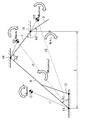
- FIG. 5 is a conceptual diagram illustrating a setting of post-excavation operation of the work machine 100 according to the first embodiment.
- the work machine 100 shows a case where the bucket 8 is moved to the soil removal position by the operation after excavation.
- the dump truck 200 is provided, and the work machine 100 discharges the earth and sand held by the bucket 8 on the loading platform of the dump truck 200.
- Point P10 is the excavation end point after the excavation operation, and is the turning start point (Start) at which the turning operation is started.
- the point P13 is a turning end point (Goal) at which the turning operation ends.
- the points P10 and P13 are three-dimensional coordinates and are stored in advance in the storage unit 32.
- the post-excavation operation setting unit 60 sets a first operation in which the boom 6 has a large vertical movement in the period after excavation and before soil removal, and a second operation in which the boom 6 has a small vertical movement.
- the post-excavation operation setting unit 60 raises the bucket 8 from the turning start point while turning the dump truck 200 so as not to interfere with the loading platform of the dump truck 200, and sets the height at the start of soil removal.
- the second operation of turning to the turning end point after setting the height at the start of excavation is set.
- Point P12 is a point where the first operation is switched to the second operation as a turning operation.
- the load measurement processing unit 52 executes a process of measuring the load inside the bucket 8 during the second operation period.
- the post-excavation motion setting unit 60 calculates the point P12 based on the point P10 and the point P13, and sets the section from the point P10 to the point P12 as the first operation and the point P12 to the point P13 as the second operation.
- the post-excavation motion setting unit 60 calculates the target bucket height HA for raising the bucket 8 based on the information at the points P10 and P13.
- the post-excavation operation setting unit 60 calculates a set period TB that raises the bucket 8 by the target bucket height HA based on the set speed in the vertical direction, which is the default value of the work machine 2.
- the storage unit 32 stores in advance a speed at which the boom 6 and the arm 7 are operated to raise or lower the bucket 8 as a set speed in the vertical direction, which is a default value of the work machine 2. Further, the turning speed is stored in advance in the storage unit 32.
- the post-excavation operation setting unit 60 calculates the point P12 based on the set period TB and the turning speed.
- the point P12 is calculated as a position where the target bucket height HA rises from the position of the point P10 and the turning angle ⁇ is swiveled based on the set period TB and the turning speed with reference to the central axis of the swivel body 3.
- the post-excavation operation setting unit 60 sets the height of the bucket 8 while controlling the swivel body 3 and the working machine 2 to perform the swivel operation for the set period TB until the bucket 8 reaches the point P10 to the point P12. Set to 1 operation.
- the post-excavation motion setting unit 60 sets the set period TA until the bucket 8 reaches the points P11 to P12 as the second motion in which only the swivel body 3 is controlled to execute the swivel motion.
- the load measurement processing unit 52 measures the load inside the bucket 8 during the period in which the second operation is executed.
- the period TA is a measurable period during which the load measurement processing unit 52 can measure the load inside the bucket 8.
- FIG. 6 is a diagram illustrating a bottom pressure of the boom cylinder 10 according to the first embodiment. As shown in FIG. 6, a case is shown in which an automatic control process for repeatedly executing a series of processes of excavation operation, post-excavation swivel operation, soil removal operation, and post-soil removal swivel operation is executed. A state in which the bottom pressure fluctuates based on the movement of the boom 6 during operation is shown.
- the first operation in which the boom 6 moves in the vertical direction is large and the second operation in which the boom 6 moves in the vertical direction is small are included.
- the bottom pressure is stable during the measurement period because the vertical movement of the boom 6 is small. Therefore, since the process of measuring the load inside the bucket 8 is executed during the second operation period when the bottom pressure is stable, highly accurate measurement process is possible.
- the state of the bottom pressure of the boom cylinder 10 is described, but the same applies to the state of the head pressure of the boom cylinder 10.
- the load measurement processing unit 52 can execute a process of measuring the load inside the bucket 8 when the bucket 8 reaches the point P12.
- the load measurement processing unit 52 executes a process of measuring the load inside the bucket 8 when the amount of change in the bottom pressure of the boom cylinder 10 detected by the pressure sensor 6b becomes equal to or less than a predetermined threshold value. May be good.
- the pressure sensor 6a may be used to execute a process of measuring the load inside the bucket 8 when the amount of change in the head pressure of the boom cylinder 10 is equal to or less than a predetermined threshold value. Good.
- the load measurement processing unit 52 has described the case of executing the process of measuring the load inside the bucket 8 when the point P12 is reached, the load measurement processing unit 52 is not limited to the predetermined position, and for example, the height of the bucket 8 is equal to or higher than the predetermined value. May be executed to measure the load inside the bucket 8 when the value is reached. Specifically, the load measurement processing unit 52 may execute a process of measuring the load inside the bucket 8 when the height of the bucket 8 rises by the target bucket height HA from the position of the point P10. ..
- the post-excavation operation setting unit 60 controls the work machine 2 and the swivel body 3 to raise the bucket 8 from the swivel start point in the period after excavation and before soil removal to start soil removal.
- the case where the first operation set to the height of the above is executed and only the swivel body 3 is controlled to execute the second operation has been described, but the present invention is not particularly limited to this.
- the post-excavation operation setting unit 60 controls only the swivel body 3 to execute the second operation in the period after excavation and before soil removal, and controls the work machine 2 and the swivel body 3 to discharge the bucket 8. It may be set to execute the first operation set near the height at the start of soil.
- the load measurement processing unit 52 executes a process of measuring the load inside the bucket 8 during the second operation in which the vertical movement of the boom 6 is small in the period after excavation and before soil removal. The case of doing so was explained.
- the measurable period TA is a predetermined period or longer in order to perform highly accurate measurement.
- FIG. 7 is a block diagram illustrating a functional configuration of the arithmetic unit 31 # of the work machine 100 based on the first modification of the first embodiment.
- the arithmetic unit 31 # is different from the arithmetic unit 31 described with reference to FIG. 4 in that the post-excavation operation setting unit 60 is replaced with the post-excavation operation setting unit 60 #. Since the other configurations are the same as those described in FIG. 4, the detailed description thereof will not be repeated.
- the post-excavation operation setting unit 60 # includes a turning target period calculation unit 64 and a setting unit 66.
- the turning target period calculation unit 64 calculates the first turning target period of the turning body 3 based on the turning start point and the turning end point of the turning body 3 and the turning speed of the turning body 3.
- the setting unit 66 determines whether or not the first turning target period is equal to or longer than a predetermined period. When the first turning target period is equal to or longer than the predetermined period, the setting unit 66 performs the first and second operations to measure the load inside the bucket 8 during at least the predetermined period. Set the operation. When the first turning target period is not equal to or longer than the predetermined period, the setting unit 66 performs the first and second operations so as to execute the second operation for the predetermined period or longer in order to measure the load inside the bucket 8. Set.
- the post-excavation operation setting unit 60 # calculates the first turning target period of the turning body 3 based on the turning start point and the turning end point of the turning body 3 and the turning speed of the turning body 3.
- the post-excavation motion setting unit 60 # determines whether or not the first turning target period is equal to or longer than a predetermined period. When the first turning target period is equal to or longer than the predetermined period, the post-excavation motion setting unit 60 # is so as to execute the second motion to measure the load inside the bucket 8 during at least the predetermined period. Set the 1st and 2nd operations.
- FIG. 8 is a conceptual diagram illustrating a setting of post-excavation operation of the work machine 100 according to the first modification of the first embodiment.
- the work machine 100 shows a case where the bucket 8 is moved to the soil removal position by the operation after excavation.
- the dump truck 200 is provided, and the work machine 100 discharges the earth and sand held by the bucket 8 on the loading platform of the dump truck 200.
- the post-excavation operation setting unit 60 # has a first operation of raising the bucket 8 from the turning start point and setting it to the height at the start of soil removal so as not to interfere with the loading platform of the dump truck 200, and soil discharge. After setting the height at the start, the second operation of turning to the turning end point is set.
- the turning target period calculation unit 64 calculates the turning angle ⁇ based on the central axes of the point P10, the point P13, and the turning body 3.
- the turning target period calculation unit 64 calculates the first turning target period T for turning the turning body 3 from the turning start point to the turning end point based on the turning angle ⁇ and the turning speed.
- the setting unit 66 determines whether or not the first turning target period T is equal to or longer than the predetermined period Tp. When the first turning target period T is equal to or longer than the predetermined period Tp, the setting unit 66 first executes the second operation to measure the load inside the bucket 8 during at least the predetermined period Tp or more. And set the second operation. When the first turning target period T is not equal to or longer than the predetermined period Tp, the setting unit 66 performs the first and first operations so as to execute the second operation for the predetermined period Tp or more in order to measure the load inside the bucket 8. 2 Set the operation.
- the setting unit 66 uses the remaining period Tq obtained by subtracting the predetermined period Tp from the first turning target period T to rotate the bucket 8 from the turning start point so as not to interfere with the loading platform of the dump truck 200. Set the first operation to raise and efficiently set the height at the start of soil removal.
- the setting unit 66 calculates the target bucket height HA for raising the bucket 8 based on the information of the points P10 and P13.
- the setting unit 66 calculates a set period TB for raising the bucket 8 by the target bucket height HA based on the set speed in the vertical direction, which is the default value of the work machine 2.
- the storage unit 32 stores in advance a speed at which the boom 6 and the arm 7 are operated to raise or lower the bucket 8 as a set speed in the vertical direction, which is a default value of the work machine 2.
- the setting unit 66 compares the period Tq and the set period TB, and describes the case where the period Tq is equal to or longer than the set period TB.
- the setting unit 66 sets the setting period TB of the period Tq to a period during which the first operation of setting the height of the bucket 8 is executed while controlling the swivel body 3 and the working machine 2 to perform the swivel operation.
- the setting unit 66 sets the period TA in which the set period TB is subtracted from the first turning target period T to the period in which only the turning body 3 is controlled to execute the second operation.
- the load measurement processing unit 52 measures the load inside the bucket 8 during the period in which the second operation is executed.
- the period TA is a measurable period during which the load measurement processing unit 52 can measure the load inside the bucket 8.
- the setting unit 66 sets the first and second operations so that the second operation of Tp for a predetermined period is always secured in the period after excavation and before soil removal.
- the predetermined period Tp is provided in the load measurement processing unit 52 to acquire a plurality of sampling points such as displacement amounts, head pressures, bottom pressures, etc. of the cylinders 10, 11 and 12 in order to measure a load with high accuracy. ing.
- the load measurement processing unit 52 can sufficiently acquire sampling points for measuring a load with high accuracy.
- the load measurement processing unit 52 executes a process of measuring the load inside the bucket 8 during the second operation in which the pressure of the hydraulic cylinder whose vertical movement of the boom 6 is small is stable, highly accurate measurement processing is possible. Is.
- the setting of the first and second operations of the setting unit 66 in the above is an example.
- the setting unit 66 controls only the swivel body 3 in the period after excavation and before soil removal so that the second operation of Tp for a predetermined period is secured from the turning start point, and turns using the period Tq. It is also possible to raise the bucket 8 while operating it and set it to execute the first operation of setting the height at the start of soil removal.
- the setting unit 66 may adjust the turning speed so that the second operation of the predetermined period Tp is secured as an example.
- the first turning target period T may be lengthened by slowing the turning speed to set the first and second movements in which the second movement of the predetermined period Tp or more is secured.
- FIG. 9 is a diagram illustrating a setting flow of the post-excavation operation by the post-excavation operation setting unit 60 # according to the first modification of the first embodiment.
- the post-excavation motion setting unit 60 # executes a process of calculating the turning target period (step S2).
- the turning target period calculation unit 64 calculates the turning angle ⁇ based on the turning start point P10, the turning end point P13, and the central axis of the turning body 3.
- the turning target period calculation unit 64 calculates the first turning target period T for turning the turning body 3 based on the turning angle ⁇ and the turning speed.
- the post-excavation operation setting unit 60 # determines whether or not the first turning target period is equal to or longer than a predetermined period (step S4).
- the setting unit 66 determines whether or not the first turning target period T is equal to or longer than the predetermined period Tp.
- the post-excavation operation setting unit 60 # determines that the first turning target period is equal to or longer than the predetermined period (YES in step S4)
- the first operation is executed so as to execute the second operation for the predetermined period or longer.
- the second operation is set (step S6).
- the process ends (end).
- the setting unit 66 sets the first and second operations so that the second operation of Tp for a predetermined period is surely secured in the period after excavation and before soil removal.
- step S4 when the post-excavation operation setting unit 60 # determines that the first turning target period is not equal to or longer than the predetermined period (NO in step S4), the turning speed is adjusted (step S8). Then, the process proceeds to step S6, and the post-excavation motion setting unit 60 sets the first and second motion turning motions so as to execute the second motion for a predetermined period or longer.
- the setting unit 66 adjusts and slows down the set turning speed of the turning body 3. Therefore, it is possible to lengthen the first turning target period T based on the adjusted turning speed. As described above, the setting unit 66 sets the first and second operations so that the second operation of Tp for a predetermined period is always secured in the period after excavation and before soil removal.
- the load measurement processing unit 52 can secure a measurable period of Tp or more for a predetermined period, and can sufficiently acquire sampling points for measuring the load. As a result, the load measurement processing unit 52 can perform highly accurate measurement processing.
- the load measurement processing unit 52 uses the start timing of soil removal as a trigger to acquire data for a predetermined period before soil removal, and executes a process of measuring the load inside the bucket 8. Is also good.
- Modification 2 In the first modification of the first embodiment, the case where the period Tq is equal to or longer than the set period TB has been described by comparing the period Tq and the set period TB in FIG. On the other hand, comparing the period Tq and the set period TB, it is possible that the period TB is longer than the period Tq. In this case, the measurable period TA may not be secured for a predetermined period Tp or more.
- the setting unit 66 compares the period Tq and the set period TB, and when the period TB is longer than the set period Tq, adjusts the set speed in the vertical direction, which is the default value of the work machine 2.
- the set period TB can be shortened by increasing the ascending speed of the boom 6 and the arm 7.
- the hydraulic oil distributed to the arm cylinder 11 may be accommodated in the boom cylinder 10 to accelerate the boom 6. By accelerating the boom 6, it is possible to increase the ascending speed and shorten the set period TB.
- the setting unit 66 adjusts the set speed in the vertical direction, which is the default value of the work machine 2, and shortens the set period TB for executing the first operation, thereby shortening the set period TB. It is possible to set the first and second operations so that the second operation of the above is always secured.
- the setting unit 66 may set the execution of the pre-turning preparatory process so that the second operation of Tp for a predetermined period is surely secured in the period after excavation and before soil removal.
- FIG. 10 is a block diagram illustrating a functional configuration of the arithmetic unit 31P of the work machine 100 based on the second modification of the first embodiment.
- the arithmetic unit 31P is different from the configuration of the arithmetic unit 31 # of FIG. 7 in that the post-excavation operation setting unit 60 # is replaced with the post-excavation operation setting unit 60P. Since the other configurations are the same, the detailed description thereof will not be repeated.
- the post-excavation operation setting unit 60P is different from the post-excavation operation setting unit 60 in that a pre-turning preparatory processing setting unit 69 is further provided.
- the post-excavation operation setting unit 60P determines that the measurable period TA cannot be secured for a predetermined period Tp or more, it sets the execution of the pre-turning preparatory process so that the measurable period TA becomes the predetermined period Tp or more.
- the pre-turning preparation processing setting unit 69 controls the work machine 2 before the start of the turning operation of the turning body 3 as a part of the first operation according to the instruction of the setting unit 66 to adjust the height of the bucket 8. Set the execution of the pre-turn preparatory process to be adjusted.
- FIG. 11 is a conceptual diagram illustrating a setting of post-excavation operation of the work machine 100 according to the second modification of the first embodiment.
- the work machine 100 shows a case where the bucket 8 is moved to the soil removal position by the operation after excavation as described in FIG. Then, the turning start point at which the turning operation is started is different.
- the point P10 is the excavation end point after the excavation operation.
- Point P11 is a turning start point at which the turning operation is started.
- Point P13 is a turning end point at which the turning operation ends.
- the pre-turning preparatory processing setting unit 69 sets the execution of the pre-turning preparatory processing that controls the work machine 2 from the point P10 to the point P11 to raise the height of the bucket 8.
- the post-excavation motion control unit 50 controls the work machine 2 before the start of the swivel operation of the swivel body 3 according to the setting of the pre-swivel preparatory process setting unit 69 to adjust the height of the bucket 8.
- the turning start point at which the turning operation is started by the pre-turning preparatory process is changed from P10 to P11.
- the target bucket height from the turning start point P11 is adjusted to HA #.
- the set period TB # that raises the bucket 8 to the height at the start of soil removal is shortened so that the second operation of the predetermined period Tp or more is always secured in the period after excavation and before soil removal. It is possible to set the execution of the pre-turn preparatory process to.
- the turning start point at which the turning operation is started is adjusted by setting the execution of the pre-turning preparation process so that the second operation of Tp or more for a predetermined period is always secured. Since the process of measuring the load inside the bucket 8 is executed during the second operation, highly accurate measurement process is possible. (Modification example 3) In the above, the case where the process of measuring the load inside the bucket 8 is executed in the period after excavation and before excavation has been described, but the load inside the bucket 8 is measured in the period after excavation and before excavation. The same can be applied when executing a process.
- FIG. 12 is a block diagram illustrating a functional configuration of the arithmetic unit 31Q of the work machine 100 based on the third modification of the first embodiment.
- the arithmetic unit 31Q is different from the configuration of the arithmetic unit 31 # described with reference to FIG. 7 in that it is further provided with a post-earth removal operation setting unit 70 for setting the operation after earth removal. .. Since the other configurations are the same as those described with reference to FIG. 7, the detailed description thereof will not be repeated.
- the operation setting unit 70 after excavation of soil controls the swivel operation by the swivel body 3 (swivel operation after excavation) and at least one of the working machines 2 to control the bucket 8 after excavation. Set the operation to move to the excavation position.
- the post-earthquake operation setting unit 70 sets a third operation in which the boom 6 has a large vertical movement in the period after excavation and before excavation, and a fourth operation in which the boom 6 has a small vertical movement.
- the post-earthquake operation control unit 58 executes the third operation and the fourth operation set by the post-excavation operation setting unit 70 in the period after excavation and before excavation.
- the soil removal operation control unit 58 moves the soil removal operation bucket 8 to the excavation position by controlling at least one of the rotation operation (soil removal operation) by the swivel body 3 and the work machine 2.
- the post-soil removal operation control unit 58 executes a third operation in which the boom 6 has a large vertical movement and a fourth operation in which the boom 6 has a small vertical movement.
- the excavation operation control unit 54 again controls the work machine 2 to execute an excavation operation for excavating earth and sand or the like, which is an object to be excavated, using the bucket 8. Subsequent operations are the same as above and are repeatedly executed.
- the post-soil removal operation control unit 58 and the post-soil removal operation setting unit 70 are examples of the “second operation control unit” and the “second operation setting unit” of the present disclosure.
- FIG. 13 is a conceptual diagram illustrating the setting of the operation after soil removal of the work machine 100 according to the third modification of the first embodiment.
- the work machine 100 shows a case where the bucket 8 is moved to the excavation position by the operation after excavation.
- a dump truck 200 is provided, and the work machine 100 moves the bucket 8 that has been excavated on the loading platform of the dump truck 200 to the excavation position.
- Point P13 # is the soil discharge end point after the soil discharge operation, and is the turning start point (Start) at which the turning operation is started.
- the point P10 # is a turning end point (Goal) at which the turning operation ends.
- the points P10 # and P13 # are three-dimensional coordinates and are stored in advance in the storage unit 32.
- the post-earthquake operation setting unit 70 sets a third operation in which the boom 6 has a large vertical movement in the period after excavation and before excavation, and a fourth operation in which the boom 6 has a small vertical movement.
- the post-soil removal operation setting unit 70 performs a fourth operation of turning the bucket 8 from the turning start point while maintaining the height at the end of soil removal so as not to interfere with the loading platform of the dump truck 200, and discharging.
- a third operation is set in which the height is lowered from the height at the end of soil and set to the height at the start of excavation.
- Point P12 # is a point where the fourth operation is switched to the third operation as a turning operation.
- the load measurement processing unit 52 executes a process of measuring the load inside the bucket 8 during the fourth operation period.
- the post-excretion operation setting unit 70 calculates the point P12 based on the points P10 # and the point P13 #, the section from the point P13 # to the point P12 # is the fourth operation, and the point P12 # to the point P10 # is the third. Set to operation.
- the post-earthquake operation setting unit 70 calculates the target bucket height HAP for lowering the bucket 8 based on the information of the points P10 # and the points P13 #.
- the operation setting unit 70 after excavation calculates the set period TTB for lowering the bucket 8 by the target bucket height HAP based on the set speed in the vertical direction, which is the default value of the work machine 2.
- the storage unit 32 stores in advance a speed at which the boom 6 and the arm 7 are operated to raise or lower the bucket 8 as a set speed in the vertical direction, which is a default value of the work machine 2. Further, the turning speed is stored in advance in the storage unit 32.
- the operation setting unit 70 after excavation calculates the point P12 # based on the set period TTB and the turning speed.
- the point P12 # swivels by a turning angle ⁇ minutes based on the set period TTB and the turning speed with reference to the central axis of the swivel body 3, and the target bucket is moved from the height of the point P13 #. It is calculated as the position when descending by the height HAP.
- the operation setting unit 70 after excavation sets the set period TTA until the bucket 8 reaches the points P13 # to the point P12 # as the fourth operation in which only the swivel body 3 is controlled to execute the swivel operation.
- the operation setting unit 70 after excavating the soil adjusts the height of the bucket 8 while controlling the swivel body 3 and the working machine 2 to perform the swivel operation for the set period TTB until the bucket 8 reaches the points P12 # to the point P10 #. Set to the third operation to be set.
- the load measurement processing unit 52 measures the load inside the bucket 8 during the period in which the fourth operation is executed.
- the period TTA is a measurable period during which the load measurement processing unit 52 can measure the load inside the bucket 8.
- FIG. 14 is a diagram illustrating the bottom pressure of the boom cylinder 10 according to the third modification of the first embodiment.
- FIG. 14 a case is shown in which an automatic control process for repeatedly executing a series of processes of excavation operation, post-excavation swivel operation, soil discharge operation, and post-soil excavation swivel operation is executed. A state in which the bottom pressure fluctuates based on the movement of the boom 6 during operation is shown.
- the first operation in which the boom 6 moves in the vertical direction is large and the second operation in which the boom 6 moves in the vertical direction is small are included.
- the bottom pressure is stable during the measurement period because the vertical movement of the boom 6 is small. Therefore, since the process of measuring the load inside the bucket 8 is executed during the period when the bottom pressure is stable, the measurement process with high accuracy is possible.
- the third operation in which the vertical movement of the boom 6 is large and the fourth operation in which the vertical movement of the boom 6 is small are included.
- the bottom pressure is stable during the measurement period because the vertical movement of the boom 6 is small. Therefore, since the process of measuring the load inside the bucket 8 is executed during the period when the bottom pressure is stable, the measurement process with high accuracy is possible.
- the state of the bottom pressure of the boom cylinder 10 is described, but the same applies to the state of the head pressure of the boom cylinder 10.
- FIG. 15 is a diagram illustrating a configuration of a hydraulic system of the work machine 100 according to the second embodiment.
- the work machine 100 includes a boom cylinder 10 for driving the boom 6, an arm cylinder 11 for driving the arm 7, a bucket cylinder 12 for driving the bucket 8, and a swivel motor for swiveling the swivel body 3. It includes 124, a controller 130 for controlling the work machine 100, an engine 138, a hydraulic pump 140, a main valve 125, a self-pressure reducing valve 146, and an EPC valve 150.
- the engine 138 is, for example, a diesel engine.
- the hydraulic pump 140 is driven by the engine 138 to discharge hydraulic oil.
- the hydraulic pump 140 is a variable displacement hydraulic pump. It may be a fixed-capacity hydraulic pump that changes the discharge amount of hydraulic oil according to the rotation speed of the engine 138.
- the main valve 125 receives the hydraulic oil supplied from the hydraulic pump 140, and distributes and supplies the hydraulic oil to the boom cylinder 10, the arm cylinder 11, the bucket cylinder 12, and the swivel motor 124, respectively.
- the controller 130 outputs a command current to the EPC valve 150.
- the EPC valve 150 controls the main valve 125 according to the command current from the controller 130.
- the hydraulic oil output from the hydraulic pump 140 is reduced to a constant pressure by the self-pressure pressure reducing valve 146 and supplied for the pilot.
- the controller 130 is composed of an arithmetic unit 131 (for example, a CPU (Central Processing Unit)), a storage unit 132, and the like, and controls the work machine 100 by executing a program or the like stored in the storage unit 132. ..
- an arithmetic unit 131 for example, a CPU (Central Processing Unit)
- a storage unit 132 for example, a hard disk drive, a solid state drive, or the like.
- the work machine 100 further includes an operation device 180 for operating the boom 6, a load measurement button 160, and a display 170.
- FIG. 16 is a block diagram illustrating a functional configuration of the arithmetic unit 131 of the work machine 100 based on the second embodiment.
- the arithmetic unit 131 of the work machine 100 based on the second embodiment has a load measurement processing unit 52 # that measures the load inside the bucket 8 and a boom restriction control unit 59 that limits the movement of the boom 6. And a display control unit 55 that controls the display content of the display 170.
- the load measurement processing unit 52 # measures the load inside the bucket 8 according to the operation instruction of the load measurement button 160. Since the measurement method is the same as that described in the first embodiment, the details thereof will not be repeated.
- the boom limiting control unit 59 limits the movement of the boom 6 according to the operation instruction of the load measurement button 160.
- the boom limit control unit 59 invalidates the input from the operation device 180 that operates the boom 6 according to the operation instruction of the load measurement button 160 for a predetermined period.
- the load measurement processing unit 52 # measures the load inside the bucket 8 during a predetermined period in which the movement of the boom 6 is restricted according to the operation instruction of the load measurement button 160.
- the case where the input from the operation device 180 that operates the boom 6 according to the operation instruction of the load measurement button 160 is invalidated for a predetermined period has been described, but the EPC valve is not invalid and is based on the operation command of the boom 6.
- the command current to 150 may be adjusted. Specifically, the movement of the boom 6 may be restricted by setting the upper limit value of the command current. Alternatively, the output of the command current to the EPC valve 150 based on the boom operation command may be delayed. Since the process of measuring the load inside the bucket 8 is executed during the period when the pressure of the boom cylinder 10 whose vertical movement of the boom 6 is restricted by the process is relatively stable, highly accurate measurement process is possible. is there.
- the method of limiting the movement of the boom 6 according to the operation instruction of the load measurement button 160 has been described, but the operator is urged to limit the movement of the boom 6 instead of forcibly limiting the movement of the boom 6.
- the guidance screen may be displayed.
- the display control unit 55 displays a guidance screen on the display 170 according to the operation instruction of the load measurement button 160.
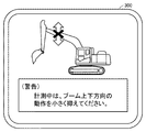
- FIG. 17 is a diagram illustrating a guidance screen during the measurement period according to the second embodiment.
- the guidance screen 300 displayed on the display 170 is shown with reference to FIG.
- the message "Please keep the movement in the vertical direction of the boom small during (warning) measurement" is displayed.
- the operator can prompt the operation of the boom 6 by the operating device 180.
- This process promotes the suppression of the vertical movement of the boom 6, and by executing the process of measuring the load inside the bucket 8 during the period when the pressure of the boom cylinder 10 is relatively stable, a highly accurate measurement process can be performed. It is possible.
- the above guidance screen may be displayed while forcibly restricting the movement of the boom 6.
- the display control unit 55 has described the case where the guidance screen is displayed on the display 170 according to the operation instruction of the load measurement button 160, but the guidance to the display 170 is based on the operation instruction of the boom 6 by the operation device 180.
- the screen may be displayed. For example, when the amount of operation of the boom 6 by the operating device 180 is equal to or greater than a predetermined amount, the guidance screen may be displayed assuming that the boom 6 has a large vertical movement.
- a speaker may be used to notify the warning sound.
- the message on the guidance screen 300 may be notified by using a speaker.
- a hydraulic excavator (backhoe) is mentioned as an example of a work machine, but it is not limited to the hydraulic excavator (backhoe), and other than a loading excavator, a mechanical rope excavator, an electric excavator, a wheel loader, a bucket crane and the like. It is also applicable to various types of work machines.
Landscapes
- Engineering & Computer Science (AREA)
- Mining & Mineral Resources (AREA)
- General Engineering & Computer Science (AREA)
- Civil Engineering (AREA)
- Structural Engineering (AREA)
- Mechanical Engineering (AREA)
- Physics & Mathematics (AREA)
- Fluid Mechanics (AREA)
- Life Sciences & Earth Sciences (AREA)
- General Life Sciences & Earth Sciences (AREA)
- Paleontology (AREA)
- General Physics & Mathematics (AREA)
- Operation Control Of Excavators (AREA)
- Component Parts Of Construction Machinery (AREA)
Abstract
This work machine comprises: a work apparatus including a bucket and a boom; a turning body on which the work apparatus is mounted and which performs a turning operation; a first operation setting unit which sets, for a period after excavation but before soil removal, a first operation in which the movement of the boom in the vertical direction is large, and a second operation in which the movement of the boom in the vertical direction is small; a first operation control unit which controls the work apparatus and/or the turning body to execute the first operation and the second operation; and a load measurement processing unit which measures a load inside the bucket in the period of the second operation.
Description
本開示は、作業機械および作業機械の制御方法に関する。
This disclosure relates to a work machine and a control method for the work machine.
従来より、バケット内の荷重を計測することは作業機械の仕事量を知る上で重要である。
Conventionally, measuring the load inside the bucket is important for knowing the workload of the work machine.
この点で、特許文献1(特開2018-48548号公報)には、作業機械の油圧シリンダの圧力センサの情報を用いてバケット内の荷重を推定する方式が提案されており、静止状態でバケット内の荷重を推定する方式が提案されている(特許文献1)。
In this regard, Patent Document 1 (Japanese Unexamined Patent Publication No. 2018-48548) proposes a method of estimating the load in the bucket using the information of the pressure sensor of the hydraulic cylinder of the work machine, and the bucket is in a stationary state. A method of estimating the load inside has been proposed (Patent Document 1).
しかしながら、静止状態の期間に荷重を推定する場合には、当該期間を確保する必要があるため作業サイクルの期間が長くなる可能性がある。
However, when estimating the load during the stationary state, the work cycle period may become longer because it is necessary to secure the relevant period.
この点で、特許文献2(特表2011-516755号公報)には、作業機械の旋回動作中にバケット内の荷重を推定する方式が提案されている。
In this respect, Patent Document 2 (Japanese Patent Laid-Open No. 2011-516755) proposes a method of estimating the load in the bucket during the turning operation of the work machine.
一方で、作業機械の旋回動作中に油圧シリンダの圧力が不安定となる場合があり、その際にバケット内の荷重を推定した場合には、バケット内の荷重を正確に計測することができない。
On the other hand, the pressure of the hydraulic cylinder may become unstable during the turning operation of the work machine, and if the load in the bucket is estimated at that time, the load in the bucket cannot be measured accurately.
したがって、掘削後、排土前の期間において、油圧シリンダの圧力が安定した状態となるように作業機械の動作を設定することが重要である。
Therefore, it is important to set the operation of the work machine so that the pressure of the hydraulic cylinder becomes stable during the period after excavation and before soil removal.
本開示の目的は、掘削後、排土前の期間において精度の高いバケット内の荷重の計測が可能な作業機械および作業機械の制御方法を提供することである。
An object of the present disclosure is to provide a work machine and a control method of the work machine capable of measuring the load in the bucket with high accuracy in the period after excavation and before soil removal.
本開示のある局面に従う作業機械は、バケットおよびブームを含む作業機と、作業機を搭載し、旋回動作を行う旋回体と、掘削後、排土前の期間におけるブームの上下方向の動きが大きい第1動作と、ブームの上下方向の動きが小さい第2動作とを設定する第1動作設定部と、作業機および旋回体の少なくとも一方を制御して第1動作および第2動作を実行する第1動作制御部と、第2動作の期間にバケット内部の荷重を計測する荷重計測処理部とを備える。
The work machine according to a certain aspect of the present disclosure includes a work machine including a bucket and a boom, a swivel body on which the work machine is mounted and performs a swivel operation, and a large vertical movement of the boom in the period after excavation and before soil removal. A first operation setting unit that sets a first operation and a second operation in which the boom moves in a small vertical direction, and a first operation that controls at least one of a work machine and a swivel body to execute the first operation and the second operation. It includes one operation control unit and a load measurement processing unit that measures the load inside the bucket during the second operation period.
本開示のある局面に従う作業機械の制御方法は、掘削後、排土前の期間におけるバケットおよびブームを含む作業機のブームの上下方向の動きが大きい第1動作と、ブームの上下方向の動きが小さい第2動作とを設定するステップと、作業機および作業機を搭載し、旋回動作を行う旋回体の少なくとも一方を制御して第1動作および第2動作を実行するステップと、第2動作の期間にバケット内部の荷重を計測するステップとを備える。
According to a certain aspect of the present disclosure, the control method of the work machine includes the first operation in which the boom of the work machine including the bucket and the boom moves in the vertical direction in the period after excavation and before the soil is discharged, and the movement in the vertical direction of the boom. A step of setting a small second motion, a step of mounting a work machine and a work machine, and controlling at least one of the swivel bodies that perform the swivel motion to execute the first motion and the second motion, and a step of performing the second motion. It is provided with a step of measuring the load inside the bucket during the period.
本開示の作業機械および作業機械の制御方法は、精度の高いバケット内の荷重の計測が可能である。
The work machine and the control method of the work machine of the present disclosure can measure the load in the bucket with high accuracy.
以下、実施形態について図面を参照しながら説明する。以下の説明では、同一部品には、同一の符号を付している。それらの名称および機能の同じである。したがって、それらについての詳細な説明については繰り返さない。
Hereinafter, the embodiment will be described with reference to the drawings. In the following description, the same parts are designated by the same reference numerals. They have the same name and function. Therefore, the detailed explanation of them will not be repeated.
(実施形態1)
<作業機械の全体構成>
図1は、実施形態1に基づく作業機械100の外観図である。 (Embodiment 1)
<Overall configuration of work machine>
FIG. 1 is an external view of thework machine 100 based on the first embodiment.
<作業機械の全体構成>
図1は、実施形態1に基づく作業機械100の外観図である。 (Embodiment 1)
<Overall configuration of work machine>
FIG. 1 is an external view of the
図1に示されるように、本開示の思想を適用可能な作業機械として油圧により作動する作業機2を備える油圧ショベルを例に挙げて説明する。
As shown in FIG. 1, a hydraulic excavator including a work machine 2 operated by a flood control as a work machine to which the idea of the present disclosure can be applied will be described as an example.
作業機械100は、車両本体1と、作業機2とを備える。
車両本体1は、旋回体3と、運転室4と、走行装置5とを有する。 Thework machine 100 includes a vehicle body 1 and a work machine 2.
Thevehicle body 1 has a swivel body 3, a driver's cab 4, and a traveling device 5.
車両本体1は、旋回体3と、運転室4と、走行装置5とを有する。 The
The
旋回体3は、走行装置5の上に配置される。走行装置5は、旋回体3を支持する。旋回体3は、旋回軸AXを中心に旋回可能である。運転室4には、オペレータが着座する運転席4Sが設けられる。オペレータは、運転室4において作業機械100を操作する。走行装置5は、一対の履帯5Crを有する。履帯5Crの回転により、作業機械100が走行する。走行装置5は、車輪(タイヤ)で構成されていてもよい。
The swivel body 3 is arranged on the traveling device 5. The traveling device 5 supports the swivel body 3. The swivel body 3 can swivel around the swivel shaft AX. The driver's cab 4 is provided with a driver's seat 4S on which the operator sits. The operator operates the work machine 100 in the driver's cab 4. The traveling device 5 has a pair of tracks 5Cr. The work machine 100 runs by the rotation of the track 5Cr. The traveling device 5 may be composed of wheels (tires).
運転席4Sに着座したオペレータを基準として各部の位置関係について説明する。前後方向とは、運転席4Sに着座したオペレータの前後方向をいう。左右方向とは、運転席4Sに着座したオペレータを基準とした左右方向をいう。左右方向は、車両の幅方向(車幅方向)に一致する。運転席4Sに着座したオペレータに正面に正対する方向を前方向とし、前方向とは反対の方向を後方向とする。運転席4Sに着座したオペレータが正面に正対したとき右側、左側をそれぞれ右方向、左方向とする。
The positional relationship of each part will be explained with reference to the operator seated in the driver's seat 4S. The front-rear direction means the front-rear direction of the operator seated in the driver's seat 4S. The left-right direction refers to the left-right direction with respect to the operator seated in the driver's seat 4S. The left-right direction coincides with the width direction of the vehicle (vehicle width direction). The direction facing the front of the operator seated in the driver's seat 4S is the front direction, and the direction opposite to the front direction is the rear direction. When the operator seated in the driver's seat 4S faces the front, the right side and the left side are the right direction and the left direction, respectively.
旋回体3は、エンジンが収容されるエンジンルーム9と、旋回体3の後部に設けられるカウンタウェイトとを有する。旋回体3において、エンジンルーム9の前方に手すり19が設けられる。エンジンルーム9には、エンジン及び油圧ポンプなどが配置されている。
The swivel body 3 has an engine room 9 in which the engine is housed and a counter weight provided at the rear of the swivel body 3. In the swivel body 3, a handrail 19 is provided in front of the engine room 9. An engine, a hydraulic pump, and the like are arranged in the engine room 9.
作業機2は、旋回体3に搭載されて支持される。作業機2は、ブーム6と、アーム7と、バケット8と、ブームシリンダ10と、アームシリンダ11と、バケットシリンダ12とを有する。
The work machine 2 is mounted on and supported by the swivel body 3. The working machine 2 has a boom 6, an arm 7, a bucket 8, a boom cylinder 10, an arm cylinder 11, and a bucket cylinder 12.
ブーム6は、ブームピン13を介して旋回体3に接続される。アーム7は、アームピン14を介してブーム6に接続される。バケット8は、バケットピン15を介してアーム7に接続される。ブームシリンダ10は、ブーム6を駆動する。アームシリンダ11は、アーム7を駆動する。バケットシリンダ12は、バケット8を駆動する。ブーム6の基端部(ブームフート)と旋回体3とが接続される。ブーム6の先端部(ブームトップ)とアーム7の基端部(アームフート)とが接続される。アーム7の先端部(アームトップ)とバケット8の基端部とが接続される。ブームシリンダ10、アームシリンダ11およびバケットシリンダ12はいずれも、作動油によって駆動される油圧シリンダである。
The boom 6 is connected to the swivel body 3 via the boom pin 13. The arm 7 is connected to the boom 6 via the arm pin 14. The bucket 8 is connected to the arm 7 via the bucket pin 15. The boom cylinder 10 drives the boom 6. The arm cylinder 11 drives the arm 7. The bucket cylinder 12 drives the bucket 8. The base end portion (boom foot) of the boom 6 and the swivel body 3 are connected. The tip end portion (boom top) of the boom 6 and the base end portion (arm foot) of the arm 7 are connected. The tip end portion (arm top) of the arm 7 and the base end portion of the bucket 8 are connected. The boom cylinder 10, arm cylinder 11, and bucket cylinder 12 are all hydraulic cylinders driven by hydraulic oil.
ブーム6は、中心軸であるブームピン13を中心に旋回体3に対して回転可能である。アーム7は、ブームピン13と平行な中心軸であるアームピン14を中心にブーム6に対して回転可能である。バケット8は、ブームピン13およびアームピン14と平行な中心軸であるバケットピン15を中心にアーム7に対して回転可能である。
The boom 6 is rotatable with respect to the swivel body 3 about the boom pin 13 which is the central axis. The arm 7 is rotatable with respect to the boom 6 about the arm pin 14, which is a central axis parallel to the boom pin 13. The bucket 8 is rotatable with respect to the arm 7 about a bucket pin 15 which is a central axis parallel to the boom pin 13 and the arm pin 14.
なお、ブーム6、バケット8、作業機2、旋回体3は、本開示の「ブーム」、「バケット」、「作業機」、「旋回体」の一例である。
The boom 6, bucket 8, working machine 2, and swivel body 3 are examples of the "boom", "bucket", "working machine", and "swivel body" of the present disclosure.
図2は、実施形態1に基づく作業機械100を模式的に説明する図である。
図2には、作業機械100の側面図が示される。 FIG. 2 is a diagram schematically illustrating awork machine 100 based on the first embodiment.
FIG. 2 shows a side view of thework machine 100.
図2には、作業機械100の側面図が示される。 FIG. 2 is a diagram schematically illustrating a
FIG. 2 shows a side view of the
ブームシリンダ10のヘッド側には、圧力センサ6aが取り付けられている。圧力センサ6aは、ブームシリンダ10のシリンダヘッド側油室40A(図3)内の作動油の圧力(ヘッド圧)を検出することができる。ブームシリンダ10のボトム側には、圧力センサ6bが取り付けられている。圧力センサ6bは、ブームシリンダ10のシリンダボトム側油室40B(図3)内の作動油の圧力(ボトム圧)を検出することができる。
A pressure sensor 6a is attached to the head side of the boom cylinder 10. The pressure sensor 6a can detect the pressure (head pressure) of the hydraulic oil in the cylinder head side oil chamber 40A (FIG. 3) of the boom cylinder 10. A pressure sensor 6b is attached to the bottom side of the boom cylinder 10. The pressure sensor 6b can detect the pressure (bottom pressure) of the hydraulic oil in the cylinder bottom side oil chamber 40B (FIG. 3) of the boom cylinder 10.
ブームシリンダ10、アームシリンダ11およびバケットシリンダ12のそれぞれには、ストロークセンサ(検知部)7a、7b、7cが取り付けられている。
Stroke sensors (detection units) 7a, 7b, and 7c are attached to the boom cylinder 10, arm cylinder 11, and bucket cylinder 12, respectively.
ストロークセンサ7a、7b、7cと、圧力センサ6a、6bとの各々は、コントローラ30の演算装置31に電気的に接続されている。
Each of the stroke sensors 7a, 7b, 7c and the pressure sensors 6a, 6b is electrically connected to the arithmetic unit 31 of the controller 30.
演算装置31は、ブームシリンダ10におけるストロークセンサ7aのセンサ出力に基づいてブーム角A1を算出する。演算装置31は、アームシリンダ11におけるストロークセンサ7bのセンサ出力に基づいてアーム角A2を算出する。演算装置31は、バケットシリンダ12におけるストロークセンサ7cのセンサ出力に基づいてバケット角A3を算出する。なお、本例においては、ストロークセンサ7a、7b、7cのセンサ出力に基づいてブーム角A1、アーム角A2、バケット角A3を算出する場合について説明するが特にこれに限られず、例えばブーム6、アーム7、バケット8に取り付けた慣性計測装置(IMU:inertial measurement unit)を用いてブーム角A1、アーム角A2、バケット角A3を算出することも可能である。
The arithmetic unit 31 calculates the boom angle A1 based on the sensor output of the stroke sensor 7a in the boom cylinder 10. The arithmetic unit 31 calculates the arm angle A2 based on the sensor output of the stroke sensor 7b in the arm cylinder 11. The arithmetic unit 31 calculates the bucket angle A3 based on the sensor output of the stroke sensor 7c in the bucket cylinder 12. In this example, the case where the boom angle A1, the arm angle A2, and the bucket angle A3 are calculated based on the sensor outputs of the stroke sensors 7a, 7b, and 7c will be described, but the present invention is not particularly limited to this, and for example, the boom 6, arm. 7. It is also possible to calculate the boom angle A1, the arm angle A2, and the bucket angle A3 using an inertial measurement unit (IMU) attached to the bucket 8.
これにより、演算装置31は、ブームシリンダ10のヘッド圧およびボトム圧と、ブーム角A1と、アーム角A2と、バケット角A3とを取得する。
As a result, the arithmetic unit 31 acquires the head pressure and bottom pressure of the boom cylinder 10, the boom angle A1, the arm angle A2, and the bucket angle A3.
コントローラ30は、演算装置31だけでなく、記憶部32を有していてもよい。記憶部32には、ブーム6、アーム7、バケット8の重量、形状などを記憶していてもよい。
The controller 30 may have a storage unit 32 as well as the arithmetic unit 31. The storage unit 32 may store the weight, shape, and the like of the boom 6, the arm 7, and the bucket 8.
当該情報は、記憶部32に当初から記憶されていてもよく、またオペレータの操作により作業機械100の外部から記憶部32に取り込まれてもよい。
The information may be stored in the storage unit 32 from the beginning, or may be taken into the storage unit 32 from the outside of the work machine 100 by the operation of the operator.
コントローラ30(演算装置31)は、ブームシリンダ10の負荷に基づいてバケット8内の現在の荷重値(計算荷重値)Wを演算する機能を有している。具体的には、コントローラ30(演算装置31)は、ブーム6、アーム7およびバケット8のモーメントの釣り合いからバケット8内の現在の荷重値(計算荷重値)Wを演算する。なお、ブームシリンダ10の負荷とは、ブームシリンダ10のヘッド圧およびボトム圧から得られる、いわゆる軸力である。
The controller 30 (arithmetic unit 31) has a function of calculating the current load value (calculated load value) W in the bucket 8 based on the load of the boom cylinder 10. Specifically, the controller 30 (arithmetic unit 31) calculates the current load value (calculated load value) W in the bucket 8 from the balance of the moments of the boom 6, the arm 7, and the bucket 8. The load of the boom cylinder 10 is a so-called axial force obtained from the head pressure and the bottom pressure of the boom cylinder 10.
<荷重値Wを演算する方法>
図3は、実施形態1に従うモーメントの釣り合いを説明するための作業機2の模式図である。 <How to calculate the load value W>
FIG. 3 is a schematic view of a workingmachine 2 for explaining the balance of moments according to the first embodiment.
図3は、実施形態1に従うモーメントの釣り合いを説明するための作業機2の模式図である。 <How to calculate the load value W>
FIG. 3 is a schematic view of a working
図3に示されるように、実施形態1においては、ブームピン13回りの各モーメントの釣り合いからバケット8内の現在の荷重値Wが検出される。ここで、ブームピン13回りの各モーメントの釣り合いは以下の式(1)により表される。
As shown in FIG. 3, in the first embodiment, the current load value W in the bucket 8 is detected from the balance of each moment around the boom pin 13. Here, the balance of each moment around the boom pin 13 is expressed by the following equation (1).
Mboomcyl=Mboom+Marm+Mbucket+W×L ・・・式(1)
式(1)において、Mboomcylは、ブームシリンダ10のブームピン13回りのモーメントである。Mboomは、ブーム6のブームピン13回りのモーメントである。Marmは、アーム7のブームピン13回りのモーメントである。Mbucketは、バケット8のブームピン13回りのモーメントである。Wは、バケット8内の現在の荷重値である。Lは、ブームピン13からバケットピン15(バケット8がアーム7に支持される部分)までの水平方向の距離である。 Mboomcyl = Mboom + Marm + Mbucket + W × L ・ ・ ・ Equation (1)
In the formula (1), Mboomcyl is a moment around theboom pin 13 of the boom cylinder 10. Mboom is a moment around the boom pin 13 of the boom 6. Marm is a moment around the boom pin 13 of the arm 7. Mbucket is a moment around the boom pin 13 of the bucket 8. W is the current load value in the bucket 8. L is the horizontal distance from the boom pin 13 to the bucket pin 15 (the portion where the bucket 8 is supported by the arm 7).
式(1)において、Mboomcylは、ブームシリンダ10のブームピン13回りのモーメントである。Mboomは、ブーム6のブームピン13回りのモーメントである。Marmは、アーム7のブームピン13回りのモーメントである。Mbucketは、バケット8のブームピン13回りのモーメントである。Wは、バケット8内の現在の荷重値である。Lは、ブームピン13からバケットピン15(バケット8がアーム7に支持される部分)までの水平方向の距離である。 Mboomcyl = Mboom + Marm + Mbucket + W × L ・ ・ ・ Equation (1)
In the formula (1), Mboomcyl is a moment around the
Mboomcylは、ブームシリンダ10の負荷(ヘッド圧およびボトム圧)から算出される。
Mboomcyl is calculated from the load (head pressure and bottom pressure) of the boom cylinder 10.
Mboomは、ブーム6の重心C1の位置およびブームピン13の間の距離r1と、ブーム6の重量M1との積(r1×M1)により算出される。ブーム6の重心C1の位置は、ブーム角A1などから算出される。ブーム6の重量M1などは、記憶部32に記憶されている。
Mboom is calculated by the product (r1 × M1) of the position of the center of gravity C1 of the boom 6 and the distance r1 between the boom pins 13 and the weight M1 of the boom 6. The position of the center of gravity C1 of the boom 6 is calculated from the boom angle A1 and the like. The weight M1 of the boom 6 and the like are stored in the storage unit 32.
Marmは、アーム7の重心C2の位置およびブームピン13の間の距離r2と、アーム7の重量M2との積(r2×M2)により算出される。アーム7の重心C2の位置は、アーム角A2などから算出される。アーム7の重量M2などは、記憶部32に記憶されている。
Marm is calculated by the product (r2 × M2) of the position of the center of gravity C2 of the arm 7 and the distance r2 between the boom pins 13 and the weight M2 of the arm 7. The position of the center of gravity C2 of the arm 7 is calculated from the arm angle A2 and the like. The weight M2 of the arm 7 and the like are stored in the storage unit 32.
Mbucketは、バケット8の重心C3の位置およびブームピン13の間の距離r3と、バケット8の重量M3との積(r3×M3)により算出される。バケットの重心C3の位置は、バケット角A3などから算出される。バケット8の重量M3などは、記憶部32に記憶されている。
Mbucket is calculated by the product (r3 × M3) of the position of the center of gravity C3 of the bucket 8 and the distance r3 between the boom pins 13 and the weight M3 of the bucket 8. The position of the center of gravity C3 of the bucket is calculated from the bucket angle A3 and the like. The weight M3 of the bucket 8 and the like are stored in the storage unit 32.
一方、圧力センサ6aによりブームシリンダ10のヘッド圧が検出される。圧力センサ6bによりブームシリンダ10のボトム圧が検出される。このブームシリンダ10のヘッド圧とボトム圧とに基づいてブームシリンダ10のブームピン13回りのモーメントMboomcylがコントローラ30などにより算出される。
On the other hand, the pressure sensor 6a detects the head pressure of the boom cylinder 10. The bottom pressure of the boom cylinder 10 is detected by the pressure sensor 6b. Based on the head pressure and bottom pressure of the boom cylinder 10, the moment M boommcyl around the boom pin 13 of the boom cylinder 10 is calculated by the controller 30 or the like.
算出されたブーム角A1、アーム角A2、ブーム6の長さおよびアーム7の長さに基づいて、ブームピン13からバケットピン15までの水平方向の距離Lがコントローラ30などにより算出される。
Based on the calculated boom angle A1, arm angle A2, boom 6 length, and arm 7 length, the horizontal distance L from the boom pin 13 to the bucket pin 15 is calculated by the controller 30 or the like.
上記により算出された各モーメントMboomcyl、Mboom、Marm、Mbucketおよび距離Lを上式(1)に代入することにより、バケット8内の現在の荷重値Wがコントローラ30などにより算出される。
By substituting each moment Mboomcyl, Mboom, Marm, Mbucket and distance L calculated above into the above equation (1), the current load value W in the bucket 8 is calculated by the controller 30 or the like.
上記のように荷重値Wは各シリンダ10、11、12の変位量、ヘッド圧、ボトム圧などを用いて算出される。
As described above, the load value W is calculated using the displacement amount, head pressure, bottom pressure, etc. of each cylinder 10, 11, 12.
<演算装置31の機能構成>
図4は、実施形態1に基づく作業機械100の演算装置31の機能構成を説明するブロック図である。 <Functional configuration ofarithmetic unit 31>
FIG. 4 is a block diagram illustrating a functional configuration of thearithmetic unit 31 of the work machine 100 based on the first embodiment.
図4は、実施形態1に基づく作業機械100の演算装置31の機能構成を説明するブロック図である。 <Functional configuration of
FIG. 4 is a block diagram illustrating a functional configuration of the
図4に示されるように、実施形態1に基づく作業機械100の演算装置31は、上記したように各シリンダ10、11、12の変位量に基づいてブーム角A1、アーム角A2およびバケット角A3を算出し、算出されたブーム角A1、アーム角A2およびバケット角A3に基づいてブーム6、アーム7およびバケット8の位置を特定することが可能となり、自動制御が可能となる。この点で、演算装置31は、掘削動作、掘削後旋回動作、排土動作、排土後旋回動作の一連の処理を繰り返し実行する自動制御処理を実行する。
As shown in FIG. 4, the arithmetic unit 31 of the work machine 100 based on the first embodiment has a boom angle A1, an arm angle A2, and a bucket angle A3 based on the displacement amounts of the cylinders 10, 11, and 12 as described above. Is calculated, and the positions of the boom 6, arm 7, and bucket 8 can be specified based on the calculated boom angle A1, arm angle A2, and bucket angle A3, and automatic control becomes possible. In this respect, the arithmetic unit 31 executes an automatic control process that repeatedly executes a series of processes of excavation operation, post-excavation swivel operation, soil discharge operation, and post-soil discharge swivel operation.
演算装置31は、旋回動作を含め掘削後、排土前の期間の動作を制御する掘削後動作制御部50と、バケット8内部の荷重を計測する荷重計測処理部52と、掘削動作を制御する掘削動作制御部54と、排土動作を制御する排土動作制御部56と、旋回動作を含め排土後、掘削前の期間の動作を制御する排土後動作制御部58と、掘削後の動作を設定する掘削後動作設定部60とを含む。
The computing device 31 controls the excavation operation, the post-excavation operation control unit 50 that controls the operation during the period after excavation including the turning operation and before the soil removal, the load measurement processing unit 52 that measures the load inside the bucket 8. The excavation operation control unit 54, the earth removal operation control unit 56 that controls the earth removal operation, the post-excavation operation control unit 58 that controls the operation during the period after excavation including the turning operation and before excavation, and the post-excavation operation. The post-excavation motion setting unit 60 for setting the motion is included.
掘削動作制御部54は、作業機2を制御して掘削対象物である土砂等をバケット8を用いて掘削する掘削動作を実行する。掘削動作制御部54は、掘削動作による土砂等をバケット8内に安定的に抱え込むためにバケット8の開口面を水平方向あるいは水平方向に近い方向に設定する。
The excavation operation control unit 54 controls the work machine 2 to execute an excavation operation for excavating earth and sand or the like, which is an object to be excavated, using the bucket 8. The excavation operation control unit 54 sets the opening surface of the bucket 8 in the horizontal direction or a direction close to the horizontal direction in order to stably hold the earth and sand due to the excavation operation in the bucket 8.
掘削後動作設定部60は、掘削後、排土前の期間において、旋回体3による旋回動作(掘削後旋回動作)および作業機2の少なくとも一方の制御により、掘削動作によりバケット8に抱え込まれた土砂等を排土位置まで移動させる動作を設定する。
The post-excavation motion setting unit 60 was held in the bucket 8 by the excavation operation during the period after excavation and before soil removal under the control of the swivel motion (post-excavation swivel motion) by the swivel body 3 and at least one of the work equipment 2. Set the operation to move the earth and sand to the excavation position.
掘削後動作設定部60は、掘削後、排土前の期間におけるブーム6の上下方向の動きが大きい第1動作と、ブーム6の上下方向の動きが小さい第2動作とを設定する。
The post-excavation operation setting unit 60 sets a first operation in which the boom 6 has a large vertical movement in the period after excavation and before soil removal, and a second operation in which the boom 6 has a small vertical movement.
掘削後動作制御部50は、掘削後、排土前の期間において、掘削後動作設定部60により設定された第1動作および第2動作を実行する。
The post-excavation motion control unit 50 executes the first operation and the second operation set by the post-excavation motion setting unit 60 in the period after excavation and before soil removal.
掘削後動作制御部50は、旋回体3による旋回動作(掘削後旋回動作)および作業機2の少なくとも一方の制御により、掘削動作によりバケット8に抱え込まれた土砂等を排土位置まで移動させる。掘削後動作制御部50は、ブーム6の上下方向の動きが大きい第1動作と、ブーム6の上下方向の動きが小さい第2動作とを実行する。
The post-excavation motion control unit 50 moves the earth and sand held in the bucket 8 by the excavation operation to the soil discharge position by controlling at least one of the swivel motion (post-excavation swivel motion) by the swivel body 3 and the work machine 2. The post-excavation motion control unit 50 executes a first operation in which the boom 6 has a large vertical movement and a second operation in which the boom 6 has a small vertical movement.
排土動作制御部56は、掘削後旋回動作の後、作業機2を制御してバケット8に抱え込まれた土砂等をダンプトラックの荷台に排土する排土動作を実行する。
The soil discharge operation control unit 56 controls the work machine 2 to execute the soil discharge operation of discharging the earth and sand held in the bucket 8 to the loading platform of the dump truck after the turning operation after excavation.
排土後動作制御部58は、排土後、掘削前の期間において、旋回体3による旋回動作(排土後旋回動作)により、排土動作後の空になったバケット8を掘削位置まで移動させる。
In the period after excavation and before excavation, the operation control unit 58 after excavation moves the empty bucket 8 after excavation to the excavation position by the swivel operation by the swivel body 3 (swivel operation after excavation). Let me.
掘削動作制御部54は、再び作業機2を制御して掘削対象物である土砂等をバケット8を用いて掘削する掘削動作を実行する。以降の動作については、上記と同様であり繰り返し実行する。
The excavation operation control unit 54 again controls the work machine 2 to execute an excavation operation for excavating earth and sand or the like, which is an object to be excavated, using the bucket 8. Subsequent operations are the same as above and are repeatedly executed.
荷重計測処理部52は、掘削後、排土前の期間における所定期間にバケット8内部の荷重を計測する。荷重計測処理部52は、掘削後、排土前の期間における第2動作の期間にバケット8内部の荷重を計測する。
The load measurement processing unit 52 measures the load inside the bucket 8 during a predetermined period in the period after excavation and before soil removal. The load measurement processing unit 52 measures the load inside the bucket 8 during the second operation period in the period after excavation and before soil removal.
なお、掘削後動作制御部50、荷重計測処理部52、掘削後動作設定部60は、本開示の「第1動作制御部」、「荷重計測処理部」、「第1動作設定部」の一例である。
The post-excavation motion control unit 50, the load measurement processing unit 52, and the post-excavation motion setting unit 60 are examples of the "first operation control unit", "load measurement processing unit", and "first operation setting unit" of the present disclosure. Is.
<掘削後動作の設定>
図5は、実施形態1に従う作業機械100の掘削後動作の設定を説明する概念図である。 <Setting of operation after excavation>
FIG. 5 is a conceptual diagram illustrating a setting of post-excavation operation of thework machine 100 according to the first embodiment.
図5は、実施形態1に従う作業機械100の掘削後動作の設定を説明する概念図である。 <Setting of operation after excavation>
FIG. 5 is a conceptual diagram illustrating a setting of post-excavation operation of the
図5に示されるように、作業機械100は、掘削後動作によりバケット8を排土位置に移動させる場合が示されている。ここで、ダンプトラック200が設けられており、作業機械100は、ダンプトラック200の荷台にバケット8で抱え込んだ土砂等を排土する。
As shown in FIG. 5, the work machine 100 shows a case where the bucket 8 is moved to the soil removal position by the operation after excavation. Here, the dump truck 200 is provided, and the work machine 100 discharges the earth and sand held by the bucket 8 on the loading platform of the dump truck 200.
地点P10は、掘削動作後の掘削終了地点であり、旋回動作を開始する旋回開始地点(Start)である。地点P13は、旋回動作を終了する旋回終了地点(Goal)である。地点P10およびP13は、3次元座標であり記憶部32に予め記憶されている。
Point P10 is the excavation end point after the excavation operation, and is the turning start point (Start) at which the turning operation is started. The point P13 is a turning end point (Goal) at which the turning operation ends. The points P10 and P13 are three-dimensional coordinates and are stored in advance in the storage unit 32.
掘削後動作設定部60は、掘削後、排土前の期間におけるブーム6の上下方向の動きが大きい第1動作と、ブーム6の上下方向の動きが小さい第2動作とを設定する。
The post-excavation operation setting unit 60 sets a first operation in which the boom 6 has a large vertical movement in the period after excavation and before soil removal, and a second operation in which the boom 6 has a small vertical movement.
例えば、掘削後動作設定部60は、ダンプトラック200の荷台に干渉しないように、旋回動作させながらバケット8を旋回開始地点から上昇させて排土開始の際の高さに設定する第1動作と、排土開始の際の高さに設定した後に旋回終了地点に旋回動作させる第2動作とを設定する。
For example, the post-excavation operation setting unit 60 raises the bucket 8 from the turning start point while turning the dump truck 200 so as not to interfere with the loading platform of the dump truck 200, and sets the height at the start of soil removal. , The second operation of turning to the turning end point after setting the height at the start of excavation is set.
地点P12は、旋回動作として第1動作から第2動作に切り替わる地点である。本例においては、荷重計測処理部52は、第2動作の期間にバケット8内部の荷重を計測する処理を実行する。
Point P12 is a point where the first operation is switched to the second operation as a turning operation. In this example, the load measurement processing unit 52 executes a process of measuring the load inside the bucket 8 during the second operation period.
掘削後動作設定部60は、地点P10および地点P13に基づいて地点P12を算出し、地点P10~地点P12までの区間を第1動作、地点P12~地点P13を第2動作に設定する。
The post-excavation motion setting unit 60 calculates the point P12 based on the point P10 and the point P13, and sets the section from the point P10 to the point P12 as the first operation and the point P12 to the point P13 as the second operation.
具体的には、掘削後動作設定部60は、地点P10と地点P13との情報に基づいてバケット8を上昇させる目標バケット高さHAを算出する。
Specifically, the post-excavation motion setting unit 60 calculates the target bucket height HA for raising the bucket 8 based on the information at the points P10 and P13.
掘削後動作設定部60は、作業機2の既定値である上下方向の設定速度に基づいてバケット8を目標バケット高さHA分上昇させる設定期間TBを算出する。記憶部32には、作業機2の既定値である上下方向の設定速度としてブーム6およびアーム7を動作させてバケット8を上昇あるいは下降させる速度が予め記憶されている。また、記憶部32には、旋回速度が予め記憶されている。
The post-excavation operation setting unit 60 calculates a set period TB that raises the bucket 8 by the target bucket height HA based on the set speed in the vertical direction, which is the default value of the work machine 2. The storage unit 32 stores in advance a speed at which the boom 6 and the arm 7 are operated to raise or lower the bucket 8 as a set speed in the vertical direction, which is a default value of the work machine 2. Further, the turning speed is stored in advance in the storage unit 32.
掘削後動作設定部60は、設定期間TBと旋回速度とに基づいて地点P12を算出する。
The post-excavation operation setting unit 60 calculates the point P12 based on the set period TB and the turning speed.
地点P12は、地点P10の位置から目標バケット高さHA分上昇するとともに、旋回体3の中心軸を基準に設定期間TBと旋回速度とに基づく旋回角β分旋回移動した位置として算出される。
The point P12 is calculated as a position where the target bucket height HA rises from the position of the point P10 and the turning angle β is swiveled based on the set period TB and the turning speed with reference to the central axis of the swivel body 3.
掘削後動作設定部60は、バケット8が地点P10~地点P12に到達するまでの設定期間TBについて、旋回体3および作業機2を制御して旋回動作させながらバケット8の高さを設定する第1動作に設定する。
The post-excavation operation setting unit 60 sets the height of the bucket 8 while controlling the swivel body 3 and the working machine 2 to perform the swivel operation for the set period TB until the bucket 8 reaches the point P10 to the point P12. Set to 1 operation.
掘削後動作設定部60は、バケット8が地点P11~地点P12に到達するまでの設定期間TAについて、旋回体3のみを制御して旋回動作を実行する第2動作に設定する。
The post-excavation motion setting unit 60 sets the set period TA until the bucket 8 reaches the points P11 to P12 as the second motion in which only the swivel body 3 is controlled to execute the swivel motion.
本例においては、荷重計測処理部52は、第2動作を実行する期間にバケット8内部の荷重を計測する。期間TAは、荷重計測処理部52において、バケット8内部の荷重を計測することが可能な計測可能期間である。
In this example, the load measurement processing unit 52 measures the load inside the bucket 8 during the period in which the second operation is executed. The period TA is a measurable period during which the load measurement processing unit 52 can measure the load inside the bucket 8.
図6は、実施形態1に従うブームシリンダ10のボトム圧について説明する図である。
図6に示されるように、掘削動作、掘削後旋回動作、排土動作、排土後旋回動作の一連の処理を繰り返し実行する自動制御処理を実行する場合が示されている。動作中のブーム6の動きに基づいてボトム圧が変動している状態が示されている。 FIG. 6 is a diagram illustrating a bottom pressure of theboom cylinder 10 according to the first embodiment.
As shown in FIG. 6, a case is shown in which an automatic control process for repeatedly executing a series of processes of excavation operation, post-excavation swivel operation, soil removal operation, and post-soil removal swivel operation is executed. A state in which the bottom pressure fluctuates based on the movement of theboom 6 during operation is shown.
図6に示されるように、掘削動作、掘削後旋回動作、排土動作、排土後旋回動作の一連の処理を繰り返し実行する自動制御処理を実行する場合が示されている。動作中のブーム6の動きに基づいてボトム圧が変動している状態が示されている。 FIG. 6 is a diagram illustrating a bottom pressure of the
As shown in FIG. 6, a case is shown in which an automatic control process for repeatedly executing a series of processes of excavation operation, post-excavation swivel operation, soil removal operation, and post-soil removal swivel operation is executed. A state in which the bottom pressure fluctuates based on the movement of the
掘削後、排土前の期間において、ブーム6の上下方向の動きが大きい第1動作とブーム6の上下方向の動きが小さい第2動作とを含む。第2動作は、ブーム6の上下方向の動きが小さいため計測期間中のボトム圧は安定している。したがって、当該ボトム圧が安定している第2動作期間にバケット8内部の荷重を計測する処理を実行するため精度の高い計測処理が可能である。なお、本例においては、ブームシリンダ10のボトム圧の状態について説明しているが、ブームシリンダ10のヘッド圧の状態についても同様である。
In the period after excavation and before soil removal, the first operation in which the boom 6 moves in the vertical direction is large and the second operation in which the boom 6 moves in the vertical direction is small are included. In the second operation, the bottom pressure is stable during the measurement period because the vertical movement of the boom 6 is small. Therefore, since the process of measuring the load inside the bucket 8 is executed during the second operation period when the bottom pressure is stable, highly accurate measurement process is possible. In this example, the state of the bottom pressure of the boom cylinder 10 is described, but the same applies to the state of the head pressure of the boom cylinder 10.
荷重計測処理部52は、バケット8が地点P12に到達した場合にバケット8内部の荷重を計測する処理を実行することが可能である。
The load measurement processing unit 52 can execute a process of measuring the load inside the bucket 8 when the bucket 8 reaches the point P12.
排土開始に近づくほど、すなわち、計測可能期間TAの終わりに近いほど、ブームシリンダのボトム圧は安定しているため高精度の測定が可能である。したがって、計測可能期間TAの終わりに近い所定位置にバケット8が到達した場合にバケット8内部の荷重を計測する処理を実行するようにしても良い。
The closer to the start of soil removal, that is, the closer to the end of the measurable period TA, the more stable the bottom pressure of the boom cylinder is, so high-precision measurement is possible. Therefore, when the bucket 8 reaches a predetermined position near the end of the measurable period TA, the process of measuring the load inside the bucket 8 may be executed.
また、荷重計測処理部52は、圧力センサ6bにより検出されるブームシリンダ10のボトム圧の変化量が所定の閾値以下となった場合にバケット8内部の荷重を計測する処理を実行するようにしてもよい。なお、圧力センサ6bに限られず圧力センサ6aを用いて、ブームシリンダ10のヘッド圧の変化量が所定の閾値以下となった場合にバケット8内部の荷重を計測する処理を実行するようにしてもよい。
Further, the load measurement processing unit 52 executes a process of measuring the load inside the bucket 8 when the amount of change in the bottom pressure of the boom cylinder 10 detected by the pressure sensor 6b becomes equal to or less than a predetermined threshold value. May be good. Not limited to the pressure sensor 6b, the pressure sensor 6a may be used to execute a process of measuring the load inside the bucket 8 when the amount of change in the head pressure of the boom cylinder 10 is equal to or less than a predetermined threshold value. Good.
また、荷重計測処理部52は、地点P12に到達した場合にバケット8内部の荷重を計測する処理を実行する場合について説明したが、所定位置に限られず、例えばバケット8の高さが所定値以上に到達した場合にバケット8内部の荷重を計測する処理を実行するようにしてもよい。具体的には、荷重計測処理部52は、バケット8の高さが地点P10の位置から目標バケット高さHA分上昇した場合にバケット8内部の荷重を計測する処理を実行するようにしてもよい。
Further, although the load measurement processing unit 52 has described the case of executing the process of measuring the load inside the bucket 8 when the point P12 is reached, the load measurement processing unit 52 is not limited to the predetermined position, and for example, the height of the bucket 8 is equal to or higher than the predetermined value. May be executed to measure the load inside the bucket 8 when the value is reached. Specifically, the load measurement processing unit 52 may execute a process of measuring the load inside the bucket 8 when the height of the bucket 8 rises by the target bucket height HA from the position of the point P10. ..
なお、上記においては、掘削後動作設定部60は、掘削後、排土前の期間において、作業機2および旋回体3を制御してバケット8を旋回開始地点から上昇させて排土開始の際の高さに設定する第1動作を実行し、旋回体3のみを制御して第2動作を実行するように設定する場合について説明したが、特にこれに限られない。例えば、掘削後動作設定部60は、掘削後、排土前の期間において、旋回体3のみを制御して第2動作を実行し、作業機2および旋回体3を制御してバケット8を排土開始の際の高さ付近に設定する第1動作を実行するように設定してもよい。
In the above, the post-excavation operation setting unit 60 controls the work machine 2 and the swivel body 3 to raise the bucket 8 from the swivel start point in the period after excavation and before soil removal to start soil removal. The case where the first operation set to the height of the above is executed and only the swivel body 3 is controlled to execute the second operation has been described, but the present invention is not particularly limited to this. For example, the post-excavation operation setting unit 60 controls only the swivel body 3 to execute the second operation in the period after excavation and before soil removal, and controls the work machine 2 and the swivel body 3 to discharge the bucket 8. It may be set to execute the first operation set near the height at the start of soil.
(変形例1)
上記の実施形態1においては、荷重計測処理部52は、掘削後、排土前の期間におけるブーム6の上下方向の動きが小さい第2動作の間にバケット8内部の荷重を計測する処理を実行する場合について説明した。 (Modification example 1)
In the first embodiment, the loadmeasurement processing unit 52 executes a process of measuring the load inside the bucket 8 during the second operation in which the vertical movement of the boom 6 is small in the period after excavation and before soil removal. The case of doing so was explained.
上記の実施形態1においては、荷重計測処理部52は、掘削後、排土前の期間におけるブーム6の上下方向の動きが小さい第2動作の間にバケット8内部の荷重を計測する処理を実行する場合について説明した。 (Modification example 1)
In the first embodiment, the load
この点で、精度の高い計測を実行するためには計測可能期間TAが所定期間以上あることが望ましい。
In this respect, it is desirable that the measurable period TA is a predetermined period or longer in order to perform highly accurate measurement.
図7は、実施形態1の変形例1に基づく作業機械100の演算装置31#の機能構成を説明するブロック図である。
FIG. 7 is a block diagram illustrating a functional configuration of the arithmetic unit 31 # of the work machine 100 based on the first modification of the first embodiment.
図7を参照して、演算装置31#は、図4で説明した演算装置31と比較して、掘削後動作設定部60を掘削後動作設定部60#に置換した点が異なる。その他の構成については図4で説明したのと同様であるのでその詳細な説明については繰り返さない。
With reference to FIG. 7, the arithmetic unit 31 # is different from the arithmetic unit 31 described with reference to FIG. 4 in that the post-excavation operation setting unit 60 is replaced with the post-excavation operation setting unit 60 #. Since the other configurations are the same as those described in FIG. 4, the detailed description thereof will not be repeated.
掘削後動作設定部60#は、旋回目標期間算出部64と、設定部66とを含む。
旋回目標期間算出部64は、旋回体3の旋回開始地点と旋回終了地点と旋回体3の旋回速度とに基づいて旋回体3の第1旋回目標期間を算出する。 The post-excavationoperation setting unit 60 # includes a turning target period calculation unit 64 and a setting unit 66.
The turning targetperiod calculation unit 64 calculates the first turning target period of the turning body 3 based on the turning start point and the turning end point of the turning body 3 and the turning speed of the turning body 3.
旋回目標期間算出部64は、旋回体3の旋回開始地点と旋回終了地点と旋回体3の旋回速度とに基づいて旋回体3の第1旋回目標期間を算出する。 The post-excavation
The turning target
設定部66は、第1旋回目標期間が所定期間以上であるか否かを判断する。設定部66は、第1旋回目標期間が所定期間以上である場合には、少なくとも所定期間以上の間にバケット8内部の荷重を計測するために第2動作を実行するように第1および第2動作を設定する。設定部66は、第1旋回目標期間が所定期間以上でない場合には、バケット8内部の荷重を計測するために所定期間以上の間、第2動作を実行するように第1および第2動作を設定する。
The setting unit 66 determines whether or not the first turning target period is equal to or longer than a predetermined period. When the first turning target period is equal to or longer than the predetermined period, the setting unit 66 performs the first and second operations to measure the load inside the bucket 8 during at least the predetermined period. Set the operation. When the first turning target period is not equal to or longer than the predetermined period, the setting unit 66 performs the first and second operations so as to execute the second operation for the predetermined period or longer in order to measure the load inside the bucket 8. Set.
掘削後動作設定部60#は、旋回体3の旋回開始地点と旋回終了地点と旋回体3の旋回速度とに基づいて旋回体3の第1旋回目標期間を算出する。掘削後動作設定部60#は、第1旋回目標期間が所定期間以上であるか否かを判断する。掘削後動作設定部60#は、第1旋回目標期間が所定期間以上である場合には、少なくとも所定期間以上の間にバケット8内部の荷重を計測するために第2動作を実行するように第1および第2動作を設定する。
The post-excavation operation setting unit 60 # calculates the first turning target period of the turning body 3 based on the turning start point and the turning end point of the turning body 3 and the turning speed of the turning body 3. The post-excavation motion setting unit 60 # determines whether or not the first turning target period is equal to or longer than a predetermined period. When the first turning target period is equal to or longer than the predetermined period, the post-excavation motion setting unit 60 # is so as to execute the second motion to measure the load inside the bucket 8 during at least the predetermined period. Set the 1st and 2nd operations.
<掘削後動作の設定>
図8は、実施形態1の変形例1に従う作業機械100の掘削後動作の設定を説明する概念図である。 <Setting of operation after excavation>
FIG. 8 is a conceptual diagram illustrating a setting of post-excavation operation of thework machine 100 according to the first modification of the first embodiment.
図8は、実施形態1の変形例1に従う作業機械100の掘削後動作の設定を説明する概念図である。 <Setting of operation after excavation>
FIG. 8 is a conceptual diagram illustrating a setting of post-excavation operation of the
図8に示されるように、基本的には図5で説明したのと同様である。
作業機械100は、掘削後動作によりバケット8を排土位置に移動させる場合が示されている。ここで、ダンプトラック200が設けられており、作業機械100は、ダンプトラック200の荷台にバケット8で抱え込んだ土砂等を排土する。 As shown in FIG. 8, it is basically the same as that described in FIG.
Thework machine 100 shows a case where the bucket 8 is moved to the soil removal position by the operation after excavation. Here, the dump truck 200 is provided, and the work machine 100 discharges the earth and sand held by the bucket 8 on the loading platform of the dump truck 200.
作業機械100は、掘削後動作によりバケット8を排土位置に移動させる場合が示されている。ここで、ダンプトラック200が設けられており、作業機械100は、ダンプトラック200の荷台にバケット8で抱え込んだ土砂等を排土する。 As shown in FIG. 8, it is basically the same as that described in FIG.
The
例えば、掘削後動作設定部60#は、ダンプトラック200の荷台に干渉しないように、バケット8を旋回開始地点から上昇させて排土開始の際の高さに設定する第1動作と、排土開始の際の高さに設定した後に旋回終了地点に旋回動作させる第2動作とを設定する。
For example, the post-excavation operation setting unit 60 # has a first operation of raising the bucket 8 from the turning start point and setting it to the height at the start of soil removal so as not to interfere with the loading platform of the dump truck 200, and soil discharge. After setting the height at the start, the second operation of turning to the turning end point is set.
旋回目標期間算出部64は、地点P10と地点P13と旋回体3の中心軸に基づいて旋回角αを算出する。
The turning target period calculation unit 64 calculates the turning angle α based on the central axes of the point P10, the point P13, and the turning body 3.
旋回目標期間算出部64は、旋回角αおよび旋回速度に基づいて旋回体3を旋回開始地点から旋回終了地点まで旋回させる第1旋回目標期間Tを算出する。
The turning target period calculation unit 64 calculates the first turning target period T for turning the turning body 3 from the turning start point to the turning end point based on the turning angle α and the turning speed.
設定部66は、第1旋回目標期間Tが所定期間Tp以上であるか否かを判断する。設定部66は、第1旋回目標期間Tが所定期間Tp以上である場合には、少なくとも所定期間Tp以上の間にバケット8内部の荷重を計測するために第2動作を実行するように第1および第2動作を設定する。設定部66は、第1旋回目標期間Tが所定期間Tp以上でない場合には、バケット8内部の荷重を計測するために所定期間Tp以上の間、第2動作を実行するように第1および第2動作を設定する。
The setting unit 66 determines whether or not the first turning target period T is equal to or longer than the predetermined period Tp. When the first turning target period T is equal to or longer than the predetermined period Tp, the setting unit 66 first executes the second operation to measure the load inside the bucket 8 during at least the predetermined period Tp or more. And set the second operation. When the first turning target period T is not equal to or longer than the predetermined period Tp, the setting unit 66 performs the first and first operations so as to execute the second operation for the predetermined period Tp or more in order to measure the load inside the bucket 8. 2 Set the operation.
本例においては、一例として第1旋回目標期間Tが所定期間Tp以上である場合について説明する。
In this example, a case where the first turning target period T is equal to or longer than a predetermined period Tp will be described as an example.
設定部66は、一例として第1旋回目標期間Tから所定期間Tpを減算した残りの期間Tqを用いて、ダンプトラック200の荷台に干渉しないように、旋回動作させながらバケット8を旋回開始地点から上昇させて効率的に排土開始の際の高さに設定する第1動作を設定する。
As an example, the setting unit 66 uses the remaining period Tq obtained by subtracting the predetermined period Tp from the first turning target period T to rotate the bucket 8 from the turning start point so as not to interfere with the loading platform of the dump truck 200. Set the first operation to raise and efficiently set the height at the start of soil removal.
本例においては、設定部66は、地点P10と地点P13との情報に基づいてバケット8を上昇させる目標バケット高さHAを算出する。
In this example, the setting unit 66 calculates the target bucket height HA for raising the bucket 8 based on the information of the points P10 and P13.
設定部66は、作業機2の既定値である上下方向の設定速度に基づいてバケット8を目標バケット高さHA分上昇させる設定期間TBを算出する。記憶部32には、作業機2の既定値である上下方向の設定速度としてブーム6およびアーム7を動作させてバケット8を上昇あるいは下降させる速度が予め記憶されている。
The setting unit 66 calculates a set period TB for raising the bucket 8 by the target bucket height HA based on the set speed in the vertical direction, which is the default value of the work machine 2. The storage unit 32 stores in advance a speed at which the boom 6 and the arm 7 are operated to raise or lower the bucket 8 as a set speed in the vertical direction, which is a default value of the work machine 2.
本例においては、設定部66は、期間Tqと設定期間TBとを比較して、期間Tqは設定期間TB以上の場合について説明する。
In this example, the setting unit 66 compares the period Tq and the set period TB, and describes the case where the period Tq is equal to or longer than the set period TB.
設定部66は、期間Tqのうち設定期間TBについて、旋回体3および作業機2を制御して、旋回動作させながらバケット8の高さを設定する第1動作を実行する期間に設定する。
The setting unit 66 sets the setting period TB of the period Tq to a period during which the first operation of setting the height of the bucket 8 is executed while controlling the swivel body 3 and the working machine 2 to perform the swivel operation.
そして、設定部66は、第1旋回目標期間Tから設定期間TBを減算した期間TAについて、旋回体3のみを制御して第2動作を実行する期間に設定する。
Then, the setting unit 66 sets the period TA in which the set period TB is subtracted from the first turning target period T to the period in which only the turning body 3 is controlled to execute the second operation.
本例においては、荷重計測処理部52は、第2動作を実行する期間にバケット8内部の荷重を計測する。期間TAは、荷重計測処理部52において、バケット8内部の荷重を計測することが可能な計測可能期間である。
In this example, the load measurement processing unit 52 measures the load inside the bucket 8 during the period in which the second operation is executed. The period TA is a measurable period during which the load measurement processing unit 52 can measure the load inside the bucket 8.
本例においては、設定部66は、掘削後、排土前の期間において、所定期間Tpの第2動作が必ず確保されるように第1および第2動作を設定する。所定期間Tpは、荷重計測処理部52において、精度の高い荷重を計測するために各シリンダ10、11、12の変位量、ヘッド圧、ボトム圧等の複数のサンプリング点を取得するために設けられている。
In this example, the setting unit 66 sets the first and second operations so that the second operation of Tp for a predetermined period is always secured in the period after excavation and before soil removal. The predetermined period Tp is provided in the load measurement processing unit 52 to acquire a plurality of sampling points such as displacement amounts, head pressures, bottom pressures, etc. of the cylinders 10, 11 and 12 in order to measure a load with high accuracy. ing.
荷重計測処理部52は、計測可能期間TAが所定期間Tp以上の場合には、精度の高い荷重を計測するためのサンプリング点を十分に取得できる。
When the measurable period TA is Tp or more for a predetermined period, the load measurement processing unit 52 can sufficiently acquire sampling points for measuring a load with high accuracy.
荷重計測処理部52は、ブーム6の上下方向の動きが小さい油圧シリンダの圧力が安定している第2動作中にバケット8内部の荷重を計測する処理を実行するため精度の高い計測処理が可能である。
Since the load measurement processing unit 52 executes a process of measuring the load inside the bucket 8 during the second operation in which the pressure of the hydraulic cylinder whose vertical movement of the boom 6 is small is stable, highly accurate measurement processing is possible. Is.
なお、上記における設定部66の第1および第2動作の設定は一例である。
例えば、設定部66は、掘削後、排土前の期間において、旋回体3のみを制御して旋回開始地点から所定期間Tpの第2動作が確保されるようにして、期間Tqを用いて旋回動作させながらバケット8を上昇させて排土開始の際の高さに設定する第1動作を実行するように設定することも可能である。 The setting of the first and second operations of thesetting unit 66 in the above is an example.
For example, the settingunit 66 controls only the swivel body 3 in the period after excavation and before soil removal so that the second operation of Tp for a predetermined period is secured from the turning start point, and turns using the period Tq. It is also possible to raise the bucket 8 while operating it and set it to execute the first operation of setting the height at the start of soil removal.
例えば、設定部66は、掘削後、排土前の期間において、旋回体3のみを制御して旋回開始地点から所定期間Tpの第2動作が確保されるようにして、期間Tqを用いて旋回動作させながらバケット8を上昇させて排土開始の際の高さに設定する第1動作を実行するように設定することも可能である。 The setting of the first and second operations of the
For example, the setting
設定部66は、第1旋回目標期間Tが所定期間Tp以上でない場合には、一例として所定期間Tpの第2動作が確保されるように旋回速度を調整するようにしても良い。例えば、旋回速度を遅くすることにより第1旋回目標期間Tを長くして、所定期間Tp以上の第2動作を確保した第1および第2動作を設定するようにしてもよい。
When the first turning target period T is not equal to or greater than the predetermined period Tp, the setting unit 66 may adjust the turning speed so that the second operation of the predetermined period Tp is secured as an example. For example, the first turning target period T may be lengthened by slowing the turning speed to set the first and second movements in which the second movement of the predetermined period Tp or more is secured.
図9は、実施形態1の変形例1に従う掘削後動作設定部60#による掘削後動作の設定フローを説明する図である。
FIG. 9 is a diagram illustrating a setting flow of the post-excavation operation by the post-excavation operation setting unit 60 # according to the first modification of the first embodiment.
図9を参照して、掘削後動作設定部60#は、旋回目標期間を算出する処理を実行する(ステップS2)。旋回目標期間算出部64は、旋回開始地点である地点P10と旋回終了地点である地点P13と旋回体3の中心軸に基づいて旋回角αを算出する。旋回目標期間算出部64は、旋回角αおよび旋回速度に基づいて旋回体3を旋回させる第1旋回目標期間Tを算出する。
With reference to FIG. 9, the post-excavation motion setting unit 60 # executes a process of calculating the turning target period (step S2). The turning target period calculation unit 64 calculates the turning angle α based on the turning start point P10, the turning end point P13, and the central axis of the turning body 3. The turning target period calculation unit 64 calculates the first turning target period T for turning the turning body 3 based on the turning angle α and the turning speed.
次に、掘削後動作設定部60#は、第1旋回目標期間が所定期間以上であるか否かを判定する(ステップS4)。設定部66は、第1旋回目標期間Tが所定期間Tp以上であるか否かを判定する。
Next, the post-excavation operation setting unit 60 # determines whether or not the first turning target period is equal to or longer than a predetermined period (step S4). The setting unit 66 determines whether or not the first turning target period T is equal to or longer than the predetermined period Tp.
次に、掘削後動作設定部60#は、第1旋回目標期間が所定期間以上であると判定した場合(ステップS4においてYES)には、所定期間以上、第2動作を実行するように第1および第2動作を設定する(ステップS6)。そして、処理を終了する(エンド)。設定部66は、掘削後、排土前の期間において、所定期間Tpの第2動作が必ず確保されるように第1および第2動作を設定する。
Next, when the post-excavation operation setting unit 60 # determines that the first turning target period is equal to or longer than the predetermined period (YES in step S4), the first operation is executed so as to execute the second operation for the predetermined period or longer. And the second operation is set (step S6). Then, the process ends (end). The setting unit 66 sets the first and second operations so that the second operation of Tp for a predetermined period is surely secured in the period after excavation and before soil removal.
一方、掘削後動作設定部60#は、第1旋回目標期間が所定期間以上でないと判定した場合(ステップS4においてNO)には、旋回速度を調整する(ステップS8)。そして、ステップS6に進み、掘削後動作設定部60は#、所定期間以上、第2動作を実行するように第1および第2動作旋回動作を設定する。
On the other hand, when the post-excavation operation setting unit 60 # determines that the first turning target period is not equal to or longer than the predetermined period (NO in step S4), the turning speed is adjusted (step S8). Then, the process proceeds to step S6, and the post-excavation motion setting unit 60 sets the first and second motion turning motions so as to execute the second motion for a predetermined period or longer.
設定部66は、旋回体3の設定されている旋回速度を調整して遅くする。したがって、当該調整した旋回速度に基づいて、第1旋回目標期間Tを長くすることが可能である。設定部66は、上記したように掘削後、排土前の期間において、所定期間Tpの第2動作が必ず確保されるように第1および第2動作を設定する。
The setting unit 66 adjusts and slows down the set turning speed of the turning body 3. Therefore, it is possible to lengthen the first turning target period T based on the adjusted turning speed. As described above, the setting unit 66 sets the first and second operations so that the second operation of Tp for a predetermined period is always secured in the period after excavation and before soil removal.
したがって、荷重計測処理部52は、所定期間Tp以上の計測可能期間を確保することが可能となるため荷重を計測するためのサンプリング点を十分に取得できる。これにより、荷重計測処理部52は、精度の高い計測処理が可能である。
Therefore, the load measurement processing unit 52 can secure a measurable period of Tp or more for a predetermined period, and can sufficiently acquire sampling points for measuring the load. As a result, the load measurement processing unit 52 can perform highly accurate measurement processing.
なお、排土開始に近づくほど、すなわち、計測可能期間の終わりに近いほど、ブームシリンダのボトム圧は安定しているため高精度の測定が可能である。したがって、計測可能期間の終わりに近い所定期間のデータを取得して、バケット8内部の荷重を計測する処理を実行するようにしても良い。
The closer to the start of soil removal, that is, the closer to the end of the measurable period, the more stable the bottom pressure of the boom cylinder is, so that highly accurate measurement is possible. Therefore, it is possible to acquire the data for a predetermined period near the end of the measurable period and execute the process of measuring the load inside the bucket 8.
具体的には、荷重計測処理部52は、排土の開始タイミングをトリガにして、排土前の所定期間のデータを取得して、バケット8内部の荷重を計測する処理を実行するようにしても良い。
Specifically, the load measurement processing unit 52 uses the start timing of soil removal as a trigger to acquire data for a predetermined period before soil removal, and executes a process of measuring the load inside the bucket 8. Is also good.
(変形例2)
上記の実施形態1の変形例1においては、図8において、期間Tqと設定期間TBとを比較して、期間Tqは設定期間TB以上の場合について説明した。一方で、期間Tqと設定期間TBとを比較して、期間TBの方が期間Tqよりも長い場合も考えられる。この場合、計測可能期間TAが所定期間Tp以上確保できなくなる可能性がある。 (Modification 2)
In the first modification of the first embodiment, the case where the period Tq is equal to or longer than the set period TB has been described by comparing the period Tq and the set period TB in FIG. On the other hand, comparing the period Tq and the set period TB, it is possible that the period TB is longer than the period Tq. In this case, the measurable period TA may not be secured for a predetermined period Tp or more.
したがって、実施形態1の変形例2においては、設定期間TBを調整する方式について説明する。
Therefore, in the second modification of the first embodiment, a method of adjusting the set period TB will be described.
一例として、設定部66は、期間Tqと設定期間TBとを比較して、期間TBの方が設定期間Tqよりも長い場合には、作業機2の既定値である上下方向の設定速度を調整する。具体的には、ブーム6およびアーム7の上昇速度を上げることにより、設定期間TBを短縮することが可能である。例えば、アームシリンダ11に分配する作動油をブームシリンダ10へ融通して、ブーム6を加速させても良い。ブーム6を加速させることにより上昇速度を上げて設定期間TBを短縮することが可能である。
As an example, the setting unit 66 compares the period Tq and the set period TB, and when the period TB is longer than the set period Tq, adjusts the set speed in the vertical direction, which is the default value of the work machine 2. To do. Specifically, the set period TB can be shortened by increasing the ascending speed of the boom 6 and the arm 7. For example, the hydraulic oil distributed to the arm cylinder 11 may be accommodated in the boom cylinder 10 to accelerate the boom 6. By accelerating the boom 6, it is possible to increase the ascending speed and shorten the set period TB.
設定部66は、掘削後、排土前の期間において、作業機2の既定値である上下方向の設定速度を調整して第1動作を実行する設定期間TBを短縮することにより、所定期間Tpの第2動作が必ず確保されるように第1および第2動作を設定することが可能である。
In the period after excavation and before soil removal, the setting unit 66 adjusts the set speed in the vertical direction, which is the default value of the work machine 2, and shortens the set period TB for executing the first operation, thereby shortening the set period TB. It is possible to set the first and second operations so that the second operation of the above is always secured.
設定部66は、掘削後、排土前の期間において、所定期間Tpの第2動作が必ず確保されるように旋回前準備処理の実行を設定するようにしても良い。
The setting unit 66 may set the execution of the pre-turning preparatory process so that the second operation of Tp for a predetermined period is surely secured in the period after excavation and before soil removal.
図10は、実施形態1の変形例2に基づく作業機械100の演算装置31Pの機能構成を説明するブロック図である。
FIG. 10 is a block diagram illustrating a functional configuration of the arithmetic unit 31P of the work machine 100 based on the second modification of the first embodiment.
図10を参照して、演算装置31Pは、図7の演算装置31#の構成と比較して、掘削後動作設定部60#を掘削後動作設定部60Pに置換した点が異なる。その他の構成については同様であるのでその詳細な説明については繰り返さない。
With reference to FIG. 10, the arithmetic unit 31P is different from the configuration of the arithmetic unit 31 # of FIG. 7 in that the post-excavation operation setting unit 60 # is replaced with the post-excavation operation setting unit 60P. Since the other configurations are the same, the detailed description thereof will not be repeated.
掘削後動作設定部60Pは、掘削後動作設定部60と比較して、旋回前準備処理設定部69をさらに設けた点が異なる。
The post-excavation operation setting unit 60P is different from the post-excavation operation setting unit 60 in that a pre-turning preparatory processing setting unit 69 is further provided.
掘削後動作設定部60Pは、計測可能期間TAが所定期間Tp以上確保できないと判定した場合には、計測可能期間TAが所定期間Tp以上となるように旋回前準備処理の実行を設定する。
When the post-excavation operation setting unit 60P determines that the measurable period TA cannot be secured for a predetermined period Tp or more, it sets the execution of the pre-turning preparatory process so that the measurable period TA becomes the predetermined period Tp or more.
具体的には、旋回前準備処理設定部69は、設定部66の指示に従って第1動作の一部として旋回体3の旋回動作の開始前に作業機2を制御してバケット8の高さを調整する旋回前準備処理の実行を設定する。
Specifically, the pre-turning preparation processing setting unit 69 controls the work machine 2 before the start of the turning operation of the turning body 3 as a part of the first operation according to the instruction of the setting unit 66 to adjust the height of the bucket 8. Set the execution of the pre-turn preparatory process to be adjusted.
図11は、実施形態1の変形例2に従う作業機械100の掘削後動作の設定を説明する概念図である。
FIG. 11 is a conceptual diagram illustrating a setting of post-excavation operation of the work machine 100 according to the second modification of the first embodiment.
図11に示されるように、作業機械100は、図8で説明したのと同様に掘削後動作によりバケット8を排土位置に移動させる場合が示されている。そして、旋回動作を開始する旋回開始地点が異なる。
As shown in FIG. 11, the work machine 100 shows a case where the bucket 8 is moved to the soil removal position by the operation after excavation as described in FIG. Then, the turning start point at which the turning operation is started is different.
具体的には、地点P10は、掘削動作後の掘削終了地点である。地点P11は、旋回動作を開始する旋回開始地点である。地点P13は、旋回動作を終了する旋回終了地点である。
Specifically, the point P10 is the excavation end point after the excavation operation. Point P11 is a turning start point at which the turning operation is started. Point P13 is a turning end point at which the turning operation ends.
旋回前準備処理設定部69は、地点P10から地点P11まで作業機2を制御してバケット8の高さを上昇させる旋回前準備処理の実行を設定する。
The pre-turning preparatory processing setting unit 69 sets the execution of the pre-turning preparatory processing that controls the work machine 2 from the point P10 to the point P11 to raise the height of the bucket 8.
掘削後動作制御部50は、旋回前準備処理設定部69の旋回前準備処理の設定に従って旋回体3の旋回動作の開始前に作業機2を制御してバケット8の高さを調整する。
The post-excavation motion control unit 50 controls the work machine 2 before the start of the swivel operation of the swivel body 3 according to the setting of the pre-swivel preparatory process setting unit 69 to adjust the height of the bucket 8.
本例においては、旋回前準備処理により旋回動作を開始する旋回開始地点をP10からP11に変更する。これにより、旋回開始地点P11からの目標バケット高さをHA#に調整する。当該調整により、バケット8を排土開始の際の高さまで上昇させる設定期間TB#を短縮して、掘削後、排土前の期間において、所定期間Tp以上の第2動作が必ず確保されるように旋回前準備処理の実行を設定することが可能である。
In this example, the turning start point at which the turning operation is started by the pre-turning preparatory process is changed from P10 to P11. As a result, the target bucket height from the turning start point P11 is adjusted to HA #. By this adjustment, the set period TB # that raises the bucket 8 to the height at the start of soil removal is shortened so that the second operation of the predetermined period Tp or more is always secured in the period after excavation and before soil removal. It is possible to set the execution of the pre-turn preparatory process to.
実施形態1の変形例2においては、旋回前準備処理の実行の設定により、旋回動作を開始する旋回開始地点を調整して、所定期間Tp以上の第2動作が必ず確保されるようにして、第2動作中にバケット8内部の荷重を計測する処理を実行するため精度の高い計測処理が可能である。
(変形例3)
上記においては、掘削後、排土前の期間において、バケット8内部の荷重を計測する処理を実行する場合について説明したが、排土後、掘削前の期間において、バケット8内部の荷重を計測する処理を実行する場合にも同様に適用可能である。 In the second modification of the first embodiment, the turning start point at which the turning operation is started is adjusted by setting the execution of the pre-turning preparation process so that the second operation of Tp or more for a predetermined period is always secured. Since the process of measuring the load inside thebucket 8 is executed during the second operation, highly accurate measurement process is possible.
(Modification example 3)
In the above, the case where the process of measuring the load inside thebucket 8 is executed in the period after excavation and before excavation has been described, but the load inside the bucket 8 is measured in the period after excavation and before excavation. The same can be applied when executing a process.
(変形例3)
上記においては、掘削後、排土前の期間において、バケット8内部の荷重を計測する処理を実行する場合について説明したが、排土後、掘削前の期間において、バケット8内部の荷重を計測する処理を実行する場合にも同様に適用可能である。 In the second modification of the first embodiment, the turning start point at which the turning operation is started is adjusted by setting the execution of the pre-turning preparation process so that the second operation of Tp or more for a predetermined period is always secured. Since the process of measuring the load inside the
(Modification example 3)
In the above, the case where the process of measuring the load inside the
図12は、実施形態1の変形例3に基づく作業機械100の演算装置31Qの機能構成を説明するブロック図である。
FIG. 12 is a block diagram illustrating a functional configuration of the arithmetic unit 31Q of the work machine 100 based on the third modification of the first embodiment.
図12を参照して、演算装置31Qは、図7で説明した演算装置31#の構成と比較して、排土後の動作を設定する排土後動作設定部70をさらに設けた点が異なる。その他の構成については、図7で説明したのと同様であるのでその詳細な説明については繰り返さない。
With reference to FIG. 12, the arithmetic unit 31Q is different from the configuration of the arithmetic unit 31 # described with reference to FIG. 7 in that it is further provided with a post-earth removal operation setting unit 70 for setting the operation after earth removal. .. Since the other configurations are the same as those described with reference to FIG. 7, the detailed description thereof will not be repeated.
排土後動作設定部70は、排土後、掘削前の期間において、旋回体3による旋回動作(排土後旋回動作)および作業機2の少なくとも一方の制御により、排土動作後のバケット8を掘削位置まで移動させる動作を設定する。
In the period after excavation and before excavation, the operation setting unit 70 after excavation of soil controls the swivel operation by the swivel body 3 (swivel operation after excavation) and at least one of the working machines 2 to control the bucket 8 after excavation. Set the operation to move to the excavation position.
排土後動作設定部70は、排土後、掘削前の期間におけるブーム6の上下方向の動きが大きい第3動作と、ブーム6の上下方向の動きが小さい第4動作とを設定する。
The post-earthquake operation setting unit 70 sets a third operation in which the boom 6 has a large vertical movement in the period after excavation and before excavation, and a fourth operation in which the boom 6 has a small vertical movement.
排土後動作制御部58は、排土後、掘削前の期間において、排土後動作設定部70により設定された第3動作および第4動作を実行する。
The post-earthquake operation control unit 58 executes the third operation and the fourth operation set by the post-excavation operation setting unit 70 in the period after excavation and before excavation.
排土後動作制御部58は、旋回体3による旋回動作(排土後旋回動作)および作業機2の少なくとも一方の制御により、排土動作したバケット8を掘削位置まで移動させる。排土後動作制御部58は、ブーム6の上下方向の動きが大きい第3動作と、ブーム6の上下方向の動きが小さい第4動作とを実行する。
The soil removal operation control unit 58 moves the soil removal operation bucket 8 to the excavation position by controlling at least one of the rotation operation (soil removal operation) by the swivel body 3 and the work machine 2. The post-soil removal operation control unit 58 executes a third operation in which the boom 6 has a large vertical movement and a fourth operation in which the boom 6 has a small vertical movement.
掘削動作制御部54は、再び作業機2を制御して掘削対象物である土砂等をバケット8を用いて掘削する掘削動作を実行する。以降の動作については、上記と同様であり繰り返し実行する。
The excavation operation control unit 54 again controls the work machine 2 to execute an excavation operation for excavating earth and sand or the like, which is an object to be excavated, using the bucket 8. Subsequent operations are the same as above and are repeatedly executed.
なお、排土後動作制御部58、排土後動作設定部70は、本開示の「第2動作制御部」、「第2動作設定部」の一例である。
The post-soil removal operation control unit 58 and the post-soil removal operation setting unit 70 are examples of the "second operation control unit" and the "second operation setting unit" of the present disclosure.
<排土後動作の設定>
図13は、実施形態1の変形例3に従う作業機械100の排土後動作の設定を説明する概念図である。 <Setting of operation after soil removal>
FIG. 13 is a conceptual diagram illustrating the setting of the operation after soil removal of thework machine 100 according to the third modification of the first embodiment.
図13は、実施形態1の変形例3に従う作業機械100の排土後動作の設定を説明する概念図である。 <Setting of operation after soil removal>
FIG. 13 is a conceptual diagram illustrating the setting of the operation after soil removal of the
図13に示されるように、作業機械100は、排土後動作によりバケット8を掘削位置に移動させる場合が示されている。ここで、ダンプトラック200が設けられており、作業機械100は、ダンプトラック200の荷台において排土動作したバケット8を掘削位置に移動させる。
As shown in FIG. 13, the work machine 100 shows a case where the bucket 8 is moved to the excavation position by the operation after excavation. Here, a dump truck 200 is provided, and the work machine 100 moves the bucket 8 that has been excavated on the loading platform of the dump truck 200 to the excavation position.
地点P13#は、排土動作後の排土終了地点であり、旋回動作を開始する旋回開始地点(Start)である。地点P10#は、旋回動作を終了する旋回終了地点(Goal)である。地点P10#およびP13#は、3次元座標であり記憶部32に予め記憶されている。
Point P13 # is the soil discharge end point after the soil discharge operation, and is the turning start point (Start) at which the turning operation is started. The point P10 # is a turning end point (Goal) at which the turning operation ends. The points P10 # and P13 # are three-dimensional coordinates and are stored in advance in the storage unit 32.
排土後動作設定部70は、排土後、掘削前の期間におけるブーム6の上下方向の動きが大きい第3動作と、ブーム6の上下方向の動きが小さい第4動作とを設定する。
The post-earthquake operation setting unit 70 sets a third operation in which the boom 6 has a large vertical movement in the period after excavation and before excavation, and a fourth operation in which the boom 6 has a small vertical movement.
例えば、排土後動作設定部70は、ダンプトラック200の荷台に干渉しないように、バケット8を排土終了の際の高さを維持しつつ旋回開始地点から旋回動作させる第4動作と、排土終了の際の高さから下降させて掘削開始の際の高さに設定する第3動作とを設定する。
For example, the post-soil removal operation setting unit 70 performs a fourth operation of turning the bucket 8 from the turning start point while maintaining the height at the end of soil removal so as not to interfere with the loading platform of the dump truck 200, and discharging. A third operation is set in which the height is lowered from the height at the end of soil and set to the height at the start of excavation.
地点P12#は、旋回動作として第4動作から第3動作に切り替わる地点である。本例においては、荷重計測処理部52は、第4動作の期間にバケット8内部の荷重を計測する処理を実行する。
Point P12 # is a point where the fourth operation is switched to the third operation as a turning operation. In this example, the load measurement processing unit 52 executes a process of measuring the load inside the bucket 8 during the fourth operation period.
排土後動作設定部70は、地点P10#および地点P13#に基づいて地点P12を算出し、地点P13#~地点P12#までの区間を第4動作、地点P12#~地点P10#を第3動作に設定する。
The post-excretion operation setting unit 70 calculates the point P12 based on the points P10 # and the point P13 #, the section from the point P13 # to the point P12 # is the fourth operation, and the point P12 # to the point P10 # is the third. Set to operation.
具体的には、排土後動作設定部70は、地点P10#と地点P13#との情報に基づいてバケット8を下降させる目標バケット高さHAPを算出する。
Specifically, the post-earthquake operation setting unit 70 calculates the target bucket height HAP for lowering the bucket 8 based on the information of the points P10 # and the points P13 #.
排土後動作設定部70は、作業機2の既定値である上下方向の設定速度に基づいてバケット8を目標バケット高さHAP分下降させる設定期間TTBを算出する。記憶部32には、作業機2の既定値である上下方向の設定速度としてブーム6およびアーム7を動作させてバケット8を上昇あるいは下降させる速度が予め記憶されている。また、記憶部32には、旋回速度が予め記憶されている。
The operation setting unit 70 after excavation calculates the set period TTB for lowering the bucket 8 by the target bucket height HAP based on the set speed in the vertical direction, which is the default value of the work machine 2. The storage unit 32 stores in advance a speed at which the boom 6 and the arm 7 are operated to raise or lower the bucket 8 as a set speed in the vertical direction, which is a default value of the work machine 2. Further, the turning speed is stored in advance in the storage unit 32.
排土後動作設定部70は、設定期間TTBと旋回速度とに基づいて地点P12#を算出する。
The operation setting unit 70 after excavation calculates the point P12 # based on the set period TTB and the turning speed.
地点P12#は、地点P10#に到達する前に、旋回体3の中心軸を基準に設定期間TTBと旋回速度とに基づく旋回角β分旋回移動するとともに、地点P13#の高さから目標バケット高さHAP分下降する際の位置として算出される。
Before reaching the point P10 #, the point P12 # swivels by a turning angle β minutes based on the set period TTB and the turning speed with reference to the central axis of the swivel body 3, and the target bucket is moved from the height of the point P13 #. It is calculated as the position when descending by the height HAP.
排土後動作設定部70は、バケット8が地点P13#~地点P12#に到達するまでの設定期間TTAについて、旋回体3のみを制御して旋回動作を実行する第4動作に設定する。
The operation setting unit 70 after excavation sets the set period TTA until the bucket 8 reaches the points P13 # to the point P12 # as the fourth operation in which only the swivel body 3 is controlled to execute the swivel operation.
排土後動作設定部70は、バケット8が地点P12#~地点P10#に到達するまでの設定期間TTBについて、旋回体3および作業機2を制御して旋回動作させながらバケット8の高さを設定する第3動作に設定する。
The operation setting unit 70 after excavating the soil adjusts the height of the bucket 8 while controlling the swivel body 3 and the working machine 2 to perform the swivel operation for the set period TTB until the bucket 8 reaches the points P12 # to the point P10 #. Set to the third operation to be set.
本例においては、荷重計測処理部52は、第4動作を実行する期間にバケット8内部の荷重を計測する。期間TTAは、荷重計測処理部52において、バケット8内部の荷重を計測することが可能な計測可能期間である。
In this example, the load measurement processing unit 52 measures the load inside the bucket 8 during the period in which the fourth operation is executed. The period TTA is a measurable period during which the load measurement processing unit 52 can measure the load inside the bucket 8.
図14は、実施形態1の変形例3に従うブームシリンダ10のボトム圧について説明する図である。
FIG. 14 is a diagram illustrating the bottom pressure of the boom cylinder 10 according to the third modification of the first embodiment.
図14に示されるように、掘削動作、掘削後旋回動作、排土動作、排土後旋回動作の一連の処理を繰り返し実行する自動制御処理を実行する場合が示されている。動作中のブーム6の動きに基づいてボトム圧が変動している状態が示されている。
As shown in FIG. 14, a case is shown in which an automatic control process for repeatedly executing a series of processes of excavation operation, post-excavation swivel operation, soil discharge operation, and post-soil excavation swivel operation is executed. A state in which the bottom pressure fluctuates based on the movement of the boom 6 during operation is shown.
掘削後、排土前の期間において、ブーム6の上下方向の動きが大きい第1動作とブーム6の上下方向の動きが小さい第2動作とを含む。第2動作は、ブーム6の上下方向の動きが小さいため計測期間中のボトム圧は安定している。したがって、当該ボトム圧が安定している期間にバケット8内部の荷重を計測する処理を実行するため精度の高い計測処理が可能である。
In the period after excavation and before soil removal, the first operation in which the boom 6 moves in the vertical direction is large and the second operation in which the boom 6 moves in the vertical direction is small are included. In the second operation, the bottom pressure is stable during the measurement period because the vertical movement of the boom 6 is small. Therefore, since the process of measuring the load inside the bucket 8 is executed during the period when the bottom pressure is stable, the measurement process with high accuracy is possible.
また、排土後、掘採前の期間において、ブーム6の上下方向の動きが大きい第3動作とブーム6の上下方向の動きが小さい第4動作とを含む。第4動作は、ブーム6の上下方向の動きが小さいため計測期間中のボトム圧は安定している。したがって、当該ボトム圧が安定している期間にバケット8内部の荷重を計測する処理を実行するため精度の高い計測処理が可能である。なお、本例においては、ブームシリンダ10のボトム圧の状態について説明しているが、ブームシリンダ10のヘッド圧の状態についても同様である。
In addition, in the period after excavation and before excavation, the third operation in which the vertical movement of the boom 6 is large and the fourth operation in which the vertical movement of the boom 6 is small are included. In the fourth operation, the bottom pressure is stable during the measurement period because the vertical movement of the boom 6 is small. Therefore, since the process of measuring the load inside the bucket 8 is executed during the period when the bottom pressure is stable, the measurement process with high accuracy is possible. In this example, the state of the bottom pressure of the boom cylinder 10 is described, but the same applies to the state of the head pressure of the boom cylinder 10.
したがって、排土前の状態のバケット8内部の荷重と、排土後の状態のバケット8内部の荷重とをそれぞれ精度よく計測することが可能である。
Therefore, it is possible to accurately measure the load inside the bucket 8 before soil removal and the load inside the bucket 8 after soil removal.
排土前の状態のバケット8内部の荷重と、排土後の状態のバケット8内部の荷重との差分を算出することにより、ダンプトラック200の荷台に積載された土砂等を精度よく計測することが可能である。
By calculating the difference between the load inside the bucket 8 before soil removal and the load inside the bucket 8 after soil removal, it is possible to accurately measure the earth and sand loaded on the loading platform of the dump truck 200. Is possible.
(実施形態2)
上記の実施形態では、旋回動作中のブーム6の動きを制御して当該期間に荷重を計測する方式について説明したが、旋回動作中に限られず、荷重を計測する際にはブーム6の動きを制御して荷重を計測するようにしてもよい。 (Embodiment 2)
In the above embodiment, the method of controlling the movement of theboom 6 during the turning operation and measuring the load during the period has been described, but the movement of the boom 6 is measured not only during the turning operation but also when measuring the load. It may be controlled to measure the load.
上記の実施形態では、旋回動作中のブーム6の動きを制御して当該期間に荷重を計測する方式について説明したが、旋回動作中に限られず、荷重を計測する際にはブーム6の動きを制御して荷重を計測するようにしてもよい。 (Embodiment 2)
In the above embodiment, the method of controlling the movement of the
図15は、実施形態2に従う作業機械100の油圧系の構成を説明する図である。
図15を参照して、作業機械100は、ブーム6を駆動するブームシリンダ10と、アーム7を駆動するアームシリンダ11と、バケット8を駆動するバケットシリンダ12と、旋回体3を旋回させる旋回モータ124と、作業機械100を制御するコントローラ130と、エンジン138と、油圧ポンプ140と、メインバルブ125と、自己圧減圧弁146と、EPC弁150とを備えている。 FIG. 15 is a diagram illustrating a configuration of a hydraulic system of thework machine 100 according to the second embodiment.
With reference to FIG. 15, thework machine 100 includes a boom cylinder 10 for driving the boom 6, an arm cylinder 11 for driving the arm 7, a bucket cylinder 12 for driving the bucket 8, and a swivel motor for swiveling the swivel body 3. It includes 124, a controller 130 for controlling the work machine 100, an engine 138, a hydraulic pump 140, a main valve 125, a self-pressure reducing valve 146, and an EPC valve 150.
図15を参照して、作業機械100は、ブーム6を駆動するブームシリンダ10と、アーム7を駆動するアームシリンダ11と、バケット8を駆動するバケットシリンダ12と、旋回体3を旋回させる旋回モータ124と、作業機械100を制御するコントローラ130と、エンジン138と、油圧ポンプ140と、メインバルブ125と、自己圧減圧弁146と、EPC弁150とを備えている。 FIG. 15 is a diagram illustrating a configuration of a hydraulic system of the
With reference to FIG. 15, the
エンジン138は、例えば、ディーゼル式のエンジンである。
油圧ポンプ140は、エンジン138によって駆動され、作動油を吐出する。油圧ポンプ140は、可変容量型の油圧ポンプである。エンジン138の回転数に応じて作動油の吐出量を変化させる固定容量型の油圧ポンプであってもよい。 Theengine 138 is, for example, a diesel engine.
Thehydraulic pump 140 is driven by the engine 138 to discharge hydraulic oil. The hydraulic pump 140 is a variable displacement hydraulic pump. It may be a fixed-capacity hydraulic pump that changes the discharge amount of hydraulic oil according to the rotation speed of the engine 138.
油圧ポンプ140は、エンジン138によって駆動され、作動油を吐出する。油圧ポンプ140は、可変容量型の油圧ポンプである。エンジン138の回転数に応じて作動油の吐出量を変化させる固定容量型の油圧ポンプであってもよい。 The
The
メインバルブ125は、油圧ポンプ140から供給される作動油を受けて、ブームシリンダ10,アームシリンダ11,バケットシリンダ12および旋回モータ124にそれぞれ作動油を分配して供給する。
The main valve 125 receives the hydraulic oil supplied from the hydraulic pump 140, and distributes and supplies the hydraulic oil to the boom cylinder 10, the arm cylinder 11, the bucket cylinder 12, and the swivel motor 124, respectively.
コントローラ130は、EPC弁150に指令電流を出力する。EPC弁150は、コントローラ130からの指令電流に従って、メインバルブ125を制御する。
The controller 130 outputs a command current to the EPC valve 150. The EPC valve 150 controls the main valve 125 according to the command current from the controller 130.
油圧ポンプ140から出力された作動油は、自己圧減圧弁146によって一定の圧力に減らされてパイロット用に供給される。
The hydraulic oil output from the hydraulic pump 140 is reduced to a constant pressure by the self-pressure pressure reducing valve 146 and supplied for the pilot.
実施形態に従うコントローラ130は、演算装置131(例えばCPU(Central Processing Unit))および記憶部132等で構成され、記憶部132に格納されているプログラム等を実行することにより、作業機械100を制御する。
The controller 130 according to the embodiment is composed of an arithmetic unit 131 (for example, a CPU (Central Processing Unit)), a storage unit 132, and the like, and controls the work machine 100 by executing a program or the like stored in the storage unit 132. ..
作業機械100は、ブーム6を操作する操作装置180と、荷重計測ボタン160と、ディスプレイ170とをさらに備えている。
The work machine 100 further includes an operation device 180 for operating the boom 6, a load measurement button 160, and a display 170.
図16は、実施形態2に基づく作業機械100の演算装置131の機能構成を説明するブロック図である。
FIG. 16 is a block diagram illustrating a functional configuration of the arithmetic unit 131 of the work machine 100 based on the second embodiment.
図16に示されるように、実施形態2に基づく作業機械100の演算装置131は、バケット8内部の荷重を計測する荷重計測処理部52#と、ブーム6の動きを制限するブーム制限制御部59と、ディスプレイ170の表示内容を制御する表示制御部55とを含む。
As shown in FIG. 16, the arithmetic unit 131 of the work machine 100 based on the second embodiment has a load measurement processing unit 52 # that measures the load inside the bucket 8 and a boom restriction control unit 59 that limits the movement of the boom 6. And a display control unit 55 that controls the display content of the display 170.
本例において、荷重計測処理部52#は、荷重計測ボタン160の操作指示に従ってバケット8内部の荷重を計測する。計測方式については、実施形態1で説明したのと同様であるのでその詳細については説明を繰り返さない。
In this example, the load measurement processing unit 52 # measures the load inside the bucket 8 according to the operation instruction of the load measurement button 160. Since the measurement method is the same as that described in the first embodiment, the details thereof will not be repeated.
ブーム制限制御部59は、荷重計測ボタン160の操作指示に従ってブーム6の動きを制限する。
The boom limiting control unit 59 limits the movement of the boom 6 according to the operation instruction of the load measurement button 160.
具体的には、ブーム制限制御部59は、荷重計測ボタン160の操作指示に従ってブーム6を操作する操作装置180からの入力を所定期間無効にする。
Specifically, the boom limit control unit 59 invalidates the input from the operation device 180 that operates the boom 6 according to the operation instruction of the load measurement button 160 for a predetermined period.
当該処理により、ブーム6の動きは所定期間制限される。
荷重計測処理部52#は、荷重計測ボタン160の操作指示に従ってブーム6の動きが制限された所定期間中にバケット8内部の荷重を計測する。 By this process, the movement of theboom 6 is restricted for a predetermined period.
The loadmeasurement processing unit 52 # measures the load inside the bucket 8 during a predetermined period in which the movement of the boom 6 is restricted according to the operation instruction of the load measurement button 160.
荷重計測処理部52#は、荷重計測ボタン160の操作指示に従ってブーム6の動きが制限された所定期間中にバケット8内部の荷重を計測する。 By this process, the movement of the
The load
これにより、ブーム6の上下方向の動きが制限されているため当該計測期間中のボトム圧は安定している。したがって、当該ボトム圧が安定している期間にバケット8内部の荷重を計測する処理を実行するため精度の高い計測処理が可能である。
As a result, the vertical movement of the boom 6 is restricted, so that the bottom pressure is stable during the measurement period. Therefore, since the process of measuring the load inside the bucket 8 is executed during the period when the bottom pressure is stable, the measurement process with high accuracy is possible.
なお、本例においては、荷重計測ボタン160の操作指示に従ってブーム6を操作する操作装置180からの入力を所定期間無効にする場合について説明したが、無効ではなくブーム6の操作指令に基づくEPC弁150への指令電流を調整するようにしてもよい。具体的には、指令電流の上限値を設定することによりブーム6の動きを制限するようにしてもよい。あるいは、ブームの操作指令に基づくEPC弁150への指令電流の出力を遅延させてもよい。当該処理によりブーム6の上下方向の動きが制限されているブームシリンダ10の圧力が比較的安定している期間にバケット8内部の荷重を計測する処理を実行するため精度の高い計測処理が可能である。
In this example, the case where the input from the operation device 180 that operates the boom 6 according to the operation instruction of the load measurement button 160 is invalidated for a predetermined period has been described, but the EPC valve is not invalid and is based on the operation command of the boom 6. The command current to 150 may be adjusted. Specifically, the movement of the boom 6 may be restricted by setting the upper limit value of the command current. Alternatively, the output of the command current to the EPC valve 150 based on the boom operation command may be delayed. Since the process of measuring the load inside the bucket 8 is executed during the period when the pressure of the boom cylinder 10 whose vertical movement of the boom 6 is restricted by the process is relatively stable, highly accurate measurement process is possible. is there.
上記においては、荷重計測ボタン160の操作指示に従ってブーム6の動きを制限する方式について説明したが、ブーム6の動きを強制的に制限するのではなくブーム6の動きを制限するようにオペレータに促すガイダンス画面を表示するようにしても良い。
In the above, the method of limiting the movement of the boom 6 according to the operation instruction of the load measurement button 160 has been described, but the operator is urged to limit the movement of the boom 6 instead of forcibly limiting the movement of the boom 6. The guidance screen may be displayed.
表示制御部55は、荷重計測ボタン160の操作指示に従ってディスプレイ170にガイダンス画面を表示する。
The display control unit 55 displays a guidance screen on the display 170 according to the operation instruction of the load measurement button 160.
図17は、実施形態2に従う計測期間中のガイダンス画面を説明する図である。
図17を参照して、ディスプレイ170に表示されたガイダンス画面300が示されている。ガイダンス画面300には、「(警告)計測中は、ブーム上下方向の動作を小さく抑えてください。」のメッセージが表示されている。 FIG. 17 is a diagram illustrating a guidance screen during the measurement period according to the second embodiment.
Theguidance screen 300 displayed on the display 170 is shown with reference to FIG. On the guidance screen 300, the message "Please keep the movement in the vertical direction of the boom small during (warning) measurement" is displayed.
図17を参照して、ディスプレイ170に表示されたガイダンス画面300が示されている。ガイダンス画面300には、「(警告)計測中は、ブーム上下方向の動作を小さく抑えてください。」のメッセージが表示されている。 FIG. 17 is a diagram illustrating a guidance screen during the measurement period according to the second embodiment.
The
当該ガイダンス画面300に従ってオペレータは、操作装置180によるブーム6の操作を促すことが可能である。
According to the guidance screen 300, the operator can prompt the operation of the boom 6 by the operating device 180.
当該処理によりブーム6の上下方向の動きの抑制を促して、ブームシリンダ10の圧力が比較的安定している期間にバケット8内部の荷重を計測する処理を実行することにより精度の高い計測処理が可能である。
This process promotes the suppression of the vertical movement of the boom 6, and by executing the process of measuring the load inside the bucket 8 during the period when the pressure of the boom cylinder 10 is relatively stable, a highly accurate measurement process can be performed. It is possible.
なお、ブーム6の動きを強制的に制限しながら上記のガイダンス画面を表示するようにしてもよい。
The above guidance screen may be displayed while forcibly restricting the movement of the boom 6.
また、上記においては、表示制御部55は、荷重計測ボタン160の操作指示に従ってディスプレイ170にガイダンス画面を表示する場合について説明したが、操作装置180によるブーム6の操作指示に基づいてディスプレイ170にガイダンス画面を表示するようにしてもよい。例えば、操作装置180によるブーム6の操作量が所定量以上である場合には、ブーム6の上下方向の動きが大きい場合であるとして、当該ガイダンス画面を表示するようにしてもよい。
Further, in the above, the display control unit 55 has described the case where the guidance screen is displayed on the display 170 according to the operation instruction of the load measurement button 160, but the guidance to the display 170 is based on the operation instruction of the boom 6 by the operation device 180. The screen may be displayed. For example, when the amount of operation of the boom 6 by the operating device 180 is equal to or greater than a predetermined amount, the guidance screen may be displayed assuming that the boom 6 has a large vertical movement.
また、本例においては、ディスプレイ170を用いてガイダンス画面を表示する場合について説明したが、例えばスピーカを用いて警告音を報知してもよい。例えば、ガイダンス画面300のメッセージをスピーカを用いて報知してもよい。
Further, in this example, the case where the guidance screen is displayed using the display 170 has been described, but for example, a speaker may be used to notify the warning sound. For example, the message on the guidance screen 300 may be notified by using a speaker.
上記の実施形態では、作業機械の一例として油圧ショベル(バックホウ)を挙げているが油圧ショベル(バックホウ)に限らず、ローディングショベル、機械式のロープショベル、電動ショベル、ホイールローダ、バケットクレーン等の他の種類の作業機械にも適用可能である。
In the above embodiment, a hydraulic excavator (backhoe) is mentioned as an example of a work machine, but it is not limited to the hydraulic excavator (backhoe), and other than a loading excavator, a mechanical rope excavator, an electric excavator, a wheel loader, a bucket crane and the like. It is also applicable to various types of work machines.
以上、本開示の実施形態について説明したが、今回開示された実施形態は全ての点で例示であって制限的なものではないと考えられるべきである。本開示の範囲は請求の範囲によって示され、請求の範囲と均等の意味および範囲内での全ての変更が含まれることが意図される。
Although the embodiments of the present disclosure have been described above, it should be considered that the embodiments disclosed this time are examples in all respects and are not restrictive. The scope of the present disclosure is indicated by the claims and is intended to include all modifications within the meaning and scope equivalent to the claims.
1 車両本体、2 作業機、3 旋回体、4 運転室、4S 運転席、5 走行装置、5Cr 履帯、6 ブーム、6a,6b 圧力センサ、7 アーム、7a,7b,7c ストロークセンサ、8 バケット、9 エンジンルーム、10 ブームシリンダ、11 アームシリンダ、12 バケットシリンダ、13 ブームピン、14 アームピン、15 バケットピン、19 手すり、30,130 コントローラ、31,31#,31P,31Q,131 演算装置、32,132 記憶部、50 掘削後動作制御部、52 荷重計測処理部、54 掘削動作制御部、55 表示制御部、56 排土動作制御部、58 排土後動作制御部、59 ブーム制限制御部、60 掘削後動作設定部、64,72 旋回目標期間算出部、66,74 設定部、69 旋回前準備処理設定部、70 排土後動作設定部、100 作業機械、124 旋回モータ、125 メインバルブ、138 エンジン、140 油圧ポンプ、146 自己圧減圧弁、150 EPC弁、160 荷重計測ボタン、170 ディスプレイ、180 操作装置、200 ダンプトラック、300 ガイダンス画面。
1 vehicle body, 2 work equipment, 3 swivel body, 4 driver's cab, 4S driver's seat, 5 traveling device, 5Cr footband, 6 boom, 6a, 6b pressure sensor, 7 arm, 7a, 7b, 7c stroke sensor, 8 bucket, 9 engine room, 10 boom cylinder, 11 arm cylinder, 12 bucket cylinder, 13 boom pin, 14 arm pin, 15 bucket pin, 19 handrail, 30,130 controller, 31,31 #, 31P, 31Q, 131 arithmetic unit, 32,132 Storage unit, 50 Post-excavation operation control unit, 52 Load measurement processing unit, 54 Excavation operation control unit, 55 Display control unit, 56 Excavation operation control unit, 58 Post-excavation operation control unit, 59 Boom limit control unit, 60 Excavation Post-operation setting unit, 64,72 turning target period calculation unit, 66,74 setting unit, 69 pre-turning preparation processing setting unit, 70 post-earth removal operation setting unit, 100 work machine, 124 swivel motor, 125 main valve, 138 engine , 140 hydraulic pump, 146 self-pressure pressure reducing valve, 150 EPC valve, 160 load measurement button, 170 display, 180 operation device, 200 dump truck, 300 guidance screen.
Claims (12)
- バケットおよびブームを含む作業機と、
前記作業機を搭載し、旋回動作を行う旋回体と、
掘削後、排土前の期間における前記ブームの上下方向の動きが大きい第1動作と、前記ブームの上下方向の動きが小さい第2動作とを設定する第1動作設定部と、
前記作業機および前記旋回体の少なくとも一方を制御して前記第1動作および第2動作を実行する第1動作制御部と、
前記第2動作の期間にバケット内部の荷重を計測する荷重計測処理部とを備える、作業機械。 With work equipment including buckets and booms,
A swivel body equipped with the above-mentioned work machine and performing a swivel operation,
A first operation setting unit that sets a first operation in which the boom has a large vertical movement and a second operation in which the boom has a small vertical movement in the period after excavation and before soil removal.
A first motion control unit that controls at least one of the working machine and the swivel body to execute the first motion and the second motion.
A work machine including a load measurement processing unit that measures the load inside the bucket during the second operation period. - 前記第1動作設定部は、
前記旋回体の旋回開始地点と旋回終了地点と前記旋回体の旋回速度とに基づいて前記旋回体の第1旋回目標期間を算出し、
前記第1旋回目標期間が所定期間以上であるか否かを判断し、
前記第1旋回目標期間が前記所定期間以上である場合には、少なくとも前記所定期間以上の間に前記バケット内部の荷重を計測するために前記第2動作を実行するように前記第1および第2動作を設定する、請求項1記載の作業機械。 The first operation setting unit is
The first turning target period of the turning body is calculated based on the turning start point and the turning end point of the turning body and the turning speed of the turning body.
It is determined whether or not the first turning target period is equal to or longer than the predetermined period.
When the first turning target period is equal to or longer than the predetermined period, the first and second operations are performed so as to perform the second operation in order to measure the load inside the bucket during at least the predetermined period. The work machine according to claim 1, wherein the operation is set. - 前記第1動作設定部は、前記第1旋回目標期間が前記所定期間以上でない場合には、前記第1旋回目標期間が前記所定期間以上となるように前記旋回体の旋回速度を調整する、請求項1記載の作業機械。 When the first turning target period is not equal to or longer than the predetermined period, the first operation setting unit adjusts the turning speed of the turning body so that the first turning target period is equal to or longer than the predetermined period. Item 1. The work machine according to item 1.
- 前記第1動作設定部は、
前記作業機の速度に基づいて前記バケットを排土開始の際の高さに移動する第1設定期間を算出し、
前記第1旋回目標期間から前記第1設定期間を減算した前記バケット内部の荷重を計測することが可能な第1計測可能期間が前記所定期間以上であるか否かを判断し、
前記第1計測可能期間が前記所定期間以上である場合には、前記第1設定期間を前記第1動作の実行期間に設定し、前記第1計測可能期間を前記第2動作の実行期間に設定する、請求項2記載の作業機械。 The first operation setting unit is
Based on the speed of the working machine, the first set period for moving the bucket to the height at the start of soil removal is calculated.
It is determined whether or not the first measurable period in which the load inside the bucket can be measured by subtracting the first set period from the first turning target period is equal to or longer than the predetermined period.
When the first measurable period is equal to or longer than the predetermined period, the first set period is set as the execution period of the first operation, and the first measurable period is set as the execution period of the second operation. The work machine according to claim 2. - 前記第1動作設定部は、前記第1計測可能期間が前記所定期間以上でない場合には、前記第1計測可能期間が前記所定期間以上となるように前記第1動作中の前記ブームの上昇速度を調整する、請求項4記載の作業機械。 When the first measurable period is not equal to or longer than the predetermined period, the first operation setting unit increases the ascending speed of the boom during the first operation so that the first measurable period becomes longer than the predetermined period. 4. The work machine according to claim 4.
- 前記第1動作設定部は、前記第1計測可能期間が前記所定期間以上でない場合には、前記第1計測可能期間が前記所定期間以上となるように前記第1動作として前記旋回体の旋回動作の開始前に前記作業機を制御して前記バケットの高さを調整する旋回前準備処理の実行を設定する、請求項4記載の作業機械。 When the first measurable period is not longer than the predetermined period, the first operation setting unit performs the turning operation of the swivel body as the first operation so that the first measurable period is longer than the predetermined period. 4. The work machine according to claim 4, wherein the work machine is controlled before the start of the operation to set the execution of the pre-swivel preparatory process for adjusting the height of the bucket.
- 排土後、掘削前の期間における前記ブームの上下方向の動きが大きい第3動作と、前記ブームの上下方向の動きが小さい第4動作とを設定する第2動作設定部と、
前記作業機および前記旋回体の少なくとも一方を制御して前記第3動作および第4動作を実行する第2動作制御部とをさらに備え、
前記第2動作設定部は、
前記旋回体の旋回開始地点と旋回終了地点と前記旋回体の旋回速度とに基づいて前記旋回体の第2旋回目標期間を算出し、
前記第2旋回目標期間が前記所定期間以上である場合には、少なくとも前記所定期間以上の間に前記バケット内部の荷重を計測するために前記第4動作を実行するように前記第3および第4動作を実行するように設定する、請求項1記載の作業機械。 A second operation setting unit that sets a third operation in which the boom has a large vertical movement and a fourth operation in which the boom has a small vertical movement in the period after excavation and before excavation.
A second operation control unit that controls at least one of the working machine and the swivel body to execute the third operation and the fourth operation is further provided.
The second operation setting unit is
The second turning target period of the turning body is calculated based on the turning start point and the turning end point of the turning body and the turning speed of the turning body.
When the second turning target period is equal to or longer than the predetermined period, the third and fourth operations are performed so as to perform the fourth operation in order to measure the load inside the bucket during at least the predetermined period or longer. The work machine according to claim 1, which is set to perform an operation. - 前記作業機は、
前記ブームを駆動するブームシリンダと、
前記ブームシリンダの圧力を検出するセンサとを含み、
前記荷重計測処理部は、前記センサにより検出される圧力の変化量が所定の閾値以下となった場合に前記バケット内部の荷重を計測する、請求項1~7のいずれか1項に記載の作業機械。 The working machine is
The boom cylinder that drives the boom and
Including a sensor that detects the pressure of the boom cylinder.
The work according to any one of claims 1 to 7, wherein the load measurement processing unit measures the load inside the bucket when the amount of change in pressure detected by the sensor is equal to or less than a predetermined threshold value. machine. - 前記荷重計測処理部は、前記バケットの高さが所定値以上に到達した場合に前記バケット内部の荷重を計測する、請求項1~7のいずれか1項に記載の作業機械。 The work machine according to any one of claims 1 to 7, wherein the load measurement processing unit measures the load inside the bucket when the height of the bucket reaches a predetermined value or more.
- 前記荷重計測処理部は、前記バケットが所定位置を通過した場合に前記バケット内部の荷重を計測する、請求項1~7のいずれか1項に記載の作業機械。 The work machine according to any one of claims 1 to 7, wherein the load measurement processing unit measures the load inside the bucket when the bucket passes a predetermined position.
- 前記加重計測処理部は、前記第2動作の期間のうち排土時を基準とした前記排土前の所定期間の情報に基づいて前記バケット内部の荷重を計測する、請求項1~7のいずれか1項に記載の作業機械。 Any of claims 1 to 7, wherein the weight measurement processing unit measures the load inside the bucket based on the information of the predetermined period before the soil removal based on the time of soil removal in the second operation period. The work machine described in item 1.
- 掘削後、排土前の期間におけるバケットおよびブームを含む作業機の前記ブームの上下方向の動きが大きい第1動作と、前記ブームの上下方向の動きが小さい第2動作とを設定するステップと、
前記作業機および前記作業機を搭載し、旋回動作を行う旋回体の少なくとも一方を制御して前記第1動作および第2動作を実行するステップと、
前記第2動作の期間にバケット内部の荷重を計測するステップとを備える、作業機械の制御方法。 A step of setting a first operation in which the vertical movement of the boom of the work machine including the bucket and the boom is large and a second operation in which the vertical movement of the boom is small in the period after excavation and before soil removal, and
A step of mounting the work machine and the work machine and controlling at least one of the swivel bodies that perform the swivel operation to execute the first operation and the second operation.
A method for controlling a work machine, comprising a step of measuring a load inside a bucket during the second operation period.
Priority Applications (4)
| Application Number | Priority Date | Filing Date | Title |
|---|---|---|---|
| KR1020227013572A KR20220066157A (en) | 2019-12-02 | 2020-11-26 | Working Machines and Control Methods of Working Machines |
| DE112020004926.4T DE112020004926T5 (en) | 2019-12-02 | 2020-11-26 | Work machine and control method for the work machine |
| US17/778,074 US20220412041A1 (en) | 2019-12-02 | 2020-11-26 | Work machine and control method for work machine |
| CN202080082006.1A CN114787452A (en) | 2019-12-02 | 2020-11-26 | Work machine and method for controlling work machine |
Applications Claiming Priority (2)
| Application Number | Priority Date | Filing Date | Title |
|---|---|---|---|
| JP2019218013A JP7355624B2 (en) | 2019-12-02 | 2019-12-02 | Work machines and work machine control methods |
| JP2019-218013 | 2019-12-02 |
Publications (1)
| Publication Number | Publication Date |
|---|---|
| WO2021111963A1 true WO2021111963A1 (en) | 2021-06-10 |
Family
ID=76219505
Family Applications (1)
| Application Number | Title | Priority Date | Filing Date |
|---|---|---|---|
| PCT/JP2020/043945 WO2021111963A1 (en) | 2019-12-02 | 2020-11-26 | Work machine and control method for work machine |
Country Status (6)
| Country | Link |
|---|---|
| US (1) | US20220412041A1 (en) |
| JP (1) | JP7355624B2 (en) |
| KR (1) | KR20220066157A (en) |
| CN (1) | CN114787452A (en) |
| DE (1) | DE112020004926T5 (en) |
| WO (1) | WO2021111963A1 (en) |
Cited By (1)
| Publication number | Priority date | Publication date | Assignee | Title |
|---|---|---|---|---|
| DE102021210155A1 (en) | 2021-09-14 | 2023-03-16 | Robert Bosch Gesellschaft mit beschränkter Haftung | Method for invoking a weighing function of a work machine and work machine |
Families Citing this family (3)
| Publication number | Priority date | Publication date | Assignee | Title |
|---|---|---|---|---|
| GB2592237B (en) * | 2020-02-20 | 2022-07-20 | Terex Gb Ltd | Material processing apparatus with hybrid power system |
| JP2023010087A (en) * | 2021-07-09 | 2023-01-20 | コベルコ建機株式会社 | Work machine |
| JP7377391B1 (en) | 2023-04-28 | 2023-11-09 | 株式会社Earthbrain | Estimation device, estimation method and program |
Citations (5)
| Publication number | Priority date | Publication date | Assignee | Title |
|---|---|---|---|---|
| JPH04344427A (en) * | 1991-03-05 | 1992-12-01 | Caterpillar Inc | Dynamic-chargeable-load monitoring apparatus |
| JP5406223B2 (en) * | 2008-03-07 | 2014-02-05 | キャタピラー インコーポレイテッド | Adaptive payload monitoring system |
| JP2016003462A (en) * | 2014-06-16 | 2016-01-12 | 住友重機械工業株式会社 | Shovel support device |
| JP2018145754A (en) * | 2017-03-09 | 2018-09-20 | 日立建機株式会社 | Load measurement device of work machine |
| JP2018188831A (en) * | 2017-04-28 | 2018-11-29 | 株式会社小松製作所 | Work machine and control method of the same |
Family Cites Families (5)
| Publication number | Priority date | Publication date | Assignee | Title |
|---|---|---|---|---|
| JP2002332663A (en) * | 2001-05-09 | 2002-11-22 | Hitachi Constr Mach Co Ltd | Load measuring apparatus for hydraulic back hoe |
| JP6415839B2 (en) * | 2014-03-31 | 2018-10-31 | 住友重機械工業株式会社 | Excavator |
| CN113107045A (en) * | 2015-12-28 | 2021-07-13 | 住友建机株式会社 | Shovel, shovel control device, and shovel control method |
| DE102016011530A1 (en) | 2016-09-23 | 2018-03-29 | Liebherr-Mining Equipment Colmar Sas | Method for assisting a dredger when loading a transport device and assistance system |
| KR20200111193A (en) * | 2018-01-30 | 2020-09-28 | 스미토모 겐키 가부시키가이샤 | Shovel and shovel management system |
-
2019
- 2019-12-02 JP JP2019218013A patent/JP7355624B2/en active Active
-
2020
- 2020-11-26 KR KR1020227013572A patent/KR20220066157A/en not_active Application Discontinuation
- 2020-11-26 CN CN202080082006.1A patent/CN114787452A/en active Pending
- 2020-11-26 US US17/778,074 patent/US20220412041A1/en active Pending
- 2020-11-26 DE DE112020004926.4T patent/DE112020004926T5/en active Pending
- 2020-11-26 WO PCT/JP2020/043945 patent/WO2021111963A1/en active Application Filing
Patent Citations (5)
| Publication number | Priority date | Publication date | Assignee | Title |
|---|---|---|---|---|
| JPH04344427A (en) * | 1991-03-05 | 1992-12-01 | Caterpillar Inc | Dynamic-chargeable-load monitoring apparatus |
| JP5406223B2 (en) * | 2008-03-07 | 2014-02-05 | キャタピラー インコーポレイテッド | Adaptive payload monitoring system |
| JP2016003462A (en) * | 2014-06-16 | 2016-01-12 | 住友重機械工業株式会社 | Shovel support device |
| JP2018145754A (en) * | 2017-03-09 | 2018-09-20 | 日立建機株式会社 | Load measurement device of work machine |
| JP2018188831A (en) * | 2017-04-28 | 2018-11-29 | 株式会社小松製作所 | Work machine and control method of the same |
Cited By (1)
| Publication number | Priority date | Publication date | Assignee | Title |
|---|---|---|---|---|
| DE102021210155A1 (en) | 2021-09-14 | 2023-03-16 | Robert Bosch Gesellschaft mit beschränkter Haftung | Method for invoking a weighing function of a work machine and work machine |
Also Published As
| Publication number | Publication date |
|---|---|
| CN114787452A (en) | 2022-07-22 |
| JP7355624B2 (en) | 2023-10-03 |
| US20220412041A1 (en) | 2022-12-29 |
| JP2021088815A (en) | 2021-06-10 |
| DE112020004926T5 (en) | 2022-06-23 |
| KR20220066157A (en) | 2022-05-23 |
Similar Documents
| Publication | Publication Date | Title |
|---|---|---|
| WO2021111963A1 (en) | Work machine and control method for work machine | |
| US11085168B2 (en) | Work machine | |
| US11236488B2 (en) | Work machine | |
| JP6986853B2 (en) | Work machine and control method of work machine | |
| KR102430343B1 (en) | construction machinery | |
| CN111183110B (en) | Control of a loader | |
| CN106687645A (en) | Operation vehicle and control method of working vehicle | |
| EP3907336A1 (en) | Monitoring device and construction machine | |
| JP7353958B2 (en) | Working machines, measuring methods and systems | |
| WO2020195880A1 (en) | Work machine, system, and work machine control method | |
| WO2013088816A1 (en) | Load measurement device for hydraulic shovel | |
| JP2021147772A (en) | Work machine and method for detecting fatigue of work machine | |
| JP2021050492A (en) | Hydraulic excavator | |
| US20220341123A1 (en) | Work machine | |
| CN114599838A (en) | Work machine, metering method, and system including work machine | |
| US20240044110A1 (en) | Work machine | |
| WO2021085167A1 (en) | Work machine | |
| WO2020255622A1 (en) | Work machine and control method for work machine | |
| JP2024057328A (en) | Abnormality determination device for a work machine and work machine equipped with the same | |
| WO2022209214A1 (en) | Computing device and computation method | |
| CN115176057A (en) | Construction machine | |
| JP2021011694A (en) | Work machine and control method of work machine |
Legal Events
| Date | Code | Title | Description |
|---|---|---|---|
| 121 | Ep: the epo has been informed by wipo that ep was designated in this application |
Ref document number: 20895817 Country of ref document: EP Kind code of ref document: A1 |
|
| ENP | Entry into the national phase |
Ref document number: 20227013572 Country of ref document: KR Kind code of ref document: A |
|
| 122 | Ep: pct application non-entry in european phase |
Ref document number: 20895817 Country of ref document: EP Kind code of ref document: A1 |