WO2021095138A1 - 方法、システム及び変換装置 - Google Patents
方法、システム及び変換装置 Download PDFInfo
- Publication number
- WO2021095138A1 WO2021095138A1 PCT/JP2019/044409 JP2019044409W WO2021095138A1 WO 2021095138 A1 WO2021095138 A1 WO 2021095138A1 JP 2019044409 W JP2019044409 W JP 2019044409W WO 2021095138 A1 WO2021095138 A1 WO 2021095138A1
- Authority
- WO
- WIPO (PCT)
- Prior art keywords
- communication
- communication flow
- packet
- traffic
- flows
- Prior art date
Links
Images


Classifications
-
- H—ELECTRICITY
- H04—ELECTRIC COMMUNICATION TECHNIQUE
- H04L—TRANSMISSION OF DIGITAL INFORMATION, e.g. TELEGRAPHIC COMMUNICATION
- H04L47/00—Traffic control in data switching networks
- H04L47/10—Flow control; Congestion control
- H04L47/12—Avoiding congestion; Recovering from congestion
- H04L47/125—Avoiding congestion; Recovering from congestion by balancing the load, e.g. traffic engineering
-
- H—ELECTRICITY
- H04—ELECTRIC COMMUNICATION TECHNIQUE
- H04L—TRANSMISSION OF DIGITAL INFORMATION, e.g. TELEGRAPHIC COMMUNICATION
- H04L47/00—Traffic control in data switching networks
- H04L47/10—Flow control; Congestion control
- H04L47/24—Traffic characterised by specific attributes, e.g. priority or QoS
- H04L47/2491—Mapping quality of service [QoS] requirements between different networks
-
- H—ELECTRICITY
- H04—ELECTRIC COMMUNICATION TECHNIQUE
- H04L—TRANSMISSION OF DIGITAL INFORMATION, e.g. TELEGRAPHIC COMMUNICATION
- H04L63/00—Network architectures or network communication protocols for network security
- H04L63/14—Network architectures or network communication protocols for network security for detecting or protecting against malicious traffic
- H04L63/1408—Network architectures or network communication protocols for network security for detecting or protecting against malicious traffic by monitoring network traffic
-
- H—ELECTRICITY
- H04—ELECTRIC COMMUNICATION TECHNIQUE
- H04L—TRANSMISSION OF DIGITAL INFORMATION, e.g. TELEGRAPHIC COMMUNICATION
- H04L63/00—Network architectures or network communication protocols for network security
- H04L63/14—Network architectures or network communication protocols for network security for detecting or protecting against malicious traffic
- H04L63/1441—Countermeasures against malicious traffic
- H04L63/1475—Passive attacks, e.g. eavesdropping or listening without modification of the traffic monitored
-
- H—ELECTRICITY
- H04—ELECTRIC COMMUNICATION TECHNIQUE
- H04W—WIRELESS COMMUNICATION NETWORKS
- H04W28/00—Network traffic management; Network resource management
- H04W28/16—Central resource management; Negotiation of resources or communication parameters, e.g. negotiating bandwidth or QoS [Quality of Service]
- H04W28/18—Negotiating wireless communication parameters
Definitions
- This disclosure relates to methods, systems and converters.
- IoT Internet of Things
- Non-Patent Document 1 describes a method of inducing erroneous estimation by converting the statistical characteristics of traffic against an attack that estimates a Web access destination from the characteristics of traffic. Specifically, according to Non-Patent Document 1, by adding a dummy packet, traffic is increased and the throughput characteristics are converted.
- Non-Patent Document 1 by adding a dummy packet to an attacker who estimates a Web access destination from the characteristics of traffic, the traffic is increased and the throughput characteristics are converted.
- communication traffic that requires real-time performance is generally accompanied by high-frequency communication, it is considered that the increase in traffic is not effective.
- the communication traffic is accompanied by more frequent communication, and is ultimately regarded as a communication traffic that requires real-time performance. Therefore, adding a dummy packet is not effective for an attacker who wants to estimate a service that requires real-time performance.
- An object of the present disclosure is to provide methods, systems and converters that allow the analysis of traffic traffic to mislead the estimation of the source.
- a method is to divide the original communication flow from the source device into a plurality of communication flows that match the selected traffic characteristics, and to divide the plurality of communication flows into the above-mentioned plurality of communication flows. It includes transmitting a packet belonging to each of the plurality of communication flows to the restoration device that restores the original communication flow.
- a system includes a conversion device and a restoration device, wherein the conversion device adapts the original communication flow from the source device to a plurality of communication flows that match selected traffic features.
- the packet belonging to each of the plurality of communication flows is transmitted to the restoration device, the restoration device receives the packet belonging to each of the plurality of communication flows, and the plurality of communication flows are transmitted to the original. Restore to the communication flow of.
- the conversion device includes a conversion unit that divides the original communication flow from the source device into a plurality of communication flows that match the selected traffic characteristics, and the above-mentioned plurality of communication flows.
- a transmission unit that transmits packets belonging to each of the plurality of communication flows is provided to the restoration device that restores the communication flow.
- An example of the schematic configuration of the system according to the first embodiment is shown. It is a block diagram which shows the example of the schematic functional structure of the conversion apparatus which concerns on 1st Embodiment. It is a block diagram which shows the example of the schematic hardware structure of the conversion apparatus which concerns on 1st Embodiment. It is a block diagram which shows the example of the schematic functional structure of the restoration apparatus which concerns on 1st Embodiment. It is a block diagram which shows the example of the schematic hardware configuration of the restoration apparatus which concerns on 1st Embodiment. A first example of the period and the packet sequence for each period included in the traffic feature is shown. A second example of the period and the packet sequence for each period included in the traffic feature is shown.
- FIG. 1 shows an example of a schematic configuration of the system 1 according to the first embodiment.
- the system 1 includes a network 10, a source device 20, a destination device 30, a conversion device 100, and a restoration device 200.
- Network 10 is a shared network, which allows a malicious observer to observe traffic in network 10.
- Source device 20 and destination device 30 For example, the source device 20 transmits a packet (that is, data) to the destination device 30 via the network 10.
- a packet that is, data
- a series of packets (a series of data) transmitted from the source device 20 to the destination device 30 may be referred to as traffic or communication traffic.
- the series of packets (series of data) may be called a communication flow.
- the communication flow here means, for example, a series of packets (a series of data) including the same IP (Internet Protocol) address and the same port number. It can be said that the IP address is the position identifier of the device and the port number is the identifier of the application in the device.
- the source device 20 is an IoT device
- the destination device 30 is a server (for example, a cloud server) that receives data from the IoT device.
- the source device 20 is an environment sensor such as a temperature sensor, a network camera (also called a Web camera) such as a surveillance camera, or a robot that can be remotely controlled.
- the source device 20 and the destination device 30 are not limited to this example.
- FIG. 1 Although one source device 20 is shown in FIG. 1, as a matter of course, a plurality of source devices 20 may exist, and each of the plurality of source devices 20 is supported. There may be a device 30 as a destination.
- the conversion device 100 receives the original communication traffic from the source device 20 and converts the original communication traffic. By converting the original communication traffic, the traffic characteristics (that is, the characteristics of the communication traffic) are also converted.
- the conversion device 100 transmits the converted communication traffic to the restoration device 200 via the network 10.
- the restoration device 200 restores the converted communication traffic to the original communication traffic, and transmits the original communication traffic to the destination device 30.
- the conversion device 100 divides the original communication flow from the source device into a plurality of communication flows that match the selected traffic characteristics. The details of the operation will be described later.
- the conversion device 100 may be an IoT gateway that accommodates traffic from the IoT device, or may be a proxy server installed in the network of the IoT device.
- the restoration device 200 may be, for example, a proxy server in the network to which a server (for example, a cloud server) that receives data from an IoT device belongs.
- a server for example, a cloud server
- the conversion device 100 and the restoration device 200 are not limited to these examples.
- FIG. 2 is a block diagram showing an example of a schematic functional configuration of the conversion device 100 according to the first embodiment.
- the conversion device 100 includes a reception unit 110, a conversion unit 120, a transmission unit 130, and a determination unit 140.
- the receiving unit 110 receives the original communication traffic from the source device 20. That is, the receiving unit 110 receives the packet generated and transmitted by the transmission source device 20. For example, the receiving unit 110 receives a packet belonging to the original communication flow from the source device 20.
- the receiving unit 110 may receive information (for example, from the source device 20) necessary for the determination unit 140 to determine the conversion policy.
- the conversion unit 120 performs conversion processing on the original communication flow according to the conversion policy determined by the determination unit 140. By the conversion process, the traffic characteristics (that is, the characteristics of communication traffic) are converted.
- the conversion unit 120 divides the original communication flow into a plurality of communication flows that match the selected traffic characteristics. The details of the operation will be described later.
- the transmission unit 130 transmits a packet belonging to each of the plurality of communication flows to the restoration device 200.
- the transmission unit 130 also transmits, for example, the conversion policy determined by the determination unit 140 to the restoration device 200.
- the determination unit 140 determines a conversion policy indicating what kind of traffic characteristics the communication flow has by the conversion process of the original communication flow.
- FIG. 3 is a block diagram showing an example of a schematic hardware configuration of the conversion device 100 according to the first embodiment.
- the conversion device 100 includes a processor 181, a main memory 183, a storage 185, a communication interface 187, and an input / output interface 189.
- the processor 181 and the main memory 183, the storage 185, the communication interface 187, and the input / output interface 189 are connected to each other via the bus 191.
- the processor 181 executes a program read from the main memory 183.
- the processor 181 is a CPU (Central Processing Unit).
- the main memory 183 stores programs and various data.
- the main memory 183 is a RAM (Random Access Memory).
- Storage 185 stores programs and various data.
- the storage 185 includes an SSD (Solid State Drive) and / or an HDD (Hard Disk Drive).
- Communication interface 187 is an interface for communication with other devices.
- the communication interface 187 is a network adapter or network interface card.
- the input / output interface 189 is an interface for connecting to an input device such as a keyboard and an output device such as a display.
- the receiving unit 110 and the transmitting unit 130 may be implemented by the processor 181 and the main memory 183 and the communication interface 187.
- the conversion unit 120 and the determination unit 140 may be implemented by the processor 181 and the main memory 183.
- the hardware configuration of the converter 100 is not limited to this example.
- the conversion device 100 may be implemented by other hardware configurations.
- the conversion device 100 may be virtualized. That is, the conversion device 100 may be implemented as a virtual machine.
- the conversion device 100 (virtual machine) may operate as a virtual machine on a physical machine (hardware) including a processor, memory, and the like and a hypervisor.
- the conversion device 100 (virtual machine) may be distributed and operated in a plurality of physical machines.
- the conversion device 100 may include a memory (main memory 183) for storing a program (instruction) and one or more processors (processor 181) capable of executing the program (instruction).
- the one or more processors may execute the above program to operate the receiving unit 110, the converting unit 120, the transmitting unit 130, and / or the determining unit 140.
- the program may be a program for causing the processor to execute the operations of the receiving unit 110, the converting unit 120, the transmitting unit 130, and / or the determining unit 140.
- FIG. 4 is a block diagram showing an example of a schematic functional configuration of the restoration device 200 according to the first embodiment.
- the restoration device 200 includes a reception unit 210, a restoration unit 220, and a transmission unit 230.
- the receiving unit 210 receives packets belonging to each of the plurality of communication flows (that is, the divided communication flows) from the conversion device 100.
- the receiving unit 210 also receives, for example, the conversion policy from the conversion device 100.
- the restoration unit 220 restores the plurality of communication flows (that is, the communication flow after division) to the original communication flow (that is, the communication flow before division) according to the conversion policy.
- the transmission unit 230 transmits a packet belonging to the original communication flow to the destination device 30.
- FIG. 5 is a block diagram showing an example of a schematic hardware configuration of the restoration device 200 according to the first embodiment.
- the restoration device 200 includes a processor 281, a main memory 283, a storage 285, a communication interface 287, and an input / output interface 289.
- the processor 281, the main memory 283, the storage 285, the communication interface 287, and the input / output interface 289 are connected to each other via the bus 291.
- the processor 281 executes a program read from the main memory 283.
- the processor 281 is a CPU (Central Processing Unit).
- the main memory 283 stores programs and various data.
- the main memory 283 is a RAM (Random Access Memory).
- the storage 285 stores programs and various data.
- the storage 285 includes an SSD (Solid State Drive) and / or an HDD (Hard Disk Drive).
- the communication interface 287 is an interface for communication with other devices.
- the communication interface 287 is a network adapter or network interface card.
- the input / output interface 289 is an interface for connecting to an input device such as a keyboard and an output device such as a display.
- the receiving unit 210 and the transmitting unit 230 may be implemented by the processor 281, the main memory 283, and the communication interface 287.
- the restoration unit 220 may be implemented by the processor 281 and the main memory 283.
- the hardware configuration of the restoration device 200 is not limited to this example.
- the restoration device 200 may be implemented by other hardware configurations.
- the restoration device 200 may be virtualized. That is, the restoration device 200 may be implemented as a virtual machine.
- the restoration device 200 (virtual machine) may operate as a virtual machine on a physical machine (hardware) including a processor, memory, and the like and a hypervisor.
- the restoration device 200 (virtual machine) may be distributed and operated in a plurality of physical machines.
- the restoration device 200 may include a memory (main memory 283) for storing a program (instruction) and one or more processors (processor 281) capable of executing the program (instruction).
- the one or more processors may execute the above program to operate the receiving unit 210, the restoring unit 220, and / or the transmitting unit 230.
- the program may be a program for causing the processor to execute the operations of the receiving unit 210, the restoring unit 220, and / or the transmitting unit 230.
- the conversion device 100 (conversion unit 120) divides the original communication flow from the source device 20 into a plurality of communication flows that match the selected traffic features.
- the conversion device 100 (transmission unit 130) transmits packets belonging to the plurality of communication flows to the restoration device 200.
- the restoration device 200 receives the packet belonging to each of the plurality of flows.
- the restoration device 200 restores the plurality of communication flows to the original communication flow.
- the conversion device 100 acquires information used for selecting the traffic feature to which the plurality of communication flows (that is, the communication flow after division) are compatible.
- the source device 20 observes the communication traffic from the source device 20 and calculates the traffic characteristics.
- the source device 20 may observe the traffic of the communication interface of the source device 20.
- a relay device between the source device 20 and the destination device 30 may observe the communication traffic from the source device 20.
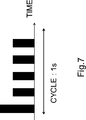
- the traffic feature may include a period (s) and / or a packet sequence for each period.
- the source device 20 may be a temperature sensor that transmits temperature information, in which case the period may be 60 seconds (ie, 60s), as shown in FIG.
- the packet sequence for each cycle may be as shown in FIG.
- the source device 20 may be a network camera that transmits moving image information, in which case the period is 1 second, as shown in FIG. (That is, 1s) may be used, and the packet sequence for each cycle may be as shown in FIG.
- the terminal type is the terminal type of the source device 20
- the QoS index is an index of service quality (QoS) required by the source device 20.
- the QoS index is a qualitative category such as delay sensitive (characteristics that are greatly affected by delay, in other words, real time) or delay robust (characteristics that are less affected by delay, in other words, non-real time).
- the QoS index may be in the range of quantitative values such as a delay time of 100 milliseconds (that is, 100 ms) or less, or a throughput of 1 Mbps or more.
- the conversion device 100 acquires, for example, the terminal type, the QoS index, and the traffic characteristics.
- the source device 20 may be a temperature sensor.
- the terminal type may be the model number of the temperature sensor
- the QoS index may be delayed robust
- the traffic features may be acquired from the temperature sensor.
- the source device 20 may be a network camera.
- the terminal type may be the model number of the network camera
- the QoS index may be delay-sensitive and / or band-sensitive
- the traffic features are acquired from the network camera. May be good.
- the conversion device 100 acquires a set of the terminal type, the QoS index, and the traffic features for the devices 20 of a plurality of transmission sources. As a result, the set for each of the plurality of source devices 20 is prepared in advance.
- the conversion device 100 determines a conversion policy indicating what kind of traffic characteristics the communication flow has by the conversion process for the original communication flow from the source device 20. decide.
- FIG. 8 is a flowchart for explaining an example of a schematic flow of the conversion policy determination process according to the first embodiment.
- the conversion device 100 first selects the traffic feature to which the divided communication flow (that is, the plurality of communication flows) matches (S310).
- the conversion policy includes the number of communication flows after division, the address information of the communication flow after division, and the transmission timing of the communication flow after division.
- the number of communication flows is determined (S320)
- the address information of the divided communication flows is determined (S330)
- the transmission timing of the divided communication flows is determined (S340).
- the conversion device 100 determines the traffic features to which the divided communication flows (that is, the plurality of communication flows) match (S310).
- the above traffic features include, for example, a packet size (bit) and / or a packet arrival interval (s).
- the packet size and / or the packet arrival interval is, for example, the distribution or statistic of the packet size and / or the packet arrival interval (eg, maximum, minimum, mean, median, variance, standard deviation, kurtosis, And / or skewness, etc.).
- the above traffic feature may include a cycle (s) and / or a packet sequence for each cycle.
- the conversion device 100 has a traffic feature to which the communication flow after division matches based on the information acquired in advance (that is, terminal type, QoS index and / or traffic feature). Select.
- the conversion device 100 first obtains a QoS index for the source device 20 acquired in advance (hereinafter, "first QoS index").
- a QoS index (hereinafter, referred to as “second QoS index”) for the communication flow after division is set based on (referred to as).
- the first QoS index can also be said to be a QoS index of the original communication flow from the source device 20.
- the second QoS index (ie, the QoS index for the divided communication flow) is different from the first QoS index (ie, the QoS index for the original communication flow from the source device 20).
- the first QoS index corresponds to a service quality that requires real-time performance
- the second QoS index corresponds to a service quality that does not require real-time performance.
- the first QoS index may be delayed sensitive, and the second QoS index may be set to delayed robust.
- the first QoS index may have a delay time of 100 ms or less, and the second QoS index may be set to a delay time of 1 s or more.
- one service can be pretended to be another service.
- a service that requires real-time performance can be pretended to be a non-real-time service.
- the conversion device 100 determines whether the conversion device 100 (determination unit 140) has a communication flow after division based on the second QoS index (that is, a QoS index for the communication flow after division). Select a matching traffic feature.
- the conversion device 100 randomly selects one of the terminal types associated with the same QoS index as the second QoS index (that is, the QoS index for the communication flow after division).
- the traffic feature associated with the one terminal type may be selected as the above-mentioned traffic feature to which the communication flow after division matches.
- the source device 20 is a network camera
- the first QoS index may be delayed sensitive and the second QoS index may be set to delayed robust.
- the model number (terminal type) of the temperature sensor associated with the delay robustness may be selected, or the traffic feature associated with the model number (terminal type) of the temperature sensor may be selected.
- the conversion device 100 may select the traffic feature closest to the second QoS index (for example, a delay time of 1 s or more).
- the conversion device 100 calculates the average value of the traffic features associated with the same QoS index as the second QoS index, and divides the average value into the communication flow after division. May be selected as the above-mentioned traffic feature to which.
- the divided communication flow may include one or more communication flows that match each of the two or more traffic features.
- the divided communication flows include one or more communication flows that match the first traffic features (eg, the traffic features of the first temperature sensor) and a second. It may include one or more communication flows that match the traffic characteristics (eg, the traffic characteristics of the second temperature sensor).
- the conversion device 100 determines the number of communication flows after division based on the selected traffic characteristics (S320).
- the conversion device 100 determines the number of communication flows that can realize the above-selected traffic features. In other words, the conversion device 100 (determination unit 140) determines the number of divided communication flows (those that match the selected traffic features) required to restore the original communication flow.
- the number of communication flows (M) after division is [the number of packets in the cycle of the original communication flow] (x) [the number of packets in the cycle required to realize the selected traffic feature].
- the number of communication flows (M) after division can be said to be the smallest integer that satisfies the following formula.
- each of the above two or more traffic features is indicated by an index i
- the number of packets in the cycle required to realize the traffic feature i is indicated by Ni
- the number of communication flows matching the traffic feature i is indicated.
- Mi is the smallest integer satisfying the following equation.
- the conversion device 100 determines the address information of the communication flow after division (S330).
- the address information includes each IP address and port number of the divided communication flow.
- a communication flow means a series of packets (a series of data) including the same IP address and the same port number. That is, the communication flow is identified by the IP address and the port number.
- the port number is a TCP (Transmission Control Protocol) or UDP (User Datagram Protocol) port number.
- the plurality of communication flows (that is, the communication flow after division) are transmitted to the restoration device 200. Therefore, the destination IP address of each of the plurality of communication flows becomes the IP address of the restoration device 200.
- each of the plurality of communication flows (that is, the communication flow after division) is a communication flow different from any other communication flow included in the plurality of communication flows. Therefore, the source IP address, the source port number, and / or the destination port number of each of the plurality of communication flows are values unique to the communication flow.
- the source port number of the communication flow after division is 20001 to 20100.
- the source port number of the communication flow after the division is also a port number unique to the communication flow.
- the source IP address may also be an IP address unique to the communication flow.
- the port number unique to the communication flow or the IP address unique to the communication flow may be a randomly selected value instead of a continuous value.
- the conversion device 100 determines the transmission timing for each of the plurality of communication flows after division (S340).
- the conversion device 100 (determining unit 140) performs the divided communication so that the transmission timing of each of the plurality of communication flows after the division matches the selected traffic characteristics. Determine the transmission timing of each flow.
- FIG. 9 shows an example of a method of determining the transmission timing of each communication flow after division according to the first embodiment.
- the original communication flow (ORIGINAL FLOW) is divided into four communication flows (FLOW 1 to 4).
- the packets may be temporarily stored in the buffer because the packets do not always arrive at the same interval for each cycle due to fluctuations in communication quality or the like.
- the packet for the communication flow 1 arrives in the original communication flow
- the packet is transmitted as a packet belonging to the communication flow 1.
- the packet for the communication flow 2 arrives in the original communication flow
- the packet is transmitted as a packet belonging to the communication flow 2.
- the communication flow 3 and the communication flow 4 are also transmitted in the same manner.
- the transmission timing of the communication flow 1 is the start time of the cycle
- the transmission timing of the communication flow 2 is the time after time 41 from the start time of the cycle
- the transmission timing of the communication flow 3 is the start of the cycle.
- the time point is 43 hours later than the time point
- the transmission timing of the communication flow 4 is a time point 45 hours later than the start time point of the cycle.
- the transmission timing of the divided communication flow determined by the conversion device 100 may be specific timings (time 41, time 43, and time 45) as shown in FIG.
- FIG. 10 is a sequence diagram for explaining an example of a schematic flow of a process of conversion and restoration of a communication flow according to the first embodiment.
- the source device 20 transmits a packet belonging to the original communication flow (that is, a packet of data generated by an application running in the source device 20) (S410).
- the conversion device 100 receives the packet belonging to the original communication flow.
- the conversion device 100 (conversion unit 120) divides the original communication flow from the source device 20 into a plurality of communication flows that match the selected traffic characteristics (S420).
- the conversion device 100 selects a traffic feature and determines a conversion policy based on the traffic feature.
- the conversion device 100 (conversion unit 120) divides the original communication flow into a plurality of communication flows according to the conversion policy.
- the conversion policy includes the number of communication flows after division, and the conversion device 100 (conversion unit 120) divides the original communication flow into the number of communication flows.
- the conversion policy includes address information (IP address and port number) of the communication flow after division, and the conversion device 100 (conversion unit 120) applies to each of the plurality of communication flows according to the address information.
- IP address and port number IP address and port number
- the conversion device 100 (conversion unit 120) has a communication flow-specific source IP address, a communication flow-specific source port number, and / or a communication flow-specific destination port number in each of the plurality of communication flows. To set.
- the conversion device 100 (conversion unit 120) sets the destination IP address to the IP address of the restoration device 200 in each of the plurality of communication flows.
- the original communication flow is divided into the plurality of communication flows according to the conversion policy determined based on the traffic characteristics. Therefore, the characteristics of the communication traffic related to the plurality of communication flows are the traffic characteristics. Fits to.
- the conversion device 100 transmits packets belonging to each of the plurality of communication flows to the restoration device 200 (S430).
- the conversion device 100 transmits a packet belonging to each of the plurality of communication flows to the restoration device 200 at a timing matching the selected traffic feature.
- the conversion policy includes transmission timing of individual packets belonging to each of the divided communication flows, and the conversion device 100 (transmission unit 130) belongs to each of the plurality of communication flows according to the transmission timing.
- the packet is transmitted to the restoration device 200.
- the restoration device 200 receives packets belonging to each of the plurality of communication flows.
- the restoration device 200 restores the plurality of communication flows to the original communication flow (S440).
- the conversion device 100 transmits the above conversion policy to the restoration device 200.
- the restoration device 200 restores the plurality of communication flows to the original communication flow according to the conversion policy.
- the above conversion policy includes the address information (IP address and port number) of the divided communication flow and the address information (IP address and port number) of the original communication flow.
- the restoration device 200 (restoration unit 220) replaces the address information of the divided communication flow (that is, the plurality of communication flows) with the address information of the original communication flow.
- the restoration device 200 transmits a packet belonging to the original communication flow (that is, the restored traffic) to the destination device 30 (S450).
- the destination device 30 receives the packet belonging to the original communication flow.
- the original communication flow is divided and restored. This makes it possible, for example, to mislead the estimation of the source by analyzing the communication traffic.
- the estimation of the source based on the communication traffic is performed by analyzing the statistics of the characteristics of the communication traffic such as the packet transmission interval and the packet size. Therefore, for example, as shown in FIG. 11, when the source device 20 (for example, a network camera) transmits a statistic (for example, a moving image traffic) that requires real-time performance to the destination device 30, the network 10 The statistics of the characteristics of the traffic are analyzed, and it can be estimated that the traffic requiring real-time performance is transmitted from the source device 20.
- the traffic that requires real-time performance for example, moving image traffic
- the traffic that does not require real-time performance for example, sensor traffic.
- Divided into traffic therefore, in the network 10, the statistics of the characteristics of the traffic after division are analyzed, and it can be erroneously estimated that the traffic that does not require real-time performance is transmitted.
- the original traffic eg, the traffic that requires real-time performance
- another traffic eg, the traffic that requires real-time performance
- it can be disguised as another packet that does not require real-time performance. That is, by dividing the communication flow and reducing the traffic amount in each flow, it is possible to make the high-frequency communication look like the low-frequency communication. Therefore, it is possible to induce a mispresumption about the source by the communication traffic analysis.
- the original communication flow is divided into a plurality of communication flows. For example, if the number of packets in the cycle of the original communication flow is an integral multiple of the number of communication flows, the packets in the original communication flow can be allocated to a plurality of flows without excess or deficiency.
- the number of packets in the cycle of the original communication flow is not often an integral multiple of the number of flows.
- the divided communication flow may include a communication flow with a small number of packets, and the communication flow may not be well adapted to the selected traffic features (particularly, packet arrival intervals). As a result, it can be difficult to accurately induce mispresumption.
- the conversion device 100 (conversion unit 120) has the packet feature of the communication flow included in the plurality of communication flows (that is, the communication flow after division). Dummy packets are added to the communication flow to match the packet arrival intervals contained in the selected traffic features.
- the number of packets per unit time in the communication flow included in the plurality of communication flows is included in the packet arrival interval (that is, the packet arrival interval) included in the selected traffic feature.
- the conversion device 100 converts dummy packets to the communication flow. That is, the dummy packet is added to the communication flow in which the number of packets per unit time is smaller than the number of packets corresponding to the packet arrival interval included in the selected traffic feature among the plurality of communication flows.
- the dummy packet has the same address information as the packet included in the communication flow.
- the communication flows included in the plurality of communication flows are selected as the traffic features (particularly, packet arrival intervals). Will be compatible with. Therefore, misestimation by analysis of communication traffic can be accurately induced.
- the restoration device 200 uses the dummy packet when restoring the plurality of communication flows (that is, the communication flow after division) to the original communication flow. Discard.
- the conversion device 100 converts identification information to the header or payload (for example, the last few bits) of the dummy packet.
- the restoration device 200 identifies the packet containing the identification information as a dummy packet, and discards the packet (that is, the dummy packet).
- Second variant> When large-sized data is transmitted by the source device 20, the data is fragmented into an MTU (Maximum Transmission Unit), which is the maximum size of packets that can be processed by the network. In this case, the distribution of the size of the packet transmitted by the source device 20 is biased toward the MTU.
- MTU Maximum Transmission Unit
- the distribution of the size of the packet transmitted by the source device 20 is not biased toward the MTU.
- an environmental sensor such as a temperature sensor transmits data having a size smaller than that of the MTU (for example, several bytes to several hundred bytes).
- the conversion device 100 has the packet feature of the communication flow included in the plurality of communication flows (that is, the communication flow after division). Performs specific processing (eg, packet division, addition of dummy bits, or packet aggregation) on packets belonging to the original communication flow so as to match the packet size included in the selected traffic features. ..
- the restoration device 200 restores the plurality of communication flows (that is, the communication flow after division) to the original communication flow. Restoration processing corresponding to the processing is also performed.
- the conversion device 100 converts identification information to the header or payload (for example, the last few bits) of the packet generated by the specific process.
- the restoration device 200 identifies a packet containing the identification information as a packet generated by the specific processing, and performs the restoration processing on the packet.
- the identification information may be identification information according to the content of the specific process, and the restoration device 200 (restoration unit 220) may identify the content of the specific process based on the identification information. Good.
- the conversion device 100 (conversion unit 120) has a traffic characteristic of a communication flow included in the plurality of communication flows (that is, a communication flow after division).
- the packet belonging to the original communication flow may be divided into a plurality of packets so as to match the packet size included in the selected traffic feature.
- the conversion device 100 may divide the packet belonging to the original communication flow into a plurality of packets.
- the conversion device 100 converts a packet exceeding the maximum value of the packet size distribution included in the selected traffic feature into packets having a packet size with a high probability of occurrence in the distribution.
- the conversion device 100 converts a packet exceeding the maximum value of the packet size distribution included in the selected traffic feature into packets having a packet size with a high probability of occurrence in the distribution.
- Good For example, when the packet belonging to the original communication flow is a 1500-byte packet, the average packet size is 500 bytes, and the maximum value of the packet size is 1000 bytes in the selected traffic feature, the original.
- the packet of the communication flow of the above may be divided into a packet of 500 bytes and a packet of 1000 bytes. Alternatively, the packet of the original communication flow may be divided into two packets of 750 bytes.
- the conversion device 100 may divide a packet exceeding the maximum value of the packet size distribution included in the selected traffic feature into a stochastically selected packet. For example, when 10 packets of the original communication flow arrive and the size of each of the 10 packets is 800 bytes, 4 packets are selected from the 10 packets and the packet is selected. Each of the four packets may be divided into a 500-byte packet and a 300-byte packet. This makes it possible, for example, to bring the traffic characteristics of the divided communication flow closer to a more natural probability distribution.
- the packet may be divided as described above.
- the size of the packet becomes smaller, and the packet belonging to the divided communication flow matches the packet size included in the selected traffic feature. Therefore, misestimation by analysis of communication traffic can be accurately induced.
- the conversion device 100 For the restoration process in the restoration device 200, the conversion device 100 (conversion unit 120) identifies each header or payload (for example, the last few bits) of the plurality of packets (that is, the divided packets). Information may be given. The identification information may indicate the original packet and the order in the original packet.
- the conversion device 100 (conversion unit 120) has a packet feature of the communication flow included in the plurality of communication flows (that is, the communication flow after division). However, a dummy bit may be added to the packet belonging to the original communication flow so as to match the packet size included in the selected traffic feature.
- the conversion device 100 may add a dummy bit to the packet belonging to the original communication flow.
- the conversion device 100 (conversion unit 120) of the original communication flow so that the size of the packet belonging to the original communication flow becomes the average value of the packet sizes included in the selected traffic feature. Dummy bits may be added to the above packet.
- dummy bits may be added as described above.
- the size of the packet becomes larger, and the packet belonging to the divided communication flow becomes suitable for the packet size included in the selected traffic feature. Therefore, misestimation by analysis of communication traffic can be accurately induced.
- the conversion device 100 may add identification information to the header or payload (for example, the last few bits) of each packet to which the dummy bits are added. Good.
- the identification information may indicate the number of added bits and the position of the added bits (for example, the end of a packet).
- the conversion device 100 has a traffic characteristic of the communication flow included in the plurality of communication flows (that is, the communication flow after division). , Packets belonging to the original communication flow and one or more other packets may be aggregated to fit the packet size included in the selected traffic features. That is, the conversion device 100 (conversion unit 120) may generate an aggregated packet including the packet of the original communication flow and the one or more other packets.
- the one or more other packets may be packets belonging to another original communication flow different from the original communication flow. That is, packets from a plurality of original communication flows may be aggregated. Further, the other original communication flow may be the communication flow of the device 20 of the other transmission source. That is, packets from the devices 20 of a plurality of sources may be aggregated.
- the conversion device 100 may aggregate the packet of the original communication flow and one or more other packets.
- the conversion device 100 sets the packet of the original communication flow and the packet of the original communication flow so that the size of the aggregated packet becomes the average value of the packet sizes included in the selected traffic features. It may be aggregated with one or more other packets.
- packets may be aggregated as described above.
- the size of the packet becomes larger, and the packet belonging to the divided communication flow becomes suitable for the packet size included in the selected traffic feature. Therefore, misestimation by analysis of communication traffic can be accurately induced.
- the communication flow after division includes, for example, communication flows from a plurality of devices, it may be more difficult to estimate the device 20 of each transmission source.
- the conversion device 100 may add identification information to the header or payload (for example, the last few bits) of the aggregated packet for the restoration process in the restoration device 200.
- the identification information may indicate a delimiter between a plurality of packets in the aggregated packet.
- the conversion device 100 (conversion unit 120) divides the original communication flow from the transmission device 20 into a plurality of communication flows. This makes it possible to make the original traffic (for example, a traffic that requires real-time performance) look like another traffic (for example, another traffic that does not require real-time performance).
- the first embodiment is not limited to this example.
- the conversion device 100 (conversion unit 120) aggregates a plurality of original communication flows from the source device 20.
- the conversion device 100 (conversion unit 120) may aggregate a plurality of original communication flows from a single source device 20 or a plurality of original communication flows from a plurality of source devices 20. You may. Further, the conversion device 100 (transmission unit 130) transmits the aggregated communication flow to the restoration device 200.
- the conversion device 100 is a device different from the source device 20, and the restoration device 200 is a device different from the destination device 30.
- the first embodiment is not limited to this example.
- the conversion device 100 may be the source device 20. That is, the operation or function of the conversion device 100 may be implemented in the source device 20.
- the restoration device 200 may be the destination device 30. That is, the operation or function of the restoration device 200 may be implemented in the destination device 30.
- Second embodiment A second embodiment of the present disclosure will be described with reference to FIGS. 13-18.
- the first embodiment described above is a specific embodiment, but the second embodiment is a more generalized embodiment.
- FIG. 13 shows an example of a schematic configuration of the system 2 according to the second embodiment.
- the system 2 includes a network 50, a converter 600 and a restorer 700.
- the description of the network 50, the conversion device 600, and the restoration device 700 is the same as the description of the network 10, the conversion device 100, and the restoration device 200 according to the first embodiment, except for the difference in reference numerals. Therefore, a duplicate description will be omitted here.
- the network 50, the conversion device 600, and the restoration device 700 according to the second embodiment are not limited to this example.
- FIG. 14 is a block diagram showing an example of a schematic functional configuration of the conversion device 600 according to the second embodiment.
- the conversion device 600 includes a conversion unit 610 and a transmission unit 620.
- the description of the conversion unit 610 and the transmission unit 620 is the same as the description of the conversion unit 120 and the transmission unit 130 according to the first embodiment, except for the difference in reference numerals. Therefore, a duplicate description will be omitted here.
- the conversion unit 610 and the transmission unit 620 according to the second embodiment are not limited to this example.
- FIG. 15 is a block diagram showing an example of a schematic hardware configuration of the conversion device 600 according to the second embodiment.
- the conversion device 600 includes a processor 681, a main memory 683, a storage 685, a communication interface 687, and an input / output interface 689.
- the processor 681, the main memory 683, the storage 685, the communication interface 687, and the input / output interface 689 are connected to each other via the bus 691.
- the description of the hardware configuration of the conversion device 600 is the same as the description of the hardware configuration of the conversion device 100 according to the first embodiment, except for the difference in reference numerals. Therefore, a duplicate description will be omitted here.
- the hardware configuration of the conversion device 600 according to the second embodiment is not limited to this example.
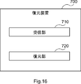
- FIG. 16 is a block diagram showing an example of a schematic functional configuration of the restoration device 700 according to the second embodiment.
- the restoration device 700 includes a reception unit 710 and a restoration unit 720.
- the description of the receiving unit 710 and the restoring unit 720 is the same as the description of the receiving unit 210 and the restoring unit 220 according to the first embodiment, except for the difference in reference numerals. Therefore, a duplicate description will be omitted here.
- the receiving unit 710 and the restoring unit 720 according to the second embodiment are not limited to this example.
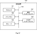
- FIG. 17 is a block diagram showing an example of a schematic hardware configuration of the restoration device 700 according to the second embodiment.
- the restoration device 700 includes a processor 781, a main memory 783, a storage 785, a communication interface 787, and an input / output interface 789.
- the processor 781, the main memory 783, the storage 785, the communication interface 787, and the input / output interface 789 are connected to each other via the bus 791.
- the description of the hardware configuration of the restoration device 700 is the same as the description of the hardware configuration of the restoration device 200 according to the first embodiment, except for the difference in reference numerals. Therefore, a duplicate description will be omitted here.
- the hardware configuration of the restoration device 700 according to the second embodiment is not limited to this example.
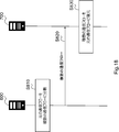
- FIG. 18 is a sequence diagram for explaining an example of a schematic flow of the processing of conversion and restoration of the communication flow according to the second embodiment.
- the conversion device 600 (conversion unit 610) divides the original communication flow from the source device into a plurality of communication flows that match the selected traffic characteristics (S810).
- the conversion device 100 transmits packets belonging to each of the plurality of communication flows to the restoration device 200 (S820).
- the restoration device 200 receives the packet belonging to each of the plurality of flows.
- the restoration device 200 restores the plurality of communication flows to the original communication flow (S830).
- the original communication flow is converted (that is, divided) and restored. This makes it possible, for example, to mislead the estimation of the source by analyzing the communication traffic.
- the steps in the processing described herein do not necessarily have to be performed in chronological order in the order described in the flowchart or sequence diagram.
- the steps in the process may be executed in an order different from the order described as a flowchart or a sequence diagram, or may be executed in parallel.
- some of the steps in the process may be deleted, and additional steps may be added to the process.
- a method including processing of a component of the conversion device or the restoration device described in the present specification may be provided, and a program for causing the processor to execute the processing of the component may be provided.
- a non-transitory computer readable recording medium may be provided that can be read by the computer on which the program is recorded.
- Appendix 2 The method according to Appendix 1, wherein the selected traffic feature is a traffic feature selected based on a second quality of service index that is different from the first quality of service index for the original communication flow.
- the first service quality index corresponds to the service quality that requires real-time performance.
- the second service quality index corresponds to service quality that does not require real-time performance. The method described in Appendix 2.
- Addendum 1 further includes setting a source IP (Internet Protocol) address unique to the communication flow, a source port number unique to the communication flow, or a destination port number unique to the communication flow in each of the plurality of communication flows. The method according to any one of 4 to 4.
- IP Internet Protocol
- the selected traffic features include packet arrival intervals. Adding a dummy packet to the communication flow so that the traffic characteristics of the communication flow included in the plurality of communication flows match the packet arrival interval.
- the selected traffic features include packet size and The packet belonging to the original communication flow is divided into a plurality of packets, or the packet belongs to the original communication flow so that the traffic characteristics of the communication flow included in the plurality of communication flows match the packet size. Adding a dummy bit or aggregating a packet belonging to the original communication flow with one or more other packets.
- the conversion device Divide the original communication flow from the source device into multiple communication flows that match the selected traffic characteristics. A packet belonging to each of the plurality of communication flows is transmitted to the restoration device, and the packet is transmitted to the restoration device. The restoration device is Upon receiving the packet belonging to each of the plurality of communication flows, Restoring the plurality of communication flows to the original communication flow, system.
- Appendix 9 The system according to Appendix 8, wherein the selected traffic feature is a traffic feature selected based on a second quality of service index that is different from the first quality of service index for the original communication flow.
- the first service quality index corresponds to the service quality that requires real-time performance.
- the second service quality index corresponds to service quality that does not require real-time performance.
- the conversion device sets a source IP (Internet Protocol) address peculiar to the communication flow, a source port number peculiar to the communication flow, or a destination port number peculiar to the communication flow in each of the plurality of communication flows.
- the system according to any one of 1 to 11.
- the selected traffic features include packet arrival intervals.
- the conversion device adds a dummy packet to the communication flow so that the traffic characteristics of the communication flow included in the plurality of communication flows match the packet arrival interval.
- the system according to any one of Appendix 8 to 12.
- the selected traffic features include packet size and
- the conversion device divides a packet belonging to the original communication flow into a plurality of packets or performs the original communication so that the traffic characteristics of the communication flows included in the plurality of communication flows match the packet size.
- a dummy bit is added to a packet belonging to the flow, or a packet belonging to the original communication flow and one or more other packets are aggregated.
- the system according to any one of Appendix 8 to 13.
- a converter that divides the original communication flow from the source device into multiple communication flows that match the selected traffic characteristics.
- a transmission unit that transmits packets belonging to each of the plurality of communication flows to a restoration device that restores the plurality of communication flows to the original communication flow.
- Appendix 16 The converter according to Appendix 15, wherein the selected traffic feature is a traffic feature selected based on a second quality of service index that is different from the first quality of service index for the original communication flow.
- the first service quality index corresponds to the service quality that requires real-time performance.
- the second service quality index corresponds to service quality that does not require real-time performance.
- the conversion unit sets a source IP (Internet Protocol) address peculiar to the communication flow, a source port number peculiar to the communication flow, or a destination port number peculiar to the communication flow in each of the plurality of communication flows.
- the conversion device according to any one of 18 to 18.
- the selected traffic features include packet arrival intervals.
- the conversion unit adds a dummy packet to the communication flow so that the traffic characteristics of the communication flows included in the plurality of communication flows match the packet arrival interval.
- the conversion device according to any one of Supplementary note 15 to 19.
- the selected traffic features include packet size and
- the conversion unit divides a packet belonging to the original communication flow into a plurality of packets or performs the original communication so that the traffic characteristics of the communication flows included in the plurality of communication flows match the packet size.
- a dummy bit is added to a packet belonging to the flow, or a packet belonging to the original communication flow and one or more other packets are aggregated.
- the conversion device according to any one of Appendix 15 to 20.
- a receiver that receives packets belonging to each of the plurality of communication flows from a conversion device that divides the original communication flow from the source device into a plurality of communication flows that match the selected traffic characteristics.
- a restoration unit that restores the plurality of communication flows to the original communication flow, Restoration device equipped with.
Landscapes
- Engineering & Computer Science (AREA)
- Computer Networks & Wireless Communication (AREA)
- Signal Processing (AREA)
- Computer Security & Cryptography (AREA)
- Quality & Reliability (AREA)
- Computer Hardware Design (AREA)
- Computing Systems (AREA)
- General Engineering & Computer Science (AREA)
- Data Exchanges In Wide-Area Networks (AREA)
Abstract
【課題】通信トラヒックの分析による送信元についての推定を誤らせることを可能にすること。 【解決手段】本開示の一側面に係る方法は、送信元の装置からの元の通信フローを、選択されたトラヒック特徴に適合する複数の通信フローに分割することと、上記複数の通信フローを上記元の通信フローに復元する復元装置へ、上記複数の通信フローの各々に属するパケットを送信することと、を含む。
Description
本開示は、方法、システム及び変換装置に関する。
あらゆるモノが無線ネットワークを介してインターネットに接続されるIoT(Internet of Things)の普及により、工場や農業等の様々な分野でIoTを活用したユースケースが期待されている。その一方で、多様なモノがインターネットに接続されることで、IoT通信におけるセキュリティリスクが高まることが懸念されている。
IoTサービスに対する攻撃例を挙げる。遠隔ロボット制御やネットワークカメラによる監視を想定する。ロボット制御では、遠隔地から制御コマンドが低遅延で到達することで安定した制御が可能となる。また、ネットワークカメラによる監視では、低遅延でカメラからの映像が遠隔の監視サーバに到達することでリアルタイムな監視を実現できる。これらのリアルタイム性を要求するIoTデバイスのトラヒックに対して、悪意のあるユーザが何らかの方法でIoTサービスを識別し、中継装置において膨大なクロストラヒックを挿入すると、スループットの劣化や通信遅延の増大が意図的に引き起こされ、結果としてサービス妨害が起こり得る。また、リアルタイム性を要するサービスに対して通信を遮断することもサービス妨害として挙げられる。
近年では、通信トラヒックの暗号化が推進されているため、パケットのペイロードから生のアプリレベルの情報を取得することが困難となってきている。その一方で、統計学や機械学習といったデータ分析技術の高度化により、パケットサイズやパケット到着間隔の統計量等の通信トラヒックの特徴を分析することによって、通信プロトコルのみでなく、アプリケーションやIoTデバイス種別の識別が可能となってきている。このような通信トラヒックの分析技術は、暗号化トラヒックに対する通信品質の改善等に活用できるが、悪意のあるユーザが利用すれば、通信トラヒックの送信元(source)の情報を間接的に推定され、前述のようなIoTサービスに対する攻撃に繋がる恐れがある。このように通信トラヒックを分析することによって間接的に推定した送信元の情報を用いることでセキュリティ攻撃を行うことは、Traffic analysis attack として知られている。Traffic analysis attackにより、特に、通信トラヒックからユーザのWebアクセス先が推定され、ユーザ毎のアクセス傾向等のプライバシーが、悪意のあるユーザに知られてしまう恐れがある。
例えば、非特許文献1では、トラヒックの特徴からWebアクセス先を推定する攻撃に対して、トラヒックの統計的な特徴を変換することで誤推定を誘発する方法が、記載されている。具体的には、非特許文献1によれば、ダミーパケットを追加することにより、トラヒックが増加し、スループット特性が変換される。
Mohsen Imani, et al., ``Mockingbird: Defending Against Deep-Learning-Based Website Fingerprinting Attacks with Adversarial Traces,’’ arXiv:1902.06626, 2019.
上述したように、非特許文献1では、トラヒックの特徴からWebアクセス先を推定する攻撃者に対して、ダミーパケットを追加することにより、トラヒックが増加し、スループット特性が変換される。しかし、リアルタイム性を要求する通信トラヒックは一般的に高頻度な通信を伴うので、トラヒックの増加は効果的でないと考えられる。具体的には、リアルタイム性を要求する通信トラヒックにダミーパケットが追加されると、当該通信トラヒックは、さらに高頻度な通信を伴うこととなり、結局、リアルタイム性を要求する通信トラヒックとみなされる。そのため、リアルタイム性を要求するサービスを推定したい攻撃者に対しては、ダミーパケットの追加は効果的ではない。
本開示の目的は、通信トラヒックの分析による送信元についての推定を誤らせることを可能にする方法、システム及び変換装置を提供することにある。
本開示の一側面(aspect)に係る方法は、送信元の装置からの元の通信フローを、選択されたトラヒック特徴に適合する複数の通信フローに分割することと、上記複数の通信フローを上記元の通信フローに復元する復元装置へ、上記複数の通信フローの各々に属するパケットを送信することと、を含む。
本開示の一側面に係るシステムは、変換装置と、復元装置と、を含み、上記変換装置は、送信元の装置からの元の通信フローを、選択されたトラヒック特徴に適合する複数の通信フローに分割し、上記複数の通信フローの各々に属するパケットを上記復元装置へ送信し、上記復元装置は、上記複数の通信フローの各々に属する前記パケットを受信し、上記複数の通信フローを上記元の通信フローに復元する。
本開示の一側面に係る変換装置は、送信元の装置からの元の通信フローを、選択されたトラヒック特徴に適合する複数の通信フローに分割する変換部と、上記複数の通信フローを上記元の通信フローに復元する復元装置へ、上記複数の通信フローの各々に属するパケットを送信する送信部と、を備える。
本開示によれば、通信トラヒックの分析による送信元についての推定を誤らせることが可能になる。なお、本開示により、当該効果の代わりに、又は当該効果とともに、他の効果が奏されてもよい。
以下、添付の図面を参照して本開示の実施形態を詳細に説明する。なお、本明細書及び図面において、同様に説明されることが可能な要素については、同一の符号を付することにより重複説明が省略され得る。
説明は、以下の順序で行われる。
1.第1の実施形態
1.1.システムの構成
1.2.変換装置の構成
1.3.復元装置の構成
1.4.動作例
1.5.第1の変形例
1.6.第2の変形例
1.7.第3の変形例
1.8.第4の変形例
2.第2の実施形態
2.1.システムの構成
2.2.変換装置の構成
2.3.復元装置の構成
2.4.動作例
1.第1の実施形態
1.1.システムの構成
1.2.変換装置の構成
1.3.復元装置の構成
1.4.動作例
1.5.第1の変形例
1.6.第2の変形例
1.7.第3の変形例
1.8.第4の変形例
2.第2の実施形態
2.1.システムの構成
2.2.変換装置の構成
2.3.復元装置の構成
2.4.動作例
<<1.第1の実施形態>>
図1~図12を参照して、本開示の第1の実施形態を説明する。
図1~図12を参照して、本開示の第1の実施形態を説明する。
<1.1.システムの構成>
図1は、第1の実施形態に係るシステム1の概略的な構成の一例を示す。図1を参照すると、システム1は、ネットワーク10、送信元の装置(source device)20、宛先の装置(destination device)30、変換装置100及び復元装置200を含む。
図1は、第1の実施形態に係るシステム1の概略的な構成の一例を示す。図1を参照すると、システム1は、ネットワーク10、送信元の装置(source device)20、宛先の装置(destination device)30、変換装置100及び復元装置200を含む。
(1)ネットワーク10
例えば、ネットワーク10は、共有ネットワーク(shared network)であり、悪意のある観測者が、ネットワーク10におけるトラヒックを観測し得る。
例えば、ネットワーク10は、共有ネットワーク(shared network)であり、悪意のある観測者が、ネットワーク10におけるトラヒックを観測し得る。
(2)送信元の装置20及び宛先の装置30
例えば、送信元の装置20は、ネットワーク10経由で宛先の装置30へパケット(即ち、データ)を送信する。例えば、送信元の装置20から宛先の装置30へ送信される一連のパケット(一連のデータ)は、トラヒック又は通信トラヒックと呼ばれ得る。また、当該一連のパケット(一連のデータ)は、通信フローと呼ばれ得る。ここでの通信フローとは、例えば、同一のIP(Internet Protocol)アドレス及び同一のポート番号を含む一連のパケット(一連のデータ)を意味する。IPアドレスは、装置(device)の位置識別子であり、ポート番号は、装置内のアプリケーションの識別子であると言える。
例えば、送信元の装置20は、ネットワーク10経由で宛先の装置30へパケット(即ち、データ)を送信する。例えば、送信元の装置20から宛先の装置30へ送信される一連のパケット(一連のデータ)は、トラヒック又は通信トラヒックと呼ばれ得る。また、当該一連のパケット(一連のデータ)は、通信フローと呼ばれ得る。ここでの通信フローとは、例えば、同一のIP(Internet Protocol)アドレス及び同一のポート番号を含む一連のパケット(一連のデータ)を意味する。IPアドレスは、装置(device)の位置識別子であり、ポート番号は、装置内のアプリケーションの識別子であると言える。
例えば、送信元の装置20は、IoTデバイスであり、宛先の装置30は、IoTデバイスからのデータを受信するサーバ(例えば、クラウドサーバ)である。具体的には、例えば、送信元の装置20は、温度センサ等の環境センサ、監視カメラ等のネットワークカメラ(Webカメラとも呼ばれる)、又は遠隔で制御可能なロボットである。ただし、当然ながら、送信元の装置20及び宛先の装置30は、この例に限定されない。
なお、図1には、1つの送信元の装置20が示されているが、当然ながら、複数の送信元の装置20が存在してもよく、当該複数の送信元の装置20の各々に対応する宛先の装置30が存在してもよい。
(3)変換装置100及び復元装置200
第1の実施形態では、変換装置100は、送信元の装置20からの元の(original)通信トラヒックを受信し、当該元の通信トラヒックを変換する。当該元の通信トラヒックの変換により、トラヒック特徴(即ち、通信トラヒックの特徴)も変換される。変換装置100は、変換された通信トラヒックをネットワーク10経由で復元装置200へ送信する。復元装置200は、当該変換された通信トラヒックを上記元の通信トラヒックに復元し、上記元の通信トラヒックを宛先の装置30へ送信する。
第1の実施形態では、変換装置100は、送信元の装置20からの元の(original)通信トラヒックを受信し、当該元の通信トラヒックを変換する。当該元の通信トラヒックの変換により、トラヒック特徴(即ち、通信トラヒックの特徴)も変換される。変換装置100は、変換された通信トラヒックをネットワーク10経由で復元装置200へ送信する。復元装置200は、当該変換された通信トラヒックを上記元の通信トラヒックに復元し、上記元の通信トラヒックを宛先の装置30へ送信する。
より具体的には、後述するように、変換装置100は、送信元の装置からの元の通信フローを、選択されたトラヒック特徴に適合する複数の通信フローに分割する。当該動作の詳細は、後に説明する。
変換装置100は、IoTデバイスからのトラヒックを収容するIoTゲートウェイであってもよく、又は、IoTデバイスのネットワーク内に設置するプロキシサーバであってもよい。復元装置200は、例えば、IoTデバイスからのデータを受信するサーバ(例えば、クラウドサーバ)が属するネットワーク内のプロキシサーバであってもよい。ただし、当然ながら、変換装置100及び復元装置200は、これらの例に限定されない。
<1.2.変換装置の構成>
(1)機能構成
図2は、第1の実施形態に係る変換装置100の概略的な機能構成の例を示すブロック図である。図2を参照すると、変換装置100は、受信部110、変換部120、送信部130及び決定部140を備える。
(1)機能構成
図2は、第1の実施形態に係る変換装置100の概略的な機能構成の例を示すブロック図である。図2を参照すると、変換装置100は、受信部110、変換部120、送信部130及び決定部140を備える。
-受信部110
受信部110は、送信元の装置20からの元の通信トラヒックを受信する。即ち、受信部110は、送信元の装置20により生成され、送信されるパケットを受信する。例えば、受信部110は、送信元の装置20からの元の通信フローに属するパケットを受信する。
受信部110は、送信元の装置20からの元の通信トラヒックを受信する。即ち、受信部110は、送信元の装置20により生成され、送信されるパケットを受信する。例えば、受信部110は、送信元の装置20からの元の通信フローに属するパケットを受信する。
受信部110は、決定部140による変換ポリシーの決定に必要な情報を(例えば送信元の装置20から)受信してもよい。
-変換部120
変換部120は、決定部140により決定される変換ポリシーにしたがって、上記元の通信フローについての変換処理を行う。当該変換処理により、トラヒック特徴(即ち、通信トラヒックの特徴)が変換される。
変換部120は、決定部140により決定される変換ポリシーにしたがって、上記元の通信フローについての変換処理を行う。当該変換処理により、トラヒック特徴(即ち、通信トラヒックの特徴)が変換される。
より具体的には、後述するように、変換部120は、上記元の通信フローを、選択されたトラヒック特徴に適合する複数の通信フローに分割する。当該動作の詳細は、後に説明する。
-送信部130
送信部130は、上記複数の通信フローの各々に属するパケットを復元装置200へ送信する。
送信部130は、上記複数の通信フローの各々に属するパケットを復元装置200へ送信する。
送信部130は、例えば、決定部140により決定される変換ポリシーも復元装置200へ送信する。
-決定部140
決定部140は、上記元の通信フローについての変換処理によりどのようなトラヒック特徴をもつ通信フローを得るかを示す変換ポリシーを決定する。
決定部140は、上記元の通信フローについての変換処理によりどのようなトラヒック特徴をもつ通信フローを得るかを示す変換ポリシーを決定する。
(2)ハードウェア構成
図3は、第1の実施形態に係る変換装置100の概略的なハードウェア構成の例を示すブロック図である。図3を参照すると、変換装置100は、プロセッサ181、メインメモリ183、ストレージ185、通信インターフェイス187及び入出力インターフェイス189を備える。プロセッサ181、メインメモリ183、ストレージ185、通信インターフェイス187及び入出力インターフェイス189は、バス191を介して互いに接続されている。
図3は、第1の実施形態に係る変換装置100の概略的なハードウェア構成の例を示すブロック図である。図3を参照すると、変換装置100は、プロセッサ181、メインメモリ183、ストレージ185、通信インターフェイス187及び入出力インターフェイス189を備える。プロセッサ181、メインメモリ183、ストレージ185、通信インターフェイス187及び入出力インターフェイス189は、バス191を介して互いに接続されている。
プロセッサ181は、メインメモリ183から読み出されるプログラムを実行する。一例として、プロセッサ181は、CPU(Central Processing Unit)である。
メインメモリ183は、プログラム及び各種データを記憶する。一例として、メインメモリ183は、RAM(Random Access Memory)である。
ストレージ185は、プログラム及び各種データを記憶する。一例として、ストレージ185は、SSD(Solid State Drive)及び/又はHDD(Hard Disk Drive)を含む。
通信インターフェイス187は、他の装置との通信のためのインターフェイスである。一例として、通信インターフェイス187は、ネットワークアダプタ又はネットワークインターフェイスカードである。
入出力インターフェイス189は、キーボード等の入力装置、及びディスプレイ等の出力装置との接続のためのインターフェイスである。
受信部110及び送信部130は、プロセッサ181、メインメモリ183及び通信インターフェイス187により実装されてもよい。変換部120及び決定部140は、プロセッサ181及びメインメモリ183により実装されてもよい。
当然ながら、変換装置100のハードウェア構成はこの例に限定されない。変換装置100は、他のハードウェア構成により実装されてもよい。
あるいは、変換装置100は、仮想化されていてもよい。即ち、変換装置100は、仮想マシンとして実装されてもよい。この場合に、変換装置100(仮想マシン)は、プロセッサ及びメモリ等を含む物理マシン(ハードウェア)及びハイパーバイザ上で仮想マシンとして動作してもよい。当然ながら、変換装置100(仮想マシン)は、複数の物理マシンに分散され、動作してもよい。
変換装置100は、プログラム(命令)を記憶するメモリ(メインメモリ183)と、当該プログラム(命令)を実行可能な1つ以上のプロセッサ(プロセッサ181)とを含んでもよい。当該1つ以上のプロセッサは、上記プログラムを実行して、受信部110、変換部120、送信部130及び/又は決定部140の動作を行ってもよい。上記プログラムは、受信部110、変換部120、送信部130及び/又は決定部140の動作をプロセッサに実行させるためのプログラムであってもよい。
<1.3.復元装置の構成>
(1)機能構成
図4は、第1の実施形態に係る復元装置200の概略的な機能構成の例を示すブロック図である。図4を参照すると、復元装置200は、受信部210、復元部220及び送信部230を備える。
(1)機能構成
図4は、第1の実施形態に係る復元装置200の概略的な機能構成の例を示すブロック図である。図4を参照すると、復元装置200は、受信部210、復元部220及び送信部230を備える。
-受信部210
受信部210は、変換装置100からの複数の通信フロー(即ち、分割後の通信フロー)の各々に属するパケットを受信する。
受信部210は、変換装置100からの複数の通信フロー(即ち、分割後の通信フロー)の各々に属するパケットを受信する。
受信部210は、例えば、変換装置100からの変換ポリシーも受信する。
-復元部220
復元部220は、上記変換ポリシーにしたがって、上記複数の通信フロー(即ち、分割後の通信フロー)を元の通信フロー(即ち、分割前の通信フロー)に復元する。
復元部220は、上記変換ポリシーにしたがって、上記複数の通信フロー(即ち、分割後の通信フロー)を元の通信フロー(即ち、分割前の通信フロー)に復元する。
-送信部230
送信部230は、上記元の通信フローに属するパケットを宛先の装置30へ送信する。
送信部230は、上記元の通信フローに属するパケットを宛先の装置30へ送信する。
(2)ハードウェア構成
図5は、第1の実施形態に係る復元装置200の概略的なハードウェア構成の例を示すブロック図である。図3を参照すると、復元装置200は、プロセッサ281、メインメモリ283、ストレージ285、通信インターフェイス287及び入出力インターフェイス289を備える。プロセッサ281、メインメモリ283、ストレージ285、通信インターフェイス287及び入出力インターフェイス289は、バス291を介して互いに接続されている。
図5は、第1の実施形態に係る復元装置200の概略的なハードウェア構成の例を示すブロック図である。図3を参照すると、復元装置200は、プロセッサ281、メインメモリ283、ストレージ285、通信インターフェイス287及び入出力インターフェイス289を備える。プロセッサ281、メインメモリ283、ストレージ285、通信インターフェイス287及び入出力インターフェイス289は、バス291を介して互いに接続されている。
プロセッサ281は、メインメモリ283から読み出されるプログラムを実行する。一例として、プロセッサ281は、CPU(Central Processing Unit)である。
メインメモリ283は、プログラム及び各種データを記憶する。一例として、メインメモリ283は、RAM(Random Access Memory)である。
ストレージ285は、プログラム及び各種データを記憶する。一例として、ストレージ285は、SSD(Solid State Drive)及び/又はHDD(Hard Disk Drive)を含む。
通信インターフェイス287は、他の装置との通信のためのインターフェイスである。一例として、通信インターフェイス287は、ネットワークアダプタ又はネットワークインターフェイスカードである。
入出力インターフェイス289は、キーボード等の入力装置、及びディスプレイ等の出力装置との接続のためのインターフェイスである。
受信部210及び送信部230は、プロセッサ281、メインメモリ283及び通信インターフェイス287により実装されてもよい。復元部220は、プロセッサ281及びメインメモリ283により実装されてもよい。
当然ながら、復元装置200のハードウェア構成はこの例に限定されない。復元装置200は、他のハードウェア構成により実装されてもよい。
あるいは、復元装置200は、仮想化されていてもよい。即ち、復元装置200は、仮想マシンとして実装されてもよい。この場合に、復元装置200(仮想マシン)は、プロセッサ及びメモリ等を含む物理マシン(ハードウェア)及びハイパーバイザ上で仮想マシンとして動作してもよい。当然ながら、復元装置200(仮想マシン)は、複数の物理マシンに分散され、動作してもよい。
復元装置200は、プログラム(命令)を記憶するメモリ(メインメモリ283)と、当該プログラム(命令)を実行可能な1つ以上のプロセッサ(プロセッサ281)とを含んでもよい。当該1つ以上のプロセッサは、上記プログラムを実行して、受信部210、復元部220及び/又は送信部230の動作を行ってもよい。上記プログラムは、受信部210、復元部220及び/又は送信部230の動作をプロセッサに実行させるためのプログラムであってもよい。
<1.4.動作例>
第1の実施形態では、変換装置100(変換部120)は、送信元の装置20からの元の通信フローを、選択されたトラヒック特徴に適合する複数の通信フローに分割する。変換装置100(送信部130)は、上記複数の通信フローに属するパケットを復元装置200へ送信する。
第1の実施形態では、変換装置100(変換部120)は、送信元の装置20からの元の通信フローを、選択されたトラヒック特徴に適合する複数の通信フローに分割する。変換装置100(送信部130)は、上記複数の通信フローに属するパケットを復元装置200へ送信する。
さらに、第1の実施形態では、復元装置200(受信部210)は、上記複数のフローの各々に属する上記パケットを受信する。復元装置200(復元部220)は、上記複数の通信フローを上記元の通信フローに復元する。
以下、第1の実施形態に係る動作をより詳細に説明する。
(1)事前準備
まず、事前準備として、変換装置100(決定部140)は、上記複数の通信フロー(即ち、分割後の通信フロー)が適合する上記トラヒック特徴の選択に用いる情報を取得する。
まず、事前準備として、変換装置100(決定部140)は、上記複数の通信フロー(即ち、分割後の通信フロー)が適合する上記トラヒック特徴の選択に用いる情報を取得する。
例えば、送信元の装置20は、送信元の装置20からの通信トラヒックを観測し、トラヒック特徴を算出する。例えば、送信元の装置20は、送信元の装置20の通信インターフェイスのトラヒックを観測してもよい。あるいは、送信元の装置20と宛先の装置30との間にある中継装置が、送信元の装置20からの通信トラヒックを観測してもよい。
上記トラヒック特徴は、例えば、パケットサイズ(bit)及び/又はパケット到着間隔(s)の分布又は統計量(最大値、最小値、平均値、中央値、分散、標準偏差、尖度、及び/又は歪度等)を含む。多くの場合IoTデバイスの通信には周期性が存在するので、上記トラヒック特徴は、周期(s)及び/又は周期ごとのパケット列を含んでもよい。一例として、送信元の装置20は、温度情報を送信する温度センサであってもよく、この場合に、図6に示されるように、周期は60秒(即ち、60s)であってもよく、周期ごとのパケット列は図6に示されるとおりであってもよい。別の例として、図7に示されるように、送信元の装置20は、動画像情報を送信するネットワークカメラであってもよく、この場合に、図7に示されるように、周期は1秒(即ち、1s)であってもよく、周期ごとのパケット列は図7に示されるとおりであってもよい。
例えば、トラヒック特徴は、端末種別及びサービス品質(Quality of Service:QoS)指標に紐付けられる。当該端末種別は、送信元の装置20の端末種別であり、当該QoS指標は、送信元の装置20が要求するサービス品質(QoS)の指標である。一例として、上記QoS指標は、遅延センシティブ(遅延による影響が大きい特性、換言すると、リアルタイム)又は遅延ロバスト(遅延による影響が小さい特性、換言すると、非リアルタイム)等の定性的なカテゴリである。別の例として、上記QoS指標は、遅延時間100ミリ秒(即ち、100ms)以内、又は、スループット1Mbps以上等の、定量的な値の範囲であってもよい。
変換装置100(決定部140)は、例えば、上記端末種別、上記QoS指標及び上記トラヒック特徴を取得する。一例として、送信元の装置20は温度センサであってもよい。この場合に、上記端末種別は、当該温度センサの型番であってもよく、上記QoS指標は遅延ロバストであってもよく、上記トラヒック特徴は、上記温度センサから取得されてもよい。別の例として、送信元の装置20はネットワークカメラであってもよい。この場合に、上記端末種別は、当該ネットワークカメラの型番であってもよく、上記QoS指標は、遅延センシティブ及び/又は帯域センシティブであってもよく、上記トラヒック特徴は、上記ネットワークカメラから取得されてもよい。
例えば、変換装置100は、複数の送信元の装置20について、上記端末種別、上記QoS指標及び上記トラヒック特徴のセットを取得する。これにより、複数の送信元の装置20の各々についての当該セットが事前に用意される。
(2)変換ポリシーの決定
変換装置100(決定部140)は、送信元の装置20からの元の通信フローについての変換処理によりどのようなトラヒック特徴をもつ通信フローを得るかを示す変換ポリシーを決定する。
変換装置100(決定部140)は、送信元の装置20からの元の通信フローについての変換処理によりどのようなトラヒック特徴をもつ通信フローを得るかを示す変換ポリシーを決定する。
図8は、第1の実施形態に係る変換ポリシー決定処理の概略的な流れの例を説明するためのフローチャートである。
例えば、変換装置100(決定部140)は、まず、分割後の通信フロー(即ち、上記複数の通信フロー)が適合する上記トラヒック特徴を選択する(S310)。例えば、上記変換ポリシーは、分割後の通信フローの数、分割後の通信フローのアドレス情報、及び、分割後の通信フローの送信タイミングを含み、変換装置100(決定部140)は、分割後の通信フローの数を決定し(S320)、分割後の通信フローのアドレス情報を決定し(S330)、分割後の通信フローの送信タイミングを決定する(S340)。
-S310:トラヒック特徴の選択
変換装置100(決定部140)は、分割後の通信フロー(即ち、上記複数の通信フロー)が適合する上記トラヒック特徴を選択する(S310)。
変換装置100(決定部140)は、分割後の通信フロー(即ち、上記複数の通信フロー)が適合する上記トラヒック特徴を選択する(S310)。
--トラヒック特徴
上記トラヒック特徴は、例えば、パケットサイズ(bit)及び/又はパケット到着間隔(s)を含む。当該パケットサイズ及び/又は当該パケット到着間隔は、例えば、パケットサイズ及び/又はパケット到着間隔の分布又は統計量(例えば、最大値、最小値、平均値、中央値、分散、標準偏差、尖度、及び/又は歪度等)であってもよい。
上記トラヒック特徴は、例えば、パケットサイズ(bit)及び/又はパケット到着間隔(s)を含む。当該パケットサイズ及び/又は当該パケット到着間隔は、例えば、パケットサイズ及び/又はパケット到着間隔の分布又は統計量(例えば、最大値、最小値、平均値、中央値、分散、標準偏差、尖度、及び/又は歪度等)であってもよい。
上記トラヒック特徴は、周期(s)及び/又は周期ごとのパケット列を含んでもよい。
--選択手法
例えば、変換装置100(決定部140)は、事前準備で取得した情報(即ち、端末種別、QoS指標及び/又はトラヒック特徴)に基づいて、分割後の通信フローが適合するトラヒック特徴を選択する。
例えば、変換装置100(決定部140)は、事前準備で取得した情報(即ち、端末種別、QoS指標及び/又はトラヒック特徴)に基づいて、分割後の通信フローが適合するトラヒック特徴を選択する。
---QoS指標の設定
具体的には、例えば、まず、変換装置100(決定部140)は、事前準備で取得した送信元の装置20についてのQoS指標(以下、「第1のQoS指標」と呼ぶ)に基づいて、分割後の通信フローについてのQoS指標(以下、「第2のQoS指標」と呼ぶ)を設定する。当該第1のQoS指標は、送信元の装置20からの元の通信フローのQoS指標とも言える。
具体的には、例えば、まず、変換装置100(決定部140)は、事前準備で取得した送信元の装置20についてのQoS指標(以下、「第1のQoS指標」と呼ぶ)に基づいて、分割後の通信フローについてのQoS指標(以下、「第2のQoS指標」と呼ぶ)を設定する。当該第1のQoS指標は、送信元の装置20からの元の通信フローのQoS指標とも言える。
例えば、上記第2のQoS指標(即ち、分割後の通信フローについてのQoS指標)は、上記第1のQoS指標(即ち、送信元の装置20からの元の通信フローのQoS指標)とは異なる。より具体的には、例えば、上記第1のQoS指標は、リアルタイム性を求めるサービス品質に対応し、上記第2のQoS指標は、リアルタイム性を求めないサービス品質に対応する。
一例として、上記第1のQoS指標が、遅延センシティブであり、上記第2のQoS指標は、遅延ロバストに設定されてもよい。別の例として、上記第1のQoS指標が、遅延時間100ms以内であり、上記第2のQoS指標は、遅延時間1s以上に設定されてもよい。
このような設定により、例えば、あるサービスを別のサービスと見せかけることができる。より具体的には、例えば、リアルタイム性を要求するサービスを非リアルタイムのサービスと見せかけることができる。
---トラヒック特徴の選択
さらに、例えば、変換装置100(決定部140)は、上記第2のQoS指標(即ち、分割後の通信フローについてのQoS指標)に基づいて、分割後の通信フローが適合する上記トラヒック特徴を選択する。
さらに、例えば、変換装置100(決定部140)は、上記第2のQoS指標(即ち、分割後の通信フローについてのQoS指標)に基づいて、分割後の通信フローが適合する上記トラヒック特徴を選択する。
一例として、変換装置100(決定部140)は、上記第2のQoS指標(即ち、分割後の通信フローについてのQoS指標)と同じQoS指標に紐付けられた端末種別のうちの1つをランダムで選択してもよく、当該1つの端末種別に紐付けられたトラヒック特徴を、分割後の通信フローが適合する上記トラヒック特徴として選択してもよい。例えば、送信元の装置20がネットワークカメラである場合に、上記第1のQoS指標が遅延センシティブであってもよく、上記第2のQoS指標が遅延ロバストに設定されてもよい。この場合に、遅延ロバストに紐付けられた温度センサの型番(端末種別)が選択されてもよく、当該温度センサの型番(端末種別)に紐付けられたトラヒック特徴が選択されてもよい。
別の例として、変換装置100(決定部140)は、上記第2のQoS指標(例えば、遅延時間1s以上)に最も近いトラヒック特徴を選択してもよい。
さらに別の例として、変換装置100(決定部140)は、上記第2のQoS指標と同じQoS指標に紐付けられたトラヒック特徴の平均値を算出し、当該平均値を、分割後の通信フローが適合する上記トラヒック特徴として選択してもよい。
なお、1つのトラヒック特徴ではなく、2つ以上のトラヒック特徴が選択されてもよい。即ち、分割後の通信フロー(即ち、上記複数の通信フロー)は、2つ以上のトラヒック特徴の各々に適合する1つ以上の通信フローを含んでもよい。一例として、分割後の通信フロー(即ち、上記複数の通信フロー)は、第1のトラヒック特徴(例えば、第1の温度センサのトラヒック特徴)に適合する1つ以上の通信フローと、第2のトラヒック特徴(例えば、第2の温度センサのトラヒック特徴)に適合する1つ以上の通信フローとを含んでもよい。
-S320:通信フロー数の算出
変換装置100(決定部140)は、上記選択されたトラヒック特徴に基づいて、分割後の通信フローの数を決定する(S320)。
変換装置100(決定部140)は、上記選択されたトラヒック特徴に基づいて、分割後の通信フローの数を決定する(S320)。
例えば、変換装置100(決定部140)は、上記選択されたトラヒック特徴を実現可能な通信フローの数を決定する。換言すると、変換装置100(決定部140)は、上記元の通信フローの復元に必要な分割後の通信フロー(上記選択されたトラヒック特徴に適合するもの)の数を決定する。
より具体的には、例えば、分割後の通信フローの数(M)は、[元の通信フローの周期内のパケット数](x)を[選択されたトラヒック特徴の実現に必要な周期内のパケット数](N)で割った結果を切り上げることにより得られる数である。即ち、分割後の通信フローの数(M)は、以下の式により得られる。

あるいは、分割後の通信フローの数(M)は、以下の式を満たす最小の整数とも言える。

なお、上述したように、1つのトラヒック特徴ではなく、2つ以上のトラヒック特徴が選択されてもよい。この場合に、上記元の通信フローの復元のために、当該2つ以上のトラヒック特徴の各々に適合する通信フローがいくつ必要であるか、という組合せ問題が解かれてもよい。例えば、上記2つ以上のトラヒック特徴の各々が、インデックスiにより示され、トラヒック特徴iの実現に必要な周期内のパケット数が、Niにより示され、トラヒック特徴iに適合する通信フローの数が、Miにより示され、上記元の通信フローの周期内のパケット数が、xにより示される場合に、Miは、以下の式を満たす最小の整数となる。

-S330:アドレス情報の決定
変換装置100(決定部140)は、分割後の通信フローのアドレス情報を決定する(S330)。当該アドレス情報は、分割後の通信フローの各々のIPアドレス及びポート番号を含む。
変換装置100(決定部140)は、分割後の通信フローのアドレス情報を決定する(S330)。当該アドレス情報は、分割後の通信フローの各々のIPアドレス及びポート番号を含む。
上述したように、例えば、通信フローは、同一のIPアドレス及び同一のポート番号を含む一連のパケット(一連のデータ)を意味する。即ち、通信フローは、IPアドレス及びポート番号により識別される。例えば、当該ポート番号は、TCP(Transmission Control Protocol)又はUDP(User Datagram Protocol)のポート番号である。
上記複数の通信フロー(即ち、分割後の通信フロー)は、復元装置200へ送信される。よって、上記複数の通信フローの各々の宛先IPアドレスは、復元装置200のIPアドレスとなる。
一方、上記複数の通信フロー(即ち、分割後の通信フロー)の各々は、上記複数の通信フローに含まれる他のいずれの通信フローとも異なる通信フローである。よって、上記複数の通信フローの各々の送信元IPアドレス、送信元ポート番号、及び/又は宛先のポート番号は、通信フロー固有の値となる。
一例として、分割後の通信フローの数が100である場合に、当該分割後の通信フローの送信元ポート番号は、20001~20100となる。例えば、当該分割後の通信フローの送信元ポート番号も、通信フロー固有のポート番号となる。さらに、送信元IPアドレスも、通信フロー固有のIPアドレスとなってもよい。なお、通信フロー固有のポート番号又は通信フロー固有のIPアドレスは、連続した値ではなく、ランダムに選択された値であってもよい。
-S340:送信タイミングの決定
変換装置100(決定部140)は、分割後の上記複数の通信フローの各々について送信タイミングを決定する(S340)。
変換装置100(決定部140)は、分割後の上記複数の通信フローの各々について送信タイミングを決定する(S340)。
具体的には、例えば、変換装置100(決定部140)は、分割後の上記複数の通信フローの各々の送信タイミングが上記選択されたトラヒック特徴に適合するように、分割後の上記複数の通信フローの各々の送信タイミングを決定する。
図9は、第1の実施形態に係る分割後の個々の通信フローの送信タイミング決定方法の例を示す。図9の例では、元の通信フロー(ORIGINAL FLOW)は、4つの通信フロー(FLOW 1~4)に分割される。元の通信フローについては、通信品質の揺らぎ等により必ずしも周期ごとに同じ間隔でパケットが到達するとは限らないため、パケットは一時的にバッファに格納され得る。通信フロー1のためのパケットが元の通信フローにおいて到達すると、当該パケットは、通信フロー1に属するパケットとして送信される。次に、通信フロー2のためのパケットが元の通信フローにおいて到達すると、当該パケットは、通信フロー2に属するパケットとして送信される。通信フロー3及び通信フロー4も同様に送信される。例えば、通信フロー1の送信タイミングは、周期の開始時点であり、通信フロー2の送信タイミングは、周期の開始時点から時間41だけ後の時点であり、通信フロー3の送信タイミングは、周期の開始時点から時間43だけ後の時点であり、通信フロー4の送信タイミングは、周期の開始時点から時間45だけ後の時点である。
変換装置100(決定部140)により決定される分割後の通信フローの送信タイミングは、図9に示されるような具体的なタイミング(時間41、時間43及び時間45)であってもよい。
(3)通信フローの変換と復元
図10は、第1の実施形態に係る通信フローの変換及び復元の処理の概略的な流れの例を説明するためのシーケンス図である。
図10は、第1の実施形態に係る通信フローの変換及び復元の処理の概略的な流れの例を説明するためのシーケンス図である。
-S410
送信元の装置20は、元の通信フローに属するパケット(即ち、送信元の装置20内で稼働するアプリケーションにより生成されるデータのパケット)を送信する(S410)。変換装置100(受信部110)は、当該元の通信フローに属する当該パケットを受信する。
送信元の装置20は、元の通信フローに属するパケット(即ち、送信元の装置20内で稼働するアプリケーションにより生成されるデータのパケット)を送信する(S410)。変換装置100(受信部110)は、当該元の通信フローに属する当該パケットを受信する。
-S420
変換装置100(変換部120)は、送信元の装置20からの上記元の通信フローを、選択されたトラヒック特徴に適合する複数の通信フローに分割する(S420)。
変換装置100(変換部120)は、送信元の装置20からの上記元の通信フローを、選択されたトラヒック特徴に適合する複数の通信フローに分割する(S420)。
例えば、図8を参照して説明したように、変換装置100(決定部140)は、トラヒック特徴を選択し、当該トラヒック特徴に基づいて変換ポリシーを決定する。変換装置100(変換部120)は、当該変換ポリシーにしたがって、上記元の通信フローを複数の通信フローに分割する。
例えば、上記変換ポリシーは、分割後の通信フローの数を含み、変換装置100(変換部120)は、上記元の通信フローを当該数の通信フローに分割する。
例えば、上記変換ポリシーは、分割後の通信フローのアドレス情報(IPアドレス及びポート番号)を含み、変換装置100(変換部120)は、当該アドレス情報にしたがって、上記複数の通信フローの各々に、IPアドレス及びポート番号を設定する。とりわけ、変換装置100(変換部120)は、上記複数の通信フローの各々において、通信フロー固有の送信元IPアドレス、通信フロー固有の送信元ポート番号、及び/又は、通信フロー固有の宛先ポート番号を設定する。なお、変換装置100(変換部120)は、上記複数の通信フローの各々において、宛先IPアドレスを復元装置200のIPアドレスに設定する。
このように、上記トラヒック特徴に基づいて決定された上記変換ポリシーにしたがって上記元の通信フローが上記複数の通信フローに分割されるので、上記複数の通信フローに関する通信トラヒックの特徴は、上記トラヒック特徴に適合する。
-S430
変換装置100(送信部130)は、上記複数の通信フローの各々に属するパケットを復元装置200へ送信する(S430)。
変換装置100(送信部130)は、上記複数の通信フローの各々に属するパケットを復元装置200へ送信する(S430)。
例えば、変換装置100(送信部130)は、上記選択されたトラヒック特徴に適合するタイミングで、上記複数の通信フローの各々に属するパケットを復元装置200へ送信する。例えば、上記変換ポリシーは、分割後の通信フローの各々に属する個々のパケットの送信タイミングを含み、変換装置100(送信部130)は、当該送信タイミングにしたがって、上記複数の通信フローの各々に属するパケットを復元装置200へ送信する。
復元装置200(受信部210)は、上記複数の通信フローの各々に属するパケットを受信する。
-S440
復元装置200(復元部220)は、上記複数の通信フローを上記元の通信フローに復元する(S440)。
復元装置200(復元部220)は、上記複数の通信フローを上記元の通信フローに復元する(S440)。
例えば、変換装置100(送信部130)は、上記変換ポリシーを復元装置200へ送信する。復元装置200(復元部220)は、上記変換ポリシーにしたがって、上記複数の通信フローを上記元の通信フローに復元する。
例えば、上記変換ポリシーは、分割後の通信フローのアドレス情報(IPアドレス及びポート番号)と、元の通信フローのアドレス情報(IPアドレス及びポート番号)とを含む。復元装置200(復元部220)は、分割後の通信フロー(即ち、上記複数の通信フロー)のアドレス情報を、元の通信フローのアドレス情報に置き換える。
-S450
復元装置200(送信部230)は、上記元の通信フローに属するパケット(即ち、復元されたトラヒック)を宛先の装置30へ送信する(S450)。宛先の装置30は、上記元の通信フローに属する上記パケットを受信する。
復元装置200(送信部230)は、上記元の通信フローに属するパケット(即ち、復元されたトラヒック)を宛先の装置30へ送信する(S450)。宛先の装置30は、上記元の通信フローに属する上記パケットを受信する。
(4)効果
以上のように、元の通信フローの分割と復元が行われる。これにより、例えば、通信トラヒックの分析による送信元についての推定を誤らせることが可能になる。
具体的には、通信トラヒックに基づく送信元についての推定は、パケット送信間隔及びパケットサイズ等の通信トラヒックの特徴の統計量を分析することによって行われる。そのため、例えば、図11に示されるように、送信元の装置20(例えば、ネットワークカメラ)が、リアルタイム性を要求するトラヒック(例えば、動画トラヒック)を宛先の装置30へ送信する場合、ネットワーク10において当該トラヒックの特徴の統計量が分析され、リアルタイム性を要求するトラヒックが送信元の装置20から送信されていると推定され得る。一方、第1の実施形態によれば、図12に示されるように、リアルタイム性を要求するトラヒック(例えば、動画トラヒック)は、例えば、リアルタイム性を要求しないトラヒック(例えば、センサトラヒック)と同様のトラヒックに分割される。そのため、ネットワーク10では、分割後のトラヒックの特徴の統計量が分析され、リアルタイム性を要求しないトラヒックが送信されていると誤って推定され得る。
換言すると、トラヒック特徴(例えば、パケット送信間隔及び/又はパケットサイズ等)が変換されるように通信フローを分割することにより、元のトラヒック(例えば、リアルタイム性を要求するトラヒック)を他のトラヒック(例えば、リアルタイム性を要求しない他のトラヒック)に見せかけることができる。即ち、通信フローを分割し、フロー単位のトラヒック量を削減することにより、高頻度な通信を低頻度な通信に見せかけることができる。よって、通信トラヒック分析による送信元についての誤推定を誘発することができる。
<1.5.第1の変形例>
第1の実施形態の上述した例では、元の通信フローが複数の通信フローに分割される。例えば、当該元の通信フローの周期内におけるパケット数が通信フロー数の整数倍であれば、当該元の通信フロー内のパケットを過不足なく複数のフローに割り当てることができる。
第1の実施形態の上述した例では、元の通信フローが複数の通信フローに分割される。例えば、当該元の通信フローの周期内におけるパケット数が通信フロー数の整数倍であれば、当該元の通信フロー内のパケットを過不足なく複数のフローに割り当てることができる。
しかし、元の通信フローの周期内におけるパケット数がフロー数の整数倍であることは多くない。この場合に、分割後の通信フローの中には、パケット数が少ない通信フローが存在し、当該通信フローは、選択されたトラヒック特徴(特に、パケット到着間隔)に良好に適合しなくなり得る。その結果、誤推定を正確に誘発することが困難になり得る。
そこで、第1の実施形態の第1の変形例では、変換装置100(変換部120)は、上記複数の通信フロー(即ち、分割後の通信フロー)に含まれる通信フローのトラヒック特徴が、上記選択されたトラヒック特徴に含まれるパケット到着間隔に適合するように、当該通信フローにダミーパケットを追加する。
より具体的には、例えば、上記複数の通信フロー(即ち、分割後の通信フロー)に含まれる通信フロー内の単位時間あたりのパケット数が、上記選択されたトラヒック特徴に含まれるパケット到着間隔(例えば、分布又は統計量)に対応するパケット数よりも小さい場合に、変換装置100(変換部120)は、当該通信フローにダミーパケットを追加する。即ち、上記複数の通信フローのうち、単位時間あたりのパケット数が上記選択されたトラヒック特徴に含まれるパケット到着間隔に対応するパケット数よりも小さい通信フローに、ダミーパケットが追加される。上記ダミーパケットは、当該通信フローに含まれるパケットと同じアドレス情報をもつ。
このようなダミーパケットの追加(即ち、パケットパディング)により、例えば、上記複数の通信フロー(即ち、分割後の通信フロー)に含まれる通信フローが上記選択されたトラヒック特徴(特に、パケット到着間隔)に適合するようになる。そのため、通信トラヒックの分析による誤推定が正確に誘発され得る。
なお、ダミーパケットが追加される場合、復元装置200(復元部220)は、上記複数の通信フロー(即ち、分割後の通信フロー)を上記元の通信フローに復元するときに、上記ダミーパケットを破棄する。このようなダミーパケットの破棄を可能にするために、変換装置100(変換部120)は、上記ダミーパケットのヘッダ又はペイロード(例えば、末尾の数ビット)に識別情報を付与する。復元装置200(復元部220)は、当該識別情報を含むパケットをダミーパケットとして識別し、当該パケット(即ち、ダミーパケット)を破棄する。
<1.6.第2の変形例>
サイズが大きいデータが送信元の装置20により送信される場合、当該データは、ネットワークで処理可能なパケットの最大サイズであるMTU(Maximum Transmission Unit)にフラグメントされる。この場合、送信元の装置20により送信されるパケットのサイズの分布は、MTUに偏っている。
サイズが大きいデータが送信元の装置20により送信される場合、当該データは、ネットワークで処理可能なパケットの最大サイズであるMTU(Maximum Transmission Unit)にフラグメントされる。この場合、送信元の装置20により送信されるパケットのサイズの分布は、MTUに偏っている。
一方、送信元の装置20により送信されるパケットのサイズの分布がMTUに偏っていない可能性もある。例えば、温度センサ等の環境センサは、MTUよりもサイズが小さい(例えば、数バイト~数百バイト程度)データを送信する。このような場合に、送信元の装置20からの通信フローに適合するトラヒック特徴の候補(特に、パケットサイズ)がなく、当該通信フローに適合するトラヒック特徴を選択することが困難になる可能性がある。また、その逆も起こりえる。即ち、トラヒック特徴の候補におけるパケットサイズが小さいため、送信元の装置20からの通信フローに適合するトラヒック特徴の候補(特に、パケットサイズ)がなく、当該通信フローに適合するトラヒック特徴を選択することが困難になる可能性がある。
そこで、第1の実施形態の第2の変形例では、変換装置100(変換部120)は、上記複数の通信フロー(即ち、分割後の通信フロー)に含まれる通信フローのトラヒック特徴が、上記選択されたトラヒック特徴に含まれるパケットサイズに適合するように、上記元の通信フローに属するパケットに対して特定の処理(例えば、パケットの分割、ダミービットの追加、又は、パケットの集約)を行う。
なお、上記特定の処理が行われる場合、復元装置200(復元部220)は、上記複数の通信フロー(即ち、分割後の通信フロー)を上記元の通信フローに復元するときに、当該特定の処理に対応する復元処理も行う。このような復元処理を可能にするために、変換装置100(変換部120)は、上記特定の処理により生成されたパケットのヘッダ又はペイロード(例えば、末尾の数ビット)に識別情報を付与する。復元装置200(復元部220)は、当該識別情報を含むパケットを、上記特定の処理により生成されたパケットとして識別し、当該パケットに対して上記復元処理を行う。上記識別情報は、上記特定の処理の内容に応じた識別情報であってもよく、復元装置200(復元部220)は、上記識別情報に基づいて、上記特定の処理の内容を識別してもよい。
(1)第1の例:パケットの分割
第1の例として、変換装置100(変換部120)は、上記複数の通信フロー(即ち、分割後の通信フロー)に含まれる通信フローのトラヒック特徴が、上記選択されたトラヒック特徴に含まれるパケットサイズに適合するように、上記元の通信フローに属するパケットを複数のパケットに分割してもよい。
第1の例として、変換装置100(変換部120)は、上記複数の通信フロー(即ち、分割後の通信フロー)に含まれる通信フローのトラヒック特徴が、上記選択されたトラヒック特徴に含まれるパケットサイズに適合するように、上記元の通信フローに属するパケットを複数のパケットに分割してもよい。
具体的には、例えば、上記元の通信フローに属するパケットのサイズ(例えば、分布又は統計量)が、上記選択されたトラヒック特徴に含まれるパケットサイズ(例えば、分布又は統計量)よりも大きい場合に、変換装置100(変換部120)は、上記元の通信フローに属するパケットを複数のパケットに分割してもよい。
一例として、変換装置100(変換部120)は、上記選択されたトラヒック特徴に含まれるパケットサイズの分布の最大値を超えるパケットを、当該分布において発生確率が高いパケットサイズのパケットに分割してもよい。例えば、上記元の通信フローに属するパケットが1500バイトのパケットであり、上記選択されたトラヒック特徴において、パケットサイズの平均が500バイトであり、パケットサイズの最大値1000バイトである場合に、上記元の通信フローの上記パケットは、500バイトのパケットと1000バイトのパケットとに分割されてもよい。あるいは、上記元の通信フローの上記パケットは、750バイトの2つのパケットに分割されてもよい。
別の例として、変換装置100(変換部120)は、上記選択されたトラヒック特徴に含まれるパケットサイズの分布の最大値を超えるパケットを、確率的に選択されたパケットに分割してもよい。例えば、上記元の通信フローの10個のパケットが到着し、当該10個のパケットの各々のサイズが800バイトである場合に、当該10個のパケットの中から4個のパケットが選択され、当該4個のパケットの各々が、500バイトのパケットと300バイトのパケットとに分割されてもよい。これにより、例えば、分割後の通信フローのトラヒック特徴をより自然な確率分布に近づけることが可能になる。
例えば以上のようにパケットの分割が行われてもよい。これにより、例えば、パケットのサイズがより小さくなり、分割後の通信フローに属するパケットが、上記選択されたトラヒック特徴に含まれるパケットサイズに適合するようになる。そのため、通信トラヒックの分析による誤推定が正確に誘発され得る。
なお、復元装置200における復元処理のために、変換装置100(変換部120)は、上記複数のパケット(即ち、分割後のパケット)の各々のヘッダ又はペイロード(例えば、末尾の数ビット)に識別情報を付与してもよい。当該識別情報は、元のパケットと、当該元のパケットにおける順序とを示してもよい。
(2)第2の例:ダミービットの追加
第2の例として、変換装置100(変換部120)は、上記複数の通信フロー(即ち、分割後の通信フロー)に含まれる通信フローのトラヒック特徴が、上記選択されたトラヒック特徴に含まれるパケットサイズに適合するように、上記元の通信フローに属するパケットにダミービットを追加してもよい。
第2の例として、変換装置100(変換部120)は、上記複数の通信フロー(即ち、分割後の通信フロー)に含まれる通信フローのトラヒック特徴が、上記選択されたトラヒック特徴に含まれるパケットサイズに適合するように、上記元の通信フローに属するパケットにダミービットを追加してもよい。
具体的には、例えば、上記元の通信フローに属するパケットのサイズ(例えば、分布又は統計量)が、上記選択されたトラヒック特徴に含まれるパケットサイズ(例えば、分布又は統計量)よりも小さい場合に、変換装置100(変換部120)は、上記元の通信フローに属するパケットにダミービットを追加してもよい。
一例として、変換装置100(変換部120)は、上記元の通信フローに属するパケットのサイズが、上記選択されたトラヒック特徴に含まれるパケットサイズの平均値になるように、上記元の通信フローの上記パケットにダミービットを追加してもよい。
例えば以上のようにダミービットの追加が行われてもよい。これにより、例えば、パケットのサイズがより大きくなり、分割後の通信フローに属するパケットが、上記選択されたトラヒック特徴に含まれるパケットサイズに適合するようになる。そのため、通信トラヒックの分析による誤推定が正確に誘発され得る。
なお、復元装置200における復元処理のために、変換装置100(変換部120)は、ダミービットが追加された各パケットのヘッダ又はペイロード(例えば、末尾の数ビット)に識別情報を付与してもよい。当該識別情報は、追加されたビットの数、及び、追加されたビットの位置(例えばパケットの末尾等)を示してもよい。
(3)第3の例:パケットの集約
第3の例として、変換装置100(変換部120)は、上記複数の通信フロー(即ち、分割後の通信フロー)に含まれる通信フローのトラヒック特徴が、上記選択されたトラヒック特徴に含まれるパケットサイズに適合するように、上記元の通信フローに属するパケットと1つ以上の他のパケットとを集約してもよい。即ち、変換装置100(変換部120)は、上記元の通信フローの当該パケットと当該1つ以上の他のパケットとを含む集約パケットを生成してもよい。
第3の例として、変換装置100(変換部120)は、上記複数の通信フロー(即ち、分割後の通信フロー)に含まれる通信フローのトラヒック特徴が、上記選択されたトラヒック特徴に含まれるパケットサイズに適合するように、上記元の通信フローに属するパケットと1つ以上の他のパケットとを集約してもよい。即ち、変換装置100(変換部120)は、上記元の通信フローの当該パケットと当該1つ以上の他のパケットとを含む集約パケットを生成してもよい。
上記1つ以上の他のパケットは、上記元の通信フローとは異なる他の元の通信フローに属するパケットであってもよい。即ち、複数の元の通信フローからのパケットが集約されてもよい。さらに、上記他の元の通信フローは、他の送信元の装置20の通信フローであってもよい。即ち、複数の送信元の装置20からのパケットが集約されてもよい。
具体的には、例えば、上記元の通信フローに属するパケットのサイズ(例えば、分布又は統計量)が、上記選択されたトラヒック特徴に含まれるパケットサイズ(例えば、分布又は統計量)よりも小さい場合に、変換装置100(変換部120)は、上記元の通信フローの上記パケットと、上記1つ以上の他のパケットとを集約してもよい。
一例として、変換装置100(変換部120)は、集約パケットのサイズが、上記選択されたトラヒック特徴に含まれるパケットサイズの平均値になるように、上記元の通信フローの上記パケットと、上記1つ以上の他のパケットとを集約してもよい。
例えば以上のようにパケットの集約が行われてもよい。これにより、例えば、パケットのサイズがより大きくなり、分割後の通信フローに属するパケットが、上記選択されたトラヒック特徴に含まれるパケットサイズに適合するようになる。そのため、通信トラヒックの分析による誤推定が正確に誘発され得る。また、分割後の通信フローには、例えば複数の装置からの通信フローが混在するようになるので、個々の送信元の装置20についての推定がさらに難しくなり得る。
なお、復元装置200における復元処理のために、変換装置100(変換部120)は、集約パケットのヘッダ又はペイロード(例えば、末尾の数ビット)に識別情報を付与してもよい。当該識別情報は、上記集約パケットにおける複数のパケット間の区切りを示してもよい。
<1.7.第3の変形例>
第1の実施形態の上述した例では、変換装置100(変換部120)が送信元の装置20からの元の通信フローを複数の通信フローに分割することを説明した。これにより、元のトラヒック(例えば、リアルタイム性を要求するトラヒック)を他のトラヒック(例えば、リアルタイム性を要求しない他のトラヒック)に見せかけることができる。しかし、第1の実施形態はこの例に限定されない。
第1の実施形態の上述した例では、変換装置100(変換部120)が送信元の装置20からの元の通信フローを複数の通信フローに分割することを説明した。これにより、元のトラヒック(例えば、リアルタイム性を要求するトラヒック)を他のトラヒック(例えば、リアルタイム性を要求しない他のトラヒック)に見せかけることができる。しかし、第1の実施形態はこの例に限定されない。
第1の実施形態の第3の変形例では、変換装置100(変換部120)は、送信元の装置20からの複数の元の通信フローを集約する。変換装置100(変換部120)は、単一の送信元の装置20からの複数の元の通信フローを集約してもよく、複数の送信元の装置20からの複数の元の通信フローを集約してもよい。さらに、変換装置100(送信部130)は、集約後の通信フローを復元装置200へ送信する。
これによっても、元のトラヒックを他のトラヒックに見せかけることができる。そのため、誤推定が正確に誘発され得る。
<1.8.第4の変形例>
第1の実施形態の上述した例では、変換装置100は、送信元の装置20とは異なる装置であり、復元装置200は、宛先の装置30とは異なる装置である。しかしながら、第1の実施形態はこの例に限定されない。
第1の実施形態の上述した例では、変換装置100は、送信元の装置20とは異なる装置であり、復元装置200は、宛先の装置30とは異なる装置である。しかしながら、第1の実施形態はこの例に限定されない。
第1の実施形態の第4の変形例では、変換装置100は、送信元の装置20であってもよい。即ち、変換装置100の動作又は機能は、送信元の装置20において実装されてもよい。
さらに/あるいは、第1の実施形態の第4の変形例では、復元装置200は、宛先の装置30であってもよい。即ち、復元装置200の動作又は機能は、宛先の装置30において実装されてもよい。
<<2.第2の実施形態>>
図13~図18を参照して、本開示の第2の実施形態を説明する。上述した第1の実施形態は、具体的な実施形態であるが、第2の実施形態は、より一般化された実施形態である。
図13~図18を参照して、本開示の第2の実施形態を説明する。上述した第1の実施形態は、具体的な実施形態であるが、第2の実施形態は、より一般化された実施形態である。
<2.1.システムの構成>
図13は、第2の実施形態に係るシステム2の概略的な構成の一例を示す。図2を参照すると、システム2は、ネットワーク50、変換装置600及び復元装置700を含む。
図13は、第2の実施形態に係るシステム2の概略的な構成の一例を示す。図2を参照すると、システム2は、ネットワーク50、変換装置600及び復元装置700を含む。
ネットワーク50、変換装置600及び復元装置700についての説明は、例えば、符号の相違を除き、第1の実施形態に係るネットワーク10、変換装置100及び復元装置200についての説明と同じである。よって、ここでは重複する説明を省略する。
なお、当然ながら、第2の実施形態に係るネットワーク50、変換装置600及び復元装置700は、この例に限定されない。
<2.2.変換装置の構成>
(1)機能構成
図14は、第2の実施形態に係る変換装置600の概略的な機能構成の例を示すブロック図である。図14を参照すると、変換装置600は、変換部610及び送信部620を備える。
(1)機能構成
図14は、第2の実施形態に係る変換装置600の概略的な機能構成の例を示すブロック図である。図14を参照すると、変換装置600は、変換部610及び送信部620を備える。
変換部610及び送信部620についての説明は、例えば、符号の相違を除き、第1の実施形態に係る変換部120及び送信部130についての説明と同じである。よって、ここでは重複する説明を省略する。
なお、当然ながら、第2の実施形態に係る変換部610及び送信部620は、この例に限定されない。
(2)ハードウェア構成
図15は、第2の実施形態に係る変換装置600の概略的なハードウェア構成の例を示すブロック図である。図15を参照すると、変換装置600は、プロセッサ681、メインメモリ683、ストレージ685、通信インターフェイス687及び入出力インターフェイス689を備える。プロセッサ681、メインメモリ683、ストレージ685、通信インターフェイス687及び入出力インターフェイス689は、バス691を介して互いに接続されている。
図15は、第2の実施形態に係る変換装置600の概略的なハードウェア構成の例を示すブロック図である。図15を参照すると、変換装置600は、プロセッサ681、メインメモリ683、ストレージ685、通信インターフェイス687及び入出力インターフェイス689を備える。プロセッサ681、メインメモリ683、ストレージ685、通信インターフェイス687及び入出力インターフェイス689は、バス691を介して互いに接続されている。
変換装置600のハードウェア構成についての説明は、例えば、符号の相違を除き、第1の実施形態に係る変換装置100のハードウェア構成についての説明と同じである。よって、ここでは重複する説明を省略する。
なお、当然ながら、第2の実施形態に係る変換装置600のハードウェア構成は、この例に限定されない。
<2.3.復元装置の構成>
(1)機能構成
図16は、第2の実施形態に係る復元装置700の概略的な機能構成の例を示すブロック図である。図16を参照すると、復元装置700は、受信部710及び復元部720を備える。
(1)機能構成
図16は、第2の実施形態に係る復元装置700の概略的な機能構成の例を示すブロック図である。図16を参照すると、復元装置700は、受信部710及び復元部720を備える。
受信部710及び復元部720についての説明は、例えば、符号の相違を除き、第1の実施形態に係る受信部210及び復元部220についての説明と同じである。よって、ここでは重複する説明を省略する。
なお、当然ながら、第2の実施形態に係る受信部710及び復元部720は、この例に限定されない。
(2)ハードウェア構成
図17は、第2の実施形態に係る復元装置700の概略的なハードウェア構成の例を示すブロック図である。図17を参照すると、復元装置700は、プロセッサ781、メインメモリ783、ストレージ785、通信インターフェイス787及び入出力インターフェイス789を備える。プロセッサ781、メインメモリ783、ストレージ785、通信インターフェイス787及び入出力インターフェイス789は、バス791を介して互いに接続されている。
図17は、第2の実施形態に係る復元装置700の概略的なハードウェア構成の例を示すブロック図である。図17を参照すると、復元装置700は、プロセッサ781、メインメモリ783、ストレージ785、通信インターフェイス787及び入出力インターフェイス789を備える。プロセッサ781、メインメモリ783、ストレージ785、通信インターフェイス787及び入出力インターフェイス789は、バス791を介して互いに接続されている。
復元装置700のハードウェア構成についての説明は、例えば、符号の相違を除き、第1の実施形態に係る復元装置200のハードウェア構成についての説明と同じである。よって、ここでは重複する説明を省略する。
なお、当然ながら、第2の実施形態に係る復元装置700のハードウェア構成は、この例に限定されない。
<2.4.動作例>
図18は、第2の実施形態に係る通信フローの変換及び復元の処理の概略的な流れの例を説明するためのシーケンス図である。
図18は、第2の実施形態に係る通信フローの変換及び復元の処理の概略的な流れの例を説明するためのシーケンス図である。
変換装置600(変換部610)は、送信元の装置からの元の通信フローを、選択されたトラヒック特徴に適合する複数の通信フローに分割する(S810)。
変換装置100(送信部620)は、復元装置200へ上記複数の通信フローの各々に属するパケットを送信する(S820)。復元装置200(受信部710)は、上記複数のフローの各々に属する上記パケットを受信する。
復元装置200(復元部720)は、上記複数の通信フローを上記元の通信フローに復元する(S830)。
このような通信フローの変換及び復元についての説明は、例えば、符号の相違を除き、第1の実施形態に係る通信フローの変換及び復元についての説明と同じである。よって、ここでは重複する説明を省略する。
以上のように、元の通信フローの変換(即ち、分割)と復元が行われる。これにより、例えば、通信トラヒックの分析による送信元についての推定を誤らせることが可能になる。
以上、本開示の実施形態を説明したが、本開示はこれらの実施形態に限定されるものではない。これらの実施形態は例示にすぎないということ、及び、本開示のスコープ及び精神から逸脱することなく様々な変形が可能であるということは、当業者に理解されるであろう。
例えば、本明細書に記載されている処理におけるステップは、必ずしもフローチャート又はシーケンス図に記載された順序に沿って時系列に実行されなくてよい。例えば、処理におけるステップは、フローチャート又はシーケンス図として記載した順序と異なる順序で実行されても、並列的に実行されてもよい。また、処理におけるステップの一部が削除されてもよく、さらなるステップが処理に追加されてもよい。
また、本明細書において説明した変換装置又は復元装置の構成要素の処理を含む方法が提供されてもよく、当該構成要素の処理をプロセッサに実行させるためのプログラムが提供されてもよい。また、当該プログラムを記録したコンピュータに読み取り可能な非一時的記録媒体(Non-transitory computer readable recording medium)が提供されてもよい。当然ながら、このような方法、プログラム、及びコンピュータに読み取り可能な非一時的記録媒体も本開示に含まれる。
上記実施形態の一部又は全部は、以下の付記のようにも記載され得るが、以下には限られない。
(付記1)
送信元の装置からの元の通信フローを、選択されたトラヒック特徴に適合する複数の通信フローに分割することと、
前記複数の通信フローを前記元の通信フローに復元する復元装置へ、前記複数の通信フローの各々に属するパケットを送信することと、
を含む方法。
送信元の装置からの元の通信フローを、選択されたトラヒック特徴に適合する複数の通信フローに分割することと、
前記複数の通信フローを前記元の通信フローに復元する復元装置へ、前記複数の通信フローの各々に属するパケットを送信することと、
を含む方法。
(付記2)
前記選択されたトラヒック特徴は、前記元の通信フローについての第1のサービス品質指標とは異なる第2のサービス品質指標に基づいて選択されるトラヒック特徴である、付記1に記載の方法。
前記選択されたトラヒック特徴は、前記元の通信フローについての第1のサービス品質指標とは異なる第2のサービス品質指標に基づいて選択されるトラヒック特徴である、付記1に記載の方法。
(付記3)
前記第1のサービス品質指標は、リアルタイム性を求めるサービス品質に対応し、
前記第2のサービス品質指標は、リアルタイム性を求めないサービス品質に対応する、
付記2に記載の方法。
前記第1のサービス品質指標は、リアルタイム性を求めるサービス品質に対応し、
前記第2のサービス品質指標は、リアルタイム性を求めないサービス品質に対応する、
付記2に記載の方法。
(付記4)
前記複数の通信フローの各々に属するパケットは、前記選択されたトラヒック特徴に適合するタイミングで、前記復元装置へ送信される、付記1~3のいずれか1項に記載の方法。
前記複数の通信フローの各々に属するパケットは、前記選択されたトラヒック特徴に適合するタイミングで、前記復元装置へ送信される、付記1~3のいずれか1項に記載の方法。
(付記5)
前記複数の通信フローの各々において、通信フロー固有の送信元IP(Internet Protocol)アドレス、通信フロー固有の送信元ポート番号、又は通信フロー固有の宛先ポート番号を設定すること、をさらに含む、付記1~4のいずれか1項に記載の方法。
前記複数の通信フローの各々において、通信フロー固有の送信元IP(Internet Protocol)アドレス、通信フロー固有の送信元ポート番号、又は通信フロー固有の宛先ポート番号を設定すること、をさらに含む、付記1~4のいずれか1項に記載の方法。
(付記6)
前記選択されたトラヒック特徴は、パケット到着間隔を含み、
前記複数の通信フローに含まれる通信フローのトラヒック特徴が前記パケット到着間隔に適合するように、当該通信フローにダミーパケットを追加すること、
をさらに含む、付記1~5のいずれか1項に記載の方法。
前記選択されたトラヒック特徴は、パケット到着間隔を含み、
前記複数の通信フローに含まれる通信フローのトラヒック特徴が前記パケット到着間隔に適合するように、当該通信フローにダミーパケットを追加すること、
をさらに含む、付記1~5のいずれか1項に記載の方法。
(付記7)
前記選択されたトラヒック特徴は、パケットサイズを含み、
前記複数の通信フローに含まれる通信フローのトラヒック特徴が前記パケットサイズに適合するように、前記元の通信フローに属するパケットを複数のパケットに分割し、又は、前記元の通信フローに属するパケットにダミービットを追加し、又は、前記元の通信フローに属するパケットと1つ以上の他のパケットとを集約すること、
をさらに含む、付記1~6のいずれか1項に記載の方法。
前記選択されたトラヒック特徴は、パケットサイズを含み、
前記複数の通信フローに含まれる通信フローのトラヒック特徴が前記パケットサイズに適合するように、前記元の通信フローに属するパケットを複数のパケットに分割し、又は、前記元の通信フローに属するパケットにダミービットを追加し、又は、前記元の通信フローに属するパケットと1つ以上の他のパケットとを集約すること、
をさらに含む、付記1~6のいずれか1項に記載の方法。
(付記8)
変換装置と、
復元装置と、
を含み、
前記変換装置は、
送信元の装置からの元の通信フローを、選択されたトラヒック特徴に適合する複数の通信フローに分割し、
前記複数の通信フローの各々に属するパケットを前記復元装置へ送信し、
前記復元装置は、
前記複数の通信フローの各々に属する前記パケットを受信し、
前記複数の通信フローを前記元の通信フローに復元する、
システム。
変換装置と、
復元装置と、
を含み、
前記変換装置は、
送信元の装置からの元の通信フローを、選択されたトラヒック特徴に適合する複数の通信フローに分割し、
前記複数の通信フローの各々に属するパケットを前記復元装置へ送信し、
前記復元装置は、
前記複数の通信フローの各々に属する前記パケットを受信し、
前記複数の通信フローを前記元の通信フローに復元する、
システム。
(付記9)
前記選択されたトラヒック特徴は、前記元の通信フローについての第1のサービス品質指標とは異なる第2のサービス品質指標に基づいて選択されるトラヒック特徴である、付記8に記載のシステム。
前記選択されたトラヒック特徴は、前記元の通信フローについての第1のサービス品質指標とは異なる第2のサービス品質指標に基づいて選択されるトラヒック特徴である、付記8に記載のシステム。
(付記10)
前記第1のサービス品質指標は、リアルタイム性を求めるサービス品質に対応し、
前記第2のサービス品質指標は、リアルタイム性を求めないサービス品質に対応する、
付記9に記載のシステム。
前記第1のサービス品質指標は、リアルタイム性を求めるサービス品質に対応し、
前記第2のサービス品質指標は、リアルタイム性を求めないサービス品質に対応する、
付記9に記載のシステム。
(付記11)
前記変換装置は、前記選択されたトラヒック特徴に適合するタイミングで、前記複数の通信フローの各々に属するパケットを前記復元装置へ送信する、付記8~10のいずれか1項に記載のシステム。
前記変換装置は、前記選択されたトラヒック特徴に適合するタイミングで、前記複数の通信フローの各々に属するパケットを前記復元装置へ送信する、付記8~10のいずれか1項に記載のシステム。
(付記12)
前記変換装置は、前記複数の通信フローの各々において、通信フロー固有の送信元IP(Internet Protocol)アドレス、通信フロー固有の送信元ポート番号、又は通信フロー固有の宛先ポート番号を設定する、付記8~11のいずれか1項に記載のシステム。
前記変換装置は、前記複数の通信フローの各々において、通信フロー固有の送信元IP(Internet Protocol)アドレス、通信フロー固有の送信元ポート番号、又は通信フロー固有の宛先ポート番号を設定する、付記8~11のいずれか1項に記載のシステム。
(付記13)
前記選択されたトラヒック特徴は、パケット到着間隔を含み、
前記変換装置は、前記複数の通信フローに含まれる通信フローのトラヒック特徴が前記パケット到着間隔に適合するように、当該通信フローにダミーパケットを追加する、
付記8~12のいずれか1項に記載のシステム。
前記選択されたトラヒック特徴は、パケット到着間隔を含み、
前記変換装置は、前記複数の通信フローに含まれる通信フローのトラヒック特徴が前記パケット到着間隔に適合するように、当該通信フローにダミーパケットを追加する、
付記8~12のいずれか1項に記載のシステム。
(付記14)
前記選択されたトラヒック特徴は、パケットサイズを含み、
前記変換装置は、前記複数の通信フローに含まれる通信フローのトラヒック特徴が前記パケットサイズに適合するように、前記元の通信フローに属するパケットを複数のパケットに分割し、又は、前記元の通信フローに属するパケットにダミービットを追加し、又は、前記元の通信フローに属するパケットと1つ以上の他のパケットとを集約する、
付記8~13のいずれか1項に記載のシステム。
前記選択されたトラヒック特徴は、パケットサイズを含み、
前記変換装置は、前記複数の通信フローに含まれる通信フローのトラヒック特徴が前記パケットサイズに適合するように、前記元の通信フローに属するパケットを複数のパケットに分割し、又は、前記元の通信フローに属するパケットにダミービットを追加し、又は、前記元の通信フローに属するパケットと1つ以上の他のパケットとを集約する、
付記8~13のいずれか1項に記載のシステム。
(付記15)
送信元の装置からの元の通信フローを、選択されたトラヒック特徴に適合する複数の通信フローに分割する変換部と、
前記複数の通信フローを前記元の通信フローに復元する復元装置へ、前記複数の通信フローの各々に属するパケットを送信する送信部と、
を備える変換装置。
送信元の装置からの元の通信フローを、選択されたトラヒック特徴に適合する複数の通信フローに分割する変換部と、
前記複数の通信フローを前記元の通信フローに復元する復元装置へ、前記複数の通信フローの各々に属するパケットを送信する送信部と、
を備える変換装置。
(付記16)
前記選択されたトラヒック特徴は、前記元の通信フローについての第1のサービス品質指標とは異なる第2のサービス品質指標に基づいて選択されるトラヒック特徴である、付記15に記載の変換装置。
前記選択されたトラヒック特徴は、前記元の通信フローについての第1のサービス品質指標とは異なる第2のサービス品質指標に基づいて選択されるトラヒック特徴である、付記15に記載の変換装置。
(付記17)
前記第1のサービス品質指標は、リアルタイム性を求めるサービス品質に対応し、
前記第2のサービス品質指標は、リアルタイム性を求めないサービス品質に対応する、
付記16に記載の変換装置。
前記第1のサービス品質指標は、リアルタイム性を求めるサービス品質に対応し、
前記第2のサービス品質指標は、リアルタイム性を求めないサービス品質に対応する、
付記16に記載の変換装置。
(付記18)
前記送信部は、前記選択されたトラヒック特徴に適合するタイミングで、前記複数の通信フローの各々に属するパケットを前記復元装置へ送信する、付記15~17のいずれか1項に記載の変換装置。
前記送信部は、前記選択されたトラヒック特徴に適合するタイミングで、前記複数の通信フローの各々に属するパケットを前記復元装置へ送信する、付記15~17のいずれか1項に記載の変換装置。
(付記19)
前記変換部は、前記複数の通信フローの各々において、通信フロー固有の送信元IP(Internet Protocol)アドレス、通信フロー固有の送信元ポート番号、又は通信フロー固有の宛先ポート番号を設定する、付記15~18のいずれか1項に記載の変換装置。
前記変換部は、前記複数の通信フローの各々において、通信フロー固有の送信元IP(Internet Protocol)アドレス、通信フロー固有の送信元ポート番号、又は通信フロー固有の宛先ポート番号を設定する、付記15~18のいずれか1項に記載の変換装置。
(付記20)
前記選択されたトラヒック特徴は、パケット到着間隔を含み、
前記変換部は、前記複数の通信フローに含まれる通信フローのトラヒック特徴が前記パケット到着間隔に適合するように、当該通信フローにダミーパケットを追加する、
付記15~19のいずれか1項に記載の変換装置。
前記選択されたトラヒック特徴は、パケット到着間隔を含み、
前記変換部は、前記複数の通信フローに含まれる通信フローのトラヒック特徴が前記パケット到着間隔に適合するように、当該通信フローにダミーパケットを追加する、
付記15~19のいずれか1項に記載の変換装置。
(付記21)
前記選択されたトラヒック特徴は、パケットサイズを含み、
前記変換部は、前記複数の通信フローに含まれる通信フローのトラヒック特徴が前記パケットサイズに適合するように、前記元の通信フローに属するパケットを複数のパケットに分割し、又は、前記元の通信フローに属するパケットにダミービットを追加し、又は、前記元の通信フローに属するパケットと1つ以上の他のパケットとを集約する、
付記15~20のいずれか1項に記載の変換装置。
前記選択されたトラヒック特徴は、パケットサイズを含み、
前記変換部は、前記複数の通信フローに含まれる通信フローのトラヒック特徴が前記パケットサイズに適合するように、前記元の通信フローに属するパケットを複数のパケットに分割し、又は、前記元の通信フローに属するパケットにダミービットを追加し、又は、前記元の通信フローに属するパケットと1つ以上の他のパケットとを集約する、
付記15~20のいずれか1項に記載の変換装置。
(付記22)
送信元の装置からの元の通信フローを、選択されたトラヒック特徴に適合する複数の通信フローに分割することと、
前記複数の通信フローを前記元の通信フローに復元する復元装置へ、前記複数の通信フローの各々に属するパケットを送信することと、
をプロセッサに実行させるプログラム。
送信元の装置からの元の通信フローを、選択されたトラヒック特徴に適合する複数の通信フローに分割することと、
前記複数の通信フローを前記元の通信フローに復元する復元装置へ、前記複数の通信フローの各々に属するパケットを送信することと、
をプロセッサに実行させるプログラム。
(付記23)
送信元の装置からの元の通信フローを、選択されたトラヒック特徴に適合する複数の通信フローに分割することと、
前記複数の通信フローを前記元の通信フローに復元する復元装置へ、前記複数の通信フローの各々に属するパケットを送信することと、
をプロセッサに実行させるプログラムを記録したコンピュータに読み取り可能な非一時的記録媒体。
送信元の装置からの元の通信フローを、選択されたトラヒック特徴に適合する複数の通信フローに分割することと、
前記複数の通信フローを前記元の通信フローに復元する復元装置へ、前記複数の通信フローの各々に属するパケットを送信することと、
をプロセッサに実行させるプログラムを記録したコンピュータに読み取り可能な非一時的記録媒体。
(付記24)
変換装置において、
送信元の装置からの元の通信フローを、選択されたトラヒック特徴に適合する複数の通信フローに分割することと、
前記複数の通信フローの各々に属するパケットを復元装置へ送信することと、
前記復元装置において、
前記複数の通信フローの各々に属する前記パケットを受信することと、
前記複数の通信フローを前記元の通信フローに復元することと、
を含む方法。
変換装置において、
送信元の装置からの元の通信フローを、選択されたトラヒック特徴に適合する複数の通信フローに分割することと、
前記複数の通信フローの各々に属するパケットを復元装置へ送信することと、
前記復元装置において、
前記複数の通信フローの各々に属する前記パケットを受信することと、
前記複数の通信フローを前記元の通信フローに復元することと、
を含む方法。
(付記25)
送信元の装置からの元の通信フローを、選択されたトラヒック特徴に適合する複数の通信フローに分割する変換装置から、当該複数の通信フローの各々に属するパケットを受信する受信部と、
前記複数の通信フローを前記元の通信フローに復元する復元部と、
を備える復元装置。
送信元の装置からの元の通信フローを、選択されたトラヒック特徴に適合する複数の通信フローに分割する変換装置から、当該複数の通信フローの各々に属するパケットを受信する受信部と、
前記複数の通信フローを前記元の通信フローに復元する復元部と、
を備える復元装置。
(付記26)
送信元の装置からの元の通信フローを、選択されたトラヒック特徴に適合する複数の通信フローに分割する変換装置から、当該複数の通信フローの各々に属するパケットを受信することと、
前記複数の通信フローを前記元の通信フローに復元することと、
を含む方法。
送信元の装置からの元の通信フローを、選択されたトラヒック特徴に適合する複数の通信フローに分割する変換装置から、当該複数の通信フローの各々に属するパケットを受信することと、
前記複数の通信フローを前記元の通信フローに復元することと、
を含む方法。
(付記27)
送信元の装置からの元の通信フローを、選択されたトラヒック特徴に適合する複数の通信フローに分割する変換装置から、当該複数の通信フローの各々に属するパケットを受信することと、
前記複数の通信フローを前記元の通信フローに復元することと、
をプロセッサに実行させるプログラム。
送信元の装置からの元の通信フローを、選択されたトラヒック特徴に適合する複数の通信フローに分割する変換装置から、当該複数の通信フローの各々に属するパケットを受信することと、
前記複数の通信フローを前記元の通信フローに復元することと、
をプロセッサに実行させるプログラム。
(付記28)
送信元の装置からの元の通信フローを、選択されたトラヒック特徴に適合する複数の通信フローに分割する変換装置から、当該複数の通信フローの各々に属するパケットを受信することと、
前記複数の通信フローを前記元の通信フローに復元することと、
をプロセッサに実行させるプログラムを記録したコンピュータに読み取り可能な非一時的記録媒体。
送信元の装置からの元の通信フローを、選択されたトラヒック特徴に適合する複数の通信フローに分割する変換装置から、当該複数の通信フローの各々に属するパケットを受信することと、
前記複数の通信フローを前記元の通信フローに復元することと、
をプロセッサに実行させるプログラムを記録したコンピュータに読み取り可能な非一時的記録媒体。
1、2 システム
10 ネットワーク
20 送信元の装置
30 宛先の装置
100、600 変換装置
120、610 変換部
130、620 送信部
200、700 復元装置
210、710 受信部
220、720 復元部
10 ネットワーク
20 送信元の装置
30 宛先の装置
100、600 変換装置
120、610 変換部
130、620 送信部
200、700 復元装置
210、710 受信部
220、720 復元部
Claims (21)
- 送信元の装置からの元の通信フローを、選択されたトラヒック特徴に適合する複数の通信フローに分割することと、
前記複数の通信フローを前記元の通信フローに復元する復元装置へ、前記複数の通信フローの各々に属するパケットを送信することと、
を含む方法。 - 前記選択されたトラヒック特徴は、前記元の通信フローについての第1のサービス品質指標とは異なる第2のサービス品質指標に基づいて選択されるトラヒック特徴である、請求項1に記載の方法。
- 前記第1のサービス品質指標は、リアルタイム性を求めるサービス品質に対応し、
前記第2のサービス品質指標は、リアルタイム性を求めないサービス品質に対応する、
請求項2に記載の方法。 - 前記複数の通信フローの各々に属するパケットは、前記選択されたトラヒック特徴に適合するタイミングで、前記復元装置へ送信される、請求項1~3のいずれか1項に記載の方法。
- 前記複数の通信フローの各々において、通信フロー固有の送信元IP(Internet Protocol)アドレス、通信フロー固有の送信元ポート番号、又は通信フロー固有の宛先ポート番号を設定すること、をさらに含む、請求項1~4のいずれか1項に記載の方法。
- 前記選択されたトラヒック特徴は、パケット到着間隔を含み、
前記複数の通信フローに含まれる通信フローのトラヒック特徴が前記パケット到着間隔に適合するように、当該通信フローにダミーパケットを追加すること、
をさらに含む、請求項1~5のいずれか1項に記載の方法。 - 前記選択されたトラヒック特徴は、パケットサイズを含み、
前記複数の通信フローに含まれる通信フローのトラヒック特徴が前記パケットサイズに適合するように、前記元の通信フローに属するパケットを複数のパケットに分割し、又は、前記元の通信フローに属するパケットにダミービットを追加し、又は、前記元の通信フローに属するパケットと1つ以上の他のパケットとを集約すること、
をさらに含む、請求項1~6のいずれか1項に記載の方法。 - 変換装置と、
復元装置と、
を含み、
前記変換装置は、
送信元の装置からの元の通信フローを、選択されたトラヒック特徴に適合する複数の通信フローに分割し、
前記複数の通信フローの各々に属するパケットを前記復元装置へ送信し、
前記復元装置は、
前記複数の通信フローの各々に属する前記パケットを受信し、
前記複数の通信フローを前記元の通信フローに復元する、
システム。 - 前記選択されたトラヒック特徴は、前記元の通信フローについての第1のサービス品質指標とは異なる第2のサービス品質指標に基づいて選択されるトラヒック特徴である、請求項8に記載のシステム。
- 前記第1のサービス品質指標は、リアルタイム性を求めるサービス品質に対応し、
前記第2のサービス品質指標は、リアルタイム性を求めないサービス品質に対応する、
請求項9に記載のシステム。 - 前記変換装置は、前記選択されたトラヒック特徴に適合するタイミングで、前記複数の通信フローの各々に属するパケットを前記復元装置へ送信する、請求項8~10のいずれか1項に記載のシステム。
- 前記変換装置は、前記複数の通信フローの各々において、通信フロー固有の送信元IP(Internet Protocol)アドレス、通信フロー固有の送信元ポート番号、又は通信フロー固有の宛先ポート番号を設定する、請求項8~11のいずれか1項に記載のシステム。
- 前記選択されたトラヒック特徴は、パケット到着間隔を含み、
前記変換装置は、前記複数の通信フローに含まれる通信フローのトラヒック特徴が前記パケット到着間隔に適合するように、当該通信フローにダミーパケットを追加する、
請求項8~12のいずれか1項に記載のシステム。 - 前記選択されたトラヒック特徴は、パケットサイズを含み、
前記変換装置は、前記複数の通信フローに含まれる通信フローのトラヒック特徴が前記パケットサイズに適合するように、前記元の通信フローに属するパケットを複数のパケットに分割し、又は、前記元の通信フローに属するパケットにダミービットを追加し、又は、前記元の通信フローに属するパケットと1つ以上の他のパケットとを集約する、
請求項8~13のいずれか1項に記載のシステム。 - 送信元の装置からの元の通信フローを、選択されたトラヒック特徴に適合する複数の通信フローに分割する変換部と、
前記複数の通信フローを前記元の通信フローに復元する復元装置へ、前記複数の通信フローの各々に属するパケットを送信する送信部と、
を備える変換装置。 - 前記選択されたトラヒック特徴は、前記元の通信フローについての第1のサービス品質指標とは異なる第2のサービス品質指標に基づいて選択されるトラヒック特徴である、請求項15に記載の変換装置。
- 前記第1のサービス品質指標は、リアルタイム性を求めるサービス品質に対応し、
前記第2のサービス品質指標は、リアルタイム性を求めないサービス品質に対応する、
請求項16に記載の変換装置。 - 前記送信部は、前記選択されたトラヒック特徴に適合するタイミングで、前記複数の通信フローの各々に属するパケットを前記復元装置へ送信する、請求項15~17のいずれか1項に記載の変換装置。
- 前記変換部は、前記複数の通信フローの各々において、通信フロー固有の送信元IP(Internet Protocol)アドレス、通信フロー固有の送信元ポート番号、又は通信フロー固有の宛先ポート番号を設定する、請求項15~18のいずれか1項に記載の変換装置。
- 前記選択されたトラヒック特徴は、パケット到着間隔を含み、
前記変換部は、前記複数の通信フローに含まれる通信フローのトラヒック特徴が前記パケット到着間隔に適合するように、当該通信フローにダミーパケットを追加する、
請求項15~19のいずれか1項に記載の変換装置。 - 前記選択されたトラヒック特徴は、パケットサイズを含み、
前記変換部は、前記複数の通信フローに含まれる通信フローのトラヒック特徴が前記パケットサイズに適合するように、前記元の通信フローに属するパケットを複数のパケットに分割し、又は、前記元の通信フローに属するパケットにダミービットを追加し、又は、前記元の通信フローに属するパケットと1つ以上の他のパケットとを集約する、
請求項15~20のいずれか1項に記載の変換装置。
Priority Applications (3)
| Application Number | Priority Date | Filing Date | Title |
|---|---|---|---|
| JP2021555673A JP7396368B2 (ja) | 2019-11-12 | 2019-11-12 | 方法、システム及び変換装置 |
| US17/770,486 US20220393987A1 (en) | 2019-11-12 | 2019-11-12 | Method, system, and conversion apparatus |
| PCT/JP2019/044409 WO2021095138A1 (ja) | 2019-11-12 | 2019-11-12 | 方法、システム及び変換装置 |
Applications Claiming Priority (1)
| Application Number | Priority Date | Filing Date | Title |
|---|---|---|---|
| PCT/JP2019/044409 WO2021095138A1 (ja) | 2019-11-12 | 2019-11-12 | 方法、システム及び変換装置 |
Publications (1)
| Publication Number | Publication Date |
|---|---|
| WO2021095138A1 true WO2021095138A1 (ja) | 2021-05-20 |
Family
ID=75912073
Family Applications (1)
| Application Number | Title | Priority Date | Filing Date |
|---|---|---|---|
| PCT/JP2019/044409 WO2021095138A1 (ja) | 2019-11-12 | 2019-11-12 | 方法、システム及び変換装置 |
Country Status (3)
| Country | Link |
|---|---|
| US (1) | US20220393987A1 (ja) |
| JP (1) | JP7396368B2 (ja) |
| WO (1) | WO2021095138A1 (ja) |
Citations (1)
| Publication number | Priority date | Publication date | Assignee | Title |
|---|---|---|---|---|
| JP2010130329A (ja) * | 2008-11-27 | 2010-06-10 | Mitsubishi Electric Corp | 通信装置および中継装置 |
Family Cites Families (3)
| Publication number | Priority date | Publication date | Assignee | Title |
|---|---|---|---|---|
| SE0000707D0 (sv) * | 1999-05-04 | 2000-03-01 | Magnus Agervald | System för överförande av data via flera kommunikationsvägar |
| EP1065845A3 (en) * | 1999-06-30 | 2003-08-06 | Nec Corporation | Shooting blanks method for high throughput in input-queued switches |
| KR20190020082A (ko) * | 2016-06-18 | 2019-02-27 | 클레버넷 인코퍼레이티드 | 다수의 채널을 사용하여 성능을 향상시키는 지능형 적응 전송 계층 |
-
2019
- 2019-11-12 WO PCT/JP2019/044409 patent/WO2021095138A1/ja active Application Filing
- 2019-11-12 JP JP2021555673A patent/JP7396368B2/ja active Active
- 2019-11-12 US US17/770,486 patent/US20220393987A1/en active Pending
Patent Citations (1)
| Publication number | Priority date | Publication date | Assignee | Title |
|---|---|---|---|---|
| JP2010130329A (ja) * | 2008-11-27 | 2010-06-10 | Mitsubishi Electric Corp | 通信装置および中継装置 |
Non-Patent Citations (2)
| Title |
|---|
| 4 February 2011 (2011-02-04), GENEBANK: "GRN_EB Homo sapiens cDNA 5', mRNA sequence.", retrieved from NCBI Database accession no. CN365873.1 * |
| IMANI, M. ET AL.: "Mockingbird: Defending Against Deep-Learning-Based Website Fingerprinting Attacks with Adversarial Traces", ARXIV:1902.06626V2, 16 May 2019 (2019-05-16), pages 1 - 14, Retrieved from the Internet <URL:https://arxiv.org/pdf/1902.06626v2.pdf> [retrieved on 20191204] * |
Also Published As
| Publication number | Publication date |
|---|---|
| JPWO2021095138A1 (ja) | 2021-05-20 |
| US20220393987A1 (en) | 2022-12-08 |
| JP7396368B2 (ja) | 2023-12-12 |
Similar Documents
| Publication | Publication Date | Title |
|---|---|---|
| US11700275B2 (en) | Detection of malware and malicious applications | |
| Strayer et al. | Botnet detection based on network behavior | |
| WO2016106592A1 (zh) | 一种特征信息分析方法及装置 | |
| JP4658098B2 (ja) | フロー情報制限装置および方法 | |
| KR101295708B1 (ko) | 트래픽 수집장치, 트래픽 분석장치, 시스템 및 그 분석방법 | |
| CA3043031A1 (en) | Application characterization using transport protocol analysis | |
| EP2258084A1 (en) | Technique for classifying network traffic and for validating a mechanism for calassifying network traffic | |
| WO2016110273A1 (zh) | 一种对访问请求进行限制的系统和方法 | |
| Suárez-Varela et al. | Flow monitoring in Software-Defined Networks: Finding the accuracy/performance tradeoffs | |
| Meng et al. | Achieving consistent low latency for wireless real-time communications with the shortest control loop | |
| WO2019159833A1 (ja) | 脅威情報抽出装置及び脅威情報抽出システム | |
| Gharakheili et al. | iTeleScope: Softwarized network middle-box for real-time video telemetry and classification | |
| Zhou et al. | Online internet traffic measurement and monitoring using spark streaming | |
| WO2021095138A1 (ja) | 方法、システム及び変換装置 | |
| Liu et al. | Doom: a training-free, real-time video flow identification method for encrypted traffic | |
| Cardozo et al. | Bufferbloat systematic analysis | |
| Rajaboevich et al. | Analysis of methods for measuring available bandwidth and classification of network traffic | |
| Lübben et al. | Estimation method for the delay performance of closed-loop flow control with application to TCP | |
| Salem et al. | Persistent dataset generation using real-time operative framework | |
| JP2018029303A (ja) | 通知システムおよび通知方法 | |
| US20180331930A1 (en) | Non-transitory computer-readable recording medium recording burst detection program, burst detection method and information processing apparatus | |
| Seufert et al. | Marina: Realizing ML-Driven Real-Time Network Traffic Monitoring at Terabit Scale | |
| JP4766703B2 (ja) | エッジノードおよび帯域制御方法 | |
| JP2018032983A (ja) | 端末装置および通信監視方法 | |
| EP3580892B1 (en) | Transport layer monitoring and performance assessment for ott services |
Legal Events
| Date | Code | Title | Description |
|---|---|---|---|
| 121 | Ep: the epo has been informed by wipo that ep was designated in this application |
Ref document number: 19952521 Country of ref document: EP Kind code of ref document: A1 |
|
| ENP | Entry into the national phase |
Ref document number: 2021555673 Country of ref document: JP Kind code of ref document: A |
|
| NENP | Non-entry into the national phase |
Ref country code: DE |
|
| 122 | Ep: pct application non-entry in european phase |
Ref document number: 19952521 Country of ref document: EP Kind code of ref document: A1 |