WO2021085368A1 - Imaging device, imaging optical system, and imaging method - Google Patents
Imaging device, imaging optical system, and imaging method Download PDFInfo
- Publication number
- WO2021085368A1 WO2021085368A1 PCT/JP2020/040065 JP2020040065W WO2021085368A1 WO 2021085368 A1 WO2021085368 A1 WO 2021085368A1 JP 2020040065 W JP2020040065 W JP 2020040065W WO 2021085368 A1 WO2021085368 A1 WO 2021085368A1
- Authority
- WO
- WIPO (PCT)
- Prior art keywords
- optical system
- pupil region
- imaging optical
- imaging
- wavelength band
- Prior art date
Links
- 238000003384 imaging method Methods 0.000 title claims abstract description 287
- 230000003287 optical effect Effects 0.000 title claims abstract description 287
- 210000001747 pupil Anatomy 0.000 claims abstract description 241
- 230000004075 alteration Effects 0.000 claims abstract description 151
- 238000012545 processing Methods 0.000 claims abstract description 16
- 230000010287 polarization Effects 0.000 claims description 40
- 201000009310 astigmatism Diseases 0.000 claims description 19
- 230000004907 flux Effects 0.000 claims description 18
- 206010010071 Coma Diseases 0.000 claims description 15
- 230000015572 biosynthetic process Effects 0.000 claims description 9
- 206010073261 Ovarian theca cell tumour Diseases 0.000 claims description 3
- 208000001644 thecoma Diseases 0.000 claims description 3
- 238000004148 unit process Methods 0.000 claims 1
- 238000000034 method Methods 0.000 abstract description 12
- 230000008569 process Effects 0.000 abstract description 4
- 238000010586 diagram Methods 0.000 description 29
- 230000003595 spectral effect Effects 0.000 description 9
- 230000033228 biological regulation Effects 0.000 description 8
- 230000005540 biological transmission Effects 0.000 description 8
- 239000011159 matrix material Substances 0.000 description 7
- 230000002093 peripheral effect Effects 0.000 description 4
- 238000013459 approach Methods 0.000 description 3
- QNRATNLHPGXHMA-XZHTYLCXSA-N (r)-(6-ethoxyquinolin-4-yl)-[(2s,4s,5r)-5-ethyl-1-azabicyclo[2.2.2]octan-2-yl]methanol;hydrochloride Chemical compound Cl.C([C@H]([C@H](C1)CC)C2)CN1[C@@H]2[C@H](O)C1=CC=NC2=CC=C(OCC)C=C21 QNRATNLHPGXHMA-XZHTYLCXSA-N 0.000 description 2
- 239000006185 dispersion Substances 0.000 description 2
- 239000011521 glass Substances 0.000 description 2
- 230000007246 mechanism Effects 0.000 description 2
- 230000001105 regulatory effect Effects 0.000 description 2
- 230000000295 complement effect Effects 0.000 description 1
- 238000012937 correction Methods 0.000 description 1
- 230000003111 delayed effect Effects 0.000 description 1
- 238000013461 design Methods 0.000 description 1
- 229910044991 metal oxide Inorganic materials 0.000 description 1
- 150000004706 metal oxides Chemical class 0.000 description 1
- 238000012986 modification Methods 0.000 description 1
- 230000004048 modification Effects 0.000 description 1
- 239000004065 semiconductor Substances 0.000 description 1
- 238000012546 transfer Methods 0.000 description 1
Images


Classifications
-
- G—PHYSICS
- G02—OPTICS
- G02B—OPTICAL ELEMENTS, SYSTEMS OR APPARATUS
- G02B5/00—Optical elements other than lenses
- G02B5/005—Diaphragms
-
- H—ELECTRICITY
- H04—ELECTRIC COMMUNICATION TECHNIQUE
- H04N—PICTORIAL COMMUNICATION, e.g. TELEVISION
- H04N23/00—Cameras or camera modules comprising electronic image sensors; Control thereof
- H04N23/10—Cameras or camera modules comprising electronic image sensors; Control thereof for generating image signals from different wavelengths
- H04N23/11—Cameras or camera modules comprising electronic image sensors; Control thereof for generating image signals from different wavelengths for generating image signals from visible and infrared light wavelengths
-
- G—PHYSICS
- G01—MEASURING; TESTING
- G01J—MEASUREMENT OF INTENSITY, VELOCITY, SPECTRAL CONTENT, POLARISATION, PHASE OR PULSE CHARACTERISTICS OF INFRARED, VISIBLE OR ULTRAVIOLET LIGHT; COLORIMETRY; RADIATION PYROMETRY
- G01J3/00—Spectrometry; Spectrophotometry; Monochromators; Measuring colours
- G01J3/28—Investigating the spectrum
- G01J3/30—Measuring the intensity of spectral lines directly on the spectrum itself
- G01J3/36—Investigating two or more bands of a spectrum by separate detectors
-
- G—PHYSICS
- G02—OPTICS
- G02B—OPTICAL ELEMENTS, SYSTEMS OR APPARATUS
- G02B13/00—Optical objectives specially designed for the purposes specified below
-
- G—PHYSICS
- G02—OPTICS
- G02B—OPTICAL ELEMENTS, SYSTEMS OR APPARATUS
- G02B13/00—Optical objectives specially designed for the purposes specified below
- G02B13/16—Optical objectives specially designed for the purposes specified below for use in conjunction with image converters or intensifiers, or for use with projectors, e.g. objectives for projection TV
-
- G—PHYSICS
- G02—OPTICS
- G02B—OPTICAL ELEMENTS, SYSTEMS OR APPARATUS
- G02B15/00—Optical objectives with means for varying the magnification
- G02B15/14—Optical objectives with means for varying the magnification by axial movement of one or more lenses or groups of lenses relative to the image plane for continuously varying the equivalent focal length of the objective
- G02B15/142—Optical objectives with means for varying the magnification by axial movement of one or more lenses or groups of lenses relative to the image plane for continuously varying the equivalent focal length of the objective having two groups only
-
- G—PHYSICS
- G02—OPTICS
- G02B—OPTICAL ELEMENTS, SYSTEMS OR APPARATUS
- G02B27/00—Optical systems or apparatus not provided for by any of the groups G02B1/00 - G02B26/00, G02B30/00
- G02B27/0025—Optical systems or apparatus not provided for by any of the groups G02B1/00 - G02B26/00, G02B30/00 for optical correction, e.g. distorsion, aberration
- G02B27/0068—Optical systems or apparatus not provided for by any of the groups G02B1/00 - G02B26/00, G02B30/00 for optical correction, e.g. distorsion, aberration having means for controlling the degree of correction, e.g. using phase modulators, movable elements
-
- G—PHYSICS
- G02—OPTICS
- G02B—OPTICAL ELEMENTS, SYSTEMS OR APPARATUS
- G02B5/00—Optical elements other than lenses
- G02B5/30—Polarising elements
- G02B5/3025—Polarisers, i.e. arrangements capable of producing a definite output polarisation state from an unpolarised input state
- G02B5/3033—Polarisers, i.e. arrangements capable of producing a definite output polarisation state from an unpolarised input state in the form of a thin sheet or foil, e.g. Polaroid
-
- H—ELECTRICITY
- H04—ELECTRIC COMMUNICATION TECHNIQUE
- H04N—PICTORIAL COMMUNICATION, e.g. TELEVISION
- H04N23/00—Cameras or camera modules comprising electronic image sensors; Control thereof
-
- H—ELECTRICITY
- H04—ELECTRIC COMMUNICATION TECHNIQUE
- H04N—PICTORIAL COMMUNICATION, e.g. TELEVISION
- H04N23/00—Cameras or camera modules comprising electronic image sensors; Control thereof
- H04N23/50—Constructional details
- H04N23/55—Optical parts specially adapted for electronic image sensors; Mounting thereof
-
- G—PHYSICS
- G03—PHOTOGRAPHY; CINEMATOGRAPHY; ANALOGOUS TECHNIQUES USING WAVES OTHER THAN OPTICAL WAVES; ELECTROGRAPHY; HOLOGRAPHY
- G03B—APPARATUS OR ARRANGEMENTS FOR TAKING PHOTOGRAPHS OR FOR PROJECTING OR VIEWING THEM; APPARATUS OR ARRANGEMENTS EMPLOYING ANALOGOUS TECHNIQUES USING WAVES OTHER THAN OPTICAL WAVES; ACCESSORIES THEREFOR
- G03B11/00—Filters or other obturators specially adapted for photographic purposes
Definitions
- the present invention relates to an image pickup apparatus, an image pickup optical system, and an image pickup method, and particularly relates to a technique for capturing an image of a plurality of wavelength bands.
- Patent Document 1 Conventionally, a multi-band camera described in Patent Document 1 has been proposed as this type of imaging device.
- This multi-band camera is equipped with a photographing optical system having an imaging lens system and a spectroscopic filter plate.
- the spectroscopic filter plate is inserted in the optical path passing through the image pickup lens system, and a plurality of spectral regions that transmit light of a plurality of wavelength bands different from each other are arranged substantially concentrically around the optical axis related to the image pickup lens system.
- the multi-band camera captures a plurality of spectral images of the subject in a surface-sequential manner by switching between a light-transmitting state and a light-shielding state in a plurality of spectral regions of the spectroscopic filter plate.
- the imaging misalignment characteristics of the chromatic aberration of the imaging lens system with respect to each of the plurality of wavelength bands are adjusted so as to be substantially canceled by the spherical aberration of the imaging lens system and the spectroscopic filter.
- One embodiment according to the technique of the present disclosure provides an imaging device, an imaging optical system, and an imaging method capable of simultaneously capturing images in different wavelength bands and improving the focusing accuracy of each image.
- the image pickup apparatus has a first pupil region through which light in the first wavelength band is passed and a second pupil through which light in a second wavelength band different from the first wavelength band is passed.
- An imaging optical system having a region, the axial chromatic aberration of the imaging optical system due to the difference between the first wavelength band and the second wavelength band, the aberration other than the axial chromatic aberration of the imaging optical system, and the first of the imaging optical system.
- An imaging optical system that reduces based on the relationship between the positions of the first pupil region and the second pupil region, and the first pixel and the second pupil that receive light passing through the first pupil region of the imaging optical system.
- the image pickup element including the second pixel that receives the light passing through the region and the signal output from the image pickup element are processed, and the first pixel is based on the output signal of the first pixel and the output signal of the second pixel. It includes a signal processing unit that generates a first image in the wavelength band and a second image in the second wavelength band, respectively.
- the aberration other than the axial chromatic aberration of the image pickup optical system is spherical aberration.
- the first pupil region is a pupil region closer to the optical axis of the imaging optical system than the second pupil region, and the first pupil region
- the representative wavelength of the wavelength band is preferably shorter than the representative wavelength of the second wavelength band.
- the first pupil region is a circular or ring-shaped pupil region divided by concentric circles centered on the optical axis of the imaging optical system, and is a second pupil region. Is preferably a ring-shaped pupil region outside the first pupil region.
- aberrations other than the axial chromatic aberration of the image pickup optical system are coma aberrations.
- the imaging position on the optical axis of the imaging optical system of light passing through the first pupil region passes through the second pupil region due to coma of the imaging optical system. It is preferable that the representative wavelength of the first wavelength band is shorter than the representative wavelength of the second wavelength band because the light moves to the image side of the image formation position on the optical axis of the light.
- the image pickup optical system includes a first region and a second region located opposite to a straight line intersecting the optical axis of the image pickup optical system with the optical axis interposed therebetween.
- the first pupil region may be a pupil region corresponding to the first region of the imaging optical system
- the second pupil region may be a pupil region corresponding to the second region of the imaging optical system. preferable.
- aberrations other than the axial chromatic aberration of the image pickup optical system are astigmatisms.
- the imaging position on the optical axis of the imaging optical system of the light passing through the first pupil region is set to the second pupil region due to the non-point aberration of the imaging optical system. It is preferable that the light moves to the image side of the image formation position on the optical axis of the passing light, and the representative wavelength of the first wavelength band is shorter than the representative wavelength of the second wavelength band.
- the image formation position on the optical axis of the light incident on the first region symmetrical with respect to the optical axis of the image pickup optical system moves to the image side.
- astigmatism in which the imaging position on the optical axis of the light incident on the second region orthogonal to the first region, which is the second region symmetric with respect to the optical axis moves toward the object side.
- the first pupil region may be a pupil region corresponding to the first region of the imaging optical system
- the second pupil region may be a pupil region corresponding to the second region of the imaging optical system. preferable.
- the imaging optical system has a first wavelength selection filter for passing light in the first wavelength band from the first pupil region and a second from the second pupil region. It is preferable to include a wavelength selection filter unit having a second wavelength selection filter for passing light in the wavelength band.
- the image pickup optical system further has a third pupil region through which light in a third wavelength band intermediate between the first wavelength band and the second wavelength band is passed.
- the third pupil region is a pupil region between the first pupil region and the second pupil region, and the image sensor receives a third pixel that receives light passing through the third pupil region.
- the signal processing unit further generates a third image in the third wavelength band based on the output signal of the third pixel.
- the imaging optical system passes through a first polarizing filter that polarizes the light passing through the first pupil region in the first direction and a second pupil region.
- a third polarizing filter that includes a second polarizing filter that polarizes light in a second direction different from the first direction, and polarized light incident on the first pixel of the imaging element in the first direction. Is arranged, and it is preferable that a fourth polarizing filter for polarizing the incident light in the second direction is arranged in the second pixel.
- a third wavelength selection filter for passing light in the first wavelength band of the incident light is arranged in the first pixel of the image pickup device, and the image pickup device is provided. It is preferable that a fourth wavelength selection filter for passing light in the second wavelength band of the incident light is arranged in the second pixel of the above.
- a first light-shielding mask having a first microlens and a first aperture corresponding to a first pupil region is arranged in the first pixel of the image pickup device. It is preferable that a second light-shielding mask having a second microlens and a second aperture corresponding to the second pupil region is arranged in the second pixel of the image sensor.
- the image pickup optical system limits the light flux incident on the image pickup device only in the first pupil region and the second pupil region that function as a diaphragm or a diaphragm. ..
- the imaging optical system has a front group lens arranged on the object side of the diaphragm and a rear group lens arranged on the image side of the diaphragm.
- the first pupil region and the second pupil region are located between the front group lens and the rear group lens, and the front group lens is an off-axis main ray incident on the first pupil region and the second pupil region. It is preferable to have an angular magnification that makes the angle close to perpendicular to the aperture surface.
- the imaging optical system has a front group lens arranged on the object side of the diaphragm and a rear group lens arranged on the image side of the diaphragm.
- the first pupil region and the second pupil region are located between the front group lens and the rear group lens, and the front group lens is an axial marginal ray angle incident on the first pupil region and the second pupil region. It is preferable to have a focal length that brings the lens closer to the aperture surface.
- the first pupil region and the second pupil region function as a diaphragm or are adjacent to the diaphragm.
- n be an integer of 2 or more
- i be a parameter that changes in the range of 1 to n
- ⁇ i be the i-th pupil region of the imaging optical system.
- ⁇ ij be the representative wavelength of light transmitted through the i-th pupil region ⁇ i.
- the m i be the number of the representative wavelength in the pupil region ⁇ i of the i
- j be a parameter that changes in the range of 1 to m.
- ⁇ ij be the j-th representative wavelength in the i-th pupil region ⁇ i.
- f ( ⁇ ) be the paraxial focal length at the wavelength ⁇ of the imaging optical system.
- g (x, y; ⁇ ) be the axial longitudinal aberration of the wavelength ⁇ at the pupil coordinates (x, y) of the pupil region of the imaging optical system.
- S ⁇ i be the area of the i-th pupil region ⁇ i
- the imaging optical system includes the following [Equation 1] and [Equation 2] equations.
- b in the equation [Equation 2] is preferably b ⁇ 8p.
- the invention according to still another aspect is an imaging optical system constituting the above-mentioned imaging device.
- the invention has a first pupil region for passing light in the first wavelength band and a second pupil region for passing light in a second wavelength band different from the first wavelength band.
- the imaging optical system the axial chromatic aberration of the imaging optical system due to the difference between the first wavelength band and the second wavelength band, the aberration other than the axial chromatic aberration of the imaging optical system, and the first pupil of the imaging optical system.
- n an integer of 2 or more
- i be a parameter that changes in the range of 1 to n
- ⁇ i be the i-th pupil region of the imaging optical system.
- ⁇ ij be the representative wavelength of light transmitted through the i-th pupil region ⁇ i.
- the m i be the number of the representative wavelength in the pupil region ⁇ i of the i
- Let j be a parameter that changes in the range of 1 to m.
- ⁇ ij be the j-th representative wavelength in the i-th pupil region ⁇ i.
- f ( ⁇ ) be the paraxial focal length at the wavelength ⁇ of the imaging optical system.
- g (x, y; ⁇ ) be the axial longitudinal aberration of the wavelength ⁇ at the pupil coordinates (x, y) of the pupil region of the imaging optical system.
- S ⁇ i be the area of the i-th pupil region ⁇ i
- the imaging optical system includes the following [Equation 1] and [Equation 2] equations.
- the imaging method is a second pupil region that allows light in a first wavelength band to pass through and a second pupil region that allows light in a second wavelength band different from the first wavelength band to pass through.
- An imaging optical system having a pupil region, the axial chromatic aberration of the imaging optical system due to the difference between the first wavelength band and the second wavelength band is measured by the aberrations other than the axial chromatic aberration of the imaging optical system and the imaging optical system.
- the step of dividing the passing light into pupils and incidenting them on the first pixel and the second pixel included in the image pickup element and the signal output from the image pickup element by the signal processing unit are processed to form the first pixel. It includes a step of generating a first image of the first wavelength band and a second image of the second wavelength band based on the output signal and the output signal of the second pixel, respectively.
- FIG. 1 is a diagram showing a schematic configuration of an embodiment of an imaging device according to the present invention.
- FIG. 2 is a front view showing an embodiment of the bandpass filter unit shown in FIG.
- FIG. 3 is a graph showing the transmission wavelength characteristics of the first bandpass filter and the second bandpass filter of the bandpass filter unit shown in FIG.
- FIG. 4 is a diagram used to explain the sign of spherical aberration.
- FIG. 5 is a front view of the polarizing filter unit shown in FIG.
- FIG. 6 is a diagram showing a schematic configuration of an array of pixels of the image pickup device shown in FIG.
- FIG. 7 is a diagram showing a schematic configuration of the image pickup device shown in FIG. FIG.
- FIG. 8 is a cross-sectional view showing a schematic configuration of one pixel (broken line portion in FIG. 7) shown in FIG. 7.
- FIG. 9 is a diagram showing an example of an arrangement pattern of the polarizing filter elements provided in each pixel block of the image pickup device.
- FIG. 10 is a front view showing another embodiment of the bandpass filter unit.
- FIG. 11 is a graph showing the transmission wavelength characteristics of each of the four bandpass filters of the bandpass filter unit shown in FIG.
- FIG. 12 is a front view of a polarizing filter unit provided corresponding to the bandpass filter unit shown in FIG.
- FIG. 13 is a diagram showing a schematic configuration of another image pickup device applied to the image pickup apparatus according to the present invention.
- FIG. 14 is a cross-sectional view showing a schematic configuration of one pixel (broken line portion in FIG. 13) shown in FIG.
- FIG. 15 is a diagram showing an aberration type of an imaging optical system and variations of a bandpass filter unit corresponding to the aberration type.
- FIG. 16 is a diagram showing an aberration type of an imaging optical system and other variations of a bandpass filter unit corresponding to the aberration type.
- FIG. 17 is a diagram showing an aberration type of the imaging optical system and still another variation of the bandpass filter unit corresponding to the aberration type.
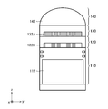
- FIG. 18 is a cross-sectional view showing an example of an imaging optical system to which the present invention is applied.
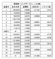
- FIG. 19 is a chart showing lens data of the imaging optical system shown in FIG. FIG.
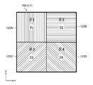
- FIG. 20 is a front view showing the configuration of the bandpass filter unit applied to the imaging optical system shown in FIG.
- FIG. 21 is a graph showing spherical aberration, astigmatism, distortion, and chromatic aberration of magnification of the imaging optical system shown in FIG.
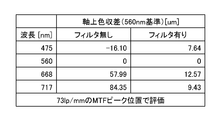
- FIG. 22 is a chart showing changes in axial chromatic aberration of the imaging optical system when the bandpass filter unit is not arranged and when it is arranged in the imaging optical system shown in FIG.
- FIG. 23 is a diagram used to explain the off-axis luminous flux diameter on the diaphragm.
- FIG. 24 is a diagram used to explain the presence or absence of luminous flux regulation other than the aperture.
- FIG. 21 is a graph showing spherical aberration, astigmatism, distortion, and chromatic aberration of magnification of the imaging optical system shown in FIG.
- FIG. 22 is a chart showing changes in axial chromatic aberration of the imaging optical system when the bandpass filter unit is not arranged and
- FIG. 25 is a diagram used to explain the angle of the off-axis main ray passing through the diaphragm.
- FIG. 26 is a diagram used to explain the axial marginal ray angle passing through the diaphragm.
- FIG. 27 is a diagram showing another example of the arrangement pattern of the polarizing filter element provided in each pixel block of the image pickup device.
- FIG. 28 is a diagram showing an example of one pixel of an image pickup device having a light-shielding mask.
- FIG. 29 is a flowchart showing an embodiment of the imaging method according to the present invention.
- FIG. 1 is a diagram showing a schematic configuration of an embodiment of an imaging device according to the present invention.
- the image pickup device 1 of the present embodiment is a multispectral camera that captures a first image and a second image having different wavelength bands, and includes an image pickup optical system 10, an image sensor 100, and a signal processing unit 200. ..
- the imaging optical system 10 is configured by combining a plurality of lenses 12.
- the imaging optical system 10 has a bandpass filter unit 16 and a polarizing filter unit 18 in the vicinity of the pupil thereof. Further, the imaging optical system 10 has a focus adjusting mechanism (not shown). The focus adjustment mechanism adjusts the focus by, for example, moving the entire imaging optical system 10 back and forth along the optical axis L.
- FIG. 2 is a front view showing an embodiment of the bandpass filter unit shown in FIG.
- the bandpass filter unit 16 shown in FIG. 2 has a first pupil region through which light in the first wavelength band ⁇ 1 is passed and a second pupil region through which light in a second wavelength band ⁇ 2 different from the first wavelength band is passed. It is an example of the pupil region, and functions as a wavelength selection unit that transmits light of a different wavelength band for each of the pupil regions of the first pupil region and the second pupil region.
- the bandpass filter unit 16 is arranged so that its center coincides with the optical axis L of the imaging optical system 10, and is a circular aperture region 16A1 and an aperture region divided by concentric circles centered on the optical axis L. It is composed of a frame body 16A having an outer ring-shaped opening region 16A2 of 16A1 and two wavelength selection filters (bandpass filters) 16B1 and 16B2 provided in the frame body 16A.
- one opening region 16A1 provided in the frame body 16A will be referred to as a first opening region 16A1, and the other opening region 16A2 will be referred to as a second opening region 16A2. Distinguish between 16A1 and 16A2. Further, the bandpass filter 16B1 provided in the first opening region 16A1 is referred to as a first bandpass filter 16B1, and the bandpass filter 16B2 provided in the second opening region 16A2 is referred to as a second bandpass filter 16B2. Distinguish between two bandpass filters 16B1 and 16B2.
- the frame body 16A has a light-shielding property, and the light in the first wavelength band ⁇ 1 and the first bandpass filter 16B2 are passed through the first bandpass filter 16B1 and the second bandpass filter 16B2 provided in the two opening regions 16A1 and 16A2. It transmits light in the wavelength band ⁇ 2 of 2.
- the bandpass filter unit 16 functions as a diaphragm. A diaphragm (not shown) may be provided in the imaging optical system 10, and the bandpass filter unit 16 may be installed adjacent to the diaphragm.
- the region of the first bandpass filter 16B1 (first pupil region) is larger than the region of the second bandpass filter 16B2 (second pupil region) of the imaging optical system. It is a pupil region close to the optical axis L of 10.
- FIG. 3 is a graph showing the transmission wavelength characteristics of the first bandpass filter 16B1 and the second bandpass filter 16B2, respectively.
- the first bandpass filter 16B1 transmits light in the first wavelength band ⁇ 1 and the second bandpass filter 16B2 transmits light in the second wavelength band ⁇ 2.
- the representative wavelength of the first wavelength band ⁇ 1 is shorter than the representative wavelength of the second wavelength band ⁇ 2 that passes through the second bandpass filter 16B2.
- the first bandpass filter 16B1 of the bandpass filter unit 16 transmits the light of the first wavelength band ⁇ 1 from the first pupil region near the optical axis L of the imaging optical system 10 and the second bandpass.
- the filter 16B2 transmits light in the second wavelength band ⁇ 2 from the second pupil region far from the optical axis L of the imaging optical system 10.
- the image formation position shifts toward the image plane as the distance from the optical axis of the lens increases in the peripheral direction.
- the image formation position shifts toward the object side as the distance from the optical axis of the lens increases in the peripheral direction.
- the imaging optical system 10 of this example is a lens having negative spherical aberration, and the imaging position shifts toward the object side as the distance from the optical axis of the lens increases in the peripheral direction.
- the imaging optical system 10 uses this characteristic of spherical aberration to reduce axial chromatic aberration as shown below.
- the imaging position of the light in the first wavelength band ⁇ 1 shifts to the object side from the imaging position of the light in the second wavelength band ⁇ 2.
- the image forming position of the luminous flux incident on the imaging optical system 10 shifts toward the object side as the distance from the optical axis L in the peripheral direction increases.
- a first bandpass filter 16B1 that transmits light of the first wavelength band ⁇ 1 is arranged in a circular opening region 16A1 (a region close to the optical axis L) of the frame body 16A, and a ring-shaped opening of the frame body 16A.
- the bandpass filter unit 16 is configured by arranging the second bandpass filter 16B2 that transmits light of the second wavelength band ⁇ 2 in the region 16A2 (the region far from the optical axis L).
- the imaging optical system 10 is realized in which the deviation of the imaging position due to the aberrations (1) and (2) above is canceled out and the axial chromatic aberration is satisfactorily corrected.
- the first bandpass filter 16B1 When the imaging optical system has positive spherical aberration, the first bandpass filter 16B1 has a ring-shaped shape far from the optical axis L, contrary to the bandpass filter unit 16 shown in FIG.
- the second bandpass filter 16B2 is arranged in the opening region 16A2, and the circular opening region 16A1 close to the optical axis L is arranged.
- FIG. 5 is a front view of the polarizing filter unit 18 shown in FIG.
- the polarizing filter unit 18 divides the light passing through the two pupil regions (bandpass filters 16B1 and 16B2) into pupils, and divides the light into two types of pixels (first pixel and second pixel) included in the image sensor 100. It constitutes a part of the pupil division optical system to be incident.
- the polarizing filter unit 18 is arranged so that its center coincides with the optical axis L of the imaging optical system 10, and includes the frame body 18A and the two polarizing filters 18B1 and 18B2. Consists of ,.
- the frame body 18A of the polarizing filter unit 18 has the same projected shape as the frame body 16A of the bandpass filter unit 16, and has a circular opening region 18A1 divided by concentric circles centered on the optical axis L and an annular shape. It has an opening area 18A2.
- the polarizing filter 18B1 is arranged in the circular opening region 18A1 of the frame body 18A, and the polarizing filter 18B2 is arranged in the annular opening region 18A2.
- the polarizing filter 18B1 (first polarizing filter) polarized the light passing through the first pupil region in the first direction
- the polarizing filter 18B2 (second polarizing filter) used the second pupil region.
- the light passing through is polarized in a second direction different from the first direction. That is, the directions of the polarization axes of the two polarizing filters 18B1 and 18B2 are different from each other by 90 °, and in FIG. 5, the direction of the polarization axis of the polarizing filter 18B1 is an xy plane orthogonal to the optical axis L (x axis).
- the upper left-right direction (x-axis direction), and the direction of the polarization axis of the polarizing filter 18B2 is the up-down direction (y-axis direction).
- one opening region 18A1 provided in the frame body 18A is referred to as a first opening region 18A1, and the other opening region 18A2 is referred to as a second opening region 18A2. Distinguish between 18A1 and 18A2.
- the polarizing filter 18B1 provided in the first opening region 18A1 is referred to as a first polarizing filter 18B1
- the polarizing filter 18B2 provided in the second opening region 18A2 is referred to as a second polarizing filter 18B2.
- the two polarizing filters 18B1 and 18B2 are distinguished.
- the pupil region is divided into two regions by the bandpass filter unit 16 and the polarizing filter unit 18. That is, the first pupil region defined by the first aperture region 16A1 of the bandpass filter unit 16 and the first aperture region 18A1 of the polarizing filter unit 18, and the second aperture region 16A2 of the bandpass filter unit 16 And a second pupil region defined by the second aperture region 18A2 of the polarizing filter unit 18.
- Light with different characteristics is emitted from the first pupil region and the second pupil region. That is, the first light having the first wavelength band ⁇ 1 and the polarization direction in the x direction is emitted from the first pupil region, and the second wavelength band ⁇ 2 is emitted from the second pupil region. A second light having a polarization direction of y is emitted.
- FIG. 6 is a diagram showing a schematic configuration of a pixel arrangement of the image sensor 100 shown in FIG.
- the image sensor 100 has a plurality of types (two types) of pixels P1 and P2 on the light receiving surface thereof.
- the pixels P1 and P2 are regularly arranged at a constant pitch along the horizontal direction (x-axis direction) and the vertical direction (y-axis direction).
- one pixel block PB (X, Y) is composed of four adjacent (2 ⁇ 2) pixels P1 and P2, and the pixel block PB (X, Y) is horizontal. It is regularly arranged along the direction (x-axis direction) and the vertical direction (y-axis direction).
- each pixel P1 and P2 are distinguished by using the pixel P1 as the first pixel P1 and the pixel P2 as the second pixel P2, if necessary.
- Each pixel P1 and P2 has different optical characteristics.
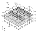
- FIG. 7 is a diagram showing a schematic configuration of the image pickup device 100 shown in FIG. 1, and FIG. 8 is a cross-sectional view showing a schematic configuration of one pixel (broken line portion in FIG. 7) shown in FIG.
- the image sensor 100 is a CMOS (Complementary Metal-Oxide Semiconductor) type image sensor, and has a pixel array layer 110, a polarizing filter element array layer 120, and a microlens array layer 140. Each layer is arranged in the order of the pixel array layer 110, the polarizing filter element array layer 120, and the microlens array layer 140 from the image plane side to the object side.
- the image sensor 100 is not limited to the CMOS type, and may be an XY address type or a CCD (Charge Coupled Device) type image sensor.
- the pixel array layer 110 is configured by arranging a large number of photodiodes 112 two-dimensionally.
- One photodiode 112 constitutes one pixel.
- Each photodiode 112 is regularly arranged along the horizontal direction (x direction) and the vertical direction (y direction).
- the polarizing filter element array layer 120 is configured by two-dimensionally arranging two types of polarizing filter elements 122A and 122B having different polarization directions (polarization directions of transmitted light).
- each polarizing filter element 122A and 122B is distinguished by using the polarizing filter element 122A as the first polarizing filter element 122A and the polarizing filter element 122B as the second polarizing filter element 122B, if necessary.
- the polarizing filter elements 122A and 122B are arranged at the same intervals as the photodiode 112, and are provided for each pixel.
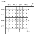
- FIG. 9 is a diagram showing an example of an arrangement pattern of the polarizing filter elements provided in each pixel block of the image pickup device 100.
- the two polarizing filters 18B1 and 18B2 are different from each other in the direction of the polarization axis by 90 °, and the direction of the polarization axis of the first polarization filter element 122A (first polarization direction ⁇ 1) is shown in FIG.
- the direction of the polarization axis of the second polarizing filter 18B2 is the vertical direction (y-axis direction).
- the polarizing filter elements 122A and 122B are regularly arranged.
- the first polarization direction ⁇ 1 of the first polarization filter element 122A coincides with the polarization direction of the first polarization filter 18B1 of the polarization filter unit 18 (FIG. 5), and the second polarization of the second polarization filter element 122B.
- the direction ⁇ 2 coincides with the polarization direction of the second polarizing filter 18B2 of the polarizing filter unit 18.
- the first pixel P1 having the polarizing filter element 122A of the imaging element 100 receives only the first light of the first wavelength band ⁇ 1 transmitted through the first pupil region having the first polarizing filter 18B1.
- the second pixel P2 having the polarizing filter element 122B receives only the second light of the second wavelength band ⁇ 2 transmitted through the second pupil region having the second polarizing filter 18B2.
- the image pickup device 1 When the image pickup device 1 receives a shooting instruction input from a shutter release switch or the like, the image pickup device 1 performs exposure control on the image sensor 100.
- the optical image of the subject imaged on the light receiving surface of the image sensor 100 by this exposure control is converted into an electric signal by the image sensor 100.
- Charges corresponding to the amount of light incident on the photodiode 112 are accumulated in each pixel (first pixel, second pixel) of the image sensor 100, and the amount of charge accumulated in each pixel from the image sensor 100.
- the electric signal corresponding to the above is read out as an image signal and output.
- the signal processing unit 200 processes the signal output from the image sensor 100, and based on the output signal of the first pixel P1 and the output signal of the second pixel P2, the first wavelength band ⁇ 1 A first image of the above and a second image of the second wavelength band ⁇ 2 are generated, respectively.
- the image pickup apparatus 1 can simultaneously capture the first image of the first wavelength band ⁇ 1 and the second image (multispectral image) of the second wavelength band ⁇ 2, and the first image and the first image and The second image is an image having different wavelength bands from each other, but is captured as an image in which the axial chromatic aberration of the imaging optical system 10 is improved.
- FIG. 10 is a front view showing another embodiment of the bandpass filter unit.
- the bandpass filter unit 16-2 shown in FIG. 10 has a first pupil region through which light in the first wavelength band ⁇ 11 passes, a second pupil region through which light in the second wavelength band ⁇ 12 passes, and a second pupil region.
- This is an example of a third pupil region through which light in the wavelength band ⁇ 21 passes and a fourth pupil region in which light in the fourth wavelength band ⁇ 22 passes, and is a pupil region from the first pupil region to the fourth pupil region. It functions as a wavelength selection unit that transmits light in different wavelength bands.
- the bandpass filter unit 16-2 is arranged so that its center coincides with the optical axis of the imaging optical system, and has a circular aperture region divided by concentric circles centered on the optical axis and three ring-shaped aperture regions. 16-2A and the first wavelength selection filter to the fourth wavelength selection filter (four bandpass filters) 16-2B1 to 16-2B4 provided in the frame body 16-2A. Will be done.
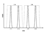
- FIG. 11 is a graph showing the transmission wavelength characteristics of each of the four bandpass filters 16-2B1 to 16-2B4 of the bandpass filter unit 16-2 shown in FIG.
- the bandpass filter 16-2B1 transmits light in the first wavelength band ⁇ 11
- the bandpass filter 16-2B2 transmits light in the second wavelength band ⁇ 12
- the bandpass filter 16-2B3 transmits light in the second wavelength band ⁇ 12.
- the bandpass filter 16-2B4 transmits the light of the wavelength band ⁇ 21 of the above, and transmits the light of the fourth wavelength band ⁇ 22.
- the second wavelength band ⁇ 12, the third wavelength band ⁇ 21, and the fourth wavelength band in which the representative wavelengths are sequentially lengthened are provided in the three ring-shaped pupil regions in which the pass filter 16-2B1 is arranged and sequentially moves away from the optical axis.
- Bandpass filters 16-2B2 to 16-2B4 that transmit the light of ⁇ 22 are arranged.
- An imaging optical system capable of satisfactorily correcting axial chromatic aberration is configured by canceling the deviation of the imaging position due to axial chromatic aberration by the deviation of the imaging position due to spherical aberration.
- FIG. 12 is a front view of the polarizing filter unit 18-2 provided corresponding to the bandpass filter unit 16-2 shown in FIG.
- the polarizing filter unit 18-2 divides the light passing through the four pupil regions (bandpass filters 16-2B1 to 16-2B4) into pupils, and divides the light into four types of pixels (first) included in the image sensor 100-2. It constitutes a part of the pupil division optical system that is incident on the pixels (pixels to the fourth pixel).
- the polarizing filter unit 18-2 is arranged so that its center coincides with the optical axis of the imaging optical system.
- the frame body 18-2A and the four polarizing filters It is composed of 18-2B1 to 18-2B4.
- the frame 18-2A of the polarizing filter unit 18-2 has the same projected shape as the frame 16-2A of the bandpass filter unit 16-2, and is a circular opening divided by concentric circles centered on the optical axis. It has a region and three ring-shaped opening regions.
- the polarizing filter 18-2B1 is arranged in the circular opening region of the frame body 18-2A, and the three polarizing filters 18-2B2 to 18-2B4 are arranged in the three ring-shaped opening regions, respectively.
- the polarization axes of the two polarization filters 18-2B1 and 18-2B3 out of the four polarization filters 18-2B1 to 18B4 are in the left-right direction (x-axis direction) on FIG. 12, and the remaining two polarizations.
- the polarization axes of the filters 18-2B3 and 18-2B4 are in the vertical direction (y-axis direction) on FIG. 12, and the polarizing filters 18-2B1 and 18-2B3 and the polarizing filters 18-2B3 and 18-2B4 are mutually exclusive.
- the directions of the polarization axes are different by 90 °.
- the bandpass filter unit 16-2 shown in FIG. 10 transmits light of four wavelength bands ⁇ 11, ⁇ 12, ⁇ 21, and ⁇ 22 from four pupil regions, respectively, and transmits light of four wavelength bands ⁇ 11, ⁇ 12, ⁇ 21, and ⁇ 22, respectively. Is emitted by the polarizing filter unit 18-2 as the first light in the wavelength bands ⁇ 11 and ⁇ 21 in the x direction in the polarization direction and the second light in the wavelength bands ⁇ 12 and ⁇ 22 in the y direction in the polarization direction.
- FIG. 13 is a diagram showing a schematic configuration of another image pickup device applied to the image pickup device according to the present invention.
- FIG. 14 is a cross-sectional view showing a schematic configuration of one pixel (broken line portion in FIG. 13) shown in FIG.
- the same reference numerals are given to the parts common to the image pickup devices shown in FIGS. 7 and 8, and detailed description thereof will be omitted.
- the image pickup device 100-2 shown in FIGS. 13 and 14 has the addition of a spectroscopic filter element array layer 130 functioning as a first wavelength selection filter and a second wavelength selection filter. It is different from the element 100.
- the spectroscopic filter element array layer 130 is configured by two-dimensionally arranging two types of spectroscopic filter elements 132A and 132B (first wavelength selection filter and second wavelength selection filter) having different transmission wavelength characteristics from each other.
- each spectroscopic filter element 132A and 132B will be distinguished by using the spectroscopic filter element 132A as the first spectroscopic filter element 132A and the spectroscopic filter element 132B as the second spectroscopic filter element 132B, if necessary.
- the spectroscopic filter elements 132A and 132B are arranged at the same intervals as the photodiode 112, and are provided for each pixel.
- FIG. 11 is a graph including an example of transmission wavelength characteristics of each spectroscopic filter element.
- the first spectroscopic filter element 132A transmits light in the wavelength band ⁇ A
- the second spectroscopic filter element 132B transmits light in the wavelength band ⁇ B.
- the first light in the wavelength bands ⁇ 11 and ⁇ 21 whose polarization direction is the x direction and the second light in the wavelength bands ⁇ 12 and ⁇ 22 whose polarization direction is the y direction are incident on the image pickup element 100-2.
- the pixel having the first spectral filter element 132A and the first polarizing filter element 122A is defined as the pixel P1
- the first spectral filter element 132A and the second polarizing filter element A pixel having 122B is a pixel P2
- a pixel having a second spectral filter element 132B and a first polarizing filter element 122A is a pixel P3
- a pixel having a second spectral filter element 132B and a second polarizing filter element 122B is defined as the pixel P1
- one pixel block PB (X, Y) is composed of four adjacent (2 ⁇ 2) pixels P1, P2, P3, and P4, and this pixel block PB (X, Y) is formed.
- PBs (X, Y) are regularly arranged along the horizontal direction (x-axis direction) and the vertical direction (y-axis direction).
- pixels P1, P2, P3, and P4 are referred to as first pixel P1, second pixel P2, third pixel P3, and fourth pixel P4, and four types of pixels P1, P2, P3, and P4 are referred to as four types. Pixels P1, P2, P3, P4 are distinguished.
- the four types of pixels P1 to P4 are composed of polarizing filter elements 122A and 122B, and spectroscopic filter elements 132A. With the combination of 132B, only light in any one of the four wavelength bands ⁇ 11 to ⁇ 22 is received. That is, the first pixel P1 receives only the light in the wavelength band ⁇ 11, the second pixel P2 receives only the light in the wavelength band ⁇ 12, and the third pixel P3 receives only the light in the wavelength band ⁇ 21. Upon receiving light, the fourth pixel P4 receives only light in the wavelength band ⁇ 22.
- the image pickup device When the image pickup device receives a shooting instruction input from a shutter release switch or the like, the image pickup device performs exposure control on the image pickup element 100-2.
- the optical image of the subject imaged on the light receiving surface of the image sensor 100-2 by this exposure control is converted into an electric signal by the image sensor 100-2.
- an electric charge corresponding to the amount of light incident on the photodiode 112 is accumulated, and from the image sensor 100-2, the electric charge accumulated in each pixel is accumulated.
- the corresponding electric signal is read out as an image signal and output.
- the signal processing unit 200 shown in FIG. 1 processes the signal output from the image pickup element 100-2, and outputs the output signal of the first pixel P1, the output signal of the second pixel P2, and the output signal of the third pixel P3. , And a first image of the first wavelength band ⁇ 11, a second image of the second wavelength band ⁇ 12, a third image of the third wavelength band ⁇ 21, and a third image of the third wavelength band ⁇ 21, based on the output signal of the fourth pixel P4. A fourth image of the fourth wavelength band ⁇ 22 is generated, respectively.
- the image pickup apparatus can use the first image of the first wavelength band ⁇ 11, the second image of the second wavelength band ⁇ 12, the third image of the third wavelength band ⁇ 21, and the fourth wavelength band ⁇ 22.
- the fourth image (multispectral image) can be simultaneously imaged, and the first to fourth images have different wavelength bands from each other, but the axial chromatic aberration of the imaging optical system is improved. It is imaged as an image.
- [Variations of bandpass filter units corresponding to the aberration type of the imaging optical system] 15 to 17 are diagrams showing an aberration type of the imaging optical system and variations of the bandpass filter unit corresponding to the aberration type, respectively.
- Spherical aberration, coma, and astigmatism can be considered as the aberration types of the imaging optical system that can be applied to correct the axial chromatic aberration of the imaging optical system.
- the imaging optical system may be designed so that aberrations other than the axial chromatic aberration of the imaging optical system are positively generated.
- spherical aberration is generated by changing the surface spacing or curvature near the aperture for an imaging optical system in which spherical aberration is well corrected. It is possible to make it.
- coma is generated by eccentricity of a lens near the diaphragm, and as a method of realizing an imaging optical system having astigmatism, it is near the diaphragm. It is conceivable to generate astigmatism by arranging the anamorphic lens.
- the imaging position shifts depending on the position of the pupil.
- the regions a1, b1 and c1 are a region in which the phase advances with respect to the region b1 in the imaging optical system and the region c1 is a region c1 in which the phase is delayed, the regions a1, b1 and c1 The imaging position approaches the image plane side in order.
- Bandpass filters having different wavelength bands are assigned to each of the corresponding pupil regions a2, b2, and c2. That is, a bandpass filter having a long wavelength that transmits in the order of regions a2, b2, and c2 is arranged.
- bandpass filters having different transmission wavelength bands are appropriately arranged corresponding to (B) “wavelength allocation image” in FIG. 15, the deviation of the imaging position due to the influences of 1) and 2) cancel each other out. It is possible to realize an imaging optical system in which axial chromatic aberration is satisfactorily corrected.
- FIG. 15 (C) “concentric circle type”
- FIG. 15 (D) “circular opening vertical 3-hole type”
- FIG. E "Circular opening cross 5 hole type”
- FIG. 16 (F) “Circular opening vertical 5 hole type”
- FIG. 16 (G) “Circular opening cross 9 hole type”
- FIG. 16 (H) “Circular”
- the six bandpass filter units shown in “Opening 8 directions 9 holes type" are shown in FIGS. 15 and 16.
- the imaging optical system having spherical aberration has the characteristic (characteristic of negative spherical aberration) shown in (A) “aberration characteristic” of FIG. 15, in order to correct the axial chromatic aberration, (B) of FIG.
- a bandpass filter having a long wavelength that transmits in the order of regions a2, b2, and c2 that are sequentially moved away from the optical axis is arranged.
- the "concentric circle type" in FIG. 15 (C) is a bandpass filter unit of the same type as the bandpass filter unit 16 shown in FIG. 2 and the bandpass filter unit 16-2 shown in FIG.
- the filter unit has a visible white filter in a circular aperture on the optical axis or a circular aperture without a filter, and a plurality of circular apertures separated by an equal distance from the optical axis have a representative wavelength higher than that of the visible white representative wavelength.
- a bandpass filter that transmits light in a long wavelength band is arranged.
- an image in the visible white wavelength band and an image in a wavelength band having a longer representative wavelength than the visible white representative wavelength can be simultaneously captured, and each image having a different wavelength band can be captured at the same time. Even so, the focusing accuracy of each image can be improved.
- (F) “circular opening vertical 5-hole type” of FIG. 16 and (G) “circular opening cross 9-hole type” of FIG. 16 (E) of FIG. 15 have a first wavelength band having a short wavelength in the center.
- a bandpass filter that transmits light is arranged, and a bandpass filter that transmits light in a second wavelength band having a long wavelength is arranged in the outermost part, and an intermediate between the first wavelength band and the second wavelength band is arranged in the middle. It has a third pupil region through which light in the third wavelength band of the above is passed.
- bandpass filter units when the spherical aberration is negative, a bandpass filter having a longer wavelength is arranged as the distance from the optical axis increases. In this way, by arranging the bandpass fill for each wavelength band in consideration of the spherical aberration of the imaging optical system, the deviation of the imaging position for each wavelength due to the axial chromatic aberration is reduced, and a plurality of images are simultaneously imaged. I am trying to improve the focusing accuracy of the image.
- the light is transmitted in the order of regions gradually moving away from the optical axis. Place a bandpass filter with a short wavelength.
- FIG. 15 (D) “circular opening vertical 3-hole type”
- FIG. 15 (E) “circular opening cross 5-hole type”
- 16 (F) “Circular opening vertical 5 hole type”
- FIG. 16 (G) “Circular opening cross 9 hole type”
- FIG. 16 (H) “Circular opening 8 direction 9 hole type”
- FIG. J) "Square opening 2x2 type”
- FIG. 17 (K) Square opening 8-hole rhombic type
- FIG. 17 (L) “Square opening 3x3 type", FIG.
- the imaging position on the optical axis of the light incident on the region a2 of the (first region) and the region c2 (second region) moves to the image side, and is on the optical axis of the light incident on the region c2.
- the imaging position moves to the object side.
- the bandpass filter unit that reduces axial chromatic aberration by utilizing coma has three circular openings from bottom to top in FIG. Bandpass filters that transmit longer wavelengths are sequentially arranged.
- the imaging position shifts toward the object from the bottom to the top due to the influence of coma, but the wavelength gradually shifts from the bottom to the top.
- a bandpass filter unit having a long bandpass filter it is possible to cancel the deviation of the imaging position due to axial chromatic aberration and obtain a good image in which the deviation of the imaging position for each wavelength is reduced. ..
- a bandpass filter in which the transmitted wavelength becomes longer is sequentially arranged in each opening from the bottom to the top.
- the 10 bandpass filter units shown in the “divided type” and the “fan-shaped 8-divided type” in FIG. 17 (O) are shown in FIGS. 15 to 17.
- the imaging optical system having astigmatism has the characteristics shown in (A) "abrasive characteristics" of FIG. 15, it is incident on the left and right regions (first region) symmetrical with respect to the optical axis of the imaging optical system.
- the imaging position on the optical axis of light moves to the image side, and it is an upper and lower region (second region) symmetrical with respect to the optical axis and is orthogonal to the left and right regions (including the case where it is substantially orthogonal).
- the imaging position on the optical axis of the light incident on the upper and lower regions moves to the object side.
- the bandpass filter unit that reduces axial chromatic aberration by utilizing non-point aberration has a circular aperture in the center (on the optical axis) in FIG.
- the left and right circular openings are arranged with short wavelength bandpass filters
- the upper and lower circular openings are arranged with short wavelength bandpass filters.
- bandpass filters having shorter wavelengths transmitted are sequentially arranged as the distance from the center in the left-right direction is shorter than that of the center bandpass filter, while the center.
- a bandpass filter having a longer transmitted wavelength is sequentially arranged than the central bandpass filter as the distance from the bandpass filter increases in the vertical direction.
- band pass filter In the case of (I) "circular aperture astigmatism special type" of FIG. 16, a band pass filter is not arranged in the center, and light is emitted to the 12 circular openings formed along the sides of the substantially rhombus. Bandpass filters with shorter transmitted wavelengths are sequentially arranged as they move away from the straight line in the vertical direction passing through the axis in the horizontal direction.
- the bandpass filter unit shown in (J) “square opening 2x2 type” in FIG. 16 and (N) “fan-shaped 4-split type” in FIG. 17 has a visible white filter in the left and right openings or an opening without a filter. Bandpass filters that transmit light in a wavelength band whose representative wavelength is longer than the representative wavelength of visible white are arranged in the upper and lower openings.
- a bandpass filter in which the transmitted wavelength becomes shorter as the distance from the left and right direction increases is arranged, and a bandpass filter in which the transmitted wavelength becomes longer as the distance from the vertical direction increases.
- the wavelength to be transmitted depends on the characteristic of the astigmatism. It is necessary to determine the position and area of multiple bandpass filters with different wavelengths.
- FIG. 18 is a cross-sectional view showing an example of an imaging optical system to which the present invention is applied.
- the imaging optical system 20 shown in FIG. 18 includes a front group lens 20A arranged on the object side of the aperture position indicated by the surface number 8 and a rear group lens 20B arranged on the image side of the aperture position. Have.
- 1 to 7 indicate surface numbers for the four lenses constituting the front group lens 20A
- 9 to 16 indicate surface numbers for the four lenses constituting the rear group lens 20B and the parallel flat plate. ing.
- FIG. 19 is a chart showing the lens data of the imaging optical system 20 shown in FIG.
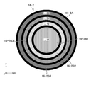
- FIG. 20 is a front view showing the configuration of the bandpass filter unit applied to the imaging optical system 20 shown in FIG.
- the bandpass filter unit 16-3 shown in FIG. 20 is arranged between the front group lens 20A and the rear group lens 20B of the imaging optical system 20 shown in FIG. 18, for example, at the position of the aperture shown in FIG. It is placed and can function as a fixed diaphragm or can be placed adjacent to the diaphragm.
- the bandpass filter unit 16-3 is a "concentric circle type" bandpass filter unit equivalent to the bandpass filter unit 16-2 shown in FIG. 10, and has diameters of 6 mm, 6 ⁇ 2 mm, 6 ⁇ 3 mm, and 12 mm, respectively.
- a pass filter, a bandpass filter that transmits a representative wavelength ⁇ 21 (red: 668 nm), and a bandpass filter that transmits a representative wavelength ⁇ 22 (red edge: 717 nm) are arranged and configured.
- the imaging optical system 20 of this embodiment has a polarizing filter unit (corresponding to the polarizing filter unit 18-2 shown in FIG. 12) corresponding to the bandpass filter unit 16-3.
- FIG. 21 is a graph showing spherical aberration, astigmatism, distortion, and chromatic aberration of magnification of the imaging optical system 20 shown in FIG.
- FIG. 22 is a chart showing changes in the axial chromatic aberration of the imaging optical system 20 when the bandpass filter unit 16-3 is not arranged in the imaging optical system 20 and when it is arranged.
- the axial chromatic aberration shown in FIG. 22 indicates the amount of deviation of the imaging position of another wavelength with respect to the wavelength ⁇ 12 (60 nm), and the negative value indicates the amount of deviation toward the object side. Further, these deviation amounts were measured based on the imaging position where the MFT (Modulation Transfer Function) at the spatial frequency 73 [lp / mm] takes a peak value.
- MFT Modulation Transfer Function
- n be an integer of 2 or more
- i be a parameter that changes in the range of 1 to n
- ⁇ i be the i-th pupil region of the imaging optical system.
- ⁇ ij be the representative wavelength of light transmitted through the i-th pupil region ⁇ i.
- the m i be the number of the representative wavelength in the pupil region ⁇ i of the i
- j be a parameter that changes in the range of 1 to m.
- ⁇ ij be the j-th representative wavelength in the i-th pupil region ⁇ i.
- f ( ⁇ ) be the paraxial focal length at the wavelength ⁇ of the imaging optical system.
- g (x, y; ⁇ ) be the axial longitudinal aberration of the wavelength ⁇ at the pupil coordinates (x, y) of the pupil region of the imaging optical system.
- S ⁇ i be the area of the third pupil region ⁇ i.
- the imaging optical system is based on the following [Equation 1] and [Equation 2] equations.
- Equation 1 means that the imaging optical system has axial chromatic aberration exceeding a.
- Equation 2 is preferably b ⁇ 8p.
- the depth of focus of the imaging optical system can be expressed as ⁇ ⁇ F, where ⁇ is the permissible circle of confusion diameter and F is the aperture value (F value).
- F the aperture value
- the axial chromatic aberration of the imaging optical system can be reduced within the depth of focus of the imaging optical system.
- the permissible circle of confusion diameter ⁇ is a full Nyquist of the pixel pitch p of the image sensor, and b ⁇ 4p.
- the axial chromatic aberration with a filter shown in FIG. 22 satisfies b ⁇ 4p.
- FIG. 23 is a diagram used to explain the off-axis luminous flux diameter on the diaphragm.
- the image of the wavelength assigned to the outermost outline does not show the periphery with a high image height as shown in FIG. 23 (B). That is, the image circle becomes smaller.
- an imaging optical system having a large image circle is used so that the off-axis luminous flux can cover the outermost ring-shaped region, and as shown in FIG. 23 (C), the image of the wavelength assigned to the outermost shell is also the outermost periphery. It is preferable to capture up to.
- FIG. 24 is a diagram used to explain the presence or absence of luminous flux regulation other than the aperture.
- FIG. 24 (A) is a diagram showing an imaging optical system 30-1 in which the luminous flux is regulated by the diaphragm 32
- FIG. 24 (B) is a diagram showing an imaging optical system 30-2 in which the luminous flux is regulated by other than the diaphragm 32.
- the off-axis luminous flux diameter on the diaphragm 32 can cover almost the entire area of the diaphragm 32, and it is possible to cover each ring-shaped region (for each wavelength band).
- the image size can be the same.
- FIG. 25 is a diagram used to explain the angle of the off-axis main ray passing through the diaphragm.
- the imaging optical system 40 shown in FIG. 25 has a front group lens 40A and a rear group lens 40B, and an aperture surface 42 is located between the front group lens 40A and the rear group lens 40B.
- the angle ⁇ of the off-axis main ray passing through the diaphragm surface 42 is determined by the angle of the ray and the angular magnification of the front lens group lens 40A.
- the angle ⁇ of the off-axis main ray passing through the diaphragm surface 42 approaches perpendicular to the diaphragm surface 42.
- the input angle of light incident on the diaphragm surface 42 or the bandpass filter (not shown) arranged adjacent to the diaphragm surface 42 can be reduced, and the wavelength shift due to the large incident angle is reduced. can do.
- FIG. 26 is a diagram used to explain the axial marginal ray angle passing through the diaphragm.
- the imaging optical system 50 shown in FIG. 26 has a front group lens 50A and a rear group lens 50B, and an aperture surface 52 is located between the front group lens 50A and the rear group lens 50B.
- the axial marginal ray angle ⁇ passing through the diaphragm surface 52 is determined by the entrance pupil diameter and the focal length of the front lens group lens 50A.
- the front group lens 50A has a focal length that brings the on-axis marginal ray angle ⁇ incident on the diaphragm surface 52 closer to perpendicular to the diaphragm surface 52.
- the axial marginal ray angle ⁇ passing through the diaphragm surface 52 approaches perpendicular to the diaphragm surface 52.
- the axial marginal ray angle ⁇ (input angle) incident on the diaphragm surface 52 or the bandpass filter (not shown) arranged adjacent to the diaphragm surface 52 can be reduced, and the incident angle becomes large. This makes it possible to reduce the wavelength shift.
- FIG. 27 is a diagram showing another example of the arrangement pattern of the polarizing filter element provided in each pixel block of the image pickup device.
- the four pixels P1 to P4 constituting one pixel block PB are provided with polarizing filter elements 122A to 122D having different transmission polarization directions.
- the first pixel P1 is provided with a polarizing filter element 122A (first polarizing filter) that transmits light in the polarization direction ⁇ 1 (for example, 90 °).
- the second pixel P2 is provided with a second polarizing filter element 122B (second polarizing filter) that transmits light in the polarization direction ⁇ 2 (for example, 0 °).
- the third pixel P3 is provided with a third polarizing filter element 122C (third polarizing filter) that transmits light in the polarization direction ⁇ 3 (for example, 45 °).
- the fourth pixel P4 is provided with a fourth polarizing filter element 122D (fourth polarizing filter) that transmits light in the polarization direction ⁇ 4 (for example, 135 °).
- the number of wavelength bands selected by the bandpass filter unit is three, and three types of polarization filter units (for example, ⁇ 1, ⁇ 2, ⁇ 3) are arranged corresponding to each pupil region of the bandpass filter unit. It is assumed that it has been done.
- the signal processing unit 200 (FIG. 1) performs interference removal processing to generate an image signal in each wavelength band.
- the pixel signal (signal value) obtained from the first pixel P1 of each pixel block PB (X, Y) is x1
- the pixel signal obtained from the second pixel P2 is x2
- the signal processing unit 200 calculates three pixel signals X1 to X3 corresponding to light in each wavelength band (for example, ⁇ 1, ⁇ 2, ⁇ 3) from the three pixel signals x1 to x3, and eliminates interference.
- the three pixel signals X1 to X3 corresponding to the light of each wavelength band ⁇ 1, ⁇ 2, and ⁇ 3 are calculated by the [Equation 4] equation using the matrix A of the [Equation 3] equation, and the interference is eliminated. To do.
- Interference occurs when light from the pupil region of each wavelength band is mixed into each pixel P1 to P3.
- the ratio of light incident on the pupil region of each wavelength band received by each pixel P1 to P3 (the amount of interference (also referred to as the interference ratio)) is the polarization direction of the polarizing filter unit provided in the pupil region of each wavelength band. It is uniquely determined from the relationship between the above and the polarization directions of the polarizing filter elements 122A to 122C provided in the pixels P1 to P3.
- the ratio of light incident on the first pupil region received by the first pixel P1 (interference amount) is b11, and the ratio of light incident on the second pupil region is received by the first pixel P1.
- the ratio of light incident on b12 and the third pupil region received by the first pixel P1 is b13, the following relationship holds between X1, X2, X3 and x1.
- X1, X2, and X3 are calculated by the following equation by multiplying both sides of the equation [Equation 9] by the inverse matrix B -1 of the matrix B.
- the pixel signals X1, X2, and X3 of the image obtained in each pupil region are each pixel P1 based on the ratio (interference amount) that the light incident on each pupil region is received by each pixel P1 to P3. It can be calculated from the pixel signals x1, x2, x3 of P3.
- a first microlens and a first light-shielding mask having a first aperture corresponding to a first pupil region are arranged in the first pixel of the image sensor, and a second microlens is placed in the second pixel of the image sensor. And a second shading mask with a second aperture corresponding to the second pupil region is placed.
- the first pupil region and the second pupil region are divided by using the light-shielding mask (first light-shielding mask, second light-shielding mask), and the first pixel and the second pixel of the image pickup device are divided.
- a light beam passing through each pupil region can be incident on the surface.
- FIG. 28 is a diagram showing an example of one pixel of an image pickup device having a light-shielding mask.
- 112 is a photodiode
- 142 is a microlens
- the light-shielding mask M is arranged between the photodiode 112 and the microlens 142.
- the light-shielding mask M has an opening corresponding to the shape of each pupil region.
- the photodiode 112 receives only the light passing through the desired pupil region by the light-shielding mask M.
- the pixel block of the image pickup device by configuring the pixel block of the image pickup device with a plurality of types of pixels provided with a light-shielding mask M having an aperture corresponding to the shape of each pupil region, an image of each wavelength band passing through each pupil region is acquired. can do.
- FIG. 29 is a flowchart showing an embodiment of the imaging method according to the present invention.
- the imaging method shown in FIG. 29 corresponds to the imaging device 1 shown in FIG. 1, and when carrying out this imaging method, the imaging optical system 10 according to the present invention is prepared.
- the image pickup apparatus 1 determines whether or not there is an instruction input for taking an image of a plurality of wavelength bands by, for example, an instruction input from a shutter release switch (step S10).
- the image pickup device 1 controls the exposure to the image pickup device 100 when it receives an input of a shooting instruction (step S12). As a result, electric charges corresponding to the amount of light incident on the photodiode are accumulated in each pixel (first pixel P1 and second pixel P2) of the image sensor 100, and are accumulated in each pixel from the image sensor 100. An electric signal corresponding to the amount of electric charge is read out as an image signal and output.
- the signal processing unit 200 acquires a signal output from the image sensor 100 (step S14), generates a first image in the first wavelength band based on the output signal of the first pixel P1, and second. A second image of the second wavelength band ⁇ 2 is generated based on the output signal of the pixel P2.
- the image pickup apparatus 1 can simultaneously capture the first image of the first wavelength band ⁇ 1 and the second image (multispectral image) of the second wavelength band ⁇ 2, and the first image and the first image and The second image is an image in which the wavelength bands differ from each other due to the bandpass filter unit 16, but the axial chromatic aberration of the imaging optical system 10 due to the difference between the first wavelength band ⁇ 1 and the second wavelength band ⁇ 2 is captured.
- Imaging optics that reduce based on the relationship between aberrations other than axial chromatic aberration of the optical system 10 (spherical aberration in the embodiment of FIG. 1) and the positions of the first pupil region and the second pupil region of the imaging optical system 10. Since it is the system 10, it is captured as a multispectral image with improved axial chromatic aberration.
- the imaging apparatus is not limited to capturing still images in a plurality of wavelength bands, and may capture moving images in a plurality of wavelength bands at the same time.
- the present invention is not limited to the image pickup apparatus, and includes an image pickup optical system constituting the image pickup apparatus.
- an imaging device in which the imaging optical system can be exchanged, it is possible to acquire a multispectral image in a desired wavelength band by exchanging with an imaging optical system designed according to the wavelength band.
- Imaging device 10 20, 30-1, 30-2, 40, 50 Imaging optical system 11A, 11B Restriction point 12 Lens 16, 16-2, 16-3, 16-4 Bandpass filter unit 16A, 16-2A , 18A, 18-2A Frame 16B1, 16B2, 16-2B1, 16-2B2, 16-2B3, 16-2B4 Bandpass filter 16A1, 16A2, 18A1, 18A2 Opening area 18, 18-2 Polarized filter unit 18B1, 18B2 , 18-2B1, 18-2B2, 18-2B3 Polarizing filter 20A, 40A, 50A Front group lens 20B, 40B, 50B Rear group lens 32 Aperture 42, 52 Aperture surface 100, 100-2 Imaging element 110 Pixel array layer 112 Photo Diode 120 Polarized filter element Array layer 122A, 122B, 122C, 122D Polarized filter element 130 Spectral filter element Array layer 132A, 132B Spectral filter element 140 Microlens Array layer 142 Microlens 200 Signal processing unit L Optical axis M Shading mask P1, P2
Landscapes
- Physics & Mathematics (AREA)
- General Physics & Mathematics (AREA)
- Optics & Photonics (AREA)
- Engineering & Computer Science (AREA)
- Multimedia (AREA)
- Signal Processing (AREA)
- Spectroscopy & Molecular Physics (AREA)
- Color Television Image Signal Generators (AREA)
- Studio Devices (AREA)
Abstract
Provided are an imaging device, an imaging optical system, and an imaging method with which images in mutually different wavelength bands can be captured simultaneously and in which focusing precision of the images can be improved. This imaging device (1) comprises: an imaging optical system (10) having a first pupil region that transmits light in a first wavelength band and a second pupil region that transmits light in a second wavelength band, the imaging optical system (10) reducing axial chromatic aberration of the imaging optical system (10) on the basis of the relationship between aberrations other than axial chromatic aberration of the imaging optical system (10) and the positions of the first and second pupil regions of the imaging optical system (10); an imaging element (100) including first pixels that receive light transmitted through the first pupil region of the imaging optical system (10) and second pixels that receive light transmitted through the second pupil region; and a signal processing unit (200) that processes signals outputted from the imaging element (100) and generates a first image in the first wavelength band and a second image in the second wavelength band on the basis of output signals of the first pixels and output signals of the second pixels, respectively.
Description
本発明は撮像装置、撮像光学系及び撮像方法に係り、特に複数の波長帯域の画像をそれぞれ撮影する技術に関する。
The present invention relates to an image pickup apparatus, an image pickup optical system, and an image pickup method, and particularly relates to a technique for capturing an image of a plurality of wavelength bands.
従来、この種の撮像装置として、特許文献1に記載のマルチバンドカメラが提案されている。
Conventionally, a multi-band camera described in Patent Document 1 has been proposed as this type of imaging device.
このマルチバンドカメラは、撮像レンズ系と分光フィルタ板とを有する撮影光学系を備えている。分光フィルタ板は、撮像レンズ系を通る光路中に介挿され、互いに異なる複数の波長帯域の光をそれぞれ透過させる複数の分光領域が、撮像レンズ系に関する光軸を中心として略同心円状に配列される分光フィルタを有している。
This multi-band camera is equipped with a photographing optical system having an imaging lens system and a spectroscopic filter plate. The spectroscopic filter plate is inserted in the optical path passing through the image pickup lens system, and a plurality of spectral regions that transmit light of a plurality of wavelength bands different from each other are arranged substantially concentrically around the optical axis related to the image pickup lens system. Has a spectroscopic filter.
マルチバンドカメラは、分光フィルタ板の複数の分光領域における透光状態と遮光状態とを切り替えることにより被写体の複数の分光画像を面順次方式で撮像している。
The multi-band camera captures a plurality of spectral images of the subject in a surface-sequential manner by switching between a light-transmitting state and a light-shielding state in a plurality of spectral regions of the spectroscopic filter plate.
また、複数の波長帯域それぞれに関して撮像レンズ系が有する色収差の結像位置ずれ特性を、撮像レンズ系の球面収差及び分光フィルタにより略打ち消すように調整している。
Further, the imaging misalignment characteristics of the chromatic aberration of the imaging lens system with respect to each of the plurality of wavelength bands are adjusted so as to be substantially canceled by the spherical aberration of the imaging lens system and the spectroscopic filter.
本開示の技術に係る一つの実施形態は、それぞれ異なる波長帯域の画像を同時に撮像し、かつ各画像の合焦精度を向上させることができる撮像装置、撮像光学系及び撮像方法を提供する。
One embodiment according to the technique of the present disclosure provides an imaging device, an imaging optical system, and an imaging method capable of simultaneously capturing images in different wavelength bands and improving the focusing accuracy of each image.
本発明の一の態様に係る撮像装置は、第1の波長帯域の光を通過させる第1の瞳領域及び第1の波長帯域とは異なる第2の波長帯域の光を通過させる第2の瞳領域を有する撮像光学系であって、第1の波長帯域と第2の波長帯域との違いによる撮像光学系の軸上色収差を、撮像光学系の軸上色収差以外の収差と撮像光学系の第1の瞳領域及び第2の瞳領域の位置との関係に基づいて低減する撮像光学系と、撮像光学系の第1の瞳領域を通過する光を受光する第1の画素及び第2の瞳領域を通過する光を受光する第2の画素を含む撮像素子と、撮像素子から出力される信号を処理し、第1の画素の出力信号及び第2の画素の出力信号に基づいて第1の波長帯域の第1の画像及び第2の波長帯域の第2の画像をそれぞれ生成する信号処理部と、を備える。
The image pickup apparatus according to one aspect of the present invention has a first pupil region through which light in the first wavelength band is passed and a second pupil through which light in a second wavelength band different from the first wavelength band is passed. An imaging optical system having a region, the axial chromatic aberration of the imaging optical system due to the difference between the first wavelength band and the second wavelength band, the aberration other than the axial chromatic aberration of the imaging optical system, and the first of the imaging optical system. An imaging optical system that reduces based on the relationship between the positions of the first pupil region and the second pupil region, and the first pixel and the second pupil that receive light passing through the first pupil region of the imaging optical system. The image pickup element including the second pixel that receives the light passing through the region and the signal output from the image pickup element are processed, and the first pixel is based on the output signal of the first pixel and the output signal of the second pixel. It includes a signal processing unit that generates a first image in the wavelength band and a second image in the second wavelength band, respectively.
本発明の他の態様に係る撮像装置において、撮像光学系の軸上色収差以外の収差は、球面収差である。
In the image pickup apparatus according to another aspect of the present invention, the aberration other than the axial chromatic aberration of the image pickup optical system is spherical aberration.
本発明の更に他の態様に係る撮像装置において、球面収差が負の場合、第1の瞳領域は、第2の瞳領域よりも撮像光学系の光軸に近い瞳領域であり、第1の波長帯域の代表波長は、第2の波長帯域の代表波長よりも短いことが好ましい。
In the imaging apparatus according to still another aspect of the present invention, when the spherical aberration is negative, the first pupil region is a pupil region closer to the optical axis of the imaging optical system than the second pupil region, and the first pupil region The representative wavelength of the wavelength band is preferably shorter than the representative wavelength of the second wavelength band.
本発明の更に他の態様に係る撮像装置において、第1の瞳領域は、撮像光学系の光軸を中心とした同心円により区分される円形又は輪帯状の瞳領域であり、第2の瞳領域は、第1の瞳領域の外側の輪帯状の瞳領域であることが好ましい。
In the imaging apparatus according to still another aspect of the present invention, the first pupil region is a circular or ring-shaped pupil region divided by concentric circles centered on the optical axis of the imaging optical system, and is a second pupil region. Is preferably a ring-shaped pupil region outside the first pupil region.
本発明の更に他の態様に係る撮像装置において、撮像光学系の軸上色収差以外の収差は、コマ収差である。
In the image pickup apparatus according to still another aspect of the present invention, aberrations other than the axial chromatic aberration of the image pickup optical system are coma aberrations.
本発明の更に他の態様に係る撮像装置において、第1の瞳領域を通過する光の撮像光学系の光軸上の結像位置は、撮像光学系のコマ収差により第2の瞳領域を通過する光の光軸上の結像位置よりも像側に移動し、第1の波長帯域の代表波長は、第2の波長帯域の代表波長よりも短いことが好ましい。
In the imaging apparatus according to still another aspect of the present invention, the imaging position on the optical axis of the imaging optical system of light passing through the first pupil region passes through the second pupil region due to coma of the imaging optical system. It is preferable that the representative wavelength of the first wavelength band is shorter than the representative wavelength of the second wavelength band because the light moves to the image side of the image formation position on the optical axis of the light.
本発明の更に他の態様に係る撮像装置において、撮像光学系は、撮像光学系の光軸と交差する直線に対して光軸を挟んで反対に位置する第1の領域及び第2の領域のうちの第1の領域に入射する光の光軸上の結像位置が像側に移動し、第2の領域に入射する光の光軸上の結像位置が物体側に移動するコマ収差を有し、第1の瞳領域は、撮像光学系の第1の領域に対応する瞳領域であり、第2の瞳領域は、撮像光学系の第2の領域に対応する瞳領域であることが好ましい。
In the image pickup apparatus according to still another aspect of the present invention, the image pickup optical system includes a first region and a second region located opposite to a straight line intersecting the optical axis of the image pickup optical system with the optical axis interposed therebetween. Coma in which the image formation position on the optical axis of the light incident on the first region moves to the image side and the image formation position on the optical axis of the light incident on the second region moves to the object side. The first pupil region may be a pupil region corresponding to the first region of the imaging optical system, and the second pupil region may be a pupil region corresponding to the second region of the imaging optical system. preferable.
本発明の更に他の態様に係る撮像装置において、撮像光学系の軸上色収差以外の収差は、非点収差である。
In the image pickup apparatus according to still another aspect of the present invention, aberrations other than the axial chromatic aberration of the image pickup optical system are astigmatisms.
本発明の更に他の態様に係る撮像装置において、第1の瞳領域を通過する光の撮像光学系の光軸上の結像位置は、撮像光学系の非点収差により第2の瞳領域を通過する光の光軸上の結像位置よりも像側に移動し、第1の波長帯域の代表波長は、第2の波長帯域の代表波長よりも短いことが好ましい。
In the imaging apparatus according to still another aspect of the present invention, the imaging position on the optical axis of the imaging optical system of the light passing through the first pupil region is set to the second pupil region due to the non-point aberration of the imaging optical system. It is preferable that the light moves to the image side of the image formation position on the optical axis of the passing light, and the representative wavelength of the first wavelength band is shorter than the representative wavelength of the second wavelength band.
本発明の更に他の態様に係る撮像装置において、撮像光学系は、撮像光学系の光軸に対して対称の第1の領域に入射する光の光軸上の結像位置が像側に移動し、光軸に対して対称の第2の領域であって、第1の領域と直交する第2の領域に入射する光の光軸上の結像位置が物体側に移動する非点収差を有し、第1の瞳領域は、撮像光学系の第1の領域に対応する瞳領域であり、第2の瞳領域は、撮像光学系の第2の領域に対応する瞳領域であることが好ましい。
In the image pickup apparatus according to still another aspect of the present invention, in the image pickup optical system, the image formation position on the optical axis of the light incident on the first region symmetrical with respect to the optical axis of the image pickup optical system moves to the image side. However, astigmatism in which the imaging position on the optical axis of the light incident on the second region orthogonal to the first region, which is the second region symmetric with respect to the optical axis, moves toward the object side. The first pupil region may be a pupil region corresponding to the first region of the imaging optical system, and the second pupil region may be a pupil region corresponding to the second region of the imaging optical system. preferable.
本発明の更に他の態様に係る撮像装置において、撮像光学系は、第1の瞳領域から第1の波長帯域の光を通過させる第1の波長選択フィルタと第2の瞳領域から第2の波長帯域の光を通過させる第2の波長選択フィルタとを有する波長選択フィルタユニットを含むことが好ましい。
In the imaging apparatus according to still another aspect of the present invention, the imaging optical system has a first wavelength selection filter for passing light in the first wavelength band from the first pupil region and a second from the second pupil region. It is preferable to include a wavelength selection filter unit having a second wavelength selection filter for passing light in the wavelength band.
本発明の更に他の態様に係る撮像装置において、撮像光学系は、第1の波長帯域と第2の波長帯域の中間の第3の波長帯域の光を通過させる第3の瞳領域を更に有し、第3の瞳領域は、第1の瞳領域と第2の瞳領域との間の瞳領域であり、撮像素子は、第3の瞳領域を通過する光を受光する第3の画素を更に含み、信号処理部は、第3の画素の出力信号に基づいて第3の波長帯域の第3の画像を更に生成することが好ましい。
In the image pickup apparatus according to still another aspect of the present invention, the image pickup optical system further has a third pupil region through which light in a third wavelength band intermediate between the first wavelength band and the second wavelength band is passed. The third pupil region is a pupil region between the first pupil region and the second pupil region, and the image sensor receives a third pixel that receives light passing through the third pupil region. Further including, it is preferable that the signal processing unit further generates a third image in the third wavelength band based on the output signal of the third pixel.
本発明の更に他の態様に係る撮像装置において、撮像光学系は、第1の瞳領域を通過する光を第1の方向に偏光する第1の偏光フィルタと、第2の瞳領域を通過する光を第1の方向とは異なる第2の方向に偏光する第2の偏光フィルタとを含み、撮像素子の第1の画素には入射する光を第1の方向に偏光する第3の偏光フィルタが配置され、第2の画素には入射する光を第2の方向に偏光する第4の偏光フィルタが配置されることが好ましい。
In the imaging apparatus according to still another aspect of the present invention, the imaging optical system passes through a first polarizing filter that polarizes the light passing through the first pupil region in the first direction and a second pupil region. A third polarizing filter that includes a second polarizing filter that polarizes light in a second direction different from the first direction, and polarized light incident on the first pixel of the imaging element in the first direction. Is arranged, and it is preferable that a fourth polarizing filter for polarizing the incident light in the second direction is arranged in the second pixel.
本発明の更に他の態様に係る撮像装置において、撮像素子の第1の画素には入射する光のうちの第1の波長帯域の光を通過させる第3の波長選択フィルタが配置され、撮像素子の第2の画素には入射する光のうちの第2の波長帯域の光を通過させる第4の波長選択フィルタが配置されることが好ましい。
In the image pickup apparatus according to still another aspect of the present invention, a third wavelength selection filter for passing light in the first wavelength band of the incident light is arranged in the first pixel of the image pickup device, and the image pickup device is provided. It is preferable that a fourth wavelength selection filter for passing light in the second wavelength band of the incident light is arranged in the second pixel of the above.
本発明の更に他の態様に係る撮像装置において、撮像素子の第1の画素には第1のマイクロレンズと第1の瞳領域に対応する第1の開口を有する第1の遮光マスクが配置され、撮像素子の第2の画素には第2のマイクロレンズと第2の瞳領域に対応する第2の開口を有する第2の遮光マスクが配置されることが好ましい。
In the image pickup apparatus according to still another aspect of the present invention, a first light-shielding mask having a first microlens and a first aperture corresponding to a first pupil region is arranged in the first pixel of the image pickup device. It is preferable that a second light-shielding mask having a second microlens and a second aperture corresponding to the second pupil region is arranged in the second pixel of the image sensor.
本発明の更に他の態様に係る撮像装置において、撮像光学系は、撮像素子に入射する光束を、絞り又は絞りとして機能する第1の瞳領域及び第2の瞳領域のみで制限することが好ましい。
In the image pickup apparatus according to still another aspect of the present invention, it is preferable that the image pickup optical system limits the light flux incident on the image pickup device only in the first pupil region and the second pupil region that function as a diaphragm or a diaphragm. ..
本発明の更に他の態様に係る撮像装置において、撮像光学系は、絞りよりも物体側に配置された前群レンズと、絞りよりも像側に配置された後群レンズとを有し、第1の瞳領域及び第2の瞳領域は、前群レンズと後群レンズとの間に位置し、前群レンズは、第1の瞳領域及び第2の瞳領域に入射する軸外主光線の角度を絞り面に対して垂直に近づける角倍率を有することが好ましい。
In the imaging apparatus according to still another aspect of the present invention, the imaging optical system has a front group lens arranged on the object side of the diaphragm and a rear group lens arranged on the image side of the diaphragm. The first pupil region and the second pupil region are located between the front group lens and the rear group lens, and the front group lens is an off-axis main ray incident on the first pupil region and the second pupil region. It is preferable to have an angular magnification that makes the angle close to perpendicular to the aperture surface.
本発明の更に他の態様に係る撮像装置において、撮像光学系は、絞りよりも物体側に配置された前群レンズと、絞りよりも像側に配置された後群レンズとを有し、第1の瞳領域及び第2の瞳領域は、前群レンズと後群レンズとの間に位置し、前群レンズは、第1の瞳領域及び第2の瞳領域に入射する軸上マージナル光線角度を絞り面に対して垂直に近づける焦点距離を有することが好ましい。
In the imaging apparatus according to still another aspect of the present invention, the imaging optical system has a front group lens arranged on the object side of the diaphragm and a rear group lens arranged on the image side of the diaphragm. The first pupil region and the second pupil region are located between the front group lens and the rear group lens, and the front group lens is an axial marginal ray angle incident on the first pupil region and the second pupil region. It is preferable to have a focal length that brings the lens closer to the aperture surface.
本発明の更に他の態様に係る撮像装置において、第1の瞳領域及び第2の瞳領域は、絞りとして機能し、又は絞りに隣接することが好ましい。
In the image pickup apparatus according to still another aspect of the present invention, it is preferable that the first pupil region and the second pupil region function as a diaphragm or are adjacent to the diaphragm.
本発明の更に他の態様に係る撮像装置において、
nを2以上の整数とし、
iを1からnの範囲で変化するパラメータとし、
Ωiを撮像光学系の第iの瞳領域とし、
λijを第iの瞳領域Ωiを透過する光の代表波長とし、
miを第iの瞳領域Ωiにおける代表波長の数とし、
jを1からmの範囲で変化するパラメータとし、
λijを第iの瞳領域Ωiにおけるj番目の代表波長とし、
f(λ)を、撮像光学系の波長λにおける近軸焦点距離とし、
g(x,y;λ)を、撮像光学系の瞳領域の瞳座標(x, y)における波長λの軸上縦収差とし、
SΩiを第iの瞳領域Ωiの面積とすると、
撮像光学系は、次の[数1]式及び[数2]式、 In the image pickup apparatus according to still another aspect of the present invention.
Let n be an integer of 2 or more
Let i be a parameter that changes in the range of 1 to n
Let Ωi be the i-th pupil region of the imaging optical system.
Let λ ij be the representative wavelength of light transmitted through the i-th pupil region Ωi.
The m i be the number of the representative wavelength in the pupil region Ωi of the i,
Let j be a parameter that changes in the range of 1 to m.
Let λ ij be the j-th representative wavelength in the i-th pupil region Ωi.
Let f (λ) be the paraxial focal length at the wavelength λ of the imaging optical system.
Let g (x, y; λ) be the axial longitudinal aberration of the wavelength λ at the pupil coordinates (x, y) of the pupil region of the imaging optical system.
Let SΩ i be the area of the i-th pupil region Ω i
The imaging optical system includes the following [Equation 1] and [Equation 2] equations.

(ただし、a≧b)
を満たすi1,i2,j1,j2の組合せが存在することが好ましい。 (However, a ≧ b)
It is preferable that there is a combination of i1, i2, j1, j2 that satisfies the above conditions.
を満たすi1,i2,j1,j2の組合せが存在することが好ましい。 (However, a ≧ b)
It is preferable that there is a combination of i1, i2, j1, j2 that satisfies the above conditions.
本発明の更に他の態様に係る撮像装置において、撮像素子の画素ピッチをpとすると、[数2]式中のbは、b≦8pであることが好ましい。
In the image pickup apparatus according to still another aspect of the present invention, where p is the pixel pitch of the image pickup device, b in the equation [Equation 2] is preferably b ≦ 8p.
更に他の態様に係る発明は、上記の撮像装置を構成する撮像光学系である。
The invention according to still another aspect is an imaging optical system constituting the above-mentioned imaging device.
更に他の態様に係る発明は、第1の波長帯域の光を通過させる第1の瞳領域及び第1の波長帯域とは異なる第2の波長帯域の光を通過させる第2の瞳領域を有する撮像光学系であって、第1の波長帯域と第2の波長帯域との違いによる撮像光学系の軸上色収差を、撮像光学系の軸上色収差以外の収差と撮像光学系の第1の瞳領域及び第2の瞳領域の位置との関係に基づいて低減する撮像光学系において、
nを2以上の整数とし、
iを1からnの範囲で変化するパラメータとし、
Ωiを撮像光学系の第iの瞳領域とし、
λijを第iの瞳領域Ωiを透過する光の代表波長とし、
miを第iの瞳領域Ωiにおける代表波長の数とし、
jを1からmの範囲で変化するパラメータとし、
λijを第iの瞳領域Ωiにおけるj番目の代表波長とし、
f(λ)を、撮像光学系の波長λにおける近軸焦点距離とし、
g(x,y;λ)を、撮像光学系の瞳領域の瞳座標(x, y)における波長λの軸上縦収差とし、
SΩiを第iの瞳領域Ωiの面積とすると、
撮像光学系は、次の[数1]式及び[数2]式、 The invention according to still another aspect has a first pupil region for passing light in the first wavelength band and a second pupil region for passing light in a second wavelength band different from the first wavelength band. In the imaging optical system, the axial chromatic aberration of the imaging optical system due to the difference between the first wavelength band and the second wavelength band, the aberration other than the axial chromatic aberration of the imaging optical system, and the first pupil of the imaging optical system. In an imaging optical system that reduces based on the relationship between the region and the position of the second pupil region,
Let n be an integer of 2 or more
Let i be a parameter that changes in the range of 1 to n
Let Ωi be the i-th pupil region of the imaging optical system.
Let λ ij be the representative wavelength of light transmitted through the i-th pupil region Ωi.
The m i be the number of the representative wavelength in the pupil region Ωi of the i,
Let j be a parameter that changes in the range of 1 to m.
Let λ ij be the j-th representative wavelength in the i-th pupil region Ωi.
Let f (λ) be the paraxial focal length at the wavelength λ of the imaging optical system.
Let g (x, y; λ) be the axial longitudinal aberration of the wavelength λ at the pupil coordinates (x, y) of the pupil region of the imaging optical system.
Let SΩ i be the area of the i-th pupil region Ω i
The imaging optical system includes the following [Equation 1] and [Equation 2] equations.

(ただし、a≧b)
を満たすi1,i2,j1,j2の組合せが存在する撮像光学系である。 (However, a ≧ b)
This is an imaging optical system in which a combination of i1, i2, j1, and j2 that satisfies the above conditions exists.
を満たすi1,i2,j1,j2の組合せが存在する撮像光学系である。 (However, a ≧ b)
This is an imaging optical system in which a combination of i1, i2, j1, and j2 that satisfies the above conditions exists.
本発明の更に他の態様に係る撮像方法は、第1の波長帯域の光を通過させる第1の瞳領域及び第1の波長帯域とは異なる第2の波長帯域の光を通過させる第2の瞳領域を有する撮像光学系であって、第1の波長帯域と第2の波長帯域との違いによる撮像光学系の軸上色収差を、撮像光学系の軸上色収差以外の収差と撮像光学系の第1の瞳領域及び第2の瞳領域の位置との関係に基づいて低減する撮像光学系を準備するステップと、撮像光学系の第1の瞳領域を通過する光及び第2の瞳領域を通過する光を、それぞれ瞳分割して撮像素子に含まれる第1の画素及び第2の画素に入射させるステップと、信号処理部により撮像素子から出力される信号を処理し、第1の画素の出力信号及び第2の画素の出力信号に基づいて第1の波長帯域の第1の画像及び第2の波長帯域の第2の画像をそれぞれ生成するステップと、を含む。
The imaging method according to still another aspect of the present invention is a second pupil region that allows light in a first wavelength band to pass through and a second pupil region that allows light in a second wavelength band different from the first wavelength band to pass through. An imaging optical system having a pupil region, the axial chromatic aberration of the imaging optical system due to the difference between the first wavelength band and the second wavelength band is measured by the aberrations other than the axial chromatic aberration of the imaging optical system and the imaging optical system. A step of preparing an imaging optical system to reduce based on the relationship between the positions of the first pupil region and the second pupil region, and the light passing through the first pupil region of the imaging optical system and the second pupil region. The step of dividing the passing light into pupils and incidenting them on the first pixel and the second pixel included in the image pickup element and the signal output from the image pickup element by the signal processing unit are processed to form the first pixel. It includes a step of generating a first image of the first wavelength band and a second image of the second wavelength band based on the output signal and the output signal of the second pixel, respectively.
以下、添付図面に従って本発明に係る撮像装置、撮像光学系及び撮像方法の好ましい実施形態について説明する。
Hereinafter, preferred embodiments of the image pickup apparatus, the image pickup optical system, and the image pickup method according to the present invention will be described with reference to the accompanying drawings.
[撮像装置の構成]
図1は、本発明に係る撮像装置の実施形態の概略構成を示す図である。 [Configuration of imaging device]
FIG. 1 is a diagram showing a schematic configuration of an embodiment of an imaging device according to the present invention.
図1は、本発明に係る撮像装置の実施形態の概略構成を示す図である。 [Configuration of imaging device]
FIG. 1 is a diagram showing a schematic configuration of an embodiment of an imaging device according to the present invention.
本実施形態の撮像装置1は、波長帯域が異なる第1の画像及び第2の画像を撮像するマルチスペクトルカメラであり、撮像光学系10と、撮像素子100と、信号処理部200と、を備える。
The image pickup device 1 of the present embodiment is a multispectral camera that captures a first image and a second image having different wavelength bands, and includes an image pickup optical system 10, an image sensor 100, and a signal processing unit 200. ..
[撮像光学系]
撮像光学系10は、複数のレンズ12を組み合わせて構成される。撮像光学系10は、その瞳近傍にバンドパスフィルタユニット16及び偏光フィルタユニット18を有する。また、撮像光学系10は、図示しない焦点調節機構を有する。焦点調節機構は、例えば、撮像光学系10の全体を光軸Lに沿って前後移動させて、焦点を調節する。 [Imaging optical system]
The imagingoptical system 10 is configured by combining a plurality of lenses 12. The imaging optical system 10 has a bandpass filter unit 16 and a polarizing filter unit 18 in the vicinity of the pupil thereof. Further, the imaging optical system 10 has a focus adjusting mechanism (not shown). The focus adjustment mechanism adjusts the focus by, for example, moving the entire imaging optical system 10 back and forth along the optical axis L.
撮像光学系10は、複数のレンズ12を組み合わせて構成される。撮像光学系10は、その瞳近傍にバンドパスフィルタユニット16及び偏光フィルタユニット18を有する。また、撮像光学系10は、図示しない焦点調節機構を有する。焦点調節機構は、例えば、撮像光学系10の全体を光軸Lに沿って前後移動させて、焦点を調節する。 [Imaging optical system]
The imaging
図2は、図1に示したバンドパスフィルタユニットの実施形態を示す正面図である。
FIG. 2 is a front view showing an embodiment of the bandpass filter unit shown in FIG.
図2に示すバンドパスフィルタユニット16は、第1の波長帯域λ1の光を通過させる第1の瞳領域及び第1の波長帯域とは異なる第2の波長帯域λ2の光を通過させる第2の瞳領域の一例であり、第1の瞳領域及び第2の瞳領域の瞳領域ごとに異なる波長帯域の光を透過させる波長選択ユニットとして機能する。
The bandpass filter unit 16 shown in FIG. 2 has a first pupil region through which light in the first wavelength band λ1 is passed and a second pupil region through which light in a second wavelength band λ2 different from the first wavelength band is passed. It is an example of the pupil region, and functions as a wavelength selection unit that transmits light of a different wavelength band for each of the pupil regions of the first pupil region and the second pupil region.
バンドパスフィルタユニット16は、その中心が撮像光学系10の光軸Lと一致するように配置されるもので、光軸Lを中心とする同心円により区分される円形の開口領域16A1、及び開口領域16A1の外側の輪帯状の開口領域16A2を備えた枠体16Aと、その枠体16Aに備えられた2つの波長選択フィルタ(バンドパスフィルタ)16B1、16B2とにより構成される。
The bandpass filter unit 16 is arranged so that its center coincides with the optical axis L of the imaging optical system 10, and is a circular aperture region 16A1 and an aperture region divided by concentric circles centered on the optical axis L. It is composed of a frame body 16A having an outer ring-shaped opening region 16A2 of 16A1 and two wavelength selection filters (bandpass filters) 16B1 and 16B2 provided in the frame body 16A.
尚、以下においては、必要に応じて、枠体16Aに備えられる一方の開口領域16A1を第1の開口領域16A1、他方の開口領域16A2を第2の開口領域16A2と称して、2つの開口領域16A1、16A2を区別する。また、第1の開口領域16A1に備えられるバンドパスフィルタ16B1を第1のバンドパスフィルタ16B1、第2の開口領域16A2に備えられるバンドパスフィルタ16B2を第2のバンドパスフィルタ16B2と称して、2つのバンドパスフィルタ16B1、16B2を区別する。
In the following, if necessary, one opening region 16A1 provided in the frame body 16A will be referred to as a first opening region 16A1, and the other opening region 16A2 will be referred to as a second opening region 16A2. Distinguish between 16A1 and 16A2. Further, the bandpass filter 16B1 provided in the first opening region 16A1 is referred to as a first bandpass filter 16B1, and the bandpass filter 16B2 provided in the second opening region 16A2 is referred to as a second bandpass filter 16B2. Distinguish between two bandpass filters 16B1 and 16B2.
枠体16Aは、遮光性を有し、2つの開口領域16A1、16A2に設けられた第1のバンドパスフィルタ16B1及び第2のバンドパスフィルタ16B2を介して第1の波長帯域λ1の光及び第2の波長帯域λ2の光を透過させる。このバンドパスフィルタユニット16は、絞りとして機能する。尚、撮像光学系10に図示しない絞りを設け、バンドパスフィルタユニット16をその絞りに隣接して設置するようにしてもよい。
The frame body 16A has a light-shielding property, and the light in the first wavelength band λ1 and the first bandpass filter 16B2 are passed through the first bandpass filter 16B1 and the second bandpass filter 16B2 provided in the two opening regions 16A1 and 16A2. It transmits light in the wavelength band λ2 of 2. The bandpass filter unit 16 functions as a diaphragm. A diaphragm (not shown) may be provided in the imaging optical system 10, and the bandpass filter unit 16 may be installed adjacent to the diaphragm.
また、図2からも明らかなように、第1のバンドパスフィルタ16B1の領域(第1の瞳領域)は、第2のバンドパスフィルタ16B2の領域(第2の瞳領域)よりも撮像光学系10の光軸Lに近い瞳領域である。
Further, as is clear from FIG. 2, the region of the first bandpass filter 16B1 (first pupil region) is larger than the region of the second bandpass filter 16B2 (second pupil region) of the imaging optical system. It is a pupil region close to the optical axis L of 10.
図3は、第1のバンドパスフィルタ16B1及び第2のバンドパスフィルタ16B2のそれぞれの透過波長特性を示すグラフである。
FIG. 3 is a graph showing the transmission wavelength characteristics of the first bandpass filter 16B1 and the second bandpass filter 16B2, respectively.
第1のバンドパスフィルタ16B1は、第1の波長帯域λ1の光を透過させ、第2のバンドパスフィルタ16B2は、第2の波長帯域λ2の光を透過させる。第1の波長帯域λ1の代表波長は、第2のバンドパスフィルタ16B2を透過する第2の波長帯域λ2の代表波長よりも短い。
The first bandpass filter 16B1 transmits light in the first wavelength band λ1 and the second bandpass filter 16B2 transmits light in the second wavelength band λ2. The representative wavelength of the first wavelength band λ1 is shorter than the representative wavelength of the second wavelength band λ2 that passes through the second bandpass filter 16B2.
したがって、バンドパスフィルタユニット16の第1のバンドパスフィルタ16B1は、撮像光学系10の光軸Lに近い第1の瞳領域から第1の波長帯域λ1の光を透過させ、第2のバンドパスフィルタ16B2は、撮像光学系10の光軸Lから遠い第2の瞳領域から第2の波長帯域λ2の光を透過させる。
Therefore, the first bandpass filter 16B1 of the bandpass filter unit 16 transmits the light of the first wavelength band λ1 from the first pupil region near the optical axis L of the imaging optical system 10 and the second bandpass. The filter 16B2 transmits light in the second wavelength band λ2 from the second pupil region far from the optical axis L of the imaging optical system 10.
ところで、通常のレンズでは、ガラスの分散特性から,波長の短い光線ほど近く(物体側)に結像する性質(軸上色収差)をもつ。その一方、各種の収差特性を有するレンズにおいては、瞳の位置ごとに結像位置がずれる。
By the way, due to the dispersion characteristics of glass, ordinary lenses have the property of forming an image closer (on the object side) to light rays with shorter wavelengths (axial chromatic aberration). On the other hand, in a lens having various aberration characteristics, the imaging position shifts depending on the position of the pupil.
例えば、図4に示すように正の球面収差を有するレンズの場合((A)の場合)、レンズの光軸から周辺方向に遠ざかる程、結像位置が像面側にずれる。また、図4に示すように負の球面収差を有するレンズの場合((B)の場合)、レンズの光軸から周辺方向に遠ざかる程、結像位置が物体側にずれる。
For example, in the case of a lens having positive spherical aberration as shown in FIG. 4 (in the case of (A)), the image formation position shifts toward the image plane as the distance from the optical axis of the lens increases in the peripheral direction. Further, in the case of a lens having negative spherical aberration as shown in FIG. 4 (in the case of (B)), the image formation position shifts toward the object side as the distance from the optical axis of the lens increases in the peripheral direction.
本例の撮像光学系10は、負の球面収差を有するレンズであり、レンズの光軸から周辺方向に遠ざかる程、結像位置が物体側にずれる。撮像光学系10は、この球面収差の特性を使用し、以下に示すように軸上色収差を低減させる。
The imaging optical system 10 of this example is a lens having negative spherical aberration, and the imaging position shifts toward the object side as the distance from the optical axis of the lens increases in the peripheral direction. The imaging optical system 10 uses this characteristic of spherical aberration to reduce axial chromatic aberration as shown below.
(1)撮像光学系10の軸上色収差により、第1の波長帯域λ1の光の結像位置は、第2の波長帯域λ2の光の結像位置よりも物体側にずれる。
(1) Due to the axial chromatic aberration of the imaging optical system 10, the imaging position of the light in the first wavelength band λ1 shifts to the object side from the imaging position of the light in the second wavelength band λ2.
(2)撮像光学系10の負の球面収差により、撮像光学系10に入射する光束は、光軸Lから周辺方向に遠ざかる程、結像位置が物体側にずれる。
(2) Due to the negative spherical aberration of the imaging optical system 10, the image forming position of the luminous flux incident on the imaging optical system 10 shifts toward the object side as the distance from the optical axis L in the peripheral direction increases.
そこで、枠体16Aの円形の開口領域16A1(光軸Lに近い領域)に第1の波長帯域λ1の光を透過させる第1のバンドパスフィルタ16B1を配置し、枠体16Aの輪帯状の開口領域16A2(光軸Lから遠い領域)に第2の波長帯域λ2の光を透過させる第2のバンドパスフィルタ16B2を配置することで、バンドパスフィルタユニット16を構成する。
Therefore, a first bandpass filter 16B1 that transmits light of the first wavelength band λ1 is arranged in a circular opening region 16A1 (a region close to the optical axis L) of the frame body 16A, and a ring-shaped opening of the frame body 16A. The bandpass filter unit 16 is configured by arranging the second bandpass filter 16B2 that transmits light of the second wavelength band λ2 in the region 16A2 (the region far from the optical axis L).
これにより、上記(1)、(2)の収差による結像位置のずれを相殺し、軸上色収差が良好に補正された撮像光学系10を実現している。
As a result, the imaging optical system 10 is realized in which the deviation of the imaging position due to the aberrations (1) and (2) above is canceled out and the axial chromatic aberration is satisfactorily corrected.
尚、撮像光学系が正の球面収差を有している場合には、図2に示したバンドパスフィルタユニット16とは逆に、第1のバンドパスフィルタ16B1を光軸Lから遠い輪帯状の開口領域16A2に配置し、第2のバンドパスフィルタ16B2を光軸Lに近い円形の開口領域16A1を配置する。
When the imaging optical system has positive spherical aberration, the first bandpass filter 16B1 has a ring-shaped shape far from the optical axis L, contrary to the bandpass filter unit 16 shown in FIG. The second bandpass filter 16B2 is arranged in the opening region 16A2, and the circular opening region 16A1 close to the optical axis L is arranged.
図5は、図1に示した偏光フィルタユニット18の正面図である。
FIG. 5 is a front view of the polarizing filter unit 18 shown in FIG.
偏光フィルタユニット18は、2つの瞳領域(バンドパスフィルタ16B1、16B2)を通過する光を瞳分割して、撮像素子100に含まれる2種類の画素(第1の画素及び第2の画素)に入射させる瞳分割光学系の一部を構成する。
The polarizing filter unit 18 divides the light passing through the two pupil regions (bandpass filters 16B1 and 16B2) into pupils, and divides the light into two types of pixels (first pixel and second pixel) included in the image sensor 100. It constitutes a part of the pupil division optical system to be incident.
偏光フィルタユニット18は、バンドパスフィルタユニット16と同様に、その中心が撮像光学系10の光軸Lと一致するように配置されるもので、枠体18Aと、2つの偏光フィルタ18B1、18B2と、で構成される。
Like the bandpass filter unit 16, the polarizing filter unit 18 is arranged so that its center coincides with the optical axis L of the imaging optical system 10, and includes the frame body 18A and the two polarizing filters 18B1 and 18B2. Consists of ,.
偏光フィルタユニット18の枠体18Aは、バンドパスフィルタユニット16の枠体16Aと投影した形状が同一であり、光軸Lを中心とする同心円により区分される円形の開口領域18A1、及び輪帯状の開口領域18A2を備えている。
The frame body 18A of the polarizing filter unit 18 has the same projected shape as the frame body 16A of the bandpass filter unit 16, and has a circular opening region 18A1 divided by concentric circles centered on the optical axis L and an annular shape. It has an opening area 18A2.
偏光フィルタ18B1は、枠体18Aの円形の開口領域18A1に配設され、偏光フィルタ18B2は、輪帯状の開口領域18A2に配設される。
The polarizing filter 18B1 is arranged in the circular opening region 18A1 of the frame body 18A, and the polarizing filter 18B2 is arranged in the annular opening region 18A2.
ここで、偏光フィルタ18B1(第1の偏光フィルタ)は、第1の瞳領域を通過する光を第1の方向に偏光し、偏光フィルタ18B2(第2の偏光フィルタ)は、第2の瞳領域を通過する光を第1の方向とは異なる第2の方向に偏光する。即ち、2つの偏光フィルタ18B1、18B2は、互いに偏光軸の方向が90°異なっており、図5上で、偏光フィルタ18B1の偏光軸の方向は、光軸L(x軸)と直交するxy平面上の左右方向(x軸方向)であり、偏光フィルタ18B2の偏光軸の方向は、上下方向(y軸方向)である。
Here, the polarizing filter 18B1 (first polarizing filter) polarized the light passing through the first pupil region in the first direction, and the polarizing filter 18B2 (second polarizing filter) used the second pupil region. The light passing through is polarized in a second direction different from the first direction. That is, the directions of the polarization axes of the two polarizing filters 18B1 and 18B2 are different from each other by 90 °, and in FIG. 5, the direction of the polarization axis of the polarizing filter 18B1 is an xy plane orthogonal to the optical axis L (x axis). The upper left-right direction (x-axis direction), and the direction of the polarization axis of the polarizing filter 18B2 is the up-down direction (y-axis direction).
尚、以下においては、必要に応じて、枠体18Aに備えられる一方の開口領域18A1を第1の開口領域18A1、他方の開口領域18A2を第2の開口領域18A2と称して、2つの開口領域18A1、18A2を区別する。また、第1の開口領域18A1に備えられる偏光フィルタ18B1を第1の偏光フィルタ18B1、第2の開口領域18A2に備えられる偏光フィルタ18B2を第2の偏光フィルタ18B2と称して、偏光軸が異なる2つの偏光フィルタ18B1、18B2を区別する。
In the following, if necessary, one opening region 18A1 provided in the frame body 18A is referred to as a first opening region 18A1, and the other opening region 18A2 is referred to as a second opening region 18A2. Distinguish between 18A1 and 18A2. Further, the polarizing filter 18B1 provided in the first opening region 18A1 is referred to as a first polarizing filter 18B1, and the polarizing filter 18B2 provided in the second opening region 18A2 is referred to as a second polarizing filter 18B2. The two polarizing filters 18B1 and 18B2 are distinguished.
上記構成の撮像光学系10は、バンドパスフィルタユニット16及び偏光フィルタユニット18によって、瞳領域が2つの領域に分割される。即ち、バンドパスフィルタユニット16の第1の開口領域16A1と偏光フィルタユニット18の第1の開口領域18A1とによって画定される第1の瞳領域と、バンドパスフィルタユニット16の第2の開口領域16A2と偏光フィルタユニット18の第2の開口領域18A2とによって画定される第2の瞳領域とに分割される。
In the imaging optical system 10 having the above configuration, the pupil region is divided into two regions by the bandpass filter unit 16 and the polarizing filter unit 18. That is, the first pupil region defined by the first aperture region 16A1 of the bandpass filter unit 16 and the first aperture region 18A1 of the polarizing filter unit 18, and the second aperture region 16A2 of the bandpass filter unit 16 And a second pupil region defined by the second aperture region 18A2 of the polarizing filter unit 18.
第1の瞳領域及び第2の瞳領域からは、それぞれ特性の異なる光が出射される。即ち、第1の瞳領域からは、第1の波長帯域λ1の光であって、偏光方向がx方向の第1の光が出射され、第2の瞳領域からは、第2の波長帯域λ2の光であって、偏光方向がy方向の第2の光が出射される。
Light with different characteristics is emitted from the first pupil region and the second pupil region. That is, the first light having the first wavelength band λ1 and the polarization direction in the x direction is emitted from the first pupil region, and the second wavelength band λ2 is emitted from the second pupil region. A second light having a polarization direction of y is emitted.
[撮像素子]
図6は、図1に示した撮像素子100の画素の配列の概略構成を示す図である。 [Image sensor]
FIG. 6 is a diagram showing a schematic configuration of a pixel arrangement of theimage sensor 100 shown in FIG.
図6は、図1に示した撮像素子100の画素の配列の概略構成を示す図である。 [Image sensor]
FIG. 6 is a diagram showing a schematic configuration of a pixel arrangement of the
同図に示すように、撮像素子100は、その受光面に複数種類(2種類)の画素P1、P2を有する。各画素P1、P2は、水平方向(x軸方向)及び垂直方向(y軸方向)に沿って、一定ピッチで規則的に配列される。
As shown in the figure, the image sensor 100 has a plurality of types (two types) of pixels P1 and P2 on the light receiving surface thereof. The pixels P1 and P2 are regularly arranged at a constant pitch along the horizontal direction (x-axis direction) and the vertical direction (y-axis direction).
本例の撮像素子100は、隣接する4個(2×2個)の画素P1、P2で1つの画素ブロックPB(X,Y)が構成され、この画素ブロックPB(X,Y)が、水平方向(x軸方向)及び垂直方向(y軸方向)に沿って規則的に配列される。以下、必要に応じて、画素P1を第1の画素P1、画素P2を第2の画素P2として、各画素P1、P2を区別する。各画素P1、P2は、それぞれ異なる光学特性を有する。
In the image pickup device 100 of this example, one pixel block PB (X, Y) is composed of four adjacent (2 × 2) pixels P1 and P2, and the pixel block PB (X, Y) is horizontal. It is regularly arranged along the direction (x-axis direction) and the vertical direction (y-axis direction). Hereinafter, each pixel P1 and P2 are distinguished by using the pixel P1 as the first pixel P1 and the pixel P2 as the second pixel P2, if necessary. Each pixel P1 and P2 has different optical characteristics.
図7は、図1に示した撮像素子100の概略構成を示す図であり、図8は、図7に示した1つ画素(図7の破線部)の概略構成を示す断面図である。
FIG. 7 is a diagram showing a schematic configuration of the image pickup device 100 shown in FIG. 1, and FIG. 8 is a cross-sectional view showing a schematic configuration of one pixel (broken line portion in FIG. 7) shown in FIG.
撮像素子100は、CMOS(Complementary Metal-Oxide Semiconductor)型のイメージセンサであり、ピクセルアレイ層110、偏光フィルタ素子アレイ層120、及びマイクロレンズアレイ層140を有する。各層は、像面側から物体側に向かって、ピクセルアレイ層110、偏光フィルタ素子アレイ層120、マイクロレンズアレイ層140の順で配置される。尚、撮像素子100は、CMOS型に限らず、XYアドレス型、又はCCD(Charge Coupled Device)型のイメージセンサでもよい。
The image sensor 100 is a CMOS (Complementary Metal-Oxide Semiconductor) type image sensor, and has a pixel array layer 110, a polarizing filter element array layer 120, and a microlens array layer 140. Each layer is arranged in the order of the pixel array layer 110, the polarizing filter element array layer 120, and the microlens array layer 140 from the image plane side to the object side. The image sensor 100 is not limited to the CMOS type, and may be an XY address type or a CCD (Charge Coupled Device) type image sensor.
ピクセルアレイ層110は、多数のフォトダイオード112を二次元的に配列して構成される。1つのフォトダイオード112は、1つの画素を構成する。各フォトダイオード112は、水平方向(x方向)及び垂直方向(y方向)に沿って規則的に配置される。
The pixel array layer 110 is configured by arranging a large number of photodiodes 112 two-dimensionally. One photodiode 112 constitutes one pixel. Each photodiode 112 is regularly arranged along the horizontal direction (x direction) and the vertical direction (y direction).
偏光フィルタ素子アレイ層120は、偏光方向(透過させる光の偏光方向)の異なる2種類の偏光フィルタ素子122A、122Bを二次元的に配列して構成される。
The polarizing filter element array layer 120 is configured by two-dimensionally arranging two types of polarizing filter elements 122A and 122B having different polarization directions (polarization directions of transmitted light).
以下、必要に応じて、偏光フィルタ素子122Aを第1の偏光フィルタ素子122A、偏光フィルタ素子122Bを第2の偏光フィルタ素子122Bとして、各偏光フィルタ素子122A、122Bを区別する。各偏光フィルタ素子122A、122Bは、フォトダイオード112と同じ間隔で配置され、画素ごとに備えられる。
Hereinafter, each polarizing filter element 122A and 122B is distinguished by using the polarizing filter element 122A as the first polarizing filter element 122A and the polarizing filter element 122B as the second polarizing filter element 122B, if necessary. The polarizing filter elements 122A and 122B are arranged at the same intervals as the photodiode 112, and are provided for each pixel.
図9は、撮像素子100の各画素ブロックに備えられる偏光フィルタ素子の配列パターンの一例を示す図である。
FIG. 9 is a diagram showing an example of an arrangement pattern of the polarizing filter elements provided in each pixel block of the image pickup device 100.
同図に示すように2つの偏光フィルタ18B1、18B2は、互いに偏光軸の方向が90°異なっており、第1の偏光フィルタ素子122Aの偏光軸の方向(第1の偏光方向Θ1)は、図9上で左右方向(x軸方向)であり、第2の偏光フィルタ18B2の偏光軸の方向は、上下方向(y軸方向)である。各画素ブロックPB(X,Y)において、偏光フィルタ素子122A、122Bは、規則的に配列される。
As shown in the figure, the two polarizing filters 18B1 and 18B2 are different from each other in the direction of the polarization axis by 90 °, and the direction of the polarization axis of the first polarization filter element 122A (first polarization direction Θ1) is shown in FIG. The direction of the polarization axis of the second polarizing filter 18B2 is the vertical direction (y-axis direction). In each pixel block PB (X, Y), the polarizing filter elements 122A and 122B are regularly arranged.
第1の偏光フィルタ素子122Aの第1の偏光方向Θ1は、偏光フィルタユニット18(図5)の第1の偏光フィルタ18B1の偏光方向と一致し、第2の偏光フィルタ素子122Bの第2の偏光方向Θ2は、偏光フィルタユニット18の第2の偏光フィルタ18B2の偏光方向と一致している。
The first polarization direction Θ1 of the first polarization filter element 122A coincides with the polarization direction of the first polarization filter 18B1 of the polarization filter unit 18 (FIG. 5), and the second polarization of the second polarization filter element 122B. The direction Θ2 coincides with the polarization direction of the second polarizing filter 18B2 of the polarizing filter unit 18.
したがって、撮像素子100の偏光フィルタ素子122Aを有する第1の画素P1は、第1の偏光フィルタ18B1を有する第1の瞳領域を透過する第1の波長帯域λ1の第1の光のみを受光し、偏光フィルタ素子122Bを有する第2の画素P2は、第2の偏光フィルタ18B2を有する第2の瞳領域を透過する第2の波長帯域λ2の第2の光のみを受光する。
Therefore, the first pixel P1 having the polarizing filter element 122A of the imaging element 100 receives only the first light of the first wavelength band λ1 transmitted through the first pupil region having the first polarizing filter 18B1. The second pixel P2 having the polarizing filter element 122B receives only the second light of the second wavelength band λ2 transmitted through the second pupil region having the second polarizing filter 18B2.
撮像装置1は、シャッタレリーズスイッチ等から撮影指示入力を受け付けると、撮像素子100における露光制御を行う。この露光制御により撮像素子100の受光面に結像された被写体の光学像は、撮像素子100により電気信号に変換される。撮像素子100の各画素(第1の画素、第2の画素)には、フォトダイオード112に入射する光の光量に応じた電荷が蓄積され、撮像素子100からは各画素に蓄積された電荷量に応じた電気信号が画像信号として読み出され、出力される。
When the image pickup device 1 receives a shooting instruction input from a shutter release switch or the like, the image pickup device 1 performs exposure control on the image sensor 100. The optical image of the subject imaged on the light receiving surface of the image sensor 100 by this exposure control is converted into an electric signal by the image sensor 100. Charges corresponding to the amount of light incident on the photodiode 112 are accumulated in each pixel (first pixel, second pixel) of the image sensor 100, and the amount of charge accumulated in each pixel from the image sensor 100. The electric signal corresponding to the above is read out as an image signal and output.
図1に戻って、信号処理部200は、撮像素子100から出力される信号を処理し、第1の画素P1の出力信号及び第2の画素P2の出力信号に基づいて第1の波長帯域λ1の第1の画像及び第2の波長帯域λ2の第2の画像をそれぞれ生成する。
Returning to FIG. 1, the signal processing unit 200 processes the signal output from the image sensor 100, and based on the output signal of the first pixel P1 and the output signal of the second pixel P2, the first wavelength band λ1 A first image of the above and a second image of the second wavelength band λ2 are generated, respectively.
これにより、撮像装置1は、第1の波長帯域λ1の第1の画像及び第2の波長帯域λ2の第2の画像(マルチスペクトル画像)を同時に撮像することができ、かつ第1の画像及び第2の画像は、互いに波長帯域が異なる画像であるが、撮像光学系10が有する軸上色収差が改善された画像として撮像される。
As a result, the image pickup apparatus 1 can simultaneously capture the first image of the first wavelength band λ1 and the second image (multispectral image) of the second wavelength band λ2, and the first image and the first image and The second image is an image having different wavelength bands from each other, but is captured as an image in which the axial chromatic aberration of the imaging optical system 10 is improved.
[バンドパスフィルタユニットの他の実施形態]
図10は、バンドパスフィルタユニットの他の実施形態を示す正面図である。 [Other Embodiments of Bandpass Filter Unit]
FIG. 10 is a front view showing another embodiment of the bandpass filter unit.
図10は、バンドパスフィルタユニットの他の実施形態を示す正面図である。 [Other Embodiments of Bandpass Filter Unit]
FIG. 10 is a front view showing another embodiment of the bandpass filter unit.
図10に示すバンドパスフィルタユニット16-2は、第1の波長帯域λ11の光を通過させる第1の瞳領域、第2の波長帯域λ12の光を通過させる第2の瞳領域、第2の波長帯域λ21の光を通過させる第3の瞳領域、及び第4の波長帯域λ22の光を通過させる第4の瞳領域の一例であり、第1の瞳領域から第4の瞳領域の瞳領域ごとに異なる波長帯域の光を透過させる波長選択ユニットとして機能する。
The bandpass filter unit 16-2 shown in FIG. 10 has a first pupil region through which light in the first wavelength band λ11 passes, a second pupil region through which light in the second wavelength band λ12 passes, and a second pupil region. This is an example of a third pupil region through which light in the wavelength band λ21 passes and a fourth pupil region in which light in the fourth wavelength band λ22 passes, and is a pupil region from the first pupil region to the fourth pupil region. It functions as a wavelength selection unit that transmits light in different wavelength bands.
バンドパスフィルタユニット16-2は、その中心が撮像光学系の光軸と一致するように配置され、光軸を中心とする同心円により区分される円形の開口領域、及び輪帯状の3つの開口領域を備えた枠体16-2Aと、その枠体16-2Aに備えられた第1の波長選択フィルタ~第4の波長選択フィルタ(4つのバンドパスフィルタ)16-2B1~16-2B4とで構成される。
The bandpass filter unit 16-2 is arranged so that its center coincides with the optical axis of the imaging optical system, and has a circular aperture region divided by concentric circles centered on the optical axis and three ring-shaped aperture regions. 16-2A and the first wavelength selection filter to the fourth wavelength selection filter (four bandpass filters) 16-2B1 to 16-2B4 provided in the frame body 16-2A. Will be done.
図11は、図10に示したバンドパスフィルタユニット16-2の4つのバンドパスフィルタ16-2B1~16-2B4のそれぞれの透過波長特性を示すグラフである。
FIG. 11 is a graph showing the transmission wavelength characteristics of each of the four bandpass filters 16-2B1 to 16-2B4 of the bandpass filter unit 16-2 shown in FIG.
バンドパスフィルタ16-2B1は、第1の波長帯域λ11の光を透過させ、バンドパスフィルタ16-2B2は、第2の波長帯域λ12の光を透過させ、バンドパスフィルタ16-2B3は、第3の波長帯域λ21の光を透過させ、バンドパスフィルタ16-2B4は、第4の波長帯域λ22の光を透過させる。
The bandpass filter 16-2B1 transmits light in the first wavelength band λ11, the bandpass filter 16-2B2 transmits light in the second wavelength band λ12, and the bandpass filter 16-2B3 transmits light in the second wavelength band λ12. The bandpass filter 16-2B4 transmits the light of the wavelength band λ21 of the above, and transmits the light of the fourth wavelength band λ22.
ここで、バンドパスフィルタユニット16-2の光軸に最も近い円形の瞳領域には、4つの波長帯域のうちの最も波長の短い代表波長を有する第1の波長帯域λ11の光を透過させるバンドパスフィルタ16-2B1が配置され、光軸から順次遠ざかる輪帯状の3つの瞳領域には、代表波長が順次長くなる第2の波長帯域λ12、第3の波長帯域λ21、及び第4の波長帯域λ22の光を透過させるバンドパスフィルタ16-2B2~16-2B4が配置される。即ち、バンドパスフィルタユニット16-2には、光軸から遠ざかるにしたがって代表波長が順次長くなる、第1の波長帯域λ11~第4の波長帯域λ22の光を透過させるバンドパスフィルタ16-2B1~16-2B4が配置される。
Here, in the circular pupil region closest to the optical axis of the bandpass filter unit 16-2, a band that transmits light in the first wavelength band λ11 having the shortest representative wavelength among the four wavelength bands. The second wavelength band λ12, the third wavelength band λ21, and the fourth wavelength band in which the representative wavelengths are sequentially lengthened are provided in the three ring-shaped pupil regions in which the pass filter 16-2B1 is arranged and sequentially moves away from the optical axis. Bandpass filters 16-2B2 to 16-2B4 that transmit the light of λ22 are arranged. That is, in the bandpass filter unit 16-2, the bandpass filters 16-2B1 to transmit the light of the first wavelength band λ11 to the fourth wavelength band λ22 whose representative wavelengths gradually become longer as the distance from the optical axis increases. 16-2B4 is placed.
撮像光学系の軸上色収差により、被写体光の波長が短い程、その結像位置は物体側にずれるが、撮像光学系が負の球面収差を有し、かつ光軸Lから順次遠ざかる第1の瞳領域~第4の瞳領域に、代表波長が順次長くなる第1の波長帯域λ11~第4の波長帯域λ22の光を透過させるバンドパスフィルタ16-2B1~16-2B4を配置することで、軸上色収差による結像位置のずれを、球面収差による結像位置のずれにより相殺し、軸上色収差を良好に補正することができる撮像光学系を構成する。
Due to the axial chromatic aberration of the imaging optical system, the shorter the wavelength of the subject light, the more the imaging position shifts to the object side, but the imaging optical system has negative spherical aberration and gradually moves away from the optical axis L. By arranging band pass filters 16-2B1 to 16-2B4 that transmit light in the first wavelength band λ11 to the fourth wavelength band λ22 in which the representative wavelengths are sequentially lengthened in the pupil region to the fourth pupil region, An imaging optical system capable of satisfactorily correcting axial chromatic aberration is configured by canceling the deviation of the imaging position due to axial chromatic aberration by the deviation of the imaging position due to spherical aberration.
図12は、図10に示したバンドパスフィルタユニット16-2に対応して設けられた偏光フィルタユニット18-2の正面図である。
FIG. 12 is a front view of the polarizing filter unit 18-2 provided corresponding to the bandpass filter unit 16-2 shown in FIG.
偏光フィルタユニット18-2は、4つの瞳領域(バンドパスフィルタ16-2B1~16-2B4)を通過する光を瞳分割して、撮像素子100-2に含まれる4種類の画素(第1の画素~第4の画素)に入射させる瞳分割光学系の一部を構成する。
The polarizing filter unit 18-2 divides the light passing through the four pupil regions (bandpass filters 16-2B1 to 16-2B4) into pupils, and divides the light into four types of pixels (first) included in the image sensor 100-2. It constitutes a part of the pupil division optical system that is incident on the pixels (pixels to the fourth pixel).
偏光フィルタユニット18-2は、バンドパスフィルタユニット16-2と同様に、その中心が撮像光学系の光軸と一致するように配置されるもので、枠体18-2Aと、4つの偏光フィルタ18-2B1~18-2B4と、で構成される。
Like the bandpass filter unit 16-2, the polarizing filter unit 18-2 is arranged so that its center coincides with the optical axis of the imaging optical system. The frame body 18-2A and the four polarizing filters It is composed of 18-2B1 to 18-2B4.
偏光フィルタユニット18-2の枠体18-2Aは、バンドパスフィルタユニット16-2の枠体16-2Aと投影した形状が同一であり、光軸を中心とする同心円により区分される円形の開口領域、及び3つの輪帯状の開口領域を備えている。
The frame 18-2A of the polarizing filter unit 18-2 has the same projected shape as the frame 16-2A of the bandpass filter unit 16-2, and is a circular opening divided by concentric circles centered on the optical axis. It has a region and three ring-shaped opening regions.
偏光フィルタ18-2B1は、枠体18-2Aの円形の開口領域に配設され、3つの偏光フィルタ18-2B2~18-2B4は、それぞれ3つの輪帯状の開口領域に配設される。
The polarizing filter 18-2B1 is arranged in the circular opening region of the frame body 18-2A, and the three polarizing filters 18-2B2 to 18-2B4 are arranged in the three ring-shaped opening regions, respectively.
ここで、4つの偏光フィルタ18-2B1~18B4のうちの2つの偏光フィルタ18-2B1、18-2B3の偏光軸は、図12上で左右方向(x軸方向)であり、残りの2つの偏光フィルタ18-2B3、18-2B4の偏光軸は、図12上で上下方向(y軸方向)であり、偏光フィルタ18-2B1、18-2B3と偏光フィルタ18-2B3、18-2B4とは、互いに偏光軸の方向が90°異なっている。
Here, the polarization axes of the two polarization filters 18-2B1 and 18-2B3 out of the four polarization filters 18-2B1 to 18B4 are in the left-right direction (x-axis direction) on FIG. 12, and the remaining two polarizations. The polarization axes of the filters 18-2B3 and 18-2B4 are in the vertical direction (y-axis direction) on FIG. 12, and the polarizing filters 18-2B1 and 18-2B3 and the polarizing filters 18-2B3 and 18-2B4 are mutually exclusive. The directions of the polarization axes are different by 90 °.
図10に示したバンドパスフィルタユニット16-2は、4つの瞳領域からそれぞれ4つの波長帯域λ11、λ12、λ21、λ22の光を透過させ、4つの波長帯域λ11、λ12、λ21、λ22の光は、偏光フィルタユニット18-2により偏光方向がx方向の波長帯域λ11、λ21の第1の光、及び偏光方向がy方向の波長帯域λ12、λ22の第2の光として出射される。
The bandpass filter unit 16-2 shown in FIG. 10 transmits light of four wavelength bands λ11, λ12, λ21, and λ22 from four pupil regions, respectively, and transmits light of four wavelength bands λ11, λ12, λ21, and λ22, respectively. Is emitted by the polarizing filter unit 18-2 as the first light in the wavelength bands λ11 and λ21 in the x direction in the polarization direction and the second light in the wavelength bands λ12 and λ22 in the y direction in the polarization direction.
図13は、本発明に係る撮像装置に適用される他の撮像素子の概略構成を示す図である。図14は、図13に示した1つ画素(図13の破線部)の概略構成を示す断面図である。尚、図13及び図14において、図7及び図8に示した撮像素子と共通する部分には同一の符号を付し、その詳細な説明は省略する。
FIG. 13 is a diagram showing a schematic configuration of another image pickup device applied to the image pickup device according to the present invention. FIG. 14 is a cross-sectional view showing a schematic configuration of one pixel (broken line portion in FIG. 13) shown in FIG. In FIGS. 13 and 14, the same reference numerals are given to the parts common to the image pickup devices shown in FIGS. 7 and 8, and detailed description thereof will be omitted.
図13及び図14に示す撮像素子100-2は、第1の波長選択フィルタ及び第2の波長選択フィルタとして機能する分光フィルタ素子アレイ層130が追加されている点で、図7に示した撮像素子100と相違する。
The image pickup device 100-2 shown in FIGS. 13 and 14 has the addition of a spectroscopic filter element array layer 130 functioning as a first wavelength selection filter and a second wavelength selection filter. It is different from the element 100.
分光フィルタ素子アレイ層130は、互いに透過波長特性の異なる2種類の分光フィルタ素子132A、132B(第1の波長選択フィルタ、第2の波長選択フィルタ)を二次元的に配列して構成される。以下、必要に応じて、分光フィルタ素子132Aを第1の分光フィルタ素子132A、分光フィルタ素子132Bを第2の分光フィルタ素子132Bとして、各分光フィルタ素子132A、132Bを区別する。各分光フィルタ素子132A、132Bは、フォトダイオード112と同じ間隔で配置され、画素ごとに備えられる。
The spectroscopic filter element array layer 130 is configured by two-dimensionally arranging two types of spectroscopic filter elements 132A and 132B (first wavelength selection filter and second wavelength selection filter) having different transmission wavelength characteristics from each other. Hereinafter, each spectroscopic filter element 132A and 132B will be distinguished by using the spectroscopic filter element 132A as the first spectroscopic filter element 132A and the spectroscopic filter element 132B as the second spectroscopic filter element 132B, if necessary. The spectroscopic filter elements 132A and 132B are arranged at the same intervals as the photodiode 112, and are provided for each pixel.
図11は、各分光フィルタ素子の透過波長特性の一例を含むグラフである。
FIG. 11 is a graph including an example of transmission wavelength characteristics of each spectroscopic filter element.
図11に示すように第1の分光フィルタ素子132Aは、波長帯域λAの光を透過させ、第2の分光フィルタ素子132Bは、波長帯域λBの光を透過させる。
As shown in FIG. 11, the first spectroscopic filter element 132A transmits light in the wavelength band λA, and the second spectroscopic filter element 132B transmits light in the wavelength band λB.
撮像素子100-2には、偏光方向がx方向の波長帯域λ11、λ21の第1の光と、偏光方向がy方向の波長帯域λ12、λ22の第2の光が入射する。
The first light in the wavelength bands λ11 and λ21 whose polarization direction is the x direction and the second light in the wavelength bands λ12 and λ22 whose polarization direction is the y direction are incident on the image pickup element 100-2.
一方、撮像素子100-2の各画素のうち、第1の分光フィルタ素子132A及び第1の偏光フィルタ素子122Aを有する画素を画素P1とし、第1の分光フィルタ素子132A及び第2の偏光フィルタ素子122Bを有する画素を画素P2とし、第2の分光フィルタ素子132B及び第1の偏光フィルタ素子122Aを有する画素を画素P3とし、第2の分光フィルタ素子132B及び第2の偏光フィルタ素子122Bを有する画素を画素P4とすると、撮像素子100-2は、隣接する4個(2×2個)の画素P1、P2、P3、P4で1つの画素ブロックPB(X,Y)が構成され、この画素ブロックPB(X,Y)が、水平方向(x軸方向)及び垂直方向(y軸方向)に沿って規則的に配列される。
On the other hand, among the pixels of the image pickup element 100-2, the pixel having the first spectral filter element 132A and the first polarizing filter element 122A is defined as the pixel P1, and the first spectral filter element 132A and the second polarizing filter element A pixel having 122B is a pixel P2, a pixel having a second spectral filter element 132B and a first polarizing filter element 122A is a pixel P3, and a pixel having a second spectral filter element 132B and a second polarizing filter element 122B. When is a pixel P4, in the image pickup element 100-2, one pixel block PB (X, Y) is composed of four adjacent (2 × 2) pixels P1, P2, P3, and P4, and this pixel block PB (X, Y) is formed. PBs (X, Y) are regularly arranged along the horizontal direction (x-axis direction) and the vertical direction (y-axis direction).
以下においては、必要に応じて、画素P1、P2、P3、P4を、第1の画素P1,第2の画素P2,第3の画素P3、及び第4の画素P4と称して、4種類の画素P1、P2、P3、P4を区別する。
In the following, if necessary, pixels P1, P2, P3, and P4 are referred to as first pixel P1, second pixel P2, third pixel P3, and fourth pixel P4, and four types of pixels P1, P2, P3, and P4 are referred to as four types. Pixels P1, P2, P3, P4 are distinguished.
4種類の画素P1~P4は、偏光フィルタ素子122A、122B、及び分光フィルタ素子132A.132Bの組合せにより、4つの波長帯域λ11~λ22のうちのいずれか1つの波長帯域の光のみを受光する。即ち、第1の画素P1は、波長帯域λ11の光のみを受光し、第2の画素P2は、波長帯域λ12の光のみを受光し、第3の画素P3は、波長帯域λ21の光のみを受光し、第4の画素P4は、波長帯域λ22の光のみを受光する。
The four types of pixels P1 to P4 are composed of polarizing filter elements 122A and 122B, and spectroscopic filter elements 132A. With the combination of 132B, only light in any one of the four wavelength bands λ11 to λ22 is received. That is, the first pixel P1 receives only the light in the wavelength band λ11, the second pixel P2 receives only the light in the wavelength band λ12, and the third pixel P3 receives only the light in the wavelength band λ21. Upon receiving light, the fourth pixel P4 receives only light in the wavelength band λ22.
撮像装置は、シャッタレリーズスイッチ等から撮影指示入力を受け付けると、撮像素子100-2における露光制御を行う。この露光制御により撮像素子100-2の受光面に結像された被写体の光学像は、撮像素子100-2により電気信号に変換される。撮像素子100-2の各画素(画素P1~P4)には、フォトダイオード112に入射する光の光量に応じた電荷が蓄積され、撮像素子100-2からは各画素に蓄積された電荷量に応じた電気信号が画像信号として読み出され、出力される。
When the image pickup device receives a shooting instruction input from a shutter release switch or the like, the image pickup device performs exposure control on the image pickup element 100-2. The optical image of the subject imaged on the light receiving surface of the image sensor 100-2 by this exposure control is converted into an electric signal by the image sensor 100-2. In each pixel (pixels P1 to P4) of the image sensor 100-2, an electric charge corresponding to the amount of light incident on the photodiode 112 is accumulated, and from the image sensor 100-2, the electric charge accumulated in each pixel is accumulated. The corresponding electric signal is read out as an image signal and output.
図1に示す信号処理部200は、撮像素子100-2から出力される信号を処理し、第1の画素P1の出力信号、第2の画素P2の出力信号、第3の画素P3の出力信号、及び第4の画素P4の出力信号に基づいて第1の波長帯域λ11の第1の画像、第2の波長帯域λ12の第2の画像、第3の波長帯域λ21の第3の画像、及び第4の波長帯域λ22の第4の画像をそれぞれ生成する。
The signal processing unit 200 shown in FIG. 1 processes the signal output from the image pickup element 100-2, and outputs the output signal of the first pixel P1, the output signal of the second pixel P2, and the output signal of the third pixel P3. , And a first image of the first wavelength band λ11, a second image of the second wavelength band λ12, a third image of the third wavelength band λ21, and a third image of the third wavelength band λ21, based on the output signal of the fourth pixel P4. A fourth image of the fourth wavelength band λ22 is generated, respectively.
これにより、撮像装置は、第1の波長帯域λ11の第1の画像、第2の波長帯域λ12の第2の画像、第3の波長帯域λ21の第3の画像、及び第4の波長帯域λ22の第4の画像(マルチスペクトル画像)を同時に撮像することができ、かつ第1の画像から第4の画像は、互いに波長帯域が異なる画像であるが、撮像光学系が有する軸上色収差が改善された画像として撮像される。
As a result, the image pickup apparatus can use the first image of the first wavelength band λ11, the second image of the second wavelength band λ12, the third image of the third wavelength band λ21, and the fourth wavelength band λ22. The fourth image (multispectral image) can be simultaneously imaged, and the first to fourth images have different wavelength bands from each other, but the axial chromatic aberration of the imaging optical system is improved. It is imaged as an image.
[撮像光学系の収差タイプに対応するバンドパスフィルタユニットのバリエーション]
図15から図17は、それぞれ撮像光学系の収差タイプとその収差タイプに対応するバンドパスフィルタユニットのバリエーションを示す図である。 [Variations of bandpass filter units corresponding to the aberration type of the imaging optical system]
15 to 17 are diagrams showing an aberration type of the imaging optical system and variations of the bandpass filter unit corresponding to the aberration type, respectively.
撮像光学系の軸上色収差の補正に適用可能な撮像光学系の収差タイプとしては、球面収差、コマ収差及び非点収差が考えられる。
Spherical aberration, coma, and astigmatism can be considered as the aberration types of the imaging optical system that can be applied to correct the axial chromatic aberration of the imaging optical system.
撮像光学系の軸上色収差を補正するために、撮像光学系の軸上色収差以外の収差が積極的に発生するように撮像光学系を設計するようにしてもよい。
In order to correct the axial chromatic aberration of the imaging optical system, the imaging optical system may be designed so that aberrations other than the axial chromatic aberration of the imaging optical system are positively generated.
軸上色収差以外の収差として球面収差を有する撮像光学系を実現する方法としては、球面収差のよく補正された撮像光学系に対して、絞り近傍の面間隔または曲率を変更し、球面収差を発生させることが考えられる。
As a method of realizing an imaging optical system having spherical aberration as an aberration other than axial chromatic aberration, spherical aberration is generated by changing the surface spacing or curvature near the aperture for an imaging optical system in which spherical aberration is well corrected. It is possible to make it.
また、コマ収差を有する撮像光学系を実現する方法としては、絞り近傍のレンズを偏芯させることによりコマ収差を発生させ、非点収差を有する撮像光学系を実現する方法としては、絞り近傍にアナモフィックレンズを配置することにより非点収差を発生させることが考えられる。
Further, as a method of realizing an imaging optical system having coma, coma is generated by eccentricity of a lens near the diaphragm, and as a method of realizing an imaging optical system having astigmatism, it is near the diaphragm. It is conceivable to generate astigmatism by arranging the anamorphic lens.
<軸上色収差の補正の原理>
1)通常のレンズでは、ガラスの分散特性から、波長の短い光線ほど物体側に結像する性質をもつ(軸上色収差)。 <Principle of correction of axial chromatic aberration>
1) Due to the dispersion characteristics of glass, ordinary lenses have the property that light rays with shorter wavelengths form an image on the object side (axial chromatic aberration).
1)通常のレンズでは、ガラスの分散特性から、波長の短い光線ほど物体側に結像する性質をもつ(軸上色収差)。 <Principle of correction of axial chromatic aberration>
1) Due to the dispersion characteristics of glass, ordinary lenses have the property that light rays with shorter wavelengths form an image on the object side (axial chromatic aberration).
2)収差の残存するレンズにおいては、瞳の位置ごとに結像位置がずれる。
2) In a lens with residual aberration, the imaging position shifts depending on the position of the pupil.
図15の(A)「収差特性」に示すように、球面収差、コマ収差、又は非点収差が撮像光学系にレンズに残存すると仮定する。
As shown in (A) "Aberration characteristics" of FIG. 15, it is assumed that spherical aberration, coma, or astigmatism remains in the lens in the imaging optical system.
図15の(A)「収差特性」では、撮像光学系の領域b1に対して領域a1は位相が進む領域であり、領域c1は位相が遅れる領域c1と仮定すると、領域a1、b1、c1の順に結像位置が像面側に近づく。
In the “aberration characteristics” of FIG. 15A, assuming that the region a1 is a region in which the phase advances with respect to the region b1 in the imaging optical system and the region c1 is a region c1 in which the phase is delayed, the regions a1, b1 and c1 The imaging position approaches the image plane side in order.
したがって、軸上色収差を補正するためには、図15の(A)「収差特性」に対応して、図15の(B)「波長割り当てイメージ」で示すように、領域a1、b、c1に対応する瞳の領域a2、b2、c2ごとに、波長帯域が異なるバンドパスフィルタを割り当てる。即ち、領域a2、b2、c2の順に透過する波長の長いバンドパスフィルタを配置する。
Therefore, in order to correct the axial chromatic aberration, in order to correct the axial chromatic aberration, as shown in the “wavelength allocation image” of FIG. 15 (B) corresponding to the “aberration characteristic” of FIG. Bandpass filters having different wavelength bands are assigned to each of the corresponding pupil regions a2, b2, and c2. That is, a bandpass filter having a long wavelength that transmits in the order of regions a2, b2, and c2 is arranged.
図15の(B)「波長割り当てイメージ」に対応して、それぞれ透過する波長帯域が異なるバンドパスフィルタを適切に配置すれば、1)、2)の影響による結像位置のずれがキャンセルし合い、良好に軸上色収差が補正された撮像光学系を実現することができる。
If bandpass filters having different transmission wavelength bands are appropriately arranged corresponding to (B) “wavelength allocation image” in FIG. 15, the deviation of the imaging position due to the influences of 1) and 2) cancel each other out. It is possible to realize an imaging optical system in which axial chromatic aberration is satisfactorily corrected.
<球面収差を利用して軸上色収差を低減するバンドパスフィルタユニット>
球面収差を利用して軸上色収差を低減するバンドパスフィルタユニットのバリエーションとして、図15の(C)「同心円タイプ」、図15の(D)「円形開口縦3穴タイプ」、図15の(E)「円形開口十字5穴タイプ」、図16の(F)「円形開口縦5穴タイプ」、図16の(G)「円形開口十字9穴タイプ」、及び図16の(H)「円形開口8方向9穴タイプ」に示す6個のバンドパスフィルタユニットが、図15及び図16に示されている。 <Bandpass filter unit that uses spherical aberration to reduce axial chromatic aberration>
As variations of the bandpass filter unit that reduces axial chromatic aberration by utilizing spherical aberration, FIG. 15 (C) "concentric circle type", FIG. 15 (D) "circular opening vertical 3-hole type", and FIG. E) "Circular opening cross 5 hole type", FIG. 16 (F) "Circular opening vertical 5 hole type", FIG. 16 (G) "Circular opening cross 9 hole type", and FIG. 16 (H) "Circular" The six bandpass filter units shown in "Opening 8 directions 9 holes type" are shown in FIGS. 15 and 16.
球面収差を利用して軸上色収差を低減するバンドパスフィルタユニットのバリエーションとして、図15の(C)「同心円タイプ」、図15の(D)「円形開口縦3穴タイプ」、図15の(E)「円形開口十字5穴タイプ」、図16の(F)「円形開口縦5穴タイプ」、図16の(G)「円形開口十字9穴タイプ」、及び図16の(H)「円形開口8方向9穴タイプ」に示す6個のバンドパスフィルタユニットが、図15及び図16に示されている。 <Bandpass filter unit that uses spherical aberration to reduce axial chromatic aberration>
As variations of the bandpass filter unit that reduces axial chromatic aberration by utilizing spherical aberration, FIG. 15 (C) "concentric circle type", FIG. 15 (D) "circular opening vertical 3-hole type", and FIG. E) "
球面収差を有する撮像光学系が、図15の(A)「収差特性」に示す特性(負の球面収差の特性)を有する場合、軸上色収差を補正するためには、図15の(B)「波長割り当てイメージ」に示すように、光軸から順次遠ざかる領域a2、b2、c2の順に透過する波長の長いバンドパスフィルタを配置する。
When the imaging optical system having spherical aberration has the characteristic (characteristic of negative spherical aberration) shown in (A) “aberration characteristic” of FIG. 15, in order to correct the axial chromatic aberration, (B) of FIG. As shown in the “wavelength allocation image”, a bandpass filter having a long wavelength that transmits in the order of regions a2, b2, and c2 that are sequentially moved away from the optical axis is arranged.
図15の(C)「同心円タイプ」は、図2に示したバンドパスフィルタユニット16、及び図10に示したバンドパスフィルタユニット16-2と同種のバンドパスフィルタユニットである。
The "concentric circle type" in FIG. 15 (C) is a bandpass filter unit of the same type as the bandpass filter unit 16 shown in FIG. 2 and the bandpass filter unit 16-2 shown in FIG.
図15の(D)「円形開口縦3穴タイプ」、図15の(E)「円形開口十字5穴タイプ」、及び図16の(H)「円形開口8方向9穴タイプ」に示すバンドパスフィルタユニットは、光軸上の円形開口に可視白色のフィルタ、又はフィルタなしの円形開口を有し、光軸から等距離だけ離れた複数の円形開口に、可視白色の代表波長よりも代表波長が長い波長帯域の光を透過させるバンドパスフィルタが配置されている。これらのバンドパスフィルタユニットによれば、可視白色の波長帯域の画像と、可視白色の代表波長よりも代表波長が長い波長帯域の画像とを同時に撮像することができ、かつ波長帯域の異なる各画像であっても各画像の合焦精度を高くすることができる。
Band paths shown in (D) "circular opening vertical 3-hole type" in FIG. 15, (E) "circular opening cross 5-hole type" in FIG. 15, and (H) "circular opening 8-direction 9-hole type" in FIG. The filter unit has a visible white filter in a circular aperture on the optical axis or a circular aperture without a filter, and a plurality of circular apertures separated by an equal distance from the optical axis have a representative wavelength higher than that of the visible white representative wavelength. A bandpass filter that transmits light in a long wavelength band is arranged. According to these bandpass filter units, an image in the visible white wavelength band and an image in a wavelength band having a longer representative wavelength than the visible white representative wavelength can be simultaneously captured, and each image having a different wavelength band can be captured at the same time. Even so, the focusing accuracy of each image can be improved.
尚、図16の(F)「円形開口縦5穴タイプ」、図16の(G)「円形開口十字9穴タイプ」図15の(E)は、中央に波長の短い第1の波長帯域の光を透過するバンドパスフィルタが配置され、最外郭に波長の長い第2の波長帯域の光を透過するバンドパスフィルタが配置され、その中間に第1の波長帯域と第2の波長帯域の中間の第3の波長帯域の光を通過させる第3の瞳領域を有している。
In addition, (F) "circular opening vertical 5-hole type" of FIG. 16 and (G) "circular opening cross 9-hole type" of FIG. 16 (E) of FIG. 15 have a first wavelength band having a short wavelength in the center. A bandpass filter that transmits light is arranged, and a bandpass filter that transmits light in a second wavelength band having a long wavelength is arranged in the outermost part, and an intermediate between the first wavelength band and the second wavelength band is arranged in the middle. It has a third pupil region through which light in the third wavelength band of the above is passed.
これらの6つのバンドパスフィルタユニットは、球面収差が負の場合、光軸から遠ざかるにしたがって、波長の長いバンドパスフィルタが配置される。このように、波長帯域ごとのバンドパスフィルを、撮像光学系の球面収差を考慮して配置することで、軸上色収差による波長ごとの結像位置のずれを低減し、同時に撮像される複数の画像の合焦精度を向上させるようにしている。
In these six bandpass filter units, when the spherical aberration is negative, a bandpass filter having a longer wavelength is arranged as the distance from the optical axis increases. In this way, by arranging the bandpass fill for each wavelength band in consideration of the spherical aberration of the imaging optical system, the deviation of the imaging position for each wavelength due to the axial chromatic aberration is reduced, and a plurality of images are simultaneously imaged. I am trying to improve the focusing accuracy of the image.
尚、図15の(A)に示した負の球面収差の特性を有する撮像光学系とは異なる、正の球面収差を有する撮像光学系の場合には、光軸から順次遠ざかる領域の順に透過する波長の短いバンドパスフィルタを配置する。
In the case of an imaging optical system having positive spherical aberration, which is different from the imaging optical system having negative spherical aberration characteristics shown in FIG. 15 (A), the light is transmitted in the order of regions gradually moving away from the optical axis. Place a bandpass filter with a short wavelength.
<コマ収差を利用して軸上色収差を低減するバンドパスフィルタユニット>
コマ収差を利用して軸上色収差を低減するバンドパスフィルタユニットのバリエーションとして、図15の(D)「円形開口縦3穴タイプ」、図15の(E)「円形開口十字5穴タイプ」、図16の(F)「円形開口縦5穴タイプ」、図16の(G)「円形開口十字9穴タイプ」、図16の(H)「円形開口8方向9穴タイプ」、図16の(J)「正方形開口2×2タイプ」、図17の(K)「正方形開口8穴菱形タイプ」、図17の(L)「正方形開口3×3タイプ」、図17の(M)「正方形開口十字タイプ」、図17の(N)「扇形4分割タイプ」、及び図17の(O)「扇形8分割タイプ」に示す10個のバンドパスフィルタユニットが、図15から図17に示されている。 <Bandpass filter unit that uses coma to reduce axial chromatic aberration>
As variations of the bandpass filter unit that reduces axial chromatic aberration by utilizing coma, FIG. 15 (D) "circular opening vertical 3-hole type", FIG. 15 (E) "circular opening cross 5-hole type", 16 (F) "Circular opening vertical 5 hole type", FIG. 16 (G) "Circular opening cross 9 hole type", FIG. 16 (H) "Circular opening 8 direction 9 hole type", FIG. J) "Square opening 2x2 type", FIG. 17 (K) "Square opening 8-hole rhombic type", FIG. 17 (L) "Square opening 3x3 type", FIG. 17 (M) "Square opening" The 10 bandpass filter units shown in "Cross type", (N) "Fan-shaped 4-split type" in FIG. 17, and (O) "Fan-shaped 8-split type" in FIG. 17 are shown in FIGS. 15 to 17. There is.
コマ収差を利用して軸上色収差を低減するバンドパスフィルタユニットのバリエーションとして、図15の(D)「円形開口縦3穴タイプ」、図15の(E)「円形開口十字5穴タイプ」、図16の(F)「円形開口縦5穴タイプ」、図16の(G)「円形開口十字9穴タイプ」、図16の(H)「円形開口8方向9穴タイプ」、図16の(J)「正方形開口2×2タイプ」、図17の(K)「正方形開口8穴菱形タイプ」、図17の(L)「正方形開口3×3タイプ」、図17の(M)「正方形開口十字タイプ」、図17の(N)「扇形4分割タイプ」、及び図17の(O)「扇形8分割タイプ」に示す10個のバンドパスフィルタユニットが、図15から図17に示されている。 <Bandpass filter unit that uses coma to reduce axial chromatic aberration>
As variations of the bandpass filter unit that reduces axial chromatic aberration by utilizing coma, FIG. 15 (D) "circular opening vertical 3-hole type", FIG. 15 (E) "circular opening cross 5-hole type", 16 (F) "Circular opening vertical 5 hole type", FIG. 16 (G) "
コマ収差を有する撮像光学系が、図15の(A)「収差特性」に示す特性を有する場合、撮像光学系の光軸と交差する直線に対して光軸を挟んで反対に位置する領域a2(第1の領域)及び領域c2(第2の領域)のうちの領域a2に入射する光の光軸上の結像位置が像側に移動し、領域c2に入射する光の光軸上の結像位置が物体側に移動する。
When the imaging optical system having coma has the characteristics shown in (A) "aberration characteristics" of FIG. 15, the region a2 located opposite to the straight line intersecting the optical axis of the imaging optical system with the optical axis in between. The imaging position on the optical axis of the light incident on the region a2 of the (first region) and the region c2 (second region) moves to the image side, and is on the optical axis of the light incident on the region c2. The imaging position moves to the object side.
したがって、軸上色収差を補正するためには、図15の(B)「波長割り当てイメージ」に示すように、図15上で、下から上に向かう領域a2、b2、c2の順に透過する波長の長いバンドパスフィルタを配置する。
Therefore, in order to correct the axial chromatic aberration, as shown in (B) “Wavelength allocation image” of FIG. 15, in FIG. 15, the wavelengths transmitted in the order of the regions a2, b2, and c2 from the bottom to the top are transmitted. Place a long bandpass filter.
図15の(D)「円形開口縦3穴タイプ」において、コマ収差を利用して軸上色収差を低減するバンドパスフィルタユニットは、図15上で下から上に向かって、3つの円形開口に順次、透過する波長が長くなるバンドパスフィルタが配置されている。
In (D) "circular opening vertical 3-hole type" of FIG. 15, the bandpass filter unit that reduces axial chromatic aberration by utilizing coma has three circular openings from bottom to top in FIG. Bandpass filters that transmit longer wavelengths are sequentially arranged.
図15の(B)に示した「波長割り当てイメージ」によれば、コマ収差の影響により下から上に向かうにつれて、結像位置が物体側にずれるが、下から上に向かって順次、波長が長くなるバンドパスフィルタを有するバンドパスフィルタユニットを適用することで、軸上色収差による結像位置のずれをキャンセルし、波長ごとの結像位置のずれが低減された良好な画像を得ることができる。
According to the "wavelength allocation image" shown in FIG. 15 (B), the imaging position shifts toward the object from the bottom to the top due to the influence of coma, but the wavelength gradually shifts from the bottom to the top. By applying a bandpass filter unit having a long bandpass filter, it is possible to cancel the deviation of the imaging position due to axial chromatic aberration and obtain a good image in which the deviation of the imaging position for each wavelength is reduced. ..
他のバンドパスフィルタユニットも同様に、下から上に向かって、各開口に順次、透過する波長が長くなるバンドパスフィルタが配置されている。
Similarly, in the other bandpass filter units, a bandpass filter in which the transmitted wavelength becomes longer is sequentially arranged in each opening from the bottom to the top.
尚、図15の(A)に示したコマ収差の特性を有する撮像光学系とは異なるコマ収差を有する撮像光学系の場合には、そのコマ収差の特性に応じて、透過する波長が異なる複数のバンドパスフィルタの配置位置を決定する必要がある。
In the case of an imaging optical system having coma aberration different from that of the imaging optical system having coma aberration characteristics shown in FIG. 15A, a plurality of transmitted wavelengths differ depending on the coma aberration characteristics. It is necessary to determine the placement position of the bandpass filter.
<非点収差を利用して軸上色収差を低減するバンドパスフィルタユニット>
非点収差を利用して軸上色収差を低減するバンドパスフィルタユニットのバリエーションとして、図15の(E)「円形開口十字5穴タイプ」、図16の(G)「円形開口十字9穴タイプ」、図16の(H)「円形開口8方向9穴タイプ」、図16の(I)「円形開口非点収差特殊タイプ」、図16の(J)「正方形開口2×2タイプ」、図17の(K)「正方形開口8穴菱形タイプ」、図17の(L)「正方形開口3×3タイプ」、図17の(M)「正方形開口十字タイプ」、図17の(N)「扇形4分割タイプ」、及び図17の(O)「扇形8分割タイプ」に示す10個のバンドパスフィルタユニットが、図15から図17に示されている。 <Bandpass filter unit that reduces axial chromatic aberration by using astigmatism>
As variations of the bandpass filter unit that reduces axial chromatic aberration by utilizing astigmatism, (E) "circular opening cross 5 hole type" in FIG. 15 and (G) "circular opening cross 9 hole type" in FIG. , FIG. 16 (H) “Circular opening 8 directions 9 holes type”, FIG. 16 (I) “Circular opening astigmatism special type”, FIG. 16 (J) “Square opening 2 × 2 type”, FIG. (K) "Square opening 8-hole rhombic type", FIG. 17 (L) "Square opening 3 x 3 type", FIG. 17 (M) "Square opening cross type", FIG. 17 (N) "Fan shape 4" The 10 bandpass filter units shown in the “divided type” and the “fan-shaped 8-divided type” in FIG. 17 (O) are shown in FIGS. 15 to 17.
非点収差を利用して軸上色収差を低減するバンドパスフィルタユニットのバリエーションとして、図15の(E)「円形開口十字5穴タイプ」、図16の(G)「円形開口十字9穴タイプ」、図16の(H)「円形開口8方向9穴タイプ」、図16の(I)「円形開口非点収差特殊タイプ」、図16の(J)「正方形開口2×2タイプ」、図17の(K)「正方形開口8穴菱形タイプ」、図17の(L)「正方形開口3×3タイプ」、図17の(M)「正方形開口十字タイプ」、図17の(N)「扇形4分割タイプ」、及び図17の(O)「扇形8分割タイプ」に示す10個のバンドパスフィルタユニットが、図15から図17に示されている。 <Bandpass filter unit that reduces axial chromatic aberration by using astigmatism>
As variations of the bandpass filter unit that reduces axial chromatic aberration by utilizing astigmatism, (E) "
非点収差を有する撮像光学系が、図15の(A)「収差特性」に示す特性を有する場合、撮像光学系の光軸に対して対称の左右の領域(第1の領域)に入射する光の光軸上の結像位置が像側に移動し、光軸に対して対称の上下の領域(第2の領域)であって、左右の領域と直交(略直交する場合を含む)する上下の領域に入射する光の光軸上の結像位置が物体側に移動する。
When the imaging optical system having astigmatism has the characteristics shown in (A) "abrasive characteristics" of FIG. 15, it is incident on the left and right regions (first region) symmetrical with respect to the optical axis of the imaging optical system. The imaging position on the optical axis of light moves to the image side, and it is an upper and lower region (second region) symmetrical with respect to the optical axis and is orthogonal to the left and right regions (including the case where it is substantially orthogonal). The imaging position on the optical axis of the light incident on the upper and lower regions moves to the object side.
したがって、軸上色収差を補正するためには、図15の(B)「波長割り当てイメージ」に示すように、図15上で、左右の領域a2、中央の領域b2、上下の領域c2の順に透過する波長の長いバンドパスフィルタを配置する。
Therefore, in order to correct the axial chromatic aberration, as shown in (B) “Wavelength allocation image” of FIG. 15, in FIG. 15, the left and right regions a2, the central region b2, and the upper and lower regions c2 are transmitted in this order. Place a bandpass filter with a long wavelength.
図15の(E)「円形開口十字5穴タイプ」において、非点収差を利用して軸上色収差を低減するバンドパスフィルタユニットは、図15上で、中央(光軸上)の円形開口に配置されるバンドパスフィルタに対して、左右の円形開口には透過する波長が短いンドパスフィルタが配置され、上下の円形開口には透過する波長が短いンドパスフィルタが配置されている。
In FIG. 15 (E) "Circular aperture cross 5-hole type", the bandpass filter unit that reduces axial chromatic aberration by utilizing non-point aberration has a circular aperture in the center (on the optical axis) in FIG. With respect to the arranged bandpass filters, the left and right circular openings are arranged with short wavelength bandpass filters, and the upper and lower circular openings are arranged with short wavelength bandpass filters.
図15の(G)「円形開口十字9穴タイプ」の場合、中央から左右方向に離れるにしたがって、中央のバンドパスフィルタよりも順次、透過する波長が短いバンドパスフィルタが配置され、一方、中央から上下方向に離れるにしたがって、中央のバンドパスフィルタよりも順次、透過する波長が長いバンドパスフィルタが配置されている。
In the case of (G) "circular opening cross 9-hole type" of FIG. 15, bandpass filters having shorter wavelengths transmitted are sequentially arranged as the distance from the center in the left-right direction is shorter than that of the center bandpass filter, while the center. A bandpass filter having a longer transmitted wavelength is sequentially arranged than the central bandpass filter as the distance from the bandpass filter increases in the vertical direction.
図16の(H)「円形開口8方向9穴タイプ」の場合、中央を含む斜め方向の5つの円形開口には、中央の円形開口に配置されるバンドパスフィルタと同じバンドパスフィルタが配置されている点で、図15の(E)「円形開口十字5穴タイプ」と相違する。
In the case of (H) "circular opening 8 directions 9 holes type" of FIG. 16, the same bandpass filter as the bandpass filter arranged in the central circular opening is arranged in the five circular openings in the diagonal direction including the center. In that respect, it is different from (E) "circular opening cross 5-hole type" in FIG.
図16の(I)「円形開口非点収差特殊タイプ」の場合、中央にはバンドパスフィルタが配置されておらず、略菱形の辺に沿って形成された12個の円形開口には、光軸を通る上下方向に直線から左右方向に離れるにしたがって、順次、透過する波長が短いバンドパスフィルタが配置されている。
In the case of (I) "circular aperture astigmatism special type" of FIG. 16, a band pass filter is not arranged in the center, and light is emitted to the 12 circular openings formed along the sides of the substantially rhombus. Bandpass filters with shorter transmitted wavelengths are sequentially arranged as they move away from the straight line in the vertical direction passing through the axis in the horizontal direction.
図16の(J)「正方形開口2×2タイプ」、及び図17の(N)「扇形4分割タイプ」に示すバンドパスフィルタユニットは、左右の開口に可視白色のフィルタ、又はフィルタなしの開口を有し、上下の開口には可視白色の代表波長よりも代表波長が長い波長帯域の光を透過させるバンドパスフィルタが配置されている。
The bandpass filter unit shown in (J) "square opening 2x2 type" in FIG. 16 and (N) "fan-shaped 4-split type" in FIG. 17 has a visible white filter in the left and right openings or an opening without a filter. Bandpass filters that transmit light in a wavelength band whose representative wavelength is longer than the representative wavelength of visible white are arranged in the upper and lower openings.
他のバンドパスフィルタユニットも同様に、左右方向に離れるにしたがって透過する波長が短くなるバンドパスフィルタが配置され、上下方向に離れるにしたがって透過する波長が長くなるバンドパスフィルタが配置されている。
Similarly, in other bandpass filter units, a bandpass filter in which the transmitted wavelength becomes shorter as the distance from the left and right direction increases is arranged, and a bandpass filter in which the transmitted wavelength becomes longer as the distance from the vertical direction increases.
尚、図15の(A)に示した非点収差の特性を有する撮像光学系とは異なる非点収差を有する撮像光学系の場合には、その非点収差の特性に応じて、透過する波長が異なる複数のバンドパスフィルタの位置、領域を決定する必要がある。
In the case of an imaging optical system having astigmatism different from that of the imaging optical system having the characteristic of astigmatism shown in FIG. 15A, the wavelength to be transmitted depends on the characteristic of the astigmatism. It is necessary to determine the position and area of multiple bandpass filters with different wavelengths.
<実施例>
図18は、本発明が適用される撮像光学系の実施例を示す断面図である。 <Example>
FIG. 18 is a cross-sectional view showing an example of an imaging optical system to which the present invention is applied.
図18は、本発明が適用される撮像光学系の実施例を示す断面図である。 <Example>
FIG. 18 is a cross-sectional view showing an example of an imaging optical system to which the present invention is applied.
図18に示す撮像光学系20は、面番号8で示した絞りの位置よりも物体側に配置された前群レンズ20Aと、絞りの位置よりも像側に配置された後群レンズ20Bとを有している。
The imaging optical system 20 shown in FIG. 18 includes a front group lens 20A arranged on the object side of the aperture position indicated by the surface number 8 and a rear group lens 20B arranged on the image side of the aperture position. Have.
尚、図18において、1~7は、前群レンズ20Aを構成する4つのレンズに対する面番号を示し、9~16は、後群レンズ20Bを構成する4つのレンズ及び平行平板に対する面番号を示している。
In FIG. 18, 1 to 7 indicate surface numbers for the four lenses constituting the front group lens 20A, and 9 to 16 indicate surface numbers for the four lenses constituting the rear group lens 20B and the parallel flat plate. ing.
図19は、図18に示した撮像光学系20のレンズデータを示す図表である。
FIG. 19 is a chart showing the lens data of the imaging optical system 20 shown in FIG.
図20は、図19に示した撮像光学系20に適用されたバンドパスフィルタユニットの構成を示す正面図である。
FIG. 20 is a front view showing the configuration of the bandpass filter unit applied to the imaging optical system 20 shown in FIG.
図20に示すバンドパスフィルタユニット16-3は、図18に示した撮像光学系20の前群レンズ20Aと後群レンズ20Bとの間に配置され、例えば、図18に示した絞りの位置に配置され、固定の絞りとして機能し、又は絞りに隣接する位置に配置することができる。
The bandpass filter unit 16-3 shown in FIG. 20 is arranged between the front group lens 20A and the rear group lens 20B of the imaging optical system 20 shown in FIG. 18, for example, at the position of the aperture shown in FIG. It is placed and can function as a fixed diaphragm or can be placed adjacent to the diaphragm.
バンドパスフィルタユニット16-3は、図10に示したバンドパスフィルタユニット16-2と同等の「同心円タイプ」のバンドパスフィルタユニットであり、それぞれ直径6mm,6√2mm、6√3mm、12mmの4つの同心円により区分される円形の開口領域、及び輪帯状の3つの開口領域に、それぞれ代表波長λ11(青:475nm)を透過させるバンドパスフィルタ、代表波長λ12(緑:560nm)を透過させるバンドパスフィルタ、代表波長λ21(赤:668nm)を透過させるバンドパスフィルタ、及び代表波長λ22(レッドエッジ:717nm)を透過させるバンドパスフィルタが配置されて構成されている。
The bandpass filter unit 16-3 is a "concentric circle type" bandpass filter unit equivalent to the bandpass filter unit 16-2 shown in FIG. 10, and has diameters of 6 mm, 6√2 mm, 6√3 mm, and 12 mm, respectively. A bandpass filter that transmits a representative wavelength λ11 (blue: 475 nm) and a band that transmits a representative wavelength λ12 (green: 560 nm) in a circular opening region divided by four concentric circles and three ring-shaped opening regions, respectively. A pass filter, a bandpass filter that transmits a representative wavelength λ21 (red: 668 nm), and a bandpass filter that transmits a representative wavelength λ22 (red edge: 717 nm) are arranged and configured.
尚、本実施例の撮像光学系20は、バンドパスフィルタユニット16-3に対応する偏光フィルタユニット(図12に示した偏光フィルタユニット18-2に相当するもの)を有している。
The imaging optical system 20 of this embodiment has a polarizing filter unit (corresponding to the polarizing filter unit 18-2 shown in FIG. 12) corresponding to the bandpass filter unit 16-3.
図21は、図18に示した撮像光学系20の球面収差、非点収差、歪曲収差及び倍率色収差を示すグラフである。
FIG. 21 is a graph showing spherical aberration, astigmatism, distortion, and chromatic aberration of magnification of the imaging optical system 20 shown in FIG.
図22は、撮像光学系20にバンドパスフィルタユニット16-3を配置しない場合と配置した場合の、撮像光学系20の軸上色収差の変化を示す図表である。
FIG. 22 is a chart showing changes in the axial chromatic aberration of the imaging optical system 20 when the bandpass filter unit 16-3 is not arranged in the imaging optical system 20 and when it is arranged.
図22に示す軸上色収差は、波長λ12(60nm)を基準にした他の波長の結像位置のずれ量を示しており、負は物体側へのずれ量を示している。また、これらのずれ量は、空間周波数73[lp/mm]におけるMFT(Modulation Transfer Function)がピーク値をとる結像位置に基づいて測定した。
The axial chromatic aberration shown in FIG. 22 indicates the amount of deviation of the imaging position of another wavelength with respect to the wavelength λ12 (60 nm), and the negative value indicates the amount of deviation toward the object side. Further, these deviation amounts were measured based on the imaging position where the MFT (Modulation Transfer Function) at the spatial frequency 73 [lp / mm] takes a peak value.
図22に示すように、撮像光学系20にバンドパスフィルタユニット16-3を配置することで、撮像光学系20による軸上色収差が低減していることが分かる。
As shown in FIG. 22, it can be seen that the axial chromatic aberration due to the imaging optical system 20 is reduced by arranging the bandpass filter unit 16-3 in the imaging optical system 20.
[撮像光学系の特徴]
次に、本発明に係る撮像装置、特に各種の収差を含む撮像光学系の特徴について定量的に説明する。 [Characteristics of imaging optical system]
Next, the features of the image pickup apparatus according to the present invention, particularly the image pickup optical system including various aberrations, will be quantitatively described.
次に、本発明に係る撮像装置、特に各種の収差を含む撮像光学系の特徴について定量的に説明する。 [Characteristics of imaging optical system]
Next, the features of the image pickup apparatus according to the present invention, particularly the image pickup optical system including various aberrations, will be quantitatively described.
まず、撮像光学系に係る各種の変数、パラメータ等を下記の通り定義する。
First, various variables, parameters, etc. related to the imaging optical system are defined as follows.
nを2以上の整数とし、
iを1からnの範囲で変化するパラメータとし、
Ωiを撮像光学系の第iの瞳領域とし、
λijを第iの瞳領域Ωiを透過する光の代表波長とし、
miを第iの瞳領域Ωiにおける代表波長の数とし、
jを1からmの範囲で変化するパラメータとし、
λijを第iの瞳領域Ωiにおけるj番目の代表波長とし、
f(λ)を、撮像光学系の波長λにおける近軸焦点距離とし、
g(x,y;λ)を、撮像光学系の瞳領域の瞳座標(x,y)における波長λの軸上縦収差とし、
SΩiを第iの瞳領域Ωiの面積とする。 Let n be an integer of 2 or more
Let i be a parameter that changes in the range of 1 to n
Let Ωi be the i-th pupil region of the imaging optical system.
Let λ ij be the representative wavelength of light transmitted through the i-th pupil region Ωi.
The m i be the number of the representative wavelength in the pupil region Ωi of the i,
Let j be a parameter that changes in the range of 1 to m.
Let λ ij be the j-th representative wavelength in the i-th pupil region Ωi.
Let f (λ) be the paraxial focal length at the wavelength λ of the imaging optical system.
Let g (x, y; λ) be the axial longitudinal aberration of the wavelength λ at the pupil coordinates (x, y) of the pupil region of the imaging optical system.
Let SΩ i be the area of the third pupil region Ω i.
上記の定義の元に、撮像光学系は、次の[数1]式及び[数2]式、
Based on the above definition, the imaging optical system is based on the following [Equation 1] and [Equation 2] equations.

(ただし、a≧b)
を満たす、少なくともi1,i2,j1,j2の組合せが存在する。 (However, a ≧ b)
There are at least combinations of i1, i2, j1, j2 that satisfy.
を満たす、少なくともi1,i2,j1,j2の組合せが存在する。 (However, a ≧ b)
There are at least combinations of i1, i2, j1, j2 that satisfy.
[数1]式は、撮像光学系がaを超える軸上色収差を有していることを意味する。
Equation [Equation 1] means that the imaging optical system has axial chromatic aberration exceeding a.
[数2]式は、撮像光学系の瞳の位置、領域ごとに適宜の波長の光を透過させることで、撮像光学系の各種の収差に基づく軸上縦収差により軸上色収差が低減され、aを超える軸上色収差がb未満になることを意味する。
In the equation [Equation 2], by transmitting light of an appropriate wavelength for each position and region of the pupil of the imaging optical system, axial chromatic aberration is reduced due to axial longitudinal aberration based on various aberrations of the imaging optical system. It means that the axial chromatic aberration exceeding a becomes less than b.
ここで、撮像素子の画素ピッチをpとすると、[数2]式中のbは、b≦8pであることが好ましい。
Here, assuming that the pixel pitch of the image sensor is p, b in the equation [Equation 2] is preferably b ≦ 8p.
上記の8pの根拠は、以下の通りである。
The grounds for the above 8p are as follows.
撮像光学系の焦点深度は、許容錯乱円径をδ、絞り値(F値)をFとすると、±δFで表すことがでいる。ここで、F=4とすると、焦点深度は±4δである。
The depth of focus of the imaging optical system can be expressed as ± δF, where δ is the permissible circle of confusion diameter and F is the aperture value (F value). Here, assuming that F = 4, the depth of focus is ± 4δ.
許容錯乱円径δは、撮像素子の画素ピッチpのハーフナイキストとすると、δ=2pとなる。したがって、撮像光学系の焦点深度は、±4δ=±8pとなる。
The permissible circle of confusion diameter δ is δ = 2p, assuming that the pixel pitch p of the image sensor is a half Nyquist. Therefore, the depth of focus of the imaging optical system is ± 4δ = ± 8p.
したがって、b≦8pとすることで、撮像光学系の軸上色収差を、撮像光学系の焦点深度以内に低減することができる。
Therefore, by setting b ≦ 8p, the axial chromatic aberration of the imaging optical system can be reduced within the depth of focus of the imaging optical system.
尚、許容錯乱円径δを、撮像素子の画素ピッチpのフルナイキストとし、b≦4pにすることが、より好ましい。
It is more preferable that the permissible circle of confusion diameter δ is a full Nyquist of the pixel pitch p of the image sensor, and b ≦ 4p.
また、実施例に使用した撮像素子の画素ピッチは、p=3.45μmであるが、この場合、8p=27.6μm、4p=13.8μmになる。図22に示したフィルタ有りの軸上色収差は、b≦4pを満足している。
The pixel pitch of the image sensor used in the examples is p = 3.45 μm, but in this case, 8p = 27.6 μm and 4p = 13.8 μm. The axial chromatic aberration with a filter shown in FIG. 22 satisfies b ≦ 4p.
[絞り上での軸外光束径について]
図23は、絞り上での軸外光束径を説明するために用いた図である。 [About the off-axis luminous flux diameter on the aperture]
FIG. 23 is a diagram used to explain the off-axis luminous flux diameter on the diaphragm.
図23は、絞り上での軸外光束径を説明するために用いた図である。 [About the off-axis luminous flux diameter on the aperture]
FIG. 23 is a diagram used to explain the off-axis luminous flux diameter on the diaphragm.
図23(A)に示すバンドパスフィルタユニット16-4において、軸外光束が、図23(A)の点線で示したような円17の内部しか通過しない場合、この画角における最外郭に割り当てられた波長の光は届かなくなる。
In the bandpass filter unit 16-4 shown in FIG. 23 (A), when the off-axis luminous flux passes only inside the circle 17 as shown by the dotted line in FIG. 23 (A), it is assigned to the outermost shell at this angle of view. Light of the specified wavelength will not reach.
この場合、最外郭に割り当てられた波長の画像は、図23(B)に示すように像高の高い周辺が写らなくなる。即ち、イメージサークルが小さくなる。
In this case, the image of the wavelength assigned to the outermost outline does not show the periphery with a high image height as shown in FIG. 23 (B). That is, the image circle becomes smaller.
そこで、軸外光束が最外郭の輪帯状の領域をカバーできるくらい、イメージサークルが大きい撮像光学系を使用し、図23(C)に示すように最外郭に割り当てられた波長の画像も最周辺まで写るようにすることが好ましい。
Therefore, an imaging optical system having a large image circle is used so that the off-axis luminous flux can cover the outermost ring-shaped region, and as shown in FIG. 23 (C), the image of the wavelength assigned to the outermost shell is also the outermost periphery. It is preferable to capture up to.
[絞り以外の光束規制の有無について]
図24は、絞り以外の光束規制の有無を説明するために用いた図である。 [Regarding the presence or absence of luminous flux regulation other than aperture]
FIG. 24 is a diagram used to explain the presence or absence of luminous flux regulation other than the aperture.
図24は、絞り以外の光束規制の有無を説明するために用いた図である。 [Regarding the presence or absence of luminous flux regulation other than aperture]
FIG. 24 is a diagram used to explain the presence or absence of luminous flux regulation other than the aperture.
図24(A)は、絞り32により光束が規制される撮像光学系30-1を示し、図24(B)は絞り32以外でも光束を規制する撮像光学系30-2を示す図である。
FIG. 24 (A) is a diagram showing an imaging optical system 30-1 in which the luminous flux is regulated by the diaphragm 32, and FIG. 24 (B) is a diagram showing an imaging optical system 30-2 in which the luminous flux is regulated by other than the diaphragm 32.
図24(B)に示すように、絞り32以外に光束を規制する規制箇所11A、11Bがある場合、絞り32上での軸外光束が絞り径よりも小さくなってしまう。
As shown in FIG. 24 (B), when there are regulation points 11A and 11B that regulate the light flux other than the diaphragm 32, the off-axis light flux on the diaphragm 32 becomes smaller than the diaphragm diameter.
絞り32以外による光束の規制をなくす(又は最小にする)ことで、絞り32上の軸外光束径が絞り32のほぼ全域をカバーすることができ、輪帯状の領域ごと(波長帯域ごと)のイメージサイズを同じにすることができる。
By removing (or minimizing) the regulation of the luminous flux other than the diaphragm 32, the off-axis luminous flux diameter on the diaphragm 32 can cover almost the entire area of the diaphragm 32, and it is possible to cover each ring-shaped region (for each wavelength band). The image size can be the same.
通常の光学設計では、光線カット(絞り以外の光束規制)を入れることで、収差を低減して性能を向上させている。
In normal optical design, aberration is reduced and performance is improved by inserting a light beam cut (luminous flux regulation other than aperture).
図24(A)に示すように、絞り32以外では光線カットされないようにすることで、通常は収差の低減が難しくなるが、本発明では収差を利用して軸上色収差を補正するため、光線カットが制限されても所望の性能を実現することができる。
As shown in FIG. 24 (A), it is usually difficult to reduce the aberration by preventing the light beam from being cut except for the aperture 32. However, in the present invention, since the axial chromatic aberration is corrected by using the aberration, the light beam The desired performance can be achieved even if the cut is limited.
[絞り上角度の規制1について]
図25は、絞りを通過する軸外主光線の角度を説明するために用いた図である。 [Regulation 1 of aperture angle]
FIG. 25 is a diagram used to explain the angle of the off-axis main ray passing through the diaphragm.
図25は、絞りを通過する軸外主光線の角度を説明するために用いた図である。 [
FIG. 25 is a diagram used to explain the angle of the off-axis main ray passing through the diaphragm.
図25に示す撮像光学系40は、前群レンズ40Aと後群レンズ40Bとを有し、前群レンズ40Aと後群レンズ40Bとの間に絞り面42が位置している。
The imaging optical system 40 shown in FIG. 25 has a front group lens 40A and a rear group lens 40B, and an aperture surface 42 is located between the front group lens 40A and the rear group lens 40B.
図25に示すように、絞り面42を通過する軸外主光線の角度αは、その光線の角度と前群レンズ40Aの角倍率により決まる。
As shown in FIG. 25, the angle α of the off-axis main ray passing through the diaphragm surface 42 is determined by the angle of the ray and the angular magnification of the front lens group lens 40A.
前群レンズ40Aの角倍率を小さくすると、絞り面42を通過する軸外主光線の角度αが絞り面42に対して垂直に近づく。これにより、絞り面42又は絞り面42に隣接して配置されるバンドパスフィルタ(図示せず)に入射する光の入力角を小さくすことができ、入射角が大きくなることによる波長シフトを低減することができる。
When the angular magnification of the front group lens 40A is reduced, the angle α of the off-axis main ray passing through the diaphragm surface 42 approaches perpendicular to the diaphragm surface 42. As a result, the input angle of light incident on the diaphragm surface 42 or the bandpass filter (not shown) arranged adjacent to the diaphragm surface 42 can be reduced, and the wavelength shift due to the large incident angle is reduced. can do.
[絞り上角度の規制2について]
図26は、絞りを通過する軸上マージナル光線角度を説明するために用いた図である。 [Regulation 2 of aperture angle]
FIG. 26 is a diagram used to explain the axial marginal ray angle passing through the diaphragm.
図26は、絞りを通過する軸上マージナル光線角度を説明するために用いた図である。 [
FIG. 26 is a diagram used to explain the axial marginal ray angle passing through the diaphragm.
図26に示す撮像光学系50は、前群レンズ50Aと後群レンズ50Bとを有し、前群レンズ50Aと後群レンズ50Bとの間に絞り面52が位置している。
The imaging optical system 50 shown in FIG. 26 has a front group lens 50A and a rear group lens 50B, and an aperture surface 52 is located between the front group lens 50A and the rear group lens 50B.
図26に示すように、絞り面52を通過する軸上マージナル光線角度βは、入射瞳径と前群レンズ50Aの焦点距離により決まる。
As shown in FIG. 26, the axial marginal ray angle β passing through the diaphragm surface 52 is determined by the entrance pupil diameter and the focal length of the front lens group lens 50A.
そこで、前群レンズ50Aは、絞り面52に入射する軸上マージナル光線角度βを絞り面52に対して垂直に近づける焦点距離を有するものとする。
Therefore, it is assumed that the front group lens 50A has a focal length that brings the on-axis marginal ray angle β incident on the diaphragm surface 52 closer to perpendicular to the diaphragm surface 52.
前群レンズ50Aの焦点距離を長くすると、絞り面52を通過する軸上マージナル光線角度βが絞り面52に対して垂直に近づく。これにより、絞り面52又は絞り面52に隣接して配置されるバンドパスフィルタ(図示せず)に入射する軸上マージナル光線角度β(入力角)を小さくすることができ、入射角が大きくなることによる波長シフトを低減することができる。
When the focal length of the front group lens 50A is lengthened, the axial marginal ray angle β passing through the diaphragm surface 52 approaches perpendicular to the diaphragm surface 52. As a result, the axial marginal ray angle β (input angle) incident on the diaphragm surface 52 or the bandpass filter (not shown) arranged adjacent to the diaphragm surface 52 can be reduced, and the incident angle becomes large. This makes it possible to reduce the wavelength shift.
[瞳分割により複数の画像を取得する他の方法]
<偏光フィルタを使用して3つの画像を取得する方法>
図27は、撮像素子の各画素ブロックに備えられる偏光フィルタ素子の配列パターンの他の例を示す図である。 [Other methods to acquire multiple images by splitting the pupil]
<How to acquire 3 images using a polarizing filter>
FIG. 27 is a diagram showing another example of the arrangement pattern of the polarizing filter element provided in each pixel block of the image pickup device.
同図に示すように、1つの画素ブロックPB(X,Y)を構成する4つの画素P1~P4に、透過偏光方向の異なる偏光フィルタ素子122A~122Dが備えられる。具体的には、第1の画素P1には、偏光方向Θ1(例えば、90°)の光を透過させる偏光フィルタ素子122A(第1の偏光フィルタ)が備えられる。第2の画素P2には、偏光方向Θ2(例えば、0°)の光を透過させる第2の偏光フィルタ素子122B(第2の偏光フィルタ)が備えられる。第3の画素P3には、偏光方向Θ3(例えば、45°)の光を透過させる第3の偏光フィルタ素子122C(第3の偏光フィルタ)が備えられる。第4の画素P4には、偏光方向Θ4(例えば、135°)の光を透過させる第4の偏光フィルタ素子122D(第4の偏光フィルタ)が備えられる。
As shown in the figure, the four pixels P1 to P4 constituting one pixel block PB (X, Y) are provided with polarizing filter elements 122A to 122D having different transmission polarization directions. Specifically, the first pixel P1 is provided with a polarizing filter element 122A (first polarizing filter) that transmits light in the polarization direction Θ1 (for example, 90 °). The second pixel P2 is provided with a second polarizing filter element 122B (second polarizing filter) that transmits light in the polarization direction Θ2 (for example, 0 °). The third pixel P3 is provided with a third polarizing filter element 122C (third polarizing filter) that transmits light in the polarization direction Θ3 (for example, 45 °). The fourth pixel P4 is provided with a fourth polarizing filter element 122D (fourth polarizing filter) that transmits light in the polarization direction Θ4 (for example, 135 °).
尚、バンドパスフィルタユニットにより選択される波長帯域は3つとし、バンドパスフィルタユニットの各瞳領域に対応して、3種類の偏光方向(例えば、Θ1、Θ2、Θ3)の偏光フィルタユニットが配置されているものとする。
The number of wavelength bands selected by the bandpass filter unit is three, and three types of polarization filter units (for example, Θ1, Θ2, Θ3) are arranged corresponding to each pupil region of the bandpass filter unit. It is assumed that it has been done.
撮像素子の各画素ブロックPB(X,Y)から第1の画素P1、第2の画素P2、第3の画素P3、第4の画素P4の画素信号を分離して抽出することにより、4つの画像信号D1~D4が生成される。しかし、この4つの画像信号には、混信(クロストーク)が生じている。即ち、各画素P1~P4には、各波長帯域の光が入射するため、生成される画像は、各波長帯域の画像が所定の割合で混合した画像となる。
Four pixel signals of the first pixel P1, the second pixel P2, the third pixel P3, and the fourth pixel P4 are separated and extracted from each pixel block PB (X, Y) of the image sensor. Image signals D1 to D4 are generated. However, crosstalk has occurred in these four image signals. That is, since light in each wavelength band is incident on each pixel P1 to P4, the generated image is an image in which images in each wavelength band are mixed at a predetermined ratio.
このため、信号処理部200(図1)は、混信除去処理を行って、各波長帯域の画像信号を生成する。
Therefore, the signal processing unit 200 (FIG. 1) performs interference removal processing to generate an image signal in each wavelength band.
以下、信号処理部200において行われる混信除去処理について説明する。
Hereinafter, the interference removal process performed by the signal processing unit 200 will be described.
各画素ブロックPB(X,Y)の第1の画素P1で得られる画素信号(信号値)をx1、第2の画素P2で得られる画素信号をx2、第3の画素P3で得られる画素信号をx3とする。各画素ブロックPB(X,Y)からは、3つの画素信号x1~x3が得られる。信号処理部200は、この3つの画素信号x1~x3から各波長帯域(例えば、λ1、λ2、λ3)の光に対応した3つの画素信号X1~X3を算出し、混信を除去する。具体的には、[数3]式の行列Aを用いた[数4]式によって、各波長帯域λ1、λ2、λ3の光に対応した3つの画素信号X1~X3を算出し、混信を除去する。
The pixel signal (signal value) obtained from the first pixel P1 of each pixel block PB (X, Y) is x1, the pixel signal obtained from the second pixel P2 is x2, and the pixel signal obtained from the third pixel P3. Let be x3. From each pixel block PB (X, Y), three pixel signals x1 to x3 can be obtained. The signal processing unit 200 calculates three pixel signals X1 to X3 corresponding to light in each wavelength band (for example, λ1, λ2, λ3) from the three pixel signals x1 to x3, and eliminates interference. Specifically, the three pixel signals X1 to X3 corresponding to the light of each wavelength band λ1, λ2, and λ3 are calculated by the [Equation 4] equation using the matrix A of the [Equation 3] equation, and the interference is eliminated. To do.


以下、上記の[数4]式によって混信を除去できる理由について説明する。
The reason why interference can be eliminated by the above equation [Equation 4] will be described below.
混信は、各画素P1~P3に波長帯域ごとの瞳領域からの光が混入することで発生する。波長帯域ごとの瞳領域に入射した光が、各画素P1~P3で受光される割合(混信量(混信比率ともいう))は、波長帯域ごとの瞳領域に備えられた偏光フィルタユニットの偏光方向と、各画素P1~P3に備えられた偏光フィルタ素子122A~122Cの偏光方向との関係から一意に定まる。
Interference occurs when light from the pupil region of each wavelength band is mixed into each pixel P1 to P3. The ratio of light incident on the pupil region of each wavelength band received by each pixel P1 to P3 (the amount of interference (also referred to as the interference ratio)) is the polarization direction of the polarizing filter unit provided in the pupil region of each wavelength band. It is uniquely determined from the relationship between the above and the polarization directions of the polarizing filter elements 122A to 122C provided in the pixels P1 to P3.
いま、第1の瞳領域に入射した光が第1の画素P1で受光される割合(混信量)をb11、第2の瞳領域に入射した光が第1の画素P1で受光される割合をb12、第3の瞳領域に入射した光が第1の画素P1で受光される割合をb13とすると、X1、X2、X3とx1との間には、次の関係が成り立つ。
Now, the ratio of light incident on the first pupil region received by the first pixel P1 (interference amount) is b11, and the ratio of light incident on the second pupil region is received by the first pixel P1. Assuming that the ratio of light incident on b12 and the third pupil region received by the first pixel P1 is b13, the following relationship holds between X1, X2, X3 and x1.
[数5]
b11*X1+b12*X2+b13*X3=x1
また、第1の瞳領域に入射した光が第2の画素P2で受光される割合をb21、第2の瞳領域に入射した光が第2の画素P2で受光される割合をb22、第3の瞳領域に入射した光が第2の画素P2で受光される割合をb23とすると、X1、X2、X3とx2との間には、次の関係が成り立つ。 [Number 5]
b11 * X1 + b12 * X2 + b13 * X3 = x1
Further, the ratio of the light incident on the first pupil region received by the second pixel P2 is b21, and the ratio of the light incident on the second pupil region received by the second pixel P2 is b22, the third. Assuming that the ratio at which the light incident on the pupil region of the above is received by the second pixel P2 is b23, the following relationship holds between X1, X2, X3 and x2.
[数6]
b21*X1+b22*X2+b23*X3=x2
また、第1の瞳領域に入射した光が第3の画素P3で受光される割合をb31、第2の瞳領域に入射した光が第3の画素P3で受光される割合をb32、第3の瞳領域に入射した光が第3の画素P3で受光される割合をb33とすると、X1、X2、X3とx3との間には、次の関係が成り立つ。 [Number 6]
b21 * X1 + b22 * X2 + b23 * X3 = x2
Further, the ratio of the light incident on the first pupil region received by the third pixel P3 is b31, and the ratio of the light incident on the second pupil region received by the third pixel P3 is b32, the third. Assuming that the ratio of light incident on the pupil region of the third pixel P3 being received by the third pixel P3 is b33, the following relationship holds between X1, X2, X3 and x3.
[数7]
b31*X1+b32*X2+b33*X3=x3
X1、X2、X3について、[数4]式~[数6]式の連立方程式を解くことで、元の画像の画素信号、即ち、3つの瞳領域を通過する画像の画素信号X1、X2、X3を取得できる。 [Number 7]
b31 * X1 + b32 * X2 + b33 * X3 = x3
For X1, X2, and X3, by solving the simultaneous equations of equations [Equation 4] to [Equation 6], the pixel signals of the original image, that is, the pixel signals X1, X2, of the image passing through the three pupil regions, You can get X3.
ここで、上記の連立方程式は、[数8]式の行列Bを用いた[数9]式で表わすことができる。
Here, the above simultaneous equations can be expressed by the equation [Equation 9] using the matrix B of the equation [Equation 8].


X1、X2、X3は、[数9]式の両辺に行列Bの逆行列B-1をかけることで、次式により算出される。
X1, X2, and X3 are calculated by the following equation by multiplying both sides of the equation [Equation 9] by the inverse matrix B -1 of the matrix B.

このように、各瞳領域で得られる画像の画素信号X1、X2、X3は、各瞳領域に入射した光が各画素P1~P3で受光される割合(混信量)に基づいて、各画素P1~P3の画素信号x1、x2、x3から算出できる。尚、上記[数3]式における行列Aは、行列Bの逆行列B-1である(A=B-1)。
As described above, the pixel signals X1, X2, and X3 of the image obtained in each pupil region are each pixel P1 based on the ratio (interference amount) that the light incident on each pupil region is received by each pixel P1 to P3. It can be calculated from the pixel signals x1, x2, x3 of P3. The matrix A in the above equation [Equation 3] is an inverse matrix B -1 of the matrix B (A = B -1 ).
<遮光マスクを使用して瞳分割する方法>
撮像素子の第1の画素に第1のマイクロレンズと第1の瞳領域に対応する第1の開口を有する第1の遮光マスクを配置し、撮像素子の第2の画素に第2のマイクロレンズと第2の瞳領域に対応する第2の開口を有する第2の遮光マスクを配置する。これにより、遮光マスク(第1の遮光マスク、第2の遮光マスク)を使用して第1の瞳領域及び第2の瞳領域を分割して、撮像素子の第1の画素及び第2の画素に各瞳領域を通過する光束をそれぞれ入射させることができる。 <How to divide the pupil using a shading mask>
A first microlens and a first light-shielding mask having a first aperture corresponding to a first pupil region are arranged in the first pixel of the image sensor, and a second microlens is placed in the second pixel of the image sensor. And a second shading mask with a second aperture corresponding to the second pupil region is placed. As a result, the first pupil region and the second pupil region are divided by using the light-shielding mask (first light-shielding mask, second light-shielding mask), and the first pixel and the second pixel of the image pickup device are divided. A light beam passing through each pupil region can be incident on the surface.
図28は、遮光マスクを有する撮像素子の1つの画素の一例を示す図である。
FIG. 28 is a diagram showing an example of one pixel of an image pickup device having a light-shielding mask.
図28において、112はフォトダイオード、142はマイクロレンズであり、遮光マスクMは、フォトダイオード112とマイクロレンズ142との間に配置される。
In FIG. 28, 112 is a photodiode, 142 is a microlens, and the light-shielding mask M is arranged between the photodiode 112 and the microlens 142.
また、遮光マスクMは、各瞳領域の形状に対応する開口を有する。フォトダイオード112は、遮光マスクMにより所望の瞳領域を通過する光のみを受光する。
Further, the light-shielding mask M has an opening corresponding to the shape of each pupil region. The photodiode 112 receives only the light passing through the desired pupil region by the light-shielding mask M.
したがって、撮像素子の画素ブロックを、各瞳領域の形状に対応する開口を有する遮光マスクMを備えた複数の種類の画素で構成することで、各瞳領域を通過する各波長帯域の画像を取得することができる。
Therefore, by configuring the pixel block of the image pickup device with a plurality of types of pixels provided with a light-shielding mask M having an aperture corresponding to the shape of each pupil region, an image of each wavelength band passing through each pupil region is acquired. can do.
[撮像方法]
図29は、本発明に係る撮像方法の実施形態を示すフローチャートである。尚、図29に示す撮像方法は、図1に示した撮像装置1に対応するものであり、この撮像方法を実施する際に、本発明に係る撮像光学系10を準備する。 [Imaging method]
FIG. 29 is a flowchart showing an embodiment of the imaging method according to the present invention. The imaging method shown in FIG. 29 corresponds to theimaging device 1 shown in FIG. 1, and when carrying out this imaging method, the imaging optical system 10 according to the present invention is prepared.
図29は、本発明に係る撮像方法の実施形態を示すフローチャートである。尚、図29に示す撮像方法は、図1に示した撮像装置1に対応するものであり、この撮像方法を実施する際に、本発明に係る撮像光学系10を準備する。 [Imaging method]
FIG. 29 is a flowchart showing an embodiment of the imaging method according to the present invention. The imaging method shown in FIG. 29 corresponds to the
図29において、撮像装置1は、複数の波長帯域の画像の撮影指示入力があった否かを、例えば、シャッタレリーズスイッチからの指示入力により判別する(ステップS10)。
In FIG. 29, the image pickup apparatus 1 determines whether or not there is an instruction input for taking an image of a plurality of wavelength bands by, for example, an instruction input from a shutter release switch (step S10).
撮像装置1は、撮影の指示入力を受け付けると、撮像素子100への露光を制御する(ステップS12)。これにより、撮像素子100の各画素(第1の画素P1、第2の画素P2)には、フォトダイオードに入射する光の光量に応じた電荷が蓄積され、撮像素子100からは各画素に蓄積された電荷量に応じた電気信号が画像信号として読み出され、出力される。
The image pickup device 1 controls the exposure to the image pickup device 100 when it receives an input of a shooting instruction (step S12). As a result, electric charges corresponding to the amount of light incident on the photodiode are accumulated in each pixel (first pixel P1 and second pixel P2) of the image sensor 100, and are accumulated in each pixel from the image sensor 100. An electric signal corresponding to the amount of electric charge is read out as an image signal and output.
信号処理部200は、撮像素子100から出力される信号を取得し(ステップS14)、第1の画素P1の出力信号に基づいて第1の波長帯域の第1の画像を生成し、第2の画素P2の出力信号に基づいて第2の波長帯域λ2の第2の画像を生成する。
The signal processing unit 200 acquires a signal output from the image sensor 100 (step S14), generates a first image in the first wavelength band based on the output signal of the first pixel P1, and second. A second image of the second wavelength band λ2 is generated based on the output signal of the pixel P2.
これにより、撮像装置1は、第1の波長帯域λ1の第1の画像及び第2の波長帯域λ2の第2の画像(マルチスペクトル画像)を同時に撮像することができ、かつ第1の画像及び第2の画像は、バンドパスフィルタユニット16により互いに波長帯域が異なる画像であるが、第1の波長帯域λ1と第2の波長帯域λ2との違いによる撮像光学系10の軸上色収差を、撮像光学系10の軸上色収差以外の収差(図1の実施形態では、球面収差)と撮像光学系10の第1の瞳領域及び第2の瞳領域の位置との関係に基づいて低減する撮像光学系10であるため、軸上色収差が改善されたマルチスペクトル画像として撮像される。
As a result, the image pickup apparatus 1 can simultaneously capture the first image of the first wavelength band λ1 and the second image (multispectral image) of the second wavelength band λ2, and the first image and the first image and The second image is an image in which the wavelength bands differ from each other due to the bandpass filter unit 16, but the axial chromatic aberration of the imaging optical system 10 due to the difference between the first wavelength band λ1 and the second wavelength band λ2 is captured. Imaging optics that reduce based on the relationship between aberrations other than axial chromatic aberration of the optical system 10 (spherical aberration in the embodiment of FIG. 1) and the positions of the first pupil region and the second pupil region of the imaging optical system 10. Since it is the system 10, it is captured as a multispectral image with improved axial chromatic aberration.
[その他]
本発明に係る撮像装置は、複数の波長帯域の静止画を撮像するものに限らず、複数の波長帯域の動画を同時に撮影するものでもよい。 [Other]
The imaging apparatus according to the present invention is not limited to capturing still images in a plurality of wavelength bands, and may capture moving images in a plurality of wavelength bands at the same time.
本発明に係る撮像装置は、複数の波長帯域の静止画を撮像するものに限らず、複数の波長帯域の動画を同時に撮影するものでもよい。 [Other]
The imaging apparatus according to the present invention is not limited to capturing still images in a plurality of wavelength bands, and may capture moving images in a plurality of wavelength bands at the same time.
また、本発明は撮像装置に限らず、その撮像装置を構成する撮像光学系を含む。例えば、撮像光学系が交換できる撮像装置の場合、波長帯域に応じて設計された撮像光学系に交換することで、所望の波長帯域のマルチスペクトル画像を撮像することができる。
Further, the present invention is not limited to the image pickup apparatus, and includes an image pickup optical system constituting the image pickup apparatus. For example, in the case of an imaging device in which the imaging optical system can be exchanged, it is possible to acquire a multispectral image in a desired wavelength band by exchanging with an imaging optical system designed according to the wavelength band.
更に、本発明は上述した実施形態に限定されず、本発明の精神を逸脱しない範囲で種々の変形が可能であることは言うまでもない。
Furthermore, it goes without saying that the present invention is not limited to the above-described embodiment, and various modifications can be made without departing from the spirit of the present invention.
1 撮像装置
10、20、30-1、30-2、40、50 撮像光学系
11A、11B 規制箇所
12 レンズ
16、16-2、16-3、16-4 バンドパスフィルタユニット
16A、16-2A、18A、18-2A 枠体
16B1、16B2、16-2B1、16-2B2、16-2B3、16-2B4 バンドパスフィルタ
16A1、16A2、18A1、18A2 開口領域
18、18-2 偏光フィルタユニット
18B1、18B2、18-2B1、18-2B2、18-2B3 偏光フィルタ
20A、40A,50A 前群レンズ
20B,40B、50B 後群レンズ
32 絞り
42、52 絞り面
100、100-2 撮像素子
110 ピクセルアレイ層
112 フォトダイオード
120 偏光フィルタ素子アレイ層
122A、122B、122C、122D 偏光フィルタ素子
130 分光フィルタ素子アレイ層
132A、132B 分光フィルタ素子
140 マイクロレンズアレイ層
142 マイクロレンズ
200 信号処理部
L 光軸
M 遮光マスク
P1、P2、P3、P4 画素
PB 画素ブロック
S10 ステップ
S12 ステップ
S14 ステップ
Θ1、Θ2、Θ3、Θ4 偏光方向
Ωi 瞳領域
α 軸外主光線の角度
β 軸上マージナル光線角度 1 Imaging device 10, 20, 30-1, 30-2, 40, 50 Imaging optical system 11A, 11B Restriction point 12 Lens 16, 16-2, 16-3, 16-4 Bandpass filter unit 16A, 16-2A , 18A, 18-2A Frame 16B1, 16B2, 16-2B1, 16-2B2, 16-2B3, 16-2B4 Bandpass filter 16A1, 16A2, 18A1, 18A2 Opening area 18, 18-2 Polarized filter unit 18B1, 18B2 , 18-2B1, 18-2B2, 18-2B3 Polarizing filter 20A, 40A, 50A Front group lens 20B, 40B, 50B Rear group lens 32 Aperture 42, 52 Aperture surface 100, 100-2 Imaging element 110 Pixel array layer 112 Photo Diode 120 Polarized filter element Array layer 122A, 122B, 122C, 122D Polarized filter element 130 Spectral filter element Array layer 132A, 132B Spectral filter element 140 Microlens Array layer 142 Microlens 200 Signal processing unit L Optical axis M Shading mask P1, P2 , P3, P4 pixel PB pixel block S10 step S12 step S14 step Θ1, Θ2, Θ3, Θ4 Polarization direction Ωi Eye region α Off-axis main ray angle β On-axis marginal ray angle
10、20、30-1、30-2、40、50 撮像光学系
11A、11B 規制箇所
12 レンズ
16、16-2、16-3、16-4 バンドパスフィルタユニット
16A、16-2A、18A、18-2A 枠体
16B1、16B2、16-2B1、16-2B2、16-2B3、16-2B4 バンドパスフィルタ
16A1、16A2、18A1、18A2 開口領域
18、18-2 偏光フィルタユニット
18B1、18B2、18-2B1、18-2B2、18-2B3 偏光フィルタ
20A、40A,50A 前群レンズ
20B,40B、50B 後群レンズ
32 絞り
42、52 絞り面
100、100-2 撮像素子
110 ピクセルアレイ層
112 フォトダイオード
120 偏光フィルタ素子アレイ層
122A、122B、122C、122D 偏光フィルタ素子
130 分光フィルタ素子アレイ層
132A、132B 分光フィルタ素子
140 マイクロレンズアレイ層
142 マイクロレンズ
200 信号処理部
L 光軸
M 遮光マスク
P1、P2、P3、P4 画素
PB 画素ブロック
S10 ステップ
S12 ステップ
S14 ステップ
Θ1、Θ2、Θ3、Θ4 偏光方向
Ωi 瞳領域
α 軸外主光線の角度
β 軸上マージナル光線角度 1
Claims (24)
- 第1の波長帯域の光を通過させる第1の瞳領域及び前記第1の波長帯域とは異なる第2の波長帯域の光を通過させる第2の瞳領域を有する撮像光学系であって、前記第1の波長帯域と前記第2の波長帯域との違いによる前記撮像光学系の軸上色収差を、前記撮像光学系の軸上色収差以外の収差と前記撮像光学系の前記第1の瞳領域及び前記第2の瞳領域の位置との関係に基づいて低減する前記撮像光学系と、
前記撮像光学系の前記第1の瞳領域を通過する光を受光する第1の画素及び前記第2の瞳領域を通過する光を受光する第2の画素を含む撮像素子と、
前記撮像素子から出力される信号を処理し、前記第1の画素の出力信号及び前記第2の画素の出力信号に基づいて前記第1の波長帯域の第1の画像及び前記第2の波長帯域の第2の画像をそれぞれ生成する信号処理部と、
を備えた撮像装置。 An imaging optical system having a first pupil region for passing light in the first wavelength band and a second pupil region for passing light in a second wavelength band different from the first wavelength band. The axial chromatic aberration of the imaging optical system due to the difference between the first wavelength band and the second wavelength band, the aberration other than the axial chromatic aberration of the imaging optical system, the first pupil region of the imaging optical system, and the The imaging optical system, which is reduced based on the relationship with the position of the second pupil region,
An image pickup device including a first pixel that receives light passing through the first pupil region of the imaging optical system and a second pixel that receives light passing through the second pupil region.
The signal output from the image sensor is processed, and the first image and the second wavelength band of the first wavelength band are processed based on the output signal of the first pixel and the output signal of the second pixel. The signal processing unit that generates the second image of
Imaging device equipped with. - 前記撮像光学系の軸上色収差以外の収差は、球面収差である、
請求項1に記載の撮像装置。 Aberrations other than the axial chromatic aberration of the imaging optical system are spherical aberrations.
The imaging device according to claim 1. - 前記球面収差が負の場合、前記第1の瞳領域は、前記第2の瞳領域よりも前記撮像光学系の光軸に近い瞳領域であり、
前記第1の波長帯域の代表波長は、前記第2の波長帯域の代表波長よりも短い、
請求項2に記載の撮像装置。 When the spherical aberration is negative, the first pupil region is a pupil region closer to the optical axis of the imaging optical system than the second pupil region.
The representative wavelength of the first wavelength band is shorter than the representative wavelength of the second wavelength band.
The imaging device according to claim 2. - 前記第1の瞳領域は、前記撮像光学系の光軸を中心とした同心円により区分される円形又は輪帯状の瞳領域であり、前記第2の瞳領域は、前記第1の瞳領域の外側の輪帯状の瞳領域である、
請求項3に記載の撮像装置。 The first pupil region is a circular or ring-shaped pupil region divided by concentric circles centered on the optical axis of the imaging optical system, and the second pupil region is outside the first pupil region. The ring-shaped pupil area of
The imaging device according to claim 3. - 前記撮像光学系の軸上色収差以外の収差は、コマ収差である、
請求項1に記載の撮像装置。 Aberrations other than the axial chromatic aberration of the imaging optical system are coma aberrations.
The imaging device according to claim 1. - 前記第1の瞳領域を通過する光の前記撮像光学系の光軸上の結像位置は、前記撮像光学系の前記コマ収差により前記第2の瞳領域を通過する光の前記光軸上の結像位置よりも像側に移動し、
前記第1の波長帯域の代表波長は、前記第2の波長帯域の代表波長よりも短い、
請求項5に記載の撮像装置。 The imaging position of the light passing through the first pupil region on the optical axis of the imaging optical system is on the optical axis of the light passing through the second pupil region due to the coma aberration of the imaging optical system. Move to the image side from the image formation position,
The representative wavelength of the first wavelength band is shorter than the representative wavelength of the second wavelength band.
The imaging device according to claim 5. - 前記撮像光学系は、前記撮像光学系の光軸と交差する直線に対して前記光軸を挟んで反対に位置する第1の領域及び第2の領域のうちの前記第1の領域に入射する光の前記光軸上の結像位置が像側に移動し、前記第2の領域に入射する光の前記光軸上の結像位置が物体側に移動する前記コマ収差を有し、
前記第1の瞳領域は、前記撮像光学系の前記第1の領域に対応する瞳領域であり、前記第2の瞳領域は、前記撮像光学系の前記第2の領域に対応する瞳領域である、
請求項6に記載の撮像装置。 The imaging optical system is incident on the first region of the first region and the second region located opposite to the straight line intersecting the optical axis of the imaging optical system with the optical axis in between. It has the coma aberration in which the imaging position of the light on the optical axis moves to the image side and the imaging position of the light incident on the second region on the optical axis moves to the object side.
The first pupil region is a pupil region corresponding to the first region of the imaging optical system, and the second pupil region is a pupil region corresponding to the second region of the imaging optical system. is there,
The imaging device according to claim 6. - 前記撮像光学系の軸上色収差以外の収差は、非点収差である、
請求項1に記載の撮像装置。 Aberrations other than the axial chromatic aberration of the imaging optical system are astigmatisms.
The imaging device according to claim 1. - 前記第1の瞳領域を通過する光の前記撮像光学系の光軸上の結像位置は、前記撮像光学系の前記非点収差により前記第2の瞳領域を通過する光の前記光軸上の結像位置よりも像側に移動し、
前記第1の波長帯域の代表波長は、前記第2の波長帯域の代表波長よりも短い、
請求項8に記載の撮像装置。 The imaging position of the light passing through the first pupil region on the optical axis of the imaging optical system is on the optical axis of the light passing through the second pupil region due to the astigmatism of the imaging optical system. Moved to the image side of the image formation position of
The representative wavelength of the first wavelength band is shorter than the representative wavelength of the second wavelength band.
The imaging device according to claim 8. - 前記撮像光学系は、前記撮像光学系の光軸に対して対称の第1の領域に入射する光の前記光軸上の結像位置が像側に移動し、前記光軸に対して対称の第2の領域であって、前記第1の領域と直交する第2の領域に入射する光の前記光軸上の結像位置が物体側に移動する前記非点収差を有し、
前記第1の瞳領域は、前記撮像光学系の前記第1の領域に対応する瞳領域であり、前記第2の瞳領域は、前記撮像光学系の前記第2の領域に対応する瞳領域である、
請求項9に記載の撮像装置。 In the imaging optical system, the imaging position of the light incident on the first region symmetrical with respect to the optical axis of the imaging optical system moves to the image side and is symmetrical with respect to the optical axis. The second region has the astigmatism in which the imaging position of the light incident on the second region orthogonal to the first region moves toward the object side on the optical axis.
The first pupil region is a pupil region corresponding to the first region of the imaging optical system, and the second pupil region is a pupil region corresponding to the second region of the imaging optical system. is there,
The imaging device according to claim 9. - 前記撮像光学系は、前記第1の瞳領域から第1の波長帯域の光を通過させる第1の波長選択フィルタと前記第2の瞳領域から前記第2の波長帯域の光を通過させる第2の波長選択フィルタとを有する波長選択フィルタユニットを含む、
請求項1から10のいずれか1項に記載の撮像装置。 The imaging optical system has a first wavelength selection filter that allows light in the first wavelength band to pass from the first pupil region and a second wavelength selection filter that allows light in the second wavelength band to pass from the second pupil region. Includes a wavelength selection filter unit with a wavelength selection filter of
The imaging device according to any one of claims 1 to 10. - 前記撮像光学系は、前記第1の波長帯域と前記第2の波長帯域の中間の第3の波長帯域の光を通過させる第3の瞳領域を更に有し、
前記第3の瞳領域は、前記第1の瞳領域と前記第2の瞳領域との間の瞳領域であり、
前記撮像素子は、前記第3の瞳領域を通過する光を受光する第3の画素を更に含み、
前記信号処理部は、前記第3の画素の出力信号に基づいて前記第3の波長帯域の第3の画像を更に生成する、
請求項1から11のいずれか1項に記載の撮像装置。 The imaging optical system further has a third pupil region through which light in a third wavelength band intermediate between the first wavelength band and the second wavelength band is passed.
The third pupil region is a pupil region between the first pupil region and the second pupil region.
The image pickup device further includes a third pixel that receives light passing through the third pupil region.
The signal processing unit further generates a third image in the third wavelength band based on the output signal of the third pixel.
The imaging device according to any one of claims 1 to 11. - 前記撮像光学系は、前記第1の瞳領域を通過する光を第1の方向に偏光する第1の偏光フィルタと、前記第2の瞳領域を通過する光を前記第1の方向とは異なる第2の方向に偏光する第2の偏光フィルタとを含み、
前記撮像素子の前記第1の画素には入射する光を前記第1の方向に偏光する第3の偏光フィルタが配置され、前記第2の画素には入射する光を前記第2の方向に偏光する第4の偏光フィルタが配置される、
請求項1から12のいずれか1項に記載の撮像装置。 The imaging optical system differs from the first polarization filter that polarizes the light passing through the first pupil region in the first direction and the light passing through the second pupil region from the first direction. Includes a second polarizing filter that polarizes in the second direction.
A third polarizing filter that polarizes the incident light in the first direction is arranged in the first pixel of the image sensor, and the incident light is polarized in the second direction in the second pixel. A fourth polarizing filter is placed,
The imaging device according to any one of claims 1 to 12. - 前記撮像素子の前記第1の画素には入射する光のうちの前記第1の波長帯域の光を通過させる第3の波長選択フィルタが配置され、前記撮像素子の前記第2の画素には入射する光のうちの前記第2の波長帯域の光を通過させる第4の波長選択フィルタが配置される、
請求項1から12いずれか1項に記載の撮像装置。 A third wavelength selection filter that allows light in the first wavelength band of the incident light to pass through is arranged in the first pixel of the image sensor, and is incident on the second pixel of the image sensor. A fourth wavelength selection filter that allows light in the second wavelength band to pass through is arranged.
The imaging device according to any one of claims 1 to 12. - 前記撮像素子の前記第1の画素には第1のマイクロレンズと前記第1の瞳領域に対応する第1の開口を有する第1の遮光マスクが配置され、前記撮像素子の前記第2の画素には第2のマイクロレンズと前記第2の瞳領域に対応する第2の開口を有する第2の遮光マスクが配置される、
請求項1から12のいずれか1項に記載の撮像装置。 A first microlens and a first light-shielding mask having a first aperture corresponding to the first pupil region are arranged in the first pixel of the image sensor, and the second pixel of the image sensor is arranged. A second light-shielding mask having a second aperture corresponding to the second pupil region is arranged in the second microlens.
The imaging device according to any one of claims 1 to 12. - 前記撮像光学系は、前記撮像素子に入射する光束を、絞り又は絞りとして機能する前記第1の瞳領域及び前記第2の瞳領域のみで制限する請求項1から15のいずれか1項に記載の撮像装置。 The image pickup optical system according to any one of claims 1 to 15, wherein the light flux incident on the image pickup element is limited only by the first pupil region and the second pupil region that function as a diaphragm or a diaphragm. Image sensor.
- 前記撮像光学系は、絞りよりも物体側に配置された前群レンズと、前記絞りよりも像側に配置された後群レンズとを有し、
前記第1の瞳領域及び前記第2の瞳領域は、前記前群レンズと前記後群レンズとの間に位置し、
前記前群レンズは、前記第1の瞳領域及び前記第2の瞳領域に入射する軸外主光線の角度を絞り面に対して垂直に近づける角倍率を有する、
請求項1から16のいずれか1項に記載の撮像装置。 The imaging optical system has a front group lens arranged on the object side of the diaphragm and a rear group lens arranged on the image side of the diaphragm.
The first pupil region and the second pupil region are located between the front group lens and the rear group lens.
The front group lens has an angular magnification that brings the angles of the off-axis main rays incident on the first pupil region and the second pupil region closer to perpendicular to the diaphragm surface.
The imaging device according to any one of claims 1 to 16. - 前記撮像光学系は、絞りよりも物体側に配置された前群レンズと、前記絞りよりも像側に配置された後群レンズとを有し、
前記第1の瞳領域及び前記第2の瞳領域は、前記前群レンズと前記後群レンズとの間に位置し、
前記前群レンズは、前記第1の瞳領域及び前記第2の瞳領域に入射する軸上マージナル光線角度を絞り面に対して垂直に近づける焦点距離を有する、
請求項1から17のいずれか1項に記載の撮像装置。 The imaging optical system has a front group lens arranged on the object side of the diaphragm and a rear group lens arranged on the image side of the diaphragm.
The first pupil region and the second pupil region are located between the front group lens and the rear group lens.
The front group lens has a focal length that brings the axial marginal ray angles incident on the first pupil region and the second pupil region closer to perpendicular to the diaphragm surface.
The imaging device according to any one of claims 1 to 17. - 前記第1の瞳領域及び前記第2の瞳領域は、絞りとして機能し、又は絞りに隣接する、
請求項1から18のいずれか1項に記載の撮像装置。 The first pupil region and the second pupil region function as a diaphragm or are adjacent to the diaphragm.
The imaging device according to any one of claims 1 to 18. - nを2以上の整数とし、
iを1からnの範囲で変化するパラメータとし、
Ωiを前記撮像光学系の第iの瞳領域とし、
λijを前記第iの瞳領域Ωiを透過する光の代表波長とし、
miを前記第iの瞳領域Ωiにおける代表波長の数とし、
jを1からmの範囲で変化するパラメータとし、
λijを前記第iの瞳領域Ωiにおけるj番目の代表波長とし、
f(λ)を、前記撮像光学系の波長λにおける近軸焦点距離とし、
g(x,y;λ)を、前記撮像光学系の瞳領域の瞳座標(x, y)における波長λの軸上縦収差とし、
SΩiを前記第iの瞳領域Ωiの面積とすると、
前記撮像光学系は、次の[数1]式及び[数2]式、


を満たすi1,i2,j1,j2の組合せが存在する、
請求項1から19のいずれか1項に記載の撮像装置。 Let n be an integer of 2 or more
Let i be a parameter that changes in the range of 1 to n
Let Ωi be the i-th pupil region of the imaging optical system.
Let λ ij be the representative wavelength of the light transmitted through the i-th pupil region Ωi.
The m i be the number of the representative wavelength in the pupil region Ωi of the first i,
Let j be a parameter that changes in the range of 1 to m.
Let λ ij be the j-th representative wavelength in the i-th pupil region Ωi.
Let f (λ) be the paraxial focal length at the wavelength λ of the imaging optical system.
Let g (x, y; λ) be the axial longitudinal aberration of the wavelength λ at the pupil coordinates (x, y) of the pupil region of the imaging optical system.
Let SΩ i be the area of the i-th pupil region Ωi.
The imaging optical system includes the following equations [Equation 1] and [Equation 2],
There are combinations of i1, i2, j1, j2 that satisfy
The imaging device according to any one of claims 1 to 19. - 前記撮像素子の画素ピッチをpとすると、前記[数2]式中の前記bは、b≦8pである請求項20に記載の撮像装置。 The imaging device according to claim 20, wherein if the pixel pitch of the image pickup device is p, the b in the equation [Equation 2] is b ≦ 8p.
- 請求項1から21のいずれか1項に記載の撮像装置を構成する撮像光学系。 An imaging optical system constituting the imaging apparatus according to any one of claims 1 to 21.
- 第1の波長帯域の光を通過させる第1の瞳領域及び前記第1の波長帯域とは異なる第2の波長帯域の光を通過させる第2の瞳領域を有する撮像光学系であって、前記第1の波長帯域と前記第2の波長帯域との違いによる前記撮像光学系の軸上色収差を、前記撮像光学系の軸上色収差以外の収差と前記撮像光学系の前記第1の瞳領域及び前記第2の瞳領域の位置との関係に基づいて低減する前記撮像光学系において、
nを2以上の整数とし、
iを1からnの範囲で変化するパラメータとし、
Ωiを前記撮像光学系の第iの瞳領域とし、
λijを前記第iの瞳領域Ωiを透過する光の代表波長とし、
miを前記第iの瞳領域Ωiにおける代表波長の数とし、
jを1からmの範囲で変化するパラメータとし、
λijを前記第iの瞳領域Ωiにおけるj番目の代表波長とし、
f(λ)を、前記撮像光学系の波長λにおける近軸焦点距離とし、
g(x,y;λ)を、前記撮像光学系の瞳領域の瞳座標(x, y)における波長λの軸上縦収差とし、
SΩiを前記第iの瞳領域Ωiの面積とすると、
前記撮像光学系は、次の[数1]式及び[数2]式、


を満たすi1,i2,j1,j2の組合せが存在する、
撮像光学系。 An imaging optical system having a first pupil region for passing light in the first wavelength band and a second pupil region for passing light in a second wavelength band different from the first wavelength band. The axial chromatic aberration of the imaging optical system due to the difference between the first wavelength band and the second wavelength band, the aberration other than the axial chromatic aberration of the imaging optical system, the first pupil region of the imaging optical system, and the In the imaging optical system that reduces based on the relationship with the position of the second pupil region,
Let n be an integer of 2 or more
Let i be a parameter that changes in the range of 1 to n
Let Ωi be the i-th pupil region of the imaging optical system.
Let λ ij be the representative wavelength of the light transmitted through the i-th pupil region Ωi.
The m i be the number of the representative wavelength in the pupil region Ωi of the first i,
Let j be a parameter that changes in the range of 1 to m.
Let λ ij be the j-th representative wavelength in the i-th pupil region Ωi.
Let f (λ) be the paraxial focal length at the wavelength λ of the imaging optical system.
Let g (x, y; λ) be the axial longitudinal aberration of the wavelength λ at the pupil coordinates (x, y) of the pupil region of the imaging optical system.
Let SΩ i be the area of the i-th pupil region Ωi.
The imaging optical system includes the following equations [Equation 1] and [Equation 2],
There are combinations of i1, i2, j1, j2 that satisfy
Imaging optical system. - 第1の波長帯域の光を通過させる第1の瞳領域及び前記第1の波長帯域とは異なる第2の波長帯域の光を通過させる第2の瞳領域を有する撮像光学系であって、前記第1の波長帯域と前記第2の波長帯域との違いによる前記撮像光学系の軸上色収差を、前記撮像光学系の軸上色収差以外の収差と前記撮像光学系の前記第1の瞳領域及び前記第2の瞳領域の位置との関係に基づいて低減する前記撮像光学系を準備するステップと、
前記撮像光学系の前記第1の瞳領域を通過する光及び前記第2の瞳領域を通過する光を、それぞれ瞳分割して撮像素子に含まれる第1の画素及び第2の画素に入射させるステップと、
信号処理部により前記撮像素子から出力される信号を処理し、前記第1の画素の出力信号及び前記第2の画素の出力信号に基づいて前記第1の波長帯域の第1の画像及び前記第2の波長帯域の第2の画像をそれぞれ生成するステップと、
を含む撮像方法。 An imaging optical system having a first pupil region for passing light in the first wavelength band and a second pupil region for passing light in a second wavelength band different from the first wavelength band. The axial chromatic aberration of the imaging optical system due to the difference between the first wavelength band and the second wavelength band, the aberration other than the axial chromatic aberration of the imaging optical system, the first pupil region of the imaging optical system, and the The step of preparing the imaging optical system to reduce based on the relationship with the position of the second pupil region, and
The light passing through the first pupil region and the light passing through the second pupil region of the imaging optical system are divided into pupils and incident on the first pixel and the second pixel included in the image sensor, respectively. Steps and
The signal processing unit processes the signal output from the image pickup device, and based on the output signal of the first pixel and the output signal of the second pixel, the first image in the first wavelength band and the first image are described. The step of generating the second image of each of the two wavelength bands, and
Imaging method including.
Priority Applications (3)
| Application Number | Priority Date | Filing Date | Title |
|---|---|---|---|
| CN202080075588.0A CN114631057A (en) | 2019-10-30 | 2020-10-26 | Image pickup apparatus, image pickup optical system, and image pickup method |
| JP2021553594A JP7220302B2 (en) | 2019-10-30 | 2020-10-26 | Imaging device, imaging optical system, and imaging method |
| US17/721,330 US11930256B2 (en) | 2019-10-30 | 2022-04-14 | Imaging device, imaging optical system, and imaging method |
Applications Claiming Priority (2)
| Application Number | Priority Date | Filing Date | Title |
|---|---|---|---|
| JP2019-197778 | 2019-10-30 | ||
| JP2019197778 | 2019-10-30 |
Related Child Applications (1)
| Application Number | Title | Priority Date | Filing Date |
|---|---|---|---|
| US17/721,330 Continuation US11930256B2 (en) | 2019-10-30 | 2022-04-14 | Imaging device, imaging optical system, and imaging method |
Publications (1)
| Publication Number | Publication Date |
|---|---|
| WO2021085368A1 true WO2021085368A1 (en) | 2021-05-06 |
Family
ID=75715161
Family Applications (1)
| Application Number | Title | Priority Date | Filing Date |
|---|---|---|---|
| PCT/JP2020/040065 WO2021085368A1 (en) | 2019-10-30 | 2020-10-26 | Imaging device, imaging optical system, and imaging method |
Country Status (4)
| Country | Link |
|---|---|
| US (1) | US11930256B2 (en) |
| JP (1) | JP7220302B2 (en) |
| CN (1) | CN114631057A (en) |
| WO (1) | WO2021085368A1 (en) |
Families Citing this family (1)
| Publication number | Priority date | Publication date | Assignee | Title |
|---|---|---|---|---|
| US11853845B2 (en) * | 2020-09-02 | 2023-12-26 | Cognex Corporation | Machine vision system and method with multi-aperture optics assembly |
Citations (3)
| Publication number | Priority date | Publication date | Assignee | Title |
|---|---|---|---|---|
| JP2004157059A (en) * | 2002-11-08 | 2004-06-03 | Minolta Co Ltd | Imaging device and lens optical system |
| WO2012043211A1 (en) * | 2010-10-01 | 2012-04-05 | 富士フイルム株式会社 | Imaging device |
| WO2014020791A1 (en) * | 2012-08-02 | 2014-02-06 | パナソニック株式会社 | Polarized color imaging device |
Family Cites Families (9)
| Publication number | Priority date | Publication date | Assignee | Title |
|---|---|---|---|---|
| JPH10170816A (en) * | 1996-12-09 | 1998-06-26 | Canon Inc | Focusing information detector, focus detector, and camera using the same |
| WO2012111220A1 (en) * | 2011-02-15 | 2012-08-23 | 富士フイルム株式会社 | Image capturing device, image capturing device main body, and shading correction method |
| EP2536153B1 (en) * | 2011-04-22 | 2016-04-13 | Panasonic Intellectual Property Management Co., Ltd. | Image capture device, image capture system, and image capture method |
| US9658463B2 (en) * | 2012-02-03 | 2017-05-23 | Panasonic Intellectual Property Management Co., Ltd. | Imaging device and imaging system |
| EP2858342A4 (en) * | 2012-05-28 | 2016-04-06 | Nikon Corp | Imaging device |
| US9509893B2 (en) * | 2014-03-31 | 2016-11-29 | Panasonic Intellectual Property Management Co., Ltd. | Imaging device and analyzing apparatus using the imaging device |
| GB2548462B (en) | 2016-01-29 | 2020-06-17 | Canon Kk | Image sensor and image capturing apparatus |
| JP6931401B2 (en) * | 2017-10-11 | 2021-09-01 | 富士フイルム株式会社 | Imaging equipment and image processing equipment |
| CN113966605B (en) * | 2019-06-11 | 2023-08-18 | 富士胶片株式会社 | Image pickup apparatus |
-
2020
- 2020-10-26 JP JP2021553594A patent/JP7220302B2/en active Active
- 2020-10-26 WO PCT/JP2020/040065 patent/WO2021085368A1/en active Application Filing
- 2020-10-26 CN CN202080075588.0A patent/CN114631057A/en active Pending
-
2022
- 2022-04-14 US US17/721,330 patent/US11930256B2/en active Active
Patent Citations (3)
| Publication number | Priority date | Publication date | Assignee | Title |
|---|---|---|---|---|
| JP2004157059A (en) * | 2002-11-08 | 2004-06-03 | Minolta Co Ltd | Imaging device and lens optical system |
| WO2012043211A1 (en) * | 2010-10-01 | 2012-04-05 | 富士フイルム株式会社 | Imaging device |
| WO2014020791A1 (en) * | 2012-08-02 | 2014-02-06 | パナソニック株式会社 | Polarized color imaging device |
Also Published As
| Publication number | Publication date |
|---|---|
| JP7220302B2 (en) | 2023-02-09 |
| US11930256B2 (en) | 2024-03-12 |
| US20220239850A1 (en) | 2022-07-28 |
| JPWO2021085368A1 (en) | 2021-05-06 |
| CN114631057A (en) | 2022-06-14 |
Similar Documents
| Publication | Publication Date | Title |
|---|---|---|
| US8854525B2 (en) | Imaging device, imaging system, and imaging method | |
| JP4483951B2 (en) | Imaging device | |
| US9395516B2 (en) | Imaging device | |
| US8717483B2 (en) | Imaging device, imaging system, and imaging method | |
| WO2007123064A1 (en) | Compound eye camera module | |
| WO2013047111A1 (en) | Imaging device and focus parameter value calculation method | |
| JP2007279312A (en) | Imaging element, image sensor and imaging apparatus | |
| WO2013114895A1 (en) | Imaging device | |
| JP7378920B2 (en) | Optical device and imaging system equipped with the same | |
| WO2021085368A1 (en) | Imaging device, imaging optical system, and imaging method | |
| JP5942984B2 (en) | Image processing apparatus, imaging apparatus, and image processing program | |
| US11402727B2 (en) | Optical apparatus and imaging system including the same | |
| US20200021723A1 (en) | Micro-optical component for generating an image | |
| JP6929511B2 (en) | Image sensor and image sensor | |
| JP2020088684A (en) | Compound-eye imaging apparatus | |
| JP2004157059A (en) | Imaging device and lens optical system | |
| JPWO2021085368A5 (en) | ||
| WO2012153504A1 (en) | Imaging device and program for controlling imaging device | |
| JP5589799B2 (en) | Imaging device | |
| US6798586B1 (en) | Corrector optic compensating spherical and coma aberrations generated by a prism | |
| US20220028914A1 (en) | Image sensor and image capturing apparatus | |
| US11829053B2 (en) | Optical unit, optical apparatus, imaging apparatus, and imaging system | |
| WO2022092007A1 (en) | Optical member, lens device, and imaging device | |
| JPH09243813A (en) | Filter wheel provided with chromatic aberration compensating lens | |
| JP2017026814A (en) | Imaging optical system and imaging system |
Legal Events
| Date | Code | Title | Description |
|---|---|---|---|
| 121 | Ep: the epo has been informed by wipo that ep was designated in this application |
Ref document number: 20881828 Country of ref document: EP Kind code of ref document: A1 |
|
| DPE2 | Request for preliminary examination filed before expiration of 19th month from priority date (pct application filed from 20040101) | ||
| ENP | Entry into the national phase |
Ref document number: 2021553594 Country of ref document: JP Kind code of ref document: A |
|
| NENP | Non-entry into the national phase |
Ref country code: DE |
|
| 122 | Ep: pct application non-entry in european phase |
Ref document number: 20881828 Country of ref document: EP Kind code of ref document: A1 |