WO2021084647A1 - Air-conditioning system and control device - Google Patents
Air-conditioning system and control device Download PDFInfo
- Publication number
- WO2021084647A1 WO2021084647A1 PCT/JP2019/042550 JP2019042550W WO2021084647A1 WO 2021084647 A1 WO2021084647 A1 WO 2021084647A1 JP 2019042550 W JP2019042550 W JP 2019042550W WO 2021084647 A1 WO2021084647 A1 WO 2021084647A1
- Authority
- WO
- WIPO (PCT)
- Prior art keywords
- wind speed
- air
- room
- conditioning system
- air conditioning
- Prior art date
Links
Images


Classifications
-
- F—MECHANICAL ENGINEERING; LIGHTING; HEATING; WEAPONS; BLASTING
- F24—HEATING; RANGES; VENTILATING
- F24F—AIR-CONDITIONING; AIR-HUMIDIFICATION; VENTILATION; USE OF AIR CURRENTS FOR SCREENING
- F24F11/00—Control or safety arrangements
- F24F11/62—Control or safety arrangements characterised by the type of control or by internal processing, e.g. using fuzzy logic, adaptive control or estimation of values
- F24F11/63—Electronic processing
-
- F—MECHANICAL ENGINEERING; LIGHTING; HEATING; WEAPONS; BLASTING
- F24—HEATING; RANGES; VENTILATING
- F24F—AIR-CONDITIONING; AIR-HUMIDIFICATION; VENTILATION; USE OF AIR CURRENTS FOR SCREENING
- F24F11/00—Control or safety arrangements
- F24F11/70—Control systems characterised by their outputs; Constructional details thereof
- F24F11/72—Control systems characterised by their outputs; Constructional details thereof for controlling the supply of treated air, e.g. its pressure
- F24F11/74—Control systems characterised by their outputs; Constructional details thereof for controlling the supply of treated air, e.g. its pressure for controlling air flow rate or air velocity
-
- F—MECHANICAL ENGINEERING; LIGHTING; HEATING; WEAPONS; BLASTING
- F24—HEATING; RANGES; VENTILATING
- F24F—AIR-CONDITIONING; AIR-HUMIDIFICATION; VENTILATION; USE OF AIR CURRENTS FOR SCREENING
- F24F11/00—Control or safety arrangements
- F24F11/70—Control systems characterised by their outputs; Constructional details thereof
- F24F11/72—Control systems characterised by their outputs; Constructional details thereof for controlling the supply of treated air, e.g. its pressure
- F24F11/79—Control systems characterised by their outputs; Constructional details thereof for controlling the supply of treated air, e.g. its pressure for controlling the direction of the supplied air
Definitions
- the present invention relates to an air conditioning system and a control device.
- Wind speed along with temperature and humidity, affects the comfort that air conditioning gives to occupants (hereinafter referred to as "comfort"). If the wind speed around the occupants in the room to be air-conditioned can be grasped, it is possible to control the air-conditioning to improve the comfort of each person.
- Patent Document 1 describes that when the relationship between the distance from the air conditioner and the wind speed is memorized and the position of the person is estimated, the wind speed around the person is estimated based on the memorized relationship. ing. Further, Patent Document 1 below describes that an anemometer is attached to a remote controller or a smartphone capable of operating an air conditioner, and the wind speed measured by the anemometer is estimated as the wind speed around a person.
- Patent Document 2 describes controlling a plurality of air conditioners so as to satisfy the environment settings of each person present in the space to be air-conditioned.
- the air conditioner is installed based on the performance information of the air conditioner such as the wind speed and the wind direction uniquely determined by the prior experiment, the floor plan information of the target space, the arrangement information of the air conditioner, and the occupant information. I'm in control.
- the wind speed is estimated based on the relationship between the distance from the air conditioner and the wind speed.
- the wind speed will be when the air conditioner has a plurality of air outlets, or when the air conditioner is located at a position other than the front of the air outlets.
- An object of the present invention is to obtain the wind speed distribution by air conditioning by a simple method and to enable the use for air conditioning control.
- the air-conditioning system is a terminal device having an air-conditioning port directed toward a room, blowing air from the air-blowing port to air-condition the room, and a wind speed sensor arranged in the room.
- the wind speed position acquisition means for acquiring the wind speed information measured in the vicinity of the terminal device and the position information of the terminal device, and the wind speed distribution template prepared in advance, the acquired wind speed information and the position information. It is characterized by comprising an estimation means for estimating a wide range of wind speed distribution in the room in accordance with the above.
- the air conditioner includes two or more of the air outlets, and the estimation means applies the same template to the air blower range of each of the air outlets, performs the same parameter fitting, and performs the same parameter fitting. It is characterized by estimating the wind speed distribution.
- the template is formed symmetrically with respect to the center line in the blowing direction.
- the wind speed position acquisition means acquires the wind speed information measured by a plurality of the wind speed sensors arranged on substantially the same horizontal plane, and the estimation means is substantially the same as the wind speed sensor. It is characterized in that the wind speed distribution is estimated for the horizontal plane of.
- the wind speed at each position of the plurality of people satisfies the blowing condition based on the person position acquisition means for acquiring the information on the positions of the plurality of people in the room and the estimated wind speed distribution.
- the air conditioner is provided with a control means for controlling the blowing air.
- the air conditioner has a changing means for changing at least one of the air volume, the wind direction, and the temperature in response to a user's instruction, and when the change is made by the changing means, the above-mentioned It is characterized in that it is provided with a correction means for correcting the wind speed distribution.
- One aspect of the present invention is characterized in that a correction means for correcting the wind speed distribution is provided when the layout related to air conditioning in the room is changed.
- the measured value estimated value comparing means for comparing the measured value of the wind speed newly measured by the wind speed sensor with the estimated value based on the estimated wind speed distribution, and the measured value estimated value comparing means.
- the measured value estimated value comparing means for comparing the measured value of the wind speed newly measured by the wind speed sensor with the estimated value based on the estimated wind speed distribution, and the measured value estimated value comparing means.
- the room is divided into a plurality of areas based on the layout information related to air conditioning in the room, and the estimation means distributes the wind speed by a method different for each divided area. Is characterized by estimating.
- the control device is a control device that has an air blower directed toward a room and controls an air conditioner that blows air from the air blower to perform air conditioning in the room, and is arranged in the room.
- the wind speed position acquisition means for acquiring the wind speed information measured in the vicinity of the terminal device and the position information of the terminal device from the terminal device provided with the wind speed sensor, and the wind speed distribution template prepared in advance. It is characterized by comprising an estimation means for estimating a wide range of wind speed distribution in the room by adapting to the information of the above and the information of the position.
- the template since the template is used, it is easy to estimate the wind speed distribution in the room to be air-conditioned.
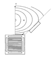
- FIG. 1 is a view showing the room 10 from above.
- the room 10 is a rectangular space surrounded by wall surfaces 12 on all sides. Doors and windows are provided on the wall surface 12, but the illustration is omitted in FIG.
- the indoor units 20 and 30 which are devices installed in the building among the air conditioners constituting the air conditioning system, are attached to the ceiling of the room 10.
- the indoor unit 20 has four air outlets 22, 24, 26, and 28 directed toward the room 10
- the indoor unit 30 has four air outlets 32, 34, 36, and 38 directed toward the room 10.
- the indoor units 20 and 30 are devices that perform cooling operation and heating operation of the indoor 10 by circulating a refrigerant and exchanging heat with an outdoor unit (not shown). The cooled or heated air is blown into the room 10 from the air outlet 22 or the like with a set air volume and direction.
- each pair of desks 40, 44, 48 and chairs 42, 46, 50 is assigned to a resident (typically an employee) in room 10. The occupants spend most of their time in the office sitting in the chairs 42, 46, and 50.
- one round desk 52 for meetings is installed, and three chairs 54, 56, 58 are provided around it.
- the occupants gather around the round desk 52 and select appropriate chairs 54, 56, and 58 to sit down when having a meeting or the like.
- the air outlets 22 of the indoor units 20 and 30 Therefore, it will be continuously blown.
- the wind speed of the air sent from the air outlet 22 and the like, together with the temperature and humidity, is a factor that determines the comfort of air conditioning in the indoor 10 spaces. Therefore, in the air-conditioning system according to the embodiment, the maximum wind speed is prevented so that each occupant does not receive a very strong wind speed while sitting on the chairs 42, 46, 50, 54, 56, 58.
- the ventilation is controlled under the limited ventilation conditions.
- the blowing control is performed under the blowing conditions with a limited minimum wind speed so as to receive the blowing at a certain wind speed. This aims to improve the overall air-conditioning comfort of the room 10.
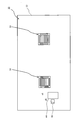
- FIG. 2 is a block diagram showing an outline of the functional configuration of the air conditioning system 60.
- the air conditioning system 60 includes an air conditioner 70, a wind speed sensor device 140, a PC 150, a smartphone 160, and a mobile partition 170.
- the air conditioner 70 is a device that air-conditions the room 10.
- the air conditioner 70 includes an outdoor unit and computer hardware as hardware in addition to the indoor units 20 and 30 shown in FIG. In the air conditioner 70, these hardwares are used to form a heating / cooling mechanism 72, a blowing mechanism 74, a setting changing unit 80, and a control unit 90.
- the heating / cooling mechanism 72 is a mechanism for heating or cooling air by exchanging heat between the indoor units 20 and 30 and the outdoor unit via a refrigerant.
- the heating and cooling settings are basically performed by instructions from the central monitoring room of the building, but adjustment instructions from the user can also be received through the setting changing unit 80.
- the blower mechanism 74 is a mechanism for blowing air from the blower ports 22 and the like of the indoor units 20 and 30.
- the air blowing mechanism 74 is provided with an air volume adjusting unit 76 and an air direction adjusting unit 78.
- the air volume adjusting unit 76 adjusts the amount of air sent out from the air outlet 22 or the like per unit time.
- the air volume is adjusted by adjusting the wind speed of the air to be sent out.
- the wind direction adjusting unit 78 changes the angle of the air outlet 22. In the wind direction adjustment, for example, a change for strengthening the degree of downward movement, a change for increasing the degree of upward movement, a change for swinging between upward and downward directions, and the like are performed. Wind direction adjustment may change the wind direction within the horizontal direction.
- the ventilation setting is basically performed by the instruction from the central monitoring room of the building, but the adjustment instruction from the user can also be received through the setting change unit 80. Further, the air conditioner 70 has a function of setting the ventilation by controlling the control unit 90, as will
- the setting changing unit 80 is an example of the changing means, and receives an operation from the user to change the operation of the air conditioner 70.
- the setting changing unit 80 can adjust, for example, the temperature, the wind direction, the air volume, and the like.
- the control unit 90 is a control device that controls the air conditioner 70.
- the control unit 90 controls computer hardware such as a processor that performs arithmetic processing, a memory that stores data, and a transmission / reception circuit for transmitting / receiving to / from an external device by software such as an OS (Operating System) and an application program (application). It works by doing.
- OS Operating System
- application application program
- the control unit 90 is assumed to be built in the air conditioner 70 in the embodiment, it can be constructed by using, for example, an external computer set to enable communication.
- a wind speed distribution estimation unit 100, a blower control unit 120, and a correction determination unit 130 are constructed by an application.
- the wind speed distribution estimation unit 100 estimates the wind speed distribution for a wide area in the room 10.
- the wide range means a range wider than the local range in which the wind speed sensor device 140 measures the wind speed, and does not necessarily mean the entire area of the room 10.
- the wind speed distribution is expressed in a mathematical formula format, a map format, a tabular format, or the like as a function of the position in the room 10, for example.
- the wind speed distribution estimation unit 100 is provided with a wind speed position acquisition unit 102, a layout acquisition unit 104, an area division unit 106, a parameter fitting unit 108, and a correction processing unit 110.
- the wind speed position acquisition unit 102 is an example of the wind speed position acquisition means, and acquires wind speed information and position information from the wind speed sensor device 140.
- the layout acquisition unit 104 acquires air conditioning-related layout information from the PC 150.
- the air-conditioning-related layout information refers to information on the shape related to the air flow in the room 10 and the arrangement of articles and the like (this is called a layout).
- the layout information includes information on the arrangement of the wall surface 12, doors, windows, etc., which is the boundary of the room 10, and information on the arrangement of large equipment such as a library and a partition. Further, the layout information includes information on the indoor units 20 and 30, that is, information on the positions of the indoor units 20 and 30 in the room 10 and the position and direction of the air outlet 22 and the like. Further, the layout information includes layout information regarding seats of people such as desks 40, 44, 48, 52 and chairs 42, 46, 50, 54, 56, 58 provided in the room 10.
- the area division unit 106 is an example of the division means, and divides the area for obtaining the wind speed distribution in the room 10 into a plurality of areas based on the layout information regarding the shape of the room 10. That is, the wind speed distribution is estimated by a different method for each area.
- the parameter fitting unit 108 is an example of the estimation means, and performs parameter fitting on a model of the wind speed distribution expressed using the parameters (this is called a template) to obtain a wind speed distribution suitable for the room 10. As a result, the wind speed distribution in the room 10 is estimated.
- Templates include, for example, polynomials in space coordinates (for example, first-order polynomials, second-order polynomials, third-order polynomials, etc.), Fourier series in space coordinates, and exponential functions in space coordinates. There are things that are done. A template using a polynomial will be illustrated later.
- the Fourier series is, for example, a feature that makes it easy to express a rotationally symmetric wind speed distribution in polar coordinates, or expresses wind speeds from a plurality of indoor units 20 and 30 arranged in a grid pattern in orthogonal linear coordinates. It has the feature that it is easy to do.
- the exponential function has a feature that it is easy to express the attenuation of the wind speed at a position away from the air outlet 22 and the like.
- the template is not limited to the one expressed by an expression, and may be expressed in a map format or a tabular format having values at a large number of grid points in space.
- the template has parameters whose values are undecided, and it is possible to adapt the template to the actual wind speed by performing parameter fitting based on the wind speed information and position information acquired by the wind speed position acquisition unit 102. Become. Parameter fitting is performed, for example, by the method of least squares.
- the correction processing unit 110 is an example of the correction means, and once corrects the estimated wind speed distribution.
- the correction is performed when the correction determination unit 130 determines that the correction is necessary.
- the correction may be to re-perform the parameter fitting by the parameter fitting unit 108, or to change a part of the result of the parameter fitting already performed (for example, only the constant term).
- the blower control unit 120 is an example of the control means, determines the blower mode in the air conditioner 70, and gives an instruction to the blower mechanism 74.
- the blast control unit 120 is provided with a person position acquisition unit 122, an estimated value calculation unit 124, and a blast condition determination unit 126.
- the person position acquisition unit 122 is an example of the person position acquisition means, and acquires information on the position of a resident in the room 10. For example, the person position acquisition unit 122 acquires seating information from the PC 150 and compares it with the layout information about the seats acquired by the layout acquisition unit 104 to obtain information on the positions of a plurality of occupants in the room 10. Obtainable. In addition, the person position acquisition unit 122 can obtain the position information of the occupant by acquiring the position information from the smartphone 160 possessed by the occupant in the room 10.
- the estimated value calculation unit 124 obtains the estimated value of the wind speed at the position of the occupant in the room 10 acquired by the person position acquisition unit 122 based on the wind speed distribution estimated by the wind speed distribution estimation unit 100.
- the ventilation condition determination unit 126 determines whether or not the estimated value of the wind speed at the position of the occupant obtained by the estimation value calculation unit 124 satisfies the ventilation condition.
- the maximum wind speed or the minimum wind speed can be set. Specifically, it is possible to give a condition that the wind speed is equal to or less than the preset maximum wind speed or equal to or more than the minimum wind speed at the positions of all the occupants in the room 10 or all the occupants who are seated. it can. It is also possible to set the time average value of the wind speed as the blowing condition. Specifically, there is a condition that the time average value of the wind speed is within a predetermined range at the positions of all the occupants in the room 10.
- the blowing conditions may be different depending on the temperature. Further, when the air volume or the wind direction is changed by the setting changing unit 80, the blowing conditions may also be changed.
- the ventilation conditions can be given by the administrator through, for example, the PC 150.
- the blast control unit 120 determines the blast control mode based on the determination result in the blast condition determination unit 126. Specifically, when the current blast condition determination unit 126 determines that the blast condition is satisfied, the current state is maintained. On the other hand, if the ventilation conditions are not satisfied, the air volume is reduced or increased, or the wind direction is changed so as to satisfy the ventilation conditions.
- the blower control unit 120 transmits an instruction to execute the determined control mode to the blower mechanism 74.
- the blower control unit 120 confirms whether or not the blower condition is actually satisfied as a result of instructing the blower mechanism 74 to blow air, and if not, repeats a series of processes again. May be good.
- the correction determination unit 130 determines whether or not the wind speed distribution estimated by the wind speed distribution estimation unit 100 needs to be corrected based on the determination conditions.
- the determination condition is a condition for whether or not to perform correction.
- the determination condition is set by the administrator through, for example, the PC 150.
- the correction determination unit 130 includes an actual measurement value estimation value comparison unit 132, a ventilation setting change processing unit 134, a layout change processing unit 136, and an alert output unit 138.
- the measured value estimation value comparison unit 132 is an example of the actual measurement value estimation value comparison means, and the wind speed distribution (that is, the estimated value) estimated by the wind speed distribution estimation unit 100 is the wind speed information acquired by the wind speed position acquisition unit 102 after the estimation. (That is, the measured value) is compared.
- the correction determination unit 130 determines whether or not the accuracy of the estimated value is within a predetermined range in light of the determination conditions.
- the ventilation setting change processing unit 134 acquires the setting change information based on the user instruction from the setting change unit 80.
- the correction determination unit 130 determines whether or not the already estimated wind speed distribution should be corrected by changing the setting.
- the determination condition for example, whether the setting change instructs a large air volume change or a large wind direction change is set. If the determination condition is satisfied, the correction determination unit 130 determines that correction is necessary.
- the layout change processing unit 136 acquires information regarding the layout change.
- the correction determination unit 130 determines the necessity of correction in light of the determination conditions.
- Examples of the information regarding the layout change acquired by the layout change processing unit 136 include information regarding the opening / closing of the moving partition 170 shown in the figure, as well as information such as opening / closing of the door and opening / closing of the window.
- the determination condition is set from the viewpoint of whether or not the acquired layout change significantly changes the air flow in the room 10. For example, it is set that the correction is necessary when the moving partition 170 is opened and closed, and the correction is not necessary when the door or window is opened and closed.
- the alert output unit 138 is an example of an output means, and when it is determined by the correction determination unit 130 that correction is necessary, an alert message calling attention is output as an image or voice. For example, the alert output unit 138 outputs an alert message to a log file (referring to an automatically created electronic management record) in the control unit 90, which is not shown. This allows the manager to perceive that the wind speed distribution needs to be corrected.
- the alert output unit 138 can also display an alert message on the display screen of the PC 150.
- the wind speed sensor device 140 is a device including a wind speed sensor 142 and a position sensor 144.
- the wind speed sensor device 140 can be constructed by attaching the wind speed sensor 142 to, for example, a movable terminal device such as a PC or a smartphone.
- the wind speed sensor 142 is at least a sensor capable of measuring the wind speed, and may further be capable of measuring the wind direction.
- the principle of the wind speed sensor 142 is not particularly limited, and various types such as a wind turbine type, an ultrasonic type, and a thermal type can be used.
- the position sensor 144 is a sensor that can identify the position in the room with a certain degree of accuracy. Examples of the position sensor 144 include a sensor based on the principle of triangulation of radio waves.
- the accuracy allowed for the position sensor 144 depends on the accuracy required for the estimated wind speed distribution. For example, when the wind speed distribution is performed on a horizontal plane (in other words, a specific height level), it is sufficient for the position sensor 144 to obtain the horizontal position, even if the vertical position cannot be obtained. Good.
- the PC 150 is a terminal device for controlling the operation of the control unit 90 in the air conditioner 70.
- the PC 150 is provided with a layout input unit 152 and an attendance input unit 154.
- the layout input unit 152 is for inputting the above-mentioned layout information.
- the occupancy input unit 154 is for inputting occupancy information such as whether or not the occupant is in the room 10 or whether or not the occupant is in a predetermined seat.
- the PC 150 it is possible to further set the reference of the area division in the area division unit 106 of the wind speed distribution estimation unit 100 and the selection of the template to be adopted in the parameter fitting unit 108. Further, from the PC 150, it is also possible to set the ventilation condition of the ventilation condition determination unit 126 in the ventilation control unit 120, set the correction determination condition in the correction determination unit 130, and the like.
- the smartphone 160 is a portable terminal device held by a resident.
- the smartphone 160 is provided with a position sensor 162.
- the position sensor 162 is a sensor that can identify a position in a room with a certain degree of accuracy, such as a sensor based on the principle of triangulation of radio waves.
- the position information acquired by the smartphone 160 is transmitted to the air conditioner 70.
- the person position acquisition unit 122 of the air blower control unit 120 of the air conditioner 70 can acquire the position information of the occupants.
- the moving partition 170 is a mobile partition provided in the room 10, and is a facility that affects the air flow in the room 10. By opening the moving partition 170, the room 10 is divided into two small rooms, and by closing the moving partition 170, the room 10 becomes one large room.
- the moving partition 170 is provided with a sensor 172.
- the sensor 172 detects whether the moving partition 170 is open or closed. The detection information by the sensor 172 is transmitted to the air conditioner 70.
- FIG. 3 is a flowchart showing an example of processing in the air conditioning system 60.
- the air conditioner 70 first starts air conditioning (S10) without receiving any special ventilation control.
- the manager of the air conditioner 70 sets the wind speed sensor devices 140 at several places in the room 10 (S12).
- the wind speed sensor 142 acquires the wind speed information
- the position sensor 144 acquires the position information (S14).
- the wind speed sensor device 140 transmits the acquired wind speed information and position information to the control unit 90 of the air conditioner 70 (S16).
- the administrator operates the layout input unit 152 of the PC 150 to input the layout information, and operates the attendance input unit 154 to input the presence information (S18).
- the PC 150 transmits the input layout information and presence information to the control unit 90 of the air conditioner 70 (S20).
- the parameter fitting unit 108 of the wind speed distribution estimation unit 100 performs parameter fitting to the template and constructs an estimation formula that gives the wind speed distribution (S22).
- the person position acquisition unit 122 acquires the position of each seat of the occupant, and the estimated value calculation unit 124 calculates the estimated value of the wind speed in each seat (S24).
- the ventilation condition determination unit 126 of the ventilation control unit 120 determines whether or not the ventilation in each seat satisfies the ventilation condition (S26). If so, maintain the current ventilation. If not satisfied, the ventilation control unit 120 determines a new ventilation mode and instructs the ventilation mechanism 74 (S28).
- the blower mechanism 74 changes the blower according to the instruction (S30).
- step S22 In the embodiment shown below, almost the same amount of air is blown from each of the air outlets 22 and the like in the indoor units 20 and 30, and the center of the air blowing direction. It is assumed that the air is blown symmetrically with respect to the line.
- the wind speed distribution shall be determined only for an appropriate horizontal plane in the room 10 (for example, the average head or chest height of the occupants). Therefore, in the horizontal plane around the indoor units 20 and 30, coordinate systems are set in the vicinity of the air outlets 22 and the like, and the same wind speed distribution template is applied to each of the set coordinate systems.
- FIG. 4 and 5 are diagrams showing a process of setting a coordinate system in the room 10.
- FIG. 4 shows the periphery of the indoor unit 20 in FIG. 1
- FIG. 5 shows the entire area of the indoor unit 10.
- the circumference of the indoor unit 20 is divided into eight coordinate regions A, B, C, D, E, F, G, and H at an angle of 45 degrees about the indoor unit 20.
- Each coordinate area A to H defines a spatial range for setting the coordinate system.
- the coordinate areas A and B are the areas in which the air from the air outlet 22 is dominant
- the coordinate areas C and D are the areas in which the air from the air outlet 24 is dominant
- the coordinate areas E and F are the areas in which the air is blown.
- the air blown from the air outlet 26 is the dominant range
- the coordinate areas G and H are the areas where the air blown from the air outlet 28 is dominant.
- xy orthogonal straight line coordinates are set.
- the center line in the blower direction (this is a line passing through the center in the longitudinal direction of the blower port 22 and extending outward in the longitudinal direction) is defined as the x-axis.
- the x-axis is also a boundary line separating the coordinate regions A and B.
- the y-axis perpendicular to the x-axis is set.
- the xy orthogonal linear coordinates are set in the coordinate regions C to H.
- the xy orthogonal linear coordinates set in the coordinate area A and the coordinate area B, the coordinate area C and the coordinate area D, the coordinate area E and the coordinate area F, and the coordinate area G and the coordinate area H are between the respective coordinate areas. It is line symmetric with respect to the x-axis passing through. Further, the xy orthogonal linear coordinates set in the coordinate regions A to H are rotationally symmetric at 90 degrees with respect to the center of the indoor unit 20.
- the xy orthogonal linear coordinates given here are an example, and other coordinate systems such as orthogonal curvilinear coordinates such as polar coordinates can be used.
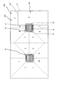
- FIG. 5 is a diagram for explaining the setting of the coordinate region when two indoor units 20 and 30 are present in the room 10, as shown in FIG.
- eight coordinate regions A to H in which the air blown from each air outlet 22 or the like of the indoor unit 20 is dominant are set around the indoor unit 20.
- eight coordinate regions I to P in which the air from each air outlet 32 or the like of the indoor unit 30 is dominant are set around the indoor unit 20.
- the coordinate area B and the coordinate area I, the coordinate area C and the coordinate area P, the coordinate area D and the coordinate area O, and the coordinate area E and the coordinate area N are in an overlapping relationship with each other until they reach the wall surface 12. is there.
- the coordinate region is defined depending on which of the indoor units 20 and 30 is dominant.
- the coordinate area B and the coordinate area I are formed by the dividing line 180 equidistant from the indoor units 20 and 30.
- the coordinate area C and the coordinate area P, the coordinate area D and the coordinate area O, and the coordinate area E and the coordinate area N are separated.
- FIGS. 6 and 7 are diagrams illustrating an example of a wind speed distribution template. As described above, it is assumed that the same ventilation is performed in each of the coordinate regions A to P, and that the positions (x, y) in the respective xy orthogonal linear coordinates have the same wind speed distribution V (x, y). Assume. Therefore, in FIGS. 6 and 7, an example of a wind speed distribution template is displayed only for the coordinate region A.
- FIG. 6 is a diagram showing the contour lines of the wind speed distribution V when the wind speed distribution V (x, y) is expressed by the linear equations of x and y as the following equation.
- Equation 1 the real number parameters a, b, and c are undecided at the stage of the template, and are determined by performing parameter fitting so as to be close to the actual wind speed.
- the parameter a when the parameter a is negative, the closer to the air outlet 22, the faster the wind speed, and when the parameter b is negative, the closer to the x-axis, which is the central axis of the air, the faster the wind speed.
- the distribution V (x, y) can be expressed.
- FIG. 7 is a diagram showing the contour lines of the wind speed distribution V when the wind speed distribution V (x, y) is expressed by the quadratic equation of x and the linear equation of y as follows.
- V (x, y) a (x ⁇ b) 2 + cy + d ⁇ ⁇ ⁇ (Equation 2)
- the real number parameters a, b, c, and d are undecided at the stage of the template, and are determined by performing parameter fitting so as to be close to the actual wind speed.
- the parameter c is negative, the closer to the x-axis which is the central axis of the blast. It is possible to express the wind speed distribution V (x, y) in which the wind speed becomes faster.
- FIGS. 6 and 7 only the coordinate area A is shown, but the same wind speed distribution V (x, y) is applied to the other coordinate areas B to P.
- the value of the wind speed distribution V is continuous due to the symmetry of the coordinate system. Therefore, the wind speed distribution of the entire room 10 can be expressed in a simple format.
- the templates shown in FIGS. 6 and 7 are examples, and as described above, various templates using a polynomial of spatial coordinates, a Fourier series, an exponential function, or the like can be adopted. Further, the wind speed distribution may be obtained not only for a specific horizontal plane but also for a plurality of vertical levels (that is, a three-dimensional wind speed distribution is obtained).
- the coordinate region directly below the indoor units 20 and 30 in the indoor 10 is not mentioned.
- the coordinate area directly under the indoor units 20 and 30 it is conceivable to extend the xy orthogonal linear coordinates set in the surrounding coordinate areas A to P to the center of the indoor units 20 and 30 and adopt the same template. ..
- the wind speed is the highest immediately below the center of the indoor units 20 and 30, so it is considered that a realistic wind speed is not given.
- the templates shown in FIGS. 7 and 2 are adopted, the wind speed is weak directly under the indoor units 20 and 30, and it is expected that a realistic wind speed distribution will be provided.
- FIG. 8 is a diagram illustrating wind speed measurement for performing parameter fitting.
- FIG. 8 is a diagram corresponding to FIG. 5, and shows a state in which wind speed sensors 190, 192, 194, and 196 are provided at four locations in the room 10.
- the wind speed sensor 190 and the like are provided in a horizontal plane at the same height at which the wind speed is to be measured. Since the wind speed generally has a temporal turbulence, the wind speed sensor 190 or the like measures the wind speed over a certain long time (for example, 1 minute or more). Further, in the wind speed sensor device 140 corresponding to the wind speed sensor 190 or the like, the position sensor 144 acquires the position information in the room 10.
- the acquired position and wind speed information is used for parameter fitting in the wind speed distribution template.
- the template shown in FIG. 6 and Equation 1 there are three parameters a, b, and c to be determined. Therefore, the data obtained by the four wind speed sensors 190 and the like is larger than the number required to determine the three parameters a, b, and c. Therefore, for example, parameter fitting by the least squares method is performed to determine the parameters a, b, and c that minimize the difference from the four acquired data.
- the four wind speed sensors 190 may be moved after an appropriate time has elapsed, and parameter fitting including the wind speed data may be performed at the moved positions. This makes it possible to improve the estimation accuracy of the wind speed distribution in the entire space.
- the wind speed distribution in the room 10 can be obtained.
- the wind speed distribution is given by an estimation equation having the form of V (x, y).
- the wind speed distribution is given by an estimation formula having the form of V (x, y, z) using the vertical coordinates z as well. Therefore, if appropriate position coordinates (x, y) or (x, y, z) are given, the wind speed at that position can be estimated.
- FIG. 9 is a diagram showing an example of finding the position of a resident in the room in step S24.
- the desk 44 and the chair 46 shown in FIG. 1 are shown in the room 10.
- the estimated value V (x5, y5) of the wind speed at this position can be acquired.
- the estimated value of the wind speed is acquired for the positions of all the occupants.
- step S26 it is determined whether or not the estimated values of the wind speeds at the obtained positions of all the occupants satisfy the ventilation condition.
- the blowing condition for example, a condition that the wind speed is equal to or less than a predetermined value Vmax is set. In the example shown in FIG. 9,
- V (x5, y5) ⁇ Vmax ... (Equation 3) Is evaluated.
- step S26 it is evaluated whether or not the wind speed at the positions of all the occupants is Vmax or less.
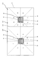
- FIG. 10 is a diagram showing a room 200 similar to the room 10 shown in FIG.
- the same or similar configurations as those in FIG. 1 and the like are designated by the same reference numerals, and the description thereof will be omitted or simplified.
- FIG. 10 as in FIG. 1, two indoor units 20 and 30 are provided in the room 200.
- the room 200 shown in FIG. 10 is different from the room 10 shown in FIG. 1 in that a partition 202 having a height close to the ceiling is provided. Since the air conditioning in the room 200 is affected by the partition 202, it is necessary to devise the estimation of the velocity distribution.
- a relatively narrow area 206 is formed in the room 200 by the partition 202 and the wall surface 12.
- This area 206 includes only the air outlet 28 of the indoor unit 20. Further, the shape of the wide area 204 not surrounded by the partition 202 is also complicated.
- the room 200 is divided into a plurality of areas based on the layout information, and the ventilation is requested separately for each area. Specifically, the room 200 is divided into a wide area 204 and a narrow area 206, and the wider area 204 is divided into an area indicated by the symbol S located behind the partition 202 when viewed from the indoor unit 20, and other areas. It is divided into and.
- the coordinate area is set in the same manner as in the example of FIG. 5, and the coordinate areas A to E are set around the indoor unit 20. ..
- the range of the coordinate areas A and E is set narrower than that in the example of FIG.
- the wind speed distribution can be obtained in the same manner as in the case described with reference to FIG. 5 and the like.
- the wind speed distribution is estimated by performing parameter fitting based on the actual wind speed after applying an appropriate template in consideration of the influence of the partition 202 and the wall surface 12.
- parameter fitting is performed again after applying the same or different template as other areas. This makes it possible to estimate the wind speed distribution suitable for the actual situation in the area.
- FIG. 11 is a diagram corresponding to FIG. 5, in which the room 210 is separated into two areas 212 and 214 by a moving partition 170.
- the moving partition 170 has a floor-to-ceiling height, and when closed, there is almost no air flow between the areas 212 and 214.
- the moving partition 170 is opened, the room 10 becomes a single large space as shown in FIG. 1 or FIG.
- the moving partition 170 is open.
- the coordinate areas A to P are set for the room 10, and the velocity distribution can be obtained by performing parameter fitting on the template.
- the moving partition 170 is closed and the state shown in FIG. 11 is reached.
- the sensor 172 of the moving partition 170 detects the closed state and transmits it to the control unit 90 of the air conditioner 70.
- the layout change processing unit 136 of the correction determination unit 130 recognizes the layout change of the moving partition 170. Then, the correction determination unit 130 determines whether or not the velocity distribution should be corrected according to the determination conditions set in advance.
- Judgment conditions and correction modes can be set in various ways.
- the provision of the moving partition 170 narrows the coordinate areas B, C, D, and E around the indoor unit 20, and the coordinate areas I, N, O, and P around the indoor unit 30. Becomes wider. Therefore, as a determination condition, it is assumed that correction is required when opening and closing the moving partition 170.
- the estimation formula of V (x, y) that gives the wind speed distribution is not changed, and the coordinate regions B, C, D, E, I, N,
- An embodiment in which the range of O and P is changed between the state shown in FIG. 5 and the state shown in FIG. 11 can be mentioned.
- Correction can be performed in cases other than layout changes.
- the flowchart shown in FIG. 3 after changing the ventilation in step S30, it is conceivable to make a correction to match the wind speed information newly input from the wind speed sensor device 140. That is, when the estimated value of the wind speed distribution and the actually measured value actually measured by the wind speed sensor device 140 are different, the wind speed distribution may be corrected.
- the judgment condition for correction is that the correction is performed when the difference in wind speed is greater than or equal to the predetermined value, or when the error in wind speed (the difference in wind speed divided by the measured value) is greater than or equal to the predetermined value. be able to.
- the correction when the measured value and the estimated value are different may be performed by the mode described with reference to FIG. 11, that is, the correction of adding ⁇ to the estimated speed distribution, the correction of multiplying the estimated speed distribution by ⁇ , or the like. ..
- a different template may be selected, and the parameter fitting may be performed again according to the measured value to estimate the wind speed distribution.
- the correction may be performed when the change is made by the setting change unit 80 of the air conditioner 70.
- the heating / cooling mechanism 72 and the blowing mechanism 74 in the air conditioner 70 perform blowing according to the change. Therefore, it may be necessary to correct the wind speed distribution estimated before that. Therefore, as the determination conditions for correction, correction is performed when the temperature setting changes by a predetermined value or more, the air volume changes by a predetermined value or more, or the wind direction changes by a predetermined value or more. be able to.
- corrections may be made by adding ⁇ to the estimated speed distribution, by multiplying the estimated speed distribution by ⁇ , or by making corrections that change the template. Good.
- the parameter fitting may be performed again without changing the template.
- the alert output unit 138 in the correction determination unit 130 of the air conditioner 70 may output the alert log. As a result, the administrator can grasp that the correction determination condition is satisfied.
Landscapes
- Engineering & Computer Science (AREA)
- Chemical & Material Sciences (AREA)
- Combustion & Propulsion (AREA)
- Mechanical Engineering (AREA)
- General Engineering & Computer Science (AREA)
- Physics & Mathematics (AREA)
- Signal Processing (AREA)
- Fluid Mechanics (AREA)
- Fuzzy Systems (AREA)
- Mathematical Physics (AREA)
- Air Conditioning Control Device (AREA)
Abstract
An air-conditioning system (60) includes an air conditioner (70) and a control unit (90). The air conditioner (70) has an air outlet (22) or the like directed toward a room (10) and blows air through the air outlet (22) or the like to perform air conditioning. After the air conditioner (70) starts air conditioning (S10), the control unit (90) acquires the measured wind speed information and position information from a wind speed sensor device (140) equipped with an air speed sensor (142) disposed in the room (10) (S16). The control unit (90) estimates the wind speed distribution over a wide area by performing parameter fitting to match a wind speed distribution template prepared in advance to the acquired wind speed information and position information (S22).
Description
本発明は、空調システム及び制御装置に関する。
The present invention relates to an air conditioning system and a control device.
風速は、温度、湿度などとともに、空調が在室者に与える快適性(以下、「快適性」という。)に影響を与える。空調対象の室内にいる在室者の周囲の風速を把握することができれば、各人の快適性を向上させる空調制御が可能となる。
Wind speed, along with temperature and humidity, affects the comfort that air conditioning gives to occupants (hereinafter referred to as "comfort"). If the wind speed around the occupants in the room to be air-conditioned can be grasped, it is possible to control the air-conditioning to improve the comfort of each person.
下記特許文献1には、空調機からの距離と風速との関係を記憶しておき、人の位置を推定した場合に、記憶した関係に基づいて人の周囲の風速を推定することが記載されている。また、下記特許文献1には、空調機を操作可能なリモコンあるいはスマートフォンに風速計を取り付けておき、風速計により計測された風速を、人の周囲の風速として推定することが記載されている。
Patent Document 1 below describes that when the relationship between the distance from the air conditioner and the wind speed is memorized and the position of the person is estimated, the wind speed around the person is estimated based on the memorized relationship. ing. Further, Patent Document 1 below describes that an anemometer is attached to a remote controller or a smartphone capable of operating an air conditioner, and the wind speed measured by the anemometer is estimated as the wind speed around a person.
下記特許文献2には、空調の対象となる空間に在席する各人の環境設定を満たすように、複数の空調機を制御することが記載されている。具体的には、事前の実験により一意に定められた風速、風向などの空調機の性能情報と、対象空間の間取り情報、空調機の配置情報、在席者情報などに基づいて、空調機を制御している。
Patent Document 2 below describes controlling a plurality of air conditioners so as to satisfy the environment settings of each person present in the space to be air-conditioned. Specifically, the air conditioner is installed based on the performance information of the air conditioner such as the wind speed and the wind direction uniquely determined by the prior experiment, the floor plan information of the target space, the arrangement information of the air conditioner, and the occupant information. I'm in control.
上記特許文献1では、空調機からの距離と風速との関係に基づいて風速を推定している。しかし、空調機が複数の送風口をもつ場合、あるは、送風口の正面以外の位置における場合などに、どのような風速となるのか明らかではない。また、全ての人に風速計を持たせることは、現実的ではない。そこで、室内の風速分布を詳細に把握するために、風速センサを多数設置すること、あるいは詳細な流体シミュレーションを行うことも考えられるが、多くの手間とコストが必要となる。
In Patent Document 1 above, the wind speed is estimated based on the relationship between the distance from the air conditioner and the wind speed. However, it is not clear what the wind speed will be when the air conditioner has a plurality of air outlets, or when the air conditioner is located at a position other than the front of the air outlets. Also, it is not realistic to have everyone have an anemometer. Therefore, in order to grasp the wind speed distribution in the room in detail, it is conceivable to install a large number of wind speed sensors or perform a detailed fluid simulation, but a lot of labor and cost are required.
上記特許文献2では、事前に実験を行って一意に定めた風速、風向を利用した制御を行っている。このため、実際に空調を行った状態との不一致が懸念される。
In Patent Document 2 above, control is performed using a wind speed and a wind direction uniquely determined by conducting an experiment in advance. For this reason, there is a concern that there may be a discrepancy with the state in which air conditioning is actually performed.
本発明の目的は、空調による風速分布を簡易な手法で求めて、空調制御への利用を可能とすることにある。
An object of the present invention is to obtain the wind speed distribution by air conditioning by a simple method and to enable the use for air conditioning control.
本発明にかかる空調システムは、室内に向けた送風口を有し、前記送風口から空気を送風して、前記室内の空調を行う空調機と、前記室内に配置された風速センサを備える端末装置から、当該端末装置付近で計測された風速の情報及び当該端末装置の位置の情報を取得する風速位置取得手段と、予め用意した風速分布のテンプレートを、取得した前記風速の情報及び前記位置の情報に適合させて、前記室内における広範囲の風速分布を推定する推定手段と、を備えることを特徴とする。
The air-conditioning system according to the present invention is a terminal device having an air-conditioning port directed toward a room, blowing air from the air-blowing port to air-condition the room, and a wind speed sensor arranged in the room. From, the wind speed position acquisition means for acquiring the wind speed information measured in the vicinity of the terminal device and the position information of the terminal device, and the wind speed distribution template prepared in advance, the acquired wind speed information and the position information. It is characterized by comprising an estimation means for estimating a wide range of wind speed distribution in the room in accordance with the above.
本発明の一態様においては、前記空調機は2以上の前記送風口を備え、前記推定手段は、それぞれの前記送風口の送風範囲に同一のテンプレートを適用し、同一のパラメータフィッティングを行って前記風速分布を推定する、ことを特徴とする。
In one aspect of the present invention, the air conditioner includes two or more of the air outlets, and the estimation means applies the same template to the air blower range of each of the air outlets, performs the same parameter fitting, and performs the same parameter fitting. It is characterized by estimating the wind speed distribution.
本発明の一態様においては、前記テンプレートは、送風方向の中心線に対して左右対称に形成される、ことを特徴とする。
In one aspect of the present invention, the template is formed symmetrically with respect to the center line in the blowing direction.
本発明の一態様においては、前記風速位置取得手段は、略同一の水平面に配置された複数の前記風速センサが計測する前記風速の情報を取得し、前記推定手段は、前記風速センサと略同一の水平面について前記風速分布を推定する、ことを特徴とする。
In one aspect of the present invention, the wind speed position acquisition means acquires the wind speed information measured by a plurality of the wind speed sensors arranged on substantially the same horizontal plane, and the estimation means is substantially the same as the wind speed sensor. It is characterized in that the wind speed distribution is estimated for the horizontal plane of.
本発明の一態様においては、前記室内にいる複数人の位置の情報を取得する人位置取得手段と、推定された前記風速分布に基づいて、前記複数人の各位置における風速が送風条件を満たすように、前記空調機による送風を制御する制御手段と、を備える、ことを特徴とする。
In one aspect of the present invention, the wind speed at each position of the plurality of people satisfies the blowing condition based on the person position acquisition means for acquiring the information on the positions of the plurality of people in the room and the estimated wind speed distribution. As described above, the air conditioner is provided with a control means for controlling the blowing air.
本発明の一態様においては、前記空調機は、ユーザの指示を受け付けて風量、風向、温度の少なくとも一つを変更する変更手段を有し、前記変更手段による変更が行われた場合に、前記風速分布を補正する補正手段を備える、ことを特徴とする。
In one aspect of the present invention, the air conditioner has a changing means for changing at least one of the air volume, the wind direction, and the temperature in response to a user's instruction, and when the change is made by the changing means, the above-mentioned It is characterized in that it is provided with a correction means for correcting the wind speed distribution.
本発明の一態様においては、前記室内における空調関連のレイアウトに変更があった場合に、前記風速分布を補正する補正手段を備える、ことを特徴とする。
One aspect of the present invention is characterized in that a correction means for correcting the wind speed distribution is provided when the layout related to air conditioning in the room is changed.
本発明の一態様においては、前記風速センサが新たに計測した風速の実測値と、推定された前記風速分布による推定値とを比較する実測値推定値比較手段と、前記実測値推定値比較手段による比較の結果、前記推定値の精度が所定値よりも悪い場合に、前記風速分布を補正する補正手段と、を備える、ことを特徴とする。
In one aspect of the present invention, the measured value estimated value comparing means for comparing the measured value of the wind speed newly measured by the wind speed sensor with the estimated value based on the estimated wind speed distribution, and the measured value estimated value comparing means. As a result of the comparison according to the above, when the accuracy of the estimated value is worse than the predetermined value, the wind speed distribution is corrected by the correction means.
本発明の一態様においては、前記風速センサが新たに計測した風速の実測値と、推定された前記風速分布による推定値とを比較する実測値推定値比較手段と、前記実測値推定値比較手段による比較の結果、前記推定値の精度が所定値よりも悪い場合に、注意を促す出力を行う出力手段と、を備える、ことを特徴とする。
In one aspect of the present invention, the measured value estimated value comparing means for comparing the measured value of the wind speed newly measured by the wind speed sensor with the estimated value based on the estimated wind speed distribution, and the measured value estimated value comparing means. As a result of the comparison according to the above, when the accuracy of the estimated value is worse than a predetermined value, an output means for calling attention is provided.
本発明の一態様においては、前記室内の空調関連のレイアウト情報に基づいて、前記室内を複数のエリアに分割する分割手段を備え、前記推定手段は、分割したエリアごとに異なる手法で前記風速分布を推定する、ことを特徴とする。
In one aspect of the present invention, the room is divided into a plurality of areas based on the layout information related to air conditioning in the room, and the estimation means distributes the wind speed by a method different for each divided area. Is characterized by estimating.
本発明にかかる制御装置は、室内に向けた送風口を有し、前記送風口から空気を送風して、前記室内の空調を行う空調機を制御する制御装置であって、前記室内に配置された風速センサを備える端末装置から、当該端末装置付近で計測された風速の情報及び当該端末装置の位置の情報を取得する風速位置取得手段と、予め用意した風速分布のテンプレートを、取得した前記風速の情報及び前記位置の情報に適合させて、前記室内における広範囲の風速分布を推定する推定手段と、を備える、ことを特徴とする。
The control device according to the present invention is a control device that has an air blower directed toward a room and controls an air conditioner that blows air from the air blower to perform air conditioning in the room, and is arranged in the room. The wind speed position acquisition means for acquiring the wind speed information measured in the vicinity of the terminal device and the position information of the terminal device from the terminal device provided with the wind speed sensor, and the wind speed distribution template prepared in advance. It is characterized by comprising an estimation means for estimating a wide range of wind speed distribution in the room by adapting to the information of the above and the information of the position.
本発明によれば、テンプレートを利用するため、空調対象となる室内の風速分布の推定が容易化される。
According to the present invention, since the template is used, it is easy to estimate the wind speed distribution in the room to be air-conditioned.
以下に、図面を参照しながら、実施形態について説明する。説明においては、理解を容易にするため、具体的な態様について示すが、これらは実施形態を例示するものであり、他にも様々な実施形態をとることが可能である。
The embodiment will be described below with reference to the drawings. In the description, specific embodiments are shown for ease of understanding, but these are examples of embodiments, and various other embodiments can be taken.
まず、図1を参照して、実施形態にかかる空調システムが導入される状況を説明する。空調対象としては、ビル内のオフィスである室内10を例示している。図1は室内10を上方から図示した図である。室内10は、四方を壁面12で囲まれた長方形状の空間である。壁面12には、ドア及び窓が設けられているが、図1では図示を省略している。
First, the situation in which the air conditioning system according to the embodiment is introduced will be described with reference to FIG. As an air-conditioning target, an indoor 10 which is an office in a building is illustrated. FIG. 1 is a view showing the room 10 from above. The room 10 is a rectangular space surrounded by wall surfaces 12 on all sides. Doors and windows are provided on the wall surface 12, but the illustration is omitted in FIG.
室内10の天井には、空調システムを構成する空調機のうち建物内に設置される装置である2つの室内機20、30が取り付けられている。室内機20は室内10に向けた4つの送風口22、24、26、28を有しており、室内機30は室内10に向けた4つの送風口32、34、36、38を有している。室内機20、30は、図示を省略した室外機との間で、冷媒を循環させ、熱交換を行うことで、室内10の冷房運転及び暖房運転を行う装置である。冷却または加熱された空気は、送風口22等から、設定された風量、風向で室内10に送風される。
Two indoor units 20 and 30, which are devices installed in the building among the air conditioners constituting the air conditioning system, are attached to the ceiling of the room 10. The indoor unit 20 has four air outlets 22, 24, 26, and 28 directed toward the room 10, and the indoor unit 30 has four air outlets 32, 34, 36, and 38 directed toward the room 10. There is. The indoor units 20 and 30 are devices that perform cooling operation and heating operation of the indoor 10 by circulating a refrigerant and exchanging heat with an outdoor unit (not shown). The cooled or heated air is blown into the room 10 from the air outlet 22 or the like with a set air volume and direction.
室内10には、3台の角形の机40、44、48が設置されており、それぞれに1脚の椅子42、46、50が設けられている。机40、44、48と椅子42、46、50の各組は、室内10の在室者(典型的には従業員)に割り当てられている。在室者は、オフィスに出勤している時間の多くを、各椅子42、46、50に着座した状態で在席する。
In the room 10, three square desks 40, 44, 48 are installed, and one chair 42, 46, 50 is provided for each. Each pair of desks 40, 44, 48 and chairs 42, 46, 50 is assigned to a resident (typically an employee) in room 10. The occupants spend most of their time in the office sitting in the chairs 42, 46, and 50.
室内10には、打ち合わせ用の1台の丸い机52が設置されており、周囲には3脚の椅子54、56、58が設けられている。在室者は、打ち合わせを行う場合などに、丸い机52の周りに集まって、適当な椅子54、56、58を選択して着座する。
In the room 10, one round desk 52 for meetings is installed, and three chairs 54, 56, 58 are provided around it. The occupants gather around the round desk 52 and select appropriate chairs 54, 56, and 58 to sit down when having a meeting or the like.
在室者は、椅子42、46、50、54、56、58に座っている場合、あるいは、移動せずに特定のポイントに立ち続けている場合には、室内機20、30の送風口22等から、持続的に送風を受けることになる。送風口22等から送られる空気の風速は、温度、湿度などとともに、室内10空間における空調の快適性を決定づける要因となる。そこで、実施形態にかかる空調システムでは、各在室者が椅子42、46、50、54、56、58に座っている期間などに、あまり強い風速の送風を受けることが無いように、最大風速を限定した送風条件の下で送風制御を行う。また、必要に応じて、ある程度の風速の送風を受けるように、最小風速を限定した送風条件の下で送風制御を行う。これにより、室内10の全体の空調快適性を向上させることを目指している。
If the occupants are sitting on chairs 42, 46, 50, 54, 56, 58, or if they continue to stand at a specific point without moving, the air outlets 22 of the indoor units 20 and 30 Therefore, it will be continuously blown. The wind speed of the air sent from the air outlet 22 and the like, together with the temperature and humidity, is a factor that determines the comfort of air conditioning in the indoor 10 spaces. Therefore, in the air-conditioning system according to the embodiment, the maximum wind speed is prevented so that each occupant does not receive a very strong wind speed while sitting on the chairs 42, 46, 50, 54, 56, 58. The ventilation is controlled under the limited ventilation conditions. In addition, if necessary, the blowing control is performed under the blowing conditions with a limited minimum wind speed so as to receive the blowing at a certain wind speed. This aims to improve the overall air-conditioning comfort of the room 10.
図2は、空調システム60の機能構成の概略を示すブロック図である。空調システム60には、空調機70と、風速センサ装置140と、PC150と、スマートフォン160と、移動間仕切170が含まれる。
FIG. 2 is a block diagram showing an outline of the functional configuration of the air conditioning system 60. The air conditioning system 60 includes an air conditioner 70, a wind speed sensor device 140, a PC 150, a smartphone 160, and a mobile partition 170.
空調機70は、室内10の空調を行う装置である。空調機70は、ハードウエアとして、図1に示した室内機20、30の他に、室外機及びコンピュータハードウエアを含んでいる。空調機70では、これらのハードウエアを利用して、加熱冷却機構72、送風機構74、設定変更部80及び制御部90が形成されている。
The air conditioner 70 is a device that air-conditions the room 10. The air conditioner 70 includes an outdoor unit and computer hardware as hardware in addition to the indoor units 20 and 30 shown in FIG. In the air conditioner 70, these hardwares are used to form a heating / cooling mechanism 72, a blowing mechanism 74, a setting changing unit 80, and a control unit 90.
加熱冷却機構72は、室内機20、30及び室外機の間で、冷媒を介した熱交換を行って、空気の加熱あるいは冷却を行う機構である。加熱、冷却の設定は、基本的にはビルの中央監視室からの指示で行われるが、設定変更部80を通じてユーザからの調整指示を受け付けることもできる。
The heating / cooling mechanism 72 is a mechanism for heating or cooling air by exchanging heat between the indoor units 20 and 30 and the outdoor unit via a refrigerant. The heating and cooling settings are basically performed by instructions from the central monitoring room of the building, but adjustment instructions from the user can also be received through the setting changing unit 80.
送風機構74は、室内機20、30の送風口22等からの送風を行う機構である。送風機構74には、風量調整部76と風向調整部78が設けられている。風量調整部76は、送風口22等から単位時間あたりに送出する空気量を調整する。風量調節は、送出する空気の風速を調整することで行われる。風向調整部78は、送風口22の角度を変更する。風向調節では、例えば、下向きの度合いを強める変更、上向きの度合いを高める変更、上向きと下向きの間で首振り(スイング)を行う変更などが行われる。風向調節では、水平方向内での風向の変更が行われる場合もある。送風の設定は、基本的にはビルの中央監視室からの指示で行われるが、設定変更部80を通じてユーザからの調整指示を受け付けることもできる。さらに、空調機70では、後述するように、送風の設定を制御部90の制御によって実施する機能を有している。
The blower mechanism 74 is a mechanism for blowing air from the blower ports 22 and the like of the indoor units 20 and 30. The air blowing mechanism 74 is provided with an air volume adjusting unit 76 and an air direction adjusting unit 78. The air volume adjusting unit 76 adjusts the amount of air sent out from the air outlet 22 or the like per unit time. The air volume is adjusted by adjusting the wind speed of the air to be sent out. The wind direction adjusting unit 78 changes the angle of the air outlet 22. In the wind direction adjustment, for example, a change for strengthening the degree of downward movement, a change for increasing the degree of upward movement, a change for swinging between upward and downward directions, and the like are performed. Wind direction adjustment may change the wind direction within the horizontal direction. The ventilation setting is basically performed by the instruction from the central monitoring room of the building, but the adjustment instruction from the user can also be received through the setting change unit 80. Further, the air conditioner 70 has a function of setting the ventilation by controlling the control unit 90, as will be described later.
設定変更部80は、変更手段の例であり、ユーザからの操作を受け付けて、空調機70の運転を変更するものである。設定変更部80では、例えば、温度、風向、風量などの調整を行うことができる。
The setting changing unit 80 is an example of the changing means, and receives an operation from the user to change the operation of the air conditioner 70. The setting changing unit 80 can adjust, for example, the temperature, the wind direction, the air volume, and the like.
制御部90は、空調機70の制御を行う制御装置である。制御部90は、演算処理を行うプロセッサ、データを記憶するメモリ、外部装置と送受信するための送受信回路などのコンピュータハードウエアを、OS(Operating System)、アプリケーションプログラム(アプリ)などのソフトウエアで制御することで動作する。制御部90は、実施形態では空調機70に内蔵することを想定しているが、例えば、通信可能に設定された外部のコンピュータを用いて構築することも可能である。制御部90には、アプリによって、風速分布推定部100、送風制御部120、補正判定部130が構築されている。
The control unit 90 is a control device that controls the air conditioner 70. The control unit 90 controls computer hardware such as a processor that performs arithmetic processing, a memory that stores data, and a transmission / reception circuit for transmitting / receiving to / from an external device by software such as an OS (Operating System) and an application program (application). It works by doing. Although the control unit 90 is assumed to be built in the air conditioner 70 in the embodiment, it can be constructed by using, for example, an external computer set to enable communication. In the control unit 90, a wind speed distribution estimation unit 100, a blower control unit 120, and a correction determination unit 130 are constructed by an application.
風速分布推定部100は、室内10における広範囲のエリアについて、風速分布を推定するものである。広範囲とは、風速センサ装置140が風速を計測する局所的な範囲よりも広い範囲をいい、必ずしも室内10の全域を意味しない。風速分布は、例えば、室内10における位置の関数として、数式形式、マップ形式、表形式などで表現される。風速分布推定部100には、風速位置取得部102、レイアウト取得部104、エリア分割部106、パラメータフィッティング部108及び補正処理部110が設けられている。
The wind speed distribution estimation unit 100 estimates the wind speed distribution for a wide area in the room 10. The wide range means a range wider than the local range in which the wind speed sensor device 140 measures the wind speed, and does not necessarily mean the entire area of the room 10. The wind speed distribution is expressed in a mathematical formula format, a map format, a tabular format, or the like as a function of the position in the room 10, for example. The wind speed distribution estimation unit 100 is provided with a wind speed position acquisition unit 102, a layout acquisition unit 104, an area division unit 106, a parameter fitting unit 108, and a correction processing unit 110.
風速位置取得部102は、風速位置取得手段の例であり、風速センサ装置140から、風速の情報及び位置の情報を取得する。
The wind speed position acquisition unit 102 is an example of the wind speed position acquisition means, and acquires wind speed information and position information from the wind speed sensor device 140.
レイアウト取得部104は、PC150から空調関連のレイアウト情報を取得する。空調関連のレイアウト情報とは、室内10の空気の流れに関係した形状及び物品等の配置(これをレイアウトという)についての情報をいう。レイアウト情報には、室内10の境界である壁面12、ドア、窓の配置等に関する情報と、書庫、パーティション等の大型備品類の配置に関する情報が含まれる。また、レイアウト情報には、室内機20、30に関する情報、すなわち、室内10における室内機20、30の位置や、送風口22等の位置と方向に関する情報が含まれる。さらに、レイアウト情報には、室内10に設けられた机40、44、48、52、及び椅子42、46、50、54、56、58などの人の座席に関するレイアウトの情報も含まれる。
The layout acquisition unit 104 acquires air conditioning-related layout information from the PC 150. The air-conditioning-related layout information refers to information on the shape related to the air flow in the room 10 and the arrangement of articles and the like (this is called a layout). The layout information includes information on the arrangement of the wall surface 12, doors, windows, etc., which is the boundary of the room 10, and information on the arrangement of large equipment such as a library and a partition. Further, the layout information includes information on the indoor units 20 and 30, that is, information on the positions of the indoor units 20 and 30 in the room 10 and the position and direction of the air outlet 22 and the like. Further, the layout information includes layout information regarding seats of people such as desks 40, 44, 48, 52 and chairs 42, 46, 50, 54, 56, 58 provided in the room 10.
エリア分割部106は、分割手段の例であり、室内10の形状に関するレイアウト情報に基づいて、室内10における風速分布を求めるエリアを複数に分割する。すなわち、風速分布は、エリアごとに異なった手法で推定されることになる。
The area division unit 106 is an example of the division means, and divides the area for obtaining the wind speed distribution in the room 10 into a plurality of areas based on the layout information regarding the shape of the room 10. That is, the wind speed distribution is estimated by a different method for each area.
パラメータフィッティング部108は、推定手段の例であり、パラメータを用いて表現された風速分布のモデル(これをテンプレートと呼ぶ)にパラメータフィッティングを行って、室内10に適合した風速分布を求める。これにより、室内10の風速分布が推定される。テンプレートとしては、例えば、空間座標の多項式(例えば、1次多項式、2次多項式、3次多項式など)で表されるもの、空間座標のフーリエ級数で表されるもの、空間座標の指数関数で表されるものなどが挙げられる。多項式を用いたテンプレートについては後で例示する。フーリエ級数は、例えば、回転対称性のある風速分布を極座標で表現することが容易である特徴、あるいは、格子状に複数配置された室内機20、30等からの風速を直交直線座標で表現することが容易である特徴をもつ。指数関数は、送風口22等から離れた位置での風速の減衰を表現することが容易である特徴をもつ。テンプレートは、式で表現されるものに限られず、空間の多数の格子点で値をもったマップ形式あるいは表形式で表現されてもよい。テンプレートには、値が未定のパラメータがあり、風速位置取得部102が取得した風速の情報及び位置の情報に基づいて、パラメータフィッティングをすることで、テンプレートを実際の風速に適合させることが可能となる。パラメータフィッティングは、例えば、最小二乗法によって行われる。
The parameter fitting unit 108 is an example of the estimation means, and performs parameter fitting on a model of the wind speed distribution expressed using the parameters (this is called a template) to obtain a wind speed distribution suitable for the room 10. As a result, the wind speed distribution in the room 10 is estimated. Templates include, for example, polynomials in space coordinates (for example, first-order polynomials, second-order polynomials, third-order polynomials, etc.), Fourier series in space coordinates, and exponential functions in space coordinates. There are things that are done. A template using a polynomial will be illustrated later. The Fourier series is, for example, a feature that makes it easy to express a rotationally symmetric wind speed distribution in polar coordinates, or expresses wind speeds from a plurality of indoor units 20 and 30 arranged in a grid pattern in orthogonal linear coordinates. It has the feature that it is easy to do. The exponential function has a feature that it is easy to express the attenuation of the wind speed at a position away from the air outlet 22 and the like. The template is not limited to the one expressed by an expression, and may be expressed in a map format or a tabular format having values at a large number of grid points in space. The template has parameters whose values are undecided, and it is possible to adapt the template to the actual wind speed by performing parameter fitting based on the wind speed information and position information acquired by the wind speed position acquisition unit 102. Become. Parameter fitting is performed, for example, by the method of least squares.
補正処理部110は、補正手段の例であり、一端、推定した風速分布を補正するものである。補正は、補正判定部130において補正が必要と判断された場合に実施される。補正は、パラメータフィッティング部108によるパラメータフィッティングを再度実施するものであってもよいし、既に行われたパラメータフィッティングの結果の一部(例えば定数項のみ)を変更するものであってもよい。
The correction processing unit 110 is an example of the correction means, and once corrects the estimated wind speed distribution. The correction is performed when the correction determination unit 130 determines that the correction is necessary. The correction may be to re-perform the parameter fitting by the parameter fitting unit 108, or to change a part of the result of the parameter fitting already performed (for example, only the constant term).
送風制御部120は、制御手段の例であり、空調機70における送風態様を決定し、送風機構74に指示を行う。送風制御部120には、人位置取得部122、推定値算出部124及び送風条件判定部126が設けられている。
The blower control unit 120 is an example of the control means, determines the blower mode in the air conditioner 70, and gives an instruction to the blower mechanism 74. The blast control unit 120 is provided with a person position acquisition unit 122, an estimated value calculation unit 124, and a blast condition determination unit 126.
人位置取得部122は、人位置取得手段の例であり、室内10にいる在室者の位置の情報を取得する。人位置取得部122は、例えば、PC150から在席情報を取得し、レイアウト取得部104が取得した座席についてのレイアウト情報と照らし合わせることで、室内10にいる複数の在室者の位置の情報を得ることができる。また、人位置取得部122は、室内10にいる在室者が所持するスマートフォン160から位置の情報を取得することで、当該在室者の位置の情報を得ることができる。
The person position acquisition unit 122 is an example of the person position acquisition means, and acquires information on the position of a resident in the room 10. For example, the person position acquisition unit 122 acquires seating information from the PC 150 and compares it with the layout information about the seats acquired by the layout acquisition unit 104 to obtain information on the positions of a plurality of occupants in the room 10. Obtainable. In addition, the person position acquisition unit 122 can obtain the position information of the occupant by acquiring the position information from the smartphone 160 possessed by the occupant in the room 10.
推定値算出部124は、風速分布推定部100が推定した風速分布に基づいて、人位置取得部122が取得した室内10にいる在室者の位置における風速の推定値を求める。
The estimated value calculation unit 124 obtains the estimated value of the wind speed at the position of the occupant in the room 10 acquired by the person position acquisition unit 122 based on the wind speed distribution estimated by the wind speed distribution estimation unit 100.
送風条件判定部126は、推定値算出部124が求めた在室者の位置における風速の推定値が、送風条件を満たすか否かを判定する。送風条件としては、最大風速あるいは最小風速を設定することができる。具体的には、室内10にいる全在室者、または、着座中の全在室者の位置において、風速があらかじめ設定した最大風速以下、または、最小風速以上であるとの条件を与えることができる。送風条件として、風速の時間平均値について設定することも可能である。具体的には、室内10にいる全在室者の位置において、風速の時間平均値が所定の範囲内であるという条件が挙げられる。送風条件は、温度に応じて異ならせてもよい。また、設定変更部80により風量または風向が変更された場合に、送風条件も変更されるようにしてもよい。送風条件は、例えば、PC150を通じて管理者が与えることが可能である。
The ventilation condition determination unit 126 determines whether or not the estimated value of the wind speed at the position of the occupant obtained by the estimation value calculation unit 124 satisfies the ventilation condition. As the blowing condition, the maximum wind speed or the minimum wind speed can be set. Specifically, it is possible to give a condition that the wind speed is equal to or less than the preset maximum wind speed or equal to or more than the minimum wind speed at the positions of all the occupants in the room 10 or all the occupants who are seated. it can. It is also possible to set the time average value of the wind speed as the blowing condition. Specifically, there is a condition that the time average value of the wind speed is within a predetermined range at the positions of all the occupants in the room 10. The blowing conditions may be different depending on the temperature. Further, when the air volume or the wind direction is changed by the setting changing unit 80, the blowing conditions may also be changed. The ventilation conditions can be given by the administrator through, for example, the PC 150.
送風制御部120では、送風条件判定部126における判定結果に基づいて、送風の制御態様を決定する。具体的には、現在の送風が送風条件判定部126において送風条件を満たしていると判断された場合には、現状維持する。他方、送風条件を満たしていない場合には、送風条件を満たすように、風量の減少もしくは増大、または、風向の変更などを行う。送風制御部120では、決定した制御態様を実行させる指示を、送風機構74に送信する。なお、送風制御部120では、送風機構74に送風の指示を行った結果、実際に送風条件を満たすようになったか否かを確認し、満たさない場合には再度一連の処理を繰り返すようにしてもよい。
The blast control unit 120 determines the blast control mode based on the determination result in the blast condition determination unit 126. Specifically, when the current blast condition determination unit 126 determines that the blast condition is satisfied, the current state is maintained. On the other hand, if the ventilation conditions are not satisfied, the air volume is reduced or increased, or the wind direction is changed so as to satisfy the ventilation conditions. The blower control unit 120 transmits an instruction to execute the determined control mode to the blower mechanism 74. The blower control unit 120 confirms whether or not the blower condition is actually satisfied as a result of instructing the blower mechanism 74 to blow air, and if not, repeats a series of processes again. May be good.
補正判定部130は、風速分布推定部100において推定した風速分布の補正が必要か否かを判定条件に基づいて判定する。判定条件は、補正を行うか否かの条件を設定したものである。判定条件の設定は、例えば、PC150を通じて管理者により行われる。補正判定部130は、実測値推定値比較部132、送風設定変更処理部134、レイアウト変更処理部136、及びアラート出力部138を備える。
The correction determination unit 130 determines whether or not the wind speed distribution estimated by the wind speed distribution estimation unit 100 needs to be corrected based on the determination conditions. The determination condition is a condition for whether or not to perform correction. The determination condition is set by the administrator through, for example, the PC 150. The correction determination unit 130 includes an actual measurement value estimation value comparison unit 132, a ventilation setting change processing unit 134, a layout change processing unit 136, and an alert output unit 138.
実測値推定値比較部132は、実測値推定値比較手段の例であり、風速分布推定部100で推定した風速分布(すなわち推定値)を、推定後に風速位置取得部102が取得した風速の情報(すなわち実測値)と比較する。補正判定部130では、推定値の精度が所定の範囲内にあるか否かを、判定条件に照らして判定する。
The measured value estimation value comparison unit 132 is an example of the actual measurement value estimation value comparison means, and the wind speed distribution (that is, the estimated value) estimated by the wind speed distribution estimation unit 100 is the wind speed information acquired by the wind speed position acquisition unit 102 after the estimation. (That is, the measured value) is compared. The correction determination unit 130 determines whether or not the accuracy of the estimated value is within a predetermined range in light of the determination conditions.
送風設定変更処理部134は、設定変更部80からユーザ指示に基づく設定変更情報を取得する。この場合、補正判定部130は、既に推定した風速分布が、設定変更によって補正すべきものとなったか否かを判定する。この場合の判定条件としては、例えば、設定変更が、大きな風量変更を指示するものであるか、あるいは、大きな風向変更を指示するのであるか、などが設定される。補正判定部130は、判定条件を満たす場合、補正が必要であると判定する。
The ventilation setting change processing unit 134 acquires the setting change information based on the user instruction from the setting change unit 80. In this case, the correction determination unit 130 determines whether or not the already estimated wind speed distribution should be corrected by changing the setting. As the determination condition in this case, for example, whether the setting change instructs a large air volume change or a large wind direction change is set. If the determination condition is satisfied, the correction determination unit 130 determines that correction is necessary.
レイアウト変更処理部136は、レイアウトの変更に関する情報を取得する。レイアウトの変更情報を取得した場合、補正判定部130は、判定条件に照らして、補正の必要性を判定する。レイアウト変更処理部136が取得するレイアウトの変更に関する情報としては、図示した移動間仕切170の開閉に関する情報の他、ドアの開閉、窓の開閉などの情報が挙げられる。判定条件は、取得したレイアウト変更が室内10の空気の流れを大きく変えるものであるか否かという観点から設定される。例えば、移動間仕切170の開閉が行われた場合には補正が必要であり、ドアまたは窓の開閉が行われた場合には補正は不要であるとの設定が行われる。
The layout change processing unit 136 acquires information regarding the layout change. When the layout change information is acquired, the correction determination unit 130 determines the necessity of correction in light of the determination conditions. Examples of the information regarding the layout change acquired by the layout change processing unit 136 include information regarding the opening / closing of the moving partition 170 shown in the figure, as well as information such as opening / closing of the door and opening / closing of the window. The determination condition is set from the viewpoint of whether or not the acquired layout change significantly changes the air flow in the room 10. For example, it is set that the correction is necessary when the moving partition 170 is opened and closed, and the correction is not necessary when the door or window is opened and closed.
アラート出力部138は、出力手段の例であり、補正判定部130によって補正が必要であると判定された場合に、注意を促すアラートメッセージを画像または音声により出力する。例えば、アラート出力部138は、制御部90内における図示を省略したログファイル(自動的に作成される電子的な管理記録をいう)に、アラートメッセージを出力する。これにより、管理者は、風速分布の補正が必要であることを知覚することができる。また、アラート出力部138は、PC150の表示画面にアラートメッセージを表示させることもできる。
The alert output unit 138 is an example of an output means, and when it is determined by the correction determination unit 130 that correction is necessary, an alert message calling attention is output as an image or voice. For example, the alert output unit 138 outputs an alert message to a log file (referring to an automatically created electronic management record) in the control unit 90, which is not shown. This allows the manager to perceive that the wind speed distribution needs to be corrected. The alert output unit 138 can also display an alert message on the display screen of the PC 150.
風速センサ装置140は、風速センサ142及び位置センサ144を備えた装置である。風速センサ装置140は、例えば、PC、スマートフォンなどの移動可能な端末装置に、風速センサ142を取り付けることで構築することができる。風速センサ142は、少なくとも風速が計測可能なセンサであり、さらに風向が計測可能であってもよい。風速センサ142の原理は特に限定されず、例えば、風車式、超音波式、熱式など様々なものを使用することができる。位置センサ144は、室内における位置をある程度の精度で特定できるセンサである。位置センサ144としては、電波の三角測量の原理に基づくセンサを挙げることができる。位置センサ144に許容される精度は、推定する風速分布に求める精度に応じて変わってくる。例えば、風速分布を水平面(言い換えれば特定の高さレベル)で行う場合には、位置センサ144は、水平方向の位置が求められれば十分であり、鉛直方向の位置を求めることができなくてもよい。
The wind speed sensor device 140 is a device including a wind speed sensor 142 and a position sensor 144. The wind speed sensor device 140 can be constructed by attaching the wind speed sensor 142 to, for example, a movable terminal device such as a PC or a smartphone. The wind speed sensor 142 is at least a sensor capable of measuring the wind speed, and may further be capable of measuring the wind direction. The principle of the wind speed sensor 142 is not particularly limited, and various types such as a wind turbine type, an ultrasonic type, and a thermal type can be used. The position sensor 144 is a sensor that can identify the position in the room with a certain degree of accuracy. Examples of the position sensor 144 include a sensor based on the principle of triangulation of radio waves. The accuracy allowed for the position sensor 144 depends on the accuracy required for the estimated wind speed distribution. For example, when the wind speed distribution is performed on a horizontal plane (in other words, a specific height level), it is sufficient for the position sensor 144 to obtain the horizontal position, even if the vertical position cannot be obtained. Good.
PC150は、空調機70における制御部90の動作を制御するための端末装置である。PC150には、レイアウト入力部152、在席入力部154が設けられている。レイアウト入力部152は、上述のレイアウト情報を入力するためのものである。在席入力部154は、在室者が室内10にいるか否か、あるいは、所定の座席にいるか否かなどの在席情報を入力するためのものである。PC150では、さらに、風速分布推定部100のエリア分割部106におけるエリア分割の基準、パラメータフィッティング部108において採用するテンプレートの選択の設定を行うことができる。また、PC150からは、送風制御部120における送風条件判定部126の送風条件の設定、補正判定部130における補正の判定条件の設定などを行うこともできる。
The PC 150 is a terminal device for controlling the operation of the control unit 90 in the air conditioner 70. The PC 150 is provided with a layout input unit 152 and an attendance input unit 154. The layout input unit 152 is for inputting the above-mentioned layout information. The occupancy input unit 154 is for inputting occupancy information such as whether or not the occupant is in the room 10 or whether or not the occupant is in a predetermined seat. In the PC 150, it is possible to further set the reference of the area division in the area division unit 106 of the wind speed distribution estimation unit 100 and the selection of the template to be adopted in the parameter fitting unit 108. Further, from the PC 150, it is also possible to set the ventilation condition of the ventilation condition determination unit 126 in the ventilation control unit 120, set the correction determination condition in the correction determination unit 130, and the like.
スマートフォン160は、在室者が保持する携帯可能な端末装置である。スマートフォン160には、位置センサ162が設けられている。位置センサ162は、電波の三角測量の原理に基づくセンサなど、室内における位置をある程度の精度で特定できるセンサである。スマートフォン160が取得した位置の情報は、空調機70に送信される。これにより、空調機70の送風制御部120の人位置取得部122では、在室者の位置の情報を取得することができる。
The smartphone 160 is a portable terminal device held by a resident. The smartphone 160 is provided with a position sensor 162. The position sensor 162 is a sensor that can identify a position in a room with a certain degree of accuracy, such as a sensor based on the principle of triangulation of radio waves. The position information acquired by the smartphone 160 is transmitted to the air conditioner 70. As a result, the person position acquisition unit 122 of the air blower control unit 120 of the air conditioner 70 can acquire the position information of the occupants.
移動間仕切170は、室内10に設けられた移動式の仕切りであり、室内10の空気の流れに影響を与える設備である。移動間仕切170を開くことで室内10は2つの小さな部屋に分断され、移動間仕切170を閉じることで室内10は一つの大きな部屋となる。移動間仕切170には、センサ172が設けられている。センサ172によって、移動間仕切170が開いているか閉じているかが検出される。センサ172による検出情報は、空調機70に送信される。
The moving partition 170 is a mobile partition provided in the room 10, and is a facility that affects the air flow in the room 10. By opening the moving partition 170, the room 10 is divided into two small rooms, and by closing the moving partition 170, the room 10 becomes one large room. The moving partition 170 is provided with a sensor 172. The sensor 172 detects whether the moving partition 170 is open or closed. The detection information by the sensor 172 is transmitted to the air conditioner 70.
続いて、図3を参照して、空調システム60の動作について説明する。図3は、空調システム60における処理の一例を示すフローチャートである。
Subsequently, the operation of the air conditioning system 60 will be described with reference to FIG. FIG. 3 is a flowchart showing an example of processing in the air conditioning system 60.
図3に示した処理では、空調機70は、まず、特段の送風制御を受けることなく、空調を開始する(S10)ことを想定している。この状態で、空調機70の管理者は、室内10の数か所に風速センサ装置140を設定する(S12)。風速センサ装置140では風速センサ142が風速の情報を取得し、位置センサ144が位置の情報を取得する(S14)。風速センサ装置140は、取得した風速の情報と位置の情報を空調機70の制御部90に送信する(S16)。
In the process shown in FIG. 3, it is assumed that the air conditioner 70 first starts air conditioning (S10) without receiving any special ventilation control. In this state, the manager of the air conditioner 70 sets the wind speed sensor devices 140 at several places in the room 10 (S12). In the wind speed sensor device 140, the wind speed sensor 142 acquires the wind speed information, and the position sensor 144 acquires the position information (S14). The wind speed sensor device 140 transmits the acquired wind speed information and position information to the control unit 90 of the air conditioner 70 (S16).
また、管理者は、PC150のレイアウト入力部152を操作してレイアウト情報を入力し、在席入力部154を操作して在席情報を入力する(S18)。PC150は、入力されたレイアウト情報及び在席情報を空調機70の制御部90に送信する(S20)。
Further, the administrator operates the layout input unit 152 of the PC 150 to input the layout information, and operates the attendance input unit 154 to input the presence information (S18). The PC 150 transmits the input layout information and presence information to the control unit 90 of the air conditioner 70 (S20).
空調機70の制御部90では、風速分布推定部100のパラメータフィッティング部108がテンプレートに対してパラメータフィッティングを行い、風速分布を与える推定式を構築する(S22)。制御部90の送風制御部120では、人位置取得部122が在席者の各座席の位置を取得し、推定値算出部124が各座席における風速の推定値を算出する(S24)。そして、送風制御部120の送風条件判定部126が、各座席における送風が送風条件を満たすか否かを判定する(S26)。満たす場合は、現状の送風を維持する。満たさない場合には、送風制御部120において、新たな送風態様を決定し、送風機構74に指示する(S28)。送風機構74では、指示に従って送風の変更を行う(S30)。
In the control unit 90 of the air conditioner 70, the parameter fitting unit 108 of the wind speed distribution estimation unit 100 performs parameter fitting to the template and constructs an estimation formula that gives the wind speed distribution (S22). In the ventilation control unit 120 of the control unit 90, the person position acquisition unit 122 acquires the position of each seat of the occupant, and the estimated value calculation unit 124 calculates the estimated value of the wind speed in each seat (S24). Then, the ventilation condition determination unit 126 of the ventilation control unit 120 determines whether or not the ventilation in each seat satisfies the ventilation condition (S26). If so, maintain the current ventilation. If not satisfied, the ventilation control unit 120 determines a new ventilation mode and instructs the ventilation mechanism 74 (S28). The blower mechanism 74 changes the blower according to the instruction (S30).
ここで、ステップS22~S26を中心に、具体的な例を挙げて、処理態様を補足説明する。まず、ステップS22の推定式の構築であるが、以下に示す実施形態では、室内機20、30における各送風口22等からは、ほぼ同風量の送風が行われること、かつ、送風方向の中心線に対して左右対称に送風が行われることを想定している。また、風速分布は、室内10における適当な水平面(例えば、在室者の平均的な頭部あるいは胸部の高さ)についてのみ求めるものとする。そこで、室内機20、30の周囲の水平面において、各送風口22等の付近のそれぞれに座標系を設定し、設定した各座標系に同一の風速分布テンプレートを適用する。
Here, focusing on steps S22 to S26, a specific example will be given to supplementarily explain the processing mode. First, regarding the construction of the estimation formula in step S22, in the embodiment shown below, almost the same amount of air is blown from each of the air outlets 22 and the like in the indoor units 20 and 30, and the center of the air blowing direction. It is assumed that the air is blown symmetrically with respect to the line. In addition, the wind speed distribution shall be determined only for an appropriate horizontal plane in the room 10 (for example, the average head or chest height of the occupants). Therefore, in the horizontal plane around the indoor units 20 and 30, coordinate systems are set in the vicinity of the air outlets 22 and the like, and the same wind speed distribution template is applied to each of the set coordinate systems.
図4及び図5は、室内10に座標系を設定する過程を示す図である。図4は、図1における室内機20の周囲を示しており、図5は、室内10の全域を示している。
4 and 5 are diagrams showing a process of setting a coordinate system in the room 10. FIG. 4 shows the periphery of the indoor unit 20 in FIG. 1, and FIG. 5 shows the entire area of the indoor unit 10.
図4に示した例では、室内機20の周囲を、室内機20を中心とする角度45度ずつの8つの座標領域A、B、C、D、E、F、G、Hに区分している。各座標領域A~Hは座標系を設定する空間的範囲を画定するものである。このうち、座標領域A、Bは送風口22からの送風が支配的な範囲であり、座標領域C、Dは送風口24からの送風が支配的な範囲であり、座標領域E、Fは送風口26からの送風が支配的な範囲であり、座標領域G、Hは、送風口28からの送風が支配的な範囲である。
In the example shown in FIG. 4, the circumference of the indoor unit 20 is divided into eight coordinate regions A, B, C, D, E, F, G, and H at an angle of 45 degrees about the indoor unit 20. There is. Each coordinate area A to H defines a spatial range for setting the coordinate system. Of these, the coordinate areas A and B are the areas in which the air from the air outlet 22 is dominant, the coordinate areas C and D are the areas in which the air from the air outlet 24 is dominant, and the coordinate areas E and F are the areas in which the air is blown. The air blown from the air outlet 26 is the dominant range, and the coordinate areas G and H are the areas where the air blown from the air outlet 28 is dominant.
各座標領域A~Hに対しては、x-y直交直線座標を設定している。送風口22の周囲の場合には、送風方向の中心線(これは送風口22における長手方向の中心を通り、長手方向に垂直に外向きに延びる線である)をx軸としている。x軸は座標領域A、Bを隔てる境界線でもある。座標領域A、Bでは、それぞれx軸に垂直なy軸を設定している。同様にして、座標領域C~Hにもx-y直交直線座標を設定している。座標領域Aと座標領域B、座標領域Cと座標領域D、座標領域Eと座標領域F,座標領域Gと座標領域Hに設定されたx-y直交直線座標は、それぞれ、各座標領域の間を通るx軸に対して線対称となる。また、座標領域A~Hに設定されたx-y直交直線座標は、室内機20の中心に対して90度の回転対称となっている。なお、ここで例に挙げたx-y直交直線座標は一例であり、例えば、極座標のような直交曲線座標など、他の座標系を用いることも可能である。
For each coordinate area A to H, xy orthogonal straight line coordinates are set. In the case of the periphery of the blower port 22, the center line in the blower direction (this is a line passing through the center in the longitudinal direction of the blower port 22 and extending outward in the longitudinal direction) is defined as the x-axis. The x-axis is also a boundary line separating the coordinate regions A and B. In the coordinate areas A and B, the y-axis perpendicular to the x-axis is set. Similarly, the xy orthogonal linear coordinates are set in the coordinate regions C to H. The xy orthogonal linear coordinates set in the coordinate area A and the coordinate area B, the coordinate area C and the coordinate area D, the coordinate area E and the coordinate area F, and the coordinate area G and the coordinate area H are between the respective coordinate areas. It is line symmetric with respect to the x-axis passing through. Further, the xy orthogonal linear coordinates set in the coordinate regions A to H are rotationally symmetric at 90 degrees with respect to the center of the indoor unit 20. The xy orthogonal linear coordinates given here are an example, and other coordinate systems such as orthogonal curvilinear coordinates such as polar coordinates can be used.
図5は、図1に示したように、室内10に2台の室内機20、30が存在する場合における座標領域の設定について説明する図である。この場合、まず、室内機20の周囲には、図4に示したように、室内機20の各送風口22等からの送風が支配的な8つの座標領域A~Hを設定する。同様にして、室内機30の周囲には、室内機30の各送風口32等からの送風が支配的な8つの座標領域I~Pを設定する。このとき、座標領域Bと座標領域I、座標領域Cと座標領域P、座標領域Dと座標領域O,座標領域Eと座標領域Nは、それぞれ、壁面12に至るまでの間に互いに重なり合う関係にある。そこで、室内機20、30のいずれからの送風が支配的であるかによって、座標領域を画定する。図5に示した例では、室内機20、30の性能が同じであることを仮定しており、室内機20、30から等距離にある区分線180でもって、座標領域Bと座標領域I、座標領域Cと座標領域P、座標領域Dと座標領域O,座標領域Eと座標領域Nを隔てている。
FIG. 5 is a diagram for explaining the setting of the coordinate region when two indoor units 20 and 30 are present in the room 10, as shown in FIG. In this case, first, as shown in FIG. 4, eight coordinate regions A to H in which the air blown from each air outlet 22 or the like of the indoor unit 20 is dominant are set around the indoor unit 20. Similarly, around the indoor unit 30, eight coordinate regions I to P in which the air from each air outlet 32 or the like of the indoor unit 30 is dominant are set. At this time, the coordinate area B and the coordinate area I, the coordinate area C and the coordinate area P, the coordinate area D and the coordinate area O, and the coordinate area E and the coordinate area N are in an overlapping relationship with each other until they reach the wall surface 12. is there. Therefore, the coordinate region is defined depending on which of the indoor units 20 and 30 is dominant. In the example shown in FIG. 5, it is assumed that the performances of the indoor units 20 and 30 are the same, and the coordinate area B and the coordinate area I are formed by the dividing line 180 equidistant from the indoor units 20 and 30. The coordinate area C and the coordinate area P, the coordinate area D and the coordinate area O, and the coordinate area E and the coordinate area N are separated.
図6及び図7は、風速分布のテンプレートの例を説明する図である。上述の通り、各座標領域A~Pでは同様の送風が行われるとしており、それぞれのx-y直交直線座標における位置(x,y)では、同じ風速分布V(x,y)をもつことを仮定する。そこで、図6及び図7では、座標領域Aについてのみ風速分布のテンプレートの例を表示している。
6 and 7 are diagrams illustrating an example of a wind speed distribution template. As described above, it is assumed that the same ventilation is performed in each of the coordinate regions A to P, and that the positions (x, y) in the respective xy orthogonal linear coordinates have the same wind speed distribution V (x, y). Assume. Therefore, in FIGS. 6 and 7, an example of a wind speed distribution template is displayed only for the coordinate region A.
図6は、風速分布V(x,y)をxとyの1次式によって次式のように表現した場合において、風速分布Vの等値線を示す図である。
FIG. 6 is a diagram showing the contour lines of the wind speed distribution V when the wind speed distribution V (x, y) is expressed by the linear equations of x and y as the following equation.
V(x,y)=ax+by+c ・・・(式1)
式1において、実数パラメータa,b,cは、テンプレートの段階では未定であり、実際の風速に近くなるようにパラメータフィッティングを行って決定される。このテンプレートでは、パラメータaが負である場合には送風口22に近いほど風速が速く、また、パラメータbが負である場合には送風の中心軸であるx軸に近いほど風速が速くなる風速分布V(x,y)を表現することができる。 V (x, y) = ax + by + c ... (Equation 1)
In Equation 1, the real number parameters a, b, and c are undecided at the stage of the template, and are determined by performing parameter fitting so as to be close to the actual wind speed. In this template, when the parameter a is negative, the closer to theair outlet 22, the faster the wind speed, and when the parameter b is negative, the closer to the x-axis, which is the central axis of the air, the faster the wind speed. The distribution V (x, y) can be expressed.
式1において、実数パラメータa,b,cは、テンプレートの段階では未定であり、実際の風速に近くなるようにパラメータフィッティングを行って決定される。このテンプレートでは、パラメータaが負である場合には送風口22に近いほど風速が速く、また、パラメータbが負である場合には送風の中心軸であるx軸に近いほど風速が速くなる風速分布V(x,y)を表現することができる。 V (x, y) = ax + by + c ... (Equation 1)
In Equation 1, the real number parameters a, b, and c are undecided at the stage of the template, and are determined by performing parameter fitting so as to be close to the actual wind speed. In this template, when the parameter a is negative, the closer to the
図7は、風速分布V(x,y)をxの2次式とyの1次式によって次のように表現した場合において、風速分布Vの等値線を示す図である。
FIG. 7 is a diagram showing the contour lines of the wind speed distribution V when the wind speed distribution V (x, y) is expressed by the quadratic equation of x and the linear equation of y as follows.
V(x,y)=a(x-b)2+cy+d ・・・(式2)
実数パラメータa,b,c、dはテンプレートの段階では未定であり、実際の風速に近くなるようにパラメータフィッティングを行って決定される。このテンプレートでは、パラメータaが負かつパラメータbが正である場合、x=bの地点で風速が極大となり、また、パラメータcが負である場合には送風の中心軸であるx軸に近いほど風速が速くなる風速分布V(x,y)を表現することができる。 V (x, y) = a (x−b) 2 + cy + d ・ ・ ・ (Equation 2)
The real number parameters a, b, c, and d are undecided at the stage of the template, and are determined by performing parameter fitting so as to be close to the actual wind speed. In this template, when the parameter a is negative and the parameter b is positive, the wind speed becomes maximum at the point of x = b, and when the parameter c is negative, the closer to the x-axis which is the central axis of the blast. It is possible to express the wind speed distribution V (x, y) in which the wind speed becomes faster.
図6及び図7に示した例では、座標領域Aのみについて示したが、他の座標領域B~Pにおいても、同じ風速分布V(x,y)が適用される。座標領域の境界線上では、座標系の対称性から風速分布Vの値は連続となる。したがって、簡易な形式で、室内10全体の風速分布を表現できる。なお、図6及び図7に示したテンプレートは一例であり、上述の通り、テンプレートとしては、空間座標の多項式、フーリエ級数、指数関数などを用いた様々なものを採用することが可能である。また、風速分布は、特定の水平面だけでなく、複数の鉛直レベルについて求める(すなわち3次元の風速分布を求める)ようにしてもよい。
In the examples shown in FIGS. 6 and 7, only the coordinate area A is shown, but the same wind speed distribution V (x, y) is applied to the other coordinate areas B to P. On the boundary line of the coordinate region, the value of the wind speed distribution V is continuous due to the symmetry of the coordinate system. Therefore, the wind speed distribution of the entire room 10 can be expressed in a simple format. The templates shown in FIGS. 6 and 7 are examples, and as described above, various templates using a polynomial of spatial coordinates, a Fourier series, an exponential function, or the like can be adopted. Further, the wind speed distribution may be obtained not only for a specific horizontal plane but also for a plurality of vertical levels (that is, a three-dimensional wind speed distribution is obtained).
また、以上の説明においては、室内10における室内機20、30の直下の座標領域については言及しなかった。室内機20、30直下の座標領域については、周囲の座標領域A~Pに設定されたx-y直交直線座標を室内機20、30の中心まで延長し、同じテンプレートを採用することが考えられる。ただし、図6及び式1に示したテンプレートを採用した場合には、室内機20、30の中心直下が最も風速が速くなってしまうため、現実的な風速を与えないと考えられる。他方、図7及び式2に示したテンプレートを採用した場合には、室内機20、30の直下は風速が弱く、現実的な風速分布を与えることが予想される。このように、ある程度単純なテンプレートを使用する場合には、そのテンプレートがどの程度現実的な風速分布を採用しているかを検討しておく必要がある。また、別の対応としては、室内機20、30直下のエリアにおける風速分布を、周囲の座標領域A~Pのエリアとは別に求める態様が挙げられる。風速分布を求めるエリアを分割する態様については後述する。
Further, in the above description, the coordinate region directly below the indoor units 20 and 30 in the indoor 10 is not mentioned. For the coordinate area directly under the indoor units 20 and 30, it is conceivable to extend the xy orthogonal linear coordinates set in the surrounding coordinate areas A to P to the center of the indoor units 20 and 30 and adopt the same template. .. However, when the template shown in FIG. 6 and Equation 1 is adopted, the wind speed is the highest immediately below the center of the indoor units 20 and 30, so it is considered that a realistic wind speed is not given. On the other hand, when the templates shown in FIGS. 7 and 2 are adopted, the wind speed is weak directly under the indoor units 20 and 30, and it is expected that a realistic wind speed distribution will be provided. In this way, when using a template that is simple to some extent, it is necessary to consider how realistic the wind speed distribution is. Another measure is to obtain the wind speed distribution in the area directly under the indoor units 20 and 30 separately from the surrounding coordinate areas A to P. A mode for dividing the area for obtaining the wind speed distribution will be described later.
次に、テンプレートに対するパラメータフィッティングについて説明する。 図8は、パラメータフィッティングを行うための風速計測について説明する図である。図8は、図5に対応する図であり、室内10の4か所に風速センサ190、192、194、196が設けられた状態を示している。風速センサ190等は、風速を計測したい同じ高さの水平面内に設けられている。一般に風速には時間的な乱れがあるため、風速センサ190等は、ある程度の長い時間(例えば1分間以上)にわたって風速を計測する。また、風速センサ190等に対応した風速センサ装置140では、位置センサ144によって室内10における位置の情報を取得する。
Next, the parameter fitting for the template will be explained. FIG. 8 is a diagram illustrating wind speed measurement for performing parameter fitting. FIG. 8 is a diagram corresponding to FIG. 5, and shows a state in which wind speed sensors 190, 192, 194, and 196 are provided at four locations in the room 10. The wind speed sensor 190 and the like are provided in a horizontal plane at the same height at which the wind speed is to be measured. Since the wind speed generally has a temporal turbulence, the wind speed sensor 190 or the like measures the wind speed over a certain long time (for example, 1 minute or more). Further, in the wind speed sensor device 140 corresponding to the wind speed sensor 190 or the like, the position sensor 144 acquires the position information in the room 10.
図8に示した例では、風速センサ190は座標(x,y)=(x1,y1)に設けられており、風速センサ192は座標(x,y)=(x2,0)に設けられており、風速センサ194は座標(x,y)=(x3,y3)に設けられており、風速センサ196は座標(x,y)=(x4,y4)に設けられている。なお、これらの風速センサ190等は異なる座標領域に設けられているが、上述の通りの対称性を利用しているため、共通の座標軸上で位置を特定することができる。また、これにより、風速センサ190等の設置個数あるいは設置個所を減らしても、精度よく風速分布を推定することが可能となる。
In the example shown in FIG. 8, the wind speed sensor 190 is provided at the coordinates (x, y) = (x1, y1), and the wind speed sensor 192 is provided at the coordinates (x, y) = (x2,0). The wind speed sensor 194 is provided at the coordinates (x, y) = (x3, y3), and the wind speed sensor 196 is provided at the coordinates (x, y) = (x4, y4). Although these wind speed sensors 190 and the like are provided in different coordinate regions, since they utilize the symmetry as described above, the positions can be specified on a common coordinate axis. Further, this makes it possible to accurately estimate the wind speed distribution even if the number of installed wind speed sensors 190 or the like or the number of installed locations is reduced.
取得した位置及び風速の情報は、風速分布テンプレートにおけるパラメータフィッティングに利用される。例えば、図6及び式1に示したテンプレートを使用する場合、決定すべきパラメータa,b,cは3個である。したがって、4つの風速センサ190等により得られたデータは3個のパラメータa,b,cを決定するのに必要な数よりも多い。そこで、例えば最小二乗法によるパラメータフィッティングを行って、取得した4つのデータからの差異を最も小さくするパラメータa,b,cを決定する。
The acquired position and wind speed information is used for parameter fitting in the wind speed distribution template. For example, when using the template shown in FIG. 6 and Equation 1, there are three parameters a, b, and c to be determined. Therefore, the data obtained by the four wind speed sensors 190 and the like is larger than the number required to determine the three parameters a, b, and c. Therefore, for example, parameter fitting by the least squares method is performed to determine the parameters a, b, and c that minimize the difference from the four acquired data.
他方、図7及び式2に示したテンプレートを使用する場合、決定すべきパラメータa,b,c,dは4個である。したがって、4つの風速センサ190等により得られたデータによってただちにパラメータa,b,c,dの値を決定するパラメータフィッティングが可能である。
On the other hand, when using the template shown in FIG. 7 and Equation 2, there are four parameters a, b, c, and d to be determined. Therefore, parameter fitting that immediately determines the values of the parameters a, b, c, and d is possible based on the data obtained by the four wind speed sensors 190 and the like.
なお、室内10では、一般に外乱が少なく、送風が安定的に行われる。したがって、例えば、4つの風速センサ190を適当な時間経過後に移動させて、移動した位置で風速のデータを含めたパラメータフィッティングを行うようにしてもよい。これにより、風速分布の推定精度を空間全体で高めることが可能となる。
In the room 10, there is generally little disturbance and stable ventilation is performed. Therefore, for example, the four wind speed sensors 190 may be moved after an appropriate time has elapsed, and parameter fitting including the wind speed data may be performed at the moved positions. This makes it possible to improve the estimation accuracy of the wind speed distribution in the entire space.
パラメータフィッティングを行った結果、室内10の風速分布が求められる。式1あるいは式2などを用いて2次元の風速分布を求めた場合には、風速分布はV(x,y)の形式をもつ推定式で与えられる。また、3次元の風速分布を求めた場合には、風速分布は、鉛直座標zも用いてV(x,y,z)の形式をもつ推定式で与えられる。したがって、適当な位置座標(x,y)あるいは(x,y,z)を与えれば、その位置における風速を推定できることになる。
As a result of parameter fitting, the wind speed distribution in the room 10 can be obtained. When a two-dimensional wind speed distribution is obtained using Equation 1 or Equation 2, the wind speed distribution is given by an estimation equation having the form of V (x, y). Further, when the three-dimensional wind speed distribution is obtained, the wind speed distribution is given by an estimation formula having the form of V (x, y, z) using the vertical coordinates z as well. Therefore, if appropriate position coordinates (x, y) or (x, y, z) are given, the wind speed at that position can be estimated.
図9は、ステップS24において、在室者の位置を求める例を示す図である。図9では、室内10の中に、図1に示した机44と椅子46が図示されている。ここでは、椅子46の中心付近が在室者の位置であるとして、座標(x,y)=(x5,y5)である位置の情報が取得されている。これにより、ステップS24では、この位置における風速の推定値V(x5,y5)を取得することができる。同様にして、ステップS24では、全ての在室者の位置について、風速の推定値が取得される。
FIG. 9 is a diagram showing an example of finding the position of a resident in the room in step S24. In FIG. 9, the desk 44 and the chair 46 shown in FIG. 1 are shown in the room 10. Here, assuming that the vicinity of the center of the chair 46 is the position of the occupant, the information on the position where the coordinates (x, y) = (x5, y5) is acquired is acquired. As a result, in step S24, the estimated value V (x5, y5) of the wind speed at this position can be acquired. Similarly, in step S24, the estimated value of the wind speed is acquired for the positions of all the occupants.
ステップS26では、求めた全ての在室者の位置における風速の推定値が送風条件を満たすか否かを判定する。送風条件としては、例えば、風速が所定値Vmax以下であるとの条件が設定される。図9に示した例では、
In step S26, it is determined whether or not the estimated values of the wind speeds at the obtained positions of all the occupants satisfy the ventilation condition. As the blowing condition, for example, a condition that the wind speed is equal to or less than a predetermined value Vmax is set. In the example shown in FIG. 9,
V(x5,y5) ≦ Vmax ・・・(式3)
が評価される。同様にして、ステップS26では、全ての在室者の位置における風速がVmax以下であるか否かが評価される。 V (x5, y5) ≤ Vmax ... (Equation 3)
Is evaluated. Similarly, in step S26, it is evaluated whether or not the wind speed at the positions of all the occupants is Vmax or less.
が評価される。同様にして、ステップS26では、全ての在室者の位置における風速がVmax以下であるか否かが評価される。 V (x5, y5) ≤ Vmax ... (Equation 3)
Is evaluated. Similarly, in step S26, it is evaluated whether or not the wind speed at the positions of all the occupants is Vmax or less.
評価の結果、全ての在室者の位置における風速がVmax以下である場合には、送風条件を満たしており、送風設定を変更する必要がないと判断される。他方、少なくとも一人の在室者の位置における風速がVmaxを上回った場合には、送風条件は満たさないと判断される。そこで、送風条件を満たすように、例えば、風向を変更する制御、あるいは風量を減らす制御などが行われる。この結果、室内10全体の快適性が確保される。
As a result of the evaluation, if the wind speed at the positions of all the occupants is Vmax or less, it is judged that the ventilation conditions are satisfied and it is not necessary to change the ventilation settings. On the other hand, when the wind speed at the position of at least one occupant exceeds Vmax, it is determined that the ventilation condition is not satisfied. Therefore, for example, control for changing the wind direction or control for reducing the air volume is performed so as to satisfy the blowing condition. As a result, the comfort of the entire room 10 is ensured.
次に、図10を参照して、室内10のレイアウトが複雑な場合の処理について説明する。図10は、図1に示した室内10に類似した室内200について示す図である。図10においては、図1等と同一または類似する構成には、同一の符号を付して説明を省略または簡略化する。
Next, with reference to FIG. 10, processing when the layout of the room 10 is complicated will be described. FIG. 10 is a diagram showing a room 200 similar to the room 10 shown in FIG. In FIG. 10, the same or similar configurations as those in FIG. 1 and the like are designated by the same reference numerals, and the description thereof will be omitted or simplified.
図10では、図1と同様に、室内200には2つの室内機20、30が設けられている。しかし、図10に示した室内200では、天井近い高さのあるパーティション202が設けられている点で、図1に示した室内10とは異なる。室内200の空調は、パーティション202の影響を受けるため、速度分布の推定には工夫が必要となる。
In FIG. 10, as in FIG. 1, two indoor units 20 and 30 are provided in the room 200. However, the room 200 shown in FIG. 10 is different from the room 10 shown in FIG. 1 in that a partition 202 having a height close to the ceiling is provided. Since the air conditioning in the room 200 is affected by the partition 202, it is necessary to devise the estimation of the velocity distribution.
図10に示す通り、パーティション202と壁面12によって、室内200には、比較的狭いエリア206が形成されている。このエリア206には、室内機20の送風口28のみが含まれている。また、パーティション202に囲まれない広いエリア204の形状も複雑化している。
As shown in FIG. 10, a relatively narrow area 206 is formed in the room 200 by the partition 202 and the wall surface 12. This area 206 includes only the air outlet 28 of the indoor unit 20. Further, the shape of the wide area 204 not surrounded by the partition 202 is also complicated.
そこで、図10に示す例では、レイアウト情報に基づいて、室内200を、複数のエリアに分割してそれぞれ別々に送風を求めることとしている。具体的には、室内200を広いエリア204と狭いエリア206に分割し、さらに広いエリア204を、室内機20から見てパーティション202の背後に位置する符号Sで示したエリアと、それ以外のエリアとに分割している。
Therefore, in the example shown in FIG. 10, the room 200 is divided into a plurality of areas based on the layout information, and the ventilation is requested separately for each area. Specifically, the room 200 is divided into a wide area 204 and a narrow area 206, and the wider area 204 is divided into an area indicated by the symbol S located behind the partition 202 when viewed from the indoor unit 20, and other areas. It is divided into and.
広いエリア204のうち符号Sで示した範囲を除くエリアでは、図5の例と同様にして座標領域設定をしており、室内機20の周囲には、座標領域A~Eが設定されている。ただし、座標領域A、Eは、図5の例に比べて範囲を狭く設定されている。これらの座標領域A~Eと、室内機30の周囲の座標領域I~Pでは、図5などを参照して説明した場合と同様にして風速分布が求められる。
In the area of the wide area 204 excluding the range indicated by the reference numeral S, the coordinate area is set in the same manner as in the example of FIG. 5, and the coordinate areas A to E are set around the indoor unit 20. .. However, the range of the coordinate areas A and E is set narrower than that in the example of FIG. In these coordinate areas A to E and the coordinate areas I to P around the indoor unit 30, the wind speed distribution can be obtained in the same manner as in the case described with reference to FIG. 5 and the like.
他方、広いエリア204のうち符号Sで示したエリアは、室内機20の送風口22からの送風が直接的には届かない。このため、このエリアでは、例えば、風速はゼロであると仮定する処理が行われる。あるいは、このエリアのみについて、例えば図6と式1に示したテンプレートを適用し、実際の風速に基づくパラメータフィッティングを行って風速分布が推定される。
On the other hand, in the area indicated by the symbol S in the wide area 204, the air blown from the air outlet 22 of the indoor unit 20 does not reach directly. Therefore, in this area, for example, a process assuming that the wind speed is zero is performed. Alternatively, for this area only, for example, the templates shown in FIG. 6 and Equation 1 are applied, and parameter fitting based on the actual wind speed is performed to estimate the wind speed distribution.
また、狭いエリア206については、パーティション202及び壁面12の影響を考慮して、適当なテンプレートを適用した上で、実際の風速に基づくパラメータフィッティングを行って風速分布が推定される。
For the narrow area 206, the wind speed distribution is estimated by performing parameter fitting based on the actual wind speed after applying an appropriate template in consideration of the influence of the partition 202 and the wall surface 12.
このように、他のエリアとは同一の風速分布を適用することが難しいエリアについては、他のエリアと同一または異なるテンプレートを適用した上で、改めてパラメータフィッティングが行われる。これにより、そのエリアの実情に適した風速分布推定が可能となる。
In this way, for areas where it is difficult to apply the same wind speed distribution as other areas, parameter fitting is performed again after applying the same or different template as other areas. This makes it possible to estimate the wind speed distribution suitable for the actual situation in the area.
次に、図11を参照して、レイアウトの変更が生じた場合について説明する。図11は、図5に対応する図であるが、室内210が移動間仕切170によって二つのエリア212、214に隔てられている。移動間仕切170は、床から天井までの高さを有しており、閉じた場合にはエリア212、214の間の空気の流れはほとんどなくなる。他方、移動間仕切170を開いた場合には、図1あるいは図5に示したように、室内10は単一の大きな空間となる。
Next, a case where a layout change occurs will be described with reference to FIG. FIG. 11 is a diagram corresponding to FIG. 5, in which the room 210 is separated into two areas 212 and 214 by a moving partition 170. The moving partition 170 has a floor-to-ceiling height, and when closed, there is almost no air flow between the areas 212 and 214. On the other hand, when the moving partition 170 is opened, the room 10 becomes a single large space as shown in FIG. 1 or FIG.
ここで、まず、移動間仕切170が開かれた状態について考える。この場合には、図5などを参照して説明したように、室内10に対して座標領域A~Pが設定され、テンプレートにパラメータフィッティングを施すことで、速度分布を求めることができる。この状態で、移動間仕切170を閉じ、図11に示す状態になったとする。この場合、移動間仕切170のセンサ172が閉状態を検出して、空調機70の制御部90に送信する。
Here, first consider the state in which the moving partition 170 is open. In this case, as described with reference to FIG. 5 and the like, the coordinate areas A to P are set for the room 10, and the velocity distribution can be obtained by performing parameter fitting on the template. In this state, it is assumed that the moving partition 170 is closed and the state shown in FIG. 11 is reached. In this case, the sensor 172 of the moving partition 170 detects the closed state and transmits it to the control unit 90 of the air conditioner 70.
制御部90では、補正判定部130のレイアウト変更処理部136が移動間仕切170についてのレイアウト変更を認識する。そして、補正判定部130では、予め設定された判定条件に従って、速度分布の補正をすべきか否かを判定する。
In the control unit 90, the layout change processing unit 136 of the correction determination unit 130 recognizes the layout change of the moving partition 170. Then, the correction determination unit 130 determines whether or not the velocity distribution should be corrected according to the determination conditions set in advance.
判定条件及び補正の態様は様々に設定可能である。図11の例では、移動間仕切170が設けられたことによって、室内機20の周囲の座標領域B、C、D、Eが狭くなり、室内機30の周囲の座標領域I、N、O、Pが広くなる。そこで、判定条件としては、移動間仕切170の開閉にあたっては補正が必要になるとする。そして、基本的に送風口22等からの風速分布は変わらないとして、風速分布を与えるV(x,y)の推定式は変更せず、座標領域B、C、D、E、I、N、O、Pの範囲を、図5に示した状態と図11に示した状態との間で変更する態様が挙げられる。
Judgment conditions and correction modes can be set in various ways. In the example of FIG. 11, the provision of the moving partition 170 narrows the coordinate areas B, C, D, and E around the indoor unit 20, and the coordinate areas I, N, O, and P around the indoor unit 30. Becomes wider. Therefore, as a determination condition, it is assumed that correction is required when opening and closing the moving partition 170. Then, assuming that the wind speed distribution from the air outlet 22 and the like basically does not change, the estimation formula of V (x, y) that gives the wind speed distribution is not changed, and the coordinate regions B, C, D, E, I, N, An embodiment in which the range of O and P is changed between the state shown in FIG. 5 and the state shown in FIG. 11 can be mentioned.
補正が必要と判定された場合に、別の補正を行うことも可能である。例えば、エリア212における座標領域C,Dについては、図8に示した風速センサ194における実測値に基づいて、風速分布の補正を行うことが考えられる。具体的には、風速センサ194における実測値がα(αは実数であり正も負もとりうる)だけ増えた場合に、座標領域C、Dの当初の風速分布Vにαを加えたV+αを補正後の風速分布とする態様が考えられる。また、別の例としては、風速センサ194における実測値がβ倍(βは正の実数であり1より小さい場合も1より大きい場合もある)に増えた場合に、座標領域C、Dの当初の風速分布vをβ倍したβBを補正後の風速分布とする態様が考えられる。同様にして、エリア214における座標領域O、Pについては、図8に示した風速センサ196における実測値に基づいて補正をすることが考えられる。
If it is determined that correction is necessary, it is possible to make another correction. For example, for the coordinate regions C and D in the area 212, it is conceivable to correct the wind speed distribution based on the measured values of the wind speed sensor 194 shown in FIG. Specifically, when the measured value in the wind speed sensor 194 increases by α (α is a real number and can be positive or negative), V + α is corrected by adding α to the initial wind speed distribution V in the coordinate regions C and D. It is conceivable that the wind speed distribution will be used later. As another example, when the measured value in the wind speed sensor 194 increases β times (β is a positive real number and may be smaller than 1 or larger than 1), the initial coordinate regions C and D are initially set. It is conceivable that βB obtained by multiplying the wind speed distribution v by β is used as the corrected wind speed distribution. Similarly, it is conceivable to correct the coordinate regions O and P in the area 214 based on the measured values of the wind speed sensor 196 shown in FIG.
補正は、レイアウト変更以外の場合にも行うことが可能である。例えば、図3に示したフローチャートにおいて、ステップS30の送風変更を行った後に、風速センサ装置140から新たに入力される風速情報に適合させる補正を行うことが考えられる。すなわち、風速分布の推定値と、実際に風速センサ装置140で計測した実測値とが異なる場合に、風速分布の補正をするようにしてもよい。補正を行う判定条件としては、風速の差が所定値以上である場合、あるいは、風速の誤差(風速の差を実測値で割ったもの)が所定値以上である場合に、補正を行うとすることができる。
Correction can be performed in cases other than layout changes. For example, in the flowchart shown in FIG. 3, after changing the ventilation in step S30, it is conceivable to make a correction to match the wind speed information newly input from the wind speed sensor device 140. That is, when the estimated value of the wind speed distribution and the actually measured value actually measured by the wind speed sensor device 140 are different, the wind speed distribution may be corrected. The judgment condition for correction is that the correction is performed when the difference in wind speed is greater than or equal to the predetermined value, or when the error in wind speed (the difference in wind speed divided by the measured value) is greater than or equal to the predetermined value. be able to.
実測値と推定値が異なる場合の補正は、図11を参照して説明した態様、すなわち推定した速度分布にαを加える補正、あるいは、推定した速度分布をβ倍する補正などにより行ってもよい。しかし、実測値と推定値が違う場合には、風速分布の推定を根本的に見直すような補正を行うことも考えられる。そこで、異なるテンプレートを選択し、実測値に合わせて再度パラメータフィッティングを行って風速分布を推定してもよい。
The correction when the measured value and the estimated value are different may be performed by the mode described with reference to FIG. 11, that is, the correction of adding α to the estimated speed distribution, the correction of multiplying the estimated speed distribution by β, or the like. .. However, if the measured value and the estimated value are different, it is conceivable to make a correction so as to fundamentally review the estimation of the wind speed distribution. Therefore, a different template may be selected, and the parameter fitting may be performed again according to the measured value to estimate the wind speed distribution.
また、補正は、空調機70の設定変更部80によって変更が行われる場合に行うようにしてもよい。ユーザが設定変更部80を通じて、温度、風量、風向などを変更した場合、空調機70では、加熱冷却機構72及び送風機構74が変更に適合した送風を実施する。このため、それ以前に推定した風速分布の補正が必要となる場合がある。そこで、補正を行う判定条件として、温度設定が所定値以上変化した場合、風量が所定値以上変化した場合、風向が所定値以上変化した場合のいずれかを満たしたときに、補正を行うとすることができる。
Further, the correction may be performed when the change is made by the setting change unit 80 of the air conditioner 70. When the user changes the temperature, the air volume, the air direction, or the like through the setting changing unit 80, the heating / cooling mechanism 72 and the blowing mechanism 74 in the air conditioner 70 perform blowing according to the change. Therefore, it may be necessary to correct the wind speed distribution estimated before that. Therefore, as the determination conditions for correction, correction is performed when the temperature setting changes by a predetermined value or more, the air volume changes by a predetermined value or more, or the wind direction changes by a predetermined value or more. be able to.
補正を行う場合には、上述のように、推定した速度分布にαを加える補正、あるいは、推定した速度分布をβ倍する補正などにより行ってもよいし、テンプレートを変更する補正により行ってもよい。また、テンプレートを変更せずに、単にパラメータフィッティングのみを改めて行うようにしてもよい。
When making corrections, as described above, corrections may be made by adding α to the estimated speed distribution, by multiplying the estimated speed distribution by β, or by making corrections that change the template. Good. Alternatively, the parameter fitting may be performed again without changing the template.
補正の判定条件を満たす場合には、空調機70の補正判定部130におけるアラート出力部138によって、アラートのログを出力するようにしてもよい。これにより、管理者は、補正の判定条件を満たしたことを把握することが可能となる。
If the correction determination condition is satisfied, the alert output unit 138 in the correction determination unit 130 of the air conditioner 70 may output the alert log. As a result, the administrator can grasp that the correction determination condition is satisfied.
以上の説明では、風速センサ装置140による風速の計測は、継続的に行われることを前提とした。しかし、空調機70の動作が安定している限りは、同じ運転条件下では、毎回、風速が計測されることが予想される。そこで、一旦、推定した風速分布を記憶しておき、次回、温度、風量、風向、レイアウトが同じ設定である場合には、記憶した風速分布に基づいて、在室者の周囲の風速を推定するようにしてもよい。これにより、風速センサ装置140を除去した場合にも、風速の制御を行うことが可能となる。
In the above explanation, it is assumed that the wind speed measurement by the wind speed sensor device 140 is continuously performed. However, as long as the operation of the air conditioner 70 is stable, it is expected that the wind speed will be measured every time under the same operating conditions. Therefore, once the estimated wind speed distribution is memorized, the next time, when the temperature, air volume, wind direction, and layout are the same, the wind speed around the occupants is estimated based on the memorized wind speed distribution. You may do so. This makes it possible to control the wind speed even when the wind speed sensor device 140 is removed.
また、以上の説明では、送風口22等の周囲で同じテンプレートを用いるために、送風口22等の周囲に、それぞれ局所的なx-y直交直線座標を導入した。しかし、例えば、室内10において単一の座標を導入しても、送風口22等の各周囲で同じテンプレートを用いることは可能である。具体的には、テンプレートを平行移動及び回転させる数学的処理を行えばよい。
Further, in the above description, in order to use the same template around the air outlet 22 and the like, local xy orthogonal linear coordinates are introduced around the air outlet 22 and the like. However, for example, even if a single coordinate is introduced in the room 10, it is possible to use the same template around each of the air outlets 22 and the like. Specifically, mathematical processing may be performed to translate and rotate the template.
10 室内、12 壁面、20 室内機、22,24,26,28 送風口、30 室内機、32,34,36,38 送風口、40,44,48,52 机、42,46,50,54,56,58 椅子、60 空調システム、70 空調機、72 加熱冷却機構、74 送風機構、76 風量調整部、78 風向調整部、80 設定変更部、90 制御部、100 風速分布推定部、102 風速位置取得部、104 レイアウト取得部、106 エリア分割部、108 パラメータフィッティング部、110 補正処理部、120 送風制御部、122 人位置取得部、124 推定値算出部、126 送風条件判定部、130 補正判定部、132 実測値推定値比較部、134 送風設定変更処理部、136 レイアウト変更処理部、138 アラート出力部、140 風速センサ装置、142 風速センサ、144 位置センサ、152 レイアウト入力部、154 在席入力部、160 スマートフォン、162 位置センサ、170 移動間仕切、172 センサ、180 区分線、190,192,194,196 風速センサ、200 室内、202 パーティション、204,206 エリア、210 室内、212,214 エリア。
10 indoors, 12 wall surfaces, 20 indoor units, 22, 24, 26, 28 air outlets, 30 indoor units, 32, 34, 36, 38 air outlets, 40, 44, 48, 52 desks, 42, 46, 50, 54 , 56, 58 chairs, 60 air conditioning system, 70 air conditioner, 72 heating and cooling mechanism, 74 air blowing mechanism, 76 air volume adjustment unit, 78 wind direction adjustment unit, 80 setting change unit, 90 control unit, 100 wind speed distribution estimation unit, 102 wind speed Position acquisition unit, 104 layout acquisition unit, 106 area division unit, 108 parameter fitting unit, 110 correction processing unit, 120 ventilation control unit, 122 person position acquisition unit, 124 estimated value calculation unit, 126 ventilation condition determination unit, 130 correction determination Unit, 132 Measured value estimation value comparison unit, 134 Blower setting change processing unit, 136 Layout change processing unit, 138 Alert output unit, 140 Wind speed sensor device, 142 Wind speed sensor, 144 Position sensor, 152 Layout input unit, 154 Attendance input Department, 160 smartphone, 162 position sensor, 170 moving partition, 172 sensor, 180 dividing line, 190, 192, 194, 196 wind speed sensor, 200 indoor, 202 partition, 204, 206 area, 210 indoor, 212, 214 area.
Claims (11)
- 室内に向けた送風口を有し、前記送風口から空気を送風して、前記室内の空調を行う空調機と、
前記室内に配置された風速センサを備える端末装置から、当該端末装置付近で計測された風速の情報及び当該端末装置の位置の情報を取得する風速位置取得手段と、
予め用意した風速分布のテンプレートを、取得した前記風速の情報及び前記位置の情報に適合させて、前記室内における広範囲の風速分布を推定する推定手段と、
を備えることを特徴とする空調システム。 An air conditioner that has a blower port facing the room and blows air from the blower port to air-condition the room.
A wind speed position acquisition means for acquiring wind speed information measured in the vicinity of the terminal device and position information of the terminal device from a terminal device provided with a wind speed sensor arranged in the room.
An estimation means for estimating a wide range of wind speed distribution in the room by matching the wind speed distribution template prepared in advance with the acquired wind speed information and the position information.
An air conditioning system characterized by being equipped with. - 請求項1に記載の空調システムにおいて、
前記空調機は2以上の前記送風口を備え、
前記推定手段は、それぞれの前記送風口の送風範囲に同一のテンプレートを適用し、同一のパラメータフィッティングを行って前記風速分布を推定する、ことを特徴とする空調システム。 In the air conditioning system according to claim 1,
The air conditioner includes two or more of the air outlets.
The air conditioning system is characterized in that the estimation means applies the same template to the ventilation range of each of the ventilation ports, performs the same parameter fitting, and estimates the wind speed distribution. - 請求項1に記載の空調システムにおいて、
前記テンプレートは、送風方向の中心線に対して左右対称に形成される、ことを特徴とする空調システム。 In the air conditioning system according to claim 1,
The template is an air conditioning system characterized in that it is formed symmetrically with respect to the center line in the blowing direction. - 請求項1に記載の空調システムにおいて、
前記風速位置取得手段は、略同一の水平面に配置された複数の前記風速センサが計測する前記風速の情報を取得し、
前記推定手段は、前記風速センサと略同一の水平面について前記風速分布を推定する、ことを特徴とする空調システム。 In the air conditioning system according to claim 1,
The wind speed position acquisition means acquires the wind speed information measured by the plurality of wind speed sensors arranged on substantially the same horizontal plane, and obtains the wind speed information.
The air conditioning system is characterized in that the estimation means estimates the wind speed distribution on a horizontal plane substantially the same as the wind speed sensor. - 請求項1に記載の空調システムにおいて、
前記室内にいる複数人の位置の情報を取得する人位置取得手段と、
推定された前記風速分布に基づいて、前記複数人の各位置における風速が送風条件を満たすように、前記空調機による送風を制御する制御手段と、
を備える、ことを特徴とする空調システム。 In the air conditioning system according to claim 1,
A person position acquisition means for acquiring information on the positions of a plurality of people in the room, and
Based on the estimated wind speed distribution, a control means for controlling the ventilation by the air conditioner so that the wind speed at each position of the plurality of people satisfies the ventilation condition.
An air conditioning system characterized by being equipped with. - 請求項1に記載の空調システムにおいて、
前記空調機は、ユーザの指示を受け付けて風量、風向、温度の少なくとも一つを変更する変更手段を有し、
前記変更手段による変更が行われた場合に、前記風速分布を補正する補正手段を備える、ことを特徴とする空調システム。 In the air conditioning system according to claim 1,
The air conditioner has a changing means for changing at least one of air volume, wind direction, and temperature in response to a user's instruction.
An air conditioning system comprising a correction means for correcting the wind speed distribution when a change is made by the change means. - 請求項1に記載の空調システムにおいて、
前記室内における空調関連のレイアウトに変更があった場合に、前記風速分布を補正する補正手段を備える、ことを特徴とする空調システム。 In the air conditioning system according to claim 1,
An air-conditioning system comprising a correction means for correcting the wind speed distribution when there is a change in the air-conditioning-related layout in the room. - 請求項1に記載の空調システムにおいて、
前記風速センサが新たに計測した風速の実測値と、推定された前記風速分布による推定値とを比較する実測値推定値比較手段と、
前記実測値推定値比較手段による比較の結果、前記推定値の精度が所定値よりも悪い場合に、前記風速分布を補正する補正手段と、
を備える、ことを特徴とする空調システム。 In the air conditioning system according to claim 1,
An actually measured value estimated value comparing means for comparing the actually measured value of the wind speed newly measured by the wind speed sensor with the estimated value based on the estimated wind speed distribution.
As a result of comparison by the measured value estimated value comparing means, when the accuracy of the estimated value is worse than a predetermined value, the correction means for correcting the wind speed distribution and the correction means.
An air conditioning system characterized by being equipped with. - 請求項1に記載の空調システムにおいて、
前記風速センサが新たに計測した風速の実測値と、推定された前記風速分布による推定値とを比較する実測値推定値比較手段と、
前記実測値推定値比較手段による比較の結果、前記推定値の精度が所定値よりも悪い場合に、注意を促す出力を行う出力手段と、
を備える、ことを特徴とする空調システム。 In the air conditioning system according to claim 1,
An actually measured value estimated value comparing means for comparing the actually measured value of the wind speed newly measured by the wind speed sensor with the estimated value based on the estimated wind speed distribution.
As a result of comparison by the actually measured value estimated value comparing means, when the accuracy of the estimated value is worse than a predetermined value, an output means that calls attention is output.
An air conditioning system characterized by being equipped with. - 請求項1に記載の空調システムにおいて、
前記室内の空調関連のレイアウト情報に基づいて、前記室内を複数のエリアに分割する分割手段を備え、
前記推定手段は、分割したエリアごとに異なる手法で前記風速分布を推定する、ことを特徴とする空調システム。 In the air conditioning system according to claim 1,
A dividing means for dividing the room into a plurality of areas based on the layout information related to air conditioning in the room is provided.
The estimation means is an air conditioning system characterized in that the wind speed distribution is estimated by a method different for each divided area. - 室内に向けた送風口を有し、前記送風口から空気を送風して、前記室内の空調を行う空調機を制御する制御装置であって、
前記室内に配置された風速センサを備える端末装置から、当該端末装置付近で計測された風速の情報及び当該端末装置の位置の情報を取得する風速位置取得手段と、
予め用意した風速分布のテンプレートを、取得した前記風速の情報及び前記位置の情報に適合させて、前記室内における広範囲の風速分布を推定する推定手段と、
を備える、ことを特徴とする制御装置。
A control device having a blower port directed toward a room and controlling an air conditioner that blows air from the blower port to perform air conditioning in the room.
A wind speed position acquisition means for acquiring wind speed information measured in the vicinity of the terminal device and position information of the terminal device from a terminal device provided with a wind speed sensor arranged in the room.
An estimation means for estimating a wide range of wind speed distribution in the room by matching the wind speed distribution template prepared in advance with the acquired wind speed information and the position information.
A control device comprising.
Priority Applications (2)
| Application Number | Priority Date | Filing Date | Title |
|---|---|---|---|
| JP2021553956A JPWO2021084647A1 (en) | 2019-10-30 | 2019-10-30 | |
| PCT/JP2019/042550 WO2021084647A1 (en) | 2019-10-30 | 2019-10-30 | Air-conditioning system and control device |
Applications Claiming Priority (1)
| Application Number | Priority Date | Filing Date | Title |
|---|---|---|---|
| PCT/JP2019/042550 WO2021084647A1 (en) | 2019-10-30 | 2019-10-30 | Air-conditioning system and control device |
Publications (1)
| Publication Number | Publication Date |
|---|---|
| WO2021084647A1 true WO2021084647A1 (en) | 2021-05-06 |
Family
ID=75714929
Family Applications (1)
| Application Number | Title | Priority Date | Filing Date |
|---|---|---|---|
| PCT/JP2019/042550 WO2021084647A1 (en) | 2019-10-30 | 2019-10-30 | Air-conditioning system and control device |
Country Status (2)
| Country | Link |
|---|---|
| JP (1) | JPWO2021084647A1 (en) |
| WO (1) | WO2021084647A1 (en) |
Cited By (1)
| Publication number | Priority date | Publication date | Assignee | Title |
|---|---|---|---|---|
| WO2023202073A1 (en) * | 2022-04-21 | 2023-10-26 | 青岛海尔空调器有限总公司 | Method and apparatus for controlling air blowing of air conditioner, air conditioner, and storage medium |
Citations (4)
| Publication number | Priority date | Publication date | Assignee | Title |
|---|---|---|---|---|
| JPS63153347A (en) * | 1986-12-18 | 1988-06-25 | Daikin Ind Ltd | Air-conditioning machine |
| JP2011089677A (en) * | 2009-10-21 | 2011-05-06 | Yamatake Corp | Air conditioning control device and method |
| WO2016092590A1 (en) * | 2014-12-09 | 2016-06-16 | 三菱電機株式会社 | Air conditioning system |
| WO2018179750A1 (en) * | 2017-03-28 | 2018-10-04 | パナソニックIpマネジメント株式会社 | Environment control system and environment control method |
Family Cites Families (1)
| Publication number | Priority date | Publication date | Assignee | Title |
|---|---|---|---|---|
| JP5445119B2 (en) * | 2009-12-24 | 2014-03-19 | ダイキン工業株式会社 | Navigation device and navigation system |
-
2019
- 2019-10-30 WO PCT/JP2019/042550 patent/WO2021084647A1/en active Application Filing
- 2019-10-30 JP JP2021553956A patent/JPWO2021084647A1/ja active Pending
Patent Citations (4)
| Publication number | Priority date | Publication date | Assignee | Title |
|---|---|---|---|---|
| JPS63153347A (en) * | 1986-12-18 | 1988-06-25 | Daikin Ind Ltd | Air-conditioning machine |
| JP2011089677A (en) * | 2009-10-21 | 2011-05-06 | Yamatake Corp | Air conditioning control device and method |
| WO2016092590A1 (en) * | 2014-12-09 | 2016-06-16 | 三菱電機株式会社 | Air conditioning system |
| WO2018179750A1 (en) * | 2017-03-28 | 2018-10-04 | パナソニックIpマネジメント株式会社 | Environment control system and environment control method |
Cited By (1)
| Publication number | Priority date | Publication date | Assignee | Title |
|---|---|---|---|---|
| WO2023202073A1 (en) * | 2022-04-21 | 2023-10-26 | 青岛海尔空调器有限总公司 | Method and apparatus for controlling air blowing of air conditioner, air conditioner, and storage medium |
Also Published As
| Publication number | Publication date |
|---|---|
| JPWO2021084647A1 (en) | 2021-05-06 |
Similar Documents
| Publication | Publication Date | Title |
|---|---|---|
| CN107525237B (en) | Intelligent air conditioner control method and intelligent air conditioner | |
| CN107576021B (en) | Wall-hanging air conditioner indoor unit and its control method | |
| US10222768B2 (en) | Method of and system for determination of measured parameter gradients for environmental system control | |
| US9854335B2 (en) | Method of and system for automatically adjusting airflow | |
| WO2016203538A1 (en) | Air-conditioning control system | |
| CA2849007C (en) | Building automation system control with motion sensing | |
| US10365004B2 (en) | Control method and communication device | |
| CN107631354A (en) | Wall-hanging air conditioner indoor unit and its control method | |
| US20140081467A1 (en) | Air-conditioning management apparatus | |
| JP2008075973A (en) | Sensor system for air-conditioning | |
| JP2009257617A (en) | Air-conditioning system and control method therefor | |
| JP2018048750A (en) | Air conditioning control device, air conditioning control method, and air conditioning control program | |
| JP2009019860A (en) | Air-conditioning system and electromagnetic wave oscillating device position specifying system | |
| KR20190062307A (en) | Apparatus for evaluating indoor thermal environment using thermal camera and method thereof | |
| WO2021084647A1 (en) | Air-conditioning system and control device | |
| CN104279723B (en) | Displaying device and method | |
| JP2016008782A (en) | Air conditioning system and air conditioning control method | |
| JPH08128704A (en) | Air conditioning control | |
| JP7389361B2 (en) | Information processing equipment, air conditioning systems and programs | |
| KR20200136706A (en) | Air conditioner and operating method thereof | |
| JP6953753B2 (en) | Air conditioner system | |
| WO2019077856A1 (en) | Position estimation device, air conditioning system, position estimation method, and program | |
| KR102246575B1 (en) | Apparatus for measuring indoor surface temperature using infrared thermal imaging camera and method thereof | |
| CN113237200A (en) | Air supply control method of air conditioner | |
| US20230020824A1 (en) | Heating, ventilation, and air-conditioning system and method of controlling a heating, ventilation, and air-conditioning system |
Legal Events
| Date | Code | Title | Description |
|---|---|---|---|
| 121 | Ep: the epo has been informed by wipo that ep was designated in this application |
Ref document number: 19950946 Country of ref document: EP Kind code of ref document: A1 |
|
| ENP | Entry into the national phase |
Ref document number: 2021553956 Country of ref document: JP Kind code of ref document: A |
|
| NENP | Non-entry into the national phase |
Ref country code: DE |
|
| 122 | Ep: pct application non-entry in european phase |
Ref document number: 19950946 Country of ref document: EP Kind code of ref document: A1 |