WO2021075118A1 - Image display device - Google Patents
Image display device Download PDFInfo
- Publication number
- WO2021075118A1 WO2021075118A1 PCT/JP2020/028273 JP2020028273W WO2021075118A1 WO 2021075118 A1 WO2021075118 A1 WO 2021075118A1 JP 2020028273 W JP2020028273 W JP 2020028273W WO 2021075118 A1 WO2021075118 A1 WO 2021075118A1
- Authority
- WO
- WIPO (PCT)
- Prior art keywords
- unit
- dimensional object
- person
- display device
- user
- Prior art date
Links
- 238000001514 detection method Methods 0.000 claims description 44
- 238000005259 measurement Methods 0.000 claims description 13
- 238000000034 method Methods 0.000 description 69
- 230000004048 modification Effects 0.000 description 24
- 238000012986 modification Methods 0.000 description 24
- NJPPVKZQTLUDBO-UHFFFAOYSA-N novaluron Chemical compound C1=C(Cl)C(OC(F)(F)C(OC(F)(F)F)F)=CC=C1NC(=O)NC(=O)C1=C(F)C=CC=C1F NJPPVKZQTLUDBO-UHFFFAOYSA-N 0.000 description 12
- 230000003287 optical effect Effects 0.000 description 8
- 210000000056 organ Anatomy 0.000 description 4
- 230000001678 irradiating effect Effects 0.000 description 3
- 239000000203 mixture Substances 0.000 description 3
- 241000287486 Spheniscidae Species 0.000 description 2
- 230000001133 acceleration Effects 0.000 description 2
- 230000000694 effects Effects 0.000 description 2
- 238000005516 engineering process Methods 0.000 description 2
- 239000011521 glass Substances 0.000 description 2
- 238000003384 imaging method Methods 0.000 description 2
- 238000001356 surgical procedure Methods 0.000 description 2
- KZEVSDGEBAJOTK-UHFFFAOYSA-N 1-(2,4,6,7-tetrahydrotriazolo[4,5-c]pyridin-5-yl)-2-[5-[2-[[3-(trifluoromethoxy)phenyl]methylamino]pyrimidin-5-yl]-1,3,4-oxadiazol-2-yl]ethanone Chemical compound N1N=NC=2CN(CCC=21)C(CC=1OC(=NN=1)C=1C=NC(=NC=1)NCC1=CC(=CC=C1)OC(F)(F)F)=O KZEVSDGEBAJOTK-UHFFFAOYSA-N 0.000 description 1
- YJLUBHOZZTYQIP-UHFFFAOYSA-N 2-[5-[2-(2,3-dihydro-1H-inden-2-ylamino)pyrimidin-5-yl]-1,3,4-oxadiazol-2-yl]-1-(2,4,6,7-tetrahydrotriazolo[4,5-c]pyridin-5-yl)ethanone Chemical compound C1C(CC2=CC=CC=C12)NC1=NC=C(C=N1)C1=NN=C(O1)CC(=O)N1CC2=C(CC1)NN=N2 YJLUBHOZZTYQIP-UHFFFAOYSA-N 0.000 description 1
- 208000019901 Anxiety disease Diseases 0.000 description 1
- 230000036506 anxiety Effects 0.000 description 1
- 230000002238 attenuated effect Effects 0.000 description 1
- 210000000887 face Anatomy 0.000 description 1
- 239000004973 liquid crystal related substance Substances 0.000 description 1
- 238000004519 manufacturing process Methods 0.000 description 1
- 230000001151 other effect Effects 0.000 description 1
- 230000002093 peripheral effect Effects 0.000 description 1
Images


Classifications
-
- G—PHYSICS
- G06—COMPUTING; CALCULATING OR COUNTING
- G06T—IMAGE DATA PROCESSING OR GENERATION, IN GENERAL
- G06T15/00—3D [Three Dimensional] image rendering
-
- G—PHYSICS
- G06—COMPUTING; CALCULATING OR COUNTING
- G06F—ELECTRIC DIGITAL DATA PROCESSING
- G06F3/00—Input arrangements for transferring data to be processed into a form capable of being handled by the computer; Output arrangements for transferring data from processing unit to output unit, e.g. interface arrangements
- G06F3/01—Input arrangements or combined input and output arrangements for interaction between user and computer
- G06F3/048—Interaction techniques based on graphical user interfaces [GUI]
- G06F3/0484—Interaction techniques based on graphical user interfaces [GUI] for the control of specific functions or operations, e.g. selecting or manipulating an object, an image or a displayed text element, setting a parameter value or selecting a range
- G06F3/04845—Interaction techniques based on graphical user interfaces [GUI] for the control of specific functions or operations, e.g. selecting or manipulating an object, an image or a displayed text element, setting a parameter value or selecting a range for image manipulation, e.g. dragging, rotation, expansion or change of colour
-
- G—PHYSICS
- G02—OPTICS
- G02B—OPTICAL ELEMENTS, SYSTEMS OR APPARATUS
- G02B30/00—Optical systems or apparatus for producing three-dimensional [3D] effects, e.g. stereoscopic images
-
- G—PHYSICS
- G03—PHOTOGRAPHY; CINEMATOGRAPHY; ANALOGOUS TECHNIQUES USING WAVES OTHER THAN OPTICAL WAVES; ELECTROGRAPHY; HOLOGRAPHY
- G03B—APPARATUS OR ARRANGEMENTS FOR TAKING PHOTOGRAPHS OR FOR PROJECTING OR VIEWING THEM; APPARATUS OR ARRANGEMENTS EMPLOYING ANALOGOUS TECHNIQUES USING WAVES OTHER THAN OPTICAL WAVES; ACCESSORIES THEREFOR
- G03B21/00—Projectors or projection-type viewers; Accessories therefor
- G03B21/14—Details
-
- G—PHYSICS
- G06—COMPUTING; CALCULATING OR COUNTING
- G06F—ELECTRIC DIGITAL DATA PROCESSING
- G06F1/00—Details not covered by groups G06F3/00 - G06F13/00 and G06F21/00
- G06F1/16—Constructional details or arrangements
- G06F1/1601—Constructional details related to the housing of computer displays, e.g. of CRT monitors, of flat displays
-
- G—PHYSICS
- G06—COMPUTING; CALCULATING OR COUNTING
- G06F—ELECTRIC DIGITAL DATA PROCESSING
- G06F1/00—Details not covered by groups G06F3/00 - G06F13/00 and G06F21/00
- G06F1/16—Constructional details or arrangements
- G06F1/1613—Constructional details or arrangements for portable computers
- G06F1/1626—Constructional details or arrangements for portable computers with a single-body enclosure integrating a flat display, e.g. Personal Digital Assistants [PDAs]
-
- G—PHYSICS
- G06—COMPUTING; CALCULATING OR COUNTING
- G06F—ELECTRIC DIGITAL DATA PROCESSING
- G06F1/00—Details not covered by groups G06F3/00 - G06F13/00 and G06F21/00
- G06F1/16—Constructional details or arrangements
- G06F1/1613—Constructional details or arrangements for portable computers
- G06F1/1633—Constructional details or arrangements of portable computers not specific to the type of enclosures covered by groups G06F1/1615 - G06F1/1626
- G06F1/1637—Details related to the display arrangement, including those related to the mounting of the display in the housing
- G06F1/1643—Details related to the display arrangement, including those related to the mounting of the display in the housing the display being associated to a digitizer, e.g. laptops that can be used as penpads
-
- G—PHYSICS
- G06—COMPUTING; CALCULATING OR COUNTING
- G06F—ELECTRIC DIGITAL DATA PROCESSING
- G06F3/00—Input arrangements for transferring data to be processed into a form capable of being handled by the computer; Output arrangements for transferring data from processing unit to output unit, e.g. interface arrangements
- G06F3/01—Input arrangements or combined input and output arrangements for interaction between user and computer
- G06F3/011—Arrangements for interaction with the human body, e.g. for user immersion in virtual reality
- G06F3/013—Eye tracking input arrangements
-
- G—PHYSICS
- G06—COMPUTING; CALCULATING OR COUNTING
- G06F—ELECTRIC DIGITAL DATA PROCESSING
- G06F3/00—Input arrangements for transferring data to be processed into a form capable of being handled by the computer; Output arrangements for transferring data from processing unit to output unit, e.g. interface arrangements
- G06F3/01—Input arrangements or combined input and output arrangements for interaction between user and computer
- G06F3/03—Arrangements for converting the position or the displacement of a member into a coded form
- G06F3/041—Digitisers, e.g. for touch screens or touch pads, characterised by the transducing means
-
- G—PHYSICS
- G06—COMPUTING; CALCULATING OR COUNTING
- G06F—ELECTRIC DIGITAL DATA PROCESSING
- G06F3/00—Input arrangements for transferring data to be processed into a form capable of being handled by the computer; Output arrangements for transferring data from processing unit to output unit, e.g. interface arrangements
- G06F3/01—Input arrangements or combined input and output arrangements for interaction between user and computer
- G06F3/048—Interaction techniques based on graphical user interfaces [GUI]
- G06F3/0481—Interaction techniques based on graphical user interfaces [GUI] based on specific properties of the displayed interaction object or a metaphor-based environment, e.g. interaction with desktop elements like windows or icons, or assisted by a cursor's changing behaviour or appearance
- G06F3/04815—Interaction with a metaphor-based environment or interaction object displayed as three-dimensional, e.g. changing the user viewpoint with respect to the environment or object
-
- G—PHYSICS
- G06—COMPUTING; CALCULATING OR COUNTING
- G06F—ELECTRIC DIGITAL DATA PROCESSING
- G06F3/00—Input arrangements for transferring data to be processed into a form capable of being handled by the computer; Output arrangements for transferring data from processing unit to output unit, e.g. interface arrangements
- G06F3/01—Input arrangements or combined input and output arrangements for interaction between user and computer
- G06F3/048—Interaction techniques based on graphical user interfaces [GUI]
- G06F3/0487—Interaction techniques based on graphical user interfaces [GUI] using specific features provided by the input device, e.g. functions controlled by the rotation of a mouse with dual sensing arrangements, or of the nature of the input device, e.g. tap gestures based on pressure sensed by a digitiser
- G06F3/0488—Interaction techniques based on graphical user interfaces [GUI] using specific features provided by the input device, e.g. functions controlled by the rotation of a mouse with dual sensing arrangements, or of the nature of the input device, e.g. tap gestures based on pressure sensed by a digitiser using a touch-screen or digitiser, e.g. input of commands through traced gestures
- G06F3/04883—Interaction techniques based on graphical user interfaces [GUI] using specific features provided by the input device, e.g. functions controlled by the rotation of a mouse with dual sensing arrangements, or of the nature of the input device, e.g. tap gestures based on pressure sensed by a digitiser using a touch-screen or digitiser, e.g. input of commands through traced gestures for inputting data by handwriting, e.g. gesture or text
-
- G—PHYSICS
- G06—COMPUTING; CALCULATING OR COUNTING
- G06F—ELECTRIC DIGITAL DATA PROCESSING
- G06F3/00—Input arrangements for transferring data to be processed into a form capable of being handled by the computer; Output arrangements for transferring data from processing unit to output unit, e.g. interface arrangements
- G06F3/14—Digital output to display device ; Cooperation and interconnection of the display device with other functional units
-
- G—PHYSICS
- G06—COMPUTING; CALCULATING OR COUNTING
- G06F—ELECTRIC DIGITAL DATA PROCESSING
- G06F3/00—Input arrangements for transferring data to be processed into a form capable of being handled by the computer; Output arrangements for transferring data from processing unit to output unit, e.g. interface arrangements
- G06F3/16—Sound input; Sound output
-
- G—PHYSICS
- G06—COMPUTING; CALCULATING OR COUNTING
- G06T—IMAGE DATA PROCESSING OR GENERATION, IN GENERAL
- G06T7/00—Image analysis
- G06T7/70—Determining position or orientation of objects or cameras
-
- G—PHYSICS
- G09—EDUCATION; CRYPTOGRAPHY; DISPLAY; ADVERTISING; SEALS
- G09G—ARRANGEMENTS OR CIRCUITS FOR CONTROL OF INDICATING DEVICES USING STATIC MEANS TO PRESENT VARIABLE INFORMATION
- G09G3/00—Control arrangements or circuits, of interest only in connection with visual indicators other than cathode-ray tubes
- G09G3/001—Control arrangements or circuits, of interest only in connection with visual indicators other than cathode-ray tubes using specific devices not provided for in groups G09G3/02 - G09G3/36, e.g. using an intermediate record carrier such as a film slide; Projection systems; Display of non-alphanumerical information, solely or in combination with alphanumerical information, e.g. digital display on projected diapositive as background
- G09G3/003—Control arrangements or circuits, of interest only in connection with visual indicators other than cathode-ray tubes using specific devices not provided for in groups G09G3/02 - G09G3/36, e.g. using an intermediate record carrier such as a film slide; Projection systems; Display of non-alphanumerical information, solely or in combination with alphanumerical information, e.g. digital display on projected diapositive as background to produce spatial visual effects
-
- H—ELECTRICITY
- H04—ELECTRIC COMMUNICATION TECHNIQUE
- H04N—PICTORIAL COMMUNICATION, e.g. TELEVISION
- H04N5/00—Details of television systems
- H04N5/74—Projection arrangements for image reproduction, e.g. using eidophor
-
- H—ELECTRICITY
- H04—ELECTRIC COMMUNICATION TECHNIQUE
- H04R—LOUDSPEAKERS, MICROPHONES, GRAMOPHONE PICK-UPS OR LIKE ACOUSTIC ELECTROMECHANICAL TRANSDUCERS; DEAF-AID SETS; PUBLIC ADDRESS SYSTEMS
- H04R1/00—Details of transducers, loudspeakers or microphones
- H04R1/20—Arrangements for obtaining desired frequency or directional characteristics
- H04R1/32—Arrangements for obtaining desired frequency or directional characteristics for obtaining desired directional characteristic only
- H04R1/40—Arrangements for obtaining desired frequency or directional characteristics for obtaining desired directional characteristic only by combining a number of identical transducers
-
- H—ELECTRICITY
- H04—ELECTRIC COMMUNICATION TECHNIQUE
- H04R—LOUDSPEAKERS, MICROPHONES, GRAMOPHONE PICK-UPS OR LIKE ACOUSTIC ELECTROMECHANICAL TRANSDUCERS; DEAF-AID SETS; PUBLIC ADDRESS SYSTEMS
- H04R3/00—Circuits for transducers, loudspeakers or microphones
-
- G—PHYSICS
- G09—EDUCATION; CRYPTOGRAPHY; DISPLAY; ADVERTISING; SEALS
- G09G—ARRANGEMENTS OR CIRCUITS FOR CONTROL OF INDICATING DEVICES USING STATIC MEANS TO PRESENT VARIABLE INFORMATION
- G09G2340/00—Aspects of display data processing
- G09G2340/04—Changes in size, position or resolution of an image
- G09G2340/0464—Positioning
-
- G—PHYSICS
- G09—EDUCATION; CRYPTOGRAPHY; DISPLAY; ADVERTISING; SEALS
- G09G—ARRANGEMENTS OR CIRCUITS FOR CONTROL OF INDICATING DEVICES USING STATIC MEANS TO PRESENT VARIABLE INFORMATION
- G09G2354/00—Aspects of interface with display user
Definitions
- This technology relates to an image display device.
- a cylindrical screen and a substantially disk-shaped mirror are laminated on the upper side of a cylindrical pedestal, and a laser beam corresponding to each color of RGB is scanned at the center of the pedestal with the optical axis directed vertically upward.
- An image display device in which a color projector is arranged has been proposed (see, for example, Patent Document 1).
- the color projector emits the laser beam vertically upward, and the emitted laser beam is reflected radially toward the entire circumference of the screen by the reflection mirror.
- the screen on which the laser beam is reflected all around displays a three-dimensional image in which the three-dimensional object can be visually recognized from a plurality of surrounding directions in the space divided by the screen.
- An object of the present disclosure is to provide an image display device capable of automatically turning the front surface of a three-dimensional object represented by a three-dimensional image toward a user.
- the image display device of the present disclosure includes (a) a display unit that displays a three-dimensional image in which a three-dimensional object appears to exist in a space divided by members constituting the outer surface so that it can be visually recognized from a plurality of surrounding directions. , (B) The direction estimation unit that estimates the direction in which the user exists when viewed from the display unit, and (c) The front of the three-dimensional object displayed by the display unit in the direction in which the user exists estimated by the direction estimation unit. It is provided with a display control unit for directing.
- the image display device of the present disclosure is (a) a display that displays a three-dimensional image in which a three-dimensional object appears to exist in a space divided by members constituting an outer surface so that it can be visually recognized from a plurality of surrounding directions.
- a three-dimensional object that is provided with a unit and (b) a touch panel provided on the outer surface of the display unit, and (c) when a flick operation is performed on the touch panel, the display unit displays in the direction of the flick operation. It is provided with a display control unit for rotating.
- FIGS. 1 to 29 An example of the image display device according to the embodiment of the present disclosure will be described with reference to FIGS. 1 to 29.
- the embodiments of the present disclosure will be described in the following order.
- the present disclosure is not limited to the following examples.
- the effects described herein are exemplary and not limited, and may have other effects.
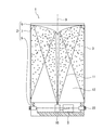
- the image display device 1 according to the first embodiment is a display device capable of visually recognizing a three-dimensional image from a plurality of surrounding directions. As shown in FIG. 6, the size of the image display device 1 is small enough to be held by the user with one hand. As shown in FIG. 1, the image display device 1 of the first embodiment includes a display unit 2, a touch panel 3, a plurality of cameras 4, and a controller 5. In FIG. 1, a part of the pedestal 6 is broken so that the internal configuration of the pedestal 6 of the display unit 2 can be visually recognized.
- the display unit 2 is formed by stacking a cylindrical screen 7 and a substantially disk-shaped reflection mirror 8 in this order on the upper side of a cylindrical pedestal 6 having an open upper surface and a closed lower surface. At the center of the inside of the pedestal 6, an exit portion 10 with the optical axis 9 directed vertically upward is arranged.
- the emitting unit 10 for example, a color projector that scans a laser beam corresponding to each color of RGB (hereinafter, also referred to as “image light 11”) and displays each pixel can be adopted. Then, the emitting unit 10 radially emits the image light 11 for forming the three-dimensional image upward according to the signal from the controller 5, and reflects the emitted image light 11 on the screen 7 by the reflection mirror 8. .
- As the three-dimensional image for example, an image in which the three-dimensional object 13 (see FIG. 2) appears to exist in the space 12 partitioned by the screen 7 can be adopted.
- a hologram screen on which a three-dimensional image is displayed can be adopted by diffusing and emitting the incident image light 11.
- a transmissive hologram capable of seeing through the screen 7 as described in International Publication No. 2018/163945 can be adopted.
- the transmissive hologram as shown in FIG. 2, the back side of the image display device 1 can be seen from a place where the three-dimensional object 13 represented by the three-dimensional image is not displayed, and the screen 7 is made of transparent glass or the like. You can make it feel like a container.
- FIG. 2 illustrates a case where a penguins character is used as the three-dimensional object 13.
- the reflection mirror 8 a mirror having a reflecting surface downward that reflects the image light 11 emitted from the emitting unit 10 can be adopted. Then, the reflection mirror 8 radially reflects the image light 11 emitted upward from the exit portion 10 toward the entire circumference of the screen 7.
- the emitting unit 10 radially emits the image light 11 upward according to the signal from the controller 5, and the emitted image light 11 is the reflection mirror 8. Is reflected radially toward the entire circumference of the screen 7. Then, as shown in FIG. 2, a three-dimensional image in which the three-dimensional object 13 appears to exist in the space 12 partitioned by the screen 7 is surrounded by the screen 7 in which the image light 11 is reflected all around. It is displayed so that it can be visually recognized from multiple directions. At that time, by making the screen 7 feel like a container such as transparent glass, it is possible to make it appear that the three-dimensional object 13 is housed in the container.
- the space 12 may be a space separated by a member forming an outer surface convex outward, and may be, for example, a space divided by a semi-cylindrical screen 7 or a square tubular screen 7. It may be a space.
- the touch panel 3 is provided on the entire circumference of the outer peripheral surface of the screen 7 and detects the presence or absence of contact with fingers or the like and the coordinates of the contact position.
- the detection result of the touch panel 3 is output to the controller 5.
- Each of the plurality of cameras 4 is arranged at equal intervals on the side wall portion of the pedestal 6, and captures a moving image of an image around the display unit 2.
- the camera 4 for example, a CCD camera or a CMOS camera can be adopted.
- Each of the moving image data is output to the controller 5.
- FIGS. 1 to 3 four cameras 4 in which the optical axes of the lenses are different from each other by 90 ° are used to illustrate a case where 360 ° around the display unit 2 is photographed. Further, in FIG.
- the area A 1 is also described as the shooting range of the first camera 4 (also referred to as “4 1 ” in FIG. 3), and the area A 2 is also described as the second camera 4 (also referred to as “4 2” in FIG. 3).
- Area A 3 is the shooting range of the third camera 4 (also referred to as “4 3 ” in FIG. 3)
- area A 4 is the shooting range of the fourth camera 4 (also referred to as “4 4” in FIG. 3). The shooting range.
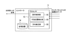
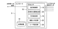
- the controller 5 is arranged inside the pedestal 6 and includes hardware resources such as a storage device 14 and a processor 15 as shown in FIG.
- the storage device 14 stores a control program of the image display device 1 that can be executed by the processor 15. Further, the storage device 14 stores various data necessary for executing the control program.
- the processor 15 realizes the display control unit 16, the eye position detection unit 17, and the direction estimation unit 18 according to the control program stored in the storage device 14. Then, the display control unit 16, the eye position detection unit 17, and the direction estimation unit 18 output a signal for controlling the image light 11 to the output unit 10 based on the moving image data output from the camera 4, and generate a three-dimensional image. Executes a control process for changing the front direction of the three-dimensional object 13 represented by.
- the front surface of the three-dimensional object 13 is preset at the time of manufacturing the image display device 1. For example, the most informative aspect.
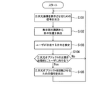
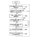
- step S101 the display control unit 16 outputs a signal to the output unit 10 to emit the image light 11 for displaying the three-dimensional image on the display unit 2.
- the display control unit 16 outputs a signal to the output unit 10 to emit the image light 11 for displaying the three-dimensional image on the display unit 2.
- the display control unit 16 outputs a signal to the output unit 10 to emit the image light 11 for displaying the three-dimensional image on the display unit 2.
- the display control unit 16 outputs a signal to the output unit 10 to emit the image light 11 for displaying the three-dimensional image on the display unit 2.
- the three-dimensional object 13 is a character
- a three-dimensional image in which the character performs some action is displayed.
- the three-dimensional object 13 is an organ on which surgery is performed, a three-dimensional image in which the organ is realistically represented is displayed.
- the display control unit 16 acquires the detection result output from the touch panel 3, detects the presence or absence of a flick operation on the touch panel 3 based on the acquired detection result, and determines that there is a flick operation.
- the configuration may be such that a three-dimensional image in which the three-dimensional object 13 is rotated in the direction of the flick operation is displayed.
- the rotation speed may be increased if the acceleration or speed of the fingers during the flick operation is high, and may be slow if the speed is slow.
- the three-dimensional object 13 is rotated by the flick operation, if it is determined that the flick operation is performed in the same direction as the rotation direction during the rotation of the three-dimensional object 13, the rotation of the three-dimensional object 13 is accelerated.
- the rotation of the three-dimensional object 13 is decelerated or the three-dimensional object 13 is rotated in the reverse direction. If the flick operation is not performed during the rotation of the three-dimensional object 13, the rotation of the three-dimensional object 13 is gradually attenuated. Further, when it is determined that there is a mere touch operation in which the fingers are not moved to the left or right during the rotation of the three-dimensional object 13, the rotation of the three-dimensional object 13 is braked. As a result, the user can rotate the three-dimensional object 13 and turn the front surface of the three-dimensional object 13 in a desired direction by performing a flick operation on the touch panel 3.
- step S102 the eye position detecting unit 17 detects the position of a person's eyes existing around the display unit 2. Specifically, first, the data of the moving image output from each of the plurality of cameras 4 is acquired. Subsequently, based on the acquired data, that is, the shooting results around the display unit 2, the position of the human eye existing around the display unit 2 is detected. As a method of detecting the position of the eyes, for example, a method of performing pattern matching or the like on moving image data can be adopted. Subsequently, the process proceeds to step S103, and the direction estimation unit 18 estimates the direction in which the user exists when viewed from the display unit 2. Specifically, the direction in which the eye position is detected in step S102 is output as the estimation result of the direction in which the user exists.
- step S104 the display control unit 16 determines whether or not the front surface of the three-dimensional object 13 represented by the three-dimensional image is automatically turned toward the user. Specifically, it is determined whether the angle difference between the direction in which the user exists estimated in step S103 and the direction in front of the three-dimensional object 13 represented by the three-dimensional image is larger than a predetermined value. As the predetermined value, for example, 1 to 5 ° can be adopted. Then, when it is determined that the angle difference is equal to or less than a predetermined value, it is determined that the front surface of the three-dimensional object 13 is already facing the user, and it is determined that the front surface of the three-dimensional object 13 is not automatically directed to the user.
- a predetermined value for example, 1 to 5 ° can be adopted.
- step S101 the process returns to step S101.
- the process proceeds to step S105.
- step S105 the display control unit 16 outputs a signal for rotating the three-dimensional object 13 represented by the three-dimensional image to the output unit 10.
- the image data of the three-dimensional image in which the front surface of the three-dimensional object 13 displayed by the display unit 2 is directed in the direction in which the user estimated in step S103 exists is sequentially created.
- image data for example, by rotating the three-dimensional object 13, image data that changes the front orientation of the three-dimensional object 13 represented by the three-dimensional image is used.
- the rotation of the three-dimensional object 13 is performed at a constant speed with the optical axis 9 of the emitting unit 10, that is, the central axis of the screen 7 as the rotation axis. Further, the rotation direction is determined so that the amount of rotation of the three-dimensional object 13 is minimized.
- the display control unit 16 sequentially converts the created image data into the data of the image light 11, and sequentially outputs a signal for irradiating the image light 11 indicated by the converted data to the exit unit 10.
- the flow of creating image data of the three-dimensional image ⁇ converting the image light 11 into data ⁇ outputting the signal to the emitting unit 10 is repeated until the front surface of the three-dimensional object 13 faces the direction in which the user exists.
- the process returns to step S101.
- the display unit 2 of the image display device 1 as shown in FIG.
- the three-dimensional object 13 represented by the three-dimensional image gradually rotates, and the front surface of the three-dimensional object 13 gradually turns toward the user 100. Be done.
- the dotted penguins represent the three-dimensional object 13 before rotation
- the solid line represents the three-dimensional object 13 after rotation
- the arrows represent the rotation direction of the three-dimensional object 13. There is.
- the direction in which the user exists is estimated from the display unit 2, and the display unit 2 displays in the estimated direction.
- the front of the three-dimensional object 13 is turned to face. Therefore, the front of the three-dimensional object 13 can be turned toward the user. Therefore, for example, when the three-dimensional object 13 is a character and the front of the three-dimensional object 13 is the face of the character, the face of the character can be shown to the user, and the user can fully feel the charm of the character. be able to.
- the inflamed site can be shown to a user (for example, a surgeon of surgery). It can give a lot of information to the user.
- the position of a person's eyes existing around the display unit 2 is detected, and the direction in which the eye position is detected is the direction in which the user exists. It is output as the estimation result of. Therefore, the front of the three-dimensional object 13 can be directed toward the person who is looking at the three-dimensional object 13. Further, in the image display device 1 according to the first embodiment of the present disclosure, an image around the display unit 2 is photographed by the camera 4, and the position of the human eye is detected based on the photographed result. The human eye can be easily detected from the surroundings of the display unit 2, and the direction in which the user exists can be easily estimated.
- the front direction of the three-dimensional object 13 displayed by the display unit 2 is changed by rotating the three-dimensional object 13. .. Therefore, unlike the method of instantly switching the orientation of the three-dimensional object 13, for example, the user intends to turn the front of the three-dimensional object 13 toward the user by showing the rotation of the three-dimensional object 13. It is possible to grasp that the image display device 1 recognizes the above, and the operation can proceed without anxiety.
- the rotation direction of the three-dimensional object 13 is determined so that the rotation amount of the three-dimensional object 13 is minimized. Therefore, it is possible to shorten the time required for the front surface of the three-dimensional object 13 to face in the direction in which the user exists, and it is possible to prevent the rotation time from becoming long.
- the image display device 1 when a flick operation is performed on the touch panel 3, the three-dimensional object 13 displayed by the display unit 2 in the direction of the flick operation is displayed. I tried to rotate it. Therefore, the user can rotate the three-dimensional object 13 and turn the front surface of the three-dimensional object 13 in a desired direction by performing a flick operation on the touch panel 3.
- the image display device according to the second embodiment of the present disclosure will be described. Since the overall configuration of the image display device of the second embodiment is the same as that of FIG. 1, the illustration is omitted.
- the image display device 1 of the second embodiment is different from the first embodiment in that when the user performs a pre-registered finger gesture, the front surface of the three-dimensional object 13 is directed in the direction in which the user exists. It's different.
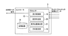
- the finger position detecting unit 19 is realized instead of the eye position detecting unit 17.
- the control processing steps S102, S103 and S104 shown in FIG. 5 are replaced with steps S201, S202 and S203.
- step S201 the finger position detecting unit 19 detects the position of a person's finger existing around the display unit 2. Specifically, first, the data of the moving image output from each of the plurality of cameras 4 is acquired. Subsequently, based on the acquired data, that is, the shooting results around the display unit 2, the positions of the fingers of a person existing around the display unit 2 are detected. As a finger detection method, a method of performing pattern matching or the like on moving image data can be adopted. Subsequently, the process proceeds to step S202, and the direction estimation unit 18 estimates the direction in which the user exists when viewed from the display unit 2. Specifically, the direction in which the position of the finger is detected in step S201 is output as the estimation result of the direction in which the user exists.
- step S203 the display control unit 16 determines whether or not the front surface of the three-dimensional object 13 represented by the three-dimensional image is automatically turned toward the user. Specifically, it is determined whether the locus of the finger position detected in step S201 indicates a pre-registered finger gesture.
- the gestures of the fingers for example, an operation of clapping a hand, an operation of waving both hands, and an operation of waving one hand can be adopted with the hand directed toward the image display device 1.
- the display control unit 16 determines that the detected locus of the finger position does not indicate a pre-registered gesture, it determines that the front surface of the three-dimensional object 13 is not automatically directed to the user.
- step S101 If it is determined that the gesture indicates a pre-registered gesture, it is determined that the front surface of the three-dimensional object 13 is automatically directed to the user (Yes), and the process proceeds to step S105.
- the user exists in the direction in which the finger of a person existing around the display unit 2 is detected and the position of the finger is detected. It is output as the estimation result of the direction to do. Therefore, for example, when a finger gesture is performed on the three-dimensional object 13, the front surface of the three-dimensional object 13 can be directed to the person who performed the finger gesture. Further, in the image display device 1 according to the second embodiment of the present disclosure, the periphery of the display unit 2 is photographed by the camera 4, and the position of the fingers is detected based on the imaged result. Therefore, the periphery of the display unit 2 is detected. The position of the finger can be easily detected from the above, and the direction in which the user exists can be easily estimated.
- step S301 the display control unit 16 determines whether the display control unit 16 automatically turns the front surface of the three-dimensional object 13 represented by the three-dimensional image toward the user. Specifically, first, the detection result output from the touch panel 3 is acquired. Subsequently, based on the acquired detection result (information on the presence or absence of contact with the fingers or the like), it is determined whether or not the fingers are in contact with the touch panel 3. Then, when it is determined that the finger is not in contact with the touch panel 3, it is determined that the front surface of the three-dimensional object 13 is not automatically directed to the user (No), and the process returns to step S101.
- step S302 the direction estimation unit 18 detects the position of the touch panel 3 that has been operated by a finger. Specifically, the coordinate information of the contact position of the finger or the like is acquired from the detection result acquired from the touch panel 3 in step S301. Subsequently, the process proceeds to step S303, and the direction estimation unit 18 estimates the direction in which the user exists when viewed from the display unit 2. Specifically, the normal direction of the position on the touch panel 3 detected in step S302 is output as an estimation result of the direction in which the user exists.
- the position of the touch panel 3 where the finger has been operated is detected, and the normal direction of the detected position is set by the user. Is output as the estimation result of the direction in which. Therefore, for example, when a flick operation is performed on the touch panel 3, the three-dimensional object 13 is rotated in the direction of the flick operation, and the rotation is directed to the person who performed the flick operation on the front surface of the three-dimensional object 13. It can be stopped in a state of being.
- step S401 the grip determination unit 20 determines whether the display unit 2 is gripped. Specifically, first, the detection result output from the touch panel 3 is acquired. Subsequently, based on the acquired detection result (information on the coordinates of the contact position of the fingers and the like), it is determined whether or not a plurality of fingers are in contact with the touch panel 3. Then, when it is determined that a plurality of fingers are not in contact with the touch panel 3, it is determined that the display unit 2 is not gripped (No), and the process returns to step S101. On the other hand, when it is determined that a plurality of fingers are in contact with the touch panel 3, it is determined that the display unit 2 is gripped (Yes), and the process proceeds to step S402.
- step S402 the gripping position detecting unit 21 detects the position of the finger holding the display unit 2. Specifically, based on the detection result acquired from the touch panel 3 in step S401, the position of the finger in contact with the touch panel 3 is detected, and the detected position of the finger is the position of the finger holding the display unit 2. And.
- the position of the finger is represented by, for example, a palm-shaped area including a plurality of coordinates output from the touch panel 3.
- step S403 the direction estimation unit 18 estimates the direction in which the user exists when viewed from the display unit 2 based on the detection result of the position of the finger holding the display unit 2. Specifically, the normal direction of the position on the touch panel 3 farthest from the region detected in step S402 is output as the estimation result of the direction in which the user exists.
- the image display device 1 it is determined whether or not the display unit 2 is gripped, and when it is determined that the display unit 2 is gripped, the display unit 2 is gripped.
- the position of the finger holding the 2 is detected, and the direction in which the user is present is estimated based on the detection result.
- the position of the face of the user 100 can be estimated based on the position of the fingers, and the front surface of the three-dimensional object 13 can be directed to the user.
- the position of the finger holding the display unit 2 is detected based on the detection result of the touch panel 3, so that the display unit 2 is gripped.
- the position of the finger is easily detected, and the direction of the user 100 can be easily estimated.
- Each of the microphones 22 is arranged at equal intervals on the side wall portion of the pedestal 6, and acquires the sound around the display unit 2.
- the microphone 22 for example, a microphone having high directivity can be adopted.
- Each of the sound data is output to the controller 5.
- 13 and 16 illustrate a case where four microphones 22 whose directivity directions are different from each other by 90 ° are used to collect sound at 360 ° around the display unit 2.
- the first microphone 22 is region B 1 sound collecting range (in FIG. 16 also referred to as "22 1"), the region B 2 (also referred to as FIG. 16 "22 2") and the second microphone 22 sound collecting range, region B 3 third microphone 22 sound collecting range (also referred to as FIG.
- the region B 4 is (also referred to as FIG. 16 in "22 4") fourth microphone 22
- the image display device 1 according to the fifth embodiment of the present disclosure shows an example in which a plurality of microphones 22 are used, other configurations may be adopted. For example, only one microphone 22 may be provided, and the microphone 22 may be moved to specify a sound source by using the Doppler effect.
- step S501 the sound generation position detection unit 23 detects the sound generation position around the display unit 2. Specifically, first, sound data output from each of the plurality of microphones 22 is acquired. Subsequently, the position where the sound generated around the display unit 2 is generated is detected based on the acquired data, that is, the sound collection result around the display unit 2.
- a method for detecting the sound generation position for example, the method described in JP-A-2016-5181 can be adopted.
- Japanese Unexamined Patent Publication No. 2016-5181 defines the amplitude ratio of each microphone 22 as sound source position information that reflects the directional characteristics of each microphone 22 and the attenuation due to the distance between the sound source and the microphone 22.
- step S502 A method of selecting the microphone output ratio closest to the calculated amplitude ratio from the microphone output ratios, referring to the sound source position information, and acquiring the sound source position corresponding to the selected microphone output ratio is described. Subsequently, the process proceeds to step S502, and the direction estimation unit 18 estimates the direction in which the user exists. Specifically, the direction in which the sound generation position is detected in step S501 is output as the estimation result of the direction in which the user exists.
- step S503 the display control unit 16 determines whether or not the front surface of the three-dimensional object 13 represented by the three-dimensional image is automatically turned toward the user. Specifically, it is determined whether or not the sound acquired in step S501 includes a sound registered in advance. Examples of the sound registered in advance include a voice calling for the name of the image display device 1, a voice calling for the name of the three-dimensional object 13 displayed on the display unit 2, and a sound of clapping hands. Then, when the display control unit 16 determines that the acquired sound does not include the sound registered in advance, it determines that the front surface of the three-dimensional object 13 does not automatically face the user (No) step. Return to S101. On the other hand, when it is determined that the sound registered in advance is included, it is determined that the front surface of the three-dimensional object 13 is automatically directed to the user, and the process proceeds to (Yes) step S105.
- the sound generation position generated around the display unit 2 is detected, and the direction in which the sound generation position is detected is set by the user. Is output as the estimation result of the direction in which. Therefore, for example, when a call or the like is made to the three-dimensional object 13, the front of the three-dimensional object 13 can be turned to the person who made the call or the like.
- the sound around the display unit 2 is acquired by the microphone 22, and the sound generation position is detected based on the acquisition result. Therefore, the position of the person who calls the three-dimensional object 13 and generates the sound can be detected with high accuracy. Further, by increasing the number of microphones 22, the position of the user can be detected with higher accuracy.
- the image display device 1 it is determined whether the sound acquired by the microphone 22 includes the sound registered in advance, and it is determined that the sound includes the sound registered in advance.
- the front of the three-dimensional object 13 displayed by the display unit 2 is oriented in the direction in which the estimated user exists. Therefore, for example, by using a voice calling a name on the three-dimensional object 13 as a pre-registered sound, it is possible to prevent another voice such as a conversation from being mistakenly recognized as a calling voice, and three-dimensional. It is possible to prevent the front surface of the object 13 from being pointed at a person who is not calling.
- the distance measuring sensor 24 may be used. Each of the distance measuring sensors 24 is arranged at equal intervals on the side wall portion of the pedestal 6, and the surface of an object around the display unit 2 can be detected from the detection result so that the position of the human eye around the display unit 2 can be detected. Measure the distance to multiple points.
- a TOF (Time Of Flight) camera or a Structure Beam sensor can be adopted.
- Each of the distance data is output to the controller 5.
- four distance measuring sensors 24 whose optical axes of the lenses are different from each other by 90 ° are used to illustrate a case where distance measurement is performed at 360 ° around the display unit 2.
- region C 1 is the distance measuring range of the first distance measuring sensor 24 (in FIG. 18 also referred to as "24 1")
- the region C 2 is the second distance measuring sensor 24 (FIG. 18 "24 2 ranging range "and also referred to)
- region C 3 is ranging scope of the third distance measuring sensor 24 (in FIG. 18 also referred to as” 24 3 ")
- the region C 4 a fourth distance measuring sensor 24 (FIG. 18 in a distance measurement range of the also referred to as "24 4").
- step S601 the eye position detecting unit 17 detects the position of a person's eyes existing around the display unit 2. Specifically, first, the distance data output from each of the plurality of distance measuring sensors 24 is acquired. Subsequently, based on the acquired data, that is, the distance measurement results around the display unit 2, the position of the human eye existing around the display unit 2 is detected. As a method for detecting the position of the eyes, for example, a method of analyzing unevenness information obtained from distance data can be adopted.
- the distances to a plurality of points on the surface of the object around the display unit 2 are measured by the distance measuring sensor 24, and based on the measurement results, the human eye. Try to detect the position. Therefore, for example, as in the case of using the camera 4, the human eye can be easily detected from the periphery of the display unit 2, and the direction in which the user exists can be easily estimated.
- step S701 the finger position detecting unit 19 detects the position of a person's finger existing around the display unit 2. Specifically, first, the distance data output from each of the plurality of distance measuring sensors 24 is acquired. Subsequently, the positions of the fingers of a person existing around the display unit 2 are detected based on the acquired data, that is, the distance measurement results around the display unit 2.
- a finger detection method a method of analyzing unevenness information obtained from distance data can be adopted.
- the distances to a plurality of points on the surface of the object around the display unit 2 are measured by the distance measuring sensor 24, and based on the measurement results, the human fingers Try to detect the position. Therefore, for example, as in the case of using the camera 4, a person's fingers can be easily detected from the periphery of the display unit 2, and the direction in which the user exists can be easily estimated.
- the image display device 1 is small enough to be lifted by a user with one hand, but other configurations are adopted. You can also do it. For example, as shown in FIG. 21, it may be as large as the height.
- the image display device 1 is made large, it is determined whether or not there are a plurality of people around the display unit 2, and the user of the image display device 1, that is, the tertiary image represented by the three-dimensional image is selected from the plurality of people.
- the configuration may be such that the person to whom the front surface of the original object 13 is directed is determined. When such a configuration is applied to the first embodiment, for example, as shown in FIG.
- the processor 15 determines the display control unit 16 and the eye position according to the control program stored in the storage device 14.
- a plurality of person determination unit 25 and a user setting unit 26 may be realized. Further, as shown in FIG. 23, steps S801, S802 and S803 may be provided instead of step S103 of the control process shown in FIG.
- step S801 the plurality of person determination unit 25 determines whether or not there are a plurality of persons around the display unit 2. Specifically, it is determined in step S102 whether or not the eyes of a plurality of persons have been detected. Then, when it is determined that the eyes of a plurality of persons are detected, it is determined that there are a plurality of persons around the display unit 2 (Yes), and the process proceeds to step S802. On the other hand, when it is determined that only one person's eyes are detected, it is determined that there is only one person around the display unit 2 (No), and the process proceeds to step S803.
- step S802 the user setting unit 26 selects the person who has the highest degree of interest in the three-dimensional object 13 among the plurality of people existing around the display unit 2, the user whose direction is detected in step S803, that is, three-dimensional.
- the process proceeds to step S803.
- a method of detecting the person who has the highest degree of interest in the three-dimensional object 13 for example, the person who has seen the three-dimensional object 13 for the longest time is detected from among a plurality of people, and the detected person has the highest degree of interest. You can adopt the method of judging as a person.
- the time for viewing the three-dimensional object 13 for example, the continuous time in which the eye position is detected in step S102 can be adopted.
- the direction estimation unit 18 estimates the direction in which the user exists when viewed from the display unit 2. Specifically, the direction in which the eye position is detected in step S102 is output as the estimation result of the direction in which the user exists.
- the determination in step S801 is "Yes" and the user is determined from among a plurality of persons in step S802, the user exists in the direction in which the eye position of the person determined by the user is detected. Output as the direction estimation result.
- the eye position detection unit 17 determines whether or not the eyes of a plurality of persons have been detected, and when it is determined that the eyes of a plurality of persons have been detected, the number of persons is determined. Among them, the person who has the highest degree of interest in the three-dimensional object 13 is judged as the user. Therefore, when a plurality of people are looking at the three-dimensional object 13, the front of the three-dimensional object 13 can be directed to the person who has the highest degree of interest in the three-dimensional object 13.
- the person who has seen the three-dimensional object 13 for the longest time among the plurality of people existing around the display unit 2 is detected, and the person who has detected the detected person has the highest degree of interest. I tried to judge. Therefore, when a plurality of people are looking at the three-dimensional object 13, the front of the three-dimensional object 13 can be directed to the person who has been looking at the three-dimensional object 13 for the longest time. Also, when the person is facing the front of the 3D object 13 and the person turns to another direction or leaves the place, another person who is looking at the 3D object 13 for the longest time at that time. The front of the three-dimensional object 13 can be turned to.
- the configuration of the above modification that is, a configuration in which it is determined whether or not a plurality of people surround the display unit 2 and a user of the image display device 1 is determined from the plurality of people.
- the processor 15 has a display control unit 16, a finger position detection unit 19, and a direction estimation unit 18 according to a control program stored in the storage device 14.
- the configuration may be such that the plurality of person determination unit 25 and the user setting unit 26 are realized.
- steps S901, S902 and S903 may be provided instead of step S303 of the control process shown in FIG.
- step S901 the multi-person determination unit 25 determines whether or not a plurality of people are performing a flick operation on the touch panel 3. Specifically, first, the detection result (information on the coordinates of the contact position of a finger or the like) output from the touch panel 3 is acquired. Subsequently, based on the acquired detection result, it is determined whether or not the flick operation is detected at a plurality of locations on the touch panel 3. Then, when it is determined that the flick operation is detected at a plurality of locations, it is determined that a plurality of people are performing the flick operation on the touch panel 3 (Yes), and the process proceeds to step S902. On the other hand, when it is determined that the flick operation is detected only at one place, it is determined that there is only one person who is flicking the touch panel 3 (No), and the process proceeds to step S903.
- step S902 the user setting unit 26 selects the person who has the highest degree of interest in the three-dimensional object 13 among the plurality of people who are flicking the touch panel 3, the user whose direction is detected in step S903, that is, three-dimensional.
- the process proceeds to step S903.
- a method of detecting the person having the highest degree of interest in the three-dimensional object 13 for example, the person having the fastest flick operation speed is detected from among a plurality of people, and the detected person is regarded as the person having the highest degree of interest.
- a method of judgment can be adopted.
- the speed of the flick operation for example, the acceleration and speed of the fingers can be adopted.
- step S903 the direction estimation unit 18 estimates the direction in which the user exists when viewed from the display unit 2. Specifically, the normal direction of the position on the touch panel 3 detected in step S302 is output as an estimation result of the direction in which the user exists.
- the determination in step S901 is "Yes” and the user is determined from among a plurality of persons in step S902, the user determines the normal direction of the position on the touch panel 3 in which the person determined by the user is in contact. Is output as the estimation result of the direction in which.
- the image display device 1 when it is determined whether or not a plurality of people are performing a flick operation and it is determined that a plurality of people are performing a flick operation, a three-dimensional object among the plurality of people is used.
- the person with the highest degree of interest in 13 is judged to be the user. Therefore, when a plurality of people are trying to turn the 3D object 13 toward their own side, the front of the 3D object 13 can be turned to the person who has the highest interest in the 3D object 13.
- the person with the fastest flick operation is detected, and the detected person is determined to be the person with the highest degree of interest. Therefore, when a plurality of people are pointing the three-dimensional object 13 toward their own side, the front of the three-dimensional object 13 can be directed to a person who has a fast flick operation.
- step S1001 the plurality of people determination unit 25 determines whether or not a plurality of people are performing a flick operation on the touch panel 3 by the same procedure as in step S901 described above. Then, when it is determined that a plurality of people are performing a flick operation on the touch panel 3 (Yes), the process proceeds to step S1002. On the other hand, if it is determined that there is only one person who is flicking the touch panel 3, (No), the process proceeds to step S1004.
- step S1002 the display control unit 16 rotates the three-dimensional object 13 at a speed corresponding to the total value of the flick operations of each person performing the flick operation on the touch panel 3. Specifically, first, based on the detection result (information on the coordinates of the contact position of a finger or the like) acquired from the touch panel 3, the speed of the flick operation performed at each of a plurality of locations on the touch panel 3 is detected. For the speed of the flick operation, for example, clockwise is a positive value and counterclockwise is a negative value in a plan view. Subsequently, the detected speeds are totaled, and image data of a three-dimensional image in which the three-dimensional object 13 is rotated at a speed corresponding to the total value is sequentially created.
- the image data of the three-dimensional image that gradually attenuates the rotation of the three-dimensional object 13 is sequentially created. Further, when it is determined that there is a mere touch operation in which the fingers are not moved to the left or right during the rotation of the three-dimensional object 13, the image data of the three-dimensional image that brakes the rotation of the three-dimensional object 13 is sequentially created. At the same time, the created image data is sequentially converted into the data of the image light 11, and the signal for irradiating the image light 11 indicated by the converted data is sequentially output to the emitting unit 10.
- step S1003 the user setting unit 26 selects the person closest to the front of the three-dimensional object 13 among the plurality of people who are flicking the touch panel 3, the user whose direction is detected in step S1004, that is, the three-dimensional object 13.
- the process proceeds to step S1004.
- a method of detecting the person closest to the front surface of the three-dimensional object 13 for example, in a plan view, a straight line extending from the optical axis 9 toward the front surface of the three-dimensional object 13 and a flick operation are performed from the optical axis 9. It is possible to adopt a method of detecting the person having the smallest narrow angle formed by the straight line extended to the person.
- step S1004 the direction estimation unit 18 estimates the direction in which the user exists when viewed from the display unit 2. Specifically, the normal direction of the position on the touch panel 3 detected in step S302 is output as an estimation result of the direction in which the user exists.
- the determination in step S1001 is "Yes" and the user is determined from among a plurality of persons in step S1003, the user determines the normal direction of the position on the touch panel 3 in which the person determined by the user is in contact. Is output as the estimation result of the direction in which.
- the image display device 1 when it is determined that a plurality of people are performing a flick operation on the touch panel 3, the speed corresponding to the total value of the flick operations of each person.
- the three-dimensional object 13 is rotated by.
- the rotation of the three-dimensional object 13 by the flick operation is stopped, the person closest to the front of the three-dimensional object 13 among the plurality of people is set as the user.
- a person A flicks the touch panel 3 to rotate the three-dimensional object 13, and rotates the three-dimensional object 13 when the front surface of the three-dimensional object 13 faces the direction in which another person B exists.
- one person A can turn the front of the three-dimensional object 13 toward another person B only by stopping the rotation of the three-dimensional object 13 at an approximate position, and the operation can be performed relatively easily. ..
- the processor 15 has a display control unit 16, a sound generation position detection unit 23, and a direction estimation unit 18 according to a control program stored in the storage device 14.
- the configuration may be such that the plurality of person determination unit 25 and the user setting unit 26 are realized.
- steps S1101, S1102 and S1103 may be provided instead of step S502 of the control process shown in FIG.
- step S1101 the plurality of person determination unit 25 determines whether or not there are a plurality of persons around the display unit 2. Specifically, it is determined in step S501 whether or not the sounds for a plurality of people have been acquired. Then, when it is determined that the sounds for a plurality of persons have been acquired, it is determined that there are a plurality of persons around the display unit 2 (Yes), and the process proceeds to step S1102. On the other hand, when it is determined that only the sound for one person has been acquired, it is determined that there is only one person around the display unit 2 (No), and the process proceeds to step S1103.
- step S1102 the user setting unit 26 selects the person who has the highest degree of interest in the three-dimensional object 13 among the plurality of people existing around the display unit 2, the user whose direction is detected in step S1103, that is, the three-dimensional object.
- step S1103 As a method of detecting the person having the highest degree of interest in the three-dimensional object 13, for example, the person who emits the pre-registered sound for the longest time is detected, and the detected person is determined to be the person having the highest degree of interest. The method can be adopted.
- the time for emitting the pre-registered sound for example, the continuous time in which the sound is detected in step S501 can be adopted.
- step S1103 the direction estimation unit 18 estimates the direction in which the user exists when viewed from the display unit 2. Specifically, the direction in which the sound generation position is detected in step S501 is output as the estimation result of the direction in which the user exists.
- the determination in step S1101 is "Yes" and the user is determined from among a plurality of persons in step S1102, the user determines the direction in which the sound generation position of the person determined by the user is detected. Is output as the estimation result of the direction in which.
- the image display device 1 when it is determined whether the sound for a plurality of people is acquired by the microphone 22, and it is determined that the sound for a plurality of people is acquired, the third order among the plurality of people is determined.
- the user has the highest degree of interest in the original object 13. Therefore, for example, when a plurality of people are calling to the three-dimensional object 13, the front of the three-dimensional object 13 can be directed to the person who has the highest degree of interest in the three-dimensional object 13.
- the person who emits the pre-registered sound for the longest time is detected among a plurality of people, and the detected person is determined to be the person with the highest degree of interest. ..
- the front of the three-dimensional object 13 can be directed to the person who is making the call for the longest time.
- the person who last emits the pre-registered sound is detected among the plurality of people, and the detected person is determined to be the person with the highest degree of interest. Therefore, for example, when a person A calls the three-dimensional object 13 and the front of the three-dimensional object 13 is directed to the person A, when the person A stops the call, at that time, The front of the 3D object 13 can be turned to another person B who is calling to the 3D object 13.
- the front surface of the three-dimensional object 13 is automatically directed to the user is shown, but another configuration is adopted. You can also. For example, as shown in FIG. 29, the front surface of the three-dimensional object 13 may be automatically turned toward the user, and then the front surface of the three-dimensional object 13 may be rotated in a predetermined direction according to a word uttered by the user.
- a configuration in which step S1201 is provided after step S105 of the control process shown in FIG. 15 may be used.
- step S1201 the display control unit 16 determines whether the sound emitted by the user includes a word (hereinafter, also referred to as “direction instruction”) for directing the front surface of the three-dimensional object 13 in a predetermined direction.
- a word hereinafter, also referred to as “direction instruction”
- direction instruction for example, "turning to the left” or "turning to the right” can be adopted.
- sound data output from each of the plurality of microphones 22 is acquired.
- it is determined whether or not the sound indicated by the acquired data includes a direction instruction.
- the display control unit 16 determines that the sounds acquired from each of the plurality of microphones 22 do not include the direction indication, the process returns to step S101.
- the three-dimensional object 13 displayed by the display unit 2 in the direction indicated by the direction instruction (left direction, right direction) when viewed from the user.
- Image data of a three-dimensional image is sequentially created by rotating the three-dimensional object 13 so that the front of the object faces.
- the created image data is sequentially converted into the data of the image light 11, and the signal for irradiating the image light 11 indicated by the converted data is sequentially output to the emitting unit 10.
- step S101 In such a flow of creating image data of a three-dimensional image ⁇ converting the image light 11 into data ⁇ outputting a signal to the emitting unit 10, the front surface of the three-dimensional object 13 rotates in the direction indicated by the direction instruction. Is repeated until is stopped, and when the rotation of the three-dimensional object 13 is stopped, the process proceeds to step S101.
- the word that causes the front surface of the three-dimensional object 13 to be directed in a predetermined direction in the sound emitted by the user is determined whether (direction instruction) is included and it is determined that such a word (direction instruction) is included, the front of the three-dimensional object 13 displayed by the display unit 2 is viewed from the user. I tried to turn it in a predetermined direction. Therefore, for example, when a plurality of people are looking at the three-dimensional object 13, one person A can tell the direction of another person B, so that the front of the three-dimensional object 13 can be directed to another person B. ..
- words that directly indicate the direction such as "turn left” and "turn right" are used as direction instructions for directing the front surface of the three-dimensional object 13 in a predetermined direction.
- Other configurations can be adopted.
- a word indicating a person's name may be used, such as "turn toward B-chan”.
- the person's name and face image are registered in advance, and when it is determined that the person's name is included in the voice uttered by the user, the person's name is acquired from the camera 4.
- the position of the person with the name may be detected based on the imaging result and the face image registered in advance, and the front surface of the three-dimensional object 13 may be directed in the direction of the detected position.
- a three-dimensional image may be displayed using a device in which a liquid crystal display is arranged on each surface of the cube.
- a three-dimensional image can be visually recognized from around 360 ° around the display unit 2 as the display unit 2. It is also possible to adopt the configuration of. For example, a configuration may be used in which the visible angle range of the three-dimensional image is narrower than 360 °.
- various actions calling, gesture, line of sight) requesting the front of the three-dimensional object 13 to be turned as described in the first to fifth embodiments are performed by a plurality of people.
- the user may be determined to perform the action having the highest priority, and the front of the three-dimensional object 13 represented by the three-dimensional image may be directed in the direction in which the determined user exists.
- the priority is, for example, the person who called the name of the image display device 1 or the name of the three-dimensional object 13> the person who made the gesture of the finger> the person who just saw it.
- the present technology can have the following configurations.
- a display unit that displays a three-dimensional image in which a three-dimensional object appears to exist in a space separated by members that make up the outer surface so that it can be visually recognized from multiple surrounding directions.
- a direction estimation unit that estimates the direction in which the user exists when viewed from the display unit, and a direction estimation unit.
- An image display device including a display control unit that directs the front of the three-dimensional object displayed by the display unit in the direction in which the user is present, which is estimated by the direction estimation unit.
- An eye position detecting unit for detecting the position of a person's eyes existing around the display unit is provided.
- the image display device wherein the direction estimation unit outputs the direction in which the position of the eye is detected as an estimation result of the direction in which the user exists.
- a camera for photographing the surroundings of the display unit is provided.
- the image display device according to (2) above, wherein the eye position detecting unit detects the position of the eye based on a shooting result around the display unit.
- a distance measuring sensor for measuring distances to a plurality of points on the surface of an object around the display unit is provided.
- the image display device according to (3), wherein the eye position detecting unit detects the position of the eye based on the measurement result of the distance.
- a multi-person determination unit that determines whether or not the eyes of a plurality of people have been detected by the eye position detection unit, When it is determined that the eyes of a plurality of persons are detected, the user setting unit for determining the person having the highest degree of interest in the three-dimensional object among the plurality of persons is provided with the user setting unit (2) to (4). ).
- the image display device according to any one of. (6)
- the image display device according to (5) above, wherein the user setting unit detects a person who has viewed the three-dimensional object for the longest time among the plurality of people, and determines that the detected person is the person having the highest degree of interest. .. (7)
- a finger position detecting unit for detecting the position of a person's finger existing around the display unit is provided.
- the image display device wherein the direction estimation unit outputs the direction in which the position of the finger is detected as an estimation result of the direction in which the user exists.
- a camera for photographing the surroundings of the display unit is provided.
- the image display device according to (7) above, wherein the finger position detecting unit detects the position of the finger based on a shooting result around the display unit.
- a distance measuring sensor for measuring distances to a plurality of points on the surface of an object around the display unit is provided.
- the image display device according to (7), wherein the finger position detecting unit detects the position of the finger based on the measurement result of the distance.
- a grip determination unit that determines whether the display unit is gripped, and a grip determination unit.
- a gripping position detecting unit that detects the position of the finger holding the display unit when it is determined that the display unit is gripped.
- a touch panel provided on the outer surface of the display unit is provided.
- the gripping position detecting unit detects the position of a finger holding the display unit based on the detection result of the touch panel.
- a touch panel provided on the outer surface of the display unit is provided.
- the direction estimation unit detects a position on the touch panel that has been operated by a finger, and outputs the normal direction of the detected position as an estimation result of the direction in which the user exists in the above (1).
- a sound generation position detection unit for detecting a sound generation position around the display unit is provided.
- a microphone for acquiring the sound around the display unit is provided.
- the image display device according to (13), wherein the sound generation position detection unit detects the sound generation position based on the sound acquisition result.
- the display control unit determines whether the sound acquired by the microphone includes a sound registered in advance, and when it is determined that the sound includes the sound registered in advance, the direction estimation unit estimates the sound.
- the image display device according to (14), wherein the front surface of the three-dimensional object displayed by the display unit is directed in the direction in which the user exists.
- a multi-person determination unit that determines whether sounds for a plurality of people have been acquired by the microphone, and a multi-person determination unit.
- the user setting unit (15) is provided with a user setting unit that determines that the person who has the highest degree of interest in the three-dimensional object among the plurality of people is the user when it is determined that the sounds for a plurality of people have been acquired.
- Image display device is provided with a user setting unit that determines that the person who has the highest degree of interest in the three-dimensional object among the plurality of people is the user when it is determined that the sounds for a plurality of people have been acquired.
- any of the above (13) to (18) for causing the front surface of the three-dimensional object displayed by the display unit to face in a predetermined direction when viewed from the user is included.
- the image display device described in Crab. (20) The image display device according to any one of (1) to (19), wherein the display control unit causes the display unit to change the front direction of the three-dimensional object by rotating the three-dimensional object.
- a user setting unit for determining the person having the highest degree of interest in the three-dimensional object among the plurality of people is provided as a user.
- Image display device The image display device according to (22), wherein the user setting unit detects a person having the fastest flick operation among the plurality of people, and determines that the detected person is the person having the highest degree of interest.
- a touch panel provided on the outer surface of the display unit is provided.
- the display control unit rotates the three-dimensional object at a speed corresponding to the total value of the flick operations of each person.
- the user setting unit is provided, wherein when the rotation of the three-dimensional object is stopped by the flick operation, the person closest to the front of the three-dimensional object among the plurality of people is set as the user.
- Image display device. (25) A display unit that displays a three-dimensional image in which a three-dimensional object appears to exist in a space separated by members that make up the outer surface so that it can be visually recognized from multiple surrounding directions.
- a touch panel provided on the outer surface of the display unit and An image display device including a display control unit that rotates the three-dimensional object displayed by the display unit in the direction of the flick operation when a flick operation is performed on the touch panel.
Abstract
Description
本開示は、三次元画像が現す三次元オブジェクトの正面を自動的にユーザに向けることが可能な画像表示装置を提供することを目的とする。 However, in the image display device described in
An object of the present disclosure is to provide an image display device capable of automatically turning the front surface of a three-dimensional object represented by a three-dimensional image toward a user.
1-1 画像表示装置の全体の構成
1-2 制御処理の内容
2.第2の実施形態:画像表示装置
2-1 要部の構成
3.第3の実施形態:画像表示装置
3-1 要部の構成
4.第4の実施形態:画像表示装置
4-1 要部の構成
5.第5の実施形態:画像表示装置
5-1 要部の構成
6.変形例
6-1 第1の変形例
6-2 第2の変形例
6-3 第3の変形例
6-4 その他の変形例 1. 1. First Embodiment: Image Display Device 1-1 Overall Configuration of Image Display Device 1-2 Contents of
[1-1 画像表示装置の全体の構成]
本開示の第1の実施形態に係る画像表示装置について説明する。第1の実施形態に係る画像表示装置1は、周囲の複数方向から三次元画像を視認可能な表示装置である。画像表示装置1の大きさは、図6に示すようにユーザが片手で持てる程度に小型のものとする。
図1に示すように、第1の実施形態の画像表示装置1は、表示部2と、タッチパネル3と、複数のカメラ4と、コントローラ5とを備えている。図1では、表示部2の台座6の内部の構成を視認できるように、台座6の一部が破断して示されている。 <1. First Embodiment>
[1-1 Overall configuration of image display device]
The image display device according to the first embodiment of the present disclosure will be described. The
As shown in FIG. 1, the
台座6の内部の中心には、光軸9を鉛直上方に向けた出射部10が配置されている。出射部10としては、例えば、RGBの各色に対応したレーザ光(以下、「画像光11」とも呼ぶ)を走査して各画素を表示するカラープロジェクタを採用できる。そして、出射部10は、コントローラ5からの信号に従って、三次元画像を構成するための画像光11を上方に向けて放射状に出射し、出射した画像光11を反射ミラー8でスクリーン7に反射させる。三次元画像としては、例えば、スクリーン7で区切られた空間12内に三次元オブジェクト13(図2参照)が存在するように見える画像を採用することができる。 The
At the center of the inside of the
反射ミラー8としては、出射部10から出射された画像光11を反射する反射面を下方に有するミラーを採用できる。そして、反射ミラー8は、出射部10から上方に向けて放射状に出射された画像光11を、スクリーン7の全周に向けて放射状に反射する。 As the screen 7, for example, a hologram screen on which a three-dimensional image is displayed can be adopted by diffusing and emitting the
As the
なお、第1の実施形態では、空間12として、円筒状のスクリーン7で区切られた空間を用いる例を示したが、他の構成を採用することもできる。空間12は、外側に凸の外面を構成する部材で区切られた空間であればよく、例えば、半円筒状のスクリーン7で区切られた空間でもよいし、四角筒状のスクリーン7で区切られた空間であってもよい。 In the
In the first embodiment, an example in which a space separated by a cylindrical screen 7 is used as the
複数のカメラ4のそれぞれは、台座6の側壁部に等間隔に配置され、表示部2の周囲の画像の動画を撮影する。カメラ4としては、例えば、CCDカメラ、CMOSカメラを採用できる。動画のデータのそれぞれは、コントローラ5に出力される。図1~図3では、レンズの光軸を互いに90°ずつ異ならせた4台のカメラ4を用いて、表示部2の周囲360°を撮影する場合を例示している。また、図3中において、領域A1は第1のカメラ4(図3では「41」とも記す)の撮影範囲、領域A2は第2のカメラ4(図3では「42」とも記す)の撮影範囲、領域A3は第3のカメラ4(図3では「43」とも記す)の撮影範囲、領域A4は第4のカメラ4(図3では「44」とも記す)の撮影範囲である。 The
Each of the plurality of
記憶装置14は、プロセッサ15で実行可能な画像表示装置1の制御プログラムを記憶している。また記憶装置14は、制御プログラムの実行に必要な各種データを記憶する。
プロセッサ15は、記憶装置14に記憶されている制御プログラムに従って、表示制御部16、目位置検出部17及び方向推定部18を実現する。そして、表示制御部16、目位置検出部17及び方向推定部18により、カメラ4から出力される動画のデータに基づき、画像光11を制御する信号を出射部10に出力して、三次元画像が現す三次元オブジェクト13の正面の向きを変化させる制御処理を実行する。三次元オブジェクト13の正面は、画像表示装置1の製造時に予め設定される。例えば、最も情報が豊富な面とする。 The
The
The
次に、プロセッサ15で実現される表示制御部16、目位置検出部17及び方向推定部18が実行する制御処理について説明する。制御処理は、画像表示装置1の図示しない電源スイッチがオン状態にされると実行される。
図5に示すように、まず、ステップS101では、表示制御部16が、表示部2に三次元画像を表示させる画像光11を出射させる信号を出射部10に出力する。その際、例えば、三次元オブジェクト13がキャラクターである場合には、キャラクターが何らかのアクションを行う三次元画像を表示させる。また、例えば、三次元オブジェクト13が手術が行われる臓器である場合には、臓器がリアルに表現された三次元画像を表示させる。
また、例えば、表示制御部16が、タッチパネル3から出力される検出結果を取得し、取得した検出結果に基づきタッチパネル3へのフリック操作の有無を検出し、フリック操作があると判定した場合には、フリック操作の向きに三次元オブジェクト13を回転させる三次元画像を表示させる構成としてもよい。回転速度は、例えば、フリック操作時の手指の加速度や速度が速ければ速くし、遅ければ遅くしてもよい。フリック操作によって三次元オブジェクト13を回転させる場合、三次元オブジェクト13の回転中に回転方向と同方向へのフリック操作があったと判定した場合には、三次元オブジェクト13の回転を加速させる。一方、三次元オブジェクト13の回転中に回転方向と逆方向へのフリック操作があったと判定した場合には、三次元オブジェクト13の回転を減速させる、または三次元オブジェクト13を逆回転させる。また、三次元オブジェクト13の回転中にフリック操作が行われなかった場合には、三次元オブジェクト13の回転を徐々に減衰させる。また、三次元オブジェクト13の回転中に手指を左右に動かさない単なるタッチ操作があったと判定した場合には、三次元オブジェクト13の回転にブレーキをかける。これにより、ユーザは、タッチパネル3にフリック操作を行うことで、三次元オブジェクト13を回転させて、三次元オブジェクト13の正面を所望の方向へ向けることができる。 [1-2 Contents of control processing]
Next, the control processing executed by the
As shown in FIG. 5, first, in step S101, the
Further, for example, when the
続いてステップS103に移行して、方向推定部18が、表示部2から見てユーザが存在する方向を推定する。具体的には、ステップS102で目の位置を検出した方向を、ユーザが存在する方向の推定結果として出力する。 Subsequently, in step S102, the eye
Subsequently, the process proceeds to step S103, and the
また、本開示の第1の実施形態に係る画像表示装置1では、表示部2の周囲の画像をカメラ4で撮影し、その撮影結果に基づき、人の目の位置を検出するようにしたため、表示部2の周囲から人の目を容易に検出でき、ユーザが存在する方向を容易に推定できる。 Further, in the
Further, in the
[2-1 要部の構成]
次に、本開示の第2の実施形態に係る画像表示装置について説明する。第2の実施形態の画像表示装置の全体構成は、図1と同様であるから図示を省略する。
第2の実施形態の画像表示装置1は、ユーザが予め登録された手指のジェスチャーを行った場合に、三次元オブジェクト13の正面をユーザが存在する方向に向ける点が、第1の実施形態と異なっている。具体的には、第2の実施形態では、図7に示すように、目位置検出部17に代えて手指位置検出部19を実現する構成となっている。また、図8に示すように、図5に示した制御処理のステップS102、S103及びS104に代えてステップS201、S202及びS203を備える構成となっている。 <2. Second Embodiment: Image Display Device>
[2-1 Composition of key parts]
Next, the image display device according to the second embodiment of the present disclosure will be described. Since the overall configuration of the image display device of the second embodiment is the same as that of FIG. 1, the illustration is omitted.
The
続いてステップS202に移行して、方向推定部18が、表示部2から見てユーザが存在する方向を推定する。具体的には、ステップS201で手指の位置を検出した方向を、ユーザが存在する方向の推定結果として出力する。
続いてステップS203に移行して、表示制御部16が、三次元画像が現す三次元オブジェクト13の正面を自動的にユーザに向けるかを判定する。具体的には、ステップS201で検出された手指の位置の軌跡が予め登録された手指のジェスチャーを示すものであるかを判定する。手指のジェスチャーとしては、例えば、手を画像表示装置1の方向に向けた状態にして、手を叩く動作、両手を振る動作、片手を振る動作を採用することができる。そして、表示制御部16が、検出された手指の位置の軌跡が予め登録されたジェスチャーを示すものではないと判定した場合には、三次元オブジェクト13の正面を自動的にユーザに向けないと判定して(No)ステップS101に戻る。一方、予め登録されたジェスチャーを示すものであると判定した場合には、三次元オブジェクト13の正面を自動的にユーザに向けると判定して(Yes)、ステップS105に移行する。 In step S201, the finger
Subsequently, the process proceeds to step S202, and the
Subsequently, the process proceeds to step S203, and the
また、本開示の第2の実施形態に係る画像表示装置1では、表示部2の周囲をカメラ4で撮影し、その撮影結果に基づき手指の位置を検出するようにしたため、表示部2の周囲から手指の位置を容易に検出でき、ユーザが存在する方向を容易に推定できる。 As described above, in the
Further, in the
[3-1 要部の構成]
次に、本開示の第3の実施形態に係る画像表示装置について説明する。第3の実施形態の画像表示装置の全体構成は、図1と同様であるから図示を省略する。
第3の実施形態の画像表示装置1は、ユーザがタッチパネル3にフリック操作を行った場合に、三次元オブジェクト13の正面をユーザが存在する方向に向ける点が、第1の実施形態と異なっている。具体的には、第3の実施形態では、図9に示すように、図5に示した制御処理のステップS102、S103及びS104に代えてステップS301、S302及びS303を備える構成となっている。 <3. Third Embodiment: Image Display Device>
[3-1 Composition of key parts]
Next, the image display device according to the third embodiment of the present disclosure will be described. Since the overall configuration of the image display device according to the third embodiment is the same as that shown in FIG. 1, the illustration is omitted.
The
ステップS302では、方向推定部18が、タッチパネル3のうちの手指による操作があった位置を検出する。具体的には、ステップS301でタッチパネル3から取得した検出結果から手指等の接触位置の座標の情報を取得する。
続いてステップS303に移行して、方向推定部18が、表示部2から見てユーザが存在する方向を推定する。具体的には、ステップS302で検出したタッチパネル3上の位置の法線方向を、ユーザが存在する方向の推定結果として出力する。 In step S301, the
In step S302, the
Subsequently, the process proceeds to step S303, and the
なお、本開示の第3の実施形態に係る画像表示装置1では、三次元オブジェクト13の正面がユーザが存在する方向と異なる方向を向いている状態が所定時間以上継続しているかを判定し、所定時間以上継続していると判定した場合に、三次元画像が現す三次元オブジェクト13の正面を自動的にユーザが存在する方向に向ける構成としてもよい。 As described above, in the
In the
[4-1 要部の構成]
次に、本開示の第4の実施形態に係る画像表示装置について説明する。第4の実施形態の画像表示装置の全体構成は、図1と同様であるから図示を省略する。
第4の実施形態の画像表示装置1は、ユーザが表示部2を把持した場合に、三次元オブジェクト13の正面をユーザが存在する方向に向ける点が、第1の実施形態と異なっている。具体的には、第4の実施形態では、図10に示すように、目位置検出部17に代えて把持判定部20及び把持位置検出部21を実現する構成となっている。また、図11に示すように、図5に示した制御処理のステップS102及びS103に代えてステップS401及びS402を備える構成となっている。 <4. Fourth Embodiment: Image Display Device>
[4-1 Composition of key parts]
Next, the image display device according to the fourth embodiment of the present disclosure will be described. Since the overall configuration of the image display device of the fourth embodiment is the same as that of FIG. 1, the illustration is omitted.
The
ステップS402では、把持位置検出部21が、表示部2を把持している手指の位置を検出する。具体的には、ステップS401でタッチパネル3から取得した検出結果に基づき、タッチパネル3に接触している手指の位置を検出し、検出した手指の位置を、表示部2を把持している手指の位置とする。手指の位置は、例えば、タッチパネル3から出力される複数の座標を含む手のひら状の領域によって表される。
続いてステップS403に移行して、方向推定部18が、表示部2を把持している手指の位置の検出結果に基づき、表示部2から見てユーザが存在する方向を推定する。具体的には、ステップS402で検出した領域から最も遠いタッチパネル3上の位置の法線方向を、ユーザが存在する方向の推定結果として出力する。 In step S401, the
In step S402, the gripping position detecting unit 21 detects the position of the finger holding the
Subsequently, in step S403, the
また、本開示の第4の実施形態に係る画像表示装置1では、タッチパネル3の検出結果に基づき、表示部2を把持している手指の位置を検出するようにしたため、表示部2を把持している手指の位置を容易に検出でき、ユーザ100の方向を容易に推定できる。 As described above, in the
Further, in the
[5-1 要部の構成]
次に、本開示の第5の実施形態に係る画像表示装置について説明する。第5の実施形態の画像表示装置の全体構成は、図1と同様であるから図示を省略する。
第5の実施形態の画像表示装置1は、ユーザが予め登録された音を発した場合に、三次元オブジェクト13の正面をユーザが存在する方向に向ける点が、第1の実施形態と異なっている。具体的には、第5の実施形態では、図13に示すように、カメラ4に代えてマイク22を備える構成となっている。また、図14に示すように、目位置検出部17に代えて音発生位置検出部23を実現する構成となっている。また、図15に示すように、図5に示した制御処理のステップS102、S103及びS104に代えてステップS501、S502及びS503を備える構成となっている。 <5. Fifth Embodiment: Image display device>
[5-1 Configuration of key parts]
Next, the image display device according to the fifth embodiment of the present disclosure will be described. Since the overall configuration of the image display device according to the fifth embodiment is the same as that shown in FIG. 1, the illustration is omitted.
The
なお、本開示の第5の実施形態に係る画像表示装置1では、複数のマイク22を用いる例を示したが、他の構成を採用することもできる。例えば、マイク22を1つだけ備え、マイク22を動かしてドップラー効果を利用して音源を特定する構成としてもよい。 Each of the
Although the
続いてステップS502に移行して、方向推定部18が、ユーザが存在する方向を推定する。具体的には、ステップS501で音の発生位置を検出した方向を、ユーザが存在する方向の推定結果として出力する。 In step S501, the sound generation
Subsequently, the process proceeds to step S502, and the
また、本開示の第5の実施形態に係る画像表示装置1では、表示部2の周囲の音をマイク22で取得し、その取得結果に基づき、音の発生位置を検出するようにした。それゆえ、三次元オブジェクト13に呼びかけて音を発生している人の位置を高精度に検出できる。また、マイク22の数を増やすことで、ユーザの位置をより高精度に検出できる。 As described above, in the
Further, in the
[6-1 第1の変形例]
なお、本開示の第1及び第2の実施形態に係る画像表示装置1では、ユーザの目の位置や手指の位置を検出するためにカメラ4を用いる例を示したが、他の構成を採用することもできる。例えば、図17に示すように、測距センサ24を用いる構成としてもよい。
測距センサ24のそれぞれは、台座6の側壁部に等間隔に配置され、検出結果から表示部2の周囲の人の目の位置を検出できるように、表示部2の周囲にある物体の表面の複数点までの距離を測定する。測距センサ24としては、例えば、TOF(Time Of Flight)カメラ、Structure Beamセンサを採用することができる。距離のデータのそれぞれは、コントローラ5に出力される。図17及び図18では、レンズの光軸を互いに90°ずつ異ならせた4台の測距センサ24用いて、表示部2の周囲360°で測距を行う場合を例示している。また図18中、領域C1は第1の測距センサ24(図18では「241」とも記す)の測距範囲、領域C2は第2の測距センサ24(図18では「242」とも記す)の測距範囲、領域C3は第3の測距センサ24(図18では「243」とも記す)の測距範囲、領域C4は第4の測距センサ24(図18では「244」とも記す)の測距範囲である。 <6. Modification example>
[6-1 First modification]
In the
Each of the
ステップS601では、目位置検出部17が、表示部2の周囲に存在する人の目の位置を検出する。具体的には、まず、複数の測距センサ24のそれぞれから出力される距離のデータを取得する。続いて、取得したデータ、つまり、表示部2の周囲の測距結果それぞれに基づき、表示部2の周囲に存在する人の目の位置を検出する。目の位置の検出方法としては、例えば、距離のデータから求まる凹凸情報を解析等する方法を採用できる。
このように、本変形例に係る画像表示装置1では、表示部2の周囲にある物体の表面の複数点までの距離を測距センサ24で測定し、その測定結果に基づき、人の目の位置を検出するようにする。それゆえ、例えば、カメラ4を用いた場合と同様、表示部2の周囲から人の目を容易に検出でき、ユーザが存在する方向を容易に推定することができる。 When the configuration using the
In step S601, the eye
As described above, in the
ステップS701では、手指位置検出部19が、表示部2の周囲に存在する人の手指の位置を検出する。具体的には、まず、複数の測距センサ24のそれぞれから出力される距離のデータを取得する。続いて、取得したデータ、つまり、表示部2の周囲の測距結果それぞれに基づき、表示部2の周囲に存在する人の手指の位置を検出する。手指の検出方法としては、距離のデータから求まる凹凸情報を解析等する方法を採用することができる。
このように、本変形例に係る画像表示装置1では、表示部2の周囲にある物体の表面の複数点までの距離を測距センサ24で測定し、その測定結果に基づき、人の手指の位置を検出するようにする。それゆえ、例えば、カメラ4を用いた場合と同様、表示部2の周囲から人の手指を容易に検出でき、ユーザが存在する方向を容易に推定することができる。 Although the example in which the configuration using the
In step S701, the finger
As described above, in the
また、本開示の第1~第5の実施形態に係る画像表示装置1では、画像表示装置1をユーザが片手で持ち上げられる程度の小型のものとする例を示したが、他の構成を採用することもできる。例えば、図21に示すように、背丈程度の大型のものとしてもよい。
画像表示装置1を大型のものとする場合、表示部2の周囲に複数人が存在するかを判定し、その複数人のうちから、画像表示装置1のユーザ、つまり、三次元画像が現す三次元オブジェクト13の正面が向けられる人を決定する構成としてもよい。このような構成を第1の実施形態に適用する場合には、例えば、図22に示すように、プロセッサ15が、記憶装置14に記憶されている制御プログラムに従って、表示制御部16、目位置検出部17及び方向推定部18に加えて、複数人判定部25及びユーザ設定部26を実現する構成としてもよい。また、図23に示すように、図5に示した制御処理のステップS103に代えてステップS801、S802及びS803が設けられた構成としてもよい。 [6-2 Second variant]
Further, in the
When the
ステップS802では、ユーザ設定部26が、表示部2の周囲に存在する複数人のうち三次元オブジェクト13への関心度が最も高い人を、ステップS803で方向が検出されるユーザ、つまり、三次元オブジェクト13の正面が向けられるユーザと判断した後、ステップS803に移行する。三次元オブジェクト13への関心度が最も高い人を検出する方法としては、例えば、複数人のうちから三次元オブジェクト13を最も長く見ている人を検出し、検出した人を関心度が最も高い人と判断する方法を採用できる。三次元オブジェクト13を見ている時間としては、例えば、ステップS102で目の位置が検出されている連続時間を採用することができる。即ち、直前まで三次元オブジェクト13を長時間連続して見ている人であっても、現在三次元オブジェクト13から目を逸してる人は、三次元オブジェクト13を最も長く見ている人として検出されない。
ステップS803では、方向推定部18が、表示部2から見てユーザが存在する方向を推定する。具体的には、ステップS102で目の位置を検出した方向を、ユーザが存在する方向の推定結果として出力する。なお、ステップS801の判定が「Yes」となり、ステップS802で複数人のうちからユーザが決定された場合には、ユーザに決定された人の目の位置が検出された方向を、ユーザが存在する方向の推定結果として出力する。 In step S801, the plurality of
In step S802, the
In step S803, the
また、本変形例に係る画像表示装置1では、表示部2の周囲に存在する複数人のうち三次元オブジェクト13を最も長く見ている人を検出し、検出した人を関心度が最も高い人と判断するようにした。それゆえ、複数人が三次元オブジェクト13を見ているときに、三次元オブジェクト13を最も長時間見ていた人に三次元オブジェクト13の正面を向けることができる。また、ある人に三次元オブジェクト13の正面を向けていたときに、その人が他の方向を向いたりその場を立ち去ったりした場合その時点で三次元オブジェクト13を最も長く見ている別の人に三次元オブジェクト13の正面を向けることができる。 As described above, in the
Further, in the
第3の実施形態に適用する場合、例えば、図24に示すように、プロセッサ15が、記憶装置14に記憶されている制御プログラムに従って、表示制御部16、手指位置検出部19、方向推定部18に加えて、複数人判定部25及びユーザ設定部26を実現する構成としてもよい。また、図25に示すように、図9に示した制御処理のステップS303に代えてステップS901、S902及びS903が設けられた構成としてもよい。 In the first embodiment, the configuration of the above modification, that is, a configuration in which it is determined whether or not a plurality of people surround the
When applied to the third embodiment, for example, as shown in FIG. 24, the
ステップS903では、方向推定部18が、表示部2から見てユーザが存在する方向を推定する。具体的には、ステップS302で検出したタッチパネル3上の位置の法線方向を、ユーザが存在する方向の推定結果として出力する。なお、ステップS901の判定が「Yes」となり、ステップS902で複数人のうちからユーザが決定された場合には、ユーザに決定された人が接触したタッチパネル3上の位置の法線方向を、ユーザが存在する方向の推定結果として出力する。 In step S902, the
In step S903, the
また、本変形例に係る画像表示装置1では、フリック操作の速さが最も速い人を検出し、検出した人を関心度が最も高い人と判断するようにした。それゆえ、複数人が三次元オブジェクト13を自身の側へ向けているときに、フリック操作が速い人に三次元オブジェクト13の正面を向けることができる。 As described above, in the
Further, in the
ステップS1001では、複数人判定部25が、上記したステップS901と同様の手順により、タッチパネル3に複数人がフリック操作を行っているかを判定する。そして、タッチパネル3に複数人がフリック操作を行っていると判定した場合には(Yes)、ステップS1002に移行する。一方、タッチパネル3をフリック操作している人が1人しかいないと判定した場合には(No)、ステップS1004に移行する。 Further, as another configuration applied to the third embodiment, for example, the configuration shown in FIG. 24 is realized, and as shown in FIG. 26, step S1001 is replaced with step S303 of the control process shown in FIG. , S1002 and S1003 may be provided.
In step S1001, the plurality of
また同時に、作成した画像データを画像光11のデータに順次変換し、変換して得たデータが示す画像光11を照射させる信号を出射部10に順次出力する。このような、三次元画像の画像データの作成→画像光11のデータへの変換→出射部10への信号の出力のフローは、フリック操作による三次元オブジェクト13の回転が停止されるまで繰り返され、三次元オブジェクト13の回転が停止されると、ステップS1003に移行する。 In step S1002, the
At the same time, the created image data is sequentially converted into the data of the
ステップS1004では、方向推定部18が、表示部2から見てユーザが存在する方向を推定する。具体的には、ステップS302で検出したタッチパネル3上の位置の法線方向を、ユーザが存在する方向の推定結果として出力する。なお、ステップS1001の判定が「Yes」となり、ステップS1003で複数人のうちからユーザが決定された場合には、ユーザに決定された人が接触したタッチパネル3上の位置の法線方向を、ユーザが存在する方向の推定結果として出力する。 In step S1003, the
In step S1004, the
ステップS1102では、ユーザ設定部26が、表示部2の周囲に存在する複数人のうち三次元オブジェクト13への関心度が最も高い人を、ステップS1103で方向が検出されるユーザ、つまり三次元オブジェクト13の正面が向けられるユーザと判断した後、ステップS1103に移行する。三次元オブジェクト13への関心度が最も高い人を検出する方法としては、例えば、予め登録された音を最も長く発している人を検出し、検出した人を関心度が最も高い人と判断する方法を採用できる。予め登録された音を発している時間としては、例えば、ステップS501で音が検出されている連続時間を採用できる。また、関心度が最も高い人を検出する他の方法としては、例えば、予め登録された音を最後に発した人を検出し、検出した人を関心度が最も高い人と判断する方法を採用できる。
ステップS1103では、方向推定部18が、表示部2から見てユーザが存在する方向を推定する。具体的には、ステップS501で音の発生位置を検出した方向を、ユーザが存在する方向の推定結果として出力する。なお、ステップS1101の判定が「Yes」となり、ステップS1102で複数人のうちからユーザが決定された場合には、ユーザに決定された人が発している音の発生位置を検出した方向を、ユーザが存在する方向の推定結果として出力する。 In step S1101, the plurality of
In step S1102, the
In step S1103, the
また、本変形例に係る画像表示装置1では、複数人のうち、予め登録された音を最も長く発している人を検出し、検出した人を関心度が最も高い人と判断するようにした。それゆえ、例えば、複数人が三次元オブジェクト13に呼びかけを行っているときに、呼びかけを最も長時間行っている人に三次元オブジェクト13の正面を向けることができる。
また、本変形例に係る画像表示装置1では、複数人のうち、予め登録された音を最後に発した人を検出し、検出した人を関心度が最も高い人と判断するようにした。それゆえ、例えば、ある人Aが三次元オブジェクト13に呼びかける等して、ある人Aに三次元オブジェクト13の正面が向けられていたときに、ある人Aが呼びかけを止めた場合、その時点で三次元オブジェクト13に呼びかけを行っている別の人Bに三次元オブジェクト13の正面を向けることができる。 As described above, in the
Further, in the
Further, in the
また、本開示の第1~第5の実施形態に係る画像表示装置1では、三次元オブジェクト13の正面をユーザに自動的に向けるものとする例を示したが、他の構成を採用することもできる。例えば、図29に示すように、三次元オブジェクト13の正面をユーザに自動的に向けた後、ユーザから発せられる言葉に従って、三次元オブジェクト13の正面を所定方向に回転させる構成としてもよい。このような構成を第5の実施形態に適用する場合には、例えば、図29に示すように、図15に示した制御処理のステップS105の後に、ステップS1201が設けられた構成としてもよい。 [6-3 Third variant]
Further, in the
そして、表示制御部16が、複数のマイク22それぞれから取得された音が方向指示を含まないと判定した場合には、ステップS101に戻る。一方、取得された音が方向指示を含むと判定した場合には、まず、ユーザから見て方向指示が示す方向(左方向、右方向)に、表示部2が表示している三次元オブジェクト13の正面が向くように三次元オブジェクト13を回転させる三次元画像の画像データを順次作成する。また同時に、作成した画像データを画像光11のデータに順次変換し、変換して得たデータが示す画像光11を照射させる信号を出射部10に順次出力する。このような、三次元画像の画像データの作成→画像光11のデータへの変換→出射部10への信号の出力のフローは、三次元オブジェクト13の正面が方向指示が示す方向に向いて回転が停止されるまで繰り返され、三次元オブジェクト13の回転が停止されると、ステップS101に移行する。 In step S1201, the
Then, when the
なお、本変形例では、三次元オブジェクト13の正面を所定方向に向けさせる方向指示として「左を向いて」「右を向いて」等、方向を直接的に示す言葉を用いる例を示したが、他の構成を採用することもできる。例えば、「Bちゃんの方を向いて」等、人の名前を示す言葉を用いてもよい。人の名前を示す言葉を用いる場合、人の名前と顔画像とを予め登録しておき、ユーザが発した声のうちに人の名前が含まれていると判定した場合に、カメラ4から取得される撮像結果と予め登録した顔画像とに基づき、名前の人の位置を検出し、検出した位置の方向に、三次元オブジェクト13の正面を向ける構成としてもよい。 As described above, in the
In this modification, an example is shown in which words that directly indicate the direction, such as "turn left" and "turn right", are used as direction instructions for directing the front surface of the three-
(1)また、第1~第5の実施形態に係る画像表示装置1では、台座6の内部にコントローラ5を配置して、コントローラ5を表示部2と一体とする例を示したが、他の構成を採用することもできる。例えば、表示部2の外部にコントローラ5を配置して、コントローラ5を表示部2と別体としてもよい。コントローラ5を表示部2と別体とする場合、コントローラ5を大型化することができ、複雑な三次元画像を表示することができる。
(2)また、第1~第5の実施形態に係る画像表示装置1では、円筒状のスクリーン7に画像光11を照射して三次元画像を表示する例を示したが、他の構成を採用することもできる。例えば、立方体の各面に液晶ディスプレイが配置された装置を用いて三次元画像を表示する構成としてもよい。
(3)また、第1~第5の実施形態に係る画像表示装置1では、表示部2として、三次元画像を表示部2の周囲360°から視認可能なものを用いる例を示したが他の構成を採用することもできる。例えば、三次元画像を視認可能な角度範囲が360°よりも狭いものを用いる構成としてもよい。
(4)また、第1~第5の実施形態に記載したような、三次元オブジェクト13の正面を向けることを要求する各種の行為(呼びかけ、ジェスチャー、視線)が複数人によって行われた場合、優先度が最も高い行為を行った人をユーザに決定し、決定されたユーザが存在する方向に、三次元画像が現す三次元オブジェクト13の正面を向ける構成としてもよい。優先度は、例えば、画像表示装置1の名前や三次元オブジェクト13の名前の呼びかけを行った人>手指のジェスチャーを行った人>単に見ていただけの人、の順とする。 [6-4 Other Modifications]
(1) Further, in the
(2) Further, in the
(3) Further, in the
(4) Further, when various actions (calling, gesture, line of sight) requesting the front of the three-
(1)
外面を構成する部材で区切られた空間内に三次元オブジェクトが存在するように見える三次元画像を周囲の複数方向から視認できるように表示する表示部と、
前記表示部から見てユーザが存在する方向を推定する方向推定部と、
前記方向推定部で推定した前記ユーザが存在する方向に、前記表示部が表示している前記三次元オブジェクトの正面を向けさせる表示制御部とを備える
画像表示装置。
(2)
前記表示部の周囲に存在する人の目の位置を検出する目位置検出部を備え、
前記方向推定部は、前記目の位置が検出された方向を、前記ユーザが存在する方向の推定結果として出力する
前記(1)に記載の画像表示装置。
(3)
前記表示部の周囲を撮影するカメラを備え、
前記目位置検出部は、前記表示部の周囲の撮影結果に基づき、前記目の位置を検出する
前記(2)に記載の画像表示装置。
(4)
前記表示部の周囲にある物体の表面の複数点までの距離を測定する測距センサを備え、
前記目位置検出部は、前記距離の測定結果に基づき、前記目の位置を検出する
前記(3)に記載の画像表示装置。
(5)
前記目位置検出部で複数人分の目が検出されたかを判定する複数人判定部と、
複数人分の目が検出されたと判定した場合に、前記複数人のうち前記三次元オブジェクトへの関心度が最も高い人を前記ユーザと判断するユーザ設定部とを備える
前記(2)から(4)の何れかに記載の画像表示装置。
(6)
前記ユーザ設定部は、前記複数人のうち前記三次元オブジェクトを最も長く見ている人を検出し、検出した人を前記関心度が最も高い人と判断する
前記(5)に記載の画像表示装置。
(7)
前記表示部の周囲に存在する人の手指の位置を検出する手指位置検出部を備え、
前記方向推定部は、前記手指の位置が検出された方向を、前記ユーザが存在する方向の推定結果として出力する
前記(1)に記載の画像表示装置。
(8)
前記表示部の周囲を撮影するカメラを備え、
前記手指位置検出部は、前記表示部の周囲の撮影結果に基づき、前記手指の位置を検出する
前記(7)に記載の画像表示装置。
(9)
前記表示部の周囲にある物体の表面の複数点までの距離を測定する測距センサを備え、
前記手指位置検出部は、前記距離の測定結果に基づき、前記手指の位置を検出する
前記(7)に記載の画像表示装置。
(10)
前記表示部が把持されているかを判定する把持判定部と、
前記表示部が把持されていると判定した場合に、前記表示部を把持している手指の位置を検出する把持位置検出部とを備え、
前記方向推定部は、前記表示部を把持している手指の位置の検出結果に基づき、前記ユーザが存在する方向を推定する
前記(1)に記載の画像表示装置。
(11)
前記表示部の前記外面に設けられたタッチパネルを備え、
前記把持位置検出部は、前記タッチパネルの検出結果に基づき、前記表示部を把持している手指の位置を検出する
前記(10)に記載の画像表示装置。
(12)
前記表示部の前記外面に設けられたタッチパネルを備え、
前記方向推定部は、前記タッチパネルのうちの、手指による操作があった位置を検出し、検出された位置の法線方向を、前記ユーザが存在する方向の推定結果として出力する
前記(1)に記載の画像表示装置。
(13)
前記表示部の周囲で発生した音の発生位置を検出する音発生位置検出部を備え、
前記方向推定部は、前記音の発生位置が検出された方向を、前記ユーザが存在する方向の推定結果として出力する
前記(1)に記載の画像表示装置。
(14)
前記表示部の周囲の音を取得するマイクを備え、
前記音発生位置検出部は、前記音の取得結果に基づき、前記音の発生位置を検出する
前記(13)に記載の画像表示装置。
(15)
前記表示制御部は、前記マイクで取得された音が予め登録された音を含むものであるかを判定し、前記予め登録された音を含むものであると判定した場合に、前記方向推定部で推定した前記ユーザが存在する方向に、前記表示部が表示している前記三次元オブジェクトの正面を向けさせる
前記(14)に記載の画像表示装置。
(16)
前記マイクで複数人分の音が取得されたかを判定する複数人判定部と、
複数人分の音が取得されたと判定した場合に、前記複数人のうち前記三次元オブジェクトへの関心度が最も高い人を前記ユーザと判断するユーザ設定部とを備える
前記(15)に記載の画像表示装置。
(17)
前記ユーザ設定部は、前記複数人のうち前記予め登録された音を最も長く発している人を検出し、検出した人を前記関心度が最も高い人と判断する
前記(16)に記載の画像表示装置。
(18)
前記ユーザ設定部は、前記複数人のうち前記予め登録された音を最後に発した人を検出し、検出した人を前記関心度が最も高い人と判断する
前記(16)記載の画像表示装置。
(19)
前記表示制御部は、前記三次元オブジェクトの正面が前記ユーザに向けられた後、前記ユーザが発した音のうちに前記三次元オブジェクトの正面を所定方向に向けさせる言葉が含まれているかを判定し、当該言葉が含まれていると判定した場合に、前記表示部が表示している前記三次元オブジェクトの正面を前記ユーザから見て所定方向へ向けさせる
前記(13)から(18)の何れかに記載の画像表示装置。
(20)
前記表示制御部は、前記三次元オブジェクトを回転させることで、前記表示部に前記三次元オブジェクトの正面の向きを変更させる
前記(1)から(19)の何れかに記載の画像表示装置。
(21)
前記表示制御部は、前記三次元オブジェクトの回転量が最小となるように、前記三次元オブジェクトの回転方向を決定する
前記(20)に記載の画像表示装置。
(22)
前記表示部の前記外面に設けられたタッチパネルと、
前記タッチパネルに複数人がフリック操作を行っているかを判定する複数人判定部と、
複数人がフリック操作を行っていると判定した場合には、前記複数人のうち前記三次元オブジェクトへの関心度が最も高い人をユーザと判断するユーザ設定部とを備える
前記(1)に記載の画像表示装置。
(23)
前記ユーザ設定部は、前記複数人のうち前記フリック操作の速さが最も速い人を検出し、検出した人を前記関心度が最も高い人と判断する
前記(22)に記載の画像表示装置。
(24)
前記表示部の前記外面に設けられたタッチパネルを備え、
前記表示制御部は、複数人が前記タッチパネルにフリック操作を行っている場合には、各人の前記フリック操作の速さの合計値に応じた速さで前記三次元オブジェクトを回転させ、
更に、前記フリック操作による前記三次元オブジェクトの回転が停止されると、前記複数人のうち前記三次元オブジェクトの正面に最も近い人を、前記ユーザとするユーザ設定部を備える
前記(1)に記載の画像表示装置。
(25)
外面を構成する部材で区切られた空間内に三次元オブジェクトが存在するように見える三次元画像を周囲の複数方向から視認できるように表示する表示部と、
前記表示部の前記外面に設けられたタッチパネルと、
前記タッチパネルにフリック操作が行われている場合には、前記フリック操作の向きに、前記表示部が表示している前記三次元オブジェクトを回転させる表示制御部とを備える
画像表示装置。 The present technology can have the following configurations.
(1)
A display unit that displays a three-dimensional image in which a three-dimensional object appears to exist in a space separated by members that make up the outer surface so that it can be visually recognized from multiple surrounding directions.
A direction estimation unit that estimates the direction in which the user exists when viewed from the display unit, and a direction estimation unit.
An image display device including a display control unit that directs the front of the three-dimensional object displayed by the display unit in the direction in which the user is present, which is estimated by the direction estimation unit.
(2)
An eye position detecting unit for detecting the position of a person's eyes existing around the display unit is provided.
The image display device according to (1), wherein the direction estimation unit outputs the direction in which the position of the eye is detected as an estimation result of the direction in which the user exists.
(3)
A camera for photographing the surroundings of the display unit is provided.
The image display device according to (2) above, wherein the eye position detecting unit detects the position of the eye based on a shooting result around the display unit.
(4)
A distance measuring sensor for measuring distances to a plurality of points on the surface of an object around the display unit is provided.
The image display device according to (3), wherein the eye position detecting unit detects the position of the eye based on the measurement result of the distance.
(5)
A multi-person determination unit that determines whether or not the eyes of a plurality of people have been detected by the eye position detection unit,
When it is determined that the eyes of a plurality of persons are detected, the user setting unit for determining the person having the highest degree of interest in the three-dimensional object among the plurality of persons is provided with the user setting unit (2) to (4). ). The image display device according to any one of.
(6)
The image display device according to (5) above, wherein the user setting unit detects a person who has viewed the three-dimensional object for the longest time among the plurality of people, and determines that the detected person is the person having the highest degree of interest. ..
(7)
A finger position detecting unit for detecting the position of a person's finger existing around the display unit is provided.
The image display device according to (1), wherein the direction estimation unit outputs the direction in which the position of the finger is detected as an estimation result of the direction in which the user exists.
(8)
A camera for photographing the surroundings of the display unit is provided.
The image display device according to (7) above, wherein the finger position detecting unit detects the position of the finger based on a shooting result around the display unit.
(9)
A distance measuring sensor for measuring distances to a plurality of points on the surface of an object around the display unit is provided.
The image display device according to (7), wherein the finger position detecting unit detects the position of the finger based on the measurement result of the distance.
(10)
A grip determination unit that determines whether the display unit is gripped, and a grip determination unit.
It is provided with a gripping position detecting unit that detects the position of the finger holding the display unit when it is determined that the display unit is gripped.
The image display device according to (1) above, wherein the direction estimation unit estimates the direction in which the user exists based on the detection result of the position of the finger holding the display unit.
(11)
A touch panel provided on the outer surface of the display unit is provided.
The image display device according to (10), wherein the gripping position detecting unit detects the position of a finger holding the display unit based on the detection result of the touch panel.
(12)
A touch panel provided on the outer surface of the display unit is provided.
The direction estimation unit detects a position on the touch panel that has been operated by a finger, and outputs the normal direction of the detected position as an estimation result of the direction in which the user exists in the above (1). The image display device described.
(13)
A sound generation position detection unit for detecting a sound generation position around the display unit is provided.
The image display device according to (1), wherein the direction estimation unit outputs a direction in which the sound generation position is detected as an estimation result of the direction in which the user exists.
(14)
A microphone for acquiring the sound around the display unit is provided.
The image display device according to (13), wherein the sound generation position detection unit detects the sound generation position based on the sound acquisition result.
(15)
The display control unit determines whether the sound acquired by the microphone includes a sound registered in advance, and when it is determined that the sound includes the sound registered in advance, the direction estimation unit estimates the sound. The image display device according to (14), wherein the front surface of the three-dimensional object displayed by the display unit is directed in the direction in which the user exists.
(16)
A multi-person determination unit that determines whether sounds for a plurality of people have been acquired by the microphone, and a multi-person determination unit.
The user setting unit (15) is provided with a user setting unit that determines that the person who has the highest degree of interest in the three-dimensional object among the plurality of people is the user when it is determined that the sounds for a plurality of people have been acquired. Image display device.
(17)
The image according to (16) above, wherein the user setting unit detects the person who emits the pre-registered sound for the longest time among the plurality of people, and determines that the detected person is the person having the highest degree of interest. Display device.
(18)
The image display device according to (16), wherein the user setting unit detects a person who last emits the pre-registered sound among the plurality of people, and determines that the detected person is the person having the highest degree of interest. ..
(19)
After the front surface of the three-dimensional object is directed to the user, the display control unit determines whether the sound emitted by the user includes a word for directing the front surface of the three-dimensional object in a predetermined direction. However, when it is determined that the word is included, any of the above (13) to (18) for causing the front surface of the three-dimensional object displayed by the display unit to face in a predetermined direction when viewed from the user. The image display device described in Crab.
(20)
The image display device according to any one of (1) to (19), wherein the display control unit causes the display unit to change the front direction of the three-dimensional object by rotating the three-dimensional object.
(21)
The image display device according to (20), wherein the display control unit determines the rotation direction of the three-dimensional object so that the rotation amount of the three-dimensional object is minimized.
(22)
A touch panel provided on the outer surface of the display unit and
A multi-person determination unit that determines whether a plurality of people are flicking on the touch panel, and a multi-person determination unit.
The description in (1) above, wherein when it is determined that a plurality of people are performing a flick operation, a user setting unit for determining the person having the highest degree of interest in the three-dimensional object among the plurality of people is provided as a user. Image display device.
(23)
The image display device according to (22), wherein the user setting unit detects a person having the fastest flick operation among the plurality of people, and determines that the detected person is the person having the highest degree of interest.
(24)
A touch panel provided on the outer surface of the display unit is provided.
When a plurality of people are performing a flick operation on the touch panel, the display control unit rotates the three-dimensional object at a speed corresponding to the total value of the flick operations of each person.
Further, according to the above (1), the user setting unit is provided, wherein when the rotation of the three-dimensional object is stopped by the flick operation, the person closest to the front of the three-dimensional object among the plurality of people is set as the user. Image display device.
(25)
A display unit that displays a three-dimensional image in which a three-dimensional object appears to exist in a space separated by members that make up the outer surface so that it can be visually recognized from multiple surrounding directions.
A touch panel provided on the outer surface of the display unit and
An image display device including a display control unit that rotates the three-dimensional object displayed by the display unit in the direction of the flick operation when a flick operation is performed on the touch panel.
Claims (25)
- 外面を構成する部材で区切られた空間内に三次元オブジェクトが存在するように見える三次元画像を周囲の複数方向から視認できるように表示する表示部と、
前記表示部から見てユーザが存在する方向を推定する方向推定部と、
前記方向推定部で推定した前記ユーザが存在する方向に、前記表示部が表示している前記三次元オブジェクトの正面を向けさせる表示制御部とを備える
画像表示装置。 A display unit that displays a three-dimensional image in which a three-dimensional object appears to exist in a space separated by members that make up the outer surface so that it can be visually recognized from multiple surrounding directions.
A direction estimation unit that estimates the direction in which the user exists when viewed from the display unit, and a direction estimation unit.
An image display device including a display control unit that directs the front of the three-dimensional object displayed by the display unit in the direction in which the user is present, which is estimated by the direction estimation unit. - 前記表示部の周囲に存在する人の目の位置を検出する目位置検出部を備え、
前記方向推定部は、前記目の位置が検出された方向を、前記ユーザが存在する方向の推定結果として出力する
請求項1に記載の画像表示装置。 An eye position detecting unit for detecting the position of a person's eyes existing around the display unit is provided.
The image display device according to claim 1, wherein the direction estimation unit outputs the direction in which the position of the eye is detected as an estimation result of the direction in which the user exists. - 前記表示部の周囲を撮影するカメラを備え、
前記目位置検出部は、前記表示部の周囲の撮影結果に基づき、前記目の位置を検出する
請求項2に記載の画像表示装置。 A camera for photographing the surroundings of the display unit is provided.
The image display device according to claim 2, wherein the eye position detection unit detects the eye position based on a shooting result around the display unit. - 前記表示部の周囲にある物体の表面の複数点までの距離を測定する測距センサを備え、
前記目位置検出部は、前記距離の測定結果に基づき、前記目の位置を検出する
請求項2に記載の画像表示装置。 A distance measuring sensor for measuring distances to a plurality of points on the surface of an object around the display unit is provided.
The image display device according to claim 2, wherein the eye position detecting unit detects the eye position based on the measurement result of the distance. - 前記目位置検出部で複数人分の目が検出されたかを判定する複数人判定部と、
複数人分の目が検出されたと判定した場合に、前記複数人のうち前記三次元オブジェクトへの関心度が最も高い人を前記ユーザと判断するユーザ設定部とを備える
請求項2に記載の画像表示装置。 A multi-person determination unit that determines whether or not the eyes of a plurality of people have been detected by the eye position detection unit,
The image according to claim 2, further comprising a user setting unit that determines that the person who has the highest degree of interest in the three-dimensional object among the plurality of people is the user when it is determined that the eyes of a plurality of people are detected. Display device. - 前記ユーザ設定部は、前記複数人のうち前記三次元オブジェクトを最も長く見ている人を検出し、検出した人を前記関心度が最も高い人と判断する
請求項5に記載の画像表示装置。 The image display device according to claim 5, wherein the user setting unit detects a person who has viewed the three-dimensional object for the longest time among the plurality of people, and determines that the detected person is the person having the highest degree of interest. - 前記表示部の周囲に存在する人の手指の位置を検出する手指位置検出部を備え、
前記方向推定部は、前記手指の位置が検出された方向を、前記ユーザが存在する方向の推定結果として出力する
請求項1に記載の画像表示装置。 A finger position detecting unit for detecting the position of a person's finger existing around the display unit is provided.
The image display device according to claim 1, wherein the direction estimation unit outputs the direction in which the position of the finger is detected as an estimation result of the direction in which the user exists. - 前記表示部の周囲を撮影するカメラを備え、
前記手指位置検出部は、前記表示部の周囲の撮影結果に基づき、前記手指の位置を検出する
請求項7に記載の画像表示装置。 A camera for photographing the surroundings of the display unit is provided.
The image display device according to claim 7, wherein the finger position detecting unit detects the position of the finger based on a shooting result around the display unit. - 前記表示部の周囲にある物体の表面の複数点までの距離を測定する測距センサを備え、
前記手指位置検出部は、前記距離の測定結果に基づき、前記手指の位置を検出する
請求項7に記載の画像表示装置。 A distance measuring sensor for measuring distances to a plurality of points on the surface of an object around the display unit is provided.
The image display device according to claim 7, wherein the finger position detecting unit detects the position of the finger based on the measurement result of the distance. - 前記表示部が把持されているかを判定する把持判定部と、
前記表示部が把持されていると判定した場合に、前記表示部を把持している手指の位置を検出する把持位置検出部とを備え、
前記方向推定部は、前記表示部を把持している手指の位置の検出結果に基づき、前記ユーザが存在する方向を推定する
請求項1に記載の画像表示装置。 A grip determination unit that determines whether the display unit is gripped, and a grip determination unit.
It is provided with a gripping position detecting unit that detects the position of the finger holding the display unit when it is determined that the display unit is gripped.
The image display device according to claim 1, wherein the direction estimation unit estimates the direction in which the user exists based on the detection result of the position of the finger holding the display unit. - 前記表示部の前記外面に設けられたタッチパネルを備え、
前記把持位置検出部は、前記タッチパネルの検出結果に基づき、前記表示部を把持している手指の位置を検出する
請求項10に記載の画像表示装置。 A touch panel provided on the outer surface of the display unit is provided.
The image display device according to claim 10, wherein the gripping position detecting unit detects the position of a finger holding the display unit based on the detection result of the touch panel. - 前記表示部の前記外面に設けられたタッチパネルを備え、
前記方向推定部は、前記タッチパネルのうちの、手指による操作があった位置を検出し、検出された位置の法線方向を、前記ユーザが存在する方向の推定結果として出力する
請求項1に記載の画像表示装置。 A touch panel provided on the outer surface of the display unit is provided.
The direction estimation unit according to claim 1, detects a position on the touch panel that has been operated by a finger, and outputs the normal direction of the detected position as an estimation result of the direction in which the user exists. Image display device. - 前記表示部の周囲で発生した音の発生位置を検出する音発生位置検出部を備え、
前記方向推定部は、前記音の発生位置が検出された方向を、前記ユーザが存在する方向の推定結果として出力する
請求項1に記載の画像表示装置。 A sound generation position detection unit for detecting a sound generation position around the display unit is provided.
The image display device according to claim 1, wherein the direction estimation unit outputs the direction in which the sound generation position is detected as an estimation result of the direction in which the user exists. - 前記表示部の周囲の音を取得するマイクを備え、
前記音発生位置検出部は、前記音の取得結果に基づき、前記音の発生位置を検出する
請求項13に記載の画像表示装置。 A microphone for acquiring the sound around the display unit is provided.
The image display device according to claim 13, wherein the sound generation position detection unit detects the sound generation position based on the sound acquisition result. - 前記表示制御部は、前記マイクで取得された音が予め登録された音を含むものであるかを判定し、前記予め登録された音を含むものであると判定した場合に、前記方向推定部で推定した前記ユーザが存在する方向に、前記表示部が表示している前記三次元オブジェクトの正面を向けさせる
請求項14に記載の画像表示装置。 The display control unit determines whether the sound acquired by the microphone includes a sound registered in advance, and when it is determined that the sound includes the sound registered in advance, the direction estimation unit estimates the sound. The image display device according to claim 14, wherein the front surface of the three-dimensional object displayed by the display unit is directed in the direction in which the user exists. - 前記マイクで複数人分の音が取得されたかを判定する複数人判定部と、
複数人分の音が取得されたと判定した場合に、前記複数人のうち前記三次元オブジェクトへの関心度が最も高い人を前記ユーザと判断するユーザ設定部とを備える
請求項15に記載の画像表示装置。 A multi-person determination unit that determines whether sounds for a plurality of people have been acquired by the microphone, and a multi-person determination unit.
The image according to claim 15, further comprising a user setting unit that determines that the person who has the highest degree of interest in the three-dimensional object among the plurality of people is the user when it is determined that the sounds for a plurality of people have been acquired. Display device. - 前記ユーザ設定部は、前記複数人のうち前記予め登録された音を最も長く発している人を検出し、検出した人を前記関心度が最も高い人と判断する
請求項16に記載の画像表示装置。 The image display according to claim 16, wherein the user setting unit detects the person who emits the pre-registered sound for the longest time among the plurality of people, and determines that the detected person is the person having the highest degree of interest. apparatus. - 前記ユーザ設定部は、前記複数人のうち前記予め登録された音を最後に発した人を検出し、検出した人を前記関心度が最も高い人と判断する
請求項16に記載の画像表示装置。 The image display device according to claim 16, wherein the user setting unit detects a person who last emits the pre-registered sound among the plurality of people, and determines that the detected person is the person having the highest degree of interest. .. - 前記表示制御部は、前記三次元オブジェクトの正面が前記ユーザに向けられた後、前記ユーザが発した音のうちに前記三次元オブジェクトの正面を所定方向に向けさせる言葉が含まれているかを判定し、当該言葉が含まれていると判定した場合に、前記表示部が表示している前記三次元オブジェクトの正面を前記ユーザから見て所定方向へ向けさせる
請求項13に記載の画像表示装置。 After the front surface of the three-dimensional object is directed to the user, the display control unit determines whether the sound emitted by the user includes a word for directing the front surface of the three-dimensional object in a predetermined direction. The image display device according to claim 13, wherein when it is determined that the word is included, the front surface of the three-dimensional object displayed by the display unit is directed in a predetermined direction when viewed from the user. - 前記表示制御部は、前記三次元オブジェクトを回転させることで、前記表示部に前記三次元オブジェクトの正面の向きを変更させる
請求項1に記載の画像表示装置。 The image display device according to claim 1, wherein the display control unit rotates the three-dimensional object to cause the display unit to change the front direction of the three-dimensional object. - 前記表示制御部は、前記三次元オブジェクトの回転量が最小となるように、前記三次元オブジェクトの回転方向を決定する
請求項20に記載の画像表示装置。 The image display device according to claim 20, wherein the display control unit determines the rotation direction of the three-dimensional object so that the rotation amount of the three-dimensional object is minimized. - 前記表示部の前記外面に設けられたタッチパネルと、
前記タッチパネルに複数人がフリック操作を行っているかを判定する複数人判定部と、
複数人がフリック操作を行っていると判定した場合には、前記複数人のうち前記三次元オブジェクトへの関心度が最も高い人をユーザと判断するユーザ設定部とを備える
請求項1に記載の画像表示装置。 A touch panel provided on the outer surface of the display unit and
A multi-person determination unit that determines whether a plurality of people are flicking on the touch panel, and a multi-person determination unit.
The first aspect of claim 1, wherein when it is determined that a plurality of people are performing a flick operation, a user setting unit that determines that the person who has the highest degree of interest in the three-dimensional object among the plurality of people is a user. Image display device. - 前記ユーザ設定部は、前記複数人のうち前記フリック操作の速さが最も速い人を検出し、検出した人を前記関心度が最も高い人と判断する
請求項22に記載の画像表示装置。 The image display device according to claim 22, wherein the user setting unit detects a person having the fastest flick operation among the plurality of people, and determines that the detected person is the person having the highest degree of interest. - 前記表示部の前記外面に設けられたタッチパネルを備え、
前記表示制御部は、複数人が前記タッチパネルにフリック操作を行っている場合には、各人の前記フリック操作の速さの合計値に応じた速さで前記三次元オブジェクトを回転させ、
更に、前記フリック操作による前記三次元オブジェクトの回転が停止されると、前記複数人のうち前記三次元オブジェクトの正面に最も近い人を、前記ユーザとするユーザ設定部を備える
請求項1に記載の画像表示装置。 A touch panel provided on the outer surface of the display unit is provided.
When a plurality of people are performing a flick operation on the touch panel, the display control unit rotates the three-dimensional object at a speed corresponding to the total value of the flick operations of each person.
Further, the first aspect of the present invention is provided with a user setting unit, wherein when the rotation of the three-dimensional object is stopped by the flick operation, the person closest to the front of the three-dimensional object among the plurality of people is set as the user. Image display device. - 外面を構成する部材で区切られた空間内に三次元オブジェクトが存在するように見える三次元画像を周囲の複数方向から視認できるように表示する表示部と、
前記表示部の前記外面に設けられたタッチパネルと、
前記タッチパネルにフリック操作が行われている場合には、前記フリック操作の向きに、前記表示部が表示している前記三次元オブジェクトを回転させる表示制御部とを備える
画像表示装置。 A display unit that displays a three-dimensional image in which a three-dimensional object appears to exist in a space separated by members that make up the outer surface so that it can be visually recognized from multiple surrounding directions.
A touch panel provided on the outer surface of the display unit and
An image display device including a display control unit that rotates the three-dimensional object displayed by the display unit in the direction of the flick operation when a flick operation is performed on the touch panel.
Priority Applications (2)
| Application Number | Priority Date | Filing Date | Title |
|---|---|---|---|
| JP2021552106A JPWO2021075118A1 (en) | 2019-10-15 | 2020-07-21 | |
| US17/766,816 US20240087205A1 (en) | 2019-10-15 | 2020-07-21 | Image display apparatus |
Applications Claiming Priority (2)
| Application Number | Priority Date | Filing Date | Title |
|---|---|---|---|
| JP2019-188504 | 2019-10-15 | ||
| JP2019188504 | 2019-10-15 |
Publications (1)
| Publication Number | Publication Date |
|---|---|
| WO2021075118A1 true WO2021075118A1 (en) | 2021-04-22 |
Family
ID=75537551
Family Applications (1)
| Application Number | Title | Priority Date | Filing Date |
|---|---|---|---|
| PCT/JP2020/028273 WO2021075118A1 (en) | 2019-10-15 | 2020-07-21 | Image display device |
Country Status (3)
| Country | Link |
|---|---|
| US (1) | US20240087205A1 (en) |
| JP (1) | JPWO2021075118A1 (en) |
| WO (1) | WO2021075118A1 (en) |
Citations (8)
| Publication number | Priority date | Publication date | Assignee | Title |
|---|---|---|---|---|
| JP2006189962A (en) * | 2004-12-28 | 2006-07-20 | Japan Science & Technology Agency | Three-dimensional image display method |
| JP2010082714A (en) * | 2008-09-30 | 2010-04-15 | Mitsubishi Heavy Ind Ltd | Communication robot |
| JP2013105084A (en) * | 2011-11-15 | 2013-05-30 | Mitsubishi Electric Corp | Information display system |
| JP2015232633A (en) * | 2014-06-10 | 2015-12-24 | セイコーエプソン株式会社 | Display device |
| JP2018084908A (en) * | 2016-11-22 | 2018-05-31 | 富士ゼロックス株式会社 | Terminal device and program |
| JP2019095523A (en) * | 2017-11-20 | 2019-06-20 | 富士ソフト株式会社 | Robot and robot control method |
| JP2019135827A (en) * | 2018-02-05 | 2019-08-15 | ディズニー エンタープライゼス インコーポレイテッド | Floating image display system |
| JP2019139170A (en) * | 2018-02-14 | 2019-08-22 | Gatebox株式会社 | Image display device, image display method, and image display program |
Family Cites Families (1)
| Publication number | Priority date | Publication date | Assignee | Title |
|---|---|---|---|---|
| US9791708B2 (en) * | 2014-06-10 | 2017-10-17 | Seiko Epson Corporation | Display apparatus |
-
2020
- 2020-07-21 US US17/766,816 patent/US20240087205A1/en active Pending
- 2020-07-21 WO PCT/JP2020/028273 patent/WO2021075118A1/en active Application Filing
- 2020-07-21 JP JP2021552106A patent/JPWO2021075118A1/ja active Pending
Patent Citations (8)
| Publication number | Priority date | Publication date | Assignee | Title |
|---|---|---|---|---|
| JP2006189962A (en) * | 2004-12-28 | 2006-07-20 | Japan Science & Technology Agency | Three-dimensional image display method |
| JP2010082714A (en) * | 2008-09-30 | 2010-04-15 | Mitsubishi Heavy Ind Ltd | Communication robot |
| JP2013105084A (en) * | 2011-11-15 | 2013-05-30 | Mitsubishi Electric Corp | Information display system |
| JP2015232633A (en) * | 2014-06-10 | 2015-12-24 | セイコーエプソン株式会社 | Display device |
| JP2018084908A (en) * | 2016-11-22 | 2018-05-31 | 富士ゼロックス株式会社 | Terminal device and program |
| JP2019095523A (en) * | 2017-11-20 | 2019-06-20 | 富士ソフト株式会社 | Robot and robot control method |
| JP2019135827A (en) * | 2018-02-05 | 2019-08-15 | ディズニー エンタープライゼス インコーポレイテッド | Floating image display system |
| JP2019139170A (en) * | 2018-02-14 | 2019-08-22 | Gatebox株式会社 | Image display device, image display method, and image display program |
Also Published As
| Publication number | Publication date |
|---|---|
| JPWO2021075118A1 (en) | 2021-04-22 |
| US20240087205A1 (en) | 2024-03-14 |
Similar Documents
| Publication | Publication Date | Title |
|---|---|---|
| JP6724987B2 (en) | Control device and detection method | |
| JP6822473B2 (en) | Display device | |
| RU2678361C1 (en) | Audio navigation assistance | |
| JP4980368B2 (en) | Orientable user interface | |
| US9710130B2 (en) | User focus controlled directional user input | |
| TWI549505B (en) | Comprehension and intent-based content for augmented reality displays | |
| US10257423B2 (en) | Method and system for determining proper positioning of an object | |
| US9727132B2 (en) | Multi-visor: managing applications in augmented reality environments | |
| US8928579B2 (en) | Interacting with an omni-directionally projected display | |
| US11481025B2 (en) | Display control apparatus, display apparatus, and display control method | |
| JP6822472B2 (en) | Display devices, programs, display methods and controls | |
| JP2015515688A (en) | Touch-sensitive user interface | |
| JP2021523432A (en) | Power management for optical position tracking devices | |
| WO2016053320A1 (en) | Gesture based manipulation of three-dimensional images | |
| TWI674529B (en) | Mixed reality assembly and method of forming mixed reality | |
| KR20220130809A (en) | Location tracking system for head-worn display systems | |
| JP3792907B2 (en) | Hand pointing device | |
| JP2022546053A (en) | Virtual mirror system and method | |
| WO2021075118A1 (en) | Image display device | |
| JPH09293147A (en) | Image processor using eye detection | |
| WO2021085028A1 (en) | Image display device | |
| WO2021020069A1 (en) | Display device, display method, and program | |
| WO2022159911A1 (en) | Systems and methods for object interactions | |
| RU167769U1 (en) | DEVICE FORMING VIRTUAL ARRIVAL OBJECTS | |
| KR101196570B1 (en) | An apparatus for experiencing |
Legal Events
| Date | Code | Title | Description |
|---|---|---|---|
| 121 | Ep: the epo has been informed by wipo that ep was designated in this application |
Ref document number: 20876649 Country of ref document: EP Kind code of ref document: A1 |
|
| ENP | Entry into the national phase |
Ref document number: 2021552106 Country of ref document: JP Kind code of ref document: A |
|
| WWE | Wipo information: entry into national phase |
Ref document number: 17766816 Country of ref document: US |
|
| NENP | Non-entry into the national phase |
Ref country code: DE |
|
| 122 | Ep: pct application non-entry in european phase |
Ref document number: 20876649 Country of ref document: EP Kind code of ref document: A1 |