WO2021060407A1 - Projection image displaying member, windshield glass, and head-up display system - Google Patents
Projection image displaying member, windshield glass, and head-up display system Download PDFInfo
- Publication number
- WO2021060407A1 WO2021060407A1 PCT/JP2020/036123 JP2020036123W WO2021060407A1 WO 2021060407 A1 WO2021060407 A1 WO 2021060407A1 JP 2020036123 W JP2020036123 W JP 2020036123W WO 2021060407 A1 WO2021060407 A1 WO 2021060407A1
- Authority
- WO
- WIPO (PCT)
- Prior art keywords
- layer
- liquid crystal
- light
- image display
- display member
- Prior art date
Links
Images


Classifications
-
- G—PHYSICS
- G02—OPTICS
- G02B—OPTICAL ELEMENTS, SYSTEMS OR APPARATUS
- G02B27/00—Optical systems or apparatus not provided for by any of the groups G02B1/00 - G02B26/00, G02B30/00
- G02B27/01—Head-up displays
- G02B27/0101—Head-up displays characterised by optical features
-
- G—PHYSICS
- G02—OPTICS
- G02B—OPTICAL ELEMENTS, SYSTEMS OR APPARATUS
- G02B5/00—Optical elements other than lenses
- G02B5/30—Polarising elements
- G02B5/3083—Birefringent or phase retarding elements
-
- B—PERFORMING OPERATIONS; TRANSPORTING
- B60—VEHICLES IN GENERAL
- B60R—VEHICLES, VEHICLE FITTINGS, OR VEHICLE PARTS, NOT OTHERWISE PROVIDED FOR
- B60R1/00—Optical viewing arrangements; Real-time viewing arrangements for drivers or passengers using optical image capturing systems, e.g. cameras or video systems specially adapted for use in or on vehicles
- B60R1/001—Optical viewing arrangements; Real-time viewing arrangements for drivers or passengers using optical image capturing systems, e.g. cameras or video systems specially adapted for use in or on vehicles integrated in the windows, e.g. Fresnel lenses
-
- G—PHYSICS
- G02—OPTICS
- G02B—OPTICAL ELEMENTS, SYSTEMS OR APPARATUS
- G02B5/00—Optical elements other than lenses
- G02B5/30—Polarising elements
- G02B5/3016—Polarising elements involving passive liquid crystal elements
-
- G—PHYSICS
- G02—OPTICS
- G02B—OPTICAL ELEMENTS, SYSTEMS OR APPARATUS
- G02B5/00—Optical elements other than lenses
- G02B5/30—Polarising elements
- G02B5/3025—Polarisers, i.e. arrangements capable of producing a definite output polarisation state from an unpolarised input state
-
- G—PHYSICS
- G02—OPTICS
- G02F—OPTICAL DEVICES OR ARRANGEMENTS FOR THE CONTROL OF LIGHT BY MODIFICATION OF THE OPTICAL PROPERTIES OF THE MEDIA OF THE ELEMENTS INVOLVED THEREIN; NON-LINEAR OPTICS; FREQUENCY-CHANGING OF LIGHT; OPTICAL LOGIC ELEMENTS; OPTICAL ANALOGUE/DIGITAL CONVERTERS
- G02F1/00—Devices or arrangements for the control of the intensity, colour, phase, polarisation or direction of light arriving from an independent light source, e.g. switching, gating or modulating; Non-linear optics
- G02F1/01—Devices or arrangements for the control of the intensity, colour, phase, polarisation or direction of light arriving from an independent light source, e.g. switching, gating or modulating; Non-linear optics for the control of the intensity, phase, polarisation or colour
- G02F1/13—Devices or arrangements for the control of the intensity, colour, phase, polarisation or direction of light arriving from an independent light source, e.g. switching, gating or modulating; Non-linear optics for the control of the intensity, phase, polarisation or colour based on liquid crystals, e.g. single liquid crystal display cells
- G02F1/1313—Devices or arrangements for the control of the intensity, colour, phase, polarisation or direction of light arriving from an independent light source, e.g. switching, gating or modulating; Non-linear optics for the control of the intensity, phase, polarisation or colour based on liquid crystals, e.g. single liquid crystal display cells specially adapted for a particular application
-
- G—PHYSICS
- G02—OPTICS
- G02F—OPTICAL DEVICES OR ARRANGEMENTS FOR THE CONTROL OF LIGHT BY MODIFICATION OF THE OPTICAL PROPERTIES OF THE MEDIA OF THE ELEMENTS INVOLVED THEREIN; NON-LINEAR OPTICS; FREQUENCY-CHANGING OF LIGHT; OPTICAL LOGIC ELEMENTS; OPTICAL ANALOGUE/DIGITAL CONVERTERS
- G02F1/00—Devices or arrangements for the control of the intensity, colour, phase, polarisation or direction of light arriving from an independent light source, e.g. switching, gating or modulating; Non-linear optics
- G02F1/01—Devices or arrangements for the control of the intensity, colour, phase, polarisation or direction of light arriving from an independent light source, e.g. switching, gating or modulating; Non-linear optics for the control of the intensity, phase, polarisation or colour
- G02F1/13—Devices or arrangements for the control of the intensity, colour, phase, polarisation or direction of light arriving from an independent light source, e.g. switching, gating or modulating; Non-linear optics for the control of the intensity, phase, polarisation or colour based on liquid crystals, e.g. single liquid crystal display cells
- G02F1/133—Constructional arrangements; Operation of liquid crystal cells; Circuit arrangements
- G02F1/1333—Constructional arrangements; Manufacturing methods
- G02F1/1335—Structural association of cells with optical devices, e.g. polarisers or reflectors
- G02F1/13363—Birefringent elements, e.g. for optical compensation
- G02F1/133636—Birefringent elements, e.g. for optical compensation with twisted orientation, e.g. comprising helically oriented LC-molecules or a plurality of twisted birefringent sublayers
-
- G—PHYSICS
- G03—PHOTOGRAPHY; CINEMATOGRAPHY; ANALOGOUS TECHNIQUES USING WAVES OTHER THAN OPTICAL WAVES; ELECTROGRAPHY; HOLOGRAPHY
- G03B—APPARATUS OR ARRANGEMENTS FOR TAKING PHOTOGRAPHS OR FOR PROJECTING OR VIEWING THEM; APPARATUS OR ARRANGEMENTS EMPLOYING ANALOGOUS TECHNIQUES USING WAVES OTHER THAN OPTICAL WAVES; ACCESSORIES THEREFOR
- G03B21/00—Projectors or projection-type viewers; Accessories therefor
- G03B21/54—Accessories
- G03B21/56—Projection screens
- G03B21/60—Projection screens characterised by the nature of the surface
- G03B21/62—Translucent screens
-
- B—PERFORMING OPERATIONS; TRANSPORTING
- B60—VEHICLES IN GENERAL
- B60R—VEHICLES, VEHICLE FITTINGS, OR VEHICLE PARTS, NOT OTHERWISE PROVIDED FOR
- B60R2300/00—Details of viewing arrangements using cameras and displays, specially adapted for use in a vehicle
- B60R2300/20—Details of viewing arrangements using cameras and displays, specially adapted for use in a vehicle characterised by the type of display used
- B60R2300/205—Details of viewing arrangements using cameras and displays, specially adapted for use in a vehicle characterised by the type of display used using a head-up display
-
- G—PHYSICS
- G02—OPTICS
- G02B—OPTICAL ELEMENTS, SYSTEMS OR APPARATUS
- G02B27/00—Optical systems or apparatus not provided for by any of the groups G02B1/00 - G02B26/00, G02B30/00
- G02B27/01—Head-up displays
- G02B27/0101—Head-up displays characterised by optical features
- G02B2027/0118—Head-up displays characterised by optical features comprising devices for improving the contrast of the display / brillance control visibility
-
- G—PHYSICS
- G02—OPTICS
- G02B—OPTICAL ELEMENTS, SYSTEMS OR APPARATUS
- G02B27/00—Optical systems or apparatus not provided for by any of the groups G02B1/00 - G02B26/00, G02B30/00
- G02B27/01—Head-up displays
- G02B2027/0192—Supplementary details
- G02B2027/0196—Supplementary details having transparent supporting structure for display mounting, e.g. to a window or a windshield
-
- G—PHYSICS
- G02—OPTICS
- G02F—OPTICAL DEVICES OR ARRANGEMENTS FOR THE CONTROL OF LIGHT BY MODIFICATION OF THE OPTICAL PROPERTIES OF THE MEDIA OF THE ELEMENTS INVOLVED THEREIN; NON-LINEAR OPTICS; FREQUENCY-CHANGING OF LIGHT; OPTICAL LOGIC ELEMENTS; OPTICAL ANALOGUE/DIGITAL CONVERTERS
- G02F1/00—Devices or arrangements for the control of the intensity, colour, phase, polarisation or direction of light arriving from an independent light source, e.g. switching, gating or modulating; Non-linear optics
- G02F1/01—Devices or arrangements for the control of the intensity, colour, phase, polarisation or direction of light arriving from an independent light source, e.g. switching, gating or modulating; Non-linear optics for the control of the intensity, phase, polarisation or colour
- G02F1/13—Devices or arrangements for the control of the intensity, colour, phase, polarisation or direction of light arriving from an independent light source, e.g. switching, gating or modulating; Non-linear optics for the control of the intensity, phase, polarisation or colour based on liquid crystals, e.g. single liquid crystal display cells
- G02F1/133—Constructional arrangements; Operation of liquid crystal cells; Circuit arrangements
- G02F1/1333—Constructional arrangements; Manufacturing methods
- G02F1/1335—Structural association of cells with optical devices, e.g. polarisers or reflectors
- G02F1/133528—Polarisers
- G02F1/133543—Cholesteric polarisers
Definitions
- the present invention relates to a projected image display member, a windshield glass having the projected image display member, and a head-up display system using the windshield glass.
- head-up display head-up display system
- head-up display head-up display system
- the head-up display is also referred to as "HUD”.
- HUD is an abbreviation for "Head up Display”.
- the driver can obtain various information such as a map, running speed, and vehicle condition while looking at the outside world in front of him without moving his eyes significantly. However, it can be expected to drive more safely.
- the HUD normally projects an s-polarized image from a projector, and the s-polarized image is projected onto the windshield glass at an angle close to Brewster's angle and reflected. Display the image.
- the driver often wears sunglasses when driving.
- sunglasses polarized sunglasses that suppress glare caused by reflected light such as a puddle on the road and light that hinders operation such as glare caused by reflected light from the bonnet are known.
- the glaring light that the driver feels dazzling, such as glaring due to reflected light from a puddle on the road is s-polarized light. Therefore, polarized sunglasses are usually made to block s-polarized light.
- most of the projected light of the HUD is s-polarized light. Therefore, in a normal HUD, when wearing polarized sunglasses, it becomes impossible to observe the projected image.
- a general windshield glass for a vehicle is a so-called laminated glass in which two glass plates are attached with a film called an interlayer film.
- the projected image is reflected by the windshield glass of the laminated glass
- the projected light reflected by the glass plate inside the vehicle becomes the observed projected image.
- the projected light transmitted through the glass inside the car is also reflected by the glass plate outside the car, resulting in a double image.
- the windshield glass is a so-called wedge-shaped laminated glass in which two glass plates are attached at an angle. There is a need to.
- the projected image is displayed by projecting the projected light of p-polarized light from the projector and reflecting the projected light of p-polarized light by, for example, a half mirror film incorporated in the windshield glass.
- Patent Document 1 describes a light reflecting layer PRL-1 having a central reflection wavelength of 400 nm or more and less than 500 nm and a reflectance of 5% or more and 25% or less with respect to normal light at the central reflection wavelength, and 500 nm or more and less than 600 nm.
- the light reflecting layer PRL-2 having a central reflection wavelength and having a reflectance of 5% or more and 25% or less for normal light at the central reflection wavelength, and for normal light having a central reflection wavelength of 600 nm or more and less than 700 nm.
- the light-reflecting layers PRL-3 having a reflectance of 5% or more and 25% or less, at least two or more light-reflecting layers including one or more light-reflecting layers and having different central reflection wavelengths are laminated.
- a half mirror film light reflecting film
- at least two or more light reflecting layers to be laminated reflect polarization in the same direction.
- Patent Document 2 describes a light reflecting layer PRL-1 having a central reflection wavelength of 400 nm or more and less than 500 nm in a planar shape and a reflectance of 5% or more and 25% or less with respect to normal light at the central reflection wavelength, and 500 nm in a planar shape.
- the center has a light reflection layer PRL-2 having a central reflection wavelength of 600 nm or more and a central reflection wavelength of 5% or more and 25% or less with respect to normal light, and a central reflection wavelength of 600 nm or more and less than 700 nm in a planar shape.
- the light-reflecting layers PRL-3 having a reflectance of 5% or more and 25% or less with respect to normal light at a reflection wavelength
- at least two or more of the light-reflecting layers PRL-3 containing one or more light-reflecting layers and having different central reflection wavelengths from each other.
- the light-reflecting layers are laminated, and at least two or more light-reflecting layers to be laminated have the property of reflecting polarized light in the same direction, and all of them retain the curved shape under no load.
- a curved half mirror film (light reflecting film) having a thickness of 50 ⁇ m or more and 500 ⁇ m or less is described.
- Patent Document 1 and Patent Document 2 describe that this half mirror film is used for the HUD.
- the half mirror films described in Patent Documents 1 and 2 described above are incorporated into, for example, windshield glass to form a HUD.
- the half mirror films described in Patent Document 1 and Patent Document 2 reflect p-polarized light. Therefore, according to the HUD using this half mirror film and a projector that projects a p-polarized image, the projected image can be observed even when wearing polarized sunglasses that block s-polarized light. Moreover, since the projected light is not reflected by the glass plate, it is not necessary to make the windshield glass wedge-shaped in order to eliminate the double image.
- the light that the driver feels dazzling and hinders driving is often s-polarized light.
- the s-polarized light that has entered from the outside of the windshield glass is polarized light when passing through the light-reflecting film in the windshield glass. Changes, and the p-polarized light component is mixed.
- polarized sunglasses block s-polarized light, this p-polarized component transmits polarized sunglasses. Therefore, in the HUD that displays the projected image with p-polarized light, the function of the polarized sunglasses that shields the glare of the reflected light, which is mainly composed of s-polarized light, may be impaired, which may hinder driving.
- An object of the present invention is to provide a projection image display member capable of realizing a HUD having excellent suitability for polarized sunglasses, a windshield glass having the projection image display member, and a HUD using the windshield glass. ..
- the present invention has the following configuration.
- a projection image display member having a transparent base material having an in-plane retardation of 5000 nm or more and at least one selective reflection layer, and the selective reflection layer is located on the incident side of the projected light from the transparent base material. ..
- [2] Having a polarization conversion layer that converts linearly polarized light into circularly polarized light or changes the polarization direction of linearly polarized light.
- the projected image display member according to [1] wherein the transparent base material, the selective reflection layer, and the polarization conversion layer are provided in this order.
- the polarization conversion layer is a retardation layer having an in-plane retardation of 100 to 450 nm at a wavelength of 550 nm.
- the polarization conversion layer is a layer in which a spiral orientation structure of a liquid crystal compound twisted and oriented along a spiral axis extending along a thickness direction is fixed.
- the windshield glass according to [8] which has a projected image display member between the first glass plate and the second glass plate.
- the first glass plate is inside the vehicle, and the projected image display member is provided in any of [8] to [10] with the transparent base material on the second glass plate side of the selective reflection layer.
- a head-up display system comprising the windshield glass according to any one of [8] to [12] and a projector that projects p-polarized projection light onto the windshield glass.
- a projection image display member capable of realizing a HUD having excellent suitability for polarized sunglasses, a windshield glass having the projection image display member, and a HUD using the windshield glass.
- FIG. 1 is a diagram conceptually showing an example of a projected image display member of the present invention.
- FIG. 2 is a conceptual diagram for explaining the action of the transparent base material.
- FIG. 3 is a conceptual diagram for explaining the action of the transparent base material.
- FIG. 4 is a conceptual diagram for explaining the action of the transparent base material.
- FIG. 5 is a diagram conceptually showing an example of the windshield glass of the present invention.
- FIG. 6 is a diagram conceptually showing another example of the windshield glass of the present invention.
- FIG. 7 is a diagram conceptually showing another example of the windshield glass of the present invention.
- FIG. 8 is a diagram conceptually showing an example of the HUD of the present invention.
- FIG. 9 is a conceptual diagram for explaining a method of forming an alignment film.
- visible light is light having a wavelength visible to the human eye among electromagnetic waves, and indicates light in the wavelength range of 380 to 780 nm.
- Invisible light is light in a wavelength region of less than 380 nm or in a wavelength region of more than 780 nm.
- the light in the wavelength range of 420 to 490 nm is blue light (B light)
- the light in the wavelength range of 495 to 570 nm is green light (G light).
- the light in the wavelength range of 620 to 750 nm is red light (R light).
- infrared rays indicate a wavelength range of more than 780 nm and 2000 nm or less in invisible light.
- p-polarized light means polarized light that oscillates in a direction parallel to the incident surface of light.
- the incident surface is perpendicular to the reflecting surface and means a surface containing the incident light rays and the reflected rays.
- the vibration plane of the electric field vector is parallel to the entrance plane.
- the in-plane retardation Re (in-plane phase difference) is a value measured using AxoScan manufactured by Axometrics. Unless otherwise specified, the measurement wavelength is 550 nm.
- projection image means an image based on the projection of light from a projector to be used, not the surrounding landscape such as the front.
- the projected image is observed as a virtual image that appears to emerge beyond the projected image display portion of the windshield glass when viewed from the observer.
- the “screen image” means an image displayed on a drawing device of a projector or an image drawn on an intermediate image screen or the like by the drawing device. In contrast to a virtual image, the image is a real image.
- the "visible light transmittance” is the A light source visible light transmittance defined in JIS R 3212: 2015 (safety glass test method for automobiles). That is, for the visible light transmittance, the transmittance of each wavelength in the range of 380 to 780 nm is measured with a spectrophotometer using an A light source, and the wavelength distribution of the CIE (International Lighting Commission) light adaptation standard relative luminous efficiency. And the transmittance obtained by multiplying the transmittance at each wavelength and weight averaging the weight coefficient obtained from the wavelength interval.
- CIE International Lighting Commission
- liquid crystal composition and the liquid crystal compound include those which no longer exhibit liquid crystal property due to curing or the like as a concept.
- the projected image display member of the present invention is a half mirror (half mirror film) that reflects the projected light carrying an image (projected image) and displays the image supported by the projected light as a projected image by the reflected light of the projected light. ).
- the projected image display member has visible light transmission.
- the visible light transmittance of the projected image display member is preferably 80% or more, more preferably 82% or more, still more preferably 84% or more.
- the projected image display member does not substantially show reflection in a wavelength region having high visual sensitivity.
- substantially the same reflection is shown in the vicinity of a wavelength of 550 nm. Is preferable.
- “Substantially equivalent reflection” means, for example, the reflectance of natural light (unpolarized light) at a target wavelength measured from the normal direction with a spectrophotometer such as the spectrophotometer "V-670" manufactured by JASCO Corporation.
- the difference between the two is 10% or less.
- the difference in reflectance is preferably 5% or less, more preferably 3% or less, further preferably 2% or less, and particularly preferably 1% or less.
- Visible light transmittance that meets the standards of vehicle windshield glass even when combined with glass with low visible light transmittance by showing substantially the same reflection in the wavelength range with high luminosity factor. The rate can be achieved.
- the projected image display member may be a thin film or sheet.
- the projected image display member may be in the form of a roll as a thin film before being used for the windshield glass.
- the projected image display member may have a function as a half mirror for at least a part of the projected light. Therefore, the projected image display member does not need to function as a half mirror for light in the entire visible light region, for example. Further, the projected image display member may have the function as the above-mentioned half mirror for light at all incident angles, but the above-mentioned half mirror for light at at least a part of the incident angles. It suffices to have the function as.
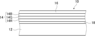
- FIG. 1 conceptually shows an example of the projected image display member of the present invention.
- the projected image display member 10 has a transparent base material 12, a selective reflection layer 14, a polarization conversion layer 16, and a sticking layer 18.
- the projected image display member 10 of the present invention is a half mirror film for reflecting projected light and displaying a projected image, and is used for a HUD in combination with, for example, windshield glass.
- the selective reflection layer 14 is arranged on the incident side of the projected light rather than the transparent base material 12. That is, in the case of the projected image display member shown in FIG. 1, the polarization conversion layer 16 is the incident surface of the projected light. Therefore, when the projected image display member 10 of the present invention is mounted on a HUD or the like, the selective reflection layer 14 is on the inside of the vehicle and the transparent base material 12 is on the outside of the vehicle.
- the projected light of the HUD is incident from the selective reflection layer 14 (polarization conversion layer 16) side and reflected.
- the outside light from the outside of the vehicle enters from the transparent base material 12, passes through the sticking layer 18, the selective reflection layer 14, and the polarization conversion layer 16 and reaches the inside of the vehicle and the like.
- the transparent base material 12 is transparent and has an in-plane retardation Re of 5000 nm or more.
- the transparent base material 12 is a characteristic member of the projected image display member of the present invention.
- the transparent base material 12 will be described in detail later.
- the sticking layer 18 is for sticking the transparent base material 12 and the selective reflection layer 14.
- the adhesive layer 18 has fluidity when bonded, and then becomes a solid. Even a layer made of an adhesive is a soft solid gel-like (rubber-like) when bonded, and is subsequently gel-like. It may be a layer made of a pressure-sensitive adhesive whose state does not change, or a layer made of a material having the characteristics of both an adhesive and a pressure-sensitive adhesive.
- the materials are acrylate type, urethane type, urethane acrylate type, and epoxy, respectively.
- Compounds such as system, epoxy acrylate system, polyolefin system, modified olefin system, polypropylene system, ethylene vinyl alcohol system, vinyl chloride system, chloroprene rubber system, cyanoacrylate system, polyamide system, polyimide system, polystyrene system, and polyvinyl butyral system.
- the photocuring type is preferable as the curing method.
- the material is preferably an acrylate-based material, a urethane acrylate-based material, an epoxy acrylate-based material, or the like.
- the sticking layer 18 may be formed by using OCA (Optical Clear Adhesive).
- OCA Optical Clear Adhesive
- a commercially available product for an image display device particularly a commercially available product for the surface of an image display unit of an image display device may be used.
- Examples of commercially available products include an adhesive sheet manufactured by Panac Co., Ltd. (PD-S1 and the like), an adhesive sheet of the MHM series manufactured by Niei Kako Co., Ltd., and the like.
- the thickness of the sticking layer 18 is preferably 0.5 to 10 ⁇ m, more preferably 1.0 to 5.0 ⁇ m. Further, the thickness of the sticking layer 18 formed by using OCA may be 10 to 50 ⁇ m, preferably 15 to 30 ⁇ m.
- the adhesive layer 18 is unnecessary.
- the selective reflection layer 14 is a layer that reflects light wavelength-selectively. Specifically, the selective reflection layer 14 is a layer that selectively reflects in a specific wavelength range. In the illustrated example, the selective reflection layer 14 selectively reflects light in a predetermined wavelength range and transmits other light.
- the selective reflection layer 14 is preferably a polarization reflection layer.
- the polarized light reflecting layer is a layer that reflects linearly polarized light, circularly polarized light, or elliptically polarized light.
- the polarized light reflecting layer is preferably a circularly polarized light reflecting layer or a linearly polarized light reflecting layer.
- the circularly polarized light reflecting layer is a layer that reflects the circularly polarized light of one of the senses (turning direction) and transmits the circularly polarized light of the other sense in the selective reflection wavelength range.
- the linearly polarized light reflecting layer is a layer that reflects linearly polarized light in one polarization direction at the center wavelength of selective reflection and transmits linearly polarized light in the polarization direction orthogonal to the reflected polarization direction.
- the polarized light reflecting layer can transmit unreflected polarized light. Therefore, by using the polarized light reflecting layer, a part of light can be transmitted even in the wavelength range where the selective reflecting layer 14 shows reflection.
- the selective reflection layer 14 is preferably a circularly polarized light reflection layer, and particularly preferably a cholesteric liquid crystal layer having a fixed cholesteric liquid crystal phase.
- the selective reflection layer 14 of the projected image display member 10 shown in the figure has a red reflection cholesteric liquid crystal layer 46R having a selective reflection center wavelength in the wavelength range of red light, and a selective reflection center wavelength in the wavelength range of green light. It has three selective reflection layers, a green reflection cholesteric liquid crystal layer 46G having a green reflection cholesteric liquid crystal layer 46G and a blue reflection cholesteric liquid crystal layer 46B having a selective reflection center wavelength in the wavelength range of blue light.
- the projected image display member 10 of the illustrated example corresponds to a full-color projected image that reflects red light, green light, and blue light, but the present invention is not limited to this.
- the selective reflective layer 14 of the projected image display member has only the red reflective cholesteric liquid crystal layer 46R and the green reflective cholesteric liquid crystal layer 46G, or has only the red reflective cholesteric liquid crystal layer 46R and the blue reflective cholesteric liquid crystal layer 46B. It may have or have only a green reflective cholesteric liquid crystal layer 46G and a blue reflective cholesteric liquid crystal layer 46B, and may correspond to a two-color projected image.
- the selective reflective layer 14 may correspond to monochrome projected light having only one of the red reflective cholesteric liquid crystal layer 46R, the green reflective cholesteric liquid crystal layer 46G, and the blue reflective cholesteric liquid crystal layer 46B. .. That is, the projection display member of the present invention basically reflects all blue light, green light, and red light when the projection light projected by the HUD projector is a full-color image. It is configured to do. When the projected light projected by the HUD projector is a two-color image, the selective reflection layer 14 is also configured to reflect two colors of the same color. When the projected light projected by the HUD projector is a monochrome image, the selective reflection layer 14 is also configured to reflect the same color.
- the cholesteric liquid crystal layer means a layer formed by fixing the cholesteric liquid crystal phase.
- the cholesteric liquid crystal layer may be a layer in which the orientation of the liquid crystal compound in the cholesteric liquid crystal phase is maintained.
- the cholesteric liquid crystal layer is typically polymerized and cured by ultraviolet irradiation, heating, etc. after the polymerizable liquid crystal compound is placed in the oriented state of the cholesteric liquid crystal phase to form a non-fluid layer, and at the same time Any layer may be used as long as it is a layer that has changed to a state in which the orientation form is not changed by an external field or an external force.
- the optical properties of the cholesteric liquid crystal phase are retained in the layer, and the liquid crystal compound in the layer does not have to exhibit liquid crystal property anymore.
- the polymerizable liquid crystal compound may lose its liquid crystal property due to its high molecular weight due to the curing reaction.
- the cholesteric liquid crystal phase selectively reflects the circular polarization of one sense of right-handed or left-handed circular polarization and exhibits circular polarization selective reflection that transmits the circular polarization of the other sense. ..
- a film containing a layer in which a cholesteric liquid crystal phase exhibiting circularly polarized selective reflectivity is fixed many films formed from a composition containing a polymerizable liquid crystal compound have been known conventionally, and the cholesteric liquid crystal layer has been conventionally known. You can refer to the technology.
- the spiral pitch P (one spiral pitch) of the spiral structure is, in other words, the length in the spiral axial direction for one spiral winding.
- the spiral pitch P is the length in the spiral axis direction in which the director of the liquid crystal compound (in the case of a rod-shaped liquid crystal, the long axis direction) that constitutes the cholesteric liquid crystal phase rotates 360 °.
- the direction of the spiral axis of the normal cholesteric liquid crystal layer coincides with the thickness direction of the cholesteric liquid crystal layer.
- SEM scanning Electron Microscope
- the spiral pitch P of the cholesteric liquid crystal layer is twice the distance between the bright lines.
- the spiral pitch P of the cholesteric liquid crystal layer is equal to the length of three bright lines and two dark lines in the thickness direction, that is, the length of three dark lines and two bright lines in the thickness direction. This length is the distance between the centers of the upper and lower bright lines or dark lines in the thickness direction.
- the selective reflection center wavelength and the full width at half maximum (full width at half maximum) of the cholesteric liquid crystal layer can be obtained as an example as follows.
- a spectrophotometer manufactured by JASCO Corporation, V-670
- a decrease peak in transmittance is observed in the selective reflection band.
- the value of the wavelength on the short wavelength side is ⁇ l (nm)
- the value of the wavelength on the long wavelength side is ⁇ h (nm)
- the selective reflection center wavelength ⁇ and the half-value width ⁇ can be expressed by the following equations.
- the selective reflection center wavelength obtained as described above substantially coincides with the wavelength at the center of gravity of the reflection peak of the circular polarization reflection spectrum measured from the normal direction of the cholesteric liquid crystal layer.
- the spiral pitch of the cholesteric liquid crystal phase depends on the type of chiral agent used together with the polymerizable liquid crystal compound and the concentration thereof added, a desired pitch can be obtained by adjusting these.
- a desired pitch can be obtained by adjusting these.
- the cholesteric liquid crystal layers are arranged in order from the one having the shortest center wavelength of selective reflection when viewed from the incident side of the projected light.
- each cholesteric liquid crystal layer a cholesteric liquid crystal layer having a spiral sense of either right or left is used.
- the sense of circularly polarized light reflected by the cholesteric liquid crystal layer matches the sense of spiraling. It is preferable that the cholesteric liquid crystal layers having a plurality of layers having different selective reflection center wavelengths have the same sense of spiral, that is, the swirling direction of the reflected circularly polarized light.
- the ⁇ n can be adjusted by adjusting the type or mixing ratio of the polymerizable liquid crystal compound, or by controlling the temperature at the time of fixing the orientation.
- a plurality of cholesteric liquid crystal layers having the same pitch P and the same spiral sense may be laminated. Circular polarization selectivity can be increased at a specific wavelength by laminating cholesteric liquid crystal layers having the same pitch P and the same spiral sense.
- the plurality of cholesteric liquid crystal layers constituting the selective reflection layer 14 may be obtained by laminating a separately prepared cholesteric liquid crystal layer using an adhesive or the like, or on the surface of the previous cholesteric liquid crystal layer formed by the method described later.
- a liquid crystal composition (coating liquid) containing a polymerizable liquid crystal compound or the like may be directly applied, and the steps of orientation and fixing may be repeated, but the latter is preferable.
- the next cholesteric liquid crystal layer directly on the surface of the previously formed cholesteric liquid crystal layer the orientation orientation of the liquid crystal molecules on the air interface side of the previously formed cholesteric liquid crystal layer and the cholesteric liquid crystal layer formed on the cholesteric liquid crystal layer. This is because the orientation directions of the lower liquid crystal molecules are the same, and the polarization characteristics of the laminated body of the cholesteric liquid crystal layer are improved. In addition, interference unevenness that may occur due to uneven thickness of the adhesive layer is not observed.
- the thickness of the cholesteric liquid crystal layer is preferably 0.2 to 10 ⁇ m, more preferably 0.5 to 10 ⁇ m, further preferably 1.0 to 8.0 ⁇ m, and particularly preferably 1.5 to 6.0 ⁇ m.
- the total thickness of the cholesteric liquid crystal layer is preferably 2.0 to 30 ⁇ m, more preferably 2.5 to 25 ⁇ m, and even more preferably 3.0 to 20 ⁇ m.
- cholesteric liquid crystal layer a material and a method for producing the cholesteric liquid crystal layer will be described.
- the material used for forming the cholesteric liquid crystal layer described above include a liquid crystal composition containing a polymerizable liquid crystal compound and a chiral agent (optically active compound). If necessary, the above-mentioned liquid crystal composition mixed with a surfactant, a polymerization initiator, etc. and dissolved in a solvent or the like is further applied to a support, an alignment film, a cholesteric liquid crystal layer as an lower layer, or the like, and cholesteric orientation. After aging, the liquid crystal composition can be fixed by curing to form a cholesteric liquid crystal layer.
- the polymerizable liquid crystal compound may be a rod-shaped liquid crystal compound or a disk-shaped liquid crystal compound, but is preferably a rod-shaped liquid crystal compound.
- Examples of the rod-shaped polymerizable liquid crystal compound forming the cholesteric liquid crystal layer include a rod-shaped nematic liquid crystal compound.
- rod-shaped nematic liquid crystal compounds examples include azomethines, azoxys, cyanobiphenyls, cyanophenyl esters, benzoic acid esters, cyclohexanecarboxylic acid phenyl esters, cyanophenylcyclohexanes, cyano-substituted phenylpyrimidines, and alkoxy-substituted phenylpyrimidines.
- Phenyldioxans, trans, and alkenylcyclohexylbenzonitriles are preferably used. Not only low molecular weight liquid crystal compounds but also high molecular weight liquid crystal compounds can be used.
- the polymerizable liquid crystal compound is obtained by introducing a polymerizable group into the liquid crystal compound.
- the polymerizable group include an unsaturated polymerizable group, an epoxy group, and an aziridinyl group, and an unsaturated polymerizable group is preferable, and an ethylenically unsaturated polymerizable group is particularly preferable.
- the polymerizable group can be introduced into the molecule of the liquid crystal compound by various methods.
- the number of polymerizable groups contained in the polymerizable liquid crystal compound is preferably 1 to 6 in one molecule, and more preferably 1 to 3.
- Examples of polymerizable liquid crystal compounds include Makromol. Chem. , 190, 2255 (1989), Advanced Materials 5, 107 (1993), US Pat. No.
- the amount of the polymerizable liquid crystal compound added to the liquid crystal composition is preferably 80 to 99.9% by mass, preferably 85 to 99.5% by mass, based on the solid content mass (mass excluding the solvent) of the liquid crystal composition. % Is more preferable, and 90 to 99% by mass is further preferable.
- the cholesteric liquid crystal layer may have a low ⁇ n.
- the low ⁇ n cholesteric liquid crystal layer can be formed by using a low ⁇ n polymerizable liquid crystal compound.
- the low ⁇ n polymerizable liquid crystal compound will be specifically described.
- a narrow-band selective reflection layer can be obtained by forming a cholesteric liquid crystal phase using a low ⁇ n polymerizable liquid crystal compound and forming a film in which the cholesteric liquid crystal phase is fixed.
- the low ⁇ n polymerizable liquid crystal compound include the compounds described in WO2015 / 115390, WO2015 / 147243, WO2016 / 035773, JP-A-2015-163596, and JP-A-2016-053149.
- the description of WO2016 / 047648 can also be referred to.
- the liquid crystal compound is also preferably a polymerizable compound represented by the following formula (I) described in WO2016 / 047648.
- A represents a phenylene group which may have a substituent or a trans-1,4-cyclohexylene group which may have a substituent
- L is a single bond, -CH 2.
- the phenylene group in the formula (I) is preferably a 1,4-phenylene group.
- the substituent when "may have a substituent" for the phenylene group and the trans-1,4-cyclohexylene group is not particularly limited, and is, for example, an alkyl group, a cycloalkyl group, an alkoxy group, or an alkyl ether. Examples thereof include a substituent selected from the group consisting of a group, an amide group, an amino group, a halogen atom, and a group composed of a combination of two or more of the above-mentioned substituents.
- the phenylene group and the trans-1,4-cyclohexylene group may have 1 to 4 substituents. When having two or more substituents, the two or more substituents may be the same or different from each other.
- the alkyl group may be either linear or branched.
- the alkyl group preferably has 1 to 30 carbon atoms, more preferably 1 to 10 carbon atoms, and even more preferably 1 to 6 carbon atoms.
- Examples of alkyl groups include methyl group, ethyl group, n-propyl group, isopropyl group, n-butyl group, isobutyl group, sec-butyl group, tert-butyl group, n-pentyl group, isopentyl group and neopentyl.
- alkyl group 1,1-dimethylpropyl group, n-hexyl group, isohexyl group, linear or branched heptyl group, octyl group, nonyl group, decyl group, undecyl group, or dodecyl group can be mentioned.
- the above description regarding the alkyl group is the same for the alkoxy group containing the alkyl group.
- specific examples of the alkylene group when referred to as an alkylene group include a divalent group obtained by removing one arbitrary hydrogen atom in each of the above-mentioned examples of an alkyl group.
- the halogen atom include a fluorine atom, a chlorine atom, a bromine atom, and an iodine atom.
- the number of carbon atoms of the cycloalkyl group is preferably 3 to 20, more preferably 5 or more, preferably 10 or less, more preferably 8 or less, still more preferably 6 or less.
- Examples of the cycloalkyl group include a cyclopropyl group, a cyclobutyl group, a cyclopentyl group, a cyclohexyl group, a cycloheptyl group, and a cyclooctyl group.
- X 3 represents a single bond, -O-, -S-, or -N (Sp 4- Q 4 )-, or a nitrogen atom forming a ring structure with Q 3 and Sp 3.
- Sp 3 and Sp 4 are independently one or more-in a single bond, a linear or branched alkylene group having 1 to 20 carbon atoms, and a linear or branched alkylene group having 1 to 20 carbon atoms.
- the replacement position is not particularly limited. Of these, a tetrahydrofuranyl group is preferable, and a 2-tetrahydrofuranyl group is particularly preferable.
- the m-1 Ls may be the same or different from each other.
- Sp 1 and Sp 2 are independently one or more-in a single bond, a linear or branched alkylene group having 1 to 20 carbon atoms, and a linear or branched alkylene group having 1 to 20 carbon atoms.
- the linking group selected from the group consisting of substituted groups is shown.
- Q 1 and Q 2 each independently represent a polymerizable group selected from the group consisting of a hydrogen atom or a group represented by the above formulas Q-1 to Q-5, where Q 1 and Q 2 have . Either one shows a polymerizable group.
- the polymerizable group an acryloyl group (formula Q-1) or a methacryloyl group (formula Q-2) is preferable.
- m represents an integer of 3 to 12.
- m is preferably an integer of 3 to 9, more preferably an integer of 3 to 7, and even more preferably an integer of 3 to 5.
- the polymerizable compound represented by the formula (I) has at least one phenylene group which may have a substituent as A and a trans-1,4-cyclohexylene group which may have a substituent. It is preferable to include at least one.
- the polymerizable compound represented by the formula (I) preferably contains 1 to 4 trans-1,4-cyclohexylene groups which may have a substituent as A, and preferably contains 1 to 3 of them. Is more preferable, and it is more preferable to contain 2 or 3 of them.
- the polymerizable compound represented by the formula (I) preferably contains 1 or more phenylene groups as A, which may have a substituent, and more preferably 1 to 4 groups. It is more preferable to include 3 pieces, and it is particularly preferable to contain 2 or 3 pieces.
- polymerizable compound represented by the formula (I) in addition to the compounds described in paragraphs 0051 to 0058 of WO2016 / 047648, Japanese Patent Application Laid-Open No. 2013-112631, Japanese Patent Application Laid-Open No. 2010-070543, Examples thereof include the compounds described in Japanese Patent No. 4725516, WO2015 / 115390, WO2015 / 147243, WO2016 / 035873, JP-A-2015-163596, and JP-A-2016-53149.
- the chiral agent has the function of inducing the helical structure of the cholesteric liquid crystal phase. Since the chiral compound has a different sense of spiral or spiral pitch depending on the compound, it may be selected according to the purpose.
- the chiral agent is not particularly limited, and known compounds can be used.
- Examples of chiral agents include Liquid Crystal Device Handbook (Chapter 3, 4-3, TN, Chiral Auxiliary for STN, page 199, Japan Society for the Promotion of Science 142, 1989), JP-A-2003-287623, Examples thereof include compounds described in JP-A-2002-302487, JP-A-2002-080478, JP-A-2002-08851, JP-A-2010-181852, and JP-A-2014-034581.
- the chiral agent generally contains an asymmetric carbon atom, but an axial asymmetric compound or a surface asymmetric compound that does not contain an asymmetric carbon atom can also be used as the chiral agent.
- Examples of axially asymmetric or surface asymmetric compounds include binaphthyl, helicene, paracyclophane, and derivatives thereof.
- the chiral agent may have a polymerizable group. When both the chiral agent and the liquid crystal compound have a polymerizable group, the repeating unit derived from the polymerizable liquid crystal compound and the repeating unit derived from the chiral agent are derived by the polymerization reaction between the polymerizable chiral agent and the polymerizable liquid crystal compound.
- the polymerizable group of the polymerizable chiral agent is preferably a group of the same type as the polymerizable group of the polymerizable liquid crystal compound. Therefore, the polymerizable group of the chiral agent is preferably an unsaturated polymerizable group, an epoxy group or an aziridinyl group, more preferably an unsaturated polymerizable group, and preferably an ethylenically unsaturated polymerizable group. Especially preferable.
- the chiral agent may be a liquid crystal compound.
- an isosorbide derivative As the chiral agent, an isosorbide derivative, an isomannide derivative, a binaphthyl derivative and the like can be preferably used.
- As the isosorbide derivative a commercially available product such as LC756 manufactured by BASF may be used.
- the content of the chiral agent in the liquid crystal composition is preferably 0.01 to 200 mol%, more preferably 1 to 30 mol% of the amount of the polymerizable liquid crystal compound.
- the content of the chiral auxiliary in the liquid crystal composition is intended to be the concentration (mass%) of the chiral agent with respect to the total solid content in the composition.
- the liquid crystal composition preferably contains a polymerization initiator.
- the polymerization initiator used is preferably a photopolymerization initiator capable of initiating the polymerization reaction by irradiation with ultraviolet rays.
- photopolymerization initiators include ⁇ -carbonyl compounds (described in US Pat. No. 2,376,661 and US Pat. No. 2,376,670), acidoin ethers (described in US Pat. No. 2,448,828), and ⁇ -hydrogens.
- Substituent aromatic acidoine compound described in US Pat. No.
- an acylphosphine oxide compound or an oxime compound is also preferable to use an acylphosphine oxide compound or an oxime compound as the polymerization initiator.
- acylphosphine oxide compound for example, a commercially available IRGACURE810 (compound name: bis (2,4,6-trimethylbenzoyl) -phenylphosphine oxide) manufactured by BASF Japan Ltd. can be used.
- Oxime compounds include IRGACURE OXE01 (manufactured by BASF), IRGACURE OXE02 (manufactured by BASF), TR-PBG-304 (manufactured by Changzhou Powerful Electronics New Materials Co., Ltd.), ADEKA ARCULS NCI-831 and ADEKA ARCULS NCI.
- a commercially available product such as -930 (manufactured by ADEKA Corporation) can be used. Only one type of polymerization initiator may be used, or two or more types may be used in combination.
- the content of the photopolymerization initiator in the liquid crystal composition is preferably 0.1 to 20% by mass, more preferably 0.5 to 5% by mass, based on the content of the polymerizable liquid crystal compound.
- the liquid crystal composition may optionally contain a cross-linking agent in order to improve the film strength and durability after curing.
- a cross-linking agent one that cures with ultraviolet rays, heat, humidity or the like can be preferably used.
- the cross-linking agent is not particularly limited and may be appropriately selected depending on the intended purpose.
- cross-linking agent examples include polyfunctional acrylate compounds such as trimethylolpropantri (meth) acrylate and pentaerythritol tri (meth) acrylate; epoxy compounds such as glycidyl (meth) acrylate and ethylene glycol diglycidyl ether; 2,2- Aziridine compounds such as bishydroxymethylbutanol-tris [3- (1-aziridinyl) propionate], 4,4-bis (ethyleneiminocarbonylamino) diphenylmethane; isocyanate compounds such as hexamethylenediisocyanate and biuret-type isocyanate; oxazoline group side Polyoxazoline compounds contained in the chain; alkoxysilane compounds such as vinyltrimethoxysilane and N- (2-aminoethyl) 3-aminopropyltrimethoxysilane can be mentioned.
- polyfunctional acrylate compounds such as trimethylolpropantri (meth) acryl
- a known catalyst can be used depending on the reactivity of the cross-linking agent, and the productivity can be improved in addition to the improvement of the film strength and durability. These may be used alone or in combination of two or more.
- the content of the cross-linking agent is preferably 3 to 20% by mass, more preferably 5 to 15% by mass. By setting the content of the cross-linking agent to 3% by mass or more, the effect of improving the cross-linking density can be obtained, and by setting the content of the cross-linking agent to 20% by mass or less, the stability of the cholesteric liquid crystal layer is lowered. Can be prevented.
- "(meth) acrylate” is used in the meaning of "any one or both of acrylate and methacrylate".
- orientation control agent An orientation control agent may be added to the liquid crystal composition, which contributes to the stable or rapid planar orientation of the cholesteric liquid crystal layer.
- the orientation control agent include the fluorine (meth) acrylate-based polymers described in paragraphs [0018] to [0043] of JP-A-2007-272185, and paragraphs [0031]-[0031] of JP-A-2012-203237. 0034] and the like, and examples thereof include compounds represented by the formulas (I) to (IV) described in JP-A-2013-113913.
- the orientation control agent one type may be used alone, or two or more types may be used in combination.
- the amount of the orientation control agent added to the liquid crystal composition is preferably 0.01 to 10% by mass, more preferably 0.01 to 5% by mass, and 0.02 to 1 to the total mass of the polymerizable liquid crystal compound. Mass% is particularly preferred.
- the liquid crystal composition may contain at least one selected from various additives such as a surfactant for adjusting the surface tension of the coating film and making the thickness uniform, and a polymerizable monomer. .. Further, if necessary, a polymerization inhibitor, an antioxidant, an ultraviolet absorber, a light stabilizer, a coloring material, metal oxide fine particles, and the like are not added to the liquid crystal composition to reduce the optical performance. It can be added in a range.
- the cholesteric liquid crystal layer is formed as follows. First, a liquid crystal composition is prepared in which a polymerizable liquid crystal compound, a polymerization initiator, and a chiral agent and a surfactant added as needed are dissolved in a solvent. Next, the prepared liquid crystal composition is applied onto the resin layer, the alignment film, the polarization conversion layer 16, the previously prepared cholesteric liquid crystal layer, or the like, and dried to obtain a coating film. Further, the coating film can be irradiated with active rays to polymerize the liquid crystal composition (polymerizable liquid crystal compound) to form a cholesteric liquid crystal layer in which the cholesteric regularity is fixed.
- the laminated film composed of a plurality of cholesteric liquid crystal layers can be formed by repeating the above-mentioned manufacturing process of the cholesteric liquid crystal layer.
- the solvent used for preparing the liquid crystal composition is not particularly limited and may be appropriately selected depending on the intended purpose, but an organic solvent is preferably used.
- the organic solvent is not particularly limited and may be appropriately selected depending on the intended purpose.
- the method for applying the liquid crystal composition to the support, the alignment film, the cholesteric liquid crystal layer as the lower layer, and the like is not particularly limited and may be appropriately selected depending on the intended purpose.
- the coating method include wire bar coating method, curtain coating method, extrusion coating method, direct gravure coating method, reverse gravure coating method, die coating method, spin coating method, dip coating method, spray coating method, and slide coating. Law etc. can be mentioned. It can also be carried out by transferring the liquid crystal composition separately coated on the support.
- the liquid crystal molecules are oriented by heating the applied liquid crystal composition.
- the heating temperature is preferably 200 ° C. or lower, more preferably 130 ° C. or lower.
- the liquid crystal composition can be cured by further polymerizing the oriented liquid crystal compound.
- the polymerization may be either thermal polymerization or photopolymerization using light irradiation, but photopolymerization is preferable. It is preferable to use ultraviolet rays for light irradiation.
- the irradiation energy is preferably 20mJ / cm 2 ⁇ 50J / cm 2, more preferably 100 ⁇ 1,500mJ / cm 2.
- light irradiation may be carried out under heating conditions or a nitrogen atmosphere.
- the irradiation ultraviolet wavelength is preferably 350 to 430 nm.
- the polymerization reaction rate is preferably high from the viewpoint of stability. Specifically, the polymerization reaction rate is preferably 70% or more, more preferably 80% or more.
- the polymerization reaction rate can be determined by measuring the consumption ratio of the polymerizable functional group by measuring the infrared absorption spectrum.
- the projected image display member 10 may use a linearly polarized light reflecting layer as the selective reflecting layer.
- the linearly polarized light reflecting layer include a polarizing plate in which thin films having different refractive index anisotropy are laminated.
- Such a polarizing plate has a high visible light transmittance similar to the cholesteric liquid crystal layer, and can reflect the projected light incident obliquely at the time of use in the HUD at a wavelength having high visual sensitivity.
- polarizing plate in which thin films having different refractive index anisotropy are laminated, for example, those described in Japanese Patent Publication No. 9-506837 can be used.
- a polarizing plate when processed under the conditions selected to obtain the refractive index relationship, a polarizing plate can be formed using a wide variety of materials.
- one of the first materials needs to have a different refractive index than the second material in the chosen direction.
- This difference in refractive index can be achieved by a variety of methods, including stretching, extrusion, or coating during or after film formation.
- it is preferable to have similar rheological properties eg, melt viscosity
- a commercially available product can be used as the polarizing plate in which thin films having different refractive index anisotropy are laminated.
- a product in which a reflective polarizing plate and a temporary support are laminated may be used.
- Examples of commercially available products include DBEF (registered trademark) (manufactured by 3M) and commercially available optical films sold as APF (Advanced Polarizing Film (manufactured by 3M)).
- the thickness of the linearly polarized light reflecting layer is preferably 2.0 to 50 ⁇ m, more preferably 8.0 to 30 ⁇ m.
- the polarization conversion layer 16 converts linearly polarized light into circularly polarized light, and also converts circularly polarized light into linearly polarized light. Alternatively, the polarization conversion layer 16 changes the polarization direction of linearly polarized light. In the projected image display member 10 of the present invention, the polarization conversion layer 16 is located on the incident side of the projected light with respect to the selective reflection layer 14.
- the polarization conversion layer 16 is not an essential component of the projected image display member of the present invention. That is, the projected image display member of the present invention may be composed of, for example, only the selective reflection layer 14 and the transparent base material 12. However, since the projected image display member has the polarization conversion layer 16, the display brightness of the projected light when used for the HUD can be improved. Therefore, it is preferable that the projected image display member of the present invention has the polarization conversion layer 16 as shown in the illustrated example.
- a retardation layer is exemplified.
- a ⁇ / 4 layer ( ⁇ / 4 retardation layer) having a phase difference in the plane direction of ⁇ / 4 is preferable.
- the in-plane retardation Re at a wavelength of 550 nm is preferably 100 to 450 nm, and more preferably 120 to 200 nm or 300 to 400 nm.
- ⁇ / 2 layer ( ⁇ / 2 retardation layer) 3 ⁇ / 4 layer (3 ⁇ / 4 retardation layer) and the like can also be used.
- the retardation layer as the polarization conversion layer 16 converts p-polarized light into circularly polarized light in the turning direction reflected by the cholesteric liquid crystal layer according to the turning direction of the circularly polarized light reflected by the cholesteric liquid crystal layer.
- the position of the slow axis is set and arranged.
- the retardation layer is not limited, and various known ones can be used as long as they can convert linearly polarized light into circularly polarized light.
- the retardation layer include a stretched polycarbonate film, a stretched norbornene-based polymer film, a transparent film oriented containing inorganic particles having compound refraction such as strontium carbonate, and an inorganic dielectric on a support.
- examples thereof include a thin film obtained by obliquely depositing a polycarbonate compound, a film in which a polymerizable liquid crystal compound is uniaxially oriented and fixed, and a film in which a liquid crystal compound is uniaxially oriented and fixed in orientation.
- a film in which a polymerizable liquid crystal compound is uniaxially oriented and fixed in orientation is preferably exemplified as a retardation layer.
- a liquid crystal composition containing a polymerizable liquid crystal compound is applied to the surface of a temporary support or an alignment film, and the polymerizable liquid crystal compound in the liquid crystal composition is nematically oriented in a liquid crystal state. After being formed into a liquid crystal, it can be fixed by curing to form a liquid crystal.
- the formation of the retardation layer in this case can be performed in the same manner as the formation of the cholesteric liquid crystal layer described above, except that the chiral agent is not added to the liquid crystal composition.
- the heating temperature is preferably 50 to 120 ° C, more preferably 60 to 100 ° C.
- the retardation layer is obtained by applying a composition containing a polymer liquid crystal compound to the surface of a temporary support or an alignment film, forming a nematic orientation in a liquid crystal state, and then cooling the orientation to fix the orientation. It may be a layer to be formed.
- the thickness of the retardation layer is not limited, but is preferably 0.2 to 300 ⁇ m, more preferably 0.5 to 150 ⁇ m, and even more preferably 1.0 to 80 ⁇ m.
- the thickness of the retardation layer formed by using the liquid crystal composition is not particularly limited, but is preferably 0.2 to 10 ⁇ m, more preferably 0.5 to 5.0 ⁇ m, and preferably 0.7 to 2.0 ⁇ m. More preferred.
- the slow phase axis Sa is set at an angle ⁇ with respect to the axis H in an arbitrary direction of the retardation layer.
- the direction of the slow-phase axis Sa can be set, for example, by rubbing the alignment film that is the lower layer of the retardation layer.
- the direction of the slow axis Sa of the retardation layer is the incident direction of the projected light for displaying the projected image and the selective reflection layer 14 when the projected image display member 10 is used for the HUD (see FIG. 8). It is preferable to determine according to the sense of the spiral of the constituent cholesteric liquid crystal layer.
- the projector emits the projected light of p-polarized light
- the projected image display member 10 reflects the p-polarized light to display the image.
- the retardation layer first converts the incident p-polarized projected light into circularly polarized light.
- the selective reflection layer 14 (cholesteric liquid crystal layer) selectively reflects this circularly polarized light and re-enters the retardation layer.
- the retardation layer converts circularly polarized light into p-polarized light.
- the projected image display member 10 reflects the incident p-polarized projected light as it is in p-polarized light.
- the retardation layer converts the incident p-polarized light into circularly polarized light in the turning direction reflected by the selective reflecting layer 14 according to the sense of circularly polarized light selectively reflected by the selective reflecting layer 14 (cholesteric liquid crystal layer).
- the direction of the slow axis Sa is set so as to do so. That is, when the selective reflection layer 14 selectively reflects the right circularly polarized light, the retardation layer is set in the direction of the slow phase axis Sa so as to make the incident p-polarized light right circularly polarized light.
- the retardation layer reverses the direction of the slow phase axis Sa so that the incident p-polarized light becomes the left circularly polarized light. Tilt to set.
- the setting of the slow phase axis of the retardation layer is regarded as the vertical direction (vertical direction) when the axis H shown in FIG. 9 is mounted on the windshield glass and used as a HUD.
- the direction of the slow axis Sa of the retardation layer may be set.
- the polarization conversion layer 16 is not limited to the retardation layer.
- the polarization conversion layer 16 is a rotating layer (twist) that swirls the polarization direction of linearly polarized light (p-polarized light), which is formed by fixing the spiral orientation structure of the liquid crystal compound twist-oriented along a spiral axis extending along the thickness direction. Layer) is also available. That is, as the polarization conversion layer 16, a optical rotation layer (optical rotation film) in which a liquid crystal compound is twisted and oriented can also be used.
- the optical rotation layer as the polarization conversion layer 16 is not limited to this, but when the number of pitches of the spiral orientation structure is x and the film thickness of the optical rotation layer is y (unit: ⁇ m), (I) 0.2 ⁇ x ⁇ 1.5 (Ii) 1.0 ⁇ y ⁇ 5.0 It is preferable to look at at least one of them.
- the optical rotation layer more preferably satisfies both the formula (i) and the formula (ii). It is preferable to satisfy.
- the spiral pitch is the same as that of the cholesteric liquid crystal layer described above.
- the pitch number x of the spiral orientation structure of the optical rotation layer By setting the pitch number x of the spiral orientation structure of the optical rotation layer to 0.2 or more, it is preferable in that the turning effect of linearly polarized light can be sufficiently obtained. By setting the pitch number x of the spiral orientation structure of the optical rotation layer to 1.5 or less, it is preferable in that linearly polarized light can be prevented from turning unnecessarily.
- the film thickness of the optical rotation layer By setting the film thickness of the optical rotation layer to 1.0 ⁇ m or more, it is preferable in that the turning effect of linearly polarized light can be sufficiently obtained. By setting the film thickness of the optical rotation layer to 5.0 ⁇ m or less, it is possible to prevent the optical rotation layer from becoming unnecessarily thick, which is preferable.
- the pitch number x of the spiral orientation structure is more preferably 0.25 to 1.3, and even more preferably 0.3 to 1.0.
- the film thickness is more preferably 1.1 to 4.5 ⁇ m, further preferably 1.2 to 4.0 ⁇ m.
- Such an optical rotation layer may be formed so as to satisfy the above-mentioned film thickness and the number of spiral pitches according to the above-mentioned cholesteric liquid crystal layer.
- the projected image display member 10 of the present invention has a transparent base material 12.
- the transparent base material 12 has an in-plane retardation Re of 5000 nm or more. Further, the transparent base material 12 has a visible light transmittance of 80% or more.
- the visible light transmittance of the transparent base material 12 is preferably 85% or more, more preferably 87% or more, still more preferably 90% or more.
- the selective reflection layer 14 is located closer to the incident side of the projected light than the transparent base material 12. Therefore, when the projected image display member 10 is mounted on the windshield glass and used as a HUD, the selective reflection layer 14 is on the inside of the vehicle (inner surface side) on the incident side of the projected light, and the transparent base material 12 is It will be on the outside (outer surface side) of the car. That is, in the projected image display member 10, the outside light first passes through the transparent base material 12 and enters the vehicle interior.
- the projected image display member 10 of the present invention has such a transparent base material 12 on the side opposite to the incident side of the projected light with respect to the selective reflection layer 14, that is, on the incident side of the external light. Improved suitability for polarized sunglasses.
- the projected light of p-polarized light is incident on the windshield glass and incorporated into the windshield glass for displaying the projected image.
- the projected image is displayed by the member 10 reflecting the p-polarized light.
- the polarization conversion layer 16 is a retardation layer
- the retardation layer converts p-polarization into circular polarization in a predetermined turning direction.
- the selective reflection layer 14 reflects this circularly polarized light, and the retardation layer reconverts it into p-polarized light to reflect the incident p-polarized light.
- the HUD of the present invention can eliminate the double image caused by the light reflected on the inner surface and the outer surface of the windshield glass by projecting the p-polarized light and reflecting the p-polarized light by the projected image display member 10. Therefore, it is not necessary to make the windshield glass wedge-shaped.
- the projected image display member 10 having the polarization conversion layer 16 can reflect the incident p-polarized light with a high reflectance without waste, the brightness of the projected image by the HUD can also be improved.
- polarized sunglasses are designed to block the s-polarized component. Therefore, in the HUD that projects the projected light of normal s-polarized light, when the driver wears polarized sunglasses, the projected image cannot be observed. On the other hand, in the HUD using the projected image display member 10 of the present invention, the projected image is p-polarized. Therefore, according to the present invention, unlike the HUD that projects s-polarized light, even when the driver uses polarized sunglasses, the projected image of the HUD can be properly observed.
- the polarized light of the non-reflective component when incident on and transmitted to a reflective layer that selectively reflects a predetermined circular polarization, such as a reflective layer using a cholesteric layer, the polarization state changes.
- the glare component that penetrates from the outside of the windshield glass is mainly s-polarized light. Therefore, the s-polarized light transmitted through the reflective layer that selectively reflects the circularly polarized light corresponding to the p-polarized light is ideally the circularly polarized light in the turning direction corresponding to the s-polarized light. This circularly polarized light is then converted into s-polarized light again by the retardation layer. Therefore, s-polarized light, which is a glare component that penetrates from the outside of the windshield glass, can be shielded by using polarized sunglasses.
- the s-polarized light incident on the windshield glass from the outside is incident on the windshield glass at various angles as well as the component incident on the reflective layer (reflection film, half mirror) of the windshield glass from the normal direction. Therefore, in the HUD in which p-polarized light is projected by the conventional retardation layer and circularly polarized light reflecting layer as shown in Patent Document 1 and Patent Document 2, the s-polarized light that has penetrated from the outside and transmitted through the reflecting layer is circular. It becomes elliptically polarized light instead of polarized light. When such elliptically polarized light passes through the retardation layer, not only s-polarized light but also p-polarized light components are mixed in the transmitted light.
- the surface of the selective reflection layer 14 opposite to the incident side of the projected light that is, in the plane of the selective reflection layer 14 on the incident side of the external light. It has a transparent base material 12 having a retardation Re of 5000 nm or more. That is, the reflected light that is incident from the outside of the windshield and whose main component is s-polarized light that becomes glare passes through the transparent base material 12 and then through the selective reflection layer 14 and the polarization conversion layer 16 to reach the inside of the vehicle. ..
- the projected image display member 10 of the present invention improves the suitability of polarized sunglasses in the HUD for projecting p-polarized light.
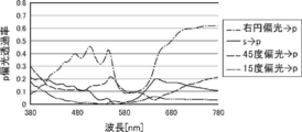
- FIG. 2 shows.
- the ratio of conversion to p-polarized light differs depending on the polarization of the incident light. Specifically, the ratio of circularly polarized light converted to p-polarized light is the highest, and the ratio of linearly polarized light having a polarization direction of 15 ° to s-polarized light is converted to p-polarized light is low. That is, in this half mirror film, the ratio of p-polarized light in the transmitted light differs depending on the polarization direction of the linearly polarized light incident from the reflection layer side.
- the transparent base material 12 having an in-plane retardation Re of 5000 nm or more
- polarization elimination occurs, and the polarized light is converted into various types of polarized light such as left and right circularly polarized light and linearly polarized light having different polarization directions.
- the ratio of polarized light converted after transmission differs depending on the angle formed by the polarization direction of the incident linearly polarized light and the slow axis of the transparent base material 12.
- the transparent base material 12 having a high in-plane retardation Re is arranged on the outside light incident side of the half mirror film having the selective reflection layer 14 and the polarization conversion layer 16, and the incident s-polarized light and the transparent base material 12
- the angle formed by the slow axis and converting the linearly polarized light incident on the selective reflection layer 14 into linearly polarized light with a low ratio of p-polarized light the s-polarized light incident as external light is converted to p-polarized light.
- the ratio to be generated can be reduced.
- the angle formed by the incident s-polarized light and the slow-phase axis of the transparent base material 12 is, to be exact, the vibration surface of the s-polarized light (the vibration direction of the s-polarized light) and the slow-phase axis of the transparent base material 12. It is the angle to be formed.
- FIG. 3 and 4 show the cholesteric liquid crystal layer side when the transparent base material is provided or not provided on the selective reflection layer side of the half mirror film having the selective reflection layer composed of the cholesteric liquid crystal layer and the ⁇ / 4 layer.
- the p-polarized light reflectance when s-polarized light is incident is shown.
- FIG. 3 shows an example in which the angle formed by the s-polarized light and the slow axis of the transparent base material is 15 °.
- FIG. 4 shows an example in which the angle formed by the polarization direction of s-polarized light and the slow axis of the transparent base material is 60 °. As shown in FIG.
- a transparent base material is placed on the selective reflection layer side of a half mirror film having a selective reflection layer composed of a cholesteric liquid crystal layer and a ⁇ / 4 layer by tilting the slow axis by 30 ° with respect to s-polarized light.
- the polarized light is polarized by the projected light of p-polarized light. It makes it possible to observe the projected image of HUD wearing sunglasses, eliminates the need to make the windshield glass wedge-shaped, and suppresses the conversion of s-polarized light incident as external light into p-polarized light. It is also possible to improve the suitability of polarized sunglasses that block the glare of external light that hinders the use of polarized sunglasses.
- the angle formed by the slow axis of the transparent base material 12 and the s-polarized light there is no limitation on the angle formed by the slow axis of the transparent base material 12 and the s-polarized light. That is, the angle formed by the slow axis of the transparent base material 12 and the s-polarized light, which can reduce the ratio of the s-polarized light incident as external light to be converted into p-polarized light, differs depending on the polarization conversion layer 16.
- the angle formed by the slow axis of the transparent base material 12 and the s-polarized light which can reduce the ratio of s-polarized light incident as external light to be converted to p-polarized light, is the case where a retardation layer is used as the polarization conversion layer 16.
- the angle formed by the slow axis of the transparent base material 12 and the s-polarized light may be appropriately set according to the polarization conversion layer 16 to be used.
- the angle formed by the slow axis of the transparent substrate 12 and the s-polarized light is preferably 10 to 30 °, more preferably 15 to 25 °.
- the s-polarized light of the external light incident on the vehicle or the like is usually linearly polarized light in the horizontal direction.
- the horizontal linearly polarized light is a linearly polarized light whose vibration surface (vibration direction) is horizontal. Therefore, in the windshield glass of the present invention, the s-polarized light is replaced with the horizontal direction to set the angle formed by the horizontal direction and the slow axis of the transparent base material 12 of the projected image display member 10. That is, in the windshield glass of the present invention, for example, when the polarization conversion layer 16 is a ⁇ / 4 layer, the angle formed by the slow axis of the transparent base material 12 and the horizontal direction is 10 to 30 °. Is preferable. The same applies to the HUD of the present invention using the windshield glass of the present invention described later.
- the material for forming the transparent base material 12 is not limited, and various materials can be used as long as the transparent base material 12 having the above-mentioned visible light transmittance and in-plane retardation Re of 5000 nm or more can be obtained.
- Acronitrile-based resin, cycloolefin-based resin and the like are exemplified.
- polyester-based resins are preferably exemplified, and among them, polyethylene terephthalate (PET) and polyethylene naphthalate (PEN) are more preferable.
- the transparent base material 12 can be produced as follows when the material is polyester such as PET. First, the polyester material is melted and extruded into a sheet. Next, the molded unstretched polyester is heated to a temperature equal to or higher than the glass transition temperature and laterally stretched by a tenter or the like. Then, the transparent base material 12 can be obtained by subjecting it to heat treatment. At this time, the in-plane retardation Re of the transparent base material 12 can be adjusted by adjusting the stretching ratio and the stretching temperature. In general, the higher the stretching ratio, the larger the in-plane retardation Re, and the lower the stretching temperature, the larger the in-plane retardation Re.
- the thickness of the transparent base material 12 there is no limitation on the thickness of the transparent base material 12. That is, the thickness of the transparent base material 12 may be appropriately set according to the stretching ratio, the stretching temperature, and the forming material so that the desired in-plane retardation Re can be obtained.
- the thickness of the transparent base material 12 is preferably 10 to 200 ⁇ m, more preferably 20 to 150 ⁇ m, and even more preferably 40 to 100 ⁇ m.
- the projected image display member 10 may have an alignment film as a lower layer to which the liquid crystal composition is applied when the selective reflection layer 14 (cholesteric liquid crystal layer) and / or the polarization conversion layer 16 is formed.
- the alignment film is a rubbing treatment of a layer made of an organic compound such as a polymer (resin such as polyimide, polyvinyl alcohol, polyester, polyarylate, polyamideimide, polyetherimide, polyamide and modified polyamide), oblique vapor deposition of an inorganic compound, and micro.
- a layer having a groove and accumulation of organic compounds for example, ⁇ -tricosanoic acid, dioctadecylmethylammonium chloride and methyl stearylate
- organic compounds for example, ⁇ -tricosanoic acid, dioctadecylmethylammonium chloride and methyl stearylate
- LB film Langmuir-Blogget method
- an alignment film whose alignment function is generated by applying an electric field, applying a magnetic field, or irradiating light may be used.
- an alignment film in which a polymer layer to be an alignment film is subjected to a rubbing treatment is preferably exemplified.
- a known method can be used for the rubbing treatment, and as an example, the rubbing treatment can be carried out by rubbing the surface of the polymer layer with paper or cloth in a certain direction.
- the liquid crystal composition may be applied to the surface of the resin layer, which will be described later, by rubbing treatment without providing the alignment film. That is, the resin layer may act as an alignment film.
- the thickness of the alignment film is not limited, but is preferably 0.01 to 5.0 ⁇ m, more preferably 0.05 to 2.0 ⁇ m.
- the alignment layer may be peeled off together with the temporary support. That is, the alignment film exists only at the time of manufacturing the projected image display member, and does not have to be a layer constituting the projected image display member when the projected image display member is completed.
- the projected image display member 10 may have a resin layer on the surface of the polarization conversion layer 16.
- the surface of the polarization conversion layer 16 is a surface opposite to the selective reflection layer 14 of the polarization conversion layer 16. Having a resin layer on the surface of the polarization conversion layer 16 is preferable in that damage to the polarization conversion layer 16 can be prevented.
- the resin layer preferably has a high visible light transmittance.
- the visible light transmittance of the resin layer is preferably 80% or more, more preferably 85% or more, still more preferably 90% or more.
- the in-plane retardation Re of the resin layer is not limited, but a smaller one is preferable.
- the in-plane retardation Re of the resin layer is preferably 10 nm or less, more preferably 5 nm or less, and even more preferably 2 nm or less.
- the thickness of the resin layer is not limited, and the thickness at which the required performance can be obtained may be appropriately set according to the purpose of forming the resin layer and the material for forming the resin layer.
- the thickness of the resin layer is preferably 5 to 1000 ⁇ m, more preferably 20 to 400 ⁇ m, still more preferably 40 to 100 ⁇ m.
- the thickness of the resin layer is preferably 5 ⁇ m or more, the effect of forming the resin layer can be preferably obtained, and a certain degree of rigidity can be secured, which is preferable in that the film can be easily positioned during transfer.
- By setting the thickness of the resin layer to 1000 ⁇ m or less it is possible to prevent the projected image display member 10 from becoming unnecessarily thick, and it is preferable in that it is easy to transfer when the reflective member has a curvature.
- the material for forming the resin layer is not limited, and various resin materials can be used as long as they satisfy the above conditions. Examples thereof include PET, TAC (triacetyl cellulose), PC (polycarbonate), COP (cycloolefin polymer), PMMA (polymethyl methacrylate) and the like.
- a glass plate may be provided on the surface of the polarization conversion layer 16 instead of the resin layer.
- Such a cast image display member 10 can be manufactured by various methods.
- a film to be an alignment film is formed on the surface of a resin film or the like to be a resin layer, and a rubbing treatment or the like is performed to form an alignment film.
- the polarization conversion layer 16 is formed on the alignment film, and the selective reflection layer 14 such as a cholesteric liquid crystal layer is formed on the surface of the polarization conversion layer 16.
- the orientation of the liquid crystal compound when the liquid crystal layers are laminated follows the orientation state of the lower liquid crystal layer.
- the laminate composed of the resin layer (alignment film), the polarization conversion layer 16 and the selective reflection layer 14 is attached to the transparent base material 12 with the selective reflection layer 14 directed by the attachment layer 18 such as OCA. , Complete the projection image display member.
- the projected image display member 10 may have a hard coat layer on the polarization conversion layer 16 or the resin layer (opposite surface of the selective reflection layer 14) to improve scratch resistance, if necessary. Good.
- the hard coat layer is preferably formed using a composition for forming a hard coat layer.
- the composition for forming a hard coat layer preferably contains a compound having three or more ethylenically unsaturated double bond groups in the molecule.
- Examples of the compound having three or more ethylenically unsaturated double bond groups in the molecule include an ester of a polyhydric alcohol and (meth) acrylic acid, vinylbenzene and its derivative, vinylsulfone, and (meth) acrylamide. Can be mentioned. Among them, from the viewpoint of hardness, a compound having three or more (meth) acryloyl groups is preferable, and an acrylate-based compound that forms a cured product having a high hardness widely used in the art can be mentioned. Examples of such a compound include an ester of a polyhydric alcohol and (meth) acrylic acid.
- ester of the polyhydric alcohol and the (meth) acrylic acid examples include pentaerythritol tetra (meth) acrylate, pentaerythritol tri (meth) acrylate, trimethylolpropane tri (meth) acrylate, and EO-modified trimethylolpropane tri (meth).
- Tris (acetyloxyethyl) isocyanurate and the like can be mentioned.
- Specific compounds of polyfunctional acrylate compounds having three or more (meth) acryloyl groups include KAYARAD DPHA, DPHA-2C, PET-30, TMPTA, TPA-320, manufactured by Nippon Kayaku Co., Ltd. TPA-330, RP-1040, T-1420, D-310, DPCA-20, DPCA-30, DPCA-60 and GPO-303, and V manufactured by Osaka Organic Chemical Industry Co., Ltd. Examples thereof include esterified compounds of polyols such as # 400 and V # 36095D and (meth) acrylic acid.
- UV-1400B UV-1700B, UV-6300B, UV-7550B, UV-7600B, UV-7605B, UV-7610B, UV-7620EA, UV-7630B, UV- 7640B, UV-6630B, UV-7000B, UV-7510B, UV-7461TE, UV-3000B, UV-3200B, UV-3210EA, UV-3310EA, UV-3310B, UV- 3500BA, UV-3520TL, UV-3700B, UV-6100B, UV-6640B, UV-2000B, UV-2010B, UV-2250EA and UV-2750B (manufactured by Nippon Synthetic Chemical Co., Ltd.) , UL-503LN (manufactured by Kyoeisha Chemical Co., Ltd.), Unidic 17-806, 17-813, V-4030 and V-4000BA (manufactured by Dainippon Ink and Chemicals Co., Ltd.), EB-1290K, EB-220 , EB-5129,
- the compound having three or more ethylenically unsaturated double bond groups in the molecule may be composed of a single compound, or a plurality of compounds may be used in combination.
- the hard coat layer can be formed by applying the above-mentioned composition for forming a hard coat layer to the surface of the resin layer, drying and curing the composition.
- the hard coat layer can be formed by the following coating method, but is not limited to this method. Dip coating method, air knife coating method, curtain coating method, roller coating method, wire bar coating method, gravure coating method, slide coating method, extrusion coating method (die coating method) (see JP-A-2003-164788), and , A known method such as a microgravure coating method is used, and among them, a microgravure coating method and a die coating method are preferable.
- ⁇ Drying and curing conditions for the hard coat layer> a preferable example of a drying and curing method in the case of forming a layer by coating such as a hard coat layer will be described below.
- it is effective to cure by combining irradiation with ionizing radiation and heat treatment before, at the same time as, or after irradiation.
- the patterns of some manufacturing processes are shown below, but are not limited thereto. In the following example, "-" indicates that the heat treatment has not been performed.
- a step of performing heat treatment at the same time as ionizing radiation curing is also preferable.
- the temperature of the heat treatment is not limited as long as it does not damage the support of the hard coat layer and the constituent layer including the hard coat layer, but is preferably 25 to 150 ° C., more preferably 30 to 80 ° C.
- the heat treatment time varies depending on the molecular weight of the component used, the interaction with other components, the viscosity, and the like, but is about 15 seconds to 1 hour, preferably 20 seconds to 30 minutes, and more preferably 30 seconds to 5 seconds. Minutes.
- the type of ionizing radiation is not particularly limited, and examples thereof include X-rays, electron beams, ultraviolet rays, visible light, and infrared rays, but ultraviolet rays are widely used.
- the coating film is ultraviolet curable, it is preferable to irradiate each layer with ultraviolet rays having an irradiation amount of 10 to 1000 mJ / cm 2 with an ultraviolet lamp to cure each layer.
- ultraviolet rays having the above-mentioned energy may be applied at once, or may be divided and irradiated.
- the ultraviolet rays in two or more times.
- initially irradiated with ultraviolet rays of 150 mJ / cm 2 or lower dose then at 50 mJ / cm 2 or more dose, and preferably against ultraviolet radiation higher than the initial dose.
- the windshield glass of the present invention is a windshield glass used for a vehicle or the like, which has the member for displaying a projected image of the present invention.
- the windshield glass of the present invention is basically a known windshield glass (windshield glass) except that it has the projected image display member of the present invention.
- the windshield glass of the present invention is generally used as a windshield for vehicles such as cars and trains, aircraft, ships, motorcycles, and vehicles such as play equipment.
- the terms “outside and inside” refer to the outside and inside of an aircraft, and the outside and inside of a ship.
- the projected light is projected onto the windshield glass from the inside of the vehicle.
- FIG. 5 conceptually shows an example of the windshield glass of the present invention using the projected image display member 10 of the present invention.
- the windshield glass 20A shown in FIG. 5 has a configuration in which the above-described projection image display member 10 of the present invention is sandwiched between the interlayer films 26, and the laminate is sandwiched between the first glass plate 24a and the second glass plate 24b.
- the projected image display member 10 may be provided on the entire surface or a part of the windshield glass 20A. In this regard, the same applies to the examples shown later.
- the first glass plate 24a is the inside of the vehicle.
- the selective reflection layer 14 and the transparent base material 12 have the selective reflection layer 14 (polarization conversion layer 16) located on the first glass plate 24a side, and the transparent base material 12 is the second glass. It is located on the plate 24b side.
- first glass plate 24a and the second glass plate 24b glass plates generally used for windshield glass can be used.
- a glass plate having a visible light transmittance of 80% or less such as 73% and 76%, such as green glass having high heat shielding property is exemplified.
- shapes of the first glass plate 24a and the second glass plate 24b various shapes can be used depending on the vehicle to be mounted and the like. Therefore, the shapes of the first glass plate 24a and the second glass plate 24b may be curved, flat, or a mixture of curved and flat surfaces.
- the thickness of the first glass plate 24a and the second glass plate 24b is not limited, and a thickness capable of obtaining sufficient strength may be appropriately set according to the material for forming the glass plate and the like.
- the thickness of the first glass plate 24a and the second glass plate 24b is preferably 0.5 to 5.0 mm, more preferably 1.0 to 3.0 mm, and even more preferably 2.0 to 2.3 mm.
- the first glass plate 24a and the second glass plate 24b may have the same material and / or different thickness.
- the interlayer film 26 is also provided on a laminated glass used as a windshield glass, which adheres the first glass plate 24a and the second glass plate 24b and prevents the glass from penetrating into the vehicle in the event of an accident.
- a known interlayer film for example, a resin film containing a resin such as polyvinyl butyral (PVB), ethylene-vinyl acetate copolymer, and chlorine-containing resin can be used.
- the above-mentioned resin is preferably the main component of the interlayer film.
- the main component means a component that occupies 50% by mass or more of the components that form an object.
- polyvinyl butyral and ethylene-vinyl acetate copolymer are preferably exemplified, and polyvinyl butyral is more preferably exemplified.
- the resin is preferably a synthetic resin.
- Polyvinyl butyral can be obtained by acetalizing polyvinyl alcohol with butyraldehyde.
- the preferred lower limit of the degree of acetalization of polyvinyl butyral described above is 40%, the preferred upper limit is 85%, the more preferred lower limit is 60%, and the more preferred upper limit is 75%.
- Polyvinyl alcohol is usually obtained by saponifying polyvinyl acetate, and polyvinyl alcohol having a saponification degree of 80 to 99.8 mol% is generally used. Further, the preferable lower limit of the degree of polymerization of the above-mentioned polyvinyl alcohol is 200, and the preferable upper limit is 3000. When the degree of polymerization of polyvinyl alcohol is 200 or more, the penetration resistance of the obtained laminated glass is unlikely to decrease, and when it is 3000 or less, the moldability of the resin film is good and the rigidity of the resin film does not become too large. Good workability. A more preferred lower limit is 500 and a more preferred upper limit is 2000.
- FIG. 6 shows another example of the windshield glass of the present invention.
- the same member is designated by the same reference numeral. Therefore, in each example, the first glass plate 24a is on the inside of the vehicle and the second glass plate 24b is on the outside of the vehicle.
- the projected image display member 10 is sandwiched between the interlayer films 26, and the laminated body is sandwiched between the first glass plate 24a and the second glass plate 24b.
- the projected image display member 10 is attached to one interlayer film 26, and the laminated body of the projected image display member 10 and one intermediate film 26 is formed.
- the structure is sandwiched between the first glass plate 24a and the second glass plate 24b.
- the selective reflection layer 14 is located on the first glass plate 24a side, and the transparent base material 12 is located on the second glass plate 24b side.
- Such a windshield glass may be produced according to a known method. For example, a laminated body in which the projected image display member 10 is sandwiched between two interlayer films 26, or a laminated body in which the projected image display member 10 is attached to one intermediate film 26 is prepared. Next, this laminated body is sandwiched between the first glass plate 24a and the second glass plate 24b. A laminated body in which two glass plates are laminated is subjected to heat treatment and pressure treatment several times, and finally heat treatment under pressure conditions using an autoclave or the like to perform a window. Make a shield glass. Examples of the pressurizing treatment include a treatment using a rubber roller.
- FIG. 7 shows another example of the windshield glass of the present invention.
- the projected image display member 10 is not arranged between the first glass plate 24a and the second glass plate 24b, but the projected image is displayed on the first glass plate 24a inside the vehicle. It has a structure in which the member 10 is attached. That is, in the windshield glass 20C shown in FIG. 7, the projected image display member 10 of the present invention is attached to the inner surface (vehicle inner surface) of the car inner glass of the known windshield glass. In the windshield glass 20C, the outside light is incident on the projected image display member 10 from the first glass plate 24a side. Further, the projected light is incident from the inside of the vehicle as in the other examples.
- the transparent base material 12 is located on the first glass plate 24a side of the selective reflection layer 14 and the transparent base material 12, and the selective reflection layer 14 is a transparent base material. It is located on the side separated from the first glass plate 24a from 12.
- the projected image display member 10 may be attached to the first glass plate 24a by a known method.
- a method of attaching the projection image display member 10 to the first glass plate 24a by using the attachment layer 18 of the projection image display member 10 described above is exemplified.
- the thickness of the sticking layer is the same as that of the sticking layer 18 described above.
- FIG. 8 conceptually shows an example of the HUD of the present invention.
- the HUD 30 shown in FIG. 8 has the windshield glass 20A of the present invention described above and the projector 32.
- the windshield glass 20B shown in FIG. 6 and the windshield glass 20C shown in FIG. 7 can also be used.
- the projector 32 projects the projected light of p-polarized light.
- the projector 32 shown in FIG. 8 includes an image forming unit 34, an intermediate image screen 36, a mirror 38, and a concave mirror 40.
- the projected light projected by the projector 32 is transmitted to the windshield glass 20A through the transmission window 46 provided on the dashboard 42 as shown by the alternate long and short dash line, and is projected and reflected by the driver.
- O Observed by O. Similar to the known HUD, in the HUD of the illustrated example, the driver O observes a virtual image of the image projected on the windshield glass 20A.
- the HUD using the projected image display member of the present invention is not limited to the HUD (Windshield HUD) that projects the projected image on the windshield glass 20A as shown in the illustrated example. That is, as the HUD that utilizes the present invention, various known HUDs that project the projected image on various members, such as a HUD (combiner HUD) that projects the projected image on a so-called combiner, can be used in various ways. At this time, the combiner has the projected image display member of the present invention.
- the image forming unit 34 has an LCD 50 (Liquid Crystal Display) and a projection lens 52. Both the LCD 50 and the projection lens 52 are known ones used in projectors for HUDs.
- the image forming unit 34 projects the image displayed by the LCD 50 onto the intermediate image screen 36 by the projection lens 52.
- an intermediate image screen 36 creates a real image, and the real image is reflected by a mirror 38 and a concave mirror 40 in a predetermined optical path. As described above, this reflected light is transmitted through the transmission window 46 provided on the dashboard 42, projected onto the windshield glass 20A, and observed by the driver O (see the alternate long and short dash line).
- the LCD 50 displays a p-polarized image (projected image).
- a polarizing plate that converts the projected light from the LCD 50 into p-polarized light is provided in the middle of the optical path of the projected light from the LCD 50 to the concave mirror 40.
- a polarizing plate that converts the projected light from the LCD 50 into p-polarized light may be provided outside the projector 32, that is, in the middle of the optical path of the projected light from the concave mirror 40 to the windshield glass 20A. In this case, this polarizing plate is also regarded as an optical element constituting the projector 32.
- a polarizing plate in which thin films having different refractive index anisotropy are laminated can be mentioned.
- the polarizing plate in which thin films having different refractive index anisotropy are laminated for example, those described in Japanese Patent Publication No. 9-506837 can be used.
- a polarizing plate when processed under the conditions selected to obtain the refractive index relationship, a polarizing plate can be formed using a wide variety of materials. In general, one of the first materials needs to have a different refractive index than the second material in the chosen direction. This difference in refractive index can be achieved by a variety of methods, including stretching, extrusion, or coating during or after film formation.
- a commercially available product may be used as the polarizing plate in which thin films having different refractive index anisotropy are laminated.
- a product in which a reflective polarizing plate and a temporary support are laminated may be used.
- Examples of commercially available products include DBEF (manufactured by 3M) and APF (Advanced Polarizing Film (manufactured by 3M)).
- DBEF manufactured by 3M
- APF Advanced Polarizing Film
- the polarizing plate an absorption type polarizing plate containing an iodine compound and a general linear polarizing plate such as a reflection type polarizing plate such as a wire grid can also be used.
- the image forming unit 34 is not limited to the one using the LCD 50, and various known image forming means used in the HUD projector can be used.
- HUD projectors such as a fluorescent display tube, LCOS (Liquid Crystal on Silicon) using liquid crystal, organic electroluminescence (organic EL) display, and DLP (Digital Light Processing) using DMD (Digital Micromirror Device), etc.
- LCOS Liquid Crystal on Silicon
- organic EL organic electroluminescence
- DLP Digital Light Processing
- the projected image is projected on the intermediate image screen 36 by the projection lens as in the LCD 50.
- an image forming means of the image forming unit 34 a light beam modulated according to the formed image is irradiated from a light source, R light, G light and B light are combined as necessary, and then the light beam is used. It is also possible to use an image forming means by optical beam scanning (optical beam scanning), which forms a projected image by converting The light beam may be modulated according to the projected image by directly modulating the light source or by using an external light modulator.
- the light source include an LED (Light Emitting Diode, a light emitting diode, an organic light emitting diode (including an OLED (Organic Light Emitting Diode)), a discharge tube, and a laser light source.
- Examples of the two-dimensional optical deflector include a galvanometer mirror (galvanometer mirror), a combination of a galvanometer mirror and a polygon mirror, and a MEMS (Micro Electro Mechanical Systems). Among them, MEMS is preferably used.
- the scanning method is not limited, and known light beam scanning methods such as random scan and raster scan can be used. Among them, raster scan is preferably exemplified.
- the projected light emitted from the image forming unit 34 is then made into a real image (visible image) by the intermediate image screen 36.
- the intermediate image screen 36 is not limited, and various known intermediate image screens that realize a projected image in a HUD projector can be used.
- Examples of the intermediate image screen 36 include a scattering film, a microlens array, and a screen for rear projection.
- the intermediate image screen 36 has birefringence, such as when a plastic material is used as the intermediate image screen 36, the polarizing plane and the light intensity of the polarized light incident on the intermediate image screen 36 are disturbed, and as a result, the projected image has color unevenness. Etc. are likely to occur. In this case, the problem of color unevenness can be reduced by using a retardation layer having a predetermined retardation.
- the intermediate image screen 36 preferably has a function of spreading and transmitting the incident projected light. This is because the projected image can be enlarged and displayed.
- an intermediate image screen composed of a microlens array is exemplified.
- the microarray lens used in the HUD is described in, for example, Japanese Patent Application Laid-Open No. 2012-226303, Japanese Patent Application Laid-Open No. 2010-145745, and Japanese Patent Application Laid-Open No. 2007-523369.
- the projected light realized by the intermediate image screen 36 is reflected by the mirror 38 and the concave mirror 40 in a predetermined optical path, transmitted through the transmission window 46 provided in the dashboard 42, and is a windshield. It is projected on glass 20A and observed by driver O (see single-point chain line).
- the mirror 38 is a known mirror used for adjusting the optical path of projected light in a projector. Further, the mirror 38 may be a so-called cold mirror that reflects visible light and transmits infrared rays to prevent heating of the constituent members of the projector by sunlight incident from the windshield glass.
- the concave mirror 40 is a known concave mirror (concave mirror) used in a HUD projector that magnifies and projects the projected light.
- the projector 32 in the illustrated example uses the mirror 38 and the concave mirror 40 as members for changing the optical path of the projected light, but the present invention is not limited thereto.
- the projector 32 may have only one of the mirror 38 and the concave mirror 40, or in addition to or in addition to the mirror 38 and / or the concave mirror 40, another light reflecting element such as a free-form curved mirror may be used.
- You may have one or more. That is, as long as the projector constituting the HUD of the present invention can project the projected light of p-polarized light, a configuration using various light reflecting elements can be used.
- the p-polarized light projected by the projector 32, transmitted through the transmission window 46, and incident on the windshield glass 20A is transmitted through the first glass plate 24a and the interlayer film 26, and is incident on the projected image display member 10. .
- the polarization conversion layer 16 is a ⁇ / 4 plate
- the projected light of p-polarized light incident on the projected image display member 10 is converted into circular polarization in the turning direction corresponding to p-polarization by the polarization conversion layer 16. Will be done.
- the converted circularly polarized light is reflected by the selective reflection layer 14.
- the circularly polarized light projected by the selective reflection layer 14 is converted into p-polarized light again by the polarization conversion layer 16 ( ⁇ / 4 plate) and emitted as reflected light, and is observed by the driver O as a projected image.
- This projected light is p-polarized. Therefore, even when the driver O wears polarized sunglasses that block s-polarized light, the projected image can be suitably observed.
- the external light incident on the outer surface of the windshield glass 20A passes through the second glass plate 24b and the interlayer film 26 and is incident on the projected image display member 10 from the transparent base material 12 side.
- the glaring s-polarized light incident on the projected image display member 10 first passes through the transparent base material 12 and is converted into p-polarized light by the selective reflection layer 14 and the polarization conversion layer 16 ( ⁇ / 4 plate). It is converted to light with few components. This light then passes through the selective reflection layer 14 and the polarization conversion layer 16 and penetrates into the vehicle through the interlayer film 24 and the first glass plate 24a. Therefore, of the outside light that has entered the vehicle, the glare component is mainly s-polarized light, which is shielded by polarized sunglasses and does not interfere with driving.
- the present invention is not limited to the above-described embodiment and does not deviate from the gist of the present invention. Of course, various improvements and changes may be made in.
- Composition 1 for forming a cholesteric liquid crystal layer forming a cholesteric liquid crystal layer having a selective reflection center wavelength of 480 nm at an incident angle of 5 ° by mixing the following components, cholesteric having a selective reflection center wavelength of 650 nm at an incident angle of 5 °
- a cholesteric liquid crystal layer forming composition 2 for forming a liquid crystal layer and a cholesteric liquid crystal layer forming composition 3 for forming a cholesteric liquid crystal layer having an incident angle of 5 ° and a selective reflection center wavelength of 700 nm were prepared.
- compositions 1, 2 and 3 for forming a cholesteric liquid crystal layer ⁇ ⁇ Mixture 1 100 parts by mass ⁇ Orientation control agent 1 (fluorine-based horizontal alignment agent 1) 0.05 parts by mass ⁇ Orientation control agent 2 (fluorine-based horizontal alignment agent 2) 0.02 parts by mass ⁇
- Right-turning chiral agent LC756 Adjusted and polymerized initiator according to the target reflection wavelength (IRGACURE OXE01, manufactured by BASF) 1.0 part by mass ⁇ Solvent (methyl ethyl ketone) Amount that makes the solute concentration 20% by mass ⁇ -
- compositions 1 to 3 for forming a cholesteric liquid crystal layer were prepared into compositions 1 to 3 for forming a cholesteric liquid crystal layer by adjusting the prescription amount of the right-turning chiral agent LC756.
- a single-layer cholesteric liquid crystal layer was prepared on the support in the same manner as in the production of the selective reflection layer described later, and the reflection characteristics of visible light were confirmed.
- the film thickness was 0.2 ⁇ m for the cholesteric liquid crystal layer forming composition 1, 0.7 ⁇ m for the cholesteric liquid crystal layer forming composition 2, and 2 ⁇ m for the cholesteric liquid crystal layer forming composition 3.
- all of the produced cholesteric liquid crystal layers are right-handed circularly polarized light reflecting layers, and the selective reflection center wavelength at an incident angle of 5 ° is 480 nm for the cholesteric liquid crystal layer forming composition 1 and 480 nm for the cholesteric liquid crystal layer forming composition 2.
- the wavelength was 650 nm
- the composition 3 for forming a cholesteric liquid crystal layer was 700 nm.
- composition for forming a retardation layer The following components were mixed to prepare a composition for forming a retardation layer having the following composition.
- ⁇ Composition for forming a retardation layer ⁇ ⁇ Mixture 1 100 parts by mass ⁇ Orientation control agent 1 0.05 parts by mass ⁇ Orientation control agent 2 0.01 parts by mass ⁇ Polymerization initiator IRGACURE OXE01 (manufactured by BASF) 1.0 part by mass ⁇ Solvent (methyl ethyl ketone) Amount that makes the solute concentration 20% by mass ⁇ -
- Example 1 ⁇ Manufacture of projecting image display member >> ⁇ Saponification of cellulose acylate film>
- a 40 ⁇ m cellulose acylate film (TAC film) obtained by the same production method as in Example 20 of International Publication No. 2014/112575 is passed through a dielectric heating roll having a temperature of 60 ° C. to bring the film surface temperature to 40 ° C.
- an alkaline solution having the composition shown below was applied to one side of the film using a bar coater at a coating amount of 14 mL / m 2 , and heated to 110 ° C. a steam-type far-infrared heater (manufactured by Noritake Company Limited). ) For 10 seconds.
- the cellulose acylate film 1 was saponified by allowing it to stay in a drying zone at 70 ° C. for 5 seconds and drying.
- the in-plane retardation Re of the cellulose acylate film 1 was measured by AxoScan and found to be 1 nm.
- composition of composition for forming an alignment film ⁇ ⁇ 28 parts by mass of modified polyvinyl alcohol ⁇ Citric acid ester (AS3, manufactured by Sankyo Chemical Co., Ltd.) 1.2 parts by mass ⁇ Photoinitiator (Irgacure 2959, manufactured by BASF) 0.84 parts by mass ⁇ Glutaraldehyde 2.8 parts by mass ⁇ 699 parts by mass of water and 226 parts by mass of methanol ⁇
- ⁇ Formation of retardation layer> As conceptually shown in FIG. 9, on the surface of the alignment film of the cellulose acylate film 1 on which the alignment film is formed, 90 ° clockwise with respect to the longitudinal direction of the cellulose acylate film 1 when viewed from the alignment film surface. A rubbing treatment (rayon cloth, pressure: 0.1 kgf (0.98N), rotation speed: 1000 rpm (revolutions per minute), transport speed: 10 m / min, number of times: 1 reciprocation) was performed in the direction of rotation.
- H is the longitudinal direction of the cellulose acylate film 1
- Sa is the direction of the rubbing treatment
- the angle ⁇ is 45 °.
- the composition for forming a retardation layer was applied to the rubbed surface of the alignment film on the cellulose acylate film 1 using a wire bar. After that, the coating film is dried and placed on a hot plate at 50 ° C., and in an environment with an oxygen concentration of 1000 ppm or less, an electrodeless lamp "D valve" (60 mW / cm 2 ) manufactured by Fusion UV Systems Co., Ltd. is used for 6 seconds.
- the liquid crystal phase was fixed by irradiating with ultraviolet rays to obtain a ⁇ / 4 layer as a polarization conversion layer.
- the film thickness of the produced ⁇ / 4 layer was measured by a non-contact film thickness meter (F20 manufactured by Filmometrics Co., Ltd.), it was 0.7 ⁇ m.
- the retardation of the produced retardation layer was measured using AxoScan and found to be 140 nm.
- a coating layer was obtained by applying the cholesteric liquid crystal layer forming composition 1 to the surface of the formed retardation layer at room temperature using a wire bar so that the thickness of the dry film after drying was 0.2 ⁇ m. ..
- the coating layer is dried at room temperature for 30 seconds, then heated in an atmosphere of 85 ° C. for 2 minutes, and then at 60 ° C. in an environment with an oxygen concentration of 1000 ppm or less, which is a D valve (90 mW / cm 2) manufactured by Fusion UV Systems.
- the cholesteric liquid crystal phase was fixed by irradiating ultraviolet rays at an output of 60% for 6 to 12 seconds with a lamp) to obtain a cholesteric liquid crystal layer having a thickness of 0.2 ⁇ m.
- the same process was repeated using the cholesteric liquid crystal layer forming composition 2 on the surface of the obtained cholesteric liquid crystal layer to obtain a cholesteric liquid crystal layer having a thickness of 0.7 ⁇ m.
- the same process was repeated using the cholesteric liquid crystal layer forming composition 3 on the surface of the obtained cholesteric liquid crystal layer to obtain a cholesteric liquid crystal layer having a thickness of 2 ⁇ m.
- a laminate A having a cellulose acylate film 1 having an alignment film, a retardation layer, and a selective reflection layer composed of three cholesteric liquid crystal layers was obtained.
- the reflection spectrum of the laminate A was measured with a spectrophotometer (V-670, manufactured by JASCO Corporation). As a result, a reflection spectrum having a selective reflection center wavelength at a wavelength of 480 nm, a wavelength of 650 nm, and a wavelength of 700 nm was obtained at an incident angle of 5 °.
- the PET material was melted at 290 ° C., extruded into a sheet through a film forming die, and cooled by being brought into close contact with a water-cooled rotary quenching drum to prepare an unstretched film.
- This unstretched film was preheated at 120 ° C. for 1 minute by a biaxial stretching test device (manufactured by Toyo Seishin Co., Ltd.), and then stretched at 120 ° C. at a stretching ratio of 4.5 times. Then, it was stretched to a stretching ratio of 1.5 times in a direction orthogonal to the previous stretching direction.
- a transparent substrate having a refractive index in the slow axis direction of 1.70, a refractive index in the phase advance axis direction of 1.60, a film thickness of 84 ⁇ m, and an in-plane retardation Re at a wavelength of 550 nm was produced. These measurements were performed using AxoScan.
- the produced laminate A was attached to a transparent substrate by OCA (MHM-UVC15, manufactured by Niei Kako Co., Ltd.). The sticking was performed by directing the cholesteric liquid crystal layer (selective reflective layer) toward the transparent substrate. Further, in the attachment, the H direction in the alignment film forming the ⁇ / 4 layer is regarded as the vertical direction, and the angle of the slow axis of the transparent base material with respect to the direction orthogonal to the H direction (horizontal direction) is 15 °. As described above, the transparent base material was attached.
- the short side of the obtained projected image display member was cut into a size of 250 mm on the short side (vertical) and 280 mm on the long side (horizontal) so as to coincide with the vertical direction (H direction).
- a glass plate manufactured by Central Glass Co., Ltd., FL2, visible light transmittance 90% having a length of 300 mm, a width of 300 mm, and a thickness of 2 mm was prepared.
- a PVB film was placed as an interlayer film having a thickness of 0.38 mm manufactured by Sekisui Chemical Co., Ltd., which was cut to the same size.
- a sheet-shaped projection image display member was installed on the interlayer film with the retardation layer side facing up. The projected image display member and the glass plate were installed so as to be vertically and horizontally aligned.
- a glass plate (manufactured by Central Glass Co., Ltd., FL2, visible light transmittance 90%) having a length of 300 mm, a width of 300 mm, and a thickness of 2 mm was installed on the projected image display member.
- This laminate was held at 90 ° C. and 10 kPa (0.1 atm) for 1 hour, and then heated in an autoclave (manufactured by Kurihara Seisakusho) at 115 ° C. and 1.3 MPa (13 atm) for 20 minutes to remove air bubbles. , Obtained a laminated glass.
- Example 2 A member for displaying a projected image was produced in the same manner as in Example 1 except that it did not have a ⁇ / 4 layer as a polarization conversion layer.
- the layer structure of the produced video display member is as follows. Transparent substrate / OCA / 3-layer cholesteric liquid crystal layer / TAC Using this projected image display member, laminated glass was produced in the same manner as in Example 1.
- the transparent base material is not provided with the ⁇ / 4 layer as the polarization conversion layer as in Example 2
- the transparent base material is subjected to an orientation treatment such as rubbing, and a cholesteric liquid crystal layer is formed on the alignment treatment surface of the transparent base material. It is also possible to form.
- Example 3 Composition for forming optical rotation layer
- the following components were mixed to prepare a composition for forming an optical rotation layer having the following composition.
- ⁇ Composition for forming an optical rotation layer ⁇ ⁇ Mixture 1 100 parts by mass ⁇ Orientation control agent 1 0.05 parts by mass ⁇ Orientation control agent 2 0.02 parts by mass ⁇
- Right swivel chiral agent LC756 (manufactured by BASF) 0.47 parts by mass ⁇
- Polymerization initiator IRGACURE OXE01 (Made by BASF) 1.0 part by mass ⁇ Solvent (methyl ethyl ketone) Amount that makes the solute concentration 20% by mass ⁇ -
- the film thickness d of the spiral structure can be expressed by "pitch P of the spiral structure x number of pitches".
- the pitch P of the spiral structure is the length of one pitch in the spiral structure.
- a composition for forming a polarization conversion layer was prepared so that the selective reflection center wavelength ⁇ was 5550 nm in the case of a cholesteric liquid crystal layer, and the film thickness of the coating film was such that the number of pitches was 0.7. The thickness was 2.5 ⁇ m.
- the layer structure of the produced video display member is as follows. Transparent base material / OCA / 3-layer cholesteric liquid crystal layer / optical rotation layer / TAC Using this projected image display member, laminated glass was produced in the same manner as in Example 1.
- Example 4 The same cast image display member as in Example 1 was produced.
- the layer structure is as follows. Transparent base material / OCA / 3-layer cholesteric liquid crystal layer / ⁇ / 4-layer / TAC
- a glass plate (manufactured by Central Glass Co., Ltd., FL2, visible light transmittance 90%) having a length of 300 mm, a width of 300 mm, and a thickness of 2 mm was prepared.
- a PVB film was placed as an interlayer film having a thickness of 0.38 mm manufactured by Sekisui Chemical Co., Ltd., which was cut to the same size.
- a glass plate (manufactured by Central Glass Co., Ltd., FL2, visible light transmittance 90%) having a length of 300 mm, a width of 300 mm, and a thickness of 2 mm was placed on the interlayer film. This laminate was held at 90 ° C.
- a member for displaying a projected image was attached to one surface of the produced laminated glass by OCA (MHM-UVC15 manufactured by Niei Kako Co., Ltd.).
- the projected image display member and the glass plate were attached vertically and horizontally in the same manner.
- Example 5 The same cast image display member as in Example 2 was produced.
- the layer structure is as follows. Transparent substrate / OCA / 3-layer cholesteric liquid crystal layer / TAC This projected image display member was attached to the same laminated glass as in Example 4 in the same manner as in Example 4.
- Example 6 In the preparation of the transparent base material, the transparent base material was prepared in the same manner as in Example 1 except that the film thickness was set to 60 ⁇ m. The in-plane retardation Re of the transparent substrate prepared in the same manner as in Example 1 was measured and found to be 6000 nm. A member for displaying a projected image was produced in the same manner as in Example 1 except that this transparent base material was used.
- the layer structure is as follows. Transparent base material / OCA / 3-layer cholesteric liquid crystal layer / ⁇ / 4-layer / TAC This projected image display member was attached to the same laminated glass as in Example 4 in the same manner as in Example 4.
- Example 7 In the preparation of the transparent base material, the transparent base material was prepared in the same manner as in Example 1 except that the film thickness was 100 ⁇ m. The in-plane retardation Re of the transparent substrate prepared in the same manner as in Example 1 was measured and found to be 10000 nm. A member for displaying a projected image was produced in the same manner as in Example 1 except that this transparent base material was used.
- the layer structure of the produced video display member is as follows. Transparent base material / OCA / 3-layer cholesteric liquid crystal layer / ⁇ / 4 layer / TAC This projected image display member was attached to the same laminated glass as in Example 4 in the same manner as in Example 4.
- Example 8 When the laminate A and the transparent base material are attached, the angle of the slow axis of the transparent base material with respect to the direction (horizontal direction) orthogonal to the H direction (vertical direction) in the alignment film forming the ⁇ / 4 layer is A member for displaying a projected image was produced in the same manner as in Example 1 except that the transparent base material was attached so as to be 40 °.
- the layer structure of the produced video display member is as follows. Transparent base material / OCA / 3-layer cholesteric liquid crystal layer / ⁇ / 4 layer / TAC A laminated glass was produced in the same manner as in Example 1 except that the projected image display member was used.
- Example 1 A projected image display member was produced in the same manner as in Example 1 except that a TAC film having a thickness of 40 ⁇ m and an in-plane retardation Re of 1 nm was used instead of the transparent base material.
- the layer structure of the produced video display member is as follows. TAC / OCA / 3-layer cholesteric liquid crystal layer / ⁇ / 4-layer / TAC
- a laminated glass was produced in the same manner as in Example 1 except that the projected image display member was used.
- the transparent base material was prepared in the same manner as in Example 1 except that the film thickness was 32 ⁇ m.
- the in-plane retardation Re was measured in the same manner as in Example 1, it was 3200 nm.
- a member for displaying a projected image was produced in the same manner as in Example 1 except that this transparent base material (PET) was used.
- PET transparent base material
- the layer structure of the produced video display member is as follows. PET / OCA / 3-layer cholesteric liquid crystal layer / ⁇ / 4-layer / TAC
- a laminated glass was produced in the same manner as in Example 1 except that the projected image display member was used.
- Example 3 A member for displaying a projected image was produced in the same manner as in Example 1 except that the transparent base material was not attached.
- the layer structure of the produced video display member is as follows. 3-layer cholesteric liquid crystal layer / ⁇ / 4 layer / TAC A laminated glass was produced in the same manner as in Example 1 except that the projected image display member was used.
- Example 4 Using the same transparent substrate (Re 8400 nm PET) as in Example 1 instead of the cellulose acylate film, the alignment film, ⁇ / 4 layer and selective reflection layer (3-layer cholesteric liquid crystal layer) are used as in Example 1. Was formed to produce a member for displaying a projected image. The relationship between the slow axis of the transparent substrate and the H direction of the alignment film was the same as in Example 1. The layer structure of the produced video display member is as follows. 3-layer cholesteric liquid crystal layer / ⁇ / 4 layer / transparent base material Using this projected image display member, laminated glass was produced in the same manner as in Example 1.
- the prepared laminated glass was evaluated as follows. [Evaluation of brightness] From the glass surface on the polarization conversion layer ( ⁇ / 4 layer, optical rotation layer) side, p-polarized light is incident from the direction of 65 ° with respect to the normal direction of the laminated glass, and the reflectance spectrum of the specularly reflected light is measured by a specular photometer (spectrum It was measured by V-670) manufactured by JASCO Corporation. The specularly reflected light is the reflected light in the incident surface on the side opposite to the incident direction with respect to the normal direction and at 65 ° with respect to the normal direction. At this time, a linear polarizing plate was placed on the light receiving portion of the spectrophotometer.
- the linear polarizing plate made the direction of the transmission axis parallel to the direction of the p-polarized light incident on the spectrophotometer. That is, this linear polarizing plate acts as polarized sunglasses. Further, the vertical direction (vertical direction) of the laminated glass and the direction of p-polarized light incident on the laminated glass were made parallel. Therefore, the transmission axis of the ⁇ / 4 layer is 45 ° with respect to s-polarized light and p-polarized light.
- the reflectance is multiplied by a coefficient according to the visual sensitivity and the emission spectrum of a general liquid crystal display device to calculate the projected image reflectance, which is used as the brightness. evaluated.
- the brightness was evaluated according to the following evaluation criteria.
- a Evaluation is a level at which the projected image can be clearly observed even in fine weather.
- the B rating the projected image can be observed, but it is a little difficult to see in fine weather.
- the C rating is a level at which it is difficult to see the projected image.
- the transmission axis of the ⁇ / 4 layer is 45 ° with respect to s-polarized light and p-polarized light.
- the visible light transmittance was calculated by multiplying the coefficient corresponding to the luminosity factor and the emission spectrum of the D65 light source at wavelengths of every 10 nm from 380 to 780 nm, and evaluated as the suitability for polarized sunglasses.
- the suitability of polarized sunglasses was evaluated according to the following evaluation criteria. Evaluation Criteria for Polarized Sunglasses Suitability A Less than 3% B 3% or more and less than 5% C 5% or more The results are shown in the table below.
- the projected image display member of the present invention having a transparent substrate on the incident side of the external light, p-polarized light incident from the transparent substrate side and transmitted through the projected image display member.
- the components can be reduced, and high suitability for polarized sunglasses can be obtained in HUD and the like.
- the projected image display member has a ⁇ / 4 layer as the polarization conversion layer, the slow axis of the transparent base material and the s-polarized light (horizontal). By setting the angle formed by the direction) to 30 ° or less, better suitability for polarized sunglasses can be obtained.
- the projected image display member has a polarization conversion layer, so that the p-polarized luminance, that is, the HUD display luminance can be improved. ..
- Comparative Example 1 using a TAC film having an in-plane retardation Re of 1 nm instead of a transparent substrate Comparative Example 2 using a PET substrate but having an in-plane retardation Re of 3200 nm, and external light incident.
- Comparative Example 3 which does not have a base material on the side the suitability for polarized sunglasses is low, and when HUD is used, the glare that hinders driving cannot be shielded by the polarized sunglasses.
- Comparative Example 4 in which the transparent base material is located on the incident side of the projected light the p-polarized luminance, that is, the display luminance of the HUD is low. From the above results, the effect of the present invention is clear.
- Projection image display member 12 Transparent base material 14 Selective reflective layer 14R Red reflective cholesteric liquid crystal layer 14G Green reflective cholesteric liquid crystal layer 14B Blue reflective cholesteric liquid crystal layer 16 Polarization conversion layer 18
- Adhesive layer 20A, 20B, 20C Windshield glass 24a No. 1 glass plate 24b 2nd glass plate 26 interlayer film 30 HUD 32 Projector 34 Image forming part 36 Intermediate image screen 38 Mirror 40 Concave mirror 42 Dashboard 46 Transparent window 50 LCD (Liquid crystal display) 52 Projection lens O Driver
Abstract
The present invention addresses the problem of providing: a projection image displaying member with which a projection image can be displayed using p-polarization, and which can achieve a head-up display system having excellent adaptability for polarized sunglasses; a windshield; and a head-up display system. The problem is solved by a projection image displaying member having a transparent substrate having an in-plane retardation of 5,000 nm or more; and at least one selective reflective layer, wherein the selective reflective layer is positioned closer to an incident side of projection light than the transparent substrate.
Description
本発明は、投映像表示用部材、この投映像表示用部材を有するウインドシールドガラス、および、このウインドシールドガラスを用いるヘッドアップディスプレイシステムに関する。
The present invention relates to a projected image display member, a windshield glass having the projected image display member, and a head-up display system using the windshield glass.
車両等のウインドシールドガラスに画像を投映し、運転者に情報を提供する、いわゆるヘッドアップディスプレイ(ヘッドアップディスプレイシステム)が知られている。以下の説明では、ヘッドアップディスプレイを『HUD』とも言う。なお、HUDとは、『Head up Display』の略である。
HUDによれば、運転者は、前方の外界を見ながら、視線を大きく動かすことなく、地図、走行速度、および、車両の状態など、様々な情報を得ることができるため、各種の情報を得ながら、より安全に運転を行うことが期待できる。 A so-called head-up display (head-up display system) that projects an image on a windshield glass of a vehicle or the like and provides information to the driver is known. In the following description, the head-up display is also referred to as "HUD". HUD is an abbreviation for "Head up Display".
According to the HUD, the driver can obtain various information such as a map, running speed, and vehicle condition while looking at the outside world in front of him without moving his eyes significantly. However, it can be expected to drive more safely.
周知のように、光の反射では、s偏光をブリュースター角で入射すると、最も高い反射率が得られる。
これに対応して、HUDでは、通常、プロジェクターからs偏光の投映像を投映して、s偏光の投映像をブリュースター角に近い角度でウインドシールドガラスに入射して、反射させることにより、投映像を表示する。 As is well known, in the reflection of light, the highest reflectance is obtained when s-polarized light is incident at Brewster's angle.
In response to this, the HUD normally projects an s-polarized image from a projector, and the s-polarized image is projected onto the windshield glass at an angle close to Brewster's angle and reflected. Display the image.
ここで、運転者は、サングラスを着用して運転する場合も多い。サングラスとしては、路上の水たまり等の反射光によるギラツキ、および、ボンネットの反射光によるギラツキ等の運転の妨げとなる光を抑制する偏光サングラスが知られている。
路上の水たまり等の反射光によるギラツキなど、運転者が眩しいと感じるギラツキとなる光は、多くの場合、s偏光である。そのため、偏光サングラスは、通常、s偏光を遮光するように作られている。
ところが、上述のように、HUDの投映光は、多くがs偏光である。そのため、通常のHUDでは、偏光サングラスを着用した場合には、投映像を観察できなくなってしまう。 Here, the driver often wears sunglasses when driving. As sunglasses, polarized sunglasses that suppress glare caused by reflected light such as a puddle on the road and light that hinders operation such as glare caused by reflected light from the bonnet are known.
In many cases, the glaring light that the driver feels dazzling, such as glaring due to reflected light from a puddle on the road, is s-polarized light. Therefore, polarized sunglasses are usually made to block s-polarized light.
However, as described above, most of the projected light of the HUD is s-polarized light. Therefore, in a normal HUD, when wearing polarized sunglasses, it becomes impossible to observe the projected image.
また、一般的な車両用のウインドシールドガラスは、2枚のガラス板を中間膜と呼ばれる膜で貼着した、いわゆる合わせガラスである。
合わせガラスのウインドシールドガラスによって投映像を反射するHUDでは、車内側のガラス板で反射された投映光が、観察される投映像となる。しかしながら、車内側のガラスを透過した投映光は、車外側のガラス板でも反射され、二重像を生じてしまう。
この二重像を解消するために、s偏光をウインドシールドガラスに入射するHUDでは、ウインドシールドガラスは、2枚のガラス板を角度をつけて貼着する、いわゆする楔型の合わせガラスとする必要がある。 Further, a general windshield glass for a vehicle is a so-called laminated glass in which two glass plates are attached with a film called an interlayer film.
In the HUD where the projected image is reflected by the windshield glass of the laminated glass, the projected light reflected by the glass plate inside the vehicle becomes the observed projected image. However, the projected light transmitted through the glass inside the car is also reflected by the glass plate outside the car, resulting in a double image.
In order to eliminate this double image, in the HUD where s-polarized light is incident on the windshield glass, the windshield glass is a so-called wedge-shaped laminated glass in which two glass plates are attached at an angle. There is a need to.
このような問題に対して、p偏光を反射するハーフミラーフィルムを用いるHUDも提案されている。このHUDでは、プロジェクターからp偏光の投映光を投映して、例えばウインドシールドガラスに組み込んだハーフミラーフィルムによってp偏光の投映光を反射することで、投映像を表示する。
For such a problem, a HUD using a half mirror film that reflects p-polarized light has also been proposed. In this HUD, the projected image is displayed by projecting the projected light of p-polarized light from the projector and reflecting the projected light of p-polarized light by, for example, a half mirror film incorporated in the windshield glass.
例えば、特許文献1には、400nm以上500nm未満の中心反射波長をもち中心反射波長での通常光に対する反射率が5%以上25%以下である光反射層PRL-1と、500nm以上600nm未満の中心反射波長をもち中心反射波長での通常光に対する反射率が5%以上25%以下である光反射層PRL-2と、600nm以上700nm未満の中心反射波長をもち中心反射波長での通常光に対する反射率が5%以上25%以下である光反射層PRL-3のうち、1つ以上の光反射層を含み、かつ互いに異なる中心反射波長をもつ少なくとも2つ以上の光反射層が積層され、積層される少なくとも2つ以上の光反射層は、いずれも同じ向きの偏光を反射する、ハーフミラーフィルム(光反射フィルム)が記載されている。
For example, Patent Document 1 describes a light reflecting layer PRL-1 having a central reflection wavelength of 400 nm or more and less than 500 nm and a reflectance of 5% or more and 25% or less with respect to normal light at the central reflection wavelength, and 500 nm or more and less than 600 nm. For the light reflecting layer PRL-2 having a central reflection wavelength and having a reflectance of 5% or more and 25% or less for normal light at the central reflection wavelength, and for normal light having a central reflection wavelength of 600 nm or more and less than 700 nm. Of the light-reflecting layers PRL-3 having a reflectance of 5% or more and 25% or less, at least two or more light-reflecting layers including one or more light-reflecting layers and having different central reflection wavelengths are laminated. A half mirror film (light reflecting film) is described in which at least two or more light reflecting layers to be laminated reflect polarization in the same direction.
特許文献2には、平面形状で400nm以上500nm未満の中心反射波長をもち中心反射波長での通常光に対する反射率が5%以上25%以下である光反射層PRL-1と、平面形状で500nm以上600nm未満の中心反射波長をもち中心反射波長での通常光に対する反射率が5%以上25%以下である光反射層PRL-2と、平面形状で600nm以上700nm未満の中心反射波長をもち中心反射波長での通常光に対する反射率が5%以上25%以下である光反射層PRL-3のうち、1つ以上の光反射層を含み、かつ互いに異なる中心反射波長をもつ少なくとも2つ以上の光反射層が積層され、積層される少なくとも2つ以上の光反射層は、いずれも同じ向きの偏光を反射する特性を有し、かついずれも無負荷状態で曲面形状を保持してなり、かつ厚さが50μm以上500μm以下である曲面形状のハーフミラーフィルム(光反射フィルム)が記載されている。
特許文献1および特許文献2には、このハーフミラーフィルムが、HUDに用いられることが記載されている。Patent Document 2 describes a light reflecting layer PRL-1 having a central reflection wavelength of 400 nm or more and less than 500 nm in a planar shape and a reflectance of 5% or more and 25% or less with respect to normal light at the central reflection wavelength, and 500 nm in a planar shape. The center has a light reflection layer PRL-2 having a central reflection wavelength of 600 nm or more and a central reflection wavelength of 5% or more and 25% or less with respect to normal light, and a central reflection wavelength of 600 nm or more and less than 700 nm in a planar shape. Of the light-reflecting layers PRL-3 having a reflectance of 5% or more and 25% or less with respect to normal light at a reflection wavelength, at least two or more of the light-reflecting layers PRL-3 containing one or more light-reflecting layers and having different central reflection wavelengths from each other. The light-reflecting layers are laminated, and at least two or more light-reflecting layers to be laminated have the property of reflecting polarized light in the same direction, and all of them retain the curved shape under no load. A curved half mirror film (light reflecting film) having a thickness of 50 μm or more and 500 μm or less is described.
Patent Document 1 andPatent Document 2 describe that this half mirror film is used for the HUD.
特許文献1および特許文献2には、このハーフミラーフィルムが、HUDに用いられることが記載されている。
Patent Document 1 and
上述の特許文献1および特許文献2に記載されるハーフミラーフィルムは、例えば、ウインドシールドガラスに組み込まれて、HUDを構成する。
ここで、特許文献1および特許文献2に記載されるハーフミラーフィルムは、p偏光を反射するものである。そのため、このハーフミラーフィルムと、p偏光の投映像を投映するプロジェクターを用いるHUDによれば、s偏光を遮光する偏光サングラスをかけた場合でも、投映像を観察できる。また、ガラス板で投映光を反射しないので、二重像を解消するために、ウインドシールドガラスを楔型にする必要もない。 The half mirror films described inPatent Documents 1 and 2 described above are incorporated into, for example, windshield glass to form a HUD.
Here, the half mirror films described in Patent Document 1 andPatent Document 2 reflect p-polarized light. Therefore, according to the HUD using this half mirror film and a projector that projects a p-polarized image, the projected image can be observed even when wearing polarized sunglasses that block s-polarized light. Moreover, since the projected light is not reflected by the glass plate, it is not necessary to make the windshield glass wedge-shaped in order to eliminate the double image.
ここで、特許文献1および特許文献2に記載されるハーフミラーフィルムは、p偏光を反射するものである。そのため、このハーフミラーフィルムと、p偏光の投映像を投映するプロジェクターを用いるHUDによれば、s偏光を遮光する偏光サングラスをかけた場合でも、投映像を観察できる。また、ガラス板で投映光を反射しないので、二重像を解消するために、ウインドシールドガラスを楔型にする必要もない。 The half mirror films described in
Here, the half mirror films described in Patent Document 1 and
ここで、上述のように、路上の水たまり等の反射光によるギラツキなど、運転者が眩しいと感じて運転の妨げになる光は、多くの場合、s偏光である。
ところが、p偏光を反射するハーフミラーフィルムを有するウインドシールドフィルムを用いた場合、ウインドシールドガラスの車外側から侵入したs偏光は、ウインドシールドガラス中の光反射フィルムを通過する際に、光の偏光が変化して、p偏光の成分が混在してしまう。上述のように、偏光サングラスはs偏光を遮光するので、このp偏光の成分は、偏光サングラスを透過してしまう。そのため、p偏光で投映像を表示するHUDでは、s偏光が主成分である上述の反射光のギラツキを遮光する偏光サングラスの機能が損なわれ、運転の妨げになってしまう可能性が有る。 Here, as described above, the light that the driver feels dazzling and hinders driving, such as glare caused by reflected light from a puddle on the road, is often s-polarized light.
However, when a windshield film having a half mirror film that reflects p-polarized light is used, the s-polarized light that has entered from the outside of the windshield glass is polarized light when passing through the light-reflecting film in the windshield glass. Changes, and the p-polarized light component is mixed. As described above, since polarized sunglasses block s-polarized light, this p-polarized component transmits polarized sunglasses. Therefore, in the HUD that displays the projected image with p-polarized light, the function of the polarized sunglasses that shields the glare of the reflected light, which is mainly composed of s-polarized light, may be impaired, which may hinder driving.
本発明の目的は、偏光サングラス適性に優れたHUDを実現可能な投映像表示用部材、この投映像表示用部材を有するウインドシールドガラス、および、このウインドシールドガラスを用いるHUDを提供することにある。
An object of the present invention is to provide a projection image display member capable of realizing a HUD having excellent suitability for polarized sunglasses, a windshield glass having the projection image display member, and a HUD using the windshield glass. ..
上記目的を達成するために、本発明は、以下の構成を有する。
[1] 面内レタデーションが5000nm以上である透明基材と、少なくとも1層の選択反射層とを有し、透明基材より選択反射層が投映光の入射側に位置する、投映像表示用部材。
[2] 直線偏光を円偏光に変換する、または、直線偏光の偏光方向を変更する、偏光変換層を有し、
透明基材、選択反射層および偏光変換層が、この順番で設けられる、[1]に記載の投映像表示用部材。
[3] 偏光変換層は、波長550nmにおける面内位相差が100~450nmの位相差層である、[2]に記載の投映像表示用部材。
[4] 偏光変換層は、厚さ方向に沿って伸びる螺旋軸に沿って捩れ配向した液晶化合物の螺旋配向構造を固定した層である、[2]に記載の投映像表示用部材。
[5] 螺旋配向構造のピッチ数をx、偏光変換層の膜厚をy(μm)とした際に、
(i)0.2≦x≦1.5
(ii)1.0≦y≦5.0
の少なくとも一方を満たす、[4]に記載の投映像表示用部材。
[6] 選択反射層が、コレステリック液晶相を固定してなるコレステリック液晶層である、[1]~[5]のいずれかに記載の投映像表示用部材。
[7] 入射するs偏光と、透明基材の遅相軸とが成す角度が、10~30°である、[1]~[6]のいずれかに記載の投映像表示用部材。
[8] 貼着される第1ガラス板および第2ガラス板と、[1]~[7]のいずれかに記載の投映像表示用部材と、を有するウインドシールドガラス。
[9] 第1ガラス板と第2ガラス板との間に、投映像表示用部材を有する、[8]に記載のウインドシールドガラス。
[10] 第1ガラス板の第2ガラス板とは逆側の面に、投映像表示用部材が貼着される、[8]に記載のウインドシールドガラス。
[11] 第1ガラス板が車内側であり、投映像表示用部材は、透明基材を選択反射層よりも第2ガラス板側にして設けられる、[8]~[10]のいずれかに記載のウインドシールドガラス。
[12] 実装された状態における水平方向と、投映像表示用部材の透明基材の遅相軸とが成す角度が、10~30°である、[8]~[11]のいずれかに記載のウインドシールドガラス。
[13] [8]~[12]のいずれかに記載のウインドシールドガラスと、ウインドシールドガラスにp偏光の投映光を投映するプロジェクターとを有する、ヘッドアップディスプレイシステム。 In order to achieve the above object, the present invention has the following configuration.
[1] A projection image display member having a transparent base material having an in-plane retardation of 5000 nm or more and at least one selective reflection layer, and the selective reflection layer is located on the incident side of the projected light from the transparent base material. ..
[2] Having a polarization conversion layer that converts linearly polarized light into circularly polarized light or changes the polarization direction of linearly polarized light.
The projected image display member according to [1], wherein the transparent base material, the selective reflection layer, and the polarization conversion layer are provided in this order.
[3] The projected image display member according to [2], wherein the polarization conversion layer is a retardation layer having an in-plane retardation of 100 to 450 nm at a wavelength of 550 nm.
[4] The member for displaying a projected image according to [2], wherein the polarization conversion layer is a layer in which a spiral orientation structure of a liquid crystal compound twisted and oriented along a spiral axis extending along a thickness direction is fixed.
[5] When the number of pitches of the spiral orientation structure is x and the film thickness of the polarization conversion layer is y (μm),
(I) 0.2 ≤ x ≤ 1.5
(Ii) 1.0 ≤ y ≤ 5.0
The projected image display member according to [4], which satisfies at least one of the above.
[6] The projected image display member according to any one of [1] to [5], wherein the selective reflection layer is a cholesteric liquid crystal layer in which the cholesteric liquid crystal phase is fixed.
[7] The projected image display member according to any one of [1] to [6], wherein the angle formed by the incident s-polarized light and the slow axis of the transparent base material is 10 to 30 °.
[8] A windshield glass having a first glass plate and a second glass plate to be attached, and a projection image display member according to any one of [1] to [7].
[9] The windshield glass according to [8], which has a projected image display member between the first glass plate and the second glass plate.
[10] The windshield glass according to [8], wherein a projection image display member is attached to a surface of the first glass plate opposite to the second glass plate.
[11] The first glass plate is inside the vehicle, and the projected image display member is provided in any of [8] to [10] with the transparent base material on the second glass plate side of the selective reflection layer. The windshield glass described.
[12] Described in any one of [8] to [11], wherein the angle formed by the horizontal direction in the mounted state and the slow axis of the transparent base material of the projected image display member is 10 to 30 °. Windshield glass.
[13] A head-up display system comprising the windshield glass according to any one of [8] to [12] and a projector that projects p-polarized projection light onto the windshield glass.
本発明によれば、偏光サングラス適性に優れたHUDを実現可能な投映像表示用部材、この投映像表示用部材を有するウインドシールドガラス、および、このウインドシールドガラスを用いるHUDが提供される。
According to the present invention, there are provided a projection image display member capable of realizing a HUD having excellent suitability for polarized sunglasses, a windshield glass having the projection image display member, and a HUD using the windshield glass.
以下、本発明の投映像表示用部材、ウインドシールドガラス、および、HUD(ヘッドアップディスプレイシステム)について、添付の図面に示される好適実施例を基に詳細に説明する。
Hereinafter, the projected image display member, the windshield glass, and the HUD (head-up display system) of the present invention will be described in detail based on the preferred embodiments shown in the attached drawings.
本明細書において「~」とはその前後に記載される数値を下限値および上限値として含む意味で使用される。
In this specification, "-" is used to mean that the numerical values described before and after it are included as the lower limit value and the upper limit value.
本明細書において、可視光は、電磁波のうち、ヒトの目で見える波長の光であり、380~780nmの波長域の光を示す。非可視光は、380nm未満の波長域または780nmを超える波長域の光である。また、これに限定されるものではないが、可視光のうち、420~490nmの波長域の光は青色光(B光)であり、495~570nmの波長域の光は緑色光(G光)であり、620~750nmの波長域の光は赤色光(R光)である。さらに、これに限定されるものではないが、赤外線とは、非可視光のうち、780nm超2000nm以下の波長域を示す。
In the present specification, visible light is light having a wavelength visible to the human eye among electromagnetic waves, and indicates light in the wavelength range of 380 to 780 nm. Invisible light is light in a wavelength region of less than 380 nm or in a wavelength region of more than 780 nm. Further, although not limited to this, among the visible light, the light in the wavelength range of 420 to 490 nm is blue light (B light), and the light in the wavelength range of 495 to 570 nm is green light (G light). The light in the wavelength range of 620 to 750 nm is red light (R light). Further, but not limited to this, infrared rays indicate a wavelength range of more than 780 nm and 2000 nm or less in invisible light.
本明細書において、p偏光は光の入射面に平行な方向に振動する偏光を意味する。入射面は反射面に垂直で、入射光線と反射光線とを含む面を意味する。p偏光は電場ベクトルの振動面が入射面に平行である。
In the present specification, p-polarized light means polarized light that oscillates in a direction parallel to the incident surface of light. The incident surface is perpendicular to the reflecting surface and means a surface containing the incident light rays and the reflected rays. In p-polarized light, the vibration plane of the electric field vector is parallel to the entrance plane.
本明細書において、面内レタデーションRe(面内位相差)は、Axometrics(アクソメトリクス)社製のAxoScanを用いて測定した値である。特に言及のないときは、測定波長は550nmとする。
In the present specification, the in-plane retardation Re (in-plane phase difference) is a value measured using AxoScan manufactured by Axometrics. Unless otherwise specified, the measurement wavelength is 550 nm.
本明細書において、「投映像(projection image)」は、前方などの周囲の風景ではない、使用するプロジェクターからの光の投射に基づく映像を意味する。投映像は、観察者から見てウインドシールドガラスの投映像表示部位の先に浮かび上がって見える虚像として観測される。
本明細書において、「画像(screen image)」はプロジェクターの描画デバイスに表示される像または、描画デバイスにより中間像スクリーン等に描画される像を意味する。虚像に対して、画像は実像である。 In the present specification, "projection image" means an image based on the projection of light from a projector to be used, not the surrounding landscape such as the front. The projected image is observed as a virtual image that appears to emerge beyond the projected image display portion of the windshield glass when viewed from the observer.
In the present specification, the “screen image” means an image displayed on a drawing device of a projector or an image drawn on an intermediate image screen or the like by the drawing device. In contrast to a virtual image, the image is a real image.
本明細書において、「可視光透過率」はJIS R 3212:2015(自動車用安全ガラス試験方法)において定められたA光源可視光透過率とする。すなわち、可視光透過率は、A光源を用い分光光度計にて、380~780nmの範囲の各波長の透過率を測定し、CIE(国際照明委員会)の明順応標準比視感度の波長分布および波長間隔から得られる重価係数を各波長での透過率に乗じて加重平均することによって求められる透過率である。
In the present specification, the "visible light transmittance" is the A light source visible light transmittance defined in JIS R 3212: 2015 (safety glass test method for automobiles). That is, for the visible light transmittance, the transmittance of each wavelength in the range of 380 to 780 nm is measured with a spectrophotometer using an A light source, and the wavelength distribution of the CIE (International Lighting Commission) light adaptation standard relative luminous efficiency. And the transmittance obtained by multiplying the transmittance at each wavelength and weight averaging the weight coefficient obtained from the wavelength interval.
また、本明細書において、液晶組成物、液晶化合物とは、硬化等により、もはや液晶性を示さなくなったものも概念として含まれる。
Further, in the present specification, the liquid crystal composition and the liquid crystal compound include those which no longer exhibit liquid crystal property due to curing or the like as a concept.
<<投映像表示用部材>>
本発明の投映像表示用部材は、画像(投映像)を担持する投映光を反射し、投映光の反射光で、投映光が担持する画像を投映像として表示する、ハーフミラー(ハーフミラーフィルム)である。
投映像表示用部材は可視光透過性を有する。具体的には、投映像表示用部材の可視光透過率は、80%以上が好ましく、82%以上がより好ましく、84%以上がさらに好ましい。このような高い可視光透過率を有することにより可視光透過率が低いガラスと組み合わせて合わせガラスとしたときであっても、車両のウインドシールドガラスの規格を満たす可視光透過率を実現することができる。 << Member for displaying projected images >>
The projected image display member of the present invention is a half mirror (half mirror film) that reflects the projected light carrying an image (projected image) and displays the image supported by the projected light as a projected image by the reflected light of the projected light. ).
The projected image display member has visible light transmission. Specifically, the visible light transmittance of the projected image display member is preferably 80% or more, more preferably 82% or more, still more preferably 84% or more. By having such a high visible light transmittance, it is possible to realize a visible light transmittance that satisfies the standard of the windshield glass of a vehicle even when it is combined with a glass having a low visible light transmittance to form a laminated glass. it can.
投映像表示用部材は、視感度の高い波長域において実質的な反射を示さないことが好ましい。
具体的には、法線方向からの光に対して、通常の合わせガラスと、投映像表示用部材を組み込んだ合わせガラスとを比較したときに、波長550nm近辺で実質的に同等な反射を示すことが好ましい。特に、490~620nmの可視光波長域において、実質的に同等な反射を示すのが好ましい。
「実質的に同等な反射」とは、例えば、日本分光社製の分光光度計「V-670」等の分光光度計で法線方向から測定した対象の波長における自然光(無偏光)の反射率の差が、10%以下であることを意味する。上述の波長域において、反射率の差は、5%以下が好ましく、3%以下がより好ましく、2%以下がさらに好ましく、1%以下が特に好ましい。
視感度の高い波長域において実質的に同等な反射を示すことによって、可視光透過率が低いガラスと組み合わせて合わせガラスとしたときであっても、車両のウインドシールドガラスの規格を満たす可視光透過率を実現することができる。 It is preferable that the projected image display member does not substantially show reflection in a wavelength region having high visual sensitivity.
Specifically, when a normal laminated glass and a laminated glass incorporating a projected image display member are compared with respect to light from the normal direction, substantially the same reflection is shown in the vicinity of a wavelength of 550 nm. Is preferable. In particular, it is preferable to show substantially the same reflection in the visible light wavelength range of 490 to 620 nm.
"Substantially equivalent reflection" means, for example, the reflectance of natural light (unpolarized light) at a target wavelength measured from the normal direction with a spectrophotometer such as the spectrophotometer "V-670" manufactured by JASCO Corporation. Means that the difference between the two is 10% or less. In the above wavelength range, the difference in reflectance is preferably 5% or less, more preferably 3% or less, further preferably 2% or less, and particularly preferably 1% or less.
Visible light transmittance that meets the standards of vehicle windshield glass even when combined with glass with low visible light transmittance by showing substantially the same reflection in the wavelength range with high luminosity factor. The rate can be achieved.
投映像表示用部材は、薄膜のフィルム状およびシート状等であればよい。投映像表示用部材は、ウインドシールドガラスに使用される前は、薄膜のフィルムとしてロール状等になっていてもよい。
The projected image display member may be a thin film or sheet. The projected image display member may be in the form of a roll as a thin film before being used for the windshield glass.
投映像表示用部材は、少なくとも投映されている光の一部に対して、ハーフミラーとしての機能を有しているものであればよい。従って、投映像表示用部材は、例えば、可視光域全域の光に対してハーフミラーとして機能していることを必要とするものではない。
また、投映像表示用部材は、全ての入射角の光に対して上述のハーフミラーとしての機能を有していてもよいが、少なくとも一部の入射角の光に対して、上述のハーフミラーとしての機能を有していればよい。 The projected image display member may have a function as a half mirror for at least a part of the projected light. Therefore, the projected image display member does not need to function as a half mirror for light in the entire visible light region, for example.
Further, the projected image display member may have the function as the above-mentioned half mirror for light at all incident angles, but the above-mentioned half mirror for light at at least a part of the incident angles. It suffices to have the function as.
図1に、本発明の投映像表示用部材の一例を概念的に示す。
図1に示すように、投映像表示用部材10は、透明基材12と、選択反射層14と、偏光変換層16と、貼着層18とを有する。 FIG. 1 conceptually shows an example of the projected image display member of the present invention.
As shown in FIG. 1, the projectedimage display member 10 has a transparent base material 12, a selective reflection layer 14, a polarization conversion layer 16, and a sticking layer 18.
図1に示すように、投映像表示用部材10は、透明基材12と、選択反射層14と、偏光変換層16と、貼着層18とを有する。 FIG. 1 conceptually shows an example of the projected image display member of the present invention.
As shown in FIG. 1, the projected
本発明の投映像表示用部材10は、投映光を反射して投映像を表示するためのハーフミラーフィルムであって、例えば、ウインドシールドガラスと組み合わされてHUDに用いられる。
本発明の投映像表示用部材10は、透明基材12よりも、選択反射層14が投映光の入射側に配置される。すなわち、図1に示す投映像表示用部材であれば、偏光変換層16が投映光の入射面となる。
従って、本発明の投映像表示用部材10は、HUD等に搭載された場合には、選択反射層14が車内側で、透明基材12側が車外側となる。すなわち、HUDの投映光は、選択反射層14(偏光変換層16)側から入射して、反射される。他方、車外からの外光は、透明基材12から入射して、貼着層18、選択反射層14および偏光変換層16を透過して、車内等に至る。 The projectedimage display member 10 of the present invention is a half mirror film for reflecting projected light and displaying a projected image, and is used for a HUD in combination with, for example, windshield glass.
In the projectedimage display member 10 of the present invention, the selective reflection layer 14 is arranged on the incident side of the projected light rather than the transparent base material 12. That is, in the case of the projected image display member shown in FIG. 1, the polarization conversion layer 16 is the incident surface of the projected light.
Therefore, when the projectedimage display member 10 of the present invention is mounted on a HUD or the like, the selective reflection layer 14 is on the inside of the vehicle and the transparent base material 12 is on the outside of the vehicle. That is, the projected light of the HUD is incident from the selective reflection layer 14 (polarization conversion layer 16) side and reflected. On the other hand, the outside light from the outside of the vehicle enters from the transparent base material 12, passes through the sticking layer 18, the selective reflection layer 14, and the polarization conversion layer 16 and reaches the inside of the vehicle and the like.
本発明の投映像表示用部材10は、透明基材12よりも、選択反射層14が投映光の入射側に配置される。すなわち、図1に示す投映像表示用部材であれば、偏光変換層16が投映光の入射面となる。
従って、本発明の投映像表示用部材10は、HUD等に搭載された場合には、選択反射層14が車内側で、透明基材12側が車外側となる。すなわち、HUDの投映光は、選択反射層14(偏光変換層16)側から入射して、反射される。他方、車外からの外光は、透明基材12から入射して、貼着層18、選択反射層14および偏光変換層16を透過して、車内等に至る。 The projected
In the projected
Therefore, when the projected
本発明の投映像表示用部材10において、透明基材12は、透明で、かつ、5000nm以上の面内レタデーションReを有する。
透明基材12は、本発明の投映像表示用部材における特徴的な部材である。
透明基材12に関しては、後に詳述する。 In the projectedimage display member 10 of the present invention, the transparent base material 12 is transparent and has an in-plane retardation Re of 5000 nm or more.
Thetransparent base material 12 is a characteristic member of the projected image display member of the present invention.
Thetransparent base material 12 will be described in detail later.
透明基材12は、本発明の投映像表示用部材における特徴的な部材である。
透明基材12に関しては、後に詳述する。 In the projected
The
The
<貼着層>
貼着層18は、透明基材12と選択反射層14とを貼着するためのものである。
貼着層18は、貼り合わせる際には流動性を有し、その後、固体になる、接着剤からなる層でも、貼り合わせる際にゲル状(ゴム状)の柔らかい固体で、その後もゲル状の状態が変化しない、粘着剤からなる層でも、接着剤と粘着剤との両方の特徴を持った材料からなる層でもよい。 <Attachment layer>
Thesticking layer 18 is for sticking the transparent base material 12 and the selective reflection layer 14.
Theadhesive layer 18 has fluidity when bonded, and then becomes a solid. Even a layer made of an adhesive is a soft solid gel-like (rubber-like) when bonded, and is subsequently gel-like. It may be a layer made of a pressure-sensitive adhesive whose state does not change, or a layer made of a material having the characteristics of both an adhesive and a pressure-sensitive adhesive.
貼着層18は、透明基材12と選択反射層14とを貼着するためのものである。
貼着層18は、貼り合わせる際には流動性を有し、その後、固体になる、接着剤からなる層でも、貼り合わせる際にゲル状(ゴム状)の柔らかい固体で、その後もゲル状の状態が変化しない、粘着剤からなる層でも、接着剤と粘着剤との両方の特徴を持った材料からなる層でもよい。 <Attachment layer>
The
The
接着剤としては硬化方式の観点からホットメルトタイプ、熱硬化タイプ、光硬化タイプ、反応硬化タイプ、硬化の不要な感圧接着タイプがあり、それぞれ素材としてアクリレート系、ウレタン系、ウレタンアクリレート系、エポキシ系、エポキシアクリレート系、ポリオレフィン系、変性オレフィン系、ポリプロピレン系、エチレンビニルアルコール系、塩化ビニル系、クロロプレンゴム系、シアノアクリレート系、ポリアミド系、ポリイミド系、ポリスチレン系、および、ポリビニルブチラール系などの化合物を使用することができる。作業性および生産性の観点からは、硬化方式として光硬化タイプが好ましい。また、光学的な透明性および耐熱性の観点からは、素材はアクリレート系、ウレタンアクリレート系、および、エポキシアクリレート系等が好ましい。
From the viewpoint of curing method, there are hot melt type, thermosetting type, photocuring type, reaction curing type, and pressure-sensitive adhesive type that does not require curing, and the materials are acrylate type, urethane type, urethane acrylate type, and epoxy, respectively. Compounds such as system, epoxy acrylate system, polyolefin system, modified olefin system, polypropylene system, ethylene vinyl alcohol system, vinyl chloride system, chloroprene rubber system, cyanoacrylate system, polyamide system, polyimide system, polystyrene system, and polyvinyl butyral system. Can be used. From the viewpoint of workability and productivity, the photocuring type is preferable as the curing method. Further, from the viewpoint of optical transparency and heat resistance, the material is preferably an acrylate-based material, a urethane acrylate-based material, an epoxy acrylate-based material, or the like.
貼着層18は、OCA(Optical Clear Adhesive(光学透明接着剤))を用いて形成されたものであってもよい。OCAとしては、画像表示装置用の市販品、特に画像表示装置の画像表示部表面用の市販品を用いればよい。市販品の例としては、パナック社製の粘着シート(PD-S1など)、および、日栄化工社製のMHMシリーズの粘着シートなどが挙げられる。
貼着層18の厚さには、制限はない。貼着層18の厚さは、0.5~10μmが好ましく、1.0~5.0μmがより好ましい。また、OCAを用いて形成された貼着層18の厚さは、10~50μmであってもよく、15~30μmが好ましい。 Thesticking layer 18 may be formed by using OCA (Optical Clear Adhesive). As the OCA, a commercially available product for an image display device, particularly a commercially available product for the surface of an image display unit of an image display device may be used. Examples of commercially available products include an adhesive sheet manufactured by Panac Co., Ltd. (PD-S1 and the like), an adhesive sheet of the MHM series manufactured by Niei Kako Co., Ltd., and the like.
There is no limit to the thickness of thesticking layer 18. The thickness of the sticking layer 18 is preferably 0.5 to 10 μm, more preferably 1.0 to 5.0 μm. Further, the thickness of the sticking layer 18 formed by using OCA may be 10 to 50 μm, preferably 15 to 30 μm.
貼着層18の厚さには、制限はない。貼着層18の厚さは、0.5~10μmが好ましく、1.0~5.0μmがより好ましい。また、OCAを用いて形成された貼着層18の厚さは、10~50μmであってもよく、15~30μmが好ましい。 The
There is no limit to the thickness of the
なお、透明基材12に、十分な密着力で、直接、選択反射層14を形成できる場合には、貼着層18は不要である。
If the selective reflective layer 14 can be directly formed on the transparent base material 12 with sufficient adhesion, the adhesive layer 18 is unnecessary.
<選択反射層>
選択反射層14は、波長選択的に光を反射する層である。具体的には、選択反射層14は、特定の波長域の選択的に反射する層である。
図示例において、選択反射層14は、所定の波長域の光を選択的に反射し、それ以外の光を透過する <Selective reflective layer>
Theselective reflection layer 14 is a layer that reflects light wavelength-selectively. Specifically, the selective reflection layer 14 is a layer that selectively reflects in a specific wavelength range.
In the illustrated example, theselective reflection layer 14 selectively reflects light in a predetermined wavelength range and transmits other light.
選択反射層14は、波長選択的に光を反射する層である。具体的には、選択反射層14は、特定の波長域の選択的に反射する層である。
図示例において、選択反射層14は、所定の波長域の光を選択的に反射し、それ以外の光を透過する <Selective reflective layer>
The
In the illustrated example, the
選択反射層14は偏光反射層であるのが好ましい。偏光反射層は、直線偏光、円偏光、または楕円偏光を反射する層である。
偏光反射層は、円偏光反射層または直線偏光反射層であるのが好ましい。円偏光反射層は、選択的な反射波長域において、いずれか一方のセンス(旋回方向)の円偏光を反射し、かつ、他方のセンスの円偏光を透過する層である。また、直線偏光反射層は、選択反射の中心波長において、1つの偏光方向の直線偏光を反射し、反射する偏光方向に直交する偏光方向の直線偏光を透過する層である。
偏光反射層は反射しない偏光を透過させることができる。従って、偏光反射層を用いることで、選択反射層14が反射を示す波長域においても、一部の光を透過させることができる。 Theselective reflection layer 14 is preferably a polarization reflection layer. The polarized light reflecting layer is a layer that reflects linearly polarized light, circularly polarized light, or elliptically polarized light.
The polarized light reflecting layer is preferably a circularly polarized light reflecting layer or a linearly polarized light reflecting layer. The circularly polarized light reflecting layer is a layer that reflects the circularly polarized light of one of the senses (turning direction) and transmits the circularly polarized light of the other sense in the selective reflection wavelength range. The linearly polarized light reflecting layer is a layer that reflects linearly polarized light in one polarization direction at the center wavelength of selective reflection and transmits linearly polarized light in the polarization direction orthogonal to the reflected polarization direction.
The polarized light reflecting layer can transmit unreflected polarized light. Therefore, by using the polarized light reflecting layer, a part of light can be transmitted even in the wavelength range where the selective reflectinglayer 14 shows reflection.
偏光反射層は、円偏光反射層または直線偏光反射層であるのが好ましい。円偏光反射層は、選択的な反射波長域において、いずれか一方のセンス(旋回方向)の円偏光を反射し、かつ、他方のセンスの円偏光を透過する層である。また、直線偏光反射層は、選択反射の中心波長において、1つの偏光方向の直線偏光を反射し、反射する偏光方向に直交する偏光方向の直線偏光を透過する層である。
偏光反射層は反射しない偏光を透過させることができる。従って、偏光反射層を用いることで、選択反射層14が反射を示す波長域においても、一部の光を透過させることができる。 The
The polarized light reflecting layer is preferably a circularly polarized light reflecting layer or a linearly polarized light reflecting layer. The circularly polarized light reflecting layer is a layer that reflects the circularly polarized light of one of the senses (turning direction) and transmits the circularly polarized light of the other sense in the selective reflection wavelength range. The linearly polarized light reflecting layer is a layer that reflects linearly polarized light in one polarization direction at the center wavelength of selective reflection and transmits linearly polarized light in the polarization direction orthogonal to the reflected polarization direction.
The polarized light reflecting layer can transmit unreflected polarized light. Therefore, by using the polarized light reflecting layer, a part of light can be transmitted even in the wavelength range where the selective reflecting
選択反射層14は、円偏光反射層であるのが好ましく、特に、コレステリック液晶相を固定してなるコレステリック液晶層であるのが好ましい。
図に示す投映像表示用部材10の選択反射層14は、好ましい一例として、赤色光の波長域に選択反射中心波長を有する赤色反射コレステリック液晶層46R、緑色光の波長域に選択反射中心波長を有する緑色反射コレステリック液晶層46G、および、青色光の波長域に選択反射中心波長を有する青色反射コレステリック液晶層46Bの、3層の選択反射層を有する。 Theselective reflection layer 14 is preferably a circularly polarized light reflection layer, and particularly preferably a cholesteric liquid crystal layer having a fixed cholesteric liquid crystal phase.
As a preferable example, theselective reflection layer 14 of the projected image display member 10 shown in the figure has a red reflection cholesteric liquid crystal layer 46R having a selective reflection center wavelength in the wavelength range of red light, and a selective reflection center wavelength in the wavelength range of green light. It has three selective reflection layers, a green reflection cholesteric liquid crystal layer 46G having a green reflection cholesteric liquid crystal layer 46G and a blue reflection cholesteric liquid crystal layer 46B having a selective reflection center wavelength in the wavelength range of blue light.
図に示す投映像表示用部材10の選択反射層14は、好ましい一例として、赤色光の波長域に選択反射中心波長を有する赤色反射コレステリック液晶層46R、緑色光の波長域に選択反射中心波長を有する緑色反射コレステリック液晶層46G、および、青色光の波長域に選択反射中心波長を有する青色反射コレステリック液晶層46Bの、3層の選択反射層を有する。 The
As a preferable example, the
なお、図示例の投映像表示用部材10は、赤色光、緑色光および青色光を反射するフルカラーの投映像に対応するものであるが、本発明は、これに制限はされない。
本発明において、投映像表示用部材の選択反射層14は、赤色反射コレステリック液晶層46Rおよび緑色反射コレステリック液晶層46Gのみを有する、または、赤色反射コレステリック液晶層46Rおよび青色反射コレステリック液晶層46Bのみを有する、または、緑色反射コレステリック液晶層46Gおよび青色反射コレステリック液晶層46Bのみを有する、2色の投映像に対応するものでもよい。または、選択反射層14は、赤色反射コレステリック液晶層46R、緑色反射コレステリック液晶層46G、および、青色反射コレステリック液晶層46Bのうちの、1層のみを有する、モノクロの投映光に対応するものでもよい。
すなわち、本発明の投映上表示用部材は、基本的に、HUDのプロジェクターが投映する投映光がフルカラー画像である場合には、選択反射層14も青色光、緑色光および赤色光を、全て反射するように構成される。HUDのプロジェクターが投映する投映光が2色画像である場合には、選択反射層14も同じ色の2色を反射するように構成される。HUDのプロジェクターが投映する投映光がモノクロ画像である場合には、選択反射層14も同じ色を反射するように構成される。 The projectedimage display member 10 of the illustrated example corresponds to a full-color projected image that reflects red light, green light, and blue light, but the present invention is not limited to this.
In the present invention, the selectivereflective layer 14 of the projected image display member has only the red reflective cholesteric liquid crystal layer 46R and the green reflective cholesteric liquid crystal layer 46G, or has only the red reflective cholesteric liquid crystal layer 46R and the blue reflective cholesteric liquid crystal layer 46B. It may have or have only a green reflective cholesteric liquid crystal layer 46G and a blue reflective cholesteric liquid crystal layer 46B, and may correspond to a two-color projected image. Alternatively, the selective reflective layer 14 may correspond to monochrome projected light having only one of the red reflective cholesteric liquid crystal layer 46R, the green reflective cholesteric liquid crystal layer 46G, and the blue reflective cholesteric liquid crystal layer 46B. ..
That is, the projection display member of the present invention basically reflects all blue light, green light, and red light when the projection light projected by the HUD projector is a full-color image. It is configured to do. When the projected light projected by the HUD projector is a two-color image, theselective reflection layer 14 is also configured to reflect two colors of the same color. When the projected light projected by the HUD projector is a monochrome image, the selective reflection layer 14 is also configured to reflect the same color.
本発明において、投映像表示用部材の選択反射層14は、赤色反射コレステリック液晶層46Rおよび緑色反射コレステリック液晶層46Gのみを有する、または、赤色反射コレステリック液晶層46Rおよび青色反射コレステリック液晶層46Bのみを有する、または、緑色反射コレステリック液晶層46Gおよび青色反射コレステリック液晶層46Bのみを有する、2色の投映像に対応するものでもよい。または、選択反射層14は、赤色反射コレステリック液晶層46R、緑色反射コレステリック液晶層46G、および、青色反射コレステリック液晶層46Bのうちの、1層のみを有する、モノクロの投映光に対応するものでもよい。
すなわち、本発明の投映上表示用部材は、基本的に、HUDのプロジェクターが投映する投映光がフルカラー画像である場合には、選択反射層14も青色光、緑色光および赤色光を、全て反射するように構成される。HUDのプロジェクターが投映する投映光が2色画像である場合には、選択反射層14も同じ色の2色を反射するように構成される。HUDのプロジェクターが投映する投映光がモノクロ画像である場合には、選択反射層14も同じ色を反射するように構成される。 The projected
In the present invention, the selective
That is, the projection display member of the present invention basically reflects all blue light, green light, and red light when the projection light projected by the HUD projector is a full-color image. It is configured to do. When the projected light projected by the HUD projector is a two-color image, the
[コレステリック液晶層(円偏光反射層)]
コレステリック液晶層は、コレステリック液晶相を固定してなる層を意味する。
コレステリック液晶層は、コレステリック液晶相となっている液晶化合物の配向が保持されている層であればよい。コレステリック液晶層は、典型的には、重合性液晶化合物をコレステリック液晶相の配向状態としたうえで、紫外線照射および加熱等によって重合、硬化し、流動性が無い層を形成して、同時に、また外場または外力によって配向形態に変化を生じさせることがない状態に変化した層であればよい。なお、コレステリック液晶層においては、コレステリック液晶相の光学的性質が層中において保持されていれば十分であり、層中の液晶化合物は、もはや液晶性を示していなくてもよい。例えば、重合性液晶化合物は、硬化反応により高分子量化して、もはや液晶性を失っていてもよい。 [Cholesteric liquid crystal layer (circularly polarized light reflecting layer)]
The cholesteric liquid crystal layer means a layer formed by fixing the cholesteric liquid crystal phase.
The cholesteric liquid crystal layer may be a layer in which the orientation of the liquid crystal compound in the cholesteric liquid crystal phase is maintained. The cholesteric liquid crystal layer is typically polymerized and cured by ultraviolet irradiation, heating, etc. after the polymerizable liquid crystal compound is placed in the oriented state of the cholesteric liquid crystal phase to form a non-fluid layer, and at the same time Any layer may be used as long as it is a layer that has changed to a state in which the orientation form is not changed by an external field or an external force. In the cholesteric liquid crystal layer, it is sufficient that the optical properties of the cholesteric liquid crystal phase are retained in the layer, and the liquid crystal compound in the layer does not have to exhibit liquid crystal property anymore. For example, the polymerizable liquid crystal compound may lose its liquid crystal property due to its high molecular weight due to the curing reaction.
コレステリック液晶相は、右円偏光または左円偏光のいずれか一方のセンスの円偏光を選択的に反射させると共に、他方のセンスの円偏光を透過する円偏光選択反射を示すことが知られている。
円偏光選択反射性を示すコレステリック液晶相を固定した層を含むフィルムとして、重合性液晶化合物を含む組成物から形成されたフィルムは従来から数多く知られており、コレステリック液晶層については、それらの従来技術を参照することができる。 It is known that the cholesteric liquid crystal phase selectively reflects the circular polarization of one sense of right-handed or left-handed circular polarization and exhibits circular polarization selective reflection that transmits the circular polarization of the other sense. ..
As a film containing a layer in which a cholesteric liquid crystal phase exhibiting circularly polarized selective reflectivity is fixed, many films formed from a composition containing a polymerizable liquid crystal compound have been known conventionally, and the cholesteric liquid crystal layer has been conventionally known. You can refer to the technology.
コレステリック液晶層による選択反射の中心波長(選択反射中心波長)λは、コレステリック液晶相における螺旋構造(螺旋配向構造)の螺旋ピッチP(=螺旋の周期)に依存し、コレステリック液晶層の平均屈折率nとλ=n×Pの関係に従う。この式からわかるように、n値および/またはP値を調整することにより、選択反射中心波長を調整することができる。
螺旋構造の螺旋ピッチP(螺旋1ピッチ)とは、言い換えれば、螺旋の巻き数1回分の螺旋軸方向の長さである。すなわち、螺旋ピッチPは、コレステリック液晶相を構成する液晶化合物のダイレクター(棒状液晶であれば長軸方向)が360°回転する螺旋軸方向の長さである。通常のコレステリック液晶層の螺旋軸方向は、コレステリック液晶層の厚さ方向と一致する。
また、コレステリック液晶層の断面を走査型電子顕微鏡(SEM(Scanning Electron Microscope))で観察すると、コレステリック液晶相に由来して、厚さ方向に明線(明部)と暗線(暗部)とを交互に有する縞模様が観察される。
コレステリック液晶層の螺旋ピッチPは、明線間の距離の2倍となる。言い替えれば、コレステリック液晶層の螺旋ピッチPは、厚さ方向の明線3本および暗線2本分の長さ、すなわち、厚さ方向の暗線3本および明線2本分の長さに等しい。なお、この長さは、厚さ方向の上下の明線または暗線の中心間距離である。 The center wavelength (selective reflection center wavelength) λ of selective reflection by the cholesteric liquid crystal layer depends on the spiral pitch P (= spiral period) of the spiral structure (spiral orientation structure) in the cholesteric liquid crystal phase, and the average refractive index of the cholesteric liquid crystal layer. It follows the relationship between n and λ = n × P. As can be seen from this equation, the selective reflection center wavelength can be adjusted by adjusting the n value and / or the P value.
The spiral pitch P (one spiral pitch) of the spiral structure is, in other words, the length in the spiral axial direction for one spiral winding. That is, the spiral pitch P is the length in the spiral axis direction in which the director of the liquid crystal compound (in the case of a rod-shaped liquid crystal, the long axis direction) that constitutes the cholesteric liquid crystal phase rotates 360 °. The direction of the spiral axis of the normal cholesteric liquid crystal layer coincides with the thickness direction of the cholesteric liquid crystal layer.
Further, when the cross section of the cholesteric liquid crystal layer is observed with a scanning electron microscope (SEM (Scanning Electron Microscope)), bright lines (bright areas) and dark lines (dark areas) alternate in the thickness direction due to the cholesteric liquid crystal phase. The striped pattern on the surface is observed.
The spiral pitch P of the cholesteric liquid crystal layer is twice the distance between the bright lines. In other words, the spiral pitch P of the cholesteric liquid crystal layer is equal to the length of three bright lines and two dark lines in the thickness direction, that is, the length of three dark lines and two bright lines in the thickness direction. This length is the distance between the centers of the upper and lower bright lines or dark lines in the thickness direction.
コレステリック液晶層の選択反射中心波長および半値幅(半値全幅)は、一例として、下記のように求めることができる。
分光光度計(日本分光社製、V-670)を用いて、法線方向からコレステリック液晶層の反射スペクトルを測定すると、選択反射帯域に透過率の低下ピークがみられる。このピークの極小透過率と低下前の透過率との中間(平均)の透過率となる2つの波長のうち、短波長側の波長の値をλl(nm)、長波長側の波長の値をλh(nm)とすると、選択反射中心波長λと半値幅Δλは下記式で表すことができる。
λ=(λl+λh)/2Δλ=(λh-λl)
上述のように求められる選択反射中心波長は、コレステリック液晶層の法線方向から測定した円偏光反射スペクトルの反射ピークの重心位置にある波長と略一致する。 The selective reflection center wavelength and the full width at half maximum (full width at half maximum) of the cholesteric liquid crystal layer can be obtained as an example as follows.
When the reflection spectrum of the cholesteric liquid crystal layer is measured from the normal direction using a spectrophotometer (manufactured by JASCO Corporation, V-670), a decrease peak in transmittance is observed in the selective reflection band. Of the two wavelengths that are intermediate (average) between the minimum transmittance of this peak and the transmittance before the decrease, the value of the wavelength on the short wavelength side is λ l (nm), and the value of the wavelength on the long wavelength side. Let be λ h (nm), and the selective reflection center wavelength λ and the half-value width Δλ can be expressed by the following equations.
λ = (λ l + λ h ) / 2 Δλ = (λ h -λ l )
The selective reflection center wavelength obtained as described above substantially coincides with the wavelength at the center of gravity of the reflection peak of the circular polarization reflection spectrum measured from the normal direction of the cholesteric liquid crystal layer.
コレステリック液晶相の螺旋ピッチは、重合性液晶化合物と共に用いるキラル剤の種類、および、その添加濃度に依存するため、これらを調整することによって所望のピッチを得ることができる。なお、螺旋のセンスおよびピッチの測定法については「液晶化学実験入門」日本液晶学会編 シグマ出版2007年出版、46頁、および「液晶便覧」液晶便覧編集委員会 丸善 196頁に記載の方法を用いることができる。
Since the spiral pitch of the cholesteric liquid crystal phase depends on the type of chiral agent used together with the polymerizable liquid crystal compound and the concentration thereof added, a desired pitch can be obtained by adjusting these. For the measurement method of spiral sense and pitch, use the method described in "Introduction to Liquid Crystal Chemistry Experiment", edited by Liquid Crystal Society of Japan, Sigma Publishing, 2007, p. 46, and "Liquid Crystal Handbook", Liquid Crystal Handbook Editing Committee, Maruzen, p. 196. be able to.
また、投映像表示用部材において、コレステリック液晶層は、投映光の入射側から見て、選択反射の中心波長が短いものから順に配置されていることが好ましい。
Further, in the projected image display member, it is preferable that the cholesteric liquid crystal layers are arranged in order from the one having the shortest center wavelength of selective reflection when viewed from the incident side of the projected light.
各コレステリック液晶層としては、螺旋のセンスが右または左のいずれかであるコレステリック液晶層が用いられる。コレステリック液晶層が反射する円偏光のセンス(円偏光の旋回方向)は、螺旋のセンスに一致する。
なお、選択反射中心波長が異なる複数層のコレステリック液晶層は、螺旋のセンスは、すなわち反射する円偏光の旋回方向は、全て同じであるのが好ましい。 As each cholesteric liquid crystal layer, a cholesteric liquid crystal layer having a spiral sense of either right or left is used. The sense of circularly polarized light reflected by the cholesteric liquid crystal layer (the direction of rotation of circularly polarized light) matches the sense of spiraling.
It is preferable that the cholesteric liquid crystal layers having a plurality of layers having different selective reflection center wavelengths have the same sense of spiral, that is, the swirling direction of the reflected circularly polarized light.
選択反射を示す選択反射帯の半値幅Δλ(nm)は、液晶化合物の複屈折Δnと上述のピッチPに依存し、Δλ=Δn×Pの関係に従う。そのため、選択反射帯の幅の制御は、Δnを調整して行うことができる。Δnの調整は重合性液晶化合物の種類または混合比率を調整したり、配向固定時の温度を制御したりすることで行うことができる。
選択反射の中心波長が同一の1種のコレステリック液晶層の形成のために、ピッチPが同じで、同じ螺旋のセンスのコレステリック液晶層を複数積層してもよい。ピッチPが同じで、同じ螺旋のセンスのコレステリック液晶層を積層することによって、特定の波長で円偏光選択性を高くすることができる。 The full width at half maximum Δλ (nm) of the selective reflection band showing selective reflection depends on the birefringence Δn of the liquid crystal compound and the above-mentioned pitch P, and follows the relationship of Δλ = Δn × P. Therefore, the width of the selective reflection band can be controlled by adjusting Δn. The Δn can be adjusted by adjusting the type or mixing ratio of the polymerizable liquid crystal compound, or by controlling the temperature at the time of fixing the orientation.
In order to form one kind of cholesteric liquid crystal layer having the same center wavelength of selective reflection, a plurality of cholesteric liquid crystal layers having the same pitch P and the same spiral sense may be laminated. Circular polarization selectivity can be increased at a specific wavelength by laminating cholesteric liquid crystal layers having the same pitch P and the same spiral sense.
選択反射層14を構成する複数のコレステリック液晶層は、別に作製したコレステリック液晶層を接着剤等を用いて積層してもよく、あるいは、後述する方法で形成された先のコレステリック液晶層の表面に、直接、重合性液晶化合物等を含む液晶組成物(塗布液)を塗布し、配向および固定の工程を繰り返してもよいが、後者が好ましい。
先に形成されたコレステリック液晶層の表面に直接次のコレステリック液晶層を形成することにより、先に形成したコレステリック液晶層の空気界面側の液晶分子の配向方位と、その上に形成するコレステリック液晶層の下側の液晶分子の配向方位が一致し、コレステリック液晶層の積層体の偏光特性が良好となるからである。また、接着層の厚さムラに由来して生じ得る干渉ムラが観測されないからである。 The plurality of cholesteric liquid crystal layers constituting theselective reflection layer 14 may be obtained by laminating a separately prepared cholesteric liquid crystal layer using an adhesive or the like, or on the surface of the previous cholesteric liquid crystal layer formed by the method described later. , A liquid crystal composition (coating liquid) containing a polymerizable liquid crystal compound or the like may be directly applied, and the steps of orientation and fixing may be repeated, but the latter is preferable.
By forming the next cholesteric liquid crystal layer directly on the surface of the previously formed cholesteric liquid crystal layer, the orientation orientation of the liquid crystal molecules on the air interface side of the previously formed cholesteric liquid crystal layer and the cholesteric liquid crystal layer formed on the cholesteric liquid crystal layer. This is because the orientation directions of the lower liquid crystal molecules are the same, and the polarization characteristics of the laminated body of the cholesteric liquid crystal layer are improved. In addition, interference unevenness that may occur due to uneven thickness of the adhesive layer is not observed.
先に形成されたコレステリック液晶層の表面に直接次のコレステリック液晶層を形成することにより、先に形成したコレステリック液晶層の空気界面側の液晶分子の配向方位と、その上に形成するコレステリック液晶層の下側の液晶分子の配向方位が一致し、コレステリック液晶層の積層体の偏光特性が良好となるからである。また、接着層の厚さムラに由来して生じ得る干渉ムラが観測されないからである。 The plurality of cholesteric liquid crystal layers constituting the
By forming the next cholesteric liquid crystal layer directly on the surface of the previously formed cholesteric liquid crystal layer, the orientation orientation of the liquid crystal molecules on the air interface side of the previously formed cholesteric liquid crystal layer and the cholesteric liquid crystal layer formed on the cholesteric liquid crystal layer. This is because the orientation directions of the lower liquid crystal molecules are the same, and the polarization characteristics of the laminated body of the cholesteric liquid crystal layer are improved. In addition, interference unevenness that may occur due to uneven thickness of the adhesive layer is not observed.
コレステリック液晶層の厚さは、0.2~10μmが好ましく、0.5~10μmがより好ましく、1.0~8.0μmがさらに好ましく、1.5~6.0μmが特に好ましい。
また、コレステリック液晶層の厚さの総計は、2.0~30μmが好ましく、2.5~25μmがより好ましく、3.0~20μmがさらに好ましい。 The thickness of the cholesteric liquid crystal layer is preferably 0.2 to 10 μm, more preferably 0.5 to 10 μm, further preferably 1.0 to 8.0 μm, and particularly preferably 1.5 to 6.0 μm.
The total thickness of the cholesteric liquid crystal layer is preferably 2.0 to 30 μm, more preferably 2.5 to 25 μm, and even more preferably 3.0 to 20 μm.
(コレステリック液晶層の作製方法)
以下、コレステリック液晶層の作製材料および作製方法について説明する。
上述のコレステリック液晶層の形成に用いる材料としては、重合性液晶化合物とキラル剤(光学活性化合物)とを含む液晶組成物等が挙げられる。必要に応じて、さらに、界面活性剤および重合開始剤等と混合して溶剤等に溶解した上述の液晶組成物を、支持体、配向膜、下層となるコレステリック液晶層等に塗布し、コレステリック配向熟成後、液晶組成物の硬化により固定化してコレステリック液晶層を形成することができる。 (Method of manufacturing cholesteric liquid crystal layer)
Hereinafter, a material and a method for producing the cholesteric liquid crystal layer will be described.
Examples of the material used for forming the cholesteric liquid crystal layer described above include a liquid crystal composition containing a polymerizable liquid crystal compound and a chiral agent (optically active compound). If necessary, the above-mentioned liquid crystal composition mixed with a surfactant, a polymerization initiator, etc. and dissolved in a solvent or the like is further applied to a support, an alignment film, a cholesteric liquid crystal layer as an lower layer, or the like, and cholesteric orientation. After aging, the liquid crystal composition can be fixed by curing to form a cholesteric liquid crystal layer.
(重合性液晶化合物)
重合性液晶化合物は、棒状液晶化合物であっても、円盤状液晶化合物であってもよいが、棒状液晶化合物であることが好ましい。
コレステリック液晶層を形成する棒状の重合性液晶化合物の例としては、棒状ネマチック液晶化合物が挙げられる。棒状ネマチック液晶化合物としては、アゾメチン類、アゾキシ類、シアノビフェニル類、シアノフェニルエステル類、安息香酸エステル類、シクロヘキサンカルボン酸フェニルエステル類、シアノフェニルシクロヘキサン類、シアノ置換フェニルピリミジン類、アルコキシ置換フェニルピリミジン類、フェニルジオキサン類、トラン類、および、アルケニルシクロヘキシルベンゾニトリル類が好ましく用いられる。低分子液晶化合物だけではなく、高分子液晶化合物も用いることができる。 (Polymerizable liquid crystal compound)
The polymerizable liquid crystal compound may be a rod-shaped liquid crystal compound or a disk-shaped liquid crystal compound, but is preferably a rod-shaped liquid crystal compound.
Examples of the rod-shaped polymerizable liquid crystal compound forming the cholesteric liquid crystal layer include a rod-shaped nematic liquid crystal compound. Examples of rod-shaped nematic liquid crystal compounds include azomethines, azoxys, cyanobiphenyls, cyanophenyl esters, benzoic acid esters, cyclohexanecarboxylic acid phenyl esters, cyanophenylcyclohexanes, cyano-substituted phenylpyrimidines, and alkoxy-substituted phenylpyrimidines. , Phenyldioxans, trans, and alkenylcyclohexylbenzonitriles are preferably used. Not only low molecular weight liquid crystal compounds but also high molecular weight liquid crystal compounds can be used.
重合性液晶化合物は、重合性基を液晶化合物に導入することで得られる。重合性基の例には、不飽和重合性基、エポキシ基、および、アジリジニル基が含まれ、不飽和重合性基が好ましく、エチレン性不飽和重合性基が特に好ましい。重合性基は種々の方法で、液晶化合物の分子中に導入できる。重合性液晶化合物が有する重合性基の個数は、好ましくは一分子中に1~6個、より好ましくは1~3個である。
重合性液晶化合物の例は、Makromol.Chem.,190巻、2255頁(1989年)、Advanced Materials 5巻、107頁(1993年)、米国特許第4683327号明細書、米国特許第5622648号明細書、米国特許第5770107号明細書、WO95/022586、WO95/024455、WO97/000600、WO98/023580、WO98/052905、特開平1-272551号公報、特開平6-016616号公報、特開平7-110469号公報、特開平11-080081号公報、および、特開2001-328973号公報等に記載の化合物が含まれる。2種類以上の重合性液晶化合物を併用してもよい。2種類以上の重合性液晶化合物を併用すると、配向温度を低下させることができる。 The polymerizable liquid crystal compound is obtained by introducing a polymerizable group into the liquid crystal compound. Examples of the polymerizable group include an unsaturated polymerizable group, an epoxy group, and an aziridinyl group, and an unsaturated polymerizable group is preferable, and an ethylenically unsaturated polymerizable group is particularly preferable. The polymerizable group can be introduced into the molecule of the liquid crystal compound by various methods. The number of polymerizable groups contained in the polymerizable liquid crystal compound is preferably 1 to 6 in one molecule, and more preferably 1 to 3.
Examples of polymerizable liquid crystal compounds include Makromol. Chem. , 190, 2255 (1989),Advanced Materials 5, 107 (1993), US Pat. No. 4,683,327, US Pat. No. 5,622,648, US Pat. No. 5,770,107, WO 95/022586. , WO95 / 024455, WO97 / 000600, WO98 / 023580, WO98 / 052905, JP-A 1-2725551, JP-A-6-016616, JP-A-7-110469, JP-A-11-08081, and , JP-A-2001-328973, and the like. Two or more kinds of polymerizable liquid crystal compounds may be used in combination. When two or more kinds of polymerizable liquid crystal compounds are used in combination, the orientation temperature can be lowered.
重合性液晶化合物の例は、Makromol.Chem.,190巻、2255頁(1989年)、Advanced Materials 5巻、107頁(1993年)、米国特許第4683327号明細書、米国特許第5622648号明細書、米国特許第5770107号明細書、WO95/022586、WO95/024455、WO97/000600、WO98/023580、WO98/052905、特開平1-272551号公報、特開平6-016616号公報、特開平7-110469号公報、特開平11-080081号公報、および、特開2001-328973号公報等に記載の化合物が含まれる。2種類以上の重合性液晶化合物を併用してもよい。2種類以上の重合性液晶化合物を併用すると、配向温度を低下させることができる。 The polymerizable liquid crystal compound is obtained by introducing a polymerizable group into the liquid crystal compound. Examples of the polymerizable group include an unsaturated polymerizable group, an epoxy group, and an aziridinyl group, and an unsaturated polymerizable group is preferable, and an ethylenically unsaturated polymerizable group is particularly preferable. The polymerizable group can be introduced into the molecule of the liquid crystal compound by various methods. The number of polymerizable groups contained in the polymerizable liquid crystal compound is preferably 1 to 6 in one molecule, and more preferably 1 to 3.
Examples of polymerizable liquid crystal compounds include Makromol. Chem. , 190, 2255 (1989),
また、液晶組成物中の重合性液晶化合物の添加量は、液晶組成物の固形分質量(溶媒を除いた質量)に対して、80~99.9質量%が好ましく、85~99.5質量%がより好ましく、90~99質量%がさらに好ましい。
The amount of the polymerizable liquid crystal compound added to the liquid crystal composition is preferably 80 to 99.9% by mass, preferably 85 to 99.5% by mass, based on the solid content mass (mass excluding the solvent) of the liquid crystal composition. % Is more preferable, and 90 to 99% by mass is further preferable.
可視光透過率を向上させるためには、コレステリック液晶層は低Δnであってもよい。低Δnのコレステリック液晶層は、低Δn重合性液晶化合物を用いて形成することができる。以下、低Δn重合性液晶化合物について具体的に説明する。
In order to improve the visible light transmittance, the cholesteric liquid crystal layer may have a low Δn. The low Δn cholesteric liquid crystal layer can be formed by using a low Δn polymerizable liquid crystal compound. Hereinafter, the low Δn polymerizable liquid crystal compound will be specifically described.
(低Δn重合性液晶化合物)
低Δn重合性液晶化合物を利用してコレステリック液晶相を形成し、これを固定したフィルムとすることにより、狭帯域選択反射層を得ることができる。低Δn重合性液晶化合物の例としては、WO2015/115390、WO2015/147243、WO2016/035873、特開2015-163596号公報、特開2016-053149号公報に記載の化合物が挙げられる。半値幅の小さい選択反射層を与える液晶組成物については、WO2016/047648の記載も参照できる。 (Low Δn polymerizable liquid crystal compound)
A narrow-band selective reflection layer can be obtained by forming a cholesteric liquid crystal phase using a low Δn polymerizable liquid crystal compound and forming a film in which the cholesteric liquid crystal phase is fixed. Examples of the low Δn polymerizable liquid crystal compound include the compounds described in WO2015 / 115390, WO2015 / 147243, WO2016 / 035773, JP-A-2015-163596, and JP-A-2016-053149. For a liquid crystal composition that provides a selective reflection layer having a small half width, the description of WO2016 / 047648 can also be referred to.
液晶化合物は、WO2016/047648に記載の以下の式(I)で表される重合性化合物であることも好ましい。
The liquid crystal compound is also preferably a polymerizable compound represented by the following formula (I) described in WO2016 / 047648.

式(I)中、Aは、置換基を有していてもよいフェニレン基または置換基を有していてもよいトランス-1,4-シクロヘキシレン基を示し、Lは単結合、-CH2O-、-OCH2-、-(CH2)2OC(=O)-、-C(=O)O(CH2)2-、-C(=O)O-、-OC(=O)-、-OC(=O)O-、-CH=CH-C(=O)O-、および-OC(=O)-CH=CH-からなる群から選択される連結基を示し、mは3~12の整数を示し、Sp1およびSp2はそれぞれ独立に、単結合、炭素数1から20の直鎖もしくは分岐のアルキレン基、および炭素数1から20の直鎖もしくは分岐のアルキレン基において1つまたは2つ以上の-CH2-が-O-、-S-、-NH-、-N(CH3)-、-C(=O)-、-OC(=O)-、または-C(=O)O-で置換された基からなる群から選択される連結基を示し、Q1およびQ2はそれぞれ独立に、水素原子または以下の式Q-1~式Q-5で表される基からなる群から選択される重合性基を示し、ただしQ1およびQ2のいずれか一方は重合性基を示す。
In formula (I), A represents a phenylene group which may have a substituent or a trans-1,4-cyclohexylene group which may have a substituent, and L is a single bond, -CH 2. O-, -OCH 2 -,-(CH 2 ) 2 OC (= O)-, -C (= O) O (CH 2 ) 2- , -C (= O) O-, -OC (= O) Indicates a linking group selected from the group consisting of-, -OC (= O) O-, -CH = CH-C (= O) O-, and -OC (= O) -CH = CH-, where m is Representing an integer of 3 to 12, Sp 1 and Sp 2 are independently in a single bond, a linear or branched alkylene group having 1 to 20 carbon atoms, and a linear or branched alkylene group having 1 to 20 carbon atoms. One or more -CH 2- is -O-, -S-, -NH-, -N (CH 3 )-, -C (= O)-, -OC (= O)-, or- Indicates a linking group selected from the group consisting of groups substituted with C (= O) O-, where Q 1 and Q 2 are independently represented by hydrogen atoms or the following formulas Q-1 to Q-5. Indicates a polymerizable group selected from the group consisting of the groups to be used , where either Q 1 or Q 2 indicates a polymerizable group.

式(I)中の、フェニレン基は1,4-フェニレン基であることが好ましい。
フェニレン基およびトランス-1,4-シクロヘキシレン基について「置換基を有していてもよい」というときの置換基は、特に限定されず、例えば、アルキル基、シクロアルキル基、アルコキシ基、アルキルエーテル基、アミド基、アミノ基、およびハロゲン原子ならびに、上述の置換基を2つ以上組み合わせて構成される基からなる群から選択される置換基が挙げられる。また、置換基の例としては、後述の-C(=O)-X3-Sp3-Q3で表される置換基が挙げられる。フェニレン基およびトランス-1,4-シクロヘキシレン基は、置換基を1~4個有していてもよい。2個以上の置換基を有するとき、2個以上の置換基は互いに同一であっても異なっていてもよい。 The phenylene group in the formula (I) is preferably a 1,4-phenylene group.
The substituent when "may have a substituent" for the phenylene group and the trans-1,4-cyclohexylene group is not particularly limited, and is, for example, an alkyl group, a cycloalkyl group, an alkoxy group, or an alkyl ether. Examples thereof include a substituent selected from the group consisting of a group, an amide group, an amino group, a halogen atom, and a group composed of a combination of two or more of the above-mentioned substituents. Further, as an example of the substituent, a substituent represented by -C (= O) -X 3- Sp 3- Q 3 described later can be mentioned. The phenylene group and the trans-1,4-cyclohexylene group may have 1 to 4 substituents. When having two or more substituents, the two or more substituents may be the same or different from each other.
アルキル基は直鎖状および分岐鎖状のいずれでもよい。アルキル基の炭素数は1~30が好ましく、1~10がより好ましく、1~6がさらに好ましい。アルキル基の例としては、例えば、メチル基、エチル基、n-プロピル基、イソプロピル基、n-ブチル基、イソブチル基、sec-ブチル基、tert-ブチル基、n-ペンチル基、イソペンチル基、ネオペンチル基、1,1-ジメチルプロピル基、n-ヘキシル基、イソヘキシル基、直鎖状または分岐鎖状のヘプチル基、オクチル基、ノニル基、デシル基、ウンデシル基、またはドデシル基を挙げることができる。アルキル基に関する上述の説明はアルキル基を含むアルコキシ基においても同様である。また、アルキレン基というときのアルキレン基の具体例としては、上述のアルキル基の例それぞれにおいて、任意の水素原子を1つ除いて得られる2価の基等が挙げられる。ハロゲン原子としては、フッ素原子、塩素原子、臭素原子、およびヨウ素原子が挙げられる。
The alkyl group may be either linear or branched. The alkyl group preferably has 1 to 30 carbon atoms, more preferably 1 to 10 carbon atoms, and even more preferably 1 to 6 carbon atoms. Examples of alkyl groups include methyl group, ethyl group, n-propyl group, isopropyl group, n-butyl group, isobutyl group, sec-butyl group, tert-butyl group, n-pentyl group, isopentyl group and neopentyl. Group, 1,1-dimethylpropyl group, n-hexyl group, isohexyl group, linear or branched heptyl group, octyl group, nonyl group, decyl group, undecyl group, or dodecyl group can be mentioned. The above description regarding the alkyl group is the same for the alkoxy group containing the alkyl group. Further, specific examples of the alkylene group when referred to as an alkylene group include a divalent group obtained by removing one arbitrary hydrogen atom in each of the above-mentioned examples of an alkyl group. Examples of the halogen atom include a fluorine atom, a chlorine atom, a bromine atom, and an iodine atom.
シクロアルキル基の炭素数は、3~20が好ましく、5以上がより好ましく、また、10以下が好ましく、8以下がより好ましく、6以下がさらに好ましい。シクロアルキル基の例としては、シクロプロピル基、シクロブチル基、シクロペンチル基、シクロヘキシル基、シクロヘプチル基、シクロオクチル基を挙げることができる。
The number of carbon atoms of the cycloalkyl group is preferably 3 to 20, more preferably 5 or more, preferably 10 or less, more preferably 8 or less, still more preferably 6 or less. Examples of the cycloalkyl group include a cyclopropyl group, a cyclobutyl group, a cyclopentyl group, a cyclohexyl group, a cycloheptyl group, and a cyclooctyl group.
フェニレン基およびトランス-1,4-シクロヘキシレン基が有していてもよい置換基としては特に、アルキル基、およびアルコキシ基、-C(=O)-X3-Sp3-Q3からなる群から選択される置換基が好ましい。ここで、X3は単結合、-O-、-S-、もしくは-N(Sp4-Q4)-を示すか、または、Q3およびSp3と共に環構造を形成している窒素原子を示す。Sp3、Sp4はそれぞれ独立に、単結合、炭素数1から20の直鎖もしくは分岐のアルキレン基、および炭素数1から20の直鎖もしくは分岐のアルキレン基において1つまたは2つ以上の-CH2-が-O-、-S-、-NH-、-N(CH3)-、-C(=O)-、-OC(=O)-、または-C(=O)O-で置換された基からなる群から選択される連結基を示す。
Particularly phenylene group and trans-1,4-cyclohexylene group substituent which may have an alkyl group, and alkoxy group, the group consisting of -C (= O) -X 3 -Sp 3 -Q 3 Substituents selected from are preferred. Here, X 3 represents a single bond, -O-, -S-, or -N (Sp 4- Q 4 )-, or a nitrogen atom forming a ring structure with Q 3 and Sp 3. Shown. Sp 3 and Sp 4 are independently one or more-in a single bond, a linear or branched alkylene group having 1 to 20 carbon atoms, and a linear or branched alkylene group having 1 to 20 carbon atoms. CH 2 -is -O-, -S-, -NH-, -N (CH 3 )-, -C (= O)-, -OC (= O)-, or -C (= O) O- The linking group selected from the group consisting of substituted groups is shown.
Q3およびQ4はそれぞれ独立に、水素原子、シクロアルキル基、シクロアルキル基において1つもしくは2つ以上の-CH2-が-O-、-S-、-NH-、-N(CH3)-、-C(=O)-、-OC(=O)-、もしくは-C(=O)O-で置換された基、または式Q-1~式Q-5で表される基からなる群から選択されるいずれかの重合性基を示す。
Q 3 and Q 4 are independently one or more of -CH 2- in hydrogen atom, cycloalkyl group, cycloalkyl group-O-, -S-, -NH-, -N (CH 3). )-, -C (= O)-, -OC (= O)-, or a group substituted with -C (= O) O-, or a group represented by the formulas Q-1 to Q-5. Indicates any polymerizable group selected from the group.
シクロアルキル基において1つまたは2つ以上の-CH2-が-O-、-S-、-NH-、-N(CH3)-、-C(=O)-、-OC(=O)-、または-C(=O)O-で置換された基として、具体的には、テトラヒドロフラニル基、ピロリジニル基、イミダゾリジニル基、ピラゾリジニル基、ピペリジル基、ピペラジニル基、および、モルホルニル基等が挙げられる。置換位置は特に限定されない。これらのうち、テトラヒドロフラニル基が好ましく、特に2-テトラヒドロフラニル基が好ましい。
One or more -CH 2- in a cycloalkyl group are -O-, -S-, -NH-, -N (CH 3 )-, -C (= O)-, -OC (= O) Specific examples of the group substituted with − or −C (= O) O— include a tetrahydrofuranyl group, a pyrrolidinyl group, an imidazolidinyl group, a pyrazoridinyl group, a piperidyl group, a piperazinyl group, and a morphornyl group. .. The replacement position is not particularly limited. Of these, a tetrahydrofuranyl group is preferable, and a 2-tetrahydrofuranyl group is particularly preferable.
式(I)において、Lは単結合、-CH2O-、-OCH2-、-(CH2)2OC(=O)-、-C(=O)O(CH2)2-、-C(=O)O-、-OC(=O)-、-OC(=O)O-、-CH=CH-C(=O)O-、および、-OC(=O)-CH=CH-からなる群から選択される連結基を示す。Lは-C(=O)O-または-OC(=O)-であることが好ましい。m-1個のLは互いに同一でも異なっていてもよい。
In formula (I), L is a single bond, -CH 2 O-, -OCH 2 -,-(CH 2 ) 2 OC (= O)-, -C (= O) O (CH 2 ) 2 -,- C (= O) O-, -OC (= O)-, -OC (= O) O-, -CH = CH-C (= O) O-, and -OC (= O) -CH = CH Indicates a linking group selected from the group consisting of-. L is preferably -C (= O) O- or -OC (= O)-. The m-1 Ls may be the same or different from each other.
Sp1、Sp2はそれぞれ独立に、単結合、炭素数1から20の直鎖もしくは分岐のアルキレン基、および炭素数1から20の直鎖もしくは分岐のアルキレン基において1つまたは2つ以上の-CH2-が-O-、-S-、-NH-、-N(CH3)-、-C(=O)-、-OC(=O)-、または-C(=O)O-で置換された基からなる群から選択される連結基を示す。Sp1およびSp2はそれぞれ独立に、両末端にそれぞれ-O-、-OC(=O)-、および-C(=O)O-からなる群から選択される連結基が結合した炭素数1から10の直鎖のアルキレン基、-OC(=O)-、-C(=O)O-、-O-、および炭素数1から10の直鎖のアルキレン基からなる群から選択される基を1または2以上組み合わせて構成される連結基であることが好ましく、両方の末端に-O-がそれぞれ結合した炭素数1から10の直鎖のアルキレン基であることが好ましい。
Sp 1 and Sp 2 are independently one or more-in a single bond, a linear or branched alkylene group having 1 to 20 carbon atoms, and a linear or branched alkylene group having 1 to 20 carbon atoms. CH 2 -is -O-, -S-, -NH-, -N (CH 3 )-, -C (= O)-, -OC (= O)-, or -C (= O) O- The linking group selected from the group consisting of substituted groups is shown. Sp 1 and Sp 2 have 1 carbon atoms to which a linking group selected from the group consisting of -O-, -OC (= O)-, and -C (= O) O- is bonded to both ends independently of each other. A group selected from the group consisting of linear alkylene groups of 10 to 10, -OC (= O)-, -C (= O) O-, -O-, and linear alkylene groups having 1 to 10 carbon atoms. It is preferable that it is a linking group composed of 1 or a combination of 1 or 2 or more, and it is preferable that it is a linear alkylene group having 1 to 10 carbon atoms in which —O— is bonded to both ends.
Q1およびQ2はそれぞれ独立に、水素原子、もしくは上述の式Q-1~式Q-5で表される基からなる群から選択される重合性基を示し、ただしQ1およびQ2のいずれか一方は重合性基を示す。
重合性基としては、アクリロイル基(式Q-1)またはメタクリロイル基(式Q-2)が好ましい。 Q 1 and Q 2 each independently represent a polymerizable group selected from the group consisting of a hydrogen atom or a group represented by the above formulas Q-1 to Q-5, where Q 1 and Q 2 have . Either one shows a polymerizable group.
As the polymerizable group, an acryloyl group (formula Q-1) or a methacryloyl group (formula Q-2) is preferable.
式(I)中、mは、3~12の整数を示す。mは、3~9の整数が好ましく、3~7の整数がより好ましく、3~5の整数がさらに好ましい。
In formula (I), m represents an integer of 3 to 12. m is preferably an integer of 3 to 9, more preferably an integer of 3 to 7, and even more preferably an integer of 3 to 5.
式(I)で表される重合性化合物は、Aとして置換基を有していてもよいフェニレン基を少なくとも1つおよび置換基を有していてもよいトランス-1,4-シクロヘキシレン基を少なくとも1つ含むことが好ましい。式(I)で表される重合性化合物は、Aとして、置換基を有していてもよいトランス-1,4-シクロヘキシレン基を1~4個含むことが好ましく、1~3個含むことがより好ましく、2または3個含むことがさらに好ましい。また、式(I)で表される重合性化合物は、Aとして、置換基を有していてもよいフェニレン基を1個以上含むことが好ましく、1~4個含むことがより好ましく、1~3個含むことがさらに好ましく、2個または3個含むことが特に好ましい。
The polymerizable compound represented by the formula (I) has at least one phenylene group which may have a substituent as A and a trans-1,4-cyclohexylene group which may have a substituent. It is preferable to include at least one. The polymerizable compound represented by the formula (I) preferably contains 1 to 4 trans-1,4-cyclohexylene groups which may have a substituent as A, and preferably contains 1 to 3 of them. Is more preferable, and it is more preferable to contain 2 or 3 of them. Further, the polymerizable compound represented by the formula (I) preferably contains 1 or more phenylene groups as A, which may have a substituent, and more preferably 1 to 4 groups. It is more preferable to include 3 pieces, and it is particularly preferable to contain 2 or 3 pieces.
式(I)において、Aで表されるトランス-1,4-シクロヘキシレン基の数をmで割った数をmcとしたとき、0.1<mc<0.9が好ましく、0.3<mc<0.8がより好ましく、0.5<mc<0.7がさらに好ましい。液晶組成物が0.5<mc<0.7である式(I)で表される重合性化合物と共に、0.1<mc<0.3である式(I)で表される重合性化合物を含むことも好ましい。
In formula (I), when the number of trans-1,4-cyclohexylene groups represented by A divided by m is mc, 0.1 <mc <0.9 is preferable, and 0.3 <. mc <0.8 is more preferable, and 0.5 <mc <0.7 is even more preferable. A polymerizable compound represented by the formula (I) having a liquid crystal composition of 0.5 <mc <0.7 and a polymerizable compound represented by the formula (I) having a liquid crystal composition of 0.1 <mc <0.3. It is also preferable to include.
式(I)で表される重合性化合物の例として具体的には、WO2016/047648の段落0051~0058に記載の化合物のほか、特開2013-112631号公報、特開2010-70543号公報、特許4725516号、WO2015/115390、WO2015/147243、WO2016/035873、特開2015-163596号公報、および、特開2016-53149号公報に記載の化合物等を挙げることができる。
Specifically, as an example of the polymerizable compound represented by the formula (I), in addition to the compounds described in paragraphs 0051 to 0058 of WO2016 / 047648, Japanese Patent Application Laid-Open No. 2013-112631, Japanese Patent Application Laid-Open No. 2010-070543, Examples thereof include the compounds described in Japanese Patent No. 4725516, WO2015 / 115390, WO2015 / 147243, WO2016 / 035873, JP-A-2015-163596, and JP-A-2016-53149.
(キラル剤:光学活性化合物)
キラル剤はコレステリック液晶相の螺旋構造を誘起する機能を有する。キラル化合物は、化合物によって誘起する螺旋のセンスまたは螺旋ピッチが異なるため、目的に応じて選択すればよい。
キラル剤としては、特に制限はなく、公知の化合物を用いることができる。キラル剤の例としては、液晶デバイスハンドブック(第3章4-3項、TN、STN用カイラル剤、199頁、日本学術振興会第142委員会編、1989)、特開2003-287623号、特開2002-302487号、特開2002-080478号、特開2002-080851号、特開2010-181852号、および、特開2014-034581号等の各公報に記載の化合物が挙げられる。 (Chiral agent: optically active compound)
The chiral agent has the function of inducing the helical structure of the cholesteric liquid crystal phase. Since the chiral compound has a different sense of spiral or spiral pitch depending on the compound, it may be selected according to the purpose.
The chiral agent is not particularly limited, and known compounds can be used. Examples of chiral agents include Liquid Crystal Device Handbook (Chapter 3, 4-3, TN, Chiral Auxiliary for STN, page 199, Japan Society for the Promotion of Science 142, 1989), JP-A-2003-287623, Examples thereof include compounds described in JP-A-2002-302487, JP-A-2002-080478, JP-A-2002-08851, JP-A-2010-181852, and JP-A-2014-034581.
キラル剤は、一般に不斉炭素原子を含むが、不斉炭素原子を含まない軸性不斉化合物あるいは面性不斉化合物も、キラル剤として用いることができる。軸性不斉化合物または面性不斉化合物の例には、ビナフチル、ヘリセン、パラシクロファン、および、これらの誘導体が含まれる。
キラル剤は、重合性基を有していてもよい。キラル剤と液晶化合物とがいずれも重合性基を有する場合は、重合性キラル剤と重合性液晶化合物との重合反応により、重合性液晶化合物から誘導される繰り返し単位と、キラル剤から誘導される繰り返し単位とを有するポリマーを形成することができる。この態様では、重合性キラル剤が有する重合性基は、重合性液晶化合物が有する重合性基と、同種の基であることが好ましい。従って、キラル剤の重合性基も、不飽和重合性基、エポキシ基またはアジリジニル基であることが好ましく、不飽和重合性基であることがさらに好ましく、エチレン性不飽和重合性基であることが特に好ましい。
また、キラル剤は、液晶化合物であってもよい。 The chiral agent generally contains an asymmetric carbon atom, but an axial asymmetric compound or a surface asymmetric compound that does not contain an asymmetric carbon atom can also be used as the chiral agent. Examples of axially asymmetric or surface asymmetric compounds include binaphthyl, helicene, paracyclophane, and derivatives thereof.
The chiral agent may have a polymerizable group. When both the chiral agent and the liquid crystal compound have a polymerizable group, the repeating unit derived from the polymerizable liquid crystal compound and the repeating unit derived from the chiral agent are derived by the polymerization reaction between the polymerizable chiral agent and the polymerizable liquid crystal compound. Polymers with repeating units can be formed. In this aspect, the polymerizable group of the polymerizable chiral agent is preferably a group of the same type as the polymerizable group of the polymerizable liquid crystal compound. Therefore, the polymerizable group of the chiral agent is preferably an unsaturated polymerizable group, an epoxy group or an aziridinyl group, more preferably an unsaturated polymerizable group, and preferably an ethylenically unsaturated polymerizable group. Especially preferable.
Moreover, the chiral agent may be a liquid crystal compound.
キラル剤としては、イソソルビド誘導体、イソマンニド誘導体、および、ビナフチル誘導体等を好ましく用いることができる。イソソルビド誘導体としては、BASF社製のLC756等の市販品を用いてもよい。
液晶組成物における、キラル剤の含有量は、重合性液晶化合物量の0.01~200モル%が好ましく、1~30モル%がより好ましい。なお、液晶組成物中におけるキラル剤の含有量は、組成物中の全固形分に対するキラル剤の濃度(質量%)を意図する。 As the chiral agent, an isosorbide derivative, an isomannide derivative, a binaphthyl derivative and the like can be preferably used. As the isosorbide derivative, a commercially available product such as LC756 manufactured by BASF may be used.
The content of the chiral agent in the liquid crystal composition is preferably 0.01 to 200 mol%, more preferably 1 to 30 mol% of the amount of the polymerizable liquid crystal compound. The content of the chiral auxiliary in the liquid crystal composition is intended to be the concentration (mass%) of the chiral agent with respect to the total solid content in the composition.
(重合開始剤)
液晶組成物は、重合開始剤を含有していることが好ましい。紫外線照射により重合反応を進行させる態様では、使用する重合開始剤は、紫外線照射によって重合反応を開始可能な光重合開始剤であることが好ましい。
光重合開始剤の例には、α-カルボニル化合物(米国特許第2367661号、米国特許第2367670号の各明細書記載)、アシロインエーテル(米国特許第2448828号明細書記載)、α-炭化水素置換芳香族アシロイン化合物(米国特許第2722512号明細書記載)、多核キノン化合物(米国特許第3046127号、米国特許第2951758号の各明細書記載)、トリアリールイミダゾールダイマーとp-アミノフェニルケトンとの組み合わせ(米国特許第3549367号明細書記載)、アクリジンおよびフェナジン化合物(特開昭60-105667号公報、米国特許第4239850号明細書記載)、アシルフォスフィンオキシド化合物(特公昭63-040799号公報、特公平5-029234号公報、特開平10-095788号公報、特開平10-029997号公報、特開2001-233842号公報、特開2000-080068号公報、特開2006-342166号公報、特開2013-114249号公報、特開2014-137466号公報、特許4223071号公報、特開2010-262028号公報、特表2014-500852号公報記載)、オキシム化合物(特開2000-066385号公報、特許第4454067号公報記載)、および、オキサジアゾール化合物(米国特許第4212970号明細書記載)等が挙げられる。例えば、特開2012-208494号公報の段落0500~0547の記載も参酌できる。 (Polymerization initiator)
The liquid crystal composition preferably contains a polymerization initiator. In the embodiment in which the polymerization reaction is allowed to proceed by irradiation with ultraviolet rays, the polymerization initiator used is preferably a photopolymerization initiator capable of initiating the polymerization reaction by irradiation with ultraviolet rays.
Examples of photopolymerization initiators include α-carbonyl compounds (described in US Pat. No. 2,376,661 and US Pat. No. 2,376,670), acidoin ethers (described in US Pat. No. 2,448,828), and α-hydrogens. Substituent aromatic acidoine compound (described in US Pat. No. 2,725,512), polynuclear quinone compound (described in US Pat. No. 3,46127, US Pat. No. 2,951,758), triarylimidazole dimer and p-aminophenyl ketone. Combination (described in US Pat. No. 3,549,637), aclysine and phenazine compounds (Japanese Patent Laid-Open No. 60-105667, described in US Pat. No. 4,239,850), acylphosphine oxide compounds (Japanese Patent Laid-Open No. 63-040799), Japanese Patent Application Laid-Open No. 5-029234, Japanese Patent Application Laid-Open No. 10-0957788, Japanese Patent Application Laid-Open No. 10-0299997, Japanese Patent Application Laid-Open No. 2001-233842, Japanese Patent Application Laid-Open No. 2000-080068, Japanese Patent Application Laid-Open No. 2006-342166, Japanese Patent Application Laid-Open No. 2013-114249, Japanese Patent Application Laid-Open No. 2014-137466, Japanese Patent Application Laid-Open No. 4223071, Japanese Patent Application Laid-Open No. 2010-262028, Japanese Patent Application Laid-Open No. 2014-500852), Oxim compound (Japanese Patent Laid-Open No. 2000-066385, Japanese Patent No. 4454067 (described in Japanese Patent No. 4454067), and oxadiazole compounds (described in US Pat. No. 4212970) and the like. For example, the description in paragraphs 0500 to 0547 of JP2012-208494A can also be taken into consideration.
重合開始剤としては、アシルフォスフィンオキシド化合物またはオキシム化合物を用いることも好ましい。
アシルフォスフィンオキシド化合物としては、例えば、市販品のBASFジャパン(株)製のIRGACURE810(化合物名:ビス(2,4,6-トリメチルベンゾイル)-フェニルフォスフィンオキサイド)を用いることができる。オキシム化合物としては、IRGACURE OXE01(BASF社製)、IRGACURE OXE02(BASF社製)、TR-PBG-304(常州強力電子新材料有限公司製)、ならびに、アデカアークルズNCI-831およびアデカアークルズNCI-930(ADEKA社製)等の市販品を用いることができる。
重合開始剤は、1種のみ用いてもよいし、2種以上を併用してもよい。
液晶組成物中の光重合開始剤の含有量は、重合性液晶化合物の含有量に対して0.1~20質量%が好ましく、0.5~5質量%がより好ましい。 It is also preferable to use an acylphosphine oxide compound or an oxime compound as the polymerization initiator.
As the acylphosphine oxide compound, for example, a commercially available IRGACURE810 (compound name: bis (2,4,6-trimethylbenzoyl) -phenylphosphine oxide) manufactured by BASF Japan Ltd. can be used. Oxime compounds include IRGACURE OXE01 (manufactured by BASF), IRGACURE OXE02 (manufactured by BASF), TR-PBG-304 (manufactured by Changzhou Powerful Electronics New Materials Co., Ltd.), ADEKA ARCULS NCI-831 and ADEKA ARCULS NCI. A commercially available product such as -930 (manufactured by ADEKA Corporation) can be used.
Only one type of polymerization initiator may be used, or two or more types may be used in combination.
The content of the photopolymerization initiator in the liquid crystal composition is preferably 0.1 to 20% by mass, more preferably 0.5 to 5% by mass, based on the content of the polymerizable liquid crystal compound.
(架橋剤)
液晶組成物は、硬化後の膜強度向上、耐久性向上のため、任意に架橋剤を含有していてもよい。架橋剤としては、紫外線、熱、湿気等で硬化するものが好適に使用できる。
架橋剤としては、特に制限はなく、目的に応じて適宜選択することができる。架橋剤としては、例えば、トリメチロールプロパントリ(メタ)アクリレート、ペンタエリスリトールトリ(メタ)アクリレート等の多官能アクリレート化合物;グリシジル(メタ)アクリレート、エチレングリコールジグリシジルエーテル等のエポキシ化合物;2,2-ビスヒドロキシメチルブタノール-トリス[3-(1-アジリジニル)プロピオネート]、4,4-ビス(エチレンイミノカルボニルアミノ)ジフェニルメタン等のアジリジン化合物;ヘキサメチレンジイソシアネート、ビウレット型イソシアネート等のイソシアネート化合物;オキサゾリン基を側鎖に有するポリオキサゾリン化合物;ビニルトリメトキシシラン、N-(2-アミノエチル)3-アミノプロピルトリメトキシシラン等のアルコキシシラン化合物等が挙げられる。また、架橋剤の反応性に応じて公知の触媒を用いることができ、膜強度および耐久性向上に加えて生産性を向上させることができる。これらは、1種単独で使用してもよいし、2種以上を併用してもよい。
架橋剤の含有量は、3~20質量%が好ましく、5~15質量%がより好ましい。架橋剤の含有量を3質量%以上とすることにより、架橋密度向上の効果を得ることができ、架橋剤の含有量を20質量%以下とすることにより、コレステリック液晶層の安定性の低下を防止できる。
なお、「(メタ)アクリレート」は、「アクリレートおよびメタクリレートのいずれか一方または双方」の意味で使用される。 (Crosslinking agent)
The liquid crystal composition may optionally contain a cross-linking agent in order to improve the film strength and durability after curing. As the cross-linking agent, one that cures with ultraviolet rays, heat, humidity or the like can be preferably used.
The cross-linking agent is not particularly limited and may be appropriately selected depending on the intended purpose. Examples of the cross-linking agent include polyfunctional acrylate compounds such as trimethylolpropantri (meth) acrylate and pentaerythritol tri (meth) acrylate; epoxy compounds such as glycidyl (meth) acrylate and ethylene glycol diglycidyl ether; 2,2- Aziridine compounds such as bishydroxymethylbutanol-tris [3- (1-aziridinyl) propionate], 4,4-bis (ethyleneiminocarbonylamino) diphenylmethane; isocyanate compounds such as hexamethylenediisocyanate and biuret-type isocyanate; oxazoline group side Polyoxazoline compounds contained in the chain; alkoxysilane compounds such as vinyltrimethoxysilane and N- (2-aminoethyl) 3-aminopropyltrimethoxysilane can be mentioned. Further, a known catalyst can be used depending on the reactivity of the cross-linking agent, and the productivity can be improved in addition to the improvement of the film strength and durability. These may be used alone or in combination of two or more.
The content of the cross-linking agent is preferably 3 to 20% by mass, more preferably 5 to 15% by mass. By setting the content of the cross-linking agent to 3% by mass or more, the effect of improving the cross-linking density can be obtained, and by setting the content of the cross-linking agent to 20% by mass or less, the stability of the cholesteric liquid crystal layer is lowered. Can be prevented.
In addition, "(meth) acrylate" is used in the meaning of "any one or both of acrylate and methacrylate".
(配向制御剤)
液晶組成物中には、安定的にまたは迅速にプレーナー配向のコレステリック液晶層とするために寄与する配向制御剤を添加してもよい。配向制御剤の例としては、特開2007-272185号公報の段落[0018]~[0043]等に記載のフッ素(メタ)アクリレート系ポリマー、特開2012-203237号公報の段落[0031]~[0034]等に記載の式(I)~(IV)で表される化合物、および、特開2013-113913号公報に記載の化合物等が挙げられる。
なお、配向制御剤としては1種を単独で用いてもよいし、2種以上を併用してもよい。 (Orientation control agent)
An orientation control agent may be added to the liquid crystal composition, which contributes to the stable or rapid planar orientation of the cholesteric liquid crystal layer. Examples of the orientation control agent include the fluorine (meth) acrylate-based polymers described in paragraphs [0018] to [0043] of JP-A-2007-272185, and paragraphs [0031]-[0031] of JP-A-2012-203237. 0034] and the like, and examples thereof include compounds represented by the formulas (I) to (IV) described in JP-A-2013-113913.
As the orientation control agent, one type may be used alone, or two or more types may be used in combination.
液晶組成物中における、配向制御剤の添加量は、重合性液晶化合物の全質量に対して0.01~10質量%が好ましく、0.01~5質量%がより好ましく、0.02~1質量%が特に好ましい。
The amount of the orientation control agent added to the liquid crystal composition is preferably 0.01 to 10% by mass, more preferably 0.01 to 5% by mass, and 0.02 to 1 to the total mass of the polymerizable liquid crystal compound. Mass% is particularly preferred.
(その他の添加剤)
その他、液晶組成物は、塗膜の表面張力を調整し厚さを均一にするための界面活性剤、および重合性モノマー等の種々の添加剤から選ばれる少なくとも1種を含有していてもよい。また、液晶組成物中には、必要に応じて、さらに、重合禁止剤、酸化防止剤、紫外線吸収剤、光安定化剤、色材、および、金属酸化物微粒子等を、光学性能を低下させない範囲で添加することができる。 (Other additives)
In addition, the liquid crystal composition may contain at least one selected from various additives such as a surfactant for adjusting the surface tension of the coating film and making the thickness uniform, and a polymerizable monomer. .. Further, if necessary, a polymerization inhibitor, an antioxidant, an ultraviolet absorber, a light stabilizer, a coloring material, metal oxide fine particles, and the like are not added to the liquid crystal composition to reduce the optical performance. It can be added in a range.
コレステリック液晶層は、一例として、以下のように形成する。まず、重合性液晶化合物および重合開始剤、さらに必要に応じて添加されるキラル剤および界面活性剤等を溶媒に溶解させた液晶組成物を調製する。次いで、調製した液晶組成物を、樹脂層、配向膜、偏光変換層16、または、先に作製されたコレステリック液晶層等の上に塗布し、乾燥させて、塗膜を得る。さらに、この塗膜に活性光線を照射して液晶組成物(重合性液晶化合物)を重合し、コレステリック規則性が固定化されたコレステリック液晶層を形成することができる。
なお、複数のコレステリック液晶層からなる積層膜は、コレステリック液晶層の上述の製造工程を繰り返し行うことにより形成することができる。 As an example, the cholesteric liquid crystal layer is formed as follows. First, a liquid crystal composition is prepared in which a polymerizable liquid crystal compound, a polymerization initiator, and a chiral agent and a surfactant added as needed are dissolved in a solvent. Next, the prepared liquid crystal composition is applied onto the resin layer, the alignment film, thepolarization conversion layer 16, the previously prepared cholesteric liquid crystal layer, or the like, and dried to obtain a coating film. Further, the coating film can be irradiated with active rays to polymerize the liquid crystal composition (polymerizable liquid crystal compound) to form a cholesteric liquid crystal layer in which the cholesteric regularity is fixed.
The laminated film composed of a plurality of cholesteric liquid crystal layers can be formed by repeating the above-mentioned manufacturing process of the cholesteric liquid crystal layer.
なお、複数のコレステリック液晶層からなる積層膜は、コレステリック液晶層の上述の製造工程を繰り返し行うことにより形成することができる。 As an example, the cholesteric liquid crystal layer is formed as follows. First, a liquid crystal composition is prepared in which a polymerizable liquid crystal compound, a polymerization initiator, and a chiral agent and a surfactant added as needed are dissolved in a solvent. Next, the prepared liquid crystal composition is applied onto the resin layer, the alignment film, the
The laminated film composed of a plurality of cholesteric liquid crystal layers can be formed by repeating the above-mentioned manufacturing process of the cholesteric liquid crystal layer.
(溶媒)
液晶組成物の調製に使用する溶媒には、特に制限はなく、目的に応じて適宜選択することができるが、有機溶媒が好ましく用いられる。
有機溶媒には、特に制限はなく、目的に応じて適宜選択することができ、例えば、ケトン類、アルキルハライド類、アミド類、スルホキシド類、ヘテロ環化合物、炭化水素類、エステル類、および、エーテル類等が挙げられる。これらは、1種単独で使用してもよいし、2種以上を併用してもよい。これらの中でも、環境への負荷を考慮した場合にはケトン類が特に好ましい。 (solvent)
The solvent used for preparing the liquid crystal composition is not particularly limited and may be appropriately selected depending on the intended purpose, but an organic solvent is preferably used.
The organic solvent is not particularly limited and may be appropriately selected depending on the intended purpose. For example, ketones, alkyl halides, amides, sulfoxides, heterocyclic compounds, hydrocarbons, esters, and ethers. Kind and the like. These may be used alone or in combination of two or more. Among these, ketones are particularly preferable in consideration of the burden on the environment.
(塗布、配向、重合)
支持体、配向膜、下層となるコレステリック液晶層等への液晶組成物の塗布方法には、特に制限はなく、目的に応じて適宜選択することができる。塗布方法としては、例えば、ワイヤーバーコーティング法、カーテンコーティング法、押し出しコーティング法、ダイレクトグラビアコーティング法、リバースグラビアコーティング法、ダイコーティング法、スピンコーティング法、ディップコーティング法、スプレーコーティング法、および、スライドコーティング法等が挙げられる。また、別途支持体上に塗設した液晶組成物を転写することによっても実施できる。
塗布した液晶組成物を加熱することにより、液晶分子を配向させる。加熱温度は、200℃以下が好ましく、130℃以下がより好ましい。この配向処理により、重合性液晶化合物が、フィルム面に対して実質的に垂直な方向に螺旋軸を有するようにねじれ配向している光学薄膜が得られる。 (Coating, orientation, polymerization)
The method for applying the liquid crystal composition to the support, the alignment film, the cholesteric liquid crystal layer as the lower layer, and the like is not particularly limited and may be appropriately selected depending on the intended purpose. Examples of the coating method include wire bar coating method, curtain coating method, extrusion coating method, direct gravure coating method, reverse gravure coating method, die coating method, spin coating method, dip coating method, spray coating method, and slide coating. Law etc. can be mentioned. It can also be carried out by transferring the liquid crystal composition separately coated on the support.
The liquid crystal molecules are oriented by heating the applied liquid crystal composition. The heating temperature is preferably 200 ° C. or lower, more preferably 130 ° C. or lower. By this alignment treatment, an optical thin film in which the polymerizable liquid crystal compound is twist-oriented so as to have a spiral axis in a direction substantially perpendicular to the film surface can be obtained.
配向させた液晶化合物をさらに重合させることにより、液晶組成物を硬化することができる。重合は、熱重合、光照射を利用する光重合のいずれでもよいが、光重合が好ましい。光照射は、紫外線を用いることが好ましい。照射エネルギーは、20mJ/cm2~50J/cm2が好ましく、100~1,500mJ/cm2がより好ましい。
光重合反応を促進するため、加熱条件下または窒素雰囲気下で光照射を実施してもよい。照射紫外線波長は350~430nmが好ましい。重合反応率は、安定性の観点から、高い方が好ましい。具体的には、重合反応率は、70%以上が好ましく、80%以上がより好ましい。重合反応率は、重合性の官能基の消費割合を赤外線吸収スペクトルの測定により、決定することができる。 The liquid crystal composition can be cured by further polymerizing the oriented liquid crystal compound. The polymerization may be either thermal polymerization or photopolymerization using light irradiation, but photopolymerization is preferable. It is preferable to use ultraviolet rays for light irradiation. The irradiation energy is preferably 20mJ / cm 2 ~ 50J / cm 2, more preferably 100 ~ 1,500mJ / cm 2.
In order to promote the photopolymerization reaction, light irradiation may be carried out under heating conditions or a nitrogen atmosphere. The irradiation ultraviolet wavelength is preferably 350 to 430 nm. The polymerization reaction rate is preferably high from the viewpoint of stability. Specifically, the polymerization reaction rate is preferably 70% or more, more preferably 80% or more. The polymerization reaction rate can be determined by measuring the consumption ratio of the polymerizable functional group by measuring the infrared absorption spectrum.
[直線偏光反射層]
投映像表示用部材10は、選択反射層として、直線偏光反射層を用いてもよい。
直線偏光反射層としては、例えば、屈折率異方性の異なる薄膜を積層した偏光板が挙げられる。このような偏光板は、コレステリック液晶層と同様に高い可視光透過率を有し、HUDにおける使用時に斜めから入射する投映光を視感度の高い波長において反射することができる。 [Linear polarized light reflection layer]
The projectedimage display member 10 may use a linearly polarized light reflecting layer as the selective reflecting layer.
Examples of the linearly polarized light reflecting layer include a polarizing plate in which thin films having different refractive index anisotropy are laminated. Such a polarizing plate has a high visible light transmittance similar to the cholesteric liquid crystal layer, and can reflect the projected light incident obliquely at the time of use in the HUD at a wavelength having high visual sensitivity.
投映像表示用部材10は、選択反射層として、直線偏光反射層を用いてもよい。
直線偏光反射層としては、例えば、屈折率異方性の異なる薄膜を積層した偏光板が挙げられる。このような偏光板は、コレステリック液晶層と同様に高い可視光透過率を有し、HUDにおける使用時に斜めから入射する投映光を視感度の高い波長において反射することができる。 [Linear polarized light reflection layer]
The projected
Examples of the linearly polarized light reflecting layer include a polarizing plate in which thin films having different refractive index anisotropy are laminated. Such a polarizing plate has a high visible light transmittance similar to the cholesteric liquid crystal layer, and can reflect the projected light incident obliquely at the time of use in the HUD at a wavelength having high visual sensitivity.
屈折率異方性の異なる薄膜を積層した偏光板としては、例えば、特表平9-506837号公報等に記載されたものを用いることができる。具体的には、屈折率関係を得るために選ばれた条件下で加工すると、広く様々な材料を用いて、偏光板を形成できる。一般に、第1の材料の一つが、選ばれた方向において、第2の材料とは異なる屈折率を有することが必要である。この屈折率の違いは、フィルムの形成中、またはフィルムの形成後の延伸、押出成形、或いはコーティングを含む様々な方法で達成できる。さらに、2つの材料が同時押出することができるように、類似のレオロジー特性(例えば、溶融粘度)を有することが好ましい。
As the polarizing plate in which thin films having different refractive index anisotropy are laminated, for example, those described in Japanese Patent Publication No. 9-506837 can be used. Specifically, when processed under the conditions selected to obtain the refractive index relationship, a polarizing plate can be formed using a wide variety of materials. In general, one of the first materials needs to have a different refractive index than the second material in the chosen direction. This difference in refractive index can be achieved by a variety of methods, including stretching, extrusion, or coating during or after film formation. Further, it is preferable to have similar rheological properties (eg, melt viscosity) so that the two materials can be extruded at the same time.
屈折率異方性の異なる薄膜を積層した偏光板としては、市販品を用いることができる。市販品としては、反射型偏光板と仮支持体との積層体となっているものを用いてもよい。市販品としては、例えば、DBEF(登録商標)(3M社製)、および、APF(高度偏光フィルム(Advanced Polarizing Film(3M社製))として販売されている市販の光学フィルム等が挙げられる。
直線偏光反射層の厚さは、2.0~50μmが好ましく、8.0~30μmがより好ましい。 A commercially available product can be used as the polarizing plate in which thin films having different refractive index anisotropy are laminated. As a commercially available product, a product in which a reflective polarizing plate and a temporary support are laminated may be used. Examples of commercially available products include DBEF (registered trademark) (manufactured by 3M) and commercially available optical films sold as APF (Advanced Polarizing Film (manufactured by 3M)).
The thickness of the linearly polarized light reflecting layer is preferably 2.0 to 50 μm, more preferably 8.0 to 30 μm.
<偏光変換層>
偏光変換層16は、直線偏光を円偏光に変換し、また、円偏光を直線偏光に変換するものである。あるいは、偏光変換層16は、直線偏光の偏光方向を変更するものである。
本発明の投映像表示用部材10において、偏光変換層16は、選択反射層14よりも投映光の入射側に位置する。 <Polarization conversion layer>
Thepolarization conversion layer 16 converts linearly polarized light into circularly polarized light, and also converts circularly polarized light into linearly polarized light. Alternatively, the polarization conversion layer 16 changes the polarization direction of linearly polarized light.
In the projectedimage display member 10 of the present invention, the polarization conversion layer 16 is located on the incident side of the projected light with respect to the selective reflection layer 14.
偏光変換層16は、直線偏光を円偏光に変換し、また、円偏光を直線偏光に変換するものである。あるいは、偏光変換層16は、直線偏光の偏光方向を変更するものである。
本発明の投映像表示用部材10において、偏光変換層16は、選択反射層14よりも投映光の入射側に位置する。 <Polarization conversion layer>
The
In the projected
なお、本発明の投映像表示用部材において、偏光変換層16は、必須の構成部材ではない。すなわち、本発明の投映像表示用部材は、例えば、選択反射層14および透明基材12のみで構成されてもよい。
しかしながら、投映像表示用部材が偏光変換層16を有することにより、HUDに用いた場合の投映光の表示輝度を向上できる。従って、本発明の投映像表示用部材は、図示例のように、偏光変換層16を有するのが好ましい。 Thepolarization conversion layer 16 is not an essential component of the projected image display member of the present invention. That is, the projected image display member of the present invention may be composed of, for example, only the selective reflection layer 14 and the transparent base material 12.
However, since the projected image display member has thepolarization conversion layer 16, the display brightness of the projected light when used for the HUD can be improved. Therefore, it is preferable that the projected image display member of the present invention has the polarization conversion layer 16 as shown in the illustrated example.
しかしながら、投映像表示用部材が偏光変換層16を有することにより、HUDに用いた場合の投映光の表示輝度を向上できる。従って、本発明の投映像表示用部材は、図示例のように、偏光変換層16を有するのが好ましい。 The
However, since the projected image display member has the
偏光変換層16としては、一例として、位相差層が例示される。中でも、面方向の位相差がλ/4であるλ/4層(λ/4位相差層)が好ましい。従って、位相差層は、例えば、波長550nmにおける面内レタデーションReが100~450nmであるのが好ましく、120~200nmあるいは300~400nmであるのがより好ましい。
また、偏光変換層16としての位相差層は、λ/2層(λ/2位相差層)、および、3λ/4層(3λ/4位相差層)等も利用可能である。
後述するが、偏光変換層16としての位相差層は、コレステリック液晶層が反射する円偏光の旋回方向に応じて、p偏光をコレステリック液晶層が反射する旋回方向の円偏光に変換するように、遅相軸の位置を設定して配置される。 As an example of thepolarization conversion layer 16, a retardation layer is exemplified. Of these, a λ / 4 layer (λ / 4 retardation layer) having a phase difference in the plane direction of λ / 4 is preferable. Therefore, for the retardation layer, for example, the in-plane retardation Re at a wavelength of 550 nm is preferably 100 to 450 nm, and more preferably 120 to 200 nm or 300 to 400 nm.
Further, as the retardation layer as thepolarization conversion layer 16, λ / 2 layer (λ / 2 retardation layer), 3λ / 4 layer (3λ / 4 retardation layer) and the like can also be used.
As will be described later, the retardation layer as thepolarization conversion layer 16 converts p-polarized light into circularly polarized light in the turning direction reflected by the cholesteric liquid crystal layer according to the turning direction of the circularly polarized light reflected by the cholesteric liquid crystal layer. The position of the slow axis is set and arranged.
また、偏光変換層16としての位相差層は、λ/2層(λ/2位相差層)、および、3λ/4層(3λ/4位相差層)等も利用可能である。
後述するが、偏光変換層16としての位相差層は、コレステリック液晶層が反射する円偏光の旋回方向に応じて、p偏光をコレステリック液晶層が反射する旋回方向の円偏光に変換するように、遅相軸の位置を設定して配置される。 As an example of the
Further, as the retardation layer as the
As will be described later, the retardation layer as the
位相差層には、制限はなく、直線偏光を円偏光に変換できるものであれば、公知の各種のものが利用可能である。
位相差層としては、例えば、延伸されたポリカーボネートフィルム、延伸されたノルボルネン系ポリマーフィルム、炭酸ストロンチウムのような複屈折を有する無機粒子を含有して配向させた透明フィルム、支持体上に無機誘電体を斜め蒸着した薄膜、重合性液晶化合物を一軸配向させて配向固定したフィルム、および、液晶化合物を一軸配向させて配向固定したフィルム等が挙げられる。 The retardation layer is not limited, and various known ones can be used as long as they can convert linearly polarized light into circularly polarized light.
Examples of the retardation layer include a stretched polycarbonate film, a stretched norbornene-based polymer film, a transparent film oriented containing inorganic particles having compound refraction such as strontium carbonate, and an inorganic dielectric on a support. Examples thereof include a thin film obtained by obliquely depositing a polycarbonate compound, a film in which a polymerizable liquid crystal compound is uniaxially oriented and fixed, and a film in which a liquid crystal compound is uniaxially oriented and fixed in orientation.
中でも、重合性液晶化合物を一軸配向させて配向固定したフィルムは、位相差層として、好適に例示される。
このような位相差層は、一例として、仮支持体、または配向膜表面に、重合性液晶化合物を含む液晶組成物を塗布し、そこで液晶組成物中の重合性液晶化合物を液晶状態においてネマチック配向に形成後、硬化によって固定化して、形成することができる。
この場合の位相差層の形成は、液晶組成物中にキラル剤を添加しない以外は、上述のコレステリック液晶層の形成と同様に行うことができる。ただし、液晶組成物の塗布後のネマチック配向の際、加熱温度は50~120℃が好ましく、60~100℃がより好ましい。 Among them, a film in which a polymerizable liquid crystal compound is uniaxially oriented and fixed in orientation is preferably exemplified as a retardation layer.
In such a retardation layer, as an example, a liquid crystal composition containing a polymerizable liquid crystal compound is applied to the surface of a temporary support or an alignment film, and the polymerizable liquid crystal compound in the liquid crystal composition is nematically oriented in a liquid crystal state. After being formed into a liquid crystal, it can be fixed by curing to form a liquid crystal.
The formation of the retardation layer in this case can be performed in the same manner as the formation of the cholesteric liquid crystal layer described above, except that the chiral agent is not added to the liquid crystal composition. However, at the time of nematic orientation after application of the liquid crystal composition, the heating temperature is preferably 50 to 120 ° C, more preferably 60 to 100 ° C.
位相差層は、高分子液晶化合物を含む組成物を、仮支持体または配向膜等の表面に塗布して、液晶状態においてネマチック配向に形成後、冷却することによって、この配向を固定化して得られる層であってもよい。
The retardation layer is obtained by applying a composition containing a polymer liquid crystal compound to the surface of a temporary support or an alignment film, forming a nematic orientation in a liquid crystal state, and then cooling the orientation to fix the orientation. It may be a layer to be formed.
位相差層の厚さには、制限はないが、0.2~300μmが好ましく、0.5~150μmがより好ましく、1.0~80μmがさらに好ましい。液晶組成物を用いて形成される位相差層の厚さは、特に限定はないが、0.2~10μmが好ましく、0.5~5.0μmがより好ましく、0.7~2.0μmがさらに好ましい。
The thickness of the retardation layer is not limited, but is preferably 0.2 to 300 μm, more preferably 0.5 to 150 μm, and even more preferably 1.0 to 80 μm. The thickness of the retardation layer formed by using the liquid crystal composition is not particularly limited, but is preferably 0.2 to 10 μm, more preferably 0.5 to 5.0 μm, and preferably 0.7 to 2.0 μm. More preferred.
位相差層は、例えば、図9に示すように、位相差層の任意の方向の軸Hに対して、角度α傾けて遅相軸Saが設定される。遅相軸Saの方向は、例えば、位相差層の下層となる配向膜のラビング処理により設定できる。
位相差層の遅相軸Saの方向は、投映像表示用部材10をHUD(図8参照)に用いた場合における、投映像表示のための投映光の入射方向、および、選択反射層14を構成するコレステリック液晶層の螺旋のセンスに応じて決定することが好ましい。 For the retardation layer, for example, as shown in FIG. 9, the slow phase axis Sa is set at an angle α with respect to the axis H in an arbitrary direction of the retardation layer. The direction of the slow-phase axis Sa can be set, for example, by rubbing the alignment film that is the lower layer of the retardation layer.
The direction of the slow axis Sa of the retardation layer is the incident direction of the projected light for displaying the projected image and theselective reflection layer 14 when the projected image display member 10 is used for the HUD (see FIG. 8). It is preferable to determine according to the sense of the spiral of the constituent cholesteric liquid crystal layer.
位相差層の遅相軸Saの方向は、投映像表示用部材10をHUD(図8参照)に用いた場合における、投映像表示のための投映光の入射方向、および、選択反射層14を構成するコレステリック液晶層の螺旋のセンスに応じて決定することが好ましい。 For the retardation layer, for example, as shown in FIG. 9, the slow phase axis Sa is set at an angle α with respect to the axis H in an arbitrary direction of the retardation layer. The direction of the slow-phase axis Sa can be set, for example, by rubbing the alignment film that is the lower layer of the retardation layer.
The direction of the slow axis Sa of the retardation layer is the incident direction of the projected light for displaying the projected image and the
後述するが、本発明の投映像表示用部材10を用いるHUDでは、プロジェクターがp偏光の投映光を出射し、投映像表示用部材10が、p偏光を反射することで、画像を表示する。
具体的には、投映像表示用部材10では、まず、位相差層が、入射したp偏光の投映光を円偏光に変換する。次いで、選択反射層14(コレステリック液晶層)が、この円偏光を選択的に反射して、位相差層に再入射する。さらに、位相差層が、円偏光をp偏光に変換する。投映像表示用部材10は、これにより、入射したp偏光の投映光を、p偏光のまま反射する。
従って、位相差層は、選択反射層14(コレステリック液晶層)が選択的に反射する円偏光のセンスに応じて、入射したp偏光を、選択反射層14が反射する旋回方向の円偏光に変換するように、遅相軸Saの方向が設定される。すなわち、選択反射層14が、右円偏光を選択的に反射する場合には、位相差層は、入射したp偏光を右円偏光にするように、遅相軸Saの方向が設定される。逆に、選択反射層14が、左円偏光を選択的に反射する場合には、位相差層は、入射したp偏光を左円偏光にするように、遅相軸Saの方向を、逆に傾けて設定される。 As will be described later, in the HUD using the projectedimage display member 10 of the present invention, the projector emits the projected light of p-polarized light, and the projected image display member 10 reflects the p-polarized light to display the image.
Specifically, in the projectedimage display member 10, the retardation layer first converts the incident p-polarized projected light into circularly polarized light. Next, the selective reflection layer 14 (cholesteric liquid crystal layer) selectively reflects this circularly polarized light and re-enters the retardation layer. Further, the retardation layer converts circularly polarized light into p-polarized light. As a result, the projected image display member 10 reflects the incident p-polarized projected light as it is in p-polarized light.
Therefore, the retardation layer converts the incident p-polarized light into circularly polarized light in the turning direction reflected by the selective reflectinglayer 14 according to the sense of circularly polarized light selectively reflected by the selective reflecting layer 14 (cholesteric liquid crystal layer). The direction of the slow axis Sa is set so as to do so. That is, when the selective reflection layer 14 selectively reflects the right circularly polarized light, the retardation layer is set in the direction of the slow phase axis Sa so as to make the incident p-polarized light right circularly polarized light. On the contrary, when the selective reflection layer 14 selectively reflects the left circularly polarized light, the retardation layer reverses the direction of the slow phase axis Sa so that the incident p-polarized light becomes the left circularly polarized light. Tilt to set.
具体的には、投映像表示用部材10では、まず、位相差層が、入射したp偏光の投映光を円偏光に変換する。次いで、選択反射層14(コレステリック液晶層)が、この円偏光を選択的に反射して、位相差層に再入射する。さらに、位相差層が、円偏光をp偏光に変換する。投映像表示用部材10は、これにより、入射したp偏光の投映光を、p偏光のまま反射する。
従って、位相差層は、選択反射層14(コレステリック液晶層)が選択的に反射する円偏光のセンスに応じて、入射したp偏光を、選択反射層14が反射する旋回方向の円偏光に変換するように、遅相軸Saの方向が設定される。すなわち、選択反射層14が、右円偏光を選択的に反射する場合には、位相差層は、入射したp偏光を右円偏光にするように、遅相軸Saの方向が設定される。逆に、選択反射層14が、左円偏光を選択的に反射する場合には、位相差層は、入射したp偏光を左円偏光にするように、遅相軸Saの方向を、逆に傾けて設定される。 As will be described later, in the HUD using the projected
Specifically, in the projected
Therefore, the retardation layer converts the incident p-polarized light into circularly polarized light in the turning direction reflected by the selective reflecting
このような位相差層の遅相軸の設定は、一例として、図9に示す軸Hを、ウインドシールドガラスに搭載されてHUDとして使用される際における、上下方向(鉛直方向)と見なして、位相差層の遅相軸Saの方向を設定すればよい。
As an example, the setting of the slow phase axis of the retardation layer is regarded as the vertical direction (vertical direction) when the axis H shown in FIG. 9 is mounted on the windshield glass and used as a HUD. The direction of the slow axis Sa of the retardation layer may be set.
本発明の投映像表示用部材10において、偏光変換層16は、位相差層に制限はされない。偏光変換層16としては、厚さ方向に沿って伸びる螺旋軸に沿って捩れ配向した液晶化合物の螺旋配向構造を固定してなる、直線偏光(p偏光)の偏光方向を旋回させる旋光層(ツイスト層)も、利用可能である。すなわち、偏光変換層16としては、液晶化合物を捩じれ配向する旋光層(旋光フィルム)も利用可能である。
In the projected image display member 10 of the present invention, the polarization conversion layer 16 is not limited to the retardation layer. The polarization conversion layer 16 is a rotating layer (twist) that swirls the polarization direction of linearly polarized light (p-polarized light), which is formed by fixing the spiral orientation structure of the liquid crystal compound twist-oriented along a spiral axis extending along the thickness direction. Layer) is also available. That is, as the polarization conversion layer 16, a optical rotation layer (optical rotation film) in which a liquid crystal compound is twisted and oriented can also be used.
偏光変換層16としての旋光層は、これに制限はされないが、螺旋配向構造のピッチ数をx、旋光層の膜厚をy(単位μm)とした際に、
(i)0.2≦x≦1.5
(ii)1.0≦y≦5.0
の少なくとも一方を見たすのが好ましい。特に、旋光層は、式(i)および式(ii)の両者を満たすのがより好ましい。を満たすのが好ましい。
なお、螺旋ピッチは、上述したコレステリック液晶層と同様である。 The optical rotation layer as thepolarization conversion layer 16 is not limited to this, but when the number of pitches of the spiral orientation structure is x and the film thickness of the optical rotation layer is y (unit: μm),
(I) 0.2 ≤ x ≤ 1.5
(Ii) 1.0 ≤ y ≤ 5.0
It is preferable to look at at least one of them. In particular, the optical rotation layer more preferably satisfies both the formula (i) and the formula (ii). It is preferable to satisfy.
The spiral pitch is the same as that of the cholesteric liquid crystal layer described above.
(i)0.2≦x≦1.5
(ii)1.0≦y≦5.0
の少なくとも一方を見たすのが好ましい。特に、旋光層は、式(i)および式(ii)の両者を満たすのがより好ましい。を満たすのが好ましい。
なお、螺旋ピッチは、上述したコレステリック液晶層と同様である。 The optical rotation layer as the
(I) 0.2 ≤ x ≤ 1.5
(Ii) 1.0 ≤ y ≤ 5.0
It is preferable to look at at least one of them. In particular, the optical rotation layer more preferably satisfies both the formula (i) and the formula (ii). It is preferable to satisfy.
The spiral pitch is the same as that of the cholesteric liquid crystal layer described above.
旋光層の螺旋配向構造のピッチ数xを0.2以上とすることにより、直線偏光の旋回効果を十分に得られる等の点で好ましい。旋光層の螺旋配向構造のピッチ数xを1.5以下とすることにより、直線偏光が不要に旋回することを防止できる等の点で好ましい。
旋光層の膜厚を1.0μm以上とすることにより、直線偏光の旋回効果を十分に得られる等の点で好ましい。旋光層の膜厚を5.0μm以下とすることにより、旋光層が不要に厚くなることを防止できる等の点で好ましい。 By setting the pitch number x of the spiral orientation structure of the optical rotation layer to 0.2 or more, it is preferable in that the turning effect of linearly polarized light can be sufficiently obtained. By setting the pitch number x of the spiral orientation structure of the optical rotation layer to 1.5 or less, it is preferable in that linearly polarized light can be prevented from turning unnecessarily.
By setting the film thickness of the optical rotation layer to 1.0 μm or more, it is preferable in that the turning effect of linearly polarized light can be sufficiently obtained. By setting the film thickness of the optical rotation layer to 5.0 μm or less, it is possible to prevent the optical rotation layer from becoming unnecessarily thick, which is preferable.
偏光変換層16としての旋光層において、螺旋配向構造のピッチ数xは0.25~1.3がより好ましく、0.3~1.0がさらに好ましい。
また、偏光変換層16としての旋光層において、膜厚は、1.1~4.5μmがより好ましく、1.2~4.0μmがさらに好ましい。 In the optical rotation layer as thepolarization conversion layer 16, the pitch number x of the spiral orientation structure is more preferably 0.25 to 1.3, and even more preferably 0.3 to 1.0.
Further, in the optical rotation layer as thepolarization conversion layer 16, the film thickness is more preferably 1.1 to 4.5 μm, further preferably 1.2 to 4.0 μm.
また、偏光変換層16としての旋光層において、膜厚は、1.1~4.5μmがより好ましく、1.2~4.0μmがさらに好ましい。 In the optical rotation layer as the
Further, in the optical rotation layer as the
このような旋光層は、上述したコレステリック液晶層に準じて、上述した膜厚および螺旋ピッチ数を満たすように形成すればよい。
Such an optical rotation layer may be formed so as to satisfy the above-mentioned film thickness and the number of spiral pitches according to the above-mentioned cholesteric liquid crystal layer.
<透明基材>
本発明の投映像表示用部材10は、透明基材12を有する。
透明基材12は、面内レタデーションReが5000nm以上である。
また、透明基材12は、可視光透過率が、80%以上である。透明基材12の可視光透過率は、85%以上が好ましく、87%以上がより好ましく、90%以上がさらに好ましい。 <Transparent base material>
The projectedimage display member 10 of the present invention has a transparent base material 12.
Thetransparent base material 12 has an in-plane retardation Re of 5000 nm or more.
Further, thetransparent base material 12 has a visible light transmittance of 80% or more. The visible light transmittance of the transparent base material 12 is preferably 85% or more, more preferably 87% or more, still more preferably 90% or more.
本発明の投映像表示用部材10は、透明基材12を有する。
透明基材12は、面内レタデーションReが5000nm以上である。
また、透明基材12は、可視光透過率が、80%以上である。透明基材12の可視光透過率は、85%以上が好ましく、87%以上がより好ましく、90%以上がさらに好ましい。 <Transparent base material>
The projected
The
Further, the
上述したように、本発明の投映像表示用部材10においては、透明基材12よりも選択反射層14が投映光の入射側に位置する。
従って、投映像表示用部材10がウインドシールドガラスに装着され、HUDとして用いられる場合には、選択反射層14が投映光の入射側となる車内側(内面側)となり、透明基材12は、車外側(外面側)となる。すなわち、投映像表示用部材10においては、外光は、最初に透明基材12を通って、車内に侵入する。
本発明の投映像表示用部材10は、このような透明基材12を、選択反射層14に対して投映光の入射側と反対側、すなわち、外光の入射側に有することにより、HUDの偏光サングラス適性を向上している。 As described above, in the projectedimage display member 10 of the present invention, the selective reflection layer 14 is located closer to the incident side of the projected light than the transparent base material 12.
Therefore, when the projectedimage display member 10 is mounted on the windshield glass and used as a HUD, the selective reflection layer 14 is on the inside of the vehicle (inner surface side) on the incident side of the projected light, and the transparent base material 12 is It will be on the outside (outer surface side) of the car. That is, in the projected image display member 10, the outside light first passes through the transparent base material 12 and enters the vehicle interior.
The projectedimage display member 10 of the present invention has such a transparent base material 12 on the side opposite to the incident side of the projected light with respect to the selective reflection layer 14, that is, on the incident side of the external light. Improved suitability for polarized sunglasses.
従って、投映像表示用部材10がウインドシールドガラスに装着され、HUDとして用いられる場合には、選択反射層14が投映光の入射側となる車内側(内面側)となり、透明基材12は、車外側(外面側)となる。すなわち、投映像表示用部材10においては、外光は、最初に透明基材12を通って、車内に侵入する。
本発明の投映像表示用部材10は、このような透明基材12を、選択反射層14に対して投映光の入射側と反対側、すなわち、外光の入射側に有することにより、HUDの偏光サングラス適性を向上している。 As described above, in the projected
Therefore, when the projected
The projected
本発明の投映像表示用部材10(本発明のウインドシールドガラス)を用いる本発明のHUDでは、p偏光の投映光をウインドシールドガラスに入射して、ウインドシールドガラスに組み込まれた投映像表示用部材10がp偏光を反射することにより、投映像を表示する。具体的には、投映像表示用部材10では、偏光変換層16が位相差層である場合には、位相差層(偏光変換層16)がp偏光を所定の旋回方向の円偏光に変換し、この円偏光を選択反射層14が反射し、位相差層がp偏光に再変換することで、入射したp偏光を反射する。
p偏光をガラスに対して斜めに入射すると、ガラスによる反射は非常に少なくなる。本発明のHUDは、p偏光を投映して、投映像表示用部材10によってp偏光を反射することにより、ウインドシールドガラスの内面および外面で反射する光に起因する二重像を解消できる。従って、ウインドシールドガラスをクサビ型にする必要も無い。
加えて、偏光変換層16を有する投映像表示用部材10は、入射したp偏光を無駄なく高い反射率で反射できるので、HUDによる投映像の輝度も向上できる。 In the HUD of the present invention using the projectedimage display member 10 of the present invention (the windshield glass of the present invention), the projected light of p-polarized light is incident on the windshield glass and incorporated into the windshield glass for displaying the projected image. The projected image is displayed by the member 10 reflecting the p-polarized light. Specifically, in the projected image display member 10, when the polarization conversion layer 16 is a retardation layer, the retardation layer (polarization conversion layer 16) converts p-polarization into circular polarization in a predetermined turning direction. The selective reflection layer 14 reflects this circularly polarized light, and the retardation layer reconverts it into p-polarized light to reflect the incident p-polarized light.
When the p-polarized light is incident on the glass at an angle, the reflection by the glass is very small. The HUD of the present invention can eliminate the double image caused by the light reflected on the inner surface and the outer surface of the windshield glass by projecting the p-polarized light and reflecting the p-polarized light by the projectedimage display member 10. Therefore, it is not necessary to make the windshield glass wedge-shaped.
In addition, since the projectedimage display member 10 having the polarization conversion layer 16 can reflect the incident p-polarized light with a high reflectance without waste, the brightness of the projected image by the HUD can also be improved.
p偏光をガラスに対して斜めに入射すると、ガラスによる反射は非常に少なくなる。本発明のHUDは、p偏光を投映して、投映像表示用部材10によってp偏光を反射することにより、ウインドシールドガラスの内面および外面で反射する光に起因する二重像を解消できる。従って、ウインドシールドガラスをクサビ型にする必要も無い。
加えて、偏光変換層16を有する投映像表示用部材10は、入射したp偏光を無駄なく高い反射率で反射できるので、HUDによる投映像の輝度も向上できる。 In the HUD of the present invention using the projected
When the p-polarized light is incident on the glass at an angle, the reflection by the glass is very small. The HUD of the present invention can eliminate the double image caused by the light reflected on the inner surface and the outer surface of the windshield glass by projecting the p-polarized light and reflecting the p-polarized light by the projected
In addition, since the projected
一方、水たまりの反射光、対向車のウインドシールドの反射光、および、ボンネットの反射光など、車両等においてウインドシールドガラスの外部から侵入する、いわゆるギラツキ成分は、多くがs偏光である。そのため、偏光サングラスは、s偏光成分を遮光するようになっている。
従って、通常のs偏光の投映光を投映するHUDでは、運転者が偏光サングラスを着用した場合には、投映像を観察できない。
これに対して、本発明の投映像表示用部材10を用いるHUDは、投映像がp偏光である。そのため、本発明によれば、s偏光を投映するHUDとは異なり、運転者が偏光サングラスを使用した場合でも、HUDの投映像を適正に観察できる。 On the other hand, most of the so-called glare components that enter from the outside of the windshield glass in a vehicle or the like, such as the reflected light of a puddle, the reflected light of the windshield of an oncoming vehicle, and the reflected light of a bonnet, are s-polarized light. Therefore, polarized sunglasses are designed to block the s-polarized component.
Therefore, in the HUD that projects the projected light of normal s-polarized light, when the driver wears polarized sunglasses, the projected image cannot be observed.
On the other hand, in the HUD using the projectedimage display member 10 of the present invention, the projected image is p-polarized. Therefore, according to the present invention, unlike the HUD that projects s-polarized light, even when the driver uses polarized sunglasses, the projected image of the HUD can be properly observed.
従って、通常のs偏光の投映光を投映するHUDでは、運転者が偏光サングラスを着用した場合には、投映像を観察できない。
これに対して、本発明の投映像表示用部材10を用いるHUDは、投映像がp偏光である。そのため、本発明によれば、s偏光を投映するHUDとは異なり、運転者が偏光サングラスを使用した場合でも、HUDの投映像を適正に観察できる。 On the other hand, most of the so-called glare components that enter from the outside of the windshield glass in a vehicle or the like, such as the reflected light of a puddle, the reflected light of the windshield of an oncoming vehicle, and the reflected light of a bonnet, are s-polarized light. Therefore, polarized sunglasses are designed to block the s-polarized component.
Therefore, in the HUD that projects the projected light of normal s-polarized light, when the driver wears polarized sunglasses, the projected image cannot be observed.
On the other hand, in the HUD using the projected
ここで、コレステリック層を用いる反射層など、所定の円偏光を選択的に反射する反射層に、非反射成分の偏光が入射して透過すると、偏光状態が変化する。
上述のように、ウインドシールドガラスの外部から侵入するギラツキ成分は、主にs偏光である。従って、p偏光に対応する円偏光を選択的に反射する反射層を透過したs偏光は、理想的にはs偏光に対応する旋回方向の円偏光になる。この円偏光は、次いで、位相差層によって、再度、s偏光に変換される。そのため、ウインドシールドガラスの外部から侵入するギラツキ成分であるs偏光は、偏光サングラスを用いることで遮光できる。 Here, when the polarized light of the non-reflective component is incident on and transmitted to a reflective layer that selectively reflects a predetermined circular polarization, such as a reflective layer using a cholesteric layer, the polarization state changes.
As described above, the glare component that penetrates from the outside of the windshield glass is mainly s-polarized light. Therefore, the s-polarized light transmitted through the reflective layer that selectively reflects the circularly polarized light corresponding to the p-polarized light is ideally the circularly polarized light in the turning direction corresponding to the s-polarized light. This circularly polarized light is then converted into s-polarized light again by the retardation layer. Therefore, s-polarized light, which is a glare component that penetrates from the outside of the windshield glass, can be shielded by using polarized sunglasses.
ところが、外部からウインドシールドガラスに入射するs偏光は、ウインドシールドガラスの反射層(反射フィルム、ハーフミラー)に法線方向から入射する成分のみではなく、様々な角度でウインドシールドガラスに入射する。そのため、特許文献1および特許文献2に示されるような、従来の位相差層および円偏光反射層によってp偏光を投映するHUDでは、外部から侵入して、反射層を透過したs偏光は、円偏光ではなく、楕円偏光になってしまう。
このような楕円偏光が位相差層を透過すると、透過光には、s偏光のみならず、p偏光の成分も混在する。p偏光は、偏光サングラスで遮光できないので、偏光サングラスを透過してしまう。
そのため、従来のp偏光を投映するHUDでは、s偏光が主成分である上述の反射光のギラツキをカットする偏光サングラスの機能が損なわれ、p偏光のギラツキが偏光サングラスを透過してしまい、運転の支障となる。すなわち、特許文献1および特許文献2に示されるような、従来のp偏光を投映する、位相差層および円偏光反射層を用いるハーフミラーフィルムを利用するHUDは、偏光サングラス適性が低い。 However, the s-polarized light incident on the windshield glass from the outside is incident on the windshield glass at various angles as well as the component incident on the reflective layer (reflection film, half mirror) of the windshield glass from the normal direction. Therefore, in the HUD in which p-polarized light is projected by the conventional retardation layer and circularly polarized light reflecting layer as shown in Patent Document 1 andPatent Document 2, the s-polarized light that has penetrated from the outside and transmitted through the reflecting layer is circular. It becomes elliptically polarized light instead of polarized light.
When such elliptically polarized light passes through the retardation layer, not only s-polarized light but also p-polarized light components are mixed in the transmitted light. Since p-polarized light cannot be shielded by polarized sunglasses, it passes through polarized sunglasses.
Therefore, in the conventional HUD that projects p-polarized light, the function of the polarized sunglasses that cuts the glare of the above-mentioned reflected light whose main component is s-polarized light is impaired, and the glare of p-polarized light passes through the polarized sunglasses, and the operation is performed. It becomes a hindrance to. That is, a HUD using a half mirror film using a retardation layer and a circularly polarized light reflecting layer, which projects conventional p-polarized light, as shown in Patent Document 1 andPatent Document 2, has low suitability for polarized sunglasses.
このような楕円偏光が位相差層を透過すると、透過光には、s偏光のみならず、p偏光の成分も混在する。p偏光は、偏光サングラスで遮光できないので、偏光サングラスを透過してしまう。
そのため、従来のp偏光を投映するHUDでは、s偏光が主成分である上述の反射光のギラツキをカットする偏光サングラスの機能が損なわれ、p偏光のギラツキが偏光サングラスを透過してしまい、運転の支障となる。すなわち、特許文献1および特許文献2に示されるような、従来のp偏光を投映する、位相差層および円偏光反射層を用いるハーフミラーフィルムを利用するHUDは、偏光サングラス適性が低い。 However, the s-polarized light incident on the windshield glass from the outside is incident on the windshield glass at various angles as well as the component incident on the reflective layer (reflection film, half mirror) of the windshield glass from the normal direction. Therefore, in the HUD in which p-polarized light is projected by the conventional retardation layer and circularly polarized light reflecting layer as shown in Patent Document 1 and
When such elliptically polarized light passes through the retardation layer, not only s-polarized light but also p-polarized light components are mixed in the transmitted light. Since p-polarized light cannot be shielded by polarized sunglasses, it passes through polarized sunglasses.
Therefore, in the conventional HUD that projects p-polarized light, the function of the polarized sunglasses that cuts the glare of the above-mentioned reflected light whose main component is s-polarized light is impaired, and the glare of p-polarized light passes through the polarized sunglasses, and the operation is performed. It becomes a hindrance to. That is, a HUD using a half mirror film using a retardation layer and a circularly polarized light reflecting layer, which projects conventional p-polarized light, as shown in Patent Document 1 and
これに対して、本発明の投映像表示用部材10では、選択反射層14における投映光の入射側とは逆側の面、すなわち、選択反射層14よりも外光の入射側に、面内レタデーションReが5000nm以上の透明基材12を有する。すなわち、ウインドシールドの外部から入射した、ギラツキとなるs偏光が主成分である反射光は、透明基材12を透過した後、選択反射層14および偏光変換層16を透過して、車内に至る。
本発明の投映像表示用部材10は、このような構成を有することにより、p偏光を投映するHUDにおける偏光サングラス適性を向上している。 On the other hand, in the projectedimage display member 10 of the present invention, the surface of the selective reflection layer 14 opposite to the incident side of the projected light, that is, in the plane of the selective reflection layer 14 on the incident side of the external light. It has a transparent base material 12 having a retardation Re of 5000 nm or more. That is, the reflected light that is incident from the outside of the windshield and whose main component is s-polarized light that becomes glare passes through the transparent base material 12 and then through the selective reflection layer 14 and the polarization conversion layer 16 to reach the inside of the vehicle. ..
By having such a configuration, the projectedimage display member 10 of the present invention improves the suitability of polarized sunglasses in the HUD for projecting p-polarized light.
本発明の投映像表示用部材10は、このような構成を有することにより、p偏光を投映するHUDにおける偏光サングラス適性を向上している。 On the other hand, in the projected
By having such a configuration, the projected
コレステリック層を用いる反射層などの所定の円偏光を選択的に反射する反射層と、位相差層(偏向変換層)とを有するハーフミラーフィルムに、反射層側から光が入射すると、図2に示すように、入射する光の偏光によって、p偏光に変換される比率が異なる。具体的には、円偏光がp偏光に変換される比率が最も高く、偏光方向がs偏光に対して15°の直線偏光がp偏光に変換される比率が低い。
すなわち、このハーフミラーフィルムでは、反射層側から入射する直線偏光の偏光方向によって、透過光におけるp偏光の比率が異なる。 When light is incident on a half mirror film having a reflective layer that selectively reflects a predetermined circularly polarized light such as a reflective layer using a cholesteric layer and a retardation layer (deflection conversion layer) from the reflective layer side, FIG. 2 shows. As shown, the ratio of conversion to p-polarized light differs depending on the polarization of the incident light. Specifically, the ratio of circularly polarized light converted to p-polarized light is the highest, and the ratio of linearly polarized light having a polarization direction of 15 ° to s-polarized light is converted to p-polarized light is low.
That is, in this half mirror film, the ratio of p-polarized light in the transmitted light differs depending on the polarization direction of the linearly polarized light incident from the reflection layer side.
一方、面内レタデーションReが5000nm以上の透明基材12にs偏光が入射すると、偏光解消が生じて、左右の円偏光、および、偏光方向が異なる直線偏光など、様々な偏光に変換される。
ここで、透明基材12では、入射する直線偏光の偏光方向と、透明基材12の遅相軸とが成す角度に応じて、透過後に変換される偏光の割合が異なる。
従って、選択反射層14と偏光変換層16とを有するハーフミラーフィルムの外光入射側に面内レタデーションReが高い透明基材12を配置し、かつ、入射するs偏光と、透明基材12の遅相軸とが成す角度を調節して、選択反射層14に入射する直線偏光を、p偏光となる比率が低くなる直線偏光とすることで、外光として入射したs偏光がp偏光に変換される割合を、低減できる。
なお、入射するs偏光と透明基材12の遅相軸とが成す角度とは、正確には、s偏光の振動面(s偏光の振動方向)と、透明基材12の遅相軸とが成す角度である。 On the other hand, when s-polarized light is incident on thetransparent base material 12 having an in-plane retardation Re of 5000 nm or more, polarization elimination occurs, and the polarized light is converted into various types of polarized light such as left and right circularly polarized light and linearly polarized light having different polarization directions.
Here, in thetransparent base material 12, the ratio of polarized light converted after transmission differs depending on the angle formed by the polarization direction of the incident linearly polarized light and the slow axis of the transparent base material 12.
Therefore, thetransparent base material 12 having a high in-plane retardation Re is arranged on the outside light incident side of the half mirror film having the selective reflection layer 14 and the polarization conversion layer 16, and the incident s-polarized light and the transparent base material 12 By adjusting the angle formed by the slow axis and converting the linearly polarized light incident on the selective reflection layer 14 into linearly polarized light with a low ratio of p-polarized light, the s-polarized light incident as external light is converted to p-polarized light. The ratio to be generated can be reduced.
The angle formed by the incident s-polarized light and the slow-phase axis of thetransparent base material 12 is, to be exact, the vibration surface of the s-polarized light (the vibration direction of the s-polarized light) and the slow-phase axis of the transparent base material 12. It is the angle to be formed.
ここで、透明基材12では、入射する直線偏光の偏光方向と、透明基材12の遅相軸とが成す角度に応じて、透過後に変換される偏光の割合が異なる。
従って、選択反射層14と偏光変換層16とを有するハーフミラーフィルムの外光入射側に面内レタデーションReが高い透明基材12を配置し、かつ、入射するs偏光と、透明基材12の遅相軸とが成す角度を調節して、選択反射層14に入射する直線偏光を、p偏光となる比率が低くなる直線偏光とすることで、外光として入射したs偏光がp偏光に変換される割合を、低減できる。
なお、入射するs偏光と透明基材12の遅相軸とが成す角度とは、正確には、s偏光の振動面(s偏光の振動方向)と、透明基材12の遅相軸とが成す角度である。 On the other hand, when s-polarized light is incident on the
Here, in the
Therefore, the
The angle formed by the incident s-polarized light and the slow-phase axis of the
図3および図4に、コレステリック液晶層からなる選択反射層とλ/4層とを有するハーフミラーフィルムの選択反射層側に、透明基材を設けた場合および設けない場合における、コレステリック液晶層側からs偏光を入射した場合のp偏光反射率を示す。
図3は、s偏光と透明基材の遅相軸とが成す角度を15°とした例である。他方、図4は、s偏光の偏光方向と透明基材の遅相軸とが成す角度を60°とした例である。
図3に示すように、コレステリック液晶層からなる選択反射層とλ/4層とを有するハーフミラーフィルムの選択反射層側に、s偏光に対して遅相軸を30°傾けて透明基材を配置することにより、透過光におけるp偏光の比率を大幅に低減できる。 3 and 4 show the cholesteric liquid crystal layer side when the transparent base material is provided or not provided on the selective reflection layer side of the half mirror film having the selective reflection layer composed of the cholesteric liquid crystal layer and the λ / 4 layer. The p-polarized light reflectance when s-polarized light is incident is shown.
FIG. 3 shows an example in which the angle formed by the s-polarized light and the slow axis of the transparent base material is 15 °. On the other hand, FIG. 4 shows an example in which the angle formed by the polarization direction of s-polarized light and the slow axis of the transparent base material is 60 °.
As shown in FIG. 3, a transparent base material is placed on the selective reflection layer side of a half mirror film having a selective reflection layer composed of a cholesteric liquid crystal layer and a λ / 4 layer by tilting the slow axis by 30 ° with respect to s-polarized light. By arranging the arrangement, the ratio of p-polarized light in the transmitted light can be significantly reduced.
従って、面内レタデーションReが5000nm以上の透明基材12を有する本発明の投映像表示用部材10(本発明のウインドシールドガラスおよび本発明のHUD)によれば、p偏光の投映光によって、偏光サングラスを着用したHUDの投映像の観察と可能にし、かつ、ウインドシールドガラスを楔型にする必要を無くすと共に、外光として入射するs偏光がp偏光に変換されることも抑制して、運転の支障となる外光のギラツキを遮蔽する偏光サングラス適性も向上できる。
Therefore, according to the projected image display member 10 of the present invention (the windshield glass of the present invention and the HUD of the present invention) having the transparent base material 12 having an in-plane retardation Re of 5000 nm or more, the polarized light is polarized by the projected light of p-polarized light. It makes it possible to observe the projected image of HUD wearing sunglasses, eliminates the need to make the windshield glass wedge-shaped, and suppresses the conversion of s-polarized light incident as external light into p-polarized light. It is also possible to improve the suitability of polarized sunglasses that block the glare of external light that hinders the use of polarized sunglasses.
本発明の投映像表示用部材10において、透明基材12の遅相軸と、s偏光とが成す角度には、制限はない。
すなわち、外光として入射するs偏光がp偏光に変換される比率を低減できる、透明基材12の遅相軸とs偏光とが成す角度は、偏光変換層16に応じて異なる。例えば、外光として入射するs偏光がp偏光に変換される比率を低減できる、透明基材12の遅相軸とs偏光とが成す角度は、偏光変換層16として位相差層を用いる場合であっても、λ/4層と、λ/2層と、3λ/4層とで異なる。
従って、透明基材12の遅相軸とs偏光とが成す角度は、使用する偏光変換層16に応じて、適宜、設定すればよい。
例えば、偏光変換層16がλ/4層である場合には、透明基材12の遅相軸とs偏光とが成す角度は、10~30°が好ましく、15~25°がより好ましい。 In the projectedimage display member 10 of the present invention, there is no limitation on the angle formed by the slow axis of the transparent base material 12 and the s-polarized light.
That is, the angle formed by the slow axis of thetransparent base material 12 and the s-polarized light, which can reduce the ratio of the s-polarized light incident as external light to be converted into p-polarized light, differs depending on the polarization conversion layer 16. For example, the angle formed by the slow axis of the transparent base material 12 and the s-polarized light, which can reduce the ratio of s-polarized light incident as external light to be converted to p-polarized light, is the case where a retardation layer is used as the polarization conversion layer 16. Even if there is, the λ / 4 layer, the λ / 2 layer, and the 3λ / 4 layer are different.
Therefore, the angle formed by the slow axis of thetransparent base material 12 and the s-polarized light may be appropriately set according to the polarization conversion layer 16 to be used.
For example, when thepolarization conversion layer 16 is a λ / 4 layer, the angle formed by the slow axis of the transparent substrate 12 and the s-polarized light is preferably 10 to 30 °, more preferably 15 to 25 °.
すなわち、外光として入射するs偏光がp偏光に変換される比率を低減できる、透明基材12の遅相軸とs偏光とが成す角度は、偏光変換層16に応じて異なる。例えば、外光として入射するs偏光がp偏光に変換される比率を低減できる、透明基材12の遅相軸とs偏光とが成す角度は、偏光変換層16として位相差層を用いる場合であっても、λ/4層と、λ/2層と、3λ/4層とで異なる。
従って、透明基材12の遅相軸とs偏光とが成す角度は、使用する偏光変換層16に応じて、適宜、設定すればよい。
例えば、偏光変換層16がλ/4層である場合には、透明基材12の遅相軸とs偏光とが成す角度は、10~30°が好ましく、15~25°がより好ましい。 In the projected
That is, the angle formed by the slow axis of the
Therefore, the angle formed by the slow axis of the
For example, when the
なお、車両等に入射する外光のs偏光は、通常、水平方向の直線偏光である。水平方向の直線偏光とは、振動面(振動方向)が水平方向の直線偏光である。
従って、本発明のウインドシールドガラスでは、s偏光を水平方向に置き換えて、水平方向と投映像表示用部材10の透明基材12の遅相軸とが成す角度とする。すなわち、本発明のウインドシールドガラスでは、例えば、偏光変換層16がλ/4層である場合には、透明基材12の遅相軸と水平方向とが成す角度が10~30°であるのが好ましい。
この点に関しては、後述する本発明のウインドシールドガラスを用いる本発明のHUDでも、同様である。 The s-polarized light of the external light incident on the vehicle or the like is usually linearly polarized light in the horizontal direction. The horizontal linearly polarized light is a linearly polarized light whose vibration surface (vibration direction) is horizontal.
Therefore, in the windshield glass of the present invention, the s-polarized light is replaced with the horizontal direction to set the angle formed by the horizontal direction and the slow axis of thetransparent base material 12 of the projected image display member 10. That is, in the windshield glass of the present invention, for example, when the polarization conversion layer 16 is a λ / 4 layer, the angle formed by the slow axis of the transparent base material 12 and the horizontal direction is 10 to 30 °. Is preferable.
The same applies to the HUD of the present invention using the windshield glass of the present invention described later.
従って、本発明のウインドシールドガラスでは、s偏光を水平方向に置き換えて、水平方向と投映像表示用部材10の透明基材12の遅相軸とが成す角度とする。すなわち、本発明のウインドシールドガラスでは、例えば、偏光変換層16がλ/4層である場合には、透明基材12の遅相軸と水平方向とが成す角度が10~30°であるのが好ましい。
この点に関しては、後述する本発明のウインドシールドガラスを用いる本発明のHUDでも、同様である。 The s-polarized light of the external light incident on the vehicle or the like is usually linearly polarized light in the horizontal direction. The horizontal linearly polarized light is a linearly polarized light whose vibration surface (vibration direction) is horizontal.
Therefore, in the windshield glass of the present invention, the s-polarized light is replaced with the horizontal direction to set the angle formed by the horizontal direction and the slow axis of the
The same applies to the HUD of the present invention using the windshield glass of the present invention described later.
透明基材12の形成材料には、制限はなく、上述した可視光透過率および面内レタデーションReが5000nm以上の透明基材12が得られるものであれば、各種の材料が利用可能である。
一例として、ポリエステル系樹脂、ポリオレフィン系樹脂、(メタ)アクリル系樹脂、ポリウレタン系樹脂、ポリエーテルサルホン系樹脂、ポリカーボネート系樹脂、ポリスルホン系樹脂、ポリエーテル系樹脂、ポリエーテルケトン系樹脂、(メタ)アクロニトリル系樹脂、および、シクロオレフィン系樹脂等が例示される。中でも、ポリエステル系樹脂が好ましく例示され、その中でも、ポリエチレンテレフタレート(PET)、および、ポリエチレンナフタレート(PEN)がより好ましい。 The material for forming thetransparent base material 12 is not limited, and various materials can be used as long as the transparent base material 12 having the above-mentioned visible light transmittance and in-plane retardation Re of 5000 nm or more can be obtained.
As an example, polyester resin, polyolefin resin, (meth) acrylic resin, polyurethane resin, polyether sulfone resin, polycarbonate resin, polysulfone resin, polyether resin, polyether ketone resin, (meth). ) Acronitrile-based resin, cycloolefin-based resin and the like are exemplified. Among them, polyester-based resins are preferably exemplified, and among them, polyethylene terephthalate (PET) and polyethylene naphthalate (PEN) are more preferable.
一例として、ポリエステル系樹脂、ポリオレフィン系樹脂、(メタ)アクリル系樹脂、ポリウレタン系樹脂、ポリエーテルサルホン系樹脂、ポリカーボネート系樹脂、ポリスルホン系樹脂、ポリエーテル系樹脂、ポリエーテルケトン系樹脂、(メタ)アクロニトリル系樹脂、および、シクロオレフィン系樹脂等が例示される。中でも、ポリエステル系樹脂が好ましく例示され、その中でも、ポリエチレンテレフタレート(PET)、および、ポリエチレンナフタレート(PEN)がより好ましい。 The material for forming the
As an example, polyester resin, polyolefin resin, (meth) acrylic resin, polyurethane resin, polyether sulfone resin, polycarbonate resin, polysulfone resin, polyether resin, polyether ketone resin, (meth). ) Acronitrile-based resin, cycloolefin-based resin and the like are exemplified. Among them, polyester-based resins are preferably exemplified, and among them, polyethylene terephthalate (PET) and polyethylene naphthalate (PEN) are more preferable.
透明基材12は、一例として、材料がPET等のポリエステルである場合には、以下のように作製できる。まず、材料のポリエステルを溶融し、シート状に押出し成型する。次いで、成型した未延伸のポリエステルをガラス転移温度以上の温度に加熱して、テンター等によって横延伸する。その後、熱処理を施すことにより、透明基材12を得ることができる。
この際において、延伸倍率および延伸温度を調整することで、透明基材12の面内レタデーションReを調節できる。一般的に、延伸倍率が高いほど面内レタデーションReが大きくなり、また、延伸温度が低いほど面内レタデーションReが大きくなる。 As an example, thetransparent base material 12 can be produced as follows when the material is polyester such as PET. First, the polyester material is melted and extruded into a sheet. Next, the molded unstretched polyester is heated to a temperature equal to or higher than the glass transition temperature and laterally stretched by a tenter or the like. Then, the transparent base material 12 can be obtained by subjecting it to heat treatment.
At this time, the in-plane retardation Re of thetransparent base material 12 can be adjusted by adjusting the stretching ratio and the stretching temperature. In general, the higher the stretching ratio, the larger the in-plane retardation Re, and the lower the stretching temperature, the larger the in-plane retardation Re.
この際において、延伸倍率および延伸温度を調整することで、透明基材12の面内レタデーションReを調節できる。一般的に、延伸倍率が高いほど面内レタデーションReが大きくなり、また、延伸温度が低いほど面内レタデーションReが大きくなる。 As an example, the
At this time, the in-plane retardation Re of the
透明基材12の厚さにも制限はない。すなわち、透明基材12の厚さは、目的とする面内レタデーションReを得られる厚さを、延伸倍率および延伸温度、ならびに、形成材料に応じて、適宜、設定すればよい。
透明基材12の厚さは、10~200μmが好ましく、20~150μmがより好ましく、40~100μmがさらに好ましい。 There is no limitation on the thickness of thetransparent base material 12. That is, the thickness of the transparent base material 12 may be appropriately set according to the stretching ratio, the stretching temperature, and the forming material so that the desired in-plane retardation Re can be obtained.
The thickness of thetransparent base material 12 is preferably 10 to 200 μm, more preferably 20 to 150 μm, and even more preferably 40 to 100 μm.
透明基材12の厚さは、10~200μmが好ましく、20~150μmがより好ましく、40~100μmがさらに好ましい。 There is no limitation on the thickness of the
The thickness of the
[配向膜]
投映像表示用部材10は、選択反射層14(コレステリック液晶層)および/または偏光変換層16を形成する際に、液晶組成物が塗布される下層として、配向膜を有してもよい。
配向膜は、ポリマーなどの有機化合物(ポリイミド、ポリビニルアルコール、ポリエステル、ポリアリレート、ポリアミドイミド、ポリエーテルイミド、ポリアミドおよび変性ポリアミドなどの樹脂)からなる層のラビング処理、無機化合物の斜方蒸着、マイクログルーブを有する層の形成、ならびに、ラングミュア・ブロジェット法(LB膜)を用いた有機化合物(例えば、ω-トリコサン酸、ジオクタデシルメチルアンモニウムクロライドおよびステアリル酸メチル)の累積等の手段で、設けることができる。さらに、電場の付与、磁場の付与または光照射により、配向機能が生じる配向膜を用いてもよい。
中でも、配向膜となるポリマー層に、ラビング処理を行った配向膜は、好ましく例示される。ラビング処理は、公知の方法が利用可能であり、一例として、ポリマー層の表面を、紙、布で一定方向に、擦ることにより実施することができる。
配向膜を設けずに、後述する樹脂層をラビング処理した表面に、液晶組成物を塗布してもよい。すなわち、樹脂層を配向膜として作用させてもよい。
配向膜の厚さには制限はないが、0.01~5.0μmが好ましく、0.05~2.0μmがより好ましい。
なお、仮支持体を用いて選択反射層等を有する投映像表示用部材を作製する場合は、配向層は仮支持体と共に剥離してもよい。すなわち、配向膜は、投映像表示用部材の作製時のみに存在し、投映像表示用部材が完成した時点では、投映像表示用部材を構成する層とはならなくてもよい。 [Alignment film]
The projectedimage display member 10 may have an alignment film as a lower layer to which the liquid crystal composition is applied when the selective reflection layer 14 (cholesteric liquid crystal layer) and / or the polarization conversion layer 16 is formed.
The alignment film is a rubbing treatment of a layer made of an organic compound such as a polymer (resin such as polyimide, polyvinyl alcohol, polyester, polyarylate, polyamideimide, polyetherimide, polyamide and modified polyamide), oblique vapor deposition of an inorganic compound, and micro. It is provided by means such as formation of a layer having a groove and accumulation of organic compounds (for example, ω-tricosanoic acid, dioctadecylmethylammonium chloride and methyl stearylate) using the Langmuir-Blogget method (LB film). Can be done. Further, an alignment film whose alignment function is generated by applying an electric field, applying a magnetic field, or irradiating light may be used.
Among them, an alignment film in which a polymer layer to be an alignment film is subjected to a rubbing treatment is preferably exemplified. A known method can be used for the rubbing treatment, and as an example, the rubbing treatment can be carried out by rubbing the surface of the polymer layer with paper or cloth in a certain direction.
The liquid crystal composition may be applied to the surface of the resin layer, which will be described later, by rubbing treatment without providing the alignment film. That is, the resin layer may act as an alignment film.
The thickness of the alignment film is not limited, but is preferably 0.01 to 5.0 μm, more preferably 0.05 to 2.0 μm.
When a projecting image display member having a selective reflection layer or the like is produced using the temporary support, the alignment layer may be peeled off together with the temporary support. That is, the alignment film exists only at the time of manufacturing the projected image display member, and does not have to be a layer constituting the projected image display member when the projected image display member is completed.
投映像表示用部材10は、選択反射層14(コレステリック液晶層)および/または偏光変換層16を形成する際に、液晶組成物が塗布される下層として、配向膜を有してもよい。
配向膜は、ポリマーなどの有機化合物(ポリイミド、ポリビニルアルコール、ポリエステル、ポリアリレート、ポリアミドイミド、ポリエーテルイミド、ポリアミドおよび変性ポリアミドなどの樹脂)からなる層のラビング処理、無機化合物の斜方蒸着、マイクログルーブを有する層の形成、ならびに、ラングミュア・ブロジェット法(LB膜)を用いた有機化合物(例えば、ω-トリコサン酸、ジオクタデシルメチルアンモニウムクロライドおよびステアリル酸メチル)の累積等の手段で、設けることができる。さらに、電場の付与、磁場の付与または光照射により、配向機能が生じる配向膜を用いてもよい。
中でも、配向膜となるポリマー層に、ラビング処理を行った配向膜は、好ましく例示される。ラビング処理は、公知の方法が利用可能であり、一例として、ポリマー層の表面を、紙、布で一定方向に、擦ることにより実施することができる。
配向膜を設けずに、後述する樹脂層をラビング処理した表面に、液晶組成物を塗布してもよい。すなわち、樹脂層を配向膜として作用させてもよい。
配向膜の厚さには制限はないが、0.01~5.0μmが好ましく、0.05~2.0μmがより好ましい。
なお、仮支持体を用いて選択反射層等を有する投映像表示用部材を作製する場合は、配向層は仮支持体と共に剥離してもよい。すなわち、配向膜は、投映像表示用部材の作製時のみに存在し、投映像表示用部材が完成した時点では、投映像表示用部材を構成する層とはならなくてもよい。 [Alignment film]
The projected
The alignment film is a rubbing treatment of a layer made of an organic compound such as a polymer (resin such as polyimide, polyvinyl alcohol, polyester, polyarylate, polyamideimide, polyetherimide, polyamide and modified polyamide), oblique vapor deposition of an inorganic compound, and micro. It is provided by means such as formation of a layer having a groove and accumulation of organic compounds (for example, ω-tricosanoic acid, dioctadecylmethylammonium chloride and methyl stearylate) using the Langmuir-Blogget method (LB film). Can be done. Further, an alignment film whose alignment function is generated by applying an electric field, applying a magnetic field, or irradiating light may be used.
Among them, an alignment film in which a polymer layer to be an alignment film is subjected to a rubbing treatment is preferably exemplified. A known method can be used for the rubbing treatment, and as an example, the rubbing treatment can be carried out by rubbing the surface of the polymer layer with paper or cloth in a certain direction.
The liquid crystal composition may be applied to the surface of the resin layer, which will be described later, by rubbing treatment without providing the alignment film. That is, the resin layer may act as an alignment film.
The thickness of the alignment film is not limited, but is preferably 0.01 to 5.0 μm, more preferably 0.05 to 2.0 μm.
When a projecting image display member having a selective reflection layer or the like is produced using the temporary support, the alignment layer may be peeled off together with the temporary support. That is, the alignment film exists only at the time of manufacturing the projected image display member, and does not have to be a layer constituting the projected image display member when the projected image display member is completed.
[樹脂層]
投映像表示用部材10は、偏光変換層16の表面に樹脂層を有してもよい。偏光変換層16の表面とは、偏光変換層16の選択反射層14とは逆側の面である。
偏光変換層16の表面に樹脂層を有することにより、偏光変換層16の損傷を防止できる等の点で好ましい。 [Resin layer]
The projectedimage display member 10 may have a resin layer on the surface of the polarization conversion layer 16. The surface of the polarization conversion layer 16 is a surface opposite to the selective reflection layer 14 of the polarization conversion layer 16.
Having a resin layer on the surface of thepolarization conversion layer 16 is preferable in that damage to the polarization conversion layer 16 can be prevented.
投映像表示用部材10は、偏光変換層16の表面に樹脂層を有してもよい。偏光変換層16の表面とは、偏光変換層16の選択反射層14とは逆側の面である。
偏光変換層16の表面に樹脂層を有することにより、偏光変換層16の損傷を防止できる等の点で好ましい。 [Resin layer]
The projected
Having a resin layer on the surface of the
樹脂層は可視光の透過率が高いのが好ましい。
樹脂層の可視光透過率は、80%以上が好ましく、85%以上がより好ましく、90%以上がさらに好ましい。
樹脂層の可視光透過率を80%以上とすることにより、高輝度の投映像を投映できる、反射時の損失が少なく高輝度の投映像を投影できる等の点で好ましい。 The resin layer preferably has a high visible light transmittance.
The visible light transmittance of the resin layer is preferably 80% or more, more preferably 85% or more, still more preferably 90% or more.
By setting the visible light transmittance of the resin layer to 80% or more, it is possible to project a high-brightness projected image, and it is possible to project a high-brightness projected image with little loss during reflection.
樹脂層の面内レタデーションReには制限はないが、小さい方が好ましい。
樹脂層の面内レタデーションReは、10nm以下が好ましく、5nm以下がより好ましく、2nm以下がさらに好ましい。
樹脂層の面内レタデーションReを10nm以下とすることにより、樹脂層によって投映光の偏光が崩れることを防止できる、直線偏光が入射した際の干渉が減少する等の点で好ましい。 The in-plane retardation Re of the resin layer is not limited, but a smaller one is preferable.
The in-plane retardation Re of the resin layer is preferably 10 nm or less, more preferably 5 nm or less, and even more preferably 2 nm or less.
By setting the in-plane retardation Re of the resin layer to 10 nm or less, it is possible to prevent the polarization of the projected light from being disrupted by the resin layer, and it is preferable in that interference when linearly polarized light is incident is reduced.
樹脂層の厚さには、制限はなく、樹脂層の形成目的および形成材料に応じて、必用な性能を得られる厚さを、適宜、設定すればよい。
樹脂層の厚さは、5~1000μmが好ましく、20~400μmがより好ましく、40~100μmさらに好ましい。
樹脂層の厚さを5μm以上とすることにより、樹脂層を形成した効果を好適に得られる、ある程度の剛性が確保できるため転写する際のフィルムの位置決めがしやすい等の点で好ましい。
樹脂層の厚さを1000μm以下とすることにより、投映像表示用部材10が不要に厚くなることを防止できる、反射部材が曲率を持つ際に転写しやすい等の点で好ましい。 The thickness of the resin layer is not limited, and the thickness at which the required performance can be obtained may be appropriately set according to the purpose of forming the resin layer and the material for forming the resin layer.
The thickness of the resin layer is preferably 5 to 1000 μm, more preferably 20 to 400 μm, still more preferably 40 to 100 μm.
By setting the thickness of the resin layer to 5 μm or more, the effect of forming the resin layer can be preferably obtained, and a certain degree of rigidity can be secured, which is preferable in that the film can be easily positioned during transfer.
By setting the thickness of the resin layer to 1000 μm or less, it is possible to prevent the projectedimage display member 10 from becoming unnecessarily thick, and it is preferable in that it is easy to transfer when the reflective member has a curvature.
樹脂層の厚さは、5~1000μmが好ましく、20~400μmがより好ましく、40~100μmさらに好ましい。
樹脂層の厚さを5μm以上とすることにより、樹脂層を形成した効果を好適に得られる、ある程度の剛性が確保できるため転写する際のフィルムの位置決めがしやすい等の点で好ましい。
樹脂層の厚さを1000μm以下とすることにより、投映像表示用部材10が不要に厚くなることを防止できる、反射部材が曲率を持つ際に転写しやすい等の点で好ましい。 The thickness of the resin layer is not limited, and the thickness at which the required performance can be obtained may be appropriately set according to the purpose of forming the resin layer and the material for forming the resin layer.
The thickness of the resin layer is preferably 5 to 1000 μm, more preferably 20 to 400 μm, still more preferably 40 to 100 μm.
By setting the thickness of the resin layer to 5 μm or more, the effect of forming the resin layer can be preferably obtained, and a certain degree of rigidity can be secured, which is preferable in that the film can be easily positioned during transfer.
By setting the thickness of the resin layer to 1000 μm or less, it is possible to prevent the projected
樹脂層の形成材料には、制限はなく、好ましくは上述の条件を満たすものであれば、各種の樹脂材料が利用可能である。
一例として、PET、TAC(トリアセチルセルロース)、PC(ポリカーボネート)、COP(シクロオレフィンポリマー)、および、PMMA(ポリメチルメタアクリレート)等が例示される。
なお、樹脂層に変えて、ガラス板を偏光変換層16の表面に設けてもよい。 The material for forming the resin layer is not limited, and various resin materials can be used as long as they satisfy the above conditions.
Examples thereof include PET, TAC (triacetyl cellulose), PC (polycarbonate), COP (cycloolefin polymer), PMMA (polymethyl methacrylate) and the like.
A glass plate may be provided on the surface of thepolarization conversion layer 16 instead of the resin layer.
一例として、PET、TAC(トリアセチルセルロース)、PC(ポリカーボネート)、COP(シクロオレフィンポリマー)、および、PMMA(ポリメチルメタアクリレート)等が例示される。
なお、樹脂層に変えて、ガラス板を偏光変換層16の表面に設けてもよい。 The material for forming the resin layer is not limited, and various resin materials can be used as long as they satisfy the above conditions.
Examples thereof include PET, TAC (triacetyl cellulose), PC (polycarbonate), COP (cycloolefin polymer), PMMA (polymethyl methacrylate) and the like.
A glass plate may be provided on the surface of the
このような投映像表示用部材10は、各種の方法で作製可能である。
一例として、樹脂層となる樹脂フィルム等の表面に配向膜となる膜を形成し、ラビング処理等を行って配向膜を形成する。次いで、配向膜に偏光変換層16を形成し、偏光変換層16の表面にコレステリック液晶層等の選択反射層14を形成する。一般的に、液晶層を積層した場合における液晶化合物の配向は、下層の液晶層の配向状態を踏襲する。
次いで、樹脂層(配向膜)、偏光変換層16および選択反射層14からなる積層体を、OCA等の貼着層18によって、選択反射層14を向けて透明基材12に貼着することで、投映像表示用部材を完成する。 Such a castimage display member 10 can be manufactured by various methods.
As an example, a film to be an alignment film is formed on the surface of a resin film or the like to be a resin layer, and a rubbing treatment or the like is performed to form an alignment film. Next, thepolarization conversion layer 16 is formed on the alignment film, and the selective reflection layer 14 such as a cholesteric liquid crystal layer is formed on the surface of the polarization conversion layer 16. In general, the orientation of the liquid crystal compound when the liquid crystal layers are laminated follows the orientation state of the lower liquid crystal layer.
Next, the laminate composed of the resin layer (alignment film), thepolarization conversion layer 16 and the selective reflection layer 14 is attached to the transparent base material 12 with the selective reflection layer 14 directed by the attachment layer 18 such as OCA. , Complete the projection image display member.
一例として、樹脂層となる樹脂フィルム等の表面に配向膜となる膜を形成し、ラビング処理等を行って配向膜を形成する。次いで、配向膜に偏光変換層16を形成し、偏光変換層16の表面にコレステリック液晶層等の選択反射層14を形成する。一般的に、液晶層を積層した場合における液晶化合物の配向は、下層の液晶層の配向状態を踏襲する。
次いで、樹脂層(配向膜)、偏光変換層16および選択反射層14からなる積層体を、OCA等の貼着層18によって、選択反射層14を向けて透明基材12に貼着することで、投映像表示用部材を完成する。 Such a cast
As an example, a film to be an alignment film is formed on the surface of a resin film or the like to be a resin layer, and a rubbing treatment or the like is performed to form an alignment film. Next, the
Next, the laminate composed of the resin layer (alignment film), the
[ハードコート層]
投映像表示用部材10は、必用に応じて、偏光変換層16または樹脂層の上(選択反射層14の逆面)に、耐擦傷性を向上するために、ハードコート層を有してもよい。 [Hard coat layer]
The projectedimage display member 10 may have a hard coat layer on the polarization conversion layer 16 or the resin layer (opposite surface of the selective reflection layer 14) to improve scratch resistance, if necessary. Good.
投映像表示用部材10は、必用に応じて、偏光変換層16または樹脂層の上(選択反射層14の逆面)に、耐擦傷性を向上するために、ハードコート層を有してもよい。 [Hard coat layer]
The projected
[ハードコート形成用組成物]
ハードコート層は、ハードコート層形成用組成物を用いて形成するのが好ましい。
ハードコート層形成用組成物は、分子内に3個以上のエチレン性不飽和二重結合基を有する化合物を含むのが好ましい。
エチレン性不飽和二重結合基としては、(メタ)アクリロイル基、ビニル基、スチリル基、および、アリル基等の重合性官能基が挙げられ、中でも、(メタ)アクリロイル基、および、-C(O)OCH=CH2が好ましく、より好ましくは(メタ)アクリロイル基である。エチレン性不飽和二重結合基を有する事によって、高い硬度を維持する事ができ、耐湿熱性も付与する事ができる。さらに、分子内に3個以上のエチレン性不飽和二重結合基を有する事によって、より高い硬度を発現できる。 [Composition for forming a hard coat]
The hard coat layer is preferably formed using a composition for forming a hard coat layer.
The composition for forming a hard coat layer preferably contains a compound having three or more ethylenically unsaturated double bond groups in the molecule.
Examples of the ethylenically unsaturated double bond group include polymerizable functional groups such as a (meth) acryloyl group, a vinyl group, a styryl group, and an allyl group. Among them, a (meth) acryloyl group and -C ( O) OCH = CH 2 is preferable, and a (meth) acryloyl group is more preferable. By having an ethylenically unsaturated double bond group, high hardness can be maintained and moisture and heat resistance can be imparted. Furthermore, higher hardness can be expressed by having three or more ethylenically unsaturated double bond groups in the molecule.
分子内に3個以上のエチレン性不飽和二重結合基を有する化合物としては、多価アルコールと(メタ)アクリル酸とのエステル、ビニルベンゼンおよびその誘導体、ビニルスルホン、ならびに、(メタ)アクリルアミド等が挙げられる。中でも硬度の観点から、3個以上の(メタ)アクリロイル基を有する化合物が好ましく、本業界で広範に用いられる高硬度の硬化物を形成するアクリレート系化合物が挙げられる。このような化合物としては、多価アルコールと(メタ)アクリル酸とのエステルが例示される。多価アルコールと(メタ)アクリル酸とのエステルとしては、例えば、ペンタエリスリトールテトラ(メタ)アクリレート、ペンタエリスリトールトリ(メタ)アクリレート、トリメチロールプロパントリ(メタ)アクリレート、EO変性トリメチロールプロパントリ(メタ)アクリレート、PO変性トリメチロールプロパントリ(メタ)アクリレート、EO変性リン酸トリ(メタ)アクリレート、トリメチロールエタントリ(メタ)アクリレート、ジトリメチロールプロパンテトラ(メタ)アクリレート、ジペンタエリスリトールテトラ(メタ)アクリレート、ジペンタエリスリトールペンタ(メタ)アクリレート、ジペンタエリスリトールヘキサ(メタ)アクリレート、ペンタエリスリトールヘキサ(メタ)アクリレート、1,2,3-クロヘキサンテトラメタクリレート、ポリウレタンポリアクリレート、ポリエステルポリアクリレート、および、カプロラクトン変性トリス(アクリロキシエチル)イソシアヌレート等が挙げられる。
3個以上の(メタ)アクリロイル基を有する多官能アクリレート系化合物類の具体化合物としては、日本化薬社製のKAYARAD DPHA、同DPHA-2C、同PET-30、同TMPTA、同TPA-320、同TPA-330、同RP-1040、同T-1420、同D-310、同DPCA-20、同DPCA-30、同DPCA-60および同GPO-303、ならびに、大阪有機化学工業社製のV#400およびV#36095D等のポリオールと(メタ)アクリル酸のエステル化物を挙げることができる。
また、紫光UV-1400B、同UV-1700B、同UV-6300B、同UV-7550B、同UV-7600B、同UV-7605B、同UV-7610B、同UV-7620EA、同UV-7630B、同UV-7640B、同UV-6630B、同UV-7000B、同UV-7510B、同UV-7461TE、同UV-3000B、同UV-3200B、同UV-3210EA、同UV-3310EA、同UV-3310B、同UV-3500BA、同UV-3520TL、同UV-3700B、同UV-6100B、同UV-6640B、同UV-2000B、同UV-2010B、同UV-2250EAおよび同UV-2750B(以上、日本合成化学社製)、UL-503LN(共栄社化学社製)、ユニディック17-806、同17-813、同V-4030および同V-4000BA(以上、大日本インキ化学工業社製)、EB-1290K、EB-220、EB-5129、EB-1830およびEB-4358(以上、ダイセルUCB社製)、ハイコープAU-2010および同AU-2020(以上、トクシキ社製)、アロニックスM-1960(東亜合成社製)、ならびに、アートレジンUN-3320HA,同UN-3320HC,同UN-3320HS、同UN-904および同HDP-4Tなどの3官能以上のウレタンアクリレート化合物、アロニックスM-8100,M-8030およびM-9050(以上、東亞合成社製)、ならびに、KBM-8307(ダイセルサイテック社製)などの3官能以上のポリエステル化合物等も、好適に使用することができる。
また、分子内に3個以上のエチレン性不飽和二重結合基を有する化合物は単一の化合物から構成しても良いし、複数の化合物を組み合わせて用いる事もできる。 Examples of the compound having three or more ethylenically unsaturated double bond groups in the molecule include an ester of a polyhydric alcohol and (meth) acrylic acid, vinylbenzene and its derivative, vinylsulfone, and (meth) acrylamide. Can be mentioned. Among them, from the viewpoint of hardness, a compound having three or more (meth) acryloyl groups is preferable, and an acrylate-based compound that forms a cured product having a high hardness widely used in the art can be mentioned. Examples of such a compound include an ester of a polyhydric alcohol and (meth) acrylic acid. Examples of the ester of the polyhydric alcohol and the (meth) acrylic acid include pentaerythritol tetra (meth) acrylate, pentaerythritol tri (meth) acrylate, trimethylolpropane tri (meth) acrylate, and EO-modified trimethylolpropane tri (meth). ) Acrylate, PO-modified trimethylolpropane tri (meth) acrylate, EO-modified trimethylolpropane tri (meth) acrylate, trimethylolethane tri (meth) acrylate, dimethylolpropane tetra (meth) acrylate, dipentaerythritol tetra (meth) acrylate , Dipentaerythritol penta (meth) acrylate, dipentaerythritol hexa (meth) acrylate, pentaerythritol hexa (meth) acrylate, 1,2,3-clohexanetetramethacrylate, polyurethane polyacrylate, polyester polyacrylate, and caprolactone modification. Tris (acetyloxyethyl) isocyanurate and the like can be mentioned.
Specific compounds of polyfunctional acrylate compounds having three or more (meth) acryloyl groups include KAYARAD DPHA, DPHA-2C, PET-30, TMPTA, TPA-320, manufactured by Nippon Kayaku Co., Ltd. TPA-330, RP-1040, T-1420, D-310, DPCA-20, DPCA-30, DPCA-60 and GPO-303, and V manufactured by Osaka Organic Chemical Industry Co., Ltd. Examples thereof include esterified compounds of polyols such as # 400 and V # 36095D and (meth) acrylic acid.
In addition, purple light UV-1400B, UV-1700B, UV-6300B, UV-7550B, UV-7600B, UV-7605B, UV-7610B, UV-7620EA, UV-7630B, UV- 7640B, UV-6630B, UV-7000B, UV-7510B, UV-7461TE, UV-3000B, UV-3200B, UV-3210EA, UV-3310EA, UV-3310B, UV- 3500BA, UV-3520TL, UV-3700B, UV-6100B, UV-6640B, UV-2000B, UV-2010B, UV-2250EA and UV-2750B (manufactured by Nippon Synthetic Chemical Co., Ltd.) , UL-503LN (manufactured by Kyoeisha Chemical Co., Ltd.), Unidic 17-806, 17-813, V-4030 and V-4000BA (manufactured by Dainippon Ink and Chemicals Co., Ltd.), EB-1290K, EB-220 , EB-5129, EB-1830 and EB-4358 (all manufactured by Daicel UCB), Hicorp AU-2010 and AU-2020 (all manufactured by Tokushiki), Aronix M-1960 (manufactured by Toa Synthetic), , Artresin UN-3320HA, UN-3320HC, UN-3320HS, UN-904 and HDP-4T and other trifunctional or higher functional urethane acrylate compounds, Aronix M-8100, M-8030 and M-9050 (or higher). , Toa Synthetic Co., Ltd.), and trifunctional or higher functional polyester compounds such as KBM-8307 (manufactured by Daicel Cytec) can also be preferably used.
Further, the compound having three or more ethylenically unsaturated double bond groups in the molecule may be composed of a single compound, or a plurality of compounds may be used in combination.
[ハードコート層の形成方法]
ハードコート層は、樹脂層の表面に、上述したハードコート層形成用組成物を塗布して、乾燥、硬化させることで形成できる。 [Method of forming hard coat layer]
The hard coat layer can be formed by applying the above-mentioned composition for forming a hard coat layer to the surface of the resin layer, drying and curing the composition.
ハードコート層は、樹脂層の表面に、上述したハードコート層形成用組成物を塗布して、乾燥、硬化させることで形成できる。 [Method of forming hard coat layer]
The hard coat layer can be formed by applying the above-mentioned composition for forming a hard coat layer to the surface of the resin layer, drying and curing the composition.
<ハードコート層の塗布方式>
ハードコート層は以下の塗布方法により形成することができるが、この方法に制限されない。ディップコート法、エアーナイフコート法、カーテンコート法、ローラーコート法、ワイヤーバーコート法、グラビアコート法、スライドコート法、エクストルージョンコート法(ダイコート法)(特開2003-164788号公報参照)、および、マイクログラビアコート法等の公知の方法が用いられ、その中でもマイクログラビアコート法、ダイコート法が好ましい。 <Applying method of hard coat layer>
The hard coat layer can be formed by the following coating method, but is not limited to this method. Dip coating method, air knife coating method, curtain coating method, roller coating method, wire bar coating method, gravure coating method, slide coating method, extrusion coating method (die coating method) (see JP-A-2003-164788), and , A known method such as a microgravure coating method is used, and among them, a microgravure coating method and a die coating method are preferable.
<ハードコート層の乾燥、硬化条件>
本発明において、ハードコート層など塗布により層形成する場合の、乾燥、硬化方法に関して、好ましい例を以下に述べる。
本発明では、電離放射線による照射と、照射の前、照射と同時または照射後の熱処理とを組み合わせることにより、硬化することが有効である。
以下に、いくつかの製造工程のパターンを示すが、これらに制限はされない。なお、以下の例において、「-」は熱処理を行っていないことを示す。 <Drying and curing conditions for the hard coat layer>
In the present invention, a preferable example of a drying and curing method in the case of forming a layer by coating such as a hard coat layer will be described below.
In the present invention, it is effective to cure by combining irradiation with ionizing radiation and heat treatment before, at the same time as, or after irradiation.
The patterns of some manufacturing processes are shown below, but are not limited thereto. In the following example, "-" indicates that the heat treatment has not been performed.
照射前 → 照射と同時 → 照射後
(1)熱処理 → 電離放射線硬化 → -
(2)熱処理 → 電離放射線硬化 → 熱処理
(3) - → 電離放射線硬化 → 熱処理 Before irradiation → Simultaneously with irradiation → After irradiation (1) Heat treatment → Ionizing radiation curing → -
(2) Heat treatment → Ionizing radiation curing → Heat treatment (3) - → Ionizing radiation curing → Heat treatment
その他、電離放射線硬化時に同時に熱処理を行う工程も好ましい。
In addition, a step of performing heat treatment at the same time as ionizing radiation curing is also preferable.
本発明において、ハードコート層を形成する場合には、上述のとおり、電離放射線による照射と組み合わせて熱処理を行うことが好ましい。熱処理の温度は、ハードコート層の支持体、ハードコート層を含めた構成層を損なうものでなければ制限はないが、好ましくは25~150℃、より好ましくは30~80℃である。
In the present invention, when forming a hard coat layer, it is preferable to perform heat treatment in combination with irradiation with ionizing radiation as described above. The temperature of the heat treatment is not limited as long as it does not damage the support of the hard coat layer and the constituent layer including the hard coat layer, but is preferably 25 to 150 ° C., more preferably 30 to 80 ° C.
熱処理の時間は、使用成分の分子量、その他の成分との相互作用、および、粘度などにより異なるが、15秒~1時間程度であり、好ましくは20秒~30分、より好ましくは30秒~5分である。
The heat treatment time varies depending on the molecular weight of the component used, the interaction with other components, the viscosity, and the like, but is about 15 seconds to 1 hour, preferably 20 seconds to 30 minutes, and more preferably 30 seconds to 5 seconds. Minutes.
電離放射線の種類については、特に制限はなく、X線、電子線、紫外線、可視光、および、赤外線などが挙げられるが、紫外線が広く用いられる。
例えば、塗膜が紫外線硬化性であれば、紫外線ランプによって10~1000mJ/cm2の照射量の紫外線を照射して各層を硬化するのが好ましい。照射の際には、上述のエネルギーの紫外線を一度に当ててもよいし、分割して照射することもできる。特に、塗膜の面内での性能ばらつきを少なくでき、さらに、カールを良化させるという観点からは、2回以上に分割して紫外線を照射するのが好ましい。一例として、初期に150mJ/cm2以下の低照射量の紫外線を照射し、その後、50mJ/cm2以上の照射量で、かつ初期よりも高い照射量の紫外線を当てるのが好ましい。 The type of ionizing radiation is not particularly limited, and examples thereof include X-rays, electron beams, ultraviolet rays, visible light, and infrared rays, but ultraviolet rays are widely used.
For example, if the coating film is ultraviolet curable, it is preferable to irradiate each layer with ultraviolet rays having an irradiation amount of 10 to 1000 mJ / cm 2 with an ultraviolet lamp to cure each layer. At the time of irradiation, ultraviolet rays having the above-mentioned energy may be applied at once, or may be divided and irradiated. In particular, from the viewpoint of reducing the in-plane performance variation of the coating film and further improving the curl, it is preferable to irradiate the ultraviolet rays in two or more times. As an example, initially irradiated with ultraviolet rays of 150 mJ / cm 2 or lower dose, then at 50 mJ / cm 2 or more dose, and preferably against ultraviolet radiation higher than the initial dose.
<<ウインドシールドガラス>>
本発明のウインドシールドガラスは、本発明の投映像表示用部材を有する、車両等に用いられるウインドシールドガラスである。本発明のウインドシールドガラスは、本発明の投映像表示用部材を有する以外は、基本的に、公知のウインドシールドガラス(風防ガラス)である。
本発明のウインドシールドガラスは、車および電車等の車両、航空機、船舶、二輪車、ならびに、遊具等の乗り物一般に風防ガラスとして用いられる。
なお、以下の説明において、車外および車内とは、航空機であれば機外および機内を、船舶であれば船外および船内、それぞれを示す。HUDにおいて、投映光は、車内側からウインドシールドガラスに投映される。 << Windshield glass >>
The windshield glass of the present invention is a windshield glass used for a vehicle or the like, which has the member for displaying a projected image of the present invention. The windshield glass of the present invention is basically a known windshield glass (windshield glass) except that it has the projected image display member of the present invention.
The windshield glass of the present invention is generally used as a windshield for vehicles such as cars and trains, aircraft, ships, motorcycles, and vehicles such as play equipment.
In the following description, the terms “outside and inside” refer to the outside and inside of an aircraft, and the outside and inside of a ship. In the HUD, the projected light is projected onto the windshield glass from the inside of the vehicle.
図5に、本発明の投映像表示用部材10を用いる、本発明のウインドシールドガラスの一例を概念的に示す。
図5に示すウインドシールドガラス20Aは、上述した本発明の投映像表示用部材10を中間膜26で挟持し、この積層体を第1ガラス板24aと第2ガラス板24bとで挟持した構成を有する。なお、本発明のウインドシールドガラス20Aにおいて、投映像表示用部材10は、ウインドシールドガラス20Aの全面に設けても良く、一部に設けてもよい。この点に関しては、後に示す例も同様である。
ウインドシールドガラス20Aにおいては、第1ガラス板24aが車内側となる。従って、投映像表示用部材10において、選択反射層14および透明基材12は、選択反射層14(偏光変換層16)が第1ガラス板24a側に位置し、透明基材12が第2ガラス板24b側に位置する。 FIG. 5 conceptually shows an example of the windshield glass of the present invention using the projectedimage display member 10 of the present invention.
Thewindshield glass 20A shown in FIG. 5 has a configuration in which the above-described projection image display member 10 of the present invention is sandwiched between the interlayer films 26, and the laminate is sandwiched between the first glass plate 24a and the second glass plate 24b. Have. In the windshield glass 20A of the present invention, the projected image display member 10 may be provided on the entire surface or a part of the windshield glass 20A. In this regard, the same applies to the examples shown later.
In thewindshield glass 20A, the first glass plate 24a is the inside of the vehicle. Therefore, in the projected image display member 10, the selective reflection layer 14 and the transparent base material 12 have the selective reflection layer 14 (polarization conversion layer 16) located on the first glass plate 24a side, and the transparent base material 12 is the second glass. It is located on the plate 24b side.
図5に示すウインドシールドガラス20Aは、上述した本発明の投映像表示用部材10を中間膜26で挟持し、この積層体を第1ガラス板24aと第2ガラス板24bとで挟持した構成を有する。なお、本発明のウインドシールドガラス20Aにおいて、投映像表示用部材10は、ウインドシールドガラス20Aの全面に設けても良く、一部に設けてもよい。この点に関しては、後に示す例も同様である。
ウインドシールドガラス20Aにおいては、第1ガラス板24aが車内側となる。従って、投映像表示用部材10において、選択反射層14および透明基材12は、選択反射層14(偏光変換層16)が第1ガラス板24a側に位置し、透明基材12が第2ガラス板24b側に位置する。 FIG. 5 conceptually shows an example of the windshield glass of the present invention using the projected
The
In the
第1ガラス板24aおよび第2ガラス板24bは、ウインドシールドガラスに一般的に用いられるガラス板が利用可能である。一例として、遮熱性の高いグリーンガラス等の、可視光透過率が73%および76%等の80%以下となるガラス板が例示される。
第1ガラス板24aおよび第2ガラス板24bの形状も、装着される車両等に応じた各種の形状が利用可能である。従って、第1ガラス板24aおよび第2ガラス板24bの形状は、曲面状でも、平面状でも、曲面と平面とが混在した形状でもよい。 As thefirst glass plate 24a and the second glass plate 24b, glass plates generally used for windshield glass can be used. As an example, a glass plate having a visible light transmittance of 80% or less such as 73% and 76%, such as green glass having high heat shielding property, is exemplified.
As for the shapes of thefirst glass plate 24a and the second glass plate 24b, various shapes can be used depending on the vehicle to be mounted and the like. Therefore, the shapes of the first glass plate 24a and the second glass plate 24b may be curved, flat, or a mixture of curved and flat surfaces.
第1ガラス板24aおよび第2ガラス板24bの形状も、装着される車両等に応じた各種の形状が利用可能である。従って、第1ガラス板24aおよび第2ガラス板24bの形状は、曲面状でも、平面状でも、曲面と平面とが混在した形状でもよい。 As the
As for the shapes of the
第1ガラス板24aおよび第2ガラス板24bの厚さには、制限はなく、ガラス板の形成材料等に応じて、十分な強度を得られる厚さを、適宜、設定すれば良い。
第1ガラス板24aおよび第2ガラス板24bの厚さは、0.5~5.0mmが好ましく、1.0~3.0mmがより好ましく、2.0~2.3mmがさらに好ましい。
なお、第1ガラス板24aおよび第2ガラス板24bは、材料および/または厚さが、同じでも、異なってもよい。 The thickness of thefirst glass plate 24a and the second glass plate 24b is not limited, and a thickness capable of obtaining sufficient strength may be appropriately set according to the material for forming the glass plate and the like.
The thickness of thefirst glass plate 24a and the second glass plate 24b is preferably 0.5 to 5.0 mm, more preferably 1.0 to 3.0 mm, and even more preferably 2.0 to 2.3 mm.
Thefirst glass plate 24a and the second glass plate 24b may have the same material and / or different thickness.
第1ガラス板24aおよび第2ガラス板24bの厚さは、0.5~5.0mmが好ましく、1.0~3.0mmがより好ましく、2.0~2.3mmがさらに好ましい。
なお、第1ガラス板24aおよび第2ガラス板24bは、材料および/または厚さが、同じでも、異なってもよい。 The thickness of the
The thickness of the
The
中間膜26も、第1ガラス板24aと第2ガラス板24bとを貼着すると共に、事故が起きた際にガラスが車内に突き抜けることを防止する、ウインドシールドガラスとして用いられる合わせガラスに設けられる、公知の中間膜である。
中間膜26としては、例えば、ポリビニルブチラール(PVB)、エチレン-酢酸ビニル共重合体、および、塩素含有樹脂等の樹脂を含む樹脂膜を用いることができる。上述の樹脂は、中間膜の主成分であることが好ましい。なお、主成分であるとは、物を形成する成分の内の50質量%以上を占める成分のことをいう。 Theinterlayer film 26 is also provided on a laminated glass used as a windshield glass, which adheres the first glass plate 24a and the second glass plate 24b and prevents the glass from penetrating into the vehicle in the event of an accident. , A known interlayer film.
As theintermediate film 26, for example, a resin film containing a resin such as polyvinyl butyral (PVB), ethylene-vinyl acetate copolymer, and chlorine-containing resin can be used. The above-mentioned resin is preferably the main component of the interlayer film. The main component means a component that occupies 50% by mass or more of the components that form an object.
中間膜26としては、例えば、ポリビニルブチラール(PVB)、エチレン-酢酸ビニル共重合体、および、塩素含有樹脂等の樹脂を含む樹脂膜を用いることができる。上述の樹脂は、中間膜の主成分であることが好ましい。なお、主成分であるとは、物を形成する成分の内の50質量%以上を占める成分のことをいう。 The
As the
上述の樹脂のうち、ポリビニルブチラールおよびエチレン-酢酸ビニル共重合体が好ましく例示され、ポリビニルブチラールがより好ましく例示される。樹脂は、合成樹脂であるのが好ましい。
ポリビニルブチラールは、ポリビニルアルコールをブチルアルデヒドによりアセタール化して得ることができる。上述のポリビニルブチラールのアセタール化度の好ましい下限は40%、好ましい上限は85%であり、より好ましい下限は60%、より好ましい上限は75%である。 Among the above-mentioned resins, polyvinyl butyral and ethylene-vinyl acetate copolymer are preferably exemplified, and polyvinyl butyral is more preferably exemplified. The resin is preferably a synthetic resin.
Polyvinyl butyral can be obtained by acetalizing polyvinyl alcohol with butyraldehyde. The preferred lower limit of the degree of acetalization of polyvinyl butyral described above is 40%, the preferred upper limit is 85%, the more preferred lower limit is 60%, and the more preferred upper limit is 75%.
ポリビニルアルコールは、通常、ポリ酢酸ビニルを鹸化することにより得られ、鹸化度80~99.8モル%のポリビニルアルコールが一般的に用いられる。
また、上述のポリビニルアルコールの重合度の好ましい下限は200、好ましい上限は3000である。ポリビニルアルコールの重合度が200以上であると、得られる合わせガラスの耐貫通性が低下しにくく、3000以下であると、樹脂膜の成形性がよく、しかも樹脂膜の剛性が大きくなり過ぎず、加工性が良好である。より好ましい下限は500、より好ましい上限は2000である。 Polyvinyl alcohol is usually obtained by saponifying polyvinyl acetate, and polyvinyl alcohol having a saponification degree of 80 to 99.8 mol% is generally used.
Further, the preferable lower limit of the degree of polymerization of the above-mentioned polyvinyl alcohol is 200, and the preferable upper limit is 3000. When the degree of polymerization of polyvinyl alcohol is 200 or more, the penetration resistance of the obtained laminated glass is unlikely to decrease, and when it is 3000 or less, the moldability of the resin film is good and the rigidity of the resin film does not become too large. Good workability. A more preferred lower limit is 500 and a more preferred upper limit is 2000.
図6に、本発明のウインドシールドガラスの別の例を示す。
なお、図6~図8では、ウインドシールドガラスは、同じ部材を多用するので、同じ部材には同じ符号を付す。従って、いずれの例においても、第1ガラス板24aが車内側で、第2ガラス板24bが車外側である。 FIG. 6 shows another example of the windshield glass of the present invention.
In FIGS. 6 to 8, since the windshield glass uses the same member many times, the same member is designated by the same reference numeral. Therefore, in each example, thefirst glass plate 24a is on the inside of the vehicle and the second glass plate 24b is on the outside of the vehicle.
なお、図6~図8では、ウインドシールドガラスは、同じ部材を多用するので、同じ部材には同じ符号を付す。従って、いずれの例においても、第1ガラス板24aが車内側で、第2ガラス板24bが車外側である。 FIG. 6 shows another example of the windshield glass of the present invention.
In FIGS. 6 to 8, since the windshield glass uses the same member many times, the same member is designated by the same reference numeral. Therefore, in each example, the
図5に示すウインドシールドガラス20Aは、投映像表示用部材10を中間膜26で挟持し、この積層体を第1ガラス板24aと第2ガラス板24bとで挟持している。
これに対し、図6に示すウインドシールドガラス20Bは、投映像表示用部材10を1枚の中間膜26に貼着し、投映像表示用部材10と1枚の中間膜26との積層体を、第1ガラス板24aと第2ガラス板24bとで挟持した構成と有する。投映像表示用部材10が中間膜よりも小さい場合(カットバック)には、このような構成も可能である。
本例においても、投映像表示用部材10では、選択反射層14が第1ガラス板24a側に位置し、透明基材12が第2ガラス板24b側に位置する。 In thewindshield glass 20A shown in FIG. 5, the projected image display member 10 is sandwiched between the interlayer films 26, and the laminated body is sandwiched between the first glass plate 24a and the second glass plate 24b.
On the other hand, in thewindshield glass 20B shown in FIG. 6, the projected image display member 10 is attached to one interlayer film 26, and the laminated body of the projected image display member 10 and one intermediate film 26 is formed. , The structure is sandwiched between the first glass plate 24a and the second glass plate 24b. Such a configuration is also possible when the projected image display member 10 is smaller than the interlayer film (cutback).
Also in this example, in the projectedimage display member 10, the selective reflection layer 14 is located on the first glass plate 24a side, and the transparent base material 12 is located on the second glass plate 24b side.
これに対し、図6に示すウインドシールドガラス20Bは、投映像表示用部材10を1枚の中間膜26に貼着し、投映像表示用部材10と1枚の中間膜26との積層体を、第1ガラス板24aと第2ガラス板24bとで挟持した構成と有する。投映像表示用部材10が中間膜よりも小さい場合(カットバック)には、このような構成も可能である。
本例においても、投映像表示用部材10では、選択反射層14が第1ガラス板24a側に位置し、透明基材12が第2ガラス板24b側に位置する。 In the
On the other hand, in the
Also in this example, in the projected
このようなウインドシールドガラスは、公知の方法に準じて作製すればよい。
例えば、投映像表示用部材10を2枚の中間膜26で挟持した積層体、または、投映像表示用部材10を1枚の中間膜26に貼着した積層体を用意する。
次いで、この積層体を、第1ガラス板24aと第2ガラス板24bとで挟持する。
2枚のガラス板を積層した積層体に対して、加熱処理と加圧処理とを、数回、繰り返し、最後にオートクレーブ等を利用して加圧条件下での加熱処理を行うことにより、ウインドシールドガラスを作製する。加圧処理としては、ゴムローラーを用いた処理等が例示される。 Such a windshield glass may be produced according to a known method.
For example, a laminated body in which the projectedimage display member 10 is sandwiched between two interlayer films 26, or a laminated body in which the projected image display member 10 is attached to one intermediate film 26 is prepared.
Next, this laminated body is sandwiched between thefirst glass plate 24a and the second glass plate 24b.
A laminated body in which two glass plates are laminated is subjected to heat treatment and pressure treatment several times, and finally heat treatment under pressure conditions using an autoclave or the like to perform a window. Make a shield glass. Examples of the pressurizing treatment include a treatment using a rubber roller.
例えば、投映像表示用部材10を2枚の中間膜26で挟持した積層体、または、投映像表示用部材10を1枚の中間膜26に貼着した積層体を用意する。
次いで、この積層体を、第1ガラス板24aと第2ガラス板24bとで挟持する。
2枚のガラス板を積層した積層体に対して、加熱処理と加圧処理とを、数回、繰り返し、最後にオートクレーブ等を利用して加圧条件下での加熱処理を行うことにより、ウインドシールドガラスを作製する。加圧処理としては、ゴムローラーを用いた処理等が例示される。 Such a windshield glass may be produced according to a known method.
For example, a laminated body in which the projected
Next, this laminated body is sandwiched between the
A laminated body in which two glass plates are laminated is subjected to heat treatment and pressure treatment several times, and finally heat treatment under pressure conditions using an autoclave or the like to perform a window. Make a shield glass. Examples of the pressurizing treatment include a treatment using a rubber roller.
図7に、本発明のウインドシールドガラスの別の例を示す。
図7に示すウインドシールドガラス20Cは、第1ガラス板24aと第2ガラス板24bとの間に投映像表示用部材10を配置するのではなく、車内側の第1ガラス板24aに投映像表示用部材10を貼着した構成を有する。すなわち、図7に示すウインドシールドガラス20Cは、公知のウインドシールドガラスの車内側ガラスの内面(車内側表面)に、本発明の投映像表示用部材10を貼着したものである。
ウインドシールドガラス20Cでは、外光は第1ガラス板24a側から投映像表示用部材10に入射する。また、車内側から投映光が入射するのは、他の例と同様である。
従って、ウインドシールドガラス20Cの投映像表示用部材10において、選択反射層14および透明基材12は、透明基材12が第1ガラス板24a側に位置し、選択反射層14は、透明基材12より第1ガラス板24aと離間する側に位置する。 FIG. 7 shows another example of the windshield glass of the present invention.
In thewindshield glass 20C shown in FIG. 7, the projected image display member 10 is not arranged between the first glass plate 24a and the second glass plate 24b, but the projected image is displayed on the first glass plate 24a inside the vehicle. It has a structure in which the member 10 is attached. That is, in the windshield glass 20C shown in FIG. 7, the projected image display member 10 of the present invention is attached to the inner surface (vehicle inner surface) of the car inner glass of the known windshield glass.
In thewindshield glass 20C, the outside light is incident on the projected image display member 10 from the first glass plate 24a side. Further, the projected light is incident from the inside of the vehicle as in the other examples.
Therefore, in the projectedimage display member 10 of the windshield glass 20C, the transparent base material 12 is located on the first glass plate 24a side of the selective reflection layer 14 and the transparent base material 12, and the selective reflection layer 14 is a transparent base material. It is located on the side separated from the first glass plate 24a from 12.
図7に示すウインドシールドガラス20Cは、第1ガラス板24aと第2ガラス板24bとの間に投映像表示用部材10を配置するのではなく、車内側の第1ガラス板24aに投映像表示用部材10を貼着した構成を有する。すなわち、図7に示すウインドシールドガラス20Cは、公知のウインドシールドガラスの車内側ガラスの内面(車内側表面)に、本発明の投映像表示用部材10を貼着したものである。
ウインドシールドガラス20Cでは、外光は第1ガラス板24a側から投映像表示用部材10に入射する。また、車内側から投映光が入射するのは、他の例と同様である。
従って、ウインドシールドガラス20Cの投映像表示用部材10において、選択反射層14および透明基材12は、透明基材12が第1ガラス板24a側に位置し、選択反射層14は、透明基材12より第1ガラス板24aと離間する側に位置する。 FIG. 7 shows another example of the windshield glass of the present invention.
In the
In the
Therefore, in the projected
第1ガラス板24aへの投映像表示用部材10の貼着は、公知の方法で行えばよい。
一例として、上述した投映像表示用部材10の貼着層18を用いて、第1ガラス板24aに投映像表示用部材10の貼着する方法が例示される。この際において、貼着層の厚さは、上述した貼着層18に準ずる。 The projectedimage display member 10 may be attached to the first glass plate 24a by a known method.
As an example, a method of attaching the projectionimage display member 10 to the first glass plate 24a by using the attachment layer 18 of the projection image display member 10 described above is exemplified. At this time, the thickness of the sticking layer is the same as that of the sticking layer 18 described above.
一例として、上述した投映像表示用部材10の貼着層18を用いて、第1ガラス板24aに投映像表示用部材10の貼着する方法が例示される。この際において、貼着層の厚さは、上述した貼着層18に準ずる。 The projected
As an example, a method of attaching the projection
<<HUD(ヘッドアップディスプレイ(システム))>>
図8に、本発明のHUDの一例を概念的に示す。
図8に示すHUD30は、上述した本発明のウインドシールドガラス20Aと、プロジェクター32とを有する。なお、図8に示すHUDには、図6に示すウインドシールドガラス20Bおよび図7に示すウインドシールドガラス20Cも利用可能である。 << HUD (Head-up Display (System)) >>
FIG. 8 conceptually shows an example of the HUD of the present invention.
TheHUD 30 shown in FIG. 8 has the windshield glass 20A of the present invention described above and the projector 32. For the HUD shown in FIG. 8, the windshield glass 20B shown in FIG. 6 and the windshield glass 20C shown in FIG. 7 can also be used.
図8に、本発明のHUDの一例を概念的に示す。
図8に示すHUD30は、上述した本発明のウインドシールドガラス20Aと、プロジェクター32とを有する。なお、図8に示すHUDには、図6に示すウインドシールドガラス20Bおよび図7に示すウインドシールドガラス20Cも利用可能である。 << HUD (Head-up Display (System)) >>
FIG. 8 conceptually shows an example of the HUD of the present invention.
The
本発明のHUD30において、プロジェクター32は、p偏光の投映光を投映する。
図8に示すプロジェクター32は、画像形成部34と、中間像スクリーン36と、ミラー38と、凹面ミラー40と、を有して構成される。 In theHUD 30 of the present invention, the projector 32 projects the projected light of p-polarized light.
Theprojector 32 shown in FIG. 8 includes an image forming unit 34, an intermediate image screen 36, a mirror 38, and a concave mirror 40.
図8に示すプロジェクター32は、画像形成部34と、中間像スクリーン36と、ミラー38と、凹面ミラー40と、を有して構成される。 In the
The
図8に示すHUD30では、プロジェクター32が投映した投映光は、一点鎖線で示すように、ダッシュボード42に設けられた透過窓46を透過して、ウインドシールドガラス20Aに投映、反射され、運転者Oによって観察される。
なお、公知のHUDと同様、図示例のHUDでも、運転者Oは、ウインドシールドガラス20Aに投映された画像の虚像を観察している。 In theHUD 30 shown in FIG. 8, the projected light projected by the projector 32 is transmitted to the windshield glass 20A through the transmission window 46 provided on the dashboard 42 as shown by the alternate long and short dash line, and is projected and reflected by the driver. Observed by O.
Similar to the known HUD, in the HUD of the illustrated example, the driver O observes a virtual image of the image projected on thewindshield glass 20A.
なお、公知のHUDと同様、図示例のHUDでも、運転者Oは、ウインドシールドガラス20Aに投映された画像の虚像を観察している。 In the
Similar to the known HUD, in the HUD of the illustrated example, the driver O observes a virtual image of the image projected on the
なお、本発明の投映像表示用部材を用いるHUDは、図示例のようにウインドシールドガラス20Aに投映像を投映するHUD(ウインドシールドHUD)に制限はされない。
すなわち、本発明を利用するHUDは、例えば、いわゆるコンバイナーに投映像を投映するHUD(コンバイナーHUD)等、各種の部材に投映像を投映する公知のHUDが、各種、利用可能である。なお、この際には、コンバイナーが、本発明の投映像表示用部材を有する。 The HUD using the projected image display member of the present invention is not limited to the HUD (Windshield HUD) that projects the projected image on thewindshield glass 20A as shown in the illustrated example.
That is, as the HUD that utilizes the present invention, various known HUDs that project the projected image on various members, such as a HUD (combiner HUD) that projects the projected image on a so-called combiner, can be used in various ways. At this time, the combiner has the projected image display member of the present invention.
すなわち、本発明を利用するHUDは、例えば、いわゆるコンバイナーに投映像を投映するHUD(コンバイナーHUD)等、各種の部材に投映像を投映する公知のHUDが、各種、利用可能である。なお、この際には、コンバイナーが、本発明の投映像表示用部材を有する。 The HUD using the projected image display member of the present invention is not limited to the HUD (Windshield HUD) that projects the projected image on the
That is, as the HUD that utilizes the present invention, various known HUDs that project the projected image on various members, such as a HUD (combiner HUD) that projects the projected image on a so-called combiner, can be used in various ways. At this time, the combiner has the projected image display member of the present invention.
画像形成部34は、LCD50(Liquid Crystal Display、液晶ディスプレイ)と、投映レンズ52とを有する。
LCD50および投映レンズ52は、共に、HUD用のプロジェクターで用いられる公知の物である。画像形成部34は、LCD50が表示した画像を、投映レンズ52によって中間像スクリーン36に投映する。
プロジェクター32では、中間像スクリーン36によって実像化し、この実像をミラー38および凹面ミラー40によって所定の光路に反射する。この反射光は、上述のように、ダッシュボード42に設けられた透過窓46を透過して、ウインドシールドガラス20Aに投映され、運転者Oによって観察される(一点鎖線参照)。 Theimage forming unit 34 has an LCD 50 (Liquid Crystal Display) and a projection lens 52.
Both theLCD 50 and the projection lens 52 are known ones used in projectors for HUDs. The image forming unit 34 projects the image displayed by the LCD 50 onto the intermediate image screen 36 by the projection lens 52.
In theprojector 32, an intermediate image screen 36 creates a real image, and the real image is reflected by a mirror 38 and a concave mirror 40 in a predetermined optical path. As described above, this reflected light is transmitted through the transmission window 46 provided on the dashboard 42, projected onto the windshield glass 20A, and observed by the driver O (see the alternate long and short dash line).
LCD50および投映レンズ52は、共に、HUD用のプロジェクターで用いられる公知の物である。画像形成部34は、LCD50が表示した画像を、投映レンズ52によって中間像スクリーン36に投映する。
プロジェクター32では、中間像スクリーン36によって実像化し、この実像をミラー38および凹面ミラー40によって所定の光路に反射する。この反射光は、上述のように、ダッシュボード42に設けられた透過窓46を透過して、ウインドシールドガラス20Aに投映され、運転者Oによって観察される(一点鎖線参照)。 The
Both the
In the
LCD50は、p偏光の画像(投映像)を表示するものである。
なお、LCD50が、p偏光の投映光を表示するものでは無い場合には、例えば、LCD50から凹面ミラー40に至る投映光の光路の途中に、LCD50からの投映光をp偏光にする偏光板を設ける。
または、プロジェクター32の外部、すなわち、凹面ミラー40からウインドシールドガラス20Aに至る投映光の光路の途中に、LCD50からの投映光をp偏光にする偏光板を設けてもよい。この際においては、この偏光板も、プロジェクター32を構成する光学素子と見なす。
以上の点に関しては、後述する各種の画像形成手段も同様である。 TheLCD 50 displays a p-polarized image (projected image).
When theLCD 50 does not display the projected light of p-polarized light, for example, a polarizing plate that converts the projected light from the LCD 50 into p-polarized light is provided in the middle of the optical path of the projected light from the LCD 50 to the concave mirror 40. Provide.
Alternatively, a polarizing plate that converts the projected light from theLCD 50 into p-polarized light may be provided outside the projector 32, that is, in the middle of the optical path of the projected light from the concave mirror 40 to the windshield glass 20A. In this case, this polarizing plate is also regarded as an optical element constituting the projector 32.
With respect to the above points, the same applies to various image forming means described later.
なお、LCD50が、p偏光の投映光を表示するものでは無い場合には、例えば、LCD50から凹面ミラー40に至る投映光の光路の途中に、LCD50からの投映光をp偏光にする偏光板を設ける。
または、プロジェクター32の外部、すなわち、凹面ミラー40からウインドシールドガラス20Aに至る投映光の光路の途中に、LCD50からの投映光をp偏光にする偏光板を設けてもよい。この際においては、この偏光板も、プロジェクター32を構成する光学素子と見なす。
以上の点に関しては、後述する各種の画像形成手段も同様である。 The
When the
Alternatively, a polarizing plate that converts the projected light from the
With respect to the above points, the same applies to various image forming means described later.
偏光板としては、一例として、屈折率異方性の異なる薄膜を積層した偏光板が挙げられる。屈折率異方性の異なる薄膜を積層した偏光板としては、例えば特表平9-506837号公報などに記載されたものを用いることができる。具体的には、屈折率関係を得るために選ばれた条件下で加工すると、広く様々な材料を用いて、偏光板を形成できる。
一般に、第1の材料の一つが、選ばれた方向において、第2の材料とは異なる屈折率を有することが必要である。この屈折率の違いは、フィルムの形成中、またはフィルムの形成後の延伸、押出成形、或いはコーティングを含む様々な方法で達成できる。さらに、2つの材料が同時押出することができるように、類似のレオロジー特性(例えば、溶融粘度)を有することが好ましい。
屈折率異方性の異なる薄膜を積層した偏光板は、市販品を用いてもよい。市販品としては、反射型偏光板と仮支持体との積層体となっているものを用いてもよい。市販品としては、例えば、DBEF(3M社製)、および、APF(高度偏光フィルム(Advanced Polarizing Film(3M社製))等が挙げられる。
また、偏光板は、ヨウ素化合物を含む吸収型偏光板、および、ワイヤーグリッドなどの反射型偏光板等の一般的な直線偏光板も利用可能である。 As an example of the polarizing plate, a polarizing plate in which thin films having different refractive index anisotropy are laminated can be mentioned. As the polarizing plate in which thin films having different refractive index anisotropy are laminated, for example, those described in Japanese Patent Publication No. 9-506837 can be used. Specifically, when processed under the conditions selected to obtain the refractive index relationship, a polarizing plate can be formed using a wide variety of materials.
In general, one of the first materials needs to have a different refractive index than the second material in the chosen direction. This difference in refractive index can be achieved by a variety of methods, including stretching, extrusion, or coating during or after film formation. Further, it is preferable to have similar rheological properties (eg, melt viscosity) so that the two materials can be extruded at the same time.
A commercially available product may be used as the polarizing plate in which thin films having different refractive index anisotropy are laminated. As a commercially available product, a product in which a reflective polarizing plate and a temporary support are laminated may be used. Examples of commercially available products include DBEF (manufactured by 3M) and APF (Advanced Polarizing Film (manufactured by 3M)).
Further, as the polarizing plate, an absorption type polarizing plate containing an iodine compound and a general linear polarizing plate such as a reflection type polarizing plate such as a wire grid can also be used.
なお、本発明のHUDを構成するプロジェクターにおいて、画像形成部34は、LCD50を用いるものに制限はされず、HUDのプロジェクターで用いられている公知の画像形成手段が、各種、利用可能である。
一例として、蛍光表示管、液晶を利用するLCOS(Liquid Crystal on Silicon)、有機エレクトロルミネッセンス(有機EL)ディスプレイ、および、DMD(Digital Micromirror Device)を用いるDLP(Digital Light Processing)等、HUDのプロジェクター(イメージャー)で利用されている公知の画像形成手段が、各種、利用可能である。これらの画像形成手段では、LCD50と同様、投映レンズによって、投映像が中間像スクリーン36に投映される。 In the projector constituting the HUD of the present invention, theimage forming unit 34 is not limited to the one using the LCD 50, and various known image forming means used in the HUD projector can be used.
As an example, HUD projectors such as a fluorescent display tube, LCOS (Liquid Crystal on Silicon) using liquid crystal, organic electroluminescence (organic EL) display, and DLP (Digital Light Processing) using DMD (Digital Micromirror Device), etc. Various known image forming means used in the imager) can be used. In these image forming means, the projected image is projected on theintermediate image screen 36 by the projection lens as in the LCD 50.
一例として、蛍光表示管、液晶を利用するLCOS(Liquid Crystal on Silicon)、有機エレクトロルミネッセンス(有機EL)ディスプレイ、および、DMD(Digital Micromirror Device)を用いるDLP(Digital Light Processing)等、HUDのプロジェクター(イメージャー)で利用されている公知の画像形成手段が、各種、利用可能である。これらの画像形成手段では、LCD50と同様、投映レンズによって、投映像が中間像スクリーン36に投映される。 In the projector constituting the HUD of the present invention, the
As an example, HUD projectors such as a fluorescent display tube, LCOS (Liquid Crystal on Silicon) using liquid crystal, organic electroluminescence (organic EL) display, and DLP (Digital Light Processing) using DMD (Digital Micromirror Device), etc. Various known image forming means used in the imager) can be used. In these image forming means, the projected image is projected on the
また、画像形成部34の画像形成手段としては、光源から、形成画像に応じて変調した光ビームを照射して、必用に応じてR光、G光およびB光を合光した後、光ビームをp偏光にして、光偏向器によって二次元的に走査することで投映像を形成する、光ビーム走査(光ビームスキャン)による画像形手段も利用可能である。
なお、投映する画像に応じた光ビームの変調は、光源を直接変調しても、外部の光変調器を用いて行ってもよい。
光源としては、LED(Light Emitting Diode、発光ダイオード、有機発光ダイオード(OLED(Organic Light Emitting Diode)を含む)、放電管、および、レーザー光源等が例示される。
二次元的な光偏向器としては、ガルバノミラー(ガルバノメーターミラー)、ガルバノミラーとポリゴンミラーとの組み合わせ、および、MEMS(Micro Electro Mechanical Systems、微小電子機械システム)等が例示される。中でも、MEMSは、好適に利用される。走査方法には制限はなく、ランダムスキャンおよびラスタースキャン等の公知の光ビームの走査方法が利用可能である。中でも、ラスタースキャンは好適に例示される。 Further, as an image forming means of theimage forming unit 34, a light beam modulated according to the formed image is irradiated from a light source, R light, G light and B light are combined as necessary, and then the light beam is used. It is also possible to use an image forming means by optical beam scanning (optical beam scanning), which forms a projected image by converting
The light beam may be modulated according to the projected image by directly modulating the light source or by using an external light modulator.
Examples of the light source include an LED (Light Emitting Diode, a light emitting diode, an organic light emitting diode (including an OLED (Organic Light Emitting Diode)), a discharge tube, and a laser light source.
Examples of the two-dimensional optical deflector include a galvanometer mirror (galvanometer mirror), a combination of a galvanometer mirror and a polygon mirror, and a MEMS (Micro Electro Mechanical Systems). Among them, MEMS is preferably used. The scanning method is not limited, and known light beam scanning methods such as random scan and raster scan can be used. Among them, raster scan is preferably exemplified.
なお、投映する画像に応じた光ビームの変調は、光源を直接変調しても、外部の光変調器を用いて行ってもよい。
光源としては、LED(Light Emitting Diode、発光ダイオード、有機発光ダイオード(OLED(Organic Light Emitting Diode)を含む)、放電管、および、レーザー光源等が例示される。
二次元的な光偏向器としては、ガルバノミラー(ガルバノメーターミラー)、ガルバノミラーとポリゴンミラーとの組み合わせ、および、MEMS(Micro Electro Mechanical Systems、微小電子機械システム)等が例示される。中でも、MEMSは、好適に利用される。走査方法には制限はなく、ランダムスキャンおよびラスタースキャン等の公知の光ビームの走査方法が利用可能である。中でも、ラスタースキャンは好適に例示される。 Further, as an image forming means of the
The light beam may be modulated according to the projected image by directly modulating the light source or by using an external light modulator.
Examples of the light source include an LED (Light Emitting Diode, a light emitting diode, an organic light emitting diode (including an OLED (Organic Light Emitting Diode)), a discharge tube, and a laser light source.
Examples of the two-dimensional optical deflector include a galvanometer mirror (galvanometer mirror), a combination of a galvanometer mirror and a polygon mirror, and a MEMS (Micro Electro Mechanical Systems). Among them, MEMS is preferably used. The scanning method is not limited, and known light beam scanning methods such as random scan and raster scan can be used. Among them, raster scan is preferably exemplified.
画像形成部34から出射された投映光は、次いで、中間像スクリーン36によって実像化(可視像化)される。
中間像スクリーン36には、制限はなく、HUDのプロジェクターにおいて、投映像を実像化する公知の中間像スクリーンが、各種、利用可能である。 The projected light emitted from theimage forming unit 34 is then made into a real image (visible image) by the intermediate image screen 36.
Theintermediate image screen 36 is not limited, and various known intermediate image screens that realize a projected image in a HUD projector can be used.
中間像スクリーン36には、制限はなく、HUDのプロジェクターにおいて、投映像を実像化する公知の中間像スクリーンが、各種、利用可能である。 The projected light emitted from the
The
中間像スクリーン36としては、散乱膜、マイクロレンズアレイ、および、リアプロジェクション用のスクリーン等が例示される。中間像スクリーン36としてプラスチック材料を用いる場合など、中間像スクリーン36が複屈折性を有すると、中間像スクリーン36に入射した偏光の偏光面および光強度が乱され、その結果、投映像に色ムラ等が生じやすくなる。この際には、所定の位相差を有する位相差層を用いることにより、この色ムラの問題が低減できる。
Examples of the intermediate image screen 36 include a scattering film, a microlens array, and a screen for rear projection. When the intermediate image screen 36 has birefringence, such as when a plastic material is used as the intermediate image screen 36, the polarizing plane and the light intensity of the polarized light incident on the intermediate image screen 36 are disturbed, and as a result, the projected image has color unevenness. Etc. are likely to occur. In this case, the problem of color unevenness can be reduced by using a retardation layer having a predetermined retardation.
中間像スクリーン36は、入射した投映光を広げて透過させる機能を有するものが好ましい。投映像の拡大表示が可能となるからである。
このような中間像スクリーンとしては、一例として、マイクロレンズアレイで構成される中間像スクリーンが例示される。HUDで用いられるマイクロアレイレンズについては、例えば、特開2012-226303号公報、特開2010-145745号公報、および、特表2007-523369号公報等に記載がある。 Theintermediate image screen 36 preferably has a function of spreading and transmitting the incident projected light. This is because the projected image can be enlarged and displayed.
As an example of such an intermediate image screen, an intermediate image screen composed of a microlens array is exemplified. The microarray lens used in the HUD is described in, for example, Japanese Patent Application Laid-Open No. 2012-226303, Japanese Patent Application Laid-Open No. 2010-145745, and Japanese Patent Application Laid-Open No. 2007-523369.
このような中間像スクリーンとしては、一例として、マイクロレンズアレイで構成される中間像スクリーンが例示される。HUDで用いられるマイクロアレイレンズについては、例えば、特開2012-226303号公報、特開2010-145745号公報、および、特表2007-523369号公報等に記載がある。 The
As an example of such an intermediate image screen, an intermediate image screen composed of a microlens array is exemplified. The microarray lens used in the HUD is described in, for example, Japanese Patent Application Laid-Open No. 2012-226303, Japanese Patent Application Laid-Open No. 2010-145745, and Japanese Patent Application Laid-Open No. 2007-523369.
中間像スクリーン36で実像化された投映光は、上述のように、ミラー38および凹面ミラー40によって、所定の光路に反射され、ダッシュボード42に設けられた透過窓46を透過して、ウインドシールドガラス20Aに投映され、運転者Oによって観察される(一点鎖線参照)。
As described above, the projected light realized by the intermediate image screen 36 is reflected by the mirror 38 and the concave mirror 40 in a predetermined optical path, transmitted through the transmission window 46 provided in the dashboard 42, and is a windshield. It is projected on glass 20A and observed by driver O (see single-point chain line).
ミラー38は、プロジェクターにおいて投映光の光路の調整に用いられる公知のミラーである。また、ミラー38は、可視光を反射して赤外線を透過することにより、ウインドシールドガラスから入射した太陽光によるプロジェクターの構成部材の加熱を防止する、いわゆるコールドミラーであってもよい。
一方、凹面ミラー40は、投映光を拡大投映する、HUDのプロジェクターに用いられる、公知の凹面ミラー(凹面鏡)である。 Themirror 38 is a known mirror used for adjusting the optical path of projected light in a projector. Further, the mirror 38 may be a so-called cold mirror that reflects visible light and transmits infrared rays to prevent heating of the constituent members of the projector by sunlight incident from the windshield glass.
On the other hand, theconcave mirror 40 is a known concave mirror (concave mirror) used in a HUD projector that magnifies and projects the projected light.
一方、凹面ミラー40は、投映光を拡大投映する、HUDのプロジェクターに用いられる、公知の凹面ミラー(凹面鏡)である。 The
On the other hand, the
なお、図示例のプロジェクター32は、投映光の光路を変更する部材として、ミラー38および凹面ミラー40を用いているが、本発明は、これに制限はされない。
例えば、プロジェクター32は、ミラー38および凹面ミラー40の一方のみを有するものでもよく、あるいは、ミラー38および/または凹面ミラー40に加え、または変えて、自由曲面ミラー等の他の光反射素子を、1以上、有してもよい。
すなわち、本発明のHUDを構成するプロジェクターは、p偏光の投映光を投映可能なものであれば、各種の光反射素子を用いた構成が利用可能である。 Theprojector 32 in the illustrated example uses the mirror 38 and the concave mirror 40 as members for changing the optical path of the projected light, but the present invention is not limited thereto.
For example, theprojector 32 may have only one of the mirror 38 and the concave mirror 40, or in addition to or in addition to the mirror 38 and / or the concave mirror 40, another light reflecting element such as a free-form curved mirror may be used. You may have one or more.
That is, as long as the projector constituting the HUD of the present invention can project the projected light of p-polarized light, a configuration using various light reflecting elements can be used.
例えば、プロジェクター32は、ミラー38および凹面ミラー40の一方のみを有するものでもよく、あるいは、ミラー38および/または凹面ミラー40に加え、または変えて、自由曲面ミラー等の他の光反射素子を、1以上、有してもよい。
すなわち、本発明のHUDを構成するプロジェクターは、p偏光の投映光を投映可能なものであれば、各種の光反射素子を用いた構成が利用可能である。 The
For example, the
That is, as long as the projector constituting the HUD of the present invention can project the projected light of p-polarized light, a configuration using various light reflecting elements can be used.
プロジェクター32によって投映され、透過窓46を透過してウインドシールドガラス20Aに入射したp偏光の投映光は、第1ガラス板24aおよび中間膜26を透過して、投映像表示用部材10に入射する。
投映像表示用部材10に入射したp偏光の投映光は、例えば、偏光変換層16がλ/4板である場合には、偏光変換層16によってp偏光に対応する旋回方向の円偏光に変換される。変換された円偏光の投映光は、選択反射層14によって反射される。選択反射層14によって反射された円偏光の投映光は、偏光変換層16(λ/4板)によって、再度、p偏光に変換されて反射光として出射され、投映像として運転者Oに観察される。
この投映光はp偏光である。従って、運転者Oがs偏光を遮光する偏光サングラスを着用している場合でも、好適に投映像を観察できる。 The p-polarized light projected by theprojector 32, transmitted through the transmission window 46, and incident on the windshield glass 20A is transmitted through the first glass plate 24a and the interlayer film 26, and is incident on the projected image display member 10. ..
For example, when thepolarization conversion layer 16 is a λ / 4 plate, the projected light of p-polarized light incident on the projected image display member 10 is converted into circular polarization in the turning direction corresponding to p-polarization by the polarization conversion layer 16. Will be done. The converted circularly polarized light is reflected by the selective reflection layer 14. The circularly polarized light projected by the selective reflection layer 14 is converted into p-polarized light again by the polarization conversion layer 16 (λ / 4 plate) and emitted as reflected light, and is observed by the driver O as a projected image. To.
This projected light is p-polarized. Therefore, even when the driver O wears polarized sunglasses that block s-polarized light, the projected image can be suitably observed.
投映像表示用部材10に入射したp偏光の投映光は、例えば、偏光変換層16がλ/4板である場合には、偏光変換層16によってp偏光に対応する旋回方向の円偏光に変換される。変換された円偏光の投映光は、選択反射層14によって反射される。選択反射層14によって反射された円偏光の投映光は、偏光変換層16(λ/4板)によって、再度、p偏光に変換されて反射光として出射され、投映像として運転者Oに観察される。
この投映光はp偏光である。従って、運転者Oがs偏光を遮光する偏光サングラスを着用している場合でも、好適に投映像を観察できる。 The p-polarized light projected by the
For example, when the
This projected light is p-polarized. Therefore, even when the driver O wears polarized sunglasses that block s-polarized light, the projected image can be suitably observed.
一方、ウインドシールドガラス20Aの外面、すなわち第2ガラス板24bから入射した外光は、第2ガラス板24bおよび中間膜26を透過して、透明基材12側から投映像表示用部材10に入射する。
投映像表示用部材10に入射したギラツキとなるs偏光は、まず、透明基材12を透過して、選択反射層14および偏光変換層16(λ/4板)によってp偏光に変換される偏光成分が少ない光に変換される。この光は、次いで、選択反射層14および偏光変換層16を透過して、中間膜24および第1ガラス板24aをして車内に侵入する。従って、車内に侵入した外光のうち、ギラツキとなる成分は主にs偏光であり、偏光サングラスによって遮光され、運転を阻害しない。 On the other hand, the external light incident on the outer surface of thewindshield glass 20A, that is, the second glass plate 24b, passes through the second glass plate 24b and the interlayer film 26 and is incident on the projected image display member 10 from the transparent base material 12 side. To do.
The glaring s-polarized light incident on the projectedimage display member 10 first passes through the transparent base material 12 and is converted into p-polarized light by the selective reflection layer 14 and the polarization conversion layer 16 (λ / 4 plate). It is converted to light with few components. This light then passes through the selective reflection layer 14 and the polarization conversion layer 16 and penetrates into the vehicle through the interlayer film 24 and the first glass plate 24a. Therefore, of the outside light that has entered the vehicle, the glare component is mainly s-polarized light, which is shielded by polarized sunglasses and does not interfere with driving.
投映像表示用部材10に入射したギラツキとなるs偏光は、まず、透明基材12を透過して、選択反射層14および偏光変換層16(λ/4板)によってp偏光に変換される偏光成分が少ない光に変換される。この光は、次いで、選択反射層14および偏光変換層16を透過して、中間膜24および第1ガラス板24aをして車内に侵入する。従って、車内に侵入した外光のうち、ギラツキとなる成分は主にs偏光であり、偏光サングラスによって遮光され、運転を阻害しない。 On the other hand, the external light incident on the outer surface of the
The glaring s-polarized light incident on the projected
以上、本発明の投映像表示用部材、ウインドシールドおよびHUD(ヘッドアップディスプレイシステム)について詳細に説明したが、本発明は、上述の実施例に限定はされず、本発明の要旨を逸脱しない範囲において、各種の改良および変更を加えてもよいのは、もちろんである。
Although the projection image display member, the windshield and the HUD (head-up display system) of the present invention have been described in detail above, the present invention is not limited to the above-described embodiment and does not deviate from the gist of the present invention. Of course, various improvements and changes may be made in.
以下に本発明の実施例を挙げて本発明をさらに具体的に説明する。以下の実施例、比較例、作製例に示す材料、試薬、物質量とその割合、操作等は本発明の趣旨から逸脱しない限り適宜変更することができる。従って、本発明の範囲は、以下の実施例、および、参考例に限定されるものではない。
(コレステリック液晶層形成用組成物1、2および3)
下記の成分を混合して、入射角5°で選択反射中心波長が480nmであるコレステリック液晶層を形成するコレステリック液晶層形成用組成物1、入射角5°で選択反射中心波長が650nmであるコレステリック液晶層を形成するコレステリック液晶層形成用組成物2、および、入射角5°で選択反射中心波長が700nmであるコレステリック液晶層を形成するコレステリック液晶層形成用組成物3を調製した。
―――――――――――――――――――――――――――――――――
コレステリック液晶層形成用組成物1、2および3
―――――――――――――――――――――――――――――――――
・混合物1 100質量部
・配向制御剤1(フッ素系水平配向剤1) 0.05質量部
・配向制御剤2(フッ素系水平配向剤2) 0.02質量部
・右旋回性キラル剤LC756(BASF社製)
目標の反射波長に合わせて調整
・重合開始剤(IRGACURE OXE01、BASF社製)
1.0質量部
・溶媒(メチルエチルケトン) 溶質濃度が20質量%となる量
――――――――――――――――――――――――――――――――― Hereinafter, the present invention will be described in more detail with reference to examples of the present invention. The materials, reagents, amount of substance and its ratio, operation, etc. shown in the following Examples, Comparative Examples, and Production Examples can be appropriately changed as long as they do not deviate from the gist of the present invention. Therefore, the scope of the present invention is not limited to the following examples and reference examples.
(Cholesteric liquid crystallayer forming compositions 1, 2 and 3)
Composition 1 for forming a cholesteric liquid crystal layer forming a cholesteric liquid crystal layer having a selective reflection center wavelength of 480 nm at an incident angle of 5 ° by mixing the following components, cholesteric having a selective reflection center wavelength of 650 nm at an incident angle of 5 ° A cholesteric liquid crystallayer forming composition 2 for forming a liquid crystal layer and a cholesteric liquid crystal layer forming composition 3 for forming a cholesteric liquid crystal layer having an incident angle of 5 ° and a selective reflection center wavelength of 700 nm were prepared.
―――――――――――――――――――――――――――――――――
Compositions 1, 2 and 3 for forming a cholesteric liquid crystal layer
―――――――――――――――――――――――――――――――――
・ Mixture 1 100 parts by mass ・ Orientation control agent 1 (fluorine-based horizontal alignment agent 1) 0.05 parts by mass ・ Orientation control agent 2 (fluorine-based horizontal alignment agent 2) 0.02 parts by mass ・ Right-turning chiral agent LC756 (Made by BASF)
Adjusted and polymerized initiator according to the target reflection wavelength (IRGACURE OXE01, manufactured by BASF)
1.0 part by mass ・ Solvent (methyl ethyl ketone) Amount that makes the solute concentration 20% by mass ――――――――――――――――――――――――――――――― -
(コレステリック液晶層形成用組成物1、2および3)
下記の成分を混合して、入射角5°で選択反射中心波長が480nmであるコレステリック液晶層を形成するコレステリック液晶層形成用組成物1、入射角5°で選択反射中心波長が650nmであるコレステリック液晶層を形成するコレステリック液晶層形成用組成物2、および、入射角5°で選択反射中心波長が700nmであるコレステリック液晶層を形成するコレステリック液晶層形成用組成物3を調製した。
―――――――――――――――――――――――――――――――――
コレステリック液晶層形成用組成物1、2および3
―――――――――――――――――――――――――――――――――
・混合物1 100質量部
・配向制御剤1(フッ素系水平配向剤1) 0.05質量部
・配向制御剤2(フッ素系水平配向剤2) 0.02質量部
・右旋回性キラル剤LC756(BASF社製)
目標の反射波長に合わせて調整
・重合開始剤(IRGACURE OXE01、BASF社製)
1.0質量部
・溶媒(メチルエチルケトン) 溶質濃度が20質量%となる量
――――――――――――――――――――――――――――――――― Hereinafter, the present invention will be described in more detail with reference to examples of the present invention. The materials, reagents, amount of substance and its ratio, operation, etc. shown in the following Examples, Comparative Examples, and Production Examples can be appropriately changed as long as they do not deviate from the gist of the present invention. Therefore, the scope of the present invention is not limited to the following examples and reference examples.
(Cholesteric liquid crystal
Composition 1 for forming a cholesteric liquid crystal layer forming a cholesteric liquid crystal layer having a selective reflection center wavelength of 480 nm at an incident angle of 5 ° by mixing the following components, cholesteric having a selective reflection center wavelength of 650 nm at an incident angle of 5 ° A cholesteric liquid crystal
―――――――――――――――――――――――――――――――――
―――――――――――――――――――――――――――――――――
・ Mixture 1 100 parts by mass ・ Orientation control agent 1 (fluorine-based horizontal alignment agent 1) 0.05 parts by mass ・ Orientation control agent 2 (fluorine-based horizontal alignment agent 2) 0.02 parts by mass ・ Right-turning chiral agent LC756 (Made by BASF)
Adjusted and polymerized initiator according to the target reflection wavelength (IRGACURE OXE01, manufactured by BASF)
1.0 part by mass ・ Solvent (methyl ethyl ketone) Amount that makes the solute concentration 20% by mass ――――――――――――――――――――――――――――――― -


この組成のコレステリック液晶層形成用組成物を、右旋回性キラル剤LC756の処方量を調整して、コレステリック液晶層形成用組成物1~3を調製した。
コレステリック液晶層形成用組成物1~3を用いて、後述する選択反射層の作製と同様に支持体上に単一層のコレステリック液晶層を作製し、可視域光の反射特性を確認した。なお、膜厚は、コレステリック液晶層形成用組成物1が0.2μm、コレステリック液晶層形成用組成物2が0.7μm、コレステリック液晶層形成用組成物3が2μmとした。その結果、作製したコレステリック液晶層は、全て右円偏光反射層であり、入射角5°における選択反射中心波長は、コレステリック液晶層形成用組成物1が480nm、コレステリック液晶層形成用組成物2が650nm、コレステリック液晶層形成用組成物3が700nmであった。 The composition for forming a cholesteric liquid crystal layer having this composition was prepared into compositions 1 to 3 for forming a cholesteric liquid crystal layer by adjusting the prescription amount of the right-turning chiral agent LC756.
Using the cholesteric liquid crystal layer forming compositions 1 to 3, a single-layer cholesteric liquid crystal layer was prepared on the support in the same manner as in the production of the selective reflection layer described later, and the reflection characteristics of visible light were confirmed. The film thickness was 0.2 μm for the cholesteric liquid crystal layer forming composition 1, 0.7 μm for the cholesteric liquid crystal layer forming composition 2, and 2 μm for the cholesteric liquid crystal layer forming composition 3. As a result, all of the produced cholesteric liquid crystal layers are right-handed circularly polarized light reflecting layers, and the selective reflection center wavelength at an incident angle of 5 ° is 480 nm for the cholesteric liquid crystal layer forming composition 1 and 480 nm for the cholesteric liquid crystal layer forming composition 2. The wavelength was 650 nm, and the composition 3 for forming a cholesteric liquid crystal layer was 700 nm.
コレステリック液晶層形成用組成物1~3を用いて、後述する選択反射層の作製と同様に支持体上に単一層のコレステリック液晶層を作製し、可視域光の反射特性を確認した。なお、膜厚は、コレステリック液晶層形成用組成物1が0.2μm、コレステリック液晶層形成用組成物2が0.7μm、コレステリック液晶層形成用組成物3が2μmとした。その結果、作製したコレステリック液晶層は、全て右円偏光反射層であり、入射角5°における選択反射中心波長は、コレステリック液晶層形成用組成物1が480nm、コレステリック液晶層形成用組成物2が650nm、コレステリック液晶層形成用組成物3が700nmであった。 The composition for forming a cholesteric liquid crystal layer having this composition was prepared into compositions 1 to 3 for forming a cholesteric liquid crystal layer by adjusting the prescription amount of the right-turning chiral agent LC756.
Using the cholesteric liquid crystal layer forming compositions 1 to 3, a single-layer cholesteric liquid crystal layer was prepared on the support in the same manner as in the production of the selective reflection layer described later, and the reflection characteristics of visible light were confirmed. The film thickness was 0.2 μm for the cholesteric liquid crystal layer forming composition 1, 0.7 μm for the cholesteric liquid crystal
(位相差層形成用組成物)
下記の成分を混合し、下記組成の位相差層形成用組成物を調製した。
―――――――――――――――――――――――――――――――――
位相差層形成用組成物
―――――――――――――――――――――――――――――――――
・混合物1 100質量部
・配向制御剤1 0.05質量部
・配向制御剤2 0.01質量部
・重合開始剤IRGACURE OXE01(BASF社製)
1.0質量部
・溶媒(メチルエチルケトン) 溶質濃度が20質量%となる量
――――――――――――――――――――――――――――――――― (Composition for forming a retardation layer)
The following components were mixed to prepare a composition for forming a retardation layer having the following composition.
―――――――――――――――――――――――――――――――――
Composition for forming a retardation layer ――――――――――――――――――――――――――――――――――
・ Mixture 1 100 parts by mass ・ Orientation control agent 1 0.05 parts by mass ・Orientation control agent 2 0.01 parts by mass ・ Polymerization initiator IRGACURE OXE01 (manufactured by BASF)
1.0 part by mass ・ Solvent (methyl ethyl ketone) Amount that makes the solute concentration 20% by mass ――――――――――――――――――――――――――――――― -
下記の成分を混合し、下記組成の位相差層形成用組成物を調製した。
―――――――――――――――――――――――――――――――――
位相差層形成用組成物
―――――――――――――――――――――――――――――――――
・混合物1 100質量部
・配向制御剤1 0.05質量部
・配向制御剤2 0.01質量部
・重合開始剤IRGACURE OXE01(BASF社製)
1.0質量部
・溶媒(メチルエチルケトン) 溶質濃度が20質量%となる量
――――――――――――――――――――――――――――――――― (Composition for forming a retardation layer)
The following components were mixed to prepare a composition for forming a retardation layer having the following composition.
―――――――――――――――――――――――――――――――――
Composition for forming a retardation layer ――――――――――――――――――――――――――――――――――
・ Mixture 1 100 parts by mass ・ Orientation control agent 1 0.05 parts by mass ・
1.0 part by mass ・ Solvent (methyl ethyl ketone) Amount that makes the solute concentration 20% by mass ――――――――――――――――――――――――――――――― -
[実施例1]
<<投映像表示用部材の作製>>
<セルロースアシレートフィルムの鹸化>
国際公開第2014/112575号の実施例20と同一の作製方法で得られた40μmセルロースアシレートフィルム(TACフィルム)を、温度60℃の誘電式加熱ロールを通過させ、フィルム表面温度を40℃に昇温した後に、フィルムの片面に下記に示す組成のアルカリ溶液を、バーコーターを用いて塗布量14mL/m2で塗布し、110℃に加熱したスチーム式遠赤外ヒーター(ノリタケカンパニーリミテド社製)の下に10秒間滞留させた。
次いで、同じくバーコーターを用いて、純水を3mL/m2塗布した。
次いで、ファウンテンコーターによる水洗とエアナイフによる水切りを3回繰り返した後に、70℃の乾燥ゾーンに5秒間滞留させて乾燥し、鹸化処理したセルロースアシレートフィルム1を作製した。
セルロースアシレートフィルム1の面内レタデーションReをAxoScanで測定したところ、1nmであった。 [Example 1]
<< Manufacture of projecting image display member >>
<Saponification of cellulose acylate film>
A 40 μm cellulose acylate film (TAC film) obtained by the same production method as in Example 20 of International Publication No. 2014/112575 is passed through a dielectric heating roll having a temperature of 60 ° C. to bring the film surface temperature to 40 ° C. After raising the temperature, an alkaline solution having the composition shown below was applied to one side of the film using a bar coater at a coating amount of 14 mL / m 2 , and heated to 110 ° C. a steam-type far-infrared heater (manufactured by Noritake Company Limited). ) For 10 seconds.
Then, using the same bar coater, pure water was applied at 3 mL / m 2.
Next, after repeating washing with water with a fountain coater and draining with an air knife three times, the cellulose acylate film 1 was saponified by allowing it to stay in a drying zone at 70 ° C. for 5 seconds and drying.
The in-plane retardation Re of the cellulose acylate film 1 was measured by AxoScan and found to be 1 nm.
―――――――――――――――――――――――――――――――――
アルカリ溶液
―――――――――――――――――――――――――――――――――
・水酸化カリウム 4.7質量部
・水 15.7質量部
・イソプロパノール 64.8質量部
・界面活性剤(C16H33O(CH2CH2O)10H) 1.0質量部
・プロピレングリコール 14.9質量部
――――――――――――――――――――――――――――――――― ―――――――――――――――――――――――――――――――――
Alkaline solution ――――――――――――――――――――――――――――――――――
・ Potassium hydroxide 4.7 parts by mass ・ Water 15.7 parts by mass ・ Isopropanol 64.8 parts by mass ・ Surfactant (C 16 H 33 O (CH 2 CH 2 O) 10 H) 1.0 parts by mass ・ Propylene Glycol 14.9 parts by mass ――――――――――――――――――――――――――――――――――
<配向膜の形成>
鹸化処理したセルロースアシレートフィルム1(樹脂層)の鹸化処理面に、下記に示す組成の配向膜形成用組成物を、ワイヤーバーコーターで24mL/m2塗布し、100℃の温風で120秒乾燥した。 <Formation of alignment film>
24 mL / m 2 of the composition for forming an alignment film having the composition shown below is applied to the saponified surface of the saponified cellulose acylate film 1 (resin layer) with a wire bar coater, and warm air at 100 ° C. for 120 seconds. It was dry.
―――――――――――――――――――――――――――――――――
配向膜形成用組成物の組成
―――――――――――――――――――――――――――――――――
・変性ポリビニルアルコール 28質量部
・クエン酸エステル(AS3、三共化学社製) 1.2質量部
・光開始剤(イルガキュア2959、BASF社製) 0.84質量部
・グルタルアルデヒド 2.8質量部
・水 699質量部
・メタノール 226質量部
――――――――――――――――――――――――――――――――― ―――――――――――――――――――――――――――――――――
Composition of composition for forming an alignment film ――――――――――――――――――――――――――――――――――
・ 28 parts by mass of modified polyvinyl alcohol ・ Citric acid ester (AS3, manufactured by Sankyo Chemical Co., Ltd.) 1.2 parts by mass ・ Photoinitiator (Irgacure 2959, manufactured by BASF) 0.84 parts by mass ・ Glutaraldehyde 2.8 parts by mass ・699 parts by mass of water and 226 parts by mass of methanol ―――――――――――――――――――――――――――――――――
(変性ポリビニルアルコール)

(Denatured polyvinyl alcohol)
<位相差層の形成>
配向膜を形成したセルロースアシレートフィルム1の配向膜の表面に、図9に概念的に示すように、配向膜面から見て、セルロースアシレートフィルム1の長手方向を基準に時計回りに90°回転させた方向にラビング処理(レーヨン布、圧力:0.1kgf(0.98N)、回転数:1000rpm(revolutions per minute)、搬送速度:10m/min、回数:1往復)を施した。
図9において、Hはセルロースアシレートフィルム1の長手方向、Saはラビング処理の方向、角度αは45°である。 <Formation of retardation layer>
As conceptually shown in FIG. 9, on the surface of the alignment film of the cellulose acylate film 1 on which the alignment film is formed, 90 ° clockwise with respect to the longitudinal direction of the cellulose acylate film 1 when viewed from the alignment film surface. A rubbing treatment (rayon cloth, pressure: 0.1 kgf (0.98N), rotation speed: 1000 rpm (revolutions per minute), transport speed: 10 m / min, number of times: 1 reciprocation) was performed in the direction of rotation.
In FIG. 9, H is the longitudinal direction of the cellulose acylate film 1, Sa is the direction of the rubbing treatment, and the angle α is 45 °.
セルロースアシレートフィルム1上の配向膜のラビングした表面に、位相差層形成用組成物をワイヤーバーを用いて塗布した。その後、塗膜を乾燥させて50℃のホットプレート上に置き、酸素濃度1000ppm以下の環境で、フュージョンUVシステムズ社製の無電極ランプ「Dバルブ」(60mW/cm2)を用いて6秒間、紫外線を照射し、液晶相を固定して、偏光変換層としてのλ/4層を得た。
作製したλ/4層の膜厚を非接触式膜厚計(フィルメトリクス社製、F20)によって測定したところ、0.7μmであった。
作製した位相差層のレタデーションをAxoScanを用いて測定したところ、140nmであった。 The composition for forming a retardation layer was applied to the rubbed surface of the alignment film on the cellulose acylate film 1 using a wire bar. After that, the coating film is dried and placed on a hot plate at 50 ° C., and in an environment with an oxygen concentration of 1000 ppm or less, an electrodeless lamp "D valve" (60 mW / cm 2 ) manufactured by Fusion UV Systems Co., Ltd. is used for 6 seconds. The liquid crystal phase was fixed by irradiating with ultraviolet rays to obtain a λ / 4 layer as a polarization conversion layer.
When the film thickness of the produced λ / 4 layer was measured by a non-contact film thickness meter (F20 manufactured by Filmometrics Co., Ltd.), it was 0.7 μm.
The retardation of the produced retardation layer was measured using AxoScan and found to be 140 nm.
<選択反射層の形成>
形成した位相差層の表面に、コレステリック液晶層形成用組成物1を乾燥後の乾膜の厚さが0.2μmになるようにワイヤーバーを用いて室温にて塗布して塗布層を得た。塗布層を室温にて30秒間乾燥させた後、85℃の雰囲気で2分間加熱し、その後、酸素濃度1000ppm以下の環境にて60℃でフュージョンUVシステムズ社製のDバルブ(90mW/cm2のランプ)にて出力60%で6~12秒間、紫外線を照射し、コレステリック液晶相を固定して、厚さ0.2μmのコレステリック液晶層を得た。
次に、得られたコレステリック液晶層の表面にさらにコレステリック液晶層形成用組成物2を用いて同様の工程を繰り返し、厚さ0.7μmのコレステリック液晶層を得た。
次に、得られたコレステリック液晶層の表面にさらにコレステリック液晶層形成用組成物3を用いて同様の工程を繰り返し、厚さ2μmのコレステリック液晶層を得た。 <Formation of selective reflection layer>
A coating layer was obtained by applying the cholesteric liquid crystal layer forming composition 1 to the surface of the formed retardation layer at room temperature using a wire bar so that the thickness of the dry film after drying was 0.2 μm. .. The coating layer is dried at room temperature for 30 seconds, then heated in an atmosphere of 85 ° C. for 2 minutes, and then at 60 ° C. in an environment with an oxygen concentration of 1000 ppm or less, which is a D valve (90 mW / cm 2) manufactured by Fusion UV Systems. The cholesteric liquid crystal phase was fixed by irradiating ultraviolet rays at an output of 60% for 6 to 12 seconds with a lamp) to obtain a cholesteric liquid crystal layer having a thickness of 0.2 μm.
Next, the same process was repeated using the cholesteric liquid crystallayer forming composition 2 on the surface of the obtained cholesteric liquid crystal layer to obtain a cholesteric liquid crystal layer having a thickness of 0.7 μm.
Next, the same process was repeated using the cholesteric liquid crystal layer forming composition 3 on the surface of the obtained cholesteric liquid crystal layer to obtain a cholesteric liquid crystal layer having a thickness of 2 μm.
形成した位相差層の表面に、コレステリック液晶層形成用組成物1を乾燥後の乾膜の厚さが0.2μmになるようにワイヤーバーを用いて室温にて塗布して塗布層を得た。塗布層を室温にて30秒間乾燥させた後、85℃の雰囲気で2分間加熱し、その後、酸素濃度1000ppm以下の環境にて60℃でフュージョンUVシステムズ社製のDバルブ(90mW/cm2のランプ)にて出力60%で6~12秒間、紫外線を照射し、コレステリック液晶相を固定して、厚さ0.2μmのコレステリック液晶層を得た。
次に、得られたコレステリック液晶層の表面にさらにコレステリック液晶層形成用組成物2を用いて同様の工程を繰り返し、厚さ0.7μmのコレステリック液晶層を得た。
次に、得られたコレステリック液晶層の表面にさらにコレステリック液晶層形成用組成物3を用いて同様の工程を繰り返し、厚さ2μmのコレステリック液晶層を得た。 <Formation of selective reflection layer>
A coating layer was obtained by applying the cholesteric liquid crystal layer forming composition 1 to the surface of the formed retardation layer at room temperature using a wire bar so that the thickness of the dry film after drying was 0.2 μm. .. The coating layer is dried at room temperature for 30 seconds, then heated in an atmosphere of 85 ° C. for 2 minutes, and then at 60 ° C. in an environment with an oxygen concentration of 1000 ppm or less, which is a D valve (90 mW / cm 2) manufactured by Fusion UV Systems. The cholesteric liquid crystal phase was fixed by irradiating ultraviolet rays at an output of 60% for 6 to 12 seconds with a lamp) to obtain a cholesteric liquid crystal layer having a thickness of 0.2 μm.
Next, the same process was repeated using the cholesteric liquid crystal
Next, the same process was repeated using the cholesteric liquid crystal layer forming composition 3 on the surface of the obtained cholesteric liquid crystal layer to obtain a cholesteric liquid crystal layer having a thickness of 2 μm.
このようにして、配向膜を有するセルロースアシレートフィルム1と、位相差層と、3層のコレステリック液晶層からなる選択反射層と、を有する積層体Aを得た。
積層体Aの反射スペクトルを、分光光度計(日本分光株式会社製、V-670)で測定した。その結果、入射角5°において、波長480nm、波長650nm、および、波長700nmに選択反射中心波長を有する反射スペクトルが得られた。 In this way, a laminate A having a cellulose acylate film 1 having an alignment film, a retardation layer, and a selective reflection layer composed of three cholesteric liquid crystal layers was obtained.
The reflection spectrum of the laminate A was measured with a spectrophotometer (V-670, manufactured by JASCO Corporation). As a result, a reflection spectrum having a selective reflection center wavelength at a wavelength of 480 nm, a wavelength of 650 nm, and a wavelength of 700 nm was obtained at an incident angle of 5 °.
<透明基材の作製>
PET材料を290℃で溶融して、フィルム形成ダイを通して、シート状に押出し、水冷冷却した回転急冷ドラム上に密着させて冷却し、未延伸フィルムを作製した。
この未延伸フィルムを二軸延伸試験装置(東洋精社製)によって、120℃で1分間予熱した後、120℃で、延伸倍率4.5倍に延伸した。その後、先の延伸方向と直交する方向に延伸倍率1.5倍に延伸した。
これにより、遅相軸方向の屈折率が1.70、進相軸方向の屈折率が1.60、膜厚84μm、波長550nmにおける面内レタデーションReが8400nmの透明基材を作製した。なお、これらの測定は、AxoScanを用いて行った。 <Preparation of transparent base material>
The PET material was melted at 290 ° C., extruded into a sheet through a film forming die, and cooled by being brought into close contact with a water-cooled rotary quenching drum to prepare an unstretched film.
This unstretched film was preheated at 120 ° C. for 1 minute by a biaxial stretching test device (manufactured by Toyo Seishin Co., Ltd.), and then stretched at 120 ° C. at a stretching ratio of 4.5 times. Then, it was stretched to a stretching ratio of 1.5 times in a direction orthogonal to the previous stretching direction.
As a result, a transparent substrate having a refractive index in the slow axis direction of 1.70, a refractive index in the phase advance axis direction of 1.60, a film thickness of 84 μm, and an in-plane retardation Re at a wavelength of 550 nm was produced. These measurements were performed using AxoScan.
作製した積層体Aを、OCA(日栄化工社製、MHM-UVC15)によって、透明基材に貼着した。貼着はコレステリック液晶層(選択反射層)を透明基材に向けて行った。
また、貼着は、λ/4層を形成した配向膜におけるH方向を鉛直方向と見なして、H方向と直交する方向(水平方向)に対する透明基材の遅相軸の角度が15°となるように、透明基材の貼着を行った。
得られた投映像表示用部材ついて、短辺を鉛直方向(H方向)と一致して、短辺(縦)250mm×長辺(横)280mmのサイズに切断した。
これにより、
透明基材/OCA/3層コレステリック液晶層/λ/4層/TAC
の層構成を有する投映像表示用部材を作製した。 The produced laminate A was attached to a transparent substrate by OCA (MHM-UVC15, manufactured by Niei Kako Co., Ltd.). The sticking was performed by directing the cholesteric liquid crystal layer (selective reflective layer) toward the transparent substrate.
Further, in the attachment, the H direction in the alignment film forming the λ / 4 layer is regarded as the vertical direction, and the angle of the slow axis of the transparent base material with respect to the direction orthogonal to the H direction (horizontal direction) is 15 °. As described above, the transparent base material was attached.
The short side of the obtained projected image display member was cut into a size of 250 mm on the short side (vertical) and 280 mm on the long side (horizontal) so as to coincide with the vertical direction (H direction).
This will
Transparent base material / OCA / 3-layer cholesteric liquid crystal layer / λ / 4-layer / TAC
A member for displaying a projected image having the above-mentioned layer structure was produced.
<合わせガラスの作製>
縦300mm×横300mm、厚さ2mmのガラス板(セントラル硝子社製、FL2、可視光線透過率90%)を用意した。
このガラス板の上に、同じサイズにカッティングした積水化学社製の厚さ0.38mmの中間膜としてPVBフィルムを設置した。
中間膜の上に、シート状の投映像表示用部材を、位相差層側を上面にして設置した。なお、投映像表示用部材とガラス板とは、縦および横を一致して設置した。
投映像表示用部材の上に、縦300mm×横300mm、厚さ2mmのガラス板(セントラル硝子社製、FL2、可視光線透過率90%)を設置した。
この積層体を90℃、10kPa(0.1気圧)下で一時間保持した後に、オートクレーブ(栗原製作所製)にて115℃、1.3MPa(13気圧)で20分間加熱して気泡を除去し、合わせガラスを得た。 <Making laminated glass>
A glass plate (manufactured by Central Glass Co., Ltd., FL2, visible light transmittance 90%) having a length of 300 mm, a width of 300 mm, and a thickness of 2 mm was prepared.
On this glass plate, a PVB film was placed as an interlayer film having a thickness of 0.38 mm manufactured by Sekisui Chemical Co., Ltd., which was cut to the same size.
A sheet-shaped projection image display member was installed on the interlayer film with the retardation layer side facing up. The projected image display member and the glass plate were installed so as to be vertically and horizontally aligned.
A glass plate (manufactured by Central Glass Co., Ltd., FL2, visible light transmittance 90%) having a length of 300 mm, a width of 300 mm, and a thickness of 2 mm was installed on the projected image display member.
This laminate was held at 90 ° C. and 10 kPa (0.1 atm) for 1 hour, and then heated in an autoclave (manufactured by Kurihara Seisakusho) at 115 ° C. and 1.3 MPa (13 atm) for 20 minutes to remove air bubbles. , Obtained a laminated glass.
[実施例2]
偏光変換層としてのλ/4層を有さない以外は、実施例1と同様にして、投映像表示用部材を作製した。
作製した投映像表示用部材の層構成は、以下のとおりである。
透明基材/OCA/3層コレステリック液晶層/TAC
この投映像表示用部材を用いて、実施例1と同様に合わせガラスを作製した。
なお、実施例2のように、偏光変換層としてのλ/4層を有さない場合には、透明基材にラビング等による配向処理を行い、透明基材の配向処理面にコレステリック液晶層を形成することも可能である。この際には、OCA(貼着層)およびTAC(樹脂層)を設けなくてもよいので、層構成は『透明基材/3層コレステリック液晶層』となる。
[実施例3]
(旋光層形成用組成物)
下記の成分を混合し、下記組成の旋光層形成用組成物を調製した。
―――――――――――――――――――――――――――――――――
旋光層形成用組成物
―――――――――――――――――――――――――――――――――
・混合物1 100質量部
・配向制御剤1 0.05質量部
・配向制御剤2 0.02質量部
・右旋回性キラル剤LC756(BASF社製) 0.47質量部
・重合開始剤IRGACURE OXE01(BASF社製)
1.0質量部
・溶媒(メチルエチルケトン) 溶質濃度が20質量%となる量
――――――――――――――――――――――――――――――――― [Example 2]
A member for displaying a projected image was produced in the same manner as in Example 1 except that it did not have a λ / 4 layer as a polarization conversion layer.
The layer structure of the produced video display member is as follows.
Transparent substrate / OCA / 3-layer cholesteric liquid crystal layer / TAC
Using this projected image display member, laminated glass was produced in the same manner as in Example 1.
When the transparent base material is not provided with the λ / 4 layer as the polarization conversion layer as in Example 2, the transparent base material is subjected to an orientation treatment such as rubbing, and a cholesteric liquid crystal layer is formed on the alignment treatment surface of the transparent base material. It is also possible to form. In this case, since it is not necessary to provide OCA (adhesion layer) and TAC (resin layer), the layer structure is "transparent base material / 3-layer cholesteric liquid crystal layer".
[Example 3]
(Composition for forming optical rotation layer)
The following components were mixed to prepare a composition for forming an optical rotation layer having the following composition.
―――――――――――――――――――――――――――――――――
Composition for forming an optical rotation layer ――――――――――――――――――――――――――――――――――
・ Mixture 1 100 parts by mass ・ Orientation control agent 1 0.05 parts by mass ・Orientation control agent 2 0.02 parts by mass ・ Right swivel chiral agent LC756 (manufactured by BASF) 0.47 parts by mass ・ Polymerization initiator IRGACURE OXE01 (Made by BASF)
1.0 part by mass ・ Solvent (methyl ethyl ketone) Amount that makes the solute concentration 20% by mass ――――――――――――――――――――――――――――――― -
偏光変換層としてのλ/4層を有さない以外は、実施例1と同様にして、投映像表示用部材を作製した。
作製した投映像表示用部材の層構成は、以下のとおりである。
透明基材/OCA/3層コレステリック液晶層/TAC
この投映像表示用部材を用いて、実施例1と同様に合わせガラスを作製した。
なお、実施例2のように、偏光変換層としてのλ/4層を有さない場合には、透明基材にラビング等による配向処理を行い、透明基材の配向処理面にコレステリック液晶層を形成することも可能である。この際には、OCA(貼着層)およびTAC(樹脂層)を設けなくてもよいので、層構成は『透明基材/3層コレステリック液晶層』となる。
[実施例3]
(旋光層形成用組成物)
下記の成分を混合し、下記組成の旋光層形成用組成物を調製した。
―――――――――――――――――――――――――――――――――
旋光層形成用組成物
―――――――――――――――――――――――――――――――――
・混合物1 100質量部
・配向制御剤1 0.05質量部
・配向制御剤2 0.02質量部
・右旋回性キラル剤LC756(BASF社製) 0.47質量部
・重合開始剤IRGACURE OXE01(BASF社製)
1.0質量部
・溶媒(メチルエチルケトン) 溶質濃度が20質量%となる量
――――――――――――――――――――――――――――――――― [Example 2]
A member for displaying a projected image was produced in the same manner as in Example 1 except that it did not have a λ / 4 layer as a polarization conversion layer.
The layer structure of the produced video display member is as follows.
Transparent substrate / OCA / 3-layer cholesteric liquid crystal layer / TAC
Using this projected image display member, laminated glass was produced in the same manner as in Example 1.
When the transparent base material is not provided with the λ / 4 layer as the polarization conversion layer as in Example 2, the transparent base material is subjected to an orientation treatment such as rubbing, and a cholesteric liquid crystal layer is formed on the alignment treatment surface of the transparent base material. It is also possible to form. In this case, since it is not necessary to provide OCA (adhesion layer) and TAC (resin layer), the layer structure is "transparent base material / 3-layer cholesteric liquid crystal layer".
[Example 3]
(Composition for forming optical rotation layer)
The following components were mixed to prepare a composition for forming an optical rotation layer having the following composition.
―――――――――――――――――――――――――――――――――
Composition for forming an optical rotation layer ――――――――――――――――――――――――――――――――――
・ Mixture 1 100 parts by mass ・ Orientation control agent 1 0.05 parts by mass ・
1.0 part by mass ・ Solvent (methyl ethyl ketone) Amount that makes the solute concentration 20% by mass ――――――――――――――――――――――――――――――― -
位相差層形成用組成物に変えて、この旋光層形成用組成物を用いて、同様に、偏光変換層としての旋光層を形成した以外は、実施例1と同様にして、投映像表示用部材を作製した。
なお、螺旋構造の膜厚dは『螺旋構造のピッチP×ピッチ数』で表せる。上述のように、螺旋構造のピッチPとは、螺旋構造における1ピッチの長さである。また、コレステリック液晶層では、選択反射中心波長λは『1ピッチの長さP×面内の平均屈折率n』と一致する(λ=P×n)。従って、ピッチPは『選択反射中心波長λ/面内の平均屈折率n』となる(P=λ/n)。
このことから、コレステリック液晶層とした場合に、選択反射中心波長λが5550nmとなるように、偏光変換層形成用組成物を調製し、ピッチ数が0.7となるように、塗膜の膜厚を2.5μmとした。
作製した投映像表示用部材の層構成は、以下のとおりである。
透明基材/OCA/3層コレステリック液晶層/旋光層/TAC
この投映像表示用部材を用いて、実施例1と同様に合わせガラスを作製した。 Similar to Example 1, for displaying projected images, except that the optical rotation layer forming composition was used instead of the retardation layer forming composition to form the optical rotation layer as the polarization conversion layer. A member was produced.
The film thickness d of the spiral structure can be expressed by "pitch P of the spiral structure x number of pitches". As described above, the pitch P of the spiral structure is the length of one pitch in the spiral structure. Further, in the cholesteric liquid crystal layer, the selective reflection center wavelength λ coincides with “the length of one pitch P × the average refractive index n in the plane” (λ = P × n). Therefore, the pitch P is "selective reflection center wavelength λ / average refractive index n in the plane" (P = λ / n).
From this, a composition for forming a polarization conversion layer was prepared so that the selective reflection center wavelength λ was 5550 nm in the case of a cholesteric liquid crystal layer, and the film thickness of the coating film was such that the number of pitches was 0.7. The thickness was 2.5 μm.
The layer structure of the produced video display member is as follows.
Transparent base material / OCA / 3-layer cholesteric liquid crystal layer / optical rotation layer / TAC
Using this projected image display member, laminated glass was produced in the same manner as in Example 1.
[実施例4]
実施例1と同じ投映像表示用部材を作製した。層構成は以下のとおりである。
透明基材/OCA/3層コレステリック液晶層/λ/4層/TAC [Example 4]
The same cast image display member as in Example 1 was produced. The layer structure is as follows.
Transparent base material / OCA / 3-layer cholesteric liquid crystal layer / λ / 4-layer / TAC
実施例1と同じ投映像表示用部材を作製した。層構成は以下のとおりである。
透明基材/OCA/3層コレステリック液晶層/λ/4層/TAC [Example 4]
The same cast image display member as in Example 1 was produced. The layer structure is as follows.
Transparent base material / OCA / 3-layer cholesteric liquid crystal layer / λ / 4-layer / TAC
<合わせガラスの作製>
縦300mm×横300mm、厚さ2mmのガラス板(セントラル硝子社製、FL2、可視光線透過率90%)を用意した。
このガラス板の上に、同じサイズにカッティングした積水化学社製の厚さ0.38mmの中間膜としてPVBフィルムを設置した。
中間膜の上に、縦300mm×横300mm、厚さ2mmのガラス板(セントラル硝子社製、FL2、可視光線透過率90%)を設置した。
この積層体を90℃、10kPa(0.1気圧)下で一時間保持した後に、オートクレーブ(栗原製作所製)にて115℃、1.3MPa(13気圧)で20分間加熱して気泡を除去し、合わせガラスを得た。 <Making laminated glass>
A glass plate (manufactured by Central Glass Co., Ltd., FL2, visible light transmittance 90%) having a length of 300 mm, a width of 300 mm, and a thickness of 2 mm was prepared.
On this glass plate, a PVB film was placed as an interlayer film having a thickness of 0.38 mm manufactured by Sekisui Chemical Co., Ltd., which was cut to the same size.
A glass plate (manufactured by Central Glass Co., Ltd., FL2, visible light transmittance 90%) having a length of 300 mm, a width of 300 mm, and a thickness of 2 mm was placed on the interlayer film.
This laminate was held at 90 ° C. and 10 kPa (0.1 atm) for 1 hour, and then heated in an autoclave (manufactured by Kurihara Seisakusho) at 115 ° C. and 1.3 MPa (13 atm) for 20 minutes to remove air bubbles. , Obtained a laminated glass.
作製した合わせガラスの一方の面に、OCA(日栄化工社製、MHM-UVC15)によって、投映像表示用部材を貼着した。
なお、投映像表示用部材とガラス板とは、縦および横を一致して貼着した。 A member for displaying a projected image was attached to one surface of the produced laminated glass by OCA (MHM-UVC15 manufactured by Niei Kako Co., Ltd.).
The projected image display member and the glass plate were attached vertically and horizontally in the same manner.
[実施例5]
実施例2と同じ投映像表示用部材を作製した。層構成は以下のとおりである。
透明基材/OCA/3層コレステリック液晶層/TAC
この投映像表示用部材を、実施例4と同じ合わせガラスに、実施例4と同様にして貼着した。 [Example 5]
The same cast image display member as in Example 2 was produced. The layer structure is as follows.
Transparent substrate / OCA / 3-layer cholesteric liquid crystal layer / TAC
This projected image display member was attached to the same laminated glass as in Example 4 in the same manner as in Example 4.
[実施例6]
透明基材の作製において、膜厚を60μmとした以外は、実施例1と同様に透明基材を作製した。実施例1と同様に作製した透明基材の面内レタデーションReを測定したところ、6000nmであった。
この透明基材を用いた以外は、実施例1と同様にして、投映像表示用部材を作製した。層構成は以下のとおりである。
透明基材/OCA/3層コレステリック液晶層/λ/4層/TAC
この投映像表示用部材を、実施例4と同じ合わせガラスに、実施例4と同様にして貼着した。 [Example 6]
In the preparation of the transparent base material, the transparent base material was prepared in the same manner as in Example 1 except that the film thickness was set to 60 μm. The in-plane retardation Re of the transparent substrate prepared in the same manner as in Example 1 was measured and found to be 6000 nm.
A member for displaying a projected image was produced in the same manner as in Example 1 except that this transparent base material was used. The layer structure is as follows.
Transparent base material / OCA / 3-layer cholesteric liquid crystal layer / λ / 4-layer / TAC
This projected image display member was attached to the same laminated glass as in Example 4 in the same manner as in Example 4.
[実施例7]
透明基材の作製において、膜厚を100μmとした以外は、実施例1と同様に透明基材を作製した。実施例1と同様に作製した透明基材の面内レタデーションReを測定したところ、10000nmであった。
この透明基材を用いた以外は、実施例1と同様にして、投映像表示用部材を作製した。作製した投映像表示用部材の層構成は以下のとおりである。
透明基材/OCA/3層コレステリック液晶層/λ/4層/TAC
この投映像表示用部材を、実施例4と同じ合わせガラスに、実施例4と同様にして貼着した。 [Example 7]
In the preparation of the transparent base material, the transparent base material was prepared in the same manner as in Example 1 except that the film thickness was 100 μm. The in-plane retardation Re of the transparent substrate prepared in the same manner as in Example 1 was measured and found to be 10000 nm.
A member for displaying a projected image was produced in the same manner as in Example 1 except that this transparent base material was used. The layer structure of the produced video display member is as follows.
Transparent base material / OCA / 3-layer cholesteric liquid crystal layer / λ / 4 layer / TAC
This projected image display member was attached to the same laminated glass as in Example 4 in the same manner as in Example 4.
[実施例8]
積層体Aと透明基材との貼着の際に、λ/4層を形成した配向膜におけるH方向(鉛直方向)と直交する方向(水平方向)に対する透明基材の遅相軸の角度が40°となるように、透明基材の貼着を行った以外は、実施例1と同様にして、投映像表示用部材を作製した。作製した投映像表示用部材の層構成は以下のとおりである。
透明基材/OCA/3層コレステリック液晶層/λ/4層/TAC
この投映像表示用部材を用いた以外は、実施例1と同様にして、合わせガラスを作製した。 [Example 8]
When the laminate A and the transparent base material are attached, the angle of the slow axis of the transparent base material with respect to the direction (horizontal direction) orthogonal to the H direction (vertical direction) in the alignment film forming the λ / 4 layer is A member for displaying a projected image was produced in the same manner as in Example 1 except that the transparent base material was attached so as to be 40 °. The layer structure of the produced video display member is as follows.
Transparent base material / OCA / 3-layer cholesteric liquid crystal layer / λ / 4 layer / TAC
A laminated glass was produced in the same manner as in Example 1 except that the projected image display member was used.
[比較例1]
透明基材に変えて、厚さが40μm、面内レタデーションReが1nmのTACフィルムを用いた以外は、実施例1と同様に投映像表示用部材を作製した。作製した投映像表示用部材の層構成は以下のとおりである。
TAC/OCA/3層コレステリック液晶層/λ/4層/TAC
この投映像表示用部材を用いた以外は、実施例1と同様にして、合わせガラスを作製した。 [Comparative Example 1]
A projected image display member was produced in the same manner as in Example 1 except that a TAC film having a thickness of 40 μm and an in-plane retardation Re of 1 nm was used instead of the transparent base material. The layer structure of the produced video display member is as follows.
TAC / OCA / 3-layer cholesteric liquid crystal layer / λ / 4-layer / TAC
A laminated glass was produced in the same manner as in Example 1 except that the projected image display member was used.
[比較例2]
透明基材の作製において、膜厚を32μmとした以外は、実施例1と同様に透明基材を作製した。実施例1と同様に面内レタデーションReを測定したところ、3200nmであった。
この透明基材(PET)を用いた以外は、実施例1と同様にして、投映像表示用部材を作製した。作製した投映像表示用部材の層構成は以下のとおりである。
PET/OCA/3層コレステリック液晶層/λ/4層/TAC
この投映像表示用部材を用いた以外は、実施例1と同様にして、合わせガラスを作製した。 [Comparative Example 2]
In the preparation of the transparent base material, the transparent base material was prepared in the same manner as in Example 1 except that the film thickness was 32 μm. When the in-plane retardation Re was measured in the same manner as in Example 1, it was 3200 nm.
A member for displaying a projected image was produced in the same manner as in Example 1 except that this transparent base material (PET) was used. The layer structure of the produced video display member is as follows.
PET / OCA / 3-layer cholesteric liquid crystal layer / λ / 4-layer / TAC
A laminated glass was produced in the same manner as in Example 1 except that the projected image display member was used.
[比較例3]
透明基材を貼着しない以外は、実施例1と同様にして、投映像表示用部材を作製した。作製した投映像表示用部材の層構成は以下のとおりである。
3層コレステリック液晶層/λ/4層/TAC
この投映像表示用部材を用いた以外は、実施例1と同様にして、合わせガラスを作製した。 [Comparative Example 3]
A member for displaying a projected image was produced in the same manner as in Example 1 except that the transparent base material was not attached. The layer structure of the produced video display member is as follows.
3-layer cholesteric liquid crystal layer / λ / 4 layer / TAC
A laminated glass was produced in the same manner as in Example 1 except that the projected image display member was used.
[比較例4]
セルロースアシレートフィルムに変えて、実施例1と同じ透明基材(Re8400nmのPET)を用いて、実施例1と同様に、配向膜、λ/4層および選択反射層(3層コレステリック液晶層)を形成して、投映像表示用部材を作製した。
なお、透明基材の遅相軸と、配向膜のH方向との関係は、実施例1と同様にした。
作製した投映像表示用部材の層構成は以下のとおりである。
3層コレステリック液晶層/λ/4層/透明基材
この投映像表示用部材を用いて、実施例1と同様に合わせガラスを作製した。 [Comparative Example 4]
Using the same transparent substrate (Re 8400 nm PET) as in Example 1 instead of the cellulose acylate film, the alignment film, λ / 4 layer and selective reflection layer (3-layer cholesteric liquid crystal layer) are used as in Example 1. Was formed to produce a member for displaying a projected image.
The relationship between the slow axis of the transparent substrate and the H direction of the alignment film was the same as in Example 1.
The layer structure of the produced video display member is as follows.
3-layer cholesteric liquid crystal layer / λ / 4 layer / transparent base material Using this projected image display member, laminated glass was produced in the same manner as in Example 1.
作製した合わせガラスについて、以下の評価を行った。
[輝度の評価]
偏光変換層(λ/4層、旋光層)側のガラス面から、合わせガラスの法線方向に対し65°の方向からp偏光を入射し、その正反射光の反射率スペクトルを分光光度計(日本分光株式会社製、V-670)で測定した。正反射光とは、入射面内で法線方向に対して入射方向と反対側の、法線方向に対し65°の方向の反射光である。
このとき、分光光度計の受光部に直線偏光板を配置した。直線偏光板は、透過軸の方向を、分光光度計に入射するp偏光の方向と平行にした。すなわち、この直線偏光板が、偏光サングラスとして作用する。
また、合わせガラスの縦方向(鉛直方向)と、合わせガラスに入射するp偏光の方向とを平行にした。従って、λ/4層の透過軸は、s偏光およびp偏光に対して45°である。
JIS R3106に従って、380~780nmでの10nm毎の波長において、反射率に視感度に応じた係数、および、一般的な液晶表示装置の発光スペクトルをそれぞれ乗じて投映像反射率を計算し、輝度として評価した。輝度の評価は、下記評価基準にて評価した。 The prepared laminated glass was evaluated as follows.
[Evaluation of brightness]
From the glass surface on the polarization conversion layer (λ / 4 layer, optical rotation layer) side, p-polarized light is incident from the direction of 65 ° with respect to the normal direction of the laminated glass, and the reflectance spectrum of the specularly reflected light is measured by a specular photometer (spectrum It was measured by V-670) manufactured by JASCO Corporation. The specularly reflected light is the reflected light in the incident surface on the side opposite to the incident direction with respect to the normal direction and at 65 ° with respect to the normal direction.
At this time, a linear polarizing plate was placed on the light receiving portion of the spectrophotometer. The linear polarizing plate made the direction of the transmission axis parallel to the direction of the p-polarized light incident on the spectrophotometer. That is, this linear polarizing plate acts as polarized sunglasses.
Further, the vertical direction (vertical direction) of the laminated glass and the direction of p-polarized light incident on the laminated glass were made parallel. Therefore, the transmission axis of the λ / 4 layer is 45 ° with respect to s-polarized light and p-polarized light.
According to JIS R3106, at wavelengths of every 10 nm from 380 to 780 nm, the reflectance is multiplied by a coefficient according to the visual sensitivity and the emission spectrum of a general liquid crystal display device to calculate the projected image reflectance, which is used as the brightness. evaluated. The brightness was evaluated according to the following evaluation criteria.
A 投映像反射率25%以上
B 投映像反射率11%以上25%未満
C 投映像反射率11%未満
A評価は、晴天下でも、投映像がハッキリ観察できるレベルである。
B評価は、投映像が観察できるが、晴天下では、やや見えにくいレベルである。
C評価は、投映像が見えにくいレベルである。 A Projected image reflectance 25% or more B Projected image reflectance 11% or more and less than 25% C Projected image reflectance less than 11% A Evaluation is a level at which the projected image can be clearly observed even in fine weather.
In the B rating, the projected image can be observed, but it is a little difficult to see in fine weather.
The C rating is a level at which it is difficult to see the projected image.
[偏光サングラス適性の評価]
透明基材側のガラス面から、合わせガラスの法線方向に対し65°の方向からs偏光を入射し、合わせガラスを透過したp偏光を分光光度計(日本分光株式会社製、V-670)で測定した。
このとき、分光光度計の受光部に直線偏光板を配置した。直線偏光板は、透過軸の方向と、分光光度計に入射するp偏光の方向とを平行にした。すなわち、この直線偏光板が、偏光サングラスとして作用する。
また、合わせガラスの横方向(水平方向)と、合わせガラスに入射するs偏光の方向とを平行にした。従って、λ/4層の透過軸は、s偏光およびp偏光に対して45°である。
JIS R3106に従って、380~780nmでの10nm毎の波長において、視感度に応じた係数およびD65光源の発光スペクトルをそれぞれ乗じて可視光線透過率を計算し、偏光サングラス適性として評価した。偏光サングラス適性の評価は、下記評価基準にて評価した。
偏光サングラス適性の評価基準
A 3%未満
B 3%以上5%未満
C 5%以上
結果を下記の表に示す。 [Evaluation of suitability for polarized sunglasses]
From the glass surface on the transparent substrate side, s-polarized light is incident from the direction of 65 ° with respect to the normal direction of the laminated glass, and the p-polarized light transmitted through the laminated glass is a spectrophotometer (manufactured by Nippon Spectral Co., Ltd., V-670) Measured in.
At this time, a linear polarizing plate was placed on the light receiving portion of the spectrophotometer. The linear polarizing plate made the direction of the transmission axis parallel to the direction of the p-polarized light incident on the spectrophotometer. That is, this linear polarizing plate acts as polarized sunglasses.
Further, the lateral direction (horizontal direction) of the laminated glass and the direction of s-polarized light incident on the laminated glass were made parallel. Therefore, the transmission axis of the λ / 4 layer is 45 ° with respect to s-polarized light and p-polarized light.
According to JIS R3106, the visible light transmittance was calculated by multiplying the coefficient corresponding to the luminosity factor and the emission spectrum of the D65 light source at wavelengths of every 10 nm from 380 to 780 nm, and evaluated as the suitability for polarized sunglasses. The suitability of polarized sunglasses was evaluated according to the following evaluation criteria.
Evaluation Criteria for Polarized Sunglasses Suitability A Less than 3% B 3% or more and less than 5% C 5% or more The results are shown in the table below.
透明基材側のガラス面から、合わせガラスの法線方向に対し65°の方向からs偏光を入射し、合わせガラスを透過したp偏光を分光光度計(日本分光株式会社製、V-670)で測定した。
このとき、分光光度計の受光部に直線偏光板を配置した。直線偏光板は、透過軸の方向と、分光光度計に入射するp偏光の方向とを平行にした。すなわち、この直線偏光板が、偏光サングラスとして作用する。
また、合わせガラスの横方向(水平方向)と、合わせガラスに入射するs偏光の方向とを平行にした。従って、λ/4層の透過軸は、s偏光およびp偏光に対して45°である。
JIS R3106に従って、380~780nmでの10nm毎の波長において、視感度に応じた係数およびD65光源の発光スペクトルをそれぞれ乗じて可視光線透過率を計算し、偏光サングラス適性として評価した。偏光サングラス適性の評価は、下記評価基準にて評価した。
偏光サングラス適性の評価基準
A 3%未満
B 3%以上5%未満
C 5%以上
結果を下記の表に示す。 [Evaluation of suitability for polarized sunglasses]
From the glass surface on the transparent substrate side, s-polarized light is incident from the direction of 65 ° with respect to the normal direction of the laminated glass, and the p-polarized light transmitted through the laminated glass is a spectrophotometer (manufactured by Nippon Spectral Co., Ltd., V-670) Measured in.
At this time, a linear polarizing plate was placed on the light receiving portion of the spectrophotometer. The linear polarizing plate made the direction of the transmission axis parallel to the direction of the p-polarized light incident on the spectrophotometer. That is, this linear polarizing plate acts as polarized sunglasses.
Further, the lateral direction (horizontal direction) of the laminated glass and the direction of s-polarized light incident on the laminated glass were made parallel. Therefore, the transmission axis of the λ / 4 layer is 45 ° with respect to s-polarized light and p-polarized light.
According to JIS R3106, the visible light transmittance was calculated by multiplying the coefficient corresponding to the luminosity factor and the emission spectrum of the D65 light source at wavelengths of every 10 nm from 380 to 780 nm, and evaluated as the suitability for polarized sunglasses. The suitability of polarized sunglasses was evaluated according to the following evaluation criteria.
Evaluation Criteria for Polarized Sunglasses Suitability A Less than 3% B 3% or more and less than 5

上記表に示されるように、外光の入射側に透明基材を有する本発明の投映像表示用部材によれば、透明基材側から入射して、投映像表示用部材を透過するp偏光成分を低減することができ、HUD等において、高い偏光サングラス適性が得られる。
特に、実施例1と実施例8とに示されるように、投映像表示用部材が、偏光変換層としてλ/4層を有する場合には、透明基材の遅相軸と、s偏光(水平方向)とが成す角度を30°以下とすることで、より良好な偏光サングラス適性が得られる。また、実施例1と実施例2、および、実施例4と実施例5に示されるように、投映像表示用部材が偏光変換層を有することにより、p偏光輝度すなわちHUDの表示輝度も向上できる。
これに対して、透明基材に変えて面内レタデーションReが1nmのTACフィルムを用いた比較例1、PET基材であるが面内レタデーションReが3200nmである比較例2、および、外光入射側に基材を有さない比較例3は、偏光サングラス適性が低く、HUDとした際に、運転に支障をきたすギラツキを偏光サングラスによって遮光できない。また、透明基材が投映光の入射側に位置する比較例4は、p偏光輝度すなわちHUDの表示輝度が低い。
以上の結果より、本発明の効果は、明らかである。 As shown in the above table, according to the projected image display member of the present invention having a transparent substrate on the incident side of the external light, p-polarized light incident from the transparent substrate side and transmitted through the projected image display member. The components can be reduced, and high suitability for polarized sunglasses can be obtained in HUD and the like.
In particular, as shown in Examples 1 and 8, when the projected image display member has a λ / 4 layer as the polarization conversion layer, the slow axis of the transparent base material and the s-polarized light (horizontal). By setting the angle formed by the direction) to 30 ° or less, better suitability for polarized sunglasses can be obtained. Further, as shown in Examples 1 and 2, and Examples 4 and 5, the projected image display member has a polarization conversion layer, so that the p-polarized luminance, that is, the HUD display luminance can be improved. ..
On the other hand, Comparative Example 1 using a TAC film having an in-plane retardation Re of 1 nm instead of a transparent substrate, Comparative Example 2 using a PET substrate but having an in-plane retardation Re of 3200 nm, and external light incident. In Comparative Example 3 which does not have a base material on the side, the suitability for polarized sunglasses is low, and when HUD is used, the glare that hinders driving cannot be shielded by the polarized sunglasses. Further, in Comparative Example 4 in which the transparent base material is located on the incident side of the projected light, the p-polarized luminance, that is, the display luminance of the HUD is low.
From the above results, the effect of the present invention is clear.
車載用のHUD等に、好適に利用可能である。
It can be suitably used for an in-vehicle HUD or the like.
10 投映像表示用部材
12 透明基材
14 選択反射層
14R 赤色反射コレステリック液晶層
14G 緑色反射コレステリック液晶層
14B 青色反射コレステリック液晶層
16 偏光変換層
18 貼着層
20A,20B,20C ウインドシールドガラス
24a 第1ガラス板
24b 第2ガラス板
26 中間膜
30 HUD
32 プロジェクター
34 画像形成部
36 中間像スクリーン
38 ミラー
40 凹面ミラー
42 ダッシュボード
46 透過窓
50 LCD(液晶ディスプレイ)
52 投映レンズ
O 運転者 10 Projectionimage display member 12 Transparent base material 14 Selective reflective layer 14R Red reflective cholesteric liquid crystal layer 14G Green reflective cholesteric liquid crystal layer 14B Blue reflective cholesteric liquid crystal layer 16 Polarization conversion layer 18 Adhesive layer 20A, 20B, 20C Windshield glass 24a No. 1 glass plate 24b 2nd glass plate 26 interlayer film 30 HUD
32Projector 34 Image forming part 36 Intermediate image screen 38 Mirror 40 Concave mirror 42 Dashboard 46 Transparent window 50 LCD (Liquid crystal display)
52 Projection lens O Driver
12 透明基材
14 選択反射層
14R 赤色反射コレステリック液晶層
14G 緑色反射コレステリック液晶層
14B 青色反射コレステリック液晶層
16 偏光変換層
18 貼着層
20A,20B,20C ウインドシールドガラス
24a 第1ガラス板
24b 第2ガラス板
26 中間膜
30 HUD
32 プロジェクター
34 画像形成部
36 中間像スクリーン
38 ミラー
40 凹面ミラー
42 ダッシュボード
46 透過窓
50 LCD(液晶ディスプレイ)
52 投映レンズ
O 運転者 10 Projection
32
52 Projection lens O Driver
Claims (13)
- 面内レタデーションが5000nm以上である透明基材と、少なくとも1層の選択反射層とを有し、前記透明基材より前記選択反射層が投映光の入射側に位置する、投映像表示用部材。 A projected image display member having a transparent base material having an in-plane retardation of 5000 nm or more and at least one selective reflection layer, and the selective reflection layer is located on the incident side of the projected light from the transparent base material.
- 直線偏光を円偏光に変換する、または、直線偏光の偏光方向を変更する、偏光変換層を有し、
前記透明基材、前記選択反射層および前記偏光変換層が、この順番で設けられる、請求項1に記載の投映像表示用部材。 It has a polarization conversion layer that converts linearly polarized light into circularly polarized light or changes the polarization direction of linearly polarized light.
The projected image display member according to claim 1, wherein the transparent base material, the selective reflection layer, and the polarization conversion layer are provided in this order. - 前記偏光変換層は、波長550nmにおける面内位相差が100~450nmの位相差層である、請求項2に記載の投映像表示用部材。 The projected image display member according to claim 2, wherein the polarization conversion layer is a retardation layer having an in-plane retardation of 100 to 450 nm at a wavelength of 550 nm.
- 前記偏光変換層は、厚さ方向に沿って伸びる螺旋軸に沿って捩れ配向した液晶化合物の螺旋配向構造を固定した層である、請求項2に記載の投映像表示用部材。 The projection image display member according to claim 2, wherein the polarization conversion layer is a layer in which a spiral orientation structure of a liquid crystal compound twisted and oriented along a spiral axis extending along a thickness direction is fixed.
- 前記螺旋配向構造のピッチ数をx、前記偏光変換層の膜厚をy(μm)とした際に、
(i)0.2≦x≦1.5
(ii)1.0≦y≦5.0
の少なくとも一方を満たす、請求項4に記載の投映像表示用部材。 When the number of pitches of the spiral orientation structure is x and the film thickness of the polarization conversion layer is y (μm),
(I) 0.2 ≤ x ≤ 1.5
(Ii) 1.0 ≤ y ≤ 5.0
The projected image display member according to claim 4, which satisfies at least one of the above. - 前記選択反射層が、コレステリック液晶相を固定してなるコレステリック液晶層である、請求項1~5のいずれか1項に記載の投映像表示用部材。 The projected image display member according to any one of claims 1 to 5, wherein the selective reflection layer is a cholesteric liquid crystal layer having a cholesteric liquid crystal phase fixed thereto.
- 入射するs偏光と、前記透明基材の遅相軸とが成す角度が、10~30°である、請求項1~6のいずれか1項に記載の投映像表示用部材。 The projected image display member according to any one of claims 1 to 6, wherein the angle formed by the incident s-polarized light and the slow axis of the transparent base material is 10 to 30 °.
- 貼着される第1ガラス板および第2ガラス板と、請求項1~7のいずれか1項に記載の投映像表示用部材と、を有するウインドシールドガラス。 A windshield glass having a first glass plate and a second glass plate to be attached, and a projection image display member according to any one of claims 1 to 7.
- 前記第1ガラス板と第2ガラス板との間に、前記投映像表示用部材を有する、請求項8に記載のウインドシールドガラス。 The windshield glass according to claim 8, wherein the projected image display member is provided between the first glass plate and the second glass plate.
- 前記第1ガラス板の前記第2ガラス板とは逆側の面に、前記投映像表示用部材が貼着される、請求項8に記載のウインドシールドガラス。 The windshield glass according to claim 8, wherein the projected image display member is attached to the surface of the first glass plate opposite to the second glass plate.
- 前記第1ガラス板が車内側であり、前記投映像表示用部材は、前記透明基材を前記選択反射層よりも前記第2ガラス板側にして設けられる、請求項8~10のいずれか1項に記載のウインドシールドガラス。 Any one of claims 8 to 10, wherein the first glass plate is inside the vehicle, and the projected image display member is provided with the transparent base material on the second glass plate side of the selective reflection layer. Windshield glass as described in the section.
- 実装された状態における水平方向と、前記投映像表示用部材の前記透明基材の遅相軸とが成す角度が、10~30°である、請求項8~11のいずれか1項に記載のウインドシールドガラス。 The method according to any one of claims 8 to 11, wherein the angle formed by the horizontal direction in the mounted state and the slow axis of the transparent base material of the projected image display member is 10 to 30 °. Windshield glass.
- 請求項8~12のいずれか1項に記載のウインドシールドガラスと、前記ウインドシールドガラスにp偏光の投映光を投映するプロジェクターとを有する、ヘッドアップディスプレイシステム。 A head-up display system comprising the windshield glass according to any one of claims 8 to 12 and a projector that projects p-polarized projection light onto the windshield glass.
Priority Applications (2)
| Application Number | Priority Date | Filing Date | Title |
|---|---|---|---|
| JP2021549002A JP7314294B2 (en) | 2019-09-27 | 2020-09-24 | Projected image display materials, windshield glass and head-up display systems |
| US17/700,666 US20220214544A1 (en) | 2019-09-27 | 2022-03-22 | Projection image displaying member, windshield glass, and head-up display system |
Applications Claiming Priority (2)
| Application Number | Priority Date | Filing Date | Title |
|---|---|---|---|
| JP2019-177963 | 2019-09-27 | ||
| JP2019177963 | 2019-09-27 |
Related Child Applications (1)
| Application Number | Title | Priority Date | Filing Date |
|---|---|---|---|
| US17/700,666 Continuation US20220214544A1 (en) | 2019-09-27 | 2022-03-22 | Projection image displaying member, windshield glass, and head-up display system |
Publications (1)
| Publication Number | Publication Date |
|---|---|
| WO2021060407A1 true WO2021060407A1 (en) | 2021-04-01 |
Family
ID=75166229
Family Applications (1)
| Application Number | Title | Priority Date | Filing Date |
|---|---|---|---|
| PCT/JP2020/036123 WO2021060407A1 (en) | 2019-09-27 | 2020-09-24 | Projection image displaying member, windshield glass, and head-up display system |
Country Status (3)
| Country | Link |
|---|---|
| US (1) | US20220214544A1 (en) |
| JP (1) | JP7314294B2 (en) |
| WO (1) | WO2021060407A1 (en) |
Families Citing this family (1)
| Publication number | Priority date | Publication date | Assignee | Title |
|---|---|---|---|---|
| EP4130812A4 (en) * | 2020-03-30 | 2023-11-22 | FUJIFILM Corporation | Reflective film, windshield glass, and head-up display system |
Citations (4)
| Publication number | Priority date | Publication date | Assignee | Title |
|---|---|---|---|---|
| US5486840A (en) * | 1994-03-21 | 1996-01-23 | Delco Electronics Corporation | Head up display with incident light filter |
| JP2017187685A (en) * | 2016-04-07 | 2017-10-12 | 日本化薬株式会社 | Light reflection film having curved surface shape and method for manufacturing the same, and light control film, optical film, functional glass and head-up display using the light reflection film |
| WO2018012469A1 (en) * | 2016-07-15 | 2018-01-18 | 富士フイルム株式会社 | Wavelength-selective reflection membrane, optical film, method for manufacturing wavelength-selective reflection membrane, and image display device |
| JP2019028373A (en) * | 2017-08-02 | 2019-02-21 | スリーエム イノベイティブ プロパティズ カンパニー | Display device and infrared cut-off film |
Family Cites Families (12)
| Publication number | Priority date | Publication date | Assignee | Title |
|---|---|---|---|---|
| JP5669034B2 (en) * | 2009-02-26 | 2015-02-12 | 大日本印刷株式会社 | Electromagnetic wave reflection member |
| DE102013206505B4 (en) | 2013-04-12 | 2020-11-05 | Bayerische Motoren Werke Aktiengesellschaft | Translucent pane for displaying an image of a head-up display for polarized sunglasses, a head-up display arrangement and a vehicle with a head-up display arrangement |
| US9563114B2 (en) | 2013-05-20 | 2017-02-07 | Sharp Kabushiki Kaisha | Display device |
| JP2015034918A (en) | 2013-08-09 | 2015-02-19 | 旭化成イーマテリアルズ株式会社 | Image display method, image display device, polarizing screen, and polarizing plate |
| CN106415335B (en) * | 2014-10-10 | 2018-01-23 | 日本化药株式会社 | Optical reflection film and light control film, optical film, functional glass and the head-up display using the optical reflection film |
| JP6673000B2 (en) * | 2015-11-30 | 2020-03-25 | 株式会社リコー | Electrochromic device |
| JP6602727B2 (en) | 2016-06-06 | 2019-11-06 | 富士フイルム株式会社 | Head-up display system |
| JP2017227879A (en) * | 2016-06-21 | 2017-12-28 | 富士フイルム株式会社 | Half mirror and mirror having image display function |
| US10234684B2 (en) | 2016-09-15 | 2019-03-19 | Denso Corporation | Projection member, head up display device, and polarized sunglasses |
| JP2018045210A (en) * | 2016-09-16 | 2018-03-22 | 富士フイルム株式会社 | Vehicle projection image display system |
| JP7378913B2 (en) * | 2017-12-28 | 2023-11-14 | 大日本印刷株式会社 | Display parts |
| WO2020050612A1 (en) * | 2018-09-04 | 2020-03-12 | 주식회사 엘지화학 | Device having variable transmittance |
-
2020
- 2020-09-24 JP JP2021549002A patent/JP7314294B2/en active Active
- 2020-09-24 WO PCT/JP2020/036123 patent/WO2021060407A1/en active Application Filing
-
2022
- 2022-03-22 US US17/700,666 patent/US20220214544A1/en active Pending
Patent Citations (4)
| Publication number | Priority date | Publication date | Assignee | Title |
|---|---|---|---|---|
| US5486840A (en) * | 1994-03-21 | 1996-01-23 | Delco Electronics Corporation | Head up display with incident light filter |
| JP2017187685A (en) * | 2016-04-07 | 2017-10-12 | 日本化薬株式会社 | Light reflection film having curved surface shape and method for manufacturing the same, and light control film, optical film, functional glass and head-up display using the light reflection film |
| WO2018012469A1 (en) * | 2016-07-15 | 2018-01-18 | 富士フイルム株式会社 | Wavelength-selective reflection membrane, optical film, method for manufacturing wavelength-selective reflection membrane, and image display device |
| JP2019028373A (en) * | 2017-08-02 | 2019-02-21 | スリーエム イノベイティブ プロパティズ カンパニー | Display device and infrared cut-off film |
Also Published As
| Publication number | Publication date |
|---|---|
| US20220214544A1 (en) | 2022-07-07 |
| JPWO2021060407A1 (en) | 2021-04-01 |
| JP7314294B2 (en) | 2023-07-25 |
Similar Documents
| Publication | Publication Date | Title |
|---|---|---|
| JP7177176B2 (en) | Projected image display materials, windshield glass and head-up display systems | |
| JP7382392B2 (en) | Projection display components, windshield glass, and head-up display systems | |
| JP7299920B2 (en) | Projected image display materials, windshield glass and head-up display systems | |
| JP6768567B2 (en) | Windshield glass, heads-up display system, and half mirror film | |
| US11526006B2 (en) | Half-mirror film for displaying projection image, laminated glass for displaying projection image, and image display system | |
| JP6880244B2 (en) | Projection image display material, windshield glass and head-up display system | |
| JP7133703B2 (en) | Laminated film for projection image display, Laminated glass for projection image display, and image display system | |
| US20220221718A1 (en) | Head-up display projector | |
| JP7260449B2 (en) | Projected image display materials, windshield glass and head-up display systems | |
| WO2021060407A1 (en) | Projection image displaying member, windshield glass, and head-up display system | |
| WO2022123946A1 (en) | Reflection film, windshield glass, and head-up display system | |
| WO2021200655A1 (en) | Reflective film, windshield glass, and head-up display system | |
| WO2021200433A1 (en) | Wind shield glass and head-up display system | |
| JP7247068B2 (en) | Reflective member for projector and projector for head-up display | |
| WO2023054324A1 (en) | Head-up display system and transport | |
| WO2021246402A1 (en) | Reflective film, laminated glass production method, and laminated glass | |
| JP2019038707A (en) | Production method of laminated glass | |
| WO2023080116A1 (en) | Reflection film, windshield glass, head-up display system, and transport machine having said head-up display system | |
| WO2023080115A1 (en) | Virtual image display device, head-up display system, and transport machine |
Legal Events
| Date | Code | Title | Description |
|---|---|---|---|
| 121 | Ep: the epo has been informed by wipo that ep was designated in this application |
Ref document number: 20869995 Country of ref document: EP Kind code of ref document: A1 |
|
| ENP | Entry into the national phase |
Ref document number: 2021549002 Country of ref document: JP Kind code of ref document: A |
|
| NENP | Non-entry into the national phase |
Ref country code: DE |
|
| 122 | Ep: pct application non-entry in european phase |
Ref document number: 20869995 Country of ref document: EP Kind code of ref document: A1 |