WO2021059890A1 - Mask blank, phase shift mask, and method for producing semiconductor device - Google Patents
Mask blank, phase shift mask, and method for producing semiconductor device Download PDFInfo
- Publication number
- WO2021059890A1 WO2021059890A1 PCT/JP2020/033040 JP2020033040W WO2021059890A1 WO 2021059890 A1 WO2021059890 A1 WO 2021059890A1 JP 2020033040 W JP2020033040 W JP 2020033040W WO 2021059890 A1 WO2021059890 A1 WO 2021059890A1
- Authority
- WO
- WIPO (PCT)
- Prior art keywords
- phase shift
- film
- shift film
- mask
- atomic
- Prior art date
Links
Images

Classifications
-
- G—PHYSICS
- G03—PHOTOGRAPHY; CINEMATOGRAPHY; ANALOGOUS TECHNIQUES USING WAVES OTHER THAN OPTICAL WAVES; ELECTROGRAPHY; HOLOGRAPHY
- G03F—PHOTOMECHANICAL PRODUCTION OF TEXTURED OR PATTERNED SURFACES, e.g. FOR PRINTING, FOR PROCESSING OF SEMICONDUCTOR DEVICES; MATERIALS THEREFOR; ORIGINALS THEREFOR; APPARATUS SPECIALLY ADAPTED THEREFOR
- G03F1/00—Originals for photomechanical production of textured or patterned surfaces, e.g., masks, photo-masks, reticles; Mask blanks or pellicles therefor; Containers specially adapted therefor; Preparation thereof
- G03F1/26—Phase shift masks [PSM]; PSM blanks; Preparation thereof
- G03F1/34—Phase-edge PSM, e.g. chromeless PSM; Preparation thereof
-
- G—PHYSICS
- G03—PHOTOGRAPHY; CINEMATOGRAPHY; ANALOGOUS TECHNIQUES USING WAVES OTHER THAN OPTICAL WAVES; ELECTROGRAPHY; HOLOGRAPHY
- G03F—PHOTOMECHANICAL PRODUCTION OF TEXTURED OR PATTERNED SURFACES, e.g. FOR PRINTING, FOR PROCESSING OF SEMICONDUCTOR DEVICES; MATERIALS THEREFOR; ORIGINALS THEREFOR; APPARATUS SPECIALLY ADAPTED THEREFOR
- G03F1/00—Originals for photomechanical production of textured or patterned surfaces, e.g., masks, photo-masks, reticles; Mask blanks or pellicles therefor; Containers specially adapted therefor; Preparation thereof
- G03F1/26—Phase shift masks [PSM]; PSM blanks; Preparation thereof
-
- C—CHEMISTRY; METALLURGY
- C23—COATING METALLIC MATERIAL; COATING MATERIAL WITH METALLIC MATERIAL; CHEMICAL SURFACE TREATMENT; DIFFUSION TREATMENT OF METALLIC MATERIAL; COATING BY VACUUM EVAPORATION, BY SPUTTERING, BY ION IMPLANTATION OR BY CHEMICAL VAPOUR DEPOSITION, IN GENERAL; INHIBITING CORROSION OF METALLIC MATERIAL OR INCRUSTATION IN GENERAL
- C23C—COATING METALLIC MATERIAL; COATING MATERIAL WITH METALLIC MATERIAL; SURFACE TREATMENT OF METALLIC MATERIAL BY DIFFUSION INTO THE SURFACE, BY CHEMICAL CONVERSION OR SUBSTITUTION; COATING BY VACUUM EVAPORATION, BY SPUTTERING, BY ION IMPLANTATION OR BY CHEMICAL VAPOUR DEPOSITION, IN GENERAL
- C23C14/00—Coating by vacuum evaporation, by sputtering or by ion implantation of the coating forming material
- C23C14/06—Coating by vacuum evaporation, by sputtering or by ion implantation of the coating forming material characterised by the coating material
- C23C14/10—Glass or silica
-
- G—PHYSICS
- G03—PHOTOGRAPHY; CINEMATOGRAPHY; ANALOGOUS TECHNIQUES USING WAVES OTHER THAN OPTICAL WAVES; ELECTROGRAPHY; HOLOGRAPHY
- G03F—PHOTOMECHANICAL PRODUCTION OF TEXTURED OR PATTERNED SURFACES, e.g. FOR PRINTING, FOR PROCESSING OF SEMICONDUCTOR DEVICES; MATERIALS THEREFOR; ORIGINALS THEREFOR; APPARATUS SPECIALLY ADAPTED THEREFOR
- G03F1/00—Originals for photomechanical production of textured or patterned surfaces, e.g., masks, photo-masks, reticles; Mask blanks or pellicles therefor; Containers specially adapted therefor; Preparation thereof
- G03F1/26—Phase shift masks [PSM]; PSM blanks; Preparation thereof
- G03F1/32—Attenuating PSM [att-PSM], e.g. halftone PSM or PSM having semi-transparent phase shift portion; Preparation thereof
Definitions
- the present invention relates to a mask blank for a phase shift mask, a phase shift mask, and a method for manufacturing a semiconductor device.
- a fine pattern is formed using a photolithography method.
- a number of transfer masks are usually used to form this fine pattern.
- an ArF excimer laser (wavelength 193 nm) has been increasingly applied as an exposure light source when manufacturing a semiconductor device.
- CPL mask chromeless phase shift mask
- an etching stopper film is provided on the translucent substrate, and a phase shift film containing silicon and oxygen and having a transmittance substantially equal to that of the translucent substrate is provided on the etching stopper film. It is known that it has a structure.
- a CPL mask a mask in which a digging portion and a non-digging portion are provided on a substrate transparent to exposure light and a transfer pattern is formed by the digging portion and the non-digging portion is also known.
- an etching stop layer, a phase shift layer pattern, and a light-shielding layer pattern are provided in this order on a transparent substrate, and a silicon nitride film (Si 3 N 4 film) is provided as an etching stop layer, and a phase shift layer is provided.
- An optical mask blank is disclosed in which SiO 2 films are provided in this order, and a low-reflection chromium light-shielding film in which a chromium oxide film, a metallic chromium film, and a chromium oxide film are laminated in this order as a light-shielding layer is provided.
- Patent Document 2 in a chromeless phase shift mask in which a digging portion is provided in a substrate transparent to exposure light and the phase of transmitted light is controlled, a portion adjacent to the substrate digging portion or a peripheral portion of the substrate is provided.
- the CPL mask basically has only a strong phase shift effect generated between the exposure light transmitted through the digging portion and the exposure light transmitted through the non-digging portion in the region where the digging portion is formed in a plan view. It is configured to create a transferred image. The smaller the difference between the transmittance of the dug portion and the transmittance of the non-drilled portion with respect to the exposure light, the stronger the phase shift effect. Further, in the case of the CPL mask, in order to improve the CD uniformity of the transferred image, the difference between the phase shift effects generated between the dug portion and the non-drilled portion in the plane should be reduced. Is desired. That is, it is desired that the depths of the dug portions provided in the plane be the same.
- the digging portion of the conventional CPL mask is formed by digging the translucent substrate to a predetermined depth by dry etching.
- the present invention has been made to solve the conventional problems, and it is possible to increase the transmittance of the ArF excimer laser with respect to the exposure light and suppress the film thickness required to secure a desired phase difference. It is an object of the present invention to provide a mask blank provided with a phase shift film. Further, the present invention includes a phase shift film having a transfer pattern capable of increasing the transmittance of the ArF excimer laser with respect to the exposure light and suppressing the film thickness required to secure a desired phase difference. It is intended to provide a mask. Then, the present invention provides a method for manufacturing a semiconductor device using such a phase shift mask.
- the present invention has the following configuration as a means for solving the above problems.
- the phase shift film contains silicon, oxygen and nitrogen and
- the ratio of the nitrogen content [atomic%] to the silicon content [atomic%] of the phase shift film is 0.20 or more and 0.52 or less.
- the ratio of the oxygen content [atomic%] to the silicon content [atomic%] of the phase shift film is 1.16 or more and 1.70 or less.
- the refractive index n of the phase shift film with respect to the wavelength of the exposure light of the ArF excimer laser is 1.7 or more and 2.0 or less.
- the phase shift film has a function of transmitting the exposure light with a transmittance of 70% or more, and has passed through the air for the same distance as the thickness of the phase shift film with respect to the exposure light transmitted through the phase shift film.
- (Structure 5) The mask blank according to any one of configurations 1 to 4, wherein the phase shift film has a thickness of 140 nm or less.
- phase shift mask provided with a phase shift film having a transfer pattern on the main surface of a translucent substrate.
- the phase shift film contains silicon, oxygen and nitrogen and The ratio of the nitrogen content [atomic%] to the silicon content [atomic%] of the phase shift film is 0.20 or more and 0.52 or less.
- the ratio of the oxygen content [atomic%] to the silicon content [atomic%] of the phase shift film is 1.16 or more and 1.70 or less.
- the refractive index n of the phase shift film with respect to the wavelength of the exposure light of the ArF excimer laser is 1.7 or more and 2.0 or less.
- a phase shift mask characterized in that the extinction coefficient k of the phase shift film with respect to the wavelength of the exposure light is 0.05 or less.
- phase shift mask according to the configuration 7 or 8, wherein the silicon content of the phase shift film is 30 atomic% or more.
- the phase shift film has a function of transmitting the exposure light with a transmittance of 70% or more, and has passed through the air for the same distance as the thickness of the phase shift film with respect to the exposure light transmitted through the phase shift film.
- phase shift mask according to any one of configurations 7 to 10, wherein the phase shift film has a thickness of 140 nm or less.
- Structure 12 The phase shift mask according to any one of configurations 7 to 11, wherein a light-shielding film having a pattern including a light-shielding band is provided on the phase-shift film.
- Structure 13 A method for manufacturing a semiconductor device, which comprises a step of exposing and transferring a transfer pattern to a resist film on a semiconductor substrate using the phase shift mask according to the configuration 12.
- the mask blank of the present invention having the above configuration is a mask blank having a phase shift film on the main surface of a translucent substrate, and the phase shift film contains silicon, oxygen and nitrogen, and the phase shift film is contained.
- the ratio of the nitrogen content [atomic%] to the silicon content [atomic%] of the shift film is 0.20 or more and 0.52 or less, and oxygen to the silicon content [atomic%] of the phase shift film.
- the ratio of the content [atomic%] of is 1.16 or more and 1.70 or less, and the refractive index n with respect to the wavelength of the exposure light of the ArF excima laser of the phase shift film is 1.7 or more and 2.0 or less.
- the phase shift film has an extinction coefficient k with respect to the wavelength of the exposure light of 0.05 or less.
- phase shift mask provided with a phase shift film having a transfer pattern capable of increasing the transmittance of the ArF excimer laser with respect to the exposure light and suppressing the film thickness required to secure a desired phase difference can be manufactured. can do. Further, in the manufacture of a semiconductor device using this phase shift mask, it becomes possible to transfer a pattern to a resist film or the like on the semiconductor device with good accuracy.
- the phase shift film is desired to have a high transmittance (for example, 70% or more) with respect to ArF exposure light in order to generate a strong phase shift effect. ..
- a high transmittance for example, 70% or more
- SiO 2 of the same material system as that of the translucent substrate is suitable as the material of the phase shift film.
- the phase shift film formed of SiO 2 has a small refractive index n with respect to ArF exposure light. In order to cause the phase shift effect on the phase shift film, it is necessary to significantly increase the film thickness.
- the phase shift film composed of silicon and oxygen further contains a metal element.
- the phase shift film composed of silicon and oxygen also contains nitrogen (that is, the phase shift film is formed of a SiON-based material containing silicon, oxygen and nitrogen as main components) to contain a metal element.
- the refractive index n of the phase shift film can be increased.
- the phase shift film of the SiON-based material has a trade-off that the film thickness required to generate a strong phase shift effect decreases as the nitrogen content increases, but the transmittance decreases. There is a relationship. Therefore, when the phase shift film is formed of a SiON-based material, the nitrogen content is such that a high transmittance for ArF exposure light can be ensured while the film thickness required to generate a strong phase shift effect can be reduced. And finding a range of oxygen content is important.
- the phase shift film preferably has an amorphous structure or a microcrystal structure, it is generally formed by a sputtering method.
- a sputtering method By adjusting the pressure and sputtering voltage in the film formation chamber when the phase shift film is formed by reactive sputtering, it is possible to make the internal structure of the phase shift film somewhat sparse (a state with many gaps). ..
- the transmittance for the exposure light can be increased to some extent. By utilizing this, it seems that the decrease in ArF transmittance due to increasing the nitrogen content of the SiON-based material film can be suppressed at first glance.
- such a SiON-based material film has low physical resistance to the pattern after forming a fine pattern by dry etching, and also has low chemical resistance. Such a SiON-based material film is not suitable for a phase shift film.
- the present inventors have found a suitable phase shift film as an alternative to the digging portion of the CPL mask. That is, the phase shift film is formed of a material containing silicon, nitrogen and oxygen. Then, the ratio of the nitrogen content [atomic%] to the silicon content [atomic%] of the phase shift film is 0.20 or more and 0.52 or less, and the ratio to the oxygen content [atomic%]. The ratio of nitrogen content [atomic%] shall be 1.16 or more and 1.70 or less. Further, the refractive index n of the phase shift film with respect to the ArF exposure light is set to 1.7 or more and 2.0 or less, and the extinction coefficient k with respect to the ArF exposure light is set to 0.05 or less. With such a configuration, it is possible to generate a strong phase shift effect with a relatively thin film thickness while forming a phase shift film having a dense internal structure and having a high transmittance for ArF exposure light.
- the mask blank according to the embodiment of the present invention is a CPL (Chromeless Phase Lithography) mask, that is, a mask blank used for manufacturing a chromeless phase shift mask.
- the CPL mask is a type in which a light-shielding film is basically not provided in the transfer pattern forming region except for a large pattern region, and the transfer pattern is formed by a buried portion and a non-digged portion of a translucent substrate. It is a phase shift mask of.
- FIG. 1 shows a schematic configuration of an embodiment of a mask blank. The mask blank 100 shown in FIG.
- the mask blank 100 has a configuration in which a phase shift film 2, a light shielding film 3, and a hard mask film 4 are laminated in this order on one main surface of the translucent substrate 1.
- the mask blank 100 may have a configuration in which the hard mask film 4 is not provided, if necessary. Further, the mask blank 100 may have a structure in which a resist film is laminated on the hard mask film 4 as needed. The details of the main components of the mask blank 100 will be described below.
- the translucent substrate 1 is made of a material having good transparency to the exposure light used in the exposure process in lithography.
- synthetic quartz glass, aluminosilicate glass, soda-lime glass, low thermal expansion glass (SiO 2- TiO 2 glass, etc.), and various other glass substrates can be used.
- the substrate using synthetic quartz glass has high transparency to ArF excimer laser light (wavelength: about 193 nm), it can be suitably used as the translucent substrate 1 of the mask blank 100.
- the exposure step in lithography referred to here is an exposure step in lithography using a phase shift mask produced by using this mask blank 100, and the exposure light is ArF excimer laser light unless otherwise specified.
- the refractive index of the material forming the translucent substrate 1 in the exposure light is preferably 1.5 or more and 1.6 or less, more preferably 1.52 or more and 1.59 or less, and 1.54 or more and 1 It is more preferably .58 or less.
- the phase shift film 2 preferably has a function of transmitting exposure light with a transmittance of 70% or more. This is because a sufficient phase shift effect is generated between the exposure light transmitted through the inside of the phase shift film 2 and the exposure light transmitted through the air. It is more preferable that the phase shift film 2 has a function of transmitting exposure light with a transmittance of 75% or more.
- the transmittance of the phase shift film 2 with respect to the exposure light is preferably 93% or less, and more preferably 90% or less. This is to limit the film thickness of the phase shift film 2 to an appropriate range in which optical performance can be ensured.
- the phase shift film 2 is between the exposure light transmitted through the phase shift film 2 and the exposure light passing through the air by the same distance as the thickness of the phase shift film 2. It is preferable that the light is adjusted so as to have a function of causing a phase difference of 150 degrees or more and 210 degrees or less.
- the phase difference in the phase shift film 2 is more preferably 155 degrees or more, and further preferably 160 degrees or more.
- the phase difference in the phase shift film 2 is more preferably 200 degrees or less, and further preferably 190 degrees or less.
- the refractive index n (hereinafter, simply referred to as the refractive index n) with respect to the wavelength of the exposure light is 1.7 or more. It is preferably 1.75 or more, and more preferably 1.75 or more.
- the refractive index n of the phase shift film 2 is preferably 2.0 or less, and more preferably 1.98 or less.
- the extinction coefficient k (hereinafter, simply referred to as the extinction coefficient k) of the phase shift film 2 with respect to the wavelength of the exposure light is preferably 0.05 or less, and more preferably 0.04 or less.
- the extinction coefficient k of the phase shift film 2 is preferably 0.005 or more, and more preferably 0.007 or more.
- the refractive index n and the extinction coefficient k of the phase shift film 2 are numerical values derived by regarding the entire phase shift film 2 as one optically uniform layer.
- the refractive index n and the extinction coefficient k of the thin film including the phase shift film 2 are not determined only by the composition of the thin film.
- the film density and crystal state of the thin film are also factors that influence the refractive index n and the extinction coefficient k. Therefore, various conditions for forming a thin film by reactive sputtering are adjusted so that the thin film has a desired refractive index n and extinction coefficient k.
- a mixed gas of a noble gas and a reactive gas oxygen gas, nitrogen gas, etc.
- the film thickness of the phase shift film 2 is preferably 140 nm or less in order to reduce the occurrence of pattern collapse.
- the film thickness of the phase shift film 2 is preferably 95 nm or more, and more preferably 100 nm or more, in order to secure the function of producing a desired phase difference.
- the phase shift film 2 preferably contains silicon, nitrogen and oxygen.
- the total content of silicon, nitrogen and oxygen in the phase shift film 2 is preferably 97 atomic% or more, more preferably 98 atomic% or more, and further preferably 99 atomic% or more.
- the content of the metal element is preferably less than 1 atomic%, and more preferably not more than the lower limit of detection. This is because when the phase shift film 2 contains a metal element, the extinction coefficient k increases.
- the phase shift film 2 is preferably formed of a material composed of silicon, oxygen and nitrogen, or is formed of a material composed of one or more elements selected from metalloid elements and non-metal elements, silicon, oxygen and nitrogen. You may. This is because if the contents of the metalloid element and the non-metal element are to some extent, the influence on the optical characteristics of the phase shift film 2 is minor. On the other hand, the phase shift film 2 may contain any metalloid element. Among these metalloid elements, when one or more elements selected from boron, germanium, antimony and tellurium are contained, the conductivity of silicon used as a target when the phase shift film 2 is formed by a sputtering method can be enhanced. It is preferable because it can be expected.
- the phase shift film 2 can be patterned by dry etching using a fluorine-based gas, and has sufficient etching selectivity with respect to the light-shielding film 3 described later.
- the oxygen content of the phase shift membrane 2 is preferably 42 atomic% or more, and more preferably 43 atomic% or more, from the viewpoint of increasing the transmittance.
- the oxygen content of the phase shift film 2 is preferably 60 atomic% or less, and more preferably 58 atomic% or less, from the viewpoint of suppressing a decrease in the refractive index n.
- the nitrogen content of the phase shift film 2 is preferably 6 atomic% or more, and more preferably 7 atomic% or more, from the viewpoint of increasing the refractive index n.
- the nitrogen content of the phase shift film 2 is preferably 22 atomic% or less, and more preferably 20 atomic% or less, from the viewpoint of suppressing an increase in the extinction coefficient k.
- the silicon content of the phase shift film 2 is preferably 30 atomic% or more, and more preferably 33 atomic% or more, from the viewpoint of enhancing physical resistance and chemical resistance.
- the silicon content of the phase shift film 2 is preferably 40 atomic% or less, and more preferably 38 atomic% or less, from the viewpoint of increasing the transmittance.
- the N / Si ratio in the phase shift film 2 is preferably 0.20 or more, and more preferably 0.22 or more, from the viewpoint of increasing the refractive index n.
- the N / Si ratio is preferably 0.52 or less, and more preferably 0.51 or less, from the viewpoint of suppressing an increase in the extinction coefficient k.
- the O / Si ratio in the phase shift film 2 is preferably 1.16 or more, and more preferably 1.17 or more, from the viewpoint of increasing the transmittance.
- the O / Si ratio is preferably 1.70 or less, and more preferably 1.69 or less, from the viewpoint of suppressing a decrease in the refractive index n.
- the ratio of the nitrogen content [atomic%] to the oxygen content [atomic%] of the phase shift film 2 (hereinafter referred to as N / O ratio) is 0.12 or more from the viewpoint of increasing the refractive index n. It is preferably 0.13 or more, and more preferably 0.13 or more. On the other hand, this N / O ratio is preferably 0.45 or less, and more preferably 0.44 or less, from the viewpoint of suppressing an increase in the extinction coefficient k.
- the phase shift film 2 is preferably a single-layer film having a uniform composition, but is not necessarily limited to this, and may be formed of a plurality of layers and has a composition in the thickness direction. It may have an inclined configuration.
- the mask blank 100 includes a light-shielding film 3 on the phase shift film 2.
- the outer peripheral region of the region where the transfer pattern is formed is the exposure light transmitted through the outer peripheral region when exposure-transferred to a resist film on a semiconductor wafer using an exposure apparatus. It is required to secure an optical density (OD) equal to or higher than a predetermined value so that the resist film is not affected.
- the outer peripheral region of the phase shift mask preferably has an OD of 2.8 or more, and more preferably 3.0 or more.
- the phase shift film 2 has a function of transmitting exposure light with a transmittance of 70% or more, and it is difficult to secure a predetermined value of optical density only with the phase shift film 2. Therefore, at the stage of manufacturing the mask blank 100, it is necessary to laminate the light-shielding film 3 on the phase-shift film 2 in order to secure the insufficient optical density.
- the light-shielding film 3 in the region where the phase shift effect is used (basically the transfer pattern forming region) is removed during the manufacturing of the phase shift mask 200 (see FIG. 2). Then, the phase shift mask 200 in which the optical density of a predetermined value is secured in the outer peripheral region can be manufactured.
- the light-shielding film 3 can be applied to both a single-layer structure and a laminated structure having two or more layers. Further, even if each layer of the light-shielding film 3 having a single-layer structure and the light-shielding film 3 having a laminated structure of two or more layers has substantially the same composition in the thickness direction of the film or the layer, the composition is formed in the thickness direction of the layer. It may have an inclined configuration.
- the mask blank 100 in the embodiment shown in FIG. 1 has a configuration in which a light-shielding film 3 is laminated on the phase shift film 2 without interposing another film.
- the light-shielding film 3 in this case is preferably formed of a material containing chromium.
- the material containing chromium that forms the light-shielding film 3 include a material containing chromium metal and one or more elements selected from oxygen, nitrogen, carbon, boron, and fluorine in chromium.
- the material for forming the light-shielding film 3 is one or more elements selected from oxygen, nitrogen, carbon, boron and fluorine in chromium.
- a material containing is preferable.
- the chromium-containing material forming the light-shielding film 3 may contain one or more elements of molybdenum, indium and tin. By containing one or more elements of molybdenum, indium and tin, the etching rate for a mixed gas of chlorine-based gas and oxygen gas can be made faster.
- the mask blank 100 of the present invention is not limited to the one shown in FIG. 1, and is configured such that another film (etching mask / stopper film) is interposed between the phase shift film 2 and the light shielding film 3. You may. In this case, it is preferable that the etching mask / stopper film is formed of the chromium-containing material and the light-shielding film 3 is formed of the silicon-containing material.
- the silicon-containing material forming the light-shielding film 3 may contain a transition metal or may contain a metal element other than the transition metal.
- the pattern formed on the light-shielding film 3 is basically a light-shielding band pattern in the outer peripheral region, and the integrated irradiation amount of ArF exposure light is smaller than that in the transfer pattern region, and a fine pattern is arranged in this outer peripheral region. This is because it is rare, and even if the ArF light resistance is low, a substantial problem is unlikely to occur. Further, when the transition metal is contained in the light-shielding film 3, the light-shielding performance is greatly improved as compared with the case where the light-shielding film 3 is not contained, and the thickness of the light-shielding film 3 can be reduced.
- transition metal contained in the light-shielding film 3 examples include molybdenum (Mo), tantalum (Ta), tungsten (W), titanium (Ti), chromium (Cr), hafnium (Hf), nickel (Ni), and vanadium (V). , Zirconium (Zr), ruthenium (Ru), rhodium (Rh), niobium (Nb), palladium (Pd) and the like, or an alloy of these metals.
- the light-shielding film 3 may have a structure in which a layer made of a material containing chromium and a layer made of a material containing a transition metal and silicon are laminated in this order from the phase shift film 2 side.
- the specific matters of the material containing chromium and the material containing transition metal and silicon in this case are the same as in the case of the light-shielding film 3 described above.
- the hard mask film 4 is provided in contact with the surface of the light-shielding film 3.
- the hard mask film 4 is a film formed of a material having etching resistance against the etching gas used when etching the light-shielding film 3.
- the hard mask film 4 only needs to have a film thickness sufficient to function as an etching mask until the dry etching for forming a pattern on the light shielding film 3 is completed, and basically has optical characteristics. Not restricted by. Therefore, the thickness of the hard mask film 4 can be made significantly thinner than the thickness of the light-shielding film 3.
- the hard mask film 4 is preferably made of a material containing silicon. Since the hard mask film 4 in this case tends to have low adhesion to the resist film of the organic material, the surface of the hard mask film 4 is subjected to HMDS (Hexamethyldisilazane) treatment to improve the adhesion of the surface. Is preferable.
- the hard mask film 4 in this case is more preferably formed of SiO 2 , SiN, SiON, or the like.
- the material of the hard mask film 4 when the light-shielding film 3 is made of a material containing chromium
- a material containing tantalum can also be applied.
- the material containing tantalum in this case include, in addition to tantalum metal, a material in which tantalum contains one or more elements selected from nitrogen, oxygen, boron and carbon.
- Ta, TaN, TaO, TaON, TaBN, TaBO, TaBON, TaCN, TaCO, TaCON, TaBCN, TaBOCN and the like can be mentioned.
- the hard mask film 4 is preferably formed of the above-mentioned material containing chromium.
- the resist film of the organic material is formed with a film thickness of 100 nm or less in contact with the surface of the hard mask film 4.
- SRAF Sub-Resolution Assist Feature
- the transfer pattern phase shift pattern
- the cross-sectional aspect ratio of the resist pattern can be as low as 1: 2.5, it is possible to prevent the resist pattern from collapsing or detaching during development, rinsing, or the like of the resist film. It is more preferable that the resist film has a film thickness of 80 nm or less.
- the resist film of the organic material is formed with a film thickness of 100 nm or less in contact with the surface of the hard mask film 4.
- SRAF Sub-Resolution Assist Feature
- the film thickness of the resist film can be suppressed by providing the hard mask film 4 as described above, whereby the cross-sectional aspect ratio of the resist pattern composed of the resist film is set to 1: 2.5. Can be lowered.
- the resist film has a film thickness of 80 nm or less.
- the resist film is preferably a resist for electron beam drawing exposure, and more preferably a chemically amplified resist.
- the mask blank 100 may be provided with an etching stopper film between the translucent substrate 1 and the phase shift film 2.
- This etching stopper film is required to have sufficient etching selectivity with the phase shift film 2 with respect to dry etching when patterning the phase shift film 2. Further, the etching stopper film is also required to have a high transmittance for exposure light.
- the etching stopper film is preferably formed of a material containing one or more elements selected from aluminum and hafnium and oxygen.
- examples of the material of the etching stopper film include a material containing aluminum, silicon, and oxygen, and a material containing aluminum, hafnium, and oxygen.
- the etching stopper film is preferably formed of a material containing aluminum, hafnium, and oxygen.
- the etching stopper film can increase the transmittance for exposure light and increase the dry etching resistance to fluorine-based gas
- the ratio of the hafnium content to the total content of hafnium and aluminum by atomic% (hereinafter, Hf / [ Hf + Al] ratio may be expressed as 0.86 or less, more preferably 0.80 or less, and further preferably 0.75 or less.
- the etching stopper film preferably has an Hf / [Hf + Al] ratio of 0.40 or more.
- the etching stopper film has an Hf / [Hf + Al] ratio of 0.60. The above is more preferable.
- the etching stopper film preferably has a content of metals other than aluminum and hafnium of 2 atomic% or less, more preferably 1 atomic% or less, and is equal to or less than the lower limit of detection when composition analysis is performed by X-ray photoelectron spectroscopy. Is more preferable. This is because if the etching stopper film contains a metal other than aluminum and hafnium, it causes a decrease in the transmittance for exposure light. Further, the etching stopper film preferably has a total content of elements other than aluminum, hafnium and oxygen of 5 atomic% or less, and more preferably 3 atomic% or less.
- the etching stopper film may be formed of a material composed of hafnium, aluminum and oxygen.
- Materials composed of hafnium, aluminum, and oxygen include these constituent elements and other elements (helium (He), neon (Ne), argon) that are inevitably contained in the etching stopper film when forming a film by the sputtering method.
- a material containing only noble gases such as (Ar), krypton (Kr) and xenon (Xe), hydrogen (H), carbon (C), etc.).
- the etching stopper film preferably has an amorphous structure. More specifically, the etching stopper film preferably has an amorphous structure containing a bond of hafnium and oxygen and a bond of aluminum and oxygen. The surface roughness of the etching stopper film can be made good, and the transmittance with respect to the exposure light can be increased.
- the etching stopper film is preferable as it has a higher transmittance with respect to the exposure light.
- the transmittance with respect to the exposure light is also required. It is difficult to make the transmittance the same as that of the translucent substrate 1 (that is, when the transmittance of the translucent substrate 1 (synthetic quartz glass) with respect to the exposure light is 100%, the transmittance of the etching stopper film is 100. It will be less than%.).
- the transmittance of the translucent substrate 1 with respect to the exposure light is 100%, the transmittance of the etching stopper film is preferably 85% or more, and more preferably 90% or more.
- the etching stopper film preferably has an oxygen content of 60 atomic% or more, more preferably 61.5 atomic% or more, and further preferably 62 atomic% or more. This is because it is required that a large amount of oxygen is contained in the etching stopper film in order to make the transmittance with respect to the exposure light equal to or higher than the above value.
- the etching stopper film preferably has an oxygen content of 66 atomic% or less.
- the etching stopper film preferably has a thickness of 2 nm or more. Considering the influence of dry etching with a fluorine-based gas and the influence of chemical cleaning performed from the mask blank to the manufacture of the transfer mask, the thickness of the etching stopper film is more preferably 3 nm or more.
- the etching stopper film uses a material with high transmittance for exposure light, but the transmittance decreases as the thickness increases. Further, the etching stopper film has a higher refractive index than the material forming the translucent substrate 1, and the thicker the etching stopper film, the more the mask pattern (Bias correction, OPC, etc.) actually formed on the phase shift film 2. The influence on the design of the pattern to which SRAF or the like is added becomes large. Considering these points, the etching stopper film is preferably 10 nm or less, preferably 8 nm or less, and more preferably 6 nm or less.
- the etching stopper film preferably has a refractive index of 2.90 or less with respect to exposure light, and more preferably 2.86 or less. This is to reduce the influence on the design of the mask pattern actually formed on the phase shift film 2. Since the etching stopper film is formed of a material containing hafnium and aluminum, it cannot have the same refractive index n as that of the translucent substrate 1.
- the etching stopper film preferably has a refractive index of 2.10 or more, and more preferably 2.20 or more.
- the etching stopper film preferably has an extinction coefficient with respect to exposure light of 0.30 or less, and more preferably 0.29 or less. This is because the transmittance of the etching stopper film with respect to the exposure light is increased.
- the etching stopper film preferably has an extinction coefficient k of 0.06 or more.
- the etching stopper film has a high uniformity of composition in the thickness direction (the difference in the content of each constituent element in the thickness direction is within a fluctuation range of 5 atomic% or less).
- the etching stopper film may have a film structure whose composition is inclined in the thickness direction.
- the composition inclination is such that the Hf / [Hf + Al] ratio on the translucent substrate 1 side of the etching stopper film is lower than the Hf / [Hf + Al] ratio on the phase shift film 2 side. This is because the etching stopper film is preferably desired to have higher chemical resistance on the phase shift film 2 side, while it is desired to have higher transmittance for exposure light on the translucent substrate 1 side.
- the etching stopper film may be formed of a material made of aluminum, silicon and oxygen.
- the content of the metal other than aluminum in this etching stopper film is preferably 2 atomic% or less, more preferably 1 atomic% or less, and is equal to or less than the lower limit of detection when the composition is analyzed by X-ray photoelectron spectroscopy. Is more preferable.
- the etching stopper film preferably has a total content of elements other than silicon, aluminum and oxygen of 5 atomic% or less, and more preferably 3 atomic% or less.
- the etching stopper film is preferably formed of a material made of silicon, aluminum and oxygen.
- the materials composed of silicon, aluminum, and oxygen are elements that are inevitably contained in the etching stopper film (helium (He), neon (Ne), argon) when the film is formed by the sputtering method.
- a material containing only rare gases such as (Ar), krypton (Kr) and xenon (Xe), hydrogen (H), carbon (C), etc.).
- This etching stopper film preferably has an oxygen content of 60 atomic% or more.
- the etching stopper film has a ratio of the content [atomic%] of silicon (Si) to the total content [atomic%] of silicon (Si) and aluminum (Al) (hereinafter referred to as "Si / [Si + Al] ratio"). Is preferably 4/5 or less.
- the Si / [Si + Al] ratio in this etching stopper film is more preferably 3/4 or less, and further preferably 2/3 or less.
- the etching stopper film preferably has a Si / [Si + Al] ratio of silicon (Si) and aluminum (Al) of 1/5 or more.
- the mask blank 100 having the above configuration is manufactured by the following procedure. First, the translucent substrate 1 is prepared. In this translucent substrate 1, the end face and the main surface are polished to a predetermined surface roughness (for example, the root mean square roughness Rq is 0.2 nm or less in the inner region of a quadrangle having a side of 1 ⁇ m), and then the predetermined surface roughness is determined. It has been washed and dried.
- a predetermined surface roughness for example, the root mean square roughness Rq is 0.2 nm or less in the inner region of a quadrangle having a side of 1 ⁇ m
- the phase shift film 2 is formed on the translucent substrate 1 by a sputtering method. After the phase shift film 2 is formed, an annealing treatment at a predetermined heating temperature is appropriately performed. Next, the above-mentioned light-shielding film 3 is formed on the phase-shift film 2 by a sputtering method. Then, the above-mentioned hard mask film 4 is formed on the light-shielding film 3 by a sputtering method.
- a sputtering target and a sputtering gas containing the materials constituting each of the above films in a predetermined composition ratio are used, and if necessary, a mixed gas of the above-mentioned noble gas and the reactive gas is used.
- a film is formed using it as a sputtering gas.
- the etching stopper film described above is formed on the mask blank 100, two targets, a mixed target of hafnium and oxygen and a mixed target of aluminum and oxygen, are placed in the film forming chamber before the phase shift film 2 is formed. It is preferable that at least one of the above is arranged and an etching stopper film is formed on the translucent substrate 1 by reactive sputtering.
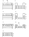
- FIG. 2 shows a phase shift mask 200 according to an embodiment of the present invention manufactured from the mask blank 100 of the above embodiment and a manufacturing process thereof.
- a phase shift pattern 2a which is a transfer pattern, is formed on the phase shift film 2 of the mask blank 100, and a pattern including a light shielding band is formed on the light shielding film 3.
- the light-shielding pattern 3b having the light-shielding pattern 3b is formed.
- the method for manufacturing the phase shift mask 200 uses the mask blank 100, and includes a step of forming a transfer pattern on the light-shielding film 3 by dry etching and a light-shielding film 3 having the transfer pattern.
- the method for manufacturing the phase shift mask 200 of the present invention will be described according to the manufacturing process shown in FIG.
- phase shift mask 200 using the mask blank 100 in which the hard mask film 4 is laminated on the light-shielding film 3 will be described. Further, a case where a material containing chromium is applied to the light-shielding film 3 and a material containing silicon is applied to the hard mask film 4 will be described.
- a resist film is formed by a spin coating method in contact with the hard mask film 4 of the mask blank 100.
- the first pattern which is a transfer pattern (phase shift pattern) to be formed on the phase shift film 2
- the first resist pattern 5a is formed (see FIG. 2A).
- dry etching was performed using a fluorine-based gas to form the first pattern (hard mask pattern 4a) on the hard mask film 4 (see FIG. 2B). ..
- dry etching is performed using a mixed gas of chlorine-based gas and oxygen gas using the hard mask pattern 4a as a mask, and the first pattern (light-shielding pattern 3a) is formed on the light-shielding film 3. (See FIG. 2 (c)). Subsequently, dry etching was performed using a fluorine-based gas using the light-shielding pattern 3a as a mask to form a first pattern (phase shift pattern 2a) on the phase shift film 2 and remove the hard mask pattern 4a (FIG. 6). 2 (d)).
- a resist film was formed on the mask blank 100 by a spin coating method.
- a second pattern which is a pattern to be formed on the light-shielding film 3 (light-shielding pattern)
- a second resist pattern 6b was formed (see FIG. 2E).
- dry etching was performed using a mixed gas of chlorine-based gas and oxygen gas to form a second pattern (light-shielding pattern 3b) on the light-shielding film 3 (FIG. 2 (FIG. 2). f) See).
- the second resist pattern 6b was removed, and a predetermined process such as cleaning was performed to obtain a phase shift mask 200 (see FIG. 2 (g)).
- the chlorine-based gas used in the dry etching is not particularly limited as long as it contains Cl.
- Cl 2 , NaCl 2 , CHCl 3 , CH 2 Cl 2 , CCl 4 , BCl 3, and the like can be mentioned.
- the fluorine-based gas used in the dry etching is not particularly limited as long as it contains F.
- CHF 3 , CF 4 , C 2 F 6 , C 4 F 8 , SF 6, and the like can be mentioned.
- the fluorine-based gas containing no C has a relatively low etching rate with respect to the glass substrate, damage to the glass substrate can be further reduced.
- the phase shift mask 200 manufactured by the manufacturing method shown in FIG. 2 is a phase shift mask provided with a phase shift film 2 (phase shift pattern 2a) having a transfer pattern on a translucent substrate 1.
- phase shift mask 200 By manufacturing the phase shift mask 200 in this way, the phase shift mask 200 provided with the phase shift film 2 capable of enhancing the phase shift effect on the exposure light of the ArF excimer laser and suppressing the film thickness can be obtained. Obtainable.
- a phase shift mask can also be manufactured by the manufacturing method shown in FIG. 2 using a mask blank provided with an etching stopper film. In this case, the etching stopper film remains without being removed from the phase shift mask.
- the method for manufacturing a semiconductor device of the present invention is characterized by including a step of exposing and transferring a transfer pattern to a resist film on a semiconductor substrate by using the phase shift mask 200.
- the phase shift mask 200 is set on the mask stage of the exposure apparatus using the ArF excimer laser as the exposure light, and the resist film on the semiconductor device is set.
- the transfer pattern is exposed to transfer, a fine transfer pattern can be transferred to the resist film on the semiconductor device. Therefore, when the pattern of the resist film is used as a mask and the lower layer film is dry-etched to form a circuit pattern, a high-precision circuit pattern without wiring short circuit or disconnection can be formed.
- a translucent substrate 1 made of synthetic quartz glass having a main surface size of about 152 mm ⁇ about 152 mm and a thickness of about 6.35 mm was prepared.
- the end face and the main surface of the translucent substrate 1 are polished to a predetermined surface roughness (Rq of 0.2 nm or less), and then subjected to a predetermined cleaning treatment and a drying treatment.
- Rq surface roughness
- each optical characteristic of the translucent substrate 1 was measured using a spectroscopic ellipsometer (M-2000D manufactured by JA Woollam)
- the refractive index in light having a wavelength of 193 nm was 1.556 and the extinction coefficient was 0. It was 000.
- the translucent substrate 1 is installed in the single-wafer sputtering apparatus, and the reaction using a Crypton (Kr) gas, an oxygen (O 2 ) gas, and a nitrogen (N 2 ) gas as the sputtering gas using a Si target.
- a phase shift film 2 made of silicon, oxygen, and nitrogen was formed on the translucent substrate 1 with a thickness of 136.4 nm so as to obtain a desired phase difference.
- phase shift amount measuring device MPM193 manufactured by Lasertec
- the transmittance was 92.0% and the phase difference was 179.9 degrees. It was (deg).
- each optical characteristic of the phase shift film 2 was measured using a spectroscopic ellipsometer (M-2000D manufactured by JA Woollam)
- the refractive index n in light having a wavelength of 193 nm was 1.709, and the extinction coefficient k. was 0.005.
- a phase shift film was formed on another translucent substrate under the same film forming conditions.
- phase shift film was analyzed by X-ray photoelectron spectroscopy (XPS analysis).
- the N / O ratio was 0.120
- the O / Si ratio was 1.696
- the N / Si ratio was 0.203.
- the film density was calculated for this phase shift film 2 using a measuring device (GXR-300 manufactured by Rigaku Co., Ltd.) using the X-ray reflectivity method (XRR), it was found that the film was sufficiently dense. It could be confirmed.
- the translucent substrate 1 is installed in the single-wafer sputtering apparatus, and the reactivity is carried out in a mixed gas atmosphere of argon (Ar), carbon dioxide (CO 2 ) and helium (He) using a chromium (Cr) target.
- a light-shielding film 3 (CrOC film Cr: 71 atomic%, O: 15 atomic%, C: 14 atomic%) composed of chromium, oxygen and carbon is formed in contact with the surface of the phase shift film 2 at a thickness of 59 nm. Formed.
- the translucent substrate 1 on which the light-shielding film (CrOC film) 3 was formed was heat-treated.
- a spectrophotometer Cary 4000 manufactured by Azilent Technology Co., Ltd.
- a translucent substrate 1 in which a phase shift film 2 and a light-shielding film 3 are laminated is installed in a single-wafer sputtering apparatus, and an argon (Ar) gas is sputtered using a silicon dioxide (SiO 2) target.
- a hard mask film 4 made of silicon and oxygen was formed on the light-shielding film 3 by reactive sputtering to a thickness of 12 nm. Further, a predetermined cleaning treatment was performed to produce the mask blank 100 of Example 1.
- the halftone type phase shift mask 200 of Example 1 was manufactured by the following procedure. First, the surface of the hard mask film 4 was subjected to HMDS treatment. Subsequently, a resist film made of a chemically amplified resist for electron beam writing was formed with a film thickness of 80 nm in contact with the surface of the hard mask film 4 by a spin coating method. Next, a first pattern, which is a phase shift pattern to be formed on the phase shift film 2, is electron-beam-drawn on the resist film, subjected to a predetermined development process and a cleaning process, and a resist having the first pattern is performed. A pattern 5a was formed (see FIG. 2A).
- the resist pattern 5a was removed.
- dry etching is performed using a mixed gas of chlorine gas (Cl 2 ) and oxygen gas (O 2 ) to form a first pattern (light-shielding pattern 3a) on the light-shielding film 3. (See FIG. 2 (c)).
- etching is performed using a fluorine-based gas (CF 4 + He) to form a first pattern (phase shift pattern 2a) on the phase shift film 2, and at the same time, a hard mask pattern. 4a was removed (see FIG. 2D).
- CF 4 + He fluorine-based gas
- a resist film made of a chemically amplified resist for electron beam writing was formed on the light-shielding pattern 3a by a spin coating method with a film thickness of 150 nm.
- a second pattern which is a pattern to be formed on the light-shielding film (a pattern including a light-shielding band pattern), is exposed and drawn on the resist film, and further subjected to a predetermined process such as development processing to have a light-shielding pattern.
- a resist pattern 6b was formed (see FIG. 2E).
- Example 2 [Manufacturing of mask blank]
- the mask blank 100 of Example 2 was manufactured in the same procedure as in Example 1 except for the phase shift film 2.
- the phase shift film 2 of the second embodiment has different film forming conditions from the phase shift film 2 of the first embodiment. Specifically, a translucent substrate 1 is installed in a single-wafer sputtering apparatus, a Si target is used, and the gas flow rates of oxygen gas and nitrogen gas are changed to sputter krypton gas, oxygen gas, and nitrogen gas. Reactive sputtering was performed. As a result, a phase shift film 2 made of silicon, oxygen, and nitrogen was formed on the translucent substrate 1 with a thickness of 128.7 nm so as to obtain a desired phase difference.
- phase shift amount measuring device MPM193 manufactured by Lasertec
- the transmittance was 89.5% and the phase difference was 179.7 degrees. It was (deg).
- M-2000D manufactured by JA Woollam the refractive index n in light having a wavelength of 193 nm was 1.750 and the extinction coefficient k. was 0.009.
- a phase shift film was formed on another translucent substrate under the same film forming conditions. Further, the phase shift film was analyzed by X-ray photoelectron spectroscopy (XPS analysis).
- the N / O ratio was 0.155
- the O / Si ratio was 1.636
- the N / Si ratio was 0.254.
- the film density was calculated for this phase shift film 2 using a measuring device (GXR-300 manufactured by Rigaku Co., Ltd.) using the X-ray reflectivity method (XRR), it was found that the film was sufficiently dense. It could be confirmed.
- phase shift mask 200 of Example 2 was manufactured by the same procedure as in Example 1. Simulation of a transfer image when the phase shift mask 200 of Example 2 is exposed and transferred to a resist film on a semiconductor device with exposure light having a wavelength of 193 nm using AIMS193 (manufactured by Carl Zeiss) in the same manner as in Example 1. was done. When the exposure transfer image of this simulation was verified, there were no short circuits or disconnections in the wiring, and the design specifications were fully satisfied. From this result, even if the phase shift mask 200 of the second embodiment is set on the mask stage of the exposure apparatus and exposed to the resist film on the semiconductor device, the circuit pattern finally formed on the semiconductor device is high. It can be said that it can be formed with accuracy.
- Example 3 [Manufacturing of mask blank]
- the mask blank 100 of Example 3 was manufactured in the same procedure as in Example 1 except for the phase shift film 2.
- the phase shift film 2 of the third embodiment has different film forming conditions from the phase shift film 2 of the first embodiment. Specifically, a translucent substrate 1 is installed in a single-wafer sputtering apparatus, a Si target is used, and the gas flow rates of oxygen gas and nitrogen gas are changed to sputter krypton gas, oxygen gas, and nitrogen gas. Reactive sputtering was performed. As a result, a phase shift film 2 made of silicon, oxygen, and nitrogen was formed on the translucent substrate 1 with a thickness of 108.7 nm so as to obtain a desired phase difference.
- phase shift amount measuring device MPM193 manufactured by Lasertec
- the transmittance was 80.9% and the phase difference was 181.3 degrees. It was (deg).
- each optical characteristic of the phase shift film 2 was measured using a spectroscopic ellipsometer (M-2000D manufactured by JA Woollam)
- the refractive index n in light having a wavelength of 193 nm was 1.890
- the extinction coefficient k. was 0.026.
- a phase shift film was formed on another translucent substrate under the same film forming conditions. Further, the phase shift film was analyzed by X-ray photoelectron spectroscopy (XPS analysis).
- the N / O ratio was 0.300
- the O / Si ratio was 1.373
- the N / Si ratio was 0.412.
- the film density was calculated for this phase shift film 2 using a measuring device (GXR-300 manufactured by Rigaku Co., Ltd.) using the X-ray reflectivity method (XRR), it was found that the film was sufficiently dense. It could be confirmed.
- phase shift mask 200 of Example 3 was manufactured by the same procedure as in Example 1. Simulation of a transfer image when the phase shift mask 200 of Example 3 is exposed and transferred to a resist film on a semiconductor device with exposure light having a wavelength of 193 nm using AIMS193 (manufactured by Carl Zeiss) in the same manner as in Example 1. was done. When the exposure transfer image of this simulation was verified, there were no short circuits or disconnections in the wiring, and the design specifications were fully satisfied. From this result, even if the phase shift mask 200 of Example 3 is set on the mask stage of the exposure apparatus and exposed and transferred to the resist film on the semiconductor device, the circuit pattern finally formed on the semiconductor device is high. It can be said that it can be formed with accuracy.
- Example 4 [Manufacturing of mask blank]
- the mask blank 100 of Example 4 was manufactured in the same procedure as in Example 1 except for the phase shift film 2.
- the phase shift film 2 of the fourth embodiment has different film forming conditions from the phase shift film 2 of the first embodiment. Specifically, a translucent substrate 1 is installed in a single-wafer sputtering apparatus, a Si target is used, and the gas flow rates of oxygen gas and nitrogen gas are changed to sputter krypton gas, oxygen gas, and nitrogen gas. Reactive sputtering was performed. As a result, a phase shift film 2 made of silicon, oxygen, and nitrogen was formed on the translucent substrate 1 with a thickness of 100.1 nm so as to obtain a desired phase difference.
- phase shift amount measuring device MPM193 manufactured by Lasertec
- the transmittance was 75.4% and the phase difference was 181.3 degrees. It was (deg).
- each optical characteristic of the phase shift film 2 was measured using a spectroscopic ellipsometer (M-2000D manufactured by JA Woollam)
- the refractive index n in light having a wavelength of 193 nm was 1.973, and the extinction coefficient k. was 0.039.
- a phase shift film was formed on another translucent substrate under the same film forming conditions. Further, the phase shift film was analyzed by X-ray photoelectron spectroscopy (XPS analysis).
- the N / O ratio was 0.412
- the O / Si ratio was 1.211
- the N / Si ratio was 0.499.
- the film density was calculated for this phase shift film 2 using a measuring device (GXR-300 manufactured by Rigaku Co., Ltd.) using the X-ray reflectivity method (XRR), it was found that the film was sufficiently dense. It could be confirmed.
- phase shift mask 200 of Example 4 was manufactured by the same procedure as in Example 1. Simulation of a transfer image when the phase shift mask 200 of Example 4 is exposed and transferred to a resist film on a semiconductor device with exposure light having a wavelength of 193 nm using AIMS193 (manufactured by Carl Zeiss) in the same manner as in Example 1. was done. When the exposure transfer image of this simulation was verified, there were no short circuits or disconnections in the wiring, and the design specifications were fully satisfied. From this result, even if the phase shift mask 200 of the fourth embodiment is set on the mask stage of the exposure apparatus and exposed to the resist film on the semiconductor device, the circuit pattern finally formed on the semiconductor device is high. It can be said that it can be formed with accuracy.
- Example 5 [Manufacturing of mask blank]
- the mask blank 100 of Example 5 was manufactured in the same procedure as in Example 1 except for the phase shift film 2.
- the phase shift film 2 of the fifth embodiment has different film forming conditions from the phase shift film 2 of the first embodiment. Specifically, a translucent substrate 1 is installed in a single-wafer sputtering apparatus, a Si target is used, and the gas flow rates of oxygen gas and nitrogen gas are changed to sputter krypton gas, oxygen gas, and nitrogen gas. Reactive sputtering was performed. As a result, a phase shift film 2 made of silicon, oxygen, and nitrogen was formed on the translucent substrate 1 with a thickness of 98.2 nm so as to obtain a desired phase difference.
- phase shift amount measuring device MPM193 manufactured by Lasertec
- the transmittance was 74.0% and the phase difference was 181.7 degrees. It was (deg).
- each optical characteristic of the phase shift film 2 was measured using a spectroscopic ellipsometer (M-2000D manufactured by JA Woollam)
- the refractive index n in light having a wavelength of 193 nm was 1.994
- the extinction coefficient k. was 0.043.
- a phase shift film was formed on another translucent substrate under the same film forming conditions.
- phase shift film was analyzed by X-ray photoelectron spectroscopy (XPS analysis).
- the N / O ratio was 0.448
- the O / Si ratio was 1.161
- the N / Si ratio was 0.520.
- the film density was calculated for this phase shift film 2 using a measuring device (GXR-300 manufactured by Rigaku Co., Ltd.) using the X-ray reflectivity method (XRR), it was found that the film was sufficiently dense. It could be confirmed.
- phase shift mask 200 of Example 5 was manufactured by the same procedure as in Example 1. Simulation of a transfer image when the phase shift mask 200 of Example 5 is exposed and transferred to a resist film on a semiconductor device with exposure light having a wavelength of 193 nm using AIMS193 (manufactured by Carl Zeiss) in the same manner as in Example 1. was done. When the exposure transfer image of this simulation was verified, there were no short circuits or disconnections in the wiring, and the design specifications were fully satisfied. From this result, even if the phase shift mask 200 of Example 5 is set on the mask stage of the exposure apparatus and exposed and transferred to the resist film on the semiconductor device, the circuit pattern finally formed on the semiconductor device is high. It can be said that it can be formed with accuracy.
- Example 6 [Manufacturing of mask blank]
- the mask blank 100 of Example 6 was manufactured in the same procedure as in Example 3 except for the film thickness of the phase shift film 2.
- the phase shift film 2 of Example 6 was subjected to reactive sputtering under the same film forming conditions as the phase shift film 2 of Example 3.
- a phase shift film 2 made of silicon, oxygen, and nitrogen was formed on the translucent substrate 1 with a thickness of 125.0 nm so as to obtain a desired phase difference.
- phase shift mask 200 of Example 6 was manufactured by the same procedure as in Example 1. Simulation of a transfer image when the phase shift mask 200 of Example 6 is exposed and transferred to a resist film on a semiconductor device with exposure light having a wavelength of 193 nm using AIMS193 (manufactured by Carl Zeiss) in the same manner as in Example 1. was done. When the exposure transfer image of this simulation was verified, there were no short circuits or disconnections in the wiring, and the design specifications were fully satisfied. From this result, even if the phase shift mask 200 of Example 6 is set on the mask stage of the exposure apparatus and exposed and transferred to the resist film on the semiconductor device, the circuit pattern finally formed on the semiconductor device is high. It can be said that it can be formed with accuracy.
- the mask blank of Comparative Example 1 was manufactured in the same procedure as in Example 1 except for the phase shift film.
- the phase shift film of Comparative Example 1 has different film forming conditions from the phase shift film 2 of Example 1. Specifically, a translucent substrate is installed in a single-wafer sputtering apparatus, a Si target is used, the gas flow rates of oxygen gas and nitrogen gas are changed, and krypton gas, oxygen gas, and nitrogen gas are used as sputtering gas. Reactive sputtering was performed. As a result, a phase shift film composed of silicon, oxygen and nitrogen was formed on the translucent substrate with a thickness of 143.1 nm so as to obtain a desired phase difference.
- phase shift amount measuring device MPM193 manufactured by Lasertec
- the transmittance was 93.8% and the phase difference was 180.5 degrees (180.5 degrees). It was deg).
- each optical characteristic of the phase shift film was measured using a spectroscopic ellipsometer (M-2000D manufactured by JA Woollam)
- the refractive index n and the extinction coefficient k in light having a wavelength of 193 nm were 1.676. It was 0.003.
- a phase shift film was formed on another translucent substrate under the same film forming conditions. Further, the phase shift film was analyzed by X-ray photoelectron spectroscopy (XPS analysis).
- the N / O ratio was 0.091
- the O / Si ratio was 1.763
- the N / Si ratio was 0.161.
- the film density was calculated for this phase-shifted film using a measuring device (GXR-300 manufactured by Rigaku Co., Ltd.) using the X-ray reflectivity method (XRR), it was confirmed that the film was sufficiently dense. did it.
- phase shift mask of Comparative Example 1 was manufactured by the same procedure as in Example 1.
- a simulation of a transfer image when exposure transfer was performed on a resist film on a semiconductor device with exposure light having a wavelength of 193 nm using AIMS193 (manufactured by Carl Zeiss) in the same manner as in Example 1. went.
- AIMS193 manufactured by Carl Zeiss
- the mask blank of Comparative Example 2 was manufactured in the same procedure as in Example 1 except for the film thickness of the phase shift film and the light-shielding film.
- the phase shift film of Comparative Example 2 has different film forming conditions from the phase shift film 2 of Example 1. Specifically, a translucent substrate is installed in a single-wafer sputtering apparatus, a Si target is used, the gas flow rates of oxygen gas and nitrogen gas are changed, and krypton gas, oxygen gas, and nitrogen gas are used as sputtering gas. Reactive sputtering was performed. As a result, a phase shift film composed of silicon, oxygen and nitrogen was formed on the translucent substrate with a thickness of 92.2 nm so as to obtain a desired phase difference.
- phase shift amount measuring device MPM193 manufactured by Lasertec
- the transmittance was 68.5% and the phase difference was 184.9 degrees (184.9 degrees). It was deg).
- each optical characteristic of the phase shift film was measured using a spectroscopic ellipsometer (M-2000D manufactured by JA Woollam)
- the refractive index n and the extinction coefficient k in light having a wavelength of 193 nm were 2.077. It was 0.058.
- a phase shift film was formed on another translucent substrate under the same film forming conditions. Further, the phase shift film was analyzed by X-ray photoelectron spectroscopy (XPS analysis).
- the N / O ratio was 0.563
- the O / Si ratio was 1.067
- the N / Si ratio was 0.600.
- the film density was calculated for this phase-shifted film using a measuring device (GXR-300 manufactured by Rigaku Co., Ltd.) using the X-ray reflectivity method (XRR), it was confirmed that the film was sufficiently dense. did it.
- phase shift mask of Comparative Example 2 was manufactured by the same procedure as in Example 1.
- a simulation of a transfer image when exposure transfer was performed on a resist film on a semiconductor device with exposure light having a wavelength of 193 nm using AIMS193 (manufactured by Carl Zeiss) in the same manner as in Example 1. went.
- AIMS193 manufactured by Carl Zeiss
- the mask blank of Comparative Example 3 was manufactured in the same procedure as in Example 1 except for the phase shift film.
- the phase shift film of Comparative Example 3 has different film forming conditions from the phase shift film 2 of Example 1. Specifically, a translucent substrate was installed in a single-wafer sputtering apparatus, and reactive sputtering was performed using a Si target, using oxygen gas and krypton gas as sputtering gases without using nitrogen gas. As a result, a phase shift film made of silicon and oxygen was formed on the translucent substrate with a thickness of 172.7 nm so as to obtain a desired phase difference.
- phase shift amount measuring device MPM193 manufactured by Lasertec
- the transmittance was 100.0% and the phase difference was 180.4 degrees (180.4 degrees). It was deg).
- each optical characteristic of the phase shift film was measured using a spectroscopic ellipsometer (M-2000D manufactured by JA Woollam)
- the refractive index n and the extinction coefficient k in light having a wavelength of 193 nm were 1.560. It was 0.000.
- a phase shift film was formed on another translucent substrate under the same film forming conditions.
- the N / O ratio was 0.000
- the O / Si ratio was 1.994
- the N / Si ratio was 0.000.
- the film density was calculated for this phase shift film 2 using a measuring device (GXR-300 manufactured by Rigaku Co., Ltd.) using the X-ray reflectivity method (XRR), it was found that the film was sufficiently dense. It could be confirmed.
- phase shift mask of Comparative Example 3 was manufactured by the same procedure as in Example 1.
- the simulation of the transfer image when the phase shift mask was exposed and transferred to the resist film on the semiconductor device with the exposure light having a wavelength of 193 nm using AIMS193 (manufactured by Carl Zeiss) in the same manner as in Example 1. went.
- AIMS193 manufactured by Carl Zeiss
- Translucent substrate 2 Phase shift film 2a Phase shift pattern 3 Light shielding film 3a, 3b Light shielding pattern 4 Hard mask film 4a Hard mask pattern 5a Resist pattern 6b Resist pattern 100 Mask blank 200 Phase shift mask
Landscapes
- Chemical & Material Sciences (AREA)
- Physics & Mathematics (AREA)
- General Physics & Mathematics (AREA)
- Chemical Kinetics & Catalysis (AREA)
- Engineering & Computer Science (AREA)
- Materials Engineering (AREA)
- Mechanical Engineering (AREA)
- Metallurgy (AREA)
- Organic Chemistry (AREA)
- Preparing Plates And Mask In Photomechanical Process (AREA)
Abstract
The present invention provides a mask blank equipped with a phase shift film capable of improving transmittance for exposure light from an ArF excimer laser and suppressing film thickness required to ensure a desired phase difference. Provided is a mask blank equipped with a phase shift film (2) on a main surface of a light-transmitting substrate (1), wherein the phase shift film (2) contains silicon, oxygen, and nitrogen, the ratio of nitrogen content [at%] to silicon content [at%] of the phase shift film (2) is 0.20-0.52 inclusive, the ratio of oxygen content [at%] to silicon content [at%] of the phase shift film (2) is 1.16-1.70 inclusive, an refractive index n with respect to the wavelength of exposure light from an ArF excimer laser of the phase shift film (2) is 1.7-2.0 inclusive, and an extinction coefficient k is 0.05 or less.
Description
本発明は、位相シフトマスク用のマスクブランク、位相シフトマスク及び半導体デバイスの製造方法に関する。
The present invention relates to a mask blank for a phase shift mask, a phase shift mask, and a method for manufacturing a semiconductor device.
半導体デバイスの製造工程では、フォトリソグラフィー法を用いて微細パターンの形成が行われている。また、この微細パターンの形成には通常何枚もの転写用マスクが使用される。半導体デバイスのパターンを微細化するに当たっては、転写用マスクに形成されるマスクパターンの微細化に加え、フォトリソグラフィーで使用される露光光源の波長の短波長化が必要となる。近年、半導体装置を製造する際の露光光源にArFエキシマレーザー(波長193nm)が適用されることが増えてきている。
In the semiconductor device manufacturing process, a fine pattern is formed using a photolithography method. In addition, a number of transfer masks are usually used to form this fine pattern. In order to miniaturize the pattern of a semiconductor device, it is necessary to shorten the wavelength of the exposure light source used in photolithography in addition to miniaturizing the mask pattern formed on the transfer mask. In recent years, an ArF excimer laser (wavelength 193 nm) has been increasingly applied as an exposure light source when manufacturing a semiconductor device.
転写用マスクの一種に、クロムレス位相シフトマスク(CPLマスク)がある。CPLマスクとしては、透光性基板の上にエッチングストッパー膜を設け、このエッチングストッパー膜の上に、ケイ素および酸素を含有し、透光性基板とほぼ同等の透過率を有する位相シフト膜を設けた構成としたものが知られている。また、CPLマスクとして、露光光に対して透明な基板に掘込部と非掘込部を設け、掘込部と非掘込部とによって転写パターンを構成するものも知られている。
There is a chromeless phase shift mask (CPL mask) as a kind of transfer mask. As the CPL mask, an etching stopper film is provided on the translucent substrate, and a phase shift film containing silicon and oxygen and having a transmittance substantially equal to that of the translucent substrate is provided on the etching stopper film. It is known that it has a structure. Further, as a CPL mask, a mask in which a digging portion and a non-digging portion are provided on a substrate transparent to exposure light and a transfer pattern is formed by the digging portion and the non-digging portion is also known.
例えば、特許文献1には、透明基板上に、エッチング停止層、位相シフト層パターンそして遮光層パターンがこの順に備えられ、エッチング停止層として窒化珪素膜(Si3N4膜)、位相シフト層としてSiO2膜をこの順に設け、その上に遮光層として酸化クロム膜・金属クロム膜・酸化クロム膜をこの順に積層した低反射クロム遮光膜を設けた光学マスクブランクが開示されている。
また、特許文献2には、露光光に対して透明な基板に掘り込み部を設け、透過する光の位相を制御したクロムレス位相シフトマスクにおいて、前記基板掘り込み部に隣接する部分又は基板周辺部に設けられた遮光膜が、フッ素系ガスを主体とするエッチングガスを用いたエッチングプロセスにおいてエッチング可能な材料であるMoSi又はMoSi化合物を主な材料とする膜Aを含むクロムレス位相シフトマスク用フォトマスクブランクが開示されている。 For example, inPatent Document 1, an etching stop layer, a phase shift layer pattern, and a light-shielding layer pattern are provided in this order on a transparent substrate, and a silicon nitride film (Si 3 N 4 film) is provided as an etching stop layer, and a phase shift layer is provided. An optical mask blank is disclosed in which SiO 2 films are provided in this order, and a low-reflection chromium light-shielding film in which a chromium oxide film, a metallic chromium film, and a chromium oxide film are laminated in this order as a light-shielding layer is provided.
Further, inPatent Document 2, in a chromeless phase shift mask in which a digging portion is provided in a substrate transparent to exposure light and the phase of transmitted light is controlled, a portion adjacent to the substrate digging portion or a peripheral portion of the substrate is provided. A photomask for a chromeless phase shift mask containing a film A whose main material is MoSi or a MoSi compound, which is a material that can be etched in an etching process using an etching gas mainly composed of a fluorine-based gas. The blank is disclosed.
また、特許文献2には、露光光に対して透明な基板に掘り込み部を設け、透過する光の位相を制御したクロムレス位相シフトマスクにおいて、前記基板掘り込み部に隣接する部分又は基板周辺部に設けられた遮光膜が、フッ素系ガスを主体とするエッチングガスを用いたエッチングプロセスにおいてエッチング可能な材料であるMoSi又はMoSi化合物を主な材料とする膜Aを含むクロムレス位相シフトマスク用フォトマスクブランクが開示されている。 For example, in
Further, in
CPLマスクは、基本的に平面視で掘込部が形成されている領域では、掘込部を透過する露光光と非掘込部を透過する露光光との間で生じる強い位相シフト効果のみで転写像を作り出す構成となっている。露光光に対する掘込部の透過率と非掘込部の透過率との差が小さいほど位相シフト効果は増強される。また、CPLマスクの場合、転写像のCD均一性(CD Umiformity)を高めるためには、面内での掘込部と非掘込部との間で生じる各位相シフト効果の差を小さくすることが望まれる。すなわち、面内に設けられる掘込部の深さを同じにすることが望まれる。従来のCPLマスクの掘込部は、透光性基板をドライエッチングで所定の深さまで掘り込むことによって形成される。しかし、透光性基板に設けられる各掘込部の深さをドライエッチングのエッチング時間等の制御によって同じにすることは難しい。また、ドライエッチングで掘込部の底面を平坦にすることも難しい。
The CPL mask basically has only a strong phase shift effect generated between the exposure light transmitted through the digging portion and the exposure light transmitted through the non-digging portion in the region where the digging portion is formed in a plan view. It is configured to create a transferred image. The smaller the difference between the transmittance of the dug portion and the transmittance of the non-drilled portion with respect to the exposure light, the stronger the phase shift effect. Further, in the case of the CPL mask, in order to improve the CD uniformity of the transferred image, the difference between the phase shift effects generated between the dug portion and the non-drilled portion in the plane should be reduced. Is desired. That is, it is desired that the depths of the dug portions provided in the plane be the same. The digging portion of the conventional CPL mask is formed by digging the translucent substrate to a predetermined depth by dry etching. However, it is difficult to make the depth of each digging portion provided on the translucent substrate the same by controlling the etching time of dry etching and the like. It is also difficult to flatten the bottom surface of the dug portion by dry etching.
そこで、これらの問題を解決するために、特許文献1に開示されているような透光性基板の上に、エッチングストッパー膜を介して、ケイ素と酸素とからなる位相シフト膜を設けることを試みた。すなわち、従来のCPLマスクの掘込部に代わるものとして、ケイ素と酸素とからなる位相シフト膜にドライエッチングで微細パターンを形成することを検討した。露光光にArFエキシマレーザー光(以下、これをArF露光光という。)が適用されるCPLマスクの場合、所望の位相シフト効果を生じさせるためには、ケイ素と酸素とからなる位相シフト膜の厚さは、少なくとも170nm以上であることが求められる。同じ構造体である透光性基板を掘り込んで掘込部を形成する場合、その掘込部の深さが深くても、その掘込部のパターンが倒れにくく、あるいは脱落しにくい。これに対し、エッチングストッパー膜の上に設けられた位相シフト膜に微細パターンを形成する場合、エッチングストッパー膜と位相シフト膜のパターンとの間の密着性はそれほど高くないため、位相シフト膜のパターンが倒れやすい、あるいは脱落しやすいという問題があった。この問題は、透光性基板に接して位相シフト膜を設けた場合でも同様に発生する。
Therefore, in order to solve these problems, an attempt is made to provide a phase shift film composed of silicon and oxygen on a translucent substrate as disclosed in Patent Document 1 via an etching stopper film. It was. That is, as an alternative to the digging portion of the conventional CPL mask, it was examined to form a fine pattern by dry etching on a phase shift film composed of silicon and oxygen. In the case of a CPL mask to which ArF excimer laser light (hereinafter referred to as ArF exposure light) is applied to the exposure light, the thickness of the phase shift film composed of silicon and oxygen is required to produce a desired phase shift effect. The laser is required to be at least 170 nm or more. When a translucent substrate having the same structure is dug to form a digging portion, even if the digging portion is deep, the pattern of the digging portion is unlikely to collapse or fall off. On the other hand, when a fine pattern is formed on the phase shift film provided on the etching stopper film, the adhesion between the etching stopper film and the pattern of the phase shift film is not so high, so that the pattern of the phase shift film is not so high. There was a problem that it was easy to fall down or fall off. This problem also occurs when the phase shift film is provided in contact with the translucent substrate.
本発明は、従来の課題を解決するためになされたものであり、ArFエキシマレーザーの露光光に対する透過率を高めることができるとともに所望の位相差の確保に必要な膜厚を抑制することができる位相シフト膜を備えたマスクブランクを提供することを目的としている。また、本発明は、ArFエキシマレーザーの露光光に対する透過率を高めることができるとともに所望の位相差の確保に必要な膜厚を抑制することができる転写パターンを有する位相シフト膜を備えた位相シフトマスクを提供することを目的としている。そして、本発明は、このような位相シフトマスクを用いた半導体デバイスの製造方法を提供する。
The present invention has been made to solve the conventional problems, and it is possible to increase the transmittance of the ArF excimer laser with respect to the exposure light and suppress the film thickness required to secure a desired phase difference. It is an object of the present invention to provide a mask blank provided with a phase shift film. Further, the present invention includes a phase shift film having a transfer pattern capable of increasing the transmittance of the ArF excimer laser with respect to the exposure light and suppressing the film thickness required to secure a desired phase difference. It is intended to provide a mask. Then, the present invention provides a method for manufacturing a semiconductor device using such a phase shift mask.
本発明は上記の課題を解決する手段として、以下の構成を有する。
The present invention has the following configuration as a means for solving the above problems.
(構成1)
透光性基板の主表面上に位相シフト膜を備えたマスクブランクであって、
前記位相シフト膜は、ケイ素、酸素および窒素を含有し、
前記位相シフト膜のケイ素の含有量[原子%]に対する窒素の含有量[原子%]の比率は、0.20以上0.52以下であり、
前記位相シフト膜のケイ素の含有量[原子%]に対する酸素の含有量[原子%]の比率は、1.16以上1.70以下であり、
前記位相シフト膜のArFエキシマレーザーの露光光の波長に対する屈折率nは、1.7以上2.0以下であり、
前記位相シフト膜の前記露光光の波長に対する消衰係数kは、0.05以下である
ことを特徴とするマスクブランク。 (Structure 1)
A mask blank having a phase shift film on the main surface of a translucent substrate.
The phase shift film contains silicon, oxygen and nitrogen and
The ratio of the nitrogen content [atomic%] to the silicon content [atomic%] of the phase shift film is 0.20 or more and 0.52 or less.
The ratio of the oxygen content [atomic%] to the silicon content [atomic%] of the phase shift film is 1.16 or more and 1.70 or less.
The refractive index n of the phase shift film with respect to the wavelength of the exposure light of the ArF excimer laser is 1.7 or more and 2.0 or less.
A mask blank having an extinction coefficient k of the phase shift film with respect to the wavelength of the exposure light of 0.05 or less.
(構成2)
前記位相シフト膜の酸素の含有量[原子%]に対する窒素の含有量[原子%]の比率は、0.12以上0.45以下であることを特徴とする構成1記載のマスクブランク。
(構成3)
前記位相シフト膜のケイ素の含有量は、30原子%以上であることを特徴とする構成1または2に記載のマスクブランク。 (Structure 2)
The mask blank according toConfiguration 1, wherein the ratio of the nitrogen content [atomic%] to the oxygen content [atomic%] of the phase shift film is 0.12 or more and 0.45 or less.
(Structure 3)
The mask blank according to the configuration 1 or 2, wherein the silicon content of the phase shift film is 30 atomic% or more.
前記位相シフト膜の酸素の含有量[原子%]に対する窒素の含有量[原子%]の比率は、0.12以上0.45以下であることを特徴とする構成1記載のマスクブランク。
(構成3)
前記位相シフト膜のケイ素の含有量は、30原子%以上であることを特徴とする構成1または2に記載のマスクブランク。 (Structure 2)
The mask blank according to
(Structure 3)
The mask blank according to the
(構成4)
前記位相シフト膜は、前記露光光を70%以上の透過率で透過させる機能と、前記位相シフト膜を透過した前記露光光に対して前記位相シフト膜の厚さと同じ距離だけ空気中を通過した露光光との間で150度以上210度以下の位相差を生じさせる機能とを有することを特徴とする構成1から3のいずれかに記載のマスクブランク。
(構成5)
前記位相シフト膜は、厚さが140nm以下であることを特徴とする構成1から4のいずれかに記載のマスクブランク。 (Structure 4)
The phase shift film has a function of transmitting the exposure light with a transmittance of 70% or more, and has passed through the air for the same distance as the thickness of the phase shift film with respect to the exposure light transmitted through the phase shift film. The mask blank according to any one ofconfigurations 1 to 3, wherein the mask blank has a function of causing a phase difference of 150 degrees or more and 210 degrees or less with the exposure light.
(Structure 5)
The mask blank according to any one ofconfigurations 1 to 4, wherein the phase shift film has a thickness of 140 nm or less.
前記位相シフト膜は、前記露光光を70%以上の透過率で透過させる機能と、前記位相シフト膜を透過した前記露光光に対して前記位相シフト膜の厚さと同じ距離だけ空気中を通過した露光光との間で150度以上210度以下の位相差を生じさせる機能とを有することを特徴とする構成1から3のいずれかに記載のマスクブランク。
(構成5)
前記位相シフト膜は、厚さが140nm以下であることを特徴とする構成1から4のいずれかに記載のマスクブランク。 (Structure 4)
The phase shift film has a function of transmitting the exposure light with a transmittance of 70% or more, and has passed through the air for the same distance as the thickness of the phase shift film with respect to the exposure light transmitted through the phase shift film. The mask blank according to any one of
(Structure 5)
The mask blank according to any one of
(構成6)
前記位相シフト膜の上に遮光膜を備えることを特徴とする構成1から5のいずれかに記載のマスクブランク。
(構成7)
透光性基板の主表面上に、転写パターンを有する位相シフト膜を備えた位相シフトマスクであって、
前記位相シフト膜は、ケイ素、酸素および窒素を含有し、
前記位相シフト膜のケイ素の含有量[原子%]に対する窒素の含有量[原子%]の比率は、0.20以上0.52以下であり、
前記位相シフト膜のケイ素の含有量[原子%]に対する酸素の含有量[原子%]の比率は、1.16以上1.70以下であり、
前記位相シフト膜のArFエキシマレーザーの露光光の波長に対する屈折率nは、1.7以上2.0以下であり、
前記位相シフト膜の前記露光光の波長に対する消衰係数kは、0.05以下である
ことを特徴とする位相シフトマスク。 (Structure 6)
The mask blank according to any one ofconfigurations 1 to 5, wherein a light-shielding film is provided on the phase shift film.
(Structure 7)
A phase shift mask provided with a phase shift film having a transfer pattern on the main surface of a translucent substrate.
The phase shift film contains silicon, oxygen and nitrogen and
The ratio of the nitrogen content [atomic%] to the silicon content [atomic%] of the phase shift film is 0.20 or more and 0.52 or less.
The ratio of the oxygen content [atomic%] to the silicon content [atomic%] of the phase shift film is 1.16 or more and 1.70 or less.
The refractive index n of the phase shift film with respect to the wavelength of the exposure light of the ArF excimer laser is 1.7 or more and 2.0 or less.
A phase shift mask characterized in that the extinction coefficient k of the phase shift film with respect to the wavelength of the exposure light is 0.05 or less.
前記位相シフト膜の上に遮光膜を備えることを特徴とする構成1から5のいずれかに記載のマスクブランク。
(構成7)
透光性基板の主表面上に、転写パターンを有する位相シフト膜を備えた位相シフトマスクであって、
前記位相シフト膜は、ケイ素、酸素および窒素を含有し、
前記位相シフト膜のケイ素の含有量[原子%]に対する窒素の含有量[原子%]の比率は、0.20以上0.52以下であり、
前記位相シフト膜のケイ素の含有量[原子%]に対する酸素の含有量[原子%]の比率は、1.16以上1.70以下であり、
前記位相シフト膜のArFエキシマレーザーの露光光の波長に対する屈折率nは、1.7以上2.0以下であり、
前記位相シフト膜の前記露光光の波長に対する消衰係数kは、0.05以下である
ことを特徴とする位相シフトマスク。 (Structure 6)
The mask blank according to any one of
(Structure 7)
A phase shift mask provided with a phase shift film having a transfer pattern on the main surface of a translucent substrate.
The phase shift film contains silicon, oxygen and nitrogen and
The ratio of the nitrogen content [atomic%] to the silicon content [atomic%] of the phase shift film is 0.20 or more and 0.52 or less.
The ratio of the oxygen content [atomic%] to the silicon content [atomic%] of the phase shift film is 1.16 or more and 1.70 or less.
The refractive index n of the phase shift film with respect to the wavelength of the exposure light of the ArF excimer laser is 1.7 or more and 2.0 or less.
A phase shift mask characterized in that the extinction coefficient k of the phase shift film with respect to the wavelength of the exposure light is 0.05 or less.
(構成8)
前記位相シフト膜の酸素の含有量[原子%]に対する窒素の含有量[原子%]の比率は、0.12以上0.45以下であることを特徴とする構成7記載の位相シフトマスク。 (Structure 8)
The phase shift mask according to the configuration 7, wherein the ratio of the nitrogen content [atomic%] to the oxygen content [atomic%] of the phase shift film is 0.12 or more and 0.45 or less.
前記位相シフト膜の酸素の含有量[原子%]に対する窒素の含有量[原子%]の比率は、0.12以上0.45以下であることを特徴とする構成7記載の位相シフトマスク。 (Structure 8)
The phase shift mask according to the configuration 7, wherein the ratio of the nitrogen content [atomic%] to the oxygen content [atomic%] of the phase shift film is 0.12 or more and 0.45 or less.
(構成9)
前記位相シフト膜のケイ素の含有量は、30原子%以上であることを特徴とする構成7または8に記載の位相シフトマスク。
(構成10)
前記位相シフト膜は、前記露光光を70%以上の透過率で透過させる機能と、前記位相シフト膜を透過した前記露光光に対して前記位相シフト膜の厚さと同じ距離だけ空気中を通過した露光光との間で150度以上210度以下の位相差を生じさせる機能とを有することを特徴とする構成7から9のいずれかに記載の位相シフトマスク。 (Structure 9)
The phase shift mask according to the configuration 7 or 8, wherein the silicon content of the phase shift film is 30 atomic% or more.
(Structure 10)
The phase shift film has a function of transmitting the exposure light with a transmittance of 70% or more, and has passed through the air for the same distance as the thickness of the phase shift film with respect to the exposure light transmitted through the phase shift film. The phase shift mask according to any one of configurations 7 to 9, further comprising a function of generating a phase difference of 150 degrees or more and 210 degrees or less with the exposure light.
(構成11)
前記位相シフト膜は、厚さが140nm以下であることを特徴とする構成7から10のいずれかに記載の位相シフトマスク。
(構成12)
前記位相シフト膜の上に、遮光帯を含むパターンを有する遮光膜を備えることを特徴とする構成7から11のいずれかに記載の位相シフトマスク。
(構成13)
構成12記載の位相シフトマスクを用い、半導体基板上のレジスト膜に転写パターンを露光転写する工程を備えることを特徴とする半導体デバイスの製造方法。 (Structure 11)
The phase shift mask according to any one of configurations 7 to 10, wherein the phase shift film has a thickness of 140 nm or less.
(Structure 12)
The phase shift mask according to any one of configurations 7 to 11, wherein a light-shielding film having a pattern including a light-shielding band is provided on the phase-shift film.
(Structure 13)
A method for manufacturing a semiconductor device, which comprises a step of exposing and transferring a transfer pattern to a resist film on a semiconductor substrate using the phase shift mask according to the configuration 12.
以上の構成を有する本発明のマスクブランクは、透光性基板の主表面上に位相シフト膜を備えたマスクブランクであって、前記位相シフト膜は、ケイ素、酸素および窒素を含有し、前記位相シフト膜のケイ素の含有量[原子%]に対する窒素の含有量[原子%]の比率は、0.20以上0.52以下であり、前記位相シフト膜のケイ素の含有量[原子%]に対する酸素の含有量[原子%]の比率は、1.16以上1.70以下であり、前記位相シフト膜のArFエキシマレーザーの露光光の波長に対する屈折率nは、1.7以上2.0以下であり、前記位相シフト膜の前記露光光の波長に対する消衰係数kは、0.05以下であることを特徴とする。このため、ArFエキシマレーザーの露光光に対する透過率を高めることができるとともに所望の位相差の確保に必要な膜厚を抑制することができる転写パターンを有する位相シフト膜を備えた位相シフトマスクを製造することができる。さらに、この位相シフトマスクを用いた半導体デバイスの製造において、半導体デバイス上のレジスト膜等に精度良好にパターンを転写することが可能になる。
The mask blank of the present invention having the above configuration is a mask blank having a phase shift film on the main surface of a translucent substrate, and the phase shift film contains silicon, oxygen and nitrogen, and the phase shift film is contained. The ratio of the nitrogen content [atomic%] to the silicon content [atomic%] of the shift film is 0.20 or more and 0.52 or less, and oxygen to the silicon content [atomic%] of the phase shift film. The ratio of the content [atomic%] of is 1.16 or more and 1.70 or less, and the refractive index n with respect to the wavelength of the exposure light of the ArF excima laser of the phase shift film is 1.7 or more and 2.0 or less. The phase shift film has an extinction coefficient k with respect to the wavelength of the exposure light of 0.05 or less. Therefore, a phase shift mask provided with a phase shift film having a transfer pattern capable of increasing the transmittance of the ArF excimer laser with respect to the exposure light and suppressing the film thickness required to secure a desired phase difference can be manufactured. can do. Further, in the manufacture of a semiconductor device using this phase shift mask, it becomes possible to transfer a pattern to a resist film or the like on the semiconductor device with good accuracy.
以下、本発明の各実施の形態について説明するが、まず本発明に至った経緯について説明する。CPLマスクの掘込部を位相シフト膜で形成する場合、強い位相シフト効果を生じさせるために、その位相シフト膜はArF露光光に対する高い透過率(例えば、70%以上)を有することが望まれる。透過率の観点だけで考えると位相シフト膜の材料には、透光性基板と同じ材料系のSiO2が好適である。しかし、SiO2で形成された位相シフト膜は、ArF露光光に対する屈折率nが小さい。その位相シフト膜に位相シフト効果を生じさせるためには膜厚を大幅に厚くする必要が生じる。
Hereinafter, embodiments of the present invention will be described, but first, the background to the present invention will be described. When the digging portion of the CPL mask is formed of a phase shift film, the phase shift film is desired to have a high transmittance (for example, 70% or more) with respect to ArF exposure light in order to generate a strong phase shift effect. .. Considering only from the viewpoint of transmittance, SiO 2 of the same material system as that of the translucent substrate is suitable as the material of the phase shift film. However, the phase shift film formed of SiO 2 has a small refractive index n with respect to ArF exposure light. In order to cause the phase shift effect on the phase shift film, it is necessary to significantly increase the film thickness.
位相シフト膜の屈折率nを大きくする観点では、ケイ素と酸素とからなる位相シフト膜にさらに金属元素を含有させることが好ましい。しかし、位相シフト膜に金属元素を含有させることに伴う消衰係数kの上昇度合いが大きく、高い透過率を確保することが難しい。一方、ケイ素と酸素とからなる位相シフト膜に窒素を含有させる(すなわち、ケイ素、酸素および窒素を主成分とするSiON系材料で位相シフト膜を形成する。)ことによっても、金属元素を含有させるほど顕著ではないが、その位相シフト膜の屈折率nを大きくすることができる。しかし、位相シフト膜中の窒素の含有量を増やすにつれ、位相シフト膜の屈折率nは徐々に上昇していくが、それと連動して位相シフト膜の消衰係数kが徐々に低下していく傾向がある。すなわち、SiON系材料の位相シフト膜は、窒素含有量が増えていくにつれて、強い位相シフト効果を生じさせるのに必要な膜厚が薄くなっていくが、透過率は低下していくというトレードオフの関係がある。このため、位相シフト膜をSiON系材料で形成する場合、強い位相シフト効果を生じさせるのに必要な膜厚を薄くできながらも、ArF露光光に対する高い透過率を確保できるような、窒素含有量と酸素含有量の範囲を見つけることが重要となる。
From the viewpoint of increasing the refractive index n of the phase shift film, it is preferable that the phase shift film composed of silicon and oxygen further contains a metal element. However, it is difficult to secure a high transmittance because the degree of increase in the extinction coefficient k due to the inclusion of the metal element in the phase shift film is large. On the other hand, the phase shift film composed of silicon and oxygen also contains nitrogen (that is, the phase shift film is formed of a SiON-based material containing silicon, oxygen and nitrogen as main components) to contain a metal element. Although not so remarkable, the refractive index n of the phase shift film can be increased. However, as the nitrogen content in the phase shift film is increased, the refractive index n of the phase shift film gradually increases, and in conjunction with this, the extinction coefficient k of the phase shift film gradually decreases. Tend. That is, the phase shift film of the SiON-based material has a trade-off that the film thickness required to generate a strong phase shift effect decreases as the nitrogen content increases, but the transmittance decreases. There is a relationship. Therefore, when the phase shift film is formed of a SiON-based material, the nitrogen content is such that a high transmittance for ArF exposure light can be ensured while the film thickness required to generate a strong phase shift effect can be reduced. And finding a range of oxygen content is important.
一方、位相シフト膜は、アモルファス構造あるいは微結晶構造であることが好ましいため、スパッタリング法で形成することが一般的である。位相シフト膜を反応性スパッタリングで形成するときの成膜室内の圧力やスパッタ電圧を調整することで、位相シフト膜の内部構造をある程度疎な状態(隙間が多い状態)にすることは可能である。位相シフト膜の内部構造を疎な状態することで、露光光に対する透過率をある程度高くすることはできる。これを利用すれば、SiON系材料膜の窒素含有量を多くすることによるArF透過率の低下を抑制できるように一見思える。しかし、このようなSiON系材料膜は、ドライエッチングで微細パターンを形成したとき後のパターンの物理的耐性が低く、耐薬性も低い。このようなSiON系材料膜は、位相シフト膜には適さない。
On the other hand, since the phase shift film preferably has an amorphous structure or a microcrystal structure, it is generally formed by a sputtering method. By adjusting the pressure and sputtering voltage in the film formation chamber when the phase shift film is formed by reactive sputtering, it is possible to make the internal structure of the phase shift film somewhat sparse (a state with many gaps). .. By making the internal structure of the phase shift film sparse, the transmittance for the exposure light can be increased to some extent. By utilizing this, it seems that the decrease in ArF transmittance due to increasing the nitrogen content of the SiON-based material film can be suppressed at first glance. However, such a SiON-based material film has low physical resistance to the pattern after forming a fine pattern by dry etching, and also has low chemical resistance. Such a SiON-based material film is not suitable for a phase shift film.
本発明者らはさらなる鋭意検討を行った結果、CPLマスクの掘込部に代わる好適な位相シフト膜を見出すに至った。すなわち、その位相シフト膜は、ケイ素、窒素および酸素を含有する材料で形成する。その上で、その位相シフト膜のケイ素の含有量[原子%]に対する窒素の含有量[原子%]の比率は、0.20以上0.52以下としつつ、酸素の含有量[原子%]に対する窒素の含有量[原子%]の比率は、1.16以上1.70以下とする。さらに、位相シフト膜のArF露光光に対する屈折率nを1.7以上2.0以下としつつ、ArF露光光に対する消衰係数kを0.05以下となるようにする。このような構成とすることで、緻密な内部構造の位相シフト膜としつつ、ArF露光光に対する透過率が高いながらも、比較的薄い膜厚で強い位相シフト効果を生じさせることが可能となる。
As a result of further diligent studies, the present inventors have found a suitable phase shift film as an alternative to the digging portion of the CPL mask. That is, the phase shift film is formed of a material containing silicon, nitrogen and oxygen. Then, the ratio of the nitrogen content [atomic%] to the silicon content [atomic%] of the phase shift film is 0.20 or more and 0.52 or less, and the ratio to the oxygen content [atomic%]. The ratio of nitrogen content [atomic%] shall be 1.16 or more and 1.70 or less. Further, the refractive index n of the phase shift film with respect to the ArF exposure light is set to 1.7 or more and 2.0 or less, and the extinction coefficient k with respect to the ArF exposure light is set to 0.05 or less. With such a configuration, it is possible to generate a strong phase shift effect with a relatively thin film thickness while forming a phase shift film having a dense internal structure and having a high transmittance for ArF exposure light.
以下、図面に基づいて、上述した本発明の詳細な構成を説明する。なお、各図において同様の構成要素には同一の符号を付して説明を行う。
Hereinafter, the detailed configuration of the present invention described above will be described with reference to the drawings. In each figure, the same components will be described with the same reference numerals.
〈マスクブランク〉
本発明の実施の形態に係るマスクブランクは、CPL(Chromeless Phase Lithography)マスク、すなわちクロムレス位相シフトマスクを製造するために使用されるマスクブランクである。CPLマスクは、転写パターン形成領域内は、大パターンの領域を除いて、基本的に遮光膜は設けられず、透光性基板の掘込部と非掘込部とによって転写パターンを構成するタイプの位相シフトマスクである。
図1に、マスクブランクの実施形態の概略構成を示す。図1に示すマスクブランク100は、透光性基板1における一方の主表面上に、位相シフト膜2、遮光膜3、及び、ハードマスク膜4がこの順に積層された構成である。マスクブランク100は、必要に応じてハードマスク膜4を設けない構成であってもよい。また、マスクブランク100は、ハードマスク膜4上に、必要に応じてレジスト膜を積層させた構成であってもよい。以下、マスクブランク100の主要構成部の詳細を説明する。 <Mask blank>
The mask blank according to the embodiment of the present invention is a CPL (Chromeless Phase Lithography) mask, that is, a mask blank used for manufacturing a chromeless phase shift mask. The CPL mask is a type in which a light-shielding film is basically not provided in the transfer pattern forming region except for a large pattern region, and the transfer pattern is formed by a buried portion and a non-digged portion of a translucent substrate. It is a phase shift mask of.
FIG. 1 shows a schematic configuration of an embodiment of a mask blank. The mask blank 100 shown in FIG. 1 has a configuration in which aphase shift film 2, a light shielding film 3, and a hard mask film 4 are laminated in this order on one main surface of the translucent substrate 1. The mask blank 100 may have a configuration in which the hard mask film 4 is not provided, if necessary. Further, the mask blank 100 may have a structure in which a resist film is laminated on the hard mask film 4 as needed. The details of the main components of the mask blank 100 will be described below.
本発明の実施の形態に係るマスクブランクは、CPL(Chromeless Phase Lithography)マスク、すなわちクロムレス位相シフトマスクを製造するために使用されるマスクブランクである。CPLマスクは、転写パターン形成領域内は、大パターンの領域を除いて、基本的に遮光膜は設けられず、透光性基板の掘込部と非掘込部とによって転写パターンを構成するタイプの位相シフトマスクである。
図1に、マスクブランクの実施形態の概略構成を示す。図1に示すマスクブランク100は、透光性基板1における一方の主表面上に、位相シフト膜2、遮光膜3、及び、ハードマスク膜4がこの順に積層された構成である。マスクブランク100は、必要に応じてハードマスク膜4を設けない構成であってもよい。また、マスクブランク100は、ハードマスク膜4上に、必要に応じてレジスト膜を積層させた構成であってもよい。以下、マスクブランク100の主要構成部の詳細を説明する。 <Mask blank>
The mask blank according to the embodiment of the present invention is a CPL (Chromeless Phase Lithography) mask, that is, a mask blank used for manufacturing a chromeless phase shift mask. The CPL mask is a type in which a light-shielding film is basically not provided in the transfer pattern forming region except for a large pattern region, and the transfer pattern is formed by a buried portion and a non-digged portion of a translucent substrate. It is a phase shift mask of.
FIG. 1 shows a schematic configuration of an embodiment of a mask blank. The mask blank 100 shown in FIG. 1 has a configuration in which a
[透光性基板]
透光性基板1は、リソグラフィーにおける露光工程で用いられる露光光に対して透過性が良好な材料からなる。このような材料としては、合成石英ガラス、アルミノシリケートガラス、ソーダライムガラス、低熱膨張ガラス(SiO2-TiO2ガラス等)、その他各種のガラス基板を用いることができる。特に、合成石英ガラスを用いた基板は、ArFエキシマレーザー光(波長:約193nm)に対する透過性が高いので、マスクブランク100の透光性基板1として好適に用いることができる。
尚、ここで言うリソグラフィーにおける露光工程とは、このマスクブランク100を用いて作製された位相シフトマスクを使用したリソグラフィーにおける露光工程であり、露光光とは、特に断りの無い限り、ArFエキシマレーザー光(波長:193nm)を指すものとする。
透光性基板1を形成する材料の露光光における屈折率は、1.5以上1.6以下であることが好ましく、1.52以上1.59以下であるとより好ましく、1.54以上1.58以下であるとさらに好ましい。 [Translucent substrate]
Thetranslucent substrate 1 is made of a material having good transparency to the exposure light used in the exposure process in lithography. As such a material, synthetic quartz glass, aluminosilicate glass, soda-lime glass, low thermal expansion glass (SiO 2- TiO 2 glass, etc.), and various other glass substrates can be used. In particular, since the substrate using synthetic quartz glass has high transparency to ArF excimer laser light (wavelength: about 193 nm), it can be suitably used as the translucent substrate 1 of the mask blank 100.
The exposure step in lithography referred to here is an exposure step in lithography using a phase shift mask produced by using this mask blank 100, and the exposure light is ArF excimer laser light unless otherwise specified. (Wavelength: 193 nm).
The refractive index of the material forming thetranslucent substrate 1 in the exposure light is preferably 1.5 or more and 1.6 or less, more preferably 1.52 or more and 1.59 or less, and 1.54 or more and 1 It is more preferably .58 or less.
透光性基板1は、リソグラフィーにおける露光工程で用いられる露光光に対して透過性が良好な材料からなる。このような材料としては、合成石英ガラス、アルミノシリケートガラス、ソーダライムガラス、低熱膨張ガラス(SiO2-TiO2ガラス等)、その他各種のガラス基板を用いることができる。特に、合成石英ガラスを用いた基板は、ArFエキシマレーザー光(波長:約193nm)に対する透過性が高いので、マスクブランク100の透光性基板1として好適に用いることができる。
尚、ここで言うリソグラフィーにおける露光工程とは、このマスクブランク100を用いて作製された位相シフトマスクを使用したリソグラフィーにおける露光工程であり、露光光とは、特に断りの無い限り、ArFエキシマレーザー光(波長:193nm)を指すものとする。
透光性基板1を形成する材料の露光光における屈折率は、1.5以上1.6以下であることが好ましく、1.52以上1.59以下であるとより好ましく、1.54以上1.58以下であるとさらに好ましい。 [Translucent substrate]
The
The exposure step in lithography referred to here is an exposure step in lithography using a phase shift mask produced by using this mask blank 100, and the exposure light is ArF excimer laser light unless otherwise specified. (Wavelength: 193 nm).
The refractive index of the material forming the
[位相シフト膜]
位相シフト膜2は、露光光を70%以上の透過率で透過させる機能を有していることが好ましい。位相シフト膜2の内部を透過した露光光と空気中を透過した露光光との間で十分な位相シフト効果を生じさせるためである。位相シフト膜2は、露光光を75%以上の透過率で透過させる機能を有しているとより好ましい。また、位相シフト膜2の露光光に対する透過率は、93%以下であると好ましく、90%以下であるとより好ましい。位相シフト膜2の膜厚を、光学的な性能を確保できる適正な範囲に抑えるためである。 [Phase shift film]
Thephase shift film 2 preferably has a function of transmitting exposure light with a transmittance of 70% or more. This is because a sufficient phase shift effect is generated between the exposure light transmitted through the inside of the phase shift film 2 and the exposure light transmitted through the air. It is more preferable that the phase shift film 2 has a function of transmitting exposure light with a transmittance of 75% or more. The transmittance of the phase shift film 2 with respect to the exposure light is preferably 93% or less, and more preferably 90% or less. This is to limit the film thickness of the phase shift film 2 to an appropriate range in which optical performance can be ensured.
位相シフト膜2は、露光光を70%以上の透過率で透過させる機能を有していることが好ましい。位相シフト膜2の内部を透過した露光光と空気中を透過した露光光との間で十分な位相シフト効果を生じさせるためである。位相シフト膜2は、露光光を75%以上の透過率で透過させる機能を有しているとより好ましい。また、位相シフト膜2の露光光に対する透過率は、93%以下であると好ましく、90%以下であるとより好ましい。位相シフト膜2の膜厚を、光学的な性能を確保できる適正な範囲に抑えるためである。 [Phase shift film]
The
位相シフト膜2は、適切な位相シフト効果を得るために、この位相シフト膜2を透過した露光光に対し、この位相シフト膜2の厚さと同じ距離だけ空気中を通過した露光光との間で150度以上210度以下の位相差を生じさせる機能を有するように調整されていることが好ましい。位相シフト膜2における前記位相差は、155度以上であることがより好ましく、160度以上であるとさらに好ましい。他方、位相シフト膜2における位相差は、200度以下であることがより好ましく、190度以下であるとさらに好ましい。
In order to obtain an appropriate phase shift effect, the phase shift film 2 is between the exposure light transmitted through the phase shift film 2 and the exposure light passing through the air by the same distance as the thickness of the phase shift film 2. It is preferable that the light is adjusted so as to have a function of causing a phase difference of 150 degrees or more and 210 degrees or less. The phase difference in the phase shift film 2 is more preferably 155 degrees or more, and further preferably 160 degrees or more. On the other hand, the phase difference in the phase shift film 2 is more preferably 200 degrees or less, and further preferably 190 degrees or less.
位相シフト膜2の全体で、上記の透過率、位相差の各条件を少なくとも満たすために、露光光の波長に対する屈折率n(以下、単に屈折率nという。)は、1.7以上であることが好ましく、1.75以上であるとより好ましい。また、位相シフト膜2の屈折率nは、2.0以下であることが好ましく、1.98以下であるとより好ましい。位相シフト膜2の露光光の波長に対する消衰係数k(以下、単に消衰係数kという。)は、0.05以下であると好ましく、0.04以下であるとより好ましい。また、位相シフト膜2の消衰係数kは、0.005以上であると好ましく、0.007以上であるとより好ましい。なお、位相シフト膜2の屈折率nおよび消衰係数kは、位相シフト膜2の全体を光学的に均一な1つの層とみなして導出された数値である。
In order to satisfy at least the above-mentioned transmittance and phase difference conditions in the entire phase shift film 2, the refractive index n (hereinafter, simply referred to as the refractive index n) with respect to the wavelength of the exposure light is 1.7 or more. It is preferably 1.75 or more, and more preferably 1.75 or more. The refractive index n of the phase shift film 2 is preferably 2.0 or less, and more preferably 1.98 or less. The extinction coefficient k (hereinafter, simply referred to as the extinction coefficient k) of the phase shift film 2 with respect to the wavelength of the exposure light is preferably 0.05 or less, and more preferably 0.04 or less. The extinction coefficient k of the phase shift film 2 is preferably 0.005 or more, and more preferably 0.007 or more. The refractive index n and the extinction coefficient k of the phase shift film 2 are numerical values derived by regarding the entire phase shift film 2 as one optically uniform layer.
位相シフト膜2を含む薄膜の屈折率nと消衰係数kは、その薄膜の組成だけで決まるものではない。その薄膜の膜密度や結晶状態なども屈折率nや消衰係数kを左右する要素である。このため、反応性スパッタリングで薄膜を成膜するときの諸条件を調整して、その薄膜が所望の屈折率nおよび消衰係数kとなるように成膜する。位相シフト膜2を、上記の屈折率nと消衰係数kの範囲にするには、反応性スパッタリングで成膜する際に、貴ガスと反応性ガス(酸素ガス、窒素ガス等)の混合ガスの比率を調整することだけに限られない。反応性スパッタリングで成膜する際における成膜室内の圧力、スパッタリングターゲットに印加する電力、ターゲットと透光性基板1との間の距離等の位置関係など多岐にわたる。これらの成膜条件は成膜装置に固有のものであり、形成される薄膜が所望の屈折率nおよび消衰係数kになるように適宜調整されるものである。ただし、上記の理由から、位相シフト膜2に対し、その内部構造が疎な状態になってしまうような過度な調整は行わない。
The refractive index n and the extinction coefficient k of the thin film including the phase shift film 2 are not determined only by the composition of the thin film. The film density and crystal state of the thin film are also factors that influence the refractive index n and the extinction coefficient k. Therefore, various conditions for forming a thin film by reactive sputtering are adjusted so that the thin film has a desired refractive index n and extinction coefficient k. In order to make the phase shift film 2 within the range of the above-mentioned refractive index n and extinction coefficient k, a mixed gas of a noble gas and a reactive gas (oxygen gas, nitrogen gas, etc.) is formed when the film is formed by reactive sputtering. It is not limited to adjusting the ratio of. There are various positional relationships such as the pressure in the film forming chamber when forming a film by reactive sputtering, the electric power applied to the sputtering target, and the distance between the target and the translucent substrate 1. These film forming conditions are unique to the film forming apparatus, and are appropriately adjusted so that the formed thin film has a desired refractive index n and extinction coefficient k. However, for the above reason, the phase shift film 2 is not excessively adjusted so that its internal structure becomes sparse.
位相シフト膜2の膜厚は、パターン倒れの発生を低減するために、140nm以下であると好ましい。また、位相シフト膜2の膜厚は、所望の位相差を生じさせる機能を確保するために、95nm以上であることが好ましく、100nm以上であるとより好ましい。
The film thickness of the phase shift film 2 is preferably 140 nm or less in order to reduce the occurrence of pattern collapse. The film thickness of the phase shift film 2 is preferably 95 nm or more, and more preferably 100 nm or more, in order to secure the function of producing a desired phase difference.
位相シフト膜2は、ケイ素、窒素および酸素を含有することが好ましい。位相シフト膜2は、ケイ素、窒素および酸素の合計含有量が97原子%以上であると好ましく、98原子%以上であるとより好ましく、99原子%以上であるとさらに好ましい。また、位相シフト膜2に対してX線光電子分光分析による組成分析を行った場合、金属元素の含有量は1原子%未満であることが好ましく、検出下限値以下であることがより好ましい。位相シフト膜2に金属元素を含有させると消衰係数kが上昇する要因となるためである。
The phase shift film 2 preferably contains silicon, nitrogen and oxygen. The total content of silicon, nitrogen and oxygen in the phase shift film 2 is preferably 97 atomic% or more, more preferably 98 atomic% or more, and further preferably 99 atomic% or more. Further, when the composition analysis of the phase shift film 2 by X-ray photoelectron spectroscopy is performed, the content of the metal element is preferably less than 1 atomic%, and more preferably not more than the lower limit of detection. This is because when the phase shift film 2 contains a metal element, the extinction coefficient k increases.
位相シフト膜2は、ケイ素、酸素および窒素からなる材料で形成されることが好ましく、または半金属元素および非金属元素から選ばれる1以上の元素とケイ素と酸素と窒素とからなる材料で形成されてもよい。半金属元素と非金属元素はある程度の含有量であれば、位相シフト膜2の光学特性に与える影響は軽微であるためである。一方、位相シフト膜2には、いずれの半金属元素を含有してもよい。この半金属元素の中でも、ホウ素、ゲルマニウム、アンチモンおよびテルルから選ばれる一以上の元素を含有させると、位相シフト膜2をスパッタリング法で成膜するときにターゲットとして用いるケイ素の導電性を高めることが期待できるため、好ましい。この位相シフト膜2は、フッ素系ガスを用いたドライエッチングによってパターニングが可能であり、後述の遮光膜3に対して、十分なエッチング選択性を有する。
The phase shift film 2 is preferably formed of a material composed of silicon, oxygen and nitrogen, or is formed of a material composed of one or more elements selected from metalloid elements and non-metal elements, silicon, oxygen and nitrogen. You may. This is because if the contents of the metalloid element and the non-metal element are to some extent, the influence on the optical characteristics of the phase shift film 2 is minor. On the other hand, the phase shift film 2 may contain any metalloid element. Among these metalloid elements, when one or more elements selected from boron, germanium, antimony and tellurium are contained, the conductivity of silicon used as a target when the phase shift film 2 is formed by a sputtering method can be enhanced. It is preferable because it can be expected. The phase shift film 2 can be patterned by dry etching using a fluorine-based gas, and has sufficient etching selectivity with respect to the light-shielding film 3 described later.
位相シフト膜2の酸素の含有量は、透過率を高める観点から、42原子%以上であることが好ましく、43原子%以上であるとより好ましい。位相シフト膜2の酸素の含有量は、屈折率nの低下を抑制する観点から、60原子%以下であることが好ましく、58原子%以下であるとより好ましい。
また、位相シフト膜2の窒素の含有量は、屈折率nを高める観点から、6原子%以上であることが好ましく、7原子%以上であるとより好ましい。位相シフト膜2の窒素の含有量は、消衰係数kの上昇を抑制する観点から、22原子%以下であることが好ましく、20原子%以下であるとより好ましい。
また、位相シフト膜2のケイ素の含有量は、物理的耐性を高める観点および耐薬性を高める観点から、30原子%以上であることが好ましく、33原子%以上であるとより好ましい。位相シフト膜2のケイ素の含有量は、透過率を高める観点から、40原子%以下であることが好ましく、38原子%以下であるとより好ましい。 The oxygen content of thephase shift membrane 2 is preferably 42 atomic% or more, and more preferably 43 atomic% or more, from the viewpoint of increasing the transmittance. The oxygen content of the phase shift film 2 is preferably 60 atomic% or less, and more preferably 58 atomic% or less, from the viewpoint of suppressing a decrease in the refractive index n.
Further, the nitrogen content of thephase shift film 2 is preferably 6 atomic% or more, and more preferably 7 atomic% or more, from the viewpoint of increasing the refractive index n. The nitrogen content of the phase shift film 2 is preferably 22 atomic% or less, and more preferably 20 atomic% or less, from the viewpoint of suppressing an increase in the extinction coefficient k.
The silicon content of thephase shift film 2 is preferably 30 atomic% or more, and more preferably 33 atomic% or more, from the viewpoint of enhancing physical resistance and chemical resistance. The silicon content of the phase shift film 2 is preferably 40 atomic% or less, and more preferably 38 atomic% or less, from the viewpoint of increasing the transmittance.
また、位相シフト膜2の窒素の含有量は、屈折率nを高める観点から、6原子%以上であることが好ましく、7原子%以上であるとより好ましい。位相シフト膜2の窒素の含有量は、消衰係数kの上昇を抑制する観点から、22原子%以下であることが好ましく、20原子%以下であるとより好ましい。
また、位相シフト膜2のケイ素の含有量は、物理的耐性を高める観点および耐薬性を高める観点から、30原子%以上であることが好ましく、33原子%以上であるとより好ましい。位相シフト膜2のケイ素の含有量は、透過率を高める観点から、40原子%以下であることが好ましく、38原子%以下であるとより好ましい。 The oxygen content of the
Further, the nitrogen content of the
The silicon content of the
また、位相シフト膜2におけるN/Si比率は、屈折率nを高める観点から、0.20以上であることが好ましく、0.22以上であることがより好ましい。一方、このN/Si比率は、消衰係数kの上昇を抑制する観点から、0.52以下であることが好ましく、0.51以下であることがより好ましい。
また、位相シフト膜2におけるO/Si比率は、透過率を高める観点から、1.16以上であることが好ましく、1.17以上であることがより好ましい。一方、このO/Si比率は、屈折率nの低下を抑制する観点から、1.70以下であることが好ましく、1.69以下であることがより好ましい。
また、位相シフト膜2の酸素の含有量[原子%]に対する窒素の含有量[原子%]の比率(以下、N/O比率という。)は、屈折率nを高める観点から、0.12以上であることが好ましく、0.13以上であることがより好ましい。一方、このN/O比率は、消衰係数kの上昇を抑制する観点から、0.45以下であることが好ましく、0.44以下であることがより好ましい。
なお、位相シフト膜2は、組成が均一な単層膜であることが好ましいが、必ずしもこれに限定されるものではなく、複数層で形成されるものであってもよく、厚さ方向で組成傾斜した構成であってもよい。 The N / Si ratio in thephase shift film 2 is preferably 0.20 or more, and more preferably 0.22 or more, from the viewpoint of increasing the refractive index n. On the other hand, the N / Si ratio is preferably 0.52 or less, and more preferably 0.51 or less, from the viewpoint of suppressing an increase in the extinction coefficient k.
Further, the O / Si ratio in thephase shift film 2 is preferably 1.16 or more, and more preferably 1.17 or more, from the viewpoint of increasing the transmittance. On the other hand, the O / Si ratio is preferably 1.70 or less, and more preferably 1.69 or less, from the viewpoint of suppressing a decrease in the refractive index n.
The ratio of the nitrogen content [atomic%] to the oxygen content [atomic%] of the phase shift film 2 (hereinafter referred to as N / O ratio) is 0.12 or more from the viewpoint of increasing the refractive index n. It is preferably 0.13 or more, and more preferably 0.13 or more. On the other hand, this N / O ratio is preferably 0.45 or less, and more preferably 0.44 or less, from the viewpoint of suppressing an increase in the extinction coefficient k.
Thephase shift film 2 is preferably a single-layer film having a uniform composition, but is not necessarily limited to this, and may be formed of a plurality of layers and has a composition in the thickness direction. It may have an inclined configuration.
また、位相シフト膜2におけるO/Si比率は、透過率を高める観点から、1.16以上であることが好ましく、1.17以上であることがより好ましい。一方、このO/Si比率は、屈折率nの低下を抑制する観点から、1.70以下であることが好ましく、1.69以下であることがより好ましい。
また、位相シフト膜2の酸素の含有量[原子%]に対する窒素の含有量[原子%]の比率(以下、N/O比率という。)は、屈折率nを高める観点から、0.12以上であることが好ましく、0.13以上であることがより好ましい。一方、このN/O比率は、消衰係数kの上昇を抑制する観点から、0.45以下であることが好ましく、0.44以下であることがより好ましい。
なお、位相シフト膜2は、組成が均一な単層膜であることが好ましいが、必ずしもこれに限定されるものではなく、複数層で形成されるものであってもよく、厚さ方向で組成傾斜した構成であってもよい。 The N / Si ratio in the
Further, the O / Si ratio in the
The ratio of the nitrogen content [atomic%] to the oxygen content [atomic%] of the phase shift film 2 (hereinafter referred to as N / O ratio) is 0.12 or more from the viewpoint of increasing the refractive index n. It is preferably 0.13 or more, and more preferably 0.13 or more. On the other hand, this N / O ratio is preferably 0.45 or less, and more preferably 0.44 or less, from the viewpoint of suppressing an increase in the extinction coefficient k.
The
[遮光膜]
マスクブランク100は、位相シフト膜2上に遮光膜3を備える。一般に、位相シフトマスクでは、転写パターンが形成される領域(転写パターン形成領域)の外周領域は、露光装置を用いて半導体ウェハ上のレジスト膜に露光転写した際に外周領域を透過した露光光による影響をレジスト膜が受けないように、所定値以上の光学濃度(OD)を確保することが求められている。位相シフトマスクの外周領域は、ODが2.8以上であると好ましく、3.0以上であるとより好ましい。上述のように、位相シフト膜2は70%以上の透過率で露光光を透過する機能を有しており、位相シフト膜2だけでは所定値の光学濃度を確保することは困難である。このため、マスクブランク100を製造する段階で位相シフト膜2の上に、不足する光学濃度を確保するために遮光膜3を積層しておくことが必要とされる。このようなマスクブランク100の構成とすることで、位相シフトマスク200(図2参照)を製造する途上で、位相シフト効果を使用する領域(基本的に転写パターン形成領域)の遮光膜3を除去すれば、外周領域に所定値の光学濃度が確保された位相シフトマスク200を製造することができる。 [Shading film]
Themask blank 100 includes a light-shielding film 3 on the phase shift film 2. Generally, in a phase shift mask, the outer peripheral region of the region where the transfer pattern is formed (transfer pattern forming region) is the exposure light transmitted through the outer peripheral region when exposure-transferred to a resist film on a semiconductor wafer using an exposure apparatus. It is required to secure an optical density (OD) equal to or higher than a predetermined value so that the resist film is not affected. The outer peripheral region of the phase shift mask preferably has an OD of 2.8 or more, and more preferably 3.0 or more. As described above, the phase shift film 2 has a function of transmitting exposure light with a transmittance of 70% or more, and it is difficult to secure a predetermined value of optical density only with the phase shift film 2. Therefore, at the stage of manufacturing the mask blank 100, it is necessary to laminate the light-shielding film 3 on the phase-shift film 2 in order to secure the insufficient optical density. With such a configuration of the mask blank 100, the light-shielding film 3 in the region where the phase shift effect is used (basically the transfer pattern forming region) is removed during the manufacturing of the phase shift mask 200 (see FIG. 2). Then, the phase shift mask 200 in which the optical density of a predetermined value is secured in the outer peripheral region can be manufactured.
マスクブランク100は、位相シフト膜2上に遮光膜3を備える。一般に、位相シフトマスクでは、転写パターンが形成される領域(転写パターン形成領域)の外周領域は、露光装置を用いて半導体ウェハ上のレジスト膜に露光転写した際に外周領域を透過した露光光による影響をレジスト膜が受けないように、所定値以上の光学濃度(OD)を確保することが求められている。位相シフトマスクの外周領域は、ODが2.8以上であると好ましく、3.0以上であるとより好ましい。上述のように、位相シフト膜2は70%以上の透過率で露光光を透過する機能を有しており、位相シフト膜2だけでは所定値の光学濃度を確保することは困難である。このため、マスクブランク100を製造する段階で位相シフト膜2の上に、不足する光学濃度を確保するために遮光膜3を積層しておくことが必要とされる。このようなマスクブランク100の構成とすることで、位相シフトマスク200(図2参照)を製造する途上で、位相シフト効果を使用する領域(基本的に転写パターン形成領域)の遮光膜3を除去すれば、外周領域に所定値の光学濃度が確保された位相シフトマスク200を製造することができる。 [Shading film]
The
遮光膜3は、単層構造および2層以上の積層構造のいずれも適用可能である。また、単層構造の遮光膜3および2層以上の積層構造の遮光膜3の各層は、膜または層の厚さ方向でほぼ同じ組成である構成であっても、層の厚さ方向で組成傾斜した構成であってもよい。
The light-shielding film 3 can be applied to both a single-layer structure and a laminated structure having two or more layers. Further, even if each layer of the light-shielding film 3 having a single-layer structure and the light-shielding film 3 having a laminated structure of two or more layers has substantially the same composition in the thickness direction of the film or the layer, the composition is formed in the thickness direction of the layer. It may have an inclined configuration.
図1に記載の実施の形態におけるマスクブランク100は、位相シフト膜2の上に、他の膜を介さずに遮光膜3を積層した構成としている。この構成の場合の遮光膜3は、位相シフト膜2にパターンを形成する際に用いられるエッチングガスに対して十分なエッチング選択性を有する材料を適用する必要がある。この場合の遮光膜3は、クロムを含有する材料で形成することが好ましい。遮光膜3を形成するクロムを含有する材料としては、クロム金属のほか、クロムに酸素、窒素、炭素、ホウ素およびフッ素から選ばれる一以上の元素を含有する材料が挙げられる。
The mask blank 100 in the embodiment shown in FIG. 1 has a configuration in which a light-shielding film 3 is laminated on the phase shift film 2 without interposing another film. For the light-shielding film 3 in this configuration, it is necessary to apply a material having sufficient etching selectivity with respect to the etching gas used when forming a pattern on the phase shift film 2. The light-shielding film 3 in this case is preferably formed of a material containing chromium. Examples of the material containing chromium that forms the light-shielding film 3 include a material containing chromium metal and one or more elements selected from oxygen, nitrogen, carbon, boron, and fluorine in chromium.
一般に、クロム系材料は、塩素系ガスと酸素ガスの混合ガスでエッチングされるが、クロム金属はこのエッチングガスに対するエッチングレートがあまり高くない。塩素系ガスと酸素ガスの混合ガスのエッチングガスに対するエッチングレートを高める点を考慮すると、遮光膜3を形成する材料としては、クロムに酸素、窒素、炭素、ホウ素およびフッ素から選ばれる一以上の元素を含有する材料が好ましい。また、遮光膜3を形成するクロムを含有する材料にモリブデン、インジウムおよびスズのうち一以上の元素を含有させてもよい。モリブデン、インジウムおよびスズのうち一以上の元素を含有させることで、塩素系ガスと酸素ガスの混合ガスに対するエッチングレートをより速くすることができる。
Generally, chromium-based materials are etched with a mixed gas of chlorine-based gas and oxygen gas, but chromium metal does not have a very high etching rate for this etching gas. Considering the point of increasing the etching rate of the mixed gas of chlorine-based gas and oxygen gas with respect to the etching gas, the material for forming the light-shielding film 3 is one or more elements selected from oxygen, nitrogen, carbon, boron and fluorine in chromium. A material containing is preferable. Further, the chromium-containing material forming the light-shielding film 3 may contain one or more elements of molybdenum, indium and tin. By containing one or more elements of molybdenum, indium and tin, the etching rate for a mixed gas of chlorine-based gas and oxygen gas can be made faster.
なお、本発明のマスクブランク100は、図1に示したものに限定されるものではなく、位相シフト膜2と遮光膜3の間に別の膜(エッチングマスク兼ストッパー膜)を介するように構成してもよい。この場合においては、前記のクロムを含有する材料でエッチングマスク兼ストッパー膜を形成し、ケイ素を含有する材料で遮光膜3を形成する構成とすることが好ましい。遮光膜3を形成するケイ素を含有する材料には、遷移金属を含有させてもよく、遷移金属以外の金属元素を含有させてもよい。遮光膜3に形成されるパターンは、基本的に外周領域の遮光帯パターンであり、転写用パターン領域に比べてArF露光光の積算照射量が少ないことや、この外周領域に微細パターンが配置されていることは稀であり、ArF耐光性が低くても実質的な問題が生じにくいためである。また、遮光膜3に遷移金属を含有させると、含有させない場合に比べて遮光性能が大きく向上し、遮光膜3の厚さを薄くすることが可能となるためである。遮光膜3に含有させる遷移金属としては、モリブデン(Mo)、タンタル(Ta)、タングステン(W)、チタン(Ti)、クロム(Cr)、ハフニウム(Hf)、ニッケル(Ni)、バナジウム(V)、ジルコニウム(Zr)、ルテニウム(Ru)、ロジウム(Rh)、ニオブ(Nb)、パラジウム(Pd)等のいずれか1つの金属またはこれらの金属の合金が挙げられる。
The mask blank 100 of the present invention is not limited to the one shown in FIG. 1, and is configured such that another film (etching mask / stopper film) is interposed between the phase shift film 2 and the light shielding film 3. You may. In this case, it is preferable that the etching mask / stopper film is formed of the chromium-containing material and the light-shielding film 3 is formed of the silicon-containing material. The silicon-containing material forming the light-shielding film 3 may contain a transition metal or may contain a metal element other than the transition metal. The pattern formed on the light-shielding film 3 is basically a light-shielding band pattern in the outer peripheral region, and the integrated irradiation amount of ArF exposure light is smaller than that in the transfer pattern region, and a fine pattern is arranged in this outer peripheral region. This is because it is rare, and even if the ArF light resistance is low, a substantial problem is unlikely to occur. Further, when the transition metal is contained in the light-shielding film 3, the light-shielding performance is greatly improved as compared with the case where the light-shielding film 3 is not contained, and the thickness of the light-shielding film 3 can be reduced. Examples of the transition metal contained in the light-shielding film 3 include molybdenum (Mo), tantalum (Ta), tungsten (W), titanium (Ti), chromium (Cr), hafnium (Hf), nickel (Ni), and vanadium (V). , Zirconium (Zr), ruthenium (Ru), rhodium (Rh), niobium (Nb), palladium (Pd) and the like, or an alloy of these metals.
一方、遮光膜3として、位相シフト膜2側からクロムを含有する材料からなる層と遷移金属とケイ素を含有する材料からなる層がこの順に積層した構造を備えてもよい。この場合におけるクロムを含有する材料および遷移金属とケイ素を含有する材料の具体的な事項については、上記の遮光膜3の場合と同様である。
On the other hand, the light-shielding film 3 may have a structure in which a layer made of a material containing chromium and a layer made of a material containing a transition metal and silicon are laminated in this order from the phase shift film 2 side. The specific matters of the material containing chromium and the material containing transition metal and silicon in this case are the same as in the case of the light-shielding film 3 described above.
[ハードマスク膜]
ハードマスク膜4は、遮光膜3の表面に接して設けられている。ハードマスク膜4は、遮光膜3をエッチングする際に用いられるエッチングガスに対してエッチング耐性を有する材料で形成された膜である。このハードマスク膜4は、遮光膜3にパターンを形成するためのドライエッチングが終わるまでの間、エッチングマスクとして機能することができるだけの膜の厚さがあれば十分であり、基本的に光学特性の制限を受けない。このため、ハードマスク膜4の厚さは遮光膜3の厚さに比べて大幅に薄くすることができる。 [Hardmask film]
Thehard mask film 4 is provided in contact with the surface of the light-shielding film 3. The hard mask film 4 is a film formed of a material having etching resistance against the etching gas used when etching the light-shielding film 3. The hard mask film 4 only needs to have a film thickness sufficient to function as an etching mask until the dry etching for forming a pattern on the light shielding film 3 is completed, and basically has optical characteristics. Not restricted by. Therefore, the thickness of the hard mask film 4 can be made significantly thinner than the thickness of the light-shielding film 3.
ハードマスク膜4は、遮光膜3の表面に接して設けられている。ハードマスク膜4は、遮光膜3をエッチングする際に用いられるエッチングガスに対してエッチング耐性を有する材料で形成された膜である。このハードマスク膜4は、遮光膜3にパターンを形成するためのドライエッチングが終わるまでの間、エッチングマスクとして機能することができるだけの膜の厚さがあれば十分であり、基本的に光学特性の制限を受けない。このため、ハードマスク膜4の厚さは遮光膜3の厚さに比べて大幅に薄くすることができる。 [Hardmask film]
The
このハードマスク膜4は、遮光膜3がクロムを含有する材料で形成されている場合は、ケイ素を含有する材料で形成されることが好ましい。なお、この場合のハードマスク膜4は、有機系材料のレジスト膜との密着性が低い傾向があるため、ハードマスク膜4の表面をHMDS(Hexamethyldisilazane)処理を施し、表面の密着性を向上させることが好ましい。なお、この場合のハードマスク膜4は、SiO2、SiN、SiON等で形成されるとより好ましい。
When the light-shielding film 3 is made of a material containing chromium, the hard mask film 4 is preferably made of a material containing silicon. Since the hard mask film 4 in this case tends to have low adhesion to the resist film of the organic material, the surface of the hard mask film 4 is subjected to HMDS (Hexamethyldisilazane) treatment to improve the adhesion of the surface. Is preferable. The hard mask film 4 in this case is more preferably formed of SiO 2 , SiN, SiON, or the like.
また、遮光膜3がクロムを含有する材料で形成されている場合におけるハードマスク膜4の材料として、前記のほか、タンタルを含有する材料も適用可能である。この場合におけるタンタルを含有する材料としては、タンタル金属のほか、タンタルに窒素、酸素、ホウ素および炭素から選ばれる一以上の元素を含有させた材料などが挙げられる。たとえば、Ta、TaN、TaO、TaON、TaBN、TaBO、TaBON、TaCN、TaCO、TaCON、TaBCN、TaBOCNなどが挙げられる。また、ハードマスク膜4は、遮光膜3がケイ素を含有する材料で形成されている場合、前記のクロムを含有する材料で形成されることが好ましい。
Further, as the material of the hard mask film 4 when the light-shielding film 3 is made of a material containing chromium, in addition to the above, a material containing tantalum can also be applied. Examples of the material containing tantalum in this case include, in addition to tantalum metal, a material in which tantalum contains one or more elements selected from nitrogen, oxygen, boron and carbon. For example, Ta, TaN, TaO, TaON, TaBN, TaBO, TaBON, TaCN, TaCO, TaCON, TaBCN, TaBOCN and the like can be mentioned. Further, when the light-shielding film 3 is made of a material containing silicon, the hard mask film 4 is preferably formed of the above-mentioned material containing chromium.
マスクブランク100において、ハードマスク膜4の表面に接して、有機系材料のレジスト膜が100nm以下の膜厚で形成されていることが好ましい。DRAM hp32nm世代に対応する微細パターンの場合、ハードマスク膜4に形成すべき転写パターン(位相シフトパターン)に、線幅が40nmのSRAF(Sub-Resolution Assist Feature)が設けられることがある。しかし、この場合でも、レジストパターンの断面アスペクト比が1:2.5と低くすることができるので、レジスト膜の現像時、リンス時等にレジストパターンが倒壊や脱離することを抑制できる。なお、レジスト膜は、膜厚が80nm以下であるとより好ましい。
In the mask blank 100, it is preferable that the resist film of the organic material is formed with a film thickness of 100 nm or less in contact with the surface of the hard mask film 4. In the case of a fine pattern corresponding to the DRAM hp 32 nm generation, SRAF (Sub-Resolution Assist Feature) having a line width of 40 nm may be provided in the transfer pattern (phase shift pattern) to be formed on the hard mask film 4. However, even in this case, since the cross-sectional aspect ratio of the resist pattern can be as low as 1: 2.5, it is possible to prevent the resist pattern from collapsing or detaching during development, rinsing, or the like of the resist film. It is more preferable that the resist film has a film thickness of 80 nm or less.
[レジスト膜]
マスクブランク100において、ハードマスク膜4の表面に接して、有機系材料のレジスト膜が100nm以下の膜厚で形成されていることが好ましい。DRAM hp32nm世代に対応する微細パターンの場合、遮光膜3に形成すべき遮光パターンに、線幅が40nmのSRAF(Sub-Resolution Assist Feature)が設けられることがある。しかし、この場合でも上述のようにハードマスク膜4を設けたことによってレジスト膜の膜厚を抑えることができ、これによってこのレジスト膜で構成されたレジストパターンの断面アスペクト比を1:2.5と低くすることができる。したがって、レジスト膜の現像時、リンス時等にレジストパターンが倒壊や脱離することを抑制することができる。なお、レジスト膜は、膜厚が80nm以下であることがより好ましい。レジスト膜は、電子線描画露光用のレジストであると好ましく、さらにそのレジストが化学増幅型であるとより好ましい。 [Resist film]
In the mask blank 100, it is preferable that the resist film of the organic material is formed with a film thickness of 100 nm or less in contact with the surface of thehard mask film 4. In the case of a fine pattern corresponding to the DRAM hp 32 nm generation, SRAF (Sub-Resolution Assist Feature) having a line width of 40 nm may be provided in the light-shielding pattern to be formed on the light-shielding film 3. However, even in this case, the film thickness of the resist film can be suppressed by providing the hard mask film 4 as described above, whereby the cross-sectional aspect ratio of the resist pattern composed of the resist film is set to 1: 2.5. Can be lowered. Therefore, it is possible to prevent the resist pattern from collapsing or detaching during development, rinsing, or the like of the resist film. It is more preferable that the resist film has a film thickness of 80 nm or less. The resist film is preferably a resist for electron beam drawing exposure, and more preferably a chemically amplified resist.
マスクブランク100において、ハードマスク膜4の表面に接して、有機系材料のレジスト膜が100nm以下の膜厚で形成されていることが好ましい。DRAM hp32nm世代に対応する微細パターンの場合、遮光膜3に形成すべき遮光パターンに、線幅が40nmのSRAF(Sub-Resolution Assist Feature)が設けられることがある。しかし、この場合でも上述のようにハードマスク膜4を設けたことによってレジスト膜の膜厚を抑えることができ、これによってこのレジスト膜で構成されたレジストパターンの断面アスペクト比を1:2.5と低くすることができる。したがって、レジスト膜の現像時、リンス時等にレジストパターンが倒壊や脱離することを抑制することができる。なお、レジスト膜は、膜厚が80nm以下であることがより好ましい。レジスト膜は、電子線描画露光用のレジストであると好ましく、さらにそのレジストが化学増幅型であるとより好ましい。 [Resist film]
In the mask blank 100, it is preferable that the resist film of the organic material is formed with a film thickness of 100 nm or less in contact with the surface of the
[エッチングストッパー膜]
図示はされていないが、マスクブランク100において、透光性基板1と位相シフト膜2の間にエッチングストッパー膜を備えるようにしてもよい。このエッチングストッパー膜は、位相シフト膜2をパターニングするときのドライエッチングに対し、位相シフト膜2との間で十分なエッチング選択性を有することが求められる。さらに、このエッチングストッパー膜は、露光光に対する高い透過率を有することも求められる。エッチングストッパー膜は、アルミニウムおよびハフニウムから選ばれる1以上の元素と酸素とを含有する材料で形成することが好ましい。例えば、エッチングストッパー膜の材料としては、アルミニウムとケイ素と酸素を含有する材料、アルミニウムとハフニウムと酸素を含有する材料などが挙げられる。特に、エッチングストッパー膜は、アルミニウムとハフニウムと酸素を含有する材料で形成されることが好ましい。 [Etching stopper film]
Although not shown, the mask blank 100 may be provided with an etching stopper film between thetranslucent substrate 1 and the phase shift film 2. This etching stopper film is required to have sufficient etching selectivity with the phase shift film 2 with respect to dry etching when patterning the phase shift film 2. Further, the etching stopper film is also required to have a high transmittance for exposure light. The etching stopper film is preferably formed of a material containing one or more elements selected from aluminum and hafnium and oxygen. For example, examples of the material of the etching stopper film include a material containing aluminum, silicon, and oxygen, and a material containing aluminum, hafnium, and oxygen. In particular, the etching stopper film is preferably formed of a material containing aluminum, hafnium, and oxygen.
図示はされていないが、マスクブランク100において、透光性基板1と位相シフト膜2の間にエッチングストッパー膜を備えるようにしてもよい。このエッチングストッパー膜は、位相シフト膜2をパターニングするときのドライエッチングに対し、位相シフト膜2との間で十分なエッチング選択性を有することが求められる。さらに、このエッチングストッパー膜は、露光光に対する高い透過率を有することも求められる。エッチングストッパー膜は、アルミニウムおよびハフニウムから選ばれる1以上の元素と酸素とを含有する材料で形成することが好ましい。例えば、エッチングストッパー膜の材料としては、アルミニウムとケイ素と酸素を含有する材料、アルミニウムとハフニウムと酸素を含有する材料などが挙げられる。特に、エッチングストッパー膜は、アルミニウムとハフニウムと酸素を含有する材料で形成されることが好ましい。 [Etching stopper film]
Although not shown, the mask blank 100 may be provided with an etching stopper film between the
エッチングストッパー膜は、露光光に対する透過率を高めてフッ素系ガスに対するドライエッチング耐性を高めることができるため、ハフニウムおよびアルミニウムの合計含有量に対するハフニウムの含有量の原子%による比率(以下、Hf/[Hf+Al]比率と表記することもある。)が、0.86以下であることが好ましく、0.80以下であるとより好ましく、0.75以下であるとさらに好ましい。
一方、薬液洗浄(特に、アンモニア過水やTMAH等のアルカリ洗浄)に対する耐性の観点から、エッチングストッパー膜は、Hf/[Hf+Al]比率が、0.40以上であることが好ましい。また、SC-1洗浄と称されるアンモニア水、過酸化水素水および脱イオン水の混合液を用いた薬液洗浄の観点からは、エッチングストッパー膜は、Hf/[Hf+Al]比率が、0.60以上であることがより好ましい。 Since the etching stopper film can increase the transmittance for exposure light and increase the dry etching resistance to fluorine-based gas, the ratio of the hafnium content to the total content of hafnium and aluminum by atomic% (hereinafter, Hf / [ Hf + Al] ratio may be expressed as 0.86 or less, more preferably 0.80 or less, and further preferably 0.75 or less.
On the other hand, from the viewpoint of resistance to chemical cleaning (particularly, alkaline cleaning such as ammonia peroxide and TMAH), the etching stopper film preferably has an Hf / [Hf + Al] ratio of 0.40 or more. Further, from the viewpoint of chemical solution cleaning using a mixed solution of ammonia water, hydrogen peroxide solution and deionized water called SC-1 cleaning, the etching stopper film has an Hf / [Hf + Al] ratio of 0.60. The above is more preferable.
エッチングストッパー膜は、アルミニウム及びハフニウム以外の金属の含有量を2原子%以下とすることが好ましく、1原子%以下とするとより好ましく、X線光電子分光法による組成分析を行った時に検出下限値以下であるとさらに好ましい。エッチングストッパー膜がアルミニウム及びハフニウム以外の金属を含有していると、露光光に対する透過率が低下する要因となるためである。また、エッチングストッパー膜は、アルミニウム及びハフニウムおよび酸素以外の元素の合計含有量が5原子%以下であることが好ましく、3原子%以下であるとより好ましい。
The etching stopper film preferably has a content of metals other than aluminum and hafnium of 2 atomic% or less, more preferably 1 atomic% or less, and is equal to or less than the lower limit of detection when composition analysis is performed by X-ray photoelectron spectroscopy. Is more preferable. This is because if the etching stopper film contains a metal other than aluminum and hafnium, it causes a decrease in the transmittance for exposure light. Further, the etching stopper film preferably has a total content of elements other than aluminum, hafnium and oxygen of 5 atomic% or less, and more preferably 3 atomic% or less.
エッチングストッパー膜は、ハフニウム、アルミニウムおよび酸素からなる材料で形成するとよい。ハフニウム、アルミニウムおよび酸素からなる材料とは、これらの構成元素のほか、スパッタ法で成膜する際、エッチングストッパー膜に含有されることが不可避な元素(ヘリウム(He)、ネオン(Ne)、アルゴン(Ar)、クリプトン(Kr)およびキセノン(Xe)等の貴ガス、水素(H)、炭素(C)等)のみを含有する材料のことをいう。エッチングストッパー膜中にハフニウムやアルミニウムと結合する他の元素の存在を極小にすることにより、エッチングストッパー膜中におけるハフニウムおよび酸素の結合とアルミニウムおよび酸素の結合の比率を大幅に高めることができる。これにより、フッ素系ガスによるドライエッチングのエッチング耐性をより高くし、薬液洗浄に対する耐性をより高め、露光光に対する透過率をより高めることができる。エッチングストッパー膜は、アモルファス構造とすることが好ましい。より具体的には、エッチングストッパー膜は、ハフニウムおよび酸素の結合とアルミニウムおよび酸素の結合を含む状態のアモルファス構造であることが好ましい。エッチングストッパー膜の表面粗さを良好なものとすることができつつ、露光光に対する透過率を高めることができる。
The etching stopper film may be formed of a material composed of hafnium, aluminum and oxygen. Materials composed of hafnium, aluminum, and oxygen include these constituent elements and other elements (helium (He), neon (Ne), argon) that are inevitably contained in the etching stopper film when forming a film by the sputtering method. A material containing only noble gases such as (Ar), krypton (Kr) and xenon (Xe), hydrogen (H), carbon (C), etc.). By minimizing the presence of other elements that bind to hafnium and aluminum in the etching stopper film, the ratio of the bonds of hafnium and oxygen to the bonds of aluminum and oxygen in the etching stopper film can be significantly increased. As a result, the etching resistance of dry etching with a fluorine-based gas can be further increased, the resistance to chemical cleaning can be further increased, and the transmittance to exposure light can be further increased. The etching stopper film preferably has an amorphous structure. More specifically, the etching stopper film preferably has an amorphous structure containing a bond of hafnium and oxygen and a bond of aluminum and oxygen. The surface roughness of the etching stopper film can be made good, and the transmittance with respect to the exposure light can be increased.
エッチングストッパー膜は、露光光に対する透過率が高いほど好ましいが、エッチングストッパー膜は、透光性基板1との間でフッ素系ガスに対する十分なエッチング選択性も同時に求められるため、露光光に対する透過率を透光性基板1と同じ透過率とすることは難しい(すなわち、露光光に対する透光性基板1(合成石英ガラス)の透過率を100%としたときのエッチングストッパー膜の透過率は、100%未満となる。)。露光光に対する透光性基板1の透過率を100%としたときのエッチングストッパー膜の透過率は、85%以上であることが好ましく、90%以上であるとより好ましい。
The etching stopper film is preferable as it has a higher transmittance with respect to the exposure light. However, since the etching stopper film is also required to have sufficient etching selectivity for fluorine-based gas with the translucent substrate 1, the transmittance with respect to the exposure light is also required. It is difficult to make the transmittance the same as that of the translucent substrate 1 (that is, when the transmittance of the translucent substrate 1 (synthetic quartz glass) with respect to the exposure light is 100%, the transmittance of the etching stopper film is 100. It will be less than%.). When the transmittance of the translucent substrate 1 with respect to the exposure light is 100%, the transmittance of the etching stopper film is preferably 85% or more, and more preferably 90% or more.
エッチングストッパー膜は、酸素含有量が60原子%以上であることが好ましく、61.5原子%以上であることがより好ましく、62原子%以上であることがさらに好ましい。露光光に対する透過率を上記の数値以上とするには、エッチングストッパー膜中に酸素を多く含有させることが求められるためである。他方、エッチングストッパー膜は、酸素含有量が66原子%以下であることが好ましい。
The etching stopper film preferably has an oxygen content of 60 atomic% or more, more preferably 61.5 atomic% or more, and further preferably 62 atomic% or more. This is because it is required that a large amount of oxygen is contained in the etching stopper film in order to make the transmittance with respect to the exposure light equal to or higher than the above value. On the other hand, the etching stopper film preferably has an oxygen content of 66 atomic% or less.
エッチングストッパー膜は、厚さが2nm以上であることが好ましい。マスクブランクから転写用マスクを製造するまでに行われるフッ素系ガスによるドライエッチングによる影響、薬液洗浄による影響を考慮すると、エッチングストッパー膜の厚さは3nm以上あることがより好ましい。
The etching stopper film preferably has a thickness of 2 nm or more. Considering the influence of dry etching with a fluorine-based gas and the influence of chemical cleaning performed from the mask blank to the manufacture of the transfer mask, the thickness of the etching stopper film is more preferably 3 nm or more.
エッチングストッパー膜は、露光光に対する透過率が高い材料を適用してはいるが、厚さが厚くなるにつれて透過率は低下する。また、エッチングストッパー膜は、透光性基板1を形成する材料よりも屈折率が高く、エッチングストッパー膜の厚さが厚くなるほど、位相シフト膜2に実際に形成するマスクパターン(Bias補正やOPCやSRAF等を付与したパターン)を設計する際に与える影響が大きくなる。これらの点を考慮すると、エッチングストッパー膜は、10nm以下であることが望まれ、8nm以下であると好ましく、6nm以下であるとより好ましい。
The etching stopper film uses a material with high transmittance for exposure light, but the transmittance decreases as the thickness increases. Further, the etching stopper film has a higher refractive index than the material forming the translucent substrate 1, and the thicker the etching stopper film, the more the mask pattern (Bias correction, OPC, etc.) actually formed on the phase shift film 2. The influence on the design of the pattern to which SRAF or the like is added becomes large. Considering these points, the etching stopper film is preferably 10 nm or less, preferably 8 nm or less, and more preferably 6 nm or less.
エッチングストッパー膜は、露光光に対する屈折率が2.90以下であると好ましく、2.86以下であるとより好ましい。位相シフト膜2に実際に形成するマスクパターンを設計する際に与える影響を小さくするためである。エッチングストッパー膜は、ハフニウムとアルミニウムを含有する材料で形成されるため、透光性基板1と同じ屈折率nとすることができない。エッチングストッパー膜は、屈折率が2.10以上であると好ましく、2.20以上であるとより好ましい。一方、エッチングストッパー膜は、露光光に対する消衰係数が0.30以下であると好ましく、0.29以下であるとより好ましい。エッチングストッパー膜の露光光に対する透過率が高くするためである。エッチングストッパー膜は、消衰係数kが0.06以上であることが好ましい。
The etching stopper film preferably has a refractive index of 2.90 or less with respect to exposure light, and more preferably 2.86 or less. This is to reduce the influence on the design of the mask pattern actually formed on the phase shift film 2. Since the etching stopper film is formed of a material containing hafnium and aluminum, it cannot have the same refractive index n as that of the translucent substrate 1. The etching stopper film preferably has a refractive index of 2.10 or more, and more preferably 2.20 or more. On the other hand, the etching stopper film preferably has an extinction coefficient with respect to exposure light of 0.30 or less, and more preferably 0.29 or less. This is because the transmittance of the etching stopper film with respect to the exposure light is increased. The etching stopper film preferably has an extinction coefficient k of 0.06 or more.
エッチングストッパー膜は、厚さ方向で組成の均一性が高い(厚さ方向における各構成元素の含有量の差が5原子%以内の変動幅に収まっている。)ことが好ましい。他方、エッチングストッパー膜は、厚さ方向で組成傾斜した膜構造であってもよい。この場合、エッチングストッパー膜の透光性基板1側のHf/[Hf+Al]比率を位相シフト膜2側のHf/[Hf+Al]比率よりも低くなるような組成傾斜とすることが好ましい。エッチングストッパー膜は、位相シフト膜2側の方に薬液耐性が高いことが優先的に望まれる反面、透光性基板1側の方に露光光に対する透過率が高いことが望まれるためである。
It is preferable that the etching stopper film has a high uniformity of composition in the thickness direction (the difference in the content of each constituent element in the thickness direction is within a fluctuation range of 5 atomic% or less). On the other hand, the etching stopper film may have a film structure whose composition is inclined in the thickness direction. In this case, it is preferable that the composition inclination is such that the Hf / [Hf + Al] ratio on the translucent substrate 1 side of the etching stopper film is lower than the Hf / [Hf + Al] ratio on the phase shift film 2 side. This is because the etching stopper film is preferably desired to have higher chemical resistance on the phase shift film 2 side, while it is desired to have higher transmittance for exposure light on the translucent substrate 1 side.
一方、エッチングストッパー膜は、アルミニウム、ケイ素および酸素からなる材料で形成してもよい。このエッチングストッパー膜は、アルミニウム以外の金属の含有量を2原子%以下とすることが好ましく、1原子%以下とするとより好ましく、X線光電子分光法による組成分析を行ったときに検出下限値以下であるとさらに好ましい。また、このエッチングストッパー膜は、ケイ素、アルミニウムおよび酸素以外の元素の合計含有量が5原子%以下であることが好ましく、3原子%以下であるとより好ましい。エッチングストッパー膜は、ケイ素、アルミニウムおよび酸素からなる材料で形成すると好ましい。ケイ素、アルミニウムおよび酸素からなる材料とは、これらの構成元素のほか、スパッタ法で成膜する際、エッチングストッパー膜に含有されることが不可避な元素(ヘリウム(He)、ネオン(Ne)、アルゴン(Ar)、クリプトン(Kr)およびキセノン(Xe)等の希ガス、水素(H)、炭素(C)等)のみを含有する材料のことをいう。
On the other hand, the etching stopper film may be formed of a material made of aluminum, silicon and oxygen. The content of the metal other than aluminum in this etching stopper film is preferably 2 atomic% or less, more preferably 1 atomic% or less, and is equal to or less than the lower limit of detection when the composition is analyzed by X-ray photoelectron spectroscopy. Is more preferable. Further, the etching stopper film preferably has a total content of elements other than silicon, aluminum and oxygen of 5 atomic% or less, and more preferably 3 atomic% or less. The etching stopper film is preferably formed of a material made of silicon, aluminum and oxygen. In addition to these constituent elements, the materials composed of silicon, aluminum, and oxygen are elements that are inevitably contained in the etching stopper film (helium (He), neon (Ne), argon) when the film is formed by the sputtering method. A material containing only rare gases such as (Ar), krypton (Kr) and xenon (Xe), hydrogen (H), carbon (C), etc.).
このエッチングストッパー膜は、酸素含有量が60原子%以上であることが好ましい。エッチングストッパー膜は、ケイ素(Si)およびアルミニウム(Al)の合計含有量[原子%]に対するケイ素(Si)の含有量[原子%]の比率(以下、「Si/[Si+Al]比率」という。)が4/5以下であることが好ましい。このエッチングストッパー膜におけるSi/[Si+Al]比率は3/4以下であるとより好ましく、2/3以下であるとさらに好ましい。このエッチングストッパー膜は、ケイ素(Si)およびアルミニウム(Al)のSi/[Si+Al]比率が1/5以上であることが好ましい。
This etching stopper film preferably has an oxygen content of 60 atomic% or more. The etching stopper film has a ratio of the content [atomic%] of silicon (Si) to the total content [atomic%] of silicon (Si) and aluminum (Al) (hereinafter referred to as "Si / [Si + Al] ratio"). Is preferably 4/5 or less. The Si / [Si + Al] ratio in this etching stopper film is more preferably 3/4 or less, and further preferably 2/3 or less. The etching stopper film preferably has a Si / [Si + Al] ratio of silicon (Si) and aluminum (Al) of 1/5 or more.
[マスクブランクの製造手順]
以上の構成のマスクブランク100は、次のような手順で製造する。先ず、透光性基板1を用意する。この透光性基板1は、端面及び主表面が所定の表面粗さ(例えば、一辺が1μmの四角形の内側領域内において自乗平均平方根粗さRqが0.2nm以下)に研磨され、その後、所定の洗浄処理及び乾燥処理を施されたものである。 [Manufacturing procedure for mask blank]
The mask blank 100 having the above configuration is manufactured by the following procedure. First, thetranslucent substrate 1 is prepared. In this translucent substrate 1, the end face and the main surface are polished to a predetermined surface roughness (for example, the root mean square roughness Rq is 0.2 nm or less in the inner region of a quadrangle having a side of 1 μm), and then the predetermined surface roughness is determined. It has been washed and dried.
以上の構成のマスクブランク100は、次のような手順で製造する。先ず、透光性基板1を用意する。この透光性基板1は、端面及び主表面が所定の表面粗さ(例えば、一辺が1μmの四角形の内側領域内において自乗平均平方根粗さRqが0.2nm以下)に研磨され、その後、所定の洗浄処理及び乾燥処理を施されたものである。 [Manufacturing procedure for mask blank]
The mask blank 100 having the above configuration is manufactured by the following procedure. First, the
次に、この透光性基板1上に、スパッタリング法によって位相シフト膜2を成膜する。位相シフト膜2を成膜した後には、所定の加熱温度でのアニール処理を適宜行う。次に、位相シフト膜2上に、スパッタリング法によって上記の遮光膜3を成膜する。そして、遮光膜3上にスパッタリング法によって、上記のハードマスク膜4を成膜する。スパッタリング法による成膜においては、上記の各膜を構成する材料を所定の組成比で含有するスパッタリングターゲット及びスパッタリングガスを用い、さらに必要に応じて上述の貴ガスと反応性ガスとの混合ガスをスパッタリングガスとして用いた成膜を行う。この後、このマスクブランク100がレジスト膜を有するものである場合には、必要に応じてハードマスク膜4の表面に対してHMDS(Hexamethyldisilazane)処理を施す。そして、HMDS処理がされたハードマスク膜4の表面上に、スピンコート法等の塗布法によってレジスト膜を形成し、マスクブランク100を完成させる。
なお、マスクブランク100に上述したエッチングストッパー膜を構成する場合には、位相シフト膜2を成膜する前に、成膜室内にハフニウムおよび酸素の混合ターゲットとアルミニウムおよび酸素の混合ターゲットの2つのターゲットの少なくともいずれかを配置し、透光性基板1上にエッチングストッパー膜を反応性スパッタリングによって形成することが好ましい。 Next, thephase shift film 2 is formed on the translucent substrate 1 by a sputtering method. After the phase shift film 2 is formed, an annealing treatment at a predetermined heating temperature is appropriately performed. Next, the above-mentioned light-shielding film 3 is formed on the phase-shift film 2 by a sputtering method. Then, the above-mentioned hard mask film 4 is formed on the light-shielding film 3 by a sputtering method. In the film formation by the sputtering method, a sputtering target and a sputtering gas containing the materials constituting each of the above films in a predetermined composition ratio are used, and if necessary, a mixed gas of the above-mentioned noble gas and the reactive gas is used. A film is formed using it as a sputtering gas. After that, when the mask blank 100 has a resist film, the surface of the hard mask film 4 is subjected to HMDS (Hexamethyldisilazane) treatment as needed. Then, a resist film is formed on the surface of the HMDS-treated hard mask film 4 by a coating method such as a spin coating method to complete the mask blank 100.
When the etching stopper film described above is formed on the mask blank 100, two targets, a mixed target of hafnium and oxygen and a mixed target of aluminum and oxygen, are placed in the film forming chamber before thephase shift film 2 is formed. It is preferable that at least one of the above is arranged and an etching stopper film is formed on the translucent substrate 1 by reactive sputtering.
なお、マスクブランク100に上述したエッチングストッパー膜を構成する場合には、位相シフト膜2を成膜する前に、成膜室内にハフニウムおよび酸素の混合ターゲットとアルミニウムおよび酸素の混合ターゲットの2つのターゲットの少なくともいずれかを配置し、透光性基板1上にエッチングストッパー膜を反応性スパッタリングによって形成することが好ましい。 Next, the
When the etching stopper film described above is formed on the mask blank 100, two targets, a mixed target of hafnium and oxygen and a mixed target of aluminum and oxygen, are placed in the film forming chamber before the
〈位相シフトマスクの製造方法〉
図2に、上記実施形態のマスクブランク100から製造される本発明の実施形態に係る位相シフトマスク200とその製造工程を示す。図2(g)に示されているように、位相シフトマスク200は、マスクブランク100の位相シフト膜2に転写パターンである位相シフトパターン2aが形成され、遮光膜3に遮光帯を含むパターンを有する遮光パターン3bが形成されていることを特徴としている。マスクブランク100にハードマスク膜4が設けられている構成の場合、この位相シフトマスク200の作成途上でハードマスク膜4は除去される。 <Manufacturing method of phase shift mask>
FIG. 2 shows aphase shift mask 200 according to an embodiment of the present invention manufactured from the mask blank 100 of the above embodiment and a manufacturing process thereof. As shown in FIG. 2 (g), in the phase shift mask 200, a phase shift pattern 2a, which is a transfer pattern, is formed on the phase shift film 2 of the mask blank 100, and a pattern including a light shielding band is formed on the light shielding film 3. It is characterized in that the light-shielding pattern 3b having the light-shielding pattern 3b is formed. In the case where the mask blank 100 is provided with the hard mask film 4, the hard mask film 4 is removed during the process of producing the phase shift mask 200.
図2に、上記実施形態のマスクブランク100から製造される本発明の実施形態に係る位相シフトマスク200とその製造工程を示す。図2(g)に示されているように、位相シフトマスク200は、マスクブランク100の位相シフト膜2に転写パターンである位相シフトパターン2aが形成され、遮光膜3に遮光帯を含むパターンを有する遮光パターン3bが形成されていることを特徴としている。マスクブランク100にハードマスク膜4が設けられている構成の場合、この位相シフトマスク200の作成途上でハードマスク膜4は除去される。 <Manufacturing method of phase shift mask>
FIG. 2 shows a
本発明の実施形態に係る位相シフトマスク200の製造方法は、前記のマスクブランク100を用いるものであり、ドライエッチングにより遮光膜3に転写パターンを形成する工程と、転写パターンを有する遮光膜3をマスクとするドライエッチングにより位相シフト膜2に転写パターンを形成する工程と、遮光パターンを有するレジスト膜(レジストパターン6b)をマスクとするドライエッチングにより遮光膜3に遮光パターン3bを形成する工程とを備えることを特徴としている。以下、図2に示す製造工程にしたがって、本発明の位相シフトマスク200の製造方法を説明する。なお、ここでは、遮光膜3の上にハードマスク膜4が積層したマスクブランク100を用いた位相シフトマスク200の製造方法について説明する。また、遮光膜3にはクロムを含有する材料を適用し、ハードマスク膜4にはケイ素を含有する材料を適用した場合について述べる。
The method for manufacturing the phase shift mask 200 according to the embodiment of the present invention uses the mask blank 100, and includes a step of forming a transfer pattern on the light-shielding film 3 by dry etching and a light-shielding film 3 having the transfer pattern. A step of forming a transfer pattern on the phase shift film 2 by dry etching as a mask and a step of forming a light-shielding pattern 3b on the light-shielding film 3 by dry etching using a resist film (resist pattern 6b) having a light-shielding pattern as a mask. It is characterized by being prepared. Hereinafter, the method for manufacturing the phase shift mask 200 of the present invention will be described according to the manufacturing process shown in FIG. Here, a method of manufacturing the phase shift mask 200 using the mask blank 100 in which the hard mask film 4 is laminated on the light-shielding film 3 will be described. Further, a case where a material containing chromium is applied to the light-shielding film 3 and a material containing silicon is applied to the hard mask film 4 will be described.
まず、マスクブランク100におけるハードマスク膜4に接して、レジスト膜をスピン塗布法によって形成する。次に、レジスト膜に対して、位相シフト膜2に形成すべき転写パターン(位相シフトパターン)である第1のパターンを電子線で露光描画し、さらに現像処理等の所定の処理を行い、位相シフトパターンを有する第1のレジストパターン5aを形成した(図2(a)参照)。続いて、第1のレジストパターン5aをマスクとして、フッ素系ガスを用いたドライエッチングを行い、ハードマスク膜4に第1のパターン(ハードマスクパターン4a)を形成した(図2(b)参照)。
First, a resist film is formed by a spin coating method in contact with the hard mask film 4 of the mask blank 100. Next, the first pattern, which is a transfer pattern (phase shift pattern) to be formed on the phase shift film 2, is exposed and drawn on the resist film with an electron beam, and further subjected to a predetermined process such as a development process to perform a phase shift. A first resist pattern 5a having a shift pattern was formed (see FIG. 2A). Subsequently, using the first resist pattern 5a as a mask, dry etching was performed using a fluorine-based gas to form the first pattern (hard mask pattern 4a) on the hard mask film 4 (see FIG. 2B). ..
次に、レジストパターン5aを除去してから、ハードマスクパターン4aをマスクとして、塩素系ガスと酸素ガスの混合ガスを用いたドライエッチングを行い、遮光膜3に第1のパターン(遮光パターン3a)を形成する(図2(c)参照)。続いて、遮光パターン3aをマスクとして、フッ素系ガスを用いたドライエッチングを行い、位相シフト膜2に第1のパターン(位相シフトパターン2a)を形成し、かつハードマスクパターン4aを除去した(図2(d)参照)。
Next, after removing the resist pattern 5a, dry etching is performed using a mixed gas of chlorine-based gas and oxygen gas using the hard mask pattern 4a as a mask, and the first pattern (light-shielding pattern 3a) is formed on the light-shielding film 3. (See FIG. 2 (c)). Subsequently, dry etching was performed using a fluorine-based gas using the light-shielding pattern 3a as a mask to form a first pattern (phase shift pattern 2a) on the phase shift film 2 and remove the hard mask pattern 4a (FIG. 6). 2 (d)).
次に、マスクブランク100上にレジスト膜をスピン塗布法によって形成した。次に、レジスト膜に対して、遮光膜3に形成すべきパターン(遮光パターン)である第2のパターンを電子線で露光描画し、さらに現像処理等の所定の処理を行い、遮光パターンを有する第2のレジストパターン6bを形成した(図2(e)参照)。続いて、第2のレジストパターン6bをマスクとして、塩素系ガスと酸素ガスの混合ガスを用いたドライエッチングを行い、遮光膜3に第2のパターン(遮光パターン3b)を形成した(図2(f)参照)。さらに、第2のレジストパターン6bを除去し、洗浄等の所定の処理を経て、位相シフトマスク200を得た(図2(g)参照)。
Next, a resist film was formed on the mask blank 100 by a spin coating method. Next, a second pattern, which is a pattern to be formed on the light-shielding film 3 (light-shielding pattern), is exposed and drawn on the resist film with an electron beam, and further subjected to a predetermined process such as development processing to have a light-shielding pattern. A second resist pattern 6b was formed (see FIG. 2E). Subsequently, using the second resist pattern 6b as a mask, dry etching was performed using a mixed gas of chlorine-based gas and oxygen gas to form a second pattern (light-shielding pattern 3b) on the light-shielding film 3 (FIG. 2 (FIG. 2). f) See). Further, the second resist pattern 6b was removed, and a predetermined process such as cleaning was performed to obtain a phase shift mask 200 (see FIG. 2 (g)).
前記のドライエッチングで使用される塩素系ガスとしては、Clが含まれていれば特に制限はない。たとえば、Cl2、SiCl2、CHCl3、CH2Cl2、CCl4、BCl3等があげられる。また、前記のドライエッチングで使用されるフッ素系ガスとしては、Fが含まれていれば特に制限はない。たとえば、CHF3、CF4、C2F6、C4F8、SF6等があげられる。特に、Cを含まないフッ素系ガスは、ガラス基板に対するエッチングレートが比較的低いため、ガラス基板へのダメージをより小さくすることができる。
The chlorine-based gas used in the dry etching is not particularly limited as long as it contains Cl. For example, Cl 2 , NaCl 2 , CHCl 3 , CH 2 Cl 2 , CCl 4 , BCl 3, and the like can be mentioned. Further, the fluorine-based gas used in the dry etching is not particularly limited as long as it contains F. For example, CHF 3 , CF 4 , C 2 F 6 , C 4 F 8 , SF 6, and the like can be mentioned. In particular, since the fluorine-based gas containing no C has a relatively low etching rate with respect to the glass substrate, damage to the glass substrate can be further reduced.
図2に示す製造方法によって製造された位相シフトマスク200は、透光性基板1上に、転写パターンを有する位相シフト膜2(位相シフトパターン2a)を備えた位相シフトマスクである。
The phase shift mask 200 manufactured by the manufacturing method shown in FIG. 2 is a phase shift mask provided with a phase shift film 2 (phase shift pattern 2a) having a transfer pattern on a translucent substrate 1.
このように位相シフトマスク200を製造することにより、ArFエキシマレーザーの露光光に対する位相シフト効果を高めることができるとともに、膜厚を抑制することができる位相シフト膜2を備えた位相シフトマスク200を得ることができる。
なお、エッチングストッパー膜を備えたマスクブランクを用いて、図2に示す製造方法によって位相シフトマスクを製造することもできる。この場合において、エッチングストッパー膜は、位相シフトマスクから除去されずに残存している。 By manufacturing thephase shift mask 200 in this way, the phase shift mask 200 provided with the phase shift film 2 capable of enhancing the phase shift effect on the exposure light of the ArF excimer laser and suppressing the film thickness can be obtained. Obtainable.
A phase shift mask can also be manufactured by the manufacturing method shown in FIG. 2 using a mask blank provided with an etching stopper film. In this case, the etching stopper film remains without being removed from the phase shift mask.
なお、エッチングストッパー膜を備えたマスクブランクを用いて、図2に示す製造方法によって位相シフトマスクを製造することもできる。この場合において、エッチングストッパー膜は、位相シフトマスクから除去されずに残存している。 By manufacturing the
A phase shift mask can also be manufactured by the manufacturing method shown in FIG. 2 using a mask blank provided with an etching stopper film. In this case, the etching stopper film remains without being removed from the phase shift mask.
さらに、本発明の半導体デバイスの製造方法は、前記の位相シフトマスク200を用い、半導体基板上のレジスト膜に転写パターンを露光転写する工程を備えることを特徴としている。
Further, the method for manufacturing a semiconductor device of the present invention is characterized by including a step of exposing and transferring a transfer pattern to a resist film on a semiconductor substrate by using the phase shift mask 200.
本発明の位相シフトマスク200やマスクブランク100は、上記の通りの効果を有するため、ArFエキシマレーザーを露光光とする露光装置のマスクステージに位相シフトマスク200をセットし、半導体デバイス上のレジスト膜に転写パターンを露光転写する際、半導体デバイス上のレジスト膜に、微細な転写パターンを転写することができる。このため、このレジスト膜のパターンをマスクとして、その下層膜をドライエッチングして回路パターンを形成した場合、配線短絡や断線のない高精度の回路パターンを形成することができる。
Since the phase shift mask 200 and the mask blank 100 of the present invention have the above-mentioned effects, the phase shift mask 200 is set on the mask stage of the exposure apparatus using the ArF excimer laser as the exposure light, and the resist film on the semiconductor device is set. When the transfer pattern is exposed to transfer, a fine transfer pattern can be transferred to the resist film on the semiconductor device. Therefore, when the pattern of the resist film is used as a mask and the lower layer film is dry-etched to form a circuit pattern, a high-precision circuit pattern without wiring short circuit or disconnection can be formed.
以下、本発明の実施の形態をさらに具体的に説明するための、実施例1~6および比較例1~3について述べる。
Hereinafter, Examples 1 to 6 and Comparative Examples 1 to 3 will be described in order to more specifically explain the embodiment of the present invention.
〈実施例1〉
[マスクブランクの製造]
図1を参照し、主表面の寸法が約152mm×約152mmで、厚さが約6.35mmの合成石英ガラスからなる透光性基板1を準備した。この透光性基板1は、端面及び主表面が所定の表面粗さ(Rqで0.2nm以下)に研磨され、その後、所定の洗浄処理及び乾燥処理が施されている。分光エリプソメーター(J.A.Woollam社製 M-2000D)を用いて透光性基板1の各光学特性を測定したところ、波長193nmの光における屈折率は1.556、消衰係数は0.000であった。 <Example 1>
[Manufacturing of mask blank]
With reference to FIG. 1, atranslucent substrate 1 made of synthetic quartz glass having a main surface size of about 152 mm × about 152 mm and a thickness of about 6.35 mm was prepared. The end face and the main surface of the translucent substrate 1 are polished to a predetermined surface roughness (Rq of 0.2 nm or less), and then subjected to a predetermined cleaning treatment and a drying treatment. When each optical characteristic of the translucent substrate 1 was measured using a spectroscopic ellipsometer (M-2000D manufactured by JA Woollam), the refractive index in light having a wavelength of 193 nm was 1.556 and the extinction coefficient was 0. It was 000.
[マスクブランクの製造]
図1を参照し、主表面の寸法が約152mm×約152mmで、厚さが約6.35mmの合成石英ガラスからなる透光性基板1を準備した。この透光性基板1は、端面及び主表面が所定の表面粗さ(Rqで0.2nm以下)に研磨され、その後、所定の洗浄処理及び乾燥処理が施されている。分光エリプソメーター(J.A.Woollam社製 M-2000D)を用いて透光性基板1の各光学特性を測定したところ、波長193nmの光における屈折率は1.556、消衰係数は0.000であった。 <Example 1>
[Manufacturing of mask blank]
With reference to FIG. 1, a
次に、枚葉式スパッタリング装置内に透光性基板1を設置し、Siターゲットを用い、クリプトン(Kr)ガス、酸素(O2)ガス、窒素(N2)ガスをスパッタリングガスとする反応性スパッタリングにより、透光性基板1上に、所望の位相差が得られるように、ケイ素、酸素及び窒素からなる位相シフト膜2を136.4nmの厚さで形成した。
Next, the translucent substrate 1 is installed in the single-wafer sputtering apparatus, and the reaction using a Crypton (Kr) gas, an oxygen (O 2 ) gas, and a nitrogen (N 2 ) gas as the sputtering gas using a Si target. By sputtering, a phase shift film 2 made of silicon, oxygen, and nitrogen was formed on the translucent substrate 1 with a thickness of 136.4 nm so as to obtain a desired phase difference.
位相シフト量測定装置(レーザーテック社製 MPM193)を用いて、位相シフト膜2の波長193nmの光に対する透過率と位相差を測定したところ、透過率が92.0%、位相差が179.9度(deg)であった。また、分光エリプソメーター(J.A.Woollam社製 M-2000D)を用いて位相シフト膜2の各光学特性を測定したところ、波長193nmの光における屈折率nは1.709、消衰係数kは0.005であった。別の透光性基板上に同じ成膜条件で位相シフト膜を形成した。さらに、その位相シフト膜に対し、X線光電子分光法による分析(XPS分析)を行った。その結果、位相シフト膜の組成は、Si:N:O=34.5:7.0:58.5(原子%比)であった。そして、N/O比率は0.120、O/Si比率は1.696、N/Si比率は0.203であった。一方、この位相シフト膜2に対してX線反射率法(XRR)を用いた測定装置(GXR-300 リガク社製)を用いて膜密度を算出したところ、十分に緻密な膜であることが確認できた。
When the transmittance and phase difference of the phase shift film 2 with respect to light having a wavelength of 193 nm were measured using a phase shift amount measuring device (MPM193 manufactured by Lasertec), the transmittance was 92.0% and the phase difference was 179.9 degrees. It was (deg). Further, when each optical characteristic of the phase shift film 2 was measured using a spectroscopic ellipsometer (M-2000D manufactured by JA Woollam), the refractive index n in light having a wavelength of 193 nm was 1.709, and the extinction coefficient k. Was 0.005. A phase shift film was formed on another translucent substrate under the same film forming conditions. Further, the phase shift film was analyzed by X-ray photoelectron spectroscopy (XPS analysis). As a result, the composition of the phase shift film was Si: N: O = 34.5: 7.0: 58.5 (atomic% ratio). The N / O ratio was 0.120, the O / Si ratio was 1.696, and the N / Si ratio was 0.203. On the other hand, when the film density was calculated for this phase shift film 2 using a measuring device (GXR-300 manufactured by Rigaku Co., Ltd.) using the X-ray reflectivity method (XRR), it was found that the film was sufficiently dense. It could be confirmed.
次に、枚葉式スパッタ装置内に透光性基板1を設置し、クロム(Cr)ターゲットを用い、アルゴン(Ar)、二酸化炭素(CO2)およびヘリウム(He)の混合ガス雰囲気で反応性スパッタリングにより、位相シフト膜2の表面に接して、クロム、酸素および炭素からなる遮光膜3(CrOC膜 Cr:71原子%,O:15原子%,C:14原子%)を59nmの膜厚で形成した。
Next, the translucent substrate 1 is installed in the single-wafer sputtering apparatus, and the reactivity is carried out in a mixed gas atmosphere of argon (Ar), carbon dioxide (CO 2 ) and helium (He) using a chromium (Cr) target. By sputtering, a light-shielding film 3 (CrOC film Cr: 71 atomic%, O: 15 atomic%, C: 14 atomic%) composed of chromium, oxygen and carbon is formed in contact with the surface of the phase shift film 2 at a thickness of 59 nm. Formed.
次に、上記遮光膜(CrOC膜)3が形成された透光性基板1に対して、加熱処理を施した。加熱処理後、位相シフト膜2及び遮光膜3が積層された透光性基板1に対し、分光光度計(アジレントテクノロジー社製 Cary4000)を用い、位相シフト膜2と遮光膜3の積層構造のArFエキシマレーザーの光の波長(約193nm)における光学濃度を測定したところ、3.0以上であることが確認できた。
Next, the translucent substrate 1 on which the light-shielding film (CrOC film) 3 was formed was heat-treated. ArF having a laminated structure of the phase shift film 2 and the light shielding film 3 using a spectrophotometer (Cary 4000 manufactured by Azilent Technology Co., Ltd.) on the translucent substrate 1 on which the phase shift film 2 and the light shielding film 3 are laminated after the heat treatment. When the optical density at the light wavelength (about 193 nm) of the excimer laser was measured, it was confirmed that it was 3.0 or more.
次に、枚葉式スパッタリング装置内に、位相シフト膜2及び遮光膜3が積層された透光性基板1を設置し、二酸化ケイ素(SiO2)ターゲットを用い、アルゴン(Ar)ガスをスパッタリングガスとし、反応性スパッタリングにより遮光膜3の上に、ケイ素及び酸素からなるハードマスク膜4を12nmの厚さで形成した。さらに所定の洗浄処理を施し、実施例1のマスクブランク100を製造した。
Next, a translucent substrate 1 in which a phase shift film 2 and a light-shielding film 3 are laminated is installed in a single-wafer sputtering apparatus, and an argon (Ar) gas is sputtered using a silicon dioxide (SiO 2) target. Then, a hard mask film 4 made of silicon and oxygen was formed on the light-shielding film 3 by reactive sputtering to a thickness of 12 nm. Further, a predetermined cleaning treatment was performed to produce the mask blank 100 of Example 1.
[位相シフトマスクの製造]
次に、この実施例1のマスクブランク100を用い、以下の手順で実施例1のハーフトーン型の位相シフトマスク200を製造した。最初に、ハードマスク膜4の表面にHMDS処理を施した。続いて、スピン塗布法によって、ハードマスク膜4の表面に接して、電子線描画用化学増幅型レジストからなるレジスト膜を膜厚80nmで形成した。次に、このレジスト膜に対して、位相シフト膜2に形成すべき位相シフトパターンである第1のパターンを電子線描画し、所定の現像処理及び洗浄処理を行い、第1のパターンを有するレジストパターン5aを形成した(図2(a)参照)。 [Manufacturing of phase shift mask]
Next, using themask blank 100 of Example 1, the halftone type phase shift mask 200 of Example 1 was manufactured by the following procedure. First, the surface of the hard mask film 4 was subjected to HMDS treatment. Subsequently, a resist film made of a chemically amplified resist for electron beam writing was formed with a film thickness of 80 nm in contact with the surface of the hard mask film 4 by a spin coating method. Next, a first pattern, which is a phase shift pattern to be formed on the phase shift film 2, is electron-beam-drawn on the resist film, subjected to a predetermined development process and a cleaning process, and a resist having the first pattern is performed. A pattern 5a was formed (see FIG. 2A).
次に、この実施例1のマスクブランク100を用い、以下の手順で実施例1のハーフトーン型の位相シフトマスク200を製造した。最初に、ハードマスク膜4の表面にHMDS処理を施した。続いて、スピン塗布法によって、ハードマスク膜4の表面に接して、電子線描画用化学増幅型レジストからなるレジスト膜を膜厚80nmで形成した。次に、このレジスト膜に対して、位相シフト膜2に形成すべき位相シフトパターンである第1のパターンを電子線描画し、所定の現像処理及び洗浄処理を行い、第1のパターンを有するレジストパターン5aを形成した(図2(a)参照)。 [Manufacturing of phase shift mask]
Next, using the
次に、レジストパターン5aをマスクとし、CF4ガスを用いたドライエッチングを行い、ハードマスク膜4に第1のパターン(ハードマスクパターン4a)を形成した(図2(b)参照)。
Next, using the resist pattern 5a as a mask, dry etching was performed using CF 4 gas to form a first pattern (hard mask pattern 4a) on the hard mask film 4 (see FIG. 2B).
次に、レジストパターン5aを除去した。続いて、ハードマスクパターン4aをマスクとし、塩素ガス(Cl2)と酸素ガス(O2)の混合ガスを用いたドライエッチングを行い、遮光膜3に第1のパターン(遮光パターン3a)を形成した(図2(c)参照)。
Next, the resist pattern 5a was removed. Subsequently, using the hard mask pattern 4a as a mask, dry etching is performed using a mixed gas of chlorine gas (Cl 2 ) and oxygen gas (O 2 ) to form a first pattern (light-shielding pattern 3a) on the light-shielding film 3. (See FIG. 2 (c)).
次に、遮光パターン3aをマスクとし、フッ素系ガス(CF4+He)を用いたドライエッチングを行い、位相シフト膜2に第1のパターン(位相シフトパターン2a)を形成し、かつ同時にハードマスクパターン4aを除去した(図2(d)参照)。
Next, using the light-shielding pattern 3a as a mask, dry etching is performed using a fluorine-based gas (CF 4 + He) to form a first pattern (phase shift pattern 2a) on the phase shift film 2, and at the same time, a hard mask pattern. 4a was removed (see FIG. 2D).
次に、遮光パターン3a上に、スピン塗布法によって、電子線描画用化学増幅型レジストからなるレジスト膜を膜厚150nmで形成した。次に、レジスト膜に対して、遮光膜に形成すべきパターン(遮光帯パターンを含むパターン)である第2のパターンを露光描画し、さらに現像処理等の所定の処理を行い、遮光パターンを有するレジストパターン6bを形成した(図2(e)参照)。続いて、レジストパターン6bをマスクとして、塩素ガス(Cl2)と酸素ガス(O2)の混合ガスを用いたドライエッチングを行い、遮光膜3に第2のパターン(遮光パターン3b)を形成した(図2(f)参照)。さらに、レジストパターン6bを除去し、洗浄等の所定の処理を経て、位相シフトマスク200を得た(図2(g)参照)。
Next, a resist film made of a chemically amplified resist for electron beam writing was formed on the light-shielding pattern 3a by a spin coating method with a film thickness of 150 nm. Next, a second pattern, which is a pattern to be formed on the light-shielding film (a pattern including a light-shielding band pattern), is exposed and drawn on the resist film, and further subjected to a predetermined process such as development processing to have a light-shielding pattern. A resist pattern 6b was formed (see FIG. 2E). Subsequently, using the resist pattern 6b as a mask, dry etching was performed using a mixed gas of chlorine gas (Cl 2 ) and oxygen gas (O 2 ) to form a second pattern (light-shielding pattern 3b) on the light-shielding film 3. (See FIG. 2 (f)). Further, the resist pattern 6b was removed, and a predetermined treatment such as cleaning was performed to obtain a phase shift mask 200 (see FIG. 2 (g)).
[パターン転写性能の評価]
以上の手順を得て作製された位相シフトマスク200に対し、AIMS193(Carl Zeiss社製)を用いて、波長193nmの露光光で半導体デバイス上のレジスト膜に露光転写したときにおける転写像のシミュレーションを行った。このシミュレーションの露光転写像を検証したところ、配線短絡や断線がなく、設計仕様を十分に満たしていた。この結果から、この実施例1の位相シフトマスク200を露光装置のマスクステージにセットし、半導体デバイス上のレジスト膜に露光転写したとしても、最終的に半導体デバイス上に形成される回路パターンは高精度で形成できるといえる。 [Evaluation of pattern transfer performance]
Simulation of a transfer image when thephase shift mask 200 produced by the above procedure is exposed and transferred to a resist film on a semiconductor device with exposure light having a wavelength of 193 nm using AIMS193 (manufactured by Carl Zeiss). went. When the exposure transfer image of this simulation was verified, there were no short circuits or disconnections in the wiring, and the design specifications were fully satisfied. From this result, even if the phase shift mask 200 of the first embodiment is set on the mask stage of the exposure apparatus and exposed to the resist film on the semiconductor device, the circuit pattern finally formed on the semiconductor device is high. It can be said that it can be formed with accuracy.
以上の手順を得て作製された位相シフトマスク200に対し、AIMS193(Carl Zeiss社製)を用いて、波長193nmの露光光で半導体デバイス上のレジスト膜に露光転写したときにおける転写像のシミュレーションを行った。このシミュレーションの露光転写像を検証したところ、配線短絡や断線がなく、設計仕様を十分に満たしていた。この結果から、この実施例1の位相シフトマスク200を露光装置のマスクステージにセットし、半導体デバイス上のレジスト膜に露光転写したとしても、最終的に半導体デバイス上に形成される回路パターンは高精度で形成できるといえる。 [Evaluation of pattern transfer performance]
Simulation of a transfer image when the
〈実施例2〉
[マスクブランクの製造]
実施例2のマスクブランク100は、位相シフト膜2以外については、実施例1と同様の手順で製造した。この実施例2の位相シフト膜2は、実施例1の位相シフト膜2とは成膜条件を変更している。具体的には、枚葉式スパッタリング装置内に透光性基板1を設置し、Siターゲットを用い、酸素ガス、窒素ガスのガス流量を変更して、クリプトンガス、酸素ガス、窒素ガスをスパッタリングガスとする反応性スパッタリングを行った。これにより、透光性基板1上に、所望の位相差が得られるように、ケイ素、酸素及び窒素からなる位相シフト膜2を128.7nmの厚さで形成した。 <Example 2>
[Manufacturing of mask blank]
Themask blank 100 of Example 2 was manufactured in the same procedure as in Example 1 except for the phase shift film 2. The phase shift film 2 of the second embodiment has different film forming conditions from the phase shift film 2 of the first embodiment. Specifically, a translucent substrate 1 is installed in a single-wafer sputtering apparatus, a Si target is used, and the gas flow rates of oxygen gas and nitrogen gas are changed to sputter krypton gas, oxygen gas, and nitrogen gas. Reactive sputtering was performed. As a result, a phase shift film 2 made of silicon, oxygen, and nitrogen was formed on the translucent substrate 1 with a thickness of 128.7 nm so as to obtain a desired phase difference.
[マスクブランクの製造]
実施例2のマスクブランク100は、位相シフト膜2以外については、実施例1と同様の手順で製造した。この実施例2の位相シフト膜2は、実施例1の位相シフト膜2とは成膜条件を変更している。具体的には、枚葉式スパッタリング装置内に透光性基板1を設置し、Siターゲットを用い、酸素ガス、窒素ガスのガス流量を変更して、クリプトンガス、酸素ガス、窒素ガスをスパッタリングガスとする反応性スパッタリングを行った。これにより、透光性基板1上に、所望の位相差が得られるように、ケイ素、酸素及び窒素からなる位相シフト膜2を128.7nmの厚さで形成した。 <Example 2>
[Manufacturing of mask blank]
The
位相シフト量測定装置(レーザーテック社製 MPM193)を用いて、位相シフト膜2の波長193nmの光に対する透過率と位相差を測定したところ、透過率が89.5%、位相差が179.7度(deg)であった。また、分光エリプソメーター(J.A.Woollam社製 M-2000D)を用いて位相シフト膜2の各光学特性を測定したところ、波長193nmの光における屈折率nは1.750、消衰係数kは0.009であった。別の透光性基板上に同じ成膜条件で位相シフト膜を形成した。さらに、その位相シフト膜に対し、X線光電子分光法による分析(XPS分析)を行った。その結果、位相シフト膜の組成は、Si:N:O=34.6:8.8:56.6(原子%比)であった。そして、N/O比率は0.155、O/Si比率は1.636、N/Si比率は0.254であった。一方、この位相シフト膜2に対してX線反射率法(XRR)を用いた測定装置(GXR-300 リガク社製)を用いて膜密度を算出したところ、十分に緻密な膜であることが確認できた。
When the transmittance and phase difference of the phase shift film 2 with respect to light having a wavelength of 193 nm were measured using a phase shift amount measuring device (MPM193 manufactured by Lasertec), the transmittance was 89.5% and the phase difference was 179.7 degrees. It was (deg). Further, when each optical characteristic of the phase shift film 2 was measured using a spectroscopic ellipsometer (M-2000D manufactured by JA Woollam), the refractive index n in light having a wavelength of 193 nm was 1.750 and the extinction coefficient k. Was 0.009. A phase shift film was formed on another translucent substrate under the same film forming conditions. Further, the phase shift film was analyzed by X-ray photoelectron spectroscopy (XPS analysis). As a result, the composition of the phase shift film was Si: N: O = 34.6: 8.8: 56.6 (atomic% ratio). The N / O ratio was 0.155, the O / Si ratio was 1.636, and the N / Si ratio was 0.254. On the other hand, when the film density was calculated for this phase shift film 2 using a measuring device (GXR-300 manufactured by Rigaku Co., Ltd.) using the X-ray reflectivity method (XRR), it was found that the film was sufficiently dense. It could be confirmed.
[位相シフトマスクの製造と評価]
次に、この実施例2のマスクブランク100を用い、実施例1と同様の手順で、実施例2の位相シフトマスク200を製造した。実施例2の位相シフトマスク200に対し、実施例1と同様にAIMS193(Carl Zeiss社製)を用いて、波長193nmの露光光で半導体デバイス上のレジスト膜に露光転写したときにおける転写像のシミュレーションを行った。このシミュレーションの露光転写像を検証したところ、配線短絡や断線がなく、設計仕様を十分に満たしていた。この結果から、この実施例2の位相シフトマスク200を露光装置のマスクステージにセットし、半導体デバイス上のレジスト膜に露光転写したとしても、最終的に半導体デバイス上に形成される回路パターンは高精度で形成できるといえる。 [Manufacturing and evaluation of phase shift mask]
Next, using themask blank 100 of Example 2, the phase shift mask 200 of Example 2 was manufactured by the same procedure as in Example 1. Simulation of a transfer image when the phase shift mask 200 of Example 2 is exposed and transferred to a resist film on a semiconductor device with exposure light having a wavelength of 193 nm using AIMS193 (manufactured by Carl Zeiss) in the same manner as in Example 1. Was done. When the exposure transfer image of this simulation was verified, there were no short circuits or disconnections in the wiring, and the design specifications were fully satisfied. From this result, even if the phase shift mask 200 of the second embodiment is set on the mask stage of the exposure apparatus and exposed to the resist film on the semiconductor device, the circuit pattern finally formed on the semiconductor device is high. It can be said that it can be formed with accuracy.
次に、この実施例2のマスクブランク100を用い、実施例1と同様の手順で、実施例2の位相シフトマスク200を製造した。実施例2の位相シフトマスク200に対し、実施例1と同様にAIMS193(Carl Zeiss社製)を用いて、波長193nmの露光光で半導体デバイス上のレジスト膜に露光転写したときにおける転写像のシミュレーションを行った。このシミュレーションの露光転写像を検証したところ、配線短絡や断線がなく、設計仕様を十分に満たしていた。この結果から、この実施例2の位相シフトマスク200を露光装置のマスクステージにセットし、半導体デバイス上のレジスト膜に露光転写したとしても、最終的に半導体デバイス上に形成される回路パターンは高精度で形成できるといえる。 [Manufacturing and evaluation of phase shift mask]
Next, using the
〈実施例3〉
[マスクブランクの製造]
実施例3のマスクブランク100は、位相シフト膜2以外については、実施例1と同様の手順で製造した。この実施例3の位相シフト膜2は、実施例1の位相シフト膜2とは成膜条件を変更している。具体的には、枚葉式スパッタリング装置内に透光性基板1を設置し、Siターゲットを用い、酸素ガス、窒素ガスのガス流量を変更して、クリプトンガス、酸素ガス、窒素ガスをスパッタリングガスとする反応性スパッタリングを行った。これにより、透光性基板1上に、所望の位相差が得られるように、ケイ素、酸素及び窒素からなる位相シフト膜2を108.7nmの厚さで形成した。 <Example 3>
[Manufacturing of mask blank]
Themask blank 100 of Example 3 was manufactured in the same procedure as in Example 1 except for the phase shift film 2. The phase shift film 2 of the third embodiment has different film forming conditions from the phase shift film 2 of the first embodiment. Specifically, a translucent substrate 1 is installed in a single-wafer sputtering apparatus, a Si target is used, and the gas flow rates of oxygen gas and nitrogen gas are changed to sputter krypton gas, oxygen gas, and nitrogen gas. Reactive sputtering was performed. As a result, a phase shift film 2 made of silicon, oxygen, and nitrogen was formed on the translucent substrate 1 with a thickness of 108.7 nm so as to obtain a desired phase difference.
[マスクブランクの製造]
実施例3のマスクブランク100は、位相シフト膜2以外については、実施例1と同様の手順で製造した。この実施例3の位相シフト膜2は、実施例1の位相シフト膜2とは成膜条件を変更している。具体的には、枚葉式スパッタリング装置内に透光性基板1を設置し、Siターゲットを用い、酸素ガス、窒素ガスのガス流量を変更して、クリプトンガス、酸素ガス、窒素ガスをスパッタリングガスとする反応性スパッタリングを行った。これにより、透光性基板1上に、所望の位相差が得られるように、ケイ素、酸素及び窒素からなる位相シフト膜2を108.7nmの厚さで形成した。 <Example 3>
[Manufacturing of mask blank]
The
位相シフト量測定装置(レーザーテック社製 MPM193)を用いて、位相シフト膜2の波長193nmの光に対する透過率と位相差を測定したところ、透過率が80.9%、位相差が181.3度(deg)であった。また、分光エリプソメーター(J.A.Woollam社製 M-2000D)を用いて位相シフト膜2の各光学特性を測定したところ、波長193nmの光における屈折率nは1.890、消衰係数kは0.026であった。別の透光性基板上に同じ成膜条件で位相シフト膜を形成した。さらに、その位相シフト膜に対し、X線光電子分光法による分析(XPS分析)を行った。その結果、位相シフト膜の組成は、Si:N:O=35.9:14.8:49.3(原子%比)であった。そして、N/O比率は0.300、O/Si比率は1.373、N/Si比率は0.412であった。一方、この位相シフト膜2に対してX線反射率法(XRR)を用いた測定装置(GXR-300 リガク社製)を用いて膜密度を算出したところ、十分に緻密な膜であることが確認できた。
When the transmittance and phase difference of the phase shift film 2 with respect to light having a wavelength of 193 nm were measured using a phase shift amount measuring device (MPM193 manufactured by Lasertec), the transmittance was 80.9% and the phase difference was 181.3 degrees. It was (deg). Further, when each optical characteristic of the phase shift film 2 was measured using a spectroscopic ellipsometer (M-2000D manufactured by JA Woollam), the refractive index n in light having a wavelength of 193 nm was 1.890, and the extinction coefficient k. Was 0.026. A phase shift film was formed on another translucent substrate under the same film forming conditions. Further, the phase shift film was analyzed by X-ray photoelectron spectroscopy (XPS analysis). As a result, the composition of the phase shift film was Si: N: O = 35.9: 14.8: 49.3 (atomic% ratio). The N / O ratio was 0.300, the O / Si ratio was 1.373, and the N / Si ratio was 0.412. On the other hand, when the film density was calculated for this phase shift film 2 using a measuring device (GXR-300 manufactured by Rigaku Co., Ltd.) using the X-ray reflectivity method (XRR), it was found that the film was sufficiently dense. It could be confirmed.
[位相シフトマスクの製造と評価]
次に、この実施例3のマスクブランク100を用い、実施例1と同様の手順で、実施例3の位相シフトマスク200を製造した。実施例3の位相シフトマスク200に対し、実施例1と同様にAIMS193(Carl Zeiss社製)を用いて、波長193nmの露光光で半導体デバイス上のレジスト膜に露光転写したときにおける転写像のシミュレーションを行った。このシミュレーションの露光転写像を検証したところ、配線短絡や断線がなく、設計仕様を十分に満たしていた。この結果から、この実施例3の位相シフトマスク200を露光装置のマスクステージにセットし、半導体デバイス上のレジスト膜に露光転写したとしても、最終的に半導体デバイス上に形成される回路パターンは高精度で形成できるといえる。 [Manufacturing and evaluation of phase shift mask]
Next, using themask blank 100 of Example 3, the phase shift mask 200 of Example 3 was manufactured by the same procedure as in Example 1. Simulation of a transfer image when the phase shift mask 200 of Example 3 is exposed and transferred to a resist film on a semiconductor device with exposure light having a wavelength of 193 nm using AIMS193 (manufactured by Carl Zeiss) in the same manner as in Example 1. Was done. When the exposure transfer image of this simulation was verified, there were no short circuits or disconnections in the wiring, and the design specifications were fully satisfied. From this result, even if the phase shift mask 200 of Example 3 is set on the mask stage of the exposure apparatus and exposed and transferred to the resist film on the semiconductor device, the circuit pattern finally formed on the semiconductor device is high. It can be said that it can be formed with accuracy.
次に、この実施例3のマスクブランク100を用い、実施例1と同様の手順で、実施例3の位相シフトマスク200を製造した。実施例3の位相シフトマスク200に対し、実施例1と同様にAIMS193(Carl Zeiss社製)を用いて、波長193nmの露光光で半導体デバイス上のレジスト膜に露光転写したときにおける転写像のシミュレーションを行った。このシミュレーションの露光転写像を検証したところ、配線短絡や断線がなく、設計仕様を十分に満たしていた。この結果から、この実施例3の位相シフトマスク200を露光装置のマスクステージにセットし、半導体デバイス上のレジスト膜に露光転写したとしても、最終的に半導体デバイス上に形成される回路パターンは高精度で形成できるといえる。 [Manufacturing and evaluation of phase shift mask]
Next, using the
〈実施例4〉
[マスクブランクの製造]
実施例4のマスクブランク100は、位相シフト膜2以外については、実施例1と同様の手順で製造した。この実施例4の位相シフト膜2は、実施例1の位相シフト膜2とは成膜条件を変更している。具体的には、枚葉式スパッタリング装置内に透光性基板1を設置し、Siターゲットを用い、酸素ガス、窒素ガスのガス流量を変更して、クリプトンガス、酸素ガス、窒素ガスをスパッタリングガスとする反応性スパッタリングを行った。これにより、透光性基板1上に、所望の位相差が得られるように、ケイ素、酸素及び窒素からなる位相シフト膜2を100.1nmの厚さで形成した。 <Example 4>
[Manufacturing of mask blank]
Themask blank 100 of Example 4 was manufactured in the same procedure as in Example 1 except for the phase shift film 2. The phase shift film 2 of the fourth embodiment has different film forming conditions from the phase shift film 2 of the first embodiment. Specifically, a translucent substrate 1 is installed in a single-wafer sputtering apparatus, a Si target is used, and the gas flow rates of oxygen gas and nitrogen gas are changed to sputter krypton gas, oxygen gas, and nitrogen gas. Reactive sputtering was performed. As a result, a phase shift film 2 made of silicon, oxygen, and nitrogen was formed on the translucent substrate 1 with a thickness of 100.1 nm so as to obtain a desired phase difference.
[マスクブランクの製造]
実施例4のマスクブランク100は、位相シフト膜2以外については、実施例1と同様の手順で製造した。この実施例4の位相シフト膜2は、実施例1の位相シフト膜2とは成膜条件を変更している。具体的には、枚葉式スパッタリング装置内に透光性基板1を設置し、Siターゲットを用い、酸素ガス、窒素ガスのガス流量を変更して、クリプトンガス、酸素ガス、窒素ガスをスパッタリングガスとする反応性スパッタリングを行った。これにより、透光性基板1上に、所望の位相差が得られるように、ケイ素、酸素及び窒素からなる位相シフト膜2を100.1nmの厚さで形成した。 <Example 4>
[Manufacturing of mask blank]
The
位相シフト量測定装置(レーザーテック社製 MPM193)を用いて、位相シフト膜2の波長193nmの光に対する透過率と位相差を測定したところ、透過率が75.4%、位相差が181.3度(deg)であった。また、分光エリプソメーター(J.A.Woollam社製 M-2000D)を用いて位相シフト膜2の各光学特性を測定したところ、波長193nmの光における屈折率nは1.973、消衰係数kは0.039であった。別の透光性基板上に同じ成膜条件で位相シフト膜を形成した。さらに、その位相シフト膜に対し、X線光電子分光法による分析(XPS分析)を行った。その結果、位相シフト膜の組成は、Si:N:O=36.9:18.4:44.7(原子%比)であった。そして、N/O比率は0.412、O/Si比率は1.211、N/Si比率は0.499であった。一方、この位相シフト膜2に対してX線反射率法(XRR)を用いた測定装置(GXR-300 リガク社製)を用いて膜密度を算出したところ、十分に緻密な膜であることが確認できた。
When the transmittance and phase difference of the phase shift film 2 with respect to light having a wavelength of 193 nm were measured using a phase shift amount measuring device (MPM193 manufactured by Lasertec), the transmittance was 75.4% and the phase difference was 181.3 degrees. It was (deg). Further, when each optical characteristic of the phase shift film 2 was measured using a spectroscopic ellipsometer (M-2000D manufactured by JA Woollam), the refractive index n in light having a wavelength of 193 nm was 1.973, and the extinction coefficient k. Was 0.039. A phase shift film was formed on another translucent substrate under the same film forming conditions. Further, the phase shift film was analyzed by X-ray photoelectron spectroscopy (XPS analysis). As a result, the composition of the phase shift film was Si: N: O = 36.9: 18.4: 44.7 (atomic% ratio). The N / O ratio was 0.412, the O / Si ratio was 1.211, and the N / Si ratio was 0.499. On the other hand, when the film density was calculated for this phase shift film 2 using a measuring device (GXR-300 manufactured by Rigaku Co., Ltd.) using the X-ray reflectivity method (XRR), it was found that the film was sufficiently dense. It could be confirmed.
[位相シフトマスクの製造と評価]
次に、この実施例4のマスクブランク100を用い、実施例1と同様の手順で、実施例4の位相シフトマスク200を製造した。実施例4の位相シフトマスク200に対し、実施例1と同様にAIMS193(Carl Zeiss社製)を用いて、波長193nmの露光光で半導体デバイス上のレジスト膜に露光転写したときにおける転写像のシミュレーションを行った。このシミュレーションの露光転写像を検証したところ、配線短絡や断線がなく、設計仕様を十分に満たしていた。この結果から、この実施例4の位相シフトマスク200を露光装置のマスクステージにセットし、半導体デバイス上のレジスト膜に露光転写したとしても、最終的に半導体デバイス上に形成される回路パターンは高精度で形成できるといえる。 [Manufacturing and evaluation of phase shift mask]
Next, using themask blank 100 of Example 4, the phase shift mask 200 of Example 4 was manufactured by the same procedure as in Example 1. Simulation of a transfer image when the phase shift mask 200 of Example 4 is exposed and transferred to a resist film on a semiconductor device with exposure light having a wavelength of 193 nm using AIMS193 (manufactured by Carl Zeiss) in the same manner as in Example 1. Was done. When the exposure transfer image of this simulation was verified, there were no short circuits or disconnections in the wiring, and the design specifications were fully satisfied. From this result, even if the phase shift mask 200 of the fourth embodiment is set on the mask stage of the exposure apparatus and exposed to the resist film on the semiconductor device, the circuit pattern finally formed on the semiconductor device is high. It can be said that it can be formed with accuracy.
次に、この実施例4のマスクブランク100を用い、実施例1と同様の手順で、実施例4の位相シフトマスク200を製造した。実施例4の位相シフトマスク200に対し、実施例1と同様にAIMS193(Carl Zeiss社製)を用いて、波長193nmの露光光で半導体デバイス上のレジスト膜に露光転写したときにおける転写像のシミュレーションを行った。このシミュレーションの露光転写像を検証したところ、配線短絡や断線がなく、設計仕様を十分に満たしていた。この結果から、この実施例4の位相シフトマスク200を露光装置のマスクステージにセットし、半導体デバイス上のレジスト膜に露光転写したとしても、最終的に半導体デバイス上に形成される回路パターンは高精度で形成できるといえる。 [Manufacturing and evaluation of phase shift mask]
Next, using the
〈実施例5〉
[マスクブランクの製造]
実施例5のマスクブランク100は、位相シフト膜2以外については、実施例1と同様の手順で製造した。この実施例5の位相シフト膜2は、実施例1の位相シフト膜2とは成膜条件を変更している。具体的には、枚葉式スパッタリング装置内に透光性基板1を設置し、Siターゲットを用い、酸素ガス、窒素ガスのガス流量を変更して、クリプトンガス、酸素ガス、窒素ガスをスパッタリングガスとする反応性スパッタリングを行った。これにより、透光性基板1上に、所望の位相差が得られるように、ケイ素、酸素及び窒素からなる位相シフト膜2を98.2nmの厚さで形成した。 <Example 5>
[Manufacturing of mask blank]
Themask blank 100 of Example 5 was manufactured in the same procedure as in Example 1 except for the phase shift film 2. The phase shift film 2 of the fifth embodiment has different film forming conditions from the phase shift film 2 of the first embodiment. Specifically, a translucent substrate 1 is installed in a single-wafer sputtering apparatus, a Si target is used, and the gas flow rates of oxygen gas and nitrogen gas are changed to sputter krypton gas, oxygen gas, and nitrogen gas. Reactive sputtering was performed. As a result, a phase shift film 2 made of silicon, oxygen, and nitrogen was formed on the translucent substrate 1 with a thickness of 98.2 nm so as to obtain a desired phase difference.
[マスクブランクの製造]
実施例5のマスクブランク100は、位相シフト膜2以外については、実施例1と同様の手順で製造した。この実施例5の位相シフト膜2は、実施例1の位相シフト膜2とは成膜条件を変更している。具体的には、枚葉式スパッタリング装置内に透光性基板1を設置し、Siターゲットを用い、酸素ガス、窒素ガスのガス流量を変更して、クリプトンガス、酸素ガス、窒素ガスをスパッタリングガスとする反応性スパッタリングを行った。これにより、透光性基板1上に、所望の位相差が得られるように、ケイ素、酸素及び窒素からなる位相シフト膜2を98.2nmの厚さで形成した。 <Example 5>
[Manufacturing of mask blank]
The
位相シフト量測定装置(レーザーテック社製 MPM193)を用いて、位相シフト膜2の波長193nmの光に対する透過率と位相差を測定したところ、透過率が74.0%、位相差が181.7度(deg)であった。また、分光エリプソメーター(J.A.Woollam社製 M-2000D)を用いて位相シフト膜2の各光学特性を測定したところ、波長193nmの光における屈折率nは1.994、消衰係数kは0.043であった。別の透光性基板上に同じ成膜条件で位相シフト膜を形成した。さらに、その位相シフト膜に対し、X線光電子分光法による分析(XPS分析)を行った。その結果、位相シフト膜の組成は、Si:N:O=37.3:19.4:43.3(原子%比)であった。そして、N/O比率は0.448、O/Si比率は1.161、N/Si比率は0.520であった。一方、この位相シフト膜2に対してX線反射率法(XRR)を用いた測定装置(GXR-300 リガク社製)を用いて膜密度を算出したところ、十分に緻密な膜であることが確認できた。
When the transmittance and phase difference of the phase shift film 2 with respect to light having a wavelength of 193 nm were measured using a phase shift amount measuring device (MPM193 manufactured by Lasertec), the transmittance was 74.0% and the phase difference was 181.7 degrees. It was (deg). Further, when each optical characteristic of the phase shift film 2 was measured using a spectroscopic ellipsometer (M-2000D manufactured by JA Woollam), the refractive index n in light having a wavelength of 193 nm was 1.994, and the extinction coefficient k. Was 0.043. A phase shift film was formed on another translucent substrate under the same film forming conditions. Further, the phase shift film was analyzed by X-ray photoelectron spectroscopy (XPS analysis). As a result, the composition of the phase shift film was Si: N: O = 37.3: 19.4: 43.3 (atomic% ratio). The N / O ratio was 0.448, the O / Si ratio was 1.161, and the N / Si ratio was 0.520. On the other hand, when the film density was calculated for this phase shift film 2 using a measuring device (GXR-300 manufactured by Rigaku Co., Ltd.) using the X-ray reflectivity method (XRR), it was found that the film was sufficiently dense. It could be confirmed.
[位相シフトマスクの製造と評価]
次に、この実施例5のマスクブランク100を用い、実施例1と同様の手順で、実施例5の位相シフトマスク200を製造した。実施例5の位相シフトマスク200に対し、実施例1と同様にAIMS193(Carl Zeiss社製)を用いて、波長193nmの露光光で半導体デバイス上のレジスト膜に露光転写したときにおける転写像のシミュレーションを行った。このシミュレーションの露光転写像を検証したところ、配線短絡や断線がなく、設計仕様を十分に満たしていた。この結果から、この実施例5の位相シフトマスク200を露光装置のマスクステージにセットし、半導体デバイス上のレジスト膜に露光転写したとしても、最終的に半導体デバイス上に形成される回路パターンは高精度で形成できるといえる。 [Manufacturing and evaluation of phase shift mask]
Next, using themask blank 100 of Example 5, the phase shift mask 200 of Example 5 was manufactured by the same procedure as in Example 1. Simulation of a transfer image when the phase shift mask 200 of Example 5 is exposed and transferred to a resist film on a semiconductor device with exposure light having a wavelength of 193 nm using AIMS193 (manufactured by Carl Zeiss) in the same manner as in Example 1. Was done. When the exposure transfer image of this simulation was verified, there were no short circuits or disconnections in the wiring, and the design specifications were fully satisfied. From this result, even if the phase shift mask 200 of Example 5 is set on the mask stage of the exposure apparatus and exposed and transferred to the resist film on the semiconductor device, the circuit pattern finally formed on the semiconductor device is high. It can be said that it can be formed with accuracy.
次に、この実施例5のマスクブランク100を用い、実施例1と同様の手順で、実施例5の位相シフトマスク200を製造した。実施例5の位相シフトマスク200に対し、実施例1と同様にAIMS193(Carl Zeiss社製)を用いて、波長193nmの露光光で半導体デバイス上のレジスト膜に露光転写したときにおける転写像のシミュレーションを行った。このシミュレーションの露光転写像を検証したところ、配線短絡や断線がなく、設計仕様を十分に満たしていた。この結果から、この実施例5の位相シフトマスク200を露光装置のマスクステージにセットし、半導体デバイス上のレジスト膜に露光転写したとしても、最終的に半導体デバイス上に形成される回路パターンは高精度で形成できるといえる。 [Manufacturing and evaluation of phase shift mask]
Next, using the
〈実施例6〉
[マスクブランクの製造]
実施例6のマスクブランク100は、位相シフト膜2の膜厚以外については、実施例3と同様の手順で製造した。この実施例6の位相シフト膜2は、実施例3の位相シフト膜2と同じ成膜条件で反応性スパッタリングを行った。これにより、透光性基板1上に、所望の位相差が得られるように、ケイ素、酸素及び窒素からなる位相シフト膜2を125.0nmの厚さで形成した。 <Example 6>
[Manufacturing of mask blank]
Themask blank 100 of Example 6 was manufactured in the same procedure as in Example 3 except for the film thickness of the phase shift film 2. The phase shift film 2 of Example 6 was subjected to reactive sputtering under the same film forming conditions as the phase shift film 2 of Example 3. As a result, a phase shift film 2 made of silicon, oxygen, and nitrogen was formed on the translucent substrate 1 with a thickness of 125.0 nm so as to obtain a desired phase difference.
[マスクブランクの製造]
実施例6のマスクブランク100は、位相シフト膜2の膜厚以外については、実施例3と同様の手順で製造した。この実施例6の位相シフト膜2は、実施例3の位相シフト膜2と同じ成膜条件で反応性スパッタリングを行った。これにより、透光性基板1上に、所望の位相差が得られるように、ケイ素、酸素及び窒素からなる位相シフト膜2を125.0nmの厚さで形成した。 <Example 6>
[Manufacturing of mask blank]
The
位相シフト量測定装置(レーザーテック社製 MPM193)を用いて、位相シフト膜2の波長193nmの光に対する透過率と位相差を測定したところ、透過率が73.2%、位相差が205.1度(deg)であった。また、分光エリプソメーター(J.A.Woollam社製 M-2000D)を用いて位相シフト膜2の各光学特性を測定したところ、波長193nmの光における屈折率nは1.890、消衰係数kは0.026であった。位相シフト膜の組成、N/O比率、O/Si比率、N/Si比率は、実施例3と同一であった。一方、この位相シフト膜2に対してX線反射率法(XRR)を用いた測定装置(GXR-300 リガク社製)を用いて膜密度を算出したところ、十分に緻密な膜であることが確認できた。
When the transmittance and phase difference of the phase shift film 2 with respect to light having a wavelength of 193 nm were measured using a phase shift amount measuring device (MPM193 manufactured by Lasertec), the transmittance was 73.2% and the phase difference was 205.1 degrees. It was (deg). Further, when each optical characteristic of the phase shift film 2 was measured using a spectroscopic ellipsometer (M-2000D manufactured by JA Woollam), the refractive index n in light having a wavelength of 193 nm was 1.890, and the extinction coefficient k. Was 0.026. The composition of the phase shift film, the N / O ratio, the O / Si ratio, and the N / Si ratio were the same as those in Example 3. On the other hand, when the film density was calculated for this phase shift film 2 using a measuring device (GXR-300 manufactured by Rigaku Co., Ltd.) using the X-ray reflectivity method (XRR), it was found that the film was sufficiently dense. It could be confirmed.
[位相シフトマスクの製造と評価]
次に、この実施例6のマスクブランク100を用い、実施例1と同様の手順で、実施例6の位相シフトマスク200を製造した。実施例6の位相シフトマスク200に対し、実施例1と同様にAIMS193(Carl Zeiss社製)を用いて、波長193nmの露光光で半導体デバイス上のレジスト膜に露光転写したときにおける転写像のシミュレーションを行った。このシミュレーションの露光転写像を検証したところ、配線短絡や断線がなく、設計仕様を十分に満たしていた。この結果から、この実施例6の位相シフトマスク200を露光装置のマスクステージにセットし、半導体デバイス上のレジスト膜に露光転写したとしても、最終的に半導体デバイス上に形成される回路パターンは高精度で形成できるといえる。 [Manufacturing and evaluation of phase shift mask]
Next, using themask blank 100 of Example 6, the phase shift mask 200 of Example 6 was manufactured by the same procedure as in Example 1. Simulation of a transfer image when the phase shift mask 200 of Example 6 is exposed and transferred to a resist film on a semiconductor device with exposure light having a wavelength of 193 nm using AIMS193 (manufactured by Carl Zeiss) in the same manner as in Example 1. Was done. When the exposure transfer image of this simulation was verified, there were no short circuits or disconnections in the wiring, and the design specifications were fully satisfied. From this result, even if the phase shift mask 200 of Example 6 is set on the mask stage of the exposure apparatus and exposed and transferred to the resist film on the semiconductor device, the circuit pattern finally formed on the semiconductor device is high. It can be said that it can be formed with accuracy.
次に、この実施例6のマスクブランク100を用い、実施例1と同様の手順で、実施例6の位相シフトマスク200を製造した。実施例6の位相シフトマスク200に対し、実施例1と同様にAIMS193(Carl Zeiss社製)を用いて、波長193nmの露光光で半導体デバイス上のレジスト膜に露光転写したときにおける転写像のシミュレーションを行った。このシミュレーションの露光転写像を検証したところ、配線短絡や断線がなく、設計仕様を十分に満たしていた。この結果から、この実施例6の位相シフトマスク200を露光装置のマスクステージにセットし、半導体デバイス上のレジスト膜に露光転写したとしても、最終的に半導体デバイス上に形成される回路パターンは高精度で形成できるといえる。 [Manufacturing and evaluation of phase shift mask]
Next, using the
〈比較例1〉
[マスクブランクの製造]
比較例1のマスクブランクは、位相シフト膜以外については、実施例1と同様の手順で製造した。この比較例1の位相シフト膜は、実施例1の位相シフト膜2とは成膜条件を変更している。具体的には、枚葉式スパッタリング装置内に透光性基板を設置し、Siターゲットを用い、酸素ガス、窒素ガスのガス流量を変更して、クリプトンガス、酸素ガス、窒素ガスをスパッタリングガスとする反応性スパッタリングを行った。これにより、透光性基板上に、所望の位相差が得られるように、ケイ素、酸素及び窒素からなる位相シフト膜を143.1nmの厚さで形成した。 <Comparative example 1>
[Manufacturing of mask blank]
The mask blank of Comparative Example 1 was manufactured in the same procedure as in Example 1 except for the phase shift film. The phase shift film of Comparative Example 1 has different film forming conditions from thephase shift film 2 of Example 1. Specifically, a translucent substrate is installed in a single-wafer sputtering apparatus, a Si target is used, the gas flow rates of oxygen gas and nitrogen gas are changed, and krypton gas, oxygen gas, and nitrogen gas are used as sputtering gas. Reactive sputtering was performed. As a result, a phase shift film composed of silicon, oxygen and nitrogen was formed on the translucent substrate with a thickness of 143.1 nm so as to obtain a desired phase difference.
[マスクブランクの製造]
比較例1のマスクブランクは、位相シフト膜以外については、実施例1と同様の手順で製造した。この比較例1の位相シフト膜は、実施例1の位相シフト膜2とは成膜条件を変更している。具体的には、枚葉式スパッタリング装置内に透光性基板を設置し、Siターゲットを用い、酸素ガス、窒素ガスのガス流量を変更して、クリプトンガス、酸素ガス、窒素ガスをスパッタリングガスとする反応性スパッタリングを行った。これにより、透光性基板上に、所望の位相差が得られるように、ケイ素、酸素及び窒素からなる位相シフト膜を143.1nmの厚さで形成した。 <Comparative example 1>
[Manufacturing of mask blank]
The mask blank of Comparative Example 1 was manufactured in the same procedure as in Example 1 except for the phase shift film. The phase shift film of Comparative Example 1 has different film forming conditions from the
位相シフト量測定装置(レーザーテック社製 MPM193)を用いて、位相シフト膜の波長193nmの光に対する透過率と位相差を測定したところ、透過率が93.8%、位相差が180.5度(deg)であった。また、分光エリプソメーター(J.A.Woollam社製 M-2000D)を用いて位相シフト膜の各光学特性を測定したところ、波長193nmの光における屈折率nは1.676、消衰係数kは0.003であった。別の透光性基板上に同じ成膜条件で位相シフト膜を形成した。さらに、その位相シフト膜に対し、X線光電子分光法による分析(XPS分析)を行った。その結果、位相シフト膜の組成は、Si:N:O=34.2:5.5:60.3(原子%比)であった。そして、N/O比率は0.091、O/Si比率は1.763、N/Si比率は0.161であった。一方、この位相シフト膜に対してX線反射率法(XRR)を用いた測定装置(GXR-300 リガク社製)を用いて膜密度を算出したところ、十分に緻密な膜であることが確認できた。
When the transmittance and phase difference of the phase shift film with respect to light having a wavelength of 193 nm were measured using a phase shift amount measuring device (MPM193 manufactured by Lasertec), the transmittance was 93.8% and the phase difference was 180.5 degrees (180.5 degrees). It was deg). Further, when each optical characteristic of the phase shift film was measured using a spectroscopic ellipsometer (M-2000D manufactured by JA Woollam), the refractive index n and the extinction coefficient k in light having a wavelength of 193 nm were 1.676. It was 0.003. A phase shift film was formed on another translucent substrate under the same film forming conditions. Further, the phase shift film was analyzed by X-ray photoelectron spectroscopy (XPS analysis). As a result, the composition of the phase shift film was Si: N: O = 34.2: 5.5: 60.3 (atomic% ratio). The N / O ratio was 0.091, the O / Si ratio was 1.763, and the N / Si ratio was 0.161. On the other hand, when the film density was calculated for this phase-shifted film using a measuring device (GXR-300 manufactured by Rigaku Co., Ltd.) using the X-ray reflectivity method (XRR), it was confirmed that the film was sufficiently dense. did it.
[位相シフトマスクの製造と評価]
次に、この比較例1のマスクブランクを用い、実施例1と同様の手順で、比較例1の位相シフトマスクを製造した。比較例1の位相シフトマスクに対し、実施例1と同様にAIMS193(Carl Zeiss社製)を用いて、波長193nmの露光光で半導体デバイス上のレジスト膜に露光転写したときにおける転写像のシミュレーションを行った。このシミュレーションの露光転写像を検証したところ、配線短絡や断線が発生しており、設計仕様を満たすものではなかった。この原因は、位相シフト膜のパターンの一部に倒れや脱落が発生したことにあると推察される。この結果から、この比較例1の位相シフトマスクを露光装置のマスクステージにセットし、半導体デバイス上のレジスト膜に露光転写した場合、最終的に半導体デバイス上に形成される回路パターンを高精度で形成することは困難であるといえる。 [Manufacturing and evaluation of phase shift mask]
Next, using the mask blank of Comparative Example 1, a phase shift mask of Comparative Example 1 was manufactured by the same procedure as in Example 1. For the phase shift mask of Comparative Example 1, a simulation of a transfer image when exposure transfer was performed on a resist film on a semiconductor device with exposure light having a wavelength of 193 nm using AIMS193 (manufactured by Carl Zeiss) in the same manner as in Example 1. went. When the exposure transfer image of this simulation was verified, wiring short circuits and disconnections occurred and did not meet the design specifications. It is presumed that the cause of this is that a part of the pattern of the phase shift film collapses or falls off. From this result, when the phase shift mask of Comparative Example 1 is set on the mask stage of the exposure apparatus and the exposure transfer is performed on the resist film on the semiconductor device, the circuit pattern finally formed on the semiconductor device can be obtained with high accuracy. It can be said that it is difficult to form.
〈比較例2〉
[マスクブランクの製造]
比較例2のマスクブランクは、位相シフト膜、そして遮光膜の膜厚以外については、実施例1と同様の手順で製造した。この比較例2の位相シフト膜は、実施例1の位相シフト膜2とは成膜条件を変更している。具体的には、枚葉式スパッタリング装置内に透光性基板を設置し、Siターゲットを用い、酸素ガス、窒素ガスのガス流量を変更して、クリプトンガス、酸素ガス、窒素ガスをスパッタリングガスとする反応性スパッタリングを行った。これにより、透光性基板上に、所望の位相差が得られるように、ケイ素、酸素及び窒素からなる位相シフト膜を92.2nmの厚さで形成した。 <Comparative example 2>
[Manufacturing of mask blank]
The mask blank of Comparative Example 2 was manufactured in the same procedure as in Example 1 except for the film thickness of the phase shift film and the light-shielding film. The phase shift film of Comparative Example 2 has different film forming conditions from thephase shift film 2 of Example 1. Specifically, a translucent substrate is installed in a single-wafer sputtering apparatus, a Si target is used, the gas flow rates of oxygen gas and nitrogen gas are changed, and krypton gas, oxygen gas, and nitrogen gas are used as sputtering gas. Reactive sputtering was performed. As a result, a phase shift film composed of silicon, oxygen and nitrogen was formed on the translucent substrate with a thickness of 92.2 nm so as to obtain a desired phase difference.
[マスクブランクの製造]
比較例2のマスクブランクは、位相シフト膜、そして遮光膜の膜厚以外については、実施例1と同様の手順で製造した。この比較例2の位相シフト膜は、実施例1の位相シフト膜2とは成膜条件を変更している。具体的には、枚葉式スパッタリング装置内に透光性基板を設置し、Siターゲットを用い、酸素ガス、窒素ガスのガス流量を変更して、クリプトンガス、酸素ガス、窒素ガスをスパッタリングガスとする反応性スパッタリングを行った。これにより、透光性基板上に、所望の位相差が得られるように、ケイ素、酸素及び窒素からなる位相シフト膜を92.2nmの厚さで形成した。 <Comparative example 2>
[Manufacturing of mask blank]
The mask blank of Comparative Example 2 was manufactured in the same procedure as in Example 1 except for the film thickness of the phase shift film and the light-shielding film. The phase shift film of Comparative Example 2 has different film forming conditions from the
位相シフト量測定装置(レーザーテック社製 MPM193)を用いて、位相シフト膜の波長193nmの光に対する透過率と位相差を測定したところ、透過率が68.5%、位相差が184.9度(deg)であった。また、分光エリプソメーター(J.A.Woollam社製 M-2000D)を用いて位相シフト膜の各光学特性を測定したところ、波長193nmの光における屈折率nは2.077、消衰係数kは0.058であった。別の透光性基板上に同じ成膜条件で位相シフト膜を形成した。さらに、その位相シフト膜に対し、X線光電子分光法による分析(XPS分析)を行った。その結果、位相シフト膜の組成は、Si:N:O=37.5:22.5:40.0(原子%比)であった。そして、N/O比率は0.563、O/Si比率は1.067、N/Si比率は0.600であった。一方、この位相シフト膜に対してX線反射率法(XRR)を用いた測定装置(GXR-300 リガク社製)を用いて膜密度を算出したところ、十分に緻密な膜であることが確認できた。
When the transmittance and phase difference of the phase shift film with respect to light having a wavelength of 193 nm were measured using a phase shift amount measuring device (MPM193 manufactured by Lasertec), the transmittance was 68.5% and the phase difference was 184.9 degrees (184.9 degrees). It was deg). Further, when each optical characteristic of the phase shift film was measured using a spectroscopic ellipsometer (M-2000D manufactured by JA Woollam), the refractive index n and the extinction coefficient k in light having a wavelength of 193 nm were 2.077. It was 0.058. A phase shift film was formed on another translucent substrate under the same film forming conditions. Further, the phase shift film was analyzed by X-ray photoelectron spectroscopy (XPS analysis). As a result, the composition of the phase shift film was Si: N: O = 37.5: 22.5: 40.0 (atomic% ratio). The N / O ratio was 0.563, the O / Si ratio was 1.067, and the N / Si ratio was 0.600. On the other hand, when the film density was calculated for this phase-shifted film using a measuring device (GXR-300 manufactured by Rigaku Co., Ltd.) using the X-ray reflectivity method (XRR), it was confirmed that the film was sufficiently dense. did it.
[位相シフトマスクの製造と評価]
次に、この比較例2のマスクブランクを用い、実施例1と同様の手順で、比較例2の位相シフトマスクを製造した。比較例2の位相シフトマスクに対し、実施例1と同様にAIMS193(Carl Zeiss社製)を用いて、波長193nmの露光光で半導体デバイス上のレジスト膜に露光転写したときにおける転写像のシミュレーションを行った。このシミュレーションの露光転写像を検証したところ、設計仕様を満たすものではなかった。この原因は、位相シフト膜の透過率を十分に高くできず、パターン解像性が大幅に低下したことにあると推察される。この結果から、この比較例2の位相シフトマスクを露光装置のマスクステージにセットし、半導体デバイス上のレジスト膜に露光転写した場合、最終的に半導体デバイス上に形成される回路パターンを高精度で形成することは困難であるといえる。 [Manufacturing and evaluation of phase shift mask]
Next, using the mask blank of Comparative Example 2, the phase shift mask of Comparative Example 2 was manufactured by the same procedure as in Example 1. For the phase shift mask of Comparative Example 2, a simulation of a transfer image when exposure transfer was performed on a resist film on a semiconductor device with exposure light having a wavelength of 193 nm using AIMS193 (manufactured by Carl Zeiss) in the same manner as in Example 1. went. When the exposure transfer image of this simulation was verified, it did not meet the design specifications. It is presumed that the cause of this is that the transmittance of the phase shift film cannot be sufficiently increased and the pattern resolution is significantly reduced. From this result, when the phase shift mask of Comparative Example 2 is set on the mask stage of the exposure apparatus and the exposure transfer is performed on the resist film on the semiconductor device, the circuit pattern finally formed on the semiconductor device can be obtained with high accuracy. It can be said that it is difficult to form.
〈比較例3〉
[マスクブランクの製造]
比較例3のマスクブランクは、位相シフト膜以外については、実施例1と同様の手順で製造した。この比較例3の位相シフト膜は、実施例1の位相シフト膜2とは成膜条件を変更している。具体的には、枚葉式スパッタリング装置内に透光性基板を設置し、Siターゲットを用い、窒素ガスを使用せず、酸素ガス、およびクリプトンガスをスパッタリングガスとする反応性スパッタリングを行った。これにより、透光性基板上に、所望の位相差が得られるように、ケイ素及び酸素からなる位相シフト膜を172.7nmの厚さで形成した。 <Comparative example 3>
[Manufacturing of mask blank]
The mask blank of Comparative Example 3 was manufactured in the same procedure as in Example 1 except for the phase shift film. The phase shift film of Comparative Example 3 has different film forming conditions from thephase shift film 2 of Example 1. Specifically, a translucent substrate was installed in a single-wafer sputtering apparatus, and reactive sputtering was performed using a Si target, using oxygen gas and krypton gas as sputtering gases without using nitrogen gas. As a result, a phase shift film made of silicon and oxygen was formed on the translucent substrate with a thickness of 172.7 nm so as to obtain a desired phase difference.
[マスクブランクの製造]
比較例3のマスクブランクは、位相シフト膜以外については、実施例1と同様の手順で製造した。この比較例3の位相シフト膜は、実施例1の位相シフト膜2とは成膜条件を変更している。具体的には、枚葉式スパッタリング装置内に透光性基板を設置し、Siターゲットを用い、窒素ガスを使用せず、酸素ガス、およびクリプトンガスをスパッタリングガスとする反応性スパッタリングを行った。これにより、透光性基板上に、所望の位相差が得られるように、ケイ素及び酸素からなる位相シフト膜を172.7nmの厚さで形成した。 <Comparative example 3>
[Manufacturing of mask blank]
The mask blank of Comparative Example 3 was manufactured in the same procedure as in Example 1 except for the phase shift film. The phase shift film of Comparative Example 3 has different film forming conditions from the
位相シフト量測定装置(レーザーテック社製 MPM193)を用いて、位相シフト膜の波長193nmの光に対する透過率と位相差を測定したところ、透過率が100.0%、位相差が180.4度(deg)であった。また、分光エリプソメーター(J.A.Woollam社製 M-2000D)を用いて位相シフト膜の各光学特性を測定したところ、波長193nmの光における屈折率nは1.560、消衰係数kは0.000であった。別の透光性基板上に同じ成膜条件で位相シフト膜を形成した。位相シフト膜の組成は、Si:O=33.4:66.6(原子%比)であった。そして、N/O比率は0.000、O/Si比率は1.994、N/Si比率は0.000であった。一方、この位相シフト膜2に対してX線反射率法(XRR)を用いた測定装置(GXR-300 リガク社製)を用いて膜密度を算出したところ、十分に緻密な膜であることが確認できた。
When the transmittance and phase difference of the phase shift film with respect to light having a wavelength of 193 nm were measured using a phase shift amount measuring device (MPM193 manufactured by Lasertec), the transmittance was 100.0% and the phase difference was 180.4 degrees (180.4 degrees). It was deg). Further, when each optical characteristic of the phase shift film was measured using a spectroscopic ellipsometer (M-2000D manufactured by JA Woollam), the refractive index n and the extinction coefficient k in light having a wavelength of 193 nm were 1.560. It was 0.000. A phase shift film was formed on another translucent substrate under the same film forming conditions. The composition of the phase shift film was Si: O = 33.4: 66.6 (atomic% ratio). The N / O ratio was 0.000, the O / Si ratio was 1.994, and the N / Si ratio was 0.000. On the other hand, when the film density was calculated for this phase shift film 2 using a measuring device (GXR-300 manufactured by Rigaku Co., Ltd.) using the X-ray reflectivity method (XRR), it was found that the film was sufficiently dense. It could be confirmed.
[位相シフトマスクの製造と評価]
次に、この比較例3のマスクブランクを用い、実施例1と同様の手順で、比較例3の位相シフトマスクを製造した。比較例3の位相シフトマスクに対し、実施例1と同様にAIMS193(Carl Zeiss社製)を用いて、波長193nmの露光光で半導体デバイス上のレジスト膜に露光転写したときにおける転写像のシミュレーションを行った。このシミュレーションの露光転写像を検証したところ、配線短絡や断線が発生しており、設計仕様を満たすものではなかった。この原因は、位相シフト膜のパターンの一部に倒れや脱落が発生したことにあると推察される。この結果から、この比較例3の位相シフトマスクを露光装置のマスクステージにセットし、半導体デバイス上のレジスト膜に露光転写した場合、最終的に半導体デバイス上に形成される回路パターンを高精度で形成することは困難であるといえる。 [Manufacturing and evaluation of phase shift mask]
Next, using the mask blank of Comparative Example 3, the phase shift mask of Comparative Example 3 was manufactured by the same procedure as in Example 1. For the phase shift mask of Comparative Example 3, the simulation of the transfer image when the phase shift mask was exposed and transferred to the resist film on the semiconductor device with the exposure light having a wavelength of 193 nm using AIMS193 (manufactured by Carl Zeiss) in the same manner as in Example 1. went. When the exposure transfer image of this simulation was verified, wiring short circuits and disconnections occurred and did not meet the design specifications. It is presumed that the cause of this is that a part of the pattern of the phase shift film collapses or falls off. From this result, when the phase shift mask of Comparative Example 3 is set on the mask stage of the exposure apparatus and the exposure transfer is performed on the resist film on the semiconductor device, the circuit pattern finally formed on the semiconductor device can be obtained with high accuracy. It can be said that it is difficult to form.
1 透光性基板
2 位相シフト膜
2a 位相シフトパターン
3 遮光膜
3a,3b 遮光パターン
4 ハードマスク膜
4a ハードマスクパターン
5a レジストパターン
6b レジストパターン
100 マスクブランク
200 位相シフトマスク 1Translucent substrate 2 Phase shift film 2a Phase shift pattern 3 Light shielding film 3a, 3b Light shielding pattern 4 Hard mask film 4a Hard mask pattern 5a Resist pattern 6b Resist pattern 100 Mask blank 200 Phase shift mask
2 位相シフト膜
2a 位相シフトパターン
3 遮光膜
3a,3b 遮光パターン
4 ハードマスク膜
4a ハードマスクパターン
5a レジストパターン
6b レジストパターン
100 マスクブランク
200 位相シフトマスク 1
Claims (13)
- 透光性基板の主表面上に位相シフト膜を備えたマスクブランクであって、
前記位相シフト膜は、ケイ素、酸素および窒素を含有し、
前記位相シフト膜のケイ素の含有量[原子%]に対する窒素の含有量[原子%]の比率は、0.20以上0.52以下であり、
前記位相シフト膜のケイ素の含有量[原子%]に対する酸素の含有量[原子%]の比率は、1.16以上1.70以下であり、
前記位相シフト膜のArFエキシマレーザーの露光光の波長に対する屈折率nは、1.7以上2.0以下であり、
前記位相シフト膜の前記露光光の波長に対する消衰係数kは、0.05以下である
ことを特徴とするマスクブランク。 A mask blank having a phase shift film on the main surface of a translucent substrate.
The phase shift film contains silicon, oxygen and nitrogen and
The ratio of the nitrogen content [atomic%] to the silicon content [atomic%] of the phase shift film is 0.20 or more and 0.52 or less.
The ratio of the oxygen content [atomic%] to the silicon content [atomic%] of the phase shift film is 1.16 or more and 1.70 or less.
The refractive index n of the phase shift film with respect to the wavelength of the exposure light of the ArF excimer laser is 1.7 or more and 2.0 or less.
A mask blank having an extinction coefficient k of the phase shift film with respect to the wavelength of the exposure light of 0.05 or less. - 前記位相シフト膜の酸素の含有量[原子%]に対する窒素の含有量[原子%]の比率は、0.12以上0.45以下であることを特徴とする請求項1記載のマスクブランク。 The mask blank according to claim 1, wherein the ratio of the nitrogen content [atomic%] to the oxygen content [atomic%] of the phase shift film is 0.12 or more and 0.45 or less.
- 前記位相シフト膜のケイ素の含有量は、30原子%以上であることを特徴とする請求項1または2に記載のマスクブランク。 The mask blank according to claim 1 or 2, wherein the silicon content of the phase shift film is 30 atomic% or more.
- 前記位相シフト膜は、前記露光光を70%以上の透過率で透過させる機能と、前記位相シフト膜を透過した前記露光光に対して前記位相シフト膜の厚さと同じ距離だけ空気中を通過した露光光との間で150度以上210度以下の位相差を生じさせる機能とを有することを特徴とする請求項1から3のいずれかに記載のマスクブランク。 The phase shift film has a function of transmitting the exposure light with a transmittance of 70% or more, and has passed through the air for the same distance as the thickness of the phase shift film with respect to the exposure light transmitted through the phase shift film. The mask blank according to any one of claims 1 to 3, further comprising a function of generating a phase difference of 150 degrees or more and 210 degrees or less with the exposure light.
- 前記位相シフト膜は、厚さが140nm以下であることを特徴とする請求項1から4のいずれかに記載のマスクブランク。 The mask blank according to any one of claims 1 to 4, wherein the phase shift film has a thickness of 140 nm or less.
- 前記位相シフト膜の上に遮光膜を備えることを特徴とする請求項1から5のいずれかに記載のマスクブランク。 The mask blank according to any one of claims 1 to 5, wherein a light-shielding film is provided on the phase shift film.
- 透光性基板の主表面上に、転写パターンを有する位相シフト膜を備えた位相シフトマスクであって、
前記位相シフト膜は、ケイ素、酸素および窒素を含有し、
前記位相シフト膜のケイ素の含有量[原子%]に対する窒素の含有量[原子%]の比率は、0.20以上0.52以下であり、
前記位相シフト膜のケイ素の含有量[原子%]に対する酸素の含有量[原子%]の比率は、1.16以上1.70以下であり、
前記位相シフト膜のArFエキシマレーザーの露光光の波長に対する屈折率nは、1.7以上2.0以下であり、
前記位相シフト膜の前記露光光の波長に対する消衰係数kは、0.05以下である
ことを特徴とする位相シフトマスク。 A phase shift mask provided with a phase shift film having a transfer pattern on the main surface of a translucent substrate.
The phase shift film contains silicon, oxygen and nitrogen and
The ratio of the nitrogen content [atomic%] to the silicon content [atomic%] of the phase shift film is 0.20 or more and 0.52 or less.
The ratio of the oxygen content [atomic%] to the silicon content [atomic%] of the phase shift film is 1.16 or more and 1.70 or less.
The refractive index n of the phase shift film with respect to the wavelength of the exposure light of the ArF excimer laser is 1.7 or more and 2.0 or less.
A phase shift mask characterized in that the extinction coefficient k of the phase shift film with respect to the wavelength of the exposure light is 0.05 or less. - 前記位相シフト膜の酸素の含有量[原子%]に対する窒素の含有量[原子%]の比率は、0.12以上0.45以下であることを特徴とする請求項7記載の位相シフトマスク。 The phase shift mask according to claim 7, wherein the ratio of the nitrogen content [atomic%] to the oxygen content [atomic%] of the phase shift film is 0.12 or more and 0.45 or less.
- 前記位相シフト膜のケイ素の含有量は、30原子%以上であることを特徴とする請求項7または8に記載の位相シフトマスク。 The phase shift mask according to claim 7 or 8, wherein the silicon content of the phase shift film is 30 atomic% or more.
- 前記位相シフト膜は、前記露光光を70%以上の透過率で透過させる機能と、前記位相シフト膜を透過した前記露光光に対して前記位相シフト膜の厚さと同じ距離だけ空気中を通過した露光光との間で150度以上210度以下の位相差を生じさせる機能とを有することを特徴とする請求項7から9のいずれかに記載の位相シフトマスク。 The phase shift film has a function of transmitting the exposure light with a transmittance of 70% or more, and has passed through the air for the same distance as the thickness of the phase shift film with respect to the exposure light transmitted through the phase shift film. The phase shift mask according to any one of claims 7 to 9, further comprising a function of generating a phase difference of 150 degrees or more and 210 degrees or less with the exposure light.
- 前記位相シフト膜は、厚さが140nm以下であることを特徴とする請求項7から10のいずれかに記載の位相シフトマスク。 The phase shift mask according to any one of claims 7 to 10, wherein the phase shift film has a thickness of 140 nm or less.
- 前記位相シフト膜の上に、遮光帯を含むパターンを有する遮光膜を備えることを特徴とする請求項7から11のいずれかに記載の位相シフトマスク。 The phase shift mask according to any one of claims 7 to 11, wherein a light-shielding film having a pattern including a light-shielding band is provided on the phase-shift film.
- 請求項12記載の位相シフトマスクを用い、半導体基板上のレジスト膜に転写パターンを露光転写する工程を備えることを特徴とする半導体デバイスの製造方法。 A method for manufacturing a semiconductor device, which comprises a step of exposing and transferring a transfer pattern to a resist film on a semiconductor substrate using the phase shift mask according to claim 12.
Priority Applications (4)
| Application Number | Priority Date | Filing Date | Title |
|---|---|---|---|
| KR1020227007112A KR20220066884A (en) | 2019-09-25 | 2020-09-01 | Mask blank, phase shift mask and manufacturing method of semiconductor device |
| US17/634,481 US20220342294A1 (en) | 2019-09-25 | 2020-09-01 | Mask blank, phase shift mask, and method of manufacturing semiconductor device |
| JP2021548729A JPWO2021059890A1 (en) | 2019-09-25 | 2020-09-01 | |
| CN202080066119.2A CN114521245A (en) | 2019-09-25 | 2020-09-01 | Mask blank, phase shift mask and method for manufacturing semiconductor device |
Applications Claiming Priority (2)
| Application Number | Priority Date | Filing Date | Title |
|---|---|---|---|
| JP2019-173996 | 2019-09-25 | ||
| JP2019173996 | 2019-09-25 |
Publications (1)
| Publication Number | Publication Date |
|---|---|
| WO2021059890A1 true WO2021059890A1 (en) | 2021-04-01 |
Family
ID=75166612
Family Applications (1)
| Application Number | Title | Priority Date | Filing Date |
|---|---|---|---|
| PCT/JP2020/033040 WO2021059890A1 (en) | 2019-09-25 | 2020-09-01 | Mask blank, phase shift mask, and method for producing semiconductor device |
Country Status (6)
| Country | Link |
|---|---|
| US (1) | US20220342294A1 (en) |
| JP (1) | JPWO2021059890A1 (en) |
| KR (1) | KR20220066884A (en) |
| CN (1) | CN114521245A (en) |
| TW (1) | TW202125093A (en) |
| WO (1) | WO2021059890A1 (en) |
Citations (13)
| Publication number | Priority date | Publication date | Assignee | Title |
|---|---|---|---|---|
| JP2000066369A (en) * | 1998-08-25 | 2000-03-03 | Murata Mfg Co Ltd | Production of phase-shift mask |
| JP2000231183A (en) * | 1999-02-10 | 2000-08-22 | Semiconductor Leading Edge Technologies Inc | Pattern forming method and phase shift mask |
| JP2002156739A (en) * | 2000-11-21 | 2002-05-31 | Toppan Printing Co Ltd | Phase shift mask blank and phase shift mask |
| JP2002258458A (en) * | 2000-12-26 | 2002-09-11 | Hoya Corp | Halftone phase shift mask and mask blank |
| JP2002318449A (en) * | 2001-03-21 | 2002-10-31 | Internatl Business Mach Corp <Ibm> | Phase shifting mask |
| JP2005043646A (en) * | 2003-07-22 | 2005-02-17 | Toppan Printing Co Ltd | Method for manufacturing halftone phase shift mask |
| JP2007158328A (en) * | 2005-11-30 | 2007-06-21 | Asml Netherlands Bv | Lithographic apparatus and device manufacturing method |
| JP2012073326A (en) * | 2010-09-28 | 2012-04-12 | Toppan Printing Co Ltd | Photo mask, photo mask blank and photo mask manufacturing method |
| JP2015143816A (en) * | 2013-12-26 | 2015-08-06 | Hoya株式会社 | Method for manufacturing photomask, photomask, and pattern transfer method |
| JP2018072543A (en) * | 2016-10-28 | 2018-05-10 | 凸版印刷株式会社 | Photomask blank, photomask and manufacturing method of photomask |
| JP2018194829A (en) * | 2017-05-18 | 2018-12-06 | エスアンドエス テック カンパニー リミテッド | Phase-shift blankmask and photomask |
| JP2019144444A (en) * | 2018-02-22 | 2019-08-29 | Hoya株式会社 | Mask blank, phase shift mask, and manufacturing method of semiconductor device |
| JP2020052195A (en) * | 2018-09-26 | 2020-04-02 | 信越化学工業株式会社 | Phase shift-type photomask blank and phase shift-type photomask |
Family Cites Families (9)
| Publication number | Priority date | Publication date | Assignee | Title |
|---|---|---|---|---|
| JPS5134386A (en) * | 1974-09-18 | 1976-03-24 | Nippon Denki Sylvania Kk | |
| JP3422054B2 (en) | 1993-11-01 | 2003-06-30 | 凸版印刷株式会社 | Optical mask and method of manufacturing the same |
| JP4881633B2 (en) | 2006-03-10 | 2012-02-22 | 凸版印刷株式会社 | Photomask blank for chromeless phase shift mask, chromeless phase shift mask, and method of manufacturing chromeless phase shift mask |
| WO2016147518A1 (en) * | 2015-03-19 | 2016-09-22 | Hoya株式会社 | Mask blank, transfer mask, method for manufacturing transfer mask, and method for manufacturing semiconductor device |
| KR20180041042A (en) * | 2016-10-13 | 2018-04-23 | 주식회사 에스앤에스텍 | Phase Shift Blankmask and Photomask |
| US11022875B2 (en) * | 2018-02-27 | 2021-06-01 | Hoya Corporation | Mask blank, phase shift mask, and method of manufacturing semiconductor device |
| US11314161B2 (en) * | 2018-03-14 | 2022-04-26 | Hoya Corporation | Mask blank, phase shift mask, and method of manufacturing semiconductor device |
| WO2020066590A1 (en) * | 2018-09-25 | 2020-04-02 | Hoya株式会社 | Mask blank, transfer mask, and semiconductor-device manufacturing method |
| CN112740106A (en) * | 2018-09-27 | 2021-04-30 | Hoya株式会社 | Mask blank, transfer mask, and method for manufacturing semiconductor device |
-
2020
- 2020-09-01 WO PCT/JP2020/033040 patent/WO2021059890A1/en active Application Filing
- 2020-09-01 CN CN202080066119.2A patent/CN114521245A/en active Pending
- 2020-09-01 KR KR1020227007112A patent/KR20220066884A/en unknown
- 2020-09-01 JP JP2021548729A patent/JPWO2021059890A1/ja active Pending
- 2020-09-01 US US17/634,481 patent/US20220342294A1/en not_active Abandoned
- 2020-09-14 TW TW109131468A patent/TW202125093A/en unknown
Patent Citations (13)
| Publication number | Priority date | Publication date | Assignee | Title |
|---|---|---|---|---|
| JP2000066369A (en) * | 1998-08-25 | 2000-03-03 | Murata Mfg Co Ltd | Production of phase-shift mask |
| JP2000231183A (en) * | 1999-02-10 | 2000-08-22 | Semiconductor Leading Edge Technologies Inc | Pattern forming method and phase shift mask |
| JP2002156739A (en) * | 2000-11-21 | 2002-05-31 | Toppan Printing Co Ltd | Phase shift mask blank and phase shift mask |
| JP2002258458A (en) * | 2000-12-26 | 2002-09-11 | Hoya Corp | Halftone phase shift mask and mask blank |
| JP2002318449A (en) * | 2001-03-21 | 2002-10-31 | Internatl Business Mach Corp <Ibm> | Phase shifting mask |
| JP2005043646A (en) * | 2003-07-22 | 2005-02-17 | Toppan Printing Co Ltd | Method for manufacturing halftone phase shift mask |
| JP2007158328A (en) * | 2005-11-30 | 2007-06-21 | Asml Netherlands Bv | Lithographic apparatus and device manufacturing method |
| JP2012073326A (en) * | 2010-09-28 | 2012-04-12 | Toppan Printing Co Ltd | Photo mask, photo mask blank and photo mask manufacturing method |
| JP2015143816A (en) * | 2013-12-26 | 2015-08-06 | Hoya株式会社 | Method for manufacturing photomask, photomask, and pattern transfer method |
| JP2018072543A (en) * | 2016-10-28 | 2018-05-10 | 凸版印刷株式会社 | Photomask blank, photomask and manufacturing method of photomask |
| JP2018194829A (en) * | 2017-05-18 | 2018-12-06 | エスアンドエス テック カンパニー リミテッド | Phase-shift blankmask and photomask |
| JP2019144444A (en) * | 2018-02-22 | 2019-08-29 | Hoya株式会社 | Mask blank, phase shift mask, and manufacturing method of semiconductor device |
| JP2020052195A (en) * | 2018-09-26 | 2020-04-02 | 信越化学工業株式会社 | Phase shift-type photomask blank and phase shift-type photomask |
Also Published As
| Publication number | Publication date |
|---|---|
| TW202125093A (en) | 2021-07-01 |
| KR20220066884A (en) | 2022-05-24 |
| JPWO2021059890A1 (en) | 2021-04-01 |
| US20220342294A1 (en) | 2022-10-27 |
| CN114521245A (en) | 2022-05-20 |
Similar Documents
| Publication | Publication Date | Title |
|---|---|---|
| JP6297734B2 (en) | Mask blank, phase shift mask, and semiconductor device manufacturing method | |
| JP5940755B1 (en) | Mask blank, phase shift mask, method for manufacturing phase shift mask, and method for manufacturing semiconductor device | |
| JP6087401B2 (en) | Mask blank, phase shift mask, and semiconductor device manufacturing method | |
| JP6271780B2 (en) | Mask blank, phase shift mask, and semiconductor device manufacturing method | |
| JP6058757B1 (en) | Mask blank, phase shift mask, method for manufacturing phase shift mask, and method for manufacturing semiconductor device | |
| JP6545795B2 (en) | Mask blank, transfer mask, method of manufacturing mask blank, method of manufacturing transfer mask, and method of manufacturing semiconductor device | |
| JP6526938B1 (en) | Mask blank, phase shift mask and method for manufacturing semiconductor device | |
| JP6818921B2 (en) | Mask blank, transfer mask manufacturing method, and semiconductor device manufacturing method | |
| WO2020189168A1 (en) | Mask blank, method for manufacturing transfer mask, and method for manufacturing semiconductor device | |
| JP6490786B2 (en) | Mask blank, phase shift mask, and semiconductor device manufacturing method | |
| JP6828221B2 (en) | Manufacturing method for mask blanks, transfer masks and semiconductor devices | |
| JP6821865B2 (en) | Manufacturing method for mask blanks, transfer masks and semiconductor devices | |
| WO2019230312A1 (en) | Mask blank, phase-shift mask, and semiconductor device manufacturing method | |
| WO2019230313A1 (en) | Mask blank, phase-shift mask, and semiconductor device manufacturing method | |
| JP6295352B2 (en) | Mask blank manufacturing method, phase shift mask manufacturing method, and semiconductor device manufacturing method | |
| WO2018168464A1 (en) | Mask blank, transfer mask and method for producing semiconductor device | |
| WO2021044917A1 (en) | Mask blank, phase shift mask and method for producing semiconductor device | |
| JP6896694B2 (en) | Mask blank, phase shift mask, phase shift mask manufacturing method and semiconductor device manufacturing method | |
| WO2021059890A1 (en) | Mask blank, phase shift mask, and method for producing semiconductor device | |
| TW202303261A (en) | Mask blank, phase shift mask, and method for manufacturing semiconductor device |
Legal Events
| Date | Code | Title | Description |
|---|---|---|---|
| 121 | Ep: the epo has been informed by wipo that ep was designated in this application |
Ref document number: 20869206 Country of ref document: EP Kind code of ref document: A1 |
|
| ENP | Entry into the national phase |
Ref document number: 2021548729 Country of ref document: JP Kind code of ref document: A |
|
| NENP | Non-entry into the national phase |
Ref country code: DE |
|
| 122 | Ep: pct application non-entry in european phase |
Ref document number: 20869206 Country of ref document: EP Kind code of ref document: A1 |