WO2021039906A1 - Estimation device and estimation method - Google Patents
Estimation device and estimation method Download PDFInfo
- Publication number
- WO2021039906A1 WO2021039906A1 PCT/JP2020/032370 JP2020032370W WO2021039906A1 WO 2021039906 A1 WO2021039906 A1 WO 2021039906A1 JP 2020032370 W JP2020032370 W JP 2020032370W WO 2021039906 A1 WO2021039906 A1 WO 2021039906A1
- Authority
- WO
- WIPO (PCT)
- Prior art keywords
- temperature
- power storage
- equation
- storage device
- observer
- Prior art date
Links
Images


Classifications
-
- G—PHYSICS
- G01—MEASURING; TESTING
- G01R—MEASURING ELECTRIC VARIABLES; MEASURING MAGNETIC VARIABLES
- G01R31/00—Arrangements for testing electric properties; Arrangements for locating electric faults; Arrangements for electrical testing characterised by what is being tested not provided for elsewhere
- G01R31/36—Arrangements for testing, measuring or monitoring the electrical condition of accumulators or electric batteries, e.g. capacity or state of charge [SoC]
- G01R31/374—Arrangements for testing, measuring or monitoring the electrical condition of accumulators or electric batteries, e.g. capacity or state of charge [SoC] with means for correcting the measurement for temperature or ageing
-
- H—ELECTRICITY
- H01—ELECTRIC ELEMENTS
- H01M—PROCESSES OR MEANS, e.g. BATTERIES, FOR THE DIRECT CONVERSION OF CHEMICAL ENERGY INTO ELECTRICAL ENERGY
- H01M10/00—Secondary cells; Manufacture thereof
- H01M10/42—Methods or arrangements for servicing or maintenance of secondary cells or secondary half-cells
- H01M10/48—Accumulators combined with arrangements for measuring, testing or indicating the condition of cells, e.g. the level or density of the electrolyte
- H01M10/486—Accumulators combined with arrangements for measuring, testing or indicating the condition of cells, e.g. the level or density of the electrolyte for measuring temperature
-
- G—PHYSICS
- G01—MEASURING; TESTING
- G01R—MEASURING ELECTRIC VARIABLES; MEASURING MAGNETIC VARIABLES
- G01R31/00—Arrangements for testing electric properties; Arrangements for locating electric faults; Arrangements for electrical testing characterised by what is being tested not provided for elsewhere
- G01R31/36—Arrangements for testing, measuring or monitoring the electrical condition of accumulators or electric batteries, e.g. capacity or state of charge [SoC]
- G01R31/367—Software therefor, e.g. for battery testing using modelling or look-up tables
-
- G—PHYSICS
- G01—MEASURING; TESTING
- G01R—MEASURING ELECTRIC VARIABLES; MEASURING MAGNETIC VARIABLES
- G01R31/00—Arrangements for testing electric properties; Arrangements for locating electric faults; Arrangements for electrical testing characterised by what is being tested not provided for elsewhere
- G01R31/36—Arrangements for testing, measuring or monitoring the electrical condition of accumulators or electric batteries, e.g. capacity or state of charge [SoC]
- G01R31/389—Measuring internal impedance, internal conductance or related variables
-
- G—PHYSICS
- G01—MEASURING; TESTING
- G01R—MEASURING ELECTRIC VARIABLES; MEASURING MAGNETIC VARIABLES
- G01R31/00—Arrangements for testing electric properties; Arrangements for locating electric faults; Arrangements for electrical testing characterised by what is being tested not provided for elsewhere
- G01R31/36—Arrangements for testing, measuring or monitoring the electrical condition of accumulators or electric batteries, e.g. capacity or state of charge [SoC]
- G01R31/392—Determining battery ageing or deterioration, e.g. state of health
-
- H—ELECTRICITY
- H01—ELECTRIC ELEMENTS
- H01M—PROCESSES OR MEANS, e.g. BATTERIES, FOR THE DIRECT CONVERSION OF CHEMICAL ENERGY INTO ELECTRICAL ENERGY
- H01M50/00—Constructional details or processes of manufacture of the non-active parts of electrochemical cells other than fuel cells, e.g. hybrid cells
- H01M50/20—Mountings; Secondary casings or frames; Racks, modules or packs; Suspension devices; Shock absorbers; Transport or carrying devices; Holders
- H01M50/204—Racks, modules or packs for multiple batteries or multiple cells
-
- H—ELECTRICITY
- H01—ELECTRIC ELEMENTS
- H01M—PROCESSES OR MEANS, e.g. BATTERIES, FOR THE DIRECT CONVERSION OF CHEMICAL ENERGY INTO ELECTRICAL ENERGY
- H01M50/00—Constructional details or processes of manufacture of the non-active parts of electrochemical cells other than fuel cells, e.g. hybrid cells
- H01M50/20—Mountings; Secondary casings or frames; Racks, modules or packs; Suspension devices; Shock absorbers; Transport or carrying devices; Holders
- H01M50/296—Mountings; Secondary casings or frames; Racks, modules or packs; Suspension devices; Shock absorbers; Transport or carrying devices; Holders characterised by terminals of battery packs
-
- H—ELECTRICITY
- H01—ELECTRIC ELEMENTS
- H01M—PROCESSES OR MEANS, e.g. BATTERIES, FOR THE DIRECT CONVERSION OF CHEMICAL ENERGY INTO ELECTRICAL ENERGY
- H01M50/00—Constructional details or processes of manufacture of the non-active parts of electrochemical cells other than fuel cells, e.g. hybrid cells
- H01M50/50—Current conducting connections for cells or batteries
- H01M50/569—Constructional details of current conducting connections for detecting conditions inside cells or batteries, e.g. details of voltage sensing terminals
-
- Y—GENERAL TAGGING OF NEW TECHNOLOGICAL DEVELOPMENTS; GENERAL TAGGING OF CROSS-SECTIONAL TECHNOLOGIES SPANNING OVER SEVERAL SECTIONS OF THE IPC; TECHNICAL SUBJECTS COVERED BY FORMER USPC CROSS-REFERENCE ART COLLECTIONS [XRACs] AND DIGESTS
- Y02—TECHNOLOGIES OR APPLICATIONS FOR MITIGATION OR ADAPTATION AGAINST CLIMATE CHANGE
- Y02E—REDUCTION OF GREENHOUSE GAS [GHG] EMISSIONS, RELATED TO ENERGY GENERATION, TRANSMISSION OR DISTRIBUTION
- Y02E60/00—Enabling technologies; Technologies with a potential or indirect contribution to GHG emissions mitigation
- Y02E60/10—Energy storage using batteries
Definitions
- the present invention relates to an estimation device and an estimation method.
- power storage elements such as lithium-ion batteries have been used in a wide range of fields such as notebook personal computers, power supplies for mobile terminals such as smartphones, renewable energy power storage systems, and power supplies for IoT devices.
- the battery cell is divided into a plurality of cell blocks, the temperature of the cell block at the temperature measurement position where the temperature is measured, and the calorific value in each cell block. Based on the above, a method for estimating the temperature of a cell block at a position where the temperature has not been measured is disclosed.
- Patent Document 1 does not disclose a calibration method when the temperature estimated by the simulation and the temperature measured by the sensor are different, and it is difficult to judge whether or not accurate temperature estimation is possible. is there. Further, when the method disclosed in Patent Document 1 is applied to a power storage device provided with a plurality of power storage elements, it is necessary to provide a temperature detection means for each of the power storage elements in order to detect the temperature of each power storage element, and the manufacturing cost. It becomes a factor to push up.
- the present invention has been made in view of such circumstances, and an object of the present invention is to provide an estimation device and an estimation method capable of estimating a detailed temperature distribution while feeding back the temperature measured by a temperature sensor.
- the estimation device has an acquisition unit that acquires a measurement result from a temperature sensor that measures the temperature at a specific location where heat generated from a power storage device is transmitted, and the temperature sensor measures according to the input of the measurement result. It is equipped with an observer that estimates the temperature at places where it is not.
- the estimation method is a state equation that acquires the measurement result from a temperature sensor that measures the temperature at a specific location where the heat generated from the power storage device is transmitted and simulates heat conduction in the power storage device, and a state equation in the state equation.
- the temperature sensor does not measure. Estimate the temperature.
- a detailed temperature distribution can be estimated while feeding back the temperature measured by the temperature sensor.
- OCP open circuit potential
- the estimation device has an acquisition unit that acquires a measurement result from a temperature sensor that measures the temperature at a specific location where heat generated from a power storage device is transmitted, and the temperature sensor measures according to the input of the measurement result. It is equipped with an observer that estimates the temperature at places where it is not. According to this configuration, it is possible to estimate the temperature of the part not measured by the temperature sensor while feeding back the temperature of the part measured by the temperature sensor.
- the observer is based on a state equation that simulates heat conduction in the power storage device and an observation equation that represents the relationship between the state variable in the state equation and the observation variable that can be observed by the temperature sensor.
- the temperature at a location not measured by the temperature sensor may be estimated.
- the temperature at a place not measured by the temperature sensor can be estimated through the state variable obtained from the observer.
- the observer may have an internal parameter designed so that the temperature estimated by the observer and the temperature measured by the temperature sensor are asymptotic. According to this configuration, the observer can be constructed so that the estimated temperature by the observer and the temperature measured by the temperature sensor are substantially the same.
- the temperature sensor is provided in the power storage device, and the observer may estimate the temperature outside the power storage device based on the temperature of the power storage device measured by the temperature sensor. According to this configuration, the temperature outside the power storage device can be estimated based on the temperature of the power storage device.
- the observer may formulate the observer gain by a Kalman filter so that the robust has an estimation function even if there is a disturbance due to heat transfer between the power storage device and the surrounding environment. According to this configuration, even when system noise and observation noise are included, it is possible to estimate the temperature while suppressing the influence of system noise and observation noise by appropriately evaluating the observer gain of the disturbance observer using the Kalman filter. It becomes.
- the estimation device may be configured as a server device arranged apart from the power storage device. According to this configuration, in the server device installed in a place away from the power storage device, the temperature of the place not measured by the temperature sensor can be estimated, so that a large-scale energy consisting of a large power storage device or a plurality of power storage elements can be estimated. Even when the storage device is the calculation target, it can be calculated at high speed.
- the estimation device may include a calculation unit that simulates deterioration prediction of the power storage device using the temperature estimated by the observer. According to this configuration, the accuracy of deterioration prediction can be improved by more accurately estimating the temperature of the unmeasured portion.
- the simulation of the deterioration prediction of the power storage device may be a simulation based on the physical model of the power storage device. According to this configuration, the deterioration of the power storage device can be simulated by accurately reflecting the physical phenomenon inside the power storage device.
- the estimation method is a state equation that acquires the measurement result from a temperature sensor that measures the temperature at a specific location where the heat generated from the power storage device is transmitted and simulates heat conduction in the power storage device, and a state equation in the state equation.
- the temperature sensor does not measure. Estimate the temperature. According to this configuration, it is possible to estimate the temperature of the part not measured by the temperature sensor while feeding back the temperature of the part measured by the temperature sensor.
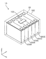
- FIG. 1 is a schematic external view of the power storage system 10 according to the present embodiment.
- the power storage system 10 according to the present embodiment includes an estimation device 100, power storage elements 200A to 200E, and a storage case 300 for accommodating the estimation device 100 and the power storage elements 200A to 200E.
- the power storage device 20 is configured by the power storage elements 200A to 200E.
- the power storage elements 200 are also simply described.
- the estimation device 100 is, for example, a flat plate-shaped circuit board arranged on the upper surface of a plurality of power storage elements 200 and equipped with a circuit for estimating the temperature of the power storage elements 200 at a predetermined time point. Specifically, the estimation device 100 is connected to all the power storage elements 200, acquires information from each power storage element 200, and estimates the temperature of each power storage element 200 at a predetermined time point.
- the location of the estimation device 100 is not limited to the upper surface of the power storage element 200. Alternatively, it may be the side surface of the power storage element 200 or the lower surface of the power storage element 200. Further, the shape of the estimation device 100 is not particularly limited. Further, the estimation device 100 may be a server device located at a location away from the power storage element 200, and may be configured to acquire information of sensors (sensors 103A to 103D shown in FIG. 3) by communication. Many of the mathematical formulas described in the present specification are simple, and when the power storage element is a small power storage element 200 as described in the examples, an inexpensive arithmetic processing unit is sufficient.
- a larger energy storage element is the calculation target or a large-scale energy storage device composed of a plurality of energy storage elements, the calculation load increases and the calculation processing speed decreases. In such a case, it may be possible to perform high-speed processing by transferring the sensor acquisition value to a server device located away from the power storage element by communication and performing arithmetic processing on the server device.
- the power storage element 200 is a secondary battery such as a lithium ion secondary battery.
- the power storage element 200 is applied to a power source for automobiles such as an electric vehicle (EV), a hybrid electric vehicle (HEV), or a plug-in hybrid electric vehicle (PHEV), a power source for electronic devices, a power source for power storage, and the like.
- a power source for automobiles such as an electric vehicle (EV), a hybrid electric vehicle (HEV), or a plug-in hybrid electric vehicle (PHEV), a power source for electronic devices, a power source for power storage, and the like.
- EV electric vehicle
- HEV hybrid electric vehicle
- PHEV plug-in hybrid electric vehicle
- the number of power storage elements 200 is not limited to five.
- the number of power storage elements 200 may be one or two or more. Further, some power storage elements 200 may be connected in parallel.
- the power storage element 200 may be a secondary battery other than the lithium ion secondary battery. Further, the same principle holds for all devices having a heat generating portion (for example, power module, primary battery, fuel cell, electronic board, switchboard, etc.), not limited to the secondary battery.
- FIG. 2 is a perspective view showing the configuration of the power storage element 200. Specifically, FIG. 2 shows a configuration in which the main body portion of the container 210 is separated from the power storage element 200.
- the power storage element 200 includes a container 210, a positive electrode terminal 220, and a negative electrode terminal 230.
- a positive electrode current collector 240, a negative electrode current collector 250, and two electrode bodies 261,262 are housed inside the container 210.
- a spacer arranged inside the container 210, a gasket arranged around the terminal, a gas discharge valve for releasing the pressure when the pressure inside the container 210 rises, an electrode body 261 and the like.
- An insulating film or the like that wraps 262 or the like may be arranged.
- the electrolytic solution is sealed inside the container 210, the illustration is omitted.
- the type of the electrolytic solution is not particularly limited as long as it does not impair the performance of the power storage element 200, and various types can be selected.
- a solid exhibiting ionic conductivity for example, an ionic conductive polymer or an ionic conductive ceramic
- ionic conductivity for example, an ionic conductive polymer or an ionic conductive ceramic
- the container 210 is a box-shaped member having plate-shaped side walls 211 to 214 and a bottom wall 215 constituting the container body, and a plate-shaped lid 216 that closes the opening of the container body.
- a weldable metal such as stainless steel, aluminum, or an aluminum alloy, or a resin can also be used.
- the electrode bodies 261, 262 include a positive electrode plate, a negative electrode plate, and a separator, and are two storage elements (power generation elements) capable of storing electricity. That is, the two electrode bodies 261 and the electrode body 262 are arranged side by side in the direction of the Y axis shown in FIG.
- the positive electrode plates of the electrodes 261 and 262 have a positive electrode active material layer formed on a positive electrode base material layer which is a long strip-shaped current collecting foil made of aluminum, an aluminum alloy, or the like.
- the negative electrode plate is formed by forming a negative electrode active material layer on a negative electrode base material layer which is a long strip-shaped current collecting foil made of copper, a copper alloy, or the like.
- the separator for example, a microporous sheet made of resin or a non-woven fabric can be used.
- the current collecting foil known materials such as nickel, iron, stainless steel, titanium, calcined carbon, conductive polymer, conductive glass, and Al—Cd alloy may be used as appropriate.
- Electrode plates are laminated and formed on the electrode bodies 261 and 262. That is, the electrode bodies 261 and 262 are formed by winding those arranged in layers so that the separator is sandwiched between the positive electrode plate and the negative electrode plate. Specifically, in the electrode bodies 261 and 262, the positive electrode plate and the negative electrode plate are wound by shifting each other in the direction of the winding axis (virtual axis parallel to the X axis shown in FIG. 2) via the separator. Has been done. Further, on the outermost periphery of each of the electrode bodies 261 and 262, only the separators that do not pass through either the positive electrode plate or the negative electrode plate are doubly overlapped and wound one or two times to ensure insulation. .. In the present embodiment, an oval shape is shown as a cross-sectional shape of the electrode bodies 261 and 262. Alternatively, the cross-sectional shape of the electrode bodies 261 and 262 may be an elliptical shape or the like.
- the positive electrode active material used for the positive electrode active material layer any known material can be appropriately used as long as it is a positive electrode active material that can occlude and release lithium ions.
- a polyanionic compound such as LiMPO 4 , LiMSiO 4 , LiMBO 3 (M is one or more transition metal elements selected from Fe, Ni, Mn, Co, etc.), LiMn 2 O 4 And LiMn 1.5 Ni 0.5 O 4 spinnel type lithium manganese oxide, LiMO 2 (M is Fe, Ni, Lithium transition metal oxides such as one or more transition metal elements selected from Mn, Co and the like, including lithium excess type composite oxides) can be used.
- the negative electrode active material used for the negative electrode active material layer a known material can be appropriately used as long as it is a negative electrode active material capable of occluding and releasing lithium ions.
- the negative electrode active material lithium metal, lithium alloy (lithium metal-containing alloy such as lithium-silicon, lithium-aluminum, lithium-lead, lithium-tin, lithium-aluminum-tin, lithium-gallium, and wood alloy)
- alloys capable of storing and releasing lithium carbon materials (for example, graphite, non-graphitized carbon, easily graphitized carbon, low-temperature calcined carbon, amorphous carbon, etc.), silicon oxide, metal oxide, lithium metal oxide (Li 4 Ti 5 O 12, etc.), polyphosphate compounds, or compounds of transition metals and Group 14 to Group 16 elements, such as Co 3 O 4 and Fe 2 P, which are generally called conversion negatives. Be done.
- the positive electrode terminal 220 is an electrode terminal electrically connected to the positive electrode plate of the electrode bodies 261,262, and the negative electrode terminal 230 is an electrode terminal electrically connected to the negative electrode plate of the electrode bodies 261,262.
- the positive electrode terminal 220 and the negative electrode terminal 230 are attached to the lid body 216.
- the positive electrode terminal 220 and the negative electrode terminal 230 are formed of, for example, aluminum or an aluminum alloy.
- the positive electrode current collector 240 is a member having conductivity and rigidity that is electrically connected (bonded) to the positive electrode terminal 220 and the positive electrode plate of the electrode bodies 261,262.
- the negative electrode current collector 250 is a member having conductivity and rigidity that is electrically connected (bonded) to the negative electrode terminal 230 and the negative electrode plate of the electrode bodies 261,262.
- the positive electrode current collector 240 and the negative electrode current collector 250 are fixed to the lid body 216.
- the positive electrode current collector 240 is formed of aluminum, an aluminum alloy, or the like, similarly to the positive electrode base material layer.
- the negative electrode current collector 250 is formed of copper, a copper alloy, or the like, similarly to the negative electrode base material layer.
- FIG. 3 is a block diagram showing an internal configuration of the estimation device 100.
- the estimation device 100 includes a calculation unit (estimation unit) 101, a storage unit 102, an input unit 103, and an output unit 104.
- the calculation unit 101 is an arbitrary calculation circuit including a microcomputer, a volatile or non-volatile memory, and the like.
- the microcomputer controls the operation of each part of the hardware according to the computer program stored in the memory in advance, and causes the entire device to function as the estimation device of the present application.
- the calculation unit 101 performs a calculation for estimating the temperature of each power storage element 200 based on the heat balance model of each power storage element 200 represented by using the element temperature and the environmental temperature.
- the element temperature indicates the temperature of the power storage element 200 measured by the temperature sensor 103A described later.
- the environmental temperature indicates the outside air temperature of the power storage device 20 (that is, the temperature of the space in which the power storage device 20 is arranged). A method of estimating the temperature of each power storage element 200 without measuring the environmental temperature will be described later in the second embodiment.
- the arithmetic unit 101 is an arbitrary arithmetic circuit including a microcomputer, a volatile or non-volatile memory, and the like.
- the arithmetic unit 101 may be configured by a CPU (Central Processing Unit), a ROM (Read Only Memory), a RAM (Random Access Memory), or the like.
- the storage unit 102 is a storage device such as a flash memory.
- the storage unit 102 stores data necessary for calculating the temperature estimation of each power storage element 200.
- the storage unit 102 includes data such as the volume, surface area, specific heat, density of each power storage element 200, the value of heat conductance between adjacent power storage elements 200, and the heat transfer coefficient to the outside.
- the value of thermal conductance used in the calculation of temperature estimation may change as the power storage element 200 expands. Therefore, the storage unit 102 may store a table showing the relationship between the strain value measured by the strain sensor 103C, which will be described later, and the thermal conductance value.
- the value of the heat transfer coefficient used in the calculation of temperature estimation may change depending on the air flow around the power storage device 20. Therefore, the storage unit 102 may store a table showing the relationship between the value of the flow velocity measured by the current meter 103D, which will be described later, and the value of the heat transfer coefficient. Alternatively, the calculation of the heat transfer coefficient may be performed from the relational expression that holds between the Nusselt number, the Prandtl number, and the Reynolds number.
- the input unit 103 includes an interface for connecting various sensors.
- the sensor connected to the input unit 103 includes a temperature sensor 103A that measures the temperature (element temperature) of the power storage element 200.
- the temperature sensor 103A is an existing sensor such as a thermocouple or a thermista.
- the power storage element 200 to be measured is a part (for example, the power storage element 200E) of the five power storage elements 200A to 200E included in the power storage device 20.
- the number of power storage elements 200 to be measured may be one, or may be two to four. That is, when the number of power storage devices 20 is N (N is an integer of 2 or more), the power storage elements 200 to be measured are appropriately installed in the range of 1 to (N-1).
- the temperature sensor 103A is arranged, for example, on the upper surface of the power storage device 20. Alternatively, the temperature sensor 103A is arranged on the side surface or the lower surface of the power storage device 20.
- a temperature sensor 103B for measuring the environmental temperature of the power storage device 20 may be connected to the input unit 103.
- the temperature sensor 103B is an existing sensor such as a thermocouple or a thermistor.
- the temperature sensor 103B may be installed at an appropriate location of the power storage device 20, or may be installed at an appropriate location around the storage device 20.
- the estimation device 100 includes a communication interface for communicating with an external device, the environmental temperature information may be acquired by communication instead of the configuration in which the environmental temperature information is acquired from the temperature sensor 103B.
- a distortion sensor 103C that detects the magnitude of distortion of the power storage element 200 may be connected to the input unit 103.
- the strain sensor 103C is an existing sensor using a strain gauge type load cell or the like.
- the strain sensor 103C is provided for each of the power storage elements 200.
- a current meter 103D that measures the flow of air around the power storage device 20 may be connected to the input unit 103.
- the current meter 103D is an existing measuring device such as a flow meter.
- the current meter 103D is installed at an appropriate place around the power storage device 20.
- the output unit 104 includes an interface for connecting an external device.
- the output unit 104 outputs the temperature estimation result of each power storage element 200, which is the calculation result of the calculation unit 101, to an external device.
- the external device connected to the output unit 104 is, for example, a management device for managing the state of the power storage device 20 or a control device for controlling the operation of the power storage device 20.
- the external device connected to the output unit 104 may be a control device such as a mobile terminal or an electric vehicle that operates by the electric power supplied from the power storage device 20.
- the external device may calculate the charge rate (SOC: State Of Charge), soundness (SOH: State Of Health), etc. of the power storage device based on the temperature estimation result of the estimation device 100.
- the external device may control the operation of the power storage device 20 according to the temperature estimation result of the estimation device 100.
- the estimation device 100 determines the element temperature measured for some of the power storage elements 200 (for example, 200E) among the plurality of power storage elements 200 (200A to 200E) constituting the power storage device 20 and the environmental temperature of the power storage device 20.
- the temperature of each power storage element 200A to 200E is estimated using the considered heat balance model.
- the heat balance model of each power storage element 200A to 200E is represented by a heat transfer equation, and for example, the following equation 1 is used.
- T 1 to T 5 , S 1 to S 5 , Q 1 to Q 5 , and h 1 to h 5 are the temperature (K), surface area (m 2 ), and calorific value (W) of the power storage elements 200A to 200E, respectively.
- Heat transfer coefficient to the outside (W / m 2 / K).
- k ij represents the thermal conductance (W / K) between the i-th power storage element 200 (for example, the power storage element 200A) and the j-th power storage element 200 (for example, the power storage element 200B).
- ⁇ , C p , and V represent the density (kg / m 3 ), specific heat (J / kg / K), and volume (m 3 ) of the power storage element 200.
- the density, specific heat, and volume values may be set individually for the power storage elements 200A to 200E.
- T 0 represents the environmental temperature (K).
- t represents time (s).
- the left side in Equation 1 represents the amount of heat used to raise the temperature of the power storage element 200.
- the term including the thermal conductance kij on the right side represents the thermal conduction based on the temperature difference between the adjacent power storage elements 200 and 200.
- the term including the heat transfer coefficients h 1 to h 5 on the right side represents heat dissipation from the power storage element 200 to the outside, and is a negative value when heat dissipation is generated.
- Term including Q 1 ⁇ Q 5 represents the heat generation of the electric storage device 20. Factors of heat generation include Joule heat and reaction heat due to energization.
- the calculation unit 101 may perform a calculation using a preset value as the value of the thermal conductance kij in Equation 1, and performs a calculation using a value changed according to the distortion of the power storage element 200. May be good. In the latter case, the value of the thermal conductance corresponding to the distortion of the power storage element 200 may be read from the table defining the relationship between the distortion of the power storage element 200 and the thermal conductance.
- the calculation unit 101 may perform a calculation using a preset value as the value of the heat transfer coefficient h 1 to h 5 in the equation 1, and calculates using a value changed according to the flow velocity of the surrounding fluid. May be done. In the latter case, the value of the heat transfer coefficient according to the flow velocity of the surrounding fluid may be read from the table that defines the relationship between the flow velocity and the heat transfer coefficient.
- Equation 2 By rewriting the time derivative on the left side of Equation 1 with the time difference, the following Equation 2 can be obtained.
- k is a natural number and represents a time step.
- ⁇ t represents the time step width (s) of the calculation.
- ⁇ ( ⁇ C p V / ⁇ t) -1 .
- the state vector x (k), the vector b, and the matrix A are defined by the following number 4.
- the observation equation is expressed as in equation 6.
- the T in the upper right represents transpose. More generally, the direct term is added to the right side, but in the case of heat transfer, the representative time is larger than the calculation time, so it can be ignored in many cases.
- the scalar observation value y (k) was used as the observation variable.
- C is an observation vector (or observation matrix) having the element temperature measured by the temperature sensor 103A as an element.
- the observation vector is expressed by the following equation 7.
- Equation 5 is an equation of state that simulates heat conduction in the power storage device 20
- Equation 6 is an equation of state that represents the relationship between the equation of state and the observation variables that can be observed by the temperature sensor 103A.
- the temperature is estimated using an observer corresponding to the actual system represented by the equation of state of equation 5 and the observation equation of equation 6.
- FIG. 4 is a state variable diagram including an observer.
- the observer O1 corresponding to the actual system represented by the equation of state of Equation 5 and the observation equation of Equation 6 is represented by the discrete space equation of state shown in Equation 8 and the observation equation shown in Equation 9.
- z -1 represents a delayer by z-transform
- I represents a unit matrix.
- the parameters A, b, c and the control input u (k) are the same in the actual system and the observer O1, but the state variables and the observed variables are different.
- the behavior of the observer O1 is modified by using the feedback.
- L be the feedback gain (observer gain).
- L is a vertical vector having the same dimension as x (k).
- the discrete space equation of state with the observer gain added is represented by the following equation tens.
- the temperature sensor 103A measures the temperature through the state variable x # hat (k) of the observer O1. It is possible to estimate the temperature of the portion where the temperature is not set (for example, the temperature on the power storage elements 200A to 200D).
- FIG. 5 is a flowchart illustrating a processing procedure of the estimation process executed by the estimation device 100.
- the calculation unit 101 of the estimation device 100 reads numerical values such as physical property values and boundary conditions from the storage unit 102 (step S101), and exhibits the discrete space state equations and observation equations indicating the actual system, and the discrete space state indicating the observer O1.
- the equation and the observation equation are set (step S102).
- the calculation unit 101 acquires the measurement result by the temperature sensor 103A through the input unit 103 (step S103).
- the calculation unit 101 executes an operation based on the acquired measurement result, the discrete equation and the observation equation indicating the set actual system, and the discrete equation and the observation equation indicating the observer O1 (step S104), and the state of the observer O1.
- An estimate of the temperature is obtained through the state variable x # hat (x) included in the equation (step S105).
- the temperature measured at a specific place for example, the power storage element 200E
- the estimated temperature at the place are The temperature of other parts (for example, power storage elements 200A to 200D) can be estimated while feeding back the difference between the two.
- the temperature of the power storage elements 200A to 200D is estimated based on the temperature measured for the power storage element 200E and the amount of heat absorption and heat generation.
- the endothermic amount includes not only the endothermic heat of the electrode portion, but also a member that electrically connects the power storage elements (not shown in FIG. 1, for example, a positive terminal 220 of the power storage element 200A and a negative terminal of the power storage element 200B).
- the amount of heat generated by an electrical connection member such as a bus bar that connects the 230 may be added.
- all state variables x (k) are estimated from only one observation value of the scalar observation value y (k).
- all the state variables can be estimated by the same calculation method.
- the state vector x (k) has been described as one state quantity for one power storage device, the power storage device may be divided into a plurality of regions to consider a three-dimensional temperature distribution, and the positive electrode / negative electrode terminals may be considered. Even if the temperature of the electrical connection member such as the bus bar or the bus bar is included in the state vector x (k), the temperature can be estimated by exactly the same logic.
- the heat conduction equation of the power storage device 20 is expressed as follows.
- ⁇ , C p , and V represent the density (kg / m 3 ), specific heat (J / kg / K), and volume (m 3 ) of the power storage device 20.
- T represents the temperature (K) of the power storage device 20
- T 0 represents the temperature of the ambient environment.
- t is the time (s)
- h is the heat transfer coefficient (W / m 2 / K) of the path from the power storage device 20 to the surrounding environment
- S is the surface area of the power storage device 20 (m 2 )
- Q is the heat generation of the power storage device 20. Represents a quantity (W).
- the heat conduction equation for the power storage device 20 is shown.
- the heat conduction equation may be described for the individual power storage elements 200A to 200E constituting the power storage device 20.
- T is the temperature of the power storage device 20, for example, the temperature measured by the temperature sensor 103A.
- the second term on the right side represents endothermic heat generated by Joule heat generation and electrochemical reaction heat, and is a value that can be calculated using internal resistance, reaction heat, energization amount, and the like. That is, the second term on the right side can be treated as a known value.
- the third term on the right side is a term representing the influence of the temperature of the ambient environment, and is an unknown value. The third term on the right side includes not only heat dissipation from the power storage device 20 to the outside but also heat conduction from the housing case 300 and the like.
- Equation 13 the equation of state is described with the second term on the right side of Equation 13 as the control input and the third term as the disturbance.
- the number 13 is simplified, it is expressed as the number 14.
- A ⁇ hS / ⁇ C p V
- B 1 / ⁇ C p V
- D hS / ⁇ C p V
- u Q
- d T 0 .
- u represents the control input
- B and u and D and d can be set arbitrarily.
- A, B, and D are scalars, but they can also be described as vectors.
- the fluctuation speed of disturbance is sufficiently slower than the speed of calculation processing, especially in the case of thermal problems. Therefore, the first derivative of the disturbance may be set to zero.
- y represents the observed value
- C represents the observation matrix, but for the time being, y and C are treated as scalars.
- the temperature is estimated using an observer corresponding to the actual system represented by the equation of state of Equation 20 and the observation equation of FIG.
- FIG. 6 is a state variable diagram including a disturbance observer. Assuming that the systems represented by equations 20 and 21 are observable, the equations of state and observations of the disturbance observer O2 are expressed as equations 22 and 23, respectively.
- x and y with hat represents the estimation value of the observer
- L e denotes an observer gain.
- the observer gain L e is such that the matrix (A e- L e C e ) becomes a near-stable matrix, that is, all the real parts of the eigenvalues of the matrix (A e- L e C e) are negative. It may be set appropriately.
- the estimation device 100 can estimate the temperature outside the power storage device 20 through the d # hat (k) obtained from the disturbance observer O2.
- the estimation device 100 can estimate that the outside of the power storage device 20 is in a high temperature state.
- the estimation device 100 compares the value of d obtained from the disturbance observer O2 with the preset threshold value, and when the value of d is higher than the threshold value, informs that the outside of the power storage device 20 is in a high temperature state. It may be notified from the output unit 104.
- one disturbance in the power storage device 20 is estimated by one observed value.
- the state vector x in the equation 17 is a vertical vector of (p + q) ⁇ 1
- A is a matrix of p ⁇ p
- a unit matrix of q ⁇ q is used instead of 1 of the scalar
- B is a vertical vector of p ⁇ 1.
- y in the equation 18 may be a vertical vector of r ⁇ 1
- c may be a matrix of r ⁇ p.
- the estimation device 100 may estimate a plurality of disturbances (temperatures outside the power storage device 20) and map and display the estimated temperature outside the power storage device 20 as a function of position.
- the temperature of the ambient environment can be estimated.
- the temperature sensor 103B for measuring the temperature of the ambient environment can be omitted.
- the estimation device 100 may compare the estimated temperature of the ambient environment with the measured value of the temperature sensor 103B, and determine the validity of the measured value of the temperature sensor 103B.
- the temperature sensor 103B may be an inappropriate value (for example, the temperature is measured in a region lower than the surroundings), the observer calculation may calculate a temperature that deviates from the actual state. is there.
- the temperature can be estimated while verifying the validity of the temperature of the ambient environment used in the calculation of the observer.
- the Kalman filter is used to suppress the influence of noise.
- the discrete space state equation and the observation equation including the system noise w (k) and the observation noise v (k) are represented by the following equations 24 and 25, respectively.
- the observer gain L e of the disturbance observer using a Kalman filter is expressed by the following Expression 26.
- V represents the covariance matrix of the system noise
- W represents the covariance matrix of the observed noise.
- the observer gain L e is derived via the Ricatch equation based on the LQ (Linear Quadratic) control theory that minimizes the evaluation function expressed by the quadratic form.
- the matrix P in Equation 26 is represented as a solution that satisfies the following Ricatch equation.
- the third embodiment even when including the system noise and observation noise, by appropriately evaluate the observer gain L e of the disturbance observer using a Kalman filter, the influence of the system noise and observation noise It is possible to estimate the temperature using an observer while suppressing the noise.
- An equivalent circuit model is well known as a mathematical model representing the electrical characteristics of a power storage element 200 represented by a lithium ion battery.
- FIG. 7 is a circuit diagram showing an example of an equivalent circuit model.
- the equivalent circuit model of the power storage element 200 is often represented by a combination of a resistor, a capacitance component, and a voltage source as shown in FIG. 7, for example.
- R 0 is an ohm resistance component
- R 1 is a positive electrode reaction resistance component
- C 1 is a positive electrode capacitance component
- R 2 is a negative electrode reaction resistance component
- C 2 is a negative electrode capacitance component
- E eq is an open circuit.
- FIG. 7 is an example, and there is no limitation on the combination of series and parallel and the number and types of electric circuit elements.
- SOC is an abbreviation for State Of Charge, and represents a fully charged state as 100% and a fully discharged state as 0%.
- the components of R 0 to R 2 , C 1 to C 2 , and E eq are expressed as a two-variable function of SOC and temperature. As the relationship between the values of R 0 to R 2 , C 1 to C 2 , and E eq , and the SOC and temperature, the values obtained in advance may be used.
- the power storage system 10 may hold a mathematical model of the power storage element 200 in addition to the estimation device 100.
- the mathematical model of the power storage element 200 includes information on the open circuit potential and internal impedance of the power storage element 200, and shows the relationship between current and voltage.
- the mathematical model of the power storage element 200 is used for a state estimator (also referred to as an observer) of the power storage element 200 and future prediction.
- the estimation device 100 By using the estimation device 100, it is possible to accurately and accurately estimate the temperature of each power storage element 200, so that the characteristic value of each element of the equivalent circuit becomes more accurate and the simulation of charge / discharge characteristics can be improved. You can expect it.
- the Newman model it is assumed that a plurality of active material particles having a uniform particle size constituting the positive and negative electrodes are arranged adjacent to each other.
- the amount to be solved is the potential of the active material particles (solid phase potential), the potential of the electrolytic solution (liquid phase potential), the ion concentration of the electrolytic solution, and the molecular diffusion of the stored lithium ions in the active material of the positive and negative electrodes. These amounts are solved in consideration of the equilibrium potential at the solid-liquid interface, the activation overvoltage determined by the Butler-Volmer equation, and the stoichiometry.
- the Newman model is described by the Nernst-Planck equation, the charge conservation equation, the diffusion equation, the Butler-Volmer equation, and the Nernst equation described below.
- the Nernst-Planck equation is an equation for solving ion electrophoresis and ion diffusion in an electrolytic solution or a porous electrode, and is expressed by the following equation.
- ⁇ l and eff are liquid phase conductivity (S / m), ⁇ l is liquid phase potential (V), R is gas constant (J / (K ⁇ mol)), T is temperature (K), and F. is the Faraday constant (C / mol), f is the activity coefficient, c l is the electrolyte ion concentration (mol / m 3), t + is a cation transport number, i tot is the reaction current density per volume.
- the effective liquid phase conductivity ⁇ l, eff is the apparent conductivity in the porous body, and is often expressed as a function of the conductivity of the liquid phase bulk and the solid phase volume ratio ⁇ s.
- the charge conservation formula is a formula that expresses electron conduction in a porous electrode or a current collector, and is expressed by the following formula.
- ⁇ s is the solid phase potential (V)
- ⁇ s is the solid phase conductivity (S / m)
- itot is the reaction current density per volume (A / m 3 ).
- the solid phase refers to the electron conduction part.
- the diffusion equation is an equation that expresses the diffusion of occluded lithium ions in active material particles, and is expressed by the following equation.
- c s is the concentration of occluded lithium ions in the solid phase (mol / m 3 )
- t is the time (s)
- D s is the diffusion coefficient of occluded lithium ions in the active material particles (m 2 / s). .. D s may be a function of occluded lithium ions in the active material particles, electrode composition, SOC (State Of Charge), or temperature.
- the Butler-Volmer equation is an equation that expresses the activation overvoltage in the charge transfer reaction that occurs at the interface between the active material particles and the electrolytic solution
- the Nernst equation is the definition equation of the equilibrium potential E eq , which are expressed by the following equations, respectively. ..
- i loc is the reaction current density (A / m 2 )
- i 0 is the exchange current density (A / m 2 )
- ⁇ a and ⁇ c are the transition coefficients
- ⁇ is the activation overvoltage (V)
- E eq is.
- E 0 is the standard equilibrium potential (V)
- n is the number of involved electrons
- a 0 is the oxidizing agent concentration
- a R is the reducing agent concentration (mol / m 3 ).
- Equation 32 shows the relational expression between the occluded lithium ion concentration in the solid phase and the occluded lithium ion flux involved in the charge transfer reaction on the surface of the active material particles.
- r 0 represents the radius (m) of the active material particles
- J s is the flux of occluded lithium ions (mol / m 2 s).
- J s is the amount of stored lithium ions per unit area and unit time that is lost and generated by the charge transfer reaction.
- Equation 33 is an equation expressing the relationship between the flux J s of the occluded lithium ion and the reaction current density i loc.
- Equation 34 is an equation expressing the relationship between the reaction current density i loc and the reaction current density i tot per volume.
- S v is the specific surface area per unit volume (m 2 / m 3 ).
- S v may be a function of the radius r 0 of the active material particle.
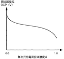
- FIG. 8 is a graph showing the relationship between the occluded lithium ion concentration in the solid phase and the open circuit potential (OCP) in a typical positive electrode material.
- ⁇ is a dimensionless number defined by Equation 35 and is a function of the occluded lithium ion concentration c s.
- the open circuit potential OCP of the positive electrode is expressed as a function of the positive electrode ⁇ .
- Equation 2 the second term on the right side of Equation 2 can be ignored.
- the liquid phase current will be calculated by Ohm's law. Since terms with strong non-linearity can be ignored, calculation stability can be improved while reducing the calculation load.
- the Butler-Volmer equation was used as the equation expressing the activation overvoltage in the charge transfer reaction, but the Tafel equation may be used instead. Furthermore, it may be given in any table data format.
- the exchange current density may be a function of the occluded lithium ion concentration in the electrode, the electrode composition, the SOC, or the temperature.
- the diffusion equation of the charge carrier in the solid phase described in Equation 4 may be omitted if the influence of the concentration overvoltage is negligible or if the calculation load is to be reduced.
- An estimation device that gives temperature dependence to the reaction resistance equation (that is, Butler-Volmer equation), ionic conductivity, ion diffusivity, diffusion coefficient of occluded lithium ions in the active material, or other physical property values in this model.
- a single particle model may be used in which the electrodes are represented by a single active material particle.
- the single particle model for example, the non-patent document "Single-Particle Model for a Lithium-Ion Cell: Thermal Behavior, Meng Guo, Godfrey Sikha, and Ralph E. White, Journal of The Electrochemical Society, 158 (2) 122- You can refer to the model disclosed in "132 (2011)”.
- the single particle model is a model that simplifies the above-mentioned Newman model and assumes that all the active material particles constituting the positive and negative electrodes are the same.
- reaction resistance equation that is, Butler-Volmer equation
- the ionic conductivity, the ion diffusivity, the diffusivity of occluded lithium ions in the active material, or other physical property values are given temperature dependence, and the estimation device 100 By giving the temperature estimate obtained from the above as an input condition to the simulation of the single particle model, precise charge / discharge characteristic simulation becomes possible.
- a polynomial model may be used that expresses the open circuit voltage OCV and the internal resistance as a power function of temperature and SOC.
- the polynomial model for example, the non-patent document "Modeling the Dependence of the Discharge Behavior of a Lithium-Ion Battery on the Environmental Temperature, Ui Seong Kim, Jaesin Yi, Chee Burm Shin, Taeyoung The model disclosed in "Electrochemical Society, 158 (5) 611-618 (2011)" can be referred to.
- the temperature estimate described in the embodiment as an input condition to the simulation of the polynomial model, a precise charge / discharge characteristic simulation becomes possible.
- a precise charge / discharge characteristic simulation can be performed by using the estimation device 100.
- cooling and heating conditions include, for example, air volume, wind direction, and air temperature for air cooling, and refrigerant flow rate and refrigerant temperature for water cooling.
- feedback control such as PID control or on / off control may be used.
- the estimation device 100 By using the estimation device 100, abnormal heating of the power storage element 200 can be estimated.
- the estimated temperature of the power storage element 200 may be an abnormal value (the abnormal value is often higher than usual). Since such a power storage element 200 may be in an abnormal state due to an internal short circuit or the like, it is desirable to take measures such as disconnection immediately.
- Battery deterioration mechanisms typified by lithium-ion batteries include at least (1) isolation of active material particles, (2) reduction of charge carriers, (3) increase of electrical resistance, and (4) conductivity in electrolytes. It is known that there are four types of decrease. These deterioration mechanisms contribute in combination to change the charge / discharge characteristics of the battery, causing a decrease in capacity.
- the estimation device 100 can determine the rate of deterioration, assuming that it has a temperature dependence based on, for example, the Arrhenius equation. Alternatively, the estimator 100 may determine the rate of progression of deterioration based on any other function of temperature. It is known that deterioration includes aging deterioration (sometimes called calendar deterioration) that deteriorates with time and cycle deterioration that deteriorates according to the number of cycles, and it is an experiment that both are functions of temperature. It has been confirmed in.
- the estimation device 100 may simulate the deterioration of the power storage device 20 based on the determined deterioration progress rate.
- the deterioration prediction method for example, the method disclosed in Patent Document "Japanese Patent Application No. 2019-064218: Development Support Device, Development Support Method, and Computer Program" may be used.
- the calculation unit 101 of the estimation device 100 calculates the speed at which the electrical resistance increases, that is, the speed at which the electrical conductivity decreases, according to the following equation of equations 36 or 37.
- r cycle and res represent the speed (S / m / number of cycles) at which the electrical conductivity decreases depending on the number of cycles.
- r cycle, res ⁇ 0. k 0, res are reaction rate constants, for example a function of the number of cycles.
- E a0, res represents the activation energy (J / mol) of cycle deterioration, and is a coefficient representing the influence of temperature.
- i is the current density (A / m 2 ), and
- the reaction rate is set to a constant.
- rt and res represent the speed at which the electrical conductivity decreases with the elapsed time (S / m / s).
- rt, res ⁇ 0.
- k 1 and res are reaction rate constants, for example a function of time.
- k 1, res may be defined by any function based on experimental data.
- E a1 and res represent the activation energy (J / mol) of deterioration over time, and are coefficients representing the influence of temperature.
- ⁇ t is the elapsed time (s).
- the rate at which the electrical conductivity decreases is the sum of the numbers 36 and 37.
- the calculation unit 101 of the estimation device 100 calculates the speed at which the isolation of the active material particles progresses by the formula of the equation 38 or 39.
- r cycle and iso represent the speed (1 / number of cycles) at which the isolation of the active material particles progresses depending on the number of cycles.
- k 0, iso is the reaction rate constant, for example a function of the number of cycles.
- E a0 and iso represent the activation energy (J / mol) of cycle deterioration, and are coefficients representing the influence of temperature.
- i is the current density (A / m 2 ).
- rt and iso represent the rate at which the isolation of the active material particles progresses with the elapsed time (1 / s).
- rt, iso ⁇ 0.
- k 1 and iso are reaction rate constants, for example a function of time.
- k 1, iso may be defined by any function based on experimental data.
- E a1 and iso represent the activation energy (J / mol) of deterioration over time, and are coefficients representing the influence of temperature.
- ⁇ t is the elapsed time (s).
- the rate at which isolation progresses is the sum of numbers 38 and 39.
- the deterioration mechanism due to the decrease in charge carriers is a phenomenon in which ions in the electrolytic solution disappear due to a side reaction on the surface of the electrode during charging.
- the third degradation mechanism is known to be accelerated by both time and cycle in the case of lithium-ion batteries.
- P is a substance that is the source of by-products.
- x: (1-x) is the stoichiometric ratio of the main reaction: the side reaction, but it is usually (1-x) / x ⁇ 1, and the stoichiometric coefficient of the side reaction is very small.
- Lithium ions which are obtained by multiplying the stoichiometric coefficient of the side reaction by the current density and the surface area of the electrode and dividing by the Faraday constant, disappear from the electrolytic solution.
- the amount of Li + disappeared in the liquid phase is J Li + (mol / m 2 s)
- the amount of Li inflow to the solid phase J Li (mol / m 2 s) is set.
- J Li xJ Li + .
- x may be a function of the upper limit value SOC max, the lower limit value SOC min , the temperature T, and the current density i as appropriate. For example, it may be a function as described in Equation 40.
- h is an arbitrary function defined to fit the experimental data. Note that 0.0 ⁇ x ⁇ 1.0.
- the deterioration mechanism due to the decrease in conductivity in the electrolytic solution is mainly the decrease in conductivity due to the disappearance of the charge carrier.
- Charge carrier disappearance occurs mainly when a resistor film is formed on the surface of the active material particles.
- FIG. 9 is a graph showing the relationship between the lithium ion concentration in the electrolytic solution and the ionic conductivity.
- the horizontal axis of the graph shown in FIG. 9 shows the lithium ion concentration in the electrolytic solution, and the vertical axis shows the ion conductivity.
- the relationship between the lithium ion concentration in the electrolytic solution and the ionic conductivity is often as shown in FIG.
- the calculation unit 101 of the estimation device 100 can calculate the rate of decrease in conductivity by the same function as in equations 36 and 37.
- the power storage device 20 may be a module in which a plurality of cells are connected in series, a bank in which a plurality of modules are connected in series, a domain in which a plurality of banks are connected in parallel, or the like.
- the estimation device 100 acquires the temperature measured for some modules as the element temperature, and each power storage element 200 including the temperature of the unmeasured module.
- the temperature of (in this example, the temperature of each module) may be estimated.
- the estimation device 100 acquires the temperature measured for a part of the banks as the element temperature, and includes the temperature of each of the unmeasured banks.
- the temperature of the power storage element 200 (in this example, the temperature of each bank) may be estimated.
- Power storage system 20 Power storage device 100 Estimator 101 Calculation unit 102 Storage unit 103 Input unit 103A Temperature sensor 103B Temperature sensor 103C Strain sensor 103D Current meter 104 Output unit 200 Power storage element
Landscapes
- Chemical & Material Sciences (AREA)
- Chemical Kinetics & Catalysis (AREA)
- Electrochemistry (AREA)
- General Chemical & Material Sciences (AREA)
- Physics & Mathematics (AREA)
- General Physics & Mathematics (AREA)
- Engineering & Computer Science (AREA)
- Manufacturing & Machinery (AREA)
- Secondary Cells (AREA)
Abstract
This estimation device is provided with: an acquiring unit which acquires a measurement result from a temperature sensor for measuring temperature at a specific location to which heat generated by an electrical storage device is transmitted; and an observer which, in accordance with input of the measurement result, estimates the temperature at a location where the temperature sensor has not performed measurement.
Description
本発明は、推定装置及び推定方法に関する。
The present invention relates to an estimation device and an estimation method.
近年、リチウムイオン電池などの蓄電素子は、ノート型パーソナルコンピュータ、スマートフォンなどの携帯端末の電源、再生可能エネルギー蓄電システム、IoTデバイス電源など、幅広い分野において使用されている。
In recent years, power storage elements such as lithium-ion batteries have been used in a wide range of fields such as notebook personal computers, power supplies for mobile terminals such as smartphones, renewable energy power storage systems, and power supplies for IoT devices.
このような蓄電素子を備えたバッテリの運用において、蓄電素子における温度をモニタリングすることは不可欠である。蓄電素子の温度をモニタリングする手法として、例えば特許文献1には、電池セルを複数のセルブロックに分割し、温度が測定される温度測定位置のセルブロックの温度と、各セルブロックにおける発熱量とに基づき、温度未測定位置のセルブロックの温度を推定する手法が開示されている。
In the operation of a battery equipped with such a power storage element, it is indispensable to monitor the temperature of the power storage element. As a method for monitoring the temperature of the power storage element, for example, in Patent Document 1, the battery cell is divided into a plurality of cell blocks, the temperature of the cell block at the temperature measurement position where the temperature is measured, and the calorific value in each cell block. Based on the above, a method for estimating the temperature of a cell block at a position where the temperature has not been measured is disclosed.
しかしながら、特許文献1では、シミュレーションによって推定された温度と、センサによって測定された温度とが異なる場合の校正手法については開示しておらず、正確な温度推定が可能か否かの判断は困難である。さらに、特許文献1に開示された手法を、複数の蓄電素子を備えた蓄電デバイスに適用する場合、各蓄電素子の温度を検出するために、それぞれに温度検出手段を設ける必要があり、製造コストを押し上げる要因となる。
However, Patent Document 1 does not disclose a calibration method when the temperature estimated by the simulation and the temperature measured by the sensor are different, and it is difficult to judge whether or not accurate temperature estimation is possible. is there. Further, when the method disclosed in Patent Document 1 is applied to a power storage device provided with a plurality of power storage elements, it is necessary to provide a temperature detection means for each of the power storage elements in order to detect the temperature of each power storage element, and the manufacturing cost. It becomes a factor to push up.
本発明は、斯かる事情に鑑みてなされたものであり、温度センサによって計測された温度をフィードバックしながら、詳細な温度分布を推定できる推定装置及び推定方法を提供することを目的とする。
The present invention has been made in view of such circumstances, and an object of the present invention is to provide an estimation device and an estimation method capable of estimating a detailed temperature distribution while feeding back the temperature measured by a temperature sensor.
推定装置は、蓄電デバイスから発せられる熱が伝達する特定の箇所にて温度を計測する温度センサから、計測結果を取得する取得部と、前記計測結果の入力に応じて、前記温度センサが計測をしていない箇所における温度を推定するオブザーバとを備える。
The estimation device has an acquisition unit that acquires a measurement result from a temperature sensor that measures the temperature at a specific location where heat generated from a power storage device is transmitted, and the temperature sensor measures according to the input of the measurement result. It is equipped with an observer that estimates the temperature at places where it is not.
推定方法は、蓄電デバイスから発せられる熱が伝達する特定の箇所にて温度を計測する温度センサから、計測結果を取得し、前記蓄電デバイスにおける熱伝導を模擬する状態方程式と、該状態方程式における状態変数と前記温度センサによって観測可能な観測変数との関係を表す観測方程式とに基づき前記状態変数を推定するオブザーバに対し、前記計測結果を入力することによって、前記温度センサが計測していない箇所における温度を推定する。
The estimation method is a state equation that acquires the measurement result from a temperature sensor that measures the temperature at a specific location where the heat generated from the power storage device is transmitted and simulates heat conduction in the power storage device, and a state equation in the state equation. By inputting the measurement result to the observer who estimates the state variable based on the observation equation representing the relationship between the variable and the observation variable observable by the temperature sensor, the temperature sensor does not measure. Estimate the temperature.
本願によれば、温度センサによって計測された温度をフィードバックしながら、詳細な温度分布を推定できる。
According to the present application, a detailed temperature distribution can be estimated while feeding back the temperature measured by the temperature sensor.
推定装置は、蓄電デバイスから発せられる熱が伝達する特定の箇所にて温度を計測する温度センサから、計測結果を取得する取得部と、前記計測結果の入力に応じて、前記温度センサが計測をしていない箇所における温度を推定するオブザーバとを備える。
この構成によれば、温度センサが計測した箇所の温度をフィードバックしながら、温度センサが計測していない箇所の温度を推定できる。 The estimation device has an acquisition unit that acquires a measurement result from a temperature sensor that measures the temperature at a specific location where heat generated from a power storage device is transmitted, and the temperature sensor measures according to the input of the measurement result. It is equipped with an observer that estimates the temperature at places where it is not.
According to this configuration, it is possible to estimate the temperature of the part not measured by the temperature sensor while feeding back the temperature of the part measured by the temperature sensor.
推定装置において、前記オブザーバは、前記蓄電デバイスにおける熱伝導を模擬する状態方程式と、該状態方程式における状態変数と前記温度センサによって観測可能な観測変数との関係を表す観測方程式とに基づき、前記状態変数を導出することによって、前記温度センサが計測していない箇所における温度を推定してもよい。この構成によれば、オブザーバから得られる状態変数を通じて、温度センサが計測していない箇所における温度を推定できる。
In the estimation device, the observer is based on a state equation that simulates heat conduction in the power storage device and an observation equation that represents the relationship between the state variable in the state equation and the observation variable that can be observed by the temperature sensor. By deriving a variable, the temperature at a location not measured by the temperature sensor may be estimated. According to this configuration, the temperature at a place not measured by the temperature sensor can be estimated through the state variable obtained from the observer.
推定装置において、前記オブザーバは、前記オブザーバによる推定温度と前記温度センサによる計測温度とが漸近するように設計された内部パラメータを有してもよい。この構成によれば、オブザーバによる推定温度と温度センサによる計測温度とが略同一となるようにオブザーバを構築することができる。
In the estimation device, the observer may have an internal parameter designed so that the temperature estimated by the observer and the temperature measured by the temperature sensor are asymptotic. According to this configuration, the observer can be constructed so that the estimated temperature by the observer and the temperature measured by the temperature sensor are substantially the same.
推定装置において、前記温度センサは前記蓄電デバイスに設けられており、前記オブザーバは、前記温度センサによって計測される前記蓄電デバイスの温度に基づき、前記蓄電デバイスの外部の温度を推定してもよい。この構成によれば、蓄電デバイスの温度に基づき、蓄電デバイスの外部の温度を推定できる。
In the estimation device, the temperature sensor is provided in the power storage device, and the observer may estimate the temperature outside the power storage device based on the temperature of the power storage device measured by the temperature sensor. According to this configuration, the temperature outside the power storage device can be estimated based on the temperature of the power storage device.
推定装置において、前記オブザーバは、前記蓄電デバイスと周囲環境との間の熱伝達による外乱があってもロバストに推定機能をもたせるようにオブザーバゲインをカルマンフィルタにより定式化してもよい。この構成によれば、システム雑音及び観測雑音を含む場合であっても、カルマンフィルタを用いた外乱オブザーバのオブザーバゲインを適切に評価することにより、システム雑音及び観測雑音の影響を抑えた温度推定が可能となる。
In the estimation device, the observer may formulate the observer gain by a Kalman filter so that the robust has an estimation function even if there is a disturbance due to heat transfer between the power storage device and the surrounding environment. According to this configuration, even when system noise and observation noise are included, it is possible to estimate the temperature while suppressing the influence of system noise and observation noise by appropriately evaluating the observer gain of the disturbance observer using the Kalman filter. It becomes.
推定装置は、前記蓄電デバイスから離隔して配置されるサーバ装置として構成されてもよい。この構成によれば、蓄電デバイスから離れた場所に設置されたサーバ装置内において、温度センサが計測していない箇所の温度を推定できるので、大型の蓄電デバイスや複数の蓄電素子からなる大規模エネルギー貯蔵装置が計算対象となる場合であっても、高速に演算できる。
The estimation device may be configured as a server device arranged apart from the power storage device. According to this configuration, in the server device installed in a place away from the power storage device, the temperature of the place not measured by the temperature sensor can be estimated, so that a large-scale energy consisting of a large power storage device or a plurality of power storage elements can be estimated. Even when the storage device is the calculation target, it can be calculated at high speed.
推定装置は、前記オブザーバによって推定された温度を用いて、前記蓄電デバイスの劣化予測をシミュレートする演算部を備えてもよい。この構成によれば、計測していない箇所の温度をより正確に推定することによって、劣化予測の正確さを向上させることができる。
The estimation device may include a calculation unit that simulates deterioration prediction of the power storage device using the temperature estimated by the observer. According to this configuration, the accuracy of deterioration prediction can be improved by more accurately estimating the temperature of the unmeasured portion.
推定装置において、前記蓄電デバイスの劣化予測のシミュレーションは、前記蓄電デバイスの物理モデルに基づくシミュレーションであってもよい。この構成によれば、蓄電デバイス内部の物理現象を的確に反映させて、蓄電デバイスの劣化をシミュレートできる。
In the estimation device, the simulation of the deterioration prediction of the power storage device may be a simulation based on the physical model of the power storage device. According to this configuration, the deterioration of the power storage device can be simulated by accurately reflecting the physical phenomenon inside the power storage device.
推定方法は、蓄電デバイスから発せられる熱が伝達する特定の箇所にて温度を計測する温度センサから、計測結果を取得し、前記蓄電デバイスにおける熱伝導を模擬する状態方程式と、該状態方程式における状態変数と前記温度センサによって観測可能な観測変数との関係を表す観測方程式とに基づき前記状態変数を推定するオブザーバに対し、前記計測結果を入力することによって、前記温度センサが計測していない箇所における温度を推定する。
この構成によれば、温度センサが計測した箇所の温度をフィードバックしながら、温度センサが計測していない箇所の温度を推定できる。 The estimation method is a state equation that acquires the measurement result from a temperature sensor that measures the temperature at a specific location where the heat generated from the power storage device is transmitted and simulates heat conduction in the power storage device, and a state equation in the state equation. By inputting the measurement result to the observer who estimates the state variable based on the observation equation representing the relationship between the variable and the observation variable observable by the temperature sensor, the temperature sensor does not measure. Estimate the temperature.
According to this configuration, it is possible to estimate the temperature of the part not measured by the temperature sensor while feeding back the temperature of the part measured by the temperature sensor.
以下、本発明をその実施の形態を示す図面に基づいて具体的に説明する。
(実施の形態1)
図1は本実施の形態に係る蓄電システム10の模式的外観図である。本実施の形態に係る蓄電システム10は、推定装置100と、蓄電素子200A~200Eと、推定装置100及び蓄電素子200A~200Eを収容する収容ケース300とを備える。本実施の形態では、蓄電素子200A~200Eにより蓄電デバイス20を構成する。以下の説明において、蓄電素子200A~200Eを区別して説明する必要がない場合には、単に蓄電素子200とも記載する。 Hereinafter, the present invention will be specifically described with reference to the drawings showing the embodiments thereof.
(Embodiment 1)
FIG. 1 is a schematic external view of thepower storage system 10 according to the present embodiment. The power storage system 10 according to the present embodiment includes an estimation device 100, power storage elements 200A to 200E, and a storage case 300 for accommodating the estimation device 100 and the power storage elements 200A to 200E. In the present embodiment, the power storage device 20 is configured by the power storage elements 200A to 200E. In the following description, when it is not necessary to distinguish the power storage elements 200A to 200E, the power storage elements 200 are also simply described.
(実施の形態1)
図1は本実施の形態に係る蓄電システム10の模式的外観図である。本実施の形態に係る蓄電システム10は、推定装置100と、蓄電素子200A~200Eと、推定装置100及び蓄電素子200A~200Eを収容する収容ケース300とを備える。本実施の形態では、蓄電素子200A~200Eにより蓄電デバイス20を構成する。以下の説明において、蓄電素子200A~200Eを区別して説明する必要がない場合には、単に蓄電素子200とも記載する。 Hereinafter, the present invention will be specifically described with reference to the drawings showing the embodiments thereof.
(Embodiment 1)
FIG. 1 is a schematic external view of the
推定装置100は、例えば複数の蓄電素子200の上面に配置され、所定時点での蓄電素子200の温度を推定する回路を搭載した平板状の回路基板である。具体的には、推定装置100は、全ての蓄電素子200に接続されており、それぞれの蓄電素子200から情報を取得して、それぞれの蓄電素子200の所定時点での温度を推定する。
The estimation device 100 is, for example, a flat plate-shaped circuit board arranged on the upper surface of a plurality of power storage elements 200 and equipped with a circuit for estimating the temperature of the power storage elements 200 at a predetermined time point. Specifically, the estimation device 100 is connected to all the power storage elements 200, acquires information from each power storage element 200, and estimates the temperature of each power storage element 200 at a predetermined time point.
推定装置100の配置場所は、蓄電素子200の上面に限定されない。代替的に、蓄電素子200の側面であってもよく、蓄電素子200の下面であってもよい。また、推定装置100の形状も特に限定されない。さらに、推定装置100は、蓄電素子200から離れた場所にあるサーバ装置であって、センサ類(図3に示す各センサ103A~103D)の情報を通信により取得する構成であってもよい。本明細書に記載する数式は単純なものが多く、蓄電素子が実施例に挙げるような小型の蓄電素子200である場合には安価な演算処理装置で足りる。より大型の蓄電素子が計算対象であったり、複数の蓄電素子からなる大規模エネルギー貯蔵装置であれば、計算負荷が増大し、演算処理速度が低下する。このような場合、通信によってセンサ取得値を蓄電素子から離れた場所にあるサーバ装置へ転送し、サーバ装置にて演算処理を行う方が高速処理が可能な場合がある。
The location of the estimation device 100 is not limited to the upper surface of the power storage element 200. Alternatively, it may be the side surface of the power storage element 200 or the lower surface of the power storage element 200. Further, the shape of the estimation device 100 is not particularly limited. Further, the estimation device 100 may be a server device located at a location away from the power storage element 200, and may be configured to acquire information of sensors (sensors 103A to 103D shown in FIG. 3) by communication. Many of the mathematical formulas described in the present specification are simple, and when the power storage element is a small power storage element 200 as described in the examples, an inexpensive arithmetic processing unit is sufficient. If a larger energy storage element is the calculation target or a large-scale energy storage device composed of a plurality of energy storage elements, the calculation load increases and the calculation processing speed decreases. In such a case, it may be possible to perform high-speed processing by transferring the sensor acquisition value to a server device located away from the power storage element by communication and performing arithmetic processing on the server device.
蓄電素子200は、リチウムイオン二次電池などの二次電池である。蓄電素子200は、電気自動車(EV)、ハイブリッド電気自動車(HEV)、またはプラグインハイブリッド電気自動車(PHEV)等の自動車用電源や、電子機器用電源、電力貯蔵用電源などに適用される。図1では、5個の矩形状の蓄電素子200が直列に配置されて組電池を構成している。
The power storage element 200 is a secondary battery such as a lithium ion secondary battery. The power storage element 200 is applied to a power source for automobiles such as an electric vehicle (EV), a hybrid electric vehicle (HEV), or a plug-in hybrid electric vehicle (PHEV), a power source for electronic devices, a power source for power storage, and the like. In FIG. 1, five rectangular power storage elements 200 are arranged in series to form an assembled battery.
蓄電素子200の個数は5個に限定されない。例えば、蓄電素子200の個数は1個であってもよく、2個以上であってもよい。更に、いくつかの蓄電素子200は並列に接続されてもよい。また、蓄電素子200は、リチウムイオン二次電池以外の二次電池であってもよい。さらに、二次電池に限らず、発熱部をもつデバイス(例えばパワーモジュール、一次電池、燃料電池、電子基板、配電盤など)であれば、全てに同様の原理が成立する。
The number of power storage elements 200 is not limited to five. For example, the number of power storage elements 200 may be one or two or more. Further, some power storage elements 200 may be connected in parallel. Further, the power storage element 200 may be a secondary battery other than the lithium ion secondary battery. Further, the same principle holds for all devices having a heat generating portion (for example, power module, primary battery, fuel cell, electronic board, switchboard, etc.), not limited to the secondary battery.
以下、蓄電素子200が液系のリチウムイオン電池であると仮定して、蓄電素子200の構成について詳しく説明する。
図2は蓄電素子200の構成を示す斜視図である。具体的には、図2は、蓄電素子200から容器210の本体部分を分離した状態での構成を示している。 Hereinafter, the configuration of thepower storage element 200 will be described in detail on the assumption that the power storage element 200 is a liquid-based lithium ion battery.
FIG. 2 is a perspective view showing the configuration of thepower storage element 200. Specifically, FIG. 2 shows a configuration in which the main body portion of the container 210 is separated from the power storage element 200.
図2は蓄電素子200の構成を示す斜視図である。具体的には、図2は、蓄電素子200から容器210の本体部分を分離した状態での構成を示している。 Hereinafter, the configuration of the
FIG. 2 is a perspective view showing the configuration of the
図2に示すように、蓄電素子200は、容器210と、正極端子220と、負極端子230とを備える。容器210内方には、正極集電体240と、負極集電体250と、2つの電極体261,262とが収容されている。
As shown in FIG. 2, the power storage element 200 includes a container 210, a positive electrode terminal 220, and a negative electrode terminal 230. A positive electrode current collector 240, a negative electrode current collector 250, and two electrode bodies 261,262 are housed inside the container 210.
上記の構成要素の他、容器210内方に配置されるスペーサ、端子まわりに配置されるガスケット、容器210内の圧力が上昇したときに当該圧力を開放するためのガス排出弁、電極体261、262等を包み込む絶縁フィルムなどが配置されていてもよい。また、容器210の内部には、電解液が封入されているが、図示は省略する。なお、当該電解液としては、蓄電素子200の性能を損なうものでなければその種類に特に制限はなく、様々なものを選択できる。また、異なる蓄電素子200の例として、前記液系のリチウムイオン電池における電解液の代わりにイオン導電性を示す固体(例えば、イオン導電性高分子やイオン導電性セラミックスなど)を用いたものであってもよい。
In addition to the above components, a spacer arranged inside the container 210, a gasket arranged around the terminal, a gas discharge valve for releasing the pressure when the pressure inside the container 210 rises, an electrode body 261 and the like. An insulating film or the like that wraps 262 or the like may be arranged. Further, although the electrolytic solution is sealed inside the container 210, the illustration is omitted. The type of the electrolytic solution is not particularly limited as long as it does not impair the performance of the power storage element 200, and various types can be selected. Further, as an example of a different power storage element 200, a solid exhibiting ionic conductivity (for example, an ionic conductive polymer or an ionic conductive ceramic) is used instead of the electrolytic solution in the liquid-based lithium ion battery. You may.
容器210は、容器本体を構成する板状の側壁211~214及び底壁215と、当該容器本体の開口を閉塞する板状の蓋体216とを有する箱型の部材である。容器210の材質には、例えばステンレス鋼、アルミニウム、アルミニウム合金など溶接可能な金属、若しくは、樹脂を用いることもできる。
The container 210 is a box-shaped member having plate-shaped side walls 211 to 214 and a bottom wall 215 constituting the container body, and a plate-shaped lid 216 that closes the opening of the container body. As the material of the container 210, a weldable metal such as stainless steel, aluminum, or an aluminum alloy, or a resin can also be used.
電極体261、262は、正極板と負極板とセパレータとを備え、電気を蓄えることができる2つの蓄電要素(発電要素)である。つまり、電極体261及び電極体262の2つの電極体が、 図2において示されるY軸の方向に並んで配置されている。
The electrode bodies 261, 262 include a positive electrode plate, a negative electrode plate, and a separator, and are two storage elements (power generation elements) capable of storing electricity. That is, the two electrode bodies 261 and the electrode body 262 are arranged side by side in the direction of the Y axis shown in FIG.
ここで、電極体261、262が有する正極板は、アルミニウムやアルミニウム合金などからなる長尺帯状の集電箔である正極基材層上に正極活物質層が形成されたものである。負極板は、銅や銅合金などからなる長尺帯状の集電箔である負極基材層上に負極活物質層が形成されたものである。セパレータは、例えば樹脂からなる微多孔性のシートや、不織布を用いることができる。集電箔として、ニッケル、鉄、ステンレス鋼、チタン、焼成炭素、導電性高分子、導電性ガラス、Al-Cd合金など、適宜公知の材料を用いてもよい。
Here, the positive electrode plates of the electrodes 261 and 262 have a positive electrode active material layer formed on a positive electrode base material layer which is a long strip-shaped current collecting foil made of aluminum, an aluminum alloy, or the like. The negative electrode plate is formed by forming a negative electrode active material layer on a negative electrode base material layer which is a long strip-shaped current collecting foil made of copper, a copper alloy, or the like. As the separator, for example, a microporous sheet made of resin or a non-woven fabric can be used. As the current collecting foil, known materials such as nickel, iron, stainless steel, titanium, calcined carbon, conductive polymer, conductive glass, and Al—Cd alloy may be used as appropriate.
電極体261、262には、極板が積層されて形成されている。つまり、電極体261、262は、正極板と負極板との間にセパレータが挟み込まれるように層状に配置されたものが巻回されて形成されている。具体的には、電極体261、262は、正極板と負極板とが、セパレータを介して、巻回軸(図2において示されるX軸に平行な仮想軸)の方向に互いにずらして巻回されている。また、電極体261、262それぞれの最外周には、正極板及び負極板のいずれも介さないセパレータのみが2重に重ね合わされた状態で1~2周巻回され、絶縁性を確保している。本実施の形態では、電極体261、262の断面形状として長円形状を図示している。代替的に、電極体261、262の断面形状は、楕円形状などであってもよい。
Electrode plates are laminated and formed on the electrode bodies 261 and 262. That is, the electrode bodies 261 and 262 are formed by winding those arranged in layers so that the separator is sandwiched between the positive electrode plate and the negative electrode plate. Specifically, in the electrode bodies 261 and 262, the positive electrode plate and the negative electrode plate are wound by shifting each other in the direction of the winding axis (virtual axis parallel to the X axis shown in FIG. 2) via the separator. Has been done. Further, on the outermost periphery of each of the electrode bodies 261 and 262, only the separators that do not pass through either the positive electrode plate or the negative electrode plate are doubly overlapped and wound one or two times to ensure insulation. .. In the present embodiment, an oval shape is shown as a cross-sectional shape of the electrode bodies 261 and 262. Alternatively, the cross-sectional shape of the electrode bodies 261 and 262 may be an elliptical shape or the like.
正極活物質層に用いられる正極活物質としては、リチウムイオンを吸蔵放出可能な正極活物質であれば、適宜公知の材料を使用できる。例えば、正極活物質として、LiMPO4 、LiMSiO4 、LiMBO3 (MはFe、Ni、Mn、Co等から選択される1種または2種以上の遷移金属元素)等のポリアニオン化合物、LiMn2 O4 やLiMn1.5Ni0.5 O4 等のスピネル型リチウムマンガン酸化物、LiMO2 (MはFe、Ni、
Mn、Co等から選択される1種または2種以上の遷移金属元素、リチウム過剰型の複合酸化物も含む)等のリチウム遷移金属酸化物等を用いることができる。 As the positive electrode active material used for the positive electrode active material layer, any known material can be appropriately used as long as it is a positive electrode active material that can occlude and release lithium ions. For example, as the positive electrode active material, a polyanionic compound such as LiMPO 4 , LiMSiO 4 , LiMBO 3 (M is one or more transition metal elements selected from Fe, Ni, Mn, Co, etc.), LiMn 2 O 4 And LiMn 1.5 Ni 0.5 O 4 spinnel type lithium manganese oxide, LiMO 2 (M is Fe, Ni,
Lithium transition metal oxides such as one or more transition metal elements selected from Mn, Co and the like, including lithium excess type composite oxides) can be used.
負極活物質層に用いられる負極活物質としては、リチウムイオンを吸蔵放出可能な負極活物質であれば、適宜公知の材料を使用できる。例えば、負極活物質として、リチウム金属、リチウム合金(リチウム-ケイ素、リチウム-アルミニウム、リチウム-鉛、リチウム-錫、リチウム-アルミニウム-錫、リチウム-ガリウム、及びウッド合金等のリチウム金属含有合金)の他、リチウムを吸蔵・放出可能な合金、炭素材料(例えば黒鉛、難黒鉛化炭素、易黒鉛化炭素、低温焼成炭素、非晶質カーボン等)、ケイ素酸化物、金属酸化物、リチウム金属酸化物(Li4 Ti5 O12等)、ポリリン酸化合物、あるいは、一般にコンバージョン負極と呼ばれる、Co3 O4 やFe2 P等の、遷移金属と第14族~第16族元素との化合物などが挙げられる。
As the negative electrode active material used for the negative electrode active material layer, a known material can be appropriately used as long as it is a negative electrode active material capable of occluding and releasing lithium ions. For example, as the negative electrode active material, lithium metal, lithium alloy (lithium metal-containing alloy such as lithium-silicon, lithium-aluminum, lithium-lead, lithium-tin, lithium-aluminum-tin, lithium-gallium, and wood alloy) In addition, alloys capable of storing and releasing lithium, carbon materials (for example, graphite, non-graphitized carbon, easily graphitized carbon, low-temperature calcined carbon, amorphous carbon, etc.), silicon oxide, metal oxide, lithium metal oxide (Li 4 Ti 5 O 12, etc.), polyphosphate compounds, or compounds of transition metals and Group 14 to Group 16 elements, such as Co 3 O 4 and Fe 2 P, which are generally called conversion negatives. Be done.
正極端子220は、電極体261,262の正極板に電気的に接続された電極端子であり、負極端子230は、電極体261,262の負極板に電気的に接続された電極端子である。正極端子220及び負極端子230は、蓋体216に取り付けられている。なお、正極端子220及び負極端子230は、例えば、アルミニウムまたはアルミニウム合金などによって形成される。
The positive electrode terminal 220 is an electrode terminal electrically connected to the positive electrode plate of the electrode bodies 261,262, and the negative electrode terminal 230 is an electrode terminal electrically connected to the negative electrode plate of the electrode bodies 261,262. The positive electrode terminal 220 and the negative electrode terminal 230 are attached to the lid body 216. The positive electrode terminal 220 and the negative electrode terminal 230 are formed of, for example, aluminum or an aluminum alloy.
正極集電体240は、正極端子220と電極体261,262の正極板とに電気的に接続(接合)される導電性と剛性とを備えた部材である。負極集電体250は、負極端子230と電極体261,262の負極板とに電気的に接続(接合)される導電性と剛性とを備えた部材である。正極集電体240及び負極集電体250は、蓋体216に固定されている。正極集電体240は、正極基材層と同様にアルミニウムまたはアルミニウム合金などによって形成される。負極集電体250は、上記負極基材層と同様に銅または銅合金などによって形成される。
The positive electrode current collector 240 is a member having conductivity and rigidity that is electrically connected (bonded) to the positive electrode terminal 220 and the positive electrode plate of the electrode bodies 261,262. The negative electrode current collector 250 is a member having conductivity and rigidity that is electrically connected (bonded) to the negative electrode terminal 230 and the negative electrode plate of the electrode bodies 261,262. The positive electrode current collector 240 and the negative electrode current collector 250 are fixed to the lid body 216. The positive electrode current collector 240 is formed of aluminum, an aluminum alloy, or the like, similarly to the positive electrode base material layer. The negative electrode current collector 250 is formed of copper, a copper alloy, or the like, similarly to the negative electrode base material layer.
以下、推定装置100の構成について説明する。
図3は推定装置100の内部構成を示すブロック図である。推定装置100は、演算部(推定部)101、記憶部102、入力部103、及び出力部104を備える。 Hereinafter, the configuration of theestimation device 100 will be described.
FIG. 3 is a block diagram showing an internal configuration of theestimation device 100. The estimation device 100 includes a calculation unit (estimation unit) 101, a storage unit 102, an input unit 103, and an output unit 104.
図3は推定装置100の内部構成を示すブロック図である。推定装置100は、演算部(推定部)101、記憶部102、入力部103、及び出力部104を備える。 Hereinafter, the configuration of the
FIG. 3 is a block diagram showing an internal configuration of the
演算部101は、マイコン、揮発性又は不揮発性のメモリ等を備える任意の演算回路である。マイコンは、メモリに予め格納されたコンピュータプログラムに従って、ハードウェア各部の動作を制御し、装置全体を本願の推定装置として機能させる。具体的には、演算部101は、素子温度と環境温度とを用いて表される各蓄電素子200の熱収支モデルに基づき、各蓄電素子200の温度を推定するための演算を行う。ここで、素子温度は、後述する温度センサ103Aによって計測される蓄電素子200の温度を示している。環境温度は、蓄電デバイス20の外気温(すなわち、蓄電デバイス20が配置されている空間の温度)を示している。なお、後に実施の形態2にて環境温度を計測せずに各蓄電素子200の温度を推定する方法について述べる。
The calculation unit 101 is an arbitrary calculation circuit including a microcomputer, a volatile or non-volatile memory, and the like. The microcomputer controls the operation of each part of the hardware according to the computer program stored in the memory in advance, and causes the entire device to function as the estimation device of the present application. Specifically, the calculation unit 101 performs a calculation for estimating the temperature of each power storage element 200 based on the heat balance model of each power storage element 200 represented by using the element temperature and the environmental temperature. Here, the element temperature indicates the temperature of the power storage element 200 measured by the temperature sensor 103A described later. The environmental temperature indicates the outside air temperature of the power storage device 20 (that is, the temperature of the space in which the power storage device 20 is arranged). A method of estimating the temperature of each power storage element 200 without measuring the environmental temperature will be described later in the second embodiment.
本実施の形態において、演算部101は、マイコン、揮発性又は不揮発性のメモリ等を備える任意の演算回路である。代替的に、演算部101は、CPU(Central Processing Unit)、ROM(Read Only Memory)、RAM(Random Access Memory)などにより構成されてもよい。
In the present embodiment, the arithmetic unit 101 is an arbitrary arithmetic circuit including a microcomputer, a volatile or non-volatile memory, and the like. Alternatively, the arithmetic unit 101 may be configured by a CPU (Central Processing Unit), a ROM (Read Only Memory), a RAM (Random Access Memory), or the like.
記憶部102は、フラッシュメモリなどの記憶装置である。記憶部102には、各蓄電素子200の温度推定の演算に必要なデータが記憶される。例えば、記憶部102には、各蓄電素子200の体積、表面積、比熱、密度、隣り合う蓄電素子200との間の熱コンダクタンスの値、外部への熱伝達率等のデータが含まれる。
The storage unit 102 is a storage device such as a flash memory. The storage unit 102 stores data necessary for calculating the temperature estimation of each power storage element 200. For example, the storage unit 102 includes data such as the volume, surface area, specific heat, density of each power storage element 200, the value of heat conductance between adjacent power storage elements 200, and the heat transfer coefficient to the outside.
温度推定の演算に用いられる熱コンダクタンスの値は、蓄電素子200が膨張することによって変化する可能性がある。このため、記憶部102には、後述する歪みセンサ103Cによって計測される歪みの値と、熱コンダクタンスの値との関係を示すテーブルが格納されていてもよい。
The value of thermal conductance used in the calculation of temperature estimation may change as the power storage element 200 expands. Therefore, the storage unit 102 may store a table showing the relationship between the strain value measured by the strain sensor 103C, which will be described later, and the thermal conductance value.
温度推定の演算に用いられる熱伝達率の値は、蓄電デバイス20の周囲における空気の流れによって変化する可能性がある。このため、記憶部102には、後述する流速計103Dによって計測される流速の値と、熱伝達率の値との関係を示すテーブルが格納されていてもよい。または、ヌセルト数、プラントル数およびレイノルズ数の間で成り立つ関係式から熱伝達率を算出する演算を行ってもよい。
The value of the heat transfer coefficient used in the calculation of temperature estimation may change depending on the air flow around the power storage device 20. Therefore, the storage unit 102 may store a table showing the relationship between the value of the flow velocity measured by the current meter 103D, which will be described later, and the value of the heat transfer coefficient. Alternatively, the calculation of the heat transfer coefficient may be performed from the relational expression that holds between the Nusselt number, the Prandtl number, and the Reynolds number.
入力部103は、各種センサを接続するためのインタフェースを備える。入力部103に接続されるセンサには、蓄電素子200の温度(素子温度)を計測する温度センサ103Aが含まれる。温度センサ103Aは、熱電対、サーミスタなどの既存のセンサである。本実施の形態において、計測対象の蓄電素子200は、蓄電デバイス20が備える5個の蓄電素子200A~200Eのうちの一部(例えば蓄電素子200E)である。計測対象の蓄電素子200は、1個であってもよく、2~4個であってもよい。すなわち、蓄電デバイス20がN個(Nは2以上の整数)である場合、計測対象の蓄電素子200は、1個~(N-1)個の範囲にて適宜設置される。温度センサ103Aは、例えば蓄電デバイス20の上面に配置される。代替的に、温度センサ103Aは、蓄電デバイス20の側面又は下面に配置される。
The input unit 103 includes an interface for connecting various sensors. The sensor connected to the input unit 103 includes a temperature sensor 103A that measures the temperature (element temperature) of the power storage element 200. The temperature sensor 103A is an existing sensor such as a thermocouple or a thermista. In the present embodiment, the power storage element 200 to be measured is a part (for example, the power storage element 200E) of the five power storage elements 200A to 200E included in the power storage device 20. The number of power storage elements 200 to be measured may be one, or may be two to four. That is, when the number of power storage devices 20 is N (N is an integer of 2 or more), the power storage elements 200 to be measured are appropriately installed in the range of 1 to (N-1). The temperature sensor 103A is arranged, for example, on the upper surface of the power storage device 20. Alternatively, the temperature sensor 103A is arranged on the side surface or the lower surface of the power storage device 20.
入力部103には、蓄電デバイス20の環境温度を計測する温度センサ103Bが接続されてもよい。温度センサ103Bは、熱電対、サーミスタ等の既存のセンサである。温度センサ103Bは、蓄電デバイス20の適宜箇所に設置されてもよく、周囲の適宜箇所に設置されてもよい。推定装置100が外部機器と通信を行う通信インタフェースを備える場合、温度センサ103Bから環境温度の情報を取得する構成に代えて、通信により環境温度の情報を取得してもよい。
A temperature sensor 103B for measuring the environmental temperature of the power storage device 20 may be connected to the input unit 103. The temperature sensor 103B is an existing sensor such as a thermocouple or a thermistor. The temperature sensor 103B may be installed at an appropriate location of the power storage device 20, or may be installed at an appropriate location around the storage device 20. When the estimation device 100 includes a communication interface for communicating with an external device, the environmental temperature information may be acquired by communication instead of the configuration in which the environmental temperature information is acquired from the temperature sensor 103B.
入力部103には、蓄電素子200の歪みの大きさを検知する歪みセンサ103Cが接続されてもよい。歪みセンサ103Cは、歪みゲージ式のロードセル等を用いた既存のセンサである。歪みセンサ103Cは、蓄電素子200のそれぞれに対して設けられる。
A distortion sensor 103C that detects the magnitude of distortion of the power storage element 200 may be connected to the input unit 103. The strain sensor 103C is an existing sensor using a strain gauge type load cell or the like. The strain sensor 103C is provided for each of the power storage elements 200.
入力部103には、蓄電デバイス20の周囲の空気の流れを計測する流速計103Dが接続されてもよい。流速計103Dは、フローメータなどの既存の計測機器である。流速計103Dは、蓄電デバイス20の周囲の適宜箇所に設置される。
A current meter 103D that measures the flow of air around the power storage device 20 may be connected to the input unit 103. The current meter 103D is an existing measuring device such as a flow meter. The current meter 103D is installed at an appropriate place around the power storage device 20.
出力部104は、外部装置を接続するインタフェースを備える。出力部104は、演算部101の演算結果である各蓄電素子200の温度推定結果を外部装置へ出力する。出力部104に接続される外部装置は、一例では、蓄電デバイス20の状態を管理する管理装置、又は蓄電デバイス20の動作を制御する制御装置である。代替的に、出力部104に接続される外部装置は、蓄電デバイス20から供給される電力により動作する携帯端末や電気自動車などの制御装置であってもよい。外部装置は、推定装置100の温度推定結果に基づき、蓄電デバイスの充電率(SOC : State Of Charge)、健全度(SOH : State Of Health)等を計算してもよい。外部装置は、推定装置100の温度推定結果に応じて、蓄電デバイス20の動作を制御してもよい。
The output unit 104 includes an interface for connecting an external device. The output unit 104 outputs the temperature estimation result of each power storage element 200, which is the calculation result of the calculation unit 101, to an external device. The external device connected to the output unit 104 is, for example, a management device for managing the state of the power storage device 20 or a control device for controlling the operation of the power storage device 20. Alternatively, the external device connected to the output unit 104 may be a control device such as a mobile terminal or an electric vehicle that operates by the electric power supplied from the power storage device 20. The external device may calculate the charge rate (SOC: State Of Charge), soundness (SOH: State Of Health), etc. of the power storage device based on the temperature estimation result of the estimation device 100. The external device may control the operation of the power storage device 20 according to the temperature estimation result of the estimation device 100.
以下、推定装置100が実行する演算処理の内容について説明する。
推定装置100は、蓄電デバイス20を構成する複数の蓄電素子200(200A~200E)のうちの一部の蓄電素子200(例えば200E)について計測された素子温度と、蓄電デバイス20の環境温度とを考慮した熱収支モデルを用いて、各蓄電素子200A~200Eの温度を推定する。 Hereinafter, the contents of the arithmetic processing executed by theestimation device 100 will be described.
Theestimation device 100 determines the element temperature measured for some of the power storage elements 200 (for example, 200E) among the plurality of power storage elements 200 (200A to 200E) constituting the power storage device 20 and the environmental temperature of the power storage device 20. The temperature of each power storage element 200A to 200E is estimated using the considered heat balance model.
推定装置100は、蓄電デバイス20を構成する複数の蓄電素子200(200A~200E)のうちの一部の蓄電素子200(例えば200E)について計測された素子温度と、蓄電デバイス20の環境温度とを考慮した熱収支モデルを用いて、各蓄電素子200A~200Eの温度を推定する。 Hereinafter, the contents of the arithmetic processing executed by the
The
各蓄電素子200A~200Eの熱収支モデルは、伝熱方程式によって表され、例えば、以下の数1が用いられる。
The heat balance model of each power storage element 200A to 200E is represented by a heat transfer equation, and for example, the following equation 1 is used.

ここで、T1 ~T5 、S1 ~S5 、Q1 ~Q5 、h1 ~h5 は、それぞれ蓄電素子200A~200Eの温度(K)、表面積(m2 )、発熱量(W)、外部への熱伝達率(W/m2 /K)を表す。kijは、i番目の蓄電素子200(例えば蓄電素子200A)とj番目の蓄電素子200(例えば蓄電素子200B)との間の熱コンダクタンス(W/K)を表す。ρ、Cp 、Vは、蓄電素子200の密度(kg/m3 )、比熱(J/kg/K)、体積(m3 )を表す。代替的に、蓄電素子200A~200Eに対して、個別に密度、比熱、体積の値を設定してもよい。T0 は、環境温度(K)を表す。tは、時間(s)を表す。
Here, T 1 to T 5 , S 1 to S 5 , Q 1 to Q 5 , and h 1 to h 5 are the temperature (K), surface area (m 2 ), and calorific value (W) of the power storage elements 200A to 200E, respectively. ), Heat transfer coefficient to the outside (W / m 2 / K). k ij represents the thermal conductance (W / K) between the i-th power storage element 200 (for example, the power storage element 200A) and the j-th power storage element 200 (for example, the power storage element 200B). ρ, C p , and V represent the density (kg / m 3 ), specific heat (J / kg / K), and volume (m 3 ) of the power storage element 200. Alternatively, the density, specific heat, and volume values may be set individually for the power storage elements 200A to 200E. T 0 represents the environmental temperature (K). t represents time (s).
数1における左辺は、蓄電素子200の温度上昇に用いられた熱量を表す。右辺の熱コンダクタンスkij を含む項は、隣り合う蓄電素子200,200の温度差に基づく熱伝導を表す。右辺の熱伝達率h1 ~h5 を含む項は、蓄電素子200から外部への放熱を表しており、放熱が発生している場合にはマイナスの値となる。Q1 ~Q5 を含む項は、蓄電デバイス20の発熱を表す。発熱の要因には、通電によるジュール熱や反応熱などがある。
The left side in Equation 1 represents the amount of heat used to raise the temperature of the power storage element 200. The term including the thermal conductance kij on the right side represents the thermal conduction based on the temperature difference between the adjacent power storage elements 200 and 200. The term including the heat transfer coefficients h 1 to h 5 on the right side represents heat dissipation from the power storage element 200 to the outside, and is a negative value when heat dissipation is generated. Term including Q 1 ~ Q 5 represents the heat generation of the electric storage device 20. Factors of heat generation include Joule heat and reaction heat due to energization.
演算部101は、数1における熱コンダクタンスkij の値として、予め設定された値を用いて演算を行ってもよく、蓄電素子200の歪みに応じて変化させた値を用いて演算を行ってもよい。後者の場合、蓄電素子200の歪みと熱コンダクタンスとの関係を規定したテーブルから、蓄電素子200の歪みに応じた熱コンダクタンスの値を読み込めばよい。
The calculation unit 101 may perform a calculation using a preset value as the value of the thermal conductance kij in Equation 1, and performs a calculation using a value changed according to the distortion of the power storage element 200. May be good. In the latter case, the value of the thermal conductance corresponding to the distortion of the power storage element 200 may be read from the table defining the relationship between the distortion of the power storage element 200 and the thermal conductance.
演算部101は、数1における熱伝達率h1 ~h5 の値として、予め設定された値を用いて演算を行ってもよく、周囲流体の流速に応じて変化させた値を用いて演算を行ってもよい。後者の場合、流速と熱伝達率との関係を規定したテーブルから、周囲流体の流速に応じた熱伝達率の値を読み込めばよい。
The calculation unit 101 may perform a calculation using a preset value as the value of the heat transfer coefficient h 1 to h 5 in the equation 1, and calculates using a value changed according to the flow velocity of the surrounding fluid. May be done. In the latter case, the value of the heat transfer coefficient according to the flow velocity of the surrounding fluid may be read from the table that defines the relationship between the flow velocity and the heat transfer coefficient.
数1における左辺の時間微分を時間差分により書き換えることによって、以下の数2が得られる。
By rewriting the time derivative on the left side of Equation 1 with the time difference, the following Equation 2 can be obtained.

ここで、kは自然数であり、時間ステップを表している。Δtは計算の時間刻み幅(s)を表す。
Here, k is a natural number and represents a time step. Δt represents the time step width (s) of the calculation.
数2を整理することによって、以下の数3が得られる。
By rearranging the number 2, the following number 3 can be obtained.

ここで、α=(ρCp V/Δt)-1である。
Here, α = (ρC p V / Δt) -1 .
次に、数3を行列表現するために、状態ベクトルx(k)、ベクトルb、行列Aを、以下の数4により定義する。
Next, in order to represent the number 3 in a matrix, the state vector x (k), the vector b, and the matrix A are defined by the following number 4.

ここで、a11=1-α(k12+S1 h1 )、a22=1-α(k12+k23+S2 h2 )、a33=1-α(k23+k34+S3 h3 )、a44=1-α(k34+k45+S4 h4 )、a55=1-α(k45+S5 h5 )である。また、a12=a21=αk12、a23=a32=αk23、a34=a43=αk34、a45=a54=αk45であり、その他は0である。
Here, a 11 = 1-α (k 12 + S 1 h 1 ), a 22 = 1-α (k 12 + k 23 + S 2 h 2 ), a 33 = 1-α (k 23 + k 34 + S 3 h 3) ), A 44 = 1-α (k 34 + k 45 + S 4 h 4 ), a 55 = 1-α (k 45 + S 5 h 5 ). Further, a 12 = a 21 = αk 12 , a 23 = a 32 = αk 23 , a 34 = a 43 = αk 34 , a 45 = a 54 = αk 45 , and the others are 0.
上記の状態ベクトルx(k)を状態変数として含む離散空間状態方程式は、以下のように表される。ここでは、u(k)=1としてよい。
The discrete space equation of state including the above state vector x (k) as a state variable is expressed as follows. Here, u (k) = 1 may be set.

観測方程式は、数6のように表される。右上付のTは転置を表す。より一般的には、直達項が右辺に加わるが、伝熱の場合は演算時間に比べて代表時間が大きいため、無視してよい場合が多い。
The observation equation is expressed as in equation 6. The T in the upper right represents transpose. More generally, the direct term is added to the right side, but in the case of heat transfer, the representative time is larger than the calculation time, so it can be ignored in many cases.

数6の観測方程式では、観測変数としてスカラー観測値y(k)を用いた。代替的に、観測値は複数であってもよい。ここで、Cは、温度センサ103Aによって計測される素子温度を要素とする観測ベクトル(又は観測行列)である。例えば、5番目の蓄電素子200の温度のみを計測する場合、観測ベクトルは以下の数7にように表される。
In the observation equation of Equation 6, the scalar observation value y (k) was used as the observation variable. Alternatively, there may be multiple observations. Here, C is an observation vector (or observation matrix) having the element temperature measured by the temperature sensor 103A as an element. For example, when measuring only the temperature of the fifth power storage element 200, the observation vector is expressed by the following equation 7.

数5は蓄電デバイス20における熱伝導を模擬する状態方程式であり、数6はその状態方程式における状態変数と温度センサ103Aによって観測可能な観測変数との関係を表す観測方程式である。
Equation 5 is an equation of state that simulates heat conduction in the power storage device 20, and Equation 6 is an equation of state that represents the relationship between the equation of state and the observation variables that can be observed by the temperature sensor 103A.
本実施の形態では、数5の状態方程式及び数6の観測方程式により表される現実のシステムに対応したオブザーバを用いて温度推定を行う。
In the present embodiment, the temperature is estimated using an observer corresponding to the actual system represented by the equation of state of equation 5 and the observation equation of equation 6.
図4はオブザーバを含む状態変数線図である。数5の状態方程式及び数6の観測方程式により表される現実のシステムに対応したオブザーバO1は、数8に示す離散空間状態方程式と、数9に示す観測方程式とにより表される。図4中のz-1はz変換による遅延器を表し、Iは単位行列を表す。
FIG. 4 is a state variable diagram including an observer. The observer O1 corresponding to the actual system represented by the equation of state of Equation 5 and the observation equation of Equation 6 is represented by the discrete space equation of state shown in Equation 8 and the observation equation shown in Equation 9. In FIG. 4, z -1 represents a delayer by z-transform, and I represents a unit matrix.


現実のシステムとオブザーバO1とでは、パラメータA,b,c及び制御入力u(k)は同一であるが、状態変数及び観測変数が異なる。現実のシステムにおける状態変数x(k)と、オブザーバO1の状態変数x#hat(k)との間に差がある場合、実測とシミュレーションモデルとの間に差があることを表す。そこで、フィードバックを用いて、オブザーバO1の振る舞いを修正する。フィードバックのゲイン(オブザーバゲイン)をLとする。Lは、x(k)と同じ次元を有する縦ベクトルである。オブザーバゲインを追加した離散空間状態方程式は、以下の数10により表される。
The parameters A, b, c and the control input u (k) are the same in the actual system and the observer O1, but the state variables and the observed variables are different. When there is a difference between the state variable x (k) in the actual system and the state variable x # hat (k) of the observer O1, it means that there is a difference between the actual measurement and the simulation model. Therefore, the behavior of the observer O1 is modified by using the feedback. Let L be the feedback gain (observer gain). L is a vertical vector having the same dimension as x (k). The discrete space equation of state with the observer gain added is represented by the following equation tens.

このとき、(k+1)ステップにおける現実のシステムとオブザーバO1との観測変数の差は、以下のように表される。
At this time, the difference between the observed variables of the actual system and the observer O1 in the (k + 1) step is expressed as follows.

ここで、x#hat(k+1)-x(k+1)、x#hat(k)-x(k)は、現実のシステムとオブザーバO1との差を表すが、行列(A-LCT )の固有値の実部が全て負であれば、誤差は0に漸近することが知られている。すなわち、行列(A-LCT )の固有値の実部が全て負となるようにオブザーバゲインが設計されたオブザーバO1を用いることによって、オブザーバO1から得られる状態変数x#hat(k)を、現実のシステムにおける状態変数x(k)に一致させることができる。現実のシステムにおける状態変数x(k)は、数4に示すように各蓄電素子200A~200Eにおける温度を表しているので、オブザーバO1の状態変数x#hat(k)を通じて、温度センサ103Aが計測をしていない箇所の温度(例えば、蓄電素子200A~200D上の温度)を推定できる。
Here, x # hat (k + 1 ) -x (k + 1), x # hat (k) -x (k) , which represents the difference between the real system and observer O1, the eigenvalues of the matrix (A-LC T) It is known that the error approaches 0 if all the real parts of are negative. That is, the matrix by using the observer O1 of the observer gain is designed as a real part of the eigenvalues is negative all (A-LC T), the state variable x # hat obtained from the observer O1 (k), the real Can be matched to the state variable x (k) in the system of. Since the state variable x (k) in the actual system represents the temperature in each storage element 200A to 200E as shown in Equation 4, the temperature sensor 103A measures the temperature through the state variable x # hat (k) of the observer O1. It is possible to estimate the temperature of the portion where the temperature is not set (for example, the temperature on the power storage elements 200A to 200D).
以下、推定装置100が実行する推定処理について説明する。
図5は推定装置100が実行する推定処理の処理手順を説明するフローチャートである。推定装置100の演算部101は、記憶部102から物性値や境界条件などの数値を読み出し(ステップS101)、現実のシステムを示す離散空間状態方程式及び観測方程式、並びに、オブザーバO1を示す離散空間状態方程式及び観測方程式を設定する(ステップS102)。 Hereinafter, the estimation process executed by theestimation device 100 will be described.
FIG. 5 is a flowchart illustrating a processing procedure of the estimation process executed by theestimation device 100. The calculation unit 101 of the estimation device 100 reads numerical values such as physical property values and boundary conditions from the storage unit 102 (step S101), and exhibits the discrete space state equations and observation equations indicating the actual system, and the discrete space state indicating the observer O1. The equation and the observation equation are set (step S102).
図5は推定装置100が実行する推定処理の処理手順を説明するフローチャートである。推定装置100の演算部101は、記憶部102から物性値や境界条件などの数値を読み出し(ステップS101)、現実のシステムを示す離散空間状態方程式及び観測方程式、並びに、オブザーバO1を示す離散空間状態方程式及び観測方程式を設定する(ステップS102)。 Hereinafter, the estimation process executed by the
FIG. 5 is a flowchart illustrating a processing procedure of the estimation process executed by the
次いで、演算部101は、入力部103を通じて、温度センサ103Aによる計測結果を取得する(ステップS103)。
Next, the calculation unit 101 acquires the measurement result by the temperature sensor 103A through the input unit 103 (step S103).
演算部101は、取得した計測結果と、設定した現実のシステムを示す離散方程式及び観測方程式、並びにオブザーバO1を示す離散方程式及び観測方程式とに基づく演算を実行し(ステップS104)、オブザーバO1の状態方程式に含まれる状態変数x#hat(x)を通じて、温度の推定値を取得する(ステップS105)。これらの計測および計算処理を、実機が稼働するのと同時にリアルタイムで繰り返し実行することによって、計測していない温度すなわち潜在的な状態変数を推定できる。
The calculation unit 101 executes an operation based on the acquired measurement result, the discrete equation and the observation equation indicating the set actual system, and the discrete equation and the observation equation indicating the observer O1 (step S104), and the state of the observer O1. An estimate of the temperature is obtained through the state variable x # hat (x) included in the equation (step S105). By repeatedly executing these measurement and calculation processes in real time at the same time as the actual machine is operating, it is possible to estimate the unmeasured temperature, that is, the potential state variable.
以上のように、本実施の形態では、オブザーバO1を用いることによって、蓄電デバイス20から発せられる熱が伝達する特定の箇所(例えば、蓄電素子200E)について計測された温度と当該箇所における推定温度との差をフィードバックさせながら、他の箇所(例えば、蓄電素子200A~200D)の温度を推定できる。
As described above, in the present embodiment, by using the observer O1, the temperature measured at a specific place (for example, the power storage element 200E) to which the heat generated from the power storage device 20 is transferred and the estimated temperature at the place are The temperature of other parts (for example, power storage elements 200A to 200D) can be estimated while feeding back the difference between the two.
本実施の形態では、蓄電素子200Eについて計測された温度と吸発熱量とに基づき、蓄電素子200A~200Dの温度を推定する構成とした。吸発熱量には電極部分の吸発熱だけではなく、蓄電素子間を電気的に接続する部材(図1には示していないが、例えば蓄電素子200Aの正極端子220と、蓄電素子200Bの負極端子230とを接続するバスバーなどの電気的接続部材)の発熱量を加えてもよい。
In the present embodiment, the temperature of the power storage elements 200A to 200D is estimated based on the temperature measured for the power storage element 200E and the amount of heat absorption and heat generation. The endothermic amount includes not only the endothermic heat of the electrode portion, but also a member that electrically connects the power storage elements (not shown in FIG. 1, for example, a positive terminal 220 of the power storage element 200A and a negative terminal of the power storage element 200B). The amount of heat generated by an electrical connection member such as a bus bar that connects the 230 may be added.
また、本実施の形態では、スカラー観測値y(k)の1つの観測値のみで全ての状態変数x(k)を推定する例を示した。代替的に、観測値が複数であっても、同様の計算手法にて、全ての状態変数を推定することができる。さらに、状態ベクトルx(k)は1つの蓄電デバイスについて1つの状態量として説明したが、蓄電デバイスを複数領域に分割して3次元的な温度分布を考慮してもよいし、正極・負極端子やバスバーなどの電気的接続部材温度の温度を状態ベクトルx(k)に含めても、全く同じ論理によって温度推定が可能である。
Further, in the present embodiment, an example is shown in which all state variables x (k) are estimated from only one observation value of the scalar observation value y (k). Alternatively, even if there are a plurality of observed values, all the state variables can be estimated by the same calculation method. Further, although the state vector x (k) has been described as one state quantity for one power storage device, the power storage device may be divided into a plurality of regions to consider a three-dimensional temperature distribution, and the positive electrode / negative electrode terminals may be considered. Even if the temperature of the electrical connection member such as the bus bar or the bus bar is included in the state vector x (k), the temperature can be estimated by exactly the same logic.
(実施の形態2)
実施の形態2では、蓄電デバイス20と周囲環境との間の熱のやり取りを考慮して、温度推定を行う構成について説明する。
なお、システムの全体構成、蓄電デバイス20及び推定装置100の内部構成は実施の形態1と同様であり、その説明を省略する。 (Embodiment 2)
In the second embodiment, a configuration for estimating the temperature in consideration of heat exchange between thepower storage device 20 and the surrounding environment will be described.
The overall configuration of the system and the internal configurations of thepower storage device 20 and the estimation device 100 are the same as those in the first embodiment, and the description thereof will be omitted.
実施の形態2では、蓄電デバイス20と周囲環境との間の熱のやり取りを考慮して、温度推定を行う構成について説明する。
なお、システムの全体構成、蓄電デバイス20及び推定装置100の内部構成は実施の形態1と同様であり、その説明を省略する。 (Embodiment 2)
In the second embodiment, a configuration for estimating the temperature in consideration of heat exchange between the
The overall configuration of the system and the internal configurations of the
蓄電デバイス20の熱伝導方程式は、以下のように表される。
The heat conduction equation of the power storage device 20 is expressed as follows.

ここで、ρ、Cp 、Vは、蓄電デバイス20の密度(kg/m3 )、比熱(J/kg/K)、体積(m3 )を表す。Tは蓄電デバイス20の温度(K)を表し、T0 は周囲環境の温度を表す。tは時間(s)、hは蓄電デバイス20から周囲環境に至る経路の熱伝達率(W/m2 /K)、Sは蓄電デバイス20の表面積(m2 )、Qは蓄電デバイス20の発熱量(W)を表す。
Here, ρ, C p , and V represent the density (kg / m 3 ), specific heat (J / kg / K), and volume (m 3 ) of the power storage device 20. T represents the temperature (K) of the power storage device 20, and T 0 represents the temperature of the ambient environment. t is the time (s), h is the heat transfer coefficient (W / m 2 / K) of the path from the power storage device 20 to the surrounding environment, S is the surface area of the power storage device 20 (m 2 ), and Q is the heat generation of the power storage device 20. Represents a quantity (W).
本実施の形態では、簡略化のために、蓄電デバイス20についての熱伝導方程式を示した。代替的に、実施の形態1と同様に、蓄電デバイス20を構成する個々の蓄電素子200A~200Eについて熱伝導方程式を記述してもよい。
In this embodiment, for the sake of simplicity, the heat conduction equation for the power storage device 20 is shown. Alternatively, as in the first embodiment, the heat conduction equation may be described for the individual power storage elements 200A to 200E constituting the power storage device 20.
数12を変形すると数13の式が得られる。ここで、Tは蓄電デバイス20の温度であり、例えば温度センサ103Aによって計測される温度である。右辺第2項は、ジュール発熱や電気化学反応熱による吸発熱を表し、内部抵抗、反応熱、通電量などを用いて算出可能な値である。すなわち、右辺第2項は、既知の値として取り扱うことが可能である。右辺第3項は、周囲環境の温度の影響を表す項であり、未知の値である。右辺第3項は、蓄電デバイス20から外部への放熱に限らず、収容ケース300等からの熱伝導も含む。
By transforming the number 12, the formula of the number 13 can be obtained. Here, T is the temperature of the power storage device 20, for example, the temperature measured by the temperature sensor 103A. The second term on the right side represents endothermic heat generated by Joule heat generation and electrochemical reaction heat, and is a value that can be calculated using internal resistance, reaction heat, energization amount, and the like. That is, the second term on the right side can be treated as a known value. The third term on the right side is a term representing the influence of the temperature of the ambient environment, and is an unknown value. The third term on the right side includes not only heat dissipation from the power storage device 20 to the outside but also heat conduction from the housing case 300 and the like.

本実施の形態では、数13の右辺第2項を制御入力、第3項を外乱として、状態方程式が記述される。数13を簡略化した場合、数14のように表される。
In this embodiment, the equation of state is described with the second term on the right side of Equation 13 as the control input and the third term as the disturbance. When the number 13 is simplified, it is expressed as the number 14.

ここで、A=-hS/ρCp V、B=1/ρCp V、D=hS/ρCp V、u=Q、d=T0 である。数14において、uは制御入力を表し、dは外乱を表している。Bとu、Dとdは任意に設定することが可能である。数14において、A,B,Dはスカラーであるが、ベクトルとして記述することも可能である。
Here, A = −hS / ρC p V, B = 1 / ρC p V, D = hS / ρC p V, u = Q, d = T 0 . In Eq. 14, u represents the control input and d represents the disturbance. B and u and D and d can be set arbitrarily. In Eq. 14, A, B, and D are scalars, but they can also be described as vectors.
外乱の変動速度は、特に熱問題の場合、計算処理の速度に比べて十分に遅い。そこで、外乱の一階時間微分はゼロとしてもよい。
The fluctuation speed of disturbance is sufficiently slower than the speed of calculation processing, especially in the case of thermal problems. Therefore, the first derivative of the disturbance may be set to zero.
観測方程式は数15により表される。
The observation equation is represented by the equation 15.

ここで、yは観測値、Cは観測行列を表すが、当面はy及びCをスカラーとして取り扱う。
Here, y represents the observed value and C represents the observation matrix, but for the time being, y and C are treated as scalars.
状態ベクトルxを数16により定義した場合、状態方程式は数17のように表される。
When the state vector x is defined by the equation 16, the equation of state is expressed as the equation 17.


また、蓄電デバイス20の温度Tは温度センサ103Aで計測する一方、周囲環境の温度T0 は計測しないことから、数15の観測方程式は、状態ベクトルxを用いて、以下の数18の形式に書き換えられる。
Further, since the temperature T of the power storage device 20 is measured by the temperature sensor 103A, but the temperature T 0 of the ambient environment is not measured, the observation equation of equation 15 is in the form of equation 18 below using the state vector x. Can be rewritten.

数17の各成分を離散化した場合、数19のように表される。
When each component of the number 17 is discretized, it is expressed as the number 19.

数19をまとめて記述すると、数20のように表される。
When the number 19 is described together, it is expressed as the number 20.

ここで、Ae =1-AΔt、De =DΔt、Be =BΔtとした。
同様に、数18を離散化した場合、数21のように表される。 Here, and A e = 1-AΔt, D e = DΔt, and B e = BΔt.
Similarly, when the equation 18 is discretized, it is expressed as the equation 21.
同様に、数18を離散化した場合、数21のように表される。 Here, and A e = 1-AΔt, D e = DΔt, and B e = BΔt.
Similarly, when the equation 18 is discretized, it is expressed as the equation 21.

本実施の形態では、数20の状態方程式及び図21の観測方程式により表される現実のシステムに対応したオブザーバを用いて温度推定を行う。
In the present embodiment, the temperature is estimated using an observer corresponding to the actual system represented by the equation of state of Equation 20 and the observation equation of FIG.
図6は外乱オブザーバを含む状態変数線図である。数20及び数21により表されるシステムは可観測であると仮定した場合、外乱オブザーバO2の状態方程式及び観測方程式は、それぞれ数22及び数23のように表される。
FIG. 6 is a state variable diagram including a disturbance observer. Assuming that the systems represented by equations 20 and 21 are observable, the equations of state and observations of the disturbance observer O2 are expressed as equations 22 and 23, respectively.


ここで、ハット付きのx及びyは、オブザーバの推定値を表し、Le はオブザーバゲインを表す。オブザーバゲインLe は、行列(Ae -Le Ce )が漸近安定な行列になるように、すなわち行列(Ae -Le Ce )の固有値の実部が全て負になるように、適宜設定すればよい。行列(Ae -Le Ce )の固有値の実部が全て負となるようにオブザーバゲインが設計された外乱オブザーバO2を用いることによって、外乱オブザーバO2から得られる状態変数T#hat(k)を、現実のシステムにおける状態変数x(k)に一致させることができる。このとき、推定装置100は、外乱オブザーバO2から得られるd#hat(k)を通じて、蓄電デバイス20の外部の温度を推定できる。
Here, x and y with hat represents the estimation value of the observer, L e denotes an observer gain. The observer gain L e is such that the matrix (A e- L e C e ) becomes a near-stable matrix, that is, all the real parts of the eigenvalues of the matrix (A e- L e C e) are negative. It may be set appropriately. The state variable T # hat (k) obtained from the disturbance observer O2 by using the disturbance observer O2 whose observer gain is designed so that all the real parts of the eigenvalues of the matrix (A e- L e C e) are negative. Can be matched to the state variable x (k) in the real system. At this time, the estimation device 100 can estimate the temperature outside the power storage device 20 through the d # hat (k) obtained from the disturbance observer O2.
推定装置100は、外乱項であるdの値が異常値を示す場合(大きな値を示す場合)、蓄電デバイス20の外部が高温状態になっていると推定できる。推定装置100は、外乱オブザーバO2から得られるdの値と予め設定した閾値とを比較し、dの値が閾値よりも高い場合、蓄電デバイス20の外部が高温状態になっている旨の情報を出力部104より通知してもよい。
When the value of d, which is a disturbance term, shows an abnormal value (when it shows a large value), the estimation device 100 can estimate that the outside of the power storage device 20 is in a high temperature state. The estimation device 100 compares the value of d obtained from the disturbance observer O2 with the preset threshold value, and when the value of d is higher than the threshold value, informs that the outside of the power storage device 20 is in a high temperature state. It may be notified from the output unit 104.
本実施の形態では、蓄電デバイス20における1つの外乱を1つの観測値によって推定する構成とした。代替的に、各変数は任意の個数を用いてもよい。例えば、推定装置100は、p個(pは1以上の整数)の蓄電デバイス20において、q個(pは1以上の整数)の外乱をr個(rは1以上の整数)の観測値を用いて推定してもよい。例えば、p=5の場合、各蓄電デバイス20の熱伝導方程式として、数2と同様の式が用いられる。また、数17における状態ベクトルxを(p+q)×1の縦ベクトル、Aはp×pの行列、スカラーの1に代えてq×qの単位行列、Bはp×1の縦ベクトルを用いればよい。更に、数18におけるyはr×1の縦ベクトル、cはr×pの行列を用いればよい。
In the present embodiment, one disturbance in the power storage device 20 is estimated by one observed value. Alternatively, any number of variables may be used. For example, the estimation device 100 makes r observation values (r is an integer of 1 or more) of q disturbances (p is an integer of 1 or more) in the power storage device 20 of p (p is an integer of 1 or more). It may be estimated using. For example, when p = 5, the same equation as in Equation 2 is used as the heat conduction equation of each power storage device 20. Further, if the state vector x in the equation 17 is a vertical vector of (p + q) × 1, A is a matrix of p × p, a unit matrix of q × q is used instead of 1 of the scalar, and B is a vertical vector of p × 1. Good. Further, y in the equation 18 may be a vertical vector of r × 1, and c may be a matrix of r × p.
推定装置100は、複数の外乱(蓄電デバイス20の外部の温度)を推定し、蓄電デバイス20の外部の推定温度を位置の関数としてマッピング表示してもよい。
The estimation device 100 may estimate a plurality of disturbances (temperatures outside the power storage device 20) and map and display the estimated temperature outside the power storage device 20 as a function of position.
実施の形態2の方法によれば、周囲環境の温度を推定できる。これにより、例えば周囲環境の温度を測定する温度センサ103Bを省略できる。
According to the method of the second embodiment, the temperature of the ambient environment can be estimated. Thereby, for example, the temperature sensor 103B for measuring the temperature of the ambient environment can be omitted.
推定装置100は、推定した周囲環境の温度と、温度センサ103Bの計測値とを比較し、温度センサ103Bの計測値の妥当性を判断してもよい。周囲環境の温度を測定する温度センサ103Bは通常は蓄電システム10に対して1個のみであるが、必ずしも蓄電システム10の外表面全域が同じ温度であるとは限らない。そのため、温度センサ103Bの計測値が不適切な値(例えば、周囲に比べて低温の領域で測温していた等)であればオブザーバの計算は実態から乖離した温度を算出してしまうことがある。実施の形態2の方法を用いれば、オブザーバの計算に用いる周囲環境の温度の妥当性を検証しながら温度を推定できる。
The estimation device 100 may compare the estimated temperature of the ambient environment with the measured value of the temperature sensor 103B, and determine the validity of the measured value of the temperature sensor 103B. Normally, there is only one temperature sensor 103B for measuring the temperature of the ambient environment with respect to the power storage system 10, but the entire outer surface of the power storage system 10 is not always the same temperature. Therefore, if the measured value of the temperature sensor 103B is an inappropriate value (for example, the temperature is measured in a region lower than the surroundings), the observer calculation may calculate a temperature that deviates from the actual state. is there. By using the method of the second embodiment, the temperature can be estimated while verifying the validity of the temperature of the ambient environment used in the calculation of the observer.
(実施の形態3)
実施の形態3では、システム雑音及び観測雑音を含む場合の温度推定について説明する。
なお、システムの全体構成、蓄電デバイス20及び推定装置100の内部構成は実施の形態1と同様であり、その説明を省略する。また、実施の形態3の説明では、実施の形態2において説明した外乱オブザーバの式(すなわちシステムのパラメータに下付添え字のeがある式)を用いるが、Ae をA、Ce をCに読み換えることによって、同様の理論が実施の形態1においても成立する。 (Embodiment 3)
In the third embodiment, temperature estimation when system noise and observation noise are included will be described.
The overall configuration of the system and the internal configurations of thepower storage device 20 and the estimation device 100 are the same as those in the first embodiment, and the description thereof will be omitted. Further, in the description of the third embodiment, the disturbance observer equation (that is, the equation having the subscript e in the system parameter) described in the second embodiment is used, but A e is A and C e is C. The same theory holds in the first embodiment by reading as.
実施の形態3では、システム雑音及び観測雑音を含む場合の温度推定について説明する。
なお、システムの全体構成、蓄電デバイス20及び推定装置100の内部構成は実施の形態1と同様であり、その説明を省略する。また、実施の形態3の説明では、実施の形態2において説明した外乱オブザーバの式(すなわちシステムのパラメータに下付添え字のeがある式)を用いるが、Ae をA、Ce をCに読み換えることによって、同様の理論が実施の形態1においても成立する。 (Embodiment 3)
In the third embodiment, temperature estimation when system noise and observation noise are included will be described.
The overall configuration of the system and the internal configurations of the
実施の形態3では、カルマンフィルタを用いて雑音の影響を抑制する。システム雑音w(k)及び観測雑音v(k)を含む離散空間状態方程式及び観測方程式は、それぞれ以下の数24及び数25により表される。
In the third embodiment, the Kalman filter is used to suppress the influence of noise. The discrete space state equation and the observation equation including the system noise w (k) and the observation noise v (k) are represented by the following equations 24 and 25, respectively.


ここで、カルマンフィルタを用いた外乱オブザーバのオブザーバゲインLe は、以下の数26により表される。式中のVはシステム雑音の共分散行列を表し、Wは観測雑音の共分散行列を表す。
Here, the observer gain L e of the disturbance observer using a Kalman filter is expressed by the following Expression 26. In the equation, V represents the covariance matrix of the system noise, and W represents the covariance matrix of the observed noise.

オブザーバゲインLe は、二次形式により表される評価関数を最小化するLQ(Linear Quadratic)制御理論に基づき、リカッチ方程式を介して導出される。数26における行列Pは、次のリカッチ方程式を満たす解として表される。
The observer gain L e is derived via the Ricatch equation based on the LQ (Linear Quadratic) control theory that minimizes the evaluation function expressed by the quadratic form. The matrix P in Equation 26 is represented as a solution that satisfies the following Ricatch equation.

以上のように、実施の形態3では、システム雑音及び観測雑音を含む場合であっても、カルマンフィルタを用いた外乱オブザーバのオブザーバゲインLe を適切に評価することにより、システム雑音及び観測雑音の影響を抑えつつ、オブザーバを用いた温度推定が可能となる。
As described above, in the third embodiment, even when including the system noise and observation noise, by appropriately evaluate the observer gain L e of the disturbance observer using a Kalman filter, the influence of the system noise and observation noise It is possible to estimate the temperature using an observer while suppressing the noise.
以下、温度推定の応用例について記載する。
The application example of temperature estimation will be described below.
(応用例1)
リチウムイオン電池に代表される蓄電素子200の電気特性を表す数理モデルとして等価回路モデルがよく知られている。図7は等価回路モデルの一例を示す回路図である。蓄電素子200の等価回路モデルは、例えば図7に示すような抵抗器、容量成分、電圧源の組み合わせによって表現されることが多い。 (Application example 1)
An equivalent circuit model is well known as a mathematical model representing the electrical characteristics of apower storage element 200 represented by a lithium ion battery. FIG. 7 is a circuit diagram showing an example of an equivalent circuit model. The equivalent circuit model of the power storage element 200 is often represented by a combination of a resistor, a capacitance component, and a voltage source as shown in FIG. 7, for example.
リチウムイオン電池に代表される蓄電素子200の電気特性を表す数理モデルとして等価回路モデルがよく知られている。図7は等価回路モデルの一例を示す回路図である。蓄電素子200の等価回路モデルは、例えば図7に示すような抵抗器、容量成分、電圧源の組み合わせによって表現されることが多い。 (Application example 1)
An equivalent circuit model is well known as a mathematical model representing the electrical characteristics of a
図7中のR0 はオーム抵抗成分、R1 は正極の反応抵抗成分、C1 は正極の容量成分、R2 は負極の反応抵抗成分、C2 は負極の容量成分、Eeqは開回路電圧(OCV : Open Circuit Voltage)である。ただし、図7は例示であって、直列、並列の組み合わせや電気回路素子の個数や種類に制限はない。
In FIG. 7, R 0 is an ohm resistance component, R 1 is a positive electrode reaction resistance component, C 1 is a positive electrode capacitance component, R 2 is a negative electrode reaction resistance component, C 2 is a negative electrode capacitance component, and E eq is an open circuit. Voltage (OCV: Open Circuit Voltage). However, FIG. 7 is an example, and there is no limitation on the combination of series and parallel and the number and types of electric circuit elements.
リチウムイオン電池に代表される蓄電素子200の充放電特性は、温度やSOCの影響を強く受けることが知られている。SOCとはState Of Chargeの略称であり、満充電状態を100%、完全放電状態を0%として表す。R0 ~R2 、C1 ~C2 、Eeqの成分は、SOC及び温度の二変数関数として表現される。R0 ~R2 、C1 ~C2 、Eeqの値と、SOC及び温度の関係は、予め取得された値を用いてよい。
It is known that the charge / discharge characteristics of the power storage element 200 represented by a lithium ion battery are strongly affected by temperature and SOC. SOC is an abbreviation for State Of Charge, and represents a fully charged state as 100% and a fully discharged state as 0%. The components of R 0 to R 2 , C 1 to C 2 , and E eq are expressed as a two-variable function of SOC and temperature. As the relationship between the values of R 0 to R 2 , C 1 to C 2 , and E eq , and the SOC and temperature, the values obtained in advance may be used.
蓄電システム10は、推定装置100の他に、蓄電素子200の数理モデルを保持してもよい。蓄電素子200の数理モデルは、蓄電素子200の開回路電位、内部インピーダンスの情報を含み、電流及び電圧の関係を示すものである。蓄電素子200の数理モデルは、蓄電素子200の状態推定器(オブザーバともいう)や将来予測に使用される。
The power storage system 10 may hold a mathematical model of the power storage element 200 in addition to the estimation device 100. The mathematical model of the power storage element 200 includes information on the open circuit potential and internal impedance of the power storage element 200, and shows the relationship between current and voltage. The mathematical model of the power storage element 200 is used for a state estimator (also referred to as an observer) of the power storage element 200 and future prediction.
推定装置100を用いることで、精緻かつ正確な各蓄電素子200の温度推定が可能になるため、等価回路の各素子の特性値がより正確となり、充放電特性のシミュレーションも精度が向上することが期待できる。
By using the estimation device 100, it is possible to accurately and accurately estimate the temperature of each power storage element 200, so that the characteristic value of each element of the equivalent circuit becomes more accurate and the simulation of charge / discharge characteristics can be improved. You can expect it.
(応用例2)
等価回路以外の電池モデルとして、例えば、非特許文献「Comparison of Modeling Predictions with Experimental Data from Plastic Lithium Ion Cells, M.Doyle, T.F.Fuller and J.Newman, Journal of The Electrochemical Society , 143 (6), 1890-1903 (1996)」に開示されたモデルを用いてもよい。本モデルは、いわゆるNewmanモデルと呼ばれる、電池(特にリチウムイオン電池)の物理モデルである。 (Application example 2)
As a battery model other than the equivalent circuit, for example, the non-patent document "Comparison of Modeling Predictions with Experimental Data from Plastic Lithium Ion Cells, M.Doyle, TFFuller and J.Newman, Journal of The Electrochemical Society, 143 (6), 1890- The model disclosed in 1903 (1996) may be used. This model is a physical model of a battery (particularly a lithium ion battery), which is a so-called Newman model.
Newmanモデルでは、正負極の電極を構成する均一な粒径の活物質粒子が、複数隣接して並んでいる形状を仮定する。解かれる量は、活物質粒子の電位(固相電位)、電解液の電位(液相電位)、電解液のイオン濃度および正負極の活物質中における吸蔵リチウムイオンの分子拡散である。これらの量を、固液界面での平衡電位や、Butler―Volmer式で決まる活性化過電圧、化学量論を考慮して互いに関連付けながら解くものである。Newmanモデルは、以下において説明するNernst-Planck式、電荷保存式、拡散方程式、Butler-Volmer式、及びNernst式により記述される
In the Newman model, it is assumed that a plurality of active material particles having a uniform particle size constituting the positive and negative electrodes are arranged adjacent to each other. The amount to be solved is the potential of the active material particles (solid phase potential), the potential of the electrolytic solution (liquid phase potential), the ion concentration of the electrolytic solution, and the molecular diffusion of the stored lithium ions in the active material of the positive and negative electrodes. These amounts are solved in consideration of the equilibrium potential at the solid-liquid interface, the activation overvoltage determined by the Butler-Volmer equation, and the stoichiometry. The Newman model is described by the Nernst-Planck equation, the charge conservation equation, the diffusion equation, the Butler-Volmer equation, and the Nernst equation described below.
Nernst-Planck式は、電解液や多孔電極におけるイオン泳動とイオン拡散とを解くための方程式であり、次式により表される。
The Nernst-Planck equation is an equation for solving ion electrophoresis and ion diffusion in an electrolytic solution or a porous electrode, and is expressed by the following equation.

ここで、σl,eff は液相伝導率(S/m)、φl は液相電位(V)、Rは気体定数(J/(K・mol))、Tは温度(K)、Fはファラデー定数(C/mol)、fは活量係数、cl は電解質のイオン濃度(mol/m3 )、t+ はカチオン輸率、itot は体積当たりの反応電流密度である。液相有効伝導率σl,eff は、多孔体中における見かけの伝導率であり、液相バルクの伝導率と固相体積比率εs の関数で表すことが多い。
Here, σ l and eff are liquid phase conductivity (S / m), φ l is liquid phase potential (V), R is gas constant (J / (K · mol)), T is temperature (K), and F. is the Faraday constant (C / mol), f is the activity coefficient, c l is the electrolyte ion concentration (mol / m 3), t + is a cation transport number, i tot is the reaction current density per volume. The effective liquid phase conductivity σ l, eff is the apparent conductivity in the porous body, and is often expressed as a function of the conductivity of the liquid phase bulk and the solid phase volume ratio ε s.
電荷保存式は、多孔電極や集電体での電子伝導を表す式であり、次式により表される。
The charge conservation formula is a formula that expresses electron conduction in a porous electrode or a current collector, and is expressed by the following formula.

ここで、φs は固相電位(V)、σs は固相伝導率(S/m)、itot は体積当たりの反応電流密度(A/m3 )である。固相は電子伝導部を指す。
Here, φ s is the solid phase potential (V), σ s is the solid phase conductivity (S / m), and itot is the reaction current density per volume (A / m 3 ). The solid phase refers to the electron conduction part.
拡散方程式は、活物質粒子中での吸蔵リチウムイオンの拡散を表す方程式であり、次式により表される。
The diffusion equation is an equation that expresses the diffusion of occluded lithium ions in active material particles, and is expressed by the following equation.

ここで、cs は固相中の吸蔵リチウムイオン濃度(mol/m3 )、tは時間(s)、Ds は活物質粒子中の吸蔵リチウムイオンの拡散係数(m2 /s)である。Ds は活物質粒子中の吸蔵リチウムイオン、電極組成、SOC(State Of Charge)、又は温度の関数としてもよい。
Here, c s is the concentration of occluded lithium ions in the solid phase (mol / m 3 ), t is the time (s), and D s is the diffusion coefficient of occluded lithium ions in the active material particles (m 2 / s). .. D s may be a function of occluded lithium ions in the active material particles, electrode composition, SOC (State Of Charge), or temperature.
Butler-Volmer式は、活物質粒子と電解液との界面で起こる電荷移動反応での活性化過電圧を表す式、Nernst式は、平衡電位Eeq の定義式であり、それぞれ次式により表される。
The Butler-Volmer equation is an equation that expresses the activation overvoltage in the charge transfer reaction that occurs at the interface between the active material particles and the electrolytic solution, and the Nernst equation is the definition equation of the equilibrium potential E eq , which are expressed by the following equations, respectively. ..

ここで、iloc は反応電流密度(A/m2 )、i0 は交換電流密度(A/m2 )、αa ,αc は移行係数、ηは活性化過電圧(V)、Eeqは平衡電位(V)、E0 は標準平衡電位(V)、nは関与電子数、a0 は酸化剤濃度、aR は還元剤濃度(mol/m3 )である。
Here, i loc is the reaction current density (A / m 2 ), i 0 is the exchange current density (A / m 2 ), α a and α c are the transition coefficients, η is the activation overvoltage (V), and E eq is. Equilibrium potential (V), E 0 is the standard equilibrium potential (V), n is the number of involved electrons, a 0 is the oxidizing agent concentration, and a R is the reducing agent concentration (mol / m 3 ).
数32に活物質粒子の表面における、固相中の吸蔵リチウムイオン濃度と電荷移動反応に関わる吸蔵リチウムイオンフラックスの関係式を示す。r0 は活物質粒子の半径(m)を表し、Js は吸蔵リチウムイオンのフラックス(mol/m2 s)である。換言すれば、Js は電荷移動反応によって消失生成する、単位面積単位時間当たりの吸蔵リチウムイオンの量である。
Equation 32 shows the relational expression between the occluded lithium ion concentration in the solid phase and the occluded lithium ion flux involved in the charge transfer reaction on the surface of the active material particles. r 0 represents the radius (m) of the active material particles, and J s is the flux of occluded lithium ions (mol / m 2 s). In other words, J s is the amount of stored lithium ions per unit area and unit time that is lost and generated by the charge transfer reaction.

数33は、吸蔵リチウムイオンのフラックスJs と反応電流密度iloc との関係を表す式である。
Equation 33 is an equation expressing the relationship between the flux J s of the occluded lithium ion and the reaction current density i loc.

数34は、反応電流密度iloc と体積当たりの反応電流密度itot との関係を表す式である。Sv は単位体積当たりの比表面積(m2 /m3 )である。Sv は活物質粒子の半径r0 の関数であってもよい。
Equation 34 is an equation expressing the relationship between the reaction current density i loc and the reaction current density i tot per volume. S v is the specific surface area per unit volume (m 2 / m 3 ). S v may be a function of the radius r 0 of the active material particle.

図8は典型的な正極材料における固相中の吸蔵リチウムイオン濃度と開回路電位(OCP)との関係を示すグラフである。θは数35で定義される無次元数であり、吸蔵リチウムイオン濃度cs の関数である。csmaxは電池製造時、すなわち電池が全く劣化していない時点(すなわち0サイクル目)での、放電末期(=下限電圧時)における固相中の吸蔵リチウムイオン濃度(mol/m3 )である。一方、csminは電池製造時、すなわち電池が全く劣化していない時点(すなわち0サイクル目)での、放電初期(=上限電圧時=満充電時)における固相中の吸蔵リチウムイオン濃度(mol/m3 )である。満充電時はcs =csminなのでθ=0.0、放電末期はcs =csmaxなのでθ=1.0であることから、電池の放電に伴い、θは平均的には0.0から1.0に変化する。このように、正極の開回路電位OCPは正極θの関数として表される。同じようにして、負極の開回路電位OCPもまた負極θの関数として表される。負極では、放電初期にθ=1.0で、放電末期にθ=0.0であることに注意する。
FIG. 8 is a graph showing the relationship between the occluded lithium ion concentration in the solid phase and the open circuit potential (OCP) in a typical positive electrode material. θ is a dimensionless number defined by Equation 35 and is a function of the occluded lithium ion concentration c s. c smax is the occluded lithium ion concentration (mol / m 3 ) in the solid phase at the end of discharge (= lower limit voltage) at the time of battery manufacturing, that is, at the time when the battery is not deteriorated at all (that is, the 0th cycle). .. On the other hand, c smin is the occluded lithium ion concentration (mol) in the solid phase at the initial stage of discharge (= upper limit voltage = full charge) at the time of battery manufacturing, that is, when the battery is not deteriorated at all (that is, the 0th cycle). / M 3 ). When fully charged, c s = c smin, so θ = 0.0, and at the end of discharge, c s = c smax, so θ = 1.0. Therefore, as the battery is discharged, θ is 0.0 on average. It changes from 1.0 to 1.0. In this way, the open circuit potential OCP of the positive electrode is expressed as a function of the positive electrode θ. Similarly, the open circuit potential OCP of the negative electrode is also expressed as a function of the negative electrode θ. Note that at the negative electrode, θ = 1.0 at the beginning of discharge and θ = 0.0 at the end of discharge.

以上はNewmanモデルの一般的な説明であるが、例えば、カチオン(正イオン)の輸率t+ ≒1.0であれば、数2第一式の右辺第二項は無視できる。この場合、液相の電流はオームの法則で計算されることになる。非線形性の強い項を無視できるので、計算負荷を低減しつつ計算安定性を向上させることができる。
The above is a general explanation of the Newman model. For example, if the cation (positive ion) transport number t + ≈1.0, the second term on the right side of Equation 2 can be ignored. In this case, the liquid phase current will be calculated by Ohm's law. Since terms with strong non-linearity can be ignored, calculation stability can be improved while reducing the calculation load.
電荷移動反応での活性化過電圧を表す式としてButler-Volmer式を用いたが、代替的にTafel式を用いてもよい。さらには、任意のテーブルデータの形式で与えてもよい。交換電流密度は、電極中の吸蔵リチウムイオン濃度、電極組成、SOC、または温度の関数としてもよい。数4に記載した固相における電荷担体の拡散方程式は、濃度過電圧の影響が無視できる場合または計算負荷を低減させたい場合は、省略してもよい。
The Butler-Volmer equation was used as the equation expressing the activation overvoltage in the charge transfer reaction, but the Tafel equation may be used instead. Furthermore, it may be given in any table data format. The exchange current density may be a function of the occluded lithium ion concentration in the electrode, the electrode composition, the SOC, or the temperature. The diffusion equation of the charge carrier in the solid phase described in Equation 4 may be omitted if the influence of the concentration overvoltage is negligible or if the calculation load is to be reduced.
このモデル中の反応抵抗の式(すなわち、Butler―Volmer式)やイオン伝導率、イオン拡散係数、活物質中の吸蔵リチウムイオンの拡散係数、或いはその他の物性値に温度依存性を与え、推定装置100から得られる温度推定値をNewmanモデルのシミュレーションに入力条件として与えることで、精緻な充放電特性シミュレーションが可能になる。
An estimation device that gives temperature dependence to the reaction resistance equation (that is, Butler-Volmer equation), ionic conductivity, ion diffusivity, diffusion coefficient of occluded lithium ions in the active material, or other physical property values in this model. By giving the temperature estimation value obtained from 100 as an input condition to the simulation of the Newman model, precise charge / discharge characteristic simulation becomes possible.
代替的に、電極を単一の活物質粒子によって表現する単粒子モデルが用いられてもよい。単粒子モデルについては、例えば、非特許文献「Single-Particle Model for a Lithium-Ion Cell : Thermal Behavior, Meng Guo, Godfrey Sikha, and Ralph E. White, Journal of The Electrochemical Society ,158 (2) 122-132 (2011) 」に開示されたモデルを参照すればよい。単粒子モデルは、前述のNewmanモデルを簡略化し、正負極の電極を構成する活物質粒子が全て同一であると仮定したモデルである。モデル中の反応抵抗の式(すなわち、Butler―Volmer式)やイオン伝導率、イオン拡散係数、活物質中の吸蔵リチウムイオンの拡散係数、或いはその他の物性値に温度依存性を与え、推定装置100から得られる温度推定値を単粒子モデルのシミュレーションに入力条件として与えることで、精緻な充放電特性シミュレーションが可能になる。
Alternatively, a single particle model may be used in which the electrodes are represented by a single active material particle. Regarding the single particle model, for example, the non-patent document "Single-Particle Model for a Lithium-Ion Cell: Thermal Behavior, Meng Guo, Godfrey Sikha, and Ralph E. White, Journal of The Electrochemical Society, 158 (2) 122- You can refer to the model disclosed in "132 (2011)". The single particle model is a model that simplifies the above-mentioned Newman model and assumes that all the active material particles constituting the positive and negative electrodes are the same. The reaction resistance equation (that is, Butler-Volmer equation) in the model, the ionic conductivity, the ion diffusivity, the diffusivity of occluded lithium ions in the active material, or other physical property values are given temperature dependence, and the estimation device 100 By giving the temperature estimate obtained from the above as an input condition to the simulation of the single particle model, precise charge / discharge characteristic simulation becomes possible.
代替的に、開回路電圧OCVと内部抵抗とを、温度とSOCのべき乗関数で表す多項式モデルが用いられてもよい。多項式モデルについては、例えば、非特許文献「Modeling the Dependence of the Discharge Behavior of a Lithium-Ion Battery on the Environmental Temperature, Ui Seong Kim, Jaeshin Yi, Chee Burm Shin, Taeyoung Han, and Seongyong Park, Journal of The Electrochemical Society ,158 (5) 611-618 (2011)」に開示されたモデルを参照すればよい。実施の形態に記載した温度推定値を多項式モデルのシミュレーションに入力条件として与えることで、精緻な充放電特性シミュレーションが可能になる。
Alternatively, a polynomial model may be used that expresses the open circuit voltage OCV and the internal resistance as a power function of temperature and SOC. Regarding the polynomial model, for example, the non-patent document "Modeling the Dependence of the Discharge Behavior of a Lithium-Ion Battery on the Environmental Temperature, Ui Seong Kim, Jaesin Yi, Chee Burm Shin, Taeyoung The model disclosed in "Electrochemical Society, 158 (5) 611-618 (2011)" can be referred to. By giving the temperature estimate described in the embodiment as an input condition to the simulation of the polynomial model, a precise charge / discharge characteristic simulation becomes possible.
更に代替的に、蓄電素子200の特性を表すモデルであり、温度の入力を必要とするものであれば、推定装置100を用いて、精緻な充放電特性シミュレーションが可能になる。
As a further alternative, if it is a model that represents the characteristics of the power storage element 200 and requires an input of temperature, a precise charge / discharge characteristic simulation can be performed by using the estimation device 100.
(応用例3)
推定装置100を用いることによって、蓄電デバイス20内の温度分布を推定できる。推定された温度分布に基づき、適切な冷却条件や加熱条件が決められてもよい。冷却条件及び加熱条件として、空冷であれば、例えば風量、風向、風温度、水冷であれば、冷媒流量、冷媒温度などがある。条件決定の方法は、PID制御やon/off制御などのフィードバック制御が用いられてもよい。 (Application example 3)
By using theestimation device 100, the temperature distribution in the power storage device 20 can be estimated. Appropriate cooling and heating conditions may be determined based on the estimated temperature distribution. Cooling conditions and heating conditions include, for example, air volume, wind direction, and air temperature for air cooling, and refrigerant flow rate and refrigerant temperature for water cooling. As a method for determining the condition, feedback control such as PID control or on / off control may be used.
推定装置100を用いることによって、蓄電デバイス20内の温度分布を推定できる。推定された温度分布に基づき、適切な冷却条件や加熱条件が決められてもよい。冷却条件及び加熱条件として、空冷であれば、例えば風量、風向、風温度、水冷であれば、冷媒流量、冷媒温度などがある。条件決定の方法は、PID制御やon/off制御などのフィードバック制御が用いられてもよい。 (Application example 3)
By using the
(応用例4)
推定装置100を用いることによって、蓄電素子200の異常加熱を推定することができる。推定された蓄電素子200の温度が異常値(異常値は多くの場合、通常よりも高い値である。)となることがありうる。このような蓄電素子200は内部短絡などによって異常状態となっている可能性があるため、ただちに断路などの措置を取ることが望ましい。 (Application example 4)
By using theestimation device 100, abnormal heating of the power storage element 200 can be estimated. The estimated temperature of the power storage element 200 may be an abnormal value (the abnormal value is often higher than usual). Since such a power storage element 200 may be in an abnormal state due to an internal short circuit or the like, it is desirable to take measures such as disconnection immediately.
推定装置100を用いることによって、蓄電素子200の異常加熱を推定することができる。推定された蓄電素子200の温度が異常値(異常値は多くの場合、通常よりも高い値である。)となることがありうる。このような蓄電素子200は内部短絡などによって異常状態となっている可能性があるため、ただちに断路などの措置を取ることが望ましい。 (Application example 4)
By using the
(応用例5)
推定装置100を用いることによって、限られた温度情報に基づいた場合であっても、より精緻な劣化予測シミュレーションが可能となる。具体的には、既知の劣化予測の式中に含まれる温度に、推定装置100により推定された温度を用いることで、より精緻な劣化予測が可能となる。特に、複数の単電池が直列に接続されてなる組電池が用いられる蓄電池システムにおいては、劣化の大きい単電池の性能が電池システム全体の性能に及ぼす影響が非常に大きいため、推定装置100より得られる温度推定値を用いて、より精緻な劣化予測を行うことは非常に有用である。 (Application example 5)
By using theestimation device 100, more precise deterioration prediction simulation can be performed even when based on limited temperature information. Specifically, by using the temperature estimated by the estimation device 100 as the temperature included in the known deterioration prediction formula, more precise deterioration prediction becomes possible. In particular, in a storage battery system in which an assembled battery in which a plurality of cells are connected in series is used, the performance of the cell with large deterioration has a great influence on the performance of the entire battery system, and thus is obtained from the estimation device 100. It is very useful to make more precise deterioration predictions using the obtained temperature estimates.
推定装置100を用いることによって、限られた温度情報に基づいた場合であっても、より精緻な劣化予測シミュレーションが可能となる。具体的には、既知の劣化予測の式中に含まれる温度に、推定装置100により推定された温度を用いることで、より精緻な劣化予測が可能となる。特に、複数の単電池が直列に接続されてなる組電池が用いられる蓄電池システムにおいては、劣化の大きい単電池の性能が電池システム全体の性能に及ぼす影響が非常に大きいため、推定装置100より得られる温度推定値を用いて、より精緻な劣化予測を行うことは非常に有用である。 (Application example 5)
By using the
電池の劣化挙動は、温度の影響を強く受けることが知られている。温度を正確に考慮することによって、より正確なシミュレーションができるが、現実的には可観測量が限られており、センサ測定量のみに基づくシミュレーションでは正確性が劣る問題があった。本方法による温度補正を行い、温度情報をより正確にすることによって、劣化予測の正確さを向上させることができる。
It is known that the deterioration behavior of batteries is strongly affected by temperature. A more accurate simulation can be performed by accurately considering the temperature, but in reality, the observable amount is limited, and there is a problem that the accuracy is inferior in the simulation based only on the sensor measurement amount. By performing temperature correction by this method and making the temperature information more accurate, the accuracy of deterioration prediction can be improved.
より正確な劣化予測を行う方法として、実際に観測した電流、電圧、温度などの観測量に基づき、それを、本願の温度オブザーバを使って補正した履歴データを用いて劣化計算をすることが考えられる。
As a method for more accurate deterioration prediction, it is conceivable to calculate deterioration based on the observed amount of current, voltage, temperature, etc. actually observed, and using the historical data corrected by using the temperature observer of the present application. Be done.
リチウムイオン電池に代表される電池の劣化メカニズムには、少なくとも(1)活物質粒子の孤立化、(2)電荷担体の減少、(3)電気抵抗の増大、(4)電解液における導電性の低下、の4種類があることが知られている。これらの劣化メカニズムが複合的に寄与して、電池の充放電特性が変化し、容量低下を引き起こす。
Battery deterioration mechanisms typified by lithium-ion batteries include at least (1) isolation of active material particles, (2) reduction of charge carriers, (3) increase of electrical resistance, and (4) conductivity in electrolytes. It is known that there are four types of decrease. These deterioration mechanisms contribute in combination to change the charge / discharge characteristics of the battery, causing a decrease in capacity.
温度はこれらの劣化の進行速度を決める因子の中でも特に重要なものである。そのため、温度を精緻に把握することは、劣化予測の観点からも重要である。推定装置100は、例えばアレニウス型の反応速度式に基づいた温度の依存性を持っているとして、劣化の進行速度を決定できる。代替的に、推定装置100は、その他の任意の温度の関数に基づき、劣化の進行速度を決定してもよい。劣化には、経時によって劣化する経時劣化(カレンダー劣化と呼ばれることもある)と、サイクル数に応じて劣化するサイクル劣化があることが知られており、いずれも温度の関数となることが実験などで確認されている。
Temperature is one of the most important factors that determine the rate of progress of these deteriorations. Therefore, it is important to grasp the temperature precisely from the viewpoint of deterioration prediction. The estimation device 100 can determine the rate of deterioration, assuming that it has a temperature dependence based on, for example, the Arrhenius equation. Alternatively, the estimator 100 may determine the rate of progression of deterioration based on any other function of temperature. It is known that deterioration includes aging deterioration (sometimes called calendar deterioration) that deteriorates with time and cycle deterioration that deteriorates according to the number of cycles, and it is an experiment that both are functions of temperature. It has been confirmed in.
推定装置100は、決定した劣化の進行速度に基づき、蓄電デバイス20の劣化をシミュレートしてもよい。劣化予測方法として、例えば特許文献『特願2019-064218号:開発支援装置、開発支援方法、及びコンピュータプログラム』に開示されている手法を用いてもよい。
The estimation device 100 may simulate the deterioration of the power storage device 20 based on the determined deterioration progress rate. As the deterioration prediction method, for example, the method disclosed in Patent Document "Japanese Patent Application No. 2019-064218: Development Support Device, Development Support Method, and Computer Program" may be used.
例えば、推定装置100の演算部101は、以下の数36又は数37の式により電気抵抗が増大する速度、すなわち電気伝導率が減少する速度を計算する。
For example, the calculation unit 101 of the estimation device 100 calculates the speed at which the electrical resistance increases, that is, the speed at which the electrical conductivity decreases, according to the following equation of equations 36 or 37.

ここで、rcycle,res はサイクル数によって電気伝導率が減少する速度(S/m/サイクル数)を表す。典型的には、rcycle,res <0である。k0,res は反応速度定数であり、例えばサイクル数の関数である。Ea0,resはサイクル劣化の活性化エネルギ(J/mol)を表し、温度の影響を表す係数である。iは電流密度(A/m2 )であり、||は絶対値を表す。電気自動車用の電池のように、明確にサイクル数を定義できない場合は、例えば反応速度を定数にするなど、サイクル数が表れない式を用いてもよい。
Here, r cycle and res represent the speed (S / m / number of cycles) at which the electrical conductivity decreases depending on the number of cycles. Typically, r cycle, res <0. k 0, res are reaction rate constants, for example a function of the number of cycles. E a0, res represents the activation energy (J / mol) of cycle deterioration, and is a coefficient representing the influence of temperature. i is the current density (A / m 2 ), and || represents the absolute value. When the number of cycles cannot be clearly defined, such as a battery for an electric vehicle, an expression that does not show the number of cycles may be used, for example, the reaction rate is set to a constant.

ここで、rt,res は経過時間によって電気伝導率が減少する速度である(S/m/s)を表す。典型的には、rt,res <0である。k1,res は反応速度定数であり、例えば時間の関数である。代替的に、k1,res は実験データに基づく任意の関数により定義してもよい。Ea1,resは経時劣化の活性化エネルギ(J/mol)を表し、温度の影響を表す係数である。Δtは経過時間(s)である。電気伝導率が減少する速度は、数36と数37の和になる。
Here , rt and res represent the speed at which the electrical conductivity decreases with the elapsed time (S / m / s). Typically , rt, res <0. k 1 and res are reaction rate constants, for example a function of time. Alternatively, k 1, res may be defined by any function based on experimental data. E a1 and res represent the activation energy (J / mol) of deterioration over time, and are coefficients representing the influence of temperature. Δt is the elapsed time (s). The rate at which the electrical conductivity decreases is the sum of the numbers 36 and 37.
推定装置100の演算部101は、数38又は数39の式により、活物質粒子の孤立化が進行する速度を計算する。
The calculation unit 101 of the estimation device 100 calculates the speed at which the isolation of the active material particles progresses by the formula of the equation 38 or 39.

ここで、rcycle,iso はサイクル数によって活物質粒子の孤立化が進行する速度(1/サイクル数)を表す。典型的には、rcycle,iso <0である。k0,iso は反応速度定数であり、例えばサイクル数の関数である。Ea0,isoはサイクル劣化の活性化エネルギ(J/mol)を表し、温度の影響を表す係数である。iは電流密度(A/m2 )である。電気自動車用の電池のように、明確にサイクル数を定義できない場合は、例えば反応速度を定数にするなど、サイクル数が表れない式を用いてもよい。
Here, r cycle and iso represent the speed (1 / number of cycles) at which the isolation of the active material particles progresses depending on the number of cycles. Typically, r cycle, iso <0. k 0, iso is the reaction rate constant, for example a function of the number of cycles. E a0 and iso represent the activation energy (J / mol) of cycle deterioration, and are coefficients representing the influence of temperature. i is the current density (A / m 2 ). When the number of cycles cannot be clearly defined, such as a battery for an electric vehicle, an expression that does not show the number of cycles may be used, for example, the reaction rate is set to a constant.

ここで、rt,iso は経過時間によって活物質粒子の孤立化が進行する速度である(1/s)を表す。典型的には、rt,iso <0である。k1,iso は反応速度定数であり、例えば時間の関数である。代替的に、k1,iso は実験データに基づく任意の関数により定義してもよい。Ea1,isoは経時劣化の活性化エネルギ(J/mol)を表し、温度の影響を表す係数である。Δtは経過時間(s)である。孤立化が進行する速度は、数38と数39の和になる。
Here , rt and iso represent the rate at which the isolation of the active material particles progresses with the elapsed time (1 / s). Typically , rt, iso <0. k 1 and iso are reaction rate constants, for example a function of time. Alternatively, k 1, iso may be defined by any function based on experimental data. E a1 and iso represent the activation energy (J / mol) of deterioration over time, and are coefficients representing the influence of temperature. Δt is the elapsed time (s). The rate at which isolation progresses is the sum of numbers 38 and 39.
第3の劣化メカニズムとして、充放電に関与する電荷担体の減少について説明する。電荷担体の減少による劣化メカニズムとは、充電時に電極の表面で電解液中のイオンが副反応によって消失する現象である。
As the third deterioration mechanism, the reduction of charge carriers involved in charging / discharging will be described. The deterioration mechanism due to the decrease in charge carriers is a phenomenon in which ions in the electrolytic solution disappear due to a side reaction on the surface of the electrode during charging.
第3の劣化メカニズムは、リチウムイオン電池の場合、経時及びサイクルの両方によって加速されることが知られている。充電時には、Li+ +e- +6C+P→xLiC6 +(1-x)LiSEI の反応式によって表されるように、Liが生成される主反応(理想的にはx=1)以外に、LiSEI という副生成物が生成される。Pは副生成物の元となる物質である。ここで、x:(1-x)は主反応:副反応の量論比であるが、通常は(1-x)/x<<1であり、副反応の量論係数は非常に小さい。副反応の量論係数に電流密度と電極の表面積を乗じてファラデー定数で割ったリチウムイオンが電解液から消失する。本メカニズムを表現するためには、液相でのLi+ の消失量をJLi+ (mol/m2 s)としたとき、固相へのLiの流入量JLi(mol/m2 s)を、JLi=xJLi+ とすればよい。
The third degradation mechanism is known to be accelerated by both time and cycle in the case of lithium-ion batteries. During charging, Li + + e - + 6C + P → xLiC 6 + as represented by (1-x) Li SEI reaction formula, in addition to the main reaction which Li is generated (ideally x = 1), Li SEI By-product is generated. P is a substance that is the source of by-products. Here, x: (1-x) is the stoichiometric ratio of the main reaction: the side reaction, but it is usually (1-x) / x << 1, and the stoichiometric coefficient of the side reaction is very small. Lithium ions, which are obtained by multiplying the stoichiometric coefficient of the side reaction by the current density and the surface area of the electrode and dividing by the Faraday constant, disappear from the electrolytic solution. In order to express this mechanism, when the amount of Li + disappeared in the liquid phase is J Li + (mol / m 2 s), the amount of Li inflow to the solid phase J Li (mol / m 2 s) is set. , J Li = xJ Li + .
xは適宜に上限値SOCmax 及び下限値SOCmin 、温度T、電流密度iの関数としてよい。例えば、数40に記載するような関数としてもよい。hは実験データに適合するよう定められた任意の関数である。0.0≦x≦1.0であることに注意する。
x may be a function of the upper limit value SOC max, the lower limit value SOC min , the temperature T, and the current density i as appropriate. For example, it may be a function as described in Equation 40. h is an arbitrary function defined to fit the experimental data. Note that 0.0 ≦ x ≦ 1.0.

副反応は充電時以外に、通電をしていなくても生じるが、こちらは実測データを元に、リチウムイオンの消失速度rLiを時間の関数(rLi=g(t))として与えるとよい。関数gとして、時間tの平方根に比例する関数がしばしば用いられる。関数gは、さらに温度に関する因子を含んでもよい。充放電に関与する電荷担体が減少する速度は、JLi+とrLiの和になる。
Side reactions occur even when the power is not supplied, except when charging, but here it is better to give the lithium ion disappearance rate r Li as a function of time (r Li = g (t)) based on the measured data. .. As the function g, a function proportional to the square root of time t is often used. The function g may further include a factor relating to temperature. The rate at which the charge carriers involved in charging and discharging decrease is the sum of J Li + and r Li.
第4の劣化メカニズムとして、電解液における導電性の低下について説明する。電解液における導電性の低下による劣化メカニズムとは、主には電荷担体が消失することによる導電性低下である。電荷担体消失は、主として活物質粒子の表面に抵抗体被膜が形成された場合に生じる。
As the fourth deterioration mechanism, the decrease in conductivity in the electrolytic solution will be described. The deterioration mechanism due to the decrease in conductivity in the electrolytic solution is mainly the decrease in conductivity due to the disappearance of the charge carrier. Charge carrier disappearance occurs mainly when a resistor film is formed on the surface of the active material particles.
充放電を繰り返すと、電解液中のリチウムイオンが減少することが知られている。電解液の導電率は、リチウムイオン濃度の関数であり、一般的に初期製造時に最大であるが、リチウムイオン濃度の低下と共に低下することが知られている。図9は電解液中のリチウムイオン濃度とイオン導電率との関係を示すグラフである。図9に示すグラフの横軸は電解液中のリチウムイオン濃度を示し、縦軸はイオン導電率を示している。電解液中のリチウムイオン濃度とイオン導電率との関係は、図9に示すような関係になることが多い。推定装置100の演算部101は、導電性の低下速度を、数36及び数37と同様の関数により計算することができる。
It is known that the lithium ions in the electrolytic solution decrease when charging and discharging are repeated. The conductivity of the electrolytic solution is a function of the lithium ion concentration, and is generally the maximum at the time of initial production, but it is known that the conductivity decreases as the lithium ion concentration decreases. FIG. 9 is a graph showing the relationship between the lithium ion concentration in the electrolytic solution and the ionic conductivity. The horizontal axis of the graph shown in FIG. 9 shows the lithium ion concentration in the electrolytic solution, and the vertical axis shows the ion conductivity. The relationship between the lithium ion concentration in the electrolytic solution and the ionic conductivity is often as shown in FIG. The calculation unit 101 of the estimation device 100 can calculate the rate of decrease in conductivity by the same function as in equations 36 and 37.
(応用例6)
数1~数4に記載したQ1 ~Q5 の値は、(応用例1)及び(応用例2)に記載したような電池モデルに基づいて算出されてもよい。 (Application example 6)
The value of Q 1 to Q 5 described in 1 to several 4 may be calculated based on the battery model as described in (Application Example 1) and (Application Example 2).
数1~数4に記載したQ1 ~Q5 の値は、(応用例1)及び(応用例2)に記載したような電池モデルに基づいて算出されてもよい。 (Application example 6)
The value of Q 1 to Q 5 described in 1 to several 4 may be calculated based on the battery model as described in (Application Example 1) and (Application Example 2).
今回開示された実施形態は、全ての点において例示であって、制限的なものではないと考えられるべきである。本発明の範囲は、上述した意味ではなく、特許請求の範囲によって示され、特許請求の範囲と均等の意味及び範囲内での全ての変更が含まれることが意図される。
The embodiments disclosed this time should be considered to be exemplary in all respects and not restrictive. The scope of the present invention is indicated by the scope of claims, not the above-mentioned meaning, and is intended to include all modifications within the meaning and scope equivalent to the scope of claims.
例えば、蓄電デバイス20は、複数のセルを直列に接続したモジュール、複数のモジュールを直列に接続したバンク、複数のバンクを並列に接続したドメイン等であってもよい。蓄電デバイス20が複数のモジュールにより構成されるバンクである場合、推定装置100は、一部のモジュールについて計測された温度を素子温度として取得し、計測されていないモジュールの温度を含む各蓄電素子200の温度(この例では各モジュールの温度)を推定してもよい。同様に、蓄電デバイス20が複数のバンクにより構成されるドメインである場合、推定装置100は、一部のバンクについて計測された温度を素子温度として取得し、計測されていないバンクの温度を含む各蓄電素子200の温度(この例では各バンクの温度)を推定してもよい。
For example, the power storage device 20 may be a module in which a plurality of cells are connected in series, a bank in which a plurality of modules are connected in series, a domain in which a plurality of banks are connected in parallel, or the like. When the power storage device 20 is a bank composed of a plurality of modules, the estimation device 100 acquires the temperature measured for some modules as the element temperature, and each power storage element 200 including the temperature of the unmeasured module. The temperature of (in this example, the temperature of each module) may be estimated. Similarly, when the power storage device 20 is a domain composed of a plurality of banks, the estimation device 100 acquires the temperature measured for a part of the banks as the element temperature, and includes the temperature of each of the unmeasured banks. The temperature of the power storage element 200 (in this example, the temperature of each bank) may be estimated.
10 蓄電システム
20 蓄電デバイス
100 推定装置
101 演算部
102 記憶部
103 入力部
103A 温度センサ
103B 温度センサ
103C 歪みセンサ
103D 流速計
104 出力部
200 蓄電素子 10Power storage system 20 Power storage device 100 Estimator 101 Calculation unit 102 Storage unit 103 Input unit 103A Temperature sensor 103B Temperature sensor 103C Strain sensor 103D Current meter 104 Output unit 200 Power storage element
20 蓄電デバイス
100 推定装置
101 演算部
102 記憶部
103 入力部
103A 温度センサ
103B 温度センサ
103C 歪みセンサ
103D 流速計
104 出力部
200 蓄電素子 10
Claims (9)
- 蓄電デバイスから発せられる熱が伝達する特定の箇所にて温度を計測する温度センサから、計測結果を取得する取得部と、
前記計測結果の入力に応じて、前記温度センサが計測をしていない箇所における温度を推定するオブザーバと
を備える推定装置。 An acquisition unit that acquires measurement results from a temperature sensor that measures the temperature at a specific location where the heat generated from the power storage device is transmitted.
An estimation device including an observer that estimates the temperature at a location where the temperature sensor is not measuring in response to the input of the measurement result. - 前記オブザーバは、前記蓄電デバイスにおける熱伝導を模擬する状態方程式と、該状態方程式における状態変数と前記温度センサによって観測可能な観測変数との関係を表す観測方程式とに基づき、前記状態変数を導出することによって、前記温度センサが計測していない箇所における温度を推定する
請求項1に記載の推定装置。 The observer derives the state variable based on a state equation that simulates heat conduction in the power storage device and an observation equation that represents the relationship between the state variable in the state equation and the observation variable that can be observed by the temperature sensor. The estimation device according to claim 1, wherein the temperature is estimated at a location not measured by the temperature sensor. - 前記オブザーバは、前記オブザーバによる推定温度と前記温度センサによる計測温度とが漸近するように設計された内部パラメータを有する
請求項1又は請求項2に記載の推定装置。 The estimation device according to claim 1 or 2, wherein the observer has an internal parameter designed so that the temperature estimated by the observer and the temperature measured by the temperature sensor are asymptotic. - 前記温度センサは前記蓄電デバイスに設けられており、
前記オブザーバは、前記温度センサによって計測される前記蓄電デバイスの温度に基づき、前記蓄電デバイスの外部の温度を推定する
請求項1から請求項3の何れか1つに記載の推定装置。 The temperature sensor is provided in the power storage device and
The estimation device according to any one of claims 1 to 3, wherein the observer estimates the temperature outside the power storage device based on the temperature of the power storage device measured by the temperature sensor. - 前記オブザーバは、オブザーバゲインをカルマンフィルタにより定式化してある
請求項1から請求項4の何れか1つに記載の推定装置。 The estimation device according to any one of claims 1 to 4, wherein the observer is an observer gain formulated by a Kalman filter. - 前記蓄電デバイスから離隔して配置されるサーバ装置として構成される
請求項1から請求項5の何れか1つに記載の推定装置。 The estimation device according to any one of claims 1 to 5, which is configured as a server device arranged apart from the power storage device. - 前記オブザーバによって推定された温度を用いて、前記蓄電デバイスの劣化予測をシミュレートする演算部
を備える請求項1から請求項6の何れか1つに記載の推定装置。 The estimation device according to any one of claims 1 to 6, further comprising a calculation unit that simulates deterioration prediction of the power storage device using the temperature estimated by the observer. - 前記蓄電デバイスの劣化予測のシミュレーションは、前記蓄電デバイスの物理モデルに基づくシミュレーションである
請求項7に記載の推定装置。 The estimation device according to claim 7, wherein the simulation of deterioration prediction of the power storage device is a simulation based on the physical model of the power storage device. - 蓄電デバイスから発せられる熱が伝達する特定の箇所にて温度を計測する温度センサから、計測結果を取得し、
前記蓄電デバイスにおける熱伝導を模擬する状態方程式と、該状態方程式における状態変数と前記温度センサによって観測可能な観測変数との関係を表す観測方程式とに基づき前記状態変数を推定するオブザーバに対し、前記計測結果を入力することによって、前記温度センサが計測していない箇所における温度を推定する
推定方法。 Obtain the measurement result from the temperature sensor that measures the temperature at a specific point where the heat generated from the power storage device is transferred.
The observer who estimates the state variable based on the state equation simulating heat conduction in the power storage device and the observation equation representing the relationship between the state variable in the state equation and the observation variable observable by the temperature sensor. An estimation method that estimates the temperature at a location not measured by the temperature sensor by inputting the measurement result.
Priority Applications (3)
| Application Number | Priority Date | Filing Date | Title |
|---|---|---|---|
| US17/638,027 US20220276311A1 (en) | 2019-08-30 | 2020-08-27 | Estimation device and estimation method |
| EP20857474.9A EP4024561A4 (en) | 2019-08-30 | 2020-08-27 | Estimation device and estimation method |
| CN202080048037.5A CN114051671A (en) | 2019-08-30 | 2020-08-27 | Estimation device and estimation method |
Applications Claiming Priority (4)
| Application Number | Priority Date | Filing Date | Title |
|---|---|---|---|
| JP2019158977 | 2019-08-30 | ||
| JP2019-158977 | 2019-08-30 | ||
| JP2020-129607 | 2020-07-30 | ||
| JP2020129607A JP2021039939A (en) | 2019-08-30 | 2020-07-30 | Estimation device and estimation method |
Publications (1)
| Publication Number | Publication Date |
|---|---|
| WO2021039906A1 true WO2021039906A1 (en) | 2021-03-04 |
Family
ID=74685895
Family Applications (1)
| Application Number | Title | Priority Date | Filing Date |
|---|---|---|---|
| PCT/JP2020/032370 WO2021039906A1 (en) | 2019-08-30 | 2020-08-27 | Estimation device and estimation method |
Country Status (4)
| Country | Link |
|---|---|
| US (1) | US20220276311A1 (en) |
| EP (1) | EP4024561A4 (en) |
| CN (1) | CN114051671A (en) |
| WO (1) | WO2021039906A1 (en) |
Families Citing this family (1)
| Publication number | Priority date | Publication date | Assignee | Title |
|---|---|---|---|---|
| CN116593065B (en) * | 2023-07-14 | 2023-09-15 | 青岛义龙包装机械有限公司 | Data analysis method of bag type packaging machine detection platform |
Citations (5)
| Publication number | Priority date | Publication date | Assignee | Title |
|---|---|---|---|---|
| JP2009099375A (en) | 2007-10-17 | 2009-05-07 | Sony Corp | Battery pack and temperature estimation method |
| WO2014073208A1 (en) * | 2012-11-12 | 2014-05-15 | アルプス・グリーンデバイス株式会社 | Storage-device-state detection method |
| WO2017022857A1 (en) * | 2015-08-06 | 2017-02-09 | 株式会社デンソー | Battery temperature estimating device |
| JP2018170144A (en) * | 2017-03-29 | 2018-11-01 | 三菱自動車工業株式会社 | Battery temperature estimation device and method, and battery state estimation device |
| JP2019064218A (en) | 2017-10-04 | 2019-04-25 | 株式会社日本触媒 | Method for producing ceramic sheet |
Family Cites Families (2)
| Publication number | Priority date | Publication date | Assignee | Title |
|---|---|---|---|---|
| CA2874632C (en) * | 2012-05-23 | 2021-06-22 | The Regents Of The University Of Michigan | Estimating core temperatures of battery cells in a battery pack |
| US11300624B2 (en) * | 2017-07-28 | 2022-04-12 | Northstar Battery Company, Llc | System for utilizing battery operating data |
-
2020
- 2020-08-27 WO PCT/JP2020/032370 patent/WO2021039906A1/en unknown
- 2020-08-27 EP EP20857474.9A patent/EP4024561A4/en active Pending
- 2020-08-27 US US17/638,027 patent/US20220276311A1/en active Pending
- 2020-08-27 CN CN202080048037.5A patent/CN114051671A/en active Pending
Patent Citations (5)
| Publication number | Priority date | Publication date | Assignee | Title |
|---|---|---|---|---|
| JP2009099375A (en) | 2007-10-17 | 2009-05-07 | Sony Corp | Battery pack and temperature estimation method |
| WO2014073208A1 (en) * | 2012-11-12 | 2014-05-15 | アルプス・グリーンデバイス株式会社 | Storage-device-state detection method |
| WO2017022857A1 (en) * | 2015-08-06 | 2017-02-09 | 株式会社デンソー | Battery temperature estimating device |
| JP2018170144A (en) * | 2017-03-29 | 2018-11-01 | 三菱自動車工業株式会社 | Battery temperature estimation device and method, and battery state estimation device |
| JP2019064218A (en) | 2017-10-04 | 2019-04-25 | 株式会社日本触媒 | Method for producing ceramic sheet |
Non-Patent Citations (4)
| Title |
|---|
| M. DOYLET. F. FULLERJ. NEWMAN: "Comparison of Modeling Predictions with Experimental Data from Plastic Lithium Ion Cells", JOURNAL OF THE ELECTROCHEMICAL SOCIETY, vol. 143, no. 6, 1996, pages 1890 - 1903 |
| MENG GUOGODFREY SIKHARALPH E. WHITE: "Single-Particle Model for a Lithium-Ion Cell: Thermal Behavior", JOURNAL OF THE ELECTROCHEMICAL SOCIETY, vol. 158, no. 2, 2011, pages 122 - 132 |
| See also references of EP4024561A4 |
| UI SEONG KIMJAESHIN YICHEE BURM SHINTAEYOUNG HANSEONGYONG PARK: "Modeling the Dependence of the Discharge Behavior of a Lithium-Ion Battery on the Environmental Temperature", JOURNAL OF THE ELECTROCHEMICAL SOCIETY, vol. 158, no. 5, 2011, pages 611 - 618 |
Also Published As
| Publication number | Publication date |
|---|---|
| CN114051671A (en) | 2022-02-15 |
| EP4024561A4 (en) | 2022-10-12 |
| EP4024561A1 (en) | 2022-07-06 |
| US20220276311A1 (en) | 2022-09-01 |
Similar Documents
| Publication | Publication Date | Title |
|---|---|---|
| Ghalkhani et al. | Electrochemical–thermal model of pouch-type lithium-ion batteries | |
| Dai et al. | Adaptive Kalman filtering based internal temperature estimation with an equivalent electrical network thermal model for hard-cased batteries | |
| Williford et al. | Effects of entropy changes in anodes and cathodes on the thermal behavior of lithium ion batteries | |
| Smith | Electrochemical control of lithium-ion batteries [applications of control] | |
| Gomadam et al. | Mathematical modeling of lithium-ion and nickel battery systems | |
| Mohtat et al. | Differential expansion and voltage model for li-ion batteries at practical charging rates | |
| JP2021039939A (en) | Estimation device and estimation method | |
| KR102233612B1 (en) | Auxiliary battery management | |
| JP6001823B2 (en) | Secondary battery simulation device | |
| JP2014522548A (en) | Optimized method for thermal management of electrochemical storage equipment | |
| US11660980B2 (en) | Energy conscious warm-up of lithium-ion cells from sub-zero temperatures | |
| US10962598B2 (en) | Energy storage device state estimation device and energy storage device state estimation method | |
| WO2022065346A1 (en) | Estimating device, estimating method, and computer program | |
| Wang et al. | Decoupling parameter estimation strategy based electrochemical-thermal coupled modeling method for large format lithium-ion batteries with internal temperature experimental validation | |
| Muñoz et al. | Parameter optimization of an electrochemical and thermal model for a lithium-ion commercial battery | |
| Kraft et al. | Implications of the heat generation of LMR-NCM on the thermal behavior of large-format lithium-ion batteries | |
| WO2021039906A1 (en) | Estimation device and estimation method | |
| Lin et al. | Physics-based and control-oriented modeling of diffusion-induced stress in Li-ion batteries | |
| WO2020022463A1 (en) | Electric storage device and temperature estimation method | |
| Ma et al. | Comparative study of thermal characteristics of lithium-ion batteries for vehicle applications | |
| WO2020189727A1 (en) | Estimation device and estimation method | |
| Yan et al. | Electrothermal characterization and modeling of lithium-ion pouch cells in thermal runaway | |
| JP2022041144A (en) | Cut out gear and power storage element | |
| Marcicki et al. | Robustness evaluation for state-of-charge and state-of-health estimation considering electrochemical parameter uncertainties | |
| Morabito et al. | Real time feasibility and performance of moving horizon estimation for Li-ion batteries based on first principles electrochemical models |
Legal Events
| Date | Code | Title | Description |
|---|---|---|---|
| 121 | Ep: the epo has been informed by wipo that ep was designated in this application |
Ref document number: 20857474 Country of ref document: EP Kind code of ref document: A1 |
|
| NENP | Non-entry into the national phase |
Ref country code: DE |
|
| ENP | Entry into the national phase |
Ref document number: 2020857474 Country of ref document: EP Effective date: 20220330 |