WO2021039040A1 - Transfer system, transfer device, and transfer method - Google Patents
Transfer system, transfer device, and transfer method Download PDFInfo
- Publication number
- WO2021039040A1 WO2021039040A1 PCT/JP2020/023646 JP2020023646W WO2021039040A1 WO 2021039040 A1 WO2021039040 A1 WO 2021039040A1 JP 2020023646 W JP2020023646 W JP 2020023646W WO 2021039040 A1 WO2021039040 A1 WO 2021039040A1
- Authority
- WO
- WIPO (PCT)
- Prior art keywords
- transferred
- shelf
- main body
- moving
- transfer
- Prior art date
Links
Images


Classifications
-
- H—ELECTRICITY
- H01—ELECTRIC ELEMENTS
- H01L—SEMICONDUCTOR DEVICES NOT COVERED BY CLASS H10
- H01L21/00—Processes or apparatus adapted for the manufacture or treatment of semiconductor or solid state devices or of parts thereof
- H01L21/67—Apparatus specially adapted for handling semiconductor or electric solid state devices during manufacture or treatment thereof; Apparatus specially adapted for handling wafers during manufacture or treatment of semiconductor or electric solid state devices or components ; Apparatus not specifically provided for elsewhere
- H01L21/677—Apparatus specially adapted for handling semiconductor or electric solid state devices during manufacture or treatment thereof; Apparatus specially adapted for handling wafers during manufacture or treatment of semiconductor or electric solid state devices or components ; Apparatus not specifically provided for elsewhere for conveying, e.g. between different workstations
- H01L21/67703—Apparatus specially adapted for handling semiconductor or electric solid state devices during manufacture or treatment thereof; Apparatus specially adapted for handling wafers during manufacture or treatment of semiconductor or electric solid state devices or components ; Apparatus not specifically provided for elsewhere for conveying, e.g. between different workstations between different workstations
- H01L21/6773—Conveying cassettes, containers or carriers
-
- H—ELECTRICITY
- H01—ELECTRIC ELEMENTS
- H01L—SEMICONDUCTOR DEVICES NOT COVERED BY CLASS H10
- H01L21/00—Processes or apparatus adapted for the manufacture or treatment of semiconductor or solid state devices or of parts thereof
- H01L21/67—Apparatus specially adapted for handling semiconductor or electric solid state devices during manufacture or treatment thereof; Apparatus specially adapted for handling wafers during manufacture or treatment of semiconductor or electric solid state devices or components ; Apparatus not specifically provided for elsewhere
- H01L21/677—Apparatus specially adapted for handling semiconductor or electric solid state devices during manufacture or treatment thereof; Apparatus specially adapted for handling wafers during manufacture or treatment of semiconductor or electric solid state devices or components ; Apparatus not specifically provided for elsewhere for conveying, e.g. between different workstations
- H01L21/67763—Apparatus specially adapted for handling semiconductor or electric solid state devices during manufacture or treatment thereof; Apparatus specially adapted for handling wafers during manufacture or treatment of semiconductor or electric solid state devices or components ; Apparatus not specifically provided for elsewhere for conveying, e.g. between different workstations the wafers being stored in a carrier, involving loading and unloading
- H01L21/67766—Mechanical parts of transfer devices
-
- H—ELECTRICITY
- H01—ELECTRIC ELEMENTS
- H01L—SEMICONDUCTOR DEVICES NOT COVERED BY CLASS H10
- H01L21/00—Processes or apparatus adapted for the manufacture or treatment of semiconductor or solid state devices or of parts thereof
- H01L21/67—Apparatus specially adapted for handling semiconductor or electric solid state devices during manufacture or treatment thereof; Apparatus specially adapted for handling wafers during manufacture or treatment of semiconductor or electric solid state devices or components ; Apparatus not specifically provided for elsewhere
- H01L21/677—Apparatus specially adapted for handling semiconductor or electric solid state devices during manufacture or treatment thereof; Apparatus specially adapted for handling wafers during manufacture or treatment of semiconductor or electric solid state devices or components ; Apparatus not specifically provided for elsewhere for conveying, e.g. between different workstations
- H01L21/67763—Apparatus specially adapted for handling semiconductor or electric solid state devices during manufacture or treatment thereof; Apparatus specially adapted for handling wafers during manufacture or treatment of semiconductor or electric solid state devices or components ; Apparatus not specifically provided for elsewhere for conveying, e.g. between different workstations the wafers being stored in a carrier, involving loading and unloading
- H01L21/67769—Storage means
-
- H—ELECTRICITY
- H01—ELECTRIC ELEMENTS
- H01L—SEMICONDUCTOR DEVICES NOT COVERED BY CLASS H10
- H01L21/00—Processes or apparatus adapted for the manufacture or treatment of semiconductor or solid state devices or of parts thereof
- H01L21/67—Apparatus specially adapted for handling semiconductor or electric solid state devices during manufacture or treatment thereof; Apparatus specially adapted for handling wafers during manufacture or treatment of semiconductor or electric solid state devices or components ; Apparatus not specifically provided for elsewhere
- H01L21/677—Apparatus specially adapted for handling semiconductor or electric solid state devices during manufacture or treatment thereof; Apparatus specially adapted for handling wafers during manufacture or treatment of semiconductor or electric solid state devices or components ; Apparatus not specifically provided for elsewhere for conveying, e.g. between different workstations
- H01L21/67763—Apparatus specially adapted for handling semiconductor or electric solid state devices during manufacture or treatment thereof; Apparatus specially adapted for handling wafers during manufacture or treatment of semiconductor or electric solid state devices or components ; Apparatus not specifically provided for elsewhere for conveying, e.g. between different workstations the wafers being stored in a carrier, involving loading and unloading
- H01L21/67775—Docking arrangements
-
- H—ELECTRICITY
- H01—ELECTRIC ELEMENTS
- H01L—SEMICONDUCTOR DEVICES NOT COVERED BY CLASS H10
- H01L21/00—Processes or apparatus adapted for the manufacture or treatment of semiconductor or solid state devices or of parts thereof
- H01L21/67—Apparatus specially adapted for handling semiconductor or electric solid state devices during manufacture or treatment thereof; Apparatus specially adapted for handling wafers during manufacture or treatment of semiconductor or electric solid state devices or components ; Apparatus not specifically provided for elsewhere
- H01L21/677—Apparatus specially adapted for handling semiconductor or electric solid state devices during manufacture or treatment thereof; Apparatus specially adapted for handling wafers during manufacture or treatment of semiconductor or electric solid state devices or components ; Apparatus not specifically provided for elsewhere for conveying, e.g. between different workstations
- H01L21/67763—Apparatus specially adapted for handling semiconductor or electric solid state devices during manufacture or treatment thereof; Apparatus specially adapted for handling wafers during manufacture or treatment of semiconductor or electric solid state devices or components ; Apparatus not specifically provided for elsewhere for conveying, e.g. between different workstations the wafers being stored in a carrier, involving loading and unloading
- H01L21/67778—Apparatus specially adapted for handling semiconductor or electric solid state devices during manufacture or treatment thereof; Apparatus specially adapted for handling wafers during manufacture or treatment of semiconductor or electric solid state devices or components ; Apparatus not specifically provided for elsewhere for conveying, e.g. between different workstations the wafers being stored in a carrier, involving loading and unloading involving loading and unloading of wafers
Definitions
- This disclosure relates to a transfer system, a transfer device, and a transfer method.
- a storage system including a storage device having a plurality of shelves, a transfer device for transferring goods to each of the plurality of shelves, and a control device for controlling the operation of the transfer device is known.
- a storage system when it becomes impossible to automatically transfer the article due to a failure of the control device or the like, it may be necessary for the operator to manually transfer the article.
- the forklift truck described in Patent Document 1 is a device for transferring articles using a trolley on a base pallet into which a fork is inserted.
- an object of the present disclosure is to provide a transfer system, a transfer device, and a transfer method that allow an operator to easily transfer an article regardless of the height of the shelf.
- the one-sided transfer system of the present disclosure has a plurality of shelves arranged vertically and from one side in one horizontal direction, each of the plurality of shelves being vertically arranged and one side.
- a storage device including a mounting portion on which an opening area is formed and an article is placed, and a mounting portion provided according to the position of the mounting portion in the vertical direction, and a plurality of shelves.
- Each is a shelf to be transferred, and is provided with a transfer device used for transferring articles from one side to the shelf to be transferred, and the transfer device is to attach the shelf to be transferred.
- the main body that can be attached to the part from one side, and the main body and the shelf that can be transferred along one direction with the main body attached to the attachment part of the shelf to be transferred. It has a moving portion that moves between the moving portions, and an elevating portion that raises and lowers the moving portion through the opening area of the shelf to be transferred while the main body portion is attached to the mounting portion of the shelf to be transferred.
- each of the plurality of shelves includes a mounting portion provided according to the position of the mounting portion in the vertical direction, and in the transfer device, the moving portion and the main body portion are included. It is configured so that it can be moved to the shelf to be transferred while being attached to the attachment portion of the shelf to be transferred. As a result, the worker can transfer the article to the shelf to be transferred by simply attaching the main body of the transfer device to the attachment portion of the shelf to be transferred. Therefore, according to this transfer system, the worker can easily transfer the article regardless of the height of the shelf.
- the transfer device further comprises a pair of attachments, each of which has a connection and a connection that are attached to the attachment of the shelf to be transferred.
- the main body may be attached to the mounting portion via a pair of attachments, including an extending portion extending from one side to the other and supporting the main body. According to this, since the main body of the transfer device is supported by the two extending portions extending from the two connecting portions to one side, the article can be transferred in a stable state. ..
- the connections extend along the vertical direction, and each pair of attachments further provides a reinforcement spanned between the connection and the extension. It may be included. According to this, since the load capacity of the pair of attachments is increased, even a heavy article can be transferred in a stable state.
- the elevating part may be an air jack. According to this, since the transfer device can be reduced in weight, the transfer device can be more easily attached to the attachment portion of the storage device.
- the transfer device further comprises a guide that guides the moving portion in one direction, the guide having the main body attached to the mounting portion of the shelf to be transferred.
- the guide In the state, it may be configured to extend from the main body to directly below the opening area of the shelf to be transferred. According to this, since the moving portion is guided by the guide extending along one direction, the article can be transferred in a more stable state.
- the guide since the operator simply attaches the main body of the transfer device to the attachment part of the shelf to be transferred, the guide extends directly under the opening area of the shelf to be transferred, which is unnecessary for the operator. It is possible to suppress the occurrence of a heavy work load.
- the guide may be a linear guide. According to this, the article can be transferred in a more stable state with a simple configuration.
- the article may be a container containing a semiconductor wafer. According to this, the container containing the semiconductor wafer, which is a precision instrument, can be easily transferred.
- the transfer device on one side of the present disclosure has a plurality of shelves arranged vertically and from one side in one horizontal direction, each of the plurality of shelves being vertically arranged and one side.
- a storage device including a mounting portion in which an opening area is formed and an article is placed on the side of the shelf, and a mounting portion provided according to the position of the mounting portion in the vertical direction, a plurality of shelves Each is a shelf to be transferred, and it is a transfer device used to transfer articles from one side to the shelf to be transferred from one side to the attachment part of the shelf to be transferred. Movement that can support the main body to be attached and the main body to move between the main body and the shelf to be transferred along one direction while the main body is attached to the attachment of the shelf to be transferred. It is provided with a portion and an elevating portion for raising and lowering the moving portion through the opening area of the shelf to be transferred while the main body portion is attached to the attachment portion of the shelf to be transferred.
- the worker can easily transfer the article regardless of the height of the shelf for the reason described above.
- the transfer method of one aspect of the present disclosure is the transfer method implemented in the above transfer system, and the first step of preparing the transfer device and the attachment of the shelf to be transferred after the first step.
- the moving part is moved along one direction directly under the opening area of the shelf to be transferred while the moving part is lowered.
- the third step and the fourth step in which the moving part is raised through the opening area of the shelf to be transferred and the moving part supports the article, by using the elevating part after the third step and the third step.
- a fifth step of moving the moving portion to the main body portion along one direction with the moving portion raised is included.
- the worker can easily and stably transfer the article regardless of the height of the shelf for the reason described above.
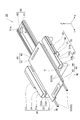
- FIG. 1 is a side view of a storage system including a storage device in which the transfer device of one embodiment is used.
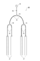
- FIG. 2 is a perspective view of a container to which the transfer device of one embodiment is transferred.
- FIG. 3 is a side view of the transfer system of one embodiment.
- FIG. 4 is a plan view of the transfer system shown in FIG.
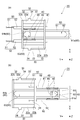
- FIG. 5 is a perspective view of the transfer device of one embodiment.
- FIG. 6 is a cross-sectional view of an elevating portion of the transfer device shown in FIG.
- FIG. 7 is a cross-sectional view taken along the line VII-VII of the transfer device shown in FIG.
- FIG. 8 is a bottom view of the transfer device shown in FIG.
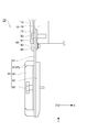
- FIG. 9 is a side view of the attachment of the transfer device shown in FIG. FIG.
- FIG. 10 is a plan view of the attachment shown in FIG.
- FIG. 11 is a flowchart of the transfer method of one embodiment.
- FIG. 12 is a side view of the transfer system in which the transfer method shown in FIG. 11 is implemented.
- FIG. 13 is a side view of the transfer system in which the transfer method shown in FIG. 11 is implemented.
- the storage system 100 includes a pair of storage devices 10, a crane 3, a ring opener 4, a conveyor 5, a port 6, and a system control unit 7.
- each axial direction in the Cartesian coordinate system of the three-dimensional space is referred to as an X direction, a Y direction, and a Z direction.
- the Y direction is a horizontal one direction
- the Z direction is a vertical direction (vertical direction).
- the pair of storage devices 10 are arranged so as to face each other at intervals in the Y direction.
- the storage device 10 arranged on one side in the Y direction is provided above the ring opener 4.
- Each storage device 10 has a plurality of shelves 11 for storing the container (article) 9.
- the plurality of shelves 11 are arranged in the X direction and the Z direction.
- the container 9 is transferred to each shelf 11 from the crane 3 side (one side) in the Y direction.
- the crane 3 side is referred to as the front side
- the opposite side is referred to as the rear side.
- the container 9 is a container for storing a semiconductor wafer.
- the container 9 has a ring 9a, a bottom portion 9b, and an upper lid portion 9c.
- the container 9 has a plurality of rings 9a provided with holding portions for holding the wafer.
- Each ring 9a constitutes a tray on which the wafer is placed.
- Each ring 9a holds the semiconductor wafer inside and protects the outer circumference of the semiconductor wafer.
- Each ring 9a is, for example, a member of a rectangular plate frame having a circular opening when viewed from the Z direction.
- the plurality of rings 9a are alternately stacked in the Z direction in order to keep their sides confidential.
- a plurality of rings 9a stacked on the bottom surface 9b are placed on the bottom portion 9b.
- the upper lid portion 9c is arranged above the plurality of stacked rings 9a.
- the bottom portion 9b and the top lid portion 9c are, for example, plate-shaped members.
- the stacked rings 9a are pressed against the lower bottom portion 9b by utilizing the weight of the upper lid portion 9c.
- the container 9 can separate the laminated rings 9a from each other.
- the bottom portion 9b has an opening that communicates the inside of the container 9 with the outside of the container 9.
- the inside of the container 9 is filled with purge gas through an opening formed in the bottom portion 9b.
- the crane 3 is a transport device for transporting the container 9.
- the crane 3 transfers the container 9 between the plurality of shelves 11 and the ring opener 4.
- the crane 3 is arranged in the area between the pair of storage devices 10.
- the crane 3 has a traveling portion 3a, a support pillar 3b, and a loading platform 3c.
- the traveling unit 3a travels along a track (not shown) by a traveling driving unit such as a motor.
- the orbit extends along the X direction.
- the support pillar 3b extends upward from the traveling portion 3a along the Z direction.
- the loading platform 3c moves up and down along the support pillar 3b by an elevating drive unit such as a motor.
- the loading platform 3c includes a loading platform on which the container 9 is placed, a swivel section for adjusting the orientation of the container 9, and a transfer section for transferring the container 9 to each of the plurality of shelves 11.
- the ring opener 4 is arranged on one side in the Y direction with respect to the crane 3.
- the ring opener 4 is a device that opens and closes a part of a plurality of rings 9a in the Z direction so that a semiconductor wafer can be transferred to a container 9 conveyed from each shelf 11 by a crane 3.
- the ring opener 4 opens a predetermined one or a plurality of places among the plurality of laminated rings 9a.
- the ring opener 4 is opened among the plurality of rings 9a. Close the part.
- the port 6 is arranged on one side in the Y direction with respect to the ring opener 4. That is, the port 6 is arranged in the Y direction on the side opposite to the storage device 10 when viewed from the ring opener 4.
- the port 6 is a portion for passing the FOUP (Front Opening Unified Pod) 8 between the transport vehicle (not shown) and the storage system 100.
- the automatic guided vehicle is, for example, a ceiling-traveling automatic guided vehicle that travels along a track provided on the ceiling of a semiconductor factory.
- the FOUP 8 is mounted on port 6 by a transport vehicle.
- the FOUP 8 has a box-shaped housing having an opening and a lid covering the opening. The lid is removable from the housing.
- the FOUP 8 accommodates, for example, a plurality of semiconductor wafers and the like.
- the FOUP 8 has a flange that is held by the transport vehicle.
- the carrier 5 is arranged between the ring opener 4 and the port 6 in the Y direction.
- the FOUP 8 is mounted on the port 6 so as to be adjacent to the carrier 5.
- the carrier 5 is an EFEM (Equipment Front End Module).
- the transfer machine 5 has an arm that can be inserted into the inside of the FOUP 8 or the inside of the container 9 and can transfer a semiconductor wafer.
- the conveyor 5 has a function of removing the lid of the opening provided in the FOUP 8.
- the transfer machine 5 has a function of transferring a semiconductor wafer between the ring 9a of the container 9 and the inside of the FOUP 8 by an arm. Specifically, the transporter 5 takes out the semiconductor wafer from the inside of the ring 9a of the container 9 and stores the semiconductor wafer inside the FOUP 8.
- the transporter 5 takes out the semiconductor wafer from the container 9 by inserting an arm between the plurality of open rings 9a in the container 9.
- the conveyor 5 takes out the semiconductor wafer stored inside the FOUP 8 on the port 6 and stores the semiconductor wafer inside the ring 9a of the container 9.
- the transfer machine 5 takes out the semiconductor wafer from the FOUP 8 by inserting the arm into the FOUP 8 through the opening of the FOUP 8.
- the system control unit 7 controls each operation of the storage system 100.
- the system control unit 7 is an electronic control unit including a CPU (Central Processing Unit), a ROM (Read Only Memory), a RAM (Random Access Memory), and the like.
- the system control unit 7 can be configured as software in which a program stored in the ROM is loaded on the RAM and executed by the CPU.
- the system control unit 7 may be configured as hardware such as an electronic circuit.
- the system control unit 7 may be composed of one device or a plurality of devices. When it is composed of a plurality of devices, one system control unit 7 is logically constructed by connecting them via a communication network such as the Internet or an intranet.
- the system control unit 7 is wirelessly or wiredly connected to the crane 3, the ring opener 4, and the conveyor 5, and controls the operations of the crane 3, the ring opener 4, and the conveyor 5.
- the system control unit 7 starts various controls.
- the crane 3 carries out the container 9 from each shelf 11 of the storage device 10 and moves it to the ring opener 4.
- the ring opener 4 opens a predetermined portion of the plurality of laminated rings 9a in the Z direction so that the semiconductor wafer can be taken out from the ring 9a.
- the conveyor 5 removes the lid of the FOUP 8.
- the transfer machine 5 takes out the semiconductor wafer from the ring 9a of the container 9 and stores it inside the FOUP 8.
- the transfer machine 5 closes the opening of the FOUP 8 through which the FOUP 8 communicates with a lid.
- the predetermined number of sheets here is one or the upper limit number of sheets that can be stored in FOUP8, for example, 25 sheets. This completes the process of transferring from the container 9 to the FOUP 8 by the storage system 100.
- the process of transferring the semiconductor wafer from the FOUP 8 to the inside of the container 9 by the storage system 100 is carried out by changing the target of loading and unloading by the transporter 5 in the above process. That is, in the above processing, the transporter 5 takes out the semiconductor wafer from the inside of the FOUP 8 and stores the semiconductor wafer in the ring 9a of the container 9.
- the container 9 stores a predetermined number of semiconductor wafers
- the ring opener 4 closes a part of the plurality of rings 9a in the container 9 in the Z direction
- the crane 3 closes the container 9 for each shelf 11. Reprint.
- the predetermined number of sheets here is an upper limit number of sheets that can be stored in one sheet or the container 9, and is, for example, 25 sheets.
- the transfer system 1 is configured by the storage device 10 and the transfer device 20.
- the transfer system 1 and the transfer device 20 cannot automatically transfer the container 9 due to, for example, a failure of the system control unit 7 of the storage system 100, and the operator can transfer the container to the storage device 10. It can be used when reprinting 9.
- each of the plurality of shelves 11 to which the container 9 is transferred is the shelf 11 to be transferred.
- the transfer system 1 the operator enters between the pair of storage devices 10 provided with the crane 3 and attaches the transfer device 20 to the shelf 11 to be transferred.
- the transfer device 20 is used to transfer the container 9 from the front side (one side in one horizontal direction) with respect to the shelf 11 to be transferred.
- the storage device 10 further has a plurality of side wall portions 12 and a back wall portion 13.
- the side wall portion 12 is a plate-shaped member extending in the Y direction and the Z direction.
- the plurality of side wall portions 12 are arranged so as to face each other at intervals in the X direction.
- the plurality of side wall portions 12 are connected to the plurality of shelves 11.
- the shelves 11 to be transferred are partitioned in the X direction by a pair of side wall portions 12.
- the back wall portion 13 is connected to the rear end portions of the plurality of side wall portions 12.
- the back wall portion 13 is a plate-shaped member extending in the X direction and the Z direction.
- the transfer opening has a width (length in the X direction) and a height (length in the Z direction) at which the container 9 can be transferred.
- the container 9 is transferred to the shelf 11 to be transferred, the container 9 is transferred from the front side through the transfer opening to the space surrounded by the two side wall portions 12 and the back wall portion 13.
- the inside of the pair of side wall portions 12 may be referred to simply as the inside, and the outside of the pair of side wall portions 12 may be simply referred to as the outside in the X direction.
- the shelf 11 to be transferred includes the mounting portion 14 and the mounting portion 15.
- the container 9 is placed on the mounting portion 14.
- the mounting portion 14 is formed with an opening region 14a that opens on the front side (an example of one side) and in the Z direction.
- the mounting unit 14 has a pair of mounting tables 16, a gas filling table 17, a gas pipe 18, and a space 19.
- a pair of mounting tables 16 are provided inside the side wall portion 12, respectively.
- Each of the pair of mounting tables 16 is a plate-shaped member extending in the X direction and the Y direction, and is a member supporting both ends of the container 9 in the X direction.
- the pair of mounting tables 16 are connected to and supported by the inner surfaces of the two side wall portions 12 sandwiching the shelf 11 to be transferred. In the X direction, there is an opening between the pair of mounting tables 16.
- the pair of mounting tables 16 support the container 9 by coming into contact with the bottom 9b of the container 9.
- the opening area 14a opens in the Z direction and the front side on the shelf 11 to be transferred.
- the opening region 14a is a space between a pair of mounting tables 16.
- the opening region 14a communicates with the upper and lower spaces on the front side of the back wall portion 13.
- the front side of at least one pair of mounting tables 16 is not connected by the opening region 14a.
- the opening region 14a has a width (length in the X direction) and a depth (length in the Y direction) at which the moving portion 40 of the transfer device 20 described later can move up and down.
- the opening region 14a has, for example, the same thickness as the thickness (length in the Z direction) of the pair of mounting tables 16.
- the gas filling table 17 and the gas pipe 18 communicate with a gas cylinder (not shown) to ventilate purge gas.
- the gas filling table 17 is provided on a mounting table 16 of one of the pair of mounting tables 16.
- the gas pipe 18 is a pipe line that communicates the gas filling table 17 and the gas cylinder.
- a space 19 is formed directly under the opening area 14a of the shelf 11 to be transferred.
- the opening area 14a of the shelf 11 to be transferred means the opening area 14a of the shelf 11 to be transferred and the upper lid of the container 9 stored in the shelf 11 one step below the shelf 11 to be transferred. It is an area between the part 9c (when the shelf 11 to be transferred is the lowest stage, the area corresponding to the area).
- the space 19 has at least a height (length in the Z direction) into which the guide 60 of the transfer device 20 described later can be inserted.
- the mounting portion 15 is provided on the shelf 11 to be transferred according to the position of the mounting portion 14 in the Z direction.
- the transfer device 20 is attached to the shelf 11 to be transferred by connecting to the attachment portion 15.
- the mounting portion 15 is provided at the front end of the side wall portion 12.
- the mounting portion 15 has a plurality of small holes into which the attachment fixture 83 of the attachment 70 in the transfer device 20 described later can be fitted inward.
- the transfer device 20 has a main body portion 30, a moving portion 40, an elevating portion 50, a guide 60, and a pair of attachments 70.
- the main body 30 is attached to the attachment 15 from the front side (one side).
- the main body portion 30 includes a pair of support portions 31, a frame body 32, a pair of engaging recesses 33, and a pair of engaging stoppers 34.
- the pair of support portions 31 can support the container 9.
- a pair of support portions 31 support both ends of the container 9 in the X direction.
- Each of the pair of support portions 31 is an elongated member extending in the Y direction.
- a pair of support portions 31 can horizontally support the container 9 on each upper surface 31a.
- the frame body 32 supports a pair of support portions 31.
- the frame body 32 supports a pair of support portions 31 and extends in the Y direction, and a pair of support members 32a that support the pair of support members 32a and extend in the X direction. It is composed of.
- the frame body 32 composed of a pair of support members 32a and a pair of support members 32b has a rectangular frame shape when viewed from the Z direction.
- the pair of support members 32a and the pair of support members 32b in the frame body 32 are elongated members having a rectangular cross section with respect to their extending directions.
- Each upper surface of the pair of support members 32a is connected to the respective bottom surfaces of the pair of support portions 31.
- the X-direction ends of the respective upper surfaces of the pair of support members 32b are connected to the Y-direction ends of the respective bottom surfaces of the pair of support members 32a.
- Each of the pair of engaging recesses 33 is provided on the outer surface of each of the pair of support members 32a.
- Each of the pair of engaging recesses 33 has recesses extending in the Y direction.
- Each of the pair of engaging recesses 33 has a small hole into which the main body fixture 93 of the pair of attachments 70, which will be described later, can be fitted inward.
- Each of the pair of engagement stoppers 34 is provided on each outer surface of the pair of support members 32a so as to contact or approach the respective front ends of the pair of engagement recesses 33 in the Y direction. Has been done. Each of the pair of engaging stoppers 34 is provided so as to cover a part or all of the cross section of the pair of engaging recesses 33 with respect to the extending direction (Y direction).
- the moving unit 40 can support the container 9, and the main body 30 and the moving target are transferred along the Y direction (one direction) with the main body 30 attached to the mounting portion 15 of the shelf 11 to be transferred. Move to and from the shelf 11.
- the moving portion 40 is configured to be movable to the front side or the rear side with respect to the mounting portion 15.
- the moving portion 40 includes a moving plate 41, a grip portion 42, a non-slip portion 43, and a protrusion 44.
- the moving plate 41 can support the container 9.
- the moving plate 41 has a plate shape.
- the length of the moving plate 41 in the Y direction is longer than or the same as the length of the container 9 in the Y direction.
- the moving plate 41 moves between the main body 30 and the shelf 11 to be transferred along the Y direction (one direction).
- the grip portion 42 is provided on the moving plate 41.
- the grip portion 42 is gripped when the operator moves the moving plate 41.
- the operator grips the grip portion 42 and applies a force to the front side or the rear side to move the moving plate 41 to the front side or the rear side.
- the grip portion 42 is provided at the front end portion on the moving plate 41.
- the grip portion 42 is made of, for example, resin.
- the non-slip portion 43 is provided on the moving plate 41 to prevent the container 9 from slipping off the moving plate 41.
- the non-slip portion 43 is provided at the rear end portion on the moving plate 41.
- the non-slip portion 43 is made of, for example, a resin.
- the protrusion 44 is provided on the moving plate 41 and positions the container 9 on the moving plate 41.
- the protrusion 44 projects from the horizontal plane of the moving plate 41. By engaging the recess 44 provided in the bottom 9b of the container 9 with the protrusion 44, the movement of the container 9 in the horizontal direction is suppressed.
- the protrusion 44 is connected to a screw provided below the moving plate 41, and the position of the upper end of the protrusion 44 in the Z direction can be adjusted by the screw.
- the elevating part 50 raises and lowers the moving part 40.
- the elevating part 50 is an air jack.
- the elevating portion 50 includes a plurality of balloon portions 51, a pair of outer shells 52, a plurality of air tubes 53, a plurality of connectors 54, a check valve 55, and a manual pump 56. I'm out.
- Each balloon portion 51 expands in at least the Z direction when a gas is supplied to the inside thereof, and contracts in at least the Z direction when the gas is discharged from the inside thereof.
- Each balloon portion 51 is made of, for example, a tubular silicon rubber.
- One end of each balloon portion 51 is connected to each air tube 53. Both ends inside each balloon portion 51 except the air tube 53 are closed with, for example, liquid silicon.
- Each balloon portion 51 is arranged below the moving plate 41 so as to extend in the Y direction. Since each balloon portion 51 horizontally supports the moving plate 41, the center of the moving plate 41 and the center of each balloon portion 51 are arranged so as to coincide with each other in the Y direction.
- the plurality of balloon portions 51 are provided below the moving plate 41 along the Y direction at both ends on the outer side of the moving plate 41.
- a plurality of balloon portions 51 are laminated in the Z direction for one end side of the moving plate 41 along the Y direction.
- the pair of outer shells 52 protects from physical contact with each balloon portion 51.
- Each of the pair of outer shells 52 is provided along the Y direction on the outer circumference of a plurality of balloon portions 51 provided on one end side of the moving plate 41 along the Y direction.
- Each outer shell 52 is a set of upper and lower members separated into upper and lower parts.
- Each outer shell 52 is connected to the upper surface of each support member 32b of the frame body 32 and the lower surface of the moving plate 41.
- each of the upper and lower pairs of outer shells 52 come into contact with each other to form a tubular shape extending along the Y direction.
- the upper member of the upper and lower pair of outer shells 52 rises to separate from the lower member.
- Each outer shell 52 is made of, for example, metal.
- Each air tube 53 is a pipeline that communicates each balloon portion 51 and the manual pump 56 via each connecting tool 54.
- Each air tube 53 extends from the front end of each balloon portion 51 to the front side.
- Each air tube 53 can circulate gas between each balloon portion 51 and the manual pump 56.
- Each air tube 53 is made of, for example, silicone rubber.
- Each connecting tool 54 connects each air tube 53 extending from each balloon portion 51 between each balloon portion 51 and the check valve 55.
- Each connecting tool 54 connects each air tube 53 so as to be composed of one air tube 53 from each balloon portion 51 to the check valve 55.
- Each connector 54 is made of, for example, metal.
- the check valve 55 is provided between each balloon portion 51 and the manual pump 56. Regardless of whether the check valve 55 is opened or closed, the flow of gas from the manual pump 56 to each balloon portion 51 is not suppressed.
- the check valve 55 opens the valve, gas flows from each balloon portion 51 to the manual pump 56.
- the check valve 55 closes the valve, gas does not flow from each balloon portion 51 to the manual pump 56.
- the manual pump 56 can circulate gas to each balloon portion 51 through each air tube 53 by applying a force by an operator.
- the manual pump 56 is, for example, an air pump.
- FIG. 7A shows a state in which the moving portion 40 is lowered. At this time, gas is not supplied from the manual pump 56 to the inside of each balloon portion 51 through each air tube 53, and each balloon portion 51 is in a contracted state.
- the moving plate 41 of the moving portion 40 is located below the upper surface 31a of each supporting portion 31 or at the same height as the upper surface 31a of each supporting portion 31.
- the container 9 is placed on the transfer device 20 with the moving plate 41 located below the upper surface 31a of each support portion 31, the container 9 is supported only on the upper surface 31a of each support portion 31.
- the container 9 is placed on the transfer device 20 in a state where the moving plate 41 is located at the same height as the upper surface 31a of each support portion 31, the container 9 is the upper surface 31a of each support portion 31 and the moving plate. Supported by 41.
- FIG. 7 shows a state in which the moving portion 40 is raised.
- gas is supplied from the manual pump 56 to the inside of each balloon portion 51 through each air tube 53, so that each balloon portion 51 is in an expanded state.
- the height of each balloon portion 51 increases at least in the Z direction by expanding.
- the moving plate 41 of the moving portion 40 is located above the upper surface 31a of each supporting portion 31.
- the guide 60 guides the moving portion 40 along the Y direction (one direction).
- FIG. 8A shows a state in which the moving portion 40 is arranged on the front side.
- FIG. 8B shows a state in which the moving portion 40 has moved to the rear side.
- the guide 60 is a linear guide.
- the guide 60 includes a linear guide 61, a carry-in stopper 62, and a carry-out stopper 63.
- the linear guide 61 extends from the main body 30 directly below the opening area 14a of the shelf 11 to be transferred in a state where the main body 30 is attached to the attachment portion 15 of the shelf 11 to be transferred.
- the linear guide 61 is inserted into the space 19 directly below the opening area 14a of the shelf 11 to be transferred.
- the linear guide 61 has a rectangular frame shape when viewed from above.
- the linear guide 61 moves the moving plate 41 to the front side or the rear side by the portion extending in the Y direction.
- the rear end 61a of the linear guide 61 is arranged at a position close to the back wall 13 of the storage device 10 when the main body 30 is attached to the shelf 11 to be transferred.
- the front end portion 61b of the linear guide 61 extends to the support member 32b located on the front side when viewed from the center of the frame body 32.
- the carry-in stopper 62 and the carry-out stopper 63 are provided on the linear guide 61 and project in the X direction.
- the carry-in stopper 62 and the carry-out stopper 63 are provided inside the linear guide 61 and project inward.
- the carry-in stopper 62 is provided on the rear side when viewed from the center of the linear guide 61, and restricts the movement of the moving plate 41 to the rear side.
- the carry-out stopper 63 is provided on the front side when viewed from the center of the linear guide 61, and restricts the movement of the moving plate 41 to the front side.
- the moving portion 40 includes the slider 45 and the contact portion 46.
- the slider 45 is provided on the lower surface of the moving plate 41.
- the moving plate 41 is movably connected to the slider 45 in the Z direction.
- the slider 45 is, for example, a linear slider.
- the slider 45 is arranged outside the member extending in the Y direction of the linear guide 61 so as to sandwich the linear guide 61 of the guide 60 from the outside to the inside in the X direction.
- the slider 45 moves along the linear guide 61 together with the moving plate 41 between the main body 30 and the opening area 14a of the shelf 11 to be transferred.
- the contact portion 46 is provided on the lower surface of the moving plate 41.
- the contact portion 46 is, for example, a substantially rectangular parallelepiped member.
- the contact portion 46 regulates the movement of the moving portion 40 by contacting the carry-in stopper 62 and the carry-out stopper 63.
- the contact portion 46 and the carry-in stopper 62 are provided so that the contact portion 46 comes into contact with the carry-in stopper 62.
- the contact portion 46 and the carry-in stopper 62 are provided so that when the container 9 is carried out from the shelf 11 to be transferred, the protrusions 44 are directly below the recess provided in the bottom 9b of the container 9 on the pair of mounting tables 16. It is provided so as to regulate the movement of the moving plate 41 from the position of the moving plate 41 when it is positioned.
- the contact portion 46 and the carry-out portion 46 come into contact with the carry-out stopper 63.
- Each stopper 63 is provided.
- each of the pair of attachments 70 includes a connecting portion 80 and an extending portion 90.
- Each of the pair of attachments 70 includes a reinforcing portion 99.
- the pair of attachments 70 are detachably provided on the attachment portion 15 of the shelf 11 to be transferred.
- the pair of attachments 70 are detachably connected to the main body 30 so as to sandwich the main body 30 from the outside in the X direction.
- the connection portion 80 is attached to the attachment portion 15 of the storage device 10.
- the connection portion 80 includes a connection plate 81, a wall contact portion 82, a plurality of attachment fixtures 83, and a plurality of attachment hooks 84.
- the connecting plate 81 is a plate-shaped member extending along the Z direction.
- the connection plate 81 is provided inside the mounting portion 15 in the X direction.
- the connection plate 81 has a plurality of small holes into which a plurality of attachment fixtures 83 can be fitted inward in the X direction.
- the wall contact portion 82 is provided on the outer surface of the connection plate 81. When the main body portion 30 is attached to the attachment portion 15 of the shelf 11 to be transferred, the rear surface of the wall contact portion 82 comes into contact with the front surface of the side wall portion 12.
- the wall contact portion 82 is a substantially rectangular parallelepiped member.
- Each attachment fixture 83 connects the attachment portion 15 and the connection plate 81.
- Each attachment fixture 83 is, for example, a screw, a pin, or the like.
- Each attachment fixture 83 is fitted into each small hole of the attachment portion 15 and the connection plate 81 and extends from the outside to the inside to regulate the movement of each attachment 70 in the Y direction and the Z direction.
- Each mounting hook 84 is a hook-shaped member rotatably provided on the connecting plate 81. As each mounting hook 84 rotates about its rotation axis, the hook portion of each mounting hook 84 and each attachment fixture 83 are engaged with each other. This makes it difficult for each attachment fixture 83 to come off from the small holes of the attachment portion 15 and the connection plate 81. Each attachment hook 84 can be disengaged from the hook portion of each attachment hook 84 and each attachment fixture 83 by rotating the hook portion in a direction away from each attachment fixture 83. ..
- the number of mounting hooks 84 is equal to or greater than the number of attachment fixtures 83.
- the extending portion 90 extends from the connecting portion 80 to the front side (one side) and supports the main body portion 30.
- the extending portion 90 includes an extending plate 91, an engaging convex portion 92, a main body fixing tool 93, a fixing tool support base 94, and a height adjusting unit 95.
- the extending plate 91 is a plate-shaped member extending along the Y direction.
- the extending plate 91 is connected to the connecting plate 81 at the rear end.
- the extending plate 91 has a small hole into which the main body fixing tool 93 can be fitted inward in the X direction.
- the engaging convex portion 92 engages with the engaging concave portion 33 of the main body portion 30 to fix the main body portion 30 to the shelf 11 to be transferred in the X direction.
- the engaging convex portion 92 is provided so as to be movable in the Z direction.
- the engaging convex portion 92 is a convex portion that extends in the Y direction, is provided inside the extending plate 91 in the X direction, and projects inward.
- the engaging convex portion 92 engages with the front end portion of the engaging convex portion 92 from the rear end portion of the engaging concave portion 33 of the main body portion 30, and the engaging concave portion 33 engages with the engaging convex portion 92.
- the main body 30 and each attachment 70 are engaged with each other by being inserted so as to move to the rear side.
- the engaging convex portion 92 horizontally supports the main body portion 30.
- the engaging stopper 34 restricts the engaging convex portion 92 from protruding from the engaging concave portion 33 to the front side.
- the length of the engaging convex portion 92 in the Y direction is shorter than or the same as the length of the engaging concave portion 33.
- the engaging convex portion 92 has a small hole into which the main body fixture 93 can be fitted inward in the X direction.
- the main body fixing tool 93 fixes the main body portion 30 and each attachment 70 in the Y direction and the Z direction by fitting into the small holes of the engaging concave portion 33, the extending plate 91, and the engaging convex portion 92.
- the main body fixture 93 is, for example, a screw or a pin.
- the small holes in the extending plate 91 extend in the Z direction as compared with the small holes in the engaging concave portion 33 and the engaging convex portion 92.
- the main body fixing tool 93 is fitted into a small hole after the main body portion 30 engages with the engaging concave portion 33 and the engaging convex portion 92 to position the main body portion 30 and each attachment 70.
- the fixture support 94 is provided on the outer surface of the extending plate 91 in the X direction.
- the fixture support 94 is rotatably connected to the main body fixture 93.
- the fixture support base 94 has a small hole into which the main body fixture 93 can be fitted inward in the X direction.
- the main body fixing tool 93 is fitted into the small holes in the order of the fixing tool support base 94, the extending plate 91, the engaging convex portion 92, and the engaging concave portion 33 from the outside in the X direction.
- Each of the small holes of the engaging concave portion 33, the engaging convex portion 92, and the fixture support base 94 has a smaller extending length in the Z direction than the small holes of the extending plate 91.
- Each of the small holes of the engaging concave portion 33, the engaging convex portion 92, and the fixture support base 94 has a diameter one size larger than the diameter of the fitting portion of the main body fixture 93.
- the height adjustment unit 95 adjusts the height of the fixture support base 94 in the Z direction.
- the height adjusting unit 95 includes a height adjusting base 96 and a plurality of height adjusting screws 97.
- the height adjusting base 96 is provided so as to be fixed to the outer surface of the extending plate 91 in the X direction and below the fixture support base 94.
- the height adjusting table 96 has a plurality of screw holes in the Z direction.
- the plurality of height adjusting screws 97 are fitted into the screw holes provided in the height adjusting base 96 along the Z direction, and project upward from the height adjusting base 96.
- Each height adjusting screw 97 supports the fixture support 94 by contacting the upper end of each height adjusting screw 97 with the fixture support 94.
- Each height adjusting screw 97 changes the length of the portion protruding upward from the height adjusting table 96 by rotating.
- the position of the fixture support base 94 supported by the upper ends of the height adjusting screws 97 in the Z direction is adjusted. That is, by increasing the length of the portion protruding upward from the height adjusting base 96, the position of the fixture support base 94 in the Z direction moves upward. By shortening the length of the portion protruding upward from the height adjusting base 96, the position of the fixture support base 94 in the Z direction moves downward.
- the main body fixture 93 moves in the Z direction by contacting the edge of the small hole of the moving fixture support 94.
- the moving main body fixing tool 93 moves the main body portion 30 and the engaging convex portion 92 in the Z direction by contacting the edges of the small holes of the engaging concave portion 33 and the engaging convex portion 92.
- the reinforcing portion 99 is hung between the connecting portion 80 and the extending portion 90.
- the reinforcing portion 99 connects the lower end of the connecting plate 81 of the connecting portion 80 and the front end of the extending plate 91 of the extending portion 90, and supports the extending plate 91.
- the reinforcing portion 99 has a plate shape. In order to reduce the weight of each attachment 70, the area surrounded by the connecting plate 81, the extending plate 91 and the reinforcing portion 99 is open.
- the connecting plate 81, the extending plate 91, and the reinforcing portion 99 are composed of one plate-shaped member. [Transfer method]
- a transfer method carried out using the transfer device 20 to transfer the container 9 from the front side to the shelf 11 to be transferred will be described.
- a transfer method of carrying out the container 9 from the front side to the shelf 11 to be transferred using the transfer device 20 will be described.
- the container 9 is mounted on a pair of mounting tables 16 of the mounting portions 14 in the storage device 10.
- the worker prepares the transfer device 20 (S200: first step).
- the operator carries the transfer device 20 and enters between the pair of storage devices 10 provided with the crane 3.
- each of the pair of attachments 70 attaches each of the pair of attachments 70 to the attachment portion 15 to the shelf 11 to be transferred in the storage device 10 (S210).
- the operator attaches the connection portion 80 to the attachment portion 15.
- the mounting portion 15 and the connecting plate 81 are connected.
- the attachment fixture 83 and the attachment hook 84 are engaged with each other, so that each attachment fixture 83 is less likely to be detached from each of the attachment portion 15 and the connection plate 81.
- the operator attaches the main body portion 30 to the attachment portion 15 of the shelf 11 to be transferred from the front side via a pair of attachments 70 (S220: second step).
- the operator attaches the pair of attachments 70 to the attachment portion 15 of the shelf 11 to be transferred, and attaches the main body portion 30 to the pair of attachments 70.
- the operator engages the pair of engaging recesses 33 of the main body 30 with the pair of engaging protrusions 92 and moves them to the rear side.
- the pair of engaging convex portions 92 abuts on the pair of engaging stoppers 34 of the main body portion 30, the protrusion of the pair of engaging convex portions 92 to the front side is restricted.
- the main body fixing tool 93 is fitted into the small holes of the fixing tool support base 94, the extending plate 91, the engaging convex portion 92, and the engaging concave portion 33 in order from the outside.
- the main body 30 and the pair of attachments 70 are fixed, and the main body 30 is attached to the attachment 15 via the pair of attachments 70.
- the pair of engaging recesses 33 are engaged with the pair of engaging protrusions 92, the main body 30 moves to the rear side, so that the linear guide 61 of the guide 60 is the space of the shelf 11 to be transferred. It is inserted in 19.
- the height adjusting unit 95 adjusts the position of the main body fixture 93 in the Z direction. As a result, the positions of the moving portion 40 and the linear guide 61 connected to the main body 30 in the Z direction can be adjusted, and the moving portion 40 can be smoothly moved and the linear guide 61 can be smoothly inserted.
- the operator moves the moving unit 40 to the space 19 which is the space directly below the opening area 14a of the shelf 11 to be transferred (S230: third step) with the moving unit 40 lowered.
- the check valve 55 is opened in the elevating part 50, the gas in each balloon part 51 is released to the outside.
- the moving plate 41 of the moving portion 40 is in a lowered state.
- the operator grips the grip portion 42 of the moving portion 40 and moves the moving plate 41 to the rear side along the linear guide 61 to insert the moving plate 41 into the space 19 of the shelf 11 to be transferred.
- the moving plate 41 can move to the rear side until the contact portion 46 comes into contact with the carry-in stopper 62.
- the moving plate 41 is inserted into the space 19 so that the protrusions 44 are located directly below the recesses provided in the bottom 9b of the container 9 on the pair of mounting tables 16.
- the operator raises the moving portion 40 through the opening area 14a of the shelf 11 to be transferred by using the elevating portion 50, and causes the moving portion 40 to support the container 9 (S240: 4th step). ..
- the operator moves the moving plate 41 of the moving portion 40 to the rear side and raises the moving plate 41.
- the operator uses a manual pump 56 to supply gas to the inside of each balloon portion 51 through each air tube 53 and each connector 54.
- Each balloon portion 51 expands when gas is supplied, and raises the moving plate 41.
- the moving plate 41 passes upward through the opening region 14a of the shelf 11 to be transferred.
- the moving plate 41 When the moving plate 41 is located at the same height as the pair of mounting tables 16, the moving plate 41 comes into contact with the container 9, and the protrusion 44 engages with the recess provided in the center of the bottom 9b of the container 9. To do. As the moving plate 41 is further raised, the container 9 is supported by the moving plate 41.
- the operator moves the moving portion 40 supporting the container 9 to the main body portion 30 (S250: fifth step).
- the operator grips the grip portion 42 of the moving portion 40 and moves the moving plate 41 forward along the linear guide 61 while inflating each balloon portion 51 to support the container 9.
- the 41 is carried out from the shelf 11 to be transferred.
- the moving plate 41 can be moved forward until the contact portion 46 comes into contact with the carry-out stopper 63.
- the operator may contract each balloon portion 51 of the elevating portion 50. That is, as shown in FIG. 3, the operator lowers the moving plate 41 by the elevating portion 50 in a state where the moving plate 41 is moved forward, and the container 9 is placed on the upper surface 31a of each support portion 31 of the main body portion 30. It may be placed in.
- the transfer method shown in FIG. 11 is completed. As a result, the container 9 is carried out from the shelf 11 to be transferred.
- the operator attaches each of the pair of attachments 70 to the attachment portion 15 with respect to the shelf 11 to be transferred in the storage device 10.
- the operator carries out the same work as the attachment work (S210) of the pair of attachments 70 in the transfer method of carrying out.
- the operator attaches the main body portion 30 to the mounting portion 15 of the shelf 11 to be transferred from the front side.
- the operator carries out the same work as the attachment work (S220) of the main body portion 30 in the transfer method of carrying out.
- the container 9 is placed on the pair of support portions 31 of the main body portion 30 or the moving plate 41 of the moving portion 40 by the operator.
- the operator raises the moving portion 40 by using the elevating portion 50, and causes only the moving portion 40 to support the container 9.
- the operator uses a manual pump 56 to supply gas to the inside of each balloon portion 51 through each air tube 53 and each connector 54.
- Each balloon portion 51 expands when gas is supplied, and raises the moving plate 41.
- the elevating portion 50 If the elevating portion 50 is in a raised state during the mounting work of the main body portion 30, it is not necessary to carry out the raising work of the moving portion 40 by the elevating portion 50. At this time, the operator places the container 9 so that the recess provided in the center of the bottom portion 9b of the container 9 engages with the protrusion 44.
- the operator moves the moving unit 40 to the opening area 14a of the shelf 11 to be transferred while the moving unit 40 is raised.
- the operator grips the grip portion 42 of the moving portion 40 and moves the moving plate 41 to the rear side along the linear guide 61 so that the moving plate 41 passes through the transfer opening of the shelf 11 to be transferred. And insert it directly above the opening area 14a.
- Immediately above the opening area 14a of the shelf 11 to be transferred is an area between the opening area 14a of the shelf 11 to be transferred and the opening area 14a of the shelf 11 one step above the shelf 11 to be transferred. Is.
- the moving plate 41 can be moved to the rear side until the contact portion 46 comes into contact with the carry-in stopper 62.
- the moving plate 41 moves the container 9 to a state in which the container 9 does not protrude from the front end of the shelf 11 to be transferred.
- the moving portion 40 is lowered by using the elevating portion 50, and the container is placed only on the pair of mounting tables 16 of the mounting portions 14 on the shelf 11 to be transferred.
- Support 9 By opening the check valve 55, the operator discharges gas from the inside of each balloon portion 51 through each air tube 53 and each connecting tool 54.
- Each balloon portion 51 contracts when the gas is discharged, and lowers the moving plate 41.
- the moving plate 41 moves below the pair of mounting tables 16 through the opening region 14a, the contact between the container 9 and the moving plate 41 is released, and a recess and a protrusion provided in the center of the bottom 9b of the container 9 are released.
- the engagement with the portion 44 is released.
- the container 9 is placed on a pair of mounting stands 16 of the mounting portion 14.
- the moving plate 41 is located in the space 19.
- the moving plate 41 of the moving portion 40 is in a lowered state.
- the operator moves the moving portion 40 to the main body portion 30.
- the operator grips the grip portion 42 of the moving portion 40 and moves the moving plate 41 forward along the linear guide 61 while contracting each balloon portion 51, whereby the moving plate 41 is transferred to the shelf to be transferred. Pull out from 11.
- the moving plate 41 can be moved forward until the contact portion 46 comes into contact with the carry-out stopper 63.
- the transfer system 1, the transfer device 20, and the transfer method of the present disclosure the operator can easily and stably transfer the container 9 regardless of the height of the shelf 11 to be transferred. ..
- the container 9 cannot be automatically transferred due to a failure of the system control unit 7 of the storage system 100 or the like, and the operator transfers the container 9 to the storage device 10, the operator The transfer system 1, the transfer device 20, and the transfer method can be used.
- Transfer system 1, transfer device 20, and transfer method can be used. In these cases, the operator can easily transfer the container 9 to the shelf 11 to be transferred by simply attaching the main body 30 of the transfer device 20 to the attachment portion 15 of the shelf 11 to be transferred. ..
- the pair of attachments 70 are provided for the shelf 11 to be transferred, the main body 30 is supported by the extending portion 90 extending from the connecting portion 80 to the front side, so that the state is stable.
- the container 9 can be transferred at.
- the pair of attachments 70 includes the reinforcing portion 99, the load capacity of the pair of attachments 70 increases, so that the container 9 can be moved in a stable state even when the container 9 is heavy, for example. Can be placed.
- the elevating part 50 is an air jack, the weight of the transfer device 20 can be reduced, so that the transfer device 20 can be more easily attached to the attachment part 15 of the storage device 10.
- the transfer device 20 since the transfer device 20 has the guide 60, the moving portion 40 is guided by the guide 60 extending along the Y direction, so that the container 9 can be transferred in a more stable state. It can be transferred to the shelf 11. Further, the guide 60 extends to the space 19 directly below the opening area 14a of the shelf 11 to be transferred by simply attaching the main body 30 of the transfer device 20 to the attachment portion 15 of the shelf 11 to be transferred. Therefore, it is possible to prevent the worker from causing an extra work load.
- the guide 60 may be a linear guide 61, and the container 9 can be transferred in a more stable state with a simple configuration.
- the container 9 may be a container in which a semiconductor wafer is stored, and a container in which a semiconductor wafer, which is a precision instrument, is stored can be easily transferred.
- the moving portion 40 can suppress the slipping of the container 9 from the moving plate 41 by including the non-slip portion 43 or the protruding portion 44.
- the attachment fixture 83 is easily removed after the transfer of the container 9 is completed by fitting the attachment fixture 83 from the outside to the inside into the small holes provided in the mounting portion 15 and the connection plate 81, it is unnecessary for the operator. It is possible to suppress the occurrence of a work load. [Modification example]
- the present disclosure is not limited to the above-described embodiment.
- the container 9 may be a container such as a reticle pod for storing a plurality of glass substrates, or an article such as a general part.
- the pair of mounting tables 16 may be connected via a connecting member on the back side. In this case, the pair of mounting tables 16 are connected so as not to interfere with the moving portion 40 that moves up and down through the opening region 14a.
- the main body portion 30 does not have to include a pair of support portions 31. In this case, before and after the transfer of the container 9, only the moving plate 41 supports the container 9.
- the main body 30 does not have to include a pair of engaging recesses 33.
- each attachment 70 may not include the engaging protrusion 92.
- the main body 30 may be fixed by using a plurality of attachment fixtures 83 for one attachment 70. As a result, the main body 30 is supported horizontally. That is, the moving plate 41 of the moving portion 40 connected to the main body 30 is fixed to each attachment 70 so as to be horizontal.
- the main body 30 does not have to include a pair of engaging stoppers 34.
- the main body 30 includes a pair of engaging protrusions 92 instead of a pair of engaging recesses 33, and a pair of attachments 70 includes a pair of engaging recesses 33 instead of a pair of engaging protrusions 92. May include.
- the moving unit 40 may be a mechanism that moves in the Y direction by power from a drive source such as a motor.
- the moving unit 40 may be a mechanism that moves in the Y direction by a hydraulic jack, an electric jack, an air jack, a ball screw, or the like.
- the moving portion 40 does not have to include the grip portion 42. In this case, the operator moves the moving plate 41 by directly grasping the moving plate 41.
- the moving portion 40 may not include the non-slip portion 43 or the protrusion 44.
- the slider 45 may be arranged so as to press the member extending in the Y direction of the linear guide 61 of the guide 60 in the X direction from the inside to the outside.
- the elevating part 50 does not have to be an air jack.
- the elevating unit 50 may be a mechanism that elevates and elevates in the Z direction by power from a drive source such as a motor.
- the elevating part 50 may be a hydraulic jack, an electric jack, or a ball screw.
- the plurality of balloon portions 51 may be inside the moving plate 41 in the Y direction.
- the linear guide 61 is provided below the moving plate 41 and outside in the Y direction.
- One balloon portion 51 may be provided in the Z direction for each end edge of the moving plate 41 along the Y direction.
- one connector 54 is provided.
- the balloon portion 51 may be provided with one balloon portion 51 with respect to the moving plate 41.
- the connecting tool 54 may not be provided.
- the connector 54 may not be provided when the air tube 53 is composed of one tube.
- the transfer device 20 does not have to have the guide 60.
- the moving portion 40 may have, for example, a handle member extending in the Y direction on the front side of the moving plate 41.
- the handle member has a length that allows the moving plate 41 to move directly below the opening region 14a.
- the linear guide 61 of the guide 60 may be composed of one or a plurality of long members extending in the Y direction. The guide 60 does not have to extend to the space 19 directly below the opening region 14a.
- the position of the slider 45 in the moving portion 40 is adjusted so that the moving plate 41 of the moving portion 40 can move to the space 19 directly below the opening region 14a and the moving plate 41 can support the container 9.
- the length of the moving plate 41 extending rearward from the slider 45 in the Y direction may be adjusted.
- the transfer device 20 does not have to have a pair of attachments 70.
- the main body portion 30 is directly attached to the attachment portion 15 from the front side without going through a pair of attachments 70.
- each support portion 31 of the main body portion 30 may have a small hole on the rear side in the Y direction and the outer side surface in the X direction.
- the operator may directly attach the main body portion 30 to the attachment portion 15 from the front side by fitting the attachment fixture 83 into the small holes of each attachment portion 15 and each support portion 31.
- the attachments 70 do not have to be a pair.
- the transfer device 20 has, for example, one attachment 70, and the main body 30 has one engaging recess 33.
- Each attachment 70 may be connected to an attachment portion 15 located above the main body portion 30 in the Z direction.
- the lower end of the connection plate 81 of the connection portion 80 and the rear end of the extension plate 91 of the extension portion 90 are connected, and the reinforcing portion 99 extends with the upper end of the connection plate 81 of the connection portion 80. It is arranged so as to connect the front end of the extension plate 91 of the portion 90.
- the connection plate 81 may be provided outside the mounting portion 15 and the wall contact portion 82 in the X direction. Only one attachment fixture 83 may be provided for each of the pair of attachments 70.
- connection fixture 83 When the upper end of the connection plate 81 of the connection portion 80 and the rear end of the extension plate 91 of the extension portion 90 are connected, one attachment fixture 83 is fitted in the upper part of the connection plate 81. .. When the lower end of the connection plate 81 of the connection portion 80 and the rear end of the extension plate 91 of the extension portion 90 are connected, one attachment fixture 83 is fitted in the lower part of the connection plate 81. ..
- a plurality of engaging protrusions 92 may be provided in each of the pair of attachments 70 in the Y direction.
- the engaging convex portions 92 are members extending in the Y direction, and the plurality of engaging convex portions 92 are provided at intervals in the Y direction.
- Each engaging recess 33 of the main body 30 horizontally supports the main body 30 by engaging with a plurality of engaging convex portions 92 in the Y direction.
- the pair of engaging convex portions 92 may be provided on the outer side of the extending plate 91 in the X direction and may be convex portions extending in the Y direction. In this case, the pair of engaging recesses 33 of the main body 30 are connected outside the pair of engaging protrusions 92.
- Each support member 32a is provided on the outside of each engagement convex portion 92, and each support member 32a extends above or below the extension plate 91 of each attachment 70.
- the number of screw holes in the height adjusting base 96 and the number of height adjusting screws 97 may be one each.
- Each attachment 70 does not have to include the reinforcing portion 99.
- the area surrounded by the connecting plate 81, the extending plate 91 and the reinforcing portion 99 may not be open.
- the connecting plate 81, the extending plate 91, and the reinforcing portion 99 may not be composed of one plate-shaped member, but may be composed of a plurality of plate-shaped members.
- the transfer method does not have to include the attachment work (S210) of the pair of attachments 70.
- the operator directly attaches the main body portion 30 to the attachment portion 15 from the front side without passing through the pair of attachments 70.
- the transfer method may include the work of removing the main body portion 30 from the pair of attachments 70, or the work of removing the pair of attachments 70 from the attachment portion 15.
- the transfer method when the moving plate 41 is moved to the shelf 11 to be transferred, the entire moving plate 41 does not have to be inserted into the space 19.
- the moving operation (S230) of the moving portion 40 when the container 9 is carried out to the shelf 11 to be transferred the moving plate 41 is inserted at least behind the center of gravity of the container 9.
- the moving plate 41 has the front end of the container 9 placed on the moving plate 41 from the mounting portion 15. It is inserted so that it is located on the rear side.
Landscapes
- Engineering & Computer Science (AREA)
- Physics & Mathematics (AREA)
- Condensed Matter Physics & Semiconductors (AREA)
- General Physics & Mathematics (AREA)
- Manufacturing & Machinery (AREA)
- Computer Hardware Design (AREA)
- Microelectronics & Electronic Packaging (AREA)
- Power Engineering (AREA)
- Robotics (AREA)
- Warehouses Or Storage Devices (AREA)
- Container, Conveyance, Adherence, Positioning, Of Wafer (AREA)
Abstract
This transfer system is provided with: a housing device including a placement part having a plurality of shelves which are arranged in the vertical direction and to which an article is transferred from one side in one horizontal direction, with each of the plurality of shelves having formed therein an opening region that is open in the vertical direction and to one side and that has an article placed thereon, and including mounting parts that are disposed in accordance with the position of the placement part in the vertical direction; and a transfer device that sets each of the plurality of shelves as a shelf to be transferred and that is used for transferring an article from one side to the shelf to be transferred, wherein the transfer device has: a body part that is mounted from one side to the mounting part of the shelf to be transferred; a movable part that can support an article and that is moved between the body part and the shelf to be transferred along one direction in a state where the body part is mounted to the mounting part of the shelf to be transferred; and a lifting and lowering part for allowing the body part to pass through the opening region of the shelve to be transferred in a state where the body part is mounted to the mounting part of the shelf to be transferred, and lifting and lowering the movable part.
Description
本開示は、移載システム、移載装置及び移載方法に関する。
This disclosure relates to a transfer system, a transfer device, and a transfer method.
複数の棚を有する収納装置と、複数の棚のそれぞれに対して物品を移載する移載装置と、移載装置の動作を制御する制御装置と、を備える収納システムが知られている。このような収納システムにおいては、制御装置の故障等に起因して自動で物品を移載することができなくなった場合に、作業者が手動で物品を移載する必要性が生じ得る。
A storage system including a storage device having a plurality of shelves, a transfer device for transferring goods to each of the plurality of shelves, and a control device for controlling the operation of the transfer device is known. In such a storage system, when it becomes impossible to automatically transfer the article due to a failure of the control device or the like, it may be necessary for the operator to manually transfer the article.
作業者が手動で物品を移載する必要性が生じた場合には、例えば、特許文献1に記載のフォークリフトトラックのような装置を利用することが考えられる。特許文献1に記載のフォークリフトトラックは、フォークが挿入されたベースパレット上の台車を用いて物品を移載するための装置である。
When it becomes necessary for a worker to manually transfer an article, it is conceivable to use a device such as the forklift truck described in Patent Document 1, for example. The forklift truck described in Patent Document 1 is a device for transferring articles using a trolley on a base pallet into which a fork is inserted.
しかしながら、特許文献1に記載のフォークリフトトラックのような装置を利用する場合には、棚に対するベースパレットの位置決めを精度良く行う必要があるため、特にリフトを昇降させる操作において作業者に高い技量が要求される。
However, when using a device such as the forklift truck described in Patent Document 1, it is necessary to accurately position the base pallet with respect to the shelf, so that a high skill is required for the operator especially in the operation of raising and lowering the lift. Will be done.
そこで、本開示は、棚の高さによらず作業者が物品を容易に移載することができる移載システム、移載装置及び移載方法を提供することを目的とする。
Therefore, an object of the present disclosure is to provide a transfer system, a transfer device, and a transfer method that allow an operator to easily transfer an article regardless of the height of the shelf.
本開示の一側面の移載システムは、上下方向に配列され且つ水平な一方向における一方の側から物品が移載される複数の棚を有し、複数の棚のそれぞれが、上下方向及び一方の側に開口する開口領域が形成され且つ物品が載置される載置部と、上下方向における載置部の位置に応じて設けられた取付部と、を含む収納装置と、複数の棚のそれぞれを移載対象の棚とし、移載対象の棚に対して一方の側から物品を移載するために用いられる移載装置と、を備え、移載装置は、移載対象の棚の取付部に一方の側から取り付けられる本体部と、物品を支持可能であり、本体部が移載対象の棚の取付部に取り付けられた状態で一方向に沿って本体部と移載対象の棚との間で移動する移動部と、本体部が移載対象の棚の取付部に取り付けられた状態で移載対象の棚の開口領域を通って移動部を昇降させる昇降部と、を有する。
The one-sided transfer system of the present disclosure has a plurality of shelves arranged vertically and from one side in one horizontal direction, each of the plurality of shelves being vertically arranged and one side. A storage device including a mounting portion on which an opening area is formed and an article is placed, and a mounting portion provided according to the position of the mounting portion in the vertical direction, and a plurality of shelves. Each is a shelf to be transferred, and is provided with a transfer device used for transferring articles from one side to the shelf to be transferred, and the transfer device is to attach the shelf to be transferred. The main body that can be attached to the part from one side, and the main body and the shelf that can be transferred along one direction with the main body attached to the attachment part of the shelf to be transferred. It has a moving portion that moves between the moving portions, and an elevating portion that raises and lowers the moving portion through the opening area of the shelf to be transferred while the main body portion is attached to the mounting portion of the shelf to be transferred.
この移載システムでは、収納装置において、複数の棚のそれぞれが、上下方向における載置部の位置に応じて設けられた取付部を含んでおり、移載装置において、移動部が、本体部が移載対象の棚の取付部に取り付けられた状態で移載対象の棚に対して移動可能となるように、構成されている。これにより、作業者が移載対象の棚の取付部に移載装置の本体部を取り付けるだけで、移載対象の棚に対する物品の移載が可能な状態となる。よって、この移載システムによれば、棚の高さによらず作業者が物品を容易に移載することができる。
In this transfer system, in the storage device, each of the plurality of shelves includes a mounting portion provided according to the position of the mounting portion in the vertical direction, and in the transfer device, the moving portion and the main body portion are included. It is configured so that it can be moved to the shelf to be transferred while being attached to the attachment portion of the shelf to be transferred. As a result, the worker can transfer the article to the shelf to be transferred by simply attaching the main body of the transfer device to the attachment portion of the shelf to be transferred. Therefore, according to this transfer system, the worker can easily transfer the article regardless of the height of the shelf.
本開示の一側面の移載システムでは、移載装置は、1対のアタッチメントを更に有し、1対のアタッチメントのそれぞれは、移載対象の棚の取付部に取り付けられる接続部と、接続部から一方の側に延在し、本体部を支持する延在部と、を含み、本体部は、1対のアタッチメントを介して取付部に取り付けられてもよい。これによれば、移載装置の本体部が、2個の接続部から一方の側に延在する2個の延在部によって支持されるため、安定した状態で物品を移載することができる。
In one aspect of the transfer system of the present disclosure, the transfer device further comprises a pair of attachments, each of which has a connection and a connection that are attached to the attachment of the shelf to be transferred. The main body may be attached to the mounting portion via a pair of attachments, including an extending portion extending from one side to the other and supporting the main body. According to this, since the main body of the transfer device is supported by the two extending portions extending from the two connecting portions to one side, the article can be transferred in a stable state. ..
本開示の一側面の移載システムでは、接続部は、上下方向に沿って延在し、1対のアタッチメントのそれぞれは、接続部と延在部との間に掛け渡された補強部を更に含んでいてもよい。これによれば、1対のアタッチメントの耐荷重が増大するため、例えば重い物品であっても、安定した状態で物品を移載することができる。
In one aspect of the transfer system of the present disclosure, the connections extend along the vertical direction, and each pair of attachments further provides a reinforcement spanned between the connection and the extension. It may be included. According to this, since the load capacity of the pair of attachments is increased, even a heavy article can be transferred in a stable state.
本開示の一側面の移載システムでは、昇降部は、エアジャッキであってもよい。これによれば、移載装置を軽量化することができるため、収納装置の取付部に移載装置をより容易に取り付けることができる。
In the transfer system of one aspect of the present disclosure, the elevating part may be an air jack. According to this, since the transfer device can be reduced in weight, the transfer device can be more easily attached to the attachment portion of the storage device.
本開示の一側面の移載システムでは、移載装置は、一方向に沿って移動部を案内するガイドを更に有し、ガイドは、本体部が移載対象の棚の取付部に取り付けられた状態で本体部から移載対象の棚の開口領域の直下に延在するように構成されていてもよい。これによれば、一方向に沿って延在するガイドに移動部が案内されるため、より一層安定した状態で物品を移載することができる。また、作業者が移載対象の棚の取付部に移載装置の本体部を取り付けるだけで、移載対象の棚の開口領域の直下にガイドが延在した状態となるため、作業者に余計な作業負担を生じさせるのを抑制することができる。
In one aspect of the transfer system of the present disclosure, the transfer device further comprises a guide that guides the moving portion in one direction, the guide having the main body attached to the mounting portion of the shelf to be transferred. In the state, it may be configured to extend from the main body to directly below the opening area of the shelf to be transferred. According to this, since the moving portion is guided by the guide extending along one direction, the article can be transferred in a more stable state. In addition, since the operator simply attaches the main body of the transfer device to the attachment part of the shelf to be transferred, the guide extends directly under the opening area of the shelf to be transferred, which is unnecessary for the operator. It is possible to suppress the occurrence of a heavy work load.
本開示の一側面の移載システムでは、ガイドは、リニアガイドであってもよい。これによれば、簡易な構成で、より一層安定した状態で物品を移載することができる。
In the transfer system of one aspect of the present disclosure, the guide may be a linear guide. According to this, the article can be transferred in a more stable state with a simple configuration.
本開示の一側面の移載システムでは、物品は、半導体ウエハを格納した容器であってもよい。これによれば、精密機器である半導体ウエハを格納した容器を容易に移載することができる。
In the transfer system of one aspect of the present disclosure, the article may be a container containing a semiconductor wafer. According to this, the container containing the semiconductor wafer, which is a precision instrument, can be easily transferred.
本開示の一側面の移載装置は、上下方向に配列され且つ水平な一方向における一方の側から物品が移載される複数の棚を有し、複数の棚のそれぞれが、上下方向及び一方の側に開口する開口領域が形成され且つ物品が載置される載置部と、上下方向における載置部の位置に応じて設けられた取付部と、を含む収納装置において、複数の棚のそれぞれを移載対象の棚とし、移載対象の棚に対して一方の側から物品を移載するために用いられる移載装置であって、移載対象の棚の取付部に一方の側から取り付けられる本体部と、物品を支持可能であり、本体部が移載対象の棚の取付部に取り付けられた状態で一方向に沿って本体部と移載対象の棚との間で移動する移動部と、本体部が移載対象の棚の取付部に取り付けられた状態で移載対象の棚の開口領域を通って移動部を昇降させる昇降部と、を備える。
The transfer device on one side of the present disclosure has a plurality of shelves arranged vertically and from one side in one horizontal direction, each of the plurality of shelves being vertically arranged and one side. In a storage device including a mounting portion in which an opening area is formed and an article is placed on the side of the shelf, and a mounting portion provided according to the position of the mounting portion in the vertical direction, a plurality of shelves Each is a shelf to be transferred, and it is a transfer device used to transfer articles from one side to the shelf to be transferred from one side to the attachment part of the shelf to be transferred. Movement that can support the main body to be attached and the main body to move between the main body and the shelf to be transferred along one direction while the main body is attached to the attachment of the shelf to be transferred. It is provided with a portion and an elevating portion for raising and lowering the moving portion through the opening area of the shelf to be transferred while the main body portion is attached to the attachment portion of the shelf to be transferred.
この移載装置によれば、上述した理由により、棚の高さによらず作業者が物品を容易に移載することができる。
According to this transfer device, the worker can easily transfer the article regardless of the height of the shelf for the reason described above.
本開示の一側面の移載方法は、上記移載システムにおいて実施される移載方法であって、移載装置を準備する第1ステップと、第1ステップの後に、移載対象の棚の取付部に一方の側から本体部を取り付ける第2ステップと、第2ステップの後に、移動部を下降させた状態で、一方向に沿って移載対象の棚の開口領域の直下に移動部を移動させる第3ステップと、第3ステップの後に、昇降部を用いることで、移載対象の棚の開口領域を通って移動部を上昇させ、移動部に物品を支持させる第4ステップと、第4ステップの後に、移動部を上昇させた状態で、一方向に沿って本体部に移動部を移動させる第5ステップと、を含む。
The transfer method of one aspect of the present disclosure is the transfer method implemented in the above transfer system, and the first step of preparing the transfer device and the attachment of the shelf to be transferred after the first step. In the second step of attaching the main body to the part from one side, and after the second step, the moving part is moved along one direction directly under the opening area of the shelf to be transferred while the moving part is lowered. The third step and the fourth step, in which the moving part is raised through the opening area of the shelf to be transferred and the moving part supports the article, by using the elevating part after the third step and the third step. After the step, a fifth step of moving the moving portion to the main body portion along one direction with the moving portion raised is included.
この移載方法によれば、上述した理由により、棚の高さによらず作業者が物品を容易に安定して移載することができる。
According to this transfer method, the worker can easily and stably transfer the article regardless of the height of the shelf for the reason described above.
本開示によれば、棚の高さによらず作業者が物品を容易に移載することができる移載システム、移載装置及び移載方法を提供することが可能となる。
According to the present disclosure, it is possible to provide a transfer system, a transfer device, and a transfer method that allow an operator to easily transfer an article regardless of the height of the shelf.
以下、本開示の実施形態について、図面を参照して詳細に説明する。なお、各図において同一又は相当部分には同一符号を付し、重複する説明を省略する。
[収納システムの構成] Hereinafter, embodiments of the present disclosure will be described in detail with reference to the drawings. In each figure, the same or corresponding parts are designated by the same reference numerals, and duplicate description will be omitted.
[Storage system configuration]
[収納システムの構成] Hereinafter, embodiments of the present disclosure will be described in detail with reference to the drawings. In each figure, the same or corresponding parts are designated by the same reference numerals, and duplicate description will be omitted.
[Storage system configuration]
一実施形態の移載装置が用いられる収納装置を含む収納システムについて説明する。図1に示されるように、収納システム100は、1対の収納装置10と、クレーン3と、リングオープナ4と、搬送機5と、ポート6と、システム制御部7と、を備えている。以下の説明では、3次元空間の直交座標系における各軸方向をX方向、Y方向及びZ方向という。そのうち、Y方向は水平な一方向であり、Z方向は上下方向(鉛直方向)である。
A storage system including a storage device in which the transfer device of one embodiment is used will be described. As shown in FIG. 1, the storage system 100 includes a pair of storage devices 10, a crane 3, a ring opener 4, a conveyor 5, a port 6, and a system control unit 7. In the following description, each axial direction in the Cartesian coordinate system of the three-dimensional space is referred to as an X direction, a Y direction, and a Z direction. Among them, the Y direction is a horizontal one direction, and the Z direction is a vertical direction (vertical direction).
1対の収納装置10は、Y方向において間隔をあけて対向するように配置されている。Y方向における一方の側に配置された収納装置10は、リングオープナ4の上方に設けられている。各収納装置10は、容器(物品)9を収納する複数の棚11を有している。各収納装置10において、複数の棚11は、X方向及びZ方向に配列されている。各棚11には、Y方向におけるクレーン3側(一方の側)から容器9が移載される。以下の説明では、各棚11を基準とした場合に、クレーン3側を前側といい、その反対側を後側という。
The pair of storage devices 10 are arranged so as to face each other at intervals in the Y direction. The storage device 10 arranged on one side in the Y direction is provided above the ring opener 4. Each storage device 10 has a plurality of shelves 11 for storing the container (article) 9. In each storage device 10, the plurality of shelves 11 are arranged in the X direction and the Z direction. The container 9 is transferred to each shelf 11 from the crane 3 side (one side) in the Y direction. In the following description, when each shelf 11 is used as a reference, the crane 3 side is referred to as the front side, and the opposite side is referred to as the rear side.
図2に示されるように、容器9は、半導体ウエハを格納する容器である。容器9は、リング9a、底部9b及び上蓋部9cを有している。容器9は、ウエハを保持する保持部が設けられたリング9aを複数有している。各リング9aは、ウエハを載せるトレーを構成する。各リング9aは、半導体ウエハを内部に保持し、半導体ウエハの外周を保護する。各リング9aは、例えば、Z方向から見て円形の開口が形成された矩形板枠の部材である。複数のリング9aは、その側面を機密にするべく、Z方向において交互に積み重ねられている。底部9bは、その上面に積み重ねられた複数のリング9aが載置されている。上蓋部9cは、積み重ねられた複数のリング9aの上方に配置されている。底部9b及び上蓋部9cは、例えば板状の部材である。積み重ねられた複数のリング9aは、上蓋部9cの重さを利用して下方の底部9bへ押さえ付けられている。容器9は、積層されたリング9aをそれぞれ分離可能である。底部9bは、容器9の内部と容器9の外部とを連通する開口を有する。容器9の内部には、底部9bに形成された開口を通じてパージガスが封入される。
As shown in FIG. 2, the container 9 is a container for storing a semiconductor wafer. The container 9 has a ring 9a, a bottom portion 9b, and an upper lid portion 9c. The container 9 has a plurality of rings 9a provided with holding portions for holding the wafer. Each ring 9a constitutes a tray on which the wafer is placed. Each ring 9a holds the semiconductor wafer inside and protects the outer circumference of the semiconductor wafer. Each ring 9a is, for example, a member of a rectangular plate frame having a circular opening when viewed from the Z direction. The plurality of rings 9a are alternately stacked in the Z direction in order to keep their sides confidential. A plurality of rings 9a stacked on the bottom surface 9b are placed on the bottom portion 9b. The upper lid portion 9c is arranged above the plurality of stacked rings 9a. The bottom portion 9b and the top lid portion 9c are, for example, plate-shaped members. The stacked rings 9a are pressed against the lower bottom portion 9b by utilizing the weight of the upper lid portion 9c. The container 9 can separate the laminated rings 9a from each other. The bottom portion 9b has an opening that communicates the inside of the container 9 with the outside of the container 9. The inside of the container 9 is filled with purge gas through an opening formed in the bottom portion 9b.
図1に示されるように、クレーン3は、容器9を搬送する搬送装置である。クレーン3は、複数の棚11とリングオープナ4との間で容器9を移載する。クレーン3は、1対の収納装置10の間の領域に配置されている。クレーン3は、走行部3a、支持柱3b及び荷台3cを有する。走行部3aは、モータ等の走行駆動部によって軌道(図示省略)に沿って走行する。当該軌道は、X方向に沿って延在している。支持柱3bは、走行部3aから上側にZ方向に沿って延在している。荷台3cは、モータ等の昇降駆動部によって支持柱3bに沿って昇降する。荷台3cは、容器9を載置する荷台、容器9の向きを調整する旋回部、及び、容器9を複数の棚11のそれぞれに移載する移載部を含んでいる。
As shown in FIG. 1, the crane 3 is a transport device for transporting the container 9. The crane 3 transfers the container 9 between the plurality of shelves 11 and the ring opener 4. The crane 3 is arranged in the area between the pair of storage devices 10. The crane 3 has a traveling portion 3a, a support pillar 3b, and a loading platform 3c. The traveling unit 3a travels along a track (not shown) by a traveling driving unit such as a motor. The orbit extends along the X direction. The support pillar 3b extends upward from the traveling portion 3a along the Z direction. The loading platform 3c moves up and down along the support pillar 3b by an elevating drive unit such as a motor. The loading platform 3c includes a loading platform on which the container 9 is placed, a swivel section for adjusting the orientation of the container 9, and a transfer section for transferring the container 9 to each of the plurality of shelves 11.
リングオープナ4は、クレーン3に対してY方向における一方の側に配置されている。リングオープナ4は、クレーン3によって各棚11から搬送された容器9に対して半導体ウエハを移載できるように複数のリング9aの一部の間をZ方向において開閉する装置である。所定の1又は複数のリング9aに対して半導体ウエハが移載される場合、リングオープナ4は、積層された複数のリング9aのうちの所定の1箇所又は複数箇所を開く。所定の1又は複数のリング9aに対して半導体ウエハが移載された後にクレーン3によって棚11に対して容器9が移載される場合、リングオープナ4は、複数のリング9aのうち、開いた箇所を閉じる。
The ring opener 4 is arranged on one side in the Y direction with respect to the crane 3. The ring opener 4 is a device that opens and closes a part of a plurality of rings 9a in the Z direction so that a semiconductor wafer can be transferred to a container 9 conveyed from each shelf 11 by a crane 3. When the semiconductor wafer is transferred to a predetermined one or a plurality of rings 9a, the ring opener 4 opens a predetermined one or a plurality of places among the plurality of laminated rings 9a. When the container 9 is transferred to the shelf 11 by the crane 3 after the semiconductor wafer is transferred to the predetermined one or more rings 9a, the ring opener 4 is opened among the plurality of rings 9a. Close the part.
ポート6は、リングオープナ4に対してY方向における一方の側に配置されている。すなわち、ポート6は、Y方向において、リングオープナ4から見て収納装置10とは反対側に配置されている。ポート6は、搬送車(図示省略)と収納システム100との間でFOUP(Front Opening Unified Pod)8を受け渡す部分である。搬送車は、例えば、半導体工場の天井に設けられた軌道に沿って走行する天井走行式無人搬送車である。
The port 6 is arranged on one side in the Y direction with respect to the ring opener 4. That is, the port 6 is arranged in the Y direction on the side opposite to the storage device 10 when viewed from the ring opener 4. The port 6 is a portion for passing the FOUP (Front Opening Unified Pod) 8 between the transport vehicle (not shown) and the storage system 100. The automatic guided vehicle is, for example, a ceiling-traveling automatic guided vehicle that travels along a track provided on the ceiling of a semiconductor factory.
FOUP8は、搬送車によってポート6上に載置される。FOUP8は、開口部を有する箱状の筐体、及び、開口部を覆う蓋を有している。蓋は、筐体に対し取り外し可能に設けられている。FOUP8には、例えば、複数の半導体ウエハ等が収容される。FOUP8は、搬送車に保持されるフランジを有している。
FOUP8 is mounted on port 6 by a transport vehicle. The FOUP 8 has a box-shaped housing having an opening and a lid covering the opening. The lid is removable from the housing. The FOUP 8 accommodates, for example, a plurality of semiconductor wafers and the like. The FOUP 8 has a flange that is held by the transport vehicle.
搬送機5は、Y方向においてリングオープナ4とポート6との間に配置されている。FOUP8は、搬送機5と隣接するようにポート6上に載置されている。搬送機5は、EFEM(Equipment Front End Module)である。搬送機5は、FOUP8の内部又は容器9の内部に挿入可能、かつ、半導体ウエハを移載可能なアームを有している。搬送機5は、FOUP8に設けられた開口部の蓋を取り外す機能を有している。搬送機5は、アームにより容器9のリング9aとFOUP8の内部との間で半導体ウエハを移載する機能を有している。具体的には、搬送機5は、容器9のリング9aの内部から半導体ウエハを取り出し、FOUP8の内部に当該半導体ウエハを格納する。このとき、搬送機5は、容器9において、開かれた複数のリング9aの間にアームを差し込むことにより、容器9から半導体ウエハを取り出す。あるいは、搬送機5は、ポート6上のFOUP8の内部に格納された半導体ウエハを取り出し、容器9のリング9aの内部に当該半導体ウエハを格納する。このとき、搬送機5は、FOUP8の開口部を通ってFOUP8の内部にアームを差し込むことにより、FOUP8から半導体ウエハを取り出す。
The carrier 5 is arranged between the ring opener 4 and the port 6 in the Y direction. The FOUP 8 is mounted on the port 6 so as to be adjacent to the carrier 5. The carrier 5 is an EFEM (Equipment Front End Module). The transfer machine 5 has an arm that can be inserted into the inside of the FOUP 8 or the inside of the container 9 and can transfer a semiconductor wafer. The conveyor 5 has a function of removing the lid of the opening provided in the FOUP 8. The transfer machine 5 has a function of transferring a semiconductor wafer between the ring 9a of the container 9 and the inside of the FOUP 8 by an arm. Specifically, the transporter 5 takes out the semiconductor wafer from the inside of the ring 9a of the container 9 and stores the semiconductor wafer inside the FOUP 8. At this time, the transporter 5 takes out the semiconductor wafer from the container 9 by inserting an arm between the plurality of open rings 9a in the container 9. Alternatively, the conveyor 5 takes out the semiconductor wafer stored inside the FOUP 8 on the port 6 and stores the semiconductor wafer inside the ring 9a of the container 9. At this time, the transfer machine 5 takes out the semiconductor wafer from the FOUP 8 by inserting the arm into the FOUP 8 through the opening of the FOUP 8.
システム制御部7は、収納システム100の各動作を制御する。システム制御部7は、CPU(Central Processing Unit)、ROM(Read Only Memory)及びRAM(Random Access Memory)等からなる電子制御ユニットである。システム制御部7は、例えばROMに格納されているプログラムがRAM上にロードされてCPUで実行されるソフトウェアとして構成することができる。システム制御部7は、電子回路等によるハードウェアとして構成されてもよい。システム制御部7は、1つの装置で構成されてもよいし、複数の装置で構成されてもよい。複数の装置で構成されている場合には、これらがインターネット又はイントラネット等の通信ネットワークを介して接続されることで、論理的に1つのシステム制御部7が構築されている。システム制御部7は、クレーン3、リングオープナ4及び搬送機5と無線又は有線で接続されており、クレーン3、リングオープナ4及び搬送機5の動作を制御する。
The system control unit 7 controls each operation of the storage system 100. The system control unit 7 is an electronic control unit including a CPU (Central Processing Unit), a ROM (Read Only Memory), a RAM (Random Access Memory), and the like. For example, the system control unit 7 can be configured as software in which a program stored in the ROM is loaded on the RAM and executed by the CPU. The system control unit 7 may be configured as hardware such as an electronic circuit. The system control unit 7 may be composed of one device or a plurality of devices. When it is composed of a plurality of devices, one system control unit 7 is logically constructed by connecting them via a communication network such as the Internet or an intranet. The system control unit 7 is wirelessly or wiredly connected to the crane 3, the ring opener 4, and the conveyor 5, and controls the operations of the crane 3, the ring opener 4, and the conveyor 5.
ここで、収納システム100が、収納装置10に収納された容器9の内部から半導体ウエハをFOUP8に移載する動作を説明する。搬送車によりFOUP8がポート6上に載置された場合に、システム制御部7は各種制御を開始する。クレーン3は、収納装置10の各棚11から容器9を搬出し、リングオープナ4まで移動させる。リングオープナ4は、積層された複数のリング9aの所定の箇所をZ方向において開き、リング9aから半導体ウエハを取り出し可能にする。搬送機5は、FOUP8の蓋を取り外す。搬送機5は、容器9のリング9aから半導体ウエハを取り出し、FOUP8の内部に格納する。FOUP8が所定の枚数の半導体ウエハを格納した場合、搬送機5は、連通するFOUP8の開口部を蓋により閉塞する。ここでの所定の枚数は、1枚又はFOUP8に収納可能な上限の枚数であり、例えば25枚である。以上により収納システム100による容器9からFOUP8に移載する処理が完了する。
Here, the operation of the storage system 100 transferring the semiconductor wafer from the inside of the container 9 stored in the storage device 10 to the FOUP 8 will be described. When the FOUP 8 is mounted on the port 6 by the transport vehicle, the system control unit 7 starts various controls. The crane 3 carries out the container 9 from each shelf 11 of the storage device 10 and moves it to the ring opener 4. The ring opener 4 opens a predetermined portion of the plurality of laminated rings 9a in the Z direction so that the semiconductor wafer can be taken out from the ring 9a. The conveyor 5 removes the lid of the FOUP 8. The transfer machine 5 takes out the semiconductor wafer from the ring 9a of the container 9 and stores it inside the FOUP 8. When the FOUP 8 stores a predetermined number of semiconductor wafers, the transfer machine 5 closes the opening of the FOUP 8 through which the FOUP 8 communicates with a lid. The predetermined number of sheets here is one or the upper limit number of sheets that can be stored in FOUP8, for example, 25 sheets. This completes the process of transferring from the container 9 to the FOUP 8 by the storage system 100.
収納システム100によりFOUP8から容器9の内部に半導体ウエハを移載する処理は、上記の処理において搬送機5による搬出及び搬入の対象を変更することで実施される。すなわち、上記の処理のうち、搬送機5は、FOUP8の内部から半導体ウエハを取り出し、容器9のリング9aに当該半導体ウエハを格納させる。容器9が所定の枚数の半導体ウエハを格納した場合、リングオープナ4は、容器9における複数のリング9aの一部の間をZ方向において閉じ、クレーン3は、各棚11に対して容器9を移載する。ここでの所定の枚数は、1枚又は容器9に収納可能な上限の枚数であり、例えば25枚である。以上により収納システム100によるFOUP8から容器9に移載する処理が完了する。これらにより、収納システム100は、容器9及びFOUP8からの半導体ウエハの移載を自動で実行することが可能となる。
[移載システム及び移載装置の構成] The process of transferring the semiconductor wafer from theFOUP 8 to the inside of the container 9 by the storage system 100 is carried out by changing the target of loading and unloading by the transporter 5 in the above process. That is, in the above processing, the transporter 5 takes out the semiconductor wafer from the inside of the FOUP 8 and stores the semiconductor wafer in the ring 9a of the container 9. When the container 9 stores a predetermined number of semiconductor wafers, the ring opener 4 closes a part of the plurality of rings 9a in the container 9 in the Z direction, and the crane 3 closes the container 9 for each shelf 11. Reprint. The predetermined number of sheets here is an upper limit number of sheets that can be stored in one sheet or the container 9, and is, for example, 25 sheets. With the above, the process of transferring from FOUP 8 to the container 9 by the storage system 100 is completed. As a result, the storage system 100 can automatically transfer the semiconductor wafers from the container 9 and the FOUP 8.
[Configuration of transfer system and transfer device]
[移載システム及び移載装置の構成] The process of transferring the semiconductor wafer from the
[Configuration of transfer system and transfer device]
図3及び図4に示されるように、本実施形態では、収納装置10及び移載装置20によって移載システム1が構成されている。移載システム1及び移載装置20は、例えば収納システム100のシステム制御部7の故障等に起因して自動で容器9を移載することができなくなり、作業者が収納装置10に対して容器9を移載する場合に利用することができる。収納装置10において、容器9が移載される複数の棚11のそれぞれは、移載対象の棚11である。移載システム1において、作業者は、クレーン3が設けられている1対の収納装置10の間に入り、移載対象の棚11に移載装置20を取り付ける。移載装置20は、移載対象の棚11に対して前側(水平な一方向における一方の側)から容器9を移載するために用いられる。
As shown in FIGS. 3 and 4, in the present embodiment, the transfer system 1 is configured by the storage device 10 and the transfer device 20. The transfer system 1 and the transfer device 20 cannot automatically transfer the container 9 due to, for example, a failure of the system control unit 7 of the storage system 100, and the operator can transfer the container to the storage device 10. It can be used when reprinting 9. In the storage device 10, each of the plurality of shelves 11 to which the container 9 is transferred is the shelf 11 to be transferred. In the transfer system 1, the operator enters between the pair of storage devices 10 provided with the crane 3 and attaches the transfer device 20 to the shelf 11 to be transferred. The transfer device 20 is used to transfer the container 9 from the front side (one side in one horizontal direction) with respect to the shelf 11 to be transferred.
収納装置10は、更に複数の側壁部12及び奥壁部13を有している。側壁部12は、Y方向及びZ方向に延在する板状の部材である。複数の側壁部12は、X方向において間隔をあけてそれぞれ対向するように配置されている。複数の側壁部12は、複数の棚11と接続している。移載対象の棚11は、1対の側壁部12によりX方向において仕切られている。奥壁部13は、複数の側壁部12の後側の端部と接続している。奥壁部13は、X方向及びZ方向に延在する板状の部材である。収納装置10には、Z方向において連続して並んだ2つの棚11の間、且つ、X方向において連続して並んだ2つの側壁部12の間、且つ、前側において、X方向及びZ方向に広がる移載用開口が形成されている。移載用開口は、容器9が移載可能な幅(X方向における長さ)及び高さ(Z方向における長さ)を有している。容器9は、移載対象の棚11に移載される場合、前側から移載用開口を通って2つの側壁部12及び奥壁部13に囲まれた空間に移載される。なお、以下、移載対象の棚11に着目した場合に、X方向において、1対の側壁部12の内側を単に内側といい、1対の側壁部12の外側を単に外側という場合がある。
The storage device 10 further has a plurality of side wall portions 12 and a back wall portion 13. The side wall portion 12 is a plate-shaped member extending in the Y direction and the Z direction. The plurality of side wall portions 12 are arranged so as to face each other at intervals in the X direction. The plurality of side wall portions 12 are connected to the plurality of shelves 11. The shelves 11 to be transferred are partitioned in the X direction by a pair of side wall portions 12. The back wall portion 13 is connected to the rear end portions of the plurality of side wall portions 12. The back wall portion 13 is a plate-shaped member extending in the X direction and the Z direction. In the storage device 10, between two shelves 11 continuously arranged in the Z direction, between two side wall portions 12 continuously arranged in the X direction, and on the front side in the X direction and the Z direction. A widening transfer opening is formed. The transfer opening has a width (length in the X direction) and a height (length in the Z direction) at which the container 9 can be transferred. When the container 9 is transferred to the shelf 11 to be transferred, the container 9 is transferred from the front side through the transfer opening to the space surrounded by the two side wall portions 12 and the back wall portion 13. Hereinafter, when focusing on the shelf 11 to be transferred, the inside of the pair of side wall portions 12 may be referred to simply as the inside, and the outside of the pair of side wall portions 12 may be simply referred to as the outside in the X direction.
移載対象の棚11は、載置部14及び取付部15を含んでいる。載置部14には、容器9が載置される。また、載置部14には、前側(一方の側の一例)及びZ方向に開口する開口領域14aが形成されている。載置部14は、1対の載置台16、ガス封入台17、ガス管18及び空間19を有している。1対の載置台16は、側壁部12の内側にそれぞれ設けられている。1対の載置台16のそれぞれは、X方向及びY方向に延在する板状の部材であり、X方向における容器9の両端を支持する部材である。1対の載置台16は、移載対象の棚11を挟んだ2つの側壁部12の内側の面にそれぞれ接続され、支持されている。X方向において、1対の載置台16の間は開口している。容器9が移載対象の棚11に搬入された場合に、1対の載置台16は、容器9の底部9bと接することで容器9を支持する。
The shelf 11 to be transferred includes the mounting portion 14 and the mounting portion 15. The container 9 is placed on the mounting portion 14. Further, the mounting portion 14 is formed with an opening region 14a that opens on the front side (an example of one side) and in the Z direction. The mounting unit 14 has a pair of mounting tables 16, a gas filling table 17, a gas pipe 18, and a space 19. A pair of mounting tables 16 are provided inside the side wall portion 12, respectively. Each of the pair of mounting tables 16 is a plate-shaped member extending in the X direction and the Y direction, and is a member supporting both ends of the container 9 in the X direction. The pair of mounting tables 16 are connected to and supported by the inner surfaces of the two side wall portions 12 sandwiching the shelf 11 to be transferred. In the X direction, there is an opening between the pair of mounting tables 16. When the container 9 is carried into the shelf 11 to be transferred, the pair of mounting tables 16 support the container 9 by coming into contact with the bottom 9b of the container 9.
開口領域14aは、移載対象の棚11においてZ方向及び前側に開口している。開口領域14aは、1対の載置台16の間の空間である。開口領域14aは、奥壁部13の前側において、上方及び下方の空間を連通している。開口領域14aにより、少なくとも1対の載置台16の前側は、連結されていない。開口領域14aは、後述の移載装置20の移動部40が昇降可能な幅(X方向における長さ)及び奥行き(Y方向における長さ)を有している。開口領域14aは、例えば、1対の載置台16の厚さ(Z方向における長さ)と同一の厚さを有している。
The opening area 14a opens in the Z direction and the front side on the shelf 11 to be transferred. The opening region 14a is a space between a pair of mounting tables 16. The opening region 14a communicates with the upper and lower spaces on the front side of the back wall portion 13. The front side of at least one pair of mounting tables 16 is not connected by the opening region 14a. The opening region 14a has a width (length in the X direction) and a depth (length in the Y direction) at which the moving portion 40 of the transfer device 20 described later can move up and down. The opening region 14a has, for example, the same thickness as the thickness (length in the Z direction) of the pair of mounting tables 16.
ガス封入台17及びガス管18は、ガスボンベ(図示省略)に連通し、パージガスを通気する。ガス封入台17は、1対の載置台16のうち、いずれか一方の載置台16上に設けられている。ガス管18は、ガス封入台17とガスボンベとを連通する管路である。移載対象の棚11の載置部14上に容器9が載置されるとき、容器9は、底部9bに形成された開口とガス封入台17とが係合するように載置される。パージガスが、底部9bに形成された開口、ガス封入台17及びガス管18を介して容器9の内部に封入されることにより、容器9は、パージ処理される。
The gas filling table 17 and the gas pipe 18 communicate with a gas cylinder (not shown) to ventilate purge gas. The gas filling table 17 is provided on a mounting table 16 of one of the pair of mounting tables 16. The gas pipe 18 is a pipe line that communicates the gas filling table 17 and the gas cylinder. When the container 9 is placed on the mounting portion 14 of the shelf 11 to be transferred, the container 9 is placed so that the opening formed in the bottom portion 9b and the gas filling table 17 engage with each other. The container 9 is purged by encapsulating the purge gas inside the container 9 via an opening formed in the bottom 9b, a gas filling table 17, and a gas pipe 18.
移載対象の棚11の開口領域14aの直下には、空間19が形成されている。移載対象の棚11の開口領域14aの直下とは、当該移載対象の棚11の開口領域14aと、当該移載対象の棚11の1段下の棚11に収納される容器9の上蓋部9cとの間の領域(移載対象の棚11が最下段である場合には、当該領域に対応する領域)である。空間19は、少なくとも後述の移載装置20のガイド60が挿入可能な高さ(Z方向における長さ)を有している。
A space 19 is formed directly under the opening area 14a of the shelf 11 to be transferred. Immediately below the opening area 14a of the shelf 11 to be transferred means the opening area 14a of the shelf 11 to be transferred and the upper lid of the container 9 stored in the shelf 11 one step below the shelf 11 to be transferred. It is an area between the part 9c (when the shelf 11 to be transferred is the lowest stage, the area corresponding to the area). The space 19 has at least a height (length in the Z direction) into which the guide 60 of the transfer device 20 described later can be inserted.
取付部15は、移載対象の棚11において、Z方向における載置部14の位置に応じて設けられている。移載装置20は、取付部15に接続することで移載対象の棚11に取り付けられる。取付部15は、側壁部12の前側の端部に設けられている。取付部15は、後述の移載装置20におけるアタッチメント70のアタッチメント固定具83が内側に向かって嵌入可能な複数の小穴を有している。
The mounting portion 15 is provided on the shelf 11 to be transferred according to the position of the mounting portion 14 in the Z direction. The transfer device 20 is attached to the shelf 11 to be transferred by connecting to the attachment portion 15. The mounting portion 15 is provided at the front end of the side wall portion 12. The mounting portion 15 has a plurality of small holes into which the attachment fixture 83 of the attachment 70 in the transfer device 20 described later can be fitted inward.
移載装置20は、本体部30と、移動部40と、昇降部50と、ガイド60と、1対のアタッチメント70とを有している。
The transfer device 20 has a main body portion 30, a moving portion 40, an elevating portion 50, a guide 60, and a pair of attachments 70.
本体部30は、取付部15に前側(一方の側)から取り付けられる。図5に示すように、本体部30は、1対の支持部31、枠体32、1対の係合凹部33及び1対の係合ストッパ34を含んでいる。1対の支持部31は、容器9を支持可能である。1対の支持部31は、X方向において容器9の両端を支持する。1対の支持部31のそれぞれは、Y方向に延在する長尺状の部材である。1対の支持部31は、それぞれの上面31aにおいて容器9を水平に支持可能である。
The main body 30 is attached to the attachment 15 from the front side (one side). As shown in FIG. 5, the main body portion 30 includes a pair of support portions 31, a frame body 32, a pair of engaging recesses 33, and a pair of engaging stoppers 34. The pair of support portions 31 can support the container 9. A pair of support portions 31 support both ends of the container 9 in the X direction. Each of the pair of support portions 31 is an elongated member extending in the Y direction. A pair of support portions 31 can horizontally support the container 9 on each upper surface 31a.
枠体32は、1対の支持部31を支持している。枠体32は、1対の支持部31を支持しY方向に延在する1対の支持部材32a、及び、1対の支持部材32aを支持しX方向に延在する1対の支持部材32bから構成されている。1対の支持部材32a及び1対の支持部材32bにより構成される枠体32は、Z方向から見て矩形枠状を呈する。枠体32における1対の支持部材32a及び1対の支持部材32bは、それぞれの延在方向に対する横断面が矩形状の長尺状の部材である。1対の支持部材32aのそれぞれの上面は、1対の支持部31のそれぞれの底面と接続されている。1対の支持部材32bのそれぞれの上面のX方向における端部は、1対の支持部材32aのそれぞれの底面のY方向における端部と接続されている。
The frame body 32 supports a pair of support portions 31. The frame body 32 supports a pair of support portions 31 and extends in the Y direction, and a pair of support members 32a that support the pair of support members 32a and extend in the X direction. It is composed of. The frame body 32 composed of a pair of support members 32a and a pair of support members 32b has a rectangular frame shape when viewed from the Z direction. The pair of support members 32a and the pair of support members 32b in the frame body 32 are elongated members having a rectangular cross section with respect to their extending directions. Each upper surface of the pair of support members 32a is connected to the respective bottom surfaces of the pair of support portions 31. The X-direction ends of the respective upper surfaces of the pair of support members 32b are connected to the Y-direction ends of the respective bottom surfaces of the pair of support members 32a.
1対の係合凹部33のそれぞれは、1対の支持部材32aのそれぞれの外側の面に設けられている。1対の係合凹部33のそれぞれは、Y方向に延在する凹部を有している。1対の係合凹部33のそれぞれは、後述する1対のアタッチメント70の本体固定具93が内側に向かって嵌入可能な小穴を有している。
Each of the pair of engaging recesses 33 is provided on the outer surface of each of the pair of support members 32a. Each of the pair of engaging recesses 33 has recesses extending in the Y direction. Each of the pair of engaging recesses 33 has a small hole into which the main body fixture 93 of the pair of attachments 70, which will be described later, can be fitted inward.
1対の係合ストッパ34のそれぞれは、Y方向において、1対の係合凹部33のそれぞれの前側の端部に接触又は近接するように1対の支持部材32aのそれぞれの外側の面に設けられている。1対の係合ストッパ34のそれぞれは、1対の係合凹部33のそれぞれの延在方向(Y方向)に対する横断面の一部又は全部を覆うように突出して設けられている。
Each of the pair of engagement stoppers 34 is provided on each outer surface of the pair of support members 32a so as to contact or approach the respective front ends of the pair of engagement recesses 33 in the Y direction. Has been done. Each of the pair of engaging stoppers 34 is provided so as to cover a part or all of the cross section of the pair of engaging recesses 33 with respect to the extending direction (Y direction).
移動部40は、容器9を支持可能であり、本体部30が移載対象の棚11の取付部15に取り付けられた状態でY方向(一方向)に沿って本体部30と移載対象の棚11との間で移動する。移動部40は、取付部15に対して前側又は後側に移動可能となるように構成されている。移動部40は、移動板41、把持部42、滑り止め部43及び突起部44を含んでいる。
The moving unit 40 can support the container 9, and the main body 30 and the moving target are transferred along the Y direction (one direction) with the main body 30 attached to the mounting portion 15 of the shelf 11 to be transferred. Move to and from the shelf 11. The moving portion 40 is configured to be movable to the front side or the rear side with respect to the mounting portion 15. The moving portion 40 includes a moving plate 41, a grip portion 42, a non-slip portion 43, and a protrusion 44.
移動板41は、容器9を支持可能である。移動板41は、板状を呈する。移動板41のY方向における長さは、容器9のY方向における長さより長い長さ又は同一の長さである。移動板41は、Y方向(一方向)に沿って本体部30と移載対象の棚11との間で移動する。把持部42は、移動板41に設けられている。把持部42は、作業者が移動板41を移動する場合に把持される。作業者は、把持部42を把持し、前側又は後側に力を作用させることで移動板41を前側又は後側に移動させる。把持部42は、移動板41上の前側の端部に設けられている。把持部42は、例えば樹脂で構成されている。
The moving plate 41 can support the container 9. The moving plate 41 has a plate shape. The length of the moving plate 41 in the Y direction is longer than or the same as the length of the container 9 in the Y direction. The moving plate 41 moves between the main body 30 and the shelf 11 to be transferred along the Y direction (one direction). The grip portion 42 is provided on the moving plate 41. The grip portion 42 is gripped when the operator moves the moving plate 41. The operator grips the grip portion 42 and applies a force to the front side or the rear side to move the moving plate 41 to the front side or the rear side. The grip portion 42 is provided at the front end portion on the moving plate 41. The grip portion 42 is made of, for example, resin.
滑り止め部43は、移動板41上に設けられ、容器9が移動板41から滑落することを抑制する。滑り止め部43は、移動板41上の後側の端部に設けられている。滑り止め部43は、例えば樹脂で構成されている。容器9が移動板41上に載置される場合、容器9は、把持部42と滑り止め部43との間に載置される。突起部44は、移動板41上に設けられ、容器9を移動板41上で位置決めする。突起部44は、移動板41の水平面から突出している。容器9の底部9bに設けられている凹みと突起部44とが係合することにより、容器9の水平方向への移動を抑制する。突起部44は、移動板41の下方に設けられたねじと接続し、そのねじによりZ方向における突起部44の上端の位置を調整可能である。
The non-slip portion 43 is provided on the moving plate 41 to prevent the container 9 from slipping off the moving plate 41. The non-slip portion 43 is provided at the rear end portion on the moving plate 41. The non-slip portion 43 is made of, for example, a resin. When the container 9 is placed on the moving plate 41, the container 9 is placed between the grip portion 42 and the non-slip portion 43. The protrusion 44 is provided on the moving plate 41 and positions the container 9 on the moving plate 41. The protrusion 44 projects from the horizontal plane of the moving plate 41. By engaging the recess 44 provided in the bottom 9b of the container 9 with the protrusion 44, the movement of the container 9 in the horizontal direction is suppressed. The protrusion 44 is connected to a screw provided below the moving plate 41, and the position of the upper end of the protrusion 44 in the Z direction can be adjusted by the screw.
昇降部50は、移動部40を昇降させる。昇降部50は、エアジャッキである。図5及び図6に示すように、昇降部50は、複数のバルーン部51、1対の外殻52、複数のエアチューブ53、複数の連結具54、逆止弁55及び手動ポンプ56を含んでいる。各バルーン部51は、その内部に気体が供給されることにより少なくともZ方向に膨張し、その内部から気体が排出されることにより少なくともZ方向に収縮する。各バルーン部51は、例えば筒状のシリコンゴムで構成されている。各バルーン部51の一端は、各エアチューブ53と接続されている。エアチューブ53を除く各バルーン部51の内部の両端部は、例えば、液状シリコンで閉塞されている。各バルーン部51は、移動板41の下方においてY方向に延在するように配置されている。各バルーン部51は、移動板41を水平に支持するため、Y方向において移動板41の中心と各バルーン部51の中心とが一致するように配置されている。複数のバルーン部51は、移動板41の外側の両端辺において、それぞれY方向に沿って移動板41の下方に設けられている。移動板41のY方向に沿った1つの端辺につき、複数のバルーン部51がZ方向において積層されている。
The elevating part 50 raises and lowers the moving part 40. The elevating part 50 is an air jack. As shown in FIGS. 5 and 6, the elevating portion 50 includes a plurality of balloon portions 51, a pair of outer shells 52, a plurality of air tubes 53, a plurality of connectors 54, a check valve 55, and a manual pump 56. I'm out. Each balloon portion 51 expands in at least the Z direction when a gas is supplied to the inside thereof, and contracts in at least the Z direction when the gas is discharged from the inside thereof. Each balloon portion 51 is made of, for example, a tubular silicon rubber. One end of each balloon portion 51 is connected to each air tube 53. Both ends inside each balloon portion 51 except the air tube 53 are closed with, for example, liquid silicon. Each balloon portion 51 is arranged below the moving plate 41 so as to extend in the Y direction. Since each balloon portion 51 horizontally supports the moving plate 41, the center of the moving plate 41 and the center of each balloon portion 51 are arranged so as to coincide with each other in the Y direction. The plurality of balloon portions 51 are provided below the moving plate 41 along the Y direction at both ends on the outer side of the moving plate 41. A plurality of balloon portions 51 are laminated in the Z direction for one end side of the moving plate 41 along the Y direction.
1対の外殻52は、各バルーン部51における物理的な接触から保護する。1対の外殻52のそれぞれは、移動板41のY方向に沿った1つの端辺に設けられた複数のバルーン部51の外周において、Y方向に沿って設けられている。各外殻52は、上下に分離する上下1組の部材である。各外殻52は、枠体32の各支持部材32bの上面及び移動板41の下面に接続している。各バルーン部51が収縮している場合、上下1組の外殻52のそれぞれが接触し、Y方向に沿って延在した筒状を呈する。各バルーン部51が膨張する場合、上下1組の外殻52のうち、上方の部材が上昇することで下方の部材と分離する。各外殻52は、例えば金属で構成されている。
The pair of outer shells 52 protects from physical contact with each balloon portion 51. Each of the pair of outer shells 52 is provided along the Y direction on the outer circumference of a plurality of balloon portions 51 provided on one end side of the moving plate 41 along the Y direction. Each outer shell 52 is a set of upper and lower members separated into upper and lower parts. Each outer shell 52 is connected to the upper surface of each support member 32b of the frame body 32 and the lower surface of the moving plate 41. When each balloon portion 51 is contracted, each of the upper and lower pairs of outer shells 52 come into contact with each other to form a tubular shape extending along the Y direction. When each balloon portion 51 expands, the upper member of the upper and lower pair of outer shells 52 rises to separate from the lower member. Each outer shell 52 is made of, for example, metal.
各エアチューブ53は、各連結具54を介して各バルーン部51と手動ポンプ56とを連通する管路である。各エアチューブ53は、各バルーン部51の前側の端部から前側に延在している。各エアチューブ53は、各バルーン部51と手動ポンプ56との間において気体を流通させることができる。各エアチューブ53は、例えば、シリコンゴムで構成されている。各連結具54は、各バルーン部51から延在する各エアチューブ53を、各バルーン部51と逆止弁55との間で連結している。各連結具54は、各バルーン部51から逆止弁55に至るまでに1本のエアチューブ53で構成されるように、各エアチューブ53を連結している。各連結具54は、例えば金属で構成されている。
Each air tube 53 is a pipeline that communicates each balloon portion 51 and the manual pump 56 via each connecting tool 54. Each air tube 53 extends from the front end of each balloon portion 51 to the front side. Each air tube 53 can circulate gas between each balloon portion 51 and the manual pump 56. Each air tube 53 is made of, for example, silicone rubber. Each connecting tool 54 connects each air tube 53 extending from each balloon portion 51 between each balloon portion 51 and the check valve 55. Each connecting tool 54 connects each air tube 53 so as to be composed of one air tube 53 from each balloon portion 51 to the check valve 55. Each connector 54 is made of, for example, metal.
逆止弁55は、各バルーン部51と手動ポンプ56との間に設けられている。逆止弁55の開放又は閉塞に関わらず、手動ポンプ56から各バルーン部51への気体の流通は抑制されない。逆止弁55が弁を開放する場合、各バルーン部51から手動ポンプ56へ気体が流通する。逆止弁55が弁を閉塞する場合、各バルーン部51から手動ポンプ56へ気体は流通しない。手動ポンプ56は、作業者が力を作用させることで、各エアチューブ53を通じて各バルーン部51に気体を流通させることができる。手動ポンプ56は、例えばエアポンプである。
The check valve 55 is provided between each balloon portion 51 and the manual pump 56. Regardless of whether the check valve 55 is opened or closed, the flow of gas from the manual pump 56 to each balloon portion 51 is not suppressed. When the check valve 55 opens the valve, gas flows from each balloon portion 51 to the manual pump 56. When the check valve 55 closes the valve, gas does not flow from each balloon portion 51 to the manual pump 56. The manual pump 56 can circulate gas to each balloon portion 51 through each air tube 53 by applying a force by an operator. The manual pump 56 is, for example, an air pump.
図7に示すように、昇降部50は移動部40を昇降させる。図7の(a)は、移動部40が下降した状態を示す。このとき、手動ポンプ56から各エアチューブ53を通じて各バルーン部51の内部に気体が供給されておらず、各バルーン部51は、収縮した状態である。移動部40の移動板41は、各支持部31の上面31aより下方又は各支持部31の上面31aと同一の高さに位置する。移動板41が各支持部31の上面31aより下方に位置する状態で移載装置20上に容器9が載置される場合、容器9は、各支持部31の上面31aのみに支持される。移動板41が各支持部31の上面31aと同一の高さに位置する状態で移載装置20上に容器9が載置される場合、容器9は、各支持部31の上面31a及び移動板41により支持される。
As shown in FIG. 7, the elevating part 50 raises and lowers the moving part 40. FIG. 7A shows a state in which the moving portion 40 is lowered. At this time, gas is not supplied from the manual pump 56 to the inside of each balloon portion 51 through each air tube 53, and each balloon portion 51 is in a contracted state. The moving plate 41 of the moving portion 40 is located below the upper surface 31a of each supporting portion 31 or at the same height as the upper surface 31a of each supporting portion 31. When the container 9 is placed on the transfer device 20 with the moving plate 41 located below the upper surface 31a of each support portion 31, the container 9 is supported only on the upper surface 31a of each support portion 31. When the container 9 is placed on the transfer device 20 in a state where the moving plate 41 is located at the same height as the upper surface 31a of each support portion 31, the container 9 is the upper surface 31a of each support portion 31 and the moving plate. Supported by 41.
図7の(b)は、移動部40が上昇した状態を示す。このとき、手動ポンプ56から各エアチューブ53を通じて各バルーン部51の内部に気体が供給されることで、各バルーン部51は、膨張した状態となる。各バルーン部51は、膨張することにより少なくともZ方向に向かって高さを増大させる。これにより、移動部40の移動板41は、各支持部31の上面31aより上方に位置する。移動板41が各支持部31の上面31aより上方に位置する状態で移載装置20上に容器9が載置される場合、容器9は、移動板41のみに支持される。
(B) of FIG. 7 shows a state in which the moving portion 40 is raised. At this time, gas is supplied from the manual pump 56 to the inside of each balloon portion 51 through each air tube 53, so that each balloon portion 51 is in an expanded state. The height of each balloon portion 51 increases at least in the Z direction by expanding. As a result, the moving plate 41 of the moving portion 40 is located above the upper surface 31a of each supporting portion 31. When the container 9 is placed on the transfer device 20 in a state where the moving plate 41 is located above the upper surface 31a of each support portion 31, the container 9 is supported only by the moving plate 41.
図3及び図8に示すように、ガイド60は、Y方向(一方向)に沿って移動部40を案内する。図8の(a)は、移動部40が前側に配置されている状態を示す。図8の(b)は、移動部40が後側に移動した状態を示す。ガイド60は、リニアガイドである。ガイド60は、リニアガイド61、搬入ストッパ62及び搬出ストッパ63を含んでいる。
As shown in FIGS. 3 and 8, the guide 60 guides the moving portion 40 along the Y direction (one direction). FIG. 8A shows a state in which the moving portion 40 is arranged on the front side. FIG. 8B shows a state in which the moving portion 40 has moved to the rear side. The guide 60 is a linear guide. The guide 60 includes a linear guide 61, a carry-in stopper 62, and a carry-out stopper 63.
リニアガイド61は、本体部30が移載対象の棚11の取付部15に取り付けられた状態で本体部30から移載対象の棚11の開口領域14aの直下に延在している。本体部30が取付部15に取り付けられた場合、リニアガイド61は、移載対象の棚11の開口領域14aの直下の空間19に挿入される。リニアガイド61は、上面視において矩形枠状を呈する。リニアガイド61は、Y方向に延在する部分により移動板41を前側又は後側に移動させる。リニアガイド61の後側の端部61aは、本体部30が移載対象の棚11に取り付けられる場合、収納装置10の奥壁部13に近接する位置に配置される。リニアガイド61の前側の端部61bは、枠体32の中心から見て前側に位置する支持部材32bまで延在している。
The linear guide 61 extends from the main body 30 directly below the opening area 14a of the shelf 11 to be transferred in a state where the main body 30 is attached to the attachment portion 15 of the shelf 11 to be transferred. When the main body 30 is attached to the attachment 15, the linear guide 61 is inserted into the space 19 directly below the opening area 14a of the shelf 11 to be transferred. The linear guide 61 has a rectangular frame shape when viewed from above. The linear guide 61 moves the moving plate 41 to the front side or the rear side by the portion extending in the Y direction. The rear end 61a of the linear guide 61 is arranged at a position close to the back wall 13 of the storage device 10 when the main body 30 is attached to the shelf 11 to be transferred. The front end portion 61b of the linear guide 61 extends to the support member 32b located on the front side when viewed from the center of the frame body 32.
搬入ストッパ62及び搬出ストッパ63は、リニアガイド61に設けられ、X方向に突出している。搬入ストッパ62及び搬出ストッパ63は、リニアガイド61の内側に設けられ、内側に突出している。搬入ストッパ62は、リニアガイド61の中心から見て後側に設けられ、移動板41の後側への移動を規制している。搬出ストッパ63は、リニアガイド61の中心から見て前側に設けられ、移動板41の前側への移動を規制している。
The carry-in stopper 62 and the carry-out stopper 63 are provided on the linear guide 61 and project in the X direction. The carry-in stopper 62 and the carry-out stopper 63 are provided inside the linear guide 61 and project inward. The carry-in stopper 62 is provided on the rear side when viewed from the center of the linear guide 61, and restricts the movement of the moving plate 41 to the rear side. The carry-out stopper 63 is provided on the front side when viewed from the center of the linear guide 61, and restricts the movement of the moving plate 41 to the front side.
ここで、図8に示すように、移動部40は、スライダ45及び当接部46を含んでいる。スライダ45は、移動板41の下面に設けられている。移動板41は、スライダ45に対してZ方向に移動可能に接続している。スライダ45は、例えばリニアスライダである。スライダ45は、X方向においてガイド60のリニアガイド61を外側から内側へ挟み込むようにリニアガイド61のY方向に延在する部材の外側に配置されている。スライダ45は、リニアガイド61に沿って移動板41と共に本体部30と移載対象の棚11の開口領域14aとの間を移動する。
Here, as shown in FIG. 8, the moving portion 40 includes the slider 45 and the contact portion 46. The slider 45 is provided on the lower surface of the moving plate 41. The moving plate 41 is movably connected to the slider 45 in the Z direction. The slider 45 is, for example, a linear slider. The slider 45 is arranged outside the member extending in the Y direction of the linear guide 61 so as to sandwich the linear guide 61 of the guide 60 from the outside to the inside in the X direction. The slider 45 moves along the linear guide 61 together with the moving plate 41 between the main body 30 and the opening area 14a of the shelf 11 to be transferred.
当接部46は、移動板41の下面に設けられている。当接部46は、例えば略直方体状の部材である。当接部46は、搬入ストッパ62及び搬出ストッパ63に当接することで移動部40の移動を規制している。移動板41が後側に移動する場合、移動板41が移載対象の棚11の開口領域14aに到達した後、且つ、移動板41の後側の端部が奥壁部13に到達する前に、当接部46が搬入ストッパ62と当接するように当接部46及び搬入ストッパ62はそれぞれ設けられている。当接部46及び搬入ストッパ62は、容器9を移載対象の棚11から搬出する場合において、突起部44が1対の載置台16上の容器9の底部9bに設けられた凹みの直下に位置するときの移動板41の位置から移動板41の移動を規制するように設けられている。移動板41が前側に移動する場合、移動板41が移載対象の棚11の開口領域14aより前側に移動した後に、当接部46が搬出ストッパ63と当接するように当接部46及び搬出ストッパ63はそれぞれ設けられている。
The contact portion 46 is provided on the lower surface of the moving plate 41. The contact portion 46 is, for example, a substantially rectangular parallelepiped member. The contact portion 46 regulates the movement of the moving portion 40 by contacting the carry-in stopper 62 and the carry-out stopper 63. When the moving plate 41 moves to the rear side, after the moving plate 41 reaches the opening area 14a of the shelf 11 to be transferred and before the rear end of the moving plate 41 reaches the back wall portion 13. The contact portion 46 and the carry-in stopper 62 are provided so that the contact portion 46 comes into contact with the carry-in stopper 62. The contact portion 46 and the carry-in stopper 62 are provided so that when the container 9 is carried out from the shelf 11 to be transferred, the protrusions 44 are directly below the recess provided in the bottom 9b of the container 9 on the pair of mounting tables 16. It is provided so as to regulate the movement of the moving plate 41 from the position of the moving plate 41 when it is positioned. When the moving plate 41 moves to the front side, after the moving plate 41 moves to the front side from the opening area 14a of the shelf 11 to be transferred, the contact portion 46 and the carry-out portion 46 come into contact with the carry-out stopper 63. Each stopper 63 is provided.
図9及び図10に示すように、1対のアタッチメント70のそれぞれは、接続部80及び延在部90を含んでいる。1対のアタッチメント70のそれぞれは、補強部99を含んでいる。1対のアタッチメント70は、移載対象の棚11の取付部15に着脱自在に設けられる。1対のアタッチメント70は、X方向において本体部30を外側から挟み込むようにして本体部30と着脱自在に接続する。
As shown in FIGS. 9 and 10, each of the pair of attachments 70 includes a connecting portion 80 and an extending portion 90. Each of the pair of attachments 70 includes a reinforcing portion 99. The pair of attachments 70 are detachably provided on the attachment portion 15 of the shelf 11 to be transferred. The pair of attachments 70 are detachably connected to the main body 30 so as to sandwich the main body 30 from the outside in the X direction.
接続部80は、収納装置10の取付部15に取り付けられる。接続部80は、接続板81、壁当て部82、複数のアタッチメント固定具83、及び複数の取付フック84を含んでいる。接続板81は、Z方向に沿って延在している板状の部材である。接続板81は、X方向において、取付部15に対して内側に設けられている。接続板81は、X方向において内側に向かって複数のアタッチメント固定具83がそれぞれ嵌入可能な複数の小穴を有している。壁当て部82は、接続板81の外側の面に設けられている。本体部30が移載対象の棚11の取付部15に取り付けられる場合、壁当て部82の後側の面は、側壁部12の前側の面と接触する。壁当て部82は、略直方体状の部材である。
The connection portion 80 is attached to the attachment portion 15 of the storage device 10. The connection portion 80 includes a connection plate 81, a wall contact portion 82, a plurality of attachment fixtures 83, and a plurality of attachment hooks 84. The connecting plate 81 is a plate-shaped member extending along the Z direction. The connection plate 81 is provided inside the mounting portion 15 in the X direction. The connection plate 81 has a plurality of small holes into which a plurality of attachment fixtures 83 can be fitted inward in the X direction. The wall contact portion 82 is provided on the outer surface of the connection plate 81. When the main body portion 30 is attached to the attachment portion 15 of the shelf 11 to be transferred, the rear surface of the wall contact portion 82 comes into contact with the front surface of the side wall portion 12. The wall contact portion 82 is a substantially rectangular parallelepiped member.
各アタッチメント固定具83は、取付部15と接続板81とを連結している。各アタッチメント固定具83は、例えばねじ、ピン等である。各アタッチメント固定具83は、取付部15及び接続板81のそれぞれの小穴に嵌入し、外側から内側に延在することにより、各アタッチメント70のY方向及びZ方向への移動を規制する。
Each attachment fixture 83 connects the attachment portion 15 and the connection plate 81. Each attachment fixture 83 is, for example, a screw, a pin, or the like. Each attachment fixture 83 is fitted into each small hole of the attachment portion 15 and the connection plate 81 and extends from the outside to the inside to regulate the movement of each attachment 70 in the Y direction and the Z direction.
各取付フック84は、接続板81に回動可能に設けられる鉤状の部材である。各取付フック84がその回動軸を中心に回動することにより、各取付フック84の鉤の部分と各アタッチメント固定具83とが係合する。これにより、各アタッチメント固定具83が取付部15及び接続板81のそれぞれの小穴から脱離しにくくなる。各取付フック84は、その鉤部を各アタッチメント固定具83から離間させる方向に回動させることで、各取付フック84の鉤の部分と各アタッチメント固定具83との係合を解除することができる。取付フック84は、アタッチメント固定具83の個数と同一の個数又はそれ以上の個数だけ設けられている。
Each mounting hook 84 is a hook-shaped member rotatably provided on the connecting plate 81. As each mounting hook 84 rotates about its rotation axis, the hook portion of each mounting hook 84 and each attachment fixture 83 are engaged with each other. This makes it difficult for each attachment fixture 83 to come off from the small holes of the attachment portion 15 and the connection plate 81. Each attachment hook 84 can be disengaged from the hook portion of each attachment hook 84 and each attachment fixture 83 by rotating the hook portion in a direction away from each attachment fixture 83. .. The number of mounting hooks 84 is equal to or greater than the number of attachment fixtures 83.
延在部90は、接続部80から前側(一方の側)に延在し、本体部30を支持する。延在部90は、延在板91、係合凸部92、本体固定具93、固定具支持台94、及び高さ調整ユニット95を含む。延在板91は、Y方向に沿って延在している板状の部材である。延在板91は、その後側の端部において接続板81と接続している。延在板91は、X方向において内側に向かって本体固定具93が嵌入可能な小穴を有している。
The extending portion 90 extends from the connecting portion 80 to the front side (one side) and supports the main body portion 30. The extending portion 90 includes an extending plate 91, an engaging convex portion 92, a main body fixing tool 93, a fixing tool support base 94, and a height adjusting unit 95. The extending plate 91 is a plate-shaped member extending along the Y direction. The extending plate 91 is connected to the connecting plate 81 at the rear end. The extending plate 91 has a small hole into which the main body fixing tool 93 can be fitted inward in the X direction.
係合凸部92は、本体部30の係合凹部33と係合することで、本体部30を移載対象の棚11に対してX方向について固定する。係合凸部92は、Z方向に移動可能に設けられる。係合凸部92は、Y方向に延在し、X方向において延在板91の内側に設けられ、内側に向かって突出している凸部である。係合凸部92は、係合凸部92の前側の端部に対して本体部30の係合凹部33における後側の端部より係合し、係合凹部33が係合凸部92に対して後側に移動するように挿入されることで、本体部30と各アタッチメント70とが係合する。これにより、係合凸部92は、本体部30を水平に支持する。係合凸部92は、係合ストッパ34により、係合凹部33から前側への突出が規制される。係合凸部92のY方向における長さは、係合凹部33の長さより短い長さ、又は同一の長さである。係合凸部92は、X方向において内側に向かって本体固定具93が嵌入可能な小穴を有している。
The engaging convex portion 92 engages with the engaging concave portion 33 of the main body portion 30 to fix the main body portion 30 to the shelf 11 to be transferred in the X direction. The engaging convex portion 92 is provided so as to be movable in the Z direction. The engaging convex portion 92 is a convex portion that extends in the Y direction, is provided inside the extending plate 91 in the X direction, and projects inward. The engaging convex portion 92 engages with the front end portion of the engaging convex portion 92 from the rear end portion of the engaging concave portion 33 of the main body portion 30, and the engaging concave portion 33 engages with the engaging convex portion 92. The main body 30 and each attachment 70 are engaged with each other by being inserted so as to move to the rear side. As a result, the engaging convex portion 92 horizontally supports the main body portion 30. The engaging stopper 34 restricts the engaging convex portion 92 from protruding from the engaging concave portion 33 to the front side. The length of the engaging convex portion 92 in the Y direction is shorter than or the same as the length of the engaging concave portion 33. The engaging convex portion 92 has a small hole into which the main body fixture 93 can be fitted inward in the X direction.
本体固定具93は、係合凹部33、延在板91及び係合凸部92の小穴に嵌入することで、本体部30と各アタッチメント70とをY方向及びZ方向において固定する。本体固定具93は、例えばねじ又はピン等である。延在板91の小穴は、係合凹部33及び係合凸部92の小穴に比べてZ方向に延在している。本体固定具93は、本体部30が係合凹部33と係合凸部92とが係合した後に小穴に嵌入して本体部30と各アタッチメント70とを位置決めする。
The main body fixing tool 93 fixes the main body portion 30 and each attachment 70 in the Y direction and the Z direction by fitting into the small holes of the engaging concave portion 33, the extending plate 91, and the engaging convex portion 92. The main body fixture 93 is, for example, a screw or a pin. The small holes in the extending plate 91 extend in the Z direction as compared with the small holes in the engaging concave portion 33 and the engaging convex portion 92. The main body fixing tool 93 is fitted into a small hole after the main body portion 30 engages with the engaging concave portion 33 and the engaging convex portion 92 to position the main body portion 30 and each attachment 70.
固定具支持台94は、X方向において延在板91の外側の面に設けられている。固定具支持台94は、本体固定具93と回動可能に接続する。固定具支持台94は、X方向において内側に向かって本体固定具93が嵌入可能な小穴を有している。本体固定具93は、X方向において外側から、固定具支持台94、延在板91、係合凸部92及び係合凹部33の順に小穴に嵌入する。係合凹部33、係合凸部92及び固定具支持台94のそれぞれの小穴は、延在板91の小穴に比べて、Z方向において延在する長さが小さい。係合凹部33、係合凸部92及び固定具支持台94のそれぞれの小穴は、本体固定具93の嵌入する部位の径より一回り大きい径を有している。
The fixture support 94 is provided on the outer surface of the extending plate 91 in the X direction. The fixture support 94 is rotatably connected to the main body fixture 93. The fixture support base 94 has a small hole into which the main body fixture 93 can be fitted inward in the X direction. The main body fixing tool 93 is fitted into the small holes in the order of the fixing tool support base 94, the extending plate 91, the engaging convex portion 92, and the engaging concave portion 33 from the outside in the X direction. Each of the small holes of the engaging concave portion 33, the engaging convex portion 92, and the fixture support base 94 has a smaller extending length in the Z direction than the small holes of the extending plate 91. Each of the small holes of the engaging concave portion 33, the engaging convex portion 92, and the fixture support base 94 has a diameter one size larger than the diameter of the fitting portion of the main body fixture 93.
高さ調整ユニット95は、固定具支持台94のZ方向における高さを調整する。高さ調整ユニット95は、高さ調整台96及び複数の高さ調整ねじ97を含んでいる。高さ調整台96は、X方向において延在板91の外側の面に、且つ、固定具支持台94の下方に固定されて設けられている。高さ調整台96は、Z方向に複数のねじ穴を有している。複数の高さ調整ねじ97は、Z方向に沿って高さ調整台96に設けられたねじ穴に嵌入し、高さ調整台96の上方に突出している。各高さ調整ねじ97の上端部が固定具支持台94に接触することにより、各高さ調整ねじ97は、固定具支持台94を支持する。各高さ調整ねじ97は、回動することにより、高さ調整台96から上方に突出した部分の長さを変える。これにより、各高さ調整ねじ97の上端により支持された固定具支持台94のZ方向における位置を調整する。すなわち、高さ調整台96から上方に突出した部分の長さを長くすることで、固定具支持台94のZ方向における位置は上方に移動する。高さ調整台96から上方に突出した部分の長さを短くすることで、固定具支持台94のZ方向における位置は下方に移動する。本体固定具93は、移動する固定具支持台94の小穴の縁に接触することによりZ方向に移動する。移動する本体固定具93は、係合凹部33及び係合凸部92のそれぞれの小穴の縁に接触することで本体部30及び係合凸部92をZ方向に移動させる。
The height adjustment unit 95 adjusts the height of the fixture support base 94 in the Z direction. The height adjusting unit 95 includes a height adjusting base 96 and a plurality of height adjusting screws 97. The height adjusting base 96 is provided so as to be fixed to the outer surface of the extending plate 91 in the X direction and below the fixture support base 94. The height adjusting table 96 has a plurality of screw holes in the Z direction. The plurality of height adjusting screws 97 are fitted into the screw holes provided in the height adjusting base 96 along the Z direction, and project upward from the height adjusting base 96. Each height adjusting screw 97 supports the fixture support 94 by contacting the upper end of each height adjusting screw 97 with the fixture support 94. Each height adjusting screw 97 changes the length of the portion protruding upward from the height adjusting table 96 by rotating. As a result, the position of the fixture support base 94 supported by the upper ends of the height adjusting screws 97 in the Z direction is adjusted. That is, by increasing the length of the portion protruding upward from the height adjusting base 96, the position of the fixture support base 94 in the Z direction moves upward. By shortening the length of the portion protruding upward from the height adjusting base 96, the position of the fixture support base 94 in the Z direction moves downward. The main body fixture 93 moves in the Z direction by contacting the edge of the small hole of the moving fixture support 94. The moving main body fixing tool 93 moves the main body portion 30 and the engaging convex portion 92 in the Z direction by contacting the edges of the small holes of the engaging concave portion 33 and the engaging convex portion 92.
補強部99は、接続部80と延在部90との間に掛け渡されている。補強部99は、接続部80の接続板81の下端と延在部90の延在板91の前側の端部とを結び、延在板91を支持している。補強部99は、板状を呈する。各アタッチメント70の軽量化のため、接続板81、延在板91及び補強部99に囲まれた領域は開口している。なお、各アタッチメント70において、接続板81、延在板91及び補強部99は、1枚の板状の部材で構成されている。
[移載方法] The reinforcingportion 99 is hung between the connecting portion 80 and the extending portion 90. The reinforcing portion 99 connects the lower end of the connecting plate 81 of the connecting portion 80 and the front end of the extending plate 91 of the extending portion 90, and supports the extending plate 91. The reinforcing portion 99 has a plate shape. In order to reduce the weight of each attachment 70, the area surrounded by the connecting plate 81, the extending plate 91 and the reinforcing portion 99 is open. In each attachment 70, the connecting plate 81, the extending plate 91, and the reinforcing portion 99 are composed of one plate-shaped member.
[Transfer method]
[移載方法] The reinforcing
[Transfer method]
次に、移載対象の棚11に対して前側から容器9を移載するために移載装置20を用いて実施される移載方法を説明する。まず、図11に示すように、移載装置20を用いて移載対象の棚11に対して前側から容器9を搬出する移載方法を説明する。このとき、容器9は、収納装置10における載置部14の1対の載置台16上に載置されている。
Next, a transfer method carried out using the transfer device 20 to transfer the container 9 from the front side to the shelf 11 to be transferred will be described. First, as shown in FIG. 11, a transfer method of carrying out the container 9 from the front side to the shelf 11 to be transferred using the transfer device 20 will be described. At this time, the container 9 is mounted on a pair of mounting tables 16 of the mounting portions 14 in the storage device 10.
最初に、作業者は、移載装置20を準備する(S200:第1ステップ)。作業者は、移載装置20を携行し、クレーン3が設けられている1対の収納装置10の間に入る。
First, the worker prepares the transfer device 20 (S200: first step). The operator carries the transfer device 20 and enters between the pair of storage devices 10 provided with the crane 3.
続いて、作業者は、1対のアタッチメント70のそれぞれを収納装置10における移載対象の棚11に対する取付部15に取り付ける(S210)。作業者は、接続部80を取付部15に取り付ける。各アタッチメント固定具83が取付部15及び接続板81のそれぞれの小穴に嵌入することにより、取付部15と接続板81とが連結される。各取付フック84が回動することにより、アタッチメント固定具83と取付フック84とのそれぞれが係合することで各アタッチメント固定具83が取付部15及び接続板81のそれぞれから脱離しにくくなる。
Subsequently, the operator attaches each of the pair of attachments 70 to the attachment portion 15 to the shelf 11 to be transferred in the storage device 10 (S210). The operator attaches the connection portion 80 to the attachment portion 15. By fitting each attachment fixture 83 into the small holes of the mounting portion 15 and the connecting plate 81, the mounting portion 15 and the connecting plate 81 are connected. As each attachment hook 84 rotates, the attachment fixture 83 and the attachment hook 84 are engaged with each other, so that each attachment fixture 83 is less likely to be detached from each of the attachment portion 15 and the connection plate 81.
続いて、作業者は、移載対象の棚11の取付部15に1対のアタッチメント70を介して前側から本体部30を取り付ける(S220:第2ステップ)。図12に示すように、作業者は、1対のアタッチメント70を移載対象の棚11の取付部15に取り付け、本体部30を1対のアタッチメント70に取り付ける。作業者は、本体部30の1対の係合凹部33を1対の係合凸部92に係合させ、後側に移動させる。1対の係合凸部92が本体部30の1対の係合ストッパ34に当接することにより、1対の係合凸部92の前側への突出が規制される。本体固定具93は、固定具支持台94、延在板91、係合凸部92及び係合凹部33のそれぞれの小穴に外側から順に嵌入する。これにより、本体部30と1対のアタッチメント70とが固定され、本体部30が1対のアタッチメント70を介して取付部15に取り付けられる。1対の係合凹部33を1対の係合凸部92に係合させるときに本体部30が後側へと移動することで、ガイド60のリニアガイド61が移載対象の棚11の空間19に挿入される。移動部40が空間19に向かって移動しにくい場合又はリニアガイド61の挿入が滞る場合には、高さ調整ユニット95により本体固定具93のZ方向における位置を調整する。これにより、本体部30に接続されている移動部40及びリニアガイド61のZ方向における位置が調整され、移動部40の移動及びリニアガイド61の挿入を円滑にすることができる。
Subsequently, the operator attaches the main body portion 30 to the attachment portion 15 of the shelf 11 to be transferred from the front side via a pair of attachments 70 (S220: second step). As shown in FIG. 12, the operator attaches the pair of attachments 70 to the attachment portion 15 of the shelf 11 to be transferred, and attaches the main body portion 30 to the pair of attachments 70. The operator engages the pair of engaging recesses 33 of the main body 30 with the pair of engaging protrusions 92 and moves them to the rear side. When the pair of engaging convex portions 92 abuts on the pair of engaging stoppers 34 of the main body portion 30, the protrusion of the pair of engaging convex portions 92 to the front side is restricted. The main body fixing tool 93 is fitted into the small holes of the fixing tool support base 94, the extending plate 91, the engaging convex portion 92, and the engaging concave portion 33 in order from the outside. As a result, the main body 30 and the pair of attachments 70 are fixed, and the main body 30 is attached to the attachment 15 via the pair of attachments 70. When the pair of engaging recesses 33 are engaged with the pair of engaging protrusions 92, the main body 30 moves to the rear side, so that the linear guide 61 of the guide 60 is the space of the shelf 11 to be transferred. It is inserted in 19. When the moving portion 40 is difficult to move toward the space 19 or the insertion of the linear guide 61 is delayed, the height adjusting unit 95 adjusts the position of the main body fixture 93 in the Z direction. As a result, the positions of the moving portion 40 and the linear guide 61 connected to the main body 30 in the Z direction can be adjusted, and the moving portion 40 can be smoothly moved and the linear guide 61 can be smoothly inserted.
続いて、作業者は、移動部40を下降させた状態で、移載対象の棚11の開口領域14aの直下の空間である空間19に移動部40を移動させる(S230:第3ステップ)。昇降部50において逆止弁55が開放されることにより、各バルーン部51内の気体は外部に放出される。これにより、移動部40の移動板41は下降した状態となる。作業者は、移動部40の把持部42を把持し、移動板41をリニアガイド61に沿って後側に移動させることで、移動板41を移載対象の棚11の空間19に挿入する。移動板41は、当接部46が搬入ストッパ62と当接するまで後側に移動することができる。移動板41は、突起部44が1対の載置台16上の容器9の底部9bに設けられた凹みの直下に位置するように空間19内に挿入される。
Subsequently, the operator moves the moving unit 40 to the space 19 which is the space directly below the opening area 14a of the shelf 11 to be transferred (S230: third step) with the moving unit 40 lowered. When the check valve 55 is opened in the elevating part 50, the gas in each balloon part 51 is released to the outside. As a result, the moving plate 41 of the moving portion 40 is in a lowered state. The operator grips the grip portion 42 of the moving portion 40 and moves the moving plate 41 to the rear side along the linear guide 61 to insert the moving plate 41 into the space 19 of the shelf 11 to be transferred. The moving plate 41 can move to the rear side until the contact portion 46 comes into contact with the carry-in stopper 62. The moving plate 41 is inserted into the space 19 so that the protrusions 44 are located directly below the recesses provided in the bottom 9b of the container 9 on the pair of mounting tables 16.
続いて、作業者は、昇降部50を用いることで移載対象の棚11の開口領域14aを通って移動部40を上昇させ、移動部40に容器9を支持させる(S240:第4ステップ)。図13に示すように、作業者は、移動部40の移動板41を後側に移動させ、移動板41を上昇させる。作業者は、手動ポンプ56を用いて、各エアチューブ53及び各連結具54を通じて各バルーン部51の内部に気体を供給する。各バルーン部51は、気体が供給されることで膨張し、移動板41を上昇させる。移動板41は、上昇することで移載対象の棚11の開口領域14aを通って上方に通過する。移動板41が1対の載置台16と同一の高さに位置する場合、移動板41が容器9と接触し、突起部44は、容器9の底部9bの中央に設けられた凹みと係合する。移動板41が更に上昇することで、容器9は移動板41に支持される。
Subsequently, the operator raises the moving portion 40 through the opening area 14a of the shelf 11 to be transferred by using the elevating portion 50, and causes the moving portion 40 to support the container 9 (S240: 4th step). .. As shown in FIG. 13, the operator moves the moving plate 41 of the moving portion 40 to the rear side and raises the moving plate 41. The operator uses a manual pump 56 to supply gas to the inside of each balloon portion 51 through each air tube 53 and each connector 54. Each balloon portion 51 expands when gas is supplied, and raises the moving plate 41. By ascending, the moving plate 41 passes upward through the opening region 14a of the shelf 11 to be transferred. When the moving plate 41 is located at the same height as the pair of mounting tables 16, the moving plate 41 comes into contact with the container 9, and the protrusion 44 engages with the recess provided in the center of the bottom 9b of the container 9. To do. As the moving plate 41 is further raised, the container 9 is supported by the moving plate 41.
続いて、作業者は、容器9を支持している移動部40を本体部30まで移動させる(S250:第5ステップ)。作業者は、移動部40の把持部42を把持し、各バルーン部51を膨張させたまま前側に移動板41をリニアガイド61に沿って移動させることで、容器9を支持している移動板41を移載対象の棚11から搬出する。移動板41は、当接部46が搬出ストッパ63と当接するまで前側に移動させることができる。作業者は、昇降部50の各バルーン部51を収縮させてもよい。すなわち、図3に示すように、作業者は、移動板41を前側に移動させた状態で昇降部50により移動板41を下降させ、容器9を本体部30の各支持部31の上面31a上に載置させてもよい。第5ステップ(S250)が終了すると、図11に示された移載方法が終了する。これにより、容器9が移載対象の棚11から搬出される。
Subsequently, the operator moves the moving portion 40 supporting the container 9 to the main body portion 30 (S250: fifth step). The operator grips the grip portion 42 of the moving portion 40 and moves the moving plate 41 forward along the linear guide 61 while inflating each balloon portion 51 to support the container 9. The 41 is carried out from the shelf 11 to be transferred. The moving plate 41 can be moved forward until the contact portion 46 comes into contact with the carry-out stopper 63. The operator may contract each balloon portion 51 of the elevating portion 50. That is, as shown in FIG. 3, the operator lowers the moving plate 41 by the elevating portion 50 in a state where the moving plate 41 is moved forward, and the container 9 is placed on the upper surface 31a of each support portion 31 of the main body portion 30. It may be placed in. When the fifth step (S250) is completed, the transfer method shown in FIG. 11 is completed. As a result, the container 9 is carried out from the shelf 11 to be transferred.
次に、移載装置20を用いて移載対象の棚11に対して前側から容器9を搬入する移載方法を説明する。最初に、作業者は、移載装置20を準備する。作業者は、搬出する移載方法における移載装置20の準備作業(S200)と同一の作業を実施する。
Next, a transfer method of carrying the container 9 from the front side to the shelf 11 to be transferred using the transfer device 20 will be described. First, the operator prepares the transfer device 20. The worker carries out the same work as the preparatory work (S200) of the transfer device 20 in the transfer method of carrying out.
続いて、アタッチメントを取り付ける作業として、作業者は、1対のアタッチメント70のそれぞれを収納装置10における移載対象の棚11に対する取付部15に取り付ける。作業者は、搬出する移載方法における1対のアタッチメント70の取付作業(S210)と同一の作業を実施する。
Subsequently, as the work of attaching the attachments, the operator attaches each of the pair of attachments 70 to the attachment portion 15 with respect to the shelf 11 to be transferred in the storage device 10. The operator carries out the same work as the attachment work (S210) of the pair of attachments 70 in the transfer method of carrying out.
続いて、本体部30の取付作業として、作業者は、移載対象の棚11の取付部15に前側から本体部30を取り付ける。作業者は、搬出する移載方法における本体部30の取付作業(S220)と同一の作業を実施する。このとき、作業者により、容器9は、本体部30の1対の支持部31又は移動部40の移動板41上に載置される。
Subsequently, as the mounting work of the main body portion 30, the operator attaches the main body portion 30 to the mounting portion 15 of the shelf 11 to be transferred from the front side. The operator carries out the same work as the attachment work (S220) of the main body portion 30 in the transfer method of carrying out. At this time, the container 9 is placed on the pair of support portions 31 of the main body portion 30 or the moving plate 41 of the moving portion 40 by the operator.
続いて、昇降部50による移動部40の上昇作業として、作業者は、昇降部50を用いることで移動部40を上昇させ、移動部40のみに容器9を支持させる。作業者は、手動ポンプ56を用いて、各エアチューブ53及び各連結具54を通じて各バルーン部51の内部に気体を供給する。各バルーン部51は、気体が供給されることで膨張し、移動板41を上昇させる。移動板41が1対の支持部31と同一の高さに位置する場合、移動板41が容器9と接触し、突起部44は、容器9の底部9bの中央に設けられた凹みと係合する。移動板41が更に上昇することで、容器9は移動板41のみに支持される。なお、本体部30の取付作業のときに昇降部50が上昇した状態であれば、この昇降部50による移動部40の上昇作業は実行しなくてもよい。このとき、作業者は、容器9の底部9bの中央に設けられた凹みが突起部44と係合するように容器9を載置する。
Subsequently, as an ascending work of the moving portion 40 by the elevating portion 50, the operator raises the moving portion 40 by using the elevating portion 50, and causes only the moving portion 40 to support the container 9. The operator uses a manual pump 56 to supply gas to the inside of each balloon portion 51 through each air tube 53 and each connector 54. Each balloon portion 51 expands when gas is supplied, and raises the moving plate 41. When the moving plate 41 is located at the same height as the pair of support portions 31, the moving plate 41 comes into contact with the container 9, and the protrusion 44 engages with the recess provided in the center of the bottom 9b of the container 9. To do. As the moving plate 41 is further raised, the container 9 is supported only by the moving plate 41. If the elevating portion 50 is in a raised state during the mounting work of the main body portion 30, it is not necessary to carry out the raising work of the moving portion 40 by the elevating portion 50. At this time, the operator places the container 9 so that the recess provided in the center of the bottom portion 9b of the container 9 engages with the protrusion 44.
続いて、移動部40の移動作業として、作業者は、移動部40を上昇させた状態で、移載対象の棚11の開口領域14aに移動部40を移動させる。作業者は、移動部40の把持部42を把持し、移動板41をリニアガイド61に沿って後側に移動させることで、移動板41を移載対象の棚11の移載用開口を通って開口領域14aの直上に挿入する。移載対象の棚11の開口領域14aの直上とは、当該移載対象の棚11の開口領域14aと当該移載対象の棚11の1段上の棚11の開口領域14aとの間の領域である。移動板41は、当接部46が搬入ストッパ62と当接するまで後側に移動させることができる。移動板41は、容器9が移載対象の棚11の前側の端部から突出していない状態まで移動させる。
Subsequently, as the moving work of the moving unit 40, the operator moves the moving unit 40 to the opening area 14a of the shelf 11 to be transferred while the moving unit 40 is raised. The operator grips the grip portion 42 of the moving portion 40 and moves the moving plate 41 to the rear side along the linear guide 61 so that the moving plate 41 passes through the transfer opening of the shelf 11 to be transferred. And insert it directly above the opening area 14a. Immediately above the opening area 14a of the shelf 11 to be transferred is an area between the opening area 14a of the shelf 11 to be transferred and the opening area 14a of the shelf 11 one step above the shelf 11 to be transferred. Is. The moving plate 41 can be moved to the rear side until the contact portion 46 comes into contact with the carry-in stopper 62. The moving plate 41 moves the container 9 to a state in which the container 9 does not protrude from the front end of the shelf 11 to be transferred.
続いて、昇降部50による移動部40の下降作業として、昇降部50を用いることで移動部40を下降させ、移載対象の棚11における載置部14の1対の載置台16のみに容器9を支持させる。作業者は、逆止弁55を開放することにより、各エアチューブ53及び各連結具54を通じて各バルーン部51の内部から気体を排出する。各バルーン部51は、気体が排出されることで収縮し、移動板41を下降させる。移動板41が開口領域14aを通って1対の載置台16より下方に移動した場合、容器9と移動板41との接触が解除され、容器9の底部9bの中央に設けられた凹みと突起部44との係合が解除される。容器9は、載置部14の1対の載置台16上に載置される。移動板41が更に下降することで、移動板41は空間19に位置する。これにより、移動部40の移動板41は下降した状態となる。
Subsequently, as the lowering work of the moving portion 40 by the elevating portion 50, the moving portion 40 is lowered by using the elevating portion 50, and the container is placed only on the pair of mounting tables 16 of the mounting portions 14 on the shelf 11 to be transferred. Support 9 By opening the check valve 55, the operator discharges gas from the inside of each balloon portion 51 through each air tube 53 and each connecting tool 54. Each balloon portion 51 contracts when the gas is discharged, and lowers the moving plate 41. When the moving plate 41 moves below the pair of mounting tables 16 through the opening region 14a, the contact between the container 9 and the moving plate 41 is released, and a recess and a protrusion provided in the center of the bottom 9b of the container 9 are released. The engagement with the portion 44 is released. The container 9 is placed on a pair of mounting stands 16 of the mounting portion 14. When the moving plate 41 is further lowered, the moving plate 41 is located in the space 19. As a result, the moving plate 41 of the moving portion 40 is in a lowered state.
続いて、移動部40の引き出し作業として、作業者は、移動部40を本体部30まで移動させる。作業者は、移動部40の把持部42を把持し、各バルーン部51を収縮させたまま前側に移動板41をリニアガイド61に沿って移動させることで、移動板41を移載対象の棚11から引き出す。移動板41は、当接部46が搬出ストッパ63と当接するまで前側に移動させることができる。移動部40の引き出し作業が終了すると、容器9を搬入する移載方法が終了する。
[作用及び効果] Subsequently, as a pull-out operation of the movingportion 40, the operator moves the moving portion 40 to the main body portion 30. The operator grips the grip portion 42 of the moving portion 40 and moves the moving plate 41 forward along the linear guide 61 while contracting each balloon portion 51, whereby the moving plate 41 is transferred to the shelf to be transferred. Pull out from 11. The moving plate 41 can be moved forward until the contact portion 46 comes into contact with the carry-out stopper 63. When the pulling-out work of the moving unit 40 is completed, the transfer method for carrying in the container 9 is completed.
[Action and effect]
[作用及び効果] Subsequently, as a pull-out operation of the moving
[Action and effect]
本開示の移載システム1、移載装置20、及び移載方法によれば、移載対象の棚11の高さによらず作業者が容器9を容易に安定して移載することができる。収納システム100のシステム制御部7の故障等に起因して自動で容器9を移載することができなくなり、作業者が収納装置10に対して容器9を移載する場合に、作業者は、移載システム1、移載装置20、及び移載方法を利用することができる。また、Z方向において複数の棚11に載置された容器9同士の間隔が狭く、且つ、容器9が重いことにより作業者が手作業で容器を持ち上げることが困難である場合に、作業者は、移載システム1、移載装置20、及び移載方法を利用することができる。これらの場合、作業者が移載対象の棚11の取付部15に移載装置20の本体部30を取り付けるだけで、移載対象の棚11に対する容器9の移載を容易に行うことができる。
According to the transfer system 1, the transfer device 20, and the transfer method of the present disclosure, the operator can easily and stably transfer the container 9 regardless of the height of the shelf 11 to be transferred. .. When the container 9 cannot be automatically transferred due to a failure of the system control unit 7 of the storage system 100 or the like, and the operator transfers the container 9 to the storage device 10, the operator The transfer system 1, the transfer device 20, and the transfer method can be used. Further, when the distance between the containers 9 placed on the plurality of shelves 11 in the Z direction is narrow and the containers 9 are heavy, it is difficult for the operator to manually lift the containers. , Transfer system 1, transfer device 20, and transfer method can be used. In these cases, the operator can easily transfer the container 9 to the shelf 11 to be transferred by simply attaching the main body 30 of the transfer device 20 to the attachment portion 15 of the shelf 11 to be transferred. ..
また、移載対象の棚11に対して1対のアタッチメント70が設けられていることにより、本体部30が接続部80から前側に延在する延在部90によって支持されるため、安定した状態で容器9を移載することができる。また、1対のアタッチメント70が補強部99を含んでいることによって、1対のアタッチメント70の耐荷重が増大するため、例えば容器9が重い場合であっても、安定した状態で容器9を移載することができる。
Further, since the pair of attachments 70 are provided for the shelf 11 to be transferred, the main body 30 is supported by the extending portion 90 extending from the connecting portion 80 to the front side, so that the state is stable. The container 9 can be transferred at. Further, since the pair of attachments 70 includes the reinforcing portion 99, the load capacity of the pair of attachments 70 increases, so that the container 9 can be moved in a stable state even when the container 9 is heavy, for example. Can be placed.
また、昇降部50がエアジャッキであることにより、移載装置20を軽量化することができるため、収納装置10の取付部15に移載装置20をより容易に取り付けることができる。また、移載装置20がガイド60を有していることによって、Y方向に沿って延在するガイド60に移動部40が案内されるため、より一層安定した状態で容器9を移載対象の棚11に移載することができる。また、作業者が移載対象の棚11の取付部15に移載装置20の本体部30を取り付けるだけで、移載対象の棚11の開口領域14aの直下の空間19にガイド60が延在した状態となるため、作業者に余計な作業負担を生じさせるのを防止することができる。ガイド60は、リニアガイド61であってもよく、簡易な構成で、より一層安定した状態で容器9を移載することができる。
Further, since the elevating part 50 is an air jack, the weight of the transfer device 20 can be reduced, so that the transfer device 20 can be more easily attached to the attachment part 15 of the storage device 10. Further, since the transfer device 20 has the guide 60, the moving portion 40 is guided by the guide 60 extending along the Y direction, so that the container 9 can be transferred in a more stable state. It can be transferred to the shelf 11. Further, the guide 60 extends to the space 19 directly below the opening area 14a of the shelf 11 to be transferred by simply attaching the main body 30 of the transfer device 20 to the attachment portion 15 of the shelf 11 to be transferred. Therefore, it is possible to prevent the worker from causing an extra work load. The guide 60 may be a linear guide 61, and the container 9 can be transferred in a more stable state with a simple configuration.
また、容器9は、半導体ウエハを格納した容器であってもよく、精密機器である半導体ウエハを格納した容器を容易に移載することができる。また、移動部40は、滑り止め部43又は突起部44を含むことにより、容器9の移動板41からの滑落を抑制することができる。また、アタッチメント固定具83は、取付部15及び接続板81に設けられた小穴に対して外側から内側に嵌入することにより、容器9の移載終了後に取り外し容易であるため、作業者に余計な作業負担を生じさせるのを抑制することができる。
[変形例] Further, thecontainer 9 may be a container in which a semiconductor wafer is stored, and a container in which a semiconductor wafer, which is a precision instrument, is stored can be easily transferred. Further, the moving portion 40 can suppress the slipping of the container 9 from the moving plate 41 by including the non-slip portion 43 or the protruding portion 44. Further, since the attachment fixture 83 is easily removed after the transfer of the container 9 is completed by fitting the attachment fixture 83 from the outside to the inside into the small holes provided in the mounting portion 15 and the connection plate 81, it is unnecessary for the operator. It is possible to suppress the occurrence of a work load.
[Modification example]
[変形例] Further, the
[Modification example]
本開示は、上述した本実施形態に限定されない。例えば、各構成の材料及び形状には、上述した材料及び形状に限らず、様々な材料及び形状を採用することができる。例えば、容器9は、複数のガラス基板を格納するレチクルポッド等のような容器、及び一般部品等の物品であってもよい。1対の載置台16は、奥側において連結部材を介して連結していてもよい。この場合、1対の載置台16は、開口領域14aを通って昇降する移動部40と干渉しないように連結される。
The present disclosure is not limited to the above-described embodiment. For example, as the material and shape of each configuration, not only the above-mentioned material and shape but also various materials and shapes can be adopted. For example, the container 9 may be a container such as a reticle pod for storing a plurality of glass substrates, or an article such as a general part. The pair of mounting tables 16 may be connected via a connecting member on the back side. In this case, the pair of mounting tables 16 are connected so as not to interfere with the moving portion 40 that moves up and down through the opening region 14a.
本体部30は、1対の支持部31を含まなくてもよい。この場合、容器9の移載前後において、移動板41のみが容器9を支持する。本体部30は、1対の係合凹部33を含まなくてもよい。この場合、各アタッチメント70は、係合凸部92を含まなくてもよい。本体部30と各アタッチメント70との接続において、1つのアタッチメント70につき複数のアタッチメント固定具83が用いられることにより、本体部30が固定されてもよい。これにより、本体部30は、水平に支持される。すなわち、本体部30に接続される移動部40の移動板41が水平になるように各アタッチメント70に固定される。本体部30は、1対の係合ストッパ34を含まなくてもよい。この場合、本体部30が移載対象の棚11又は取付部15に当接することで本体部30の後側への移動が抑制される。本体部30は、1対の係合凹部33の代わりに1対の係合凸部92を含み、1対のアタッチメント70は1対の係合凸部92の代わりに1対の係合凹部33を含んでもよい。
The main body portion 30 does not have to include a pair of support portions 31. In this case, before and after the transfer of the container 9, only the moving plate 41 supports the container 9. The main body 30 does not have to include a pair of engaging recesses 33. In this case, each attachment 70 may not include the engaging protrusion 92. In the connection between the main body 30 and each attachment 70, the main body 30 may be fixed by using a plurality of attachment fixtures 83 for one attachment 70. As a result, the main body 30 is supported horizontally. That is, the moving plate 41 of the moving portion 40 connected to the main body 30 is fixed to each attachment 70 so as to be horizontal. The main body 30 does not have to include a pair of engaging stoppers 34. In this case, the movement of the main body 30 to the rear side is suppressed by contacting the main body 30 with the shelf 11 or the mounting portion 15 to be transferred. The main body 30 includes a pair of engaging protrusions 92 instead of a pair of engaging recesses 33, and a pair of attachments 70 includes a pair of engaging recesses 33 instead of a pair of engaging protrusions 92. May include.
移動部40は、モータ等の駆動源による動力によってY方向に沿って移動する機構であってもよい。移動部40は、油圧ジャッキ、電動ジャッキ、エアジャッキ又はボールねじなどによってY方向に沿って移動する機構であってもよい。移動部40は、把持部42を含まなくてもよい。この場合、作業者は、移動板41を直接把持することで移動板41を移動させる。移動部40は、滑り止め部43又は突起部44を含まなくてもよい。スライダ45は、X方向においてガイド60のリニアガイド61のY方向に延在する部材を内側から外側へ押圧するように配置されていてもよい。
The moving unit 40 may be a mechanism that moves in the Y direction by power from a drive source such as a motor. The moving unit 40 may be a mechanism that moves in the Y direction by a hydraulic jack, an electric jack, an air jack, a ball screw, or the like. The moving portion 40 does not have to include the grip portion 42. In this case, the operator moves the moving plate 41 by directly grasping the moving plate 41. The moving portion 40 may not include the non-slip portion 43 or the protrusion 44. The slider 45 may be arranged so as to press the member extending in the Y direction of the linear guide 61 of the guide 60 in the X direction from the inside to the outside.
昇降部50は、エアジャッキでなくてもよい。昇降部50は、モータ等の駆動源による動力によってZ方向に昇降する機構であってもよい。昇降部50は、油圧ジャッキ、電動ジャッキ、又はボールねじであってもよい。複数のバルーン部51は、Y方向において、移動板41の内側でもよい。この場合、リニアガイド61は、移動板41の下方、且つ、Y方向において外側に設けられる。バルーン部51は、移動板41のY方向に沿った1つの端辺につき、Z方向において1つ設けられてもよい。この場合、連結具54は1つ設けられている。バルーン部51は、移動板41に対して1つのバルーン部51が設けられてもよい。この場合、連結具54は、設けられなくてもよい。連結具54は、エアチューブ53が1本のチューブで構成される場合、設けられなくてもよい。
The elevating part 50 does not have to be an air jack. The elevating unit 50 may be a mechanism that elevates and elevates in the Z direction by power from a drive source such as a motor. The elevating part 50 may be a hydraulic jack, an electric jack, or a ball screw. The plurality of balloon portions 51 may be inside the moving plate 41 in the Y direction. In this case, the linear guide 61 is provided below the moving plate 41 and outside in the Y direction. One balloon portion 51 may be provided in the Z direction for each end edge of the moving plate 41 along the Y direction. In this case, one connector 54 is provided. The balloon portion 51 may be provided with one balloon portion 51 with respect to the moving plate 41. In this case, the connecting tool 54 may not be provided. The connector 54 may not be provided when the air tube 53 is composed of one tube.
移載装置20は、ガイド60を有さなくてもよい。この場合、移動部40は、例えば移動板41の前側にY方向に延在する把手部材を有していてもよい。把手部材は、移動板41が開口領域14aの直下に移動可能な長さを有する。移載対象の棚11に対して容器9を移載する場合、作業者は、把手部材を把持して移動部40及び昇降部50をY方向に沿って移動させる。ガイド60のリニアガイド61は、Y方向に延在する1又は複数の長尺上の部材から構成されていてもよい。ガイド60は、開口領域14aの直下の空間19まで延在していなくてもよい。この場合、移動部40の移動板41が開口領域14aの直下の空間19に移動可能で、且つ、移動板41が容器9を支持可能なように、移動部40におけるスライダ45の位置を調整し、スライダ45から後側に延在する移動板41のY方向における長さを調整してもよい。
The transfer device 20 does not have to have the guide 60. In this case, the moving portion 40 may have, for example, a handle member extending in the Y direction on the front side of the moving plate 41. The handle member has a length that allows the moving plate 41 to move directly below the opening region 14a. When the container 9 is transferred to the shelf 11 to be transferred, the operator grips the handle member and moves the moving portion 40 and the elevating portion 50 along the Y direction. The linear guide 61 of the guide 60 may be composed of one or a plurality of long members extending in the Y direction. The guide 60 does not have to extend to the space 19 directly below the opening region 14a. In this case, the position of the slider 45 in the moving portion 40 is adjusted so that the moving plate 41 of the moving portion 40 can move to the space 19 directly below the opening region 14a and the moving plate 41 can support the container 9. , The length of the moving plate 41 extending rearward from the slider 45 in the Y direction may be adjusted.
移載装置20は、1対のアタッチメント70を有さなくてもよい。この場合、本体部30は、1対のアタッチメント70を介さず取付部15に前側から直接取り付けられる。例えば、本体部30の各支持部31は、Y方向における後側、且つ、X方向における外側の側面に小穴を有してもよい。作業者は、アタッチメント固定具83を各取付部15及び各支持部31の小穴に嵌入させることにより本体部30を取付部15に前側から直接取り付けてもよい。アタッチメント70は、1対でなくてもよい。この場合、移載装置20は、例えば、1つのアタッチメント70を有し、本体部30は、係合凹部33を1つ有している。各アタッチメント70は、Z方向において、本体部30より上方に位置する取付部15と接続してもよい。この場合、接続部80の接続板81の下端と延在部90の延在板91の後側の端部とが接続し、補強部99は、接続部80の接続板81の上端と延在部90の延在板91の前側の端部とを結ぶように配置されている。接続板81は、X方向において、取付部15及び壁当て部82に対して外側に設けられてもよい。アタッチメント固定具83は、1対のアタッチメント70のそれぞれに1つだけ設けられていてもよい。接続部80の接続板81の上端と延在部90の延在板91の後側の端部とが接続している場合、1つのアタッチメント固定具83が接続板81の上部に嵌入している。接続部80の接続板81の下端と延在部90の延在板91の後側の端部とが接続している場合、1つのアタッチメント固定具83が接続板81の下部に嵌入している。
The transfer device 20 does not have to have a pair of attachments 70. In this case, the main body portion 30 is directly attached to the attachment portion 15 from the front side without going through a pair of attachments 70. For example, each support portion 31 of the main body portion 30 may have a small hole on the rear side in the Y direction and the outer side surface in the X direction. The operator may directly attach the main body portion 30 to the attachment portion 15 from the front side by fitting the attachment fixture 83 into the small holes of each attachment portion 15 and each support portion 31. The attachments 70 do not have to be a pair. In this case, the transfer device 20 has, for example, one attachment 70, and the main body 30 has one engaging recess 33. Each attachment 70 may be connected to an attachment portion 15 located above the main body portion 30 in the Z direction. In this case, the lower end of the connection plate 81 of the connection portion 80 and the rear end of the extension plate 91 of the extension portion 90 are connected, and the reinforcing portion 99 extends with the upper end of the connection plate 81 of the connection portion 80. It is arranged so as to connect the front end of the extension plate 91 of the portion 90. The connection plate 81 may be provided outside the mounting portion 15 and the wall contact portion 82 in the X direction. Only one attachment fixture 83 may be provided for each of the pair of attachments 70. When the upper end of the connection plate 81 of the connection portion 80 and the rear end of the extension plate 91 of the extension portion 90 are connected, one attachment fixture 83 is fitted in the upper part of the connection plate 81. .. When the lower end of the connection plate 81 of the connection portion 80 and the rear end of the extension plate 91 of the extension portion 90 are connected, one attachment fixture 83 is fitted in the lower part of the connection plate 81. ..
1対のアタッチメント70のそれぞれには、複数の係合凸部92をY方向に設けてもよい。この場合、係合凸部92は、Y方向に延在する部材であり、複数の係合凸部92は、Y方向において間隔をあけて設けられている。本体部30の各係合凹部33は、Y方向において複数の係合凸部92とそれぞれ係合することで、本体部30を水平に支持する。1対の係合凸部92は、X方向において延在板91の外側に設けられ、Y方向に延在する凸部であってもよい。この場合、本体部30の1対の係合凹部33は、1対の係合凸部92の外側において接続される。各支持部材32aは、各係合凸部92の外側に設けられ、各支持部材32aは、各アタッチメント70の延在板91の上方又は下方において延在する。高さ調整台96のねじ穴の数及び高さ調整ねじ97の数は、それぞれ1つずつであってもよい。各アタッチメント70は、補強部99を含まなくてもよい。接続板81、延在板91及び補強部99に囲まれた領域は開口していなくてもよい。各アタッチメント70において、接続板81、延在板91及び補強部99は、1枚の板状の部材で構成されていなくてもよく、複数の板状の部材で構成されていてもよい。
A plurality of engaging protrusions 92 may be provided in each of the pair of attachments 70 in the Y direction. In this case, the engaging convex portions 92 are members extending in the Y direction, and the plurality of engaging convex portions 92 are provided at intervals in the Y direction. Each engaging recess 33 of the main body 30 horizontally supports the main body 30 by engaging with a plurality of engaging convex portions 92 in the Y direction. The pair of engaging convex portions 92 may be provided on the outer side of the extending plate 91 in the X direction and may be convex portions extending in the Y direction. In this case, the pair of engaging recesses 33 of the main body 30 are connected outside the pair of engaging protrusions 92. Each support member 32a is provided on the outside of each engagement convex portion 92, and each support member 32a extends above or below the extension plate 91 of each attachment 70. The number of screw holes in the height adjusting base 96 and the number of height adjusting screws 97 may be one each. Each attachment 70 does not have to include the reinforcing portion 99. The area surrounded by the connecting plate 81, the extending plate 91 and the reinforcing portion 99 may not be open. In each attachment 70, the connecting plate 81, the extending plate 91, and the reinforcing portion 99 may not be composed of one plate-shaped member, but may be composed of a plurality of plate-shaped members.
移載方法は、1対のアタッチメント70の取付作業(S210)を含まなくてもよい。この場合、第2ステップとして、作業者は、本体部30を1対のアタッチメント70を介さず取付部15に前側から直接取り付ける。移載方法は、本体部30を1対のアタッチメント70から取り外す作業、又は、取付部15から1対のアタッチメント70を取り外す作業を含んでもよい。移載方法において、移載対象の棚11に移動板41を移動させる場合に、移動板41の全部が空間19の内部に挿入されなくてもよい。移載対象の棚11に対して容器9を搬出する場合の移動部40の移動作業(S230)において、移動板41は、少なくとも容器9の重心より後側に挿入される。移載対象の棚11に対して容器9を搬入する場合の移動部40の移動作業において、移動板41は、移動板41上に載置された容器9の前側の端部が取付部15より後側に位置するように挿入される。
The transfer method does not have to include the attachment work (S210) of the pair of attachments 70. In this case, as a second step, the operator directly attaches the main body portion 30 to the attachment portion 15 from the front side without passing through the pair of attachments 70. The transfer method may include the work of removing the main body portion 30 from the pair of attachments 70, or the work of removing the pair of attachments 70 from the attachment portion 15. In the transfer method, when the moving plate 41 is moved to the shelf 11 to be transferred, the entire moving plate 41 does not have to be inserted into the space 19. In the moving operation (S230) of the moving portion 40 when the container 9 is carried out to the shelf 11 to be transferred, the moving plate 41 is inserted at least behind the center of gravity of the container 9. In the moving work of the moving portion 40 when the container 9 is carried into the shelf 11 to be transferred, the moving plate 41 has the front end of the container 9 placed on the moving plate 41 from the mounting portion 15. It is inserted so that it is located on the rear side.
1…移載システム、9…容器、9b…底部、10…収納装置、11…棚、14…載置部、14a…開口領域、15…取付部、20…移載装置、30…本体部、40…移動部、50…昇降部、60…ガイド、61…リニアガイド、70…アタッチメント、80…接続部、90…延在部、99…補強部、100…収納システム。
1 ... Transfer system, 9 ... Container, 9b ... Bottom, 10 ... Storage device, 11 ... Shelf, 14 ... Mounting part, 14a ... Opening area, 15 ... Mounting part, 20 ... Transfer device, 30 ... Main body part, 40 ... moving part, 50 ... elevating part, 60 ... guide, 61 ... linear guide, 70 ... attachment, 80 ... connecting part, 90 ... extending part, 99 ... reinforcing part, 100 ... storage system.
Claims (9)
- 上下方向に配列され且つ水平な一方向における一方の側から物品が移載される複数の棚を有し、前記複数の棚のそれぞれが、前記上下方向及び前記一方の側に開口する開口領域が形成され且つ前記物品が載置される載置部と、前記上下方向における前記載置部の位置に応じて設けられた取付部と、を含む収納装置と、
前記複数の棚のそれぞれを移載対象の棚とし、前記移載対象の棚に対して前記一方の側から前記物品を移載するために用いられる移載装置と、を備え、
前記移載装置は、
前記移載対象の棚の前記取付部に前記一方の側から取り付けられる本体部と、
前記物品を支持可能であり、前記本体部が前記移載対象の棚の前記取付部に取り付けられた状態で前記一方向に沿って前記本体部と前記移載対象の棚との間で移動する移動部と、
前記本体部が前記移載対象の棚の前記取付部に取り付けられた状態で前記移載対象の棚の前記開口領域を通って前記移動部を昇降させる昇降部と、を有する、移載システム。 It has a plurality of shelves arranged in the vertical direction and to which articles are transferred from one side in one horizontal direction, and each of the plurality of shelves has an opening area that opens in the vertical direction and the one side. A storage device including a mounting portion formed and on which the article is placed, and a mounting portion provided according to the position of the previously described mounting portion in the vertical direction.
Each of the plurality of shelves is used as a shelf to be transferred, and a transfer device used for transferring the article from one side of the shelf to be transferred is provided.
The transfer device is
A main body that is attached to the attachment of the shelf to be transferred from one side,
The article can be supported and moves between the main body and the shelf to be transferred along the one direction in a state where the main body is attached to the mounting portion of the shelf to be transferred. Moving part and
A transfer system having a lifting portion that raises and lowers the moving portion through the opening area of the shelf to be transferred while the main body portion is attached to the mounting portion of the shelf to be transferred. - 前記移載装置は、1対のアタッチメントを更に有し、
前記1対のアタッチメントのそれぞれは、
前記移載対象の棚の前記取付部に取り付けられる接続部と、
前記接続部から前記一方の側に延在し、前記本体部を支持する延在部と、を含み、
前記本体部は、前記1対のアタッチメントを介して前記取付部に取り付けられる、請求項1に記載の移載システム。 The transfer device further comprises a pair of attachments.
Each of the pair of attachments
A connection portion attached to the attachment portion of the shelf to be transferred, and a connection portion
Including an extending portion extending from the connecting portion to the one side and supporting the main body portion.
The transfer system according to claim 1, wherein the main body is attached to the mounting portion via the pair of attachments. - 前記接続部は、前記上下方向に沿って延在し、
前記1対のアタッチメントのそれぞれは、前記接続部と前記延在部との間に掛け渡された補強部を更に含む、請求項2に記載の移載システム。 The connection portion extends along the vertical direction and extends.
The transfer system according to claim 2, wherein each of the pair of attachments further includes a reinforcing portion extending between the connecting portion and the extending portion. - 前記昇降部は、エアジャッキである、請求項1~3のいずれか一項に記載の移載システム。 The transfer system according to any one of claims 1 to 3, wherein the elevating part is an air jack.
- 前記移載装置は、前記一方向に沿って前記移動部を案内するガイドを更に有し、
前記ガイドは、前記本体部が前記移載対象の棚の前記取付部に取り付けられた状態で前記本体部から前記移載対象の棚の前記開口領域の直下に延在するように、構成されている、請求項1~4のいずれか一項に記載の移載システム。 The transfer device further includes a guide that guides the moving portion along the one direction.
The guide is configured so that the main body portion extends from the main body portion directly below the opening area of the shelf to be transferred while the main body portion is attached to the mounting portion of the shelf to be transferred. The transfer system according to any one of claims 1 to 4. - 前記ガイドは、リニアガイドである、請求項5に記載の移載システム。 The transfer system according to claim 5, wherein the guide is a linear guide.
- 前記物品は、半導体ウエハを格納した容器である、請求項1~6のいずれか一項に記載の移載システム。 The transfer system according to any one of claims 1 to 6, wherein the article is a container in which a semiconductor wafer is stored.
- 上下方向に配列され且つ水平な一方向における一方の側から物品が移載される複数の棚を有し、前記複数の棚のそれぞれが、前記上下方向及び前記一方の側に開口する開口領域が形成され且つ前記物品が載置される載置部と、前記上下方向における前記載置部の位置に応じて設けられた取付部と、を含む収納装置において、前記複数の棚のそれぞれを移載対象の棚とし、前記移載対象の棚に対して前記一方の側から前記物品を移載するために用いられる移載装置であって、
前記移載対象の棚の前記取付部に前記一方の側から取り付けられる本体部と、
前記物品を支持可能であり、前記本体部が前記移載対象の棚の前記取付部に取り付けられた状態で前記一方向に沿って前記本体部と前記移載対象の棚との間で移動する移動部と、
前記本体部が前記移載対象の棚の前記取付部に取り付けられた状態で前記移載対象の棚の前記開口領域を通って前記移動部を昇降させる昇降部と、を備える、
移載装置。 It has a plurality of shelves arranged in the vertical direction and to which articles are transferred from one side in one horizontal direction, and each of the plurality of shelves has an opening area that opens in the vertical direction and the one side. In a storage device including a mounting portion formed and on which the article is placed and a mounting portion provided according to the position of the previously described mounting portion in the vertical direction, each of the plurality of shelves is transferred. A transfer device used as a target shelf and for transferring the article from the one side to the transfer target shelf.
A main body that is attached to the attachment of the shelf to be transferred from one side,
The article can be supported and moves between the main body and the shelf to be transferred along the one direction in a state where the main body is attached to the mounting portion of the shelf to be transferred. Moving part and
A lifting portion for raising and lowering the moving portion through the opening area of the shelf to be transferred while the main body portion is attached to the mounting portion of the shelf to be transferred.
Transfer device. - 請求項1~7のいずれか一項に記載の移載システムにおいて実施される移載方法であって、
前記移載装置を準備する第1ステップと、
前記第1ステップの後に、前記移載対象の棚の前記取付部に前記一方の側から前記本体部を取り付ける第2ステップと、
前記第2ステップの後に、前記移動部を下降させた状態で、前記一方向に沿って前記移載対象の棚の前記開口領域の直下に前記移動部を移動させる第3ステップと、
前記第3ステップの後に、前記昇降部を用いることで、前記移載対象の棚の前記開口領域を通って前記移動部を上昇させ、前記移動部に前記物品を支持させる第4ステップと、
前記第4ステップの後に、前記移動部を上昇させた状態で、前記一方向に沿って前記本体部に前記移動部を移動させる第5ステップと、を含む、
移載方法。 A transfer method implemented in the transfer system according to any one of claims 1 to 7.
The first step of preparing the transfer device and
After the first step, a second step of attaching the main body portion to the attachment portion of the shelf to be transferred from the one side,
After the second step, in a state where the moving portion is lowered, the moving portion is moved along the one direction directly below the opening area of the shelf to be transferred.
After the third step, by using the elevating part, the moving part is raised through the opening area of the shelf to be transferred, and the moving part supports the article.
After the fourth step, the fifth step of moving the moving portion to the main body portion along the one direction in a state where the moving portion is raised is included.
Transfer method.
Priority Applications (4)
| Application Number | Priority Date | Filing Date | Title |
|---|---|---|---|
| EP20855981.5A EP4023569A4 (en) | 2019-08-27 | 2020-06-16 | Transfer system, transfer device, and transfer method |
| US17/635,251 US11776832B2 (en) | 2019-08-27 | 2020-06-16 | Transfer system, transfer device, and transfer method |
| CN202080059470.9A CN114270493A (en) | 2019-08-27 | 2020-06-16 | Mobile placement system, mobile placement device and mobile placement method |
| JP2021542030A JP7272445B2 (en) | 2019-08-27 | 2020-06-16 | TRANSFER SYSTEM, TRANSFER DEVICE, AND TRANSFER METHOD |
Applications Claiming Priority (2)
| Application Number | Priority Date | Filing Date | Title |
|---|---|---|---|
| JP2019154520 | 2019-08-27 | ||
| JP2019-154520 | 2019-08-27 |
Publications (1)
| Publication Number | Publication Date |
|---|---|
| WO2021039040A1 true WO2021039040A1 (en) | 2021-03-04 |
Family
ID=74683648
Family Applications (1)
| Application Number | Title | Priority Date | Filing Date |
|---|---|---|---|
| PCT/JP2020/023646 WO2021039040A1 (en) | 2019-08-27 | 2020-06-16 | Transfer system, transfer device, and transfer method |
Country Status (6)
| Country | Link |
|---|---|
| US (1) | US11776832B2 (en) |
| EP (1) | EP4023569A4 (en) |
| JP (1) | JP7272445B2 (en) |
| CN (1) | CN114270493A (en) |
| TW (1) | TW202120404A (en) |
| WO (1) | WO2021039040A1 (en) |
Citations (3)
| Publication number | Priority date | Publication date | Assignee | Title |
|---|---|---|---|---|
| JPS5011278U (en) * | 1973-05-30 | 1975-02-05 | ||
| JP2592760Y2 (en) * | 1992-08-28 | 1999-03-24 | 川崎重工業株式会社 | Telescopic fork |
| JPH11106007A (en) | 1997-10-06 | 1999-04-20 | Hirokazu Dezuki | Method for carrying-in/out load or pallet from housing shelf |
Family Cites Families (7)
| Publication number | Priority date | Publication date | Assignee | Title |
|---|---|---|---|---|
| JPS5228698B2 (en) | 1973-05-30 | 1977-07-28 | ||
| US4926545A (en) | 1989-05-17 | 1990-05-22 | At&T Bell Laboratories | Method of manufacturing optical assemblies |
| US7793906B2 (en) * | 2008-03-31 | 2010-09-14 | Shinko Electric Co., Ltd. | Clamping mechanism |
| WO2012060146A1 (en) | 2010-11-04 | 2012-05-10 | ムラテックオートメーション株式会社 | Stacker crane and method of loading and unloading goods |
| SG195228A1 (en) * | 2011-05-31 | 2013-12-30 | Murata Machinery Ltd | Drawer device and storage device |
| WO2015071951A1 (en) * | 2013-11-12 | 2015-05-21 | 株式会社ダイフク | Article storage facility |
| JP6784277B2 (en) * | 2018-06-11 | 2020-11-11 | 村田機械株式会社 | Stocker and carrier system |
-
2020
- 2020-06-16 JP JP2021542030A patent/JP7272445B2/en active Active
- 2020-06-16 WO PCT/JP2020/023646 patent/WO2021039040A1/en unknown
- 2020-06-16 US US17/635,251 patent/US11776832B2/en active Active
- 2020-06-16 EP EP20855981.5A patent/EP4023569A4/en active Pending
- 2020-06-16 CN CN202080059470.9A patent/CN114270493A/en active Pending
- 2020-08-25 TW TW109128870A patent/TW202120404A/en unknown
Patent Citations (3)
| Publication number | Priority date | Publication date | Assignee | Title |
|---|---|---|---|---|
| JPS5011278U (en) * | 1973-05-30 | 1975-02-05 | ||
| JP2592760Y2 (en) * | 1992-08-28 | 1999-03-24 | 川崎重工業株式会社 | Telescopic fork |
| JPH11106007A (en) | 1997-10-06 | 1999-04-20 | Hirokazu Dezuki | Method for carrying-in/out load or pallet from housing shelf |
Also Published As
| Publication number | Publication date |
|---|---|
| EP4023569A4 (en) | 2023-11-08 |
| US20220293445A1 (en) | 2022-09-15 |
| CN114270493A (en) | 2022-04-01 |
| EP4023569A1 (en) | 2022-07-06 |
| US11776832B2 (en) | 2023-10-03 |
| JP7272445B2 (en) | 2023-05-12 |
| JPWO2021039040A1 (en) | 2021-03-04 |
| TW202120404A (en) | 2021-06-01 |
Similar Documents
| Publication | Publication Date | Title |
|---|---|---|
| TWI770232B (en) | Transport vehicle and transport facility | |
| KR101879021B1 (en) | Conveying method and substrate processing apparatus | |
| US7695234B2 (en) | Device for temporarily loading, storing and unloading a container | |
| JP2011178563A (en) | Storage rack | |
| JP2020007082A (en) | Article transport device | |
| KR101409752B1 (en) | Multi Chamber Substrate Processing Apparatus using Robot for Transferring Substrate | |
| JP5586739B2 (en) | Substrate processing apparatus, stocker apparatus, and substrate container transport method | |
| JP3182985B2 (en) | Chip supply device and magazine replacement method in chip supply device | |
| WO2021039040A1 (en) | Transfer system, transfer device, and transfer method | |
| JP2010241547A (en) | Traveling vehicle system | |
| TWI819550B (en) | Compound fork device and system including the same | |
| KR20120022598A (en) | Substrate processing apparatus and method of manufacturing a semiconductor device | |
| CN220392501U (en) | Loading and unloading interfacing apparatus and loading and unloading system | |
| KR101869460B1 (en) | Method for controlling top flange mounting apparatus on wafer cassette | |
| TWM588876U (en) | Material tray storage device | |
| JPWO2008023418A1 (en) | Storage pallet and automatic assembly equipment | |
| CN117410219A (en) | Carrier transfer apparatus, article storage system, and carrier placement method | |
| KR20220022617A (en) | Apparatus for storing carriers | |
| JPS6312738B2 (en) | ||
| TWI481539B (en) | Storage and method for loading and unloading | |
| TW202239674A (en) | Transportation device, and method for manufacturing glass sheet transporter | |
| CN111573091A (en) | Article storage facility | |
| KR100978856B1 (en) | Method and equipment for treating substrate | |
| KR20200072976A (en) | Substrate supply module and die bonding apparatus including the same | |
| JP2019119553A (en) | Article conveyance facility |
Legal Events
| Date | Code | Title | Description |
|---|---|---|---|
| 121 | Ep: the epo has been informed by wipo that ep was designated in this application |
Ref document number: 20855981 Country of ref document: EP Kind code of ref document: A1 |
|
| ENP | Entry into the national phase |
Ref document number: 2021542030 Country of ref document: JP Kind code of ref document: A |
|
| NENP | Non-entry into the national phase |
Ref country code: DE |
|
| ENP | Entry into the national phase |
Ref document number: 2020855981 Country of ref document: EP Effective date: 20220328 |