WO2021029277A1 - Endoscope system and method for operating same - Google Patents
Endoscope system and method for operating same Download PDFInfo
- Publication number
- WO2021029277A1 WO2021029277A1 PCT/JP2020/029827 JP2020029827W WO2021029277A1 WO 2021029277 A1 WO2021029277 A1 WO 2021029277A1 JP 2020029827 W JP2020029827 W JP 2020029827W WO 2021029277 A1 WO2021029277 A1 WO 2021029277A1
- Authority
- WO
- WIPO (PCT)
- Prior art keywords
- measurement
- subject
- light
- mode
- image
- Prior art date
Links
Images


Classifications
-
- A—HUMAN NECESSITIES
- A61—MEDICAL OR VETERINARY SCIENCE; HYGIENE
- A61B—DIAGNOSIS; SURGERY; IDENTIFICATION
- A61B1/00—Instruments for performing medical examinations of the interior of cavities or tubes of the body by visual or photographical inspection, e.g. endoscopes; Illuminating arrangements therefor
- A61B1/06—Instruments for performing medical examinations of the interior of cavities or tubes of the body by visual or photographical inspection, e.g. endoscopes; Illuminating arrangements therefor with illuminating arrangements
- A61B1/0655—Control therefor
-
- G—PHYSICS
- G02—OPTICS
- G02B—OPTICAL ELEMENTS, SYSTEMS OR APPARATUS
- G02B23/00—Telescopes, e.g. binoculars; Periscopes; Instruments for viewing the inside of hollow bodies; Viewfinders; Optical aiming or sighting devices
- G02B23/24—Instruments or systems for viewing the inside of hollow bodies, e.g. fibrescopes
- G02B23/2407—Optical details
- G02B23/2446—Optical details of the image relay
-
- A—HUMAN NECESSITIES
- A61—MEDICAL OR VETERINARY SCIENCE; HYGIENE
- A61B—DIAGNOSIS; SURGERY; IDENTIFICATION
- A61B1/00—Instruments for performing medical examinations of the interior of cavities or tubes of the body by visual or photographical inspection, e.g. endoscopes; Illuminating arrangements therefor
- A61B1/00002—Operational features of endoscopes
- A61B1/00004—Operational features of endoscopes characterised by electronic signal processing
- A61B1/00006—Operational features of endoscopes characterised by electronic signal processing of control signals
-
- A—HUMAN NECESSITIES
- A61—MEDICAL OR VETERINARY SCIENCE; HYGIENE
- A61B—DIAGNOSIS; SURGERY; IDENTIFICATION
- A61B1/00—Instruments for performing medical examinations of the interior of cavities or tubes of the body by visual or photographical inspection, e.g. endoscopes; Illuminating arrangements therefor
- A61B1/00002—Operational features of endoscopes
- A61B1/00004—Operational features of endoscopes characterised by electronic signal processing
- A61B1/00009—Operational features of endoscopes characterised by electronic signal processing of image signals during a use of endoscope
- A61B1/000095—Operational features of endoscopes characterised by electronic signal processing of image signals during a use of endoscope for image enhancement
-
- A—HUMAN NECESSITIES
- A61—MEDICAL OR VETERINARY SCIENCE; HYGIENE
- A61B—DIAGNOSIS; SURGERY; IDENTIFICATION
- A61B1/00—Instruments for performing medical examinations of the interior of cavities or tubes of the body by visual or photographical inspection, e.g. endoscopes; Illuminating arrangements therefor
- A61B1/00002—Operational features of endoscopes
- A61B1/00043—Operational features of endoscopes provided with output arrangements
- A61B1/00055—Operational features of endoscopes provided with output arrangements for alerting the user
-
- A—HUMAN NECESSITIES
- A61—MEDICAL OR VETERINARY SCIENCE; HYGIENE
- A61B—DIAGNOSIS; SURGERY; IDENTIFICATION
- A61B1/00—Instruments for performing medical examinations of the interior of cavities or tubes of the body by visual or photographical inspection, e.g. endoscopes; Illuminating arrangements therefor
- A61B1/00064—Constructional details of the endoscope body
- A61B1/00071—Insertion part of the endoscope body
- A61B1/0008—Insertion part of the endoscope body characterised by distal tip features
- A61B1/00096—Optical elements
-
- A—HUMAN NECESSITIES
- A61—MEDICAL OR VETERINARY SCIENCE; HYGIENE
- A61B—DIAGNOSIS; SURGERY; IDENTIFICATION
- A61B1/00—Instruments for performing medical examinations of the interior of cavities or tubes of the body by visual or photographical inspection, e.g. endoscopes; Illuminating arrangements therefor
- A61B1/04—Instruments for performing medical examinations of the interior of cavities or tubes of the body by visual or photographical inspection, e.g. endoscopes; Illuminating arrangements therefor combined with photographic or television appliances
- A61B1/045—Control thereof
-
- A—HUMAN NECESSITIES
- A61—MEDICAL OR VETERINARY SCIENCE; HYGIENE
- A61B—DIAGNOSIS; SURGERY; IDENTIFICATION
- A61B1/00—Instruments for performing medical examinations of the interior of cavities or tubes of the body by visual or photographical inspection, e.g. endoscopes; Illuminating arrangements therefor
- A61B1/06—Instruments for performing medical examinations of the interior of cavities or tubes of the body by visual or photographical inspection, e.g. endoscopes; Illuminating arrangements therefor with illuminating arrangements
- A61B1/0623—Instruments for performing medical examinations of the interior of cavities or tubes of the body by visual or photographical inspection, e.g. endoscopes; Illuminating arrangements therefor with illuminating arrangements for off-axis illumination
-
- A—HUMAN NECESSITIES
- A61—MEDICAL OR VETERINARY SCIENCE; HYGIENE
- A61B—DIAGNOSIS; SURGERY; IDENTIFICATION
- A61B1/00—Instruments for performing medical examinations of the interior of cavities or tubes of the body by visual or photographical inspection, e.g. endoscopes; Illuminating arrangements therefor
- A61B1/06—Instruments for performing medical examinations of the interior of cavities or tubes of the body by visual or photographical inspection, e.g. endoscopes; Illuminating arrangements therefor with illuminating arrangements
- A61B1/0638—Instruments for performing medical examinations of the interior of cavities or tubes of the body by visual or photographical inspection, e.g. endoscopes; Illuminating arrangements therefor with illuminating arrangements providing two or more wavelengths
-
- A—HUMAN NECESSITIES
- A61—MEDICAL OR VETERINARY SCIENCE; HYGIENE
- A61B—DIAGNOSIS; SURGERY; IDENTIFICATION
- A61B5/00—Measuring for diagnostic purposes; Identification of persons
- A61B5/103—Detecting, measuring or recording devices for testing the shape, pattern, colour, size or movement of the body or parts thereof, for diagnostic purposes
- A61B5/107—Measuring physical dimensions, e.g. size of the entire body or parts thereof
- A61B5/1076—Measuring physical dimensions, e.g. size of the entire body or parts thereof for measuring dimensions inside body cavities, e.g. using catheters
-
- G—PHYSICS
- G02—OPTICS
- G02B—OPTICAL ELEMENTS, SYSTEMS OR APPARATUS
- G02B23/00—Telescopes, e.g. binoculars; Periscopes; Instruments for viewing the inside of hollow bodies; Viewfinders; Optical aiming or sighting devices
- G02B23/24—Instruments or systems for viewing the inside of hollow bodies, e.g. fibrescopes
- G02B23/2407—Optical details
- G02B23/2461—Illumination
-
- G—PHYSICS
- G02—OPTICS
- G02B—OPTICAL ELEMENTS, SYSTEMS OR APPARATUS
- G02B23/00—Telescopes, e.g. binoculars; Periscopes; Instruments for viewing the inside of hollow bodies; Viewfinders; Optical aiming or sighting devices
- G02B23/24—Instruments or systems for viewing the inside of hollow bodies, e.g. fibrescopes
- G02B23/2407—Optical details
- G02B23/2423—Optical details of the distal end
- G02B23/243—Objectives for endoscopes
- G02B23/2438—Zoom objectives
Definitions
- the present invention relates to an endoscope system that displays a measurement marker for measuring the size of a subject and a method of operating the same.
- the distance to the subject or the size of the subject is acquired.
- the subject is irradiated with illumination light and measurement light, and a measurement light irradiation region such as spot light appears on the subject by irradiating the beam light. Then, a measurement marker for measuring the size of the subject is displayed on the subject image in correspondence with the position of the spot light.
- the user doctor may change the setting conditions for the light source device, the endoscope, and the processor device to a color or illumination that makes it easy to detect the lesion in order to facilitate the detection of the lesion.
- the setting conditions are changed in this way, the position of the spot light may not be detected.
- the position of the measurement light irradiation region such as spot light can be detected, and the measurement marker corresponding to the observation distance can be displayed. I was asked to do it.
- a measurement light irradiation region formed on a subject by measurement light is provided for setting conditions related to a light source device, an endoscope, and a processor device. It is an object of the present invention to provide an endoscopic system capable of detecting the position of an endoscope and a method of operating the endoscopic system.
- the endoscope system of the present invention includes a light source device, an endoscope that irradiates a subject with measurement light, and a processor device that has a processor and generates a subject image of the subject, and the processor determines the size of the subject.
- the setting conditions for the light source device, the endoscope, or the processor device are set in advance. If the specified prohibition setting condition is met, the setting condition is changed by the setting change operation when the setting condition setting change operation is performed during the first control and length measurement mode that prohibits switching to the length measurement mode.
- the second control that invalidates the setting change operation, or the setting when the setting change operation of the setting condition is performed in the length measurement mode.
- the setting condition to be changed by the change operation corresponds to the prohibition setting condition
- at least one of the third control for switching from the length measurement mode to another mode is performed.
- the prohibition setting condition includes the first prohibition setting condition that prevents the detection of the position of the measurement light irradiation region appearing on the subject by irradiating the measurement light from the subject image.
- the subject image includes a measurement light image based on the color of the measurement light
- the setting condition includes a special observation mode in which the measurement light image is not used for displaying the measurement image
- the first prohibition setting condition includes. It is preferable that a special observation mode is included. If a switch to the length measurement mode is performed during the special observation mode, the processor cancels the special observation mode and switches to the length measurement mode instead of prohibiting the switch to the length measurement mode. It is preferable to control the switching.
- the measurement light image is preferably a red image.
- the prohibition setting condition includes a second prohibition setting condition that hinders the display of the measurement marker corresponding to the observation distance in the measurement image.
- the second prohibition setting condition preferably includes the use of a zoom function for enlarging or reducing the subject in the subject image.
- the processor When the processor performs the first control for prohibiting switching to the length measuring mode, it is preferable to notify that the switching to the length measuring mode is prohibited.
- the processor When the processor performs the second control for invalidating the setting change operation, it is preferable to notify that the setting change operation is invalidated.
- the processor performs the third control for switching from the length measurement mode to another mode, it is preferable to notify that the mode is switched to another mode.
- the measurement marker is a first measurement marker indicating the actual size of the subject, an intersection line on the subject formed by the measurement light, and a second scale on the intersection line that serves as an index of the size of the subject. It is preferable to include a marker for measuring.
- the endoscope has a measurement light emitting unit that irradiates the measurement light and an imaging optical system that is provided at a position different from the measurement light emitting unit at the tip portion and receives the light from the subject, and the measurement light is imaged. It emits at an angle to the optical axis of the optical system, and the processor acquires a subject image including the measurement light irradiation area that appears on the subject by irradiating the measurement light, and the position of the measurement light irradiation area from the subject image. It is preferable to detect the above and display the measurement image on the display corresponding to the position of the measurement light irradiation region.
- the present invention relates to a method of operating an endoscope system including a light source device, an endoscope that irradiates a subject with measurement light, and a processor device that has a processor and generates a subject image of the subject.
- a predetermined prohibition setting condition is met, the setting is changed when the setting condition setting change operation is performed during the first control / length measurement mode that prohibits switching to the length measurement mode.
- the second control for invalidating the setting change operation or when the setting change operation of the setting condition is performed in the length measurement mode.
- at least one of the third control for switching from the length measurement mode to another mode is performed.
- the measurement marker when the measurement marker is displayed on an image using the measurement light, the measurement light formed on the subject by the measurement light with respect to the setting conditions related to the light source device, the endoscope, and the processor device.
- the position of the irradiation region can be detected, and the measurement marker corresponding to the observation distance can be displayed.
- the endoscope system 10 includes an endoscope 12, a light source device 14, a processor device 16, a monitor 18 (display), and a user interface 19.
- the endoscope 12 has an insertion portion 12a to be inserted into the subject, an operation portion 12b provided at the base end portion of the insertion portion 12a, and a universal cable 12c.
- the universal cable 12c images a light guide 28 (see FIG. 3) that guides the illumination light emitted by the light source device 14, a control line for transmitting a control signal used for controlling the endoscope 12, and an observation target.
- This is a cable in which a signal line for transmitting the obtained image signal, a power line for supplying power to each part of the endoscope 12, and the like are integrated.
- a connector 29 for connecting to the light source device 14 is provided at the tip of the universal cable 12c.
- the light source device 14 generates illumination light by, for example, a semiconductor light source such as an LED (Light Emitting Diode) or an LD (Laser Diode) or a halogen lamp such as a xenon lamp.
- a semiconductor light source such as an LED (Light Emitting Diode) or an LD (Laser Diode) or a halogen lamp such as a xenon lamp.
- the light source device 14 is electrically connected to the processor device 16, and the connector 29 of the endoscope 12 is connected to the processor device 16 via the light source device 14. Transmission and reception of control signals, image signals, etc. between the light source device 14 and the connector 29 is wireless communication. Therefore, the light source device 14 wirelessly transmits a control signal or the like transmitted / received to / from the connector 29 to the processor device 16. Further, the light source device 14 supplies the connector 29 with electric power for driving the endoscope 12, and this electric power is also supplied wirelessly.
- the processor device 16 controls the amount of illumination light emitted by the light source device 14, the light emission timing, and each part of the endoscope 12, and uses an image signal obtained by imaging an observation target irradiated with the illumination light to obtain an endoscope image. To generate. Further, the processor device 16 is electrically connected to the monitor 18 and the user interface 19. The monitor 18 displays an endoscopic image generated by the processor device 16, information about the endoscopic image, and the like. The user interface 19 has a function of accepting input operations such as function settings.
- the endoscope 12 has a normal observation mode, a special observation mode, and a length measurement mode, and these three modes can be switched by a mode changeover switch 13a provided on the operation unit 12b of the endoscope 12.
- the normal observation mode is a mode in which the observation target is illuminated by the illumination light.
- the special observation mode is a mode in which the observation target is illuminated with special light different from the illumination light.
- the illumination light and the measurement light are illuminated on the observation target, and a measurement marker used for measuring the size of the observation target and the like is displayed on the subject image obtained by imaging the observation target.
- the illumination light is light used to give brightness to the entire observation target and observe the entire observation target.
- Special light is light used to emphasize a specific area of an observation target.
- the measurement light is light used for displaying a measurement marker.
- the operation unit 12b of the endoscope 12 is provided with a freeze switch 13b for operating a still image acquisition instruction for instructing acquisition of a still image of a subject image.
- the screen of the monitor 18 freezes and displays an alert sound (for example, "pee") to the effect that a still image is acquired.
- the still image of the subject image obtained before and after the operation timing of the freeze switch 13b is stored in the still image storage unit 42 (see FIG. 3) in the processor device 16.
- the still image storage unit 42 is a storage unit such as a hard disk or a USB (Universal Serial Bus) memory.
- the processor device 16 can be connected to the network, the still image of the subject image is stored in the still image storage server (not shown) connected to the network in place of or in addition to the still image storage unit 42. You may.
- a still image acquisition instruction may be given using an operating device other than the freeze switch 13b.
- a foot pedal may be connected to the processor device 16 to give a still image acquisition instruction when the user operates the foot pedal (not shown) with his / her foot. You may use the foot pedal for mode switching.
- a gesture recognition unit (not shown) that recognizes the user's gesture is connected to the processor device 16, and when the gesture recognition unit recognizes a specific gesture performed by the user, a still image acquisition instruction is given. You may do it.
- the mode switching may also be performed using the gesture recognition unit.
- a line-of-sight input unit (not shown) provided near the monitor 18 is connected to the processor device 16, and the line-of-sight input unit recognizes that the user's line of sight is within a predetermined area of the monitor 18 for a certain period of time or longer. If this happens, a still image acquisition instruction may be given.
- a voice recognition unit (not shown) may be connected to the processor device 16 so that when the voice recognition unit recognizes a specific voice emitted by the user, a still image acquisition instruction may be given. The mode switching may also be performed using the voice recognition unit.
- an operation panel such as a touch panel may be connected to the processor device 16 to give a still image acquisition instruction when the user performs a specific operation on the operation panel. The mode switching may also be performed using the operation panel.
- the tip portion 12d of the endoscope 12 has a substantially circular shape, and an imaging optical system 21 that receives light from the subject and an illumination optical system that irradiates the subject with illumination light. 22, the measurement light emitting unit 23 that radiates the measurement light to the subject, the opening 24 for projecting the treatment tool toward the subject, and the air supply water supply nozzle 25 for supplying air and water. It is provided.
- the optical axis Ax of the imaging optical system 21 extends in a direction perpendicular to the paper surface.
- the vertical first direction D1 is orthogonal to the optical axis Ax
- the horizontal second direction D2 is orthogonal to the optical axis Ax and the first direction D1.
- the imaging optical system 21 and the measurement light emitting unit 23 are provided at different positions of the tip portion 12d, and are arranged along the first direction D1.
- the light source device 14 includes a light source unit 26 and a light source control unit 27.
- the light source unit 26 generates illumination light or special light for illuminating the subject.
- the illumination light or special light emitted from the light source unit 26 is incident on the light guide 28 and is applied to the subject through the illumination lens 22a.
- the light source unit 26 includes, as a light source of illumination light, a white light source that emits white light, or a plurality of light sources including a white light source and a light source that emits light of other colors (for example, a blue light source that emits blue light). Is used.
- the light source unit 26 as a light source of special light, a light source that emits wideband light including blue narrow band light for emphasizing surface layer information such as surface blood vessels is used.
- the light source control unit 27 is connected to the system control unit 41 of the processor device 16.
- the illumination light may be a white mixed color light in which blue light, green light, and red light are combined. In this case, it is preferable to design the illumination optical system 22 so that the irradiation range of green light is larger than the irradiation range of red light.
- the light source control unit 27 controls the light source unit 26 based on an instruction from the system control unit 41.
- the system control unit 41 gives an instruction regarding the light source control to the light source control unit 27, and also controls the light source 23a (see FIG. 5) of the measurement light emission unit 23.
- the system control unit 41 controls to turn on the illumination light and turn off the measurement light in the normal observation mode.
- the special observation mode the special light is turned on and the measurement light is turned off.
- the system control unit 41 turns on the illumination light and controls to turn on the measurement light.
- the illumination optical system 22 has an illumination lens 22a, and the light from the light guide 28 is irradiated to the observation target through the illumination lens 22a.
- the image pickup optical system 21 includes an objective lens 21a, a zoom lens 21b, and an image pickup element 32.
- the reflected light from the observation target enters the image sensor 32 via the objective lens 21a and the zoom lens 21b. As a result, a reflected image to be observed is formed on the image sensor 32.
- the zoom lens 21b has an optical zoom function for enlarging or reducing the subject as a zoom function by moving between the telephoto end and the wide end.
- the optical zoom function can be switched on and off by the zoom operation unit 13c (see FIG. 1) provided in the operation unit 12b of the endoscope, and when the optical zoom function is ON, the zoom operation unit is further turned on. By manipulating 13c, the subject is enlarged or reduced at a specific magnification.
- the image sensor 32 is a color image sensor, which captures a reflected image of a subject and outputs an image signal.
- the image sensor 32 is preferably a CCD (Charge Coupled Device) image sensor, a CMOS (Complementary Metal-Oxide Semiconductor) image sensor, or the like.
- the image pickup device 32 used in the present invention is a color image pickup sensor for obtaining a red image, a green image, and a red image of three colors of R (red), G (green), and B (blue).
- the red image is an image output from a red pixel provided with a red color filter in the image sensor 32.
- the green image is an image output from a green pixel provided with a green color filter in the image sensor 32.
- the blue image is an image output from a blue pixel provided with a blue color filter in the image sensor 32.
- the image sensor 32 is controlled by the image sensor 33.
- the image signal output from the image sensor 32 is transmitted to the CDS / AGC circuit 34.
- the CDS / AGC circuit 34 performs correlated double sampling (CDS (Correlated Double Sampling)) and automatic gain control (AGC (Auto Gain Control)) on an image signal which is an analog signal.
- CDS Correlated Double Sampling
- AGC Automatic gain control
- the image signal that has passed through the CDS / AGC circuit 34 is converted into a digital image signal by the A / D converter (A / D (Analog / Digital) converter) 35.
- the A / D converted digital image signal is input to the communication I / F (Interface) 37 of the light source device 14 via the communication I / F (Interface) 36.
- the processor device 16 has a program for controlling modes such as the first control, the second control, and the third control, which will be described later, incorporated in a program storage memory (not shown).
- the system control unit 41 configured by the processor operates a program embedded in the program storage memory to connect the reception unit 38 connected to the communication I / F (Interface) 37 of the light source device 14 and the signal processing unit 39. Then, the function of the display control unit 40 is realized. Further, by the operation of the above program, the functions of the first signal processing unit 50, the mode control unit 56, the irradiation position detection unit 58, and the second signal processing unit (see FIG. 8) included in the signal processing unit 39 are also realized.
- the communication I / F receives the image signal transmitted from the communication I / F 37 and transmits it to the signal processing unit 39.
- the signal processing unit 39 has a built-in memory that temporarily stores an image signal received from the receiving unit 38, and processes an image signal group that is a set of image signals stored in the memory to generate a subject image.
- the receiving unit 38 may directly send the control signal related to the light source control unit 27 to the system control unit 41.
- the processing units related to the length measurement mode (for example, the first signal processing unit 50 and the second signal processing unit 52) are length measurement processors (not shown) that are separate from the processor device 16. It may be provided in). In this case, the length measuring processor and the processor device 16 are kept in a state where they can communicate with each other so that images or various information can be transmitted and received.
- the blue image of the subject image is on the B channel of the monitor 18, the green image of the subject image is on the G channel of the monitor 18, and the red image of the subject image is on the G channel.
- a color subject image is displayed on the monitor 18 by performing signal allocation processing assigned to each R channel of the monitor 18. Also in the length measurement mode, the same signal allocation processing as in the normal observation mode is performed.
- the special observation mode when the special observation mode is set, the red image of the subject image is not used for the display of the monitor 18, and the blue image of the subject image is used for the B channel and the G channel of the monitor 18. By assigning the green image of the subject image to the R channel of the monitor 18, the pseudo-color subject image is displayed on the monitor 18.
- FIG. 4A shows a subject image in a state where the digital zoom function is OFF
- FIG. 4B shows a subject with the digital zoom function ON which is enlarged by cutting out the central portion of the subject image in FIG. 4A. The image is shown.
- the digital zoom function is OFF, the subject is not enlarged or reduced by cropping the subject image.
- the signal processing unit 39 When the signal processing unit 39 is set to the length measurement mode, the signal processing unit 39 performs a structure emphasizing process for emphasizing the structure of blood vessels and the like on the subject image, and the normal part and the lesion part of the observation target. A color difference enhancement process that extends the color difference may be performed.
- the display control unit 40 displays the subject image generated by the signal processing unit 39 on the monitor 18.
- the system control unit 41 controls the image pickup device 32 via the image pickup control section 33 provided in the endoscope 12.
- the image pickup control unit 33 also controls the CDS / AGC34 and the A / D35 in accordance with the control of the image pickup element 32.
- the measurement light emitting unit 23 emits the measurement light obliquely with respect to the optical axis Ax of the imaging optical system 21.
- the measurement light emitting unit 23 includes a light source 23a, a diffractive optical element DOE23b (Diffractive Optical Element), a prism 23c, and an emitting unit 23d.
- the light source 23a emits light of a color (specifically, visible light) that can be detected by the pixels of the image pickup element 32, and is a light emitting element such as a laser light source LD (LaserDiode) or an LED (LightEmittingDiode). , Including a condensing lens that collects the light emitted from this light emitting element.
- the light source 23a is provided on a scope electric substrate (not shown).
- the scope electric board is provided at the tip end portion 12d of the endoscope, and receives power from the light source device 14 or the processor device 16 to supply power to the light source 23a.
- the wavelength of the light emitted by the light source 23a is, for example, 600 nm or more and 650 nm or less red (beam light color) laser light, but light in other wavelength bands, for example, 495 nm or more and 570 nm or less. You may use the green light of.
- the light source 23a is controlled by the system control unit 41, and emits light based on an instruction from the system control unit 41.
- the DOE23b converts the light emitted from the light source into the measurement light for obtaining the measurement information.
- the amount of measured light may be adjusted from the viewpoint of protecting the human body, eyes, and internal organs, and the amount of light may be adjusted to such an extent that whiteout (pixel saturation) is sufficient in the observation range of the endoscope 12. preferable.
- the prism 23c is an optical member for changing the traveling direction of the measurement light after conversion by DOE23b.
- the prism 23c changes the traveling direction of the measurement light so as to intersect the field of view of the imaging optical system 21 including the objective lens 21a. The details of the traveling direction of the measurement light will also be described later.
- the measurement light Lm emitted from the prism 23c is applied to the subject through the exit portion 23d formed of the optical member.
- a spot SP as a measurement light irradiation region is formed in the subject.
- the position of the spot SP is characterized by the irradiation position detection unit 58 (see FIG. 8), and a measurement marker indicating the size of the subject is set according to the position of the spot SP.
- the set measurement marker is displayed on the subject image.
- the measurement markers include a plurality of types such as a first measurement marker and a second measurement marker, and which type of measurement marker is to be displayed on the subject image. Can be selected according to the user's instructions. As the user's instruction, for example, the user interface 19 is used.
- the exit portion 23d may be a measurement assist slit formed in the tip portion 12d of the endoscope.
- the emitting portion 23d is composed of an optical member, it is preferable to apply an antireflection coating (AR (Anti-Reflection) coating) (antireflection portion).
- AR Anti-Reflection
- the antireflection coat is provided is that when the measurement light is reflected without passing through the emission unit 23d and the ratio of the measurement light emitted to the subject decreases, the irradiation position detection unit 58, which will be described later, determines the measurement light. This is because it becomes difficult to recognize the position of the spot SP formed on the subject.
- the measurement light emitting unit 23 may be any as long as it can emit the measurement light toward the field of view of the imaging optical system 21.
- the light source 23a may be provided in the light source device, and the light emitted from the light source 23a may be guided to the DOE 23b by an optical fiber.
- the measurement light Lm is emitted in the direction crossing the field of view of the imaging optical system 21. It may be configured to be made to.
- the measurement light is emitted in a state where the optical axis Lm of the measurement light intersects the optical axis Ax of the imaging optical system 21.
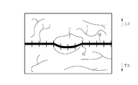
- the measurement light Lm in the imaging range (indicated by arrows Qx, Qy, Qz) at each point at the near end Px, the center vicinity Py, and the far end Pz of the range Rx. It can be seen that the positions of the spots SP formed on the subject (points where the arrows Qx, Qy, and Qz intersect with the optical axis Ax) are different.
- the shooting angle of view of the imaging optical system 21 is represented in the region sandwiched between the two solid lines 101, and the measurement is performed in the central region (the region sandwiched between the two dotted lines 102) having less aberration in the shooting angle of view. I have to.
- the size of the subject can be measured from the movement of the spot position with respect to the change in the observation distance. it can. Then, by imaging the subject illuminated by the measurement light with the image sensor 32, a subject image including the spot SP can be obtained.
- the position of the spot SP differs depending on the relationship between the optical axis Ax of the imaging optical system 21 and the optical axis Lm of the measurement light Lm and the observation distance, but if the observation distance is short, the same actual size ( For example, the number of pixels indicating 5 mm) increases, and the number of pixels decreases as the observation distance increases.
- the signal processing unit 39 of the processor device 16 controls whether or not the length measurement mode can be executed, and detects the position of the spot SP in the subject image in a state where the length measurement mode is permitted to be executed.
- the first signal processing unit 50 is provided, and the second signal processing unit 52 that sets a measurement marker according to the position of the spot SP is provided.
- the signal processing unit 39 is input with a subject image of the subject illuminated by the illumination light.
- the special observation mode is set, the subject image of the subject illuminated by the special light is input.
- the length measurement mode is set, the subject image of the subject illuminated by the illumination light and the measurement light is input.
- the first signal processing unit 50 includes a mode control unit 56 that controls whether or not the length measurement mode can be executed, and an irradiation position detection unit 58 that detects the irradiation position of the spot SP from the subject image.
- the details of the mode control unit 56 will be described later.
- the irradiation position detection unit 58 detects the irradiation position of the spot SP from the subject image in a state where the execution of the length measurement mode is permitted. Specifically, the irradiation position detection unit 58 calculates the coordinates of the spot SP from the subject image in real time, and obtains the irradiation position of the spot SP from the calculated coordinates.
- the irradiation position detection unit 58 In order for the irradiation position detection unit 58 to detect the irradiation position of the spot SP, it is absolutely necessary that the subject image includes a beam color light image based on the color of the measurement light. As a method of detecting the irradiation position, it is preferable to acquire the coordinates of the center of gravity of the spot SP in the subject image.
- the mode control unit 56 when the mode changeover switch 13a is used to switch to the length measurement mode, the setting conditions currently being set for the light source device 14, the endoscope 12, and the processor device 16 are predetermined. Prohibition When the setting condition is met, the setting change operation is performed when the setting condition setting change operation is performed by the user interface 19 during the first control and length measurement mode that prohibits switching to the length measurement mode. When the setting condition to be changed corresponds to the prohibited setting condition, the setting change operation of the setting condition is performed by the user interface 19 in the second control for invalidating the setting change operation or in the length measurement mode. In this case, if the setting condition to be changed by the setting change operation corresponds to the prohibition setting condition, at least one of the third controls for automatically switching from the length measurement mode to another mode is performed.
- the setting conditions for the light source device 14 include the illumination conditions of the illumination light used in the normal observation mode or the length measurement mode, the illumination conditions of the special light used in the special observation mode, or the illumination of the auxiliary light for measurement used in the length measurement mode. Conditions are included. Illumination conditions include, for example, the amount of illumination light.
- the setting conditions for the endoscope 12 include imaging conditions for imaging a subject. The imaging conditions include, for example, shutter speed and the like.
- the setting conditions for the processor device 16 include processing conditions such as image processing for the subject image. The processing conditions include, for example, color balance, brightness correction, and various enhancement processes.
- the position detection of the spot light SP is optimized, and the setting conditions (illumination light amount, shutter speed, color balance, brightness correction, various enhancement processing) that satisfy the visibility at the time of user's dimension measurement are set. It is preferable to do so.
- the prohibition setting conditions include the first prohibition setting condition that prevents the detection of the position of the measurement light irradiation area from the subject image in the length measurement mode, and the prevention of accurately displaying the measurement marker corresponding to the observation distance in the measurement image.
- the second prohibition setting condition is included.
- the first prohibition setting condition includes, for example, a special observation mode in which the measurement light image is not used for displaying the measurement image, brightness enhancement or red enhancement for the subject image, and the like. As described above, in the special observation mode, since the red image which is the measurement light image is not used for the display of the monitor 18, it is difficult to detect the measurement light irradiation area. In the length measurement mode, it is preferable to lower the brightness of the subject image and suppress the redness as compared with the normal observation mode or the special observation mode.
- the second prohibition setting condition includes, for example, the use (ON) of a zoom function such as an optical zoom function or a digital zoom function. This is because the measurement marker displayed in the measurement image is determined according to the position of the spot SP and not according to the magnification of the zoom function. Therefore, when the zoom function is ON, the measurement marker is set. This is because it is difficult to display according to the observation distance.
- a zoom function such as an optical zoom function or a digital zoom function.
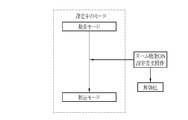
- the mode control unit 56 switches to the length measurement mode as shown in FIG.
- the first control for maintaining the state of the special observation mode is performed by prohibiting the switching of.
- the mode control unit 56 displays a message on the monitor 18 notifying that the switching to the length measurement mode is prohibited (issues a warning sound). May be).
- the mode control unit 56 may perform control to cancel the special observation mode and switch to the length measurement mode as shown in FIG.
- the mode control unit 56 turns on the zoom function as shown in FIG.
- the second control is performed to invalidate the setting change operation.
- the mode control unit 56 displays a message on the monitor 18 notifying that the setting change operation for turning on the zoom function has been invalidated (as shown in FIG. 13). You may make a warning sound).
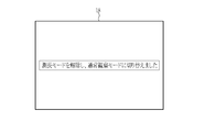
- the mode control unit 56 cancels the length measurement mode as shown in FIG. Then, as another mode, a third control for switching to the normal observation mode is performed.
- the mode control unit 56 notifies that the length measurement mode is canceled (the measurement marker is hidden) and the normal observation mode is switched to, as shown in FIG.
- the message to be displayed is displayed on the monitor 18 (a warning sound may be emitted).
- the setting change operation for turning on the zoom function is enabled, and the subject on the subject image is enlarged or reduced by the zoom function.
- the second signal processing unit 52 sets a first measurement marker as a measurement marker for measuring the size of the subject based on the irradiation position of the spot SP, and sets the first measurement marker on the monitor 18.
- the second signal processing unit 52 refers to the irradiation position by referring to the marker table 62 that stores the measurement marker image whose display mode differs depending on the irradiation position of the spot SP and the marker display position in association with the irradiation position of the spot. Set the measurement marker image corresponding to.
- the measurement marker image for example, has a different size or shape depending on the irradiation position of the spot SP and the marker display position.
- the display of the measurement marker image will be described later.
- the stored contents of the marker table 62 are maintained even when the power of the processor device 16 is turned off.
- the marker table 62 stores the measurement marker image and the irradiation position in association with each other, and stores the distance to the subject corresponding to the irradiation position (distance between the tip portion 12d of the endoscope 12 and the subject) and the measurement. It may be stored in association with the marker image.
- the display control unit 40 controls the display mode of the measurement marker to be different depending on the irradiation position of the spot SP and the marker display position. Do. Specifically, the display control unit 40 displays a measurement image on which a first measurement marker is superimposed, centered on the spot SP, on the monitor 18.
- the first measurement marker for example, a circular measurement marker is used. In this case, as shown in FIG. 16, when the observation distance is close to the near-end Px, the actual size is 5 mm (horizontal direction and vertical of the subject image) in accordance with the center of the spot SP1 formed on the tumor tm1 of the subject.
- the marker M1 indicating the direction) is displayed.
- the measurement marker is displayed on the monitor 18, the observation distance may also be displayed on the monitor 18.
- the marker display position of the marker M1 is located in the peripheral portion of the subject image affected by the distortion by the imaging optical system 21, the marker M1 has an elliptical shape according to the influence of the distortion and the like. Since the above marker M1 substantially coincides with the range of the tumor tm1, the tumor tm1 can be measured to be about 5 mm. Note that the spot may not be displayed on the subject image, and only the first measurement marker may be displayed.
- the actual size is 5 mm (horizontal and vertical directions of the subject image) in accordance with the center of the spot SP2 formed on the tumor tm2 of the subject.
- the indicator M2 is displayed. Since the marker display position of the marker M2 is located at the center of the subject image that is not easily affected by distortion by the imaging optical system 21, the marker M2 is circular without being affected by distortion or the like. ..
- a marker M3 indicating an actual size of 5 mm (horizontal direction and vertical direction of the subject image) is displayed so as to be aligned with the center of the spot SP3 formed on the tumor tm3 of the subject. Since the marker display position of the marker M3 is located in the peripheral portion of the subject image affected by the distortion caused by the imaging optical system 21, the marker M1 has an elliptical shape in accordance with the influence of the distortion or the like. As shown in FIGS. 16 to 18 above, the size of the first measurement marker corresponding to the same actual size of 5 mm becomes smaller as the observation distance becomes longer. Further, the shape of the first measurement marker differs depending on the marker display position according to the influence of the distortion caused by the imaging optical system 21.
- the center of the spot SP and the center of the marker are displayed so as to coincide with each other.
- the first measurement marker is located at a position away from the spot SP. May be displayed.
- the first measurement marker in a state in which the distortion aberration of the subject image is corrected and not deformed may be displayed in the corrected subject image. ..
- the first measurement marker corresponding to the actual size of the subject of 5 mm is displayed, but the actual size of the subject is an arbitrary value (for example, 2 mm) according to the observation target and the observation purpose. , 3 mm, 10 mm, etc.) may be set.
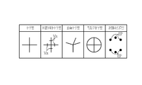
- the first measurement marker has a substantially circular shape, but as shown in FIG. 19, it may have a cross shape in which vertical lines and horizontal lines intersect. Further, a graduated cross shape in which a scale Mx is added to at least one of a cross-shaped vertical line and a horizontal line may be used.
- the first measurement marker a distorted cross shape in which at least one of a vertical line and a horizontal line is tilted may be used.
- the first measurement marker may be a circle in which a cross shape and a circle are combined and a cross shape.
- the first measurement marker may be a measurement point cloud type in which a plurality of measurement point EPs corresponding to the actual size from the spot are combined.
- the number of the first measurement markers may be one or a plurality, and the color of the first measurement markers may be changed according to the actual size.
- the first measurement marker as shown in FIG. 20, three plurality of circular markers M4A, M4B, and M4C (the sizes are 2 mm, 5 mm, and 10 mm in diameter, respectively) having different sizes are used as tumors.
- the spot SP4 formed on the tm4 may be displayed on the subject image as a center. Since a plurality of these three concentric markers are displayed, the trouble of switching can be saved, and measurement is possible even when the subject has a non-linear shape.
- a combination of multiple conditions can be prepared in advance and selected from the combinations. It may be. Further, as shown in FIG.
- the three circular markers are concentric circles having the same center, but are not limited to concentric circles, and may be a plurality of circles based on the position of the spot SP4.
- all three concentric markers are displayed in the same color (black), but when displaying a plurality of concentric markers, they may be displayed as a plurality of colored concentric markers whose colors are changed by the markers.
- the marker M5A is represented by a dotted line representing red
- the marker M5B is represented by a solid line representing blue
- the marker M5C is represented by a alternate long and short dash line representing white.
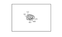
- the first measurement marker in addition to a plurality of concentric markers, as shown in FIG. 22, a plurality of distorted concentric markers in which each concentric circle is distorted may be used.
- the distorted concentric markers M6A, M6B, and M6C are displayed on the subject image centering on the spot SP5 formed on the tumor tm5.
- the mode control unit 56 sets in advance the setting conditions currently being set for the light source device 14, the endoscope 12, or the processor device 16.
- the set prohibition setting condition is met, the operation of switching to the length measurement mode is invalidated, and the first control for prohibiting the switch to the length measurement mode is performed.
- the first control is performed, a message notifying "prohibition of switching to the length measurement mode" is displayed on the monitor 18. If the user wishes to use the length measurement mode, he / she operates the mode switching SW13a or the user interface 19 to change the setting condition to one that does not correspond to the prohibited setting condition. Then, the mode switching SW13a is operated again to switch to the length measurement mode. As a result, the mode is switched to the length measurement mode.
- the setting condition to be changed by the setting change operation corresponds to the prohibition setting condition.
- a message notifying "invalidation of the setting change operation" is displayed on the monitor 18.
- the user cancels the length measurement mode and enables the setting change operation.
- the user interface 19 or the like is operated to perform a third control for switching from the length measurement mode to another mode.
- the third control is performed, the setting change operation is enabled and the setting condition is changed.
- the monitor 18 displays a message notifying that "the length measurement mode has been switched to another mode". These notifications may use icons, indicators, etc. that indicate the length measurement mode state and observation conditions.
- the subject In the length measurement mode, the subject is constantly irradiated with the illumination light and the spot light (measurement light).
- the illumination light is constantly lit and constantly irradiates the subject with the spot.
- the light may intermittently irradiate the subject with spot light by repeating turning on and off (or dimming) every frame (or every few frames).
- the position of the spot light is detected and the display setting of the measurement marker is performed. Then, it is preferable to superimpose and display the measurement marker for which the display setting has been made on the image obtained in the frame that irradiates only the illumination light.
- the measurement light the light formed as a spot when the subject is irradiated is used, but other light may be used.
- a line-shaped measurement light formed as an intersecting line 80 on the subject may be used.
- the intersecting line 80 which is a line-shaped irradiation region, is formed on the subject.
- a second measurement marker including the intersection line 80 and the scale 82 as an index of the size of the subject is generated on the intersection line 80.
- the irradiation position detection unit 58 detects the position of the intersection line 80 (irradiation position of the measurement light).
- the subject When line-shaped measurement light is used as the measurement light, the subject may be constantly irradiated with the illumination light and the line-shaped measurement light during the length measurement mode, and as shown in FIG. 26, the illumination light is While constantly irradiating the subject, the line-shaped measurement light intermittently illuminates the subject by repeating turning on and off (or dimming) every frame (or every few frames). You may. In this case, in the frame that lights the line-shaped measurement light, the position of the line-shaped measurement light is detected and the display of the measurement marker is set. Then, it is preferable to superimpose and display the measurement marker for which the display setting has been made on the image obtained in the frame that irradiates only the illumination light.
- the striped pattern light ZPL formed as the light of the striped pattern on the subject when the subject is irradiated may be used (for example, Japanese Patent Application Laid-Open No. 2016-1983304 (see).
- the striped pattern light ZPL is obtained by irradiating a liquid crystal shutter (not shown) with variable transmittance with a specific laser light, and a region (transmission region) through which the specific laser light is transmitted by the liquid crystal shutter and a specific laser light. Is formed from two different patterns of vertical stripes that do not pass through (non-transparent area) and repeat periodically in the horizontal direction.
- the cycle of the striped pattern light changes depending on the distance to the subject. Therefore, the cycle or phase of the striped pattern light is shifted by the liquid crystal shutter and irradiated multiple times.
- the three-dimensional shape of the subject is measured based on a plurality of images obtained by shifting the period or phase.
- the subject is alternately irradiated with the striped pattern light of phase X, the striped pattern light of phase Y, and the striped pattern light of phase Z.
- the striped pattern light of the phases X, Y, and Z is phase-shifted by 120 ° (2 ⁇ / 3) from the vertical striped pattern.
- the three-dimensional shape of the subject is measured using three types of images obtained based on each striped pattern light.
- the striped pattern light of phase X, the striped pattern light of phase Y, and the striped pattern light of phase Z are switched in units of one frame (or several frames). It is preferable to irradiate the subject. It is preferable that the illumination light always irradiates the subject.
- the measurement light LPL having a grid pattern formed as a grid pattern when the subject is irradiated may be used (for example, JP-A-2017-217215). See Gazette).
- the measurement light LPL of the grid pattern is not a perfect grid, but is slightly deformed from the grid such as wavy so as to improve the detection accuracy of the grid pattern.
- the grid pattern is provided with an S code indicating that the end points of the left and right horizontal lines are continuous.
- the grid pattern may be a pattern in which vertical lines and horizontal lines are regularly arranged, or a pattern in which a plurality of spots are arranged in a vertical and horizontal grid pattern.
- the subject may be constantly irradiated with the illumination light and the grid pattern measurement light LPL during the length measurement mode, and as shown in FIG. While the illumination light constantly illuminates the subject, the grid pattern measurement light LPL repeats turning on and off (or dimming) every frame (or every few frames) to measure the grid pattern.
- the subject may be irradiated with the LPL intermittently. In this case, in the frame that lights the measurement light LPL of the grid pattern, the three-dimensional shape is measured based on the measurement light LPL of the grid pattern. Then, it is preferable to superimpose and display the measurement result of the three-dimensional shape on the image obtained in the frame that irradiates only the illumination light.
- a three-dimensional plane light TPL represented by a mesh line on the subject image may be used (see, for example, Japanese Patent Publication No. 2017-508529).
- the tip portion 12d is moved so that the three-dimensional plane light TPL matches the measurement target.
- the distance of the intersection curve CC between the three-dimensional parallel light TPL and the subject is calculated by a process based on a manual operation such as a user interface or an automatic process.
- the subject When the three-dimensional plane light TPL is used as the measurement light, the subject may be constantly irradiated with the illumination light and the three-dimensional plane light TPL during the length measurement mode, and as shown in FIG. 32, the illumination light is While constantly irradiating the subject, the three-dimensional plane light TPL intermittently irradiates the subject with the three-dimensional plane light TPL by repeating turning on and off (or dimming) every frame (or every few frames). You may.
- the hardware structure of the processing unit that executes various processes is various processors as shown below.
- the circuit configuration is changed after manufacturing the CPU (Central Processing Unit), FPGA (Field Programmable Gate Array), etc., which are general-purpose processors that execute software (programs) and function as various processing units. It includes a programmable logic device (PLD), which is a possible processor, a dedicated electric circuit, which is a processor having a circuit configuration specially designed for executing various processes, and the like.
- PLD programmable logic device
- One processing unit may be composed of one of these various processors, or may be composed of a combination of two or more processors of the same type or different types (for example, a plurality of FPGAs or a combination of a CPU and an FPGA). May be done. Further, a plurality of processing units may be configured by one processor. As an example of configuring a plurality of processing units with one processor, first, as represented by a computer such as a client or a server, one processor is configured by a combination of one or more CPUs and software. There is a form in which this processor functions as a plurality of processing units.
- SoC System On Chip
- a processor that realizes the functions of the entire system including a plurality of processing units with one IC (Integrated Circuit) chip is used.
- the various processing units are configured by using one or more of the above-mentioned various processors as a hardware-like structure.
- the hardware structure of these various processors is, more specifically, an electric circuit in the form of a combination of circuit elements such as semiconductor elements.
- the hardware structure of the storage unit is a storage device such as an HDD (hard disk drive) or SSD (solid state drive).
- the measurement light and the irradiation of the measurement light are preferably as follows.
- the measurement light is preferably spot light.
- the measurement light is preferably a line-shaped measurement light.
- the measurement light is preferably a measurement light having a grid pattern.
- the measurement light is preferably three-dimensional plane light. It is preferable to intermittently irradiate the subject with the measurement light.
- the measurement light is preferably striped pattern light. It is preferable to switch a plurality of striped pattern lights having different phases or periods to irradiate the subject.
Landscapes
- Health & Medical Sciences (AREA)
- Life Sciences & Earth Sciences (AREA)
- Physics & Mathematics (AREA)
- Surgery (AREA)
- Engineering & Computer Science (AREA)
- Optics & Photonics (AREA)
- Medical Informatics (AREA)
- General Health & Medical Sciences (AREA)
- Pathology (AREA)
- Veterinary Medicine (AREA)
- Biomedical Technology (AREA)
- Heart & Thoracic Surgery (AREA)
- Biophysics (AREA)
- Molecular Biology (AREA)
- Animal Behavior & Ethology (AREA)
- Public Health (AREA)
- Radiology & Medical Imaging (AREA)
- Nuclear Medicine, Radiotherapy & Molecular Imaging (AREA)
- Astronomy & Astrophysics (AREA)
- General Physics & Mathematics (AREA)
- Signal Processing (AREA)
- Dentistry (AREA)
- Oral & Maxillofacial Surgery (AREA)
- Endoscopes (AREA)
- Instruments For Viewing The Inside Of Hollow Bodies (AREA)
Abstract
The present invention provides an endoscope system and a method for operating the same with which it is possible to bring setting conditions relating to an optical source device, an endoscope, and a processor device, for example, to a state in which the position of a measurement light irradiation region is detectable. A mode control unit (56) performs first control for prohibiting switching to a length measurement mode if a setting condition relating to a light source device (14), an endoscope (12), or a processor device (16) corresponds to a prohibited setting condition when a switching operation to the light measurement mode has been performed, and performs at least either of second control for invalidating a setting change operation or third control for switching from the length measurement mode to another mode if a setting condition to be changed by the setting change operation during the length measurement mode corresponds to a prohibited setting condition.
Description
本発明は、被写体の大きさを測定するための計測用マーカを表示する内視鏡システム及びその作動方法に関する。
The present invention relates to an endoscope system that displays a measurement marker for measuring the size of a subject and a method of operating the same.
光源装置、内視鏡、及び、プロセッサ装置を有する内視鏡システムでは、被写体までの距離又は被写体の大きさなどを取得することが行われている。例えば、特許文献1では、照明光及び計測光を被写体に照射し、ビーム光の照射により被写体に、スポット光などの計測光照射領域を出現させる。そして、スポット光の位置に対応させて、被写体のサイズを計測するための計測用マーカを被写体画像上に表示している。
In an endoscope system having a light source device, an endoscope, and a processor device, the distance to the subject or the size of the subject is acquired. For example, in Patent Document 1, the subject is irradiated with illumination light and measurement light, and a measurement light irradiation region such as spot light appears on the subject by irradiating the beam light. Then, a measurement marker for measuring the size of the subject is displayed on the subject image in correspondence with the position of the spot light.
スポット光の位置を被写体画像から正しく検出する方法として、RGB/HSVなどの映像の色/明度/彩度などを用いた色分離の方式がある。しかしながら、被写体において、生体内乱反射や残渣、変質(変色)した組織が含まれている場合は、スポット光の位置を検出することが難しい場合がある。また、ユーザーである医師は、病変を検出し易くするために、光源装置、内視鏡、及び、プロセッサ装置に関する設定条件を、病変部を検出しやすい色又は照明に変更する場合がある。このように設定条件を変更した場合には、スポット光の位置を検出することができない場合がある。そこで、光源装置、内視鏡、及び、プロセッサ装置に関する設定条件について、スポット光など計測光照射領域の位置を検出可能な状態にし、且つ、観察距離に対応した計測用マーカを表示可能な状態にすること求められていた。
As a method of correctly detecting the position of the spot light from the subject image, there is a color separation method using the color / brightness / saturation of the image such as RGB / HSV. However, it may be difficult to detect the position of the spot light when the subject contains diffused reflection, residue, or altered (discolored) tissue in the living body. In addition, the user doctor may change the setting conditions for the light source device, the endoscope, and the processor device to a color or illumination that makes it easy to detect the lesion in order to facilitate the detection of the lesion. When the setting conditions are changed in this way, the position of the spot light may not be detected. Therefore, regarding the setting conditions related to the light source device, the endoscope, and the processor device, the position of the measurement light irradiation region such as spot light can be detected, and the measurement marker corresponding to the observation distance can be displayed. I was asked to do it.
本発明は、計測光を用いて計測用マーカを画像上に表示する場合において、光源装置、内視鏡、及び、プロセッサ装置に関する設定条件について、計測光により被写体上に形成される計測光照射領域の位置を検出可能な状態などにすることができる内視鏡システム及びその作動方法を提供することを目的とする。
In the present invention, when a measurement marker is displayed on an image using measurement light, a measurement light irradiation region formed on a subject by measurement light is provided for setting conditions related to a light source device, an endoscope, and a processor device. It is an object of the present invention to provide an endoscopic system capable of detecting the position of an endoscope and a method of operating the endoscopic system.
本発明の内視鏡システムは、光源装置と、計測光を被写体に照射する内視鏡と、プロセッサを有し、被写体に関する被写体画像を生成するプロセッサ装置とを備え、プロセッサは、被写体のサイズを計測するための計測用マーカを表示させた計測用画像をディスプレイに表示する測長モードへの切り替え操作が行われた場合において、光源装置、内視鏡、又は、プロセッサ装置に関する設定条件が、予め定められた禁止設定条件に該当する場合には、測長モードへの切り替えを禁止する第1制御、測長モード中において、設定条件の設定変更操作が行われた場合において、設定変更操作によって変更しようとする設定条件が、禁止設定条件に該当する場合には、設定変更操作を無効化する第2制御、又は、測長モード中において、設定条件の設定変更操作が行われた場合において、設定変更操作によって変更しようとする設定条件が、禁止設定条件に該当する場合には、測長モードから他のモードに切り替える第3制御の少なくともいずれかを行う。
The endoscope system of the present invention includes a light source device, an endoscope that irradiates a subject with measurement light, and a processor device that has a processor and generates a subject image of the subject, and the processor determines the size of the subject. When the operation to switch to the length measurement mode for displaying the measurement image displaying the measurement marker for measurement on the display is performed, the setting conditions for the light source device, the endoscope, or the processor device are set in advance. If the specified prohibition setting condition is met, the setting condition is changed by the setting change operation when the setting condition setting change operation is performed during the first control and length measurement mode that prohibits switching to the length measurement mode. If the setting condition to be tried corresponds to the prohibited setting condition, the second control that invalidates the setting change operation, or the setting when the setting change operation of the setting condition is performed in the length measurement mode. When the setting condition to be changed by the change operation corresponds to the prohibition setting condition, at least one of the third control for switching from the length measurement mode to another mode is performed.
禁止設定条件には、被写体画像から計測光の照射により被写体に現れる計測光照射領域の位置の検出を妨げる第1禁止設定条件が含まれることが好ましい。被写体画像には、計測光の色に基づく計測光画像が含まれ、設定条件には、計測光画像を計測用画像の表示に用いない特殊観察モードが含まれ、第1禁止設定条件には、特殊観察モードが含まれることが好ましい。プロセッサは、特殊観察モード中に、測長モードへの切り替え操作が行われた場合には、測長モードへの切り替えを禁止することに代えて、特殊観察モードを解除して、測長モードへ切り替える制御を行うことが好ましい。計測光画像は赤色画像であることが好ましい。
It is preferable that the prohibition setting condition includes the first prohibition setting condition that prevents the detection of the position of the measurement light irradiation region appearing on the subject by irradiating the measurement light from the subject image. The subject image includes a measurement light image based on the color of the measurement light, the setting condition includes a special observation mode in which the measurement light image is not used for displaying the measurement image, and the first prohibition setting condition includes. It is preferable that a special observation mode is included. If a switch to the length measurement mode is performed during the special observation mode, the processor cancels the special observation mode and switches to the length measurement mode instead of prohibiting the switch to the length measurement mode. It is preferable to control the switching. The measurement light image is preferably a red image.
禁止設定条件には、計測用画像において観察距離に対応した計測用マーカの表示を妨げる第2禁止設定条件が含まれることが好ましい。第2禁止設定条件には、被写体画像において被写体を拡大又は縮小するズーム機能の使用が含まれることが好ましい。
It is preferable that the prohibition setting condition includes a second prohibition setting condition that hinders the display of the measurement marker corresponding to the observation distance in the measurement image. The second prohibition setting condition preferably includes the use of a zoom function for enlarging or reducing the subject in the subject image.
プロセッサは、測長モードへの切り替えを禁止する第1制御を行う場合には、測長モードへの切り替えを禁止する旨の報知を行うことが好ましい。プロセッサは、設定変更操作を無効化する第2制御を行う場合には、設定変更操作を無効化する旨の報知を行うことが好ましい。プロセッサは、測長モードから他のモードに切り替える第3制御を行う場合には、他のモードに切り替える旨の報知を行うことが好ましい。
When the processor performs the first control for prohibiting switching to the length measuring mode, it is preferable to notify that the switching to the length measuring mode is prohibited. When the processor performs the second control for invalidating the setting change operation, it is preferable to notify that the setting change operation is invalidated. When the processor performs the third control for switching from the length measurement mode to another mode, it is preferable to notify that the mode is switched to another mode.
計測用マーカは、被写体の実寸サイズを示す第1の計測用マーカ、又は、計測光によって形成される被写体上の交差ライン、及び交差ライン上に被写体の大きさの指標となる目盛りからなる第2の計測用マーカを含むことが好ましい。
The measurement marker is a first measurement marker indicating the actual size of the subject, an intersection line on the subject formed by the measurement light, and a second scale on the intersection line that serves as an index of the size of the subject. It is preferable to include a marker for measuring.
内視鏡は、計測光を照射する計測光出射部、及び、先端部において計測光出射部とは異なる位置に設けられ、被写体からの光を受光する撮像光学系を有し、計測光は撮像光学系の光軸に対して斜めに出射し、プロセッサは、被写体画像であって計測光の照射により被写体に現れる計測光照射領域を含む被写体画像を取得し、被写体画像から計測光照射領域の位置を検出し、計測光照射領域の位置に対応して、計測用画像をディスプレイにて表示することが好ましい。
The endoscope has a measurement light emitting unit that irradiates the measurement light and an imaging optical system that is provided at a position different from the measurement light emitting unit at the tip portion and receives the light from the subject, and the measurement light is imaged. It emits at an angle to the optical axis of the optical system, and the processor acquires a subject image including the measurement light irradiation area that appears on the subject by irradiating the measurement light, and the position of the measurement light irradiation area from the subject image. It is preferable to detect the above and display the measurement image on the display corresponding to the position of the measurement light irradiation region.
本発明は、光源装置と、計測光を被写体に照射する内視鏡と、プロセッサを有し、被写体に関する被写体画像を生成するプロセッサ装置とを備える内視鏡システムの作動方法において、プロセッサは、被写体のサイズを計測するための計測用マーカを表示させた計測用画像をディスプレイに表示する測長モードへの切り替え操作が行われた場合において、光源装置、内視鏡、又は、プロセッサ装置に関する設定条件が、予め定められた禁止設定条件に該当する場合には、測長モードへの切り替えを禁止する第1制御、測長モード中において、設定条件の設定変更操作が行われた場合において、設定変更操作によって変更しようとする設定条件が、禁止設定条件に該当する場合には、設定変更操作を無効化する第2制御、又は、測長モード中において、設定条件の設定変更操作が行われた場合において、設定変更操作によって変更しようとする設定条件が、禁止設定条件に該当する場合には、測長モードから他のモードに切り替える第3制御の少なくともいずれかを行う。
The present invention relates to a method of operating an endoscope system including a light source device, an endoscope that irradiates a subject with measurement light, and a processor device that has a processor and generates a subject image of the subject. Setting conditions for the light source device, endoscope, or processor device when the operation to switch to the length measurement mode is performed to display the measurement image displaying the measurement marker for measuring the size of However, if a predetermined prohibition setting condition is met, the setting is changed when the setting condition setting change operation is performed during the first control / length measurement mode that prohibits switching to the length measurement mode. When the setting condition to be changed by the operation corresponds to the prohibited setting condition, the second control for invalidating the setting change operation, or when the setting change operation of the setting condition is performed in the length measurement mode. In the above, when the setting condition to be changed by the setting change operation corresponds to the prohibition setting condition, at least one of the third control for switching from the length measurement mode to another mode is performed.
本発明によれば、計測光を用いて計測用マーカを画像上に表示する場合において、光源装置、内視鏡、及び、プロセッサ装置に関する設定条件について、計測光により被写体上に形成される計測光照射領域の位置を検出可能な状態にし、且つ、観察距離に対応した計測用マーカを表示可能な状態にすることができる。
According to the present invention, when the measurement marker is displayed on an image using the measurement light, the measurement light formed on the subject by the measurement light with respect to the setting conditions related to the light source device, the endoscope, and the processor device. The position of the irradiation region can be detected, and the measurement marker corresponding to the observation distance can be displayed.
図1に示すように、内視鏡システム10は、内視鏡12と、光源装置14と、プロセッサ装置16と、モニタ18(ディスプレイ)と、ユーザーインターフェース19と、を有する。内視鏡12は、被検体内に挿入する挿入部12aと、挿入部12aの基端部分に設けられた操作部12bと、ユニバーサルケーブル12cと、を有する。ユニバーサルケーブル12cは、光源装置14が発する照明光を導光するライトガイド28(図3参照)や、内視鏡12の制御に使用する制御信号を伝送するための制御線、観察対象を撮像して得られた画像信号を送信する信号線、内視鏡12の各部に電力を供給する電力線等が一体になったケーブルである。ユニバーサルケーブル12cの先端には光源装置14に接続するコネクタ29が設けられている。
As shown in FIG. 1, the endoscope system 10 includes an endoscope 12, a light source device 14, a processor device 16, a monitor 18 (display), and a user interface 19. The endoscope 12 has an insertion portion 12a to be inserted into the subject, an operation portion 12b provided at the base end portion of the insertion portion 12a, and a universal cable 12c. The universal cable 12c images a light guide 28 (see FIG. 3) that guides the illumination light emitted by the light source device 14, a control line for transmitting a control signal used for controlling the endoscope 12, and an observation target. This is a cable in which a signal line for transmitting the obtained image signal, a power line for supplying power to each part of the endoscope 12, and the like are integrated. A connector 29 for connecting to the light source device 14 is provided at the tip of the universal cable 12c.
光源装置14は、例えば、LED(Light Emitting Diode)やLD(Laser Diode)等の半導体光源やキセノンランプ等のハロゲンランプによって照明光を発生する。コネクタ29を光源装置14に接続した場合、照明光はコネクタ29のライトガイド28(図3参照)に入射し、挿入部12aの先端から観察対象に照射される。
The light source device 14 generates illumination light by, for example, a semiconductor light source such as an LED (Light Emitting Diode) or an LD (Laser Diode) or a halogen lamp such as a xenon lamp. When the connector 29 is connected to the light source device 14, the illumination light enters the light guide 28 (see FIG. 3) of the connector 29 and is irradiated to the observation target from the tip of the insertion portion 12a.
また、光源装置14はプロセッサ装置16と電気的に接続しており、内視鏡12のコネクタ29は光源装置14を介してプロセッサ装置16と接続する。光源装置14とコネクタ29の制御信号や画像信号等の送受信は無線通信である。このため、光源装置14は、無線でコネクタ29と送受信した制御信号等をプロセッサ装置16に伝送する。さらに、光源装置14はコネクタ29に内視鏡12を駆動するための電力を供給するが、この電力の供給も無線で行う。
Further, the light source device 14 is electrically connected to the processor device 16, and the connector 29 of the endoscope 12 is connected to the processor device 16 via the light source device 14. Transmission and reception of control signals, image signals, etc. between the light source device 14 and the connector 29 is wireless communication. Therefore, the light source device 14 wirelessly transmits a control signal or the like transmitted / received to / from the connector 29 to the processor device 16. Further, the light source device 14 supplies the connector 29 with electric power for driving the endoscope 12, and this electric power is also supplied wirelessly.
プロセッサ装置16は、光源装置14が発する照明光の光量や発光タイミング、内視鏡12の各部を制御し、照明光が照射された観察対象を撮像して得る画像信号を用いて内視鏡画像を生成する。また、プロセッサ装置16は、モニタ18及びユーザーインターフェース19と電気的に接続する。モニタ18は、プロセッサ装置16が生成した内視鏡画像や、内視鏡画像に関する情報等を表示する。ユーザーインターフェース19は、機能設定等の入力操作を受け付ける機能を有する。
The processor device 16 controls the amount of illumination light emitted by the light source device 14, the light emission timing, and each part of the endoscope 12, and uses an image signal obtained by imaging an observation target irradiated with the illumination light to obtain an endoscope image. To generate. Further, the processor device 16 is electrically connected to the monitor 18 and the user interface 19. The monitor 18 displays an endoscopic image generated by the processor device 16, information about the endoscopic image, and the like. The user interface 19 has a function of accepting input operations such as function settings.
内視鏡12は、通常観察モードと、特殊観察モードと、測長モードとを備えており、これら3つのモードは内視鏡12の操作部12bに設けられたモード切替スイッチ13aによって切り替えられる。通常観察モードは、照明光によって観察対象を照明するモードである。特殊観察モードは、照明光と異なる特殊光によって観察対象を照明するモードである。測長モードは、照明光及び計測光を観察対象に照明し、且つ、観察対象の撮像により得られる被写体画像上に、観察対象の大きさなどの測定に用いられる計測用マーカを表示する。なお、照明光は、観察対象全体に明るさを与えて観察対象全体を観察するために用いられる光である。特殊光は、観察対象のうち特定領域を強調するために用いられる光である。計測光は、計測用マーカの表示に用いられる光である。
The endoscope 12 has a normal observation mode, a special observation mode, and a length measurement mode, and these three modes can be switched by a mode changeover switch 13a provided on the operation unit 12b of the endoscope 12. The normal observation mode is a mode in which the observation target is illuminated by the illumination light. The special observation mode is a mode in which the observation target is illuminated with special light different from the illumination light. In the length measurement mode, the illumination light and the measurement light are illuminated on the observation target, and a measurement marker used for measuring the size of the observation target and the like is displayed on the subject image obtained by imaging the observation target. The illumination light is light used to give brightness to the entire observation target and observe the entire observation target. Special light is light used to emphasize a specific area of an observation target. The measurement light is light used for displaying a measurement marker.
また、内視鏡12の操作部12bには、被写体画像の静止画の取得を指示する静止画取得指示を操作するためのフリーズスイッチ13bが設けられている。ユーザーがフリーズスイッチ13bを操作することにより、モニタ18の画面がフリーズ表示し、合わせて、静止画取得を行う旨のアラート音(例えば「ピー」)を発する。そして、フリーズスイッチ13bの操作タイミング前後に得られる被写体画像の静止画が、プロセッサ装置16内の静止画保存部42(図3参照)に保存される。なお、静止画保存部42はハードディスクやUSB(Universal Serial Bus)メモリなどの記憶部である。プロセッサ装置16がネットワークに接続可能である場合には、静止画保存部42に代えて又は加えて、ネットワークに接続された静止画保存サーバ(図示しない)に被写体画像の静止画を保存するようにしてもよい。
Further, the operation unit 12b of the endoscope 12 is provided with a freeze switch 13b for operating a still image acquisition instruction for instructing acquisition of a still image of a subject image. When the user operates the freeze switch 13b, the screen of the monitor 18 freezes and displays an alert sound (for example, "pee") to the effect that a still image is acquired. Then, the still image of the subject image obtained before and after the operation timing of the freeze switch 13b is stored in the still image storage unit 42 (see FIG. 3) in the processor device 16. The still image storage unit 42 is a storage unit such as a hard disk or a USB (Universal Serial Bus) memory. When the processor device 16 can be connected to the network, the still image of the subject image is stored in the still image storage server (not shown) connected to the network in place of or in addition to the still image storage unit 42. You may.
なお、フリーズスイッチ13b以外の操作機器を用いて、静止画取得指示を行うようにしてもよい。例えば、プロセッサ装置16にフットペダルを接続し、ユーザーが足でフットペダル(図示しない)を操作した場合に、静止画取得指示を行うようにしてもよい。モード切替についてのフットペダルで行うようにしてもよい。また、プロセッサ装置16に、ユーザーのジェスチャーを認識するジェスチャー認識部(図示しない)を接続し、ジェスチャー認識部が、ユーザーによって行われた特定のジェスチャーを認識した場合に、静止画取得指示を行うようにしてもよい。モード切替についても、ジェスチャー認識部を用いて行うようにしてもよい。
Note that a still image acquisition instruction may be given using an operating device other than the freeze switch 13b. For example, a foot pedal may be connected to the processor device 16 to give a still image acquisition instruction when the user operates the foot pedal (not shown) with his / her foot. You may use the foot pedal for mode switching. Further, a gesture recognition unit (not shown) that recognizes the user's gesture is connected to the processor device 16, and when the gesture recognition unit recognizes a specific gesture performed by the user, a still image acquisition instruction is given. You may do it. The mode switching may also be performed using the gesture recognition unit.
また、モニタ18の近くに設けた視線入力部(図示しない)をプロセッサ装置16に接続し、視線入力部が、モニタ18のうち所定領域内にユーザーの視線が一定時間以上入っていることを認識した場合に、静止画取得指示を行うようにしてもよい。また、プロセッサ装置16に音声認識部(図示しない)を接続し、音声認識部が、ユーザーが発した特定の音声を認識した場合に、静止画取得指示を行うようにしてもよい。モード切替についても、音声認識部を用いて行うようにしてもよい。また、プロセッサ装置16に、タッチパネルなどのオペレーションパネル(図示しない)を接続し、オペレーションパネルに対してユーザーが特定の操作を行った場合に、静止画取得指示を行うようにしてもよい。モード切替についても、オペレーションパネルを用いて行うようにしてもよい。
Further, a line-of-sight input unit (not shown) provided near the monitor 18 is connected to the processor device 16, and the line-of-sight input unit recognizes that the user's line of sight is within a predetermined area of the monitor 18 for a certain period of time or longer. If this happens, a still image acquisition instruction may be given. Further, a voice recognition unit (not shown) may be connected to the processor device 16 so that when the voice recognition unit recognizes a specific voice emitted by the user, a still image acquisition instruction may be given. The mode switching may also be performed using the voice recognition unit. Further, an operation panel (not shown) such as a touch panel may be connected to the processor device 16 to give a still image acquisition instruction when the user performs a specific operation on the operation panel. The mode switching may also be performed using the operation panel.
図2に示すように、内視鏡12の先端部12dは略円形となっており、被写体からの光を受光する撮像光学系21と、被写体に対して照明光を照射するための照明光学系22と、被写体に対して計測光を被写体に放射する計測光出射部23と、処置具を被写体に向けて突出させるための開口24と、送気送水を行うための送気送水ノズル25とが設けられている。
As shown in FIG. 2, the tip portion 12d of the endoscope 12 has a substantially circular shape, and an imaging optical system 21 that receives light from the subject and an illumination optical system that irradiates the subject with illumination light. 22, the measurement light emitting unit 23 that radiates the measurement light to the subject, the opening 24 for projecting the treatment tool toward the subject, and the air supply water supply nozzle 25 for supplying air and water. It is provided.
撮像光学系21の光軸Axは、紙面に対して垂直な方向に延びている。縦の第1方向D1は、光軸Axに対して直交しており、横の第2方向D2は、光軸Ax及び第1方向D1に対して直交する。撮像光学系21と計測光出射部23とは、それぞれ先端部12dの異なる位置に設けられており、第1方向D1に沿って配列されている。
The optical axis Ax of the imaging optical system 21 extends in a direction perpendicular to the paper surface. The vertical first direction D1 is orthogonal to the optical axis Ax, and the horizontal second direction D2 is orthogonal to the optical axis Ax and the first direction D1. The imaging optical system 21 and the measurement light emitting unit 23 are provided at different positions of the tip portion 12d, and are arranged along the first direction D1.
図3に示すように、光源装置14は、光源部26と、光源制御部27とを備えている。光源部26は、被写体を照明するための照明光又は特殊光を発生する。光源部26から出射された照明光又は特殊光は、ライトガイド28に入射され、照明レンズ22aを通って被写体に照射される。光源部26としては、照明光の光源として、白色光を出射する白色光源、又は、白色光源とその他の色の光を出射する光源(例えば青色光を出射する青色光源)を含む複数の光源等が用いられる。また、光源部26としては、特殊光の光源として、表層血管など表層情報を強調するための青色狭帯域光を含む広帯域光を発する光源が用いられる。光源制御部27は、プロセッサ装置16のシステム制御部41と接続されている。なお、照明光としては、青色光、緑色光、及び赤色光をそれぞれ組み合わせた白色の混色光としてもよい。この場合には、赤色光の照射範囲に比べて緑色光の照射範囲のほうが大きくなるように、照明光学系22の光学設計を行うことが好ましい。
As shown in FIG. 3, the light source device 14 includes a light source unit 26 and a light source control unit 27. The light source unit 26 generates illumination light or special light for illuminating the subject. The illumination light or special light emitted from the light source unit 26 is incident on the light guide 28 and is applied to the subject through the illumination lens 22a. The light source unit 26 includes, as a light source of illumination light, a white light source that emits white light, or a plurality of light sources including a white light source and a light source that emits light of other colors (for example, a blue light source that emits blue light). Is used. Further, as the light source unit 26, as a light source of special light, a light source that emits wideband light including blue narrow band light for emphasizing surface layer information such as surface blood vessels is used. The light source control unit 27 is connected to the system control unit 41 of the processor device 16. The illumination light may be a white mixed color light in which blue light, green light, and red light are combined. In this case, it is preferable to design the illumination optical system 22 so that the irradiation range of green light is larger than the irradiation range of red light.
光源制御部27は、システム制御部41からの指示に基づいて光源部26を制御する。システム制御部41は、光源制御部27に対して、光源制御に関する指示を行う他に、計測光出射部23の光源23a(図5参照)も制御する。通常観察モードの場合には、システム制御部41は、通常観察モードの場合は、照明光を点灯し、計測光を消灯する制御を行う。特殊観察モードの場合は、特殊光を点灯し、計測光を消灯する制御を行う。測長モードの場合には、システム制御部41は、照明光を点灯し、計測光を点灯する制御を行う。
The light source control unit 27 controls the light source unit 26 based on an instruction from the system control unit 41. The system control unit 41 gives an instruction regarding the light source control to the light source control unit 27, and also controls the light source 23a (see FIG. 5) of the measurement light emission unit 23. In the normal observation mode, the system control unit 41 controls to turn on the illumination light and turn off the measurement light in the normal observation mode. In the special observation mode, the special light is turned on and the measurement light is turned off. In the length measurement mode, the system control unit 41 turns on the illumination light and controls to turn on the measurement light.
照明光学系22は照明レンズ22aを有しており、この照明レンズ22aを介して、ライトガイド28からの光が観察対象に照射される。撮像光学系21は、対物レンズ21a、ズームレンズ21b、及び撮像素子32を有している。観察対象からの反射光は、対物レンズ21a及びズームレンズ21bを介して、撮像素子32に入射する。これにより、撮像素子32に観察対象の反射像が結像される。
The illumination optical system 22 has an illumination lens 22a, and the light from the light guide 28 is irradiated to the observation target through the illumination lens 22a. The image pickup optical system 21 includes an objective lens 21a, a zoom lens 21b, and an image pickup element 32. The reflected light from the observation target enters the image sensor 32 via the objective lens 21a and the zoom lens 21b. As a result, a reflected image to be observed is formed on the image sensor 32.
ズームレンズ21bは、テレ端とワイド端との間で移動することによって、ズーム機能として、被写体を拡大又は縮小する光学ズーム機能を有する。光学ズーム機能のONとOFFは、内視鏡の操作部12bに設けられたズーム操作部13c(図1参照)により切り替えることが可能であり、光学ズーム機能がONの状態で、さらにズーム操作部13cを操作することにより、特定の拡大率で被写体を拡大又は縮小する。
The zoom lens 21b has an optical zoom function for enlarging or reducing the subject as a zoom function by moving between the telephoto end and the wide end. The optical zoom function can be switched on and off by the zoom operation unit 13c (see FIG. 1) provided in the operation unit 12b of the endoscope, and when the optical zoom function is ON, the zoom operation unit is further turned on. By manipulating 13c, the subject is enlarged or reduced at a specific magnification.
撮像素子32はカラーの撮像センサであり、被検体の反射像を撮像して画像信号を出力する。この撮像素子32は、CCD(Charge Coupled Device)撮像センサやCMOS(Complementary Metal-Oxide Semiconductor)撮像センサ等であることが好ましい。本発明で用いられる撮像素子32は、R(赤)、G(緑)B(青)の3色の赤色画像、緑色画像、及び赤色画像を得るためのカラーの撮像センサである。赤色画像は、撮像素子32において赤色のカラーフィルタが設けられた赤色画素から出力される画像である。緑色画像は、撮像素子32において緑色のカラーフィルタが設けられた緑色画素から出力される画像である。青色画像は、撮像素子32において青色のカラーフィルタが設けられた青色画素から出力される画像である。撮像素子32は、撮像制御部33によって制御される。
The image sensor 32 is a color image sensor, which captures a reflected image of a subject and outputs an image signal. The image sensor 32 is preferably a CCD (Charge Coupled Device) image sensor, a CMOS (Complementary Metal-Oxide Semiconductor) image sensor, or the like. The image pickup device 32 used in the present invention is a color image pickup sensor for obtaining a red image, a green image, and a red image of three colors of R (red), G (green), and B (blue). The red image is an image output from a red pixel provided with a red color filter in the image sensor 32. The green image is an image output from a green pixel provided with a green color filter in the image sensor 32. The blue image is an image output from a blue pixel provided with a blue color filter in the image sensor 32. The image sensor 32 is controlled by the image sensor 33.
撮像素子32から出力される画像信号は、CDS/AGC回路34に送信される。CDS・AGC回路34は、アナログ信号である画像信号に相関二重サンプリング(CDS(Correlated Double Sampling))や自動利得制御(AGC(Auto Gain Control))を行う。CDS/AGC回路34を経た画像信号は、A/D変換器(A/D(Analog /Digital)コンバータ)35により、デジタル画像信号に変換される。A/D変換されたデジタル画像信号は、通信I/F(Interface)36を介して、光源装置14の通信I/F(Interface)37に入力される。
The image signal output from the image sensor 32 is transmitted to the CDS / AGC circuit 34. The CDS / AGC circuit 34 performs correlated double sampling (CDS (Correlated Double Sampling)) and automatic gain control (AGC (Auto Gain Control)) on an image signal which is an analog signal. The image signal that has passed through the CDS / AGC circuit 34 is converted into a digital image signal by the A / D converter (A / D (Analog / Digital) converter) 35. The A / D converted digital image signal is input to the communication I / F (Interface) 37 of the light source device 14 via the communication I / F (Interface) 36.
プロセッサ装置16は、後述する第1制御、第2制御、及び第3制御などモードに関する制御などに関するプログラムがプログラム格納メモリ(図示しない)に組み込まれている。プロセッサによって構成されるシステム制御部41は、プログラム格納メモリに組み込まれたプログラムを動作することによって、光源装置14の通信I/F(Interface)37と接続される受信部38と、信号処理部39と、表示制御部40の機能が実現する。また、上記プログラムの動作によって、信号処理部39に含まれる第1信号処理部50、モード制御部56、照射位置検出部58、及び第2信号処理部(図8参照)の機能も実現する。
The processor device 16 has a program for controlling modes such as the first control, the second control, and the third control, which will be described later, incorporated in a program storage memory (not shown). The system control unit 41 configured by the processor operates a program embedded in the program storage memory to connect the reception unit 38 connected to the communication I / F (Interface) 37 of the light source device 14 and the signal processing unit 39. Then, the function of the display control unit 40 is realized. Further, by the operation of the above program, the functions of the first signal processing unit 50, the mode control unit 56, the irradiation position detection unit 58, and the second signal processing unit (see FIG. 8) included in the signal processing unit 39 are also realized.
通信I/Fは、通信I/F37から伝送されてきた画像信号を受信して信号処理部39に伝達する。信号処理部39は、受信部38から受けた画像信号を一時記憶するメモリを内蔵しており、メモリに記憶された画像信号の集合である画像信号群を処理して、被写体画像を生成する。なお、受信部38は、光源制御部27に関連する制御信号については、システム制御部41に直接送るようにしてもよい。また、プロセッサ装置16のうち、測長モードに関連する処理部(例えば、第1信号処理部50及び第2信号処理部52)については、プロセッサ装置16とは別体の測長用プロセッサ(図示しない)に設けてもよい。この場合、測長用プロセッサとプロセッサ装置16とは、画像又は各種情報が送受信可能なように、互いに通信可能な状態にしておく。
The communication I / F receives the image signal transmitted from the communication I / F 37 and transmits it to the signal processing unit 39. The signal processing unit 39 has a built-in memory that temporarily stores an image signal received from the receiving unit 38, and processes an image signal group that is a set of image signals stored in the memory to generate a subject image. The receiving unit 38 may directly send the control signal related to the light source control unit 27 to the system control unit 41. Further, among the processor devices 16, the processing units related to the length measurement mode (for example, the first signal processing unit 50 and the second signal processing unit 52) are length measurement processors (not shown) that are separate from the processor device 16. It may be provided in). In this case, the length measuring processor and the processor device 16 are kept in a state where they can communicate with each other so that images or various information can be transmitted and received.
信号処理部39では、通常観察モードに設定されている場合には、被写体画像の青色画像はモニタ18のBチャンネルに、被写体画像の緑色画像はモニタ18のGチャンネルに、被写体画像の赤色画像はモニタ18のRチャンネルにそれぞれ割り当てる信号割り当て処理を行うことによって、カラーの被写体画像がモニタ18に表示する。測長モードについても、通常観察モードと同様の信号割り当て処理を行う。一方、信号処理部39では、特殊観察モードに設定されている場合には、被写体画像の赤色画像はモニタ18の表示には使用せず、被写体画像の青色画像をモニタ18のBチャンネルとGチャンネルに割り当て、被写体画像の緑色画像をモニタ18のRチャンネルに割り当てることによって、疑似カラーの被写体画像をモニタ18に表示する。
In the signal processing unit 39, when the normal observation mode is set, the blue image of the subject image is on the B channel of the monitor 18, the green image of the subject image is on the G channel of the monitor 18, and the red image of the subject image is on the G channel. A color subject image is displayed on the monitor 18 by performing signal allocation processing assigned to each R channel of the monitor 18. Also in the length measurement mode, the same signal allocation processing as in the normal observation mode is performed. On the other hand, in the signal processing unit 39, when the special observation mode is set, the red image of the subject image is not used for the display of the monitor 18, and the blue image of the subject image is used for the B channel and the G channel of the monitor 18. By assigning the green image of the subject image to the R channel of the monitor 18, the pseudo-color subject image is displayed on the monitor 18.
信号処理部39は、ズーム機能として、ユーザーインターフェース19によってデジタルズーム機能がONに設定されている場合には、被写体画像の一部を切り取って拡大又は縮小することによって、特定の倍率で被写体を拡大又は縮小する。図4(A)は、デジタルズーム機能がOFFの状態の被写体画像を示しており、図4(B)は、図4(A)の被写体画像のうち中心部分を切り取って拡大したデジタルズーム機能ONの被写体画像を示している。なお、デジタルズーム機能がOFFの場合には、被写体画像の切り取りによる被写体の拡大又は縮小は行われない。
When the digital zoom function is set to ON by the user interface 19 as the zoom function, the signal processing unit 39 enlarges or reduces the subject at a specific magnification by cutting out a part of the subject image and enlarging or reducing it. to shrink. FIG. 4A shows a subject image in a state where the digital zoom function is OFF, and FIG. 4B shows a subject with the digital zoom function ON which is enlarged by cutting out the central portion of the subject image in FIG. 4A. The image is shown. When the digital zoom function is OFF, the subject is not enlarged or reduced by cropping the subject image.
なお、信号処理部39では、測長モードに設定されている場合には、被写体画像に対して、血管などの構造を強調する構造強調処理や、観察対象のうち正常部と病変部などとの色差を拡張した色差強調処理を施すようにしてもよい。
When the signal processing unit 39 is set to the length measurement mode, the signal processing unit 39 performs a structure emphasizing process for emphasizing the structure of blood vessels and the like on the subject image, and the normal part and the lesion part of the observation target. A color difference enhancement process that extends the color difference may be performed.
表示制御部40は、信号処理部39によって生成された被写体画像をモニタ18に表示する。システム制御部41は、内視鏡12に設けられた撮像制御部33を介して、撮像素子32の制御を行う。撮像制御部33は、撮像素子32の制御に合わせて、CDS/AGC34及びA/D35の制御も行う。
The display control unit 40 displays the subject image generated by the signal processing unit 39 on the monitor 18. The system control unit 41 controls the image pickup device 32 via the image pickup control section 33 provided in the endoscope 12. The image pickup control unit 33 also controls the CDS / AGC34 and the A / D35 in accordance with the control of the image pickup element 32.
図5に示すように、計測光出射部23は、撮像光学系21の光軸Axに対して斜めに計測光を出射する。計測光出射部23は、光源23aと、回折光学素子DOE23b(Diffractive Optical Element)と、プリズム23cと、出射部23dとを備える。光源23aは、撮像素子32の画素によって検出可能な色の光(具体的には可視光)を出射するものであり、レーザー光源LD(Laser Diode)又はLED(Light Emitting Diode)等の発光素子と、この発光素子から出射される光を集光する集光レンズとを含む。なお、光源23aはスコープエレキ基板(図示しない)に設けられている。スコープエレキ基板は、内視鏡の先端部12dに設けられており、光源装置14又はプロセッサ装置16から電力の供給を受けて、光源23aに電力を供給している。
As shown in FIG. 5, the measurement light emitting unit 23 emits the measurement light obliquely with respect to the optical axis Ax of the imaging optical system 21. The measurement light emitting unit 23 includes a light source 23a, a diffractive optical element DOE23b (Diffractive Optical Element), a prism 23c, and an emitting unit 23d. The light source 23a emits light of a color (specifically, visible light) that can be detected by the pixels of the image pickup element 32, and is a light emitting element such as a laser light source LD (LaserDiode) or an LED (LightEmittingDiode). , Including a condensing lens that collects the light emitted from this light emitting element. The light source 23a is provided on a scope electric substrate (not shown). The scope electric board is provided at the tip end portion 12d of the endoscope, and receives power from the light source device 14 or the processor device 16 to supply power to the light source 23a.
本実施形態では、光源23aが出射する光の波長は、例えば、600nm以上650nm以下の赤色(ビーム光の色)のレーザー光を使用するが、その他の波長帯域の光、例えば、495nm以上570nm以下の緑色光を用いてもよい。光源23aはシステム制御部41によって制御され、システム制御部41からの指示に基づいて光出射を行う。DOE23bは、光源から出射した光を、計測情報を得るための計測光に変換する。なお、計測光は、人体、目、内臓保護の観点に基づいて光量が調整され、且つ、内視鏡12の観察範囲では十分に白飛び(画素飽和)する程度の光量に調整されることが好ましい。
In the present embodiment, the wavelength of the light emitted by the light source 23a is, for example, 600 nm or more and 650 nm or less red (beam light color) laser light, but light in other wavelength bands, for example, 495 nm or more and 570 nm or less. You may use the green light of. The light source 23a is controlled by the system control unit 41, and emits light based on an instruction from the system control unit 41. The DOE23b converts the light emitted from the light source into the measurement light for obtaining the measurement information. The amount of measured light may be adjusted from the viewpoint of protecting the human body, eyes, and internal organs, and the amount of light may be adjusted to such an extent that whiteout (pixel saturation) is sufficient in the observation range of the endoscope 12. preferable.
プリズム23cは、DOE23bで変換後の計測光の進行方向を変えるための光学部材である。プリズム23cは、対物レンズ21aを含む撮像光学系21の視野と交差するように、計測光の進行方向を変更する。計測光の進行方向の詳細についても、後述する。プリズム23cから出射した計測光Lmは、光学部材で形成される出射部23dを通って、被写体へと照射される。
The prism 23c is an optical member for changing the traveling direction of the measurement light after conversion by DOE23b. The prism 23c changes the traveling direction of the measurement light so as to intersect the field of view of the imaging optical system 21 including the objective lens 21a. The details of the traveling direction of the measurement light will also be described later. The measurement light Lm emitted from the prism 23c is applied to the subject through the exit portion 23d formed of the optical member.
計測光が被写体に照射されることにより、図6に示すように、被写体において、計測光照射領域としてのスポットSPが形成される。このスポットSPの位置は、照射位置検出部58(図8参照)によって特性され、また、スポットSPの位置に応じて、被写体のサイズを表す計測用マーカが設定される。設定された計測用マーカは、被写体画像上に表示される。なお、計測用マーカには、後述するように、第1の計測用マーカ、第2の計測用マーカなど複数の種類が含まれ、いずれの種類の計測用マーカを被写体画像上に表示するかについては、ユーザーの指示によって選択が可能となっている。ユーザーの指示としては、例えば、ユーザーインターフェース19が用いられる。
By irradiating the subject with the measurement light, as shown in FIG. 6, a spot SP as a measurement light irradiation region is formed in the subject. The position of the spot SP is characterized by the irradiation position detection unit 58 (see FIG. 8), and a measurement marker indicating the size of the subject is set according to the position of the spot SP. The set measurement marker is displayed on the subject image. As will be described later, the measurement markers include a plurality of types such as a first measurement marker and a second measurement marker, and which type of measurement marker is to be displayed on the subject image. Can be selected according to the user's instructions. As the user's instruction, for example, the user interface 19 is used.
なお、出射部23dを光学部材で構成することに代えて、内視鏡の先端部12dに形成される計測補助用スリットとしてもよい。また、出射部23dを光学部材で構成する場合には、反射防止コート(AR(Anti-Reflection)コート)(反射防止部)を施すことが好ましい。このように反射防止コートを設けるのは、計測光が出射部23dを透過せずに反射して、被写体に照射される計測光の割合が低下すると、後述する照射位置検出部58が、計測光により被写体上に形成されるスポットSPの位置を認識し難くなるためである。
Instead of forming the exit portion 23d with an optical member, it may be a measurement assist slit formed in the tip portion 12d of the endoscope. Further, when the emitting portion 23d is composed of an optical member, it is preferable to apply an antireflection coating (AR (Anti-Reflection) coating) (antireflection portion). The reason why the antireflection coat is provided is that when the measurement light is reflected without passing through the emission unit 23d and the ratio of the measurement light emitted to the subject decreases, the irradiation position detection unit 58, which will be described later, determines the measurement light. This is because it becomes difficult to recognize the position of the spot SP formed on the subject.
なお、計測光出射部23は、計測光を撮像光学系21の視野に向けて出射できるものであればよい。例えば、光源23aが光源装置に設けられ、光源23aから出射された光が光ファイバによってDOE23bにまで導光されるものであってもよい。また、プリズム23cを用いずに、光源23a及びDOE23bの向きを、撮像光学系21の光軸Axに対して斜めに設置することで、撮像光学系21の視野を横切る方向に計測光Lmを出射させる構成としてもよい。
The measurement light emitting unit 23 may be any as long as it can emit the measurement light toward the field of view of the imaging optical system 21. For example, the light source 23a may be provided in the light source device, and the light emitted from the light source 23a may be guided to the DOE 23b by an optical fiber. Further, by arranging the directions of the light source 23a and DOE23b diagonally with respect to the optical axis Ax of the imaging optical system 21 without using the prism 23c, the measurement light Lm is emitted in the direction crossing the field of view of the imaging optical system 21. It may be configured to be made to.
計測光の進行方向については、図7に示すように、計測光の光軸Lmが撮像光学系21の光軸Axと交差する状態で、計測光を出射する。観察距離の範囲Rxにおいて観察可能であるとすると、範囲Rxの近端Px、中央付近Py、及び遠端Pzでは、各点での撮像範囲(矢印Qx、Qy、Qzで示す)における計測光Lmによって被写体上に形成されるスポットSPの位置(各矢印Qx、Qy、Qzが光軸Axと交わる点)が異なることが分かる。なお、撮像光学系21の撮影画角は2つの実線101で挟まれる領域内で表され、この撮影画角のうち収差の少ない中央領域(2つの点線102で挟まれる領域)で計測を行うようにしている。
As for the traveling direction of the measurement light, as shown in FIG. 7, the measurement light is emitted in a state where the optical axis Lm of the measurement light intersects the optical axis Ax of the imaging optical system 21. Assuming that observation is possible in the range Rx of the observation distance, the measurement light Lm in the imaging range (indicated by arrows Qx, Qy, Qz) at each point at the near end Px, the center vicinity Py, and the far end Pz of the range Rx. It can be seen that the positions of the spots SP formed on the subject (points where the arrows Qx, Qy, and Qz intersect with the optical axis Ax) are different. The shooting angle of view of the imaging optical system 21 is represented in the region sandwiched between the two solid lines 101, and the measurement is performed in the central region (the region sandwiched between the two dotted lines 102) having less aberration in the shooting angle of view. I have to.
以上のように、計測光の光軸Lmを光軸Axと交差する状態で、計測光Lmを出射することによって、観察距離の変化に対するスポット位置の移動から、被写体の大きさを計測することができる。そして、計測光が照明された被写体を撮像素子32で撮像することによって、スポットSPを含む被写体画像が得られる。被写体画像では、スポットSPの位置は、撮像光学系21の光軸Axと計測光Lmの光軸Lmとの関係、及び観察距離に応じて異なるが、観察距離が近ければ、同一の実寸サイズ(例えば5mm)を示すピクセル数が多くなり、観察距離が遠ければピクセル数が少なくなる。
As described above, by emitting the measurement light Lm with the optical axis Lm of the measurement light intersecting the optical axis Ax, the size of the subject can be measured from the movement of the spot position with respect to the change in the observation distance. it can. Then, by imaging the subject illuminated by the measurement light with the image sensor 32, a subject image including the spot SP can be obtained. In the subject image, the position of the spot SP differs depending on the relationship between the optical axis Ax of the imaging optical system 21 and the optical axis Lm of the measurement light Lm and the observation distance, but if the observation distance is short, the same actual size ( For example, the number of pixels indicating 5 mm) increases, and the number of pixels decreases as the observation distance increases.
図8に示すように、プロセッサ装置16の信号処理部39は、測長モードの実行の可否等を制御し、測長モードの実行が許可された状態において、被写体画像におけるスポットSPの位置を検出する第1信号処理部50と、スポットSPの位置に応じて計測用マーカを設定する第2信号処理部52とを備えている。なお、信号処理部39には、通常観察モードに設定されている場合には、照明光によって照明された被写体の被写体画像が入力される。特殊観察モードに設定されている場合には、特殊光によって照明された被写体の被写体画像が入力される。測長モードに設定されている場合には、照明光及び計測光によって照明された被写体の被写体画像が入力される。
As shown in FIG. 8, the signal processing unit 39 of the processor device 16 controls whether or not the length measurement mode can be executed, and detects the position of the spot SP in the subject image in a state where the length measurement mode is permitted to be executed. The first signal processing unit 50 is provided, and the second signal processing unit 52 that sets a measurement marker according to the position of the spot SP is provided. When the normal observation mode is set, the signal processing unit 39 is input with a subject image of the subject illuminated by the illumination light. When the special observation mode is set, the subject image of the subject illuminated by the special light is input. When the length measurement mode is set, the subject image of the subject illuminated by the illumination light and the measurement light is input.
第1信号処理部50は、測長モードの実行可否などに関する制御を行うモード制御部56と、被写体画像からスポットSPの照射位置を検出する照射位置検出部58とを備えている。モード制御部56の詳細については後述する。照射位置検出部58では、測長モードの実行が許可された状態で、被写体画像から、スポットSPの照射位置を検出する。具体的には、照射位置検出部58では、リアルタイムに、被写体画像からスポットSPの座標を算出し、算出した座標からスポットSPの照射位置を求める。照射位置検出部58にてスポットSPの照射位置を検出するためには、被写体画像に、計測光の色に基づくビーム色光画像が含まれていることが必ず必要である。照射位置の検出方法としては、被写体画像におけるスポットSPの重心位置座標を取得することが好ましい。
The first signal processing unit 50 includes a mode control unit 56 that controls whether or not the length measurement mode can be executed, and an irradiation position detection unit 58 that detects the irradiation position of the spot SP from the subject image. The details of the mode control unit 56 will be described later. The irradiation position detection unit 58 detects the irradiation position of the spot SP from the subject image in a state where the execution of the length measurement mode is permitted. Specifically, the irradiation position detection unit 58 calculates the coordinates of the spot SP from the subject image in real time, and obtains the irradiation position of the spot SP from the calculated coordinates. In order for the irradiation position detection unit 58 to detect the irradiation position of the spot SP, it is absolutely necessary that the subject image includes a beam color light image based on the color of the measurement light. As a method of detecting the irradiation position, it is preferable to acquire the coordinates of the center of gravity of the spot SP in the subject image.
モード制御部56は、モード切替スイッチ13aによって測長モードへの切り替え操作が行われた場合において、光源装置14、内視鏡12、プロセッサ装置16に関する現在設定中の設定条件が、予め定められた禁止設定条件に該当する場合には、測長モードへの切り替えを禁止する第1制御、測長モード中において、ユーザーインターフェース19によって設定条件の設定変更操作が行われた場合において、設定変更操作によって変更しようとする設定条件が禁止設定条件に該当する場合には、設定変更操作を無効化する第2制御、又は、測長モード中において、ユーザーインターフェース19によって設定条件の設定変更操作が行われた場合において、設定変更操作によって変更しようとする設定条件が禁止設定条件に該当する場合には、測長モードから他のモードへ自動的に切り替える第3制御の少なくともいずれかを行う。
In the mode control unit 56, when the mode changeover switch 13a is used to switch to the length measurement mode, the setting conditions currently being set for the light source device 14, the endoscope 12, and the processor device 16 are predetermined. Prohibition When the setting condition is met, the setting change operation is performed when the setting condition setting change operation is performed by the user interface 19 during the first control and length measurement mode that prohibits switching to the length measurement mode. When the setting condition to be changed corresponds to the prohibited setting condition, the setting change operation of the setting condition is performed by the user interface 19 in the second control for invalidating the setting change operation or in the length measurement mode. In this case, if the setting condition to be changed by the setting change operation corresponds to the prohibition setting condition, at least one of the third controls for automatically switching from the length measurement mode to another mode is performed.
光源装置14に関する設定条件としては、通常観察モード又は測長モードにて用いる照明光の照明条件、特殊観察モードにて用いる特殊光の照明条件、又は、測長モードに用いる計測用補助光の照明条件が含まれる。照明条件には、例えば、照明光量などが含まれる。内視鏡12に関する設定条件としては、被写体の撮像に関する撮像条件が含まれる。撮像条件としては、例えば、シャッタースピードなどが含まれる。プロセッサ装置16に関する設定条件としては、被写体画像に関する画像処理などの処理条件が含まれる。処理条件には、例えば、カラーバランス、明るさ補正、各種強調処理などが含まれる。なお、測長モードにおいては、スポット光SPの位置検出を最適化し、ユーザーの寸法測定時の視認性を満たす設定条件(照明光量、シャッタースピード、カラーバランス、明るさ補正、各種強調処理)に設定することが好ましい。
The setting conditions for the light source device 14 include the illumination conditions of the illumination light used in the normal observation mode or the length measurement mode, the illumination conditions of the special light used in the special observation mode, or the illumination of the auxiliary light for measurement used in the length measurement mode. Conditions are included. Illumination conditions include, for example, the amount of illumination light. The setting conditions for the endoscope 12 include imaging conditions for imaging a subject. The imaging conditions include, for example, shutter speed and the like. The setting conditions for the processor device 16 include processing conditions such as image processing for the subject image. The processing conditions include, for example, color balance, brightness correction, and various enhancement processes. In the length measurement mode, the position detection of the spot light SP is optimized, and the setting conditions (illumination light amount, shutter speed, color balance, brightness correction, various enhancement processing) that satisfy the visibility at the time of user's dimension measurement are set. It is preferable to do so.
禁止設定条件には、測長モードにおいて被写体画像から計測光照射領域の位置の検出を妨げる第1禁止設定条件と、計測用画像において観察距離に対応した計測用マーカを正確に表示することを妨げる第2禁止設定条件が含まれる。第1禁止設定条件としては、例えば、計測光画像を計測用画像の表示に用いない特殊観察モード、被写体画像に対する明るさ強調又は赤色強調などが含まれる。上記したように、特殊観察モードでは、計測光画像である赤色画像はモニタ18の表示に用いられないため、計測光照射領域の検出が困難である。なお、測長モードでは、通常観察モード又は特殊観察モードと比較して、被写体画像における明るさを低くし、また、赤味を抑えることが好ましい。
The prohibition setting conditions include the first prohibition setting condition that prevents the detection of the position of the measurement light irradiation area from the subject image in the length measurement mode, and the prevention of accurately displaying the measurement marker corresponding to the observation distance in the measurement image. The second prohibition setting condition is included. The first prohibition setting condition includes, for example, a special observation mode in which the measurement light image is not used for displaying the measurement image, brightness enhancement or red enhancement for the subject image, and the like. As described above, in the special observation mode, since the red image which is the measurement light image is not used for the display of the monitor 18, it is difficult to detect the measurement light irradiation area. In the length measurement mode, it is preferable to lower the brightness of the subject image and suppress the redness as compared with the normal observation mode or the special observation mode.
また、第2禁止設定条件としては、例えば、光学ズーム機能又はデジタルズーム機能などのズーム機能の使用(ON)が含まれる。これは、計測用画像で表示する計測用マーカは、スポットSPの位置に応じて定められ、ズーム機能の倍率に応じては定められていないことから、ズーム機能がONの場合、計測用マーカが観察距離に対応して表示することが難しいためである。
The second prohibition setting condition includes, for example, the use (ON) of a zoom function such as an optical zoom function or a digital zoom function. This is because the measurement marker displayed in the measurement image is determined according to the position of the spot SP and not according to the magnification of the zoom function. Therefore, when the zoom function is ON, the measurement marker is set. This is because it is difficult to display according to the observation distance.
例えば、特殊観察モードに設定されている状態において、モード切替スイッチ13aにより測長モードへの切り替え操作が行われた場合には、図9に示すように、モード制御部56は、測長モードへの切り替えを禁止して、特殊観察モードの状態を維持する第1制御を行う。第1制御が行われた場合には、モード制御部56は、図10に示すように、測長モードへの切り替えが禁止されたことを報知するメッセージをモニタ18に表示する(警告音を発してもよい)。なお、モード制御部56は、測長モードへの切り替えを禁止することに代えて、図11に示すように、特殊観察モードを解除して、測長モードに切り替える制御を行ってもよい。
For example, when the mode changeover switch 13a is used to switch to the length measurement mode in the state of being set to the special observation mode, the mode control unit 56 switches to the length measurement mode as shown in FIG. The first control for maintaining the state of the special observation mode is performed by prohibiting the switching of. When the first control is performed, as shown in FIG. 10, the mode control unit 56 displays a message on the monitor 18 notifying that the switching to the length measurement mode is prohibited (issues a warning sound). May be). In addition, instead of prohibiting the switching to the length measurement mode, the mode control unit 56 may perform control to cancel the special observation mode and switch to the length measurement mode as shown in FIG.
また、測長モード中において、ズーム操作部13cによる操作によりズーム機能をONにする設定変更操作が行われた場合には、図12に示すように、モード制御部56は、ズーム機能をONにする設定変更操作を無効化する第2制御を行う。第2制御が行われた場合には、モード制御部56は、図13に示すように、ズーム機能をONにする設定変更操作が無効化されたことを報知するメッセージをモニタ18に表示する(警告音を発してもよい)。
Further, in the length measurement mode, when the setting change operation for turning on the zoom function is performed by the operation by the zoom operation unit 13c, the mode control unit 56 turns on the zoom function as shown in FIG. The second control is performed to invalidate the setting change operation. When the second control is performed, as shown in FIG. 13, the mode control unit 56 displays a message on the monitor 18 notifying that the setting change operation for turning on the zoom function has been invalidated (as shown in FIG. 13). You may make a warning sound).
また、測長モード中において、ズーム操作部13cによる操作によりズーム機能をONにする設定変更操作が行われた場合には、図14に示すように、モード制御部56は、測長モードを解除して、他のモードとして、通常観察モードに切り替える第3制御を行う。第3制御が行われた場合には、モード制御部56は、図15に示すように、測長モードが解除(計測用マーカの非表示化)されて通常観察モードに切り替えられたことを報知するメッセージをモニタ18に表示する(警告音を発してもよい)。なお、第3制御が行われた場合は、ズーム機能をONにする設定変更操作を有効化して、ズーム機能により被写体画像上での被写体を拡大又は縮小する。
Further, in the length measurement mode, when the setting change operation for turning on the zoom function is performed by the operation by the zoom operation unit 13c, the mode control unit 56 cancels the length measurement mode as shown in FIG. Then, as another mode, a third control for switching to the normal observation mode is performed. When the third control is performed, the mode control unit 56 notifies that the length measurement mode is canceled (the measurement marker is hidden) and the normal observation mode is switched to, as shown in FIG. The message to be displayed is displayed on the monitor 18 (a warning sound may be emitted). When the third control is performed, the setting change operation for turning on the zoom function is enabled, and the subject on the subject image is enlarged or reduced by the zoom function.
第2信号処理部52は、スポットSPの照射位置に基づいて、被写体のサイズを計測するための計測用マーカとして、第1の計測用マーカを設定し、第1の計測用マーカをモニタ18に表示するマーカ表示位置を設定する。第2信号処理部52は、スポットSPの照射位置及びマーカ表示位置によって表示態様が異なる計測用マーカ画像と、スポットの照射位置とのを関連付けて記憶するマーカ用テーブル62を参照して、照射位置に対応する計測用マーカ画像を設定する。
The second signal processing unit 52 sets a first measurement marker as a measurement marker for measuring the size of the subject based on the irradiation position of the spot SP, and sets the first measurement marker on the monitor 18. Set the marker display position to be displayed. The second signal processing unit 52 refers to the irradiation position by referring to the marker table 62 that stores the measurement marker image whose display mode differs depending on the irradiation position of the spot SP and the marker display position in association with the irradiation position of the spot. Set the measurement marker image corresponding to.
計測用マーカ画像は、スポットSPの照射位置及びマーカ表示位置によって、例えば、大きさ、又は、形状が異なっている。計測用マーカ画像の表示に関しては、後述する。また、マーカ用テーブル62については、プロセッサ装置16の電源をOFFにした場合であっても、保存内容が維持される。なお、マーカ用テーブル62は、計測用マーカ画像と照射位置とを関連付けて記憶するが、照射位置に対応する被写体との距離(内視鏡12の先端部12dと被写体との距離)と計測用マーカ画像とを関連付けて記憶してもよい。
The measurement marker image, for example, has a different size or shape depending on the irradiation position of the spot SP and the marker display position. The display of the measurement marker image will be described later. Further, the stored contents of the marker table 62 are maintained even when the power of the processor device 16 is turned off. The marker table 62 stores the measurement marker image and the irradiation position in association with each other, and stores the distance to the subject corresponding to the irradiation position (distance between the tip portion 12d of the endoscope 12 and the subject) and the measurement. It may be stored in association with the marker image.
表示制御部40は、計測用マーカを被写体画像に重畳した計測用画像をモニタ18に表示する場合において、計測用マーカを、スポットSPの照射位置及びマーカ表示位置に応じて表示態様が異なる制御を行う。具体的には、表示制御部40は、スポットSPを中心として、第1の計測用マーカを重畳した計測用画像をモニタ18に表示する。第1の計測用マーカとしては、例えば、円型の計測マーカを用いる。この場合、図16に示すように、観察距離が近端Pxに近い場合には、被写体の腫瘍tm1上に形成されたスポットSP1の中心に合わせて、実寸サイズ5mm(被写体画像の水平方向及び垂直方向)を示すマーカM1が表示される。なお、計測用マーカをモニタ18に表示する場合には、観察距離も合わせてモニタ18に表示してもよい。
When the display control unit 40 displays the measurement image on which the measurement marker is superimposed on the subject image on the monitor 18, the display control unit 40 controls the display mode of the measurement marker to be different depending on the irradiation position of the spot SP and the marker display position. Do. Specifically, the display control unit 40 displays a measurement image on which a first measurement marker is superimposed, centered on the spot SP, on the monitor 18. As the first measurement marker, for example, a circular measurement marker is used. In this case, as shown in FIG. 16, when the observation distance is close to the near-end Px, the actual size is 5 mm (horizontal direction and vertical of the subject image) in accordance with the center of the spot SP1 formed on the tumor tm1 of the subject. The marker M1 indicating the direction) is displayed. When the measurement marker is displayed on the monitor 18, the observation distance may also be displayed on the monitor 18.
マーカM1のマーカ表示位置は、撮像光学系21による歪みの影響を受ける被写体画像の周辺部に位置しているため、マーカM1は、歪み等の影響に合わせて、楕円状となっている。以上のマーカM1は腫瘍tm1の範囲とはほぼ一致しているため、腫瘍tm1は5mm程度と計測することができる。なお、被写体画像に対しては、スポットを表示せず、第1の計測用マーカのみを表示するようにしてもよい。
Since the marker display position of the marker M1 is located in the peripheral portion of the subject image affected by the distortion by the imaging optical system 21, the marker M1 has an elliptical shape according to the influence of the distortion and the like. Since the above marker M1 substantially coincides with the range of the tumor tm1, the tumor tm1 can be measured to be about 5 mm. Note that the spot may not be displayed on the subject image, and only the first measurement marker may be displayed.
また、図17に示すように、観察距離が中央付近Pyに近い場合、被写体の腫瘍tm2上に形成されたスポットSP2の中心に合わせて、実寸サイズ5mm(被写体画像の水平方向及び垂直方向)を示すマーカM2が表示される。マーカM2のマーカ表示位置は、撮像光学系21によって歪みの影響を受けにくい被写体画像の中心部に位置しているため、マーカM2は、歪み等の影響を受けることなく、円状となっている。
Further, as shown in FIG. 17, when the observation distance is close to Py near the center, the actual size is 5 mm (horizontal and vertical directions of the subject image) in accordance with the center of the spot SP2 formed on the tumor tm2 of the subject. The indicator M2 is displayed. Since the marker display position of the marker M2 is located at the center of the subject image that is not easily affected by distortion by the imaging optical system 21, the marker M2 is circular without being affected by distortion or the like. ..
また、図18に示すように、被写体の腫瘍tm3上に形成されたスポットSP3の中心に合わせて、実寸サイズ5mm(被写体画像の水平方向及び垂直方向)を示すマーカM3が表示される。マーカM3のマーカ表示位置は、撮像光学系21による歪みの影響を受ける被写体画像の周辺部に位置しているため、マーカM1は、歪み等の影響に合わせて、楕円状となっている。以上の図16~図18に示すように、観察距離が長くなるにつれて同一の実寸サイズ5mmに対応する第1の計測用マーカの大きさが小さくなっている。また、マーカ表示位置によって、撮像光学系21による歪みの影響に合わせて、第1の計測用マーカの形状も異なっている。
Further, as shown in FIG. 18, a marker M3 indicating an actual size of 5 mm (horizontal direction and vertical direction of the subject image) is displayed so as to be aligned with the center of the spot SP3 formed on the tumor tm3 of the subject. Since the marker display position of the marker M3 is located in the peripheral portion of the subject image affected by the distortion caused by the imaging optical system 21, the marker M1 has an elliptical shape in accordance with the influence of the distortion or the like. As shown in FIGS. 16 to 18 above, the size of the first measurement marker corresponding to the same actual size of 5 mm becomes smaller as the observation distance becomes longer. Further, the shape of the first measurement marker differs depending on the marker display position according to the influence of the distortion caused by the imaging optical system 21.
なお、図16~図18では、スポットSPの中心とマーカの中心を一致させて表示しているが、計測精度上問題にならない場合には、スポットSPから離れた位置に第1の計測用マーカを表示してもよい。ただし、この場合にもスポットの近傍に第1の計測用マーカを表示することが好ましい。また、第1の計測用マーカを変形して表示するのではなく、被写体画像の歪曲収差を補正し変形させない状態の第1の計測用マーカを補正後の被写体画像に表示するようにしてもよい。
In FIGS. 16 to 18, the center of the spot SP and the center of the marker are displayed so as to coincide with each other. However, if there is no problem in terms of measurement accuracy, the first measurement marker is located at a position away from the spot SP. May be displayed. However, also in this case, it is preferable to display the first measurement marker in the vicinity of the spot. Further, instead of displaying the first measurement marker in a deformed manner, the first measurement marker in a state in which the distortion aberration of the subject image is corrected and not deformed may be displayed in the corrected subject image. ..
また、図16~図18では、被写体の実寸サイズ5mmに対応する第1の計測用マーカを表示しているが、被写体の実寸サイズは観察対象や観察目的に応じて任意の値(例えば、2mm、3mm、10mm等)を設定してもよい。また、図16~図18では、第1の計測用マーカを、略円型としているが、図19に示すように、縦線と横線が交差する十字型としてもよい。また、十字型の縦線と横線の少なくとも一方に、目盛りMxを付けた目盛り付き十字型としてもよい。また、第1の計測用マーカとして、縦線、横線のうち少なくともいずれかを傾けた歪曲十字型としてもよい。また、第1の計測用マーカを、十字型と円を組み合わせた円及び十字型としてもよい。その他、第1の計測用マーカを、スポットから実寸サイズに対応する複数の測定点EPを組み合わせた計測用点群型としてもよい。また、第1の計測用マーカの数は一つでも複数でもよいし、実寸サイズに応じて第1の計測用マーカの色を変化させてもよい。
Further, in FIGS. 16 to 18, the first measurement marker corresponding to the actual size of the subject of 5 mm is displayed, but the actual size of the subject is an arbitrary value (for example, 2 mm) according to the observation target and the observation purpose. , 3 mm, 10 mm, etc.) may be set. Further, in FIGS. 16 to 18, the first measurement marker has a substantially circular shape, but as shown in FIG. 19, it may have a cross shape in which vertical lines and horizontal lines intersect. Further, a graduated cross shape in which a scale Mx is added to at least one of a cross-shaped vertical line and a horizontal line may be used. Further, as the first measurement marker, a distorted cross shape in which at least one of a vertical line and a horizontal line is tilted may be used. Further, the first measurement marker may be a circle in which a cross shape and a circle are combined and a cross shape. In addition, the first measurement marker may be a measurement point cloud type in which a plurality of measurement point EPs corresponding to the actual size from the spot are combined. Further, the number of the first measurement markers may be one or a plurality, and the color of the first measurement markers may be changed according to the actual size.
なお、第1の計測用マーカとして、図20に示すように、大きさが異なる3つの複数の円状のマーカM4A、M4B、M4C(大きさはそれぞれ直径が2mm、5mm、10mm)を、腫瘍tm4上に形成されたスポットSP4を中心として、被写体画像上に表示するようにしてもよい。この3つの同心円状のマーカは、マーカを複数表示するので切替の手間が省け、また、被写体が非線形な形状をしている場合でも計測が可能である。なお、スポットを中心として同心円状のマーカを複数表示する場合には、大きさや色をマーカ毎に指定するのではなく、複数の条件の組合せを予め用意しておきその組み合わせの中から選択できるようにしてもよい。また、図20のように、3つの円状のマーカに限らず、2つ、又は4以上の円状のマーカを用いてもよい。図20では、3つの円状のマーカは、それぞれの中心が同一である同心円であるが、同心円に限らず、スポットSP4の位置を基準とした複数の円でもよい。
As the first measurement marker, as shown in FIG. 20, three plurality of circular markers M4A, M4B, and M4C (the sizes are 2 mm, 5 mm, and 10 mm in diameter, respectively) having different sizes are used as tumors. The spot SP4 formed on the tm4 may be displayed on the subject image as a center. Since a plurality of these three concentric markers are displayed, the trouble of switching can be saved, and measurement is possible even when the subject has a non-linear shape. When displaying multiple concentric markers centered on the spot, instead of specifying the size and color for each marker, a combination of multiple conditions can be prepared in advance and selected from the combinations. It may be. Further, as shown in FIG. 20, not only three circular markers but also two or four or more circular markers may be used. In FIG. 20, the three circular markers are concentric circles having the same center, but are not limited to concentric circles, and may be a plurality of circles based on the position of the spot SP4.
図20では、3つの同心円状のマーカを全て同じ色(黒)で表示しているが、複数の同心円状のマーカを表示する場合、マーカによって色を変えた複数の色付き同心円状のマーカとしてもよい。図21に示すように、マーカM5Aは赤色を表す点線、マーカM5Bは青色を表す実線、マーカM5Cは白を表す一点鎖線で表示している。このようにマーカの色を変えることで識別性が向上し、容易に計測を行うことができる。
In FIG. 20, all three concentric markers are displayed in the same color (black), but when displaying a plurality of concentric markers, they may be displayed as a plurality of colored concentric markers whose colors are changed by the markers. Good. As shown in FIG. 21, the marker M5A is represented by a dotted line representing red, the marker M5B is represented by a solid line representing blue, and the marker M5C is represented by a alternate long and short dash line representing white. By changing the color of the marker in this way, the distinctiveness is improved and the measurement can be easily performed.
また、第1の計測用マーカとしては、複数の同心円状のマーカの他、図22に示すように、各同心円を歪曲させた複数の歪曲同心円状のマーカを用いてもよい。この場合、歪曲同心円状のマーカM6A、マーカM6B、マーカM6Cが、腫瘍tm5に形成されたスポットSP5を中心に被写体画像に表示されている。
Further, as the first measurement marker, in addition to a plurality of concentric markers, as shown in FIG. 22, a plurality of distorted concentric markers in which each concentric circle is distorted may be used. In this case, the distorted concentric markers M6A, M6B, and M6C are displayed on the subject image centering on the spot SP5 formed on the tumor tm5.
次に、本発明の一連の流れについて、図23に示すフローチャートを用いて説明する。モード切替SW13aを操作して、測長モードへの切り替え操作が行われると、モード制御部56は、光源装置14、内視鏡12、又は、プロセッサ装置16に関する現在設定中の設定条件が、予め設定された禁止設定条件に該当する場合には、測長モードへの切替操作を無効化し、測長モードへの切り替えを禁止する第1制御を行う。第1制御が行われた場合には、モニタ18に、「測長モードへの切り替え禁止」を報知するメッセージが表示される。なお、ユーザーが測長モードの使用を希望する場合は、モード切替SW13a又はユーザーインターフェース19などを操作して、禁止設定条件に該当しない設定条件に変更する操作を行う。そして、再度、モード切替SW13aを操作して、測長モードへの切り替え操作を行う。これにより、測長モードへの切り替えが行われる。
Next, a series of flows of the present invention will be described with reference to the flowchart shown in FIG. When the mode switching SW13a is operated to switch to the length measurement mode, the mode control unit 56 sets in advance the setting conditions currently being set for the light source device 14, the endoscope 12, or the processor device 16. When the set prohibition setting condition is met, the operation of switching to the length measurement mode is invalidated, and the first control for prohibiting the switch to the length measurement mode is performed. When the first control is performed, a message notifying "prohibition of switching to the length measurement mode" is displayed on the monitor 18. If the user wishes to use the length measurement mode, he / she operates the mode switching SW13a or the user interface 19 to change the setting condition to one that does not correspond to the prohibited setting condition. Then, the mode switching SW13a is operated again to switch to the length measurement mode. As a result, the mode is switched to the length measurement mode.
次に、測長モード中において、ユーザーインターフェース19などによって、設定条件の設定変更操作が行われた場合には、設定変更操作によって変更しようとする設定条件が、禁止設定条件に該当する場合には、設定変更操作を無効化して、測長モードを継続させる第2制御を行う。第2制御が行われた場合には、モニタ18に、「設定変更操作の無効化」を報知するメッセージが表示される。
Next, in the length measurement mode, when the setting change operation of the setting condition is performed by the user interface 19 or the like, the setting condition to be changed by the setting change operation corresponds to the prohibition setting condition. , Disables the setting change operation and performs the second control to continue the length measurement mode. When the second control is performed, a message notifying "invalidation of the setting change operation" is displayed on the monitor 18.
一方、測長モード中において、設定変更操作によって変更しようとする設定条件が、禁止設定条件に該当する場合であっても、ユーザーが、測長モードを解除して、設定変更操作を有効化することを希望する場合には、ユーザーインターフェース19等を操作して、測長モードから他のモードへ切り替える第3制御を行う。第3制御が行われた場合には、設定変更操作は有効化された、設定条件が変更される。また、モニタ18には、「測長モードから他のモードへ切り替えられた」ことを報知するメッセージが表示される。これらの報知は測長モード状態や観察条件を示すアイコンやインジケータ等を用いてもよい。
On the other hand, in the length measurement mode, even if the setting condition to be changed by the setting change operation corresponds to the prohibited setting condition, the user cancels the length measurement mode and enables the setting change operation. If this is desired, the user interface 19 or the like is operated to perform a third control for switching from the length measurement mode to another mode. When the third control is performed, the setting change operation is enabled and the setting condition is changed. Further, the monitor 18 displays a message notifying that "the length measurement mode has been switched to another mode". These notifications may use icons, indicators, etc. that indicate the length measurement mode state and observation conditions.
なお、測長モードにおいては、照明光とスポット光(計測光)を常時被写体に照射しているが、図24に示すように、照明光は常時点灯して被写体に常時照射する一方で、スポット光は1フレーム毎(又は数フレーム毎)に、点灯と消灯(又は減光)を繰り返すことによって、スポット光を間欠的に被写体に照射してもよい。この場合には、スポット光を点灯するフレームにおいて、スポット光の位置検出及び計測用マーカの表示設定を行う。そして、照明光のみを照射するフレームにおいて得られた画像に対して、表示設定を行った計測用マーカを重畳表示するようにすることが好ましい。
In the length measurement mode, the subject is constantly irradiated with the illumination light and the spot light (measurement light). However, as shown in FIG. 24, the illumination light is constantly lit and constantly irradiates the subject with the spot. The light may intermittently irradiate the subject with spot light by repeating turning on and off (or dimming) every frame (or every few frames). In this case, in the frame that lights the spot light, the position of the spot light is detected and the display setting of the measurement marker is performed. Then, it is preferable to superimpose and display the measurement marker for which the display setting has been made on the image obtained in the frame that irradiates only the illumination light.
なお、計測光については、被写体に照射された場合に、スポットとして形成される光を用いているが、その他の光を用いるようにしてもよい。例えば、被写体に照射された場合に、図25に示すように、被写体上に交差ライン80として形成されるライン状の計測光を用いるようにしてもよい。ライン状の計測光が被写体に照射されることで、被写体上にはライン状の照射領域である交差ライン80が形成される。この場合には、計測用マーカとして、交差ライン80及び交差ライン80上に被写体の大きさ(例えば、ポリープP)の指標となる目盛り82からなる第2の計測用マーカを生成する。ライン状の計測光を用いる場合には、照射位置検出部58は、交差ライン80の位置(計測光の照射位置)を検出する。交差ライン80が下方に位置する程、観察距離が近く、交差ライン80が上方に位置する程、観察距離が遠くなる。そのため、交差ライン80が下方に位置する程、目盛り82の間隔は大きくなり、交差ライン80が上方に位置する程、目盛り82の間隔は小さくなる。
As the measurement light, the light formed as a spot when the subject is irradiated is used, but other light may be used. For example, when the subject is irradiated, as shown in FIG. 25, a line-shaped measurement light formed as an intersecting line 80 on the subject may be used. When the subject is irradiated with the line-shaped measurement light, the intersecting line 80, which is a line-shaped irradiation region, is formed on the subject. In this case, as a measurement marker, a second measurement marker including the intersection line 80 and the scale 82 as an index of the size of the subject (for example, the polyp P) is generated on the intersection line 80. When the line-shaped measurement light is used, the irradiation position detection unit 58 detects the position of the intersection line 80 (irradiation position of the measurement light). The lower the crossing line 80 is, the closer the observation distance is, and the higher the crossing line 80 is, the farther the observation distance is. Therefore, the lower the intersection line 80 is, the larger the distance between the scales 82 is, and the higher the intersection line 80 is, the smaller the distance between the scales 82 is.
計測光としてライン状の計測光を用いる場合においては、測長モード中に、照明光とライン状の計測光を常時被写体に照射してもよく、また、図26に示すように、照明光は常時被写体に照射する一方で、ライン状の計測光は1フレーム毎(又は数フレーム毎)に、点灯と消灯(又は減光)を繰り返すことによって、ライン状の計測光を間欠的に被写体に照射してもよい。この場合には、ライン状の計測光を点灯するフレームにおいて、ライン状の計測光の位置検出及び計測用マーカの表示設定を行う。そして、照明光のみを照射するフレームにおいて得られた画像に対して、表示設定を行った計測用マーカを重畳表示することが好ましい。
When line-shaped measurement light is used as the measurement light, the subject may be constantly irradiated with the illumination light and the line-shaped measurement light during the length measurement mode, and as shown in FIG. 26, the illumination light is While constantly irradiating the subject, the line-shaped measurement light intermittently illuminates the subject by repeating turning on and off (or dimming) every frame (or every few frames). You may. In this case, in the frame that lights the line-shaped measurement light, the position of the line-shaped measurement light is detected and the display of the measurement marker is set. Then, it is preferable to superimpose and display the measurement marker for which the display setting has been made on the image obtained in the frame that irradiates only the illumination light.
なお、計測光については、被写体に照射された場合に、図27に示すように、被写体上に縞状のパターンの光として形成される縞状パターン光ZPLを用いてもよい(例えば、特開2016-198304号公報参照)。縞状パターン光ZPLは、透過率可変の液晶シャッター(図示しない)に特定のレーザー光を照射することによって得られ、液晶シャッタによって特定のレーザー光を透過する領域(透過領域)と特定のレーザー光を透過しない(非透過領域)とが水平方向に周期的に繰り返す2つの異なる縦縞のパターンから形成される。計測光として縞状パターン光を用いる場合には、被写体との距離によって、縞状パターン光の周期が変化することから、液晶シャッタによって縞状パターン光の周期又は位相をシフトして複数回照射し、周期又は位相をシフトして得られる複数の画像に基づいて、被写体の3次元形状の測定が行われている。
As the measurement light, as shown in FIG. 27, the striped pattern light ZPL formed as the light of the striped pattern on the subject when the subject is irradiated may be used (for example, Japanese Patent Application Laid-Open No. 2016-1983304 (see). The striped pattern light ZPL is obtained by irradiating a liquid crystal shutter (not shown) with variable transmittance with a specific laser light, and a region (transmission region) through which the specific laser light is transmitted by the liquid crystal shutter and a specific laser light. Is formed from two different patterns of vertical stripes that do not pass through (non-transparent area) and repeat periodically in the horizontal direction. When striped pattern light is used as the measurement light, the cycle of the striped pattern light changes depending on the distance to the subject. Therefore, the cycle or phase of the striped pattern light is shifted by the liquid crystal shutter and irradiated multiple times. The three-dimensional shape of the subject is measured based on a plurality of images obtained by shifting the period or phase.
例えば、位相Xの縞状パターン光と、位相Yの縞状パターン光と、位相Zの縞状パターン光とを交互に被写体に照射する。位相X、Y、Zの縞状パターン光は、縦縞のパターンを120°(2π/3)ずつ位相シフトしている。この場合には、各縞状パターン光に基づいて得られる3種類の画像を用いて、被写体の3次元形状を測定する。例えば、図28に示すように、位相Xの縞状パターン光と、位相Yの縞状パターン光と、位相Zの縞状パターン光とを、それぞれ1フレーム単位(又は数フレーム単位)で切り替えて被写体に照射することが好ましい。なお、照明光は常時被写体に照射することが好ましい。
For example, the subject is alternately irradiated with the striped pattern light of phase X, the striped pattern light of phase Y, and the striped pattern light of phase Z. The striped pattern light of the phases X, Y, and Z is phase-shifted by 120 ° (2π / 3) from the vertical striped pattern. In this case, the three-dimensional shape of the subject is measured using three types of images obtained based on each striped pattern light. For example, as shown in FIG. 28, the striped pattern light of phase X, the striped pattern light of phase Y, and the striped pattern light of phase Z are switched in units of one frame (or several frames). It is preferable to irradiate the subject. It is preferable that the illumination light always irradiates the subject.
なお、計測光については、被写体に照射された場合に、図29に示すように、格子状のパターンとして形成される格子状パターンの計測光LPLを用いてもよい(例えば、特開2017-217215号公報参照)。この場合は、格子状パターンの計測光LPLを被写体に照射した場合の格子状パターンの変形状態によって被写体の3次元形状を測定することから、格子状パターンを正確に検出することが求められる。そのため、格子状パターンの計測光LPLは完全な格子状ではなく、格子状パターンの検出精度を高めるように、波状にするなど格子状から若干変形させている。また、格子状のパターンには、左右の横線分の端点が連続であることを示すSのコードが設けられている。格子状パターンの検出時には、パターンだけでなく、Sのコードも合わせて検出することによって、パターンの検出精度を高めている。なお、格子状パターンとしては、縦線と横線が規則的に配列されたパターンの他、複数のスポットが縦と横に格子状に配列されたパターンであってもよい。
As the measurement light, as shown in FIG. 29, the measurement light LPL having a grid pattern formed as a grid pattern when the subject is irradiated may be used (for example, JP-A-2017-217215). See Gazette). In this case, since the three-dimensional shape of the subject is measured according to the deformed state of the grid pattern when the subject is irradiated with the measurement light LPL of the grid pattern, it is required to accurately detect the grid pattern. Therefore, the measurement light LPL of the grid pattern is not a perfect grid, but is slightly deformed from the grid such as wavy so as to improve the detection accuracy of the grid pattern. Further, the grid pattern is provided with an S code indicating that the end points of the left and right horizontal lines are continuous. When detecting the grid pattern, not only the pattern but also the S code is detected to improve the pattern detection accuracy. The grid pattern may be a pattern in which vertical lines and horizontal lines are regularly arranged, or a pattern in which a plurality of spots are arranged in a vertical and horizontal grid pattern.
計測光として格子状パターンの計測光LPLを用いる場合においては、測長モード中に、照明光と格子状パターンの計測光LPLを常時被写体に照射してもよく、また、図30に示すように、照明光は常時被写体に照射する一方で、格子状パターンの計測光LPLは1フレーム毎(又は数フレーム毎)に、点灯と消灯(又は減光)を繰り返すことによって、格子状パターンの計測光LPLを間欠的に被写体に照射してもよい。この場合には、格子状パターンの計測光LPLを点灯するフレームにおいて、格子状パターンの計測光LPLに基づく3次元形状の計測を行う。そして、照明光のみを照射するフレームにおいて得られた画像に対して、3次元形状の計測結果を重畳表示することが好ましい。
When the grid pattern measurement light LPL is used as the measurement light, the subject may be constantly irradiated with the illumination light and the grid pattern measurement light LPL during the length measurement mode, and as shown in FIG. While the illumination light constantly illuminates the subject, the grid pattern measurement light LPL repeats turning on and off (or dimming) every frame (or every few frames) to measure the grid pattern. The subject may be irradiated with the LPL intermittently. In this case, in the frame that lights the measurement light LPL of the grid pattern, the three-dimensional shape is measured based on the measurement light LPL of the grid pattern. Then, it is preferable to superimpose and display the measurement result of the three-dimensional shape on the image obtained in the frame that irradiates only the illumination light.
なお、計測光については、図31示すように、被写体画像上において網線によって表される3次元平面光TPLを用いてもよい(例えば、特表2017-508529号公報参照)。この場合には、3次元平面光TPLが測定対象に合うように先端部12dを動かす。そして、3次元平面光TPLが測定対象に交差した場合に、3次元平行光TPLと被写体との交差曲線CCの距離を、ユーザーインターフェース等の手動操作に基づく処理又は自動処理によって、算出する。
As the measurement light, as shown in FIG. 31, a three-dimensional plane light TPL represented by a mesh line on the subject image may be used (see, for example, Japanese Patent Publication No. 2017-508529). In this case, the tip portion 12d is moved so that the three-dimensional plane light TPL matches the measurement target. Then, when the three-dimensional plane light TPL intersects the measurement target, the distance of the intersection curve CC between the three-dimensional parallel light TPL and the subject is calculated by a process based on a manual operation such as a user interface or an automatic process.
計測光として3次元平面光TPLを用いる場合においては、測長モード中に、照明光と3次元平面光TPLを常時被写体に照射してもよく、また、図32に示すように、照明光は常時被写体に照射する一方で、3次元平面光TPLは1フレーム毎(又は数フレーム毎)に、点灯と消灯(又は減光)を繰り返すことによって、3次元平面光TPLを間欠的に被写体に照射してもよい。
When the three-dimensional plane light TPL is used as the measurement light, the subject may be constantly irradiated with the illumination light and the three-dimensional plane light TPL during the length measurement mode, and as shown in FIG. 32, the illumination light is While constantly irradiating the subject, the three-dimensional plane light TPL intermittently irradiates the subject with the three-dimensional plane light TPL by repeating turning on and off (or dimming) every frame (or every few frames). You may.
上記実施形態において、受信部38、信号処理部39、表示制御部40、システム制御部41、静止画保存部42、第1信号処理部50、第2信号処理部52、モード制御部56、照射位置検出部58、マーカ用テーブル62といった各種の処理を実行する処理部(processing unit)のハードウェア的な構造は、次に示すような各種のプロセッサ(processor)である。各種のプロセッサには、ソフトウエア(プログラム)を実行して各種の処理部として機能する汎用的なプロセッサであるCPU(Central Processing Unit)、FPGA (Field Programmable Gate Array) などの製造後に回路構成を変更可能なプロセッサであるプログラマブルロジックデバイス(Programmable Logic Device:PLD)、各種の処理を実行するために専用に設計された回路構成を有するプロセッサである専用電気回路などが含まれる。
In the above embodiment, the receiving unit 38, the signal processing unit 39, the display control unit 40, the system control unit 41, the still image storage unit 42, the first signal processing unit 50, the second signal processing unit 52, the mode control unit 56, and the irradiation. The hardware structure of the processing unit that executes various processes such as the position detection unit 58 and the marker table 62 is various processors as shown below. For various processors, the circuit configuration is changed after manufacturing the CPU (Central Processing Unit), FPGA (Field Programmable Gate Array), etc., which are general-purpose processors that execute software (programs) and function as various processing units. It includes a programmable logic device (PLD), which is a possible processor, a dedicated electric circuit, which is a processor having a circuit configuration specially designed for executing various processes, and the like.
1つの処理部は、これら各種のプロセッサのうちの1つで構成されてもよいし、同種または異種の2つ以上のプロセッサの組み合せ(例えば、複数のFPGAや、CPUとFPGAの組み合わせ)で構成されてもよい。また、複数の処理部を1つのプロセッサで構成してもよい。複数の処理部を1つのプロセッサで構成する例としては、第1に、クライアントやサーバなどのコンピュータに代表されるように、1つ以上のCPUとソフトウエアの組み合わせで1つのプロセッサを構成し、このプロセッサが複数の処理部として機能する形態がある。第2に、システムオンチップ(System On Chip:SoC)などに代表されるように、複数の処理部を含むシステム全体の機能を1つのIC(Integrated Circuit)チップで実現するプロセッサを使用する形態がある。このように、各種の処理部は、ハードウェア的な構造として、上記各種のプロセッサを1つ以上用いて構成される。
One processing unit may be composed of one of these various processors, or may be composed of a combination of two or more processors of the same type or different types (for example, a plurality of FPGAs or a combination of a CPU and an FPGA). May be done. Further, a plurality of processing units may be configured by one processor. As an example of configuring a plurality of processing units with one processor, first, as represented by a computer such as a client or a server, one processor is configured by a combination of one or more CPUs and software. There is a form in which this processor functions as a plurality of processing units. Secondly, as typified by System On Chip (SoC), there is a form in which a processor that realizes the functions of the entire system including a plurality of processing units with one IC (Integrated Circuit) chip is used. is there. As described above, the various processing units are configured by using one or more of the above-mentioned various processors as a hardware-like structure.
さらに、これらの各種のプロセッサのハードウェア的な構造は、より具体的には、半導体素子などの回路素子を組み合わせた形態の電気回路(circuitry)である。また、記憶部のハードウェア的な構造はHDD(hard disc drive)やSSD(solid state drive)等の記憶装置である。
Furthermore, the hardware structure of these various processors is, more specifically, an electric circuit in the form of a combination of circuit elements such as semiconductor elements. The hardware structure of the storage unit is a storage device such as an HDD (hard disk drive) or SSD (solid state drive).
なお、計測光と計測光の照射に関しては、以下であることが好ましい。計測光はスポット光であることが好ましい。計測光はライン状の計測光であることが好ましい。計測光は格子状パターンの計測光であることが好ましい。計測光は3次元平面光であることが好ましい。計測光を間欠的に被写体に照射することが好ましい。計測光は縞状パターン光であることが好ましい。位相又は周期が異なる複数の縞状パターン光を切り替えて被写体に照射することが好ましい。
It should be noted that the measurement light and the irradiation of the measurement light are preferably as follows. The measurement light is preferably spot light. The measurement light is preferably a line-shaped measurement light. The measurement light is preferably a measurement light having a grid pattern. The measurement light is preferably three-dimensional plane light. It is preferable to intermittently irradiate the subject with the measurement light. The measurement light is preferably striped pattern light. It is preferable to switch a plurality of striped pattern lights having different phases or periods to irradiate the subject.
10 内視鏡システム
12 内視鏡
12a 挿入部
12b 操作部
12c 湾曲部
12d 先端部
13a モード切替スイッチ
13b フリーズスイッチ
13c ズーム操作部
14 光源装置
16 プロセッサ装置
18 モニタ
19 ユーザーインターフェース
21 撮像光学系
21a 対物レンズ
21b ズームレンズ
22 照明光学系
22a 照明レンズ
23 計測光出射部
23a 光源
23b DOE
23c プリズム
23d 出射部
24 開口
25 送気送水ノズル
26 光源部
27 光源制御部
28 ライトガイド
29 コネクタ
32 撮像素子
33 撮像制御部
34 CDS/AGC回路
35 A/D変換器
36 通信I/F
37 通信I/F
38 受信部
39 信号処理部
40 表示制御部
41 システム制御部
42 静止画保存部
50 第1信号処理部
52 第2信号処理部
56 モード制御部
58 照射位置検出部
62 マーカ用テーブル
80 交差ライン
82 目盛り
101,102 実線
M1、M2、M3 十字型のマーカ
tm1、tm2、tm3、tm4、tm5 腫瘍
SP スポット
SP1、SP2、SP3、SP4、SP5 スポット
M4A、M4B、M4C、M5A、M5B、M5C 円状のマーカ
M6A、M6B、M6C 歪曲同心円状のマーカ
P ポリープ 10Endoscope system 12 Endoscope 12a Insertion part 12b Operation part 12c Curved part 12d Tip part 13a Mode changeover switch 13b Freeze switch 13c Zoom operation part 14 Light source device 16 Processor device 18 Monitor 19 User interface 21 Imaging optical system 21a Objective lens 21b Zoom lens 22 Illumination optical system 22a Illumination lens 23 Measurement light emission unit 23a Light source 23b DOE
23c Prism 23d Exit 24 Opening 25 Air supply Water supply nozzle 26 Light source 27 Light source control 28 Light guide 29 Connector 32 Image sensor 33 Image sensor 34 CDS / AGC circuit 35 A / D converter 36 Communication I / F
37 Communication I / F
38Reception unit 39 Signal processing unit 40 Display control unit 41 System control unit 42 Still image storage unit 50 1st signal processing unit 52 2nd signal processing unit 56 Mode control unit 58 Irradiation position detection unit 62 Marker table 80 Crossing line 82 Scale 101,102 Solid lines M1, M2, M3 Cross-shaped markers tm1, tm2, tm3, tm4, tm5 Tumor SP spots SP1, SP2, SP3, SP4, SP5 spots M4A, M4B, M4C, M5A, M5B, M5C Circular markers M6A, M6B, M6C Distorted concentric marker P polyp
12 内視鏡
12a 挿入部
12b 操作部
12c 湾曲部
12d 先端部
13a モード切替スイッチ
13b フリーズスイッチ
13c ズーム操作部
14 光源装置
16 プロセッサ装置
18 モニタ
19 ユーザーインターフェース
21 撮像光学系
21a 対物レンズ
21b ズームレンズ
22 照明光学系
22a 照明レンズ
23 計測光出射部
23a 光源
23b DOE
23c プリズム
23d 出射部
24 開口
25 送気送水ノズル
26 光源部
27 光源制御部
28 ライトガイド
29 コネクタ
32 撮像素子
33 撮像制御部
34 CDS/AGC回路
35 A/D変換器
36 通信I/F
37 通信I/F
38 受信部
39 信号処理部
40 表示制御部
41 システム制御部
42 静止画保存部
50 第1信号処理部
52 第2信号処理部
56 モード制御部
58 照射位置検出部
62 マーカ用テーブル
80 交差ライン
82 目盛り
101,102 実線
M1、M2、M3 十字型のマーカ
tm1、tm2、tm3、tm4、tm5 腫瘍
SP スポット
SP1、SP2、SP3、SP4、SP5 スポット
M4A、M4B、M4C、M5A、M5B、M5C 円状のマーカ
M6A、M6B、M6C 歪曲同心円状のマーカ
P ポリープ 10
37 Communication I / F
38
Claims (13)
- 光源装置と、
計測光を被写体に照射する内視鏡と、
プロセッサを有し、前記被写体に関する被写体画像を生成するプロセッサ装置とを備え、
前記プロセッサは、
前記被写体のサイズを計測するための計測用マーカを表示させた計測用画像をディスプレイに表示する測長モードへの切り替え操作が行われた場合において、前記光源装置、前記内視鏡、又は、前記プロセッサ装置に関する設定条件が、予め定められた禁止設定条件に該当する場合には、前記測長モードへの切り替えを禁止する第1制御、
前記測長モード中において、前記設定条件の設定変更操作が行われた場合において、前記設定変更操作によって変更しようとする前記設定条件が、前記禁止設定条件に該当する場合には、前記設定変更操作を無効化する第2制御、又は、
前記測長モード中において、前記設定条件の設定変更操作が行われた場合において、前記設定変更操作によって変更しようとする前記設定条件が、前記禁止設定条件に該当する場合には、前記測長モードから他のモードに切り替える第3制御の少なくともいずれかを行う内視鏡システム。 Light source device and
An endoscope that irradiates the subject with measurement light,
A processor device having a processor and generating a subject image relating to the subject is provided.
The processor
When the operation of switching to the length measurement mode for displaying the measurement image displaying the measurement marker for measuring the size of the subject on the display is performed, the light source device, the endoscope, or the above. When the setting condition related to the processor device corresponds to a predetermined prohibition setting condition, the first control for prohibiting switching to the length measurement mode,
In the length measurement mode, when the setting change operation of the setting condition is performed, if the setting condition to be changed by the setting change operation corresponds to the prohibition setting condition, the setting change operation Second control to invalidate, or
When the setting change operation of the setting condition is performed in the length measurement mode, if the setting condition to be changed by the setting change operation corresponds to the prohibition setting condition, the length measurement mode An endoscopic system that performs at least one of the third controls to switch from to another mode. - 前記禁止設定条件には、前記被写体画像から前記計測光の照射により前記被写体に現れる計測光照射領域の位置の検出を妨げる第1禁止設定条件が含まれる請求項1記載の内視鏡システム。 The endoscope system according to claim 1, wherein the prohibition setting condition includes a first prohibition setting condition that prevents detection of the position of the measurement light irradiation region appearing on the subject by irradiation of the measurement light from the subject image.
- 前記被写体画像には、前記計測光の色に基づく計測光画像が含まれ、
前記設定条件には、前記計測光画像を前記計測用画像の表示に用いない特殊観察モードが含まれ、
前記第1禁止設定条件には、前記特殊観察モードが含まれる請求項2記載の内視鏡システム。 The subject image includes a measurement light image based on the color of the measurement light.
The setting condition includes a special observation mode in which the measurement light image is not used for displaying the measurement image.
The endoscope system according to claim 2, wherein the first prohibition setting condition includes the special observation mode. - 前記プロセッサは、
前記特殊観察モード中に、前記測長モードへの切り替え操作が行われた場合には、前記測長モードへの切り替えを禁止することに代えて、前記特殊観察モードを解除して、前記測長モードへ切り替える制御を行う請求項3記載の内視鏡システム。 The processor
When the operation for switching to the length measurement mode is performed during the special observation mode, the special observation mode is canceled and the length measurement is performed instead of prohibiting the switching to the length measurement mode. The endoscope system according to claim 3, which controls switching to a mode. - 前記計測光画像は赤色画像である請求項3または4記載の内視鏡システム。 The endoscope system according to claim 3 or 4, wherein the measurement optical image is a red image.
- 前記禁止設定条件には、前記計測用画像において観察距離に対応した計測用マーカの表示を妨げる第2禁止設定条件が含まれる請求項1ないし5いずれか1項記載の内視鏡システム。 The endoscope system according to any one of claims 1 to 5, wherein the prohibition setting condition includes a second prohibition setting condition that prevents the display of the measurement marker corresponding to the observation distance in the measurement image.
- 前記第2禁止設定条件には、前記被写体画像において前記被写体を拡大又は縮小するズーム機能の使用が含まれる請求項6記載の内視鏡システム。 The endoscope system according to claim 6, wherein the second prohibition setting condition includes the use of a zoom function for enlarging or reducing the subject in the subject image.
- 前記プロセッサは、
前記測長モードへの切り替えを禁止する第1制御を行う場合には、前記測長モードへの切り替えを禁止する旨の報知を行う請求項1ないし7いずれか1項記載の内視鏡システム。 The processor
The endoscope system according to any one of claims 1 to 7, wherein when the first control for prohibiting the switching to the length measuring mode is performed, the notification to the effect that the switching to the length measuring mode is prohibited is performed. - 前記プロセッサは、
前記設定変更操作を無効化する第2制御を行う場合には、前記設定変更操作を無効化する旨の報知を行う請求項1ないし7いずれか1項記載の内視鏡システム。 The processor
The endoscope system according to any one of claims 1 to 7, which notifies that the setting change operation is invalid when the second control for invalidating the setting change operation is performed. - 前記プロセッサは、
前記測長モードから他のモードに切り替える第3制御を行う場合には、前記他のモードに切り替える旨の報知を行う請求項1ないし7いずれか1項記載の内視鏡システム。 The processor
The endoscope system according to any one of claims 1 to 7, wherein when the third control for switching from the length measurement mode to another mode is performed, the notification to switch to the other mode is performed. - 前記計測用マーカは、前記被写体の実寸サイズを示す第1の計測用マーカ、又は、前記計測光によって形成される前記被写体上の交差ライン、及び前記交差ライン上に前記被写体の大きさの指標となる目盛りからなる第2の計測用マーカを含む請求項1ないし10いずれか1項記載の内視鏡システム。 The measurement marker is a first measurement marker indicating the actual size of the subject, an intersection line on the subject formed by the measurement light, and an index of the size of the subject on the intersection line. The endoscopic system according to any one of claims 1 to 10, further comprising a second measurement marker consisting of a scale.
- 前記内視鏡は、
前記計測光を照射する計測光出射部、及び、先端部において前記計測光出射部とは異なる位置に設けられ、前記被写体からの光を受光する撮像光学系を有し、前記計測光は前記撮像光学系の光軸に対して斜めに出射し、
前記プロセッサは、
前記被写体画像であって前記計測光の照射により前記被写体に現れる計測光照射領域を含む被写体画像を取得し、
前記被写体画像から前記計測光照射領域の位置を検出し、
前記計測光照射領域の位置に対応して、前記計測用画像をディスプレイにて表示する請求項1ないし11いずれか1項記載の内視鏡システム。 The endoscope is
It has a measurement light emitting unit that irradiates the measurement light and an imaging optical system that is provided at a position different from the measurement light emitting unit at the tip and receives light from the subject, and the measurement light is the imaging It emits diagonally with respect to the optical axis of the optical system.
The processor
A subject image including the measurement light irradiation region that appears on the subject by irradiation with the measurement light is acquired.
The position of the measurement light irradiation region is detected from the subject image,
The endoscope system according to any one of claims 1 to 11, wherein the measurement image is displayed on a display corresponding to the position of the measurement light irradiation region. - 光源装置と、
計測光を被写体に照射する内視鏡と、
プロセッサを有し、前記被写体に関する被写体画像を生成するプロセッサ装置とを備える内視鏡システムの作動方法において、
前記プロセッサは、
前記被写体のサイズを計測するための計測用マーカを表示させた計測用画像をディスプレイに表示する測長モードへの切り替え操作が行われた場合において、前記光源装置、前記内視鏡、又は、前記プロセッサ装置に関する設定条件が、予め定められた禁止設定条件に該当する場合には、前記測長モードへの切り替えを禁止する第1制御、
前記測長モード中において、前記設定条件の設定変更操作が行われた場合において、前記設定変更操作によって変更しようとする前記設定条件が、前記禁止設定条件に該当する場合には、前記設定変更操作を無効化する第2制御、又は、
前記測長モード中において、前記設定条件の設定変更操作が行われた場合において、前記設定変更操作によって変更しようとする前記設定条件が、前記禁止設定条件に該当する場合には、前記測長モードから他のモードに切り替える第3制御の少なくともいずれかを行う内視鏡システムの作動方法。
Light source device and
An endoscope that irradiates the subject with measurement light,
In a method of operating an endoscope system having a processor and a processor device for generating a subject image relating to the subject.
The processor
When the operation of switching to the length measurement mode for displaying the measurement image displaying the measurement marker for measuring the size of the subject on the display is performed, the light source device, the endoscope, or the above. When the setting condition related to the processor device corresponds to a predetermined prohibition setting condition, the first control for prohibiting switching to the length measurement mode,
In the length measurement mode, when the setting change operation of the setting condition is performed, if the setting condition to be changed by the setting change operation corresponds to the prohibition setting condition, the setting change operation Second control to invalidate, or
When the setting change operation of the setting condition is performed in the length measurement mode, if the setting condition to be changed by the setting change operation corresponds to the prohibition setting condition, the length measurement mode A method of operating an endoscopic system that performs at least one of the third controls to switch from to another mode.
Priority Applications (3)
| Application Number | Priority Date | Filing Date | Title |
|---|---|---|---|
| CN202080056811.7A CN114207499A (en) | 2019-08-13 | 2020-08-04 | Endoscope system and method for operating same |
| EP20851701.1A EP4016162A4 (en) | 2019-08-13 | 2020-08-04 | Endoscope system and method for operating same |
| JP2021539221A JP7116264B2 (en) | 2019-08-13 | 2020-08-04 | Endoscope system and its operating method |
Applications Claiming Priority (4)
| Application Number | Priority Date | Filing Date | Title |
|---|---|---|---|
| JP2019-148607 | 2019-08-13 | ||
| JP2019148607 | 2019-08-13 | ||
| JP2020-051379 | 2020-03-23 | ||
| JP2020051379 | 2020-03-23 |
Publications (1)
| Publication Number | Publication Date |
|---|---|
| WO2021029277A1 true WO2021029277A1 (en) | 2021-02-18 |
Family
ID=74571061
Family Applications (1)
| Application Number | Title | Priority Date | Filing Date |
|---|---|---|---|
| PCT/JP2020/029827 WO2021029277A1 (en) | 2019-08-13 | 2020-08-04 | Endoscope system and method for operating same |
Country Status (4)
| Country | Link |
|---|---|
| EP (1) | EP4016162A4 (en) |
| JP (1) | JP7116264B2 (en) |
| CN (1) | CN114207499A (en) |
| WO (1) | WO2021029277A1 (en) |
Cited By (1)
| Publication number | Priority date | Publication date | Assignee | Title |
|---|---|---|---|---|
| EP4094668A1 (en) * | 2021-05-26 | 2022-11-30 | FUJIFILM Corporation | Endoscopy service support device, endoscopy service support system, and method of operating endoscopy service support device |
Families Citing this family (1)
| Publication number | Priority date | Publication date | Assignee | Title |
|---|---|---|---|---|
| CN115143929A (en) * | 2022-03-28 | 2022-10-04 | 南京大学 | Endoscopic range finder based on optical fiber bundle |
Citations (9)
| Publication number | Priority date | Publication date | Assignee | Title |
|---|---|---|---|---|
| JP2008125996A (en) * | 2006-11-24 | 2008-06-05 | Pentax Corp | Endoscope-subject distance measuring system |
| JP2016198304A (en) | 2015-04-10 | 2016-12-01 | オリンパス株式会社 | Endoscope system |
| JP2017508529A (en) | 2014-03-02 | 2017-03-30 | ブイ.ティー.エム.(バーチャル テープ メジャー)テクノロジーズ リミテッド | Endoscope measurement system and method |
| JP2017217215A (en) | 2016-06-07 | 2017-12-14 | 公立大学法人広島市立大学 | Three-dimensional shape measuring apparatus and three-dimensional shape measuring method |
| WO2018051680A1 (en) | 2016-09-15 | 2018-03-22 | 富士フイルム株式会社 | Endoscope system |
| WO2018055933A1 (en) * | 2016-09-20 | 2018-03-29 | 富士フイルム株式会社 | Measurement assistance device, endoscope system, endoscope system processor, and measurement assistance method |
| WO2018180250A1 (en) * | 2017-03-28 | 2018-10-04 | 富士フイルム株式会社 | Measurement assistance device, endoscope system and processor |
| WO2019017018A1 (en) * | 2017-07-18 | 2019-01-24 | 富士フイルム株式会社 | Endoscope device and measurement support method |
| JP2020014808A (en) * | 2018-07-27 | 2020-01-30 | 富士フイルム株式会社 | Endoscope apparatus, operation method for the same, and program for endoscope apparatus |
Family Cites Families (6)
| Publication number | Priority date | Publication date | Assignee | Title |
|---|---|---|---|---|
| JP3441449B2 (en) * | 1991-03-11 | 2003-09-02 | オリンパス光学工業株式会社 | Endoscope device |
| JP5371366B2 (en) * | 2008-10-22 | 2013-12-18 | 富士フイルム株式会社 | Endoscope apparatus and method for operating endoscope apparatus |
| EP2737843A4 (en) * | 2012-03-29 | 2015-05-06 | Olympus Medical Systems Corp | Endoscope system |
| JP6016226B2 (en) * | 2012-04-04 | 2016-10-26 | シャープ株式会社 | Length measuring device, length measuring method, program |
| JP2016032485A (en) * | 2012-12-27 | 2016-03-10 | 国立大学法人 東京医科歯科大学 | Endoscopic surgery support system and image control method |
| JP6430074B2 (en) * | 2016-11-01 | 2018-11-28 | オリンパス株式会社 | Living body observation system |
-
2020
- 2020-08-04 WO PCT/JP2020/029827 patent/WO2021029277A1/en unknown
- 2020-08-04 EP EP20851701.1A patent/EP4016162A4/en active Pending
- 2020-08-04 CN CN202080056811.7A patent/CN114207499A/en active Pending
- 2020-08-04 JP JP2021539221A patent/JP7116264B2/en active Active
Patent Citations (9)
| Publication number | Priority date | Publication date | Assignee | Title |
|---|---|---|---|---|
| JP2008125996A (en) * | 2006-11-24 | 2008-06-05 | Pentax Corp | Endoscope-subject distance measuring system |
| JP2017508529A (en) | 2014-03-02 | 2017-03-30 | ブイ.ティー.エム.(バーチャル テープ メジャー)テクノロジーズ リミテッド | Endoscope measurement system and method |
| JP2016198304A (en) | 2015-04-10 | 2016-12-01 | オリンパス株式会社 | Endoscope system |
| JP2017217215A (en) | 2016-06-07 | 2017-12-14 | 公立大学法人広島市立大学 | Three-dimensional shape measuring apparatus and three-dimensional shape measuring method |
| WO2018051680A1 (en) | 2016-09-15 | 2018-03-22 | 富士フイルム株式会社 | Endoscope system |
| WO2018055933A1 (en) * | 2016-09-20 | 2018-03-29 | 富士フイルム株式会社 | Measurement assistance device, endoscope system, endoscope system processor, and measurement assistance method |
| WO2018180250A1 (en) * | 2017-03-28 | 2018-10-04 | 富士フイルム株式会社 | Measurement assistance device, endoscope system and processor |
| WO2019017018A1 (en) * | 2017-07-18 | 2019-01-24 | 富士フイルム株式会社 | Endoscope device and measurement support method |
| JP2020014808A (en) * | 2018-07-27 | 2020-01-30 | 富士フイルム株式会社 | Endoscope apparatus, operation method for the same, and program for endoscope apparatus |
Non-Patent Citations (1)
| Title |
|---|
| See also references of EP4016162A4 |
Cited By (1)
| Publication number | Priority date | Publication date | Assignee | Title |
|---|---|---|---|---|
| EP4094668A1 (en) * | 2021-05-26 | 2022-11-30 | FUJIFILM Corporation | Endoscopy service support device, endoscopy service support system, and method of operating endoscopy service support device |
Also Published As
| Publication number | Publication date |
|---|---|
| EP4016162A4 (en) | 2022-10-12 |
| JPWO2021029277A1 (en) | 2021-02-18 |
| JP7116264B2 (en) | 2022-08-09 |
| EP4016162A1 (en) | 2022-06-22 |
| CN114207499A (en) | 2022-03-18 |
Similar Documents
| Publication | Publication Date | Title |
|---|---|---|
| JPWO2018159363A1 (en) | Endoscope system and operation method thereof | |
| WO2021029277A1 (en) | Endoscope system and method for operating same | |
| JP7115897B2 (en) | endoscope device | |
| JP7099971B2 (en) | Endoscope device, calibration device, and calibration method | |
| EP3698714B1 (en) | Endoscope apparatus | |
| JPWO2021029277A5 (en) | ||
| JP7029359B2 (en) | Endoscope device and its operation method as well as programs for endoscope devices | |
| WO2021039718A1 (en) | Endoscope system and method for operating same | |
| JP6924727B2 (en) | Endoscope device | |
| WO2021132153A1 (en) | Endoscope and endoscope system | |
| WO2022049806A1 (en) | Calibration device and method | |
| JP7214840B2 (en) | endoscope, endoscopic device | |
| WO2021225026A1 (en) | Test chart, check system, and check method | |
| JP2020014808A (en) | Endoscope apparatus, operation method for the same, and program for endoscope apparatus | |
| WO2022049807A1 (en) | Endoscope system and method for operating same | |
| JPH08266474A (en) | Ophthalmologic apparatus | |
| US20220378276A1 (en) | Endoscopy service support device, endoscopy service support system, and method of operating endoscopy service support device | |
| US20230240511A1 (en) | Endoscope system and endoscope system operation method | |
| WO2022224859A1 (en) | Endoscope system and method for operating same | |
| WO2021039471A1 (en) | Endoscope device, operating method therefor, and program for endoscope device | |
| JPWO2020153186A1 (en) | Endoscope device | |
| WO2023273013A1 (en) | Surgical navigation device and system | |
| JP2020005745A (en) | Endoscope apparatus | |
| JP2020151250A (en) | Endoscope apparatus and operation method therefor, and program for endoscope apparatus |
Legal Events
| Date | Code | Title | Description |
|---|---|---|---|
| 121 | Ep: the epo has been informed by wipo that ep was designated in this application |
Ref document number: 20851701 Country of ref document: EP Kind code of ref document: A1 |
|
| ENP | Entry into the national phase |
Ref document number: 2021539221 Country of ref document: JP Kind code of ref document: A |
|
| NENP | Non-entry into the national phase |
Ref country code: DE |
|
| ENP | Entry into the national phase |
Ref document number: 2020851701 Country of ref document: EP Effective date: 20220314 |