WO2021020024A1 - Display medium, display product, and display set - Google Patents
Display medium, display product, and display set Download PDFInfo
- Publication number
- WO2021020024A1 WO2021020024A1 PCT/JP2020/026100 JP2020026100W WO2021020024A1 WO 2021020024 A1 WO2021020024 A1 WO 2021020024A1 JP 2020026100 W JP2020026100 W JP 2020026100W WO 2021020024 A1 WO2021020024 A1 WO 2021020024A1
- Authority
- WO
- WIPO (PCT)
- Prior art keywords
- layer
- display
- circularly polarized
- polarized light
- display medium
- Prior art date
Links
- 230000010287 polarization Effects 0.000 claims abstract description 261
- 238000000926 separation method Methods 0.000 claims abstract description 176
- 239000000463 material Substances 0.000 claims description 97
- 229920005989 resin Polymers 0.000 claims description 79
- 239000011347 resin Substances 0.000 claims description 79
- 230000003098 cholesteric effect Effects 0.000 claims description 75
- 238000005259 measurement Methods 0.000 claims description 9
- 239000000758 substrate Substances 0.000 abstract description 18
- 239000010410 layer Substances 0.000 description 866
- 239000004973 liquid crystal related substance Substances 0.000 description 39
- 238000004519 manufacturing process Methods 0.000 description 34
- 239000000976 ink Substances 0.000 description 29
- 239000000203 mixture Substances 0.000 description 25
- 230000000052 comparative effect Effects 0.000 description 24
- 229920000642 polymer Polymers 0.000 description 20
- 150000001875 compounds Chemical class 0.000 description 17
- 239000002904 solvent Substances 0.000 description 12
- 239000011295 pitch Substances 0.000 description 11
- 238000000034 method Methods 0.000 description 10
- 238000011282 treatment Methods 0.000 description 9
- 239000000853 adhesive Substances 0.000 description 8
- 230000001070 adhesive effect Effects 0.000 description 8
- 238000013461 design Methods 0.000 description 8
- 230000000694 effects Effects 0.000 description 8
- UWCWUCKPEYNDNV-LBPRGKRZSA-N 2,6-dimethyl-n-[[(2s)-pyrrolidin-2-yl]methyl]aniline Chemical compound CC1=CC=CC(C)=C1NC[C@H]1NCCC1 UWCWUCKPEYNDNV-LBPRGKRZSA-N 0.000 description 7
- 239000004986 Cholesteric liquid crystals (ChLC) Substances 0.000 description 7
- 238000005286 illumination Methods 0.000 description 6
- 239000012790 adhesive layer Substances 0.000 description 5
- 230000001747 exhibiting effect Effects 0.000 description 5
- -1 polyethylene terephthalate Polymers 0.000 description 5
- 229920000915 polyvinyl chloride Polymers 0.000 description 5
- 239000004800 polyvinyl chloride Substances 0.000 description 5
- 125000002723 alicyclic group Chemical group 0.000 description 4
- 239000011230 binding agent Substances 0.000 description 4
- 239000003086 colorant Substances 0.000 description 4
- 230000007246 mechanism Effects 0.000 description 4
- 239000002245 particle Substances 0.000 description 4
- 239000005020 polyethylene terephthalate Substances 0.000 description 4
- 229920000139 polyethylene terephthalate Polymers 0.000 description 4
- 238000010438 heat treatment Methods 0.000 description 3
- 230000001771 impaired effect Effects 0.000 description 3
- 239000000178 monomer Substances 0.000 description 3
- 239000000049 pigment Substances 0.000 description 3
- 239000004417 polycarbonate Substances 0.000 description 3
- 229920000515 polycarbonate Polymers 0.000 description 3
- 238000012545 processing Methods 0.000 description 3
- 238000002834 transmittance Methods 0.000 description 3
- FBPFZTCFMRRESA-KVTDHHQDSA-N D-Mannitol Chemical group OC[C@@H](O)[C@@H](O)[C@H](O)[C@H](O)CO FBPFZTCFMRRESA-KVTDHHQDSA-N 0.000 description 2
- RTZKZFJDLAIYFH-UHFFFAOYSA-N Diethyl ether Chemical compound CCOCC RTZKZFJDLAIYFH-UHFFFAOYSA-N 0.000 description 2
- 239000004793 Polystyrene Substances 0.000 description 2
- IDCBOTIENDVCBQ-UHFFFAOYSA-N TEPP Chemical compound CCOP(=O)(OCC)OP(=O)(OCC)OCC IDCBOTIENDVCBQ-UHFFFAOYSA-N 0.000 description 2
- 230000009471 action Effects 0.000 description 2
- 125000002915 carbonyl group Chemical group [*:2]C([*:1])=O 0.000 description 2
- 230000008859 change Effects 0.000 description 2
- 239000003085 diluting agent Substances 0.000 description 2
- 238000001035 drying Methods 0.000 description 2
- 238000003475 lamination Methods 0.000 description 2
- 230000031700 light absorption Effects 0.000 description 2
- 229920003023 plastic Polymers 0.000 description 2
- 239000004033 plastic Substances 0.000 description 2
- 229920002223 polystyrene Polymers 0.000 description 2
- 238000002360 preparation method Methods 0.000 description 2
- 239000002356 single layer Substances 0.000 description 2
- 239000000126 substance Substances 0.000 description 2
- 229920005992 thermoplastic resin Polymers 0.000 description 2
- LWRBVKNFOYUCNP-UHFFFAOYSA-N 2-methyl-1-(4-methylsulfanylphenyl)-2-morpholin-4-ylpropan-1-one Chemical compound C1=CC(SC)=CC=C1C(=O)C(C)(C)N1CCOCC1 LWRBVKNFOYUCNP-UHFFFAOYSA-N 0.000 description 1
- 239000004925 Acrylic resin Substances 0.000 description 1
- 229920000178 Acrylic resin Polymers 0.000 description 1
- 239000004215 Carbon black (E152) Substances 0.000 description 1
- 229920001747 Cellulose diacetate Polymers 0.000 description 1
- 229920002284 Cellulose triacetate Polymers 0.000 description 1
- 239000004695 Polyether sulfone Substances 0.000 description 1
- 239000004698 Polyethylene Substances 0.000 description 1
- 239000004642 Polyimide Substances 0.000 description 1
- 239000004820 Pressure-sensitive adhesive Substances 0.000 description 1
- BQCADISMDOOEFD-UHFFFAOYSA-N Silver Chemical compound [Ag] BQCADISMDOOEFD-UHFFFAOYSA-N 0.000 description 1
- NNLVGZFZQQXQNW-ADJNRHBOSA-N [(2r,3r,4s,5r,6s)-4,5-diacetyloxy-3-[(2s,3r,4s,5r,6r)-3,4,5-triacetyloxy-6-(acetyloxymethyl)oxan-2-yl]oxy-6-[(2r,3r,4s,5r,6s)-4,5,6-triacetyloxy-2-(acetyloxymethyl)oxan-3-yl]oxyoxan-2-yl]methyl acetate Chemical compound O([C@@H]1O[C@@H]([C@H]([C@H](OC(C)=O)[C@H]1OC(C)=O)O[C@H]1[C@@H]([C@@H](OC(C)=O)[C@H](OC(C)=O)[C@@H](COC(C)=O)O1)OC(C)=O)COC(=O)C)[C@@H]1[C@@H](COC(C)=O)O[C@@H](OC(C)=O)[C@H](OC(C)=O)[C@H]1OC(C)=O NNLVGZFZQQXQNW-ADJNRHBOSA-N 0.000 description 1
- NIXOWILDQLNWCW-UHFFFAOYSA-N acrylic acid group Chemical group C(C=C)(=O)O NIXOWILDQLNWCW-UHFFFAOYSA-N 0.000 description 1
- 230000001154 acute effect Effects 0.000 description 1
- 239000002390 adhesive tape Substances 0.000 description 1
- 150000001350 alkyl halides Chemical class 0.000 description 1
- 150000001408 amides Chemical class 0.000 description 1
- WPYMKLBDIGXBTP-UHFFFAOYSA-N benzoic acid Chemical compound OC(=O)C1=CC=CC=C1 WPYMKLBDIGXBTP-UHFFFAOYSA-N 0.000 description 1
- 125000004106 butoxy group Chemical group [*]OC([H])([H])C([H])([H])C(C([H])([H])[H])([H])[H] 0.000 description 1
- 230000000295 complement effect Effects 0.000 description 1
- 125000004122 cyclic group Chemical group 0.000 description 1
- 229920001971 elastomer Polymers 0.000 description 1
- JBTWLSYIZRCDFO-UHFFFAOYSA-N ethyl methyl carbonate Chemical compound CCOC(=O)OC JBTWLSYIZRCDFO-UHFFFAOYSA-N 0.000 description 1
- 238000001125 extrusion Methods 0.000 description 1
- 239000004744 fabric Substances 0.000 description 1
- 239000011521 glass Substances 0.000 description 1
- 150000002391 heterocyclic compounds Chemical class 0.000 description 1
- 229930195733 hydrocarbon Natural products 0.000 description 1
- 150000002430 hydrocarbons Chemical class 0.000 description 1
- 239000004615 ingredient Substances 0.000 description 1
- 239000003999 initiator Substances 0.000 description 1
- 239000003049 inorganic solvent Substances 0.000 description 1
- 229910001867 inorganic solvent Inorganic materials 0.000 description 1
- 150000002576 ketones Chemical class 0.000 description 1
- 238000010030 laminating Methods 0.000 description 1
- 239000010985 leather Substances 0.000 description 1
- 235000010355 mannitol Nutrition 0.000 description 1
- 238000000691 measurement method Methods 0.000 description 1
- 229910052751 metal Inorganic materials 0.000 description 1
- 239000002184 metal Substances 0.000 description 1
- 238000002156 mixing Methods 0.000 description 1
- 230000004048 modification Effects 0.000 description 1
- 238000012986 modification Methods 0.000 description 1
- JFNLZVQOOSMTJK-KNVOCYPGSA-N norbornene Chemical compound C1[C@@H]2CC[C@H]1C=C2 JFNLZVQOOSMTJK-KNVOCYPGSA-N 0.000 description 1
- 230000003287 optical effect Effects 0.000 description 1
- 239000003960 organic solvent Substances 0.000 description 1
- 229920003229 poly(methyl methacrylate) Polymers 0.000 description 1
- 229920002492 poly(sulfone) Polymers 0.000 description 1
- 229920002647 polyamide Polymers 0.000 description 1
- 229920001230 polyarylate Polymers 0.000 description 1
- 229920000728 polyester Polymers 0.000 description 1
- 229920006393 polyether sulfone Polymers 0.000 description 1
- 229920000573 polyethylene Polymers 0.000 description 1
- 229920001721 polyimide Polymers 0.000 description 1
- 239000003505 polymerization initiator Substances 0.000 description 1
- 230000000379 polymerizing effect Effects 0.000 description 1
- 239000004926 polymethyl methacrylate Substances 0.000 description 1
- 229920000098 polyolefin Polymers 0.000 description 1
- 229920001955 polyphenylene ether Polymers 0.000 description 1
- 229920002635 polyurethane Polymers 0.000 description 1
- 239000004814 polyurethane Substances 0.000 description 1
- 239000005060 rubber Substances 0.000 description 1
- 229910052709 silver Inorganic materials 0.000 description 1
- 239000004332 silver Substances 0.000 description 1
- 150000003462 sulfoxides Chemical class 0.000 description 1
- 239000004094 surface-active agent Substances 0.000 description 1
- 239000012780 transparent material Substances 0.000 description 1
- 238000000870 ultraviolet spectroscopy Methods 0.000 description 1
- 229920002554 vinyl polymer Polymers 0.000 description 1
- XLYOFNOQVPJJNP-UHFFFAOYSA-N water Substances O XLYOFNOQVPJJNP-UHFFFAOYSA-N 0.000 description 1
Images


Classifications
-
- G—PHYSICS
- G09—EDUCATION; CRYPTOGRAPHY; DISPLAY; ADVERTISING; SEALS
- G09F—DISPLAYING; ADVERTISING; SIGNS; LABELS OR NAME-PLATES; SEALS
- G09F19/00—Advertising or display means not otherwise provided for
- G09F19/12—Advertising or display means not otherwise provided for using special optical effects
-
- G—PHYSICS
- G02—OPTICS
- G02F—OPTICAL DEVICES OR ARRANGEMENTS FOR THE CONTROL OF LIGHT BY MODIFICATION OF THE OPTICAL PROPERTIES OF THE MEDIA OF THE ELEMENTS INVOLVED THEREIN; NON-LINEAR OPTICS; FREQUENCY-CHANGING OF LIGHT; OPTICAL LOGIC ELEMENTS; OPTICAL ANALOGUE/DIGITAL CONVERTERS
- G02F1/00—Devices or arrangements for the control of the intensity, colour, phase, polarisation or direction of light arriving from an independent light source, e.g. switching, gating or modulating; Non-linear optics
- G02F1/01—Devices or arrangements for the control of the intensity, colour, phase, polarisation or direction of light arriving from an independent light source, e.g. switching, gating or modulating; Non-linear optics for the control of the intensity, phase, polarisation or colour
- G02F1/13—Devices or arrangements for the control of the intensity, colour, phase, polarisation or direction of light arriving from an independent light source, e.g. switching, gating or modulating; Non-linear optics for the control of the intensity, phase, polarisation or colour based on liquid crystals, e.g. single liquid crystal display cells
- G02F1/133—Constructional arrangements; Operation of liquid crystal cells; Circuit arrangements
- G02F1/1333—Constructional arrangements; Manufacturing methods
- G02F1/1335—Structural association of cells with optical devices, e.g. polarisers or reflectors
- G02F1/133528—Polarisers
- G02F1/133541—Circular polarisers
-
- G—PHYSICS
- G02—OPTICS
- G02B—OPTICAL ELEMENTS, SYSTEMS OR APPARATUS
- G02B5/00—Optical elements other than lenses
- G02B5/30—Polarising elements
- G02B5/3025—Polarisers, i.e. arrangements capable of producing a definite output polarisation state from an unpolarised input state
-
- B—PERFORMING OPERATIONS; TRANSPORTING
- B42—BOOKBINDING; ALBUMS; FILES; SPECIAL PRINTED MATTER
- B42D—BOOKS; BOOK COVERS; LOOSE LEAVES; PRINTED MATTER CHARACTERISED BY IDENTIFICATION OR SECURITY FEATURES; PRINTED MATTER OF SPECIAL FORMAT OR STYLE NOT OTHERWISE PROVIDED FOR; DEVICES FOR USE THEREWITH AND NOT OTHERWISE PROVIDED FOR; MOVABLE-STRIP WRITING OR READING APPARATUS
- B42D25/00—Information-bearing cards or sheet-like structures characterised by identification or security features; Manufacture thereof
- B42D25/30—Identification or security features, e.g. for preventing forgery
- B42D25/351—Translucent or partly translucent parts, e.g. windows
-
- B—PERFORMING OPERATIONS; TRANSPORTING
- B42—BOOKBINDING; ALBUMS; FILES; SPECIAL PRINTED MATTER
- B42D—BOOKS; BOOK COVERS; LOOSE LEAVES; PRINTED MATTER CHARACTERISED BY IDENTIFICATION OR SECURITY FEATURES; PRINTED MATTER OF SPECIAL FORMAT OR STYLE NOT OTHERWISE PROVIDED FOR; DEVICES FOR USE THEREWITH AND NOT OTHERWISE PROVIDED FOR; MOVABLE-STRIP WRITING OR READING APPARATUS
- B42D25/00—Information-bearing cards or sheet-like structures characterised by identification or security features; Manufacture thereof
- B42D25/30—Identification or security features, e.g. for preventing forgery
- B42D25/36—Identification or security features, e.g. for preventing forgery comprising special materials
- B42D25/364—Liquid crystals
-
- G—PHYSICS
- G02—OPTICS
- G02B—OPTICAL ELEMENTS, SYSTEMS OR APPARATUS
- G02B27/00—Optical systems or apparatus not provided for by any of the groups G02B1/00 - G02B26/00, G02B30/00
- G02B27/28—Optical systems or apparatus not provided for by any of the groups G02B1/00 - G02B26/00, G02B30/00 for polarising
- G02B27/283—Optical systems or apparatus not provided for by any of the groups G02B1/00 - G02B26/00, G02B30/00 for polarising used for beam splitting or combining
-
- G—PHYSICS
- G02—OPTICS
- G02B—OPTICAL ELEMENTS, SYSTEMS OR APPARATUS
- G02B27/00—Optical systems or apparatus not provided for by any of the groups G02B1/00 - G02B26/00, G02B30/00
- G02B27/32—Fiducial marks and measuring scales within the optical system
- G02B27/34—Fiducial marks and measuring scales within the optical system illuminated
-
- G—PHYSICS
- G02—OPTICS
- G02B—OPTICAL ELEMENTS, SYSTEMS OR APPARATUS
- G02B5/00—Optical elements other than lenses
- G02B5/08—Mirrors
- G02B5/0808—Mirrors having a single reflecting layer
-
- G—PHYSICS
- G02—OPTICS
- G02B—OPTICAL ELEMENTS, SYSTEMS OR APPARATUS
- G02B5/00—Optical elements other than lenses
- G02B5/30—Polarising elements
- G02B5/3016—Polarising elements involving passive liquid crystal elements
-
- G—PHYSICS
- G02—OPTICS
- G02B—OPTICAL ELEMENTS, SYSTEMS OR APPARATUS
- G02B5/00—Optical elements other than lenses
- G02B5/30—Polarising elements
- G02B5/3025—Polarisers, i.e. arrangements capable of producing a definite output polarisation state from an unpolarised input state
- G02B5/3033—Polarisers, i.e. arrangements capable of producing a definite output polarisation state from an unpolarised input state in the form of a thin sheet or foil, e.g. Polaroid
- G02B5/3041—Polarisers, i.e. arrangements capable of producing a definite output polarisation state from an unpolarised input state in the form of a thin sheet or foil, e.g. Polaroid comprising multiple thin layers, e.g. multilayer stacks
- G02B5/305—Polarisers, i.e. arrangements capable of producing a definite output polarisation state from an unpolarised input state in the form of a thin sheet or foil, e.g. Polaroid comprising multiple thin layers, e.g. multilayer stacks including organic materials, e.g. polymeric layers
-
- G—PHYSICS
- G02—OPTICS
- G02B—OPTICAL ELEMENTS, SYSTEMS OR APPARATUS
- G02B5/00—Optical elements other than lenses
- G02B5/30—Polarising elements
- G02B5/3083—Birefringent or phase retarding elements
-
- G—PHYSICS
- G02—OPTICS
- G02F—OPTICAL DEVICES OR ARRANGEMENTS FOR THE CONTROL OF LIGHT BY MODIFICATION OF THE OPTICAL PROPERTIES OF THE MEDIA OF THE ELEMENTS INVOLVED THEREIN; NON-LINEAR OPTICS; FREQUENCY-CHANGING OF LIGHT; OPTICAL LOGIC ELEMENTS; OPTICAL ANALOGUE/DIGITAL CONVERTERS
- G02F1/00—Devices or arrangements for the control of the intensity, colour, phase, polarisation or direction of light arriving from an independent light source, e.g. switching, gating or modulating; Non-linear optics
- G02F1/01—Devices or arrangements for the control of the intensity, colour, phase, polarisation or direction of light arriving from an independent light source, e.g. switching, gating or modulating; Non-linear optics for the control of the intensity, phase, polarisation or colour
- G02F1/13—Devices or arrangements for the control of the intensity, colour, phase, polarisation or direction of light arriving from an independent light source, e.g. switching, gating or modulating; Non-linear optics for the control of the intensity, phase, polarisation or colour based on liquid crystals, e.g. single liquid crystal display cells
- G02F1/133—Constructional arrangements; Operation of liquid crystal cells; Circuit arrangements
- G02F1/1333—Constructional arrangements; Manufacturing methods
- G02F1/1335—Structural association of cells with optical devices, e.g. polarisers or reflectors
- G02F1/133528—Polarisers
- G02F1/133536—Reflective polarizers
-
- G—PHYSICS
- G02—OPTICS
- G02F—OPTICAL DEVICES OR ARRANGEMENTS FOR THE CONTROL OF LIGHT BY MODIFICATION OF THE OPTICAL PROPERTIES OF THE MEDIA OF THE ELEMENTS INVOLVED THEREIN; NON-LINEAR OPTICS; FREQUENCY-CHANGING OF LIGHT; OPTICAL LOGIC ELEMENTS; OPTICAL ANALOGUE/DIGITAL CONVERTERS
- G02F1/00—Devices or arrangements for the control of the intensity, colour, phase, polarisation or direction of light arriving from an independent light source, e.g. switching, gating or modulating; Non-linear optics
- G02F1/01—Devices or arrangements for the control of the intensity, colour, phase, polarisation or direction of light arriving from an independent light source, e.g. switching, gating or modulating; Non-linear optics for the control of the intensity, phase, polarisation or colour
- G02F1/13—Devices or arrangements for the control of the intensity, colour, phase, polarisation or direction of light arriving from an independent light source, e.g. switching, gating or modulating; Non-linear optics for the control of the intensity, phase, polarisation or colour based on liquid crystals, e.g. single liquid crystal display cells
- G02F1/133—Constructional arrangements; Operation of liquid crystal cells; Circuit arrangements
- G02F1/1333—Constructional arrangements; Manufacturing methods
- G02F1/1335—Structural association of cells with optical devices, e.g. polarisers or reflectors
- G02F1/133528—Polarisers
- G02F1/133543—Cholesteric polarisers
Definitions
- the present invention relates to a display medium, a display article to be observed through the display medium, and a display set including a combination thereof.
- Circular polarizing plates generally have a function of selectively transmitting one of circular polarization having a clockwise rotation direction (that is, right circular polarization) and circular polarization having a counterclockwise rotation direction (that is, left circular polarization). Have. Utilizing such a function, a circular polarizing plate has been conventionally used for authenticity identification (Patent Documents 1 and 2).
- the present inventor considered that the function of the circular polarizing plate could be utilized in applications other than authenticity identification applications, and attempted to create a new display mode.
- the present invention has been devised in view of the above problems, and an object of the present invention is to provide a display set capable of realizing a new display mode which has never existed in the past, and a display medium and display article applicable to the display set. To do.
- the present inventor has diligently studied to solve the above-mentioned problems.
- the present inventor has a multilayer base material having a polarization separation layer having a circular polarization separation function and a retardation layer, and a reflective layer having a specific circular polarization separation function provided on the surface of the multilayer base material.
- the present invention has been completed by finding that a display set including a combination of a display medium including the above-mentioned and a display article including a base article and a display layer having a circular polarization separation function; can solve the above-mentioned problems. That is, the present invention includes the following.
- a multi-layer base material provided with a polarization separation layer and a retardation layer, and a first reflection layer provided on a surface of the multi-layer base material on the polarization separation layer side are provided.
- the polarization separating layer can reflect circularly polarized light of one rotational direction D A, and transmits the circularly polarized light rotating in the opposite direction
- the first reflective layer can reflect the circularly polarized light in one of the rotation directions D B1 and transmit the circularly polarized light in the opposite rotation direction.
- a display medium in which the rotation direction DA of circularly polarized light that can be reflected by the polarization separation layer and the rotation direction D B1 of circularly polarized light that can be reflected by the first reflective layer are the same.
- a second reflective layer provided on the surface of the multilayer base material on the retardation layer side is provided.
- the second reflective layer can reflect the circularly polarized light in one of the rotation directions DB2 and transmit the circularly polarized light in the opposite rotation direction.
- the rotation direction D A circularly polarized light whose polarization separating layer can be reflected
- the a second reflective layer is the rotating direction D B2 of the circularly polarized light can reflect is reversed, the display medium according to (1).
- a multi-layer base material including a polarizing separation layer and a retardation layer, and a second reflection layer provided on a surface of the multi-layer base material on the retardation layer side are provided.
- the polarization separating layer can reflect circularly polarized light of one rotational direction D A, and transmits the circularly polarized light rotating in the opposite direction
- the second reflective layer can reflect the circularly polarized light in one of the rotation directions DB2 and transmit the circularly polarized light in the opposite rotation direction.
- a display medium in which the rotation direction DA of circularly polarized light that can be reflected by the polarization separation layer and the rotation direction D B2 of circularly polarized light that can be reflected by the second reflective layer are opposite.
- the in-plane retardation of the retardation layer at the measurement wavelength of 590 nm is “ ⁇ (2n + 1) / 2 ⁇ ⁇ 590 nm-30 nm” or more and “ ⁇ (2n + 1) / 2 ⁇ ⁇ 590 nm + 30 nm” or less (however, however). n represents an integer of 0 or more.), The display medium according to any one of [1] to [5].
- the polarization separation layer is a layer of a resin having cholesteric regularity.
- the display article includes a base article and a display layer provided on the base article. Wherein the display layer is capable of reflecting a circularly polarized light of one rotational direction D D, and transmits the circularly polarized light rotating in the opposite direction, the display article.
- a first display layer capable of reflecting circularly polarized light in the same rotation direction D D1 as the rotation direction DA of circularly polarized light that can be reflected by the polarization separation layer and transmitting circularly polarized light in the opposite rotation direction. Reflects circularly polarized light of the polarization rotation direction of the separation layer is circularly polarized light can reflect D A reverse rotation direction D D2, a second display layer which can transmit circularly polarized light rotating in the opposite direction, at least The labeled article according to [9], including one. [11] A display set including the display medium according to any one of [1] to [8] and the display article according to [9] or [10].
- the present invention it is possible to provide a display set capable of realizing a new display mode that has never existed in the past, and a display medium and display article applicable to the display set.
- FIG. 1 is a cross-sectional view schematically showing a display medium according to the first embodiment of the present invention.
- FIG. 2 is a schematic plan view of the display medium according to the first embodiment of the present invention as viewed from one side (the side on which the first reflective layer is provided).
- FIG. 3 is a schematic plan view of the display medium according to the first embodiment of the present invention as viewed from the other side (the side opposite to the side on which the first reflective layer is provided).
- FIG. 4 is a cross-sectional view schematically showing a display medium according to the first embodiment of the present invention.
- FIG. 5 is a cross-sectional view schematically showing a display medium according to the first embodiment of the present invention.
- FIG. 6 is a cross-sectional view schematically showing a display medium according to a second embodiment of the present invention.
- FIG. 7 is a schematic plan view of the display medium according to the second embodiment of the present invention as viewed from one side (the side opposite to the side on which the second reflective layer is provided).
- FIG. 8 is a schematic plan view of the display medium according to the second embodiment of the present invention as viewed from the other side (the side on which the second reflective layer is provided).
- FIG. 9 is a cross-sectional view schematically showing a display medium according to a second embodiment of the present invention.
- FIG. 10 is a cross-sectional view schematically showing a display medium according to a second embodiment of the present invention.
- FIG. 11 is a cross-sectional view schematically showing a display medium according to a third embodiment of the present invention.
- FIG. 12 is a schematic plan view of the display medium according to the third embodiment of the present invention as viewed from one side (the side on which the first reflective layer is provided).
- FIG. 13 is a schematic plan view of the display medium according to the third embodiment of the present invention as viewed from the other side (the side on which the second reflective layer is provided).
- FIG. 14 is a cross-sectional view schematically showing a display set according to a fourth embodiment of the present invention.
- FIG. 15 is a cross-sectional view schematically showing a display article included in the display set according to the fourth embodiment of the present invention.
- FIG. 12 is a schematic plan view of the display medium according to the third embodiment of the present invention as viewed from one side (the side on which the first reflective layer is provided).
- FIG. 13 is a schematic plan view of the display medium according to the third embodiment of the present invention as viewed from the other side (
- FIG. 16 is a plan view schematically showing a display article included in the display set according to the fourth embodiment of the present invention.
- FIG. 17 is a plan view schematically showing an image visually recognized when the display set shown in FIG. 14 is observed from above in the drawing.
- FIG. 18 is a cross-sectional view schematically showing a display set according to a fourth embodiment of the present invention.
- FIG. 19 is a plan view schematically showing an image visually recognized when the display set shown in FIG. 18 is observed from above in the drawing.
- FIG. 20 is a cross-sectional view schematically showing the display set manufactured in the first embodiment.
- FIG. 21 is a cross-sectional view schematically showing the display set manufactured in the second embodiment.
- FIG. 22 is a cross-sectional view schematically showing the display set manufactured in Comparative Example 1.
- FIG. 23 is a cross-sectional view schematically showing the display set manufactured in Comparative Example 2.
- FIG. 24 is a cross-sectional view schematically showing the display set manufactured in Comparative Example 3.
- FIG. 25 is a cross-sectional view schematically showing the display set manufactured in Comparative Example 4.
- nx represents the refractive index in the direction perpendicular to the thickness direction of the layer (in-plane direction) and in the direction giving the maximum refractive index.
- ny represents the refractive index in the in-plane direction orthogonal to the nx direction.
- nz represents the refractive index in the thickness direction.
- d represents the thickness of the layer.
- the measurement wavelength is 590 nm unless otherwise specified.
- circularly polarized light includes elliptically polarized light as long as the effect of the present invention is not significantly impaired.
- a display set includes a display medium and a display article.
- the display medium includes a multi-layer base material including a polarization separation layer and a retardation layer, and a reflection layer such as a first reflection layer and a second reflection layer provided on at least one surface of the multi-layer base material.
- the display article includes a base article and a display layer provided on the base article.
- the multilayer base material included in the display medium can transmit a part of irradiation light such as unpolarized light including both right-handed circularly polarized light and left-handed circularly polarized light.
- the polarization separation layer provided in the multilayer substrate to reflect circularly polarized light of right-handed and one rotational direction D A counterclockwise, capable of transmitting a circularly polarized light rotating in the opposite direction. Therefore, the multilayer base material can be a member that is transparent or translucent with respect to irradiation light.
- the reflective layer included in the display medium is provided so as to reflect circularly polarized light of right-handed and one rotational direction D B counterclockwise, capable of transmitting a circularly polarized light rotating in the opposite direction.
- the rotation direction DB1 of the circularly polarized light that can be reflected by the first reflective layer provided on the surface of the multilayer substrate on the polarization separating layer side is the rotation of the circularly polarized light that can be reflected by the polarizing separating layer. It is set to be the same as the direction D A.
- the "plane on the polarization separation layer side of the multi-layer base material” means that the distance to the polarization separation layer is shorter than the distance to the retardation layer among the front surface and the back surface of the multi-layer base material. Represents the direction.
- the direction of rotation D B2 of the circularly polarized light by the second reflection layer provided on a surface of the retardation layer side can reflect a multilayer substrate is set to reverse the polarization separation layer and the direction of rotation D A circularly polarized light can be reflected Will be done.
- the "plane of the retardation layer of the multi-layer base material" is the front surface and the back surface of the multi-layer base material, whichever has a longer distance to the polarization separation layer than the distance to the retardation layer. Represents the face of.
- the display medium when the display medium is observed from the reflective layer side, strong light reflection occurs in the reflective layer, so that the reflective layer can be visually recognized.
- the display medium when the display medium is observed from the opposite side to the reflective layer, the light is reflected by the reflective layer.
- the reflective layer is invisible because it does not occur or the reflection is weak. Therefore, when the display medium is observed under light containing both right-handed and left-handed circularly polarized light, the image of the display medium that is visually recognized when observed from the front surface while the multilayer base material is transparent or translucent. And the image of the display medium that is visually recognized by observing from the back surface may be different.
- the multilayer substrate is transparent or translucent as described above, at least a part of the display medium may be transparent or translucent. .. Therefore, the observer can observe the displayed article through the display medium.
- the retardation layer included in the multilayer base material changes the polarization state of the light transmitted through the retardation layer, the rotation direction of the circularly polarized light blocked by the multilayer base material is the traveling direction of the circularly polarized light. Can vary depending on.
- the display medium can switch between right-handed circularly polarized light and left-handed circularly polarized light depending on the orientation of the front and back.
- the display layer of the display article is provided so as to reflect the circular polarization in a specific rotation direction and transmit the circular polarization in the opposite rotation direction. Therefore, depending on the orientation of the display medium, the circularly polarized light reflected by the display layer may or may not be blocked by the display medium. Therefore, when the display article is observed through the display medium, the image of the display article observed from the front surface and visually recognized may be different from the image of the display article observed from the back surface.
- the image of the display medium and the image of the display article to be visually recognized may be different depending on the orientation of the display medium. Therefore, by combining different images in this way, a complementary design can be realized, a new display mode that has not existed in the past can be achieved, and a complicated and highly flexible design can be created.
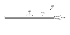
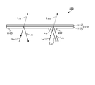
- FIG. 1 is a cross-sectional view schematically showing a display medium 100 according to the first embodiment of the present invention.
- FIG. 2 is a schematic plan view of the display medium 100 according to the first embodiment of the present invention as viewed from one side (the side on which the first reflective layer 120 is provided).
- FIG. 3 is a schematic plan view of the display medium 100 according to the first embodiment of the present invention as viewed from the other side (the side opposite to the side where the first reflective layer 120 is provided).
- the display medium 100 includes reflections provided on the multilayer base material 110 and the surface 110U on the polarization separation layer side of the multilayer base material 110.
- a first reflective layer 120 as a layer is provided.
- the multilayer base material 110 includes a polarizing separation layer 111 and a retardation layer 112.
- the polarization separation layer 111 has a circular polarization separation function.
- the "circular polarization separation function” means a function of reflecting circular polarization in one of the clockwise and counterclockwise rotation directions and transmitting circular polarization in the opposite rotation direction.
- the polarization separating layer 111 in the wavelength range capable of exhibiting the circularly polarized light separation function, reflects circularly polarized light of one rotational direction D A, and transmits the circularly polarized light of opposite direction of rotation and the direction of rotation D A be able to.
- the wavelength range in which the polarization separation layer 111 can exhibit the circular polarization separation function may be appropriately referred to as a “polarization separation wavelength range”.
- the reflectance of the polarization separation layer 111 with respect to unpolarized light in the polarization separation wavelength range is usually 35% to 50%, preferably 40% to 50%.
- the polarization separation wavelength range is preferably in the visible wavelength region.
- the visible wavelength region usually refers to a wavelength region of 400 nm or more and 780 nm or less.
- the wavelength width of the polarization separation wavelength range is wide.
- the wavelength width of the specific polarization separation wavelength range is preferably 70 nm or more, more preferably 100 nm or more, still more preferably 200 nm or more, and particularly preferably 400 nm or more. Since the wavelength width of the polarization separation wavelength range is wide, the range of circularly polarized color that can be reflected by the polarization separation layer 111 can be widened. Therefore, the reflection layer such as the first reflection layer 120 and the display layer of the display article (FIGS. 1 to 1). 3), the degree of freedom in color can be increased, and a display mode with high design can be achieved.
- the upper limit of the wavelength width of the polarization separation wavelength range is not particularly limited, but may be, for example, 600 nm or less.
- a resin layer having cholesteric regularity is preferable.
- a resin having cholesteric regularity may be appropriately referred to as "cholesteric resin” below.
- Cholesteric regularity means that the molecular axes are aligned in a certain direction on one plane, but the direction of the molecular axes shifts at a slight angle on the next plane that overlaps with it, and further shifts on the next plane. As described above, the structure is such that the angle of the molecular axis in the plane is deviated (twisted) as it sequentially passes through the planes arranged in an overlapping manner.
- the molecules inside a layer have cholesteric regularity, the molecules are arranged so that their molecular axes are oriented in a certain direction on a first plane inside the layer.
- the direction of the molecular axis deviates slightly from the direction of the molecular axis in the first plane.
- the direction of the molecular axis is further angled from the direction of the molecular axis in the second plane. In this way, in the planes that are arranged in an overlapping manner, the angles of the molecular axes in the planes are sequentially shifted (twisted).
- Such a structure in which the direction of the molecular axis is twisted is usually a spiral structure and an optically chiral structure.
- the cholesteric resin layer can exert a circular polarization separation function.
- the reflection in the cholesteric resin layer reflects the circularly polarized light while maintaining its chirality.
- the specific wavelength at which the cholesteric resin layer exerts the circular polarization separation function generally depends on the pitch of the helical structure in the cholesteric resin layer.
- the pitch of the spiral structure is the distance in the plane normal direction until the direction of the molecular axis in the spiral structure gradually shifts as it advances in the plane and then returns to the original molecular axis direction.
- the pitch size of this spiral structure it is possible to change the wavelength at which the circular polarization separation function is exhibited.
- the pitch size of the spiral structure for example, the method described in JP-A-2009-300622 can be used.
- Specific examples include a method of adjusting the type of chiral agent and adjusting the amount of the chiral agent in the cholesteric liquid crystal composition.
- the pitch size of the spiral structure is continuously changed in the layer, it is possible to obtain a circular polarization separation function over a wide wavelength range by a single layer of cholesteric resin.
- Examples of the cholesteric resin layer capable of exhibiting the circular polarization separation function in a wide wavelength range include (i) a cholesteric resin layer in which the pitch size of the spiral structure is changed stepwise, and (ii) a spiral structure. Examples thereof include a layer of cholesteric resin in which the size of the pitch is continuously changed.
- the cholesteric resin layer in which the pitch of the spiral structure is changed stepwise can be obtained, for example, by laminating a plurality of cholesteric resin layers having different pitches of the spiral structure.
- Lamination can be performed by preparing a plurality of layers of cholesteric resin having different spiral structures in advance and then fixing each layer with an adhesive or an adhesive.
- the lamination can be performed by forming a layer of a certain cholesteric resin and then sequentially forming another layer of a cholesteric resin.
- the layer of the cholesteric resin in which the pitch size of the spiral structure is continuously changed includes, for example, one or more irradiation treatments of active energy rays and / or heating treatment on the layer of the liquid crystal composition. It can be obtained by curing the layer of the liquid crystal composition after performing the broadband treatment. According to the above-mentioned wide band processing, the pitch of the spiral structure can be continuously changed in the thickness direction, so that the wavelength range (reflection band) in which the cholesteric resin layer can exert the circular polarization separation function can be extended. It can, and is therefore called wideband processing.
- the cholesteric resin layer may be a single-layer structure consisting of only one layer, or a multi-layer structure including two or more layers.
- the number of layers contained in the cholesteric resin layer is preferably 1 to 100, more preferably 1 to 20, from the viewpoint of ease of production.
- the cholesteric liquid crystal composition refers to a composition capable of exhibiting a liquid crystal phase (cholesteric liquid crystal phase) in which the liquid crystal compound has cholesteric regularity when the liquid crystal compound contained in the liquid crystal composition is oriented.
- the material referred to as a "liquid crystal composition” for convenience includes not only a mixture of two or more substances but also a material composed of a single substance.
- Specific examples of the method for producing the cholesteric resin layer include the methods described in JP-A-2014-174471 and JP-A-2015-27743.
- the twisting direction in the cholesteric regularity can be appropriately selected depending on the structure of the chiral agent contained in the liquid crystal composition.
- a cholesteric liquid crystal composition containing a chiral agent which imparts dextrorotatory properties is used, and when the twist direction is counterclockwise, a cholesteric liquid crystal composition containing a chiral agent which imparts dextrorotatory properties is used.
- a liquid crystal composition can be used.
- the thickness of the polarizing separation layer 111 is preferably 2 ⁇ m or more, more preferably 3 ⁇ m or more, preferably 1000 ⁇ m or less, and more preferably 500 ⁇ m or less.
- the thickness of the polarizing separation layer 111 is equal to or greater than the lower limit of the above range, the reflective layer is visually recognized when the display medium 100 is observed from the side opposite to the side where the reflective layer such as the first reflective layer 120 is provided. It can be made difficult.
- the thickness of the polarizing separation layer 111 is not more than the upper limit of the above range, the transparency can be enhanced.
- the retardation layer 112 is a layer having a specific range of in-plane retardation Re provided on one side of the polarization separation layer 111.
- a part or the whole of the retardation layer 112 overlaps a part or the whole of the polarization separation layer 111. That is, the position in the in-plane direction perpendicular to the thickness direction of the display medium 100 is the same for a part or the whole of the retardation layer 112 and a part or the whole of the polarization separation layer 111.
- an example in which the entire retardation layer 112 and the entire polarization separation layer 111 overlap when viewed from the thickness direction will be described.
- the range of the in-plane retardation Re of the retardation layer 112 is such that an image visually recognized by observing one side of the display medium 100 and an image visually recognized by observing the other side of the display medium 100 are desired designs. It can be set within a range that differs to the extent that sex can be obtained. Normally, the in-plane retardation Re of the retardation layer 112 is set so that the rotation direction of the circularly polarized light transmitted through the polarization separation layer can be reversed.
- the specific range of the in-plane retardation Re of the retardation layer 112 is preferably " ⁇ (2n + 1) / 2 ⁇ x 590 nm-30 nm" or more, more preferably " ⁇ (2n + 1) /" at the measurement wavelength of 590 nm.
- n represents an integer of 0 or more.
- the retardation layer 112 having the in-plane retardation Re in the above range at the measurement wavelength of 590 nm can usually function as a 1/2 wave plate in a wide range of the visible wavelength region, the retardation layer 112 causes circularly polarized light of a wide range of colors.
- the polarization state of the can be adjusted appropriately. Therefore, the degree of freedom in color of the reflective layer such as the first reflective layer 120 and the display layer of the display article (not shown in FIGS. 1 to 3) can be increased, so that a display mode with high design can be achieved. Become.
- the retardation layer 112 preferably has anti-wavelength dispersibility.
- Inverse wavelength dispersibility means that the in-plane retardations Re (450) and Re (550) at the measurement wavelengths of 450 nm and 550 nm satisfy the following formula (R1).
- the retardation layer 112 having anti-wavelength dispersibility can exhibit its optical function in a wide wavelength range. Therefore, by using the retardation layer 112 having anti-wavelength dispersibility, it can function as a 1/2 wave plate in a wide range of the visible wavelength region, so that the retardation layer 112 appropriately obtains the polarization state of circularly polarized light of a wide range of colors. Can be adjusted to. Therefore, the degree of freedom in color of the reflective layer such as the first reflective layer 120 and the display layer of the display article (not shown in FIGS. 1 to 3) can be increased, so that a display mode with high design can be achieved. Become.
- a stretched film can be used as the retardation layer 112 as the retardation layer 112, for example, a stretched film can be used.
- the stretched film is a film obtained by stretching a resin film, and an arbitrary in-plane retardation can be obtained by appropriately adjusting factors such as the type of resin, stretching conditions, and thickness.
- a thermoplastic resin is usually used.
- the thermoplastic resin may contain a polymer and optionally any component. Examples of the polymer include polycarbonate, polyethersulfone, polyethylene terephthalate, polyimide, polymethylmethacrylate, polysulfone, polyarylate, polyethylene, polyphenylene ether, polystyrene, polyvinyl chloride, cellulose diacetate, cellulose triacetate, and alicyclic type. Examples include structure-containing polymers.
- one type of polymer may be used alone, or two or more types may be used in combination at an arbitrary ratio.
- an alicyclic structure-containing polymer is preferable from the viewpoint of transparency, low hygroscopicity, dimensional stability and processability.
- the alicyclic structure-containing polymer is a polymer having an alicyclic structure in the main chain and / or the side chain, and for example, those described in JP-A-2007-057791 can be used.
- the stretched film as the retardation layer 112 can be manufactured by producing a resin film from the above resin and then subjecting the resin film to a stretching treatment.
- Specific examples of the method for producing the retardation layer 112 as a stretched film include the method described in International Publication No. 2019/059067.
- the thickness of the stretched film is not particularly limited, but is preferably 5 ⁇ m or more, more preferably 10 ⁇ m or more, particularly preferably 20 ⁇ m or more, preferably 1 mm or less, more preferably 500 ⁇ m or less, and particularly preferably 200 ⁇ m or less. ..
- a liquid crystal cured layer is a layer formed of a cured product of a liquid crystal composition containing a liquid crystal compound.
- a liquid crystal cured layer is obtained by forming a layer of the liquid crystal composition, orienting the molecules of the liquid crystal compound contained in the layer of the liquid crystal composition, and then curing the layer of the liquid crystal composition.
- an arbitrary in-plane retardation can be obtained by appropriately adjusting factors such as the type of the liquid crystal compound, the orientation state of the liquid crystal compound, and the thickness.
- the type of the liquid crystal compound is arbitrary, but when it is desired to obtain the retardation layer 112 having the reverse wavelength dispersibility, it is preferable to use the reverse wavelength dispersive liquid crystal compound.
- the reverse wavelength dispersible liquid crystal compound refers to a liquid crystal compound that exhibits reverse wavelength dispersibility when homogenically oriented. Further, homogenically aligning a liquid crystal compound means forming a layer containing the liquid crystal compound, and setting the direction of the maximum refractive index in the refractive index ellipsoid of the molecule of the liquid crystal compound in the layer to the surface of the layer. Orientation in one direction parallel to.
- Specific examples of the inverse wavelength dispersible liquid crystal compound include the compounds described in International Publication No. 2014/069515, International Publication No. 2015/064851 and the like.
- the thickness of the liquid crystal cured layer is not particularly limited, but is preferably 0.5 ⁇ m or more, more preferably 1.0 ⁇ m or more, preferably 10 ⁇ m or less, more preferably 7 ⁇ m or less, and particularly preferably 5 ⁇ m or less.
- the multilayer base material 110 may include an arbitrary layer (not shown) as long as the effect of the present invention is not significantly impaired.
- the optional layer include a support layer that supports the polarization separation layer 111 and the retardation layer 112, an adhesive layer that adheres the polarization separation layer 111 and the retardation layer 112, and the like.
- These arbitrary layers preferably have a small in-plane retardation.
- the specific in-plane retardation of any layer is preferably 20 nm or less, more preferably 10 nm or less, particularly preferably 5 nm or less, and ideally 0 nm. Since the layer having such a small in-plane retardation is an optically isotropic layer, it is possible to suppress a change in the polarization state due to the arbitrary layer.
- the first reflective layer 120 as a reflective layer is provided on the surface 110U on the polarization separation layer side of the multilayer base material 110.
- the first reflective layer 120 may be provided directly on the surface 110U of the multilayer base material 110, or may be provided indirectly.
- a layer is provided “directly” on a surface, it means that there is no other layer between the surface and the layer.
- "indirectly” providing a layer on a certain surface means that there is another layer (adhesive layer or the like) between the surface and the layer.
- the first reflective layer 120 may be provided on a part of the surface 110U of the multilayer base material 110, or may be provided on the entire surface 110U. Usually, the first reflective layer 120 is provided so as to overlap both the polarizing separation layer 111 and the retardation layer 112 of the multilayer base material 110 when viewed from the thickness direction. That is, the position in the in-plane direction perpendicular to the thickness direction of the display medium 100 is the entire first reflective layer 120, a part or the whole of the retardation layer 112, and a part or the whole of the polarizing separation layer 111. And usually they are the same. Further, the first reflective layer 120 may have a planar shape according to the design of the display medium 100.
- the first reflective layer 120 having the planar shape of the letter “B” will be described as an example.
- the entire first reflective layer 120 overlaps a part of the polarization separation layer 111 and a part of the retardation layer 112 of the multilayer base material 110 when viewed from the thickness direction.
- the first reflective layer 120 has a circular polarization separation function. Therefore, the first reflective layer 120 reflects the circular polarization in one of the rotation directions D B1 in the wavelength range in which the circular polarization separation function can be exhibited, and transmits the circular polarization in the rotation direction opposite to the rotation direction D B1. Can be made to.
- the wavelength range in which the first reflective layer 120 can exhibit the circular polarization separation function may be appropriately referred to as the “first reflected wavelength range”.
- the range of reflectance of the first reflective layer 120 for non-polarization in the first reflection wavelength range can be the same as the range of reflectance of the polarization separation layer 111 for non-polarization in the polarization separation wavelength range.
- the first reflection wavelength range of the first reflection layer 120 usually overlaps with the polarization separation wavelength range of the polarization separation layer 111 included in the multilayer base material 110.
- a part of the first reflection wavelength range and a part of the polarization separation wavelength range may overlap, or the whole first reflection wavelength range and a part of the polarization separation wavelength range may overlap.
- a part of one reflection wavelength range and the whole polarization separation wavelength range may overlap, or the whole first reflection wavelength range and the whole polarization separation wavelength range may overlap.
- it is preferable that the first reflection wavelength range is within the polarization separation wavelength range because the entire first reflection wavelength range overlaps with a part or all of the polarization separation wavelength range.
- the lower limit of the first reflection wavelength range is equal to or higher than the lower limit of the polarization separation wavelength range
- the upper limit of the first reflection wavelength range is equal to or lower than the upper limit of the polarization separation wavelength range.
- Rotational direction D B1 of the circularly polarized light first reflective layer 120 can be reflected, the polarization separating layer 111 is set to be the same as the rotational direction D A circularly polarized light can be reflected. Therefore, when light enters the first reflective layer 120 through the multilayer base material 110, at least a part of the circularly polarized light (specifically, the circularly polarized light in the polarization separation wavelength range) contained in the light. the rotational direction D C, the circular polarization direction of rotation D B1 of the first reflective layer 120 can be reflected is reversed. Therefore, the first reflective layer 120 can hardly or hardly reflect the light that has passed through the multilayer base material 110 and enters the first reflective layer 120.
- Such a first reflective layer 120 may be a layer of cholesteric resin, but is preferably a layer containing flakes of cholesteric resin.
- the flakes of the cholesteric resin can be used as a pigment containing a minute layer of the cholesteric resin. Therefore, the layer containing the flakes of the cholesteric resin can exhibit the circular polarization separation function as well as the layer of the cholesteric resin itself.
- the shear force applied when forming a layer containing flakes of cholesteric resin causes the main surface of the flakes and the layer plane of the layer containing the flakes to be oriented parallel to or close to parallel. ..
- the orientation direction of the flakes may vary, the circularly polarized light reflected by the flakes may be scattered as a whole of the layer containing the flakes of the cholesteric resin.
- the layer containing the flakes of the cholesteric resin can be visually recognized as an image different from the surroundings. Therefore, there is a case where the polarization separation wavelength range of the polarization separation layer 111 and the first reflection wavelength range of the first reflection layer 120 match and the color of the polarization separation layer 111 and the color of the first reflection layer 120 become the same. Even so, the first reflective layer 120 can be visually recognized due to the scattering.
- the particle size of the cholesteric resin flakes is preferably 1 ⁇ m or more in order to obtain decorativeness. Above all, it is desirable that the particle size of the flakes is equal to or larger than the thickness of the layer containing the flakes. In this case, each flake is likely to be oriented so that the main surface of the flake and the layer plane of the layer containing the flake are parallel or at an acute angle. Therefore, since the flakes can be effectively received, the circular polarization separation function of the layer containing the flakes can be enhanced.
- the upper limit of the particle size of the flakes is preferably 500 ⁇ m or less, more preferably 100 ⁇ m or less, from the viewpoint of obtaining moldability and printability.
- the particle size of the flakes means the diameter of a circle having the same area of the flakes.
- the flakes of the cholesteric resin for example, the crushed product of the cholesteric resin layer described above can be used. Such flakes can be produced, for example, by the production method described in Japanese Patent No. 6142714.
- the layer containing the flakes of the cholesteric resin may contain any component in combination with the flakes.
- Optional ingredients include binders that bind the flakes together.
- the binder include polymers such as polyester-based polymers, acrylic-based polymers, polystyrene-based polymers, polyamide-based polymers, polyurethane-based polymers, polyolefin-based polymers, polycarbonate-based polymers, and polyvinyl-based polymers.
- the amount of the binder is preferably 20 parts by weight or more, more preferably 40 parts by weight or more, particularly preferably 60 parts by weight or more, preferably 1000 parts by weight or less, and more preferably 800 parts by weight with respect to 100 parts by weight of the flakes. Parts or less, particularly preferably 600 parts by weight or less.
- the layer containing the flakes of the cholesteric resin can be produced, for example, by applying an ink containing flakes, a solvent, and if necessary, an ink containing any component, and drying the layer.
- an inorganic solvent such as water may be used, or an organic solvent such as a ketone solvent, an alkyl halide solvent, an amide solvent, a sulfoxide solvent, a heterocyclic compound, a hydrocarbon solvent, an ester solvent, and an ether solvent may be used. Good.
- the amount of the solvent is preferably 40 parts by weight or more, more preferably 60 parts by weight or more, particularly preferably 80 parts by weight or more, preferably 1000 parts by weight or less, and more preferably 800 parts by weight with respect to 100 parts by weight of the flakes. Parts or less, particularly preferably 600 parts by weight or less.
- the ink may contain a monomer of the polymer in place of or in combination with the polymer as a binder.
- a layer containing flakes of the cholesteric resin can be formed by applying ink, drying, and then polymerizing the monomers.
- the ink preferably contains a polymerization initiator.
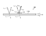
- 4 and 5 are cross-sectional views schematically showing the display medium 100 according to the first embodiment of the present invention. 4 and 5 show schematically the paths of light reflected by the polarizing separation layer 111 and the first reflection layer 120. In the actual display medium 100, various light absorptions and reflections may occur in addition to those described below, but in the following description, the main light paths will be schematically described for convenience of explaining the action. ..
- FIG. 4 shows a case where the first reflective layer 120 side of the display medium 100 is irradiated with irradiation light LI1 such as unpolarized light including both right-handed circularly polarized light and left-handed circularly polarized light.
- irradiation light LI1 such as unpolarized light including both right-handed circularly polarized light and left-handed circularly polarized light.
- the polarization separation layer 111 and the retardation layer 112 are arranged in this order, so that the irradiation light LI1 enters the polarization separation layer 111.
- Some of the irradiated light L I1 is reflected by the polarization separating layer 111 as circularly polarized light L R1 rotational direction D A.
- Circularly polarized light L R1 other light L T1 reflected is transmitted through the polarization separating layer 111, further passes through the retardation layer 112, exiting to the outside of the display medium 100. Since circularly polarized light L R1 by the polarization separating layer 111 is reflected, at the time just after passing through the polarization separating layer 111, some or all of the light L T1 transmitted through the polarization separating layer 111, the direction of rotation D A reverse It is circularly polarized light in the direction of rotation.
- the first reflection layer 120 in the area where the first reflection layer 120 is provided, the first reflection layer 120, the polarization separation layer 111, and the retardation layer 112 are arranged in this order, so that the irradiation light LI1 can be obtained. It enters the first reflective layer 120. Some of the circularly polarized light included in the irradiation light L I1 is reflected by the first reflective layer 120 as a circularly polarized light L R2 in the rotating direction D B1. Light L T2 other than circularly polarized light L R2 that is reflected and enters the polarization separation layer 111.
- the light L T2 which enters the polarization separating layer 111 may include circularly polarized light L R3 in the rotational direction D A which can be reflected. Therefore, part of the light L T2 may be reflected by the polarization separating layer 111 as circularly polarized light L R3 rotational direction D A. These reflected circularly polarized light L R2 and L R3 other light L T3 is transmitted through the polarization separating layer 111, further passes through the retardation layer 112, exiting to the outside of the display medium 100.
- the circular polarization of some or all contained in the light L T3 exiting from the display medium 100 passes through the retardation layer 112, the same rotational direction as the rotational direction D A It is circularly polarized.
- the first reflective layer 120 side of the display medium 100 when the first reflective layer 120 side of the display medium 100 is illuminated with the irradiation light LI1 including both right circular polarization and left circular polarization, strong light reflection occurs in the first reflective layer 120.
- the observer can visually recognize the circularly polarized light LR2 reflected by the first reflection layer 120. Therefore, an observer observing from the first reflective layer 120 side of the display medium 100 can visually recognize the image of the first reflective layer 120 as shown in FIG.
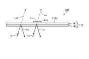
- FIG. 5 shows a case where the side of the display medium 100 opposite to the first reflective layer 120 is irradiated with irradiation light LI2 such as unpolarized light containing both right-handed circularly polarized light and left-handed circularly polarized light.
- irradiation light LI2 such as unpolarized light containing both right-handed circularly polarized light and left-handed circularly polarized light.
- the irradiation light LI2 passes through the retardation layer 112 of the multilayer base material 110 and then enters the polarization separation layer 111.
- a part of the irradiation light LI2 is reflected by the polarization separation layer 111 as circularly polarized light LR4 in the rotation direction DA, and the rotation direction is reversed by passing through the retardation layer 112.
- the rotation direction of a part or all of the circularly polarized light contained in the light LT4 transmitted through the polarization separation layer 111 is reflected by the polarization separation layer 111. made in the direction of rotation D a and opposite circular polarization L R4.
- the rotational direction D B1 of the circularly polarized light first reflective layer 120 can be reflected as a reflection layer according to the present embodiment is the same as the rotational direction D A circularly polarized light L R4 which are reflected by the polarization separating layer 111 ..
- the light L T4 entering the first reflection layer 120 is either the first reflective layer 120 does not include circularly polarized light rotating direction D B1 which can be reflected, contains only a small amount. Therefore, all or most of the light LT4 is not reflected by the first reflective layer 120. Therefore, the light L T5 of all or most of the light L T4 exits from the display medium 100 passes through the first reflective layer 120.
- the first reflective layer 120 can be visually recognized when observed from the first reflective layer side, but the first reflective layer 120 and When observed from the opposite side, the first reflective layer 120 cannot be visually recognized. Therefore, according to the display medium 100, the image of the display medium that is visually recognized when observed from the front surface and the image of the display medium that is visually recognized when observed from the back surface while the multilayer base material 110 is transparent or translucent. It is possible to have a specific display mode in which the above is different.
- an image of the display medium 100 and a display article (the present embodiment) that are visually recognized according to the orientation of the front and back of the display medium 100. (Not shown) can be different from each other.
- the first reflective layer 120 as the reflective layer is provided on the surface 110U of the multilayer base material 110 on the polarization separation layer side, but the reflective layer is located at the position of the multilayer base material 110. It may be formed on the surface on the side of the retardation layer.
- a second reflective layer as a reflective layer is provided on the surface of the multilayer base material 110 on the retardation layer side.
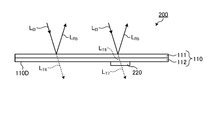
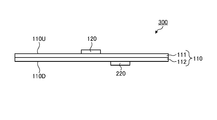
- FIG. 6 is a cross-sectional view schematically showing the display medium 200 according to the second embodiment of the present invention.
- FIG. 7 is a schematic plan view of the display medium 200 according to the second embodiment of the present invention as viewed from one side (the side opposite to the side on which the second reflective layer 220 is provided).
- FIG. 8 is a schematic plan view of the display medium 200 according to the second embodiment of the present invention as viewed from the other side (the side on which the second reflective layer 220 is provided).
- the display medium 200 has a multilayer base material 110 including a polarizing separation layer 111 and a retardation layer 112, and a position of the multilayer base material 110.
- a second reflective layer 220 as a reflective layer provided on the surface 110D on the differential layer side is provided.
- the multilayer base material 110 included in the display medium 200 according to the second embodiment can be the same as that included in the display medium 100 according to the first embodiment.
- the display medium 200 according to the second embodiment uses the same multi-layer base material 110 as described in the first embodiment, the same effect as described in the first embodiment can be obtained.
- the second reflective layer 220 as a reflective layer is provided on the surface 110D on the retardation layer side of the multilayer base material 110.
- the second reflective layer 220 may be provided directly or indirectly on the surface 110D of the multilayer base material 110, as in the case of the first reflective layer 120 described in the first embodiment. ..
- the second reflective layer 220 may be provided on a part of the surface 110D of the multilayer base material 110, or may be provided on the entire surface 110D. Normally, when viewed from the thickness direction, the second reflective layer 220 overlaps both the polarization separation layer 111 and the retardation layer 112 of the multilayer base material 110, like the first reflective layer 120 described in the first embodiment. It is provided in. In the present embodiment, the second reflective layer 220 having the planar shape of the letter “E” will be described as an example. In this example, the entire second reflective layer 220 overlaps a part of the polarization separation layer 111 and a part of the retardation layer 112 of the multilayer base material 110 when viewed from the thickness direction.
- the second reflective layer 220 has a circular polarization separation function. Therefore, the second reflective layer 220 reflects the circular polarization in one of the rotation directions D B2 in the wavelength range in which the circular polarization separation function can be exhibited, and transmits the circular polarization in the rotation direction opposite to the rotation direction D B2. Can be made to.
- the wavelength range in which the second reflective layer 220 can exhibit the circular polarization separation function may be appropriately referred to as the “second reflected wavelength range”.
- the range of reflectance of the second reflective layer 220 for non-polarization in the second reflection wavelength range is the same as the range of reflectance of the first reflective layer 120 for non-polarization in the first reflection wavelength range described in the first embodiment. It is possible.
- the second reflection wavelength range of the second reflection layer 220 usually overlaps with the polarization separation wavelength range of the polarization separation layer 111 included in the multilayer base material 110.
- a part of the second reflection wavelength range and a part of the polarization separation wavelength range may overlap, and the whole second reflection wavelength range and a part of the polarization separation wavelength range may overlap.
- a part of the two reflection wavelength range and the entire polarization separation wavelength range may overlap, or the entire second reflection wavelength range and the entire polarization separation wavelength range may overlap.
- it is preferable that the second reflection wavelength range is within the polarization separation wavelength range because the entire second reflection wavelength range overlaps with a part or all of the polarization separation wavelength range.
- the lower limit of the second reflection wavelength range is equal to or higher than the lower limit of the polarization separation wavelength range
- the upper limit of the second reflection wavelength range is equal to or lower than the upper limit of the polarization separation wavelength range.
- Rotational direction D B2 of the circularly polarized light by the second reflection layer 220 can be reflected, the polarization separating layer 111 is set to reverse the rotational direction D A circularly polarized light can be reflected. Therefore, when light enters the second reflective layer 220 through the multilayer base material 110, at least a part of the circularly polarized light (specifically, the circularly polarized light in the polarization separation wavelength range) contained in the light. the rotational direction D C, the circular polarization direction of rotation D B2 of the second reflective layer 220 can be reflected is reversed. Therefore, the second reflective layer 220 can hardly or hardly reflect the light that has passed through the multilayer base material 110 and enters the second reflective layer 220.
- Such a second reflective layer 220 may be a cholesteric resin layer like the first reflective layer 120 described in the first embodiment, but is preferably a layer containing flakes of the cholesteric resin.
- a layer containing cholesteric resin flakes is used as the second reflective layer 220, the same effect as described in the first embodiment can be obtained.
- 9 and 10 are cross-sectional views schematically showing the display medium 200 according to the second embodiment of the present invention.
- 9 and 10 show schematically the paths of light reflected by the polarizing separation layer 111 and the second reflection layer 220.
- various light absorptions and reflections may occur in addition to those described below, but in the following description, the main light paths will be schematically described for convenience of explaining the action. ..
- FIG. 9 shows a case where the display medium 200 is irradiated with irradiation light LI3 such as unpolarized light including both right-handed circularly polarized light and left-handed circularly polarized light on the side opposite to the second reflective layer 220.
- irradiation light LI3 such as unpolarized light including both right-handed circularly polarized light and left-handed circularly polarized light on the side opposite to the second reflective layer 220.
- the polarization separation layer 111 and the retardation layer 112 are arranged in this order, so that the irradiation light LI3 enters the polarization separation layer 111.
- Some of the irradiated light L I3 is reflected by the polarization separating layer 111 as circularly polarized light L R5 in the rotating direction D A.
- the reflected circularly polarized light L R5 other light L T6 is transmitted through the polarization separating layer 111, further passes through the retardation layer 112, exiting to the outside of the display medium 200. Since circularly polarized light L R5 by the polarization separating layer 111 is reflected, at the time just after passing through the polarization separating layer 111, some or all of the light L T6 transmitted through the polarization separating layer 111, the direction of rotation D A reverse It is circularly polarized light in the direction of rotation.
- the polarization separation layer 111, the retardation layer 112, and the second reflection layer 220 are arranged in this order, so that the second reflection layer 220 is arranged.
- a part of the irradiation light L I3 is reflected by the polarization separating layer 111 as circularly polarized light L R5 in the rotating direction D a, reflected circularly polarized light L R5 other light L T6 polarization separating It is transparent to the layer 111 and the retardation layer 112.
- the light LT6 transmitted through the retardation layer 112 then enters the second reflection layer 220.
- the direction of rotation of some or all of the circularly polarized light contained in the light L T6 after passing through the retardation layer 112 is the same as the rotational direction D A circularly polarized light L R5 reflected by the polarization separating layer 111 .
- the rotational direction D B2 of the circularly polarized light by the second reflection layer 220 as a reflection layer according to the present embodiment can be reflected is the direction of rotation D A and opposite circular polarization L R5 reflected by the polarization separating layer 111 .. Therefore, the light L T6 entering the second reflective layer 220, or the second reflective layer 220 does not include circularly polarized light in the direction of rotation D B2 which can reflect, contain only a small amount.
- the light LT6 is not reflected by the second reflective layer 220. Since the direction of rotation D A circularly polarized light by the second reflection layer 220 and the rotational direction D B2 of the circularly polarized light can reflect the polarization separating layer 111 may be reflected is reversed, as in the area where the second reflecting layer 220 is not provided , even in areas where the second reflecting layer 220 is provided, some or all of the light L T7 leaving the display medium 200 passes through the second reflective layer 220, a circularly polarized light in the same rotational direction as the rotational direction D a ing.
- FIG. 10 shows a case where the second reflective layer 220 side of the display medium 200 is irradiated with irradiation light LI4 such as unpolarized light including both right-handed circularly polarized light and left-handed circularly polarized light.
- irradiation light LI4 such as unpolarized light including both right-handed circularly polarized light and left-handed circularly polarized light.
- the irradiation light LI4 passes through the retardation layer 112 of the multilayer base material 110 and then enters the polarization separation layer 111.
- Some of the irradiated light L I4 is reflected by the polarization separating layer 111 as circularly polarized light L R6 rotational direction D A, the direction of rotation is reversed by passing through the retardation layer 112.
- the irradiation light LI4 enters the second reflection layer 220.
- a part of the circularly polarized light contained in the irradiation light LI4 is reflected by the second reflecting layer 220 as the circularly polarized light LR7 in the rotation direction D B2 .
- Light L T9 other than circularly polarized light L R7 reflected is transmitted through the retardation layer 112, it enters the polarization separating layer 111.
- the light L T9 entering the polarization separating layer 111 may include circularly polarized light L R8 rotational direction D A which can be reflected.
- part of the light L T9 may be reflected by the polarization separating layer 111 as circularly polarized light L R8 rotational direction D A.
- These reflected circularly polarized light L R7 and L R8 other light L T10 is transmitted through the polarization separating layer 111, exiting to the outside of the display medium 200.
- the light L T10 is emitted from the display medium 200 after passing through the polarization separation layer 111. Therefore, the light L transmitted through the polarization separation layer 111 and emitted from the display medium 200.
- some or all of the T10 has a direction of rotation D a reverse rotation direction of the circularly polarized light.
- the second reflective layer 220 side of the display medium 200 when the second reflective layer 220 side of the display medium 200 is illuminated with the irradiation light LI4 including both right circular polarization and left circular polarization, strong light reflection occurs in the second reflective layer 220.
- the observer can visually recognize the circularly polarized light LR7 reflected by the second reflective layer 220. Therefore, the observer observing from the second reflective layer 220 side of the display medium 200 can visually recognize the image of the second reflective layer 220 as shown in FIG.
- the second reflective layer 220 can be visually recognized when observed from the second reflective layer 220 side, but the second reflective layer 220 is visible.
- the second reflective layer 220 cannot be visually recognized when observed from the opposite side. Therefore, according to the display medium 200, the image of the display medium observed from the front surface and the image of the display medium observed from the back surface while the multilayer base material 110 is transparent or translucent. It is possible to have a specific display mode in which the above is different. Further, according to the display medium 200 according to the present embodiment, the same advantages as the display medium 100 described in the first embodiment can be obtained.
- first reflective layer 120 or the second reflective layer 220 as a reflective layer is provided on one surface 110U or 110D of the multilayer base material 110 is shown, but the display medium. May be provided with reflective layers on both sides thereof.
- first reflective layer and the second reflective layer as the reflective layers are provided on both surfaces of the multilayer base material 110 will be described.
- FIG. 11 is a cross-sectional view schematically showing the display medium 300 according to the third embodiment of the present invention.
- FIG. 12 is a schematic plan view of the display medium 300 according to the third embodiment of the present invention as viewed from one side (the side on which the first reflective layer 120 is provided).
- FIG. 13 is a schematic plan view of the display medium 300 according to the third embodiment of the present invention as viewed from the other side (the side on which the second reflective layer 220 is provided).
- the display medium 300 includes a multilayer base material 110 including a polarization separation layer 111 and a retardation layer 112, and polarization of the multilayer base material 110.
- the first reflective layer 120 as a reflective layer provided on the surface 110U on the separation layer side
- the second reflective layer 220 as a reflective layer provided on the surface 110D on the retardation layer side of the multilayer base material 110.
- the multilayer base material 110 included in the display medium 300 according to the third embodiment can be the same as that included in the display medium 100 according to the first embodiment.
- the same display medium 300 as described in the first embodiment is used as the multilayer base material 110 in the display medium 300 according to the third embodiment, the same effect as described in the first embodiment can be obtained.
- the first reflective layer 120 included in the display medium 300 according to the third embodiment may be the same as that included in the display medium 100 according to the first embodiment.
- the display medium 300 according to the third embodiment uses the same first reflective layer 120 as described in the first embodiment, the same effect as described in the first embodiment can be obtained.
- the second reflective layer 220 included in the display medium 300 according to the third embodiment may be the same as that included in the display medium 200 according to the second embodiment.
- the display medium 300 according to the third embodiment uses the same second reflective layer 220 as described in the second embodiment, the same effect as described in the second embodiment can be obtained.
- the first reflective layer 120 of the display medium 300 is the first reflection of the display medium 300 under irradiation light including both right-handed circularly polarized light and left-handed circularly polarized light by the same mechanism as described in the first embodiment. Although it can be visually recognized by an observer observing from the layer 120 side (FIG. 12), it can be visually recognized by an observer observing from the second reflection layer 220 side as the side opposite to the first reflection layer 120 of the display medium 300. Cannot be done (Fig. 13).
- the second reflective layer 220 of the display medium 300 is the second reflective layer 220 of the display medium 300 under irradiation light including both right-handed circularly polarized light and left-handed circularly polarized light by the same mechanism as described in the second embodiment.
- the display medium 300 while the multilayer base material 110 is transparent or translucent, the image of the display medium that is observed and visually recognized from the front surface and the image of the display medium that is visually recognized from the back surface are visually recognized. It is possible to have a specific display mode in which the image of the display medium is different from that of the display medium. Further, according to the display medium 300 according to the present embodiment, the same advantages as those of the display media 100 and 200 described in the first embodiment and the second embodiment can be obtained.
- the shape, size, and material of the reflective layers, and the wavelength and reflectance of the circularly polarized light reflected by the reflective layer are determined. , It may be the same or different.
- the display medium is not limited to that described in the first to third embodiments described above.
- the display medium may further include any element in combination with the reflective layers such as the multilayer base material 110, the first reflective layer 120, and the second reflective layer 220 described above.
- the display medium may include any layer having a circular polarization separation function on the surfaces 110U and 110D of the multilayer base material 110 in addition to the first reflective layer 120 and the second reflective layer 220.
- the polarization separation layer side surface 110U of the multi layer substrate 110, and reflected circularly polarized light rotation of the circularly polarized light is polarized light separation layer 111 can reflect the direction D A reverse rotation direction D E1, the rotation it may comprise a first optional layer that can transmit circularly polarized light of the opposite rotational direction to the direction D E1.
- a second arbitrary layer capable of transmitting circularly polarized light in a rotation direction opposite to that of the rotation direction DE2 may be provided.
- Any of these layers can be formed, for example, as a layer of cholesteric resin, a layer containing flakes of cholesteric resin, and the like. Any of these layers can usually be seen both from the front side and from the back side.
- the display medium may include an arbitrary non-chiral layer containing a colorant such as a pigment and a dye that does not have a circular polarization separation function.
- This non-chiral layer may be provided on the surface 110U on the polarization separation layer side of the multilayer base material 110, or may be provided on the surface 110D on the retardation layer side.
- This non-chiral layer can usually be visually recognized both when observed from the front surface and when observed from the back surface.
- the display medium may be provided with an adhesive layer for bonding the above-mentioned layers to each other.
- the display medium may include an adhesive layer between the multilayer base material 110 and the first reflective layer 120, and adheres between the multilayer base material 110 and the second reflective layer 220. It may have layers.
- the adhesive layer preferably has a small in-plane retardation, like any layer that the multilayer substrate 110 may have.
- the display medium may include a cover layer that protects each of the above-mentioned layers. It is preferable that these cover layers are provided outside the above-mentioned layers.
- the display medium may include a cover layer, a second reflective layer, a multilayer base material, a first reflective layer, and a cover layer in this order in the thickness direction.
- a cover layer can be formed of a transparent material, for example, a resin.
- the display medium may include any layer having a small in-plane retardation between the above-mentioned layers and as the outermost layer of the display medium as long as the effect of the present invention is not significantly impaired.
- Any layer having such a small in-plane retardation may be hereinafter referred to as a "low Re layer".
- the specific in-plane retardation of this low Re layer is usually 0 nm or more and 5 nm or less.
- the positions where the low Re layer is provided are, for example, the positions of the first reflective layer opposite to the multilayer base material, the positions between the first reflective layer and the multilayer substrate, the polarization separation layer and the retardation layer.
- the position between, the position between the multi-layer base material and the second reflective layer, the position of the second reflective layer opposite to the multi-layer base material, and the like are not limited thereto.
- the low Re layer preferably has high light transmittance, and the total light transmittance of the low Re layer is preferably 80% or more, more preferably 85% or more.
- Examples of such a low Re layer material include hard polyvinyl chloride, soft polyvinyl chloride, acrylic resin, glass, polycarbonate (PC), polyethylene terephthalate (PET), and the like.
- the specific material can be appropriately selected according to the application of the display medium, the required texture, durability, and mechanical strength.
- the display medium described above can be used as a display set in combination with a display article for observation through the display medium.
- the display article to be combined with the display medium includes a base article and a display layer provided on the base article.
- Display layer is a layer having a circularly polarized light separating function to reflect circularly polarized light of one rotational direction D D, and the direction of rotation D D can transmit circularly polarized light of the opposite rotational direction. Therefore, the direction of rotation D part or all of the circular polarization of D is the reflection from the display layers, a multilayer substrate of the display medium can be transmitted in one of the following order (i) and (ii), the other order Cannot be transparent.
- the order of the polarization separation layer and the retardation layer (Ii) The order of the retardation layer and the polarization separation layer.
- the image of the display article visually recognized through the display medium can be different depending on the orientation of the front and back of the display medium.
- the display medium itself can have a different image of the display medium visually recognized depending on the orientation of the front and back of the display medium.
- FIG. 14 is a cross-sectional view schematically showing the display set 400 according to the fourth embodiment of the present invention.
- the display set 400 according to the fourth embodiment of the present invention includes a display medium 300 and a display article 500.
- the display set 400 including the display medium 300 described in the third embodiment will be described as an example.
- FIG. 15 is a cross-sectional view schematically showing a display article 500 included in the display set 400 according to the fourth embodiment of the present invention.
- FIG. 16 is a plan view schematically showing a display article 500 included in the display set 400 according to the fourth embodiment of the present invention.
- the display article 500 includes a base article 510, and a first display layer 520 and a second display layer 530 as display layers provided on the base article 510.
- the base article 510 is an article provided with a display layer such as a first display layer 520 and a second display layer 530, and the range thereof is not limited.
- Examples of the base article 510 include cloth products such as clothing; leather products such as bags and shoes; metal products such as screws; paper products such as price tags; plastic products such as cards and plastic banknotes; rubber products such as tires; However, it is not limited to these examples.
- Both the first display layer 520 and the second display layer 530 as the display layer have a circular polarization separation function.
- the rotation direction D D1 of the circular polarization that can be reflected by the first display layer 520 and the rotation direction D D2 of the circular polarization that can be reflected by the second display layer 530 are opposite.
- the first display layer 520 in the wavelength range capable of exhibiting the circularly polarized light separating function, the circularly polarized light can reflect the polarization separating layer 111 included in the display medium 300 in the rotational direction D A in the same rotational direction D D1 reflects circularly polarized light can be transmitted through the circularly polarized light of reverse rotation direction to the rotation direction D D1.
- the second display layer 530 in the wavelength range capable of exhibiting the circularly polarized light separation function, reflects the circularly polarized light rotation of the circularly polarized light is polarized light separation layer 111 can reflect the direction D A reverse rotation direction D D2, its Circularly polarized light in the direction opposite to the direction of rotation D D2 can be transmitted.
- the wavelength range in which the first display layer 520 can exert the circular polarization separation function may be appropriately referred to as the "first display wavelength range”.
- the wavelength range in which the second display layer 530 can exhibit the circular polarization separation function may be appropriately referred to as a "second display wavelength range”.
- the first display wavelength range and the second display wavelength range may be collectively referred to as simply "display wavelength range”.
- the range of reflectance for unpolarized light of the first display layer 520 and the second display layer 530 in the display wavelength range can be the same as the range of reflectance for non-polarized light of the polarization separation layer 111 in the polarization separation wavelength range.
- the reflectance of the first display layer 520 and the reflectance of the second display layer 530 may be the same or different.
- the display wavelength range of the first display layer 520 and the second display layer 530 usually overlaps with the polarization separation wavelength range of the polarization separation layer 111 included in the display medium 300.
- a part of the display wavelength range and a part of the polarization separation wavelength range may overlap, or the whole display wavelength range and a part of the polarization separation wavelength range may overlap, and one of the display wavelength ranges.
- the unit and the entire polarization separation wavelength range may overlap, or the entire display wavelength range and the entire polarization separation wavelength range may overlap. Above all, it is preferable that the display wavelength range is within the polarization separation wavelength range because the entire display wavelength range overlaps with a part or all of the polarization separation wavelength range.
- the lower limit of the display wavelength range is equal to or higher than the lower limit of the polarization separation wavelength range
- the upper limit of the display wavelength range is equal to or lower than the upper limit of the polarization separation wavelength range.
- Such a first display layer 520 and a second display layer 530 may be a cholesteric resin layer like the first reflective layer 120 described in the first embodiment, but are layers containing cholesteric resin flakes. Is preferable.
- the first display layer 520 having the planar shape of the letter "I” and the second display layer 530 having the planar shape of the letter “S” are provided on the sheet-shaped base article 510.
- Article 500 will be described as an example.
- the display article 500 may be provided with an arbitrary non-chiral layer 540 containing a colorant such as a pigment and a dye having no circular polarization separation function, if necessary.
- a colorant such as a pigment and a dye having no circular polarization separation function
- the non-chiral layer 540 having the planar shape of the letter “M” will be described as an example.
- the display set 400 has a combination of the display medium 300 and the display article 500 having the above-described configuration. Therefore, the observer can visually recognize the image described below.
- the observer usually observes the display set 400 from above in the figure. Therefore, the observer observes the display medium 300 from the first reflective layer 120 side, and at the same time, observes the display article 500 through the display medium 300.
- FIG. 17 is a plan view schematically showing an image visually recognized when the display set 400 shown in FIG. 14 is observed from above in the drawing.
- the image visually recognized by the observer who observes the display set 400 as described above includes the first reflective layer 120 of the display medium 300, the first display layer 520 of the display article 500, and non-chiral.
- the layer 540 appears, but the second reflective layer 220 of the display medium 300 and the second display layer 530 of the display article 500 do not appear.
- the mechanism by which such an image is visually recognized is as follows.
- the polarization separation layer 111, the retardation layer 112, and the display article 500 are arranged in this order in the thickness direction of the display medium 300. Therefore, the irradiation light irradiated to the display medium 300 enters the display article 500 after a part of the circularly polarized light is reflected by the polarization separating layer 111 and the light other than the reflected circularly polarized light passes through the retardation layer 112. To do.
- the light L T1 of which is the same rotational direction of the circularly polarized light and the direction of rotation D A circularly polarized light reflected by the polarization separation layer 111 (FIG. 4 and L T3, and, referring to the light L T6 and L T7 in FIG. 9).
- the first display layer 520 may reflect circularly polarized light in the direction of rotation D A in the same rotational direction D D1, the light that enters the display article 500 is transmitted through the display medium 300, it produces a large reflection. Since the reflected light is circularly polarized light in the rotation direction D D1 , the rotation direction is reversed by passing through the retardation layer 112, and the light can be transmitted through the polarization separation layer 111. Therefore, since the strong light reflected by the first display layer 520 can pass through the display medium 300, the observer can visually recognize the image of the first display layer 520.
- the second display layer 530 may reflect circularly polarized light in the direction of rotation D A reverse rotation direction D D2, the light that enters the display article 500 is transmitted through the display medium 300, a weak reflection or no reflection .. Further, even if light is reflected by the second display layer 530, the reflected light is circularly polarized light in the rotation direction D D2 , so that the rotation direction is reversed by passing through the retardation layer 112. , Part or all is reflected by the polarization separation layer 111. Therefore, since there is no or weak light that can be reflected by the second display layer 530 and transmitted through the display medium 300, the observer cannot visually recognize the image of the second display layer 530.
- the non-chiral layer 540 light reflection occurs regardless of the polarization state of the light entering the display article 500. Therefore, since a part or the whole of the reflected light can pass through the display medium 300, the observer can visually recognize the image of the non-chiral layer 540.
- the observer can visually recognize the image of the first reflection layer 120 observed without passing through the multilayer base material 110, but the multilayer base material 110 The image of the second reflective layer 220 observed through is not visible.
- the observer can see the image shown by the first reflective layer 120 (letter "B"), the image shown by the first display layer 520 (letter “I”), and the non-chiral layer.
- the layer represented by 540 (letter "M") can be visually recognized, but the image of the second reflection layer 220 and the image of the second display layer 530 cannot be visually recognized.
- FIG. 18 is a cross-sectional view schematically showing the display set 400 according to the fourth embodiment of the present invention.
- the display medium 300 and the display article 500 are overlapped with the surface 110U on the polarization separation layer 111 side of the multilayer base material 110 facing the display article 500.
- the observer usually observes the display set 400 from above in the figure. Therefore, the observer observes the display medium 300 from the second reflective layer 220 side, and at the same time, observes the display article 500 through the display medium 300.
- FIG. 19 is a plan view schematically showing an image visually recognized when the display set 400 shown in FIG. 18 is observed from above in the drawing.
- the image visually recognized by the observer who observes the display set 400 as described above includes the second reflective layer 220 of the display medium 300, the second display layer 530 of the display article 500, and non-chiral.
- the layer 540 appears, but the first reflective layer 120 of the display medium 300 and the first display layer 520 of the display article 500 do not appear.
- the mechanism by which such an image is visually recognized is as follows.
- the retardation layer 112, the polarization separation layer 111, and the display article 500 are arranged in this order in the thickness direction of the display medium 300. Therefore, the irradiation light irradiated to the display medium 300 passes through the retardation layer 112, and after a part of the circular polarization is reflected by the polarization separation layer 111, it enters the display article 500. Some or all of the light entering into such display article 500, the has become the the circular polarization direction of rotation D A reverse rotation direction of the circularly polarized light reflected by the polarization separating layer 111 (FIG. 5 light L T4 and L T5, as well as reference light L T8 and L T10 in FIG. 10).
- the first display layer 520 may reflect circularly polarized light in the direction of rotation D A in the same rotational direction D D1, the light that enters the display article 500 is transmitted through the display medium 300, a weak reflection or no reflection. Further, even if light is reflected by the first display layer 520, the reflected light is circularly polarized light in the rotation direction DD1 , so that part or all of the reflected light is reflected by the polarization separation layer 111. Therefore, since there is no or weak light that can be reflected by the first display layer 520 and transmitted through the display medium 300, the observer cannot visually recognize the image of the first display layer 520.
- the second display layer 530 may reflect circularly polarized light in the direction of rotation D A reverse rotation direction D D2, the light that enters the display article 500 is transmitted through the display medium 300, it produces a large reflection. Since the reflected light is circularly polarized light in the rotation direction D D2 , it can pass through the polarization separation layer 111. Therefore, since the strong light reflected by the second display layer 530 can pass through the display medium 300, the observer can visually recognize the image of the second display layer 530.
- the non-chiral layer 540 light reflection occurs regardless of the polarization state of the light entering the display article 500. Therefore, since a part or the whole of the reflected light can pass through the display medium 300, the observer can visually recognize the image of the non-chiral layer 540.
- the observer can visually recognize the image of the second reflective layer 220 observed without passing through the multilayer base material 110, but the multilayer base material 110 The image of the first reflective layer 120 observed through is not visible.
- the observer can see the image shown by the second reflective layer 220 (letter "E"), the image shown by the second display layer 530 (letter "S”), and the non-chiral layer.
- the layer represented by 540 (letter "M") can be visually recognized, but the image of the first reflection layer 120 and the image of the first display layer 520 cannot be visually recognized.
- the image visually recognized can be different depending on the orientation of the display medium 300. Therefore, by combining different images in this way, it is possible to realize a new display mode that has not existed in the past, and it is possible to create a complicated and highly flexible design.
- the multilayer base material 110 of the display medium 300 is transparent or translucent, as described above, depending on the orientation of the display medium 300. Since the difference in image can be a display that is unexpected to a general observer, it can be expected to have a great impact on the observer.
- the display article 500 including both the first display layer 520 and the second display layer 530 has been described as an example, but at least one of the first display layer 520 and the second display layer 530 has been described.
- a display article containing the above may be used.
- a display article having one or more first display layers 520 and not having a second display layer 530 may be used.
- a display article having one or more second display layers 530 and not having the first display layer 520 may be used.
- the base film was peeled off from the multi-layer film to obtain a cholesteric resin layer.
- the reflectance when unpolarized light (wavelength 400 nm to 800 nm) was incident on the cholesteric resin layer was measured using an ultraviolet-visible spectrophotometer (“UV-Vis 550” manufactured by JASCO Corporation).
- the in-plane retardation was measured at a measurement wavelength of 590 nm using a phase difference meter (“Axoscan” manufactured by Axometrics).
- a base film As a base film, a long polyethylene terephthalate film (“A4100” manufactured by Toyobo Co., Ltd .; thickness 100 ⁇ m) was prepared. This base film was attached to the feeding portion of the film transport device, and the following operations were performed while transporting the base film in the long direction.
- A4100 manufactured by Toyobo Co., Ltd .; thickness 100 ⁇ m
- the surface of the base film was subjected to a rubbing treatment in a long direction parallel to the transport direction.
- the liquid crystal composition was applied to the surface of the base film subjected to the rubbing treatment using a die coater to form a layer of the liquid crystal composition.
- the layer of the liquid crystal composition was subjected to an orientation treatment by heating at 120 ° C. for 4 minutes.
- the layer of the liquid crystal composition was subjected to a broadband treatment.
- the reflection band was controlled to a desired bandwidth by alternately repeating weak ultraviolet irradiation of 5 mJ / cm 2 to 30 mJ / cm 2 and heating treatment of 100 ° C. to 120 ° C. a plurality of times.
- the layer of the liquid crystal composition was irradiated with ultraviolet rays of 800 mJ / cm 2 to cure the layer of the liquid crystal composition.
- a multi-layer film including a base film and a layer of cholesteric resin was obtained.
- the reflectance of the cholesteric resin layer of this multi-layer film was measured by the above-mentioned measuring method.
- the cholesteric resin layer had a wavelength range from 450 nm to 700 nm in which the reflectance with respect to unpolarized light was 40% or more.
- the reflectance of the cholesteric resin layer of this multi-layer film was measured by the above-mentioned measuring method.
- the cholesteric resin layer had a wavelength range from 450 nm to 700 nm in which the reflectance with respect to unpolarized light was 40% or more.
- the cholesteric resin layer was peeled off from the multi-layer film thus obtained and pulverized to obtain flakes. 10 parts of these flakes were mixed with 85 parts of screen ink (“No. 2500 medium” manufactured by Jujo Chemical Co., Ltd.) and 5 parts of a special diluent (Tetron standard solvent) for the screen ink to obtain an ink.
- a base film containing a norbornene-based polymer as a cyclic structure-containing polymer (“ZEONOR film” manufactured by Nippon Zeon Co., Ltd .; a film produced by extrusion molding; an unstretched product) was prepared. This base film was stretched 3.9 times in one direction at a stretching temperature of 130 ° C. to obtain a retardation film. The thickness of this retardation film was 38 ⁇ m, and the in-plane retardation was 280 nm.
- FIG. 20 is a cross-sectional view schematically showing the display set 1 manufactured in the first embodiment.
- the display set 1 manufactured in the first embodiment includes the display medium 10 and the display article 20.
- Display medium 10 the polarization separation layer 11 and the multilayer substrate 13 with a phase difference layer 12; character layer B R as a first reflective layer provided on the surface of the polarization separation layer side of the multilayer substrate 13; and includes a character layer E L as a second reflective layer provided on the surface of the retardation layer side of the multilayer substrate 13.
- the display medium 10 produced in Example 1 contained a support layer and an adhesive, but these are not shown in FIG. 20.
- a method of manufacturing the display set 1 will be described.
- the cholesteric resin layer of the multi-layer film produced in Production Example 1 and the optically isotropic support film (polyvinyl chloride film) are bonded to each other via an adhesive to form a base film of the multi-layer film. It peeled off.
- the surface of the cholesteric resin layer that appeared by peeling off the base film and the retardation film produced in Production Example 4 were bonded to each other via an adhesive.
- the retardation layer 12 as the retardation film were provided in this order to obtain a multilayer base material 13.
- the display medium 10 was turned over and placed on the display article 20, and the display set 1 was observed again.
- the character layer S L, the character layer E L and character layer M X has been visible, character layer I R and the character layer B R was not visible.
- Example 1 The results of Example 1 are summarized in Table 1 below.
- “Positive” The rotation direction of the circularly polarized light that can reflect the character layer and the rotation direction of the circularly polarized light that can reflect the polarization separation layer are the same.
- “Reverse” The rotation direction of circularly polarized light that can reflect the character layer and the rotation direction of circularly polarized light that can reflect the polarization separation layer are opposite.
- “Non” The character layer does not have a circular polarization separation function.
- FIG. 21 is a cross-sectional view schematically showing the display set 2 manufactured in the second embodiment.
- the display set 2 manufactured in the second embodiment includes the display medium 30 and the display article 20.
- the display article 20 is the same as that of the first embodiment.
- the display medium 30, except that the character layer E R instead of the character layer E L is formed is the same as the display medium 10 of Example 1.
- Character layer E R instead of the ink produced in Production Example 3, except for using ink prepared in Preparation Example 2 was formed in the same manner as the character layer E L formed in Example 1.
- the character layer E R corresponds to the second optional layer having flakes polarization separation layer 11 can reflect circularly polarized light in the same rotational direction as the rotational direction of the circularly polarized light can be reflected.
- the display medium 30 was turned over and placed on the display article 20, and the display set 2 was observed again.
- the character layer S L, the character layer E R and the character layer M X has been visible, character layer I R and the character layer B R was not visible.
- Example 2 The results of Example 2 are summarized in Table 2 below. In the column of "direction of circularly polarized light that can be reflected” in Table 2, the meanings of the abbreviations “positive”, “reverse” and “non” are the same as in Table 1.
- FIG. 22 is a cross-sectional view schematically showing the display set 3 manufactured in Comparative Example 1.
- the display set 3 manufactured in Comparative Example 1 includes a display medium 40 and a display article 20.
- the display article 20 is the same as that of the first embodiment.
- the display medium 40 is a phase difference layer 12 without, as well, except that the character layer E R instead of the character layer E L is formed is the same as the display medium 10 of Example 1.
- the display medium 40 was manufactured by the following procedure.
- the cholesteric resin layer of the multi-layer film produced in Production Example 1 and the optically isotropic support film (polyvinyl chloride film) are bonded to each other via an adhesive to form a base film of the multi-layer film. It peeled off.
- On the layer of cholesteric resin to print the letter "B” in the ink produced in Production Example 2, and dried to form a character layer B R.
- the support film to print the letter "E” in the ink produced in Production Example 2, and dried to form a character layer E R.
- the display medium 40 was turned over and placed on the display article 20, and the display set 3 was observed again.
- the character layer S L, the character layer E R and the character layer M X has been visible, character layer I R and the character layer B R was not visible.
- FIG. 23 is a cross-sectional view schematically showing the display set 4 manufactured in Comparative Example 2.
- the display set 4 manufactured in Comparative Example 2 includes a display medium 50 and a display article 20.
- the display article 20 is the same as that of the first embodiment.
- the display medium 50, except that the character layer E L instead of the character layer E R is formed is the same as the display medium 40 of Comparative Example 1.
- Character layer E L instead of the ink produced in Production Example 2, except for using an ink produced in Production Example 3 was formed in the same manner as the character layer E R formed in Comparative Example 1.
- the display medium 50 was turned over and placed on the display article 20, and the display set 4 was observed again.
- the character layer S L, the character layer E L and character layer M X has been visible, character layer I R and the character layer B R was not visible.
- FIG. 24 is a cross-sectional view schematically showing the display set 5 manufactured in Comparative Example 3.
- the display set 5 manufactured in Comparative Example 3 includes a display medium 60 and a display article 20.
- the display article 20 is the same as that of the first embodiment.
- the display medium 60 is the same as the display medium 10 of the first embodiment except that a circularly polarizing filter 63 including a linear polarizing element 61 and a quarter wave plate 62 in combination is provided instead of the multilayer base material 13. Is.
- the display medium 60 was manufactured by the following procedure.
- the slightly blackish circular polarization filter 63 described in Example 1 of Japanese Patent No. 5828182 was prepared.
- the circularly polarized light filter 63 was capable of transmitting right circularly polarized light and absorbing left circularly polarized light.
- On linear polarizer 61 of the circular polarizing filter 63 to print the letter "B" in the ink produced in Production Example 2, and dried to form a character layer B R.
- the 1/4-wave plate 62 to print the letter "E” in the ink produced in Production Example 3, and dried to form a character layer E L.
- the display medium 60 was turned over and placed on the display article 20, and the display set 5 was observed again.
- the character layer I R, a character layer S L, the character layer B R, a character layer E L and character layer M X both visible.
- FIG. 25 is a cross-sectional view schematically showing the display set 6 manufactured in Comparative Example 4.
- the display set 6 manufactured in Comparative Example 4 includes a display medium 70 and a display article 20.
- the display article 20 is the same as that of the first embodiment.
- the display medium 70, except that the character layer E R instead of the character layer E L is formed is the same as the display medium 60 of Comparative Example 3.
- Character layer E R instead of the ink produced in Production Example 3, except for using ink prepared in Preparation Example 2 was formed in the same manner as the character layer E L formed in Comparative Example 3.
- the display medium 70 was turned over and placed on the display article 20, and the display set 6 was observed again.
- the character layer I R, a character layer S L, the character layer B R, a character layer E R and the character layer M X both visible.
- Display medium 110 Multi-layer base material 110U Polarization separation layer side surface of multi-layer base material 110D Phase difference layer side surface of multi-layer base material 111 Polarization separation layer 112 Phase difference layer 120 First reflection layer 200 Display medium 220 No. Two reflective layers 300 Display medium 400 Display set 500 Display article 510 Underlay article 520 First display layer 530 Second display layer 540 Non-chiral layer
Landscapes
- Physics & Mathematics (AREA)
- General Physics & Mathematics (AREA)
- Optics & Photonics (AREA)
- Nonlinear Science (AREA)
- Chemical & Material Sciences (AREA)
- Crystallography & Structural Chemistry (AREA)
- Mathematical Physics (AREA)
- Accounting & Taxation (AREA)
- Engineering & Computer Science (AREA)
- Theoretical Computer Science (AREA)
- Marketing (AREA)
- Business, Economics & Management (AREA)
- Polarising Elements (AREA)
Abstract
A display medium that comprises: a multilayer substrate comprising a polarization separation layer and a phase difference layer; and a first reflective layer provided on a surface on the polarization separation layer side of the multilayer substrate. The polarization separation layer reflects circular polarization light in one rotation direction DA and can transmit circular polarization light in the opposite rotation direction. The first reflective layer reflects circular polarization light in one rotation direction DB1 and can transmit circular polarization light in the opposite rotation direction. The rotation direction DA of the circular polarization light that the polarization separation layer can reflect is the same as the rotation direction DB1 for circular polarization light that the first reflective layer can reflect.
Description
本発明は、表示媒体と、その表示媒体を通して観察されるための表示物品と、それらを組み合わせて含む表示セットとに関する。
The present invention relates to a display medium, a display article to be observed through the display medium, and a display set including a combination thereof.
円偏光板は、一般に、右回りの回転方向を有する円偏光(即ち、右円偏光)及び左回りの回転方向を有する円偏光(即ち、左円偏光)の一方を選択的に透過させる機能を有する。このような機能を活用して、従来から、円偏光板は、真正性の識別用途に用いられることがあった(特許文献1及び2)。
Circular polarizing plates generally have a function of selectively transmitting one of circular polarization having a clockwise rotation direction (that is, right circular polarization) and circular polarization having a counterclockwise rotation direction (that is, left circular polarization). Have. Utilizing such a function, a circular polarizing plate has been conventionally used for authenticity identification (Patent Documents 1 and 2).
本発明者は、前記の円偏光板の機能は、真正性の識別用途以外の用途においても活用しうると考え、新たな表示態様を創出することを試みた。
The present inventor considered that the function of the circular polarizing plate could be utilized in applications other than authenticity identification applications, and attempted to create a new display mode.
本発明は、前記の課題に鑑みて創案されたもので、従来には無い新たな表示態様を実現できる表示セット、並びに、当該表示セットに適用できる表示媒体及び表示物品を提供することを目的とする。
The present invention has been devised in view of the above problems, and an object of the present invention is to provide a display set capable of realizing a new display mode which has never existed in the past, and a display medium and display article applicable to the display set. To do.
本発明者は、前記の課題を解決するべく鋭意検討した。その結果、本発明者は、円偏光分離機能を有する偏光分離層及び位相差層を備える複層基材と、その複層基材の表面に設けられた特定の円偏光分離機能を有する反射層と、を備える表示媒体と;下地物品と円偏光分離機能を有する表示層とを備える表示物品と;を組み合わせて備える表示セットが、前記の課題を解決できることを見い出し、本発明を完成させた。
すなわち、本発明は、下記のものを含む。 The present inventor has diligently studied to solve the above-mentioned problems. As a result, the present inventor has a multilayer base material having a polarization separation layer having a circular polarization separation function and a retardation layer, and a reflective layer having a specific circular polarization separation function provided on the surface of the multilayer base material. The present invention has been completed by finding that a display set including a combination of a display medium including the above-mentioned and a display article including a base article and a display layer having a circular polarization separation function; can solve the above-mentioned problems.
That is, the present invention includes the following.
〔1〕 偏光分離層及び位相差層を備える複層基材と、前記複層基材の前記偏光分離層側の面に設けられた第一反射層と、を備え、
前記偏光分離層は、一方の回転方向DAの円偏光を反射し、その逆の回転方向の円偏光を透過させることができ、
前記第一反射層は、一方の回転方向DB1の円偏光を反射し、その逆の回転方向の円偏光を透過させることができ、
前記偏光分離層が反射できる円偏光の回転方向DAと、前記第一反射層が反射できる円偏光の回転方向DB1とが、同じである、表示媒体。
〔2〕 前記複層基材の前記位相差層側の面に設けられた第二反射層を備え、
前記第二反射層は、一方の回転方向DB2の円偏光を反射し、その逆の回転方向の円偏光を透過させることができ、
前記偏光分離層が反射できる円偏光の回転方向DAと、前記第二反射層が反射できる円偏光の回転方向DB2とが、逆である、〔1〕に記載の表示媒体。
〔3〕 偏光分離層及び位相差層を備える複層基材と、前記複層基材の前記位相差層側の面に設けられた第二反射層と、を備え、
前記偏光分離層は、一方の回転方向DAの円偏光を反射し、その逆の回転方向の円偏光を透過させることができ、
前記第二反射層は、一方の回転方向DB2の円偏光を反射し、その逆の回転方向の円偏光を透過させることができ、
前記偏光分離層が反射できる円偏光の回転方向DAと、前記第二反射層が反射できる円偏光の回転方向DB2とが、逆である、表示媒体。
〔4〕 前記第一反射層が、コレステリック規則性を有する樹脂のフレークを含有する、〔1〕又は〔2〕に記載の表示媒体。
〔5〕 前記第二反射層が、コレステリック規則性を有する樹脂のフレークを含有する、〔2〕又は〔3〕に記載の表示媒体。
〔6〕 測定波長590nmにおける前記位相差層の面内レターデーションが、「{(2n+1)/2}×590nm-30nm」以上、「{(2n+1)/2}×590nm+30nm」以下である(ただし、nは、0以上の整数を表す。)、〔1〕~〔5〕のいずれか一項に記載の表示媒体。
〔7〕 前記偏光分離層が円偏光を反射できる波長範囲の波長幅が、70nm以上である、〔1〕~〔6〕のいずれか一項に記載の表示媒体。
〔8〕 前記偏光分離層が、コレステリック規則性を有する樹脂の層である、〔1〕~〔7〕のいずれか一項に記載の表示媒体。
〔9〕 〔1〕~〔8〕のいずれか一項に記載の表示媒体を通して観察されるための表示物品であって、
前記表示物品が、下地物品と、前記下地物品に設けられた表示層とを備え、
前記表示層が、一方の回転方向DDの円偏光を反射し、その逆の回転方向の円偏光を透過させることができる、表示物品。
〔10〕 表示層として、
前記偏光分離層が反射できる円偏光の回転方向DAと同じ回転方向DD1の円偏光を反射し、その逆の回転方向の円偏光を透過させることができる第一表示層と、
前記偏光分離層が反射できる円偏光の回転方向DAと逆の回転方向DD2の円偏光を反射し、その逆の回転方向の円偏光を透過させることができる第二表示層と、の少なくとも一つを含む、〔9〕に記載の表示物品。
〔11〕 〔1〕~〔8〕のいずれか一項に記載の表示媒体と、〔9〕又は〔10〕に記載の表示物品と、を含む、表示セット。 [1] A multi-layer base material provided with a polarization separation layer and a retardation layer, and a first reflection layer provided on a surface of the multi-layer base material on the polarization separation layer side are provided.
The polarization separating layer can reflect circularly polarized light of one rotational direction D A, and transmits the circularly polarized light rotating in the opposite direction,
The first reflective layer can reflect the circularly polarized light in one of the rotation directions D B1 and transmit the circularly polarized light in the opposite rotation direction.
A display medium in which the rotation direction DA of circularly polarized light that can be reflected by the polarization separation layer and the rotation direction D B1 of circularly polarized light that can be reflected by the first reflective layer are the same.
[2] A second reflective layer provided on the surface of the multilayer base material on the retardation layer side is provided.
The second reflective layer can reflect the circularly polarized light in one of the rotation directions DB2 and transmit the circularly polarized light in the opposite rotation direction.
Wherein the rotation direction D A circularly polarized light whose polarization separating layer can be reflected, the a second reflective layer is the rotating direction D B2 of the circularly polarized light can reflect is reversed, the display medium according to (1).
[3] A multi-layer base material including a polarizing separation layer and a retardation layer, and a second reflection layer provided on a surface of the multi-layer base material on the retardation layer side are provided.
The polarization separating layer can reflect circularly polarized light of one rotational direction D A, and transmits the circularly polarized light rotating in the opposite direction,
The second reflective layer can reflect the circularly polarized light in one of the rotation directions DB2 and transmit the circularly polarized light in the opposite rotation direction.
A display medium in which the rotation direction DA of circularly polarized light that can be reflected by the polarization separation layer and the rotation direction D B2 of circularly polarized light that can be reflected by the second reflective layer are opposite.
[4] The display medium according to [1] or [2], wherein the first reflective layer contains flakes of a resin having cholesteric regularity.
[5] The display medium according to [2] or [3], wherein the second reflective layer contains flakes of a resin having cholesteric regularity.
[6] The in-plane retardation of the retardation layer at the measurement wavelength of 590 nm is “{(2n + 1) / 2} × 590 nm-30 nm” or more and “{(2n + 1) / 2} × 590 nm + 30 nm” or less (however, however). n represents an integer of 0 or more.), The display medium according to any one of [1] to [5].
[7] The display medium according to any one of [1] to [6], wherein the wavelength width of the wavelength range in which the polarization separation layer can reflect circularly polarized light is 70 nm or more.
[8] The display medium according to any one of [1] to [7], wherein the polarization separation layer is a layer of a resin having cholesteric regularity.
[9] A display article for observing through the display medium according to any one of [1] to [8].
The display article includes a base article and a display layer provided on the base article.
Wherein the display layer is capable of reflecting a circularly polarized light of one rotational direction D D, and transmits the circularly polarized light rotating in the opposite direction, the display article.
[10] As a display layer
A first display layer capable of reflecting circularly polarized light in the same rotation direction D D1 as the rotation direction DA of circularly polarized light that can be reflected by the polarization separation layer and transmitting circularly polarized light in the opposite rotation direction.
Reflects circularly polarized light of the polarization rotation direction of the separation layer is circularly polarized light can reflect D A reverse rotation direction D D2, a second display layer which can transmit circularly polarized light rotating in the opposite direction, at least The labeled article according to [9], including one.
[11] A display set including the display medium according to any one of [1] to [8] and the display article according to [9] or [10].
前記偏光分離層は、一方の回転方向DAの円偏光を反射し、その逆の回転方向の円偏光を透過させることができ、
前記第一反射層は、一方の回転方向DB1の円偏光を反射し、その逆の回転方向の円偏光を透過させることができ、
前記偏光分離層が反射できる円偏光の回転方向DAと、前記第一反射層が反射できる円偏光の回転方向DB1とが、同じである、表示媒体。
〔2〕 前記複層基材の前記位相差層側の面に設けられた第二反射層を備え、
前記第二反射層は、一方の回転方向DB2の円偏光を反射し、その逆の回転方向の円偏光を透過させることができ、
前記偏光分離層が反射できる円偏光の回転方向DAと、前記第二反射層が反射できる円偏光の回転方向DB2とが、逆である、〔1〕に記載の表示媒体。
〔3〕 偏光分離層及び位相差層を備える複層基材と、前記複層基材の前記位相差層側の面に設けられた第二反射層と、を備え、
前記偏光分離層は、一方の回転方向DAの円偏光を反射し、その逆の回転方向の円偏光を透過させることができ、
前記第二反射層は、一方の回転方向DB2の円偏光を反射し、その逆の回転方向の円偏光を透過させることができ、
前記偏光分離層が反射できる円偏光の回転方向DAと、前記第二反射層が反射できる円偏光の回転方向DB2とが、逆である、表示媒体。
〔4〕 前記第一反射層が、コレステリック規則性を有する樹脂のフレークを含有する、〔1〕又は〔2〕に記載の表示媒体。
〔5〕 前記第二反射層が、コレステリック規則性を有する樹脂のフレークを含有する、〔2〕又は〔3〕に記載の表示媒体。
〔6〕 測定波長590nmにおける前記位相差層の面内レターデーションが、「{(2n+1)/2}×590nm-30nm」以上、「{(2n+1)/2}×590nm+30nm」以下である(ただし、nは、0以上の整数を表す。)、〔1〕~〔5〕のいずれか一項に記載の表示媒体。
〔7〕 前記偏光分離層が円偏光を反射できる波長範囲の波長幅が、70nm以上である、〔1〕~〔6〕のいずれか一項に記載の表示媒体。
〔8〕 前記偏光分離層が、コレステリック規則性を有する樹脂の層である、〔1〕~〔7〕のいずれか一項に記載の表示媒体。
〔9〕 〔1〕~〔8〕のいずれか一項に記載の表示媒体を通して観察されるための表示物品であって、
前記表示物品が、下地物品と、前記下地物品に設けられた表示層とを備え、
前記表示層が、一方の回転方向DDの円偏光を反射し、その逆の回転方向の円偏光を透過させることができる、表示物品。
〔10〕 表示層として、
前記偏光分離層が反射できる円偏光の回転方向DAと同じ回転方向DD1の円偏光を反射し、その逆の回転方向の円偏光を透過させることができる第一表示層と、
前記偏光分離層が反射できる円偏光の回転方向DAと逆の回転方向DD2の円偏光を反射し、その逆の回転方向の円偏光を透過させることができる第二表示層と、の少なくとも一つを含む、〔9〕に記載の表示物品。
〔11〕 〔1〕~〔8〕のいずれか一項に記載の表示媒体と、〔9〕又は〔10〕に記載の表示物品と、を含む、表示セット。 [1] A multi-layer base material provided with a polarization separation layer and a retardation layer, and a first reflection layer provided on a surface of the multi-layer base material on the polarization separation layer side are provided.
The polarization separating layer can reflect circularly polarized light of one rotational direction D A, and transmits the circularly polarized light rotating in the opposite direction,
The first reflective layer can reflect the circularly polarized light in one of the rotation directions D B1 and transmit the circularly polarized light in the opposite rotation direction.
A display medium in which the rotation direction DA of circularly polarized light that can be reflected by the polarization separation layer and the rotation direction D B1 of circularly polarized light that can be reflected by the first reflective layer are the same.
[2] A second reflective layer provided on the surface of the multilayer base material on the retardation layer side is provided.
The second reflective layer can reflect the circularly polarized light in one of the rotation directions DB2 and transmit the circularly polarized light in the opposite rotation direction.
Wherein the rotation direction D A circularly polarized light whose polarization separating layer can be reflected, the a second reflective layer is the rotating direction D B2 of the circularly polarized light can reflect is reversed, the display medium according to (1).
[3] A multi-layer base material including a polarizing separation layer and a retardation layer, and a second reflection layer provided on a surface of the multi-layer base material on the retardation layer side are provided.
The polarization separating layer can reflect circularly polarized light of one rotational direction D A, and transmits the circularly polarized light rotating in the opposite direction,
The second reflective layer can reflect the circularly polarized light in one of the rotation directions DB2 and transmit the circularly polarized light in the opposite rotation direction.
A display medium in which the rotation direction DA of circularly polarized light that can be reflected by the polarization separation layer and the rotation direction D B2 of circularly polarized light that can be reflected by the second reflective layer are opposite.
[4] The display medium according to [1] or [2], wherein the first reflective layer contains flakes of a resin having cholesteric regularity.
[5] The display medium according to [2] or [3], wherein the second reflective layer contains flakes of a resin having cholesteric regularity.
[6] The in-plane retardation of the retardation layer at the measurement wavelength of 590 nm is “{(2n + 1) / 2} × 590 nm-30 nm” or more and “{(2n + 1) / 2} × 590 nm + 30 nm” or less (however, however). n represents an integer of 0 or more.), The display medium according to any one of [1] to [5].
[7] The display medium according to any one of [1] to [6], wherein the wavelength width of the wavelength range in which the polarization separation layer can reflect circularly polarized light is 70 nm or more.
[8] The display medium according to any one of [1] to [7], wherein the polarization separation layer is a layer of a resin having cholesteric regularity.
[9] A display article for observing through the display medium according to any one of [1] to [8].
The display article includes a base article and a display layer provided on the base article.
Wherein the display layer is capable of reflecting a circularly polarized light of one rotational direction D D, and transmits the circularly polarized light rotating in the opposite direction, the display article.
[10] As a display layer
A first display layer capable of reflecting circularly polarized light in the same rotation direction D D1 as the rotation direction DA of circularly polarized light that can be reflected by the polarization separation layer and transmitting circularly polarized light in the opposite rotation direction.
Reflects circularly polarized light of the polarization rotation direction of the separation layer is circularly polarized light can reflect D A reverse rotation direction D D2, a second display layer which can transmit circularly polarized light rotating in the opposite direction, at least The labeled article according to [9], including one.
[11] A display set including the display medium according to any one of [1] to [8] and the display article according to [9] or [10].
本発明によれば、従来には無い新たな表示態様を実現できる表示セット、並びに、当該表示セットに適用できる表示媒体及び表示物品を提供できる。
According to the present invention, it is possible to provide a display set capable of realizing a new display mode that has never existed in the past, and a display medium and display article applicable to the display set.
以下、実施形態及び例示物を示して本発明について詳細に説明する。ただし、本発明は、以下に説明する実施形態及び例示物に限定されるものでは無く、本発明の請求の範囲及びその均等の範囲を逸脱しない範囲において、任意に変更して実施できる。
Hereinafter, the present invention will be described in detail with reference to embodiments and examples. However, the present invention is not limited to the embodiments and examples described below, and can be arbitrarily modified and carried out within the scope of the claims of the present invention and the equivalent scope thereof.
以下の説明において、層の面内レタデーションReは、別に断らない限り、Re=(nx-ny)×dで表される値である。ここで、nxは、層の厚み方向に垂直な方向(面内方向)であって最大の屈折率を与える方向の屈折率を表す。nyは、前記面内方向であってnxの方向に直交する方向の屈折率を表す。nzは厚み方向の屈折率を表す。dは、層の厚みを表す。測定波長は、別に断らない限り、590nmである。
In the following description, the in-plane retardation Re of the layer is a value represented by Re = (nx-ny) × d unless otherwise specified. Here, nx represents the refractive index in the direction perpendicular to the thickness direction of the layer (in-plane direction) and in the direction giving the maximum refractive index. ny represents the refractive index in the in-plane direction orthogonal to the nx direction. nz represents the refractive index in the thickness direction. d represents the thickness of the layer. The measurement wavelength is 590 nm unless otherwise specified.
以下の説明において、「円偏光」には、本発明の効果を著しく損なわない範囲であれば、楕円偏光も包含される。
In the following description, "circularly polarized light" includes elliptically polarized light as long as the effect of the present invention is not significantly impaired.
[1.表示セットの概要]
本発明の一実施形態に係る表示セットは、表示媒体と表示物品とを含む。表示媒体は、偏光分離層及び位相差層を備える複層基材と、この複層基材の少なくとも一方の面に設けられた第一反射層及び第二反射層などの反射層とを備える。また、表示物品は、下地物品と、この下地物品に設けられた表示層とを備える。 [1. Display set overview]
A display set according to an embodiment of the present invention includes a display medium and a display article. The display medium includes a multi-layer base material including a polarization separation layer and a retardation layer, and a reflection layer such as a first reflection layer and a second reflection layer provided on at least one surface of the multi-layer base material. Further, the display article includes a base article and a display layer provided on the base article.
表示媒体が備える複層基材は、右円偏光及び左円偏光の両方を含む非偏光等の照射光の一部を透過させることができる。具体的には、複層基材が備える偏光分離層が、右回り及び左回りの一方の回転方向DAの円偏光を反射し、その逆の回転方向の円偏光を透過させうる。したがって、複層基材は、照射光に対して透明又は半透明な部材でありうる。
The multilayer base material included in the display medium can transmit a part of irradiation light such as unpolarized light including both right-handed circularly polarized light and left-handed circularly polarized light. Specifically, the polarization separation layer provided in the multilayer substrate, to reflect circularly polarized light of right-handed and one rotational direction D A counterclockwise, capable of transmitting a circularly polarized light rotating in the opposite direction. Therefore, the multilayer base material can be a member that is transparent or translucent with respect to irradiation light.
さらに、表示媒体が備える反射層は、右回り及び左回りの一方の回転方向DBの円偏光を反射し、その逆の回転方向の円偏光を透過させうるように設けられている。
Furthermore, the reflective layer included in the display medium is provided so as to reflect circularly polarized light of right-handed and one rotational direction D B counterclockwise, capable of transmitting a circularly polarized light rotating in the opposite direction.
具体的には、反射層のうち、複層基材の偏光分離層側の面に設けられる第一反射層が反射できる円偏光の回転方向DB1は、偏光分離層が反射できる円偏光の回転方向DAと同じに設定される。別に断らない限り、「複層基材の偏光分離層側の面」とは、複層基材のオモテ面及びウラ面のうち、偏光分離層までの距離が位相差層までの距離よりも短い方の面を表す。これにより、複層基材を透過して第一反射層に光が進入する場合でも、その光に含まれる少なくとも一部の円偏光の回転方向DCと、第一反射層が反射できる円偏光の回転方向DB1とは、逆となる。
Specifically, among the reflective layers, the rotation direction DB1 of the circularly polarized light that can be reflected by the first reflective layer provided on the surface of the multilayer substrate on the polarization separating layer side is the rotation of the circularly polarized light that can be reflected by the polarizing separating layer. It is set to be the same as the direction D A. Unless otherwise specified, the "plane on the polarization separation layer side of the multi-layer base material" means that the distance to the polarization separation layer is shorter than the distance to the retardation layer among the front surface and the back surface of the multi-layer base material. Represents the direction. Accordingly, even when light enters the first reflective layer passes through the multi-layer substrate, and the rotational direction D C of at least a portion of the circularly polarized light included in the light, circularly polarized light is first reflective layer can reflect The direction of rotation is opposite to that of D B1 .
また、複層基材の位相差層側の面に設けられる第二反射層が反射できる円偏光の回転方向DB2は、偏光分離層が反射できる円偏光の回転方向DAとは逆に設定される。別に断らない限り、「複層基材の位相差層の面」とは、複層基材のオモテ面及びウラ面のうち、偏光分離層までの距離が位相差層までの距離よりも長い方の面を表す。これにより、複層基材を透過して第二反射層に光が進入する場合でも、その光に含まれる少なくとも一部の円偏光の回転方向DCと、第二反射層が反射できる円偏光の回転方向DB2とは、逆となる。
Further, the direction of rotation D B2 of the circularly polarized light by the second reflection layer provided on a surface of the retardation layer side can reflect a multilayer substrate is set to reverse the polarization separation layer and the direction of rotation D A circularly polarized light can be reflected Will be done. Unless otherwise specified, the "plane of the retardation layer of the multi-layer base material" is the front surface and the back surface of the multi-layer base material, whichever has a longer distance to the polarization separation layer than the distance to the retardation layer. Represents the face of. Thus, even if the light enters the second reflective layer passes through the multi-layer substrate, and the rotational direction D C of at least a portion of the circularly polarized light included in the light, circularly polarized light which the second reflective layer can reflect Is opposite to the direction of rotation DB2 .
そうすると、第一反射層及び第二反射層という両方の反射層において、複層基材を透過して反射層に光が進入する場合には、その光の一部又は全部は、当該反射層によって反射されない。
Then, in both the first reflective layer and the second reflective layer, when light enters the reflective layer through the multilayer base material, a part or all of the light is transmitted by the reflective layer. Not reflected.
よって、表示媒体を反射層側から観察すると、反射層で強い光の反射が生じるので、反射層は視認できるが、表示媒体を反射層とは反対側から観察すると、反射層で光の反射が生じないか反射が弱いので、反射層は視認できない。したがって、表示媒体を右円偏光及び左円偏光の両方を含む光の下で観察した場合、複層基材が透明又は半透明でありながら、オモテ面から観察して視認される表示媒体の像とウラ面から観察して視認される表示媒体の像とが異なりうる。
Therefore, when the display medium is observed from the reflective layer side, strong light reflection occurs in the reflective layer, so that the reflective layer can be visually recognized. However, when the display medium is observed from the opposite side to the reflective layer, the light is reflected by the reflective layer. The reflective layer is invisible because it does not occur or the reflection is weak. Therefore, when the display medium is observed under light containing both right-handed and left-handed circularly polarized light, the image of the display medium that is visually recognized when observed from the front surface while the multilayer base material is transparent or translucent. And the image of the display medium that is visually recognized by observing from the back surface may be different.
また、右円偏光及び左円偏光の両方を含む照射光の下では、前記のように複層基材が透明又は半透明であるので、表示媒体の少なくとも一部も透明又は半透明でありうる。したがって、観察者は、表示媒体を通して表示物品を観察することができる。ここで、複層基材が備える位相差層が、当該位相差層を透過する光の偏光状態を変化させるので、複層基材で遮られる円偏光の回転方向は、その円偏光の進行方向により異なりうる。例えば、複層基材のオモテ面に照射される右円偏光が複層基材によって遮られる場合、その複層基材は、複層基材のウラ面に照射された左円偏光を遮ることができる。よって、表示媒体は、表裏の向きによって、遮る円偏光を右円偏光と左円偏光とで切り替えることができる。
Further, under irradiation light including both right-handed circularly polarized light and left-handed circularly polarized light, since the multilayer substrate is transparent or translucent as described above, at least a part of the display medium may be transparent or translucent. .. Therefore, the observer can observe the displayed article through the display medium. Here, since the retardation layer included in the multilayer base material changes the polarization state of the light transmitted through the retardation layer, the rotation direction of the circularly polarized light blocked by the multilayer base material is the traveling direction of the circularly polarized light. Can vary depending on. For example, when the right circularly polarized light applied to the front surface of the multi-layer base material is blocked by the multi-layer base material, the multi-layer base material blocks the left circular polarization irradiated to the back surface of the multi-layer base material. Can be done. Therefore, the display medium can switch between right-handed circularly polarized light and left-handed circularly polarized light depending on the orientation of the front and back.
表示物品の表示層は、特定の回転方向の円偏光を反射し、その逆の回転方向の円偏光を透過させることができるように設けられている。そのため、表示媒体の向きに応じて、表示層で反射した円偏光は、表示媒体で遮られたり遮られなかったりしうる。したがって、表示媒体を通して表示物品を観察した場合、オモテ面から観察して視認される表示物品の像とウラ面から観察して視認される表示物品の像とが異なりうる。
The display layer of the display article is provided so as to reflect the circular polarization in a specific rotation direction and transmit the circular polarization in the opposite rotation direction. Therefore, depending on the orientation of the display medium, the circularly polarized light reflected by the display layer may or may not be blocked by the display medium. Therefore, when the display article is observed through the display medium, the image of the display article observed from the front surface and visually recognized may be different from the image of the display article observed from the back surface.
このように、本実施形態に係る表示セットでは、表示媒体の向きに応じて、視認される表示媒体の像及び表示物品の像が、いずれも異なりうる。よって、このように異なる像の組み合わせにより、相補的なデザインが実現可能となり、従来には無かった新たな表示態様を達成でき、ひいては複雑且つ自由度の高い意匠を作成できる。
As described above, in the display set according to the present embodiment, the image of the display medium and the image of the display article to be visually recognized may be different depending on the orientation of the display medium. Therefore, by combining different images in this way, a complementary design can be realized, a new display mode that has not existed in the past can be achieved, and a complicated and highly flexible design can be created.
[2.表示媒体に係る第一実施形態]
図1は、本発明の第一実施形態に係る表示媒体100を模式的に示す断面図である。また、図2は、本発明の第一実施形態に係る表示媒体100を一側(第一反射層120が設けられた側)から見た模式的な平面図である。さらに、図3は、本発明の第一実施形態に係る表示媒体100を他側(第一反射層120が設けられたのとは反対側)から見た模式的な平面図である。 [2. First Embodiment relating to a display medium]
FIG. 1 is a cross-sectional view schematically showing adisplay medium 100 according to the first embodiment of the present invention. Further, FIG. 2 is a schematic plan view of the display medium 100 according to the first embodiment of the present invention as viewed from one side (the side on which the first reflective layer 120 is provided). Further, FIG. 3 is a schematic plan view of the display medium 100 according to the first embodiment of the present invention as viewed from the other side (the side opposite to the side where the first reflective layer 120 is provided).
図1は、本発明の第一実施形態に係る表示媒体100を模式的に示す断面図である。また、図2は、本発明の第一実施形態に係る表示媒体100を一側(第一反射層120が設けられた側)から見た模式的な平面図である。さらに、図3は、本発明の第一実施形態に係る表示媒体100を他側(第一反射層120が設けられたのとは反対側)から見た模式的な平面図である。 [2. First Embodiment relating to a display medium]
FIG. 1 is a cross-sectional view schematically showing a
図1~図3に示すように、本発明の第一実施形態に係る表示媒体100は、複層基材110と、この複層基材110の偏光分離層側の面110Uに設けられた反射層としての第一反射層120と、を備える。
As shown in FIGS. 1 to 3, the display medium 100 according to the first embodiment of the present invention includes reflections provided on the multilayer base material 110 and the surface 110U on the polarization separation layer side of the multilayer base material 110. A first reflective layer 120 as a layer is provided.
複層基材110は、偏光分離層111及び位相差層112を備える。
The multilayer base material 110 includes a polarizing separation layer 111 and a retardation layer 112.
偏光分離層111は、円偏光分離機能を有する。「円偏光分離機能」とは、右回り及び左回りのうちの一方の回転方向の円偏光を反射し、その逆の回転方向の円偏光を透過させる機能を意味する。よって、偏光分離層111は、当該円偏光分離機能を発揮できる波長範囲において、一方の回転方向DAの円偏光を反射し、その回転方向DAとは逆の回転方向の円偏光を透過させることができる。以下の説明では、このように偏光分離層111が円偏光分離機能を発揮できる波長範囲を、適宜「偏光分離波長範囲」ということがある。偏光分離波長範囲における偏光分離層111の非偏光に対する反射率は、通常35%~50%、好ましくは40%~50%である。
The polarization separation layer 111 has a circular polarization separation function. The "circular polarization separation function" means a function of reflecting circular polarization in one of the clockwise and counterclockwise rotation directions and transmitting circular polarization in the opposite rotation direction. Thus, the polarization separating layer 111, in the wavelength range capable of exhibiting the circularly polarized light separation function, reflects circularly polarized light of one rotational direction D A, and transmits the circularly polarized light of opposite direction of rotation and the direction of rotation D A be able to. In the following description, the wavelength range in which the polarization separation layer 111 can exhibit the circular polarization separation function may be appropriately referred to as a “polarization separation wavelength range”. The reflectance of the polarization separation layer 111 with respect to unpolarized light in the polarization separation wavelength range is usually 35% to 50%, preferably 40% to 50%.
肉眼で視認できる表示態様を実現する観点から、偏光分離波長範囲は、可視波長領域にあることが好ましい。可視波長領域とは、通常、400nm以上780nm以下の波長域をいう。
From the viewpoint of realizing a display mode that can be visually recognized with the naked eye, the polarization separation wavelength range is preferably in the visible wavelength region. The visible wavelength region usually refers to a wavelength region of 400 nm or more and 780 nm or less.
偏光分離波長範囲の波長幅は、広いことが好ましい。具体的な偏光分離波長範囲の波長幅は、好ましくは70nm以上、より好ましくは100nm以上、更に好ましくは200nm以上、特に好ましくは400nm以上である。偏光分離波長範囲の波長幅が広いことにより、偏光分離層111によって反射できる円偏光の色の範囲を広くできるので、第一反射層120等の反射層及び表示物品の表示層(図1~図3では図示せず。)の色の自由度を高めることができ、意匠性の高い表示態様が可能になる。偏光分離波長範囲の波長幅の上限は、特段の制限はないが、例えば、600nm以下でありうる。
It is preferable that the wavelength width of the polarization separation wavelength range is wide. The wavelength width of the specific polarization separation wavelength range is preferably 70 nm or more, more preferably 100 nm or more, still more preferably 200 nm or more, and particularly preferably 400 nm or more. Since the wavelength width of the polarization separation wavelength range is wide, the range of circularly polarized color that can be reflected by the polarization separation layer 111 can be widened. Therefore, the reflection layer such as the first reflection layer 120 and the display layer of the display article (FIGS. 1 to 1). 3), the degree of freedom in color can be increased, and a display mode with high design can be achieved. The upper limit of the wavelength width of the polarization separation wavelength range is not particularly limited, but may be, for example, 600 nm or less.
偏光分離層111としては、コレステリック規則性を有する樹脂の層が好ましい。コレステリック規則性を有する樹脂を、以下、適宜「コレステリック樹脂」ということがある。コレステリック規則性とは、ある平面上では分子軸が一定の方向に並んでいるが、それに重なる次の平面では分子軸の方向が少し角度をなしてずれ、さらに次の平面ではさらに角度がずれるというように、重なって配列している平面を順次透過して進むに従って当該平面中の分子軸の角度がずれて(ねじれて)いく構造である。即ち、ある層の内部の分子がコレステリック規則性を有する場合、分子は、層の内部のある第一の平面上では分子軸が一定の方向になるよう並ぶ。層の内部の、当該第一の平面に重なる次の第二の平面では、分子軸の方向が、第一の平面における分子軸の方向と、少し角度をなしてずれる。当該第二の平面にさらに重なる次の第三の平面では、分子軸の方向が、第二の平面における分子軸の方向から、さらに角度をなしてずれる。このように、重なって配列している平面において、当該平面中の分子軸の角度が順次ずれて(ねじれて)いく。このように分子軸の方向がねじれてゆく構造は、通常はらせん構造であり、光学的にカイラルな構造である。
As the polarization separation layer 111, a resin layer having cholesteric regularity is preferable. A resin having cholesteric regularity may be appropriately referred to as "cholesteric resin" below. Cholesteric regularity means that the molecular axes are aligned in a certain direction on one plane, but the direction of the molecular axes shifts at a slight angle on the next plane that overlaps with it, and further shifts on the next plane. As described above, the structure is such that the angle of the molecular axis in the plane is deviated (twisted) as it sequentially passes through the planes arranged in an overlapping manner. That is, when the molecules inside a layer have cholesteric regularity, the molecules are arranged so that their molecular axes are oriented in a certain direction on a first plane inside the layer. In the next second plane that overlaps the first plane inside the layer, the direction of the molecular axis deviates slightly from the direction of the molecular axis in the first plane. In the next third plane that further overlaps the second plane, the direction of the molecular axis is further angled from the direction of the molecular axis in the second plane. In this way, in the planes that are arranged in an overlapping manner, the angles of the molecular axes in the planes are sequentially shifted (twisted). Such a structure in which the direction of the molecular axis is twisted is usually a spiral structure and an optically chiral structure.
通常、コレステリック樹脂の層は、円偏光分離機能を発揮できる。コレステリック樹脂の層における反射は、円偏光を、そのキラリティを維持したまま反射する。
Normally, the cholesteric resin layer can exert a circular polarization separation function. The reflection in the cholesteric resin layer reflects the circularly polarized light while maintaining its chirality.
コレステリック樹脂の層が円偏光分離機能を発揮する具体的な波長は、一般に、コレステリック樹脂の層におけるらせん構造のピッチに依存する。らせん構造のピッチとは、らせん構造において分子軸の方向が平面を進むに従って少しずつ角度がずれていき、そして再びもとの分子軸方向に戻るまでの平面法線方向の距離である。このらせん構造のピッチの大きさを変えることによって、円偏光分離機能を発揮する波長を変えることができる。ピッチを調整する方法としては、例えば、特開2009-300662号公報に記載の方法を用いうる。具体例を挙げると、コレステリック液晶組成物において、カイラル剤の種類を調整したり、カイラル剤の量を調整したりする方法が挙げられる。特に、層内において、らせん構造のピッチの大きさが連続的に変化していると、単一のコレステリック樹脂の層により広い波長範囲に亘る円偏光分離機能を得ることができる。
The specific wavelength at which the cholesteric resin layer exerts the circular polarization separation function generally depends on the pitch of the helical structure in the cholesteric resin layer. The pitch of the spiral structure is the distance in the plane normal direction until the direction of the molecular axis in the spiral structure gradually shifts as it advances in the plane and then returns to the original molecular axis direction. By changing the pitch size of this spiral structure, it is possible to change the wavelength at which the circular polarization separation function is exhibited. As a method for adjusting the pitch, for example, the method described in JP-A-2009-300622 can be used. Specific examples include a method of adjusting the type of chiral agent and adjusting the amount of the chiral agent in the cholesteric liquid crystal composition. In particular, when the pitch size of the spiral structure is continuously changed in the layer, it is possible to obtain a circular polarization separation function over a wide wavelength range by a single layer of cholesteric resin.
広い波長範囲で円偏光分離機能を発揮できるコレステリック樹脂の層としては、例えば、(i)らせん構造のピッチの大きさを段階的に変化させたコレステリック樹脂の層、及び、(ii)らせん構造のピッチの大きさを連続的に変化させたコレステリック樹脂の層、等が挙げられる。
Examples of the cholesteric resin layer capable of exhibiting the circular polarization separation function in a wide wavelength range include (i) a cholesteric resin layer in which the pitch size of the spiral structure is changed stepwise, and (ii) a spiral structure. Examples thereof include a layer of cholesteric resin in which the size of the pitch is continuously changed.
(i)らせん構造のピッチを段階的に変化させたコレステリック樹脂の層は、例えば、らせん構造のピッチが異なる複数のコレステリック樹脂の層を積層することによって得ることができる。積層は、予めらせん構造のピッチが異なる複数のコレステリック樹脂の層を作製した後に、各層を粘着剤又は接着剤を介して固着することによって行なうことができる。または、積層は、あるコレステリック樹脂の層を形成した上に、別のコレステリック樹脂の層を順次形成していくことによって行なうこともできる。
(I) The cholesteric resin layer in which the pitch of the spiral structure is changed stepwise can be obtained, for example, by laminating a plurality of cholesteric resin layers having different pitches of the spiral structure. Lamination can be performed by preparing a plurality of layers of cholesteric resin having different spiral structures in advance and then fixing each layer with an adhesive or an adhesive. Alternatively, the lamination can be performed by forming a layer of a certain cholesteric resin and then sequentially forming another layer of a cholesteric resin.
(ii)らせん構造のピッチの大きさを連続的に変化させたコレステリック樹脂の層は、例えば、液晶組成物の層に、1回以上の活性エネルギー線の照射処理及び/又は加温処理を含む広帯域化処理を施した後で、その液晶組成物の層を硬化させて得ることができる。前記の広帯域化処理によれば、らせん構造のピッチを厚み方向において連続的に変化させることができるので、コレステリック樹脂の層が円偏光分離機能を発揮できる波長範囲(反射帯域)を拡張することができ、そのため、広帯域化処理と呼ばれる。
(Ii) The layer of the cholesteric resin in which the pitch size of the spiral structure is continuously changed includes, for example, one or more irradiation treatments of active energy rays and / or heating treatment on the layer of the liquid crystal composition. It can be obtained by curing the layer of the liquid crystal composition after performing the broadband treatment. According to the above-mentioned wide band processing, the pitch of the spiral structure can be continuously changed in the thickness direction, so that the wavelength range (reflection band) in which the cholesteric resin layer can exert the circular polarization separation function can be extended. It can, and is therefore called wideband processing.
コレステリック樹脂の層は、1層のみからなる単層構造の層でもよく、2層以上の層を含む複層構造の層であってもよい。コレステリック樹脂の層に含まれる層の数は、製造のし易さの観点から、1~100であることが好ましく、1~20であることがより好ましい。
The cholesteric resin layer may be a single-layer structure consisting of only one layer, or a multi-layer structure including two or more layers. The number of layers contained in the cholesteric resin layer is preferably 1 to 100, more preferably 1 to 20, from the viewpoint of ease of production.
コレステリック樹脂の層の製造方法に制限はないが、通常は、コレステリック液晶組成物を用いて製造しうる。コレステリック液晶組成物とは、当該液晶組成物に含まれる液晶化合物を配向させた場合に、液晶化合物がコレステリック規則性を有した液晶相(コレステリック液晶相)を呈することができる組成物をいう。ここで便宜上「液晶組成物」と称する材料は、2以上の物質の混合物のみならず、単一の物質からなる材料をも包含する。具体的なコレステリック樹脂の層の製造方法としては、例えば、特開2014-174471号公報、特開2015-27743号公報に記載の方法が挙げられる。このようなコレステリック液晶組成物を用いる製造方法では、コレステリック規則性におけるねじれ方向は、液晶組成物が含むカイラル剤の構造により適宜選択できる。例えば、ねじれを右回りとする場合には、右旋性を付与するカイラル剤を含むコレステリック液晶組成物を用い、ねじれ方向を左回りとする場合には、左旋性を付与するカイラル剤を含むコレステリック液晶組成物を用いうる。
There are no restrictions on the method for producing the cholesteric resin layer, but usually, it can be produced using a cholesteric liquid crystal composition. The cholesteric liquid crystal composition refers to a composition capable of exhibiting a liquid crystal phase (cholesteric liquid crystal phase) in which the liquid crystal compound has cholesteric regularity when the liquid crystal compound contained in the liquid crystal composition is oriented. Here, the material referred to as a "liquid crystal composition" for convenience includes not only a mixture of two or more substances but also a material composed of a single substance. Specific examples of the method for producing the cholesteric resin layer include the methods described in JP-A-2014-174471 and JP-A-2015-27743. In the production method using such a cholesteric liquid crystal composition, the twisting direction in the cholesteric regularity can be appropriately selected depending on the structure of the chiral agent contained in the liquid crystal composition. For example, when the twist is clockwise, a cholesteric liquid crystal composition containing a chiral agent which imparts dextrorotatory properties is used, and when the twist direction is counterclockwise, a cholesteric liquid crystal composition containing a chiral agent which imparts dextrorotatory properties is used. A liquid crystal composition can be used.
偏光分離層111の厚みは、好ましくは2μm以上、より好ましくは3μm以上であり、好ましくは1000μm以下、より好ましくは500μm以下である。偏光分離層111の厚みが前記範囲の下限値以上である場合、第一反射層120等の反射層が設けられたのとは反対側から表示媒体100を観察したときにその反射層を視認しにくくするできる。他方、偏光分離層111の厚みが前記範囲の上限値以下である場合、透明性を高めることができる。
The thickness of the polarizing separation layer 111 is preferably 2 μm or more, more preferably 3 μm or more, preferably 1000 μm or less, and more preferably 500 μm or less. When the thickness of the polarizing separation layer 111 is equal to or greater than the lower limit of the above range, the reflective layer is visually recognized when the display medium 100 is observed from the side opposite to the side where the reflective layer such as the first reflective layer 120 is provided. It can be made difficult. On the other hand, when the thickness of the polarizing separation layer 111 is not more than the upper limit of the above range, the transparency can be enhanced.
位相差層112は、偏光分離層111の片側に設けられた特定の範囲の面内レターデーションReを有する層である。厚み方向から見て、位相差層112の一部又は全体は、偏光分離層111の一部又は全体に重なる。すなわち、表示媒体100の厚み方向に対して垂直な面内方向での位置が、位相差層112の一部又は全体と、偏光分離層111の一部又は全体とで、同じである。本実施形態では、厚み方向から見て、位相差層112の全体と偏光分離層111の全体とが重なった例を示して説明する。
The retardation layer 112 is a layer having a specific range of in-plane retardation Re provided on one side of the polarization separation layer 111. When viewed from the thickness direction, a part or the whole of the retardation layer 112 overlaps a part or the whole of the polarization separation layer 111. That is, the position in the in-plane direction perpendicular to the thickness direction of the display medium 100 is the same for a part or the whole of the retardation layer 112 and a part or the whole of the polarization separation layer 111. In the present embodiment, an example in which the entire retardation layer 112 and the entire polarization separation layer 111 overlap when viewed from the thickness direction will be described.
位相差層112の面内レターデーションReの範囲は、表示媒体100の一側を観察して視認される像と、表示媒体100の他側を観察して視認される像とが、所望の意匠性が得られる程度に相違する範囲で設定しうる。通常は、位相差層112の面内レターデーションReは、偏光分離層を透過した円偏光の回転方向を反転させられるように設定される。
The range of the in-plane retardation Re of the retardation layer 112 is such that an image visually recognized by observing one side of the display medium 100 and an image visually recognized by observing the other side of the display medium 100 are desired designs. It can be set within a range that differs to the extent that sex can be obtained. Normally, the in-plane retardation Re of the retardation layer 112 is set so that the rotation direction of the circularly polarized light transmitted through the polarization separation layer can be reversed.
位相差層112の面内レターデーションReの具体的な範囲を挙げると、測定波長590nmにおいて、好ましくは「{(2n+1)/2}×590nm-30nm」以上、より好ましくは「{(2n+1)/2}×590nm-20nm」以上、特に好ましくは「{(2n+1)/2}×590nm-10nm」以上であり、好ましくは「{(2n+1)/2}×590nm+30nm」以下、より好ましくは「{(2n+1)/2}×590nm+20nm」以下、特に好ましくは「{(2n+1)/2}×590nm+10nm」以下である。ここで、nは、0以上の整数を表す。測定波長590nmにおいて前記範囲の面内レターデーションReを有する位相差層112は、通常、可視波長領域の広い範囲で1/2波長板として機能できるので、位相差層112によって広範な色の円偏光の偏光状態を適切に調整できる。よって、第一反射層120等の反射層及び表示物品の表示層(図1~図3では図示せず。)の色の自由度を高めることができるので、意匠性の高い表示態様が可能になる。
The specific range of the in-plane retardation Re of the retardation layer 112 is preferably "{(2n + 1) / 2} x 590 nm-30 nm" or more, more preferably "{(2n + 1) /" at the measurement wavelength of 590 nm. 2} x 590 nm-20 nm "or more, particularly preferably" {(2n + 1) / 2} x 590 nm-10 nm "or more, preferably" {(2n + 1) / 2} x 590 nm + 30 nm "or less, more preferably" {( 2n + 1) / 2} x 590 nm + 20 nm "or less, particularly preferably" {(2n + 1) / 2} x 590 nm + 10 nm "or less. Here, n represents an integer of 0 or more. Since the retardation layer 112 having the in-plane retardation Re in the above range at the measurement wavelength of 590 nm can usually function as a 1/2 wave plate in a wide range of the visible wavelength region, the retardation layer 112 causes circularly polarized light of a wide range of colors. The polarization state of the can be adjusted appropriately. Therefore, the degree of freedom in color of the reflective layer such as the first reflective layer 120 and the display layer of the display article (not shown in FIGS. 1 to 3) can be increased, so that a display mode with high design can be achieved. Become.
位相差層112は、逆波長分散性を有することが好ましい。逆波長分散性とは、測定波長450nm及び550nmにおける面内レターデーションRe(450)及びRe(550)が、下記式(R1)を満たすことをいう。
Re(450)<Re(550) (R1)
逆波長分散性を有する位相差層112は、広い波長範囲においてその光学的機能を発揮できる。よって、逆波長分散性を有する位相差層112を用いることにより、可視波長領域の広い範囲で1/2波長板として機能できるので、位相差層112によって広範な色の円偏光の偏光状態を適切に調整できる。よって、第一反射層120等の反射層及び表示物品の表示層(図1~図3では図示せず。)の色の自由度を高めることができるので、意匠性の高い表示態様が可能になる。 Theretardation layer 112 preferably has anti-wavelength dispersibility. Inverse wavelength dispersibility means that the in-plane retardations Re (450) and Re (550) at the measurement wavelengths of 450 nm and 550 nm satisfy the following formula (R1).
Re (450) <Re (550) (R1)
Theretardation layer 112 having anti-wavelength dispersibility can exhibit its optical function in a wide wavelength range. Therefore, by using the retardation layer 112 having anti-wavelength dispersibility, it can function as a 1/2 wave plate in a wide range of the visible wavelength region, so that the retardation layer 112 appropriately obtains the polarization state of circularly polarized light of a wide range of colors. Can be adjusted to. Therefore, the degree of freedom in color of the reflective layer such as the first reflective layer 120 and the display layer of the display article (not shown in FIGS. 1 to 3) can be increased, so that a display mode with high design can be achieved. Become.
Re(450)<Re(550) (R1)
逆波長分散性を有する位相差層112は、広い波長範囲においてその光学的機能を発揮できる。よって、逆波長分散性を有する位相差層112を用いることにより、可視波長領域の広い範囲で1/2波長板として機能できるので、位相差層112によって広範な色の円偏光の偏光状態を適切に調整できる。よって、第一反射層120等の反射層及び表示物品の表示層(図1~図3では図示せず。)の色の自由度を高めることができるので、意匠性の高い表示態様が可能になる。 The
Re (450) <Re (550) (R1)
The
位相差層112としては、例えば、延伸フィルムを用いることができる。延伸フィルムは、樹脂フィルムを延伸して得られるフィルムであり、樹脂の種類、延伸条件、厚み等の要素を適切に調整することで、任意の面内レターデーションを得ることができる。樹脂としては、通常、熱可塑性樹脂を用いる。この熱可塑性樹脂は、重合体と、必要に応じて任意の成分を含みうる。重合体としては、例えば、ポリカーボネート、ポリエーテルスルホン、ポリエチレンテレフタレート、ポリイミド、ポリメチルメタクリレート、ポリスルホン、ポリアリレート、ポリエチレン、ポリフェニレンエーテル、ポリスチレン、ポリ塩化ビニル、二酢酸セルロース、三酢酸セルロース、及び脂環式構造含有重合体などが挙げられる。また、重合体は、1種類を単独で用いてもよく、2種類以上を任意の比率で組み合わせて用いてもよい。中でも、透明性、低吸湿性、寸法安定性及び加工性の観点から、脂環式構造含有重合体が好適である。脂環式構造含有重合体は、主鎖及び/又は側鎖に脂環式構造を有する重合体であり、例えば、特開2007-057971号公報に記載のものを用いうる。
As the retardation layer 112, for example, a stretched film can be used. The stretched film is a film obtained by stretching a resin film, and an arbitrary in-plane retardation can be obtained by appropriately adjusting factors such as the type of resin, stretching conditions, and thickness. As the resin, a thermoplastic resin is usually used. The thermoplastic resin may contain a polymer and optionally any component. Examples of the polymer include polycarbonate, polyethersulfone, polyethylene terephthalate, polyimide, polymethylmethacrylate, polysulfone, polyarylate, polyethylene, polyphenylene ether, polystyrene, polyvinyl chloride, cellulose diacetate, cellulose triacetate, and alicyclic type. Examples include structure-containing polymers. In addition, one type of polymer may be used alone, or two or more types may be used in combination at an arbitrary ratio. Among them, an alicyclic structure-containing polymer is preferable from the viewpoint of transparency, low hygroscopicity, dimensional stability and processability. The alicyclic structure-containing polymer is a polymer having an alicyclic structure in the main chain and / or the side chain, and for example, those described in JP-A-2007-057791 can be used.
位相差層112としての延伸フィルムは、前記の樹脂から樹脂フィルムを製造した後で、その樹脂フィルムに延伸処理を施して、製造できる。延伸フィルムとしての位相差層112の製造方法の具体例としては、例えば、国際公開第2019/059067号に記載の方法が挙げられる。
The stretched film as the retardation layer 112 can be manufactured by producing a resin film from the above resin and then subjecting the resin film to a stretching treatment. Specific examples of the method for producing the retardation layer 112 as a stretched film include the method described in International Publication No. 2019/059067.
延伸フィルムの厚みは、特段の制限は無いが、好ましくは5μm以上、より好ましくは10μm以上、特に好ましくは20μm以上であり、好ましくは1mm以下、より好ましくは500μm以下、特に好ましくは200μm以下である。
The thickness of the stretched film is not particularly limited, but is preferably 5 μm or more, more preferably 10 μm or more, particularly preferably 20 μm or more, preferably 1 mm or less, more preferably 500 μm or less, and particularly preferably 200 μm or less. ..
位相差層112としては、例えば、液晶硬化層を用いてもよい。液晶硬化層とは、液晶性化合物を含む液晶組成物の硬化物で形成された層である。通常、液晶組成物の層を形成し、その液晶組成物の層に含まれる液晶性化合物の分子を配向させた後に、液晶組成物の層を硬化させることにより、液晶硬化層が得られる。この液晶硬化層は、液晶性化合物の種類、液晶性化合物の配向状態、厚み等の要素を適切に調整することで、任意の面内レターデーションを得ることができる。
As the retardation layer 112, for example, a liquid crystal cured layer may be used. The liquid crystal cured layer is a layer formed of a cured product of a liquid crystal composition containing a liquid crystal compound. Usually, a liquid crystal cured layer is obtained by forming a layer of the liquid crystal composition, orienting the molecules of the liquid crystal compound contained in the layer of the liquid crystal composition, and then curing the layer of the liquid crystal composition. In this liquid crystal cured layer, an arbitrary in-plane retardation can be obtained by appropriately adjusting factors such as the type of the liquid crystal compound, the orientation state of the liquid crystal compound, and the thickness.
液晶性化合物の種類は任意であるが、逆波長分散性を有する位相差層112を得たい場合には、逆波長分散性液晶性化合物を用いることが好ましい。逆波長分散性液晶性化合物とは、ホモジニアス配向した場合に、逆波長分散性を示す液晶性化合物をいう。また、液晶性化合物をホモジニアス配向させる、とは、当該液晶性化合物を含む層を形成し、その層における液晶性化合物の分子の屈折率楕円体において最大の屈折率の方向を、前記層の面に平行なある一の方向に配向させることをいう。逆波長分散性液晶性化合物の具体例としては、例えば、国際公開第2014/069515号、国際公開第2015/064581号などに記載された化合物が挙げられる。
The type of the liquid crystal compound is arbitrary, but when it is desired to obtain the retardation layer 112 having the reverse wavelength dispersibility, it is preferable to use the reverse wavelength dispersive liquid crystal compound. The reverse wavelength dispersible liquid crystal compound refers to a liquid crystal compound that exhibits reverse wavelength dispersibility when homogenically oriented. Further, homogenically aligning a liquid crystal compound means forming a layer containing the liquid crystal compound, and setting the direction of the maximum refractive index in the refractive index ellipsoid of the molecule of the liquid crystal compound in the layer to the surface of the layer. Orientation in one direction parallel to. Specific examples of the inverse wavelength dispersible liquid crystal compound include the compounds described in International Publication No. 2014/069515, International Publication No. 2015/064851 and the like.
液晶硬化層の厚みは、特段の制限は無いが、好ましくは0.5μm以上、より好ましくは1.0μm以上であり、好ましくは10μm以下、より好ましくは7μm以下、特に好ましくは5μm以下である。
The thickness of the liquid crystal cured layer is not particularly limited, but is preferably 0.5 μm or more, more preferably 1.0 μm or more, preferably 10 μm or less, more preferably 7 μm or less, and particularly preferably 5 μm or less.
複層基材110は、本発明の効果を著しく損なわない範囲で、任意の層(図示せず。)を備えていてもよい。任意の層としては、偏光分離層111及び位相差層112を支持する支持層、偏光分離層111及び位相差層112を接着する接着層、などが挙げられる。これら任意の層は、面内レターデーションが小さいことが好ましい。任意の層の具体的な面内レターデーションは、好ましくは20nm以下、より好ましくは10nm以下、特に好ましくは5nm以下であり、理想的には0nmである。このように面内レターデーションが小さい層は、光学等方性の層であるので、当該任意の層による偏光状態の変化を抑制できる。
The multilayer base material 110 may include an arbitrary layer (not shown) as long as the effect of the present invention is not significantly impaired. Examples of the optional layer include a support layer that supports the polarization separation layer 111 and the retardation layer 112, an adhesive layer that adheres the polarization separation layer 111 and the retardation layer 112, and the like. These arbitrary layers preferably have a small in-plane retardation. The specific in-plane retardation of any layer is preferably 20 nm or less, more preferably 10 nm or less, particularly preferably 5 nm or less, and ideally 0 nm. Since the layer having such a small in-plane retardation is an optically isotropic layer, it is possible to suppress a change in the polarization state due to the arbitrary layer.
反射層としての第一反射層120は、複層基材110の偏光分離層側の面110Uに設けられている。第一反射層120は、複層基材110の面110Uに、直接に設けられていてもよく、間接的に設けられていてもよい。ある面に層が「直接に」設けられるとは、その面と層との間に他の層が無いことをいう。また、ある面に層が「間接的に」設けられるとは、その面と層との間に他の層(接着層等)があることをいう。
The first reflective layer 120 as a reflective layer is provided on the surface 110U on the polarization separation layer side of the multilayer base material 110. The first reflective layer 120 may be provided directly on the surface 110U of the multilayer base material 110, or may be provided indirectly. When a layer is provided "directly" on a surface, it means that there is no other layer between the surface and the layer. Further, "indirectly" providing a layer on a certain surface means that there is another layer (adhesive layer or the like) between the surface and the layer.
第一反射層120は、複層基材110の面110Uの一部に設けられていてもよく、面110Uの全体に設けられていてもよい。通常、厚み方向から見て、第一反射層120は、複層基材110の偏光分離層111及び位相差層112の両方に重なるように設けられる。すなわち、表示媒体100の厚み方向に対して垂直な面内方向での位置が、第一反射層120の全体と、位相差層112の一部又は全体並びに偏光分離層111の一部又は全体とで、通常、同じになっている。さらに、第一反射層120は、表示媒体100の意匠に応じた平面形状を有しうる。本実施形態においては、文字「B」の平面形状を有する第一反射層120を例を示して説明する。この例においては、第一反射層120の全体が、厚み方向から見て、複層基材110の偏光分離層111の一部及び位相差層112の一部に重なっている。
The first reflective layer 120 may be provided on a part of the surface 110U of the multilayer base material 110, or may be provided on the entire surface 110U. Usually, the first reflective layer 120 is provided so as to overlap both the polarizing separation layer 111 and the retardation layer 112 of the multilayer base material 110 when viewed from the thickness direction. That is, the position in the in-plane direction perpendicular to the thickness direction of the display medium 100 is the entire first reflective layer 120, a part or the whole of the retardation layer 112, and a part or the whole of the polarizing separation layer 111. And usually they are the same. Further, the first reflective layer 120 may have a planar shape according to the design of the display medium 100. In the present embodiment, the first reflective layer 120 having the planar shape of the letter “B” will be described as an example. In this example, the entire first reflective layer 120 overlaps a part of the polarization separation layer 111 and a part of the retardation layer 112 of the multilayer base material 110 when viewed from the thickness direction.
第一反射層120は、円偏光分離機能を有する。よって、第一反射層120は、当該円偏光分離機能を発揮できる波長範囲において、一方の回転方向DB1の円偏光を反射し、その回転方向DB1とは逆の回転方向の円偏光を透過させることができる。以下の説明では、このように第一反射層120が円偏光分離機能を発揮できる波長範囲を、適宜「第一反射波長範囲」ということがある。第一反射波長範囲における第一反射層120の非偏光に対する反射率の範囲は、偏光分離波長範囲における偏光分離層111の非偏光に対する反射率の範囲と同じでありうる。
The first reflective layer 120 has a circular polarization separation function. Therefore, the first reflective layer 120 reflects the circular polarization in one of the rotation directions D B1 in the wavelength range in which the circular polarization separation function can be exhibited, and transmits the circular polarization in the rotation direction opposite to the rotation direction D B1. Can be made to. In the following description, the wavelength range in which the first reflective layer 120 can exhibit the circular polarization separation function may be appropriately referred to as the “first reflected wavelength range”. The range of reflectance of the first reflective layer 120 for non-polarization in the first reflection wavelength range can be the same as the range of reflectance of the polarization separation layer 111 for non-polarization in the polarization separation wavelength range.
第一反射層120の第一反射波長範囲は、通常、複層基材110に含まれる偏光分離層111の偏光分離波長範囲と重複する。第一反射波長範囲の一部と偏光分離波長範囲の一部とが重複していてもよく、第一反射波長範囲の全部と偏光分離波長範囲の一部とが重複していてもよく、第一反射波長範囲の一部と偏光分離波長範囲の全部とが重複していてもよく、第一反射波長範囲の全部と偏光分離波長範囲の全部とが重複していてもよい。中でも、第一反射波長範囲の全部が偏光分離波長範囲の一部又は全部と重複していることにより、第一反射波長範囲が偏光分離波長範囲内にあることが好ましい。よって、好ましくは、第一反射波長範囲の下限が、偏光分離波長範囲の下限以上であり、また、第一反射波長範囲の上限が、偏光分離波長範囲の上限以下である。この場合、第一反射層120とは反対側から表示媒体100を観察した場合に、第一反射層120の視認性を効果的に低くできる。
The first reflection wavelength range of the first reflection layer 120 usually overlaps with the polarization separation wavelength range of the polarization separation layer 111 included in the multilayer base material 110. A part of the first reflection wavelength range and a part of the polarization separation wavelength range may overlap, or the whole first reflection wavelength range and a part of the polarization separation wavelength range may overlap. A part of one reflection wavelength range and the whole polarization separation wavelength range may overlap, or the whole first reflection wavelength range and the whole polarization separation wavelength range may overlap. Above all, it is preferable that the first reflection wavelength range is within the polarization separation wavelength range because the entire first reflection wavelength range overlaps with a part or all of the polarization separation wavelength range. Therefore, preferably, the lower limit of the first reflection wavelength range is equal to or higher than the lower limit of the polarization separation wavelength range, and the upper limit of the first reflection wavelength range is equal to or lower than the upper limit of the polarization separation wavelength range. In this case, when the display medium 100 is observed from the side opposite to the first reflective layer 120, the visibility of the first reflective layer 120 can be effectively lowered.
第一反射層120が反射できる円偏光の回転方向DB1は、偏光分離層111が反射できる円偏光の回転方向DAと同じに設定されている。よって、複層基材110を透過して第一反射層120に光が進入する場合に、その光に含まれる少なくとも一部の円偏光(具体的には、偏光分離波長範囲の円偏光)の回転方向DCと、第一反射層120が反射できる円偏光の回転方向DB1とは、逆になる。したがって、第一反射層120は、複層基材110を透過して第一反射層120に進入する光を反射しないか、又はほとんど反射しないことができる。
Rotational direction D B1 of the circularly polarized light first reflective layer 120 can be reflected, the polarization separating layer 111 is set to be the same as the rotational direction D A circularly polarized light can be reflected. Therefore, when light enters the first reflective layer 120 through the multilayer base material 110, at least a part of the circularly polarized light (specifically, the circularly polarized light in the polarization separation wavelength range) contained in the light. the rotational direction D C, the circular polarization direction of rotation D B1 of the first reflective layer 120 can be reflected is reversed. Therefore, the first reflective layer 120 can hardly or hardly reflect the light that has passed through the multilayer base material 110 and enters the first reflective layer 120.
このような第一反射層120は、コレステリック樹脂の層であってもよいが、コレステリック樹脂のフレークを含有する層であることが好ましい。コレステリック樹脂のフレークは、コレステリック樹脂の微小な層を含む顔料として用いることができる。よって、コレステリック樹脂のフレークを含む層は、コレステリック樹脂の層自体と同じく、円偏光分離機能を発揮できる。通常、コレステリック樹脂のフレークを含む層を形成する際に与えられるせん断力によって、フレークの主面と、そのフレークを含有する層の層平面とは、平行に又は平行に近くなるように配向される。しかし、そのフレークの配向方向にはバラツキが生じうるので、コレステリック樹脂のフレークを含有する層の全体としては、フレークによって反射される円偏光が散乱を生じうる。この散乱が生じると、そのコレステリック樹脂のフレークを含有する層は、周囲とは異なる像として視認されうる。よって、偏光分離層111の偏光分離波長範囲と第一反射層120の第一反射波長範囲とが一致して偏光分離層111の色と第一反射層120の色とが同じになる場合であっても、前記の散乱により、第一反射層120は視認されることができる。
Such a first reflective layer 120 may be a layer of cholesteric resin, but is preferably a layer containing flakes of cholesteric resin. The flakes of the cholesteric resin can be used as a pigment containing a minute layer of the cholesteric resin. Therefore, the layer containing the flakes of the cholesteric resin can exhibit the circular polarization separation function as well as the layer of the cholesteric resin itself. Usually, the shear force applied when forming a layer containing flakes of cholesteric resin causes the main surface of the flakes and the layer plane of the layer containing the flakes to be oriented parallel to or close to parallel. .. However, since the orientation direction of the flakes may vary, the circularly polarized light reflected by the flakes may be scattered as a whole of the layer containing the flakes of the cholesteric resin. When this scattering occurs, the layer containing the flakes of the cholesteric resin can be visually recognized as an image different from the surroundings. Therefore, there is a case where the polarization separation wavelength range of the polarization separation layer 111 and the first reflection wavelength range of the first reflection layer 120 match and the color of the polarization separation layer 111 and the color of the first reflection layer 120 become the same. Even so, the first reflective layer 120 can be visually recognized due to the scattering.
コレステリック樹脂のフレークの粒径は、装飾性を得る上で、1μm以上が好ましい。中でも、フレークの粒径は、当該フレークを含む層の厚み以上であることが望ましい。この場合、各フレークを、フレークの主面と当該フレークを含有する層の層平面とが平行又は鋭角をなすように配向させやすい。そのため、フレークが効果的に受光できるようになるので当該フレークを含有する層の円偏光分離機能を高めることができる。フレークの粒径の上限は、成形性及び印刷適性を得る観点から、500μm以下が好ましく、100μm以下がより好ましい。ここで、フレークの粒径とは、当該フレークの同面積の円の直径をいう。
The particle size of the cholesteric resin flakes is preferably 1 μm or more in order to obtain decorativeness. Above all, it is desirable that the particle size of the flakes is equal to or larger than the thickness of the layer containing the flakes. In this case, each flake is likely to be oriented so that the main surface of the flake and the layer plane of the layer containing the flake are parallel or at an acute angle. Therefore, since the flakes can be effectively received, the circular polarization separation function of the layer containing the flakes can be enhanced. The upper limit of the particle size of the flakes is preferably 500 μm or less, more preferably 100 μm or less, from the viewpoint of obtaining moldability and printability. Here, the particle size of the flakes means the diameter of a circle having the same area of the flakes.
コレステリック樹脂のフレークとしては、例えば、上述したコレステリック樹脂の層の破砕物を用いうる。このようなフレークは、例えば、特許第6142714号公報に記載の製造方法により製造できる。
As the flakes of the cholesteric resin, for example, the crushed product of the cholesteric resin layer described above can be used. Such flakes can be produced, for example, by the production method described in Japanese Patent No. 6142714.
コレステリック樹脂のフレークを含有する層は、前記フレークに組み合わせて任意の成分を含んでいてもよい。任意の成分としては、フレークを結着させるバインダーが挙げられる。バインダーとしては、例えば、ポリエステル系ポリマー、アクリル系ポリマー、ポリスチレン系ポリマー、ポリアミド系ポリマー、ポリウレタン系ポリマー、ポリオレフィン系ポリマー、ポリカーボネート系ポリマー、ポリビニル系ポリマー等の重合体が挙げられる。バインダーの量は、フレーク100重量部に対して、好ましくは20重量部以上、より好ましくは40重量部以上、特に好ましくは60重量部以上であり、好ましくは1000重量部以下、より好ましくは800重量部以下、特に好ましくは600重量部以下である。
The layer containing the flakes of the cholesteric resin may contain any component in combination with the flakes. Optional ingredients include binders that bind the flakes together. Examples of the binder include polymers such as polyester-based polymers, acrylic-based polymers, polystyrene-based polymers, polyamide-based polymers, polyurethane-based polymers, polyolefin-based polymers, polycarbonate-based polymers, and polyvinyl-based polymers. The amount of the binder is preferably 20 parts by weight or more, more preferably 40 parts by weight or more, particularly preferably 60 parts by weight or more, preferably 1000 parts by weight or less, and more preferably 800 parts by weight with respect to 100 parts by weight of the flakes. Parts or less, particularly preferably 600 parts by weight or less.
コレステリック樹脂のフレークを含有する層は、例えば、フレーク、溶媒、及び、必要に応じて任意の成分を含むインキを塗布し、乾燥させることにより、製造しうる。溶媒としては、水等の無機溶媒を用いてもよく、ケトン溶媒、アルキルハライド溶媒、アミド溶媒、スルホキシド溶媒、ヘテロ環化合物、炭化水素溶媒、エステル溶媒、およびエーテル溶媒などの有機溶媒を用いてもよい。溶媒の量は、フレーク100重量部に対して、好ましくは40重量部以上、より好ましくは60重量部以上、特に好ましくは80重量部以上であり、好ましくは1000重量部以下、より好ましくは800重量部以下、特に好ましくは600重量部以下である。
The layer containing the flakes of the cholesteric resin can be produced, for example, by applying an ink containing flakes, a solvent, and if necessary, an ink containing any component, and drying the layer. As the solvent, an inorganic solvent such as water may be used, or an organic solvent such as a ketone solvent, an alkyl halide solvent, an amide solvent, a sulfoxide solvent, a heterocyclic compound, a hydrocarbon solvent, an ester solvent, and an ether solvent may be used. Good. The amount of the solvent is preferably 40 parts by weight or more, more preferably 60 parts by weight or more, particularly preferably 80 parts by weight or more, preferably 1000 parts by weight or less, and more preferably 800 parts by weight with respect to 100 parts by weight of the flakes. Parts or less, particularly preferably 600 parts by weight or less.
前記のインキは、バインダーとしての重合体の代わりに、又は重合体と組み合わせて、その重合体の単量体を含みうる。この場合、インキを塗布し、乾燥させた後で単量体を重合させることにより、コレステリック樹脂のフレークを含有する層を形成できる。単量体を含む場合は、インキは、重合開始剤を含むことが好ましい。
The ink may contain a monomer of the polymer in place of or in combination with the polymer as a binder. In this case, a layer containing flakes of the cholesteric resin can be formed by applying ink, drying, and then polymerizing the monomers. When the ink contains a monomer, the ink preferably contains a polymerization initiator.
図4及び図5は、本発明の第一実施形態に係る表示媒体100を模式的に示す断面図である。この図4及び図5では、偏光分離層111及び第一反射層120において反射する光の経路を概略的に示す。実際の表示媒体100では、下記に説明する以外にも、様々な光の吸収及び反射が発生しうるが、以下の説明では、作用の説明の便宜上、主な光の経路を概略的に説明する。
4 and 5 are cross-sectional views schematically showing the display medium 100 according to the first embodiment of the present invention. 4 and 5 show schematically the paths of light reflected by the polarizing separation layer 111 and the first reflection layer 120. In the actual display medium 100, various light absorptions and reflections may occur in addition to those described below, but in the following description, the main light paths will be schematically described for convenience of explaining the action. ..
図4では、表示媒体100の第一反射層120側に、右円偏光及び左円偏光の両方を含む非偏光等の照射光LI1が照射された場合を示す。この図4に示すように、第一反射層120が設けられていないエリアでは、偏光分離層111及び位相差層112がこの順に並んでいるので、照射光LI1は、偏光分離層111に進入する。照射光LI1の一部は、回転方向DAの円偏光LR1として偏光分離層111で反射される。反射された円偏光LR1以外の光LT1は、偏光分離層111を透過し、更に位相差層112を透過して、表示媒体100の外部に出ていく。偏光分離層111により円偏光LR1が反射されるので、偏光分離層111を透過した直後の時点では、偏光分離層111を透過する光LT1の一部又は全部は、回転方向DAと逆の回転方向の円偏光となっている。しかし、位相差層112を透過することによってその回転方向が反転させられるので、位相差層112を透過した後の光LT1に含まれる一部又は全部の円偏光は、回転方向DAと同じ回転方向の円偏光となっている。
FIG. 4 shows a case where the first reflective layer 120 side of the display medium 100 is irradiated with irradiation light LI1 such as unpolarized light including both right-handed circularly polarized light and left-handed circularly polarized light. As shown in FIG. 4, in the area where the first reflection layer 120 is not provided, the polarization separation layer 111 and the retardation layer 112 are arranged in this order, so that the irradiation light LI1 enters the polarization separation layer 111. To do. Some of the irradiated light L I1 is reflected by the polarization separating layer 111 as circularly polarized light L R1 rotational direction D A. Circularly polarized light L R1 other light L T1 reflected is transmitted through the polarization separating layer 111, further passes through the retardation layer 112, exiting to the outside of the display medium 100. Since circularly polarized light L R1 by the polarization separating layer 111 is reflected, at the time just after passing through the polarization separating layer 111, some or all of the light L T1 transmitted through the polarization separating layer 111, the direction of rotation D A reverse It is circularly polarized light in the direction of rotation. However, since the rotational direction by passing through the retardation layer 112 is inverted, circular polarization of some or all contained in the light L T1 after passing through the retardation layer 112 is the same as the rotational direction D A It is circularly polarized in the direction of rotation.
また、図4に示すように、第一反射層120が設けられたエリアでは、第一反射層120、偏光分離層111及び位相差層112がこの順に並んでいるので、照射光LI1は、第一反射層120に進入する。照射光LI1に含まれる円偏光の一部は、回転方向DB1の円偏光LR2として第一反射層120で反射される。反射された円偏光LR2以外の光LT2は、偏光分離層111に進入する。進入した光LT2には、偏光分離層111が反射しうる回転方向DAの円偏光LR3が含まれうる。そのため、光LT2の一部は、回転方向DAの円偏光LR3として偏光分離層111で反射されうる。これら反射された円偏光LR2及びLR3以外の光LT3は、偏光分離層111を透過し、更に位相差層112を透過して、表示媒体100の外部に出ていく。第一反射層120が設けられていないエリアと同じく、位相差層112を透過して表示媒体100から出る光LT3に含まれる一部又は全部の円偏光は、回転方向DAと同じ回転方向の円偏光となっている。
Further, as shown in FIG. 4, in the area where the first reflection layer 120 is provided, the first reflection layer 120, the polarization separation layer 111, and the retardation layer 112 are arranged in this order, so that the irradiation light LI1 can be obtained. It enters the first reflective layer 120. Some of the circularly polarized light included in the irradiation light L I1 is reflected by the first reflective layer 120 as a circularly polarized light L R2 in the rotating direction D B1. Light L T2 other than circularly polarized light L R2 that is reflected and enters the polarization separation layer 111. The light L T2 which enters the polarization separating layer 111 may include circularly polarized light L R3 in the rotational direction D A which can be reflected. Therefore, part of the light L T2 may be reflected by the polarization separating layer 111 as circularly polarized light L R3 rotational direction D A. These reflected circularly polarized light L R2 and L R3 other light L T3 is transmitted through the polarization separating layer 111, further passes through the retardation layer 112, exiting to the outside of the display medium 100. Like the area for the first reflective layer 120 is not provided, the circular polarization of some or all contained in the light L T3 exiting from the display medium 100 passes through the retardation layer 112, the same rotational direction as the rotational direction D A It is circularly polarized.
このように、表示媒体100の第一反射層120側を右円偏光及び左円偏光の両方を含む照射光LI1で照らして観察すると、第一反射層120で強い光の反射が生じるので、観察者は、第一反射層120で反射される円偏光LR2を視認できる。よって、表示媒体100の第一反射層120側から観察する観察者は、図2に示すように、第一反射層120の像を視認できる。
In this way, when the first reflective layer 120 side of the display medium 100 is illuminated with the irradiation light LI1 including both right circular polarization and left circular polarization, strong light reflection occurs in the first reflective layer 120. The observer can visually recognize the circularly polarized light LR2 reflected by the first reflection layer 120. Therefore, an observer observing from the first reflective layer 120 side of the display medium 100 can visually recognize the image of the first reflective layer 120 as shown in FIG.
他方、図5では、表示媒体100の第一反射層120とは反対側に、右円偏光及び左円偏光の両方を含む非偏光等の照射光LI2が照射された場合を示す。この図5に示すように、第一反射層120が設けられていないエリアでは、照射光LI2は、複層基材110の位相差層112を透過した後、偏光分離層111に進入する。照射光LI2の一部は、回転方向DAの円偏光LR4として偏光分離層111で反射され、位相差層112を透過することによってその回転方向が反転させられる。反射された円偏光LR4以外の光LT4は、偏光分離層111を透過して、表示媒体100の外部に出ていく。偏光分離層111により円偏光LR4が反射されるので、偏光分離層111を透過して表示媒体100から出る光LT4の一部又は全部は、回転方向DAと逆の回転方向の円偏光となっている。
On the other hand, FIG. 5 shows a case where the side of the display medium 100 opposite to the first reflective layer 120 is irradiated with irradiation light LI2 such as unpolarized light containing both right-handed circularly polarized light and left-handed circularly polarized light. As shown in FIG. 5, in the area where the first reflection layer 120 is not provided, the irradiation light LI2 passes through the retardation layer 112 of the multilayer base material 110 and then enters the polarization separation layer 111. A part of the irradiation light LI2 is reflected by the polarization separation layer 111 as circularly polarized light LR4 in the rotation direction DA, and the rotation direction is reversed by passing through the retardation layer 112. Light L T4 other than circularly polarized light L R4 reflected is transmitted through the polarization separating layer 111, exiting to the outside of the display medium 100. Since circularly polarized light L R4 is reflected by the polarization separating layer 111, some or all of the light L T4 leaving the display medium 100 passes through the polarization separating layer 111, the direction of rotation D A reverse rotation direction of the circularly polarized light It has become.
また、図5に示すように、第一反射層120が設けられたエリアでは、第一反射層120が設けられていないエリアと同じく、照射光LI2の一部が、回転方向DAの円偏光LR4として偏光分離層111で反射され、反射された円偏光LR4以外の光LT4が偏光分離層111を透過する。偏光分離層111を透過した光LT4は、その後、第一反射層120に進入する。しかし、偏光分離層111により円偏光LR4が反射されるので、偏光分離層111を透過した光LT4に含まれる一部又は全部の円偏光の回転方向は、偏光分離層111で反射された円偏光LR4の回転方向DAと逆になる。ここで、本実施形態に係る反射層としての第一反射層120が反射できる円偏光の回転方向DB1は、偏光分離層111で反射された円偏光LR4の回転方向DAと同じである。よって、第一反射層120に進入する光LT4は、第一反射層120が反射できる回転方向DB1の円偏光を含まないか、少量しか含まない。したがって、光LT4の全て又は大部分は、第一反射層120では反射されない。よって、その光LT4の全て又は大部分の光LT5は、第一反射層120を透過して表示媒体100から出ていく。第一反射層120が反射できる円偏光の回転方向DB1と偏光分離層111が反射できる円偏光の回転方向DAとが同じであるから、第一反射層120が設けられていないエリアと同じく、光LT5の一部又は全部は、回転方向DAと逆の回転方向の円偏光となっている。
Further, as shown in FIG. 5, in the area where the first reflective layer 120 is provided, as in the area of the first reflective layer 120 is not provided, a part of the irradiation light L I2, circle in the rotational direction D A is reflected by the polarization separation layer 111 as a polarization L R4, circularly polarized light L R4 other light L T4 reflected is transmitted through the polarization separating layer 111. Light L T4 transmitted through the polarization separating layer 111 is then enters the first reflective layer 120. However, since the circularly polarized light LR4 is reflected by the polarization separation layer 111, the rotation direction of a part or all of the circularly polarized light contained in the light LT4 transmitted through the polarization separation layer 111 is reflected by the polarization separation layer 111. made in the direction of rotation D a and opposite circular polarization L R4. Here, the rotational direction D B1 of the circularly polarized light first reflective layer 120 can be reflected as a reflection layer according to the present embodiment is the same as the rotational direction D A circularly polarized light L R4 which are reflected by the polarization separating layer 111 .. Therefore, the light L T4 entering the first reflection layer 120 is either the first reflective layer 120 does not include circularly polarized light rotating direction D B1 which can be reflected, contains only a small amount. Therefore, all or most of the light LT4 is not reflected by the first reflective layer 120. Therefore, the light L T5 of all or most of the light L T4 exits from the display medium 100 passes through the first reflective layer 120. Since the direction of rotation D A circularly polarized light whose polarization separating layer 111 and the rotational direction D B1 of the circularly polarized light first reflective layer 120 can be reflected can reflection is the same, as in the area of the first reflective layer 120 is not provided , some or all of the light L T5 has a direction of rotation D a reverse rotation direction of the circularly polarized light.
このように、表示媒体100の第一反射層120とは反対側を右円偏光及び左円偏光の両方を含む照射光LI2で照らして観察すると、第一反射層120で光の反射が生じないか反射が弱いので、観察者は、第一反射層120で反射される光を視認できない。よって、表示媒体100の第一反射層120とは反対側から観察する観察者は、図3に示すように、第一反射層120の像を視認できない。
In this way, when the side of the display medium 100 opposite to the first reflective layer 120 is illuminated with the irradiation light LI2 containing both right circular polarization and left circular polarization, light is reflected by the first reflection layer 120. The observer cannot see the light reflected by the first reflective layer 120 because it is absent or the reflection is weak. Therefore, as shown in FIG. 3, an observer observing from the side opposite to the first reflective layer 120 of the display medium 100 cannot visually recognize the image of the first reflective layer 120.
したがって、本実施形態に係る表示媒体100は、複層基材110が透明又は半透明でありながら、第一反射層側から観察すると第一反射層120を視認できるが、第一反射層120とは反対側から観察すると第一反射層120を視認できない。よって、表示媒体100によれば、複層基材110が透明又は半透明でありながら、オモテ面から観察して視認される表示媒体の像とウラ面から観察して視認される表示媒体の像とを相違させられるという、特異的な表示態様が可能である。
さらに、後述するように表示セット(本実施形態では図示せず。)として用いた場合に、表示媒体100の表裏の向きに応じて、視認される表示媒体100の像及び表示物品(本実施形態では図示せず。)の像をいずれも相違させることができる。 Therefore, in thedisplay medium 100 according to the present embodiment, while the multilayer base material 110 is transparent or translucent, the first reflective layer 120 can be visually recognized when observed from the first reflective layer side, but the first reflective layer 120 and When observed from the opposite side, the first reflective layer 120 cannot be visually recognized. Therefore, according to the display medium 100, the image of the display medium that is visually recognized when observed from the front surface and the image of the display medium that is visually recognized when observed from the back surface while the multilayer base material 110 is transparent or translucent. It is possible to have a specific display mode in which the above is different.
Further, when used as a display set (not shown in the present embodiment) as described later, an image of thedisplay medium 100 and a display article (the present embodiment) that are visually recognized according to the orientation of the front and back of the display medium 100. (Not shown) can be different from each other.
さらに、後述するように表示セット(本実施形態では図示せず。)として用いた場合に、表示媒体100の表裏の向きに応じて、視認される表示媒体100の像及び表示物品(本実施形態では図示せず。)の像をいずれも相違させることができる。 Therefore, in the
Further, when used as a display set (not shown in the present embodiment) as described later, an image of the
[3.表示媒体に係る第二実施形態]
第一実施形態では、反射層としての第一反射層120を、複層基材110の偏光分離層側の面110Uに設けた例を示したが、反射層は、複層基材110の位相差層側の面に形成してもよい。以下、このように複層基材110の位相差層側の面に反射層としての第二反射層を設けた実施形態について、説明する。 [3. Second Embodiment relating to a display medium]
In the first embodiment, an example is shown in which the firstreflective layer 120 as the reflective layer is provided on the surface 110U of the multilayer base material 110 on the polarization separation layer side, but the reflective layer is located at the position of the multilayer base material 110. It may be formed on the surface on the side of the retardation layer. Hereinafter, an embodiment in which a second reflective layer as a reflective layer is provided on the surface of the multilayer base material 110 on the retardation layer side will be described.
第一実施形態では、反射層としての第一反射層120を、複層基材110の偏光分離層側の面110Uに設けた例を示したが、反射層は、複層基材110の位相差層側の面に形成してもよい。以下、このように複層基材110の位相差層側の面に反射層としての第二反射層を設けた実施形態について、説明する。 [3. Second Embodiment relating to a display medium]
In the first embodiment, an example is shown in which the first
図6は、本発明の第二実施形態に係る表示媒体200を模式的に示す断面図である。また、図7は、本発明の第二実施形態に係る表示媒体200を一側(第二反射層220が設けられたのとは反対側)から見た模式的な平面図である。さらに、図8は、本発明の第二実施形態に係る表示媒体200を他側(第二反射層220が設けられた側)から見た模式的な平面図である。
FIG. 6 is a cross-sectional view schematically showing the display medium 200 according to the second embodiment of the present invention. Further, FIG. 7 is a schematic plan view of the display medium 200 according to the second embodiment of the present invention as viewed from one side (the side opposite to the side on which the second reflective layer 220 is provided). Further, FIG. 8 is a schematic plan view of the display medium 200 according to the second embodiment of the present invention as viewed from the other side (the side on which the second reflective layer 220 is provided).
図6~図8に示すように、本発明の第二実施形態に係る表示媒体200は、偏光分離層111及び位相差層112を備える複層基材110と、この複層基材110の位相差層側の面110Dに設けられた反射層としての第二反射層220と、を備える。
As shown in FIGS. 6 to 8, the display medium 200 according to the second embodiment of the present invention has a multilayer base material 110 including a polarizing separation layer 111 and a retardation layer 112, and a position of the multilayer base material 110. A second reflective layer 220 as a reflective layer provided on the surface 110D on the differential layer side is provided.
第二実施形態に係る表示媒体200が備える複層基材110は、第一実施形態に係る表示媒体100が備えるものと同じでありうる。第二実施形態に係る表示媒体200において、複層基材110として第一実施形態で説明したのと同じものを用いる場合、第一実施形態で説明したのと同じ効果を得ることができる。
The multilayer base material 110 included in the display medium 200 according to the second embodiment can be the same as that included in the display medium 100 according to the first embodiment. When the display medium 200 according to the second embodiment uses the same multi-layer base material 110 as described in the first embodiment, the same effect as described in the first embodiment can be obtained.
反射層としての第二反射層220は、複層基材110の位相差層側の面110Dに設けられている。第二反射層220は、第一実施形態で説明した第一反射層120と同じく、複層基材110の面110Dに、直接に設けられていてもよく、間接的に設けられていてもよい。
The second reflective layer 220 as a reflective layer is provided on the surface 110D on the retardation layer side of the multilayer base material 110. The second reflective layer 220 may be provided directly or indirectly on the surface 110D of the multilayer base material 110, as in the case of the first reflective layer 120 described in the first embodiment. ..
第二反射層220は、複層基材110の面110Dの一部に設けられていてもよく、面110Dの全体に設けられていてもよい。通常、厚み方向から見て、第二反射層220は、第一実施形態で説明した第一反射層120と同じく、複層基材110の偏光分離層111及び位相差層112の両方に重なるように設けられる。本実施形態においては、文字「E」の平面形状を有する第二反射層220を例を示して説明する。この例においては、第二反射層220の全体が、厚み方向から見て、複層基材110の偏光分離層111の一部及び位相差層112の一部に重なっている。
The second reflective layer 220 may be provided on a part of the surface 110D of the multilayer base material 110, or may be provided on the entire surface 110D. Normally, when viewed from the thickness direction, the second reflective layer 220 overlaps both the polarization separation layer 111 and the retardation layer 112 of the multilayer base material 110, like the first reflective layer 120 described in the first embodiment. It is provided in. In the present embodiment, the second reflective layer 220 having the planar shape of the letter “E” will be described as an example. In this example, the entire second reflective layer 220 overlaps a part of the polarization separation layer 111 and a part of the retardation layer 112 of the multilayer base material 110 when viewed from the thickness direction.
第二反射層220は、円偏光分離機能を有する。よって、第二反射層220は、当該円偏光分離機能を発揮できる波長範囲において、一方の回転方向DB2の円偏光を反射し、その回転方向DB2とは逆の回転方向の円偏光を透過させることができる。以下の説明では、このように第二反射層220が円偏光分離機能を発揮できる波長範囲を、適宜「第二反射波長範囲」ということがある。第二反射波長範囲における第二反射層220の非偏光に対する反射率の範囲は、第一実施形態で説明した第一反射波長範囲における第一反射層120の非偏光に対する反射率の範囲と同じでありうる。
The second reflective layer 220 has a circular polarization separation function. Therefore, the second reflective layer 220 reflects the circular polarization in one of the rotation directions D B2 in the wavelength range in which the circular polarization separation function can be exhibited, and transmits the circular polarization in the rotation direction opposite to the rotation direction D B2. Can be made to. In the following description, the wavelength range in which the second reflective layer 220 can exhibit the circular polarization separation function may be appropriately referred to as the “second reflected wavelength range”. The range of reflectance of the second reflective layer 220 for non-polarization in the second reflection wavelength range is the same as the range of reflectance of the first reflective layer 120 for non-polarization in the first reflection wavelength range described in the first embodiment. It is possible.
第二反射層220の第二反射波長範囲は、通常、複層基材110に含まれる偏光分離層111の偏光分離波長範囲と重複する。第二反射波長範囲の一部と偏光分離波長範囲の一部とが重複していてもよく、第二反射波長範囲の全部と偏光分離波長範囲の一部とが重複していてもよく、第二反射波長範囲の一部と偏光分離波長範囲の全部とが重複していてもよく、第二反射波長範囲の全部と偏光分離波長範囲の全部とが重複していてもよい。中でも、第二反射波長範囲の全部が偏光分離波長範囲の一部又は全部と重複していることにより、第二反射波長範囲が偏光分離波長範囲内にあることが好ましい。よって、好ましくは、第二反射波長範囲の下限が、偏光分離波長範囲の下限以上であり、また、第二反射波長範囲の上限が、偏光分離波長範囲の上限以下である。この場合、第二反射層220とは反対側から表示媒体200を観察した場合に、第二反射層220の視認性を効果的に低くできる。
The second reflection wavelength range of the second reflection layer 220 usually overlaps with the polarization separation wavelength range of the polarization separation layer 111 included in the multilayer base material 110. A part of the second reflection wavelength range and a part of the polarization separation wavelength range may overlap, and the whole second reflection wavelength range and a part of the polarization separation wavelength range may overlap. A part of the two reflection wavelength range and the entire polarization separation wavelength range may overlap, or the entire second reflection wavelength range and the entire polarization separation wavelength range may overlap. Above all, it is preferable that the second reflection wavelength range is within the polarization separation wavelength range because the entire second reflection wavelength range overlaps with a part or all of the polarization separation wavelength range. Therefore, preferably, the lower limit of the second reflection wavelength range is equal to or higher than the lower limit of the polarization separation wavelength range, and the upper limit of the second reflection wavelength range is equal to or lower than the upper limit of the polarization separation wavelength range. In this case, when the display medium 200 is observed from the side opposite to the second reflective layer 220, the visibility of the second reflective layer 220 can be effectively lowered.
第二反射層220が反射できる円偏光の回転方向DB2は、偏光分離層111が反射できる円偏光の回転方向DAと逆に設定されている。よって、複層基材110を透過して第二反射層220に光が進入する場合に、その光に含まれる少なくとも一部の円偏光(具体的には、偏光分離波長範囲の円偏光)の回転方向DCと、第二反射層220が反射できる円偏光の回転方向DB2とは、逆になる。したがって、第二反射層220は、複層基材110を透過して第二反射層220に進入する光を反射しないか、又はほとんど反射しないことができる。
Rotational direction D B2 of the circularly polarized light by the second reflection layer 220 can be reflected, the polarization separating layer 111 is set to reverse the rotational direction D A circularly polarized light can be reflected. Therefore, when light enters the second reflective layer 220 through the multilayer base material 110, at least a part of the circularly polarized light (specifically, the circularly polarized light in the polarization separation wavelength range) contained in the light. the rotational direction D C, the circular polarization direction of rotation D B2 of the second reflective layer 220 can be reflected is reversed. Therefore, the second reflective layer 220 can hardly or hardly reflect the light that has passed through the multilayer base material 110 and enters the second reflective layer 220.
このような第二反射層220は、第一実施形態で説明した第一反射層120と同じく、コレステリック樹脂の層であってもよいが、コレステリック樹脂のフレークを含有する層であることが好ましい。第二反射層220としてコレステリック樹脂のフレークを含有する層を用いる場合、第一実施形態で説明したのと同じ効果を得ることができる。
Such a second reflective layer 220 may be a cholesteric resin layer like the first reflective layer 120 described in the first embodiment, but is preferably a layer containing flakes of the cholesteric resin. When a layer containing cholesteric resin flakes is used as the second reflective layer 220, the same effect as described in the first embodiment can be obtained.
図9及び図10は、本発明の第二実施形態に係る表示媒体200を模式的に示す断面図である。この図9及び図10では、偏光分離層111及び第二反射層220において反射する光の経路を概略的に示す。実際の表示媒体200では、下記に説明する以外にも、様々な光の吸収及び反射が発生しうるが、以下の説明では、作用の説明の便宜上、主な光の経路を概略的に説明する。
9 and 10 are cross-sectional views schematically showing the display medium 200 according to the second embodiment of the present invention. 9 and 10 show schematically the paths of light reflected by the polarizing separation layer 111 and the second reflection layer 220. In the actual display medium 200, various light absorptions and reflections may occur in addition to those described below, but in the following description, the main light paths will be schematically described for convenience of explaining the action. ..
図9では、表示媒体200の第二反射層220とは反対側に、右円偏光及び左円偏光の両方を含む非偏光等の照射光LI3が照射された場合を示す。この図9に示すように、第二反射層220が設けられていないエリアでは、偏光分離層111及び位相差層112がこの順に並んでいるので、照射光LI3は、偏光分離層111に進入する。照射光LI3の一部は、回転方向DAの円偏光LR5として偏光分離層111で反射される。反射された円偏光LR5以外の光LT6は、偏光分離層111を透過し、更に位相差層112を透過して、表示媒体200の外部に出ていく。偏光分離層111により円偏光LR5が反射されるので、偏光分離層111を透過した直後の時点では、偏光分離層111を透過する光LT6の一部又は全部は、回転方向DAと逆の回転方向の円偏光となっている。しかし、位相差層112を透過することによってその回転方向が反転させられるので、位相差層112を透過した後の光LT6に含まれる一部又は全部の円偏光は、回転方向DAと同じ回転方向の円偏光となっている。
FIG. 9 shows a case where the display medium 200 is irradiated with irradiation light LI3 such as unpolarized light including both right-handed circularly polarized light and left-handed circularly polarized light on the side opposite to the second reflective layer 220. As shown in FIG. 9, in the area where the second reflection layer 220 is not provided, the polarization separation layer 111 and the retardation layer 112 are arranged in this order, so that the irradiation light LI3 enters the polarization separation layer 111. To do. Some of the irradiated light L I3 is reflected by the polarization separating layer 111 as circularly polarized light L R5 in the rotating direction D A. The reflected circularly polarized light L R5 other light L T6 is transmitted through the polarization separating layer 111, further passes through the retardation layer 112, exiting to the outside of the display medium 200. Since circularly polarized light L R5 by the polarization separating layer 111 is reflected, at the time just after passing through the polarization separating layer 111, some or all of the light L T6 transmitted through the polarization separating layer 111, the direction of rotation D A reverse It is circularly polarized light in the direction of rotation. However, since the rotational direction by passing through the retardation layer 112 is inverted, circular polarization of some or all contained in the light L T6 after passing through the retardation layer 112 is the same as the rotational direction D A It is circularly polarized in the direction of rotation.
また、図9に示すように、第二反射層220が設けられたエリアでは、偏光分離層111、位相差層112及び第二反射層220がこの順に並んでいるので、第二反射層220が設けられていないエリアと同じく、照射光LI3の一部が、回転方向DAの円偏光LR5として偏光分離層111で反射され、反射された円偏光LR5以外の光LT6が偏光分離層111及び位相差層112を透過する。位相差層112を透過した光LT6は、その後、第二反射層220に進入する。しかし、位相差層112を透過した後の光LT6に含まれる一部又は全部の円偏光の回転方向は、偏光分離層111で反射された円偏光LR5の回転方向DAと同じである。ここで、本実施形態に係る反射層としての第二反射層220が反射できる円偏光の回転方向DB2は、偏光分離層111で反射される円偏光LR5の回転方向DAと逆である。よって、第二反射層220に進入する光LT6は、第二反射層220が反射できる回転方向DB2の円偏光を含まないか、少量しか含まない。したがって、光LT6の全て又は大部分は、第二反射層220では反射されない。第二反射層220が反射できる円偏光の回転方向DB2と偏光分離層111が反射できる円偏光の回転方向DAとが逆であるから、第二反射層220が設けられていないエリアと同じく、第二反射層220が設けられたエリアでも、第二反射層220を透過して表示媒体200から出る光LT7の一部又は全部は、回転方向DAと同じ回転方向の円偏光となっている。
Further, as shown in FIG. 9, in the area where the second reflection layer 220 is provided, the polarization separation layer 111, the retardation layer 112, and the second reflection layer 220 are arranged in this order, so that the second reflection layer 220 is arranged. Like the area not provided, a part of the irradiation light L I3 is reflected by the polarization separating layer 111 as circularly polarized light L R5 in the rotating direction D a, reflected circularly polarized light L R5 other light L T6 polarization separating It is transparent to the layer 111 and the retardation layer 112. The light LT6 transmitted through the retardation layer 112 then enters the second reflection layer 220. However, the direction of rotation of some or all of the circularly polarized light contained in the light L T6 after passing through the retardation layer 112 is the same as the rotational direction D A circularly polarized light L R5 reflected by the polarization separating layer 111 .. Here, the rotational direction D B2 of the circularly polarized light by the second reflection layer 220 as a reflection layer according to the present embodiment can be reflected is the direction of rotation D A and opposite circular polarization L R5 reflected by the polarization separating layer 111 .. Therefore, the light L T6 entering the second reflective layer 220, or the second reflective layer 220 does not include circularly polarized light in the direction of rotation D B2 which can reflect, contain only a small amount. Therefore, all or most of the light LT6 is not reflected by the second reflective layer 220. Since the direction of rotation D A circularly polarized light by the second reflection layer 220 and the rotational direction D B2 of the circularly polarized light can reflect the polarization separating layer 111 may be reflected is reversed, as in the area where the second reflecting layer 220 is not provided , even in areas where the second reflecting layer 220 is provided, some or all of the light L T7 leaving the display medium 200 passes through the second reflective layer 220, a circularly polarized light in the same rotational direction as the rotational direction D a ing.
このように、表示媒体200の第二反射層220とは反対側を右円偏光及び左円偏光の両方を含む照射光LI3で照らして観察すると、第二反射層220で光の反射が生じないか反射が弱いので、観察者は、第二反射層220で反射される光を視認できない。よって、表示媒体200の第二反射層220とは反対側から観察する観察者は、図7に示すように、第二反射層220の像を視認できない。
In this way, when the side of the display medium 200 opposite to the second reflective layer 220 is illuminated with the irradiation light LI3 including both right circular polarization and left circular polarization, light is reflected by the second reflective layer 220. The observer cannot see the light reflected by the second reflective layer 220 because it is absent or the reflection is weak. Therefore, as shown in FIG. 7, an observer observing from the side opposite to the second reflective layer 220 of the display medium 200 cannot visually recognize the image of the second reflective layer 220.
他方、図10では、表示媒体200の第二反射層220側に、右円偏光及び左円偏光の両方を含む非偏光等の照射光LI4が照射された場合を示す。この図10に示すように、第二反射層220が設けられていないエリアでは、照射光LI4は、複層基材110の位相差層112を透過した後、偏光分離層111に進入する。照射光LI4の一部は、回転方向DAの円偏光LR6として偏光分離層111で反射され、位相差層112を透過することによってその回転方向が反転させられる。反射された円偏光LR6以外の光LT8は、偏光分離層111を透過して、表示媒体200の外部に出ていく。偏光分離層111により円偏光LR6が反射されるので、偏光分離層111を透過して表示媒体200から出る光LT8の一部又は全部は、回転方向DAと逆の回転方向の円偏光となっている。
On the other hand, FIG. 10 shows a case where the second reflective layer 220 side of the display medium 200 is irradiated with irradiation light LI4 such as unpolarized light including both right-handed circularly polarized light and left-handed circularly polarized light. As shown in FIG. 10, in the area where the second reflection layer 220 is not provided, the irradiation light LI4 passes through the retardation layer 112 of the multilayer base material 110 and then enters the polarization separation layer 111. Some of the irradiated light L I4 is reflected by the polarization separating layer 111 as circularly polarized light L R6 rotational direction D A, the direction of rotation is reversed by passing through the retardation layer 112. Light L T8 non circular polarization L R6 reflected is transmitted through the polarization separating layer 111, exiting to the outside of the display medium 200. Since circularly polarized light L R6 is reflected by the polarization separating layer 111, some or all of the light L T8 leaving the display medium 200 passes through the polarization separating layer 111, the direction of rotation D A reverse rotation direction of the circularly polarized light It has become.
また、図10に示すように、第二反射層220が設けられたエリアでは、照射光LI4は、第二反射層220に進入する。照射光LI4に含まれる円偏光の一部は、回転方向DB2の円偏光LR7として第二反射層220で反射される。反射された円偏光LR7以外の光LT9は、位相差層112を透過して、偏光分離層111に進入する。進入した光LT9には、偏光分離層111が反射しうる回転方向DAの円偏光LR8が含まれうる。そのため、光LT9の一部は、回転方向DAの円偏光LR8として偏光分離層111で反射されうる。これら反射された円偏光LR7及びLR8以外の光LT10は、偏光分離層111を透過し、表示媒体200の外部に出ていく。第二反射層220が設けられていないエリアと同じく、偏光分離層111を透過してから表示媒体200から光LT10が出るので、その偏光分離層111を透過して表示媒体200から出る光LT10の一部又は全部は、回転方向DAと逆の回転方向の円偏光となっている。
Further, as shown in FIG. 10, in the area where the second reflection layer 220 is provided, the irradiation light LI4 enters the second reflection layer 220. A part of the circularly polarized light contained in the irradiation light LI4 is reflected by the second reflecting layer 220 as the circularly polarized light LR7 in the rotation direction D B2 . Light L T9 other than circularly polarized light L R7 reflected is transmitted through the retardation layer 112, it enters the polarization separating layer 111. The light L T9 entering the polarization separating layer 111 may include circularly polarized light L R8 rotational direction D A which can be reflected. Therefore, part of the light L T9 may be reflected by the polarization separating layer 111 as circularly polarized light L R8 rotational direction D A. These reflected circularly polarized light L R7 and L R8 other light L T10 is transmitted through the polarization separating layer 111, exiting to the outside of the display medium 200. As in the area where the second reflective layer 220 is not provided, the light L T10 is emitted from the display medium 200 after passing through the polarization separation layer 111. Therefore, the light L transmitted through the polarization separation layer 111 and emitted from the display medium 200. some or all of the T10 has a direction of rotation D a reverse rotation direction of the circularly polarized light.
このように、表示媒体200の第二反射層220側を右円偏光及び左円偏光の両方を含む照射光LI4で照らして観察すると、第二反射層220で強い光の反射が生じるので、観察者は、第二反射層220で反射される円偏光LR7を視認できる。よって、表示媒体200の第二反射層220側から観察する観察者は、図8に示すように、第二反射層220の像を視認できる。
In this way, when the second reflective layer 220 side of the display medium 200 is illuminated with the irradiation light LI4 including both right circular polarization and left circular polarization, strong light reflection occurs in the second reflective layer 220. The observer can visually recognize the circularly polarized light LR7 reflected by the second reflective layer 220. Therefore, the observer observing from the second reflective layer 220 side of the display medium 200 can visually recognize the image of the second reflective layer 220 as shown in FIG.
したがって、本実施形態に係る表示媒体200は、複層基材110が透明又は半透明でありながら、第二反射層220側から観察すると第二反射層220を視認できるが、第二反射層220とは反対側から観察すると第二反射層220を視認できない。よって、表示媒体200によれば、複層基材110が透明又は半透明でありながら、オモテ面から観察して視認される表示媒体の像とウラ面から観察して視認される表示媒体の像とを相違させられるという、特異的な表示態様が可能である。また、本実施形態に係る表示媒体200によれば、第一実施形態で説明した表示媒体100と同じ利点を得ることができる。
Therefore, in the display medium 200 according to the present embodiment, although the multilayer base material 110 is transparent or translucent, the second reflective layer 220 can be visually recognized when observed from the second reflective layer 220 side, but the second reflective layer 220 is visible. The second reflective layer 220 cannot be visually recognized when observed from the opposite side. Therefore, according to the display medium 200, the image of the display medium observed from the front surface and the image of the display medium observed from the back surface while the multilayer base material 110 is transparent or translucent. It is possible to have a specific display mode in which the above is different. Further, according to the display medium 200 according to the present embodiment, the same advantages as the display medium 100 described in the first embodiment can be obtained.
[4.表示媒体に係る第三実施形態]
第一実施形態及び第二実施形態では、複層基材110の一方の面110U又は110Dに反射層としての第一反射層120又は第二反射層220を設けた例を示したが、表示媒体は、その両面に反射層を備えていてもよい。以下、このように複層基材110の両面に反射層としての第一反射層及び第二反射層を設けた実施形態について、説明する。 [4. Third Embodiment relating to a display medium]
In the first embodiment and the second embodiment, an example in which the firstreflective layer 120 or the second reflective layer 220 as a reflective layer is provided on one surface 110U or 110D of the multilayer base material 110 is shown, but the display medium. May be provided with reflective layers on both sides thereof. Hereinafter, an embodiment in which the first reflective layer and the second reflective layer as the reflective layers are provided on both surfaces of the multilayer base material 110 will be described.
第一実施形態及び第二実施形態では、複層基材110の一方の面110U又は110Dに反射層としての第一反射層120又は第二反射層220を設けた例を示したが、表示媒体は、その両面に反射層を備えていてもよい。以下、このように複層基材110の両面に反射層としての第一反射層及び第二反射層を設けた実施形態について、説明する。 [4. Third Embodiment relating to a display medium]
In the first embodiment and the second embodiment, an example in which the first
図11は、本発明の第三実施形態に係る表示媒体300を模式的に示す断面図である。また、図12は、本発明の第三実施形態に係る表示媒体300を一側(第一反射層120が設けられた側)から見た模式的な平面図である。さらに、図13は、本発明の第三実施形態に係る表示媒体300を他側(第二反射層220が設けられた側)から見た模式的な平面図である。
FIG. 11 is a cross-sectional view schematically showing the display medium 300 according to the third embodiment of the present invention. Further, FIG. 12 is a schematic plan view of the display medium 300 according to the third embodiment of the present invention as viewed from one side (the side on which the first reflective layer 120 is provided). Further, FIG. 13 is a schematic plan view of the display medium 300 according to the third embodiment of the present invention as viewed from the other side (the side on which the second reflective layer 220 is provided).
図11~図13に示すように、本発明の第三実施形態に係る表示媒体300は、偏光分離層111及び位相差層112を備える複層基材110と、この複層基材110の偏光分離層側の面110Uに設けられた反射層としての第一反射層120と、この複層基材110の位相差層側の面110Dに設けられた反射層としての第二反射層220と、を備える。
As shown in FIGS. 11 to 13, the display medium 300 according to the third embodiment of the present invention includes a multilayer base material 110 including a polarization separation layer 111 and a retardation layer 112, and polarization of the multilayer base material 110. The first reflective layer 120 as a reflective layer provided on the surface 110U on the separation layer side, and the second reflective layer 220 as a reflective layer provided on the surface 110D on the retardation layer side of the multilayer base material 110. To be equipped.
第三実施形態に係る表示媒体300が備える複層基材110は、第一実施形態に係る表示媒体100が備えるものと同じでありうる。第三実施形態に係る表示媒体300において、複層基材110として第一実施形態で説明したのと同じものを用いる場合、第一実施形態で説明したのと同じ効果を得ることができる。
The multilayer base material 110 included in the display medium 300 according to the third embodiment can be the same as that included in the display medium 100 according to the first embodiment. When the same display medium 300 as described in the first embodiment is used as the multilayer base material 110 in the display medium 300 according to the third embodiment, the same effect as described in the first embodiment can be obtained.
第三実施形態に係る表示媒体300が備える第一反射層120は、第一実施形態に係る表示媒体100が備えるものと同じでありうる。第三実施形態に係る表示媒体300において、第一反射層120として第一実施形態で説明したのと同じものを用いる場合、第一実施形態で説明したのと同じ効果を得ることができる。
The first reflective layer 120 included in the display medium 300 according to the third embodiment may be the same as that included in the display medium 100 according to the first embodiment. When the display medium 300 according to the third embodiment uses the same first reflective layer 120 as described in the first embodiment, the same effect as described in the first embodiment can be obtained.
第三実施形態に係る表示媒体300が備える第二反射層220は、第二実施形態に係る表示媒体200が備えるものと同じでありうる。第三実施形態に係る表示媒体300において、第二反射層220として第二実施形態で説明したのと同じものを用いる場合、第二実施形態で説明したのと同じ効果を得ることができる。
The second reflective layer 220 included in the display medium 300 according to the third embodiment may be the same as that included in the display medium 200 according to the second embodiment. When the display medium 300 according to the third embodiment uses the same second reflective layer 220 as described in the second embodiment, the same effect as described in the second embodiment can be obtained.
この表示媒体300の第一反射層120は、第一実施形態で説明したのと同じ仕組みにより、右円偏光及び左円偏光の両方を含む照射光の下において、当該表示媒体300の第一反射層120側から観察する観察者に視認されることができるが(図12)、当該表示媒体300の第一反射層120とは反対側としての第二反射層220側から観察する観察者に視認されることができない(図13)。他方、この表示媒体300の第二反射層220は、第二実施形態で説明したのと同じ仕組みにより、右円偏光及び左円偏光の両方を含む照射光の下において、当該表示媒体300の第二反射層220側から観察する観察者に視認されることができるが(図13)、当該表示媒体300の第二反射層220とは反対側としての第一反射層120側から観察する観察者に視認されることができない(図12)。したがって、本実施形態に係る表示媒体300によれば、複層基材110が透明又は半透明でありながら、オモテ面から観察して視認される表示媒体の像とウラ面から観察して視認される表示媒体の像とを相違させられるという、特異的な表示態様が可能である。また、本実施形態に係る表示媒体300によれば、第一実施形態及び第二実施形態で説明した表示媒体100及び200と同じ利点を得ることができる。
The first reflective layer 120 of the display medium 300 is the first reflection of the display medium 300 under irradiation light including both right-handed circularly polarized light and left-handed circularly polarized light by the same mechanism as described in the first embodiment. Although it can be visually recognized by an observer observing from the layer 120 side (FIG. 12), it can be visually recognized by an observer observing from the second reflection layer 220 side as the side opposite to the first reflection layer 120 of the display medium 300. Cannot be done (Fig. 13). On the other hand, the second reflective layer 220 of the display medium 300 is the second reflective layer 220 of the display medium 300 under irradiation light including both right-handed circularly polarized light and left-handed circularly polarized light by the same mechanism as described in the second embodiment. Although it can be visually recognized by the observer observing from the side of the two reflective layers 220 (FIG. 13), the observer observing from the side of the first reflective layer 120 as the side opposite to the second reflective layer 220 of the display medium 300. Cannot be visually recognized (Fig. 12). Therefore, according to the display medium 300 according to the present embodiment, while the multilayer base material 110 is transparent or translucent, the image of the display medium that is observed and visually recognized from the front surface and the image of the display medium that is visually recognized from the back surface are visually recognized. It is possible to have a specific display mode in which the image of the display medium is different from that of the display medium. Further, according to the display medium 300 according to the present embodiment, the same advantages as those of the display media 100 and 200 described in the first embodiment and the second embodiment can be obtained.
本実施形態のように表示媒体300に複数の反射層120及び220が設けられている場合、それら反射層の形状、寸法、材料、並びに、当該反射層が反射する円偏光の波長及び反射率は、同一でもよく、異なっていてもよい。
When a plurality of reflective layers 120 and 220 are provided on the display medium 300 as in the present embodiment, the shape, size, and material of the reflective layers, and the wavelength and reflectance of the circularly polarized light reflected by the reflective layer are determined. , It may be the same or different.
[5.表示媒体に係る変形例]
表示媒体は、上述した第一実施形態~第三実施形態で説明したものに限定されない。例えば、表示媒体は、上述した複層基材110、第一反射層120及び第二反射層220等の反射層に組み合わせて、更に任意の要素を備えていてもよい。 [5. Modification example related to display medium]
The display medium is not limited to that described in the first to third embodiments described above. For example, the display medium may further include any element in combination with the reflective layers such as themultilayer base material 110, the first reflective layer 120, and the second reflective layer 220 described above.
表示媒体は、上述した第一実施形態~第三実施形態で説明したものに限定されない。例えば、表示媒体は、上述した複層基材110、第一反射層120及び第二反射層220等の反射層に組み合わせて、更に任意の要素を備えていてもよい。 [5. Modification example related to display medium]
The display medium is not limited to that described in the first to third embodiments described above. For example, the display medium may further include any element in combination with the reflective layers such as the
例えば、表示媒体は、第一反射層120及び第二反射層220以外に、円偏光分離機能を有する任意の層を複層基材110の面110U及び110Dに備えていてもよい。具体例としては、複層基材110の偏光分離層側の面110Uに、偏光分離層111が反射できる円偏光の回転方向DAと逆の回転方向DE1の円偏光を反射し、その回転方向DE1とは逆の回転方向の円偏光を透過させることができる第一の任意の層を備えていてもよい。また、別の具体例としては、複層基材110の位相差層側の面110Dに、偏光分離層111が反射できる円偏光の回転方向DAと同じ回転方向DE2の円偏光を反射し、その回転方向DE2とは逆の回転方向の円偏光を透過させることができる第二の任意の層を備えていてもよい。これらの任意の層は、例えば、コレステリック樹脂の層、コレステリック樹脂のフレークを含有する層などとして、形成しうる。これらの任意の層は、通常、オモテ面から観察した場合も、ウラ面から観察した場合も、視認されうる。
For example, the display medium may include any layer having a circular polarization separation function on the surfaces 110U and 110D of the multilayer base material 110 in addition to the first reflective layer 120 and the second reflective layer 220. As a specific example, the polarization separation layer side surface 110U of the multi layer substrate 110, and reflected circularly polarized light rotation of the circularly polarized light is polarized light separation layer 111 can reflect the direction D A reverse rotation direction D E1, the rotation it may comprise a first optional layer that can transmit circularly polarized light of the opposite rotational direction to the direction D E1. As another embodiment, the retardation layer side surface 110D of the multilayer substrate 110, the polarization separating layer 111 to reflect circularly polarized light in the same rotational direction D E2 and the direction of rotation D A circularly polarized light can be reflected , A second arbitrary layer capable of transmitting circularly polarized light in a rotation direction opposite to that of the rotation direction DE2 may be provided. Any of these layers can be formed, for example, as a layer of cholesteric resin, a layer containing flakes of cholesteric resin, and the like. Any of these layers can usually be seen both from the front side and from the back side.
また、例えば、表示媒体は、円偏光分離機能を有さない顔料及び染料等の着色剤を含む任意の非キラル層を備えていてもよい。この非キラル層は、複層基材110の偏光分離層側の面110Uに設けられていてもよく、位相差層側の面110Dに設けられていてもよい。この非キラル層は、通常、オモテ面から観察した場合も、ウラ面から観察した場合も、視認されうる。
Further, for example, the display medium may include an arbitrary non-chiral layer containing a colorant such as a pigment and a dye that does not have a circular polarization separation function. This non-chiral layer may be provided on the surface 110U on the polarization separation layer side of the multilayer base material 110, or may be provided on the surface 110D on the retardation layer side. This non-chiral layer can usually be visually recognized both when observed from the front surface and when observed from the back surface.
さらに、例えば、表示媒体は、上述した層同士を貼り合わせるための接着層を備えていてもよい。具体例を挙げると、表示媒体は、複層基材110と第一反射層120との間に接着層を備えていてもよく、複層基材110と第二反射層220との間に接着層を備えていてもよい。この接着層は、複層基材110が備えうる任意の層と同じく、面内レターデーションが小さいことが好ましい。
Further, for example, the display medium may be provided with an adhesive layer for bonding the above-mentioned layers to each other. To give a specific example, the display medium may include an adhesive layer between the multilayer base material 110 and the first reflective layer 120, and adheres between the multilayer base material 110 and the second reflective layer 220. It may have layers. The adhesive layer preferably has a small in-plane retardation, like any layer that the multilayer substrate 110 may have.
また、例えば、表示媒体は、上述した各層を保護するカバー層を備えていてもよい。これらのカバー層は、上述した層の外側に設けられることが好ましい。具体例を挙げると、表示媒体は、カバー層、第二反射層、複層基材、第一反射層及びカバー層を、厚み方向でこの順に備えうる。このようなカバー層は、透明の材料によって形成でき、例えば樹脂によって形成できる。
Further, for example, the display medium may include a cover layer that protects each of the above-mentioned layers. It is preferable that these cover layers are provided outside the above-mentioned layers. To give a specific example, the display medium may include a cover layer, a second reflective layer, a multilayer base material, a first reflective layer, and a cover layer in this order in the thickness direction. Such a cover layer can be formed of a transparent material, for example, a resin.
さらに、例えば、表示媒体は、本発明の効果を著しく阻害しない限りにおいて、上述した各層の間、及び、表示媒体の最外層として、面内レターデーションが小さい任意の層を備えていてもよい。このように面内レターデーションが小さい任意の層を、以下「低Re層」ということがある。この低Re層の具体的な面内レターデーションは、通常0nm以上5nm以下である。低Re層が設けられる位置は、例えば、第一反射層の複層基材とは反対側の位置、第一反射層と複層基材との間の位置、偏光分離層と位相差層との間の位置、複層基材と第二反射層との間の位置、第二反射層の複層基材とは反対側の位置、などが挙げられるが、これに限定されない。低Re層は、光透過性が高いことが好ましく、当該低Re層の全光線透過率は、好ましくは80%以上、より好ましくは85%以上である。このような低Re層の材料としては、例えば、硬質ポリ塩化ビニル、軟質ポリ塩化ビニル、アクリル樹脂、ガラス、ポリカーボネート(PC)、及びポリエチレンテレフタレート(PET)等が挙げられる。具体的な材料は、表示媒体の用途、求められる質感、耐久性、機械的強度に応じて、適切に選択しうる。
Further, for example, the display medium may include any layer having a small in-plane retardation between the above-mentioned layers and as the outermost layer of the display medium as long as the effect of the present invention is not significantly impaired. Any layer having such a small in-plane retardation may be hereinafter referred to as a "low Re layer". The specific in-plane retardation of this low Re layer is usually 0 nm or more and 5 nm or less. The positions where the low Re layer is provided are, for example, the positions of the first reflective layer opposite to the multilayer base material, the positions between the first reflective layer and the multilayer substrate, the polarization separation layer and the retardation layer. The position between, the position between the multi-layer base material and the second reflective layer, the position of the second reflective layer opposite to the multi-layer base material, and the like are not limited thereto. The low Re layer preferably has high light transmittance, and the total light transmittance of the low Re layer is preferably 80% or more, more preferably 85% or more. Examples of such a low Re layer material include hard polyvinyl chloride, soft polyvinyl chloride, acrylic resin, glass, polycarbonate (PC), polyethylene terephthalate (PET), and the like. The specific material can be appropriately selected according to the application of the display medium, the required texture, durability, and mechanical strength.
[6.表示セットに係る第四実施形態]
上述した表示媒体は、当該表示媒体を通して観察されるための表示物品と組み合わせた表示セットとして使用しうる。表示媒体と組み合わせられる表示物品は、下地物品と、この下地物品に設けられた表示層とを備える。表示層は、円偏光分離機能を有する層であり、一方の回転方向DDの円偏光を反射し、その回転方向DDとは逆の回転方向の円偏光を透過させることができる。そのため、表示層から反射される回転方向DDの円偏光の一部又は全部は、表示媒体の複層基材を、下記(i)及び(ii)の一方の順で透過でき、他方の順では透過できない。
(i)偏光分離層及び位相差層の順。
(ii)位相差層及び偏光分離層の順。 [6. Fourth Embodiment relating to a display set]
The display medium described above can be used as a display set in combination with a display article for observation through the display medium. The display article to be combined with the display medium includes a base article and a display layer provided on the base article. Display layer is a layer having a circularly polarized light separating function to reflect circularly polarized light of one rotational direction D D, and the direction of rotation D D can transmit circularly polarized light of the opposite rotational direction. Therefore, the direction of rotation D part or all of the circular polarization of D is the reflection from the display layers, a multilayer substrate of the display medium can be transmitted in one of the following order (i) and (ii), the other order Cannot be transparent.
(I) The order of the polarization separation layer and the retardation layer.
(Ii) The order of the retardation layer and the polarization separation layer.
よって、表示セットによれば、表示媒体の表裏の向きにより、その表示媒体を通して視認される表示物品の像を相違させることができる。また、上述したように、表示媒体それ自体も、表示媒体の表裏の向きによって視認される当該表示媒体の像を相違させることができる。以下、この表示セットの実施形態について、図面を示して詳細に説明する。
Therefore, according to the display set, the image of the display article visually recognized through the display medium can be different depending on the orientation of the front and back of the display medium. Further, as described above, the display medium itself can have a different image of the display medium visually recognized depending on the orientation of the front and back of the display medium. Hereinafter, embodiments of this display set will be described in detail with reference to the drawings.
図14は、本発明の第四実施形態に係る表示セット400を模式的に示す断面図である。図14に示すように、本発明の第四実施形態に係る表示セット400は、表示媒体300と、表示物品500とを含む。本実施形態では、第三実施形態で説明した表示媒体300を備える表示セット400を例に示して説明する。
FIG. 14 is a cross-sectional view schematically showing the display set 400 according to the fourth embodiment of the present invention. As shown in FIG. 14, the display set 400 according to the fourth embodiment of the present invention includes a display medium 300 and a display article 500. In the present embodiment, the display set 400 including the display medium 300 described in the third embodiment will be described as an example.
図15は、本発明の第四実施形態に係る表示セット400が含む表示物品500を模式的に示す断面図である。また、図16は、本発明の第四実施形態に係る表示セット400が含む表示物品500を模式的に示す平面図である。図15及び図16に示すように、表示物品500は、下地物品510と、当該下地物品510に設けられた表示層としての第一表示層520及び第二表示層530とを備える。
FIG. 15 is a cross-sectional view schematically showing a display article 500 included in the display set 400 according to the fourth embodiment of the present invention. Further, FIG. 16 is a plan view schematically showing a display article 500 included in the display set 400 according to the fourth embodiment of the present invention. As shown in FIGS. 15 and 16, the display article 500 includes a base article 510, and a first display layer 520 and a second display layer 530 as display layers provided on the base article 510.
下地物品510は、第一表示層520及び第二表示層530といった表示層が設けられる物品であり、その範囲に制限は無い。下地物品510の例としては、衣類等の布製品;カバン、靴等の皮革製品;ネジ等の金属製品;値札等の紙製品;カード、プラスチック紙幣類のプラスチック製品;タイヤ等のゴム製品;が挙げられるが、これらの例に限定されない。
The base article 510 is an article provided with a display layer such as a first display layer 520 and a second display layer 530, and the range thereof is not limited. Examples of the base article 510 include cloth products such as clothing; leather products such as bags and shoes; metal products such as screws; paper products such as price tags; plastic products such as cards and plastic banknotes; rubber products such as tires; However, it is not limited to these examples.
表示層としての第一表示層520及び第二表示層530は、いずれも、円偏光分離機能を有する。本実施形態では、第一表示層520が反射できる円偏光の回転方向DD1と、第二表示層530が反射できる円偏光の回転方向DD2とが、逆である例を示す。具体的には、第一表示層520は、当該円偏光分離機能を発揮できる波長範囲において、表示媒体300が備える偏光分離層111が反射できる円偏光の回転方向DAと同じ回転方向DD1の円偏光を反射し、その回転方向DD1とは逆の回転方向の円偏光を透過させることができる。他方、第二表示層530は、当該円偏光分離機能を発揮できる波長範囲において、偏光分離層111が反射できる円偏光の回転方向DAと逆の回転方向DD2の円偏光を反射し、その回転方向DD2とは逆の回転方向の円偏光を透過させることができる。
Both the first display layer 520 and the second display layer 530 as the display layer have a circular polarization separation function. In the present embodiment, an example is shown in which the rotation direction D D1 of the circular polarization that can be reflected by the first display layer 520 and the rotation direction D D2 of the circular polarization that can be reflected by the second display layer 530 are opposite. Specifically, the first display layer 520, in the wavelength range capable of exhibiting the circularly polarized light separating function, the circularly polarized light can reflect the polarization separating layer 111 included in the display medium 300 in the rotational direction D A in the same rotational direction D D1 reflects circularly polarized light can be transmitted through the circularly polarized light of reverse rotation direction to the rotation direction D D1. On the other hand, the second display layer 530, in the wavelength range capable of exhibiting the circularly polarized light separation function, reflects the circularly polarized light rotation of the circularly polarized light is polarized light separation layer 111 can reflect the direction D A reverse rotation direction D D2, its Circularly polarized light in the direction opposite to the direction of rotation D D2 can be transmitted.
以下の説明では、第一表示層520が円偏光分離機能を発揮できる波長範囲を、適宜「第一表示波長範囲」ということがある。また、第二表示層530が円偏光分離機能を発揮できる波長範囲を、適宜「第二表示波長範囲」ということがある。さらに、第一表示波長範囲及び第二表示波長範囲を包括して、単に「表示波長範囲」ということがある。表示波長範囲における第一表示層520及び第二表示層530の非偏光に対する反射率の範囲は、偏光分離波長範囲における偏光分離層111の非偏光に対する反射率の範囲と同じでありうる。このとき、第一表示層520の反射率と第二表示層530の反射率とは、同一でもよく、異なっていてもよい。
In the following description, the wavelength range in which the first display layer 520 can exert the circular polarization separation function may be appropriately referred to as the "first display wavelength range". Further, the wavelength range in which the second display layer 530 can exhibit the circular polarization separation function may be appropriately referred to as a "second display wavelength range". Further, the first display wavelength range and the second display wavelength range may be collectively referred to as simply "display wavelength range". The range of reflectance for unpolarized light of the first display layer 520 and the second display layer 530 in the display wavelength range can be the same as the range of reflectance for non-polarized light of the polarization separation layer 111 in the polarization separation wavelength range. At this time, the reflectance of the first display layer 520 and the reflectance of the second display layer 530 may be the same or different.
第一表示層520及び第二表示層530の表示波長範囲は、通常、表示媒体300が備える偏光分離層111の偏光分離波長範囲と重複する。表示波長範囲の一部と偏光分離波長範囲の一部とが重複していてもよく、表示波長範囲の全部と偏光分離波長範囲の一部とが重複していてもよく、表示波長範囲の一部と偏光分離波長範囲の全部とが重複していてもよく、表示波長範囲の全部と偏光分離波長範囲の全部とが重複していてもよい。中でも、表示波長範囲の全部が偏光分離波長範囲の一部又は全部と重複していることにより、表示波長範囲が偏光分離波長範囲内にあることが好ましい。よって、好ましくは、表示波長範囲の下限が、偏光分離波長範囲の下限以上であり、また、表示波長範囲の上限が、偏光分離波長範囲の上限以下である。この場合、表示媒体300の表裏の向きが適切である場合に、複層基材110が第一表示層520又は第二表示層530で反射した円偏光を効果的に遮ることができる。
The display wavelength range of the first display layer 520 and the second display layer 530 usually overlaps with the polarization separation wavelength range of the polarization separation layer 111 included in the display medium 300. A part of the display wavelength range and a part of the polarization separation wavelength range may overlap, or the whole display wavelength range and a part of the polarization separation wavelength range may overlap, and one of the display wavelength ranges. The unit and the entire polarization separation wavelength range may overlap, or the entire display wavelength range and the entire polarization separation wavelength range may overlap. Above all, it is preferable that the display wavelength range is within the polarization separation wavelength range because the entire display wavelength range overlaps with a part or all of the polarization separation wavelength range. Therefore, preferably, the lower limit of the display wavelength range is equal to or higher than the lower limit of the polarization separation wavelength range, and the upper limit of the display wavelength range is equal to or lower than the upper limit of the polarization separation wavelength range. In this case, when the front and back directions of the display medium 300 are appropriate, the circularly polarized light reflected by the first display layer 520 or the second display layer 530 can be effectively blocked by the multilayer base material 110.
このような第一表示層520及び第二表示層530は、第一実施形態で説明した第一反射層120と同じく、コレステリック樹脂の層であってもよいが、コレステリック樹脂のフレークを含有する層であることが好ましい。
Such a first display layer 520 and a second display layer 530 may be a cholesteric resin layer like the first reflective layer 120 described in the first embodiment, but are layers containing cholesteric resin flakes. Is preferable.
本実施形態では、文字「I」の平面形状を有する第一表示層520と、文字「S」の平面形状を有する第二表示層530とが、シート状の下地物品510上に設けられた表示物品500を例に示して説明する。
In the present embodiment, the first display layer 520 having the planar shape of the letter "I" and the second display layer 530 having the planar shape of the letter "S" are provided on the sheet-shaped base article 510. Article 500 will be described as an example.
また、表示物品500は、必要に応じて、円偏光分離機能を有さない顔料及び染料等の着色剤を含む任意の非キラル層540を備えていてもよい。本実施形態では、文字「M」の平面形状を有する非キラル層540を例に示して説明する。
Further, the display article 500 may be provided with an arbitrary non-chiral layer 540 containing a colorant such as a pigment and a dye having no circular polarization separation function, if necessary. In the present embodiment, the non-chiral layer 540 having the planar shape of the letter “M” will be described as an example.
表示セット400は上述した構成を有する表示媒体300及び表示物品500の組み合わせを有する。よって、観察者は、下記に説明する像を視認できる。
The display set 400 has a combination of the display medium 300 and the display article 500 having the above-described configuration. Therefore, the observer can visually recognize the image described below.
図14に示すように、複層基材110の位相差層112側の面110Dが表示物品500に対向する向きで、表示媒体300と表示物品500とを重ねた場合を説明する。この場合、通常、観察者は、図中上方から表示セット400を観察する。よって、観察者は、表示媒体300を第一反射層120側から観察すると同時に、その表示媒体300を通して表示物品500を観察する。
As shown in FIG. 14, a case where the display medium 300 and the display article 500 are overlapped with each other so that the surface 110D of the multilayer base material 110 on the retardation layer 112 side faces the display article 500 will be described. In this case, the observer usually observes the display set 400 from above in the figure. Therefore, the observer observes the display medium 300 from the first reflective layer 120 side, and at the same time, observes the display article 500 through the display medium 300.
図17は、図14に示される表示セット400を図中上方から観察した場合に視認される像を模式的に示す平面図である。図17に示すように、表示セット400を前記のように観察した観察者が視認する像には、表示媒体300の第一反射層120、並びに、表示物品500の第一表示層520及び非キラル層540が現れるが、表示媒体300の第二反射層220、並びに、表示物品500の第二表示層530は現れない。このような像が視認される仕組みは、下記の通りである。
FIG. 17 is a plan view schematically showing an image visually recognized when the display set 400 shown in FIG. 14 is observed from above in the drawing. As shown in FIG. 17, the image visually recognized by the observer who observes the display set 400 as described above includes the first reflective layer 120 of the display medium 300, the first display layer 520 of the display article 500, and non-chiral. The layer 540 appears, but the second reflective layer 220 of the display medium 300 and the second display layer 530 of the display article 500 do not appear. The mechanism by which such an image is visually recognized is as follows.
図14に示す向きで表示媒体300を設置した場合、表示媒体300の厚み方向においては、偏光分離層111、位相差層112及び表示物品500がこの順に並ぶ。よって、表示媒体300に照射された照射光は、偏光分離層111で一部の円偏光が反射され、反射された円偏光以外の光が位相差層112を透過した後に、表示物品500へ進入する。このように表示物品500へ進入する光の一部又は全部は、偏光分離層111で反射される円偏光の回転方向DAと同じ回転方向の円偏光となっている(図4の光LT1及びLT3、並びに、図9の光LT6及びLT7を参照)。
When the display medium 300 is installed in the direction shown in FIG. 14, the polarization separation layer 111, the retardation layer 112, and the display article 500 are arranged in this order in the thickness direction of the display medium 300. Therefore, the irradiation light irradiated to the display medium 300 enters the display article 500 after a part of the circularly polarized light is reflected by the polarization separating layer 111 and the light other than the reflected circularly polarized light passes through the retardation layer 112. To do. Some or all of the light entering into such display article 500, the light L T1 of which is the same rotational direction of the circularly polarized light and the direction of rotation D A circularly polarized light reflected by the polarization separation layer 111 (FIG. 4 and L T3, and, referring to the light L T6 and L T7 in FIG. 9).
よって、回転方向DAと同じ回転方向DD1の円偏光を反射できる第一表示層520では、表示媒体300を透過して表示物品500に進入する光は、大きな反射を生じる。そして、この反射した光は、回転方向DD1の円偏光であるので、位相差層112を透過することによってその回転方向が反転されて、偏光分離層111を透過できるようになる。したがって、第一表示層520で反射した強い光が表示媒体300を透過できるから、観察者は、第一表示層520の像を視認できる。
Therefore, the first display layer 520 may reflect circularly polarized light in the direction of rotation D A in the same rotational direction D D1, the light that enters the display article 500 is transmitted through the display medium 300, it produces a large reflection. Since the reflected light is circularly polarized light in the rotation direction D D1 , the rotation direction is reversed by passing through the retardation layer 112, and the light can be transmitted through the polarization separation layer 111. Therefore, since the strong light reflected by the first display layer 520 can pass through the display medium 300, the observer can visually recognize the image of the first display layer 520.
また、回転方向DAと逆の回転方向DD2の円偏光を反射できる第二表示層530では、表示媒体300を透過して表示物品500に進入する光は、反射を生じないか反射が弱い。また、仮に第二表示層530で光の反射が生じても、その反射した光は、回転方向DD2の円偏光であるので、位相差層112を透過することによってその回転方向が反転されて、偏光分離層111で一部又は全部が反射される。したがって、第二表示層530で反射して表示媒体300を透過できる光が無いか弱いから、観察者は、第二表示層530の像を視認できない。
Further, the second display layer 530 may reflect circularly polarized light in the direction of rotation D A reverse rotation direction D D2, the light that enters the display article 500 is transmitted through the display medium 300, a weak reflection or no reflection .. Further, even if light is reflected by the second display layer 530, the reflected light is circularly polarized light in the rotation direction D D2 , so that the rotation direction is reversed by passing through the retardation layer 112. , Part or all is reflected by the polarization separation layer 111. Therefore, since there is no or weak light that can be reflected by the second display layer 530 and transmitted through the display medium 300, the observer cannot visually recognize the image of the second display layer 530.
さらに、非キラル層540では、表示物品500へ進入する光の偏光状態に依存することなく光の反射が生じる。したがって、反射した光の一部又は全体が表示媒体300を透過できるから、観察者は、非キラル層540の像を視認できる。
Further, in the non-chiral layer 540, light reflection occurs regardless of the polarization state of the light entering the display article 500. Therefore, since a part or the whole of the reflected light can pass through the display medium 300, the observer can visually recognize the image of the non-chiral layer 540.
また、第一実施形態~第三実施形態で説明したように、観察者は、複層基材110を通さずに観察される第一反射層120の像を視認できるが、複層基材110を通して観察される第二反射層220の像を視認できない。
Further, as described in the first to third embodiments, the observer can visually recognize the image of the first reflection layer 120 observed without passing through the multilayer base material 110, but the multilayer base material 110 The image of the second reflective layer 220 observed through is not visible.
よって、観察者は、図17に示すように、第一反射層120で示される像(文字「B」)、第一表示層520で示される像(文字「I」)、及び、非キラル層540で示される層(文字「M」)を視認できるが、第二反射層220の像及び第二表示層530の像を視認できない。
Therefore, as shown in FIG. 17, the observer can see the image shown by the first reflective layer 120 (letter "B"), the image shown by the first display layer 520 (letter "I"), and the non-chiral layer. The layer represented by 540 (letter "M") can be visually recognized, but the image of the second reflection layer 220 and the image of the second display layer 530 cannot be visually recognized.
次に、表示媒体300を裏返した場合について説明する。図18は、本発明の第四実施形態に係る表示セット400を模式的に示す断面図である。この場合、図18に示すように、複層基材110の偏光分離層111側の面110Uが表示物品500に対向する向きで、表示媒体300と表示物品500とが重ねられる。この場合、通常、観察者は、図中上方から表示セット400を観察する。よって、観察者は、表示媒体300を第二反射層220側から観察すると同時に、その表示媒体300を通して表示物品500を観察する。
Next, the case where the display medium 300 is turned inside out will be described. FIG. 18 is a cross-sectional view schematically showing the display set 400 according to the fourth embodiment of the present invention. In this case, as shown in FIG. 18, the display medium 300 and the display article 500 are overlapped with the surface 110U on the polarization separation layer 111 side of the multilayer base material 110 facing the display article 500. In this case, the observer usually observes the display set 400 from above in the figure. Therefore, the observer observes the display medium 300 from the second reflective layer 220 side, and at the same time, observes the display article 500 through the display medium 300.
図19は、図18に示される表示セット400を図中上方から観察した場合に視認される像を模式的に示す平面図である。図19に示すように、表示セット400を前記のように観察した観察者が視認する像には、表示媒体300の第二反射層220、並びに、表示物品500の第二表示層530及び非キラル層540が現れるが、表示媒体300の第一反射層120、並びに、表示物品500の第一表示層520は現れない。このような像が視認される仕組みは、下記の通りである。
FIG. 19 is a plan view schematically showing an image visually recognized when the display set 400 shown in FIG. 18 is observed from above in the drawing. As shown in FIG. 19, the image visually recognized by the observer who observes the display set 400 as described above includes the second reflective layer 220 of the display medium 300, the second display layer 530 of the display article 500, and non-chiral. The layer 540 appears, but the first reflective layer 120 of the display medium 300 and the first display layer 520 of the display article 500 do not appear. The mechanism by which such an image is visually recognized is as follows.
図18に示す向きで表示媒体300を設置した場合、表示媒体300の厚み方向においては、位相差層112、偏光分離層111及び表示物品500がこの順に並ぶ。よって、表示媒体300に照射された照射光は、位相差層112を透過し、偏光分離層111で一部の円偏光が反射された後に、表示物品500へ進入する。このように表示物品500へ進入する光の一部又は全部は、偏光分離層111で反射される円偏光の回転方向DAと逆の回転方向の円偏光となっている(図5の光LT4及びLT5、並びに、図10の光LT8及びLT10を参照)。
When the display medium 300 is installed in the direction shown in FIG. 18, the retardation layer 112, the polarization separation layer 111, and the display article 500 are arranged in this order in the thickness direction of the display medium 300. Therefore, the irradiation light irradiated to the display medium 300 passes through the retardation layer 112, and after a part of the circular polarization is reflected by the polarization separation layer 111, it enters the display article 500. Some or all of the light entering into such display article 500, the has become the the circular polarization direction of rotation D A reverse rotation direction of the circularly polarized light reflected by the polarization separating layer 111 (FIG. 5 light L T4 and L T5, as well as reference light L T8 and L T10 in FIG. 10).
よって、回転方向DAと同じ回転方向DD1の円偏光を反射できる第一表示層520では、表示媒体300を透過して表示物品500に進入する光は、反射を生じないか反射が弱い。また、仮に第一表示層520で光の反射が生じても、その反射した光は、回転方向DD1の円偏光であるので、偏光分離層111で一部又は全部が反射される。したがって、第一表示層520で反射して表示媒体300を透過できる光が無いか弱いから、観察者は、第一表示層520の像を視認できない。
Therefore, the first display layer 520 may reflect circularly polarized light in the direction of rotation D A in the same rotational direction D D1, the light that enters the display article 500 is transmitted through the display medium 300, a weak reflection or no reflection. Further, even if light is reflected by the first display layer 520, the reflected light is circularly polarized light in the rotation direction DD1 , so that part or all of the reflected light is reflected by the polarization separation layer 111. Therefore, since there is no or weak light that can be reflected by the first display layer 520 and transmitted through the display medium 300, the observer cannot visually recognize the image of the first display layer 520.
また、回転方向DAと逆の回転方向DD2の円偏光を反射できる第二表示層530では、表示媒体300を透過して表示物品500に進入する光は、大きな反射を生じる。そして、この反射した光は、回転方向DD2の円偏光であるので、偏光分離層111を透過できる。したがって、第二表示層530で反射した強い光が表示媒体300を透過できるから、観察者は、第二表示層530の像を視認できる。
Further, the second display layer 530 may reflect circularly polarized light in the direction of rotation D A reverse rotation direction D D2, the light that enters the display article 500 is transmitted through the display medium 300, it produces a large reflection. Since the reflected light is circularly polarized light in the rotation direction D D2 , it can pass through the polarization separation layer 111. Therefore, since the strong light reflected by the second display layer 530 can pass through the display medium 300, the observer can visually recognize the image of the second display layer 530.
さらに、非キラル層540では、表示物品500へ進入する光の偏光状態に依存することなく光の反射が生じる。したがって、反射した光の一部又は全体が表示媒体300を透過できるから、観察者は、非キラル層540の像を視認できる。
Further, in the non-chiral layer 540, light reflection occurs regardless of the polarization state of the light entering the display article 500. Therefore, since a part or the whole of the reflected light can pass through the display medium 300, the observer can visually recognize the image of the non-chiral layer 540.
また、第一実施形態~第三実施形態で説明したように、観察者は、複層基材110を通さずに観察される第二反射層220の像を視認できるが、複層基材110を通して観察される第一反射層120の像を視認できない。
Further, as described in the first to third embodiments, the observer can visually recognize the image of the second reflective layer 220 observed without passing through the multilayer base material 110, but the multilayer base material 110 The image of the first reflective layer 120 observed through is not visible.
よって、観察者は、図19に示すように、第二反射層220で示される像(文字「E」)、第二表示層530で示される像(文字「S」)、及び、非キラル層540で示される層(文字「M」)を視認できるが、第一反射層120の像及び第一表示層520の像を視認できない。
Therefore, as shown in FIG. 19, the observer can see the image shown by the second reflective layer 220 (letter "E"), the image shown by the second display layer 530 (letter "S"), and the non-chiral layer. The layer represented by 540 (letter "M") can be visually recognized, but the image of the first reflection layer 120 and the image of the first display layer 520 cannot be visually recognized.
以上のように、本実施形態に係る表示セットでは、表示媒体300の向きに応じて視認される像を相違させることができる。よって、このように異なる像の組み合わせにより、従来には無かった新たな表示態様を実現でき、複雑且つ自由度の高い意匠を作成することができる。特に、右円偏光及び左円偏光の両方を含む照射光下の環境において、表示媒体300の複層基材110が透明又は半透明でありながら、表示媒体300の向きに応じて前記のように像の相違が生じることは、一般の観察者には意外性のある表示となりうるので、その観察者に大きなインパクトを与えることが期待できる。
As described above, in the display set according to the present embodiment, the image visually recognized can be different depending on the orientation of the display medium 300. Therefore, by combining different images in this way, it is possible to realize a new display mode that has not existed in the past, and it is possible to create a complicated and highly flexible design. In particular, in an environment under irradiation light including both right-handed circularly polarized light and left-handed circularly polarized light, the multilayer base material 110 of the display medium 300 is transparent or translucent, as described above, depending on the orientation of the display medium 300. Since the difference in image can be a display that is unexpected to a general observer, it can be expected to have a great impact on the observer.
前記の第四実施形態では、第一表示層520及び第二表示層530の両方を備える表示物品500を例に挙げて説明したが、第一表示層520及び第二表示層530の少なくとも一つを含む表示物品を用いてもよい。例えば、1つ又は2つ以上の第一表示層520を備え、且つ、第二表示層530を備えない表示物品を用いてもよい。また、例えば、1つ又は2つ以上の第二表示層530を備え、且つ、第一表示層520を備えない表示物品を用いてもよい。
In the fourth embodiment described above, the display article 500 including both the first display layer 520 and the second display layer 530 has been described as an example, but at least one of the first display layer 520 and the second display layer 530 has been described. A display article containing the above may be used. For example, a display article having one or more first display layers 520 and not having a second display layer 530 may be used. Further, for example, a display article having one or more second display layers 530 and not having the first display layer 520 may be used.
以下、実施例を示して本発明について具体的に説明する。ただし、本発明は以下に示す実施例に限定されるものではなく、本発明の特許請求の範囲及びその均等の範囲を逸脱しない範囲において任意に変更して実施しうる。
以下の説明において、量を表す「%」及び「部」は、別に断らない限り重量基準である。また、以下の操作は、別に断らない限り、常温常圧大気中にて行った。
以下の説明において、粘着剤としては、別に断らない限り、日東電工社製の透明延着テープ「LUCIACS CS9621T」(厚み25μm、可視光透過率90%以上、面内レターデーション3nm以下)を用いた。 Hereinafter, the present invention will be specifically described with reference to Examples. However, the present invention is not limited to the examples shown below, and can be arbitrarily modified and implemented without departing from the scope of claims of the present invention and the equivalent scope thereof.
In the following description, "%" and "part" representing quantities are based on weight unless otherwise specified. The following operations were performed in the air at normal temperature and pressure unless otherwise specified.
In the following description, unless otherwise specified, a transparent adhesive tape "LUCIACS CS9621T" (thickness 25 μm, visible light transmittance 90% or more, in-plane retardation 3 nm or less) manufactured by Nitto Denko Corporation was used as the pressure-sensitive adhesive.
以下の説明において、量を表す「%」及び「部」は、別に断らない限り重量基準である。また、以下の操作は、別に断らない限り、常温常圧大気中にて行った。
以下の説明において、粘着剤としては、別に断らない限り、日東電工社製の透明延着テープ「LUCIACS CS9621T」(厚み25μm、可視光透過率90%以上、面内レターデーション3nm以下)を用いた。 Hereinafter, the present invention will be specifically described with reference to Examples. However, the present invention is not limited to the examples shown below, and can be arbitrarily modified and implemented without departing from the scope of claims of the present invention and the equivalent scope thereof.
In the following description, "%" and "part" representing quantities are based on weight unless otherwise specified. The following operations were performed in the air at normal temperature and pressure unless otherwise specified.
In the following description, unless otherwise specified, a transparent adhesive tape "LUCIACS CS9621T" (thickness 25 μm, visible light transmittance 90% or more, in-
[コレステリック樹脂の層の反射率の測定方法]
複層フィルムから基材フィルムを剥離して、コレステリック樹脂の層を得た。このコレステリック樹脂の層に、非偏光(波長400nm~800nm)を入射したときの反射率を、紫外可視分光光度計(日本分光社製「UV-Vis 550」)を用いて測定した。 [Measuring method of reflectance of cholesteric resin layer]
The base film was peeled off from the multi-layer film to obtain a cholesteric resin layer. The reflectance when unpolarized light (wavelength 400 nm to 800 nm) was incident on the cholesteric resin layer was measured using an ultraviolet-visible spectrophotometer (“UV-Vis 550” manufactured by JASCO Corporation).
複層フィルムから基材フィルムを剥離して、コレステリック樹脂の層を得た。このコレステリック樹脂の層に、非偏光(波長400nm~800nm)を入射したときの反射率を、紫外可視分光光度計(日本分光社製「UV-Vis 550」)を用いて測定した。 [Measuring method of reflectance of cholesteric resin layer]
The base film was peeled off from the multi-layer film to obtain a cholesteric resin layer. The reflectance when unpolarized light (
[面内レターデーションの測定方法]
面内レターデーションは、測定波長590nmにおいて、位相差計(Axometrics社製「Axoscan」)を用いて測定した。 [Measurement method of in-plane retardation]
The in-plane retardation was measured at a measurement wavelength of 590 nm using a phase difference meter (“Axoscan” manufactured by Axometrics).
面内レターデーションは、測定波長590nmにおいて、位相差計(Axometrics社製「Axoscan」)を用いて測定した。 [Measurement method of in-plane retardation]
The in-plane retardation was measured at a measurement wavelength of 590 nm using a phase difference meter (“Axoscan” manufactured by Axometrics).
[製造例1:右円偏光を反射できるコレステリック樹脂の層の製造]
下記式(X1)で表される光重合性の液晶性化合物100部と、下記式(X2)で表される光重合性の非液晶性化合物25部と、カイラル剤(BASF社製「LC756」)8部と、光重合開始剤(チバ・ジャパン社製「イルガキュア907」)5部と、界面活性剤(AGCセイミケミカル社製「S-420」)0.15部と、溶媒としてのシクロペンタノン320部とを混合して、液晶組成物を調製した。 [Manufacturing Example 1: Manufacture of a cholesteric resin layer capable of reflecting right circularly polarized light]
100 parts of a photopolymerizable liquid crystal compound represented by the following formula (X1), 25 parts of a photopolymerizable non-liquid crystal compound represented by the following formula (X2), and a chiral agent (“LC756” manufactured by BASF). ) 8 parts, 5 parts of photopolymerization initiator (“Irgacure 907” manufactured by Ciba Japan), 0.15 parts of surfactant (“S-420” manufactured by AGC Seimi Chemical Co., Ltd.), and cyclopenta as a solvent. A liquid crystal composition was prepared by mixing with 320 parts of non.


基材フィルムとして、長尺のポリエチレンテレフタレートフィルム(東洋紡社製「A4100」;厚み100μm)を用意した。この基材フィルムをフィルム搬送装置の繰り出し部に取り付け、当該基材フィルムを長尺方向に搬送しながら以下の操作を行った。
As a base film, a long polyethylene terephthalate film (“A4100” manufactured by Toyobo Co., Ltd .; thickness 100 μm) was prepared. This base film was attached to the feeding portion of the film transport device, and the following operations were performed while transporting the base film in the long direction.
基材フィルムの表面に、搬送方向と平行な長尺方向へラビング処理を施した。次に、ラビング処理を施した基材フィルムの面に、ダイコーターを用いて液晶組成物を塗工して、液晶組成物の層を形成した。この液晶組成物の層に、120℃で4分間加熱する配向処理を施した。その後、液晶組成物の層に、広帯域化処理を施した。この広帯域化処理では、5mJ/cm2~30mJ/cm2の弱い紫外線照射と100℃~120℃の加温処理とを交互に複数回繰り返すことで、反射帯域を所望の帯域幅に制御した。その後、800mJ/cm2の紫外線を液晶組成物の層に照射して、液晶組成物の層を硬化させた。これにより、基材フィルム及びコレステリック樹脂の層を備える複層フィルムを得た。この複層フィルムのコレステリック樹脂の層の反射率を、上述した測定方法で測定した。測定の結果、コレステリック樹脂の層は、450nmから700nmまでの波長範囲に、非偏光に対する反射率が40%以上となる波長範囲を有していた。
The surface of the base film was subjected to a rubbing treatment in a long direction parallel to the transport direction. Next, the liquid crystal composition was applied to the surface of the base film subjected to the rubbing treatment using a die coater to form a layer of the liquid crystal composition. The layer of the liquid crystal composition was subjected to an orientation treatment by heating at 120 ° C. for 4 minutes. Then, the layer of the liquid crystal composition was subjected to a broadband treatment. In this wide band processing, the reflection band was controlled to a desired bandwidth by alternately repeating weak ultraviolet irradiation of 5 mJ / cm 2 to 30 mJ / cm 2 and heating treatment of 100 ° C. to 120 ° C. a plurality of times. Then, the layer of the liquid crystal composition was irradiated with ultraviolet rays of 800 mJ / cm 2 to cure the layer of the liquid crystal composition. As a result, a multi-layer film including a base film and a layer of cholesteric resin was obtained. The reflectance of the cholesteric resin layer of this multi-layer film was measured by the above-mentioned measuring method. As a result of the measurement, the cholesteric resin layer had a wavelength range from 450 nm to 700 nm in which the reflectance with respect to unpolarized light was 40% or more.
[製造例2:右円偏光を反射できるコレステリック樹脂のフレークを含むインキの製造]
製造例1で製造した複層フィルムから、コレステリック樹脂の層を剥がした。剥がしたコレステリック樹脂の層を粉砕して、フレークを得た。このフレーク10部を、スクリーンインキ(十条ケミカル社製「No.2500メジウム」)85部及び当該スクリーンインキの専用希釈剤(テトロン標準溶剤)5部と混合して、インキを得た。 [Manufacturing Example 2: Manufacture of ink containing flakes of cholesteric resin capable of reflecting right circularly polarized light]
The cholesteric resin layer was peeled off from the multi-layer film produced in Production Example 1. The peeled cholesteric resin layer was pulverized to obtain flakes. 10 parts of these flakes were mixed with 85 parts of screen ink (“No. 2500 medium” manufactured by Jujo Chemical Co., Ltd.) and 5 parts of a special diluent (Tetron standard solvent) for the screen ink to obtain an ink.
[製造例3:左円偏光を反射できるコレステリック樹脂のフレークを含むインキの製造]
カイラル剤の種類を、下記式(X3)に示すD-マンニトール,1,4:3,6-ジヒドロ-,2,5-ビス[4-[[[6-[[[4-[(1-オキソ-2-プロペン-1-イル)オキシ]ブトキシ]カルボニル]オキシ]-2-ナフタレニル]カルボニル]オキシ]ベンゾエート]20部に変更したこと以外は、製造例1と同じ操作を行って、基材フィルム及びコレステリック樹脂の層を備える複層フィルムを得た。この複層フィルムのコレステリック樹脂の層の反射率を、上述した測定方法で測定した。測定の結果、コレステリック樹脂の層は、450nmから700nmまでの波長範囲に、非偏光に対する反射率が40%以上となる波長範囲を有していた。 [Manufacturing Example 3: Manufacture of ink containing flakes of cholesteric resin capable of reflecting left circularly polarized light]
The type of chiral agent is D-mannitol represented by the following formula (X3), 1,4: 3,6-dihydro-, 2,5-bis [4-[[[6-[[[4-[(1-]). Oxo-2-propen-1-yl) oxy] butoxy] carbonyl] oxy] -2-naphthalenyl] carbonyl] oxy] benzoate] The same operation as in Production Example 1 was performed except that the base material was changed to 20 parts. A multi-layer film having a film and a layer of cholesteric resin was obtained. The reflectance of the cholesteric resin layer of this multi-layer film was measured by the above-mentioned measuring method. As a result of the measurement, the cholesteric resin layer had a wavelength range from 450 nm to 700 nm in which the reflectance with respect to unpolarized light was 40% or more.

こうして得た複層フィルムからコレステリック樹脂の層を剥がし、粉砕して、フレークを得た。このフレーク10部を、スクリーンインキ(十条ケミカル社製「No.2500メジウム」)85部及び当該スクリーンインキの専用希釈剤(テトロン標準溶剤)5部と混合して、インキを得た。
The cholesteric resin layer was peeled off from the multi-layer film thus obtained and pulverized to obtain flakes. 10 parts of these flakes were mixed with 85 parts of screen ink (“No. 2500 medium” manufactured by Jujo Chemical Co., Ltd.) and 5 parts of a special diluent (Tetron standard solvent) for the screen ink to obtain an ink.
[製造例4:位相差フィルムの製造]
環式構造含有重合体としてのノルボルネン系重合体を含む基材フィルム(日本ゼオン社製「ZEONORフィルム」;押出成形によって製造されたフィルム。未延伸品)を用意した。この基材フィルムを、延伸温度130℃で3.9倍に一方向に延伸して、位相差フィルムを得た。この位相差フィルムの厚みは38μm、面内レターデーションは280nmであった。 [Manufacturing Example 4: Production of Phase Difference Film]
A base film containing a norbornene-based polymer as a cyclic structure-containing polymer (“ZEONOR film” manufactured by Nippon Zeon Co., Ltd .; a film produced by extrusion molding; an unstretched product) was prepared. This base film was stretched 3.9 times in one direction at a stretching temperature of 130 ° C. to obtain a retardation film. The thickness of this retardation film was 38 μm, and the in-plane retardation was 280 nm.
[実施例1]
(表示セットの概要説明)
図20は、実施例1で製造した表示セット1を模式的に示す断面図である。図20に示すように、実施例1で製造した表示セット1は、表示媒体10及び表示物品20を含む。表示媒体10は、偏光分離層11及び位相差層12を備える複層基材13;複層基材13の偏光分離層側の面に設けられた第一反射層としての文字層BR;並びに、複層基材13の位相差層側の面に設けられた第二反射層としての文字層ELを備える。実施例1で製造した表示媒体10は、支持層及び粘着剤を含んでいたが、図20ではそれらの図示を省略する。また、表示物品20は、下地物品21;並びに、この下地物品21に設けられた第一表示層としての文字層IR、第二表示層としての文字層SL、及び、非キラル層としての文字層Mxを備える。以下、この表示セット1の製造方法を説明する。 [Example 1]
(Overview of display set)
FIG. 20 is a cross-sectional view schematically showing the display set 1 manufactured in the first embodiment. As shown in FIG. 20, the display set 1 manufactured in the first embodiment includes thedisplay medium 10 and the display article 20. Display medium 10, the polarization separation layer 11 and the multilayer substrate 13 with a phase difference layer 12; character layer B R as a first reflective layer provided on the surface of the polarization separation layer side of the multilayer substrate 13; and includes a character layer E L as a second reflective layer provided on the surface of the retardation layer side of the multilayer substrate 13. The display medium 10 produced in Example 1 contained a support layer and an adhesive, but these are not shown in FIG. 20. The display article 20 underlying article 21; and character layer I R of the first display layer provided on the base article 21, the character layer S L of the second display layer, and, as a non-chiral layer It has a character layer Mx. Hereinafter, a method of manufacturing the display set 1 will be described.
(表示セットの概要説明)
図20は、実施例1で製造した表示セット1を模式的に示す断面図である。図20に示すように、実施例1で製造した表示セット1は、表示媒体10及び表示物品20を含む。表示媒体10は、偏光分離層11及び位相差層12を備える複層基材13;複層基材13の偏光分離層側の面に設けられた第一反射層としての文字層BR;並びに、複層基材13の位相差層側の面に設けられた第二反射層としての文字層ELを備える。実施例1で製造した表示媒体10は、支持層及び粘着剤を含んでいたが、図20ではそれらの図示を省略する。また、表示物品20は、下地物品21;並びに、この下地物品21に設けられた第一表示層としての文字層IR、第二表示層としての文字層SL、及び、非キラル層としての文字層Mxを備える。以下、この表示セット1の製造方法を説明する。 [Example 1]
(Overview of display set)
FIG. 20 is a cross-sectional view schematically showing the display set 1 manufactured in the first embodiment. As shown in FIG. 20, the display set 1 manufactured in the first embodiment includes the
(表示媒体の製造)
製造例1で製造した複層フィルムのコレステリック樹脂の層と、光学等方性の支持フィルム(ポリ塩化ビニル製フィルム)とを、粘着剤を介して貼合し、複層フィルムの基材フィルムを剥離した。基材フィルムを剥がすことで現れたコレステリック樹脂の層の面と、製造例4で製造した位相差フィルムとを、粘着剤を介して貼合した。これにより、図20に示すように、支持フィルムとしての支持層(図示せず。)、粘着剤(図示せず。)、コレステリック樹脂の層としての偏光分離層11、粘着剤(図示せず。)、及び、位相差フィルムとしての位相差層12とを、この順で備える複層基材13を得た。 (Manufacturing of display media)
The cholesteric resin layer of the multi-layer film produced in Production Example 1 and the optically isotropic support film (polyvinyl chloride film) are bonded to each other via an adhesive to form a base film of the multi-layer film. It peeled off. The surface of the cholesteric resin layer that appeared by peeling off the base film and the retardation film produced in Production Example 4 were bonded to each other via an adhesive. As a result, as shown in FIG. 20, a support layer (not shown) as a support film, an adhesive (not shown), apolarizing separation layer 11 as a layer of cholesteric resin, and an adhesive (not shown). ) And the retardation layer 12 as the retardation film were provided in this order to obtain a multilayer base material 13.
製造例1で製造した複層フィルムのコレステリック樹脂の層と、光学等方性の支持フィルム(ポリ塩化ビニル製フィルム)とを、粘着剤を介して貼合し、複層フィルムの基材フィルムを剥離した。基材フィルムを剥がすことで現れたコレステリック樹脂の層の面と、製造例4で製造した位相差フィルムとを、粘着剤を介して貼合した。これにより、図20に示すように、支持フィルムとしての支持層(図示せず。)、粘着剤(図示せず。)、コレステリック樹脂の層としての偏光分離層11、粘着剤(図示せず。)、及び、位相差フィルムとしての位相差層12とを、この順で備える複層基材13を得た。 (Manufacturing of display media)
The cholesteric resin layer of the multi-layer film produced in Production Example 1 and the optically isotropic support film (polyvinyl chloride film) are bonded to each other via an adhesive to form a base film of the multi-layer film. It peeled off. The surface of the cholesteric resin layer that appeared by peeling off the base film and the retardation film produced in Production Example 4 were bonded to each other via an adhesive. As a result, as shown in FIG. 20, a support layer (not shown) as a support film, an adhesive (not shown), a
複層基材13の偏光分離層側の面に、製造例2で製造したインキで文字「B」を印刷し、乾燥して、第一反射層としての文字層BRを形成した。また、複層基材13の位相差層側の面に、製造例3で製造したインキで文字「E」を印刷し、乾燥して、第二反射層としての文字層ELを形成した。これにより、文字層BR、偏光分離層11、位相差層12、及び文字層ELを厚み方向でこの順で備える表示媒体10を得た。
The surface of the polarization separation layer side of the multilayer substrate 13, to print the letter "B" in the ink produced in Production Example 2, and dried to form a character layer B R as the first reflective layer. Further, the surface of the retardation layer side of the multilayer substrate 13, to print the letter "E" in the ink produced in Production Example 3, and dried to form a character layer E L as the second reflective layer. This gave the character layer B R, the polarization separation layer 11, a display medium 10 comprising a phase difference layer 12, and the character layer E L in the thickness direction in this order.
(表示物品の製造)
樹脂製の黒色シートの片面に、製造例2で製造したインキで文字「I」を印刷し、乾燥して、第一表示層としての文字層IRを形成した。また、黒色シートの片面に、製造例3で製造したインキで文字「S」を印刷し、乾燥して、第二表示層としての文字層SLを形成した。さらに、黒色シートの片面に、市販の銀色のインキで文字「M」を印刷し、乾燥して、非キラル層としての文字層MXを形成した。これにより、黒色シートとしての下地物品21の片面に、文字層IR、文字層SL及び文字層MXを備える表示物品20を得た。 (Manufacturing of displayed items)
On one side of the black sheet made of resin, and printing the letter "I" in the ink produced in Production Example 2, and dried to form a character layer I R of the first display layer. Further, on one surface of the black sheet, to print a letter "S" in the ink produced in Production Example 3, and dried to form a character layer S L of the second display layer. Further, on one surface of the black sheet, to print a letter "M" in the commercial silver inks, and dried to form a character layer M X as a non-chiral layer. Thus, on one side of thebase article 21 as a black sheet, to obtain a display article 20 comprising a character layer I R, a character layer S L and character layer M X.
樹脂製の黒色シートの片面に、製造例2で製造したインキで文字「I」を印刷し、乾燥して、第一表示層としての文字層IRを形成した。また、黒色シートの片面に、製造例3で製造したインキで文字「S」を印刷し、乾燥して、第二表示層としての文字層SLを形成した。さらに、黒色シートの片面に、市販の銀色のインキで文字「M」を印刷し、乾燥して、非キラル層としての文字層MXを形成した。これにより、黒色シートとしての下地物品21の片面に、文字層IR、文字層SL及び文字層MXを備える表示物品20を得た。 (Manufacturing of displayed items)
On one side of the black sheet made of resin, and printing the letter "I" in the ink produced in Production Example 2, and dried to form a character layer I R of the first display layer. Further, on one surface of the black sheet, to print a letter "S" in the ink produced in Production Example 3, and dried to form a character layer S L of the second display layer. Further, on one surface of the black sheet, to print a letter "M" in the commercial silver inks, and dried to form a character layer M X as a non-chiral layer. Thus, on one side of the
(観察)
図20に示すように、文字層IR、文字層SL及び文字層MXが上向きとなるように、表示物品20をテーブル(図示せず。)上に置いた。この表示物品20上に、文字層BR側を上にして、表示媒体10を置いた。非偏光の照明下において、これら表示媒体10及び表示物品20からなる表示セット1を上方から観察した。観察の結果、文字層IR、文字層BR及び文字層MXは視認できたが、文字層SL及び文字層ELは視認できなかった。 (Observation)
As shown in FIG. 20, as a character layer I R, a character layer S L and character layer M X facing upward, was placed adisplay article 20 on a table (not shown.). The display medium 10 was placed on the display article 20 with the character layer BR side facing up. The display set 1 composed of the display medium 10 and the display article 20 was observed from above under non-polarized illumination. As a result of the observation, the character layer I R, a character layer B R and the character layer M X has been visible, character layer S L and character layer E L could not be visually recognized.
図20に示すように、文字層IR、文字層SL及び文字層MXが上向きとなるように、表示物品20をテーブル(図示せず。)上に置いた。この表示物品20上に、文字層BR側を上にして、表示媒体10を置いた。非偏光の照明下において、これら表示媒体10及び表示物品20からなる表示セット1を上方から観察した。観察の結果、文字層IR、文字層BR及び文字層MXは視認できたが、文字層SL及び文字層ELは視認できなかった。 (Observation)
As shown in FIG. 20, as a character layer I R, a character layer S L and character layer M X facing upward, was placed a
その後、表示媒体10を裏返して表示物品20上に置き直し、表示セット1を再び観察した。観察の結果、文字層SL、文字層EL及び文字層MXは視認できたが、文字層IR及び文字層BRは視認できなかった。
Then, the display medium 10 was turned over and placed on the display article 20, and the display set 1 was observed again. As a result of the observation, the character layer S L, the character layer E L and character layer M X has been visible, character layer I R and the character layer B R was not visible.
実施例1の結果をまとめると、下記の表1の通りである。表1の「反射できる円偏光の向き」の欄において、略号「正」、「逆」及び「非」の意味は、下記の通りである。
「正」:文字層が反射できる円偏光の回転方向と、偏光分離層が反射できる円偏光の回転方向とが、同じ。
「逆」:文字層が反射できる円偏光の回転方向と、偏光分離層が反射できる円偏光の回転方向とが、逆。
「非」:文字層が、円偏光分離機能を有さない。 The results of Example 1 are summarized in Table 1 below. In the column of "direction of circularly polarized light that can be reflected" in Table 1, the meanings of the abbreviations "forward", "reverse" and "non" are as follows.
"Positive": The rotation direction of the circularly polarized light that can reflect the character layer and the rotation direction of the circularly polarized light that can reflect the polarization separation layer are the same.
"Reverse": The rotation direction of circularly polarized light that can reflect the character layer and the rotation direction of circularly polarized light that can reflect the polarization separation layer are opposite.
"Non": The character layer does not have a circular polarization separation function.

[実施例2]
(表示セットの説明)
図21は、実施例2で製造した表示セット2を模式的に示す断面図である。図21に示すように、実施例2で製造した表示セット2は、表示媒体30及び表示物品20を含む。表示物品20は、実施例1と同じである。また、表示媒体30は、文字層ELの代わりに文字層ERが形成されていること以外は、実施例1の表示媒体10と同じである。 [Example 2]
(Description of display set)
FIG. 21 is a cross-sectional view schematically showing the display set 2 manufactured in the second embodiment. As shown in FIG. 21, the display set 2 manufactured in the second embodiment includes thedisplay medium 30 and the display article 20. The display article 20 is the same as that of the first embodiment. Further, the display medium 30, except that the character layer E R instead of the character layer E L is formed is the same as the display medium 10 of Example 1.
(表示セットの説明)
図21は、実施例2で製造した表示セット2を模式的に示す断面図である。図21に示すように、実施例2で製造した表示セット2は、表示媒体30及び表示物品20を含む。表示物品20は、実施例1と同じである。また、表示媒体30は、文字層ELの代わりに文字層ERが形成されていること以外は、実施例1の表示媒体10と同じである。 [Example 2]
(Description of display set)
FIG. 21 is a cross-sectional view schematically showing the display set 2 manufactured in the second embodiment. As shown in FIG. 21, the display set 2 manufactured in the second embodiment includes the
文字層ERは、製造例3で製造したインキの代わりに、製造例2で製造したインキを用いたこと以外は、実施例1で形成された文字層ELと同じ方法で形成した。この文字層ERは、偏光分離層11が反射できる円偏光の回転方向と同じ回転方向の円偏光を反射できるフレークを有する第二の任意の層に相当する。
Character layer E R, instead of the ink produced in Production Example 3, except for using ink prepared in Preparation Example 2 was formed in the same manner as the character layer E L formed in Example 1. The character layer E R corresponds to the second optional layer having flakes polarization separation layer 11 can reflect circularly polarized light in the same rotational direction as the rotational direction of the circularly polarized light can be reflected.
(観察)
図21に示すように、文字層IR、文字層SL及び文字層MXが上向きとなるように、表示物品20をテーブル(図示せず。)上に置いた。この表示物品20上に、文字層BR側を上にして、表示媒体30を置いた。非偏光の照明下において、これら表示媒体30及び表示物品20からなる表示セット2を上方から観察した。観察の結果、文字層IR、文字層BR、文字層ER及び文字層MXは視認できたが、文字層SLは視認できなかった。 (Observation)
As shown in FIG. 21, as a character layer I R, a character layer S L and character layer M X facing upward, was placed adisplay article 20 on a table (not shown.). The display medium 30 was placed on the display article 20 with the character layer BR side facing up. The display set 2 including the display medium 30 and the display article 20 was observed from above under non-polarized illumination. As a result of the observation, the character layer I R, a character layer B R, character layer E R and the character layer M X has been visible, character layer S L could not be visually recognized.
図21に示すように、文字層IR、文字層SL及び文字層MXが上向きとなるように、表示物品20をテーブル(図示せず。)上に置いた。この表示物品20上に、文字層BR側を上にして、表示媒体30を置いた。非偏光の照明下において、これら表示媒体30及び表示物品20からなる表示セット2を上方から観察した。観察の結果、文字層IR、文字層BR、文字層ER及び文字層MXは視認できたが、文字層SLは視認できなかった。 (Observation)
As shown in FIG. 21, as a character layer I R, a character layer S L and character layer M X facing upward, was placed a
その後、表示媒体30を裏返して表示物品20上に置き直し、表示セット2を再び観察した。観察の結果、文字層SL、文字層ER及び文字層MXは視認できたが、文字層IR及び文字層BRは視認できなかった。
Then, the display medium 30 was turned over and placed on the display article 20, and the display set 2 was observed again. As a result of the observation, the character layer S L, the character layer E R and the character layer M X has been visible, character layer I R and the character layer B R was not visible.
実施例2の結果をまとめると、下記の表2の通りである。表2の「反射できる円偏光の向き」の欄において、略号「正」、「逆」及び「非」の意味は、表1と同じである。
The results of Example 2 are summarized in Table 2 below. In the column of "direction of circularly polarized light that can be reflected" in Table 2, the meanings of the abbreviations "positive", "reverse" and "non" are the same as in Table 1.

[比較例1]
(表示セットの説明)
図22は、比較例1で製造した表示セット3を模式的に示す断面図である。図22に示すように、比較例1で製造した表示セット3は、表示媒体40及び表示物品20を含む。表示物品20は、実施例1と同じである。また、表示媒体40は、位相差層12が無いこと、並びに、文字層ELの代わりに文字層ERが形成されていること以外は、実施例1の表示媒体10と同じである。 [Comparative Example 1]
(Description of display set)
FIG. 22 is a cross-sectional view schematically showing the display set 3 manufactured in Comparative Example 1. As shown in FIG. 22, the display set 3 manufactured in Comparative Example 1 includes adisplay medium 40 and a display article 20. The display article 20 is the same as that of the first embodiment. The display medium 40 is a phase difference layer 12 without, as well, except that the character layer E R instead of the character layer E L is formed is the same as the display medium 10 of Example 1.
(表示セットの説明)
図22は、比較例1で製造した表示セット3を模式的に示す断面図である。図22に示すように、比較例1で製造した表示セット3は、表示媒体40及び表示物品20を含む。表示物品20は、実施例1と同じである。また、表示媒体40は、位相差層12が無いこと、並びに、文字層ELの代わりに文字層ERが形成されていること以外は、実施例1の表示媒体10と同じである。 [Comparative Example 1]
(Description of display set)
FIG. 22 is a cross-sectional view schematically showing the display set 3 manufactured in Comparative Example 1. As shown in FIG. 22, the display set 3 manufactured in Comparative Example 1 includes a
表示媒体40は、具体的には、下記の手順で製造した。製造例1で製造した複層フィルムのコレステリック樹脂の層と、光学等方性の支持フィルム(ポリ塩化ビニル製フィルム)とを、粘着剤を介して貼合し、複層フィルムの基材フィルムを剥離した。コレステリック樹脂の層上に、製造例2で製造したインキで文字「B」を印刷し、乾燥して、文字層BRを形成した。また、支持フィルム上に、製造例2で製造したインキで文字「E」を印刷し、乾燥して、文字層ERを形成した。これにより、文字層BR、コレステリック樹脂の層としての偏光分離層11、及び文字層ERを厚み方向でこの順で備える表示媒体40を得た。
Specifically, the display medium 40 was manufactured by the following procedure. The cholesteric resin layer of the multi-layer film produced in Production Example 1 and the optically isotropic support film (polyvinyl chloride film) are bonded to each other via an adhesive to form a base film of the multi-layer film. It peeled off. On the layer of cholesteric resin, to print the letter "B" in the ink produced in Production Example 2, and dried to form a character layer B R. Further, on the support film, to print the letter "E" in the ink produced in Production Example 2, and dried to form a character layer E R. This gave a character layer B R, a display medium 40 comprising a polarization separating layer 11 as a layer of a cholesteric resin, and a character layer E R in the thickness direction in this order.
(観察)
図22に示すように、文字層IR、文字層SL及び文字層MXが上向きとなるように、表示物品20をテーブル(図示せず。)上に置いた。この表示物品20上に、文字層BR側を上にして、表示媒体40を置いた。非偏光の照明下において、これら表示媒体40及び表示物品20からなる表示セット3を上方から観察した。観察の結果、文字層SL、文字層BR及び文字層MXは視認できたが、文字層IR及び文字層ERは視認できなかった。 (Observation)
As shown in FIG. 22, as a character layer I R, a character layer S L and character layer M X facing upward, was placed adisplay article 20 on a table (not shown.). The display medium 40 was placed on the display article 20 with the character layer BR side facing up. The display set 3 including the display medium 40 and the display article 20 was observed from above under non-polarized illumination. As a result of the observation, the character layer S L, the character layer B R and the character layer M X has been visible, character layer I R and the character layer E R was not visible.
図22に示すように、文字層IR、文字層SL及び文字層MXが上向きとなるように、表示物品20をテーブル(図示せず。)上に置いた。この表示物品20上に、文字層BR側を上にして、表示媒体40を置いた。非偏光の照明下において、これら表示媒体40及び表示物品20からなる表示セット3を上方から観察した。観察の結果、文字層SL、文字層BR及び文字層MXは視認できたが、文字層IR及び文字層ERは視認できなかった。 (Observation)
As shown in FIG. 22, as a character layer I R, a character layer S L and character layer M X facing upward, was placed a
その後、表示媒体40を裏返して表示物品20上に置き直し、表示セット3を再び観察した。観察の結果、文字層SL、文字層ER及び文字層MXは視認できたが、文字層IR及び文字層BRは視認できなかった。
Then, the display medium 40 was turned over and placed on the display article 20, and the display set 3 was observed again. As a result of the observation, the character layer S L, the character layer E R and the character layer M X has been visible, character layer I R and the character layer B R was not visible.
比較例1の結果をまとめると、下記の表3の通りである。表3の「反射できる円偏光の向き」の欄において、略号「正」、「逆」及び「非」の意味は、表1と同じである。
The results of Comparative Example 1 are summarized in Table 3 below. In the column of "direction of circularly polarized light that can be reflected" in Table 3, the meanings of the abbreviations "positive", "reverse" and "non" are the same as in Table 1.

[比較例2]
(表示セットの説明)
図23は、比較例2で製造した表示セット4を模式的に示す断面図である。図23に示すように、比較例2で製造した表示セット4は、表示媒体50及び表示物品20を含む。表示物品20は、実施例1と同じである。また、表示媒体50は、文字層ERの代わりに文字層ELが形成されていること以外は、比較例1の表示媒体40と同じである。 [Comparative Example 2]
(Description of display set)
FIG. 23 is a cross-sectional view schematically showing the display set 4 manufactured in Comparative Example 2. As shown in FIG. 23, the display set 4 manufactured in Comparative Example 2 includes adisplay medium 50 and a display article 20. The display article 20 is the same as that of the first embodiment. The display medium 50, except that the character layer E L instead of the character layer E R is formed is the same as the display medium 40 of Comparative Example 1.
(表示セットの説明)
図23は、比較例2で製造した表示セット4を模式的に示す断面図である。図23に示すように、比較例2で製造した表示セット4は、表示媒体50及び表示物品20を含む。表示物品20は、実施例1と同じである。また、表示媒体50は、文字層ERの代わりに文字層ELが形成されていること以外は、比較例1の表示媒体40と同じである。 [Comparative Example 2]
(Description of display set)
FIG. 23 is a cross-sectional view schematically showing the display set 4 manufactured in Comparative Example 2. As shown in FIG. 23, the display set 4 manufactured in Comparative Example 2 includes a
文字層ELは、製造例2で製造したインキの代わりに、製造例3で製造したインキを用いたこと以外は、比較例1で形成された文字層ERと同じ方法で形成した。
Character layer E L, instead of the ink produced in Production Example 2, except for using an ink produced in Production Example 3 was formed in the same manner as the character layer E R formed in Comparative Example 1.
(観察)
図23に示すように、文字層IR、文字層SL及び文字層MXが上向きとなるように、表示物品20をテーブル(図示せず。)上に置いた。この表示物品20上に、文字層BR側を上にして、表示媒体50を置いた。非偏光の照明下において、これら表示媒体50及び表示物品20からなる表示セット4を上方から観察した。観察の結果、文字層SL、文字層BR、文字層EL及び文字層MXは視認できたが、文字層IRは視認できなかった。 (Observation)
As shown in FIG. 23, as a character layer I R, a character layer S L and character layer M X facing upward, was placed adisplay article 20 on a table (not shown.). The display medium 50 was placed on the display article 20 with the character layer BR side facing up. The display set 4 including the display medium 50 and the display article 20 was observed from above under non-polarized illumination. As a result of the observation, the character layer S L, the character layer B R, character layer E L and character layer M X has been visible, character layer I R was not visible.
図23に示すように、文字層IR、文字層SL及び文字層MXが上向きとなるように、表示物品20をテーブル(図示せず。)上に置いた。この表示物品20上に、文字層BR側を上にして、表示媒体50を置いた。非偏光の照明下において、これら表示媒体50及び表示物品20からなる表示セット4を上方から観察した。観察の結果、文字層SL、文字層BR、文字層EL及び文字層MXは視認できたが、文字層IRは視認できなかった。 (Observation)
As shown in FIG. 23, as a character layer I R, a character layer S L and character layer M X facing upward, was placed a
その後、表示媒体50を裏返して表示物品20上に置き直し、表示セット4を再び観察した。観察の結果、文字層SL、文字層EL及び文字層MXは視認できたが、文字層IR及び文字層BRは視認できなかった。
Then, the display medium 50 was turned over and placed on the display article 20, and the display set 4 was observed again. As a result of the observation, the character layer S L, the character layer E L and character layer M X has been visible, character layer I R and the character layer B R was not visible.
比較例2の結果をまとめると、下記の表4の通りである。表4の「反射できる円偏光の向き」の欄において、略号「正」、「逆」及び「非」の意味は、表1と同じである。
The results of Comparative Example 2 are summarized in Table 4 below. In the column of "direction of circularly polarized light that can be reflected" in Table 4, the meanings of the abbreviations "forward", "reverse" and "non" are the same as in Table 1.

[比較例3]
(表示セットの説明)
図24は、比較例3で製造した表示セット5を模式的に示す断面図である。図24に示すように、比較例3で製造した表示セット5は、表示媒体60及び表示物品20を含む。表示物品20は、実施例1と同じである。また、表示媒体60は、直線偏光子61と1/4波長板62とを組み合わせて備える円偏光フィルター63を複層基材13の代わりに備えること以外は、実施例1の表示媒体10と同じである。 [Comparative Example 3]
(Description of display set)
FIG. 24 is a cross-sectional view schematically showing the display set 5 manufactured in Comparative Example 3. As shown in FIG. 24, the display set 5 manufactured in Comparative Example 3 includes adisplay medium 60 and a display article 20. The display article 20 is the same as that of the first embodiment. Further, the display medium 60 is the same as the display medium 10 of the first embodiment except that a circularly polarizing filter 63 including a linear polarizing element 61 and a quarter wave plate 62 in combination is provided instead of the multilayer base material 13. Is.
(表示セットの説明)
図24は、比較例3で製造した表示セット5を模式的に示す断面図である。図24に示すように、比較例3で製造した表示セット5は、表示媒体60及び表示物品20を含む。表示物品20は、実施例1と同じである。また、表示媒体60は、直線偏光子61と1/4波長板62とを組み合わせて備える円偏光フィルター63を複層基材13の代わりに備えること以外は、実施例1の表示媒体10と同じである。 [Comparative Example 3]
(Description of display set)
FIG. 24 is a cross-sectional view schematically showing the display set 5 manufactured in Comparative Example 3. As shown in FIG. 24, the display set 5 manufactured in Comparative Example 3 includes a
表示媒体60は、具体的には、下記の手順で製造した。特許第5828182号公報の実施例1に記載の、わずかに黒味を帯びた円偏光フィルター63を用意した。この円偏光フィルター63は、右円偏光を透過し、左円偏光を吸収できるものであった。この円偏光フィルター63の直線偏光子61上に、製造例2で製造したインキで文字「B」を印刷し、乾燥して、文字層BRを形成した。また、1/4波長板62上に、製造例3で製造したインキで文字「E」を印刷し、乾燥して、文字層ELを形成した。これにより、文字層BR、円偏光フィルター63及び文字層ELを厚み方向でこの順で備える表示媒体60を得た。
Specifically, the display medium 60 was manufactured by the following procedure. The slightly blackish circular polarization filter 63 described in Example 1 of Japanese Patent No. 5828182 was prepared. The circularly polarized light filter 63 was capable of transmitting right circularly polarized light and absorbing left circularly polarized light. On linear polarizer 61 of the circular polarizing filter 63, to print the letter "B" in the ink produced in Production Example 2, and dried to form a character layer B R. Further, on the 1/4-wave plate 62, to print the letter "E" in the ink produced in Production Example 3, and dried to form a character layer E L. This gave a display medium 60 comprising a character layer B R, a circularly polarizing filter 63 and the character layer E L in the thickness direction in this order.
(観察)
図24に示すように、文字層IR、文字層SL及び文字層MXが上向きとなるように、表示物品20をテーブル(図示せず。)上に置いた。この表示物品20上に、文字層BR側を上にして、表示媒体60を置いた。非偏光の照明下において、これら表示媒体60及び表示物品20からなる表示セット5を上方から観察した。観察の結果、文字層IR、文字層BR及び文字層MXは視認できたが、文字層SL及び文字層ELは視認できなかった。 (Observation)
As shown in FIG. 24, as a character layer I R, a character layer S L and character layer M X facing upward, was placed adisplay article 20 on a table (not shown.). The display medium 60 was placed on the display article 20 with the character layer BR side facing up. The display set 5 including the display medium 60 and the display article 20 was observed from above under non-polarized illumination. As a result of the observation, the character layer I R, a character layer B R and the character layer M X has been visible, character layer S L and character layer E L could not be visually recognized.
図24に示すように、文字層IR、文字層SL及び文字層MXが上向きとなるように、表示物品20をテーブル(図示せず。)上に置いた。この表示物品20上に、文字層BR側を上にして、表示媒体60を置いた。非偏光の照明下において、これら表示媒体60及び表示物品20からなる表示セット5を上方から観察した。観察の結果、文字層IR、文字層BR及び文字層MXは視認できたが、文字層SL及び文字層ELは視認できなかった。 (Observation)
As shown in FIG. 24, as a character layer I R, a character layer S L and character layer M X facing upward, was placed a
その後、表示媒体60を裏返して表示物品20上に置き直し、表示セット5を再び観察した。観察の結果、文字層IR、文字層SL、文字層BR、文字層EL及び文字層MXをいずれも視認できた。
Then, the display medium 60 was turned over and placed on the display article 20, and the display set 5 was observed again. As a result of the observation, the character layer I R, a character layer S L, the character layer B R, a character layer E L and character layer M X both visible.
比較例3の結果をまとめると、下記の表5の通りである。表5の「反射できる円偏光の向き」の欄において、略号「正」、「逆」及び「非」の意味は、表1と同じである。
The results of Comparative Example 3 are summarized in Table 5 below. In the column of "direction of circularly polarized light that can be reflected" in Table 5, the meanings of the abbreviations "forward", "reverse" and "non" are the same as in Table 1.

[比較例4]
(表示セットの説明)
図25は、比較例4で製造した表示セット6を模式的に示す断面図である。図25に示すように、比較例4で製造した表示セット6は、表示媒体70及び表示物品20を含む。表示物品20は、実施例1と同じである。また、表示媒体70は、文字層ELの代わりに文字層ERが形成されていること以外は、比較例3の表示媒体60と同じである。 [Comparative Example 4]
(Description of display set)
FIG. 25 is a cross-sectional view schematically showing the display set 6 manufactured in Comparative Example 4. As shown in FIG. 25, the display set 6 manufactured in Comparative Example 4 includes adisplay medium 70 and a display article 20. The display article 20 is the same as that of the first embodiment. The display medium 70, except that the character layer E R instead of the character layer E L is formed is the same as the display medium 60 of Comparative Example 3.
(表示セットの説明)
図25は、比較例4で製造した表示セット6を模式的に示す断面図である。図25に示すように、比較例4で製造した表示セット6は、表示媒体70及び表示物品20を含む。表示物品20は、実施例1と同じである。また、表示媒体70は、文字層ELの代わりに文字層ERが形成されていること以外は、比較例3の表示媒体60と同じである。 [Comparative Example 4]
(Description of display set)
FIG. 25 is a cross-sectional view schematically showing the display set 6 manufactured in Comparative Example 4. As shown in FIG. 25, the display set 6 manufactured in Comparative Example 4 includes a
文字層ERは、製造例3で製造したインキの代わりに、製造例2で製造したインキを用いたこと以外は、比較例3で形成された文字層ELと同じ方法で形成した。
Character layer E R, instead of the ink produced in Production Example 3, except for using ink prepared in Preparation Example 2 was formed in the same manner as the character layer E L formed in Comparative Example 3.
(観察)
図25に示すように、文字層IR、文字層SL及び文字層MXが上向きとなるように、表示物品20をテーブル(図示せず。)上に置いた。この表示物品20上に、文字層BR側を上にして、表示媒体70を置いた。非偏光の照明下において、これら表示媒体70及び表示物品20からなる表示セット6を上方から観察した。観察の結果、文字層IR、文字層BR、文字層ER及び文字層MXは視認できたが、文字層SLは視認できなかった。 (Observation)
As shown in FIG. 25, as a character layer I R, a character layer S L and character layer M X facing upward, was placed adisplay article 20 on a table (not shown.). A display medium 70 was placed on the display article 20 with the character layer BR side facing up. The display set 6 including the display medium 70 and the display article 20 was observed from above under non-polarized illumination. As a result of the observation, the character layer I R, a character layer B R, character layer E R and the character layer M X has been visible, character layer S L could not be visually recognized.
図25に示すように、文字層IR、文字層SL及び文字層MXが上向きとなるように、表示物品20をテーブル(図示せず。)上に置いた。この表示物品20上に、文字層BR側を上にして、表示媒体70を置いた。非偏光の照明下において、これら表示媒体70及び表示物品20からなる表示セット6を上方から観察した。観察の結果、文字層IR、文字層BR、文字層ER及び文字層MXは視認できたが、文字層SLは視認できなかった。 (Observation)
As shown in FIG. 25, as a character layer I R, a character layer S L and character layer M X facing upward, was placed a
その後、表示媒体70を裏返して表示物品20上に置き直し、表示セット6を再び観察した。観察の結果、文字層IR、文字層SL、文字層BR、文字層ER及び文字層MXをいずれも視認できた。
Then, the display medium 70 was turned over and placed on the display article 20, and the display set 6 was observed again. As a result of the observation, the character layer I R, a character layer S L, the character layer B R, a character layer E R and the character layer M X both visible.
比較例4の結果をまとめると、下記の表6の通りである。表6の「反射できる円偏光の向き」の欄において、略号「正」、「逆」及び「非」の意味は、表1と同じである。
The results of Comparative Example 4 are summarized in Table 6 below. In the column of "direction of circularly polarized light that can be reflected" in Table 6, the meanings of the abbreviations "positive", "reverse" and "non" are the same as in Table 1.

100 表示媒体
110 複層基材
110U 複層基材の偏光分離層側の面
110D 複層基材の位相差層側の面
111 偏光分離層
112 位相差層
120 第一反射層
200 表示媒体
220 第二反射層
300 表示媒体
400 表示セット
500 表示物品
510 下地物品
520 第一表示層
530 第二表示層
540 非キラル層 100Display medium 110 Multi-layer base material 110U Polarization separation layer side surface of multi-layer base material 110D Phase difference layer side surface of multi-layer base material 111 Polarization separation layer 112 Phase difference layer 120 First reflection layer 200 Display medium 220 No. Two reflective layers 300 Display medium 400 Display set 500 Display article 510 Underlay article 520 First display layer 530 Second display layer 540 Non-chiral layer
110 複層基材
110U 複層基材の偏光分離層側の面
110D 複層基材の位相差層側の面
111 偏光分離層
112 位相差層
120 第一反射層
200 表示媒体
220 第二反射層
300 表示媒体
400 表示セット
500 表示物品
510 下地物品
520 第一表示層
530 第二表示層
540 非キラル層 100
Claims (11)
- 偏光分離層及び位相差層を備える複層基材と、前記複層基材の前記偏光分離層側の面に設けられた第一反射層と、を備え、
前記偏光分離層は、一方の回転方向DAの円偏光を反射し、その逆の回転方向の円偏光を透過させることができ、
前記第一反射層は、一方の回転方向DB1の円偏光を反射し、その逆の回転方向の円偏光を透過させることができ、
前記偏光分離層が反射できる円偏光の回転方向DAと、前記第一反射層が反射できる円偏光の回転方向DB1とが、同じである、表示媒体。 A multi-layer base material including a polarization separation layer and a retardation layer, and a first reflection layer provided on a surface of the multi-layer base material on the polarization separation layer side are provided.
The polarization separating layer can reflect circularly polarized light of one rotational direction D A, and transmits the circularly polarized light rotating in the opposite direction,
The first reflective layer can reflect the circularly polarized light in one of the rotation directions D B1 and transmit the circularly polarized light in the opposite rotation direction.
A display medium in which the rotation direction DA of circularly polarized light that can be reflected by the polarization separation layer and the rotation direction D B1 of circularly polarized light that can be reflected by the first reflective layer are the same. - 前記複層基材の前記位相差層側の面に設けられた第二反射層を備え、
前記第二反射層は、一方の回転方向DB2の円偏光を反射し、その逆の回転方向の円偏光を透過させることができ、
前記偏光分離層が反射できる円偏光の回転方向DAと、前記第二反射層が反射できる円偏光の回転方向DB2とが、逆である、請求項1に記載の表示媒体。 A second reflective layer provided on the surface of the multilayer base material on the retardation layer side is provided.
The second reflective layer can reflect the circularly polarized light in one of the rotation directions DB2 and transmit the circularly polarized light in the opposite rotation direction.
The rotational direction D A circularly polarized light the polarization separation layer can be reflected, the the circular polarization direction of rotation D B2 of the second reflective layer capable of reflecting is reversed, the display medium of claim 1. - 偏光分離層及び位相差層を備える複層基材と、前記複層基材の前記位相差層側の面に設けられた第二反射層と、を備え、
前記偏光分離層は、一方の回転方向DAの円偏光を反射し、その逆の回転方向の円偏光を透過させることができ、
前記第二反射層は、一方の回転方向DB2の円偏光を反射し、その逆の回転方向の円偏光を透過させることができ、
前記偏光分離層が反射できる円偏光の回転方向DAと、前記第二反射層が反射できる円偏光の回転方向DB2とが、逆である、表示媒体。 A multi-layer base material including a polarization separation layer and a retardation layer, and a second reflection layer provided on a surface of the multi-layer base material on the retardation layer side are provided.
The polarization separating layer can reflect circularly polarized light of one rotational direction D A, and transmits the circularly polarized light rotating in the opposite direction,
The second reflective layer can reflect the circularly polarized light in one of the rotation directions DB2 and transmit the circularly polarized light in the opposite rotation direction.
A display medium in which the rotation direction DA of circularly polarized light that can be reflected by the polarization separation layer and the rotation direction D B2 of circularly polarized light that can be reflected by the second reflective layer are opposite. - 前記第一反射層が、コレステリック規則性を有する樹脂のフレークを含有する、請求項1又は2に記載の表示媒体。 The display medium according to claim 1 or 2, wherein the first reflective layer contains flakes of a resin having cholesteric regularity.
- 前記第二反射層が、コレステリック規則性を有する樹脂のフレークを含有する、請求項2又は3に記載の表示媒体。 The display medium according to claim 2 or 3, wherein the second reflective layer contains flakes of a resin having cholesteric regularity.
- 測定波長590nmにおける前記位相差層の面内レターデーションが、「{(2n+1)/2}×590nm-30nm」以上、「{(2n+1)/2}×590nm+30nm」以下である(ただし、nは、0以上の整数を表す。)、請求項1~5のいずれか一項に記載の表示媒体。 The in-plane retardation of the retardation layer at the measurement wavelength of 590 nm is "{(2n + 1) / 2} x 590 nm-30 nm" or more and "{(2n + 1) / 2} x 590 nm + 30 nm" or less (however, n is The display medium according to any one of claims 1 to 5 (representing an integer of 0 or more).
- 前記偏光分離層が円偏光を反射できる波長範囲の波長幅が、70nm以上である、請求項1~6のいずれか一項に記載の表示媒体。 The display medium according to any one of claims 1 to 6, wherein the wavelength width of the wavelength range in which the polarization separation layer can reflect circularly polarized light is 70 nm or more.
- 前記偏光分離層が、コレステリック規則性を有する樹脂の層である、請求項1~7のいずれか一項に記載の表示媒体。 The display medium according to any one of claims 1 to 7, wherein the polarization separation layer is a layer of a resin having cholesteric regularity.
- 請求項1~8のいずれか一項に記載の表示媒体を通して観察されるための表示物品であって、
前記表示物品が、下地物品と、前記下地物品に設けられた表示層とを備え、
前記表示層が、一方の回転方向DDの円偏光を反射し、その逆の回転方向の円偏光を透過させることができる、表示物品。 A display article for observing through the display medium according to any one of claims 1 to 8.
The display article includes a base article and a display layer provided on the base article.
Wherein the display layer is capable of reflecting a circularly polarized light of one rotational direction D D, and transmits the circularly polarized light rotating in the opposite direction, the display article. - 表示層として、
前記偏光分離層が反射できる円偏光の回転方向DAと同じ回転方向DD1の円偏光を反射し、その逆の回転方向の円偏光を透過させることができる第一表示層と、
前記偏光分離層が反射できる円偏光の回転方向DAと逆の回転方向DD2の円偏光を反射し、その逆の回転方向の円偏光を透過させることができる第二表示層と、の少なくとも一つを含む、請求項9に記載の表示物品。 As a display layer
A first display layer capable of reflecting circularly polarized light in the same rotation direction D D1 as the rotation direction DA of circularly polarized light that can be reflected by the polarization separation layer and transmitting circularly polarized light in the opposite rotation direction.
Reflects circularly polarized light of the polarization rotation direction of the separation layer is circularly polarized light can reflect D A reverse rotation direction D D2, a second display layer which can transmit circularly polarized light rotating in the opposite direction, at least The labeled article according to claim 9, including one. - 請求項1~8のいずれか一項に記載の表示媒体と、
請求項9又は10に記載の表示物品と、を含む、表示セット。 The display medium according to any one of claims 1 to 8 and the display medium.
A display set comprising the display article according to claim 9 or 10.
Priority Applications (4)
| Application Number | Priority Date | Filing Date | Title |
|---|---|---|---|
| JP2021536861A JPWO2021020024A1 (en) | 2019-07-31 | 2020-07-02 | |
| CN202080051065.2A CN114096902B (en) | 2019-07-31 | 2020-07-02 | Display medium, display article, and display kit |
| EP20847513.7A EP4006889A4 (en) | 2019-07-31 | 2020-07-02 | Display medium, display product, and display set |
| US17/597,099 US20220244595A1 (en) | 2019-07-31 | 2020-07-02 | Display medium, display product, and display set |
Applications Claiming Priority (2)
| Application Number | Priority Date | Filing Date | Title |
|---|---|---|---|
| JP2019141797 | 2019-07-31 | ||
| JP2019-141797 | 2019-07-31 |
Publications (1)
| Publication Number | Publication Date |
|---|---|
| WO2021020024A1 true WO2021020024A1 (en) | 2021-02-04 |
Family
ID=74230577
Family Applications (1)
| Application Number | Title | Priority Date | Filing Date |
|---|---|---|---|
| PCT/JP2020/026100 WO2021020024A1 (en) | 2019-07-31 | 2020-07-02 | Display medium, display product, and display set |
Country Status (5)
| Country | Link |
|---|---|
| US (1) | US20220244595A1 (en) |
| EP (1) | EP4006889A4 (en) |
| JP (1) | JPWO2021020024A1 (en) |
| CN (1) | CN114096902B (en) |
| WO (1) | WO2021020024A1 (en) |
Cited By (1)
| Publication number | Priority date | Publication date | Assignee | Title |
|---|---|---|---|---|
| WO2022168699A1 (en) * | 2021-02-05 | 2022-08-11 | 日本ゼオン株式会社 | Optical laminate, method for determining authenticity thereof, and article |
Citations (15)
| Publication number | Priority date | Publication date | Assignee | Title |
|---|---|---|---|---|
| JPS5828182B2 (en) | 1975-09-26 | 1983-06-14 | 鹿島建設株式会社 | The basics of the tank |
| JPS6142714B2 (en) | 1978-04-03 | 1986-09-22 | Mitsubishi Electric Corp | |
| JP2000255200A (en) * | 1999-03-05 | 2000-09-19 | Dainippon Printing Co Ltd | Forgery preventive material and method for discriminating forgery |
| JP2001004829A (en) * | 1999-06-22 | 2001-01-12 | Nippon Mitsubishi Oil Corp | Cholesteric liquid crystal film |
| JP3652476B2 (en) | 1997-07-29 | 2005-05-25 | 日本発条株式会社 | Object identification structure and object provided with the structure |
| JP2007057971A (en) | 2005-08-25 | 2007-03-08 | Nippon Zeon Co Ltd | Grid polarizing film |
| JP2007093675A (en) * | 2005-09-27 | 2007-04-12 | Dainippon Printing Co Ltd | Authenticity determining medium |
| JP2009300662A (en) | 2008-06-12 | 2009-12-24 | Toppan Printing Co Ltd | Method for changing helical pitch of cholesteric liquid crystal and cholesteric liquid crystal display article using the same |
| JP2010111104A (en) * | 2008-11-10 | 2010-05-20 | Nippon Zeon Co Ltd | Decorative sheet and molded body |
| WO2014069515A1 (en) | 2012-10-30 | 2014-05-08 | 日本ゼオン株式会社 | Liquid crystal composition, retardation plate, image display device, and method for controlling wavelength dispersion in optically anisotropic layer |
| JP2014141057A (en) * | 2012-12-27 | 2014-08-07 | Nippon Zeon Co Ltd | Presentation medium for identification |
| JP2014174471A (en) | 2013-03-12 | 2014-09-22 | Nippon Zeon Co Ltd | Identification medium, method of identifying articles, and laminated structure body |
| JP2015027743A (en) | 2013-07-30 | 2015-02-12 | 日本ゼオン株式会社 | Method of producing peeled piece of resin thin film, method of producing resin thin film pigment, paint, forgery prevention article, security article and decorative article |
| WO2015064581A1 (en) | 2013-10-28 | 2015-05-07 | 日本ゼオン株式会社 | Multilayer film, optically anisotropic laminate, circular polarizer, organic electroluminescent display, and manufacturing methods |
| JP2017219760A (en) * | 2016-06-09 | 2017-12-14 | 日本ゼオン株式会社 | Coating film, method for manufacturing the same, and double layer base material and method for manufacturing the same |
Family Cites Families (6)
| Publication number | Priority date | Publication date | Assignee | Title |
|---|---|---|---|---|
| JP5176269B2 (en) * | 2005-09-28 | 2013-04-03 | 凸版印刷株式会社 | Anti-counterfeit medium and authenticity determination method |
| JP5647047B2 (en) * | 2011-03-18 | 2014-12-24 | 日本発條株式会社 | Identification medium |
| JP6065667B2 (en) * | 2013-03-12 | 2017-01-25 | 日本ゼオン株式会社 | Identification medium, article identification method, and laminated structure |
| DE112014003848T5 (en) * | 2013-08-21 | 2016-05-19 | Fujifilm Corporation | Circular polarizing filter and application thereof |
| CN105492938A (en) * | 2013-08-30 | 2016-04-13 | 富士胶片株式会社 | Stress display member and strain measurement method using stress display member |
| WO2017006787A1 (en) * | 2015-07-08 | 2017-01-12 | 富士フイルム株式会社 | Mirror equipped with image display function |
-
2020
- 2020-07-02 EP EP20847513.7A patent/EP4006889A4/en active Pending
- 2020-07-02 WO PCT/JP2020/026100 patent/WO2021020024A1/en unknown
- 2020-07-02 JP JP2021536861A patent/JPWO2021020024A1/ja active Pending
- 2020-07-02 CN CN202080051065.2A patent/CN114096902B/en active Active
- 2020-07-02 US US17/597,099 patent/US20220244595A1/en active Pending
Patent Citations (15)
| Publication number | Priority date | Publication date | Assignee | Title |
|---|---|---|---|---|
| JPS5828182B2 (en) | 1975-09-26 | 1983-06-14 | 鹿島建設株式会社 | The basics of the tank |
| JPS6142714B2 (en) | 1978-04-03 | 1986-09-22 | Mitsubishi Electric Corp | |
| JP3652476B2 (en) | 1997-07-29 | 2005-05-25 | 日本発条株式会社 | Object identification structure and object provided with the structure |
| JP2000255200A (en) * | 1999-03-05 | 2000-09-19 | Dainippon Printing Co Ltd | Forgery preventive material and method for discriminating forgery |
| JP2001004829A (en) * | 1999-06-22 | 2001-01-12 | Nippon Mitsubishi Oil Corp | Cholesteric liquid crystal film |
| JP2007057971A (en) | 2005-08-25 | 2007-03-08 | Nippon Zeon Co Ltd | Grid polarizing film |
| JP2007093675A (en) * | 2005-09-27 | 2007-04-12 | Dainippon Printing Co Ltd | Authenticity determining medium |
| JP2009300662A (en) | 2008-06-12 | 2009-12-24 | Toppan Printing Co Ltd | Method for changing helical pitch of cholesteric liquid crystal and cholesteric liquid crystal display article using the same |
| JP2010111104A (en) * | 2008-11-10 | 2010-05-20 | Nippon Zeon Co Ltd | Decorative sheet and molded body |
| WO2014069515A1 (en) | 2012-10-30 | 2014-05-08 | 日本ゼオン株式会社 | Liquid crystal composition, retardation plate, image display device, and method for controlling wavelength dispersion in optically anisotropic layer |
| JP2014141057A (en) * | 2012-12-27 | 2014-08-07 | Nippon Zeon Co Ltd | Presentation medium for identification |
| JP2014174471A (en) | 2013-03-12 | 2014-09-22 | Nippon Zeon Co Ltd | Identification medium, method of identifying articles, and laminated structure body |
| JP2015027743A (en) | 2013-07-30 | 2015-02-12 | 日本ゼオン株式会社 | Method of producing peeled piece of resin thin film, method of producing resin thin film pigment, paint, forgery prevention article, security article and decorative article |
| WO2015064581A1 (en) | 2013-10-28 | 2015-05-07 | 日本ゼオン株式会社 | Multilayer film, optically anisotropic laminate, circular polarizer, organic electroluminescent display, and manufacturing methods |
| JP2017219760A (en) * | 2016-06-09 | 2017-12-14 | 日本ゼオン株式会社 | Coating film, method for manufacturing the same, and double layer base material and method for manufacturing the same |
Non-Patent Citations (1)
| Title |
|---|
| See also references of EP4006889A4 |
Cited By (1)
| Publication number | Priority date | Publication date | Assignee | Title |
|---|---|---|---|---|
| WO2022168699A1 (en) * | 2021-02-05 | 2022-08-11 | 日本ゼオン株式会社 | Optical laminate, method for determining authenticity thereof, and article |
Also Published As
| Publication number | Publication date |
|---|---|
| JPWO2021020024A1 (en) | 2021-02-04 |
| EP4006889A1 (en) | 2022-06-01 |
| CN114096902A (en) | 2022-02-25 |
| CN114096902B (en) | 2023-12-01 |
| US20220244595A1 (en) | 2022-08-04 |
| EP4006889A4 (en) | 2023-09-06 |
Similar Documents
| Publication | Publication Date | Title |
|---|---|---|
| WO2021065484A1 (en) | Display medium, display product, and display set | |
| JP7396275B2 (en) | Identification media, authenticity determination methods, and articles | |
| WO2020261923A1 (en) | Display medium, authenticity determination method, and article including display medium | |
| JP7428137B2 (en) | Viewer for determining authenticity and its manufacturing method, method for determining authenticity of identification medium, and set for determining authenticity | |
| WO2016047517A1 (en) | Circularly polarizing plate, method for producing same, broadband λ/4 plate, organic electroluminescent display device, and liquid crystal display device | |
| WO2021020024A1 (en) | Display medium, display product, and display set | |
| JP2021076792A (en) | Display medium, manufacturing method therefor, and ink | |
| WO2021172567A1 (en) | Display medium, method for manufacturing same, and display article | |
| JP7264055B2 (en) | Authenticity judgment viewer | |
| WO2022168699A1 (en) | Optical laminate, method for determining authenticity thereof, and article | |
| WO2021220708A1 (en) | Display medium and display article | |
| WO2022168709A1 (en) | Optical laminate and method for determining authenticity thereof, and article | |
| JP7459745B2 (en) | Optical display media and articles | |
| EP4290282A1 (en) | Optical layered product, method for determining authenticity thereof, and article | |
| JP4286377B2 (en) | Method for producing cholesteric liquid crystal film | |
| WO2023189967A1 (en) | Identification medium | |
| CN219122881U (en) | Integrated patterned identifier for laminated optical films with different chiralities | |
| CN112154360B (en) | Identification medium and method for identifying the authenticity of an identification medium | |
| JP4286378B2 (en) | Method for producing polarization diffraction film | |
| JP2000309195A (en) | Transferring element | |
| JP2000310716A (en) | Transferring element | |
| JP2000310717A (en) | Transferring element |
Legal Events
| Date | Code | Title | Description |
|---|---|---|---|
| 121 | Ep: the epo has been informed by wipo that ep was designated in this application |
Ref document number: 20847513 Country of ref document: EP Kind code of ref document: A1 |
|
| ENP | Entry into the national phase |
Ref document number: 2021536861 Country of ref document: JP Kind code of ref document: A |
|
| NENP | Non-entry into the national phase |
Ref country code: DE |
|
| ENP | Entry into the national phase |
Ref document number: 2020847513 Country of ref document: EP Effective date: 20220228 |