WO2021019637A1 - Security device, server device, security system, and security function setting method - Google Patents
Security device, server device, security system, and security function setting method Download PDFInfo
- Publication number
- WO2021019637A1 WO2021019637A1 PCT/JP2019/029628 JP2019029628W WO2021019637A1 WO 2021019637 A1 WO2021019637 A1 WO 2021019637A1 JP 2019029628 W JP2019029628 W JP 2019029628W WO 2021019637 A1 WO2021019637 A1 WO 2021019637A1
- Authority
- WO
- WIPO (PCT)
- Prior art keywords
- security
- power consumption
- unit
- setting
- server device
- Prior art date
Links
Images


Classifications
-
- B—PERFORMING OPERATIONS; TRANSPORTING
- B60—VEHICLES IN GENERAL
- B60R—VEHICLES, VEHICLE FITTINGS, OR VEHICLE PARTS, NOT OTHERWISE PROVIDED FOR
- B60R16/00—Electric or fluid circuits specially adapted for vehicles and not otherwise provided for; Arrangement of elements of electric or fluid circuits specially adapted for vehicles and not otherwise provided for
- B60R16/02—Electric or fluid circuits specially adapted for vehicles and not otherwise provided for; Arrangement of elements of electric or fluid circuits specially adapted for vehicles and not otherwise provided for electric constitutive elements
-
- G—PHYSICS
- G06—COMPUTING; CALCULATING OR COUNTING
- G06F—ELECTRIC DIGITAL DATA PROCESSING
- G06F21/00—Security arrangements for protecting computers, components thereof, programs or data against unauthorised activity
- G06F21/50—Monitoring users, programs or devices to maintain the integrity of platforms, e.g. of processors, firmware or operating systems
- G06F21/55—Detecting local intrusion or implementing counter-measures
-
- H—ELECTRICITY
- H04—ELECTRIC COMMUNICATION TECHNIQUE
- H04L—TRANSMISSION OF DIGITAL INFORMATION, e.g. TELEGRAPHIC COMMUNICATION
- H04L9/00—Cryptographic mechanisms or cryptographic arrangements for secret or secure communications; Network security protocols
- H04L9/14—Cryptographic mechanisms or cryptographic arrangements for secret or secure communications; Network security protocols using a plurality of keys or algorithms
- H04L9/16—Cryptographic mechanisms or cryptographic arrangements for secret or secure communications; Network security protocols using a plurality of keys or algorithms the keys or algorithms being changed during operation
Definitions
- the present invention relates to a security device, a server device, a security system, and a security function setting method.
- Patent Document 1 discloses an in-vehicle network management system configured by connecting an abnormality detection server (cloud server) and a plurality of vehicles via a network.
- Each vehicle is equipped with a plurality of electronic control units (ECUs) connected by a bus and a gateway device.
- the gateway device includes a frame transmission / reception unit, a frame interpretation unit, a fraudulent frame detection unit, a rule holding unit, a key processing unit, a key holding unit, a frame upload unit, a fraud detection reporting unit, an update processing unit, and the like.
- the abnormality detection server is configured to include a communication unit, an authentication processing unit, a log collection processing unit, a log analysis processing unit, a security information generation unit, and the like.
- each vehicle transmits log information including frame information to the abnormality detection server.
- the abnormality detection server performs processing such as calculation of the frame abnormality degree based on the log information received from each vehicle, determines the alert level according to the calculated abnormality degree, and corresponds to the determined alert level.
- an alert notification or the like is transmitted to one or more vehicles. As a result, it is possible to call the driver or the like of the vehicle to pay attention to the abnormality, or to control the vehicle to shift to a safer state.
- the present invention has been made in view of the above problems, and provides a security device, a server device, a security system, and a security function setting method capable of suppressing power consumption related to the security function while maintaining the security function.
- the purpose is to do.
- the security device (1) is a security mounted on the mobile body in a security system including a server device and a mobile body capable of communicating with the server device. It ’s a device, A state information acquisition unit that acquires state information including the state of the self-moving object, An operation setting determination unit that determines the operation settings of each of the security functions shared by the security device and the server device according to the acquired state information. Based on the determined operation setting, the first setting unit that enables or disables each security function of the security device, and It is characterized in that it includes a sharing notification unit that gives a sharing notification to the server device for enabling or invalidating each of the security functions of the server device based on the determined operation setting.
- the operation settings (for example) of the security functions shared by the security device and the server device according to the acquired state information (in other words, the state of the self-moving body). , Valid or invalid) is determined.
- each security function of the security device is enabled or disabled based on the determined operation setting.
- the sharing notification is sent to the server device. Therefore, it is possible to assign at least a part of the security function of the security device to the server device according to the state of the self-moving body, and the security function for ensuring the safety of the security system as a whole. It is possible to suppress the power consumption related to the security function in the mobile body while maintaining the above.
- the moving body includes, but is not limited to, for example, a vehicle traveling on a road and an automatic guided vehicle used in a factory as an industrial device.
- the security device (2) is the security device (1), in which the state of one or more self-moving objects and the operation settings of the security functions shared by the security device and the server device. Equipped with a setting information storage unit that stores setting information including relationships
- the operation setting determination unit It is characterized in that it includes a first determination unit that determines the operation setting of each of the security functions corresponding to the state of the self-moving body indicated by the acquired state information from the setting information.
- the setting information is stored in the setting information storage unit, and the operation setting determination unit obtains the state information from the setting information.
- the operation setting determination unit obtains the state information from the setting information.
- the security device (3) is the above-mentioned security device (1) or (2).
- the operation setting determination unit Among the security functions of the security device, based on the total power consumption of the functions whose operation is effectively set and the allowable power consumption of the security function in the state of the self-moving object indicated by the acquired state information. It is characterized in that it includes a second determination unit that determines the operation settings of each of the security functions.
- the security device is such that the total power consumption is equal to or less than the allowable power consumption according to the allowable power consumption of the security function in the state of the self-moving body. It is possible to enable or disable each of the security functions in the above, to give flexibility in determining the operation setting, and to appropriately consume power related to the security function in the moving body. It can be suppressed.
- the security device (4) is the permissible power consumption information including the relationship between the state of one or more self-moving objects and the permissible power consumption of the security function of the security device in the security device (3).
- Allowable power consumption information storage unit to store It is equipped with a power consumption information storage unit that stores power consumption information including the relationship between the power consumption and priority of each security function of the security device.
- the second decision unit From the permissible power consumption information, the permissible power consumption of the security function corresponding to the state of the self-moving body indicated by the acquired state information is acquired.
- the operation setting of each of the security functions is determined by comparing the acquired allowable power consumption with the total power consumption of the functions of the security functions included in the power consumption information for which the operation is effectively set. It is characterized by being something to do.
- the security device (4) among the allowable power consumption acquired by the second determination unit and the security function included in the power consumption information, the power consumption of the function whose operation is effectively set. Is compared with the total of the above, and the operation setting (for example, whether to enable or disable) of each of the security functions is determined.
- the permissible power consumption information and the power consumption information it is possible to reduce the processing load of the second determination unit and to speed up the processing performed by the second determination unit.
- the security device (4) when the second determination unit makes the comparison and the total power consumption is equal to or more than the acquired allowable power consumption. It is characterized in that the decision is made to invalidate the low-priority function from the security functions whose operation is effectively set.
- the security device (5) when the total value of the power consumption is equal to or more than the acquired allowable power consumption as a result of the comparison by the second determination unit, the operation is effectively set. A decision is made to disable the low priority function among the security functions. As a result, the state in which the high-priority function is effectively set can be maintained, and the security function can be switched and set so as not to exceed the allowable power consumption, and the allowable power consumption is taken into consideration. In addition, the security function can be set so that the power consumption is appropriate.
- the security device (4) when the total value of the power consumption is less than the acquired allowable power consumption as a result of the comparison by the second determination unit.
- the security function whose operation is set to be invalid is determined to enable the function having a high priority.
- the security device (6) when the total value of the power consumption is less than the acquired allowable power consumption as a result of the comparison by the second determination unit, the operation is invalidated. A decision is made to enable the high priority function from the security functions. As a result, when the allowable power consumption is less than the allowable power consumption, the security function can be switched and set so that the high priority function is effectively set, and the allowable power consumption is taken into consideration. The security function can be set so that the power consumption is appropriate.
- the state of the self-moving body is parked, started, running or stopped, and under maintenance. It is characterized by including one of the states.
- the state of the self-moving body is shared between the security device and the server device according to the state of being parked, started, running, stopped, or being maintained. It is possible to switch the operation setting of each of the security functions. Therefore, the security function in the self-moving body can be switched to a setting capable of enhancing the power consumption suppressing effect according to the dynamics of the self-moving body. Further, the server device can be assigned the security function so that the protection function by the security function can be maintained or strengthened according to the dynamics of the self-moving body.
- the security device (8) is characterized in that, in any of the security devices (1) to (6), the state of the self-moving body includes the power state of the power supply unit of the self-moving body. It is said.
- the security device depends on the power state of the power supply unit of the self-moving body, for example, the state of the remaining power amount, or the state of the setting mode (for example, eco mode) related to the power. It is possible to switch the operation setting of each of the security functions shared by the server device and the server device. Therefore, when the power consumption related to the security function of the mobile body is desired to be further suppressed, the operation setting can be switched to the operation setting capable of enhancing the power consumption suppressing effect. Further, the server device can be assigned the security function so that the protection function by the security function can be maintained or strengthened according to the power state of the self-moving body.
- the security device (9) is the security device (1) to (8) described above.
- the security function An internal communication encryption unit that encrypts the internal communication of the mobile body, An authentication unit that certifies the locking or unlocking of the self-moving body, An access control unit that determines the access right to the internal equipment of the self-moving body, It is characterized by including one of a function of an intrusion detection unit that detects an intrusion due to a security attack on the self-moving body and a log recording unit that records an operation log of the self-moving body.
- the security device (9) as the security function shared by the security device and the server device according to the state of the self-moving body, the internal communication encryption unit, the authentication unit, the access control unit, and the like. It is possible to switch the operation setting (for example, the setting for enabling or disabling) of at least one of the intrusion detection unit and the log recording unit. Therefore, depending on the state of the self-moving body, it is possible to appropriately balance the maintenance of the protection function by the security function shared by the moving body and the server device and the suppression of the power consumption related to the security function. it can.
- the server device (1) is a server device capable of communicating with a mobile body equipped with any of the above security devices (1) to (9).
- a sharing notification acquisition unit that acquires a sharing notification from the mobile body for enabling or disabling each security function of the server device. It is characterized in that it includes a second setting unit that enables or disables each of the security functions of the server device based on the acquired notification of sharing.
- the security function executed by the server device is executed. It is possible to switch the operation setting of the above based on the sharing notification. Therefore, by bearing the security function according to the state of the self-moving body, the security system maintains the security function for ensuring safety, and consumes the moving body related to the security function. Power can be suppressed.
- the server device (2) includes a setting completion notification unit that notifies the mobile body of the completion of the setting when the setting by the second setting unit is completed in the server device (1). It is characterized by.
- the mobile body when the setting by the second setting unit is completed, the mobile body is notified of the completion of the setting, so that the mobile body has completed the setting of the security function on the server device. You can confirm that.
- the security system is configured to include a mobile body equipped with any of the security devices (1) to (9) and the server device (1) or (2). It is a feature.
- the effect of any one of the security devices (1) to (9) and the server device (1) or (2) can be obtained, and the security system as a whole is based on the security function. While maintaining the protection function, it is possible to suppress the power consumption related to the security function in the moving body, and it is possible to achieve both the maintenance of the protection function by the security function and the suppression of the power consumption related to the security function. You can build a system.
- the security function setting method is a security function setting method in a security system including a server device and a mobile body capable of communicating with the server device.
- the security device mounted on the mobile body
- the state information acquisition step to acquire the state information including the state of the self-moving object, and
- An operation setting determination step for determining the operation settings of each of the security functions shared by the security device and the server device according to the acquired state information, and
- a first setting step for enabling or disabling each of the security functions of the security device based on the determined operation setting, and Including a sharing notification step of giving a sharing notification to the server device for enabling or invalidating each of the security functions of the server device based on the determined operation setting.
- the server device The sharing notification acquisition step of acquiring the sharing notification from the moving body, and It is characterized by including a second setting step of setting each of the security functions of the server device to be valid or invalid based on the acquired notification of sharing.
- the security function setting method the operation settings (for example, valid and invalid) of the security function shared by the security device and the server device according to the acquired state information, that is, the state of the self-moving body. Which one to set) is decided. Then, each security function of the security device is enabled or disabled based on the determined operation setting. Further, based on the determined operation setting, the sharing notification is sent to the server device. Therefore, it is possible to assign at least a part of the security function of the security device to the server device according to the state of the self-moving body, and the security function for ensuring the safety of the security system as a whole. It is possible to suppress the power consumption related to the security function in the mobile body while maintaining the above.
- FIG. 1 is a schematic diagram for explaining an example of a security system to which the security device and the server device according to the embodiment (1) are applied.
- the security system 1 includes a server device 2 and one or more vehicles 4 capable of communicating with the server device 2 via the communication network 3.
- the vehicle 4 is an example of the "moving body" of the present invention.
- the type of vehicle 4 is not particularly limited.
- the security system 1 detects an abnormality that has occurred in the vehicle 4 in at least one of the vehicle 4 and the server device 2, and based on the detected abnormality, an in-vehicle system by an external attack (also referred to as a security attack or a cyber attack). This is a system for preventing an attack on a vehicle 4 and maintaining the security of the vehicle 4 by detecting an intrusion into the 40 and performing incident response processing for the attack.
- the server device 2 includes a communication unit 10, a control unit 11, and a storage unit 12.
- the server device 2 is, for example, monitored and operated by a predetermined security countermeasure organization 13, such as detecting an intrusion due to an attack on the vehicle 4, instructing an incident response to the vehicle 4, and the vehicle 4. It is equipped with one or more security functions that perform processing such as recording log data obtained from.
- the server device 2 is an example of the "server device" of the present invention.
- the server device 2 may be configured by a cloud server composed of one or more server groups that can be accessed via the communication network 3.
- the communication network 3 is a mobile phone network including a base station, a wireless communication network such as a wireless LAN (Local Area Network), an Internet, a road-to-vehicle communication network, a vehicle-to-vehicle communication network, a wired communication network such as a public telephone network, or a dedicated network. It may be configured to include various telecommunications lines such as.
- a wireless communication network such as a wireless LAN (Local Area Network), an Internet, a road-to-vehicle communication network, a vehicle-to-vehicle communication network, a wired communication network such as a public telephone network, or a dedicated network. It may be configured to include various telecommunications lines such as.
- the vehicle 4 is equipped with an in-vehicle system 40.
- the in-vehicle system 40 is an in-vehicle network system, and is a diagnostic device connection unit 41, a sensor group 42, a traveling system ECU (Electronic Control Unit) group 43, a driving support system ECU group 44, a body system ECU group 45, and an information system ECU group 46.
- a gateway ECU 50 are included, and these are connected via a bus which is a communication path.
- the gateway ECU 50 is an example of the “security device” of the present invention.
- the in-vehicle system 40 is composed of, for example, a network that communicates according to the CAN (Controller Area Network) protocol.
- a communication standard other than CAN may be adopted for the in-vehicle system 40.
- the traveling system ECU group 43, the driving support system ECU group 44, the body system ECU group 45, and the information system ECU group 46 (hereinafter, these are also collectively referred to as an ECU group) are control devices mounted on the vehicle 4.
- the gateway ECU 50 has a gateway function that performs processing such as passing (transferring) a frame (message) with each ECU group included in the in-vehicle system 40 according to the CAN protocol, and detects intrusion due to an attack on the in-vehicle system 40. It has one or more security functions that perform processing such as protection.
- the gateway device installed in the conventional in-vehicle system was configured to always operate multiple security functions regardless of the state of the vehicle in order to ensure the safety of the in-vehicle network. Therefore, even if it is desired to suppress the power consumption related to the security function, the power consumption cannot be suppressed. On the other hand, if the security function is blindly disabled (stops operation) in order to suppress the power consumption, the attack cannot be detected and the protection function of the in-vehicle system is lowered. Therefore, it was not possible to achieve both the maintenance of the protection function by the security function and the reduction of the power consumption related to the security function.
- the security system 1 adopts the following configuration in order to maintain the protection function of the in-vehicle system 40 by the security function and suppress the power consumption related to the security function. did.
- the gateway ECU 50 acquires state information including the state of its own vehicle (self-moving body) from any of the diagnostic device connection unit 41, the sensor group 42, or the ECU group, and the gateway responds to the acquired state information.
- a process of determining the operation setting (for example, whether to enable or disable) of one or more security functions shared by the ECU 50 and the server device 2 is performed. Then, based on the determined operation setting, the processing for setting each of the security functions of the gateway ECU 50 to be valid or invalid is performed, and the server sends a shared notification for setting each of the security functions of the server device 2 to be valid or invalid. This is performed for the device 2.
- the state information is, for example, information indicating at least one of a state in which the own vehicle is parked, a state in which the vehicle is starting, a state in which the vehicle is running or stopped, and a state in which the vehicle is under maintenance. It may be information indicating the power state of the power supply unit of the own vehicle, for example, the state such as the remaining power amount of the battery.
- the in-vehicle communication encryption unit that encrypts the in-vehicle communication (internal communication) of the own vehicle
- the authentication unit that authenticates the locking or unlocking of the own vehicle
- the in-vehicle equipment (internal equipment) of the own vehicle. It may include at least one of an access control unit for determining access rights, an intrusion detection unit for detecting intrusion by a security attack on the own vehicle, and a log recording unit for recording the operation log of the own vehicle.
- the server device 2 performs a process of acquiring the sharing notification for enabling or invalidating each of the security functions of the server device 2 from the vehicle 4, and based on the acquired sharing notification, the server device 2 Performs processing to enable or disable each security function.
- the operation settings of the security functions shared by the gateway ECU 50 and the server device 2 are determined according to the state of the own vehicle. Then, each security function of the security device is enabled or disabled based on the determined operation setting. Further, based on the determined operation setting, the sharing notification is sent to the server device. On the other hand, in the server device 2, the security functions of the server device 2 are set to be enabled or disabled based on the allotted notification obtained from the vehicle 4.
- the vehicle 4 at least a part of the security function of the gateway ECU 50 can be shared by the server device 2 according to the state of the own vehicle, and in the server device 2, the vehicle 4 can be assigned according to the state of the vehicle 4. It is possible to bear at least a part of the security function of. Therefore, as the entire security system 1, it is possible to suppress the power consumption related to the security function in the vehicle 4 while maintaining the protection function of the in-vehicle system 40 by the security function, and maintain the protection function by the security function and the security function. It is possible to achieve both the reduction of power consumption related to the above.
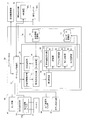
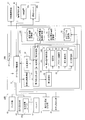
- FIG. 2 is a block diagram showing a functional configuration example of an in-vehicle system 40 equipped with the gateway ECU 50 according to the embodiment (1).
- the in-vehicle system 40 includes a diagnostic device connection unit 41, a sensor group 42, a traveling system ECU group 43, a driving support system ECU group 44, a body system ECU group 45, an information system ECU group 46, and a gateway ECU 50. ..
- the traveling system ECU group 43, the driving support system ECU group 44, the body system ECU group 45, the information system ECU group 46, and the gateway ECU 50 are composed of a computer device including one or more processors, a memory, a communication module, and the like. There is. Then, the processor mounted on each ECU reads the program stored in the memory, interprets and executes the program, and the predetermined control is executed by each ECU.
- the diagnostic machine connection unit 41 is a diagnostic connector device provided with a port to which a diagnostic machine or a scan tool for performing failure diagnosis or maintenance is connected.
- a diagnostic connector device provided with a port to which a diagnostic machine or a scan tool for performing failure diagnosis or maintenance is connected.
- OBDII On-board diagnostics II connector. It is composed of.
- the sensor group 42 includes various in-vehicle sensors that acquire sensing data used for control performed by the traveling system ECU group 43, the driving support system ECU group 44, and the like.
- a vehicle speed sensor a shift position sensor, an accelerator opening sensor, an obstacle detection sensor such as a millimeter wave radar, an image acquisition sensor such as a camera, and the like are included.
- the traveling system ECU group 43 includes a drive system ECU, a chassis system ECU, and the like.
- the drive system ECU includes control units related to "running" functions such as engine control, motor control, fuel cell control, EV (Electric Vehicle) control, and transmission control.
- the chassis-based ECU includes a control unit related to a "stop / turn” function such as brake control or steering control.
- the traveling system ECU group 43 includes a power monitoring unit 43a for monitoring the power state such as the remaining power amount of the battery 47 (power supply unit) of the vehicle 4, and the power state from the power monitoring unit 43a to the gateway ECU 50. Is sent.
- the electric power state may be, for example, a state of remaining electric energy, a state of a setting mode related to electric power (for example, an eco mode), or the like.
- the driving support system ECU group 44 includes an automatic braking support function, a lane keeping support function (also called LKA / Lane Keep Assist), a constant speed driving / inter-vehicle distance support function (also called ACC / Adaptive Cruise Control), and a forward collision warning function. , Lane departure warning function, blind spot monitoring function, traffic sign recognition function, driver monitoring function, etc., functions that automatically improve safety or realize comfortable driving by linking with the driving system ECU group 43, etc. (driving support function) , Or an automatic operation function), and at least one control unit is included.
- a lane keeping support function also called LKA / Lane Keep Assist
- ACC / Adaptive Cruise Control constant speed driving / inter-vehicle distance support function
- forward collision warning function Lane departure warning function, blind spot monitoring function, traffic sign recognition function, driver monitoring function, etc., functions that automatically improve safety or realize comfortable driving by linking with the driving system ECU group 43, etc. (driving support function) , Or an automatic operation function
- the driving support system ECU group 44 includes, for example, Level 1 (driver assistance), Level 2 (partially automatic driving), and Level 3 (conditional automatic driving) at the automatic driving level presented by the American Society of Automotive Engineers of Japan (SAE). It may be equipped with the function of (driving). Furthermore, the functions of level 4 (highly automatic driving) and level 5 (fully automatic driving) of the automatic driving level may be equipped, and the functions of only level 1 and 2 or only level 2 and 3 are equipped. You may.
- Level 1 driver assistance
- Level 2 partially automatic driving
- Level 3 conditional automatic driving
- SAE American Society of Automotive Engineers of Japan
- the body system ECU group 45 includes at least one control unit related to the function of the vehicle body such as a door lock, a smart key, a power window, an air conditioner, a light, an instrument panel, or a winker.
- the information system ECU group 46 includes an infotainment device, a telematics device, or an ITS (Intelligent Transport Systems) related device.
- the infotainment device includes an HMI (Human Machine Interface) device 46a that functions as a user interface, a car navigation device, an audio device, and the like, and the telematics device communicates with a server device 2 and the like via a communication network 3.
- a communication unit 46b and the like for this purpose are included.
- the ITS-related device includes an ETC (Electronic Toll Collection System), a communication unit for performing road-to-vehicle communication with a roadside machine such as an ITS spot, or an inter-vehicle communication.
- ETC Electronic Toll Collection System
- the gateway ECU 50 includes a gateway function unit 51, a security control unit 52, and a storage unit 70.
- the gateway function unit 51 has a function of controlling transfer of a frame (message) via each ECU group and a bus.
- a frame transmission / reception unit, a frame interpretation unit, a frame conversion unit, etc. (not shown) are mounted on a vehicle.
- a configuration necessary for mutual communication with each ECU group of the system 40 according to the CAN protocol is included.
- the security control unit 52 includes a status information acquisition unit 53, an operation setting determination unit 54, a first setting unit 55, a division notification unit 56, and a security function unit 60.
- the security control unit 52 includes a memory including a ROM (Read Only Memory), a RAM (Random Access Memory), etc., in which a program executed in each of the above units is stored, and a CPU (CPU) that reads and executes the program from the memory. It is configured to include processors such as Central Processing Unit), and the functions of the above parts are realized by the cooperation of these hardware and programs.
- ROM Read Only Memory
- RAM Random Access Memory
- CPU Central Processing Unit
- the storage unit 70 is configured to include a setting information storage unit 71 and a log data storage unit 72, and is composed of, for example, a semiconductor memory such as a flash memory.
- the state information acquisition unit 53 performs a process of acquiring state information including the state of the own vehicle (vehicle 4) from any of the diagnostic device connection unit 41, the sensor group 42, or each ECU group via the gateway function unit 51. ..
- the state information to be acquired is, for example, at least one of a state in which the own vehicle is parked, a state in which the vehicle is starting, a state in which the vehicle is running or stopped, and a state in which the vehicle is under maintenance (vehicle 4). This is information indicating the dynamics).
- a lock state signal acquired from the smart key unit included in the body system ECU group 45 may be used.
- the information indicating the state of being started for example, an ON signal acquired from a start switch of a drive source (engine, motor, etc.) included in the sensor group 42 may be used.
- the information indicating the running or stopped state includes, for example, a vehicle speed signal acquired from the vehicle speed sensor included in the sensor group 42, a shift position signal acquired from the shift position sensor, a brake pressure signal acquired from the brake sensor, and the like. You may use it.
- a signal acquired from the diagnostic machine connected to the diagnostic machine connection unit 41 may be used.
- the acquired state information may be information indicating, for example, the power state of the battery 47 of the own vehicle, for example, the state such as the remaining power amount of the battery 47, in addition to the dynamic information of the vehicle 4.
- the information indicating the power state for example, a signal indicating the amount of remaining power acquired from the power monitoring unit 43a may be used, or a signal indicating a setting mode (for example, eco mode) relating to the power may be used.
- the operation setting determination unit 54 sets the operation settings (for example, whether to enable or disable) of the security functions shared by the gateway ECU 50 and the server device 2 based on the state information acquired by the state information acquisition unit 53. Perform the process of determining.
- the operation setting determination unit 54 includes the first determination unit 54a, and the first determination unit 54a collates the acquired state information with the security function setting table read from the setting information storage unit 71, and sets the security function setting table. From the inside, the process of determining the operation setting of each security function corresponding to the state of the own vehicle indicated by the acquired state information is performed.
- the security function setting table is an example of the "setting information" of the present invention. A specific example of the security function setting table will be described later.
- the first setting unit 55 performs a process of enabling or disabling each of the security functions included in the security function unit 60 based on the operation setting determined by the operation setting determination unit 54.
- the security function unit 60 includes one or more security functions that can be executed by the gateway ECU 50.
- the in-vehicle communication encryption unit 61 the authentication unit 62, the access control unit 63, the intrusion detection unit 64, and the intrusion detection unit 64.
- the log recording unit 65 is included.
- the in-vehicle communication encryption unit 61 is an example of the “internal communication encryption unit”.
- the in-vehicle communication encryption unit 61 performs a process of encrypting the in-vehicle communication of the own vehicle (for example, data such as a frame transferred between the ECUs) performed with each ECU group via the gateway function unit 51.
- the authentication unit 62 performs a process of authenticating the unlocking or locking of the own vehicle.
- unlocking or locking the vehicle 4 is correct user information, for example, user ID (identification number), or biometric authentication information (for example, for face authentication, iris authentication, fingerprint authentication, vein authentication, or voiceprint authentication. It may be authenticated whether or not it was executed based on the information for. Alternatively, it may be authenticated whether or not the execution was performed using a correct user device such as a smart key or a mobile terminal such as a smartphone.
- the access control unit 63 performs a process of determining the access right (in other words, the presence / absence of the operation authority) to the in-vehicle equipment of the own vehicle, for example, the in-vehicle equipment such as the HMI device 46a or the navigation device.
- the access right may be determined based on, for example, the user ID, password, biometric authentication information, or the like input via the HMI device 46a or the like, and the presence or absence of the operation authority may be determined.
- the intrusion detection unit 64 performs a process of detecting an intrusion due to a security attack on the own vehicle. For example, an abnormality (for example, a frame abnormality or a bus abnormality) generated in the in-vehicle system 40 is detected based on data such as a frame acquired from each ECU group via the gateway function unit 51, and the detected abnormality is detected. Performs processing to detect the corresponding attack.
- an abnormality for example, a frame abnormality or a bus abnormality
- a frame abnormality is detected by checking parameters such as RTR (Remote Transmission Request), DLC (Data Length Code), payload, and reception cycle set for each frame ID, for example.
- the frame abnormality represents an abnormality of the CAN signal alone.
- a bus abnormality is detected by checking parameters such as a bus load factor, a bus state (state such as the presence or absence of a bus error), and an ID appearing on these buses.
- the bus anomaly represents a situational anomaly in the CAN signal.
- the log recording unit 65 performs a process of recording a history such as a processing status executed in each unit of the security function unit 60 as log data.
- the log data of each of these units is stored in the log data storage unit 72.
- the sharing notification unit 56 gives the server device 2 a sharing notification for enabling or disabling each of the security functions of the server device 2 based on the operation setting determined by the operation setting determination unit 54.
- FIG. 3 is a diagram showing a data configuration example of the security function setting table stored in the setting information storage unit 71.
- the security function setting table shown in FIG. 3 includes the relationship between the state of one or more own vehicles (vehicle state) and the operation settings (valid or invalid settings) of the security functions shared by the gateway ECU 50 and the server device 2. It is a data structure.
- the vehicle state item includes the state of the own vehicle corresponding to the state information acquired by the state information acquisition unit 53, such as parking, starting, running, or stopped, and maintenance.
- the items that execute the security function include the cloud and the car.
- the cloud corresponds to the server device 2, and the car corresponds to the gateway ECU 50.
- the security function items include security functions included in the security function unit 60, that is, in-vehicle communication encryption, authentication (user or device), access control (operation authority), intrusion detection, and log recording.
- security function is not limited to these, and other functions may be further added.
- the security function setting table the setting of how the security function is shared between the cloud and the vehicle, which are the executing bodies, in each state of the own vehicle included in the vehicle state item, in other words, which security function is provided.
- the settings for enabling and disabling which security function are registered.
- the cloud when the vehicle state is parked, the cloud enables intrusion detection and logging, the vehicle enables authentication and access control, and in-vehicle communication encryption, intrusion detection and logging.
- the setting to disable is registered. According to this setting, the vehicle 4 can focus on the security function to detect unauthorized unlocking and unauthorized operation while parked, and intrusion detection and log recording can be performed in the cloud. The power consumption related to the security function of the vehicle 4 can be suppressed.
- the cloud disables intrusion detection and logging, the vehicle enables intrusion detection and logging, and in-vehicle communication encryption.
- a setting to disable authentication and access control is registered. According to this setting, since it is necessary to preferentially check whether or not there is an abnormality in the in-vehicle system 40 in the vehicle 4 during the start-up, focus on the security function of intrusion detection and log recording, and perform in-vehicle communication encryption.
- power consumption related to the security function of the vehicle 4 can be suppressed. Further, by disabling the security function of the cloud during startup, it is possible to suppress power consumption related to communication processing such as data transmission from the vehicle 4 to the server device 2.
- the cloud When the vehicle is running or stopped, the cloud will enable intrusion detection and logging, and the vehicle will enable in-vehicle communication encryption, intrusion detection and logging, and disable authentication and access control. Is registered. According to such a setting, the event of authentication or access control does not occur in the vehicle 4 while the vehicle is running or stopped. Therefore, by disabling these functions, the power consumption related to the security function of the vehicle 4 can be suppressed. Further, if the vehicle is invaded by an attack from the outside while the vehicle is running or stopped, abnormal vehicle control may occur. Therefore, by enabling the intrusion detection and log recording functions for both the car and the cloud, it is possible to double-check the car and the cloud and enhance security.
- the setting information storage unit 71 may include two or more security function setting tables.
- FIG. 4 is a diagram showing a data configuration example of another security function setting table stored in the setting information storage unit 71.
- the security function setting table shown in FIG. 4 has a data structure including a relationship between one or more power states and operation settings (valid or invalid settings) of each security function shared by the gateway ECU 50 and the server device 2. ..
- the power status of the battery 47 that is, the remaining power of 30% or more, the remaining power of less than 30%, and the remaining power of 10%, as the state of the own vehicle corresponding to the state information acquired by the state information acquisition unit 53.
- the eco-mode setting is included when the remaining power is less than 30% and the remaining power is 30% or more.
- the ratio (%) of the remaining power and the number of items are not limited to this example, and can be appropriately set in consideration of the capacity of the battery 47 mounted on the vehicle 4 and the like.
- the items that execute the security function include the cloud and the car.
- the cloud corresponds to the server device 2, and the car corresponds to the gateway ECU 50.
- the security function items include security functions included in the security function unit 60, that is, in-vehicle communication encryption, authentication (user or device), access control (operation authority), intrusion detection, and log recording.
- security function is not limited to these, and other functions may be further added.
- the cloud when the power status is 30% or more of the remaining power, the cloud enables intrusion detection and logging, and the car has all security functions (in-vehicle communication encryption, authentication, access control, intrusion). Settings to enable detection and logging) are registered. According to such a setting, when the remaining power is sufficient (it is not necessary to suppress the power consumption), it is possible to enhance the security by enabling all the security functions of the car and the cloud.
- the cloud will enable intrusion detection and logging
- the car will enable in-vehicle communication encryption
- authentication and access control and intrusion detection and logging will be disabled.
- the settings are registered. According to this setting, when the remaining power is insufficient (power consumption needs to be suppressed), the vehicle 4 has a security function of the vehicle 4 by disabling authentication, access control, intrusion detection, and logging. It is possible to suppress the power consumption related to. Further, in the vehicle 4, the security function can be maintained by enabling the in-vehicle communication encryption and sharing the intrusion detection and the log recording in the cloud.
- the cloud will disable intrusion detection and logging, the car will enable logging, and in-vehicle communication encryption and authentication, access control and intrusion detection will be disabled. Is registered. According to this setting, when there is almost no remaining power (power consumption needs to be greatly suppressed), in vehicle 4, only logging is enabled, other functions are disabled, and the cloud is not shared (the cloud is not shared). By suppressing the power consumption required for data transmission to the cloud), it is possible to maintain the minimum security function and surely suppress the power consumption related to the security function of the vehicle 4.
- the cloud will enable intrusion detection and logging
- the car will enable authentication and access control, and in-vehicle communication encryption and intrusion.
- a setting to disable detection and logging is registered. According to this configuration, the power consumption related to the security function of the vehicle 4 is suppressed by disabling the in-vehicle communication encryption, intrusion detection, and log recording of the vehicle 4 as compared with the case where the remaining power is 30% or more. It becomes possible.
- the security functions on the cloud side are intrusion detection and log recording, but the security functions on the cloud side are not limited to these two, and other security functions are not limited to these two. It may include a function, for example, an authentication function.
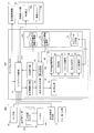
- FIG. 5 is a block diagram showing a functional configuration example of the server device 2 according to the embodiment (1).
- the server device 2 includes a communication unit 10, a control unit 11, and a storage unit 12.
- the control unit 11 includes a division notification acquisition unit 21, a second setting unit 22, a setting completion notification unit 23, a countermeasure command unit 24, and a security function unit 25.
- the control unit 11 is configured as hardware including a memory including a ROM, a RAM, etc. in which a program executed in each of the above parts is stored, a processor such as a CPU that reads a program from the memory and executes the program, and the like. The functions of the above-mentioned parts are realized by the cooperation between the program and the program.
- the storage unit 12 is configured to include a log data storage unit 12a, and is composed of, for example, one or more hard disk drives, a solid state drive, storage on the cloud, or the like.
- the sharing notification acquisition unit 21 performs a process of acquiring a sharing notification from the vehicle 4 for setting each of the security functions of the server device 2 to be valid or invalid.
- the second setting unit 22 performs a process of enabling or disabling each of the security functions of the server device 2 based on the sharing notification acquired by the sharing notification acquisition unit 21.
- the setting completion notification unit 23 performs a process of notifying the vehicle 4 of the completion of the setting when the division setting of the security function by the second setting unit 22 is completed.
- the security function unit 25 includes an intrusion detection unit 26 and a log recording unit 27.
- the intrusion detection unit 26 uses the log data acquired from the vehicle 4 to perform a process of detecting an intrusion due to a security attack on the vehicle 4. For example, from the data (frame or the like) acquired from the vehicle 4, an abnormality (for example, a frame abnormality or a bus abnormality) that has occurred in the in-vehicle system 40 of the vehicle 4 is detected, and an attack corresponding to the detected abnormality is detected. Perform processing etc.
- the log recording unit 27 performs a process of recording a history such as a processing status executed in each unit of the security function unit 25 as log data.
- the log data of each of these units is stored in the log data storage unit 12a.
- the countermeasure command unit 24 responds to the vehicle 4 based on a command from the security countermeasure organization 13. Performs processing such as sending remote control commands. Further, the countermeasure command unit 24 may perform a process of transmitting an update program or update data of each unit included in the security function unit 60 of the gateway ECU 50 to the vehicle 4.
- FIG. 6 is a flowchart showing an example of the function setting processing operation performed by the gateway ECU 50 and the server device 2 in the security system 1 according to the embodiment (1).
- the gateway ECU 50 is configured to always operate regardless of the state of the vehicle 4, and this processing operation is repeatedly executed, for example, during the operation of the gateway ECU 50.
- step S1 the gateway ECU 50 operates as the state information acquisition unit 53, and the own vehicle (vehicle 4) is connected to the diagnostic device connection unit 41, the sensor group 42, or the ECU group via the gateway function unit 51.
- the process of acquiring the state information including the state is performed, and then the process proceeds to step S2.
- the state information to be acquired at least one of the states in which the own vehicle is parked, started, running or stopped, and under maintenance. Acquire dynamic information indicating. Further, as a second example of the state information to be acquired, the power information indicating the power state of the battery 47 of the own vehicle, for example, the remaining power amount of the battery 47, the setting state such as the eco mode, may be acquired.
- step S2 the gateway ECU 50 operates as the first determination unit 54a of the operation setting determination unit 54, and sets the operation settings of the security functions shared by the gateway ECU 50 and the server device 2 according to the state information acquired in step S1.
- the process of determining is performed, and the process proceeds to step S3.
- the acquired state information is the dynamic information of the vehicle 4 given in the first example
- the acquired dynamic information is collated with the security function setting table (see FIG. 3) read from the setting information storage unit 71. To do.
- the security function setting table the operation settings of each security function corresponding to the state of the own vehicle (either parked, started, running or stopped, or under maintenance) indicated by the acquired dynamic information. (Whether it should be set to be valid or invalid) is determined, and the process of reading the data of the determined operation setting (valid or invalid) is performed.
- the acquired state information is the electric power information of the vehicle 4 given in the second example above
- the acquired electric power information is collated with the security function setting table (see FIG. 4) read from the setting information storage unit 71.
- the security function setting table is set with the power status of the own vehicle indicated by the acquired power information (remaining power 30% or more, remaining power less than 30%, remaining power less than 10%, and remaining power 30% or more).
- the operation setting of each security function corresponding to any of the above) is determined, and the process of reading the data of the determined operation setting (valid or invalid) is performed.
- step S3 the gateway ECU 50 operates as the sharing notification unit 56, and based on the operation setting of the security function determined in step S2, the gateway ECU 50 issues a sharing notification for enabling or disabling each of the security functions of the server device 2. This is performed on the server device 2, and the process proceeds to step S4.
- step S4 the gateway ECU 50 sets a predetermined response waiting time and performs a process of waiting for a response from the server device 2.
- the server device 2 operates as the sharing notification acquisition unit 21 in step S11, performs a process of acquiring the sharing notification transmitted from the vehicle 4 in step S3, and when the sharing notification is acquired from the vehicle 4, the sharing notification is obtained in step S12. Proceed with processing.
- step S12 the server device 2 operates as the second setting unit 22, and based on the sharing notification acquired in step S11, a process of enabling or disabling each of the security functions of the server device 2 (function sharing setting process). Is performed, and the process proceeds to step S13.
- step S13 the server device 2 operates as the setting completion notification unit 23, performs a process of notifying the vehicle 4 of the completion of the setting when the sharing setting process of the security function in step S12 is completed, and then the server device 2 After finishing the processing in, the server device 2 executes the security function set to be valid.
- step S5 the gateway ECU 50 determines whether or not there is a response from the server device 2 within the response waiting time set in step S4, that is, whether or not the setting completion notification is obtained from the server device 2. If it is determined that there is a response (the setting completion notification has been obtained), the process proceeds to step S6.
- step S6 the gateway ECU 50 operates as the first setting unit 55, and a process of enabling or disabling each of the security functions of the gateway ECU 50 based on the operation setting of the security function determined in step S2 (function sharing setting). Processing) is performed, and then the process returns to step S1 and the processing is repeated.
- step S5 determines in step S5 that there is no response from the server device 2 within the response waiting time (has not acquired the setting completion notification)
- the gateway ECU 50 proceeds to step S7, and in step S7, The process of suspending the setting change of the security function is performed, and the process proceeds to step S8.
- step S8 the gateway ECU 50 determines whether or not the allocation notification to the server device 2 has been retried three or more times, and if it is determined that the retry is less than three times, the process returns to step S3 and the server device 2 is retried. Then, the sharing notification is sent again. On the other hand, if it is determined in step S8 that the number of retries is three or more, the process returns to step S1, the state information acquisition process is performed, and the process is repeated thereafter.
- the security system 1 as a whole can suppress the power consumption related to the security function in the vehicle 4 while maintaining the protection function of the in-vehicle system 40 by the security function. It is possible to maintain the protection function by the security function and suppress the power consumption related to the security function at the same time.
- the operation settings of the security functions shared by the gateway ECU 50 and the server device 2 are determined according to the acquired state information. Then, each security function of the gateway ECU 50 is enabled or disabled based on the determined operation setting. In addition, the server device 2 is notified of the division based on the determined operation settings.
- the security function of the gateway ECU 50 can be shared by the server device 2 according to the state information such as the dynamic information or the electric power information of the vehicle 4, and the security of the security system 1 as a whole is ensured. It is possible to suppress the power consumption related to the security function in the vehicle 4 while maintaining the security function for the vehicle 4.
- the security function setting table is stored in the setting information storage unit 71, and the operation setting determination unit 54 of the own vehicle indicated by the state information acquired from the security function setting table.
- Security function corresponding to the state By determining the operation setting of each, the state of the own vehicle includes various states (such as the dynamics or the power state of the vehicle 4), or the security function includes various functions. However, the processing load of the operation setting determination unit 54 can be reduced, and the processing performed by the operation setting determination unit 54 can be speeded up.
- the server device 2 can share the security function so that the protection function by the security function can be maintained or strengthened according to the dynamics of the own vehicle or the power state of the own vehicle.
- the security function unit 60 includes the in-vehicle communication encryption unit 61, the authentication unit 62, the access control unit 63, the intrusion detection unit 64, and the log recording unit 65, so that the vehicle can be in the state of the own vehicle. Accordingly, it is possible to more appropriately balance the maintenance of the protection function by the security function shared by the vehicle 4 and the server device 2 and the suppression of the power consumption related to the security function.
- the security functions of the server device 2 are set to be valid or invalid based on the sharing notification acquired from the vehicle 4, so that the server device 2 It is possible to switch the operation setting of the security function executed in the above based on the sharing notification. Therefore, by paying a part of the security function of the vehicle 4 according to the state of the vehicle 4, the security function of the vehicle 4 as a whole is maintained while maintaining the security function for ensuring the safety. The power consumption involved can be suppressed.
- FIG. 7 is a block diagram showing a functional configuration example of the in-vehicle system 40A on which the gateway ECU 50A according to the embodiment (2) is mounted.
- the same reference numerals are given to the configurations having the same functions as the gateway ECU 50 and the in-vehicle system 40 according to the embodiment (1), and the description thereof will be omitted.
- the main difference between the gateway ECU 50A according to the embodiment (2) and the gateway ECU 50 according to the embodiment (1) is that the operation setting determination unit 54 of the security control unit 52A has the first determination unit 54a. Instead, the second determination unit 54b is equipped, and the storage unit 70A is equipped with the allowable power consumption information storage unit 73 and the power consumption information storage unit 74 instead of the setting information storage unit 71. is there.
- the allowable power consumption information storage unit 73 stores an allowable power consumption table including the relationship between the state of one or more own vehicles and the allowable power consumption of the security function of the gateway ECU 50A.
- FIG. 8 is a diagram showing a data configuration example of the allowable power consumption table stored in the allowable power consumption information storage unit 73.
- the allowable power consumption table shown in FIG. 8 includes the relationship between one or more own vehicle states (vehicle states) and the allowable power consumption of the security function of the gateway ECU 50A, and further includes one or more own vehicle states and a server.
- the data configuration includes the relationship with the operation settings (valid or invalid settings) of each security function shared by the device 2 (cloud).
- the vehicle status item includes the status of the own vehicle corresponding to the status information acquired by the status information acquisition unit 53, which is parked, started, running, stopped, and under maintenance.
- the value of the allowable power consumption of the security function of the vehicle 4 in each vehicle state is registered.
- the value of the allowable power consumption shown in FIG. 8 is an example, and can be appropriately set depending on the battery capacity of the vehicle 4, the type of security function, and the number of mounted vehicles 4.
- the cloud security functions include intrusion detection and log recording, and settings for enabling or disabling these security functions are registered in each vehicle state.
- the security function of the cloud is not limited to these, and other functions may be added.
- the cloud if the vehicle state is parked, running, stopped, or under maintenance, the cloud enables intrusion detection and logging, and if the vehicle state is starting, the cloud is Settings for disabling intrusion detection and enabling logging are registered.
- the allowable power consumption table may not include the data of the operation settings of the cloud security function.
- the power consumption information storage unit 74 stores a power consumption table including the relationship between the power consumption and the priority of each security function of the gateway ECU 50A.
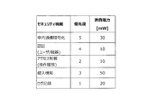
- FIG. 9 is a diagram showing a data configuration example of the power consumption table stored in the power consumption information storage unit 74.
- the power consumption table shown in FIG. 9 has a data structure including the relationship between the power consumption of each security function included in the security function unit 60 of the vehicle 4 and the priority.
- the value of power consumption for each security function is registered.
- the priority indicates, for example, the operation priority among the security functions included in the security function unit 60, and in the example shown in FIG. 9, the smaller the priority value, the higher the priority. There is. That is, the log recording has the highest priority with the priority "1", and the in-vehicle communication encryption has the lowest priority with the priority "5".
- the priority data is used when selecting a security function to enable or when selecting a security function to disable.
- the data of the permissible power consumption table stored in the permissible power consumption information storage unit 73 and the data of the power consumption table stored in the power consumption information storage unit 74 are read by the operation setting determination unit 54.
- the operation setting determination unit 54 includes the second determination unit 54b, and the second determination unit 54b includes the total power consumption of the security functions of the gateway ECU 50A for which the operation is effectively set, and the acquired state information. Based on the permissible power consumption of the security function in the state of the own vehicle indicated by, the process of determining the operation setting of each security function is performed.
- the second determination unit 54b reads the allowable power consumption table (FIG. 8) from the allowable power consumption information storage unit 73, and the state information acquired by the state information acquisition unit 53 from the allowable power consumption table. Acquires the allowable power consumption of the security function corresponding to the state of the own vehicle indicated by and the operation setting data of the security function of the cloud. For example, if the vehicle is parked, the allowable power consumption "100mW" and the operation setting of the cloud security function "Enable intrusion detection and enable log recording" are acquired from the allowable power consumption table. To do. Then, the second determination unit 54b sends the acquired operation setting of the security function of the cloud to the sharing notification unit 56.
- the allowable power consumption table FIG. 8
- the second determination unit 54b reads the power consumption table (FIG. 9) from the power consumption information storage unit 74, and is currently enabled from the power consumption table (all initial values are set to be valid). Data (priority, power consumption) of each security function is extracted and stored in the effective security function table area provided in the memory (for example, RAM of the security control unit 52A).
- the second determination unit 54b determines the allowable power consumption of the security function corresponding to the vehicle state and the power consumption of the security function (that is, the function whose operation is effectively set) stored in the effective security function table area. The process of determining the operation setting (whether to enable or disable) of each security function is performed by comparing with the total of.
- the second determination unit 54b has a lower priority among the security functions stored in the effective security function table area. It is possible to make a decision to disable a feature (in other words, remove it from the active security feature tablespace).
- the second determination unit 54b is not stored in the effective security function table area (in other words, its power consumption). It is possible to make a decision to enable (in other words, add to the effective security function tablespace) the function with high priority from the security functions (the operation is set to be disabled).
- the first setting unit 55 tells the security function unit 60 based on the operation setting (that is, the security function information stored in the effective security function table area) determined by the second determination unit 54b of the operation setting determination unit 54. Performs processing to enable or disable each of the included security functions. That is, the first setting unit 55 performs a process of effectively setting the security function stored in the effective security function table area.
- the sharing notification unit 56 gives the server device 2 a sharing notification for enabling or disabling each of the security functions of the server device 2 based on the operation settings of the cloud security function acquired from the second determination unit 54b. Do it against.
- the server device 2 acquires a sharing notification from the vehicle 4, and based on the acquired sharing notification, enables or disables each of the security functions of the server device 2. It is possible to perform the processing to be performed.
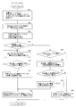
- FIG. 10 is a flowchart showing an example of the function setting processing operation performed by the security control unit 52A constituting the gateway ECU 50A according to the embodiment (2). This processing operation is executed in place of step S2 of the flowchart shown in FIG.
- step S21 the gateway ECU 50A reads the power consumption table (FIG. 9) of the security function from the power consumption information storage unit 74, and data (priority) of each security function currently enabled from the power consumption table. , Power consumption) is extracted and stored in the effective security function table area provided in the memory, and the process proceeds to step S22.
- the gateway ECU 50A reads the power consumption table (FIG. 9) of the security function from the power consumption information storage unit 74, and data (priority) of each security function currently enabled from the power consumption table. , Power consumption) is extracted and stored in the effective security function table area provided in the memory, and the process proceeds to step S22.
- all the security functions in the power consumption table may be regarded as effective, and the data of each security function may be stored in the effective security function table area.
- step S22 the gateway ECU 50A performs a process of calculating the total power consumption of each security function stored in the effective security function table, and proceeds to step S23.
- step S23 the gateway ECU 50A reads the allowable power consumption table from the allowable power consumption information storage unit 73, and corresponds to the state (vehicle state) of the own vehicle indicated by the acquired state information from the allowable power consumption table. The process of acquiring the allowable power consumption is performed, and the process proceeds to step S24.
- step S24 the gateway ECU 50A determines whether or not the total power consumption calculated in step S22 is equal to or greater than the allowable power consumption acquired in step S23, and if it is determined to be equal to or greater than the allowable power consumption, step S25. Proceed to processing.
- step S25 the gateway ECU 50A extracts the power consumption data of the security function (lowest priority function) having the lowest priority from the security functions stored in the effective security function table in step S21, and consumes the power consumption calculated in step S22.
- the process of subtracting the power consumption of the lowest priority function from the total power consumption to recalculate the total power consumption is performed, and the process proceeds to step S26.
- step S26 the gateway ECU 50A determines whether or not the total power consumption recalculated in step S25 is less than the allowable power consumption acquired in step S23, and if it is determined that the total power consumption is not less than the allowable power consumption, step S26. Return to S25 and repeat the process. On the other hand, if it is determined in step S26 that the power consumption is less than the allowable power consumption, the process proceeds to step S27.
- step S27 the gateway ECU 50A performs a process of deleting the security function having the lowest priority from the security functions stored in the effective security function table area in step S21 (deletion update process), and then proceeds to step S28. ..
- step S28 a process (determining the operation setting) for effectively determining the security function stored in the effective security function table area after the update (in this case, after the deletion and update) is performed, and then the step shown in FIG. 6 is performed. Proceed to S3.
- step S24 determines whether the total value of the power consumption calculated in step S22 is less than the allowable power consumption acquired in step S23. If it is determined in step S24 that the total value of the power consumption calculated in step S22 is less than the allowable power consumption acquired in step S23, the process proceeds to step S29.
- step S29 the gateway ECU 50A determines in step S21 whether or not there is an invalid security function that is not stored in the effective security function table area, and if it is determined that there is no invalid security function, the process is performed in step S33. To proceed. On the other hand, if it is determined that there is an invalid security function, the process proceeds to step S30.
- step S30 the gateway ECU 50A extracts the power consumption data of the security function (high priority function) having the highest priority from the invalid security functions that are not stored in the effective security function table area from the power consumption table. , The power consumption of the high priority function is added to the total power consumption calculated in step S22 to recalculate the total power consumption, and the process proceeds to step S31.
- the security function high priority function
- step S31 the gateway ECU 50A determines whether or not the total power consumption recalculated in step S30 is less than the allowable power consumption acquired in step S23, and if it is determined that the total power consumption is less than the allowable power consumption, step S31. The process proceeds to S32.
- step S32 the gateway ECU 50A adds a high-priority security function used for recalculating the total power consumption in step S30 to the security function stored in the effective security function table area in step S21 (additional update process). ), And then proceed to step S28.
- step S28 the gateway ECU 50A performs a process (determination of operation setting) for effectively determining the security function stored in the effective security function table area after the update (after the additional update), and then shows in FIG. The process proceeds to step S3.
- step S31 if the gateway ECU 50A determines that the total power consumption recalculated in step S30 is not less than the allowable power consumption, the process proceeds to step S33.
- step S33 the gateway ECU 50A performs a process (determination of operation setting) for effectively determining the security function stored in the effective security function table area in step S21, and then proceeds to step S3 shown in FIG. ..
- step S3 the server device 2 is notified of the division of duties for enabling or disabling each of the security functions of the server device 2 based on the operation settings of the cloud security function acquired from the allowable power consumption table. To do.
- the total power consumption is equal to or less than the allowable power consumption according to the allowable power consumption of the security function in the state of the own vehicle. It is possible to enable or disable each of the security functions and set them, so that the operation setting can be determined flexibly, and the power consumption related to the security function in the vehicle 4 can be appropriately suppressed. ..
- the second determination unit 54b compares the allowable power consumption acquired from the allowable power consumption table with the total power consumption of the security functions stored in the effective security function table area, and the security function is compared. Each operation setting (for example, whether to enable or disable) is determined. By using the permissible power consumption table and the power consumption table, it is possible to reduce the processing load of the second determination unit 54b and to speed up the processing performed by the second determination unit 54b.
- the security functions stored in the effective security function table area are included. Makes a decision to disable low priority features. As a result, it is possible to maintain the state in which the high-priority function is effectively set, and the security function can be switched and set so as not to exceed the allowable power consumption, and the allowable power consumption is taken into consideration and appropriate. Security functions can be set so as to consume power.
- the gateway ECU 50A when the total power consumption is less than the acquired allowable power consumption as a result of the comparison by the second determination unit 54b, the operation is set to be invalid from the security functions. A decision is made to enable the high priority features. As a result, when the allowable power consumption is less than the allowable power consumption, the security function can be switched and set so that the function having a high priority is effectively set, and the appropriate power consumption in consideration of the allowable power consumption is taken into consideration. The security function can be set so as to be.
- FIG. 11 is a block diagram showing a functional configuration example of the in-vehicle system 40B on which the gateway ECU 50B according to the embodiment (3) is mounted.
- the configurations having the same functions as the gateway ECU 50 and the in-vehicle system 40 according to the embodiment (1) and the gateway ECU 50A and the in-vehicle system 40A according to the embodiment (2) are designated by the same reference numerals and the description thereof will be described. It will be omitted.
- the main difference between the gateway ECU 50B according to the embodiment (3) and the gateway ECU 50 according to the embodiment (1) and the gateway ECU 50A according to the embodiment (2) is the operation setting of the security control unit 52B.
- the determination unit 54 is equipped with the first determination unit 54a and the second determination unit 54b, and the storage unit 70B includes the setting information storage unit 71, the allowable power consumption information storage unit 73, and the power consumption information storage unit 74. Is the point that is equipped.
- the gateway ECU 50B according to the embodiment (3) has a configuration of a characteristic portion of the gateway ECU 50 according to the embodiment (1) and the gateway ECU 50A according to the embodiment (2).
- the first determination unit 54a and the second determination unit 54b included in the operation setting determination unit 54 may be configured so that their operations can be switched according to predetermined conditions. For example, the user may be allowed to make a selection via the HMI device 46a.
- the first determination unit 54a and the second determination unit 54b may be switchable according to the state of the own vehicle. For example, when the vehicle state as the state of the own vehicle is parked or under maintenance, the operation of the security function is set using the security function setting table (FIG. 3) by the first determination unit 54a, and the vehicle is started or running. When the vehicle is in the middle or stopped, the operation of the security function may be set by using the allowable power consumption table and the power consumption table by the second determination unit 54b.
- the security function setting table FIG. 3
- the operation setting of the security function using the allowable power consumption table and the power consumption table is performed by the second determination unit 54b. If the remaining power is not sufficient, the operation of the security function may be set using the security function setting table (FIG. 4) by the first determination unit 54a.
- step S2 the gateway ECU 50B operates as the first determination unit 54a, and instead of steps S7 and S8, the processing of the flowchart shown in FIG. 10 (step S21). -Step S33) may be executed, that is, it may be configured to operate as the second determination unit 54b.
- the first determination unit 54a and the second determination unit 54b included in the operation setting determination unit 54 are configured so that their operations can be switched according to predetermined conditions. It is possible to increase the variation of the operation setting of the security function according to the state of the own vehicle and to perform the operation setting with high flexibility by operating the operation in combination or in combination. Therefore, it is possible to more appropriately achieve both the maintenance of the protection function by the security function and the reduction of the power consumption related to the security function.
- the security control units 52, 52A, 52B mounted on the gateway ECUs 50, 50A, 50B may be mounted on another ECU, or the security ECU equipped with the security control units 52, 52A, 52B may be mounted on an in-vehicle system. It may be configured to connect to 40 or the like.
- the moving body on which the security device according to the present invention is mounted is not limited to the vehicle 4 traveling on the road, and is, for example, an automatic guided vehicle (AGV) used as an industrial device in a factory or the like, or an automated guided vehicle. It may be an automatic guided vehicle or the like.
- AGV automatic guided vehicle
- the types of these unmanned vehicles (guidance method) are not particularly limited.
- the guidance system may be, for example, any of an autonomous guidance system, an image recognition system, an electromagnetic induction system, an optical guidance system, or an electromagnetic induction system.
- the security system including the unmanned transport vehicle equipped with the above-mentioned security device and the above-mentioned server device, the security system as a whole maintains the protection function by the security function in the unmanned transport vehicle. It is possible to construct an industrial equipment system capable of suppressing the power consumption related to the security function, maintaining the protection function by the security function, and suppressing the power consumption related to the security function at the same time.
- the present invention is widely used in the security-related industrial field such as an in-vehicle system, in which one or more devices detect an attack on a device system connected via a communication path and take countermeasures against the detected attack. It can be used.
- Embodiments of the present invention may also be described as, but are not limited to, the following appendices.
- Appendix 1 A security device (50) mounted on a mobile body (4) in a security system (1) including a server device (2) and a mobile body (4) capable of communicating with the server device (2).
- a state information acquisition unit (53) that acquires state information including the state of the self-moving body
- An operation setting determination unit (54) that determines the operation settings of each of the security functions shared by the security device (50) and the server device (2) according to the acquired state information.
- the first setting unit (55) that enables or disables each of the security functions of the security device (50)
- the sharing notification unit (56) that gives the sharing notification to the server device (2) to enable or disable each of the security functions of the server device (2).
- a security function setting method in a security system (1) including a server device (2) and a mobile body (4) capable of communicating with the server device (2).
- the security device (50) mounted on the mobile body (4)
- the state information acquisition step (S1) for acquiring the state information including the state of the self-moving body
- An operation setting determination step (S2) for determining the operation settings of each of the security functions shared by the security device (50) and the server device (2) according to the acquired state information.
- the server device (2) In the sharing notification acquisition step (S11) of acquiring the sharing notification from the moving body, A security function setting method including a second setting step (S12) for setting each of the security functions of the server device (2) to be valid or invalid based on the acquired notification of sharing.
- the state information acquisition step (S1) for acquiring the state information including the state of the self-moving body, and An operation setting determination step (S2) for determining the operation settings of the security functions shared by the computer (52) and the server device (2) according to the acquired state information.
- the first setting step (S6) for enabling or disabling each of the security functions of the computer (52) based on the determined operation setting, and Based on the determined operation setting, the sharing notification step (S3) of giving the sharing notification to the server device (2) for enabling or disabling each of the security functions of the server device (2) is performed.
- a computer-readable storage medium that stores a program to be executed.
- Security system 2 Server device 3 Communication network 4 Vehicle (mobile) 10 Communication unit 11 Control unit 12 Storage unit 13 Security countermeasure organization 21 Shared notification acquisition unit 22 Second setting unit 23 Setting completion notification unit 24 Countermeasure command unit 25 Security function unit 26 Intrusion detection unit 27 Log recording unit 40, 40A, 40B In-vehicle System 41 Diagnostic machine connection 42 Sensor group 43 Driving system ECU group 43a Power monitoring unit 44 Operation support system ECU group 45 Body system ECU group 46 Information system ECU group 46a HMI device 46b Communication unit 47 Battery 50, 50A, 50B Gateway ECU ( Security device) 51 Gateway function unit 52, 52A, 52B Security control unit 53 Status information acquisition unit 54 Operation setting determination unit 54a First determination unit 54b Second determination unit 55 First setting unit 56 Shared notification unit 60 Security function unit 61 In-vehicle communication encryption unit (Internal communication encryption section) 62 Authentication unit 63 Access control unit 64 Intrusion detection unit 65 Log recording unit 70, 70A, 70B Storage unit 71 Setting information storage unit 72 Log data storage unit 73 Allowable power consumption information storage unit
Landscapes
- Engineering & Computer Science (AREA)
- Computer Security & Cryptography (AREA)
- Software Systems (AREA)
- Theoretical Computer Science (AREA)
- Mechanical Engineering (AREA)
- Computer Hardware Design (AREA)
- Physics & Mathematics (AREA)
- General Engineering & Computer Science (AREA)
- General Physics & Mathematics (AREA)
- Computer Networks & Wireless Communication (AREA)
- Signal Processing (AREA)
- Small-Scale Networks (AREA)
Abstract
The purpose of the present invention is to provide a security device that is capable of suppressing power consumption while maintaining a security function. The security device is mounted on a moving body in a security system that includes a server device and the moving body, the security device comprising: an operation setting determination unit that determines, in accordance with state information including the state of an autonomous moving body, operation settings for each security function allocated in the security device and the server device; a first setting unit that sets, on the basis of the determined operation settings, each security function of the security device as enabled or disabled; and an allocation notification unit that issues to the server device, on the basis of the determined operation settings, an allocation notification for setting each of the security functions of the server device as enabled or disabled.
Description
本発明は、セキュリティ装置、サーバ装置、セキュリティシステム、及びセキュリティ機能設定方法に関する。
The present invention relates to a security device, a server device, a security system, and a security function setting method.
下記の特許文献1には、異常検知サーバ(クラウドサーバ)と、複数の車両とがネットワークで接続されて構成された車載ネットワーク管理システムについて開示されている。
各車両には、バスにより接続された複数の電子制御ユニット(ECU)と、ゲートウェイ装置とが装備されている。前記ゲートウェイ装置は、フレーム送受信部、フレーム解釈部、不正フレーム検知部、ルール保持部、鍵処理部、鍵保持部、フレームアップロード部、不正検知通報部、及び更新処理部などを含んで構成されている。
また、前記異常検知サーバは、通信部、認証処理部、ログ収集処理部、ログ分析処理部、及びセキュリティ情報生成部などを含んで構成されている。Patent Document 1 below discloses an in-vehicle network management system configured by connecting an abnormality detection server (cloud server) and a plurality of vehicles via a network.
Each vehicle is equipped with a plurality of electronic control units (ECUs) connected by a bus and a gateway device. The gateway device includes a frame transmission / reception unit, a frame interpretation unit, a fraudulent frame detection unit, a rule holding unit, a key processing unit, a key holding unit, a frame upload unit, a fraud detection reporting unit, an update processing unit, and the like. There is.
Further, the abnormality detection server is configured to include a communication unit, an authentication processing unit, a log collection processing unit, a log analysis processing unit, a security information generation unit, and the like.
各車両には、バスにより接続された複数の電子制御ユニット(ECU)と、ゲートウェイ装置とが装備されている。前記ゲートウェイ装置は、フレーム送受信部、フレーム解釈部、不正フレーム検知部、ルール保持部、鍵処理部、鍵保持部、フレームアップロード部、不正検知通報部、及び更新処理部などを含んで構成されている。
また、前記異常検知サーバは、通信部、認証処理部、ログ収集処理部、ログ分析処理部、及びセキュリティ情報生成部などを含んで構成されている。
Each vehicle is equipped with a plurality of electronic control units (ECUs) connected by a bus and a gateway device. The gateway device includes a frame transmission / reception unit, a frame interpretation unit, a fraudulent frame detection unit, a rule holding unit, a key processing unit, a key holding unit, a frame upload unit, a fraud detection reporting unit, an update processing unit, and the like. There is.
Further, the abnormality detection server is configured to include a communication unit, an authentication processing unit, a log collection processing unit, a log analysis processing unit, a security information generation unit, and the like.
前記車載ネットワーク管理システムでは、各車両が、フレームの情報を含むログ情報を前記異常検知サーバに送信する。そして、前記異常検知サーバが、各車両から受信したログ情報に基づいて、フレーム異常度の算定等の処理を行い、算定した異常度に応じてアラートレベルを決定し、決定したアラートレベルに対応する送信態様で、アラート通知等を1台又は複数台の車両に送信する。
これにより、前記車両の運転者等に異常に対する注意を促すこと、或いは、前記車両を制御して、より安全な状態に移行すること等が実現され得るとしている。 In the in-vehicle network management system, each vehicle transmits log information including frame information to the abnormality detection server. Then, the abnormality detection server performs processing such as calculation of the frame abnormality degree based on the log information received from each vehicle, determines the alert level according to the calculated abnormality degree, and corresponds to the determined alert level. In the transmission mode, an alert notification or the like is transmitted to one or more vehicles.
As a result, it is possible to call the driver or the like of the vehicle to pay attention to the abnormality, or to control the vehicle to shift to a safer state.
[発明が解決しようとする課題]
前記車載ネットワーク管理システムでは、前記異常検知サーバと、前記車両の前記ゲートウェイ装置とでそれぞれ実行されるセキュリティ処理が予め決められており、換言すれば、それぞれの役割が予め固定されている。
そのため、前記車両に装備された前記ゲートウェイ装置では、車載ネットワークの安全を担保するため、不正検知などの機能が常に動作している構成となっており、セキュリティ機能に関わる消費電力を抑制したい場合であっても、その消費電力を抑制できないという課題があった。 [Problems to be solved by the invention]
In the in-vehicle network management system, security processes executed by the abnormality detection server and the gateway device of the vehicle are predetermined, in other words, their respective roles are fixed in advance.
Therefore, in the gateway device installed in the vehicle, in order to ensure the safety of the in-vehicle network, functions such as fraud detection are always operating, and when it is desired to suppress power consumption related to the security function. Even if there is, there is a problem that the power consumption cannot be suppressed.
本発明は上記課題に鑑みなされたものであって、セキュリティ機能を維持しつつ、該セキュリティ機能に関わる消費電力を抑制することができるセキュリティ装置、サーバ装置、セキュリティシステム、及びセキュリティ機能設定方法を提供することを目的としている。
The present invention has been made in view of the above problems, and provides a security device, a server device, a security system, and a security function setting method capable of suppressing power consumption related to the security function while maintaining the security function. The purpose is to do.
上記目的を達成するために本開示に係るセキュリティ装置(1)は、サーバ装置と、該サーバ装置と通信可能な移動体とを含んで構成されるセキュリティシステムにおける、前記移動体に搭載されるセキュリティ装置であって、
自移動体の状態を含む状態情報を取得する状態情報取得部と、
取得した前記状態情報に応じて、当該セキュリティ装置及び前記サーバ装置で分担するセキュリティ機能それぞれの動作設定を決定する動作設定決定部と、
決定された前記動作設定に基づいて、当該セキュリティ装置のセキュリティ機能それぞれを有効又は無効に設定する第1設定部と、
決定された前記動作設定に基づいて、前記サーバ装置のセキュリティ機能それぞれを有効又は無効に設定させるための分担通知を前記サーバ装置に対して行う分担通知部とを備えていることを特徴としている。 In order to achieve the above object, the security device (1) according to the present disclosure is a security mounted on the mobile body in a security system including a server device and a mobile body capable of communicating with the server device. It ’s a device,
A state information acquisition unit that acquires state information including the state of the self-moving object,
An operation setting determination unit that determines the operation settings of each of the security functions shared by the security device and the server device according to the acquired state information.
Based on the determined operation setting, the first setting unit that enables or disables each security function of the security device, and
It is characterized in that it includes a sharing notification unit that gives a sharing notification to the server device for enabling or invalidating each of the security functions of the server device based on the determined operation setting.
上記セキュリティ装置(1)によれば、取得した前記状態情報(換言すれば、前記自移動体の状態)に応じて、当該セキュリティ装置及び前記サーバ装置で分担する前記セキュリティ機能それぞれの動作設定(例えば、有効及び無効のいずれに設定するのか)が決定される。そして、決定された前記動作設定に基づいて、当該セキュリティ装置のセキュリティ機能それぞれが有効又は無効に設定される。また、決定された前記動作設定に基づいて、前記分担通知が前記サーバ装置に対して行われる。
したがって、前記自移動体の状態に応じて、当該セキュリティ装置の前記セキュリティ機能の少なくとも一部を前記サーバ装置に分担させることが可能となり、前記セキュリティシステム全体として、安全を担保するための前記セキュリティ機能を維持しつつ、前記移動体における前記セキュリティ機能に関わる消費電力を抑制することができる。なお、前記移動体とは、例えば、道路を走行する車両の他、産業機器として工場などで用いられる無人搬送車も含むが、これらに限定されない。 According to the security device (1), the operation settings (for example) of the security functions shared by the security device and the server device according to the acquired state information (in other words, the state of the self-moving body). , Valid or invalid) is determined. Then, each security function of the security device is enabled or disabled based on the determined operation setting. Further, based on the determined operation setting, the sharing notification is sent to the server device.
Therefore, it is possible to assign at least a part of the security function of the security device to the server device according to the state of the self-moving body, and the security function for ensuring the safety of the security system as a whole. It is possible to suppress the power consumption related to the security function in the mobile body while maintaining the above. The moving body includes, but is not limited to, for example, a vehicle traveling on a road and an automatic guided vehicle used in a factory as an industrial device.
また本開示に係るセキュリティ装置(2)は、上記セキュリティ装置(1)において、1以上の前記自移動体の状態と、当該セキュリティ装置及び前記サーバ装置で分担する前記セキュリティ機能それぞれの動作設定との関係を含む設定情報を記憶する設定情報記憶部を備え、
前記動作設定決定部が、
前記設定情報の中から、取得した前記状態情報が示す前記自移動体の状態に対応する、前記セキュリティ機能それぞれの動作設定を決定する第1決定部を備えていることを特徴としている。 Further, the security device (2) according to the present disclosure is the security device (1), in which the state of one or more self-moving objects and the operation settings of the security functions shared by the security device and the server device. Equipped with a setting information storage unit that stores setting information including relationships
The operation setting determination unit
It is characterized in that it includes a first determination unit that determines the operation setting of each of the security functions corresponding to the state of the self-moving body indicated by the acquired state information from the setting information.
前記自移動体の状態には様々な状態が存在し、また、前記セキュリティ機能にも様々な機能が存在するため、これらの関係には多様な組み合わせ形態が含まれることとなる。
上記セキュリティ装置(2)によれば、前記設定情報記憶部には、前記設定情報が記憶されており、前記動作設定決定部が、前記設定情報の中から、取得した前記状態情報が示す前記自移動体の状態に対応する、前記セキュリティ機能それぞれの動作設定を決定することにより、前記自移動体の状態に様々な状態を含む場合や前記セキュリティ機能に様々な機能を含む場合であっても、前記動作設定決定部の処理負担を軽減でき、前記動作設定決定部が行う処理の高速化を図ることができる。 Since there are various states in the state of the self-moving body and various functions also exist in the security function, these relationships include various combinations.
According to the security device (2), the setting information is stored in the setting information storage unit, and the operation setting determination unit obtains the state information from the setting information. By determining the operation settings of each of the security functions corresponding to the state of the moving body, even when the state of the self-moving body includes various states or the security function includes various functions. The processing load of the operation setting determination unit can be reduced, and the processing performed by the operation setting determination unit can be speeded up.
また本開示に係るセキュリティ装置(3)は、上記セキュリティ装置(1)又は(2)において、
前記動作設定決定部が、
当該セキュリティ装置のセキュリティ機能のうち、その動作が有効に設定される機能の消費電力の合計と、取得した前記状態情報が示す前記自移動体の状態における前記セキュリティ機能の許容消費電力とに基づいて、前記セキュリティ機能それぞれの動作設定を決定する第2決定部を備えていることを特徴としている。 Further, the security device (3) according to the present disclosure is the above-mentioned security device (1) or (2).
The operation setting determination unit
Among the security functions of the security device, based on the total power consumption of the functions whose operation is effectively set and the allowable power consumption of the security function in the state of the self-moving object indicated by the acquired state information. It is characterized in that it includes a second determination unit that determines the operation settings of each of the security functions.
上記セキュリティ装置(3)によれば、前記自移動体の状態における前記セキュリティ機能の許容消費電力に応じて、例えば、前記消費電力の合計が、前記許容消費電力以下となるように、当該セキュリティ装置における前記セキュリティ機能それぞれを有効又は無効に切り替えて設定することが可能となり、前記動作設定の決定に柔軟性を持たせることができ、また、前記移動体における前記セキュリティ機能に関わる消費電力も適切に抑制することができる。
According to the security device (3), for example, the security device is such that the total power consumption is equal to or less than the allowable power consumption according to the allowable power consumption of the security function in the state of the self-moving body. It is possible to enable or disable each of the security functions in the above, to give flexibility in determining the operation setting, and to appropriately consume power related to the security function in the moving body. It can be suppressed.
また本開示に係るセキュリティ装置(4)は、上記セキュリティ装置(3)において、1以上の前記自移動体の状態と、当該セキュリティ装置のセキュリティ機能の許容消費電力との関係を含む許容消費電力情報を記憶する許容消費電力情報記憶部と、
当該セキュリティ装置のセキュリティ機能それぞれの消費電力と優先度との関係を含む消費電力情報を記憶する消費電力情報記憶部とを備え、
前記第2決定部が、
前記許容消費電力情報の中から、取得した前記状態情報が示す前記自移動体の状態に対応する、前記セキュリティ機能の許容消費電力を取得し、
取得した前記許容消費電力と、前記消費電力情報に含まれる前記セキュリティ機能のうち、その動作が有効に設定される機能の消費電力の合計とを比較して、前記セキュリティ機能それぞれの動作設定を決定するものであることを特徴としている。 Further, the security device (4) according to the present disclosure is the permissible power consumption information including the relationship between the state of one or more self-moving objects and the permissible power consumption of the security function of the security device in the security device (3). Allowable power consumption information storage unit to store
It is equipped with a power consumption information storage unit that stores power consumption information including the relationship between the power consumption and priority of each security function of the security device.
The second decision unit
From the permissible power consumption information, the permissible power consumption of the security function corresponding to the state of the self-moving body indicated by the acquired state information is acquired.
The operation setting of each of the security functions is determined by comparing the acquired allowable power consumption with the total power consumption of the functions of the security functions included in the power consumption information for which the operation is effectively set. It is characterized by being something to do.
上記セキュリティ装置(4)によれば、前記第2決定部により、取得した前記許容消費電力と、前記消費電力情報に含まれる前記セキュリティ機能のうち、その動作が有効に設定される機能の消費電力の合計とが比較され、前記セキュリティ機能それぞれの動作設定(例えば、有効又は無効のいずれに設定すべきか)が決定される。前記許容消費電力情報と前記消費電力情報とを用いることにより、前記第2決定部の処理負担を軽減できるとともに、前記第2決定部が行う処理の高速化を図ることができる。
According to the security device (4), among the allowable power consumption acquired by the second determination unit and the security function included in the power consumption information, the power consumption of the function whose operation is effectively set. Is compared with the total of the above, and the operation setting (for example, whether to enable or disable) of each of the security functions is determined. By using the permissible power consumption information and the power consumption information, it is possible to reduce the processing load of the second determination unit and to speed up the processing performed by the second determination unit.
また本開示に係るセキュリティ装置(5)は、上記セキュリティ装置(4)において、前記第2決定部が、前記比較した結果、前記消費電力の合計が、取得した前記許容消費電力以上である場合、その動作が有効に設定される前記セキュリティ機能の中から前記優先度が低い機能を無効にする決定を行うものであることを特徴としている。
Further, in the security device (5) according to the present disclosure, in the security device (4), when the second determination unit makes the comparison and the total power consumption is equal to or more than the acquired allowable power consumption. It is characterized in that the decision is made to invalidate the low-priority function from the security functions whose operation is effectively set.
上記セキュリティ装置(5)によれば、前記第2決定部により、前記比較された結果、前記消費電力の合計値が、取得した前記許容消費電力以上である場合、その動作が有効に設定される前記セキュリティ機能の中から前記優先度が低い機能を無効にする決定が行われる。これにより、前記優先度が高い機能が有効に設定された状態を維持できるとともに、前記許容消費電力以上とならないように、前記セキュリティ機能を切り替えて設定することができ、前記許容消費電力が考慮された、適切な消費電力となるように、前記セキュリティ機能の設定を行うことができる。
According to the security device (5), when the total value of the power consumption is equal to or more than the acquired allowable power consumption as a result of the comparison by the second determination unit, the operation is effectively set. A decision is made to disable the low priority function among the security functions. As a result, the state in which the high-priority function is effectively set can be maintained, and the security function can be switched and set so as not to exceed the allowable power consumption, and the allowable power consumption is taken into consideration. In addition, the security function can be set so that the power consumption is appropriate.
また本開示に係るセキュリティ装置(6)は、上記セキュリティ装置(4)において、前記第2決定部が、前記比較した結果、前記消費電力の合計値が、取得した前記許容消費電力未満である場合、その動作が無効に設定される前記セキュリティ機能の中から前記優先度が高い機能を有効にする決定を行うものであることを特徴としている。
Further, in the security device (6) according to the present disclosure, in the security device (4), when the total value of the power consumption is less than the acquired allowable power consumption as a result of the comparison by the second determination unit. The security function whose operation is set to be invalid is determined to enable the function having a high priority.
上記セキュリティ装置(6)によれば、前記第2決定部により、前記比較された結果、前記消費電力の合計値が、取得した前記許容消費電力未満である場合、その動作が無効に設定される前記セキュリティ機能の中から前記優先度が高い機能を有効にする決定が行われる。これにより、前記許容消費電力未満である場合には、前記優先度が高い機能が有効に設定されるように、前記セキュリティ機能を切り替えて設定することができ、前記許容消費電力が考慮された、適切な消費電力となるように、前記セキュリティ機能の設定を行うことができる。
According to the security device (6), when the total value of the power consumption is less than the acquired allowable power consumption as a result of the comparison by the second determination unit, the operation is invalidated. A decision is made to enable the high priority function from the security functions. As a result, when the allowable power consumption is less than the allowable power consumption, the security function can be switched and set so that the high priority function is effectively set, and the allowable power consumption is taken into consideration. The security function can be set so that the power consumption is appropriate.
また本開示に係るセキュリティ装置(7)は、上記セキュリティ装置(1)~(6)のいずれかにおいて、前記自移動体の状態が、駐車中、始動中、走行中又は停車中、及び整備中のうちのいずれかの状態を含むことを特徴としている。
Further, in the security device (7) according to the present disclosure, in any of the security devices (1) to (6), the state of the self-moving body is parked, started, running or stopped, and under maintenance. It is characterized by including one of the states.
上記セキュリティ装置(7)によれば、前記自移動体の状態が、駐車中、始動中、走行中又は停車中、又は整備中である状態に応じて、当該セキュリティ装置と前記サーバ装置とで分担する前記セキュリティ機能それぞれの動作設定を切り替えることが可能となる。したがって、前記自移動体における前記セキュリティ機能を、前記自移動体の動態に応じて前記消費電力の抑制効果を高めることができる設定に切り替えることができる。また、前記自移動体の動態に応じて、前記セキュリティ機能による保護機能を維持又は強化できるように、前記サーバ装置に前記セキュリティ機能を分担させることができる。
According to the security device (7), the state of the self-moving body is shared between the security device and the server device according to the state of being parked, started, running, stopped, or being maintained. It is possible to switch the operation setting of each of the security functions. Therefore, the security function in the self-moving body can be switched to a setting capable of enhancing the power consumption suppressing effect according to the dynamics of the self-moving body. Further, the server device can be assigned the security function so that the protection function by the security function can be maintained or strengthened according to the dynamics of the self-moving body.
また本開示に係るセキュリティ装置(8)は、上記セキュリティ装置(1)~(6)のいずれかにおいて、前記自移動体の状態が、当該自移動体の電源部の電力状態を含むことを特徴としている。
Further, the security device (8) according to the present disclosure is characterized in that, in any of the security devices (1) to (6), the state of the self-moving body includes the power state of the power supply unit of the self-moving body. It is said.
上記セキュリティ装置(8)によれば、前記自移動体の電源部の電力状態、例えば、残電力量の状態、又は電力に関する設定モード(例えば、エコモードなど)の状態に応じて、当該セキュリティ装置と前記サーバ装置とで分担する前記セキュリティ機能それぞれの動作設定を切り替えることが可能となる。したがって、前記移動体の前記セキュリティ機能に関わる消費電力をより抑制したい電力状態である場合に、前記消費電力の抑制効果を高めることができる動作設定に切り替えることができる。また、前記自移動体の電力状態に応じて、前記セキュリティ機能による保護機能を維持又は強化できるように、前記サーバ装置に前記セキュリティ機能を分担させることができる。
According to the security device (8), the security device depends on the power state of the power supply unit of the self-moving body, for example, the state of the remaining power amount, or the state of the setting mode (for example, eco mode) related to the power. It is possible to switch the operation setting of each of the security functions shared by the server device and the server device. Therefore, when the power consumption related to the security function of the mobile body is desired to be further suppressed, the operation setting can be switched to the operation setting capable of enhancing the power consumption suppressing effect. Further, the server device can be assigned the security function so that the protection function by the security function can be maintained or strengthened according to the power state of the self-moving body.
また本開示に係るセキュリティ装置(9)は、上記セキュリティ装置(1)~(8)のいずれかにおいて、
前記セキュリティ機能が、
前記自移動体の内部通信を暗号化する内部通信暗号部、
前記自移動体の施錠又は解錠を認証する認証部、
前記自移動体の内部装備に対するアクセス権を判定するアクセス制御部、
前記自移動体へのセキュリティ攻撃による侵入を検知する侵入検知部、及び
前記自移動体の動作ログを記録するログ記録部のうちのいずれかの機能を含むことを特徴としている。 Further, the security device (9) according to the present disclosure is the security device (1) to (8) described above.
The security function
An internal communication encryption unit that encrypts the internal communication of the mobile body,
An authentication unit that certifies the locking or unlocking of the self-moving body,
An access control unit that determines the access right to the internal equipment of the self-moving body,
It is characterized by including one of a function of an intrusion detection unit that detects an intrusion due to a security attack on the self-moving body and a log recording unit that records an operation log of the self-moving body.
上記セキュリティ装置(9)によれば、前記自移動体の状態に応じて、当該セキュリティ装置及び前記サーバ装置で分担する前記セキュリティ機能として、前記内部通信暗号部、前記認証部、前記アクセス制御部、前記侵入検知部、及び前記ログ記録部のうちの少なくともいずれかの機能の動作設定(例えば、有効又は無効にする設定)を切り替えることが可能となる。したがって、前記自移動体の状態に応じて、前記移動体と前記サーバ装置とで分担する前記セキュリティ機能による保護機能の維持と、前記セキュリティ機能に関わる消費電力の抑制とを適切に両立することができる。
According to the security device (9), as the security function shared by the security device and the server device according to the state of the self-moving body, the internal communication encryption unit, the authentication unit, the access control unit, and the like. It is possible to switch the operation setting (for example, the setting for enabling or disabling) of at least one of the intrusion detection unit and the log recording unit. Therefore, depending on the state of the self-moving body, it is possible to appropriately balance the maintenance of the protection function by the security function shared by the moving body and the server device and the suppression of the power consumption related to the security function. it can.
また本開示に係るサーバ装置(1)は、上記セキュリティ装置(1)~(9)のいずれかが搭載された移動体と通信可能なサーバ装置であって、
当該サーバ装置のセキュリティ機能それぞれを有効又は無効に設定させるための分担通知を前記移動体から取得する分担通知取得部と、
取得した前記分担通知に基づいて、当該サーバ装置の前記セキュリティ機能それぞれを有効又は無効に設定する第2設定部とを備えていることを特徴としている。 Further, the server device (1) according to the present disclosure is a server device capable of communicating with a mobile body equipped with any of the above security devices (1) to (9).
A sharing notification acquisition unit that acquires a sharing notification from the mobile body for enabling or disabling each security function of the server device.
It is characterized in that it includes a second setting unit that enables or disables each of the security functions of the server device based on the acquired notification of sharing.
上記サーバ装置(1)によれば、前記移動体から取得した前記分担通知に基づいて、当該サーバ装置の前記セキュリティ機能それぞれが有効又は無効に設定されるので、当該サーバ装置で実行する前記セキュリティ機能の動作設定を前記分担通知に基づいて切り替えることが可能となる。したがって、前記自移動体の状態に応じて、前記セキュリティ機能を負担することにより、前記セキュリティシステムとして、安全を担保するための前記セキュリティ機能を維持しつつ、前記移動体の前記セキュリティ機能に関わる消費電力を抑制させることができる。
According to the server device (1), since each of the security functions of the server device is enabled or disabled based on the sharing notification acquired from the mobile body, the security function executed by the server device is executed. It is possible to switch the operation setting of the above based on the sharing notification. Therefore, by bearing the security function according to the state of the self-moving body, the security system maintains the security function for ensuring safety, and consumes the moving body related to the security function. Power can be suppressed.
また本開示に係るサーバ装置(2)は、上記サーバ装置(1)において、前記第2設定部による設定が完了した場合、前記移動体に設定完了を通知する設定完了通知部を備えていることを特徴としている。
Further, the server device (2) according to the present disclosure includes a setting completion notification unit that notifies the mobile body of the completion of the setting when the setting by the second setting unit is completed in the server device (1). It is characterized by.
上記サーバ装置(2)によれば、前記第2設定部による設定が完了した場合、前記移動体に設定完了を通知するので、前記移動体に、前記サーバ装置で前記セキュリティ機能の設定が完了したことを確認させることができる。
According to the server device (2), when the setting by the second setting unit is completed, the mobile body is notified of the completion of the setting, so that the mobile body has completed the setting of the security function on the server device. You can confirm that.
また本開示に係るセキュリティシステムは、上記セキュリティ装置(1)~(9)のいずれかが搭載された移動体と、上記サーバ装置(1)又は(2)とを含んで構成されていることを特徴としている。
Further, the security system according to the present disclosure is configured to include a mobile body equipped with any of the security devices (1) to (9) and the server device (1) or (2). It is a feature.
上記セキュリティシステムによれば、上記セキュリティ装置(1)~(9)のいずれかと、上記サーバ装置(1)又は(2)とで奏する効果を得ることができ、セキュリティシステム全体として、前記セキュリティ機能による保護機能を維持しつつ、前記移動体における前記セキュリティ機能に関わる消費電力を抑制することができ、セキュリティ機能による保護機能の維持と、セキュリティ機能に関わる消費電力の抑制との両立を図ることができるシステムを構築することができる。
According to the security system, the effect of any one of the security devices (1) to (9) and the server device (1) or (2) can be obtained, and the security system as a whole is based on the security function. While maintaining the protection function, it is possible to suppress the power consumption related to the security function in the moving body, and it is possible to achieve both the maintenance of the protection function by the security function and the suppression of the power consumption related to the security function. You can build a system.
また本開示に係るセキュリティ機能設定方法は、サーバ装置と、該サーバ装置と通信可能な移動体とを含んで構成されるセキュリティシステムにおけるセキュリティ機能設定方法であって、
前記移動体に搭載されるセキュリティ装置が、
自移動体の状態を含む状態情報を取得する状態情報取得ステップと、
取得した前記状態情報に応じて、当該セキュリティ装置及び前記サーバ装置で分担するセキュリティ機能それぞれの動作設定を決定する動作設定決定ステップと、
決定された前記動作設定に基づいて、当該セキュリティ装置のセキュリティ機能それぞれを有効又は無効に設定する第1設定ステップと、
決定された前記動作設定に基づいて、前記サーバ装置のセキュリティ機能それぞれを有効又は無効に設定させるための分担通知を前記サーバ装置に対して行う分担通知ステップとを含み、
前記サーバ装置が、
前記分担通知を前記移動体から取得する分担通知取得ステップと、
取得した前記分担通知に基づいて、当該サーバ装置の前記セキュリティ機能それぞれを有効又は無効に設定する第2設定ステップとを含むことを特徴としている。 Further, the security function setting method according to the present disclosure is a security function setting method in a security system including a server device and a mobile body capable of communicating with the server device.
The security device mounted on the mobile body
The state information acquisition step to acquire the state information including the state of the self-moving object, and
An operation setting determination step for determining the operation settings of each of the security functions shared by the security device and the server device according to the acquired state information, and
A first setting step for enabling or disabling each of the security functions of the security device based on the determined operation setting, and
Including a sharing notification step of giving a sharing notification to the server device for enabling or invalidating each of the security functions of the server device based on the determined operation setting.
The server device
The sharing notification acquisition step of acquiring the sharing notification from the moving body, and
It is characterized by including a second setting step of setting each of the security functions of the server device to be valid or invalid based on the acquired notification of sharing.
上記セキュリティ機能設定方法によれば、取得した前記状態情報、すなわち、前記自移動体の状態に応じて、当該セキュリティ装置及び前記サーバ装置で分担する前記セキュリティ機能それぞれの動作設定(例えば、有効及び無効のいずれに設定するのか)を決定する。そして、決定した前記動作設定に基づいて、当該セキュリティ装置のセキュリティ機能それぞれを有効又は無効に設定する。また、決定した前記動作設定に基づいて、前記分担通知を前記サーバ装置に対して行う。したがって、前記自移動体の状態に応じて、当該セキュリティ装置の前記セキュリティ機能の少なくとも一部を前記サーバ装置に分担させることが可能となり、前記セキュリティシステム全体として、安全を担保するための前記セキュリティ機能を維持しつつ、前記移動体における前記セキュリティ機能に関わる消費電力を抑制することができる。
According to the security function setting method, the operation settings (for example, valid and invalid) of the security function shared by the security device and the server device according to the acquired state information, that is, the state of the self-moving body. Which one to set) is decided. Then, each security function of the security device is enabled or disabled based on the determined operation setting. Further, based on the determined operation setting, the sharing notification is sent to the server device. Therefore, it is possible to assign at least a part of the security function of the security device to the server device according to the state of the self-moving body, and the security function for ensuring the safety of the security system as a whole. It is possible to suppress the power consumption related to the security function in the mobile body while maintaining the above.
以下、本発明に係るセキュリティ装置、サーバ装置、セキュリティシステム、及びセキュリティ機能設定方法の実施の形態を図面に基づいて説明する。
Hereinafter, embodiments of the security device, server device, security system, and security function setting method according to the present invention will be described with reference to the drawings.
[適用例]
図1は、実施の形態(1)に係るセキュリティ装置とサーバ装置とが適用されたセキュリティシステムの一例を説明するための概略図である。 [Application example]
FIG. 1 is a schematic diagram for explaining an example of a security system to which the security device and the server device according to the embodiment (1) are applied.
図1は、実施の形態(1)に係るセキュリティ装置とサーバ装置とが適用されたセキュリティシステムの一例を説明するための概略図である。 [Application example]
FIG. 1 is a schematic diagram for explaining an example of a security system to which the security device and the server device according to the embodiment (1) are applied.
セキュリティシステム1は、サーバ装置2と、通信ネットワーク3を介してサーバ装置2と通信可能な1以上の車両4とを含んで構成されている。車両4が、本発明の「移動体」の一例である。車両4の種類は、特に限定されない。セキュリティシステム1は、車両4及びサーバ装置2の少なくともいずれかで車両4に発生した異常を検出し、検出した異常に基づいて、外部からの攻撃(セキュリティ攻撃、又はサイバー攻撃ともいう)による車載システム40への侵入を検知し、攻撃に対するインシデント対応処理などを行うことによって、車両4への攻撃を防御して、車両4のセキュリティ上の安全を維持するためのシステムである。
The security system 1 includes a server device 2 and one or more vehicles 4 capable of communicating with the server device 2 via the communication network 3. The vehicle 4 is an example of the "moving body" of the present invention. The type of vehicle 4 is not particularly limited. The security system 1 detects an abnormality that has occurred in the vehicle 4 in at least one of the vehicle 4 and the server device 2, and based on the detected abnormality, an in-vehicle system by an external attack (also referred to as a security attack or a cyber attack). This is a system for preventing an attack on a vehicle 4 and maintaining the security of the vehicle 4 by detecting an intrusion into the 40 and performing incident response processing for the attack.
サーバ装置2は、通信ユニット10、制御ユニット11、及び記憶ユニット12を含んで構成されている。サーバ装置2は、例えば、所定のセキュリティ対策組織13によって監視及び運営が行われるようになっており、車両4に対する攻撃による侵入を検知したり、車両4へのインシデント対応を指示したり、車両4から取得したログデータを記録したりする処理などを行う1以上のセキュリティ機能を備えている。サーバ装置2が、本発明の「サーバ装置」の一例である。なお、サーバ装置2は、通信ネットワーク3を介してアクセス可能な1以上のサーバ群からなるクラウドサーバで構成してもよい。
The server device 2 includes a communication unit 10, a control unit 11, and a storage unit 12. The server device 2 is, for example, monitored and operated by a predetermined security countermeasure organization 13, such as detecting an intrusion due to an attack on the vehicle 4, instructing an incident response to the vehicle 4, and the vehicle 4. It is equipped with one or more security functions that perform processing such as recording log data obtained from. The server device 2 is an example of the "server device" of the present invention. The server device 2 may be configured by a cloud server composed of one or more server groups that can be accessed via the communication network 3.
通信ネットワーク3は、基地局を含む携帯電話網、無線LAN(Local Area Network)などの無線通信網、インターネット、路車間通信網、車車間通信網、公衆電話網などの有線通信網、又は専用網などの各種の電気通信回線を含んで構成してもよい。
The communication network 3 is a mobile phone network including a base station, a wireless communication network such as a wireless LAN (Local Area Network), an Internet, a road-to-vehicle communication network, a vehicle-to-vehicle communication network, a wired communication network such as a public telephone network, or a dedicated network. It may be configured to include various telecommunications lines such as.
車両4には、車載システム40が搭載されている。車載システム40は、車内ネットワークシステムであり、診断機接続部41、センサ群42、走行系ECU(Electronic Control Unit)群43、運転支援系ECU群44、ボディ系ECU群45、情報系ECU群46、及びゲートウェイECU50を含んで構成され、これらが通信路であるバスを介して接続されている。ゲートウェイECU50が、本発明の「セキュリティ装置」の一例である。
The vehicle 4 is equipped with an in-vehicle system 40. The in-vehicle system 40 is an in-vehicle network system, and is a diagnostic device connection unit 41, a sensor group 42, a traveling system ECU (Electronic Control Unit) group 43, a driving support system ECU group 44, a body system ECU group 45, and an information system ECU group 46. , And a gateway ECU 50 are included, and these are connected via a bus which is a communication path. The gateway ECU 50 is an example of the “security device” of the present invention.
車載システム40は、例えば、CAN(Controller Area Network)プロトコルに従って通信するネットワークで構成されている。なお、車載システム40には、CAN以外の他の通信規格が採用されてもよい。また、走行系ECU群43、運転支援系ECU群44、ボディ系ECU群45、及び情報系ECU群46(以下、これらをまとめてECU群ともいう)は、車両4に搭載される制御装置の一例であり、これらECU群が必ずしも全て装備されている必要はなく、例えば、運転支援系ECU群44を装備していないシステムであってもよい。
The in-vehicle system 40 is composed of, for example, a network that communicates according to the CAN (Controller Area Network) protocol. A communication standard other than CAN may be adopted for the in-vehicle system 40. Further, the traveling system ECU group 43, the driving support system ECU group 44, the body system ECU group 45, and the information system ECU group 46 (hereinafter, these are also collectively referred to as an ECU group) are control devices mounted on the vehicle 4. As an example, it is not always necessary that all of these ECU groups are equipped, and for example, a system that is not equipped with the driving support system ECU group 44 may be used.
ゲートウェイECU50は、車載システム40に含まれる各ECU群との間で、CANプロトコルに従ってフレーム(メッセージ)の受け渡し(転送)などの処理を行うゲートウェイ機能と、車載システム40に対する攻撃による侵入を検知したり、防御したりする処理などを行う1以上のセキュリティ機能を備えている。
The gateway ECU 50 has a gateway function that performs processing such as passing (transferring) a frame (message) with each ECU group included in the in-vehicle system 40 according to the CAN protocol, and detects intrusion due to an attack on the in-vehicle system 40. It has one or more security functions that perform processing such as protection.
従来の車載システムに搭載されたゲートウェイ装置では、車載ネットワークの安全を担保するため複数のセキュリティ機能を、車両の状態に関わらず、常に動作させる構成となっていた。したがって、セキュリティ機能に関わる消費電力を抑制したい場合であっても、その消費電力を抑制することができなかった。一方で、その消費電力を抑制するために、無暗にセキュリティ機能を無効にする(動作を停止する)と、攻撃を検知することができなくなり、車載システムの保護機能が低下してしまうという課題があり、セキュリティ機能による保護機能の維持と、セキュリティ機能に関わる消費電力の抑制との両立を図ることができなかった。
The gateway device installed in the conventional in-vehicle system was configured to always operate multiple security functions regardless of the state of the vehicle in order to ensure the safety of the in-vehicle network. Therefore, even if it is desired to suppress the power consumption related to the security function, the power consumption cannot be suppressed. On the other hand, if the security function is blindly disabled (stops operation) in order to suppress the power consumption, the attack cannot be detected and the protection function of the in-vehicle system is lowered. Therefore, it was not possible to achieve both the maintenance of the protection function by the security function and the reduction of the power consumption related to the security function.
かかる課題に鑑み、本実施の形態に係るセキュリティシステム1では、セキュリティ機能による車載システム40の保護機能を維持しつつ、セキュリティ機能に関わる消費電力を抑制できるようにするために、次の構成を採用した。
In view of this problem, the security system 1 according to the present embodiment adopts the following configuration in order to maintain the protection function of the in-vehicle system 40 by the security function and suppress the power consumption related to the security function. did.
すなわち、ゲートウェイECU50が、診断機接続部41、センサ群42、又はECU群のいずれかから自車両(自移動体)の状態を含む状態情報を取得し、取得した前記状態情報に応じて、ゲートウェイECU50及びサーバ装置2で分担する1以上のセキュリティ機能それぞれの動作設定(例えば、有効又は無効のいずれに設定すべきか)を決定する処理を行う。そして、決定された前記動作設定に基づいて、ゲートウェイECU50のセキュリティ機能それぞれを有効又は無効に設定する処理を行うとともに、サーバ装置2のセキュリティ機能それぞれを有効又は無効に設定させるための分担通知をサーバ装置2に対して行う。
That is, the gateway ECU 50 acquires state information including the state of its own vehicle (self-moving body) from any of the diagnostic device connection unit 41, the sensor group 42, or the ECU group, and the gateway responds to the acquired state information. A process of determining the operation setting (for example, whether to enable or disable) of one or more security functions shared by the ECU 50 and the server device 2 is performed. Then, based on the determined operation setting, the processing for setting each of the security functions of the gateway ECU 50 to be valid or invalid is performed, and the server sends a shared notification for setting each of the security functions of the server device 2 to be valid or invalid. This is performed for the device 2.
前記状態情報は、例えば、自車両が、駐車中である状態、始動中である状態、走行中又は停車中である状態、及び整備中である状態のうちの少なくともいずれかの状態を示す情報であってよいし、自車両の電源部の電力状態、例えば、バッテリの残電力量などの状態を示す情報であってもよい。
The state information is, for example, information indicating at least one of a state in which the own vehicle is parked, a state in which the vehicle is starting, a state in which the vehicle is running or stopped, and a state in which the vehicle is under maintenance. It may be information indicating the power state of the power supply unit of the own vehicle, for example, the state such as the remaining power amount of the battery.
また、前記セキュリティ機能として、例えば、自車両の車内通信(内部通信)を暗号化する車内通信暗号部、自車両の施錠又は解錠を認証する認証部、自車両の車内装備(内部装備)に対するアクセス権を判定するアクセス制御部、自車両へのセキュリティ攻撃による侵入を検知する侵入検知部、及び自車両の動作ログを記録するログ記録部のうちの少なくともいずれかの機能が含まれ得る。
Further, as the security function, for example, the in-vehicle communication encryption unit that encrypts the in-vehicle communication (internal communication) of the own vehicle, the authentication unit that authenticates the locking or unlocking of the own vehicle, and the in-vehicle equipment (internal equipment) of the own vehicle. It may include at least one of an access control unit for determining access rights, an intrusion detection unit for detecting intrusion by a security attack on the own vehicle, and a log recording unit for recording the operation log of the own vehicle.
そして、サーバ装置2が、車両4から当該サーバ装置2のセキュリティ機能それぞれを有効又は無効に設定させるための分担通知を取得する処理を行い、取得した前記分担通知に基づいて、当該サーバ装置2のセキュリティ機能それぞれを有効又は無効に設定する処理を行う。
Then, the server device 2 performs a process of acquiring the sharing notification for enabling or invalidating each of the security functions of the server device 2 from the vehicle 4, and based on the acquired sharing notification, the server device 2 Performs processing to enable or disable each security function.
かかる構成により、車両4では、自車両の状態に応じて、ゲートウェイECU50及びサーバ装置2で分担するセキュリティ機能それぞれの動作設定が決定される。そして、決定された前記動作設定に基づいて、当該セキュリティ装置のセキュリティ機能それぞれが有効又は無効に設定される。また、決定された前記動作設定に基づいて、前記分担通知が前記サーバ装置に対して行われる。
一方、サーバ装置2では、車両4から取得した前記分担通知に基づいて、サーバ装置2のセキュリティ機能それぞれが有効又は無効に設定される。 With this configuration, in thevehicle 4, the operation settings of the security functions shared by the gateway ECU 50 and the server device 2 are determined according to the state of the own vehicle. Then, each security function of the security device is enabled or disabled based on the determined operation setting. Further, based on the determined operation setting, the sharing notification is sent to the server device.
On the other hand, in theserver device 2, the security functions of the server device 2 are set to be enabled or disabled based on the allotted notification obtained from the vehicle 4.
一方、サーバ装置2では、車両4から取得した前記分担通知に基づいて、サーバ装置2のセキュリティ機能それぞれが有効又は無効に設定される。 With this configuration, in the
On the other hand, in the
したがって、車両4では、自車両の状態に応じて、ゲートウェイECU50のセキュリティ機能の少なくとも一部をサーバ装置2に分担させることが可能となり、サーバ装置2では、車両4の状態に応じて、車両4のセキュリティ機能の少なくとも一部を負担することが可能となる。そのため、セキュリティシステム1全体として、セキュリティ機能による車載システム40の保護機能を維持しつつ、車両4におけるセキュリティ機能に関わる消費電力を抑制することが可能となり、セキュリティ機能による保護機能の維持と、セキュリティ機能に関わる消費電力の抑制との両立を図ることが可能となる。
Therefore, in the vehicle 4, at least a part of the security function of the gateway ECU 50 can be shared by the server device 2 according to the state of the own vehicle, and in the server device 2, the vehicle 4 can be assigned according to the state of the vehicle 4. It is possible to bear at least a part of the security function of. Therefore, as the entire security system 1, it is possible to suppress the power consumption related to the security function in the vehicle 4 while maintaining the protection function of the in-vehicle system 40 by the security function, and maintain the protection function by the security function and the security function. It is possible to achieve both the reduction of power consumption related to the above.
[構成例1]
図2は、実施の形態(1)に係るゲートウェイECU50が搭載された車載システム40の機能構成例を示すブロック図である。 [Configuration Example 1]
FIG. 2 is a block diagram showing a functional configuration example of an in-vehicle system 40 equipped with the gateway ECU 50 according to the embodiment (1).
図2は、実施の形態(1)に係るゲートウェイECU50が搭載された車載システム40の機能構成例を示すブロック図である。 [Configuration Example 1]
FIG. 2 is a block diagram showing a functional configuration example of an in-
車載システム40は、診断機接続部41、センサ群42、走行系ECU群43、運転支援系ECU群44、ボディ系ECU群45、情報系ECU群46、及びゲートウェイECU50を含んで構成されている。
The in-vehicle system 40 includes a diagnostic device connection unit 41, a sensor group 42, a traveling system ECU group 43, a driving support system ECU group 44, a body system ECU group 45, an information system ECU group 46, and a gateway ECU 50. ..
走行系ECU群43、運転支援系ECU群44、ボディ系ECU群45、情報系ECU群46、及びゲートウェイECU50は、1つ以上のプロセッサ、メモリ、及び通信モジュールなどを含むコンピュータ装置で構成されている。そして、各ECUに搭載されたプロセッサが、メモリに記憶されたプログラムを読み出し、該プログラムを解釈し実行することで、各ECUで所定の制御が実行されるようになっている。
The traveling system ECU group 43, the driving support system ECU group 44, the body system ECU group 45, the information system ECU group 46, and the gateway ECU 50 are composed of a computer device including one or more processors, a memory, a communication module, and the like. There is. Then, the processor mounted on each ECU reads the program stored in the memory, interprets and executes the program, and the predetermined control is executed by each ECU.
診断機接続部41は、故障診断、又は保守等を行うための診断機又はスキャンツールなどが接続されるポートを備えている診断用コネクタ装置であり、例えば、OBDII(On-board diagnostics II)コネクタなどで構成されている。
The diagnostic machine connection unit 41 is a diagnostic connector device provided with a port to which a diagnostic machine or a scan tool for performing failure diagnosis or maintenance is connected. For example, an OBDII (On-board diagnostics II) connector. It is composed of.
センサ群42には、走行系ECU群43や運転支援系ECU群44などで行う制御に用いるセンシングデータを取得する各種の車載センサが含まれる。例えば、車速センサ、シフトポジションセンサ、アクセル開度センサ、ミリ波レーダーなどの障害物検知センサ、又はカメラなどの画像取得センサなどが含まれる。
The sensor group 42 includes various in-vehicle sensors that acquire sensing data used for control performed by the traveling system ECU group 43, the driving support system ECU group 44, and the like. For example, a vehicle speed sensor, a shift position sensor, an accelerator opening sensor, an obstacle detection sensor such as a millimeter wave radar, an image acquisition sensor such as a camera, and the like are included.
走行系ECU群43には、駆動系ECU、シャーシ系ECUなどが含まれている。駆動系ECUには、エンジン制御、モータ制御、燃料電池制御、EV(Electric Vehicle)制御、又はトランスミッション制御等の「走る」機能に関する制御ユニットが含まれている。シャーシ系ECUには、ブレーキ制御、又はステアリング制御等の「止まる、曲がる」機能に関する制御ユニットが含まれている。
The traveling system ECU group 43 includes a drive system ECU, a chassis system ECU, and the like. The drive system ECU includes control units related to "running" functions such as engine control, motor control, fuel cell control, EV (Electric Vehicle) control, and transmission control. The chassis-based ECU includes a control unit related to a "stop / turn" function such as brake control or steering control.
また、走行系ECU群43には、車両4のバッテリ47(電源部)の残電力量などの電力状態を監視する電力監視ユニット43aが含まれており、電力監視ユニット43aからゲートウェイECU50に電力状態を示す信号が送られる。電力状態は、例えば、残電力量の状態でもよいし、電力に関する設定モード(例えば、エコモード)の状態などでもよい。
Further, the traveling system ECU group 43 includes a power monitoring unit 43a for monitoring the power state such as the remaining power amount of the battery 47 (power supply unit) of the vehicle 4, and the power state from the power monitoring unit 43a to the gateway ECU 50. Is sent. The electric power state may be, for example, a state of remaining electric energy, a state of a setting mode related to electric power (for example, an eco mode), or the like.
運転支援系ECU群44には、自動ブレーキ支援機能、車線維持支援機能(LKA/Lane Keep Assistともいう)、定速走行・車間距離支援機能(ACC/Adaptive Cruise Controlともいう)、前方衝突警告機能、車線逸脱警報機能、死角モニタリング機能、交通標識認識機能、ドライバモニタリング機能等、走行系ECU群43などとの連携により自動的に安全性の向上、又は快適な運転を実現する機能(運転支援機能、又は自動運転機能)に関する制御ユニットが少なくとも1つ以上含まれている。
The driving support system ECU group 44 includes an automatic braking support function, a lane keeping support function (also called LKA / Lane Keep Assist), a constant speed driving / inter-vehicle distance support function (also called ACC / Adaptive Cruise Control), and a forward collision warning function. , Lane departure warning function, blind spot monitoring function, traffic sign recognition function, driver monitoring function, etc., functions that automatically improve safety or realize comfortable driving by linking with the driving system ECU group 43, etc. (driving support function) , Or an automatic operation function), and at least one control unit is included.
運転支援系ECU群44には、例えば、米国自動車技術会(SAE)が提示している自動運転レベルにおけるレベル1(ドライバ支援)、レベル2(部分的自動運転)、及びレベル3(条件付自動運転)の機能が装備されていてもよい。さらに、自動運転レベルのレベル4(高度自動運転)、レベル5(完全自動運転)の機能が装備されていてもよいし、レベル1、2のみ、又はレベル2、3のみの機能が装備されていてもよい。
The driving support system ECU group 44 includes, for example, Level 1 (driver assistance), Level 2 (partially automatic driving), and Level 3 (conditional automatic driving) at the automatic driving level presented by the American Society of Automotive Engineers of Japan (SAE). It may be equipped with the function of (driving). Furthermore, the functions of level 4 (highly automatic driving) and level 5 (fully automatic driving) of the automatic driving level may be equipped, and the functions of only level 1 and 2 or only level 2 and 3 are equipped. You may.
ボディ系ECU群45には、ドアロック、スマートキー、パワーウインドウ、エアコン、ライト、メーターパネル、又はウインカ等の車体の機能に関する制御ユニットが少なくとも1つ以上含まれている。
The body system ECU group 45 includes at least one control unit related to the function of the vehicle body such as a door lock, a smart key, a power window, an air conditioner, a light, an instrument panel, or a winker.
情報系ECU群46には、インフォテイメント装置、テレマティクス装置、又はITS(Intelligent Transport Systems)関連装置が含まれている。インフォテイメント装置には、ユーザインターフェースとして機能するHMI(Human Machine Interface)装置46aの他、カーナビゲーション装置、オーディオ機器などが含まれ、テレマティクス装置には、通信ネットワーク3を介してサーバ装置2などと通信するための通信ユニット46bなどが含まれている。ITS関連装置には、ETC(Electronic Toll Collection System)、又はITSスポットなどの路側機との路車間通信、若しくは車々間通信を行うための通信ユニットなどが含まれている。
The information system ECU group 46 includes an infotainment device, a telematics device, or an ITS (Intelligent Transport Systems) related device. The infotainment device includes an HMI (Human Machine Interface) device 46a that functions as a user interface, a car navigation device, an audio device, and the like, and the telematics device communicates with a server device 2 and the like via a communication network 3. A communication unit 46b and the like for this purpose are included. The ITS-related device includes an ETC (Electronic Toll Collection System), a communication unit for performing road-to-vehicle communication with a roadside machine such as an ITS spot, or an inter-vehicle communication.
ゲートウェイECU50は、ゲートウェイ機能部51、セキュリティ制御部52、及び記憶部70を含んで構成されている。
The gateway ECU 50 includes a gateway function unit 51, a security control unit 52, and a storage unit 70.
ゲートウェイ機能部51は、各ECU群とバスを介してフレーム(メッセージ)を転送する制御などを行う機能を備えており、例えば、図示しないフレーム送受信部、フレーム解釈部、及びフレーム変換部など、車載システム40の各ECU群との間でCANプロトコルに従って相互通信するために必要な構成が含まれている。
The gateway function unit 51 has a function of controlling transfer of a frame (message) via each ECU group and a bus. For example, a frame transmission / reception unit, a frame interpretation unit, a frame conversion unit, etc. (not shown) are mounted on a vehicle. A configuration necessary for mutual communication with each ECU group of the system 40 according to the CAN protocol is included.
セキュリティ制御部52は、状態情報取得部53、動作設定決定部54、第1設定部55、分担通知部56、及びセキュリティ機能部60を含んで構成されている。
The security control unit 52 includes a status information acquisition unit 53, an operation setting determination unit 54, a first setting unit 55, a division notification unit 56, and a security function unit 60.
セキュリティ制御部52は、ハードウェアとして、上記各部で実行されるプログラムが格納されるROM(Read Only Memory)、RAM(Random Access Memory)などを含むメモリ、該メモリからプログラムを読み出して実行するCPU(Central Processing Unit)などプロセッサなどを含んで構成され、これらハードウェアとプログラムとが協働することによって、上記各部の機能が実現されるようになっている。
As hardware, the security control unit 52 includes a memory including a ROM (Read Only Memory), a RAM (Random Access Memory), etc., in which a program executed in each of the above units is stored, and a CPU (CPU) that reads and executes the program from the memory. It is configured to include processors such as Central Processing Unit), and the functions of the above parts are realized by the cooperation of these hardware and programs.
記憶部70は、設定情報記憶部71、及びログデータ記憶部72を含んで構成され、例えば、フラッシュメモリなどの半導体メモリで構成されている。
The storage unit 70 is configured to include a setting information storage unit 71 and a log data storage unit 72, and is composed of, for example, a semiconductor memory such as a flash memory.
状態情報取得部53は、ゲートウェイ機能部51を介して、診断機接続部41、センサ群42又は各ECU群のいずれかから自車両(車両4)の状態を含む状態情報を取得する処理を行う。
The state information acquisition unit 53 performs a process of acquiring state information including the state of the own vehicle (vehicle 4) from any of the diagnostic device connection unit 41, the sensor group 42, or each ECU group via the gateway function unit 51. ..
取得する状態情報は、例えば、自車両が駐車中である状態、始動中である状態、走行中又は停車中である状態、及び整備中である状態のうちの少なくともいずれかの状態(車両4の動態)を示す情報である。
The state information to be acquired is, for example, at least one of a state in which the own vehicle is parked, a state in which the vehicle is starting, a state in which the vehicle is running or stopped, and a state in which the vehicle is under maintenance (vehicle 4). This is information indicating the dynamics).
駐車中である状態を示す情報は、例えば、ボディ系ECU群45に含まれるスマートキーユニットから取得する施錠状態信号などを用いてもよい。
始動中である状態を示す情報は、例えば、センサ群42に含まれる駆動源(エンジン、又はモータなど)の始動スイッチから取得するON信号などを用いてもよい。
走行中又は停車中である状態を示す情報は、例えば、センサ群42に含まれる車速センサから取得する車速信号、シフトポジションセンサから取得するシフトポジション信号、又はブレーキセンサから取得するブレーキ圧信号などを用いてもよい。
整備中である状態を示す情報は、例えば、診断機接続部41に接続された診断機から取得する信号などを用いてもよい。 As the information indicating the parked state, for example, a lock state signal acquired from the smart key unit included in the bodysystem ECU group 45 may be used.
As the information indicating the state of being started, for example, an ON signal acquired from a start switch of a drive source (engine, motor, etc.) included in thesensor group 42 may be used.
The information indicating the running or stopped state includes, for example, a vehicle speed signal acquired from the vehicle speed sensor included in thesensor group 42, a shift position signal acquired from the shift position sensor, a brake pressure signal acquired from the brake sensor, and the like. You may use it.
As the information indicating the state of being maintained, for example, a signal acquired from the diagnostic machine connected to the diagnosticmachine connection unit 41 may be used.
始動中である状態を示す情報は、例えば、センサ群42に含まれる駆動源(エンジン、又はモータなど)の始動スイッチから取得するON信号などを用いてもよい。
走行中又は停車中である状態を示す情報は、例えば、センサ群42に含まれる車速センサから取得する車速信号、シフトポジションセンサから取得するシフトポジション信号、又はブレーキセンサから取得するブレーキ圧信号などを用いてもよい。
整備中である状態を示す情報は、例えば、診断機接続部41に接続された診断機から取得する信号などを用いてもよい。 As the information indicating the parked state, for example, a lock state signal acquired from the smart key unit included in the body
As the information indicating the state of being started, for example, an ON signal acquired from a start switch of a drive source (engine, motor, etc.) included in the
The information indicating the running or stopped state includes, for example, a vehicle speed signal acquired from the vehicle speed sensor included in the
As the information indicating the state of being maintained, for example, a signal acquired from the diagnostic machine connected to the diagnostic
また、取得する状態情報は、車両4の動態情報の他、例えば、自車両のバッテリ47の電力状態、例えば、バッテリ47の残電力量などの状態を示す情報であってもよい。電力状態を示す情報は、例えば、電力監視ユニット43aから取得する残電力量を示す信号を用いてもよいし、電力に関する設定モード(例えば、エコモード)を示す信号を用いてよい。
Further, the acquired state information may be information indicating, for example, the power state of the battery 47 of the own vehicle, for example, the state such as the remaining power amount of the battery 47, in addition to the dynamic information of the vehicle 4. As the information indicating the power state, for example, a signal indicating the amount of remaining power acquired from the power monitoring unit 43a may be used, or a signal indicating a setting mode (for example, eco mode) relating to the power may be used.
動作設定決定部54は、状態情報取得部53で取得した状態情報に基づいて、ゲートウェイECU50及びサーバ装置2で分担するセキュリティ機能それぞれの動作設定(例えば、有効又は無効のいずれに設定すべきか)を決定する処理を行う。
The operation setting determination unit 54 sets the operation settings (for example, whether to enable or disable) of the security functions shared by the gateway ECU 50 and the server device 2 based on the state information acquired by the state information acquisition unit 53. Perform the process of determining.
動作設定決定部54は、第1決定部54aを含み、第1決定部54aは、取得した状態情報と、設定情報記憶部71から読み込んだセキュリティ機能設定テーブルとを照合し、セキュリティ機能設定テーブルの中から、取得した状態情報が示す自車両の状態に対応する、セキュリティ機能それぞれの動作設定を決定する処理を行う。セキュリティ機能設定テーブルが、本発明の「設定情報」の一例である。セキュリティ機能設定テーブルの具体例については後述する。
The operation setting determination unit 54 includes the first determination unit 54a, and the first determination unit 54a collates the acquired state information with the security function setting table read from the setting information storage unit 71, and sets the security function setting table. From the inside, the process of determining the operation setting of each security function corresponding to the state of the own vehicle indicated by the acquired state information is performed. The security function setting table is an example of the "setting information" of the present invention. A specific example of the security function setting table will be described later.
第1設定部55は、動作設定決定部54で決定された動作設定に基づいて、セキュリティ機能部60に含まれるセキュリティ機能それぞれを有効又は無効に設定する処理を行う。
The first setting unit 55 performs a process of enabling or disabling each of the security functions included in the security function unit 60 based on the operation setting determined by the operation setting determination unit 54.
セキュリティ機能部60には、ゲートウェイECU50で実行可能な1以上のセキュリティ機能が含まれており、本構成例では、車内通信暗号部61、認証部62、アクセス制御部63、侵入検知部64、及びログ記録部65が含まれている。車内通信暗号部61が、「内部通信暗号部」の一例である。
The security function unit 60 includes one or more security functions that can be executed by the gateway ECU 50. In this configuration example, the in-vehicle communication encryption unit 61, the authentication unit 62, the access control unit 63, the intrusion detection unit 64, and the intrusion detection unit 64. The log recording unit 65 is included. The in-vehicle communication encryption unit 61 is an example of the “internal communication encryption unit”.
車内通信暗号部61は、ゲートウェイ機能部51を介して各ECU群との間で行われる自車両の車内通信(例えば、ECU間で転送するフレーム等のデータ)を暗号化する処理を行う。
The in-vehicle communication encryption unit 61 performs a process of encrypting the in-vehicle communication of the own vehicle (for example, data such as a frame transferred between the ECUs) performed with each ECU group via the gateway function unit 51.
認証部62は、自車両の解錠又は施錠を認証する処理を行う。例えば、車両4の解錠又は施錠が、正しいユーザ情報、例えば、ユーザID(識別番号)、又は生体認証情報(例えば、顔認証用、虹彩認証用、指紋認証用、静脈認証用、又は声紋認証用の情報)などに基づいて実行されたかどうかを認証してもよい。または、正しいユーザ機器、例えば、スマートキー、スマートフォンなどの携帯端末などを用いて実行されたかどうかを認証してもよい。
The authentication unit 62 performs a process of authenticating the unlocking or locking of the own vehicle. For example, unlocking or locking the vehicle 4 is correct user information, for example, user ID (identification number), or biometric authentication information (for example, for face authentication, iris authentication, fingerprint authentication, vein authentication, or voiceprint authentication. It may be authenticated whether or not it was executed based on the information for. Alternatively, it may be authenticated whether or not the execution was performed using a correct user device such as a smart key or a mobile terminal such as a smartphone.
アクセス制御部63は、自車両の車内装備、例えば、HMI装置46a、又はナビゲーション装置などの車内装備に対するアクセス権(換言すれば、操作権限の有無)を判定する処理を行う。アクセス権の判定は、例えば、HMI装置46aなどを介して入力された、ユーザID、パスワード、又は生体認証情報などに基づいて、操作権限の有無を判定してもよい。
The access control unit 63 performs a process of determining the access right (in other words, the presence / absence of the operation authority) to the in-vehicle equipment of the own vehicle, for example, the in-vehicle equipment such as the HMI device 46a or the navigation device. The access right may be determined based on, for example, the user ID, password, biometric authentication information, or the like input via the HMI device 46a or the like, and the presence or absence of the operation authority may be determined.
侵入検知部64は、自車両へのセキュリティ攻撃による侵入を検知する処理を行う。例えば、ゲートウェイ機能部51を介して各ECU群から取得したフレームなどのデータに基づいて、車載システム40に発生した異常(例えば、フレーム異常、又はバス異常など)を検出し、検出された異常に対応する攻撃を検知する処理などを行う。
The intrusion detection unit 64 performs a process of detecting an intrusion due to a security attack on the own vehicle. For example, an abnormality (for example, a frame abnormality or a bus abnormality) generated in the in-vehicle system 40 is detected based on data such as a frame acquired from each ECU group via the gateway function unit 51, and the detected abnormality is detected. Performs processing to detect the corresponding attack.
フレーム異常は、例えば、フレームのID毎に設定されるRTR(Remote Transmission Request)、DLC(Data Length Code)、ペイロード、受信周期などのパラメータを確認することで検出される。フレーム異常は、CAN信号単体での異常を表している。また、バス異常は、例えば、バス負荷率、バス状態(バスエラーの有無などの状態)、これらバスに出現するIDなどのパラメータを確認することで検出される。バス異常は、CAN信号の状況的な異常を表している。
A frame abnormality is detected by checking parameters such as RTR (Remote Transmission Request), DLC (Data Length Code), payload, and reception cycle set for each frame ID, for example. The frame abnormality represents an abnormality of the CAN signal alone. Further, a bus abnormality is detected by checking parameters such as a bus load factor, a bus state (state such as the presence or absence of a bus error), and an ID appearing on these buses. The bus anomaly represents a situational anomaly in the CAN signal.
ログ記録部65は、セキュリティ機能部60の各部で実行される処理状況などの履歴をログデータとして記録する処理を行う。これら各部のログデータは、ログデータ記憶部72に記憶される。
The log recording unit 65 performs a process of recording a history such as a processing status executed in each unit of the security function unit 60 as log data. The log data of each of these units is stored in the log data storage unit 72.
分担通知部56は、動作設定決定部54で決定された動作設定に基づいて、サーバ装置2のセキュリティ機能それぞれを有効又は無効に設定させるための分担通知をサーバ装置2に対して行う。
The sharing notification unit 56 gives the server device 2 a sharing notification for enabling or disabling each of the security functions of the server device 2 based on the operation setting determined by the operation setting determination unit 54.
次に、設定情報記憶部71に記憶されているセキュリティ機能設定テーブルについて説明する。
図3は、設定情報記憶部71に記憶されているセキュリティ機能設定テーブルのデータ構成例を示す図である。 Next, the security function setting table stored in the settinginformation storage unit 71 will be described.
FIG. 3 is a diagram showing a data configuration example of the security function setting table stored in the settinginformation storage unit 71.
図3は、設定情報記憶部71に記憶されているセキュリティ機能設定テーブルのデータ構成例を示す図である。 Next, the security function setting table stored in the setting
FIG. 3 is a diagram showing a data configuration example of the security function setting table stored in the setting
図3に示すセキュリティ機能設定テーブルは、1以上の自車両の状態(車両状態)と、ゲートウェイECU50及びサーバ装置2で分担するセキュリティ機能それぞれの動作設定(有効又は無効の設定)との関係を含むデータ構成となっている。
The security function setting table shown in FIG. 3 includes the relationship between the state of one or more own vehicles (vehicle state) and the operation settings (valid or invalid settings) of the security functions shared by the gateway ECU 50 and the server device 2. It is a data structure.
車両状態の項目には、状態情報取得部53で取得する状態情報に対応する自車両の状態として、駐車中、始動中、走行中又は停車中、及び整備中の状態が含まれている。
セキュリティ機能の実行主体の項目には、クラウドと車が含まれている。クラウドはサーバ装置2に対応し、車はゲートウェイECU50に対応する。 The vehicle state item includes the state of the own vehicle corresponding to the state information acquired by the stateinformation acquisition unit 53, such as parking, starting, running, or stopped, and maintenance.
The items that execute the security function include the cloud and the car. The cloud corresponds to theserver device 2, and the car corresponds to the gateway ECU 50.
セキュリティ機能の実行主体の項目には、クラウドと車が含まれている。クラウドはサーバ装置2に対応し、車はゲートウェイECU50に対応する。 The vehicle state item includes the state of the own vehicle corresponding to the state information acquired by the state
The items that execute the security function include the cloud and the car. The cloud corresponds to the
セキュリティ機能の項目には、セキュリティ機能部60に含まれるセキュリティ機能、すなわち、車内通信暗号化、認証(ユーザ又は機器)、アクセス制御(操作権限)、侵入検知、及びログ記録が含まれている。なお、セキュリティ機能は、これらに限定されるものではなく、他の機能がさらに追加されてもよい。
The security function items include security functions included in the security function unit 60, that is, in-vehicle communication encryption, authentication (user or device), access control (operation authority), intrusion detection, and log recording. The security function is not limited to these, and other functions may be further added.
セキュリティ機能設定テーブルには、車両状態の項目に含まれる自車両の状態それぞれにおいて、実行主体であるクラウドと車とでセキュリティ機能をどのように分担するのかの設定、換言すれば、どのセキュリティ機能を有効にし、どのセキュリティ機能を無効にするのかの設定が登録されている。
In the security function setting table, the setting of how the security function is shared between the cloud and the vehicle, which are the executing bodies, in each state of the own vehicle included in the vehicle state item, in other words, which security function is provided. The settings for enabling and disabling which security function are registered.
図3に示す例では、車両状態が駐車中である場合、クラウドは、侵入検知とログ記録を有効にし、車は、認証とアクセス制御を有効にし、車内通信暗号化と侵入検知とログ記録を無効にする設定が登録されている。
かかる設定によれば、駐車中、車両4では、不正な解錠や不正な操作などを検知するセキュリティ機能に注力することが可能となり、また、侵入検知とログ記録はクラウドで実行することで、車両4のセキュリティ機能に関わる消費電力を抑制できることとなる。 In the example shown in FIG. 3, when the vehicle state is parked, the cloud enables intrusion detection and logging, the vehicle enables authentication and access control, and in-vehicle communication encryption, intrusion detection and logging. The setting to disable is registered.
According to this setting, thevehicle 4 can focus on the security function to detect unauthorized unlocking and unauthorized operation while parked, and intrusion detection and log recording can be performed in the cloud. The power consumption related to the security function of the vehicle 4 can be suppressed.
かかる設定によれば、駐車中、車両4では、不正な解錠や不正な操作などを検知するセキュリティ機能に注力することが可能となり、また、侵入検知とログ記録はクラウドで実行することで、車両4のセキュリティ機能に関わる消費電力を抑制できることとなる。 In the example shown in FIG. 3, when the vehicle state is parked, the cloud enables intrusion detection and logging, the vehicle enables authentication and access control, and in-vehicle communication encryption, intrusion detection and logging. The setting to disable is registered.
According to this setting, the
車両状態が始動中(すなわち、エンジンなどの駆動源の始動中)である場合、クラウドは、侵入検知とログ記録を無効にし、車は、侵入検知とログ記録を有効にし、車内通信暗号化と認証とアクセス制御を無効にする設定が登録されている。
かかる設定によれば、始動中、車両4では、車載システム40に異常がないかどうかを優先的に確認する必要があるので、侵入検知とログ記録のセキュリティ機能に注力し、車内通信暗号化と認証とアクセス制御を無効にすることで、車両4のセキュリティ機能に関わる消費電力を抑制できる。また、始動中は、クラウドのセキュリティ機能を無効にすることで、車両4からサーバ装置2へのデータ送信などの通信処理に関わる消費電力を抑制できることとなる。 When the vehicle state is starting (ie, starting a drive source such as an engine), the cloud disables intrusion detection and logging, the vehicle enables intrusion detection and logging, and in-vehicle communication encryption. A setting to disable authentication and access control is registered.
According to this setting, since it is necessary to preferentially check whether or not there is an abnormality in the in-vehicle system 40 in the vehicle 4 during the start-up, focus on the security function of intrusion detection and log recording, and perform in-vehicle communication encryption. By disabling authentication and access control, power consumption related to the security function of the vehicle 4 can be suppressed. Further, by disabling the security function of the cloud during startup, it is possible to suppress power consumption related to communication processing such as data transmission from the vehicle 4 to the server device 2.
かかる設定によれば、始動中、車両4では、車載システム40に異常がないかどうかを優先的に確認する必要があるので、侵入検知とログ記録のセキュリティ機能に注力し、車内通信暗号化と認証とアクセス制御を無効にすることで、車両4のセキュリティ機能に関わる消費電力を抑制できる。また、始動中は、クラウドのセキュリティ機能を無効にすることで、車両4からサーバ装置2へのデータ送信などの通信処理に関わる消費電力を抑制できることとなる。 When the vehicle state is starting (ie, starting a drive source such as an engine), the cloud disables intrusion detection and logging, the vehicle enables intrusion detection and logging, and in-vehicle communication encryption. A setting to disable authentication and access control is registered.
According to this setting, since it is necessary to preferentially check whether or not there is an abnormality in the in-
車両状態が走行中又は停車中である場合、クラウドは、侵入検知とログ記録を有効にし、車は、車内通信暗号化と侵入検知とログ記録を有効にし、認証とアクセス制御を無効にする設定が登録されている。
かかる設定によれば、走行中又は停車中、車両4では、認証やアクセス制御の事象が発生しないので、これら機能を無効にすることで、車両4のセキュリティ機能に関わる消費電力を抑制できる。また、走行中又は停車中に、外部からの攻撃により車載システム40に侵入されると、異常な車両制御が発生する虞がある。そのため、侵入検知とログ記録の機能は、車、クラウドともに有効にすることで、車とクラウドでのダブルチェックを行い、セキュリティを強化することが可能となる。 When the vehicle is running or stopped, the cloud will enable intrusion detection and logging, and the vehicle will enable in-vehicle communication encryption, intrusion detection and logging, and disable authentication and access control. Is registered.
According to such a setting, the event of authentication or access control does not occur in thevehicle 4 while the vehicle is running or stopped. Therefore, by disabling these functions, the power consumption related to the security function of the vehicle 4 can be suppressed. Further, if the vehicle is invaded by an attack from the outside while the vehicle is running or stopped, abnormal vehicle control may occur. Therefore, by enabling the intrusion detection and log recording functions for both the car and the cloud, it is possible to double-check the car and the cloud and enhance security.
かかる設定によれば、走行中又は停車中、車両4では、認証やアクセス制御の事象が発生しないので、これら機能を無効にすることで、車両4のセキュリティ機能に関わる消費電力を抑制できる。また、走行中又は停車中に、外部からの攻撃により車載システム40に侵入されると、異常な車両制御が発生する虞がある。そのため、侵入検知とログ記録の機能は、車、クラウドともに有効にすることで、車とクラウドでのダブルチェックを行い、セキュリティを強化することが可能となる。 When the vehicle is running or stopped, the cloud will enable intrusion detection and logging, and the vehicle will enable in-vehicle communication encryption, intrusion detection and logging, and disable authentication and access control. Is registered.
According to such a setting, the event of authentication or access control does not occur in the
車両状態が整備中である場合、クラウドでは、侵入検知とログ記録を有効にして、車では、認証とアクセス制御と侵入検知とログ記録を有効にし、車内通信暗号化を無効にする設定が登録されている。
かかる設定によれば、整備中、車両4では、車内通信が盗聴されるなどの虞が少ないので、車内通信暗号化を無効にすることで、車両4のセキュリティ機能に関わる消費電力を抑制できる。車両4の他の機能は、安全性を高めるため有効にし、また、クラウドも侵入検知とログ記録を有効にすることで、車とクラウドでのダブルチェックを行い、セキュリティを強化することが可能となる。 If the vehicle is in maintenance, enable intrusion detection and logging in the cloud, enable authentication, access control, intrusion detection and logging in the car, and disable in-vehicle communication encryption. Has been done.
According to such a setting, there is little possibility that the in-vehicle communication is eavesdropped on thevehicle 4 during maintenance. Therefore, by disabling the in-vehicle communication encryption, the power consumption related to the security function of the vehicle 4 can be suppressed. Other functions of vehicle 4 are enabled to improve safety, and by enabling intrusion detection and logging in the cloud, it is possible to double check in the car and cloud and enhance security. Become.
かかる設定によれば、整備中、車両4では、車内通信が盗聴されるなどの虞が少ないので、車内通信暗号化を無効にすることで、車両4のセキュリティ機能に関わる消費電力を抑制できる。車両4の他の機能は、安全性を高めるため有効にし、また、クラウドも侵入検知とログ記録を有効にすることで、車とクラウドでのダブルチェックを行い、セキュリティを強化することが可能となる。 If the vehicle is in maintenance, enable intrusion detection and logging in the cloud, enable authentication, access control, intrusion detection and logging in the car, and disable in-vehicle communication encryption. Has been done.
According to such a setting, there is little possibility that the in-vehicle communication is eavesdropped on the
設定情報記憶部71には、2以上のセキュリティ機能設定テーブルが含まれてもよい。
図4は、設定情報記憶部71に記憶されている別のセキュリティ機能設定テーブルのデータ構成例を示す図である。 The settinginformation storage unit 71 may include two or more security function setting tables.
FIG. 4 is a diagram showing a data configuration example of another security function setting table stored in the settinginformation storage unit 71.
図4は、設定情報記憶部71に記憶されている別のセキュリティ機能設定テーブルのデータ構成例を示す図である。 The setting
FIG. 4 is a diagram showing a data configuration example of another security function setting table stored in the setting
図4に示すセキュリティ機能設定テーブルは、1以上の電力状態と、ゲートウェイECU50及びサーバ装置2で分担するセキュリティ機能それぞれの動作設定(有効又は無効の設定)との関係を含むデータ構成となっている。
The security function setting table shown in FIG. 4 has a data structure including a relationship between one or more power states and operation settings (valid or invalid settings) of each security function shared by the gateway ECU 50 and the server device 2. ..
電力状態の項目には、状態情報取得部53で取得する状態情報に対応する自車両の状態として、バッテリ47の電力状態、すなわち、残電力30%以上、残電力30%未満、残電力10%未満、及び残電力30%以上でエコモード設定の状態が含まれている。なお、残電力の割合(%)及び項目の数は、この例に限定されるものではなく、車両4に搭載するバッテリ47の容量などを考慮して、適宜設定することができる。
セキュリティ機能の実行主体の項目には、クラウドと車が含まれている。クラウドはサーバ装置2に対応し、車はゲートウェイECU50に対応する。 In the item of power status, the power status of thebattery 47, that is, the remaining power of 30% or more, the remaining power of less than 30%, and the remaining power of 10%, as the state of the own vehicle corresponding to the state information acquired by the state information acquisition unit 53. The eco-mode setting is included when the remaining power is less than 30% and the remaining power is 30% or more. The ratio (%) of the remaining power and the number of items are not limited to this example, and can be appropriately set in consideration of the capacity of the battery 47 mounted on the vehicle 4 and the like.
The items that execute the security function include the cloud and the car. The cloud corresponds to theserver device 2, and the car corresponds to the gateway ECU 50.
セキュリティ機能の実行主体の項目には、クラウドと車が含まれている。クラウドはサーバ装置2に対応し、車はゲートウェイECU50に対応する。 In the item of power status, the power status of the
The items that execute the security function include the cloud and the car. The cloud corresponds to the
セキュリティ機能の項目には、セキュリティ機能部60に含まれるセキュリティ機能、すなわち、車内通信暗号化、認証(ユーザ又は機器)、アクセス制御(操作権限)、侵入検知、及びログ記録が含まれている。なお、セキュリティ機能は、これらに限定されるものではなく、他の機能がさらに追加されてもよい。
The security function items include security functions included in the security function unit 60, that is, in-vehicle communication encryption, authentication (user or device), access control (operation authority), intrusion detection, and log recording. The security function is not limited to these, and other functions may be further added.
図4に示すセキュリティ機能設定テーブルには、電力状態の項目に含まれる自車両の電力状態それぞれにおいて、実行主体であるクラウドと車とでセキュリティ機能をどのように分担するのかの設定、換言すれば、どのセキュリティ機能を有効にし、どのセキュリティ機能を無効にするのかの設定が登録されている。
In the security function setting table shown in FIG. 4, the setting of how the security function is shared between the cloud and the vehicle, which are the executing bodies, in each power state of the own vehicle included in the power state item, in other words, , The setting of which security function is enabled and which security function is disabled is registered.
図4に示す例では、電力状態が残電力30%以上である場合、クラウドは、侵入検知とログ記録を有効にし、車は、全てのセキュリティ機能(車内通信暗号化、認証、アクセス制御、侵入検知、及びログ記録)を有効にする設定が登録されている。
かかる設定によれば、残電力が十分にある(消費電力を抑制する必要がない)場合、車とクラウドのセキュリティ機能を全て有効とすることで、セキュリティを強化することが可能となる。 In the example shown in FIG. 4, when the power status is 30% or more of the remaining power, the cloud enables intrusion detection and logging, and the car has all security functions (in-vehicle communication encryption, authentication, access control, intrusion). Settings to enable detection and logging) are registered.
According to such a setting, when the remaining power is sufficient (it is not necessary to suppress the power consumption), it is possible to enhance the security by enabling all the security functions of the car and the cloud.
電力状態が残電力30%未満である場合、クラウドは、侵入検知とログ記録を有効にして、車は、車内通信暗号化を有効にし、認証とアクセス制御と侵入検知とログ記録を無効にする設定が登録されている。
かかる設定によれば、残電力が十分にない(消費電力を抑制する必要がある)場合、車両4では、認証とアクセス制御と侵入検知とログ記録を無効にすることで、車両4のセキュリティ機能に関わる消費電力を抑制できる。また、車両4では、車内通信暗号化を有効にし、クラウドに侵入検知とログ記録とを分担することで、セキュリティ機能を維持することが可能となる。 If the power status is less than 30% remaining power, the cloud will enable intrusion detection and logging, the car will enable in-vehicle communication encryption, and authentication and access control and intrusion detection and logging will be disabled. The settings are registered.
According to this setting, when the remaining power is insufficient (power consumption needs to be suppressed), thevehicle 4 has a security function of the vehicle 4 by disabling authentication, access control, intrusion detection, and logging. It is possible to suppress the power consumption related to. Further, in the vehicle 4, the security function can be maintained by enabling the in-vehicle communication encryption and sharing the intrusion detection and the log recording in the cloud.
かかる設定によれば、残電力が十分にない(消費電力を抑制する必要がある)場合、車両4では、認証とアクセス制御と侵入検知とログ記録を無効にすることで、車両4のセキュリティ機能に関わる消費電力を抑制できる。また、車両4では、車内通信暗号化を有効にし、クラウドに侵入検知とログ記録とを分担することで、セキュリティ機能を維持することが可能となる。 If the power status is less than 30% remaining power, the cloud will enable intrusion detection and logging, the car will enable in-vehicle communication encryption, and authentication and access control and intrusion detection and logging will be disabled. The settings are registered.
According to this setting, when the remaining power is insufficient (power consumption needs to be suppressed), the
電力状態が残電力10%未満である場合、クラウドは、侵入検知とログ記録を無効にし、車は、ログ記録を有効にし、車内通信暗号化と認証とアクセス制御と侵入検知を無効にする設定が登録されている。
かかる設定によれば、残電力が殆どない(消費電力を大きく抑制する必要がある)場合、車両4では、ログ記録のみを有効にし、他の機能を無効し、また、クラウドの分担もなくす(クラウドへのデータ送信にかかる消費電力も抑制する)ことで、最小限のセキュリティ機能を維持し、車両4のセキュリティ機能に関わる消費電力を確実に抑制することが可能となる。 If the power status is less than 10% remaining power, the cloud will disable intrusion detection and logging, the car will enable logging, and in-vehicle communication encryption and authentication, access control and intrusion detection will be disabled. Is registered.
According to this setting, when there is almost no remaining power (power consumption needs to be greatly suppressed), invehicle 4, only logging is enabled, other functions are disabled, and the cloud is not shared (the cloud is not shared). By suppressing the power consumption required for data transmission to the cloud), it is possible to maintain the minimum security function and surely suppress the power consumption related to the security function of the vehicle 4.
かかる設定によれば、残電力が殆どない(消費電力を大きく抑制する必要がある)場合、車両4では、ログ記録のみを有効にし、他の機能を無効し、また、クラウドの分担もなくす(クラウドへのデータ送信にかかる消費電力も抑制する)ことで、最小限のセキュリティ機能を維持し、車両4のセキュリティ機能に関わる消費電力を確実に抑制することが可能となる。 If the power status is less than 10% remaining power, the cloud will disable intrusion detection and logging, the car will enable logging, and in-vehicle communication encryption and authentication, access control and intrusion detection will be disabled. Is registered.
According to this setting, when there is almost no remaining power (power consumption needs to be greatly suppressed), in
また、電力状態が残電力30%以上でエコモードに設定されている場合、クラウドは、侵入検知とログ記録を有効にして、車は、認証とアクセス制御を有効にし、車内通信暗号化と侵入検知とログ記録を無効にする設定が登録されている。
かかる構成によれば、残電力30%以上の場合と比較して、車両4の車内通信暗号化と侵入検知とログ記録を無効にすることで、車両4のセキュリティ機能に関わる消費電力を抑制することが可能となる。 Also, if the power status is set to eco mode with 30% or more remaining power, the cloud will enable intrusion detection and logging, the car will enable authentication and access control, and in-vehicle communication encryption and intrusion. A setting to disable detection and logging is registered.
According to this configuration, the power consumption related to the security function of thevehicle 4 is suppressed by disabling the in-vehicle communication encryption, intrusion detection, and log recording of the vehicle 4 as compared with the case where the remaining power is 30% or more. It becomes possible.
かかる構成によれば、残電力30%以上の場合と比較して、車両4の車内通信暗号化と侵入検知とログ記録を無効にすることで、車両4のセキュリティ機能に関わる消費電力を抑制することが可能となる。 Also, if the power status is set to eco mode with 30% or more remaining power, the cloud will enable intrusion detection and logging, the car will enable authentication and access control, and in-vehicle communication encryption and intrusion. A setting to disable detection and logging is registered.
According to this configuration, the power consumption related to the security function of the
なお、図3、図4に例示したセキュリティ機能設定テーブルでは、クラウド側のセキュリティ機能が侵入検知とログ記録であるが、クラウド側のセキュリティ機能はこの2つに限定されるものではなく、他の機能、例えば、認証機能などを含んでもよい。
In the security function setting tables illustrated in FIGS. 3 and 4, the security functions on the cloud side are intrusion detection and log recording, but the security functions on the cloud side are not limited to these two, and other security functions are not limited to these two. It may include a function, for example, an authentication function.
次に実施の形態(1)に係るサーバ装置2の構成例について説明する。
図5は、実施の形態(1)に係るサーバ装置2の機能構成例を示すブロック図である。
サーバ装置2は、通信ユニット10、制御ユニット11、及び記憶ユニット12を含んで構成されている。 Next, a configuration example of theserver device 2 according to the embodiment (1) will be described.
FIG. 5 is a block diagram showing a functional configuration example of theserver device 2 according to the embodiment (1).
Theserver device 2 includes a communication unit 10, a control unit 11, and a storage unit 12.
図5は、実施の形態(1)に係るサーバ装置2の機能構成例を示すブロック図である。
サーバ装置2は、通信ユニット10、制御ユニット11、及び記憶ユニット12を含んで構成されている。 Next, a configuration example of the
FIG. 5 is a block diagram showing a functional configuration example of the
The
制御ユニット11は、分担通知取得部21、第2設定部22、設定完了通知部23、対策指令部24、及びセキュリティ機能部25を含んで構成されている。
制御ユニット11は、ハードウェアとして、上記各部で実行されるプログラムが格納されるROM、RAMなどを含むメモリ、該メモリからプログラムを読み出して実行するCPUなどプロセッサなどを含んで構成され、これらハードウェアとプログラムとが協働することによって、上記各部の機能が実現されるようになっている。 Thecontrol unit 11 includes a division notification acquisition unit 21, a second setting unit 22, a setting completion notification unit 23, a countermeasure command unit 24, and a security function unit 25.
Thecontrol unit 11 is configured as hardware including a memory including a ROM, a RAM, etc. in which a program executed in each of the above parts is stored, a processor such as a CPU that reads a program from the memory and executes the program, and the like. The functions of the above-mentioned parts are realized by the cooperation between the program and the program.
制御ユニット11は、ハードウェアとして、上記各部で実行されるプログラムが格納されるROM、RAMなどを含むメモリ、該メモリからプログラムを読み出して実行するCPUなどプロセッサなどを含んで構成され、これらハードウェアとプログラムとが協働することによって、上記各部の機能が実現されるようになっている。 The
The
記憶ユニット12は、ログデータ記憶部12aを含んで構成され、例えば、1以上のハードディスクドライブ、ソリッドステートドライブ、又はクラウド上のストレージなどで構成されている。
The storage unit 12 is configured to include a log data storage unit 12a, and is composed of, for example, one or more hard disk drives, a solid state drive, storage on the cloud, or the like.
分担通知取得部21は、サーバ装置2のセキュリティ機能それぞれを有効又は無効に設定させるための分担通知を車両4から取得する処理を行う。
第2設定部22は、分担通知取得部21により取得した分担通知に基づいて、サーバ装置2のセキュリティ機能それぞれを有効又は無効に設定する処理を行う。
設定完了通知部23は、第2設定部22によるセキュリティ機能の分担設定が完了した場合、車両4に設定完了を通知する処理を行う。 The sharingnotification acquisition unit 21 performs a process of acquiring a sharing notification from the vehicle 4 for setting each of the security functions of the server device 2 to be valid or invalid.
Thesecond setting unit 22 performs a process of enabling or disabling each of the security functions of the server device 2 based on the sharing notification acquired by the sharing notification acquisition unit 21.
The settingcompletion notification unit 23 performs a process of notifying the vehicle 4 of the completion of the setting when the division setting of the security function by the second setting unit 22 is completed.
第2設定部22は、分担通知取得部21により取得した分担通知に基づいて、サーバ装置2のセキュリティ機能それぞれを有効又は無効に設定する処理を行う。
設定完了通知部23は、第2設定部22によるセキュリティ機能の分担設定が完了した場合、車両4に設定完了を通知する処理を行う。 The sharing
The
The setting
セキュリティ機能部25は、侵入検知部26、及びログ記録部27を含んで構成されている。
侵入検知部26は、車両4から取得するログデータを用いて、車両4へのセキュリティ攻撃による侵入を検知する処理を行う。例えば、車両4から取得したデータ(フレームなど)から、車両4の車載システム40に発生した異常(例えば、フレーム異常、又はバス異常など)を検出し、検出された異常に対応する攻撃を検知する処理などを行う。 Thesecurity function unit 25 includes an intrusion detection unit 26 and a log recording unit 27.
Theintrusion detection unit 26 uses the log data acquired from the vehicle 4 to perform a process of detecting an intrusion due to a security attack on the vehicle 4. For example, from the data (frame or the like) acquired from the vehicle 4, an abnormality (for example, a frame abnormality or a bus abnormality) that has occurred in the in-vehicle system 40 of the vehicle 4 is detected, and an attack corresponding to the detected abnormality is detected. Perform processing etc.
侵入検知部26は、車両4から取得するログデータを用いて、車両4へのセキュリティ攻撃による侵入を検知する処理を行う。例えば、車両4から取得したデータ(フレームなど)から、車両4の車載システム40に発生した異常(例えば、フレーム異常、又はバス異常など)を検出し、検出された異常に対応する攻撃を検知する処理などを行う。 The
The
ログ記録部27は、セキュリティ機能部25の各部で実行される処理状況などの履歴をログデータとして記録する処理を行う。これら各部のログデータは、ログデータ記憶部12aに記憶される。
The log recording unit 27 performs a process of recording a history such as a processing status executed in each unit of the security function unit 25 as log data. The log data of each of these units is stored in the log data storage unit 12a.
対策指令部24は、例えば、セキュリティ機能部25で、車両4への攻撃(インシデントともいう)が検知された場合に、セキュリティ対策組織13からの指令に基づいて、車両4に、インシデント対応のための遠隔制御指令を送る処理などを行う。また、対策指令部24は、ゲートウェイECU50のセキュリティ機能部60に含まれる各部の更新プログラム又は更新データなどを車両4に送信する処理を行ってもよい。
For example, when the security function unit 25 detects an attack (also referred to as an incident) on the vehicle 4, the countermeasure command unit 24 responds to the vehicle 4 based on a command from the security countermeasure organization 13. Performs processing such as sending remote control commands. Further, the countermeasure command unit 24 may perform a process of transmitting an update program or update data of each unit included in the security function unit 60 of the gateway ECU 50 to the vehicle 4.
[処理動作例]
図6は、実施の形態(1)に係るセキュリティシステム1におけるゲートウェイECU50とサーバ装置2とが行う機能設定処理動作の一例を示すフローチャートである。なお、ゲートウェイECU50は、車両4の状態に関わらず常時動作する構成となっており、本処理動作は、例えば、ゲートウェイECU50の動作中に繰り返し実行される。 [Processing operation example]
FIG. 6 is a flowchart showing an example of the function setting processing operation performed by thegateway ECU 50 and the server device 2 in the security system 1 according to the embodiment (1). The gateway ECU 50 is configured to always operate regardless of the state of the vehicle 4, and this processing operation is repeatedly executed, for example, during the operation of the gateway ECU 50.
図6は、実施の形態(1)に係るセキュリティシステム1におけるゲートウェイECU50とサーバ装置2とが行う機能設定処理動作の一例を示すフローチャートである。なお、ゲートウェイECU50は、車両4の状態に関わらず常時動作する構成となっており、本処理動作は、例えば、ゲートウェイECU50の動作中に繰り返し実行される。 [Processing operation example]
FIG. 6 is a flowchart showing an example of the function setting processing operation performed by the
まず、ステップS1では、ゲートウェイECU50は、状態情報取得部53として動作し、ゲートウェイ機能部51を介して、診断機接続部41、センサ群42又はECU群のいずれかから自車両(車両4)の状態を含む状態情報を取得する処理を行い、その後ステップS2に処理を進める。
First, in step S1, the gateway ECU 50 operates as the state information acquisition unit 53, and the own vehicle (vehicle 4) is connected to the diagnostic device connection unit 41, the sensor group 42, or the ECU group via the gateway function unit 51. The process of acquiring the state information including the state is performed, and then the process proceeds to step S2.
取得する状態情報の第1の例として、自車両が、駐車中である状態、始動中である状態、走行中又は停車中である状態、及び整備中である状態のうちの少なくともいずれかの状態を示す動態情報を取得する。
また、取得する状態情報の第2の例として、自車両のバッテリ47の電力状態、例えば、バッテリ47の残電力量、エコモードなどの設定状態を示す電力情報を取得してもよい。 As the first example of the state information to be acquired, at least one of the states in which the own vehicle is parked, started, running or stopped, and under maintenance. Acquire dynamic information indicating.
Further, as a second example of the state information to be acquired, the power information indicating the power state of thebattery 47 of the own vehicle, for example, the remaining power amount of the battery 47, the setting state such as the eco mode, may be acquired.
また、取得する状態情報の第2の例として、自車両のバッテリ47の電力状態、例えば、バッテリ47の残電力量、エコモードなどの設定状態を示す電力情報を取得してもよい。 As the first example of the state information to be acquired, at least one of the states in which the own vehicle is parked, started, running or stopped, and under maintenance. Acquire dynamic information indicating.
Further, as a second example of the state information to be acquired, the power information indicating the power state of the
ステップS2では、ゲートウェイECU50は、動作設定決定部54の第1決定部54aとして動作し、ステップS1で取得した状態情報に応じて、ゲートウェイECU50及びサーバ装置2で分担するセキュリティ機能それぞれの動作設定を決定する処理を行い、ステップS3に処理を進める。
In step S2, the gateway ECU 50 operates as the first determination unit 54a of the operation setting determination unit 54, and sets the operation settings of the security functions shared by the gateway ECU 50 and the server device 2 according to the state information acquired in step S1. The process of determining is performed, and the process proceeds to step S3.
例えば、取得した状態情報が上記第1の例に挙げた車両4の動態情報である場合、取得した動態情報と、設定情報記憶部71から読み込んだセキュリティ機能設定テーブル(図3参照)とを照合する。そして、セキュリティ機能設定テーブルの中から、取得した動態情報が示す自車両の状態(駐車中、始動中、走行中又は停車中、及び整備中のいずれか)に対応する、セキュリティ機能それぞれの動作設定(有効又は無効のいずれに設定すべきか)を決定し、決定した動作設定(有効又は無効)のデータを読み込む処理を行う。
For example, when the acquired state information is the dynamic information of the vehicle 4 given in the first example, the acquired dynamic information is collated with the security function setting table (see FIG. 3) read from the setting information storage unit 71. To do. Then, from the security function setting table, the operation settings of each security function corresponding to the state of the own vehicle (either parked, started, running or stopped, or under maintenance) indicated by the acquired dynamic information. (Whether it should be set to be valid or invalid) is determined, and the process of reading the data of the determined operation setting (valid or invalid) is performed.
また、取得した状態情報が上記第2の例に挙げた車両4の電力情報である場合、取得した電力情報と、設定情報記憶部71から読み込んだセキュリティ機能設定テーブル(図4参照)とを照合する。そして、セキュリティ機能設定テーブルの中から、取得した電力情報が示す自車両の電力状態(残電力30%以上、残電力30%未満、残電力10%未満、及び残電力30%以上でエコモード設定のいずれか)に対応する、セキュリティ機能それぞれの動作設定を決定し、決定した動作設定(有効又は無効)のデータを読み込む処理を行う。
Further, when the acquired state information is the electric power information of the vehicle 4 given in the second example above, the acquired electric power information is collated with the security function setting table (see FIG. 4) read from the setting information storage unit 71. To do. Then, from the security function setting table, the eco-mode is set with the power status of the own vehicle indicated by the acquired power information (remaining power 30% or more, remaining power less than 30%, remaining power less than 10%, and remaining power 30% or more). The operation setting of each security function corresponding to any of the above) is determined, and the process of reading the data of the determined operation setting (valid or invalid) is performed.
ステップS3では、ゲートウェイECU50は、分担通知部56として動作し、ステップS2により決定されたセキュリティ機能の動作設定に基づいて、サーバ装置2のセキュリティ機能それぞれを有効又は無効に設定させるための分担通知をサーバ装置2に対して行い、ステップS4に処理を進める。
In step S3, the gateway ECU 50 operates as the sharing notification unit 56, and based on the operation setting of the security function determined in step S2, the gateway ECU 50 issues a sharing notification for enabling or disabling each of the security functions of the server device 2. This is performed on the server device 2, and the process proceeds to step S4.
ステップS4では、ゲートウェイECU50は、所定の応答待ち時間を設定し、サーバ装置2からの応答を待機する処理を行う。
In step S4, the gateway ECU 50 sets a predetermined response waiting time and performs a process of waiting for a response from the server device 2.
一方、サーバ装置2は、ステップS11において、分担通知取得部21として動作し、ステップS3で車両4から送信された分担通知を取得する処理を行い、車両4から分担通知を取得すると、ステップS12に処理を進める。
On the other hand, the server device 2 operates as the sharing notification acquisition unit 21 in step S11, performs a process of acquiring the sharing notification transmitted from the vehicle 4 in step S3, and when the sharing notification is acquired from the vehicle 4, the sharing notification is obtained in step S12. Proceed with processing.
ステップS12では、サーバ装置2は、第2設定部22として動作し、ステップS11で取得した分担通知に基づいて、サーバ装置2のセキュリティ機能それぞれを有効又は無効に設定する処理(機能分担設定処理)を行い、ステップS13に処理を進める。
In step S12, the server device 2 operates as the second setting unit 22, and based on the sharing notification acquired in step S11, a process of enabling or disabling each of the security functions of the server device 2 (function sharing setting process). Is performed, and the process proceeds to step S13.
ステップS13では、サーバ装置2は、設定完了通知部23として動作し、ステップS12のセキュリティ機能の分担設定処理が完了した場合に、車両4に設定完了を通知する処理を行い、その後、サーバ装置2での処理を終え、サーバ装置2は、有効に設定されたセキュリティ機能を実行する。
In step S13, the server device 2 operates as the setting completion notification unit 23, performs a process of notifying the vehicle 4 of the completion of the setting when the sharing setting process of the security function in step S12 is completed, and then the server device 2 After finishing the processing in, the server device 2 executes the security function set to be valid.
一方、ゲートウェイECU50は、ステップS5において、ステップS4で設定された応答待ち時間内にサーバ装置2から応答があったか否か、すなわち、サーバ装置2から設定完了通知を取得したか否かを判断し、応答があった(設定完了通知を取得した)と判断すれば、ステップS6に処理を進める。
On the other hand, in step S5, the gateway ECU 50 determines whether or not there is a response from the server device 2 within the response waiting time set in step S4, that is, whether or not the setting completion notification is obtained from the server device 2. If it is determined that there is a response (the setting completion notification has been obtained), the process proceeds to step S6.
ステップS6では、ゲートウェイECU50は、第1設定部55として動作し、ステップS2で決定されたセキュリティ機能の動作設定に基づいて、ゲートウェイECU50のセキュリティ機能それぞれを有効又は無効に設定する処理(機能分担設定処理)を行い、その後ステップS1に戻り、処理を繰り返す。
In step S6, the gateway ECU 50 operates as the first setting unit 55, and a process of enabling or disabling each of the security functions of the gateway ECU 50 based on the operation setting of the security function determined in step S2 (function sharing setting). Processing) is performed, and then the process returns to step S1 and the processing is repeated.
一方、ゲートウェイECU50は、ステップS5において、応答待ち時間内にサーバ装置2からの応答がなかった(設定完了通知を取得しなかった)と判断すれば、ステップS7に処理を進め、ステップS7では、セキュリティ機能の設定変更を保留する処理を行い、ステップS8に処理を進める。
On the other hand, if the gateway ECU 50 determines in step S5 that there is no response from the server device 2 within the response waiting time (has not acquired the setting completion notification), the gateway ECU 50 proceeds to step S7, and in step S7, The process of suspending the setting change of the security function is performed, and the process proceeds to step S8.
ステップS8では、ゲートウェイECU50は、サーバ装置2に対する分担通知のリトライを3回以上行ったか否かを判断し、リトライが3回未満であると判断すれば、ステップS3に戻り、サーバ装置2に対して、再度、分担通知を行う。一方、ステップS8において、リトライが3回以上であると判断すれば、ステップS1に戻り、状態情報の取得処理を行い、以下、同様に処理を繰り返す。
In step S8, the gateway ECU 50 determines whether or not the allocation notification to the server device 2 has been retried three or more times, and if it is determined that the retry is less than three times, the process returns to step S3 and the server device 2 is retried. Then, the sharing notification is sent again. On the other hand, if it is determined in step S8 that the number of retries is three or more, the process returns to step S1, the state information acquisition process is performed, and the process is repeated thereafter.
[作用・効果]
上記実施の形態(1)に係るセキュリティシステム1によれば、セキュリティシステム1全体として、セキュリティ機能による車載システム40の保護機能を維持しつつ、車両4におけるセキュリティ機能に関わる消費電力を抑制することができ、セキュリティ機能による保護機能の維持と、セキュリティ機能に関わる消費電力の抑制との両立を図ることができる。 [Action / Effect]
According to thesecurity system 1 according to the embodiment (1), the security system 1 as a whole can suppress the power consumption related to the security function in the vehicle 4 while maintaining the protection function of the in-vehicle system 40 by the security function. It is possible to maintain the protection function by the security function and suppress the power consumption related to the security function at the same time.
上記実施の形態(1)に係るセキュリティシステム1によれば、セキュリティシステム1全体として、セキュリティ機能による車載システム40の保護機能を維持しつつ、車両4におけるセキュリティ機能に関わる消費電力を抑制することができ、セキュリティ機能による保護機能の維持と、セキュリティ機能に関わる消費電力の抑制との両立を図ることができる。 [Action / Effect]
According to the
また、実施の形態(1)に係るゲートウェイECU50によれば、取得した状態情報に応じて、当該ゲートウェイECU50及びサーバ装置2で分担するセキュリティ機能それぞれの動作設定が決定される。そして、決定された動作設定に基づいて、当該ゲートウェイECU50のセキュリティ機能それぞれが有効又は無効に設定される。また、サーバ装置2に対して、決定された動作設定に基づく分担通知が行われる。
Further, according to the gateway ECU 50 according to the embodiment (1), the operation settings of the security functions shared by the gateway ECU 50 and the server device 2 are determined according to the acquired state information. Then, each security function of the gateway ECU 50 is enabled or disabled based on the determined operation setting. In addition, the server device 2 is notified of the division based on the determined operation settings.
したがって、車両4の動態情報又は電力情報などの状態情報に応じて、当該ゲートウェイECU50のセキュリティ機能の少なくとも一部をサーバ装置2に分担させることが可能となり、セキュリティシステム1全体として、安全を担保するためのセキュリティ機能を維持しつつ、車両4におけるセキュリティ機能に関わる消費電力を抑制することができる。
Therefore, at least a part of the security function of the gateway ECU 50 can be shared by the server device 2 according to the state information such as the dynamic information or the electric power information of the vehicle 4, and the security of the security system 1 as a whole is ensured. It is possible to suppress the power consumption related to the security function in the vehicle 4 while maintaining the security function for the vehicle 4.
また、ゲートウェイECU50によれば、設定情報記憶部71には、セキュリティ機能設定テーブルが記憶されており、動作設定決定部54が、セキュリティ機能設定テーブルの中から、取得した状態情報が示す自車両の状態に対応するセキュリティ機能それぞれの動作設定を決定することにより、自車両の状態に様々な状態(車両4の動態又は電力状態など)を含む場合やセキュリティ機能に様々な機能を含む場合であっても、動作設定決定部54の処理負担を軽減でき、動作設定決定部54が行う処理の高速化を図ることができる。
Further, according to the gateway ECU 50, the security function setting table is stored in the setting information storage unit 71, and the operation setting determination unit 54 of the own vehicle indicated by the state information acquired from the security function setting table. Security function corresponding to the state By determining the operation setting of each, the state of the own vehicle includes various states (such as the dynamics or the power state of the vehicle 4), or the security function includes various functions. However, the processing load of the operation setting determination unit 54 can be reduced, and the processing performed by the operation setting determination unit 54 can be speeded up.
また、ゲートウェイECU50によれば、自車両の動態、又は自車両の電力状態に応じて、セキュリティ機能による保護機能を維持又は強化できるように、サーバ装置2にセキュリティ機能を分担させることができる。
Further, according to the gateway ECU 50, the server device 2 can share the security function so that the protection function by the security function can be maintained or strengthened according to the dynamics of the own vehicle or the power state of the own vehicle.
また、ゲートウェイECU50によれば、セキュリティ機能部60に、車内通信暗号部61、認証部62、アクセス制御部63、侵入検知部64、及びログ記録部65を含んでいるので、自車両の状態に応じて、車両4とサーバ装置2とで分担するセキュリティ機能による保護機能の維持と、セキュリティ機能に関わる消費電力の抑制とをより適切に両立することができる。
Further, according to the gateway ECU 50, the security function unit 60 includes the in-vehicle communication encryption unit 61, the authentication unit 62, the access control unit 63, the intrusion detection unit 64, and the log recording unit 65, so that the vehicle can be in the state of the own vehicle. Accordingly, it is possible to more appropriately balance the maintenance of the protection function by the security function shared by the vehicle 4 and the server device 2 and the suppression of the power consumption related to the security function.
また、実施の形態(1)に係るサーバ装置2によれば、車両4から取得した分担通知に基づいて、当該サーバ装置2のセキュリティ機能それぞれが有効又は無効に設定されるので、当該サーバ装置2で実行するセキュリティ機能の動作設定を前記分担通知に基づいて切り替えることが可能となる。したがって、車両4の状態に応じて、車両4のセキュリティ機能の一部を負担することにより、セキュリティシステム1全体として、安全を担保するための前記セキュリティ機能を維持しつつ、車両4のセキュリティ機能に関わる消費電力を抑制させることができる。
Further, according to the server device 2 according to the embodiment (1), the security functions of the server device 2 are set to be valid or invalid based on the sharing notification acquired from the vehicle 4, so that the server device 2 It is possible to switch the operation setting of the security function executed in the above based on the sharing notification. Therefore, by paying a part of the security function of the vehicle 4 according to the state of the vehicle 4, the security function of the vehicle 4 as a whole is maintained while maintaining the security function for ensuring the safety. The power consumption involved can be suppressed.
[構成例2]
図7は、実施の形態(2)に係るゲートウェイECU50Aが搭載された車載システム40Aの機能構成例を示すブロック図である。なお、実施の形態(1)に係るゲートウェイECU50及び車載システム40と同一機能を有する構成には、同一符号を付し、その説明を省略することとする。 [Configuration Example 2]
FIG. 7 is a block diagram showing a functional configuration example of the in-vehicle system 40A on which the gateway ECU 50A according to the embodiment (2) is mounted. The same reference numerals are given to the configurations having the same functions as the gateway ECU 50 and the in-vehicle system 40 according to the embodiment (1), and the description thereof will be omitted.
図7は、実施の形態(2)に係るゲートウェイECU50Aが搭載された車載システム40Aの機能構成例を示すブロック図である。なお、実施の形態(1)に係るゲートウェイECU50及び車載システム40と同一機能を有する構成には、同一符号を付し、その説明を省略することとする。 [Configuration Example 2]
FIG. 7 is a block diagram showing a functional configuration example of the in-
実施の形態(2)に係るゲートウェイECU50Aが、実施の形態(1)に係るゲートウェイECU50と相違している主な点は、セキュリティ制御部52Aの動作設定決定部54に、第1決定部54aの代わりに第2決定部54bが装備されている点と、記憶部70Aに、設定情報記憶部71の代わりに許容消費電力情報記憶部73と消費電力情報記憶部74とが装備されている点である。
The main difference between the gateway ECU 50A according to the embodiment (2) and the gateway ECU 50 according to the embodiment (1) is that the operation setting determination unit 54 of the security control unit 52A has the first determination unit 54a. Instead, the second determination unit 54b is equipped, and the storage unit 70A is equipped with the allowable power consumption information storage unit 73 and the power consumption information storage unit 74 instead of the setting information storage unit 71. is there.
まず、記憶部70Aに含まれる許容消費電力情報記憶部73、及び消費電力情報記憶部74について説明する。
許容消費電力情報記憶部73には、1以上の自車両の状態と、ゲートウェイECU50Aのセキュリティ機能の許容消費電力との関係を含む許容消費電力テーブルが記憶されている。 First, the allowable power consumptioninformation storage unit 73 and the power consumption information storage unit 74 included in the storage unit 70A will be described.
The allowable power consumptioninformation storage unit 73 stores an allowable power consumption table including the relationship between the state of one or more own vehicles and the allowable power consumption of the security function of the gateway ECU 50A.
許容消費電力情報記憶部73には、1以上の自車両の状態と、ゲートウェイECU50Aのセキュリティ機能の許容消費電力との関係を含む許容消費電力テーブルが記憶されている。 First, the allowable power consumption
The allowable power consumption
図8は、許容消費電力情報記憶部73に記憶されている許容消費電力テーブルのデータ構成例を示す図である。
図8に示す許容消費電力テーブルは、1以上の自車両の状態(車両状態)と、ゲートウェイECU50Aのセキュリティ機能の許容消費電力との関係を含み、さらに、1以上の自車両の状態と、サーバ装置2(クラウド)で分担するセキュリティ機能それぞれの動作設定(有効又は無効の設定)との関係を含むデータ構成となっている。 FIG. 8 is a diagram showing a data configuration example of the allowable power consumption table stored in the allowable power consumptioninformation storage unit 73.
The allowable power consumption table shown in FIG. 8 includes the relationship between one or more own vehicle states (vehicle states) and the allowable power consumption of the security function of thegateway ECU 50A, and further includes one or more own vehicle states and a server. The data configuration includes the relationship with the operation settings (valid or invalid settings) of each security function shared by the device 2 (cloud).
図8に示す許容消費電力テーブルは、1以上の自車両の状態(車両状態)と、ゲートウェイECU50Aのセキュリティ機能の許容消費電力との関係を含み、さらに、1以上の自車両の状態と、サーバ装置2(クラウド)で分担するセキュリティ機能それぞれの動作設定(有効又は無効の設定)との関係を含むデータ構成となっている。 FIG. 8 is a diagram showing a data configuration example of the allowable power consumption table stored in the allowable power consumption
The allowable power consumption table shown in FIG. 8 includes the relationship between one or more own vehicle states (vehicle states) and the allowable power consumption of the security function of the
車両状態の項目には、状態情報取得部53で取得する状態情報に対応する自車両の状態として、駐車中、始動中、走行中又は停車中、及び整備中の状態が含まれている。
The vehicle status item includes the status of the own vehicle corresponding to the status information acquired by the status information acquisition unit 53, which is parked, started, running, stopped, and under maintenance.
セキュリティ機能許容消費電力[mW]の項目には、各車両状態における車両4のセキュリティ機能の許容消費電力の値が登録されている。図8に示す許容消費電力の値は、一例であり、車両4のバッテリ容量、セキュリティ機能の種類や搭載数によって適宜設定され得る。
In the item of security function allowable power consumption [mW], the value of the allowable power consumption of the security function of the vehicle 4 in each vehicle state is registered. The value of the allowable power consumption shown in FIG. 8 is an example, and can be appropriately set depending on the battery capacity of the vehicle 4, the type of security function, and the number of mounted vehicles 4.
クラウドのセキュリティ機能には、侵入検知とログ記録とが含まれ、各車両状態において、これらセキュリティ機能を有効又は無効にするのかの設定が登録されている。なお、クラウドのセキュリティ機能は、これらに限定されるものではなく、他の機能がさらに追加されてもよい。
The cloud security functions include intrusion detection and log recording, and settings for enabling or disabling these security functions are registered in each vehicle state. The security function of the cloud is not limited to these, and other functions may be added.
図8に示す例では、車両状態が駐車中、走行中又は停車中、又は整備中である場合、クラウドは、侵入検知とログ記録を有効にし、車両状態が始動中である場合、クラウドは、侵入検知を無効、ログ記録を有効にする設定が登録されている。なお、許容消費電力テーブルに、クラウドのセキュリティ機能の動作設定のデータが含まれていない構成としてもよい。
In the example shown in FIG. 8, if the vehicle state is parked, running, stopped, or under maintenance, the cloud enables intrusion detection and logging, and if the vehicle state is starting, the cloud is Settings for disabling intrusion detection and enabling logging are registered. The allowable power consumption table may not include the data of the operation settings of the cloud security function.
消費電力情報記憶部74には、ゲートウェイECU50Aのセキュリティ機能それぞれの消費電力と優先度との関係を含む消費電力テーブルが記憶されている。
図9は、消費電力情報記憶部74に記憶されている消費電力テーブルのデータ構成例を示す図である。 The power consumptioninformation storage unit 74 stores a power consumption table including the relationship between the power consumption and the priority of each security function of the gateway ECU 50A.
FIG. 9 is a diagram showing a data configuration example of the power consumption table stored in the power consumptioninformation storage unit 74.
図9は、消費電力情報記憶部74に記憶されている消費電力テーブルのデータ構成例を示す図である。 The power consumption
FIG. 9 is a diagram showing a data configuration example of the power consumption table stored in the power consumption
図9に示す消費電力テーブルは、車両4のセキュリティ機能部60に含まれるセキュリティ機能それぞれ消費電力と、優先度との関係を含むデータ構成となっている。
消費電力の項目には、セキュリティ機能ごとの消費電力の値が登録されている。
優先度は、例えば、セキュリティ機能部60に含まれるセキュリティ機能の中の動作優先順位を示すものであり、図9に示す例では、優先度の値が小さい程、優先順位が高いことを示している。すなわち、ログ記録が優先度「1」で優先順位が最も高く、車内通信暗号化が優先度「5」で優先順位が最も低いことを示している。優先度のデータは、有効にするセキュリティ機能を選択する場合や無効にするセキュリティ機能を選択する場合などに用いられる。 The power consumption table shown in FIG. 9 has a data structure including the relationship between the power consumption of each security function included in thesecurity function unit 60 of the vehicle 4 and the priority.
In the item of power consumption, the value of power consumption for each security function is registered.
The priority indicates, for example, the operation priority among the security functions included in thesecurity function unit 60, and in the example shown in FIG. 9, the smaller the priority value, the higher the priority. There is. That is, the log recording has the highest priority with the priority "1", and the in-vehicle communication encryption has the lowest priority with the priority "5". The priority data is used when selecting a security function to enable or when selecting a security function to disable.
消費電力の項目には、セキュリティ機能ごとの消費電力の値が登録されている。
優先度は、例えば、セキュリティ機能部60に含まれるセキュリティ機能の中の動作優先順位を示すものであり、図9に示す例では、優先度の値が小さい程、優先順位が高いことを示している。すなわち、ログ記録が優先度「1」で優先順位が最も高く、車内通信暗号化が優先度「5」で優先順位が最も低いことを示している。優先度のデータは、有効にするセキュリティ機能を選択する場合や無効にするセキュリティ機能を選択する場合などに用いられる。 The power consumption table shown in FIG. 9 has a data structure including the relationship between the power consumption of each security function included in the
In the item of power consumption, the value of power consumption for each security function is registered.
The priority indicates, for example, the operation priority among the security functions included in the
許容消費電力情報記憶部73に記憶されている許容消費電力テーブル、消費電力情報記憶部74に記憶された消費電力テーブルのそれぞれのデータが、動作設定決定部54によって読み込まれるようになっている。
The data of the permissible power consumption table stored in the permissible power consumption information storage unit 73 and the data of the power consumption table stored in the power consumption information storage unit 74 are read by the operation setting determination unit 54.
動作設定決定部54は、第2決定部54bを含み、第2決定部54bは、ゲートウェイECU50Aのセキュリティ機能のうち、その動作が有効に設定される機能の消費電力の合計と、取得した状態情報が示す自車両の状態におけるセキュリティ機能の許容消費電力とに基づいて、セキュリティ機能それぞれの動作設定を決定する処理を行う。
The operation setting determination unit 54 includes the second determination unit 54b, and the second determination unit 54b includes the total power consumption of the security functions of the gateway ECU 50A for which the operation is effectively set, and the acquired state information. Based on the permissible power consumption of the security function in the state of the own vehicle indicated by, the process of determining the operation setting of each security function is performed.
より具体的には、第2決定部54bは、許容消費電力情報記憶部73から許容消費電力テーブル(図8)を読み込み、許容消費電力テーブルの中から、状態情報取得部53で取得した状態情報が示す自車両の状態に対応するセキュリティ機能の許容消費電力と、クラウドのセキュリティ機能の動作設定のデータを取得する。例えば、車両状態が駐車中であれば、許容消費電力テーブルの中から許容消費電力「100mW」と、クラウドのセキュリティ機能の動作設定「侵入検知を有効、ログ記録を有効にする設定」とを取得する。そして、第2決定部54bは、取得したクラウドのセキュリティ機能の動作設定を分担通知部56に送る。
More specifically, the second determination unit 54b reads the allowable power consumption table (FIG. 8) from the allowable power consumption information storage unit 73, and the state information acquired by the state information acquisition unit 53 from the allowable power consumption table. Acquires the allowable power consumption of the security function corresponding to the state of the own vehicle indicated by and the operation setting data of the security function of the cloud. For example, if the vehicle is parked, the allowable power consumption "100mW" and the operation setting of the cloud security function "Enable intrusion detection and enable log recording" are acquired from the allowable power consumption table. To do. Then, the second determination unit 54b sends the acquired operation setting of the security function of the cloud to the sharing notification unit 56.
また、第2決定部54bは、消費電力情報記憶部74から消費電力テーブル(図9)を読み込み、消費電力テーブルの中から、現在有効に設定されている(初期値は、全て有効に設定されている)セキュリティ機能それぞれのデータ(優先度、消費電力)を抽出し、そのメモリ(例えば、セキュリティ制御部52AのRAM)内に設けられた有効セキュリティ機能テーブル領域に格納する。
Further, the second determination unit 54b reads the power consumption table (FIG. 9) from the power consumption information storage unit 74, and is currently enabled from the power consumption table (all initial values are set to be valid). Data (priority, power consumption) of each security function is extracted and stored in the effective security function table area provided in the memory (for example, RAM of the security control unit 52A).
そして、第2決定部54bは、車両状態に対応するセキュリティ機能の許容消費電力と、有効セキュリティ機能テーブル領域に格納されたセキュリティ機能(すなわち、その動作が有効に設定されている機能)の消費電力の合計とを比較し、セキュリティ機能それぞれの動作設定(有効又は無効のいずれに設定するのか)を決定する処理を行う。
Then, the second determination unit 54b determines the allowable power consumption of the security function corresponding to the vehicle state and the power consumption of the security function (that is, the function whose operation is effectively set) stored in the effective security function table area. The process of determining the operation setting (whether to enable or disable) of each security function is performed by comparing with the total of.
第2決定部54bは、上記比較した結果、例えば、前記消費電力の合計が、前記許容消費電力以上である場合、前記有効セキュリティ機能テーブル領域に格納されているセキュリティ機能の中から優先度が低い機能を無効にする(換言すれば、有効セキュリティ機能テーブル領域から削除する)決定を行うことが可能となっている。
As a result of the above comparison, for example, when the total power consumption is equal to or greater than the allowable power consumption, the second determination unit 54b has a lower priority among the security functions stored in the effective security function table area. It is possible to make a decision to disable a feature (in other words, remove it from the active security feature tablespace).
また、第2決定部54bは、上記比較した結果、例えば、前記消費電力の合計値が、前記許容消費電力未満である場合、前記有効セキュリティ機能テーブル領域に格納されていない(換言すれば、その動作が無効に設定されている)セキュリティ機能の中から優先度が高い機能を有効にする(換言すれば、有効セキュリティ機能テーブル領域に追加する)決定を行うことが可能となっている。
Further, as a result of the above comparison, for example, when the total value of the power consumption is less than the allowable power consumption, the second determination unit 54b is not stored in the effective security function table area (in other words, its power consumption). It is possible to make a decision to enable (in other words, add to the effective security function tablespace) the function with high priority from the security functions (the operation is set to be disabled).
第1設定部55は、動作設定決定部54の第2決定部54bで決定された動作設定(すなわち、有効セキュリティ機能テーブル領域に格納されたセキュリティ機能の情報)に基づいて、セキュリティ機能部60に含まれるセキュリティ機能それぞれを有効又は無効に設定する処理を行う。すなわち、第1設定部55は、有効セキュリティ機能テーブル領域に格納されたセキュリティ機能を有効に設定する処理を行う。
The first setting unit 55 tells the security function unit 60 based on the operation setting (that is, the security function information stored in the effective security function table area) determined by the second determination unit 54b of the operation setting determination unit 54. Performs processing to enable or disable each of the included security functions. That is, the first setting unit 55 performs a process of effectively setting the security function stored in the effective security function table area.
また、分担通知部56は、第2決定部54bから取得したクラウドのセキュリティ機能の動作設定に基づいて、サーバ装置2のセキュリティ機能それぞれを有効又は無効に設定させるための分担通知をサーバ装置2に対して行う。
Further, the sharing notification unit 56 gives the server device 2 a sharing notification for enabling or disabling each of the security functions of the server device 2 based on the operation settings of the cloud security function acquired from the second determination unit 54b. Do it against.
サーバ装置2は、実施の形態(1)に係るセキュリティシステム1と同様、車両4から分担通知を取得し、取得した分担通知に基づいて、当該サーバ装置2のセキュリティ機能それぞれを有効又は無効に設定する処理を行うことが可能となっている。
Similar to the security system 1 according to the embodiment (1), the server device 2 acquires a sharing notification from the vehicle 4, and based on the acquired sharing notification, enables or disables each of the security functions of the server device 2. It is possible to perform the processing to be performed.
[処理動作例]
図10は、実施の形態(2)に係るゲートウェイECU50Aを構成するセキュリティ制御部52Aが行う機能設定処理動作の一例を示すフローチャートである。本処理動作は、図6に示したフローチャートのステップS2に代えて実行される。 [Processing operation example]
FIG. 10 is a flowchart showing an example of the function setting processing operation performed by thesecurity control unit 52A constituting the gateway ECU 50A according to the embodiment (2). This processing operation is executed in place of step S2 of the flowchart shown in FIG.
図10は、実施の形態(2)に係るゲートウェイECU50Aを構成するセキュリティ制御部52Aが行う機能設定処理動作の一例を示すフローチャートである。本処理動作は、図6に示したフローチャートのステップS2に代えて実行される。 [Processing operation example]
FIG. 10 is a flowchart showing an example of the function setting processing operation performed by the
自車両の状態を含む状態情報を取得した後(図6のステップS1の後)、ステップS21に進む。ステップS21では、ゲートウェイECU50Aは、消費電力情報記憶部74からセキュリティ機能の消費電力テーブル(図9)を読み込み、消費電力テーブルの中から、現在有効に設定されているセキュリティ機能それぞれのデータ(優先度、消費電力)を抽出し、そのメモリ内に設けられた有効セキュリティ機能テーブル領域に格納する処理を行い、ステップS22に処理を進める。なお、始動直後は、消費電力テーブル中の全てのセキュリティ機能を有効と見做し、全てのセキュリティ機能それぞれのデータを、有効セキュリティ機能テーブル領域に格納してもよい。
After acquiring the state information including the state of the own vehicle (after step S1 in FIG. 6), the process proceeds to step S21. In step S21, the gateway ECU 50A reads the power consumption table (FIG. 9) of the security function from the power consumption information storage unit 74, and data (priority) of each security function currently enabled from the power consumption table. , Power consumption) is extracted and stored in the effective security function table area provided in the memory, and the process proceeds to step S22. Immediately after starting, all the security functions in the power consumption table may be regarded as effective, and the data of each security function may be stored in the effective security function table area.
ステップS22では、ゲートウェイECU50Aは、有効セキュリティ機能テーブルに格納した、セキュリティ機能それぞれの消費電力の合計を算出する処理を行い、ステップS23に処理を進める。
In step S22, the gateway ECU 50A performs a process of calculating the total power consumption of each security function stored in the effective security function table, and proceeds to step S23.
ステップS23では、ゲートウェイECU50Aは、許容消費電力情報記憶部73から許容消費電力テーブルを読み込み、許容消費電力量テーブルの中から、取得した状態情報が示す自車両の状態(車両状態)に対応する、許容消費電力を取得する処理を行い、ステップS24に処理を進める。
In step S23, the gateway ECU 50A reads the allowable power consumption table from the allowable power consumption information storage unit 73, and corresponds to the state (vehicle state) of the own vehicle indicated by the acquired state information from the allowable power consumption table. The process of acquiring the allowable power consumption is performed, and the process proceeds to step S24.
ステップS24では、ゲートウェイECU50Aは、ステップS22で算出した消費電力の合計が、ステップS23で取得した許容消費電力以上であるか否かを判断し、許容消費電力以上であると判断すれば、ステップS25に処理を進める。
In step S24, the gateway ECU 50A determines whether or not the total power consumption calculated in step S22 is equal to or greater than the allowable power consumption acquired in step S23, and if it is determined to be equal to or greater than the allowable power consumption, step S25. Proceed to processing.
ステップS25では、ゲートウェイECU50Aは、ステップS21で有効セキュリティ機能テーブルに格納されたセキュリティ機能の中から優先度が最も低いセキュリティ機能(最低優先度機能)の消費電力データを取り出し、ステップS22で算出した消費電力の合計から最低優先度機能の消費電力を減算して、消費電力の合計を再計算する処理を行い、ステップS26に処理を進める。
In step S25, the gateway ECU 50A extracts the power consumption data of the security function (lowest priority function) having the lowest priority from the security functions stored in the effective security function table in step S21, and consumes the power consumption calculated in step S22. The process of subtracting the power consumption of the lowest priority function from the total power consumption to recalculate the total power consumption is performed, and the process proceeds to step S26.
ステップS26では、ゲートウェイECU50Aは、ステップS25で再計算した消費電力の合計が、ステップS23で取得した許容消費電力未満であるか否かを判断し、許容消費電力未満ではないと判断すれば、ステップS25に戻り、処理を繰り返す。一方、ステップS26において、許容消費電力未満であると判断すれば、ステップS27に処理を進める。
In step S26, the gateway ECU 50A determines whether or not the total power consumption recalculated in step S25 is less than the allowable power consumption acquired in step S23, and if it is determined that the total power consumption is not less than the allowable power consumption, step S26. Return to S25 and repeat the process. On the other hand, if it is determined in step S26 that the power consumption is less than the allowable power consumption, the process proceeds to step S27.
ステップS27では、ゲートウェイECU50Aは、ステップS21で有効セキュリティ機能テーブル領域に格納したセキュリティ機能の中から優先度が最も低いセキュリティ機能を削除する処理(削除更新処理)を行い、その後ステップS28に処理を進める。
ステップS28では、更新後(この場合、削除更新後)の有効セキュリティ機能テーブル領域に格納されているセキュリティ機能を有効に決定する処理(動作設定の決定)を行い、その後、図6に示したステップS3に処理を進める。 In step S27, thegateway ECU 50A performs a process of deleting the security function having the lowest priority from the security functions stored in the effective security function table area in step S21 (deletion update process), and then proceeds to step S28. ..
In step S28, a process (determining the operation setting) for effectively determining the security function stored in the effective security function table area after the update (in this case, after the deletion and update) is performed, and then the step shown in FIG. 6 is performed. Proceed to S3.
ステップS28では、更新後(この場合、削除更新後)の有効セキュリティ機能テーブル領域に格納されているセキュリティ機能を有効に決定する処理(動作設定の決定)を行い、その後、図6に示したステップS3に処理を進める。 In step S27, the
In step S28, a process (determining the operation setting) for effectively determining the security function stored in the effective security function table area after the update (in this case, after the deletion and update) is performed, and then the step shown in FIG. 6 is performed. Proceed to S3.
一方ステップS24において、ステップS22で算出した消費電力の合計値が、ステップS23で取得した許容消費電力未満であると判断すれば、ステップS29に処理を進める。
On the other hand, if it is determined in step S24 that the total value of the power consumption calculated in step S22 is less than the allowable power consumption acquired in step S23, the process proceeds to step S29.
ステップS29では、ゲートウェイECU50Aは、ステップS21で有効セキュリティ機能テーブル領域に格納されていない、無効のセキュリティ機能があるか否かを判断し、無効のセキュリティ機能がないと判断すれば、ステップS33に処理を進める。一方、無効のセキュリティ機能があると判断すれば、ステップS30に処理を進める。
In step S29, the gateway ECU 50A determines in step S21 whether or not there is an invalid security function that is not stored in the effective security function table area, and if it is determined that there is no invalid security function, the process is performed in step S33. To proceed. On the other hand, if it is determined that there is an invalid security function, the process proceeds to step S30.
ステップS30では、ゲートウェイECU50Aは、消費電力テーブルから、有効セキュリティ機能テーブル領域に格納されていない、無効のセキュリティ機能の中から優先度が最も高いセキュリティ機能(高優先度機能)の消費電力データを取り出し、ステップS22で算出した消費電力の合計に高優先度機能の消費電力を加算して、消費電力の合計を再計算する処理を行い、ステップS31に処理を進める。
In step S30, the gateway ECU 50A extracts the power consumption data of the security function (high priority function) having the highest priority from the invalid security functions that are not stored in the effective security function table area from the power consumption table. , The power consumption of the high priority function is added to the total power consumption calculated in step S22 to recalculate the total power consumption, and the process proceeds to step S31.
ステップS31では、ゲートウェイECU50Aは、ステップS30で再計算した消費電力の合計が、ステップS23で取得した許容消費電力未満であるか否かを判断し、許容消費電力未満であると判断すれば、ステップS32に処理を進める。
In step S31, the gateway ECU 50A determines whether or not the total power consumption recalculated in step S30 is less than the allowable power consumption acquired in step S23, and if it is determined that the total power consumption is less than the allowable power consumption, step S31. The process proceeds to S32.
ステップS32では、ゲートウェイECU50Aは、ステップS21で有効セキュリティ機能テーブル領域に格納したセキュリティ機能に、ステップS30の消費電力の合計の再計算に使用した高優先度のセキュリティ機能を追加する処理(追加更新処理)を行い、その後ステップS28に処理を進める。
In step S32, the gateway ECU 50A adds a high-priority security function used for recalculating the total power consumption in step S30 to the security function stored in the effective security function table area in step S21 (additional update process). ), And then proceed to step S28.
ステップS28では、ゲートウェイECU50Aは、更新後(追加更新後)の有効セキュリティ機能テーブル領域に格納されているセキュリティ機能を有効に決定する処理(動作設定の決定)を行い、その後、図6に示したステップS3に処理を進める。
In step S28, the gateway ECU 50A performs a process (determination of operation setting) for effectively determining the security function stored in the effective security function table area after the update (after the additional update), and then shows in FIG. The process proceeds to step S3.
一方ステップS31において、ゲートウェイECU50Aは、ステップS30で再計算した消費電力の合計が、許容消費電力未満ではないと判断すれば、ステップS33に処理を進める。
On the other hand, in step S31, if the gateway ECU 50A determines that the total power consumption recalculated in step S30 is not less than the allowable power consumption, the process proceeds to step S33.
ステップS33では、ゲートウェイECU50Aは、ステップS21で有効セキュリティ機能テーブル領域に格納されたセキュリティ機能を有効に決定する処理(動作設定の決定)を行い、その後、図6に示したステップS3に処理を進める。
In step S33, the gateway ECU 50A performs a process (determination of operation setting) for effectively determining the security function stored in the effective security function table area in step S21, and then proceeds to step S3 shown in FIG. ..
なお、ステップS3では、許容消費電力テーブルの中から取得したクラウドのセキュリティ機能の動作設定に基づいて、サーバ装置2のセキュリティ機能それぞれを有効又は無効に設定させるための分担通知をサーバ装置2に対して行う。
In step S3, the server device 2 is notified of the division of duties for enabling or disabling each of the security functions of the server device 2 based on the operation settings of the cloud security function acquired from the allowable power consumption table. To do.
[作用・効果]
上記実施の形態(2)に係るゲートウェイECU50Aによれば、自車両の状態におけるセキュリティ機能の許容消費電力に応じて、例えば、消費電力の合計が、許容消費電力以下となるように、ゲートウェイECU50Aにおけるセキュリティ機能それぞれを有効又は無効に切り替えて設定することが可能となり、動作設定の決定に柔軟性を持たせることができ、また、車両4におけるセキュリティ機能に関わる消費電力も適切に抑制することができる。 [Action / Effect]
According to thegateway ECU 50A according to the above embodiment (2), in the gateway ECU 50A, for example, the total power consumption is equal to or less than the allowable power consumption according to the allowable power consumption of the security function in the state of the own vehicle. It is possible to enable or disable each of the security functions and set them, so that the operation setting can be determined flexibly, and the power consumption related to the security function in the vehicle 4 can be appropriately suppressed. ..
上記実施の形態(2)に係るゲートウェイECU50Aによれば、自車両の状態におけるセキュリティ機能の許容消費電力に応じて、例えば、消費電力の合計が、許容消費電力以下となるように、ゲートウェイECU50Aにおけるセキュリティ機能それぞれを有効又は無効に切り替えて設定することが可能となり、動作設定の決定に柔軟性を持たせることができ、また、車両4におけるセキュリティ機能に関わる消費電力も適切に抑制することができる。 [Action / Effect]
According to the
また、ゲートウェイECU50Aによれば、第2決定部54bにより、許容消費電力テーブルから取得した許容消費電力と、有効セキュリティ機能テーブル領域に格納されたセキュリティ機能の消費電力の合計とが比較され、セキュリティ機能それぞれの動作設定(例えば、有効又は無効のいずれに設定すべきか)が決定される。許容消費電力テーブルと消費電力テーブルとを用いることにより、第2決定部54bの処理負担を軽減できるとともに、第2決定部54bが行う処理の高速化を図ることができる。
Further, according to the gateway ECU 50A, the second determination unit 54b compares the allowable power consumption acquired from the allowable power consumption table with the total power consumption of the security functions stored in the effective security function table area, and the security function is compared. Each operation setting (for example, whether to enable or disable) is determined. By using the permissible power consumption table and the power consumption table, it is possible to reduce the processing load of the second determination unit 54b and to speed up the processing performed by the second determination unit 54b.
また、ゲートウェイECU50Aによれば、第2決定部54bにより、前記比較された結果、消費電力の合計が、取得した許容消費電力以上である場合、有効セキュリティ機能テーブル領域に格納されたセキュリティ機能の中から優先度が低い機能を無効にする決定が行われる。これにより、優先度が高い機能が有効に設定された状態を維持できるとともに、許容消費電力以上とならないように、セキュリティ機能を切り替えて設定することができ、許容消費電力が考慮された、適切な消費電力となるように、セキュリティ機能の設定を行うことができる。
Further, according to the gateway ECU 50A, when the total power consumption is equal to or more than the acquired allowable power consumption as a result of the comparison by the second determination unit 54b, the security functions stored in the effective security function table area are included. Makes a decision to disable low priority features. As a result, it is possible to maintain the state in which the high-priority function is effectively set, and the security function can be switched and set so as not to exceed the allowable power consumption, and the allowable power consumption is taken into consideration and appropriate. Security functions can be set so as to consume power.
また、ゲートウェイECU50Aによれば、第2決定部54bにより、前記比較された結果、消費電力の合計が、取得した許容消費電力未満である場合、その動作が無効に設定されるセキュリティ機能の中から優先度が高い機能を有効にする決定が行われる。これにより、許容消費電力未満である場合には、優先度が高い機能が有効に設定されるように、セキュリティ機能を切り替えて設定することができ、許容消費電力が考慮された、適切な消費電力となるように、セキュリティ機能の設定を行うことができる。
Further, according to the gateway ECU 50A, when the total power consumption is less than the acquired allowable power consumption as a result of the comparison by the second determination unit 54b, the operation is set to be invalid from the security functions. A decision is made to enable the high priority features. As a result, when the allowable power consumption is less than the allowable power consumption, the security function can be switched and set so that the function having a high priority is effectively set, and the appropriate power consumption in consideration of the allowable power consumption is taken into consideration. The security function can be set so as to be.
[構成例3]
図11は、実施の形態(3)に係るゲートウェイECU50Bが搭載された車載システム40Bの機能構成例を示すブロック図である。なお、実施の形態(1)に係るゲートウェイECU50及び車載システム40と、実施の形態(2)に係るゲートウェイECU50A及び車載システム40Aと同一機能を有する構成には、同一符号を付し、その説明を省略することとする。 [Configuration Example 3]
FIG. 11 is a block diagram showing a functional configuration example of the in-vehicle system 40B on which the gateway ECU 50B according to the embodiment (3) is mounted. The configurations having the same functions as the gateway ECU 50 and the in-vehicle system 40 according to the embodiment (1) and the gateway ECU 50A and the in-vehicle system 40A according to the embodiment (2) are designated by the same reference numerals and the description thereof will be described. It will be omitted.
図11は、実施の形態(3)に係るゲートウェイECU50Bが搭載された車載システム40Bの機能構成例を示すブロック図である。なお、実施の形態(1)に係るゲートウェイECU50及び車載システム40と、実施の形態(2)に係るゲートウェイECU50A及び車載システム40Aと同一機能を有する構成には、同一符号を付し、その説明を省略することとする。 [Configuration Example 3]
FIG. 11 is a block diagram showing a functional configuration example of the in-
実施の形態(3)に係るゲートウェイECU50Bが、実施の形態(1)に係るゲートウェイECU50及び実施の形態(2)に係るゲートウェイECU50Aと相違している主な点は、セキュリティ制御部52Bの動作設定決定部54に、第1決定部54a及び第2決定部54bが装備されている点と、記憶部70Bに、設定情報記憶部71、許容消費電力情報記憶部73、及び消費電力情報記憶部74が装備されている点である。
The main difference between the gateway ECU 50B according to the embodiment (3) and the gateway ECU 50 according to the embodiment (1) and the gateway ECU 50A according to the embodiment (2) is the operation setting of the security control unit 52B. The determination unit 54 is equipped with the first determination unit 54a and the second determination unit 54b, and the storage unit 70B includes the setting information storage unit 71, the allowable power consumption information storage unit 73, and the power consumption information storage unit 74. Is the point that is equipped.
すなわち、実施の形態(3)に係るゲートウェイECU50Bは、実施の形態(1)に係るゲートウェイECU50と、実施の形態(2)に係るゲートウェイECU50Aとの特徴部分の構成を備えたものである。
That is, the gateway ECU 50B according to the embodiment (3) has a configuration of a characteristic portion of the gateway ECU 50 according to the embodiment (1) and the gateway ECU 50A according to the embodiment (2).
動作設定決定部54に含まれている第1決定部54aと第2決定部54bとは、所定の条件に応じて、その動作が切替可能に構成されてもよい。例えば、HMI装置46aを介してユーザに選択させるようにしてもよい。
The first determination unit 54a and the second determination unit 54b included in the operation setting determination unit 54 may be configured so that their operations can be switched according to predetermined conditions. For example, the user may be allowed to make a selection via the HMI device 46a.
または、自車両の状態に応じて、第1決定部54aと第2決定部54bとを切り替え可能に構成してもよい。例えば、自車両の状態としての車両状態が、駐車中又は整備中の場合は、第1決定部54aによるセキュリティ機能設定テーブル(図3)を用いてセキュリティ機能の動作設定を行い、始動中、走行中又は停車中の場合は、第2決定部54bによる許容消費電力テーブルと消費電力テーブルとを用いたセキュリティ機能の動作設定を行う構成としてもよい。
Alternatively, the first determination unit 54a and the second determination unit 54b may be switchable according to the state of the own vehicle. For example, when the vehicle state as the state of the own vehicle is parked or under maintenance, the operation of the security function is set using the security function setting table (FIG. 3) by the first determination unit 54a, and the vehicle is started or running. When the vehicle is in the middle or stopped, the operation of the security function may be set by using the allowable power consumption table and the power consumption table by the second determination unit 54b.
別の形態では、自車両の状態としての電力状態が、残電力が十分にある場合は、第2決定部54bによる許容消費電力テーブルと消費電力テーブルとを用いたセキュリティ機能の動作設定を行い、残電力が十分にない場合は、第1決定部54aによるセキュリティ機能設定テーブル(図4)を用いてセキュリティ機能の動作設定を行う構成としてもよい。
In another form, when the power state as the state of the own vehicle has sufficient remaining power, the operation setting of the security function using the allowable power consumption table and the power consumption table is performed by the second determination unit 54b. If the remaining power is not sufficient, the operation of the security function may be set using the security function setting table (FIG. 4) by the first determination unit 54a.
さらに別の形態では、図6に示したフローチャートにおいて、ステップS2では、ゲートウェイECU50Bが、第1決定部54aとして動作し、ステップS7、S8に代えて、図10に示したフローチャートの処理(ステップS21~ステップS33)を実行する、すなわち、第2決定部54bとして動作するように構成してもよい。
In yet another embodiment, in the flowchart shown in FIG. 6, in step S2, the gateway ECU 50B operates as the first determination unit 54a, and instead of steps S7 and S8, the processing of the flowchart shown in FIG. 10 (step S21). -Step S33) may be executed, that is, it may be configured to operate as the second determination unit 54b.
[作用・効果]
実施の形態(3)に係るゲートウェイECU50Bによれば、動作設定決定部54に含まれる第1決定部54aと第2決定部54bとを、所定の条件に応じて、その動作を切替可能に構成したり、組み合わせて動作させたりことにより、自車両の状態に応じたセキュリティ機能の動作設定のバリエーションを増やすことができ、柔軟性の高い動作設定を行うことができる。したがって、セキュリティ機能による保護機能の維持と、セキュリティ機能に関わる消費電力の抑制との両立を一層適切に図ることができる。 [Action / Effect]
According to thegateway ECU 50B according to the embodiment (3), the first determination unit 54a and the second determination unit 54b included in the operation setting determination unit 54 are configured so that their operations can be switched according to predetermined conditions. It is possible to increase the variation of the operation setting of the security function according to the state of the own vehicle and to perform the operation setting with high flexibility by operating the operation in combination or in combination. Therefore, it is possible to more appropriately achieve both the maintenance of the protection function by the security function and the reduction of the power consumption related to the security function.
実施の形態(3)に係るゲートウェイECU50Bによれば、動作設定決定部54に含まれる第1決定部54aと第2決定部54bとを、所定の条件に応じて、その動作を切替可能に構成したり、組み合わせて動作させたりことにより、自車両の状態に応じたセキュリティ機能の動作設定のバリエーションを増やすことができ、柔軟性の高い動作設定を行うことができる。したがって、セキュリティ機能による保護機能の維持と、セキュリティ機能に関わる消費電力の抑制との両立を一層適切に図ることができる。 [Action / Effect]
According to the
[変形例]
以上、本発明の実施の形態を詳細に説明したが、前述までの説明はあらゆる点において本発明の例示に過ぎない。本発明の範囲を逸脱することなく、種々の改良や変更を行うことができることは言うまでもない。 [Modification example]
Although the embodiments of the present invention have been described in detail above, the above description is merely an example of the present invention in all respects. Needless to say, various improvements and changes can be made without departing from the scope of the present invention.
例えば、ゲートウェイECU50、50A、50Bに実装されたセキュリティ制御部52、52A、52Bを、他のECUに搭載してもよいし、セキュリティ制御部52、52A、52Bが装備されたセキュリティECUを車載システム40などに接続する構成としてもよい。
For example, the security control units 52, 52A, 52B mounted on the gateway ECUs 50, 50A, 50B may be mounted on another ECU, or the security ECU equipped with the security control units 52, 52A, 52B may be mounted on an in-vehicle system. It may be configured to connect to 40 or the like.
また、上記した実施の形態では、セキュリティ装置としてのゲートウェイECU50、50A、50Bが車両4に搭載されている場合について説明した。本発明に係るセキュリティ装置が搭載される移動体は、道路を走行する車両4に限定されるものではなく、例えば、産業機器として工場などで用いられる無人搬送車(AGV:Automated guided vehicle)、又は無人搬送ロボットなどであってもよい。これら無人搬送の種類(誘導方式)は特に限定されない。誘導方式は、例えば、自律誘導方式、画像認識方式、電磁誘導方式、光学誘導方式、又は電磁誘導方式のいずれであってもよい。
Further, in the above-described embodiment, the case where the gateway ECUs 50, 50A, and 50B as security devices are mounted on the vehicle 4 has been described. The moving body on which the security device according to the present invention is mounted is not limited to the vehicle 4 traveling on the road, and is, for example, an automatic guided vehicle (AGV) used as an industrial device in a factory or the like, or an automated guided vehicle. It may be an automatic guided vehicle or the like. The types of these unmanned vehicles (guidance method) are not particularly limited. The guidance system may be, for example, any of an autonomous guidance system, an image recognition system, an electromagnetic induction system, an optical guidance system, or an electromagnetic induction system.
上記したセキュリティ装置が搭載された無人搬送車と、上記したサーバ装置とを含んで構成されるセキュリティシステムによれば、セキュリティシステム全体として、セキュリティ機能による保護機能を維持しつつ、前記無人搬送車における前記セキュリティ機能に関わる消費電力を抑制することができ、セキュリティ機能による保護機能の維持と、セキュリティ機能に関わる消費電力の抑制との両立を図ることができる産業機器システムを構築することができる。
According to the security system including the unmanned transport vehicle equipped with the above-mentioned security device and the above-mentioned server device, the security system as a whole maintains the protection function by the security function in the unmanned transport vehicle. It is possible to construct an industrial equipment system capable of suppressing the power consumption related to the security function, maintaining the protection function by the security function, and suppressing the power consumption related to the security function at the same time.
本発明は、例えば、車載システムなど、1以上の機器が通信路を介して接続された機器システムに対する攻撃を検知したり、検知された攻撃に対する対策を実行したりするセキュリティ関連の産業分野において広く利用することができる。
The present invention is widely used in the security-related industrial field such as an in-vehicle system, in which one or more devices detect an attack on a device system connected via a communication path and take countermeasures against the detected attack. It can be used.
[付記]
本発明の実施の形態は、以下の付記の様にも記載され得るが、これらに限定されない。
(付記1)
サーバ装置(2)と、該サーバ装置(2)と通信可能な移動体(4)とを含んで構成されるセキュリティシステム(1)における、前記移動体(4)に搭載されるセキュリティ装置(50)であって、
自移動体の状態を含む状態情報を取得する状態情報取得部(53)と、
取得した前記状態情報に応じて、当該セキュリティ装置(50)及び前記サーバ装置(2)で分担するセキュリティ機能それぞれの動作設定を決定する動作設定決定部(54)と、
決定された前記動作設定に基づいて、当該セキュリティ装置(50)のセキュリティ機能それぞれを有効又は無効に設定する第1設定部(55)と、
決定された前記動作設定に基づいて、前記サーバ装置(2)のセキュリティ機能それぞれを有効又は無効に設定させるための分担通知を前記サーバ装置(2)に対して行う分担通知部(56)とを備えていることを特徴とするセキュリティ装置(50)。 [Additional Notes]
Embodiments of the present invention may also be described as, but are not limited to, the following appendices.
(Appendix 1)
A security device (50) mounted on a mobile body (4) in a security system (1) including a server device (2) and a mobile body (4) capable of communicating with the server device (2). ) And
A state information acquisition unit (53) that acquires state information including the state of the self-moving body, and
An operation setting determination unit (54) that determines the operation settings of each of the security functions shared by the security device (50) and the server device (2) according to the acquired state information.
Based on the determined operation setting, the first setting unit (55) that enables or disables each of the security functions of the security device (50), and
Based on the determined operation setting, the sharing notification unit (56) that gives the sharing notification to the server device (2) to enable or disable each of the security functions of the server device (2). A security device (50) characterized by being provided.
(付記2)
サーバ装置(2)と、該サーバ装置(2)と通信可能な移動体(4)とを含んで構成されるセキュリティシステム(1)におけるセキュリティ機能設定方法であって、
前記移動体(4)に搭載されるセキュリティ装置(50)が、
自移動体の状態を含む状態情報を取得する状態情報取得ステップ(S1)と、
取得した前記状態情報に応じて、当該セキュリティ装置(50)及び前記サーバ装置(2)で分担するセキュリティ機能それぞれの動作設定を決定する動作設定決定ステップ(S2)と、
決定された前記動作設定に基づいて、当該セキュリティ装置(50)のセキュリティ機能それぞれを有効又は無効に設定する第1設定ステップ(S6)と、
決定された前記動作設定に基づいて、前記サーバ装置のセキュリティ機能それぞれを有効又は無効に設定させるための分担通知を前記サーバ装置に対して行う分担通知ステップ(S3)とを含み、
前記サーバ装置(2)が、
前記分担通知を前記移動体から取得する分担通知取得ステップ(S11)と、
取得した前記分担通知に基づいて、当該サーバ装置(2)の前記セキュリティ機能それぞれを有効又は無効に設定する第2設定ステップ(S12)とを含むことを特徴とするセキュリティ機能設定方法。 (Appendix 2)
A security function setting method in a security system (1) including a server device (2) and a mobile body (4) capable of communicating with the server device (2).
The security device (50) mounted on the mobile body (4)
The state information acquisition step (S1) for acquiring the state information including the state of the self-moving body, and
An operation setting determination step (S2) for determining the operation settings of each of the security functions shared by the security device (50) and the server device (2) according to the acquired state information.
A first setting step (S6) for enabling or disabling each of the security functions of the security device (50) based on the determined operation setting, and
Including a sharing notification step (S3) for giving a sharing notification to the server device for enabling or invalidating each of the security functions of the server device based on the determined operation setting.
The server device (2)
In the sharing notification acquisition step (S11) of acquiring the sharing notification from the moving body,
A security function setting method including a second setting step (S12) for setting each of the security functions of the server device (2) to be valid or invalid based on the acquired notification of sharing.
(付記3)
サーバ装置(2)と、該サーバ装置(2)と通信可能な移動体(4)とを含んで構成されるセキュリティシステム(1)における、前記移動体(4)に搭載される少なくとも1以上のコンピュータ(52)に、
自移動体の状態を含む状態情報を取得する状態情報取得ステップ(S1)と、
取得した前記状態情報に応じて、当該コンピュータ(52)及び前記サーバ装置(2)で分担するセキュリティ機能それぞれの動作設定を決定する動作設定決定ステップ(S2)と、
決定された前記動作設定に基づいて、当該コンピュータ(52)のセキュリティ機能それぞれを有効又は無効に設定する第1設定ステップ(S6)と、
決定された前記動作設定に基づいて、前記サーバ装置(2)のセキュリティ機能それぞれを有効又は無効に設定させるための分担通知を前記サーバ装置(2)に対して行う分担通知ステップ(S3)とを実行させ、
前記サーバ装置(2)に搭載される少なくとも1以上のコンピュータ(11)に、
前記分担通知を前記移動体から取得する分担通知取得ステップ(S11)と、
取得した前記分担通知に基づいて、当該サーバ装置(2)の前記セキュリティ機能それぞれを有効又は無効に設定する第2設定ステップ(S12)とを実行させるためのプログラム。 (Appendix 3)
At least one or more mounted on the mobile body (4) in the security system (1) including the server device (2) and the mobile body (4) capable of communicating with the server device (2). On the computer (52)
The state information acquisition step (S1) for acquiring the state information including the state of the self-moving body, and
An operation setting determination step (S2) for determining the operation settings of the security functions shared by the computer (52) and the server device (2) according to the acquired state information.
The first setting step (S6) for enabling or disabling each of the security functions of the computer (52) based on the determined operation setting, and
Based on the determined operation setting, the sharing notification step (S3) of giving the sharing notification to the server device (2) for enabling or disabling each of the security functions of the server device (2) is performed. Let it run
At least one computer (11) mounted on the server device (2)
In the sharing notification acquisition step (S11) of acquiring the sharing notification from the moving body,
A program for executing a second setting step (S12) for setting each of the security functions of the server device (2) to be valid or invalid based on the acquired notification of sharing.
(付記4)
サーバ装置(2)と、該サーバ装置(2)と通信可能な移動体(4)とを含んで構成されるセキュリティシステム(1)における、前記移動体(4)に搭載される少なくとも1以上のコンピュータ(52)に、
自移動体の状態を含む状態情報を取得する状態情報取得ステップ(S1)と、
取得した前記状態情報に応じて、当該コンピュータ(52)及び前記サーバ装置(2)で分担するセキュリティ機能それぞれの動作設定を決定する動作設定決定ステップ(S2)と、
決定された前記動作設定に基づいて、当該コンピュータ(52)のセキュリティ機能それぞれを有効又は無効に設定する第1設定ステップ(S6)と、
決定された前記動作設定に基づいて、前記サーバ装置(2)のセキュリティ機能それぞれを有効又は無効に設定させるための分担通知を前記サーバ装置(2)に対して行う分担通知ステップ(S3)とを実行させるためのプログラムを記憶したコンピュータ読み取り可能な記憶媒体。 (Appendix 4)
At least one or more mounted on the mobile body (4) in the security system (1) including the server device (2) and the mobile body (4) capable of communicating with the server device (2). On the computer (52)
The state information acquisition step (S1) for acquiring the state information including the state of the self-moving body, and
An operation setting determination step (S2) for determining the operation settings of the security functions shared by the computer (52) and the server device (2) according to the acquired state information.
The first setting step (S6) for enabling or disabling each of the security functions of the computer (52) based on the determined operation setting, and
Based on the determined operation setting, the sharing notification step (S3) of giving the sharing notification to the server device (2) for enabling or disabling each of the security functions of the server device (2) is performed. A computer-readable storage medium that stores a program to be executed.
(付記5)
サーバ装置(2)と、該サーバ装置(2)と通信可能な移動体(4)とを含んで構成されるセキュリティシステム(1)における、前記サーバ装置(2)に搭載される少なくとも1以上のコンピュータ(11)に、
当該サーバ装置(2)のセキュリティ機能それぞれを有効又は無効に設定させるための分担通知を前記移動体(4)から取得する分担通知取得ステップ(S11)と、
取得した前記分担通知に基づいて、当該サーバ装置(2)の前記セキュリティ機能それぞれを有効又は無効に設定する第2設定ステップ(S12)とを実行させるためのプログラムを記憶したコンピュータ読み取り可能な記憶媒体。 (Appendix 5)
At least one or more mounted on the server device (2) in the security system (1) including the server device (2) and the mobile body (4) capable of communicating with the server device (2). On the computer (11)
The sharing notification acquisition step (S11) for acquiring the sharing notification for enabling or disabling each of the security functions of the server device (2) from the mobile body (4), and
A computer-readable storage medium that stores a program for executing the second setting step (S12) for enabling or disabling each of the security functions of the server device (2) based on the acquired notification of sharing. ..
1 セキュリティシステム
2 サーバ装置
3 通信ネットワーク
4 車両(移動体)
10 通信ユニット
11 制御ユニット
12 記憶ユニット
13 セキュリティ対策組織
21 分担通知取得部
22 第2設定部
23 設定完了通知部
24 対策指令部
25 セキュリティ機能部
26 侵入検知部
27 ログ記録部
40、40A、40B 車載システム
41 診断機接続部
42 センサ群
43 走行系ECU群
43a 電力監視ユニット
44 運転支援系ECU群
45 ボディ系ECU群
46 情報系ECU群
46a HMI装置
46b 通信ユニット
47 バッテリ
50、50A、50B ゲートウェイECU(セキュリティ装置)
51 ゲートウェイ機能部
52、52A、52B セキュリティ制御部
53 状態情報取得部
54 動作設定決定部
54a 第1決定部
54b 第2決定部
55 第1設定部
56 分担通知部
60 セキュリティ機能部
61 車内通信暗号部(内部通信暗号部)
62 認証部
63 アクセス制御部
64 侵入検知部
65 ログ記録部
70、70A、70B 記憶部
71 設定情報記憶部
72 ログデータ記憶部
73 許容消費電力情報記憶部
74 消費電力情報記憶部 1Security system 2 Server device 3 Communication network 4 Vehicle (mobile)
10Communication unit 11 Control unit 12 Storage unit 13 Security countermeasure organization 21 Shared notification acquisition unit 22 Second setting unit 23 Setting completion notification unit 24 Countermeasure command unit 25 Security function unit 26 Intrusion detection unit 27 Log recording unit 40, 40A, 40B In-vehicle System 41 Diagnostic machine connection 42 Sensor group 43 Driving system ECU group 43a Power monitoring unit 44 Operation support system ECU group 45 Body system ECU group 46 Information system ECU group 46a HMI device 46b Communication unit 47 Battery 50, 50A, 50B Gateway ECU ( Security device)
51 Gateway function unit 52, 52A, 52B Security control unit 53 Status information acquisition unit 54 Operation setting determination unit 54a First determination unit 54b Second determination unit 55 First setting unit 56 Shared notification unit 60 Security function unit 61 In-vehicle communication encryption unit (Internal communication encryption section)
62Authentication unit 63 Access control unit 64 Intrusion detection unit 65 Log recording unit 70, 70A, 70B Storage unit 71 Setting information storage unit 72 Log data storage unit 73 Allowable power consumption information storage unit 74 Power consumption information storage unit
2 サーバ装置
3 通信ネットワーク
4 車両(移動体)
10 通信ユニット
11 制御ユニット
12 記憶ユニット
13 セキュリティ対策組織
21 分担通知取得部
22 第2設定部
23 設定完了通知部
24 対策指令部
25 セキュリティ機能部
26 侵入検知部
27 ログ記録部
40、40A、40B 車載システム
41 診断機接続部
42 センサ群
43 走行系ECU群
43a 電力監視ユニット
44 運転支援系ECU群
45 ボディ系ECU群
46 情報系ECU群
46a HMI装置
46b 通信ユニット
47 バッテリ
50、50A、50B ゲートウェイECU(セキュリティ装置)
51 ゲートウェイ機能部
52、52A、52B セキュリティ制御部
53 状態情報取得部
54 動作設定決定部
54a 第1決定部
54b 第2決定部
55 第1設定部
56 分担通知部
60 セキュリティ機能部
61 車内通信暗号部(内部通信暗号部)
62 認証部
63 アクセス制御部
64 侵入検知部
65 ログ記録部
70、70A、70B 記憶部
71 設定情報記憶部
72 ログデータ記憶部
73 許容消費電力情報記憶部
74 消費電力情報記憶部 1
10
51
62
Claims (13)
- サーバ装置と、該サーバ装置と通信可能な移動体とを含んで構成されるセキュリティシステムにおける、前記移動体に搭載されるセキュリティ装置であって、
自移動体の状態を含む状態情報を取得する状態情報取得部と、
取得した前記状態情報に応じて、当該セキュリティ装置及び前記サーバ装置で分担するセキュリティ機能それぞれの動作設定を決定する動作設定決定部と、
決定された前記動作設定に基づいて、当該セキュリティ装置のセキュリティ機能それぞれを有効又は無効に設定する第1設定部と、
決定された前記動作設定に基づいて、前記サーバ装置のセキュリティ機能それぞれを有効又は無効に設定させるための分担通知を前記サーバ装置に対して行う分担通知部とを備えていることを特徴とするセキュリティ装置。 A security device mounted on a mobile body in a security system including a server device and a mobile body capable of communicating with the server device.
A state information acquisition unit that acquires state information including the state of the self-moving object,
An operation setting determination unit that determines the operation settings of each of the security functions shared by the security device and the server device according to the acquired state information.
Based on the determined operation setting, the first setting unit that enables or disables each security function of the security device, and
A security characterized in that it includes a shared notification unit that gives a shared notification to the server device for enabling or invalidating each of the security functions of the server device based on the determined operation setting. apparatus. - 1以上の前記自移動体の状態と、当該セキュリティ装置及び前記サーバ装置で分担する前記セキュリティ機能それぞれの動作設定との関係を含む設定情報を記憶する設定情報記憶部を備え、
前記動作設定決定部が、
前記設定情報の中から、取得した前記状態情報が示す前記自移動体の状態に対応する、前記セキュリティ機能それぞれの動作設定を決定する第1決定部を備えていることを特徴とする請求項1記載のセキュリティ装置。 A setting information storage unit for storing setting information including a relationship between the state of one or more of the self-moving bodies and the operation settings of the security functions shared by the security device and the server device is provided.
The operation setting determination unit
Claim 1 is characterized in that it includes a first determination unit that determines an operation setting of each of the security functions corresponding to the state of the self-moving body indicated by the acquired state information from the setting information. The security device described. - 前記動作設定決定部が、
当該セキュリティ装置のセキュリティ機能のうち、その動作が有効に設定される機能の消費電力の合計と、取得した前記状態情報が示す前記自移動体の状態における前記セキュリティ機能の許容消費電力とに基づいて、前記セキュリティ機能それぞれの動作設定を決定する第2決定部を備えていることを特徴とする請求項1記載のセキュリティ装置。 The operation setting determination unit
Among the security functions of the security device, based on the total power consumption of the functions whose operation is effectively set and the allowable power consumption of the security function in the state of the self-moving object indicated by the acquired state information. The security device according to claim 1, further comprising a second determination unit that determines the operation settings of each of the security functions. - 1以上の前記自移動体の状態と、当該セキュリティ装置のセキュリティ機能の許容消費電力との関係を含む許容消費電力情報を記憶する許容消費電力情報記憶部と、
当該セキュリティ装置のセキュリティ機能それぞれの消費電力と優先度との関係を含む消費電力情報を記憶する消費電力情報記憶部とを備え、
前記第2決定部が、
前記許容消費電力情報の中から、取得した前記状態情報が示す前記自移動体の状態に対応する、前記セキュリティ機能の許容消費電力を取得し、
取得した前記許容消費電力と、前記消費電力情報に含まれる前記セキュリティ機能のうち、その動作が有効に設定される機能の消費電力の合計とを比較して、前記セキュリティ機能それぞれの動作設定を決定するものであることを特徴とする請求項3記載のセキュリティ装置。 An allowable power consumption information storage unit that stores allowable power consumption information including the relationship between the state of one or more self-moving objects and the allowable power consumption of the security function of the security device.
It is equipped with a power consumption information storage unit that stores power consumption information including the relationship between the power consumption and priority of each security function of the security device.
The second decision unit
From the permissible power consumption information, the permissible power consumption of the security function corresponding to the state of the self-moving body indicated by the acquired state information is acquired.
The operation setting of each of the security functions is determined by comparing the acquired allowable power consumption with the total power consumption of the functions of the security functions included in the power consumption information for which the operation is effectively set. The security device according to claim 3, wherein the security device is to be used. - 前記第2決定部が、
前記比較した結果、前記消費電力の合計が、取得した前記許容消費電力以上である場合、その動作が有効に設定される前記セキュリティ機能の中から前記優先度が低い機能を無効にする決定を行うものであることを特徴とする請求項4記載のセキュリティ装置。 The second decision unit
As a result of the comparison, when the total of the power consumption is equal to or more than the acquired allowable power consumption, it is determined to invalidate the low priority function from the security functions whose operation is set to be valid. The security device according to claim 4, wherein the security device is a device. - 前記第2決定部が、
前記比較した結果、前記消費電力の合計値が、取得した前記許容消費電力未満である場合、その動作が無効に設定される前記セキュリティ機能の中から前記優先度が高い機能を有効にする決定を行うものであることを特徴とする請求項4記載のセキュリティ装置。 The second decision unit
As a result of the comparison, when the total value of the power consumption is less than the acquired allowable power consumption, the determination to enable the function having the higher priority from the security functions whose operation is set to be invalid is determined. The security device according to claim 4, wherein the security device is to be used. - 前記自移動体の状態が、駐車中、始動中、走行中又は停車中、及び整備中のうちのいずれかの状態を含むことを特徴とする請求項1~3のいずれかの項に記載のセキュリティ装置。 The item according to any one of claims 1 to 3, wherein the state of the self-moving body includes any of the states of parking, starting, running, stopping, and servicing. Security device.
- 前記自移動体の状態が、当該自移動体の電源部の電力状態を含むことを特徴とする請求項1~3のいずれかの項に記載のセキュリティ装置。 The security device according to any one of claims 1 to 3, wherein the state of the self-moving body includes a power state of a power supply unit of the self-moving body.
- 前記セキュリティ機能が、
前記自移動体の内部通信を暗号化する内部通信暗号部、
前記自移動体の施錠又は解錠を認証する認証部、
前記自移動体の内部装備に対するアクセス権を判定するアクセス制御部、
前記自移動体へのセキュリティ攻撃による侵入を検知する侵入検知部、及び
前記自移動体の動作ログを記録するログ記録部のうちのいずれかの機能を含むことを特徴とする請求項1~3のいずれかの項に記載のセキュリティ装置。 The security function
An internal communication encryption unit that encrypts the internal communication of the mobile body,
An authentication unit that certifies the locking or unlocking of the self-moving body,
An access control unit that determines the access right to the internal equipment of the self-moving body,
Claims 1 to 3 include any of a function of an intrusion detection unit that detects an intrusion due to a security attack on the self-moving body and a log recording unit that records an operation log of the self-moving body. The security device described in any of the sections. - 請求項1~6のいずれかの項に記載のセキュリティ装置が搭載された移動体と通信可能なサーバ装置であって、
当該サーバ装置のセキュリティ機能それぞれを有効又は無効に設定させるための分担通知を前記移動体から取得する分担通知取得部と、
取得した前記分担通知に基づいて、当該サーバ装置の前記セキュリティ機能それぞれを有効又は無効に設定する第2設定部とを備えていることを特徴とするサーバ装置。 A server device capable of communicating with a mobile body equipped with the security device according to any one of claims 1 to 6.
A sharing notification acquisition unit that acquires a sharing notification from the mobile body for enabling or disabling each security function of the server device.
A server device including a second setting unit that enables or disables each of the security functions of the server device based on the acquired notification of sharing. - 前記第2設定部による設定が完了した場合、前記移動体に設定完了を通知する設定完了通知部を備えていることを特徴とする請求項10記載のサーバ装置。 The server device according to claim 10, further comprising a setting completion notification unit that notifies the mobile body of the completion of the setting when the setting by the second setting unit is completed.
- 請求項1~6のいずれかの項に記載のセキュリティ装置が搭載された移動体と、
請求項10又は請求項11記載のサーバ装置とを含んで構成されることを特徴とするセキュリティシステム。 A mobile body equipped with the security device according to any one of claims 1 to 6.
A security system including the server device according to claim 10 or 11. - サーバ装置と、該サーバ装置と通信可能な移動体とを含んで構成されるセキュリティシステムにおけるセキュリティ機能設定方法であって、
前記移動体に搭載されるセキュリティ装置が、
自移動体の状態を含む状態情報を取得する状態情報取得ステップと、
取得した前記状態情報に応じて、当該セキュリティ装置及び前記サーバ装置で分担するセキュリティ機能それぞれの動作設定を決定する動作設定決定ステップと、
決定された前記動作設定に基づいて、当該セキュリティ装置のセキュリティ機能それぞれを有効又は無効に設定する第1設定ステップと、
決定された前記動作設定に基づいて、前記サーバ装置のセキュリティ機能それぞれを有効又は無効に設定させるための分担通知を前記サーバ装置に対して行う分担通知ステップとを含み、
前記サーバ装置が、
前記分担通知を前記移動体から取得する分担通知取得ステップと、
取得した前記分担通知に基づいて、当該サーバ装置の前記セキュリティ機能それぞれを有効又は無効に設定する第2設定ステップとを含むことを特徴とするセキュリティ機能設定方法。 A security function setting method in a security system including a server device and a mobile body capable of communicating with the server device.
The security device mounted on the mobile body
The state information acquisition step to acquire the state information including the state of the self-moving object, and
An operation setting determination step for determining the operation settings of each of the security functions shared by the security device and the server device according to the acquired state information, and
A first setting step for enabling or disabling each of the security functions of the security device based on the determined operation setting, and
Including a sharing notification step of giving a sharing notification to the server device for enabling or invalidating each of the security functions of the server device based on the determined operation setting.
The server device
The sharing notification acquisition step of acquiring the sharing notification from the moving body, and
A security function setting method including a second setting step of setting each of the security functions of the server device to be valid or invalid based on the acquired notification of sharing.
Priority Applications (1)
| Application Number | Priority Date | Filing Date | Title |
|---|---|---|---|
| PCT/JP2019/029628 WO2021019637A1 (en) | 2019-07-29 | 2019-07-29 | Security device, server device, security system, and security function setting method |
Applications Claiming Priority (1)
| Application Number | Priority Date | Filing Date | Title |
|---|---|---|---|
| PCT/JP2019/029628 WO2021019637A1 (en) | 2019-07-29 | 2019-07-29 | Security device, server device, security system, and security function setting method |
Publications (1)
| Publication Number | Publication Date |
|---|---|
| WO2021019637A1 true WO2021019637A1 (en) | 2021-02-04 |
Family
ID=74228598
Family Applications (1)
| Application Number | Title | Priority Date | Filing Date |
|---|---|---|---|
| PCT/JP2019/029628 WO2021019637A1 (en) | 2019-07-29 | 2019-07-29 | Security device, server device, security system, and security function setting method |
Country Status (1)
| Country | Link |
|---|---|
| WO (1) | WO2021019637A1 (en) |
Cited By (1)
| Publication number | Priority date | Publication date | Assignee | Title |
|---|---|---|---|---|
| WO2022004544A1 (en) * | 2020-06-30 | 2022-01-06 | ファナック株式会社 | Control device |
Citations (3)
| Publication number | Priority date | Publication date | Assignee | Title |
|---|---|---|---|---|
| US20060200542A1 (en) * | 2005-02-28 | 2006-09-07 | Tendril Networks, Inc. | Apparatus and method for network-aware power management |
| WO2016140198A1 (en) * | 2015-03-04 | 2016-09-09 | 日本電信電話株式会社 | Security measure invalidation prevention device, security measure invalidation prevention method, and security measure invalidation prevention program |
| WO2018186053A1 (en) * | 2017-04-07 | 2018-10-11 | パナソニック インテレクチュアル プロパティ コーポレーション オブ アメリカ | Method for detecting unauthorized communication, system for detecting unauthorized communication, and program |
-
2019
- 2019-07-29 WO PCT/JP2019/029628 patent/WO2021019637A1/en active Application Filing
Patent Citations (3)
| Publication number | Priority date | Publication date | Assignee | Title |
|---|---|---|---|---|
| US20060200542A1 (en) * | 2005-02-28 | 2006-09-07 | Tendril Networks, Inc. | Apparatus and method for network-aware power management |
| WO2016140198A1 (en) * | 2015-03-04 | 2016-09-09 | 日本電信電話株式会社 | Security measure invalidation prevention device, security measure invalidation prevention method, and security measure invalidation prevention program |
| WO2018186053A1 (en) * | 2017-04-07 | 2018-10-11 | パナソニック インテレクチュアル プロパティ コーポレーション オブ アメリカ | Method for detecting unauthorized communication, system for detecting unauthorized communication, and program |
Cited By (2)
| Publication number | Priority date | Publication date | Assignee | Title |
|---|---|---|---|---|
| WO2022004544A1 (en) * | 2020-06-30 | 2022-01-06 | ファナック株式会社 | Control device |
| JP7392152B2 (en) | 2020-06-30 | 2023-12-05 | ファナック株式会社 | Control device |
Similar Documents
| Publication | Publication Date | Title |
|---|---|---|
| US9524160B2 (en) | In-vehicle program update apparatus | |
| US8818628B2 (en) | System and method for controlling integrated network of a vehicle | |
| US20180268629A1 (en) | Intelligent Wireless Access System and Method for a Vehicle | |
| WO2020184252A1 (en) | Autonomous valet parking system, autonomous valet parking program, and storage medium | |
| CN105009545A (en) | Motor vehicle with a driving behavior which can be modified at a later stage using an application program | |
| WO2018097813A1 (en) | Remote autonomous vehicle ride share supervision | |
| US11938898B2 (en) | Vehicle control system | |
| US20180244152A1 (en) | System and method for remotely controlling and monitoring vehicle based on iot | |
| US11367356B1 (en) | Autonomous fleet service management | |
| CN110856171A (en) | Vehicle intelligent connection | |
| CN112448998A (en) | Distributed vehicle network access authorization | |
| CN113678408A (en) | Vehicle computing system and method for processing received data | |
| WO2021019637A1 (en) | Security device, server device, security system, and security function setting method | |
| CN112217768B (en) | Method and device for transferring driving permission of vehicle | |
| CN112537316A (en) | Method for at least partially automatically guiding a motor vehicle | |
| US20230129668A1 (en) | Server, information processing system and information processing method | |
| CN115706676A (en) | Method for the trusted data transmission between controllers of a vehicle, assembly comprising controllers, computer program and vehicle | |
| JP7318710B2 (en) | Security device, incident response processing method, program, and storage medium | |
| US11176763B2 (en) | Electronic key system and electronic key managing apparatus | |
| JP7259966B2 (en) | Security device, setting change method, program, and storage medium | |
| CN112714147A (en) | Improving vehicle communication security | |
| EP3951671A1 (en) | Vehicle service authorization | |
| US20230342441A1 (en) | Blockchain method and system to prevent camera spoofing before operating vehicle | |
| CN113002479B (en) | Theft alarm for motor vehicle | |
| JP7160206B2 (en) | SECURITY DEVICE, ATTACK RESPONSE PROCESSING METHOD, COMPUTER PROGRAM AND STORAGE MEDIUM |
Legal Events
| Date | Code | Title | Description |
|---|---|---|---|
| 121 | Ep: the epo has been informed by wipo that ep was designated in this application |
Ref document number: 19939616 Country of ref document: EP Kind code of ref document: A1 |
|
| NENP | Non-entry into the national phase |
Ref country code: DE |
|
| 122 | Ep: pct application non-entry in european phase |
Ref document number: 19939616 Country of ref document: EP Kind code of ref document: A1 |
|
| NENP | Non-entry into the national phase |
Ref country code: JP |