WO2021014494A1 - Wireless communication device and wireless communication system - Google Patents
Wireless communication device and wireless communication system Download PDFInfo
- Publication number
- WO2021014494A1 WO2021014494A1 PCT/JP2019/028468 JP2019028468W WO2021014494A1 WO 2021014494 A1 WO2021014494 A1 WO 2021014494A1 JP 2019028468 W JP2019028468 W JP 2019028468W WO 2021014494 A1 WO2021014494 A1 WO 2021014494A1
- Authority
- WO
- WIPO (PCT)
- Prior art keywords
- wireless communication
- sensor
- slave device
- slave
- master
- Prior art date
Links
Images


Classifications
-
- H—ELECTRICITY
- H04—ELECTRIC COMMUNICATION TECHNIQUE
- H04Q—SELECTING
- H04Q9/00—Arrangements in telecontrol or telemetry systems for selectively calling a substation from a main station, in which substation desired apparatus is selected for applying a control signal thereto or for obtaining measured values therefrom
-
- H—ELECTRICITY
- H04—ELECTRIC COMMUNICATION TECHNIQUE
- H04W—WIRELESS COMMUNICATION NETWORKS
- H04W24/00—Supervisory, monitoring or testing arrangements
- H04W24/08—Testing, supervising or monitoring using real traffic
-
- H—ELECTRICITY
- H04—ELECTRIC COMMUNICATION TECHNIQUE
- H04W—WIRELESS COMMUNICATION NETWORKS
- H04W4/00—Services specially adapted for wireless communication networks; Facilities therefor
- H04W4/30—Services specially adapted for particular environments, situations or purposes
- H04W4/38—Services specially adapted for particular environments, situations or purposes for collecting sensor information
-
- H—ELECTRICITY
- H04—ELECTRIC COMMUNICATION TECHNIQUE
- H04Q—SELECTING
- H04Q2209/00—Arrangements in telecontrol or telemetry systems
- H04Q2209/40—Arrangements in telecontrol or telemetry systems using a wireless architecture
-
- H—ELECTRICITY
- H04—ELECTRIC COMMUNICATION TECHNIQUE
- H04Q—SELECTING
- H04Q2209/00—Arrangements in telecontrol or telemetry systems
- H04Q2209/80—Arrangements in the sub-station, i.e. sensing device
- H04Q2209/82—Arrangements in the sub-station, i.e. sensing device where the sensing device takes the initiative of sending data
- H04Q2209/823—Arrangements in the sub-station, i.e. sensing device where the sensing device takes the initiative of sending data where the data is sent when the measured values exceed a threshold, e.g. sending an alarm
-
- H—ELECTRICITY
- H04—ELECTRIC COMMUNICATION TECHNIQUE
- H04Q—SELECTING
- H04Q2209/00—Arrangements in telecontrol or telemetry systems
- H04Q2209/80—Arrangements in the sub-station, i.e. sensing device
- H04Q2209/86—Performing a diagnostic of the sensing device
-
- H—ELECTRICITY
- H04—ELECTRIC COMMUNICATION TECHNIQUE
- H04Q—SELECTING
- H04Q2209/00—Arrangements in telecontrol or telemetry systems
- H04Q2209/80—Arrangements in the sub-station, i.e. sensing device
- H04Q2209/88—Providing power supply at the sub-station
-
- H—ELECTRICITY
- H04—ELECTRIC COMMUNICATION TECHNIQUE
- H04W—WIRELESS COMMUNICATION NETWORKS
- H04W84/00—Network topologies
- H04W84/18—Self-organising networks, e.g. ad-hoc networks or sensor networks
- H04W84/20—Master-slave selection or change arrangements
Definitions
- the present disclosure relates to a wireless communication device that operates as a master device for a wireless communication system including a master device and at least one slave device, and also relates to a wireless communication system including such a wireless communication device.
- a sensor network including a plurality of sensors arranged at various positions is constructed by using a wireless communication system including a plurality of slave devices each having a sensor and a master device connected to these slave devices in a wireless communication manner. May be done. Each sensor acquires a predetermined physical quantity measurement value, and the master device reads the sensor measurement value from each slave device.
- Patent Document 1 discloses a network system including a plurality of node devices and a sensor device connected to each of the node devices via wireless communication or wired communication, and a sensor data transmission / reception method.
- the master device may not be able to acquire the measured value of a certain sensor due to some kind of failure.
- Such an event can be caused by a sensor failure, or can be caused by an interruption in communication between the master and slave devices. Therefore, it takes time and effort to identify the object to be repaired.
- the position of the slave device is not always known. In this case, it takes time and effort to specify the position of the slave device (sensor) to be repaired. Therefore, it is required to appropriately monitor the state and position of the slave device to reduce the burden of maintenance and repair.
- An object of the present disclosure is to provide a wireless communication device capable of appropriately monitoring the state and position of a slave device and reducing the burden of maintenance and repair.
- An object of the present disclosure is to provide a wireless communication system including such a wireless communication device.
- a wireless communication device that operates as a master device for a wireless communication system that includes a master device and at least one slave device.
- the slave device includes a sensor that acquires a measured value of a predetermined physical quantity, and wirelessly transmits the measured value of the sensor to a wireless communication device.
- the wireless communication device is A signal receiving circuit that wirelessly receives the measured value of the sensor from the slave device, A position estimator that estimates the position of the slave device and A storage device that stores the history of the position of the slave device, and It is provided with a master control circuit that displays the measured value of the sensor and the position of the slave device on the display device.
- the master control circuit stores it in the storage device together with an error message indicating that the communication between the wireless communication device and the slave device is interrupted. The latest position is displayed on the display device.
- the storage device stores a history of measured values of the sensor.
- the master control circuit displays an error message indicating that a malfunction of the sensor has occurred on the display device when the measured value of the sensor is unchanged over a predetermined time period.
- the master device and the slave device can communicate with each other by providing this configuration, the sensor cannot acquire the measured value due to the malfunction of the sensor.
- the wireless communication device further includes a power transmission circuit that wirelessly transmits power to the slave device.
- the slave device includes a rechargeable battery that stores electric power wirelessly transmitted from the wireless communication device, measures the charge rate of the rechargeable battery, and wirelessly transmits the charge rate to the wireless communication device.
- the signal receiving circuit wirelessly receives the charge rate of the rechargeable battery from the slave device. When the charge rate of the rechargeable battery is smaller than a predetermined threshold value, the master control circuit displays an error message indicating that the charge rate of the rechargeable battery is insufficient on the display device.
- the master device and the slave device can communicate with each other by providing this configuration, the sensor cannot acquire the measured value due to the insufficient charge rate.
- a wireless communication device that operates as a master device for a wireless communication system that includes a master device and at least one slave device.
- the slave device includes a rechargeable battery that stores electric power wirelessly transmitted from the wireless communication device, measures the charge rate of the rechargeable battery, and wirelessly transmits the charge rate to the wireless communication device.
- the slave device includes a sensor that acquires a measured value of a predetermined physical quantity, and wirelessly transmits the measured value of the sensor to a wireless communication device.
- the wireless communication device is A power transmission circuit that wirelessly transmits power to the slave device, A signal receiving circuit that wirelessly receives the charge rate of the rechargeable battery and the measured value of the sensor from the slave device.
- a position estimator that estimates the position of the slave device and A storage device that stores the history of measured values of the sensor, It is provided with a master control circuit that displays the measured value of the sensor and the position of the slave device on the display device.
- the master control circuit displays an error message indicating that the charge rate of the rechargeable battery is insufficient on the display device.
- the master control circuit displays an error message indicating that a malfunction of the sensor has occurred on the display device when the measured value of the sensor is unchanged over a predetermined time period.
- the position estimator is An antenna device with variable directivity and It includes a signal level monitor that measures the signal level of the signal wirelessly received from the slave device.
- the direction of the slave device as seen from the master device can be estimated, and the distance between the master device and the slave device can be estimated.
- the wireless communication device includes at least one slave device.
- the wireless communication system further includes a control device including a display device.
- the wireless communication device is communicably connected to the control device.
- the status and position of the slave device can be displayed in association with each other.
- the state and position of the slave device can be appropriately monitored to reduce the burden of maintenance and repair.
- FIG. 5 is a diagram showing an exemplary arrangement of the master device 1 and the slave devices 2-1 to 2-3 displayed on the display device 32 of FIG. 1, and an error occurs in the communication between the master device 1 and the slave devices 2-3. It is a figure which shows the case.
- FIG. 5 is a diagram showing an exemplary arrangement of the master device 1 and the slave devices 2-1 to 2-3 displayed on the display device 32 of FIG. 1, and an error has occurred in the operation of the sensor 23 of the slave device 2-3. It is a figure which shows the case. It is a block diagram which shows the manufacturing system including the wireless communication system which concerns on 2nd Embodiment.
- FIG. 1 is a block diagram showing a manufacturing system including a wireless communication system according to the first embodiment.
- the wireless communication system of FIG. 1 includes a master device 1 and at least one slave device, and in the example of FIG. 1, three slave devices 2-1 to 2-3.
- slave devices 2-1 to 2-3 are collectively referred to as “slave device 2".
- each slave device 2 includes a sensor 23 that acquires a predetermined measured value of a physical quantity, and wirelessly transmits the measured value of the sensor 23 to the master device 1.
- FIG. 2 is a block diagram showing the configuration of the master device 1 of FIG.
- the master device 1 includes at least a master control circuit 10, a storage device 12, a signal level monitor 17, a signal receiving circuit 18, and an antenna device ANT1.
- the signal receiving circuit 18 wirelessly receives the measured value of the sensor 23 from the slave device 2 via the antenna device ANT1.
- the antenna device ANT1 and the signal level monitor 17 function as a position estimator that estimates the position of the slave device 2 based on the signal received from the slave device 2.
- the storage device 12 stores the history of the position of the slave device 2 estimated by using the antenna device ANT1 and the signal level monitor 17.
- the master control circuit 10 displays the measured value of the sensor 23 and the position of the slave device 2 on the display device 32.
- the display device 32 may be provided in the control device 3 outside the master device 1, for example, as shown in FIG.
- FIG. 4 is a block diagram showing the configuration of the slave device 2 of FIG.
- the slave device 2 includes at least a sensor 23, a signal transmission circuit 24, and an antenna device ANT2.
- the sensor 23 acquires a predetermined measured value of the physical quantity.
- the signal transmission circuit 24 wirelessly transmits the measured value of the sensor 23 to the master device 1 via the antenna device ANT2.
- the master control circuit 10 is stored in the storage device 12 together with an error message indicating that the communication between the master device 1 and the slave device 2 is interrupted when the measured value of the sensor 23 cannot be received from the slave device 2.
- the latest position is displayed on the display device 32.
- the master device 1 and the slave device 2 may be configured and operated as follows.
- the master device 1 may additionally include a power transmission circuit 14 as shown in FIG.
- the power transmission circuit 14 wirelessly transmits electric power to the slave device 2 via the antenna device ANT1.
- the slave device 2 may additionally include a power receiving circuit 25, a rechargeable battery 21, and a charge rate monitor 22, as shown in FIG.
- the power receiving circuit 25 acquires the power wirelessly transmitted from the master device 1 via the antenna device ANT2.
- the rechargeable battery 21 stores the electric power wirelessly transmitted from the master device 1.
- the charge rate monitor 22 measures the charge rate of the rechargeable battery 21.
- the signal transmission circuit 24 of the slave device 2 wirelessly transmits the charge rate of the rechargeable battery 21 to the master device 1 in addition to the measured value of the sensor 23 via the antenna device ANT2.
- the signal receiving circuit 18 of the master device 1 wirelessly receives the charge rate of the rechargeable battery 21 from the slave device 2 via the antenna device ANT1 in addition to the measured value of the sensor 23.
- the storage device 12 stores the history of the measured values of the sensor 23 in addition to or instead of the history of the position of the slave device 2.
- the master control circuit 10 displays the error message indicating that the communication has been interrupted and the latest stored position on the display device 32, or instead, as follows. May work with.
- the charge rate of the rechargeable battery 21 is smaller than a predetermined threshold value
- the master control circuit 10 displays an error message indicating that the charge rate of the rechargeable battery 21 is insufficient on the display device 32.
- the threshold value of the charge rate is insufficient for the sensor 23 to operate, but the rechargeable battery 21 has sufficient power for the slave control circuit 20 and the signal transmission circuit 24 of the slave device 2 to operate. Set to be available for supply.
- the insufficient charge rate may occur, for example, when the wireless transmission of power from the master device 1 to the slave device 2 is interrupted, or when the rechargeable battery 21 and / or the power receiving circuit 25 fails. Further, the master control circuit 10 displays an error message indicating that a malfunction of the sensor 23 has occurred on the display device 32 when the measured value of the sensor 23 is unchanged over a predetermined time period.
- the malfunction of the sensor 23 is, for example, when the sensor 23 fails or when the sensor 23 is not installed correctly (that is, when the sensor is installed at a position or posture where the object to be measured cannot be measured). Can occur in. As a result, although communication between the master device 1 and the slave device 2 is possible, the sensor 23 cannot acquire the measured value due to another failure (insufficient charge rate or malfunction of the sensor 23).
- the position of the slave device 2 can be estimated based on the signal received by the master device 1 from the slave device 2. Therefore, the state and position of the slave device 2 can be appropriately monitored to reduce the burden of maintenance and repair.
- the state and position of the slave device 2 can be appropriately monitored to reduce the burden of maintenance and repair.
- the master device 1 and the slave devices 2-1 to 2-3 are provided in a factory equipped with a control device 3, a manufacturing device 4, and a belt conveyor 5.
- the belt conveyor 5 conveys the pallet 6 and the work 7.
- the pallet 6 and the work 7 are moved by the belt conveyor 5 so as to arrive at a predetermined position at a predetermined time.
- a predetermined work event is executed for the work 7.
- the slave devices 2-1 to 2-3 are provided in the vicinity of the predetermined positions, and are associated with the events executed at the predetermined positions.
- Sensors 23 of each slave device 2-1 to 2-3 measure a predetermined physical quantity associated with these events.
- the master device 1 collects the measured physical quantity from each of the slave devices 2-1 to 2-3 and sends it to the control device 3.
- the control device 3 controls the operation of the manufacturing device 4 based on the measured physical quantity.
- the control device 3 is, for example, a programmable logic controller.
- the manufacturing apparatus 4 executes an event of a predetermined work (for example, a processing process such as welding) on the work 7.
- the master device 1 includes a master control circuit 10, a power supply device 11, a storage device 12, a communication circuit 13, a power transmission circuit 14, a signal transmission circuit 15, an antenna control circuit 16, a signal level monitor 17, and a signal reception circuit. 18.
- the circulator circuit 19 and the antenna device ANT1 are provided.
- the master control circuit 10 controls the overall operation of the master device 1.
- the power supply device 11 supplies the electric power transmitted to the slave device 2.
- the storage device 12 stores the history of the measured values of the sensor 23 and the history of the position of the slave device 2.
- the communication circuit 13 is connected to the control device 3 via a wired or wireless communication line.
- the master control circuit 10 outputs the measured value of the sensor 23, the position of the slave device 2, and the error message to the control device 3 via the communication circuit 13.
- the power transmission circuit 14 wirelessly transmits power for operating the sensor 23 and other circuits of the slave device 2 to the slave device 2 via the circulator circuit 19 and the antenna device ANT1.
- the power transmission circuit 14 generates a CW (continuous wave) wave from, for example, the electric power supplied by the power supply device 11.
- the signal transmission circuit 15 wirelessly transmits a control signal for controlling the sensor 23 (for example, a read signal of the sensor 23) to the slave device 2 via the circulator circuit 19 and the antenna device ANT1.
- the antenna device ANT1 has a variable directivity.
- the antenna control circuit 16 controls the directivity of the antenna device ANT1 under the control of the master control circuit 10.
- the signal level monitor 17 measures the signal level of the signal wirelessly received from the slave device 2, for example, the received signal strength (RSSI).
- RSSI received signal strength
- the signal receiving circuit 18 wirelessly receives a response signal including the measured value of the sensor 23 and the charge rate of the rechargeable battery 21 from the slave device 2 via the antenna device ANT1 and the circulator circuit 19.
- the circulator circuit 19 synthesizes and separates the power and signal sent to the slave device 2 via the antenna device ANT1 and the signal received from the slave device 2 via the antenna device ANT1.
- FIG. 3 is a block diagram showing a detailed configuration of the circulator circuit 19 and the antenna device ANT1 of FIG.
- the antenna device ANT1 may be, for example, an array antenna including a plurality of antenna elements.
- the circulator circuit 19 includes a distributor 41, circulators 42-1 to 42-4, and a synthesizer 43.
- the distributor 41 distributes the electric power sent from the power transmission circuit 14 into four according to the number of antenna elements.
- the distributor 41 distributes the signal transmitted from the signal transmission circuit 15 into four according to the number of antenna elements.
- the circulators 42-1 to 42-4 send the electric power and the signal distributed by the distributor 41 to the antenna device ANT1, and also send the four signals sent from the antenna device ANT1 to the synthesizer 43.
- the synthesizer 43 synthesizes the four signals sent from the antenna device ANT1 and sends them to the signal level monitor 17 and the signal receiving circuit 18.
- the antenna device ANT1 includes a phase and amplitude adjuster 51 and antenna elements 52-1 to 52-4.
- the antenna elements 52-1 to 52-4 are arranged with a predetermined distance from each other.
- the phase and amplitude adjuster 51 adjusts the phase and amplitude of the signals transmitted and received via the antenna elements 52-1 to 52-4, whereby the antenna Controls the beam and null directions of the device ANT1.
- the slave device 2 includes a slave control circuit 20, a rechargeable battery 21, a charge rate monitor 22, a sensor 23, a signal transmission circuit 24, a power receiving circuit 25, a signal receiving circuit 26, a circulator circuit 27, and an antenna device ANT2. To be equipped.
- the slave control circuit 20 controls the overall operation of the slave device 2.
- the rechargeable battery 21 stores the electric power wirelessly transmitted from the master device 1.
- the charge rate monitor 22 measures the charge rate of the rechargeable battery 21 as described above.
- the charge rate monitor 22 measures the charge rate of the rechargeable battery 21 based on, for example, the charge voltage of the rechargeable battery 21.
- the sensor 23 acquires a predetermined measured value of the physical quantity.
- the sensor 23 may measure any of physical quantities such as temperature, light, displacement, vibration, pressure, flow rate, and inclination. Further, the sensor 23 may detect the state of some object, for example, on / off of a certain switch or device, by acquiring a measured value of a predetermined physical quantity.
- the signal transmission circuit 24 wirelessly transmits a response signal including the measured value of the sensor 23 and the charge rate of the rechargeable battery 21 to the master device 1 via the circulator circuit 27 and the antenna device ANT2.
- the power receiving circuit 25 acquires the power wirelessly transmitted from the master device 1 via the antenna device ANT2 and the circulator circuit 27.
- the signal receiving circuit 26 wirelessly receives a control signal including a read signal of the sensor 23 from the master device 1 via the antenna device ANT2 and the circulator circuit 27.
- the antenna device ANT2 has a predetermined directivity or omnidirectionality.
- the circulator circuit 27 synthesizes and separates the power and the signal sent from the master device 1 via the antenna device ANT2 and the signal sent to the master device 1 via the antenna device ANT2.
- FIG. 5 is a block diagram showing the configuration of the control device 3 of FIG.
- the control device 3 includes a system control circuit 30, a communication circuit 31, and a display device 32.
- the system control circuit 30 controls the overall operation of the control device 3 and also controls the overall operation of the manufacturing system of FIG.
- the communication circuit 31 is connected to the master device 1 via a wired or wireless communication line. Further, the communication circuit 31 is connected to the manufacturing apparatus 4 via a wired or wireless communication line.
- the system control circuit 30 transmits a read request signal requesting reading of the measured value of the sensor 23 to the master device 1 via the communication circuit 31. Further, the system control circuit 30 receives the measured value of the sensor 23, the position of the slave device 2, and the error message from the master device 1 via the communication circuit 31. Further, the system control circuit 30 transmits a control signal for controlling the operation of the manufacturing device 4 to the master device 1 via the communication circuit 31.
- the display device 32 displays the state of the manufacturing system of FIG. 1, for example, the data received from the master device 1, that is, the measured value of the sensor 23, the position of the slave device 2, and the error message.
- the display device 32 may be provided integrally with the control device 3 or may be connected to the outside of the control device 3.
- FIG. 6 is a flowchart showing a master control process executed by the master control circuit 10 of FIG.
- step S1 the master control circuit 10 determines whether or not a read request signal has been received from the control device 3, and if YES, proceeds to step S2, and if NO, repeats step S1.
- step S2 the master control circuit 10 transmits a read signal to the slave device 2 in order to read the measured value of the sensor 23.
- FIG. 7 is a flowchart showing a slave control process executed by the slave control circuit 20 of FIG.
- step S21 the slave control circuit 20 acquires the charge rate of the rechargeable battery 21 by using the charge rate monitor 22.
- step S22 the slave control circuit 20 acquires the measured value of the sensor 23.
- step S23 the slave control circuit 20 determines whether or not a read signal has been received from the master device 1. If YES, the process proceeds to step S24, and if NO, the process returns to step S21.
- step S24 the slave control circuit 20 transmits a response signal including the measured value of the sensor 23 and the charge rate of the rechargeable battery 21 to the master device 1.
- step S3 the master control circuit 10 determines whether or not a response signal has been received from the slave device 2, and if YES, proceeds to step S8, and if NO, proceeds to step S4. ..
- the master control circuit 10 repeats steps S2 to S4 until it receives a response signal to the read signal transmitted in step S2.
- the master control circuit 10 determines whether or not the number of consecutive retries in steps S2 to S4 exceeds a predetermined threshold value, and if YES, proceeds to step S5, and if NO, proceeds to step S5. Returns to step S2.
- step S5 the master control circuit 10 reads the latest position of the slave device 2 from the storage device 12.
- the position of the slave device 2 read from the storage device 12 is the past position of the slave device 2 estimated when the response signal is received from the slave device 2. Further, since the response signal is not received from the slave device 2, the measured value of the sensor 23 is unknown. Therefore, in step S6, the master control circuit 10 generates a dummy measurement value of the sensor 23.
- step S7 the master control circuit 10 sets an error code indicating an error in communication between the master device 1 and the slave device 2.
- step S8 the master control circuit 10 estimates the position of the slave device 2 based on the response signal received from the slave device 2 and stores it in the storage device 12.
- the position of the slave device 2 is estimated using the antenna device ANT1 and the signal level monitor 17 as described above.
- FIG. 9 is a diagram for explaining the estimation of the direction of the slave device 2 as seen from the master device 1 of FIG.
- the direction of the slave device 2 as seen from the master device 1 can be estimated.
- the incident angle ⁇ and the azimuth angle ⁇ of the signal arriving from the slave device 2 to the master device 1 At least one of the above can be estimated. Any algorithm for manipulating the beam of the antenna device ANT1 can be used.
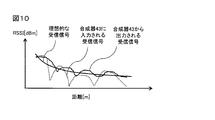
- FIG. 10 is a diagram for explaining the estimation of the distance between the master device 1 and the slave device 2 of FIG.
- the signal level of the signal wirelessly received by the master device 1 from the slave device 2 generally decreases as the distance between the master device 1 and the slave device 2 increases, and increases as the distance decreases. Therefore, the distance between the master device 1 and the slave device 2 can be estimated by measuring the signal level (for example, RSSI) of the signal wirelessly received from the slave device 2 using the signal level monitor 17.
- the signal levels of the individual received signals arriving at the antenna elements 52-1 to 52-4 and before being input to the synthesizer 43 are affected by multipath and are ideal. There is a possibility of a large deviation from the signal level in the case of the above.
- the influence of multipath can be reduced and the received signals can be brought closer to the ideal received signals. Therefore, by estimating the distance between the master device 1 and the slave device 2 based on the signal level of the received signal output from the synthesizer 43, it is estimated based on the signal level of the received signal input to the synthesizer 43. The distance can be estimated with a smaller error than when
- the antenna device ANT1 and the antenna control circuit 16 are pre-calibrated so that the direction of the slave device 2 as seen from the master device 1 can be estimated. Further, the signal level monitor 17 is pre-calibrated so that the distance between the master device 1 and the slave device 2 can be estimated.
- the relative position of the slave device 2 as seen from the master device 1 can be estimated by the method described with reference to FIGS. 9 and 10. If the absolute position of the master device 1 is known, the absolute position of the slave device 2 can be estimated.
- step S9 the master control circuit 10 determines whether or not the charge rate of the rechargeable battery 21 is equal to or higher than a predetermined threshold value, and if YES, proceeds to step S12. If NO, the process proceeds to step S10.
- the charge rate threshold value is insufficient for the sensor 23 to operate, but the rechargeable battery has sufficient power for the slave control circuit 20 and the signal transmission circuit 24 of the slave device 2 to operate. 21 is set so that it can be supplied.
- step S9 When step S9 is NO, the sensor 23 cannot operate correctly due to insufficient charging rate, so that the correct measured value of the sensor 23 cannot be obtained. Therefore, in step S10, the master control circuit 10 generates a dummy measurement value of the sensor 23. In step S11, the master control circuit 10 sets an error code indicating an error in the charging rate.
- step S12 the master control circuit 10 acquires the measured value of the sensor 23 from the response signal.
- step S13 the master control circuit 10 determines whether or not the measured value of the sensor 23 is invariant over a predetermined time period, and if YES, proceeds to step S14, and if NO, proceeds to step S15. ..
- the time period of step S13 may be set to a predetermined time length, or may be set as the number of iterations of the master control process.
- step S14 the master control circuit 10 sets an error code indicating an error of the sensor 23.
- step S15 the master control circuit 10 generates an error code (that is, no error) indicating that the communication, the charge rate, and the sensor 23 are normal.
- an error code that is, no error
- step S16 the master control circuit 10 transmits the position of the slave device 2, the measured value of the sensor 23, and the error code to the control device 3. After that, the process returns to step S1.
- FIG. 8 is a flowchart showing a system control process executed by the system control circuit 30 of FIG.
- step S31 the system control circuit 30 transmits a read request signal to the master device 1.
- step S32 the system control circuit 30 receives the position of the slave device 2, the measured value of the sensor 23, and the error code from the master device 1.
- step S33 the system control circuit 30 determines whether or not an error code indicating a communication error has been received, and if YES, proceeds to step S34, and if NO, proceeds to step S35.
- step S34 the system control circuit 30 displays the position of the slave device 2 on the display device 32 together with an error message indicating a communication error.
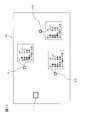
- FIG. 11 is a diagram showing an exemplary arrangement of the master device 1 and the slave devices 2-1 to 2-3 displayed on the display device 32 of FIG. 1, and is a diagram showing all the slave devices 2-1 to 2-3. It is a figure which shows the case which is normal.
- the identifier (ID) the position, the measured value (for example, temperature) of the sensor 23, the communication state, and the charging rate state are associated with each of the slave devices 2-1 to 2-3.
- the operating status of the sensor 23 are displayed.
- the system control circuit 30 may display a map of the location where the wireless communication system is arranged, and may superimpose the position of the master device 1 and the estimated position of the slave device 2 on the map.
- the system control circuit 30 may store the absolute position of the master device 1 in advance. In this case, the absolute position of the slave device 2 is based on the absolute position of the master device 1 and the estimated relative position of the slave device 2. The position can be estimated.
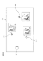
- FIG. 12 is a diagram showing an exemplary arrangement of the master device 1 and the slave devices 2-1 to 2-3 displayed on the display device 32 of FIG. 1, and is a diagram showing communication between the master device 1 and the slave devices 2-3. It is a figure which shows the case where an error occurs in. Due to the interruption of communication, the current position of the slave device 2, the measured value of the sensor 23, the charge rate of the rechargeable battery 21, and the operating state of the sensor 23 are unknown.
- the display device 32 displays the latest position (x3', y3') of the slave device 2 read from the storage device 12 of the master device 1.
- step S35 the system control circuit 30 determines whether or not an error code indicating an error in the charge rate has been received, and if YES, the process proceeds to step S36, and if NO, step S37. Proceed to.
- step S36 the system control circuit 30 displays the position of the slave device 2 on the display device 32 together with an error message indicating an error in the charge rate.
- FIG. 13 is a diagram showing an exemplary arrangement of the master device 1 and the slave devices 2-1 to 2-3 displayed on the display device 32 of FIG. 1, from the master device 1 to the slave device 2-3. It is a figure which shows the case where an error occurs in power transmission.
- the charge rate of the rechargeable battery 21 of the slave device 2-3 is insufficient due to a power transmission error.
- the display device 32 displays a dummy measurement value of the sensor 23 of the slave device 2-3.
- step S37 the system control circuit 30 determines whether or not an error code indicating an error of the sensor 23 has been received. If YES, the process proceeds to step S38, and if NO, step S39. Proceed to.
- step S38 the system control circuit 30 displays the position of the slave device 2 and the measured value of the sensor 23 on the display device 32 together with an error message indicating an error of the sensor 23.
- step S39 the system control circuit 30 displays the position of the slave device 2 and the measured value of the sensor 23 on the display device 32.
- FIG. 14 is a diagram showing an exemplary arrangement of the master device 1 and the slave devices 2-1 to 2-3 displayed on the display device 32 of FIG. 1, and shows the operation of the sensor 23 of the slave devices 2-3. It is a figure which shows the case where an error occurs. Although the sensor 23 of the slave device 2-3 has a malfunction, the current measured value is considered to be equal to the correct measured value obtained immediately before the malfunction occurs in the sensor 23. Therefore, the display device 32 displays the measured value of the sensor 23 of the slave device 2-3.
- the system control circuit 30 may control the operation of the manufacturing apparatus 4 under the control of the user, or may periodically repeat the processing of FIG.
- the charge rate of the rechargeable battery 21 is smaller than a predetermined threshold value, the charge rate of the rechargeable battery 21 is insufficient in the master control circuit 10.
- An error message indicating the presence is displayed on the display device 32.
- the master control circuit 10 displays an error message indicating that a malfunction has occurred in the sensor 23 on the display device 32 when the measured value of the sensor 23 is unchanged over a predetermined time period.
- the sensor 23 cannot acquire the measured value due to another failure (insufficient charge rate or malfunction of the sensor 23). You can see that. Even if the measured value of the sensor 23 is unknown, the position of the slave device 2 can be estimated based on the signal received by the master device 1 from the slave device 2.
- the state and position of the slave device 2 can be appropriately monitored to reduce the burden of maintenance and repair.
- the status and position of each slave device 2 can be associated and displayed on the display device 32, so that the time and labor required for maintenance and repair of the wireless communication system can be reduced. , It is possible to reduce the time and labor required for setup change of the manufacturing apparatus 4 and the like.
- maintenance and repair of the wireless communication system and the manufacturing device 4 and the like are automated by using a robot or the like that operates based on the state and position of each monitored slave device 2. You may.
- the received signals arriving at each antenna element of the array antenna are synthesized, and between the master device 1 and the slave device 2 based on the signal level of the synthesized received signal. Since the distance is estimated, the influence of multipath can be reduced and the distance can be estimated with a small error.
- the function of detecting the position of the slave device can be integrated with the system that wirelessly transmits power from the master device to the slave device.
- FIG. 15 is a block diagram showing a manufacturing system including the wireless communication system according to the second embodiment.
- the system of FIG. 15 includes a master device 1A instead of the master device 1 and the manufacturing device 4 of FIG.
- the master device 1A of FIG. 15 has the functions of the master device 1 and the manufacturing device 4 of FIG. 1, and includes, for example, the display device 32 of FIG. 5 and other components.
- the display device 32 may be provided integrally with the master device 1A, or may be connected to the outside of the master device 1A.
- Each slave device 2 may be fixed to equipment such as a factory. Further, each slave device 2 may be a mobile body worn on the robot or the user's body.
- the control device 3 may control a plurality of master devices 1.
- the signal level monitor 17 of FIG. 2 may be integrated with the signal receiving circuit 18, and in this case, the signal receiving circuit 18 may measure the signal level of the received signal.
- the charge rate of the rechargeable battery 21 may be compared with the threshold value by the master device 1 or with the threshold value by the slave device 2. In the latter case, the slave device 2 transmits the comparison result of the charge rate to the master device 1.
- step S13 of FIG. 6 the master control circuit 10 determines, for example, the measured value of the sensor 23 in advance, instead of determining whether or not the measured value of the sensor 23 is unchanged over a predetermined time period. It may be determined whether or not it is outside the specified range.
- the wireless communication device operates as a master device 1 for a wireless communication system including a master device 1 and at least one slave device 2.
- the slave device 2 includes a sensor 23 that acquires a measured value of a predetermined physical quantity, and wirelessly transmits the measured value of the sensor 23 to the master device 1.
- the master device 1 is a signal receiving circuit 18 that wirelessly receives the measured value of the sensor 23 from the slave device 2, a position estimator that estimates the position of the slave device 2, and a storage device 12 that stores the history of the position of the slave device 2.
- a master control circuit 10 that displays the measured value of the sensor 23 and the position of the slave device 2 on the display device 32.
- the master control circuit 10 is stored in the storage device 12 together with an error message indicating that the communication between the master device 1 and the slave device 2 is interrupted when the measured value of the sensor 23 cannot be received from the slave device 2. The latest position is displayed on the display device 32.
- the storage device 12 stores the history of the measured values of the sensor 23.
- the master control circuit 10 displays an error message on the display device 32 indicating that the sensor 23 has malfunctioned when the measured value of the sensor 23 is unchanged over a predetermined time period.
- the master device 1 further includes a power transmission circuit 14 for wirelessly transmitting electric power to the slave device 2. ..
- the slave device 2 includes a rechargeable battery 21 that stores electric power wirelessly transmitted from the master device 1, measures the charge rate of the rechargeable battery 21, and wirelessly transmits the charge rate to the master device 1.
- the signal receiving circuit 18 wirelessly receives the charge rate of the rechargeable battery 21 from the slave device 2.
- the master control circuit 10 displays an error message indicating that the charge rate of the rechargeable battery 21 is insufficient on the display device 32.
- the wireless communication device operates as a master device 1 for a wireless communication system including a master device 1 and at least one slave device 2.
- the slave device 2 includes a rechargeable battery 21 that stores electric power wirelessly transmitted from the master device 1, measures the charge rate of the rechargeable battery 21, and wirelessly transmits the charge rate to the master device 1.
- the slave device 2 includes a sensor 23 that acquires a measured value of a predetermined physical quantity, and wirelessly transmits the measured value of the sensor 23 to the master device 1.
- the master device 1 is a transmission circuit 14 that wirelessly transmits power to the slave device 2, a signal receiving circuit 18 that wirelessly receives the charge rate of the rechargeable battery 21 and the measured value of the sensor 23 from the slave device 2, and the position of the slave device 2.
- a position estimator for estimating the above a storage device 12 for storing the history of the measured values of the sensor 23, and a master control circuit 10 for displaying the measured values of the sensor 23 and the position of the slave device 2 on the display device 32.
- the master control circuit 10 displays an error message indicating that the charge rate of the rechargeable battery 21 is insufficient on the display device 32.
- the master control circuit 10 displays an error message on the display device 32 indicating that the sensor 23 has malfunctioned when the measured value of the sensor 23 is unchanged over a predetermined time period.
- the position estimator includes an antenna device ANT1 having variable directivity.
- a signal level monitor 17 for measuring the signal level of the signal wirelessly received from the slave device 2 is provided.
- the wireless communication system includes a wireless communication device according to one aspect of the first to fifth aspects and at least one slave device 2.
- the wireless communication system further includes a control device 3 provided with a display device 32.
- the master device 1 is communicably connected to the control device 3.
- the wireless communication system according to the aspect of the present disclosure can be used, for example, in a sensor network including a plurality of sensors.
Abstract
A wireless communication device is provided with: a signal reception circuit that wirelessly receives a measurement value of a sensor from a slave device; a position estimator that estimates a position of the slave device; a storage device that stores a history of the position of the slave device; and a master control circuit that displays the measurement value of the sensor and the position of the slave device on the display device. The master control circuit displays, when the measurement value of the sensor becomes impossible to be received from the slave device, the latest position stored in the storage device on the display device with an error message indicating that the communication between the wireless communication device and the slave device is interrupted.
Description
本開示は、マスタ装置及び少なくとも1つのスレーブ装置を含む無線通信システムのためのマスタ装置として動作する無線通信装置に関し、また、そのような無線通信装置を含む無線通信システムに関する。
The present disclosure relates to a wireless communication device that operates as a master device for a wireless communication system including a master device and at least one slave device, and also relates to a wireless communication system including such a wireless communication device.
センサをそれぞれ備える複数のスレーブ装置と、これらのスレーブ装置と無線通信可能に接続されたマスタ装置とを含む無線通信システムを用いて、さまざまな位置に配置された複数のセンサを含むセンサネットワークが構築されることがある。各センサは予め決められた物理量の測定値を取得し、マスタ装置は各スレーブ装置からセンサの測定値を読み出す。
A sensor network including a plurality of sensors arranged at various positions is constructed by using a wireless communication system including a plurality of slave devices each having a sensor and a master device connected to these slave devices in a wireless communication manner. May be done. Each sensor acquires a predetermined physical quantity measurement value, and the master device reads the sensor measurement value from each slave device.
例えば特許文献1は、複数台のノード装置とそれらのノード装置の各々に無線通信または有線通信を介して接続されるセンサ装置とを含むネットワークシステムおよびセンサデータ送受信方法を開示している。
For example, Patent Document 1 discloses a network system including a plurality of node devices and a sensor device connected to each of the node devices via wireless communication or wired communication, and a sensor data transmission / reception method.
このような無線通信システムにおいて、何らかの障害に起因して、マスタ装置があるセンサの測定値を取得できなくなることがある。このような事象は、センサの故障に起因して生じる可能性があり、また、マスタ装置及びスレーブ装置の間の通信の中断に起因して生じる可能性もある。従って、修理すべき対象を特定するために、時間及び手間がかかる。また、スレーブ装置の位置は必ずしも既知ではない。この場合、修理すべきスレーブ装置(センサ)の位置を特定するために、時間及び手間がかかる。従って、スレーブ装置の状態及び位置を適切にモニタリングして保守及び修理の負担を軽減することが求められる。
In such a wireless communication system, the master device may not be able to acquire the measured value of a certain sensor due to some kind of failure. Such an event can be caused by a sensor failure, or can be caused by an interruption in communication between the master and slave devices. Therefore, it takes time and effort to identify the object to be repaired. Also, the position of the slave device is not always known. In this case, it takes time and effort to specify the position of the slave device (sensor) to be repaired. Therefore, it is required to appropriately monitor the state and position of the slave device to reduce the burden of maintenance and repair.
本開示の目的は、スレーブ装置の状態及び位置を適切にモニタリングして保守及び修理の負担を軽減することができる無線通信装置を提供することにある。また、本開示の目的は、そのような無線通信装置を含む無線通信システムを提供することにある。
An object of the present disclosure is to provide a wireless communication device capable of appropriately monitoring the state and position of a slave device and reducing the burden of maintenance and repair. An object of the present disclosure is to provide a wireless communication system including such a wireless communication device.
本開示の側面に係る無線通信装置によれば、
マスタ装置及び少なくとも1つのスレーブ装置を含む無線通信システムのためのマスタ装置として動作する無線通信装置であって、
前記スレーブ装置は、予め決められた物理量の測定値を取得するセンサを備え、前記センサの測定値を無線通信装置に無線送信し、
前記無線通信装置は、
前記スレーブ装置から前記センサの測定値を無線受信する信号受信回路と、
前記スレーブ装置の位置を推定する位置推定器と、
前記スレーブ装置の位置の履歴を記憶する記憶装置と、
前記センサの測定値及び前記スレーブ装置の位置を表示装置に表示するマスタ制御回路とを備え、
前記マスタ制御回路は、前記スレーブ装置から前記センサの測定値を受信できなくなったとき、前記無線通信装置及び前記スレーブ装置の間の通信が中断されたことを示すエラーメッセージとともに、前記記憶装置に記憶された最新の位置を前記表示装置に表示する。 According to the wireless communication device according to the aspect of the present disclosure.
A wireless communication device that operates as a master device for a wireless communication system that includes a master device and at least one slave device.
The slave device includes a sensor that acquires a measured value of a predetermined physical quantity, and wirelessly transmits the measured value of the sensor to a wireless communication device.
The wireless communication device is
A signal receiving circuit that wirelessly receives the measured value of the sensor from the slave device,
A position estimator that estimates the position of the slave device and
A storage device that stores the history of the position of the slave device, and
It is provided with a master control circuit that displays the measured value of the sensor and the position of the slave device on the display device.
When the master control circuit cannot receive the measured value of the sensor from the slave device, the master control circuit stores it in the storage device together with an error message indicating that the communication between the wireless communication device and the slave device is interrupted. The latest position is displayed on the display device.
この構成を備えたことにより、通信の中断によりスレーブ装置の現在の位置が不明であっても、スレーブ装置が存在していると考えられる位置をユーザに提示することができる。従って、スレーブ装置の状態及び位置を適切にモニタリングして保守及び修理の負担を軽減することができる。
With this configuration, even if the current position of the slave device is unknown due to communication interruption, it is possible to present the position where the slave device is considered to exist to the user. Therefore, the state and position of the slave device can be appropriately monitored to reduce the burden of maintenance and repair.
本開示の側面に係る無線通信装置によれば、
前記記憶装置は、前記センサの測定値の履歴を記憶し、
前記マスタ制御回路は、前記センサの測定値が予め決められた時間期間にわたって不変であるとき、前記センサの動作不良が生じたことを示すエラーメッセージを前記表示装置に表示する。 According to the wireless communication device according to the aspect of the present disclosure.
The storage device stores a history of measured values of the sensor.
The master control circuit displays an error message indicating that a malfunction of the sensor has occurred on the display device when the measured value of the sensor is unchanged over a predetermined time period.
この構成を備えたことにより、マスタ装置及びスレーブ装置の通信が可能であるものの、センサの動作不良に起因して、センサが測定値を取得できなくなっていることがわかる。
It can be seen that although the master device and the slave device can communicate with each other by providing this configuration, the sensor cannot acquire the measured value due to the malfunction of the sensor.
本開示の側面に係る無線通信装置によれば、
前記無線通信装置は、前記スレーブ装置に電力を無線伝送する送電回路をさらに備え、
前記スレーブ装置は、前記無線通信装置から無線伝送された電力を蓄える充電池を備え、前記充電池の充電率を測定して前記無線通信装置に無線送信し、
前記信号受信回路は、前記スレーブ装置から前記充電池の充電率を無線受信し、
前記マスタ制御回路は、前記充電池の充電率が予め決められたしきい値より小さいとき、前記充電池の充電率が不足していることを示すエラーメッセージを前記表示装置に表示する。 According to the wireless communication device according to the aspect of the present disclosure.
The wireless communication device further includes a power transmission circuit that wirelessly transmits power to the slave device.
The slave device includes a rechargeable battery that stores electric power wirelessly transmitted from the wireless communication device, measures the charge rate of the rechargeable battery, and wirelessly transmits the charge rate to the wireless communication device.
The signal receiving circuit wirelessly receives the charge rate of the rechargeable battery from the slave device.
When the charge rate of the rechargeable battery is smaller than a predetermined threshold value, the master control circuit displays an error message indicating that the charge rate of the rechargeable battery is insufficient on the display device.
この構成を備えたことにより、マスタ装置及びスレーブ装置の通信が可能であるものの、充電率の不足に起因して、センサが測定値を取得できなくなっていることがわかる。
It can be seen that although the master device and the slave device can communicate with each other by providing this configuration, the sensor cannot acquire the measured value due to the insufficient charge rate.
本開示の側面に係る無線通信装置によれば、
マスタ装置及び少なくとも1つのスレーブ装置を含む無線通信システムのためのマスタ装置として動作する無線通信装置であって、
前記スレーブ装置は、前記無線通信装置から無線伝送された電力を蓄える充電池を備え、前記充電池の充電率を測定して前記無線通信装置に無線送信し、
前記スレーブ装置は、予め決められた物理量の測定値を取得するセンサを備え、前記センサの測定値を無線通信装置に無線送信し、
前記無線通信装置は、
前記スレーブ装置に電力を無線伝送する送電回路と、
前記スレーブ装置から前記充電池の充電率及び前記センサの測定値を無線受信する信号受信回路と、
前記スレーブ装置の位置を推定する位置推定器と、
前記センサの測定値の履歴を記憶する記憶装置と、
前記センサの測定値及び前記スレーブ装置の位置を表示装置に表示するマスタ制御回路とを備え、
前記マスタ制御回路は、前記充電池の充電率が予め決められたしきい値より小さいとき、前記充電池の充電率が不足していることを示すエラーメッセージを前記表示装置に表示し、
前記マスタ制御回路は、前記センサの測定値が予め決められた時間期間にわたって不変であるとき、前記センサの動作不良が生じたことを示すエラーメッセージを前記表示装置に表示する。 According to the wireless communication device according to the aspect of the present disclosure.
A wireless communication device that operates as a master device for a wireless communication system that includes a master device and at least one slave device.
The slave device includes a rechargeable battery that stores electric power wirelessly transmitted from the wireless communication device, measures the charge rate of the rechargeable battery, and wirelessly transmits the charge rate to the wireless communication device.
The slave device includes a sensor that acquires a measured value of a predetermined physical quantity, and wirelessly transmits the measured value of the sensor to a wireless communication device.
The wireless communication device is
A power transmission circuit that wirelessly transmits power to the slave device,
A signal receiving circuit that wirelessly receives the charge rate of the rechargeable battery and the measured value of the sensor from the slave device.
A position estimator that estimates the position of the slave device and
A storage device that stores the history of measured values of the sensor,
It is provided with a master control circuit that displays the measured value of the sensor and the position of the slave device on the display device.
When the charge rate of the rechargeable battery is smaller than a predetermined threshold value, the master control circuit displays an error message indicating that the charge rate of the rechargeable battery is insufficient on the display device.
The master control circuit displays an error message indicating that a malfunction of the sensor has occurred on the display device when the measured value of the sensor is unchanged over a predetermined time period.
この構成を備えたことにより、マスタ装置及びスレーブ装置の通信が可能であるものの、他の障害(充電率の不足、又はセンサの動作不良)に起因して、センサが測定値を取得できなくなっていることがわかる。従って、スレーブ装置の状態及び位置を適切にモニタリングして保守及び修理の負担を軽減することができる。
With this configuration, communication between the master device and the slave device is possible, but the sensor cannot acquire the measured value due to other failures (insufficient charging rate or malfunction of the sensor). You can see that there is. Therefore, the state and position of the slave device can be appropriately monitored to reduce the burden of maintenance and repair.
本開示の側面に係る無線通信装置によれば、
前記位置推定器は、
可変な指向性を有するアンテナ装置と、
前記スレーブ装置から無線受信された信号の信号レベルを測定する信号レベルモニタとを備える。 According to the wireless communication device according to the aspect of the present disclosure.
The position estimator is
An antenna device with variable directivity and
It includes a signal level monitor that measures the signal level of the signal wirelessly received from the slave device.
この構成を備えたことにより、マスタ装置から見たスレーブ装置の方向を推定し、マスタ装置及びスレーブ装置の間の距離を推定することができる。
With this configuration, the direction of the slave device as seen from the master device can be estimated, and the distance between the master device and the slave device can be estimated.
本開示の側面に係る無線通信システムによれば、
請求項1~5のうちの1つに記載の無線通信装置と、
少なくとも1つのスレーブ装置とを含む。 According to the wireless communication system according to the aspect of the present disclosure.
The wireless communication device according to one ofclaims 1 to 5,
Includes at least one slave device.
請求項1~5のうちの1つに記載の無線通信装置と、
少なくとも1つのスレーブ装置とを含む。 According to the wireless communication system according to the aspect of the present disclosure.
The wireless communication device according to one of
Includes at least one slave device.
この構成を備えたことにより、スレーブ装置の状態及び位置を適切にモニタリングして保守及び修理の負担を軽減することができる。
By providing this configuration, it is possible to appropriately monitor the state and position of the slave device and reduce the burden of maintenance and repair.
本開示の側面に係る無線通信システムによれば、
前記無線通信システムは、表示装置を備えた制御装置をさらに含み、
前記無線通信装置は前記制御装置に通信可能に接続される。 According to the wireless communication system according to the aspect of the present disclosure.
The wireless communication system further includes a control device including a display device.
The wireless communication device is communicably connected to the control device.
この構成を備えたことにより、スレーブ装置の状態及び位置を対応づけて表示することができる。
With this configuration, the status and position of the slave device can be displayed in association with each other.
本開示の側面に係る無線通信装置及び無線通信システムによれば、スレーブ装置の状態及び位置を適切にモニタリングして保守及び修理の負担を軽減することができる。
According to the wireless communication device and the wireless communication system according to the aspect of the present disclosure, the state and position of the slave device can be appropriately monitored to reduce the burden of maintenance and repair.
以下、本開示の一側面に係る実施形態(以下、「本実施形態」とも表記する)を、図面に基づいて説明する。各図面において、同じ符号は同様の構成要素を示す。
Hereinafter, an embodiment according to one aspect of the present disclosure (hereinafter, also referred to as “the present embodiment”) will be described with reference to the drawings. In each drawing, the same reference numerals indicate similar components.
[適用例]
図1は、第1の実施形態に係る無線通信システムを含む製造システムを示すブロック図である。図1の無線通信システムは、マスタ装置1と、少なくとも1つのスレーブ装置、図1の例では3つのスレーブ装置2-1~2-3とを含む。 [Application example]
FIG. 1 is a block diagram showing a manufacturing system including a wireless communication system according to the first embodiment. The wireless communication system of FIG. 1 includes amaster device 1 and at least one slave device, and in the example of FIG. 1, three slave devices 2-1 to 2-3.
図1は、第1の実施形態に係る無線通信システムを含む製造システムを示すブロック図である。図1の無線通信システムは、マスタ装置1と、少なくとも1つのスレーブ装置、図1の例では3つのスレーブ装置2-1~2-3とを含む。 [Application example]
FIG. 1 is a block diagram showing a manufacturing system including a wireless communication system according to the first embodiment. The wireless communication system of FIG. 1 includes a
本明細書では、スレーブ装置2-1~2-3を総称して「スレーブ装置2」という。
In this specification, slave devices 2-1 to 2-3 are collectively referred to as "slave device 2".
各スレーブ装置2は、後述するように、予め決められた物理量の測定値を取得するセンサ23を備え、センサ23の測定値をマスタ装置1に無線送信する。
As will be described later, each slave device 2 includes a sensor 23 that acquires a predetermined measured value of a physical quantity, and wirelessly transmits the measured value of the sensor 23 to the master device 1.
図2は、図1のマスタ装置1の構成を示すブロック図である。マスタ装置1は、少なくとも、マスタ制御回路10、記憶装置12、信号レベルモニタ17、信号受信回路18、及びアンテナ装置ANT1を備える。信号受信回路18は、アンテナ装置ANT1を介して、スレーブ装置2からセンサ23の測定値を無線受信する。アンテナ装置ANT1及び信号レベルモニタ17は、スレーブ装置2から受信した信号に基づいて、スレーブ装置2の位置を推定する位置推定器として機能する。記憶装置12は、アンテナ装置ANT1及び信号レベルモニタ17を用いて推定されたスレーブ装置2の位置の履歴を記憶する。マスタ制御回路10は、センサ23の測定値及びスレーブ装置2の位置を表示装置32に表示する。表示装置32は、例えば、図1に示すように、マスタ装置1の外部の制御装置3に設けられてもよい。
FIG. 2 is a block diagram showing the configuration of the master device 1 of FIG. The master device 1 includes at least a master control circuit 10, a storage device 12, a signal level monitor 17, a signal receiving circuit 18, and an antenna device ANT1. The signal receiving circuit 18 wirelessly receives the measured value of the sensor 23 from the slave device 2 via the antenna device ANT1. The antenna device ANT1 and the signal level monitor 17 function as a position estimator that estimates the position of the slave device 2 based on the signal received from the slave device 2. The storage device 12 stores the history of the position of the slave device 2 estimated by using the antenna device ANT1 and the signal level monitor 17. The master control circuit 10 displays the measured value of the sensor 23 and the position of the slave device 2 on the display device 32. The display device 32 may be provided in the control device 3 outside the master device 1, for example, as shown in FIG.
図4は、図1のスレーブ装置2の構成を示すブロック図である。スレーブ装置2は、少なくとも、センサ23、信号送信回路24、及びアンテナ装置ANT2を備える。センサ23は、前述のように、予め決められた物理量の測定値を取得する。信号送信回路24は、アンテナ装置ANT2を介して、センサ23の測定値をマスタ装置1に無線送信する。
FIG. 4 is a block diagram showing the configuration of the slave device 2 of FIG. The slave device 2 includes at least a sensor 23, a signal transmission circuit 24, and an antenna device ANT2. As described above, the sensor 23 acquires a predetermined measured value of the physical quantity. The signal transmission circuit 24 wirelessly transmits the measured value of the sensor 23 to the master device 1 via the antenna device ANT2.
マスタ制御回路10は、スレーブ装置2からセンサ23の測定値を受信できなくなったとき、マスタ装置1及びスレーブ装置2の間の通信が中断されたことを示すエラーメッセージとともに、記憶装置12に記憶された最新の位置を表示装置32に表示する。これにより、通信の中断によりスレーブ装置2の現在の位置が不明であっても、スレーブ装置2が存在していると考えられる位置をユーザに提示することができる。従って、スレーブ装置2の状態及び位置を適切にモニタリングして保守及び修理の負担を軽減することができる。
The master control circuit 10 is stored in the storage device 12 together with an error message indicating that the communication between the master device 1 and the slave device 2 is interrupted when the measured value of the sensor 23 cannot be received from the slave device 2. The latest position is displayed on the display device 32. As a result, even if the current position of the slave device 2 is unknown due to the interruption of communication, the position where the slave device 2 is considered to exist can be presented to the user. Therefore, the state and position of the slave device 2 can be appropriately monitored to reduce the burden of maintenance and repair.
追加又は代替として、マスタ装置1及びスレーブ装置2は、以下のように構成されて動作してもよい。
As an addition or alternative, the master device 1 and the slave device 2 may be configured and operated as follows.
マスタ装置1は、追加として、図2に示すように送電回路14を備えてもよい。送電回路14は、アンテナ装置ANT1を介して、スレーブ装置2に電力を無線伝送する。
The master device 1 may additionally include a power transmission circuit 14 as shown in FIG. The power transmission circuit 14 wirelessly transmits electric power to the slave device 2 via the antenna device ANT1.
スレーブ装置2は、追加として、図4に示すように、受電回路25、充電池21、及び充電率モニタ22を備えてもよい。受電回路25は、アンテナ装置ANT2を介して、マスタ装置1から無線伝送された電力を取得する。充電池21は、マスタ装置1から無線伝送された電力を蓄える。充電率モニタ22は、充電池21の充電率を測定する。また、スレーブ装置2の信号送信回路24は、アンテナ装置ANT2を介して、センサ23の測定値に加えて、充電池21の充電率をマスタ装置1に無線送信する。
The slave device 2 may additionally include a power receiving circuit 25, a rechargeable battery 21, and a charge rate monitor 22, as shown in FIG. The power receiving circuit 25 acquires the power wirelessly transmitted from the master device 1 via the antenna device ANT2. The rechargeable battery 21 stores the electric power wirelessly transmitted from the master device 1. The charge rate monitor 22 measures the charge rate of the rechargeable battery 21. Further, the signal transmission circuit 24 of the slave device 2 wirelessly transmits the charge rate of the rechargeable battery 21 to the master device 1 in addition to the measured value of the sensor 23 via the antenna device ANT2.
マスタ装置1の信号受信回路18は、アンテナ装置ANT1を介して、スレーブ装置2から、センサ23の測定値に加えて、充電池21の充電率を無線受信する。記憶装置12は、スレーブ装置2の位置の履歴に加えて、又はそれに代えて、センサ23の測定値の履歴を記憶する。
The signal receiving circuit 18 of the master device 1 wirelessly receives the charge rate of the rechargeable battery 21 from the slave device 2 via the antenna device ANT1 in addition to the measured value of the sensor 23. The storage device 12 stores the history of the measured values of the sensor 23 in addition to or instead of the history of the position of the slave device 2.
マスタ制御回路10は、前述のように、通信が中断されたことを示すエラーメッセージと、記憶された最新の位置とを表示装置32に表示することに加えて、又はそれに代えて、以下のように動作してもよい。マスタ制御回路10は、充電池21の充電率が予め決められたしきい値より小さいとき、充電池21の充電率が不足していることを示すエラーメッセージを表示装置32に表示する。ここで、充電率のしきい値は、センサ23が動作するには不十分であるが、スレーブ装置2のスレーブ制御回路20及び信号送信回路24が動作するには十分な電力を充電池21が供給可能であるように設定される。充電率の不足は、例えば、マスタ装置1からスレーブ装置2への電力の無線伝送が中断されたとき、又は、充電池21及び/又は受電回路25が故障したときに生じる可能性がある。また、マスタ制御回路10は、センサ23の測定値が予め決められた時間期間にわたって不変であるとき、センサ23の動作不良が生じたことを示すエラーメッセージを表示装置32に表示する。センサ23の動作不良は、例えば、センサ23が故障したとき、又は、センサ23が正しく設置されていないとき(すなわち、測定すべき対象物を測定できない位置又は姿勢でセンサが設置されているとき)に生じる可能性がある。これにより、マスタ装置1及びスレーブ装置2の通信が可能であるものの、他の障害(充電率の不足、又はセンサ23の動作不良)に起因して、センサ23が測定値を取得できなくなっていることがわかる。センサ23の測定値が不明であっても、マスタ装置1がスレーブ装置2から受信した信号に基づいて、スレーブ装置2の位置を推定することができる。従って、スレーブ装置2の状態及び位置を適切にモニタリングして保守及び修理の負担を軽減することができる。
As described above, the master control circuit 10 displays the error message indicating that the communication has been interrupted and the latest stored position on the display device 32, or instead, as follows. May work with. When the charge rate of the rechargeable battery 21 is smaller than a predetermined threshold value, the master control circuit 10 displays an error message indicating that the charge rate of the rechargeable battery 21 is insufficient on the display device 32. Here, the threshold value of the charge rate is insufficient for the sensor 23 to operate, but the rechargeable battery 21 has sufficient power for the slave control circuit 20 and the signal transmission circuit 24 of the slave device 2 to operate. Set to be available for supply. The insufficient charge rate may occur, for example, when the wireless transmission of power from the master device 1 to the slave device 2 is interrupted, or when the rechargeable battery 21 and / or the power receiving circuit 25 fails. Further, the master control circuit 10 displays an error message indicating that a malfunction of the sensor 23 has occurred on the display device 32 when the measured value of the sensor 23 is unchanged over a predetermined time period. The malfunction of the sensor 23 is, for example, when the sensor 23 fails or when the sensor 23 is not installed correctly (that is, when the sensor is installed at a position or posture where the object to be measured cannot be measured). Can occur in. As a result, although communication between the master device 1 and the slave device 2 is possible, the sensor 23 cannot acquire the measured value due to another failure (insufficient charge rate or malfunction of the sensor 23). You can see that. Even if the measured value of the sensor 23 is unknown, the position of the slave device 2 can be estimated based on the signal received by the master device 1 from the slave device 2. Therefore, the state and position of the slave device 2 can be appropriately monitored to reduce the burden of maintenance and repair.
このように、実施形態に係る無線通信システムによれば、スレーブ装置2の状態及び位置を適切にモニタリングして保守及び修理の負担を軽減することができる。
As described above, according to the wireless communication system according to the embodiment, the state and position of the slave device 2 can be appropriately monitored to reduce the burden of maintenance and repair.
[第1の実施形態]
[第1の実施形態の構成例]
図1の例では、マスタ装置1及びスレーブ装置2-1~2-3は、制御装置3、製造装置4、及びベルトコンベア5を備えた工場に設けられる。ベルトコンベア5は、パレット6及びワーク7を搬送する。パレット6及びワーク7は、ベルトコンベア5によって、予め決められた時間において予め決められた位置に到着しているように移動される。予め決められた位置において、ワーク7に対して予め決められた作業のイベントがそれぞれ実行される。スレーブ装置2-1~2-3は、予め決められた位置の近傍にそれぞれ設けられ、予め決められた位置において実行されるイベントにそれぞれ関連付けられる。各スレーブ装置2-1~2-3のセンサ23は、これらのイベントに関連付けられた予め決められた物理量を測定する。マスタ装置1は、測定された物理量を各スレーブ装置2-1~2-3から収集し、制御装置3に送る。制御装置3は、測定された物理量に基づいて製造装置4の動作を制御する。制御装置3は、例えば、プログラマブルロジックコントローラである。製造装置4は、ワーク7に対して予め決められた作業(例えば、溶接などの加工工程)のイベントを実行する。 [First Embodiment]
[Structure example of the first embodiment]
In the example of FIG. 1, themaster device 1 and the slave devices 2-1 to 2-3 are provided in a factory equipped with a control device 3, a manufacturing device 4, and a belt conveyor 5. The belt conveyor 5 conveys the pallet 6 and the work 7. The pallet 6 and the work 7 are moved by the belt conveyor 5 so as to arrive at a predetermined position at a predetermined time. At a predetermined position, a predetermined work event is executed for the work 7. The slave devices 2-1 to 2-3 are provided in the vicinity of the predetermined positions, and are associated with the events executed at the predetermined positions. Sensors 23 of each slave device 2-1 to 2-3 measure a predetermined physical quantity associated with these events. The master device 1 collects the measured physical quantity from each of the slave devices 2-1 to 2-3 and sends it to the control device 3. The control device 3 controls the operation of the manufacturing device 4 based on the measured physical quantity. The control device 3 is, for example, a programmable logic controller. The manufacturing apparatus 4 executes an event of a predetermined work (for example, a processing process such as welding) on the work 7.
[第1の実施形態の構成例]
図1の例では、マスタ装置1及びスレーブ装置2-1~2-3は、制御装置3、製造装置4、及びベルトコンベア5を備えた工場に設けられる。ベルトコンベア5は、パレット6及びワーク7を搬送する。パレット6及びワーク7は、ベルトコンベア5によって、予め決められた時間において予め決められた位置に到着しているように移動される。予め決められた位置において、ワーク7に対して予め決められた作業のイベントがそれぞれ実行される。スレーブ装置2-1~2-3は、予め決められた位置の近傍にそれぞれ設けられ、予め決められた位置において実行されるイベントにそれぞれ関連付けられる。各スレーブ装置2-1~2-3のセンサ23は、これらのイベントに関連付けられた予め決められた物理量を測定する。マスタ装置1は、測定された物理量を各スレーブ装置2-1~2-3から収集し、制御装置3に送る。制御装置3は、測定された物理量に基づいて製造装置4の動作を制御する。制御装置3は、例えば、プログラマブルロジックコントローラである。製造装置4は、ワーク7に対して予め決められた作業(例えば、溶接などの加工工程)のイベントを実行する。 [First Embodiment]
[Structure example of the first embodiment]
In the example of FIG. 1, the
図2を参照すると、マスタ装置1は、マスタ制御回路10、電源装置11、記憶装置12、通信回路13、送電回路14、信号送信回路15、アンテナ制御回路16、信号レベルモニタ17、信号受信回路18、サーキュレータ回路19、及びアンテナ装置ANT1を備える。
Referring to FIG. 2, the master device 1 includes a master control circuit 10, a power supply device 11, a storage device 12, a communication circuit 13, a power transmission circuit 14, a signal transmission circuit 15, an antenna control circuit 16, a signal level monitor 17, and a signal reception circuit. 18. The circulator circuit 19 and the antenna device ANT1 are provided.
マスタ制御回路10は、マスタ装置1の全体の動作を制御する。
The master control circuit 10 controls the overall operation of the master device 1.
電源装置11は、スレーブ装置2に送電される電力を供給する。
The power supply device 11 supplies the electric power transmitted to the slave device 2.
記憶装置12は、前述のように、センサ23の測定値の履歴及びスレーブ装置2の位置の履歴を記憶する。
As described above, the storage device 12 stores the history of the measured values of the sensor 23 and the history of the position of the slave device 2.
通信回路13は、有線又は無線の通信回線を介して制御装置3に接続される。マスタ制御回路10は、センサ23の測定値、スレーブ装置2の位置、及びエラーメッセージを、通信回路13を介して制御装置3に出力する。
The communication circuit 13 is connected to the control device 3 via a wired or wireless communication line. The master control circuit 10 outputs the measured value of the sensor 23, the position of the slave device 2, and the error message to the control device 3 via the communication circuit 13.
送電回路14は、スレーブ装置2のセンサ23ほかの回路を動作させるための電力を、サーキュレータ回路19及びアンテナ装置ANT1を介してスレーブ装置2に無線伝送する。送電回路14は、例えば、電源装置11によって供給された電力からCW(continuous wave)波を発生する。
The power transmission circuit 14 wirelessly transmits power for operating the sensor 23 and other circuits of the slave device 2 to the slave device 2 via the circulator circuit 19 and the antenna device ANT1. The power transmission circuit 14 generates a CW (continuous wave) wave from, for example, the electric power supplied by the power supply device 11.
信号送信回路15は、センサ23を制御する制御信号(例えば、センサ23の読み出し信号)を、サーキュレータ回路19及びアンテナ装置ANT1を介してスレーブ装置2に無線送信する。
The signal transmission circuit 15 wirelessly transmits a control signal for controlling the sensor 23 (for example, a read signal of the sensor 23) to the slave device 2 via the circulator circuit 19 and the antenna device ANT1.
アンテナ装置ANT1は、可変な指向性を有する。アンテナ制御回路16は、マスタ制御回路10の制御下で、アンテナ装置ANT1の指向性を制御する。
The antenna device ANT1 has a variable directivity. The antenna control circuit 16 controls the directivity of the antenna device ANT1 under the control of the master control circuit 10.
信号レベルモニタ17は、スレーブ装置2から無線受信された信号の信号レベル、例えば受信信号強度(RSSI)を測定する。
The signal level monitor 17 measures the signal level of the signal wirelessly received from the slave device 2, for example, the received signal strength (RSSI).
信号受信回路18は、センサ23の測定値及び充電池21の充電率を含む応答信号を、アンテナ装置ANT1及びサーキュレータ回路19を介してスレーブ装置2から無線受信する。
The signal receiving circuit 18 wirelessly receives a response signal including the measured value of the sensor 23 and the charge rate of the rechargeable battery 21 from the slave device 2 via the antenna device ANT1 and the circulator circuit 19.
サーキュレータ回路19は、アンテナ装置ANT1を介してスレーブ装置2に送られる電力及び信号と、アンテナ装置ANT1を介してスレーブ装置2から受信された信号とを合成及び分離する。
The circulator circuit 19 synthesizes and separates the power and signal sent to the slave device 2 via the antenna device ANT1 and the signal received from the slave device 2 via the antenna device ANT1.
図3は、図2のサーキュレータ回路19及びアンテナ装置ANT1の詳細構成を示すブロック図である。アンテナ装置ANT1は、例えば、複数のアンテナ素子を備えるアレイアンテナであってもよい。
FIG. 3 is a block diagram showing a detailed configuration of the circulator circuit 19 and the antenna device ANT1 of FIG. The antenna device ANT1 may be, for example, an array antenna including a plurality of antenna elements.
サーキュレータ回路19は、分配器41、サーキュレータ42-1~42-4、及び合成器43を備える。分配器41は、送電回路14から送られた電力を、アンテナ素子の個数に合わせて4つに分配する。同様に、分配器41は、信号送信回路15から送られた信号を、アンテナ素子の個数に合わせて4つに分配する。サーキュレータ42-1~42-4は、分配器41によって分配された電力及び信号をアンテナ装置ANT1に送り、かつ、アンテナ装置ANT1から送られた4つの信号を合成器43に送る。合成器43は、アンテナ装置ANT1から送られた4つの信号を合成し、信号レベルモニタ17及び信号受信回路18に送る。
The circulator circuit 19 includes a distributor 41, circulators 42-1 to 42-4, and a synthesizer 43. The distributor 41 distributes the electric power sent from the power transmission circuit 14 into four according to the number of antenna elements. Similarly, the distributor 41 distributes the signal transmitted from the signal transmission circuit 15 into four according to the number of antenna elements. The circulators 42-1 to 42-4 send the electric power and the signal distributed by the distributor 41 to the antenna device ANT1, and also send the four signals sent from the antenna device ANT1 to the synthesizer 43. The synthesizer 43 synthesizes the four signals sent from the antenna device ANT1 and sends them to the signal level monitor 17 and the signal receiving circuit 18.
アンテナ装置ANT1は、位相及び振幅調整器51及びアンテナ素子52-1~52-4を備える。アンテナ素子52-1~52-4は、互いに所定の間隔を有して配列される。位相及び振幅調整器51は、アンテナ制御回路16の制御下で、アンテナ素子52-1~52-4を介して送信される信号及び受信される信号の位相及び振幅を調整し、これにより、アンテナ装置ANT1のビーム及びヌルの方向を制御する。
The antenna device ANT1 includes a phase and amplitude adjuster 51 and antenna elements 52-1 to 52-4. The antenna elements 52-1 to 52-4 are arranged with a predetermined distance from each other. Under the control of the antenna control circuit 16, the phase and amplitude adjuster 51 adjusts the phase and amplitude of the signals transmitted and received via the antenna elements 52-1 to 52-4, whereby the antenna Controls the beam and null directions of the device ANT1.
図4を参照すると、スレーブ装置2は、スレーブ制御回路20、充電池21、充電率モニタ22、センサ23、信号送信回路24、受電回路25、信号受信回路26、サーキュレータ回路27、及びアンテナ装置ANT2を備える。
Referring to FIG. 4, the slave device 2 includes a slave control circuit 20, a rechargeable battery 21, a charge rate monitor 22, a sensor 23, a signal transmission circuit 24, a power receiving circuit 25, a signal receiving circuit 26, a circulator circuit 27, and an antenna device ANT2. To be equipped.
スレーブ制御回路20は、スレーブ装置2の全体の動作を制御する。
The slave control circuit 20 controls the overall operation of the slave device 2.
充電池21は、前述のように、マスタ装置1から無線伝送された電力を蓄える。
As described above, the rechargeable battery 21 stores the electric power wirelessly transmitted from the master device 1.
充電率モニタ22は、前述のように、充電池21の充電率を測定する。充電率モニタ22は、例えば、充電池21の充電電圧に基づいて、充電池21の充電率を測定する。
The charge rate monitor 22 measures the charge rate of the rechargeable battery 21 as described above. The charge rate monitor 22 measures the charge rate of the rechargeable battery 21 based on, for example, the charge voltage of the rechargeable battery 21.
センサ23は、前述のように、予め決められた物理量の測定値を取得する。センサ23は、例えば、温度、光、変位、振動、圧力、流量、傾斜などの物理量のいずれかを測定してもよい。また、センサ23は、予め決められた物理量の測定値を取得することにより、何らかの対象物の状態、例えば、あるスイッチ又は装置のオン/オフを検出してもよい。
As described above, the sensor 23 acquires a predetermined measured value of the physical quantity. The sensor 23 may measure any of physical quantities such as temperature, light, displacement, vibration, pressure, flow rate, and inclination. Further, the sensor 23 may detect the state of some object, for example, on / off of a certain switch or device, by acquiring a measured value of a predetermined physical quantity.
信号送信回路24は、センサ23の測定値及び充電池21の充電率を含む応答信号を、サーキュレータ回路27及びアンテナ装置ANT2を介してマスタ装置1に無線送信する。
The signal transmission circuit 24 wirelessly transmits a response signal including the measured value of the sensor 23 and the charge rate of the rechargeable battery 21 to the master device 1 via the circulator circuit 27 and the antenna device ANT2.
受電回路25は、アンテナ装置ANT2及びサーキュレータ回路27を介して、マスタ装置1から無線伝送された電力を取得する。
The power receiving circuit 25 acquires the power wirelessly transmitted from the master device 1 via the antenna device ANT2 and the circulator circuit 27.
信号受信回路26は、センサ23の読み出し信号などを含む制御信号を、アンテナ装置ANT2及びサーキュレータ回路27を介してマスタ装置1から無線受信する。
The signal receiving circuit 26 wirelessly receives a control signal including a read signal of the sensor 23 from the master device 1 via the antenna device ANT2 and the circulator circuit 27.
アンテナ装置ANT2は、予め決められた指向性又は無指向性を有する。
The antenna device ANT2 has a predetermined directivity or omnidirectionality.
サーキュレータ回路27は、アンテナ装置ANT2を介してマスタ装置1から送られた電力及び信号と、アンテナ装置ANT2を介してマスタ装置1に送られる信号とを合成及び分離する。
The circulator circuit 27 synthesizes and separates the power and the signal sent from the master device 1 via the antenna device ANT2 and the signal sent to the master device 1 via the antenna device ANT2.
図5は、図1の制御装置3の構成を示すブロック図である。制御装置3は、システム制御回路30、通信回路31、及び表示装置32を備える。
FIG. 5 is a block diagram showing the configuration of the control device 3 of FIG. The control device 3 includes a system control circuit 30, a communication circuit 31, and a display device 32.
システム制御回路30は、制御装置3の全体の動作を制御し、また、図1の製造システムの全体の動作を制御する。
The system control circuit 30 controls the overall operation of the control device 3 and also controls the overall operation of the manufacturing system of FIG.
通信回路31は、有線又は無線の通信回線を介してマスタ装置1に接続される。また、通信回路31は、有線又は無線の通信回線を介して製造装置4に接続される。システム制御回路30は、センサ23の測定値の読み出しを要求する読み出し要求信号を、通信回路31を介してマスタ装置1に送信する。また、システム制御回路30は、センサ23の測定値、スレーブ装置2の位置、及びエラーメッセージを、通信回路31を介してマスタ装置1から受信する。また、システム制御回路30は、製造装置4の動作を制御する制御信号を、通信回路31を介してマスタ装置1に送信する。
The communication circuit 31 is connected to the master device 1 via a wired or wireless communication line. Further, the communication circuit 31 is connected to the manufacturing apparatus 4 via a wired or wireless communication line. The system control circuit 30 transmits a read request signal requesting reading of the measured value of the sensor 23 to the master device 1 via the communication circuit 31. Further, the system control circuit 30 receives the measured value of the sensor 23, the position of the slave device 2, and the error message from the master device 1 via the communication circuit 31. Further, the system control circuit 30 transmits a control signal for controlling the operation of the manufacturing device 4 to the master device 1 via the communication circuit 31.
表示装置32は、図1の製造システムの状態を表示し、例えば、マスタ装置1から受信されたデータ、すなわち、センサ23の測定値、スレーブ装置2の位置、及びエラーメッセージを表示する。表示装置32は、制御装置3に一体的に設けられてもよく、制御装置3の外部に接続されてもよい。
The display device 32 displays the state of the manufacturing system of FIG. 1, for example, the data received from the master device 1, that is, the measured value of the sensor 23, the position of the slave device 2, and the error message. The display device 32 may be provided integrally with the control device 3 or may be connected to the outside of the control device 3.
[第1の実施形態の動作例]
図6は、図2のマスタ制御回路10によって実行されるマスタ制御処理を示すフローチャートである。 [Operation example of the first embodiment]
FIG. 6 is a flowchart showing a master control process executed by themaster control circuit 10 of FIG.
図6は、図2のマスタ制御回路10によって実行されるマスタ制御処理を示すフローチャートである。 [Operation example of the first embodiment]
FIG. 6 is a flowchart showing a master control process executed by the
ステップS1において、マスタ制御回路10は、制御装置3から読み出し要求信号を受信したか否かを判断し、YESのときはステップS2に進み、NOのときはステップS1を繰り返す。
In step S1, the master control circuit 10 determines whether or not a read request signal has been received from the control device 3, and if YES, proceeds to step S2, and if NO, repeats step S1.
ステップS2において、マスタ制御回路10は、センサ23の測定値を読み出すために、読み出し信号をスレーブ装置2に送信する。
In step S2, the master control circuit 10 transmits a read signal to the slave device 2 in order to read the measured value of the sensor 23.
図7は、図4のスレーブ制御回路20によって実行されるスレーブ制御処理を示すフローチャートである。ステップS21において、スレーブ制御回路20は、充電率モニタ22を用いて、充電池21の充電率を取得する。ステップS22において、スレーブ制御回路20は、センサ23の測定値を取得する。ステップS23において、スレーブ制御回路20は、マスタ装置1から読み出し信号を受信したか否かを判断し、YESのときはステップS24に進み、NOのときはステップS21に戻る。ステップS24において、スレーブ制御回路20は、センサ23の測定値及び充電池21の充電率を含む応答信号をマスタ装置1に送信する。
FIG. 7 is a flowchart showing a slave control process executed by the slave control circuit 20 of FIG. In step S21, the slave control circuit 20 acquires the charge rate of the rechargeable battery 21 by using the charge rate monitor 22. In step S22, the slave control circuit 20 acquires the measured value of the sensor 23. In step S23, the slave control circuit 20 determines whether or not a read signal has been received from the master device 1. If YES, the process proceeds to step S24, and if NO, the process returns to step S21. In step S24, the slave control circuit 20 transmits a response signal including the measured value of the sensor 23 and the charge rate of the rechargeable battery 21 to the master device 1.
再び図6を参照すると、ステップS3において、マスタ制御回路10は、スレーブ装置2から応答信号を受信したか否かを判断し、YESのときはステップS8に進み、NOのときはステップS4に進む。
Referring to FIG. 6 again, in step S3, the master control circuit 10 determines whether or not a response signal has been received from the slave device 2, and if YES, proceeds to step S8, and if NO, proceeds to step S4. ..
マスタ制御回路10は、ステップS2において送信した読み出し信号に対する応答信号を受信するまで、ステップS2~S4を繰り返す。ステップS4において、マスタ制御回路10は、ステップS2~S4の連続した再試行の回数が予め決められたしきい値を超えたか否かを判断し、YESのときはステップS5に進み、NOのときはステップS2に戻る。
The master control circuit 10 repeats steps S2 to S4 until it receives a response signal to the read signal transmitted in step S2. In step S4, the master control circuit 10 determines whether or not the number of consecutive retries in steps S2 to S4 exceeds a predetermined threshold value, and if YES, proceeds to step S5, and if NO, proceeds to step S5. Returns to step S2.
ステップS5において、マスタ制御回路10は、記憶装置12からスレーブ装置2の最新の位置を読み出す。ここで、記憶装置12から読み出されるスレーブ装置2の位置は、スレーブ装置2から応答信号が受信されたときに推定された、スレーブ装置2の過去の位置である。また、スレーブ装置2から応答信号が受信されないので、センサ23の測定値は不明である。従って、ステップS6において、マスタ制御回路10は、センサ23のダミーの測定値を生成する。ステップS7において、マスタ制御回路10は、マスタ装置1及びスレーブ装置2の間の通信のエラーを示すエラーコードを設定する。
In step S5, the master control circuit 10 reads the latest position of the slave device 2 from the storage device 12. Here, the position of the slave device 2 read from the storage device 12 is the past position of the slave device 2 estimated when the response signal is received from the slave device 2. Further, since the response signal is not received from the slave device 2, the measured value of the sensor 23 is unknown. Therefore, in step S6, the master control circuit 10 generates a dummy measurement value of the sensor 23. In step S7, the master control circuit 10 sets an error code indicating an error in communication between the master device 1 and the slave device 2.
ステップS8において、マスタ制御回路10は、スレーブ装置2から受信した応答信号に基づいてスレーブ装置2の位置を推定し、記憶装置12に格納する。スレーブ装置2の位置は、前述のように、アンテナ装置ANT1及び信号レベルモニタ17を用いて推定される。
In step S8, the master control circuit 10 estimates the position of the slave device 2 based on the response signal received from the slave device 2 and stores it in the storage device 12. The position of the slave device 2 is estimated using the antenna device ANT1 and the signal level monitor 17 as described above.
図9は、図1のマスタ装置1から見たスレーブ装置2の方向の推定を説明する図である。アンテナ装置ANT1のビームをスレーブ装置2に合わせることにより、マスタ装置1から見たスレーブ装置2の方向を推定することができる。図9に示すように、アンテナ装置ANT1の構造(例えば、アンテナ素子52-1~52-4の配置)に応じて、スレーブ装置2からマスタ装置1に到来する信号の入射角θ及び方位角φの少なくとも一方を推定することができる。アンテナ装置ANT1のビームを操向するための任意のアルゴリズムを使用可能である。
FIG. 9 is a diagram for explaining the estimation of the direction of the slave device 2 as seen from the master device 1 of FIG. By aligning the beam of the antenna device ANT1 with the slave device 2, the direction of the slave device 2 as seen from the master device 1 can be estimated. As shown in FIG. 9, depending on the structure of the antenna device ANT1 (for example, the arrangement of the antenna elements 52-1 to 52-4), the incident angle θ and the azimuth angle φ of the signal arriving from the slave device 2 to the master device 1 At least one of the above can be estimated. Any algorithm for manipulating the beam of the antenna device ANT1 can be used.
図10は、図1のマスタ装置1及びスレーブ装置2の間の距離の推定を説明する図である。マスタ装置1がスレーブ装置2から無線受信する信号の信号レベルは、概して、マスタ装置1及びスレーブ装置2の間の距離が大きくなるほど低下し、距離が小さくなるほど増大する。従って、信号レベルモニタ17を用いて、スレーブ装置2から無線受信された信号の信号レベル(例えばRSSI)を測定することにより、マスタ装置1及びスレーブ装置2の間の距離を推定することができる。ここで、図10に示すように、アンテナ素子52-1~52-4にそれぞれ到来し、合成器43に入力される前の個別の受信信号の信号レベルは、マルチパスの影響を受け、理想的な場合の信号レベルから大きく乖離する可能性がある。一方、これらの受信信号を合成器43によって合成することにより、マルチパスの影響を低減し、理想的な受信信号に近づけることができる。従って、合成器43から出力される受信信号の信号レベルに基づいてマスタ装置1及びスレーブ装置2の間の距離を推定することにより、合成器43に入力される受信信号の信号レベルに基づいて推定する場合よりも、小さな誤差で距離を推定することができる。
FIG. 10 is a diagram for explaining the estimation of the distance between the master device 1 and the slave device 2 of FIG. The signal level of the signal wirelessly received by the master device 1 from the slave device 2 generally decreases as the distance between the master device 1 and the slave device 2 increases, and increases as the distance decreases. Therefore, the distance between the master device 1 and the slave device 2 can be estimated by measuring the signal level (for example, RSSI) of the signal wirelessly received from the slave device 2 using the signal level monitor 17. Here, as shown in FIG. 10, the signal levels of the individual received signals arriving at the antenna elements 52-1 to 52-4 and before being input to the synthesizer 43 are affected by multipath and are ideal. There is a possibility of a large deviation from the signal level in the case of the above. On the other hand, by synthesizing these received signals by the synthesizer 43, the influence of multipath can be reduced and the received signals can be brought closer to the ideal received signals. Therefore, by estimating the distance between the master device 1 and the slave device 2 based on the signal level of the received signal output from the synthesizer 43, it is estimated based on the signal level of the received signal input to the synthesizer 43. The distance can be estimated with a smaller error than when
アンテナ装置ANT1及びアンテナ制御回路16は、マスタ装置1から見たスレーブ装置2の方向を推定できるように、予め較正される。また、信号レベルモニタ17は、マスタ装置1及びスレーブ装置2の間の距離を推定できるように、予め較正される。
The antenna device ANT1 and the antenna control circuit 16 are pre-calibrated so that the direction of the slave device 2 as seen from the master device 1 can be estimated. Further, the signal level monitor 17 is pre-calibrated so that the distance between the master device 1 and the slave device 2 can be estimated.
図9及び図10を参照して説明した方法により、マスタ装置1から見たスレーブ装置2の相対位置を推定することができる。マスタ装置1の絶対位置が既知であるならば、スレーブ装置2の絶対位置を推定することができる。
The relative position of the slave device 2 as seen from the master device 1 can be estimated by the method described with reference to FIGS. 9 and 10. If the absolute position of the master device 1 is known, the absolute position of the slave device 2 can be estimated.
再び図6を参照すると、ステップS9において、マスタ制御回路10は、充電池21の充電率が予め決められたしきい値以上であるか否かを判断し、YESのときはステップS12に進み、NOのときはステップS10に進む。充電率のしきい値は、前述のように、センサ23が動作するには不十分であるが、スレーブ装置2のスレーブ制御回路20及び信号送信回路24が動作するには十分な電力を充電池21が供給可能であるように設定される。
Referring to FIG. 6 again, in step S9, the master control circuit 10 determines whether or not the charge rate of the rechargeable battery 21 is equal to or higher than a predetermined threshold value, and if YES, proceeds to step S12. If NO, the process proceeds to step S10. As described above, the charge rate threshold value is insufficient for the sensor 23 to operate, but the rechargeable battery has sufficient power for the slave control circuit 20 and the signal transmission circuit 24 of the slave device 2 to operate. 21 is set so that it can be supplied.
ステップS9がNOのとき、充電率の不足によりセンサ23が正しく動作できないので、センサ23の正しい測定値が得られない。従って、ステップS10において、マスタ制御回路10は、センサ23のダミーの測定値を生成する。ステップS11において、マスタ制御回路10は、充電率のエラーを示すエラーコードを設定する。
When step S9 is NO, the sensor 23 cannot operate correctly due to insufficient charging rate, so that the correct measured value of the sensor 23 cannot be obtained. Therefore, in step S10, the master control circuit 10 generates a dummy measurement value of the sensor 23. In step S11, the master control circuit 10 sets an error code indicating an error in the charging rate.
ステップS12において、マスタ制御回路10は、応答信号からセンサ23の測定値を取得する。ステップS13において、マスタ制御回路10は、センサ23の測定値が予め決められた時間期間にわたって不変であるか否かを判断し、YESのときはステップS14に進み、NOのときはステップS15に進む。ここで、ステップS13の時間期間は、所定の時間長に設定されてもよく、マスタ制御処理のイテレーションの回数として設定されてもよい。
In step S12, the master control circuit 10 acquires the measured value of the sensor 23 from the response signal. In step S13, the master control circuit 10 determines whether or not the measured value of the sensor 23 is invariant over a predetermined time period, and if YES, proceeds to step S14, and if NO, proceeds to step S15. .. Here, the time period of step S13 may be set to a predetermined time length, or may be set as the number of iterations of the master control process.
ステップS14において、マスタ制御回路10は、センサ23のエラーを示すエラーコードを設定する。
In step S14, the master control circuit 10 sets an error code indicating an error of the sensor 23.
ステップS15において、マスタ制御回路10は、通信、充電率、及びセンサ23が正常であることを示すエラーコード(すなわち、エラーなし)を生成する。
In step S15, the master control circuit 10 generates an error code (that is, no error) indicating that the communication, the charge rate, and the sensor 23 are normal.
ステップS16において、マスタ制御回路10は、スレーブ装置2の位置、センサ23の測定値、及びエラーコードを制御装置3に送信する。その後、処理はステップS1に戻る。
In step S16, the master control circuit 10 transmits the position of the slave device 2, the measured value of the sensor 23, and the error code to the control device 3. After that, the process returns to step S1.
図8は、図5のシステム制御回路30によって実行されるシステム制御処理を示すフローチャートである。
FIG. 8 is a flowchart showing a system control process executed by the system control circuit 30 of FIG.
ステップS31において、システム制御回路30は、マスタ装置1に読み出し要求信号を送信する。ステップS32において、システム制御回路30は、スレーブ装置2の位置、センサ23の測定値、及びエラーコードをマスタ装置1から受信する。
In step S31, the system control circuit 30 transmits a read request signal to the master device 1. In step S32, the system control circuit 30 receives the position of the slave device 2, the measured value of the sensor 23, and the error code from the master device 1.
ステップS33において、システム制御回路30は、通信のエラーを示すエラーコードを受信したか否かを判断し、YESのときはステップS34に進み、NOのときはステップS35に進む。ステップS34において、システム制御回路30は、通信のエラーを示すエラーメッセージとともに、スレーブ装置2の位置を表示装置32に表示する。
In step S33, the system control circuit 30 determines whether or not an error code indicating a communication error has been received, and if YES, proceeds to step S34, and if NO, proceeds to step S35. In step S34, the system control circuit 30 displays the position of the slave device 2 on the display device 32 together with an error message indicating a communication error.
図11は、図1の表示装置32に表示されるマスタ装置1及びスレーブ装置2-1~2-3の例示的な配置を示す図であって、すべてのスレーブ装置2-1~2-3が正常である場合を示す図である。図11~図14の例では、各スレーブ装置2-1~2-3に関連して、その識別子(ID)、位置、センサ23の測定値(例えば温度)、通信の状態、充電率の状態、及びセンサ23の動作の状態を表示する。
FIG. 11 is a diagram showing an exemplary arrangement of the master device 1 and the slave devices 2-1 to 2-3 displayed on the display device 32 of FIG. 1, and is a diagram showing all the slave devices 2-1 to 2-3. It is a figure which shows the case which is normal. In the examples of FIGS. 11 to 14, the identifier (ID), the position, the measured value (for example, temperature) of the sensor 23, the communication state, and the charging rate state are associated with each of the slave devices 2-1 to 2-3. , And the operating status of the sensor 23 are displayed.
システム制御回路30は、無線通信システムが配置された場所のマップを表示し、マスタ装置1の位置と、スレーブ装置2の推定された位置とをマップに重畳してもよい。システム制御回路30は、マスタ装置1の絶対位置を予め記憶してもよく、この場合、マスタ装置1の絶対位置と、推定されたスレーブ装置2の相対位置とに基づいて、スレーブ装置2の絶対位置を推定することができる。
The system control circuit 30 may display a map of the location where the wireless communication system is arranged, and may superimpose the position of the master device 1 and the estimated position of the slave device 2 on the map. The system control circuit 30 may store the absolute position of the master device 1 in advance. In this case, the absolute position of the slave device 2 is based on the absolute position of the master device 1 and the estimated relative position of the slave device 2. The position can be estimated.
図12は、図1の表示装置32に表示されるマスタ装置1及びスレーブ装置2-1~2-3の例示的な配置を示す図であって、マスタ装置1及びスレーブ装置2-3の通信にエラーが生じた場合を示す図である。通信の中断により、スレーブ装置2の現在の位置、センサ23の測定値、充電池21の充電率、センサ23の動作の状態は不明である。表示装置32は、マスタ装置1の記憶装置12から読み出されたスレーブ装置2の最新の位置(x3’,y3’)を表示する。
FIG. 12 is a diagram showing an exemplary arrangement of the master device 1 and the slave devices 2-1 to 2-3 displayed on the display device 32 of FIG. 1, and is a diagram showing communication between the master device 1 and the slave devices 2-3. It is a figure which shows the case where an error occurs in. Due to the interruption of communication, the current position of the slave device 2, the measured value of the sensor 23, the charge rate of the rechargeable battery 21, and the operating state of the sensor 23 are unknown. The display device 32 displays the latest position (x3', y3') of the slave device 2 read from the storage device 12 of the master device 1.
再び図8を参照すると、ステップS35において、システム制御回路30は、充電率のエラーを示すエラーコードを受信したか否かを判断し、YESのときはステップS36に進み、NOのときはステップS37に進む。ステップS36において、システム制御回路30は、充電率のエラーを示すエラーメッセージとともに、スレーブ装置2の位置を表示装置32に表示する。
Referring to FIG. 8 again, in step S35, the system control circuit 30 determines whether or not an error code indicating an error in the charge rate has been received, and if YES, the process proceeds to step S36, and if NO, step S37. Proceed to. In step S36, the system control circuit 30 displays the position of the slave device 2 on the display device 32 together with an error message indicating an error in the charge rate.
図13は、図1の表示装置32に表示されるマスタ装置1及びスレーブ装置2-1~2-3の例示的な配置を示す図であって、マスタ装置1からスレーブ装置2-3への送電にエラーが生じた場合を示す図である。送電のエラーによりスレーブ装置2-3の充電池21の充電率が不足する。このとき、スレーブ装置2-3のセンサ23が正しく動作できないので、スレーブ装置2-3のセンサ23の正しい測定値が得られない。表示装置32は、スレーブ装置2-3のセンサ23のダミーの測定値を表示する。
FIG. 13 is a diagram showing an exemplary arrangement of the master device 1 and the slave devices 2-1 to 2-3 displayed on the display device 32 of FIG. 1, from the master device 1 to the slave device 2-3. It is a figure which shows the case where an error occurs in power transmission. The charge rate of the rechargeable battery 21 of the slave device 2-3 is insufficient due to a power transmission error. At this time, since the sensor 23 of the slave device 2-3 cannot operate correctly, the correct measured value of the sensor 23 of the slave device 2-3 cannot be obtained. The display device 32 displays a dummy measurement value of the sensor 23 of the slave device 2-3.
再び図8を参照すると、ステップS37において、システム制御回路30は、センサ23のエラーを示すエラーコードを受信したか否かを判断し、YESのときはステップS38に進み、NOのときはステップS39に進む。ステップS38において、システム制御回路30は、センサ23のエラーを示すエラーメッセージとともに、スレーブ装置2の位置及びセンサ23の測定値を表示装置32に表示する。ステップS39において、システム制御回路30は、スレーブ装置2の位置及びセンサ23の測定値を表示装置32に表示する。
Referring to FIG. 8 again, in step S37, the system control circuit 30 determines whether or not an error code indicating an error of the sensor 23 has been received. If YES, the process proceeds to step S38, and if NO, step S39. Proceed to. In step S38, the system control circuit 30 displays the position of the slave device 2 and the measured value of the sensor 23 on the display device 32 together with an error message indicating an error of the sensor 23. In step S39, the system control circuit 30 displays the position of the slave device 2 and the measured value of the sensor 23 on the display device 32.
図14は、図1の表示装置32に表示されるマスタ装置1及びスレーブ装置2-1~2-3の例示的な配置を示す図であって、スレーブ装置2-3のセンサ23の動作にエラーが生じた場合を示す図である。スレーブ装置2-3のセンサ23に動作不良が生じているが、その現在の測定値は、センサ23に動作不良が生じる直前に得られた正しい測定値に等しいと考えられる。従って、表示装置32は、スレーブ装置2-3のセンサ23の測定値を表示する。
FIG. 14 is a diagram showing an exemplary arrangement of the master device 1 and the slave devices 2-1 to 2-3 displayed on the display device 32 of FIG. 1, and shows the operation of the sensor 23 of the slave devices 2-3. It is a figure which shows the case where an error occurs. Although the sensor 23 of the slave device 2-3 has a malfunction, the current measured value is considered to be equal to the correct measured value obtained immediately before the malfunction occurs in the sensor 23. Therefore, the display device 32 displays the measured value of the sensor 23 of the slave device 2-3.
図8の処理の終了後、システム制御回路30は、ユーザの制御下で製造装置4の動作を制御してもよく、また、周期的に図8の処理を繰り返してもよい。
After the processing of FIG. 8 is completed, the system control circuit 30 may control the operation of the manufacturing apparatus 4 under the control of the user, or may periodically repeat the processing of FIG.
[第1の実施形態の効果]
第1の実施形態に係る無線通信システムによれば、マスタ制御回路10は、スレーブ装置2からセンサ23の測定値を受信できなくなったとき、マスタ装置1及びスレーブ装置2の間の通信が中断されたことを示すエラーメッセージとともに、記憶装置12に記憶された最新の位置を表示装置32に表示する。これにより、通信の中断によりスレーブ装置2の現在の位置が不明であっても、スレーブ装置2が存在していると考えられる位置をユーザに提示することができる。 [Effect of the first embodiment]
According to the wireless communication system according to the first embodiment, when themaster control circuit 10 cannot receive the measured value of the sensor 23 from the slave device 2, the communication between the master device 1 and the slave device 2 is interrupted. The latest position stored in the storage device 12 is displayed on the display device 32 together with an error message indicating that. As a result, even if the current position of the slave device 2 is unknown due to the interruption of communication, the position where the slave device 2 is considered to exist can be presented to the user.
第1の実施形態に係る無線通信システムによれば、マスタ制御回路10は、スレーブ装置2からセンサ23の測定値を受信できなくなったとき、マスタ装置1及びスレーブ装置2の間の通信が中断されたことを示すエラーメッセージとともに、記憶装置12に記憶された最新の位置を表示装置32に表示する。これにより、通信の中断によりスレーブ装置2の現在の位置が不明であっても、スレーブ装置2が存在していると考えられる位置をユーザに提示することができる。 [Effect of the first embodiment]
According to the wireless communication system according to the first embodiment, when the
また、第1の実施形態に係る無線通信システムによれば、マスタ制御回路10は、充電池21の充電率が予め決められたしきい値より小さいとき、充電池21の充電率が不足していることを示すエラーメッセージを表示装置32に表示する。また、マスタ制御回路10は、センサ23の測定値が予め決められた時間期間にわたって不変であるとき、センサ23に動作不良が生じたことを示すエラーメッセージを表示装置32に表示する。これにより、マスタ装置1及びスレーブ装置2の通信が可能であるものの、他の障害(充電率の不足、又はセンサ23の動作不良)に起因して、センサ23が測定値を取得できなくなっていることがわかる。センサ23の測定値が不明であっても、マスタ装置1がスレーブ装置2から受信した信号に基づいて、スレーブ装置2の位置を推定することができる。
Further, according to the wireless communication system according to the first embodiment, when the charge rate of the rechargeable battery 21 is smaller than a predetermined threshold value, the charge rate of the rechargeable battery 21 is insufficient in the master control circuit 10. An error message indicating the presence is displayed on the display device 32. Further, the master control circuit 10 displays an error message indicating that a malfunction has occurred in the sensor 23 on the display device 32 when the measured value of the sensor 23 is unchanged over a predetermined time period. As a result, although communication between the master device 1 and the slave device 2 is possible, the sensor 23 cannot acquire the measured value due to another failure (insufficient charge rate or malfunction of the sensor 23). You can see that. Even if the measured value of the sensor 23 is unknown, the position of the slave device 2 can be estimated based on the signal received by the master device 1 from the slave device 2.
このように、第1の実施形態に係る無線通信システムによれば、スレーブ装置2の状態及び位置を適切にモニタリングして保守及び修理の負担を軽減することができる。
As described above, according to the wireless communication system according to the first embodiment, the state and position of the slave device 2 can be appropriately monitored to reduce the burden of maintenance and repair.
第1の実施形態に係る無線通信システムによれば、各スレーブ装置2の状態及び位置を対応付けて表示装置32に表示できるので、無線通信システムを保守及び修理する時間及び手間を削減し、また、製造装置4等の段取り替えの時間及び手間を削減することができる。
According to the wireless communication system according to the first embodiment, the status and position of each slave device 2 can be associated and displayed on the display device 32, so that the time and labor required for maintenance and repair of the wireless communication system can be reduced. , It is possible to reduce the time and labor required for setup change of the manufacturing apparatus 4 and the like.
第1の実施形態に係る無線通信システムによれば、モニタリングされた各スレーブ装置2の状態及び位置に基づいて動作するロボットなどを用いて、無線通信システム及び製造装置4等の保守及び修理を自動化してもよい。
According to the wireless communication system according to the first embodiment, maintenance and repair of the wireless communication system and the manufacturing device 4 and the like are automated by using a robot or the like that operates based on the state and position of each monitored slave device 2. You may.
第1の実施形態に係る無線通信システムによれば、アレイアンテナの各アンテナ素子にそれぞれ到来した受信信号を合成し、合成された受信信号の信号レベルに基づいてマスタ装置1及びスレーブ装置2の間の距離を推定するので、マルチパスの影響を軽減し、小さな誤差で距離を推定することができる。
According to the wireless communication system according to the first embodiment, the received signals arriving at each antenna element of the array antenna are synthesized, and between the master device 1 and the slave device 2 based on the signal level of the synthesized received signal. Since the distance is estimated, the influence of multipath can be reduced and the distance can be estimated with a small error.
第1の実施形態に係る無線通信システムによれば、マスタ装置からスレーブ装置に電力を無線伝送するシステムに対して、スレーブ装置の位置を検出する機能を一体化することができる。
According to the wireless communication system according to the first embodiment, the function of detecting the position of the slave device can be integrated with the system that wirelessly transmits power from the master device to the slave device.
[第2の実施形態]
図15は、第2の実施形態に係る無線通信システムを含む製造システムを示すブロック図である。図15のシステムは、図1のマスタ装置1及び製造装置4に代えて、マスタ装置1Aを含む。図15のマスタ装置1Aは、図1のマスタ装置1及び製造装置4の機能を有し、例えば、図5の表示装置32及び他の構成要素を備える。表示装置32は、マスタ装置1Aに一体的に設けられてもよく、マスタ装置1Aの外部に接続されてもよい。 [Second Embodiment]
FIG. 15 is a block diagram showing a manufacturing system including the wireless communication system according to the second embodiment. The system of FIG. 15 includes amaster device 1A instead of the master device 1 and the manufacturing device 4 of FIG. The master device 1A of FIG. 15 has the functions of the master device 1 and the manufacturing device 4 of FIG. 1, and includes, for example, the display device 32 of FIG. 5 and other components. The display device 32 may be provided integrally with the master device 1A, or may be connected to the outside of the master device 1A.
図15は、第2の実施形態に係る無線通信システムを含む製造システムを示すブロック図である。図15のシステムは、図1のマスタ装置1及び製造装置4に代えて、マスタ装置1Aを含む。図15のマスタ装置1Aは、図1のマスタ装置1及び製造装置4の機能を有し、例えば、図5の表示装置32及び他の構成要素を備える。表示装置32は、マスタ装置1Aに一体的に設けられてもよく、マスタ装置1Aの外部に接続されてもよい。 [Second Embodiment]
FIG. 15 is a block diagram showing a manufacturing system including the wireless communication system according to the second embodiment. The system of FIG. 15 includes a
[変形例]
各スレーブ装置2は、工場などの設備に固定されてもよい。また、各スレーブ装置2は、ロボット又はユーザの身体に装着される移動体であってもよい。 [Modification example]
Eachslave device 2 may be fixed to equipment such as a factory. Further, each slave device 2 may be a mobile body worn on the robot or the user's body.
各スレーブ装置2は、工場などの設備に固定されてもよい。また、各スレーブ装置2は、ロボット又はユーザの身体に装着される移動体であってもよい。 [Modification example]
Each
制御装置3は、複数のマスタ装置1を制御してもよい。
The control device 3 may control a plurality of master devices 1.
図2の信号レベルモニタ17は信号受信回路18に一体化されてもよく、この場合、信号受信回路18が受信信号の信号レベルを測定してもよい。
The signal level monitor 17 of FIG. 2 may be integrated with the signal receiving circuit 18, and in this case, the signal receiving circuit 18 may measure the signal level of the received signal.
充電池21の充電率は、マスタ装置1がしきい値と比較してもよく、スレーブ装置2がしきい値と比較してもよい。後者の場合、スレーブ装置2は、充電率の比較結果をマスタ装置1に送信する。
The charge rate of the rechargeable battery 21 may be compared with the threshold value by the master device 1 or with the threshold value by the slave device 2. In the latter case, the slave device 2 transmits the comparison result of the charge rate to the master device 1.
図6のステップS13において、マスタ制御回路10は、センサ23の測定値が予め決められた時間期間にわたって不変であるか否かを判断することに代えて、例えば、センサ23の測定値が予め決められた範囲の外部にあるか否かを判断してもよい。
In step S13 of FIG. 6, the master control circuit 10 determines, for example, the measured value of the sensor 23 in advance, instead of determining whether or not the measured value of the sensor 23 is unchanged over a predetermined time period. It may be determined whether or not it is outside the specified range.
[まとめ]
本開示の各側面に係る無線通信装置及び無線通信システムは、以下のように表現されてもよい。 [Summary]
The wireless communication device and the wireless communication system according to each aspect of the present disclosure may be expressed as follows.
本開示の各側面に係る無線通信装置及び無線通信システムは、以下のように表現されてもよい。 [Summary]
The wireless communication device and the wireless communication system according to each aspect of the present disclosure may be expressed as follows.
本開示の第1の側面に係る無線通信装置は、マスタ装置1及び少なくとも1つのスレーブ装置2を含む無線通信システムのためのマスタ装置1として動作する。スレーブ装置2は、予め決められた物理量の測定値を取得するセンサ23を備え、センサ23の測定値をマスタ装置1に無線送信する。マスタ装置1は、スレーブ装置2からセンサ23の測定値を無線受信する信号受信回路18と、スレーブ装置2の位置を推定する位置推定器と、スレーブ装置2の位置の履歴を記憶する記憶装置12と、センサ23の測定値及びスレーブ装置2の位置を表示装置32に表示するマスタ制御回路10とを備える。マスタ制御回路10は、スレーブ装置2からセンサ23の測定値を受信できなくなったとき、マスタ装置1及びスレーブ装置2の間の通信が中断されたことを示すエラーメッセージとともに、記憶装置12に記憶された最新の位置を表示装置32に表示する。
The wireless communication device according to the first aspect of the present disclosure operates as a master device 1 for a wireless communication system including a master device 1 and at least one slave device 2. The slave device 2 includes a sensor 23 that acquires a measured value of a predetermined physical quantity, and wirelessly transmits the measured value of the sensor 23 to the master device 1. The master device 1 is a signal receiving circuit 18 that wirelessly receives the measured value of the sensor 23 from the slave device 2, a position estimator that estimates the position of the slave device 2, and a storage device 12 that stores the history of the position of the slave device 2. And a master control circuit 10 that displays the measured value of the sensor 23 and the position of the slave device 2 on the display device 32. The master control circuit 10 is stored in the storage device 12 together with an error message indicating that the communication between the master device 1 and the slave device 2 is interrupted when the measured value of the sensor 23 cannot be received from the slave device 2. The latest position is displayed on the display device 32.
本開示の第2の側面に係る無線通信装置によれば、第1の側面に係る無線通信装置において、記憶装置12は、センサ23の測定値の履歴を記憶する。マスタ制御回路10は、センサ23の測定値が予め決められた時間期間にわたって不変であるとき、センサ23に動作不良が生じたことを示すエラーメッセージを表示装置32に表示する。
According to the wireless communication device according to the second aspect of the present disclosure, in the wireless communication device according to the first aspect, the storage device 12 stores the history of the measured values of the sensor 23. The master control circuit 10 displays an error message on the display device 32 indicating that the sensor 23 has malfunctioned when the measured value of the sensor 23 is unchanged over a predetermined time period.
本開示の第3の側面に係る無線通信装置によれば、第1又は第2の側面に係る無線通信装置において、マスタ装置1は、スレーブ装置2に電力を無線伝送する送電回路14をさらに備える。スレーブ装置2は、マスタ装置1から無線伝送された電力を蓄える充電池21を備え、充電池21の充電率を測定してマスタ装置1に無線送信する。信号受信回路18は、スレーブ装置2から充電池21の充電率を無線受信する。マスタ制御回路10は、充電池21の充電率が予め決められたしきい値より小さいとき、充電池21の充電率が不足していることを示すエラーメッセージを表示装置32に表示する。
According to the wireless communication device according to the third aspect of the present disclosure, in the wireless communication device according to the first or second aspect, the master device 1 further includes a power transmission circuit 14 for wirelessly transmitting electric power to the slave device 2. .. The slave device 2 includes a rechargeable battery 21 that stores electric power wirelessly transmitted from the master device 1, measures the charge rate of the rechargeable battery 21, and wirelessly transmits the charge rate to the master device 1. The signal receiving circuit 18 wirelessly receives the charge rate of the rechargeable battery 21 from the slave device 2. When the charge rate of the rechargeable battery 21 is smaller than a predetermined threshold value, the master control circuit 10 displays an error message indicating that the charge rate of the rechargeable battery 21 is insufficient on the display device 32.
本開示の第4の側面に係る無線通信装置は、マスタ装置1及び少なくとも1つのスレーブ装置2を含む無線通信システムのためのマスタ装置1として動作する。スレーブ装置2は、マスタ装置1から無線伝送された電力を蓄える充電池21を備え、充電池21の充電率を測定してマスタ装置1に無線送信する。スレーブ装置2は、予め決められた物理量の測定値を取得するセンサ23を備え、センサ23の測定値をマスタ装置1に無線送信する。マスタ装置1は、スレーブ装置2に電力を無線伝送する送電回路14と、スレーブ装置2から充電池21の充電率及びセンサ23の測定値を無線受信する信号受信回路18と、スレーブ装置2の位置を推定する位置推定器と、センサ23の測定値の履歴を記憶する記憶装置12と、センサ23の測定値及びスレーブ装置2の位置を表示装置32に表示するマスタ制御回路10とを備える。マスタ制御回路10は、充電池21の充電率が予め決められたしきい値より小さいとき、充電池21の充電率が不足していることを示すエラーメッセージを表示装置32に表示する。マスタ制御回路10は、センサ23の測定値が予め決められた時間期間にわたって不変であるとき、センサ23に動作不良が生じたことを示すエラーメッセージを表示装置32に表示する。
The wireless communication device according to the fourth aspect of the present disclosure operates as a master device 1 for a wireless communication system including a master device 1 and at least one slave device 2. The slave device 2 includes a rechargeable battery 21 that stores electric power wirelessly transmitted from the master device 1, measures the charge rate of the rechargeable battery 21, and wirelessly transmits the charge rate to the master device 1. The slave device 2 includes a sensor 23 that acquires a measured value of a predetermined physical quantity, and wirelessly transmits the measured value of the sensor 23 to the master device 1. The master device 1 is a transmission circuit 14 that wirelessly transmits power to the slave device 2, a signal receiving circuit 18 that wirelessly receives the charge rate of the rechargeable battery 21 and the measured value of the sensor 23 from the slave device 2, and the position of the slave device 2. A position estimator for estimating the above, a storage device 12 for storing the history of the measured values of the sensor 23, and a master control circuit 10 for displaying the measured values of the sensor 23 and the position of the slave device 2 on the display device 32. When the charge rate of the rechargeable battery 21 is smaller than a predetermined threshold value, the master control circuit 10 displays an error message indicating that the charge rate of the rechargeable battery 21 is insufficient on the display device 32. The master control circuit 10 displays an error message on the display device 32 indicating that the sensor 23 has malfunctioned when the measured value of the sensor 23 is unchanged over a predetermined time period.
本開示の第5の側面に係る無線通信装置によれば、第1~第4のうちの1つの側面に係る無線通信装置において、位置推定器は、可変な指向性を有するアンテナ装置ANT1と、スレーブ装置2から無線受信された信号の信号レベルを測定する信号レベルモニタ17とを備える。
According to the wireless communication device according to the fifth aspect of the present disclosure, in the wireless communication device according to one of the first to fourth aspects, the position estimator includes an antenna device ANT1 having variable directivity. A signal level monitor 17 for measuring the signal level of the signal wirelessly received from the slave device 2 is provided.
本開示の第6の側面に係る無線通信システムは、第1~第5のうちの1つの側面に係る無線通信装置と、少なくとも1つのスレーブ装置2とを含む。
The wireless communication system according to the sixth aspect of the present disclosure includes a wireless communication device according to one aspect of the first to fifth aspects and at least one slave device 2.
本開示の第7の側面に係る無線通信システムによれば、第6の側面に係る無線通信システムにおいて、無線通信システムは、表示装置32を備えた制御装置3をさらに含む。マスタ装置1は制御装置3に通信可能に接続される。
According to the wireless communication system according to the seventh aspect of the present disclosure, in the wireless communication system according to the sixth aspect, the wireless communication system further includes a control device 3 provided with a display device 32. The master device 1 is communicably connected to the control device 3.
本開示の側面に係る無線通信システムは、例えば複数のセンサを含むセンサネットワークに利用可能である。
The wireless communication system according to the aspect of the present disclosure can be used, for example, in a sensor network including a plurality of sensors.
1,1A マスタ装置
2-1~2-3 スレーブ装置
3 制御装置
4 製造装置
5 ベルトコンベア
6 パレット
7 ワーク
10 マスタ制御回路
11 電源装置
12 記憶装置
13 通信回路
14 送電回路
15 信号送信回路
16 アンテナ制御回路
17 信号レベルモニタ
18 信号受信回路
19 サーキュレータ回路
20 スレーブ制御回路
21 充電池
22 充電率モニタ
23 センサ
24 信号送信回路
25 受電回路
26 信号受信回路
27 サーキュレータ回路
30 システム制御回路
31 通信回路
32 表示装置
41 分配器
42-1~42-4 サーキュレータ
43 合成器
51 位相及び振幅調整器
52-1~52-4 アンテナ素子
ANT1,ANT2 アンテナ装置 1,1A Master device 2-1 to 2-3Slave device 3 Control device 4 Manufacturing device 5 Belt conveyor 6 Pallet 7 Work 10 Master control circuit 11 Power supply device 12 Storage device 13 Communication circuit 14 Transmission circuit 15 Signal transmission circuit 16 Antenna control Circuit 17 Signal level monitor 18 Signal receiving circuit 19 Circulator circuit 20 Slave control circuit 21 Rechargeable battery 22 Charging rate monitor 23 Sensor 24 Signal transmitting circuit 25 Power receiving circuit 26 Signal receiving circuit 27 Circulator circuit 30 System control circuit 31 Communication circuit 32 Display device 41 Distributor 42-1 to 42-4 Circulator 43 Combiner 51 Phase and amplitude regulator 52-1 to 52-4 Antenna element ANT1, ANT2 Antenna device
2-1~2-3 スレーブ装置
3 制御装置
4 製造装置
5 ベルトコンベア
6 パレット
7 ワーク
10 マスタ制御回路
11 電源装置
12 記憶装置
13 通信回路
14 送電回路
15 信号送信回路
16 アンテナ制御回路
17 信号レベルモニタ
18 信号受信回路
19 サーキュレータ回路
20 スレーブ制御回路
21 充電池
22 充電率モニタ
23 センサ
24 信号送信回路
25 受電回路
26 信号受信回路
27 サーキュレータ回路
30 システム制御回路
31 通信回路
32 表示装置
41 分配器
42-1~42-4 サーキュレータ
43 合成器
51 位相及び振幅調整器
52-1~52-4 アンテナ素子
ANT1,ANT2 アンテナ装置 1,1A Master device 2-1 to 2-3
Claims (7)
- マスタ装置及び少なくとも1つのスレーブ装置を含む無線通信システムのためのマスタ装置として動作する無線通信装置であって、
前記スレーブ装置は、予め決められた物理量の測定値を取得するセンサを備え、前記センサの測定値を無線通信装置に無線送信し、
前記無線通信装置は、
前記スレーブ装置から前記センサの測定値を無線受信する信号受信回路と、
前記スレーブ装置の位置を推定する位置推定器と、
前記スレーブ装置の位置の履歴を記憶する記憶装置と、
前記センサの測定値及び前記スレーブ装置の位置を表示装置に表示するマスタ制御回路とを備え、
前記マスタ制御回路は、前記スレーブ装置から前記センサの測定値を受信できなくなったとき、前記無線通信装置及び前記スレーブ装置の間の通信が中断されたことを示すエラーメッセージとともに、前記記憶装置に記憶された最新の位置を前記表示装置に表示する、
無線通信装置。 A wireless communication device that operates as a master device for a wireless communication system that includes a master device and at least one slave device.
The slave device includes a sensor that acquires a measured value of a predetermined physical quantity, and wirelessly transmits the measured value of the sensor to a wireless communication device.
The wireless communication device is
A signal receiving circuit that wirelessly receives the measured value of the sensor from the slave device,
A position estimator that estimates the position of the slave device and
A storage device that stores the history of the position of the slave device, and
It is provided with a master control circuit that displays the measured value of the sensor and the position of the slave device on the display device.
When the master control circuit cannot receive the measured value of the sensor from the slave device, the master control circuit stores it in the storage device together with an error message indicating that the communication between the wireless communication device and the slave device is interrupted. The latest position is displayed on the display device.
Wireless communication device. - 前記記憶装置は、前記センサの測定値の履歴を記憶し、
前記マスタ制御回路は、前記センサの測定値が予め決められた時間期間にわたって不変であるとき、前記センサの動作不良が生じたことを示すエラーメッセージを前記表示装置に表示する、
請求項1記載の無線通信装置。 The storage device stores a history of measured values of the sensor.
The master control circuit displays an error message indicating that a malfunction of the sensor has occurred on the display device when the measured value of the sensor is unchanged over a predetermined time period.
The wireless communication device according to claim 1. - 前記無線通信装置は、前記スレーブ装置に電力を無線伝送する送電回路をさらに備え、
前記スレーブ装置は、前記無線通信装置から無線伝送された電力を蓄える充電池を備え、前記充電池の充電率を測定して前記無線通信装置に無線送信し、
前記信号受信回路は、前記スレーブ装置から前記充電池の充電率を無線受信し、
前記マスタ制御回路は、前記充電池の充電率が予め決められたしきい値より小さいとき、前記充電池の充電率が不足していることを示すエラーメッセージを前記表示装置に表示する、
請求項1又は2記載の無線通信装置。 The wireless communication device further includes a power transmission circuit that wirelessly transmits power to the slave device.
The slave device includes a rechargeable battery that stores electric power wirelessly transmitted from the wireless communication device, measures the charge rate of the rechargeable battery, and wirelessly transmits the charge rate to the wireless communication device.
The signal receiving circuit wirelessly receives the charge rate of the rechargeable battery from the slave device.
When the charge rate of the rechargeable battery is smaller than a predetermined threshold value, the master control circuit displays an error message indicating that the charge rate of the rechargeable battery is insufficient on the display device.
The wireless communication device according to claim 1 or 2. - マスタ装置及び少なくとも1つのスレーブ装置を含む無線通信システムのためのマスタ装置として動作する無線通信装置であって、
前記スレーブ装置は、前記無線通信装置から無線伝送された電力を蓄える充電池を備え、前記充電池の充電率を測定して前記無線通信装置に無線送信し、
前記スレーブ装置は、予め決められた物理量の測定値を取得するセンサを備え、前記センサの測定値を無線通信装置に無線送信し、
前記無線通信装置は、
前記スレーブ装置に電力を無線伝送する送電回路と、
前記スレーブ装置から前記充電池の充電率及び前記センサの測定値を無線受信する信号受信回路と、
前記スレーブ装置の位置を推定する位置推定器と、
前記センサの測定値の履歴を記憶する記憶装置と、
前記センサの測定値及び前記スレーブ装置の位置を表示装置に表示するマスタ制御回路とを備え、
前記マスタ制御回路は、前記充電池の充電率が予め決められたしきい値より小さいとき、前記充電池の充電率が不足していることを示すエラーメッセージを前記表示装置に表示し、
前記マスタ制御回路は、前記センサの測定値が予め決められた時間期間にわたって不変であるとき、前記センサの動作不良が生じたことを示すエラーメッセージを前記表示装置に表示する、
無線通信装置。 A wireless communication device that operates as a master device for a wireless communication system that includes a master device and at least one slave device.
The slave device includes a rechargeable battery that stores electric power wirelessly transmitted from the wireless communication device, measures the charge rate of the rechargeable battery, and wirelessly transmits the charge rate to the wireless communication device.
The slave device includes a sensor that acquires a measured value of a predetermined physical quantity, and wirelessly transmits the measured value of the sensor to a wireless communication device.
The wireless communication device is
A power transmission circuit that wirelessly transmits power to the slave device,
A signal receiving circuit that wirelessly receives the charge rate of the rechargeable battery and the measured value of the sensor from the slave device.
A position estimator that estimates the position of the slave device and
A storage device that stores the history of measured values of the sensor,
It is provided with a master control circuit that displays the measured value of the sensor and the position of the slave device on the display device.
When the charge rate of the rechargeable battery is smaller than a predetermined threshold value, the master control circuit displays an error message indicating that the charge rate of the rechargeable battery is insufficient on the display device.
The master control circuit displays an error message indicating that a malfunction of the sensor has occurred on the display device when the measured value of the sensor is unchanged over a predetermined time period.
Wireless communication device. - 前記位置推定器は、
可変な指向性を有するアンテナ装置と、
前記スレーブ装置から無線受信された信号の信号レベルを測定する信号レベルモニタとを備えた、
請求項1~4のうちの1つに記載の無線通信装置。 The position estimator is
An antenna device with variable directivity and
A signal level monitor for measuring the signal level of the signal wirelessly received from the slave device is provided.
The wireless communication device according to any one of claims 1 to 4. - 請求項1~5のうちの1つに記載の無線通信装置と、
少なくとも1つのスレーブ装置とを含む、
無線通信システム。 The wireless communication device according to one of claims 1 to 5,
Including at least one slave device,
Wireless communication system. - 前記無線通信システムは、表示装置を備えた制御装置をさらに含み、
前記無線通信装置は前記制御装置に通信可能に接続された、
請求項6記載の無線通信システム。 The wireless communication system further includes a control device including a display device.
The wireless communication device is communicably connected to the control device.
The wireless communication system according to claim 6.
Priority Applications (5)
| Application Number | Priority Date | Filing Date | Title |
|---|---|---|---|
| EP19938247.4A EP4002892A4 (en) | 2019-07-19 | 2019-07-19 | Wireless communication device and wireless communication system |
| JP2021534855A JP7287466B2 (en) | 2019-07-19 | 2019-07-19 | Wireless communication device and wireless communication system |
| US17/625,812 US20220248242A1 (en) | 2019-07-19 | 2019-07-19 | Wireless communication system for monitoring conditions and position of slave apparatus |
| CN201980098275.4A CN114097256A (en) | 2019-07-19 | 2019-07-19 | Wireless communication device and wireless communication system |
| PCT/JP2019/028468 WO2021014494A1 (en) | 2019-07-19 | 2019-07-19 | Wireless communication device and wireless communication system |
Applications Claiming Priority (1)
| Application Number | Priority Date | Filing Date | Title |
|---|---|---|---|
| PCT/JP2019/028468 WO2021014494A1 (en) | 2019-07-19 | 2019-07-19 | Wireless communication device and wireless communication system |
Publications (1)
| Publication Number | Publication Date |
|---|---|
| WO2021014494A1 true WO2021014494A1 (en) | 2021-01-28 |
Family
ID=74192516
Family Applications (1)
| Application Number | Title | Priority Date | Filing Date |
|---|---|---|---|
| PCT/JP2019/028468 WO2021014494A1 (en) | 2019-07-19 | 2019-07-19 | Wireless communication device and wireless communication system |
Country Status (5)
| Country | Link |
|---|---|
| US (1) | US20220248242A1 (en) |
| EP (1) | EP4002892A4 (en) |
| JP (1) | JP7287466B2 (en) |
| CN (1) | CN114097256A (en) |
| WO (1) | WO2021014494A1 (en) |
Citations (6)
| Publication number | Priority date | Publication date | Assignee | Title |
|---|---|---|---|---|
| JP2000194968A (en) * | 1998-12-28 | 2000-07-14 | Hitachi Building Systems Co Ltd | Environment monitoring device and method for diagnosing reliability of its sensor |
| JP2008121911A (en) * | 2006-11-08 | 2008-05-29 | Chuo Electronics Co Ltd | Free-access underfloor air-conditioning state measuring device |
| JP2013098926A (en) | 2011-11-04 | 2013-05-20 | Omron Corp | Network system, node device group, computer device, and sensor data transmitting/receiving method |
| WO2016139845A1 (en) * | 2015-03-03 | 2016-09-09 | 住友電気工業株式会社 | Sensor management apparatus, sensor, monitoring system, sensor management method, sensor management program, monitoring method, and monitoring program |
| JP2017220808A (en) * | 2016-06-08 | 2017-12-14 | シャープ株式会社 | Search system |
| US20190199136A1 (en) * | 2017-12-27 | 2019-06-27 | Research & Business Foundation Sungkyunkwan University | Energy transmitting method and apparatus, energy receiving method, and receiving node |
Family Cites Families (6)
| Publication number | Priority date | Publication date | Assignee | Title |
|---|---|---|---|---|
| KR100474930B1 (en) * | 2003-02-17 | 2005-03-10 | 엘지전자 주식회사 | Apparatus and method for monitoring history of goods in home network |
| KR102012247B1 (en) * | 2012-10-31 | 2019-08-21 | 한국전자통신연구원 | Apparatus and method for estimating location of terminal using dead reckoning |
| EP3153939A1 (en) * | 2015-10-05 | 2017-04-12 | Siemens Aktiengesellschaft | Sorting installation for sorting goods with local functional units for fault condition detection |
| US10912493B2 (en) * | 2017-01-06 | 2021-02-09 | Panasonic Intellectual Property Management Co., Ltd. | Sensor and method |
| JP6414278B1 (en) * | 2017-06-01 | 2018-10-31 | オムロン株式会社 | Wireless communication system and communication failure cause estimation program |
| US11063850B2 (en) * | 2018-08-29 | 2021-07-13 | Ati Technologies Uls | Slave-to-master data and out-of-sequence acknowledgements on a daisy-chained bus |
-
2019
- 2019-07-19 WO PCT/JP2019/028468 patent/WO2021014494A1/en unknown
- 2019-07-19 EP EP19938247.4A patent/EP4002892A4/en active Pending
- 2019-07-19 JP JP2021534855A patent/JP7287466B2/en active Active
- 2019-07-19 CN CN201980098275.4A patent/CN114097256A/en active Pending
- 2019-07-19 US US17/625,812 patent/US20220248242A1/en active Pending
Patent Citations (6)
| Publication number | Priority date | Publication date | Assignee | Title |
|---|---|---|---|---|
| JP2000194968A (en) * | 1998-12-28 | 2000-07-14 | Hitachi Building Systems Co Ltd | Environment monitoring device and method for diagnosing reliability of its sensor |
| JP2008121911A (en) * | 2006-11-08 | 2008-05-29 | Chuo Electronics Co Ltd | Free-access underfloor air-conditioning state measuring device |
| JP2013098926A (en) | 2011-11-04 | 2013-05-20 | Omron Corp | Network system, node device group, computer device, and sensor data transmitting/receiving method |
| WO2016139845A1 (en) * | 2015-03-03 | 2016-09-09 | 住友電気工業株式会社 | Sensor management apparatus, sensor, monitoring system, sensor management method, sensor management program, monitoring method, and monitoring program |
| JP2017220808A (en) * | 2016-06-08 | 2017-12-14 | シャープ株式会社 | Search system |
| US20190199136A1 (en) * | 2017-12-27 | 2019-06-27 | Research & Business Foundation Sungkyunkwan University | Energy transmitting method and apparatus, energy receiving method, and receiving node |
Non-Patent Citations (1)
| Title |
|---|
| See also references of EP4002892A4 |
Also Published As
| Publication number | Publication date |
|---|---|
| JP7287466B2 (en) | 2023-06-06 |
| US20220248242A1 (en) | 2022-08-04 |
| JPWO2021014494A1 (en) | 2021-01-28 |
| EP4002892A4 (en) | 2023-04-26 |
| EP4002892A1 (en) | 2022-05-25 |
| CN114097256A (en) | 2022-02-25 |
Similar Documents
| Publication | Publication Date | Title |
|---|---|---|
| US10355740B2 (en) | Array antenna device and calibration method therefor | |
| US20080242338A1 (en) | Radio communication apparatus and transmission power control method | |
| US8558408B2 (en) | System and method for providing redundant power to a device | |
| JP2003115092A5 (en) | ||
| US10056684B2 (en) | Wireless communication device, wireless communication system, and computer readable storage device | |
| US9924077B2 (en) | Camera for vehicle and control method for the same | |
| US8638691B2 (en) | Wireless communication system and parent node search method | |
| CN105264387A (en) | Method for determining at least one speed in a rail vehicle | |
| JPWO2004067300A1 (en) | Tire information management system | |
| US11979035B2 (en) | Wireless power transmission system for wirelessly transmitting power to prevent power shortage in load device of wireless power receiving apparatus | |
| KR20170018586A (en) | A diagnosis equipment on machine abnormality using an inclination sensor and a system using the equipment | |
| US8278779B2 (en) | System and method for providing redundant power to a device | |
| KR102236057B1 (en) | Method and system for changing battery diagnostic condition of battery management system (BMS) using connector connection | |
| WO2021014494A1 (en) | Wireless communication device and wireless communication system | |
| US9946611B2 (en) | Method, apparatus and system for matching devices | |
| US11539248B2 (en) | Wireless power transmitter apparatus capable of determining pairing of wireless power transmitter apparatuses and wireless power receiver apparatuses and transmitting sufficient power | |
| US20140163907A1 (en) | Systems and methods for fault detection | |
| CN110954149A (en) | Method for calibrating a sensor system | |
| JP2005517964A (en) | Generation and measurement of radio frequency power | |
| WO2023095411A1 (en) | Battery monitoring system, battery monitoring device, and battery monitoring method | |
| KR102023812B1 (en) | Time correction apparatus and method | |
| JP7288372B2 (en) | sensor system | |
| US20240051140A1 (en) | Diagnostic system | |
| EP3836350B1 (en) | Wireless power transmission system | |
| JP2022080557A (en) | Information collection system, collection device, and control method |
Legal Events
| Date | Code | Title | Description |
|---|---|---|---|
| 121 | Ep: the epo has been informed by wipo that ep was designated in this application |
Ref document number: 19938247 Country of ref document: EP Kind code of ref document: A1 |
|
| ENP | Entry into the national phase |
Ref document number: 2021534855 Country of ref document: JP Kind code of ref document: A |
|
| NENP | Non-entry into the national phase |
Ref country code: DE |
|
| ENP | Entry into the national phase |
Ref document number: 2019938247 Country of ref document: EP Effective date: 20220221 |