WO2020235469A1 - Tablet cassette - Google Patents
Tablet cassette Download PDFInfo
- Publication number
- WO2020235469A1 WO2020235469A1 PCT/JP2020/019407 JP2020019407W WO2020235469A1 WO 2020235469 A1 WO2020235469 A1 WO 2020235469A1 JP 2020019407 W JP2020019407 W JP 2020019407W WO 2020235469 A1 WO2020235469 A1 WO 2020235469A1
- Authority
- WO
- WIPO (PCT)
- Prior art keywords
- tablet
- rotor
- guide
- outlet
- cassette
- Prior art date
Links
Images


Classifications
-
- G—PHYSICS
- G07—CHECKING-DEVICES
- G07F—COIN-FREED OR LIKE APPARATUS
- G07F17/00—Coin-freed apparatus for hiring articles; Coin-freed facilities or services
- G07F17/0092—Coin-freed apparatus for hiring articles; Coin-freed facilities or services for assembling and dispensing of pharmaceutical articles
-
- G—PHYSICS
- G07—CHECKING-DEVICES
- G07F—COIN-FREED OR LIKE APPARATUS
- G07F11/00—Coin-freed apparatus for dispensing, or the like, discrete articles
- G07F11/005—Special arrangements for insuring that only one single article may be dispensed at a time
-
- G—PHYSICS
- G07—CHECKING-DEVICES
- G07F—COIN-FREED OR LIKE APPARATUS
- G07F11/00—Coin-freed apparatus for dispensing, or the like, discrete articles
- G07F11/007—Coin-freed apparatus for dispensing, or the like, discrete articles wherein the storage and dispensing mechanism are configurable in relation to the physical or geometrical properties of the articles to be stored or dispensed
-
- G—PHYSICS
- G07—CHECKING-DEVICES
- G07F—COIN-FREED OR LIKE APPARATUS
- G07F11/00—Coin-freed apparatus for dispensing, or the like, discrete articles
- G07F11/02—Coin-freed apparatus for dispensing, or the like, discrete articles from non-movable magazines
- G07F11/04—Coin-freed apparatus for dispensing, or the like, discrete articles from non-movable magazines in which magazines the articles are stored one vertically above the other
- G07F11/16—Delivery means
- G07F11/24—Rotary or oscillatory members
-
- G—PHYSICS
- G07—CHECKING-DEVICES
- G07F—COIN-FREED OR LIKE APPARATUS
- G07F11/00—Coin-freed apparatus for dispensing, or the like, discrete articles
- G07F11/02—Coin-freed apparatus for dispensing, or the like, discrete articles from non-movable magazines
- G07F11/44—Coin-freed apparatus for dispensing, or the like, discrete articles from non-movable magazines in which magazines the articles are stored in bulk
Definitions
- the present invention relates to a tablet cassette that accommodates a large number of tablets and ejects a desired number of tablets one by one.
- the tablet cassette is detachably attached to the base body (motor base) provided in the tablet dispensing device.
- the tablet dispenser has a large number of tablet cassettes so that a wide variety of tablets can be ejected.
- Each tablet cassette includes a tablet container that accommodates a large number of tablets and a rotor that is rotatably provided inside the tablet container. The tablets in the tablet container are discharged from the tablet outlet through the tablet guide groove formed in the rotor. The tablet discharged from the tablet outlet is discharged through the tablet discharge path of the base body.
- Tablets have various shapes. If the size of the tablet cassette and the base body is determined according to the large tablet, the tablet dispensing device becomes large. For this reason, the tablet cassette and the base body are sized so that tablets of intermediate size can be dispensed.
- the width and depth of the tablet guide groove of the rotor are formed according to the size of the tablet contained in the tablet container.
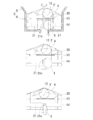
- the tablet discharge path of the base body is formed to have a constant size regardless of the tablet size of the tablet cassette. Therefore, when the width of the tablet guide groove of the rotor is increased so that a large tablet can be discharged, the tablet T discharged from the tablet cassette may be clogged in the tablet discharge path 24 of the base body 2 as shown in FIG. there were.
- Patent Document 1 describes a guide portion for guiding a tablet to a selection slot (tablet guide groove) of a circular receiver (rotor), and a drug dispenser provided with a sweeper in the vicinity of the selection slot. Sweeper separates one tablet from the selection slot so that it is dispensed.
- Patent Document 2 describes a tablet dispenser in which a dividing groove and a supply groove are provided in a rotor transport path (tablet guide groove).
- the tablet discharge path of the base body must be enlarged in order to dispense large tablets.
- the present invention has been made in view of the above-mentioned conventional problems, and an object of the present invention is to provide a tablet cassette capable of ejecting a large tablet without changing the size of a base body on which the tablet cassette is mounted. To do.
- a tablet container that holds a large number of tablets and has a tablet outlet formed at the bottom
- a tablet cassette provided with a rotor rotatably provided in the tablet container and provided with a tablet guide groove for guiding the tablet in the tablet container to the tablet outlet.
- a circumferential groove is formed in the rotor,
- a guide member that enters the peripheral groove is provided on the downstream side in the rotation direction of the rotor at the tablet outlet of the tablet container.
- the guide member is configured to have an inclined guide surface facing the tablet in the tablet guide groove in the rotational direction of the rotor and facing the tablet outlet.
- the tablet in the tablet guide groove is discharged from the tablet outlet by changing the direction by the inclined guide surface of the guide member, so that the tablet is discharged without clogging the tablet discharge path of the base body on which the tablet cassette is mounted. Therefore, a large tablet can be discharged without changing the size of the base body.
- the guide surface of the guide member is configured to turn the tablet in the tablet guide groove around an axis parallel to the tablet guide groove and discharge the tablet from the tablet outlet.
- the guide surface of the guide member is configured to look at the rotor from the tablet outlet and turn the tablet from a first profile having a large projected area to a second profile having a projected area smaller than that of the first profile.
- the guide member is provided below the center of the first profile of the tablet when the rotor is viewed from the tablet outlet.
- the guide surface of the guide member is inclined downstream in the rotational direction of the rotor toward the edge of the guide surface located radially outside from the edge of the guide surface located inside the rotor in the radial direction. ..
- the edge of the guide surface located inside the rotor in the radial direction is located between the center of the tablet outlet and the upstream edge of the rotor in the rotational direction when the rotor is viewed from the tablet outlet. To do.
- a guide member that enters the peripheral groove of the rotor is provided on the downstream side in the rotation direction of the rotor at the tablet outlet, and the guide member faces the tablet in the tablet guide groove in the rotation direction of the rotor and It has an inclined guide surface facing the tablet outlet, and the tablet in the tablet guide groove changes its direction by the guide surface of the guide member and is discharged from the tablet outlet, so that the tablet discharge path of the base body to which the tablet cassette is mounted is clogged. It is discharged without. Therefore, a large tablet can be discharged without changing the size of the base body.
- FIG. 1 The perspective view of the tablet cassette and the base body which concerns on this invention.
- FIG. 1 shows a tablet cassette 1 according to an embodiment of the present invention and a base body 2 to which the tablet cassette 1 is mounted.
- the tablet cassette 1 includes a tablet container 3 and a rotor 4.
- the tablet container 3 has a substantially rectangular tablet accommodating portion 5 for accommodating a large number of tablets, and a circular rotor accommodating portion 6 capable of accommodating a rotor 4 at the lower portion.
- the upper opening 7 of the tablet storage portion 5 can be opened and closed with a lid (not shown).
- a mounting base 8 that slides and engages with a mounting guide 23 described later of the base body 2 is mounted on the lower outer surface of the tablet container 3.
- the rotor 4 is rotatably housed in the rotor accommodating portion 6 of the tablet container 3.
- a rotating shaft 9 is provided on the bottom surface of the rotor 4, and the rotating shaft 9 penetrates the shaft hole 10 on the bottom of the tablet container 3 and is attached with the drive gear 11 shown in FIG.
- the drive gear 11 is adapted to mesh with the motor gear 22 described later of the base body 2 when the tablet cassette 1 is attached to the base body 2.
- a guide peripheral groove 14 into which the protruding portion 21b of the guide member 21, which will be described later, enters is formed below the partition peripheral groove 13.
- a rear opening 15 is provided from the lower rear portion of the tablet accommodating portion 5 of the tablet cassette 1 to the bottom portion of the rotor accommodating portion 6, and the rear opening 15 is removably closed by the opening cover 16. ing.
- a tablet outlet 17 is formed on the opening cover 16.
- a slit 18 is formed above the tablet outlet 17.
- a notch 19 is formed in the side edge of the tablet outlet 17 located on the downstream side in the rotation direction of the rotor 4.
- a partition member 20 is attached to the opening cover 16, and the partition portion 20a of the partition member 20 enters the partition peripheral groove 13 of the rotor 4 inside through the slit 18.
- a guide member 21 is attached to the notch 19 of the opening cover 16, and a protrusion 21b, which will be described later, of the guide member 21 enters the guide peripheral groove 14 of the rotor 4 inside.
- the guide member 21 includes a base portion 21a attached to the notch 19 of the opening cover 16, a protruding portion 21b protruding from the base portion 21a toward the rotor 4 and entering the guide peripheral groove 14 of the rotor 4, and the protruding portion 21a. It has a guide surface 21c formed on the side edge located on the upstream side in the rotation direction of the rotor 4.
- the guide surface 21c faces the tablet in the tablet guide groove 12 that moves by the rotation of the rotor 4 and faces the tablet outlet 17.
- the guide surface 21c is a rotor from the edge e1 of the guide surface 21c located on the inner side in the radial direction of the rotor 4 toward the edge e2 of the guide surface 21c located on the outer side in the radial direction. It is formed by a concave surface inclined to the downstream side in the rotation direction of No. 4. Further, the edge e1 of the guide surface 21c located inside the rotor 4 in the radial direction is located slightly upstream of the center of the tablet outlet 17 in the rotation direction when the rotor 4 is viewed from the tablet outlet 17.
- the guide surface 21c may be composed of a plurality of inclined surfaces as shown in FIG. 5B instead of a concave surface.
- the inclination of the guide surface 21c is changed stepwise, and the inclination on the downstream side from the transition point e3 to the edge e2 is viewed from the rotation direction of the rotor 4 rather than the inclination on the upstream side from the edge e1 to the transition point e3.
- a steep slope is desirable.
- the guide surface 21 is composed of two inclined surfaces, but may be three or more.
- edge e1 of the guide surface 21c is located between the center 17a of the tablet outlet 17 and the edge 17b on the upstream side of the rotor 4 in the rotation direction of the tablet outlet 17 when the rotor 4 is viewed from the tablet outlet 17. Is preferable.
- the base body 2 is one of a large number of base bodies 2 fixedly provided to the tablet dispensing device.
- the base body 2 has a built-in motor (not shown) that rotationally drives the rotor 4 of the tablet cassette 1, and the motor gear 22 is exposed on the upper surface.
- the base body 2 is formed with a mounting guide 23 for mounting the tablet cassette 1 and a tablet discharge path 24 through which the tablets discharged from the tablet cassette 1 pass.
- the tablet cassette 1 accommodates relatively large and flat tablets (for example, an outer diameter of 18 mm). That is, as shown in FIG. 6, the tablets contained in the tablet cassette 1 include a first profile (a) having a large projected area and a second profile (b) having a smaller projected area than the first profile (a). Has. For this reason, the tablet guide groove 12 of the rotor 4 is also formed to have a wide width. On the other hand, the tablet discharge path 24 of the base body 2 does not need to be formed wide to fit the large and flat tablet, and has a size common to all of the many base bodies 2 of the tablet dispensing device. It is formed in a size that allows the size of a tablet in the middle of the payable tablets to pass through.
- the guide member 21 is provided below the center of the first profile of the tablet when the rotor 4 is viewed from the tablet outlet 17.
- the tablet T contained in the tablet container 3 enters the tablet guide groove 12 of the rotor 4 by the rotation of the rotor 4.
- the tablet T is housed in the tablet guide groove 12 with the first profile when the outer circumference is viewed from the outside of the rotor 4.
- the tablet guide groove 12 approaches the tablet outlet 17, the lowermost tablet T of the tablet guide groove 12 and the tablet T'above the tablet T'are partitioned by the partition member 20.
- the tablet T'above the partition member 20 is supported by the partition member 20.
- the tablet T below the partition member 20 comes into contact with the guide surface 21c of the guide member 21, and as the rotor 4 rotates, the guide surface 21c of the guide member 21 causes 90 ° around the axis x parallel to the tablet guide groove 12. It rotates and turns from the first profile (a) to the second profile (b) when looking at the rotor 4 from the tablet outlet 17, and is discharged from the tablet outlet 17 while falling due to gravity.
- the tablet T discharged from the tablet outlet 17 is discharged so as to roll on the road surface of the tablet discharge path 24 of the base body 2 in a vertical posture. Therefore, as compared with the case where the tablet T slides down on the road surface of the tablet discharge path 24 in a lateral posture as in the conventional case of FIG. 13, the tablet T passes and is clogged with a margin for the width of the tablet discharge path 24. Is discharged without. Therefore, the tablet discharge path 24 of the base body 2 can be enlarged, and the large tablet T can be discharged without changing the overall width. Further, since the tablet T rolls down the tablet discharge path 24, the discharge time of the tablet T can be shortened.
- FIG. 10 shows a guide peripheral groove 14 of the rotor 4 provided at the lower end of the rotor 4 so that the guide surface 21c of the guide member 21 comes into contact with the tablet T of the tablet guide groove 12 below the center of the first profile.
- the lower portion of the tablet T is swept away and the axis x of rotation falls down with respect to the tablet guide groove 12, so that the tablet T comes into contact with the guide surface 21c.
- the discharge time of the tablet T can be further shortened as compared with the case where the tablet T comes into contact with the center of the first profile.
- the guide member 21 is attached to the tablet outlet 17 of the tablet container 3 as a separate member, but is integrally formed on the side edge of the tablet outlet 17 of the tablet container 3 as shown in FIG. ,
- the guide surface 21a may extend to the outside of the tablet container 3.
- a plurality of tablets are housed in the tablet guide groove 12 of the rotor 4, and the lowermost tablet T of the tablet guide groove 12 and the tablet T above it are accommodated.
- 'I a so-called two-stage rotor partitioned by the partition member 20, but the present invention is also applicable to a tablet cassette having a one-stage rotor.
- the rotor 4 is located between the lower large-diameter outer peripheral surface 4a and the upper small-diameter outer peripheral surface 4b. It has a step portion 4c.
- a plurality of tablet guide grooves 12 parallel to the rotation axis 9 of the rotor 4 are formed on the large-diameter outer peripheral surface 4a as in the above embodiment, and one tablet is housed in the tablet guide path 12.
- An annular tablet pocket 25 connected in the circumferential direction of the rotor 4 is provided above the tablet guide groove 12.
- the tablet pocket 25 is composed of a small diameter outer peripheral surface 4b of the rotor 4, a step portion 4c, and an inner surface of the rotor accommodating portion 6 of the tablet container 3. Since the partition member 20 is provided above the step portion 4c of the rotor 4 instead of the partition peripheral groove as in the above embodiment, the tablet pocket 25 shares the partition peripheral groove.
- One tablet is housed in the tablet guide groove 12 from the tablet pocket 25, and one tablet T in the tablet guide groove 12 and the tablet T'in the tablet pocket 25 above the tablet T'are partitioned by the partition member 20. It has become.
- a guide peripheral groove 14 in the circumferential direction is formed on the large-diameter outer peripheral surface 4a of the rotor 4, and a guide that enters the guide peripheral groove 14 on the downstream side of the tablet outlet 17 in the rotational direction.
- a member 21 is provided, and the tablet T in the tablet guide groove 12 is turned around by the guide member 21 and discharged from the tablet outlet 17.
- Tablet cassette 2 Base body 3 Tablet container 4 Rotor 12 Tablet guide groove 14 Guide peripheral groove 17 Tablet outlet 21 Guide member 21c Guide surface 25 Tablet pocket
Landscapes
- Physics & Mathematics (AREA)
- General Physics & Mathematics (AREA)
- Medical Preparation Storing Or Oral Administration Devices (AREA)
- Basic Packing Technique (AREA)
Abstract
Provided is a tablet cassette capable of discharging a large tablet without changing the size of a base body to which the tablet cassette is attached. The tablet cassette (1) comprises: a tablet container (3) housing a plurality of tablets and having a tablet outlet (17) formed in the bottom thereof; and a rotor (4) rotatably provided inside the tablet container (3) and having a tablet guide groove (12) provided therein that guides a tablet inside the tablet container (3) to the tablet outlet (17). The rotor (4) has a circumferential groove (14) formed in the circumferential direction thereof. A guide member (21) that enters the circumferential groove (14) is provided on the downstream side, in the rotation direction of the rotor (4), of the tablet outlet (17) in the tablet container (3). The guide member (21) has an inclined guide surface (21c) that faces the tablets in the tablet guide groove (12), in the rotation direction of the rotor (4), and facing the tablet outlet.
Description
本発明は、多数の錠剤を収容し、錠剤を1個ずつ所望の数だけ排出する錠剤カセットに関する。
The present invention relates to a tablet cassette that accommodates a large number of tablets and ejects a desired number of tablets one by one.
錠剤カセットは、錠剤払出装置に設けられたベース本体(モータベース)に着脱可能に取り付けられる。錠剤払出装置は、多種多様の錠剤を排出できるように、多数の錠剤カセットを有している。各錠剤カセットは、多数の錠剤を収容する錠剤容器と、該錠剤容器の内部に回転可能に設けられたロータとを備えている。錠剤容器の錠剤はロータに形成された錠剤案内溝を通って錠剤出口から排出される。錠剤出口から排出された錠剤はベース本体の錠剤排出路を通って払い出される。
The tablet cassette is detachably attached to the base body (motor base) provided in the tablet dispensing device. The tablet dispenser has a large number of tablet cassettes so that a wide variety of tablets can be ejected. Each tablet cassette includes a tablet container that accommodates a large number of tablets and a rotor that is rotatably provided inside the tablet container. The tablets in the tablet container are discharged from the tablet outlet through the tablet guide groove formed in the rotor. The tablet discharged from the tablet outlet is discharged through the tablet discharge path of the base body.
錠剤は様々な形状を有している。大きな錠剤に合わせて錠剤カセットとベース本体の大きさを決めると錠剤払出装置が大型化する。このため、錠剤カセットとベース本体は中間の大きさの錠剤が払い出すことができるように大きさが決められている。各錠剤カセットは、錠剤容器に収容される錠剤の大きさに合わせて、ロータの錠剤案内溝の幅、深さが形成されている。一方、ベース本体の錠剤排出路は、錠剤カセットの錠剤の大きさにかかわらず、一定の大きさに形成されている。このため、大きな錠剤を排出できるようにロータの錠剤案内溝の幅を大きくした場合、図13に示すように、錠剤カセットから排出される錠剤Tがベース本体2の錠剤排出路24で詰まることがあった。
Tablets have various shapes. If the size of the tablet cassette and the base body is determined according to the large tablet, the tablet dispensing device becomes large. For this reason, the tablet cassette and the base body are sized so that tablets of intermediate size can be dispensed. In each tablet cassette, the width and depth of the tablet guide groove of the rotor are formed according to the size of the tablet contained in the tablet container. On the other hand, the tablet discharge path of the base body is formed to have a constant size regardless of the tablet size of the tablet cassette. Therefore, when the width of the tablet guide groove of the rotor is increased so that a large tablet can be discharged, the tablet T discharged from the tablet cassette may be clogged in the tablet discharge path 24 of the base body 2 as shown in FIG. there were.
特許文献1には、円形レシーバ(ロータ)の選択スロット(錠剤案内溝)に錠剤を導く案内部と、選択スロットの近傍にスウィーパーを設けた薬剤払出機が記載されている。スウィーパーは、選択スロットから1つの錠剤が払い出されるように分離するものである。
Patent Document 1 describes a guide portion for guiding a tablet to a selection slot (tablet guide groove) of a circular receiver (rotor), and a drug dispenser provided with a sweeper in the vicinity of the selection slot. Sweeper separates one tablet from the selection slot so that it is dispensed.
特許文献2には、ロータの搬送路(錠剤案内溝)に分割溝と供給溝を設けた錠剤払出機が記載されている。
Patent Document 2 describes a tablet dispenser in which a dividing groove and a supply groove are provided in a rotor transport path (tablet guide groove).
いずれの特許文献の薬剤払出機も大きな錠剤を払い出すにはベース本体の錠剤排出路を大きくしなければならないものである。
In any of the patent document drug dispensers, the tablet discharge path of the base body must be enlarged in order to dispense large tablets.
本発明は、前記従来の問題点に鑑みてなされたもので、錠剤カセットが装着されるベース本体の大きさを変えることなく大きな錠剤を排出することが可能な錠剤カセットを提供することを課題とする。
The present invention has been made in view of the above-mentioned conventional problems, and an object of the present invention is to provide a tablet cassette capable of ejecting a large tablet without changing the size of a base body on which the tablet cassette is mounted. To do.
前記課題を解決するために、本発明は、
多数の錠剤を収容し、下部に錠剤出口が形成された錠剤容器と、
前記錠剤容器内に回転可能に設けられ、前記錠剤容器内の錠剤を前記錠剤出口に案内する錠剤案内溝が設けられたロータとを備えた錠剤カセットにおいて、
前記ロータに円周方向の周溝が形成され、
前記錠剤容器の前記錠剤出口の前記ロータの回転方向下流側に、前記周溝に進入するガイド部材が設けられ、
前記ガイド部材は、前記錠剤案内溝の錠剤に対して前記ロータの回転方向に対向し、かつ、前記錠剤出口に臨む傾斜したガイド面を有するように構成されている。 In order to solve the above problems, the present invention
A tablet container that holds a large number of tablets and has a tablet outlet formed at the bottom,
In a tablet cassette provided with a rotor rotatably provided in the tablet container and provided with a tablet guide groove for guiding the tablet in the tablet container to the tablet outlet.
A circumferential groove is formed in the rotor,
A guide member that enters the peripheral groove is provided on the downstream side in the rotation direction of the rotor at the tablet outlet of the tablet container.
The guide member is configured to have an inclined guide surface facing the tablet in the tablet guide groove in the rotational direction of the rotor and facing the tablet outlet.
本発明では、錠剤案内溝の錠剤はガイド部材の傾斜したガイド面により向きを変えて錠剤出口から排出されるので、錠剤カセットが装着されるベース本体の錠剤排出路を詰まることなく排出される。このため、ベース本体の大きさを変えることなく大きな錠剤を排出することができる。
In the present invention, the tablet in the tablet guide groove is discharged from the tablet outlet by changing the direction by the inclined guide surface of the guide member, so that the tablet is discharged without clogging the tablet discharge path of the base body on which the tablet cassette is mounted. Therefore, a large tablet can be discharged without changing the size of the base body.
前記ガイド部材のガイド面により前記錠剤案内溝の錠剤を前記錠剤案内溝に平行な軸の周りに向きを変えて前記錠剤出口から排出するように構成されている。
The guide surface of the guide member is configured to turn the tablet in the tablet guide groove around an axis parallel to the tablet guide groove and discharge the tablet from the tablet outlet.
前記ガイド部材のガイド面は、前記錠剤出口から前記ロータを見て、前記錠剤を投影面積の大きい第1プロフィルから該第1プロフィルより投影面積が小さい第2プロフィルに向きを変えるように構成されている。
The guide surface of the guide member is configured to look at the rotor from the tablet outlet and turn the tablet from a first profile having a large projected area to a second profile having a projected area smaller than that of the first profile. There is.
前記ガイド部材は、前記錠剤出口から前記ロータを見て、前記錠剤の第1プロフィルの中心より下方に設けられている。
The guide member is provided below the center of the first profile of the tablet when the rotor is viewed from the tablet outlet.
前記ガイド部材のガイド面は、前記ロータの半径方向内側に位置する前記ガイド面の縁から半径方向外側に位置する前記ガイド面の縁に向かって、前記ロータの回転方向下流側に傾斜している。
The guide surface of the guide member is inclined downstream in the rotational direction of the rotor toward the edge of the guide surface located radially outside from the edge of the guide surface located inside the rotor in the radial direction. ..
前記ロータの半径方向内側に位置する前記ガイド面の縁は、前記錠剤出口から前記ロータを見て、前記錠剤出口の中央から前記錠剤出口の前記ロータの回転方向上流側の縁までの間に位置する。
The edge of the guide surface located inside the rotor in the radial direction is located between the center of the tablet outlet and the upstream edge of the rotor in the rotational direction when the rotor is viewed from the tablet outlet. To do.
本発明によれば、錠剤出口のロータの回転方向下流側にロータの周溝に進入するガイド部材が設けられ、該ガイド部材は錠剤案内溝の錠剤に対してロータの回転方向に対向、かつ、錠剤出口に臨む傾斜したガイド面を有し、錠剤案内溝の錠剤はガイド部材のガイド面により向きを変えて錠剤出口から排出されるので、錠剤カセットが装着されるベース本体の錠剤排出路を詰まることなく排出される。このため、ベース本体の大きさを変えることなく大きな錠剤を排出することができる。
According to the present invention, a guide member that enters the peripheral groove of the rotor is provided on the downstream side in the rotation direction of the rotor at the tablet outlet, and the guide member faces the tablet in the tablet guide groove in the rotation direction of the rotor and It has an inclined guide surface facing the tablet outlet, and the tablet in the tablet guide groove changes its direction by the guide surface of the guide member and is discharged from the tablet outlet, so that the tablet discharge path of the base body to which the tablet cassette is mounted is clogged. It is discharged without. Therefore, a large tablet can be discharged without changing the size of the base body.
以下、本発明の実施形態を添付図面に従って説明する。
Hereinafter, embodiments of the present invention will be described with reference to the accompanying drawings.
図1は、本発明の実施形態による錠剤カセット1と、該錠剤カセット1が装着されるベース本体2を示す。
FIG. 1 shows a tablet cassette 1 according to an embodiment of the present invention and a base body 2 to which the tablet cassette 1 is mounted.
錠剤カセット1は、図2に示すように、錠剤容器3と、ロータ4とを備えている。図3に示すように、錠剤容器3は、多数の錠剤を収容する略矩形の錠剤収容部5と、下部にロータ4を収容可能な円形のロータ収容部6とを有している。錠剤収容部5の上方開口部7は図示しない蓋体で開閉可能になっている。錠剤容器3の下部外面には、図1に示すように、ベース本体2の後述する装着ガイド23にスライドして係合する装着ベース8が取り付けられている。
As shown in FIG. 2, the tablet cassette 1 includes a tablet container 3 and a rotor 4. As shown in FIG. 3, the tablet container 3 has a substantially rectangular tablet accommodating portion 5 for accommodating a large number of tablets, and a circular rotor accommodating portion 6 capable of accommodating a rotor 4 at the lower portion. The upper opening 7 of the tablet storage portion 5 can be opened and closed with a lid (not shown). As shown in FIG. 1, a mounting base 8 that slides and engages with a mounting guide 23 described later of the base body 2 is mounted on the lower outer surface of the tablet container 3.
ロータ4は、錠剤容器3のロータ収容部6に回転可能に収容されている。ロータ4の底面には回転軸9が設けられ、該回転軸9は錠剤容器3の底の軸孔10を貫通して、図4に示す駆動ギア11が取り付けられている。駆動ギア11は、錠剤カセット1がベース本体2に取り付けられたときに、ベース本体2の後述するモータギア22に噛み合うようになっている。ロータ4の外面には、ロータ4の回転軸9に平行な複数(実施例では周方向に6個)の錠剤案内溝12と、後述する仕切り部材20の仕切り部20aが進入する仕切り用周溝13と、該仕切り用周溝13の下方に後述するガイド部材21の突出部21bが進入するガイド用周溝14とが形成されている。
The rotor 4 is rotatably housed in the rotor accommodating portion 6 of the tablet container 3. A rotating shaft 9 is provided on the bottom surface of the rotor 4, and the rotating shaft 9 penetrates the shaft hole 10 on the bottom of the tablet container 3 and is attached with the drive gear 11 shown in FIG. The drive gear 11 is adapted to mesh with the motor gear 22 described later of the base body 2 when the tablet cassette 1 is attached to the base body 2. On the outer surface of the rotor 4, a plurality of tablet guide grooves 12 parallel to the rotation axis 9 of the rotor 4 (six in the circumferential direction in the embodiment) and a peripheral groove for partitioning into which the partition portion 20a of the partition member 20 described later enters. A guide peripheral groove 14 into which the protruding portion 21b of the guide member 21, which will be described later, enters is formed below the partition peripheral groove 13.
錠剤カセット1の錠剤収容部5の後方下部からロータ収容部6の底部にかけて、図2に示すように、後方開口部15が設けられ、該後方開口部15は開口カバー16によって取り外し可能に閉塞されている。開口カバー16には、錠剤出口17が形成されている。錠剤出口17の上方にはスリット18が形成されている。錠剤出口17の側縁のうち、ロータ4の回転方向下流側に位置する側縁には切り欠き19が形成されている。
As shown in FIG. 2, a rear opening 15 is provided from the lower rear portion of the tablet accommodating portion 5 of the tablet cassette 1 to the bottom portion of the rotor accommodating portion 6, and the rear opening 15 is removably closed by the opening cover 16. ing. A tablet outlet 17 is formed on the opening cover 16. A slit 18 is formed above the tablet outlet 17. A notch 19 is formed in the side edge of the tablet outlet 17 located on the downstream side in the rotation direction of the rotor 4.
開口カバー16には、仕切り部材20が取り付けられ、該仕切り部材20の仕切り部20aがスリット18を通って内部のロータ4の仕切り用周溝13に進入するようになっている。また、開口カバー16の切り欠き19には、ガイド部材21が取り付けられ、該ガイド部材21の後述する突出部21bが内部のロータ4のガイド用周溝14に進入するようになっている。
A partition member 20 is attached to the opening cover 16, and the partition portion 20a of the partition member 20 enters the partition peripheral groove 13 of the rotor 4 inside through the slit 18. A guide member 21 is attached to the notch 19 of the opening cover 16, and a protrusion 21b, which will be described later, of the guide member 21 enters the guide peripheral groove 14 of the rotor 4 inside.
ガイド部材21は、開口カバー16の切り欠き19に取り付けられる基部21aと、該基部21aからロータ4に向かって突出してロータ4のガイド用周溝14の進入する突出部21bと、該突出部21aの側縁のうち、ロータ4の回転方向上流側に位置する側縁に形成されたガイド面21cとを有している。
The guide member 21 includes a base portion 21a attached to the notch 19 of the opening cover 16, a protruding portion 21b protruding from the base portion 21a toward the rotor 4 and entering the guide peripheral groove 14 of the rotor 4, and the protruding portion 21a. It has a guide surface 21c formed on the side edge located on the upstream side in the rotation direction of the rotor 4.
ガイド面21cは、ロータ4の回転により移動してくる錠剤案内溝12の錠剤と対向、かつ、錠剤出口17に臨むようになっている。例えば、図5(a)に示すように、ガイド面21cは、ロータ4の半径方向内側に位置するガイド面21cの縁e1から半径方向外側に位置するガイド面21cの縁e2に向かって、ロータ4の回転方向下流側に傾斜した凹面で形成されている。また、ロータ4の半径方向内側に位置するガイド面21cの縁e1は、錠剤出口17からロータ4を見て、錠剤出口17の中央よりややロータ4の回転方向上流側に位置している。
The guide surface 21c faces the tablet in the tablet guide groove 12 that moves by the rotation of the rotor 4 and faces the tablet outlet 17. For example, as shown in FIG. 5A, the guide surface 21c is a rotor from the edge e1 of the guide surface 21c located on the inner side in the radial direction of the rotor 4 toward the edge e2 of the guide surface 21c located on the outer side in the radial direction. It is formed by a concave surface inclined to the downstream side in the rotation direction of No. 4. Further, the edge e1 of the guide surface 21c located inside the rotor 4 in the radial direction is located slightly upstream of the center of the tablet outlet 17 in the rotation direction when the rotor 4 is viewed from the tablet outlet 17.
なお、ガイド面21cは、凹面でなく、図5(b)に示すように、複数の傾斜面から構成されてもよい。この場合、ガイド面21cの傾斜は段階的に変化させ、遷移点e3から縁e2までの下流側の傾斜が縁e1から遷移点e3までの上流側の傾斜よりもロータ4の回転方向から見て急勾配であることが望ましい。図5(b)ではガイド面21は、2つの傾斜面から構成されているが、3以上でもよい。また、ガイド面21cの縁e1は、錠剤出口17からロータ4を見て、錠剤出口17の中央17aから錠剤出口17のロータ4の回転方向上流側の縁17bまでの間に位置していることが好ましい。
Note that the guide surface 21c may be composed of a plurality of inclined surfaces as shown in FIG. 5B instead of a concave surface. In this case, the inclination of the guide surface 21c is changed stepwise, and the inclination on the downstream side from the transition point e3 to the edge e2 is viewed from the rotation direction of the rotor 4 rather than the inclination on the upstream side from the edge e1 to the transition point e3. A steep slope is desirable. In FIG. 5B, the guide surface 21 is composed of two inclined surfaces, but may be three or more. Further, the edge e1 of the guide surface 21c is located between the center 17a of the tablet outlet 17 and the edge 17b on the upstream side of the rotor 4 in the rotation direction of the tablet outlet 17 when the rotor 4 is viewed from the tablet outlet 17. Is preferable.
ベース本体2は、図1に示すように、錠剤払出装置に固定して設けられる多数のベース本体2のうちの1つである。ベース本体2には、錠剤カセット1のロータ4を回転駆動する図示しないモータが内蔵され、そのモータギア22が上面に露出して設けられている。また、ベース本体2には、錠剤カセット1を装着するための装着ガイド23と、錠剤カセット1から排出される錠剤が通過する錠剤排出路24が形成されている。
As shown in FIG. 1, the base body 2 is one of a large number of base bodies 2 fixedly provided to the tablet dispensing device. The base body 2 has a built-in motor (not shown) that rotationally drives the rotor 4 of the tablet cassette 1, and the motor gear 22 is exposed on the upper surface. Further, the base body 2 is formed with a mounting guide 23 for mounting the tablet cassette 1 and a tablet discharge path 24 through which the tablets discharged from the tablet cassette 1 pass.
錠剤カセット1は、比較的大きく平たい錠剤(例えば外径18mm)が収容される。すなわち、錠剤カセット1に収容される錠剤は、図6に示すように、投影面積の大きい第1プロフィル(a)と、該第1プロフィル(a)より投影面積が小さい第2プロフィル(b)とを有する。このためにロータ4の錠剤案内溝12も幅が広く形成されている。一方、ベース本体2の錠剤排出路24は、この大きく平たい錠剤に合わせて幅広に形成する必要はなく、錠剤払出装置の多数のベース本体2のすべてに共通の大きさであり、錠剤払出装置で払い出し可能な錠剤の中間位の錠剤の大きさが通過できる大きさに形成されている。ガイド部材21は、錠剤出口17からロータ4を見て、錠剤の第1プロフィルの中心より下方に設けられている。
The tablet cassette 1 accommodates relatively large and flat tablets (for example, an outer diameter of 18 mm). That is, as shown in FIG. 6, the tablets contained in the tablet cassette 1 include a first profile (a) having a large projected area and a second profile (b) having a smaller projected area than the first profile (a). Has. For this reason, the tablet guide groove 12 of the rotor 4 is also formed to have a wide width. On the other hand, the tablet discharge path 24 of the base body 2 does not need to be formed wide to fit the large and flat tablet, and has a size common to all of the many base bodies 2 of the tablet dispensing device. It is formed in a size that allows the size of a tablet in the middle of the payable tablets to pass through. The guide member 21 is provided below the center of the first profile of the tablet when the rotor 4 is viewed from the tablet outlet 17.
次に、本発明の実施形態に係る錠剤カセットの動作を説明する。
Next, the operation of the tablet cassette according to the embodiment of the present invention will be described.
図7と図8に示すように、錠剤容器3に収容された錠剤Tは、ロータ4の回転によりロータ4の錠剤案内溝12に進入する。このとき、錠剤Tはロータ4の外側から外周を見たときに第1プロフィルで錠剤案内溝12に収容される。錠剤案内溝12が錠剤出口17に近付くと、錠剤案内溝12の最下位の錠剤Tとその上の錠剤T’は仕切り部材20に仕切られる。仕切り部材20より上の錠剤T’は仕切り部材20に支持される。仕切り部材20より下の錠剤Tは、ガイド部材21のガイド面21cに接触し、ロータ4が回転するにつれて、ガイド部材21のガイド面21cにより錠剤案内溝12に平行な軸xの回りに90°自転して、錠剤出口17からロータ4を見て第1プロフィル(a)から第2プロフィル(b)に向きを変えられ、錠剤出口17から重力で落下しながら排出される。
As shown in FIGS. 7 and 8, the tablet T contained in the tablet container 3 enters the tablet guide groove 12 of the rotor 4 by the rotation of the rotor 4. At this time, the tablet T is housed in the tablet guide groove 12 with the first profile when the outer circumference is viewed from the outside of the rotor 4. When the tablet guide groove 12 approaches the tablet outlet 17, the lowermost tablet T of the tablet guide groove 12 and the tablet T'above the tablet T'are partitioned by the partition member 20. The tablet T'above the partition member 20 is supported by the partition member 20. The tablet T below the partition member 20 comes into contact with the guide surface 21c of the guide member 21, and as the rotor 4 rotates, the guide surface 21c of the guide member 21 causes 90 ° around the axis x parallel to the tablet guide groove 12. It rotates and turns from the first profile (a) to the second profile (b) when looking at the rotor 4 from the tablet outlet 17, and is discharged from the tablet outlet 17 while falling due to gravity.
錠剤出口17から排出された錠剤Tは、図9に示すように、ベース本体2の錠剤排出路24の路面上を縦の姿勢で転がるように、払い出される。したがって、図13の従来のように、錠剤Tが錠剤排出路24の路面上を横の姿勢で滑り落ちる場合と比べて、錠剤排出路24の幅に対して余裕のある状態で通過し、詰まることなく排出される。このため、ベース本体2の錠剤排出路24を大きくし、全体の幅を変えることなく大きな錠剤Tを排出することができる。また、錠剤Tが錠剤排出路24を転がり落ちるため、錠剤Tの排出時間を短縮することができる。
As shown in FIG. 9, the tablet T discharged from the tablet outlet 17 is discharged so as to roll on the road surface of the tablet discharge path 24 of the base body 2 in a vertical posture. Therefore, as compared with the case where the tablet T slides down on the road surface of the tablet discharge path 24 in a lateral posture as in the conventional case of FIG. 13, the tablet T passes and is clogged with a margin for the width of the tablet discharge path 24. Is discharged without. Therefore, the tablet discharge path 24 of the base body 2 can be enlarged, and the large tablet T can be discharged without changing the overall width. Further, since the tablet T rolls down the tablet discharge path 24, the discharge time of the tablet T can be shortened.
図10は、ロータ4のガイド用周溝14をロータ4の下端に設け、ガイド部材21のガイド面21cが錠剤案内溝12の錠剤Tの第1プロフィルの中心より下方で接触するようにしたものである。この場合、錠剤Tは、ガイド面21cに接触したときに、錠剤Tの下部が足払いされて自転の軸xが錠剤案内溝12に対して倒れた状態となるので、ガイド面21cと接触した衝撃で錠剤Tが多少せり上がっても、錠剤出口17の上縁に引っ掛かることがなくなる。したがって、図7、図8に示すように錠剤Tが第1プロフィルの中心で接触する場合よりも、錠剤Tの排出時間をより一層短縮することができる。
FIG. 10 shows a guide peripheral groove 14 of the rotor 4 provided at the lower end of the rotor 4 so that the guide surface 21c of the guide member 21 comes into contact with the tablet T of the tablet guide groove 12 below the center of the first profile. Is. In this case, when the tablet T comes into contact with the guide surface 21c, the lower portion of the tablet T is swept away and the axis x of rotation falls down with respect to the tablet guide groove 12, so that the tablet T comes into contact with the guide surface 21c. Even if the tablet T is slightly raised by the impact, it will not be caught on the upper edge of the tablet outlet 17. Therefore, as shown in FIGS. 7 and 8, the discharge time of the tablet T can be further shortened as compared with the case where the tablet T comes into contact with the center of the first profile.
本発明は前記実施形態に限るものではなく、特許請求の範囲に記載の発明の要旨から逸脱することなく修正し変更することができる。
The present invention is not limited to the above-described embodiment, and can be modified and modified without departing from the gist of the invention described in the claims.
例えば、前記実施形態では、ガイド部材21は錠剤容器3の錠剤出口17に別部材として取り付けられているが、図11に示すように、錠剤容器3の錠剤出口17の側縁に一体に形成し、ガイド面21aが錠剤容器3の外側に延伸するようにしてもよい。
For example, in the above embodiment, the guide member 21 is attached to the tablet outlet 17 of the tablet container 3 as a separate member, but is integrally formed on the side edge of the tablet outlet 17 of the tablet container 3 as shown in FIG. , The guide surface 21a may extend to the outside of the tablet container 3.
また、前記実施形態のロータ4は、図7に示すように、当該ロータ4の錠剤案内溝12に複数の錠剤が収容されて、錠剤案内溝12の最下位の錠剤Tとその上の錠剤T ’は仕切り部材20により仕切られる所謂2段ロータであるが、本願発明は1段ロータを有する錠剤カセットにも適用可能である。
Further, in the rotor 4 of the embodiment, as shown in FIG. 7, a plurality of tablets are housed in the tablet guide groove 12 of the rotor 4, and the lowermost tablet T of the tablet guide groove 12 and the tablet T above it are accommodated. 'Is a so-called two-stage rotor partitioned by the partition member 20, but the present invention is also applicable to a tablet cassette having a one-stage rotor.
1段ロータを有する錠剤カセットでは、図12(a)、(b)に示すように、ロータ4は、下段の大径外周面4aと、上段の小径外周面4bと、これらの間に位置する段部4cとを有している。大径外周面4aには、前記実施形態と同様にロータ4の回転軸9に平行な複数の錠剤案内溝12が形成されているが、この錠剤案内路12には、1つの錠剤が収容される。錠剤案内溝12の上方には、ロータ4の周方向につながった環状の錠剤ポケット25が設けられている。錠剤ポケット25は、ロータ4の小径外周面4bと、段部4cと、錠剤容器3のロータ収容部6の内面とで構成されている。仕切り部材20は、前記実施形態のような仕切り用周溝ではなく、ロータ4の段部4cの上方に設けられているため、錠剤ポケット25は仕切り用周溝を共有している。錠剤ポケット25から錠剤案内溝12に1個の錠剤が収容されて、該錠剤案内溝12の1個の錠剤Tとその上方の錠剤ポケット25の錠剤T’とが仕切り部材20により仕切られるようになっている。
In a tablet cassette having a one-stage rotor, as shown in FIGS. 12A and 12B, the rotor 4 is located between the lower large-diameter outer peripheral surface 4a and the upper small-diameter outer peripheral surface 4b. It has a step portion 4c. A plurality of tablet guide grooves 12 parallel to the rotation axis 9 of the rotor 4 are formed on the large-diameter outer peripheral surface 4a as in the above embodiment, and one tablet is housed in the tablet guide path 12. To. An annular tablet pocket 25 connected in the circumferential direction of the rotor 4 is provided above the tablet guide groove 12. The tablet pocket 25 is composed of a small diameter outer peripheral surface 4b of the rotor 4, a step portion 4c, and an inner surface of the rotor accommodating portion 6 of the tablet container 3. Since the partition member 20 is provided above the step portion 4c of the rotor 4 instead of the partition peripheral groove as in the above embodiment, the tablet pocket 25 shares the partition peripheral groove. One tablet is housed in the tablet guide groove 12 from the tablet pocket 25, and one tablet T in the tablet guide groove 12 and the tablet T'in the tablet pocket 25 above the tablet T'are partitioned by the partition member 20. It has become.
この1段ロータでも、ロータ4の大径外周面4aに円周方向のガイド用周溝14が形成され、錠剤出口17のロータ4の回転方向下流側に、ガイド用周溝14に進入するガイド部材21が設けられ、錠剤案内溝12の錠剤Tがガイド部材21で向きを変えられて錠剤出口17から排出される。
Even in this one-stage rotor, a guide peripheral groove 14 in the circumferential direction is formed on the large-diameter outer peripheral surface 4a of the rotor 4, and a guide that enters the guide peripheral groove 14 on the downstream side of the tablet outlet 17 in the rotational direction. A member 21 is provided, and the tablet T in the tablet guide groove 12 is turned around by the guide member 21 and discharged from the tablet outlet 17.
1 錠剤カセット
2 ベース本体
3 錠剤容器
4 ロータ
12 錠剤案内溝
14 ガイド用周溝
17 錠剤出口
21 ガイド部材
21c ガイド面
25 錠剤ポケット 1Tablet cassette 2 Base body 3 Tablet container 4 Rotor 12 Tablet guide groove 14 Guide peripheral groove 17 Tablet outlet 21 Guide member 21c Guide surface 25 Tablet pocket
2 ベース本体
3 錠剤容器
4 ロータ
12 錠剤案内溝
14 ガイド用周溝
17 錠剤出口
21 ガイド部材
21c ガイド面
25 錠剤ポケット 1
Claims (6)
- 多数の錠剤を収容し、下部に錠剤出口が形成された錠剤容器と、
前記錠剤容器内に回転可能に設けられ、前記錠剤容器内の錠剤を前記錠剤出口に案内する錠剤案内溝が設けられたロータとを備えた錠剤カセットにおいて、
前記ロータに円周方向の周溝が形成され、
前記錠剤容器の前記錠剤出口の前記ロータの回転方向下流側に、前記周溝に進入するガイド部材が設けられ、
前記ガイド部材は、前記錠剤案内溝の錠剤に対して前記ロータの回転方向に対向、かつ、前記錠剤出口に臨む傾斜したガイド面を有することを特徴とする錠剤カセット。 A tablet container that holds a large number of tablets and has a tablet outlet formed at the bottom,
In a tablet cassette provided with a rotor rotatably provided in the tablet container and provided with a tablet guide groove for guiding the tablet in the tablet container to the tablet outlet.
A circumferential groove is formed in the rotor,
A guide member that enters the peripheral groove is provided on the downstream side in the rotation direction of the rotor at the tablet outlet of the tablet container.
The tablet cassette is characterized in that the guide member has an inclined guide surface facing the tablet in the tablet guide groove in the rotation direction of the rotor and facing the tablet outlet. - 前記ガイド部材のガイド面により前記錠剤案内溝の錠剤を前記錠剤案内溝に平行な軸の周りに向きを変えて前記錠剤出口から排出するように構成されていることを特徴とする請求項1に記載の錠剤カセット。 The first aspect of the present invention is characterized in that the guide surface of the guide member is configured to turn the tablet of the tablet guide groove around an axis parallel to the tablet guide groove and discharge the tablet from the tablet outlet. The tablet cassette described.
- 前記ガイド部材のガイド面は、前記錠剤出口から前記ロータを見て、前記錠剤を投影面積の大きい第1プロフィルから該第1プロフィルより投影面積が小さい第2プロフィルに向きを変えるように構成されていることを特徴とする請求項1又は2に記載の錠剤カセット。 The guide surface of the guide member is configured to look at the rotor from the tablet outlet and turn the tablet from a first profile having a large projected area to a second profile having a projected area smaller than that of the first profile. The tablet cassette according to claim 1 or 2, wherein the tablet cassette is provided.
- 前記ガイド部材は、前記錠剤出口から前記ロータを見て、前記錠剤の第1プロフィルの中心より下方に設けられていることを特徴とする請求項1から3のいずれかに記載の錠剤カセット。 The tablet cassette according to any one of claims 1 to 3, wherein the guide member is provided below the center of the first profile of the tablet when the rotor is viewed from the tablet outlet.
- 前記ガイド部材のガイド面は、前記ロータの半径方向内側に位置する前記ガイド面の縁から半径方向外側に位置する前記ガイド面の縁に向かって、前記ロータの回転方向下流側に傾斜していることを特徴とする請求項1から4のいずれかに記載の錠剤カセット。 The guide surface of the guide member is inclined to the downstream side in the rotational direction of the rotor toward the edge of the guide surface located radially outside from the edge of the guide surface located inside the rotor in the radial direction. The tablet cassette according to any one of claims 1 to 4, characterized in that.
- 前記ロータの半径方向内側に位置する前記ガイド面の縁は、前記錠剤出口から前記ロータを見て、前記錠剤出口の中央から前記錠剤出口の前記ロータの回転方向上流側の縁までの間に位置することを特徴とする請求項5に記載の錠剤カセット。 The edge of the guide surface located inside the rotor in the radial direction is located between the center of the tablet outlet and the upstream edge of the rotor in the rotational direction when the rotor is viewed from the tablet outlet. The tablet cassette according to claim 5, wherein the tablet cassette is made.
Priority Applications (3)
| Application Number | Priority Date | Filing Date | Title |
|---|---|---|---|
| JP2021520763A JP7410423B2 (en) | 2019-05-18 | 2020-05-15 | pill cassette |
| EP20808698.3A EP3973940A4 (en) | 2019-05-18 | 2020-05-15 | Tablet cassette |
| JP2023214655A JP2024029045A (en) | 2019-05-18 | 2023-12-20 | pill cassette |
Applications Claiming Priority (4)
| Application Number | Priority Date | Filing Date | Title |
|---|---|---|---|
| JP2019094179 | 2019-05-18 | ||
| JP2019-094179 | 2019-05-18 | ||
| JP2020085439 | 2020-05-14 | ||
| JP2020-085439 | 2020-05-14 |
Publications (1)
| Publication Number | Publication Date |
|---|---|
| WO2020235469A1 true WO2020235469A1 (en) | 2020-11-26 |
Family
ID=73458284
Family Applications (1)
| Application Number | Title | Priority Date | Filing Date |
|---|---|---|---|
| PCT/JP2020/019407 WO2020235469A1 (en) | 2019-05-18 | 2020-05-15 | Tablet cassette |
Country Status (3)
| Country | Link |
|---|---|
| EP (1) | EP3973940A4 (en) |
| JP (2) | JP7410423B2 (en) |
| WO (1) | WO2020235469A1 (en) |
Citations (4)
| Publication number | Priority date | Publication date | Assignee | Title |
|---|---|---|---|---|
| US20100078445A1 (en) * | 2008-09-30 | 2010-04-01 | Jvm Co., Ltd. | Tablet cassette of automatic tablet packing apparatus |
| KR20100036922A (en) | 2008-09-30 | 2010-04-08 | (주)제이브이엠 | Tarblet divider of the automatic medicine packing machine |
| US9550619B2 (en) | 2013-10-01 | 2017-01-24 | PharmRight Corporation | Slot adjustment and jam clearance for pharmaceutical dispenser |
| WO2017164196A1 (en) * | 2016-03-25 | 2017-09-28 | 株式会社湯山製作所 | Tablet cassette rotor and tablet cassette |
-
2020
- 2020-05-15 EP EP20808698.3A patent/EP3973940A4/en active Pending
- 2020-05-15 WO PCT/JP2020/019407 patent/WO2020235469A1/en unknown
- 2020-05-15 JP JP2021520763A patent/JP7410423B2/en active Active
-
2023
- 2023-12-20 JP JP2023214655A patent/JP2024029045A/en active Pending
Patent Citations (4)
| Publication number | Priority date | Publication date | Assignee | Title |
|---|---|---|---|---|
| US20100078445A1 (en) * | 2008-09-30 | 2010-04-01 | Jvm Co., Ltd. | Tablet cassette of automatic tablet packing apparatus |
| KR20100036922A (en) | 2008-09-30 | 2010-04-08 | (주)제이브이엠 | Tarblet divider of the automatic medicine packing machine |
| US9550619B2 (en) | 2013-10-01 | 2017-01-24 | PharmRight Corporation | Slot adjustment and jam clearance for pharmaceutical dispenser |
| WO2017164196A1 (en) * | 2016-03-25 | 2017-09-28 | 株式会社湯山製作所 | Tablet cassette rotor and tablet cassette |
Non-Patent Citations (1)
| Title |
|---|
| See also references of EP3973940A4 |
Also Published As
| Publication number | Publication date |
|---|---|
| JPWO2020235469A1 (en) | 2020-11-26 |
| JP2024029045A (en) | 2024-03-05 |
| EP3973940A1 (en) | 2022-03-30 |
| JP7410423B2 (en) | 2024-01-10 |
| EP3973940A4 (en) | 2023-04-19 |
Similar Documents
| Publication | Publication Date | Title |
|---|---|---|
| US5927546A (en) | Tablet feeder | |
| WO2003016138A1 (en) | Tablet feeder | |
| WO2020235469A1 (en) | Tablet cassette | |
| JP2009193496A (en) | Vending machine | |
| US4553694A (en) | Coin collection box for automatic cashiers and coin changers | |
| JPS62117095A (en) | Coin dispensor | |
| JP4267004B2 (en) | Coin sorter, coin detection device, and sales device | |
| US20080217355A1 (en) | Small item dispenser | |
| US6695690B2 (en) | Small coin hopper | |
| JPH10201916A (en) | Ball container for pachinko machine | |
| JP6402332B2 (en) | Coin hopper | |
| US8640915B2 (en) | Gumball machine that dispenses multiple gumballs | |
| JP3128204B2 (en) | Disc ejection device | |
| JPS6210266Y2 (en) | ||
| JP3273069B2 (en) | Hopper equipment | |
| CN212865330U (en) | Automatic feeding device for solid detergent and washing machine | |
| JP3223049U (en) | Container and article discharge device | |
| WO2022153864A1 (en) | Article-holding container | |
| JP2500697Y2 (en) | Coin dispenser | |
| KR200287080Y1 (en) | Hoper device for discharge bead. | |
| JP4348060B2 (en) | Medal transfer passage | |
| JPS6210265Y2 (en) | ||
| JP2004272331A (en) | Lid mounting device for automatic beverage vending machine | |
| JPH0110688Y2 (en) | ||
| JP4859435B2 (en) | Game machine |
Legal Events
| Date | Code | Title | Description |
|---|---|---|---|
| 121 | Ep: the epo has been informed by wipo that ep was designated in this application |
Ref document number: 20808698 Country of ref document: EP Kind code of ref document: A1 |
|
| ENP | Entry into the national phase |
Ref document number: 2021520763 Country of ref document: JP Kind code of ref document: A |
|
| NENP | Non-entry into the national phase |
Ref country code: DE |
|
| ENP | Entry into the national phase |
Ref document number: 2020808698 Country of ref document: EP Effective date: 20211220 |