WO2020230507A1 - Rotor and motor provided with same - Google Patents
Rotor and motor provided with same Download PDFInfo
- Publication number
- WO2020230507A1 WO2020230507A1 PCT/JP2020/016663 JP2020016663W WO2020230507A1 WO 2020230507 A1 WO2020230507 A1 WO 2020230507A1 JP 2020016663 W JP2020016663 W JP 2020016663W WO 2020230507 A1 WO2020230507 A1 WO 2020230507A1
- Authority
- WO
- WIPO (PCT)
- Prior art keywords
- rotor
- back yoke
- rotor back
- shaft
- circumferential direction
- Prior art date
Links
Images


Classifications
-
- H—ELECTRICITY
- H02—GENERATION; CONVERSION OR DISTRIBUTION OF ELECTRIC POWER
- H02K—DYNAMO-ELECTRIC MACHINES
- H02K1/00—Details of the magnetic circuit
- H02K1/06—Details of the magnetic circuit characterised by the shape, form or construction
- H02K1/22—Rotating parts of the magnetic circuit
- H02K1/28—Means for mounting or fastening rotating magnetic parts on to, or to, the rotor structures
-
- H—ELECTRICITY
- H02—GENERATION; CONVERSION OR DISTRIBUTION OF ELECTRIC POWER
- H02K—DYNAMO-ELECTRIC MACHINES
- H02K1/00—Details of the magnetic circuit
- H02K1/06—Details of the magnetic circuit characterised by the shape, form or construction
- H02K1/22—Rotating parts of the magnetic circuit
- H02K1/27—Rotor cores with permanent magnets
- H02K1/2706—Inner rotors
- H02K1/272—Inner rotors the magnetisation axis of the magnets being perpendicular to the rotor axis
- H02K1/274—Inner rotors the magnetisation axis of the magnets being perpendicular to the rotor axis the rotor consisting of two or more circumferentially positioned magnets
- H02K1/2753—Inner rotors the magnetisation axis of the magnets being perpendicular to the rotor axis the rotor consisting of two or more circumferentially positioned magnets the rotor consisting of magnets or groups of magnets arranged with alternating polarity
- H02K1/278—Surface mounted magnets; Inset magnets
- H02K1/2781—Magnets shaped to vary the mechanical air gap between the magnets and the stator
-
- H—ELECTRICITY
- H02—GENERATION; CONVERSION OR DISTRIBUTION OF ELECTRIC POWER
- H02K—DYNAMO-ELECTRIC MACHINES
- H02K29/00—Motors or generators having non-mechanical commutating devices, e.g. discharge tubes or semiconductor devices
- H02K29/03—Motors or generators having non-mechanical commutating devices, e.g. discharge tubes or semiconductor devices with a magnetic circuit specially adapted for avoiding torque ripples or self-starting problems
Landscapes
- Engineering & Computer Science (AREA)
- Power Engineering (AREA)
- Iron Core Of Rotating Electric Machines (AREA)
- Permanent Field Magnets Of Synchronous Machinery (AREA)
Abstract
This rotor is provided with: a shaft inserted in a through hole provided to the axial center; a rotor back yoke which is coupled to the shaft so as to rotate integrally; and magnets which are fixed and attached to the outer circumferential surface of the rotor back yoke such that magnetic poles of different polarities are alternately arranged in the circumferential direction. The rotor back yoke includes a plurality of first cutout parts provided at a predetermined interval in the circumferential direction so as to extend radially outward from the inner circumferential surface of the rotor back yoke. Each of the plurality of first cutout parts extends from one end surface to the other end surface of the rotor back yoke along the axial direction.
Description
本発明は、ロータ及びそれを備えたモータに関する。
The present invention relates to a rotor and a motor including the rotor.
従来、モータの応答性向上が求められており、これに対応した技術が種々提案されている。
Conventionally, improvement of motor responsiveness has been required, and various technologies corresponding to this have been proposed.
例えば、特許文献1~3には、ロータバックヨークに肉抜き構造を設けることにより、ロータバックヨークの質量及びロータのイナーシャを低減して、モータの応答性を向上させる構成が提案されている。
For example, Patent Documents 1 to 3 propose a configuration in which the rotor back yoke is provided with a lightening structure to reduce the mass of the rotor back yoke and the inertia of the rotor to improve the responsiveness of the motor.
ところで、近年、車両のブレーキ制御等の用途において、モータの応答性をさらに向上させる要請が高まってきている。これに応じてロータのイナーシャをさらに低減させる必要が生じてきている。
By the way, in recent years, there has been an increasing demand for further improving the responsiveness of motors in applications such as vehicle brake control. Accordingly, it has become necessary to further reduce the inertia of the rotor.
本発明はかかる点に鑑みてなされたものである。本発明の目的は、イナーシャが低減されたロータ及びそれを備えたモータを提供することにある。
The present invention has been made in view of this point. An object of the present invention is to provide a rotor having reduced inertia and a motor including the same.
上記の目的を達成するために、本発明に係るロータは、軸線の回りに回転可能に設けられたシャフトと、軸心に貫通孔を有し、シャフトが貫通孔に挿通されてシャフトに回転一体に連結されたロータバックヨークと、ロータバックヨークの外周面に固着され、ロータバックヨークの外周方向である周方向に沿って互いに異なる極性の磁極が交互に配置された複数の磁石と、を備えたロータであって、ロータバックヨークは、ロータバックヨークの内周面からロータバックヨークの半径方向である径方向の外側に向かって延びるように、かつ周方向に所定の間隔をあけて設けられた複数の第1切り欠き部を有し、複数の第1切り欠き部の各々は、軸線と平行な方向に沿ってロータバックヨークの一端面から一端面と対向する他端面まで延びている。
In order to achieve the above object, the rotor according to the present invention has a shaft rotatably provided around the axis and a through hole in the axis, and the shaft is inserted through the through hole and rotationally integrated with the shaft. It is provided with a rotor back yoke connected to the rotor back yoke and a plurality of magnets fixed to the outer peripheral surface of the rotor back yoke and having magnetic poles having different polarities alternately arranged along the circumferential direction which is the outer peripheral direction of the rotor back yoke. The rotor back yokes are provided so as to extend from the inner peripheral surface of the rotor back yoke toward the outside in the radial direction, which is the radial direction of the rotor back yoke, and at predetermined intervals in the circumferential direction. It has a plurality of first notches, and each of the plurality of first notches extends from one end surface of the rotor back yoke to the other end surface facing the one end surface along a direction parallel to the axis.
この構成によれば、ロータバックヨークの質量を低減して、ロータのイナーシャを低減できる。
According to this configuration, the mass of the rotor back yoke can be reduced and the inertia of the rotor can be reduced.
また、複数の磁石は、周方向に所定の間隔をあけて設けられており、互いに隣り合う磁石は互いに磁極が異なっていることが好ましい。
Further, it is preferable that a plurality of magnets are provided at predetermined intervals in the circumferential direction, and magnets adjacent to each other have different magnetic poles.
また、複数の磁石と接するロータバックヨークの外周部は、磁束の飽和を生じない磁路を有していることが好ましい。
Further, it is preferable that the outer peripheral portion of the rotor back yoke in contact with a plurality of magnets has a magnetic path that does not cause saturation of magnetic flux.
また、軸線と平行な方向から見て、ロータバックヨークの軸心と磁極の中心とを通る仮想線上に複数の第1切り欠き部が設けられていることが好ましい。
Further, it is preferable that a plurality of first notches are provided on the virtual line passing through the axis of the rotor back yoke and the center of the magnetic pole when viewed from a direction parallel to the axis.
また、ロータバックヨークの内周面には、軸線と平行な方向に沿って所定の間隔をあけて複数の第2切り欠き部が設けられていてもよい。
Further, a plurality of second notches may be provided on the inner peripheral surface of the rotor back yoke at predetermined intervals along a direction parallel to the axis line.
また、シャフトには、複数の歯部が周方向に沿って所定の間隔をあけて設けられており、複数の歯部と複数の第1切り欠き部とが互いにインボリュート嵌合していてもよい。
Further, a plurality of tooth portions are provided on the shaft at predetermined intervals along the circumferential direction, and the plurality of tooth portions and the plurality of first notch portions may be involute-fitted to each other. ..
また、複数の歯部のうち互いに隣り合う2つの歯部と第1切り欠き部の1つとが互いにインボリュート嵌合していてもよい。
Further, two tooth portions adjacent to each other and one of the first notch portions among the plurality of tooth portions may be involute-fitted to each other.
本発明に係るモータは、ロータと、ロータバックヨークと径方向の外側に所定の間隔をあけて設けられたステータと、を少なくとも備える。
The motor according to the present invention includes at least a rotor and a rotor back yoke and a stator provided on the outer side in the radial direction at a predetermined distance.
この構成によれば、ロータバックヨークの質量、ひいてはロータのイナーシャを低減できる。このため、高い応答性を有するモータを実現することができる。
According to this configuration, the mass of the rotor back yoke and, by extension, the inertia of the rotor can be reduced. Therefore, a motor having high responsiveness can be realized.
本発明のロータによれば、ロータバックヨークの質量を低減して、ロータのイナーシャを低減できる。本発明のモータによれば、高い応答性を有するモータを実現することができる。
According to the rotor of the present invention, the mass of the rotor back yoke can be reduced to reduce the inertia of the rotor. According to the motor of the present invention, it is possible to realize a motor having high responsiveness.
以下、本発明の実施形態を図面に基づいて詳細に説明する。以下の好ましい実施形態の説明は、本質的に例示に過ぎず、本発明、その適用物或いはその用途を制限することを意図するものでは全くない。
Hereinafter, embodiments of the present invention will be described in detail with reference to the drawings. The following description of preferred embodiments is merely exemplary and is not intended to limit the present invention, its applications or its uses.
(実施形態1)
[モータの構成]
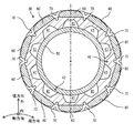
図1は、本発明の実施形態1に係るモータ100の断面模式図である。なお、図1は、モータ100の構造を模式的に図示しているものであって、実際の形状及び寸法とは異なっている。 (Embodiment 1)
[Motor configuration]
FIG. 1 is a schematic cross-sectional view of themotor 100 according to the first embodiment of the present invention. Note that FIG. 1 schematically illustrates the structure of the motor 100, and is different from the actual shape and dimensions.
[モータの構成]
図1は、本発明の実施形態1に係るモータ100の断面模式図である。なお、図1は、モータ100の構造を模式的に図示しているものであって、実際の形状及び寸法とは異なっている。 (Embodiment 1)
[Motor configuration]
FIG. 1 is a schematic cross-sectional view of the
図1に示すように、モータ100は、モータケース10と、ブラケット20と、ロータ30と、ステータ80と、軸受91,92とを備えている。なお、以降の説明において、ロータ30の半径方向を径方向と、ロータ30の外周方向を周方向と、ロータ30に設けられたシャフト50の延びる方向を軸方向と、それぞれ呼ぶ。軸方向に延びるシャフト50の中心線を回転軸線または単に軸線と呼ぶ。軸方向は軸線と平行な方向に相当する。径方向において、ロータバックヨーク40の軸心側を径方向内側または単に内側と呼ぶ。ステータ80が配設された側を径方向外側または単に外側と呼ぶ。
As shown in FIG. 1, the motor 100 includes a motor case 10, a bracket 20, a rotor 30, a stator 80, and bearings 91 and 92. In the following description, the radial direction of the rotor 30 is referred to as a radial direction, the outer peripheral direction of the rotor 30 is referred to as a circumferential direction, and the extending direction of the shaft 50 provided on the rotor 30 is referred to as an axial direction. The center line of the shaft 50 extending in the axial direction is called a rotation axis or simply an axis. The axial direction corresponds to the direction parallel to the axis. In the radial direction, the axial side of the rotor back yoke 40 is referred to as the radial inner side or simply the inner side. The side on which the stator 80 is arranged is referred to as the radial outer side or simply the outer side.
モータケース10は、両端が開口された有底筒状の金属部材である。モータケース10の内部にロータ30とステータ80とが収容される。モータケース10の開口を覆うようにブラケット20が設けられている。
The motor case 10 is a bottomed tubular metal member with both ends open. The rotor 30 and the stator 80 are housed inside the motor case 10. A bracket 20 is provided so as to cover the opening of the motor case 10.
ロータ30は、モータケース10の内部に収容されている。ロータバックヨーク40にシャフト50が挿通されている。ロータバックヨーク40には、その外周面に周方向に沿って複数の磁石60が配置されている。互いに隣り合う磁石60は磁極の極性が異なっている。シャフト50の一方の端部は、ブラケット20を貫通して、モータケース10の外部に突出するように設けられている。ロータ30及びロータ30の各部品の構造等については後で詳述する。
The rotor 30 is housed inside the motor case 10. The shaft 50 is inserted through the rotor back yoke 40. A plurality of magnets 60 are arranged on the outer peripheral surface of the rotor back yoke 40 along the circumferential direction. The magnets 60 adjacent to each other have different polarities. One end of the shaft 50 is provided so as to penetrate the bracket 20 and project to the outside of the motor case 10. The structure and the like of the rotor 30 and each component of the rotor 30 will be described in detail later.
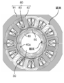
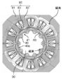
図3Aは、ロータ30及びステータ80での磁束の流れを示す断面模式図である。図3Bは、ロータ30及びステータ80での磁束の流れを示す断面模式図である。ステータ80は、モータケース10の内部に収容されている。ステータ80は、ロータ30の径方向外側にロータ30と所定の間隔をあけて設けられている。ステータ80は、モータケース10の内周面に固定されたヨーク81と、ヨーク81の周方向に沿って所定の間隔をあけて設けられた複数の突極82(図3Aと図3Bを参照)と、複数の突極82のそれぞれに巻回された複数のコイル83とで構成されている。
FIG. 3A is a schematic cross-sectional view showing the flow of magnetic flux in the rotor 30 and the stator 80. FIG. 3B is a schematic cross-sectional view showing the flow of magnetic flux in the rotor 30 and the stator 80. The stator 80 is housed inside the motor case 10. The stator 80 is provided on the outer side in the radial direction of the rotor 30 at a predetermined distance from the rotor 30. The stator 80 includes a yoke 81 fixed to the inner peripheral surface of the motor case 10 and a plurality of salient poles 82 provided at predetermined intervals along the circumferential direction of the yoke 81 (see FIGS. 3A and 3B). And a plurality of coils 83 wound around each of the plurality of salient poles 82.
軸受91,92はモータケース10の内部にそれぞれ取付けられ、シャフト50を回転軸線回りに回転可能に支持している。
The bearings 91 and 92 are mounted inside the motor case 10, respectively, and support the shaft 50 so as to be rotatable around the rotation axis.
以上説明したように、図1に示すモータ100は磁石60がロータバックヨーク40の外周面に配置された、いわゆるSPM(Surface Permanent Magnet)モータである、
モータ100は、以下のように動作する。図示しない電源接続部を通じて、互いに電気角で120°の位相差を有する3相の電流がそれぞれ複数のコイル83に供給されてステータ80が励磁され、回転磁界が発生する。この回転磁界と、ロータ30に設けられた磁石60が発生する磁界とが相互作用して、ロータ30に回転トルクが発生し、シャフト50が軸受91,92に支持されて回転軸線回りに回転する。 As described above, themotor 100 shown in FIG. 1 is a so-called SPM (Surface Permanent Magnet) motor in which the magnet 60 is arranged on the outer peripheral surface of the rotor back yoke 40.
Themotor 100 operates as follows. Through a power supply connection (not shown), a three-phase current having a phase difference of 120 ° in electrical angle is supplied to each of the plurality of coils 83 to excite the stator 80, and a rotating magnetic field is generated. This rotating magnetic field and the magnetic field generated by the magnet 60 provided in the rotor 30 interact with each other to generate rotational torque in the rotor 30, and the shaft 50 is supported by the bearings 91 and 92 and rotates around the rotation axis. ..
モータ100は、以下のように動作する。図示しない電源接続部を通じて、互いに電気角で120°の位相差を有する3相の電流がそれぞれ複数のコイル83に供給されてステータ80が励磁され、回転磁界が発生する。この回転磁界と、ロータ30に設けられた磁石60が発生する磁界とが相互作用して、ロータ30に回転トルクが発生し、シャフト50が軸受91,92に支持されて回転軸線回りに回転する。 As described above, the
The
[ロータの構成]
図2は、図1のII-II線での断面を示す断面模式図である。す。図2は、軸方向と直交する断面でのロータの模式図に相当する。図3A及び図3Bは、ロータ及びステータにおける磁束の流れを模式的に示す。図3Aは、比較のためのロータ30及びステータ80を示す。図3Bは、本実施形態に係るロータ30及びステータ80を示す。図3A及び図3Bは、図2と同様に軸方向と直交する断面を示している。説明を分かりやすくするために、図3A及び図3Bにおいてシャフト50の図示を省略している。 [Rotor configuration]
FIG. 2 is a schematic cross-sectional view showing a cross section taken along line II-II of FIG. Su. FIG. 2 corresponds to a schematic view of the rotor in a cross section orthogonal to the axial direction. 3A and 3B schematically show the flow of magnetic flux in the rotor and stator. FIG. 3A shows arotor 30 and a stator 80 for comparison. FIG. 3B shows a rotor 30 and a stator 80 according to this embodiment. 3A and 3B show a cross section orthogonal to the axial direction as in FIG. For the sake of clarity, the shaft 50 is not shown in FIGS. 3A and 3B.
図2は、図1のII-II線での断面を示す断面模式図である。す。図2は、軸方向と直交する断面でのロータの模式図に相当する。図3A及び図3Bは、ロータ及びステータにおける磁束の流れを模式的に示す。図3Aは、比較のためのロータ30及びステータ80を示す。図3Bは、本実施形態に係るロータ30及びステータ80を示す。図3A及び図3Bは、図2と同様に軸方向と直交する断面を示している。説明を分かりやすくするために、図3A及び図3Bにおいてシャフト50の図示を省略している。 [Rotor configuration]
FIG. 2 is a schematic cross-sectional view showing a cross section taken along line II-II of FIG. Su. FIG. 2 corresponds to a schematic view of the rotor in a cross section orthogonal to the axial direction. 3A and 3B schematically show the flow of magnetic flux in the rotor and stator. FIG. 3A shows a
図2に示すように、ロータ30はシャフト50とロータバックヨーク40と複数の磁石60とを有している。シャフト50は回転軸線回りに回転可能に設けられた、いわゆる中空シャフトである。
As shown in FIG. 2, the rotor 30 has a shaft 50, a rotor back yoke 40, and a plurality of magnets 60. The shaft 50 is a so-called hollow shaft rotatably provided around the rotation axis.
ロータバックヨーク40は、軸心に貫通孔42を有している。ロータバックヨーク40は、シャフト50が貫通孔42に挿通されてシャフト50に回転一体に連結されている。ロータバックヨーク40は、環状に形成された所定形状の複数の電磁鋼板を軸方向に積層して構成される。ロータバックヨーク40は、その内周面から径方向外側に向かって延びるような形状をしている。ロータバックヨーク40は、周方向に所定の間隔をあけて設けられた複数の第1切り欠き部41を有している。なお、ロータバックヨーク40の貫通孔42にシャフト50が圧入されることで、ロータバックヨーク40はシャフト50に回転一体に連結される。
The rotor back yoke 40 has a through hole 42 in the axial center. In the rotor back yoke 40, the shaft 50 is inserted through the through hole 42 and is rotationally and integrally connected to the shaft 50. The rotor back yoke 40 is formed by laminating a plurality of electromagnetic steel plates having a predetermined shape formed in an annular shape in the axial direction. The rotor back yoke 40 is shaped so as to extend radially outward from its inner peripheral surface. The rotor back yoke 40 has a plurality of first notch portions 41 provided at predetermined intervals in the circumferential direction. By press-fitting the shaft 50 into the through hole 42 of the rotor back yoke 40, the rotor back yoke 40 is rotationally and integrally connected to the shaft 50.
軸方向から見て、回転軸線と磁石60の中心、つまり磁極の中心とを通る仮想線上に第1切り欠き部41が設けられている。複数の第1切り欠き部41の各々は、軸方向に沿ってロータバックヨーク40の一端面からこれと対向する他端面まで延びて設けられている。
The first notch 41 is provided on a virtual line passing through the rotation axis and the center of the magnet 60, that is, the center of the magnetic pole when viewed from the axial direction. Each of the plurality of first notch portions 41 extends from one end surface of the rotor back yoke 40 to the other end surface facing the rotor back yoke 40 along the axial direction.
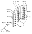
図4Bは、実施形態1に係るロータバックヨークの部分斜視図である。ロータバックヨーク40は、所定の形状を有する複数の電磁鋼板(図示せず)が軸方向に積層された複数の分割バックヨーク44を周方向に接続することで構成されている。複数の磁石60はそれぞれ、周方向に所定の間隔をあけてロータバックヨーク40の外周面に配置されるとともに、樹脂モールド部70に覆われて、当該外周面に固着されている。
FIG. 4B is a partial perspective view of the rotor back yoke according to the first embodiment. The rotor back yoke 40 is configured by connecting a plurality of divided back yokes 44 in which a plurality of electromagnetic steel plates (not shown) having a predetermined shape are laminated in the axial direction in the circumferential direction. Each of the plurality of magnets 60 is arranged on the outer peripheral surface of the rotor back yoke 40 at a predetermined interval in the circumferential direction, and is covered with the resin mold portion 70 and fixed to the outer peripheral surface.
このように構成されたロータ30を有するモータ100において、ステータ80に設けられた所定のコイル83に電流を流すと、図3A及び図3Bに示すように、ステータ80及びロータ30のそれぞれに磁束が流れる。このとき、図3Aに示すように、互いに隣り合う磁石60の間に位置するロータバックヨーク40では、磁束密度が高くなる一方、ロータバックヨーク40の軸心と磁石60の中心(磁極の中心)とを通る仮想線上では磁束密度が低くなっている。従って、前述したように、回転軸線と磁石60の中心(磁極の中心)とを通る仮想線上に第1切り欠き部41を設けることで、図3Bに示すように、磁石60と接するロータバックヨーク40の外周部40a(図4B参照)には磁束の飽和を生じない磁路が形成される。
In the motor 100 having the rotor 30 configured in this way, when a current is passed through a predetermined coil 83 provided in the stator 80, magnetic flux is generated in each of the stator 80 and the rotor 30 as shown in FIGS. 3A and 3B. It flows. At this time, as shown in FIG. 3A, in the rotor back yoke 40 located between the magnets 60 adjacent to each other, the magnetic flux density is high, while the axis of the rotor back yoke 40 and the center of the magnet 60 (center of the magnetic pole). The magnetic flux density is low on the virtual line passing through. Therefore, as described above, by providing the first notch 41 on the virtual line passing through the rotation axis and the center of the magnet 60 (center of the magnetic pole), the rotor back yoke in contact with the magnet 60 is provided as shown in FIG. 3B. A magnetic path that does not cause magnetic flux saturation is formed in the outer peripheral portion 40a (see FIG. 4B) of 40.
このようにすることで、本実施形態のモータ100は、図3Aに示すロータ30を有するモータ100とトルクがほぼ同じとなる。
By doing so, the motor 100 of the present embodiment has substantially the same torque as the motor 100 having the rotor 30 shown in FIG. 3A.
[効果等]
以上説明したように、本実施形態に係るロータ30は、回転軸線の回りに回転可能に設けられたシャフト50と、軸心に貫通孔42を有し、シャフト50が貫通孔42に挿通されてシャフト50に回転一体に連結されたロータバックヨーク40と、ロータバックヨーク40の外周面に固着され、ロータバックヨーク40の外周方向である周方向に沿って互いに異なる極性の磁極が交互に配置された磁石60と、を備えている。 [Effects, etc.]
As described above, therotor 30 according to the present embodiment has a shaft 50 rotatably provided around the rotation axis and a through hole 42 at the axis, and the shaft 50 is inserted through the through hole 42. The rotor back yoke 40, which is rotationally and integrally connected to the shaft 50, is fixed to the outer peripheral surface of the rotor back yoke 40, and magnetic poles having different polarities are alternately arranged along the circumferential direction, which is the outer peripheral direction of the rotor back yoke 40. The magnet 60 is provided.
以上説明したように、本実施形態に係るロータ30は、回転軸線の回りに回転可能に設けられたシャフト50と、軸心に貫通孔42を有し、シャフト50が貫通孔42に挿通されてシャフト50に回転一体に連結されたロータバックヨーク40と、ロータバックヨーク40の外周面に固着され、ロータバックヨーク40の外周方向である周方向に沿って互いに異なる極性の磁極が交互に配置された磁石60と、を備えている。 [Effects, etc.]
As described above, the
ロータバックヨーク40は、ロータバックヨーク40の内周面からロータバックヨーク40の半径方向である径方向外側に向かって延びるように、かつ周方向に所定の間隔をあけて設けられた複数の第1切り欠き部41を有している。複数の第1切り欠き部41の各々は、軸線と平行な方向に沿ってロータバックヨーク40の一端面から一端面と対向する他端面まで延びている。
The rotor back yoke 40 is provided so as to extend from the inner peripheral surface of the rotor back yoke 40 toward the radial outer side in the radial direction of the rotor back yoke 40 and at predetermined intervals in the circumferential direction. It has one notch 41. Each of the plurality of first notch portions 41 extends from one end surface of the rotor back yoke 40 to the other end surface facing the one end surface along a direction parallel to the axis.
ロータ30をこのように構成することで、ロータバックヨーク40の質量を低減して、ロータ30のイナーシャを低減できる。これにより、モータ100の応答性を高めることができる。特に、ブレーキ制御に用いられるモータ100において、速度-トルク(S-T)特性の全域に亘って、モータ100の応答性を高める必要があるが、本実施形態によれば、この要求を満足することができる。
By configuring the rotor 30 in this way, the mass of the rotor back yoke 40 can be reduced and the inertia of the rotor 30 can be reduced. Thereby, the responsiveness of the motor 100 can be improved. In particular, in the motor 100 used for brake control, it is necessary to improve the responsiveness of the motor 100 over the entire range of speed-torque (ST) characteristics, but according to the present embodiment, this requirement is satisfied. be able to.
また、ロータ30のイナーシャを低減するために、ロータバックヨーク40の外径とシャフト50の直径とが近くなるようにロータ30の設計がなされる場合がある。しかし、このような場合、特許文献1~3に開示された従来の構成では、シャフト50を囲むようにロータバックヨーク40を残す必要があり、肉抜き部を大きくすることが難しい。したがって、ロータバックヨーク40の質量を十分に低減できなかった。
Further, in order to reduce the inertia of the rotor 30, the rotor 30 may be designed so that the outer diameter of the rotor back yoke 40 and the diameter of the shaft 50 are close to each other. However, in such a case, in the conventional configuration disclosed in Patent Documents 1 to 3, it is necessary to leave the rotor back yoke 40 so as to surround the shaft 50, and it is difficult to increase the lightening portion. Therefore, the mass of the rotor back yoke 40 could not be sufficiently reduced.
しかし、本実施形態によれば、シャフト50の内周面に到達するように第1切り欠き部41を設けることで、ロータバックヨーク40の質量を容易に低減することができる。外周部40aを残しつつロータバックヨーク40の内周面に到るように第1切り欠き部41を設けている。このため、ロータ30のイナーシャを低減しつつ、モータ100のトルクの低下を抑制することができる。
However, according to the present embodiment, the mass of the rotor back yoke 40 can be easily reduced by providing the first notch 41 so as to reach the inner peripheral surface of the shaft 50. The first notch 41 is provided so as to reach the inner peripheral surface of the rotor back yoke 40 while leaving the outer peripheral portion 40a. Therefore, it is possible to suppress a decrease in the torque of the motor 100 while reducing the inertia of the rotor 30.
また、ロータバックヨーク40の外径とシャフト50の直径との間に一定以上の差が設けられる場合も、本実施形態のロータ30は有用である、前述したように、ロータバックヨーク40を電磁鋼板が積層された分割バックヨーク44を周方向に接続して構成する場合、電磁鋼板のそれぞれの形状を同じにできる。このため、ロータバックヨーク40の設計及び組立が容易となる。なお、ロータバックヨーク40の強度は、第1切り欠き部41の周方向の幅を適切に設定することで確保できる。
Further, the rotor 30 of the present embodiment is also useful when a difference of a certain value or more is provided between the outer diameter of the rotor back yoke 40 and the diameter of the shaft 50. As described above, the rotor back yoke 40 is electromagnetically mounted. When the split back yoke 44 in which the steel plates are laminated is connected in the circumferential direction, the shapes of the electromagnetic steel plates can be the same. Therefore, the design and assembly of the rotor back yoke 40 becomes easy. The strength of the rotor back yoke 40 can be ensured by appropriately setting the width of the first notch 41 in the circumferential direction.
また、軸方向に沿ってロータバックヨーク40の一端面から他端面まで延びるように第1切り欠き部41を形成することで、ロータバックヨーク40の質量をより低減できる。
Further, the mass of the rotor back yoke 40 can be further reduced by forming the first notch 41 so as to extend from one end surface to the other end surface of the rotor back yoke 40 along the axial direction.
磁石60と接するロータバックヨーク40の外周部40aは、磁束の飽和を生じない磁路を有しているのが好ましい。
It is preferable that the outer peripheral portion 40a of the rotor back yoke 40 in contact with the magnet 60 has a magnetic path that does not cause saturation of magnetic flux.
このようにすることで、ロータ30で発生する磁束を有効に利用できる。したがって、モータ100のトルクの低下を抑制できる。
By doing so, the magnetic flux generated by the rotor 30 can be effectively used. Therefore, it is possible to suppress a decrease in the torque of the motor 100.
また、回転軸線と平行な方向、つまり、軸方向から見て、ロータバックヨーク40の軸心と磁石60の磁極の中心とを通る仮想線上に第1切り欠き部41がそれぞれ設けられているのが好ましい。
Further, the first notch 41 is provided in a direction parallel to the rotation axis, that is, on a virtual line passing through the axis of the rotor back yoke 40 and the center of the magnetic pole of the magnet 60 when viewed from the axial direction. Is preferable.
このようにすることで、磁石60と接するロータバックヨーク40の外周部40aに磁束の飽和を生じない磁路を形成することができる。よって、ロータ30で発生する磁束を有効に利用できる。したがって、モータ100のトルクの低下を抑制できる。
By doing so, it is possible to form a magnetic path that does not cause magnetic flux saturation on the outer peripheral portion 40a of the rotor back yoke 40 that is in contact with the magnet 60. Therefore, the magnetic flux generated by the rotor 30 can be effectively used. Therefore, it is possible to suppress a decrease in the torque of the motor 100.
また、シャフト50を中空構造とすることで、シャフト50の質量を低減できる。よって、ロータ30のイナーシャをさらに低減できる。このことにより、モータ100の応答性をより高めることができる。なお、シャフト50の強度、言い換えると、シャフト50の材質及び中空率は、モータ100の仕様及び負荷等に応じて適宜決められる。
Further, by making the shaft 50 a hollow structure, the mass of the shaft 50 can be reduced. Therefore, the inertia of the rotor 30 can be further reduced. This makes it possible to further improve the responsiveness of the motor 100. The strength of the shaft 50, in other words, the material and the hollow ratio of the shaft 50 are appropriately determined according to the specifications of the motor 100, the load, and the like.
また、複数の磁石60は、周方向に所定の間隔をあけて設けられており、互いに隣り合う磁石60は互いに磁極が異なっていることが好ましい。
Further, it is preferable that the plurality of magnets 60 are provided at predetermined intervals in the circumferential direction, and the magnets 60 adjacent to each other have different magnetic poles.
本実施形態に係るモータは、ロータ30と、ロータバックヨーク40と径方向外側に所定の間隔をあけて設けられたステータ80と、を少なくとも備えている。
The motor according to the present embodiment includes at least a rotor 30, a rotor back yoke 40, and a stator 80 provided at a predetermined distance on the outer side in the radial direction.
本実施形態によれば、ロータバックヨーク40の質量、ひいてはロータ30のイナーシャが低減できる。このため、高い応答性を有するSPMモータを実現することができる。
According to this embodiment, the mass of the rotor back yoke 40 and, by extension, the inertia of the rotor 30 can be reduced. Therefore, an SPM motor having high responsiveness can be realized.
<変形例>
図4Aは、変形例に係るロータバックヨーク40の部分斜視図である。図4Bは、実施形態1に係るロータバックヨーク40の部分斜視図である。なお、図4Aにおいて、実施形態1と同様の箇所については同一の符号を付して詳細な説明を省略する。 <Modification example>
FIG. 4A is a partial perspective view of the rotor backyoke 40 according to the modified example. FIG. 4B is a partial perspective view of the rotor back yoke 40 according to the first embodiment. In FIG. 4A, the same parts as those in the first embodiment are designated by the same reference numerals, and detailed description thereof will be omitted.
図4Aは、変形例に係るロータバックヨーク40の部分斜視図である。図4Bは、実施形態1に係るロータバックヨーク40の部分斜視図である。なお、図4Aにおいて、実施形態1と同様の箇所については同一の符号を付して詳細な説明を省略する。 <Modification example>
FIG. 4A is a partial perspective view of the rotor back
図4Aに示すように、本変形例に係る構成は、ロータバックヨーク40の内周面に、軸方向に沿って所定の間隔をあけて複数の第2切り欠き部43が設けられている。この点で実施形態1に示す構成、つまり、図4Bに示す構成と異なる。
As shown in FIG. 4A, in the configuration according to this modification, a plurality of second cutout portions 43 are provided on the inner peripheral surface of the rotor back yoke 40 at predetermined intervals along the axial direction. In this respect, it differs from the configuration shown in the first embodiment, that is, the configuration shown in FIG. 4B.
本変形例によれば、ロータバックヨーク40の質量、ひいてはロータ30のイナーシャをさらに低減できる。例えば、図3Aに示すロータバックヨーク40を図1に示すモータ100に適用することで、実施形態1に示す場合に比べて、ロータバックヨーク40の質量を約4%、ロータ30のイナーシャを約3%低減することができる。
According to this modification, the mass of the rotor back yoke 40 and, by extension, the inertia of the rotor 30 can be further reduced. For example, by applying the rotor back yoke 40 shown in FIG. 3A to the motor 100 shown in FIG. 1, the mass of the rotor back yoke 40 is reduced by about 4% and the inertia of the rotor 30 is reduced by about 4% as compared with the case shown in the first embodiment. It can be reduced by 3%.
(実施形態2)
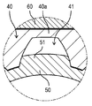
図5Aは、本発明の実施形態2に係るロータの断面模式図である。図5Bは図5Aにおける破線で囲まれた部分の拡大図である。なお、図5Aにおいて、実施形態1と同様の箇所については同一の符号を付して詳細な説明を省略する。 (Embodiment 2)
FIG. 5A is a schematic cross-sectional view of the rotor according to the second embodiment of the present invention. FIG. 5B is an enlarged view of the portion surrounded by the broken line in FIG. 5A. In FIG. 5A, the same parts as those in the first embodiment are designated by the same reference numerals, and detailed description thereof will be omitted.
図5A及び図5Bに示すように、本実施形態に係る構成は、以下の点で実施形態1に示す構成と異なる。シャフト50に、周方向に沿って所定の間隔をあけて複数の歯部51が設けられている。歯部51は、シャフト50を外周面から切り欠くことで形成されている。歯部51の歯先はシャフト50の外周面に相当する。歯部51と第1切り欠き部41とが互いにインボリュート嵌合している。具体的には、互いに隣り合う2つの歯部51と1つの第1切り欠き部41とが互いにインボリュート嵌合している。
As shown in FIGS. 5A and 5B, the configuration according to the present embodiment is different from the configuration shown in the first embodiment in the following points. A plurality of tooth portions 51 are provided on the shaft 50 at predetermined intervals along the circumferential direction. The tooth portion 51 is formed by cutting out the shaft 50 from the outer peripheral surface. The tooth tip of the tooth portion 51 corresponds to the outer peripheral surface of the shaft 50. The tooth portion 51 and the first notch portion 41 are involute-fitted to each other. Specifically, two tooth portions 51 adjacent to each other and one first notch portion 41 are involute-fitted to each other.
また、歯部51の歯面と第1切り欠き部41の側面、いわば、第1切り欠き部41の歯面とは歯面合わせがなされて、2つの歯部51と1つの第1切り欠き部41とが互いにインボリュート嵌合するように、それぞれ形状が設定されている。また、ロータ30の内周面と歯部51の歯元とは所定の間隔をあけて配置され、歯部51の歯先と第1切り欠き部41の底面とは同様に所定の間隔をあけて配置されている。
Further, the tooth surface of the tooth portion 51 and the side surface of the first notch portion 41, so to speak, the tooth surface of the first notch portion 41 are aligned with each other, and the two tooth portions 51 and one first notch are aligned. The shapes are set so that the portions 41 and the portions 41 are involutely fitted to each other. Further, the inner peripheral surface of the rotor 30 and the tooth root of the tooth portion 51 are arranged at a predetermined distance, and the tooth tip of the tooth portion 51 and the bottom surface of the first notch portion 41 are similarly spaced apart from each other. Are arranged.
本実施形態によれば、実施形態1の構成に対して、ロータ30のイナーシャをさらに低減して、モータ100の応答性を向上させることができる。具体的には、シャフト50の肉厚を部分的に薄くすることで、シャフト50自体の質量を低減し、ロータ30のイナーシャをさらに低減できる。
According to the present embodiment, the inertia of the rotor 30 can be further reduced and the responsiveness of the motor 100 can be improved with respect to the configuration of the first embodiment. Specifically, by partially reducing the wall thickness of the shaft 50, the mass of the shaft 50 itself can be reduced, and the inertia of the rotor 30 can be further reduced.
また、歯部51と第1切り欠き部41とを互いにインボリュート嵌合させることで、シャフト50とロータバックヨーク40との結合力を高められる。よって、モータ100の回転時にロータバックヨーク40が空転するのを防止することができる。したがって、モータ100のトルク低下を抑制できる。
Further, by involute fitting the tooth portion 51 and the first notch portion 41 to each other, the coupling force between the shaft 50 and the rotor back yoke 40 can be enhanced. Therefore, it is possible to prevent the rotor back yoke 40 from idling when the motor 100 rotates. Therefore, it is possible to suppress a decrease in torque of the motor 100.
また、歯部51の歯面と第1切り欠き部41の側面とが互いに歯面合わせされているため、シャフト50及びロータバックヨーク40の形状管理が容易となる。
Further, since the tooth surface of the tooth portion 51 and the side surface of the first notch portion 41 are aligned with each other, the shape management of the shaft 50 and the rotor back yoke 40 becomes easy.
なお、本実施形態では、互いに隣り合う2つの歯部51と1つの第1切り欠き部41とが互いにインボリュート嵌合した例を示した。しかし、特にこれに限定されない。互いに隣り合う3つ以上の歯部51と1つの第1切り欠き部41とが互いにインボリュート嵌合するようにしてもよい。また、図6Aに示すようにロータ30を構成してもよい。
In the present embodiment, an example is shown in which two tooth portions 51 adjacent to each other and one first notch portion 41 are involute-fitted to each other. However, it is not particularly limited to this. The three or more tooth portions 51 adjacent to each other and the one first notch portion 41 may be involute-fitted to each other. Further, the rotor 30 may be configured as shown in FIG. 6A.
図6Aは、本発明の実施形態2に係る別のロータの断面模式図である。図6Bは、図6Aにおける破線で囲まれた部分の拡大図である。なお、図6A及び図6Bにおいて、実施形態1と同様の箇所については同一の符号を付して詳細な説明を省略する。
FIG. 6A is a schematic cross-sectional view of another rotor according to the second embodiment of the present invention. FIG. 6B is an enlarged view of the portion surrounded by the broken line in FIG. 6A. In FIGS. 6A and 6B, the same parts as those in the first embodiment are designated by the same reference numerals, and detailed description thereof will be omitted.
図6Aに示すように、1つの歯部51と1つの第1切り欠き部41とが互いにインボリュート嵌合するようにしてもよい。
As shown in FIG. 6A, one tooth portion 51 and one first notch portion 41 may be involute-fitted to each other.
なお、複数の歯部51が1つの第1切り欠き部41にインボリュート嵌合するようにロータ30を構成することで、歯部51の体積、ひいてはシャフト50の質量をより大きく低減できる。これにより、ロータ30のイナーシャをより大きく低減できる。
By configuring the rotor 30 so that the plurality of tooth portions 51 are involutely fitted to one first notch portion 41, the volume of the tooth portions 51 and the mass of the shaft 50 can be further reduced. As a result, the inertia of the rotor 30 can be further reduced.
以上のように、本実施の形態のロータ30は、シャフト50には、複数の歯部51が周方向に沿って所定の間隔をあけて設けられており、複数の歯部51と複数の第1切り欠き部41とが互いにインボリュート嵌合していてもよい。
As described above, in the rotor 30 of the present embodiment, a plurality of tooth portions 51 are provided on the shaft 50 at predetermined intervals along the circumferential direction, and the plurality of tooth portions 51 and the plurality of tooth portions 51 are provided. 1 The cutout portion 41 may be involute-fitted to each other.
また、複数の歯部51のうち互いに隣り合う2つの歯部と複数の第1切り欠き部41の1つとが互いにインボリュート嵌合していてもよい。
Further, of the plurality of tooth portions 51, two tooth portions adjacent to each other and one of the plurality of first notch portions 41 may be involute-fitted to each other.
(その他の実施形態)
変形例を含む実施形態1,2に示す各構成要素を適宜組み合わせて、新たな実施形態とすることもできる。例えば、変形例に示す第2切り欠き部43を実施形態2に示すロータバックヨーク40に適用してもよい。また、ロータ30のイナーシャに関してモータ100の要求性能を満たしていれば、シャフト50を中実構造としてもよい。 (Other embodiments)
Each component shown in the first and second embodiments including the modification can be appropriately combined to form a new embodiment. For example, thesecond notch 43 shown in the modified example may be applied to the rotor back yoke 40 shown in the second embodiment. Further, the shaft 50 may have a solid structure as long as it satisfies the required performance of the motor 100 with respect to the inertia of the rotor 30.
変形例を含む実施形態1,2に示す各構成要素を適宜組み合わせて、新たな実施形態とすることもできる。例えば、変形例に示す第2切り欠き部43を実施形態2に示すロータバックヨーク40に適用してもよい。また、ロータ30のイナーシャに関してモータ100の要求性能を満たしていれば、シャフト50を中実構造としてもよい。 (Other embodiments)
Each component shown in the first and second embodiments including the modification can be appropriately combined to form a new embodiment. For example, the
また、変形例を含む実施形態1,2において、複数の磁石60がロータバックヨーク40の外周面に固着された例を示したが、周方向に沿って互いに異なる磁極が交互に配置された環状の磁石60が当該外周面に固着されていてもよい。
Further, in the first and second embodiments including the modified example, an example in which a plurality of magnets 60 are fixed to the outer peripheral surface of the rotor back yoke 40 is shown, but different magnetic poles are alternately arranged along the circumferential direction. Magnet 60 may be fixed to the outer peripheral surface.
また、シャフト50とロータバックヨーク40との連結方法は、圧入に限られず、他の方法を用いてもよい。例えば、レーザ溶接により、シャフト50とロータバックヨーク40とを互いに接合するようにしてもよい。
Further, the method of connecting the shaft 50 and the rotor back yoke 40 is not limited to press-fitting, and other methods may be used. For example, the shaft 50 and the rotor back yoke 40 may be joined to each other by laser welding.
本発明のロータは、ロータバックヨークの質量を低減して、ロータのイナーシャを低減でき、高い応答性を要するSPMモータに適用する上で有用である。
The rotor of the present invention can reduce the mass of the rotor back yoke, reduce the inertia of the rotor, and is useful for application to an SPM motor that requires high responsiveness.
10 モータケース
20 ブラケット
30 ロータ
40 ロータバックヨーク
40a 外周部
41 第1切り欠き部
42 貫通孔
43 第2切り欠き部
44 分割バックヨーク
50 シャフト
51 歯部
60 磁石
70 樹脂モールド部
80 ステータ
81 ヨーク
82 突極
83 コイル
91,92 軸受
100 モータ 10Motor case 20 Bracket 30 Rotor 40 Rotor back yoke 40a Outer circumference 41 First notch 42 Through hole 43 Second notch 44 Divided back yoke 50 Shaft 51 Tooth 60 Magnet 70 Resin mold 80 Stator 81 Yoke 82 protrusion Pole 83 Coil 91,92 Bearing 100 Motor
20 ブラケット
30 ロータ
40 ロータバックヨーク
40a 外周部
41 第1切り欠き部
42 貫通孔
43 第2切り欠き部
44 分割バックヨーク
50 シャフト
51 歯部
60 磁石
70 樹脂モールド部
80 ステータ
81 ヨーク
82 突極
83 コイル
91,92 軸受
100 モータ 10
Claims (8)
- 軸線の回りに回転可能に設けられたシャフトと、
軸心に貫通孔を有し、前記シャフトが前記貫通孔に挿通されて前記シャフトに回転一体に連結されたロータバックヨークと、
前記ロータバックヨークの外周面に固着され、前記ロータバックヨークの外周方向である周方向に沿って互いに異なる極性の磁極が交互に配置された複数の磁石と、
を備えたロータであって、
前記ロータバックヨークは、前記ロータバックヨークの内周面から前記ロータバックヨークの半径方向である径方向の外側に向かって延びるように、かつ前記周方向に所定の間隔をあけて設けられた複数の第1切り欠き部を有し、
前記複数の第1切り欠き部の各々は、前記軸線と平行な方向に沿って前記ロータバックヨークの一端面から前記一端面と対向する他端面まで延びているロータ。 A shaft that is rotatably provided around the axis and
A rotor back yoke having a through hole in the shaft center, the shaft being inserted through the through hole, and rotationally integrally connected to the shaft.
A plurality of magnets fixed to the outer peripheral surface of the rotor back yoke and having magnetic poles having different polarities alternately arranged along the circumferential direction which is the outer peripheral direction of the rotor back yoke.
It is a rotor equipped with
A plurality of the rotor back yokes are provided so as to extend from the inner peripheral surface of the rotor back yoke toward the outer side in the radial direction which is the radial direction of the rotor back yoke, and at predetermined intervals in the circumferential direction. Has the first notch of
Each of the plurality of first notch portions extends from one end surface of the rotor back yoke to the other end surface facing the one end surface along a direction parallel to the axis. - 前記複数の磁石は、前記周方向に所定の間隔をあけて設けられており、
互いに隣り合う磁石は互いに磁極が異なっている請求項1に記載のロータ。 The plurality of magnets are provided at predetermined intervals in the circumferential direction.
The rotor according to claim 1, wherein the magnets adjacent to each other have different magnetic poles. - 前記複数の磁石と接する前記ロータバックヨークの外周部は、磁束の飽和を生じない磁路を有している請求項1または2に記載のロータ。 The rotor according to claim 1 or 2, wherein the outer peripheral portion of the rotor back yoke in contact with the plurality of magnets has a magnetic path that does not cause saturation of magnetic flux.
- 前記軸線と平行な方向から見て、前記ロータバックヨークの軸心と前記磁極の中心とを通る仮想線上に前記複数の第1切り欠き部が設けられている請求項1~3のいずれか1項に記載のロータ。 Any one of claims 1 to 3 in which the plurality of first notches are provided on a virtual line passing through the axis of the rotor back yoke and the center of the magnetic poles when viewed from a direction parallel to the axis. The rotor described in the section.
- 前記ロータバックヨークの内周面には、前記軸線と平行な方向に沿って所定の間隔をあけて複数の第2切り欠き部が設けられている請求項1~4のいずれか1項に記載のロータ。 The invention according to any one of claims 1 to 4, wherein a plurality of second notches are provided on the inner peripheral surface of the rotor back yoke at predetermined intervals along a direction parallel to the axis. Rotor.
- 前記シャフトには、複数の歯部が前記周方向に沿って所定の間隔をあけて設けられており、
前記複数の歯部と前記複数の第1切り欠き部とが互いにインボリュート嵌合している請求項1~5のいずれか1項に記載のロータ。 A plurality of tooth portions are provided on the shaft at predetermined intervals along the circumferential direction.
The rotor according to any one of claims 1 to 5, wherein the plurality of tooth portions and the plurality of first notch portions are involutely fitted to each other. - 前記複数の歯部のうち互いに隣り合う2つの歯部と前記複数の第1切り欠き部の1つとが互いにインボリュート嵌合している請求項6に記載のロータ。 The rotor according to claim 6, wherein two of the plurality of tooth portions adjacent to each other and one of the plurality of first notch portions are involute-fitted to each other.
- 請求項1~7のいずれか1項に記載のロータと、
前記ロータバックヨークと前記径方向の外側に所定の間隔をあけて設けられたステータと、を少なくとも備えたモータ。 The rotor according to any one of claims 1 to 7.
A motor including at least the rotor back yoke and a stator provided at a predetermined distance on the outer side in the radial direction.
Priority Applications (3)
| Application Number | Priority Date | Filing Date | Title |
|---|---|---|---|
| CN202080034584.8A CN113812064B (en) | 2019-05-15 | 2020-04-16 | Motor with a motor housing having a motor housing with a motor housing |
| US17/608,761 US20220255380A1 (en) | 2019-05-15 | 2020-04-16 | Rotor and motor provided with same |
| EP20805879.2A EP3972089A4 (en) | 2019-05-15 | 2020-04-16 | Rotor and motor provided with same |
Applications Claiming Priority (2)
| Application Number | Priority Date | Filing Date | Title |
|---|---|---|---|
| JP2019-092466 | 2019-05-15 | ||
| JP2019092466A JP7266180B2 (en) | 2019-05-15 | 2019-05-15 | Rotor and motor with same |
Publications (1)
| Publication Number | Publication Date |
|---|---|
| WO2020230507A1 true WO2020230507A1 (en) | 2020-11-19 |
Family
ID=73223290
Family Applications (1)
| Application Number | Title | Priority Date | Filing Date |
|---|---|---|---|
| PCT/JP2020/016663 WO2020230507A1 (en) | 2019-05-15 | 2020-04-16 | Rotor and motor provided with same |
Country Status (4)
| Country | Link |
|---|---|
| US (1) | US20220255380A1 (en) |
| EP (1) | EP3972089A4 (en) |
| JP (1) | JP7266180B2 (en) |
| WO (1) | WO2020230507A1 (en) |
Families Citing this family (5)
| Publication number | Priority date | Publication date | Assignee | Title |
|---|---|---|---|---|
| JP2020099121A (en) * | 2018-12-17 | 2020-06-25 | 株式会社ミツバ | Rotor, motor, and wiper motor |
| JP7140172B2 (en) * | 2020-11-12 | 2022-09-21 | 株式会社三洋物産 | game machine |
| JP7140171B2 (en) * | 2020-11-12 | 2022-09-21 | 株式会社三洋物産 | game machine |
| JP7147829B2 (en) * | 2020-11-12 | 2022-10-05 | 株式会社三洋物産 | game machine |
| JP7140174B2 (en) * | 2020-11-12 | 2022-09-21 | 株式会社三洋物産 | game machine |
Citations (5)
| Publication number | Priority date | Publication date | Assignee | Title |
|---|---|---|---|---|
| JPS6022077B2 (en) | 1982-02-22 | 1985-05-30 | 日本パイオニクス株式会社 | How to attach metal fine particles |
| JP3677752B2 (en) | 1996-04-04 | 2005-08-03 | 日本電産シバウラ株式会社 | DC brushless motor rotor |
| JP2007014178A (en) | 2005-07-04 | 2007-01-18 | Aisin Seiki Co Ltd | Rotor |
| WO2011042984A1 (en) * | 2009-10-09 | 2011-04-14 | トヨタ自動車株式会社 | Rotor and method for manufacturing same |
| JP2014090574A (en) * | 2012-10-30 | 2014-05-15 | Fanuc Ltd | Rotor having projection for positioning permanent magnet, and motor equipped with such a rotor |
Family Cites Families (9)
| Publication number | Priority date | Publication date | Assignee | Title |
|---|---|---|---|---|
| JPS55145847U (en) * | 1979-04-09 | 1980-10-20 | ||
| DE3710658A1 (en) * | 1987-03-31 | 1988-10-13 | Standard Elektrik Lorenz Ag | ELECTRONICALLY COMMUTED, COLLECTORLESS DC MOTOR |
| JP2008187804A (en) * | 2007-01-29 | 2008-08-14 | Toyota Motor Corp | Rotor and rotary electric machine equipped with rotor |
| CN201623555U (en) * | 2010-02-25 | 2010-11-03 | 江苏富天江电子电器有限公司 | Fixing structure for steel magnet |
| JP5958439B2 (en) * | 2013-08-29 | 2016-08-02 | 株式会社デンソー | Rotor and rotating electric machine using the same |
| JP6022077B2 (en) * | 2013-10-22 | 2016-11-09 | 三菱電機株式会社 | Rotor for rotating electrical machines |
| CN115483776A (en) * | 2016-02-19 | 2022-12-16 | 莫戈公司 | Rotor assembly of electric motor |
| JP6332376B2 (en) * | 2016-09-21 | 2018-05-30 | 株式会社富士通ゼネラル | Permanent magnet motor |
| EP3664256B1 (en) * | 2017-08-03 | 2021-09-29 | LG Innotek Co., Ltd. | Motor comprising a rotor |
-
2019
- 2019-05-15 JP JP2019092466A patent/JP7266180B2/en active Active
-
2020
- 2020-04-16 WO PCT/JP2020/016663 patent/WO2020230507A1/en unknown
- 2020-04-16 EP EP20805879.2A patent/EP3972089A4/en active Pending
- 2020-04-16 US US17/608,761 patent/US20220255380A1/en active Pending
Patent Citations (5)
| Publication number | Priority date | Publication date | Assignee | Title |
|---|---|---|---|---|
| JPS6022077B2 (en) | 1982-02-22 | 1985-05-30 | 日本パイオニクス株式会社 | How to attach metal fine particles |
| JP3677752B2 (en) | 1996-04-04 | 2005-08-03 | 日本電産シバウラ株式会社 | DC brushless motor rotor |
| JP2007014178A (en) | 2005-07-04 | 2007-01-18 | Aisin Seiki Co Ltd | Rotor |
| WO2011042984A1 (en) * | 2009-10-09 | 2011-04-14 | トヨタ自動車株式会社 | Rotor and method for manufacturing same |
| JP2014090574A (en) * | 2012-10-30 | 2014-05-15 | Fanuc Ltd | Rotor having projection for positioning permanent magnet, and motor equipped with such a rotor |
Non-Patent Citations (1)
| Title |
|---|
| See also references of EP3972089A4 |
Also Published As
| Publication number | Publication date |
|---|---|
| EP3972089A4 (en) | 2022-07-06 |
| EP3972089A1 (en) | 2022-03-23 |
| US20220255380A1 (en) | 2022-08-11 |
| JP7266180B2 (en) | 2023-04-28 |
| CN113812064A (en) | 2021-12-17 |
| JP2020188611A (en) | 2020-11-19 |
Similar Documents
| Publication | Publication Date | Title |
|---|---|---|
| WO2020230507A1 (en) | Rotor and motor provided with same | |
| JP4729551B2 (en) | Axial gap type motor | |
| JP5159228B2 (en) | Magnetic inductor type synchronous rotating machine and automobile supercharger using the same | |
| JP5240593B2 (en) | Rotating electric machine | |
| US9385567B2 (en) | Rotating electric machine | |
| EP1612912A1 (en) | Permanent magnet electric machine | |
| JP5653569B2 (en) | Rotating motor and supercharger for internal combustion engine | |
| WO2017119431A1 (en) | Rotating electric motor | |
| JP6627082B2 (en) | Electric motor | |
| WO2018037652A1 (en) | Consequent pole-type rotor, electric motor, and air conditioner | |
| JP2008061312A (en) | Stator and motor equipped with the same | |
| JP2010022088A (en) | Magnet rotation type rotary electric machine | |
| JP2006271142A (en) | Rotary machine | |
| JPWO2007132768A1 (en) | motor | |
| JP2007202363A (en) | Rotary-electric machine | |
| JP5465866B2 (en) | Stator core and rotating electric machine | |
| JP2009077491A (en) | Stator core laminated body and electric motor | |
| JP2005269831A (en) | Brushless dc motor | |
| CN113812064B (en) | Motor with a motor housing having a motor housing with a motor housing | |
| JP2007259514A (en) | Rotating electric machine for employing divided stator iron core | |
| JP3425326B2 (en) | Synchronous motor | |
| WO2024070454A1 (en) | Rotating electric machine | |
| JP2006087190A (en) | Motor having noncylindrical gap | |
| JP2013183505A (en) | Hybrid excitation motor | |
| JP7318556B2 (en) | rotor |
Legal Events
| Date | Code | Title | Description |
|---|---|---|---|
| 121 | Ep: the epo has been informed by wipo that ep was designated in this application |
Ref document number: 20805879 Country of ref document: EP Kind code of ref document: A1 |
|
| NENP | Non-entry into the national phase |
Ref country code: DE |
|
| ENP | Entry into the national phase |
Ref document number: 2020805879 Country of ref document: EP Effective date: 20211215 |