WO2020217823A1 - Information processing system, information processing method, and program - Google Patents
Information processing system, information processing method, and program Download PDFInfo
- Publication number
- WO2020217823A1 WO2020217823A1 PCT/JP2020/013126 JP2020013126W WO2020217823A1 WO 2020217823 A1 WO2020217823 A1 WO 2020217823A1 JP 2020013126 W JP2020013126 W JP 2020013126W WO 2020217823 A1 WO2020217823 A1 WO 2020217823A1
- Authority
- WO
- WIPO (PCT)
- Prior art keywords
- terminal
- user
- authentication
- information
- control unit
- Prior art date
Links
Images


Classifications
-
- H—ELECTRICITY
- H04—ELECTRIC COMMUNICATION TECHNIQUE
- H04L—TRANSMISSION OF DIGITAL INFORMATION, e.g. TELEGRAPHIC COMMUNICATION
- H04L63/00—Network architectures or network communication protocols for network security
- H04L63/08—Network architectures or network communication protocols for network security for authentication of entities
- H04L63/0861—Network architectures or network communication protocols for network security for authentication of entities using biometrical features, e.g. fingerprint, retina-scan
-
- G—PHYSICS
- G06—COMPUTING; CALCULATING OR COUNTING
- G06F—ELECTRIC DIGITAL DATA PROCESSING
- G06F21/00—Security arrangements for protecting computers, components thereof, programs or data against unauthorised activity
- G06F21/30—Authentication, i.e. establishing the identity or authorisation of security principals
- G06F21/31—User authentication
- G06F21/32—User authentication using biometric data, e.g. fingerprints, iris scans or voiceprints
-
- G—PHYSICS
- G06—COMPUTING; CALCULATING OR COUNTING
- G06F—ELECTRIC DIGITAL DATA PROCESSING
- G06F21/00—Security arrangements for protecting computers, components thereof, programs or data against unauthorised activity
- G06F21/60—Protecting data
- G06F21/602—Providing cryptographic facilities or services
-
- G—PHYSICS
- G06—COMPUTING; CALCULATING OR COUNTING
- G06F—ELECTRIC DIGITAL DATA PROCESSING
- G06F21/00—Security arrangements for protecting computers, components thereof, programs or data against unauthorised activity
- G06F21/60—Protecting data
- G06F21/62—Protecting access to data via a platform, e.g. using keys or access control rules
- G06F21/6218—Protecting access to data via a platform, e.g. using keys or access control rules to a system of files or objects, e.g. local or distributed file system or database
-
- G—PHYSICS
- G09—EDUCATION; CRYPTOGRAPHY; DISPLAY; ADVERTISING; SEALS
- G09C—CIPHERING OR DECIPHERING APPARATUS FOR CRYPTOGRAPHIC OR OTHER PURPOSES INVOLVING THE NEED FOR SECRECY
- G09C1/00—Apparatus or methods whereby a given sequence of signs, e.g. an intelligible text, is transformed into an unintelligible sequence of signs by transposing the signs or groups of signs or by replacing them by others according to a predetermined system
-
- H—ELECTRICITY
- H04—ELECTRIC COMMUNICATION TECHNIQUE
- H04L—TRANSMISSION OF DIGITAL INFORMATION, e.g. TELEGRAPHIC COMMUNICATION
- H04L63/00—Network architectures or network communication protocols for network security
- H04L63/10—Network architectures or network communication protocols for network security for controlling access to devices or network resources
- H04L63/105—Multiple levels of security
-
- H—ELECTRICITY
- H04—ELECTRIC COMMUNICATION TECHNIQUE
- H04L—TRANSMISSION OF DIGITAL INFORMATION, e.g. TELEGRAPHIC COMMUNICATION
- H04L9/00—Cryptographic mechanisms or cryptographic arrangements for secret or secure communications; Network security protocols
- H04L9/32—Cryptographic mechanisms or cryptographic arrangements for secret or secure communications; Network security protocols including means for verifying the identity or authority of a user of the system or for message authentication, e.g. authorization, entity authentication, data integrity or data verification, non-repudiation, key authentication or verification of credentials
- H04L9/3226—Cryptographic mechanisms or cryptographic arrangements for secret or secure communications; Network security protocols including means for verifying the identity or authority of a user of the system or for message authentication, e.g. authorization, entity authentication, data integrity or data verification, non-repudiation, key authentication or verification of credentials using a predetermined code, e.g. password, passphrase or PIN
- H04L9/3231—Biological data, e.g. fingerprint, voice or retina
-
- G—PHYSICS
- G06—COMPUTING; CALCULATING OR COUNTING
- G06F—ELECTRIC DIGITAL DATA PROCESSING
- G06F2221/00—Indexing scheme relating to security arrangements for protecting computers, components thereof, programs or data against unauthorised activity
- G06F2221/21—Indexing scheme relating to G06F21/00 and subgroups addressing additional information or applications relating to security arrangements for protecting computers, components thereof, programs or data against unauthorised activity
- G06F2221/2117—User registration
Definitions
- the present invention relates to an information processing system, an information processing method, and a program.
- Patent Document 1 discloses a technique of authenticating the identity of a third party by biometric authentication and presenting the information to the third party.
- Patent Document 1 a third party can only see the information created by an individual. Therefore, there is a problem that the data of the information created by the individual cannot be given from the individual to an authorized third party.
- the present invention solves the above-mentioned problems, and provides an information processing system, an information processing method, and a program capable of giving data of information created by an individual from an individual to an authorized third party.
- the purpose is to give data of information created by an individual from an individual to an authorized third party.
- the information processing system includes a first terminal, an authentication server, and a second terminal.
- the first terminal divides a file containing information data created by the first user into a plurality of files and stores a plurality of divided files distributed in a plurality of clouds.
- the authentication server authenticates the user as the person himself / herself.
- the second terminal acquires a plurality of divided files distributed in a plurality of clouds by the first terminal.
- the second terminal restores the acquired plurality of divided files and acquires a file containing the information data created by the first user.
- the second terminal used by the second user when the second user can be authenticated as the person himself / herself, the file distributed and saved by the first user using the first terminal. Can be acquired and restored by the second terminal, so that the data of the information created by the individual can be given from the individual to an authorized third party.
- FIG. 1 Block diagram of the authentication server in the information processing system shown in FIG. Block diagram of the first cloud in the information processing system shown in FIG. Block diagram of the second cloud in the information processing system shown in FIG. Front view of the terminal in the information processing system shown in FIG. Block diagram of a terminal in the information processing system shown in FIG.
- the figure which shows an example of the hardware composition of the terminal in the information processing system shown in FIG. The figure which shows the outline of the personal authentication data acquired from the terminal in the information processing system shown in FIG.
- FIG. 4A The figure which shows the score value table used for the user authentication in the terminal shown in FIG. 4A.
- Flow chart of authentication process to authenticate user as person in terminal shown in FIG. 4A The figure which shows the table of the 1st encryption key database stored in the terminal shown in FIG. 4B.
- the figure which shows the table of the encryption key information database stored in the authentication server shown in FIG. The figure for demonstrating the division of the deposit file of the user executed in the terminal shown in FIG. 4A. Diagram to illustrate the configuration of the cluster FIG.
- FIG. 4A is a diagram showing processing for a cluster to which an odd number of logical addresses are assigned in the encryption processing executed by the terminal shown in FIG. 4A.
- FIG. 4A is a diagram showing a process for a cluster to which an even number of logical addresses is assigned in the encryption process executed by the terminal shown in FIG. 4A.
- Diagram showing an example of the structure of the file management table Flow chart of file storage process Flowchart of file restoration process Flowchart of file deposit processing in the first embodiment Flow chart of user registration process in file deposit process shown in FIG. Flow chart of user information sharing process in file deposit process shown in FIG. Flow chart of file deposit processing in file deposit processing shown in FIG. Flow chart of file acquisition process in file deposit process shown in FIG.
- FIG. 22 The figure which shows the table of the 1st encryption key database stored in the terminal shown in FIG. 4B in Embodiment 4.
- Flowchart of file deposit processing according to the fourth embodiment Flow chart of file deposit / update process in file deposit process shown in FIG.
- FIG. 26 Flow chart of the registration process of the first user in the file deposit process shown in FIG. 26 Flow chart of the first user authentication process in the file deposit process shown in FIG. Flow chart of the registration process of the second user in the file deposit process shown in FIG. Flow chart of biometric information acquisition processing in the file deposit processing shown in FIG. Flow chart of the registration process of disclosure setting information in the file deposit process shown in FIG. Flow chart of disclosure setting information change processing in file deposit processing shown in FIG. Flow chart of login process to authentication server in file deposit process shown in FIG. 26 Flow chart of file acquisition process in file deposit process shown in FIG. 26 Block diagram of the terminal according to the fifth embodiment Information processing block diagram of the terminal shown in FIG. The figure which shows the table of the biometric information database for authentication acquired from the terminal shown in FIG.
- the file created by the first user is distributed and stored in a plurality of clouds using the first terminal, and the first user is permitted to view the file.
- This is a system that allows a second user to acquire, restore, and use files distributed and saved in multiple clouds using the second terminal when the person is authenticated by the authentication server. ..
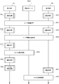
- the configuration of the information processing system 100 is shown in FIG.
- the information processing system 100 includes an authentication server 1 that authenticates a user as the user himself / herself, a first cloud 3A and a second cloud 3B that distribute and store files, and a first terminal 4A and a first terminal used by the first user. It includes a second terminal 4B used by two users.
- the first cloud 3A and the second cloud 3B are collectively referred to as cloud 3.
- the first terminal 4A and the second terminal 4B are collectively referred to as a terminal 4.
- the authentication server 1, the cloud 3, and the terminal 4 are connected to each other via the network 2.
- the authentication server 1 includes a server control unit 11 and a server storage unit 12.
- the server control unit 11 authenticates the user who accesses itself as the person himself / herself, and executes the user authentication processing program 110 for transmitting / receiving various data with the authenticated user. The details of this user authentication processing program will be described later.
- the server storage unit 12 stores a pair key of a private key and an encryption key used between the first terminal 4A used by the first user and the second terminal 4B used by the second user, and a common key.
- the encryption key information database 120 to be used is stored. The details of the encryption key information database 120 will be described later.
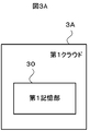
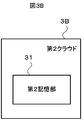
- the configurations of the first cloud 3A and the second cloud 3B are shown in FIGS. 3A and 3B.
- the first cloud 3A includes a first storage unit 30.
- the second cloud 3B includes a second storage unit 31.
- the terminal 4 in the first embodiment is a so-called smartphone, and is a user's habit due to biological information such as a user's face image, fingerprint, voiceprint, and unique behavior and operation state when the user operates the terminal 4. It has an authentication function using and.
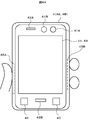
- the terminal 4 has an in-camera 41A for photographing the user's face, a speaker 42A, a microphone (microphone) 42B for calling, and an inclination for detecting the inclination of the terminal 4 in front of the terminal 4. It includes a detection unit 43, a touch panel that also serves as an operation input unit 44 and a display unit 49, a left fingerprint sensor 45A and a right fingerprint sensor 45B that detect a user's fingerprint, and a position detection unit 46 that detects the current position of the terminal 4. ..
- the terminal 4 is provided with a main camera 41B on the back surface capable of photographing a person, a landscape, an object, etc. as seen by the user.
- the in-camera 41A and the main camera 41B are collectively referred to as a shooting unit 41.
- the speaker 42A and the microphone (microphone) 42B for telephone calls are collectively referred to as a voice input / output unit 42.
- the left fingerprint sensor 45A and the right fingerprint sensor 45B are collectively referred to as a fingerprint detection unit 45.
- FIG. 4B is a block diagram showing the configuration of the terminal 4.
- the terminal 4 includes a communication unit 40, a photographing unit 41, a voice input / output unit 42, a tilt detection unit 43, an operation input unit 44, a fingerprint detection unit 45, a position detection unit 46, and a terminal storage unit 47.
- a terminal control unit 48 and a display unit 49 are provided.
- the communication unit 40 communicates with the authentication server 1 and the cloud 3 via the network 2 shown in FIG. 1 to send and receive data, and the communication unit 40 communicates with the first terminal 4A and the second terminal 4B. It includes a data communication unit capable of communicating with each other and transmitting / receiving data, and a voice communication unit for transmitting / receiving a radio signal for telephone communication between a base station (not shown).
- the data communication unit can be configured by using a wireless LAN (Local Area Network), Wi-fi (registered trademark), Bluetooth (registered trademark), or the like.
- the voice communication unit can be configured by using a communication device that transmits / receives a wireless signal for telephone communication with the base station.
- the photographing unit 41 includes the in-camera 41A and the main camera 41B shown in FIG. 4A.
- the photographing unit 41 captures a still image or a moving image such as a camera using an image sensor such as a CCD (Charge Coupled Device) or a CMOS (Complementary Metal Oxide Semiconductor) image sensor, a video camera, or the like, and captures the still image or the moving image.
- an image sensor such as a CCD (Charge Coupled Device) or a CMOS (Complementary Metal Oxide Semiconductor) image sensor, a video camera, or the like.
- CCD Charge Coupled Device
- CMOS Complementary Metal Oxide Semiconductor
- the voice input / output unit 42 includes the speaker 42A shown in FIG. 4A and the microphone 42B for telephone calls.
- the speaker 42A outputs voice received in a voice call, music data acquired from the outside via the network 2 shown in FIG. 1, and the like.
- the microphone 42B for a call is a device that picks up the voice of the user.
- the tilt detection unit 43 is a device that can detect tilt, shaking, etc. of the terminal 4.
- the tilt detection unit 43 can be configured by using various sensors that can detect the tilt of the terminal 4, such as an acceleration sensor, an angle sensor, and a magnetic sensor that detects the geomagnetism.
- the number of sensors such as acceleration sensors and angle sensors may be singular or plural.
- the type of the sensor may be either one type or a plurality of types.
- the operation input unit 44 is a device capable of inputting an operation from the user shown in FIG. 4A.
- the fingerprint detection unit 45 is a sensor that detects the user's fingerprint.
- the fingerprint detection unit 45 includes the left fingerprint sensor 45A and the right fingerprint sensor 45B shown in FIG. 4A.
- the fingerprint detection unit 45 is not limited to the fingerprint sensor, and any sensor, device, or the like capable of detecting the user's fingerprint may be used.
- the position detection unit 46 is a device that can detect the current position of the terminal 4.
- the position detection unit 46 can be configured by using a device such as GPS (Global Positioning System) that can detect the current position of the terminal 4.
- GPS Global Positioning System
- the terminal storage unit 47 includes an authentication processing program 470, an authentication biometric information database 471, an authentication user habit database 472, a score value table 473, a file management processing program 474, a file management table 475, and a first. It includes an encryption key database 476, a file division encryption key table 477, a file deposit processing program 478, a second encryption key database 479, and a file acquisition processing program 480.
- the authentication processing program 470 is a program that performs processing for authenticating a user.
- the authentication biometric information database 471 is a database that stores information on the biometric information of the user and the authentication result.
- the authentication user habit database 472 is a database that stores information on user-specific habits when operating the terminal 4 and authentication results.
- the habits peculiar to the user include the behavior when the user operates the terminal 4, the distance between the screen of the display unit 49 and the user's face, the keystroke, the way of holding, the position where the terminal 4 is used, the communication environment, and the like. , Refers to the behavior peculiar to the user when operating the terminal 4.
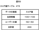
- the score value table 473 is a database in which the upper limit value and the lower limit value of the score value related to the biometric information of the user and the user's habit registered in advance in the terminal 4 and the score value serving as the threshold value for authenticating the user are stored. is there.
- the file management processing program 474 is a program for managing the processing of distributing information files to a plurality of clouds by the terminal 4 and the storage destination of the distributed information files.
- the file management table 475 is a table for managing the storage destinations of distributed information files.
- the first encryption key database 476 is a database that stores an encryption key pair of a private key and a public key used between the authentication server 1 and the second terminal 4B used by the second user, and a common key.
- the file division encryption key table 477 is an encryption for encrypting and decrypting the data of the information file distributed and stored in the first cloud 3A and the second cloud 3B by the first terminal 4A used by the first user. It is a table for managing keys.
- the file deposit processing program 478 is a program that divides the data of the information file by the first terminal 4A used by the first user and deposits the data in the first cloud 3A and the second cloud 3B.
- the second encryption key database 479 is a database that stores a pair key of a private key and a public key used between the authentication server 1 and the first terminal 4A used by the first user, and a public key.
- the file acquisition processing program 480 is a program for acquiring and restoring the data of the information file divided by the first terminal 4A used by the first user from the first cloud 3A and the second cloud 3B.
- the details of the key table 477, the file deposit processing program 478, the second encryption key database 479, and the file acquisition processing program 480 will be described later.
- the terminal control unit 48 executes various programs stored in the terminal storage unit 47. Further, the terminal control unit 48 includes a communication unit 40, a photographing unit 41, an audio input / output unit 42, a tilt detection unit 43, an operation input unit 44, a fingerprint detection unit 45, and a position detection unit 46. The data is acquired, processed, and stored in various databases of the terminal storage unit 47.
- the display unit 49 displays the processing contents of various programs executed by the terminal control unit 48.
- the display unit 49 can also display images such as still images and moving images shot by the shooting unit 41, data input from the operation input unit 44, and the like.
- the display unit 49 is laminated on the operation input unit 44, and constitutes the touch panel shown in FIG. 4A.
- the terminal 4 includes a processor 51 that executes various programs, a memory 52 for developing various programs, a display controller 53 that outputs various display data, a display device 54 that displays various display data, and a photographing unit. It includes 41, an I / O port 55 for connecting an audio input / output unit 42 and the like, a storage device 56 for storing various programs and various data, and a communication device 57 for communicating with the outside and transmitting / receiving data.
- the processor 51, the memory 52, the display controller 53, the display device 54, the I / O port 55, the storage device 56, and the communication device 57 are connected to each other via the data bus 58.
- the processor 51 reads various programs stored in the storage device 56, expands them in the memory 52, and executes them.
- the processor 51 can be configured by using a processing device such as a CPU (Central Processing Unit) and an MPU (Micro-processing Unit).
- the memory 52 can be configured by using a storage element and a storage medium such as a RAM (Random Access Memory), a volatile or non-volatile semiconductor memory such as a flash memory.
- the display controller 53 is a controller that outputs various display data to the display device 54.
- the display controller 53 can be configured by using a video signal output device such as a video card, a GPU (Graphics Processing Unit), or a graphic board.
- the display device 54 can be configured by using a display device such as an LCD (Liquid Crystal Display) or an organic EL (Electroluminescence) monitor.
- the I / O port 55 is for connection that can connect the photographing unit 41, the audio input / output unit 42, the tilt detection unit 43, the operation input unit 44, the fingerprint detection unit 45, and the position detection unit 46. It is a port.
- the I / O port 55 can be configured by using various ports to which devices can be connected, such as a USB (Universal Serial Bus) port and an IEEE1394 port.
- USB Universal Serial Bus
- the storage device 56 is a device that stores various programs executed by the processor 51 and various data used in the various programs.
- the storage device 56 can be configured by using a storage device such as an HDD (Hard Disk Drive) or an SSD (Solid State Drive).
- the communication device 57 is a device capable of transmitting and receiving various data between the authentication server 1 and the cloud 3 via the network 2 shown in FIG.
- the communication device 57 can be configured by using various devices that perform communication by wireless LAN (Local Area Network), Bluetooth (registered trademark), wireless communication, or the like.
- the terminal control unit 48 of the terminal 4 shown in FIG. 4B receives a request for user authentication from another program when the user operates the terminal 4 such as pressing the power button and detecting the fingerprint by the fingerprint detection unit 45. In that case, the biometric information is acquired.
- the biometric information data acquired by the terminal control unit 48 includes the image of the user's face taken by the in-camera 41A shown in FIG. 4A, the voice of the user picked up by the microphone 42B for calling, and the user's voice taken by the in-camera 41A. An image of the iris, a fingerprint detected by the fingerprint detection unit 45, and the like.
- the terminal control unit 48 uses the in-camera 41A shown in FIG. 4A to show the user's face. The image is taken and acquired as the user's biometric information. Further, when the user makes a call from the terminal 4 to another person and the user talks when using the terminal 4, the user needs to talk according to the instruction displayed on the screen of the display unit 49 of the terminal 4. When there is, the terminal control unit 48 acquires the voice of the user picked up by the microphone 42B for a call as the biometric information of the user. When the user holds the terminal 4 and brings the front surface of the display unit 49 shown in FIG.
- the terminal control unit 48 captures the image of the user's iris taken by the in-camera 41A. Obtained as biometric information.
- the terminal control unit 48 acquires the fingerprint detected by the fingerprint detection unit 45 as the user's biological information.
- the terminal 4 brings the terminal 4 to a position where the front surface of the display unit 49 shown in FIG. 4A faces the user's face and the user holds the terminal 4 as it is for a predetermined time or longer.
- the conditions for acquiring a plurality of biometric information are met.
- the priority order of the biometric information to be acquired is determined in advance, and the biometric information of the user is acquired in the order of priority.
- the priority is set in the order of the user's face image, voice, iris, and fingerprint.
- the terminal 4 brings the terminal 4 to a position where the front surface of the display unit 49 shown in FIG. 4A faces the user's face, and the user holds the terminal 4 as it is for a predetermined time or longer. Acquires biometric information in the order of the user's face image and fingerprint.
- the user brought the terminal 4 to a position where the front surface of the display unit 49 shown in FIG. 4A faces the user's face. It shall be.
- the terminal control unit 48 captures an image of the user's face from the in-camera 41A and stores it in the terminal 4 as biometric information of the user.
- the terminal control unit 48 compares the feature amount in the user's face image registered in advance in the terminal 4 with the feature amount in the user's face image acquired from the in-camera 41A, and obtains the similarity.
- the score value is calculated from this similarity.
- the score value is set as an upper limit value when the feature amount of the data registered in advance and the feature amount of the data acquired by the terminal control unit 48 match, and as a lower limit value when they do not match. If it is not a match or a mismatch, the score value is a value set according to the similarity of the features.
- the upper limit value and the lower limit value of the score value are stored in the score value table 473 stored in the terminal storage unit 47 of the terminal 4 shown in FIG. 4B.
- the score values set in the score value table 473 are shown in FIG. 5D.
- -100 to 100 are set as the upper limit value and the lower limit value of the score value in the biological information.
- -50 to 50 are set as the upper limit value and the lower limit value of the score value in the user's habit data.
- the upper limit value 100 of the biological information set in the score value table 473 shown in FIG. 5D is used as the score value.
- the terminal control unit 48 writes the acquired biometric information data and the obtained score value into the authentication biometric information database 471 shown in FIG. 4B.
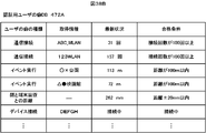
- the table of the biometric information database 471 for authentication is shown in FIG. 5B.
- the table of the biometric information database 471 for authentication includes each item of the date and time when the terminal control unit 48 acquired the biometric information, the type of the acquired biometric information, the information acquired as the biometric information, and the score value.
- the terminal control unit 48 writes 12:22:23 on March 1, 2019, which is the date and time when the biometric information was acquired, in the date and time item of the table of the biometric information database 471 for authentication shown in FIG. 5B.
- the terminal control unit 48 writes a face in the item of the acquired biometric information type.
- the terminal control unit 48 writes the data of the user's face image acquired from the in-camera 41A in the acquired information item.
- the terminal control unit 48 writes 100 in the score value item.
- the terminal control unit 48 acquires the user's habit data.
- This user's habit refers to user-specific behavior such as behavior, operation state, location, and communication state when the user uses the terminal 4.
- the user habit data acquired by the terminal control unit 48 is data on the same date and time as when the biometric information was acquired. For example, at 12:22:23 on March 1, 2019 shown in FIG. 5A, the terminal control unit 48 and the user's face obtained from the image of the user's face taken by the in-camera 41A shown in FIG. 4A.
- the position information of the terminal 4 acquired from 46 is acquired as user's habit data.
- the terminal control unit 48 compares the feature amount in each data related to the user's habit registered in advance in the terminal 4 with the feature amount in each data related to the acquired user's habit, and obtains the similarity.
- the terminal control unit 48 obtains a score value in each data regarding the user's habit based on the obtained similarity. This score value is a value within the range of the upper limit value 50 to the lower limit value -50 set in the score value table 473 shown in FIG. 5D.
- the terminal control unit 48 writes the acquired user habit data and the obtained score value into the authentication user habit database 472 stored in the terminal storage unit 47 of FIG. 4B.
- a table of the authentication user habit database 472 is shown in FIG. 5C.
- each item of the date and time when the terminal control unit 48 acquired the user habit data, the type of the user habit, the information acquired as the user habit, and the score value. Is included.
- the terminal control unit 48 writes 12:22:23 on March 1, 2019, which is the same as the date and time when the biometric information was acquired, in the date and time item of the table of the authentication user habit database 472 shown in FIG. 5C. ..
- the terminal control unit 48 writes the distance between the face and the screen in the item of the user's habit.
- the terminal control unit 48 writes 250 mm in the item of acquired information. This 250 mm is the distance between the user's face and the screen obtained by the terminal control unit 48 from the image of the user's face taken by the in-camera 41A.
- the terminal control unit 48 compares the obtained value of the distance between the user's face and the screen with the value of the distance between the user's face and the screen registered in the terminal 4, and obtains a score value from the similarity. .. Here, it is assumed that the distances do not match but the similarity is high, and the obtained score value is 35. The terminal control unit 48 writes 35 in the score value item of the table shown in FIG. 5C.
- the terminal control unit 48 puts the obtained data on the user's habits such as the inclination angle of the terminal 4 obtained by the inclination detection unit 43 into each item of the table of the authentication user's habit database 472 shown in FIG. 5C. Write. After writing the data related to the habits of all the users, the terminal control unit 48 sets the score values of the same date and time in the authentication biometric information database 471 shown in FIG. 5B and the authentication user habit database 472 shown in FIG. 5C. To sum.
- the score value of the biometric information is 100 at the date and time of 12:22:23 on March 1, 2019 in the biometric information database 471 for authentication shown in FIG. 5B.
- the score values of the user habits in the authentication user habit database 472 shown in FIG. 5C are 35, 40, -15, 25, and 42 in order from the top.
- the total of the score value 100 of this biological information and the score values 35, 40, -15, 25, and 42 of the user's habit is 227.
- the terminal control unit 48 acquires the score value set in the item of the total value from the score value table 473 shown in FIG. 5D.
- the terminal control unit 48 compares the total score value of the biometric information and the user's habit with the score value set in the item of the total value from the score value table 473. If the total score value of the biometric information and the user's habit is equal to or greater than the score value set in the total value item of the score value table 473, the terminal control unit 48 corrects the user using the terminal 4. If it is less than or equal to the score value, the user is not authenticated as not being the correct user.
- the terminal control unit 48 compares the total value 227 of the obtained score values with the total value 200 of the score values set in the score value table 473. Since the total value of the obtained score values is equal to or greater than the total value of the score values set in the score value table 473, the terminal control unit 48 authenticates the user operating the terminal 4 as a correct user.
- the user authentication method in the terminal 4 described above is stored in the terminal storage unit 47 as an authentication processing program 470.
- the terminal control unit 48 is an authentication processing program 470 when the power button is pressed, when the user operates the terminal 4 such as fingerprint detection by the fingerprint detection unit 45, or when there is a request from another program. To authenticate the user.
- the process executed by the authentication process program 470 will be described below with reference to the flowchart of the authentication process shown in FIG.
- the terminal control unit 48 acquires biological information such as a user's face image and fingerprint (step S1). Subsequently, the terminal control unit 48 acquires data related to the user's habit (step S2).
- the terminal control unit 48 compares the feature amount of the biological information registered in advance in the terminal 4 with the feature amount of the acquired biological information, and obtains the degree of similarity. From the obtained similarity, the terminal control unit 48 obtains a score value within the range from the upper limit value to the lower limit value of the score value of the biological information set in the score value table 473 of FIG. 5D. Further, the terminal control unit 48 compares the feature amount in the user habit data registered in advance in the terminal 4 with the feature amount in the acquired user habit data, and obtains the similarity. From the obtained similarity, the terminal control unit 48 obtains a score value within a range from the upper limit value to the lower limit value of the score value of the user's habit set in the score value table 473 of FIG. 5D (step S3).
- the terminal control unit 48 writes the acquired biometric information data and the obtained score value into the authentication biometric information database 471 shown in FIG. 4B. Further, the terminal control unit 48 writes and stores the acquired user habit data and the obtained score value in the authentication user habit database 472 stored in the terminal storage unit 47 of FIG. 4B (step S4).
- the terminal control unit 48 totals the score values in the biometric information and the user's habit data at the same date and time (step S5).
- the terminal control unit 48 acquires the score value set in the item of the total value from the score value table 473 shown in FIG. 5D.
- the terminal control unit 48 compares the total score value of the biometric information and the user's habit with the score value set in the item of the total value from the score value table 473 (step S6).
- the terminal control unit 48 uses the terminal 4 if the total score value of the biometric information and the user's habit is equal to or greater than the score value set in the total value item of the score value table 473 (step S6; YES). Authenticate the user as the correct user (step S7). Subsequently, the terminal control unit 48 obtains an average value of the feature amount of the biological information registered in advance in the terminal 4 and the feature amount of the acquired biological information. The terminal control unit 48 updates the feature amount of the biological information registered in the terminal 4 according to the obtained average value. Further, the terminal control unit 48 obtains an average value of the feature amount in the user habit data registered in advance in the terminal 4 and the feature amount in the acquired user habit data. The terminal control unit 48 updates the feature amount in the user's habit data registered in the terminal 4 according to the obtained average value (step S8).
- step S6 if the total score value of the biometric information and the user's habit is equal to or less than the score value set in the total value item of the score value table 473 (step S6; NO), the terminal control unit 48 shows FIG. 4B. A message indicating that the user is different is displayed on the displayed display unit 49, and the process returns to step S1 (step S9).
- the authentication processing program 470 is an example of user authentication means in the claims.
- the biometric information of the user is an example of the first authentication data in the claims.
- the user's habit data is an example of the second authentication data in the claims.
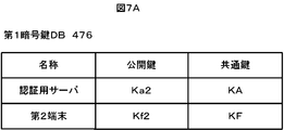
- FIG. 7A shows an example of a table of the first encryption key database 476.
- the name of the target for which the key is used as an item, the public key, and the common key are set.
- This public key is a key that becomes a pair key with the private key, and is generated by the authentication server 1 and the second terminal 4B used by the second user.
- the common key is a key used between the first terminal 4A used by the first user and the second terminal 4B used by the authentication server 1 and the second user. This common key is generated by the first terminal 4A used by the first user.
- Ka2 is stored as a public key and KA is stored as a common key in the "authentication server" which is the name of the target for which the key is used.
- Kf2 is stored as a public key and KF is stored as a common key in the "second terminal" which is the name of the object to which the key is used.
- FIG. 7B shows an example of the table of the second encryption key database 479.
- the name of the target for which the key is used as an item, the private key, the public key, and the common key are set.
- the private key and the public key are keys that serve as a pair key.
- the public key and common key used between the second terminal 4B and the authentication server 1 and the private key, public key, and common key used between the second terminal 4B and the first terminal 4A are displayed. Is remembered.
- the public key is the key generated by the authentication server 1
- the common key is the key generated by the second terminal 4B.
- the private key and the public key are the keys generated by the second terminal 4B
- the common key is the key generated by the first terminal 4A.
- KB2 is stored in the public key
- KB is stored in the common key in the "authentication server” which is the name of the target for which the key is used.
- Kf1 is stored in the private key
- Kf2 is stored in the public key
- KF is stored in the common key.
- FIG. 7C shows an example of the configuration of the file division encryption key table 477.
- the key stored in this table is a key for encrypting each divided file of the information file divided into a plurality of divided files by the first terminal 4A.
- Kr1 and Kr2 are written in the table shown in FIG. 7C.
- Kr1 and Kr2 will be referred to as file division encryption keys.
- the file division encryption key is generated not only by the key written in the file division encryption key table 477 but also by the terminal control unit 48 of the first terminal 4A and the second terminal 4B as needed.
- the generated file division encryption key is added to the end of the file division encryption key table 477.
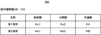
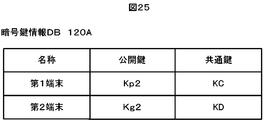
- FIG. 8 shows an example of the table of the encryption key information database 120.
- the name of the target for which the key is used as an item, the private key, the public key, and the common key are set.
- the private key and the public key are keys that serve as a pair key.
- a private key, a public key, and a common key used between the first terminal 4A and the second terminal 4B and the authentication server 1 are stored.
- Ka1 is stored in the private key
- Ka2 is stored in the public key
- KA is stored in the common key
- second terminal which is the name of the object to which the key is used
- KB1 is stored in the private key
- KB2 is stored in the public key
- KB is stored in the common key.
- the first user uses the first terminal 4A to distribute and store files in the first cloud 3A and the second cloud 3B, and the first user browses the files.
- the second terminal 4B is used to acquire the files distributed and saved in the first cloud 3A and the second cloud 3B. It is a system that can be restored. Therefore, in the following, a method of distributing and storing files in a plurality of clouds will be described with reference to FIGS. 9 to 13, assuming that the method is performed on the first terminal 4A used by the first user.
- FIGS. 9 to 12 and 14 a method of acquiring and restoring files distributed in a plurality of clouds will be described with reference to FIGS. 9 to 12 and 14 as the method of acquiring and restoring files distributed in a plurality of clouds by the second terminal 4B used by the second user.
- the file containing the information data created by the first user will be referred to as the user's deposit file.
- FIGS. 9 to 13 a method of distributing and storing files in a plurality of clouds will be described with reference to FIGS. 9 to 13, assuming that the method is performed on the first terminal 4A used by the first user.
- one user's deposit file is divided into clusters, which is the smallest unit of computer desk access.
- the number of sectors included in one cluster is arbitrary, but in the following description, it is set to eight as shown in FIG. In this embodiment, one sector is 512 bytes. Therefore, one cluster has a size of 4,096 bytes (about 4 Kbytes).
- This sector and cluster are managed by logical address.
- the cluster is specified by the upper n-3 bits of the n-bit logical address.
- Each sector in the cluster is specified by the lower 3 bits of the logical address.
- the logical address for a cluster shall mean the upper (n-3) bits of the entire n-bit logical address.
- the terminal control unit 48 of the first terminal 4A shown in FIG. 4B stores the user's deposit file in the first storage unit 30 of the first cloud 3A and the second storage unit 31 of the second cloud 3B shown in FIG. At that time, different processing is performed for the cluster to which the odd logical address ((n-3) bit) shown in FIG. 11A is assigned and the cluster to which the even logical address shown in FIG. 11B is assigned.
- a cluster to which an odd number of logical addresses is assigned is referred to as an odd numbered logical address cluster.
- a cluster to which an even number of logical addresses is assigned is referred to as an even numbered logical address cluster.
- the terminal control unit 48 of the first terminal 4A acquires the file division encryption key from the file division encryption key table 477 of the terminal storage unit 47.
- the terminal control unit 48 acquires the file division encryption keys Kr1 and Kr2 written in the file division encryption key table 477 shown in FIG. 7C.
- the terminal control unit 48 performs encryption processing by the file division encryption key Kr1 on the cluster to which the odd logical address is assigned, and arbitrarily performs the encryption processing on the first storage unit 30 of the first cloud 3A shown in FIG. 3A. Store in the physical address PA. On the other hand, the terminal control unit 48 performs encryption processing by the file division encryption key Kr2 on the cluster to which the even logical address is assigned, and arbitrary physical address PB on the second storage unit 31 of the second cloud 3B. Store in.
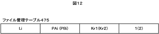
- the terminal control unit 48 generates the file management table 475 shown in FIG. 12 after performing the above processing.
- the file management table 475 includes a cluster specified by the logical address Li, a storage destination physical address PAi or PBi, a file division encryption key Kr1 or Kr2 for encryption, and a first physical address PAi or PBi. It is a table which saves in association with the number which shows the cloud 3A or the 2nd cloud 3B. For this number, for example, as shown in FIG. 12, the number indicating the first cloud 3A having the physical address PAi is set to "1", and the number indicating the second cloud 3B having the physical address PBi is set to "2". There is.
- This file management table 475 is stored in the terminal storage unit 47 of the first terminal 4A shown in FIG. 4B.
- the file division encryption key Kr1 when the logical address Li is an even number, the file division encryption key Kr1 is used, and when the logical address Li is an odd number, the file division encryption key Kr2 is used. In such a case, since the encryption key can be specified from the logical address Li, the file division encryption key Kr1 or Kr2 does not have to be stored in the file management table 475.
- the second user uses the method of encrypting and distributing the files stored in the first cloud 3A shown in FIG. 3A and the second cloud 3B shown in FIG. 3B as described above. It will be described with reference to FIGS. 9 to 12 and 14 as what is performed by the second terminal 4B.
- the terminal control unit 48 of the second terminal 4B shown in FIG. 4B sets the file management table 475 stored in advance in the server storage unit 12 of the authentication server 1 shown in FIG. 2 by the first terminal 4A to the authentication server 1. Obtained from the server storage unit 12. From the acquired file management table 475, the terminal control unit 48 of the second terminal 4B obtains the logical address of the head cluster of the cluster constituting the deposit file of the user to be restored.
- the terminal control unit 48 of the second terminal 4B specifies the cloud 3 and the physical address corresponding to the logical address of the first cluster from the file management table 475. Next, the terminal control unit 48 identifies the file division encryption key corresponding to the logical address of the first cluster. The terminal control unit 48 reads the cluster based on the specified cloud 3 and the physical address, and decrypts it using the specified file division encryption key.
- the terminal control unit 48 of the second terminal 4B executes the same operation in the subsequent clusters and decodes all the clusters.
- the terminal control unit 48 concatenates the decrypted clusters and restores the user's deposit file.
- the cluster in which the user's deposit file is divided is an example of the divided file in the claims.
- the above-mentioned method of dividing the user's deposit file and storing the divided file in a distributed manner in the cloud is included in the file management processing program 474 stored in the terminal storage unit 47 of the terminal 4 as a file storage process. Further, a method of restoring the user's deposit file from the divided files distributed and stored in the cloud is included in the file management processing program 474 stored in the terminal storage unit 47 of the terminal 4 as a file restoration process.
- the terminal control unit 48 of the first terminal 4A identifies the logical address Li of the head cluster constituting the deposit file of the user to be saved, and determines whether or not it is an odd number (step S11).
- the cluster to be processed is encrypted with the file division encryption key Kr1 (step S12).
- the terminal control unit 48 stores the encrypted cluster in the area of the free physical address PA on the first storage unit 30 of the first cloud 3A shown in FIG. 3A (step S13).
- the terminal control unit 48 of the first terminal 4A uses the logical address Li of the processed cluster, the physical address PAi of the stored area, the file division encryption key Kr1, and the first cloud 3A having the physical address PAi.
- the indicated number is associated with "1", written in the table of the file management table 475 shown in FIG. 12, and stored in the terminal storage unit 47 shown in FIG. 4B (step S14).
- the terminal control unit 48 of the first terminal 4A determines whether or not the storage of all the clusters has been completed (step S15). When the storage of all the clusters is not completed (step S15: No), the terminal control unit 48 adds 1 to the logical address Li (step S18). Subsequently, the terminal control unit 48 returns to step S11 and processes the next cluster.
- step S11 when it is determined in step S11 that the logical address of the cluster to be processed is not an odd number (step S11; NO), the cluster to be processed is encrypted with the file division encryption key Kr2 as shown in FIG. 11B. (Step S16).
- the terminal control unit 48 of the first terminal 4A stores in the area of the free physical address PB on the second storage unit 31 of the second cloud 3B shown in FIG. 3B (step S17).
- the terminal control unit 48 of the first terminal 4A assigns a number indicating the logical address Li of the processed cluster, the physical address PBi of the stored area, the file division encryption key Kr2, and the second cloud 3B having the physical address PBi.
- the file is written in the file management table 475 shown in FIG. 12 and stored in the terminal storage unit 47 shown in FIG. 4B (step S14).
- the terminal control unit 48 of the first terminal 4A determines whether or not the storage of all the clusters has been completed (step S15). When the storage of all the clusters is not completed (step S15; NO), the terminal control unit 48 adds 1 to the logical address Li (step S18). Subsequently, the terminal control unit 48 returns to step S11 and processes the next cluster. If it is determined in step S15 that the saving of all the clusters has been completed (step S15; YES), the terminal control unit 48 of the first terminal 4A ends the file storage process.
- the restoration process of the file for restoring the user's deposit file from the divided files distributed and stored in the cloud will be described with reference to the flowchart shown in FIG.
- the file restoration process will be described as a process executed by the terminal control unit 48 of the second terminal 4B shown in FIG. 4B.
- the terminal control unit 48 of the second terminal 4B shown in FIG. 4B sets the file management table 475 stored in advance in the server storage unit 12 of the authentication server 1 shown in FIG. 2 by the first terminal 4A to the authentication server 1. Obtained from the server storage unit 12. From the acquired file management table 475, the terminal control unit 48 of the second terminal 4B obtains the logical address of the head cluster of the cluster constituting the deposit file of the user to be restored. The terminal control unit 48 specifies the cloud 3 and the physical address corresponding to the logical address of the head cluster from the file management table 475. Next, the terminal control unit 48 identifies the file division encryption key corresponding to the logical address of the first cluster (step S21).
- the terminal control unit 48 of the second terminal 4B reads out the data based on the specified cloud 3 and the physical address (step S22).
- the terminal control unit 48 decrypts the cluster read from the specified cloud 3 and the physical address by using the specified file division encryption key (step S23). Subsequently, it is determined whether or not all the clusters constituting the user's deposit file have been read (step S24).
- step S24 If the reading of all the clusters constituting the user's deposit file has not been completed (step S24; NO), the process returns to step S21, and steps S21 to S23 are executed for the next cluster.
- step S24 the terminal control unit 48 concatenates the decrypted clusters and restores the user's deposit file (step S25). ..
- the first user permits the use of the file of the user's deposit file distributed and stored in the plurality of clouds 3 by the first user using the first terminal 4A.
- This is a system in which the second user can acquire, restore, and use the second terminal 4B when he / she is authenticated by the authentication server 1.
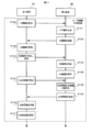
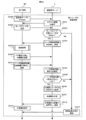
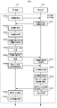
- the flow of processing executed in the information processing system 100 will be described below with reference to the flowcharts shown in FIGS. 15 to 19.
- FIG. 15 shows the overall configuration of the processing executed in the information processing system 100.
- Each process shown in FIG. 15 includes the user authentication processing program 110 of the authentication server 1 shown in FIG. 2, the file deposit processing program 478 of the first terminal 4A shown in FIG. 4B, and the second terminal shown in FIG. 4B.
- This is a process realized by executing the file acquisition processing program 480 of 4B by the authentication server 1, the first terminal 4A, and the second terminal 4B, respectively.
- the user's deposit file stored in the cloud 3 shown in FIG. 1 by the first user is stored in the terminal storage unit 47 of the first terminal 4A shown in FIG. 4B.
- the first user selects from the operation input unit 44 the icon associated with the file deposit processing program 478 displayed on the screen of the display unit 49 of the first terminal 4A shown in FIG. 4B.
- the terminal control unit 48 of the first terminal 4A authenticates whether the first user currently using the first terminal 4A is correct (step S31). This authentication is performed by the authentication process shown in FIG.
- the terminal control unit 48 executes steps S1 to S7 of the authentication process shown in FIG. 6, and when the first user is authenticated as the first user himself / herself, executes the file deposit processing program 478.
- the first terminal 4A reads the file deposit processing program 478 stored in the storage device 56 shown in FIG. 4C into the memory 52 and executes it by the processor 51.
- Step S8 is executed so that the display unit 49 shown in FIG. 4B displays that the user is different.
- the second user selects the icon associated with the file acquisition processing program 480 displayed on the screen of the display unit 49 of the second terminal 4B shown in FIG. 4B from the operation input unit 44.
- the terminal control unit 48 of the second terminal 4B authenticates whether the second user currently using the second terminal 4B is correct (step S32). This authentication is performed by the authentication process shown in FIG.
- the terminal control unit 48 executes steps S1 to S7 of the authentication process shown in FIG. 6, and when the second user is authenticated as the second user himself / herself, executes the file acquisition process program 480.
- the second terminal 4B reads the file acquisition processing program 480 stored in the storage device 56 shown in FIG. 4C into the memory 52 and executes it by the processor 51.
- Step S8 is executed so that the display unit 49 shown in FIG. 4B displays that the user is different.
- the terminal control unit 48 of the first terminal 4A and the terminal control unit 48 of the second terminal 4B perform the user registration process (step S33).
- the user registration process will be described with reference to the flowchart shown in FIG.
- the terminal control unit 48 of the first terminal 4A transmits the name of the first user and the information necessary for registration to the authentication server 1 (step S100).
- the server control unit 11 of the authentication server 1 shown in FIG. 2 receives the name of the first user and the information necessary for registration from the first terminal 4A, the server control unit 11 executes the user authentication processing program 110.
- the server control unit 11 of the authentication server 1 registers the name of the first user and necessary information.
- the server control unit 11 generates a pair key of a private key and a public key to be used with the first user (step S101).
- the key generated by the server control unit 11 is, for example, Ka1 as the private key and Ka2 as the public key.
- the server control unit 11 writes and saves the generated pair key in the table of the encryption key information database 120 shown in FIG. 8 in association with the user name.
- the server control unit 11 transmits the public key Ka2 out of the generated pair keys to the first terminal 4A (step S102).
- the terminal control unit 48 of the first terminal 4A writes the received public key Ka2 in the table of the first encryption key database 476 shown in FIG. 7A in association with the name of the target to which the key is used. For example, as shown in FIG. 7A, "authentication server” is written in the name of the target to which the key is used, and "Ka2" is written in the public key.
- the terminal control unit 48 of the first terminal 4A generates a common key to be used with the authentication server 1 (step S103).
- the common key generated by the terminal control unit 48 of the first terminal 4A is, for example, KA.
- the terminal control unit 48 of the first terminal 4A writes the common key KA in the first encryption key database 476 shown in FIG. 7A in association with the authentication server 1 to which the key is used.
- the terminal control unit 48 of the first terminal 4A encrypts the common key KA using the public key Ka2 received from the authentication server 1 in step S103, and transmits it to the authentication server 1 (step S104).
- the server control unit 11 of the authentication server 1 decrypts the common key KA received from the first terminal 4A with the private key Ka1 generated in step S101, and puts the key in the table of the encryption key information database 120 shown in FIG. Is written in association with the first terminal 4A, which is the target of use.
- the server control unit 11 stores the encryption key information database 120 in which the common key KA is written in the server storage unit 12 of the authentication server 1 shown in FIG. 2 (step S105).
- the terminal control unit 48 of the second terminal 4B transmits the name of the second user and the information necessary for registration to the authentication server 1 (step S106).
- the server control unit 11 of the authentication server 1 shown in FIG. 2 registers the name of the second user received from the second terminal 4B and the information necessary for registration.
- the server control unit 11 generates a pair key of a private key and a public key to be used with the second user (step S107).
- the key generated by the server control unit 11 is, for example, Kb1 as the private key and Kb2 as the public key.
- the server control unit 11 writes the generated pair key in the table of the encryption key information database 120 shown in FIG. 8 in association with the user name.
- the server control unit 11 transmits the public key Kb2 out of the generated pair keys to the second terminal 4B (step S108).
- the terminal control unit 48 of the second terminal 4B writes the received public key Kb2 in the table of the second encryption key database 479 shown in FIG. 7B in association with the name of the target to which the key is used. For example, as shown in FIG. 7B, "authentication server” is written in the name of the target to which the key is used, and "Kb2" is written in the public key.
- the terminal control unit 48 of the second terminal 4B generates a common key to be used with the authentication server 1 (step S109).
- the common key generated by the terminal control unit 48 of the second terminal 4B is, for example, KB.
- the terminal control unit 48 of the second terminal 4B writes the common key KB in the second encryption key database 479 shown in FIG. 7B in association with the authentication server 1 to which the key is used.
- the terminal control unit 48 of the second terminal 4B encrypts the common key KB using the public key Kb2 received from the authentication server 1 in step S109 and transmits it to the authentication server 1 (step S110).
- the server control unit 11 of the authentication server 1 decrypts the common key KB acquired from the second terminal 4B with the private key Kb1 generated in step S107, and puts the key in the table of the encryption key information database 120 shown in FIG. Is written in association with the second terminal 4B, which is the target of use.
- the server control unit 11 stores the encryption key information database 120 in which the common key KB is written in the server storage unit 12 of the authentication server 1 shown in FIG. 2 (step S111).
- the first user wants to disclose the distributed file in the cloud 3 to the second user at a timing set by himself / herself
- the first user sets the distributed file so that it can be shared with the second user.
- the terminal control unit 48 of the first terminal 4A used by the first user authenticates whether the first user currently using the first terminal 4A is correct (step S34).
- the second user who shares the distributed file authenticates whether the second user who is currently using the second terminal 4B is correct in the terminal control unit 48 of the second terminal 4B used by the second user (step). S35).
- the terminal control unit 48 of the first terminal 4A executes steps S1 to S7 of the authentication process shown in FIG. 6, and when the first user is authenticated as the first user, the terminal control unit 48 executes the user information sharing process. (Step S36). Further, when the terminal control unit 48 of the first terminal 4A executes steps S1 to S6 of the authentication process shown in FIG. 6 and cannot determine that the first user is the first user himself / herself, Step S8 is executed so that the display unit 49 shown in FIG. 4B displays that the user is different.
- the terminal control unit 48 of the second terminal 4B executes steps S1 to S7 of the authentication process shown in FIG. 6, and when the second user is authenticated as the second user, the user information is shared.
- the process is executed (step S36).
- Step S8 is executed so that the display unit 49 shown in FIG. 4B displays that the user is different.
- the terminal control unit 48 of the first terminal 4A requests the public key from the second terminal 4B (step S120).
- the terminal control unit 48 of the second terminal 4B generates a pair key of the private key and the public key (step S121).
- the pair key generated by the terminal control unit 48 of the second terminal 4B for example, the private key is Kf1 and the public key is Kf2.
- the terminal control unit 48 of the second terminal 4B writes in the table of the second encryption key database 479 shown in FIG. 7B in association with the name of the object to which the key is used and the pair key.
- the name of the object to which the key is used is "first terminal"
- the item of the private key is "Kf1”
- the item of the public key is "Kf2”.
- the terminal control unit 48 of the second terminal 4B stores the written second encryption key database 479 in the terminal storage unit 47 of the second terminal 4B shown in FIG. 4B.
- the terminal control unit 48 of the second terminal 4B transmits the public key Kf2 to the first terminal 4A (step S122).
- the terminal control unit 48 of the first terminal 4A receives the public key Kf2 from the second terminal 4B (step S123), it stores it in the first encryption key database 476 shown in FIG. 4B.
- the name of the object to which the key is used and the public key Kf2 are written in association with each other in the table of the first encryption key database 476 shown in FIG. 7A.
- “second terminal” is written in the name of the target to which the key is used
- "Kf2" is written in the item of the public key.
- the terminal control unit 48 of the first terminal 4A generates a common key to be used with the second terminal 4B.
- the terminal control unit 48 of the first terminal 4A encrypts with the public key Kf2 received from the second terminal 4B in step S123 and transmits the encryption to the second terminal 4B (step S124).
- the common key generated by the terminal control unit 48 of the first terminal 4A is, for example, KF.
- the terminal control unit 48 of the first terminal 4A stores the generated common key in the first encryption key database 476 shown in FIG. 4B.
- the name of the target for which the key is used and the common key KF are written in association with each other in the table of the first encryption key database 476 shown in FIG. 7A.
- the terminal control unit 48 of the second terminal 4B receives the common key KF from the first terminal 4A (step S125).
- the terminal control unit 48 of the second terminal 4B combines the common key KF received from the first terminal 4A with the private key Kf1 generated in step S121, and puts the key in the second encryption key database 479 shown in FIG. 4B. It is saved in association with the name of the target to be used (step S126). For example, in the table of the second encryption key database 479 shown in FIG. 7B, the name of the target for which the key is used, "first terminal", and the common key are written as KF.
- the terminal control unit 48 of the first terminal 4A requests the second terminal 4B for the biometric information of the second user (step S127).
- the biometric information of the second user may be either the biometric information of the second user registered in the second terminal 4B or the newly acquired biometric information of the second user.
- the terminal control unit 48 of the second terminal 4B encrypts the biometric information of the second user with the common key KF received from the first terminal 4A (step S128).
- the biological information of the second user is an image of the face of the second user taken by the in-camera 41A of the second terminal 4B shown in FIG. 4A.
- the terminal control unit 48 of the second terminal 4B transmits the encrypted biometric information of the second user to the first terminal 4A (step S129).
- the terminal control unit 48 of the first terminal 4A receives the encrypted biometric information of the second user from the second terminal 4B (step S130).
- the terminal control unit 48 of the first terminal 4A stores the received biological information of the second user in the terminal storage unit 47 shown in FIG. 4B (step S131).
- the first user distributes and stores the user's deposit file including the information created by the second user, which he / she wants to disclose to the second user, in the cloud 3.
- the terminal control unit 48 of the first terminal 4A used by the first user authenticates whether the first user currently using the first terminal 4A is correct (step S37).
- the terminal control unit 48 of the first terminal 4A executes steps S1 to S7 of the authentication process shown in FIG. 6, and when the first user is authenticated as the first user, the terminal control unit 48 executes the file deposit process. (Step S38).
- the file deposit process will be described below with reference to the flowchart shown in FIG.
- the terminal control unit 48 of the first terminal 4A executes steps S11 to S18 of the file storage process shown in FIG. 13 for the user's deposit file including the information created by the first user (step S141).
- the user's deposit file including the information created by the first user is divided and stored in the first cloud 3A and the second cloud 3B shown in FIG.
- the terminal control unit 48 of the first terminal 4A displays information for accessing the first cloud 3A and the second cloud 3B, the data of the file management table 475 shown in FIG. 4B, and the file division encryption key. It is encrypted with the public key Kf2 with the second terminal 4B shown in 7A (step S142).
- This file division encryption key is a key that encrypts the user's deposit file distributed and stored in the first cloud 3A and the second cloud 3B, and is the key of the terminal storage unit 47 of the first terminal 4A shown in FIG. 4B. It is stored in the file division encryption key table 477. For example, Kr1 and Kr2 written in the table of the file division encryption key table 477 shown in FIG. 7C. Further, the information for accessing the first cloud 3A and the second cloud 3B encrypted here, the data in the file management table 475 shown in FIG. 4B, and the encryption key for file division are encrypted below. This is called access information.
- the terminal control unit 48 of the first terminal 4A adds the usage start date and time of the user's deposit file and the biometric information of the second user to the encrypted access information (step S143).
- the use start date and time of the deposit file of this user is the date and time when the deposit file can be acquired by the second terminal 4B.
- the biometric information of the second user is received from the second terminal 4B in step S130 shown in FIG.
- the terminal control unit 48 of the first terminal 4A stores the encrypted access information, the date and time when the user's deposit file is used, and the biometric information of the second user in the first encryption key database 476 shown in FIG. 7A. It is encrypted with the common key KA with the authentication server 1 and transmitted to the authentication server 1 (step S144).
- the authentication server 1 receives the encrypted access information, the date and time when the user's deposit file is used, and the biometric information of the second user from the terminal control unit 48 of the first terminal 4A (step S145).
- the authentication server 1 stores the received encrypted access information, the date and time when the user's deposit file is used, and the biometric information of the second user in the server storage unit 12 shown in FIG. 2 (step S146).
- the terminal control unit 48 of the first terminal 4A newly generates an encryption key for file division.
- the keys generated here are, for example, Kr3 and Kr4.
- the terminal control unit 48 of the first terminal 4A puts a newly generated file division encryption on the next line of the file division encryption keys Kr1 and Kr2 stored in the file division encryption key table 477 of the terminal storage unit 47.
- the keys Kr3 and Kr4 are written and saved (step S147).
- the file division encryption key can be made different for each distribution time when the user's deposit file is distributed to the first cloud 3A and the second cloud 3B. Therefore, the first user can give permission to restore and use the user's deposit file to different users at each distribution time. Therefore, the first user can share necessary information for each user.
- step S39 the terminal control unit 48 of the second terminal 4B executes steps S1 to S7 of the authentication process shown in FIG. 6 (step S39), and when the second user is authenticated as the second user, the file is acquired.
- the process is executed (step S40).
- step S40 the terminal control unit 48 of the second terminal 4B executes steps S1 to S6 of the authentication process shown in FIG. 6 (step S39), and cannot determine that the second user is the second user himself / herself.
- step S8 is executed so that the display unit 49 shown in FIG. 4B displays that the user is different.
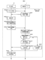
- the file acquisition process will be described below with reference to the flowchart shown in FIG.
- the second terminal 4B requests the authentication server 1 to acquire the user's deposit file including the information created by the first user (step S151).
- the server control unit 11 of the authentication server 1 shown in FIG. 2 requests the biometric information of the second user from the second terminal 4B (step S152).
- the biometric information of the second user stored in the server storage unit 12 of the authentication server 1 is received from the first terminal 4A in step S145 of FIG.
- the biometric information of the second user transmitted from the first terminal 4A to the authentication server 1 is a face image of the second user transmitted from the second terminal 4B to the first terminal 4A in step S129 shown in FIG. .. Therefore, specifically, in step S152, the server control unit 11 of the authentication server 1 requests the second terminal 4B for the face image of the second user.
- the terminal control unit 48 of the second terminal 4B encrypts the face image of the second user with the common key with the authentication server 1 and transmits it to the authentication server 1 (step S153).
- the common key for the terminal control unit 48 to encrypt the face image of the second user is the common key KB with the authentication server 1 shown in the second encryption key database 479 of FIG. 7B.
- the server control unit 11 of the authentication server 1 is based on the face image of the second user received from the first terminal 4A stored in the server storage unit 12 and the face image of the second user received from the second terminal 4B. , Authenticate the second user (step S154).
- the server control unit 11 determines whether or not the second user can authenticate with the person (step S155).
- the server control unit 11 determines whether or not the usage start date and time of the user's deposit file has passed (step S156). ..
- the server control unit 11 skips the subsequent processing. As a result, it is possible to prevent the first user from disclosing the user's deposit file deposited on the authentication server 1 using the first terminal 4A to the second user who is a third party.
- step S156 When the usage start date and time of the user's deposit file has passed (step S156; YES), the server control unit 11 of the authentication server 1 receives the information received from the first terminal 4A in step S145 shown in FIG. Encrypt with the common key KB with the terminal 4B. If the user's deposit file usage start date and time has not passed (step S156; NO), the server control unit 11 of the authentication server 1 skips the subsequent processing. As a result, it is possible to prevent the first user from disclosing the user's deposit file deposited on the authentication server 1 using the first terminal 4A to the second user who is a third party.
- the server control unit 11 of the authentication server 1 transmits the encrypted information received from the first terminal 4A in step S145 shown in FIG. 18 to the second terminal 4B (step S157).
- the encrypted information includes information for accessing the first cloud 3A and the second cloud 3B stored in the server storage unit 12 shown in FIG. 2, data in the file management table 475, and file division. Includes encryption key.
- the terminal control unit 48 of the second terminal 4B first decrypts the information received from the authentication server 1 with the common key with the authentication server 1.
- the common key for decryption here is the common key KB stored in the second encryption key database 479 of the terminal storage unit 47 of the second terminal 4B shown in FIG. 4B.
- the terminal control unit 48 of the second terminal 4B decrypts the information decrypted by the common key KB with the authentication server 1 with the private key with the first terminal 4A.
- the private key for decryption here is the private key Kf1 stored in the second encryption key database 479 of the terminal storage unit 47 of the second terminal 4B shown in FIG. 4B (step S158).
- the terminal control unit 48 of the second terminal 4B executes a file restoration process using the decoded information (step S159). For the file restoration process, steps S21 to S25 shown in FIG. 14 are executed.
- the terminal control unit 48 of the second terminal 4B saves the restored user's deposit file in the terminal storage unit 47 of the second terminal 4B shown in FIG. 4B (step S160).
- the terminal control unit of the first terminal 4A terminates the file deposit processing program 478 of the terminal storage unit 47 shown in FIG. 4B.
- the server control unit 11 of the authentication server 1 terminates the user authentication processing program 110 shown in FIG.
- the terminal control unit of the second terminal 4B terminates the file acquisition processing program 480 of the terminal storage unit 47 shown in FIG. 4B.
- the file created by the first user is distributed and stored in a plurality of clouds by using the first terminal, and the first user can view the file.
- an authorized second user is authenticated by the authentication server, he / she can use the second terminal to acquire files distributed and saved in multiple clouds, restore them, and use them. ..
- the file containing the information created by the first user can be acquired and used by the second user who is authorized by the first user, that is, who has the authority.
- the key is added to the end of the file division encryption key table 477.
- the encryption key for file division can be different for each distribution period when the files are distributed to a plurality of clouds. Therefore, the first user can restore the file containing the information created by the first user and give permission to use it to different users at each distribution time. As a result, the first user can share necessary information for each user who is a third party.
- the first user deposits the user's deposit file in the cloud 3 shown in FIG. After that, it is a system that can update the contents of the user's deposit file.
- the information is disclosed to the second user. It is possible to respond when you want to add additional content to the information to be provided.
- FIG. 20 shows the overall configuration of the processing executed in the information processing system 100 according to the second embodiment.
- Each process shown in FIG. 20 includes the user authentication processing program 110 of the authentication server 1 shown in FIG. 2, the file deposit processing program 478 of the first terminal 4A shown in FIG. 4B, and the second terminal shown in FIG. 4B.
- This is a process realized by executing the file acquisition processing program 480 of 4B by the authentication server 1, the first terminal 4A, and the second terminal 4B, respectively.
- the file deposit processing program 478 of the first terminal 4A displays an icon associated with the file deposit processing program 478 displayed on the screen of the display unit 49 of the first terminal 4A shown in FIG. 4B by the first user. It is executed by selecting from the operation input unit 44.
- the file acquisition processing program 480 of the second terminal 4B is an icon associated with the file acquisition processing program 480 displayed on the screen of the display unit 49 of the second terminal 4B shown in FIG. 4B by the second user. Is executed by selecting from the operation input unit 44.
- the user authentication processing program 110 of the authentication server 1 receives the name of the first user and information necessary for registration from the first terminal 4A by the server control unit 11 of the authentication server 1 shown in FIG. Will be executed.
- steps S51 to S58 of the flowchart shown in FIG. 20 are the same processes as steps S31 to S38 of the flowchart shown in FIG. 15 described in the first embodiment.
- the terminal control unit 48 of the first terminal 4A authenticates whether the first user currently using the first terminal 4A is correct (step S59). This authentication is performed by the authentication process shown in FIG.
- the terminal control unit 48 executes steps S1 to S7 of the authentication process shown in FIG. 6, and when the first user is authenticated as the first user himself / herself, executes the file update process (step S60).
- the file update process will be described with reference to the flowchart shown in FIG.
- Step S8 is executed so that the display unit 49 shown in FIG. 4B displays that the user is different.
- the terminal control unit 48 of the first terminal 4A executes the file restoration process of the file update process shown in FIG. 21 (step S201). For the file restoration process, steps S21 to S25 shown in FIG. 14 are executed.
- the terminal control unit 48 of the first terminal 4A stores the restored user's deposit file in the terminal storage unit 47 of the first terminal 4A shown in FIG. 4B.
- the first user updates the contents of the user's deposit file saved in the terminal storage unit 47 by the terminal control unit 48 of the first terminal 4A, and overwrites and saves the contents (step S202).
- the first user causes the terminal control unit 48 of the first terminal 4A to divide the user's deposit file into clusters, which are the minimum units of computer desk access, as shown in FIG. 9 (step S203).
- Clusters are managed by logical address.
- this logical address is referred to as a logical address Lk.
- the terminal control unit 48 of the first terminal 4A obtains the logical address of the head cluster of the cluster constituting the user's deposit file stored in the cloud 3 from the file management table 475 stored in the terminal storage unit 47 (step). S204).
- the terminal control unit 48 of the first terminal 4A stores the file division encryption key corresponding to the logical address of the first cluster obtained from the file management table 475, the physical address of the area where the first cluster is stored, and the first cluster.
- the number indicating the cloud 3 having the physical address of the area is acquired (step S205).
- the terminal control unit 48 of the first terminal 4A encrypts the first cluster of the user's deposit file divided into clusters in step S203 with the acquired file division encryption key. Subsequently, the terminal control unit 48 of the first terminal 4A determines the storage destination cloud 3 and the physical address based on the physical address acquired in step S205 and the number indicating the cloud 3 having the physical address, and encrypts the cloud 3. The converted first cluster is saved (step S206).
- the terminal control unit 48 of the first terminal 4A divides the logical address of the first cluster stored in the file management table 475 of the terminal storage unit 47 into clusters in step S203, and divides the logical address of the first cluster of the user's deposit file into clusters. Overwrite and update with (step S207).
- the terminal control unit 48 of the first terminal 4A determines whether or not the storage of all the clusters divided in step S203 has been completed (step S208). When the storage of all the clusters is not completed (step S208; NO), the terminal control unit 48 adds 1 to the logical address Lk (step S209).
- step S208 the terminal control unit 48 of the first terminal 4A returns to step S205 and processes the next cluster. If it is determined in step S208 that the saving of all the clusters has been completed (step S208; YES), the terminal control unit 48 of the first terminal 4A ends the file update process.
- the terminal control unit 48 of the second terminal 4B performs the authentication process of step S61 and the file acquisition process of step S62. Run.
- the authentication process in step S61 and the file acquisition process in step S62 are the same processes as in steps S39 and S40 of the flowchart shown in FIG.
- the second embodiment in addition to the processing executed by the information processing system 100 according to the first embodiment, after the first user deposits the user's deposit file in the cloud 3 shown in FIG.
- the contents of the user's deposit file can be updated.
- the second user is notified. It is possible to respond when you want to add additional content to the information to be disclosed.
- the first user deposits the user's deposit file in the cloud 3 shown in FIG. After that, it is a system that can change the information to be disclosed to the second user.
- the access information to the cloud 3 the first 2 It is possible to deal with the case where the user notices that the biometric information or the like is wrong.
- FIG. 22 shows the overall configuration of the processing executed in the information processing system 100 according to the third embodiment.
- Each process shown in FIG. 22 includes the user authentication processing program 110 of the authentication server 1 shown in FIG. 2, the file deposit processing program 478 of the first terminal 4A shown in FIG. 4B, and the second terminal shown in FIG. 4B.
- This is a process realized by executing the file acquisition processing program 480 of 4B by the authentication server 1, the first terminal 4A, and the second terminal 4B, respectively.
- the file deposit processing program 478 of the first terminal 4A displays an icon associated with the file deposit processing program 478 displayed on the screen of the display unit 49 of the first terminal 4A shown in FIG. 4B by the first user. It is executed by selecting from the operation input unit 44.
- the file acquisition processing program 480 of the second terminal 4B is an icon associated with the file acquisition processing program 480 displayed on the screen of the display unit 49 of the second terminal 4B shown in FIG. 4B by the second user. Is executed by selecting from the operation input unit 44.
- the user authentication processing program 110 of the authentication server 1 receives the name of the first user and information necessary for registration from the first terminal 4A by the server control unit 11 of the authentication server 1 shown in FIG. Will be executed.
- steps S71 to S78 of the flowchart shown in FIG. 22 are the same processes as steps S31 to S38 of the flowchart shown in FIG. 15 described in the first embodiment.
- the terminal control unit 48 of the first terminal 4A authenticates whether the first user currently using the first terminal 4A is correct (step S79). This authentication is performed by the authentication process shown in FIG.
- the terminal control unit 48 executes steps S1 to S7 of the authentication process shown in FIG. 6, and when the first user is authenticated as the first user himself / herself, executes the disclosure information change process (step S80). ..
- the disclosure information child change process will be described with reference to the flowchart shown in FIG.
- Step S8 is executed so that the display unit 49 shown in FIG. 4B displays that the user is different.
- the terminal control unit 48 of the first terminal 4A executes the disclosure information change process shown in FIG. 23, it first requests the encrypted information stored in the authentication server 1 and the start date and time of use of the information (step). S301).
- the encrypted information the information for accessing the first cloud 3A and the second cloud 3B, the data in the file management table 475 shown in FIG. 4B, and the file division encryption key are shown in FIG. 7A. It is encrypted with the public key Kf2 of the first terminal 4A and the second terminal 4B.
- the server control unit 11 of the authentication server 1 requests the first terminal 4A for user authentication information for authenticating the first user as a correct user (step S302).
- the information for user authentication is the name of the first user used when the first user is registered in the authentication server 1 and the information necessary for registration.
- the terminal control unit 48 of the first terminal 4A uses the name of the first user used when registering the first user in the authentication server 1 and the information required for registration in the authentication server 1 as information for user authentication. Transmit (step S303).
- the server control unit 11 of the authentication server 1 can authenticate the first user as the person (step S304; YES)
- the encrypted information requested from the first terminal 4A and the date and time when the use of the information is started Is transmitted to the first terminal 4A (step S305). If the server control unit 11 of the authentication server 1 cannot authenticate the first user as the person himself / herself (step S304; NO), the subsequent processing is skipped and the process returns to FIG.
- the terminal control unit 48 of the first terminal 4A receives the requested encrypted information and the start date and time of use of the information from the authentication server 1 (step S306).
- the first user changes the received encrypted information and the start date and time of use of the information by the terminal control unit 48 of the first terminal 4A (step S307).
- the first user combines the encrypted information with the public key Kf2 of the first terminal 4A and the second terminal 4B by the terminal control unit 48 of the first terminal 4A, and the second user
- the information for accessing the 1st cloud 3A and the 2nd cloud 3B, the data of the file management table 475 shown in FIG. 4B, and the like are changed.
- the first user encrypts the changed information with the public key Kf2 of the first terminal 4A and the second terminal 4B by the terminal control unit 48 of the first terminal 4A. Further, when changing the use start date and time of the encrypted information, the first user changes the use start date and time by the terminal control unit 48 of the first terminal 4A.
- the terminal control unit 48 of the first terminal 4A transmits the changed encrypted information and the start date and time of use of the information to the authentication server 1 (step S308).
- the server control unit 11 of the authentication server 1 receives the changed encrypted information and the start date and time of use of the information (step S309).
- the server control unit 11 of the authentication server 1 stores the received encrypted information and the start date and time of use of the information in the server storage unit 12 shown in FIG. 2 (step S310).
- step S81 the authentication process of step S81 and the file acquisition process of step S82.
- the authentication process in step S81 and the file acquisition process in step S82 are the same processes as in steps S39 and S40 of the flowchart shown in FIG.
- the third embodiment in addition to the processing executed by the information processing system 100 according to the first embodiment, after the first user deposits the user's deposit file in the cloud 3 shown in FIG. It is a system that can change the information to be disclosed to the second user. As a result, for example, when the first user deposits the user's deposit file in the cloud 3 and then wants to change the usage start date and time for the second user to start using the user's deposit file, the access information to the cloud 3, the first 2 It is possible to deal with the case where the user notices that the biometric information or the like is wrong.
- the user authentication process on the terminal 4, the terminal 4 and the authentication server 1 User authentication is performed by linking with the public key authentication performed between.
- the user can be identified without transmitting the user's biometric information to the authentication server 1, so that the user can be authenticated while preventing the leakage of the user's biometric information.
- the first encryption key database 476A shown in FIG. 24A is used in place of the first encryption key database 476 shown in FIG. 7A, which is used in the first to third embodiments.
- the second encryption key database 479A shown in FIG. 24B is used instead of the key database 479, and the encryption key information database 120A shown in FIG. 25 is used instead of the encryption key information database 120 shown in FIG.
- FIG. 24A shows an example of the table of the first encryption key database 476A.
- the name of the target for which the key is used as an item, the private key, the public key, and the common key are set.
- the private key and the public key are a pair key.
- the private key, public key, and common key associated with the "authentication server" whose name is the target for which the key is used are the keys used between the first terminal 4A used by the first user and the authentication server 1.
- the private key and the public key are keys generated by the first terminal 4A.
- the common key is a key generated by the authentication server 1.
- the public key and common key associated with the "second terminal" of the target name for which the key is used are the keys used between the first terminal 4A used by the first user and the second terminal 4B used by the second user. is there.
- This public key is a key generated by the second terminal 4B.
- the common key is a key generated by the first terminal 4A.
- Kp1 as a private key, Kp2 as a public key, and KC as a common key are stored in the "authentication server" which is the name of the target for which the key is used.
- Kh2 is stored as a public key
- KE is stored as a common key in the "second terminal" which is the name of the object to which the key is used.
- FIG. 24B shows an example of the table of the second encryption key database 479A.
- the name of the target for which the key is used as an item, the private key, the public key, and the common key are set.
- the private key and the public key are a pair key.
- the private key, public key, and common key associated with the "authentication server" whose name is the target for which the key is used are the keys used between the second terminal 4B and the authentication server 1 used by the second user.
- the private key and the public key are keys generated by the second terminal 4B.
- the common key is a key generated by the authentication server 1.
- the private key, public key, and common key associated with the "first terminal" whose name is the target for which the key is used are between the first terminal 4A used by the first user and the second terminal 4B used by the second user. This is the key to use.
- the private key and the public key are keys generated by the second terminal 4B.
- the common key is a key generated by the first terminal 4A.
- Kg1 is stored in the private key
- Kg2 is stored in the public key
- KD is stored in the common key in the "authentication server” which is the name of the target for which the key is used.
- Kh1 is stored in the private key
- Kh2 is stored in the public key
- KE is stored in the common key.
- FIG. 25 shows an example of the table of the encryption key information database 120A.
- the name of the target for which the key is used as an item, the public key, and the common key are set.
- This public key is a key that is paired with the private key.
- the public key and the common key associated with the "first terminal" whose name is the target for which the key is used are the keys used between the first terminal 4A used by the first user and the authentication server 1.
- This public key is a key generated by the first terminal 4A.
- the common key is a key generated by the authentication server 1.
- the public key and common key associated with the "second terminal" whose name is the target for which the key is used are the keys used between the second terminal 4B used by the second user and the authentication server 1.
- This public key is a key generated by the second terminal 4B.
- the common key is a key generated by the authentication server 1.
- Kp2 is stored in the public key and KC is stored in the common key in the "first terminal" which is the name of the object to which the key is used. Further, in the "second terminal" which is the name of the object to which the key is used, Kg2 is stored in the public key and KD is stored in the common key.
- FIG. 26 shows the overall configuration of the processing executed in the information processing system 100.
- Each process shown in FIG. 26 includes the user authentication processing program 110 of the authentication server 1 shown in FIG. 2, the file deposit processing program 478 of the first terminal 4A shown in FIG. 4B, and the second terminal shown in FIG. 4B.
- This is a process realized by executing the file acquisition processing program 480 of 4B by the authentication server 1, the first terminal 4A, and the second terminal 4B, respectively.
- the first user executes the file deposit / update process and stores the user's deposit file created by himself / herself in the cloud 3 shown in FIG. 1 (step S83).
- the details of the file deposit / update process will be described with reference to FIG. 27.
- the first user who uses the first terminal 4A is authenticated with the first user himself / herself by executing the authentication process shown in FIG. 6 (step S321).
- the first user who uses the first terminal 4A uses the file deposit processing program displayed on the screen of the display unit 49 of the first terminal 4A shown in FIG. 4B.
- the icon associated with 478 is selected from the operation input unit 44.
- the first user logs in to the cloud 3 by entering a user name, password, and the like on the login screen displayed on the screen of the display unit 49 (step S322).
- the login is successful, the fact that the login is successful is transmitted from the cloud 3 to the first terminal 4A (step S323).
- the first user selects storage or update of the user's deposit file created by the first user from the operation menu displayed on the screen of the display unit 49.
- the file storage process shown in FIG. 13 is executed and the user's deposit file is distributed to the cloud 3 (step S325).
- the file update process shown in FIG. 21 is executed. Then, the contents of the user's deposit file deposited in the cloud 3 are updated (step S327).
- step S326 When the update of the deposit file is not selected (step S326; NO), or when the file update process of step S327 is completed, the first user is displayed on the screen of the display unit 49 of the first terminal 4A. Select logout from the operation menu to log out the first terminal 4A from the cloud 3 (step S328).
- the terminal control unit 48 of the first terminal 4A performs the registration process of the first user (step S85).
- the registration process of the first user will be described with reference to the flowchart shown in FIG. 28.
- the terminal control unit 48 of the first terminal 4A accesses the authentication server 1 (step S330).
- the server control unit 11 of the authentication server 1 causes the terminal control unit 48 of the first terminal 4A to display a login screen on the screen of its own display unit 49 (step S331).
- the first user inputs the ID and password of the first user from the login screen displayed on the screen of the display unit 49.
- the terminal control unit 48 of the first terminal 4A transmits the ID and password input from the first user to the authentication server 1 (step S332).
- the server control unit 11 of the authentication server 1 determines whether or not the ID and password received from the first terminal 4A match those of the first user registered in advance in itself (step S333).
- the server control unit 11 of the authentication server 1 has the challenge data, the authentication proxy, the application ID, and the like.
- the user registration information required for registering one user is generated and transmitted to the first terminal 4A (step S334). If the ID and password received from the first terminal 4A are not those of the first user (step S333; NO), the server control unit 11 of the authentication server 1 transmits a registration failure to the first terminal 4A. (Step S344).
- the terminal control unit 48 of the first terminal 4A When the authentication process shown in FIG. 6 is executed in the first terminal 4A and the person using the first terminal 4A is authenticated as the first user (step S335), the terminal control unit 48 of the first terminal 4A Generates a pair key of a private key and a public key used with the authentication server 1.
- the key generated by the terminal control unit 48 of the first terminal 4A for example, the private key is Kp1 and the public key is Kp2.
- the terminal control unit 48 of the first terminal 4A writes the generated pair key in the table of the first encryption key database 476A shown in FIG. 24A in association with the name of the “authentication server”. Subsequently, the terminal control unit 48 of the first terminal 4A transmits the public key of the generated pair key to the authentication server 1 (step S336).
- the terminal control unit 48 of the first terminal 4A signs the user registration information transmitted from the authentication server 1 in step S334 with the private key and transmits it to the authentication server 1 (step S337).
- the server control unit 11 of the authentication server 1 verifies whether the user registration information transmitted from the first terminal 4A and the signature by the private key are correct (step S338). Specifically, the server control unit 11 of the authentication server 1 compares the user registration information transmitted to the first terminal 4A by itself with the user registration information received from the first terminal 4A, and whether or not they match. Is determined. Further, the server control unit 11 of the authentication server 1 verifies the signature by the private key with the public key transmitted from the first terminal 4A in step S336.
- step S339; YES When the user registration information transmitted from the first terminal 4A and the signature by the private key are correct (step S339; YES), the server control unit 11 of the authentication server 1 is the encryption key information database 120A shown in FIG.
- the public key transmitted from the first terminal 4A is written and saved in the table in association with the name of the "first terminal" (step S340). Further, when the user registration information and the signature by the private key transmitted from the first terminal 4A are not correct (step S339; NO), the server control unit 11 of the authentication server 1 first indicates that the registration has failed. It is transmitted to the terminal 4A (step S344).
- the server control unit 11 of the authentication server 1 generates a common key to be used with the first user (step S341).
- the common key generated by the server control unit 11 is, for example, KC.
- the server control unit 11 writes and saves the generated common key in the table of the encryption key information database 120A shown in FIG. 25 in association with the name of the “first terminal”.
- the server control unit 11 encrypts the generated common key with the public key transmitted from the first terminal 4A and transmits it to the first terminal 4A (step S342).
- the terminal control unit 48 of the first terminal 4A decrypts the common key transmitted from the authentication server 1 with the private key generated by itself, and displays the "authentication server" in the first encryption key database 476A shown in FIG. 24A. It is written and saved in association with the name of "(step S343).
- the terminal control unit 48 of the first terminal 4A executes the authentication process of the first user (step S86).
- the authentication process of the first user will be described with reference to the flowchart shown in FIG.
- the terminal control unit 48 of the first terminal 4A requests the authentication server 1 to log in (step S350).
- the server control unit 11 of the authentication server 1 generates authentication information necessary for authenticating the first user, such as challenge data, an authentication proxy, and an application ID, and transmits the authentication information to the first terminal 4A (step S351). ..
- the terminal control unit 48 of the first terminal 4A When the authentication process shown in FIG. 6 is executed in the first terminal 4A and the person using the first terminal 4A is authenticated as the first user (step S352), the terminal control unit 48 of the first terminal 4A Generates authentication response information such as a hash value of challenge data, a server address of an authentication proxy, and an application ID. The terminal control unit 48 of the first terminal 4A signs the generated authentication response information with the private key (step S353).
- the private key used for signature here is the private key Kp1 associated with the name of the "authentication server" written in the table of the first encryption key database 476A shown in FIG. 24A.
- the terminal control unit 48 of the first terminal 4A transmits the authentication response information signed by the private key to the authentication server 1 (step S354).
- the server control unit 11 of the authentication server 1 verifies whether the authentication response information transmitted from the first terminal 4A and the signature by the private key are correct (step S355). Specifically, the server control unit 11 of the authentication server 1 compares the authentication information transmitted by itself to the first terminal 4A with the authentication response information received from the first terminal 4A, and determines whether or not it is correct. (Step S356). Further, the server control unit 11 of the authentication server 1 verifies the signature by the private key with the public key transmitted from the first terminal 4A in step S336 shown in the flowchart of FIG. 28.
- step S356 If the authentication response information transmitted from the first terminal 4A and the signature by the private key are correct (step S356; YES), the server control unit 11 permits the login of the first terminal 4A (step S357). Subsequently, the server control unit 11 transmits to the first terminal 4A that the login is successful (step S358). Further, when the authentication response information transmitted from the first terminal 4A and the signature by the private key are not correct (step S356; NO), the server control unit 11 transmits a login failure to the first terminal 4A. (Step S359). Based on the information transmitted from the authentication server 1, the terminal control unit 48 of the first terminal 4A displays on the screen of the display unit 49 that the login is successful or the login is unsuccessful (step S360).
- the terminal control unit 48 of the second terminal 4B performs the registration process of the second user (step S88).
- the registration process of the second user will be described with reference to the flowchart shown in FIG.
- the terminal control unit 48 of the second terminal 4B accesses the authentication server 1 (step S361).
- the server control unit 11 of the authentication server 1 causes the terminal control unit 48 of the second terminal 4B to display a login screen on the screen of its own display unit 49 (step S362).
- the second user inputs the ID and password of the second user from the login screen displayed on the screen of the display unit 49.
- the terminal control unit 48 of the second terminal 4B transmits the ID and password input from the second user to the authentication server 1 (step S363).
- the server control unit 11 of the authentication server 1 determines whether or not the ID and password received from the second terminal 4B match those of the second user registered in advance in itself (step S364).
- the server control unit 11 of the authentication server 1 has the challenge data, the authentication proxy, the application ID, and the like. 2.
- Generate user registration information necessary for registering a user and transmit it to the second terminal 4B step S365. If the ID and password received from the second terminal 4B are not those of the second user (step S364; NO), the server control unit 11 of the authentication server 1 transmits to the second terminal 4B that the registration has failed. (Step S375).
- the terminal control unit 48 of the second terminal 4B When the authentication process shown in FIG. 6 is executed in the second terminal 4B and the second user is authenticated as using the second terminal 4B (step S366), the terminal control unit 48 of the second terminal 4B Generates a pair key of a private key and a public key used with the authentication server 1.
- the key generated by the terminal control unit 48 of the second terminal 4B for example, the private key is Kg1 and the public key is Kg2.
- the terminal control unit 48 of the first terminal 4A writes the generated pair key in the table of the second encryption key database 479A shown in FIG. 24B in association with the name of the “authentication server”. Subsequently, the terminal control unit 48 of the second terminal 4B transmits the public key of the generated pair key to the authentication server 1 (step S367).
- the terminal control unit 48 of the second terminal 4B signs the user registration information transmitted from the authentication server 1 in step S365 with the private key and transmits it to the authentication server 1 (step S368).
- the server control unit 11 of the authentication server 1 verifies whether the user registration information transmitted from the second terminal 4B and the signature by the private key are correct (step S369). Specifically, the server control unit 11 of the authentication server 1 compares the user registration information transmitted to the second terminal 4B by itself with the user registration information received from the second terminal 4B, and whether or not they match. Is determined. Further, the server control unit 11 of the authentication server 1 verifies the signature by the private key with the public key transmitted from the second terminal 4B in step S367 shown in the flowchart of FIG.
- step S370 When the user registration information transmitted from the second terminal 4B and the signature by the private key are correct (step S370; YES), the server control unit 11 of the authentication server 1 is the encryption key information database 120A shown in FIG.
- the public key transmitted from the second terminal 4B is written and saved in the table in association with the name of the "second terminal" (step S371). Further, when the user registration information and the signature by the private key transmitted from the second terminal 4B are not correct (step S370; NO), the server control unit 11 of the authentication server 1 secondly indicates that the registration has failed. It is transmitted to the terminal 4B (step S375).
- the server control unit 11 of the authentication server 1 generates a common key to be used with the second user (step S372).
- the common key generated by the server control unit 11 is, for example, KD.
- the server control unit 11 writes and saves the generated common key in the table of the encryption key information database 120A shown in FIG. 25 in association with the name of the “second terminal”.
- the server control unit 11 encrypts the generated common key with the public key transmitted from the second terminal 4B and transmits it to the second terminal 4B (step S373).
- the terminal control unit 48 of the second terminal 4B decrypts the common key transmitted from the authentication server 1 with the private key generated by itself, and displays the "authentication server" in the second encryption key database 479A shown in FIG. 24B. It is written and saved in association with the name of "(step S374).
- the authentication process shown in FIG. 6 authenticates that the first user is using the first terminal 4A (step S89), and the authentication process shown in FIG. 6 uses the second terminal 4B.
- the terminal control unit 48 of the first terminal 4A and the second terminal 4B performs the biometric information acquisition process (step S91). This biological information acquisition process will be described below with reference to the flowchart shown in FIG.
- the terminal control unit 48 of the first terminal 4A requests the public key from the second terminal 4B (step S380).
- the terminal control unit 48 of the second terminal 4B generates a pair key of a private key and a public key.
- the pair key generated by the terminal control unit 48 of the second terminal 4B for example, the private key is Kh1 and the public key is Kh2.
- the terminal control unit 48 of the second terminal 4B writes in the table of the second encryption key database 479A shown in FIG. 24B in association with the name of the object to which the key is used and the pair key. For example, write "first terminal" in the name of the target to which the key is used, "Kh1" in the private key item, and "Kh2" in the public key item.
- the terminal control unit 48 of the second terminal 4B stores the written second encryption key database 479 in the terminal storage unit 47 of the second terminal 4B shown in FIG. 4B. Subsequently, the terminal control unit 48 of the second terminal 4B transmits the public key Kh2 to the first terminal 4A (step S381).
- the terminal control unit 48 of the first terminal 4A receives the public key Kh2 from the second terminal 4B, it stores it in the table of the first encryption key database 476A shown in FIG. 24A (step S382).
- the name of the object to which the key is used and the public key Kh2 are written in association with each other in the table of the first encryption key database 476 shown in FIG. 24A.
- "second terminal" is written in the name of the target to which the key is used
- "Kh2" is written in the item of the public key.
- the terminal control unit 48 of the first terminal 4A generates a common key to be used with the second terminal 4B (step S383).
- the terminal control unit 48 of the first terminal 4A encrypts the generated common key and the user name of the first user with the public key transmitted from the second terminal 4B in step S381 (step S384).
- the common key generated by the terminal control unit 48 of the first terminal 4A is, for example, KE.
- the terminal control unit 48 of the first terminal 4A writes the generated common key in the table of the first encryption key database 476 shown in FIG. 24A in association with the name of the target to be used and the common key KE. For example, write "second terminal" in the name of the target to which the key is used, and write "KE" in the item of the public key.
- the terminal control unit 48 of the first terminal 4A generates challenge data for authenticating the second user (step S385).
- the terminal control unit 48 of the first terminal 4A transmits the generated challenge data, the common key, and the terminal name to the second terminal 4B (step S386).
- the terminal control unit 48 of the second terminal 4B stores the common key received from the first terminal 4A in association with the terminal name (step S387).
- the table of the second encryption key database 479A shown in FIG. 24B is associated with the terminal name as the name of the target for which the key is used, and the common key item is associated with the common key KE received from the first terminal 4A.
- write For example, write "first terminal" in the name of the target to which the key is used, and write "KE" in the item of the public key.
- the terminal control unit 48 of the first terminal 4A requests the biometric information of the second user from the second terminal 4B (step S388).
- the terminal control unit 48 of the second terminal 4B acquires the biological information of the second user (step S389).
- the biometric information of the second user acquired by the terminal control unit 48 of the second terminal 4B may be the biometric information of the second user registered in the second terminal 4B or the newly acquired biometric information of the second user. ,either will do.
- the biological information of the second user is a face image of the second user taken by the in-camera 41A of the second terminal 4B shown in FIG. 4A.
- the terminal control unit 48 of the second terminal 4B encrypts the acquired biometric information of the second user with the common key KE received from the first terminal 4A. Subsequently, the hash value of the challenge data acquired from the first terminal 4A in step S386 is signed with the private key (step S390).
- This private key is the private key Kh1 written in association with the name of the "first terminal" in the second encryption key database 479A of FIG. 24B.
- the terminal control unit 48 of the second terminal 4B transmits the biometric information of the second user encrypted with the common key KE and the hash value of the challenge data signed with the private key Kh1 to the first terminal 4A (step S391). ).
- the terminal control unit 48 of the first terminal 4A decrypts the encrypted biometric information of the second user received from the second terminal 4B with the common key KE. Subsequently, the terminal control unit 48 of the first terminal 4A verifies the hash value of the challenge data signed with the private key Kh1 (step S392).
- the terminal control unit 48 of the first terminal 4A is a public key Kh2 associated with the name of the "second terminal" written in the table of the first encryption key database 476A shown in FIG. 24A.
- the terminal control unit 48 of the first terminal 4A verifies whether or not the hash value of the challenge data generated by itself matches the hash value of the challenge data received from the second terminal 4B.
- the terminal control unit 48 of the first terminal 4A stores the received biological information of the second user in the terminal storage unit 47 shown in FIG. 4B (step S393).
- step S92 the terminal control unit 48 of the first terminal 4A Performs the registration process of the disclosure setting information (step S93). The process of registering the disclosure setting information will be described with reference to the flowchart shown in FIG. 32.
- the terminal control unit 48 of the first terminal 4A has information for accessing the first cloud 3A and the second cloud 3B in which the user's deposit files are distributed, the data of the file management table 475 shown in FIG. 4B, and the file. Disclosure setting information is generated based on the division encryption key (step S393).
- This file division encryption key is a key that encrypts the user's deposit file distributed and stored in the first cloud 3A and the second cloud 3B, and is the key of the terminal storage unit 47 of the first terminal 4A shown in FIG. 4B. It is stored in the file division encryption key table 477. For example, Kr1 and Kr2 written in the table of the file division encryption key table 477 shown in FIG. 7C.
- the terminal control unit 48 of the first terminal 4A encrypts the generated disclosure setting information data with the common key KE with the second terminal 4B (step S394).
- the terminal control unit 48 of the first terminal 4A adds the biometric information of the second user and the usage start date and time of the user's deposit file to the encrypted disclosure setting information data (step S395).
- the biometric information of the second user is transmitted from the second terminal 4B in step S391 shown in FIG.
- the user's deposit file usage start date and time is the date and time when the deposit file can be acquired from the cloud 3 by the second terminal 4B.
- the terminal control unit 48 of the first terminal 4A encrypts the generated disclosure setting information data with the common key KC with the authentication server 1 stored in the first encryption key database 476A shown in FIG. 24A. (Step S396).
- the terminal control unit 48 of the first terminal 4A transmits the encrypted disclosure setting information data to the authentication server 1 (step S397).
- the authentication server 1 receives the encrypted access information received from the terminal control unit 48 of the first terminal 4A, the date and time when the user's deposit file is used, and the biometric information of the second user.
- the authentication server 1 associates the received encrypted disclosure setting information data with the first user and the second user, and stores the data in the server storage unit 12 of the authentication server 1 shown in FIG. 2 (step S398). ).
- the terminal control unit 48 of the first terminal 4A newly generates an encryption key for file division.
- the keys generated here are, for example, Kr3 and Kr4.
- the terminal control unit 48 of the first terminal 4A puts a newly generated file division encryption on the next line of the file division encryption keys Kr1 and Kr2 stored in the file division encryption key table 477 of the terminal storage unit 47.
- Write and save the keys Kr3 and Kr4 step S399).
- the file division encryption key can be made different for each distribution time when the user's deposit file is distributed to the first cloud 3A and the second cloud 3B. Therefore, the first user can give permission to restore and use the user's deposit file to different users at each distribution time. Therefore, the first user can share necessary information for each user.
- the first user executes the disclosure setting information change process in step S95.
- the terminal control unit 48 of the first terminal 4A Performs the process of changing the disclosure setting information (step S95).
- the process of changing the disclosure setting information will be described with reference to the flowchart shown in FIG. 33.
- the terminal control unit 48 of the first terminal 4A requests the authentication server 1 for the disclosure setting information (step S401).
- the server control unit 11 of the authentication server 1 generates user authentication information necessary for authenticating the first user as a correct user, such as challenge data, an authentication proxy, and an application ID, and transmits the user authentication information to the first terminal 4A. (Step S402).
- the terminal control unit 48 of the first terminal 4A Generates authentication response information such as a hash value of challenge data, a server address of an authentication proxy, an application ID, and signature information with the private key Kp1 shown in FIG. 24A.
- the terminal control unit 48 of the first terminal 4A transmits the generated authentication response information to the authentication server 1 (step S404).
- the server control unit 11 of the authentication server 1 verifies the authentication response information received from the first terminal 4A (step S405). Specifically, the server control unit 11 of the authentication server 1 determines whether or not the hash value of the challenge data generated by itself and the hash value of the challenge data received from the first terminal 4A match. Further, the server control unit 11 of the authentication server 1 determines whether or not the server address, application ID, and the like of the authentication proxy received from the first terminal 4A match the data registered in itself. Further, the server control unit 11 of the authentication server 1 verifies the signature of the signature information with the private key Kp1 shown in FIG. 24A received from the first terminal 4A, and determines whether or not the signature is correct.
- the authentication server 1 When the server control unit 11 of the authentication server 1 verifies the authentication response information received from the first terminal 4A and the first user can authenticate with the first user himself (step S406; YES), the authentication server 1 The server control unit 11 of the above encrypts the disclosure setting information requested from the first terminal 4A, the biometric information of the second user, and the start date and time of use of the information with the common key KC with the first terminal 4A. The server control unit 11 of the authentication server 1 transmits the encrypted information to the first terminal 4A (step S407). Further, when the server control unit 11 of the authentication server 1 verifies the authentication response information received from the first terminal 4A and the first user cannot authenticate with the first user himself / herself (step S406; NO), after that. Is skipped and the process returns to FIG.
- the terminal control unit 48 of the first terminal 4A decrypts the encrypted information received from the authentication server 1 with the common key KC with the authentication server 1.
- the terminal control unit 48 of the first terminal 4A changes the decoded disclosure setting information, the biometric information of the second user, and the use start date and time of the information based on the instruction from the first user (step S408).
- the terminal control unit 48 of the first terminal 4A encrypts the changed disclosure setting information, the biometric information of the second user, and the start date and time of use of the information with the common key KC with the authentication server 1.
- the terminal control unit 48 of the first terminal 4A transmits the encrypted information to the authentication server 1 (step S409).
- the server control unit 11 of the authentication server 1 receives the encrypted information from the first terminal 4A.
- the server control unit 11 of the authentication server 1 decrypts the encrypted information with the common key KC with the first terminal 4A, and starts using the changed disclosure setting information, the biometric information of the second user, and the information thereof.
- the information stored in the server storage unit 12 shown in FIG. 2 is changed based on the date and time (step S410).
- the server control unit 11 of the authentication server 1 transmits to the first terminal 4A that the information stored in the server storage unit 12 has been changed (step S411).
- step S96 the authentication process shown in FIG. 6 is executed on the second terminal 4B and the second user is authenticated as using the second terminal.
- step S97 The login process to the authentication server will be described below with reference to the flowchart shown in FIG. 34.
- the terminal control unit 48 of the second terminal 4B requests login to the authentication server 1 (step S421).
- the server control unit 11 of the authentication server 1 generates authentication information necessary for authenticating the second user, such as challenge data, an authentication proxy, and an application ID, and transmits the authentication information to the second terminal 4B (step S422). ..
- the terminal control unit 48 of the second terminal 4B When the authentication process shown in FIG. 6 is executed on the second terminal 4B and the second user is authenticated as using the second terminal 4B (step S423), the terminal control unit 48 of the second terminal 4B Generates authentication response information such as a hash value of challenge data, a server address of an authentication proxy, and an application ID.
- the terminal control unit 48 of the second terminal 4B signs the generated authentication response information with the private key (step S424).
- the private key used for signing here is the private key Kg1 associated with the name of the "authentication server" written in the table of the second encryption key database 479A shown in FIG. 24B.
- the terminal control unit 48 of the second terminal 4B transmits the authentication response information signed by the private key to the authentication server 1 (step S425).
- the server control unit 11 of the authentication server 1 verifies whether the authentication response information transmitted from the second terminal 4B and the signature with the private key are correct (step S426). Specifically, the server control unit 11 of the authentication server 1 compares the authentication information transmitted to the second terminal 4B by itself with the authentication response information received from the second terminal 4B, and determines whether or not they match. judge. Further, the server control unit 11 of the authentication server 1 verifies the signature by the private key with the public key transmitted from the second terminal 4B in step S367 shown in the flowchart of FIG.
- step S427; YES If the authentication response information transmitted from the second terminal 4B and the signature by the private key are correct (step S427; YES), the server control unit 11 permits the login of the second terminal 4B (step S428). Subsequently, the server control unit 11 transmits to the second terminal 4B that the login is successful (step S429). Further, when the authentication response information transmitted from the second terminal 4B and the signature by the private key are not correct (step S427; NO), the server control unit 11 transmits a login failure to the second terminal 4B. (Step S430). Based on the information transmitted from the authentication server 1, the terminal control unit 48 of the second terminal 4B displays on the screen of the display unit 49 that the login is successful or the login is unsuccessful (step S431).
- step S98 The file acquisition process will be described below with reference to the flowchart shown in FIG.
- the second terminal 4B requests the authentication server 1 for the information entrusted to it by the first user (step S431).
- the information entrusted to the authentication server 1 by the first user is the disclosure setting information transmitted from the terminal control unit 48 of the first terminal 4A to the authentication server 1 in step S397 of the flowchart shown in FIG.
- the disclosure setting information includes information for accessing the first cloud 3A and the second cloud 3B in which the user's deposit files are distributed, the data of the file management table 475 shown in FIG. 4B, and the encryption key for file division. It is the information generated based on.
- the server control unit 11 of the authentication server 1 shown in FIG. 2 requests the biometric information of the second user from the second terminal 4B (step S432).
- the biometric information of the second user stored in the server storage unit 12 of the authentication server 1 is transmitted from the first terminal 4A in step S397 of the flowchart shown in FIG. 32.
- the biometric information of the second user transmitted from the first terminal 4A to the authentication server 1 is a face image of the second user transmitted from the second terminal 4B to the first terminal 4A in step S391 of the flowchart shown in FIG. Is. Therefore, specifically, in step S432, the server control unit 11 of the authentication server 1 requests the second terminal 4B for the face image of the second user.
- the terminal control unit 48 of the second terminal 4B acquires the biometric information of the second user (step S433).
- the biological information of the second user acquired by the terminal control unit 48 of the second terminal 4B is a face image of the second user taken by the in-camera 41A of the second terminal 4B shown in FIG. 4A.
- the acquired biometric information of the second user is the same as the biometric information transmitted from the second terminal 4B to the first terminal 4A in step S391 of the flowchart shown in FIG. 31 by the terminal control unit 48 of the second terminal 4B. (Step S434).
- the terminal control unit 48 of the second terminal 4B receives the acquired biometric information. Is encrypted with the common key and transmitted to the authentication server 1 (step S435).
- the common key used by the terminal control unit 48 of the second terminal 4B to encrypt the acquired biometric information is the name of the "authentication server" shown in the second encryption key database 479A shown in FIG. 24B. This is the associated common key KD. If the acquired biometric information of the second user and the biometric information transmitted from the second terminal 4B to the first terminal 4A are not the same (step S434; NO), the subsequent processing is skipped and the process returns to FIG.
- the server control unit 11 of the authentication server 1 decodes the biometric information of the second user received from the second terminal 4B with the common key.
- the common key used by the server control unit 11 of the authentication server 1 to decrypt the biometric information acquired from the second terminal 4B is the "second terminal" shown in the encryption key information database 120A shown in FIG. 25. It is a common key KD associated with the name.
- the server control unit 11 of the authentication server 1 uses the face image of the second user, which is the biometric information received from the first terminal 4A stored in the server storage unit 12, and the biometric information received from the second terminal 4B. A comparison is made with the face image of a second user (step S436).
- the server control unit 11 of the authentication server 1 determines whether or not the biometric information compared in step S436 matches (step S437). If they match (step S437; YES), the server control unit 11 determines whether or not it is the start date and time of use of the user's deposit file, assuming that the second user can authenticate with the person (step S438). If they do not match (step S437; NO), the subsequent processing is skipped and the process returns to FIG. As a result, it is possible to prevent the first user from disclosing the user's deposit file deposited in the cloud 3 using the first terminal 4A to the second user who is a third party.
- the server control unit 11 of the authentication server 1 When it is the start date and time of use of the user's deposit file (step S438; YES), the server control unit 11 of the authentication server 1 has the terminal control unit 48 of the first terminal 4A in step S397 of the flowchart shown in FIG.
- the disclosure setting information transmitted from is encrypted with the common key KD with the second terminal 4B.
- the server control unit 11 of the authentication server 1 transmits the encrypted disclosure setting information to the second terminal 4B (step S439). If the user's deposit file has not started to be used (step S438; NO), the server control unit 11 of the authentication server 1 skips the subsequent processing and returns to FIG. 26.
- the terminal control unit 48 of the second terminal 4B first decodes the disclosure setting information received from the authentication server 1 with the common key KD with the authentication server 1. Subsequently, the terminal control unit 48 of the second terminal 4B combines the disclosure setting information decrypted with the common key KD with the authentication server 1 with the private key with the first terminal 4A.
- the private key for decryption here is the private key Kh1 associated with the name of the "first terminal" of the second encryption key database 479A shown in FIG. 24B.
- the terminal control unit 48 of the second terminal 4B stores the combined disclosure setting information in its own terminal storage unit 47 shown in FIG. 4B (step S440).
- the terminal control unit 48 of the second terminal 4B executes a file restoration process using the decrypted disclosure setting information (step S441). For the file restoration process, steps S21 to S25 shown in FIG. 14 are executed.
- the terminal control unit 48 of the second terminal 4B saves the restored user's deposit file in the terminal storage unit 47 of the second terminal 4B shown in FIG. 4B (step S442).
- the terminal control unit 48 of the second terminal 4B logs out from the authentication server 1 (step S99).
- the terminal control unit of the first terminal 4A terminates the file deposit processing program 478 of the terminal storage unit 47 shown in FIG. 4B.
- the server control unit 11 of the authentication server 1 terminates the user authentication processing program 110 shown in FIG.
- the terminal control unit of the second terminal 4B terminates the file acquisition processing program 480 of the terminal storage unit 47 shown in FIG. 4B.
- the user authentication is performed by linking the user authentication process on the terminal 4 and the public key authentication performed between the terminal 4 and the authentication server 1. I do.
- the user can be identified without transmitting the user's biometric information to the authentication server 1, so that the user can be authenticated while preventing the leakage of the user's biometric information.
- the biometric information of the user who uses the terminal 4 is gray and it cannot be clearly determined whether or not the user is the user, the user's habit data is used for authentication.
- the user himself / herself can be authenticated by using the user's habit data.
- FIG. 36 shows a block diagram showing the configuration of the terminal 4 according to the fifth embodiment.
- the terminal storage unit 47A has an authentication processing program 470A for performing the user authentication processing according to the fifth embodiment, and an authentication biometric information database 471A that summarizes the biometric information of the user acquired by the terminal 4.
- the authentication user habit database 472A which summarizes the user habit data acquired by the terminal 4, and the tilt information table 481 for storing the tilt state of the terminal 4 are provided.
- the authentication processing program 470A is a program that authenticates the user based on the user's biometric information and the user's habit data acquired by the terminal 4.
- the authentication biometric information database 471A is a database for storing information on the biometric information of the user and the authentication value used for authentication.
- the authentication user habit database 472A is a database for storing information on user-specific habits when operating the terminal 4, authentication pass conditions, and the like.
- the habits peculiar to the user are the behavior when the user operates the terminal 4, the distance between the screen of the display unit 49 and the user's face, the keystroke, the way of holding, the position where the terminal 4 is used, and the specific communication. It refers to user-specific things such as the number of connections to the network, launching of a specific application, and operation.
- the tilt information table 481 is a table for storing the tilt angle of the terminal 4 detected by the tilt detection unit 43, the acquisition date and time, and the waiting time for acquisition.
- the details of the authentication biometric information database 471A, the authentication user habit database 472A, and the inclination information table 481 will be described later.
- the terminal 4 By executing the authentication processing program 470A stored in the terminal storage unit 47A of the terminal 4 shown in FIG. 36 by the processor 51 of the terminal 4 shown in FIG. 4C, the information processing block shown in FIG. 37 is transmitted to the terminal control unit 48. It will be realized. As a result, the terminal 4 is based on biometric information such as the user's face image, fingerprint, voiceprint, etc., and the user's habit data due to the user's unique behavior when operating the terminal 4, the operation state, and the like. It is possible to authenticate the user himself / herself and execute various functions on the terminal 4.
- biometric information such as the user's face image, fingerprint, voiceprint, etc.
- the information processing block includes an authentication information acquisition unit 485 that acquires biometric information for authentication and user habit data from the communication unit 40, the photographing unit 41, etc., and an authentication determination unit 486 that authenticates whether or not the user is the person himself / herself. It is provided with an authentication result display unit 487 that displays the authentication result on the display unit 49, and an authentication information update unit 488 that updates various database and table information stored in the terminal storage unit 47A according to an instruction from the authentication determination unit 486. ..
- the authentication information acquisition unit 485 acquires biometric information for authentication and user habits from the communication unit 40, the photographing unit 41, and the like.
- the authentication determination unit 486 authenticates the user based on the biometric information for authentication acquired from the authentication information acquisition unit 485, the user's habit, the authentication value stored in various databases of the terminal storage unit 47A, the acceptance conditions, and the like. I do.
- the authentication result display unit 487 receives the user's authentication result from the authentication determination unit 486, and causes the display unit 49 to display a message, an image, or the like according to the authentication result.
- the authentication information update unit 488 updates the data stored in various databases and tables stored in the terminal storage unit 47A based on the instruction from the authentication determination unit 486.
- Each biometric information acquired by the authentication information acquisition unit 485 is an example of the first authentication data and the third authentication data in the claims.
- the habit data of each user acquired by the authentication information acquisition unit 485 is an example of the second authentication data in the claims.
- each table of the authentication biometric information database 471A, the authentication user habit database 472A, and the tilt information table 481 stored in the terminal storage unit 47A is described below with reference to FIGS. 38A to 38C.
- the types of biometric information such as face and voice
- the registration information which is the biometric information of the user himself is shown.
- the average value of the authentication values obtained from the biometric information acquired by the authentication information acquisition unit 485 is stored.
- the registered information stored in the table of the authentication biometric information database 471A is the biometric information of the user himself / herself.
- the registration information is information registered in advance before the authentication process is performed on the terminal 4, and is updated when the user himself / herself can be authenticated.
- the registered information includes, for example, a feature amount obtained from a face image if the type of biometric information is a face, and a feature amount or voice data obtained from voice data or voice data if the type of biometric information is voice and its features. If the type of biometric information is iris, the iris data is stored, and if the type of biometric information is fingerprint, the feature amount obtained from the fingerprint image is stored.
- the determination of similarity of biometric information is performed based on the authentication value.
- the authentication value is a value obtained based on the result of comparing the registered information with the biometric information acquired by the authentication information acquisition unit 485 shown in FIG. 37.
- the authentication value approaches 0 when the registered information and the biometric information acquired by the authentication information acquisition unit 485 are similar, and approaches 1 when they are not similar.
- the biometric information database 471A for authentication includes an average value of authentication values, an authentication threshold value for determining the authentication value, and an authentication tolerance range value indicating a case where the user is gray in the authentication threshold value. And are included.
- the average value of the authentication value is the average value of the registration information and the authentication value obtained from the biometric information acquired by the authentication information acquisition unit 485.
- the authentication threshold is obtained by comparing the registered information with the biometric information acquired by the authentication information acquisition unit 485, and if the authentication value obtained based on the comparison result is less than or equal to this value, the user is determined to be the user himself / herself. It is a standard value for.
- the authentication threshold is a value that fluctuates according to the authentication status of the user, and an upper limit value is set in advance.
- the upper limit value is a value at which the user should not be authenticated only with the user himself / herself and biometric information when the value exceeds the value.
- the authentication threshold is 0.4 between 0, which approaches the case where the registered information and the biometric information acquired by the authentication information acquisition unit 485 are similar, and 1 which approaches the case where the information is not similar, the authentication is performed.
- the upper limit of the threshold value is 0.45.
- the authentication allowable value is obtained by comparing the registered information with the biometric information acquired by the authentication information acquisition unit 485, and when the authentication value obtained based on the comparison result is equal to or more than this value, the user is the user himself / herself. It is a reference value for determining that there is no such thing.
- the authentication allowable value is a value including the authentication allowable range value indicating the case where the user is gray as described above, it is a value that fluctuates according to the fluctuation between the authentication threshold and the authentication allowable range value.
- An upper limit is set in advance for the authentication tolerance, and this is called the maximum authentication tolerance. If the maximum authentication tolerance value is equal to or more than this value, the user should be judged as another person. For example, it is 0.5 between 0 that approaches the case where the registration information and the biometric information acquired by the authentication information acquisition unit 485 are similar and 1 that approaches the case where the information is not similar.
- the value between the authentication threshold value and the authentication tolerance value is called the authentication tolerance range value, and is a value indicating whether or not the user is the user himself / herself in gray.
- the authentication value is within the authentication allowable range value, it is not judged only by the biometric information whether or not the user is the user himself / herself, and when the user's peculiar habit of the user matches the pass condition, the user is authenticated If they do not match, the user will not be authenticated.
- User authentication based on user habits is hereinafter referred to as auxiliary authentication.
- the authentication allowable range value is a predetermined value that the user can generally consider as long as the authentication value falls within this range.
- the authentication threshold becomes 0.08, which is less than 10% of 0 that approaches a similar case and 1 that approaches a dissimilar case.
- the authentication threshold becomes the value obtained by subtracting the upper limit from the maximum authentication allowance. For example, if the upper limit of the authentication threshold is 0.45 and the maximum authentication value is 0.5, the authentication allowable range value is 0.05. Therefore, when the authentication threshold value is the upper limit value, the value of the authentication allowable range value is smaller than that when the authentication threshold value is not the upper limit value.
- the table of the authentication user habit database 472A will be described below with reference to FIG. 38B.
- the types of user habits such as communication connection and event execution
- the acquired information acquired by the authentication information acquisition unit 485 shown in FIG. 37 and the latest in each user's habit are displayed.
- the situation and the passing conditions of each user's habit are stored.
- the acquired information includes, for example, if the user's habit type is a communication connection, the connection destination address, SSID (Service Set Identifier), BSSID (Basic Service Set Identifier), etc., and the user's habit type is event execution.
- SSID Service Set Identifier
- BSSID Basic Service Set Identifier
- the location information such as the name and address of the place where the event is held, which is saved in the schedule book in advance, is the distance between the user's face and the terminal device, the distance is the distance, and if the device is connected, the connection destination A name indicating a device, an ID (Identifier), and the like are stored.
- the latest status of each user's habit is, for example, if the type of user's habit is a communication connection, the total number of connections to the communication connection destination indicated in the acquired information. The initial value of the total number of connections to the communication connection destination is 0, and the number of times is added by the connection to the communication connection destination.
- the user's habit type is event execution, the distance between the location stored in the acquired information and the user's current location is stored.
- the type of habit of the user is the distance between the face and the terminal 4, the average distance between the face and the terminal 4 calculated when the user is authenticated as the user himself / herself is stored.
- the average distance between the face and the terminal 4 is updated each time the user is authenticated as the user himself / herself.
- the initial value of the average distance between the face and the terminal 4 is the distance obtained when the biometric information shown in FIG. 38A is registered in advance before the user is authenticated by the terminal 4.
- the user's habit type is device connection, whether or not the user is connected to the device indicated by the name, ID, etc. stored in the acquired information is stored.
- the device connection is, for example, a connection between a device paired by Bluetooth® and a terminal 4.
- the pass condition of each user's habit is a condition in which the reliability of each user's habit can be guaranteed in advance.
- the tilt information table 481 stores the angle indicating the tilt of the terminal 4 acquired from the tilt detection unit 43 shown in FIG. 37, the acquisition date and time when the angle was acquired, and the waiting time which is an interval for detecting the tilt. ing.
- the angle indicating the inclination of the terminal 4 is acquired from the inclination detection unit 43 by the authentication information acquisition unit 485 shown in FIG. 37 and updated every time the waiting time elapses. Also, when updating the angle, the acquisition date and time when the angle was acquired is also updated.
- the terminal 4 When the terminal 4 according to the present embodiment completes the execution of the initialization process of the post-power on processing or wakes up from the sleep state, the terminal 4 enters a locked state in which the operation of each function is not permitted until the authentication is successful.
- the terminal control unit 48 of the terminal 4 shown in FIG. 36 sends the authentication processing program 470A stored in the terminal storage unit 47A. Execute and determine whether the user is the user himself / herself. The user authentication process by the authentication process program 470A is performed in the background at a predetermined authentication interval.
- the first user is at any time in the background while the first terminal 4A and the second terminal 4B are running.
- the second user may be authenticated, and the authentication result may be used in each step of the flowchart shown in FIGS. 15, 20, 22, and 26.
- the processing of the authentication processing program 470A executed by the terminal control unit 48 will be described below with reference to the flowcharts of the authentication processing shown in FIGS. 39A and 39B.
- This authentication process is an example of user authentication means in the claims.
- the user's face image is used as the biometric information.
- the authentication information acquisition unit 485 shown in FIG. 37 causes the photographing unit 41 to take a face photograph of the user operating the terminal 4. Specifically, the authentication information acquisition unit 485 causes the in-camera 41A to take a photograph of the face of the user facing the front of the terminal 4.
- the authentication information acquisition unit 485 acquires a user's face photograph taken from the photographing unit 41 (step S501).
- the authentication information acquisition unit 485 determines whether or not the acquired user's face photo is blurred (step S502).
- the authentication information acquisition unit 485 causes the photographing unit 41 to retry taking the user's face photo (step S503). If the user's face photo is not blurred (step S502; YES), the authentication information acquisition unit 485 determines whether the user's face can be detected from the user's face photo taken by the photographing unit 41 (step). S504).
- the authentication information acquisition unit 485 causes the photographing unit 41 to retry taking the user's face photograph (step S503). If the user's face cannot be detected from the user's face photo, lock the user who is currently operating to prevent further operations, display a message to the effect that another authentication method will be used, and so on. May be good. Further, when the user's face can be detected from the user's face photograph (step S504; YES), the authentication information acquisition unit 485 obtains the feature amount of the detected user's face image. The authentication information acquisition unit 485 transmits the obtained feature amount of the user's face image to the authentication determination unit 486.
- the authentication determination unit 486 acquires the authentication biometric information database 471A stored in the terminal storage unit 47A shown in FIG. 36.
- the authentication determination unit 486 uses the table of the biometric information database 471A for authentication shown in FIG. 38A to obtain the feature amount of the face image stored in the registration information associated with the "face" among the types of biometric information and the authentication value. Acquire the authentication tolerance and the authentication threshold of.
- the authentication determination unit 486 compares the feature amount of the face image of the registered information acquired from the authentication biometric information database 471A with the feature amount of the face image received from the authentication information acquisition unit 485, and based on the comparison result. Find the face recognition value.
- the authentication determination unit 486 determines whether the obtained face authentication value is equal to or greater than the authentication threshold acquired from the authentication biometric information database 471A (step S505).
- the authentication determination unit 486 determines whether the obtained face authentication value is equal to or less than the authentication allowable value acquired from the authentication biometric information database 471A (step). S506).
- the authentication determination unit 486 performs authentication based on the user's habit. Perform some auxiliary authentication.
- the authentication determination unit 486 causes the authentication information acquisition unit 485 to acquire the communication connection destination currently connected from the communication unit 40.
- the authentication determination unit 486 receives the current communication connection destination of the acquired communication unit 40 from the authentication information acquisition unit 485.
- the authentication determination unit 486 acquires the authentication user's habit database 472A from the terminal storage unit 47A shown in FIG. 36.
- the authentication determination unit 486 acquires the acquisition information, the number of times, and the pass conditions associated with the "communication connection" among the types of user habits stored in the table of the authentication user habit database 472A shown in FIG. 38B.
- the SSIDs ABC_WLAN and 123WLAN are stored in the acquisition information of the "communication connection".
- this ABC_WLAN it is stored that the number of connections is 31 times and the number of connections is 100 times or more as a pass condition.
- the number of connections is 157 times, and the number of connections is 100 times or more as a pass condition.
- the case where the passing condition is satisfied is referred to as trusting, and the case where the passing condition is not satisfied is referred to as not being trusted.
- the authentication determination unit 486 compares the current communication connection destination of the communication unit 40 received from the authentication information acquisition unit 485 with the acquisition information acquired from the authentication user's habit database 472A, and the current communication connection destination is trusted. It is determined whether or not the connection destination is to be connected (step S507).
- the connection destination is to be connected (step S507).
- the SSID ABC_WLAN has been acquired as the current communication connection destination of the communication unit 40.
- the ABC_WLAN in the acquisition information of the user's habit type "communication connection" stored in the authentication user's habit database 472A has been connected 31 times, and the number of connections of the pass condition is 100 times or more. Therefore, since the current communication connection destination is not a trusted communication connection destination (step S507; YES), it is determined whether or not the trusted event is being executed (step S508).
- the authentication determination unit 486 causes the authentication information acquisition unit 485 to acquire the content of the event executed immediately before from the operation input unit 44.
- the authentication determination unit 486 acquires from the calendar provided in the terminal 4 whether or not there is a schedule at the current date and time, and information on the place where the schedule is performed. If there is no schedule on that day, the authentication determination unit 486 assumes that the event is not executed with confidence (step S508; YES), and calculates the distance between the face and the terminal 4 (step S509). If there is a schedule on that day, the authentication determination unit 486 causes the authentication information acquisition unit 485 to acquire the current position information from the position detection unit 46. Subsequently, the authentication determination unit 486 acquires the authentication user's habit database 472A from the terminal storage unit 47A shown in FIG. 36.
- the authentication determination unit 486 acquires the acquisition information and the pass condition corresponding to "event execution" among the types of user habits stored in the table of the authentication user habit database 472A shown in FIG. 38B. To do. For example, as shown in FIG. 38B, " ⁇ ⁇ park” and “ ⁇ ⁇ movie theater” are stored as places where the event is held in the acquired information of "event execution", and "distance is 100 m” as a pass condition for both. It is assumed that "within” is remembered.
- the authentication determination unit 486 compares the current position information acquired from the position detection unit 46 by the authentication information acquisition unit 485 with the position information of " ⁇ ⁇ park” which is the location of the event held at the current date and time. ..
- the distance between the current location information and the location information of the event location " ⁇ ⁇ Park” is 113 m.
- the event is not executed with confidence (step S508; YES), and the distance between the face and the terminal 4 is calculated (step S509).
- the distance between the user's face and the terminal 4 is calculated based on the ratio of the user's face in the photograph of the user's face facing the front of the terminal 4 taken by the in-camera 41A shown in FIG.
- the authentication determination unit 486 acquires the authentication user's habit database 472A from the terminal storage unit 47A shown in FIG. 36.
- the authentication determination unit 486 passes the average distance corresponding to the "distance between the face and the terminal device" among the types of user habits stored in the table of the authentication user habit database 472A shown in FIG. 38B. Get the condition. For example, as shown in FIG. 38B, the average distance of the "distance between the face and the terminal device" is 262 mm, and the passing condition is stored as plus or minus 20 mm of the average distance.
- the authentication determination unit 486 determines whether or not the distance between the user's face and the terminal 4 calculated in step S509 is within the setting range set in the pass condition acquired from the authentication user's habit database 472A (step S510). .. Specifically, the average distance acquired from the authentication user's habit database 472A is 262 mm, and the pass condition is plus or minus 20 mm of the average distance, so it is determined whether or not it is in the range of 242 mm to 282 mm.
- step S510 When the distance between the user's face and the terminal 4 calculated in step S509 is in the range of 242 mm to 282 mm (step S510; YES), the authentication determination unit 486 authenticates the user using the terminal 4 as the user himself / herself. To do.
- the authentication information update unit 488 is made to update various data stored in the authentication biometric information database 471A and the authentication user habit database 472A shown in FIG. 36 (step S511).
- the authentication information update unit 488 stores the registration information associated with the biometric information type "face” in the table of the authentication biometric information database 471A shown in FIG. 38A in the registration information.
- the feature amount of the face image received by the authentication determination unit 486 from the authentication information acquisition unit 485 is added to the feature amount of the face image and updated.
- the authentication information update unit 488 is set to 1 for the number of times stored in the latest status associated with the user habit type "communication connection" in the table of the authentication user habit database 472A shown in FIG. 38B.
- the latest status corresponding to the type of user habit "distance between the face and the terminal device" stored in the table of the user habit database 472A for authentication shown in FIG. 38B is stored as the average distance. And the average distance obtained from the "distance between the face and the terminal device" calculated in step S509.
- the authentication determination unit 486 is currently connected to the authentication information acquisition unit 485 from the communication unit 10. Get the communication connection destination you are using.
- the authentication determination unit 486 receives the current communication connection destination of the acquired communication unit 40 from the authentication information acquisition unit 485. Subsequently, the authentication determination unit 486 acquires the authentication user's habit database 472A from the terminal storage unit 47A shown in FIG. 36.
- the authentication determination unit 486 acquires the acquisition information, the number of times, and the pass conditions associated with the "communication connection" among the types of user habits stored in the table of the authentication user habit database 472A shown in FIG. 38B. To do.
- the authentication determination unit 486 compares the current communication connection destination of the communication unit 40 received from the authentication information acquisition unit 485 with the acquisition information acquired from the authentication user's habit database 472A, and the current communication connection destination is trusted. It is determined whether or not the connection destination is to be connected (step S512).
- the authentication determination unit 486 authenticates the user using the terminal 4 as the user himself / herself. After that, the authentication determination unit 486 makes the authentication interval longer than the current authentication interval (step S513). This is because if the current communication connection destination is a reliable communication connection destination, the user himself / herself is considered to be in a reliable environment such as home or work. In this case, the authentication interval may be longer than the current authentication interval, the frequency of authentication may be reduced, and the minimum number of authentications required may be performed.
- the SSID ABC_WLAN has been acquired as the current communication connection destination of the communication unit 40.
- the ABC_WLAN in the acquisition information of the user's habit type "communication connection" stored in the authentication user's habit database 472A has been connected 31 times, and the number of connections of the pass condition is 100 times or more. Therefore, since the current communication connection destination is not a reliable communication connection destination (step S512; NO), the authentication determination unit 486 does not authenticate the user using the terminal 4 with the user himself, and sets the authentication interval to the present. Do not make it longer than the authentication interval of.
- step S507 for example, it is assumed that 123 WLAN of SSID is acquired as the current communication connection destination of the communication unit 40.
- the 123 WLAN in the acquisition information of the user's habit type "communication connection" stored in the authentication user's habit database 472A has been connected 156 times, and the pass condition has been connected 100 times or more. Therefore, since the current communication connection destination is a reliable communication connection destination (step S507; NO), the authentication determination unit 486 authenticates the user using the terminal 4 as the user himself / herself.
- step S508 for example, it is assumed that " ⁇ ⁇ movie theater" is stored as the place of the event to be held at the current date and time in the calendar provided in the terminal 4.
- the authentication determination unit 486 compares the current position information acquired from the position detection unit 46 by the authentication information acquisition unit 485 with the position information of the " ⁇ ⁇ movie theater" which is the location of the event to be held at the current date and time. To do. For example, the distance between the current location information and the location information of the event location “ ⁇ ⁇ movie theater” is 72 m.
- the execution of the trusted event is the original (step S508; NO), and the authentication determination unit 486 authenticates the user using the terminal 4 as the user himself / herself. After that, the authentication determination unit 486 makes the authentication interval longer than the current authentication interval (step S513).
- the authentication determination unit 486 calculates the distance between the user's face and the terminal 4 (step S514). Subsequently, the authentication determination unit 486 acquires the authentication user's habit database 472A from the terminal storage unit 47A shown in FIG. 36. The authentication determination unit 486 determines whether or not the distance between the user's face and the terminal 4 calculated in step S514 is within the setting range set in the pass condition acquired from the authentication user's habit database 472A (step S515). .. When the distance between the user's face and the terminal 4 calculated in step S509 is within the set range (step S515; YES), the authentication determination unit 486 authenticates the user using the terminal 4 as the user himself / herself. The authentication determination unit 486 causes the authentication information update unit 488 to update various data stored in the authentication biometric information database 471A and the authentication user habit database 472A shown in FIG. 36 (step S511).
- the authentication information update unit 488 stores the registration information associated with the biometric information type "face" in the table of the authentication biometric information database 471A shown in FIG. 38A in the registration information.
- the feature amount of the face image received by the authentication determination unit 486 from the authentication information acquisition unit 485 in step S505 is added to the feature amount of the face image and updated.
- the authentication information update unit 488 determines the number of times stored in the latest status corresponding to the user habit type "communication connection" in the table of the authentication user habit database 472A shown in FIG. 38B. Add 1 and update. Subsequently, the authentication information update unit 488 sets the latest status corresponding to the user habit type "event execution" in the table of the authentication user habit database 472A as the location of the event obtained in step S508; NO. Write and update the distance to the terminal 4. Further, the latest status corresponding to the user habit type "distance between the face and the terminal device" stored in the table of the authentication user habit database 472A shown in FIG. 38B is stored in the latest status. It is updated with the average distance obtained from the average distance and the "distance between the face and the terminal device" calculated in step S514.
- step S515 the authentication determination unit 486 tells the authentication information update unit 488 to the authentication living body shown in FIG. 36.
- Various data stored in the information database 471A and the authentication user habit database 472A are not updated.
- step S510 determines that the user using the terminal 4 is not the user himself / herself.
- the authentication determination unit 486 causes the authentication result display unit 487 shown in FIG. 37 to display to the display unit 49 that the authentication has not been performed.
- the authentication determination unit 486 calls the existing biometric authentication means provided in the terminal 4.
- fingerprint authentication is called as an existing biometric authentication means.
- the authentication determination unit 486 executes fingerprint authentication (step S516).
- the authentication information acquisition unit 485 causes the photographing unit 41 to take a face photograph of the user operating the terminal 4 according to the instruction from the authentication determination unit 486.
- the authentication information acquisition unit 485 acquires an image of the user's face photograph taken from the photographing unit 41, and obtains a feature amount of the user's face image.
- the authentication information acquisition unit 485 transmits the feature amount of the user's face image obtained to the authentication determination unit 486.
- the authentication determination unit 486 transmits the received feature amount of the user's face image to the authentication information update unit 488 shown in FIG. 37.
- the authentication information update unit 488 stores the feature amount of the received user's face image in the registration information associated with the biometric information type "face” in the table of the authentication biometric information database 471A shown in FIG. 38A. In addition to the feature amount of the face image that has been performed, the feature amount is updated (step S518). The authentication determination unit 486 returns to step S501 and executes the steps after step S501.
- the authentication determination unit 486 causes the authentication result display unit 487 shown in FIG. 37 to display to the display unit 49 that the authentication could not be performed. Subsequently, the authentication determination unit 486 causes the authentication result display unit 487 shown in FIG. 37 to display the login screen on the display unit 49 (step S519).
- the authentication determination unit 486 determines whether or not the biometric authentication and the auxiliary authentication have succeeded in a predetermined set number of times (step S520).
- the set number of times is an arbitrary number of times, for example, 10 times in a row, 20 times in total after the terminal 4 is started, and so on.
- the authentication determination unit 486 obtains the average value of the face authentication values obtained by the set number of authentications (step S521). .. Specifically, the authentication determination unit 486 acquires the authentication biometric information database 471A shown in FIG. 36 from the terminal storage unit 47A.
- the authentication determination unit 486 acquires the average value of the authentication values associated with the "face" among the types of biometric information from the table of the biometric information database 471A for authentication shown in FIG. 38A.
- the authentication determination unit 486 adds the face authentication value obtained in step S505 and the average value of the authentication values acquired from the authentication biometric information database 471A and divides by 2, to calculate the average value of the face authentication values. If biometric authentication and auxiliary authentication are not successful for a predetermined set number of times (step S520; NO), the process of steps S521 to S523 is skipped and the process proceeds to step S524.
- the authentication determination unit 486 transmits the average value of the face authentication values obtained in step S521 to the authentication information update unit 488.
- the authentication information update unit 488 compares the average value of the received face authentication values with the preset upper limit value of the authentication threshold value. When the average value of the face authentication values is equal to or larger than the preset upper limit value of the authentication threshold value, the authentication information update unit 488 sets the type of biometric information in the table of the authentication biometric information database 471A shown in FIG. 38A. Of these, the upper limit of the authentication threshold is written and updated in the authentication threshold associated with the "face".
- the authentication information update unit 488 can use the authentication biometric information database 471A shown in FIG. 38A to display the biometric information.
- the average value of the face authentication values obtained in step S521 is written and updated in the authentication threshold associated with the "face" among the types (step S522).
- the authentication information update unit 488 updates the authentication allowable value (step S523). Specifically, when the average value of the face authentication values obtained in step S521 is equal to or greater than the preset upper limit value of the authentication threshold value, the authentication information update unit 488 sets the preset maximum authentication allowable value. Set to the authentication tolerance. Further, when the average value of the face authentication values obtained in step S521 is equal to or less than the upper limit of the preset authentication threshold value, the average value of the face authentication values obtained in step S521 and the default authentication allowable range value are used. If the sum of the values is less than or equal to the maximum authentication tolerance, the sum is the authentication tolerance.
- the authentication information update unit 488 acquires the authentication biometric information database 471A shown in FIG. 36 from the terminal storage unit 47A.
- the authentication information update unit 488 writes the obtained authentication tolerance value in the authentication tolerance value associated with the "face" of the types of biometric information in the table of the authentication biometric information database 471A shown in FIG. 38A. Update.
- the authentication information acquisition unit 485 shown in FIG. 37 acquires the inclination angle of the terminal 4 from the inclination detection unit 43. Subsequently, the authentication information acquisition unit 485 acquires the current date and time information from a timer (not shown) (step S524). The authentication information acquisition unit 485 transmits the acquired tilt angle of the terminal 4 and the current date and time information to the authentication determination unit 486. The authentication determination unit 486 transmits the received tilt angle of the terminal 4 and the current date and time information to the authentication information update unit 488. The authentication information update unit 488 writes and saves the received inclination angle of the terminal 4 and the current date and time information in the inclination information table 481 stored in the terminal storage unit 47A shown in FIG. 36 (step S525). ..
- the authentication determination unit 486 acquires the waiting time stored in the table of the inclination information table 481 shown in FIG. 38C.
- the authentication determination unit 486 transmits the acquired waiting time to the authentication information acquisition unit 485.
- the authentication information acquisition unit 485 waits for data acquisition from the communication unit 40, the photographing unit 41, and the like during the received standby time (step S526).
- the authentication information acquisition unit 485 acquires the inclination angle of the terminal 4 from the inclination detection unit 43.
- the authentication information acquisition unit 485 acquires the current date and time information from a timer (not shown) (step S527).
- the authentication information acquisition unit 485 transmits the acquired tilt angle of the terminal 4 and the current date and time information to the authentication determination unit 486.
- the authentication determination unit 486 acquires the angle of the terminal 4 stored in the table of the tilt information table 481 shown in FIG. 38C.
- the authentication determination unit 486 compares the tilt angle of the terminal 4 received from the authentication information acquisition unit 485 with the angle of the terminal 4 acquired from the tilt information table 481 and determines whether or not the angle has changed. (Step S528).
- the change in the angle of the terminal 4 is an angle of a predetermined set value, for example, 30 degrees or more (step S528; NO)
- the authentication determination unit 486 moves the terminal 4 by the user and performs some operation. It is determined that the device has been damaged, and the process returns to step S501 shown in FIG. 39A. After that, the authentication determination unit 486 executes the processes after step S501.
- step S528 when the change in the angle of the terminal 4 is equal to or less than the angle of the preset value (step S528; YES), the authentication determination unit 486 determines that the terminal 4 has not been moved by the user. Subsequently, the authentication determination unit 486 determines whether or not it is time to authenticate the user (step S529).
- the timing for authenticating the user is the timing at which the preset authentication interval time has elapsed.
- step S529; YES the authentication determination unit 486 returns to step S501 shown in FIG. 39A. After that, the authentication determination unit 486 executes the processes after step S501. If it is not time to authenticate the user (step S529; NO), the authentication determination unit 486 returns to step S525.
- the authentication determination unit 486 executes the processes from step S525 to step S529.
- the authentication value obtained from the biometric information is equal to or less than the authentication threshold value, or is obtained from the biometric information. In either case, where the authenticated authentication value is equal to or greater than the authentication threshold value, it may be determined whether or not the authentication is successful. If the authentication value obtained from the biometric information and the authentication permissible value are the same, the authentication value obtained from the biometric information is less than or equal to the authentication permissible value, or the authentication value obtained from the biometric information is In either case, which is equal to or greater than the authentication allowable value, it may be determined whether or not the authentication is successful.
- the authentication process executed by the terminal 4 of the information processing system 100 according to the fifth embodiment is gray in which it cannot be clearly determined whether or not the result of the authentication by the biometric information of the user who uses the terminal 4 is the user himself / herself.
- the user's habit data is used for authentication.
- the user authentication process performed on the terminal 4 is executed in the background while the terminal 4 is operating, and the authentication system is improved by updating the user's biometric information and the user's habits. be able to. As a result, security can be ensured while reducing the operational burden on the user.
- the biometric information and the user's habit data registered in the terminal 4 for obtaining the score value may be updated every time the user is authenticated to improve the accuracy. Further, the value set in the score value item of the score value table 473 shown in FIG. 5D may be appropriately set by the user.
- the first terminal 4A and the second terminal 4B are configured by using a smartphone.
- the first terminal 4A and the second terminal 4B may be configured by using any device such as a PC (Personal Computer), a tablet, a PDA (Personal Digital Assistant), and the like, not limited to a smartphone.
- PC Personal Computer
- PDA Personal Digital Assistant
- the authentication server 1 performs personal authentication based on the biometric information of the second user.
- biometric information may be performed using the habit of the user that can be acquired by the second terminal 4B.
- the user's deposit file is distributed and stored in the first cloud 3A and the second cloud 3B by the first terminal 4A used by the first user, and the second is used by the second user. It is assumed that the terminal 4B acquires and restores from the first cloud 3A and the second cloud 3B. However, the operations of the first terminal 4A used by the first user and the second terminal 4B used by the second user may be reversed.
- the second user acquires the user's deposit file distributed and stored in the first cloud 3A and the second cloud 3B after the lapse of the usage start date and time set by the first user. It was supposed to be recoverable. Not limited to this, the usable period of the user's deposit file set by the first user may be set to the time when the first user is unable to move due to injury or illness after the death of the first user.
- the authentication process of authenticating the first user and the second user executed by the first terminal 4A and the second terminal 4B with the user himself / herself is performed in FIGS. 15, 20, 22, and 22. It is supposed to be performed in a predetermined step of the flowchart shown in 26. However, not limited to this, while the first terminal 4A and the second terminal 4B are running, the first user and the second user are authenticated in the background at any time, and the authentication results are shown in FIGS. It may be used in each step of the flowchart shown in 20, 22, and 26.
- the deposit file of the user created by the first user is distributed to the cloud 3.
- the timing of distributing the user's deposit file created by the first user to the cloud 3 may be any time.
- the user authentication process is realized by executing the authentication process program 470 shown in FIG. 4B or the authentication process program 470A shown in FIG. 36. All or part of each step performed by this authentication processing program 470, 470A is carried out by a semiconductor chip such as an ASIC (Application Specific Integrated Circuit), a system LSI (Large-scale Integration), a circuit composed of various circuit elements, or the like. It may be realized.
- ASIC Application Specific Integrated Circuit
- system LSI Large-scale Integration
- step S127 shown in FIG. 17 the terminal control unit 48 of the first terminal 4A requests the second terminal 4B for the biometric information of the second user, and the requested second user Biometric information was used for subsequent processing.
- the terminal control unit 48 of the first terminal 4A transmits the second terminal 4B to the authentication server 1 in step S106 shown in FIG. 16 in addition to the biometric information of the second user. 2
- the name of the user and the information necessary for registration in the authentication server 1 may be requested, and the requested biometric information, name, etc. of the second user may be used for the subsequent processing.
- step S388 shown in FIG. 31 the terminal control unit 48 of the first terminal 4A requests the second terminal 4B for the biometric information of the second user, and the requested biometric information of the second user.
- the information was used for subsequent processing.
- the terminal control unit 48 of the first terminal 4A determines that the second terminal 4B has the ID of the second user in step S364 shown in FIG. 30 in addition to the biological information of the second user.
- the determined (step S364; YES) second user ID may be requested, and the requested second user's biometric information and ID may be used for subsequent processing.
- step S395 shown in FIG. 32 the terminal control unit 48 of the first terminal 4A uses the biometric information of the second user and the deposit file of the user in the encrypted disclosure setting information data.
- the start date and time shall be added.
- the terminal control unit 48 of the first terminal 4A determines in step S364 shown in FIG. 30 that it is the ID of the second user (step S364; YES), and sets the ID of the second user to the second terminal. It may be acquired from 4B and added to the data of the encrypted disclosure setting information together with the biometric information of the second user and the usage start date and time of the user's deposit file.
- the user's face image authentication and the fingerprint authentication are used as the authentication by the user's biometric information.
- the authentication by the user's biometric information may be any method such as voiceprint authentication and iris authentication.
- the authentication by the user's face image is used as the condition for the determination to use the auxiliary authentication, but the determination may be made by a plurality of biometric information.
- connection to the trusted connection destination, the execution of the trusted event, and the distance between the user's face and the face of the terminal 4 are used as the determination conditions for the auxiliary authentication due to the user's habit.
- other methods may be used or included. For example, it is determined whether or not the device owned by the user and the terminal 4 are connected by Bluetooth (registered trademark), and if they are connected, the user is authenticated. In order to use the devices connected by Bluetooth®, it is necessary to "pair" the devices. Therefore, the connection of the device by Bluetooth (registered trademark) has strong individual specificity, and it is possible to authenticate the user himself / herself by using it as auxiliary authentication.
- the authentication determination unit 486 sets the authentication interval longer than the current authentication interval in step S513 of the flowchart shown in FIG. 39A, and increases the authentication frequency. It is lowered.
- the authentication interval does not need to be longer than the current authentication interval, and the frequency of authentication does not have to be reduced.
- step S513 of the flowchart shown in FIG. 39A does not have to be performed.
- background authentication is performed at a predetermined authentication interval.
- authentication may be performed randomly in the background without defining the timing and interval of authentication.
- the authentication may be performed at any time.
- authentication may be performed when the user performs an operation for performing a special process on the terminal 4, an irregular operation, or the like.
- the authentication server 1, the first terminal 4A, and the second terminal 4B can be realized by using a normal computer system without using a dedicated system.
- a computer-readable CD-ROM (Compact Disc Read Only Memory) or DVD-ROM (Digital definitely Disc) provides a program for realizing each function of the authentication server 1, the first terminal 4A, and the second terminal 4B.
- a computer capable of realizing each of the above functions may be configured.
- OS Operating System
- only the application may be stored in the recording medium.
- the present invention can be suitably used for an information processing system.
Abstract
Description
以下に、本発明を実施するための形態に係る情報処理システム、情報処理方法、及びプログラムについて、図面を参照して詳細に説明する。なお、図中同一または相当する部分には同一符号を付す。 (Embodiment 1)
The information processing system, information processing method, and program according to the embodiment of the present invention will be described in detail below with reference to the drawings. The same or corresponding parts in the drawings are designated by the same reference numerals.
実施の形態2に係る情報処理システム100では、上記実施の形態1に係る情報処理システム100で実行される処理に加え、第1ユーザが図1に示したクラウド3にユーザの預託ファイルを預けた後、ユーザの預託ファイルの内容を更新することができるシステムである。これにより、例えば、第1ユーザがユーザの預託ファイルをクラウド3に預けた後で、ユーザの預託ファイルに第2ユーザに見せたく無い情報が含まれているに気がついた場合、第2ユーザに開示する情報に追加の内容を加えたい場合等に、対応することができる。 (Embodiment 2)
In the
実施の形態3に係る情報処理システム100では、上記実施の形態1に係る情報処理システム100で実行される処理に加え、第1ユーザが図1に示したクラウド3にユーザの預託ファイルを預けた後、第2ユーザに開示する情報を変更することができるシステムである。これにより、例えば、第1ユーザがユーザの預託ファイルをクラウド3に預けた後で、ユーザの預託ファイルを第2ユーザに利用開始させる利用開始日時を変更したい場合、クラウド3へのアクセス情報、第2ユーザの生体情報等を間違えたことに気が付いた場合等に、対応することができる。 (Embodiment 3)
In the
実施の形態4に係る情報処理システム100では、上記実施の形態1から3に係る情報処理システム100で実行される処理とは異なり、端末4におけるユーザの認証処理と端末4と認証用サーバ1との間で行われる公開鍵認証とを連携することにより、ユーザの認証を行う。これにより、ユーザの生体情報を認証用サーバ1に送信しなくともユーザを特定することができるので、ユーザの生体情報の漏洩を防止しつつユーザの認証をすることができる。 (Embodiment 4)
In the
実施の形態5に係る情報処理システム100の端末4では、上記実施の形態1から4に係る情報処理システム100の端末4で実行される認証処理とは異なり、端末4を使用するユーザの生体情報による認証の結果がユーザ本人か否か明確に判断できないグレーな場合に、ユーザの癖のデータを用いて認証する。これにより、生体情報による認証で端末4を使用するユーザがユーザ本人か否か明確に判断できないグレーな場合にも、ユーザの癖のデータを用いてユーザ本人を認証することができる。 (Embodiment 5)
In the
上記の実施の形態1から4において、スコア値を求めるための端末4に登録された生体情報及びユーザの癖のデータは、ユーザを認証するごとに更新され、精度を高めるようにしてもよい。また、図5Dに示したスコア値テーブル473のスコア値の項目に設定されている値は、ユーザが適宜設定するようにしてもよい。 (Modification example 1)
In the above-described first to fourth embodiments, the biometric information and the user's habit data registered in the
上記の実施の形態1から5において、スマートフォンを用いて第1端末4A及び第2端末4Bを構成するものとした。しかしながら、スマートフォンに限らず、PC(Personal Computer)、タブレット、PDA(Personal Digital Assistant)等、どのような機器を用いて第1端末4A及び第2端末4Bを構成してもよい。 (Modification 2)
In the above-described first to fifth embodiments, the
上記の実施の形態1から4において、認証用サーバ1では第2ユーザの生体情報に基づいて本人認証を行った。しかしながら、生体情報に限らず、第2端末4Bで取得できるユーザの癖を用いて本人認証をしてもよい。 (Modification 3)
In the above-described first to fourth embodiments, the
実施の形態1から4では、第1ユーザの使用する第1端末4Aにより、ユーザの預託ファイルを、第1クラウド3A及び第2クラウド3Bに分散して保存し、第2ユーザの使用する第2端末4Bにより第1クラウド3A及び第2クラウド3Bから取得して復元するものとした。しかしながら、第1ユーザの使用する第1端末4Aと第2ユーザの使用する第2端末4Bの動作は逆であってもよい。 (Modification example 4)
In the first to fourth embodiments, the user's deposit file is distributed and stored in the first cloud 3A and the
実施の形態1から4では、第2ユーザは、第1クラウド3A及び第2クラウド3Bに分散して保存されたユーザの預託ファイルを、第1ユーザの設定した利用開始日時の経過後に取得し、復元できるものとした。これに限らず、第1ユーザの設定するユーザの預託ファイルの使用可能期間を、第1ユーザ本人の死亡時以降、怪我又は疾病により動けなくなった時等としてもよい。 (Modification 5)
In the first to fourth embodiments, the second user acquires the user's deposit file distributed and stored in the first cloud 3A and the
上記の実施の形態1から4では、第1端末4A及び第2端末4Bにより実行される第1ユーザ及び第2ユーザをユーザ本人と認証する認証処理を、図15、図20、図22、図26に示したフローチャートの予め定められたステップで行うものとしている。しかしながら、これに限らず、第1端末4A及び第2端末4Bが起動している間、随時バックグランドで第1ユーザ及び第2ユーザを認証するようにしておき、その認証結果を図15、図20、図22、図26に示したフローチャートの各ステップで用いるようにしてもよい。 (Modification 6)
In the above-described first to fourth embodiments, the authentication process of authenticating the first user and the second user executed by the
上記の実施の形態1から3では、図15に示したフローチャートのステップS38のファイル預け処理において、クラウド3へ第1ユーザの作成したユーザの預託ファイルを分散させるものとした。これに限らず、クラウド3へ第1ユーザの作成したユーザの預託ファイルを分散させるタイミングは、何時であってもよい。 (Modification 7)
In the above-described first to third embodiments, in the file deposit processing of step S38 of the flowchart shown in FIG. 15, the deposit file of the user created by the first user is distributed to the
上記の実施の形態1から5では、ユーザの認証処理を図4Bに示した認証処理プログラム470、または、図36に示した認証処理プログラム470Aを実行することにより実現するものとした。この認証処理プログラム470、470Aで行われる各ステップの全部または一部を、ASIC(Application Specific Integrated Circuit)、システムLSI(Large-scale Integration)等の半導体チップ、各種回路素子により構成される回路等により実現するようにしてもよい。 (Modification 8)
In the
上記実施の形態1では、図17に示したステップS127において、第1端末4Aの端末制御部48が、第2端末4Bに対して第2ユーザの生体情報を要求し、要求した第2ユーザの生体情報をその後の処理に用いるものとした。これに限らず、第1端末4Aの端末制御部48は、第2端末4Bに対して、第2ユーザの生体情報に加えて、図16に示したステップS106で認証用サーバ1に送信した第2ユーザの名称及び認証用サーバ1への登録に必要な情報を要求し、要求した第2ユーザの生体情報、名称等をその後の処理に用いるようにしてもよい。 (Modification 9)
In the first embodiment, in step S127 shown in FIG. 17, the
実施の形態4では、図31に示したステップS388において、第1端末4Aの端末制御部48が、第2端末4Bに対して第2ユーザの生体情報を要求し、要求した第2ユーザの生体情報をその後の処理に用いるものとした。これに限らず、第1端末4Aの端末制御部48は、第2端末4Bに対して、第2ユーザの生体情報に加えて、図30に示したステップS364で第2ユーザのIDであると判定された(ステップS364;YES)第2ユーザのIDを要求し、要求した第2ユーザの生体情報及びIDをその後の処理に用いるようにしてもよい。 (Modification example 10)
In the fourth embodiment, in step S388 shown in FIG. 31, the
実施の形態4では、図32に示したステップS395において第1端末4Aの端末制御部48は、暗号化した開示設定情報のデータに、第2ユーザの生体情報、及び、ユーザの預託ファイルの利用開始日時を追加するものとした。これに限らず、第1端末4Aの端末制御部48は、図30に示したステップS364で第2ユーザのIDであると判定された(ステップS364;YES)第2ユーザのIDを第2端末4Bから取得し、第2ユーザの生体情報及びユーザの預託ファイルの利用開始日時とともに、暗号化した開示設定情報のデータに追加するようにしてもよい。 (Modification 11)
In the fourth embodiment, in step S395 shown in FIG. 32, the
上記の実施の形態5において、ユーザの生体情報による認証として、ユーザの顔画像による認証と指紋認証とを使用した。これに限らず、ユーザの生体情報による認証は、声紋認証、虹彩認証等、いずれの方法であってもよい。また、上記の実施の形態においては、補助認証を使用する判定の条件としてユーザの顔画像による認証だけを使用したが、複数の生体情報により判定してもよい。 (Modification 12)
In the above-described fifth embodiment, the user's face image authentication and the fingerprint authentication are used as the authentication by the user's biometric information. Not limited to this, the authentication by the user's biometric information may be any method such as voiceprint authentication and iris authentication. Further, in the above embodiment, only the authentication by the user's face image is used as the condition for the determination to use the auxiliary authentication, but the determination may be made by a plurality of biometric information.
上記の実施の形態5において、ユーザの癖による補助認証の判定条件として信頼する接続先への接続、信頼するイベントの実行、ユーザの顔と端末4との顔の距離を用いた。これに限らず、他の方法を用いる又は含めても良い。例えば、ユーザ本人が所有するデバイスと端末4とをBluetooth(登録商標)で接続しているか否かを判定し、接続している場合にユーザ本人と認証する。Bluetooth(登録商標)により接続される機器を使用するためには、機器同士を「ペアリング」する必要がある。このため、Bluetooth(登録商標)による機器の接続は、個人の特定性が強く、補助認証として利用することでユーザ本人を認証することが可能である。また、さらに、図37に示した位置検出部46により取得したユーザの行動ルートのパターン、規則性等により、ユーザ本人か否かを判定し、行動ルートのパターン、規則性等が一致する場合にユーザ本人と認証としてもよい。 (Modification 13)
In the fifth embodiment, the connection to the trusted connection destination, the execution of the trusted event, and the distance between the user's face and the face of the
上記の実施の形態5においては、補助認証のうち、一つの認証が成功した場合に、ユーザ本人と認証した。これに限らず、複数の補助認証がすべて成功した場合にのみユーザ本人と認証するようにしてもよい。これにより、さらに認証の精度を高めることができる。 (Modification 14)
In the above-described fifth embodiment, when one of the auxiliary authentications is successful, the user is authenticated. Not limited to this, the user may be authenticated only when a plurality of auxiliary authentications are all successful. As a result, the accuracy of authentication can be further improved.
上記の実施の形態5において、生体認証及び補助認証が成功した場合、図39Aに示したフローチャートのステップS513において認証判定部486は、認証間隔を現在の認証間隔よりも長くし、認証の頻度を下げている。しかしながら、これに限らず、生体認証及び補助認証が成功した場合、認証間隔を現在の認証間隔よりも長くせずにおき、認証の頻度を下げなくてもよい。具体的には、図39Aに示したフローチャートのステップS513を行わなくてもよい。 (Modification 15)
In the above embodiment 5, when the biometric authentication and the auxiliary authentication are successful, the
上記の実施の形態5において、ユーザの認証が成功し、ユーザが継続的に端末4を操作し続ける状態、且つ端末4の傾きの変更がない場合、ユーザ本人が端末4を操作し続けているものと判断することができる。この場合、生体認証の認証閾値及び認証許容値を緩めに設定する、認証間隔を長くする等してもよい。こうすることにより、ユーザ本人に対する必要最低限の認証をバックグラウンドで行いつつ、端末4のリソースの利用を節約する事ができる。 (Modification 16)
In the fifth embodiment, when the user is successfully authenticated, the user continuously operates the
上記の実施の形態5において、予め定められた認証間隔によりバックグラウンドでの認証を行うようにした。これに限らず、認証のタイミング及び間隔を定めず、ランダムにバックグラウンドで認証を行うようにしてもよい。例えば、端末4に搭載されている各種センサの何れかにより、端末4の位置の変更、傾きの変更などの空間的な変化があった場合に、随時認証を行うようにしてもよい。また、ユーザが端末4に対し特別な処理を行うための操作、イレギュラーな操作等を行った場合に、認証を行うようにしてもよい。 (Modification 17)
In the above-described fifth embodiment, background authentication is performed at a predetermined authentication interval. Not limited to this, authentication may be performed randomly in the background without defining the timing and interval of authentication. For example, if any of the various sensors mounted on the
1 Authentication server, 2 network, 3 cloud, 3A 1st cloud, 3B 2nd cloud, 4 terminals, 4A 1st terminal, 4B 2nd terminal, 11 server control unit, 12 server storage unit, 30 1st storage unit, 31 Second storage unit, 40 Communication unit, 41 Imaging unit, 41A in-camera, 41B main camera, 42 audio input / output unit, 42A speaker, 42B call microphone (microphone), 43 tilt detection unit, 44 operation input unit, 45 fingerprint detector, 45A left fingerprint sensor, 45B right fingerprint sensor, 46 position detector, 47 terminal storage unit, 48 terminal control unit, 49 display unit, 51 processor, 52 memory, 53 display controller, 54 display device, 55 I / O port, 56 storage device, 57 communication device, 58 data bus, 100 information processing system, 110 user authentication processing program, 120, 120A encryption key information database, 470, 470A authentication processing program, 471, 471A biometric information database for authentication , 472, 472A User habit database for authentication, 473 score value table, 474 file management processing program, 475 file management table, 476, 476A first encryption key database, 477 encryption key table for file division, 478 file deposit processing program, 479, 479A second encryption key database, 480 file acquisition processing program, 481 tilt information table, 485 authentication information acquisition unit, 486 authentication judgment unit, 487 authentication result display unit, 488 authentication information update unit.
Claims (8)
- 第1ユーザの作成した情報のデータを含むファイルを、複数のファイルに分割して生成した複数の分割ファイルを、複数のクラウドに分散して記憶する第1端末と、
ユーザが本人であることを認証する認証用サーバと、
自らを使用する第2ユーザが前記認証用サーバで本人と認証された場合に、前記第1端末により複数のクラウドに分散された複数の分割ファイルを取得し、取得した前記複数の分割ファイルを復元して前記第1ユーザの作成した情報のデータを含むファイルを取得する第2端末と、
を備える情報処理システム。 A first terminal that divides a file containing information data created by the first user into a plurality of files and stores a plurality of divided files distributed in a plurality of clouds.
An authentication server that authenticates the user's identity,
When the second user who uses himself / herself is authenticated by the authentication server, the first terminal acquires a plurality of divided files distributed in a plurality of clouds and restores the acquired plurality of divided files. The second terminal that acquires the file containing the information data created by the first user, and
Information processing system equipped with. - 前記第1端末及び前記第2端末は、自らを使用する前記第1ユーザ及び前記第2ユーザを認証するためのユーザ認証手段を備える、
請求項1に記載の情報処理システム。 The first terminal and the second terminal include user authentication means for authenticating the first user and the second user who use themselves.
The information processing system according to claim 1. - 前記ユーザ認証手段は、前記第1端末及び前記第2端末を使用する前記第1ユーザ及び前記第2ユーザから取得した第1認証用データに基づくスコア値と、前記第1端末及び前記第2端末を使用する前記第1ユーザ及び前記第2ユーザから取得した第2認証用データに基づくスコア値とを合計した値が、予め定められた合計値以上である場合に、前記第1端末及び前記第2端末を使用する前記第1ユーザ及び前記第2ユーザが本人であること認証する、
請求項2に記載の情報処理システム。 The user authentication means includes a score value based on first authentication data acquired from the first user and the second user who use the first terminal and the second terminal, and the first terminal and the second terminal. When the total value of the score value based on the first user and the second authentication data acquired from the first user and the second user is equal to or more than a predetermined total value, the first terminal and the first terminal are used. 2 Authenticate that the first user and the second user who use the terminal are the person himself / herself.
The information processing system according to claim 2. - 前記第1認証用データは、前記第1端末及び前記第2端末を使用する前記第1ユーザ及び前記第2ユーザの生体情報に基づくデータであり、前記第2認証用データは、前記第1端末及び前記第2端末を使用する際の前記第1ユーザ及び前記第2ユーザの特有の振る舞いに基づくデータである、
請求項3に記載の情報処理システム。 The first authentication data is data based on biometric information of the first user and the second user who use the first terminal and the second terminal, and the second authentication data is the first terminal. And the data based on the peculiar behavior of the first user and the second user when using the second terminal.
The information processing system according to claim 3. - 前記ユーザ認証手段は、前記第1ユーザ及び前記第2ユーザから第1認証用データ及び第2認証用データを取得する認証用情報取得部と、前記認証用情報取得部で取得した第1認証用データ及び第2認証用データのうち一方または両方に基づいて、認証が成功したか否かを判定する認証判定部と、を備え、
前記認証判定部は、バックグラウンドにおいて、前記認証用情報取得部で取得した第1認証用データに基づく認証値が予め定められた認証閾値を下回る場合に認証が成功したと判定し、前記第1認証用データに基づく認証値が認証閾値以上、且つ、予め定められた認証許容値以下の場合に、前記認証用情報取得部で取得した第2認証用データに基づいて認証が成功したか否かを判定する、
請求項2に記載の情報処理システム。 The user authentication means includes an authentication information acquisition unit that acquires first authentication data and second authentication data from the first user and the second user, and a first authentication information acquisition unit that is acquired by the authentication information acquisition unit. It is provided with an authentication determination unit that determines whether or not the authentication was successful based on one or both of the data and the second authentication data.
In the background, the authentication determination unit determines that the authentication is successful when the authentication value based on the first authentication data acquired by the authentication information acquisition unit is less than a predetermined authentication threshold, and the first authentication determination unit determines that the authentication is successful. Whether or not the authentication is successful based on the second authentication data acquired by the authentication information acquisition unit when the authentication value based on the authentication data is equal to or more than the authentication threshold and equal to or less than the predetermined authentication allowable value. To judge,
The information processing system according to claim 2. - 前記認証判定部は、さらに、前記第1認証用データに基づく認証値が前記認証許容値を上回る、または、前記第2認証用データに基づく認証を失敗と判定した場合に、前記認証用情報取得部で取得した第3認証用データに基づいて認証が成功したか否かを判定する、
請求項5に記載の情報処理システム。 The authentication determination unit further acquires the authentication information when the authentication value based on the first authentication data exceeds the authentication allowable value or the authentication based on the second authentication data is determined to be a failure. Judge whether the authentication was successful based on the third authentication data acquired by the department.
The information processing system according to claim 5. - 情報処理システムで実行される情報処理方法であって、
第1ユーザの作成した情報のデータを含むファイルを、複数のファイルに分割して生成した複数の分割ファイルを、分散して格納するステップと、
第2ユーザが本人と認証された場合に、分散して格納された前記複数の分割ファイルを取得し、取得した前記複数の分割ファイルを復元して前記第1ユーザの作成した情報のデータを含むファイルを取得するステップと、
を備える情報処理方法。 It is an information processing method executed by an information processing system.
A step of dividing a file containing information data created by the first user into a plurality of files and storing a plurality of divided files in a distributed manner.
When the second user is authenticated as the person himself / herself, the plurality of divided files stored in a distributed manner are acquired, the acquired plurality of divided files are restored, and the data of the information created by the first user is included. Steps to get the file and
Information processing method including. - コンピュータに、
第1ユーザの作成した情報のデータを含むファイルを、複数のファイルに分割して生成した複数の分割ファイルを、分散して格納する処理、
第2ユーザが本人と認証された場合に、分散して格納された前記複数の分割ファイルを取得し、取得した前記複数の分割ファイルを復元して前記第1ユーザの作成した情報のデータを含むファイルを取得する処理、
を実行させるためのプログラム。
On the computer
A process of distributing and storing a plurality of divided files generated by dividing a file containing information data created by the first user into a plurality of files.
When the second user is authenticated as the person himself / herself, the plurality of divided files stored in a distributed manner are acquired, the acquired plurality of divided files are restored, and the data of the information created by the first user is included. The process of retrieving a file,
A program to execute.
Priority Applications (2)
| Application Number | Priority Date | Filing Date | Title |
|---|---|---|---|
| US17/605,970 US20220286451A1 (en) | 2019-04-24 | 2020-03-24 | Information processing system, information processing method, and program |
| JP2021515889A JP7299972B2 (en) | 2019-04-24 | 2020-03-24 | Information processing system, information processing method, and program |
Applications Claiming Priority (4)
| Application Number | Priority Date | Filing Date | Title |
|---|---|---|---|
| JP2019082505 | 2019-04-24 | ||
| JP2019-082505 | 2019-04-24 | ||
| JP2019-215159 | 2019-11-28 | ||
| JP2019215159 | 2019-11-28 |
Publications (1)
| Publication Number | Publication Date |
|---|---|
| WO2020217823A1 true WO2020217823A1 (en) | 2020-10-29 |
Family
ID=72942238
Family Applications (1)
| Application Number | Title | Priority Date | Filing Date |
|---|---|---|---|
| PCT/JP2020/013126 WO2020217823A1 (en) | 2019-04-24 | 2020-03-24 | Information processing system, information processing method, and program |
Country Status (3)
| Country | Link |
|---|---|
| US (1) | US20220286451A1 (en) |
| JP (1) | JP7299972B2 (en) |
| WO (1) | WO2020217823A1 (en) |
Families Citing this family (1)
| Publication number | Priority date | Publication date | Assignee | Title |
|---|---|---|---|---|
| US11620393B1 (en) * | 2022-05-14 | 2023-04-04 | Aswath Premaradj | System and method for facilitating distributed peer to peer storage of data |
Citations (7)
| Publication number | Priority date | Publication date | Assignee | Title |
|---|---|---|---|---|
| JP2005122700A (en) * | 2003-09-25 | 2005-05-12 | Matsushita Electric Ind Co Ltd | Apparatus and method for preventing unauthorized use, and device with function of preventing unauthorized use |
| JP2005141436A (en) * | 2003-11-05 | 2005-06-02 | Nippon Telegr & Teleph Corp <Ntt> | Information distribution storing method and information distribution storing system and its device and its program and recording medium |
| US20150339472A1 (en) * | 2008-08-22 | 2015-11-26 | International Business Machines Corporation | System and method for real world biometric analytics through the use of a multimodal biometric analytic wallet |
| WO2016175334A1 (en) * | 2015-04-30 | 2016-11-03 | 真旭 徳山 | Terminal device and computer program |
| WO2016175333A1 (en) * | 2015-04-30 | 2016-11-03 | 真旭 徳山 | Terminal device and computer program |
| JP2018120384A (en) * | 2017-01-25 | 2018-08-02 | 富士ゼロックス株式会社 | Document browsing system and program |
| JP2019021055A (en) * | 2017-07-18 | 2019-02-07 | 富士ゼロックス株式会社 | Management server, data browsing system, and program |
Family Cites Families (2)
| Publication number | Priority date | Publication date | Assignee | Title |
|---|---|---|---|---|
| JP5492274B2 (en) * | 2012-10-25 | 2014-05-14 | エヌ・ティ・ティ・コミュニケーションズ株式会社 | Authentication apparatus, authentication method, and authentication program |
| US10111093B2 (en) * | 2015-01-09 | 2018-10-23 | Qualcomm Incorporated | Mobile device to provide continuous and discrete user authentication |
-
2020
- 2020-03-24 US US17/605,970 patent/US20220286451A1/en active Pending
- 2020-03-24 WO PCT/JP2020/013126 patent/WO2020217823A1/en active Application Filing
- 2020-03-24 JP JP2021515889A patent/JP7299972B2/en active Active
Patent Citations (7)
| Publication number | Priority date | Publication date | Assignee | Title |
|---|---|---|---|---|
| JP2005122700A (en) * | 2003-09-25 | 2005-05-12 | Matsushita Electric Ind Co Ltd | Apparatus and method for preventing unauthorized use, and device with function of preventing unauthorized use |
| JP2005141436A (en) * | 2003-11-05 | 2005-06-02 | Nippon Telegr & Teleph Corp <Ntt> | Information distribution storing method and information distribution storing system and its device and its program and recording medium |
| US20150339472A1 (en) * | 2008-08-22 | 2015-11-26 | International Business Machines Corporation | System and method for real world biometric analytics through the use of a multimodal biometric analytic wallet |
| WO2016175334A1 (en) * | 2015-04-30 | 2016-11-03 | 真旭 徳山 | Terminal device and computer program |
| WO2016175333A1 (en) * | 2015-04-30 | 2016-11-03 | 真旭 徳山 | Terminal device and computer program |
| JP2018120384A (en) * | 2017-01-25 | 2018-08-02 | 富士ゼロックス株式会社 | Document browsing system and program |
| JP2019021055A (en) * | 2017-07-18 | 2019-02-07 | 富士ゼロックス株式会社 | Management server, data browsing system, and program |
Also Published As
| Publication number | Publication date |
|---|---|
| JPWO2020217823A1 (en) | 2020-10-29 |
| US20220286451A1 (en) | 2022-09-08 |
| JP7299972B2 (en) | 2023-06-28 |
Similar Documents
| Publication | Publication Date | Title |
|---|---|---|
| US20210243603A1 (en) | Wireless network access method, apparatus, device, equipment and system | |
| CN107592964B (en) | System, apparatus and method for multi-owner transfer of ownership of a device | |
| KR102330538B1 (en) | Roaming content wipe actions across devices | |
| US9386045B2 (en) | Device communication based on device trustworthiness | |
| WO2018157858A1 (en) | Information storage method, device, and computer-readable storage medium | |
| WO2016086584A1 (en) | Method and authentication device for unlocking administrative rights | |
| KR102168572B1 (en) | Synchronizing device association data among computing devices | |
| US11082214B2 (en) | Key generation apparatus and key update method | |
| EP3282737B1 (en) | Information processing device, authentication device, system, information processing method, program, and authentication method | |
| JP2020504920A (en) | Managing private transactions on a blockchain network based on workflow | |
| CN111475832B (en) | Data management method and related device | |
| JP2017224101A (en) | Information processing terminal, information processing system, program, and control method | |
| US20230066750A1 (en) | Control of A Computer System in A Power-Down State | |
| JP7000491B2 (en) | TPM-based secure multi-party computer system with non-bypassable gateway | |
| WO2020217823A1 (en) | Information processing system, information processing method, and program | |
| JP6688485B2 (en) | Service providing system, service transfer system, service providing method, and program | |
| US20220103350A1 (en) | Electronic device for selecting key to be used for encryption on basis of amount of information of data to be encrypted, and operation method of electronic device | |
| JP5937545B2 (en) | Mobile terminal, server device, information terminal, and shared terminal management system | |
| JP6946592B1 (en) | Authentication system, authentication device, authentication method, and program | |
| JP2008135969A (en) | Communication circuit unit and communication equipment | |
| JP4709109B2 (en) | Authentication system, mobile communication terminal, authentication device, and program | |
| JP7012190B1 (en) | Authentication device, authentication method, authentication system, and program | |
| JP7343680B2 (en) | Authentication device, authentication support method, and program | |
| KR20200101053A (en) | Electronic device and certification method in electronic device | |
| WO2023149510A1 (en) | Authentication device, authentication support method, and program |
Legal Events
| Date | Code | Title | Description |
|---|---|---|---|
| 121 | Ep: the epo has been informed by wipo that ep was designated in this application |
Ref document number: 20793945 Country of ref document: EP Kind code of ref document: A1 |
|
| ENP | Entry into the national phase |
Ref document number: 2021515889 Country of ref document: JP Kind code of ref document: A |
|
| NENP | Non-entry into the national phase |
Ref country code: DE |
|
| 32PN | Ep: public notification in the ep bulletin as address of the adressee cannot be established |
Free format text: NOTING OF LOSS OF RIGHTS PURSUANT TO RULE 112(1) EPC (EPO FORM 1205A DATED 20.01.2022) |
|
| 122 | Ep: pct application non-entry in european phase |
Ref document number: 20793945 Country of ref document: EP Kind code of ref document: A1 |