WO2020209258A1 - Sliding component - Google Patents
Sliding component Download PDFInfo
- Publication number
- WO2020209258A1 WO2020209258A1 PCT/JP2020/015696 JP2020015696W WO2020209258A1 WO 2020209258 A1 WO2020209258 A1 WO 2020209258A1 JP 2020015696 W JP2020015696 W JP 2020015696W WO 2020209258 A1 WO2020209258 A1 WO 2020209258A1
- Authority
- WO
- WIPO (PCT)
- Prior art keywords
- positive pressure
- pressure generating
- generating groove
- circumferential direction
- sliding
- Prior art date
Links
- 239000012530 fluid Substances 0.000 claims abstract description 39
- 238000011144 upstream manufacturing Methods 0.000 claims description 19
- 238000005461 lubrication Methods 0.000 abstract description 4
- 239000007788 liquid Substances 0.000 description 159
- 238000007789 sealing Methods 0.000 description 87
- 230000003068 static effect Effects 0.000 description 31
- 230000007246 mechanism Effects 0.000 description 26
- OKTJSMMVPCPJKN-UHFFFAOYSA-N Carbon Chemical compound [C] OKTJSMMVPCPJKN-UHFFFAOYSA-N 0.000 description 9
- 239000000463 material Substances 0.000 description 9
- 238000004519 manufacturing process Methods 0.000 description 8
- 229910052799 carbon Inorganic materials 0.000 description 7
- 230000004048 modification Effects 0.000 description 5
- 238000012986 modification Methods 0.000 description 5
- 239000012141 concentrate Substances 0.000 description 4
- 238000005452 bending Methods 0.000 description 3
- 229910002804 graphite Inorganic materials 0.000 description 2
- 239000010439 graphite Substances 0.000 description 2
- 230000012447 hatching Effects 0.000 description 2
- ZOXJGFHDIHLPTG-UHFFFAOYSA-N Boron Chemical compound [B] ZOXJGFHDIHLPTG-UHFFFAOYSA-N 0.000 description 1
- 238000007792 addition Methods 0.000 description 1
- 229910052782 aluminium Inorganic materials 0.000 description 1
- XAGFODPZIPBFFR-UHFFFAOYSA-N aluminium Chemical compound [Al] XAGFODPZIPBFFR-UHFFFAOYSA-N 0.000 description 1
- 229910052796 boron Inorganic materials 0.000 description 1
- 239000011248 coating agent Substances 0.000 description 1
- 238000000576 coating method Methods 0.000 description 1
- 239000002131 composite material Substances 0.000 description 1
- 230000007613 environmental effect Effects 0.000 description 1
- 239000007769 metal material Substances 0.000 description 1
- 239000000203 mixture Substances 0.000 description 1
- 239000002245 particle Substances 0.000 description 1
- 239000011347 resin Substances 0.000 description 1
- 229920005989 resin Polymers 0.000 description 1
- 238000005245 sintering Methods 0.000 description 1
- 239000007779 soft material Substances 0.000 description 1
- 239000007787 solid Substances 0.000 description 1
- XLYOFNOQVPJJNP-UHFFFAOYSA-N water Substances O XLYOFNOQVPJJNP-UHFFFAOYSA-N 0.000 description 1
Images


Classifications
-
- F—MECHANICAL ENGINEERING; LIGHTING; HEATING; WEAPONS; BLASTING
- F16—ENGINEERING ELEMENTS AND UNITS; GENERAL MEASURES FOR PRODUCING AND MAINTAINING EFFECTIVE FUNCTIONING OF MACHINES OR INSTALLATIONS; THERMAL INSULATION IN GENERAL
- F16C—SHAFTS; FLEXIBLE SHAFTS; ELEMENTS OR CRANKSHAFT MECHANISMS; ROTARY BODIES OTHER THAN GEARING ELEMENTS; BEARINGS
- F16C17/00—Sliding-contact bearings for exclusively rotary movement
- F16C17/04—Sliding-contact bearings for exclusively rotary movement for axial load only
- F16C17/045—Sliding-contact bearings for exclusively rotary movement for axial load only with grooves in the bearing surface to generate hydrodynamic pressure, e.g. spiral groove thrust bearings
-
- F—MECHANICAL ENGINEERING; LIGHTING; HEATING; WEAPONS; BLASTING
- F16—ENGINEERING ELEMENTS AND UNITS; GENERAL MEASURES FOR PRODUCING AND MAINTAINING EFFECTIVE FUNCTIONING OF MACHINES OR INSTALLATIONS; THERMAL INSULATION IN GENERAL
- F16C—SHAFTS; FLEXIBLE SHAFTS; ELEMENTS OR CRANKSHAFT MECHANISMS; ROTARY BODIES OTHER THAN GEARING ELEMENTS; BEARINGS
- F16C33/00—Parts of bearings; Special methods for making bearings or parts thereof
- F16C33/72—Sealings
- F16C33/74—Sealings of sliding-contact bearings
- F16C33/741—Sealings of sliding-contact bearings by means of a fluid
-
- F—MECHANICAL ENGINEERING; LIGHTING; HEATING; WEAPONS; BLASTING
- F16—ENGINEERING ELEMENTS AND UNITS; GENERAL MEASURES FOR PRODUCING AND MAINTAINING EFFECTIVE FUNCTIONING OF MACHINES OR INSTALLATIONS; THERMAL INSULATION IN GENERAL
- F16J—PISTONS; CYLINDERS; SEALINGS
- F16J15/00—Sealings
- F16J15/16—Sealings between relatively-moving surfaces
- F16J15/164—Sealings between relatively-moving surfaces the sealing action depending on movements; pressure difference, temperature or presence of leaking fluid
-
- F—MECHANICAL ENGINEERING; LIGHTING; HEATING; WEAPONS; BLASTING
- F16—ENGINEERING ELEMENTS AND UNITS; GENERAL MEASURES FOR PRODUCING AND MAINTAINING EFFECTIVE FUNCTIONING OF MACHINES OR INSTALLATIONS; THERMAL INSULATION IN GENERAL
- F16J—PISTONS; CYLINDERS; SEALINGS
- F16J15/00—Sealings
- F16J15/16—Sealings between relatively-moving surfaces
- F16J15/34—Sealings between relatively-moving surfaces with slip-ring pressed against a more or less radial face on one member
- F16J15/3404—Sealings between relatively-moving surfaces with slip-ring pressed against a more or less radial face on one member and characterised by parts or details relating to lubrication, cooling or venting of the seal
- F16J15/3408—Sealings between relatively-moving surfaces with slip-ring pressed against a more or less radial face on one member and characterised by parts or details relating to lubrication, cooling or venting of the seal at least one ring having an uneven slipping surface
- F16J15/3412—Sealings between relatively-moving surfaces with slip-ring pressed against a more or less radial face on one member and characterised by parts or details relating to lubrication, cooling or venting of the seal at least one ring having an uneven slipping surface with cavities
- F16J15/3416—Sealings between relatively-moving surfaces with slip-ring pressed against a more or less radial face on one member and characterised by parts or details relating to lubrication, cooling or venting of the seal at least one ring having an uneven slipping surface with cavities with at least one continuous groove
-
- F—MECHANICAL ENGINEERING; LIGHTING; HEATING; WEAPONS; BLASTING
- F16—ENGINEERING ELEMENTS AND UNITS; GENERAL MEASURES FOR PRODUCING AND MAINTAINING EFFECTIVE FUNCTIONING OF MACHINES OR INSTALLATIONS; THERMAL INSULATION IN GENERAL
- F16J—PISTONS; CYLINDERS; SEALINGS
- F16J15/00—Sealings
- F16J15/16—Sealings between relatively-moving surfaces
- F16J15/34—Sealings between relatively-moving surfaces with slip-ring pressed against a more or less radial face on one member
- F16J15/3404—Sealings between relatively-moving surfaces with slip-ring pressed against a more or less radial face on one member and characterised by parts or details relating to lubrication, cooling or venting of the seal
- F16J15/3408—Sealings between relatively-moving surfaces with slip-ring pressed against a more or less radial face on one member and characterised by parts or details relating to lubrication, cooling or venting of the seal at least one ring having an uneven slipping surface
- F16J15/3412—Sealings between relatively-moving surfaces with slip-ring pressed against a more or less radial face on one member and characterised by parts or details relating to lubrication, cooling or venting of the seal at least one ring having an uneven slipping surface with cavities
- F16J15/342—Sealings between relatively-moving surfaces with slip-ring pressed against a more or less radial face on one member and characterised by parts or details relating to lubrication, cooling or venting of the seal at least one ring having an uneven slipping surface with cavities with means for feeding fluid directly to the face
-
- F—MECHANICAL ENGINEERING; LIGHTING; HEATING; WEAPONS; BLASTING
- F16—ENGINEERING ELEMENTS AND UNITS; GENERAL MEASURES FOR PRODUCING AND MAINTAINING EFFECTIVE FUNCTIONING OF MACHINES OR INSTALLATIONS; THERMAL INSULATION IN GENERAL
- F16C—SHAFTS; FLEXIBLE SHAFTS; ELEMENTS OR CRANKSHAFT MECHANISMS; ROTARY BODIES OTHER THAN GEARING ELEMENTS; BEARINGS
- F16C2300/00—Application independent of particular apparatuses
- F16C2300/02—General use or purpose, i.e. no use, purpose, special adaptation or modification indicated or a wide variety of uses mentioned
Definitions
- the present invention relates to sliding parts that rotate relative to each other, for example, sliding parts used in a shaft sealing device for shaft-sealing the rotating shaft of a rotating machine in an automobile, a general industrial machine, or other sealing fields, or an automobile or a general industrial machine. Or other sliding parts used for bearings of machines in the bearing field.
- a mechanical seal is provided with a pair of annular sliding parts that rotate relative to each other and slide between sliding surfaces.
- the sliding surface of the sliding parts communicates with the high-pressure sealed liquid side and slides.
- the mechanical seal shown in Patent Document 1 is an opening that extends on the sliding surface of one of the sliding parts so as to be inclined to the downstream side in the rotational direction while facing the atmosphere side, and communicates with the fluid to be sealed.
- a plurality of positive pressure generating grooves having the above are arranged along the circumferential direction. According to this, when the sliding parts rotate relative to each other, the liquid to be sealed is introduced into the positive pressure generating groove, and the liquid to be sealed is concentrated on the most advanced portion located on the downstream side of the positive pressure generating groove. Pressure is generated, a liquid film is formed between the sliding surfaces, and the sliding surfaces are slightly separated from each other, so that lubricity is improved and friction is reduced.
- Patent Document 1 the most advanced portions of the plurality of positive pressure generating grooves arranged along the circumferential direction of the sliding surface are at the same position in the radial direction, that is, the plurality of advanced portions are. All are lined up on the same circumference.
- Patent Document 2 the tips of the plurality of V-shaped grooves arranged along the circumferential direction of the sliding surface are all arranged on the same circumference. Therefore, in Patent Documents 1 and 2, the pressure gradient in the radial direction of the sliding surface becomes large due to the positive pressure generated around the most advanced portions and the apex portions arranged on the same circumference.
- Patent Document 2 Since it becomes difficult to form a liquid film uniformly over a wide area of the sliding surface, as a result, high lubricity cannot be obtained on the entire surface of the sliding surface, and the sliding surface may be in a poorly lubricated state.
- Patent Document 2 since a plurality of liquid films of the liquid to be sealed are formed around the apex arranged on the same circumference, the liquid film on the liquid side to be sealed is covered when the sliding parts are relatively rotated. There is a problem that the gas-liquid interface between the sealing liquid and the leaking air is fixed in a specific narrow range in the radial direction.
- the present invention has been made by paying attention to such a problem, and an object of the present invention is to provide a sliding component capable of obtaining high lubricity over the entire surface of a sliding surface.
- the sliding parts of the present invention are An annular sliding component placed at a location where the rotating machine rotates relative to each other.
- a plurality of positive pressure generating grooves in which the sealed fluid on the sealed fluid side is introduced during the relative rotation of the sliding component to generate positive pressure are arranged side by side in the circumferential direction.
- Each of the positive pressure generating grooves has a cutting-edge portion at the leading edge on the downstream side in the relative rotation direction, and at least a part of the cutting-edge portions arranged side by side in the circumferential direction is different in the radial direction. It is placed in position.
- the fluid to be sealed flows to the downstream side in the relative rotation direction of each positive pressure generating groove and concentrates on the most advanced portion to generate positive pressure. Since at least a part of the most advanced portion of each positive pressure generating groove is arranged at different positions in the radial direction, positive pressure is generated at different positions in the radial direction along the circumferential direction on the sliding surface. Since the pressure gradient in the radial direction on the sliding surface becomes small, the liquid film is likely to be uniformly formed in a wide region of the sliding surface. Therefore, the lubricity of the sliding surface due to the sealed fluid is improved.
- a plurality of the most advanced portions arranged side by side may be regularly arranged along the circumferential direction. According to this, the fluid film of the fluid to be sealed is formed at a position where the fluid film to be sealed is regularly arranged at the time of relative rotation of the sliding component, so that the lubricity is improved.
- a plurality of the most advanced portions arranged side by side may be arranged in a wavy shape with their radial positions gradually changing along the circumferential direction. According to this, the fluid film of the fluid to be sealed is formed in a wavy shape when the sliding parts are relatively rotated, so that the lubricity is improved.
- the positive pressure generating groove may have an opening communicating with the sealed fluid side. According to this, when the sliding parts rotate relative to each other, the sealed fluid is easily introduced from the sealed fluid side at the opening of the positive pressure generating groove, so that a fluid film of the sealed fluid is formed at the most advanced portion. It becomes easy and the lubricity of the sliding surface becomes good.
- the positive pressure generating groove is inclined and extended to the downstream side in the relative rotation direction while facing the leak side. Even if the positive pressure generating groove is provided with a negative pressure generating groove extending from the leaking side end of the positive pressure generating groove so as to be inclined to the upstream side in the relative rotation direction while continuously facing the leaking side. Good. According to this, when the sliding parts rotate relative to each other, the fluid film of the sealed fluid formed at the most advanced portion is sucked by the negative pressure generating groove, which has a relatively negative pressure, so that the leak side of the sealed fluid It is possible to prevent leakage to and improve the sealing performance of sliding parts.
- a land extending in the circumferential direction may be provided on the leak side of the sliding surface with respect to the negative pressure generating groove. According to this, since the leak-side end of the negative pressure generating groove is closed by the land, it is possible to prevent the sealed fluid from leaking to the leak-side when the sliding component is stationary.
- the width of the land on the leakage side of the negative pressure generating groove may be constant in the radial direction over the circumferential direction. According to this, since the radial position of the leak-side end of the negative pressure generating groove is constant over the circumferential direction, it is easy to manufacture.
- the radial positions of the plurality of cutting-edge portions arranged side by side and the bent portion on the upstream side in the relative rotation direction where the positive pressure generating groove and the negative pressure generating groove intersect gradually change along the circumferential direction.
- it may be arranged in a wavy shape. According to this, since the cutting edge portion and the bending portion are arranged on the wave-shaped virtual curve, it is easy to manufacture.
- the fluid on the leak side of the positive pressure generating groove is independent of the positive pressure generating groove, and the fluid on the leaking side of the positive pressure generating groove is introduced during the relative rotation of the rotating machine.
- a second positive pressure generating groove for generating pressure is provided, and the second positive pressure generating groove may be provided with a second cutting edge portion at the leading edge on the downstream side in the relative rotation direction.
- the second positive pressure generating groove may be arranged corresponding to the number and position of the positive pressure generating groove. According to this, the second positive pressure generating groove can be machined according to the number and position of the positive pressure generating groove, and it is easy to manufacture.
- a land extending in the circumferential direction may be provided between the positive pressure generating groove and the second positive pressure generating groove in the radial direction. According to this, the positive pressure generating groove and the second positive pressure generating groove can be separated from each other, and the functions of both at the time of relative rotation can be clarified.
- the radial width of the land provided between the positive pressure generating groove and the second positive pressure generating groove may be constant over the circumferential direction.
- the second cutting-edge part is separated from the cutting-edge part on the leakage side by a certain dimension, and the second cutting-edge part where positive pressure is generated during relative rotation at positions having different diameters in the circumferential direction. Since it is arranged, it is possible to prevent the sealed fluid flowing from the fluid film generated at the most advanced portion during relative rotation from entering the leak side.
- the positions of the most advanced portions arranged side by side and the corners located on the upstream side in the relative rotation direction of the leak-side end of the positive pressure generating groove gradually change in the radial direction along the circumferential direction. It may be arranged in a wavy shape. According to this, since the cutting edge portion and the corner portion are arranged on the wave-shaped virtual curve, it is easy to manufacture.
- the sliding component is a mechanical seal
- the outer diameter side of the sliding parts constituting the mechanical seal will be described as the sealed liquid side (high pressure side)
- the inner diameter side will be described as the atmosphere side (leakage side, low pressure side).
- the sealed liquid side may be the low pressure side and the leak side may be the high pressure side
- the sealed fluid is not limited to the liquid but may be a gas, for example, the atmosphere.
- dots may be added to the grooves and the like formed on the sliding surface in the drawings.
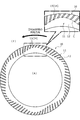
- the mechanical seal for general industrial machinery shown in FIG. 1 is an inside type that seals the sealed liquid F that tends to leak from the sealed liquid side of the sliding surface toward the atmosphere side, and is a rotary shaft 1
- the rotary sealing ring 20, which is an annular sliding component provided so as to be rotatable together with the rotating shaft 1 via the sleeve 2, and the seal cover 5 fixed to the housing 4 of the attached device are in a non-rotating state. It is mainly composed of an annular static sealing ring 10 as a sliding component provided so as to be movable in the axial direction, and the static sealing ring 10 is urged in the axial direction by the bellows 7, thereby statically sealing.
- the sliding surface 11 of the ring 10 and the sliding surface 21 of the rotary sealing ring 20 slide closely with each other.
- the sliding surface 21 of the rotary sealing ring 20 may be a flat surface or may be provided with a recessed portion.
- the static sealing ring 10 and the rotary sealing ring 20 are typically formed of SiC (hard material) or a combination of SiC (hard material) and carbon (soft material), but the sliding material is not limited to this. It can be applied as long as it is used as a sliding material for mechanical seals.
- the SiC includes a sintered body using boron, aluminum, carbon and the like as a sintering aid, and materials composed of two or more types of phases having different components and compositions, for example, SiC and SiC in which graphite particles are dispersed.
- carbon in which carbon and graphite are mixed.
- metal materials, resin materials, surface modification materials (coating materials), composite materials and the like can also be applied.
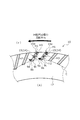
- the rotary sealing ring 20 slides relative to the static sealing ring 10 as shown by an arrow, and a plurality of dynamic pressures are applied to the sliding surface 11 of the static sealing ring 10.
- the generation mechanism 14 is evenly arranged along the circumferential direction of the static sealing ring 10.
- the portion of the sliding surface 11 other than the dynamic pressure generating mechanism 14 is a land 12 forming a flat end surface.
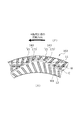
- the dynamic pressure generating mechanism 14 is provided with an opening 15a that opens to the sealed liquid side and communicates with the liquid, and is inclined to the downstream side while facing the atmosphere side, and is linear to the atmosphere side end portion 9b that is closed as the leakage side end part. It has a positive pressure generating groove 15 recessed in the air, and the cutting edge portion 9a is arranged at the leading edge on the downstream side of the atmosphere side end portion 9b. Since the land 12 is provided on the atmospheric side of the positive pressure generation groove 15, it is possible to prevent the sealed liquid F from leaking to the atmospheric side when the rotary sealing ring 20 is stationary.
- the positions of the most advanced portions 9a of the plurality of positive pressure generating grooves 15 arranged side by side in the radial direction are gradually changed along the circumferential direction, and the sine wave shape is smooth and continuous virtual over the circumferential direction. It is arranged on the curve C. Not limited to this embodiment, and not particularly shown, in addition to the cutting edge portion 9a, a corner portion 9c located on the upstream side of the atmospheric side end portion 9b of the positive pressure generation groove 15 is arranged on the virtual curve C. You may be. Furthermore, the virtual curve C has periodicity, but is not limited to this, and may not have periodicity.
- the plurality of positive pressure generating grooves 15 are narrow because the openings 15a are evenly arranged along the circumferential direction and the inclination angles of the positive pressure generating grooves 15 are different from each other. It is possible to arrange a plurality of positive pressure generating grooves 15 side by side, but the present invention is not limited to this, and each opening 15a is unevenly arranged along the circumferential direction, and each positive pressure generating groove 15 It may be provided so that the inclination angle is constant.
- the operation of the static sealing ring 10 and the rotating sealing ring 20 during relative rotation will be described.
- the sealed liquid F on the sealed liquid side of the sliding surfaces 11 and 21 is slightly formed between the sliding surfaces 11 and 21 due to the capillary phenomenon.
- the dynamic pressure generating mechanism 14 is filled with the sealed liquid F that has flowed in from the opening 15a of the positive pressure generating groove 15. Since the sealed liquid F has a higher viscosity than the gas, the amount of liquid leaking from the dynamic pressure generating mechanism 14 to the atmosphere side when the general industrial machine is stopped is extremely small.
- the sealed liquid F on the sealed liquid side is the opening of the positive pressure generating groove 15 as shown by the arrow H1. Since the flow introduced from the 15a toward the most advanced portion 9a is generated, a dynamic pressure is generated in the positive pressure generation groove 15. In the inside of the positive pressure generation groove 15, the positive pressure gradually increases from the opening 15a side on the upstream side toward the most advanced portion 9a on the downstream side.
- the pressure is highest in the vicinity of the most advanced portion 9a located at the most downstream side of the positive pressure generating groove 15, the sliding surfaces 11 and 21 are separated from each other, and the sealed liquid F is as shown by arrow H2.
- a liquid film of the sealed liquid F is formed on the sealed liquid side between the sliding surfaces 11 and 21 by flowing out from the vicinity of the most advanced portion 9a between the sliding surfaces 11 and 21 around the cutting edge portion 9a.
- a liquid film of the sealed liquid F is formed in the vicinity of the most advanced portion 9a of the plurality of positive pressure generating grooves 15, so-called fluid lubrication is performed between the sliding surfaces 11 and 21, and the lubricity is improved. It has been improved and low friction has been achieved.
- the sealed liquid F slightly flows downstream from a portion other than the most advanced portion 9a of the positive pressure generating groove 15.
- the positive pressure on the sliding surface 11 during the relative rotation of the rotary sealing ring 20 is along the circumferential direction. Since it occurs at different positions in the radial direction and the pressure gradient in the radial direction on the sliding surface 11 becomes small, the liquid film is likely to be formed substantially uniformly in a wide region of the sliding surface 11. Therefore, the lubricity of the sliding surface 11 due to the sealed liquid F is improved.
- the sealed liquid F flowing out from the positive pressure generation groove 15 to the land 12 is another positive pressure generation that is juxtaposed on the downstream side of the positive pressure generation groove 15 as shown by an arrow H3.
- the pressure in the positive pressure generating groove 15 can be stabilized.
- the sealed liquid F Flows to the downstream side in the relative rotation direction of each positive pressure generating groove 15, and concentrates on the cutting edge portion 9a to generate positive pressure. Since at least a part of the most advanced portion 9a of each positive pressure generating groove 15 is arranged at a different position in the radial direction, the positive pressure is located at a different position in the radial direction along the circumferential direction on the sliding surface 11. Since the pressure gradient in the radial direction on the sliding surface 11 becomes small, it is easy to form a liquid film substantially uniformly in a wide region of the sliding surface 11. Therefore, the lubricity of the sliding surface 11 due to the sealed liquid F is improved.
- the fluid film of the sealed liquid F is regularly arranged during the relative rotation of the rotary sealing ring 20. Since it is formed at the position, the lubricity is improved.
- the sealed liquid F is charged during the relative rotation of the rotary sealing ring 20. Since the liquid film is formed in a wavy shape, the lubricity is improved.
- the positive pressure generating groove 15 has an opening 15a communicating with the sealed liquid side, the sealed liquid is formed at the most advanced portion 9a of the positive pressure generating groove 15 during the relative rotation of the rotary sealing ring 20. Since F is easily introduced from the sealed liquid side, a liquid film of the sealed liquid F is easily formed at the cutting edge portion 9a, and the lubricity of the sliding surface 11 is improved.
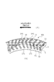
- a dynamic pressure generating mechanism 141 having a V shape with a tip facing downstream is provided in the circumferential direction of the static sealing ring 101. A plurality of them are evenly arranged. Of the two sides forming the V-shape, the dynamic pressure generation mechanism 141 opens to the sealed liquid side and communicates with the one side, which is inclined to the downstream side while facing the atmosphere side and is recessed in a straight line. The other side, which corresponds to the pressure generating groove 15 and is continuous with the positive pressure generating groove 15, is inclined to the upstream side while facing the atmosphere side, and is linear to the atmosphere side end portion 171a which is closed as the leakage side end part.
- the operation of the rotary sealing ring 20 during relative rotation will be described.
- the sealed liquid F on the sealed liquid side of the sliding surfaces 11 and 21 is slightly formed between the sliding surfaces 11 and 21 due to the capillary phenomenon.
- the dynamic pressure generation mechanism 141 is filled with the sealed liquid F that has flowed in from the opening 15a of the positive pressure generation groove 15. Since the sealed liquid F has a higher viscosity than the gas, the amount of the liquid leaking from the dynamic pressure generating mechanism 141 to the atmosphere side when the general industrial machine is stopped is extremely small.
- the sealed liquid F on the sealed liquid side is the opening of the positive pressure generating groove 15 as shown by the arrow H1. Since the flow introduced from the 15a toward the most advanced portion 9a is generated, a dynamic pressure is generated in the positive pressure generation groove 15. In the inside of the positive pressure generation groove 15, the positive pressure gradually increases from the opening 15a side on the upstream side toward the most advanced portion 9a on the downstream side.
- the pressure is highest in the vicinity of the most advanced portion 9a located at the most downstream side of the positive pressure generating groove 15, the sliding surfaces 11 and 21 are separated from each other, and the sealed liquid F is as shown by arrow H2.
- a liquid film of the sealed liquid F is formed on the sealed liquid side between the sliding surfaces 11 and 21 by flowing out from the vicinity of the most advanced portion 9a between the sliding surfaces 11 and 21 around the cutting edge portion 9a.
- a liquid film of the sealed liquid F is formed in the vicinity of the most advanced portion 9a of the plurality of positive pressure generating grooves 15, so-called fluid lubrication is performed between the sliding surfaces 11 and 21, and the lubricity is improved. It has been improved and low friction has been achieved.
- the sealed liquid F slightly flows downstream from a portion other than the most advanced portion 9a of the positive pressure generating groove 15.
- the positive pressure on the sliding surface 11 during the relative rotation of the rotary sealing ring 20 is along the circumferential direction. Since it occurs at different positions in the radial direction and the pressure gradient in the radial direction on the sliding surface 11 becomes small, it is easy to form a liquid film substantially uniformly in a wide region of the sliding surface 11. Therefore, the lubricity of the sliding surface 11 due to the sealed liquid F is improved.
- the sealed liquid F flowing out from the positive pressure generation groove 15 to the land 12 is another positive pressure generation that is juxtaposed on the downstream side of the positive pressure generation groove 15 as shown by an arrow H3.
- the pressure in the positive pressure generating groove 15 can be stabilized.
- the negative pressure generating groove 171 at the time of relative rotation of the rotary sealing ring 20 will be described.
- a dynamic pressure of negative pressure is generated in the negative pressure generating groove 171 and the sealed liquid introduced into the atmospheric side end portion 171a of the negative pressure generating groove 171.
- F is introduced from the atmosphere side end portion 171a of the negative pressure generation groove 171 toward the most advanced portion 9a.
- the inside of the negative pressure generation groove 171 gradually increases the positive pressure from the upstream end portion 171a on the atmosphere side toward the downstream side, and the end portion 171a on the atmosphere side becomes a relatively negative pressure. ..
- the pressure is highest in the vicinity of the cutting edge portion 9a, the sliding surfaces 11 and 21 are separated from each other, and the sealed liquid F is transferred from the vicinity of the cutting edge portion 9a to the sliding surface 11 around it as shown by an arrow H5.
- a liquid film of the sealed liquid F is formed on the sealed liquid side between the sliding surfaces 11 and 21.
- the sealed liquid F flowing out of the liquid film flows into the negative pressure generation groove 171 of another dynamic pressure generation mechanism 141 adjacent to the downstream side.
- the sealed liquid F once introduced from the opening 15a is circulated in the circumferential direction among the plurality of dynamic pressure generating mechanisms 141, so that the sealed liquid F can be prevented from leaking to the atmosphere side. ..
- the sealed liquid F is circulated in the circumferential direction among the plurality of dynamic pressure generating mechanisms 141 during the relative rotation of the plurality of cutting edge portions 9a arranged on the sine wave-shaped virtual curve C.
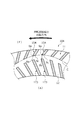
- the gas-liquid interface Y1 between the sealed liquid F and the atmosphere A on the sliding surface 11 is formed in a substantially sinusoidal shape on the atmosphere side of the virtual curve C, and the liquid film forming region Y (linear hatching in FIG. 4). (Indicated by) is formed on the sealed liquid side including the positive pressure generating groove 15 and a part of the negative pressure generating groove 171 (see FIG. 4).
- the sealed liquid F that tends to leak to the atmospheric side is removed. It can be returned to the sealed liquid F side, which is the diameter side.
- the position of the gas-liquid interface Y1 and the range of the liquid film forming region Y vary from the position shown in FIG. 4 depending on the rotational speed of the rotary sealing ring 20 during relative rotation, the pressure of the sealed liquid F, and the like. ..
- the sealed liquid F flowing out from the negative pressure generation groove 171 to the land 12 is another negative pressure generation that is juxtaposed on the downstream side of the negative pressure generation groove 171 as shown by an arrow H6.
- the pressure in the negative pressure generating groove 171 can be stabilized by flowing into the groove 171.
- the positive pressure generating groove 15 is inclined to the downstream side while facing the atmosphere side, and extends upstream while continuously facing the atmosphere side from the atmosphere side end portion 9b of the positive pressure generating groove 15.
- a negative pressure generating groove 171 extending so as to be inclined to the side is provided on the sliding surface. From this, when the rotary sealing ring 20 is relatively rotated, the liquid film of the sealed liquid F formed at the cutting edge portion 9a is sucked by the negative pressure generating groove 171 which has a relatively negative pressure, so that the sealed liquid Leakage of F to the atmosphere side can be prevented, and the sealing performance of the static sealing ring 10 and the rotary sealing ring 20 can be improved.
- the land 12 is provided on the leak side of the sliding surface 11 with respect to the negative pressure generating groove 171 so as to be continuous in the circumferential direction, that is, in an annular shape, the atmospheric side of the negative pressure generating groove 171 is provided. Since the end portion 171a is closed by the land 12, it is possible to prevent the sealed liquid F from leaking to the atmosphere side when the rotary sealing ring 20 is stationary.
- the land 12 on the atmosphere side of the negative pressure generating groove 171 has a constant radial width over the circumferential direction, the radial position of the atmospheric side end portion 171a of the negative pressure generating groove 171 is in the circumferential direction. It is easy to manufacture because it is constant over.
- the apex has a dynamic pressure generating mechanism 141. Is provided with a plurality of reverse dynamic pressure generating mechanisms 141'facing the opposite side.
- the reverse dynamic pressure generation mechanism 141' has a substantially same structure in which the dynamic pressure generation mechanism 141 is inverted in the circumferential direction, and one of the two sides forming the V shape is open to the sealed liquid side and communicates with each other.
- the reverse positive pressure generating groove 15' which is inclined to the opposite side of the positive pressure generating groove 15 while facing the atmosphere side and is recessed in a straight line, and is continuous with the reverse positive pressure generating groove 15'.
- the other side to be recessed is inclined to the opposite side of the negative pressure generation groove 171 while facing the atmosphere side, and is recessed in a straight line up to the atmosphere side end 171a'closed as the leak side.
- the tip corresponding to the pressure generation groove 171'and the intersection of the two V-shaped sides corresponds to the inverted tip portion 9a'.
- the dynamic pressure generating mechanism 141 in which the apex faces the downstream side in the relative rotation direction during forward rotation and the apex in the relative rotation direction during reverse rotation Since it is provided with a reverse dynamic pressure generating mechanism 141'facing the downstream side, it can be used regardless of the relative rotation direction between the static sealing ring 101 and the rotating sealing ring 20.
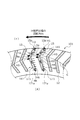
- the sliding surface 11 of the static sealing ring 103 has a positive pressure generating groove 15 extending toward the atmosphere side and inclined to the downstream side, and the positive pressure generating groove 15
- a plurality of dynamic pressure generation mechanisms 143 composed of a second positive pressure generation groove 173 that is independent of the atmosphere and is inclined to the upstream side and extends toward the atmosphere side are evenly arranged in the circumferential direction.
- the number of the second positive pressure generating grooves 173 is the same as that of the positive pressure generating grooves 15, and they are arranged so as to be located on the same radius, but the number or position is not limited to this. It does not have to be.
- the positive pressure generating groove 15 is provided with an opening 15a that opens to the sealed liquid side and communicates with the liquid, and is linearly recessed to the closed atmospheric side end portion 9b, and is at the tip of the downstream side of the atmospheric side end portion 9b. Has the most advanced portion 9a. Further, the positions of the most advanced portions 9a of the plurality of positive pressure generating grooves 15 arranged side by side in the radial direction are gradually changed along the circumferential direction, and the sine wave shape is smooth and continuous virtual over the circumferential direction. It is arranged on the curve C.
- the second positive pressure generating groove 173 is provided with an opening 173a that opens to the atmosphere side and communicates with the closed liquid side end portion 17b, and is recessed linearly to the closed liquid side end portion 17b on the downstream side of the sealed liquid side end portion 17b.
- the cutting edge 9a is located at the cutting edge of the.
- the radial width of the land 12 provided between the positive pressure generating groove 15 and the second positive pressure generating groove 173 in the radial direction is formed to be a constant width over the circumferential direction.
- the sealed liquid F on the sealed liquid side of the sliding surfaces 11 and 21 is slightly formed between the sliding surfaces 11 and 21 due to the capillary phenomenon.
- the dynamic pressure generation mechanism 143 is filled with the sealed liquid F that has flowed in from the opening 15a of the positive pressure generation groove 15. Since the sealed liquid F has a higher viscosity than the gas, the amount of leakage from the dynamic pressure generating mechanism 143 to the atmosphere side when the general industrial machine is stopped is extremely small.
- the sealed liquid F on the sealed liquid side becomes the positive pressure generating groove 15 as shown by the arrow H1. Since the flow introduced from the opening 15a to the most advanced portion 9a is generated, dynamic pressure is generated in the positive pressure generating groove 15. In the inside of the positive pressure generation groove 15, the positive pressure gradually increases from the opening 15a side on the upstream side toward the most advanced portion 9a on the downstream side.
- the pressure is highest in the vicinity of the most advanced portion 9a located at the most downstream side of the positive pressure generating groove 15, the sliding surfaces 11 and 21 are separated from each other, and the sealed liquid F is as shown by arrow H2.
- a liquid film of the sealed liquid F is formed on the sealed liquid side between the sliding surfaces 11 and 21 by flowing out from the vicinity of the most advanced portion 9a between the sliding surfaces 11 and 21 around the cutting edge portion 9a.
- a liquid film of the sealed liquid F is formed in the vicinity of the most advanced portion 9a of the plurality of positive pressure generating grooves 15, so-called fluid lubrication is performed between the sliding surfaces 11 and 21, and the lubricity is improved. It has been improved and low friction has been achieved.
- the sealed liquid F slightly flows downstream from a portion other than the most advanced portion 9a of the positive pressure generating groove 15.
- the positive pressure on the sliding surface 11 during the relative rotation of the rotary sealing ring 20 is along the circumferential direction. Since it occurs at different positions in the radial direction and the pressure gradient in the radial direction on the sliding surface 11 becomes small, it is easy to form a liquid film substantially uniformly in a wide region of the sliding surface 11. Therefore, the lubricity of the sliding surface 11 due to the sealed liquid F is improved.
- the sealed liquid F flowing out from the positive pressure generation groove 15 to the land 12 is another positive pressure generation that is juxtaposed on the downstream side of the positive pressure generation groove 15 as shown by an arrow H3.
- a liquid film having a substantially uniform film thickness is formed in the liquid film forming region W (indicated by linear hatching in FIG. 8).
- the second positive pressure generation groove 173 during relative rotation of the rotary sealing ring 20 will be described.
- the atmosphere A on the atmospheric side changes from the opening 173a of the second positive pressure generating groove 173 to the second most as shown by the arrow L1. Since the flow introduced toward the tip portion 17a is generated, dynamic pressure is generated in the second positive pressure generation groove 173.
- the positive pressure gradually increases from the opening 173a side on the upstream side toward the second cutting edge portion 17a on the downstream side.
- the pressure is highest in the vicinity of the second cutting edge portion 17a located at the most downstream side of the second positive pressure generating groove 173, the sliding surfaces 11 and 21 are separated from each other, and the atmosphere A is indicated by the arrow L2. As described above, it flows out from the vicinity of the second most advanced portion 17a between the sliding surfaces 11 and 21 around it. In this way, when a positive pressure is generated in the vicinity of the second cutting edge portion 17a, the sealed liquid F approaching the vicinity of the second cutting edge portion is repelled from the sealed liquid side to the atmosphere side of the sealed liquid F. Leakage can be prevented.
- the relative rotation of the rotary sealing ring 20 Since the liquid film is not allowed to enter the atmosphere side due to the positive pressure generated by the concentration of the atmosphere A on the plurality of second cutting-edge portions 17a, the gas-liquid interface W1 between the sealed liquid F and the atmosphere A on the sliding surface 11 sometimes. Is formed in a sinusoidal shape between the plurality of atmospheric side end portions 9b and the plurality of sealed liquid side end portions 17b, and the liquid film forming region W is formed on the sealed liquid side including the positive pressure generation groove 15. (See FIG. 8).
- the position of the gas-liquid interface W1 and the range of the liquid film forming region W vary from the position shown in FIG. 8 depending on the rotational speed of the rotary sealing ring 20 during relative rotation, the pressure of the sealed liquid F, and the like. ..
- the sealed liquid F enters the land 12 on the atmosphere side during the relative rotation of the rotary sealing ring 20.
- the atmosphere A on the atmosphere side is introduced from the opening 173a of the second positive pressure generating groove 173 toward the second leading edge 17a as shown by the arrow L3, and is shown by the arrow H9.
- the sealed liquid F merges with the flow of the atmosphere A indicated by the arrow L3, and the flow of the sealed liquid F toward the second leading edge 17a as shown by the arrow H7 is generated, and the second positive Dynamic pressure is generated in the pressure generation groove 173.
- the positive pressure inside the second positive pressure generating groove 173 gradually increases from the opening 173a side on the upstream side toward the second leading edge 17a on the downstream side. There is.
- the pressure is highest in the vicinity of the second cutting edge portion 17a located at the most downstream side of the second positive pressure generating groove 173, and the sealed liquid F is the second cutting edge portion 17a as shown by an arrow H8. It flows out from the vicinity between the sliding surfaces 11 and 21 around it. In this way, the sealed liquid F that has entered the land 12 can be returned to the sealed liquid side, which is the outer diameter side, and the leakage of the sealed liquid F to the atmosphere side can be prevented. Since the sealed liquid F is incompressible and has a high viscosity as compared with the atmosphere, the sealed liquid F that has entered the second positive pressure generation groove 173 has a sliding surface as the rotary sealing ring 20 rotates relative to each other. It is easy to flow out between 11 and 21.
- the atmosphere on the atmosphere side of the positive pressure generating groove 15 is independent of the positive pressure generating groove 15, and the atmosphere on the atmosphere side of the positive pressure generating groove 15 is introduced during the relative rotation of the rotary sealing ring 20, and the positive pressure is introduced.
- a second positive pressure generating groove 173 is provided, and the second positive pressure generating groove 173 is provided with a second cutting edge portion 17a at the leading edge on the downstream side in the relative rotation direction. From this, when the rotary sealing ring 20 is relatively rotated, the atmosphere on the atmospheric side flows to the downstream side of the second positive pressure generation groove 173 and concentrates on the second cutting edge 17a to generate positive pressure, so that positive pressure is generated from the sealed liquid side. It is possible to repel the sealed liquid F approaching the vicinity of the second cutting edge portion 17a and prevent the sealed liquid F from leaking to the atmosphere side.
- the second positive pressure generating groove 173 is arranged corresponding to the number and position of the positive pressure generating groove 15, the second positive pressure generating groove 173 is aligned with the number and position of the positive pressure generating groove 15. Can be processed and is easy to manufacture.
- the second cutting edge Since the portion 17a is separated from the cutting edge portion 9a on the leakage side by a certain dimension, and the second cutting edge portion 17a in which positive pressure is generated during relative rotation is arranged at positions having different diameters in the circumferential direction. It is possible to prevent the sealed liquid F flowing from the liquid film generated at the cutting edge portion 9a during relative rotation from entering the atmosphere side.
- the sliding surface 11 of the static sealing ring 104 has a plurality of cutting-edge portions 9a arranged side by side and an upstream side of the atmospheric side end portion 9b of the positive pressure generating groove 154.
- the corner portion 9c located at the position is easy to manufacture because its position in the radial direction gradually changes along the circumferential direction and is arranged on the sine wave-shaped virtual curve C.
- the mechanical seal for general industrial machines has been described as an example as the sliding component, but other mechanical seals for automobiles, water pumps, etc. may be used.
- the present invention is not limited to the mechanical seal, and may be a sliding component other than the mechanical seal such as a slide bearing.
- the dynamic pressure generating mechanism may be provided only on the static sealing ring 10
- the dynamic pressure generating mechanism may be provided only on the rotary sealing ring 20, and both the static sealing ring and the rotary sealing ring may be provided. It may be provided in.
- the cutting edge portion 9a and the corner portion 9c or the bending portion 92c are arranged on a smooth and continuous sinusoidal virtual curve C, but the present invention is not limited to this.
- the curve may be, for example, a wavy shape having a small period or a rectangular wavy shape.
- the positive pressure generation groove 15, the negative pressure generation groove, the reverse positive pressure generation groove 15', the reverse negative pressure generation groove 171', and the second positive pressure generation groove 173 are linearly recessed.
- the present invention is not limited to this, and for example, it may be recessed in a curved shape.
- the positive pressure generating groove is provided with an opening 15a that opens and communicates with the liquid to be sealed, but the present invention is not limited to this, and the groove may be closed without opening.
- the second positive pressure generation groove 173 is provided with an opening 173a that is open to the atmosphere and communicates with the groove 173, the present invention is not limited to this, and the groove may be closed without opening.
Landscapes
- Engineering & Computer Science (AREA)
- General Engineering & Computer Science (AREA)
- Mechanical Engineering (AREA)
- Physics & Mathematics (AREA)
- Fluid Mechanics (AREA)
- Mechanical Sealing (AREA)
- Sliding-Contact Bearings (AREA)
Abstract
Description
回転機械の相対回転する箇所に配置される環状の摺動部品であって、
前記摺動部品の摺動面には、前記摺動部品の相対回転時に被密封流体側の被密封流体が導入されて正圧を発生する正圧発生溝が周方向に複数並設されており、それぞれの前記正圧発生溝は、相対回転方向の下流側の最先端に最先端部を有し、周方向に複数並設された前記最先端部の少なくとも一部は、径方向に各々異なる位置に配置されている。
これによれば、摺動部品の相対回転時には、被密封流体が各正圧発生溝の相対回転方向の下流側に流れ最先端部に集中し正圧が発生する。それぞれの正圧発生溝の最先端部の少なくとも一部は径方向に各々異なる位置に配置されているので、摺動面においては、正圧は周方向に沿って径方向の異なる位置で発生し、摺動面における径方向の圧力勾配が小さくなるため、摺動面の広い領域で均一に液膜が形成され易い。そのため、摺動面の被密封流体による潤滑性が良好となる。 In order to solve the above problems, the sliding parts of the present invention are
An annular sliding component placed at a location where the rotating machine rotates relative to each other.
On the sliding surface of the sliding component, a plurality of positive pressure generating grooves in which the sealed fluid on the sealed fluid side is introduced during the relative rotation of the sliding component to generate positive pressure are arranged side by side in the circumferential direction. Each of the positive pressure generating grooves has a cutting-edge portion at the leading edge on the downstream side in the relative rotation direction, and at least a part of the cutting-edge portions arranged side by side in the circumferential direction is different in the radial direction. It is placed in position.
According to this, when the sliding parts rotate relative to each other, the fluid to be sealed flows to the downstream side in the relative rotation direction of each positive pressure generating groove and concentrates on the most advanced portion to generate positive pressure. Since at least a part of the most advanced portion of each positive pressure generating groove is arranged at different positions in the radial direction, positive pressure is generated at different positions in the radial direction along the circumferential direction on the sliding surface. Since the pressure gradient in the radial direction on the sliding surface becomes small, the liquid film is likely to be uniformly formed in a wide region of the sliding surface. Therefore, the lubricity of the sliding surface due to the sealed fluid is improved.
これによれば、摺動部品の相対回転時に被密封流体の流体膜が規則的に配置された位置に形成されるため、潤滑性が良好となる。 A plurality of the most advanced portions arranged side by side may be regularly arranged along the circumferential direction.
According to this, the fluid film of the fluid to be sealed is formed at a position where the fluid film to be sealed is regularly arranged at the time of relative rotation of the sliding component, so that the lubricity is improved.
これによれば、摺動部品の相対回転時に被密封流体の流体膜が波形状に形成されるため、潤滑性が良好となる。 A plurality of the most advanced portions arranged side by side may be arranged in a wavy shape with their radial positions gradually changing along the circumferential direction.
According to this, the fluid film of the fluid to be sealed is formed in a wavy shape when the sliding parts are relatively rotated, so that the lubricity is improved.
これによれば、摺動部品の相対回転時には、正圧発生溝の開口部において被密封流体が被密封流体側から導入されやすくなるため、最先端部にて被密封流体の流体膜が形成されやすくなり、摺動面の潤滑性が良好となる。 The positive pressure generating groove may have an opening communicating with the sealed fluid side.
According to this, when the sliding parts rotate relative to each other, the sealed fluid is easily introduced from the sealed fluid side at the opening of the positive pressure generating groove, so that a fluid film of the sealed fluid is formed at the most advanced portion. It becomes easy and the lubricity of the sliding surface becomes good.
前記正圧発生溝には、前記正圧発生溝の漏れ側端部から連続して漏れ側に向かいながら相対回転方向の上流側に傾斜して延設する負圧発生溝が設けられていてもよい。
これによれば、摺動部品の相対回転時には、最先端部で形成された被密封流体の流体膜を相対的に負圧となっている負圧発生溝が吸い込むため、被密封流体の漏れ側への漏れを防止し、摺動部品の密封性を向上できる。 The positive pressure generating groove is inclined and extended to the downstream side in the relative rotation direction while facing the leak side.
Even if the positive pressure generating groove is provided with a negative pressure generating groove extending from the leaking side end of the positive pressure generating groove so as to be inclined to the upstream side in the relative rotation direction while continuously facing the leaking side. Good.
According to this, when the sliding parts rotate relative to each other, the fluid film of the sealed fluid formed at the most advanced portion is sucked by the negative pressure generating groove, which has a relatively negative pressure, so that the leak side of the sealed fluid It is possible to prevent leakage to and improve the sealing performance of sliding parts.
これによれば、負圧発生溝の漏れ側端部はランドにより閉塞されているため、摺動部品の静止時には、被密封流体の漏れ側への漏れを防止できる。 A land extending in the circumferential direction may be provided on the leak side of the sliding surface with respect to the negative pressure generating groove.
According to this, since the leak-side end of the negative pressure generating groove is closed by the land, it is possible to prevent the sealed fluid from leaking to the leak-side when the sliding component is stationary.
これによれば、負圧発生溝の漏れ側端部の径方向の位置が周方向に亘って一定であるため、製造しやすい。 The width of the land on the leakage side of the negative pressure generating groove may be constant in the radial direction over the circumferential direction.
According to this, since the radial position of the leak-side end of the negative pressure generating groove is constant over the circumferential direction, it is easy to manufacture.
これによれば、波形状の仮想曲線上に最先端部と屈曲部とが配置されるため、製造しやすい。 The radial positions of the plurality of cutting-edge portions arranged side by side and the bent portion on the upstream side in the relative rotation direction where the positive pressure generating groove and the negative pressure generating groove intersect gradually change along the circumferential direction. However, it may be arranged in a wavy shape.
According to this, since the cutting edge portion and the bending portion are arranged on the wave-shaped virtual curve, it is easy to manufacture.
これによれば、摺動部品の相対回転時に漏れ側の流体が第2正圧発生溝の相対回転方向の下流側に流れ第2最先端部に集中し正圧が発生するため、被密封流体側から第2最先端部近傍に接近する被密封流体を弾き返し、被密封流体の漏れ側への漏洩を防ぐことができる。 On the sliding surface, the fluid on the leak side of the positive pressure generating groove is independent of the positive pressure generating groove, and the fluid on the leaking side of the positive pressure generating groove is introduced during the relative rotation of the rotating machine. A second positive pressure generating groove for generating pressure is provided, and the second positive pressure generating groove may be provided with a second cutting edge portion at the leading edge on the downstream side in the relative rotation direction.
According to this, when the sliding parts rotate relative to each other, the fluid on the leak side flows to the downstream side in the relative rotation direction of the second positive pressure generating groove and concentrates on the second leading edge to generate positive pressure, so that the fluid to be sealed It is possible to repel the sealed fluid approaching the vicinity of the second most advanced portion from the side and prevent the sealed fluid from leaking to the leak side.
これによれば、正圧発生溝の数及び位置にそろえて第2正圧発生溝を加工することができ、製造しやすい。 The second positive pressure generating groove may be arranged corresponding to the number and position of the positive pressure generating groove.
According to this, the second positive pressure generating groove can be machined according to the number and position of the positive pressure generating groove, and it is easy to manufacture.
これによれば、正圧発生溝と第2正圧発生溝とを離間させることができ、相対回転時における両者の機能を明確化できる。 A land extending in the circumferential direction may be provided between the positive pressure generating groove and the second positive pressure generating groove in the radial direction.
According to this, the positive pressure generating groove and the second positive pressure generating groove can be separated from each other, and the functions of both at the time of relative rotation can be clarified.
これによれば、第2最先端部が最先端部から一定寸法漏れ側に離間しており、周方向において異なる径の長さの位置で相対回転時に正圧の発生した第2最先端部が配置されることから、相対回転時に最先端部で発生した流体膜から流れる被密封流体が漏れ側に進入するのを防止できる。 The radial width of the land provided between the positive pressure generating groove and the second positive pressure generating groove may be constant over the circumferential direction.
According to this, the second cutting-edge part is separated from the cutting-edge part on the leakage side by a certain dimension, and the second cutting-edge part where positive pressure is generated during relative rotation at positions having different diameters in the circumferential direction. Since it is arranged, it is possible to prevent the sealed fluid flowing from the fluid film generated at the most advanced portion during relative rotation from entering the leak side.
これによれば、波形状の仮想曲線上に最先端部と隅部とが配置されるため、製造しやすい。 The positions of the most advanced portions arranged side by side and the corners located on the upstream side in the relative rotation direction of the leak-side end of the positive pressure generating groove gradually change in the radial direction along the circumferential direction. It may be arranged in a wavy shape.
According to this, since the cutting edge portion and the corner portion are arranged on the wave-shaped virtual curve, it is easy to manufacture.
2 スリーブ
4 ハウジング
5 シールカバー
7 ベローズ
9a 最先端部
9b 大気側端部(漏れ側端部)
9c 隅部
10 静止密封環(摺動部品)
11 摺動面
12 ランド
14 動圧発生機構
15 正圧発生溝
15a 開口部
17a 第2最先端部
20 回転密封環(摺動部品)
21 摺動面
92c 屈曲部
171 負圧発生溝
173 第2正圧発生溝 1 Rotating
11 Sliding
21 Sliding
Claims (13)
- 回転機械の相対回転する箇所に配置される環状の摺動部品であって、
前記摺動部品の摺動面には、前記摺動部品の相対回転時に被密封流体側の被密封流体が導入されて正圧を発生する正圧発生溝が周方向に複数並設されており、それぞれの前記正圧発生溝は、相対回転方向の下流側の最先端に最先端部を有し、周方向に複数並設された前記最先端部の少なくとも一部は、径方向に各々異なる位置に配置されている摺動部品。 An annular sliding component placed at a location where the rotating machine rotates relative to each other.
On the sliding surface of the sliding component, a plurality of positive pressure generating grooves in which the sealed fluid on the sealed fluid side is introduced during the relative rotation of the sliding component to generate positive pressure are arranged side by side in the circumferential direction. Each of the positive pressure generating grooves has a cutting-edge portion at the leading edge on the downstream side in the relative rotation direction, and at least a part of the cutting-edge portions arranged side by side in the circumferential direction is different in the radial direction. Sliding parts placed in position. - 複数並設された前記最先端部は、周方向に沿って規則的に配置されている請求項1に記載の摺動部品。 The sliding component according to claim 1, wherein a plurality of the most advanced portions arranged side by side are regularly arranged along the circumferential direction.
- 複数並設された前記最先端部は、周方向に沿って径方向の位置が漸次変化し、波形状に配置されている請求項1または2に記載の摺動部品。 The sliding component according to claim 1 or 2, wherein a plurality of the cutting-edge portions arranged side by side are arranged in a wavy shape with their radial positions gradually changing along the circumferential direction.
- 前記正圧発生溝は、被密封流体側に連通する開口部を有している請求項1ないし3のいずれかに記載の摺動部品。 The sliding component according to any one of claims 1 to 3, wherein the positive pressure generating groove has an opening communicating with the sealed fluid side.
- 前記正圧発生溝は、漏れ側に向かいながら相対回転方向の下流側に傾斜して延設されており、
前記摺動面には、前記正圧発生溝の漏れ側端部から連続して漏れ側に向かいながら相対回転方向の上流側に傾斜して延設する負圧発生溝が設けられている請求項1ないし4のいずれかに記載の摺動部品。 The positive pressure generating groove is inclined and extended to the downstream side in the relative rotation direction while facing the leak side.
The sliding surface is provided with a negative pressure generating groove extending from the leaking side end of the positive pressure generating groove so as to be inclined to the upstream side in the relative rotation direction while continuously facing the leaking side. The sliding component according to any one of 1 to 4. - 前記摺動面の前記負圧発生溝よりも漏れ側には、周方向に亘って延びるランドが設けられている請求項5に記載の摺動部品。 The sliding component according to claim 5, wherein a land extending in the circumferential direction is provided on the leak side of the sliding surface from the negative pressure generating groove.
- 前記負圧発生溝より漏れ側の前記ランドは、周方向に亘って径方向の幅が一定である請求項6に記載の摺動部品。 The sliding component according to claim 6, wherein the land on the leak side from the negative pressure generating groove has a constant radial width over the circumferential direction.
- 複数並設された前記最先端部と、前記正圧発生溝と前記負圧発生溝とが交差する相対回転方向の上流側の屈曲部とは、周方向に沿って径方向の位置が漸次変化し、波形状に配置されている請求項5ないし7のいずれかに記載の摺動部品。 The radial positions of the plurality of cutting-edge portions arranged side by side and the bent portion on the upstream side in the relative rotation direction where the positive pressure generating groove and the negative pressure generating groove intersect gradually change along the circumferential direction. The sliding component according to any one of claims 5 to 7, which is arranged in a wavy shape.
- 前記摺動面には、前記正圧発生溝よりも漏れ側において前記正圧発生溝とは独立し、前記回転機械の相対回転時に前記正圧発生溝よりも漏れ側の流体が導入されて正圧を発生する第2正圧発生溝が設けられており、前記第2正圧発生溝は相対回転方向の下流側の最先端に第2最先端部を備えている請求項1ないし4のいずれかに記載の摺動部品。 On the sliding surface, the fluid on the leak side of the positive pressure generating groove is independent of the positive pressure generating groove, and the fluid on the leaking side of the positive pressure generating groove is introduced during the relative rotation of the rotating machine. Any of claims 1 to 4, wherein a second positive pressure generating groove for generating pressure is provided, and the second positive pressure generating groove is provided with a second cutting edge portion at the leading edge on the downstream side in the relative rotation direction. Sliding parts described in Crab.
- 前記第2正圧発生溝は、前記正圧発生溝の数及び位置に対応して配置されている請求項9に記載の摺動部品。 The sliding component according to claim 9, wherein the second positive pressure generating groove is arranged corresponding to the number and position of the positive pressure generating groove.
- 前記正圧発生溝と前記第2正圧発生溝との径方向の間に周方向に亘って延びるランドが備えられている請求項10に記載の摺動部品。 The sliding component according to claim 10, further comprising a land extending in the circumferential direction between the positive pressure generating groove and the second positive pressure generating groove in the radial direction.
- 前記正圧発生溝と前記第2正圧発生溝との径方向の間に備えられている前記ランドの径方向の幅は、周方向に亘って一定である請求項11に記載の摺動部品。 The sliding component according to claim 11, wherein the radial width of the land provided between the positive pressure generating groove and the second positive pressure generating groove is constant over the circumferential direction. ..
- 複数並設された前記最先端部と、前記正圧発生溝の漏れ側端部の相対回転方向の上流側に位置する隅部とは、周方向に沿って径方向の位置が漸次変化し、波形状に配置されている請求項3,9,10,11または12に記載の摺動部品。 A plurality of the most advanced portions arranged side by side and the corner portion located on the upstream side in the relative rotation direction of the leak-side end portion of the positive pressure generating groove gradually change in radial position along the circumferential direction. The sliding component according to claim 3, 9, 10, 11 or 12, which is arranged in a wavy shape.
Priority Applications (7)
| Application Number | Priority Date | Filing Date | Title |
|---|---|---|---|
| CN202310654960.9A CN116447222A (en) | 2019-04-09 | 2020-04-07 | Sliding member |
| EP20787693.9A EP3954914A4 (en) | 2019-04-09 | 2020-04-07 | Sliding component |
| US17/602,137 US20220145931A1 (en) | 2019-04-09 | 2020-04-07 | Sliding component |
| KR1020237039120A KR20230159647A (en) | 2019-04-09 | 2020-04-07 | Slidng component |
| JP2021513643A JP7404351B2 (en) | 2019-04-09 | 2020-04-07 | sliding parts |
| KR1020217035587A KR102669558B1 (en) | 2019-04-09 | 2020-04-07 | sliding parts |
| CN202080026547.2A CN113661330B (en) | 2019-04-09 | 2020-04-07 | Sliding member |
Applications Claiming Priority (2)
| Application Number | Priority Date | Filing Date | Title |
|---|---|---|---|
| JP2019074466 | 2019-04-09 | ||
| JP2019-074466 | 2019-04-09 |
Publications (1)
| Publication Number | Publication Date |
|---|---|
| WO2020209258A1 true WO2020209258A1 (en) | 2020-10-15 |
Family
ID=72751296
Family Applications (1)
| Application Number | Title | Priority Date | Filing Date |
|---|---|---|---|
| PCT/JP2020/015696 WO2020209258A1 (en) | 2019-04-09 | 2020-04-07 | Sliding component |
Country Status (6)
| Country | Link |
|---|---|
| US (1) | US20220145931A1 (en) |
| EP (1) | EP3954914A4 (en) |
| JP (1) | JP7404351B2 (en) |
| KR (1) | KR20230159647A (en) |
| CN (2) | CN116447222A (en) |
| WO (1) | WO2020209258A1 (en) |
Families Citing this family (1)
| Publication number | Priority date | Publication date | Assignee | Title |
|---|---|---|---|---|
| US20220136604A1 (en) * | 2019-03-15 | 2022-05-05 | Nok Corporation | Seal ring and sealed structure |
Citations (4)
| Publication number | Priority date | Publication date | Assignee | Title |
|---|---|---|---|---|
| JPH05164249A (en) | 1991-12-13 | 1993-06-29 | Nippon John Kureen Kk | Non-contact mechanical seal |
| US6152452A (en) | 1997-10-17 | 2000-11-28 | Wang; Yuming | Face seal with spiral grooves |
| US20150345641A1 (en) * | 2014-06-03 | 2015-12-03 | Thermo King Corporation | Mechanical face seal |
| JP2019007622A (en) * | 2013-01-16 | 2019-01-17 | イーグル工業株式会社 | Sliding component |
Family Cites Families (16)
| Publication number | Priority date | Publication date | Assignee | Title |
|---|---|---|---|---|
| JPH0743038B2 (en) * | 1990-07-18 | 1995-05-15 | 株式会社荏原製作所 | Non-contact end face seal |
| US5441283A (en) * | 1993-08-03 | 1995-08-15 | John Crane Inc. | Non-contacting mechanical face seal |
| DE4409021A1 (en) * | 1994-03-16 | 1995-09-21 | Burgmann Dichtungswerk Feodor | Non-contact, gas-lubricated mechanical seal |
| JP2000199520A (en) * | 1999-01-06 | 2000-07-18 | Konica Corp | Rotary device |
| US7568839B2 (en) * | 2004-02-18 | 2009-08-04 | Seiko Instruments Inc. | Fluid dynamic pressure bearing, motor, and recording medium driving device |
| EP2375112B1 (en) * | 2009-05-25 | 2018-07-18 | Eagle Industry Co., Ltd. | Sealing device |
| KR101513278B1 (en) * | 2011-08-05 | 2015-04-17 | 이구루코교 가부시기가이샤 | Mechanical seal |
| JP2014187871A (en) * | 2014-04-23 | 2014-10-02 | Samsung Electromechanics Japan Advanced Technology Co Ltd | Disc drive device |
| WO2016167262A1 (en) * | 2015-04-15 | 2016-10-20 | イーグル工業株式会社 | Sliding parts |
| CN114935012A (en) * | 2015-06-30 | 2022-08-23 | 伊格尔工业股份有限公司 | Sealing device |
| CN106763779B (en) * | 2016-12-12 | 2019-04-12 | 昆明理工大学 | A kind of mechanical seal ring with more zigzag helicla flutes |
| WO2018139232A1 (en) * | 2017-01-30 | 2018-08-02 | イーグル工業株式会社 | Sliding component |
| KR102276083B1 (en) * | 2017-01-30 | 2021-07-13 | 이구루코교 가부시기가이샤 | sliding parts |
| CN107314112B (en) * | 2017-07-24 | 2023-07-21 | 浙江工业大学 | Mechanical seal end face structure imitating grinding disc textures |
| EP3901497A4 (en) * | 2018-12-21 | 2022-09-14 | Eagle Industry Co., Ltd. | Sliding component |
| US11821461B2 (en) * | 2019-02-15 | 2023-11-21 | Eagle Industry Co., Ltd. | Sliding components |
-
2020
- 2020-04-07 JP JP2021513643A patent/JP7404351B2/en active Active
- 2020-04-07 CN CN202310654960.9A patent/CN116447222A/en active Pending
- 2020-04-07 EP EP20787693.9A patent/EP3954914A4/en active Pending
- 2020-04-07 CN CN202080026547.2A patent/CN113661330B/en active Active
- 2020-04-07 US US17/602,137 patent/US20220145931A1/en active Pending
- 2020-04-07 WO PCT/JP2020/015696 patent/WO2020209258A1/en unknown
- 2020-04-07 KR KR1020237039120A patent/KR20230159647A/en not_active Application Discontinuation
Patent Citations (4)
| Publication number | Priority date | Publication date | Assignee | Title |
|---|---|---|---|---|
| JPH05164249A (en) | 1991-12-13 | 1993-06-29 | Nippon John Kureen Kk | Non-contact mechanical seal |
| US6152452A (en) | 1997-10-17 | 2000-11-28 | Wang; Yuming | Face seal with spiral grooves |
| JP2019007622A (en) * | 2013-01-16 | 2019-01-17 | イーグル工業株式会社 | Sliding component |
| US20150345641A1 (en) * | 2014-06-03 | 2015-12-03 | Thermo King Corporation | Mechanical face seal |
Also Published As
| Publication number | Publication date |
|---|---|
| CN116447222A (en) | 2023-07-18 |
| EP3954914A4 (en) | 2022-12-14 |
| JPWO2020209258A1 (en) | 2020-10-15 |
| KR20210145791A (en) | 2021-12-02 |
| CN113661330A (en) | 2021-11-16 |
| CN113661330B (en) | 2023-09-05 |
| EP3954914A1 (en) | 2022-02-16 |
| JP7404351B2 (en) | 2023-12-25 |
| KR20230159647A (en) | 2023-11-21 |
| US20220145931A1 (en) | 2022-05-12 |
Similar Documents
| Publication | Publication Date | Title |
|---|---|---|
| JP7369151B2 (en) | sliding parts | |
| WO2019139107A1 (en) | Sliding component | |
| WO2020196145A1 (en) | Sliding component | |
| JP7366945B2 (en) | sliding parts | |
| WO2020162351A1 (en) | Sliding component | |
| JP7313788B2 (en) | sliding parts | |
| JP2020173020A (en) | Slide part | |
| JP7307102B2 (en) | sliding parts | |
| WO2020171102A1 (en) | Sliding component | |
| WO2020209258A1 (en) | Sliding component | |
| WO2021182168A1 (en) | Sliding component | |
| JP7370681B2 (en) | sliding parts | |
| KR102669558B1 (en) | sliding parts | |
| WO2021215224A1 (en) | Pair of sliding components | |
| JP7297394B2 (en) | sliding parts | |
| US20220099190A1 (en) | Sliding component | |
| WO2023027102A1 (en) | Sliding component | |
| WO2020218286A1 (en) | Sliding component | |
| WO2024004657A1 (en) | Sliding component | |
| JP2020153468A (en) | Slide component |
Legal Events
| Date | Code | Title | Description |
|---|---|---|---|
| 121 | Ep: the epo has been informed by wipo that ep was designated in this application |
Ref document number: 20787693 Country of ref document: EP Kind code of ref document: A1 |
|
| ENP | Entry into the national phase |
Ref document number: 2021513643 Country of ref document: JP Kind code of ref document: A |
|
| NENP | Non-entry into the national phase |
Ref country code: DE |
|
| ENP | Entry into the national phase |
Ref document number: 20217035587 Country of ref document: KR Kind code of ref document: A |
|
| ENP | Entry into the national phase |
Ref document number: 2020787693 Country of ref document: EP Effective date: 20211109 |