WO2020203475A1 - Asphalt finisher - Google Patents
Asphalt finisher Download PDFInfo
- Publication number
- WO2020203475A1 WO2020203475A1 PCT/JP2020/013072 JP2020013072W WO2020203475A1 WO 2020203475 A1 WO2020203475 A1 WO 2020203475A1 JP 2020013072 W JP2020013072 W JP 2020013072W WO 2020203475 A1 WO2020203475 A1 WO 2020203475A1
- Authority
- WO
- WIPO (PCT)
- Prior art keywords
- screed
- pavement
- information acquisition
- asphalt finisher
- controller
- Prior art date
Links
Images


Classifications
-
- E—FIXED CONSTRUCTIONS
- E01—CONSTRUCTION OF ROADS, RAILWAYS, OR BRIDGES
- E01C—CONSTRUCTION OF, OR SURFACES FOR, ROADS, SPORTS GROUNDS, OR THE LIKE; MACHINES OR AUXILIARY TOOLS FOR CONSTRUCTION OR REPAIR
- E01C19/00—Machines, tools or auxiliary devices for preparing or distributing paving materials, for working the placed materials, or for forming, consolidating, or finishing the paving
- E01C19/48—Machines, tools or auxiliary devices for preparing or distributing paving materials, for working the placed materials, or for forming, consolidating, or finishing the paving for laying-down the materials and consolidating them, or finishing the surface, e.g. slip forms therefor, forming kerbs or gutters in a continuous operation in situ
-
- E—FIXED CONSTRUCTIONS
- E01—CONSTRUCTION OF ROADS, RAILWAYS, OR BRIDGES
- E01C—CONSTRUCTION OF, OR SURFACES FOR, ROADS, SPORTS GROUNDS, OR THE LIKE; MACHINES OR AUXILIARY TOOLS FOR CONSTRUCTION OR REPAIR
- E01C2301/00—Machine characteristics, parts or accessories not otherwise provided for
- E01C2301/14—Extendable screeds
- E01C2301/16—Laterally slidable screeds
Definitions
- This disclosure relates to asphalt finishers.
- the above-mentioned asphalt finisher has a surface of the pavement material compacted by the front screed (hereinafter referred to as "central pavement surface”) and a surface of the pavement material compacted by the rear screed (hereinafter referred to as “side pavement surface”). ”) And are configured to partially overlap in the direction of travel.
- the above-mentioned asphalt finisher causes a difference between the height of the central pavement surface and the height of the side pavement surface, and as a result, causes a step on the pavement surface which is the surface of the finally produced pavement body. , There is a risk of degrading the quality of the pavement surface.
- the asphalt finisher includes a tractor, a hopper installed on the front side of the tractor to receive the pavement material, a conveyor for feeding the pavement material in the hopper to the rear side of the tractor, and the conveyor.
- the screed includes an information acquisition device for acquiring information about the surface and a control device, and the screed includes a front side screed and a rear side screed arranged so as to be offset in the vehicle length direction, and the control device is the information acquisition device. Determines the presence or absence of a step formed between the surface of the pavement material compacted by the front screed and the surface of the pavement compacted by the rear screed, based on the information acquired by.
- an asphalt finisher capable of suppressing deterioration of the quality of the pavement surface is provided.
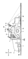
- FIG. 1 is a side view of an asphalt finisher 100 which is an example of a road machine according to an embodiment of the present invention.
- FIG. 2 is a top view of the asphalt finisher 100.
- the asphalt finisher 100 is mainly composed of a tractor 1, a hopper 2, a screed 3, and the like.
- the direction of the hopper 2 as seen from the tractor 1 (+ X direction) is the front, and the direction of the screed 3 as seen from the tractor 1 ( ⁇ X direction) is the rear.
- the tractor 1 is a mechanism for running the asphalt finisher 100.
- the tractor 1 uses the rear wheel running hydraulic motor to rotate the rear wheels 5, and uses the front wheel running hydraulic motor to rotate the front wheels 6 to move the asphalt finisher 100.
- the rear wheel running hydraulic motor and the front wheel running hydraulic motor rotate by receiving the supply of hydraulic oil from the hydraulic pump.
- the rear wheels 5 and the front wheels 6 may be replaced by crawlers.
- the controller 50 is a control device that controls the asphalt finisher 100.
- the controller 50 is composed of a microcomputer including a CPU, a memory, a non-volatile storage device, and the like, and is mounted on the tractor 1.
- the functional elements that carry out each function of the controller 50 are realized by the CPU executing the program stored in the non-volatile storage device.
- each functional element in the controller 50 may be composed of hardware, firmware, or the like.
- Hopper 2 is a mechanism for accepting pavement materials.
- the hopper 2 is installed on the front side of the tractor 1 and is configured to be opened and closed in the Y-axis direction (vehicle width direction) by the hopper cylinder.
- the asphalt finisher 100 normally receives the pavement material from the loading platform of the dump truck with the hopper 2 fully open.
- the paving material is, for example, an asphalt mixture. 1 and 2 show that the hopper 2 is in the fully open state.
- the operator of the asphalt finisher 100 normally closes the hopper 2 when the pavement material in the hopper 2 decreases, and collects the pavement material near the inner wall of the hopper 2 in the central portion of the hopper 2.
- the pavement material can be fed to the rear side of the tractor 1 by the conveyor CV in the central portion of the hopper 2.
- the pavement material fed to the rear side of the tractor 1 is spread in the vehicle width direction by the screw SC on the rear side of the tractor 1 and the front side of the screed 3.
- the screw SC is in a state where the extension screw is connected to the left and right. 1 and 2 show the pavement material PV spread by the screw SC in a rough satin pattern.
- Screed 3 is a mechanism for compacting the pavement material PV.
- the screed 3 includes a front screed 30 and a rear screed 31.
- the front screed 30 includes a left front screed 30L and a right front screed 30R
- the rear screed 31 includes a left rear screed 31L and a right rear screed 31R.
- the screed 3 is a floating screed towed by the tractor 1 and is connected to the tractor 1 via a leveling arm 3A.
- the screed 3 is moved up and down together with the leveling arm 3A by the expansion and contraction of the scree drift cylinder 25.
- the leveling cylinder 28 is a hydraulic cylinder that moves the front end portion of the leveling arm 3A up and down in order to adjust the leveling thickness of the pavement material.
- the leveling cylinder 28 includes a left leveling cylinder 28L and a right leveling cylinder 28R.
- the rear screed 31 is configured to be expandable and contractible in the vehicle width direction by a telescopic cylinder (not shown).
- the rear screed 31 may be a fixed (non-expandable) screed that is connected at the time of use using a crane or the like.
- a screed lifting device 29 is attached to the connecting portion between the front screed 30 and the rear screed 31.
- the screed elevating device 29 is configured to be able to move the rear screed 31 up and down with respect to the front screed 30.
- the screed elevating device 29 rotates a screed elevating motor as a hydraulic actuator in response to a control command from the controller 50, and drives a rotation / linear motion conversion mechanism attached to the rear screed 31.
- the rear screed 31 is moved up and down.
- the screed lifting device 29 includes a left screed lifting device 29L that moves the left rear screed 31L up and down, and a right screed lifting device 29R that moves the right rear screed 31R up and down.
- the rotation / linear motion conversion mechanism is, for example, a bolt / nut mechanism.
- the rotation / linear motion conversion mechanism may be another mechanism such as a ball screw mechanism or a rack and pinion mechanism.
- the screed elevating motor may be an electric motor.
- the screed lifting device 29 may be a hydraulic cylinder.
- a mold board 43 is attached to the front part of the screed 3.
- the mold board 43 includes a left mold board 43L and a right mold board 43R.
- the left mold board 43L is configured so that the amount of pavement material PV staying in front of the left rear screed 31L can be adjusted.
- the right mold board 43R is configured so that the amount of pavement material PV staying in front of the right rear screed 31R can be adjusted.
- the pavement material PV passes under the left rear screed 31L through the gap between the lower end of the left mold board 43L and the roadbed RB, and passes through the gap between the lower end of the right moldboard 43R and the roadbed RB to the right. It reaches under the rear screed 31R.
- the center crown device 26 is mounted on the front screed 30.
- the center crown device 26 expands and contracts the turnbuckle attached between the left front screed 30L and the right front screed 30R, and the lower surface of the left front screed 30L (left front screed plate) and the right front screed when viewed from the rear. It is a mechanism for adjusting the angle between the 30R (right front screed plate) and the lower surface.
- the center crown device 26 rotates the hydraulic motor in response to a control command from the controller 50 to rotate the body of the turnbuckle and expand and contract the turnbuckle.
- a slope crown device 27 is mounted between the front screed 30 and the rear screed 31.
- the slope crown device 27 includes a left slope crown device 27L and a right slope crown device 27R. Specifically, the left slope crown device 27L is mounted between the left front screed 30L and the left rear screed 31L, and the right slope crown device 27R is mounted between the right front screed 30R and the right rear screed 31R. ing.
- the left slope crown device 27L expands and contracts the turnbuckle attached between the left front screed 30L and the left rear screed 31L, and the lower surface and the left of the left front screed 30L (left front screed plate) when viewed from the rear. It is a mechanism for adjusting the angle between the rear screed 31L (left rear screed plate) and the lower surface.
- the left slope crown device 27L rotates the hydraulic motor in response to a control command from the controller 50 to rotate the body of the turnbuckle and expand and contract the turnbuckle.
- the right slope crown device 27R The same applies to the right slope crown device 27R.
- the scaffold step 42 is a member that constitutes a scaffold when an operator works behind the scaffold 3.
- a guide rail 1G that can be used as a handrail by the operator of the asphalt finisher 100 is installed on the upper part of the tractor 1.
- the operator of the asphalt finisher 100 includes an operator who operates the tractor 1, an operator who operates the screed 3, and the like.
- An information acquisition device 51 is attached to the guide rail 1G.
- the information acquisition device 51 may be attached to the canopy or may be directly attached to the main body of the tractor 1. Further, the information acquisition device 51 may be attached to the front screed 30 or may be attached to the rear screed 31.
- the information acquisition device 51 is configured to be able to acquire information on the surface of the pavement material PV compacted by the screed 3.
- the information acquisition device 51 is a lidar configured to be able to measure the distance to an object existing around the asphalt finisher 100, and includes a space behind the screed 3 as a measurement range.
- the measurement range of LIDAR is set so as to reliably detect a step that can be formed between the central pavement surface CP having the width W1 and the side pavement surface SP, for example, as shown in FIG.
- the side pavement surface SP includes a left side pavement surface LP having a width W2 and a right side pavement surface RP having a width W3.
- the step LD shown by the solid line in FIG. 2 is an example of a step formed between the central pavement surface CP and the left side pavement surface LP.
- the measurement range of LIDAR is set to include, for example, the range of the pavement surface having a width larger than the width of the front side screed 30 (that is, the width W1 of the central pavement surface CP). Then, the LIDAR is configured so that, for example, the distance between each of one or more points within the measurement range and the LIDAR (reference point) can be measured.
- the range Z0 to Z2 shown by the alternate long and short dash line in FIG. 2 shows three examples of the measurement range of LIDAR. In FIG. 2, for clarity, the range Z0 is shown at a position farther than the range Z1 and the range Z2 when viewed from the asphalt finisher 100 so as not to overlap the ranges Z1 and Z2.
- the positional relationship in the vehicle length direction of the ranges Z0 to Z2 in FIG. 2 does not represent the actual positional relationship. Actually, it is desirable that all the ranges Z0 to Z2 are arranged as close to the asphalt finisher 100 as possible as long as the step can be detected.
- the range Z0 is set to include the entire width of the new pavement NP, which is the pavement laid by the asphalt finisher 100.
- the range Z1 does not include the entire width of the new pavement body NP, but is set to include a width wider than the width of the front screed 30.
- the range Z2 is set to include four independent ranges of the range Z2a, the range Z2b, the range Z2c, and the range Z2d.
- the range Z2a and the range Z2b are arranged so as to detect a step that can be formed between the central pavement surface CP and the left side pavement surface LP.
- the range Z2c and the range Z2d are arranged so that a step that can be formed between the central pavement surface CP and the right side pavement surface RP can be detected.
- the range Z2a is arranged so that a step (hereinafter, referred to as "left outer step") that can be formed by the left end portion of the left front screed 30L is detected.
- the left outer step is typically formed when the left pavement LP is higher than the central pavement CP.
- the range Z2b is arranged so that a step that can be formed by the right end portion of the left rear screed 31L (hereinafter, referred to as “left inner step”) is detected.
- the left medial step is typically formed when the central pavement CP is higher than the left pavement LP.
- the range Z2c is arranged so that a step that can be formed by the left end portion of the right rear screed 31R (hereinafter, referred to as “right inner step”) is detected.
- the right medial step is typically formed when the central pavement CP is higher than the right pavement RP.
- the range Z2d is arranged so that a step that can be formed by the right end portion of the right front screed 30R (hereinafter, referred to as “right outer step”) is detected.
- the right outer step is typically formed when the right pavement RP is higher than the central pavement CP.
- the information acquisition device 51 may be a monocular camera, a stereo camera, a millimeter wave radar, an ultrasonic sensor, a laser radar, a laser scanner, a range image camera, a laser range finder, or the like.
- one information acquisition device 51 is attached to the asphalt finisher 100, but a plurality of information acquisition devices 51 may be attached to the asphalt finisher 100.
- the display device 52 is configured to display information about the asphalt finisher 100.
- the display device 52 is a liquid crystal display installed in front of the driver's seat 1S.
- the communication device 53 is configured to control communication between the asphalt finisher 100 and a device outside the asphalt finisher 100.
- the communication device 53 is installed in front of the driver's seat 1S.
- FIG. 3 is a block diagram showing a configuration example of the screed elevating system LS.
- FIG. 4 is a cross-sectional view of the newly constructed pavement body NP, and shows a state when the vertical plane including the alternate long and short dash line SE in FIG. 2 is viewed from the + X side.
- the screed lifting system LS is mainly composed of a center crown device 26, a slope crown device 27, a leveling cylinder 28, a screed lifting device 29, a controller 50, an information acquisition device 51, a display device 52, a communication device 53, and the like. ..
- the controller 50 includes an information acquisition unit 50a, a crown device drive unit 50b, a leveling cylinder drive unit 50c, and a screed elevating device drive unit 50d as functional elements.
- the information acquisition unit 50a, the crown device drive unit 50b, the leveling cylinder drive unit 50c, and the screed elevating device drive unit 50d are shown separately for convenience of explanation, but need to be physically separated. It may be composed of software components or hardware components that are common in whole or in part.
- the information acquisition unit 50a is configured to be able to acquire information on the surface of the new pavement body NP.
- the information acquisition unit 50a measures the finished shape of the surface of the new pavement body NP based on the output of the lidar as the information acquisition device 51.
- the information acquisition unit 50a measures the finished shape of the surface of the new pavement body NP using the local coordinate system centered on LIDAR and the reference coordinate system. That is, the information acquisition unit 50a specifies the coordinates in the reference coordinate system corresponding to each point on the surface of the new pavement NP by converting the coordinates in the local coordinate system into the coordinates in the reference coordinate system.
- the reference coordinate system is, for example, the world geodetic coordinate system.
- the world geographic coordinate system is a three-dimensional Cartesian coordinate system with the origin at the center of gravity of the earth, the X axis in the direction of the intersection of the Greenwich meridian and the equator, the Y axis in the direction of 90 degrees east longitude, and the Z axis in the direction of the North Pole. It is an XYZ coordinate system.
- the information acquisition unit 50a is configured to be able to measure the surface shape of the new pavement NP within the measurement range during construction, that is, while the asphalt finisher 100 is advancing.
- the information acquisition unit 50a sets a point on the feature AP outside the width direction of the new pavement NP as the reference point R1.
- the reference point R1 is set at the upper end of the L-shaped curb that separates the new pavement NP.
- the feature AP may be another member such as a wooden frame used to divide the new pavement body NP.
- the information acquisition unit 50a may set a virtual point that is not on the feature AP, such as a point vertically above the upper end of the curb by a predetermined height, as a reference point R1.
- the information acquisition unit 50a detects the curb based on the output of the rider, and sets the upper end of the curb at a position separated by a predetermined distance in the ⁇ X direction from the rear end of the asphalt finisher 100 as a reference point R1. Set as.
- the information acquisition unit 50a sets a line that passes through the reference point R1 and is parallel to the width direction (Y-axis direction) of the new pavement NP as a virtual water thread VS.
- the virtual water thread VS is typically a horizontal line passing through the reference point R1.
- the information acquisition unit 50a derives the vertical distance between the virtual water thread VS and the surface of the new pavement body NP.
- the information acquisition unit 50a sets a plurality of points (here, for convenience, 19 points P1 to P19) on the virtual water thread VS at equal intervals. Then, the points Q1 to Q19 on the surface of the new pavement body NP existing directly below each of the points P1 to P19 are specified. Specifically, the information acquisition unit 50a identifies points Q1 to Q19 based on the distance between each point on the surface of the new pavement NP and LIDAR output by LIDAR.
- the information acquisition unit 50a calculates the distance D1 between the point P1 and the point Q1.
- the information acquisition unit 50a calculates the distance D1 based on the distance between the point P1 and the lidar and the distance between the point Q1 and the lidar output by the lidar. The same applies to the distances D2 to D19.
- the information acquisition unit 50a may calculate the thickness of the new pavement NP corresponding to each of the distances D1 to D19 based on the height of the roadbed RB derived from the reference point R1.
- the points set on the virtual water thread VS may be arranged at unequal intervals. Further, the number of points may be less than 19 or 20 or more.
- the information acquisition unit 50a causes the display device 52 to display the measurement results of the distances D1 to D19.
- the information acquisition unit 50a causes the display device 52 to display the measurement results of the distances D1 to D19 by using a chart.
- the information acquisition unit 50a may display the measurement results of the distances D1 to D19 only as numerical values, or may display as a combination of a chart and numerical values.
- the information acquisition unit 50a may be configured to display information on the measurement result only when it is determined that the measurement result is abnormal.
- the information acquisition unit 50a may determine whether or not there is a step on the pavement surface based on the measurement results of the distances D1 to D19. For example, when the difference in distance between adjacent points (for example, the difference between the distance D8 with respect to the point P8 and the distance D9 with respect to the point P9) is equal to or greater than a predetermined value, the information acquisition unit 50a is located between the points P8 and P9. It is determined that the step LD exists. In this case, the information acquisition unit 50a may display the determination result of the presence / absence of the step on the display device 52. Further, when the information acquisition unit 50a determines that a step exists, the information acquisition unit 50a may display information regarding the position of the step.
- the information acquisition unit 50a may determine the presence or absence of a step by performing image processing on the image captured by the image pickup device as the information acquisition device 51.
- the image pickup apparatus is, for example, a monocular camera, a stereo camera, an infrared camera, a range image camera, a lidar, or the like.
- the image processing includes, for example, binarization processing, edge detection processing, Hough transform processing, and the like.
- the imaging range of the imaging device may include at least the range of the pavement surface shown in the range Z2 of FIG.
- the information acquisition unit 50a may transmit calculation results such as measurement results of distances D1 to D19 and determination results of presence / absence of steps to an external device.
- the information acquisition unit 50a may transmit the calculation result to a management device such as a server installed in an external management center or the like, or a support device such as a smartphone carried by the worker. This is to display the same information as the information displayed on the display device 52 on the display device attached to the management device or the support device.
- the information acquisition unit 50a may calculate the difference between the distance D1 and the ideal distance D1T corresponding to the distance D1 as the unevenness of the surface of the new pavement body NP, and output the magnitude of the unevenness as the measurement result. ..
- the ideal distance D1T is pre-stored in, for example, a non-volatile storage device. If the distance D1 matches the ideal distance D1T, the height of the points on the surface of the new pavement NP corresponding to the distance D1 is equal to the reference height defined by the feature AP. The same applies to the distances D2 to D19.
- the information acquisition unit 50a may display the size of the unevenness corresponding to each of the distances D1 to D19 on the display device 52 together with the measurement results of the distances D1 to D19.
- the information acquisition unit 50a may display the size of the unevenness corresponding to each of the distances D1 to D19 on the display device 52 instead of the measurement results of the distances D1 to D19.
- the information acquisition unit 50a may display the size of the unevenness on the display device 52 using a chart.
- the information acquisition unit 50a may display the fact on the display device 52. In this case, the information acquisition unit 50a may output an alarm from a voice output device (not shown).
- the controller 50 may display an image acquired by a camera (not shown) attached to the asphalt finisher 100 that images the rear of the asphalt finisher 100 on the display device 52. Then, the information acquisition unit 50a may superimpose and display information on the measurement results of the distances D1 to D19 on the image acquired by the camera.
- the information regarding the measurement results of the distances D1 to D19 may be, for example, a numerical value or a figure representing the size of the unevenness, or a figure or the like representing a step.
- the display device 52 may display a diagram showing at least one such as the presence or absence of the above. This figure includes, for example, at least one of a figure in which the concave portion is represented in red and the convex portion is represented in blue, and a graphic in which the step is represented by a straight line, etc. ..
- the crown device drive unit 50b is configured to drive at least one of the center crown device 26 and the slope crown device 27.
- the crown device drive unit 50b operates the center crown device 26 and the slope crown device 27 individually by using a hydraulic pump, a hydraulic motor, a control valve, and the like.
- the crown device drive unit 50b individually operates the center crown device 26 and the slope crown device 27 in response to a command from an operator of the asphalt finisher 100 via an input device (not shown).
- the crown device drive unit 50b may operate the center crown device 26 and the slope crown device 27 individually and autonomously in response to a control command from the controller 50, in addition to the command from the operator.
- the leveling cylinder drive unit 50c is configured to drive the leveling cylinder 28.
- the leveling cylinder drive unit 50c operates the leveling cylinder 28 by using a hydraulic pump, a control valve, and the like. Specifically, the leveling cylinder drive unit 50c operates the leveling cylinder 28 in response to a command from the operator of the asphalt finisher 100 via the input device.
- the leveling cylinder drive unit 50c may autonomously operate the leveling cylinder 28 in response to a control command from the controller 50, in addition to a command from the operator.
- the screed lifting device drive unit 50d is configured to drive the screed lifting device 29.
- the screed lifting device 29 is a mechanism for moving the rear screed 31 up and down in order to eliminate a step formed between the pavement surface compacted by the front screed 30 and the pavement surface compacted by the rear screed 31. Is. Eliminating the step means preventing the step detected by the controller 50 from being continuously formed thereafter.
- the step that has already been formed is removed by using, for example, a rake for leveling work, a road roller, a plate compactor, or the like.
- the screed lifting device drive unit 50d operates the screed lifting device 29 by using a hydraulic pump, a hydraulic motor, a control valve, and the like. Specifically, the screed lifting device drive unit 50d operates the screed lifting device 29 in response to a command from the operator of the asphalt finisher 100 via the input device.
- the screed elevating device drive unit 50d may autonomously operate the screed elevating device 29 in response to a control command from the controller 50, in addition to a command from the operator.
- the operator who sees the measurement results of the distances D1 to D19 displayed on the display device 52 may operate the center crown device 26 via the input device and the crown device drive unit 50b. This is to adjust the angle between the lower surface of the left front screed plate and the lower surface of the right front screed plate when viewed from the rear.
- the crown device drive unit 50b When the controller 50 detects that the thickness of the left side portion (+ Y side portion) of the new pavement body NP formed by the left rear screed 31L is increasing toward the outside, the crown device drive unit 50b A control command may be output to. In this case, the crown device drive unit 50b causes the left slope crown device 27L to perform adjustment in response to a control command from the controller 50.
- the operator who sees the measurement results of the distances D1 to D19 not only operates the center crown device 26 or the slope crown device 27 in order to adjust the thickness of the new pavement NP, but also via the leveling cylinder drive unit 50c.
- the leveling cylinder 28 may be operated. This is because when adjusting the thickness of the new pavement NP, the adjustment by the leveling cylinder is more effective than the adjustment by the center crown device 26 and the slope crown device. Further, the operator who sees the information notifying that the step exists may operate the screed elevating device 29 in order to eliminate the step.
- the controller 50 may refer to, for example, the screed lifting device drive unit 50d. You may output a control command.
- the screed elevating device drive unit 50d operates the screed elevating device 29 in response to the control command from the controller 50 to eliminate the step.
- the screed elevating device drive unit 50d includes, for example, a pavement surface compacted by the left front screed 30L and a pavement surface compacted by the left rear screed 31L by operating the screed elevating device 29. The left rear side screed 31L is moved up and down in order to eliminate the step formed between the two.
- the screed elevating device drive unit 50d rotates a screed elevating motor as a hydraulic actuator constituting the screed elevating device 29 in response to a control command from the controller 50, and causes the left rear screed 31L to rotate.
- the attached rotation / linear motion conversion mechanism is driven to move the left rear screed 31L up and down.
- the controller 50 may autonomously control at least one of the center crown device 26, the slope crown device 27, the leveling cylinder 28, and the screed elevating device 29.
- the operator may manually control at least one of the center crown device 26, the slope crown device 27, the leveling cylinder 28, and the screed elevating device 29 while checking the contents displayed on the display device 52. ..
- FIGS. 5A to 5C show three display examples of the screen GX.
- FIG. 5A is a screen GX displayed when a step formed by the right end portion of the left rear screed 31L and a step formed by the right end portion of the right front screed 30R are detected.
- FIG. 5B is a screen GX displayed when a step formed by the left end portion of the left front screed 30L is detected.
- FIG. 5C is a screen GX displayed when a step formed by the left end portion of the right rear screed 31R is detected.
- the screen GX shown in FIGS. 5A to 5C includes an airframe figure GM, a pavement material figure GP, and a road surface figure GR as common figures.
- the body figure GM represents the top view of the asphalt finisher 100.
- the airframe figure GM represents a top view of a portion behind the screw SC.
- the pavement material figure GP represents the top view of the pavement material PV before being compacted by the screed 3.
- the pavement material figure GP is represented by a coarse (thin) satin pattern.
- the road surface figure GR represents the top view of the newly constructed pavement body NP.
- the road surface figure GR is represented by a fine (dark) satin pattern.
- FIG. 5A includes figures G11, G12, G21, and G22.
- the figure G11 represents the left inner step formed by the right end portion of the left rear screed 31L.
- the figure G11 is represented by a thick broken line.
- the step LD shown by the solid line in FIG. 2 is an example of the left inner step.
- the left inner step is formed when the height of the pavement surface compacted by the left front screed 30L is higher than the height of the pavement compacted by the left rear screed 31L.
- the figure G12 represents the right outer step formed by the right end portion of the right front screed 30R.
- the figure G12 is represented by a thick broken line.
- the right outer step is formed when the height of the pavement surface compacted by the right front screed 30R is lower than the height of the pavement compacted by the right rear screed 31R.
- the figure G21 is displayed when a step on the left inner side is detected.
- the figure G21 is a balloon including character information regarding measures that can be taken to eliminate the left inner step, and indicates the position of the figure G11.
- the figure G21 can inform the operator of the asphalt finisher 100 that the left rear screed 31L is autonomously raised by the controller 50 by displaying text information such as "raise the left", for example.
- the figure G22 is displayed when the right outer step is detected.
- the figure G22 is a balloon including character information regarding measures that can be taken to eliminate the right outer step, and indicates the position of the figure G12.
- the figure G22 can inform the operator of the asphalt finisher 100 that the right rear screed 31R is autonomously lowered by the controller 50 by displaying text information such as "lower right", for example.
- FIG. 5B includes figures G13 and G23.
- Figure G13 represents the left outer step formed by the left end of the left front screed 30L.
- the figure G13 is represented by a thick broken line.
- the left outer step is formed when the height of the pavement surface compacted by the left front screed 30L is lower than the height of the pavement compacted by the left rear screed 31L.
- the figure G23 is displayed when the left outer step is detected.
- the figure G23 is a balloon including character information regarding measures that can be taken to eliminate the left outer step, and indicates the position of the figure G13.
- the figure G23 can inform the operator of the asphalt finisher 100 that the left rear screed 31L is autonomously lowered by the controller 50 by displaying text information such as "lowering the left", for example.
- FIG. 5C includes figures G14 and G24.
- the figure G14 represents a right inner step formed by the left end portion of the right rear screed 31R.
- the figure G14 is represented by a thick broken line.
- the right inner step is formed when the height of the pavement surface compacted by the right front screed 30R is higher than the height of the pavement compacted by the right rear screed 31R.
- the figure G24 is displayed when a step on the right inner side is detected.
- the figure G24 is a balloon including character information regarding measures that can be taken to eliminate the step on the right inner side, and points to the position of the figure G14.
- the figure G24 can inform the operator of the asphalt finisher 100 that the right rear screed 31R is autonomously lowered by the controller 50, for example, by displaying text information such as "raise to the right".
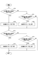
- FIG. 6 is a flowchart of the height adjustment process.
- the controller 50 repeatedly executes this height adjustment process at a predetermined control cycle, for example, when the asphalt finisher 100 is moving forward.
- the controller 50 determines whether or not there is a high step on the left outer side (step ST1).
- the information acquisition unit 50a of the controller 50 determines the presence or absence of the left outer step based on the output of the lidar as the information acquisition device 51.
- the controller 50 lowers the left rear screed 31L (step ST2). This is to eliminate the left outer step by lowering the left side pavement LP higher than the central pavement CP and adjusting the height of the left side pavement LP to the height of the central pavement CP.
- the information acquisition unit 50a of the controller 50 outputs a control command for lowering the left rear screed 31L to the screed elevating device drive unit 50d.
- the screed elevating device drive unit 50d operates the left screed elevating device 29L in response to a control command from the information acquisition unit 50a to lower the left rear screed 31L.
- the controller 50 determines whether or not there is a high step on the left inner side (step ST3).
- the information acquisition unit 50a of the controller 50 determines the presence or absence of the left inner step based on the output of the lidar as the information acquisition device 51.
- the controller 50 raises the left rear screed 31L (step ST4). This is to eliminate the left inner step by raising the left side pavement LP lower than the central pavement CP and adjusting the height of the left side pavement LP to the height of the central pavement CP.
- the information acquisition unit 50a of the controller 50 outputs a control command for raising the left rear screed 31L to the screed elevating device drive unit 50d.
- the screed elevating device drive unit 50d operates the left screed elevating device 29L in response to a control command from the information acquisition unit 50a to raise the left rear screed 31L.
- the controller 50 may be configured to determine whether or not there is a left outer step after determining whether or not there is a left inner step.
- the controller 50 determines whether or not there is a high step on the right outer side (step ST5).
- the information acquisition unit 50a of the controller 50 determines the presence or absence of the right outer step based on the output of the lidar as the information acquisition device 51.
- the controller 50 lowers the right rear screed 31R (step ST6). This is to eliminate the right outer step by lowering the right side pavement RP higher than the central pavement CP and adjusting the height of the right side pavement RP to the height of the central pavement CP.
- the information acquisition unit 50a of the controller 50 outputs a control command for lowering the right rear screed 31R to the screed elevating device drive unit 50d.
- the screed elevating device drive unit 50d operates the right screed elevating device 29R in response to a control command from the information acquisition unit 50a to lower the right rear screed 31R.
- the controller 50 determines whether or not there is a high step on the right inner side (step ST7).
- the information acquisition unit 50a of the controller 50 determines the presence or absence of the right inner step based on the output of the lidar as the information acquisition device 51.
- the controller 50 raises the right rear screed 31R (step ST8). This is to eliminate the right inner step by raising the right side pavement RP lower than the central pavement CP and adjusting the height of the right side pavement RP to the height of the central pavement CP.
- the information acquisition unit 50a of the controller 50 outputs a control command for raising the right rear screed 31R to the screed elevating device drive unit 50d.
- the screed elevating device drive unit 50d operates the right screed elevating device 29R in response to a control command from the information acquisition unit 50a to raise the right rear screed 31R.
- the controller 50 may be configured to determine whether or not there is a left outer step after determining whether or not there is a right inner step.
- the controller 50 may determine the existence or nonexistence of each of the right inner step and the right outer step, and then determine the existence or nonexistence of each of the left inner step and the left outer step, and the left inner step, the left outer step, and the right inner step may be determined. , And the presence or absence of each of the right outer step may be determined separately in any order.
- the controller 50 can prevent the step formed between the central pavement surface CP and the side pavement surface SP from continuing for a long distance.
- 7A to 7D are side views of the screed 3 and the new pavement NP when the new pavement NP of FIG. 2 is viewed from the + Y side.
- FIGS. 7A to 7D for the sake of clarity, most of the screed 3 except for the left front screed plate 30LP of the left front screed 30L and the left rear screed plate 31LP of the left rear screed 31L is omitted. ing.
- the following description relates to the case where the left rear screed 31L is raised, the case where the left rear screed 31L is lowered, the case where the right rear screed 31R is raised, and the case where the right rear screed 31R is lowered. The same applies to.
- FIG. 7A is a diagram when the controller 50 detects the step LD and starts ascending the left rear screed 31L.
- FIG. 7B is a diagram when the controller 50 raises the left rear screed 31L.
- FIG. 7C is a diagram when the controller 50 finishes ascending the left rear screed 31L.
- FIG. 7D is a view when a pavement surface without a step is formed.
- the controller 50 when the controller 50 detects the step LD having the length L0 in the X-axis direction as the left inner step, it operates the left screed elevating device 29L and operates the left rear screed in the direction indicated by the arrow AR1. Start the rise of 31L.
- the size of the step LD corresponding to the difference between the height of the rear end portion of the left front screed plate 30LP and the height of the rear end portion of the left rear screed plate 31LP is the value DP1.
- the swallowing angle ⁇ of the left rear screed plate 31LP is larger than the swallowing angle ⁇ of the left front screed plate 30LP.
- the controller 50 moves in the direction indicated by the arrow AR2 until the height of the rear end of the left front screed plate 30LP and the height of the rear end of the left rear screed plate 31LP match. Continue to rise the left rear screed 31L.
- the controller 50 raises the left rear screed 31L at a predetermined ascending speed regardless of the value DP1 which is the size of the step LD when the left rear screed 31L starts to rise. There is. However, the controller 50 may determine the target ascending speed and the target ascending width based on the value DP1.
- the size of the step LD is a value DP2 smaller than the value DP1.
- the controller 50 stops the ascending of the left rear screed 31L as shown in FIG. 7C.
- the step LD is eliminated when the length in the X-axis direction reaches the value L1. At the time of FIG. 7C, the size of the step LD is zero.
- the controller 50 maintains the height of the left rear screed 31L when the ascent of the left rear screed 31L is stopped. As a result, as shown in FIG. 7D, the asphalt finisher 100 can form a paved surface without steps.
- the asphalt finisher 100 automatically detects the step formed between the central pavement surface CP and the side pavement surface SP, and then the rear screed 31 so as to eliminate the step. Can be moved up and down autonomously. Therefore, it is possible to prevent the length of the step in the traveling direction from becoming excessive. As a result, the asphalt finisher 100 can improve the work efficiency by reducing the work for removing the step that has already been formed.
- the asphalt finisher 100 can form a pavement with few steps without being influenced by the skill level of the operator regarding the manual operation of the screed lifting device 29. Therefore, the asphalt finisher 100 can maintain the quality of the pavement formed at a certain level or higher.
- the asphalt finisher 100 has the tractor 1, the hopper 2 installed on the front side of the tractor 1 and accepting the pavement material, and the pavement material in the hopper 2 to the rear side of the tractor 1.
- the information acquisition device 51 for acquiring information on the surface of the pavement material compacted by the screed 3 and the controller 50 as a control device are provided.
- the screed 3 includes a front screed 30 and a rear screed 31 that are arranged so as to be offset in the vehicle length direction.
- the controller 50 is a step formed between the surface of the pavement material compacted by the front screed 30 and the surface of the pavement material compacted by the rear screed 31 based on the information acquired by the information acquisition device 51. It is configured to determine the presence or absence of.
- the asphalt finisher 100 can detect that a step has been formed at an early stage, so that deterioration of the quality of the formed pavement surface can be suppressed.
- the information acquisition device 51 is preferably attached to the canopy or the tractor 1. With this configuration, the asphalt finisher 100 can improve the measurement accuracy of the finished shape of the surface of the newly constructed pavement NP. This is because both the canopy and the tractor 1 have less vibration than the screed 3. However, the information acquisition device 51 may be attached to the screed 3. In this case, the information acquisition device 51 can acquire information on the surface of the pavement material at a position close to the surface of the pavement material compacted by the screed 3.
- the asphalt finisher 100 preferably includes a controller 50 as a control device that calculates the unevenness of the road surface with respect to the reference height determined by the feature AP based on the output of the information acquisition device 51, or determines the presence or absence of a step. ing.
- the asphalt finisher 100 can easily measure the shape of the surface of the new pavement NP by itself without being connected to other devices, or the presence or absence of a step on the surface of the new pavement NP can be determined. It can be easily determined.
- the information acquisition device 51 can also be used to realize other functions such as backward monitoring. Further, the operator of the asphalt finisher 100 can intuitively grasp the state of the finished shape of the surface of the new pavement NP by looking at the information on the unevenness with respect to the reference height on the surface of the new pavement NP.
- the asphalt finisher 100 preferably has a display function for displaying the result of calculation by the controller 50.
- the display function can be applied to a display device 52 mounted on the asphalt finisher 100, a display device attached to a management device such as a computer installed in an external management center, or a support device such as a smartphone carried by an operator. It is realized by the attached display device and the like.
- the asphalt finisher 100 can convey information about the new pavement NP to the operator of the asphalt finisher 100 or the workers working around the asphalt finisher 100.
- the asphalt finisher 100 may include a front screed lifting device that moves the front screed 30 up and down, in addition to the screed lifting device 29 that moves the rear screed 31 up and down.
- the asphalt finisher 100 may be configured so that the left front screed 30L and the right front screed 30R can be moved up and down separately.
- the controller 50 is configured to automatically detect the step and then move the rear screed 31 up and down to autonomously eliminate the step.
- the controller 50 may be configured to notify the operator that a step has been detected and then prompt the operator to move the rear screed 31 up and down.
- the controller 50 may use at least one of sound, light, vibration, and the like to assist the operator in manually operating the screed lifting device 29.
- Mold board 50 ... ⁇ Controller 50a ⁇ ⁇ ⁇ Information acquisition unit 50b ⁇ ⁇ ⁇ Crown device drive unit 50c ⁇ ⁇ ⁇ Leveling cylinder drive unit 50d ⁇ ⁇ ⁇ Pavement elevating device drive unit 51 ⁇ ⁇ ⁇ Information acquisition device 52 ⁇ ⁇ ⁇ Display device 53 ⁇ ⁇ Communication device 100 ⁇ ⁇ ⁇ Asphalt finisher AP ⁇ ⁇ ⁇ Feature CV ⁇ ⁇ ⁇ Conveyor NP ⁇ ⁇ ⁇ New pavement PV ⁇ ⁇ ⁇ Pavement material RB ⁇ ⁇ ⁇ Roadbed SC ⁇ ⁇ ⁇ Cylinder
Landscapes
- Engineering & Computer Science (AREA)
- Architecture (AREA)
- Civil Engineering (AREA)
- Structural Engineering (AREA)
- Road Paving Machines (AREA)
Abstract
An asphalt finisher (100) comprises: an information acquisition device (51) that acquires information relating to the surface of a pavement material compacted by screeds (3); and a controller (50). The screeds (3) include a front-side screed (30) arranged offset in the vehicle length direction, and a rear-side screed (31). The controller (50) determines, based on the information acquired by the information acquisition device (51), the level difference (LD) formed between the surface of the pavement material compacted by the front-side screed (30) and the surface of the pavement material compacted by the rear-side screed (31).
Description
本開示は、アスファルトフィニッシャに関する。
This disclosure relates to asphalt finishers.
従来、前側スクリードに対して左右方向に伸縮可能な後側スクリードを備えたアスファルトフィニッシャが知られている(特許文献1参照。)。このアスファルトフィニッシャは、後側スクリードを伸張することで敷設する道路の幅を拡大できる。
Conventionally, an asphalt finisher having a rear screed that can expand and contract in the left-right direction with respect to the front screed is known (see Patent Document 1). This asphalt finisher can increase the width of the road to be laid by extending the rear screed.
しかしながら、上述のアスファルトフィニッシャは、前側スクリードによって締め固められる舗装材の表面(以下、「中央舗装面」とする。)と後側スクリードによって締め固められる舗装材の表面(以下、「側部舗装面」とする。)とが進行方向において部分的に重複するように構成されている。
However, the above-mentioned asphalt finisher has a surface of the pavement material compacted by the front screed (hereinafter referred to as "central pavement surface") and a surface of the pavement material compacted by the rear screed (hereinafter referred to as "side pavement surface"). ”) And are configured to partially overlap in the direction of travel.
そのため、上述のアスファルトフィニッシャは、中央舗装面の高さと側部舗装面の高さとの間に違いを生じさせた結果、最終的に生成される舗装体の表面である舗装面に段差を生じさせ、舗装面の品質を低下させてしまうおそれがある。
Therefore, the above-mentioned asphalt finisher causes a difference between the height of the central pavement surface and the height of the side pavement surface, and as a result, causes a step on the pavement surface which is the surface of the finally produced pavement body. , There is a risk of degrading the quality of the pavement surface.
そこで、舗装面の品質低下を抑制できるアスファルトフィニッシャの提供が望まれる。
Therefore, it is desired to provide an asphalt finisher that can suppress deterioration of the quality of the pavement surface.
本発明の実施形態に係るアスファルトフィニッシャは、トラクタと、前記トラクタの前側に設置されて舗装材を受け入れるホッパと、前記ホッパ内の舗装材を前記トラクタの後側へ給送するコンベアと、前記コンベアにより給送された舗装材を前記トラクタの後側で敷き拡げるスクリュと、前記スクリュにより敷き拡げられた舗装材を前記スクリュの後側で締め固めるスクリードと、前記スクリードによって締め固められた舗装材の表面に関する情報を取得する情報取得装置と、制御装置と、を備え、前記スクリードは、車長方向にずらして配置される前側スクリードと後側スクリードとを含み、前記制御装置は、前記情報取得装置が取得した情報に基づき、前記前側スクリードによって締め固められる舗装材の表面と、前記後側スクリードによって締め固められる舗装材の表面との間に形成される段差の存否を判定する。
The asphalt finisher according to the embodiment of the present invention includes a tractor, a hopper installed on the front side of the tractor to receive the pavement material, a conveyor for feeding the pavement material in the hopper to the rear side of the tractor, and the conveyor. A screw that spreads the pavement material fed by the tractor on the rear side of the tractor, a screed that compacts the pavement material spread by the screw on the rear side of the screw, and a pavement material compacted by the screed. The screed includes an information acquisition device for acquiring information about the surface and a control device, and the screed includes a front side screed and a rear side screed arranged so as to be offset in the vehicle length direction, and the control device is the information acquisition device. Determines the presence or absence of a step formed between the surface of the pavement material compacted by the front screed and the surface of the pavement compacted by the rear screed, based on the information acquired by.
上述の手段により、舗装面の品質低下を抑制できるアスファルトフィニッシャが提供される。
By the above-mentioned means, an asphalt finisher capable of suppressing deterioration of the quality of the pavement surface is provided.
図1は、本発明の実施形態に係る道路機械の一例であるアスファルトフィニッシャ100の側面図である。図2はアスファルトフィニッシャ100の上面図である。アスファルトフィニッシャ100は、主に、トラクタ1、ホッパ2、及びスクリード3等で構成されている。以下では、トラクタ1から見たホッパ2の方向(+X方向)を前方とし、トラクタ1から見たスクリード3の方向(-X方向)を後方とする。
FIG. 1 is a side view of an asphalt finisher 100 which is an example of a road machine according to an embodiment of the present invention. FIG. 2 is a top view of the asphalt finisher 100. The asphalt finisher 100 is mainly composed of a tractor 1, a hopper 2, a screed 3, and the like. In the following, the direction of the hopper 2 as seen from the tractor 1 (+ X direction) is the front, and the direction of the screed 3 as seen from the tractor 1 (−X direction) is the rear.
トラクタ1は、アスファルトフィニッシャ100を走行させるための機構である。本実施形態では、トラクタ1は、後輪走行用油圧モータを用いて後輪5を回転させ、且つ、前輪走行用油圧モータを用いて前輪6を回転させてアスファルトフィニッシャ100を移動させる。後輪走行用油圧モータ及び前輪走行用油圧モータは油圧ポンプから作動油の供給を受けて回転する。後輪5及び前輪6はクローラで置き換えられてもよい。
The tractor 1 is a mechanism for running the asphalt finisher 100. In the present embodiment, the tractor 1 uses the rear wheel running hydraulic motor to rotate the rear wheels 5, and uses the front wheel running hydraulic motor to rotate the front wheels 6 to move the asphalt finisher 100. The rear wheel running hydraulic motor and the front wheel running hydraulic motor rotate by receiving the supply of hydraulic oil from the hydraulic pump. The rear wheels 5 and the front wheels 6 may be replaced by crawlers.
コントローラ50は、アスファルトフィニッシャ100を制御する制御装置である。本実施形態では、コントローラ50は、CPU、メモリ、及び不揮発性記憶装置等を含むマイクロコンピュータで構成され、トラクタ1に搭載されている。コントローラ50による各機能を担う機能要素は、不揮発性記憶装置に記憶されているプログラムをCPUが実行することで実現される。但し、コントローラ50における各機能要素は、ハードウェア又はファームウェア等で構成されていてもよい。
The controller 50 is a control device that controls the asphalt finisher 100. In the present embodiment, the controller 50 is composed of a microcomputer including a CPU, a memory, a non-volatile storage device, and the like, and is mounted on the tractor 1. The functional elements that carry out each function of the controller 50 are realized by the CPU executing the program stored in the non-volatile storage device. However, each functional element in the controller 50 may be composed of hardware, firmware, or the like.
ホッパ2は、舗装材を受け入れるための機構である。本実施形態では、ホッパ2は、トラクタ1の前側に設置され、ホッパシリンダによってY軸方向(車幅方向)に開閉できるように構成されている。アスファルトフィニッシャ100は、通常、ホッパ2を全開状態にしてダンプトラックの荷台から舗装材を受け入れる。舗装材は、例えば、アスファルト混合物である。図1及び図2はホッパ2が全開状態であることを示している。アスファルトフィニッシャ100の操作者は、通常、ホッパ2内の舗装材が減少するとホッパ2を閉じ、ホッパ2の内壁付近にあった舗装材をホッパ2の中央部に集める。ホッパ2の中央部にあるコンベアCVによってトラクタ1の後側に舗装材を給送できるようにするためである。トラクタ1の後側に給送された舗装材は、スクリュSCによってトラクタ1の後側且つスクリード3の前側で車幅方向に敷き拡げられる。本実施形態では、スクリュSCは、エクステンションスクリュが左右に連結された状態にある。図1及び図2は、スクリュSCによって敷き拡げられた舗装材PVを粗い梨地模様で示している。
Hopper 2 is a mechanism for accepting pavement materials. In the present embodiment, the hopper 2 is installed on the front side of the tractor 1 and is configured to be opened and closed in the Y-axis direction (vehicle width direction) by the hopper cylinder. The asphalt finisher 100 normally receives the pavement material from the loading platform of the dump truck with the hopper 2 fully open. The paving material is, for example, an asphalt mixture. 1 and 2 show that the hopper 2 is in the fully open state. The operator of the asphalt finisher 100 normally closes the hopper 2 when the pavement material in the hopper 2 decreases, and collects the pavement material near the inner wall of the hopper 2 in the central portion of the hopper 2. This is so that the pavement material can be fed to the rear side of the tractor 1 by the conveyor CV in the central portion of the hopper 2. The pavement material fed to the rear side of the tractor 1 is spread in the vehicle width direction by the screw SC on the rear side of the tractor 1 and the front side of the screed 3. In the present embodiment, the screw SC is in a state where the extension screw is connected to the left and right. 1 and 2 show the pavement material PV spread by the screw SC in a rough satin pattern.
スクリード3は、舗装材PVを締め固めるための機構である。本実施形態では、スクリード3は、前側スクリード30及び後側スクリード31を含む。そして、前側スクリード30は、左前側スクリード30L及び右前側スクリード30Rを含み、後側スクリード31は、左後側スクリード31L及び右後側スクリード31Rを含む。
Screed 3 is a mechanism for compacting the pavement material PV. In this embodiment, the screed 3 includes a front screed 30 and a rear screed 31. The front screed 30 includes a left front screed 30L and a right front screed 30R, and the rear screed 31 includes a left rear screed 31L and a right rear screed 31R.
スクリード3は、トラクタ1によって牽引される浮動スクリードであり、レベリングアーム3Aを介してトラクタ1に連結されている。スクリード3は、スクリードリフトシリンダ25の伸縮によってレベリングアーム3Aと共に上下に動かされる。
The screed 3 is a floating screed towed by the tractor 1 and is connected to the tractor 1 via a leveling arm 3A. The screed 3 is moved up and down together with the leveling arm 3A by the expansion and contraction of the scree drift cylinder 25.
レベリングシリンダ28は、舗装材の敷き均し厚さを調整するためにレベリングアーム3Aの前端部分を上下動させる油圧シリンダである。本実施形態では、レベリングシリンダ28は、左レベリングシリンダ28L及び右レベリングシリンダ28Rを含む。
The leveling cylinder 28 is a hydraulic cylinder that moves the front end portion of the leveling arm 3A up and down in order to adjust the leveling thickness of the pavement material. In this embodiment, the leveling cylinder 28 includes a left leveling cylinder 28L and a right leveling cylinder 28R.
本実施形態では、後側スクリード31は、不図示の伸縮シリンダによって車幅方向に伸縮可能に構成されている。但し、後側スクリード31は、クレーン等を用いて使用時に連結される固定式(非伸縮式)のスクリードであってもよい。
In the present embodiment, the rear screed 31 is configured to be expandable and contractible in the vehicle width direction by a telescopic cylinder (not shown). However, the rear screed 31 may be a fixed (non-expandable) screed that is connected at the time of use using a crane or the like.
前側スクリード30と後側スクリード31との連結部にはスクリード昇降装置29が取り付けられている。スクリード昇降装置29は、前側スクリード30に対して後側スクリード31を上下動させることができるように構成されている。本実施形態では、スクリード昇降装置29は、コントローラ50からの制御指令に応じて油圧アクチュエータとしてのスクリード昇降用モータを回転させ、後側スクリード31に取り付けられた回転・直動変換機構を駆動して後側スクリード31を上下動させる。スクリード昇降装置29は、左後側スクリード31Lを上下動させる左スクリード昇降装置29Lと、右後側スクリード31Rを上下動させる右スクリード昇降装置29Rとを含む。回転・直動変換機構は、例えば、ボルト・ナット機構である。回転・直動変換機構は、ボールネジ機構又はラック・ピニオン機構等の他の機構であってもよい。スクリード昇降用モータは、電動モータであってもよい。スクリード昇降装置29は、油圧シリンダであってもよい。
A screed lifting device 29 is attached to the connecting portion between the front screed 30 and the rear screed 31. The screed elevating device 29 is configured to be able to move the rear screed 31 up and down with respect to the front screed 30. In the present embodiment, the screed elevating device 29 rotates a screed elevating motor as a hydraulic actuator in response to a control command from the controller 50, and drives a rotation / linear motion conversion mechanism attached to the rear screed 31. The rear screed 31 is moved up and down. The screed lifting device 29 includes a left screed lifting device 29L that moves the left rear screed 31L up and down, and a right screed lifting device 29R that moves the right rear screed 31R up and down. The rotation / linear motion conversion mechanism is, for example, a bolt / nut mechanism. The rotation / linear motion conversion mechanism may be another mechanism such as a ball screw mechanism or a rack and pinion mechanism. The screed elevating motor may be an electric motor. The screed lifting device 29 may be a hydraulic cylinder.
スクリード3の前部にはモールドボード43が取り付けられている。モールドボード43は、左モールドボード43L及び右モールドボード43Rを含む。左モールドボード43Lは、左後側スクリード31Lの前方に滞留する舗装材PVの量を調整できるように構成されている。右モールドボード43Rは、右後側スクリード31Rの前方に滞留する舗装材PVの量を調整できるように構成されている。舗装材PVは、左モールドボード43Lの下端と路盤RBとの間の隙間を通って左後側スクリード31Lの下に至り、右モールドボード43Rの下端と路盤RBとの間の隙間を通って右後側スクリード31Rの下に至る。
A mold board 43 is attached to the front part of the screed 3. The mold board 43 includes a left mold board 43L and a right mold board 43R. The left mold board 43L is configured so that the amount of pavement material PV staying in front of the left rear screed 31L can be adjusted. The right mold board 43R is configured so that the amount of pavement material PV staying in front of the right rear screed 31R can be adjusted. The pavement material PV passes under the left rear screed 31L through the gap between the lower end of the left mold board 43L and the roadbed RB, and passes through the gap between the lower end of the right moldboard 43R and the roadbed RB to the right. It reaches under the rear screed 31R.
前側スクリード30にはセンタークラウン装置26が搭載されている。センタークラウン装置26は、左前側スクリード30Lと右前側スクリード30Rの間に取り付けられているターンバックルを伸縮させ、後方から見たときの左前側スクリード30L(左前側スクリードプレート)の下面と右前側スクリード30R(右前側スクリードプレート)の下面との間の角度を調整する機構である。具体的には、センタークラウン装置26は、コントローラ50からの制御指令に応じて油圧モータを回転させることでターンバックルの胴部を回転させてターンバックルを伸縮させる。
The center crown device 26 is mounted on the front screed 30. The center crown device 26 expands and contracts the turnbuckle attached between the left front screed 30L and the right front screed 30R, and the lower surface of the left front screed 30L (left front screed plate) and the right front screed when viewed from the rear. It is a mechanism for adjusting the angle between the 30R (right front screed plate) and the lower surface. Specifically, the center crown device 26 rotates the hydraulic motor in response to a control command from the controller 50 to rotate the body of the turnbuckle and expand and contract the turnbuckle.
前側スクリード30と後側スクリード31との間にはスロープクラウン装置27が搭載されている。スロープクラウン装置27は、左スロープクラウン装置27L及び右スロープクラウン装置27Rを含む。具体的には、左前側スクリード30Lと左後側スクリード31Lとの間に左スロープクラウン装置27Lが搭載され、右前側スクリード30Rと右後側スクリード31Rとの間に右スロープクラウン装置27Rが搭載されている。
A slope crown device 27 is mounted between the front screed 30 and the rear screed 31. The slope crown device 27 includes a left slope crown device 27L and a right slope crown device 27R. Specifically, the left slope crown device 27L is mounted between the left front screed 30L and the left rear screed 31L, and the right slope crown device 27R is mounted between the right front screed 30R and the right rear screed 31R. ing.
左スロープクラウン装置27Lは、左前側スクリード30Lと左後側スクリード31Lの間に取り付けられているターンバックルを伸縮させ、後方から見たときの左前側スクリード30L(左前側スクリードプレート)の下面と左後側スクリード31L(左後側スクリードプレート)の下面との間の角度を調整する機構である。具体的には、左スロープクラウン装置27Lは、コントローラ50からの制御指令に応じて油圧モータを回転させることでターンバックルの胴部を回転させてターンバックルを伸縮させる。右スロープクラウン装置27Rについても同様である。
The left slope crown device 27L expands and contracts the turnbuckle attached between the left front screed 30L and the left rear screed 31L, and the lower surface and the left of the left front screed 30L (left front screed plate) when viewed from the rear. It is a mechanism for adjusting the angle between the rear screed 31L (left rear screed plate) and the lower surface. Specifically, the left slope crown device 27L rotates the hydraulic motor in response to a control command from the controller 50 to rotate the body of the turnbuckle and expand and contract the turnbuckle. The same applies to the right slope crown device 27R.
スクリードステップ42は、作業者がスクリード3の後方で作業する際の足場を構成する部材である。
The scaffold step 42 is a member that constitutes a scaffold when an operator works behind the scaffold 3.
トラクタ1の上部には、アスファルトフィニッシャ100の操作者が手摺りとして利用可能なガイドレール1Gが設置されている。アスファルトフィニッシャ100の操作者は、トラクタ1を操作する操作者、及び、スクリード3を操作する操作者等を含む。そして、ガイドレール1Gには情報取得装置51が取り付けられている。情報取得装置51は、キャノピに取り付けられていてもよく、トラクタ1の本体に直接取り付けられていてもよい。また、情報取得装置51は、前側スクリード30に取り付けられていてもよく、後側スクリード31に取り付けられていてもよい。
A guide rail 1G that can be used as a handrail by the operator of the asphalt finisher 100 is installed on the upper part of the tractor 1. The operator of the asphalt finisher 100 includes an operator who operates the tractor 1, an operator who operates the screed 3, and the like. An information acquisition device 51 is attached to the guide rail 1G. The information acquisition device 51 may be attached to the canopy or may be directly attached to the main body of the tractor 1. Further, the information acquisition device 51 may be attached to the front screed 30 or may be attached to the rear screed 31.
情報取得装置51は、スクリード3によって締め固められた舗装材PVの表面に関する情報を取得できるように構成されている。本実施形態では、情報取得装置51は、アスファルトフィニッシャ100の周囲に存在する物体までの距離を測定できるように構成されたLIDARであり、スクリード3の後方にある空間を測定範囲として含む。
The information acquisition device 51 is configured to be able to acquire information on the surface of the pavement material PV compacted by the screed 3. In the present embodiment, the information acquisition device 51 is a lidar configured to be able to measure the distance to an object existing around the asphalt finisher 100, and includes a space behind the screed 3 as a measurement range.
LIDARの測定範囲は、例えば図2に示すように、幅W1を有する中央舗装面CPと側部舗装面SPとの間に形成され得る段差を確実に検知できるように設定される。側部舗装面SPは、幅W2を有する左側部舗装面LPと、幅W3を有する右側部舗装面RPとを含む。図2の実線で示す段差LDは、中央舗装面CPと左側部舗装面LPとの間に形成される段差の一例である。
The measurement range of LIDAR is set so as to reliably detect a step that can be formed between the central pavement surface CP having the width W1 and the side pavement surface SP, for example, as shown in FIG. The side pavement surface SP includes a left side pavement surface LP having a width W2 and a right side pavement surface RP having a width W3. The step LD shown by the solid line in FIG. 2 is an example of a step formed between the central pavement surface CP and the left side pavement surface LP.
LIDARの測定範囲は、例えば、前側スクリード30の幅(すなわち中央舗装面CPの幅W1)より大きい幅を有する舗装面の範囲を含むように設定される。そして、LIDARは、例えば、測定範囲内にある100万点以上の点のそれぞれとLIDAR(基準点)との間の距離を測定できるように構成されている。図2の一点鎖線で示す範囲Z0~Z2は、LIDARの測定範囲の3つの例を示している。なお、図2では、明瞭化のため、範囲Z0は、範囲Z1及びZ2と重ならないよう、アスファルトフィニッシャ100から見て範囲Z1及び範囲Z2よりも遠い位置に示されている。しかしながら、図2における範囲Z0~Z2の車長方向における位置関係は、実際の位置関係を表すものではない。実際には、範囲Z0~Z2は何れも、段差を検知できる限りにおいて、できるだけアスファルトフィニッシャ100に近い位置に配置されることが望ましい。
The measurement range of LIDAR is set to include, for example, the range of the pavement surface having a width larger than the width of the front side screed 30 (that is, the width W1 of the central pavement surface CP). Then, the LIDAR is configured so that, for example, the distance between each of one or more points within the measurement range and the LIDAR (reference point) can be measured. The range Z0 to Z2 shown by the alternate long and short dash line in FIG. 2 shows three examples of the measurement range of LIDAR. In FIG. 2, for clarity, the range Z0 is shown at a position farther than the range Z1 and the range Z2 when viewed from the asphalt finisher 100 so as not to overlap the ranges Z1 and Z2. However, the positional relationship in the vehicle length direction of the ranges Z0 to Z2 in FIG. 2 does not represent the actual positional relationship. Actually, it is desirable that all the ranges Z0 to Z2 are arranged as close to the asphalt finisher 100 as possible as long as the step can be detected.
範囲Z0は、アスファルトフィニッシャ100によって敷設された舗装体である新設舗装体NPの全幅を含むように設定されている。範囲Z1は、新設舗装体NPの全幅は含まないが、前側スクリード30の幅よりも広い幅を含むように設定されている。
The range Z0 is set to include the entire width of the new pavement NP, which is the pavement laid by the asphalt finisher 100. The range Z1 does not include the entire width of the new pavement body NP, but is set to include a width wider than the width of the front screed 30.
範囲Z2は、範囲Z2a、範囲Z2b、範囲Z2c、及び範囲Z2dの独立した4つの範囲を含むように設定されている。具体的には、範囲Z2a及び範囲Z2bは、中央舗装面CPと左側部舗装面LPとの間に形成され得る段差が検知されるように配置されている。範囲Z2c及び範囲Z2dは、中央舗装面CPと右側部舗装面RPとの間に形成され得る段差が検知されるように配置されている。より具体的には、範囲Z2aは、左前側スクリード30Lの左端部によって形成され得る段差(以下、「左外側段差」とする。)が検知されるように配置されている。左外側段差は、典型的には、左側部舗装面LPが中央舗装面CPより高いときに形成される。範囲Z2bは、左後側スクリード31Lの右端部によって形成され得る段差(以下、「左内側段差」とする。)が検知されるように配置されている。左内側段差は、典型的には、中央舗装面CPが左側部舗装面LPより高いときに形成される。範囲Z2cは、右後側スクリード31Rの左端部によって形成され得る段差(以下、「右内側段差」とする。)が検知されるように配置されている。右内側段差は、典型的には、中央舗装面CPが右側部舗装面RPより高いときに形成される。範囲Z2dは、右前側スクリード30Rの右端部によって形成され得る段差(以下、「右外側段差」とする。)が検知されるように配置されている。右外側段差は、典型的には、右側部舗装面RPが中央舗装面CPより高いときに形成される。
The range Z2 is set to include four independent ranges of the range Z2a, the range Z2b, the range Z2c, and the range Z2d. Specifically, the range Z2a and the range Z2b are arranged so as to detect a step that can be formed between the central pavement surface CP and the left side pavement surface LP. The range Z2c and the range Z2d are arranged so that a step that can be formed between the central pavement surface CP and the right side pavement surface RP can be detected. More specifically, the range Z2a is arranged so that a step (hereinafter, referred to as "left outer step") that can be formed by the left end portion of the left front screed 30L is detected. The left outer step is typically formed when the left pavement LP is higher than the central pavement CP. The range Z2b is arranged so that a step that can be formed by the right end portion of the left rear screed 31L (hereinafter, referred to as “left inner step”) is detected. The left medial step is typically formed when the central pavement CP is higher than the left pavement LP. The range Z2c is arranged so that a step that can be formed by the left end portion of the right rear screed 31R (hereinafter, referred to as “right inner step”) is detected. The right medial step is typically formed when the central pavement CP is higher than the right pavement RP. The range Z2d is arranged so that a step that can be formed by the right end portion of the right front screed 30R (hereinafter, referred to as “right outer step”) is detected. The right outer step is typically formed when the right pavement RP is higher than the central pavement CP.
情報取得装置51は、単眼カメラ、ステレオカメラ、ミリ波レーダ、超音波センサ、レーザレーダ、レーザスキャナ、距離画像カメラ、又はレーザレンジファインダ等であってもよい。
The information acquisition device 51 may be a monocular camera, a stereo camera, a millimeter wave radar, an ultrasonic sensor, a laser radar, a laser scanner, a range image camera, a laser range finder, or the like.
本実施形態では、1台の情報取得装置51がアスファルトフィニッシャ100に取り付けられているが、複数台の情報取得装置51がアスファルトフィニッシャ100に取り付けられていてもよい。
In the present embodiment, one information acquisition device 51 is attached to the asphalt finisher 100, but a plurality of information acquisition devices 51 may be attached to the asphalt finisher 100.
表示装置52は、アスファルトフィニッシャ100に関する情報を表示するように構成されている。本実施形態では、表示装置52は、運転席1Sの前方に設置されている液晶ディスプレイである。
The display device 52 is configured to display information about the asphalt finisher 100. In the present embodiment, the display device 52 is a liquid crystal display installed in front of the driver's seat 1S.
通信装置53は、アスファルトフィニッシャ100とアスファルトフィニッシャ100の外部にある機器との間の通信を制御するように構成されている。本実施形態では、通信装置53は、運転席1Sの前方に設置されている。
The communication device 53 is configured to control communication between the asphalt finisher 100 and a device outside the asphalt finisher 100. In the present embodiment, the communication device 53 is installed in front of the driver's seat 1S.
次に、図3及び図4を参照し、アスファルトフィニッシャ100に搭載されるスクリード昇降システムLSについて説明する。図3は、スクリード昇降システムLSの構成例を示すブロック図である。図4は、新設舗装体NPの断面図であり、図2の一点鎖線SEを含む鉛直面を+X側から見たときの状態を示す。
Next, the screed elevating system LS mounted on the asphalt finisher 100 will be described with reference to FIGS. 3 and 4. FIG. 3 is a block diagram showing a configuration example of the screed elevating system LS. FIG. 4 is a cross-sectional view of the newly constructed pavement body NP, and shows a state when the vertical plane including the alternate long and short dash line SE in FIG. 2 is viewed from the + X side.
スクリード昇降システムLSは、主に、センタークラウン装置26、スロープクラウン装置27、レベリングシリンダ28、スクリード昇降装置29、コントローラ50、情報取得装置51、表示装置52、及び通信装置53等で構成されている。
The screed lifting system LS is mainly composed of a center crown device 26, a slope crown device 27, a leveling cylinder 28, a screed lifting device 29, a controller 50, an information acquisition device 51, a display device 52, a communication device 53, and the like. ..
コントローラ50は、機能要素として情報取得部50a、クラウン装置駆動部50b、レベリングシリンダ駆動部50c、及びスクリード昇降装置駆動部50dを含む。情報取得部50a、クラウン装置駆動部50b、レベリングシリンダ駆動部50c、及びスクリード昇降装置駆動部50dは、説明の便宜のために区別されて示されているが、物理的に区別されている必要はなく、全体的に或いは部分的に共通のソフトウェアコンポーネント若しくはハードウェアコンポーネントで構成されていてもよい。
The controller 50 includes an information acquisition unit 50a, a crown device drive unit 50b, a leveling cylinder drive unit 50c, and a screed elevating device drive unit 50d as functional elements. The information acquisition unit 50a, the crown device drive unit 50b, the leveling cylinder drive unit 50c, and the screed elevating device drive unit 50d are shown separately for convenience of explanation, but need to be physically separated. It may be composed of software components or hardware components that are common in whole or in part.
情報取得部50aは、新設舗装体NPの表面に関する情報を取得できるように構成されている。本実施形態では、情報取得部50aは、情報取得装置51としてのLIDARの出力に基づいて新設舗装体NPの表面の出来形を測定する。具体的には、情報取得部50aは、LIDARを中心とする局所座標系と基準座標系とを用いて新設舗装体NPの表面の出来形を測定する。すなわち、情報取得部50aは、局所座標系における座標を基準座標系における座標に変換することで、新設舗装体NPの表面上の各点に対応する基準座標系における座標を特定する。基準座標系は、例えば世界測地座標系である。世界測地座標系は、地球の重心に原点をおき、X軸をグリニッジ子午線と赤道との交点の方向にとり、Y軸を東経90度の方向にとり、そしてZ軸を北極の方向にとる三次元直交XYZ座標系である。
The information acquisition unit 50a is configured to be able to acquire information on the surface of the new pavement body NP. In the present embodiment, the information acquisition unit 50a measures the finished shape of the surface of the new pavement body NP based on the output of the lidar as the information acquisition device 51. Specifically, the information acquisition unit 50a measures the finished shape of the surface of the new pavement body NP using the local coordinate system centered on LIDAR and the reference coordinate system. That is, the information acquisition unit 50a specifies the coordinates in the reference coordinate system corresponding to each point on the surface of the new pavement NP by converting the coordinates in the local coordinate system into the coordinates in the reference coordinate system. The reference coordinate system is, for example, the world geodetic coordinate system. The world geographic coordinate system is a three-dimensional Cartesian coordinate system with the origin at the center of gravity of the earth, the X axis in the direction of the intersection of the Greenwich meridian and the equator, the Y axis in the direction of 90 degrees east longitude, and the Z axis in the direction of the North Pole. It is an XYZ coordinate system.
情報取得部50aは、施工中、すなわち、アスファルトフィニッシャ100の前進中に、測定範囲内の新設舗装体NPの表面の出来形を測定できるように構成されている。
The information acquisition unit 50a is configured to be able to measure the surface shape of the new pavement NP within the measurement range during construction, that is, while the asphalt finisher 100 is advancing.
本実施形態では、情報取得部50aは、新設舗装体NPの幅方向の外側にある地物AP上の点を基準点R1として設定する。基準点R1は、新設舗装体NPを区切るL字型の縁石の上端に設定される。但し、地物APは、新設舗装体NPを区切るために使用される木枠等の他の部材であってもよい。或いは、情報取得部50aは、縁石の上端から所定高さだけ鉛直上方にある点等、地物AP上にない仮想点を基準点R1としてもよい。
In the present embodiment, the information acquisition unit 50a sets a point on the feature AP outside the width direction of the new pavement NP as the reference point R1. The reference point R1 is set at the upper end of the L-shaped curb that separates the new pavement NP. However, the feature AP may be another member such as a wooden frame used to divide the new pavement body NP. Alternatively, the information acquisition unit 50a may set a virtual point that is not on the feature AP, such as a point vertically above the upper end of the curb by a predetermined height, as a reference point R1.
具体的には、情報取得部50aは、ライダの出力に基づいて縁石を検知し、アスファルトフィニッシャ100の後端から-X方向に所定距離だけ離れた位置にある、その縁石の上端を基準点R1として設定する。
Specifically, the information acquisition unit 50a detects the curb based on the output of the rider, and sets the upper end of the curb at a position separated by a predetermined distance in the −X direction from the rear end of the asphalt finisher 100 as a reference point R1. Set as.
その後、情報取得部50aは、基準点R1を通る、新設舗装体NPの幅方向(Y軸方向)に平行な線を仮想的な水糸VSとして設定する。仮想的な水糸VSは、典型的には、基準点R1を通る水平線である。
After that, the information acquisition unit 50a sets a line that passes through the reference point R1 and is parallel to the width direction (Y-axis direction) of the new pavement NP as a virtual water thread VS. The virtual water thread VS is typically a horizontal line passing through the reference point R1.
その後、情報取得部50aは、仮想的な水糸VSと新設舗装体NPの表面との間の鉛直距離を導き出す。本実施形態では、情報取得部50aは、仮想的な水糸VS上に複数個の点(ここでは、便宜上、19個の点P1~P19とする。)を等間隔に設定する。そして、点P1~P19のそれぞれの真下に存在する、新設舗装体NPの表面上の点Q1~Q19を特定する。具体的には、情報取得部50aは、LIDARが出力する、新設舗装体NPの表面上の各点とLIDARとの間の距離に基づいて点Q1~Q19を特定する。
After that, the information acquisition unit 50a derives the vertical distance between the virtual water thread VS and the surface of the new pavement body NP. In the present embodiment, the information acquisition unit 50a sets a plurality of points (here, for convenience, 19 points P1 to P19) on the virtual water thread VS at equal intervals. Then, the points Q1 to Q19 on the surface of the new pavement body NP existing directly below each of the points P1 to P19 are specified. Specifically, the information acquisition unit 50a identifies points Q1 to Q19 based on the distance between each point on the surface of the new pavement NP and LIDAR output by LIDAR.
その後、情報取得部50aは、点P1と点Q1との間の距離D1を算出する。本実施形態では、情報取得部50aは、LIDARが出力する、点P1とLIDARとの間の距離、及び、点Q1とLIDARとの間の距離に基づいて距離D1を算出する。距離D2~D19についても同様である。情報取得部50aは、基準点R1から導き出される路盤RBの高さに基づいて距離D1~D19のそれぞれに対応する新設舗装体NPの厚さを算出してもよい。
After that, the information acquisition unit 50a calculates the distance D1 between the point P1 and the point Q1. In the present embodiment, the information acquisition unit 50a calculates the distance D1 based on the distance between the point P1 and the lidar and the distance between the point Q1 and the lidar output by the lidar. The same applies to the distances D2 to D19. The information acquisition unit 50a may calculate the thickness of the new pavement NP corresponding to each of the distances D1 to D19 based on the height of the roadbed RB derived from the reference point R1.
仮想的な水糸VS上に設定される点は、不等間隔に配置されてもよい。また、点の数は、19個未満であってもよく、20個以上であってもよい。
The points set on the virtual water thread VS may be arranged at unequal intervals. Further, the number of points may be less than 19 or 20 or more.
その後、情報取得部50aは、距離D1~D19の測定結果を表示装置52に表示させる。本実施形態では、情報取得部50aは、距離D1~D19の測定結果を、図表を用いて表示装置52に表示させる。但し、情報取得部50aは、距離D1~D19の測定結果を数値のみで表示させてもよく、図表と数値の組み合わせで表示させてもよい。或いは、情報取得部50aは、測定結果が異常であると判定した場合に限り、測定結果に関する情報を表示させるように構成されていてもよい。
After that, the information acquisition unit 50a causes the display device 52 to display the measurement results of the distances D1 to D19. In the present embodiment, the information acquisition unit 50a causes the display device 52 to display the measurement results of the distances D1 to D19 by using a chart. However, the information acquisition unit 50a may display the measurement results of the distances D1 to D19 only as numerical values, or may display as a combination of a chart and numerical values. Alternatively, the information acquisition unit 50a may be configured to display information on the measurement result only when it is determined that the measurement result is abnormal.
情報取得部50aは、距離D1~D19の測定結果に基づき、舗装面上に段差が存在するか否かを判定してもよい。情報取得部50aは、例えば、隣り合う点のそれぞれにおける距離の差(例えば点P8に関する距離D8と点P9に関する距離D9の差)が所定値以上の場合に、点P8と点P9との間に段差LDが存在すると判定する。この場合、情報取得部50aは、段差の存否の判定結果を表示装置52に表示させてもよい。また、情報取得部50aは、段差が存在すると判定した場合、その段差の位置に関する情報を表示させてもよい。
The information acquisition unit 50a may determine whether or not there is a step on the pavement surface based on the measurement results of the distances D1 to D19. For example, when the difference in distance between adjacent points (for example, the difference between the distance D8 with respect to the point P8 and the distance D9 with respect to the point P9) is equal to or greater than a predetermined value, the information acquisition unit 50a is located between the points P8 and P9. It is determined that the step LD exists. In this case, the information acquisition unit 50a may display the determination result of the presence / absence of the step on the display device 52. Further, when the information acquisition unit 50a determines that a step exists, the information acquisition unit 50a may display information regarding the position of the step.
情報取得部50aは、情報取得装置51としての撮像装置が撮像した画像に画像処理を施すことで、段差の存否を判定してもよい。撮像装置は、例えば、単眼カメラ、ステレオカメラ、赤外線カメラ、距離画像カメラ、又はLIDAR等である。画像処理は、例えば、二値化処理、エッジ検出処理、及びハフ変換処理等である。この場合、撮像装置の撮像範囲は、少なくとも、図2の範囲Z2で示される舗装面の範囲を含んでいればよい。
The information acquisition unit 50a may determine the presence or absence of a step by performing image processing on the image captured by the image pickup device as the information acquisition device 51. The image pickup apparatus is, for example, a monocular camera, a stereo camera, an infrared camera, a range image camera, a lidar, or the like. The image processing includes, for example, binarization processing, edge detection processing, Hough transform processing, and the like. In this case, the imaging range of the imaging device may include at least the range of the pavement surface shown in the range Z2 of FIG.
情報取得部50aは、距離D1~D19の測定結果、及び、段差の存否の判定結果等の演算結果を外部の機器に送信してもよい。例えば、情報取得部50aは、外部の管理センタ等に設置されているサーバ等の管理装置、又は、作業者が携帯するスマートフォン等の支援装置に演算結果を送信してもよい。表示装置52に表示される情報と同様の情報を管理装置又は支援装置に付属する表示装置に表示させるためである。
The information acquisition unit 50a may transmit calculation results such as measurement results of distances D1 to D19 and determination results of presence / absence of steps to an external device. For example, the information acquisition unit 50a may transmit the calculation result to a management device such as a server installed in an external management center or the like, or a support device such as a smartphone carried by the worker. This is to display the same information as the information displayed on the display device 52 on the display device attached to the management device or the support device.
情報取得部50aは、距離D1と距離D1に対応する理想的な距離D1Tとの差を、新設舗装体NPの表面の凹凸として算出し、その凹凸の大きさを測定結果として出力してもよい。理想的な距離D1Tは、例えば、不揮発性記憶装置に予め記憶されている。距離D1が理想的な距離D1Tと一致する場合、距離D1に対応する新設舗装体NPの表面上の点の高さは、地物APによって定められる基準高さに等しい。距離D2~D19についても同様である。この場合、情報取得部50aは、距離D1~D19の測定結果と共に、距離D1~D19のそれぞれに対応する凹凸の大きさを表示装置52に表示させてもよい。或いは、情報取得部50aは、距離D1~D19の測定結果の代わりに、距離D1~D19のそれぞれに対応する凹凸の大きさを表示装置52に表示させてもよい。情報取得部50aは、図表を用いて凹凸の大きさを表示装置52に表示させてもよい。
The information acquisition unit 50a may calculate the difference between the distance D1 and the ideal distance D1T corresponding to the distance D1 as the unevenness of the surface of the new pavement body NP, and output the magnitude of the unevenness as the measurement result. .. The ideal distance D1T is pre-stored in, for example, a non-volatile storage device. If the distance D1 matches the ideal distance D1T, the height of the points on the surface of the new pavement NP corresponding to the distance D1 is equal to the reference height defined by the feature AP. The same applies to the distances D2 to D19. In this case, the information acquisition unit 50a may display the size of the unevenness corresponding to each of the distances D1 to D19 on the display device 52 together with the measurement results of the distances D1 to D19. Alternatively, the information acquisition unit 50a may display the size of the unevenness corresponding to each of the distances D1 to D19 on the display device 52 instead of the measurement results of the distances D1 to D19. The information acquisition unit 50a may display the size of the unevenness on the display device 52 using a chart.
情報取得部50aは、新設舗装体NPの表面の凹凸の大きさが所定値を上回る場合、その旨を表示装置52に表示させてもよい。この場合、情報取得部50aは、不図示の音声出力装置から警報を出力させてもよい。
When the size of the unevenness on the surface of the new pavement body NP exceeds a predetermined value, the information acquisition unit 50a may display the fact on the display device 52. In this case, the information acquisition unit 50a may output an alarm from a voice output device (not shown).
コントローラ50は、アスファルトフィニッシャ100に取り付けられた、アスファルトフィニッシャ100の後方を撮像するカメラ(図示せず。)が取得した画像を表示装置52に表示させてもよい。そして、情報取得部50aは、カメラが取得した画像の上に、距離D1~D19の測定結果に関する情報を重畳表示させてもよい。この場合、距離D1~D19の測定結果に関する情報は、例えば、凹凸の大きさを表す数値又は図形等であってもよく、段差を表す図形等であってもよい。
The controller 50 may display an image acquired by a camera (not shown) attached to the asphalt finisher 100 that images the rear of the asphalt finisher 100 on the display device 52. Then, the information acquisition unit 50a may superimpose and display information on the measurement results of the distances D1 to D19 on the image acquired by the camera. In this case, the information regarding the measurement results of the distances D1 to D19 may be, for example, a numerical value or a figure representing the size of the unevenness, or a figure or the like representing a step.
情報取得部50aは、アスファルトフィニッシャ100の進行方向(X軸方向)において、新設舗装体NPの表面の出来形を連続的に測定した場合、表面の凹凸の大きさの分布、及び、表面の段差の存否等の少なくとも1つを表す図を表示装置52に表示させてもよい。この図は、例えば、新設舗装体NPを真上から見た状態で、凹部を赤色で表し、凸部を青色で表した図形、及び、段差を直線で表した図形等の少なくとも1つを含む。
When the information acquisition unit 50a continuously measures the finished shape of the surface of the new pavement NP in the traveling direction (X-axis direction) of the asphalt finisher 100, the distribution of the size of the unevenness on the surface and the step on the surface. The display device 52 may display a diagram showing at least one such as the presence or absence of the above. This figure includes, for example, at least one of a figure in which the concave portion is represented in red and the convex portion is represented in blue, and a graphic in which the step is represented by a straight line, etc. ..
クラウン装置駆動部50bは、センタークラウン装置26及びスロープクラウン装置27の少なくとも一方を駆動するように構成されている。本実施形態では、クラウン装置駆動部50bは、油圧ポンプ、油圧モータ、及び制御弁等を利用してセンタークラウン装置26及びスロープクラウン装置27を個別に動作させる。具体的には、クラウン装置駆動部50bは、アスファルトフィニッシャ100の操作者による不図示の入力装置を介した指令に応じてセンタークラウン装置26及びスロープクラウン装置27を個別に動作させる。クラウン装置駆動部50bは、操作者による指令とは別に、コントローラ50からの制御指令に応じてセンタークラウン装置26及びスロープクラウン装置27を個別に且つ自律的に動作させてもよい。
The crown device drive unit 50b is configured to drive at least one of the center crown device 26 and the slope crown device 27. In the present embodiment, the crown device drive unit 50b operates the center crown device 26 and the slope crown device 27 individually by using a hydraulic pump, a hydraulic motor, a control valve, and the like. Specifically, the crown device drive unit 50b individually operates the center crown device 26 and the slope crown device 27 in response to a command from an operator of the asphalt finisher 100 via an input device (not shown). The crown device drive unit 50b may operate the center crown device 26 and the slope crown device 27 individually and autonomously in response to a control command from the controller 50, in addition to the command from the operator.
レベリングシリンダ駆動部50cは、レベリングシリンダ28を駆動するように構成されている。レベリングシリンダ駆動部50cは、油圧ポンプ及び制御弁等を利用してレベリングシリンダ28を動作させる。具体的には、レベリングシリンダ駆動部50cは、アスファルトフィニッシャ100の操作者による入力装置を介した指令に応じてレベリングシリンダ28を動作させる。レベリングシリンダ駆動部50cは、操作者による指令とは別に、コントローラ50からの制御指令に応じてレベリングシリンダ28を自律的に動作させてもよい。
The leveling cylinder drive unit 50c is configured to drive the leveling cylinder 28. The leveling cylinder drive unit 50c operates the leveling cylinder 28 by using a hydraulic pump, a control valve, and the like. Specifically, the leveling cylinder drive unit 50c operates the leveling cylinder 28 in response to a command from the operator of the asphalt finisher 100 via the input device. The leveling cylinder drive unit 50c may autonomously operate the leveling cylinder 28 in response to a control command from the controller 50, in addition to a command from the operator.
スクリード昇降装置駆動部50dは、スクリード昇降装置29を駆動するように構成されている。スクリード昇降装置29は、前側スクリード30によって締め固められた舗装面と後側スクリード31によって締め固められた舗装面との間に形成される段差を解消するために後側スクリード31を上下動させる機構である。段差の解消は、コントローラ50によって検知された段差がその後も継続的に形成されてしまうのを防止することを意味する。既に形成されてしまった段差は、例えば、均し作業用のレーキ、ロードローラ又はプレートコンパクタ等を用いて取り除かれる。
The screed lifting device drive unit 50d is configured to drive the screed lifting device 29. The screed lifting device 29 is a mechanism for moving the rear screed 31 up and down in order to eliminate a step formed between the pavement surface compacted by the front screed 30 and the pavement surface compacted by the rear screed 31. Is. Eliminating the step means preventing the step detected by the controller 50 from being continuously formed thereafter. The step that has already been formed is removed by using, for example, a rake for leveling work, a road roller, a plate compactor, or the like.
スクリード昇降装置駆動部50dは、油圧ポンプ、油圧モータ、及び制御弁等を利用してスクリード昇降装置29を動作させる。具体的には、スクリード昇降装置駆動部50dは、アスファルトフィニッシャ100の操作者による入力装置を介した指令に応じてスクリード昇降装置29を動作させる。スクリード昇降装置駆動部50dは、操作者による指令とは別に、コントローラ50からの制御指令に応じてスクリード昇降装置29を自律的に動作させてもよい。
The screed lifting device drive unit 50d operates the screed lifting device 29 by using a hydraulic pump, a hydraulic motor, a control valve, and the like. Specifically, the screed lifting device drive unit 50d operates the screed lifting device 29 in response to a command from the operator of the asphalt finisher 100 via the input device. The screed elevating device drive unit 50d may autonomously operate the screed elevating device 29 in response to a control command from the controller 50, in addition to a command from the operator.
例えば、表示装置52に表示された、距離D1~D19の測定結果を見た操作者は、入力装置及びクラウン装置駆動部50bを介してセンタークラウン装置26を動作させてもよい。後方から見たときの左前側スクリードプレートの下面と右前側スクリードプレートの下面との間の角度を調整するためである。
For example, the operator who sees the measurement results of the distances D1 to D19 displayed on the display device 52 may operate the center crown device 26 via the input device and the crown device drive unit 50b. This is to adjust the angle between the lower surface of the left front screed plate and the lower surface of the right front screed plate when viewed from the rear.
コントローラ50は、例えば、左後側スクリード31Lによって形成された新設舗装体NPの左側部分(+Y側部分)の厚さが外側に向かって厚くなっていることを検知した場合、クラウン装置駆動部50bに対して制御指令を出力してもよい。この場合、クラウン装置駆動部50bは、コントローラ50からの制御指令に応じて左スロープクラウン装置27Lによる調整を実行させる。
When the controller 50 detects that the thickness of the left side portion (+ Y side portion) of the new pavement body NP formed by the left rear screed 31L is increasing toward the outside, the crown device drive unit 50b A control command may be output to. In this case, the crown device drive unit 50b causes the left slope crown device 27L to perform adjustment in response to a control command from the controller 50.
距離D1~D19の測定結果を見た操作者は、新設舗装体NPの厚さを調整するために、センタークラウン装置26又はスロープクラウン装置27を動作させるだけでなく、レベリングシリンダ駆動部50cを介してレベリングシリンダ28を動作させてもよい。新設舗装体NPの厚さを調整する場合には、センタークラウン装置26及びスロープクラウン装置による調整よりもレベリングシリンダによる調整のほうが有効なためである。また、段差が存在する旨を知らせる情報を見た操作者は、その段差を解消するために、スクリード昇降装置29を動作させてもよい。
The operator who sees the measurement results of the distances D1 to D19 not only operates the center crown device 26 or the slope crown device 27 in order to adjust the thickness of the new pavement NP, but also via the leveling cylinder drive unit 50c. The leveling cylinder 28 may be operated. This is because when adjusting the thickness of the new pavement NP, the adjustment by the leveling cylinder is more effective than the adjustment by the center crown device 26 and the slope crown device. Further, the operator who sees the information notifying that the step exists may operate the screed elevating device 29 in order to eliminate the step.
前側スクリード30によって形成された舗装面と、後側スクリード31によって形成された舗装面との間に段差が生じていることを検知した場合、コントローラ50は、例えば、スクリード昇降装置駆動部50dに対して制御指令を出力してもよい。この場合、スクリード昇降装置駆動部50dは、コントローラ50からの制御指令に応じてスクリード昇降装置29を動作させ、段差を消失させるようにする。具体的には、スクリード昇降装置駆動部50dは、例えば、スクリード昇降装置29を動作させることで、左前側スクリード30Lによって締め固められた舗装面と左後側スクリード31Lによって締め固められた舗装面との間に形成された段差を解消するために左後側スクリード31Lを上下動させる。より具体的には、スクリード昇降装置駆動部50dは、コントローラ50からの制御指令に応じ、スクリード昇降装置29を構成している油圧アクチュエータとしてのスクリード昇降用モータを回転させ、左後側スクリード31Lに取り付けられた回転・直動変換機構を駆動して左後側スクリード31Lを上下動させる。
When it is detected that a step is generated between the pavement surface formed by the front screed 30 and the pavement surface formed by the rear screed 31, the controller 50 may refer to, for example, the screed lifting device drive unit 50d. You may output a control command. In this case, the screed elevating device drive unit 50d operates the screed elevating device 29 in response to the control command from the controller 50 to eliminate the step. Specifically, the screed elevating device drive unit 50d includes, for example, a pavement surface compacted by the left front screed 30L and a pavement surface compacted by the left rear screed 31L by operating the screed elevating device 29. The left rear side screed 31L is moved up and down in order to eliminate the step formed between the two. More specifically, the screed elevating device drive unit 50d rotates a screed elevating motor as a hydraulic actuator constituting the screed elevating device 29 in response to a control command from the controller 50, and causes the left rear screed 31L to rotate. The attached rotation / linear motion conversion mechanism is driven to move the left rear screed 31L up and down.
上述のように、コントローラ50は、センタークラウン装置26、スロープクラウン装置27、レベリングシリンダ28、及びスクリード昇降装置29の少なくとも1つを自律的に制御してもよい。或いは、操作者は、表示装置52に表示された内容を確認しつつ、センタークラウン装置26、スロープクラウン装置27、レベリングシリンダ28、及びスクリード昇降装置29の少なくとも1つを手動で制御してもよい。
As described above, the controller 50 may autonomously control at least one of the center crown device 26, the slope crown device 27, the leveling cylinder 28, and the screed elevating device 29. Alternatively, the operator may manually control at least one of the center crown device 26, the slope crown device 27, the leveling cylinder 28, and the screed elevating device 29 while checking the contents displayed on the display device 52. ..
次に、図5A~図5Cを参照し、コントローラ50が中央舗装面CPと側部舗装面SPとの間に形成された段差を検知したときにコントローラ50によって表示装置52に表示される画面GXについて説明する。図5A~図5Cは、画面GXの3つの表示例を示す。具体的には、図5Aは、左後側スクリード31Lの右端部によって形成された段差と、右前側スクリード30Rの右端部によって形成された段差とが検知されたときに表示される画面GXである。図5Bは、左前側スクリード30Lの左端部によって形成された段差が検知されたときに表示される画面GXである。図5Cは、右後側スクリード31Rの左端部によって形成された段差が検知されたときに表示される画面GXである。
Next, referring to FIGS. 5A to 5C, the screen GX displayed on the display device 52 by the controller 50 when the controller 50 detects a step formed between the central pavement surface CP and the side pavement surface SP. Will be described. 5A to 5C show three display examples of the screen GX. Specifically, FIG. 5A is a screen GX displayed when a step formed by the right end portion of the left rear screed 31L and a step formed by the right end portion of the right front screed 30R are detected. .. FIG. 5B is a screen GX displayed when a step formed by the left end portion of the left front screed 30L is detected. FIG. 5C is a screen GX displayed when a step formed by the left end portion of the right rear screed 31R is detected.
図5A~図5Cに示す画面GXは、共通の図形として、機体図形GM、舗装材図形GP、及び路面図形GRを含む。
The screen GX shown in FIGS. 5A to 5C includes an airframe figure GM, a pavement material figure GP, and a road surface figure GR as common figures.
機体図形GMは、アスファルトフィニッシャ100の上面視を表している。本実施形態では、機体図形GMは、スクリュSCよりも後ろにある部分の上面視を表している。
The body figure GM represents the top view of the asphalt finisher 100. In the present embodiment, the airframe figure GM represents a top view of a portion behind the screw SC.
舗装材図形GPは、スクリード3によって締め固められる前の舗装材PVの上面視を表している。本実施形態では、舗装材図形GPは、粗い(薄い)梨地模様で表現されている。
The pavement material figure GP represents the top view of the pavement material PV before being compacted by the screed 3. In the present embodiment, the pavement material figure GP is represented by a coarse (thin) satin pattern.
路面図形GRは、新設舗装体NPの上面視を表している。本実施形態では、路面図形GRは、細かい(濃い)梨地模様で表現されている。
The road surface figure GR represents the top view of the newly constructed pavement body NP. In the present embodiment, the road surface figure GR is represented by a fine (dark) satin pattern.
図5Aは、図形G11、G12、G21、及びG22を含む。図形G11は、左後側スクリード31Lの右端部によって形成された左内側段差を表している。本実施形態では、図形G11は、太い破線で表されている。図2の実線で示す段差LDは、左内側段差の一例である。左内側段差は、左前側スクリード30Lによって締め固められた舗装面の高さが、左後側スクリード31Lによって締め固められた舗装面の高さよりも高い場合に形成される。
FIG. 5A includes figures G11, G12, G21, and G22. The figure G11 represents the left inner step formed by the right end portion of the left rear screed 31L. In the present embodiment, the figure G11 is represented by a thick broken line. The step LD shown by the solid line in FIG. 2 is an example of the left inner step. The left inner step is formed when the height of the pavement surface compacted by the left front screed 30L is higher than the height of the pavement compacted by the left rear screed 31L.
図形G12は、右前側スクリード30Rの右端部によって形成された右外側段差を表している。本実施形態では、図形G12は、太い破線で表されている。右外側段差は、右前側スクリード30Rによって締め固められた舗装面の高さが、右後側スクリード31Rによって締め固められた舗装面の高さよりも低い場合に形成される。
The figure G12 represents the right outer step formed by the right end portion of the right front screed 30R. In the present embodiment, the figure G12 is represented by a thick broken line. The right outer step is formed when the height of the pavement surface compacted by the right front screed 30R is lower than the height of the pavement compacted by the right rear screed 31R.
図形G21は、左内側段差が検知されたときに表示される。本実施形態では、図形G21は、左内側段差を解消するために取り得る措置に関する文字情報を含む吹き出しであり、図形G11の位置を指し示している。図形G21は、例えば、「左を上げる」といったテキスト情報を表示することで、コントローラ50によって左後側スクリード31Lが自律的に上昇させられることをアスファルトフィニッシャ100の操作者に伝えることができる。
The figure G21 is displayed when a step on the left inner side is detected. In the present embodiment, the figure G21 is a balloon including character information regarding measures that can be taken to eliminate the left inner step, and indicates the position of the figure G11. The figure G21 can inform the operator of the asphalt finisher 100 that the left rear screed 31L is autonomously raised by the controller 50 by displaying text information such as "raise the left", for example.
図形G22は、右外側段差が検知されたときに表示される。本実施形態では、図形G22は、右外側段差を解消するために取り得る措置に関する文字情報を含む吹き出しであり、図形G12の位置を指し示している。図形G22は、例えば、「右を下げる」といったテキスト情報を表示することで、コントローラ50によって右後側スクリード31Rが自律的に下降させられることをアスファルトフィニッシャ100の操作者に伝えることができる。
The figure G22 is displayed when the right outer step is detected. In the present embodiment, the figure G22 is a balloon including character information regarding measures that can be taken to eliminate the right outer step, and indicates the position of the figure G12. The figure G22 can inform the operator of the asphalt finisher 100 that the right rear screed 31R is autonomously lowered by the controller 50 by displaying text information such as "lower right", for example.
図5Bは、図形G13及びG23を含む。図形G13は、左前側スクリード30Lの左端部によって形成された左外側段差を表している。本実施形態では、図形G13は、太い破線で表されている。左外側段差は、左前側スクリード30Lによって締め固められた舗装面の高さが、左後側スクリード31Lによって締め固められた舗装面の高さよりも低い場合に形成される。
FIG. 5B includes figures G13 and G23. Figure G13 represents the left outer step formed by the left end of the left front screed 30L. In the present embodiment, the figure G13 is represented by a thick broken line. The left outer step is formed when the height of the pavement surface compacted by the left front screed 30L is lower than the height of the pavement compacted by the left rear screed 31L.
図形G23は、左外側段差が検知されたときに表示される。本実施形態では、図形G23は、左外側段差を解消するために取り得る措置に関する文字情報を含む吹き出しであり、図形G13の位置を指し示している。図形G23は、例えば、「左を下げる」といったテキスト情報を表示することで、コントローラ50によって左後側スクリード31Lが自律的に下降させられることをアスファルトフィニッシャ100の操作者に伝えることができる。
The figure G23 is displayed when the left outer step is detected. In the present embodiment, the figure G23 is a balloon including character information regarding measures that can be taken to eliminate the left outer step, and indicates the position of the figure G13. The figure G23 can inform the operator of the asphalt finisher 100 that the left rear screed 31L is autonomously lowered by the controller 50 by displaying text information such as "lowering the left", for example.
図5Cは、図形G14及びG24を含む。図形G14は、右後側スクリード31Rの左端部によって形成された右内側段差を表している。本実施形態では、図形G14は、太い破線で表されている。右内側段差は、右前側スクリード30Rによって締め固められた舗装面の高さが、右後側スクリード31Rによって締め固められた舗装面の高さよりも高い場合に形成される。
FIG. 5C includes figures G14 and G24. The figure G14 represents a right inner step formed by the left end portion of the right rear screed 31R. In the present embodiment, the figure G14 is represented by a thick broken line. The right inner step is formed when the height of the pavement surface compacted by the right front screed 30R is higher than the height of the pavement compacted by the right rear screed 31R.
図形G24は、右内側段差が検知されたときに表示される。本実施形態では、図形G24は、右内側段差を解消するために取り得る措置に関する文字情報を含む吹き出しであり、図形G14の位置を指し示している。図形G24は、例えば、「右を上げる」といったテキスト情報を表示することで、コントローラ50によって右後側スクリード31Rが自律的に下降させられることをアスファルトフィニッシャ100の操作者に伝えることができる。
The figure G24 is displayed when a step on the right inner side is detected. In the present embodiment, the figure G24 is a balloon including character information regarding measures that can be taken to eliminate the step on the right inner side, and points to the position of the figure G14. The figure G24 can inform the operator of the asphalt finisher 100 that the right rear screed 31R is autonomously lowered by the controller 50, for example, by displaying text information such as "raise to the right".
次に、図6を参照し、中央舗装面CPと側部舗装面SPとの間に形成された段差を解消するためにコントローラ50が後側スクリード31の高さを調整する処理(以下、「高さ調整処理」とする。)について説明する。図6は、高さ調整処理のフローチャートである。コントローラ50は、例えば、アスファルトフィニッシャ100が前進している際に、所定の制御周期で繰り返しこの高さ調整処理を実行する。
Next, referring to FIG. 6, a process in which the controller 50 adjusts the height of the rear screed 31 in order to eliminate the step formed between the central pavement surface CP and the side pavement surface SP (hereinafter, “” "Height adjustment process") will be described. FIG. 6 is a flowchart of the height adjustment process. The controller 50 repeatedly executes this height adjustment process at a predetermined control cycle, for example, when the asphalt finisher 100 is moving forward.
最初に、コントローラ50は、左外側が高い段差が存在するか否かを判定する(ステップST1)。本実施形態では、コントローラ50の情報取得部50aは、情報取得装置51としてのLIDARの出力に基づいて左外側段差の存否を判定する。
First, the controller 50 determines whether or not there is a high step on the left outer side (step ST1). In the present embodiment, the information acquisition unit 50a of the controller 50 determines the presence or absence of the left outer step based on the output of the lidar as the information acquisition device 51.
左外側段差が存在すると判定した場合(ステップST1のYES)、コントローラ50は、左後側スクリード31Lを下降させる(ステップST2)。中央舗装面CPより高い左側部舗装面LPを低くして左側部舗装面LPの高さを中央舗装面CPの高さに合わせることで左外側段差を解消するためである。本実施形態では、コントローラ50の情報取得部50aは、スクリード昇降装置駆動部50dに対し、左後側スクリード31Lを下降させるための制御指令を出力する。スクリード昇降装置駆動部50dは、情報取得部50aからの制御指令に応じて左スクリード昇降装置29Lを動作させて左後側スクリード31Lを下降させる。
When it is determined that the left outer step exists (YES in step ST1), the controller 50 lowers the left rear screed 31L (step ST2). This is to eliminate the left outer step by lowering the left side pavement LP higher than the central pavement CP and adjusting the height of the left side pavement LP to the height of the central pavement CP. In the present embodiment, the information acquisition unit 50a of the controller 50 outputs a control command for lowering the left rear screed 31L to the screed elevating device drive unit 50d. The screed elevating device drive unit 50d operates the left screed elevating device 29L in response to a control command from the information acquisition unit 50a to lower the left rear screed 31L.
左外側が高い段差が存在しないと判定した場合(ステップST1のNO)、コントローラ50は、左内側が高い段差が存在するか否かを判定する(ステップST3)。本実施形態では、コントローラ50の情報取得部50aは、情報取得装置51としてのLIDARの出力に基づいて左内側段差の存否を判定する。
When it is determined that there is no high step on the left outer side (NO in step ST1), the controller 50 determines whether or not there is a high step on the left inner side (step ST3). In the present embodiment, the information acquisition unit 50a of the controller 50 determines the presence or absence of the left inner step based on the output of the lidar as the information acquisition device 51.
左内側が高い段差が存在すると判定した場合(ステップST3のYES)、コントローラ50は、左後側スクリード31Lを上昇させる(ステップST4)。中央舗装面CPより低い左側部舗装面LPを高くして左側部舗装面LPの高さを中央舗装面CPの高さに合わせることで左内側段差を解消するためである。本実施形態では、コントローラ50の情報取得部50aは、スクリード昇降装置駆動部50dに対し、左後側スクリード31Lを上昇させるための制御指令を出力する。スクリード昇降装置駆動部50dは、情報取得部50aからの制御指令に応じて左スクリード昇降装置29Lを動作させて左後側スクリード31Lを上昇させる。
When it is determined that there is a high step on the left inner side (YES in step ST3), the controller 50 raises the left rear screed 31L (step ST4). This is to eliminate the left inner step by raising the left side pavement LP lower than the central pavement CP and adjusting the height of the left side pavement LP to the height of the central pavement CP. In the present embodiment, the information acquisition unit 50a of the controller 50 outputs a control command for raising the left rear screed 31L to the screed elevating device drive unit 50d. The screed elevating device drive unit 50d operates the left screed elevating device 29L in response to a control command from the information acquisition unit 50a to raise the left rear screed 31L.
コントローラ50は、左内側段差が存在するか否かを判定した後で、左外側段差が存在するか否かを判定するように構成されていてもよい。
The controller 50 may be configured to determine whether or not there is a left outer step after determining whether or not there is a left inner step.
その後、コントローラ50は、右外側が高い段差が存在するか否かを判定する(ステップST5)。本実施形態では、コントローラ50の情報取得部50aは、情報取得装置51としてのLIDARの出力に基づいて右外側段差の存否を判定する。
After that, the controller 50 determines whether or not there is a high step on the right outer side (step ST5). In the present embodiment, the information acquisition unit 50a of the controller 50 determines the presence or absence of the right outer step based on the output of the lidar as the information acquisition device 51.
右外側が高い段差が存在すると判定した場合(ステップST5のYES)、コントローラ50は、右後側スクリード31Rを下降させる(ステップST6)。中央舗装面CPより高い右側部舗装面RPを低くして右側部舗装面RPの高さを中央舗装面CPの高さに合わせることで右外側段差を解消するためである。本実施形態では、コントローラ50の情報取得部50aは、スクリード昇降装置駆動部50dに対し、右後側スクリード31Rを下降させるための制御指令を出力する。スクリード昇降装置駆動部50dは、情報取得部50aからの制御指令に応じて右スクリード昇降装置29Rを動作させて右後側スクリード31Rを下降させる。
When it is determined that there is a high step on the right outer side (YES in step ST5), the controller 50 lowers the right rear screed 31R (step ST6). This is to eliminate the right outer step by lowering the right side pavement RP higher than the central pavement CP and adjusting the height of the right side pavement RP to the height of the central pavement CP. In the present embodiment, the information acquisition unit 50a of the controller 50 outputs a control command for lowering the right rear screed 31R to the screed elevating device drive unit 50d. The screed elevating device drive unit 50d operates the right screed elevating device 29R in response to a control command from the information acquisition unit 50a to lower the right rear screed 31R.
右外側が高い段差が存在しないと判定した場合(ステップST5のNO)、コントローラ50は、右内側が高い段差が存在するか否かを判定する(ステップST7)。本実施形態では、コントローラ50の情報取得部50aは、情報取得装置51としてのLIDARの出力に基づいて右内側段差の存否を判定する。
When it is determined that there is no high step on the right outer side (NO in step ST5), the controller 50 determines whether or not there is a high step on the right inner side (step ST7). In the present embodiment, the information acquisition unit 50a of the controller 50 determines the presence or absence of the right inner step based on the output of the lidar as the information acquisition device 51.
右内側が高い段差が存在すると判定した場合(ステップST7のYES)、コントローラ50は、右後側スクリード31Rを上昇させる(ステップST8)。中央舗装面CPより低い右側部舗装面RPを高くして右側部舗装面RPの高さを中央舗装面CPの高さに合わせることで右内側段差を解消するためである。本実施形態では、コントローラ50の情報取得部50aは、スクリード昇降装置駆動部50dに対し、右後側スクリード31Rを上昇させるための制御指令を出力する。スクリード昇降装置駆動部50dは、情報取得部50aからの制御指令に応じて右スクリード昇降装置29Rを動作させて右後側スクリード31Rを上昇させる。
When it is determined that there is a high step on the right inside (YES in step ST7), the controller 50 raises the right rear screed 31R (step ST8). This is to eliminate the right inner step by raising the right side pavement RP lower than the central pavement CP and adjusting the height of the right side pavement RP to the height of the central pavement CP. In the present embodiment, the information acquisition unit 50a of the controller 50 outputs a control command for raising the right rear screed 31R to the screed elevating device drive unit 50d. The screed elevating device drive unit 50d operates the right screed elevating device 29R in response to a control command from the information acquisition unit 50a to raise the right rear screed 31R.
コントローラ50は、右内側段差が存在するか否かを判定した後で、左外側段差が存在するか否かを判定するように構成されていてもよい。
The controller 50 may be configured to determine whether or not there is a left outer step after determining whether or not there is a right inner step.
コントローラ50は、右内側段差及び右外側段差のそれぞれの存否を判定した後で、左内側段差及び左外側段差のそれぞれの存否を判定してもよく、左内側段差、左外側段差、右内側段差、及び右外側段差のそれぞれの存否を任意の順序で別々に判定してもよい。
The controller 50 may determine the existence or nonexistence of each of the right inner step and the right outer step, and then determine the existence or nonexistence of each of the left inner step and the left outer step, and the left inner step, the left outer step, and the right inner step may be determined. , And the presence or absence of each of the right outer step may be determined separately in any order.
上述の構成により、コントローラ50は、中央舗装面CPと側部舗装面SPとの間に形成された段差が長距離にわたって継続されてしまうのを防止できる。
With the above configuration, the controller 50 can prevent the step formed between the central pavement surface CP and the side pavement surface SP from continuing for a long distance.
次に、図7A~図7Dを参照し、左内側段差の一例である段差LD(図2参照。)を解消する際のスクリード3の動きについて説明する。図7A~図7Dは、図2の新設舗装体NPを+Y側から見たときのスクリード3及び新設舗装体NPの側面図である。但し、図7A~図7Dは、明瞭化のため、左前側スクリード30Lの左前側スクリードプレート30LPと左後側スクリード31Lの左後側スクリードプレート31LPとを除くスクリード3の大部分の図示を省略している。なお、以下の説明は、左後側スクリード31Lを上昇させる場合に関するが、左後側スクリード31Lを下降させる場合、右後側スクリード31Rを上昇させる場合、及び、右後側スクリード31Rを下降させる場合についても同様に適用される。
Next, with reference to FIGS. 7A to 7D, the movement of the screed 3 when eliminating the step LD (see FIG. 2), which is an example of the left inner step, will be described. 7A to 7D are side views of the screed 3 and the new pavement NP when the new pavement NP of FIG. 2 is viewed from the + Y side. However, in FIGS. 7A to 7D, for the sake of clarity, most of the screed 3 except for the left front screed plate 30LP of the left front screed 30L and the left rear screed plate 31LP of the left rear screed 31L is omitted. ing. The following description relates to the case where the left rear screed 31L is raised, the case where the left rear screed 31L is lowered, the case where the right rear screed 31R is raised, and the case where the right rear screed 31R is lowered. The same applies to.
具体的には、図7Aは、コントローラ50が段差LDを検知し、左後側スクリード31Lの上昇を開始させたときの図である。図7Bは、コントローラ50が左後側スクリード31Lを上昇させているときの図である。図7Cは、コントローラ50が左後側スクリード31Lの上昇を終了させたときの図である。図7Dは、段差のない舗装面が形成されているときの図である。
Specifically, FIG. 7A is a diagram when the controller 50 detects the step LD and starts ascending the left rear screed 31L. FIG. 7B is a diagram when the controller 50 raises the left rear screed 31L. FIG. 7C is a diagram when the controller 50 finishes ascending the left rear screed 31L. FIG. 7D is a view when a pavement surface without a step is formed.
図7Aに示すように、コントローラ50は、X軸方向の長さL0を有する段差LDを左内側段差として検知すると、左スクリード昇降装置29Lを動作させ、矢印AR1で示す方向への左後側スクリード31Lの上昇を開始させる。図7Aの時点では、左前側スクリードプレート30LPの後端部の高さと左後側スクリードプレート31LPの後端部の高さとの差に相当する段差LDの大きさは、値DP1となっている。また、左後側スクリードプレート31LPの飲み込み角度βは、左前側スクリードプレート30LPの飲み込み角度αよりも大きくなっている。
As shown in FIG. 7A, when the controller 50 detects the step LD having the length L0 in the X-axis direction as the left inner step, it operates the left screed elevating device 29L and operates the left rear screed in the direction indicated by the arrow AR1. Start the rise of 31L. At the time of FIG. 7A, the size of the step LD corresponding to the difference between the height of the rear end portion of the left front screed plate 30LP and the height of the rear end portion of the left rear screed plate 31LP is the value DP1. Further, the swallowing angle β of the left rear screed plate 31LP is larger than the swallowing angle α of the left front screed plate 30LP.
その後、図7Bに示すように、コントローラ50は、左前側スクリードプレート30LPの後端部の高さと左後側スクリードプレート31LPの後端部の高さとが一致するまでは、矢印AR2で示す方向への左後側スクリード31Lの上昇を継続させる。本実施形態では、コントローラ50は、左後側スクリード31Lの上昇を開始させたときの段差LDの大きさである値DP1とは無関係に、所定の上昇速度で左後側スクリード31Lを上昇させている。但し、コントローラ50は、値DP1に基づいて目標上昇速度及び目標上昇幅を決定してもよい。図7Bの時点では、段差LDの大きさは、値DP1よりも小さい値DP2となっている。
After that, as shown in FIG. 7B, the controller 50 moves in the direction indicated by the arrow AR2 until the height of the rear end of the left front screed plate 30LP and the height of the rear end of the left rear screed plate 31LP match. Continue to rise the left rear screed 31L. In the present embodiment, the controller 50 raises the left rear screed 31L at a predetermined ascending speed regardless of the value DP1 which is the size of the step LD when the left rear screed 31L starts to rise. There is. However, the controller 50 may determine the target ascending speed and the target ascending width based on the value DP1. At the time of FIG. 7B, the size of the step LD is a value DP2 smaller than the value DP1.
その後、コントローラ50は、左後側スクリード31Lの上昇幅が目標上昇幅に達すると、図7Cに示すように、左後側スクリード31Lの上昇を停止させる。段差LDは、X軸方向における長さが値L1に達したときに解消される。図7Cの時点では、段差LDの大きさはゼロとなっている。
After that, when the ascending width of the left rear screed 31L reaches the target ascending width, the controller 50 stops the ascending of the left rear screed 31L as shown in FIG. 7C. The step LD is eliminated when the length in the X-axis direction reaches the value L1. At the time of FIG. 7C, the size of the step LD is zero.
その後、コントローラ50は、左後側スクリード31Lの上昇を停止させたときの左後側スクリード31Lの高さを維持する。その結果、図7Dに示すように、アスファルトフィニッシャ100は、段差のない舗装面を形成できる。
After that, the controller 50 maintains the height of the left rear screed 31L when the ascent of the left rear screed 31L is stopped. As a result, as shown in FIG. 7D, the asphalt finisher 100 can form a paved surface without steps.
上述の構成により、アスファルトフィニッシャ100は、中央舗装面CPと側部舗装面SPとの間に形成される段差を自動的に検知した上で、その段差が解消されるように、後側スクリード31を自律的に上下動させることができる。そのため、進行方向における段差の長さが過大になるのを防止できる。その結果、アスファルトフィニッシャ100は、既に形成されてしまった段差を除去するための作業を減らすことで作業効率を高めることができる。
With the above configuration, the asphalt finisher 100 automatically detects the step formed between the central pavement surface CP and the side pavement surface SP, and then the rear screed 31 so as to eliminate the step. Can be moved up and down autonomously. Therefore, it is possible to prevent the length of the step in the traveling direction from becoming excessive. As a result, the asphalt finisher 100 can improve the work efficiency by reducing the work for removing the step that has already been formed.
また、アスファルトフィニッシャ100は、スクリード昇降装置29の手動操作に関する操作者の熟練度に左右されることなく、段差の少ない舗装体を形成することができる。そのため、アスファルトフィニッシャ100は、形成される舗装体の品質を一定レベル以上で維持できる。
Further, the asphalt finisher 100 can form a pavement with few steps without being influenced by the skill level of the operator regarding the manual operation of the screed lifting device 29. Therefore, the asphalt finisher 100 can maintain the quality of the pavement formed at a certain level or higher.
上述のように、本発明の実施形態に係るアスファルトフィニッシャ100は、トラクタ1と、トラクタ1の前側に設置されて舗装材を受け入れるホッパ2と、ホッパ2内の舗装材をトラクタ1の後側へ給送するコンベアCVと、コンベアCVにより給送された舗装材をトラクタ1の後側で敷き拡げるスクリュSCと、スクリュSCにより敷き拡げられた舗装材をスクリュSCの後側で締め固めるスクリード3と、スクリード3によって締め固められた舗装材の表面に関する情報を取得する情報取得装置51と、制御装置としてのコントローラ50と、を備えている。スクリード3は、車長方向にずらして配置される前側スクリード30と後側スクリード31とを含む。そして、コントローラ50は、情報取得装置51が取得した情報に基づき、前側スクリード30によって締め固められる舗装材の表面と、後側スクリード31によって締め固められる舗装材の表面との間に形成される段差の存否を判定するように構成されている。
As described above, the asphalt finisher 100 according to the embodiment of the present invention has the tractor 1, the hopper 2 installed on the front side of the tractor 1 and accepting the pavement material, and the pavement material in the hopper 2 to the rear side of the tractor 1. A conveyor CV to be fed, a screw SC that spreads the pavement material fed by the conveyor CV on the rear side of the tractor 1, and a screed 3 that compacts the pavement material spread by the screw SC on the rear side of the screw SC. The information acquisition device 51 for acquiring information on the surface of the pavement material compacted by the screed 3 and the controller 50 as a control device are provided. The screed 3 includes a front screed 30 and a rear screed 31 that are arranged so as to be offset in the vehicle length direction. Then, the controller 50 is a step formed between the surface of the pavement material compacted by the front screed 30 and the surface of the pavement material compacted by the rear screed 31 based on the information acquired by the information acquisition device 51. It is configured to determine the presence or absence of.
この構成により、アスファルトフィニッシャ100は、段差が形成されてしまったことを早期に検知できるため、形成される舗装面の品質低下を抑制できる。
With this configuration, the asphalt finisher 100 can detect that a step has been formed at an early stage, so that deterioration of the quality of the formed pavement surface can be suppressed.
情報取得装置51は、望ましくは、キャノピ又はトラクタ1に取り付けられている。この構成により、アスファルトフィニッシャ100は、新設舗装体NPの表面の出来形の測定精度を高めることができる。キャノピ及びトラクタ1は何れも、スクリード3に比べて振動が少ないためである。但し、情報取得装置51は、スクリード3に取り付けられていてもよい。この場合、情報取得装置51は、スクリード3によって締め固められた舗装材の表面に近い位置で、その舗装材の表面に関する情報を取得できる。
The information acquisition device 51 is preferably attached to the canopy or the tractor 1. With this configuration, the asphalt finisher 100 can improve the measurement accuracy of the finished shape of the surface of the newly constructed pavement NP. This is because both the canopy and the tractor 1 have less vibration than the screed 3. However, the information acquisition device 51 may be attached to the screed 3. In this case, the information acquisition device 51 can acquire information on the surface of the pavement material at a position close to the surface of the pavement material compacted by the screed 3.
アスファルトフィニッシャ100は、望ましくは、情報取得装置51の出力に基づき、地物APによって定められる基準高さに対する路面の凹凸を算出し、或いは、段差の存否を判定する制御装置としてのコントローラ50を備えている。この構成により、アスファルトフィニッシャ100は、他の装置に接続されることなく、単体で、新設舗装体NPの表面の出来形を容易に測定でき、或いは、新設舗装体NPの表面における段差の存否を容易に判定できる。また、情報取得装置51は、後方監視等の他の機能を実現するためにも利用され得る。また、アスファルトフィニッシャ100の操作者は、新設舗装体NPの表面における基準高さに対する凹凸に関する情報を見ることで、新設舗装体NPの表面の出来形の状態を直感的に把握することができる。
The asphalt finisher 100 preferably includes a controller 50 as a control device that calculates the unevenness of the road surface with respect to the reference height determined by the feature AP based on the output of the information acquisition device 51, or determines the presence or absence of a step. ing. With this configuration, the asphalt finisher 100 can easily measure the shape of the surface of the new pavement NP by itself without being connected to other devices, or the presence or absence of a step on the surface of the new pavement NP can be determined. It can be easily determined. The information acquisition device 51 can also be used to realize other functions such as backward monitoring. Further, the operator of the asphalt finisher 100 can intuitively grasp the state of the finished shape of the surface of the new pavement NP by looking at the information on the unevenness with respect to the reference height on the surface of the new pavement NP.
アスファルトフィニッシャ100は、望ましくは、コントローラ50による演算の結果を表示する表示機能を備えている。表示機能は、アスファルトフィニッシャ100に搭載されている表示装置52、外部の管理センタ等に設置されているコンピュータ等の管理装置に付属する表示装置、又は、作業者が携帯するスマートフォン等の支援装置に付属する表示装置等によって実現される。この構成により、アスファルトフィニッシャ100は、アスファルトフィニッシャ100の操作者、又は、アスファルトフィニッシャ100の周囲で作業する作業者等の関係者に、新設舗装体NPに関する情報を伝えることができる。
The asphalt finisher 100 preferably has a display function for displaying the result of calculation by the controller 50. The display function can be applied to a display device 52 mounted on the asphalt finisher 100, a display device attached to a management device such as a computer installed in an external management center, or a support device such as a smartphone carried by an operator. It is realized by the attached display device and the like. With this configuration, the asphalt finisher 100 can convey information about the new pavement NP to the operator of the asphalt finisher 100 or the workers working around the asphalt finisher 100.
以上、本発明の好ましい実施形態が説明された。しかしながら、本発明は、上述した実施形態に限定されることはない。上述した実施形態は、本発明の範囲を逸脱することなしに、種々の変形又は置換等が適用され得る。また、上述の実施形態を参照して説明された特徴のそれぞれは、技術的に矛盾しない限り、適宜に組み合わされてもよい。
The preferred embodiment of the present invention has been described above. However, the present invention is not limited to the above-described embodiments. Various modifications or substitutions can be applied to the above-described embodiments without departing from the scope of the present invention. In addition, each of the features described with reference to the above-described embodiments may be appropriately combined as long as there is no technical conflict.
例えば、アスファルトフィニッシャ100は、後側スクリード31を上下動させるスクリード昇降装置29とは別に、前側スクリード30を上下動させる前側スクリード昇降装置を備えていてもよい。この場合、アスファルトフィニッシャ100は、左前側スクリード30Lと右前側スクリード30Rとを別々に上下動させることができるように構成されていてもよい。
For example, the asphalt finisher 100 may include a front screed lifting device that moves the front screed 30 up and down, in addition to the screed lifting device 29 that moves the rear screed 31 up and down. In this case, the asphalt finisher 100 may be configured so that the left front screed 30L and the right front screed 30R can be moved up and down separately.
また、上述の実施形態では、コントローラ50は、段差を自動的に検知した上で後側スクリード31を上下動させてその段差を自律的に解消するように構成されている。しかしながら、コントローラ50は、段差を検知したことを操作者に知らせた上で、後側スクリード31の上下動を操作者に促すように構成されていてもよい。この場合、コントローラ50は、音、光及び振動等の少なくとも1つを用い、操作者によるスクリード昇降装置29の手動操作を支援してもよい。
Further, in the above-described embodiment, the controller 50 is configured to automatically detect the step and then move the rear screed 31 up and down to autonomously eliminate the step. However, the controller 50 may be configured to notify the operator that a step has been detected and then prompt the operator to move the rear screed 31 up and down. In this case, the controller 50 may use at least one of sound, light, vibration, and the like to assist the operator in manually operating the screed lifting device 29.
本願は、2019年3月29日に出願した日本国特許出願2019-066680号に基づく優先権を主張するものであり、この日本国特許出願の全内容を本願に参照により援用する。
This application claims priority based on Japanese Patent Application No. 2019-066680 filed on March 29, 2019, and the entire contents of this Japanese patent application are incorporated herein by reference.
1・・・トラクタ 1G・・・ガイドレール 1S・・・運転席 2・・・ホッパ 3・・・スクリード 3A・・・レベリングアーム 5・・・後輪 6・・・前輪 25・・・スクリードリフトシリンダ 26・・・センタークラウン装置 27・・・スロープクラウン装置 28・・・レベリングシリンダ 29・・・スクリード昇降装置 30・・・前側スクリード 31・・・後側スクリード 43・・・モールドボード 50・・・コントローラ 50a・・・情報取得部 50b・・・クラウン装置駆動部 50c・・・レベリングシリンダ駆動部 50d・・・スクリード昇降装置駆動部 51・・・情報取得装置 52・・・表示装置 53・・・通信装置 100・・・アスファルトフィニッシャ AP・・・地物 CV・・・コンベア NP・・・新設舗装体 PV・・・舗装材 RB・・・路盤 SC・・・スクリュ
1 ... tractor 1G ... guide rail 1S ... driver's seat 2 ... hopper 3 ... screed 3A ... leveling arm 5 ... rear wheel 6 ... front wheel 25 ... scree drift Cylinder 26 ... Center crown device 27 ... Slope crown device 28 ... Leveling cylinder 29 ... Screed lifting device 30 ... Front side screed 31 ... Rear screed 43 ... Mold board 50 ...・ Controller 50a ・ ・ ・ Information acquisition unit 50b ・ ・ ・ Crown device drive unit 50c ・ ・ ・ Leveling cylinder drive unit 50d ・ ・ ・ Pavement elevating device drive unit 51 ・ ・ ・ Information acquisition device 52 ・ ・ ・ Display device 53 ・ ・・ Communication device 100 ・ ・ ・ Asphalt finisher AP ・ ・ ・ Feature CV ・ ・ ・ Conveyor NP ・ ・ ・ New pavement PV ・ ・ ・ Pavement material RB ・ ・ ・ Roadbed SC ・ ・ ・ Cylinder
Claims (3)
- トラクタと、
前記トラクタの前側に設置されて舗装材を受け入れるホッパと、
前記ホッパ内の舗装材を前記トラクタの後側へ給送するコンベアと、
前記コンベアにより給送された舗装材を前記トラクタの後側で敷き拡げるスクリュと、
前記スクリュにより敷き拡げられた舗装材を前記スクリュの後側で締め固めるスクリードと、
前記スクリードによって締め固められた舗装材の表面に関する情報を取得する情報取得装置と、
制御装置と、を備え、
前記スクリードは、車長方向にずらして配置される前側スクリードと後側スクリードとを含み、
前記制御装置は、前記情報取得装置が取得した情報に基づき、前記前側スクリードによって締め固められる舗装材の表面と、前記後側スクリードによって締め固められる舗装材の表面との間に形成される段差の存否を判定する、
アスファルトフィニッシャ。 With a tractor
A hopper installed on the front side of the tractor to receive pavement material,
A conveyor that feeds the pavement material in the hopper to the rear side of the tractor,
A screw that spreads the pavement material fed by the conveyor behind the tractor, and
A screed that compacts the pavement material spread by the screw on the rear side of the screw,
An information acquisition device that acquires information on the surface of the pavement material compacted by the screed, and
Equipped with a control device,
The screed includes a front screed and a rear screed that are staggered in the vehicle length direction.
The control device is a step formed between the surface of the pavement material compacted by the front screed and the surface of the pavement compacted by the rear screed based on the information acquired by the information acquisition device. Judging the existence,
Asphalt finisher. - 前記後側スクリードを上下動させるアクチュエータを備え、
前記制御装置は、車幅方向における前記段差の位置に応じて前記アクチュエータにより前記後側スクリードを上げるか下げるかを決定する、
請求項1に記載のアスファルトフィニッシャ。 It is equipped with an actuator that moves the rear screed up and down.
The control device determines whether to raise or lower the rear screed by the actuator according to the position of the step in the vehicle width direction.
The asphalt finisher according to claim 1. - 前記情報取得装置は、キャノピ、前記トラクタ又は前記スクリードに取り付けられている、
請求項1に記載のアスファルトフィニッシャ。 The information acquisition device is attached to the canopy, the tractor or the screed.
The asphalt finisher according to claim 1.
Priority Applications (3)
| Application Number | Priority Date | Filing Date | Title |
|---|---|---|---|
| EP20782568.8A EP3951061A4 (en) | 2019-03-29 | 2020-03-24 | Asphalt finisher |
| CN202080021371.1A CN113924395A (en) | 2019-03-29 | 2020-03-24 | Asphalt rolling and leveling machine |
| JP2021511503A JP7410931B2 (en) | 2019-03-29 | 2020-03-24 | asphalt finisher |
Applications Claiming Priority (2)
| Application Number | Priority Date | Filing Date | Title |
|---|---|---|---|
| JP2019-066680 | 2019-03-29 | ||
| JP2019066680 | 2019-03-29 |
Publications (1)
| Publication Number | Publication Date |
|---|---|
| WO2020203475A1 true WO2020203475A1 (en) | 2020-10-08 |
Family
ID=72668093
Family Applications (1)
| Application Number | Title | Priority Date | Filing Date |
|---|---|---|---|
| PCT/JP2020/013072 WO2020203475A1 (en) | 2019-03-29 | 2020-03-24 | Asphalt finisher |
Country Status (4)
| Country | Link |
|---|---|
| EP (1) | EP3951061A4 (en) |
| JP (1) | JP7410931B2 (en) |
| CN (1) | CN113924395A (en) |
| WO (1) | WO2020203475A1 (en) |
Citations (7)
| Publication number | Priority date | Publication date | Assignee | Title |
|---|---|---|---|---|
| JPS6085105A (en) * | 1983-10-13 | 1985-05-14 | 酒井重工業株式会社 | Road surface re-paving apparatus |
| JPH0477608U (en) * | 1990-11-13 | 1992-07-07 | ||
| JPH08113913A (en) * | 1994-10-17 | 1996-05-07 | Shin Caterpillar Mitsubishi Ltd | Screed height control method in asphalt finisher and device thereof |
| JP2002339314A (en) * | 2001-05-14 | 2002-11-27 | Topcon Corp | Paving thickness controlling device of asphalt finisher and asphalt finisher and paving execution system |
| US20060045620A1 (en) * | 2004-08-31 | 2006-03-02 | Olson Dale M | Paving machine output monitoring system |
| JP2017160636A (en) | 2016-03-08 | 2017-09-14 | 住友建機株式会社 | Asphalt finisher |
| JP2019066680A (en) | 2017-10-02 | 2019-04-25 | 株式会社小糸製作所 | Wavelength conversion member and light source module |
Family Cites Families (14)
| Publication number | Priority date | Publication date | Assignee | Title |
|---|---|---|---|---|
| JPH0749647B2 (en) * | 1990-11-14 | 1995-05-31 | 株式会社新潟鐵工所 | How to display pavement thickness on a leveling machine |
| JP2000144626A (en) | 1998-11-12 | 2000-05-26 | Tokimec Inc | Pavement thickness control device |
| JP3383908B2 (en) * | 1999-06-15 | 2003-03-10 | 住友建機製造株式会社 | Screed device for road paving vehicles such as asphalt finishers |
| US20020110419A1 (en) * | 2001-02-15 | 2002-08-15 | Robert Batty | Height control arrangement for a strike-off plate |
| EP2325390B2 (en) | 2009-10-20 | 2019-06-26 | Joseph Vögele AG | Screed and road finisher |
| DE102010004785A1 (en) * | 2009-11-24 | 2011-05-26 | Dynapac Gmbh | Process and paver for the production of a road surface |
| EP2366831B1 (en) | 2010-03-18 | 2014-12-24 | Joseph Vögele AG | Method for controlling the process of applying a layer of road paving material and paver |
| US9004811B2 (en) * | 2012-02-24 | 2015-04-14 | Caterpillar Paving Products Inc. | Systems and methods for aiming asphalt material feed sensors |
| JP6419521B2 (en) | 2014-10-10 | 2018-11-07 | 住友建機株式会社 | Road machinery |
| EP3130939A1 (en) | 2015-08-13 | 2017-02-15 | Joseph Vögele AG | Road finisher with a radar based levelling device and control method |
| CN106087667A (en) * | 2016-08-15 | 2016-11-09 | 徐工集团工程机械股份有限公司道路机械分公司 | Triangle disposition freely-moving mangle section difference automatic regulating and controlling device and method thereof |
| CN106939544B (en) * | 2017-05-04 | 2019-02-19 | 徐州工业职业技术学院 | A kind of regulating device for paver screed difference in height |
| EP3666977B1 (en) * | 2017-08-08 | 2023-12-13 | Sumitomo (S.H.I.) Construction Machinery Co., Ltd. | Road machine |
| WO2020027205A1 (en) * | 2018-08-01 | 2020-02-06 | 住友建機株式会社 | Asphalt finisher and management device for road machines |
-
2020
- 2020-03-24 CN CN202080021371.1A patent/CN113924395A/en active Pending
- 2020-03-24 JP JP2021511503A patent/JP7410931B2/en active Active
- 2020-03-24 WO PCT/JP2020/013072 patent/WO2020203475A1/en unknown
- 2020-03-24 EP EP20782568.8A patent/EP3951061A4/en not_active Withdrawn
Patent Citations (7)
| Publication number | Priority date | Publication date | Assignee | Title |
|---|---|---|---|---|
| JPS6085105A (en) * | 1983-10-13 | 1985-05-14 | 酒井重工業株式会社 | Road surface re-paving apparatus |
| JPH0477608U (en) * | 1990-11-13 | 1992-07-07 | ||
| JPH08113913A (en) * | 1994-10-17 | 1996-05-07 | Shin Caterpillar Mitsubishi Ltd | Screed height control method in asphalt finisher and device thereof |
| JP2002339314A (en) * | 2001-05-14 | 2002-11-27 | Topcon Corp | Paving thickness controlling device of asphalt finisher and asphalt finisher and paving execution system |
| US20060045620A1 (en) * | 2004-08-31 | 2006-03-02 | Olson Dale M | Paving machine output monitoring system |
| JP2017160636A (en) | 2016-03-08 | 2017-09-14 | 住友建機株式会社 | Asphalt finisher |
| JP2019066680A (en) | 2017-10-02 | 2019-04-25 | 株式会社小糸製作所 | Wavelength conversion member and light source module |
Non-Patent Citations (1)
| Title |
|---|
| See also references of EP3951061A4 |
Also Published As
| Publication number | Publication date |
|---|---|
| JPWO2020203475A1 (en) | 2020-10-08 |
| CN113924395A (en) | 2022-01-11 |
| EP3951061A4 (en) | 2022-06-01 |
| EP3951061A1 (en) | 2022-02-09 |
| JP7410931B2 (en) | 2024-01-10 |
Similar Documents
| Publication | Publication Date | Title |
|---|---|---|
| CN205368974U (en) | Construction machinery equipment and slipform equipment of paving | |
| CN108699805B (en) | Control method of motor grader and motor grader | |
| CN105143559B (en) | Building machinery with monitoring device | |
| US20150009329A1 (en) | Device for monitoring surroundings of machinery | |
| US20130013144A1 (en) | Performance line display unit | |
| JP7445591B2 (en) | road machinery | |
| US20220002953A1 (en) | Asphalt finisher | |
| CN104032659B (en) | Milling machine and intelligence leveling system, method | |
| JP6848039B2 (en) | Excavator | |
| JP2023087053A (en) | asphalt finisher | |
| WO2020203475A1 (en) | Asphalt finisher | |
| JP7366702B2 (en) | Method for creating a composite distance image, method for creating an image for monitoring sediment sampling, and device for creating a composite distance image | |
| JP7297761B2 (en) | Management equipment for asphalt finishers and road machinery | |
| WO2024071046A1 (en) | Road machine and road surface paving system | |
| WO2022210978A1 (en) | Asphalt finisher and road surface paving system | |
| CN215217528U (en) | BIM-based road and bridge construction detection device | |
| US10889942B2 (en) | Method and system for positioning screed plates | |
| EP4283045A1 (en) | Road paving machine | |
| EP4001507B1 (en) | Method for controlling the operation of a loading conveyor belt for bulk material arranged on a self-propelled road construction or surface mining machine relative to a transport trough of a transport vehicle, as well as a road construction or surface mining machine for carrying out the method | |
| CN116892150A (en) | Control system of road machinery | |
| CN116892149A (en) | Control system of road machinery | |
| CN118056949A (en) | Asphalt rolling machine | |
| CN116892151A (en) | road machinery | |
| JP2024073926A (en) | Asphalt finisher | |
| CN117661406A (en) | Asphalt rolling machine |
Legal Events
| Date | Code | Title | Description |
|---|---|---|---|
| 121 | Ep: the epo has been informed by wipo that ep was designated in this application |
Ref document number: 20782568 Country of ref document: EP Kind code of ref document: A1 |
|
| ENP | Entry into the national phase |
Ref document number: 2021511503 Country of ref document: JP Kind code of ref document: A |
|
| NENP | Non-entry into the national phase |
Ref country code: DE |
|
| ENP | Entry into the national phase |
Ref document number: 2020782568 Country of ref document: EP Effective date: 20211029 |