WO2020202877A1 - Image inspection device - Google Patents
Image inspection device Download PDFInfo
- Publication number
- WO2020202877A1 WO2020202877A1 PCT/JP2020/006747 JP2020006747W WO2020202877A1 WO 2020202877 A1 WO2020202877 A1 WO 2020202877A1 JP 2020006747 W JP2020006747 W JP 2020006747W WO 2020202877 A1 WO2020202877 A1 WO 2020202877A1
- Authority
- WO
- WIPO (PCT)
- Prior art keywords
- image
- light
- retina
- imaging surface
- rays
- Prior art date
Links
Images


Classifications
-
- G—PHYSICS
- G01—MEASURING; TESTING
- G01M—TESTING STATIC OR DYNAMIC BALANCE OF MACHINES OR STRUCTURES; TESTING OF STRUCTURES OR APPARATUS, NOT OTHERWISE PROVIDED FOR
- G01M11/00—Testing of optical apparatus; Testing structures by optical methods not otherwise provided for
-
- G—PHYSICS
- G02—OPTICS
- G02B—OPTICAL ELEMENTS, SYSTEMS OR APPARATUS
- G02B13/00—Optical objectives specially designed for the purposes specified below
-
- G—PHYSICS
- G02—OPTICS
- G02B—OPTICAL ELEMENTS, SYSTEMS OR APPARATUS
- G02B27/00—Optical systems or apparatus not provided for by any of the groups G02B1/00 - G02B26/00, G02B30/00
- G02B27/02—Viewing or reading apparatus
Definitions
- the present invention relates to an image inspection device.
- Patent Document 1 An image projection device that irradiates a user's retina surface with scanning light scanned in a two-dimensional direction and directly projects an image onto the retina. Further, in order to inspect the characteristic value of the imaging lens, it is known that the characteristic value of the imaging lens is calculated by detecting the image light emitted through the imaging lens with the image sensor and performing image processing. (For example, Patent Document 2).
- JP-A-2015-11231 Japanese Unexamined Patent Publication No. 2003-279446
- the present invention has been made in view of the above problems, and an object of the present invention is to provide an image inspection device capable of satisfactorily inspecting an image projected by an image projection device that directly projects an image onto the retina.
- the present invention has a mounting portion on which an image projection device that directly projects an image onto the user's retina is mounted, and a planar imaging surface, and the image projection device mounted on the mounting portion projects onto the imaging surface.
- the plurality of first rays emitted from the image projection device at different times are provided at positions where the image pickup element for capturing the image to be imaged and the plurality of first rays emitted by the image projection device converge, and the image projection device irradiates the imaging surface.
- An optical system that focuses each of the light rays on the imaging surface or in the vicinity of the imaging surface, and an inspection unit that inspects an image captured by the imaging element are provided, and the retina is provided in the direction of the mounting portion of the imaging surface.
- the third ray near the edge of the image among the plurality of second rays emitted by the image projection device at different times and irradiating the retina is projected perpendicularly to the imaging surface.
- the position of the third ray on the imaging surface is set to the second position when the reticle is expanded in a plane and the surface of the retinal is aligned with the imaging surface.
- the optical system brings the third position where the fourth ray corresponding to the third ray of the plurality of first rays is applied to the imaging surface closer to the second position than the first position. It is an inspection device.
- the optical system can have a configuration in which the third position substantially coincides with the second position.
- the optical system when the optical system deploys the retina in a plane and aligns the surface of the retina with the imaging surface at all of the plurality of positions where the plurality of first rays are applied to the imaging surface.
- the configuration can be such that the corresponding positions of the plurality of positions of the plurality of second rays on the imaging surface of the above are substantially matched.
- the optical system can have a configuration in which the stray ratio at the center of the image captured by the image sensor is higher than the stray ratio at the ends.
- each of the plurality of first rays and each of the plurality of second rays includes red light, green light, and blue light
- the optical system includes the plurality of first rays composed of the green light.
- the difference between the trail ratio when the imaging surface is irradiated and the trail ratio when the plurality of second rays of green light are irradiated on the retina is the difference between the plurality of first rays of red light.
- the difference between the streak ratio when the imaging surface is irradiated with the trail ratio and the trail ratio when the plurality of second rays composed of the red light are irradiated on the retina, and the plurality of first rays composed of the blue light.
- the difference between the trail ratio when one light beam is applied to the imaging surface and the trail ratio when the plurality of second rays composed of the blue light is applied to the retina can be made smaller than the difference. ..
- each of the plurality of first rays and each of the plurality of second rays includes red light, green light, and blue light
- the plurality of first rays irradiate the imaging surface.
- the configuration can be the same as the direction.
- the optical system may include a first convex lens, a concave lens, and a second convex lens that are arranged in order from the side on which the plurality of first light rays are incident.
- the resolution of the image pickup device may be equal to or higher than the resolution of the image projected on the image pickup surface by the image projection device.
- the imaging region of the image pickup device can be configured to be larger than the projection region of the image projected on the imaging surface by the image projection device.
- one exposure time for the image sensor to capture an image projected on the imaging surface by the image projection device is the inverse of the frame rate of the image projected on the imaging surface by the image projection device.
- the optical system and the image pickup device can be configured to be rotatable with respect to the image projection device about a position where the plurality of first rays converge.
- an image projected by an image projection device that directly projects an image onto the retina can be satisfactorily inspected.
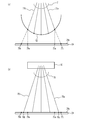
- FIG. 1 is a diagram showing an image inspection apparatus according to the first embodiment.
- FIG. 2 is an upper view of the image projection device.
- FIG. 3 is a diagram illustrating a light beam emitted from the image projection device to the image sensor.
- FIG. 4 is a diagram showing an image inspection apparatus according to a comparative example.
- 5 (a) and 5 (b) are diagrams for explaining the problems that occur in the image inspection apparatus according to the comparative example.
- 6 (a) and 6 (b) are diagrams for explaining the effect of the image inspection apparatus according to the first embodiment.
- FIG. 7 is a diagram showing the calculation results of the positions of the light rays radiated to the image pickup surface of the image pickup device and the positions of the light rays on the image pickup surface when the retina is developed in a plane.
- FIG. 8 (a) is a diagram showing the calculation result of the streak ratio when a light ray composed of green laser light is applied to the user's retina from the image projection device
- FIG. 8 (b) is an image pickup device via an optical system
- 8 (c) which shows the calculation result of the streak ratio when the image pickup surface of the above image is irradiated, is the streak ratio shown by the dotted lines in FIGS. 8 (a) and 8 (b).
- 9 (a) to 9 (c) are diagrams showing the calculation result of the streak ratio when a light ray consisting of red, green, or blue laser light is applied to the user's retina from the image projector, FIG. 9 (FIG. 9).
- FIGS. 9 FIGS. 9
- FIG. 11 (a) is a diagram showing the calculation result of the color shift of the light ray when the user's retina is expanded in a plane
- FIG. 11 (a) is a diagram showing the calculation result of the color shift of the light ray when the user's retina is expanded in a plane
- FIG. 11 (b) shows the light beam emitted to the image pickup surface of the image pickup device via the optical system. It is a figure which shows the calculation result of a color shift.
- FIG. 12 is a diagram showing the amount of misalignment between the green laser beam and the blue laser beam on the X-axis of FIGS. 11 (a) and 11 (b).
- 13 (a) to 13 (d) are diagrams for explaining the reason why the resolution of the image pickup device is preferably equal to or higher than the resolution of the image projected by the image projection device.
- FIG. 14 is a diagram illustrating an image projection area of the image projection device and an image pickup area of the image pickup device.
- FIG. 15 is a diagram illustrating the reason why it is preferable that one exposure time of the image pickup device is longer than the reciprocal of the frame rate of the image projected by the image projection device.
- FIG. 16 is a diagram illustrating rotation of the optical system and the image pickup unit with respect to the image projection device.
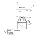
- FIG. 1 is a diagram showing an image inspection device 100 according to the first embodiment.
- the image inspection device 100 includes a mounting unit 1, an optical system 10, an imaging unit (imaging camera) 20, and a control unit 30.
- the image pickup unit 20 has an image pickup element 24 provided in the housing 22.
- the image sensor 24 is, for example, a CMOS (Complementary Metal Oxide Semiconductor) image sensor, but may be another case such as a CCD (Charge Coupled Device) image sensor.
- the optical system 10 includes a convex lens 12, a concave lens 14, and a convex lens 16.
- the convex lens 12, the concave lens 14, and the convex lens 16 are held by the holder 18.
- the holder 18 is fixed to the imaging unit 20 by the fixing member 40.
- the mounting unit 1 detachably mounts the image projection device 50, which is the inspection target of the image inspection device 100.
- the image projection device 50 is an image projection device that directly projects an image onto the retina of the user's eyeball, and is installed in the mounting unit 1 so that the emitted light rays 70 are incident on the optical system 10.
- the optical system 10 focuses the light beam 70 emitted from the image projection device 50 on the planar image pickup surface 24a or the vicinity of the image pickup surface 24a of the image pickup element 24.
- the control unit 30 is, for example, a processor such as a CPU (Central Processing Unit).
- the control unit 30 may be a circuit specially designed.
- the control unit 30 processes the image data captured by the image pickup unit 20 by a processor such as a CPU cooperating with the program to distort the image, resolution, brightness, pattern shape, gamma characteristic, contrast ratio, and aspect ratio. , And functions as an inspection unit 32 that inspects images such as hue. For these tests, commonly known methods can be used. Further, the control unit 30 may display the image data captured by the imaging unit 20 and / or the inspection data inspected by the inspection unit 32 on a display unit (for example, a liquid crystal display) (not shown).
- a display unit for example, a liquid crystal display
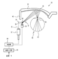
- the image projection device 50 is a retinal projection type head-mounted display that utilizes Maxwell vision in which light rays for allowing the user to visually recognize an image are directly applied to the user's retina. In Maxwell vision, the light rays forming the image converge the scanned light scanned in the two-dimensional direction near the pupil and project the image onto the retina.
- the image projection device 50 includes a light source 52, a mirror 54, a mirror 56, a scanning unit (scanner) 58, a mirror 60, a projection unit 62, a control unit 64, and an image input unit 66.
- the light source 52 and the scanning unit 58 are arranged, for example, on the vine 42 of the eyeglass-shaped frame.
- the projection unit 62 is arranged, for example, on the lens 44 of the glasses-type frame.
- the control unit 64 and the image input unit 66 may be provided on the vine 42 of the spectacle-type frame, or may be provided on an external device (for example, a mobile terminal) without being provided on the spectacle-type frame.
- Image data is input to the image input unit 66 from a camera, a recording device, and / or an image inspection device 100 (not shown).
- the control unit 64 controls the emission of the light rays 70 from the light source 52 and controls the scanning of the scanning unit 58 based on the input image data.
- the light source 52 emits light rays 70 having a single wavelength or a plurality of wavelengths under the control of the control unit 64.
- the light source 52 emits visible light such as red laser light (wavelength: about 610 nm to 660 nm), green laser light (wavelength: about 515 nm to 540 nm), and blue laser light (wavelength: about 440 nm to 480 nm).
- Examples of the light source 52 that emits red, green, and blue laser light include a light source in which RGB (red, green, and blue) laser diode chips and a three-color synthesis device are integrated.
- the control unit 64 is, for example, a processor such as a CPU (Central Processing Unit). If the camera is installed at an appropriate position of the image projection device 50 toward the user's line-of-sight direction, the image in the line-of-sight direction captured by the camera can be projected onto the retina 82 of the user's eyeball 80. In addition, a so-called Augmented Reality (AR) image is projected by projecting an image input from a recording device or the like, or superimposing a camera image and an image from a recording device or the like on the control unit 64. You can also let it.
- AR Augmented Reality
- the scanning unit 58 scans the light rays 70 emitted from the light source 52 at different times in the two-dimensional directions in the horizontal and vertical directions.
- the scanning unit 58 is, for example, a MEMS (Micro Electro Mechanical System) mirror, but may be another component such as a lithium niobate (KTN) crystal, which is an electrochemical material.
- KTN lithium niobate
- the scanning light 72 composed of the light rays 70 scanned by the scanning unit 58 is reflected by the mirror 60 toward the lens 44 of the glasses-type frame.
- the projection unit 62 is arranged on the surface of the lens 44 of the glasses-type frame on the eyeball 80 side. Therefore, the scanning light 72 is incident on the projection unit 62.
- the projection unit 62 is a free curved surface or a half mirror having a composite structure of a free curved surface and a diffractive surface.
- the scanning light 72 reflected by the projection unit 62 converges in the vicinity of the pupil 86 of the eyeball 80 and then irradiates the surface of the retina 82.
- the user can recognize the image by the afterimage effect of the scanning light 72 applied to the retina 82, and can visually recognize the external image through see-through.
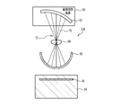
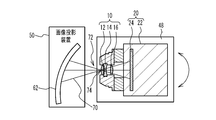
- FIG. 3 is a diagram illustrating a light beam 70 emitted from the image projection device 50 to the image sensor 24.
- the finite luminous flux diameter of the light beam 70 is illustrated, and the central portion thereof is illustrated by a broken line.
- the plurality of light rays 70 included in the scanning light 72 and emitted at different times are the image pickup surface 24a of the image pickup device 24 via the optical system 10 including the convex lens 12, the concave lens 14, and the convex lens 16. Is irradiated to.
- the plurality of light rays 70 are focused by the optical system 10 in the vicinity of the image pickup surface 24a or the image pickup surface 24a having a planar shape of the image pickup element 24.
- the light beam 70 is converted from substantially parallel light to focused light by the convex lens 12, converted from focused light to diffused light by the concave lens 14, and converted again from diffused light to focused light by the convex lens 16, and is converted to the imaging surface 24a or the imaging surface 24a or the imaging. Focus on the vicinity of the surface 24a.
- the convex lens 12 is, for example, a plano-convex lens in which the surface on the side where the light beam 70 (scanning light 72) is incident is a convex surface and the surface on the side where the light beam 70 (scanning light 72) is emitted is a flat surface.
- the concave lens 14 is, for example, a biconcave lens in which both the side where the light beam 70 is incident and the side where the light beam is emitted are concave.
- the convex lens 16 is, for example, a plano-convex lens in which the surface on the side where the light beam 70 is incident is a flat surface and the surface on the side where the light beam is emitted is a convex surface.
- the convex lens 12 and the concave lens 14 are arranged in contact with each other, for example.
- the concave lens 14 and the convex lens 16 are arranged apart, for example.
- the convex lens 12 and the concave lens 14 may be arranged at a distance narrower than the distance between the concave lens 14 and the convex lens 16.
- the scanning light 72 converges at the center of the convex surface on which the light rays 70 of the convex lens 12 are incident.
- the diameter of the light beam 70 when incident on the convex surface of the convex lens 12 is, for example, about 0.5 mm to 1 mm.
- the length dimension L from the convex surface of the convex lens 12 to the image pickup surface 24a of the image pickup element 24 is a distance obtained by correcting the length dimension from the surface of the crystalline lens of the human eyeball to the surface of the retina 82 in consideration of the refractive index of the eyeball. It corresponds to, for example, about 16 mm to 17 mm.
- the convex lenses 12 and 16 may be biconvex lenses in which both the incident side and the light emitting side of the light beam 70 are convex surfaces.
- the concave lens 14 may be a plano-concave lens in which one surface on the side where the light beam 70 is incident and the side where the light beam is emitted is a concave surface and the other surface is a flat surface.
- FIG. 4 is a diagram showing an image inspection device 500 according to a comparative example.
- the image inspection device 500 of the comparative example includes a condenser lens 90, a projected unit 92, and an imaging unit (imaging camera) 94.
- the condenser lens 90 is provided on the optical path through which the light beam 70 reflected by the projection unit 62 of the image projection device 50 passes, and at a position where the scanning light 72 converges.
- the projected portion 92 is arranged near the focusing position of the light beam 70 by the condenser lens 90.
- the projected portion 92 has a hemispherical shape with the condenser lens 90 side open, and is made of a material that is translucent with respect to the light beam 70. Since the projected unit 92 is translucent with respect to the light rays 70, the projected image is displayed and the image is transmitted through the image projected by the scanning light 72.
- the condensing lens 90 that collects the light beam 70 can be regarded as the crystalline lens of the eyeball.
- the hemispherical projected portion 92 can be regarded as the retina of the eyeball. That is, a pseudo eye (dummy eye) is formed by the condenser lens 90 corresponding to the crystalline lens and the projected portion 92 corresponding to the retina. Therefore, the diameter of the projected portion 92 is the general size of the eyeball (for example, about 24 mm).
- the image pickup unit 94 has an image pickup element 96.
- the image sensor 96 is, for example, a CMOS image sensor.
- the imaging unit 94 is provided on the side opposite to the condenser lens 90 with respect to the projected unit 92.
- the imaging unit 94 captures an image projected on the projected unit 92.
- FIG. 5 (a) and 5 (b) are diagrams for explaining the problems that occur in the image inspection apparatus 500 according to the comparative example.
- FIG. 5B it is represented by the position coordinates with the center of the image projected by the image projection device 50 as the origin.
- the unit of the numerical value indicating the coordinates is mm.
- the plane expansion coordinates (circles), which are the positions of the light rays 70 when the projected portion 92 is deployed on a plane, are as shown in FIG. 5 (b).
- the light beam 70 applied to the projected portion 92 spreads outward as compared with the vertically projected coordinates (triangular marks) at which the light beam 70 is projected perpendicularly to the imaging surface 96a of the imaging element 96.
- the vertically projected coordinates (triangular marks) at which the light beam 70 is projected perpendicularly to the imaging surface 96a of the imaging element 96.
- the image inspection device 500 of the comparative example it is difficult to satisfactorily inspect the image projected on the user's retina by the image projection device 50.
- FIG. 6A and 6 (b) are diagrams for explaining the effect of the image inspection device 100 according to the first embodiment.
- the time differs depending on the image projection device 50.
- the light beam that is emitted and irradiates the retina 82 is referred to as a light ray 71.
- one of the rays near the edge of the image 76 is the ray 71a, and the ray symmetric with respect to the center of the image 76 is the ray 71b.
- the position where the light ray 71a irradiated on the retina 82 is projected perpendicularly to the imaging surface 24a is defined as the vertical projection position 73a
- the position where the light ray 71b irradiated on the retina 82 is projected perpendicularly to the imaging surface 24a is defined as the vertical projection position 75a. ..
- the position of the ray 71a on the imaging surface 24a when the retina 82 is expanded in a plane and the surface of the retina 82 is aligned with the imaging surface 24a is defined as the plane expansion position 73b
- the position of the ray 71b is defined as the plane expansion position 75b.
- Is the irradiation position 78a, and the position of the light ray 70b corresponding to the light ray 71b on the image pickup surface 24a is the irradiation position 78b.
- the irradiation position 78a is closer to the plane development position 73b than the vertical projection position 73a.
- the irradiation position 78b is made closer to the plane development position 75b than the vertical projection position 75a.
- the optical system 10 sets the irradiation position 78a at which the light ray 70a corresponding to the light ray 71a among the plurality of light rays 70 is applied to the imaging surface 24a from the retina 82 to the imaging surface 24a. It has an optical characteristic that is closer to the plane expansion position 73b when the retina 82 is plane-expanded than the vertically projected vertical projection position 73a. As a result, the image projected by the image projection device 50 can be inspected satisfactorily.
- the optical system 10 brings the irradiation position 78a closer to the plane development position 73b than the vertical projection position 73a, and the irradiation position where the light ray 70b corresponding to the light ray 71b among the plurality of light rays 70 is applied to the imaging surface 24a. It has an optical characteristic that the 78b is closer to the plane expansion position 75b when the retina 82 is plane-expanded than the vertical projection position 75a in which the light rays 71b are projected vertically from the retina 82 to the imaging surface 24a. As a result, the image projected by the image projection device 50 can be inspected satisfactorily.
- FIG. 6B shows an example in which the irradiation position 78a is located between the vertical projection position 73a and the plane expansion position 73b, and the irradiation position 78b is located between the vertical projection position 75a and the plane expansion position 75b. Is shown as an example, but it is not limited to this case.
- the irradiation position 78a may be located on the opposite side of the plane deployment position 73b from the vertical projection position 73a, or the irradiation position 78b may be located on the opposite side of the plane deployment position 75b from the vertical projection position 75a. May be good.
- the center distance between the irradiation position 78a and the plane development position 73b is preferably 1/2 or less, more preferably 1/3 or less of the center distance between the vertical projection position 73a and the plane development position 73b. It is more preferably 1/4 or less.
- the center distance between the irradiation position 78b and the plane development position 75b is preferably 1/2 or less, more preferably 1/3 or less, and further 1/4 or less of the center distance between the vertical projection position 75a and the plane development position 75b. preferable.
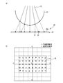
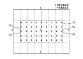
- FIG. 7 is a diagram showing calculation results of the position of the light ray 70 irradiated on the image pickup surface 24a of the image pickup element 24 and the position of the light ray 71 on the image pickup surface 24a when the retina 82 is developed in a plane.
- it is represented by the position coordinates with the center of the image projected by the image projection device 50 as the origin.
- the unit of the numerical value indicating the coordinates is mm.
- FIG. 7 is a calculation result when the convex lens 12, the concave lens 14, and the convex lens 16 having the specifications shown in Table 1 are used (note that the lenses having the same specifications are also used in FIGS. 8 to 12 shown below. It is the calculation result that was there).
- the convex lens 12 has a radius of curvature of 7.73 mm on the entrance surface, an infinite radius of curvature on the exit surface, a center thickness of 1.6 mm, a glass material of S-LAL8 manufactured by O'Hara, and a refractive index. 1.713 and the Abbe number was 53.87.
- the concave lens 14 has a radius of curvature of -12.08 mm on the entrance surface, a radius of curvature of 11.21 mm on the exit surface, a thickness of 1.0 mm at the center, a glass material of S-TIH10 manufactured by O'Hara, and a refractive index of 1.728.
- the Abbe number was set to 28.46.
- the convex lens 16 has an infinite radius of curvature on the incident surface, a radius of curvature on the exit surface of -8.43 mm, a center thickness of 1.4 mm, a glass material of S-LAM61 manufactured by O'Hara, a refractive index of 1.720, and an Abbe number. The number was 46.02. Further, the distance between the convex lens 12 and the center of the concave lens 14 is 0.39 mm, the distance between the concave lens 14 and the center of the convex lens 16 is 2.76 mm, and the distance between the center of the convex lens 16 and the imaging surface 24a is 14.79 mm. ..
- the light beam 70 covers the entire image 76 projected by the image projection device 50.
- the irradiation position coordinates (diamond mark), which is the position where the image is irradiated on the imaging surface 24a, and the plane expansion coordinates (circle mark), which is the position of the light ray 71 on the imaging surface 24a when the retina 82 is expanded in a plane, are approximately one. I am doing it.
- substantially coincidence means that 50% or more of the spot area of the light ray 70 on the image pickup surface 24a overlaps with the spot area of the light ray 71 on the image pickup surface 24a when the retina 82 is developed in a plane. is there.
- the light ray 71a on the image pickup surface 24a when the irradiation position 78a in which the light ray 70a irradiates the image pickup surface 24a expands the retina 82 in a plane so that the surface of the retina 82 coincides with the image pickup surface 24a. It is preferable to have an optical characteristic that substantially matches the plane development position 73b of. Further, in the optical system 10, the plane of the light ray 71b on the image pickup surface 24a when the irradiation position 78b in which the light ray 70b is applied to the image pickup surface 24a unfolds the retina 82 in a plane so that the surface of the retina 82 coincides with the image pickup surface 24a. It is preferable to have optical characteristics that substantially match the deployment position 75b. This makes it possible to better inspect the image projected by the image projection device 50.
- the optical system 10 has an imaging surface when the retina 82 is developed in a plane and the surface of the retina 82 is aligned with the imaging surface 24a at all of the plurality of irradiation positions where the plurality of light rays 70 are irradiated on the imaging surface 24a. It is preferable to have an optical characteristic that substantially matches the corresponding plane expansion position among the plurality of plane expansion positions of the plurality of light rays 71 in 24a. As a result, the image projected by the image projection device 50 can be inspected even better.
- the plurality of irradiation positions where the plurality of light rays 70 are irradiated on the imaging surface 24a correspond to the plurality of plane expansion positions of the plurality of rays 71 on the imaging surface 24a when the retina 82 is plane-expanded. It may be a case where the plane development position is substantially the same. More than 90% of the plurality of irradiation positions where the plurality of light rays 70 are applied to the imaging surface 24a correspond to the corresponding planes among the plurality of plane development positions of the plurality of rays 71 on the image pickup surface 24a when the retina 82 is expanded in a plane. It may be a case where the expansion position is substantially the same.
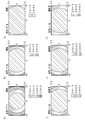
- FIG. 8A is a diagram showing the calculation result of the streak ratio when the light ray 71 composed of the green laser light is irradiated from the image projection device 50 to the user's retina 82.
- FIG. 8B is a diagram showing a calculation result of the streak ratio when a light beam 70 composed of green laser light is irradiated from the image projection device 50 to the image pickup surface 24a of the image pickup device 24 via the optical system 10.
- the streak ratio is the maximum intensity ratio of the intensity distribution of the irradiated laser.
- the wavelength is ⁇
- the RMS (root mean square) value of the wave surface aberration is W
- S It is calculated by 1- (2 ⁇ / ⁇ ) 2 ⁇ W 2 .
- FIG. 8 (c) is a dotted line ratio of FIGS. 8 (a) and 8 (b).
- the scanning angle of the scanning unit with the center of the image projected by the image projection device 50 as the origin is represented.
- the coordinate axis is the angle (°) of the scanning angle.
- the optical characteristics such as the curvature of each lens constituting the optical system 10 and the distance between the lenses are appropriately designed, and the green laser light (wavelength: 520 nm).
- the trail ratio when the image pickup surface 24a of the image pickup element 24 is irradiated is substantially the same as the trail ratio when the green laser light is irradiated to the retina 82. That is, the tendency that the stray ratio in the central portion of the image is high and the strail ratio in the peripheral portion is low is reproduced on the image pickup surface 24a of the image pickup device 24 by appropriately designing the optical system 10.
- 9 (a) to 9 (c) are diagrams showing the calculation result of the streak ratio when the light ray 71 composed of red, green, or blue laser light is irradiated from the image projection device 50 to the user's retina 82. is there.
- 9 (d) to 9 (f) show the case where the light beam 70 composed of red, green, or blue laser light is irradiated from the image projection device 50 to the image pickup surface 24a of the image pickup device 24 via the optical system 10. It is a figure which shows the calculation result of a stray ratio.
- 9 (a) to 9 (f) show the scanning angle of the scanning unit with the center of the image projected by the image projection device 50 as the origin. The coordinate axis is the angle (°) of the scanning angle.
- the green laser light is emitted from the image pickup element 24 by appropriately designing the optical characteristics such as the curvature of each lens constituting the optical system 10 and the distance between the lenses.
- the trail ratio when the imaging surface 24a is irradiated is substantially the same as the trail ratio when the green laser light is irradiated to the retina 82.
- the blue laser light (wavelength: 450 nm) is irradiated to the imaging surface 24a as shown in FIGS. 9 (a) and 9 (d).
- the trail ratio at that time shows the same tendency as the trail ratio when the blue laser light is applied to the retina 82. That is, the tendency that the stray ratio in the central portion of the image is high and the strail ratio in the peripheral portion is low is reproduced on the imaging surface 24a.
- the streak ratio when the red laser light (wavelength: 640 nm) is applied to the imaging surface 24a is such that the red laser light is applied to the retina 82. It shows the same tendency as the strare ratio at the time. That is, the tendency that the stray ratio in the central portion of the image is high and the strail ratio in the peripheral portion is low is reproduced on the imaging surface 24a.
- the optical system 10 has an optical characteristic that makes the stray ratio at the center of the image captured by the image sensor 24 higher than the stray ratio at the ends. preferable. As a result, the image projected by the image projection device 50 can be inspected satisfactorily.
- the difference between the trail ratio when the green laser light is applied to the imaging surface 24a and the trail ratio when the green laser light is applied to the retina 82 is detected on the imaging surface 24a by the blue laser light. It is preferable to have an optical characteristic that makes the difference between the strail ratio when irradiated and the stray ratio when the blue laser light is irradiated to the retina 82 smaller than the difference. Further, in the optical system 10, the difference between the trail ratio when the green laser light is applied to the imaging surface 24a and the trail ratio when the green laser light is applied to the retina 82 is detected on the imaging surface 24a by the red laser light.
- the wavelength band of the green laser light is located between the wavelength band of the blue laser light and the wavelength band of the red laser light. Therefore, by reducing the difference between the trail ratio on the imaging surface 24a with the green laser light and the trail ratio on the retina 82, the difference between the trail ratio on the imaging surface 24a with the blue and red laser light and the trail ratio on the retina 82. Can be made smaller. Therefore, the image projected by the image projection device 50 can be inspected satisfactorily.
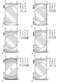
- 10 (a) to 10 (c) are diagrams showing the calculation results of RMS wave surface aberration when a ray 71 composed of red, green, or blue laser light is applied from the image projection device 50 to the user's retina 82.
- Is. 10 (d) to 10 (f) show a case where a light ray 70 composed of red, green, or blue laser light is irradiated from the image projection device 50 to the image pickup surface 24a of the image pickup device 24 via the optical system 10. It is a figure which shows the calculation result of RMS wave surface aberration.
- 10 (a) to 10 (f) show the scanning angle of the scanning unit with the center of the image projected by the image projection device 50 as the origin. The coordinate axis is the angle (°) of the scanning angle.
- the green laser light (wavelength: 520 nm) is obtained by appropriately designing the optical characteristics such as the curvature of each lens constituting the optical system 10 and the distance between the lenses. ) Approximately matches the RMS wave surface aberration when the image pickup surface 24a of the image pickup element 24 is irradiated with the RMS wave surface aberration when the green laser light is applied to the retina 82. That is, the tendency that the RMS value in the central portion of the image is small and the RMS value in the peripheral portion is large is reproduced on the image pickup surface 24a of the image pickup device 24.
- the blue laser light (wavelength: 450 nm) is transmitted to the imaging surface 24a as shown in FIGS. 10 (a) and 10 (d).
- the RMS value when irradiated shows the same tendency as the RMS value when the blue laser light irradiates the retina 82. That is, the tendency that the RMS value in the central portion of the image is small and the RMS value in the peripheral portion is large is reproduced on the imaging surface 24a.
- FIGS. 10 (a) and 10 (d) shows the same tendency as the RMS value when the blue laser light irradiates the retina 82. That is, the tendency that the RMS value in the central portion of the image is small and the RMS value in the peripheral portion is large is reproduced on the imaging surface 24a.
- the RMS value when the red laser light (wavelength: 640 nm) is applied to the imaging surface 24a is such that the red laser light is applied to the retina 82. It shows the same tendency as the RMS value at. That is, the tendency that the RMS value in the central portion of the image is small and the RMS value in the peripheral portion is large is reproduced on the imaging surface 24a.
- the optical system 10 has an optical characteristic that makes the RMS wave surface aberration at the central portion of the image captured by the image sensor 24 smaller than the RMS wave surface aberration at the end portion. You may.
- FIG. 11A is a diagram showing the calculation result of the color shift of the light beam 71 when the user's retina 82 is developed in a plane
- FIG. 11B is a diagram on the image pickup surface 24a of the image pickup device 24 via the optical system 10. It is a figure which shows the calculation result of the color shift of the light ray 70 to be irradiated.
- the scanning angle of the scanning unit with the center of the image projected by the image projection device 50 as the origin is represented.
- the coordinate axis is the angle (°) of the scanning angle.
- the image projection device 50 to the retina 82 The red laser light R, the green laser light G, and the blue laser light of the corresponding light rays are formed by the plurality of light rays 71 irradiated on the light beam 71 and the plurality of light rays 70 irradiated on the image pickup surface 24a of the image pickup element 24 from the image projection device 50.
- the tendency of the misalignment of B is matched.
- the red laser beam R is displaced outward with respect to the green laser beam G
- the blue laser beam B is displaced with respect to the green laser beam G.
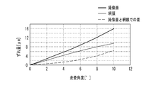
- FIG. 12 is a diagram showing the amount of misalignment between the green laser beam and the blue laser beam on the X-axis of FIGS. 11 (a) and 11 (b).
- the amount of misalignment between the green laser beam G and the blue laser beam B irradiated on the imaging surface 24a of the imaging device 24 is shown by a thick line
- the misalignment between the green laser beam G and the blue laser beam B irradiated on the retina 82 is shown by a thick line.
- the amount is indicated by a thin line.
- the difference in the amount of misalignment is shown by a broken line.
- the amount of misalignment between the green laser beam G and the blue laser beam B is the difference between the center position of the green laser beam G and the center position of the blue laser beam B.
- the difference between the amount of misalignment of the green laser light and the blue laser light on the imaging surface 24a of the imaging element 24 and the amount of misalignment of the green laser light and the blue laser light on the retina 82 as the distance from the origin increases. Is getting bigger.
- the difference between the amount of misalignment between the green laser light and the blue laser light on the image pickup surface 24a of the image sensor 24 and the amount of misalignment between the green laser light and the blue laser light on the retina 82 is 6 ⁇ m. It has become a degree.
- Table 2 shows the amount of misalignment of the green laser light and the blue laser light irradiated on the imaging surface 24a of the imaging element 24 and the retina 82 at points A to E in FIGS. 11 (a) and 11 (b). The difference between the emitted green laser light and the amount of misalignment of the blue laser light is shown. Further, Table 2 shows the amount of misalignment of the red laser light and the green laser light and the retina irradiated on the imaging surface 24a of the imaging element 24 at points A to E in FIGS. 11 (a) and 11 (b). The difference between the amount of misalignment between the red laser light and the green laser light irradiated to 82 is shown.
- the difference between the amount of misalignment between the green laser light and the blue laser light on the imaging surface 24a of the image pickup element 24 and the amount of misalignment between the green laser light and the blue laser light on the retina 82 is 12.32 ⁇ m or less. It is about 13 ⁇ m or less.
- the difference between the amount of misalignment between the red laser light and the green laser light on the imaging surface 24a of the image pickup element 24 and the amount of misalignment between the red laser light and the green laser light on the retina 82 is 12.32 ⁇ m or less, which is approximately the same. It is 13 ⁇ m or less.
- the spot diameter on the retina 82 is about 40 ⁇ m. Therefore, even if there is a difference of about 13 ⁇ m in the amount of misalignment around the projected image, the influence on inspecting the quality of the image projected by the image projection device 50 is small.
- the optical system 10 has a red laser beam and a blue laser beam with respect to the green laser beam when a plurality of light rays 70 are applied to the imaging surface 24a of the imaging device 24. It is preferable to have an optical characteristic that the misalignment direction is the same as the misalignment direction of the red laser light and the blue laser light with respect to the green laser light when the plurality of light rays 71 irradiate the user's retina 82. As a result, the image projected by the image projection device 50 can be inspected satisfactorily.
- the case where the optical system 10 includes the convex lens 12, the concave lens 14, and the convex lens 16 which are arranged in order from the side where the scanning light 72 is incident is shown as an example, but other cases may be used.
- the optical system 10 is composed of three lenses, a convex lens 12, a concave lens 14, and a convex lens 16, the configuration of the optical system 10 can be simplified.
- the case where the scanning light 72 is focused on the convex surface of the convex lens 12 is shown as an example, but other cases may be used.
- the optical system 10 may be provided at the convergence position of the scanning light 72.
- the resolution of the image sensor 24 is preferably equal to or higher than the resolution of the image projected by the image projection device 50.
- 13 (a) to 13 (d) are diagrams for explaining the reason why it is preferable that the resolution of the image pickup device 24 is equal to or higher than the resolution of the image projected by the image projection device 50.
- 13 (a) is a diagram showing an image projected on the image pickup surface 24 a of the image sensor 24 by the image projection device 50
- FIGS. 13 (b) to 13 (d) are images captured by the image sensor 24. It is a figure which shows.
- the saturation (shading) of the black-and-white image projected by the image projection device 50 is represented by the hatching density.
- the image of the black pattern 46 is projected in the image projection area 68 by the image projection device 50.
- the area between the black patterns 46 is a region where the light rays 70 are not irradiated from the image projection device 50 and the patterns are not projected.
- the resolution of the image sensor 24 is lower than the resolution of the image projected by the image projection device 50 as shown in FIG. 13B, a part of the black pattern 46 is not periodically imaged and the color of the black pattern 46 is colored.
- a black pattern 46a that does not accurately reflect the degree (shade) may be imaged. As shown in FIG.
- the resolution of the image pickup device 24 is preferably twice or more the resolution of the image projected by the image projection device 50 from the viewpoint of more accurately reflecting the shading of the image projected by the image projection device 50 for imaging. It is more preferably 3 times or more, and further preferably 4 times or more.
- FIG. 14 is a diagram illustrating an image projection area 68 of the image projection device 50 and an image pickup area 26 of the image sensor 24.
- the image pickup region 26 of the image pickup device 24 is preferably larger than the image projection area 68 of the image projection device 50.
- the length of the vertical side of the image projection region 26 is preferably 1.2 times or more, more preferably 1.5 times or more, still more preferably 1.8 times or more the length of the vertical side of the image projection area 68.
- the length of the horizontal side of the image projection region 26 is preferably 1.2 times or more, more preferably 1.5 times or more, still more preferably 1.8 times or more the length of the horizontal side of the image projection area 68.
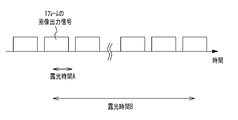
- the image sensor 24 captures an image projected by the image projection device 50 with one or a plurality of continuous exposure times, and the one continuous exposure time is the inverse of the frame rate of the image projected by the image projection device 50. Is preferably longer. For example, one continuous exposure time of the image sensor 24 is longer than 1/60 second when the frame rate of the image projected by the image projection device 50 is 60 fps, and when the frame rate of the image is 30 fps. It is preferably longer than 1/30 second.
- FIG. 15 is a diagram for explaining the reason why it is preferable that one exposure time of the image pickup device 24 is longer than the reciprocal of the frame rate of the image projected by the image projection device 50.
- one exposure time A of the image pickup device 24 is shorter than the reciprocal of the frame rate of the image projected by the image projection device 50, the entire image may not be captured.
- one exposure time B of the image sensor 24 is made longer than the inverse number of the frame rate of the image projected by the image projection device 50, the image pickup is started from the middle of the projected image and the image pickup is performed in the middle. It is possible to suppress that the entire image is not captured after finishing.
- one exposure time of the image sensor 24 is twice or more the inverse of the frame rate of the image projected by the image projection device 50. , It is more preferable that it is as long as possible.
- the image projection timing by the image projection device 50 and the image pickup timing by the image sensor 24 may be imaged by the image sensor 24 by synchronizing with (horizontal synchronization, vertical synchronization, etc.). In this case, since the image projection timing and the image pickup timing are synchronized, the image sensor 24 can capture an image of one frame or a plurality of frames.
- FIG. 16 is a diagram illustrating rotation of the optical system 10 and the image pickup unit 20 with respect to the image projection device 50.
- the optical system 10 and the optical system 10 and the convergence point 74 of the scanning light 72 projected from the projection unit 62 of the image projection device 50 the portion of the convex surface on which the light ray 70 of the convex lens 12 is incident in the first embodiment.
- the image pickup unit 20 may be rotatable with respect to the image projection device 50.
- the rotation of the optical system 10 and the imaging unit 20 with respect to the image projection device 50 may be a rotation in the left-right direction, a rotation in the up-down direction, or a rotation in the up-down-left-right direction.
- the optical system 10 and the imaging unit 20 move the image projection device 50 around the position where the scanning light 72 emitted from the image projection device 50 converges. It is preferable that the image is rotatable.
- the relative rotation of the optical system 10 and the image pickup unit 20 with respect to the image projection device 50 may be performed by placing the optical system 10 and the image pickup unit 20 on the stage 48 and rotating the stage 48, or the like. It may be done by the method of.
- the rotation of the optical system 10 and the imaging unit 20 may be performed by the inspector manually moving the stage 48, or by the inspector giving an instruction to the control unit 30 and the control unit 30 moving the stage 48. You may go.
Abstract
This image inspection device comprises a mounting part having mounted thereon an image projection device for directly projecting an image onto a retina, an imaging element that has a planar imaging surface and captures an image projected from the image projection device onto the imaging surface, an optical system that is provided at a position where a plurality of first light beams emitted from the image projection device at different times converge and focuses the plurality of first light beams emitted from the image projection device on the imaging surface or the vicinity thereof, and an inspection unit for inspecting the image captured by the imaging element. Assuming that there is a retina in the direction of the mounting part from the imaging surface and given a first position where, from among a plurality of second light beams emitted from the image projection device at different times and impinging on the retina, a third light beam near the edge of the image is vertically projected onto the imaging surface and a second position that would be the position on the imaging surface of the third light beam if the retina were expanded into a flat surface and the surface of the retina were made to coincide with the imaging surface, the optical system makes a third position, which is the position on the imaging surface impinged on by a fourth light beam from among the plurality of first light beams that corresponds to the third light beam, approach the second position more than the first position.
Description
本発明は、画像検査装置に関する。
The present invention relates to an image inspection device.
二次元方向に走査された走査光をユーザの網膜表面に照射して画像を網膜に直接投影する画像投影装置が知られている(例えば、特許文献1)。また、撮像用レンズの特性値を検査するために、撮像用レンズを介して射出される画像光を撮像素子で検出して画像処理を行うことで撮像用レンズの特性値を算出することが知られている(例えば、特許文献2)。
There is known an image projection device that irradiates a user's retina surface with scanning light scanned in a two-dimensional direction and directly projects an image onto the retina (for example, Patent Document 1). Further, in order to inspect the characteristic value of the imaging lens, it is known that the characteristic value of the imaging lens is calculated by detecting the image light emitted through the imaging lens with the image sensor and performing image processing. (For example, Patent Document 2).
画像投影装置により網膜に直接投影される画像を検査する方法として、ユーザが網膜に投影された画像を見ることによって画像を検査する方法が考えられる。しかしながら、この方法では、ユーザの個人差によるばらつき及びユーザの疲労度などによるばらつきなどによって、評価がばらついてしまう。
As a method of inspecting the image directly projected on the retina by the image projection device, a method of inspecting the image by the user looking at the image projected on the retina can be considered. However, in this method, the evaluation varies due to variations due to individual differences of users and variations due to the degree of fatigue of users.
本発明は、上記課題に鑑みなされたものであり、網膜に画像を直接投影する画像投影装置により投影される画像を良好に検査することが可能な画像検査装置を提供することを目的とする。
The present invention has been made in view of the above problems, and an object of the present invention is to provide an image inspection device capable of satisfactorily inspecting an image projected by an image projection device that directly projects an image onto the retina.
本発明は、ユーザの網膜に画像を直接投影する画像投影装置が搭載される搭載部と、平面形状の撮像面を有し、前記搭載部に搭載された前記画像投影装置から前記撮像面に投影される画像を撮像する撮像素子と、前記画像投影装置によって異なる時間に出射される複数の第1光線が収束する位置に設けられ、前記画像投影装置から前記撮像面に照射される前記複数の第1光線各々を前記撮像面又は前記撮像面の近傍に合焦させる光学系と、前記撮像素子で撮像された画像を検査する検査部と、を備え、前記撮像面の前記搭載部方向に前記網膜があると仮想したときに、前記画像投影装置によって異なる時間に出射されて前記網膜に照射される複数の第2光線のうちの前記画像の端近傍における第3光線を前記撮像面に垂直に投影したときの位置を第1位置とし、前記網膜を平面展開して前記網膜の表面を前記撮像面に一致させたときの前記撮像面における前記第3光線の位置を第2位置とした場合に、前記光学系は、前記複数の第1光線のうちの前記第3光線に対応する第4光線が前記撮像面に照射される第3位置を前記第1位置よりも前記第2位置に近づける、画像検査装置である。
The present invention has a mounting portion on which an image projection device that directly projects an image onto the user's retina is mounted, and a planar imaging surface, and the image projection device mounted on the mounting portion projects onto the imaging surface. The plurality of first rays emitted from the image projection device at different times are provided at positions where the image pickup element for capturing the image to be imaged and the plurality of first rays emitted by the image projection device converge, and the image projection device irradiates the imaging surface. An optical system that focuses each of the light rays on the imaging surface or in the vicinity of the imaging surface, and an inspection unit that inspects an image captured by the imaging element are provided, and the retina is provided in the direction of the mounting portion of the imaging surface. When imagining that there is, the third ray near the edge of the image among the plurality of second rays emitted by the image projection device at different times and irradiating the retina is projected perpendicularly to the imaging surface. When the position of the third ray on the imaging surface is set to the second position when the reticle is expanded in a plane and the surface of the retinal is aligned with the imaging surface. The optical system brings the third position where the fourth ray corresponding to the third ray of the plurality of first rays is applied to the imaging surface closer to the second position than the first position. It is an inspection device.
上記構成において、前記光学系は、前記第3位置を前記第2位置に略一致させる構成とすることができる。
In the above configuration, the optical system can have a configuration in which the third position substantially coincides with the second position.
上記構成において、前記光学系は、前記複数の第1光線が前記撮像面に照射される複数の位置の全てを、前記網膜を平面展開して前記網膜の表面を前記撮像面に一致させたときの前記撮像面における前記複数の第2光線の複数の位置のうちの対応する位置に略一致させる構成とすることができる。
In the above configuration, when the optical system deploys the retina in a plane and aligns the surface of the retina with the imaging surface at all of the plurality of positions where the plurality of first rays are applied to the imaging surface. The configuration can be such that the corresponding positions of the plurality of positions of the plurality of second rays on the imaging surface of the above are substantially matched.
上記構成において、前記光学系は、前記撮像素子で撮像される画像の中央部におけるストレール比を端部におけるストレール比よりも高くさせる構成とすることができる。
In the above configuration, the optical system can have a configuration in which the stray ratio at the center of the image captured by the image sensor is higher than the stray ratio at the ends.
上記構成において、前記複数の第1光線各々及び前記複数の第2光線各々は、赤色光、緑色光、及び青色光を含み、前記光学系は、前記緑色光からなる前記複数の第1光線が前記撮像面に照射されるときのストレール比と前記緑色光からなる前記複数の第2光線が前記網膜に照射されるときのストレール比との相違を、前記赤色光からなる前記複数の第1光線が前記撮像面に照射されるときのストレール比と前記赤色光からなる前記複数の第2光線が前記網膜に照射されるときのストレール比との相違、及び、前記青色光からなる前記複数の第1光線が前記撮像面に照射されるときのストレール比と前記青色光からなる前記複数の第2光線が前記網膜に照射されるときのストレール比との相違よりも小さくさせる構成とすることができる。
In the above configuration, each of the plurality of first rays and each of the plurality of second rays includes red light, green light, and blue light, and the optical system includes the plurality of first rays composed of the green light. The difference between the trail ratio when the imaging surface is irradiated and the trail ratio when the plurality of second rays of green light are irradiated on the retina is the difference between the plurality of first rays of red light. The difference between the streak ratio when the imaging surface is irradiated with the trail ratio and the trail ratio when the plurality of second rays composed of the red light are irradiated on the retina, and the plurality of first rays composed of the blue light. The difference between the trail ratio when one light beam is applied to the imaging surface and the trail ratio when the plurality of second rays composed of the blue light is applied to the retina can be made smaller than the difference. ..
上記構成において、前記複数の第1光線各々及び前記複数の第2光線各々は、赤色光、緑色光、及び青色光を含み、前記光学系は、前記複数の第1光線が前記撮像面に照射されるときの前記緑色光に対する前記赤色光及び前記青色光の位置ずれ方向を、前記複数の第2光線が前記網膜に照射されるときの前記緑色光に対する前記赤色光及び前記青色光の位置ずれ方向と同じにさせる構成とすることができる。
In the above configuration, each of the plurality of first rays and each of the plurality of second rays includes red light, green light, and blue light, and in the optical system, the plurality of first rays irradiate the imaging surface. The misalignment of the red light and the blue light with respect to the green light when the light is generated, and the misalignment of the red light and the blue light with respect to the green light when the plurality of second rays are applied to the retina. The configuration can be the same as the direction.
上記構成において、前記光学系は、前記複数の第1光線が入射する側から順に並んだ第1凸レンズ、凹レンズ、及び第2凸レンズを含む構成とすることができる。
In the above configuration, the optical system may include a first convex lens, a concave lens, and a second convex lens that are arranged in order from the side on which the plurality of first light rays are incident.
上記構成において、前記撮像素子の解像度は、前記画像投影装置によって前記撮像面に投影される画像の解像度以上である構成とすることができる。
In the above configuration, the resolution of the image pickup device may be equal to or higher than the resolution of the image projected on the image pickup surface by the image projection device.
上記構成において、前記撮像素子の撮像領域は、前記画像投影装置によって前記撮像面に投影される画像の投影領域よりも大きい構成とすることができる。
In the above configuration, the imaging region of the image pickup device can be configured to be larger than the projection region of the image projected on the imaging surface by the image projection device.
上記構成において、前記撮像素子が前記画像投影装置によって前記撮像面に投影される画像を撮像する1回の露光時間は、前記画像投影装置によって前記撮像面に投影される画像のフレームレートの逆数よりも長い構成とすることができる。
In the above configuration, one exposure time for the image sensor to capture an image projected on the imaging surface by the image projection device is the inverse of the frame rate of the image projected on the imaging surface by the image projection device. Can also have a long configuration.
上記構成において、前記光学系及び前記撮像素子は、前記複数の第1光線が収束する位置を中心に前記画像投影装置に対して回動可能である構成とすることができる。
In the above configuration, the optical system and the image pickup device can be configured to be rotatable with respect to the image projection device about a position where the plurality of first rays converge.
本発明によれば、網膜に画像を直接投影する画像投影装置により投影される画像を良好に検査することができる。
According to the present invention, an image projected by an image projection device that directly projects an image onto the retina can be satisfactorily inspected.
以下、図面を参照しつつ、本発明の実施例について説明する。
Hereinafter, examples of the present invention will be described with reference to the drawings.
図1は、実施例1に係る画像検査装置100を示す図である。図1のように、画像検査装置100は、搭載部1、光学系10、撮像部(撮像カメラ)20、及び制御部30を備える。撮像部20は、筐体22内に設けられた撮像素子24を有する。撮像素子24は、例えばCMOS(Complementary Metal Oxide Semiconductor)イメージセンサであるが、CCD(Charge Coupled Device)イメージセンサなど、その他の場合でもよい。光学系10は、凸レンズ12、凹レンズ14、及び凸レンズ16を含む。凸レンズ12、凹レンズ14、及び凸レンズ16はホルダ18で保持されている。ホルダ18は固定部材40によって撮像部20に固定されている。
FIG. 1 is a diagram showing an image inspection device 100 according to the first embodiment. As shown in FIG. 1, the image inspection device 100 includes a mounting unit 1, an optical system 10, an imaging unit (imaging camera) 20, and a control unit 30. The image pickup unit 20 has an image pickup element 24 provided in the housing 22. The image sensor 24 is, for example, a CMOS (Complementary Metal Oxide Semiconductor) image sensor, but may be another case such as a CCD (Charge Coupled Device) image sensor. The optical system 10 includes a convex lens 12, a concave lens 14, and a convex lens 16. The convex lens 12, the concave lens 14, and the convex lens 16 are held by the holder 18. The holder 18 is fixed to the imaging unit 20 by the fixing member 40.
搭載部1は、画像検査装置100の検査対象である画像投影装置50を着脱可能に搭載する。画像投影装置50は、ユーザの眼球の網膜に画像を直接投影する画像投影装置であり、出射する光線70が光学系10に入射されるように搭載部1に設置される。光学系10は、画像投影装置50から照射される光線70を撮像素子24の平面形状をした撮像面24a又は撮像面24a近傍に合焦させる。制御部30は、例えばCPU(Central Processing Unit)などのプロセッサである。制御部30は、専用に設計された回路でもよい。制御部30は、CPUなどのプロセッサがプログラムと協働することで、撮像部20で撮像された画像データを処理して画像の歪、解像度、輝度、パターン形状、ガンマ特性、コントラスト比、アスペクト比、及び色合いなどの画像検査を行う検査部32として機能する。これらの検査は、一般的に知られている方法を用いることができる。また、制御部30は、撮像部20で撮像された画像データ及び/又は検査部32で検査された検査データを不図示の表示部(例えば液晶ディスプレイ)に表示させてもよい。
The mounting unit 1 detachably mounts the image projection device 50, which is the inspection target of the image inspection device 100. The image projection device 50 is an image projection device that directly projects an image onto the retina of the user's eyeball, and is installed in the mounting unit 1 so that the emitted light rays 70 are incident on the optical system 10. The optical system 10 focuses the light beam 70 emitted from the image projection device 50 on the planar image pickup surface 24a or the vicinity of the image pickup surface 24a of the image pickup element 24. The control unit 30 is, for example, a processor such as a CPU (Central Processing Unit). The control unit 30 may be a circuit specially designed. The control unit 30 processes the image data captured by the image pickup unit 20 by a processor such as a CPU cooperating with the program to distort the image, resolution, brightness, pattern shape, gamma characteristic, contrast ratio, and aspect ratio. , And functions as an inspection unit 32 that inspects images such as hue. For these tests, commonly known methods can be used. Further, the control unit 30 may display the image data captured by the imaging unit 20 and / or the inspection data inspected by the inspection unit 32 on a display unit (for example, a liquid crystal display) (not shown).
ここで、図2を用いて、画像投影装置50の一例を説明する。図2は、画像投影装置50の上視図である。画像投影装置50は、ユーザに画像を視認させるための光線がユーザの網膜に直接照射されるマクスウェル視を利用した網膜投影型ヘッドマウントディスプレイである。マクスウェル視では、画像を形成する光線が二次元方向に走査された走査光を瞳孔近傍で収束させて網膜に画像を投影する。
Here, an example of the image projection device 50 will be described with reference to FIG. FIG. 2 is an upper view of the image projection device 50. The image projection device 50 is a retinal projection type head-mounted display that utilizes Maxwell vision in which light rays for allowing the user to visually recognize an image are directly applied to the user's retina. In Maxwell vision, the light rays forming the image converge the scanned light scanned in the two-dimensional direction near the pupil and project the image onto the retina.
図2のように、画像投影装置50は、光源52、ミラー54、ミラー56、走査部(スキャナー)58、ミラー60、投射部62、制御部64、及び画像入力部66を備える。光源52及び走査部58は、例えばメガネ型フレームのツル42に配置されている。投射部62は、例えばメガネ型フレームのレンズ44に配置されている。制御部64及び画像入力部66は、メガネ型フレームのツル42に設けられていてもよいし、メガネ型フレームに設けられずに外部装置(例えば携帯端末)に設けられていてもよい。
As shown in FIG. 2, the image projection device 50 includes a light source 52, a mirror 54, a mirror 56, a scanning unit (scanner) 58, a mirror 60, a projection unit 62, a control unit 64, and an image input unit 66. The light source 52 and the scanning unit 58 are arranged, for example, on the vine 42 of the eyeglass-shaped frame. The projection unit 62 is arranged, for example, on the lens 44 of the glasses-type frame. The control unit 64 and the image input unit 66 may be provided on the vine 42 of the spectacle-type frame, or may be provided on an external device (for example, a mobile terminal) without being provided on the spectacle-type frame.
画像入力部66は、図示しないカメラ、録画機器、及び/又は画像検査装置100などから画像データが入力される。制御部64は、入力された画像データに基づいて、光源52からの光線70の出射を制御するとともに、走査部58の走査を制御する。光源52は、制御部64の制御の下、単一又は複数の波長の光線70を出射する。光源52は、例えば赤色レーザ光(波長:610nm~660nm程度)、緑色レーザ光(波長:515nm~540nm程度)、及び青色レーザ光(波長:440nm~480nm程度)の可視光線を出射する。赤色、緑色、及び青色レーザ光を出射する光源52として、例えばRGB(赤・緑・青)それぞれのレーザダイオードチップと3色合成デバイスとが集積された光源が挙げられる。
Image data is input to the image input unit 66 from a camera, a recording device, and / or an image inspection device 100 (not shown). The control unit 64 controls the emission of the light rays 70 from the light source 52 and controls the scanning of the scanning unit 58 based on the input image data. The light source 52 emits light rays 70 having a single wavelength or a plurality of wavelengths under the control of the control unit 64. The light source 52 emits visible light such as red laser light (wavelength: about 610 nm to 660 nm), green laser light (wavelength: about 515 nm to 540 nm), and blue laser light (wavelength: about 440 nm to 480 nm). Examples of the light source 52 that emits red, green, and blue laser light include a light source in which RGB (red, green, and blue) laser diode chips and a three-color synthesis device are integrated.
制御部64は、例えばCPU(Central Processing Unit)などのプロセッサである。カメラをユーザの視線方向に向けて画像投影装置50の適切な位置に設置すれば、このカメラで撮像した視線方向の画像をユーザの眼球80の網膜82に投影させることができる。また、録画機器などから入力された画像を投影させたり、カメラ画像と録画機器などからの画像とを制御部64でスーパーインポーズさせたりして、いわゆる仮想現実(AR:Augmented Reality)画像を投影させることもできる。
The control unit 64 is, for example, a processor such as a CPU (Central Processing Unit). If the camera is installed at an appropriate position of the image projection device 50 toward the user's line-of-sight direction, the image in the line-of-sight direction captured by the camera can be projected onto the retina 82 of the user's eyeball 80. In addition, a so-called Augmented Reality (AR) image is projected by projecting an image input from a recording device or the like, or superimposing a camera image and an image from a recording device or the like on the control unit 64. You can also let it.
走査部58は、光源52から異なる時間に出射された光線70を水平方向及び垂直方向の二次元方向に走査する。走査部58は、例えばMEMS(Micro Electro Mechanical System)ミラーであるが、電気化学材料であるタンタル酸ニオブ酸リチウム(KTN)結晶など、その他の部品であってもよい。光源52から出射された光線70は、ミラー54及び56で反射して走査部58に入射する。
The scanning unit 58 scans the light rays 70 emitted from the light source 52 at different times in the two-dimensional directions in the horizontal and vertical directions. The scanning unit 58 is, for example, a MEMS (Micro Electro Mechanical System) mirror, but may be another component such as a lithium niobate (KTN) crystal, which is an electrochemical material. The light beam 70 emitted from the light source 52 is reflected by the mirrors 54 and 56 and enters the scanning unit 58.
走査部58で走査された光線70からなる走査光72は、ミラー60によってメガネ型フレームのレンズ44に向かって反射する。投射部62がメガネ型フレームのレンズ44の眼球80側の面に配置されている。このため、走査光72は投射部62に入射する。投射部62は、自由曲面又は自由曲面と回折面の合成構造をしたハーフミラーである。投射部62で反射した走査光72は、眼球80の瞳孔86近傍で収束した後に網膜82の表面に照射される。ユーザは、網膜82に照射された走査光72の残像効果によって画像を認識することができると共に、外界像をシースルーで視認することができる。
The scanning light 72 composed of the light rays 70 scanned by the scanning unit 58 is reflected by the mirror 60 toward the lens 44 of the glasses-type frame. The projection unit 62 is arranged on the surface of the lens 44 of the glasses-type frame on the eyeball 80 side. Therefore, the scanning light 72 is incident on the projection unit 62. The projection unit 62 is a free curved surface or a half mirror having a composite structure of a free curved surface and a diffractive surface. The scanning light 72 reflected by the projection unit 62 converges in the vicinity of the pupil 86 of the eyeball 80 and then irradiates the surface of the retina 82. The user can recognize the image by the afterimage effect of the scanning light 72 applied to the retina 82, and can visually recognize the external image through see-through.
図3は、画像投影装置50から撮像素子24に照射される光線70について説明する図である。なお、図3では、光線70の有限の光束径を図示し、その中心部分を破線で図示している。図3のように、走査光72に含まれ、異なる時間に出射される複数の光線70は、凸レンズ12、凹レンズ14、及び凸レンズ16を含む光学系10を経由して撮像素子24の撮像面24aに照射される。複数の光線70は、光学系10によって撮像素子24の平面形状をした撮像面24a又は撮像面24aの近傍に合焦する。例えば、光線70は、凸レンズ12で略平行光から集束光に変換され、凹レンズ14で集束光から拡散光に変換され、凸レンズ16で拡散光から集束光に再度変換されて、撮像面24a又は撮像面24aの近傍に合焦する。
FIG. 3 is a diagram illustrating a light beam 70 emitted from the image projection device 50 to the image sensor 24. In FIG. 3, the finite luminous flux diameter of the light beam 70 is illustrated, and the central portion thereof is illustrated by a broken line. As shown in FIG. 3, the plurality of light rays 70 included in the scanning light 72 and emitted at different times are the image pickup surface 24a of the image pickup device 24 via the optical system 10 including the convex lens 12, the concave lens 14, and the convex lens 16. Is irradiated to. The plurality of light rays 70 are focused by the optical system 10 in the vicinity of the image pickup surface 24a or the image pickup surface 24a having a planar shape of the image pickup element 24. For example, the light beam 70 is converted from substantially parallel light to focused light by the convex lens 12, converted from focused light to diffused light by the concave lens 14, and converted again from diffused light to focused light by the convex lens 16, and is converted to the imaging surface 24a or the imaging surface 24a or the imaging. Focus on the vicinity of the surface 24a.
凸レンズ12は、例えば光線70(走査光72)が入射する側の面が凸面で、出射する側の面が平面である、平凸レンズである。凹レンズ14は、例えば光線70が入射する側及び出射する側の両面が凹面である、両凹レンズである。凸レンズ16は、例えば光線70が入射する側の面が平面で、出射する側の面が凸面である、平凸レンズである。凸レンズ12と凹レンズ14は例えば接して配置されている。凹レンズ14と凸レンズ16は例えば離れて配置されている。なお、凸レンズ12と凹レンズ14は、凹レンズ14と凸レンズ16との間隔よりも狭い間隔で離れて配置されていてもよい。走査光72は、凸レンズ12の光線70が入射する凸面の中心部で収束する。凸レンズ12の凸面に入射する際の光線70の直径は、例えば0.5mm~1mm程度である。
The convex lens 12 is, for example, a plano-convex lens in which the surface on the side where the light beam 70 (scanning light 72) is incident is a convex surface and the surface on the side where the light beam 70 (scanning light 72) is emitted is a flat surface. The concave lens 14 is, for example, a biconcave lens in which both the side where the light beam 70 is incident and the side where the light beam is emitted are concave. The convex lens 16 is, for example, a plano-convex lens in which the surface on the side where the light beam 70 is incident is a flat surface and the surface on the side where the light beam is emitted is a convex surface. The convex lens 12 and the concave lens 14 are arranged in contact with each other, for example. The concave lens 14 and the convex lens 16 are arranged apart, for example. The convex lens 12 and the concave lens 14 may be arranged at a distance narrower than the distance between the concave lens 14 and the convex lens 16. The scanning light 72 converges at the center of the convex surface on which the light rays 70 of the convex lens 12 are incident. The diameter of the light beam 70 when incident on the convex surface of the convex lens 12 is, for example, about 0.5 mm to 1 mm.
凸レンズ12の凸面から撮像素子24の撮像面24aまでの長さ寸法Lは、人の眼球の水晶体の表面から網膜82の表面までの長さ寸法を眼球の屈折率を勘案して補正した距離に相当し、例えば16mm~17mm程度である。なお、凸レンズ12、16は、光線70が入射する側及び出射する側の両面が凸面である、両凸レンズの場合でもよい。凹レンズ14は、光線70が入射する側及び出射する側の一方の面が凹面で、他方の面が平面である、平凹レンズの場合でもよい。
The length dimension L from the convex surface of the convex lens 12 to the image pickup surface 24a of the image pickup element 24 is a distance obtained by correcting the length dimension from the surface of the crystalline lens of the human eyeball to the surface of the retina 82 in consideration of the refractive index of the eyeball. It corresponds to, for example, about 16 mm to 17 mm. The convex lenses 12 and 16 may be biconvex lenses in which both the incident side and the light emitting side of the light beam 70 are convex surfaces. The concave lens 14 may be a plano-concave lens in which one surface on the side where the light beam 70 is incident and the side where the light beam is emitted is a concave surface and the other surface is a flat surface.
ここで、比較例に係る画像検査装置500について説明する。図4は、比較例に係る画像検査装置500を示す図である。図4のように、比較例の画像検査装置500は、集光レンズ90と、被投影部92と、撮像部(撮像カメラ)94と、を備える。集光レンズ90は、画像投影装置50の投射部62で反射した光線70が通過する光路上であって、走査光72が収束する位置に設けられている。被投影部92は、集光レンズ90による光線70の合焦位置近傍に配置されている。被投影部92は、集光レンズ90側が開口した半球面の形状をしていて、光線70に対して半透明な材料で形成されている。被投影部92は、光線70に対して半透明であるため、走査光72によって投影される画像を表示するとともに、画像を透過させる。
Here, the image inspection device 500 according to the comparative example will be described. FIG. 4 is a diagram showing an image inspection device 500 according to a comparative example. As shown in FIG. 4, the image inspection device 500 of the comparative example includes a condenser lens 90, a projected unit 92, and an imaging unit (imaging camera) 94. The condenser lens 90 is provided on the optical path through which the light beam 70 reflected by the projection unit 62 of the image projection device 50 passes, and at a position where the scanning light 72 converges. The projected portion 92 is arranged near the focusing position of the light beam 70 by the condenser lens 90. The projected portion 92 has a hemispherical shape with the condenser lens 90 side open, and is made of a material that is translucent with respect to the light beam 70. Since the projected unit 92 is translucent with respect to the light rays 70, the projected image is displayed and the image is transmitted through the image projected by the scanning light 72.
このような構成により、光線70を集光する集光レンズ90は、眼球の水晶体とみなすことができる。半球面状の被投影部92は、眼球の網膜とみなすことができる。すなわち、水晶体に相当する集光レンズ90と網膜に相当する被投影部92とで疑似的な眼(ダミーアイ)が構成されている。したがって、被投影部92の直径は、眼球の一般的な大きさ(例えば24mm程度)になっている。
With such a configuration, the condensing lens 90 that collects the light beam 70 can be regarded as the crystalline lens of the eyeball. The hemispherical projected portion 92 can be regarded as the retina of the eyeball. That is, a pseudo eye (dummy eye) is formed by the condenser lens 90 corresponding to the crystalline lens and the projected portion 92 corresponding to the retina. Therefore, the diameter of the projected portion 92 is the general size of the eyeball (for example, about 24 mm).
撮像部94は、撮像素子96を有する。撮像素子96は、例えばCMOSイメージセンサである。撮像部94は、被投影部92に対して集光レンズ90とは反対側に設けられている。撮像部94は、被投影部92に投影された画像を撮像する。
The image pickup unit 94 has an image pickup element 96. The image sensor 96 is, for example, a CMOS image sensor. The imaging unit 94 is provided on the side opposite to the condenser lens 90 with respect to the projected unit 92. The imaging unit 94 captures an image projected on the projected unit 92.
図5(a)及び図5(b)は、比較例に係る画像検査装置500で生じる課題を説明する図である。図5(b)では、画像投影装置50によって投影される画像の中心を原点とする位置座標で表している。座標を示す数値の単位はmmである。図5(a)のように、撮像部94で被投影部92に投影された画像を撮像する場合、撮像部94は、被投影部92に照射された光線70を、光線70の照射位置から撮像素子96の撮像面96aに垂直に投影した位置である垂直投影位置97で検出する。しかしながら、人は略球面状の網膜表面を平面に展開して網膜に投影された画像を認識している。このため、被投影部92に照射された光線70を撮像素子96の撮像面96aに垂直に投影した垂直投影位置97で検出する場合では、画像投影装置50により投影される画像を良好に検査することが難しい。言い換えると、被投影部92を平面に展開したときの光線70の位置である平面展開位置98で光線70を検出しないと画像投影装置50により投影される画像を良好に検査することは難しい。
5 (a) and 5 (b) are diagrams for explaining the problems that occur in the image inspection apparatus 500 according to the comparative example. In FIG. 5B, it is represented by the position coordinates with the center of the image projected by the image projection device 50 as the origin. The unit of the numerical value indicating the coordinates is mm. When the image pickup unit 94 captures the image projected on the projected unit 92 as shown in FIG. 5A, the image pickup unit 94 transmits the light beam 70 irradiated to the projected unit 92 from the irradiation position of the light beam 70. It is detected at the vertical projection position 97, which is the position projected perpendicularly to the image pickup surface 96a of the image pickup element 96. However, a person recognizes an image projected on the retina by developing a substantially spherical surface of the retina in a plane. Therefore, when the light beam 70 irradiated to the projected portion 92 is detected at the vertical projection position 97 projected perpendicularly to the image pickup surface 96a of the image pickup element 96, the image projected by the image projection device 50 is satisfactorily inspected. It's difficult. In other words, it is difficult to satisfactorily inspect the image projected by the image projection device 50 unless the light ray 70 is detected at the plane development position 98, which is the position of the light ray 70 when the projected portion 92 is developed on a plane.
網膜に対応する被投影部92は半球面状であるため、図5(b)のように、被投影部92を平面に展開したときの光線70の位置である平面展開座標(丸印)は、被投影部92に照射された光線70を撮像素子96の撮像面96aに垂直に投影した位置である垂直投影座標(三角印)に比べて外側に広がる。例えば、左右方向の視野角が全角で40°以上となる画像76が画像投影装置50によって投影される場合で、画像76の左右方向の端近傍において、平面展開座標と垂直投影座標との差が大きくなる。なお、上下方向の視野角が大きい画像では、画像の上下方向の端近傍において、平面展開座標と垂直投影座標との差が大きくなる。このように、比較例の画像検査装置500では、画像投影装置50によってユーザの網膜に投影される画像を良好に検査することが難しい。
Since the projected portion 92 corresponding to the retina has a hemispherical shape, the plane expansion coordinates (circles), which are the positions of the light rays 70 when the projected portion 92 is deployed on a plane, are as shown in FIG. 5 (b). The light beam 70 applied to the projected portion 92 spreads outward as compared with the vertically projected coordinates (triangular marks) at which the light beam 70 is projected perpendicularly to the imaging surface 96a of the imaging element 96. For example, when an image 76 having a viewing angle of 40 ° or more in the left-right direction is projected by the image projection device 50, the difference between the plane development coordinates and the vertical projection coordinates is different in the vicinity of the edge in the left-right direction of the image 76. growing. In an image having a large viewing angle in the vertical direction, the difference between the plane development coordinates and the vertical projection coordinates becomes large in the vicinity of the vertical edge of the image. As described above, in the image inspection device 500 of the comparative example, it is difficult to satisfactorily inspect the image projected on the user's retina by the image projection device 50.
図6(a)及び図6(b)は、実施例1に係る画像検査装置100の効果を説明する図である。図6(a)のように、撮像素子24の撮像面24aの搭載部1方向(言い換えると、撮像面24aの前方)に網膜82があると仮想したときに、画像投影装置50によって異なる時間に出射されて網膜82に照射される光線を光線71とする。複数の光線71のうちの画像76の端近傍における光線の1つを光線71aとし、画像76の中心に対して光線71aと対称な光線を光線71bとする。網膜82に照射された光線71aを撮像面24aに垂直に投影した位置を垂直投影位置73aとし、網膜82に照射された光線71bを撮像面24aに垂直に投影した位置を垂直投影位置75aとする。網膜82を平面展開して網膜82の表面を撮像面24aに一致させたときの撮像面24aにおける光線71aの位置を平面展開位置73bとし、光線71bの位置を平面展開位置75bとする。
6 (a) and 6 (b) are diagrams for explaining the effect of the image inspection device 100 according to the first embodiment. As shown in FIG. 6A, when it is assumed that the retina 82 is located in one direction of the mounting portion of the image pickup surface 24a of the image pickup element 24 (in other words, in front of the image pickup surface 24a), the time differs depending on the image projection device 50. The light beam that is emitted and irradiates the retina 82 is referred to as a light ray 71. Of the plurality of rays 71, one of the rays near the edge of the image 76 is the ray 71a, and the ray symmetric with respect to the center of the image 76 is the ray 71b. The position where the light ray 71a irradiated on the retina 82 is projected perpendicularly to the imaging surface 24a is defined as the vertical projection position 73a, and the position where the light ray 71b irradiated on the retina 82 is projected perpendicularly to the imaging surface 24a is defined as the vertical projection position 75a. .. The position of the ray 71a on the imaging surface 24a when the retina 82 is expanded in a plane and the surface of the retina 82 is aligned with the imaging surface 24a is defined as the plane expansion position 73b, and the position of the ray 71b is defined as the plane expansion position 75b.
図6(b)のように、光学系10を介して撮像素子24の撮像面24aに照射される複数の光線70のうちの図6(a)の光線71aに対応する光線70aの撮像面24aにおける位置を照射位置78aとし、光線71bに対応する光線70bの撮像面24aにおける位置を照射位置78bとする。このときに、光学系10を構成する各レンズの曲率などの光学特性及び各レンズ間の距離などを適切に設計することで、照射位置78aが垂直投影位置73aよりも平面展開位置73bに近づき、照射位置78bが垂直投影位置75aよりも平面展開位置75bに近づくようにする。
As shown in FIG. 6B, the imaging surface 24a of the light ray 70a corresponding to the ray 71a of FIG. 6A among the plurality of light rays 70 irradiated on the imaging surface 24a of the image pickup device 24 via the optical system 10. Is the irradiation position 78a, and the position of the light ray 70b corresponding to the light ray 71b on the image pickup surface 24a is the irradiation position 78b. At this time, by appropriately designing the optical characteristics such as the curvature of each lens constituting the optical system 10 and the distance between the lenses, the irradiation position 78a is closer to the plane development position 73b than the vertical projection position 73a. The irradiation position 78b is made closer to the plane development position 75b than the vertical projection position 75a.
このように、実施例1では、光学系10は、複数の光線70のうち光線71aに対応する光線70aが撮像面24aに照射される照射位置78aを、光線71aを網膜82から撮像面24aに垂直に投影した垂直投影位置73aよりも網膜82を平面展開したときの平面展開位置73bに近づける光学特性を持つ。これにより、画像投影装置50によって投影される画像を良好に検査することができる。
As described above, in the first embodiment, the optical system 10 sets the irradiation position 78a at which the light ray 70a corresponding to the light ray 71a among the plurality of light rays 70 is applied to the imaging surface 24a from the retina 82 to the imaging surface 24a. It has an optical characteristic that is closer to the plane expansion position 73b when the retina 82 is plane-expanded than the vertically projected vertical projection position 73a. As a result, the image projected by the image projection device 50 can be inspected satisfactorily.
また、光学系10は、照射位置78aを垂直投影位置73aよりも平面展開位置73bに近づけ、且つ、複数の光線70のうちの光線71bに対応する光線70bが撮像面24aに照射される照射位置78bを、光線71bを網膜82から撮像面24aに垂直に投影した垂直投影位置75aよりも網膜82を平面展開したときの平面展開位置75bに近づける光学特性を持つ。これにより、画像投影装置50によって投影される画像を良好に検査することができる。
Further, the optical system 10 brings the irradiation position 78a closer to the plane development position 73b than the vertical projection position 73a, and the irradiation position where the light ray 70b corresponding to the light ray 71b among the plurality of light rays 70 is applied to the imaging surface 24a. It has an optical characteristic that the 78b is closer to the plane expansion position 75b when the retina 82 is plane-expanded than the vertical projection position 75a in which the light rays 71b are projected vertically from the retina 82 to the imaging surface 24a. As a result, the image projected by the image projection device 50 can be inspected satisfactorily.
図6(b)では、照射位置78aが垂直投影位置73aと平面展開位置73bの間に位置する場合を例に示し、照射位置78bが垂直投影位置75aと平面展開位置75bの間に位置する場合を例に示したが、この場合に限られない。照射位置78aは平面展開位置73bに対して垂直投影位置73aとは反対側に位置してもよいし、照射位置78bは平面展開位置75bに対して垂直投影位置75aとは反対側に位置してもよい。
FIG. 6B shows an example in which the irradiation position 78a is located between the vertical projection position 73a and the plane expansion position 73b, and the irradiation position 78b is located between the vertical projection position 75a and the plane expansion position 75b. Is shown as an example, but it is not limited to this case. The irradiation position 78a may be located on the opposite side of the plane deployment position 73b from the vertical projection position 73a, or the irradiation position 78b may be located on the opposite side of the plane deployment position 75b from the vertical projection position 75a. May be good.
画像を良好に検査する点から、照射位置78aと平面展開位置73bの中心間隔は、垂直投影位置73aと平面展開位置73bの中心間隔の1/2以下が好ましく、1/3以下がより好ましく、1/4以下が更に好ましい。同様に、照射位置78bと平面展開位置75bの中心間隔は、垂直投影位置75aと平面展開位置75bの中心間隔の1/2以下が好ましく、1/3以下がより好ましく、1/4以下が更に好ましい。
From the viewpoint of satisfactorily inspecting the image, the center distance between the irradiation position 78a and the plane development position 73b is preferably 1/2 or less, more preferably 1/3 or less of the center distance between the vertical projection position 73a and the plane development position 73b. It is more preferably 1/4 or less. Similarly, the center distance between the irradiation position 78b and the plane development position 75b is preferably 1/2 or less, more preferably 1/3 or less, and further 1/4 or less of the center distance between the vertical projection position 75a and the plane development position 75b. preferable.
図7は、撮像素子24の撮像面24aに照射される光線70の位置と、網膜82を平面展開したときの撮像面24aにおける光線71の位置と、の計算結果を示す図である。図7では、画像投影装置50によって投影される画像の中心を原点とする位置座標で表している。座標を示す数値の単位はmmである。また、図7は、凸レンズ12、凹レンズ14、及び凸レンズ16として表1の仕様のものを用いた場合の計算結果である(なお、以下で示す図8~図12においても同じ仕様のレンズを用いた計算結果である)。

表1のように、凸レンズ12は、入射面の曲率半径を7.73mm、出射面の曲率半径を無限大、中心の厚みを1.6mm、硝材をオハラ社製のS-LAL8、屈折率を1.713、アッベ数を53.87とした。凹レンズ14は、入射面の曲率半径を-12.08mm、出射面の曲率半径を11.21mm、中心の厚みを1.0mm、硝材をオハラ社製のS-TIH10、屈折率を1.728、アッベ数を28.46とした。凸レンズ16は、入射面の曲率半径を無限大、出射面の曲率半径を-8.43mm、中心の厚みを1.4mm、硝材をオハラ社製のS-LAM61、屈折率を1.720、アッベ数を46.02とした。また、凸レンズ12と凹レンズ14の中心での間隔を0.39mmとし、凹レンズ14と凸レンズ16の中心での間隔を2.76mmとし、凸レンズ16の中心と撮像面24aの間隔を14.79mmとした。
FIG. 7 is a diagram showing calculation results of the position of the light ray 70 irradiated on the image pickup surface 24a of the image pickup element 24 and the position of the light ray 71 on the image pickup surface 24a when the retina 82 is developed in a plane. In FIG. 7, it is represented by the position coordinates with the center of the image projected by the image projection device 50 as the origin. The unit of the numerical value indicating the coordinates is mm. Further, FIG. 7 is a calculation result when the convex lens 12, the concave lens 14, and the convex lens 16 having the specifications shown in Table 1 are used (note that the lenses having the same specifications are also used in FIGS. 8 to 12 shown below. It is the calculation result that was there).
As shown in Table 1, the convex lens 12 has a radius of curvature of 7.73 mm on the entrance surface, an infinite radius of curvature on the exit surface, a center thickness of 1.6 mm, a glass material of S-LAL8 manufactured by O'Hara, and a refractive index. 1.713 and the Abbe number was 53.87. The concave lens 14 has a radius of curvature of -12.08 mm on the entrance surface, a radius of curvature of 11.21 mm on the exit surface, a thickness of 1.0 mm at the center, a glass material of S-TIH10 manufactured by O'Hara, and a refractive index of 1.728. The Abbe number was set to 28.46. The convex lens 16 has an infinite radius of curvature on the incident surface, a radius of curvature on the exit surface of -8.43 mm, a center thickness of 1.4 mm, a glass material of S-LAM61 manufactured by O'Hara, a refractive index of 1.720, and an Abbe number. The number was 46.02. Further, the distance between the convex lens 12 and the center of the concave lens 14 is 0.39 mm, the distance between the concave lens 14 and the center of the convex lens 16 is 2.76 mm, and the distance between the center of the convex lens 16 and the imaging surface 24a is 14.79 mm. ..
図7のように、光学系10を構成する各レンズの曲率などの光学特性及び各レンズ間の距離を適切に設計することで、画像投影装置50によって投影される画像76の全体にわたって、光線70が撮像面24aに照射される位置である照射位置座標(菱形印)と、網膜82を平面展開したときの撮像面24aにおける光線71の位置である平面展開座標(丸印)と、が略一致している。なお、略一致とは、光線70の撮像面24aでのスポット領域のうちの50%以上の領域が、網膜82を平面展開したときの撮像面24aにおける光線71のスポット領域と重なっている場合である。
As shown in FIG. 7, by appropriately designing the optical characteristics such as the curvature of each lens constituting the optical system 10 and the distance between each lens, the light beam 70 covers the entire image 76 projected by the image projection device 50. The irradiation position coordinates (diamond mark), which is the position where the image is irradiated on the imaging surface 24a, and the plane expansion coordinates (circle mark), which is the position of the light ray 71 on the imaging surface 24a when the retina 82 is expanded in a plane, are approximately one. I am doing it. The term "substantial coincidence" means that 50% or more of the spot area of the light ray 70 on the image pickup surface 24a overlaps with the spot area of the light ray 71 on the image pickup surface 24a when the retina 82 is developed in a plane. is there.
このように、光学系10は、光線70aが撮像面24aに照射される照射位置78aが網膜82を平面展開して網膜82の表面を撮像面24aに一致させたときの撮像面24aにおける光線71aの平面展開位置73bに略一致させる光学特性を持つことが好ましい。また、光学系10は、光線70bが撮像面24aに照射される照射位置78bが網膜82を平面展開して網膜82の表面を撮像面24aに一致させたときの撮像面24aにおける光線71bの平面展開位置75bに略一致させる光学特性を持つことが好ましい。これにより、画像投影装置50によって投影される画像をより良好に検査することができる。
As described above, in the optical system 10, the light ray 71a on the image pickup surface 24a when the irradiation position 78a in which the light ray 70a irradiates the image pickup surface 24a expands the retina 82 in a plane so that the surface of the retina 82 coincides with the image pickup surface 24a. It is preferable to have an optical characteristic that substantially matches the plane development position 73b of. Further, in the optical system 10, the plane of the light ray 71b on the image pickup surface 24a when the irradiation position 78b in which the light ray 70b is applied to the image pickup surface 24a unfolds the retina 82 in a plane so that the surface of the retina 82 coincides with the image pickup surface 24a. It is preferable to have optical characteristics that substantially match the deployment position 75b. This makes it possible to better inspect the image projected by the image projection device 50.
また、光学系10は、複数の光線70が撮像面24aに照射される複数の照射位置の全てを、網膜82を平面展開して網膜82の表面を撮像面24aに一致させたときの撮像面24aにおける複数の光線71の複数の平面展開位置のうち対応する平面展開位置に略一致させる光学特性を持つことが好ましい。これにより、画像投影装置50によって投影される画像を更に良好に検査することができる。なお、複数の光線70が撮像面24aに照射される複数の照射位置の80%以上が、網膜82を平面展開したときの撮像面24aにおける複数の光線71の複数の平面展開位置のうちの対応する平面展開位置に略一致している場合でもよい。複数の光線70が撮像面24aに照射される複数の照射位置の90%以上が、網膜82を平面展開したときの撮像面24aにおける複数の光線71の複数の平面展開位置のうちの対応する平面展開位置に略一致している場合でもよい。
Further, the optical system 10 has an imaging surface when the retina 82 is developed in a plane and the surface of the retina 82 is aligned with the imaging surface 24a at all of the plurality of irradiation positions where the plurality of light rays 70 are irradiated on the imaging surface 24a. It is preferable to have an optical characteristic that substantially matches the corresponding plane expansion position among the plurality of plane expansion positions of the plurality of light rays 71 in 24a. As a result, the image projected by the image projection device 50 can be inspected even better. It should be noted that 80% or more of the plurality of irradiation positions where the plurality of light rays 70 are irradiated on the imaging surface 24a correspond to the plurality of plane expansion positions of the plurality of rays 71 on the imaging surface 24a when the retina 82 is plane-expanded. It may be a case where the plane development position is substantially the same. More than 90% of the plurality of irradiation positions where the plurality of light rays 70 are applied to the imaging surface 24a correspond to the corresponding planes among the plurality of plane development positions of the plurality of rays 71 on the image pickup surface 24a when the retina 82 is expanded in a plane. It may be a case where the expansion position is substantially the same.
画像を良好に検査する点から、複数の光線70の撮像面24aのスポット領域のうちの70%以上の領域が、網膜82を平面展開したときの撮像面24aにおける光線71のスポット領域と重なることが好ましく、80%以上の領域が重なることがより好ましく、90%以上の領域が重なることが更に好ましい。
From the viewpoint of satisfactorily inspecting the image, 70% or more of the spot regions of the imaging surfaces 24a of the plurality of light rays 70 overlap with the spot regions of the light rays 71 on the imaging surface 24a when the retina 82 is expanded in a plane. It is more preferable that 80% or more of the regions overlap, and more preferably 90% or more of the regions overlap.
また、画像検査装置100では、光学系10を構成する各レンズの曲率などの光学特性及び各レンズ間の距離を適切に設計して、画像投影装置50によって撮像素子24の撮像面24aに投影される画像の収差を、画像投影装置50によってユーザの網膜82に投影される画像の収差に近づけるようにしている。このことについて説明する。図8(a)は、緑色レーザ光からなる光線71が画像投影装置50からユーザの網膜82に照射されるときのストレール比の計算結果を示す図である。図8(b)は、緑色レーザ光からなる光線70が画像投影装置50から光学系10を介して撮像素子24の撮像面24aに照射されるときのストレール比の計算結果を示す図である。ここで、ストレール比とは、照射されたレーザの強度分布の最大強度比のことであり、ストレール比をS、波長をλ、波面収差のRMS(二乗平均平方根)値をWとすると、S=1-(2π/λ)2×W2で算出される。図8(c)は、図8(a)及び図8(b)の点線でのストレール比である。図8(a)及び図8(b)では、画像投影装置50によって投影される画像の中心を原点とした走査部の走査角度で表している。座標軸は走査角の角度(°)である。
Further, in the image inspection device 100, the optical characteristics such as the curvature of each lens constituting the optical system 10 and the distance between the lenses are appropriately designed, and the image projection device 50 projects the image onto the image pickup surface 24a of the image pickup element 24. The aberration of the image is brought close to the aberration of the image projected on the user's retina 82 by the image projection device 50. This will be described. FIG. 8A is a diagram showing the calculation result of the streak ratio when the light ray 71 composed of the green laser light is irradiated from the image projection device 50 to the user's retina 82. FIG. 8B is a diagram showing a calculation result of the streak ratio when a light beam 70 composed of green laser light is irradiated from the image projection device 50 to the image pickup surface 24a of the image pickup device 24 via the optical system 10. Here, the streak ratio is the maximum intensity ratio of the intensity distribution of the irradiated laser. If the streak ratio is S, the wavelength is λ, and the RMS (root mean square) value of the wave surface aberration is W, S = It is calculated by 1- (2π / λ) 2 × W 2 . FIG. 8 (c) is a dotted line ratio of FIGS. 8 (a) and 8 (b). In FIGS. 8A and 8B, the scanning angle of the scanning unit with the center of the image projected by the image projection device 50 as the origin is represented. The coordinate axis is the angle (°) of the scanning angle.
図8(a)から図8(c)のように、光学系10を構成する各レンズの曲率などの光学特性及び各レンズ間の距離を適切に設計して、緑色レーザ光(波長:520nm)が撮像素子24の撮像面24aに照射されるときのストレール比を、緑色レーザ光が網膜82に照射されるときのストレール比に略一致させている。すなわち、画像の中央部におけるストレール比は高く、周辺部におけるストレール比は低い傾向を、光学系10を適切に設計することで、撮像素子24の撮像面24aで再現している。
As shown in FIGS. 8A to 8C, the optical characteristics such as the curvature of each lens constituting the optical system 10 and the distance between the lenses are appropriately designed, and the green laser light (wavelength: 520 nm). The trail ratio when the image pickup surface 24a of the image pickup element 24 is irradiated is substantially the same as the trail ratio when the green laser light is irradiated to the retina 82. That is, the tendency that the stray ratio in the central portion of the image is high and the strail ratio in the peripheral portion is low is reproduced on the image pickup surface 24a of the image pickup device 24 by appropriately designing the optical system 10.
図9(a)から図9(c)は、赤色、緑色、又は青色レーザ光からなる光線71が画像投影装置50からユーザの網膜82に照射されるときのストレール比の計算結果を示す図である。図9(d)から図9(f)は、赤色、緑色、又は青色レーザ光からなる光線70が画像投影装置50から光学系10を介して撮像素子24の撮像面24aに照射されるときのストレール比の計算結果を示す図である。図9(a)から図9(f)では、画像投影装置50によって投影される画像の中心を原点とした走査部の走査角度で表している。座標軸は走査角の角度(°)である。
9 (a) to 9 (c) are diagrams showing the calculation result of the streak ratio when the light ray 71 composed of red, green, or blue laser light is irradiated from the image projection device 50 to the user's retina 82. is there. 9 (d) to 9 (f) show the case where the light beam 70 composed of red, green, or blue laser light is irradiated from the image projection device 50 to the image pickup surface 24a of the image pickup device 24 via the optical system 10. It is a figure which shows the calculation result of a stray ratio. 9 (a) to 9 (f) show the scanning angle of the scanning unit with the center of the image projected by the image projection device 50 as the origin. The coordinate axis is the angle (°) of the scanning angle.
図9(b)及び図9(e)のように、光学系10を構成する各レンズの曲率などの光学特性及び各レンズ間の距離を適切に設計して、緑色レーザ光が撮像素子24の撮像面24aに照射されるときのストレール比を、緑色レーザ光が網膜82に照射されるときのストレール比に略一致させている。
As shown in FIGS. 9 (b) and 9 (e), the green laser light is emitted from the image pickup element 24 by appropriately designing the optical characteristics such as the curvature of each lens constituting the optical system 10 and the distance between the lenses. The trail ratio when the imaging surface 24a is irradiated is substantially the same as the trail ratio when the green laser light is irradiated to the retina 82.
緑色レーザ光におけるストレール比を撮像面24aと網膜82で略一致させることで、図9(a)及び図9(d)のように、青色レーザ光(波長:450nm)が撮像面24aに照射されるときのストレール比は、青色レーザ光が網膜82に照射されるときのストレール比と同じ傾向を示している。すなわち、画像の中央部におけるストレール比は高く、周辺部におけるストレール比は低い傾向が、撮像面24aで再現されている。同様に、図9(c)及び図9(f)のように、赤色レーザ光(波長:640nm)が撮像面24aに照射されるときのストレール比は、赤色レーザ光が網膜82に照射されるときのストレール比と同じ傾向を示している。すなわち、画像の中央部におけるストレール比は高く、周辺部におけるストレール比は低い傾向が、撮像面24aで再現されている。
By substantially matching the trail ratio in the green laser light between the imaging surface 24a and the retina 82, the blue laser light (wavelength: 450 nm) is irradiated to the imaging surface 24a as shown in FIGS. 9 (a) and 9 (d). The trail ratio at that time shows the same tendency as the trail ratio when the blue laser light is applied to the retina 82. That is, the tendency that the stray ratio in the central portion of the image is high and the strail ratio in the peripheral portion is low is reproduced on the imaging surface 24a. Similarly, as shown in FIGS. 9 (c) and 9 (f), the streak ratio when the red laser light (wavelength: 640 nm) is applied to the imaging surface 24a is such that the red laser light is applied to the retina 82. It shows the same tendency as the strare ratio at the time. That is, the tendency that the stray ratio in the central portion of the image is high and the strail ratio in the peripheral portion is low is reproduced on the imaging surface 24a.
図9(d)から図9(f)のように、光学系10は、撮像素子24で撮像される画像の中央部におけるストレール比を端部におけるストレール比よりも高くさせる光学特性を持つことが好ましい。これにより、画像投影装置50によって投影される画像を良好に検査することができる。
As shown in FIGS. 9 (d) to 9 (f), the optical system 10 has an optical characteristic that makes the stray ratio at the center of the image captured by the image sensor 24 higher than the stray ratio at the ends. preferable. As a result, the image projected by the image projection device 50 can be inspected satisfactorily.
また、光学系10は、緑色レーザ光が撮像面24aに照射されるときのストレール比と緑色レーザ光が網膜82に照射されるときのストレール比との相違を、青色レーザ光が撮像面24aに照射されるときのストレール比と青色レーザ光が網膜82に照射されるときのストレール比との相違よりも小さくさせる光学特性を持つことが好ましい。また、光学系10は、緑色レーザ光が撮像面24aに照射されるときのストレール比と緑色レーザ光が網膜82に照射されるときのストレール比との相違を、赤色レーザ光が撮像面24aに照射されるときのストレール比と赤色レーザ光が網膜82に照射されるときのストレール比との相違よりも小さくさせる光学特性を持つことが好ましい。緑色レーザ光の波長帯域は、青色レーザ光の波長帯域と赤色レーザ光の波長帯域の間に位置する。したがって、緑色レーザ光での撮像面24aにおけるストレール比と網膜82におけるストレール比との相違を小さくすることで、青色及び赤色レーザ光での撮像面24aにおけるストレール比と網膜82におけるストレール比との相違を小さくすることができる。よって、画像投影装置50によって投影される画像を良好に検査することができる。
Further, in the optical system 10, the difference between the trail ratio when the green laser light is applied to the imaging surface 24a and the trail ratio when the green laser light is applied to the retina 82 is detected on the imaging surface 24a by the blue laser light. It is preferable to have an optical characteristic that makes the difference between the strail ratio when irradiated and the stray ratio when the blue laser light is irradiated to the retina 82 smaller than the difference. Further, in the optical system 10, the difference between the trail ratio when the green laser light is applied to the imaging surface 24a and the trail ratio when the green laser light is applied to the retina 82 is detected on the imaging surface 24a by the red laser light. It is preferable to have an optical characteristic that makes the difference between the strail ratio when irradiated and the stray ratio when the red laser light is irradiated to the retina 82 smaller than the difference. The wavelength band of the green laser light is located between the wavelength band of the blue laser light and the wavelength band of the red laser light. Therefore, by reducing the difference between the trail ratio on the imaging surface 24a with the green laser light and the trail ratio on the retina 82, the difference between the trail ratio on the imaging surface 24a with the blue and red laser light and the trail ratio on the retina 82. Can be made smaller. Therefore, the image projected by the image projection device 50 can be inspected satisfactorily.
図10(a)から図10(c)は、赤色、緑色、又は青色レーザ光からなる光線71が画像投影装置50からユーザの網膜82に照射されるときのRMS波面収差の計算結果を示す図である。図10(d)から図10(f)は、赤色、緑色、又は青色レーザ光からなる光線70が画像投影装置50から光学系10を介して撮像素子24の撮像面24aに照射されるときのRMS波面収差の計算結果を示す図である。図10(a)から図10(f)では、画像投影装置50によって投影される画像の中心を原点とした走査部の走査角度で表している。座標軸は走査角の角度(°)である。
10 (a) to 10 (c) are diagrams showing the calculation results of RMS wave surface aberration when a ray 71 composed of red, green, or blue laser light is applied from the image projection device 50 to the user's retina 82. Is. 10 (d) to 10 (f) show a case where a light ray 70 composed of red, green, or blue laser light is irradiated from the image projection device 50 to the image pickup surface 24a of the image pickup device 24 via the optical system 10. It is a figure which shows the calculation result of RMS wave surface aberration. 10 (a) to 10 (f) show the scanning angle of the scanning unit with the center of the image projected by the image projection device 50 as the origin. The coordinate axis is the angle (°) of the scanning angle.
図10(b)及び図10(e)のように、光学系10を構成する各レンズの曲率などの光学特性及び各レンズ間の距離を適切に設計することで、緑色レーザ光(波長:520nm)が撮像素子24の撮像面24aに照射されるときのRMS波面収差を、緑色レーザ光が網膜82に照射されるときのRMS波面収差に略一致させている。すなわち、画像の中央部におけるRMS値は小さく、周辺部におけるRMS値は大きい傾向を、撮像素子24の撮像面24aで再現している。
As shown in FIGS. 10 (b) and 10 (e), the green laser light (wavelength: 520 nm) is obtained by appropriately designing the optical characteristics such as the curvature of each lens constituting the optical system 10 and the distance between the lenses. ) Approximately matches the RMS wave surface aberration when the image pickup surface 24a of the image pickup element 24 is irradiated with the RMS wave surface aberration when the green laser light is applied to the retina 82. That is, the tendency that the RMS value in the central portion of the image is small and the RMS value in the peripheral portion is large is reproduced on the image pickup surface 24a of the image pickup device 24.
緑色レーザ光でのRMS波面収差を撮像面24aと網膜82で略一致させることで、図10(a)及び図10(d)のように、青色レーザ光(波長:450nm)が撮像面24aに照射されるときのRMS値は、青色レーザ光が網膜82に照射されるときのRMS値と同じ傾向を示している。すなわち、画像の中央部におけるRMS値は小さく、周辺部におけるRMS値は大きい傾向が、撮像面24aで再現されている。同様に、図10(c)及び図10(f)のように、赤色レーザ光(波長:640nm)が撮像面24aに照射されるときのRMS値は、赤色レーザ光が網膜82に照射されるときのRMS値と同じ傾向を示している。すなわち、画像の中央部におけるRMS値は小さく、周辺部におけるRMS値は大きい傾向が、撮像面24aで再現されている。
By substantially matching the RMS wave surface aberration of the green laser light on the imaging surface 24a and the retina 82, the blue laser light (wavelength: 450 nm) is transmitted to the imaging surface 24a as shown in FIGS. 10 (a) and 10 (d). The RMS value when irradiated shows the same tendency as the RMS value when the blue laser light irradiates the retina 82. That is, the tendency that the RMS value in the central portion of the image is small and the RMS value in the peripheral portion is large is reproduced on the imaging surface 24a. Similarly, as shown in FIGS. 10 (c) and 10 (f), the RMS value when the red laser light (wavelength: 640 nm) is applied to the imaging surface 24a is such that the red laser light is applied to the retina 82. It shows the same tendency as the RMS value at. That is, the tendency that the RMS value in the central portion of the image is small and the RMS value in the peripheral portion is large is reproduced on the imaging surface 24a.
図10(d)から図10(f)のように、光学系10は、撮像素子24で撮像される画像の中央部におけるRMS波面収差を端部におけるRMS波面収差よりも小さくさせる光学特性を有してもよい。
As shown in FIGS. 10 (d) to 10 (f), the optical system 10 has an optical characteristic that makes the RMS wave surface aberration at the central portion of the image captured by the image sensor 24 smaller than the RMS wave surface aberration at the end portion. You may.
次に、画像投影装置50によって撮像素子24の撮像面24aに照射される複数の光線70それぞれの色ずれについて説明する。図11(a)は、ユーザの網膜82を平面展開したときの光線71の色ずれの計算結果を示す図、図11(b)は、光学系10を介して撮像素子24の撮像面24aに照射される光線70の色ずれの計算結果を示す図である。図11(a)及び図11(b)では、画像投影装置50により投影される画像の中心を原点とした走査部の走査角度で表している。座標軸は走査角の角度(°)である。
Next, the color shift of each of the plurality of light rays 70 irradiated on the image pickup surface 24a of the image pickup device 24 by the image projection device 50 will be described. FIG. 11A is a diagram showing the calculation result of the color shift of the light beam 71 when the user's retina 82 is developed in a plane, and FIG. 11B is a diagram on the image pickup surface 24a of the image pickup device 24 via the optical system 10. It is a figure which shows the calculation result of the color shift of the light ray 70 to be irradiated. In FIGS. 11A and 11B, the scanning angle of the scanning unit with the center of the image projected by the image projection device 50 as the origin is represented. The coordinate axis is the angle (°) of the scanning angle.
図11(a)及び図11(b)のように、光学系10を構成する各レンズの曲率などの光学特性及び各レンズ間の距離を適切に設計することで、画像投影装置50から網膜82に照射される複数の光線71と画像投影装置50から撮像素子24の撮像面24aに照射される複数の光線70とで、対応する光線の赤色レーザ光R、緑色レーザ光G、及び青色レーザ光Bの位置ずれの傾向を一致させている。すなわち、網膜82に照射される複数の光線71は、原点から離れるに連れて、赤色レーザ光Rは緑色レーザ光Gに対して外側に位置がずれ、青色レーザ光Bは緑色レーザ光Gに対して内側に位置がずれているが、この傾向が撮像素子24の撮像面24aで再現されている。
By appropriately designing the optical characteristics such as the curvature of each lens constituting the optical system 10 and the distance between the lenses as shown in FIGS. 11A and 11B, the image projection device 50 to the retina 82 The red laser light R, the green laser light G, and the blue laser light of the corresponding light rays are formed by the plurality of light rays 71 irradiated on the light beam 71 and the plurality of light rays 70 irradiated on the image pickup surface 24a of the image pickup element 24 from the image projection device 50. The tendency of the misalignment of B is matched. That is, as the plurality of rays 71 irradiating the retina 82 move away from the origin, the red laser beam R is displaced outward with respect to the green laser beam G, and the blue laser beam B is displaced with respect to the green laser beam G. Although the position is shifted inward, this tendency is reproduced on the imaging surface 24a of the imaging element 24.
図12は、図11(a)及び図11(b)のX軸上での緑色レーザ光と青色レーザ光との位置ずれ量を示す図である。図12において、撮像素子24の撮像面24aに照射される緑色レーザ光Gと青色レーザ光Bの位置ずれ量を太線で、網膜82に照射される緑色レーザ光Gと青色レーザ光Bの位置ずれ量を細線で示している。また、それぞれの位置ずれ量の差を破線で示している。なお、緑色レーザ光Gと青色レーザ光Bの位置ずれ量とは、緑色レーザ光Gの中心位置と青色レーザ光Bの中心位置との差である。
FIG. 12 is a diagram showing the amount of misalignment between the green laser beam and the blue laser beam on the X-axis of FIGS. 11 (a) and 11 (b). In FIG. 12, the amount of misalignment between the green laser beam G and the blue laser beam B irradiated on the imaging surface 24a of the imaging device 24 is shown by a thick line, and the misalignment between the green laser beam G and the blue laser beam B irradiated on the retina 82 is shown by a thick line. The amount is indicated by a thin line. In addition, the difference in the amount of misalignment is shown by a broken line. The amount of misalignment between the green laser beam G and the blue laser beam B is the difference between the center position of the green laser beam G and the center position of the blue laser beam B.
図12のように、原点から離れるに従って、撮像素子24の撮像面24aでの緑色レーザ光と青色レーザ光の位置ずれ量と網膜82での緑色レーザ光と青色レーザ光の位置ずれ量との差が大きくなっている。走査角度が10°の位置では、撮像素子24の撮像面24aでの緑色レーザ光と青色レーザ光の位置ずれ量と網膜82での緑色レーザ光と青色レーザ光の位置ずれ量との差は6μm程度となっている。
As shown in FIG. 12, the difference between the amount of misalignment of the green laser light and the blue laser light on the imaging surface 24a of the imaging element 24 and the amount of misalignment of the green laser light and the blue laser light on the retina 82 as the distance from the origin increases. Is getting bigger. At a position where the scanning angle is 10 °, the difference between the amount of misalignment between the green laser light and the blue laser light on the image pickup surface 24a of the image sensor 24 and the amount of misalignment between the green laser light and the blue laser light on the retina 82 is 6 μm. It has become a degree.
表2は、図11(a)及び図11(b)の点Aから点Eでの、撮像素子24の撮像面24aに照射される緑色レーザ光と青色レーザ光の位置ずれ量と網膜82に照射される緑色レーザ光と青色レーザ光の位置ずれ量との差を示している。また、表2は、図11(a)及び図11(b)の点Aから点Eでの、撮像素子24の撮像面24aに照射される赤色レーザ光と緑色レーザ光の位置ずれ量と網膜82に照射される赤色レーザ光と緑色レーザ光の位置ずれ量との差を示している。

Table 2 shows the amount of misalignment of the green laser light and the blue laser light irradiated on the imaging surface 24a of the imaging element 24 and the retina 82 at points A to E in FIGS. 11 (a) and 11 (b). The difference between the emitted green laser light and the amount of misalignment of the blue laser light is shown. Further, Table 2 shows the amount of misalignment of the red laser light and the green laser light and the retina irradiated on the imaging surface 24a of the imaging element 24 at points A to E in FIGS. 11 (a) and 11 (b). The difference between the amount of misalignment between the red laser light and the green laser light irradiated to 82 is shown.
表2のように、撮像素子24の撮像面24aでの緑色レーザ光と青色レーザ光の位置ずれ量と網膜82での緑色レーザ光と青色レーザ光の位置ずれ量との差は12.32μm以下で、概ね13μm以下になっている。同様に、撮像素子24の撮像面24aでの赤色レーザ光と緑色レーザ光の位置ずれ量と網膜82での赤色レーザ光と緑色レーザ光の位置ずれ量との差は12.32μm以下で、概ね13μm以下になっている。例えば、画像投影装置50からユーザの眼球80の角膜に入射するときの光線の直径が0.5mm程度である場合、網膜82でのスポット径は40μm程度となる。このため、投影画像の周辺での位置ずれ量の差が13μm程度あったとしても、画像投影装置50によって投影される画像の品質を検査する上での影響は小さい。
As shown in Table 2, the difference between the amount of misalignment between the green laser light and the blue laser light on the imaging surface 24a of the image pickup element 24 and the amount of misalignment between the green laser light and the blue laser light on the retina 82 is 12.32 μm or less. It is about 13 μm or less. Similarly, the difference between the amount of misalignment between the red laser light and the green laser light on the imaging surface 24a of the image pickup element 24 and the amount of misalignment between the red laser light and the green laser light on the retina 82 is 12.32 μm or less, which is approximately the same. It is 13 μm or less. For example, when the diameter of the light beam incident on the cornea of the user's eyeball 80 from the image projection device 50 is about 0.5 mm, the spot diameter on the retina 82 is about 40 μm. Therefore, even if there is a difference of about 13 μm in the amount of misalignment around the projected image, the influence on inspecting the quality of the image projected by the image projection device 50 is small.
図11(a)及び図11(b)のように、光学系10は、複数の光線70が撮像素子24の撮像面24aに照射されるときの緑色レーザ光に対する赤色レーザ光及び青色レーザ光の位置ずれ方向が、複数の光線71がユーザの網膜82に照射されるときの緑色レーザ光に対する赤色レーザ光及び青色レーザ光の位置ずれ方向と同じになるようにする光学特性を持つことが好ましい。これにより、画像投影装置50によって投影される画像を良好に検査することができる。
As shown in FIGS. 11A and 11B, the optical system 10 has a red laser beam and a blue laser beam with respect to the green laser beam when a plurality of light rays 70 are applied to the imaging surface 24a of the imaging device 24. It is preferable to have an optical characteristic that the misalignment direction is the same as the misalignment direction of the red laser light and the blue laser light with respect to the green laser light when the plurality of light rays 71 irradiate the user's retina 82. As a result, the image projected by the image projection device 50 can be inspected satisfactorily.
図3のように、光学系10は、走査光72が入射される側から順に並んだ凸レンズ12、凹レンズ14、及び凸レンズ16を含む場合を例に示したが、その他の場合でもよい。光学系10が凸レンズ12、凹レンズ14、及び凸レンズ16の3つのレンズからなる場合、光学系10の構成を簡素化することができる。走査光72は、凸レンズ12の凸面で集束する場合を例に示したが、その他の場合でもよい。光学系10が走査光72の収束位置に設けられていればよい。
As shown in FIG. 3, the case where the optical system 10 includes the convex lens 12, the concave lens 14, and the convex lens 16 which are arranged in order from the side where the scanning light 72 is incident is shown as an example, but other cases may be used. When the optical system 10 is composed of three lenses, a convex lens 12, a concave lens 14, and a convex lens 16, the configuration of the optical system 10 can be simplified. The case where the scanning light 72 is focused on the convex surface of the convex lens 12 is shown as an example, but other cases may be used. The optical system 10 may be provided at the convergence position of the scanning light 72.
撮像素子24の解像度は、画像投影装置50により投影される画像の解像度以上であることが好ましい。図13(a)から図13(d)は、撮像素子24の解像度が画像投影装置50により投影される画像の解像度以上であることが好ましい理由を説明する図である。図13(a)は、画像投影装置50によって撮像素子24の撮像面24aに投影される画像を示す図、図13(b)から図13(d)は、撮像素子24で撮像される画像を示す図である。なお、図13(a)から図13(d)では、画像投影装置50により投影される白黒画像の彩度(濃淡)をハッチングの濃さで表している。
The resolution of the image sensor 24 is preferably equal to or higher than the resolution of the image projected by the image projection device 50. 13 (a) to 13 (d) are diagrams for explaining the reason why it is preferable that the resolution of the image pickup device 24 is equal to or higher than the resolution of the image projected by the image projection device 50. 13 (a) is a diagram showing an image projected on the image pickup surface 24 a of the image sensor 24 by the image projection device 50, and FIGS. 13 (b) to 13 (d) are images captured by the image sensor 24. It is a figure which shows. In FIGS. 13 (a) to 13 (d), the saturation (shading) of the black-and-white image projected by the image projection device 50 is represented by the hatching density.
図13(a)のように、画像投影装置50による画像投影領域68内に黒パターン46の画像が投影されている。黒パターン46の間は画像投影装置50から光線70が照射されずにパターンが投影されていない領域である。図13(b)のように、撮像素子24の解像度が画像投影装置50によって投影される画像の解像度よりも低い場合、黒パターン46の一部が周期的に撮像されないこと及び黒パターン46の彩度(濃淡)が正確に反映されていない黒パターン46aが撮像されてしまうことが生じる。図13(c)のように、撮像素子24の解像度が画像投影装置50によって投影される画像の解像度と同等である場合、黒パターン46の一部が撮像されないことが抑制される。図13(d)のように、撮像素子24の解像度が画像投影装置50によって投影される画像の解像度の2倍である場合、黒パターン46の彩度(濃淡)をより正確に反映して撮像することができる。
As shown in FIG. 13A, the image of the black pattern 46 is projected in the image projection area 68 by the image projection device 50. The area between the black patterns 46 is a region where the light rays 70 are not irradiated from the image projection device 50 and the patterns are not projected. When the resolution of the image sensor 24 is lower than the resolution of the image projected by the image projection device 50 as shown in FIG. 13B, a part of the black pattern 46 is not periodically imaged and the color of the black pattern 46 is colored. A black pattern 46a that does not accurately reflect the degree (shade) may be imaged. As shown in FIG. 13C, when the resolution of the image pickup device 24 is equal to the resolution of the image projected by the image projection device 50, it is suppressed that a part of the black pattern 46 is not captured. As shown in FIG. 13D, when the resolution of the image sensor 24 is twice the resolution of the image projected by the image projection device 50, the saturation (shade) of the black pattern 46 is more accurately reflected and the image is captured. can do.
このように、撮像素子24の解像度を画像投影装置50によって投影される画像の解像度以上とすることで、画像投影装置50によって投影される画像の一部を撮像素子24で撮像できないことを抑制できる。画像投影装置50によって投影される画像の濃淡をより正確に反映させて撮像する点から、撮像素子24の解像度は画像投影装置50によって投影される画像の解像度の2倍以上であることが好ましく、3倍以上であることがより好ましく、4倍以上であることが更に好ましい。
In this way, by setting the resolution of the image pickup device 24 to be equal to or higher than the resolution of the image projected by the image projection device 50, it is possible to prevent the image pickup device 24 from being unable to capture a part of the image projected by the image projection device 50. .. The resolution of the image pickup device 24 is preferably twice or more the resolution of the image projected by the image projection device 50 from the viewpoint of more accurately reflecting the shading of the image projected by the image projection device 50 for imaging. It is more preferably 3 times or more, and further preferably 4 times or more.
図14は、画像投影装置50の画像投影領域68と撮像素子24の撮像領域26とを説明する図である。図14のように、画像投影装置50によって投影される画像を撮像素子24で撮像するために、撮像素子24の撮像領域26は、画像投影装置50の画像投影領域68よりも大きいことが好ましい。例えば、撮像領域26の縦辺の長さは画像投影領域68の縦辺の長さの1.2倍以上が好ましく、1.5倍以上がより好ましく、1.8倍以上が更に好ましい。同様に、撮像領域26の横辺の長さは画像投影領域68の横辺の長さの1.2倍以上が好ましく、1.5倍以上がより好ましく、1.8倍以上が更に好ましい。
FIG. 14 is a diagram illustrating an image projection area 68 of the image projection device 50 and an image pickup area 26 of the image sensor 24. As shown in FIG. 14, in order for the image pickup device 24 to capture the image projected by the image projection device 50, the image pickup region 26 of the image pickup device 24 is preferably larger than the image projection area 68 of the image projection device 50. For example, the length of the vertical side of the image projection region 26 is preferably 1.2 times or more, more preferably 1.5 times or more, still more preferably 1.8 times or more the length of the vertical side of the image projection area 68. Similarly, the length of the horizontal side of the image projection region 26 is preferably 1.2 times or more, more preferably 1.5 times or more, still more preferably 1.8 times or more the length of the horizontal side of the image projection area 68.
撮像素子24は、画像投影装置50によって投影される画像を1又は複数回の連続した露光時間で撮像し、1回の連続した露光時間が画像投影装置50によって投影される画像のフレームレートの逆数よりも長いことが好ましい。例えば、撮像素子24の1回の連続した露光時間は、画像投影装置50によって投影される画像のフレームレートが60fpsである場合は1/60秒より長く、画像のフレームレートが30fpsである場合は1/30秒より長い場合が好ましい。
The image sensor 24 captures an image projected by the image projection device 50 with one or a plurality of continuous exposure times, and the one continuous exposure time is the inverse of the frame rate of the image projected by the image projection device 50. Is preferably longer. For example, one continuous exposure time of the image sensor 24 is longer than 1/60 second when the frame rate of the image projected by the image projection device 50 is 60 fps, and when the frame rate of the image is 30 fps. It is preferably longer than 1/30 second.
図15は、撮像素子24の1回の露光時間が画像投影装置50によって投影される画像のフレームレートの逆数よりも長いことが好ましい理由を説明する図である。図15のように、撮像素子24の1回の露光時間Aが画像投影装置50で投影される画像のフレームレートの逆数よりも短い場合、画像全体を撮像できないことが生じる。一方、撮像素子24の1回の露光時間Bを画像投影装置50で投影される画像のフレームレートの逆数よりも長くすることで、投影される画像の途中から撮像を開始して途中で撮像が終わって画像全体が撮像されないことを抑制できる。画像投影装置50で投影される画像全体を撮像する点から、撮像素子24の1回の露光時間は、画像投影装置50で投影される画像のフレームレートの逆数の2倍以上である場合が好ましく、可能な限り長い場合がより好ましい。
FIG. 15 is a diagram for explaining the reason why it is preferable that one exposure time of the image pickup device 24 is longer than the reciprocal of the frame rate of the image projected by the image projection device 50. As shown in FIG. 15, when one exposure time A of the image pickup device 24 is shorter than the reciprocal of the frame rate of the image projected by the image projection device 50, the entire image may not be captured. On the other hand, by making one exposure time B of the image sensor 24 longer than the inverse number of the frame rate of the image projected by the image projection device 50, the image pickup is started from the middle of the projected image and the image pickup is performed in the middle. It is possible to suppress that the entire image is not captured after finishing. From the point of capturing the entire image projected by the image projection device 50, it is preferable that one exposure time of the image sensor 24 is twice or more the inverse of the frame rate of the image projected by the image projection device 50. , It is more preferable that it is as long as possible.
なお、画像投影装置50と、画像検査装置100の制御部30と、を有線や無線での通信手段などで接続することによって、画像投影装置50による画像の投影タイミングと撮像素子24による撮像タイミング(水平同期、垂直同期など)とを同期させることで、画像投影装置50で投影される画像を撮像素子24で撮像してもよい。この場合、画像投影タイミングと撮像タイミングを同期させているため、撮像素子24によって1フレーム分、または複数フレームの画像を撮像することができる。
By connecting the image projection device 50 and the control unit 30 of the image inspection device 100 by a wired or wireless communication means or the like, the image projection timing by the image projection device 50 and the image pickup timing by the image sensor 24 ( The image projected by the image projection device 50 may be imaged by the image sensor 24 by synchronizing with (horizontal synchronization, vertical synchronization, etc.). In this case, since the image projection timing and the image pickup timing are synchronized, the image sensor 24 can capture an image of one frame or a plurality of frames.
図16は、画像投影装置50に対する光学系10及び撮像部20の回動を説明する図である。図16のように、画像投影装置50の投射部62から投射される走査光72の収束点74(実施例1では凸レンズ12の光線70が入射する凸面の部分)を中心に、光学系10及び撮像部20が画像投影装置50に対して回動可能となっていてもよい。光学系10及び撮像部20の画像投影装置50に対する回動は、左右方向の回動、上下方向の回動、又は上下左右方向の回動であってもよい。ユーザは、画像投影装置50によって網膜に投影される画像の周辺部分を見る場合、視線を移動して画像の周辺部分を見る。したがって、ユーザの視線が移動したときの画像を良好に検査するために、光学系10及び撮像部20は、画像投影装置50から照射される走査光72が収束する位置を中心に画像投影装置50に対して回動可能であることが好ましい。
FIG. 16 is a diagram illustrating rotation of the optical system 10 and the image pickup unit 20 with respect to the image projection device 50. As shown in FIG. 16, the optical system 10 and the optical system 10 and the convergence point 74 of the scanning light 72 projected from the projection unit 62 of the image projection device 50 (the portion of the convex surface on which the light ray 70 of the convex lens 12 is incident in the first embodiment). The image pickup unit 20 may be rotatable with respect to the image projection device 50. The rotation of the optical system 10 and the imaging unit 20 with respect to the image projection device 50 may be a rotation in the left-right direction, a rotation in the up-down direction, or a rotation in the up-down-left-right direction. When the user sees the peripheral portion of the image projected on the retina by the image projection device 50, the user moves his / her line of sight to see the peripheral portion of the image. Therefore, in order to satisfactorily inspect the image when the user's line of sight moves, the optical system 10 and the imaging unit 20 move the image projection device 50 around the position where the scanning light 72 emitted from the image projection device 50 converges. It is preferable that the image is rotatable.
光学系10及び撮像部20の画像投影装置50に対する相対的な回動は、光学系10及び撮像部20をステージ48上に載せ、このステージ48を回転させることで行われてもよいし、その他の方法で行われてもよい。光学系10及び撮像部20の回動は、検査者がステージ48を手動で動かすことで行ってもよいし、検査者が制御部30に指示を与えて制御部30がステージ48を動かすことで行ってもよい。
The relative rotation of the optical system 10 and the image pickup unit 20 with respect to the image projection device 50 may be performed by placing the optical system 10 and the image pickup unit 20 on the stage 48 and rotating the stage 48, or the like. It may be done by the method of. The rotation of the optical system 10 and the imaging unit 20 may be performed by the inspector manually moving the stage 48, or by the inspector giving an instruction to the control unit 30 and the control unit 30 moving the stage 48. You may go.
以上、本発明の実施例について詳述したが、本発明はかかる特定の実施例に限定されるものではなく、特許請求の範囲に記載された本発明の要旨の範囲内において、種々の変形・変更が可能である。
Although the examples of the present invention have been described in detail above, the present invention is not limited to such specific examples, and various modifications and modifications are made within the scope of the gist of the present invention described in the claims. It can be changed.
Although the examples of the present invention have been described in detail above, the present invention is not limited to such specific examples, and various modifications and modifications are made within the scope of the gist of the present invention described in the claims. It can be changed.
Claims (11)
- ユーザの網膜に画像を直接投影する画像投影装置が搭載される搭載部と、
平面形状の撮像面を有し、前記搭載部に搭載された前記画像投影装置から前記撮像面に投影される画像を撮像する撮像素子と、
前記画像投影装置によって異なる時間に出射される複数の第1光線が収束する位置に設けられ、前記画像投影装置から前記撮像面に照射される前記複数の第1光線各々を前記撮像面又は前記撮像面の近傍に合焦させる光学系と、
前記撮像素子で撮像された画像を検査する検査部と、を備え、
前記撮像面の前記搭載部方向に前記網膜があると仮想したときに、前記画像投影装置によって異なる時間に出射されて前記網膜に照射される複数の第2光線のうちの前記画像の端近傍における第3光線を前記撮像面に垂直に投影したときの位置を第1位置とし、前記網膜を平面展開して前記網膜の表面を前記撮像面に一致させたときの前記撮像面における前記第3光線の位置を第2位置とした場合に、
前記光学系は、前記複数の第1光線のうちの前記第3光線に対応する第4光線が前記撮像面に照射される第3位置を前記第1位置よりも前記第2位置に近づける、画像検査装置。 A mounting unit on which an image projection device that projects an image directly onto the user's retina is mounted.
An image pickup device having a flat image pickup surface and capturing an image projected on the image pickup surface from the image projection device mounted on the mounting portion.
A plurality of first rays emitted by the image projection device at different times are provided at a position where they converge, and each of the plurality of first rays emitted from the image projection device onto the imaging surface is formed on the imaging surface or the imaging surface. An optical system that focuses on the vicinity of the surface,
An inspection unit for inspecting an image captured by the image sensor is provided.
In the vicinity of the edge of the image among a plurality of second rays emitted by the image projection device at different times and applied to the retina when it is assumed that the retina is located in the direction of the mounting portion of the imaging surface. The position when the third ray is projected perpendicularly to the imaging surface is set as the first position, and the third ray on the imaging surface when the retina is expanded in a plane and the surface of the retina is aligned with the imaging surface. When the position of is set to the second position,
The optical system brings the third position where the fourth ray corresponding to the third ray of the plurality of first rays is applied to the imaging surface closer to the second position than the first position. Inspection equipment. - 前記光学系は、前記第3位置を前記第2位置に略一致させる、請求項1記載の画像検査装置。 The image inspection apparatus according to claim 1, wherein the optical system substantially matches the third position with the second position.
- 前記光学系は、前記複数の第1光線が前記撮像面に照射される複数の位置の全てを、前記網膜を平面展開して前記網膜の表面を前記撮像面に一致させたときの前記撮像面における前記複数の第2光線の複数の位置のうちの対応する位置に略一致させる、請求項1または2記載の画像検査装置。 The optical system has the imaging surface when the retina is expanded in a plane and the surface of the retina is aligned with the imaging surface at all of the plurality of positions where the plurality of first rays are applied to the imaging surface. The image inspection apparatus according to claim 1 or 2, wherein the image inspection apparatus substantially matches the corresponding position among the plurality of positions of the plurality of second rays in the above.
- 前記光学系は、前記撮像素子で撮像される画像の中央部におけるストレール比を端部におけるストレール比よりも高くさせる、請求項1から3のいずれか一項記載の画像検査装置。 The image inspection apparatus according to any one of claims 1 to 3, wherein the optical system makes the stray ratio at the central portion of the image captured by the image pickup device higher than the strail ratio at the end portion.
- 前記複数の第1光線各々及び前記複数の第2光線各々は、赤色光、緑色光、及び青色光を含み、
前記光学系は、前記緑色光からなる前記複数の第1光線が前記撮像面に照射されるときのストレール比と前記緑色光からなる前記複数の第2光線が前記網膜に照射されるときのストレール比との相違を、前記赤色光からなる前記複数の第1光線が前記撮像面に照射されるときのストレール比と前記赤色光からなる前記複数の第2光線が前記網膜に照射されるときのストレール比との相違、及び、前記青色光からなる前記複数の第1光線が前記撮像面に照射されるときのストレール比と前記青色光からなる前記複数の第2光線が前記網膜に照射されるときのストレール比との相違よりも小さくさせる、請求項4記載の画像検査装置。 Each of the plurality of first rays and each of the plurality of second rays includes red light, green light, and blue light.
In the optical system, the streak ratio when the plurality of first rays of light composed of green light are applied to the imaging surface and the strays when the plurality of second rays of light composed of green light are applied to the retina. The difference between the ratio and the streak ratio when the plurality of first rays of light consisting of the red light are applied to the imaging surface and the difference between the ratio and the ratio when the plurality of second rays of light consisting of the red light are applied to the retina The difference between the streak ratio and the streak ratio when the plurality of first rays composed of the blue light are applied to the imaging surface and the plurality of second rays composed of the blue light are applied to the retina. The image inspection apparatus according to claim 4, wherein the difference is smaller than the difference from the current streak ratio. - 前記複数の第1光線各々及び前記複数の第2光線各々は、赤色光、緑色光、及び青色光を含み、
前記光学系は、前記複数の第1光線が前記撮像面に照射されるときの前記緑色光に対する前記赤色光及び前記青色光の位置ずれ方向を、前記複数の第2光線が前記網膜に照射されるときの前記緑色光に対する前記赤色光及び前記青色光の位置ずれ方向と同じにさせる、請求項1から5のいずれか一項記載の画像検査装置。 Each of the plurality of first rays and each of the plurality of second rays includes red light, green light, and blue light.
In the optical system, the plurality of second rays irradiate the retina with the misalignment directions of the red light and the blue light with respect to the green light when the plurality of first rays irradiate the imaging surface. The image inspection apparatus according to any one of claims 1 to 5, wherein the direction of displacement of the red light and the blue light with respect to the green light is the same as that of the green light. - 前記光学系は、前記複数の第1光線が入射する側から順に並んだ第1凸レンズ、凹レンズ、及び第2凸レンズを含む、請求項1から6のいずれか一項記載の画像検査装置。 The image inspection apparatus according to any one of claims 1 to 6, wherein the optical system includes a first convex lens, a concave lens, and a second convex lens arranged in order from the side on which the plurality of first rays are incident.
- 前記撮像素子の解像度は、前記画像投影装置によって前記撮像面に投影される画像の解像度以上である、請求項1から7のいずれか一項記載の画像検査装置。 The image inspection device according to any one of claims 1 to 7, wherein the resolution of the image pickup device is equal to or higher than the resolution of the image projected on the image pickup surface by the image projection device.
- 前記撮像素子の撮像領域は、前記画像投影装置によって前記撮像面に投影される画像の投影領域よりも大きい、請求項1から8のいずれか一項記載の画像検査装置。 The image inspection device according to any one of claims 1 to 8, wherein the image pickup area of the image pickup device is larger than the projection area of the image projected on the image pickup surface by the image projection device.
- 前記撮像素子が前記画像投影装置によって前記撮像面に投影される画像を撮像する1回の露光時間は、前記画像投影装置によって前記撮像面に投影される画像のフレームレートの逆数よりも長い、請求項1から9のいずれか一項記載の画像検査装置。 Claimed that one exposure time for the image sensor to capture an image projected on the imaging surface by the image projection device is longer than the inverse of the frame rate of the image projected on the imaging surface by the image projection device. The image inspection apparatus according to any one of Items 1 to 9.
- 前記光学系及び前記撮像素子は、前記複数の第1光線が収束する位置を中心に前記画像投影装置に対して回動可能である、請求項1から10のいずれか一項記載の画像検査装置。
The image inspection device according to any one of claims 1 to 10, wherein the optical system and the image pickup device can rotate with respect to the image projection device around a position where the plurality of first rays converge. ..
Priority Applications (1)
| Application Number | Priority Date | Filing Date | Title |
|---|---|---|---|
| CN202080012119.4A CN113383220A (en) | 2019-04-04 | 2020-02-20 | Image inspection apparatus |
Applications Claiming Priority (2)
| Application Number | Priority Date | Filing Date | Title |
|---|---|---|---|
| JP2019072259A JP7123403B2 (en) | 2019-04-04 | 2019-04-04 | Image inspection equipment |
| JP2019-072259 | 2019-04-04 |
Publications (1)
| Publication Number | Publication Date |
|---|---|
| WO2020202877A1 true WO2020202877A1 (en) | 2020-10-08 |
Family
ID=72667812
Family Applications (1)
| Application Number | Title | Priority Date | Filing Date |
|---|---|---|---|
| PCT/JP2020/006747 WO2020202877A1 (en) | 2019-04-04 | 2020-02-20 | Image inspection device |
Country Status (4)
| Country | Link |
|---|---|
| JP (1) | JP7123403B2 (en) |
| CN (1) | CN113383220A (en) |
| TW (1) | TWI794590B (en) |
| WO (1) | WO2020202877A1 (en) |
Families Citing this family (1)
| Publication number | Priority date | Publication date | Assignee | Title |
|---|---|---|---|---|
| JP7089823B1 (en) | 2022-03-28 | 2022-06-23 | 株式会社Qdレーザ | Image projection device, visual test device, and fundus photography device |
Citations (5)
| Publication number | Priority date | Publication date | Assignee | Title |
|---|---|---|---|---|
| JPH10108835A (en) * | 1996-08-16 | 1998-04-28 | Hoya Corp | Simulation apparatus for ocular optical system |
| JPH11249085A (en) * | 1998-03-06 | 1999-09-17 | Hoya Corp | Artificial visual device |
| JPH11249086A (en) * | 1998-03-06 | 1999-09-17 | Hoya Corp | Artificial visual lens, artificial visual camera using the same and artificial visual device |
| CN106343950A (en) * | 2016-09-28 | 2017-01-25 | 天津工业大学 | Fundus camera binocular stereo-imaging system based on eye model |
| WO2018034181A1 (en) * | 2016-08-18 | 2018-02-22 | 株式会社Qdレーザ | Image inspection device, image inspection method, and image inspection device component |
Family Cites Families (12)
| Publication number | Priority date | Publication date | Assignee | Title |
|---|---|---|---|---|
| AU3193900A (en) * | 1999-03-18 | 2000-10-04 | Nikon Corporation | Exposure system and aberration measurement method for its projection optical system, and production method for device |
| JP2002184667A (en) * | 2000-12-14 | 2002-06-28 | Nikon Corp | Method of forming correcting piece, method of forming projection optical system, and method of adjusting aligner |
| JP2004172316A (en) * | 2002-11-19 | 2004-06-17 | Nikon Corp | Method and apparatus for aberration measurement for projection optical system, and exposure system |
| EP1883354A2 (en) | 2005-04-29 | 2008-02-06 | Novadaq Technologies Inc. | Choroid and retinal imaging and treatment system |
| JP5462288B2 (en) | 2009-03-04 | 2014-04-02 | パーフェクト アイピー エルエルシー | System for forming and modifying a lens and lens formed thereby |
| JP6209456B2 (en) * | 2013-05-31 | 2017-10-04 | 株式会社Qdレーザ | Image projection apparatus and projection apparatus |
| WO2016035055A1 (en) | 2014-09-05 | 2016-03-10 | Hoya Corporation | Wide depth of focus vortex intraocular lenses and associated methods |
| JP6231541B2 (en) * | 2015-06-25 | 2017-11-15 | 株式会社Qdレーザ | Image projection device |
| WO2016208266A1 (en) * | 2015-06-25 | 2016-12-29 | 株式会社Qdレーザ | Image projection device |
| IL242895B (en) * | 2015-12-03 | 2021-04-29 | Eyeway Vision Ltd | Image projection system |
| CN109073501B (en) * | 2016-04-14 | 2021-03-23 | Agc株式会社 | Inspection apparatus and inspection method |
| JP6612812B2 (en) * | 2017-06-06 | 2019-11-27 | 株式会社Qdレーザ | Image projection device |
-
2019
- 2019-04-04 JP JP2019072259A patent/JP7123403B2/en active Active
-
2020
- 2020-02-20 CN CN202080012119.4A patent/CN113383220A/en active Pending
- 2020-02-20 WO PCT/JP2020/006747 patent/WO2020202877A1/en active Application Filing
- 2020-02-26 TW TW109106330A patent/TWI794590B/en active
Patent Citations (5)
| Publication number | Priority date | Publication date | Assignee | Title |
|---|---|---|---|---|
| JPH10108835A (en) * | 1996-08-16 | 1998-04-28 | Hoya Corp | Simulation apparatus for ocular optical system |
| JPH11249085A (en) * | 1998-03-06 | 1999-09-17 | Hoya Corp | Artificial visual device |
| JPH11249086A (en) * | 1998-03-06 | 1999-09-17 | Hoya Corp | Artificial visual lens, artificial visual camera using the same and artificial visual device |
| WO2018034181A1 (en) * | 2016-08-18 | 2018-02-22 | 株式会社Qdレーザ | Image inspection device, image inspection method, and image inspection device component |
| CN106343950A (en) * | 2016-09-28 | 2017-01-25 | 天津工业大学 | Fundus camera binocular stereo-imaging system based on eye model |
Also Published As
| Publication number | Publication date |
|---|---|
| TW202037893A (en) | 2020-10-16 |
| CN113383220A (en) | 2021-09-10 |
| JP7123403B2 (en) | 2022-08-23 |
| JP2020170118A (en) | 2020-10-15 |
| TWI794590B (en) | 2023-03-01 |
Similar Documents
| Publication | Publication Date | Title |
|---|---|---|
| CN110753876B (en) | Image projection apparatus | |
| CN110709755B (en) | Image projection apparatus | |
| CN110192143B (en) | Image projection apparatus | |
| CN109642848B (en) | Image inspection apparatus and image inspection method | |
| JP2001512994A (en) | Ophthalmoscope that laser scans a wide field of view | |
| US20080151190A1 (en) | Corneal measurment apparatus and a method of using the same | |
| CN211270678U (en) | Optical system of fundus camera and fundus camera | |
| US20200333135A1 (en) | Patterned light projection apparatus and method | |
| JP2018514802A (en) | Multi-wavelength beam splitter system for simultaneous imaging of remote objects in two or more spectral channels using a single camera | |
| WO2020202877A1 (en) | Image inspection device | |
| CN112869703B (en) | Optical system of fundus camera and fundus camera | |
| WO2021132588A1 (en) | Scanning optical fundus imaging device | |
| JPWO2019045094A1 (en) | Scanning fundus photography device | |
| JP2021062162A (en) | Scanning type ocular fundus imaging apparatus | |
| JP7089823B1 (en) | Image projection device, visual test device, and fundus photography device | |
| JP6937536B1 (en) | Fundus photography device | |
| CN212346501U (en) | Stray light eliminating system of fundus camera | |
| US11822077B2 (en) | Virtual or augmented reality vision system with image sensor of the eye | |
| JP7435961B2 (en) | fundus imaging device | |
| WO2021049405A1 (en) | Corneal endothelial cell imaging device, method for controlling same, and program | |
| JP2023546873A (en) | In-line metrology systems, devices, and methods for optical devices | |
| JPH01285242A (en) | Apparatus for imaging cross-section of anterior part |
Legal Events
| Date | Code | Title | Description |
|---|---|---|---|
| 121 | Ep: the epo has been informed by wipo that ep was designated in this application |
Ref document number: 20782536 Country of ref document: EP Kind code of ref document: A1 |
|
| NENP | Non-entry into the national phase |
Ref country code: DE |
|
| 122 | Ep: pct application non-entry in european phase |
Ref document number: 20782536 Country of ref document: EP Kind code of ref document: A1 |