WO2020196689A1 - Light source device for optical measurement, spectroscopic measurement device, and spectroscopic measurement method - Google Patents
Light source device for optical measurement, spectroscopic measurement device, and spectroscopic measurement method Download PDFInfo
- Publication number
- WO2020196689A1 WO2020196689A1 PCT/JP2020/013498 JP2020013498W WO2020196689A1 WO 2020196689 A1 WO2020196689 A1 WO 2020196689A1 JP 2020013498 W JP2020013498 W JP 2020013498W WO 2020196689 A1 WO2020196689 A1 WO 2020196689A1
- Authority
- WO
- WIPO (PCT)
- Prior art keywords
- light
- fiber
- wavelength
- core
- light source
- Prior art date
Links
- 238000005259 measurement Methods 0.000 title claims abstract description 87
- 230000003287 optical effect Effects 0.000 title claims abstract description 49
- 238000000691 measurement method Methods 0.000 title claims description 18
- 239000000835 fiber Substances 0.000 claims abstract description 230
- 238000001228 spectrum Methods 0.000 claims abstract description 43
- 230000005540 biological transmission Effects 0.000 claims description 16
- 238000004364 calculation method Methods 0.000 claims description 13
- 238000000034 method Methods 0.000 claims description 12
- 230000003595 spectral effect Effects 0.000 claims description 11
- 230000001678 irradiating effect Effects 0.000 claims description 8
- 230000008569 process Effects 0.000 claims description 7
- 238000001514 detection method Methods 0.000 claims description 3
- 230000002123 temporal effect Effects 0.000 abstract description 4
- 239000006185 dispersion Substances 0.000 description 12
- 238000000862 absorption spectrum Methods 0.000 description 10
- 230000008859 change Effects 0.000 description 8
- 238000002474 experimental method Methods 0.000 description 5
- 238000010521 absorption reaction Methods 0.000 description 4
- 230000003111 delayed effect Effects 0.000 description 4
- 238000010586 diagram Methods 0.000 description 3
- 238000011160 research Methods 0.000 description 3
- 239000000758 substrate Substances 0.000 description 3
- 238000001069 Raman spectroscopy Methods 0.000 description 2
- XUIMIQQOPSSXEZ-UHFFFAOYSA-N Silicon Chemical compound [Si] XUIMIQQOPSSXEZ-UHFFFAOYSA-N 0.000 description 2
- 238000004458 analytical method Methods 0.000 description 2
- 238000000151 deposition Methods 0.000 description 2
- 230000004907 flux Effects 0.000 description 2
- 238000004519 manufacturing process Methods 0.000 description 2
- 239000000463 material Substances 0.000 description 2
- 230000007246 mechanism Effects 0.000 description 2
- 239000004038 photonic crystal Substances 0.000 description 2
- 230000001902 propagating effect Effects 0.000 description 2
- 229910052710 silicon Inorganic materials 0.000 description 2
- 239000010703 silicon Substances 0.000 description 2
- 238000003860 storage Methods 0.000 description 2
- 238000010408 sweeping Methods 0.000 description 2
- 241000238876 Acari Species 0.000 description 1
- 229910005793 GeO 2 Inorganic materials 0.000 description 1
- 229910004298 SiO 2 Inorganic materials 0.000 description 1
- 230000002547 anomalous effect Effects 0.000 description 1
- 238000004891 communication Methods 0.000 description 1
- 230000001934 delay Effects 0.000 description 1
- 230000000694 effects Effects 0.000 description 1
- 239000000284 extract Substances 0.000 description 1
- 238000000605 extraction Methods 0.000 description 1
- 238000002189 fluorescence spectrum Methods 0.000 description 1
- 230000004927 fusion Effects 0.000 description 1
- 230000002452 interceptive effect Effects 0.000 description 1
- 238000000059 patterning Methods 0.000 description 1
- 230000010363 phase shift Effects 0.000 description 1
- 238000000206 photolithography Methods 0.000 description 1
- 238000012545 processing Methods 0.000 description 1
- 230000000644 propagated effect Effects 0.000 description 1
- 230000009467 reduction Effects 0.000 description 1
- 230000004044 response Effects 0.000 description 1
- 230000035945 sensitivity Effects 0.000 description 1
- 238000000926 separation method Methods 0.000 description 1
- 238000002834 transmittance Methods 0.000 description 1
Images


Classifications
-
- G—PHYSICS
- G01—MEASURING; TESTING
- G01J—MEASUREMENT OF INTENSITY, VELOCITY, SPECTRAL CONTENT, POLARISATION, PHASE OR PULSE CHARACTERISTICS OF INFRARED, VISIBLE OR ULTRAVIOLET LIGHT; COLORIMETRY; RADIATION PYROMETRY
- G01J3/00—Spectrometry; Spectrophotometry; Monochromators; Measuring colours
- G01J3/02—Details
- G01J3/0205—Optical elements not provided otherwise, e.g. optical manifolds, diffusers, windows
- G01J3/0218—Optical elements not provided otherwise, e.g. optical manifolds, diffusers, windows using optical fibers
-
- G—PHYSICS
- G01—MEASURING; TESTING
- G01J—MEASUREMENT OF INTENSITY, VELOCITY, SPECTRAL CONTENT, POLARISATION, PHASE OR PULSE CHARACTERISTICS OF INFRARED, VISIBLE OR ULTRAVIOLET LIGHT; COLORIMETRY; RADIATION PYROMETRY
- G01J3/00—Spectrometry; Spectrophotometry; Monochromators; Measuring colours
- G01J3/02—Details
- G01J3/10—Arrangements of light sources specially adapted for spectrometry or colorimetry
-
- G—PHYSICS
- G01—MEASURING; TESTING
- G01J—MEASUREMENT OF INTENSITY, VELOCITY, SPECTRAL CONTENT, POLARISATION, PHASE OR PULSE CHARACTERISTICS OF INFRARED, VISIBLE OR ULTRAVIOLET LIGHT; COLORIMETRY; RADIATION PYROMETRY
- G01J3/00—Spectrometry; Spectrophotometry; Monochromators; Measuring colours
- G01J3/12—Generating the spectrum; Monochromators
- G01J3/14—Generating the spectrum; Monochromators using refracting elements, e.g. prisms
-
- G—PHYSICS
- G01—MEASURING; TESTING
- G01J—MEASUREMENT OF INTENSITY, VELOCITY, SPECTRAL CONTENT, POLARISATION, PHASE OR PULSE CHARACTERISTICS OF INFRARED, VISIBLE OR ULTRAVIOLET LIGHT; COLORIMETRY; RADIATION PYROMETRY
- G01J3/00—Spectrometry; Spectrophotometry; Monochromators; Measuring colours
- G01J3/12—Generating the spectrum; Monochromators
- G01J3/18—Generating the spectrum; Monochromators using diffraction elements, e.g. grating
- G01J3/1895—Generating the spectrum; Monochromators using diffraction elements, e.g. grating using fiber Bragg gratings or gratings integrated in a waveguide
-
- G—PHYSICS
- G02—OPTICS
- G02F—OPTICAL DEVICES OR ARRANGEMENTS FOR THE CONTROL OF LIGHT BY MODIFICATION OF THE OPTICAL PROPERTIES OF THE MEDIA OF THE ELEMENTS INVOLVED THEREIN; NON-LINEAR OPTICS; FREQUENCY-CHANGING OF LIGHT; OPTICAL LOGIC ELEMENTS; OPTICAL ANALOGUE/DIGITAL CONVERTERS
- G02F1/00—Devices or arrangements for the control of the intensity, colour, phase, polarisation or direction of light arriving from an independent light source, e.g. switching, gating or modulating; Non-linear optics
- G02F1/35—Non-linear optics
- G02F1/365—Non-linear optics in an optical waveguide structure
-
- G—PHYSICS
- G01—MEASURING; TESTING
- G01J—MEASUREMENT OF INTENSITY, VELOCITY, SPECTRAL CONTENT, POLARISATION, PHASE OR PULSE CHARACTERISTICS OF INFRARED, VISIBLE OR ULTRAVIOLET LIGHT; COLORIMETRY; RADIATION PYROMETRY
- G01J3/00—Spectrometry; Spectrophotometry; Monochromators; Measuring colours
- G01J3/28—Investigating the spectrum
- G01J3/30—Measuring the intensity of spectral lines directly on the spectrum itself
- G01J3/32—Investigating bands of a spectrum in sequence by a single detector
-
- G—PHYSICS
- G01—MEASURING; TESTING
- G01N—INVESTIGATING OR ANALYSING MATERIALS BY DETERMINING THEIR CHEMICAL OR PHYSICAL PROPERTIES
- G01N21/00—Investigating or analysing materials by the use of optical means, i.e. using sub-millimetre waves, infrared, visible or ultraviolet light
- G01N21/17—Systems in which incident light is modified in accordance with the properties of the material investigated
- G01N21/25—Colour; Spectral properties, i.e. comparison of effect of material on the light at two or more different wavelengths or wavelength bands
- G01N21/31—Investigating relative effect of material at wavelengths characteristic of specific elements or molecules, e.g. atomic absorption spectrometry
- G01N21/35—Investigating relative effect of material at wavelengths characteristic of specific elements or molecules, e.g. atomic absorption spectrometry using infrared light
- G01N21/359—Investigating relative effect of material at wavelengths characteristic of specific elements or molecules, e.g. atomic absorption spectrometry using infrared light using near infrared light
-
- G—PHYSICS
- G02—OPTICS
- G02F—OPTICAL DEVICES OR ARRANGEMENTS FOR THE CONTROL OF LIGHT BY MODIFICATION OF THE OPTICAL PROPERTIES OF THE MEDIA OF THE ELEMENTS INVOLVED THEREIN; NON-LINEAR OPTICS; FREQUENCY-CHANGING OF LIGHT; OPTICAL LOGIC ELEMENTS; OPTICAL ANALOGUE/DIGITAL CONVERTERS
- G02F2201/00—Constructional arrangements not provided for in groups G02F1/00 - G02F7/00
- G02F2201/30—Constructional arrangements not provided for in groups G02F1/00 - G02F7/00 grating
- G02F2201/305—Constructional arrangements not provided for in groups G02F1/00 - G02F7/00 grating diffraction grating
Definitions
- the invention of this application relates to a light source device for light measurement that emits a wide band pulsed light, and also relates to a technique of spectroscopic measurement using the light source device.
- a typical pulsed light source is a pulsed laser (pulse laser).
- pulse laser pulse laser
- SC light supercontinuum light
- SC light is light obtained by passing light from a pulsed laser source through a non-linear element such as a fiber and widening the wavelength by a non-linear optical effect such as self-phase modulation or induced Raman scattering.
- the above-mentioned broadband pulsed light is extended as a wavelength range, but remains narrow as a pulse width (time width).
- the pulse width can also be extended by using the group delay in a transmission medium such as a fiber.
- the elapsed time (time) and wavelength in the pulse are 1.
- Pulse extension can be performed in a state corresponding to 1: 1.
- the pulsed light in such a state where the elapsed time in the pulse and the wavelength have a one-to-one correspondence is sometimes called a chirped pulse light or a linear chirped pulse light.
- the correspondence between the elapsed time and the wavelength in the wideband pulsed light (hereinafter referred to as wideband stretched pulsed light) pulse-stretched in this way can be effectively used for spectroscopic measurement. That is, when a wideband extended pulsed light is received by a certain detector, the temporal change of the light intensity detected by the detector corresponds to the light intensity of each wavelength, that is, the spectrum. Therefore, the temporal change of the output data of the detector can be converted into a spectrum, and spectroscopic measurement can be performed without using a special dispersion element such as a diffraction grating. That is, the spectral characteristics (for example, spectral transmittance) of the sample can be known by irradiating the sample with broadband extended pulsed light, receiving the light from the sample with a detector, and measuring the temporal change thereof. Will be.
- wideband extended pulsed light is considered to be particularly useful in fields such as spectroscopic measurement.
- the output of the pulsed light source is increased in order to output stronger light, an unintended nonlinear optical effect occurs in the pulse stretching element, and the elapsed time and wavelength are unique (1 to 1). Correspondence) was found to collapse. If the uniqueness between the elapsed time and the wavelength is broken, the measurement accuracy will be significantly reduced, especially when used for spectroscopic measurement.
- the invention of this application is based on this finding, and an object of the present invention is to provide a light source device for light measurement in which the uniqueness of elapsed time and wavelength is not lost even when the output is high. The purpose is to enable highly accurate and high-speed spectroscopic measurement by using a light source device.
- the light source device for light measurement outputs pulsed light having a continuous spectrum and a one-to-one correspondence between the elapsed time in one pulse and the wavelength.
- This light source device includes a pulse light source that emits pulsed light having a continuous spectrum, a divider that spatially divides the pulsed light emitted from the pulsed light source according to the wavelength, and the number of wavelengths that the divider divides. It is provided with a plurality of fibers according to the number of fibers. Each fiber has an incident end located at a position where light of each wavelength that is spatially divided by the divider is incident, and has a different length depending on the wavelength of the incident light.
- the divider may be an array waveguide diffraction grating.
- the light source device for light measurement includes a diffraction grating and an optical system that collects the light dispersed by the diffraction grating at different positions according to the wavelength. , The incident end of each fiber may be arranged at each light collecting position.
- a plurality of fibers are an element fiber constituting a plurality of fiber sets and a multi-core fiber, and each fiber set has the same pattern but different lengths.
- the core of each element fiber and each core of the multi-core fiber are connected, and the number and length of the multi-core fibers are each composed of the core of each element fiber and each core of the multi-core fiber. It may have a configuration in which the total lengths of the transmission lines are selected so as to be different from each other.
- the pulse light source in this light source device for light measurement, may be a light source that emits supercontinuum light.
- the spectroscopic measuring apparatus according to the invention of the present application spatially emits a pulse light source that emits pulsed light having a continuous spectrum and pulsed light emitted from the pulsed light source according to the wavelength.
- each incident end is located at a position where the light of each wavelength spatially divided by the divider is incident, and the incident light has a one-to-one correspondence between the elapsed time in one pulse and the wavelength. The length varies depending on the wavelength of.
- this spectroscopic measuring device calculates the spectral characteristics of the object according to the detector arranged at the position where the light from the object irradiated with the light emitted from each fiber is incident and the output from the detector. It is equipped with a calculation means.
- the divider may be an array waveguide diffraction grating.
- the spectroscopic measuring apparatus includes a diffraction grating and an optical system that collects the light dispersed by the diffraction grating at different positions according to the wavelength. It may have a configuration in which the incident end of each fiber is arranged at the light collecting position.
- a plurality of fibers are an element fiber constituting a plurality of fiber sets and a multi-core fiber, and each fiber set has a plurality of elements having the same pattern but different lengths.
- the pulse light source may be a light source that emits supercontinuum light.
- the spectroscopic measurement method according to the invention of the present application includes a division step of spatially dividing pulsed light having a continuous spectrum according to a wavelength by a divider.
- the divider may be an array waveguide diffraction grating. Further, in order to solve the above problems, in this spectroscopic measurement method, the divider is provided with a diffraction grating and an optical system that collects the light dispersed by the diffraction grating at different positions according to the wavelength. It may have a configuration in which the incident end of each fiber is arranged at the light collecting position. Further, in order to solve the above problems, in this spectroscopic measurement method, the plurality of fibers are an element fiber constituting a plurality of fiber sets and a multi-core fiber, and each fiber set has a plurality of elements having the same pattern but different lengths.
- the pulsed light may be supercontinuum light in this spectroscopic measurement method.
- the broadband pulsed light is divided into light of each wavelength by a divider, and the light of each wavelength is divided according to the propagation distance in each fiber transmitting the light. Since the pulse is stretched due to the delay, there is no problem that an unintended non-linear optical effect is generated and the time wavelength uniqueness is broken. Therefore, it is possible to perform light measurement by irradiating an object with a wide band pulsed light having a unique time wavelength. Therefore, high-speed and high-quality optical measurement can be performed.
- the divider is an arrayed waveguide diffraction grating
- a plurality of fibers form a plurality of fiber sets having the same pattern but different lengths, cost reduction can be achieved.
- a time-consuming operation such as sweeping the diffraction grating is performed. It is unnecessary and can perform high-speed spectroscopic measurement.
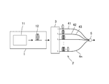
- FIG. 1 is a schematic view of a light source device for light measurement according to the first embodiment.
- the light source device for light measurement shown in FIG. 1 includes a pulse light source 1 and a pulse extension unit 2.
- the pulse extension unit 2 is a unit that pulse-extends the light from the pulse light source 1 so that the relationship between the elapsed time in one pulse and the wavelength is 1: 1.
- the pulse light source 1 is a light source that emits pulsed light having a continuous spectrum. In this embodiment, for example, it is a light source that emits light having a continuous spectrum over a wavelength width of at least 10 nm in the range of 900 nm to 1300 nm. "A spectrum continuous over a wavelength width of at least 10 nm in the range of 900 nm to 1300 nm" means any continuous wavelength width of 10 nm or more in the range of 900 nm to 1300 nm. For example, it may be continuous at 900 to 910 nm, or may be continuous at 990 to 1000 nm.
- the spectrum is continuous means that the spectrum is continuous in a certain wavelength width. This is not limited to the case where the pulsed light is continuous in the entire spectrum, and may be partially continuous.
- the point in the range of 900 nm to 1300 nm is that the light source device of the embodiment is used for light measurement in this wavelength range.
- Light having a continuous spectrum over a wavelength width of at least 10 nm is typically SC light. Therefore, in this embodiment, the pulse light source 1 is an SC light source.
- other broadband pulse light sources such as SLD (Superluminescent Diode) light sources may be used.
- the pulse light source 1 which is an SC light source includes an ultrashort pulse laser 11 and a non-linear element 12.
- the ultrashort pulse laser 11 a gain switch laser, a microchip laser, a fiber laser, or the like can be used.
- the nonlinear element 12 a fiber is often used.
- a photonic crystal fiber or other non-linear fiber can be used as the non-linear element 12.
- the fiber mode is often a single mode, but it can be used as the non-linear element 12 as long as it exhibits sufficient non-linearity even in the multi-mode.
- the pulse extension unit 2 is a major feature of the light source device of the embodiment.
- the light emitted from the pulse light source 1 has a wide wavelength band, but the pulse width remains as a short pulse on the order of femtoseconds to nanoseconds. Since it is difficult to use it for optical measurement as it is, the pulse extension unit 2 is used to extend the pulse. At this time, what is important is that a configuration is adopted in which the relationship between the elapsed time and the wavelength in one pulse is extended so as to be 1: 1. At this time, the light source device of the embodiment adopts a configuration in consideration of preventing an unintended nonlinear optical effect from occurring.
- FIG. 2 is a schematic view showing the principle of pulse elongation of wideband pulsed light.
- a configuration using a fiber having a specific group delay characteristic such as a dispersion compensation fiber (DCF) is preferably adopted.
- DCF dispersion compensation fiber
- the emitted SC light L2 becomes light whose pulse width is extended while the uniqueness of time vs. wavelength is ensured. That is, as shown on the lower side of FIG. 2, the times t 1 to t n are pulse-extended in a state of having a one-to-one correspondence with the wavelengths ⁇ 1 to ⁇ n .
- an anomalous dispersion fiber as the group delay fiber 9 for pulse extension.
- the light on the long wavelength side that existed at the beginning of the pulse is delayed, and the light on the short wavelength side that existed at a later time is dispersed in a state of advancing, so that the time within one pulse The target relationship is reversed, and the light on the short wavelength side exists at the beginning of one pulse, and the pulse is extended in a state where the light on the longer wavelength side exists with the passage of time.
- normal dispersion is preferable in this respect.
- the field of optical measurement it may be necessary to increase the intensity of the wideband pulsed light incident on the fiber in the pulse extension using such a group delay fiber.
- a group delay fiber For example, when measuring the absorption spectrum by irradiating an object with a large amount of light with light and dispersing the transmitted light, it is necessary to irradiate the object with strong light, and therefore the strong light is extended even in pulse elongation. It will be necessary to let it. Further, from the viewpoint of increasing the SN ratio of the measurement or performing the measurement at high speed, it may be necessary to irradiate the object with strong light.
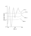
- FIG. 3 is a diagram showing the results of an experiment confirming this point.
- FIG. 3 is a diagram showing the results of an experiment confirming an unintended nonlinear optical effect when a high-intensity wideband pulsed light is pulse-stretched by a group delay fiber.
- the vertical axis is a logarithmic scale.
- a microchip laser beam having a center wavelength of 1064 nm and a pulse width of 2 nanoseconds was put into a photonic crystal fiber as a non-linear element to obtain SC light, and a single-mode fiber having a length of 5 km was used as a group delay fiber. Used as pulse stretched.
- Single-mode fiber is a fiber that is normally dispersed in the range of 1100 to 1200 nm. At this time, the energy of the incident SC light on the single mode fiber was changed to 0.009 ⁇ J, 0.038 ⁇ J, 0.19 ⁇ J, and 0.79 ⁇ J.
- the light source device for light measurement of the embodiment includes a pulse extension unit 2 that extends the pulse width of the wideband pulsed light from the pulse light source 1, and the pulse extension unit 2 is provided.
- the divider 3 and a plurality of fibers (hereinafter, referred to as extension fibers) 41 to 4n are included.
- the divider 3 is an element that spatially divides the pulsed light emitted from the pulsed light source 1 according to the wavelength.
- each extension fiber 41 to 4n is connected in parallel to the divider 3.
- the incident end of each extended fiber 4 is arranged at a position where light of each wavelength spatially divided by the divider 3 is incident. That is, when the divider 3 divides the broadband pulsed light into light having wavelengths ⁇ 1 to ⁇ n , the incident end of the extending fiber 41 is arranged at the emission position of the light having wavelength ⁇ 1 , and the incident end of the extending fiber 42 is arranged. Is arranged at the light emitting position of the wavelength ⁇ 2 , and ...
- the fiber 4n is arranged at the light emitting position of the wavelength ⁇ n .
- the lengths of the extended fibers 41 to 4n are different depending on the incident wavelength (connection position with respect to the divider 3).
- the length of each extended fiber 41 to 4n is determined so that the relationship between the elapsed time in one pulse and the wavelength is 1: 1 at the exit end of each extended fiber 41 to 4n.
- the light on the long wavelength side is present at the beginning of one pulse, and the pulse is extended while maintaining the relationship that the light on the short wavelength side gradually exists with the passage of time.
- the length of the stretched fiber that transmits light is longer. That is, if ⁇ 1 is the longest wavelength, ⁇ n is the shortest wavelength, and the lengths of the extended fibers 41, 42, ..., 4n are m 1 , m 2 , ...
- 20 single-mode fibers having different lengths from 1 to 20 m in 1 m increments can be used as extended fibers 41 to 4n.
- each extension fiber 41 to 4n does not necessarily have to be a specific group delay fiber. That is, it is not essential to adopt a fiber having an appropriate group delay characteristic according to the wavelength. If the same fiber (fiber of the same core / clad material) is used and the length is different depending on the wavelength, the time-wavelength uniqueness at each emission end is achieved. In this sense, each extension fiber 41 to 4n may be a multimode fiber. From the viewpoint of preventing unintended non-linear optical effects, multimode fiber may be preferable to single mode fiber.
- each extended fiber 41 to 4n since the difference in length of each extended fiber 41 to 4n is optimized, when the broadband pulsed light is divided into light of each wavelength and propagates through each extended fiber 41 to 4n, at each emission end. Time wavelength uniqueness is achieved. That is, the divided light is delayed according to the wavelength, the length of each extended fiber 41 to 4n, and the refractive index of the core. Therefore, if the length of each extended fiber 41 to 4n is appropriately selected according to the wavelength and the core refractive index, time wavelength uniqueness is achieved at each emission end.
- the difference in wavelength divided by the divider 3 is ⁇ and the difference in length of each extended fiber 41 to 4n is ⁇ m, even if ⁇ is constant (wavelength interval is constant), ⁇ m is It may not be constant.
- each of the extended fibers 41 to 4n has a wavelength dependence in the group delay even if it is not a group delay fiber, and thus the ⁇ m may be different in consideration of this.
- the same extension fibers 41 to 4n are used (those having the same characteristics), those having different characteristics may be used. When using different characteristics, select the difference in length according to the difference in the characteristics.
- the time ticks t 1 to t n may be discrete times. is there. That is, after the light of wavelength ⁇ 1 is observed at time t 1 , the light of wavelength ⁇ 2 is observed at time t 2 after a vacant time (there is a time zone in which no light exists). In some cases, Even in this state, since the wavelength is specified by specifying the time, it can be said that the uniqueness of the time wavelength is ensured. Of course, the wavelength may change continuously with a continuous change in time.
- a coupler 5 is provided at the exit end of each extension fiber 41 to 4n.
- the coupler 5 is an element that superimposes the beams emitted from the exit ends of the extended fibers 41 to 4n so that the same irradiation region is irradiated.
- an optical system such as a mechanism or a lens that holds the emission end of each extended fiber 41 to 4n so that the same irradiation region is irradiated may be adopted.
- a fan-in / fan-out device may also be used as the coupler 5.
- an optical coupler using a planar optical circuit or an arrayed waveguide diffraction grating can also be used.
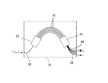
- FIG. 4 is a schematic plan view of the array waveguide diffraction grating adopted as the divider 3.
- the arrayed waveguide diffraction grating is configured by forming each functional waveguide 32 to 36 on the substrate 31.
- Each functional waveguide includes a large number of array waveguides 32 having slightly different optical path lengths, slab waveguides 33 and 34 connected to both ends (incident side and emission side) of the array waveguide 32, and incident side slab waveguides.
- the slab waveguides 33 and 34 are free spaces, and the light incident through the incident side waveguide 35 spreads in the incident side slab waveguide 33 and is incident on each array waveguide 32. Since the lengths of the array waveguides 32 are slightly different, the light reaching the end of each array waveguide 32 is out of phase (shifted) by this difference. Light is diffracted and emitted from each array waveguide 32, but the diffracted light passes through the exit side slab waveguide 34 while interfering with each other and reaches the incident end of the exit side waveguide 36. At this time, due to the phase shift, the interference light has the highest intensity at the position corresponding to the wavelength. That is, light having different wavelengths is sequentially incident on each emission end waveguide 36, and the light is spatially dispersed. Strictly speaking, each emitting side waveguide 36 is formed so that each incident end is located at such a spectroscopic position.
- An arrayed waveguide grating as shown in FIG. 4 was developed for wavelength division multiplexing (WDM) in the field of optical communication, but the inventor described it as an embodiment, although the application and wavelength range are significantly different. It has been found that the light source device can be used as a divider 3 for pulse extension.
- Such an array waveguide diffraction grating can be produced, for example, by surface-treating a substrate 31 made of silicon. Specifically, a clad layer (SiO 2 layer) is formed on the surface of a silicon substrate 31 by a flame deposition method, and a SiO 2- GeO 2 layer for a core is similarly formed by a flame deposition method, and then photolithography. It is produced by patterning two layers of SiO 2- GeO to form the waveguides 32 to 36.
- the line width of each array waveguide 32 may be, for example, about 5 to 6 ⁇ m.
- the number of light emitting side waveguides 36 is about 128, and the light is divided into different wavelengths of 3 to 50 nm and emitted. ..
- Extension fibers 41 to 4n are connected to each emission side waveguide 36 of the array waveguide diffraction grating. Therefore, light spatially divided according to the wavelength is incident on the extended fibers 41 to 4n as described above, and the light of each wavelength is transmitted by the separate extended fibers 41 to 4n and has different delay times. Is given.
- the coupler 5 is arranged at a predetermined position according to the purpose of optical measurement.
- the ultrashort pulsed light emitted from the ultrashort pulse laser 11 is widened by the nonlinear element 12 to become wideband pulsed light, and is incident on the divider 3.
- it is spatially divided by the divider 3 according to the wavelength, and light of each wavelength is incident on each of the extending fibers 41 to 4n.
- the light of each wavelength is delayed in each of the extended fibers 41 to 4n, and is emitted from each of the extended fibers 41 to 4n in a state where the time wavelength uniqueness is achieved.
- the emitted light is applied to the irradiation region directed by the coupler 5.
- the broadband pulsed light is divided into light of each wavelength by the divider 3, and the extended fibers 41 to 4n transmitting the light of each wavelength depend on the propagation distance. Since the pulse is stretched due to the delay, there is no problem that an unintended non-linear optical effect is generated and the time wavelength uniqueness is broken. That is, since the power of the wideband pulsed light is dispersed and propagated in each extended fiber 41 to 4n, even when the high power wideband pulsed light is emitted from the pulse light source 1, the light propagating in each extended fiber 41 to 4n. Power is kept low. Therefore, the uniqueness of the time wavelength is not broken.
- the object can be irradiated with the extended high-power wideband pulsed light. Therefore, even for an object having a large absorption, it is possible to perform optical measurement with a high SN ratio.
- the array waveguide diffraction grating used as the divider 3 has low loss, it is possible to irradiate light with even higher illuminance. Further, the arrayed waveguide diffraction grating has a high affinity with the fiber, and can be easily connected to each extended fiber. Therefore, there is an effect that it is easy to manufacture.
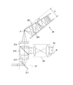
- FIG. 5 is a schematic view of the divider 3 of another example.
- the array waveguide diffraction grating is used as the divider 3, but the example of FIG. 5 is an example in which the diffraction grating 371 is used as the divider 3.
- the light is focused at different positions according to the wavelength.
- the splitter 3 includes an angular dispersion module 37 that makes the angle with respect to the optical axis different depending on the wavelength, and a non-parallel mirror pair 38 connected to the angular dispersion module 37.
- the beam splitter 372 that takes out the light of each wavelength folded by the non-parallel mirror pair 38, and the incident optical system 39 that causes the light of each wavelength taken out by the beam splitter 372 to enter into each of the extending fibers 41 to 4n. ..
- the angular dispersion module 37 has a diffraction grating 371 on which wideband pulsed light is incident, a collimator lens 373 that makes the light wavelength-dispersed by the diffraction grating 371 parallel light, and a collimator lens 373 that makes the light parallel. It includes a condenser lens 374 that connects the light to the incident point P of the non-parallel mirror pair 38.
- the beam splitter 372 for extraction is arranged between the collimator lens 373 and the condenser lens 374.
- the light of each wavelength dispersed by the diffraction grating 371 is condensed by the condensing lens 374 and connected to the incident point P of the non-parallel mirror pair 38.
- the angle at which the incident point P is reached is different depending on the wavelength, and is continuously different. Since the non-parallel mirror pair 38 is composed of a pair of flat plate mirrors 381 tilted by a slight angle ⁇ , as shown in FIG. 5, the incident light of each wavelength is alternately reflected by the flat plate mirrors 381. While coming back.
- the wideband pulsed light is spatially divided according to the wavelength and transmitted by each extended fiber 41 to 4n.
- the lengths of the extended fibers 41 to 4n are different depending on the wavelength of the incident light, and the time wavelength uniqueness is achieved at the emission end.
- the optical path length of the light having a wavelength that just returns to the position of the incident point P is slightly different depending on the wavelength, so that time dispersion occurs by this amount. Therefore, when selecting the length of the extended fiber 41 to 4n, it is desirable to take this amount of dispersion into consideration.
- FIG. 6 is a schematic view showing the divider 3 of yet another example.
- the divider 3 as shown in FIG. 6 (1), one using a pair of diffraction gratings 301 can be adopted.
- a configuration can be adopted in which light is wavelength-dispersed by a pair of diffraction gratings 301, and light of each wavelength is incident on each of the extending fibers 41 to 4n via a microlens array 302.
- the microlens array 302 is an element in which microlenses are arranged so as to collect light of each wavelength and incident it on the core of each extended fiber 41 to 4n.
- the divider 3 that employs a prism pair.
- the light is wavelength-dispersed by the pair of prisms 303, and similarly condensed by the microlens array 302 and incident on the cores of the extended fibers 41 to 4n.
- the high-intensity broadband pulsed light is pulsed. Even when emitted from the source 1, an unintended nonlinear optical effect is prevented and the time wavelength uniqueness is not disrupted.
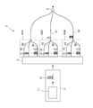
- FIG. 7 is a schematic view of the light source device for light measurement of the second embodiment.
- the configuration of the pulse extension unit 2 is different from that of the first embodiment.
- the pulse extension unit 2 includes a plurality of extension fibers. These extended fibers include fibers (hereinafter, referred to as element fibers) 41 to 4n constituting a plurality of fiber sets 4G1 to 4Gn.
- Each fiber set 4G1 to 4Gn is composed of a plurality of element fibers 41 to 4n having the same pattern but different lengths. This is intended to reduce costs by standardizing extended fibers. However, as it is, since there are extended fibers having the same length, different delays cannot be achieved in that portion. Therefore, multi-core fibers 61 to 6n are combined. In this configuration, the cores of one element fiber 41 to 4n and each core of the multi-core fibers 61 to 6n connected to the core form one transmission line, so that the number and length of the multi-core fibers 61 to 6n are determined. The transmission lines are selected so that they have different lengths.
- the fiber sets 4G1 to 4Gn of each set are 1 to 5 It shall consist of five element fibers 41 to 45 having different lengths in 1 meter increments up to meters. Prepare 4 sets of this set. Then, three multi-core fibers having five cores are prepared. The three multi-core fibers 61 to 63 have a length of 5 meters, 10 meters, and 15 meters. Then, the multi-core fiber is not connected to the first fiber group 4G1, and the 5-meter multi-core fiber 61 is connected to the next fiber group 4G2.
- each core of the 5-meter multi-core fiber 61 is connected to the core of each element fiber 41 to 45.
- a 10-meter multi-core fiber 62 is connected to the next fiber set 4G3.
- a 15-meter multi-core fiber 63 is connected to the final fiber set 4G4. In this way, 20 transmission lines having different lengths are formed in increments of 1 meter from 1 to 20 meters.
- the above is an example, and any combination may be used as long as the total lengths of the transmission lines are different from each other.
- the number of cores of the multi-core fiber 61 to 6n may be larger than the number of element fibers 41 to 4n of the fiber set 4G1 to 4Gn, but in that case, it may be free (not connected). When there are two fiber sets, one multi-core fiber is sufficient. It is also possible to use a bundle fiber instead of the multi-core fiber 61 to 6n. In the above example, a bundle fiber in which five fibers are bundled is prepared. Each bundle fiber has a length of 5 meters, 10 meters, and 15 meters, and is similarly connected to the fiber sets 4G2, 4G3, and 4G4, respectively.
- the pulse extension unit 2 includes a plurality of fiber sets 4G1 to 4Gn composed of a plurality of element fibers 41 to 4n having the same pattern but different from each other, the cost is low.
- each fiber set 4G1 to 4Gn is connected to the divider 3, and each multi-core fiber 61 to 6n is connected to the subsequent stage, but this relationship may be reversed. .. That is, each multi-core fiber 61 to 6n may be connected to the divider 3, and each fiber set 4G1 to 4Gn may be connected to the subsequent stage.
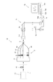
- FIG. 8 is a schematic view of the spectroscopic measuring device of the first embodiment.
- the spectroscopic measurement device shown in FIG. 8 is a light source device 10 for light measurement, an irradiation optical system 71 that irradiates an object S with light emitted from the light source device 10 for light measurement, and an object S irradiated with light. It includes a detector 72 arranged at a position where light is incident, and a calculation means 73 for calculating the spectral spectrum of the object S according to the output from the detector 72.
- the irradiation optical system 71 includes a beam expander 711 in this embodiment.
- the light from the light source device 10 is a time-extended wideband pulsed light, it is a light from an ultrashort pulse laser 11, considering that the beam diameter is small.
- a scanning mechanism such as a galvano mirror may be provided to cover a wide irradiation area by beam scanning.
- the detector 72 is provided at a position where the transmitted light from the object S is incident.
- a transparent receiving plate 74 on which the object S is arranged is provided.
- the irradiation optical system 71 is adapted to irradiate light from above, and the detector 72 is arranged below the receiving plate 74.
- the calculation means 73 a general-purpose personal computer is used in this embodiment.
- An AD converter 75 is provided between the detector 72 and the calculation means 73, and the output of the detector 72 is input to the calculation means 73 via the AD converter 75.
- the arithmetic means 73 includes a processor 731 and a storage unit (hard disk, memory, etc.) 732.
- a measurement program 733 that processes the output data from the detector 72 to calculate the absorption spectrum and other necessary programs are installed in the storage unit 732.
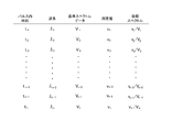
- FIG. 9 is a diagram schematically showing a main part of an example of the measurement program 733 included in the spectroscopic measuring device.
- the example of FIG. 9 is an example of a program in which the measurement program 733 measures the absorption spectrum (spectral absorption rate).
- Reference spectrum data is used in the calculation of the absorption spectrum.
- the reference spectrum data is a value for each wavelength that serves as a reference for calculating the absorption spectrum.
- the reference spectrum data is acquired by causing the light from the light source device 10 to enter the detector 72 without passing through the object S. That is, the light is directly incident on the detector 72 without passing through the object S, the output of the detector 72 is input to the calculation means 73 via the AD converter 75, and the value for each time resolution ⁇ t is acquired.
- Each value is stored as a reference intensity at each time (t 1 , t 2 , t 3 , %) For each ⁇ t (V 1 , V 2 , V 3 , ).
- the time resolution ⁇ t is an amount determined by the response speed (signal payout cycle) of the detector 72, and means a time interval for outputting a signal.
- the reference intensities V 1 , V 2 , V 3 , ... at each time t 1 , t 2 , t 3 , ... are the intensities of the corresponding wavelengths ⁇ 1 , ⁇ 2 , ⁇ 3 , ... (Spectrum).
- the relationship between the time t 1 , t 2 , t 3 , ... In one pulse and the wavelength has been investigated in advance, and the values V 1 , V 2 , V 3 , ... at each time are ⁇ 1 , respectively. It is treated as a value of ⁇ 2 , ⁇ 3 , ...
- the measurement program 733 is programmed to perform the above arithmetic processing.
- the operation of the spectroscopic measuring device will be described.
- the following description is also a description of embodiments of the spectroscopic measurement method.
- the light source device 10 is operated in a state where the object S is not arranged, the output data from the detector 72 is processed, and the reference spectrum data is acquired in advance. Then, the object S is arranged on the receiving plate 74, and the light source device 10 is operated again. Then, the output data from the detector 72 is input to the calculation means 73 via the AD converter 75, and the spectral spectrum is calculated by the measurement program 733.
- the absorption spectrum was measured using the transmitted light from the object S, but the reflected light from the object S is incident on the detector 72 to measure the reflection spectrum (spectral reflectance).
- the fluorescence spectrum may be measured by incidenting the fluorescence emitted by being excited by the light irradiated on the object S into the detector 72.
- the spectral characteristics of the scattering spectrum of the object S such as Rayleigh scattering and Raman scattering may be measured. Therefore, the light from the object S can be transmitted light, reflected light, fluorescence, scattered light, or the like from the object S irradiated with light.
- the light from the pulse light source 1 is time-divided and irradiated to the object S, so that a time-consuming operation such as sweeping the diffraction grating can be performed. It is unnecessary and can perform high-speed spectroscopic measurement.
- pulse extension that ensures uniqueness in time and wavelength
- a configuration is adopted in which transmission is performed for each wavelength with separate extended fibers 41 to 4n having different lengths, so that the object S is irradiated with light with high illuminance. Even when this is done, the uniqueness of the time wavelength is not lost.
- FIG. 10 is a schematic view of the spectroscopic measuring device of the second embodiment.
- a branching element 76 for branching the emitted light from the light source device 10 is provided in the spectroscopic measuring device of the second embodiment.
- the branching element 76 divides the optical path from the light source device 10 into a measurement optical path and a reference optical path.
- the receiving plate 74 is arranged in the optical path for measurement, and the measuring detector 72 is arranged at a position on the receiving plate 74 to receive the light transmitted through the object S.
- a reference detector 702 is arranged on the reference optical path.
- the light that is branched by the branching element 76 and travels in the reference optical path is incident on the reference detector 702 as it is.
- This light (reference light) is light for incident on the detector 702 without passing through the object S and obtaining reference spectrum data in real time.
- the measurement detector 72 and the reference detector 702 are connected to the calculation means 73 via AD converters 75 and 705, respectively.
- the measurement program 733 in the arithmetic means 73 is programmed to perform real-time reference intensity spectrum reference. That is, the measured values v 1 , v 2 , v 3 , ... At each time t 1 , t 2 , t 3 , ... Are input from the measuring detector 72, and the reference detector 72 inputs the measured values v 1 , v 2 , v 3 , ... , The reference intensities V 1 , V 2 , V 3 , ... (Reference spectrum data) at each time t 1 , t 2 , t 3 , ... At the same time are input.
- the measurement program 733 is v 1 / V according to the relationship between the time t 1 , t 2 , t 3 , ... Within one pulse and the wavelengths ⁇ 1 , ⁇ 2 , ⁇ 3 , ... 1 , v 2 / V 2 , v 3 / V 3 , ... Are calculated and used as an absorption spectrum.
- the reflection spectrum and the scattering spectrum can be measured in the same manner by using the reference spectrum data acquired in real time.
- the reference spectrum data is not acquired periodically. Except for this point, it is the same as that of the first embodiment.
- the spectroscopic measurement device and the spectroscopic measurement method of the second embodiment it is not necessary to separately acquire the reference spectrum data, so that the efficiency of the entire measurement work is high.
- the characteristics of the light source device 10 and the characteristics of the detector 72 are likely to change, it is necessary to frequently perform the calibration work, but it is not necessary in the second embodiment. Even if the characteristics of the light source device 10 and the characteristics of the detector 72 do not change, calibration work may be required when the measurement environment is different (for example, when the temperature conditions, background light conditions, etc. are different). In the second embodiment, the calibration work is not required even in such a case, so that the measurement efficiency is high.
- the first embodiment is more advantageous.
- the light source device for light measurement includes various types of light measurement in addition to the above-mentioned spectroscopic measurement.
- an application of irradiating an object with light for observation such as a microscope is also a kind of light measurement, and a case of irradiating light to measure a distance is also a kind of light measurement.
- the light source device for light measurement of the present invention can be used for such various types of light measurement.
- the continuous spectrum over a certain wavelength width included in the wavelength range of 900 to 1300 nm is significant to make it suitable for light measurement in the near infrared region, which is particularly effective for material analysis and the like.
- there are various spectroscopic measurements other than this wavelength range and the spectroscopic measuring device and the spectroscopic measuring method are not limited to this wavelength range.
- the wavelength width of the continuous spectrum is set to at least 10 nm, but this is also an example, and pulsed light having a wavelength width narrower than that may be used.
- pulsed light having a wavelength width narrower than that may be used.
- the object is a gas as in the analysis of atmospheric components and only a specific component (specific absorption spectrum) needs to be measured, or when pulsed light continuous with a narrow wavelength width is used. There is also.
- Pulse light source 10 Light source device 11
- Ultrashort pulse laser 12 Non-linear element 2
- Pulse extension unit 3 Splitter 41 to 4n Extension fiber 4G 1 to 4Gn Fiber assembly 5
- Multi-core fiber 71 Irradiation optical system 72
- Detector 73 Calculation means 75
Abstract
[Problem] To provide a light source device for optical measurement configured such that temporal wavelength uniqueness does not degrade even if output is high, and to make it possible to perform spectroscopic measurement at a high speed and accuracy. [Solution] Broadband pulsed light having a spectrum which continues across at least a wavelength width of 50 nm in a range of 900-1300 nm is emitted from a pulsed light source 1, is divided for each wavelength by a divider (3) such that the light of each wavelength is transmitted by elongated fibers 41-4n, and then the light is emitted from a coupler 5. The elongated fibers 41-4n have different lengths so that in a single pulse, the elapsed time and the wavelength correspond on a one-to-one basis at the emission end.
Description
この出願の発明は、広帯域のパルス光を出射する光測定用光源装置に関するものであり、また光源装置を使用した分光測定の技術に関するものである。
The invention of this application relates to a light source device for light measurement that emits a wide band pulsed light, and also relates to a technique of spectroscopic measurement using the light source device.
パルス光源の典型的なものは、パルス発振のレーザ(パルスレーザ)である。近年、パルスレーザの波長を広帯域化させる研究が盛んに行われており、その典型が、非線形光学効果を利用したスーパーコンティニウム光(以下、SC光という。)の生成である。SC光は、パルスレーザ源からの光をファイバのような非線形素子に通し、自己位相変調や誘導ラマン散乱のような非線形光学効果により波長を広帯域化させることで得られる光である。
A typical pulsed light source is a pulsed laser (pulse laser). In recent years, research on widening the wavelength of a pulsed laser has been actively conducted, and a typical example is the generation of supercontinuum light (hereinafter referred to as SC light) utilizing a nonlinear optical effect. SC light is light obtained by passing light from a pulsed laser source through a non-linear element such as a fiber and widening the wavelength by a non-linear optical effect such as self-phase modulation or induced Raman scattering.
上述した広帯域パルス光は、波長域としては伸長されているが、パルス幅(時間幅)としては狭いままである。しかし、ファイバのような伝送媒体における群遅延を利用するとパルス幅も伸長することができ、この際、適切な分散特性を持つ素子を選択すると、パルス内の経過時間(時刻)と波長とが1対1に対応した状態でパルス伸長することができる。このようにパルス内の経過時間と波長とが1対1に対応した状態のパルス光は、チャープパルス光又は線形チャープパルス光と呼ばれることもある。
The above-mentioned broadband pulsed light is extended as a wavelength range, but remains narrow as a pulse width (time width). However, the pulse width can also be extended by using the group delay in a transmission medium such as a fiber. At this time, if an element having appropriate dispersion characteristics is selected, the elapsed time (time) and wavelength in the pulse are 1. Pulse extension can be performed in a state corresponding to 1: 1. The pulsed light in such a state where the elapsed time in the pulse and the wavelength have a one-to-one correspondence is sometimes called a chirped pulse light or a linear chirped pulse light.
このようにパルス伸長させた広帯域パルス光(以下、広帯域伸長パルス光という。)における経過時間と波長との対応関係は、分光測定に効果的に利用することが可能である。つまり、広帯域伸長パルス光をある検出器で受光した場合、検出器が検出した光強度の時間的変化は、各波長の光強度即ちスペクトルに対応している。したがって、検出器の出力データの時間的変化をスペクトルに換算することができ、回折格子のような特別な分散素子を用いなくても分光測定が可能になる。つまり、広帯域伸長パルス光を試料に照射してその試料からの光を検出器で受光してその時間的変化を測定することで、その試料の分光特性(例えば分光透過率)を知ることができるようになる。
The correspondence between the elapsed time and the wavelength in the wideband pulsed light (hereinafter referred to as wideband stretched pulsed light) pulse-stretched in this way can be effectively used for spectroscopic measurement. That is, when a wideband extended pulsed light is received by a certain detector, the temporal change of the light intensity detected by the detector corresponds to the light intensity of each wavelength, that is, the spectrum. Therefore, the temporal change of the output data of the detector can be converted into a spectrum, and spectroscopic measurement can be performed without using a special dispersion element such as a diffraction grating. That is, the spectral characteristics (for example, spectral transmittance) of the sample can be known by irradiating the sample with broadband extended pulsed light, receiving the light from the sample with a detector, and measuring the temporal change thereof. Will be.
このように、広帯域伸長パルス光は分光測定等の分野で特に有益と考えられる。しかしながら、発明者の研究によると、より強い光を出力させるべくパルス光源の出力を高くした場合、意図しない非線形光学効果がパルス伸長素子において生じ、経過時間と波長との一意性(1対1の対応性)が崩れてしまうことが判明した。経過時間と波長との一意性が崩れると、特に分光測定に用いた場合、測定精度の著しい低下につながる。
この出願の発明は、この知見に基づくものであり、高出力とした場合にも経過時間と波長との一意性が崩れることのない光測定用光源装置を提供することを目的とし、そのような光源装置を使用することで精度の高い高速の分光測定が行えるようにすることを目的としている。 As described above, wideband extended pulsed light is considered to be particularly useful in fields such as spectroscopic measurement. However, according to the inventor's research, when the output of the pulsed light source is increased in order to output stronger light, an unintended nonlinear optical effect occurs in the pulse stretching element, and the elapsed time and wavelength are unique (1 to 1). Correspondence) was found to collapse. If the uniqueness between the elapsed time and the wavelength is broken, the measurement accuracy will be significantly reduced, especially when used for spectroscopic measurement.
The invention of this application is based on this finding, and an object of the present invention is to provide a light source device for light measurement in which the uniqueness of elapsed time and wavelength is not lost even when the output is high. The purpose is to enable highly accurate and high-speed spectroscopic measurement by using a light source device.
上記課題を解決するため、この出願の発明に係る光測定用光源装置は、スペクトルが連続しており1パルス内の経過時間と波長とが1対1で対応しているパルス光を出力する。この光源装置は、スペクトルが連続しているパルス光を出射するパルス光源と、パルス光源から出射されたパルス光を波長に応じて空間的に分割する分割器と、分割器が分割する波長の数に応じた数の複数のファイバとを備えている。各ファイバは、分割器が空間的に分割した各波長の光が入射する位置に各入射端が位置しているとともに、入射する光の波長に応じて長さが異なるものである。
また、上記課題を解決するため、この光測定用光源装置において、分割器は、アレイ導波路回折格子であり得る。
また、上記課題を解決するため、この光測定用光源装置は、分割器が、回折格子と、回折格子が分散させた光を波長に応じて異なる位置に集光する光学系とを備えており、各集光位置に前記各ファイバの入射端が配置されているという構成を持ち得る。
また、上記課題を解決するため、この光測定用光源装置は、複数のファイバが、複数のファイバ組を構成する要素ファイバと、マルチコアファイバであり、各ファイバ組は同じパターンで長さが異なる複数の要素ファイバで構成されており、各要素ファイバのコアとマルチコアファイバの各コアとが接続されており、マルチコアファイバの数及び長さは、各要素ファイバのコアとマルチコアファイバの各コアから成る各伝送路の全長が互いに異なる長さになるよう選定されているという構成を持ち得る。
また、上記課題を解決するため、この光測定用光源装置において、パルス光源は、スーパーコンティニウム光を出射する光源であり得る。
また、上記課題を解決するため、この出願の発明に係る分光測定装置は、スペクトルが連続しているパルス光を出射するパルス光源と、パルス光源から出射されたパルス光を波長に応じて空間的に分割する分割器と、分割器が分割する波長の数に応じた数の複数のファイバとを備えている。各ファイバは、分割器が空間的に分割した各波長の光が入射する位置に各入射端が位置しているとともに、1パルス内の経過時間と波長とが1対1で対応するよう入射光の波長に応じて長さが異なるものである。そして、この分光測定装置は、各ファイバから出射された光が照射された対象物からの光が入射する位置に配置された検出器と、検出器からの出力に従って対象物の分光特性を算出する演算手段とを備えている。
また、上記課題を解決するため、この分光測定装置において、分割器は、アレイ導波路回折格子であり得る。
また、上記課題を解決するため、この分光測定装置は、分割器が、回折格子と、回折格子が分散させた光を波長に応じて異なる位置に集光する光学系とを備えており、各集光位置に前記各ファイバの入射端が配置されているという構成を持ち得る。
また、上記課題を解決するため、この分光測定装置は、複数のファイバが、複数のファイバ組を構成する要素ファイバと、マルチコアファイバであり、各ファイバ組は同じパターンで長さが異なる複数の要素ファイバで構成されており、各要素ファイバのコアとマルチコアファイバの各コアとが接続されており、マルチコアファイバの数及び長さは、各要素ファイバのコアとマルチコアファイバの各コアから成る各伝送路の全長が互いに異なる長さになるよう選定されているという構成を持ち得る。
また、上記課題を解決するため、この分光測定装置において、パルス光源は、スーパーコンティニウム光を出射する光源であり得る。
また、上記課題を解決するため、この出願の発明に係る分光測定方法は、スペクトルが連続しているパルス光を波長に応じて空間的に分割器により分割する分割工程と、
分割工程において分割されたパルス光を、分割した波長の数に応じた数の複数のファイバにそれぞれ入射させて伝送させることで、1パルス内の経過時間と波長とが1対1で対応した状態とするパルス伸長工程と、
パルス伸長工程によりパルス幅が伸長されたパルス光を対象物に照射する照射工程と、
パルス伸長工程によりパルス幅が伸長されたパルス光が照射された対象物からの光を検出器で検出する検出工程と、
検出器からの出力に従って対象物の分光特性を算出する演算工程と
を備えている。
また、上記課題を解決するため、この分光測定方法において、分割器は、アレイ導波路回折格子であり得る。
また、上記課題を解決するため、この分光測定方法は、分割器が、回折格子と、回折格子が分散させた光を波長に応じて異なる位置に集光する光学系とを備えており、各集光位置に前記各ファイバの入射端が配置されているという構成を持ち得る。
また、上記課題を解決するため、この分光測定方法は、複数のファイバは、複数のファイバ組を構成する要素ファイバと、マルチコアファイバであり、各ファイバ組は同じパターンで長さが異なる複数の要素ファイバで構成されており、各要素ファイバのコアとマルチコアファイバの各コアとが接続されており、マルチコアファイバの数及び長さは、各要素ファイバのコアとマルチコアファイバの各コアから成る各伝送路の全長が互いに異なる長さになるよう選定されているという構成を持ち得る。
また、上記課題を解決するため、この分光測定方法において、パルス光は、スーパーコンティニウム光であり得る。 In order to solve the above problems, the light source device for light measurement according to the invention of the present application outputs pulsed light having a continuous spectrum and a one-to-one correspondence between the elapsed time in one pulse and the wavelength. This light source device includes a pulse light source that emits pulsed light having a continuous spectrum, a divider that spatially divides the pulsed light emitted from the pulsed light source according to the wavelength, and the number of wavelengths that the divider divides. It is provided with a plurality of fibers according to the number of fibers. Each fiber has an incident end located at a position where light of each wavelength that is spatially divided by the divider is incident, and has a different length depending on the wavelength of the incident light.
Further, in order to solve the above problems, in this light source device for light measurement, the divider may be an array waveguide diffraction grating.
Further, in order to solve the above problems, the light source device for light measurement includes a diffraction grating and an optical system that collects the light dispersed by the diffraction grating at different positions according to the wavelength. , The incident end of each fiber may be arranged at each light collecting position.
Further, in order to solve the above problems, in this light source device for optical measurement, a plurality of fibers are an element fiber constituting a plurality of fiber sets and a multi-core fiber, and each fiber set has the same pattern but different lengths. The core of each element fiber and each core of the multi-core fiber are connected, and the number and length of the multi-core fibers are each composed of the core of each element fiber and each core of the multi-core fiber. It may have a configuration in which the total lengths of the transmission lines are selected so as to be different from each other.
Further, in order to solve the above problems, in this light source device for light measurement, the pulse light source may be a light source that emits supercontinuum light.
Further, in order to solve the above problems, the spectroscopic measuring apparatus according to the invention of the present application spatially emits a pulse light source that emits pulsed light having a continuous spectrum and pulsed light emitted from the pulsed light source according to the wavelength. It is provided with a divider that divides into light sources and a plurality of fibers according to the number of wavelengths that the divider divides. In each fiber, each incident end is located at a position where the light of each wavelength spatially divided by the divider is incident, and the incident light has a one-to-one correspondence between the elapsed time in one pulse and the wavelength. The length varies depending on the wavelength of. Then, this spectroscopic measuring device calculates the spectral characteristics of the object according to the detector arranged at the position where the light from the object irradiated with the light emitted from each fiber is incident and the output from the detector. It is equipped with a calculation means.
Further, in order to solve the above problems, in this spectroscopic measuring device, the divider may be an array waveguide diffraction grating.
Further, in order to solve the above problems, the spectroscopic measuring apparatus includes a diffraction grating and an optical system that collects the light dispersed by the diffraction grating at different positions according to the wavelength. It may have a configuration in which the incident end of each fiber is arranged at the light collecting position.
Further, in order to solve the above problems, in this spectroscopic measurement device, a plurality of fibers are an element fiber constituting a plurality of fiber sets and a multi-core fiber, and each fiber set has a plurality of elements having the same pattern but different lengths. It is composed of fibers, and the core of each element fiber and each core of the multi-core fiber are connected, and the number and length of the multi-core fibers are the respective transmission lines consisting of the core of each element fiber and each core of the multi-core fiber. It is possible to have a configuration in which the total lengths of the are selected so as to be different from each other.
Further, in order to solve the above problems, in this spectroscopic measuring device, the pulse light source may be a light source that emits supercontinuum light.
Further, in order to solve the above problems, the spectroscopic measurement method according to the invention of the present application includes a division step of spatially dividing pulsed light having a continuous spectrum according to a wavelength by a divider.
A state in which the elapsed time in one pulse and the wavelength have a one-to-one correspondence by incidenting the pulsed light divided in the dividing step into a plurality of fibers corresponding to the number of divided wavelengths and transmitting the light. The pulse extension process and
An irradiation step of irradiating an object with pulsed light whose pulse width is extended by the pulse extension step,
A detection step in which a detector detects light from an object irradiated with pulsed light whose pulse width has been extended by a pulse extension step.
It is provided with a calculation process for calculating the spectral characteristics of the object according to the output from the detector.
Further, in order to solve the above problems, in this spectroscopic measurement method, the divider may be an array waveguide diffraction grating.
Further, in order to solve the above problems, in this spectroscopic measurement method, the divider is provided with a diffraction grating and an optical system that collects the light dispersed by the diffraction grating at different positions according to the wavelength. It may have a configuration in which the incident end of each fiber is arranged at the light collecting position.
Further, in order to solve the above problems, in this spectroscopic measurement method, the plurality of fibers are an element fiber constituting a plurality of fiber sets and a multi-core fiber, and each fiber set has a plurality of elements having the same pattern but different lengths. It is composed of fibers, and the core of each element fiber and each core of the multi-core fiber are connected, and the number and length of the multi-core fibers are the respective transmission lines consisting of the core of each element fiber and each core of the multi-core fiber. It is possible to have a configuration in which the total lengths of the are selected so as to be different from each other.
Further, in order to solve the above problems, the pulsed light may be supercontinuum light in this spectroscopic measurement method.
以下に説明する通り、この出願の発明に係る光測定用光源装置によれば、広帯域パルス光は分割器で各波長の光に分割され、各波長の光を伝送する各ファイバにおいて伝搬距離に応じた遅延によってパルス伸長がされるので、意図しない非線形光学効果が生じて時間波長一意性が崩れてしまう問題が生じない。このため、時間波長一意性が確保された広帯域パルス光を高い照度で対象物に照射して光測定を行うことができる。このため、高速且つ高品質の光測定が行える。
また、分割器がアレイ導波路回折格子である場合、低損失であるためさらに高照度の光照射が可能であり、また各ファイバとの接続が容易で製作し易いという効果が得られる。
また、複数のファイバが、同じパターンで長さが異なる複数のファイバ組を構成していると、コストダウンが図られる。
また、この出願の発明に係る分光測定装置や分光測定方法によれば、光源からの光が時間的に分割されて対象物に照射されるので、回折格子の掃引のような時間を要する動作は不要であり、高速の分光測定が行える。そして、時間波長一意性を確保したパルス伸長を行う際、長さの異なる別々のファイバで波長毎に伝送する構成を採用しているので、高い照度で対象物に光を照射する場合にも時間波長一意性が崩れることがない。このため、吸収の多い対象物についての分光測定のようにハイパワーの光を照射する必要のある分光測定を高精度に行うことができ、高速且つ高信頼性の装置及び方法となる。 As described below, according to the light source device for light measurement according to the invention of the present application, the broadband pulsed light is divided into light of each wavelength by a divider, and the light of each wavelength is divided according to the propagation distance in each fiber transmitting the light. Since the pulse is stretched due to the delay, there is no problem that an unintended non-linear optical effect is generated and the time wavelength uniqueness is broken. Therefore, it is possible to perform light measurement by irradiating an object with a wide band pulsed light having a unique time wavelength. Therefore, high-speed and high-quality optical measurement can be performed.
Further, when the divider is an arrayed waveguide diffraction grating, it is possible to irradiate light with higher illuminance because of low loss, and it is easy to connect to each fiber and to manufacture it.
Further, if a plurality of fibers form a plurality of fiber sets having the same pattern but different lengths, cost reduction can be achieved.
Further, according to the spectroscopic measurement device and the spectroscopic measurement method according to the invention of the present application, since the light from the light source is time-divided and irradiates the object, a time-consuming operation such as sweeping the diffraction grating is performed. It is unnecessary and can perform high-speed spectroscopic measurement. When performing pulse extension that ensures time-wavelength uniqueness, a configuration is adopted in which transmission is performed for each wavelength with separate fibers of different lengths, so even when irradiating an object with light with high illuminance, time is required. Wavelength uniqueness is not lost. Therefore, it is possible to perform spectroscopic measurement that requires irradiation with high-power light, such as spectroscopic measurement of an object having a large amount of absorption, with high accuracy, and it becomes a high-speed and highly reliable device and method.
次に、この出願の発明を実施するための形態(実施形態)について説明する。
まず、光測定用光源装置の発明の実施形態について説明する。図1は、第一の実施形態の光測定用光源装置の概略図である。図1に示す光測定用光源装置は、パルス光源1と、パルス伸長ユニット2とを備えている。パルス伸長ユニット2は、パルス光源1からの光を1パルス内の経過時間と波長との関係が1対1になるようパルス光源1からの光をパルス伸長させるユニットである。 Next, an embodiment (embodiment) for carrying out the invention of this application will be described.
First, an embodiment of the invention of the light source device for light measurement will be described. FIG. 1 is a schematic view of a light source device for light measurement according to the first embodiment. The light source device for light measurement shown in FIG. 1 includes a pulselight source 1 and a pulse extension unit 2. The pulse extension unit 2 is a unit that pulse-extends the light from the pulse light source 1 so that the relationship between the elapsed time in one pulse and the wavelength is 1: 1.
まず、光測定用光源装置の発明の実施形態について説明する。図1は、第一の実施形態の光測定用光源装置の概略図である。図1に示す光測定用光源装置は、パルス光源1と、パルス伸長ユニット2とを備えている。パルス伸長ユニット2は、パルス光源1からの光を1パルス内の経過時間と波長との関係が1対1になるようパルス光源1からの光をパルス伸長させるユニットである。 Next, an embodiment (embodiment) for carrying out the invention of this application will be described.
First, an embodiment of the invention of the light source device for light measurement will be described. FIG. 1 is a schematic view of a light source device for light measurement according to the first embodiment. The light source device for light measurement shown in FIG. 1 includes a pulse
パルス光源1は、連続したスペクトルのパルス光を出射する光源である。この実施形態では、例えば、900nmから1300nmの範囲において少なくとも10nmの波長幅に亘って連続したスペクトルの光を出射する光源となっている。「900nmから1300nmの範囲において少なくとも10nmの波長幅に亘って連続したスペクトル」とは、900~1300nmの範囲内の連続したいずれかの10nm以上の波長幅ということである。例えば、例えば900~910nmにおいて連続していても良いし、990~1000nmにおいて連続していても良い。尚、50nm以上の波長幅に亘って連続しているとさらに好適であるし、100nm以上の波長幅に亘って連続しているとさらに好適である。また、「スペクトルが連続している」とは、ある波長幅で連続したスペクトルを含んでいることを意味する。これは、パルス光の全スペクトルにおいて連続している場合には限られず、部分的に連続していても良い。
900nmから1300nmの範囲とする点は、実施形態の光源装置は、この波長域における光測定を用途としているためである。少なくとも10nmの波長幅に亘って連続したスペクトルの光とは、典型的にはSC光である。したがって、この実施形態では、パルス光源1は、SC光源となっている。但し、SLD(Superluminescent Diode)光源のような他の広帯域パルス光源が使用される場合もある。 Thepulse light source 1 is a light source that emits pulsed light having a continuous spectrum. In this embodiment, for example, it is a light source that emits light having a continuous spectrum over a wavelength width of at least 10 nm in the range of 900 nm to 1300 nm. "A spectrum continuous over a wavelength width of at least 10 nm in the range of 900 nm to 1300 nm" means any continuous wavelength width of 10 nm or more in the range of 900 nm to 1300 nm. For example, it may be continuous at 900 to 910 nm, or may be continuous at 990 to 1000 nm. It is more preferable that it is continuous over a wavelength width of 50 nm or more, and it is further preferable that it is continuous over a wavelength width of 100 nm or more. Further, "the spectrum is continuous" means that the spectrum is continuous in a certain wavelength width. This is not limited to the case where the pulsed light is continuous in the entire spectrum, and may be partially continuous.
The point in the range of 900 nm to 1300 nm is that the light source device of the embodiment is used for light measurement in this wavelength range. Light having a continuous spectrum over a wavelength width of at least 10 nm is typically SC light. Therefore, in this embodiment, thepulse light source 1 is an SC light source. However, other broadband pulse light sources such as SLD (Superluminescent Diode) light sources may be used.
900nmから1300nmの範囲とする点は、実施形態の光源装置は、この波長域における光測定を用途としているためである。少なくとも10nmの波長幅に亘って連続したスペクトルの光とは、典型的にはSC光である。したがって、この実施形態では、パルス光源1は、SC光源となっている。但し、SLD(Superluminescent Diode)光源のような他の広帯域パルス光源が使用される場合もある。 The
The point in the range of 900 nm to 1300 nm is that the light source device of the embodiment is used for light measurement in this wavelength range. Light having a continuous spectrum over a wavelength width of at least 10 nm is typically SC light. Therefore, in this embodiment, the
SC光源であるパルス光源1は、超短パルスレーザ11と、非線形素子12とを備えている。超短パルスレーザ11としては、ゲインスイッチレーザ、マイクロチップレーザ、ファイバレーザ等を用いることができる。また、非線形素子12としては、ファイバが使用される場合が多い。例えば、フォトニッククリスタルファイバやその他の非線形ファイバが非線形素子12として使用できる。ファイバのモードとしてはシングルモードの場合が多いが、マルチモードであっても十分な非線形性を示すものであれば、非線形素子12として使用できる。
The pulse light source 1 which is an SC light source includes an ultrashort pulse laser 11 and a non-linear element 12. As the ultrashort pulse laser 11, a gain switch laser, a microchip laser, a fiber laser, or the like can be used. Further, as the nonlinear element 12, a fiber is often used. For example, a photonic crystal fiber or other non-linear fiber can be used as the non-linear element 12. The fiber mode is often a single mode, but it can be used as the non-linear element 12 as long as it exhibits sufficient non-linearity even in the multi-mode.
パルス伸長ユニット2は、実施形態の光源装置の大きな特徴点を成している。パルス光源1から出射される光は、波長帯域としては広がっているが、パルス幅としてはフェムト秒からナノ秒オーダーの短パルスのままである。このままでは光測定用としては使用しづらいので、パルス伸長ユニット2によってパルス伸長させる。この際に重要なことは、1パルスにおける経過時間と波長との関係が1対1となるように伸長させる構成が採用されている点である。この際、実施形態の光源装置は、意図しない非線形光学効果が生じないように配慮した構成を採用している。
The pulse extension unit 2 is a major feature of the light source device of the embodiment. The light emitted from the pulse light source 1 has a wide wavelength band, but the pulse width remains as a short pulse on the order of femtoseconds to nanoseconds. Since it is difficult to use it for optical measurement as it is, the pulse extension unit 2 is used to extend the pulse. At this time, what is important is that a configuration is adopted in which the relationship between the elapsed time and the wavelength in one pulse is extended so as to be 1: 1. At this time, the light source device of the embodiment adopts a configuration in consideration of preventing an unintended nonlinear optical effect from occurring.
広帯域パルス光をパルス伸長させる際、意図しない非線形光学効果が生じて時間波長一意性が崩れる点は、発明者の研究の過程で確認された課題である。以下、この点について、図2を参照して説明する。図2は、広帯域パルス光のパルス伸長の原理について示した概略図である。
When the wideband pulsed light is pulse-extended, an unintended nonlinear optical effect occurs and the time wavelength uniqueness is lost, which is a problem confirmed in the process of the inventor's research. Hereinafter, this point will be described with reference to FIG. FIG. 2 is a schematic view showing the principle of pulse elongation of wideband pulsed light.
SC光のような広帯域パルス光のパルス幅を伸長させる手段としては、分散補償ファイバ(DCF)のような特定の群遅延特性を有するファイバを利用する構成が好適に採用される。例えば、ある波長範囲において連続スペクトルであるSC光L1を当該波長範囲で正の分散特性を有する群遅延ファイバ9に通すと、パルス幅が効果的に伸長される。即ち、図2に示すように、SC光L1においては、超短パルスではあるものの、1パルスの初期に最も長い波長λ1が存在し、時間が経過すると徐々に短い波長の光が存在し、パルスの終期には最も短い波長λnの光が存在する。この光を、正常分散の群遅延ファイバ9に通すと、正常分散の群遅延ファイバ9では、波長の短い光ほど遅れて伝搬するので、1パルス内の時間差が増長され、ファイバ9を出射する際には、短い波長の光は長い波長の光に比べてさらに遅れるようになる。この結果、出射するSC光L2は、時間対波長の一意性が確保された状態でパルス幅が伸長された光となる。即ち、図2の下側に示すように、時刻t1~tnは、波長λ1~λnに対してそれぞれ1対1で対応した状態でパルス伸長される。
As a means for extending the pulse width of wideband pulsed light such as SC light, a configuration using a fiber having a specific group delay characteristic such as a dispersion compensation fiber (DCF) is preferably adopted. For example, when SC light L1 having a continuous spectrum in a certain wavelength range is passed through a group delay fiber 9 having a positive dispersion characteristic in the wavelength range, the pulse width is effectively extended. That is, as shown in FIG. 2, in the SC light L1, although it is an ultrashort pulse, the longest wavelength λ 1 exists at the beginning of one pulse, and the light having a gradually shorter wavelength exists over time. At the end of the pulse there is light with the shortest wavelength λ n . When this light is passed through the normally dispersed group delay fiber 9, the light with a shorter wavelength propagates later in the normally dispersed group delay fiber 9, so that the time difference within one pulse is increased and the fiber 9 is emitted. The short wavelength light will be further delayed than the long wavelength light. As a result, the emitted SC light L2 becomes light whose pulse width is extended while the uniqueness of time vs. wavelength is ensured. That is, as shown on the lower side of FIG. 2, the times t 1 to t n are pulse-extended in a state of having a one-to-one correspondence with the wavelengths λ 1 to λ n .
尚、パルス伸長のための群遅延ファイバ9としては、異常分散ファイバを使用することも可能である。この場合は、SC光においてパルスの初期に存在していた長波長側の光が遅れ、後の時刻に存在していた短波長側の光が進む状態で分散するので、1パルス内での時間的関係が逆転し、1パルスの初期に短波長側の光が存在し、時間経過とともにより長波長側の光が存在する状態でパルス伸長されることになる。但し、正常分散の場合に比べると、パルス伸長のための伝搬距離をより長くすることが必要になる場合が多く、損失が大きくなり易い。したがって、この点で正常分散の方が好ましい。
It is also possible to use an anomalous dispersion fiber as the group delay fiber 9 for pulse extension. In this case, in the SC light, the light on the long wavelength side that existed at the beginning of the pulse is delayed, and the light on the short wavelength side that existed at a later time is dispersed in a state of advancing, so that the time within one pulse The target relationship is reversed, and the light on the short wavelength side exists at the beginning of one pulse, and the pulse is extended in a state where the light on the longer wavelength side exists with the passage of time. However, as compared with the case of normal dispersion, it is often necessary to lengthen the propagation distance for pulse extension, and the loss tends to be large. Therefore, normal dispersion is preferable in this respect.
このような群遅延ファイバを使用したパルス伸長において、光測定の分野では、ファイバに入射させる広帯域パルス光の強度を高くすることが必要になる場合がある。例えば、吸収の多い対象物に光を照射してその透過光を分光することで吸収スペクトルを測定する場合、対象物に強い光を照射する必要が生じ、そのためにパルス伸長においても強い光を伸長させる必要が生じる。また、測定のSN比を高くしたり測定を高速に行ったりする観点から、対象物に強い光を照射する必要が生じる場合がある。
In the field of optical measurement, it may be necessary to increase the intensity of the wideband pulsed light incident on the fiber in the pulse extension using such a group delay fiber. For example, when measuring the absorption spectrum by irradiating an object with a large amount of light with light and dispersing the transmitted light, it is necessary to irradiate the object with strong light, and therefore the strong light is extended even in pulse elongation. It will be necessary to let it. Further, from the viewpoint of increasing the SN ratio of the measurement or performing the measurement at high speed, it may be necessary to irradiate the object with strong light.
パルス伸長された光を高い照度で対象物に照射するには、群遅延ファイバに対して高い強度で広帯域パルス光を入射させ、高い強度を保ったままパルス伸長する必要がある。しかしながら、群遅延ファイバに高強度の広帯域パルス光を入射させると、意図しない非線形光学効果が生じ、時間波長一意性が崩れる場合がある。図3は、この点を確認した実験の結果を示す図である。
In order to irradiate an object with pulse-stretched light with high illuminance, it is necessary to inject broadband pulsed light with high intensity into the group delay fiber and pulse-stretch while maintaining high intensity. However, when high-intensity wideband pulsed light is incident on the group delay fiber, an unintended nonlinear optical effect may occur and the time wavelength uniqueness may be lost. FIG. 3 is a diagram showing the results of an experiment confirming this point.
図3は、高強度の広帯域パルス光を群遅延ファイバでパルス伸張させた場合の意図しない非線形光学効果について確認した実験の結果を示した図である。図3において縦軸は対数目盛である。
図3に結果を示す実験では、中心波長1064nm、パルス幅2ナノ秒のマイクロチップレーザ光を非線形素子としてのフォトニッククリスタルファイバに入れてSC光とし、長さ5kmのシングルモードファイバを群遅延ファイバとして使用してパルス伸張させた。シングルモードファイバは、1100~1200nmの範囲で正常分散のファイバである。この際、シングルモードファイバへの入射SC光のエネルギーを、0.009μJ、0.038μJ、0.19μJ、0.79μJと変化させた。 FIG. 3 is a diagram showing the results of an experiment confirming an unintended nonlinear optical effect when a high-intensity wideband pulsed light is pulse-stretched by a group delay fiber. In FIG. 3, the vertical axis is a logarithmic scale.
In the experiment showing the results in FIG. 3, a microchip laser beam having a center wavelength of 1064 nm and a pulse width of 2 nanoseconds was put into a photonic crystal fiber as a non-linear element to obtain SC light, and a single-mode fiber having a length of 5 km was used as a group delay fiber. Used as pulse stretched. Single-mode fiber is a fiber that is normally dispersed in the range of 1100 to 1200 nm. At this time, the energy of the incident SC light on the single mode fiber was changed to 0.009 μJ, 0.038 μJ, 0.19 μJ, and 0.79 μJ.
図3に示すように、SC光のエネルギーが0.19μJまでの場合には、1100~1200nmの波長範囲において出射光強度の大きなばらつきはないが、0.79μJの場合、出射光強度は波長に応じて激しく変動する。このような変動は、群遅延ファイバとしてのシングルモードファイバに入射して伝搬する過程でSC光に意図しないさらなる非線形光学効果が生じたことを示すものである。このような非線形光学効果が生じると、新たな波長が別の時刻に生成されるため、時間波長一意性が崩れてしまう。尚、図3に結果を示す実験では、入射するSC光のパルス幅は変わっていないので、ピーク値を変化させたということになる。
As shown in FIG. 3, when the energy of SC light is up to 0.19 μJ, there is no large variation in the emitted light intensity in the wavelength range of 1100 to 1200 nm, but when it is 0.79 μJ, the emitted light intensity is the wavelength. It fluctuates violently accordingly. Such fluctuations indicate that an unintended further nonlinear optical effect was generated in the SC light in the process of incident and propagating in the single-mode fiber as the group delay fiber. When such a nonlinear optical effect occurs, a new wavelength is generated at another time, so that the uniqueness of the time wavelength is broken. In the experiment showing the results in FIG. 3, since the pulse width of the incident SC light did not change, it means that the peak value was changed.
発明者は、このような知見に基づき、パルス伸長の構成を最適化させた。具体的には、実施形態の光測定用光源装置は、図1に示すように、パルス光源1からの広帯域パルス光のパルス幅を伸長させるパルス伸長ユニット2を備えており、パルス伸長ユニット2は、分割器3と、複数のファイバ(以下、伸長ファイバという。)41~4nとを含んでいる。
The inventor optimized the configuration of pulse extension based on such findings. Specifically, as shown in FIG. 1, the light source device for light measurement of the embodiment includes a pulse extension unit 2 that extends the pulse width of the wideband pulsed light from the pulse light source 1, and the pulse extension unit 2 is provided. , The divider 3 and a plurality of fibers (hereinafter, referred to as extension fibers) 41 to 4n are included.
分割器3は、パルス光源1から出射されたパルス光を波長に応じて空間的に分割する素子である。図1に示すように、各伸長ファイバ41~4nは、分割器3に対して並列に接続されている。各伸長ファイバ4の入射端は、分割器3が空間的に分割した各波長の光が入射する位置に配置されている。即ち、分割器3が、広帯域パルス光を波長λ1~λnまでの光に分割する場合、伸長ファイバ41の入射端は波長λ1の光の出射位置に配置され、伸長ファイバ42の入射端は波長λ2の光の出射位置に配置され、・・・ファイバ4nは波長λnの光の出射位置に配置される。
The divider 3 is an element that spatially divides the pulsed light emitted from the pulsed light source 1 according to the wavelength. As shown in FIG. 1, each extension fiber 41 to 4n is connected in parallel to the divider 3. The incident end of each extended fiber 4 is arranged at a position where light of each wavelength spatially divided by the divider 3 is incident. That is, when the divider 3 divides the broadband pulsed light into light having wavelengths λ 1 to λ n , the incident end of the extending fiber 41 is arranged at the emission position of the light having wavelength λ 1 , and the incident end of the extending fiber 42 is arranged. Is arranged at the light emitting position of the wavelength λ 2 , and ... The fiber 4n is arranged at the light emitting position of the wavelength λ n .
そして、各伸長ファイバ41~4nは、入射する波長(分割器3に対する接続位置)に応じて長さの異なるものとなっている。各伸長ファイバ41~4nの長さは、各伸長ファイバ41~4nの出射端において、1パルス内の経過時間と波長との関係が1対1になるように決められる。この実施形態では、上記と同様、1パルスの初期に長波長側の光が存在し、時間経過とともに徐々に短波長側の光が存在する関係を維持したままパルス伸長をするので、短波長の光を伝送する伸長ファイバほど長さが長くなっている。即ち、λ1を最も長い波長とし、λnを最も短い波長とし、各伸長ファイバ41,42,・・・,4nの長さをm1、m2、・・・mnとすると、m1<m2<・・・<mnとなっている。
より具体的な一例を示すと、1~20mまで1m刻みで長さが異なる20本のシングルモードファイバを伸長ファイバ41~4nとして使用することができる。 The lengths of theextended fibers 41 to 4n are different depending on the incident wavelength (connection position with respect to the divider 3). The length of each extended fiber 41 to 4n is determined so that the relationship between the elapsed time in one pulse and the wavelength is 1: 1 at the exit end of each extended fiber 41 to 4n. In this embodiment, as described above, the light on the long wavelength side is present at the beginning of one pulse, and the pulse is extended while maintaining the relationship that the light on the short wavelength side gradually exists with the passage of time. The length of the stretched fiber that transmits light is longer. That is, if λ 1 is the longest wavelength, λ n is the shortest wavelength, and the lengths of the extended fibers 41, 42, ..., 4n are m 1 , m 2 , ... mn , then m 1 < m 2 << ... < mn .
To show a more specific example, 20 single-mode fibers having different lengths from 1 to 20 m in 1 m increments can be used asextended fibers 41 to 4n.
より具体的な一例を示すと、1~20mまで1m刻みで長さが異なる20本のシングルモードファイバを伸長ファイバ41~4nとして使用することができる。 The lengths of the
To show a more specific example, 20 single-mode fibers having different lengths from 1 to 20 m in 1 m increments can be used as
このように長さの差異が最適化されるため、各伸長ファイバ41~4nは、必ずしも特定の群遅延ファイバでなくとも良い。即ち、波長に応じて適宜の群遅延特性を有するファイバを採用することは必須ではない。同一のファイバ(同一のコア/クラッド材料のファイバ)を使用し、波長に応じて長さに差異をつければ、各出射端における時間波長一意性は達成される。この意味で、各伸長ファイバ41~4nは、マルチモードファイバであっても良い。意図しない非線形光学効果を防止するという観点では、シングルモードファイバよりマルチモードファイバの方が好ましい場合もある。
Since the difference in length is optimized in this way, each extension fiber 41 to 4n does not necessarily have to be a specific group delay fiber. That is, it is not essential to adopt a fiber having an appropriate group delay characteristic according to the wavelength. If the same fiber (fiber of the same core / clad material) is used and the length is different depending on the wavelength, the time-wavelength uniqueness at each emission end is achieved. In this sense, each extension fiber 41 to 4n may be a multimode fiber. From the viewpoint of preventing unintended non-linear optical effects, multimode fiber may be preferable to single mode fiber.
いずれにしても、各伸長ファイバ41~4nの長さの差異が最適化されるため、広帯域パルス光が各波長の光に分割されて各伸長ファイバ41~4nを伝搬した際、各出射端において時間波長一意性が達成される。即ち、分割された光は、波長及び各伸長ファイバ41~4nの長さとコアの屈折率に応じて遅延する。このため、波長とコア屈折率に応じて各伸長ファイバ41~4nの長さを適宜選定すれば、各出射端において時間波長一意性が達成される。尚、分割器3が分割する波長の差異をΔλとし、各伸長ファイバ41~4nの長さの差異をΔmとした場合、Δλが一定(波長のインターバルが一定)であったとしても、Δmは一定でない場合もある。各伸長ファイバ41~4nは、群遅延ファイバでなくとも群遅延には波長依存性があるため、それを考慮してΔmに差をつける場合があるからである。
また、各伸長ファイバ41~4nは、同じもの(同じ特性のもの)が使用されているが、違う特性のものを使用しても良い。違う特性のものを使用する場合、その特性の差異に応じて長さの差異についても適宜選定する。 In any case, since the difference in length of eachextended fiber 41 to 4n is optimized, when the broadband pulsed light is divided into light of each wavelength and propagates through each extended fiber 41 to 4n, at each emission end. Time wavelength uniqueness is achieved. That is, the divided light is delayed according to the wavelength, the length of each extended fiber 41 to 4n, and the refractive index of the core. Therefore, if the length of each extended fiber 41 to 4n is appropriately selected according to the wavelength and the core refractive index, time wavelength uniqueness is achieved at each emission end. When the difference in wavelength divided by the divider 3 is Δλ and the difference in length of each extended fiber 41 to 4n is Δm, even if Δλ is constant (wavelength interval is constant), Δm is It may not be constant. This is because each of the extended fibers 41 to 4n has a wavelength dependence in the group delay even if it is not a group delay fiber, and thus the Δm may be different in consideration of this.
Further, although thesame extension fibers 41 to 4n are used (those having the same characteristics), those having different characteristics may be used. When using different characteristics, select the difference in length according to the difference in the characteristics.
また、各伸長ファイバ41~4nは、同じもの(同じ特性のもの)が使用されているが、違う特性のものを使用しても良い。違う特性のものを使用する場合、その特性の差異に応じて長さの差異についても適宜選定する。 In any case, since the difference in length of each
Further, although the
尚、パルス伸張後において、各時刻t1~tnと各波長λ1~λnとは1対1で対応してはいるものの、時刻刻t1~tnは飛び飛びの時刻である場合もある。即ち、時刻t1で波長λ1の光が観測されてから、時間が空いて(光が存在しない時間帯があって)時刻t2になって波長λ2の光が観測され、・・・という状態の場合もある。この状態でも、時間を特定すれば波長が特定されるので、時間波長一意性が確保されているといえる。勿論、時間の連続的な変化とともに波長が連続的に変化する場合もあり得る。
After pulse extension, although each time t 1 to t n and each wavelength λ 1 to λ n have a one-to-one correspondence, the time ticks t 1 to t n may be discrete times. is there. That is, after the light of wavelength λ 1 is observed at time t 1 , the light of wavelength λ 2 is observed at time t 2 after a vacant time (there is a time zone in which no light exists). In some cases, Even in this state, since the wavelength is specified by specifying the time, it can be said that the uniqueness of the time wavelength is ensured. Of course, the wavelength may change continuously with a continuous change in time.
また、図1に示すように、この実施形態では、各伸長ファイバ41~4nの出射端にはカプラ5が設けられている。カプラ5は、各伸長ファイバ41~4nの出射端から出射されるビームを重ね合わせ、同一の照射領域に照射されるようにする素子である。カプラ5としては、熔融型ファイバカプラの他、各伸長ファイバ41~4nの出射端を同一の照射領域が照射されるように保持する機構やレンズなどの光学系が採用されることもある。また、ファンイン/ファンアウトデバイスがカプラ5として使用される場合もあり得る。さらに、平面型光回路を用いた光カプラやアレイ導波路回折格子を用いることもできる。
Further, as shown in FIG. 1, in this embodiment, a coupler 5 is provided at the exit end of each extension fiber 41 to 4n. The coupler 5 is an element that superimposes the beams emitted from the exit ends of the extended fibers 41 to 4n so that the same irradiation region is irradiated. As the coupler 5, in addition to the fusion type fiber coupler, an optical system such as a mechanism or a lens that holds the emission end of each extended fiber 41 to 4n so that the same irradiation region is irradiated may be adopted. A fan-in / fan-out device may also be used as the coupler 5. Further, an optical coupler using a planar optical circuit or an arrayed waveguide diffraction grating can also be used.
次に、分割器3について、より具体的に説明する。分割器3としては、この実施形態では、アレイ導波路回折格子が採用されている。図4は、分割器3として採用されたアレイ導波路回折格子の平面概略図である。
図4に示すようにアレイ導波路回折格子は、基板31上に各機能導波路32~36を形成することで構成されている。各機能導波路は、光路長が僅かずつ異なる多数のアレイ導波路32と、アレイ導波路32の両端(入射側と出射側)に接続されたスラブ導波路33,34と、入射側スラブ導波路33に光を入射させる入射側導波路35と、出射側スラブ導波路34から各波長の光を取り出す各出射側導波路36となっている。 Next, thedivider 3 will be described more specifically. As the divider 3, an arrayed waveguide diffraction grating is adopted in this embodiment. FIG. 4 is a schematic plan view of the array waveguide diffraction grating adopted as the divider 3.
As shown in FIG. 4, the arrayed waveguide diffraction grating is configured by forming eachfunctional waveguide 32 to 36 on the substrate 31. Each functional waveguide includes a large number of array waveguides 32 having slightly different optical path lengths, slab waveguides 33 and 34 connected to both ends (incident side and emission side) of the array waveguide 32, and incident side slab waveguides. There are an incident side waveguide 35 that causes light to enter the 33, and each emitting side waveguide 36 that extracts light of each wavelength from the emitting side slab waveguide 34.
図4に示すようにアレイ導波路回折格子は、基板31上に各機能導波路32~36を形成することで構成されている。各機能導波路は、光路長が僅かずつ異なる多数のアレイ導波路32と、アレイ導波路32の両端(入射側と出射側)に接続されたスラブ導波路33,34と、入射側スラブ導波路33に光を入射させる入射側導波路35と、出射側スラブ導波路34から各波長の光を取り出す各出射側導波路36となっている。 Next, the
As shown in FIG. 4, the arrayed waveguide diffraction grating is configured by forming each
スラブ導波路33,34は自由空間であり、入射側導波路35を通って入射した光は、入射側スラブ導波路33において広がり、各アレイ導波路32に入射する。各アレイ導波路32は、僅かずつ長さが異なっているので、各アレイ導波路32の終端に達した光は、この差分だけ位相がそれぞれずれる(シフトする)。各アレイ導波路32からは光が回折して出射するが、回折光は互いに干渉しながら出射側スラブ導波路34を通り、出射側導波路36の入射端に達する。この際、位相シフトのため、干渉光は波長に応じた位置で最も強度が高くなる。つまり、各出射端導波路36には波長が順次異なる光が入射するようになり、光が空間的に分光される。厳密には、そのように分光される位置に各入射端が位置するよう各出射側導波路36が形成される。
The slab waveguides 33 and 34 are free spaces, and the light incident through the incident side waveguide 35 spreads in the incident side slab waveguide 33 and is incident on each array waveguide 32. Since the lengths of the array waveguides 32 are slightly different, the light reaching the end of each array waveguide 32 is out of phase (shifted) by this difference. Light is diffracted and emitted from each array waveguide 32, but the diffracted light passes through the exit side slab waveguide 34 while interfering with each other and reaches the incident end of the exit side waveguide 36. At this time, due to the phase shift, the interference light has the highest intensity at the position corresponding to the wavelength. That is, light having different wavelengths is sequentially incident on each emission end waveguide 36, and the light is spatially dispersed. Strictly speaking, each emitting side waveguide 36 is formed so that each incident end is located at such a spectroscopic position.
図4に示すようなアレイ導波路回折格子は、光通信の分野で波長分割多重通信 (WDM)用に開発されたものであるが、発明者は、用途及び波長域は大きく異なるものの、実施形態の光源装置においてパルス伸長のための分割器3として使用できることを見出したものである。
このようなアレイ導波路回折格子は、例えばシリコン製の基板31を表面処理することで作製することができる。具体的には、シリコン製の基板31の表面に火炎堆積法によりクラッド層(SiO2層)を形成し、コア用のSiO2-GeO2層を同様に火炎堆積法により形成した後、フォトリソグラフィによりSiO2-GeO2層をパターン化して各導波路32~36を形成することにより作製される。各アレイ導波路32の線幅は、例えば5~6μm程度で良い。 An arrayed waveguide grating as shown in FIG. 4 was developed for wavelength division multiplexing (WDM) in the field of optical communication, but the inventor described it as an embodiment, although the application and wavelength range are significantly different. It has been found that the light source device can be used as adivider 3 for pulse extension.
Such an array waveguide diffraction grating can be produced, for example, by surface-treating asubstrate 31 made of silicon. Specifically, a clad layer (SiO 2 layer) is formed on the surface of a silicon substrate 31 by a flame deposition method, and a SiO 2- GeO 2 layer for a core is similarly formed by a flame deposition method, and then photolithography. It is produced by patterning two layers of SiO 2- GeO to form the waveguides 32 to 36. The line width of each array waveguide 32 may be, for example, about 5 to 6 μm.
このようなアレイ導波路回折格子は、例えばシリコン製の基板31を表面処理することで作製することができる。具体的には、シリコン製の基板31の表面に火炎堆積法によりクラッド層(SiO2層)を形成し、コア用のSiO2-GeO2層を同様に火炎堆積法により形成した後、フォトリソグラフィによりSiO2-GeO2層をパターン化して各導波路32~36を形成することにより作製される。各アレイ導波路32の線幅は、例えば5~6μm程度で良い。 An arrayed waveguide grating as shown in FIG. 4 was developed for wavelength division multiplexing (WDM) in the field of optical communication, but the inventor described it as an embodiment, although the application and wavelength range are significantly different. It has been found that the light source device can be used as a
Such an array waveguide diffraction grating can be produced, for example, by surface-treating a
例えば 900~1300nm程度の波長幅に亘って連続スペクトルである光に使用する場合、出射側導波路36の数は128本程度であり、光は3~50nmずつ違う波長に分割されて出射される。
アレイ導波路回折格子の各出射側導波路36には、伸長ファイバ41~4nがそれぞれ接続されている。したがって、伸長ファイバ41~4nには、上記のように波長に応じて空間的に分割された光が入射し、各波長の光が別々の伸長ファイバ41~4nで伝送されてそれぞれ異なった遅延時間が与えられる。 For example, when used for light having a continuous spectrum over a wavelength width of about 900 to 1300 nm, the number of light emittingside waveguides 36 is about 128, and the light is divided into different wavelengths of 3 to 50 nm and emitted. ..
Extension fibers 41 to 4n are connected to each emission side waveguide 36 of the array waveguide diffraction grating. Therefore, light spatially divided according to the wavelength is incident on the extended fibers 41 to 4n as described above, and the light of each wavelength is transmitted by the separate extended fibers 41 to 4n and has different delay times. Is given.
アレイ導波路回折格子の各出射側導波路36には、伸長ファイバ41~4nがそれぞれ接続されている。したがって、伸長ファイバ41~4nには、上記のように波長に応じて空間的に分割された光が入射し、各波長の光が別々の伸長ファイバ41~4nで伝送されてそれぞれ異なった遅延時間が与えられる。 For example, when used for light having a continuous spectrum over a wavelength width of about 900 to 1300 nm, the number of light emitting
次に、このような実施形態の光測定用光源装置の全体の動作について説明する。
カプラ5は、光測定の目的に応じて所定の位置に配置される。超短パルスレーザ11から出射された超短パルス光は、非線形素子12で広帯域化されて広帯域パルス光となり、分割器3に入射する。そして、分割器3で波長に応じて空間的に分割され、各波長の光が各伸長ファイバ41~4nに入射される。各波長の光は、各伸長ファイバ41~4n中で遅延し、時間波長一意性が達成された状態で各伸長ファイバ41~4nから出射される。そして、出射された光は、カプラ5が指向する照射領域に照射される。 Next, the overall operation of the light source device for light measurement of such an embodiment will be described.
Thecoupler 5 is arranged at a predetermined position according to the purpose of optical measurement. The ultrashort pulsed light emitted from the ultrashort pulse laser 11 is widened by the nonlinear element 12 to become wideband pulsed light, and is incident on the divider 3. Then, it is spatially divided by the divider 3 according to the wavelength, and light of each wavelength is incident on each of the extending fibers 41 to 4n. The light of each wavelength is delayed in each of the extended fibers 41 to 4n, and is emitted from each of the extended fibers 41 to 4n in a state where the time wavelength uniqueness is achieved. Then, the emitted light is applied to the irradiation region directed by the coupler 5.
カプラ5は、光測定の目的に応じて所定の位置に配置される。超短パルスレーザ11から出射された超短パルス光は、非線形素子12で広帯域化されて広帯域パルス光となり、分割器3に入射する。そして、分割器3で波長に応じて空間的に分割され、各波長の光が各伸長ファイバ41~4nに入射される。各波長の光は、各伸長ファイバ41~4n中で遅延し、時間波長一意性が達成された状態で各伸長ファイバ41~4nから出射される。そして、出射された光は、カプラ5が指向する照射領域に照射される。 Next, the overall operation of the light source device for light measurement of such an embodiment will be described.
The
このような実施形態の光測定用光源装置によれば、広帯域パルス光は、分割器3で各波長の光に分割され、各波長の光を伝送する各伸長ファイバ41~4nにおいて伝搬距離に応じた遅延によってパルス伸長がされるので、意図しない非線形光学効果が生じて時間波長一意性が崩れてしまう問題が生じない。即ち、広帯域パルス光のパワーは、各伸長ファイバ41~4nに分散して伝搬するので、ハイパワーの広帯域パルス光をパルス光源1から出射させた場合でも、各伸長ファイバ41~4nを伝搬する光のパワーは低く抑えられる。このため、時間波長一意性が崩れてしまうことはない。そして、各伸長ファイバ41~4nからの光はカプラ5で重ね合わされるので、対象物には、伸長されたハイパワーの広帯域パルス光を照射することができる。このため、吸収の大きな対象物であってもSN比を高くした光測定が可能となる。
According to the light source device for light measurement of such an embodiment, the broadband pulsed light is divided into light of each wavelength by the divider 3, and the extended fibers 41 to 4n transmitting the light of each wavelength depend on the propagation distance. Since the pulse is stretched due to the delay, there is no problem that an unintended non-linear optical effect is generated and the time wavelength uniqueness is broken. That is, since the power of the wideband pulsed light is dispersed and propagated in each extended fiber 41 to 4n, even when the high power wideband pulsed light is emitted from the pulse light source 1, the light propagating in each extended fiber 41 to 4n. Power is kept low. Therefore, the uniqueness of the time wavelength is not broken. Then, since the light from each of the extended fibers 41 to 4n is superposed by the coupler 5, the object can be irradiated with the extended high-power wideband pulsed light. Therefore, even for an object having a large absorption, it is possible to perform optical measurement with a high SN ratio.
また、分割器3として使用されたアレイ導波路回折格子は低損失であるので、さらに高照度の光照射を可能にしている。また、アレイ導波路回折格子は、ファイバとの親和性が高く、各伸長ファイバとの接続が容易である。このため、製作し易いという効果がある。
Moreover, since the array waveguide diffraction grating used as the divider 3 has low loss, it is possible to irradiate light with even higher illuminance. Further, the arrayed waveguide diffraction grating has a high affinity with the fiber, and can be easily connected to each extended fiber. Therefore, there is an effect that it is easy to manufacture.
次に、分割器3の他の例について説明する。図5は、他の例の分割器3の概略図である。上記実施形態では、分割器3としてはアレイ導波路回折格子を使用したが、図5の例は、分割器3として、回折格子371を使用した例となっている。この例では、回折格子371と非平行ミラー対38とを組み合わせることで、光を波長に応じて異なる位置に集光させる構成となっている。
Next, another example of the divider 3 will be described. FIG. 5 is a schematic view of the divider 3 of another example. In the above embodiment, the array waveguide diffraction grating is used as the divider 3, but the example of FIG. 5 is an example in which the diffraction grating 371 is used as the divider 3. In this example, by combining the diffraction grating 371 and the non-parallel mirror pair 38, the light is focused at different positions according to the wavelength.
具体的に説明すると、分割器3は、光軸に対する角度が波長に応じて異なる角度になるようにする角分散モジュール37と、角分散モジュール37に対して接続された非平行ミラー対38と、非平行ミラー対38で折り返された各波長の光を取り出すビームスプリッタ372と、ビームスプリッタ372で取り出された各波長の光を各伸長ファイバ41~4nに入射させる入射光学系39とを備えている。
Specifically, the splitter 3 includes an angular dispersion module 37 that makes the angle with respect to the optical axis different depending on the wavelength, and a non-parallel mirror pair 38 connected to the angular dispersion module 37. The beam splitter 372 that takes out the light of each wavelength folded by the non-parallel mirror pair 38, and the incident optical system 39 that causes the light of each wavelength taken out by the beam splitter 372 to enter into each of the extending fibers 41 to 4n. ..
図5に示すように、角分散モジュール37は、広帯域パルス光が入射する回折格子371と、回折格子371で波長分散させた光を平行光にするコリメータレンズ373と、コリメータレンズ373で平行光にされた光を非平行ミラー対38の入射点Pに結ばせる集光レンズ374とを含んでいる。取り出し用のビームスプリッタ372は、コリメータレンズ373と集光レンズ374の間に配置されている。
As shown in FIG. 5, the angular dispersion module 37 has a diffraction grating 371 on which wideband pulsed light is incident, a collimator lens 373 that makes the light wavelength-dispersed by the diffraction grating 371 parallel light, and a collimator lens 373 that makes the light parallel. It includes a condenser lens 374 that connects the light to the incident point P of the non-parallel mirror pair 38. The beam splitter 372 for extraction is arranged between the collimator lens 373 and the condenser lens 374.
回折格子371で分散した各波長の光は、集光レンズ374で集光されて非平行ミラー対38の入射点Pに結ぶ。入射点Pに達する際の角度は、波長に応じて異なる角度であり、連続的に異なる角度である。非平行ミラー対38は、僅かな角度αだけ傾けられた一対の平板ミラー381で構成されているため、図5に示すように、入射した各波長の光は、平板ミラー381に交互に反射しながら戻ってくる。この際、入射点Pに集光する際の集光角θ、傾き角α、入射点Pで見た非平行ミラー対38の離間距離Dにより、飛び飛びではあるものの波長λ1~λnの光は入射点Pの位置にちょうど戻ってくる。したがって、これらの光は、入射点Pで反射してビームスプリッタ372に達し、ビームスプリッタ372で一部が反射して取り出される。取り出された光は、入射光学系39により各伸長ファイバ41~4nに入射する。
The light of each wavelength dispersed by the diffraction grating 371 is condensed by the condensing lens 374 and connected to the incident point P of the non-parallel mirror pair 38. The angle at which the incident point P is reached is different depending on the wavelength, and is continuously different. Since the non-parallel mirror pair 38 is composed of a pair of flat plate mirrors 381 tilted by a slight angle α, as shown in FIG. 5, the incident light of each wavelength is alternately reflected by the flat plate mirrors 381. While coming back. At this time, light having wavelengths λ1 to λn is incident, although it is scattered, due to the focusing angle θ, the inclination angle α, and the separation distance D of the non-parallel mirror pair 38 seen at the incident point P when focusing on the incident point P. It just returns to the position of point P. Therefore, these lights are reflected at the incident point P to reach the beam splitter 372, and a part of the light is reflected and taken out by the beam splitter 372. The extracted light is incident on each of the extending fibers 41 to 4n by the incident optical system 39.
このようにして、広帯域パルス光は、波長に応じて空間的に分割され、各伸長ファイバ41~4nで伝送される。そして、この実施形態においても、各伸長ファイバ41~4nの長さは、入射する光の波長に応じて異なる長さとされており、出射端において時間波長一意性が達成される。尚、図5から解るように、入射点Pの位置にちょうど戻ってくる波長の光は、波長に応じて光路長が少し異なるので、この分で時間分散が生じている。したがって、伸長ファイバ41~4nの長さを選定する際には、この分の分散も考慮に入れることが望ましい。
In this way, the wideband pulsed light is spatially divided according to the wavelength and transmitted by each extended fiber 41 to 4n. Also in this embodiment, the lengths of the extended fibers 41 to 4n are different depending on the wavelength of the incident light, and the time wavelength uniqueness is achieved at the emission end. As can be seen from FIG. 5, the optical path length of the light having a wavelength that just returns to the position of the incident point P is slightly different depending on the wavelength, so that time dispersion occurs by this amount. Therefore, when selecting the length of the extended fiber 41 to 4n, it is desirable to take this amount of dispersion into consideration.
上記の他、分割器3としては、上記以外にも種々のものを採用し得る。これらの例が図6に示されている。図6は、さらに他の例の分割器3を示した概略図である。
分割器3としては、図6(1)に示すように、一対の回折格子301を用いたものを採用し得る。一対の回折格子301で光を波長分散させ、マイクロレンズアレイ302を介して各伸長ファイバ41~4nに各波長の光を入射させる構成が採用できる。マイクロレンズアレイ302は、各波長の光を集光して各伸長ファイバ41~4nのコアに入射させるマイクロレンズを配列した素子である。 In addition to the above, as thedivider 3, various devices other than the above can be adopted. Examples of these are shown in FIG. FIG. 6 is a schematic view showing the divider 3 of yet another example.
As thedivider 3, as shown in FIG. 6 (1), one using a pair of diffraction gratings 301 can be adopted. A configuration can be adopted in which light is wavelength-dispersed by a pair of diffraction gratings 301, and light of each wavelength is incident on each of the extending fibers 41 to 4n via a microlens array 302. The microlens array 302 is an element in which microlenses are arranged so as to collect light of each wavelength and incident it on the core of each extended fiber 41 to 4n.
分割器3としては、図6(1)に示すように、一対の回折格子301を用いたものを採用し得る。一対の回折格子301で光を波長分散させ、マイクロレンズアレイ302を介して各伸長ファイバ41~4nに各波長の光を入射させる構成が採用できる。マイクロレンズアレイ302は、各波長の光を集光して各伸長ファイバ41~4nのコアに入射させるマイクロレンズを配列した素子である。 In addition to the above, as the
As the
また、図6(2)に示すように、プリズムペアを採用した分割器3を使用することも可能である。この例では、一対のプリズム303により光を波長分散させ、同様にマイクロレンズアレイ302で集光して各伸長ファイバ41~4nのコアに入射させる。
いずれにしても、光を波長毎に分割器3で分け、波長毎に各伸長ファイバ41~4nで伝送してファイバ長の調整により時間波長一意性を達成すると、高強度の広帯域パルス光がパルス源1から出射される際にも、意図しない非線形光学効果が防止され、時間波長一意性が崩れてしまうことはない。 Further, as shown in FIG. 6 (2), it is also possible to use thedivider 3 that employs a prism pair. In this example, the light is wavelength-dispersed by the pair of prisms 303, and similarly condensed by the microlens array 302 and incident on the cores of the extended fibers 41 to 4n.
In any case, when the light is divided by thedivider 3 for each wavelength and transmitted by each extended fiber 41 to 4n for each wavelength to achieve the time wavelength uniqueness by adjusting the fiber length, the high-intensity broadband pulsed light is pulsed. Even when emitted from the source 1, an unintended nonlinear optical effect is prevented and the time wavelength uniqueness is not disrupted.
いずれにしても、光を波長毎に分割器3で分け、波長毎に各伸長ファイバ41~4nで伝送してファイバ長の調整により時間波長一意性を達成すると、高強度の広帯域パルス光がパルス源1から出射される際にも、意図しない非線形光学効果が防止され、時間波長一意性が崩れてしまうことはない。 Further, as shown in FIG. 6 (2), it is also possible to use the
In any case, when the light is divided by the
次に、第二の実施形態の光測定用光源装置について説明する。図7は、第二の実施形態の光測定用光源装置の概略図である。
第二の実施形態の光測定用光源装置は、パルス伸長ユニット2の構成が第一の実施形態と異なっている。図7に示すように、第二の実施形態でも、パルス伸長ユニット2は、複数の伸長ファイバを備えている。これら伸長ファイバは、複数のファイバ組4G1~4Gnを構成するファイバ(以下、要素ファイバという。)41~4nを含んでいる。 Next, the light source device for light measurement of the second embodiment will be described. FIG. 7 is a schematic view of the light source device for light measurement of the second embodiment.
In the light source device for light measurement of the second embodiment, the configuration of thepulse extension unit 2 is different from that of the first embodiment. As shown in FIG. 7, also in the second embodiment, the pulse extension unit 2 includes a plurality of extension fibers. These extended fibers include fibers (hereinafter, referred to as element fibers) 41 to 4n constituting a plurality of fiber sets 4G1 to 4Gn.
第二の実施形態の光測定用光源装置は、パルス伸長ユニット2の構成が第一の実施形態と異なっている。図7に示すように、第二の実施形態でも、パルス伸長ユニット2は、複数の伸長ファイバを備えている。これら伸長ファイバは、複数のファイバ組4G1~4Gnを構成するファイバ(以下、要素ファイバという。)41~4nを含んでいる。 Next, the light source device for light measurement of the second embodiment will be described. FIG. 7 is a schematic view of the light source device for light measurement of the second embodiment.
In the light source device for light measurement of the second embodiment, the configuration of the
各ファイバ組4G1~4Gnは、同じパターンで長さが異なる複数の要素ファイバ41~4nで構成されている。これは、伸長ファイバを共通化してコストダウンを図る趣旨である。但し、このままでは、同じ長さの伸長ファイバがあることになるので、その部分では異なる遅延を達成することができない。このため、マルチコアファイバ61~6nを組み合わせている。この構成では、一つの要素ファイバ41~4nのコアと、それに接続されたマルチコアファイバ61~6nの各コアとが一つの伝送路を形成するので、マルチコアファイバ61~6nの数及び長さは、各伝送路が互いに異なる長さとなるよう選定される。
Each fiber set 4G1 to 4Gn is composed of a plurality of element fibers 41 to 4n having the same pattern but different lengths. This is intended to reduce costs by standardizing extended fibers. However, as it is, since there are extended fibers having the same length, different delays cannot be achieved in that portion. Therefore, multi-core fibers 61 to 6n are combined. In this configuration, the cores of one element fiber 41 to 4n and each core of the multi-core fibers 61 to 6n connected to the core form one transmission line, so that the number and length of the multi-core fibers 61 to 6n are determined. The transmission lines are selected so that they have different lengths.
一例を示すと、第一の実施形態において例示した20本の伸長ファイバ41~4n(20本の異なる伝送路)と等価なものを達成する場合、各組のファイバ組4G1~4Gnを1~5メートルまで1メートル刻みで長さが異なる5本の要素ファイバ41~45から成るものとする。この組を4組用意する。そして、コア数が5のマルチコアファイバを3本用意する。3本のマルチコアファイバ61~63は、5メートル、10メートル、15メートルの長さとする。その上で、最初のファイバ組4G1にはマルチコアファイバは接続せず、次のファイバ組4G2には5メートルのマルチコアファイバ61を接続する。即ち、各要素ファイバ41~45のコアに5メートルのマルチコアファイバ61の各コアを接続する。次のファイバ組4G3には、10メートルのマルチコアファイバ62を接続する。最後のファイバ組4G4には15メートルのマルチコアファイバ63を接続する。このようにすると、1~20メートルの1メートル刻みで長さが異なる20本の伝送路が形成されたことになる。
As an example, in the case of achieving the equivalent of the 20 extended fibers 41 to 4n (20 different transmission lines) exemplified in the first embodiment, the fiber sets 4G1 to 4Gn of each set are 1 to 5 It shall consist of five element fibers 41 to 45 having different lengths in 1 meter increments up to meters. Prepare 4 sets of this set. Then, three multi-core fibers having five cores are prepared. The three multi-core fibers 61 to 63 have a length of 5 meters, 10 meters, and 15 meters. Then, the multi-core fiber is not connected to the first fiber group 4G1, and the 5-meter multi-core fiber 61 is connected to the next fiber group 4G2. That is, each core of the 5-meter multi-core fiber 61 is connected to the core of each element fiber 41 to 45. A 10-meter multi-core fiber 62 is connected to the next fiber set 4G3. A 15-meter multi-core fiber 63 is connected to the final fiber set 4G4. In this way, 20 transmission lines having different lengths are formed in increments of 1 meter from 1 to 20 meters.
以上は一例であり、各伝送路の全長が互いに異なるものであれば、どのような組合せでも良い。マルチコアファイバ61~6nのコアの数がファイバ組4G1~4Gnの要素ファイバ41~4nの数より多い場合もあるが、その場合には空き(未接続)とすれば良い。尚、ファイバ組が2組の場合には、マルチコアファイバは1本で足りることになる。
また、マルチコアファイバ61~6nの代わりにバンドルファイバを使用することも可能である。上記の例では、5本のファイバを束ねたバンドルファイバを用意する。各バンドルファイバは、5メートル、10メートル、15メートルの長さとされ、同様にファイバ組4G2,4G3,4G4に対してそれぞれ接続される。 The above is an example, and any combination may be used as long as the total lengths of the transmission lines are different from each other. The number of cores of themulti-core fiber 61 to 6n may be larger than the number of element fibers 41 to 4n of the fiber set 4G1 to 4Gn, but in that case, it may be free (not connected). When there are two fiber sets, one multi-core fiber is sufficient.
It is also possible to use a bundle fiber instead of themulti-core fiber 61 to 6n. In the above example, a bundle fiber in which five fibers are bundled is prepared. Each bundle fiber has a length of 5 meters, 10 meters, and 15 meters, and is similarly connected to the fiber sets 4G2, 4G3, and 4G4, respectively.
また、マルチコアファイバ61~6nの代わりにバンドルファイバを使用することも可能である。上記の例では、5本のファイバを束ねたバンドルファイバを用意する。各バンドルファイバは、5メートル、10メートル、15メートルの長さとされ、同様にファイバ組4G2,4G3,4G4に対してそれぞれ接続される。 The above is an example, and any combination may be used as long as the total lengths of the transmission lines are different from each other. The number of cores of the
It is also possible to use a bundle fiber instead of the
また、第一の実施形態においても同様であるが、分割器3が分割する波長の数と、複数の伸長ファイバで形成される伝送路の数は一致するのが理想的であるが、一致しなくても良い。伝送路の数の方が多い場合にはその分は空きとなる。また、光測定の目的によっては測定に使用しない波長もあるから、その分の波長については分割器3に対して伸長ファイバが接続されない(伸長ファイバの数の方が少ない)場合もある。
Further, the same applies to the first embodiment, but ideally, the number of wavelengths divided by the divider 3 and the number of transmission lines formed by the plurality of extended fibers are the same, but they are the same. It does not have to be. If the number of transmission lines is larger, that amount will be vacant. Further, depending on the purpose of optical measurement, some wavelengths are not used for measurement, and therefore, the extension fibers may not be connected to the divider 3 (the number of extension fibers is smaller) for the wavelengths corresponding to the wavelengths.
第二の実施形態においても、光を波長毎に分割器3で分け、波長毎に各伸長ファイバ41~4n,61~6nで伝送するので、高強度の広帯域パルス光がパルス源1から出射される際にも、意図しない非線形光学効果が防止され、時間波長一意性が崩れてしまうことはない。
そして、パルス伸長ユニット2が、同一のパターンで異なる複数の要素ファイバ41~4nで構成された複数のファイバ組4G1~4Gnを含んでいるので、低コストとなる。
尚、図7に示す例では、分割器3に対して各ファイバ組4G1~4Gnが接続され、その後段に各マルチコアファイバ61~6nが接続されているが、この関係は逆であっても良い。即ち、分割器3に対して各マルチコアファイバ61~6nが接続され、その後段に各ファイバ組4G1~4Gnが接続されても良い。 Also in the second embodiment, since the light is divided by thedivider 3 for each wavelength and transmitted by each extended fiber 41 to 4n and 61 to 6n for each wavelength, high-intensity broadband pulsed light is emitted from the pulse source 1. In this case, the unintended nonlinear optical effect is prevented and the time wavelength uniqueness is not broken.
Further, since thepulse extension unit 2 includes a plurality of fiber sets 4G1 to 4Gn composed of a plurality of element fibers 41 to 4n having the same pattern but different from each other, the cost is low.
In the example shown in FIG. 7, each fiber set 4G1 to 4Gn is connected to thedivider 3, and each multi-core fiber 61 to 6n is connected to the subsequent stage, but this relationship may be reversed. .. That is, each multi-core fiber 61 to 6n may be connected to the divider 3, and each fiber set 4G1 to 4Gn may be connected to the subsequent stage.
そして、パルス伸長ユニット2が、同一のパターンで異なる複数の要素ファイバ41~4nで構成された複数のファイバ組4G1~4Gnを含んでいるので、低コストとなる。
尚、図7に示す例では、分割器3に対して各ファイバ組4G1~4Gnが接続され、その後段に各マルチコアファイバ61~6nが接続されているが、この関係は逆であっても良い。即ち、分割器3に対して各マルチコアファイバ61~6nが接続され、その後段に各ファイバ組4G1~4Gnが接続されても良い。 Also in the second embodiment, since the light is divided by the
Further, since the
In the example shown in FIG. 7, each fiber set 4G1 to 4Gn is connected to the
次に、分光測定装置及び分光測定方法の発明について説明する。
図8は、第一の実施形態の分光測定装置の概略図である。図8に示す分光測定装置は、光測定用光源装置10と、光測定用光源装置10から出射された光を対象物Sに照射する照射光学系71と、光照射された対象物Sからの光が入射する位置に配置された検出器72と、検出器72からの出力に従って対象物Sの分光スペクトルを算出する演算手段73とを備えている。 Next, the invention of the spectroscopic measuring device and the spectroscopic measuring method will be described.
FIG. 8 is a schematic view of the spectroscopic measuring device of the first embodiment. The spectroscopic measurement device shown in FIG. 8 is alight source device 10 for light measurement, an irradiation optical system 71 that irradiates an object S with light emitted from the light source device 10 for light measurement, and an object S irradiated with light. It includes a detector 72 arranged at a position where light is incident, and a calculation means 73 for calculating the spectral spectrum of the object S according to the output from the detector 72.
図8は、第一の実施形態の分光測定装置の概略図である。図8に示す分光測定装置は、光測定用光源装置10と、光測定用光源装置10から出射された光を対象物Sに照射する照射光学系71と、光照射された対象物Sからの光が入射する位置に配置された検出器72と、検出器72からの出力に従って対象物Sの分光スペクトルを算出する演算手段73とを備えている。 Next, the invention of the spectroscopic measuring device and the spectroscopic measuring method will be described.
FIG. 8 is a schematic view of the spectroscopic measuring device of the first embodiment. The spectroscopic measurement device shown in FIG. 8 is a
光測定用光源装置(以下、単に光源装置という。)10としては、上記第一の実施形態のものが採用されている。第二の実施形態のものでも良いことは、勿論である。
照射光学系71は、この実施形態では、ビームエキスパンダ711を含んでいる。光源装置10からの光は、時間伸長された広帯域パルス光ではあるものの、超短パルスレーザ11からの光であり、ビーム径が小さいことを考慮したものである。この他、ガルバノミラーのようなスキャン機構を設け、ビームスキャンにより広い照射領域をカバーする場合もある。 As the light source device for light measurement (hereinafter, simply referred to as a light source device) 10, the one of the first embodiment is adopted. Of course, the second embodiment may be used.
The irradiationoptical system 71 includes a beam expander 711 in this embodiment. Although the light from the light source device 10 is a time-extended wideband pulsed light, it is a light from an ultrashort pulse laser 11, considering that the beam diameter is small. In addition, a scanning mechanism such as a galvano mirror may be provided to cover a wide irradiation area by beam scanning.
照射光学系71は、この実施形態では、ビームエキスパンダ711を含んでいる。光源装置10からの光は、時間伸長された広帯域パルス光ではあるものの、超短パルスレーザ11からの光であり、ビーム径が小さいことを考慮したものである。この他、ガルバノミラーのようなスキャン機構を設け、ビームスキャンにより広い照射領域をカバーする場合もある。 As the light source device for light measurement (hereinafter, simply referred to as a light source device) 10, the one of the first embodiment is adopted. Of course, the second embodiment may be used.
The irradiation
この実施形態では、対象物Sの吸収スペクトルを測定することを想定しており、したがって検出器72は、対象物Sからの透過光が入射する位置に設けられている。対象物Sを配置する透明な受け板74が設けられている。照射光学系71は上側から光照射するようになっており、検出器72は受け板74の下方に配置されている。
In this embodiment, it is assumed that the absorption spectrum of the object S is measured, and therefore the detector 72 is provided at a position where the transmitted light from the object S is incident. A transparent receiving plate 74 on which the object S is arranged is provided. The irradiation optical system 71 is adapted to irradiate light from above, and the detector 72 is arranged below the receiving plate 74.
演算手段73としては、この実施形態では汎用PCが使用されている。検出器72と演算手段73の間にはAD変換器75が設けられており、検出器72の出力はAD変換器75を介して演算手段73に入力される。
演算手段73は、プロセッサ731や記憶部(ハードディスク、メモリ等)732を備えている。記憶部732には、検出器72からの出力データを処理して吸収スペクトルを算出する測定プログラム733やその他の必要なプログラムがインストールされている。 As the calculation means 73, a general-purpose personal computer is used in this embodiment. AnAD converter 75 is provided between the detector 72 and the calculation means 73, and the output of the detector 72 is input to the calculation means 73 via the AD converter 75.
The arithmetic means 73 includes aprocessor 731 and a storage unit (hard disk, memory, etc.) 732. A measurement program 733 that processes the output data from the detector 72 to calculate the absorption spectrum and other necessary programs are installed in the storage unit 732.
演算手段73は、プロセッサ731や記憶部(ハードディスク、メモリ等)732を備えている。記憶部732には、検出器72からの出力データを処理して吸収スペクトルを算出する測定プログラム733やその他の必要なプログラムがインストールされている。 As the calculation means 73, a general-purpose personal computer is used in this embodiment. An
The arithmetic means 73 includes a
この実施形態においては、時間波長一意性を確保した伸長パルス光を照射する光源装置10を使用しているので、測定プログラム733もそれに応じて最適化されている。図9は、分光測定装置が備える測定プログラム733の一例について主要部を概略的に示した図である。
In this embodiment, since the light source device 10 that irradiates the extended pulsed light that ensures the uniqueness of the time wavelength is used, the measurement program 733 is also optimized accordingly. FIG. 9 is a diagram schematically showing a main part of an example of the measurement program 733 included in the spectroscopic measuring device.
図9の例は、測定プログラム733が吸収スペクトル(分光吸収率)を測定するプログラムの例となっている。吸収スペクトルの算出に際しては、基準スペクトルデータが使用される。基準スペクトルデータは、吸収スペクトルを算出するための基準となる波長毎の値である。基準スペクトルデータは、光源装置10からの光を対象物Sを経ない状態で検出器72に入射させることで取得する。即ち、対象物Sを経ないで光を検出器72に直接入射させ、検出器72の出力をAD変換器75経由で演算手段73に入力させ、時間分解能Δtごとの値を取得する。各値は、Δtごとの各時刻(t1,t2,t3,・・・)の基準強度として記憶される(V1,V2,V3,・・・)。時間分解能Δtとは、検出器72の応答速度(信号払い出し周期)によって決まる量であり、信号を出力する時間間隔を意味する。
The example of FIG. 9 is an example of a program in which the measurement program 733 measures the absorption spectrum (spectral absorption rate). Reference spectrum data is used in the calculation of the absorption spectrum. The reference spectrum data is a value for each wavelength that serves as a reference for calculating the absorption spectrum. The reference spectrum data is acquired by causing the light from the light source device 10 to enter the detector 72 without passing through the object S. That is, the light is directly incident on the detector 72 without passing through the object S, the output of the detector 72 is input to the calculation means 73 via the AD converter 75, and the value for each time resolution Δt is acquired. Each value is stored as a reference intensity at each time (t 1 , t 2 , t 3 , ...) For each Δt (V 1 , V 2 , V 3 , ...). The time resolution Δt is an amount determined by the response speed (signal payout cycle) of the detector 72, and means a time interval for outputting a signal.
各時刻t1,t2,t3,・・・での基準強度V1,V2,V3,・・・は、対応する各波長λ1,λ2,λ3,・・・の強度(スペクトル)である。1パルス内の時刻t1,t2,t3,・・・と波長との関係が予め調べられており、各時刻の値V1,V2,V3,・・・が各λ1,λ2,λ3,・・・の値であると取り扱われる。
そして、対象物Sを経た光を検出器72に入射させた際、検出器72からの出力はAD変換器75を経て同様に各時刻t1,t2,t3,・・・の値(測定値)としてメモリに記憶される(v1,v2,v3,・・・)。各測定値は、基準スペクトルデータと比較され(v1/V1,v2/V2,v3/V3,・・・)、その結果が吸収スペクトルとなる(必要に応じて各逆数の対数を取る)。上記のような演算処理をするよう、測定プログラム733はプログラミングされている。 The reference intensities V 1 , V 2 , V 3 , ... at each time t 1 , t 2 , t 3 , ... Are the intensities of the corresponding wavelengths λ 1 , λ 2 , λ 3 , ... (Spectrum). The relationship between the time t 1 , t 2 , t 3 , ... In one pulse and the wavelength has been investigated in advance, and the values V 1 , V 2 , V 3 , ... at each time are λ 1 , respectively. It is treated as a value of λ 2 , λ 3 , ...
Then, when the light passing through the object S is incident on thedetector 72, the output from the detector 72 passes through the AD converter 75 and similarly, the values at each time t 1 , t 2 , t 3 , ... ( It is stored in the memory as (measured value) (v 1 , v 2 , v 3 , ...). Each measurement is compared to the reference spectrum data (v 1 / V 1 , v 2 / V 2 , v 3 / V 3 , ...) And the result is the absorption spectrum (if necessary, the reciprocal of each). Take the logarithm). The measurement program 733 is programmed to perform the above arithmetic processing.
そして、対象物Sを経た光を検出器72に入射させた際、検出器72からの出力はAD変換器75を経て同様に各時刻t1,t2,t3,・・・の値(測定値)としてメモリに記憶される(v1,v2,v3,・・・)。各測定値は、基準スペクトルデータと比較され(v1/V1,v2/V2,v3/V3,・・・)、その結果が吸収スペクトルとなる(必要に応じて各逆数の対数を取る)。上記のような演算処理をするよう、測定プログラム733はプログラミングされている。 The reference intensities V 1 , V 2 , V 3 , ... at each time t 1 , t 2 , t 3 , ... Are the intensities of the corresponding wavelengths λ 1 , λ 2 , λ 3 , ... (Spectrum). The relationship between the time t 1 , t 2 , t 3 , ... In one pulse and the wavelength has been investigated in advance, and the values V 1 , V 2 , V 3 , ... at each time are λ 1 , respectively. It is treated as a value of λ 2 , λ 3 , ...
Then, when the light passing through the object S is incident on the
次に、上記分光測定装置の動作について説明する。以下の説明は、分光測定方法の実施形態の説明でもある。実施形態の分光測定装置を使用して分光測定する場合、対象物Sを配置しない状態で光源装置10を動作させ、検出器72からの出力データを処理して予め基準スペクトルデータを取得する。その上で、対象物Sを受け板74に配置し、光源装置10を再び動作させる。そして、検出器72からの出力データをAD変換器75を介して演算手段73に入力し、測定プログラム733により分光スペクトルを算出する。
Next, the operation of the spectroscopic measuring device will be described. The following description is also a description of embodiments of the spectroscopic measurement method. When spectroscopic measurement is performed using the spectroscopic measurement device of the embodiment, the light source device 10 is operated in a state where the object S is not arranged, the output data from the detector 72 is processed, and the reference spectrum data is acquired in advance. Then, the object S is arranged on the receiving plate 74, and the light source device 10 is operated again. Then, the output data from the detector 72 is input to the calculation means 73 via the AD converter 75, and the spectral spectrum is calculated by the measurement program 733.
上記の例では対象物Sからの透過光を利用する吸収スペクトルの測定であったが、対象物Sからの反射光を検出器72に入射させて反射スペクトル(分光反射率)を測定したり、対象物Sに照射された光により励起されて放出された蛍光を検出器72に入射させて蛍光スペクトルを測定したりする場合もある。さらには、対象物Sのレイリー散乱やラマン散乱などの散乱スペクトルについて分光特性を測定する場合もある。したがって、対象物Sからの光は、光照射された対象物Sからの透過光、反射光、蛍光、散乱光などであり得る。
尚、光源装置10の測定や検出器72の感度特性が経時的に変化する場合、基準スペクトルを取得する測定(対象物Sを配置しない状態での測定)を行い、基準スペクトルを更新する校正作業が定期的に行われる。 In the above example, the absorption spectrum was measured using the transmitted light from the object S, but the reflected light from the object S is incident on thedetector 72 to measure the reflection spectrum (spectral reflectance). In some cases, the fluorescence spectrum may be measured by incidenting the fluorescence emitted by being excited by the light irradiated on the object S into the detector 72. Further, the spectral characteristics of the scattering spectrum of the object S such as Rayleigh scattering and Raman scattering may be measured. Therefore, the light from the object S can be transmitted light, reflected light, fluorescence, scattered light, or the like from the object S irradiated with light.
When the measurement of thelight source device 10 or the sensitivity characteristic of the detector 72 changes with time, the calibration work of acquiring the reference spectrum (measurement in the state where the object S is not arranged) and updating the reference spectrum is performed. Is done regularly.
尚、光源装置10の測定や検出器72の感度特性が経時的に変化する場合、基準スペクトルを取得する測定(対象物Sを配置しない状態での測定)を行い、基準スペクトルを更新する校正作業が定期的に行われる。 In the above example, the absorption spectrum was measured using the transmitted light from the object S, but the reflected light from the object S is incident on the
When the measurement of the
このような実施形態の分光測定装置及び分光測定方法によれば、パルス光源1からの光を時間的に分割して対象物Sに照射するので、回折格子の掃引のような時間を要する動作は不要であり、高速の分光測定が行える。そして、時間波長一意性を確保したパルス伸長を行う際、長さの異なる別々の伸長ファイバ41~4nで波長毎に伝送する構成を採用しているので、高い照度で対象物Sに光を照射する場合にも時間波長一意性が崩れることがない。このため、吸収の多い対象物Sについての分光測定のようにハイパワーの光を照射する必要のある分光測定を高精度に行うことができ、高速且つ高信頼性の分光測定装置及び分光測定方法となる。
According to the spectroscopic measurement device and the spectroscopic measurement method of such an embodiment, the light from the pulse light source 1 is time-divided and irradiated to the object S, so that a time-consuming operation such as sweeping the diffraction grating can be performed. It is unnecessary and can perform high-speed spectroscopic measurement. Then, when performing pulse extension that ensures uniqueness in time and wavelength, a configuration is adopted in which transmission is performed for each wavelength with separate extended fibers 41 to 4n having different lengths, so that the object S is irradiated with light with high illuminance. Even when this is done, the uniqueness of the time wavelength is not lost. Therefore, it is possible to perform spectroscopic measurement that requires irradiation with high-power light, such as spectroscopic measurement of an object S having a large amount of absorption, with high accuracy, and a high-speed and highly reliable spectroscopic measurement device and spectroscopic measurement method. It becomes.
次に、第二の実施形態の分光測定装置及び分光測定方法について説明する。図10は、第二の実施形態の分光測定装置の概略図である。
図10に示すように、第二の実施形態の分光測定装置では、光源装置10からの出射光を分岐させる分岐素子76が設けられている。分岐素子76としては、この実施形態では、ビームスプリッタが使用されている。
分岐素子76は、光源装置10からの光路を、測定用光路と参照用光路に分割するものである。測定用光路には、第一の実施形態と同様、受け板74が配置され、受け板74上の対象物Sを透過した光を受光する位置に測定用検出器72が配置されている。 Next, the spectroscopic measuring device and the spectroscopic measuring method of the second embodiment will be described. FIG. 10 is a schematic view of the spectroscopic measuring device of the second embodiment.
As shown in FIG. 10, in the spectroscopic measuring device of the second embodiment, a branchingelement 76 for branching the emitted light from the light source device 10 is provided. As the branching element 76, a beam splitter is used in this embodiment.
The branchingelement 76 divides the optical path from the light source device 10 into a measurement optical path and a reference optical path. Similar to the first embodiment, the receiving plate 74 is arranged in the optical path for measurement, and the measuring detector 72 is arranged at a position on the receiving plate 74 to receive the light transmitted through the object S.
図10に示すように、第二の実施形態の分光測定装置では、光源装置10からの出射光を分岐させる分岐素子76が設けられている。分岐素子76としては、この実施形態では、ビームスプリッタが使用されている。
分岐素子76は、光源装置10からの光路を、測定用光路と参照用光路に分割するものである。測定用光路には、第一の実施形態と同様、受け板74が配置され、受け板74上の対象物Sを透過した光を受光する位置に測定用検出器72が配置されている。 Next, the spectroscopic measuring device and the spectroscopic measuring method of the second embodiment will be described. FIG. 10 is a schematic view of the spectroscopic measuring device of the second embodiment.
As shown in FIG. 10, in the spectroscopic measuring device of the second embodiment, a branching
The branching
参照用光路上には、参照用検出器702が配置されている。参照用検出器702には、分岐素子76で分岐して参照用光路を進む光がそのまま入射するようになっている。この光(参照光)は、対象物Sを経ることなく検出器702に入射させ、基準スペクトルデータをリアルタイムで得るための光である。
A reference detector 702 is arranged on the reference optical path. The light that is branched by the branching element 76 and travels in the reference optical path is incident on the reference detector 702 as it is. This light (reference light) is light for incident on the detector 702 without passing through the object S and obtaining reference spectrum data in real time.
測定用検出器72及び参照用検出器702は、それぞれAD変換器75,705を介して演算手段73に接続されている。演算手段73内の測定プログラム733は、リアルタイムの基準強度スペクトル参照を行うようプログラミングされている。即ち、測定用検出器72からは各時刻t1,t2,t3,・・・での測定値v1,v2,v3,・・・が入力され、参照用検出器72からは、同時刻である各時刻t1,t2,t3,・・・での基準強度V1,V2,V3,・・・(基準スペクトルデータ)が入力される。測定プログラム733は、予め調べられている1パルス内の時刻t1,t2,t3,・・・と波長λ1,λ2,λ3,・・・との関に従い、v1/V1,v2/V2,v3/V3,・・・を算出し、吸収スペクトルとする。反射スペクトルや散乱スペクトルを測定する場合も、リアルタイムで取得される基準スペクトルデータにより同様に行える。
第二の実施形態の分光測定装置を使用した第二の実施形態の分光測定方法では、リアルタイムで基準スペクトルデータが取得されるので、定期的な基準スペクトルデータの取得は行われない。この点を除き、第一の実施形態と同様である。 Themeasurement detector 72 and the reference detector 702 are connected to the calculation means 73 via AD converters 75 and 705, respectively. The measurement program 733 in the arithmetic means 73 is programmed to perform real-time reference intensity spectrum reference. That is, the measured values v 1 , v 2 , v 3 , ... At each time t 1 , t 2 , t 3 , ... Are input from the measuring detector 72, and the reference detector 72 inputs the measured values v 1 , v 2 , v 3 , ... , The reference intensities V 1 , V 2 , V 3 , ... (Reference spectrum data) at each time t 1 , t 2 , t 3 , ... At the same time are input. The measurement program 733 is v 1 / V according to the relationship between the time t 1 , t 2 , t 3 , ... Within one pulse and the wavelengths λ 1 , λ 2 , λ 3 , ... 1 , v 2 / V 2 , v 3 / V 3 , ... Are calculated and used as an absorption spectrum. The reflection spectrum and the scattering spectrum can be measured in the same manner by using the reference spectrum data acquired in real time.
In the spectroscopic measurement method of the second embodiment using the spectroscopic measurement apparatus of the second embodiment, since the reference spectrum data is acquired in real time, the reference spectrum data is not acquired periodically. Except for this point, it is the same as that of the first embodiment.
第二の実施形態の分光測定装置を使用した第二の実施形態の分光測定方法では、リアルタイムで基準スペクトルデータが取得されるので、定期的な基準スペクトルデータの取得は行われない。この点を除き、第一の実施形態と同様である。 The
In the spectroscopic measurement method of the second embodiment using the spectroscopic measurement apparatus of the second embodiment, since the reference spectrum data is acquired in real time, the reference spectrum data is not acquired periodically. Except for this point, it is the same as that of the first embodiment.
第二の実施形態の分光測定装置及び分光測定方法によれば、基準スペクトルデータを別途取得することが不要なので、測定作業全体の能率が高くなる。また、第一の実施形態において、光源装置10の特性や検出器72の特性が変化し易い場合には校正作業を頻繁に行う必要があるが、第二の実施形態では不要である。光源装置10の特性や検出器72の特性が変化しなくても、測定環境が異なる場合(例えば温度条件やバックグラウンド光の条件等が異なる場合)、校正作業が必要な場合がある。第二の実施形態ではこのような場合にも校正作業は不要なので、測定の能率が高い。但し、第二の実施形態では、光源装置10からの光束を二つに分割しているので、その分だけ対象物Sに照射できる光束は低下する。したがって、より高い強度で対象物Sを照射して測定する必要がある場合には、第一の実施形態の方が有利である。
According to the spectroscopic measurement device and the spectroscopic measurement method of the second embodiment, it is not necessary to separately acquire the reference spectrum data, so that the efficiency of the entire measurement work is high. Further, in the first embodiment, when the characteristics of the light source device 10 and the characteristics of the detector 72 are likely to change, it is necessary to frequently perform the calibration work, but it is not necessary in the second embodiment. Even if the characteristics of the light source device 10 and the characteristics of the detector 72 do not change, calibration work may be required when the measurement environment is different (for example, when the temperature conditions, background light conditions, etc. are different). In the second embodiment, the calibration work is not required even in such a case, so that the measurement efficiency is high. However, in the second embodiment, since the light flux from the light source device 10 is divided into two, the light flux that can be applied to the object S is reduced by that amount. Therefore, when it is necessary to irradiate and measure the object S with a higher intensity, the first embodiment is more advantageous.
光測定用光源装置の用途として、上述した分光測定以外にも、各種の光測定が挙げられる。例えば、顕微鏡のように対象物に光照射して観察する用途も光測定の一種であるといえるし、光照射して距離を計測するような場合も光測定の一種であるといえる。本願発明の光測定用光源装置は、このような各種の光測定に利用することができる。
尚、900~1300nmの波長範囲に含まれるある波長幅に亘って連続スペクトルであることは、材料分析等に特に有効な近赤外域での光測定用として好適なものにする意義がある。但し、分光測定はこの波長範囲以外も種々のものがあり、分光測定装置や分光測定方法としては、この波長範囲に限られるものではない。 Applications of the light source device for light measurement include various types of light measurement in addition to the above-mentioned spectroscopic measurement. For example, it can be said that an application of irradiating an object with light for observation such as a microscope is also a kind of light measurement, and a case of irradiating light to measure a distance is also a kind of light measurement. The light source device for light measurement of the present invention can be used for such various types of light measurement.
It should be noted that the continuous spectrum over a certain wavelength width included in the wavelength range of 900 to 1300 nm is significant to make it suitable for light measurement in the near infrared region, which is particularly effective for material analysis and the like. However, there are various spectroscopic measurements other than this wavelength range, and the spectroscopic measuring device and the spectroscopic measuring method are not limited to this wavelength range.
また、連続スペクトルの波長幅としては少なくとも10nmとしたが、これも一例であり、それよりも狭い波長幅で連続しているパルス光が使用される場合もある。例えば、大気成分の分析のように対象物がガスであり、そのうちの特定の成分(特定の吸収スペクトル)の測定だけを行えば良い場合、狭い波長幅で連続しているパルス光を使用する場合もある。
Further, the wavelength width of the continuous spectrum is set to at least 10 nm, but this is also an example, and pulsed light having a wavelength width narrower than that may be used. For example, when the object is a gas as in the analysis of atmospheric components and only a specific component (specific absorption spectrum) needs to be measured, or when pulsed light continuous with a narrow wavelength width is used. There is also.
1 パルス光源
10 光源装置
11 超短パルスレーザ
12 非線形素子
2 パルス伸長ユニット
3 分割器
41~4n 伸長ファイバ
4G1~4Gn ファイバ組
5 カプラ
61~6n マルチコアファイバ
71 照射光学系
72 検出器
73 演算手段
75 AD変換器
S 対象物 1 Pulselight source 10 Light source device 11 Ultrashort pulse laser 12 Non-linear element 2 Pulse extension unit 3 Splitter 41 to 4n Extension fiber 4G 1 to 4Gn Fiber assembly 5 Coupler 61 to 6n Multi-core fiber 71 Irradiation optical system 72 Detector 73 Calculation means 75 AD Converter S Object
10 光源装置
11 超短パルスレーザ
12 非線形素子
2 パルス伸長ユニット
3 分割器
41~4n 伸長ファイバ
4G1~4Gn ファイバ組
5 カプラ
61~6n マルチコアファイバ
71 照射光学系
72 検出器
73 演算手段
75 AD変換器
S 対象物 1 Pulse
Claims (15)
- スペクトルが連続しており1パルス内の経過時間と波長とが1対1で対応しているパルス光を出力する光測定用光源装置であって、
スペクトルが連続しているパルス光を出射するパルス光源と、
パルス光源から出射されたパルス光を波長に応じて空間的に分割する分割器と、
分割器が分割する波長の数に応じた数の複数のファイバと
を備えており、
各ファイバは、分割器が空間的に分割した各波長の光が入射する位置に各入射端が位置しているとともに、入射する光の波長に応じて長さが異なるものであることを特徴とする光測定用光源装置。 A light source device for light measurement that outputs pulsed light having a continuous spectrum and a one-to-one correspondence between the elapsed time in one pulse and the wavelength.
A pulsed light source that emits pulsed light with a continuous spectrum,
A divider that spatially divides the pulsed light emitted from the pulsed light source according to the wavelength,
It is equipped with a plurality of fibers according to the number of wavelengths to be divided by the divider.
Each fiber is characterized in that each incident end is located at a position where light of each wavelength that is spatially divided by the divider is incident, and the length differs depending on the wavelength of the incident light. Light source device for light measurement. - 前記分割器は、アレイ導波路回折格子であることを特徴とする請求項1記載の光測定用光源装置。 The light source device for light measurement according to claim 1, wherein the divider is an arrayed waveguide diffraction grating.
- 前記分割器は、回折格子と、回折格子が分散させた光を波長に応じて異なる位置に集光する光学系とを備えており、各集光位置に前記各ファイバの入射端が配置されていることを特徴とする請求項1記載の光測定用光源装置。 The divider includes a diffraction grating and an optical system that collects the light dispersed by the diffraction grating at different positions according to the wavelength, and the incident end of each fiber is arranged at each collecting position. The light source device for light measurement according to claim 1, wherein the light source device is for light measurement.
- 前記複数のファイバは、複数のファイバ組を構成する要素ファイバと、マルチコアファイバであり、
各ファイバ組は同じパターンで長さが異なる複数の要素ファイバで構成されており、
各要素ファイバのコアとマルチコアファイバの各コアとが接続されており、マルチコアファイバの数及び長さは、各要素ファイバのコアとマルチコアファイバの各コアから成る各伝送路の全長が互いに異なる長さになるよう選定されていることを特徴とする請求項1乃至3いずれかに記載の光測定用光源装置。 The plurality of fibers are an element fiber constituting a plurality of fiber sets and a multi-core fiber.
Each fiber set consists of multiple element fibers with the same pattern but different lengths.
The core of each element fiber and each core of the multi-core fiber are connected, and the number and length of the multi-core fibers are such that the total length of each transmission line consisting of the core of each element fiber and each core of the multi-core fiber is different from each other. The light source device for light measurement according to any one of claims 1 to 3, wherein the light source device is selected so as to be. - 前記パルス光源は、スーパーコンティニウム光である前記パルス光を出射する光源であることを特徴とする請求項1乃至4いずれかに記載の光測定用光源装置。 The light source device for light measurement according to any one of claims 1 to 4, wherein the pulse light source is a light source that emits the pulsed light which is supercontinuum light.
- スペクトルが連続しているパルス光を出射するパルス光源と、
パルス光源から出射されたパルス光を波長に応じて空間的に分割する分割器と、
分割器が分割する波長の数に応じた数の複数のファイバと
を備えており、
各ファイバは、分割器が空間的に分割した各波長の光が入射する位置に各入射端が位置しているとともに、1パルス内の経過時間と波長とが1対1で対応するよう入射光の波長に応じて長さが異なるものであり、
各ファイバから出射された光が照射された対象物からの光が入射する位置に配置された検出器と、
検出器からの出力に従って対象物の分光特性を算出する演算手段と
を備えていることを特徴とする分光測定装置。 A pulsed light source that emits pulsed light with a continuous spectrum,
A divider that spatially divides the pulsed light emitted from the pulsed light source according to the wavelength,
It is equipped with a plurality of fibers according to the number of wavelengths to be divided by the divider.
In each fiber, each incident end is located at a position where the light of each wavelength spatially divided by the divider is incident, and the incident light has a one-to-one correspondence between the elapsed time in one pulse and the wavelength. The length varies depending on the wavelength of
A detector placed at a position where the light from the object irradiated with the light emitted from each fiber is incident, and
A spectroscopic measurement device including a calculation means for calculating the spectral characteristics of an object according to an output from a detector. - 前記分割器は、アレイ導波路回折格子であることを特徴とする請求項6記載の分光測定装置。 The spectroscopic measuring apparatus according to claim 6, wherein the divider is an arrayed waveguide diffraction grating.
- 前記分割器は、回折格子と、回折格子が分散させた光を波長に応じて異なる位置に集光する光学系とを備えており、各集光位置に前記各ファイバの入射端が配置されていることを特徴とする請求項6記載の分光測定装置。 The divider includes a diffraction grating and an optical system that collects the light dispersed by the diffraction grating at different positions according to the wavelength, and the incident end of each fiber is arranged at each collecting position. 6. The spectroscopic measuring apparatus according to claim 6.
- 前記複数のファイバは、複数のファイバ組を構成する要素ファイバと、マルチコアファイバであり、
各ファイバ組は同じパターンで長さが異なる複数の要素ファイバで構成されており、
各要素ファイバのコアとマルチコアファイバの各コアとが接続されており、マルチコアファイバの数及び長さは、各要素ファイバのコアとマルチコアファイバの各コアから成る各伝送路の全長が互いに異なる長さになるよう選定されていることを特徴とする請求項6乃至8いずれかに記載の分光測定装置。 The plurality of fibers are an element fiber constituting a plurality of fiber sets and a multi-core fiber.
Each fiber set consists of multiple element fibers with the same pattern but different lengths.
The core of each element fiber and each core of the multi-core fiber are connected, and the number and length of the multi-core fibers are such that the total length of each transmission line consisting of the core of each element fiber and each core of the multi-core fiber is different from each other. The spectroscopic measuring apparatus according to any one of claims 6 to 8, wherein the spectroscopic measuring apparatus is selected so as to be. - 前記パルス光源は、スーパーコンティニウム光である前記パルス光を出射する光源であることを特徴とする請求項6乃至9いずれかに記載の分光測定装置。 The spectroscopic measuring apparatus according to any one of claims 6 to 9, wherein the pulse light source is a light source that emits the pulsed light which is supercontinuum light.
- スペクトルが連続しているパルス光を波長に応じて空間的に分割器により分割する分割工程と、
分割工程において分割されたパルス光を、分割した波長の数に応じた数の複数のファイバにそれぞれ入射させて伝送させることで、1パルス内の経過時間と波長とが1対1で対応した状態とするパルス伸長工程と、
パルス伸長工程によりパルス幅が伸長されたパルス光を対象物に照射する照射工程と、
パルス伸長工程によりパルス幅が伸長されたパルス光が照射された対象物からの光を検出器で検出する検出工程と、
検出器からの出力に従って対象物の分光特性を算出する演算工程と
を備えていることを特徴とする分光測定方法。 A division process that spatially divides pulsed light with a continuous spectrum according to the wavelength by a divider, and
A state in which the elapsed time in one pulse and the wavelength have a one-to-one correspondence by incidenting and transmitting the pulsed light divided in the dividing step into a plurality of fibers corresponding to the number of divided wavelengths. The pulse extension process and
An irradiation step of irradiating an object with pulsed light whose pulse width has been extended by the pulse extension step,
A detection step in which a detector detects light from an object irradiated with pulsed light whose pulse width is extended by a pulse extension step, and a detection step.
A spectroscopic measurement method including a calculation step of calculating the spectral characteristics of an object according to an output from a detector. - 前記分割器は、アレイ導波路回折格子であることを特徴とする請求項11記載の分光測定方法。 The spectroscopic measurement method according to claim 11, wherein the divider is an arrayed waveguide diffraction grating.
- 前記分割器は、回折格子と、回折格子が分散させた光を波長に応じて異なる位置に集光する光学系とを備えており、各集光位置に前記各ファイバの入射端が配置されていることを特徴とする請求項11記載の分光測定方法。 The divider includes a diffraction grating and an optical system that collects the light dispersed by the diffraction grating at different positions according to the wavelength, and the incident end of each fiber is arranged at each collecting position. The spectroscopic measurement method according to claim 11, wherein the grating is provided.
- 前記複数のファイバは、複数のファイバ組を構成する要素ファイバと、マルチコアファイバであり、
各ファイバ組は同じパターンで長さが異なる複数の要素ファイバで構成されており、
各要素ファイバのコアとマルチコアファイバの各コアとが接続されており、マルチコアファイバの数及び長さは、各要素ファイバのコアとマルチコアファイバの各コアから成る各伝送路の全長が互いに異なる長さになるよう選定されていることを特徴とする請求項11乃至13いずれかに記載の分光測定方法。 The plurality of fibers are an element fiber constituting a plurality of fiber sets and a multi-core fiber.
Each fiber set consists of multiple element fibers with the same pattern but different lengths.
The core of each element fiber and each core of the multi-core fiber are connected, and the number and length of the multi-core fibers are such that the total length of each transmission line consisting of the core of each element fiber and each core of the multi-core fiber is different from each other. The spectroscopic measurement method according to any one of claims 11 to 13, wherein the spectroscopic measurement method is selected so as to be. - 前記パルス光は、スーパーコンティニウム光であることを特徴とする請求項11乃至14いずれかに記載の分光測定方法。 The spectroscopic measurement method according to any one of claims 11 to 14, wherein the pulsed light is supercontinuum light.
Priority Applications (3)
| Application Number | Priority Date | Filing Date | Title |
|---|---|---|---|
| EP20779848.9A EP3951335A4 (en) | 2019-03-27 | 2020-03-25 | Light source device for optical measurement, spectroscopic measurement device, and spectroscopic measurement method |
| CN202080018895.5A CN113544480A (en) | 2019-03-27 | 2020-03-25 | Light source device for light measurement, spectroscopic measurement device, and spectroscopic measurement method |
| US17/598,770 US20220170791A1 (en) | 2019-03-27 | 2020-03-25 | Light source apparatus for light measurement |
Applications Claiming Priority (2)
| Application Number | Priority Date | Filing Date | Title |
|---|---|---|---|
| JP2019-062000 | 2019-03-27 | ||
| JP2019062000A JP7115387B2 (en) | 2019-03-27 | 2019-03-27 | Light source device for light measurement, spectroscopic measurement device and spectroscopic measurement method |
Publications (1)
| Publication Number | Publication Date |
|---|---|
| WO2020196689A1 true WO2020196689A1 (en) | 2020-10-01 |
Family
ID=72611539
Family Applications (1)
| Application Number | Title | Priority Date | Filing Date |
|---|---|---|---|
| PCT/JP2020/013498 WO2020196689A1 (en) | 2019-03-27 | 2020-03-25 | Light source device for optical measurement, spectroscopic measurement device, and spectroscopic measurement method |
Country Status (5)
| Country | Link |
|---|---|
| US (1) | US20220170791A1 (en) |
| EP (1) | EP3951335A4 (en) |
| JP (3) | JP7115387B2 (en) |
| CN (1) | CN113544480A (en) |
| WO (1) | WO2020196689A1 (en) |
Cited By (4)
| Publication number | Priority date | Publication date | Assignee | Title |
|---|---|---|---|---|
| WO2022049986A1 (en) * | 2020-09-02 | 2022-03-10 | ウシオ電機株式会社 | Pulse spectroscopy device and multi-fiber radiation unit |
| WO2022059379A1 (en) * | 2020-09-17 | 2022-03-24 | ウシオ電機株式会社 | Spectrometry method, spectrometry device, product inspection method, product inspection device, and product selection device |
| WO2022064875A1 (en) * | 2020-09-25 | 2022-03-31 | ウシオ電機株式会社 | Arrayed waveguide grating, broadband light source device, and spectrometer |
| WO2022085568A1 (en) * | 2020-10-21 | 2022-04-28 | ウシオ電機株式会社 | Pulse spectroscope |
Families Citing this family (5)
| Publication number | Priority date | Publication date | Assignee | Title |
|---|---|---|---|---|
| WO2022176208A1 (en) * | 2021-02-22 | 2022-08-25 | 株式会社 ジャパンセル | Predetermined light generation method, predetermined light utilization method, service provision method using predetermined light, measurement/imaging method, optical characteristic conversion element, light source unit, measurement unit, observation device, predetermined light utilization device and service provision system |
| JP2022160819A (en) * | 2021-04-07 | 2022-10-20 | ウシオ電機株式会社 | Optical measuring device and optical measuring method |
| JP2022160821A (en) | 2021-04-07 | 2022-10-20 | ウシオ電機株式会社 | Optical measuring device |
| JP2023142557A (en) * | 2022-03-25 | 2023-10-05 | ウシオ電機株式会社 | Light source device and light measuring device |
| JP2023179208A (en) * | 2022-06-07 | 2023-12-19 | ウシオ電機株式会社 | Light measuring device |
Citations (6)
| Publication number | Priority date | Publication date | Assignee | Title |
|---|---|---|---|---|
| JPH0915661A (en) * | 1995-06-27 | 1997-01-17 | Nippon Telegr & Teleph Corp <Ntt> | Full light type time-division light pulse multiplex separating circuit and full light type tdm-wdm conversion circuit and full light type time-division channel drop circuit |
| JP2003279480A (en) * | 2002-03-22 | 2003-10-02 | Japan Science & Technology Corp | Single shot transition absorption measurement method and single shot transition absorption measurement system using broadband super-continuum ultra-short light pulse |
| JP2007501414A (en) * | 2003-05-07 | 2007-01-25 | ダコタ テクノロジーズ、インコーポレイテッド | Multi-dimensional fluorescence apparatus and method for rapid and highly sensitive quantitative analysis of mixtures |
| US7184144B2 (en) | 2002-08-08 | 2007-02-27 | Wisconsin Alumni Research Foundation | High speed swept frequency spectroscopic system |
| JP2013205390A (en) | 2012-03-29 | 2013-10-07 | Nagoya Univ | Adsorption spectroscopic measurement apparatus |
| US20170122806A1 (en) * | 2015-10-01 | 2017-05-04 | National Security Technologies, Llc | Long-pulse-width variable-wavelength chirped pulse generator and method |
Family Cites Families (26)
| Publication number | Priority date | Publication date | Assignee | Title |
|---|---|---|---|---|
| US3838278A (en) * | 1973-09-28 | 1974-09-24 | Bell Telephone Labor Inc | Optical switching network utilizing organ arrays of optical fibers |
| US3925727A (en) * | 1973-09-28 | 1975-12-09 | Bell Telephone Labor Inc | Optical sampling oscilloscope utilizing organ arrays of optical fibers |
| US5010346A (en) * | 1989-10-27 | 1991-04-23 | The Boeing Company | Electro-optical analog-to-digital converter and method for digitizing an analog signal |
| JP2891761B2 (en) * | 1990-08-31 | 1999-05-17 | 日本電信電話株式会社 | Ultrashort optical pulse modulation circuit and modulation / demodulation circuit |
| JPH08122833A (en) * | 1994-10-18 | 1996-05-17 | Nippon Telegr & Teleph Corp <Ntt> | Wave length converting device |
| US5694408A (en) * | 1995-06-07 | 1997-12-02 | Mcdonnell Douglas Corporation | Fiber optic laser system and associated lasing method |
| US6295395B1 (en) * | 1997-01-31 | 2001-09-25 | The United States Of America As Represented By The Secretary Of Commerce | True time delay generation utilizing broadband light source with fiber chirp grating array and acousto-optic beam steering and 2-D architectures |
| EP1106979B1 (en) | 1999-08-11 | 2001-11-14 | Acterna Eningen GmbH | Device for the simultaneous analysis of multiple optical channels |
| JP2002162345A (en) | 2000-11-22 | 2002-06-07 | Nippon Telegr & Teleph Corp <Ntt> | Optical waveguide spr phenomenon measuring chip with spectroscopic function and spr phenomenon measuring device |
| JP2002310729A (en) | 2001-04-09 | 2002-10-23 | Hitachi Cable Ltd | Method and instrument for distribution type physical quantity measurement |
| US7355716B2 (en) * | 2002-01-24 | 2008-04-08 | The General Hospital Corporation | Apparatus and method for ranging and noise reduction of low coherence interferometry LCI and optical coherence tomography OCT signals by parallel detection of spectral bands |
| JP4407282B2 (en) | 2003-01-08 | 2010-02-03 | 株式会社ニコン | Inverse dispersion type dual spectrometer |
| WO2005015149A1 (en) | 2003-08-12 | 2005-02-17 | Bussan Nanotech Research Institute, Inc. | Detection device, optical path length measurement device, measurement instrument, optical member evaluation method, and temperature change detection method |
| US7376349B2 (en) * | 2004-04-07 | 2008-05-20 | The Boeing Company | Analog to digital converter systems and methods |
| JP2007187757A (en) * | 2006-01-11 | 2007-07-26 | Toshiba Corp | Optical quantizer and optical analog/digital converter |
| JP4893501B2 (en) * | 2007-06-27 | 2012-03-07 | 沖電気工業株式会社 | Optical pulse time spreading device |
| WO2010038861A1 (en) * | 2008-10-03 | 2010-04-08 | 国立大学法人 横浜国立大学 | Coupled system multi-core fiber, coupling mode multiplexer and demultiplexer, system for tranmission using multi-core fiber and method for transmission using multi-core fiber |
| CN101750155A (en) * | 2008-12-19 | 2010-06-23 | 复旦大学 | Pulse SNR single shot measurement method and system based on fiber array |
| US8514485B2 (en) * | 2009-08-07 | 2013-08-20 | Northrop Grumman Systems Corporation | Passive all-fiber integrated high power coherent beam combination |
| US8531761B2 (en) * | 2010-05-27 | 2013-09-10 | Massachusetts Institute Of Technology | High peak power optical amplifier |
| US20140340634A1 (en) * | 2013-04-05 | 2014-11-20 | Wasatch Photonics, Inc. | Optical coherence tomography systems and methods |
| NL2010940C2 (en) * | 2013-06-07 | 2014-12-09 | Technobis Group B V | Fiber bragg grating interrogator assembly and method for the same. |
| EP3106828B1 (en) * | 2015-06-16 | 2023-06-07 | Academisch Medisch Centrum | Common-path integrated low coherence interferometry system and method therefor |
| NL2015448B1 (en) * | 2015-09-16 | 2017-04-03 | Technobis Group B V | Fiber Bragg grating interrogator assembly and method for the same. |
| US10539495B2 (en) | 2015-10-14 | 2020-01-21 | The University Of Tokyo | Systems and methods for generating an image of an inspection object using an attenuated beam |
| JP7217446B2 (en) | 2017-08-31 | 2023-02-03 | 学校法人総持学園 | Optical coherence tomography imaging system |
-
2019
- 2019-03-27 JP JP2019062000A patent/JP7115387B2/en active Active
-
2020
- 2020-03-25 CN CN202080018895.5A patent/CN113544480A/en active Pending
- 2020-03-25 US US17/598,770 patent/US20220170791A1/en active Pending
- 2020-03-25 WO PCT/JP2020/013498 patent/WO2020196689A1/en unknown
- 2020-03-25 EP EP20779848.9A patent/EP3951335A4/en active Pending
-
2022
- 2022-03-17 JP JP2022042986A patent/JP2022089199A/en active Pending
- 2022-03-17 JP JP2022042987A patent/JP7405175B2/en active Active
Patent Citations (6)
| Publication number | Priority date | Publication date | Assignee | Title |
|---|---|---|---|---|
| JPH0915661A (en) * | 1995-06-27 | 1997-01-17 | Nippon Telegr & Teleph Corp <Ntt> | Full light type time-division light pulse multiplex separating circuit and full light type tdm-wdm conversion circuit and full light type time-division channel drop circuit |
| JP2003279480A (en) * | 2002-03-22 | 2003-10-02 | Japan Science & Technology Corp | Single shot transition absorption measurement method and single shot transition absorption measurement system using broadband super-continuum ultra-short light pulse |
| US7184144B2 (en) | 2002-08-08 | 2007-02-27 | Wisconsin Alumni Research Foundation | High speed swept frequency spectroscopic system |
| JP2007501414A (en) * | 2003-05-07 | 2007-01-25 | ダコタ テクノロジーズ、インコーポレイテッド | Multi-dimensional fluorescence apparatus and method for rapid and highly sensitive quantitative analysis of mixtures |
| JP2013205390A (en) | 2012-03-29 | 2013-10-07 | Nagoya Univ | Adsorption spectroscopic measurement apparatus |
| US20170122806A1 (en) * | 2015-10-01 | 2017-05-04 | National Security Technologies, Llc | Long-pulse-width variable-wavelength chirped pulse generator and method |
Non-Patent Citations (2)
| Title |
|---|
| MENG, Z: "Multimode fiber spectrometer with scalable bandwidth using space- division multiplexing", AIP ADVANCES, vol. 9, no. 015004, 8 January 2019 (2019-01-08), pages 1 - 6, XP012234446 * |
| See also references of EP3951335A4 |
Cited By (4)
| Publication number | Priority date | Publication date | Assignee | Title |
|---|---|---|---|---|
| WO2022049986A1 (en) * | 2020-09-02 | 2022-03-10 | ウシオ電機株式会社 | Pulse spectroscopy device and multi-fiber radiation unit |
| WO2022059379A1 (en) * | 2020-09-17 | 2022-03-24 | ウシオ電機株式会社 | Spectrometry method, spectrometry device, product inspection method, product inspection device, and product selection device |
| WO2022064875A1 (en) * | 2020-09-25 | 2022-03-31 | ウシオ電機株式会社 | Arrayed waveguide grating, broadband light source device, and spectrometer |
| WO2022085568A1 (en) * | 2020-10-21 | 2022-04-28 | ウシオ電機株式会社 | Pulse spectroscope |
Also Published As
| Publication number | Publication date |
|---|---|
| EP3951335A1 (en) | 2022-02-09 |
| JP2022069677A (en) | 2022-05-11 |
| JP7405175B2 (en) | 2023-12-26 |
| US20220170791A1 (en) | 2022-06-02 |
| EP3951335A4 (en) | 2023-01-11 |
| JP7115387B2 (en) | 2022-08-09 |
| JP2020159973A (en) | 2020-10-01 |
| JP2022089199A (en) | 2022-06-15 |
| CN113544480A (en) | 2021-10-22 |
Similar Documents
| Publication | Publication Date | Title |
|---|---|---|
| WO2020196689A1 (en) | Light source device for optical measurement, spectroscopic measurement device, and spectroscopic measurement method | |
| US11268855B2 (en) | Wideband extended pulsed light source, spectrometry device, and spectrometry method | |
| JP2020159973A5 (en) | ||
| US11385173B2 (en) | Light source for spectroscopic analysis, spectroscopic analysis device, and spectroscopic analysis method | |
| JP2012013527A (en) | Spectrophotometer | |
| WO2020196692A1 (en) | Broadband pulse light source device, spectrometry device, and spectrometry method | |
| JP7147657B2 (en) | Broadband pulse light source device, spectroscopic measurement device and spectroscopic measurement method | |
| JPH0450639A (en) | Optical sample analyzer | |
| WO2014116128A1 (en) | Acousto-optic rf signal spectrum analyzer | |
| WO2021024890A1 (en) | Broadband pulsed light source device, spectrometry device, spectrometry method, and spectroscopic analysis method | |
| WO2022049986A1 (en) | Pulse spectroscopy device and multi-fiber radiation unit | |
| JP7238541B2 (en) | Spectroscopic measurement device and spectroscopic measurement method | |
| WO2022064875A1 (en) | Arrayed waveguide grating, broadband light source device, and spectrometer | |
| Reimer et al. | Ultra-short fiber Bragg grating used for spectral analysis of guided light in single-mode fibers | |
| WO2023181575A1 (en) | Light source device and optical measurement device | |
| US20230333010A1 (en) | Light source apparatus | |
| JP2022035080A (en) | Spectroscopy measuring device | |
| JP2012132704A (en) | Peak power monitoring device and peak power monitoring method | |
| US7646951B2 (en) | Apparatus for manufacturing optical fiber Bragg grating, optical fiber, and mid-infrared optical fiber laser | |
| JP4882377B2 (en) | Wavelength measuring device | |
| JP2020159977A (en) | Broadband pulse light source device, spectral measurement device and spectral measurement method |
Legal Events
| Date | Code | Title | Description |
|---|---|---|---|
| 121 | Ep: the epo has been informed by wipo that ep was designated in this application |
Ref document number: 20779848 Country of ref document: EP Kind code of ref document: A1 |
|
| NENP | Non-entry into the national phase |
Ref country code: DE |
|
| ENP | Entry into the national phase |
Ref document number: 2020779848 Country of ref document: EP Effective date: 20211027 |