WO2020195637A1 - Operation device and display control program - Google Patents
Operation device and display control program Download PDFInfo
- Publication number
- WO2020195637A1 WO2020195637A1 PCT/JP2020/009131 JP2020009131W WO2020195637A1 WO 2020195637 A1 WO2020195637 A1 WO 2020195637A1 JP 2020009131 W JP2020009131 W JP 2020009131W WO 2020195637 A1 WO2020195637 A1 WO 2020195637A1
- Authority
- WO
- WIPO (PCT)
- Prior art keywords
- image
- button
- displayed
- screen
- Prior art date
Links
- 238000004891 communication Methods 0.000 claims description 46
- 230000005540 biological transmission Effects 0.000 claims description 12
- 230000004044 response Effects 0.000 claims description 6
- 230000001747 exhibiting effect Effects 0.000 abstract 1
- 230000006870 function Effects 0.000 description 144
- 238000010586 diagram Methods 0.000 description 45
- 238000012937 correction Methods 0.000 description 39
- 238000012790 confirmation Methods 0.000 description 25
- 238000012545 processing Methods 0.000 description 24
- 230000007246 mechanism Effects 0.000 description 23
- 238000000034 method Methods 0.000 description 22
- 238000001514 detection method Methods 0.000 description 18
- 230000033001 locomotion Effects 0.000 description 17
- 238000012546 transfer Methods 0.000 description 11
- 210000003811 finger Anatomy 0.000 description 10
- 230000008569 process Effects 0.000 description 10
- 241000238370 Sepia Species 0.000 description 9
- 210000000078 claw Anatomy 0.000 description 8
- 238000003745 diagnosis Methods 0.000 description 8
- 230000007723 transport mechanism Effects 0.000 description 7
- 239000003086 colorant Substances 0.000 description 6
- 101100042407 Saccharomyces cerevisiae (strain ATCC 204508 / S288c) SFB2 gene Proteins 0.000 description 5
- 239000002131 composite material Substances 0.000 description 5
- 230000008859 change Effects 0.000 description 4
- 238000011161 development Methods 0.000 description 3
- 239000007788 liquid Substances 0.000 description 3
- 238000012986 modification Methods 0.000 description 3
- 230000004048 modification Effects 0.000 description 3
- 238000003825 pressing Methods 0.000 description 3
- 210000003813 thumb Anatomy 0.000 description 3
- 230000032258 transport Effects 0.000 description 3
- 230000001133 acceleration Effects 0.000 description 2
- 239000000203 mixture Substances 0.000 description 2
- 230000002194 synthesizing effect Effects 0.000 description 2
- VYZAMTAEIAYCRO-UHFFFAOYSA-N Chromium Chemical compound [Cr] VYZAMTAEIAYCRO-UHFFFAOYSA-N 0.000 description 1
- 230000002745 absorbent Effects 0.000 description 1
- 239000002250 absorbent Substances 0.000 description 1
- 239000006096 absorbing agent Substances 0.000 description 1
- 238000003491 array Methods 0.000 description 1
- 230000007423 decrease Effects 0.000 description 1
- 238000009826 distribution Methods 0.000 description 1
- 238000004049 embossing Methods 0.000 description 1
- 239000000284 extract Substances 0.000 description 1
- 238000001914 filtration Methods 0.000 description 1
- 238000007689 inspection Methods 0.000 description 1
- 230000001788 irregular Effects 0.000 description 1
- 238000004519 manufacturing process Methods 0.000 description 1
- 239000000463 material Substances 0.000 description 1
- 238000002156 mixing Methods 0.000 description 1
- 238000001454 recorded image Methods 0.000 description 1
- 229920006395 saturated elastomer Polymers 0.000 description 1
- 239000004065 semiconductor Substances 0.000 description 1
- 238000003860 storage Methods 0.000 description 1
- 238000009966 trimming Methods 0.000 description 1
Images


Classifications
-
- G—PHYSICS
- G06—COMPUTING; CALCULATING OR COUNTING
- G06F—ELECTRIC DIGITAL DATA PROCESSING
- G06F3/00—Input arrangements for transferring data to be processed into a form capable of being handled by the computer; Output arrangements for transferring data from processing unit to output unit, e.g. interface arrangements
- G06F3/01—Input arrangements or combined input and output arrangements for interaction between user and computer
- G06F3/048—Interaction techniques based on graphical user interfaces [GUI]
- G06F3/0481—Interaction techniques based on graphical user interfaces [GUI] based on specific properties of the displayed interaction object or a metaphor-based environment, e.g. interaction with desktop elements like windows or icons, or assisted by a cursor's changing behaviour or appearance
- G06F3/04817—Interaction techniques based on graphical user interfaces [GUI] based on specific properties of the displayed interaction object or a metaphor-based environment, e.g. interaction with desktop elements like windows or icons, or assisted by a cursor's changing behaviour or appearance using icons
-
- G—PHYSICS
- G06—COMPUTING; CALCULATING OR COUNTING
- G06F—ELECTRIC DIGITAL DATA PROCESSING
- G06F3/00—Input arrangements for transferring data to be processed into a form capable of being handled by the computer; Output arrangements for transferring data from processing unit to output unit, e.g. interface arrangements
- G06F3/01—Input arrangements or combined input and output arrangements for interaction between user and computer
- G06F3/048—Interaction techniques based on graphical user interfaces [GUI]
- G06F3/0481—Interaction techniques based on graphical user interfaces [GUI] based on specific properties of the displayed interaction object or a metaphor-based environment, e.g. interaction with desktop elements like windows or icons, or assisted by a cursor's changing behaviour or appearance
- G06F3/0482—Interaction with lists of selectable items, e.g. menus
-
- G—PHYSICS
- G06—COMPUTING; CALCULATING OR COUNTING
- G06F—ELECTRIC DIGITAL DATA PROCESSING
- G06F3/00—Input arrangements for transferring data to be processed into a form capable of being handled by the computer; Output arrangements for transferring data from processing unit to output unit, e.g. interface arrangements
- G06F3/01—Input arrangements or combined input and output arrangements for interaction between user and computer
- G06F3/048—Interaction techniques based on graphical user interfaces [GUI]
- G06F3/0484—Interaction techniques based on graphical user interfaces [GUI] for the control of specific functions or operations, e.g. selecting or manipulating an object, an image or a displayed text element, setting a parameter value or selecting a range
- G06F3/04845—Interaction techniques based on graphical user interfaces [GUI] for the control of specific functions or operations, e.g. selecting or manipulating an object, an image or a displayed text element, setting a parameter value or selecting a range for image manipulation, e.g. dragging, rotation, expansion or change of colour
-
- G—PHYSICS
- G06—COMPUTING; CALCULATING OR COUNTING
- G06F—ELECTRIC DIGITAL DATA PROCESSING
- G06F3/00—Input arrangements for transferring data to be processed into a form capable of being handled by the computer; Output arrangements for transferring data from processing unit to output unit, e.g. interface arrangements
- G06F3/01—Input arrangements or combined input and output arrangements for interaction between user and computer
- G06F3/048—Interaction techniques based on graphical user interfaces [GUI]
- G06F3/0484—Interaction techniques based on graphical user interfaces [GUI] for the control of specific functions or operations, e.g. selecting or manipulating an object, an image or a displayed text element, setting a parameter value or selecting a range
- G06F3/04847—Interaction techniques to control parameter settings, e.g. interaction with sliders or dials
-
- G—PHYSICS
- G06—COMPUTING; CALCULATING OR COUNTING
- G06F—ELECTRIC DIGITAL DATA PROCESSING
- G06F3/00—Input arrangements for transferring data to be processed into a form capable of being handled by the computer; Output arrangements for transferring data from processing unit to output unit, e.g. interface arrangements
- G06F3/01—Input arrangements or combined input and output arrangements for interaction between user and computer
- G06F3/048—Interaction techniques based on graphical user interfaces [GUI]
- G06F3/0484—Interaction techniques based on graphical user interfaces [GUI] for the control of specific functions or operations, e.g. selecting or manipulating an object, an image or a displayed text element, setting a parameter value or selecting a range
- G06F3/0485—Scrolling or panning
-
- G—PHYSICS
- G06—COMPUTING; CALCULATING OR COUNTING
- G06F—ELECTRIC DIGITAL DATA PROCESSING
- G06F3/00—Input arrangements for transferring data to be processed into a form capable of being handled by the computer; Output arrangements for transferring data from processing unit to output unit, e.g. interface arrangements
- G06F3/01—Input arrangements or combined input and output arrangements for interaction between user and computer
- G06F3/048—Interaction techniques based on graphical user interfaces [GUI]
- G06F3/0487—Interaction techniques based on graphical user interfaces [GUI] using specific features provided by the input device, e.g. functions controlled by the rotation of a mouse with dual sensing arrangements, or of the nature of the input device, e.g. tap gestures based on pressure sensed by a digitiser
- G06F3/0488—Interaction techniques based on graphical user interfaces [GUI] using specific features provided by the input device, e.g. functions controlled by the rotation of a mouse with dual sensing arrangements, or of the nature of the input device, e.g. tap gestures based on pressure sensed by a digitiser using a touch-screen or digitiser, e.g. input of commands through traced gestures
- G06F3/04886—Interaction techniques based on graphical user interfaces [GUI] using specific features provided by the input device, e.g. functions controlled by the rotation of a mouse with dual sensing arrangements, or of the nature of the input device, e.g. tap gestures based on pressure sensed by a digitiser using a touch-screen or digitiser, e.g. input of commands through traced gestures by partitioning the display area of the touch-screen or the surface of the digitising tablet into independently controllable areas, e.g. virtual keyboards or menus
-
- G—PHYSICS
- G06—COMPUTING; CALCULATING OR COUNTING
- G06F—ELECTRIC DIGITAL DATA PROCESSING
- G06F3/00—Input arrangements for transferring data to be processed into a form capable of being handled by the computer; Output arrangements for transferring data from processing unit to output unit, e.g. interface arrangements
- G06F3/12—Digital output to print unit, e.g. line printer, chain printer
- G06F3/1201—Dedicated interfaces to print systems
- G06F3/1202—Dedicated interfaces to print systems specifically adapted to achieve a particular effect
- G06F3/1203—Improving or facilitating administration, e.g. print management
- G06F3/1205—Improving or facilitating administration, e.g. print management resulting in increased flexibility in print job configuration, e.g. job settings, print requirements, job tickets
-
- G—PHYSICS
- G06—COMPUTING; CALCULATING OR COUNTING
- G06F—ELECTRIC DIGITAL DATA PROCESSING
- G06F3/00—Input arrangements for transferring data to be processed into a form capable of being handled by the computer; Output arrangements for transferring data from processing unit to output unit, e.g. interface arrangements
- G06F3/12—Digital output to print unit, e.g. line printer, chain printer
- G06F3/1201—Dedicated interfaces to print systems
- G06F3/1223—Dedicated interfaces to print systems specifically adapted to use a particular technique
- G06F3/1237—Print job management
- G06F3/1253—Configuration of print job parameters, e.g. using UI at the client
-
- G—PHYSICS
- G06—COMPUTING; CALCULATING OR COUNTING
- G06F—ELECTRIC DIGITAL DATA PROCESSING
- G06F3/00—Input arrangements for transferring data to be processed into a form capable of being handled by the computer; Output arrangements for transferring data from processing unit to output unit, e.g. interface arrangements
- G06F3/12—Digital output to print unit, e.g. line printer, chain printer
- G06F3/1201—Dedicated interfaces to print systems
- G06F3/1278—Dedicated interfaces to print systems specifically adapted to adopt a particular infrastructure
- G06F3/1292—Mobile client, e.g. wireless printing
-
- H—ELECTRICITY
- H04—ELECTRIC COMMUNICATION TECHNIQUE
- H04N—PICTORIAL COMMUNICATION, e.g. TELEVISION
- H04N1/00—Scanning, transmission or reproduction of documents or the like, e.g. facsimile transmission; Details thereof
- H04N1/00127—Connection or combination of a still picture apparatus with another apparatus, e.g. for storage, processing or transmission of still picture signals or of information associated with a still picture
- H04N1/00132—Connection or combination of a still picture apparatus with another apparatus, e.g. for storage, processing or transmission of still picture signals or of information associated with a still picture in a digital photofinishing system, i.e. a system where digital photographic images undergo typical photofinishing processing, e.g. printing ordering
- H04N1/00167—Processing or editing
-
- H—ELECTRICITY
- H04—ELECTRIC COMMUNICATION TECHNIQUE
- H04N—PICTORIAL COMMUNICATION, e.g. TELEVISION
- H04N1/00—Scanning, transmission or reproduction of documents or the like, e.g. facsimile transmission; Details thereof
- H04N1/00127—Connection or combination of a still picture apparatus with another apparatus, e.g. for storage, processing or transmission of still picture signals or of information associated with a still picture
- H04N1/00132—Connection or combination of a still picture apparatus with another apparatus, e.g. for storage, processing or transmission of still picture signals or of information associated with a still picture in a digital photofinishing system, i.e. a system where digital photographic images undergo typical photofinishing processing, e.g. printing ordering
- H04N1/00185—Image output
- H04N1/00188—Printing, e.g. prints or reprints
Definitions
- the present invention relates to an operation device and a display control program, and more particularly to an operation device and a display control program using a touch panel.
- the main operations are performed on the touch panel.
- the main operation is performed on the touch panel. For example, selection, processing, printing instruction, and the like of an image to be printed are all performed by touch operation on the touch panel (see, for example, Patent Document 1 and the like).
- the touch panel provided on the mobile terminal has a small screen size. Therefore, there is a limit to the information that can be displayed.
- the number of buttons and the like that can be displayed on one screen is limited. It is possible to reduce the size of the button to increase the number of displays, but if the size of the button is reduced, there is a problem that operability and visibility are deteriorated.
- the present invention has been made in view of such circumstances, and an object of the present invention is to provide an operation device and a display control program having good operability.
- a touch panel for detecting a touch operation on the screen and a display control unit for controlling the display of the touch panel are provided, and the display control unit is an image display area set on a center line passing through the center in the width direction of the screen.
- a plurality of buttons including a print button for displaying an image and instructing printing of the image displayed in the image display area and an image editing menu button are displayed side by side along the width direction of the screen, and When the button located on the center line is displayed in a larger size than the other buttons and the menu button for image editing is touch-operated, the area between the area where the button is displayed and the image display area is displayed.
- An operation device that expands and displays a plurality of operation buttons for image editing, and displays a plurality of operation buttons for image editing in a radial pattern centered on a point set on the center line.
- the display control unit scrolls a plurality of image editing operation buttons in response to a swipe operation or a flick operation on the area in which the plurality of image editing operation buttons are displayed. ..
- a touch panel for detecting a touch operation on the screen and a display control unit for controlling the display of the touch panel are provided, and the display control unit is an image display area set on a center line passing through the center in the width direction of the screen.
- a plurality of buttons including a print button for displaying an image and instructing printing of the image displayed in the image display area and an image editing menu button are displayed side by side along the width direction of the screen, and When the button located on the center line is displayed in a larger size than the other buttons and the menu button for image editing is touch-operated, the area between the area where the button is displayed and the image display area is displayed.
- An operating device that displays a slide bar for image editing, and the slide bar for image editing is displayed along a circle centered on a point set on the center line.
- the display control unit is an operation of any one of (1) to (5) above, which further displays a frame that surrounds the image displayed in the image display area and has the same margin as the printed matter. apparatus.
- the display control unit When the display control unit is instructed to print the image displayed in the image display area, the display control unit moves the image displayed in the image display area along the direction orthogonal to the width direction of the screen from the screen.
- the operating device according to any one of (1) to (7) above to be erased.
- the display control unit displays a cancel button instructing to cancel the print while moving the image displayed in the image display area on the screen, which is one of the above (1) to (8). Operating device.
- the printer is the operation device of (10) above that prints an image on instant film.
- the touch panel is an operating device according to any one of (1) to (11) above, which has a rectangular screen and the direction of the short side of the screen is the width direction.
- a display control program that enables a computer to realize a function of controlling the display of a touch panel that detects a touch operation on the screen, and displays an image in an image display area set on a center line passing through the center in the width direction of the screen.
- a plurality of buttons including a print button for displaying and instructing printing of the image displayed in the image display area and an image editing menu button are displayed side by side along the width direction of the screen and are displayed on the center line. If the located button is displayed in a larger size than the other buttons and the image editing menu button is touch-operated, the area between the button display area and the image display area is for image editing.
- a display control program that expands and displays a plurality of operation buttons of, and displays a plurality of operation buttons for image editing in a radial pattern centered on a point set on the center line.
- a display control program that enables a computer to realize a function of controlling the display of a touch panel that detects a touch operation on the screen, and displays an image in an image display area set on a center line passing through the center in the width direction of the screen.
- a plurality of buttons including a print button for displaying and instructing printing of the image displayed in the image display area and an image editing menu button are displayed side by side along the width direction of the screen and are displayed on the center line. If the located button is displayed in a larger size than the other buttons and the image editing menu button is touch-operated, the area between the button display area and the image display area is for image editing.
- a display control program that displays the slide bar of, and the slide bar for image editing is displayed along a circle centered on the point set on the center line.
- FIG. Sectional drawing which shows the schematic structure of the print part of a printer Perspective view of film pack Front view of instant film Rear view of instant film Block diagram showing the electrical configuration of the printer Block diagram of the main functions realized by the printer microcomputer Block diagram showing an example of the hardware configuration of a mobile terminal Block diagram of the main functions of mobile terminals regarding image printing Diagram showing an example of the top screen Diagram showing an example of the image selection screen Diagram showing an example of the print image confirmation screen Diagram showing an example of the enlargement and rotation operation screen Diagram showing an example of the filter operation screen.
- the figure which shows an example of the image quality correction operation screen Diagram showing an example of animation display when printing is instructed Diagram showing an example of the template print selection screen
- the figure which shows an example of the print image confirmation screen in template print Diagram showing an example of the template switching operation screen Conceptual diagram of scrolling of the selection button displayed in the operation area Diagram showing an example of the split frame selection screen Diagram
- Print system a case where the present invention is applied to a system for wirelessly transmitting and printing an image from a mobile terminal to a printer will be described as an example.
- the mobile terminal functions as an operating device for the printer.
- FIG. 1 is a diagram showing an example of the system configuration of the print system of the present embodiment.
- the printing system of the present embodiment includes a printer 10 and a mobile terminal 100 that operates the printer 10.
- the printer 10 is composed of a portable mobile printer. Further, the printer 10 is composed of an instant printer that prints an image on the instant film 12.
- a sheet film method (also referred to as a monosheet type) is used for the instant film 12.
- the mobile terminal 100 is composed of a mobile computer equipped with a touch panel (for example, a smartphone, a PDA (PERSONAL DATA ASSISTANCE), a tablet, etc.).
- a touch panel for example, a smartphone, a PDA (PERSONAL DATA ASSISTANCE), a tablet, etc.
- the printer 10 and the mobile terminal (smartphone) 100 are connected wirelessly. Communication between the printer 10 and the mobile terminal 100 is performed by, for example, short-range wireless communication such as Bluetooth (registered trademark) or WiFi (Wireless Fidelity).
- short-range wireless communication such as Bluetooth (registered trademark) or WiFi (Wireless Fidelity).
- FIG. 2 is a front perspective view showing an example of the appearance configuration of the printer.
- FIG. 3 is a rear perspective view of the printer shown in FIG.
- the printer 10 is composed of an instant printer.
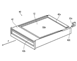
- the instant film 12 is loaded into the printer 10 in the state of a film pack (see FIG. 5) in which a plurality of sheets are housed in a case.
- the printer main body 14 has a rounded flat rectangular box shape, and is configured to be portable by being gripped with one hand. Further, the printer main body 14 is configured to be vertically placed (placed upright on a flat place) and horizontally placed (placed on a flat place). 1 and 2 show a case where the printer 10 is placed vertically.
- a push-type power button 16 is provided at a substantially central position.
- the printer 10 is turned on and off by pressing and holding the power button 16 (an operation of holding down the power button 16 for a certain period of time or longer).
- the power button 16 also serves as a light emitting unit, and emits light by emitting light from a light source unit provided inside the power button 16.
- An outlet 18 is provided on the upper part of the printer 10 (the upper part when it is placed vertically). The printed instant film 12 is discharged from the discharge port 18.
- a film pack lid 20 for opening and closing the film pack loading chamber (see FIG. 4) is provided on the back side of the printer 10. Further, an unlocking lever 22 for unlocking the film pack lid 20 is provided. When the lock is released by the lock release lever 22 and the film pack lid 20 is opened, the film pack loading chamber is opened. When the film pack lid 20 is closed after loading the instant film pack, the film pack lid 20 is locked by a lock mechanism (not shown), and the film pack is sealed in a light-shielded state.
- USB cable connection cover 24 that opens and closes a USB (Universal Serial Bus) cable connection (not shown).
- the printer 10 is charged with a built-in battery via the USB cable connection portion exposed by opening the USB cable connection portion cover 24.
- FIG. 4 is a cross-sectional view showing a schematic configuration of a printed portion of the printer. The figure shows a state in which the printer is placed horizontally.
- the printer main body 14 has a film pack loading chamber 30, a film delivery mechanism 32 that feeds instant film 12 from the film pack loaded in the film pack loading chamber 30, and an instant that is fed from the film pack.
- a film transport mechanism 34 for transporting the film 12, a print head 36 for recording an image on the instant film 12, and the like are provided.
- the film delivery mechanism 32, the film transport mechanism 34, and the print head 36 form a print section of the printer 10.
- the film pack loading chamber 30 is configured as a recess into which the film pack 40 fits, and is opened and closed by the film pack lid 20.
- FIG. 5 is a perspective view of the film pack. Further, FIG. 6 is a front view of the instant film, and FIG. 7 is a rear view of the instant film.
- the direction indicated by the arrow F is the feeding direction of the instant film 12. The instant film 12 is fed in the direction indicated by the arrow F and discharged from the case 42.
- the instant film 12 has a rectangular card shape.
- the instant film 12 is configured such that one surface is an exposed surface (a surface for recording an image by exposure) 12a and the other surface is an observation surface (a surface for observing a recorded image) 12b.
- the exposed surface 12a of the instant film 12 is provided with an exposed region 12c, a pod portion 12d, and a trap portion 12f.
- the exposure area 12c is an area for recording an image by exposure.
- the exposed area 12c becomes a printable area of the instant film 12.
- the pod portion 12d and the trap portion 12f are arranged before and after the feed direction F with the exposure region 12c interposed therebetween.
- the pod portion 12d is arranged on the front side of the feed direction F with respect to the exposure region 12c.
- the development processing liquid pod 12e containing the development processing liquid is built in the pod portion 12d.
- the trap portion 12f is arranged on the rear side of the feed direction F with respect to the exposure region 12c. 12 g of an absorbent material is built in the trap portion 12f.
- the observation surface 12b of the instant film 12 is provided with an observation region 12h.
- the observation area 12h is an area where an image is displayed. By developing the exposed area 12c, an image is displayed in the observation area 12h.
- the observation region 12h is arranged corresponding to the exposure region 12c.
- a frame 12i is provided around the observation area 12h. Therefore, the image is displayed in the frame.
- the observation area 12h is set slightly narrower than the exposure area 12c (it is set one size smaller). Therefore, when an image is recorded over the entire exposure area 12c, an image whose periphery is trimmed is printed.
- the instant film 12 is viewed with the trap portion 12f facing up and the pod portion 12d facing down. Therefore, the image is printed with the trap portion 12f facing up and the pod portion 12d facing down.
- the instant film 12 is developed by developing the developing solution of the pod portion 12d in the exposure region 12c.
- the developing solution of the pod portion 12d is squeezed out from the pod portion 12d by passing the instant film 12 between the developing rollers and 34B, and is developed in the exposure region 12c.
- the developing liquid left over during the developing process is captured by the trap unit 12f.
- the case 42 has a rectangular box shape.
- the case 42 has a rectangular exposure opening 42a in the front portion.
- the case 42 has a slit-shaped film discharge port 42b on the top surface portion.
- the exposed surface 12a faces the front side (exposure opening 42a side) of the case 42
- the pod portion 12d faces the top surface side (film discharge port 42b side) of the case 42. It is housed in layers.
- the case 42 has a slit-shaped claw opening 42c on the bottom surface portion. The instant films 12 housed in the case 42 are fed one by one toward the film discharge port 42b by allowing the claw 32a to enter through the claw opening 42c, and are discharged from the film discharge port 42b.
- a plurality of (for example, 10) instant films 12 are laminated and stored in one film pack 40.
- the film delivery mechanism 32 feeds out instant films 12 one by one from the film pack 40 loaded in the film pack loading chamber 30.
- the film feeding mechanism 32 includes a claw 32a that moves back and forth along the feeding direction of the instant film 12.
- the film feeding mechanism 32 scrapes out the instant films 12 in the case one by one by the claw 32a, and feeds the instant films 12 out of the film pack 40.
- the film transport mechanism 34 transports the instant film 12 fed from the film pack 40 by the film delivery mechanism 32 at a constant speed.
- the film transfer mechanism 34 includes a transfer roller pair 34A and a development roller pair 34B.
- the transport roller pair 34A is driven by a motor (not shown) to rotate, sandwiching and transporting both sides of the instant film 12.
- the unfolding roller pair 34B is driven by a motor (not shown) to rotate, and sandwiches and conveys the entire instant film 12.
- the pod portion 12d of the instant film 12 is crushed and developed in the process of being conveyed by the unfolding roller pair 34B.
- the print head 36 records an image on the instant film 12 sent out from the film pack 40.
- the print head 36 is composed of a line-type exposure head.
- the print head 36 irradiates the exposed surface 12a of the instant film 12 conveyed by the film conveying mechanism 34 with print light line by line, and records an image on the instant film 12 in a single pass.
- FIG. 8 is a block diagram showing an electrical configuration of the printer.
- the printer 10 includes an operation detection unit 50 that detects the operation of the power button 16, a light source unit 52 that emits light from the power button 16, a light source control unit 54 that controls light emission from the light source unit 52, and an antenna 56A.
- the operation detection unit 50 detects the operation of the power button 16.
- the power button 16 is composed of a push button, and the power of the printer 10 is turned on and off by long pressing. While the power is on, the power button 16 is assigned a function of inputting a reprint instruction. Reprinting is a function of reprinting the last printed image.
- the operation detection unit 50 detects a short press (operation of pressing and immediately releasing) the power button 16 while the power of the printer 10 is on, and outputs the detection signal to the printer microcomputer 80.
- the light source unit 52 is configured so that the emission color can be switched.
- the light source unit 52 is a three-color LED (also referred to as a full-color LED) having three-color elements of R (red; red), G (green; green), and B (blue; blue). Consists of.
- the emission color of the three-color LED can be switched by selecting the mixing ratio of the three colors of R, G, and B.
- the light source unit 52 is arranged inside the power button 16 (see FIG. 4).
- the power button 16 is entirely or partially transparent or translucent. When the light source unit 52 emits light, the power button 16 transmits light from the transparent portion or the translucent portion and emits light.
- the light source control unit 54 causes the light source unit 52 to emit light with a predetermined emission color and emission pattern in response to a command from the printer microcomputer 80.
- the wireless communication unit 56 wirelessly communicates with the mobile terminal via the antenna 56A under the control of the printer microcomputer 80. As described above, the communication with the mobile terminal 100 is performed by short-range wireless communication.
- the power supply unit 58 includes a battery and a power supply circuit, and supplies power to each unit of the printer 10.
- the battery is composed of a rechargeable secondary battery, and is charged by receiving an external power supply.
- the power supply control unit 60 controls the supply of power from the power supply unit 58 to each unit and the charging of the battery of the power supply unit 58 under the control of the printer microcomputer 80.
- the printer built-in memory 62 constitutes a storage unit of the printer 10, and stores printed image data, setting data of the printer 10, and the like.
- the printer built-in memory 62 is composed of, for example, a non-volatile memory such as an EEPROM (Electrically Erasable Programmable Read-only Memory).
- the memory control unit 64 reads / writes data to / from the printer built-in memory 62 in response to a command from the printer microcomputer 80.
- the motion detection unit 66 detects the motion of the printer 10.
- the motion detection unit 66 is composed of, for example, a motion sensor. Since the motion sensor itself is known, the detailed description thereof will be omitted. Generally, a motion sensor is configured by combining an acceleration sensor, a gyro sensor, and the like.
- the motion detection unit 66 detects the posture of the printer 10 (vertical placement, horizontal placement, tilt, etc.) and the movement of the printer 10 (lifting, placing down, turning over, etc.).
- the film delivery mechanism drive unit 68 includes a motor for driving the claw 32a of the film delivery mechanism 32 and a drive circuit thereof, and drives the film delivery mechanism 32 in response to a command from the printer microcomputer 80.
- the film transport mechanism drive unit 70 includes a motor for driving the transport rollers vs. 34A of the film transport mechanism 34 and a drive circuit thereof, and a motor for driving the deployment rollers vs. 34B and a drive circuit thereof, and is instructed by the printer microcomputer 80.
- the film transport mechanism 34 is driven accordingly.
- the printhead control unit 72 includes a control circuit for the printhead 36, and operates the printhead 36 in response to a command from the printer microcomputer 80.
- the printer microcomputer 80 is a control unit that controls the operation of the printer 10.
- the printer microcomputer 80 is composed of a microcomputer equipped with a CPU (Central Processing Unit), a ROM (Read Only Memory), and a RAM (Random Access Memory), and realizes various functions by executing a predetermined control program. ..
- FIG. 9 is a block diagram of the main functions realized by the printer microcomputer.
- the printer microcomputer 80 mainly functions as an image acquisition unit 80A, a print data generation unit 80B, a print control unit 80C, a representative color detection unit 80D, a light emission control unit 80E, and the like.
- the image acquisition unit 80A wirelessly communicates with the mobile terminal 100 via the wireless communication unit 56, and acquires image data of an image to be printed from the mobile terminal 100.
- the image data of the last printed image is read from the printer built-in memory 62 and acquired.
- the print data generation unit 80B converts the image data acquired by the image acquisition unit 80A into a data format that can be printed by the print unit (a data format that can be printed on the instant film 12 by the print head 36), and data for printing (data for printing (data format that can be printed on the instant film 12 by the print head 36)). Print data) is generated.
- the print control unit 80C controls the feeding of the instant film 12 by the film feeding mechanism 32 via the film feeding mechanism driving unit 68. Further, the transfer of the instant film 12 by the film transfer mechanism 34 is controlled via the film transfer mechanism drive unit 70. Further, the drive of the print head 36 is controlled via the print head control unit 72. The drive of the print head 36 is controlled in synchronization with the transfer of the instant film 12 based on the print data generated by the print data generation unit 80B.
- the representative color detection unit 80D detects the representative color of the image to be printed.
- the representative color of the image to be printed is the color mainly used in the image to be printed.
- the representative color detection unit 80D obtains, for example, the color distribution of the entire image to be printed, and detects the color occupying the widest area as the representative color. For example, for a sunset image in which the entire screen is dyed orange, orange is detected as a representative color. Further, for example, green is detected as a representative color for an image of a meadow.
- the representative color detection unit 80D detects the representative color in the range of the color gamut that can be reproduced by the light source unit 52.
- the representative color may be obtained from a part of the image to be printed, or the image to be printed may be obtained by dividing it into a plurality of areas.
- a detection area is set in the center of the image, and a representative color is detected from the detection area.
- the image to be printed is divided into a plurality of areas in the vertical direction (for example, divided into three equal parts), and the representative color is detected from each area.
- the light emission control unit 80E controls the light emission of the light source unit 52 via the light source control unit 54, and causes the power button 16 which is the light source unit to emit light in a predetermined color and pattern.
- the light emission control unit 80E causes the power button 16 to emit light at a predetermined timing.
- the power button 16 is made to emit light when receiving an image to be printed from the mobile terminal 100 and when printing an image.
- a plurality of predetermined colors are sequentially switched at regular time intervals to emit light. For example, seven colors of red, orange, yellow, green, light blue, blue, and purple (so-called rainbow colors) are sequentially switched at regular time intervals to emit light. The light emission continues while the image is being received.
- the representative color detected by the representative color detection unit 80D is made to emit light.
- the light emission continues while the image is being printed.
- the image is divided into a plurality of regions and the representative color is obtained, the obtained representative color is switched in order to emit light.
- the representative color detected in each area is emitted in order from the top at regular time intervals.
- an achromatic color such as black or gray is detected as a representative color, a specific color is used instead to emit light.
- a specific light emission pattern for example, seven colors of red, orange, yellow, green, light blue, blue, and purple (so-called rainbow colors) are sequentially switched at regular time intervals to emit light. Blink the color of (for example, blink white). Alternatively, the light emission is stopped.
- FIG. 10 is a block diagram showing an example of the hardware configuration of the mobile terminal. The figure shows an example in which the mobile terminal 100 is composed of a smartphone.
- the mobile terminal (smartphone) 100 includes a CPU 101 that controls the overall operation, a ROM 102 that stores basic input / output programs, a RAM 103 that is used as a work area of the CPU 101, a built-in memory 104, and a display 105.
- the position information (latitude, longitude and altitude) of the mobile terminal 100 is obtained by the touch pad 106 that detects the touch operation (position input) on the display screen, GPS (Global Positioning Systems) satellite, or IMES (Indoor MEssaging System) as indoor GPS.
- GPS Global Positioning Systems
- IMES Indoor MEssaging System
- In-camera unit 108A (camera unit provided on the display side) and out-camera unit 108B (opposite side to the display) that include the GPS receiving unit 107 that receives the included GPS signal, the photographing lens, and the image sensor, and electronically captures the image.
- GPS receiving unit 107 that receives the included GPS signal
- the photographing lens and the image sensor
- electronically captures the image and electronically captures the image.
- microphone unit 109 that inputs audio
- speaker unit 110 that includes speakers and outputs audio
- antenna 111A to wirelessly communicate with the nearest base station, etc.
- the built-in memory 104 is composed of a non-volatile memory such as EEPROM.
- the built-in memory 104 in addition to various programs including an operating system (for example, a display control program, etc.), image data of images taken by the in-camera unit 108A and the out-camera unit 108B, image data acquired from other devices, and the like are stored. Various data are stored.
- the display 105 and the touch pad 106 constitute the touch panel 120.
- the short-range wireless communication unit 112 is an example of a communication unit that communicates with the printer 10.
- the screen of the touch panel 120 has a rectangular shape.
- the mobile terminal 100 has a normal usage pattern in which the screen of the touch panel 120 is vertically oriented (the longitudinal direction of the screen is along the vertical direction).
- the longitudinal direction of the screen of the touch panel 120 is the vertical direction (Y direction in the figure), and the direction orthogonal to the vertical direction (X direction in the figure), that is, the width of the short side of the screen The direction.
- the mobile terminal 100 has a function of causing the printer 10 to print an image taken by the in-camera unit 108A or the out-camera unit 108B in relation to the printer 10, and a function of causing the printer 10 to print an image recorded in the built-in memory 104. It also has a function of checking the state of the printer 10 (for example, the remaining battery level and the number of printable sheets (the number of remaining films)). It also has a function of editing the image to be printed in relation to printing the image.
- FIG. 11 is a block diagram of the main functions of the mobile terminal with respect to image printing.
- the mobile terminal 100 controls a display control unit 100A that controls the display of the touch panel 120, an input control unit 100B that controls the input to the touch panel 120, and shooting of the image to be printed.
- Functions such as a shooting control unit 100C, a reproduction control unit 100D for controlling the reproduction of the image to be printed, an image processing unit 100E for processing and editing the image to be printed, and a communication control unit 100F for controlling communication with the printer 10.
- the display control unit 100A controls the display of the screen of the touch panel 120 to display the operation screen when printing an image on the touch panel 120.
- the display control unit 100A controls the display of the display 105, which is a display unit, to control the display of the screen of the touch panel 120.
- the display of the operation screen described later is controlled by the display control unit 100A.
- the input control unit 100B controls the operation input to the touch panel 120 and controls the input of the operation when printing an image.
- the input control unit 100B controls the input of the touch pad 106, which is the position input unit of the touch panel 120, and controls the operation input to the touch panel 120.
- the shooting control unit 100C controls the in-camera unit 108A and the out-camera unit 108B based on the operation input to the touch panel 120, and controls the shooting of the image to be printed.
- the reproduction control unit 100D controls the access to the built-in memory 104 based on the operation input to the touch panel 120, and controls the reproduction of the image to be printed.
- the image processing unit 100E processes and edits the image to be printed based on the operation input to the touch panel 120. For example, image processing such as image enlargement (trimming), image rotation, filter processing, template composition, and collage is performed to process and edit the image to be printed.
- image processing such as image enlargement (trimming), image rotation, filter processing, template composition, and collage is performed to process and edit the image to be printed.
- the filter processing is a function of changing the color tone of an image or deforming an image. For example, color correction, noise removal, mosaic processing and embossing.
- Template composition is a process of synthesizing a template image with an image to generate a composite image.
- the collage here is a process of applying an image to each area of a frame (divided frame) whose interior is divided into a plurality of areas to generate a single composite image. The generated composite image is called a collage image.
- the communication control unit 100F controls the short-range wireless communication unit 112 based on the operation input to the touch panel 120, and controls the communication with the printer 10.
- the image to be printed and the print command thereof are mainly transmitted from the mobile terminal 100 to the printer 10.
- information indicating the state of the printer 10 is mainly transmitted from the printer 10 to the mobile terminal 100.
- the communication control unit 100F is an example of a transmission control unit.
- FIG. 12 is a diagram showing an example of the top screen.
- the top screen (also called the home screen) 200 is the main menu screen.
- buttons of available functions are displayed as icons. That is, figures, symbols or patterns are displayed in combination.
- the simple print button MB1 which is a button of the "simple print” function
- the movie print button MB2 which is the button of the "movie print” function
- the button of the function of the "instant camera” Instant camera button MB3 template print button MB4 which is a function button of "template print”
- collage print button MB5 which is a button of "collage print” function
- compatibility diagnosis button which is a button of "compatibility diagnosis” function MB6 and the collage button MB7 for everyone, which is a button for the function of "collage with everyone" are displayed.
- Each button has a menu title at the bottom.
- the simple print function is a function for printing an image (still image) stored in the mobile terminal 100. Touch the simple print button MB1 on the screen to activate the function.
- the movie print function is a function that extracts one scene from a movie and prints it. Touch the movie print button MB2 on the screen to activate the function.
- the function of the instant camera is a function of taking a picture using the camera function of the mobile terminal 100 and printing the taken image with the printer 10. Touch the instant camera button MB3 on the screen to activate the function.
- the template print function is a function that synthesizes a template image with an image and prints it. Touch the template print button MB4 on the screen to activate the function.
- the collage print function is a function to generate and print a collage image.
- the collage image is generated by applying the image to each area of the frame (divided frame) whose interior is divided into a plurality of areas.
- regular divisions for example, upper and lower halves, left and right halves, upper and lower ternary divisions, left and right ternary divisions, quadruple divisions, nine equal divisions, etc.
- irregular divisions for example, upper and lower halves, left and right halves, upper and lower ternary divisions, left and right ternary divisions, quadruple divisions, nine equal divisions, etc.
- Regular divisions for example, upper and lower halves, left and right halves, upper and lower ternary divisions, left and right ternary divisions, quadruple divisions, nine equal divisions, etc.
- irregular divisions for example, upper and lower halves, left and right halves, upper and lower ternary divisions, left and right ternary divisions, quadruple divisions,
- the compatibility diagnosis function is a function for performing compatibility diagnosis from images.
- the trained model is used to analyze the image and diagnose the compatibility of the two people in the image. Touching the compatibility diagnosis button MB6 on the screen activates the function.
- the collage function for everyone is a function for multiple people to jointly generate and print a collage image.
- the function is activated.
- buttons of each function are grouped and displayed in two groups (first group MG1 and second group MG2).
- the first group MG1 is a group to which the buttons for each function of simple print, movie print, and instant camera belong.
- the first group MG1 is a group of functions whose main purpose is simple printing. This group is referred to as a "Print Mode" group.
- the second group MG2 is a group to which the buttons for each function of template print, collage print, compatibility diagnosis, and collage together belong.
- the second group MG2 is a group of functions whose main purpose is advanced printing that requires processing and editing. This group is called a "Fun Mode" group.
- the buttons belonging to the first group MG1 are displayed in the first group display area MA1, and the buttons belonging to the second group MG2 (template print button MB4, collage print).
- the button MB5, the compatibility diagnosis button MB6, and the collage button MB7) for everyone are displayed in the second group display area MA2.
- the first group display area MA1 is set at the right end of the screen of the top screen 200, and the second group display area MA2 is set at the lower part of the screen.
- the setting button SEB is further displayed on the top screen 200.
- the setting button SEB is a button that calls a screen (setting screen) for performing various settings.
- the setting button SEB is displayed at the upper right of the screen.
- the printer 10 when the printer 10 is connected (communication is established), the information of the connected printer 10 is displayed on the top screen 200.
- the information of the printer 10 is displayed in the printer information display area MA3.
- the printer information display area MA3 is set at the upper part of the screen.
- information on the name of the connected printer 10 for example, the model name
- the number of printable sheets the number of remaining films
- the remaining battery level is displayed. This information is acquired from the printer 10 when communication with the printer 10 is established.
- the simple print function is a function for printing an image stored in the mobile terminal 100.
- the rough operation procedure is (1) selection of an image to be printed and (2) instruction of printing. If necessary, the image is processed and edited.
- This screen is a screen for selecting an image to be printed.
- FIG. 13 is a diagram showing an example of an image selection screen.
- the images stored in the mobile terminal 100 are listed in a thumbnail format. That is, the images are displayed in a list in a reduced format.
- the user touches the thumbnail image of the image to be printed on the screen and selects the image to be printed.
- FIG. 13 shows an example in which all the images stored in the mobile terminal 100 are displayed in a list.
- the format may be such that only the images in the specified folder are displayed.
- the cancel button 201A is displayed on the image selection screen 201.
- the cancel button 201A is a button for instructing the cancellation of the image selection process.
- the simple print function ends. In this case, the screen display switches to the top screen 200.
- Print image confirmation screen When the image to be printed is selected, the screen of the touch panel 120 is switched to the print image confirmation screen 202.
- This screen is a screen for confirming an image to be printed (printed image).
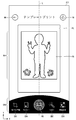
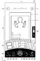
- FIG. 14 is a diagram showing an example of a print image confirmation screen.
- the print image confirmation screen 202 displays a print image PI, a print button PB instructing printing of the print image PI, a menu button for image editing, and the like.
- the print image PI is displayed in the image display area EA1 set in the screen.
- the image display area EA1 is set on the center line L, where the center line L is a straight line passing through the center of the print image confirmation screen 202 in the width direction (X direction in FIG. 14).
- the center line L is set to a substantially center position.
- the direction of the center line L is a direction along the longitudinal direction of the screen (vertical direction, Y direction in FIG. 14).
- a frame FL surrounding the image (print image PI) displayed in the image display area EA1 is displayed around the image display area EA1.
- This frame FL is composed of the same margin as the printed result (printed product). That is, it is composed of the same margin as the instant film 12 (composed of the same ratio as the frame 12i provided around the observation region 12h of the instant film 12). This makes it easier to check the final print result on the screen.
- the print button PB and the image editing menu button are displayed in the button display area EA2.
- the button display area EA2 is set at the bottom of the screen.
- the print button PB and the image editing menu button (enlargement & rotation button EB1, filter button EB2, image quality correction button EB3) are arranged in a row along the width direction of the screen (X direction in FIG. 14) in this button display area EA2. Displayed side by side.
- the print button PB is arranged on the center line L, and three image editing menu buttons (enlargement & rotation button EB1, filter button EB2, image quality correction button EB3) are arranged and displayed on both sides thereof. More specifically, the enlargement & rotation button EB1 is arranged to the left of the print button PB, and the filter button EB2 and the image quality correction button EB3 are arranged to the right of the print button PB.
- the print button PB and the image editing menu button are each displayed as icons.
- the print button PB in the center is configured to be larger than the other buttons (enlarge & rotate button EB1, filter button EB2, image quality correction button EB3) (the size of the image part that constitutes the button is large). It is composed.).
- the color of the print button PB is configured to be different from that of the other buttons. Specifically, the print button PB is composed of red while the other buttons are composed of white. As a result, the print instruction operation can be easily understood. When the other buttons are selected (touched), the color changes. This makes it possible to clarify the selected function.
- FIG. 14 shows an example in which an enlargement / rotation function, a filter function, and an image quality correction function are provided as an image editing menu.
- the enlargement and rotation functions are functions for enlarging and rotating an image.
- the enlargement and rotation functions are assigned to the enlargement & rotation button EB1.
- the enlargement / rotation functions are activated, and the image can be enlarged / rotated with respect to the print image PI.
- the filter function is a function to filter the image.
- the filter function button is assigned to the filter button EB2. When the filter button EB2 is touched on the screen, the filter function is activated and the print image PI can be filtered.
- the image quality correction function is a function that corrects the brightness, contrast, and saturation of an image.
- the image quality correction function is assigned to the image quality correction button EB3.
- the image quality correction button EB3 When the image quality correction button EB3 is touched on the screen, the image quality correction function is activated, and image quality correction (correction of image brightness, contrast, and saturation) is possible for the print image PI.
- Each function is turned on (activated) by touching each corresponding button on the screen, and turned off by touching it again. Also, if a button of another function is touched while one function is activated, the function is switched to the touched function. For example, if the image quality correction button EB3 is touched while the filter function is activated, the filter function ends and the image quality correction function is turned on.
- the back button BB and the top button TB are displayed on the print image confirmation screen 202.
- the back button BB is a button instructing to return to the previous screen.
- the top button TB is a button instructing to return to the top screen 200.
- the back button BB and the top button TB are arranged at the top of the screen.
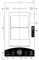
- FIG. 15 is a diagram showing an example of an enlargement / rotation operation screen.
- the enlargement slide bar SB1 for the enlargement operation and the rotation slide bar SB2 for the rotation operation are displayed.
- the enlargement slide bar SB1 is operated by sliding the knob NB1 (touching and sliding the knob NB1).
- the image is enlarged according to the amount of operation.
- the print image PI is enlarged when the knob NB1 is slid to the right of the screen, and reduced when the knob NB1 is slid to the left.
- the rotating slide bar SB2 is operated by sliding its knob NB2.
- the image is rotated according to the amount of operation.
- the printed image PI rotates clockwise when the knob NB2 is slid to the right of the screen, and counterclockwise when the knob NB2 is slid to the left. Slide the knob NB2 from the left edge to the right edge of the bar to rotate the image once.
- the enlargement slide bar SB1 and the rotation slide bar SB2 are displayed in the operation area EA3.
- the operation area EA3 is set between the image display area EA1 and the button display area EA2 in the direction (Y direction) along the center line L.
- the enlargement slide bar SB1 and the rotation slide bar SB2 are arranged vertically side by side in this area.
- both the slide bar SB1 for enlargement and the slide bar SB2 for rotation are displayed in an arcuately curved shape. More specifically, it is displayed along a circle centered on a point set on the center line L, and is displayed symmetrically with respect to the center line L.
- the overall length can be made longer than when displaying as a straight line.
- the resolution of the operation can be improved, and more detailed operation becomes possible. This works particularly effectively when the display size of the screen is small.
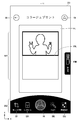
- FIG. 16 is a diagram showing an example of a filter operation screen.
- FIG. 16 shows an example in which four buttons are displayed as selection buttons. Specifically, an example is shown in the case where the normal button FB1 for returning to the normal state, the monochrome button FB2 for applying the monochrome filter, the sepia button FB3 for applying the sepia filter, and the auto button FB4 for applying the auto filter are displayed. ing.
- the monochrome filter is a filter that converts an image into monochrome in black and white.
- the monochrome button FB2 is touched on the screen, the print image PI displayed in the image display area EA1 is monochromeized in black and white.
- a sepia filter is a filter that makes the color tone of an image sepia.
- the sepia button FB3 is touched on the screen, the color tone of the print image PI displayed in the image display area EA1 is set to sepia tone.
- the auto filter is a filter that automatically optimizes the color tone of the image.
- the auto button FB4 is touched on the screen, the color tone of the print image PI displayed in the image display area EA1 is automatically corrected.
- the filter selection buttons (normal button FB1, monochrome button FB2, sepia button FB3, auto button FB4) have a rectangular shape corresponding to the outer shape of the printed image PI displayed in the image display area EA1. More specifically, it has a similar shape to the outer shape of the printed image PI (including a shape recognized to be almost similar).
- each button displays a common image that has been subjected to the same filter processing as the applied filter. For example, in the image constituting the monochrome button FB2, a chrome image is displayed even in black and white.
- each button is expanded and displayed in the operation area EA3, and is displayed radially around the point set on the center line L.
- the number and size of buttons that can be displayed can be increased as compared with the case where the buttons are displayed in a straight line. Thereby, operability can be improved.
- the number of buttons displayed on one screen can be adjusted by adjusting the curvature of the arc. That is, if the size of the buttons is the same, the larger the curvature (the larger the curvature), the more buttons can be displayed at one time.
- the filter selection buttons are examples of operation buttons for image editing.
- Image quality correction operation screen When the image quality correction button EB3 is touched on the screen, the screen is switched to the operation screen of the image quality correction function, that is, the operation screen (image quality correction operation screen) 205 for correcting the brightness, contrast, and saturation of the image.
- FIG. 17 is a diagram showing an example of an image quality correction operation screen.
- the brightness adjustment slide bar SB3 for adjusting the brightness of the image in addition to the display contents on the print image confirmation screen 202, the brightness adjustment slide bar SB3 for adjusting the brightness of the image, the contrast adjustment slide bar SB4 for adjusting the contrast of the image, and the image
- the saturation adjustment slide bar SB5 for adjusting the saturation and the reset button RSB are displayed.
- the brightness adjustment slide bar SB3 is operated by sliding its knob NB3.
- the slide bar SB3 for brightness adjustment is operated, the brightness of the image changes according to the amount of the operation.
- Knob NB3 is located in the center of the bar by default.
- the print image PI becomes brighter when the knob NB3 is slid to the right of the screen, and becomes darker when the knob NB3 is slid to the left.
- the contrast adjustment slide bar SB4 is operated by sliding its knob NB4.
- the contrast of the image changes according to the amount of the operation.
- Knob NB4 is located in the center of the bar by default.
- the contrast of the printed image PI increases when the knob NB4 is slid to the right of the screen, and decreases when the knob NB4 is slid to the left.
- the saturation adjustment slide bar SB5 is operated by sliding its knob NB5.
- the saturation adjustment slide bar SB5 When the saturation adjustment slide bar SB5 is operated, the saturation of the image changes according to the amount of operation.
- Knob NB5 is located in the center of the bar by default.
- the print image PI becomes highly saturated when the knob NB5 is slid to the right of the screen, and becomes desaturated when the knob NB5 is slid to the left.
- the reset button RSB is a button for resetting the operation of each slide bar (brightness adjustment slide bar SB3, contrast adjustment slide bar SB4, and saturation adjustment slide bar SB5).
- the reset button RSB is touched, the operation of each slide bar is reset. That is, the knob of each slide bar returns to the default position (center).
- Each slide bar (brightness adjustment slide bar SB3, contrast adjustment slide bar SB4 and saturation adjustment slide bar SB5) and the reset button RSB are displayed in the operation area EA3.
- each slide bar is arranged vertically side by side in this area. Further, each slide bar is displayed in a curved shape in an arc shape. More specifically, it is displayed along a circle centered on a point set on the center line L, and is displayed symmetrically with respect to the center line L. As a result, the resolution of the operation can be improved, and more detailed operation becomes possible.
- the reset button RSB is arranged at the right end of the operation area E3.
- the image of the image transmission is displayed as an animation. Specifically, the image that the print image PI moves with the frame FL and disappears from the edge of the screen is displayed by animation.
- FIG. 18 is a diagram showing an example of an animation display when printing is instructed.
- the screen changes to screen 206A, screen 206B, and screen 206C in chronological order.
- the print image PI moves upward along the longitudinal direction of the screen together with the frame FL and disappears from the upper edge of the screen (simulating an image in which an instant film is sent). This makes it easier to recognize that the image has been sent to the printer.
- template printing is a function that combines a template image with an image to generate a composite image and print it.
- image to be combined the image stored in the mobile terminal 100 is used.
- the rough operation procedure of template printing is (1) selection of template, (2) selection of image to be printed, and (3) instruction of printing. If necessary, the image is processed and edited.
- Template selection screen When the template print button MB4 is touched on the top screen 200, the template print function is activated. When the template print function is activated, the screen of the touch panel 120 is switched to the template selection screen 210. This screen is a screen for selecting a template image to be combined with an image to be printed.
- FIG. 19 is a diagram showing an example of a template print selection screen.
- usable template images are displayed in a list in thumbnail format.
- the user touches the template image of the pattern to be used on the screen and selects the template image to be used.
- Print image confirmation screen When the image to be printed is selected, the screen of the touch panel 120 is switched to the print image confirmation screen 202.
- This screen is a screen for confirming an image to be printed (printed image).
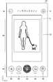
- FIG. 20 is a diagram showing an example of a print image confirmation screen in template printing.
- the screen configuration is the same as the print image confirmation screen 202 of the simple print, except that the template button EB4 is added as the image editing menu button.
- the template button EB4 is a button that calls a function for switching template images.
- the template button EB4 is used to change the template image.
- the print button PB and the image editing menu button are displayed in the button display area EA2.
- the print button PB is arranged on the center line L
- the image editing menu buttons are arranged on both sides thereof.
- the image editing menu buttons are arranged symmetrically around the print button PB.
- the enlargement & rotation button EB1 and the template button EB4 are arranged on the left side of the print button PB at regular intervals, and the filter button EB2 and the image quality correction button EB3 are arranged on the right side of the print button PB at regular intervals. Be placed.
- the central print button PB is larger than the other buttons (enlargement & rotation button EB1, filter button EB2, image quality correction button EB3, and template button EB4), as in the case of simple print.
- the screen switches to the operation screen (template switching operation screen) 212 for switching the template image.
- FIG. 21 is a diagram showing an example of a template switching operation screen.
- switchable template image selection buttons TB1, TB2, ... are displayed.
- the selection buttons TB1, TB2, ... are examples of operation buttons for image editing.
- Each button consists of a reduced image of the template image selected by that button. Therefore, the outer shape has a similar shape to the outer shape of the printed image PI (including a shape recognized as substantially similar).
- the template image selection buttons TB1, TB2, ... are expanded and displayed in the operation area EA3 in the same manner as the filter selection buttons, and are displayed radially around the point set on the center line L.
- FIG. 21 shows an example in which four selection buttons are displayed at one time (when the total number of buttons that can be displayed is four). Other selection buttons are scrolled and displayed. Scrolling is performed by swiping or flicking the screen on the selection button displayed in the operation area EA3.
- the swipe operation is an operation of sliding a finger while touching the screen.
- the flick operation is an operation in which the swipe is performed more vigorously, the screen is flipped, and the finger is slid away from the screen.
- FIG. 22 is a conceptual diagram of scrolling of the selection button displayed in the operation area.
- the selection buttons TB1, TB2, ... Displayed in the operation area EA3 are scrolled to the right (arrow R + direction) along the arc by swiping or flicking the screen to the right. (Scroll clockwise). Further, by swiping or flicking the screen to the left, the screen scrolls to the left (arrow R-direction) along the arc (scrolls counterclockwise).
- the collage print function is a function of applying an image to each area of a frame (divided frame) whose interior is divided into a plurality of areas to generate a composite image (collage image) and print it.
- the rough operation procedure of collage printing is (1) selection of divided frames, (2) selection of images to be combined, and (3) printing instructions. If necessary, the image to be combined is processed and edited.
- FIG. 23 is a diagram showing an example of a split frame selection screen.
- selectable divided frame images are displayed in a list in thumbnail format.
- the user touches the image of the divided frame of the divided pattern desired to be used on the screen and selects the divided frame to be used.
- FIG. 24 is a diagram showing an example of a collage image creation screen.
- the screen configuration is the same as that of the print image confirmation screen 202 of the simple print except that the split frame button EB5 is added.
- the area inside the image display area EA1 is divided according to the selected division frame.
- the border button FBB turns on and off the display of the border FBL of the split. Each time the user touches the border button FBB on the screen, it switches on and off.
- the border button FBB is turned on, the border FBL is displayed in the image display area EA1.
- FIG. 24 shows a case where the display of the boundary line FBL is turned on.
- the border display is turned on, the border is also displayed on the printed image.
- the split frame button EB5 is a button that calls the function of switching the split frame.
- the split frame button EB5 is used when changing the split frame.
- the print button PB and the image editing menu button are displayed in the button display area EA2. It is displayed in a line along the width direction (X direction) of the screen.
- the print button PB is arranged on the center line L, and the image editing menu buttons (enlargement & rotation button EB1, filter button EB2, image quality correction button EB3, and split frame button EB5) are arranged on both sides thereof.
- the image editing menu buttons are arranged symmetrically around the print button PB.
- the enlargement & rotation button EB1 and the split frame button EB5 are arranged at regular intervals to the left of the print button PB, and the filter button EB2 and the image quality correction button EB3 are arranged at regular intervals to the right of the print button PB. Placed in.
- the print button PB in the center is larger than the other buttons (enlarge & rotate button EB1, filter button EB2, image quality correction button EB3, and split frame button EB5), which is the same as in the case of simple print. ..
- the screen of the touch panel 120 is switched to the image selection screen (see FIG. 13). The user selects an image to be combined on this screen. When the image is selected, the screen returns to the collage image creation screen 221 again. At this time, the selected image is applied to the selected area and displayed.
- FIG. 25 is a diagram showing an example of a collage image creation screen after image selection.
- the figure shows an example of the screen display when the area on the upper side of the screen is selected and the image to be combined is selected in the divided frame in which the frame is divided into upper and lower halves. As shown in the figure, the selected image is applied to the selected area and displayed.
- the position of the image will be adjusted.
- touch the area to change the image to select it and then touch the back button BB.
- the screen is switched to the image selection screen (see FIG. 13), and the image can be selected.
- flicking the screen in the area the images may be switched in order.
- the screen switches to the operation screen (split frame switching operation screen) 222 for switching the split frame.
- FIG. 26 is a diagram showing an example of a split frame switching operation screen.
- split frame selection buttons SFB1, SFB2, ... For selecting a switchable split frame are displayed.
- the split frame selection buttons SFB1, SFB2, ... Are examples of image editing operation buttons.
- Each button consists of a reduced image of the split frame image selected by that button. Therefore, the outer shape has a similar shape to the outer shape of the printed image (including a shape recognized as substantially similar).
- the split frame selection buttons SFB1, SFB2, ... are displayed in the operation area EA3 in the same manner as the template image selection buttons, and are displayed radially around the point set on the center line L. Further, in the operation area EA3, a fixed number of divided frame selection buttons SFB1, SFB2, ... Are displayed. The other divided frame selection buttons are scrolled and displayed in the same manner as the template image selection button (see FIG. 22).
- the print button PB displayed in the button display area EA2 is touch-operated to instruct the print of the image displayed in the image display area EA1.
- Printing may be instructed by the following method instead of or in addition to the method. That is, printing is instructed by swiping or flicking the screen on the print image PI displayed in the image display area EA1 or on the frame FL.
- FIG. 27 is a conceptual diagram of an operation when printing is instructed by a flick operation.
- the image of image transmission is displayed as an animation.
- the moving direction of the print image PI at the time of animation display matches the operation direction of the print instruction. As a result, intuitive operation is possible and operability can be further improved.
- a method of instructing to stop printing on the mobile terminal side a method of displaying a button instructing to stop printing can be adopted on the screen.
- FIG. 28 is a diagram showing an example of a screen for accepting a print cancellation instruction input. The figure shows an example of a screen when canceling a print is accepted while transmitting an image.
- the print cancel button PCB is a button for instructing to cancel printing.
- the print cancel button PCB is composed of buttons with a cancel character in a rectangular frame.
- the message MI1 and the print cancel button PCB move together with the print image PI when displaying the animation. Therefore, it eventually disappears from the top edge of the screen. Printing is canceled by touching the print cancel button PCB during display.
- the print image PI moves in the opposite direction and returns to the original position. That is, it moves downward and returns to the position before the start of movement (see screen 206A in FIG. 18).
- Operations such as enlarging and rotating the image to be printed may be performed by a predetermined gesture.
- the image is enlarged or reduced by performing pinch-out and pinch-in operations on the image displayed in the image display area EA1.
- the image is moved in the operation direction.
- the image displayed in the image display area EA1 is rotated (twisted) by touching the image with two fingers (for example, the thumb and the index finger) to rotate the image.
- the pinch-in operation refers to an operation in which the screen is touched with two fingers (for example, the thumb and the index finger) and moved to pick it up.
- the pinch-out operation is an operation in which the screen is touched with two fingers (for example, the thumb and the index finger) and moved to spread.
- FIG. 29 is a diagram showing an example of an operation guide screen.
- a message indicating that the image can be enlarged, moved, and rotated by gestures on the screen (“You can edit the image by inputting gestures on the image.")
- Print MI2 Image confirmation It is displayed on the screen 202. This message MI2 is displayed, for example, when the print image confirmation screen 202 is first displayed.
- the OK button OKB is displayed to prompt the user for confirmation.
- the message MI2 is erased from the screen by touching the OK button OKB. It is preferable that the message MI2 can be displayed or hidden in the settings.
- FIG. 29 shows an example in which the display of the enlargement & rotation button is omitted.
- the print button PB is arranged on the center line L in the button display area EA2, but the type of the button arranged on the center line L is not limited to this. Buttons for other functions may be arranged.
- the print instruction operation can be clarified by arranging the print button PB on the center line and displaying it in a size larger than other buttons.
- buttons having functions other than these are displayed in the button display area EA2.
- the setting button SEB may be displayed.
- the communication connection button may be displayed instead of the print button displayed on each operation screen.
- FIG. 30 is a diagram showing an example of the display of the communication connection button. The figure shows an example when the communication connection button is displayed on the operation screen of the simple print function.
- the communication connection button CCB is displayed instead of the print button.
- the communication connection button CCB is a button for making a communication connection with the printer 10.
- a process of detecting the printer 10 capable of communicating is performed, and a process of establishing communication with the detected printer 10 is performed.
- the touch panel 120 of the smartphone 100 displays a screen for setting communication. For example, a list of communicable printers is displayed, and a screen for selecting a printer to connect to is displayed.
- FIG. 31 is a diagram showing an example of an operation screen of the function of the instant camera.
- Live view is a function that displays the image captured by the image sensor in real time.
- the operation buttons of the camera are displayed in the button display area EA2.
- the flash button CB1 is a button for switching the flash mode.
- the in / out switching button CB2 is a button for switching between the in-camera and the out-camera.
- the shutter button CB3 is a button for instructing the release.
- the timer button CB4 is a button for switching the timer function on and off.
- the date button CB5 is a button for switching the date function on and off.
- the date function is a function of imprinting the date on a predetermined position of a printed image.
- the operation buttons of the camera are arranged symmetrically around the shutter button CB3.
- the shutter button CB3 is arranged at the center in the width direction of the screen. Further, the shutter button CB3 is configured to have a size larger than that of other buttons.
- printers In the above embodiment, the case where the printer is composed of an instant printer has been described as an example, but the configuration of the printer is not limited to this. In addition, for example, it can be applied to various types of printers such as a thermal printer that prints on thermal paper, a thermal transfer printer that prints using an ink ribbon, and an inkjet printer that prints by an inkjet method. Further, the type of media used is not particularly limited, and it can be applied to a printer that prints on roll paper as well as sheet paper. Further, it can be applied to a printer that prints on a label (including a sticker) or the like.
- the device that can be used as the operating device is not limited to this. Any device (particularly a mobile device) having a touch panel that detects a touch operation on the screen, a display control unit (CPU or the like) that controls the display of the touch panel, and a communication unit can be used as an operation device. Therefore, for example, a digital camera or the like having a short-range wireless communication function and having a display unit having a touch panel can be used as an operation device. Further, a portable game machine or the like having these functions can also be used as an operating device.
- processors include CPUs (Central Processing Units) and FPGAs (Field Programmable Gate Arrays), which are general-purpose processors that execute programs and function as various processing units, and whose circuit configurations can be changed after manufacturing. Includes a dedicated electric circuit, which is a processor having a circuit configuration specially designed for executing a specific process such as a programmable logic device (PLD) and an ASIC (Application Specific Integrated Circuit).
- One processing unit constituting the inspection support device may be composed of one of the above-mentioned various processors, or may be composed of two or more processors of the same type or different types.
- one processing unit may be composed of a plurality of FPGAs or a combination of a CPU and an FPGA.
- a plurality of processing units may be configured by one processor.
- one processor is configured by a combination of one or more CPUs and software, as represented by a computer such as a client or a server.
- the processor functions as a plurality of processing units.
- SoC System On Chip
- the various processing units are configured by using one or more of the above-mentioned various processors as a hardware-like structure.
- the hardware structure of these various processors is, more specifically, an electric circuit (circuitry) in which circuit elements such as semiconductor elements are combined.
- the printer and the mobile terminal communicate wirelessly, but a wired communication may also be used. Further, in the case of wireless communication, the communication method is not particularly limited, and a known communication method can be adopted.
- the printer may be used as a remote controller of the mobile terminal.
- the mobile terminal has a camera function as in the smartphone of the above embodiment
- a mode in which the camera function is remotely controlled by a printer can be considered.
- the power button 16 provided in the printer main body 14 can function as a shutter button.
- the printer 10 of the above embodiment is provided with a function of detecting the movement of the printer main body 14, the movement of the printer main body 14 is detected, and the mobile terminal is subjected to a specific movement of the printer main body 14. It may be configured to remotely control a specific function of.
- the zoom of the camera provided in the mobile terminal can be controlled by tilting the printer body 14 back and forth (zooming up by tilting the printer body 14 forward and zooming by tilting it backward). Out etc.).
Landscapes
- Engineering & Computer Science (AREA)
- Theoretical Computer Science (AREA)
- General Engineering & Computer Science (AREA)
- Human Computer Interaction (AREA)
- Physics & Mathematics (AREA)
- General Physics & Mathematics (AREA)
- Multimedia (AREA)
- Signal Processing (AREA)
- Computer Networks & Wireless Communication (AREA)
- User Interface Of Digital Computer (AREA)
- Accessory Devices And Overall Control Thereof (AREA)
Abstract
The present invention provides a display control program and an operation device exhibiting good operability. According to the present invention, an image to be printed is displayed in an image display region EA1 set on a center line L passing through the center in the width direction of a screen. In a button display region EA2, a print button PB for instruction of printing of an image and menu buttons EB1-EB3 for image editing are displayed in a row along the width direction of the screen. The print button PB is disposed on the center line L, and is displayed with a size larger than the other buttons EB1-EB3. When the menu buttons for image editing are operated through touch operation, a plurality of operation buttons for image editing are developed and displayed in an operation region EA3 between the button display region E2 and the image display region E1. The operation buttons for image editing are displayed radially on the same circumference with a point set on the center line L as the center.
Description
本発明は、操作装置及び表示制御プログラムに係り、特に、タッチパネルを用いた操作装置及び表示制御プログラムに関する。
The present invention relates to an operation device and a display control program, and more particularly to an operation device and a display control program using a touch panel.
タッチパネルを備えた携帯端末(たとえば、スマートフォン、タブレット型コンピュータ等)では、主な操作がタッチパネルで行われる。携帯端末に保存されている画像をプリンタでプリントする場合も主な操作はタッチパネルで行われる。たとえば、プリントする画像の選択、加工、及び、プリントの指示等は、すべてタッチパネルへのタッチ操作で行われる(たとえば、特許文献1等参照)。
On mobile terminals equipped with a touch panel (for example, smartphones, tablet computers, etc.), the main operations are performed on the touch panel. Even when printing an image stored in a mobile terminal with a printer, the main operation is performed on the touch panel. For example, selection, processing, printing instruction, and the like of an image to be printed are all performed by touch operation on the touch panel (see, for example, Patent Document 1 and the like).
しかし、携帯端末に備えられているタッチパネルは画面サイズが小さい。このため、表示できる情報に限度がある。特に、画像をプリントする場合には、プリントする画像と共に各種ボタンを表示する必要があるが、一画面に表示できるボタン等の数には限度がある。ボタンのサイズを小さくして、表示数を増やすこともできるが、ボタンのサイズを小さくすると、操作性及び視認性が低下するという問題がある。また、ボタン操作に応じて、画面の表示を逐次切り換えることにより、表示可能な情報を増やすこともできるが、画面表示を切り換えると、表示が階層化され、必要な機能の呼び出しに手間がかかるという欠点がある。
However, the touch panel provided on the mobile terminal has a small screen size. Therefore, there is a limit to the information that can be displayed. In particular, when printing an image, it is necessary to display various buttons together with the image to be printed, but the number of buttons and the like that can be displayed on one screen is limited. It is possible to reduce the size of the button to increase the number of displays, but if the size of the button is reduced, there is a problem that operability and visibility are deteriorated. In addition, it is possible to increase the information that can be displayed by sequentially switching the screen display according to the button operation, but when the screen display is switched, the display is layered and it takes time to call the necessary functions. There are drawbacks.
本発明は、このような事情に鑑みてなされたもので、操作性のよい操作装置及び表示制御プログラムを提供することを目的とする。
The present invention has been made in view of such circumstances, and an object of the present invention is to provide an operation device and a display control program having good operability.
(1)画面へのタッチ操作を検出するタッチパネルと、タッチパネルの表示を制御する表示制御部と、を備え、表示制御部は、画面の幅方向の中心を通る中心線上に設定された画像表示領域に画像を表示し、かつ、画像表示領域に表示された画像のプリントを指示するプリントボタン、及び、画像編集のメニューボタンを含む複数のボタンを画面の幅方向に沿って並べて表示し、かつ、中心線上に位置するボタンを他のボタンよりも大きなサイズで表示し、かつ、画像編集のメニューボタンがタッチ操作された場合は、ボタンが表示される領域と画像表示領域との間の領域に、画像編集用の複数の操作ボタンを展開表示し、かつ、画像編集用の複数の操作ボタンは、中心線上に設定された点を中心として放射状に表示する、操作装置。
(1) A touch panel for detecting a touch operation on the screen and a display control unit for controlling the display of the touch panel are provided, and the display control unit is an image display area set on a center line passing through the center in the width direction of the screen. A plurality of buttons including a print button for displaying an image and instructing printing of the image displayed in the image display area and an image editing menu button are displayed side by side along the width direction of the screen, and When the button located on the center line is displayed in a larger size than the other buttons and the menu button for image editing is touch-operated, the area between the area where the button is displayed and the image display area is displayed. An operation device that expands and displays a plurality of operation buttons for image editing, and displays a plurality of operation buttons for image editing in a radial pattern centered on a point set on the center line.
(2)表示制御部は、画像編集の複数の操作ボタンが表示された領域上でのスワイプ操作又はフリック操作に応じて、画像編集の複数の操作ボタンをスクロールさせる、上記(1)の操作装置。
(2) The display control unit scrolls a plurality of image editing operation buttons in response to a swipe operation or a flick operation on the area in which the plurality of image editing operation buttons are displayed. ..
(3)画像編集の複数の操作ボタンの外形が、画像表示領域に表示される画像の外形と相似形状を有する、上記(1)又は(2)の操作装置。
(3) The operation device according to (1) or (2) above, wherein the outer shapes of the plurality of operation buttons for image editing have a shape similar to the outer shape of the image displayed in the image display area.
(4)画面へのタッチ操作を検出するタッチパネルと、タッチパネルの表示を制御する表示制御部と、を備え、表示制御部は、画面の幅方向の中心を通る中心線上に設定された画像表示領域に画像を表示し、かつ、画像表示領域に表示された画像のプリントを指示するプリントボタン、及び、画像編集のメニューボタンを含む複数のボタンを画面の幅方向に沿って並べて表示し、かつ、中心線上に位置するボタンを他のボタンよりも大きなサイズで表示し、かつ、画像編集のメニューボタンがタッチ操作された場合は、ボタンが表示される領域と画像表示領域との間の領域に、画像編集用のスライドバーを表示し、かつ、画像編集用のスライドバーは、中心線上に設定された点を中心とする円に沿って表示する、操作装置。
(4) A touch panel for detecting a touch operation on the screen and a display control unit for controlling the display of the touch panel are provided, and the display control unit is an image display area set on a center line passing through the center in the width direction of the screen. A plurality of buttons including a print button for displaying an image and instructing printing of the image displayed in the image display area and an image editing menu button are displayed side by side along the width direction of the screen, and When the button located on the center line is displayed in a larger size than the other buttons and the menu button for image editing is touch-operated, the area between the area where the button is displayed and the image display area is displayed. An operating device that displays a slide bar for image editing, and the slide bar for image editing is displayed along a circle centered on a point set on the center line.
(5)プリントボタンを中心線上に配置する、上記(1)から(4)のいずれか一の操作装置。
(5) An operating device according to any one of (1) to (4) above, in which the print button is arranged on the center line.
(6)表示制御部は、画像表示領域に表示された画像を囲う枠であって、プリント物と同じ余白となる枠を更に表示する、上記(1)から(5)のいずれか一の操作装置。
(6) The display control unit is an operation of any one of (1) to (5) above, which further displays a frame that surrounds the image displayed in the image display area and has the same margin as the printed matter. apparatus.
(7)画像表示領域に表示された画像又は枠上でのスワイプ操作又はフリック操作によってプリントの指示を受け付ける、上記(6)の操作装置。
(7) The operation device according to (6) above, which accepts print instructions by swiping or flicking an image displayed in the image display area or a frame.
(8)表示制御部は、画像表示領域に表示された画像のプリントが指示された場合に、画像表示領域に表示された画像を画面の幅方向と直交する方向に沿って移動させて画面から消してゆく、上記(1)から(7)のいずれか一の操作装置。
(8) When the display control unit is instructed to print the image displayed in the image display area, the display control unit moves the image displayed in the image display area along the direction orthogonal to the width direction of the screen from the screen. The operating device according to any one of (1) to (7) above to be erased.
(9)表示制御部は、画像表示領域に表示された画像を画面の移動させている間、プリントのキャンセルを指示するキャンセルボタンを表示する、上記(1)から(8)のいずれか一の操作装置。
(9) The display control unit displays a cancel button instructing to cancel the print while moving the image displayed in the image display area on the screen, which is one of the above (1) to (8). Operating device.
(10)プリンタと通信する通信部と、画像表示領域に表示された画像のプリントが指示された場合に、通信部を介してプリンタに画像データを送信する送信制御部と、を更に備えた上記(1)から(9)のいずれか一の操作装置。
(10) The above-described communication unit that communicates with the printer and a transmission control unit that transmits image data to the printer via the communication unit when an instruction to print an image displayed in the image display area is instructed. The operating device according to any one of (1) to (9).
(11)プリンタは、インスタントフィルムに画像をプリントする、上記(10)の操作装置。
(11) The printer is the operation device of (10) above that prints an image on instant film.
(12)タッチパネルは、長方形状の画面を有し、画面の短辺の方向を幅方向とする、上記(1)から(11)のいずれか一の操作装置。
(12) The touch panel is an operating device according to any one of (1) to (11) above, which has a rectangular screen and the direction of the short side of the screen is the width direction.
(13)画面へのタッチ操作を検出するタッチパネルの表示を制御する機能をコンピュータに実現させる表示制御プログラムであって、画面の幅方向の中心を通る中心線上に設定された画像表示領域に画像を表示し、かつ、画像表示領域に表示された画像のプリントを指示するプリントボタン、及び、画像編集のメニューボタンを含む複数のボタンを画面の幅方向に沿って並べて表示し、かつ、中心線上に位置するボタンを他のボタンよりも大きなサイズで表示し、かつ、画像編集のメニューボタンがタッチ操作された場合は、ボタンが表示される領域と画像表示領域との間の領域に、画像編集用の複数の操作ボタンを展開表示し、かつ、画像編集用の複数の操作ボタンは、中心線上に設定された点を中心として放射状に表示する、表示制御プログラム。
(13) A display control program that enables a computer to realize a function of controlling the display of a touch panel that detects a touch operation on the screen, and displays an image in an image display area set on a center line passing through the center in the width direction of the screen. A plurality of buttons including a print button for displaying and instructing printing of the image displayed in the image display area and an image editing menu button are displayed side by side along the width direction of the screen and are displayed on the center line. If the located button is displayed in a larger size than the other buttons and the image editing menu button is touch-operated, the area between the button display area and the image display area is for image editing. A display control program that expands and displays a plurality of operation buttons of, and displays a plurality of operation buttons for image editing in a radial pattern centered on a point set on the center line.
(14)画面へのタッチ操作を検出するタッチパネルの表示を制御する機能をコンピュータに実現させる表示制御プログラムであって、画面の幅方向の中心を通る中心線上に設定された画像表示領域に画像を表示し、かつ、画像表示領域に表示された画像のプリントを指示するプリントボタン、及び、画像編集のメニューボタンを含む複数のボタンを画面の幅方向に沿って並べて表示し、かつ、中心線上に位置するボタンを他のボタンよりも大きなサイズで表示し、かつ、画像編集のメニューボタンがタッチ操作された場合は、ボタンが表示される領域と画像表示領域との間の領域に、画像編集用のスライドバーを表示し、かつ、画像編集用のスライドバーは、中心線上に設定された点を中心とする円に沿って表示する、表示制御プログラム。
(14) A display control program that enables a computer to realize a function of controlling the display of a touch panel that detects a touch operation on the screen, and displays an image in an image display area set on a center line passing through the center in the width direction of the screen. A plurality of buttons including a print button for displaying and instructing printing of the image displayed in the image display area and an image editing menu button are displayed side by side along the width direction of the screen and are displayed on the center line. If the located button is displayed in a larger size than the other buttons and the image editing menu button is touch-operated, the area between the button display area and the image display area is for image editing. A display control program that displays the slide bar of, and the slide bar for image editing is displayed along a circle centered on the point set on the center line.
本発明によれば、操作性のよい操作装置を提供できる。
According to the present invention, it is possible to provide an operation device having good operability.
以下、添付図面に従って本発明の好ましい実施の形態について詳説する。
Hereinafter, preferred embodiments of the present invention will be described in detail with reference to the accompanying drawings.
[プリントシステム]
ここでは、携帯端末からプリンタに無線で画像を送信してプリントするシステムに本発明を適用した場合を例に説明する。この場合、携帯端末がプリンタの操作装置として機能する。 [Print system]
Here, a case where the present invention is applied to a system for wirelessly transmitting and printing an image from a mobile terminal to a printer will be described as an example. In this case, the mobile terminal functions as an operating device for the printer.
図1は、本実施の形態のプリントシステムのシステム構成の一例を示す図である。
FIG. 1 is a diagram showing an example of the system configuration of the print system of the present embodiment.
同図に示すように、本実施の形態のプリントシステムは、プリンタ10と、そのプリンタ10を操作する携帯端末100と、で構成される。
As shown in the figure, the printing system of the present embodiment includes a printer 10 and a mobile terminal 100 that operates the printer 10.
プリンタ10は、持ち運びが可能なモバイルプリンタで構成される。また、プリンタ10は、インスタントフィルム12に画像をプリントするインスタントプリンタで構成される。インスタントフィルム12には、シートフィルム方式(モノシートタイプともいう)が使用される。
The printer 10 is composed of a portable mobile printer. Further, the printer 10 is composed of an instant printer that prints an image on the instant film 12. A sheet film method (also referred to as a monosheet type) is used for the instant film 12.
携帯端末100は、タッチパネルを備えたモバイルコンピュータ(たとえば、スマートフォン、PDA(PERSONAL DATA ASSISTANCE)及びタブレット等)で構成される。なお、以下においては、携帯端末100がスマートフォンで構成される場合を例に説明する。
The mobile terminal 100 is composed of a mobile computer equipped with a touch panel (for example, a smartphone, a PDA (PERSONAL DATA ASSISTANCE), a tablet, etc.). In the following, a case where the mobile terminal 100 is composed of a smartphone will be described as an example.
プリンタ10及び携帯端末(スマートフォン)100は、ワイヤレスで接続される。プリンタ10と携帯端末100との間の通信は、たとえば、Bluetooth(登録商標)、WiFi(Wireless Fidelity)等の近距離無線通信で行われる。
The printer 10 and the mobile terminal (smartphone) 100 are connected wirelessly. Communication between the printer 10 and the mobile terminal 100 is performed by, for example, short-range wireless communication such as Bluetooth (registered trademark) or WiFi (Wireless Fidelity).
[プリンタの外観構成]
図2は、プリンタの外観構成の一例を示す正面斜視図である。図3は、図2に示すプリンタの背面斜視図である。 [Appearance configuration of printer]
FIG. 2 is a front perspective view showing an example of the appearance configuration of the printer. FIG. 3 is a rear perspective view of the printer shown in FIG.
図2は、プリンタの外観構成の一例を示す正面斜視図である。図3は、図2に示すプリンタの背面斜視図である。 [Appearance configuration of printer]
FIG. 2 is a front perspective view showing an example of the appearance configuration of the printer. FIG. 3 is a rear perspective view of the printer shown in FIG.
上記のように、プリンタ10は、インスタントプリンタで構成される。インスタントフィルム12は、複数枚がケースに収容されたフィルムパック(図5参照)の状態でプリンタ10に装填される。
As described above, the printer 10 is composed of an instant printer. The instant film 12 is loaded into the printer 10 in the state of a film pack (see FIG. 5) in which a plurality of sheets are housed in a case.
プリンタ本体14は、丸みを帯びた平たい矩形の箱型の形状を有し、片手で把持して、持ち運びが可能に構成される。また、プリンタ本体14は、縦置き(平坦な場所に立てて置くこと)及び横置き(平坦な場所に寝かせて置くこと)が可能に構成される。図1及び図2は、プリンタ10を縦置きした場合を示している。
The printer main body 14 has a rounded flat rectangular box shape, and is configured to be portable by being gripped with one hand. Further, the printer main body 14 is configured to be vertically placed (placed upright on a flat place) and horizontally placed (placed on a flat place). 1 and 2 show a case where the printer 10 is placed vertically.
プリンタ10の正面側には、ほぼ中央の位置に押下式の電源ボタン16が備えられる。プリンタ10は、この電源ボタン16の長押し(一定時間以上押し続ける操作)によって、電源がオン及びオフされる。電源ボタン16は、発光部を兼ね、その内側に備えられた光源部を発光させることにより、発光する。
On the front side of the printer 10, a push-type power button 16 is provided at a substantially central position. The printer 10 is turned on and off by pressing and holding the power button 16 (an operation of holding down the power button 16 for a certain period of time or longer). The power button 16 also serves as a light emitting unit, and emits light by emitting light from a light source unit provided inside the power button 16.
プリンタ10の上部(縦置きした場合の上部)には、排出口18が備えられる。プリントされたインスタントフィルム12は、この排出口18から排出される。
An outlet 18 is provided on the upper part of the printer 10 (the upper part when it is placed vertically). The printed instant film 12 is discharged from the discharge port 18.
プリンタ10の背面側には、フィルムパック装填室(図4参照)を開閉するフィルムパック蓋20が備えられる。また、そのフィルムパック蓋20のロックを解除するロック解除レバー22が備えられる。ロック解除レバー22でロックを解除して、フィルムパック蓋20を開けると、フィルムパック装填室が開放される。インスタントフィルムパックを装填後、フィルムパック蓋20を閉めると、図示しないロック機構によって、フィルムパック蓋20がロックされ、フィルムパックが遮光状態で密閉される。
A film pack lid 20 for opening and closing the film pack loading chamber (see FIG. 4) is provided on the back side of the printer 10. Further, an unlocking lever 22 for unlocking the film pack lid 20 is provided. When the lock is released by the lock release lever 22 and the film pack lid 20 is opened, the film pack loading chamber is opened. When the film pack lid 20 is closed after loading the instant film pack, the film pack lid 20 is locked by a lock mechanism (not shown), and the film pack is sealed in a light-shielded state.
プリンタ10の一方の側部には、USB(Universal Serial Bus)ケーブルの接続部(不図示)を開閉するUSBケーブル接続部カバー24が備えられる。プリンタ10は、このUSBケーブル接続部カバー24を開けることで露出するUSBケーブルの接続部を介して内蔵するバッテリが充電される。
One side of the printer 10 is provided with a USB cable connection cover 24 that opens and closes a USB (Universal Serial Bus) cable connection (not shown). The printer 10 is charged with a built-in battery via the USB cable connection portion exposed by opening the USB cable connection portion cover 24.
[プリンタのプリント部の構成]
図4は、プリンタのプリント部の概略構成を示す断面図である。なお、同図は、プリンタを横置きした状態を示している。 [Configuration of printer print section]
FIG. 4 is a cross-sectional view showing a schematic configuration of a printed portion of the printer. The figure shows a state in which the printer is placed horizontally.
図4は、プリンタのプリント部の概略構成を示す断面図である。なお、同図は、プリンタを横置きした状態を示している。 [Configuration of printer print section]
FIG. 4 is a cross-sectional view showing a schematic configuration of a printed portion of the printer. The figure shows a state in which the printer is placed horizontally.
同図に示すように、プリンタ本体14は、その内部にフィルムパック装填室30、フィルムパック装填室30に装填されたフィルムパックからインスタントフィルム12を送り出すフィルム送出機構32、フィルムパックから送り出されたインスタントフィルム12を搬送するフィルム搬送機構34、インスタントフィルム12に画像を記録するプリントヘッド36等を備える。フィルム送出機構32、フィルム搬送機構34及びプリントヘッド36は、プリンタ10のプリント部を構成する。
As shown in the figure, the printer main body 14 has a film pack loading chamber 30, a film delivery mechanism 32 that feeds instant film 12 from the film pack loaded in the film pack loading chamber 30, and an instant that is fed from the film pack. A film transport mechanism 34 for transporting the film 12, a print head 36 for recording an image on the instant film 12, and the like are provided. The film delivery mechanism 32, the film transport mechanism 34, and the print head 36 form a print section of the printer 10.
フィルムパック装填室30は、フィルムパック40が嵌まる凹部として構成され、フィルムパック蓋20によって開閉される。
The film pack loading chamber 30 is configured as a recess into which the film pack 40 fits, and is opened and closed by the film pack lid 20.
図5は、フィルムパックの斜視図である。また、図6は、インスタントフィルムの正面図であり、図7は、インスタントフィルムの背面図である。なお、図5から図7において、矢印Fで示す方向は、インスタントフィルム12の送り方向である。インスタントフィルム12は、矢印Fで示す方向に送られてケース42から排出される。
FIG. 5 is a perspective view of the film pack. Further, FIG. 6 is a front view of the instant film, and FIG. 7 is a rear view of the instant film. In addition, in FIGS. 5 to 7, the direction indicated by the arrow F is the feeding direction of the instant film 12. The instant film 12 is fed in the direction indicated by the arrow F and discharged from the case 42.
インスタントフィルム12は、矩形のカード形状を有する。インスタントフィルム12は、一方側の面が露光面(露光により像を記録する面)12a、他方側の面が観察面(記録された像を観察する面)12bとして構成される。
The instant film 12 has a rectangular card shape. The instant film 12 is configured such that one surface is an exposed surface (a surface for recording an image by exposure) 12a and the other surface is an observation surface (a surface for observing a recorded image) 12b.
図7に示すように、インスタントフィルム12の露光面12aには、露光領域12c、ポッド部12d、及び、トラップ部12fが備えられる。露光領域12cは、露光により画像を記録する領域である。露光領域12cが、インスタントフィルム12のプリント可能領域となる。露光領域12cを挟んで、ポッド部12dとトラップ部12fとが送り方向Fの前後に配置される。ポッド部12dは、露光領域12cに対して送り方向Fの前側に配置される。ポッド部12dには、現像処理液を内包した現像処理液ポッド12eが内蔵される。トラップ部12fは、露光領域12cに対して送り方向Fの後側に配置される。トラップ部12fには、吸収材12gが内蔵される。
As shown in FIG. 7, the exposed surface 12a of the instant film 12 is provided with an exposed region 12c, a pod portion 12d, and a trap portion 12f. The exposure area 12c is an area for recording an image by exposure. The exposed area 12c becomes a printable area of the instant film 12. The pod portion 12d and the trap portion 12f are arranged before and after the feed direction F with the exposure region 12c interposed therebetween. The pod portion 12d is arranged on the front side of the feed direction F with respect to the exposure region 12c. The development processing liquid pod 12e containing the development processing liquid is built in the pod portion 12d. The trap portion 12f is arranged on the rear side of the feed direction F with respect to the exposure region 12c. 12 g of an absorbent material is built in the trap portion 12f.
図6に示すように、インスタントフィルム12の観察面12bには、観察領域12hが備えられる。観察領域12hは、画像が表示される領域である。露光領域12cを現像処理することにより、観察領域12hに画像が表示される。観察領域12hは、露光領域12cに対応して配置される。観察領域12hの周囲には、枠12iが備えられる。したがって、画像は枠内に表示される。また、観察領域12hは、露光領域12cよりも若干狭く設定される(一回り小さく設定される。)。したがって、露光領域12cの全域に画像を記録した場合、周囲がトリミングされた画像がプリントされる。
As shown in FIG. 6, the observation surface 12b of the instant film 12 is provided with an observation region 12h. The observation area 12h is an area where an image is displayed. By developing the exposed area 12c, an image is displayed in the observation area 12h. The observation region 12h is arranged corresponding to the exposure region 12c. A frame 12i is provided around the observation area 12h. Therefore, the image is displayed in the frame. Further, the observation area 12h is set slightly narrower than the exposure area 12c (it is set one size smaller). Therefore, when an image is recorded over the entire exposure area 12c, an image whose periphery is trimmed is printed.
なお、インスタントフィルム12は、トラップ部12fが上、ポッド部12dが下となる向きで観賞する。したがって、画像は、トラップ部12fが上、ポッド部12dが下となる向きでプリントされる。
Note that the instant film 12 is viewed with the trap portion 12f facing up and the pod portion 12d facing down. Therefore, the image is printed with the trap portion 12f facing up and the pod portion 12d facing down.
インスタントフィルム12は、露光後、ポッド部12dの現像処理液を露光領域12cに展開させることにより現像処理される。ポッド部12dの現像処理液は、インスタントフィルム12を展開ローラ対34Bの間に通すことで、ポッド部12dから絞り出され、露光領域12cに展開される。展開処理時に余った現像処理液が、トラップ部12fで捕捉される。
After exposure, the instant film 12 is developed by developing the developing solution of the pod portion 12d in the exposure region 12c. The developing solution of the pod portion 12d is squeezed out from the pod portion 12d by passing the instant film 12 between the developing rollers and 34B, and is developed in the exposure region 12c. The developing liquid left over during the developing process is captured by the trap unit 12f.
ケース42は、矩形の箱形状を有する。ケース42は、正面部分に矩形状の露光用開口42aを有する。また、ケース42は、天面部分にスリット状のフィルム排出口42bを有する。インスタントフィルム12は、露光面12aをケース42の正面側(露光用開口42a側)に向け、かつ、ポッド部12dをケース42の天面側(フィルム排出口42b側)に向けて、ケース内に重ねて収容される。また、ケース42は、底面部分にスリット状のクロー開口部42cを有する。ケース42に収容されたインスタントフィルム12は、このクロー開口部42cからクロー32aを進入させることにより、1枚ずつフィルム排出口42bに向けて送られ、フィルム排出口42bから排出される。
The case 42 has a rectangular box shape. The case 42 has a rectangular exposure opening 42a in the front portion. Further, the case 42 has a slit-shaped film discharge port 42b on the top surface portion. In the instant film 12, the exposed surface 12a faces the front side (exposure opening 42a side) of the case 42, and the pod portion 12d faces the top surface side (film discharge port 42b side) of the case 42. It is housed in layers. Further, the case 42 has a slit-shaped claw opening 42c on the bottom surface portion. The instant films 12 housed in the case 42 are fed one by one toward the film discharge port 42b by allowing the claw 32a to enter through the claw opening 42c, and are discharged from the film discharge port 42b.
1つのフィルムパック40には、複数枚(たとえば10枚)のインスタントフィルム12が積層されて収容される。
A plurality of (for example, 10) instant films 12 are laminated and stored in one film pack 40.
フィルム送出機構32は、フィルムパック装填室30に装填されたフィルムパック40からインスタントフィルム12を1枚ずつ送り出す。フィルム送出機構32は、インスタントフィルム12の送り方向に沿って前後移動するクロー32aを備える。フィルム送出機構32は、そのクロー32aによってケース内のインスタントフィルム12を1枚ずつ掻き出して、インスタントフィルム12をフィルムパック40から送り出す。
The film delivery mechanism 32 feeds out instant films 12 one by one from the film pack 40 loaded in the film pack loading chamber 30. The film feeding mechanism 32 includes a claw 32a that moves back and forth along the feeding direction of the instant film 12. The film feeding mechanism 32 scrapes out the instant films 12 in the case one by one by the claw 32a, and feeds the instant films 12 out of the film pack 40.
フィルム搬送機構34は、フィルム送出機構32によってフィルムパック40から送り出されたインスタントフィルム12を一定速度で搬送する。フィルム搬送機構34は、搬送ローラ対34A及び展開ローラ対34Bを備える。搬送ローラ対34Aは、図示しないモータに駆動されて回転し、インスタントフィルム12の両サイドを挟持して搬送する。展開ローラ対34Bは、図示しないモータに駆動されて回転し、インスタントフィルム12の全体を挟持して搬送する。インスタントフィルム12は、展開ローラ対34Bによって搬送される過程でポッド部12dが押し潰されて、現像処理される。
The film transport mechanism 34 transports the instant film 12 fed from the film pack 40 by the film delivery mechanism 32 at a constant speed. The film transfer mechanism 34 includes a transfer roller pair 34A and a development roller pair 34B. The transport roller pair 34A is driven by a motor (not shown) to rotate, sandwiching and transporting both sides of the instant film 12. The unfolding roller pair 34B is driven by a motor (not shown) to rotate, and sandwiches and conveys the entire instant film 12. The pod portion 12d of the instant film 12 is crushed and developed in the process of being conveyed by the unfolding roller pair 34B.
プリントヘッド36は、フィルムパック40から送り出されたインスタントフィルム12に画像を記録する。プリントヘッド36は、ライン型の露光ヘッドで構成される。プリントヘッド36は、フィルム搬送機構34によって搬送されるインスタントフィルム12の露光面12aに1ラインずつプリント光を照射し、シングルパスでインスタントフィルム12に画像を記録する。
The print head 36 records an image on the instant film 12 sent out from the film pack 40. The print head 36 is composed of a line-type exposure head. The print head 36 irradiates the exposed surface 12a of the instant film 12 conveyed by the film conveying mechanism 34 with print light line by line, and records an image on the instant film 12 in a single pass.
[プリンタの電気的構成]
図8は、プリンタの電気的構成を示すブロック図である。 [Electrical configuration of printer]
FIG. 8 is a block diagram showing an electrical configuration of the printer.
図8は、プリンタの電気的構成を示すブロック図である。 [Electrical configuration of printer]
FIG. 8 is a block diagram showing an electrical configuration of the printer.
同図に示すように、プリンタ10は、電源ボタン16の操作を検出する操作検出部50、電源ボタン16を発光させる光源部52、光源部52の発光を制御する光源制御部54、アンテナ56Aを介して携帯端末と無線で通信する無線通信部56、電源部58、電源部58からの電源供給及び電源部58への充電を制御する電源制御部60、プリンタ内蔵メモリ62、プリンタ内蔵メモリ62にデータを読み書きするメモリ制御部64、プリンタ10の動きを検出する動き検出部66、フィルム送出機構32を駆動するフィルム送出機構駆動部68、フィルム搬送機構34を駆動するフィルム搬送機構駆動部70、プリントヘッド36を駆動するプリントヘッド制御部72及びプリンタマイコン80等を備える。
As shown in the figure, the printer 10 includes an operation detection unit 50 that detects the operation of the power button 16, a light source unit 52 that emits light from the power button 16, a light source control unit 54 that controls light emission from the light source unit 52, and an antenna 56A. The wireless communication unit 56, the power supply unit 58, the power supply control unit 60 that controls the power supply from the power supply unit 58 and the charging of the power supply unit 58, the printer built-in memory 62, and the printer built-in memory 62 that wirelessly communicate with the mobile terminal via the power supply unit 56. A memory control unit 64 for reading and writing data, a motion detection unit 66 for detecting the movement of the printer 10, a film transmission mechanism drive unit 68 for driving the film transmission mechanism 32, a film transfer mechanism drive unit 70 for driving the film transfer mechanism 34, and printing. It includes a print head control unit 72 that drives the head 36, a printer microcomputer 80, and the like.
操作検出部50は、電源ボタン16の操作を検出する。電源ボタン16は、押しボタンで構成され、長押しでプリンタ10の電源がオン及びオフされる。電源がオンされている間、電源ボタン16には、リプリントの指示を入力する機能が割り当てられる。リプリントとは、最後にプリントした画像を再度プリントする機能である。操作検出部50は、プリンタ10の電源がオンされている間、電源ボタン16の短押し(押して直ぐ離す操作)を検出して、その検出信号をプリンタマイコン80に出力する。
The operation detection unit 50 detects the operation of the power button 16. The power button 16 is composed of a push button, and the power of the printer 10 is turned on and off by long pressing. While the power is on, the power button 16 is assigned a function of inputting a reprint instruction. Reprinting is a function of reprinting the last printed image. The operation detection unit 50 detects a short press (operation of pressing and immediately releasing) the power button 16 while the power of the printer 10 is on, and outputs the detection signal to the printer microcomputer 80.
光源部52は、発光色の切り換えが可能に構成される。本実施の形態のプリンタ10では、光源部52がR(red;赤)、G(green;緑)及びB(blue;青)の三色の素子を備えた三色LED(フルカラーLEDともいう)で構成される。三色LEDは、R、G及びBの三色の混合比を選択することによって、その発光色を切り換えられる。
The light source unit 52 is configured so that the emission color can be switched. In the printer 10 of the present embodiment, the light source unit 52 is a three-color LED (also referred to as a full-color LED) having three-color elements of R (red; red), G (green; green), and B (blue; blue). Consists of. The emission color of the three-color LED can be switched by selecting the mixing ratio of the three colors of R, G, and B.
光源部52は、電源ボタン16の内側に配置される(図4参照)。電源ボタン16は、全体又は一部が透明又は半透明で構成される。電源ボタン16は、光源部52を発光させると、その透明部分又は半透明部分から光が透過して、発光する。
The light source unit 52 is arranged inside the power button 16 (see FIG. 4). The power button 16 is entirely or partially transparent or translucent. When the light source unit 52 emits light, the power button 16 transmits light from the transparent portion or the translucent portion and emits light.
光源制御部54は、プリンタマイコン80からの指令に応じて、光源部52を所定の発光色及び発光パターンで発光させる。
The light source control unit 54 causes the light source unit 52 to emit light with a predetermined emission color and emission pattern in response to a command from the printer microcomputer 80.
無線通信部56は、プリンタマイコン80による制御の下、アンテナ56Aを介して携帯端末と無線で通信する。上記のように、携帯端末100との間の通信は、近距離無線通信で行われる。
The wireless communication unit 56 wirelessly communicates with the mobile terminal via the antenna 56A under the control of the printer microcomputer 80. As described above, the communication with the mobile terminal 100 is performed by short-range wireless communication.
電源部58は、バッテリ及び電源回路を含み、プリンタ10の各部に電源を供給する。バッテリは、充電が可能な二次電池で構成され、外部から電源の供給を受けて充電される。
The power supply unit 58 includes a battery and a power supply circuit, and supplies power to each unit of the printer 10. The battery is composed of a rechargeable secondary battery, and is charged by receiving an external power supply.
電源制御部60は、プリンタマイコン80による制御の下、電源部58から各部への電源の供給及び電源部58のバッテリへの充電を制御する。
The power supply control unit 60 controls the supply of power from the power supply unit 58 to each unit and the charging of the battery of the power supply unit 58 under the control of the printer microcomputer 80.
プリンタ内蔵メモリ62は、プリンタ10の記憶部を構成し、プリントした画像データ及びプリンタ10の設定データ等が記憶される。プリンタ内蔵メモリ62は、たとえば、EEPROM(Electrically Erasable Programmable Read-only Memory)等の不揮発性メモリで構成される。
The printer built-in memory 62 constitutes a storage unit of the printer 10, and stores printed image data, setting data of the printer 10, and the like. The printer built-in memory 62 is composed of, for example, a non-volatile memory such as an EEPROM (Electrically Erasable Programmable Read-only Memory).
メモリ制御部64は、プリンタマイコン80からの指令に応じて、プリンタ内蔵メモリ62にデータを読み書きする。
The memory control unit 64 reads / writes data to / from the printer built-in memory 62 in response to a command from the printer microcomputer 80.
動き検出部66は、プリンタ10の動きを検出する。動き検出部66は、たとえば、モーションセンサで構成される。モーションセンサ自体は公知であるので、その詳細についての説明は省略する。一般にモーションセンサは、加速度センサ及びジャイロセンサ等を組み合わせて構成される。動き検出部66によって、プリンタ10の姿勢(縦置き、横置き、傾き等)、プリンタ10の移動(持ち上げる、下に置く、引っくり返す等)が検出される。
The motion detection unit 66 detects the motion of the printer 10. The motion detection unit 66 is composed of, for example, a motion sensor. Since the motion sensor itself is known, the detailed description thereof will be omitted. Generally, a motion sensor is configured by combining an acceleration sensor, a gyro sensor, and the like. The motion detection unit 66 detects the posture of the printer 10 (vertical placement, horizontal placement, tilt, etc.) and the movement of the printer 10 (lifting, placing down, turning over, etc.).
フィルム送出機構駆動部68は、フィルム送出機構32のクロー32aを駆動するモータ、及び、その駆動回路を含み、プリンタマイコン80からの指令に応じて、フィルム送出機構32を駆動する。
The film delivery mechanism drive unit 68 includes a motor for driving the claw 32a of the film delivery mechanism 32 and a drive circuit thereof, and drives the film delivery mechanism 32 in response to a command from the printer microcomputer 80.
フィルム搬送機構駆動部70は、フィルム搬送機構34の搬送ローラ対34Aを駆動するモータ及びその駆動回路、並びに、展開ローラ対34Bを駆動するモータ及びその駆動回路を含み、プリンタマイコン80からの指令に応じて、フィルム搬送機構34を駆動する。
The film transport mechanism drive unit 70 includes a motor for driving the transport rollers vs. 34A of the film transport mechanism 34 and a drive circuit thereof, and a motor for driving the deployment rollers vs. 34B and a drive circuit thereof, and is instructed by the printer microcomputer 80. The film transport mechanism 34 is driven accordingly.
プリントヘッド制御部72は、プリントヘッド36の制御回路を含み、プリンタマイコン80からの指令に応じて、プリントヘッド36を動作させる。
The printhead control unit 72 includes a control circuit for the printhead 36, and operates the printhead 36 in response to a command from the printer microcomputer 80.
プリンタマイコン80は、プリンタ10の動作を統括制御する制御部である。プリンタマイコン80は、CPU(Central Processing Unit)、ROM(Read Only Memory)及びRAM(Random Access Memory)を備えたマイクロコンピュータで構成され、所定の制御プログラムを実行することにより、種々の機能を実現する。
The printer microcomputer 80 is a control unit that controls the operation of the printer 10. The printer microcomputer 80 is composed of a microcomputer equipped with a CPU (Central Processing Unit), a ROM (Read Only Memory), and a RAM (Random Access Memory), and realizes various functions by executing a predetermined control program. ..
図9は、プリンタマイコンが実現する主な機能のブロック図である。
FIG. 9 is a block diagram of the main functions realized by the printer microcomputer.
プリンタマイコン80は、主として、画像取得部80A、プリントデータ生成部80B、プリント制御部80C、代表色検出部80D及び発光制御部80E等として機能する。
The printer microcomputer 80 mainly functions as an image acquisition unit 80A, a print data generation unit 80B, a print control unit 80C, a representative color detection unit 80D, a light emission control unit 80E, and the like.
画像取得部80Aは、無線通信部56を介して、携帯端末100と無線で通信し、携帯端末100からプリントする画像の画像データを取得する。リプリントする場合は、最後にプリントした画像の画像データをプリンタ内蔵メモリ62から読み出して取得する。
The image acquisition unit 80A wirelessly communicates with the mobile terminal 100 via the wireless communication unit 56, and acquires image data of an image to be printed from the mobile terminal 100. When reprinting, the image data of the last printed image is read from the printer built-in memory 62 and acquired.
プリントデータ生成部80Bは、画像取得部80Aで取得した画像データをプリント部でプリント可能なデータ形式(プリントヘッド36によってインスタントフィルム12にプリント可能なデータ形式)に変換して、プリント用のデータ(プリントデータ)を生成する。
The print data generation unit 80B converts the image data acquired by the image acquisition unit 80A into a data format that can be printed by the print unit (a data format that can be printed on the instant film 12 by the print head 36), and data for printing (data for printing (data format that can be printed on the instant film 12 by the print head 36)). Print data) is generated.
プリント制御部80Cは、フィルム送出機構駆動部68を介して、フィルム送出機構32によるインスタントフィルム12の送り出しを制御する。また、フィルム搬送機構駆動部70を介して、フィルム搬送機構34によるインスタントフィルム12の搬送を制御する。更に、プリントヘッド制御部72を介して、プリントヘッド36の駆動を制御する。プリントヘッド36は、プリントデータ生成部80Bで生成されたプリントデータに基づいて、インスタントフィルム12の搬送に同期して駆動が制御される。
The print control unit 80C controls the feeding of the instant film 12 by the film feeding mechanism 32 via the film feeding mechanism driving unit 68. Further, the transfer of the instant film 12 by the film transfer mechanism 34 is controlled via the film transfer mechanism drive unit 70. Further, the drive of the print head 36 is controlled via the print head control unit 72. The drive of the print head 36 is controlled in synchronization with the transfer of the instant film 12 based on the print data generated by the print data generation unit 80B.
代表色検出部80Dは、プリントする画像の代表色を検出する。プリントする画像の代表色とは、プリントする画像において中心的に用いられている色のことである。代表色検出部80Dは、たとえば、プリントする画像全体の色分布を求め、最も広い面積を占める色を代表色として検出する。たとえば、画面全体がオレンジ色に染まった夕焼けの画像については、オレンジ色が代表色として検出される。また、たとえば、草原の画像については、グリーンが代表色として検出される。なお、代表色検出部80Dは、光源部52において再現可能な色域の範囲で代表色を検出する。また、代表色については、プリントする画像の一部から求めてもよいし、プリントする画像を複数の領域に分割して求めてもよい。一部の領域から求める場合は、たとえば、画像の中央に検出領域を設定し、当該検出領域から代表色を検出する。また、画像を複数の領域に分割して求める場合は、たとえば、プリントする画像を上下方向に複数の領域に等分割(たとえば、三等分割)し、各領域から代表色を検出する。
The representative color detection unit 80D detects the representative color of the image to be printed. The representative color of the image to be printed is the color mainly used in the image to be printed. The representative color detection unit 80D obtains, for example, the color distribution of the entire image to be printed, and detects the color occupying the widest area as the representative color. For example, for a sunset image in which the entire screen is dyed orange, orange is detected as a representative color. Further, for example, green is detected as a representative color for an image of a meadow. The representative color detection unit 80D detects the representative color in the range of the color gamut that can be reproduced by the light source unit 52. Further, the representative color may be obtained from a part of the image to be printed, or the image to be printed may be obtained by dividing it into a plurality of areas. When obtaining from a part of the area, for example, a detection area is set in the center of the image, and a representative color is detected from the detection area. When the image is divided into a plurality of areas, for example, the image to be printed is divided into a plurality of areas in the vertical direction (for example, divided into three equal parts), and the representative color is detected from each area.
発光制御部80Eは、光源制御部54を介して、光源部52の発光を制御し、発光部である電源ボタン16を所定の色及びパターンで発光させる。発光制御部80Eは、あらかじめ定められたタイミングで電源ボタン16を発光させる。具体的には、携帯端末100からプリントする画像を受信する場合、及び、画像をプリントする場合に電源ボタン16を発光させる。携帯端末100からプリントする画像を受信する場合は、あらかじめ定められた複数の色を一定の時間間隔で順番に切り換えて発光させる。たとえば、赤色、オレンジ色、黄色、緑色、水色、青色及び紫色の7色(いわゆる虹色)を一定の時間間隔で順番に切り換えて発光させる。発光は、画像を受信している間、継続して行われる。一方、画像をプリントする場合は、代表色検出部80Dで検出された代表色を発光させる。発光は、画像をプリントしている間、継続して行われる。なお、画像を複数の領域に分割して代表色を求めた場合は、求めた代表色を順番に切り換えて発光させる。たとえば、プリントする画像を上下方向に三等分割して各領域から代表色を検出した場合、各領域で検出された代表色を上から順番に一定の時間間隔で発光させる。黒及びグレー等の無彩色が代表色として検出された場合は、特定の色で代替して発光させる。あるいは、特定の発光パターンで発光させる(たとえば、赤色、オレンジ色、黄色、緑色、水色、青色及び紫色の7色(いわゆる虹色)を一定の時間間隔で順番に切り換えて発光させる。あるいは、特定の色を点滅させる(たとえば、白を点滅させる。)。)。あるいは、発光を停止する。
The light emission control unit 80E controls the light emission of the light source unit 52 via the light source control unit 54, and causes the power button 16 which is the light source unit to emit light in a predetermined color and pattern. The light emission control unit 80E causes the power button 16 to emit light at a predetermined timing. Specifically, the power button 16 is made to emit light when receiving an image to be printed from the mobile terminal 100 and when printing an image. When an image to be printed is received from the mobile terminal 100, a plurality of predetermined colors are sequentially switched at regular time intervals to emit light. For example, seven colors of red, orange, yellow, green, light blue, blue, and purple (so-called rainbow colors) are sequentially switched at regular time intervals to emit light. The light emission continues while the image is being received. On the other hand, when printing an image, the representative color detected by the representative color detection unit 80D is made to emit light. The light emission continues while the image is being printed. When the image is divided into a plurality of regions and the representative color is obtained, the obtained representative color is switched in order to emit light. For example, when the image to be printed is divided into three equal parts in the vertical direction and the representative color is detected from each area, the representative color detected in each area is emitted in order from the top at regular time intervals. When an achromatic color such as black or gray is detected as a representative color, a specific color is used instead to emit light. Alternatively, it emits light in a specific light emission pattern (for example, seven colors of red, orange, yellow, green, light blue, blue, and purple (so-called rainbow colors) are sequentially switched at regular time intervals to emit light. Blink the color of (for example, blink white). Alternatively, the light emission is stopped.
[携帯端末]
図10は、携帯端末のハードウェア構成の一例を示すブロック図である。なお、同図は、携帯端末100が、スマートフォンで構成される場合の例を示している。 [Mobile terminal]
FIG. 10 is a block diagram showing an example of the hardware configuration of the mobile terminal. The figure shows an example in which themobile terminal 100 is composed of a smartphone.
図10は、携帯端末のハードウェア構成の一例を示すブロック図である。なお、同図は、携帯端末100が、スマートフォンで構成される場合の例を示している。 [Mobile terminal]
FIG. 10 is a block diagram showing an example of the hardware configuration of the mobile terminal. The figure shows an example in which the
同図に示すように、携帯端末(スマートフォン)100は、全体の動作を制御するCPU101、基本入出力プログラム等を記憶したROM102、CPU101のワークエリアとして使用されるRAM103、内蔵メモリ104、ディスプレイ105、ディスプレイ画面へのタッチ操作(位置入力)を検出するタッチパッド106、GPS(Global Positioning Systems)衛星又は屋内GPSとしてのIMES(Indoor MEssaging System)によって携帯端末100の位置情報(緯度、経度及び高度)を含んだGPS信号を受信するGPS受信部107、撮影レンズ及びイメージセンサを含み、画像を電子的に撮影するインカメラ部108A(ディスプレイ側に備えられるカメラ部)及びアウトカメラ部108B(ディスプレイと反対側の面(背面)に備えられるカメラ部)、マイクロフォンを含み、音声を入力するマイク部109、スピーカを含み、音声を出力するスピーカ部110、アンテナ111Aを利用して最寄りの基地局等と無線で通信する無線通信部111、アンテナ112Aを利用して外部機器(たとえば、プリンタ10等)と近距離無線で通信する近距離無線通信部112、地磁気センサ、ジャイロコンパス、加速度センサ等の各種センサを含むセンサ部113、メモリカード115へのデータの読み書きを行うメディアドライブ114等を備える。内蔵メモリ104は、EEPROM等の不揮発性メモリで構成される。内蔵メモリ104には、オペレーティングシステムを含む各種プログラム(たとえば、表示制御プログラム等)の他、インカメラ部108A及びアウトカメラ部108Bで撮影した画像の画像データ及び他の機器から取得した画像データ等の各種データが記憶される。ディスプレイ105及びタッチパッド106は、タッチパネル120を構成する。近距離無線通信部112は、プリンタ10と通信する通信部の一例である。
As shown in the figure, the mobile terminal (smartphone) 100 includes a CPU 101 that controls the overall operation, a ROM 102 that stores basic input / output programs, a RAM 103 that is used as a work area of the CPU 101, a built-in memory 104, and a display 105. The position information (latitude, longitude and altitude) of the mobile terminal 100 is obtained by the touch pad 106 that detects the touch operation (position input) on the display screen, GPS (Global Positioning Systems) satellite, or IMES (Indoor MEssaging System) as indoor GPS. In-camera unit 108A (camera unit provided on the display side) and out-camera unit 108B (opposite side to the display) that include the GPS receiving unit 107 that receives the included GPS signal, the photographing lens, and the image sensor, and electronically captures the image. (Camera unit provided on the front surface (rear surface)), microphone unit 109 that inputs audio, speaker unit 110 that includes speakers and outputs audio, and antenna 111A to wirelessly communicate with the nearest base station, etc. Includes a wireless communication unit 111 that communicates, a short-range wireless communication unit 112 that communicates with an external device (for example, a printer 10 or the like) by short-range radio using an antenna 112A, various sensors such as a geomagnetic sensor, a gyro compass, and an acceleration sensor. It includes a sensor unit 113, a media drive 114 that reads and writes data to and from the memory card 115, and the like. The built-in memory 104 is composed of a non-volatile memory such as EEPROM. In the built-in memory 104, in addition to various programs including an operating system (for example, a display control program, etc.), image data of images taken by the in-camera unit 108A and the out-camera unit 108B, image data acquired from other devices, and the like are stored. Various data are stored. The display 105 and the touch pad 106 constitute the touch panel 120. The short-range wireless communication unit 112 is an example of a communication unit that communicates with the printer 10.
タッチパネル120の画面は長方形状である。携帯端末100は、タッチパネル120の画面が縦になる向き(画面の長手方向が鉛直方向に沿う向き)を通常の使用形態とする。本実施の形態の携帯端末100では、タッチパネル120の画面長手方向を縦方向(図中Y方向)とし、縦方向と直交する方向(図中X方向)、すなわち、画面の短辺の方向を幅方向とする。
The screen of the touch panel 120 has a rectangular shape. The mobile terminal 100 has a normal usage pattern in which the screen of the touch panel 120 is vertically oriented (the longitudinal direction of the screen is along the vertical direction). In the mobile terminal 100 of the present embodiment, the longitudinal direction of the screen of the touch panel 120 is the vertical direction (Y direction in the figure), and the direction orthogonal to the vertical direction (X direction in the figure), that is, the width of the short side of the screen The direction.
携帯端末100は、プリンタ10との関係において、インカメラ部108A又はアウトカメラ部108Bで撮影した画像をプリンタ10にプリントさせる機能、内蔵メモリ104に記録されている画像をプリンタ10にプリントさせる機能、及び、プリンタ10の状態(たとえば、バッテリ残量及びプリント可能枚数(フィルム残数)等)を確認する機能等を有する。また、画像のプリントに関連して、プリントする画像を編集する機能を有する。
The mobile terminal 100 has a function of causing the printer 10 to print an image taken by the in-camera unit 108A or the out-camera unit 108B in relation to the printer 10, and a function of causing the printer 10 to print an image recorded in the built-in memory 104. It also has a function of checking the state of the printer 10 (for example, the remaining battery level and the number of printable sheets (the number of remaining films)). It also has a function of editing the image to be printed in relation to printing the image.
図11は、画像のプリントに関して携帯端末が有する主な機能のブロック図である。
FIG. 11 is a block diagram of the main functions of the mobile terminal with respect to image printing.
同図に示すように、携帯端末100は、画像のプリントに関して、タッチパネル120の表示を制御する表示制御部100A、タッチパネル120への入力を制御する入力制御部100B、プリントする画像の撮影を制御する撮影制御部100C、プリントする画像の再生を制御する再生制御部100D、プリントする画像を加工編集する画像処理部100E、及び、プリンタ10との間の通信を制御する通信制御部100F等の機能を有する。
As shown in the figure, the mobile terminal 100 controls a display control unit 100A that controls the display of the touch panel 120, an input control unit 100B that controls the input to the touch panel 120, and shooting of the image to be printed. Functions such as a shooting control unit 100C, a reproduction control unit 100D for controlling the reproduction of the image to be printed, an image processing unit 100E for processing and editing the image to be printed, and a communication control unit 100F for controlling communication with the printer 10. Have.
表示制御部100Aは、タッチパネル120の画面の表示を制御して、画像をプリントする際の操作画面をタッチパネル120に表示させる。表示制御部100Aは、表示部であるディスプレイ105の表示を制御して、タッチパネル120の画面の表示を制御する。後述する操作画面の表示は、この表示制御部100Aによって制御される。
The display control unit 100A controls the display of the screen of the touch panel 120 to display the operation screen when printing an image on the touch panel 120. The display control unit 100A controls the display of the display 105, which is a display unit, to control the display of the screen of the touch panel 120. The display of the operation screen described later is controlled by the display control unit 100A.
入力制御部100Bは、タッチパネル120への操作入力を制御して、画像をプリントする際の操作の入力を制御する。入力制御部100Bは、タッチパネル120の位置入力部であるタッチパッド106の入力を制御して、タッチパネル120への操作入力を制御する。
The input control unit 100B controls the operation input to the touch panel 120 and controls the input of the operation when printing an image. The input control unit 100B controls the input of the touch pad 106, which is the position input unit of the touch panel 120, and controls the operation input to the touch panel 120.
撮影制御部100Cは、タッチパネル120への操作入力に基づいて、インカメラ部108A及びアウトカメラ部108Bを制御し、プリントする画像の撮影を制御する。
The shooting control unit 100C controls the in-camera unit 108A and the out-camera unit 108B based on the operation input to the touch panel 120, and controls the shooting of the image to be printed.
再生制御部100Dは、タッチパネル120への操作入力に基づいて、内蔵メモリ104へのアクセスを制御し、プリントする画像の再生を制御する。
The reproduction control unit 100D controls the access to the built-in memory 104 based on the operation input to the touch panel 120, and controls the reproduction of the image to be printed.
画像処理部100Eは、タッチパネル120への操作入力に基づいて、プリントする画像を加工編集する。たとえば、画像の拡大(トリミング)、画像の回転、フィルター加工、テンプレート合成及びコラージュなどの画像処理を行って、プリントする画像を加工編集する。なお、フィルター加工とは、画像の色調を変化させたり、画像を変形させたりする機能をいう。たとえば、色調補正、ノイズ除去、モザイク処理及びエンボスなどである。テンプレート合成とは、画像にテンプレート画像を合成して合成画像を生成する処理のことである。また、ここでのコラージュとは、内部が複数の領域に分割されたフレーム(分割フレーム)の各領域に画像を当てはめて一枚の合成画像を生成する処理のことである。生成される合成画像をコラージュ画像と呼ぶ。
The image processing unit 100E processes and edits the image to be printed based on the operation input to the touch panel 120. For example, image processing such as image enlargement (trimming), image rotation, filter processing, template composition, and collage is performed to process and edit the image to be printed. Note that the filter processing is a function of changing the color tone of an image or deforming an image. For example, color correction, noise removal, mosaic processing and embossing. Template composition is a process of synthesizing a template image with an image to generate a composite image. Further, the collage here is a process of applying an image to each area of a frame (divided frame) whose interior is divided into a plurality of areas to generate a single composite image. The generated composite image is called a collage image.
通信制御部100Fは、タッチパネル120への操作入力に基づいて、近距離無線通信部112を制御し、プリンタ10との間の通信を制御する。携帯端末100からプリンタ10には、主として、プリントする画像及びそのプリント指令が送信される。一方、プリンタ10から携帯端末100には、主として、プリンタ10の状態を示す情報(バッテリ残量及びプリント可能枚数(フィルム残数)の情報等)が送信される。通信制御部100Fは、送信制御部の一例である。
The communication control unit 100F controls the short-range wireless communication unit 112 based on the operation input to the touch panel 120, and controls the communication with the printer 10. The image to be printed and the print command thereof are mainly transmitted from the mobile terminal 100 to the printer 10. On the other hand, information indicating the state of the printer 10 (information on the remaining battery level and the number of printable sheets (the number of remaining films), etc.) is mainly transmitted from the printer 10 to the mobile terminal 100. The communication control unit 100F is an example of a transmission control unit.
これらの機能は、CPU101が、所定のプログラム(表示制御プログラム等)を実行することによって実現される。
These functions are realized by the CPU 101 executing a predetermined program (display control program, etc.).
[操作画面]
次に、携帯端末100で撮影した画像及び携帯端末100に保存されている画像をプリンタ10でプリントする場合の携帯端末100の操作画面について説明する。 [Operation screen]
Next, the operation screen of themobile terminal 100 when the image taken by the mobile terminal 100 and the image stored in the mobile terminal 100 are printed by the printer 10 will be described.
次に、携帯端末100で撮影した画像及び携帯端末100に保存されている画像をプリンタ10でプリントする場合の携帯端末100の操作画面について説明する。 [Operation screen]
Next, the operation screen of the
[トップ画面]
図12は、トップ画面の一例を示す図である。 [the top screen]
FIG. 12 is a diagram showing an example of the top screen.
図12は、トップ画面の一例を示す図である。 [the top screen]
FIG. 12 is a diagram showing an example of the top screen.
トップ画面(ホーム画面ともいう)200は、メインメニューの画面である。トップ画面200には、使用可能な機能のボタンがアイコンで表示される。すなわち、図、記号又は絵柄を組み合わせて表示される。具体的には、図12に示すように、「シンプルプリント」の機能のボタンであるシンプルプリントボタンMB1、「ムービープリント」の機能のボタンであるムービープリントボタンMB2、「インスタントカメラ」の機能のボタンであるインスタントカメラボタンMB3、「テンプレートプリント」の機能のボタンであるテンプレートプリントボタンMB4、「コラージュプリント」の機能のボタンであるコラージュプリントボタンMB5、「相性診断」の機能のボタンである相性診断ボタンMB6、及び、「みんなでコラージュ」の機能のボタンであるみんなでコラージュボタンMB7が表示される。各ボタンには、その下部にメニュータイトルが表示される。
The top screen (also called the home screen) 200 is the main menu screen. On the top screen 200, buttons of available functions are displayed as icons. That is, figures, symbols or patterns are displayed in combination. Specifically, as shown in FIG. 12, the simple print button MB1 which is a button of the "simple print" function, the movie print button MB2 which is the button of the "movie print" function, and the button of the function of the "instant camera" Instant camera button MB3, template print button MB4 which is a function button of "template print", collage print button MB5 which is a button of "collage print" function, compatibility diagnosis button which is a button of "compatibility diagnosis" function MB6 and the collage button MB7 for everyone, which is a button for the function of "collage with everyone", are displayed. Each button has a menu title at the bottom.
シンプルプリントの機能とは、携帯端末100に保存されている画像(静止画)をプリントする機能である。画面上でシンプルプリントボタンMB1をタッチすると、当該機能が起動する。
The simple print function is a function for printing an image (still image) stored in the mobile terminal 100. Touch the simple print button MB1 on the screen to activate the function.
ムービープリントの機能とは、動画から1シーンを抽出してプリントする機能である。画面上でムービープリントボタンMB2をタッチすると、当該機能が起動する。
The movie print function is a function that extracts one scene from a movie and prints it. Touch the movie print button MB2 on the screen to activate the function.
インスタントカメラの機能とは、携帯端末100のカメラ機能を使用して撮影し、撮影した画像をプリンタ10でプリントする機能である。画面上でインスタントカメラボタンMB3をタッチすると、当該機能が起動する。
The function of the instant camera is a function of taking a picture using the camera function of the mobile terminal 100 and printing the taken image with the printer 10. Touch the instant camera button MB3 on the screen to activate the function.
テンプレートプリントの機能とは、画像にテンプレート画像を合成し、プリントする機能である。画面上でテンプレートプリントボタンMB4をタッチすると、当該機能が起動する。
The template print function is a function that synthesizes a template image with an image and prints it. Touch the template print button MB4 on the screen to activate the function.
コラージュプリントの機能とは、コラージュ画像を生成してプリントする機能である。上記のようにコラージュ画像は、内部が複数の領域に分割されたフレーム(分割フレーム)の各領域に画像を当てはめて生成される。分割の態様が、規則的なもの(たとえば、上下二等分割、左右二等分割、上下三等分割、左右三等分割、四等分割、九等分割等)と、不規則なものとがある。分割が規則的なものは、特に分割プリントとも称される。画面上でコラージュプリントボタンMB5をタッチすると、当該機能が起動する。
The collage print function is a function to generate and print a collage image. As described above, the collage image is generated by applying the image to each area of the frame (divided frame) whose interior is divided into a plurality of areas. There are regular divisions (for example, upper and lower halves, left and right halves, upper and lower ternary divisions, left and right ternary divisions, quadruple divisions, nine equal divisions, etc.) and irregular divisions. .. Those with regular divisions are also called division prints. Touch the collage print button MB5 on the screen to activate the function.
相性診断の機能とは、画像から相性診断を行う機能である。たとえば、学習済みモデルを利用して画像を解析し、画像に写されている人物(二人)の相性を診断する。画面上で相性診断ボタンMB6をタッチすると、当該機能が起動する。
The compatibility diagnosis function is a function for performing compatibility diagnosis from images. For example, the trained model is used to analyze the image and diagnose the compatibility of the two people in the image. Touching the compatibility diagnosis button MB6 on the screen activates the function.
みんなでコラージュの機能は、複数人で共同してコラージュ画像を生成し、プリントする機能である。みんなでコラージュボタンMB7を画面上でタッチすると、当該機能が起動する。
The collage function for everyone is a function for multiple people to jointly generate and print a collage image. When everyone touches the collage button MB7 on the screen, the function is activated.
図12に示すように、トップ画面200において、各機能のボタンは、2つのグループ(第1グループMG1及び第2グループMG2)にグループ分けされて表示される。
As shown in FIG. 12, on the top screen 200, the buttons of each function are grouped and displayed in two groups (first group MG1 and second group MG2).
第1グループMG1は、シンプルプリント、ムービープリント及びインスタントカメラの各機能のボタンが属するグループである。第1グループMG1は、単純なプリントを主目的とした機能のグループである。このグループを「Print Mode」のグループと称する。
The first group MG1 is a group to which the buttons for each function of simple print, movie print, and instant camera belong. The first group MG1 is a group of functions whose main purpose is simple printing. This group is referred to as a "Print Mode" group.
第2グループMG2は、テンプレートプリント、コラージュプリント、相性診断及びみんなでコラージュの各機能のボタンが属するグループである。第2グループMG2は、加工編集等を要する高度なプリントを主目的とした機能のグループである。このグループを「Fun Mode」のグループと称する。
The second group MG2 is a group to which the buttons for each function of template print, collage print, compatibility diagnosis, and collage together belong. The second group MG2 is a group of functions whose main purpose is advanced printing that requires processing and editing. This group is called a "Fun Mode" group.
第1グループMG1に属するボタン(シンプルプリントボタンMB1、ムービープリントボタンMB2及びインスタントカメラボタンMB3)は、第1グループ表示領域MA1に表示され、第2グループMG2に属するボタン(テンプレートプリントボタンMB4、コラージュプリントボタンMB5、相性診断ボタンMB6及びみんなでコラージュボタンMB7)は、第2グループ表示領域MA2に表示される。第1グループ表示領域MA1は、トップ画面200の画面右端に設定され、第2グループ表示領域MA2は、画面下部に設定される。
The buttons belonging to the first group MG1 (simple print button MB1, movie print button MB2 and instant camera button MB3) are displayed in the first group display area MA1, and the buttons belonging to the second group MG2 (template print button MB4, collage print). The button MB5, the compatibility diagnosis button MB6, and the collage button MB7) for everyone are displayed in the second group display area MA2. The first group display area MA1 is set at the right end of the screen of the top screen 200, and the second group display area MA2 is set at the lower part of the screen.
トップ画面200には、更に、設定ボタンSEBが表示される。設定ボタンSEBは、各種設定を行う画面(設定画面)を呼び出すボタンである。設定ボタンSEBは、画面右上に表示される。
The setting button SEB is further displayed on the top screen 200. The setting button SEB is a button that calls a screen (setting screen) for performing various settings. The setting button SEB is displayed at the upper right of the screen.
また、プリンタ10が接続されている場合(通信が確立している場合)、トップ画面200には、接続されたプリンタ10の情報が表示される。プリンタ10の情報は、プリンタ情報表示領域MA3に表示される。プリンタ情報表示領域MA3は、画面上部に設定される。プリンタ情報表示領域MA3には、接続されているプリンタ10の名称(たとえば、機種名)、プリント可能枚数(フィルム残数)及びバッテリ残量の情報が表示される。これらの情報は、プリンタ10との通信が確立した際にプリンタ10から取得する。
Further, when the printer 10 is connected (communication is established), the information of the connected printer 10 is displayed on the top screen 200. The information of the printer 10 is displayed in the printer information display area MA3. The printer information display area MA3 is set at the upper part of the screen. In the printer information display area MA3, information on the name of the connected printer 10 (for example, the model name), the number of printable sheets (the number of remaining films), and the remaining battery level is displayed. This information is acquired from the printer 10 when communication with the printer 10 is established.
(A)シンプルプリントの機能を使用したプリント操作
ここでは、シンプルプリントの機能を使用して、画像をプリントする場合の操作画面の構成について説明する。 (A) Print operation using the simple print function Here, the configuration of the operation screen when printing an image using the simple print function will be described.
ここでは、シンプルプリントの機能を使用して、画像をプリントする場合の操作画面の構成について説明する。 (A) Print operation using the simple print function Here, the configuration of the operation screen when printing an image using the simple print function will be described.
上記のように、シンプルプリントの機能は、携帯端末100に保存されている画像をプリントする機能である。その大まかな操作手順は、(1)プリントする画像の選択、(2)プリントの指示である。必要に応じて、画像の加工編集が行われる。
As described above, the simple print function is a function for printing an image stored in the mobile terminal 100. The rough operation procedure is (1) selection of an image to be printed and (2) instruction of printing. If necessary, the image is processed and edited.
[画像選択画面]
トップ画面200において、シンプルプリントボタンMB1をタッチすると、シンプルプリントの機能が起動する。 [Image selection screen]
When the simple print button MB1 is touched on thetop screen 200, the simple print function is activated.
トップ画面200において、シンプルプリントボタンMB1をタッチすると、シンプルプリントの機能が起動する。 [Image selection screen]
When the simple print button MB1 is touched on the
シンプルプリントの機能が起動すると、タッチパネル120の画面が、画像選択画面201に切り換わる。この画面は、プリントする画像を選択する画面である。
When the simple print function is activated, the screen of the touch panel 120 is switched to the image selection screen 201. This screen is a screen for selecting an image to be printed.
図13は、画像選択画面の一例を示す図である。
FIG. 13 is a diagram showing an example of an image selection screen.
図13に示すように、画像選択画面201では、携帯端末100に保存されている画像がサムネイル形式で一覧表示される。すなわち、画像を縮小した形式で一覧表示される。
ユーザは、プリントする画像のサムネイル画像を画面上でタッチして、プリントする画像を選択する。 As shown in FIG. 13, on theimage selection screen 201, the images stored in the mobile terminal 100 are listed in a thumbnail format. That is, the images are displayed in a list in a reduced format.
The user touches the thumbnail image of the image to be printed on the screen and selects the image to be printed.
ユーザは、プリントする画像のサムネイル画像を画面上でタッチして、プリントする画像を選択する。 As shown in FIG. 13, on the
The user touches the thumbnail image of the image to be printed on the screen and selects the image to be printed.
なお、図13では、携帯端末100に保存されているすべての画像を一覧表示する場合の例を示している。この他、指定されたフォルダ内の画像のみを表示する形式としてもよい。
Note that FIG. 13 shows an example in which all the images stored in the mobile terminal 100 are displayed in a list. In addition, the format may be such that only the images in the specified folder are displayed.
また、画像選択画面201には、図13に示すように、キャンセルボタン201Aが表示される。キャンセルボタン201Aは、画像選択処理のキャンセルを指示するボタンである。キャンセルボタン201Aがタッチされると、シンプルプリントの機能は終了する。この場合、画面の表示が、トップ画面200に切り換わる。
Further, as shown in FIG. 13, the cancel button 201A is displayed on the image selection screen 201. The cancel button 201A is a button for instructing the cancellation of the image selection process. When the cancel button 201A is touched, the simple print function ends. In this case, the screen display switches to the top screen 200.
[プリント画像確認画面]
プリントする画像が選択されると、タッチパネル120の画面が、プリント画像確認画面202に切り換わる。この画面は、プリントする画像(プリント画像)を確認するための画面である。 [Print image confirmation screen]
When the image to be printed is selected, the screen of thetouch panel 120 is switched to the print image confirmation screen 202. This screen is a screen for confirming an image to be printed (printed image).
プリントする画像が選択されると、タッチパネル120の画面が、プリント画像確認画面202に切り換わる。この画面は、プリントする画像(プリント画像)を確認するための画面である。 [Print image confirmation screen]
When the image to be printed is selected, the screen of the
図14は、プリント画像確認画面の一例を示す図である。
FIG. 14 is a diagram showing an example of a print image confirmation screen.
図14に示すように、プリント画像確認画面202には、プリント画像PI、そのプリント画像PIのプリントを指示するプリントボタンPB、及び、画像編集のメニューボタン等が表示される。
As shown in FIG. 14, the print image confirmation screen 202 displays a print image PI, a print button PB instructing printing of the print image PI, a menu button for image editing, and the like.
プリント画像PIは、画面内に設定された画像表示領域EA1に表示される。画像表示領域EA1は、プリント画像確認画面202の幅方向(図14においてX方向)の中心を通る直線を中心線Lとすると、その中心線L上に設定される。図14に示す例では、中心線L上において、ほぼ中央位置に設定した場合の例を示している。中心線Lの方向は、画面の長手方向(縦方向、図14においてY方向)に沿う方向である。
The print image PI is displayed in the image display area EA1 set in the screen. The image display area EA1 is set on the center line L, where the center line L is a straight line passing through the center of the print image confirmation screen 202 in the width direction (X direction in FIG. 14). In the example shown in FIG. 14, an example is shown in the case where the center line L is set to a substantially center position. The direction of the center line L is a direction along the longitudinal direction of the screen (vertical direction, Y direction in FIG. 14).
画像表示領域EA1の周囲には、画像表示領域EA1に表示された画像(プリント画像PI)を囲う枠FLが表示される。この枠FLは、プリントした結果物(プリント物)と同じ余白で構成される。すなわち、インスタントフィルム12と同じ余白で構成される(インスタントフィルム12の観察領域12hの周囲に備えられる枠12iと同じ比率で構成される。)。これにより、最終的なプリント結果を画面上で確認しやすくできる。
A frame FL surrounding the image (print image PI) displayed in the image display area EA1 is displayed around the image display area EA1. This frame FL is composed of the same margin as the printed result (printed product). That is, it is composed of the same margin as the instant film 12 (composed of the same ratio as the frame 12i provided around the observation region 12h of the instant film 12). This makes it easier to check the final print result on the screen.
プリントボタンPB及び画像編集のメニューボタン(拡大&回転ボタンEB1、フィルターボタンEB2、画質補正ボタンEB3)は、ボタン表示領域EA2に表示される。ボタン表示領域EA2は、画面の下部に設定される。プリントボタンPB及び画像編集のメニューボタン(拡大&回転ボタンEB1、フィルターボタンEB2、画質補正ボタンEB3)は、このボタン表示領域EA2において、画面の幅方向(図14においてX方向)に沿って一列に並べて表示される。この際、プリントボタンPBが中心線L上に配置され、その両側に3つ画像編集のメニューボタン(拡大&回転ボタンEB1、フィルターボタンEB2、画質補正ボタンEB3)が配置されて表示される。より具体的には、拡大&回転ボタンEB1がプリントボタンPBの左隣に配置され、フィルターボタンEB2及び画質補正ボタンEB3が、プリントボタンPBの右隣に配置される。
The print button PB and the image editing menu button (enlargement & rotation button EB1, filter button EB2, image quality correction button EB3) are displayed in the button display area EA2. The button display area EA2 is set at the bottom of the screen. The print button PB and the image editing menu button (enlargement & rotation button EB1, filter button EB2, image quality correction button EB3) are arranged in a row along the width direction of the screen (X direction in FIG. 14) in this button display area EA2. Displayed side by side. At this time, the print button PB is arranged on the center line L, and three image editing menu buttons (enlargement & rotation button EB1, filter button EB2, image quality correction button EB3) are arranged and displayed on both sides thereof. More specifically, the enlargement & rotation button EB1 is arranged to the left of the print button PB, and the filter button EB2 and the image quality correction button EB3 are arranged to the right of the print button PB.
プリントボタンPB及び画像編集のメニューボタン(拡大&回転ボタンEB1、フィルターボタンEB2、画質補正ボタンEB3)は、それぞれアイコンで表示される。また、中央のプリントボタンPBについては、他のボタン(拡大&回転ボタンEB1、フィルターボタンEB2、画質補正ボタンEB3)よりも大きなサイズで構成される(ボタンを構成する画像部分のサイズが大きいサイズで構成される。)。更に、本実施の形態では、プリントボタンPBの色を他のボタンと異なる色で構成している。具体的には、他のボタンは白色で構成しているのに対して、プリントボタンPBは赤色で構成している。これにより、プリントの指示操作を分かりやすくできる。なお、他のボタンは、選択(タッチ)されると、色が変化する。これにより、選択された機能を明確にできる。
The print button PB and the image editing menu button (enlargement & rotation button EB1, filter button EB2, image quality correction button EB3) are each displayed as icons. In addition, the print button PB in the center is configured to be larger than the other buttons (enlarge & rotate button EB1, filter button EB2, image quality correction button EB3) (the size of the image part that constitutes the button is large). It is composed.). Further, in the present embodiment, the color of the print button PB is configured to be different from that of the other buttons. Specifically, the print button PB is composed of red while the other buttons are composed of white. As a result, the print instruction operation can be easily understood. When the other buttons are selected (touched), the color changes. This makes it possible to clarify the selected function.
画像編集のメニューボタン(拡大&回転ボタンEB1、フィルターボタンEB2、画質補正ボタンEB3)については、その下部にメニュータイトルが表示される。なお、図14では、画像編集のメニューとして、拡大及び回転の機能、フィルターの機能、及び、画質補正の機能が用意されている場合の例を示している。
For the image editing menu buttons (enlarge & rotate button EB1, filter button EB2, image quality correction button EB3), the menu title is displayed at the bottom. Note that FIG. 14 shows an example in which an enlargement / rotation function, a filter function, and an image quality correction function are provided as an image editing menu.
拡大及び回転の機能とは、画像を拡大及び回転させる機能である。拡大及び回転の機能は、拡大&回転ボタンEB1に割り当てられる。拡大&回転ボタンEB1を画面上でタッチすると、拡大及び回転の機能が起動し、プリント画像PIに対する画像の拡大及び回転が可能になる。
The enlargement and rotation functions are functions for enlarging and rotating an image. The enlargement and rotation functions are assigned to the enlargement & rotation button EB1. When the enlargement & rotation button EB1 is touched on the screen, the enlargement / rotation functions are activated, and the image can be enlarged / rotated with respect to the print image PI.
フィルターの機能とは、画像にフィルター加工を施す機能である。フィルターの機能のボタンは、フィルターボタンEB2に割り当てられる。フィルターボタンEB2を画面上でタッチすると、フィルターの機能が起動し、プリント画像PIに対するフィルター加工が可能になる。
The filter function is a function to filter the image. The filter function button is assigned to the filter button EB2. When the filter button EB2 is touched on the screen, the filter function is activated and the print image PI can be filtered.
画質補正の機能とは、画像の明るさ、コントラスト及び彩度を補正する機能である。画質補正の機能は、画質補正ボタンEB3に割り当てられる。画質補正ボタンEB3を画面上でタッチすると、画質補正の機能が起動し、プリント画像PIに対して、画質補正(画像の明るさ、コントラスト及び彩度の補正)が可能になる。
The image quality correction function is a function that corrects the brightness, contrast, and saturation of an image. The image quality correction function is assigned to the image quality correction button EB3. When the image quality correction button EB3 is touched on the screen, the image quality correction function is activated, and image quality correction (correction of image brightness, contrast, and saturation) is possible for the print image PI.
各機能は、対応する各ボタンを画面上でタッチするとオン(起動)され、再度タッチするとオフされる。また、一つの機能が起動中に他の機能のボタンがタッチされると、タッチされた機能に切り換わる。たとえば、フィルターの機能が起動中に画質補正ボタンEB3がタッチされると、フィルターの機能は終了し、画質補正の機能がオンされる。
Each function is turned on (activated) by touching each corresponding button on the screen, and turned off by touching it again. Also, if a button of another function is touched while one function is activated, the function is switched to the touched function. For example, if the image quality correction button EB3 is touched while the filter function is activated, the filter function ends and the image quality correction function is turned on.
図14に示すように、プリント画像確認画面202には、バックボタンBB及びトップボタンTBが表示される。バックボタンBBは、一つ前の画面に戻ることを指示するボタンである。トップボタンTBは、トップ画面200に戻ることを指示するボタンである。バックボタンBB及びトップボタンTBが、画面の上部に配置される。
As shown in FIG. 14, the back button BB and the top button TB are displayed on the print image confirmation screen 202. The back button BB is a button instructing to return to the previous screen. The top button TB is a button instructing to return to the top screen 200. The back button BB and the top button TB are arranged at the top of the screen.
[拡大及び回転操作画面]
画面上で拡大&回転ボタンEB1がタッチされると、拡大及び回転の機能の操作画面、すなわち、画像の拡大操作及び回転操作を行う操作画面(拡大&回転操作画面)203に切り換わる。 [Enlargement and rotation operation screen]
When the enlargement & rotation button EB1 is touched on the screen, the operation screen of the enlargement / rotation function, that is, the operation screen (enlargement & rotation operation screen) 203 for performing the enlargement / rotation operation of the image is switched.
図15は、拡大及び回転操作画面の一例を示す図である。
FIG. 15 is a diagram showing an example of an enlargement / rotation operation screen.
拡大及び回転操作画面203では、プリント画像確認画面202での表示内容に加えて、拡大操作用の拡大用スライドバーSB1及び回転操作用の回転用スライドバーSB2が表示される。
On the enlargement / rotation operation screen 203, in addition to the display contents on the print image confirmation screen 202, the enlargement slide bar SB1 for the enlargement operation and the rotation slide bar SB2 for the rotation operation are displayed.
拡大用スライドバーSB1は、そのノブNB1をスライドさせて操作する(ノブNB1をタッチしてスライドさせる)。拡大用スライドバーSB1を操作すると、その操作量に応じて、画像が拡大する。プリント画像PIは、ノブNB1を画面右方向にスライドさせると拡大し、左方向にスライドさせると縮小する。
The enlargement slide bar SB1 is operated by sliding the knob NB1 (touching and sliding the knob NB1). When the enlargement slide bar SB1 is operated, the image is enlarged according to the amount of operation. The print image PI is enlarged when the knob NB1 is slid to the right of the screen, and reduced when the knob NB1 is slid to the left.
回転用スライドバーSB2は、そのノブNB2をスライドさせて操作する。回転用スライドバーSB2を操作すると、その操作量に応じて画像が回転する。プリント画像PIは、ノブNB2を画面右方向にスライドさせると時計回りに回転し、左方向にスライドさせると反時計回りに回転する。ノブNB2をバーの左端から右端までスライドさせると、画像が一回転する。
The rotating slide bar SB2 is operated by sliding its knob NB2. When the rotation slide bar SB2 is operated, the image is rotated according to the amount of operation. The printed image PI rotates clockwise when the knob NB2 is slid to the right of the screen, and counterclockwise when the knob NB2 is slid to the left. Slide the knob NB2 from the left edge to the right edge of the bar to rotate the image once.
拡大用スライドバーSB1及び回転用スライドバーSB2は、操作領域EA3に表示される。操作領域EA3は、中心線Lに沿う方向(Y方向)において、画像表示領域EA1及びボタン表示領域EA2の間に設定される。図15に示すように、拡大用スライドバーSB1及び回転用スライドバーSB2は、この領域に上下に並べて配置される。また、拡大用スライドバーSB1及び回転用スライドバーSB2は、共に円弧状に湾曲した形状で表示される。より具体的には、中心線L上に設定された点を中心とする円に沿って表示され、かつ、中心線Lを基準として左右対称に表示される。このように、円弧状に湾曲させて表示することにより、直線として表示させる場合に比べて、全体の長さを長くできる。これにより、操作の分解能を向上でき、より細かな操作が可能になる。このことは、画面の表示サイズが小さい場合に特に有効に作用する。
The enlargement slide bar SB1 and the rotation slide bar SB2 are displayed in the operation area EA3. The operation area EA3 is set between the image display area EA1 and the button display area EA2 in the direction (Y direction) along the center line L. As shown in FIG. 15, the enlargement slide bar SB1 and the rotation slide bar SB2 are arranged vertically side by side in this area. Further, both the slide bar SB1 for enlargement and the slide bar SB2 for rotation are displayed in an arcuately curved shape. More specifically, it is displayed along a circle centered on a point set on the center line L, and is displayed symmetrically with respect to the center line L. By displaying the curved line in an arc shape in this way, the overall length can be made longer than when displaying as a straight line. As a result, the resolution of the operation can be improved, and more detailed operation becomes possible. This works particularly effectively when the display size of the screen is small.
[フィルター操作画面]
画面上でフィルターボタンEB2がタッチされると、フィルターの機能の操作画面、すなわち、画像にフィルター加工を施す操作の操作画面(フィルター操作画面)204に切り換わる。 [Filter operation screen]
When the filter button EB2 is touched on the screen, the screen is switched to the operation screen of the filter function, that is, the operation screen (filter operation screen) 204 for the operation of filtering the image.
図16は、フィルター操作画面の一例を示す図である。
FIG. 16 is a diagram showing an example of a filter operation screen.
フィルター操作画面204では、プリント画像確認画面202での表示内容に加えて、適用するフィルターの選択ボタンが表示される。図16は、選択ボタンとして、4つのボタンを表示させた場合の例を示している。具体的には、ノーマルの状態に戻すノーマルボタンFB1、モノクロフィルターを適用するモノクロボタンFB2、セピアフィルターを適用するセピアボタンFB3、及び、オートフィルターを適用するオートボタンFB4を表示した場合の例を示している。
On the filter operation screen 204, in addition to the display contents on the print image confirmation screen 202, a button for selecting a filter to be applied is displayed. FIG. 16 shows an example in which four buttons are displayed as selection buttons. Specifically, an example is shown in the case where the normal button FB1 for returning to the normal state, the monochrome button FB2 for applying the monochrome filter, the sepia button FB3 for applying the sepia filter, and the auto button FB4 for applying the auto filter are displayed. ing.
ここで、モノクロフィルターとは、画像を白黒でモノクローム化するフィルターである。画面上でモノクロボタンFB2がタッチされると、画像表示領域EA1に表示されているプリント画像PIが白黒でモノクローム化される。
Here, the monochrome filter is a filter that converts an image into monochrome in black and white. When the monochrome button FB2 is touched on the screen, the print image PI displayed in the image display area EA1 is monochromeized in black and white.
セピアフィルターとは、画像の色調をセピア調にするフィルターである。画面上でセピアボタンFB3がタッチされると、画像表示領域EA1に表示されているプリント画像PIの色調がセピア調にされる。
A sepia filter is a filter that makes the color tone of an image sepia. When the sepia button FB3 is touched on the screen, the color tone of the print image PI displayed in the image display area EA1 is set to sepia tone.
オートフィルターとは、画像の色調を自動で最適化するフィルターである。画面上でオートボタンFB4がタッチされると、画像表示領域EA1に表示されているプリント画像PIの色調が自動で補正される。
The auto filter is a filter that automatically optimizes the color tone of the image. When the auto button FB4 is touched on the screen, the color tone of the print image PI displayed in the image display area EA1 is automatically corrected.
画面でノーマルボタンFB1がタッチされると、適用されたフィルターがキャンセルされ、オリジナルの状態に復帰する。
When the normal button FB1 is touched on the screen, the applied filter is canceled and the original state is restored.
フィルターの選択ボタン(ノーマルボタンFB1、モノクロボタンFB2、セピアボタンFB3、オートボタンFB4)は、画像表示領域EA1に表示されるプリント画像PIの外形に対応した長方形状を有する。より具体的には、プリント画像PIの外形と相似形状を有する(ほぼ相似と認められる形状を含む)。
The filter selection buttons (normal button FB1, monochrome button FB2, sepia button FB3, auto button FB4) have a rectangular shape corresponding to the outer shape of the printed image PI displayed in the image display area EA1. More specifically, it has a similar shape to the outer shape of the printed image PI (including a shape recognized to be almost similar).
また、各ボタンには、適用されるフィルターと同じフィルター加工が施された共通の画像が表示される。たとえば、モノクロボタンFB2を構成する画像には、白黒でもクローム化された画像が表示される。
In addition, each button displays a common image that has been subjected to the same filter processing as the applied filter. For example, in the image constituting the monochrome button FB2, a chrome image is displayed even in black and white.
更に、各ボタンは、操作領域EA3に展開して表示され、中心線L上に設定された点を中心として放射状に表示される。このように、放射状に表示することにより、直線状に並べて表示させる場合に比べて、表示できるボタンの数、サイズを大きくできる。これにより、操作性を向上できる。なお、一画面に表示させるボタンの数は、円弧の曲率を調整することで調整できる。すなわち、同じボタンのサイズであれば、曲率を大きくするほど(湾曲を大きくするほど)、一度に表示できるボタンの増やすことができる。
Further, each button is expanded and displayed in the operation area EA3, and is displayed radially around the point set on the center line L. By displaying in a radial pattern in this way, the number and size of buttons that can be displayed can be increased as compared with the case where the buttons are displayed in a straight line. Thereby, operability can be improved. The number of buttons displayed on one screen can be adjusted by adjusting the curvature of the arc. That is, if the size of the buttons is the same, the larger the curvature (the larger the curvature), the more buttons can be displayed at one time.
なお、フィルターの選択ボタン(ノーマルボタンFB1、モノクロボタンFB2、セピアボタンFB3、オートボタンFB4)は、画像編集用の操作ボタンの一例である。
The filter selection buttons (normal button FB1, monochrome button FB2, sepia button FB3, auto button FB4) are examples of operation buttons for image editing.
[画質補正操作画面]
画面上で画質補正ボタンEB3がタッチされると、画質補正の機能の操作画面、すなわち、画像の明るさ、コントラスト及び彩度の補正操作を行う操作画面(画質補正操作画面)205に切り換わる。 [Image quality correction operation screen]
When the image quality correction button EB3 is touched on the screen, the screen is switched to the operation screen of the image quality correction function, that is, the operation screen (image quality correction operation screen) 205 for correcting the brightness, contrast, and saturation of the image.
図17は、画質補正操作画面の一例を示す図である。
FIG. 17 is a diagram showing an example of an image quality correction operation screen.
画質補正操作画面205では、プリント画像確認画面202での表示内容に加えて、画像の明るさを調整する明るさ調整用スライドバーSB3、画像のコントラストを調整するコントラスト調整用スライドバーSB4、画像の彩度を調整する彩度調整用スライドバーSB5、及び、リセットボタンRSBが表示される。
In the image quality correction operation screen 205, in addition to the display contents on the print image confirmation screen 202, the brightness adjustment slide bar SB3 for adjusting the brightness of the image, the contrast adjustment slide bar SB4 for adjusting the contrast of the image, and the image The saturation adjustment slide bar SB5 for adjusting the saturation and the reset button RSB are displayed.
明るさ調整用スライドバーSB3は、そのノブNB3をスライドさせて操作する。明るさ調整用スライドバーSB3を操作すると、その操作量に応じて、画像の明るさが変化する。ノブNB3は、デフォルトでバーの中央に位置する。プリント画像PIは、ノブNB3を画面右方向にスライドさせると、明るくなり、左方向にスライドさせると、暗くなる。
The brightness adjustment slide bar SB3 is operated by sliding its knob NB3. When the slide bar SB3 for brightness adjustment is operated, the brightness of the image changes according to the amount of the operation. Knob NB3 is located in the center of the bar by default. The print image PI becomes brighter when the knob NB3 is slid to the right of the screen, and becomes darker when the knob NB3 is slid to the left.
コントラスト調整用スライドバーSB4は、そのノブNB4をスライドさせて操作する。コントラスト調整用スライドバーSB4を操作すると、その操作量に応じて、画像のコントラストが変化する。ノブNB4は、デフォルトでバーの中央に位置する。プリント画像PIは、ノブNB4を画面右方向にスライドさせると、コントラストが高くなり、左方向にスライドさせると、コントラストが低くなる。
The contrast adjustment slide bar SB4 is operated by sliding its knob NB4. When the slide bar SB4 for contrast adjustment is operated, the contrast of the image changes according to the amount of the operation. Knob NB4 is located in the center of the bar by default. The contrast of the printed image PI increases when the knob NB4 is slid to the right of the screen, and decreases when the knob NB4 is slid to the left.
彩度調整用スライドバーSB5は、そのノブNB5をスライドさせて操作する。彩度調整用スライドバーSB5を操作すると、その操作量に応じて、画像の彩度が変化する。ノブNB5は、デフォルトでバーの中央に位置する。プリント画像PIは、ノブNB5を画面右方向にスライドさせると、彩度が高くなり、左方向にスライドさせると、彩度が低くなる。
The saturation adjustment slide bar SB5 is operated by sliding its knob NB5. When the saturation adjustment slide bar SB5 is operated, the saturation of the image changes according to the amount of operation. Knob NB5 is located in the center of the bar by default. The print image PI becomes highly saturated when the knob NB5 is slid to the right of the screen, and becomes desaturated when the knob NB5 is slid to the left.
リセットボタンRSBは、各スライドバー(明るさ調整用スライドバーSB3、コントラスト調整用スライドバーSB4及び彩度調整用スライドバーSB5)の操作をリセットするボタンである。リセットボタンRSBが、タッチされると、各スライドバーの操作がリセットされる。すなわち、各スライドバーのノブがデフォルトの位置(中央)に復帰する。
The reset button RSB is a button for resetting the operation of each slide bar (brightness adjustment slide bar SB3, contrast adjustment slide bar SB4, and saturation adjustment slide bar SB5). When the reset button RSB is touched, the operation of each slide bar is reset. That is, the knob of each slide bar returns to the default position (center).
各スライドバー(明るさ調整用スライドバーSB3、コントラスト調整用スライドバーSB4及び彩度調整用スライドバーSB5)、及び、リセットボタンRSBは、操作領域EA3に表示される。図17に示すように、各スライドバーは、この領域に上下に並べて配置される。また、各スライドバーは、共に円弧状に湾曲した形状で表示される。より具体的には、中心線L上に設定された点を中心とする円に沿って表示され、かつ、中心線Lを基準として左右対称に表示される。これにより、操作の分解能を向上でき、より細かな操作が可能になる。リセットボタンRSBは、操作領域E3の右端に配置される。
Each slide bar (brightness adjustment slide bar SB3, contrast adjustment slide bar SB4 and saturation adjustment slide bar SB5) and the reset button RSB are displayed in the operation area EA3. As shown in FIG. 17, each slide bar is arranged vertically side by side in this area. Further, each slide bar is displayed in a curved shape in an arc shape. More specifically, it is displayed along a circle centered on a point set on the center line L, and is displayed symmetrically with respect to the center line L. As a result, the resolution of the operation can be improved, and more detailed operation becomes possible. The reset button RSB is arranged at the right end of the operation area E3.
[プリントを実行した場合の操作画面]
画面上でプリントボタンPBをタッチすると、画像表示領域EA1に表示されたプリント画像PIのプリントが指示される。プリントが指示されると、プリンタ10にプリント画像PIの画像データが送信される。 [Operation screen when printing is executed]
When the print button PB is touched on the screen, the print of the print image PI displayed in the image display area EA1 is instructed. When printing is instructed, the image data of the print image PI is transmitted to theprinter 10.
画面上でプリントボタンPBをタッチすると、画像表示領域EA1に表示されたプリント画像PIのプリントが指示される。プリントが指示されると、プリンタ10にプリント画像PIの画像データが送信される。 [Operation screen when printing is executed]
When the print button PB is touched on the screen, the print of the print image PI displayed in the image display area EA1 is instructed. When printing is instructed, the image data of the print image PI is transmitted to the
プリント画像PIの送信が実行されると、画像送信のイメージが、アニメーションで表示される。具体的には、プリント画像PIが枠FLと共に移動し、画面の縁から消えてゆくイメージがアニメーションで表示される。
When the print image PI transmission is executed, the image of the image transmission is displayed as an animation. Specifically, the image that the print image PI moves with the frame FL and disappears from the edge of the screen is displayed by animation.
図18は、プリントを指示した場合のアニメーション表示の一例を示す図である。
FIG. 18 is a diagram showing an example of an animation display when printing is instructed.
プリントを指示すると、時系列順に画面が、画面206A、画面206B、画面206Cと変化する。同図に示すように、プリント画像PIが、枠FLと共に画面の長手方向に沿って上方に移動し、画面の上縁から消えてゆく(インスタントフィルムが送られる映像を模したもの)。これにより、画像がプリンタに送信されたことを認識しやすくできる。
When printing is instructed, the screen changes to screen 206A, screen 206B, and screen 206C in chronological order. As shown in the figure, the print image PI moves upward along the longitudinal direction of the screen together with the frame FL and disappears from the upper edge of the screen (simulating an image in which an instant film is sent). This makes it easier to recognize that the image has been sent to the printer.
(B)テンプレートプリントの機能を使用したプリント操作
ここでは、テンプレートプリントの機能を使用して、画像をプリントする場合の操作画面の構成について説明する。 (B) Print Operation Using Template Print Function Here, the configuration of an operation screen when printing an image using the template print function will be described.
ここでは、テンプレートプリントの機能を使用して、画像をプリントする場合の操作画面の構成について説明する。 (B) Print Operation Using Template Print Function Here, the configuration of an operation screen when printing an image using the template print function will be described.
上記のように、テンプレートプリントは、画像にテンプレート画像を合成して合成画像を生成し、プリントする機能である。合成する画像は、携帯端末100に保存されている画像が使用される。テンプレートプリントの大まかな操作手順は、(1)テンプレートの選択、(2)プリントする画像の選択、(3)プリントの指示である。必要に応じて、画像の加工編集が行われる。
As mentioned above, template printing is a function that combines a template image with an image to generate a composite image and print it. As the image to be combined, the image stored in the mobile terminal 100 is used. The rough operation procedure of template printing is (1) selection of template, (2) selection of image to be printed, and (3) instruction of printing. If necessary, the image is processed and edited.
[テンプレート選択画面]
トップ画面200において、テンプレートプリントボタンMB4をタッチすると、テンプレートプリントの機能が起動する。テンプレートプリントの機能が起動すると、タッチパネル120の画面が、テンプレート選択画面210に切り換わる。この画面は、プリントする画像に合成するテンプレート画像を選択する画面である。 [Template selection screen]
When the template print button MB4 is touched on thetop screen 200, the template print function is activated. When the template print function is activated, the screen of the touch panel 120 is switched to the template selection screen 210. This screen is a screen for selecting a template image to be combined with an image to be printed.
トップ画面200において、テンプレートプリントボタンMB4をタッチすると、テンプレートプリントの機能が起動する。テンプレートプリントの機能が起動すると、タッチパネル120の画面が、テンプレート選択画面210に切り換わる。この画面は、プリントする画像に合成するテンプレート画像を選択する画面である。 [Template selection screen]
When the template print button MB4 is touched on the
図19は、テンプレートプリント選択画面の一例を示す図である。
FIG. 19 is a diagram showing an example of a template print selection screen.
同図に示すように、テンプレート選択画面210では、使用可能なテンプレート画像が、サムネイル形式で一覧表示される。ユーザは、使用を希望する絵柄のテンプレート画像を画面上でタッチして、使用するテンプレート画像を選択する。
As shown in the figure, on the template selection screen 210, usable template images are displayed in a list in thumbnail format. The user touches the template image of the pattern to be used on the screen and selects the template image to be used.
[画像選択画面]
テンプレート選択画面210において、使用するテンプレート画像が選択されると、タッチパネル120の画面が、画像選択画面201に切り換わる(図13参照)。ユーザは、この画面でプリントする画像を選択する。 [Image selection screen]
When the template image to be used is selected on thetemplate selection screen 210, the screen of the touch panel 120 is switched to the image selection screen 201 (see FIG. 13). The user selects an image to print on this screen.
テンプレート選択画面210において、使用するテンプレート画像が選択されると、タッチパネル120の画面が、画像選択画面201に切り換わる(図13参照)。ユーザは、この画面でプリントする画像を選択する。 [Image selection screen]
When the template image to be used is selected on the
[プリント画像確認画面]
プリントする画像が選択されると、タッチパネル120の画面が、プリント画像確認画面202に切り換わる。この画面は、プリントする画像(プリント画像)を確認するための画面である。 [Print image confirmation screen]
When the image to be printed is selected, the screen of thetouch panel 120 is switched to the print image confirmation screen 202. This screen is a screen for confirming an image to be printed (printed image).
プリントする画像が選択されると、タッチパネル120の画面が、プリント画像確認画面202に切り換わる。この画面は、プリントする画像(プリント画像)を確認するための画面である。 [Print image confirmation screen]
When the image to be printed is selected, the screen of the
図20は、テンプレートプリントでのプリント画像確認画面の一例を示す図である。
FIG. 20 is a diagram showing an example of a print image confirmation screen in template printing.
画像編集のメニューボタンとして、テンプレートボタンEB4が追加されている点以外は、シンプルプリントのプリント画像確認画面202の画面構成と同じである。テンプレートボタンEB4は、テンプレート画像を切り換える機能を呼び出すボタンである。テンプレートボタンEB4は、テンプレート画像を変更する場合に使用される。
The screen configuration is the same as the print image confirmation screen 202 of the simple print, except that the template button EB4 is added as the image editing menu button. The template button EB4 is a button that calls a function for switching template images. The template button EB4 is used to change the template image.
シンプルプリントのプリント画像確認画面202と同様に、プリントボタンPB及び画像編集のメニューボタン(拡大&回転ボタンEB1、フィルターボタンEB2、画質補正ボタンEB3、テンプレートボタンEB4)は、ボタン表示領域EA2に表示され、画面の幅方向(X方向)に沿って一列に並べて表示される。この際、プリントボタンPBが中心線L上に配置され、その両側に画像編集のメニューボタン(拡大&回転ボタンEB1、フィルターボタンEB2、画質補正ボタンEB3及びテンプレートボタンEB4)が配置される。シンプルプリントのプリント画像確認画面202と異なり、画像編集のメニューボタンは、プリントボタンPBを中心として左右対称に配置される。具体的には、拡大&回転ボタンEB1及びテンプレートボタンEB4がプリントボタンPBの左隣に一定の間隔で配置され、フィルターボタンEB2及び画質補正ボタンEB3が、プリントボタンPBの右隣に一定の間隔で配置される。中央のプリントボタンPBが、他のボタン(拡大&回転ボタンEB1、フィルターボタンEB2、画質補正ボタンEB3及びテンプレートボタンEB4)よりも大きなサイズで構成される点は、シンプルプリントの場合と同様である。
Similar to the print image confirmation screen 202 of the simple print, the print button PB and the image editing menu button (enlargement & rotation button EB1, filter button EB2, image quality correction button EB3, template button EB4) are displayed in the button display area EA2. , Are displayed side by side in a row along the width direction (X direction) of the screen. At this time, the print button PB is arranged on the center line L, and the image editing menu buttons (enlargement & rotation button EB1, filter button EB2, image quality correction button EB3, and template button EB4) are arranged on both sides thereof. Unlike the print image confirmation screen 202 of the simple print, the image editing menu buttons are arranged symmetrically around the print button PB. Specifically, the enlargement & rotation button EB1 and the template button EB4 are arranged on the left side of the print button PB at regular intervals, and the filter button EB2 and the image quality correction button EB3 are arranged on the right side of the print button PB at regular intervals. Be placed. The central print button PB is larger than the other buttons (enlargement & rotation button EB1, filter button EB2, image quality correction button EB3, and template button EB4), as in the case of simple print.
[テンプレート切り換え操作画面]
拡大及び回転の機能、フィルターの機能及び画質補正の機能は、シンプルプリントの場合と同じなので、ここでは、テンプレート画像の切り換え機能について説明する。 [Template switching operation screen]
Since the enlargement and rotation functions, the filter function, and the image quality correction function are the same as in the case of simple printing, the template image switching function will be described here.
テンプレートボタンEB4がタッチされると、テンプレート画像の切り換え操作を行う操作画面(テンプレート切り換え操作画面)212に切り換わる。
When the template button EB4 is touched, the screen switches to the operation screen (template switching operation screen) 212 for switching the template image.
図21は、テンプレート切り換え操作画面の一例を示す図である。
FIG. 21 is a diagram showing an example of a template switching operation screen.
テンプレート切り換え操作画面212では、プリント画像確認画面202での表示内容に加えて、切り換え可能なテンプレート画像の選択ボタンTB1、TB2、…が表示される。ユーザは、切り換えを希望するテンプレート画像の選択ボタンを画面上でタッチして選択する。選択ボタンTB1、TB2、…は、画像編集の操作ボタンの一例である。
On the template switching operation screen 212, in addition to the display contents on the print image confirmation screen 202, switchable template image selection buttons TB1, TB2, ... Are displayed. The user touches the selection button of the template image to be switched on the screen to select it. The selection buttons TB1, TB2, ... Are examples of operation buttons for image editing.
各ボタンは、そのボタンによって選択されるテンプレート画像を縮小した画像で構成される。したがって、その外形は、プリント画像PIの外形と相似形状を有する(ほぼ相似と認められる形状を含む)。
Each button consists of a reduced image of the template image selected by that button. Therefore, the outer shape has a similar shape to the outer shape of the printed image PI (including a shape recognized as substantially similar).
テンプレート画像の選択ボタンTB1、TB2、…は、フィルターの選択ボタンと同様に、操作領域EA3に展開表示され、中心線L上に設定された点を中心として放射状に表示される。
The template image selection buttons TB1, TB2, ... Are expanded and displayed in the operation area EA3 in the same manner as the filter selection buttons, and are displayed radially around the point set on the center line L.
なお、操作領域EA3には、一定数の選択ボタンTB1、TB2、…が表示される。図21は、一度に4つの選択ボタンを表示させる場合(ボタンの全体を表示できる数が4つの場合)の例を示している。その他の選択ボタンについては、スクロールさせて表示する。スクロールは、操作領域EA3に表示された選択ボタン上で画面をスワイプ操作又はフリック操作することによって行われる。ここで、スワイプ操作とは、画面に触れた状態で指を滑らせる操作のことである。フリック操作とは、スワイプをより勢いよく行い、画面を弾くようにして、指を滑らせつつ画面から離す操作のことである。
A certain number of selection buttons TB1, TB2, ... Are displayed in the operation area EA3. FIG. 21 shows an example in which four selection buttons are displayed at one time (when the total number of buttons that can be displayed is four). Other selection buttons are scrolled and displayed. Scrolling is performed by swiping or flicking the screen on the selection button displayed in the operation area EA3. Here, the swipe operation is an operation of sliding a finger while touching the screen. The flick operation is an operation in which the swipe is performed more vigorously, the screen is flipped, and the finger is slid away from the screen.
図22は、操作領域に表示される選択ボタンのスクロールの概念図である。
FIG. 22 is a conceptual diagram of scrolling of the selection button displayed in the operation area.
同図に示すように、操作領域EA3に表示される選択ボタンTB1、TB2、…は、画面を右方向にスワイプ操作又はフリック操作することにより、円弧に沿って右方向(矢印R+方向)にスクロールする(時計回りにスクロールする。)。また、画面を左方向にスワイプ操作又はフリック操作することにより、円弧に沿って左方向(矢印R-方向)にスクロールする(反時計回りにスクロールする。)。
As shown in the figure, the selection buttons TB1, TB2, ... Displayed in the operation area EA3 are scrolled to the right (arrow R + direction) along the arc by swiping or flicking the screen to the right. (Scroll clockwise). Further, by swiping or flicking the screen to the left, the screen scrolls to the left (arrow R-direction) along the arc (scrolls counterclockwise).
[プリントを実行した場合の操作画面]
プリントの実行は、シンプルプリントの場合と同じである。すなわち、画面上でプリントボタンPBをタッチして、プリントを指示する。プリントが指示されると、プリンタ10にプリント画像PIの画像データが送信される。画像送信のイメージが、アニメーション表示される点もシンプルプリントの場合と同様である(図18参照)。 [Operation screen when printing is executed]
The execution of printing is the same as for simple printing. That is, the print button PB is touched on the screen to instruct printing. When printing is instructed, the image data of the print image PI is transmitted to theprinter 10. The point that the image of the image transmission is displayed as an animation is the same as in the case of simple print (see FIG. 18).
プリントの実行は、シンプルプリントの場合と同じである。すなわち、画面上でプリントボタンPBをタッチして、プリントを指示する。プリントが指示されると、プリンタ10にプリント画像PIの画像データが送信される。画像送信のイメージが、アニメーション表示される点もシンプルプリントの場合と同様である(図18参照)。 [Operation screen when printing is executed]
The execution of printing is the same as for simple printing. That is, the print button PB is touched on the screen to instruct printing. When printing is instructed, the image data of the print image PI is transmitted to the
(C)コラージュプリントの機能を使用したプリント操作
ここでは、コラージュプリントの機能を使用して、画像をプリントする場合の操作画面の構成について説明する。 (C) Print operation using the collage print function Here, the configuration of the operation screen when printing an image using the collage print function will be described.
ここでは、コラージュプリントの機能を使用して、画像をプリントする場合の操作画面の構成について説明する。 (C) Print operation using the collage print function Here, the configuration of the operation screen when printing an image using the collage print function will be described.
上記のように、コラージュプリントの機能は、内部が複数の領域に分割されたフレーム(分割フレーム)の各領域に画像を当てはめて合成画像(コラージュ画像)を生成し、プリントする機能である。コラージュプリントの大まかな操作手順は、(1)分割フレームの選択、(2)合成する画像の選択、(3)プリントの指示である。必要に応じて、合成する画像の加工編集が行われる。
As described above, the collage print function is a function of applying an image to each area of a frame (divided frame) whose interior is divided into a plurality of areas to generate a composite image (collage image) and print it. The rough operation procedure of collage printing is (1) selection of divided frames, (2) selection of images to be combined, and (3) printing instructions. If necessary, the image to be combined is processed and edited.
[分割フレーム選択画面]
トップ画面200において、コラージュプリントボタンMB5をタッチすると、コラージュプリントの機能が起動する。コラージュプリントの機能が起動すると、タッチパネル120の画面が、分割フレーム選択画面220に切り換わる。この画面は、分割フレームを選択する画面である。 [Split frame selection screen]
When the collage print button MB5 is touched on thetop screen 200, the collage print function is activated. When the collage print function is activated, the screen of the touch panel 120 is switched to the split frame selection screen 220. This screen is a screen for selecting a division frame.
トップ画面200において、コラージュプリントボタンMB5をタッチすると、コラージュプリントの機能が起動する。コラージュプリントの機能が起動すると、タッチパネル120の画面が、分割フレーム選択画面220に切り換わる。この画面は、分割フレームを選択する画面である。 [Split frame selection screen]
When the collage print button MB5 is touched on the
図23は、分割フレーム選択画面の一例を示す図である。
FIG. 23 is a diagram showing an example of a split frame selection screen.
同図に示すように、分割フレーム選択画面220では、選択可能な分割フレームの画像(フレーム内の分割の態様を示した画像)が、サムネイル形式で一覧表示される。ユーザは、使用を希望する分割パターンの分割フレームの画像を画面上でタッチして、使用する分割フレームを選択する。
As shown in the figure, on the divided frame selection screen 220, selectable divided frame images (images showing the mode of division within the frame) are displayed in a list in thumbnail format. The user touches the image of the divided frame of the divided pattern desired to be used on the screen and selects the divided frame to be used.
[コラージュ画像作成画面]
分割フレーム選択画面220において、使用する分割フレームが選択されると、タッチパネル120の画面が、コラージュ画像作成画面221に切り換わる。この画面は、コラージュ画像を作成する画面である。 [Collage image creation screen]
When the division frame to be used is selected on the divisionframe selection screen 220, the screen of the touch panel 120 is switched to the collage image creation screen 221. This screen is a screen for creating a collage image.
分割フレーム選択画面220において、使用する分割フレームが選択されると、タッチパネル120の画面が、コラージュ画像作成画面221に切り換わる。この画面は、コラージュ画像を作成する画面である。 [Collage image creation screen]
When the division frame to be used is selected on the division
図24は、コラージュ画像作成画面の一例を示す図である。
FIG. 24 is a diagram showing an example of a collage image creation screen.
選択した分割フレームに応じて画像表示領域EA1の内部が分割される点、分割の境界線の表示のオン及びオフを切り換える境界線ボタンFBBが表示される点、及び、画像編集のメニューボタンとして、分割フレームボタンEB5が追加されている点以外は、シンプルプリントのプリント画像確認画面202の画面構成と同じである。
As a point where the inside of the image display area EA1 is divided according to the selected division frame, a point where the boundary line button FBB for switching the display of the division boundary line on and off is displayed, and as a menu button for image editing. The screen configuration is the same as that of the print image confirmation screen 202 of the simple print except that the split frame button EB5 is added.
画像表示領域EA1は、その内部の領域が、選択した分割フレームに応じて分割される。境界線ボタンFBBは、その分割の境界線FBLの表示をオン及びオフする。ユーザが、境界線ボタンFBBを画面上でタッチするたびにオン及びオフが切り換わる。境界線ボタンFBBをオンすると、画像表示領域EA1に境界線FBLが表示される。なお、図24は、境界線FBLの表示をオンした場合を示している。境界線の表示をオンすると、プリントされる画像にも境界線が表示される。
The area inside the image display area EA1 is divided according to the selected division frame. The border button FBB turns on and off the display of the border FBL of the split. Each time the user touches the border button FBB on the screen, it switches on and off. When the border button FBB is turned on, the border FBL is displayed in the image display area EA1. Note that FIG. 24 shows a case where the display of the boundary line FBL is turned on. When the border display is turned on, the border is also displayed on the printed image.
分割フレームボタンEB5は、分割フレームを切り換える機能を呼び出すボタンである。分割フレームボタンEB5は、分割フレームを変更する場合に使用される。
The split frame button EB5 is a button that calls the function of switching the split frame. The split frame button EB5 is used when changing the split frame.
シンプルプリントのプリント画像確認画面202と同様に、プリントボタンPB及び画像編集のメニューボタン(拡大&回転ボタンEB1、フィルターボタンEB2、画質補正ボタンEB3及び分割フレームボタンEB5)は、ボタン表示領域EA2に表示され、画面の幅方向(X方向)に沿って一列に並べて表示される。この際、プリントボタンPBが中心線L上に配置され、その両側に画像編集のメニューボタン(拡大&回転ボタンEB1、フィルターボタンEB2、画質補正ボタンEB3及び分割フレームボタンEB5)が配置される。シンプルプリントのプリント画像確認画面202と異なり、画像編集のメニューボタンは、プリントボタンPBを中心として左右対称に配置される。具体的には、拡大&回転ボタンEB1及び分割フレームボタンEB5がプリントボタンPBの左隣に一定の間隔で配置され、フィルターボタンEB2及び画質補正ボタンEB3が、プリントボタンPBの右隣に一定の間隔で配置される。中央のプリントボタンPBが、他のボタン(拡大&回転ボタンEB1、フィルターボタンEB2、画質補正ボタンEB3及び分割フレームボタンEB5)よりも大きなサイズで構成される点は、シンプルプリントの場合と同様である。
Similar to the print image confirmation screen 202 of the simple print, the print button PB and the image editing menu button (enlargement & rotation button EB1, filter button EB2, image quality correction button EB3, and split frame button EB5) are displayed in the button display area EA2. It is displayed in a line along the width direction (X direction) of the screen. At this time, the print button PB is arranged on the center line L, and the image editing menu buttons (enlargement & rotation button EB1, filter button EB2, image quality correction button EB3, and split frame button EB5) are arranged on both sides thereof. Unlike the print image confirmation screen 202 of the simple print, the image editing menu buttons are arranged symmetrically around the print button PB. Specifically, the enlargement & rotation button EB1 and the split frame button EB5 are arranged at regular intervals to the left of the print button PB, and the filter button EB2 and the image quality correction button EB3 are arranged at regular intervals to the right of the print button PB. Placed in. The print button PB in the center is larger than the other buttons (enlarge & rotate button EB1, filter button EB2, image quality correction button EB3, and split frame button EB5), which is the same as in the case of simple print. ..
画像表示領域EA1において、画像を合成する領域をタッチすると、タッチパネル120の画面が画像選択画面に切り換わる(図13参照)。ユーザは、この画面で合成する画像を選択する。画像を選択すると、再び、コラージュ画像作成画面221に復帰する。この際、選択した画像が、選択した領域に当てはめられて表示される。
In the image display area EA1, when the area for synthesizing images is touched, the screen of the touch panel 120 is switched to the image selection screen (see FIG. 13). The user selects an image to be combined on this screen. When the image is selected, the screen returns to the collage image creation screen 221 again. At this time, the selected image is applied to the selected area and displayed.
図25は、画像選択後のコラージュ画像作成画面の一例を示す図である。
FIG. 25 is a diagram showing an example of a collage image creation screen after image selection.
同図は、フレーム内が上下二等分割された分割フレームにおいて、画面上側の領域を選択して、合成する画像を選択した場合の画面表示の一例を示している。同図に示すように、選択した画像が、選択した領域に当てはめられて表示される。
The figure shows an example of the screen display when the area on the upper side of the screen is selected and the image to be combined is selected in the divided frame in which the frame is divided into upper and lower halves. As shown in the figure, the selected image is applied to the selected area and displayed.
選択した領域において、画像をタッチしながら指を移動させると、画像の位置調整が行われる。選択した画像を変更する場合は、画像を変更する領域をタッチして選択し、バックボタンBBをタッチする。本操作により、画面が画像選択画面(図13参照)に切り換わり、画像の選択が可能になる。なお、領域内で画面をフリック操作することによって、順番に画像が切り換わるようにしてもよい。
In the selected area, if you move your finger while touching the image, the position of the image will be adjusted. To change the selected image, touch the area to change the image to select it, and then touch the back button BB. By this operation, the screen is switched to the image selection screen (see FIG. 13), and the image can be selected. By flicking the screen in the area, the images may be switched in order.
分割フレームのすべての領域について、画像の選択を行い、コラージュ画像を完成させる。
Select an image for all areas of the split frame and complete the collage image.
[分割フレーム切り換え操作画面]
選択した各領域の画像については、拡大及び回転の機能、フィルターの機能及び画質補正の機能を使用することで、個別に加工編集できる。拡大及び回転の機能、フィルターの機能及び画質補正の機能は、シンプルプリントの場合と同じである。ここでは、分割フレームの切り換え機能について説明する。 [Split frame switching operation screen]
The image of each selected area can be individually processed and edited by using the enlargement / rotation function, the filter function, and the image quality correction function. The enlargement and rotation functions, filter functions, and image quality correction functions are the same as in the case of simple print. Here, the switching function of the divided frame will be described.
分割フレームボタンEB5がタッチされると、分割フレームの切り換え操作を行う操作画面(分割フレーム切り換え操作画面)222に切り換わる。
When the split frame button EB5 is touched, the screen switches to the operation screen (split frame switching operation screen) 222 for switching the split frame.
図26は、分割フレーム切り換え操作画面の一例を示す図である。
FIG. 26 is a diagram showing an example of a split frame switching operation screen.
分割フレーム切り換え操作画面222では、コラージュ画像作成画面221での表示内容に加えて、切り換え可能な分割フレームを選択する分割フレーム選択ボタンSFB1、SFB2、…が表示される。ユーザは、切り換えを希望する分割フレームの選択ボタンを画面上でタッチして選択する。分割フレーム選択ボタンSFB1、SFB2、…は、画像編集の操作ボタンの一例である。
On the split frame switching operation screen 222, in addition to the display contents on the collage image creation screen 221, split frame selection buttons SFB1, SFB2, ... For selecting a switchable split frame are displayed. The user touches the selection button of the divided frame to be switched on the screen to select it. The split frame selection buttons SFB1, SFB2, ... Are examples of image editing operation buttons.
各ボタンは、そのボタンによって選択される分割フレームの画像を縮小した画像で構成される。したがって、その外形は、プリント画像の外形と相似形状を有する(ほぼ相似と認められる形状を含む)。
Each button consists of a reduced image of the split frame image selected by that button. Therefore, the outer shape has a similar shape to the outer shape of the printed image (including a shape recognized as substantially similar).
分割フレーム選択ボタンSFB1、SFB2、…は、テンプレート画像の選択ボタンと同様に、操作領域EA3に表示され、中心線L上に設定された点を中心として放射状に表示される。また、操作領域EA3には、一定数の分割フレーム選択ボタンSFB1、SFB2、…が表示される。その他の分割フレーム選択ボタンについては、テンプレート画像の選択ボタンと同様に、スクロールさせて表示する(図22参照)。
The split frame selection buttons SFB1, SFB2, ... Are displayed in the operation area EA3 in the same manner as the template image selection buttons, and are displayed radially around the point set on the center line L. Further, in the operation area EA3, a fixed number of divided frame selection buttons SFB1, SFB2, ... Are displayed. The other divided frame selection buttons are scrolled and displayed in the same manner as the template image selection button (see FIG. 22).
分割フレームが切り換えられた場合は、再度、各領域の画像が選択される。
When the division frame is switched, the image of each area is selected again.
[プリントを実行した場合の操作画面]
コラージュ画像が完成すると、プリントが可能になる。プリントの実行は、シンプルプリントの場合と同じである。すなわち、画面上でプリントボタンPBをタッチして、プリントを指示する。プリントが指示されると、プリンタ10にプリント画像(生成されたコラージュ画像)の画像データが送信される。画像送信のイメージが、アニメーション表示される点もシンプルプリントの場合と同様である(図18参照)。 [Operation screen when printing is executed]
When the collage image is completed, it can be printed. The execution of printing is the same as for simple printing. That is, the print button PB is touched on the screen to instruct printing. When printing is instructed, the image data of the print image (generated collage image) is transmitted to theprinter 10. The point that the image of the image transmission is displayed as an animation is the same as in the case of simple print (see FIG. 18).
コラージュ画像が完成すると、プリントが可能になる。プリントの実行は、シンプルプリントの場合と同じである。すなわち、画面上でプリントボタンPBをタッチして、プリントを指示する。プリントが指示されると、プリンタ10にプリント画像(生成されたコラージュ画像)の画像データが送信される。画像送信のイメージが、アニメーション表示される点もシンプルプリントの場合と同様である(図18参照)。 [Operation screen when printing is executed]
When the collage image is completed, it can be printed. The execution of printing is the same as for simple printing. That is, the print button PB is touched on the screen to instruct printing. When printing is instructed, the image data of the print image (generated collage image) is transmitted to the
[変形例]
[プリントの指示操作の変形例]
上記実施の形態では、ボタン表示領域EA2に表示されたプリントボタンPBをタッチ操作することにより、画像表示領域EA1に表示された画像のプリントを指示する構成としている。当該方法に代えて、あるいは、当該方法に加えて、次の方法でプリントを指示してもよい。すなわち、画像表示領域EA1に表示されたプリント画像PIの上で又は枠FLの上で画面をスワイプ操作又はフリック操作することにより、プリントを指示する。 [Modification example]
[Modified example of print instruction operation]
In the above embodiment, the print button PB displayed in the button display area EA2 is touch-operated to instruct the print of the image displayed in the image display area EA1. Printing may be instructed by the following method instead of or in addition to the method. That is, printing is instructed by swiping or flicking the screen on the print image PI displayed in the image display area EA1 or on the frame FL.
図27は、フリック操作によりプリントを指示する場合の操作の概念図である。
FIG. 27 is a conceptual diagram of an operation when printing is instructed by a flick operation.
同図に示すように、画面に表示された枠FLの上を指でタッチし、上方に弾くように滑らせて、プリントを指示する。
As shown in the figure, touch the frame FL displayed on the screen with your finger and slide it upward to instruct printing.
上記のように、プリントが指示されると、画像送信のイメージがアニメーションで表示される。アニメーション表示の際のプリント画像PIの移動方向と、プリント指示の操作方向とが一致する。これにより、直感的な操作を可能にでき、より操作性を向上できる。
As mentioned above, when printing is instructed, the image of image transmission is displayed as an animation. The moving direction of the print image PI at the time of animation display matches the operation direction of the print instruction. As a result, intuitive operation is possible and operability can be further improved.
[プリントの中止]
プリントは必要に応じて中止できるようにすることが好ましい。特に、プリントを開始する前においては、プリントを中止できるようにすることにより、プリントシステムの利便性をより向上できる。 [Cancel printing]
It is preferable that printing can be stopped if necessary. In particular, the convenience of the printing system can be further improved by enabling the printing to be stopped before the printing is started.
携帯端末側でプリントの中止を指示する方法として、画面上にプリントの中止を指示するボタンを表示する方法を採用できる。
As a method of instructing to stop printing on the mobile terminal side, a method of displaying a button instructing to stop printing can be adopted on the screen.
図28は、プリントのキャンセルの指示入力を受け付ける画面の一例を示す図である。同図は、画像の送信中にプリントのキャンセルを受け付ける場合の画面の一例を示している。
FIG. 28 is a diagram showing an example of a screen for accepting a print cancellation instruction input. The figure shows an example of a screen when canceling a print is accepted while transmitting an image.
上記のように、プリントが指示されると、画像送信のイメージがアニメーションで表示される。アニメーション表示の際のプリント画像PIの上に重ねて、画像の送信中であることを示すメッセージMI1(「画像転送中」)、及び、プリントキャンセルボタンPCBを表示する。プリントキャンセルボタンPCBは、プリントの中止を指示するボタンである。プリントキャンセルボタンPCBは、矩形の枠内にキャンセルの文字を付したボタンで構成される。
As mentioned above, when printing is instructed, the image of image transmission is displayed as an animation. The message MI1 (“image transfer in progress”) indicating that the image is being transmitted and the print cancel button PCB are displayed on top of the print image PI at the time of animation display. The print cancel button PCB is a button for instructing to cancel printing. The print cancel button PCB is composed of buttons with a cancel character in a rectangular frame.
メッセージMI1及びプリントキャンセルボタンPCBは、アニメーション表示の際にプリント画像PIと共に移動する。したがって、最終的には画面の上縁から消える。表示中にプリントキャンセルボタンPCBをタッチすることにより、プリントが中止される。
The message MI1 and the print cancel button PCB move together with the print image PI when displaying the animation. Therefore, it eventually disappears from the top edge of the screen. Printing is canceled by touching the print cancel button PCB during display.
プリントを指示した後にプリントキャンセルボタンPCBがタッチされて、プリントが中止された場合は、プリント画像PIが逆方向に移動し、元の位置に復帰する。すなわち、下方向に移動し、移動開始前の位置に復帰する(図18の画面206A参照)。
If the print cancel button PCB is touched after instructing printing and printing is stopped, the print image PI moves in the opposite direction and returns to the original position. That is, it moves downward and returns to the position before the start of movement (see screen 206A in FIG. 18).
このようにプリントキャンセルボタンPCBを表示することにより、プリントを中止できること、及び、そのタイムリミットを把握でき、より操作性を向上できる。
By displaying the print cancel button PCB in this way, printing can be stopped, the time limit can be grasped, and operability can be further improved.
[画面上での画像加工の操作方法の変形例]
プリントする画像の拡大及び回転等の操作は、所定のジェスチャーで行ってもよい。たとえば、画像表示領域EA1に表示された画像上でピンチアウト及びピンチインの操作を行うことで、画像を拡大及び縮小させる。また、画像表示領域EA1に表示された画像上でスワイプ操作することにより、操作方向に画像を移動させる。また、画像表示領域EA1に表示された画像を二本の指(たとえば親指と人指し指)でタッチして回転(捻る)することにより、画像を回転させる。なお、ピンチインの操作とは、二本の指(たとえば親指と人指し指)で画面をタッチして摘むように動かす操作をいう。ピンチアウトの操作とは、二本の指(たとえば親指と人指し指)で画面をタッチして広げるように動かす操作をいう。 [Modification example of image processing operation method on the screen]
Operations such as enlarging and rotating the image to be printed may be performed by a predetermined gesture. For example, the image is enlarged or reduced by performing pinch-out and pinch-in operations on the image displayed in the image display area EA1. Further, by swiping on the image displayed in the image display area EA1, the image is moved in the operation direction. Further, the image displayed in the image display area EA1 is rotated (twisted) by touching the image with two fingers (for example, the thumb and the index finger) to rotate the image. The pinch-in operation refers to an operation in which the screen is touched with two fingers (for example, the thumb and the index finger) and moved to pick it up. The pinch-out operation is an operation in which the screen is touched with two fingers (for example, the thumb and the index finger) and moved to spread.
なお、このように画面上のジェスチャーで拡大、移動及び回転等の操作を行う場合、当該機能のオン及びオフを切り換えられる構成にすることが好ましい。たとえば、プリント画像PIを囲う枠FLにタッチすることで、当該機能のオン及びオフを切り換える構成を採用できる。この場合、枠FLをタッチするたびに、当該機能のオン及びオフが交互に切り換わる。
When performing operations such as enlargement, movement, and rotation with gestures on the screen in this way, it is preferable to have a configuration in which the function can be switched on and off. For example, by touching the frame FL surrounding the print image PI, it is possible to adopt a configuration in which the function is switched on and off. In this case, each time the frame FL is touched, the function is switched on and off alternately.
また、このように画面上のジェスチャーで拡大、移動及び回転等の操作を行う場合は、操作のガイド画面を表示することが好ましい。
In addition, when performing operations such as enlargement, movement, and rotation with gestures on the screen in this way, it is preferable to display an operation guide screen.
図29は、操作のガイド画面の一例を示す図である。
FIG. 29 is a diagram showing an example of an operation guide screen.
同図に示すように、画面上のジェスチャーによって画像を拡大、移動及び回転できることを示すメッセージ(「画像上でジェスチャー入力することで画像の編集をすることができます。」)MI2をプリント画像確認画面202に表示する。このメッセージMI2は、たとえば、プリント画像確認画面202を最初に表示させる際に表示させる。
As shown in the figure, a message indicating that the image can be enlarged, moved, and rotated by gestures on the screen ("You can edit the image by inputting gestures on the image.") Print MI2 Image confirmation It is displayed on the screen 202. This message MI2 is displayed, for example, when the print image confirmation screen 202 is first displayed.
なお、図29に示す例では、ユーザに確認を促すためにOKボタンOKBを表示させている。メッセージMI2は、OKボタンOKBがタッチされることで画面から消される。本メッセージMI2は、設定で表示及び非表示を選択できるようにすることが好ましい。
In the example shown in FIG. 29, the OK button OKB is displayed to prompt the user for confirmation. The message MI2 is erased from the screen by touching the OK button OKB. It is preferable that the message MI2 can be displayed or hidden in the settings.
また、本例のように、画面上のジェスチャーによって画像を拡大及び回転等させる場合は、拡大及び回転の機能を呼び出すボタン(拡大&回転ボタンEB1)の表示を省略できる。図29は、拡大&回転ボタンの表示を省略した例を示している。
Also, as in this example, when the image is enlarged and rotated by gestures on the screen, the display of the button (enlargement & rotation button EB1) that calls the enlargement and rotation functions can be omitted. FIG. 29 shows an example in which the display of the enlargement & rotation button is omitted.
[ボタンレイアウトの変形例]
上記実施の形態では、ボタン表示領域EA2において、プリントボタンPBを中心線L上に配置する構成としているが、中心線L上に配置するボタンの種類は、これに限定されるものではない。その他の機能のボタンを配置してもよい。 [Modified button layout]
In the above embodiment, the print button PB is arranged on the center line L in the button display area EA2, but the type of the button arranged on the center line L is not limited to this. Buttons for other functions may be arranged.
しかし、プリントに係わる操作を行う操作画面において、プリントボタンPBを中心線上に配置し、かつ、他のボタンよりも大きなサイズで表示することにより、プリントの指示操作を明確にできる。
However, on the operation screen for performing operations related to printing, the print instruction operation can be clarified by arranging the print button PB on the center line and displaying it in a size larger than other buttons.
また、上記実施の形態では、ボタン表示領域EA2には、プリントボタンPB及び画像編集のメニューボタンのみを表示させているが、ボタン表示領域EA2には、これら以外の機能のボタンを表示してもよい。たとえば、設定ボタンSEBを表示させてもよい。
Further, in the above embodiment, only the print button PB and the image editing menu button are displayed in the button display area EA2, but even if buttons having functions other than these are displayed in the button display area EA2. Good. For example, the setting button SEB may be displayed.
[画像編集のメニューの変形例]
上記実施の形態では、画像編集のメニューとして、拡大及び回転の機能、フィルターの機能、及び、画質補正の機能が備えられている場合を例に説明したが、画像編集のメニューとして用意する項目は、これに限定されるものではない。上記の項目に代えて、あるいは、上記の項目に加えて、その他の画像編集を行うことができるようにしてもよい。たとえば、ノイズ除去、シャープネスの変更等が行えるようにしてもよい。 [Example of modification of image editing menu]
In the above embodiment, the case where the image editing menu is provided with the enlargement / rotation function, the filter function, and the image quality correction function has been described as an example, but the items to be prepared as the image editing menu are , Not limited to this. Other image editing may be possible in place of or in addition to the above items. For example, noise removal, sharpness change, and the like may be performed.
また、タッチパネルを利用して、画像上に文字を書いたり、絵を描いたり、スタンプを押したりできるようにしてもよい(いわゆるお絵描きモード)。更に、画面上にキーボードを表示し、入力した文字を写し込めるようにしてもよい。たとえば、余白領域に文字を写し込めるようにしてもよい。
You may also use the touch panel to write characters, draw pictures, and stamp stamps on the image (so-called drawing mode). Further, a keyboard may be displayed on the screen so that the input characters can be copied. For example, characters may be imprinted in the margin area.
[プリンタが接続されていない場合の操作画面]
プリンタ10が接続されていない場合(プリンタ10との間の通信が確立していない場合)、各操作画面において、表示されるプリントボタンに代えて、通信接続ボタンを表示させてもよい。 [Operation screen when the printer is not connected]
When theprinter 10 is not connected (communication with the printer 10 is not established), the communication connection button may be displayed instead of the print button displayed on each operation screen.
プリンタ10が接続されていない場合(プリンタ10との間の通信が確立していない場合)、各操作画面において、表示されるプリントボタンに代えて、通信接続ボタンを表示させてもよい。 [Operation screen when the printer is not connected]
When the
図30は、通信接続ボタンの表示の一例を示す図である。なお、同図は、シンプルプリントの機能の操作画面において、通信接続ボタンを表示した場合の一例を示している。
FIG. 30 is a diagram showing an example of the display of the communication connection button. The figure shows an example when the communication connection button is displayed on the operation screen of the simple print function.
同図に示すように、プリントボタンに代えて通信接続ボタンCCBが表示される。通信接続ボタンCCBは、プリンタ10と通信接続を行うボタンである。通信接続ボタンCCBがタッチされると、通信可能なプリンタ10を検出する処理が行われ、検出されたプリンタ10との間で通信を確立させる処理が行われる。この際、スマートフォン100のタッチパネル120には、通信の設定を行う画面が表示される。たとえば、通信可能なプリンタが一覧表示され、接続するプリンタを選択する画面が表示される。
As shown in the figure, the communication connection button CCB is displayed instead of the print button. The communication connection button CCB is a button for making a communication connection with the printer 10. When the communication connection button CCB is touched, a process of detecting the printer 10 capable of communicating is performed, and a process of establishing communication with the detected printer 10 is performed. At this time, the touch panel 120 of the smartphone 100 displays a screen for setting communication. For example, a list of communicable printers is displayed, and a screen for selecting a printer to connect to is displayed.
[インスタントカメラの機能の操作画面]
図31は、インスタントカメラの機能の操作画面の一例を示す図である。 [Operation screen for instant camera functions]
FIG. 31 is a diagram showing an example of an operation screen of the function of the instant camera.
図31は、インスタントカメラの機能の操作画面の一例を示す図である。 [Operation screen for instant camera functions]
FIG. 31 is a diagram showing an example of an operation screen of the function of the instant camera.
インスタントカメラの機能の操作画面230では、画像表示領域EA1にライブビューの画像LVIが表示される。ライブビューとは、イメージセンサで捉えた映像をリアルタイムに表示させる機能である。
On the operation screen 230 of the function of the instant camera, the image LVI of the live view is displayed in the image display area EA1. Live view is a function that displays the image captured by the image sensor in real time.
また、インスタントカメラの機能の操作画面230では、ボタン表示領域EA2にカメラの操作ボタンが表示される。具体的には、フラッシュボタンCB1、イン/アウト切り換えボタンCB2、シャッターボタンCB3、タイマーボタンCB4及びデートボタンCB5が表示される。フラッシュボタンCB1は、フラッシュのモードを切り換えるボタンである。イン/アウト切り換えボタンCB2は、インカメラとアウトカメラを切り換えるボタンである。シャッターボタンCB3は、レリーズを指示するボタンである。タイマーボタンCB4は、タイマー機能のオン及びオフを切り換えるボタンである。デートボタンCB5は、デート機能のオン及びオフを切り換えるボタンである。デート機能とは、プリント画像の所定位置に日付を写し込む機能である。
Further, on the operation screen 230 of the function of the instant camera, the operation buttons of the camera are displayed in the button display area EA2. Specifically, the flash button CB1, the in / out switching button CB2, the shutter button CB3, the timer button CB4, and the date button CB5 are displayed. The flash button CB1 is a button for switching the flash mode. The in / out switching button CB2 is a button for switching between the in-camera and the out-camera. The shutter button CB3 is a button for instructing the release. The timer button CB4 is a button for switching the timer function on and off. The date button CB5 is a button for switching the date function on and off. The date function is a function of imprinting the date on a predetermined position of a printed image.
カメラの操作ボタンは、シャッターボタンCB3を中心として左右対称に配置される。シャッターボタンCB3は、画面の幅方向の中央に配置される。また、シャッターボタンCB3は、他のボタンよりも大きなサイズで構成される。
The operation buttons of the camera are arranged symmetrically around the shutter button CB3. The shutter button CB3 is arranged at the center in the width direction of the screen. Further, the shutter button CB3 is configured to have a size larger than that of other buttons.
[プリンタの他の例]
上記実施の形態では、プリンタがインスタントプリンタで構成される場合を例に説明したが、プリンタの構成は、これに限定されるものではない。この他、たとえば、感熱紙にプリントする感熱式プリンタ、インクリボンを使用してプリントする熱転写プリンタ、インクジェット方式でプリントするインクジェットプリンタ等の種々の方式のプリンタに適用できる。また、使用するメディアの種類についても特に限定されず、枚葉紙の他、ロール紙にプリントするプリンタにも適用できる。さらに、ラベル(シールを含む)等にプリントするプリンタにも適用できる。 [Other examples of printers]
In the above embodiment, the case where the printer is composed of an instant printer has been described as an example, but the configuration of the printer is not limited to this. In addition, for example, it can be applied to various types of printers such as a thermal printer that prints on thermal paper, a thermal transfer printer that prints using an ink ribbon, and an inkjet printer that prints by an inkjet method. Further, the type of media used is not particularly limited, and it can be applied to a printer that prints on roll paper as well as sheet paper. Further, it can be applied to a printer that prints on a label (including a sticker) or the like.
また、上記実施の形態では、本発明をモバイルプリンタに適用した場合を例に説明したが、本発明の適用は、これに限定されるものではない。いわゆる据え置きタイプのプリンタにも適用できる。
Further, in the above embodiment, the case where the present invention is applied to a mobile printer has been described as an example, but the application of the present invention is not limited to this. It can also be applied to so-called stationary type printers.
[操作装置の他の例]
上記実施の形態では、携帯端末を操作装置として使用する場合を例に説明したが、操作装置として使用可能な機器は、これに限定されるものではない。画面へのタッチ操作を検出するタッチパネルと、タッチパネルの表示を制御する表示制御部(CPU等)、通信部を備えた構成の機器(特に携帯機器)であれば、操作装置として使用できる。したがって、たとえば、近距離無線通信機能を備え、かつ、表示部がタッチパネルで構成されたデジタルカメラ等を操作装置として使用することもできる。また、これらの機能を備えた携帯ゲーム機等を操作装置として使用することもできる。 [Other examples of operating devices]
In the above embodiment, the case where the mobile terminal is used as the operating device has been described as an example, but the device that can be used as the operating device is not limited to this. Any device (particularly a mobile device) having a touch panel that detects a touch operation on the screen, a display control unit (CPU or the like) that controls the display of the touch panel, and a communication unit can be used as an operation device. Therefore, for example, a digital camera or the like having a short-range wireless communication function and having a display unit having a touch panel can be used as an operation device. Further, a portable game machine or the like having these functions can also be used as an operating device.
また、表示制御部等の機能を実現するハードウェアは、各種のプロセッサ(processor)で構成できる。各種プロセッサには、プログラムを実行して各種の処理部として機能する汎用的なプロセッサであるCPU(Central Processing Unit)、FPGA(Field Programmable Gate Array)などの製造後に回路構成を変更可能なプロセッサであるプログラマブルロジックデバイス(Programmable Logic Device;PLD)、ASIC(Application Specific Integrated Circuit)などの特定の処理を実行させるために専用に設計された回路構成を有するプロセッサである専用電気回路などが含まれる。点検支援装置を構成する1つの処理部は、上記各種プロセッサのうちの1つで構成されていてもよいし、同種又は異種の2つ以上のプロセッサで構成されてもよい。たとえば、1つの処理部は、複数のFPGA、あるいは、CPUとFPGAの組み合わせによって構成されてもよい。また、複数の処理部を1つのプロセッサで構成してもよい。複数の処理部を1つのプロセッサで構成する例としては、第1に、クライアントやサーバなどのコンピュータに代表されるように、1つ以上のCPUとソフトウェアの組み合わせで1つのプロセッサを構成し、このプロセッサが複数の処理部として機能する形態がある。第2に、システムオンチップ(System On Chip;SoC)などに代表されるように、複数の処理部を含むシステム全体の機能を1つのIC(Integrated Circuit)チップで実現するプロセッサを使用する形態がある。このように、各種の処理部は、ハードウェア的な構造として、上記各種プロセッサを1つ以上用いて構成される。更に、これらの各種のプロセッサのハードウェア的な構造は、より具体的には、半導体素子などの回路素子を組み合わせた電気回路(circuitry)である。
In addition, the hardware that realizes the functions of the display control unit and the like can be configured with various processors. Various processors include CPUs (Central Processing Units) and FPGAs (Field Programmable Gate Arrays), which are general-purpose processors that execute programs and function as various processing units, and whose circuit configurations can be changed after manufacturing. Includes a dedicated electric circuit, which is a processor having a circuit configuration specially designed for executing a specific process such as a programmable logic device (PLD) and an ASIC (Application Specific Integrated Circuit). One processing unit constituting the inspection support device may be composed of one of the above-mentioned various processors, or may be composed of two or more processors of the same type or different types. For example, one processing unit may be composed of a plurality of FPGAs or a combination of a CPU and an FPGA. Further, a plurality of processing units may be configured by one processor. As an example of configuring a plurality of processing units with one processor, first, one processor is configured by a combination of one or more CPUs and software, as represented by a computer such as a client or a server. There is a form in which the processor functions as a plurality of processing units. Secondly, as typified by System On Chip (SoC), there is a form in which a processor that realizes the functions of the entire system including a plurality of processing units with one IC (Integrated Circuit) chip is used. is there. As described above, the various processing units are configured by using one or more of the above-mentioned various processors as a hardware-like structure. Further, the hardware structure of these various processors is, more specifically, an electric circuit (circuitry) in which circuit elements such as semiconductor elements are combined.
[通信形態の変形例]
上記実施の形態では、プリンタと携帯端末が無線で通信する形態としているが、有線で通信する形態としてもよい。また、無線で通信する場合において、その通信方式は、特に限定されず、公知の通信方式を採用できる。 [Modified example of communication mode]
In the above embodiment, the printer and the mobile terminal communicate wirelessly, but a wired communication may also be used. Further, in the case of wireless communication, the communication method is not particularly limited, and a known communication method can be adopted.
[リモートコントローラーとしての使用]
プリンタ及び携帯端末が無線で通信する場合は、プリンタを携帯端末のリモートコントローラーとして使用してもよい。たとえば、携帯端末が、上記実施の形態のスマートフォンでのように、カメラ機能を備えている場合、そのカメラ機能をプリンタで遠隔操作する態様が考えられる。この場合、たとえば、プリンタ本体14に備えられた電源ボタン16をシャッターボタンとして機能させることができる。また、上記実施の形態のプリンタ10のように、プリンタ本体14の動きを検出する機能が備えられている場合、そのプリンタ本体14の動きを検出し、プリンタ本体14の特定の動きによって、携帯端末の特定の機能を遠隔操作する構成としてもよい。たとえば、プリンタ本体14を前後に傾ける動きによって、携帯端末に備えられたカメラのズームを制御する構成とすることができる(プリンタ本体14を前方に傾ける動きによってズームアップし、後方に傾ける動きによってズームアウトする等)。 [Use as a remote controller]
When the printer and the mobile terminal communicate wirelessly, the printer may be used as a remote controller of the mobile terminal. For example, when the mobile terminal has a camera function as in the smartphone of the above embodiment, a mode in which the camera function is remotely controlled by a printer can be considered. In this case, for example, thepower button 16 provided in the printer main body 14 can function as a shutter button. Further, when the printer 10 of the above embodiment is provided with a function of detecting the movement of the printer main body 14, the movement of the printer main body 14 is detected, and the mobile terminal is subjected to a specific movement of the printer main body 14. It may be configured to remotely control a specific function of. For example, the zoom of the camera provided in the mobile terminal can be controlled by tilting the printer body 14 back and forth (zooming up by tilting the printer body 14 forward and zooming by tilting it backward). Out etc.).
プリンタ及び携帯端末が無線で通信する場合は、プリンタを携帯端末のリモートコントローラーとして使用してもよい。たとえば、携帯端末が、上記実施の形態のスマートフォンでのように、カメラ機能を備えている場合、そのカメラ機能をプリンタで遠隔操作する態様が考えられる。この場合、たとえば、プリンタ本体14に備えられた電源ボタン16をシャッターボタンとして機能させることができる。また、上記実施の形態のプリンタ10のように、プリンタ本体14の動きを検出する機能が備えられている場合、そのプリンタ本体14の動きを検出し、プリンタ本体14の特定の動きによって、携帯端末の特定の機能を遠隔操作する構成としてもよい。たとえば、プリンタ本体14を前後に傾ける動きによって、携帯端末に備えられたカメラのズームを制御する構成とすることができる(プリンタ本体14を前方に傾ける動きによってズームアップし、後方に傾ける動きによってズームアウトする等)。 [Use as a remote controller]
When the printer and the mobile terminal communicate wirelessly, the printer may be used as a remote controller of the mobile terminal. For example, when the mobile terminal has a camera function as in the smartphone of the above embodiment, a mode in which the camera function is remotely controlled by a printer can be considered. In this case, for example, the
10 プリンタ
12 インスタントフィルム
12a インスタントフィルムの露光面
12b インスタントフィルムの観察面
12c インスタントフィルムの露光領域
12d インスタントフィルムのポッド部
12e インスタントフィルムの現像処理液ポッド
12f インスタントフィルムのトラップ部
12g インスタントフィルムの吸収材
12h インスタントフィルムの観察領域
12i インスタントフィルムの観察面の枠
14 プリンタ本体
16 電源ボタン
18 排出口
20 フィルムパック蓋
22 ロック解除レバー
24 USBケーブル接続部カバー
30 フィルムパック装填室
32 フィルム送出機構
32a クロー
34 フィルム搬送機構
34A 搬送ローラ対
34B 展開ローラ対
36 プリントヘッド
40 フィルムパック
42 フィルムパックのケース
42a ケースの露光用開口
42b ケースのフィルム排出口
42c ケースのクロー開口部
50 操作検出部
52 光源部
54 光源制御部
56 無線通信部
56A アンテナ
58 電源部
60 電源制御部
62 プリンタ内蔵メモリ
64 メモリ制御部
66 動き検出部
68 フィルム送出機構駆動部
70 フィルム搬送機構駆動部
72 プリントヘッド制御部
80 プリンタマイコン
80A 画像取得部
80B プリントデータ生成部
80C プリント制御部
80D 代表色検出部
80E 発光制御部
100 携帯端末
100A 表示制御部
100B 入力制御部
100C 撮影制御部
100D 再生制御部
100E 画像処理部
100F 通信制御部
101 CPU
102 ROM
103 RAM
104 内蔵メモリ
105 ディスプレイ
106 タッチパッド
107 GPS受信部
108A インカメラ部
108B アウトカメラ部
109 マイク部
110 スピーカ部
111 無線通信部
111A アンテナ
112 近距離無線通信部
112A アンテナ
113 センサ部
114 メディアドライブ
115 メモリカード
120 タッチパネル
200 トップ画面
201 画像選択画面
201A キャンセルボタン
202 プリント画像確認画面
203 回転操作画面
204 フィルター操作画面
205 画質補正操作画面
206A プリントを指示した場合のアニメーションの一画面
206B プリントを指示した場合のアニメーションの一画面
206C プリントを指示した場合のアニメーションの一画面
210 テンプレート選択画面
212 テンプレート切り換え操作画面
220 分割フレーム選択画面
221 コラージュ画像作成画面
222 分割フレーム切り換え操作画面
230 インスタントカメラの機能の操作画面
BB バックボタン
CB1 フラッシュボタン
CB2 アウト切り換えボタン
CB3 シャッターボタン
CB4 タイマーボタン
CB5 デートボタン
CCB 通信接続ボタン
EA1 画像表示領域
EA2 ボタン表示領域
EA3 操作領域
EB1 回転ボタン
EB2 フィルターボタン
EB3 画質補正ボタン
EB4 テンプレートボタン
EB5 分割フレームボタン
F インスタントフィルムの送り方向
FB1 ノーマルボタン
FB2 モノクロボタン
FB3 セピアボタン
FB4 オートボタン
FBB 境界線ボタン
FBL 境界線
FL 画像表示領域を囲う枠
L 画面の幅方向の中心線
LVI ライブビューの画像
MA1 第1グループ表示領域
MA2 第2グループ表示領域
MA3 プリンタ情報表示領域
MB1 シンプルプリントボタン
MB2 ムービープリントボタン
MB3 インスタントカメラボタン
MB4 テンプレートプリントボタン
MB5 コラージュプリントボタン
MB6 相性診断ボタン
MB7 コラージュボタン
MG1 第1グループ
MG2 第2グループ
MI1 メッセージ
MI2 メッセージ
NB1 拡大用スライドバーのノブ
NB2 回転用スライドバーのノブ
NB3 明るさ調整用スライドバーのノブ
NB4 コントラスト調整用スライドバーのノブ
NB5 彩度調整用スライドバーのノブ
OKB OKボタン
PB プリントボタン
PI プリント画像
R+ スクロールの方向
R- スクロールの方向
RSB リセットボタン
SB1 拡大用スライドバー
SB2 回転用スライドバー
SB3 明るさ調整用スライドバー
SB4 コントラスト調整用スライドバー
SB5 彩度調整用スライドバー
SEB 設定ボタン
SFB1、SFB2、… 分割フレーム選択ボタン
TB トップボタン
TB1、TB2、… テンプレート画像の選択ボタン 10Printer 12 Instant film 12a Instant film exposure surface 12b Instant film observation surface 12c Instant film exposure area 12d Instant film pod 12e Instant film developer pod 12f Instant film trap 12g Instant film absorber 12h Instant film observation area 12i Instant film observation surface frame 14 Printer body 16 Power button 18 Discharge port 20 Film pack lid 22 Unlock lever 24 USB cable connection cover 30 Film pack loading chamber 32 Film delivery mechanism 32a Claw 34 Film transport Mechanism 34A Conveying roller vs. 34B Deploying roller vs. 36 Printhead 40 Film pack 42 Film pack case 42a Case exposure opening 42b Case film outlet 42c Case claw opening 50 Operation detection unit 52 Light source 54 Light source control 56 Wireless communication unit 56A Antenna 58 Power supply unit 60 Power supply control unit 62 Printer built-in memory 64 Memory control unit 66 Motion detection unit 68 Film transmission mechanism drive unit 70 Film transfer mechanism drive unit 72 Printhead control unit 80 Printer microcomputer 80A Image acquisition unit 80B Print Data generation unit 80C Print control unit 80D Representative color detection unit 80E Light emission control unit 100 Mobile terminal 100A Display control unit 100B Input control unit 100C Shooting control unit 100D Playback control unit 100E Image processing unit 100F Communication control unit 101 CPU
102 ROM
103 RAM
104 Built-in memory 105 Display 106 Touch pad 107 GPS receiving unit 108A In-camera unit 108B Out-camera unit 109 Microphone unit 110 Speaker unit 111 Wireless communication unit 111A Antenna 112 Short-range wireless communication unit 112A Antenna 113 Sensor unit 114 Media drive 115 Memory card 120 Touch panel 200 Top screen 201 Image selection screen 201A Cancel button 202 Print image confirmation screen 203 Rotation operation screen 204 Filter operation screen 205 Image quality correction operation screen 206A One screen of animation when printing is instructed 206B One of animation when printing is instructed Screen 206C One screen of animation when printing is instructed 210 Template selection screen 212 Template switching operation screen 220 Split frame selection screen 221 Collage image creation screen 222 Split frame switching operation screen 230 Instant camera function operation screen BB Back button CB1 Flash Button CB2 Out switch button CB3 Shutter button CB4 Timer button CB5 Date button CCB Communication connection button EA1 Image display area EA2 Button display area EA3 Operation area EB1 Rotation button EB2 Filter button EB3 Image quality correction button EB4 Template button EB5 Split frame button F Instant film Feed direction FB1 Normal button FB2 Monochrome button FB3 Sepia button FB4 Auto button FBB Border line button FBL Border line FL Frame surrounding the image display area L Center line in the width direction of the screen LVI Live view image MA1 1st group display area MA2 2nd Group display area MA3 Printer information display area MB1 Simple print button MB2 Movie print button MB3 Instant camera button MB4 Template print button MB5 Collage print button MB6 Compatibility diagnosis button MB7 Collage button MG1 1st group MG2 2nd group MI1 Message MI2 Message NB1 For enlargement Slide bar knob NB2 Rotation slide bar knob NB3 Brightness adjustment slide bar knob NB4 Contrast adjustment slide bar knob NB5 Saturation adjustment slide bar knob OKB OK button PB Print button PI pre Image R + Scroll direction R- Scroll direction RSB Reset button SB1 Enlargement slide bar SB2 Rotation slide bar SB3 Brightness adjustment slide bar SB4 Contrast adjustment slide bar SB5 Saturation adjustment slide bar SEB Setting buttons SFB1, SFB2 , ... Split frame selection button TB Top button TB1, TB2, ... Template image selection button
12 インスタントフィルム
12a インスタントフィルムの露光面
12b インスタントフィルムの観察面
12c インスタントフィルムの露光領域
12d インスタントフィルムのポッド部
12e インスタントフィルムの現像処理液ポッド
12f インスタントフィルムのトラップ部
12g インスタントフィルムの吸収材
12h インスタントフィルムの観察領域
12i インスタントフィルムの観察面の枠
14 プリンタ本体
16 電源ボタン
18 排出口
20 フィルムパック蓋
22 ロック解除レバー
24 USBケーブル接続部カバー
30 フィルムパック装填室
32 フィルム送出機構
32a クロー
34 フィルム搬送機構
34A 搬送ローラ対
34B 展開ローラ対
36 プリントヘッド
40 フィルムパック
42 フィルムパックのケース
42a ケースの露光用開口
42b ケースのフィルム排出口
42c ケースのクロー開口部
50 操作検出部
52 光源部
54 光源制御部
56 無線通信部
56A アンテナ
58 電源部
60 電源制御部
62 プリンタ内蔵メモリ
64 メモリ制御部
66 動き検出部
68 フィルム送出機構駆動部
70 フィルム搬送機構駆動部
72 プリントヘッド制御部
80 プリンタマイコン
80A 画像取得部
80B プリントデータ生成部
80C プリント制御部
80D 代表色検出部
80E 発光制御部
100 携帯端末
100A 表示制御部
100B 入力制御部
100C 撮影制御部
100D 再生制御部
100E 画像処理部
100F 通信制御部
101 CPU
102 ROM
103 RAM
104 内蔵メモリ
105 ディスプレイ
106 タッチパッド
107 GPS受信部
108A インカメラ部
108B アウトカメラ部
109 マイク部
110 スピーカ部
111 無線通信部
111A アンテナ
112 近距離無線通信部
112A アンテナ
113 センサ部
114 メディアドライブ
115 メモリカード
120 タッチパネル
200 トップ画面
201 画像選択画面
201A キャンセルボタン
202 プリント画像確認画面
203 回転操作画面
204 フィルター操作画面
205 画質補正操作画面
206A プリントを指示した場合のアニメーションの一画面
206B プリントを指示した場合のアニメーションの一画面
206C プリントを指示した場合のアニメーションの一画面
210 テンプレート選択画面
212 テンプレート切り換え操作画面
220 分割フレーム選択画面
221 コラージュ画像作成画面
222 分割フレーム切り換え操作画面
230 インスタントカメラの機能の操作画面
BB バックボタン
CB1 フラッシュボタン
CB2 アウト切り換えボタン
CB3 シャッターボタン
CB4 タイマーボタン
CB5 デートボタン
CCB 通信接続ボタン
EA1 画像表示領域
EA2 ボタン表示領域
EA3 操作領域
EB1 回転ボタン
EB2 フィルターボタン
EB3 画質補正ボタン
EB4 テンプレートボタン
EB5 分割フレームボタン
F インスタントフィルムの送り方向
FB1 ノーマルボタン
FB2 モノクロボタン
FB3 セピアボタン
FB4 オートボタン
FBB 境界線ボタン
FBL 境界線
FL 画像表示領域を囲う枠
L 画面の幅方向の中心線
LVI ライブビューの画像
MA1 第1グループ表示領域
MA2 第2グループ表示領域
MA3 プリンタ情報表示領域
MB1 シンプルプリントボタン
MB2 ムービープリントボタン
MB3 インスタントカメラボタン
MB4 テンプレートプリントボタン
MB5 コラージュプリントボタン
MB6 相性診断ボタン
MB7 コラージュボタン
MG1 第1グループ
MG2 第2グループ
MI1 メッセージ
MI2 メッセージ
NB1 拡大用スライドバーのノブ
NB2 回転用スライドバーのノブ
NB3 明るさ調整用スライドバーのノブ
NB4 コントラスト調整用スライドバーのノブ
NB5 彩度調整用スライドバーのノブ
OKB OKボタン
PB プリントボタン
PI プリント画像
R+ スクロールの方向
R- スクロールの方向
RSB リセットボタン
SB1 拡大用スライドバー
SB2 回転用スライドバー
SB3 明るさ調整用スライドバー
SB4 コントラスト調整用スライドバー
SB5 彩度調整用スライドバー
SEB 設定ボタン
SFB1、SFB2、… 分割フレーム選択ボタン
TB トップボタン
TB1、TB2、… テンプレート画像の選択ボタン 10
102 ROM
103 RAM
104 Built-in memory 105 Display 106 Touch pad 107 GPS receiving unit 108A In-camera unit 108B Out-camera unit 109 Microphone unit 110 Speaker unit 111 Wireless communication unit 111A Antenna 112 Short-range wireless communication unit 112A Antenna 113 Sensor unit 114 Media drive 115 Memory card 120 Touch panel 200 Top screen 201 Image selection screen 201A Cancel button 202 Print image confirmation screen 203 Rotation operation screen 204 Filter operation screen 205 Image quality correction operation screen 206A One screen of animation when printing is instructed 206B One of animation when printing is instructed Screen 206C One screen of animation when printing is instructed 210 Template selection screen 212 Template switching operation screen 220 Split frame selection screen 221 Collage image creation screen 222 Split frame switching operation screen 230 Instant camera function operation screen BB Back button CB1 Flash Button CB2 Out switch button CB3 Shutter button CB4 Timer button CB5 Date button CCB Communication connection button EA1 Image display area EA2 Button display area EA3 Operation area EB1 Rotation button EB2 Filter button EB3 Image quality correction button EB4 Template button EB5 Split frame button F Instant film Feed direction FB1 Normal button FB2 Monochrome button FB3 Sepia button FB4 Auto button FBB Border line button FBL Border line FL Frame surrounding the image display area L Center line in the width direction of the screen LVI Live view image MA1 1st group display area MA2 2nd Group display area MA3 Printer information display area MB1 Simple print button MB2 Movie print button MB3 Instant camera button MB4 Template print button MB5 Collage print button MB6 Compatibility diagnosis button MB7 Collage button MG1 1st group MG2 2nd group MI1 Message MI2 Message NB1 For enlargement Slide bar knob NB2 Rotation slide bar knob NB3 Brightness adjustment slide bar knob NB4 Contrast adjustment slide bar knob NB5 Saturation adjustment slide bar knob OKB OK button PB Print button PI pre Image R + Scroll direction R- Scroll direction RSB Reset button SB1 Enlargement slide bar SB2 Rotation slide bar SB3 Brightness adjustment slide bar SB4 Contrast adjustment slide bar SB5 Saturation adjustment slide bar SEB Setting buttons SFB1, SFB2 , ... Split frame selection button TB Top button TB1, TB2, ... Template image selection button
Claims (14)
- 画面へのタッチ操作を検出するタッチパネルと、
前記タッチパネルの表示を制御する表示制御部と、
を備え、
前記表示制御部は、
画面の幅方向の中心を通る中心線上に設定された画像表示領域に画像を表示し、
かつ、
前記画像表示領域に表示された画像のプリントを指示するプリントボタン、及び、画像編集のメニューボタンを含む複数のボタンを画面の幅方向に沿って並べて表示し、かつ、
前記中心線上に位置する前記ボタンを他の前記ボタンよりも大きなサイズで表示し、
かつ、
前記画像編集のメニューボタンがタッチ操作された場合は、前記ボタンが表示される領域と前記画像表示領域との間の領域に、画像編集用の複数の操作ボタンを展開表示し、
かつ、
前記画像編集用の複数の操作ボタンは、前記中心線上に設定された点を中心として放射状に表示する、
操作装置。 A touch panel that detects touch operations on the screen and
A display control unit that controls the display of the touch panel and
With
The display control unit
The image is displayed in the image display area set on the center line passing through the center in the width direction of the screen.
And,
A plurality of buttons including a print button for instructing printing of an image displayed in the image display area and an image editing menu button are displayed side by side along the width direction of the screen, and
The button located on the center line is displayed in a larger size than the other buttons.
And,
When the menu button for image editing is touch-operated, a plurality of operation buttons for image editing are expanded and displayed in the area between the area where the button is displayed and the image display area.
And,
The plurality of operation buttons for image editing are displayed radially around the points set on the center line.
Operating device. - 前記表示制御部は、前記画像編集の複数の操作ボタンが表示された領域上でのスワイプ操作又はフリック操作に応じて、前記画像編集の複数の操作ボタンをスクロールさせる、
請求項1に記載の操作装置。 The display control unit scrolls the plurality of operation buttons for image editing in response to a swipe operation or a flick operation on the area in which the plurality of operation buttons for image editing are displayed.
The operating device according to claim 1. - 前記画像編集の複数の操作ボタンの外形が、前記画像表示領域に表示される画像の外形と相似形状を有する、
請求項1又は2に記載の操作装置。 The outer shape of the plurality of operation buttons for image editing has a similar shape to the outer shape of the image displayed in the image display area.
The operating device according to claim 1 or 2. - 画面へのタッチ操作を検出するタッチパネルと、
前記タッチパネルの表示を制御する表示制御部と、
を備え、
前記表示制御部は、
画面の幅方向の中心を通る中心線上に設定された画像表示領域に画像を表示し、
かつ、
前記画像表示領域に表示された画像のプリントを指示するプリントボタン、及び、画像編集のメニューボタンを含む複数のボタンを画面の幅方向に沿って並べて表示し、かつ、
前記中心線上に位置する前記ボタンを他の前記ボタンよりも大きなサイズで表示し、
かつ、
前記画像編集のメニューボタンがタッチ操作された場合は、前記ボタンが表示される領域と前記画像表示領域との間の領域に、画像編集用のスライドバーを表示し、
かつ、
前記画像編集用のスライドバーは、前記中心線上に設定された点を中心とする円に沿って表示する、
操作装置。 A touch panel that detects touch operations on the screen and
A display control unit that controls the display of the touch panel and
With
The display control unit
The image is displayed in the image display area set on the center line passing through the center in the width direction of the screen.
And,
A plurality of buttons including a print button for instructing printing of an image displayed in the image display area and an image editing menu button are displayed side by side along the width direction of the screen, and
The button located on the center line is displayed in a larger size than the other buttons.
And,
When the menu button for image editing is touch-operated, a slide bar for image editing is displayed in the area between the area where the button is displayed and the image display area.
And,
The slide bar for image editing is displayed along a circle centered on a point set on the center line.
Operating device. - 前記プリントボタンを前記中心線上に配置する、
請求項1から4のいずれか1項に記載の操作装置。 Place the print button on the centerline,
The operating device according to any one of claims 1 to 4. - 前記表示制御部は、前記画像表示領域に表示された画像を囲う枠であって、プリント物と同じ余白となる枠を更に表示する、
請求項1から5のいずれか1項に記載の操作装置。 The display control unit further displays a frame that surrounds the image displayed in the image display area and has the same margin as the printed matter.
The operating device according to any one of claims 1 to 5. - 前記画像表示領域に表示された画像又は前記枠上でのスワイプ操作又はフリック操作によってプリントの指示を受け付ける、
請求項6に記載の操作装置。 Accepting print instructions by swiping or flicking the image displayed in the image display area or the frame.
The operating device according to claim 6. - 前記表示制御部は、前記画像表示領域に表示された画像のプリントが指示された場合に、前記画像表示領域に表示された画像を画面の幅方向と直交する方向に沿って移動させて画面から消してゆく、
請求項1から7のいずれか1項に記載の操作装置。 When the display control unit is instructed to print the image displayed in the image display area, the display control unit moves the image displayed in the image display area along the direction orthogonal to the width direction of the screen from the screen. Erase,
The operating device according to any one of claims 1 to 7. - 前記表示制御部は、前記画像表示領域に表示された画像を画面の移動させている間、プリントのキャンセルを指示するキャンセルボタンを表示する、
請求項1から8のいずれか1項に記載の操作装置。 The display control unit displays a cancel button instructing to cancel the print while moving the screen of the image displayed in the image display area.
The operating device according to any one of claims 1 to 8. - プリンタと通信する通信部と、
前記画像表示領域に表示された画像のプリントが指示された場合に、前記通信部を介して前記プリンタに画像データを送信する送信制御部と、
を更に備えた請求項1から9のいずれか1項に記載の操作装置。 The communication unit that communicates with the printer and
A transmission control unit that transmits image data to the printer via the communication unit when an instruction to print an image displayed in the image display area is instructed.
The operating device according to any one of claims 1 to 9, further comprising. - 前記プリンタは、インスタントフィルムに画像をプリントする、
請求項10に記載の操作装置。 The printer prints an image on instant film.
The operating device according to claim 10. - 前記タッチパネルは、長方形状の画面を有し、画面の短辺の方向を幅方向とする、
請求項1から11のいずれか1項に記載の操作装置。 The touch panel has a rectangular screen, and the direction of the short side of the screen is the width direction.
The operating device according to any one of claims 1 to 11. - 画面へのタッチ操作を検出するタッチパネルの表示を制御する機能をコンピュータに実現させる表示制御プログラムであって、
画面の幅方向の中心を通る中心線上に設定された画像表示領域に画像を表示し、
かつ、
前記画像表示領域に表示された画像のプリントを指示するプリントボタン、及び、画像編集のメニューボタンを含む複数のボタンを画面の幅方向に沿って並べて表示し、かつ、
前記中心線上に位置する前記ボタンを他の前記ボタンよりも大きなサイズで表示し、
かつ、
前記画像編集のメニューボタンがタッチ操作された場合は、前記ボタンが表示される領域と前記画像表示領域との間の領域に、画像編集用の複数の操作ボタンを展開表示し、
かつ、
前記画像編集用の複数の操作ボタンは、前記中心線上に設定された点を中心として放射状に表示する、
表示制御プログラム。 A display control program that allows a computer to realize a function to control the display of a touch panel that detects touch operations on the screen.
The image is displayed in the image display area set on the center line passing through the center in the width direction of the screen.
And,
A plurality of buttons including a print button for instructing printing of an image displayed in the image display area and an image editing menu button are displayed side by side along the width direction of the screen, and
The button located on the center line is displayed in a larger size than the other buttons.
And,
When the menu button for image editing is touch-operated, a plurality of operation buttons for image editing are expanded and displayed in the area between the area where the button is displayed and the image display area.
And,
The plurality of operation buttons for image editing are displayed radially around the points set on the center line.
Display control program. - 画面へのタッチ操作を検出するタッチパネルの表示を制御する機能をコンピュータに実現させる表示制御プログラムであって、
画面の幅方向の中心を通る中心線上に設定された画像表示領域に画像を表示し、
かつ、
前記画像表示領域に表示された画像のプリントを指示するプリントボタン、及び、画像編集のメニューボタンを含む複数のボタンを画面の幅方向に沿って並べて表示し、かつ、
前記中心線上に位置する前記ボタンを他の前記ボタンよりも大きなサイズで表示し、
かつ、
前記画像編集のメニューボタンがタッチ操作された場合は、前記ボタンが表示される領域と前記画像表示領域との間の領域に、画像編集用のスライドバーを表示し、
かつ、
前記画像編集用のスライドバーは、前記中心線上に設定された点を中心とする円に沿って表示する、
表示制御プログラム。 A display control program that allows a computer to realize a function to control the display of a touch panel that detects touch operations on the screen.
The image is displayed in the image display area set on the center line passing through the center in the width direction of the screen.
And,
A plurality of buttons including a print button for instructing printing of an image displayed in the image display area and an image editing menu button are displayed side by side along the width direction of the screen, and
The button located on the center line is displayed in a larger size than the other buttons.
And,
When the menu button for image editing is touch-operated, a slide bar for image editing is displayed in the area between the area where the button is displayed and the image display area.
And,
The slide bar for image editing is displayed along a circle centered on a point set on the center line.
Display control program.
Priority Applications (4)
| Application Number | Priority Date | Filing Date | Title |
|---|---|---|---|
| JP2021508910A JP7381564B2 (en) | 2019-03-27 | 2020-03-04 | Operating device and display control program |
| CN202080023905.4A CN113632056A (en) | 2019-03-27 | 2020-03-04 | Operation device and display control program |
| EP20778551.0A EP3951573A4 (en) | 2019-03-27 | 2020-03-04 | Operation device and display control program |
| US17/470,327 US11671538B2 (en) | 2019-03-27 | 2021-09-09 | Operation device and display control program for displaying an image and a plurality of buttons on a display |
Applications Claiming Priority (2)
| Application Number | Priority Date | Filing Date | Title |
|---|---|---|---|
| JP2019060821 | 2019-03-27 | ||
| JP2019-060821 | 2019-03-27 |
Related Child Applications (1)
| Application Number | Title | Priority Date | Filing Date |
|---|---|---|---|
| US17/470,327 Continuation US11671538B2 (en) | 2019-03-27 | 2021-09-09 | Operation device and display control program for displaying an image and a plurality of buttons on a display |
Publications (1)
| Publication Number | Publication Date |
|---|---|
| WO2020195637A1 true WO2020195637A1 (en) | 2020-10-01 |
Family
ID=72608583
Family Applications (1)
| Application Number | Title | Priority Date | Filing Date |
|---|---|---|---|
| PCT/JP2020/009131 WO2020195637A1 (en) | 2019-03-27 | 2020-03-04 | Operation device and display control program |
Country Status (5)
| Country | Link |
|---|---|
| US (1) | US11671538B2 (en) |
| EP (1) | EP3951573A4 (en) |
| JP (1) | JP7381564B2 (en) |
| CN (1) | CN113632056A (en) |
| WO (1) | WO2020195637A1 (en) |
Families Citing this family (1)
| Publication number | Priority date | Publication date | Assignee | Title |
|---|---|---|---|---|
| CN115053512A (en) * | 2020-02-28 | 2022-09-13 | 富士胶片株式会社 | Control device for digital camera with printer, method for operating control device for digital camera with printer, and program for operating control device for digital camera with printer |
Citations (3)
| Publication number | Priority date | Publication date | Assignee | Title |
|---|---|---|---|---|
| JP2004262092A (en) * | 2003-02-28 | 2004-09-24 | Seiko Epson Corp | Printer and its controlling method |
| JP2012203745A (en) * | 2011-03-25 | 2012-10-22 | Brother Ind Ltd | Information processing program, information processing device, and information processing method |
| JP2015161992A (en) * | 2014-02-26 | 2015-09-07 | ブラザー工業株式会社 | Information processing program and information processor |
Family Cites Families (16)
| Publication number | Priority date | Publication date | Assignee | Title |
|---|---|---|---|---|
| JP2000196980A (en) * | 1998-10-22 | 2000-07-14 | Fuji Photo Film Co Ltd | Portable printer and camera |
| JP4343637B2 (en) | 2003-09-30 | 2009-10-14 | キヤノン株式会社 | Operation instruction method and apparatus |
| US20080250349A1 (en) * | 2007-04-05 | 2008-10-09 | Hewlett-Packard Development Company, L.P. | Graphical user interface |
| JP2009094736A (en) * | 2007-10-05 | 2009-04-30 | Sony Corp | Print system, image display device, image display method, and image display program |
| JP2009163278A (en) | 2007-12-21 | 2009-07-23 | Toshiba Corp | Portable device |
| US8601389B2 (en) * | 2009-04-30 | 2013-12-03 | Apple Inc. | Scrollable menus and toolbars |
| JP5598736B2 (en) * | 2012-02-27 | 2014-10-01 | カシオ計算機株式会社 | Image display device, image display method, and image display program |
| US9131192B2 (en) * | 2012-03-06 | 2015-09-08 | Apple Inc. | Unified slider control for modifying multiple image properties |
| US20140325429A1 (en) * | 2013-04-25 | 2014-10-30 | Hung-Sen Chang | Method for controlling the display of a document shown on a touch device |
| KR102065418B1 (en) * | 2013-09-24 | 2020-01-13 | 엘지전자 주식회사 | Mobile terminal and controlling method thereof |
| JP2016115208A (en) | 2014-12-16 | 2016-06-23 | シャープ株式会社 | Input device, wearable terminal, portable terminal, control method of input device, and control program for controlling operation of input device |
| JP6711081B2 (en) | 2016-03-31 | 2020-06-17 | ブラザー工業株式会社 | Image processing program and information processing apparatus |
| JP6471730B2 (en) * | 2016-06-29 | 2019-02-20 | 京セラドキュメントソリューションズ株式会社 | Display input device |
| US20180083971A1 (en) * | 2016-09-21 | 2018-03-22 | Telefonaktiebolaget Lm Ericsson (Publ) | Authorization with container application issued token |
| JP2018083971A (en) * | 2016-11-24 | 2018-05-31 | 国立研究開発法人産業技術総合研究所 | Magnetron sputtering device, and method for forming a transparent electrically conductive oxide film |
| US10019133B1 (en) * | 2017-04-02 | 2018-07-10 | Charles Russell McNeill | Unified computing device interface for assembly of a plurality of types of digital content for transmission to a plurality of target destinations |
-
2020
- 2020-03-04 JP JP2021508910A patent/JP7381564B2/en active Active
- 2020-03-04 WO PCT/JP2020/009131 patent/WO2020195637A1/en unknown
- 2020-03-04 CN CN202080023905.4A patent/CN113632056A/en active Pending
- 2020-03-04 EP EP20778551.0A patent/EP3951573A4/en active Pending
-
2021
- 2021-09-09 US US17/470,327 patent/US11671538B2/en active Active
Patent Citations (3)
| Publication number | Priority date | Publication date | Assignee | Title |
|---|---|---|---|---|
| JP2004262092A (en) * | 2003-02-28 | 2004-09-24 | Seiko Epson Corp | Printer and its controlling method |
| JP2012203745A (en) * | 2011-03-25 | 2012-10-22 | Brother Ind Ltd | Information processing program, information processing device, and information processing method |
| JP2015161992A (en) * | 2014-02-26 | 2015-09-07 | ブラザー工業株式会社 | Information processing program and information processor |
Non-Patent Citations (1)
| Title |
|---|
| YONEICHI TSUCHIDA: "Touch-Up Classroom: Printing Division", DIGITAL CAMERA MAGAZINE, vol. 13, no. 2, 20 January 2012 (2012-01-20), JP, pages 135 - 137, XP009530218 * |
Also Published As
| Publication number | Publication date |
|---|---|
| JP7381564B2 (en) | 2023-11-15 |
| JPWO2020195637A1 (en) | 2021-12-23 |
| US11671538B2 (en) | 2023-06-06 |
| US20210409553A1 (en) | 2021-12-30 |
| EP3951573A1 (en) | 2022-02-09 |
| EP3951573A4 (en) | 2022-05-04 |
| CN113632056A (en) | 2021-11-09 |
Similar Documents
| Publication | Publication Date | Title |
|---|---|---|
| JP7149215B2 (en) | Printing systems, printers and terminals | |
| JP6448849B2 (en) | Digital camera and display method of digital camera | |
| JP7030735B2 (en) | Printer | |
| CN102215311B (en) | Image forming apparatus | |
| CN108234812B (en) | Printer, digital camera with printer and printing method | |
| JP4453681B2 (en) | Photographic image processing apparatus, photographic image processing apparatus control method, photographic image processing control program, computer-readable recording medium, and composite image communication system | |
| JP5515464B2 (en) | Image processing apparatus, photographing / editing apparatus, image processing method, image processing program, and recording medium storing the program | |
| WO2020195637A1 (en) | Operation device and display control program | |
| JP4742996B2 (en) | Image editing apparatus, image editing method, image editing program, recording medium recording the same, and photo printing apparatus | |
| JP4793107B2 (en) | PHOTOGRAPHIC PRINTING DEVICE, PHOTOGRAPHIC PRINTING DEVICE CONTROL METHOD, IMAGE EDITING PROGRAM, AND RECORDING MEDIUM CONTAINING THE SAME | |
| JP6756602B2 (en) | Digital camera with printer | |
| JP2008210347A (en) | Image editing device, method, and program | |
| JP7220318B2 (en) | Printer, printer control method, and printer control program | |
| JP5168388B2 (en) | PHOTOGRAPHIC PRINTING DEVICE, PHOTOGRAPHIC PRINTING DEVICE CONTROL METHOD, IMAGE EDITING PROGRAM, AND RECORDING MEDIUM CONTAINING THE SAME | |
| JP5974611B2 (en) | PHOTOGRAPHIC GAME DEVICE, IMAGE GENERATION METHOD, AND IMAGE GENERATION PROGRAM | |
| JP2023051352A (en) | digital camera with printer | |
| JP4930782B2 (en) | Printing device | |
| JP2013179463A (en) | Image forming device and image forming method | |
| JP2019105988A (en) | Operation display device and program | |
| KR20040046646A (en) | A calendar vending machine and method for control of it | |
| JP2016036108A (en) | Imaging device for game, control method for imaging device for game and control program for imaging device for game |
Legal Events
| Date | Code | Title | Description |
|---|---|---|---|
| 121 | Ep: the epo has been informed by wipo that ep was designated in this application |
Ref document number: 20778551 Country of ref document: EP Kind code of ref document: A1 |
|
| ENP | Entry into the national phase |
Ref document number: 2021508910 Country of ref document: JP Kind code of ref document: A |
|
| NENP | Non-entry into the national phase |
Ref country code: DE |
|
| ENP | Entry into the national phase |
Ref document number: 2020778551 Country of ref document: EP Effective date: 20211027 |