WO2020174798A1 - Display device, head-up display, moving body, and light guide panel - Google Patents
Display device, head-up display, moving body, and light guide panel Download PDFInfo
- Publication number
- WO2020174798A1 WO2020174798A1 PCT/JP2019/047204 JP2019047204W WO2020174798A1 WO 2020174798 A1 WO2020174798 A1 WO 2020174798A1 JP 2019047204 W JP2019047204 W JP 2019047204W WO 2020174798 A1 WO2020174798 A1 WO 2020174798A1
- Authority
- WO
- WIPO (PCT)
- Prior art keywords
- light
- light guide
- guide panel
- display
- panel
- Prior art date
Links
- 230000003287 optical effect Effects 0.000 claims description 16
- 238000013459 approach Methods 0.000 claims description 6
- 230000014509 gene expression Effects 0.000 description 23
- 238000010586 diagram Methods 0.000 description 5
- 239000013256 coordination polymer Substances 0.000 description 3
- 238000007792 addition Methods 0.000 description 1
- 230000002238 attenuated effect Effects 0.000 description 1
- 230000007423 decrease Effects 0.000 description 1
- 239000004973 liquid crystal related substance Substances 0.000 description 1
- 239000000463 material Substances 0.000 description 1
- 238000000034 method Methods 0.000 description 1
- 230000001902 propagating effect Effects 0.000 description 1
- 239000011347 resin Substances 0.000 description 1
- 229920005989 resin Polymers 0.000 description 1
- 230000000630 rising effect Effects 0.000 description 1
- 239000012780 transparent material Substances 0.000 description 1
Images


Classifications
-
- G—PHYSICS
- G02—OPTICS
- G02B—OPTICAL ELEMENTS, SYSTEMS OR APPARATUS
- G02B6/00—Light guides; Structural details of arrangements comprising light guides and other optical elements, e.g. couplings
- G02B6/0001—Light guides; Structural details of arrangements comprising light guides and other optical elements, e.g. couplings specially adapted for lighting devices or systems
- G02B6/0011—Light guides; Structural details of arrangements comprising light guides and other optical elements, e.g. couplings specially adapted for lighting devices or systems the light guides being planar or of plate-like form
- G02B6/0013—Means for improving the coupling-in of light from the light source into the light guide
- G02B6/0015—Means for improving the coupling-in of light from the light source into the light guide provided on the surface of the light guide or in the bulk of it
- G02B6/002—Means for improving the coupling-in of light from the light source into the light guide provided on the surface of the light guide or in the bulk of it by shaping at least a portion of the light guide, e.g. with collimating, focussing or diverging surfaces
-
- B—PERFORMING OPERATIONS; TRANSPORTING
- B60—VEHICLES IN GENERAL
- B60K—ARRANGEMENT OR MOUNTING OF PROPULSION UNITS OR OF TRANSMISSIONS IN VEHICLES; ARRANGEMENT OR MOUNTING OF PLURAL DIVERSE PRIME-MOVERS IN VEHICLES; AUXILIARY DRIVES FOR VEHICLES; INSTRUMENTATION OR DASHBOARDS FOR VEHICLES; ARRANGEMENTS IN CONNECTION WITH COOLING, AIR INTAKE, GAS EXHAUST OR FUEL SUPPLY OF PROPULSION UNITS IN VEHICLES
- B60K35/00—Instruments specially adapted for vehicles; Arrangement of instruments in or on vehicles
- B60K35/20—Output arrangements, i.e. from vehicle to user, associated with vehicle functions or specially adapted therefor
- B60K35/21—Output arrangements, i.e. from vehicle to user, associated with vehicle functions or specially adapted therefor using visual output, e.g. blinking lights or matrix displays
- B60K35/23—Head-up displays [HUD]
-
- B—PERFORMING OPERATIONS; TRANSPORTING
- B60—VEHICLES IN GENERAL
- B60R—VEHICLES, VEHICLE FITTINGS, OR VEHICLE PARTS, NOT OTHERWISE PROVIDED FOR
- B60R1/00—Optical viewing arrangements; Real-time viewing arrangements for drivers or passengers using optical image capturing systems, e.g. cameras or video systems specially adapted for use in or on vehicles
- B60R1/001—Optical viewing arrangements; Real-time viewing arrangements for drivers or passengers using optical image capturing systems, e.g. cameras or video systems specially adapted for use in or on vehicles integrated in the windows, e.g. Fresnel lenses
-
- F—MECHANICAL ENGINEERING; LIGHTING; HEATING; WEAPONS; BLASTING
- F21—LIGHTING
- F21S—NON-PORTABLE LIGHTING DEVICES; SYSTEMS THEREOF; VEHICLE LIGHTING DEVICES SPECIALLY ADAPTED FOR VEHICLE EXTERIORS
- F21S2/00—Systems of lighting devices, not provided for in main groups F21S4/00 - F21S10/00 or F21S19/00, e.g. of modular construction
-
- G—PHYSICS
- G02—OPTICS
- G02B—OPTICAL ELEMENTS, SYSTEMS OR APPARATUS
- G02B27/00—Optical systems or apparatus not provided for by any of the groups G02B1/00 - G02B26/00, G02B30/00
- G02B27/01—Head-up displays
- G02B27/0101—Head-up displays characterised by optical features
-
- G—PHYSICS
- G02—OPTICS
- G02B—OPTICAL ELEMENTS, SYSTEMS OR APPARATUS
- G02B6/00—Light guides; Structural details of arrangements comprising light guides and other optical elements, e.g. couplings
- G02B6/0001—Light guides; Structural details of arrangements comprising light guides and other optical elements, e.g. couplings specially adapted for lighting devices or systems
- G02B6/0011—Light guides; Structural details of arrangements comprising light guides and other optical elements, e.g. couplings specially adapted for lighting devices or systems the light guides being planar or of plate-like form
- G02B6/0033—Means for improving the coupling-out of light from the light guide
- G02B6/0035—Means for improving the coupling-out of light from the light guide provided on the surface of the light guide or in the bulk of it
- G02B6/0045—Means for improving the coupling-out of light from the light guide provided on the surface of the light guide or in the bulk of it by shaping at least a portion of the light guide
- G02B6/0046—Tapered light guide, e.g. wedge-shaped light guide
-
- G—PHYSICS
- G02—OPTICS
- G02B—OPTICAL ELEMENTS, SYSTEMS OR APPARATUS
- G02B6/00—Light guides; Structural details of arrangements comprising light guides and other optical elements, e.g. couplings
- G02B6/0001—Light guides; Structural details of arrangements comprising light guides and other optical elements, e.g. couplings specially adapted for lighting devices or systems
- G02B6/0011—Light guides; Structural details of arrangements comprising light guides and other optical elements, e.g. couplings specially adapted for lighting devices or systems the light guides being planar or of plate-like form
- G02B6/0033—Means for improving the coupling-out of light from the light guide
- G02B6/005—Means for improving the coupling-out of light from the light guide provided by one optical element, or plurality thereof, placed on the light output side of the light guide
- G02B6/0055—Reflecting element, sheet or layer
-
- G—PHYSICS
- G02—OPTICS
- G02B—OPTICAL ELEMENTS, SYSTEMS OR APPARATUS
- G02B6/00—Light guides; Structural details of arrangements comprising light guides and other optical elements, e.g. couplings
- G02B6/0001—Light guides; Structural details of arrangements comprising light guides and other optical elements, e.g. couplings specially adapted for lighting devices or systems
- G02B6/0011—Light guides; Structural details of arrangements comprising light guides and other optical elements, e.g. couplings specially adapted for lighting devices or systems the light guides being planar or of plate-like form
- G02B6/0066—Light guides; Structural details of arrangements comprising light guides and other optical elements, e.g. couplings specially adapted for lighting devices or systems the light guides being planar or of plate-like form characterised by the light source being coupled to the light guide
- G02B6/0068—Arrangements of plural sources, e.g. multi-colour light sources
-
- B—PERFORMING OPERATIONS; TRANSPORTING
- B60—VEHICLES IN GENERAL
- B60K—ARRANGEMENT OR MOUNTING OF PROPULSION UNITS OR OF TRANSMISSIONS IN VEHICLES; ARRANGEMENT OR MOUNTING OF PLURAL DIVERSE PRIME-MOVERS IN VEHICLES; AUXILIARY DRIVES FOR VEHICLES; INSTRUMENTATION OR DASHBOARDS FOR VEHICLES; ARRANGEMENTS IN CONNECTION WITH COOLING, AIR INTAKE, GAS EXHAUST OR FUEL SUPPLY OF PROPULSION UNITS IN VEHICLES
- B60K2360/00—Indexing scheme associated with groups B60K35/00 or B60K37/00 relating to details of instruments or dashboards
- B60K2360/20—Optical features of instruments
- B60K2360/23—Optical features of instruments using reflectors
-
- B—PERFORMING OPERATIONS; TRANSPORTING
- B60—VEHICLES IN GENERAL
- B60K—ARRANGEMENT OR MOUNTING OF PROPULSION UNITS OR OF TRANSMISSIONS IN VEHICLES; ARRANGEMENT OR MOUNTING OF PLURAL DIVERSE PRIME-MOVERS IN VEHICLES; AUXILIARY DRIVES FOR VEHICLES; INSTRUMENTATION OR DASHBOARDS FOR VEHICLES; ARRANGEMENTS IN CONNECTION WITH COOLING, AIR INTAKE, GAS EXHAUST OR FUEL SUPPLY OF PROPULSION UNITS IN VEHICLES
- B60K2360/00—Indexing scheme associated with groups B60K35/00 or B60K37/00 relating to details of instruments or dashboards
- B60K2360/20—Optical features of instruments
- B60K2360/33—Illumination features
- B60K2360/334—Projection means
-
- B—PERFORMING OPERATIONS; TRANSPORTING
- B60—VEHICLES IN GENERAL
- B60K—ARRANGEMENT OR MOUNTING OF PROPULSION UNITS OR OF TRANSMISSIONS IN VEHICLES; ARRANGEMENT OR MOUNTING OF PLURAL DIVERSE PRIME-MOVERS IN VEHICLES; AUXILIARY DRIVES FOR VEHICLES; INSTRUMENTATION OR DASHBOARDS FOR VEHICLES; ARRANGEMENTS IN CONNECTION WITH COOLING, AIR INTAKE, GAS EXHAUST OR FUEL SUPPLY OF PROPULSION UNITS IN VEHICLES
- B60K2360/00—Indexing scheme associated with groups B60K35/00 or B60K37/00 relating to details of instruments or dashboards
- B60K2360/20—Optical features of instruments
- B60K2360/33—Illumination features
- B60K2360/336—Light guides
-
- B—PERFORMING OPERATIONS; TRANSPORTING
- B60—VEHICLES IN GENERAL
- B60K—ARRANGEMENT OR MOUNTING OF PROPULSION UNITS OR OF TRANSMISSIONS IN VEHICLES; ARRANGEMENT OR MOUNTING OF PLURAL DIVERSE PRIME-MOVERS IN VEHICLES; AUXILIARY DRIVES FOR VEHICLES; INSTRUMENTATION OR DASHBOARDS FOR VEHICLES; ARRANGEMENTS IN CONNECTION WITH COOLING, AIR INTAKE, GAS EXHAUST OR FUEL SUPPLY OF PROPULSION UNITS IN VEHICLES
- B60K2360/00—Indexing scheme associated with groups B60K35/00 or B60K37/00 relating to details of instruments or dashboards
- B60K2360/20—Optical features of instruments
- B60K2360/33—Illumination features
- B60K2360/343—Illumination of matrix displays
-
- G—PHYSICS
- G02—OPTICS
- G02B—OPTICAL ELEMENTS, SYSTEMS OR APPARATUS
- G02B27/00—Optical systems or apparatus not provided for by any of the groups G02B1/00 - G02B26/00, G02B30/00
- G02B27/01—Head-up displays
- G02B27/0179—Display position adjusting means not related to the information to be displayed
- G02B2027/0181—Adaptation to the pilot/driver
-
- G—PHYSICS
- G02—OPTICS
- G02B—OPTICAL ELEMENTS, SYSTEMS OR APPARATUS
- G02B27/00—Optical systems or apparatus not provided for by any of the groups G02B1/00 - G02B26/00, G02B30/00
- G02B27/01—Head-up displays
- G02B2027/0192—Supplementary details
- G02B2027/0196—Supplementary details having transparent supporting structure for display mounting, e.g. to a window or a windshield
Definitions
- the present disclosure relates to a display device, a head-up display including the display device, a moving body including the head-up display, and a light guide panel.
- Patent Document 1 discloses a head-up display that is mounted on a vehicle and includes a display device.
- the light (image) output from the head-up display is guided into the eye box of the occupant (observer) via the windshield.
- the display device of the head-up display described in Patent Document 1 has a light source, a transmissive display panel that displays an image, and a light guide panel that guides light from the light source to the display panel.
- the light emitted from the light source enters the inside of the light guide panel via the incident surface, is reflected in the light guide panel, and is emitted to the outside of the light guide panel via the emission surface.
- the light emitted from the light guide panel passes through the display panel and finally reaches the observer's eye box.
- the present disclosure is intended to output a high-luminance image in a display device mounted on, for example, a head-up display of a vehicle.
- a light source that emits light
- a display panel that displays images
- a light guide panel for guiding the light emitted from the light source to the display panel
- the light guide panel includes an entrance surface facing the light source, an exit surface facing the display panel, a first reflecting surface facing the entrance surface, and a second reflecting surface facing the exit surface
- the first reflection surface has a concave shape that reflects light in the light guide panel such that the reflected light approaches parallel light when viewed from the opposite direction of the display panel and the light guide panel, and the incident surface
- a display device is provided that is tilted at an angle greater than 0 degrees with respect to and intersects the second reflective surface at an angle less than 90 degrees.
- a head-up display having the display device described above.
- the above head-up display And a windshield onto which an image output from the head-up display is projected.
- a light guide panel that guides light emitted from a light source to a display panel, An entrance surface facing the light source, an exit surface facing the display panel, a first reflecting surface facing the entrance surface, and a second reflecting surface facing the exit surface,
- the first reflection surface has a concave shape that reflects light in the light guide panel such that the reflected light approaches parallel light when viewed from the opposite direction of the display panel and the light guide panel, and the incident surface
- a light guide panel is provided that is inclined at an angle greater than 0 degrees with respect to and intersects the second reflective surface at an angle less than 90 degrees.
- a display device mounted on a head-up display of a moving body can output a high-luminance image.
- FIG. 1 is a schematic diagram of a vehicle equipped with a head-up display according to Embodiment 1 of the present disclosure.
- 1 is a perspective view of a display device according to a first embodiment.
- Sectional view of the display device according to the first embodiment Front perspective view of light guide panel Rear perspective view of light guide panel Top view of the light guide panel showing propagation of light emitted from the central light source in the light guide panel
- Top view of the light guide panel showing the propagation of light emitted from the outer light source in the light guide panel
- FIG. 3 is a diagram showing a positional relationship between the display device according to Embodiment 1 and an observer's eye box.
- the top view of the light guide panel which shows the incident surface of the light guide panel which concerns on Embodiment 2.
- FIG. 1 is a schematic diagram of a vehicle equipped with a head-up display according to the first embodiment.
- a vehicle 10 is, for example, an automobile, and is equipped with a transparent windshield 12, that is, a head-up display 14 that projects light (image) on a windshield.
- the light (image) output from the head-up display 14 is guided through the windshield 12 into the eye box EB of an observer Ob, such as a driver who rides in the vehicle 10.
- the observer Ob visually recognizes the virtual image Iv. That is, the observer Ob visually recognizes the landscape seen through the windshield 12 and the virtual image Iv overlapping with it.
- the eye box EB is a space area that the observer Ob can visually recognize without missing a virtual image.
- the head-up display 14 has a housing 16.
- a display device 20 and a plurality of mirrors 22 and 24 for guiding light (image) output from the display device 20 to the windshield 12 are provided inside the housing 16.
- a convex mirror 22 that reflects the light output from the display device 20 and a concave mirror 24 that reflects the light from the convex mirror 22 toward the windshield 12 are provided in the housing 16.
- the windshield 12 and the plurality of mirrors 22 and 24 form a reflection optical system RS that guides the light output from the display device 20 to the eye box EB of the observer Ob.
- the reflective optical system RS from the display device 20 to the eye box EB differs depending on the vehicle mounting conditions of the head-up display 14.
- FIG. 2 is a perspective view of the display device according to the first embodiment.
- FIG. 3 is a cross-sectional view of the display device according to the first embodiment.
- the XYZ coordinate system shown in the drawings is for facilitating the understanding of the present disclosure and does not limit the present disclosure.
- the display device 20 displays a plurality of light sources 30A to 30C, a display panel 32 for displaying an image, and light emitted from the light sources 30A to 30C. And a light guide panel 34 that guides light toward the panel 32.
- the light sources 30A to 30C are LEDs in the case of the first embodiment.
- the number of light sources is not limited to three, and may be one, two, or four or more depending on the case.
- the display panel 32 is a transmissive liquid crystal panel in the case of the first embodiment.
- the display panel 32 has a rectangular shape having a longitudinal direction (Y-axis direction) and a lateral direction (X-axis direction). That is, the display panel 32 displays an image having a longitudinal direction and a lateral direction.
- FIG. 4A is a front perspective view of the light guide panel.
- FIG. 4B is a rear perspective view of the light guide panel.
- the light guide panel 34 is a panel-shaped member made of a transparent material such as a resin material.
- the light guide panel 34 includes an entrance surface 34a facing the light sources 30A to 30C, an exit surface 34b facing the display panel 32, a first reflecting surface 34c facing the entrance surface 34a, and an exit surface. And a second reflecting surface 34d that faces 34b.
- the plurality of light sources 30A to 30C are respectively arranged in the longitudinal direction (Y-axis direction) of the display panel 32. Is facing.
- a plurality of display panels 32 are arranged in the lateral direction (X-axis direction) of the display panel 32 which is a direction orthogonal to the facing direction (Z-axis direction) of the display panel 32 and the light guide panel 34.
- the light sources 30A to 30C are arranged side by side. The light emitted from each of the plurality of light sources 30A to 30C enters the light guide panel 34 via the incident surface 34a.
- a cylindrical lens 34e is integrally provided at a portion of the incident surface 34a of the light guide panel 34 facing each of the plurality of light sources 30A to 30C.
- Each of the cylindrical lenses 34e has a curved surface that partially circumscribes a center line extending in the opposing direction (Z-axis direction) of the display panel 32 and the light guide panel 34.
- the light sources 30A to 30C are opposed to this curved surface.
- the light distribution is narrowed so that it is not reflected by 34g and 34h.
- the emission surface 34b of the light guide panel 34 is a surface facing the display panel 32.
- the light emitted from the emission surface 34b passes through the display panel 32 and finally reaches the eye box EB of the observer Ob.
- the display device 20 has an optical member 36 such as a prism sheet between the display panel 32 and the light guide panel 34.
- the optical member 36 changes the traveling direction of the light so that the light emitted from the emission surface 34b of the light guide panel 34 is directed to the display panel 32.
- the optical member 36 changes the traveling direction of the light emitted from the optical member 36 so as to approach the normal direction (Z-axis direction) of the display panel 32.
- the first reflecting surface 34c of the light guide panel 34 is a surface facing the incident surface 34a and reflects light inside the light guide panel 34. That is, the first reflecting surface 34c faces the light sources 30A to 30C with the entrance surface 34a interposed therebetween. Further, a mirror 38 is provided so that light does not leak to the outside of the light guide panel 34 via the first reflecting surface 34c.
- the mirror 38 is, for example, a specular reflection film provided outside the first reflection surface 34c. Note that further details of the first reflecting surface 34c will be described later.
- the second reflection surface 34d of the light guide panel 34 is a surface facing the emission surface 34b and reflects light inside the light guide panel 34.
- the second reflecting surface 34d is a surface inclined with respect to the emitting surface 34b, although the reason will be described later. Specifically, the distance between the emission surface 34b and the second reflection surface 34d is increased from the incident surface 34a toward the first reflection surface 34c.
- the second reflecting surface 34d of the light guide panel 34 is a prism surface composed of a plurality of prisms 34f.
- the light reflected by the second reflecting surface 34d and traveling toward the emitting surface 34b can enter the emitting surface 34b at an incident angle smaller than the critical angle.
- the amount of light emitted from the emission surface 34b increases.
- a mirror 40 is provided so that light does not leak to the outside of the light guide panel 34 via the second reflecting surface 34d.
- the mirror 40 is, for example, a specular reflection film provided outside the second reflection surface 34d.
- the light (light ray) LB emitted from the light sources 30A to 30C enters the light guide panel 34 through the incident surface 34a and guides the light. In the panel 34, it is reflected by any one of the emission surface 34b, the first reflection surface 34c, and the second reflection surface 34d, and finally emitted to the outside of the light guide panel 34 via the emission surface 34b. It The light emitted from the light guide panel 34 has its traveling direction changed by the optical member 36, and then passes through the display panel 32.
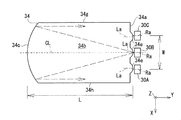
- FIG. 5A is a top view of the light guide panel showing the propagation of light emitted from the central light source 30B in the light guide panel.
- FIG. 5B is a top view of the light guide panel showing the propagation of light emitted from the outer light sources 30A and 30C in the light guide panel.
- the light emitted from the light sources 30A to 30C (shown by a plurality of different broken lines) is directed in the light guide panel 34 in a direction in which the display panel 32 and the light guide panel 34 face each other. It heads toward the first reflecting surface 34c while diverging in the (Z-axis direction).
- the first reflecting surface 34c has a concave shape when viewed in the facing direction (Z-axis direction) of the display panel 32 and the light guide panel 34. Specifically, the first reflecting surface 34c has a concave shape that reflects light so that the reflected light approaches parallel light.
- the concave shape of the first reflecting surface 34c When viewed from the facing direction (Z-axis direction) of the display panel 32 and the light guide panel 34, the concave shape of the first reflecting surface 34c has a combined focal length with the cylindrical lens 34e substantially equal to the length L of the light guide plate in the Y direction. Preferably.
- the reflected light of the first reflecting surface 34c of each light source is suppressed from diverging in the viewing direction (Z axis direction) of the display panel 32 and the light guide panel 34, That is, it propagates in the light guide panel 34 as substantially parallel light. Then, as shown in FIG. 3, the light is reflected by the second reflecting surface 34d and emitted from the emitting surface 34b.
- the first reflecting surface 34c is inclined toward the second reflecting surface 34d when viewed in the lateral direction (X-axis direction) of the display panel 32. It is preferable. That is, the first reflecting surface 34c intersects the second reflecting surface 34d at an angle smaller than 90 degrees.
- the reflected light of the first reflecting surface 34c is more efficient, that is, the emitting surface 34b is smaller in the number of reflections. Is emitted from. Therefore, the light is emitted from the emission surface 34b of the light guide panel 34 without being greatly attenuated in the light guide panel 34.
- the distance between the emission surface 34b and the second reflection surface 34d is the distance from the incidence surface 34a to the first reflection surface 34b. It is preferable that it is enlarged toward the first reflecting surface 34c.
- the light emitted from the light sources 30A to 30C is not reflected by the first reflection surface 34c, that is, becomes substantially parallel light when viewed in the facing direction (Z-axis direction) of the display panel 32 and the light guide panel 34. Without being formed, the emission from the emission surface 34b is suppressed. Specifically, part of the light emitted from the light sources 30A to 30C is reflected toward the first reflecting surface 34c without being reflected toward the emitting surface 34b by the second reflecting surface 34d. On the contrary, when the distance between the emission surface 34b and the second reflection surface 34d decreases from the incidence surface 34a toward the first reflection surface 34c, the light is emitted from the light sources 30A to 30C. Part of the light is reflected by the second reflecting surface 34d toward the emitting surface 34b.
- the first reflection surface 34c makes the display panel 32 and the light guide panel 34 substantially parallel light when viewed in the facing direction (Z-axis direction).
- the light sources 30A and 30C located outside when viewed in the facing direction (Z-axis direction) between the display panel 32 and the light guide panel 34 are It is preferable that the principal ray axis Ra is arranged so as to be offset to the outside with respect to the optical axis La of the corresponding cylindrical lens 34e.
- the position is on the center line CL passing through the center of the incident surface 34a and the center of the first reflecting surface 34c.
- the corresponding light source 30B is arranged such that its principal ray axis Ra is located on the same straight line as the optical axis La of the corresponding cylindrical lens 34e.
- the "principal ray axis" referred to here is an axis extending so as to coincide with the optical path of the ray having the highest intensity.
- the light emitted from the light source 30B and passing through the corresponding cylindrical lens 34e is directed to the first reflecting surface 34c in the extending direction (Y-axis direction) of the center line CL. Go to That is, the light can reach the entire first reflection surface 34c without being reflected by the side surfaces 34g and 34h of the light guide panel 34. As a result, most of the light from the light source 30B at the center becomes reflected light that is substantially parallel light when viewed from the facing direction (Z-axis direction) of the display panel 32 and the light guide panel 34 by the first reflecting surface 34c.
- the light sources 30A and 30C which are deviated from the center line CL of the light guide panel 34 when viewed from the facing direction (Z-axis direction) of the display panel 32 and the light guide panel 34,
- the principal ray axis Ra is arranged so as to be offset to the outside with respect to the optical axis La of the corresponding cylindrical lens 34e.
- the light emitted from the light sources 30A and 30C and passing through the corresponding cylindrical lens 34e propagates in a direction inclined inward with respect to the optical axis La of the corresponding cylindrical lens 34e. Thereby, the light can reach the first reflecting surface 34c without being reflected by the side surfaces 34g and 34h of the light guide panel 34.
- the principal ray axis of the reflected light of the first reflecting surfaces 34c of the light sources 30A and 30C arranged line-symmetrically with respect to the center line CL is on the center line CL of the light guide panel 32.
- the center line CL and particularly preferably at the center of the center line CL in the longitudinal direction (Y-axis direction) of the display panel 32.
- the light guide panel 34 emits light from its emission surface 34b so that the chief rays of the light sources 30A to 30C enter the central portion of the display panel 32.
- the shape of the light guide panel 34 for that purpose will be described with reference to FIG.
- FIG. 6 is a diagram showing shape parameters of the light guide panel.
- the parameter ⁇ is a value with respect to the orthogonal direction (Y-axis direction) of the facing direction (Z-axis direction) of the display panel 32 and the light guide panel 34, that is, the orthogonal direction of the incident surface 34a. This is the inclination angle of the second reflecting surface 34d.
- the parameter ⁇ is the direction in which the display panel 32 and the light guide panel 34 face each other (Z-axis direction), that is, the tilt angle of the first reflecting surface 34c with respect to the incident surface 34a.
- the critical angle ⁇ 2 can be expressed by the following mathematical formula 2.
- Equation 2 the parameter n is the refractive index of the light guide panel 34.
- the incident angle ⁇ 1 needs to be an angle at which total reflection occurs. That is, it is necessary to satisfy the condition shown in the following Expression 3.
- Equation 4 is a relational expression between the tilt angle ⁇ of the first reflecting surface 34c and the critical angle ⁇ 2 .
- Equation 5 is a condition under which light is emitted from the emission surface 34b without reaching the incidence surface 34a.
- the parameter N is the number of reflections of light after being reflected by the first reflection surface 34c and before being emitted from the light guide panel 34.
- the parameter d is a distance in the direction (Y-axis direction) orthogonal to the facing direction (Z-axis direction) of the display panel 32 and the light guide panel 34, in which the light is reflected once and propagates until the next reflection. The propagation distance in the Y-axis direction per rotation).
- the parameter L 1 is the length of the light guide panel in the direction (Y axis direction) orthogonal to the facing direction (Z axis direction) of the display panel 32 and the light guide panel 34.
- the number of reflections N can be calculated using the following formula 6.
- the second reflecting surface 34d is provided with a plurality of prisms 34f. Considering this prism 34f, when the rising angle of the prism 34f with respect to the second reflection surface 34d is ⁇ p , the formula 6 is replaced by the formula 7.
- the propagation distance d per reflection in Expression 5 can be calculated by Expression 8 below.
- (t 1 +t 2 )/2 in the first term on the right side indicates the average thickness of the entire light guide panel 34 (size in the facing direction (Z-axis direction) of the display panel 32 and the light guide panel 34). ing. Specifically, t 1 is the thickness of the light guide panel 34 at the incident surface 34a, and t 2 is the thickness of the light guide panel 34 at the first reflecting surface 34c.
- Equation 10 which is a condition for passing through the central portion is shown below.
- the parameter N′ is the number of reflections until the incident angle of the light reflected by the first reflecting surface 34c reaches the critical angle ⁇ 2 .
- the parameter d′ is a facing direction (Z-axis direction) of the display panel 32 and the light guide panel 34 in which the light reflected by the first reflecting surface 34c is reflected once and propagates until the next reflection. Is the distance (propagation distance per reflection) in the orthogonal direction (Y-axis direction).
- the parameter L 2 is the Y-axis between the position of the light guide panel 34 corresponding to the center (center point CP) of the display panel 32 in the Y-axis direction and the first reflecting surface 34c. The distance in the direction.
- the number of reflections N′ in Expression 10 is the same as Expression 6 as shown in Expression 11 below.
- the propagation distance d′ for each reflection in Expression 10 can be calculated by Expression 12 below.
- (t 2 +t 3 )/2 of the first term on the right side is the position of the light guide panel 34 corresponding to the center (center point CP) of the display panel 32 in the Y-axis direction and the first reflecting surface 34c.
- the average thickness of the light guide panel 34 (the size of the display panel 32 and the light guide panel 34 in the opposing direction (Z-axis direction)) is shown.
- t 2 is the thickness of the light guide panel 34 at the first reflection surface 34c
- t 3 is the light guide panel corresponding to the center (center point CP) of the display panel 32 in the Y-axis direction.
- the thickness of the light guide panel 34 at the position 34 is shown.
- the product of the number of reflections N′ until the incident angle calculated by Expression 11 becomes the critical angle ⁇ 2 and the propagation distance d′ per reflection calculated by Expression 12 is as shown in Expression 10.
- the light reflected by the first reflecting surface 34c can pass through the central portion of the display panel 32 in the range of 1/2 to 3/2 times the panel length L 2 .
- the light guide panel 34 is obtained. Can emit light from its emission surface 34b so that a large amount of light passes through the central portion of the display panel 32.
- the display device 20 According to the display device 20 according to the first embodiment as described above, it is possible to output a high-luminance image. This will be specifically described.
- FIG. 7 is a diagram showing the positional relationship between the display device according to the first embodiment and the observer's eye box.
- the light (image) output from the display device 20 is guided to the eye box EB of the observer Ob via the reflection optical system RS.
- the eye box EB of the observer Ob riding in the vehicle 10 is a region in which the left-right direction D1 is long and the up-down direction D2 is short.
- the left-right direction and the up-down direction are directions with respect to the observer Ob.
- the left-right direction D1 substantially corresponds to the vehicle width direction of the vehicle 10
- the up-down direction D2 substantially corresponds to the height direction of the vehicle 10.
- the head-up display 14 is mounted on the vehicle 10 so that the lateral direction (X-axis direction) of the display panel 32 of the display device 20 corresponds to the vertical direction D2 of the eye box EB. There is.
- the substantially parallel light is seen in the facing direction (Z-axis direction) of the display panel 32 and the light guide panel 34.
- the light propagating in the light guide panel 34 is emitted from the light guide panel 34 toward the display panel 32 in a state of being substantially parallel light.
- light in a state in which divergence of the display panel 32 in the lateral direction (X-axis direction) is suppressed is output from the display device 20.
- a part of the light is suppressed from passing above and below the eye box EB of the observer Ob, and the amount of light reaching the eye box EB is increased.
- the amount of light output from the display device increases, and the brightness of the image displayed on the windshield 12 increases.
- the head-up display 14 is arranged with respect to the eye box EB so that the vertical direction D2 of the eye box EB of the observer Ob corresponds to the lateral direction (X axis direction) of the display panel 32.
- the light guide panel 34 is manufactured so as to satisfy the following inequalities, for example.
- S(d2) is the size of the eye box EB in the vertical direction D2.
- L is the length of the light guide panel 34 in the longitudinal direction (Y-axis direction) of the display panel 32, and W is between the outermost light sources 30A and 30C. It is a distance.
- a display device mounted on a head-up display of a vehicle can output a high-luminance image.
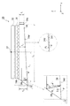
- FIG. 8 is a perspective view of a light guide panel in the display device according to the second embodiment of the present disclosure.
- FIG. 9 is a top view of the light guide panel showing an incident surface of the light guide panel according to the second embodiment.
- the light guide panel 134 of the display device includes a plurality of cylindrical lenses 134e on the incident surface 134a thereof, as in the above-described first embodiment.
- a pair of prisms 134j arranged so as to sandwich the cylindrical lens 134e is provided for each cylindrical lens 134e.
- Each prism 134j includes a light-trapping surface 134k and a reflecting surface 134l.
- Light emitted from the light sources 30A to 30D at an angle that cannot enter the cylindrical lens 134e is taken into the light guide panel 134 via the light taking-in surface 134k of the prism 134j, and is reflected by the reflecting surface 134l in the longitudinal direction of the display panel 32 (Y Reflected in the axial direction). Thereby, most of the light emitted from the plurality of light sources 30A to 30D is taken into the light guide panel 134. As a result, the display device can output an image with higher brightness.
- the display device, the head-up display including the display device, and the vehicle including the head-up display according to the present disclosure have been described above with reference to the above-described embodiments, the embodiments of the present disclosure are not limited thereto. ..
- the incident surface 34a of the light guide panel 34 is provided with a plurality of cylindrical lenses 34e corresponding to the plurality of light sources 30A to 30C.
- the embodiment of the present disclosure is not limited to this.
- the prism sheet that changes the traveling direction of the light so that the light emitted from the emission surface 34b of the light guide panel 34 is directed to the display panel 32.
- An optical member 36 such as is disposed between the display panel 32 and the light guide panel 34.
- the embodiment of the present disclosure is not limited to this.
- the second reflecting surface 34d may reflect light toward the emitting surface 34b in a direction close to the normal direction of the display panel 32. Thereby, it is not necessary to dispose the optical member 36 for changing the traveling direction of the light emitted from the light guide panel 34, between the display panel 32 and the light guide panel 34.
- the moving body is the vehicle 10 such as an automobile
- the moving body is not limited to the vehicle 10.
- the moving body may be a vehicle on which a person rides, for example, an airplane or a ship.
- the mobile may be an unmanned aerial vehicle.
- the moving body may vibrate instead of traveling.
- the present disclosure can be applied to a display device. Further, the present disclosure can be applied to a head-up display.
Landscapes
- Physics & Mathematics (AREA)
- Engineering & Computer Science (AREA)
- Optics & Photonics (AREA)
- General Physics & Mathematics (AREA)
- Mechanical Engineering (AREA)
- Chemical & Material Sciences (AREA)
- Transportation (AREA)
- Combustion & Propulsion (AREA)
- Multimedia (AREA)
- General Engineering & Computer Science (AREA)
- Instrument Panels (AREA)
- Liquid Crystal (AREA)
- Planar Illumination Modules (AREA)
Abstract
This display device has: light sources (30A-30C) for emitting light; a display panel (32) for displaying an image; and a light guide panel (34) for guiding the light emitted from the light sources (30A-30C) to the display panel. The light guide panel (34) includes an incidence surface (34a) facing the light sources (30A-30C), an exit surface (34b) facing the display panel, a first reflection surface (34c) facing the incidence surface (34a), and a second reflection surface (34d) facing the exit surface (34b). The first reflection surface (34c) has a concave shape for reflecting light so that the reflected light is close to being parallel light as viewed in a direction in which the display panel and the light guide panel face each other in the light guide panel (34), and is inclined at an angle greater than 0 degree with respect to the incidence surface (34a) and intersects the second reflection surface (34d) at an angle smaller than 90 degrees.
Description
本開示は、表示装置、表示装置を備えるヘッドアップディスプレイ、ヘッドアップディスプレイを備える移動体、および導光パネルに関する。
The present disclosure relates to a display device, a head-up display including the display device, a moving body including the head-up display, and a light guide panel.
特許文献1には、車両に搭載されて表示装置を備えるヘッドアップディスプレイが開示されている。ヘッドアップディスプレイから出力された光(映像)は、ウインドシールドを介して、乗員(観察者)のアイボックス内に導かれる。
Patent Document 1 discloses a head-up display that is mounted on a vehicle and includes a display device. The light (image) output from the head-up display is guided into the eye box of the occupant (observer) via the windshield.
特許文献1に記載のヘッドアップディスプレイの表示装置は、光源と、映像を表示する透過型の表示パネルと、光源からの光を表示パネルに導光する導光パネルとを有する。光源から出射された光は、導光パネルの入射面を介してその内部に入り、その導光パネル内で反射し、そして出射面を介して導光パネルの外部に出射される。導光パネルから出射された光は、表示パネルを通過し、最終的に観察者のアイボックスに到達する。
The display device of the head-up display described in Patent Document 1 has a light source, a transmissive display panel that displays an image, and a light guide panel that guides light from the light source to the display panel. The light emitted from the light source enters the inside of the light guide panel via the incident surface, is reflected in the light guide panel, and is emitted to the outside of the light guide panel via the emission surface. The light emitted from the light guide panel passes through the display panel and finally reaches the observer's eye box.
しかしながら、特許文献1に記載された表示装置の場合、表示パネルと導光パネルとの対向方向視で、光は、大きく発散しつつ導光パネル内を伝播し、導光パネルの出射面から発散しつつ表示パネルに向かって出射される。そのため、表示装置から出力されてウインドシールドに映る映像の輝度が低下する。
However, in the case of the display device described in Patent Document 1, when viewed from the opposite direction of the display panel and the light guide panel, light propagates in the light guide panel while largely diverging, and diverges from the emission surface of the light guide panel. Then, the light is emitted toward the display panel. Therefore, the brightness of the image output from the display device and reflected on the windshield is reduced.
そこで、本開示は、例えば車両のヘッドアップディスプレイに搭載される表示装置において、高輝度の映像を出力することを目的とする。
Therefore, the present disclosure is intended to output a high-luminance image in a display device mounted on, for example, a head-up display of a vehicle.
本開示の一態様によれば、
光を出射する光源と、
映像を表示する表示パネルと、
前記光源から出射された光を前記表示パネルに導光する導光パネルと、を有し、
前記導光パネルが、前記光源に対向する入射面、前記表示パネルに対向する出射面、前記入射面に対向する第1の反射面、および前記出射面に対向する第2の反射面を含み、
前記第1の反射面が、前記導光パネル内において前記表示パネルと前記導光パネルの対向方向視で反射光が平行光に近づくように光を反射する凹面形状を備え、且つ、前記入射面に対して0度より大きい角度で傾斜し、前記第2の反射面と90度より小さい角度で交差している、表示装置が提供される。 According to one aspect of the present disclosure,
A light source that emits light,
A display panel that displays images,
A light guide panel for guiding the light emitted from the light source to the display panel,
The light guide panel includes an entrance surface facing the light source, an exit surface facing the display panel, a first reflecting surface facing the entrance surface, and a second reflecting surface facing the exit surface,
The first reflection surface has a concave shape that reflects light in the light guide panel such that the reflected light approaches parallel light when viewed from the opposite direction of the display panel and the light guide panel, and the incident surface A display device is provided that is tilted at an angle greater than 0 degrees with respect to and intersects the second reflective surface at an angle less than 90 degrees.
本開示の別の態様によれば、
上述の表示装置を有する、ヘッドアップディスプレイが提供される。 According to another aspect of the disclosure,
There is provided a head-up display having the display device described above.
上述の表示装置を有する、ヘッドアップディスプレイが提供される。 According to another aspect of the disclosure,
There is provided a head-up display having the display device described above.
本開示の異なる態様によれば、
上述のヘッドアップディスプレイと、
前記ヘッドアップディスプレイから出力された映像が投影されるウインドシールドと、を有する、移動体が提供される。 According to different aspects of the disclosure,
The above head-up display,
And a windshield onto which an image output from the head-up display is projected.
上述のヘッドアップディスプレイと、
前記ヘッドアップディスプレイから出力された映像が投影されるウインドシールドと、を有する、移動体が提供される。 According to different aspects of the disclosure,
The above head-up display,
And a windshield onto which an image output from the head-up display is projected.
本開示のさらに異なる態様によれば、
光源から出射された光を表示パネルに導光する導光パネルであって、
前記光源に対向する入射面、前記表示パネルに対向する出射面、前記入射面に対向する第1の反射面、および前記出射面に対向する第2の反射面を含み、
前記第1の反射面が、前記導光パネル内において前記表示パネルと前記導光パネルの対向方向視で反射光が平行光に近づくように光を反射する凹面形状を備え、且つ、前記入射面に対して0度より大きい角度で傾斜し、前記第2の反射面と90度より小さい角度で交差している、導光パネルが提供される。 According to yet another aspect of the disclosure,
A light guide panel that guides light emitted from a light source to a display panel,
An entrance surface facing the light source, an exit surface facing the display panel, a first reflecting surface facing the entrance surface, and a second reflecting surface facing the exit surface,
The first reflection surface has a concave shape that reflects light in the light guide panel such that the reflected light approaches parallel light when viewed from the opposite direction of the display panel and the light guide panel, and the incident surface A light guide panel is provided that is inclined at an angle greater than 0 degrees with respect to and intersects the second reflective surface at an angle less than 90 degrees.
本開示によれば、例えば移動体のヘッドアップディスプレイに搭載される表示装置において、高輝度の映像を出力することができる。
According to the present disclosure, for example, a display device mounted on a head-up display of a moving body can output a high-luminance image.
以下、適宜図面を参照しながら、実施の形態を詳細に説明する。但し、必要以上に詳細な説明は省略する場合がある。例えば、既によく知られた事項の詳細説明や実質的に同一の構成に対する重複説明を省略する場合がある。これは、以下の説明が不必要に冗長になるのを避け、当業者の理解を容易にするためである。
Hereinafter, embodiments will be described in detail with reference to the drawings as appropriate. However, more detailed description than necessary may be omitted. For example, detailed description of well-known matters and repeated description of substantially the same configuration may be omitted. This is for avoiding unnecessary redundancy in the following description and for facilitating understanding by those skilled in the art.
なお、発明者(ら)は、当業者が本開示を十分に理解するために添付図面および以下の説明を提供するのであって、これらによって特許請求の範囲に記載の主題を限定することを意図するものではない。
It should be noted that the inventor(s) provides the accompanying drawings and the following description for those skilled in the art to fully understand the present disclosure, and intends to limit the subject matter described in the claims by these. Not something to do.
以下に、本開示の複数の実施の形態に係る表示装置について図1~図8を参照して説明する。
Hereinafter, display devices according to a plurality of embodiments of the present disclosure will be described with reference to FIGS. 1 to 8.
(実施の形態1)
図1は、本実施の形態1に係るヘッドアップディスプレイを搭載した車両の概略図である。 (Embodiment 1)
FIG. 1 is a schematic diagram of a vehicle equipped with a head-up display according to the first embodiment.
図1は、本実施の形態1に係るヘッドアップディスプレイを搭載した車両の概略図である。 (Embodiment 1)
FIG. 1 is a schematic diagram of a vehicle equipped with a head-up display according to the first embodiment.
図1に示すように、車両10は、例えば自動車であって、透明のウインドシールド12、すなわちフロントガラスに光(映像)を投影するヘッドアップディスプレイ14を搭載している。
As shown in FIG. 1, a vehicle 10 is, for example, an automobile, and is equipped with a transparent windshield 12, that is, a head-up display 14 that projects light (image) on a windshield.
ヘッドアップディスプレイ14から出力された光(映像)は、ウインドシールド12を介して、車両10に搭乗する運転者などの観察者ObのアイボックスEB内に導かれる。これにより、観察者Obは虚像Ivを視認する。すなわち、ウインドシールド12を介して見える風景とそれに重なった虚像Ivとを、観察者Obは視認する。なお、アイボックスEBは、観察者Obが虚像を欠けることなく視認できる空間領域である。
The light (image) output from the head-up display 14 is guided through the windshield 12 into the eye box EB of an observer Ob, such as a driver who rides in the vehicle 10. Thereby, the observer Ob visually recognizes the virtual image Iv. That is, the observer Ob visually recognizes the landscape seen through the windshield 12 and the virtual image Iv overlapping with it. The eye box EB is a space area that the observer Ob can visually recognize without missing a virtual image.
ヘッドアップディスプレイ14は、筐体16を有する。その筐体16内部に、表示装置20と、表示装置20から出力された光(映像)をウインドシールド12に導くための複数のミラー22、24とを有する。例えば、表示装置20から出力された光を反射する凸ミラー22と、凸ミラー22からの光をウインドシールド12に向かって反射する凹ミラー24とが筐体16内に設けられている。ウインドシールド12と、複数のミラー22、24が、表示装置20から出力された光を観察者ObのアイボックスEBに導く反射光学系RSを構成している。なお、表示装置20からアイボックスEBまでの反射光学系RSについては、ヘッドアップディスプレイ14の車両搭載条件によって異なる。
The head-up display 14 has a housing 16. A display device 20 and a plurality of mirrors 22 and 24 for guiding light (image) output from the display device 20 to the windshield 12 are provided inside the housing 16. For example, a convex mirror 22 that reflects the light output from the display device 20 and a concave mirror 24 that reflects the light from the convex mirror 22 toward the windshield 12 are provided in the housing 16. The windshield 12 and the plurality of mirrors 22 and 24 form a reflection optical system RS that guides the light output from the display device 20 to the eye box EB of the observer Ob. The reflective optical system RS from the display device 20 to the eye box EB differs depending on the vehicle mounting conditions of the head-up display 14.
図2は、本実施の形態1に係る表示装置の斜視図である。図3は、本実施の形態1に係る表示装置の断面図である。なお、図中において示すX-Y-Z座標系は、本開示の理解を容易にするためのものであって、本開示を限定するものではない。
FIG. 2 is a perspective view of the display device according to the first embodiment. FIG. 3 is a cross-sectional view of the display device according to the first embodiment. The XYZ coordinate system shown in the drawings is for facilitating the understanding of the present disclosure and does not limit the present disclosure.
図2および図3に示すように、本実施の形態1に係る表示装置20は、複数の光源30A~30Cと、映像を表示する表示パネル32と、光源30A~30Cから出射された光を表示パネル32に向かって導光する導光パネル34とを有する。
As shown in FIGS. 2 and 3, the display device 20 according to the first embodiment displays a plurality of light sources 30A to 30C, a display panel 32 for displaying an image, and light emitted from the light sources 30A to 30C. And a light guide panel 34 that guides light toward the panel 32.
光源30A~30Cは、本実施の形態1の場合、LEDである。なお、光源の数は、3個に限らず、場合によっては1個、2個または4個以上であってもよい。
The light sources 30A to 30C are LEDs in the case of the first embodiment. The number of light sources is not limited to three, and may be one, two, or four or more depending on the case.
表示パネル32は、本実施の形態1の場合、透過型の液晶パネルである。本実施の形態1の場合、表示パネル32は、長手方向(Y軸方向)と短手方向(X軸方向)とを備える矩形状である。すなわち、表示パネル32は、長手方向と短手方向とを備える映像を表示する。
The display panel 32 is a transmissive liquid crystal panel in the case of the first embodiment. In the case of the first embodiment, the display panel 32 has a rectangular shape having a longitudinal direction (Y-axis direction) and a lateral direction (X-axis direction). That is, the display panel 32 displays an image having a longitudinal direction and a lateral direction.
図4Aは、導光パネルの前方斜視図である。図4Bは、導光パネルの後方斜視図である。
FIG. 4A is a front perspective view of the light guide panel. FIG. 4B is a rear perspective view of the light guide panel.
図4Aおよび図4Bに示すように、導光パネル34は、透明な材料、例えば樹脂材料などから作製されたパネル状の部材である。具体的には、導光パネル34は、光源30A~30Cに対向する入射面34aと、表示パネル32に対向する出射面34bと、入射面34aに対向する第1の反射面34cと、出射面34bに対向する第2の反射面34dとを含んでいる。
As shown in FIGS. 4A and 4B, the light guide panel 34 is a panel-shaped member made of a transparent material such as a resin material. Specifically, the light guide panel 34 includes an entrance surface 34a facing the light sources 30A to 30C, an exit surface 34b facing the display panel 32, a first reflecting surface 34c facing the entrance surface 34a, and an exit surface. And a second reflecting surface 34d that faces 34b.
本実施の形態1の場合、図2および図3に示すように、導光パネル34の入射面34aに対して、複数の光源30A~30Cそれぞれは、表示パネル32の長手方向(Y軸方向)に対向している。また、入射面34aに沿うように、表示パネル32と導光パネル34の対向方向(Z軸方向)に対して直交する方向である表示パネル32の短手方向(X軸方向)に、複数の光源30A~30Cは並んでいる。複数の光源30A~30Cそれぞれから出射された光は、入射面34aを介して導光パネル34内に進入する。
In the case of the first embodiment, as shown in FIGS. 2 and 3, with respect to the incident surface 34a of the light guide panel 34, the plurality of light sources 30A to 30C are respectively arranged in the longitudinal direction (Y-axis direction) of the display panel 32. Is facing. In addition, along the incident surface 34a, a plurality of display panels 32 are arranged in the lateral direction (X-axis direction) of the display panel 32 which is a direction orthogonal to the facing direction (Z-axis direction) of the display panel 32 and the light guide panel 34. The light sources 30A to 30C are arranged side by side. The light emitted from each of the plurality of light sources 30A to 30C enters the light guide panel 34 via the incident surface 34a.
本実施の形態1の場合、複数の光源30A~30Cそれぞれと対向する導光パネル34の入射面34aの部分には、シリンドリカルレンズ34eが一体的に設けられている。
In the case of the first embodiment, a cylindrical lens 34e is integrally provided at a portion of the incident surface 34a of the light guide panel 34 facing each of the plurality of light sources 30A to 30C.
シリンドリカルレンズ34eそれぞれは、表示パネル32と導光パネル34の対向方向(Z軸方向)に延在する中心線を部分的に周回する湾曲面を備える。この湾曲面に対して、光源30A~30Cが対向している。表示パネル32と導光パネル34の対向方向(Z軸方向)視で、光源30A~30Cそれぞれから出射されて発散しつつシリンドリカルレンズ34eに入射した光は、シリンドリカルレンズ34eによって導光パネル34の側面34g、34hで反射されない程度に狭角配光化される。
Each of the cylindrical lenses 34e has a curved surface that partially circumscribes a center line extending in the opposing direction (Z-axis direction) of the display panel 32 and the light guide panel 34. The light sources 30A to 30C are opposed to this curved surface. When viewed from the opposite direction (Z-axis direction) of the display panel 32 and the light guide panel 34, the light emitted from each of the light sources 30A to 30C and incident on the cylindrical lens 34e while being diverged, the side surface of the light guide panel 34 by the cylindrical lens 34e. The light distribution is narrowed so that it is not reflected by 34g and 34h.
導光パネル34の出射面34bは、表示パネル32に対向する面である。この出射面34bから出射された光は、表示パネル32を透過して最終的に観察者ObのアイボックスEBに到達する。
The emission surface 34b of the light guide panel 34 is a surface facing the display panel 32. The light emitted from the emission surface 34b passes through the display panel 32 and finally reaches the eye box EB of the observer Ob.
本実施の形態1の場合、表示装置20は、表示パネル32と導光パネル34との間にプリズムシートなどの光学部材36を有する。光学部材36は、導光パネル34の出射面34bから出射された光が表示パネル32に向かうように、その光の進行方向を変更する。具体的には、光学部材36は、その光学部材36から出射された光の進行方向を表示パネル32の法線方向(Z軸方向)に近づくように変更する。
In the case of the first embodiment, the display device 20 has an optical member 36 such as a prism sheet between the display panel 32 and the light guide panel 34. The optical member 36 changes the traveling direction of the light so that the light emitted from the emission surface 34b of the light guide panel 34 is directed to the display panel 32. Specifically, the optical member 36 changes the traveling direction of the light emitted from the optical member 36 so as to approach the normal direction (Z-axis direction) of the display panel 32.
導光パネル34の第1の反射面34cは、入射面34aに対して対向する面であって、導光パネル34内で光を反射する。すなわち、第1の反射面34cは、入射面34aを挟んで、光源30A~30Cに対向する。また、第1の反射面34cを介して導光パネル34の外部に光が漏れないようにミラー38が設けられている。ミラー38は、例えば、第1の反射面34cの外側に設けられた鏡面反射フィルムである。なお、この第1の反射面34cのさらなる詳細については後述する。
The first reflecting surface 34c of the light guide panel 34 is a surface facing the incident surface 34a and reflects light inside the light guide panel 34. That is, the first reflecting surface 34c faces the light sources 30A to 30C with the entrance surface 34a interposed therebetween. Further, a mirror 38 is provided so that light does not leak to the outside of the light guide panel 34 via the first reflecting surface 34c. The mirror 38 is, for example, a specular reflection film provided outside the first reflection surface 34c. Note that further details of the first reflecting surface 34c will be described later.
導光パネル34の第2の反射面34dは、出射面34bに対して対向する面であって、導光パネル34内で光を反射する。本実施の形態1の場合、図3に示すように、理由は後述するが、第2の反射面34dは、出射面34bに対して傾斜した面である。具体的には、入射面34aから第1の反射面34cに向かうにしたがって、出射面34bと第2の反射面34dとの間の距離が拡大している。
The second reflection surface 34d of the light guide panel 34 is a surface facing the emission surface 34b and reflects light inside the light guide panel 34. In the case of the first embodiment, as shown in FIG. 3, the second reflecting surface 34d is a surface inclined with respect to the emitting surface 34b, although the reason will be described later. Specifically, the distance between the emission surface 34b and the second reflection surface 34d is increased from the incident surface 34a toward the first reflection surface 34c.
さらに、本実施の形態1の場合、導光パネル34の第2の反射面34dは、複数のプリズム34fから構成されるプリズム面である。このプリズム面により、第2の反射面34dによって反射されて出射面34bに向かう光は、臨界角に比べて小さい入射角で出射面34bに入射することができる。その結果、出射面34bから出射する光量が増加する。また、第2の反射面34dを介して導光パネル34の外部に光は漏れないようにミラー40が設けられている。ミラー40は、例えば、第2の反射面34dの外側に設けられた鏡面反射フィルムである。
Further, in the case of the first embodiment, the second reflecting surface 34d of the light guide panel 34 is a prism surface composed of a plurality of prisms 34f. By this prism surface, the light reflected by the second reflecting surface 34d and traveling toward the emitting surface 34b can enter the emitting surface 34b at an incident angle smaller than the critical angle. As a result, the amount of light emitted from the emission surface 34b increases. Further, a mirror 40 is provided so that light does not leak to the outside of the light guide panel 34 via the second reflecting surface 34d. The mirror 40 is, for example, a specular reflection film provided outside the second reflection surface 34d.
このような導光パネル34によれば、図3に示すように、光源30A~30Cから出射された光(光線)LBは、入射面34aを介して導光パネル34内に入り、その導光パネル34内において出射面34b、第1の反射面34c、および第2の反射面34dのいずれかで反射され、そして、最終的には出射面34bを介して導光パネル34の外部に出射される。導光パネル34から出射された光は、光学部材36によって進行方向を変更された後、表示パネル32を透過する。
According to such a light guide panel 34, as shown in FIG. 3, the light (light ray) LB emitted from the light sources 30A to 30C enters the light guide panel 34 through the incident surface 34a and guides the light. In the panel 34, it is reflected by any one of the emission surface 34b, the first reflection surface 34c, and the second reflection surface 34d, and finally emitted to the outside of the light guide panel 34 via the emission surface 34b. It The light emitted from the light guide panel 34 has its traveling direction changed by the optical member 36, and then passes through the display panel 32.
ここからは、導光パネル34における第1の反射面34cのさらなる詳細について説明する。
From here, further details of the first reflecting surface 34c of the light guide panel 34 will be described.
図5Aは、中央の光源30Bから出射された光の導光パネル内での伝播を示す導光パネルの上面図である。図5Bは、外側の光源30A、30Cから出射された光の導光パネル内での伝播を示す導光パネルの上面図である。
FIG. 5A is a top view of the light guide panel showing the propagation of light emitted from the central light source 30B in the light guide panel. FIG. 5B is a top view of the light guide panel showing the propagation of light emitted from the outer light sources 30A and 30C in the light guide panel.
図5Aおよび図5Bに示すように、光源30A~30Cから出射された光(異なる複数の破線で示されている)は、導光パネル34内において、表示パネル32と導光パネル34の対向方向(Z軸方向)視で発散しつつ第1の反射面34cに向かう。その第1の反射面34cは、表示パネル32と導光パネル34の対向方向(Z軸方向)視で凹面形状を備える。具体的には、第1の反射面34cは、その反射光が平行光に近づくように光を反射する凹面形状である。表示パネル32と導光パネル34の対向方向(Z軸方向)視で、第1の反射面34cの凹面形状は、シリンドリカルレンズ34eとの合成焦点距離が導光板のY方向長さLとほぼ一致することが好ましい。
As shown in FIGS. 5A and 5B, the light emitted from the light sources 30A to 30C (shown by a plurality of different broken lines) is directed in the light guide panel 34 in a direction in which the display panel 32 and the light guide panel 34 face each other. It heads toward the first reflecting surface 34c while diverging in the (Z-axis direction). The first reflecting surface 34c has a concave shape when viewed in the facing direction (Z-axis direction) of the display panel 32 and the light guide panel 34. Specifically, the first reflecting surface 34c has a concave shape that reflects light so that the reflected light approaches parallel light. When viewed from the facing direction (Z-axis direction) of the display panel 32 and the light guide panel 34, the concave shape of the first reflecting surface 34c has a combined focal length with the cylindrical lens 34e substantially equal to the length L of the light guide plate in the Y direction. Preferably.
図5Aおよび図5Bに示すように、各光源の第1の反射面34cの反射光は、表示パネル32と導光パネル34の対向方向(Z軸方向)視で発散を抑制された状態で、すなわち略平行光で導光パネル34内を伝播する。そして、図3に示すように、光は、第2の反射面34dで反射され、出射面34bから出射される。
As shown in FIG. 5A and FIG. 5B, the reflected light of the first reflecting surface 34c of each light source is suppressed from diverging in the viewing direction (Z axis direction) of the display panel 32 and the light guide panel 34, That is, it propagates in the light guide panel 34 as substantially parallel light. Then, as shown in FIG. 3, the light is reflected by the second reflecting surface 34d and emitted from the emitting surface 34b.
図3に示すように、本実施の形態1の場合、第1の反射面34cは、表示パネル32の短手方向(X軸方向)視で第2の反射面34dに向かって傾斜していることが好ましい。つまり、第1の反射面34cは、第2の反射面34dと90度より小さい角度で交差している。
As shown in FIG. 3, in the case of the first embodiment, the first reflecting surface 34c is inclined toward the second reflecting surface 34d when viewed in the lateral direction (X-axis direction) of the display panel 32. It is preferable. That is, the first reflecting surface 34c intersects the second reflecting surface 34d at an angle smaller than 90 degrees.
この場合、第1の反射面34cの反射光の多くが、第2の反射面34dに向かい、そして第2の反射面34dで出射面34bに向かって反射される。これにより、第1の反射面34cが第2の反射面34dに向かって傾斜していない場合に比べて、第1の反射面34cの反射光が、効率よく、すなわち少ない反射回数で出射面34bから出射される。そのため、導光パネル34内で大きく減衰することなく、導光パネル34の出射面34bから出射される。
In this case, most of the light reflected by the first reflecting surface 34c is reflected toward the second reflecting surface 34d, and is reflected by the second reflecting surface 34d toward the emitting surface 34b. As a result, compared with the case where the first reflecting surface 34c is not inclined toward the second reflecting surface 34d, the reflected light of the first reflecting surface 34c is more efficient, that is, the emitting surface 34b is smaller in the number of reflections. Is emitted from. Therefore, the light is emitted from the emission surface 34b of the light guide panel 34 without being greatly attenuated in the light guide panel 34.
また、上述したようにおよび図3に示すように、本実施の形態1の場合、導光パネル34において、出射面34bと第2の反射面34dとの間の距離は、入射面34aから第1の反射面34cに向かうにしたがって拡大しているのが好ましい。
Further, as described above and as shown in FIG. 3, in the case of the first embodiment, in the light guide panel 34, the distance between the emission surface 34b and the second reflection surface 34d is the distance from the incidence surface 34a to the first reflection surface 34b. It is preferable that it is enlarged toward the first reflecting surface 34c.
この場合、光源30A~30Cから出射された光が、第1の反射面34cで反射されることなく、すなわち表示パネル32と導光パネル34の対向方向(Z軸方向)視で略平行光になることなく、出射面34bから出射することが抑制される。具体的には、光源30A~30Cから出射された光の一部が、第2の反射面34dで出射面34bに向かって反射されずに、第1の反射面34cに向かって反射される。これとは逆に、出射面34bと第2の反射面34dとの間の距離が入射面34aから第1の反射面34cに向かうにしたがって減少している場合、光源30A~30Cから出射された光の一部が、第2の反射面34dで出射面34bに向かって反射される。
In this case, the light emitted from the light sources 30A to 30C is not reflected by the first reflection surface 34c, that is, becomes substantially parallel light when viewed in the facing direction (Z-axis direction) of the display panel 32 and the light guide panel 34. Without being formed, the emission from the emission surface 34b is suppressed. Specifically, part of the light emitted from the light sources 30A to 30C is reflected toward the first reflecting surface 34c without being reflected toward the emitting surface 34b by the second reflecting surface 34d. On the contrary, when the distance between the emission surface 34b and the second reflection surface 34d decreases from the incidence surface 34a toward the first reflection surface 34c, the light is emitted from the light sources 30A to 30C. Part of the light is reflected by the second reflecting surface 34d toward the emitting surface 34b.
したがって、出射面34bと第2の反射面34dとの間の距離が入射面34aから第1の反射面34cに向かうにしたがって拡大することにより、光源30A~30Cから出射された光の多くが、第1の反射面34cによって表示パネル32と導光パネル34の対向方向(Z軸方向)視で略平行光になる。
Therefore, as the distance between the emission surface 34b and the second reflection surface 34d increases from the incidence surface 34a toward the first reflection surface 34c, most of the light emitted from the light sources 30A to 30C is The first reflection surface 34c makes the display panel 32 and the light guide panel 34 substantially parallel light when viewed in the facing direction (Z-axis direction).
さらに、図5Aおよび図5Bに示すように、本実施の形態1の場合、表示パネル32と導光パネル34との対向方向(Z軸方向)視で、外側に位置する光源30A、30Cは、その主光線軸Raが対応するシリンドリカルレンズ34eの光軸Laに対して外側にオフセットするように配置されているのが好ましい。
Further, as shown in FIGS. 5A and 5B, in the case of the first embodiment, the light sources 30A and 30C located outside when viewed in the facing direction (Z-axis direction) between the display panel 32 and the light guide panel 34 are It is preferable that the principal ray axis Ra is arranged so as to be offset to the outside with respect to the optical axis La of the corresponding cylindrical lens 34e.
図5Aに示すように、表示パネル32と導光パネル34との対向方向(Z軸方向)視で入射面34aの中心と第1の反射面34cの中心とを通過する中心線CL上に位置する光源30Bは、その主光線軸Raが対応するシリンドリカルレンズ34eの光軸Laと同一直線上に位置するように配置されている。なお、ここで言う「主光線軸」は、最も強度が高い光線の光路に一致するように延在する軸である。
As shown in FIG. 5A, when viewed from the facing direction (Z-axis direction) of the display panel 32 and the light guide panel 34, the position is on the center line CL passing through the center of the incident surface 34a and the center of the first reflecting surface 34c. The corresponding light source 30B is arranged such that its principal ray axis Ra is located on the same straight line as the optical axis La of the corresponding cylindrical lens 34e. The "principal ray axis" referred to here is an axis extending so as to coincide with the optical path of the ray having the highest intensity.
このようなシリンドリカルレンズ34eに対する光源30Bの配置により、光源30Bから出射して対応するシリンドリカルレンズ34eを通過した光は、中心線CLの延在方向(Y軸方向)に第1の反射面34cに向かう。すなわち、光は、導光パネル34の側面34g、34hで反射されることなく、第1の反射面34c全体に到達することができる。その結果、中央の光源30Bの光の多くが、第1の反射面34cにより、表示パネル32と導光パネル34の対向方向(Z軸方向)視で略平行光である反射光となる。
Due to such arrangement of the light source 30B with respect to the cylindrical lens 34e, the light emitted from the light source 30B and passing through the corresponding cylindrical lens 34e is directed to the first reflecting surface 34c in the extending direction (Y-axis direction) of the center line CL. Go to That is, the light can reach the entire first reflection surface 34c without being reflected by the side surfaces 34g and 34h of the light guide panel 34. As a result, most of the light from the light source 30B at the center becomes reflected light that is substantially parallel light when viewed from the facing direction (Z-axis direction) of the display panel 32 and the light guide panel 34 by the first reflecting surface 34c.
これに対して、図5Bに示すように、表示パネル32と導光パネル34との対向方向(Z軸方向)視で、導光パネル34の中心線CLから外れている光源30A、30Cは、その主光線軸Raが対応するシリンドリカルレンズ34eの光軸Laに対して外側にオフセットするように配置されている。これにより、光源30A、30Cから出射して対応するシリンドリカルレンズ34eを通過した光は、対応するシリンドリカルレンズ34eの光軸Laに対して内側に傾いた方向に伝播する。それにより、その光は、導光パネル34の側面34g、34hで反射されることなく、第1の反射面34cに到達することができる。その結果、外側の光源30A、30Cの光の多くが、第1の反射面34cにより、表示パネル32と導光パネル34の対向方向(Z軸方向)視で略平行光である反射光となる。なお、図5Bに示すように中心線CLに対して線対称に配置されている光源30Aと30Cの第1の反射面34cの反射光の主光線軸は、導光パネル32の中心線CL上で交わるのが好ましく、特に、中心線CLの表示パネル32の長手方向(Y軸方向)の中央で交わることが好ましい。
On the other hand, as shown in FIG. 5B, the light sources 30A and 30C, which are deviated from the center line CL of the light guide panel 34 when viewed from the facing direction (Z-axis direction) of the display panel 32 and the light guide panel 34, The principal ray axis Ra is arranged so as to be offset to the outside with respect to the optical axis La of the corresponding cylindrical lens 34e. Thus, the light emitted from the light sources 30A and 30C and passing through the corresponding cylindrical lens 34e propagates in a direction inclined inward with respect to the optical axis La of the corresponding cylindrical lens 34e. Thereby, the light can reach the first reflecting surface 34c without being reflected by the side surfaces 34g and 34h of the light guide panel 34. As a result, most of the light from the light sources 30A and 30C on the outer side is reflected light that is substantially parallel light when viewed from the facing direction (Z-axis direction) of the display panel 32 and the light guide panel 34 by the first reflecting surface 34c. .. As shown in FIG. 5B, the principal ray axis of the reflected light of the first reflecting surfaces 34c of the light sources 30A and 30C arranged line-symmetrically with respect to the center line CL is on the center line CL of the light guide panel 32. At the center line CL, and particularly preferably at the center of the center line CL in the longitudinal direction (Y-axis direction) of the display panel 32.
さらにまた、導光パネル34は、光源30A~30Cの主光線が表示パネル32の中央部分へ入射するようにその出射面34bから光を出射するのが好ましい。そのための導光パネル34の形状について、図6を参照しながら説明する。
Furthermore, it is preferable that the light guide panel 34 emits light from its emission surface 34b so that the chief rays of the light sources 30A to 30C enter the central portion of the display panel 32. The shape of the light guide panel 34 for that purpose will be described with reference to FIG.
図6は、導光パネルの形状パラメータを示す図である。
FIG. 6 is a diagram showing shape parameters of the light guide panel.
図6に示すように、導光パネル34の第1の反射面34cで反射された後であって第2の反射面34dに最初に入射した光の入射角をθ1とした場合、その入射角θ1は、下記の数式1で表すことができる。

As shown in FIG. 6, when the incident angle of the light first incident on the second reflecting surface 34d after being reflected by the first reflecting surface 34c of the light guide panel 34 is θ 1 , the incidence The angle θ 1 can be expressed by Equation 1 below.
数式1において、パラメータαは、図6に示すように、表示パネル32と導光パネル34の対向方向(Z軸方向)の直交方向(Y軸方向)に対する、すなわち入射面34aの直交方向に対する第2の反射面34dの傾き角度である。また、パラメータβは、図6に示すように、表示パネル32と導光パネル34の対向方向(Z軸方向)、すなわち入射面34aに対する第1の反射面34cの傾き角度である。
In Equation 1, as shown in FIG. 6, the parameter α is a value with respect to the orthogonal direction (Y-axis direction) of the facing direction (Z-axis direction) of the display panel 32 and the light guide panel 34, that is, the orthogonal direction of the incident surface 34a. This is the inclination angle of the second reflecting surface 34d. In addition, as shown in FIG. 6, the parameter β is the direction in which the display panel 32 and the light guide panel 34 face each other (Z-axis direction), that is, the tilt angle of the first reflecting surface 34c with respect to the incident surface 34a.
また、導光パネル34において全反射が起こる最小の入射角度、すなわち臨海角をθ2とした場合、その臨界角θ2は、下記の数式2で表すことができる。

Further, when the minimum incident angle at which total reflection occurs in the light guide panel 34, that is, the waterfront angle is θ 2 , the critical angle θ 2 can be expressed by the following mathematical formula 2.
数式2において、パラメータnは、導光パネル34の屈折率である。
In Equation 2, the parameter n is the refractive index of the light guide panel 34.
ここで、導光パネル34の出射面34bからより多くの光を取り出すためには、入射角θ1は全反射が起こる角度である必要がある。すなわち、下記の数式3で示す条件を満たす必要がある。

Here, in order to extract more light from the emission surface 34b of the light guide panel 34, the incident angle θ 1 needs to be an angle at which total reflection occurs. That is, it is necessary to satisfy the condition shown in the following Expression 3.
数式3を変形すると、第1の反射面34cの傾き角度βと臨界角θ2の関係式である下記の数式4で示す条件が得られる。

When Equation 3 is modified, the condition shown by Equation 4 below, which is a relational expression between the tilt angle β of the first reflecting surface 34c and the critical angle θ 2 , is obtained.
また、第1の反射面34cの反射光は、出射面34bと第2の反射面34dで全反射しながら導光パネル34内をY軸方向に伝播する。入射面34aに光が到達することなく、出射面34bから光が出射する条件である数式5を下記に示す。

The reflected light from the first reflecting surface 34c propagates in the light guide panel 34 in the Y-axis direction while being totally reflected by the emitting surface 34b and the second reflecting surface 34d. Equation 5 below is a condition under which light is emitted from the emission surface 34b without reaching the incidence surface 34a.
数式5において、パラメータNは光が第1の反射面34cに反射後に導光パネル34から出射されるまでの反射回数である。また、パラメータdは、一度反射して次の反射までに光が伝播する、表示パネル32と導光パネル34の対向方向(Z軸方向)の直交方向(Y軸方向)についての距離(反射一回あたりのY軸方向の伝播距離)である。さらに、パラメータL1は、図6に示すように、表示パネル32と導光パネル34の対向方向(Z軸方向)の直交方向(Y軸方向)についての導光パネルの長さである。
In Equation 5, the parameter N is the number of reflections of light after being reflected by the first reflection surface 34c and before being emitted from the light guide panel 34. In addition, the parameter d is a distance in the direction (Y-axis direction) orthogonal to the facing direction (Z-axis direction) of the display panel 32 and the light guide panel 34, in which the light is reflected once and propagates until the next reflection. The propagation distance in the Y-axis direction per rotation). Further, as shown in FIG. 6, the parameter L 1 is the length of the light guide panel in the direction (Y axis direction) orthogonal to the facing direction (Z axis direction) of the display panel 32 and the light guide panel 34.
反射回数Nは、下記の数式6を用いて算出することができる。

The number of reflections N can be calculated using the following formula 6.
第2の反射面34dで反射すると+2αの光の角度変化が起こり、出射面34bで反射すると±0の光の角度変化が起こる。したがって、一度反射すると、光の角度変化が+αだけ起こるとみなすことができる。そのため、数式6に示すように、最初の入射角θ1から臨界角θ2を減算して算出された値をαで割り算すれば、入射角が臨界角θ2になるまで、すなわち導光パネル34から出射されるまでの反射回数Nを求めることができる。
When the light is reflected by the second reflecting surface 34d, the angle of light of +2α changes, and when reflected by the emitting surface 34b, the angle of light changes by ±0. Therefore, once reflected, it can be considered that the angle change of light occurs by +α. Therefore, as shown in Formula 6, if the value calculated by subtracting the critical angle θ 2 from the initial incident angle θ 1 is divided by α, the incident angle becomes the critical angle θ 2 , that is, the light guide panel. It is possible to obtain the number of reflections N until the light is emitted from 34.
なお、本実施の形態1の場合、第2の反射面34dには複数のプリズム34fが設けられている。このプリズム34fを考慮すると、第2の反射面34dに対するプリズム34fの立ち上げ角度がαpである場合、数式6は、数式7に置き換えられる。

In the first embodiment, the second reflecting surface 34d is provided with a plurality of prisms 34f. Considering this prism 34f, when the rising angle of the prism 34f with respect to the second reflection surface 34d is α p , the formula 6 is replaced by the formula 7.
数式5における反射一回あたりの伝播距離dは、下記の数式8で算出することができる。

The propagation distance d per reflection in Expression 5 can be calculated by Expression 8 below.
数式8において、右辺第1項の(t1+t2)/2は、導光パネル34全体の平均厚さ(表示パネル32と導光パネル34の対向方向(Z軸方向)のサイズ)を示している。具体的には、t1は入射面34aでの導光パネル34の厚さであって、t2は第1の反射面34cでの導光パネル34の厚さである。
In Formula 8, (t 1 +t 2 )/2 in the first term on the right side indicates the average thickness of the entire light guide panel 34 (size in the facing direction (Z-axis direction) of the display panel 32 and the light guide panel 34). ing. Specifically, t 1 is the thickness of the light guide panel 34 at the incident surface 34a, and t 2 is the thickness of the light guide panel 34 at the first reflecting surface 34c.
数式7によって算出される入射角が臨界角θ2になるまでの反射回数Nと数式8によって算出される反射一回あたりの伝播距離dとの積が、数式5に示すように導光パネルの長さL1に比べて小さい場合に、光が第1の反射面34cに反射後に導光パネル34から出射される。
The product of the number of reflections N until the incident angle calculated by Expression 7 becomes the critical angle θ 2 and the propagation distance d per reflection calculated by Expression 8 is as shown in Expression 5: When the length is smaller than L 1 , light is emitted from the light guide panel 34 after being reflected by the first reflecting surface 34c.
なお、数式5に数式7および8を代入することにより、数式5を下記の数式9のように書き換えることができる。

By substituting the equations 7 and 8 into the equation 5, the equation 5 can be rewritten as the following equation 9.
次に、光源30A~30Cの主光線が第1の反射面34cで反射後、入射面34aに到達することなく、出射面34bから出射する条件、特に出射面34bから出射光が表示パネル32の中央部分を通過する条件である数式10を下記に示す。

Next, after the chief rays of the light sources 30A to 30C are reflected by the first reflecting surface 34c, the light is emitted from the emitting surface 34b without reaching the incident surface 34a, in particular, the emitted light from the emitting surface 34b is emitted from the display panel 32. Equation 10 which is a condition for passing through the central portion is shown below.
数式10において、パラメータN’は、第1の反射面34cで反射された光の入射角が臨界角θ2になるまでの反射回数である。また、パラメータd’は、第1の反射面34cで反射された光に関する、一度反射して次の反射までに光が伝播する、表示パネル32と導光パネル34の対向方向(Z軸方向)の直交方向(Y軸方向)についての距離(反射一回あたりの伝播距離)である。そして、パラメータL2は、図6に示すように、表示パネル32のY軸方向の中心(中心点CP)に対応する導光パネル34の位置と第1の反射面34cとの間のY軸方向の距離である。
In Expression 10, the parameter N′ is the number of reflections until the incident angle of the light reflected by the first reflecting surface 34c reaches the critical angle θ 2 . In addition, the parameter d′ is a facing direction (Z-axis direction) of the display panel 32 and the light guide panel 34 in which the light reflected by the first reflecting surface 34c is reflected once and propagates until the next reflection. Is the distance (propagation distance per reflection) in the orthogonal direction (Y-axis direction). Then, as shown in FIG. 6, the parameter L 2 is the Y-axis between the position of the light guide panel 34 corresponding to the center (center point CP) of the display panel 32 in the Y-axis direction and the first reflecting surface 34c. The distance in the direction.
数式10における反射回数N’は、下記の数式11に示すように、数式6と同一である。

The number of reflections N′ in Expression 10 is the same as Expression 6 as shown in Expression 11 below.
数式10における反射一回あたりの伝播距離d’は、下記の数式12で算出することができる。

The propagation distance d′ for each reflection in Expression 10 can be calculated by Expression 12 below.
数式12において、右辺第1項の(t2+t3)/2は、表示パネル32のY軸方向の中心(中心点CP)に対応する導光パネル34の位置と第1の反射面34cとの間における導光パネル34の平均厚さ(表示パネル32と導光パネル34の対向方向(Z軸方向)のサイズ)を示している。具体的には、t2は第1の反射面34cでの導光パネル34の厚さであって、t3は表示パネル32のY軸方向の中心(中心点CP)に対応する導光パネル34の位置での該導光パネル34の厚さである。
In Expression 12, (t 2 +t 3 )/2 of the first term on the right side is the position of the light guide panel 34 corresponding to the center (center point CP) of the display panel 32 in the Y-axis direction and the first reflecting surface 34c. The average thickness of the light guide panel 34 (the size of the display panel 32 and the light guide panel 34 in the opposing direction (Z-axis direction)) is shown. Specifically, t 2 is the thickness of the light guide panel 34 at the first reflection surface 34c, and t 3 is the light guide panel corresponding to the center (center point CP) of the display panel 32 in the Y-axis direction. The thickness of the light guide panel 34 at the position 34.
数式11によって算出される入射角が臨界角θ2になるまでの反射回数N’と数式12によって算出される反射一回あたりの伝播距離d’との積が、数式10に示すように導光パネルの長さL2の1/2倍~3/2倍の範囲である場合に、第1の反射面34cで反射された光が表示パネル32の中央部分を通過することができる。
The product of the number of reflections N′ until the incident angle calculated by Expression 11 becomes the critical angle θ 2 and the propagation distance d′ per reflection calculated by Expression 12 is as shown in Expression 10. The light reflected by the first reflecting surface 34c can pass through the central portion of the display panel 32 in the range of 1/2 to 3/2 times the panel length L 2 .
なお、数式10に数式11および12を代入することにより、数式10を下記の数式13のように書き換えることができる。

By substituting the expressions 11 and 12 into the expression 10, the expression 10 can be rewritten as the following expression 13.
したがって、図6に示すように導光パネル34の形状を示すパラメータα、β、L1およびL2を、数式1、2、4、9、および13を満足するように設定すれば、導光パネル34は、表示パネル32の中央部分を多くの光が通過するようにその出射面34bから光を出射することができる。
Therefore, as shown in FIG. 6, if the parameters α, β, L1 and L2 indicating the shape of the light guide panel 34 are set so as to satisfy the mathematical expressions 1, 2, 4, 9, and 13, the light guide panel 34 is obtained. Can emit light from its emission surface 34b so that a large amount of light passes through the central portion of the display panel 32.
このような本実施の形態1に係る表示装置20によれば、高輝度の映像を出力することができる。このことについて、具体的に説明する。
According to the display device 20 according to the first embodiment as described above, it is possible to output a high-luminance image. This will be specifically described.
図7は、本実施の形態1に係る表示装置と観察者のアイボックスとの位置関係を示す図である。
FIG. 7 is a diagram showing the positional relationship between the display device according to the first embodiment and the observer's eye box.
図1および図7に示すように、本実施の形態1の場合、表示装置20から出力された光(映像)は、反射光学系RSを介して、観察者ObのアイボックスEBに導かれる。
As shown in FIGS. 1 and 7, in the case of the first embodiment, the light (image) output from the display device 20 is guided to the eye box EB of the observer Ob via the reflection optical system RS.
図7に示すように、本実施の形態1の場合、車両10に搭乗する観察者ObのアイボックスEBは、左右方向D1が長く、上下方向D2が短い領域である。なお、左右方向および上下方向は、観察者Obを基準とする方向である。本実施の形態1の場合、左右方向D1は車両10の車幅方向に実質的に対応し、上下方向D2は車両10の高さ方向に実質的に対応する。また、図7に示すように、表示装置20における表示パネル32の短手方向(X軸方向)がアイボックスEBの上下方向D2に対応するように、ヘッドアップディスプレイ14が車両10に搭載されている。
As shown in FIG. 7, in the case of the first embodiment, the eye box EB of the observer Ob riding in the vehicle 10 is a region in which the left-right direction D1 is long and the up-down direction D2 is short. The left-right direction and the up-down direction are directions with respect to the observer Ob. In the case of the first embodiment, the left-right direction D1 substantially corresponds to the vehicle width direction of the vehicle 10, and the up-down direction D2 substantially corresponds to the height direction of the vehicle 10. Further, as shown in FIG. 7, the head-up display 14 is mounted on the vehicle 10 so that the lateral direction (X-axis direction) of the display panel 32 of the display device 20 corresponds to the vertical direction D2 of the eye box EB. There is.
上述したように、また図5Aおよび図5Bに示すように、第1の反射面34cで反射されることによって表示パネル32と導光パネル34との対向方向(Z軸方向)視で略平行光である導光パネル34内を伝播する光は、その略平行光の状態で導光パネル34から表示パネル32に向かって出射される。その結果、表示パネル32の短手方向(X軸方向)への発散が抑制された状態の光が表示装置20から出力される。それにより、光の一部が観察者ObのアイボックスEBの上方や下方を通過することが抑制され、アイボックスEBに到達する光の光量が増加する。その結果、表示装置から出力される光の光量が増加し、ウインドシールド12に映る映像の輝度が増加する。
As described above, and as shown in FIGS. 5A and 5B, when the light is reflected by the first reflection surface 34c, the substantially parallel light is seen in the facing direction (Z-axis direction) of the display panel 32 and the light guide panel 34. The light propagating in the light guide panel 34 is emitted from the light guide panel 34 toward the display panel 32 in a state of being substantially parallel light. As a result, light in a state in which divergence of the display panel 32 in the lateral direction (X-axis direction) is suppressed is output from the display device 20. Thereby, a part of the light is suppressed from passing above and below the eye box EB of the observer Ob, and the amount of light reaching the eye box EB is increased. As a result, the amount of light output from the display device increases, and the brightness of the image displayed on the windshield 12 increases.
なお、図7に示すように、観察者ObのアイボックスEBの上下方向D2が表示パネル32の短手方向(X軸方向)に対応するようにヘッドアップディスプレイ14がアイボックスEBに対して配置される場合、導光パネル34は、例えば、下記の不等式を満たすように作製される。

As shown in FIG. 7, the head-up display 14 is arranged with respect to the eye box EB so that the vertical direction D2 of the eye box EB of the observer Ob corresponds to the lateral direction (X axis direction) of the display panel 32. In that case, the light guide panel 34 is manufactured so as to satisfy the following inequalities, for example.
なお、数式14において、S(d2)は、アイボックスEBの上下方向D2のサイズである。Lは、図5Aおよび図5Bに示すように、表示パネル32の長手方向(Y軸方向)の導光パネル34の長さであって、Wは、最外に位置する光源30A、30C間の距離である。
Note that in Expression 14, S(d2) is the size of the eye box EB in the vertical direction D2. As shown in FIGS. 5A and 5B, L is the length of the light guide panel 34 in the longitudinal direction (Y-axis direction) of the display panel 32, and W is between the outermost light sources 30A and 30C. It is a distance.
以上のような本実施の形態1によれば、例えば車両のヘッドアップディスプレイに搭載される表示装置において、高輝度の映像を出力することができる。
According to the first embodiment as described above, for example, a display device mounted on a head-up display of a vehicle can output a high-luminance image.
(実施の形態2)
本実施の形態2は、表示装置における導光パネルについて、上述の実施の形態1と異なる。したがって、この異なる本実施の形態2に係る表示装置の導光パネルについて説明する。 (Embodiment 2)
The second embodiment is different from the above-described first embodiment in the light guide panel in the display device. Therefore, the light guide panel of this different display device according to the second embodiment will be described.
図8は、本開示の実施の形態2に係る表示装置における導光パネルの斜視図である。図9は、実施の形態2に係る導光パネルの入射面を示す導光パネルの上面図である。
FIG. 8 is a perspective view of a light guide panel in the display device according to the second embodiment of the present disclosure. FIG. 9 is a top view of the light guide panel showing an incident surface of the light guide panel according to the second embodiment.
図8および図9に示すように、本実施の形態2に係る表示装置の導光パネル134は、上述の実施の形態1と同様に、その入射面134aに複数のシリンドリカルレンズ134eを備える。また、シリンドリカルレンズ134eそれぞれに対して、それを挟むように配置された一対のプリズム134jが設けられている。プリズム134jそれぞれは、光取り込み面134kと反射面134lを備えている。
As shown in FIGS. 8 and 9, the light guide panel 134 of the display device according to the second embodiment includes a plurality of cylindrical lenses 134e on the incident surface 134a thereof, as in the above-described first embodiment. In addition, a pair of prisms 134j arranged so as to sandwich the cylindrical lens 134e is provided for each cylindrical lens 134e. Each prism 134j includes a light-trapping surface 134k and a reflecting surface 134l.
シリンドリカルレンズ134eに入射できない角度で光源30A~30Dから出射された光は、プリズム134jの光取り込み面134kを介して導光パネル134内に取り込まれ、反射面134lで表示パネル32の長手方向(Y軸方向)へ反射される。それにより、複数の光源30A~30Dから出射された光のほとんどが導光パネル134内に取り込まれる。その結果、より高輝度の映像を表示装置は出力することができる。
Light emitted from the light sources 30A to 30D at an angle that cannot enter the cylindrical lens 134e is taken into the light guide panel 134 via the light taking-in surface 134k of the prism 134j, and is reflected by the reflecting surface 134l in the longitudinal direction of the display panel 32 (Y Reflected in the axial direction). Thereby, most of the light emitted from the plurality of light sources 30A to 30D is taken into the light guide panel 134. As a result, the display device can output an image with higher brightness.
以上、上述の複数の実施の形態を挙げて、本開示の表示装置、表示装置を備えるヘッドアップディスプレイ、およびヘッドアップディスプレイを備える車両を説明したが、本開示の実施の形態はこれに限らない。
Although the display device, the head-up display including the display device, and the vehicle including the head-up display according to the present disclosure have been described above with reference to the above-described embodiments, the embodiments of the present disclosure are not limited thereto. ..
例えば、上述の実施の形態1の場合、図5Aおよび図5Bに示すように、導光パネル34の入射面34aには、複数の光源30A~30Cに対応する複数のシリンドリカルレンズ34eが設けられている。しかしながら、本開示の実施の形態は、これに限らない。
For example, in the case of Embodiment 1 described above, as shown in FIGS. 5A and 5B, the incident surface 34a of the light guide panel 34 is provided with a plurality of cylindrical lenses 34e corresponding to the plurality of light sources 30A to 30C. There is. However, the embodiment of the present disclosure is not limited to this.
狭角配光な光源の場合、シリンドリカルレンズが導光パネルの入射面になくても、光源から出射された光の多くは、導光パネルの側面で反射することなく、第1の反射面に到達することができる。
In the case of a light source with a narrow-angle light distribution, most of the light emitted from the light source does not reflect on the side surface of the light guide panel and is reflected on the first reflecting surface even if the cylindrical lens is not on the incident surface of the light guide panel. Can be reached
また、上述の実施の形態1の場合、図3に示すように、導光パネル34の出射面34bから出射された光が表示パネル32に向かうように、その光の進行方向を変更するプリズムシートなどの光学部材36が、表示パネル32と導光パネル34との間に配置されている。しかしながら、本開示の実施の形態は、これに限らない。
Further, in the case of the above-described first embodiment, as shown in FIG. 3, the prism sheet that changes the traveling direction of the light so that the light emitted from the emission surface 34b of the light guide panel 34 is directed to the display panel 32. An optical member 36 such as is disposed between the display panel 32 and the light guide panel 34. However, the embodiment of the present disclosure is not limited to this.
例えば、第2の反射面34dを適切に光学設計することより、表示パネル32の法線方向に近い方向に第2の反射面34dが出射面34bに向かって光を反射してもよい。これにより、表示パネル32と導光パネル34との間に、導光パネル34から出射した光の進行方向を変更する光学部材36を配置する必要がなくなる。
For example, by appropriately optically designing the second reflecting surface 34d, the second reflecting surface 34d may reflect light toward the emitting surface 34b in a direction close to the normal direction of the display panel 32. Thereby, it is not necessary to dispose the optical member 36 for changing the traveling direction of the light emitted from the light guide panel 34, between the display panel 32 and the light guide panel 34.
上記実施形態では、移動体が、自動車などの車両10である場合について説明した。しかし、移動体は車両10に限らない。移動体は、人が乗る乗り物であってもよく、例えば、飛行機又は船であってもよい。移動体は、無人機であってもよい。移動体は、走行するようなものではなく、振動するものであってもよい。
In the above embodiment, the case where the moving body is the vehicle 10 such as an automobile has been described. However, the moving body is not limited to the vehicle 10. The moving body may be a vehicle on which a person rides, for example, an airplane or a ship. The mobile may be an unmanned aerial vehicle. The moving body may vibrate instead of traveling.
以上のように、本開示における技術の例示として、複数の実施の形態を説明した。そのために、添付図面および詳細な説明を提供した。
As described above, the embodiments have been described as examples of the technology in the present disclosure. To that end, the accompanying drawings and detailed description are provided.
したがって、添付図面および詳細な説明に記載された構成要素の中には、課題解決のために必須な構成要素だけでなく、前記技術を例示するために、課題解決のためには必須でない構成要素も含まれ得る。そのため、それらの必須ではない構成要素が添付図面や詳細な説明に記載されていることをもって、直ちに、それらの必須ではない構成要素が必須であるとの認定をするべきではない。
Therefore, among the components described in the accompanying drawings and the detailed description, not only the components essential for solving the problem but also the components not essential for solving the problem in order to exemplify the above technology Can also be included. Therefore, it should not be immediately recognized that the non-essential components are essential by the fact that the non-essential components are described in the accompanying drawings and the detailed description.
また、上述の実施の形態は、本開示における技術を例示するためのものであるから、請求の範囲またはその均等の範囲において種々の変更、置き換え、付加、省略などを行うことができる。
Further, since the above-described embodiment is for exemplifying the technique in the present disclosure, various changes, replacements, additions, omissions, etc. can be made within the scope of the claims or the scope of equivalents thereof.
本開示は、表示装置に適用可能である。また、ヘッドアップディスプレイに本開示は適用可能である。
The present disclosure can be applied to a display device. Further, the present disclosure can be applied to a head-up display.
30A 光源
30B 光源
30C 光源
34 導光パネル
34a 入射面
34b 出射面
34c 第1の反射面 30Alight source 30B light source 30C light source 34 light guide panel 34a entrance surface 34b exit surface 34c first reflecting surface
30B 光源
30C 光源
34 導光パネル
34a 入射面
34b 出射面
34c 第1の反射面 30A
Claims (13)
- 光を出射する光源と、
映像を表示する表示パネルと、
前記光源から出射された光を前記表示パネルに導光する導光パネルと、を有し、
前記導光パネルが、前記光源に対向する入射面、前記表示パネルに対向する出射面、前記入射面に対向する第1の反射面、および前記出射面に対向する第2の反射面を含み、
前記第1の反射面が、前記導光パネル内において前記表示パネルと前記導光パネルの対向方向視で反射光が平行光に近づくように光を反射する凹面形状を備え、且つ、前記入射面に対して0度より大きい角度で傾斜し、前記第2の反射面と90度より小さい角度で交差している、表示装置。
A light source that emits light,
A display panel that displays images,
A light guide panel for guiding the light emitted from the light source to the display panel,
The light guide panel includes an entrance surface facing the light source, an exit surface facing the display panel, a first reflecting surface facing the entrance surface, and a second reflecting surface facing the exit surface,
The first reflection surface has a concave shape that reflects light in the light guide panel such that the reflected light approaches parallel light when viewed from the opposite direction of the display panel and the light guide panel, and the incident surface A display device that is tilted at an angle greater than 0 degrees with respect to and intersects the second reflective surface at an angle less than 90 degrees.
- 前記導光パネルの屈折率をn、
前記入射面の直交方向に対する前記第2の反射面の傾き角度をα、
前記入射面に対する前記第1の反射面の傾き角度をβ、
前記入射面での前記対向方向の前記導光パネルの厚さをt1、
前記反射面での前記対向方向の前記導光パネルの厚さをt2、
前記表示パネルの前記直交方向の中心に対応する位置での前記導光パネルの厚さをt3、
前記直交方向の前記導光パネルの長さをL1、および
前記表示パネルの前記直交方向の中心に対応する前記導光パネルの位置と前記第1の反射面との間の距離をL2とした場合、
以下の式を満たす、請求項1に記載の表示装置。


The inclination angle of the second reflecting surface with respect to the orthogonal direction of the incident surface is α,
The inclination angle of the first reflecting surface with respect to the incident surface is β,
The thickness of the light guide panel in the facing direction at the incident surface is t 1 ,
The thickness of the light guide panel in the facing direction at the reflecting surface is t 2 ,
The thickness of the light guide panel at a position corresponding to the center of the display panel in the orthogonal direction is t 3 ,
The length of the light guide panel in the orthogonal direction is L 1 , and the distance between the position of the light guide panel corresponding to the center of the display panel in the orthogonal direction and the first reflective surface is L 2 . if you did this,
The display device according to claim 1, which satisfies the following formula.
- 前記出射面と前記第2の反射面との間の距離が、前記入射面から前記第1の反射面に向かうにしたがって拡大している、請求項1または2に記載の表示装置。
The display device according to claim 1, wherein a distance between the emission surface and the second reflection surface is increased from the incidence surface toward the first reflection surface.
- 前記光源が、複数の光源であって、前記入射面に沿って並んでいる、請求項1から3のいずれか一項に記載の表示装置。
The display device according to claim 1, wherein the light sources are a plurality of light sources and are arranged along the incident surface.
- 前記複数の光源それぞれと対向する前記入射面の複数の部分に、前記対向方向視で前記光源から出射された光を狭角配光化するシリンドリカルレンズが設けられている、請求項4に記載の表示装置。
The cylindrical lens which makes the light emitted from the light source into a narrow-angle light distribution by the said opposing direction view is provided in the some part of the said incident surface which opposes each of the said several light source, The said. Display device.
- 前記対向方向視で前記入射面の中心と前記第1の反射面の中心とを通過する中心線上から外れている前記光源が、対応するシリンドリカルレンズの光軸に対して前記光源の主光線軸が外側にオフセットするように配置されている、請求項5に記載の表示装置。
The light source deviated from the center line passing through the center of the incident surface and the center of the first reflective surface when viewed in the opposite direction is such that the principal ray axis of the light source is relative to the optical axis of the corresponding cylindrical lens. The display device according to claim 5, wherein the display device is arranged so as to be offset to the outside.
- 前記中心線に対して線対称に配置されている光源同士の第1の反射面の反射光の主光線軸が前記中心線における前記光源と前記入射面の対向方向の中央で交わるように、前記光源がオフセット配置されている、請求項6に記載の表示装置。
The chief ray axis of the reflected light of the first reflection surface of the light sources arranged in line symmetry with respect to the center line intersects at the center of the light source and the incident surface in the center line in the opposing direction. The display device according to claim 6, wherein the light sources are arranged offset.
- 前記シリンドリカルレンズと前記導光パネルの第1の反射面の凹形状の合成焦点距離が前記導光板の導光方向の長さとほぼ一致する、請求項7に記載の表示装置。
The display device according to claim 7, wherein a combined focal length of the cylindrical lens and the concave shape of the first reflecting surface of the light guide panel is substantially equal to the length of the light guide plate in the light guide direction.
- 前記シリンドリカルレンズを挟むように配置された一対のプリズムが設けられ、
前記一対のプリズムは、前記光源から出射された光を前記導光パネルに取り込む光取り込み面を有する、請求項8に記載の表示装置。
A pair of prisms arranged so as to sandwich the cylindrical lens is provided,
The display device according to claim 8, wherein the pair of prisms have a light-trapping surface that traps light emitted from the light source into the light guide panel.
- 請求項1から9のいずれか一項に記載の表示装置を有するヘッドアップディスプレイ。
A head-up display comprising the display device according to claim 1.
- アイボックスの上下方向のサイズをS(d2)、前記導光パネルの前記表示パネルの長手方向の長さをL、最外に位置する光源間の距離をWとして、以下の式を満たす請求項10に記載のヘッドアップディスプレイ。

- 請求項10または11に記載のヘッドアップディスプレイと、
前記ヘッドアップディスプレイから出力された映像が投影されるウインドシールドと、を有する移動体。
A head-up display according to claim 10 or 11,
A windshield onto which an image output from the head-up display is projected.
- 光源から出射された光を表示パネルに導光する導光パネルであって、
前記光源にする入射面、前記表示パネルに対向する出射面、前記入射面に対向する第1の反射面、および前記出射面に対向する第2の反射面を含み、
前記第1の反射面が、前記導光パネル内において前記表示パネルと前記導光パネルの対向方向視で反射光が平行光に近づくように光を反射する凹面形状を備え、且つ、前記入射面に対して0度より大きい角度で傾斜し、前記第2の反射面と90度より小さい角度で交差している、導光パネル。 A light guide panel that guides light emitted from a light source to a display panel,
An entrance surface that serves as the light source, an exit surface that faces the display panel, a first reflecting surface that faces the entrance surface, and a second reflecting surface that faces the exit surface;
The first reflection surface has a concave shape that reflects light in the light guide panel such that the reflected light approaches parallel light when viewed from the opposite direction of the display panel and the light guide panel, and the incident surface A light guide panel that is inclined at an angle greater than 0 degrees with respect to and intersects the second reflective surface at an angle less than 90 degrees.
Priority Applications (3)
| Application Number | Priority Date | Filing Date | Title |
|---|---|---|---|
| JP2021501586A JP7478959B2 (en) | 2019-02-28 | 2019-12-03 | Display device, head-up display, mobile object, and light guide panel |
| EP19916775.0A EP3932718A4 (en) | 2019-02-28 | 2019-12-03 | Display device, head-up display, moving body, and light guide panel |
| US17/393,667 US11867902B2 (en) | 2019-02-28 | 2021-08-04 | Display device, head-up display, moving body, and light guide panel |
Applications Claiming Priority (2)
| Application Number | Priority Date | Filing Date | Title |
|---|---|---|---|
| JP2019036254 | 2019-02-28 | ||
| JP2019-036254 | 2019-02-28 |
Related Child Applications (1)
| Application Number | Title | Priority Date | Filing Date |
|---|---|---|---|
| US17/393,667 Continuation US11867902B2 (en) | 2019-02-28 | 2021-08-04 | Display device, head-up display, moving body, and light guide panel |
Publications (1)
| Publication Number | Publication Date |
|---|---|
| WO2020174798A1 true WO2020174798A1 (en) | 2020-09-03 |
Family
ID=72238914
Family Applications (1)
| Application Number | Title | Priority Date | Filing Date |
|---|---|---|---|
| PCT/JP2019/047204 WO2020174798A1 (en) | 2019-02-28 | 2019-12-03 | Display device, head-up display, moving body, and light guide panel |
Country Status (4)
| Country | Link |
|---|---|
| US (1) | US11867902B2 (en) |
| EP (1) | EP3932718A4 (en) |
| JP (1) | JP7478959B2 (en) |
| WO (1) | WO2020174798A1 (en) |
Cited By (1)
| Publication number | Priority date | Publication date | Assignee | Title |
|---|---|---|---|---|
| WO2022230370A1 (en) * | 2021-04-28 | 2022-11-03 | パナソニックIpマネジメント株式会社 | Optical system, illumination system, display system, and moving body |
Citations (8)
| Publication number | Priority date | Publication date | Assignee | Title |
|---|---|---|---|---|
| JPH06324217A (en) * | 1993-04-19 | 1994-11-25 | Brightview Technol Inc | Backlighting assembly having multiple-reflection lighting system and using micro-prism |
| JP2006004877A (en) * | 2004-06-21 | 2006-01-05 | Nippon Leiz Co Ltd | Light guide plate, and flat illumination device |
| JP2011090832A (en) * | 2009-10-21 | 2011-05-06 | Mitsubishi Electric Corp | Planar light source, and liquid crystal display |
| US20120106196A1 (en) * | 2010-10-29 | 2012-05-03 | Cho Hyun Jin | Light guide plate and display apparatus including the same |
| JP2013502697A (en) * | 2009-08-21 | 2013-01-24 | マイクロソフト コーポレーション | Efficient light collimation with optical wedges |
| JP2013161791A (en) * | 2012-02-03 | 2013-08-19 | Ctx Opto Electronics Corp | Light source module |
| WO2017094209A1 (en) * | 2015-11-30 | 2017-06-08 | パナソニックIpマネジメント株式会社 | Image display device and headup display equipped with image display device |
| JP2018018710A (en) * | 2016-07-28 | 2018-02-01 | 株式会社 オルタステクノロジー | Light source device and display device including the same |
Family Cites Families (4)
| Publication number | Priority date | Publication date | Assignee | Title |
|---|---|---|---|---|
| US8534901B2 (en) * | 2010-09-13 | 2013-09-17 | Teledyne Reynolds, Inc. | Collimating waveguide apparatus and method |
| KR20120088121A (en) * | 2011-01-31 | 2012-08-08 | 삼성전자주식회사 | Backlight assembly and display apparatus having the same |
| WO2013173760A1 (en) * | 2012-05-18 | 2013-11-21 | Reald Inc. | Source conditioning for imaging directional backlights |
| EP3622342A4 (en) * | 2017-05-08 | 2021-02-17 | RealD Spark, LLC | Optical stack for directional display |
-
2019
- 2019-12-03 WO PCT/JP2019/047204 patent/WO2020174798A1/en unknown
- 2019-12-03 EP EP19916775.0A patent/EP3932718A4/en not_active Withdrawn
- 2019-12-03 JP JP2021501586A patent/JP7478959B2/en active Active
-
2021
- 2021-08-04 US US17/393,667 patent/US11867902B2/en active Active
Patent Citations (8)
| Publication number | Priority date | Publication date | Assignee | Title |
|---|---|---|---|---|
| JPH06324217A (en) * | 1993-04-19 | 1994-11-25 | Brightview Technol Inc | Backlighting assembly having multiple-reflection lighting system and using micro-prism |
| JP2006004877A (en) * | 2004-06-21 | 2006-01-05 | Nippon Leiz Co Ltd | Light guide plate, and flat illumination device |
| JP2013502697A (en) * | 2009-08-21 | 2013-01-24 | マイクロソフト コーポレーション | Efficient light collimation with optical wedges |
| JP2011090832A (en) * | 2009-10-21 | 2011-05-06 | Mitsubishi Electric Corp | Planar light source, and liquid crystal display |
| US20120106196A1 (en) * | 2010-10-29 | 2012-05-03 | Cho Hyun Jin | Light guide plate and display apparatus including the same |
| JP2013161791A (en) * | 2012-02-03 | 2013-08-19 | Ctx Opto Electronics Corp | Light source module |
| WO2017094209A1 (en) * | 2015-11-30 | 2017-06-08 | パナソニックIpマネジメント株式会社 | Image display device and headup display equipped with image display device |
| JP2018018710A (en) * | 2016-07-28 | 2018-02-01 | 株式会社 オルタステクノロジー | Light source device and display device including the same |
Non-Patent Citations (1)
| Title |
|---|
| See also references of EP3932718A4 * |
Cited By (1)
| Publication number | Priority date | Publication date | Assignee | Title |
|---|---|---|---|---|
| WO2022230370A1 (en) * | 2021-04-28 | 2022-11-03 | パナソニックIpマネジメント株式会社 | Optical system, illumination system, display system, and moving body |
Also Published As
| Publication number | Publication date |
|---|---|
| JP7478959B2 (en) | 2024-05-08 |
| US20210364795A1 (en) | 2021-11-25 |
| EP3932718A1 (en) | 2022-01-05 |
| JPWO2020174798A1 (en) | 2021-12-23 |
| US11867902B2 (en) | 2024-01-09 |
| EP3932718A4 (en) | 2022-03-30 |
Similar Documents
| Publication | Publication Date | Title |
|---|---|---|
| JP6589146B2 (en) | Head-up display and mobile body equipped with head-up display | |
| KR20170030594A (en) | Light guide device and virtual image display apparatus | |
| JP2012168427A (en) | Virtual image display device | |
| JP2015045808A (en) | Head-up display device | |
| US10613265B2 (en) | Display device | |
| KR102215823B1 (en) | Display device and display method | |
| WO2020174798A1 (en) | Display device, head-up display, moving body, and light guide panel | |
| JP6917571B2 (en) | Display device | |
| US20230093703A1 (en) | Display device, head-up display, and mobile object | |
| CN115004080A (en) | Light guide body and virtual image display device | |
| WO2021246001A1 (en) | Display device, head-up display, and mobile object | |
| WO2020241218A1 (en) | Projection device and head-up display | |
| WO2018190434A1 (en) | Screen and image display device | |
| US11994678B2 (en) | Image generation unit comprising a reflecting mirror disposed between a first and a second illumination system and head-up display | |
| JP7403105B2 (en) | Video display devices, head-up displays and vehicles equipped with video display devices | |
| WO2024034111A1 (en) | Planar light source device and liquid crystal display device | |
| US11415800B2 (en) | Head-up display | |
| US20230113611A1 (en) | Image generation unit and head-up display | |
| JP7373292B2 (en) | Optical elements and image display devices | |
| JP2019066813A (en) | Light guide device and display device | |
| US20220066218A1 (en) | Virtual image display device and optical unit | |
| US20220066220A1 (en) | Virtual image display device and optical unit | |
| JP2023173159A (en) | Head-up display and display | |
| WO2019239465A1 (en) | Image display device | |
| JP2023173158A (en) | Head-up display and display |
Legal Events
| Date | Code | Title | Description |
|---|---|---|---|
| 121 | Ep: the epo has been informed by wipo that ep was designated in this application |
Ref document number: 19916775 Country of ref document: EP Kind code of ref document: A1 |
|
| ENP | Entry into the national phase |
Ref document number: 2021501586 Country of ref document: JP Kind code of ref document: A |
|
| NENP | Non-entry into the national phase |
Ref country code: DE |
|
| ENP | Entry into the national phase |
Ref document number: 2019916775 Country of ref document: EP Effective date: 20210928 |