WO2020170300A1 - Dentition corrective device - Google Patents
Dentition corrective device Download PDFInfo
- Publication number
- WO2020170300A1 WO2020170300A1 PCT/JP2019/005826 JP2019005826W WO2020170300A1 WO 2020170300 A1 WO2020170300 A1 WO 2020170300A1 JP 2019005826 W JP2019005826 W JP 2019005826W WO 2020170300 A1 WO2020170300 A1 WO 2020170300A1
- Authority
- WO
- WIPO (PCT)
- Prior art keywords
- teeth
- bracket
- screw
- pressing
- orthodontic
- Prior art date
Links
Images


Classifications
-
- A—HUMAN NECESSITIES
- A61—MEDICAL OR VETERINARY SCIENCE; HYGIENE
- A61C—DENTISTRY; APPARATUS OR METHODS FOR ORAL OR DENTAL HYGIENE
- A61C7/00—Orthodontics, i.e. obtaining or maintaining the desired position of teeth, e.g. by straightening, evening, regulating, separating, or by correcting malocclusions
- A61C7/12—Brackets; Arch wires; Combinations thereof; Accessories therefor
- A61C7/14—Brackets; Fixing brackets to teeth
- A61C7/146—Positioning or placement of brackets; Tools therefor
-
- A—HUMAN NECESSITIES
- A61—MEDICAL OR VETERINARY SCIENCE; HYGIENE
- A61C—DENTISTRY; APPARATUS OR METHODS FOR ORAL OR DENTAL HYGIENE
- A61C7/00—Orthodontics, i.e. obtaining or maintaining the desired position of teeth, e.g. by straightening, evening, regulating, separating, or by correcting malocclusions
- A61C7/08—Mouthpiece-type retainers or positioners, e.g. for both the lower and upper arch
-
- A—HUMAN NECESSITIES
- A61—MEDICAL OR VETERINARY SCIENCE; HYGIENE
- A61C—DENTISTRY; APPARATUS OR METHODS FOR ORAL OR DENTAL HYGIENE
- A61C7/00—Orthodontics, i.e. obtaining or maintaining the desired position of teeth, e.g. by straightening, evening, regulating, separating, or by correcting malocclusions
- A61C7/06—Extra-oral force transmitting means, i.e. means worn externally of the mouth and placing a member in the mouth under tension
-
- A—HUMAN NECESSITIES
- A61—MEDICAL OR VETERINARY SCIENCE; HYGIENE
- A61C—DENTISTRY; APPARATUS OR METHODS FOR ORAL OR DENTAL HYGIENE
- A61C7/00—Orthodontics, i.e. obtaining or maintaining the desired position of teeth, e.g. by straightening, evening, regulating, separating, or by correcting malocclusions
- A61C7/10—Devices having means to apply outwardly directed force, e.g. expanders
Definitions
- the present invention relates to an orthodontic device that is installed in a patient's oral cavity and corrects a patient's dentition.
- Patent Document 1 a first portion that covers from the crown portion of the tooth to the periphery of the cervical portion, a second portion that constitutes a gripping member, and a first portion and a second portion are connected.
- An orthodontic device including a force applying member that is installed so as to move a tooth in a desired direction is described (see FIG. 1 and the like).
- Patent Document 2 an orthodontic device in which a shape memory alloy is embedded in the outer peripheral wall, the inner peripheral wall, and the occlusal surface of each of the upper and lower jaws of a U-shaped mouthpiece made of an elastic material or a flexible material. Is described (see FIG. 1, etc.).
- the conventional orthodontic appliance corrects all the patient's teeth in a certain direction, and there is a problem that it is difficult to individually correct the teeth in different directions.
- an orthodontic device having a complicated mechanism has a complicated usage method, which may be difficult for a patient to handle.
- the present invention has been made in response to the above-described problems of the conventional art, and an object of the present invention is to provide an orthodontic appliance that can be easily manufactured in accordance with a different dentition state for each patient. ..
- a first aspect of the present invention is directed to an inner housing that covers a tooth, an outer housing that covers the inner housing, and a penetrating the inner housing to press against the teeth. And a pressing force adjusting mechanism capable of adjusting the pressing force of the pressing unit with respect to the teeth.
- a second aspect of the present invention is the orthodontic appliance according to the first aspect, wherein the pressing force adjusting mechanism includes the outer casing, a screw screwed to the outer casing, and the screw. It is characterized in that it is composed of a fitted compression spring.
- a third aspect of the present invention is the orthodontic appliance according to the second aspect, wherein the screw is larger than the inner diameter of the screw hole of the outer casing and the outer diameter of the compression spring in the middle of the screw portion. It is characterized by having a bulge portion having an outer diameter.
- a fourth aspect of the present invention is characterized in that, in the orthodontic appliance according to the third aspect, the bulging portion is attachable to and detachable from the screw.
- a fifth aspect of the present invention is the orthodontic appliance according to any one of the first to fourth aspects, wherein the plurality of pressing portions are provided for each tooth, and at least one pressing portion is The height with respect to the tooth is different from that of the pressing portion of.
- a sixth aspect of the present invention is the orthodontic appliance according to any one of the first to fifth aspects, wherein a region of the pressing portion that abuts the tooth has a surface roughness higher than other regions. Is high.
- a seventh aspect of the present invention is the orthodontic appliance according to any one of the first to sixth aspects, wherein a material made of zirconia is formed in a region of the pressing portion that abuts the tooth. It is characterized by
- An eighth aspect of the present invention is the orthodontic appliance according to any one of the first to seventh aspects, wherein the pressing portion is provided with a regulating portion that regulates its movement. Characterize.
- a ninth aspect of the present invention is the orthodontic appliance according to any of the first to eighth aspects, wherein the pressing force adjusting mechanism adjusts the length of the bottom of the pressing portion.
- the pressing force of the pressing portion on the teeth can be adjusted.
- the inner casing that covers the teeth, the outer casing that covers the inner casing, and the penetrating through the inner casing are arranged so that they can be pressed against the teeth. Since the pressing unit and the pressing force adjusting mechanism capable of adjusting the pressing force applied to the teeth of the pressing unit are provided, the dentist or the dental technician can easily adjust the dentition according to the different dentition conditions for each patient. An orthodontic device can be created and the patient can easily orthodonticize his or her own teeth with the orthodontic device.
- the pressing force adjusting mechanism includes an outer casing, a screw screwed to the outer casing, and the screw. Since it is composed of a fitted compression spring, in addition to the effect of the orthodontic device of the first aspect, the dentist or dental technician can adjust the pressing force of the pressing portion for each tooth of the patient.
- An orthodontic appliance can be easily made and a patient can more easily orthodonticize his or her own teeth with the orthodontic appliance.
- the screw in the orthodontic device of the second aspect, has an outer diameter larger than the inner diameter of the screw hole of the outer housing and the outer diameter of the compression spring in the middle of the screw portion. Since the bulging portion having the diameter is provided, in addition to the effect of the orthodontic device of the second aspect, the pressing force of the pressing portion against the tooth can be effectively applied.
- the orthodontic device according to the third aspect since the bulge portion is attachable to and detachable from the screw, the orthodontic device according to the third aspect is provided.
- the pressing force adjusting mechanism can be easily manufactured.
- a plurality of pressing portions are provided for each tooth, and at least one pressing portion is Since the height with respect to the tooth is different as compared with the pressing portion of, the dentist or dental technician can obtain the effect of the orthodontic device according to any one of the first to fourth aspects for each tooth of the patient.
- the dentist or dental technician can obtain the effect of the orthodontic device according to any one of the first to fourth aspects for each tooth of the patient.
- the area of the pressing portion that abuts the teeth has a surface roughness higher than that of the other areas. Therefore, in addition to the effect of the orthodontic appliance according to any one of the first to fifth aspects, it is possible to reliably prevent the orthodontic appliance from slipping on the patient's teeth, and the patient can , The orthodontic appliance can be used with confidence.
- a material made of zirconia is formed in a region of the pressing portion that abuts the teeth. Therefore, in addition to the effects of the orthodontic appliance according to any of the first to sixth aspects, it is possible to reliably prevent the orthodontic appliance from slipping on the patient's teeth, and the patient can , The orthodontic appliance can be used with confidence.
- the pressing portion is provided with the regulating portion for regulating the movement thereof.
- the regulating portion for regulating the movement thereof.
- the pressing force adjusting mechanism adjusts the length of the bottom of the pressing portion. Since the pressing force of the pressing portion against the teeth can be adjusted, in addition to the effect of the orthodontic appliance according to any one of the first to eighth aspects, the pressing force adjusting mechanism can be manufactured more easily. ..
- FIG. 3 is a perspective view showing a state where the inner housing is inserted into the outer housing in the orthodontic appliance according to the first embodiment.
- the orthodontic appliance of 1st Embodiment it is a bottom view of the state which inserted the inner housing
- FIG. 3 is a plan view of the orthodontic appliance according to the first embodiment with an inner casing inserted into an outer casing.
- the orthodontic device of 1st Embodiment it is a cross-sectional view of the state which inserted the inner side housing
- the orthodontic appliance of 1st Embodiment it is a left side view of the state which inserted the inner housing
- FIG. 7 is a final explanatory diagram for explaining the method of manufacturing the pressing force adjustment mechanism in the orthodontic device of the first embodiment. It is a 1st explanatory view for explaining the adjustment method of the orthodontic appliance of a 1st embodiment. It is a 2nd explanatory view for explaining the adjusting method of the orthodontic appliance of a 1st embodiment. It is a plane sectional view of the orthodontic appliance of 1st Embodiment. It is the 1st explanatory view showing the example of wearing of the orthodontic appliance of a 1st embodiment.
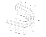
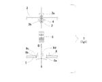
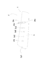
- FIG. 1 is an overall plan sectional view showing a state in which an orthodontic appliance according to a first embodiment of the present invention is mounted on a tooth.
- FIG. 2 is a perspective view showing a state in which the inner housing is inserted into the outer housing in the orthodontic appliance of the first embodiment
- FIG. 3 is a bottom view thereof
- FIG. 5 is a plan view
- FIG. 5 is a cross-sectional view thereof
- FIG. 6 is a left side view thereof.
- FIG. 7 is a component diagram of the pressing force adjusting mechanism in the orthodontic appliance of the first embodiment
- FIG. 8 illustrates a method of manufacturing the pressing force adjusting mechanism in the orthodontic appliance of the first embodiment.
- 9 is a second explanatory view thereof
- FIG. 10 is a third explanatory view thereof
- FIG. 11 is a fourth explanatory view thereof
- FIG. It is a final explanatory view.
- FIG. 13 is a first explanatory diagram for explaining an adjusting method of the orthodontic device of the first embodiment
- FIG. 14 is a second explanatory diagram thereof.
- FIG. 15 is a plan sectional view of the orthodontic device of the first embodiment
- FIG. 16 is a first explanatory view showing an example of mounting the orthodontic device of the first embodiment
- FIG. FIG. 6 is a second explanatory diagram thereof.
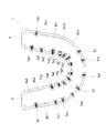
- an orthodontic appliance 1 of the present embodiment is to be mounted on the upper jaw of a patient, and has an inner casing 5 that directly covers teeth, an outer casing 3 that covers the outer periphery of the inner casing 5, Twenty-one bracket sets 7 (7a1, 7c1, 7d1, 7e1, 7f1, 7g1, 7h1, 7j1, 7q1, 7c2, 7d2, 7e2, 7f2, which penetrate through the inner housing 5 and are arranged to be pressed against teeth) 7g2, 7h2, 7j2, 7k2, 7m2, 7n2, 7p2 and 7q2) and seven cushioning members 9 (9b1, 9k1, 9m1, 9n1, 9p1, 9a2 and 9b2) that support teeth on which the bracket set 7 is not arranged. ) And is composed of.
- the number of teeth of the patient is 14 without knowing the teeth (a, b, c, d, e, f, g, h, j, k, m, n, p).
- the present invention can be applied even when there is wisdom tooth, and in that case, the orthodontic device may be produced by extending one tooth on each side.
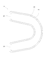
- the inner housing 5 has a substantially rectangular shape in cross section, a substantially U shape in plan view, and has an end closed. It has a groove-like shape with the upper side open.
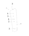
- a plurality of round holes into which brackets 8 described later are inserted are formed on the side wall surface of the inner housing 5.
- the outer side wall surface of the inner housing 5 has nine round holes (5a1, 5c1, 5d1, 5e1, 5f1, 5g1, 5h1, 5j1 and 5q1) into which a bracket 8 described later is inserted.
- the outer casing 3 is larger than the inner casing 5 in a substantially rectangular shape in a sectional view and a substantially U shape in a plan view as shown in FIGS. 2, 3, 4, 5, 6, 13 and 14. It has a V-shape and is closed at the end and has an open upper groove shape.
- the side wall surface of the outer housing 3 is formed with a plurality of round holes each having a thread groove so that a screw 2 described later can be screwed. Specifically, nine round holes (3a1, 3c1, 3d1, 3e1, 3f1, 3f1, 3f1, 3f1, 3f1, 3f1, 3f1, 3g1, 3h1, 3j1 and 3q1) are formed, and twelve round holes (3c2, 3c2, which have thread grooves are formed on the inner side wall surface of the outer housing 3 so that the screws 2 described later can be screwed together. 3d2, 3e2, 3f2, 3g2, 3h2, 3j2, 3k2, 3m2, 3n2, 3p2 and 3q2) are formed.
- the side surface of the outer housing 3 may be formed to have the same width from the patient's front teeth to the back teeth, but as shown in FIG. 6, the width of the front teeth is large and gradually decreases toward the back teeth. By doing so, the discomfort of the patient can be reduced.
- a space S is formed between the outer housing 3 and the inner housing 5 for accommodating a bracket 8 and screws 2 described later.
- the materials of the inner casing 5 and the outer casing 3 are not particularly limited as long as they are metallic materials made of biocompatible materials and synthetic polymers, and metallic materials such as titanium alloy, cobalt alloy, stainless steel, nylon, A synthetic polymer material such as polypropylene, polyethylene terephthalate, or Teflon (registered trademark) may be used, but in this embodiment, a titanium alloy is used.
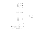
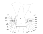
- the bracket set 7 includes a bracket 8, a spring 6 inserted into the protrusion 8d of the bracket, a screw 2 inserted into the spring 6, and a stopper 4 attached to the screw 2. , And a cushioning material 9 arranged at the bottom of the bracket 8.
- FIG. 7 is a component diagram of the pressing force adjusting mechanism in the orthodontic appliance of the first embodiment.
- the bracket 8 is a circular part in plan view, and has a disk-shaped bottom portion 8a, a cylindrical cylindrical portion 8b, a disk-shaped brim portion 8c having an outer diameter larger than that of the cylindrical portion 8b, and a center of the bottom portion 8a. It is composed of a cylindrical portion 8b and a protruding portion 8d extending coaxially from the portion.
- the material of the bracket 8 is not particularly limited as long as it is a metal material made of a biocompatible material and a synthetic polymer, and titanium alloy, cobalt alloy, metal material such as stainless steel, nylon, polypropylene, polyethylene terephthalate, Teflon (although it may be a synthetic polymer material such as a registered trademark), a titanium alloy is used in this embodiment.
- the spring 6 is an ordinary cylindrical compression spring, and is held between the bottom portion 8 a of the bracket 8 and the stopper 4 in a compressed state.
- the material of the spring 6 is not particularly limited as long as it is a metal material made of a biocompatible material and having a spring property and a synthetic polymer. Titanium alloy, cobalt alloy, metal material such as stainless steel, nylon, polypropylene, polyethylene. Although a synthetic polymer material such as terephthalate or Teflon (registered trademark) may be used, a titanium alloy is used in this embodiment.
- the screw 2 includes a screw head portion 2a and a screw shaft portion 2b, and cooperates with the stopper 4 to urge or release the spring 6.
- the material of the screw 2 is not particularly limited as long as it is a metal material made of a biocompatible material and having a spring property and a synthetic polymer, such as titanium alloy, cobalt alloy, stainless steel and other metal materials, nylon, polypropylene, polyethylene.
- a synthetic polymer material such as terephthalate or Teflon (registered trademark) may be used, a titanium alloy is used in this embodiment.
- the stopper 4 is a ring-shaped member having a round cross-section, and cooperates with the screw 2 to urge or release the spring 6 and to prevent the screw 2 from coming off the outer casing 3.
- the material of the stopper 4 is a rubber made of a biocompatible material and having elasticity.
- silicon rubber is used.
- the cushioning member 9 is a member that is arranged at the bottom of the bracket 8 and directly contacts the teeth of the patient, and its surface roughness is set to a large value from the viewpoint of preventing displacement of the teeth.
- the material of the cushioning material 9 is not particularly limited as long as it is a metal material made of a biocompatible material and a synthetic polymer, and in addition to zirconia, titanium oxide, lithium disilicate, titanium alloy, cobalt alloy, stainless steel, etc.
- the metal material may be a synthetic polymer material such as nylon, polypropylene, polyethylene terephthalate, or Teflon (registered trademark), but in the present embodiment, zirconia having a high surface roughness is used.
- bracket set 7 a method for manufacturing the bracket set 7 will be described with reference to the drawings.
- FIG. 8 is a first explanatory view for explaining the method for manufacturing the pressing force adjusting mechanism in the orthodontic appliance of the first embodiment
- FIG. 9 is a second explanatory view thereof
- FIG. FIG. 11 is a third explanatory diagram
- FIG. 11 is a fourth explanatory diagram thereof
- FIG. 12 is a final explanatory diagram thereof.
- bracket assembly 7g1 In the description of the method for manufacturing the bracket assembly 7, the bracket assembly 7g1 (see FIG. 1) will be described as an example.
- the bracket 8 is inserted into the hole 5g1 of the inner housing 5, and then the cushioning material 9 is bonded to the bottom surface of the bottom portion 8a of the bracket 8.
- the stopper 4 is moved in the direction of the arrow A which is the direction of the screw 2 to fit the stopper 4 and the screw shaft portion 2b of the screw 2 into each other. ..
- the screw 2 at that time is preferably arranged so that the screw shaft portion 2b is exposed to the upper side to some extent from the surface of the outer housing 3 in consideration of the amount of pushing into the bracket 8 described later.
- the spring 6 is moved in the direction of the arrow B, which is the direction of the bracket 8, and the spring 6 and the protrusion 8 d of the bracket 8 are fitted together.
- the bracket set 7 is arranged between the outer housing 3 and the inner housing 5 as shown in FIG. 10, and actually, as shown in FIG. It is arranged between 3 and the inner housing 5.
- the bracket 8 corresponds to the pressing portion of the present invention, and the outer housing 3, the screw 2, the stopper 4, and the spring 6 function as the pressing force adjusting mechanism of the present invention.
- the stopper 4 corresponds to the bulge portion of the present invention
- the flange portion 8c of the bracket 8 corresponds to the regulating portion of the present invention.
- the screw head 2a of the screw 2 is exposed on the surface of the outer housing 3, and the bracket 8 is exposed with respect to the patient's teeth. If the moving distance of the screw head 2a increases, the amount of exposure of the screw head 2a from the surface of the outer housing 3 decreases as the moving distance increases.
- the orthodontic appliance 1 is attached to the patient's teeth without bonding the cushioning material 9 to the bottom surface of the bracket 8. It may be arranged so as to be sandwiched between the bracket 8 and the patient's teeth when being mounted.
- FIG. 13 is a first explanatory diagram for explaining the adjusting method of the orthodontic device according to the first embodiment
- FIG. 14 is a second explanatory diagram thereof.
- bracket set 7g1 and the bracket set 7g2 (see FIG. 1) will be described as an example.
- the bracket set 7g1 includes a bracket 8g1, a spring 6g1, a screw 2g1, a stopper 4g1, and a cushioning material 9g1.
- the bracket 8g1 includes a bottom portion 8ga1, a cylindrical portion 8gb1, a collar portion 8gc1, and a protrusion portion 8gd1, and the screw 2g1 includes a screw head portion 2ga1 and a screw shaft portion 2gb1.
- the bracket set 7g2 in the description of the present adjustment method includes the bracket 8g2, the spring 6g2, the screw 2g2, the stopper 4g2, and the cushioning material 9g2.
- the bracket 8g2 includes a bottom portion 8ga2, a cylindrical portion 8gb2, a collar portion 8gc2, and a protrusion portion 8gd2.
- the screw 2g2 includes a screw head portion 2ga2 and a screw shaft portion 2gb2.
- the space between the bracket assembly 7g1 and the bracket assembly 7g2 set in the orthodontic appliance 1 is expanded.
- a gap is formed between each bracket set and the patient's tooth, and the orthodontic appliance 1 is moved toward the patient's gums G and set on the tooth g.
- the screw 2g2 set in the bracket set 7g2 is rotated to move the stopper 4g2 to the bracket 8g2 side, thereby increasing the biasing force of the spring 6g2 and
- the bracket 8g2 is brought into contact with the teeth via the cushioning material 9g2 by the urging force of 6g2.
- the proper biasing force on the patient's teeth is approximately 25 gf to 100 gf.
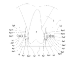
- FIG. 15 is a plan sectional view of the orthodontic appliance 1 of the first embodiment.
- the cushioning material 9 is arranged at a position where the bracket set 7 is not arranged with respect to the patient's teeth. This is used not only for teeth that do not need to be orthodontic but also for orthodontic teeth only by the inner housing 5.
- the seven cushioning materials 9 are directly arranged on the inner casing 5, and specifically, the cushioning materials 9b1, 9k1, 9m1, 9n1, 9p1, 9a2 and 9b2 are arranged on the inner casing 5. Has been done.
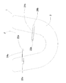
- FIG. 16 is a first explanatory view showing an example of mounting the orthodontic appliance according to the first embodiment
- FIG. 17 is a second explanatory view thereof.
- the orthodontic appliance 1 includes a rubber band 24a made of a biocompatible material between the screw 22a inserted into the upper jaw J of the patient and the hook 26a formed on the bottom surface of the outer housing 3.
- the rubber band 24b made of a biocompatible material is bridged between the screw 22b inserted into the patient's upper jaw J and the hook 26b formed on the bottom surface of the outer housing 3 to be attached to the patient's tooth. ing.
- the orthodontic appliance 1 of the present embodiment is biocompatible between the screw 22c inserted into the upper jaw J of the patient and the hook 26c formed on the inner side surface of the inner housing 5. It may be attached to the patient's teeth by bridging a rubber band 24c made of a flexible material.
- the inner housing 5 that covers the teeth the outer housing 3 that covers the inner housing 5, and the inner housing 5 that penetrates the inner housing 5 and can be pressed against the teeth. Since the bracket 8 and the pressing force adjusting mechanism capable of adjusting the pressing force applied to the teeth of the bracket 8 are provided, the dentist or the dental technician can easily adjust the teeth according to the dentition state that is different for each patient. An orthodontic appliance can be made, and the patient can easily orient his or her teeth with the orthodontic appliance.
- the pressing force adjusting mechanism includes the outer housing 3, the screw 2 screwed to the outer housing 3, and the compression spring fitted to the screw 2. Since it is composed of 6 and 6, the dentist or the dental technician can easily manufacture the orthodontic appliance in which the pressing force of the pressing portion is adjusted for each tooth of the patient, and the patient The orthodontic device makes it easier to straighten your own teeth.
- the screw 2 has an outer diameter larger than the inner diameter of the screw hole 3a1 of the outer housing 3 and the outer diameter of the compression spring 6 in the middle of the screw shaft portion 2b. Since the stopper 4 is provided, the pressing force of the bracket 8 against the teeth can be effectively applied.
- the stopper 4 can be attached to and detached from the screw 2, so that the pressing force adjusting mechanism can be easily manufactured.
- the cushioning material 9 is arranged in the region of the bracket 8 that comes into contact with the teeth, and the surface roughness is higher than the other regions. Can be reliably prevented from slipping on the patient's teeth, and the patient can use the orthodontic appliance without anxiety.
- the cushioning material 9 made of zirconia is formed in the region of the bracket 8 that abuts on the teeth of the bracket 8. The slip can be reliably prevented, and the patient can use the orthodontic appliance with peace of mind.
- the bracket 8 is provided with the flange portion 8c that restricts the movement thereof, so that the bracket 8 can be prevented from coming off from the inner housing 5. it can.
- FIG. 18 is a vertical cross-sectional view of the orthodontic device according to the second embodiment.
- FIG. 1 An overall plan sectional view of the orthodontic appliance 11 of the present embodiment is similar to FIG. 1, and a plan view of the state where the inner casing is inserted into the outer casing is similar to FIG.
- FIG. 1 A cross-sectional view of the state in which the body is inserted into the outer casing is the same as FIG.
- the orthodontic appliance 11 of the present embodiment is to be mounted on the upper jaw of a patient, and has an inner housing 15 that directly covers the teeth, an outer housing 13 that covers the outer circumference of the inner housing 15, Twenty-one bracket sets 7 (7a1, 7c1, 7d1, 7e1, 7f1, 7g1, 7h1, 7j1, 7q1, 7c2, 7d2, 7e2, 7f2, which penetrate through the inner casing 15 and are arranged to be pressed against the teeth, 7g2, 7h2, 7j2, 7k2, 7m2, 7n2, 7p2 and 7q2) and seven cushioning members 9 (9b1, 9k1, 9m1, 9n1, 9p1, 9a2 and 9b2) that support teeth on which the bracket set 7 is not arranged. ) And is composed of.
- the orthodontic appliance 11 of the present embodiment and the orthodontic appliance 1 of the first embodiment have different outer casing and inner casing configurations. That is, although the outer housing 3 of the first embodiment is configured to cover the entire inner housing 5, the outer housing 13 of the present embodiment covers the inner housing 15, but its bottom surface. In addition, a hole having a substantially U-shape in a plan view is formed so that the bottom surface of the inner casing 15 can be inserted.
- both bottom surfaces are arranged on the same plane.
- the orthodontic appliance 11 of the present embodiment can shorten the height of the orthodontic appliance 1 as compared with the orthodontic appliance 1 of the first embodiment, and the entire orthodontic appliance can be made compact. Therefore, it is possible to reduce the discomfort felt by the patient when it is worn on the patient's teeth.
- FIG. 19 is a vertical cross-sectional view of the orthodontic device according to the third embodiment.
- FIG. 1 An overall plan sectional view of the orthodontic appliance 21 of the present embodiment is similar to FIG. 1, and a plan view of the state where the inner housing is inserted into the outer housing is similar to FIG.
- the tooth e, and the bracket set 7e1 and the bracket set 7e2 (see FIG. 1) arranged for the tooth e will be described as an example.
- the bracket set 7e1 includes a bracket 8e1, a spring 6e1, a screw 2e1, a stopper 4e1 and a cushioning material 9e1.
- the bracket 8e1 includes a bottom portion 8ea1, a cylindrical portion 8eb1, a collar portion 8ec1, and a protrusion portion 8ed1.
- the screw 2e1 includes a screw head portion 2ea1 and a screw shaft portion 2eb1.
- the bracket set 7e2 in the present embodiment includes a bracket 8e2, a spring 6e2, a screw 2e2, a stopper 4e2, and a cushioning material 9e2.
- the bracket 8e2 includes a bottom portion 8ea2, a cylindrical portion 8eb2, a collar portion 8ec2, and a protrusion portion 8ed2.
- the screw 2e2 includes a screw head portion 2ea2 and a screw shaft portion 2eb2.
- an orthodontic device 21 of the present embodiment is to be mounted on the upper jaw of a patient, and has an inner casing 15 that directly covers teeth, an outer casing 13 that covers the outer periphery of the inner casing 15, Twenty-one bracket sets 7 (7a1, 7c1, 7d1, 7e1, 7f1, 7g1, 7h1, 7j1, 7q1, 7c2, 7d2, 7e2, 7f2, which penetrate through the inner housing 15 and are arranged to be pressed against teeth) 7g2, 7h2, 7j2, 7k2, 7m2, 7n2, 7p2 and 7q2) and seven cushioning members 9 (9b1, 9k1, 9m1, 9n1, 9p1, 9a2 and 9b2) that support teeth on which the bracket set 7 is not arranged. ) And is composed of.
- the brackets 8e1 and 8e2 have different heights. That is, the bracket 8e1 in FIG. 19 presses the lower part of the tooth e, while the bracket 8e2 presses the upper part of the tooth e more than the pressing position of the bracket 8e1.
- the outer bracket set may be pressed higher than the inner bracket set, or vice versa, In some cases, the outer bracket set may be pressed lower than the inner bracket set.
- a plurality of brackets 8 are provided for each tooth, and at least one bracket 8 has a different height relative to other teeth than other brackets.
- the orthodontist can easily create an orthodontic appliance with an improved orthodontic effect on the patient's teeth by changing the pressing position of the bracket for each tooth of the patient, and the patient can use the orthodontic appliance to make his or her own orthodontic appliance.
- the teeth can be corrected more easily.
- FIG. 20 is a component diagram of the pressing force adjustment mechanism in the orthodontic device of the fourth embodiment.
- FIG. 1 An overall plan sectional view of the orthodontic appliance 31 of the present embodiment is similar to that of FIG. 1, and a plan view of the state where the inner casing is inserted into the outer casing is similar to FIG.
- the orthodontic appliance 31 of the present embodiment is mounted on the upper jaw of a patient, but the shape of the bracket is different from that of the bracket 7 of the first embodiment.
- the bracket 18 of the present embodiment is a circular component in plan view, and has a bottom portion 18a longer than the bottom portion 8a of the first embodiment, a cylindrical portion 18b, and a disc-shaped member having a larger outer diameter than the cylindrical portion 18b. It is composed of a collar portion 18c and a protrusion portion 18d that extends from the bottom portion 18a coaxially with the cylindrical portion 18b.
- the bracket 18 of the present embodiment adjusts the distance between the patient's teeth and the inner housing by polishing the bottom portion 18a of the bracket 18, which improves convenience in adjusting the orthodontic device. It is what makes me.
- the material of the bracket 18 is the same as that of the bracket 8, and there is no particular problem as long as it is a metal material made of a biocompatible material or a synthetic polymer, and a metal material such as titanium alloy, cobalt alloy, stainless steel, nylon, nylon, A synthetic polymer material such as polypropylene, polyethylene terephthalate, or Teflon (registered trademark) may be used, but in this embodiment, a titanium alloy is used.
- the pressing force on the teeth of the bracket 18 can be adjusted by adjusting the length of the bottom portion 18a of the bracket 18, so that the pressing force adjusting mechanism can be manufactured more easily. can do.
- FIG. 21 is a component diagram of the pressing force adjustment mechanism in the orthodontic device of the fifth embodiment.
- FIG. 1 An overall plan sectional view of the orthodontic appliance 41 of the present embodiment is similar to that of FIG. 1, and a plan view of the state where the inner casing is inserted into the outer casing is similar to FIG.
- the orthodontic appliance 41 of the present embodiment is mounted on the upper jaw of a patient, but the shape of the screw is different from that of the screw 2 of the fourth embodiment.
- a screw head portion 12a, a screw shaft portion 12b, and a bulging portion 12c formed in the middle of the screw shaft portion 12b are integrally formed, and the bulging portion 12c biases the spring 6. Or to release.
- the screw 12 of the present embodiment is formed smaller than the screw head 2a of the first embodiment so that the screw head 12a can be inserted into the hole of the outer housing 3.
- the material of the screw 12, like the screw 2 is not particularly limited as long as it is a metal material made of a biocompatible material and having a spring property and a synthetic polymer, and a metal material such as titanium alloy, cobalt alloy, and stainless steel. Although it may be a synthetic polymer material such as nylon, polypropylene, polyethylene terephthalate, or Teflon (registered trademark), a titanium alloy is used in this embodiment.
- the screw 12 has a bulge having an inner diameter such as the screw hole 3a1 of the outer housing 3 and an outer diameter larger than the outer diameter of the compression spring 6 in the middle of the screw shaft portion 12b. Since the portion 12c is provided, the pressing force of the bracket 18 against the teeth can be effectively applied.
Landscapes
- Health & Medical Sciences (AREA)
- Oral & Maxillofacial Surgery (AREA)
- Dentistry (AREA)
- Epidemiology (AREA)
- Life Sciences & Earth Sciences (AREA)
- Animal Behavior & Ethology (AREA)
- General Health & Medical Sciences (AREA)
- Public Health (AREA)
- Veterinary Medicine (AREA)
- Dental Tools And Instruments Or Auxiliary Dental Instruments (AREA)
Abstract
Description
先ず、本発明の第1実施形態について説明する。 (First embodiment)
First, a first embodiment of the present invention will be described.
次に、本発明の第2実施形態について説明する。図18は、第2実施形態の歯列矯正装置の縦断面図である。 (Second embodiment)
Next, a second embodiment of the present invention will be described. FIG. 18 is a vertical cross-sectional view of the orthodontic device according to the second embodiment.
次に、本発明の第3実施形態について説明する。
図19は、第3実施形態の歯列矯正装置の縦断面図である。 (Third Embodiment)
Next, a third embodiment of the present invention will be described.
FIG. 19 is a vertical cross-sectional view of the orthodontic device according to the third embodiment.
次に、本発明の第3実施形態について説明する。
図20は、第4実施形態の歯列矯正装置における押圧力調節機構の部品図である。 (Fourth Embodiment)
Next, a third embodiment of the present invention will be described.
FIG. 20 is a component diagram of the pressing force adjustment mechanism in the orthodontic device of the fourth embodiment.
最後に、本発明の第5実施形態について説明する。図21は、第5実施形態の歯列矯正装置における押圧力調節機構の部品図である。 (Fifth Embodiment)
Finally, a fifth embodiment of the present invention will be described. FIG. 21 is a component diagram of the pressing force adjustment mechanism in the orthodontic device of the fifth embodiment.
2, 12・・・ネジ
3,13・・・外側筐体
4・・・ストッパー
5,15・・・内側筐体
6・・・バネ(圧縮バネ)
8,18・・・ブラケット
9・・・緩衝材 1, 11, 21, 31, 41...
8, 18...
Claims (9)
- 歯を覆う内側筐体と、
前記内側筐体を覆う外側筐体と、
前記内側筐体を貫通し前記歯に対して押圧可能に配置された押圧部と、
その押圧部の前記歯に対する押圧力を調節可能な押圧力調節機構と、
を備えたことを特徴とする歯列矯正装置。 An inner housing covering the teeth,
An outer casing that covers the inner casing,
A pressing portion penetrating the inner housing and arranged to be capable of pressing the teeth,
A pressing force adjusting mechanism capable of adjusting the pressing force of the pressing portion on the teeth,
An orthodontic device comprising: - 前記押圧力調節機構は、前記外側筐体と、その外側筐体に螺合されたネジと、そのネジに勘合された圧縮バネと、から構成されていることを特徴とする請求項1に記載の歯列矯正装置。 The pressing force adjusting mechanism includes the outer casing, a screw screwed to the outer casing, and a compression spring fitted to the screw. Orthodontic device.
- 前記ネジは、ネジ部の途中に前記外側筐体のネジ孔の内径及び前記圧縮バネの外径よりも大きな外径と有する膨隆部を備えていることを特徴とする請求項2に記載の歯列矯正装置。 The tooth according to claim 2, wherein the screw is provided with a bulge portion having an outer diameter larger than an inner diameter of a screw hole of the outer housing and an outer diameter of the compression spring in the middle of the screw portion. Row straightening device.
- 前記膨隆部は、前記ネジに対して着脱可能となっていることを特徴とする請求項3に記載の歯列矯正装置。 The orthodontic device according to claim 3, wherein the bulge portion is attachable to and detachable from the screw.
- 前記押圧部は前記歯毎に複数設けられ、少なくとも1つの押圧部は、他の押圧部に比較して前記歯に対する高さが異なることを特徴とする請求項1乃至請求項4の何れかに記載の歯列矯正装置。 A plurality of the pressing portions are provided for each of the teeth, and at least one pressing portion has a height different from that of the other pressing portions with respect to the teeth. Orthodontic device as described.
- 前記押圧部の前記歯に当接する領域は、他の領域よりも表面粗度が高いことを特徴とする請求項1乃至請求項5の何れかに記載の歯列矯正装置。 The orthodontic device according to any one of claims 1 to 5, wherein a region of the pressing portion that comes into contact with the teeth has a higher surface roughness than other regions.
- 前記押圧部の前記歯に当接する領域には、ジルコニアからなる材料が形成されていることを特徴とする請求項1乃至請求項6の何れかに記載の歯列矯正装置。 The orthodontic device according to any one of claims 1 to 6, wherein a material made of zirconia is formed in a region of the pressing portion that abuts on the teeth.
- 前記押圧部には、その移動を規制する規制部が備えられていることを特徴とする請求項1乃至請求項7の何れかに記載の歯列矯正装置。 The orthodontic appliance according to any one of claims 1 to 7, wherein the pressing portion is provided with a regulating portion that regulates the movement thereof.
- 前記押圧力調節機構は、前記押圧部の底部の長さを調節することによって、前記押圧部の前記歯に対する押圧力を調節可能であることを特徴とする請求項1乃至請求項8の何れかに記載の歯列矯正装置。
9. The pressing force adjusting mechanism is capable of adjusting the pressing force applied to the teeth of the pressing unit by adjusting the length of the bottom of the pressing unit. Orthodontic device according to.
Priority Applications (6)
| Application Number | Priority Date | Filing Date | Title |
|---|---|---|---|
| CN201980033651.1A CN112203613B (en) | 2019-02-18 | 2019-02-18 | Orthodontic device |
| PCT/JP2019/005826 WO2020170300A1 (en) | 2019-02-18 | 2019-02-18 | Dentition corrective device |
| KR1020207032610A KR102435223B1 (en) | 2019-02-18 | 2019-02-18 | orthodontic appliance |
| JP2019531846A JP6723549B1 (en) | 2019-02-18 | 2019-02-18 | Orthodontic device |
| EP19916072.2A EP3928735A4 (en) | 2019-02-18 | 2019-02-18 | Dentition corrective device |
| US17/106,894 US11406477B2 (en) | 2019-02-18 | 2020-11-30 | Orthodontic device |
Applications Claiming Priority (1)
| Application Number | Priority Date | Filing Date | Title |
|---|---|---|---|
| PCT/JP2019/005826 WO2020170300A1 (en) | 2019-02-18 | 2019-02-18 | Dentition corrective device |
Related Child Applications (1)
| Application Number | Title | Priority Date | Filing Date |
|---|---|---|---|
| US17/106,894 Continuation US11406477B2 (en) | 2019-02-18 | 2020-11-30 | Orthodontic device |
Publications (1)
| Publication Number | Publication Date |
|---|---|
| WO2020170300A1 true WO2020170300A1 (en) | 2020-08-27 |
Family
ID=71523936
Family Applications (1)
| Application Number | Title | Priority Date | Filing Date |
|---|---|---|---|
| PCT/JP2019/005826 WO2020170300A1 (en) | 2019-02-18 | 2019-02-18 | Dentition corrective device |
Country Status (6)
| Country | Link |
|---|---|
| US (1) | US11406477B2 (en) |
| EP (1) | EP3928735A4 (en) |
| JP (1) | JP6723549B1 (en) |
| KR (1) | KR102435223B1 (en) |
| CN (1) | CN112203613B (en) |
| WO (1) | WO2020170300A1 (en) |
Families Citing this family (1)
| Publication number | Priority date | Publication date | Assignee | Title |
|---|---|---|---|---|
| EP3943038B1 (en) * | 2020-07-20 | 2023-03-01 | Universität Heidelberg | Method for manufacturing a dental splint |
Citations (4)
| Publication number | Priority date | Publication date | Assignee | Title |
|---|---|---|---|---|
| JP2006511243A (en) * | 2002-04-03 | 2006-04-06 | ジャック ケイス ヒリアード | Straightening aligner assist system |
| JP2015150179A (en) | 2014-02-14 | 2015-08-24 | キープ・アップ株式会社 | orthodontic appliance |
| JP2015177969A (en) | 2014-02-28 | 2015-10-08 | 典洋 井津上 | Orthodontic appliance |
| KR101744000B1 (en) * | 2016-04-22 | 2017-06-07 | 박영수 | Tooth correction device |
Family Cites Families (19)
| Publication number | Priority date | Publication date | Assignee | Title |
|---|---|---|---|---|
| US3975825A (en) * | 1975-06-11 | 1976-08-24 | Smith C Perry | Ortho-activating method and apparatus |
| US4379693A (en) * | 1977-04-07 | 1983-04-12 | Melvin Wallshein | Orthodontic biassing device |
| US5254002B1 (en) * | 1991-04-08 | 2000-01-11 | Ormco Corp | Orthodontic plastic bracket |
| US7077646B2 (en) * | 2003-08-29 | 2006-07-18 | Jack Keith Hilliard | Automated method for producing improved orthodontic aligners |
| PT1871276E (en) | 2004-03-25 | 2012-08-03 | Dror Ortho Design Ltd | Orthodontic appliance |
| SE0601168L (en) * | 2006-05-26 | 2007-11-27 | Jan Christer Nordstroem | An arrangement for maintaining a dental position |
| US9554875B2 (en) * | 2006-09-07 | 2017-01-31 | Rmo, Inc. | Method for producing a customized orthodontic appliance |
| US8882499B2 (en) * | 2007-05-30 | 2014-11-11 | Velton C. White | Orthodontic appliance |
| JP5624094B2 (en) * | 2012-08-28 | 2014-11-12 | 哲也 下田 | Orthodontic bracket |
| US9918807B2 (en) * | 2014-04-25 | 2018-03-20 | Christopher C. Cosse | Devices, systems, and methods for adjusting a prescription of a plurality of orthodontic brackets |
| KR101579455B1 (en) * | 2014-09-30 | 2015-12-22 | 박숙규 | Transparent orthodontic device |
| US10874483B2 (en) * | 2015-07-07 | 2020-12-29 | Align Technology, Inc. | Direct fabrication of attachment templates with adhesive |
| US20170128162A1 (en) * | 2015-10-16 | 2017-05-11 | Diego Dalla-Bona | Orthodontic apparatus |
| US10588717B2 (en) * | 2015-10-20 | 2020-03-17 | Hankookin, Inc. | Detachable orthodontic bracket and wire system |
| CN105662614B (en) * | 2016-01-25 | 2018-07-27 | 陈启锋 | A kind of oral appliance and preparation method thereof |
| CN205964196U (en) * | 2016-05-17 | 2017-02-22 | 杨帅彪 | Teeth corrector |
| KR101710840B1 (en) * | 2016-09-26 | 2017-02-28 | 심윤섭 | Self-adjustable jaw joint calibration devices for snoring, sleep apnea treatment |
| FR3059544B1 (en) * | 2016-12-07 | 2019-05-10 | Oniris | INTRABUCCAL DEVICE WITH PAIR OF ARTICULATED DENTAL GUTTERS |
| CN107822723B (en) * | 2017-12-13 | 2022-05-13 | 福建省齿峰口腔颌面矫治研究所 | Method for manufacturing oral appliance |
-
2019
- 2019-02-18 JP JP2019531846A patent/JP6723549B1/en active Active
- 2019-02-18 WO PCT/JP2019/005826 patent/WO2020170300A1/en unknown
- 2019-02-18 EP EP19916072.2A patent/EP3928735A4/en active Pending
- 2019-02-18 KR KR1020207032610A patent/KR102435223B1/en active IP Right Grant
- 2019-02-18 CN CN201980033651.1A patent/CN112203613B/en active Active
-
2020
- 2020-11-30 US US17/106,894 patent/US11406477B2/en active Active
Patent Citations (4)
| Publication number | Priority date | Publication date | Assignee | Title |
|---|---|---|---|---|
| JP2006511243A (en) * | 2002-04-03 | 2006-04-06 | ジャック ケイス ヒリアード | Straightening aligner assist system |
| JP2015150179A (en) | 2014-02-14 | 2015-08-24 | キープ・アップ株式会社 | orthodontic appliance |
| JP2015177969A (en) | 2014-02-28 | 2015-10-08 | 典洋 井津上 | Orthodontic appliance |
| KR101744000B1 (en) * | 2016-04-22 | 2017-06-07 | 박영수 | Tooth correction device |
Also Published As
| Publication number | Publication date |
|---|---|
| EP3928735A4 (en) | 2022-12-28 |
| CN112203613B (en) | 2022-04-01 |
| US20210077228A1 (en) | 2021-03-18 |
| EP3928735A1 (en) | 2021-12-29 |
| KR102435223B1 (en) | 2022-08-24 |
| KR20200139249A (en) | 2020-12-11 |
| JP6723549B1 (en) | 2020-07-15 |
| US11406477B2 (en) | 2022-08-09 |
| JPWO2020170300A1 (en) | 2021-03-11 |
| CN112203613A (en) | 2021-01-08 |
Similar Documents
| Publication | Publication Date | Title |
|---|---|---|
| US7914283B2 (en) | Activatable dental appliance | |
| TWI668000B (en) | Orthodontic correction device | |
| EP3629989B1 (en) | Orthodontic system with variably-sized archwire slot | |
| KR101579455B1 (en) | Transparent orthodontic device | |
| US20140134563A1 (en) | Biocompatible self-ligating brackets | |
| EP2822500B1 (en) | Flexible orthodontic splint | |
| US11744675B2 (en) | Elastic orthodontic appliances, systems, and methods for use | |
| JP7202723B2 (en) | orthodontic appliance | |
| WO2020170300A1 (en) | Dentition corrective device | |
| TWI638646B (en) | Self-ligating bracket | |
| JP7080453B2 (en) | Sensors and systems for monitoring the wearing time of orthodontic elastic rubber | |
| WO2021175322A1 (en) | Orthodontic appliance | |
| WO2019238762A1 (en) | Method of an orthodontic treatment, use of a pearl as a holding element for an orthodontic appliance and a pearl for an orthodontic treatment | |
| AU2018272753B2 (en) | Orthodontic system with variably-sized archwire slot | |
| Halabi | Retainers: A Comparative Guide | |
| WO2017213594A1 (en) | Orthodontic bracket |
Legal Events
| Date | Code | Title | Description |
|---|---|---|---|
| ENP | Entry into the national phase |
Ref document number: 2019531846 Country of ref document: JP Kind code of ref document: A |
|
| 121 | Ep: the epo has been informed by wipo that ep was designated in this application |
Ref document number: 19916072 Country of ref document: EP Kind code of ref document: A1 |
|
| ENP | Entry into the national phase |
Ref document number: 20207032610 Country of ref document: KR Kind code of ref document: A |
|
| NENP | Non-entry into the national phase |
Ref country code: DE |
|
| ENP | Entry into the national phase |
Ref document number: 2019916072 Country of ref document: EP Effective date: 20210920 |