WO2020169845A1 - Interferometric distance measurement on the basis of propagation time differences - Google Patents
Interferometric distance measurement on the basis of propagation time differences Download PDFInfo
- Publication number
- WO2020169845A1 WO2020169845A1 PCT/EP2020/054738 EP2020054738W WO2020169845A1 WO 2020169845 A1 WO2020169845 A1 WO 2020169845A1 EP 2020054738 W EP2020054738 W EP 2020054738W WO 2020169845 A1 WO2020169845 A1 WO 2020169845A1
- Authority
- WO
- WIPO (PCT)
- Prior art keywords
- modulator
- modulation frequency
- signal
- evaluation unit
- distance
- Prior art date
Links
Classifications
-
- G—PHYSICS
- G01—MEASURING; TESTING
- G01B—MEASURING LENGTH, THICKNESS OR SIMILAR LINEAR DIMENSIONS; MEASURING ANGLES; MEASURING AREAS; MEASURING IRREGULARITIES OF SURFACES OR CONTOURS
- G01B9/00—Measuring instruments characterised by the use of optical techniques
- G01B9/02—Interferometers
- G01B9/02001—Interferometers characterised by controlling or generating intrinsic radiation properties
- G01B9/02002—Interferometers characterised by controlling or generating intrinsic radiation properties using two or more frequencies
- G01B9/02003—Interferometers characterised by controlling or generating intrinsic radiation properties using two or more frequencies using beat frequencies
-
- G—PHYSICS
- G01—MEASURING; TESTING
- G01B—MEASURING LENGTH, THICKNESS OR SIMILAR LINEAR DIMENSIONS; MEASURING ANGLES; MEASURING AREAS; MEASURING IRREGULARITIES OF SURFACES OR CONTOURS
- G01B9/00—Measuring instruments characterised by the use of optical techniques
- G01B9/02—Interferometers
- G01B9/02015—Interferometers characterised by the beam path configuration
- G01B9/02017—Interferometers characterised by the beam path configuration with multiple interactions between the target object and light beams, e.g. beam reflections occurring from different locations
- G01B9/02019—Interferometers characterised by the beam path configuration with multiple interactions between the target object and light beams, e.g. beam reflections occurring from different locations contacting different points on same face of object
-
- G—PHYSICS
- G01—MEASURING; TESTING
- G01B—MEASURING LENGTH, THICKNESS OR SIMILAR LINEAR DIMENSIONS; MEASURING ANGLES; MEASURING AREAS; MEASURING IRREGULARITIES OF SURFACES OR CONTOURS
- G01B9/00—Measuring instruments characterised by the use of optical techniques
- G01B9/02—Interferometers
- G01B9/02041—Interferometers characterised by particular imaging or detection techniques
- G01B9/02045—Interferometers characterised by particular imaging or detection techniques using the Doppler effect
-
- G—PHYSICS
- G01—MEASURING; TESTING
- G01B—MEASURING LENGTH, THICKNESS OR SIMILAR LINEAR DIMENSIONS; MEASURING ANGLES; MEASURING AREAS; MEASURING IRREGULARITIES OF SURFACES OR CONTOURS
- G01B9/00—Measuring instruments characterised by the use of optical techniques
- G01B9/02—Interferometers
- G01B9/02055—Reduction or prevention of errors; Testing; Calibration
- G01B9/02075—Reduction or prevention of errors; Testing; Calibration of particular errors
- G01B9/02078—Caused by ambiguity
-
- G—PHYSICS
- G01—MEASURING; TESTING
- G01B—MEASURING LENGTH, THICKNESS OR SIMILAR LINEAR DIMENSIONS; MEASURING ANGLES; MEASURING AREAS; MEASURING IRREGULARITIES OF SURFACES OR CONTOURS
- G01B9/00—Measuring instruments characterised by the use of optical techniques
- G01B9/02—Interferometers
- G01B9/02083—Interferometers characterised by particular signal processing and presentation
-
- G—PHYSICS
- G01—MEASURING; TESTING
- G01S—RADIO DIRECTION-FINDING; RADIO NAVIGATION; DETERMINING DISTANCE OR VELOCITY BY USE OF RADIO WAVES; LOCATING OR PRESENCE-DETECTING BY USE OF THE REFLECTION OR RERADIATION OF RADIO WAVES; ANALOGOUS ARRANGEMENTS USING OTHER WAVES
- G01S17/00—Systems using the reflection or reradiation of electromagnetic waves other than radio waves, e.g. lidar systems
- G01S17/02—Systems using the reflection of electromagnetic waves other than radio waves
- G01S17/06—Systems determining position data of a target
- G01S17/08—Systems determining position data of a target for measuring distance only
- G01S17/32—Systems determining position data of a target for measuring distance only using transmission of continuous waves, whether amplitude-, frequency-, or phase-modulated, or unmodulated
- G01S17/36—Systems determining position data of a target for measuring distance only using transmission of continuous waves, whether amplitude-, frequency-, or phase-modulated, or unmodulated with phase comparison between the received signal and the contemporaneously transmitted signal
-
- G—PHYSICS
- G01—MEASURING; TESTING
- G01B—MEASURING LENGTH, THICKNESS OR SIMILAR LINEAR DIMENSIONS; MEASURING ANGLES; MEASURING AREAS; MEASURING IRREGULARITIES OF SURFACES OR CONTOURS
- G01B2290/00—Aspects of interferometers not specifically covered by any group under G01B9/02
- G01B2290/65—Spatial scanning object beam
-
- G—PHYSICS
- G01—MEASURING; TESTING
- G01B—MEASURING LENGTH, THICKNESS OR SIMILAR LINEAR DIMENSIONS; MEASURING ANGLES; MEASURING AREAS; MEASURING IRREGULARITIES OF SURFACES OR CONTOURS
- G01B2290/00—Aspects of interferometers not specifically covered by any group under G01B9/02
- G01B2290/70—Using polarization in the interferometer
Definitions
- the present invention relates to a device and a method for measuring a distance to a reflective object, the distance or the distance being static as well as dynamic, for example to determine a relative speed between the device and the object and / or to measure vibrations of the object is determinable.
- phase difference between a reference beam running over a reference path and a measuring beam reflected on the object is determined.
- the relative phase position between the measuring beam and the reference beam one obtains after the two beams are superimposed
- this interference phase is detected with a photodetector unit, it is possible to determine the shift to a fraction of the optical wavelength.
- determining the absolute distance of the object is more complex. Since the interference phase repeats itself periodically when the object distance changes by half an optical wavelength, the uniqueness range is very small, typically a few hundred nanometers. With a simple interferometer, distances can only be determined by integrating the phase change, taking into account the period transitions.
- the measuring device and the measuring object must either first be brought together and then separated again, or a reflector must be brought from the measuring device to the measuring point (laser tracker). If, for example, the measurement is only rougher for a short time (disturbance of the line of sight or speckle effect Measurement surface) interrupted, the integration may be faulty. Discontinuities or spatial jumps when scanning objects to be measured have a similarly negative effect.
- Interferometer vibrations or oscillation states of the object can be measured qualitatively as well as quantitatively precisely and in real time.
- measurement methods based on interferometry are used. If the distance between the measuring device and the object, which is typically several meters, is also to be determined, this can typically be done by means of a further contactless distance measuring system. This can be based on a completely different measuring principle.
- the signals of the two independently working devices intended for different areas of application for measuring the absolute or rough distance on the one hand and for high-precision
- the present invention is based on the object, a
- the device and the method should be characterized by a large measuring range, by a high measuring accuracy and by a low level of equipment and technical complexity.
- One and the same device should be able to determine, on the one hand, the absolute distance, possibly several meters, between the device and the object using a single radiation source.
- the device should have a measurement accuracy in the submicrometer range, Provide nanometer range or sub-nanometer range. Furthermore, the device should be designed to be particularly compact and have a comparatively low weight. The device should be particularly suitable for mobile use.
- the device and the measuring method to be carried out with it should also be distinguished by a comparatively simple adjustment and calibration.
- This object is achieved with a device for measuring a distance to a reflecting object, with a corresponding method for measuring a distance with the reflecting object and with an algorithm, implemented as a hardware circuit or in a corresponding computer program, each with the features of the independent claims. More beneficial
- a device for measuring a distance to a reflective object has a radiation source for generating an object beam and a reference beam.
- the radiation source is typically designed to generate a transmission radiation.
- Reference beam can typically by means of a beam splitter from the
- the object beam and the reference beam are variably adjustable.
- object beams and the reference beam are variably adjustable.
- Reference beam can also be generated directly from the radiation source.
- the object beam is directed towards the object.
- the device and the object can be positioned with respect to one another in such a way that the object beam propagates towards the object.
- the device also has at least one first modulator in the beam path of the transmitted radiation or in the beam path of the object beam.
- the modulator is designed to transmit the transmitted radiation or the object beam with a first
- Modulation frequency to modulate periodically in time.
- the device also has a radiation detector on which at least part of the object beam reflected from the object interferes with the reference beam while forming a reference signal.
- the object beam and the reference beam are capable of interference with one another.
- the device also has an electronic Evaluation unit, which is signal-coupled with the radiation detector.
- the electronic evaluation unit is designed to provide a distance that is correlated with the distance to be measured on the basis of the interference signal at the radiation detector
- an amplitude-modulated signal can also be applied to the detector or measured. Using the phase position of this signal in relation to the phase of the modulator, the transit time and thus the distance to the object can be determined here.
- phase difference between two signal components with different frequencies corresponds to the phase of the beat signal, possibly up to an integer multiple of 2 pi.
- the two signal components each in the same way with a Doppler shift due to a movement of the
- DUT can be acted upon, first mixed down into the baseband. Therefore, if in the following from a phase difference of two
- Be included beat signal The determination takes place in both cases, both for the phase of the respective individual signal components and for the phase of the beat signal with reference to and comparison with the phase position of the modulator.
- unmodulated signal component in the present context means the
- modulated signal component is to be understood as meaning that or those signal components with integer multiples of the modulation frequency.
- a temporally periodic modulation by means of the first modulator leads to
- Modulation frequency reflects.
- the evaluation unit and the method to be carried out with it are designed in particular to determine a transit time difference between the reference beam and the reflected object beam by measuring the phase difference between the modulated signal component and the unmodulated signal component of the object beam.
- the signal components of the reflected object beam have none
- Runtime difference but rather a phase difference due to the modulation, which increases with the common runtime in proportion to the difference frequency of the signal components.
- the method described provides the transit time from the modulator via the reflecting object to the detector.
- the transit time through the reference arm is only included as a constant, so that in this case too the transit time is determined directly from the modulator via the reflecting object to the detector.
- the object beam has only two signal components at different frequencies.
- two radiation sources that are capable of coherence with one another or two object beams originating from different radiation sources can be used for this purpose, each of which has a beam component that is necessary for the
- a phase difference between a signal component of the reflected object beam modulated with the first modulation frequency and a phase position of the modulator can also be determined and used to determine the distance to the reflecting object.
- a phase difference between a signal component of the reflected object beam modulated with the first modulation frequency and a phase position of the modulator can also be determined and used to determine the distance to the reflecting object.
- amplitude-modulated signal can be used as an object beam.
- the reflected object beam in particular its phase, can then be compared with the phase position of the modulator or a signal transmitter generating the modulation. This relative phase is knowing the modulation frequency and the Propagation speed of the object beam a direct measure of the absolute distance to the object.
- phase difference between a first signal component of the reflected object beam modulated with the first modulation frequency and a second signal component of the reflected object beam can also be determined, with the first and second signal components being different sidebands of the modulation or different harmonics of the
- the phase position of the modulator can be done either individually or in combination.
- the first signal component and the second signal component are mixed down to a common base frequency and each of these down-mixed signal components or the difference between the respective phases of the down-mixed signal components is compared with the phase position of the modulator.
- the mentioned phase difference corresponds to the phase of a beat signal with a (synthetic) wavelength which corresponds to the difference frequency of the two signal components.
- the first and second signal components are mixed multiplicatively.
- the mixed signal obtained in this way contains differences and with regard to the frequencies of the signal components
- Modulator can be compared. This is how you get a
- Difference signal or beat signal with a (synthetic) wavelength which corresponds to the difference frequency of the two signal components.
- the (synthetic) wavelength determines the uniqueness interval of the
- Modulation frequency the uniqueness range for distance measurement is larger. However, this is at the expense of the measurement accuracy or at the expense of the spatial
- the radiation source is typically a monochromatic radiation source.
- the radiation source is typically an optical one
- the radiation source can in particular have a monochromatic laser with a comparatively large coherence length.
- the coherence length of the radiation source is
- the device advantageously has an optical interferometer, by means of which the transmitted radiation emitted by the radiation source can be divided into an object beam and a reference beam.
- the reference beam is typically directed to the radiation detector via one or more deflection devices, for example via beam splitters and / or mirrors.
- the object beam leaves the device, propagates to the object and is reflected on the object.
- the object can be a retroreflective object. However, it can also be a diffusely scattering or diffusely reflecting object.
- the modulator can be arranged behind the beam splitter in the direction of propagation of the transmitted radiation. In this way it is achieved that only the object beam is modulated with the first modulation frequency.
- the object beam thus receives at least two signal components, namely a first or basic signal component based on the carrier frequency of the transmitted radiation and a further modulated one
- the phase difference between the modulated signal component and the unmodulated signal component can typically be measured and qualitatively determined via the interference with the reference beam.
- the description chosen here for the comparison of a modulated and unmodulated signal components can be generalized to two signal components that have different frequencies, typically slightly shifted from one another, so that a measurable phase difference arises when propagating over the same distance due to the mutually shifted frequencies.
- the object beam can also only consist of a single oscillating or time-modulated signal. For the distance measurement to the object, only the phase of the object beam reflected by the object is then relative to the phase position of the
- the distance to the object is smaller than the uniqueness range specified by the first modulation frequency
- the distance results directly from the measurable phase shift between the reflected object beam and the phase position of the modulator. From the phase difference, knowing the first modulation frequency, the transit time can be determined which the object beam needs for the propagation between the measuring device and the object. From this and with knowledge of the propagation speed, the distance or the distance can finally be calculated.
- the evaluation unit is designed to use the measured phase difference between the signal component of the reflected object beam modulated with the first modulation frequency and one or the other
- the modulation gives the object beam an unmodulated signal component, typically at the carrier frequency of the radiation source, and a signal component modulated with the first modulation frequency.
- the unmodulated and the modulated signal component differ in the frequency space by the modulation frequency.
- the transit time of the reflected object beam is the time that the object beam needs to propagate from the measuring device to the object and from the object back to the measuring device.
- the transit time of the reflected object beam from the measuring device to the object and from the object back to the measuring device can also be based on the phase difference between the reflected modulated object beam and the phase position of the
- Modulator can be determined. As a result of the modulation, a beat or a further frequency-shifted signal component is generated on the object beam, which or via the
- Runtime difference between the reference beam and the reflected object beam results in a measurable phase difference or phase shift between the modulated signal component and the unmodulated signal component of the reflected
- Object beam leads.
- the transit time of the reflected object beam and thus also the transit time difference between the object beam and the reference beam can be determined. From the phase difference and / or transit time of the reflected object beam or from the transit time difference between the reflected object beam and the
- the distance between the device and the reflecting object can be determined.
- the evaluation unit is designed to determine the transit time difference between the reference beam and the reflected object beam on the basis of the above-mentioned phase difference.
- the phase difference the phase difference between the signal component of the reflected object beam modulated with the first modulation frequency and the unmodulated one can be used here
- Signal component of the reflected object beam should be meant.
- a desired uniqueness range can be established by a suitable choice of the first modulation frequency vi.
- a comparatively large uniqueness range is achieved by means of a comparatively low first modulation frequency.
- a low or only low modulation frequency reduces the measuring accuracy of the device.
- the first modulation frequencies are selected in such a way that the uniqueness areas resulting from this have a certain overlap area.
- the distance between the device and the reflecting object can initially be determined relatively roughly and then gradually increasing finer and more precisely by increasing the first modulation frequency gradually.
- first modulation frequencies are successively or gradually larger.
- Modulation frequencies used for modulating the object beam are used for modulating the object beam.
- the first modulator is designed to generate the first modulation frequency electronically.
- the modulator can be designed in particular to generate modulation frequencies in the kHz range, in the MHz range, in the GHz range or even in the terracotta range. It can in particular be provided that the modulator first
- the first modulator is a phase modulator, an amplitude modulator, a polarization modulator or a frequency modulator.
- phase modulator can be used in a comparatively large
- Frequency range for example in the gigahertz range, 10 GHz range or 100 GHz range, so that the measurement accuracy of the runtime-based method is better than the width of the uniqueness range of the interferometric method (typically half the wavelength of the laser light) in order to enable a transition between the two measurement methods.
- the phase modulator can also be an amplitude modulator in the same way Polarization modulator or a frequency modulator can be used as the first modulator.
- Polarization modulator or a frequency modulator can be used as the first modulator.
- Modulation method can be used for the first modulator.
- the evaluation unit has a multiplicative mixer and a filter connected downstream of the mixer.
- the mixer can in particular be designed as a squarer.
- a difference signal oscillating with the first modulation frequency can be generated from the interference signal present at the detector or measurable there.
- Difference signal is also the information regarding the phase difference between the modulated and unmodulated signal component of the reflected object beam and thus also information regarding the transit time difference between the
- the phase difference between the modulated and unmodulated signal component and / or the transit time difference between the reference beam and the object beam can be determined computationally from the difference signal by means of suitable signal processing.
- the evaluation unit has a demodulator, by means of which by demodulating the difference signal in the first
- Modulation frequency is the phase difference between the modulated signal component and the unmodulated signal component of the reflected object beam and / or by means of which the transit time difference between the reference beam and the object beam can be determined by demodulating the difference signal at the first modulation frequency.
- the mixer and the demodulator can be in the form of digital
- the mixer and / or the downstream filter and / or that of the modulator can also be implemented purely in terms of software.
- Evaluation units can also be implemented in terms of hardware.
- Reference beam or a second modulator in the beam path of the object beam arranged. This is designed to modulate the reference beam and / or the object beam with a second modulation frequency. Both the first and the second modulator can be arranged in the object beam. It is also conceivable that the first modulator is arranged in the object beam and the second modulator in the reference beam; and vice versa.
- the second modulator can be a frequency modulator.
- the second modulator can also be designed as a so-called one-sided modulator or as a frequency shifter.
- the frequency in the reference beam or in the object beam can be modulated or changed by means of the second modulator.
- the interferometer arrangement of the measuring device can be designed in the manner of a heterodyne interferometer.
- the reference beam and / or the object beam can be provided with a second modulation frequency by means of the second modulator.
- the reference beam can thus have a signal component modulated with the second modulation frequency and an unmodulated signal component.
- the (frequency?) modulated signal component of the reference beam can be a result of a relative movement between the object and the measuring device
- Doppler shift of the reflected object beam can be measured precisely.
- the frequency-modulated reference beam based on the interference signal, both the relative speed between the reflecting object and the
- Measuring device and the direction of movement of the reflective object can be determined relative to the measuring device.
- unmodulated signal component means the signal component at the carrier frequency in the present context.
- modulated signal component is to be understood as meaning that or those signal components with integer multiples of the modulation frequency.
- the interference signal can be subjected to a vibrometric evaluation.
- the measuring device can in particular be designed as a laser vibrometer which can measure high-precision changes in distance and vibrations or movements of the reflective object in real time. In parallel and quasi simultaneously with this, absolute distances or distances between the measuring device and the reflective object can be measured based on the transit time difference between the reflected object beam and the reference beam.
- the simultaneous or simultaneous measurement of the absolute distance or the distance between the measuring device and the reflective object as well as the detection of vibrations, oscillation states or movements of the reflective object can also take place only by means of a modulator, namely the first modulator.
- the electronic evaluation unit is designed to determine the speed of the object relative to the measuring device and a distance between the measuring device and the object simultaneously or simultaneously.
- Distance information can still be used during a scanning process that is scanning the surface of the reflecting object in order to optimize individual measurement parameters. For example, the focus of the transmitted radiation or the
- the object beam can be tracked dynamically or speckle tracking can be optimized.
- the measuring device described here can also be designed for such a simultaneous measurement of several measuring points.
- the object beam is determined on the basis of the phase offset caused by the first modulation frequency. Continuous wave operation of the radiation source can be provided here. The generation of short laser pulses, as is otherwise customary for measuring time-of-flight differences, is not required for this.
- the movement or vibration or oscillations of the reflective object and its absolute distance or distance from the measuring device can be measured precisely and virtually simultaneously with one and the same device on the basis of or by means of one and the same radiation source.
- the evaluation unit has a first bandpass filter and a second bandpass filter connected in parallel therewith.
- the first bandpass filter is designed to extract or filter out a first signal component at the second modulation frequency from the interference signal.
- the second bandpass filter is designed to use the interference signal at the difference between the first modulation frequency and the second
- Modulation frequency to extract a second signal component.
- the second signal component contains one with the difference frequency between the first and the second
- the phase difference between the modulated and unmodulated signal component of the reflected object beam and / or the transit time difference between the reference beam and the reflected one can therefore be obtained from the second signal component of the interference signal
- Object beam can be determined.
- a speed of the reflecting object relative to the measuring device can be determined and measured.
- the first and / or the second band pass filter can also be based on the
- the filter can therefore have a bandwidth around the second modulation frequency and / or around the difference between the first and second
- the evaluation unit has a first bandpass filter and a second bandpass filter connected in parallel therewith.
- the first bandpass filter can be designed to extract or filter out a first signal component at a first harmonic of the modulation frequency from the interference signal.
- the second bandpass filter can be configured to convert a second signal component from the interference signal in the second
- the first signal component and the second signal component quasi represent two different frequency bands of the means of the first and / or the second
- Modulator modulated reference beam and / or object beam It is conceivable that only one modulator is used and that the first and second signal components each have different frequency bands of the modulation of the
- a previously described differential signal can also be generated on the basis of those first and second signal components, by means of which the absolute distance or the distance to the object can be determined.
- the speed of the object relative to the measuring device can also be determined on the basis of those first and second signal components.
- the multiplicative mixer has a first input, which is connected for signaling purposes to an output of the first bandpass filter.
- the multiplicative mixer also has a second input, which is connected or coupled for signaling purposes to an output of the second bandpass filter.
- the first signal component of the interference signal can be multiplicatively mixed or multiplied with the second signal component of the interference signal.
- the individual signal components of the interference signal which have different frequencies, can be separated from one another and separated in this way.
- the mixed signal present at the output of the mixer has at least a first and a second signal component with the sum and the difference of the respective
- the difference term can be extracted from the mixer signal or filtered out by means of the filter connected downstream of the mixer.
- That filtered mixer signal can then be fed to the demodulator, which is designed to determine or calculate the phase difference or the transit time difference through the modulation at the first modulation frequency, on the basis of which finally the distance information between the measuring device and the reflecting object can be won.
- the use of the first and second band pass filters enables simpler and faster signal processing.
- the speed information of the reflective object can be determined relative to the measuring device.
- the first modulator is
- the first modulator is also designed to generate several different first modulation frequencies.
- the first modulator can be controlled and / or regulated by the evaluation unit and / or by a controller.
- the evaluation unit can therefore have a controller or regulator by means of which the first modulator is controlled or regulated.
- the device has a beam deflection unit, by means of which the object can be scanned continuously or point by point with the object beam.
- the object beam can be directed to different points or points one after the other.
- Regions of the object are directed in order to successively scan or scan the surface of the object facing the measuring device without contact, for example optically. In this way the topology of the object
- a spatially resolved speed detection or spatially resolved vibration measurement of the object over the surface of the object also take place.
- the measuring device can be designed in the manner of a multi-point interferometer. In this case, several, in particular a large number of object beams are directed onto separate measuring points of the object to be measured. A signal evaluation can then take place simultaneously or in parallel in time for all reflected object beams.
- the electronic evaluation unit has a logical transit time evaluation unit and a logical speed evaluation unit, the logical transit time evaluation unit for determining a distance to the object and the logical speed evaluation unit are designed to determine a speed of the object relative to the measuring device.
- the logical speed evaluation unit and the logical runtime evaluation unit can be implemented in a common integrated circuit or by one and the same electronic processor arrangement.
- the logical speed evaluation unit and logical transit time evaluation unit are typically designed as digital evaluation units.
- the electronic evaluation unit is designed to use a speed signal that can be generated by the logical speed evaluation unit to correct an absolute distance measurement from the object that can be determined by the logical transit time evaluation unit.
- the modulation frequency can be discrete, i.e. be varied step by step but also continuously or continuously changeable.
- the relevant modulator can be coupled to a tuning device which deterministically controls the periodic modulation of the first modulator.
- Modulation frequency or even during a continuous change in the modulation frequency by the continuous and uninterrupted measurement of the speed or the oscillation state of the object any disturbance affecting the distance measurement can be detected or also compensated.
- a variation or tuning of different modulation frequencies is controlled by the evaluation unit or by the tuning device. With a certain delay due to the signaling and electronic processing, a new modulation frequency is impressed on the object beam or the reference beam. This delay is known throughout the system.
- the signal-related delay can be measured once for the device for distance measurement, for example in the course of a calibration, and stored accordingly.
- the signaling delay can also be determined repeatedly or continuously and taken into account in the signal processing in the modulators or in the demodulators.
- the evaluation unit in a further embodiment can be able to computationally compensate for the known modulation frequency change when determining the relative speed of the object.
- the invention also relates to a method for measuring a distance to a reflective object.
- the method here comprises generating an object beam and a reference beam, more typically from one
- the object beam propagates towards the object.
- the method further comprises modulating the object beam periodically with a first modulation frequency, typically with the aid of a first modulator.
- an interference signal is detected on a radiation detector, on which at least part of the object beam reflected by the object with the
- Reference beam interferes.
- there is a phase difference that correlates with the distance to be measured between the reflecting object and the measuring device between the signal component of the reflected object beam modulated with the first modulation frequency and the unmodulated signal component of the reflected object beam is determined.
- the phase difference correlating with the distance between the modulated reflected object beam and a phase position of the modulator can be determined.
- Device for measuring a distance to a reflective object to be determined The method provided here for measuring a distance thus relates to a proper use of the device described above. All properties, features and advantages that are described in connection with the device also apply equally to the method provided here; and vice versa.
- Interference signal can be followed by a low-pass filtering.
- low-pass filtered mixed interference signal can be demodulated by means of a demodulator at the first modulation frequency. From the demodulated signal, the transit time difference between the reflected object beam and the
- Reference beam can be determined.
- the first modulation frequency is determined in such a way that the distance to be measured is smaller than a uniqueness range predetermined by the first modulation frequency. The reverse is the
- the difference in transit time between the reference beam and the object beam is repeated and successively determined on the basis of different first modulation frequencies.
- the procedure starts with a comparatively small or low first Modulation frequency, so that there is a large uniqueness range for an absolute distance measurement or distance measurement between the reflecting object and the measuring device.
- the spatial resolution or the measuring accuracy of the measuring device is comparatively low.
- the uniqueness range can be successively reduced and the measurement accuracy or the spatial resolution can be successively increased.
- the modulation frequency can be changed or tuned step by step but also continuously. Changing the modulation frequency, for example from a first modulation frequency to a second modulation frequency, takes a finite time.
- phase position can change due to drift or vibrations of the measurement object. It cannot be ruled out that during this time the unambiguous range required for the interferometric determination of the distance is exceeded. Then the chain of successive increases in accuracy would break.
- phase change or the displacement of the object i.e., the change in phase or the displacement of the object
- the phase change or the displacement of the object is now displayed in parallel and at the same time as the interferometric distance measurement, for example by means of the second modulator or with the logical speed evaluation unit.
- the use of the second modulator can be advantageous for the interferometric measurement of the speed of the object. But it is not absolutely necessary.
- the speed of the object can also always take place on the basis of those signal components of the interference signal at the radiation detector, which in a first and second Harmonics of the modulation frequency lie.
- the signal components shifted with respect to the carrier frequency are subject to the Doppler shift, which can be evaluated by means of a variant of the speed evaluation unit to determine the speed of the object, for example using PGC demodulation
- the cyclical repetition of the method for determining the absolute distance is also advantageous in this respect, since in the case of a temporary interruption or
- Blocking of the measuring beam again an absolute value for the absolute distance can be made available within a very short time.
- a distance to the object in particular an absolute distance to the object, as well as a speed of the object, or a movement or vibration state of the object relative to the object, is provided on the basis of the phase difference
- Measuring device to measure simultaneously.
- the invention also relates to a computer program for measuring a distance to a reflective object, the computer program being able to be implemented in an evaluation unit of a previously described device for distance measurement.
- the computer program can be carried out in or with the evaluation unit and has program means for periodically modulating an object beam of the measuring device as well as program means for detecting an interference signal on a radiation detector of the measuring device.
- the computer program has program means for determining a the phase difference between the reference beam and the reflected object beam correlating to the distance to be measured. All properties
- Distance measurement in an interferometer also has the advantage of a quasi-optical amplification of the information-carrying signal component.
- Radiation detector present interference signal is proportional to A / P m P r , (P m - power in the object arm, P r - power in the reference arm).
- the so-called shot noise also increases.
- the power in the reference arm is selected to be sufficiently high, the system is limited by the shot noise. This means that compared to the shot noise in the detector, all other noise sources e.g. the thermal noise or the noise of the subsequent amplifier stages have a negligible influence on the signal-to-noise ratio.
- the information which e.g. amplitude modulated in the low electronic
- Frequency range (MHz-GHz) was coded, is transferred to the phase / frequency-coded optical frequency range (100 THz). The system then works in the Continuous wave operation (cw mode). On the receiver side, ie at the detector, the information that contains the transit time must now be mixed down from the optical 100 THz frequency range to the electronically detectable and processable frequency range (MHz / GHz) with the help of the interferometer.
- Avalanche photodiodes or photo multipliers are not required.
- a difficulty for the interferometric transit time measurement according to the phase shift method is that, in addition to the absolute distance, the microscopic changes in distance from the order of the laser wavelength or the
- the phase modulation of the measuring arm is one of the possibilities
- phase-modulated laser beam with frequency w 0 can be written as a superposition of several frequencies at a distance of the modulation frequency w 1 ,
- h is the modulation index
- J n (]) is the Bessel functions of the first type. For a small modulation index, only those provide the lower orders
- n . o, + i, ⁇ 2, ... an essential contribution.
- a heterodyne interferometer is a signal that is modulated with the speed of the measurement object, which also experiences a phase shift due to the movement of the measurement object. It is practically impossible to deduce the absolute distance from the phase position of the carrier signal.
- the transit time information can be separated from the speed and an absolute distance measurement can be achieved.
- FIG. 3 shows a schematic block diagram of the evaluation unit of the measuring device
- FIG. 6 shows a schematic block diagram of the modified evaluation unit of the measuring device according to FIG. 5.
- Detailed description 1 shows a schematic representation of an exemplary embodiment of the device 1 for measuring a distance to a reflective object 80.
- the device 1 is implemented here as an interferometer. She has a
- Radiation source 10 to generate a transmission radiation 11.
- the radiation source 10 can have a coherent and monochromatic laser light source.
- the device 1 has a beam splitter 30 which, from the transmitted radiation 11, produces an object beam 12 directed towards the reflecting object 80 and an object beam
- Reference beam 14 generated or extracted.
- the object beam 12 also propagates through a first modulator 20 and through a further beam splitter 17.
- the beam splitter 17 can be designed as a polarizing beam splitter. At least a part of the object beam 15 reflected by the object 80 arrives again in the direction opposite to the object beam 12
- the reflected object beam 15 is deflected on a mirror 18 by the polarizing beam splitter 17, for example due to its rotated polarization.
- the reflected object beam 15 propagates in the direction of one
- Radiation detector 40 The radiation detector 40 can be designed as a photodiode.
- a further beam splitter 19 is arranged between the mirror 18 and the radiation detector 40. In this beam splitter 19, the reflected object beam 50 and the reference beam 14 recombine. Since the transmitted radiation 11 is a
- an interference signal is generated on the radiation detector 40.
- the present implementation of the device 1 is based on a Mach-Zehnder interferometer. However, it can also be implemented in the form of a Michelson interferometer, for example.
- a second modulator 16 is also arranged in the reference arm, that is to say between the beam splitter 30 and the beam splitter 19.
- the second modulator 16 is typically a frequency modulator.
- the radiation detector 40 is also coupled to an evaluation unit 50 to transmit signals.
- the evaluation unit 50 typically has an analog-digital converter 56, which consists of one of the Radiation detector 40 generated analog signal generates a digital signal sequence.
- the evaluation unit 50 also has a digital signal processing component, which digitally further processes the signals available from the analog-digital converter.
- the evaluation unit 50 is also connected to the first modulator 20 and to the second modulator 16 to transmit signals.
- a modulation frequency of the respective first and / or second modulators 20, 16 can be set and / or changed as required by means of the evaluation unit 50.
- Frequency generator may be provided, which is technically signaling both with the
- Evaluation unit 50 and also with at least one of the modulators 16, 20 is coupled.
- the signal processing of the evaluation unit 50 is shown as an example in different sub-units.
- the evaluation unit 50 can have a signal processor 51 that is associated with the
- Radiation detector 40 is connected for signaling purposes. For example, from
- the signal obtainable from the radiation detector 40 can be filtered, scaled and processed for the analog-digital conversion in the signal processing unit 51.
- the signal conditioning 51 has an analog-digital converter 56.
- An output of the analog / digital converter 56 is coupled to a line separator 52 for signaling purposes.
- Line separator has a first bandpass 68 and a second bandpass 70.
- the first and second bandpass filters 68, 70 typically operate at
- the evaluation unit 50 also has a run time evaluation unit 53 and a speed evaluation unit 54.
- the run time evaluation unit 53 has a multiplicative mixer 60.
- a first input 61 of the mixer 60 is
- a second input 62 of the mixer 60 is connected to an output 71 of the second
- Bandpass filters 68, 70 provided and correspondingly frequency-filtered signals can be multiplied with one another. Furthermore, or alternatively, a single interference signal provided by the analog-digital converter 56 can also be squared with the mixer 60.
- a low-pass filter 64 is connected downstream of the mixer 60.
- the combination of multiplicative mixer 60 and low-pass filter 64 makes it possible to generate a reference signal or a difference signal from the interference signal applied to detector 40.
- the difference signal can then be modulated at the first modulation frequency of the first modulator 20 via a modulator 66 connected to the output of the low-pass filter 64.
- a phase difference between a signal component of the reflected object beam 15 modulated with the first modulation frequency and an unmodulated signal component of the reflected object beam 15 is provided at the output 72 of the demodulator 66.
- the distance or the distance from the output of the first modulator 20 to the object 80 and from the object 80 to the detector 40 can finally be determined. Part of this distance, namely the optical path length from the first modulator 20 to the radiation detector 40, is constant. Varying distances between the beam splitter 17 and the
- reflecting object 80 can be determined or quantitatively measured on the basis of the phase difference which can be determined by means of the transit time evaluation unit 53.
- the logical line separator 52 is implemented in the present case by means of a multiplicative mixer and a downstream filter, its function can also be implemented in other ways, for example by separating the signal components and forming the difference using a time-frequency analysis and subsequent automated frequency peak identification.
- Measuring device 1 are preferably operated in a heterodyne mode.
- the second modulator 16 which is designed as a frequency modulator, can modulate the frequency of reference beam 14 or shift it by a second modulation frequency. With this frequency shift it is possible that the
- the speed evaluation unit 54 has a demodulator 74 which is signal-coupled to an output of the first bandpass filter 68.
- the demodulator 74 performs demodulation based on the second
- Modulation frequency off An output of the demodulator 74 is signal-coupled to an input of a differentiator 76.
- the differentiator 76 derives the demodulated signal over time. As a result, the speed and the direction of movement of the reflective object 80 relative to the measuring device can then be provided at the output 78 of the differentiator.
- FIG. 3 The block diagram of FIG. 3 is used for illustrative purposes only. The individual components shown here must by no means be implemented as hardware components. All or only part of them can be implemented as software or as logical components.
- a first step 100 an object beam 12 and a reference beam 14 are provided starting from the radiation source. This can typically be done using an im
- Beam path of the transmitted radiation 11 arranged beam splitter 30 take place.
- the object beam 12 propagates in the direction of the reflecting object 80.
- the transmission radiation 11 or the object beam 12 is modulated with a first modulation frequency by means of the first modulator 20.
- an interference signal is detected at the radiation detector 40.
- the interference signal is based on the interference of the object beam 15 reflected from the object with the reference beam 14.
- step 106 a On the basis of the detected interference signal, finally in step 106 a with the to be measured distance-correlating phase difference between a modulated with the first modulation frequency signal portion of the reflected object beam and an unmodulated signal portion of the reflected object beam determined. That determination is made on the basis of a freely selectable first modulation frequency of the first
- the first modulation frequency is chosen so that the
- the uniqueness range of the distance measurement is greater or significantly greater than a distance between the measuring device 1 and the reflected object 80.
- the method can then be continued quasi iteratively.
- the distance measurement with a comparatively small first modulation frequency may have insufficient precision or a comparatively low spatial resolution.
- the method can then continue again with step 102, but is typically increased at a different first modulation frequency, which changes by a predetermined amount compared to the previously performed distance measurement.
- the uniqueness range for the distance measurement is reduced in favor of a higher spatial resolution.
- steps 102, 104 and 106 successively and repeatedly at a higher first modulation frequency in each case, the uniqueness range of the measuring arrangement can be successively reduced through successive measurements, but the resolution and measuring accuracy for the distance measurement can be increased step by step.
- a speed measurement of the reflective object 80 can be carried out by means of the speed evaluation unit 54.
- the distance to the reflective object and the movements or the speed of the reflective object can be measured simultaneously.
- optical amplification can be achieved through a variable division of the intensities between the object beam and the reference beam.
- the intensities go into the intensity of the reference signal that can be measured at the detector 40 of the reference beam and the reflected object beam proportionally.
- the measurable and time-variable portion of the interference signal has an intensity proportional to the square root of the product of the intensity of the reference beam and the intensity of the reflected object beam.
- a so-called interferometric amplification of the interference signal at the detector 40 can be achieved by increasing the intensity of the reference beam. This is particularly advantageous for a wide variety of metrological applications, since the reference beam remains inside the measuring device.
- the intensity of the object beam and the reflected object beam can be kept at a low level that is advantageous for compliance with laser protection regulations.
- Photodiodes are used as detectors.
- the signal processing of the evaluation unit 50 is shown below by way of example for a measuring device 1 in which the first modulator 20 is implemented as a phase modulator.
- the object beam 15 reflected by the object 80 can be viewed in terms of two signal components ao and ai:
- T is the delay time difference between the reference beam 14 and the reflected object beam 15
- Ao and Ai are the respective signal amplitudes.
- V also stands for the speed of the reflective object 80 relative to the measuring device 1, which is assumed here to be constant for the sake of simplicity
- c is the speed of propagation of the object beam 12.
- the individual signal components b, a0 and a1 interfere at the radiation detector 40.
- the measurable intensity is a time averaging of the square of the interference signal, which is represented mathematically as follows.
- the DC shares, i.e. H. the temporally invariant components are filtered out in the signal conditioning 51.
- Terms in which individual frequencies are added to one another are so high-frequency due to the comparatively high carrier frequency that they are omitted from the time averaging.
- the time-averaged intensity of the interference signal is as follows:
- the signal can thus be filtered out by means of the first bandpass filter 68.
- the first band pass 68 extracts the signal components So at the second modulation frequency 002.
- the second signal components Si can be isolated or isolated with the second band pass 70.
- the second bandpass operates at the difference frequency between the second modulation frequency 002 and the first modulation frequency 001.
- the first and second signal components separated from the detected signal in this way are multiplied with one another in mixer 60 and then filtered via low-pass filter 64.
- the difference signal is represented mathematically as follows
- phase difference 001 T is obtained between the signal component modulated with the first modulation frequency 001 and the unmodulated signal component of the reflected one
- T is the transit time difference between the reference beam and the object beam.
- the signal component s A instead of the signal s A , only the signal component s a , which has the same spectral shape as s A , could be used. In contrast to the latter, the latter only contains the product of the amplitudes from the reflected object beam A 0 A t (which can be very small depending on the reflectivity of the measurement object), while s A contains the product of the amplitude of the respective component of the object beam and the reference beam ( A 0 B or A t B) and this brings about an optical amplification.
- the speed evaluation unit 54 receives the signal So as an input signal in the demodulator 74.
- the demodulator 74 performs a demodulation in the second
- Modulation frequency 002 off.
- This demodulation and the time derivative by means of the downstream differentiator 76 gives the argument V / C wo, which can be resolved according to the speed by multiplication with the term C / 2 wo.
- the speed or vibration or oscillation of the object 80 can in this respect be determined at the same time.
- a first step 100 an object beam 12 and a reference beam 14 are provided starting from the radiation source.
- the transmission radiation 11 or the object beam 12 is first Modulation frequency modulated by means of the first modulator 20.
- step 104 an interference signal is detected at the radiation detector 40. The interference signal is based on the interference of the object beam 15 reflected by the object with the reference beam 14.
- Step 108 takes place in a manner similar to that shown in step 106 in FIG.
- Flowchart shows a determination of the phase difference, which correlates with the distance to be measured, between a signal component of the reflected object beam modulated with the first modulation frequency and an unmodulated signal component of the reflected object beam.
- step 110 the speed or the state of motion of the object relative to the measuring device is determined in step 110.
- the latter typically takes place by means of the second modulation of the second modulator 16 and by means of the logical speed evaluation unit 54.
- the vibration state of the object 80 can be measured continuously and uninterruptedly. In the event that the uniqueness range for the absolute distance measurement should be lost during this time interval, this can possibly even be quantitatively detected by means of feedback from the logical speed evaluation unit 54 to the transit time evaluation unit 53.
- the differentiator 76 shown in FIG. 3 is connected to the demodulator 66 for signaling purposes and that an output of the differentiator 76 is data-related to a further input of the demodulator 66.
- Vibration measurements based on the use of two different Modulators 16, 20 enable only a single modulator 20 to be used in the alternative embodiment according to FIGS. 5 to 6.
- the further configuration of the measuring device 1 according to FIGS. 5 and 6 is designed with only a single modulator 20.
- the modulator 20 is provided with a tuning device 90, by means of which the modulation frequency of the modulator 20 can be modulated or changed as required.
- the tuning device 90 is typically integrated in the evaluation unit 50 or in a separate control for the modulator.
- the logic transit time evaluation unit 53 or the line separator 52 is almost identical to that in the embodiment according to FIG. 3.
- the first band pass 68 of the line separator 52 is decoupled from the speed evaluation unit 54.
- the speed evaluation unit 54 is coupled directly to the output of the analog-digital converter 56.
- the output of the analog-to-digital converter 56 branches, as it were, on the one hand into the line separator 52 and on the other hand into the logical speed evaluation unit 54. These are connected in parallel, so to speak, for data purposes.
- the demodulator 94 of the logic speed evaluation unit 54 can in particular be designed as a so-called PGC demodulator (Phase Generated Carrier) modulator. By means of this, the amount and the direction of a movement of the object 80 relative to the measuring device 1 can be determined.
- the demodulator 94 is also coupled to the first modulator 20 in terms of signals.
- Speed evaluation unit 54 the speed or the
- Speed evaluation unit 54 and run time evaluation unit 53 in FIG. 6 show a feedback or feedback from speed evaluation unit 54 to run time evaluation unit 53. This can be used in particular to correct the position determination for those time intervals in which the position determination is too imprecise or no longer clear due to the change in the modulation frequency.
- the feedback or the feedback can be coupled directly to the demodulator 66 of the transit time evaluation unit 53.
- the speed determination is basically possible with interferometric accuracy at all frequencies and possibly also takes place, the measurement of the speed can be continued without interruption during the tuning or during the change of the modulation frequency of the first and possibly only modulator and for the correction of the logical transit time - Evaluation unit 53 provided position or distance signal can be used.
- Distance measurement 1 is also provided with a beam deflection unit 92, by means of which the object beam 12 can be deflected as required with regard to its transverse direction so that different surface sections of the object 80 can be scanned or scanned punctually or continuously with the object beam. This is indicated in Fig. 5 with the transversely deflected object beam 12 ‘.
- the device according to FIG. 1 can also have such a
- Beam deflection unit 92 be equipped. A high-precision, spatially resolved measurement of the object is thus possible.
- the beam deflection unit 92 can have one or more adjustable mirrors as well as other beam-deflecting optical elements. Instead of or in addition to successive scanning of the surface of the object to be measured, the surface can also be measured simultaneously using several measuring beams in conjunction with one device according to the description for distance measurement (multi-point interferometry). List of reference symbols
Abstract
The invention relates to a device and to a method for measuring a distance to a reflective object (80). The device has a radiation source for generating an object beam (12) and a reference beam (14), the object beam propagating to the object (80). The device also comprises a first modulator for periodically modulating the object beam with a first modulation frequency. The device further comprises a radiation detector at which at least part of the object beam (15) reflected by the object (80) interferes with the reference beam (14) such that an interference signal is formed. An evaluation unit (50) is designed to determine a phase difference between a signal component of the reflected object beam (15) modulated with the first modulation frequency and an umodulated signal component of the reflected object beam (15) on the basis of the interference signal at the radiation detector (40), which phase difference correlates with the distance to be measured.
Description
Interferometrische Distanzmessung auf Basis von Laufzeitunterschieden Beschreibung Interferometric distance measurement based on transit time differences Description
Technisches Gebiet Technical area
Die vorliegende Erfindung betrifft eine Vorrichtung und ein Verfahren zur Messung einer Distanz zu einem reflektierenden Objekt, wobei die Distanz bzw. der Abstand statisch als auch dynamisch, etwa zur Bestimmung einer Relativgeschwindigkeit zwischen der Vorrichtung und dem Objekt und/oder zur Messung von Vibrationen des Objekts bestimmbar ist. The present invention relates to a device and a method for measuring a distance to a reflective object, the distance or the distance being static as well as dynamic, for example to determine a relative speed between the device and the object and / or to measure vibrations of the object is determinable.
Hintergrund background
Mithilfe eines Interferometers lassen sich Abstandsänderungen zu einem Objekt sehr genau messen. Dazu ermittelt man die Phasenlagendifferenz zwischen einem über eine Referenzstrecke laufenden Referenzstrahl und einem am Objekt reflektierten Messstrahl. Je nach relativer Phasenlage zwischen Messstrahl und Referenzstrahl erhält man nach Überlagerung der beiden Strahlen With the help of an interferometer, changes in distance to an object can be measured very precisely. To do this, the phase difference between a reference beam running over a reference path and a measuring beam reflected on the object is determined. Depending on the relative phase position between the measuring beam and the reference beam, one obtains after the two beams are superimposed
unterschiedliche Lichtintensitäten. Detektiert man mit einer Photodetektoreinheit diese Interferenzphase, ist es möglich die Verschiebung auf einen Bruchteil der optischen Wellenlänge zu bestimmen. different light intensities. If this interference phase is detected with a photodetector unit, it is possible to determine the shift to a fraction of the optical wavelength.
Die Ermittlung der absoluten Entfernung des Objektes ist jedoch aufwändiger. Da sich die Interferenzphase bei Änderung der Objektentfernung um eine halbe optische Wellenlänge periodisch wiederholt, ist der Eindeutigkeitsbereich sehr klein, typischerweise einige hundert Nanometer. Entfernungen lassen sich mit einem einfachen Interferometer so nur durch Aufintegrieren der Phasenänderung unter Berücksichtigung der Periodendurchgänge ermitteln. However, determining the absolute distance of the object is more complex. Since the interference phase repeats itself periodically when the object distance changes by half an optical wavelength, the uniqueness range is very small, typically a few hundred nanometers. With a simple interferometer, distances can only be determined by integrating the phase change, taking into account the period transitions.
In der praktischen Anwendung ist dies aber mit Nachteilen verbunden: Messgerät und Messobjekt müssen entweder zunächst zusammengeführt und anschließend wieder auseinandergebracht werden, oder ein Reflektor muss vom Messgerät zur Messstelle gebracht werden (Lasertracker). Wird zum Beispiel die Messung auch nur für kurze Zeit (Störung der Sichtverbindung oder Speckle-Effekt an rauer
Messoberfläche) unterbrochen, so kann die Integration fehlerhaft sein. Ähnlich negativ wirken sich Unstetigkeiten bzw. räumliche Sprünge beim Abtasten von Messobjekten aus. In practical use, however, this is associated with disadvantages: the measuring device and the measuring object must either first be brought together and then separated again, or a reflector must be brought from the measuring device to the measuring point (laser tracker). If, for example, the measurement is only rougher for a short time (disturbance of the line of sight or speckle effect Measurement surface) interrupted, the integration may be faulty. Discontinuities or spatial jumps when scanning objects to be measured have a similarly negative effect.
Mittels eines Interferometers, insbesondere mittels eines Heterodyn-Interferometers können ferner auch Relativbewegungen zwischen einem zu vermessenden Objekt und einer Messvorrichtung präzise gemessen werden. Auch können mittels eines By means of an interferometer, in particular by means of a heterodyne interferometer, relative movements between an object to be measured and a measuring device can also be measured precisely. You can also use a
Interferometers Vibrationen oder Schwingungszustände des Objekts qualitativ als auch quantitativ präzise und in Echtzeit gemessen werden. Interferometer vibrations or oscillation states of the object can be measured qualitatively as well as quantitatively precisely and in real time.
Für eine hochpräzise Vermessung von Abständen, Distanzen sowie Bewegungen des Objekts kommen daher auf Interferometrie basierende Messverfahren zum Einsatz. Soll zusätzlich noch der typischerweise mehrere Meter betragende Abstand zwischen der Messvorrichtung und dem Objekt bestimmt werden, kann dies typischerweise mittels eines weiteren berührungslosem Abstandsmesssystem erfolgen. Dieses kann auf einem gänzlich anderen Messprinzip basieren. Die Signale der beiden unabhängig arbeitenden und für unterschiedliche Einsatzbereiche vorgesehenen Vorrichtungen zur Messung des absoluten oder groben Abstands einerseits und zur hochpräzisen For a high-precision measurement of distances, as well as movements of the object, measurement methods based on interferometry are used. If the distance between the measuring device and the object, which is typically several meters, is also to be determined, this can typically be done by means of a further contactless distance measuring system. This can be based on a completely different measuring principle. The signals of the two independently working devices intended for different areas of application for measuring the absolute or rough distance on the one hand and for high-precision
Messung von Distanzen oder Bewegungszuständen des Objekts andererseits müssen daher präzise aufeinander abgestimmt werden. Daneben muss sichergestellt werden, dass beide unabhängig voneinander arbeitenden Systeme auf ein und denselben Punkt oder Bereich des reflektierenden Objekts Bezug nehmen. Dies geht mit einem vergleichsweise hohen Justage- und Kalibrierungsaufwand einher. Zudem ist der apparative Aufwand vergleichsweise hoch. On the other hand, measurements of distances or movement states of the object must therefore be precisely coordinated with one another. In addition, it must be ensured that both independently working systems refer to one and the same point or area of the reflective object. This is associated with a comparatively high adjustment and calibration effort. In addition, the outlay on equipment is comparatively high.
Der vorliegenden Erfindung liegt demgegenüber die Aufgabe zugrunde, eine The present invention is based on the object, a
verbesserte Vorrichtung und ein verbessertes Verfahren zur Messung einer Distanz zu einem reflektierenden Objekt bereitzustellen. Die Vorrichtung und das Verfahren sollen sich durch einen großen Messbereich, durch eine hohe Messgenauigkeit sowie durch einen geringen apparativen sowie technischen Aufwand auszeichnen. Mit ein und derselben Vorrichtung soll zum einen der absolute, gegebenenfalls mehrere Meter betragende Abstand zwischen der Vorrichtung und dem Objekt unter Verwendung einer einzigen Strahlungsquelle bestimmbar sein. to provide improved apparatus and method for measuring a distance to a reflective object. The device and the method should be characterized by a large measuring range, by a high measuring accuracy and by a low level of equipment and technical complexity. One and the same device should be able to determine, on the one hand, the absolute distance, possibly several meters, between the device and the object using a single radiation source.
Zugleich soll die Vorrichtung eine Messgenauigkeit im Submikrometerbereich,
Nanometerbereich oder Subnanometerbereich bereitstellen. Ferner soll die Vorrichtung besonders kompakt ausgestaltet sein und ein vergleichsweise geringes Gewicht aufweisen. Die Vorrichtung soll sich insbesondere für mobile Einsatzzwecke eignen.At the same time, the device should have a measurement accuracy in the submicrometer range, Provide nanometer range or sub-nanometer range. Furthermore, the device should be designed to be particularly compact and have a comparatively low weight. The device should be particularly suitable for mobile use.
Die Vorrichtung und das mit ihr durchzuführende Messverfahren sollen sich ferner durch eine vergleichsweise einfache Justage und Kalibrierung auszeichnen. The device and the measuring method to be carried out with it should also be distinguished by a comparatively simple adjustment and calibration.
Diese Aufgabe wird mit einer Vorrichtung zur Messung einer Distanz zu einem reflektierenden Objekt, mit einem entsprechenden Verfahren zur Messung einer Distanz zum reflektierenden Objekt und mit einem Algorithmus, implementiert als Hardwareschaltung oder in einem entsprechenden Computerprogramm, jeweils mit den Merkmalen der unabhängigen Patentansprüche gelöst. Weitere vorteilhafte This object is achieved with a device for measuring a distance to a reflecting object, with a corresponding method for measuring a distance with the reflecting object and with an algorithm, implemented as a hardware circuit or in a corresponding computer program, each with the features of the independent claims. More beneficial
Ausgestaltungen der Vorrichtung und das Verfahren sind Gegenstand jeweils abhängiger Patentansprüche. Refinements of the device and the method are the subject of each of the dependent claims.
Insoweit ist eine Vorrichtung zur Messung einer Distanz zu einem reflektierenden Objekt vorgesehen. Die Vorrichtung weist eine Strahlungsquelle zur Erzeugung eines Objektstrahls und eines Referenzstrahls auf. Typischerweise ist die Strahlungsquelle zur Erzeugung einer Sendestrahlung ausgestaltet. Der Objektstrahl und der To this extent, a device for measuring a distance to a reflective object is provided. The device has a radiation source for generating an object beam and a reference beam. The radiation source is typically designed to generate a transmission radiation. The object beam and the
Referenzstrahl können typischerweise mittels eines Strahlteilers aus der Reference beam can typically by means of a beam splitter from the
Sendestrahlung erzeugt werden. Von Vorteil ist es, wenn die Intensitäten des Transmitted radiation are generated. It is advantageous if the intensities of the
Objektstrahls und des Referenzstrahls variabel einstellbar sind. Alternativ hierzu können zueinander kohärente und somit interferenzfähige Objektstrahlen und The object beam and the reference beam are variably adjustable. As an alternative to this, object beams and
Referenzstrahl auch direkt von der Strahlungsquelle erzeugbar sein. Reference beam can also be generated directly from the radiation source.
Der Objektstrahl ist hierbei zum Objekt gerichtet. Die Vorrichtung und das Objekt sind zueinander derart positionierbar, dass der Objektstrahl zum Objekt hin propagiert. Die Vorrichtung weist ferner zumindest einen ersten Modulator im Strahlengang der Sendestrahlung oder im Strahlengang des Objektstrahls auf. Der Modulator ist dazu ausgestaltet, die Sendestrahlung bzw. den Objektstrahl mit einer ersten The object beam is directed towards the object. The device and the object can be positioned with respect to one another in such a way that the object beam propagates towards the object. The device also has at least one first modulator in the beam path of the transmitted radiation or in the beam path of the object beam. The modulator is designed to transmit the transmitted radiation or the object beam with a first
Modulationsfrequenz zeitlich periodisch zu modulieren. Modulation frequency to modulate periodically in time.
Die Vorrichtung weist ferner einen Strahlungsdetektor auf, an welchem zumindest ein Teil des vom Objekt reflektierten Objektstrahls unter Bildung eines Referenzsignals mit dem Referenzstrahl interferiert. Der Objektstrahl und der Referenzstrahl sind zueinander interferenzfähig. Des Weiteren weist die Vorrichtung eine elektronische
Auswerteeinheit auf, die signaltechnisch mit dem Strahlungsdetektor gekoppelt ist. Die elektronische Auswerteeinheit ist dazu ausgestaltet, auf Basis des Interferenzsignals am Strahlungsdetektor eine mit der zu messenden Distanz korrelierende The device also has a radiation detector on which at least part of the object beam reflected from the object interferes with the reference beam while forming a reference signal. The object beam and the reference beam are capable of interference with one another. The device also has an electronic Evaluation unit, which is signal-coupled with the radiation detector. The electronic evaluation unit is designed to provide a distance that is correlated with the distance to be measured on the basis of the interference signal at the radiation detector
Phasendifferenz zwischen einem mit der ersten Modulationsfrequenz modulierten Signalanteil des reflektierten Objektstrahls und einem unmodulierten Signalanteil des reflektierten Objektstrahls zu bestimmen. Aus der Phasendifferenz zwischen moduliertem und unmoduliertem Signalanteil des reflektierten Objektstrahls können Rückschlüsse über die Entfernung bzw. die Distanz zwischen der Vorrichtung und dem reflektierenden Objekt gezogen werden. To determine the phase difference between a signal component of the reflected object beam modulated with the first modulation frequency and an unmodulated signal component of the reflected object beam. From the phase difference between the modulated and unmodulated signal component of the reflected object beam, conclusions can be drawn about the distance or the distance between the device and the reflecting object.
Anstelle eines Interferenzsignals kann auch ein amplitudenmoduliertes Signal am Detektor anliegen, bzw. gemessen werden. Anhand der Phasenlage dieses Signals zur Phase des Modulators kann hier die Laufzeit und somit der Abstand zum Objekt bestimmt werden. Instead of an interference signal, an amplitude-modulated signal can also be applied to the detector or measured. Using the phase position of this signal in relation to the phase of the modulator, the transit time and thus the distance to the object can be determined here.
Die Phasendifferenz zweier Signalkomponenten unterschiedlicher Frequenzen entspricht der Phase des Schwebungssignals ggf. bis auf ganzzahlige Vielfache von 2 pi. Für eine solche Differenzbildung müssten die beiden Signalkomponenten, die jede in gleicher Weise mit einer Dopplerverschiebung aufgrund einer Bewegung des The phase difference between two signal components with different frequencies corresponds to the phase of the beat signal, possibly up to an integer multiple of 2 pi. For such a difference formation the two signal components, each in the same way with a Doppler shift due to a movement of the
Messobjekts beaufschlagt sein können, zunächst in das Basisband heruntergemischt werden. Wenn daher im Folgenden von einer Phasendifferenz zweier DUT can be acted upon, first mixed down into the baseband. Therefore, if in the following from a phase difference of two
Signalkomponenten unterschiedlicher Frequenzen zur Bestimmung der Entfernung die Rede ist, soll damit ausdrücklich stets auch die Phasenbestimmung des Signal components of different frequencies for determining the distance are mentioned, so the phase determination of the
Schwebungssignals eingeschlossen sein. Die Ermittlung erfolgt in beiden Fällen, sowohl für die Phase der jeweiligen einzelnen Signalkomponenten als auch für die Phase des Schwebungssignals unter Bezug auf und Vergleich mit der Phasenlage des Modulators. Be included beat signal. The determination takes place in both cases, both for the phase of the respective individual signal components and for the phase of the beat signal with reference to and comparison with the phase position of the modulator.
Unter dem Begriff„unmodulierter Signalanteil“ ist im vorliegenden Kontext der The term “unmodulated signal component” in the present context means the
Signalanteil bei der Trägerfrequenz zu verstehen. Unter dem Begriff„modulierter Signalanteil“ ist derjenige, bzw. sind diejenigen Signalanteile bei den ganzzahligen Vielfachen der Modulationsfrequenz zu verstehen. Understand the signal component at the carrier frequency. The term “modulated signal component” is to be understood as meaning that or those signal components with integer multiples of the modulation frequency.
Eine zeitlich periodische Modulation mittels des ersten Modulators führt im A temporally periodic modulation by means of the first modulator leads to
Frequenzraum zu mehreren Frequenz Komponenten mit m= 0, m= +/- 1 ; m = +/- 2, ... ,
wobei m = 0 den Signalanteil bei der der Trägerfrequenz widerspiegelt, m= +/- 1 den Signalanteil bei der ersten harmonischen Komponente der Modulationsfrequenz und m= +/- 2 den Signalanteil bei der zweiten harmonischen Komponente der Frequency space for several frequency components with m = 0, m = +/- 1; m = +/- 2, ..., where m = 0 reflects the signal component at the carrier frequency, m = +/- 1 the signal component at the first harmonic component of the modulation frequency and m = +/- 2 the signal component at the second harmonic component of the
Modulationsfrequenz widerspiegelt. Modulation frequency reflects.
Die Auswerteeinheit und das hiermit durchzuführende Verfahren ist insbesondere dazu ausgestaltet, einen Laufzeitunterschied zwischen dem Referenzstrahl und dem reflektierten Objektstrahl durch Messung des Phasenunterschieds zwischen dem modulierten Signalanteil und dem unmodulierten Signalanteil des Objektstrahls zu bestimmen. Die Signalanteile des reflektierten Objektstrahls haben keinen The evaluation unit and the method to be carried out with it are designed in particular to determine a transit time difference between the reference beam and the reflected object beam by measuring the phase difference between the modulated signal component and the unmodulated signal component of the object beam. The signal components of the reflected object beam have none
Laufzeitunterschied sondern aufgrund der Modulation einen Phasenunterschied, der mit der gemeinsamen Laufzeit proportional zur Differenzfrequenz der Signalanteile anwächst. Runtime difference but rather a phase difference due to the modulation, which increases with the common runtime in proportion to the difference frequency of the signal components.
Befindet sich kein zweiter Modulator im Referenzarm, so liefert das beschriebene Verfahren unmittelbar die Laufzeit vom Modulator über das reflektierende Objekt zum Detektor. Bei einer unveränderlichen Länge des Referenzarms geht die Laufzeit durch den Referenzarm lediglich als Konstante ein, so dass auch in diesem Fall unmittelbar die Laufzeit vom Modulator über das reflektierende Objekt zum Detektor bestimmt wird. Es ist hierbei ferner oder alternativ denkbar, dass der Objektstrahl lediglich zwei Signalanteile bei unterschiedlichen Frequenzen aufweist. Anstelle einer Modulation des Objektstrahls können hierfür auch zwei zueinander kohärenzfähige Strahlungsquellen oder zwei aus unterschiedlichen Strahlungsquellen stammende Objektstrahlen verwendet werden, welche jeweils einen Strahlanteil aufweisen, die für die If there is no second modulator in the reference arm, the method described provides the transit time from the modulator via the reflecting object to the detector. With an unchangeable length of the reference arm, the transit time through the reference arm is only included as a constant, so that in this case too the transit time is determined directly from the modulator via the reflecting object to the detector. It is further or alternatively conceivable here that the object beam has only two signal components at different frequencies. Instead of modulating the object beam, two radiation sources that are capable of coherence with one another or two object beams originating from different radiation sources can be used for this purpose, each of which has a beam component that is necessary for the
unterschiedlichen Objektstrahlen eine definierte, d.h. systembekannte different object beams a defined, i.e. system known
Frequenzverschiebung aufweisen. Have frequency shift.
Alternativ kann für die Distanzbestimmung zum reflektierenden Objekt auch eine Phasendifferenz zwischen einem mit der ersten Modulationsfrequenz modulierten Signalanteil des reflektierten Objektstrahls und einer Phasenlage des Modulators bestimmt und verwendet werden. Hierbei kann insbesondere ein Alternatively, a phase difference between a signal component of the reflected object beam modulated with the first modulation frequency and a phase position of the modulator can also be determined and used to determine the distance to the reflecting object. In particular, a
amplitudenmoduliertes Signal als Objektstrahl verwendet werden. Der reflektierte Objektstrahl, insbesondere dessen Phase kann dann mit der Phasenlage des Modulators oder eines die Modulation erzeugenden Signalgebers verglichen werden. Diese relative Phase ist in Kenntnis der Modulationsfrequenz und der
Ausbreitungsgeschwindigkeit des Objektstrahls ein direktes Maß für den absoluten Abstand zum Objekt. amplitude-modulated signal can be used as an object beam. The reflected object beam, in particular its phase, can then be compared with the phase position of the modulator or a signal transmitter generating the modulation. This relative phase is knowing the modulation frequency and the Propagation speed of the object beam a direct measure of the absolute distance to the object.
Als eine weitere Alternative kann auch die Phasendifferenz zwischen einem mit der ersten Modulationsfrequenz modulierten ersten Signalanteil des reflektierten Objektstrahls und einem zweiten Signalanteil des reflektierten Objektstrahls bestimmt werden, wobei der erste und der zweite Signalanteil unterschiedliche Seitenbänder der Modulation sind bzw. unterschiedliche harmonische der As a further alternative, the phase difference between a first signal component of the reflected object beam modulated with the first modulation frequency and a second signal component of the reflected object beam can also be determined, with the first and second signal components being different sidebands of the modulation or different harmonics of the
Modulationsfrequenz sind. Modulation frequency are.
Der Vergleich des ersten Signalanteils und zweiten Signalanteil mit der The comparison of the first signal component and the second signal component with the
Phasenlage des Modulators kann hierbei entweder einzeln oder kombiniert erfolgen. The phase position of the modulator can be done either individually or in combination.
So ist nach einer weiteren Ausführung vorgesehen, den ersten Signalanteil und den zweiten Signalanteil auf eine gemeinsame Basisfrequenz herunter zu mischen und jeden einzelnen dieser heruntergemischten Signalanteile bzw. die Differenz der jeweiligen Phasen der heruntergemischten Signalanteile mit der Phasenlage des Modulators zu vergleichen. Die genannte Phasendifferenz entspricht der Phase eines Schwebungssignals mit einer (synthetischen) Wellenlänge, welche der Differenzfrequenz der beiden Signalanteile entspricht. , According to a further embodiment, the first signal component and the second signal component are mixed down to a common base frequency and each of these down-mixed signal components or the difference between the respective phases of the down-mixed signal components is compared with the phase position of the modulator. The mentioned phase difference corresponds to the phase of a beat signal with a (synthetic) wavelength which corresponds to the difference frequency of the two signal components. ,
Nach einer weiteren, alternativen Ausgestaltung ist vorgesehen, den ersten und den zweiten Signalanteil multiplikativ zu mischen. Das so gewonnene Mischsignal enthält hinsichtlich der Frequenzen der Signalanteile Differenzen- und According to a further, alternative embodiment, provision is made for the first and second signal components to be mixed multiplicatively. The mixed signal obtained in this way contains differences and with regard to the frequencies of the signal components
Summenterme. Mittels einer nachgeschalteten Tiefpassfilterung können die Differenzenterme herausgefiltert und schließlich mit der Phasenlage des Sum terms. The difference terms can be filtered out by means of a downstream low-pass filtering and finally with the phase position of the
Modulators verglichen werden. Auf diese Art und Weise erhält man ein Modulator can be compared. This is how you get a
Differenzsignal oder Schwebungssignal mit einer (synthetischen) Wellenlänge, welche der Differenzfrequenz der beiden Signalanteile entspricht. Difference signal or beat signal with a (synthetic) wavelength which corresponds to the difference frequency of the two signal components.
Die (synthetische) Wellenlänge bestimmt das Eindeutigkeitsintervall der The (synthetic) wavelength determines the uniqueness interval of the
Positionsbestimmung. Durch Vergleich mit der Phasenlage des Modulators ergibt sich die Laufzeit zum reflektierenden Objekt und zurück zum Detektor.
Ein Eindeutigkeitsbereich für die Abstandsmessung ist durch die erste Positioning. A comparison with the phase position of the modulator gives the transit time to the reflecting object and back to the detector. A range of uniqueness for the distance measurement is given by the first
Modulationsfrequenz vi bestimmt. Dieser Abstand D bemisst sich auf D= C/(2vi). Bei einer vergleichsweise hohen Modulationsfrequenz ist der Eindeutigkeitsbereich relativ klein. Mit einer hohen Modulationsfrequenz kann jedoch das Auflösungsvermögen der Vorrichtung gesteigert werden. Bei einer vergleichsweise niedrigen Modulation frequency vi determined. This distance D is measured at D = C / (2vi). With a comparatively high modulation frequency, the uniqueness range is relatively small. With a high modulation frequency, however, the resolving power of the device can be increased. At a comparatively low one
Modulationsfrequenz ist zwar der Eindeutigkeitsbereich für die Distanzmessung größer. Dies geht jedoch zulasten der Messgenauigkeit bzw. zulasten des räumlichen Modulation frequency, the uniqueness range for distance measurement is larger. However, this is at the expense of the measurement accuracy or at the expense of the spatial
Auflösungsvermögens der Messvorrichtung. Resolving power of the measuring device.
Bei der Strahlungsquelle handelt es sich typischerweise um eine monochromatische Strahlungsquelle. Die Strahlungsquelle ist typischerweise als optische The radiation source is typically a monochromatic radiation source. The radiation source is typically an optical one
monochromatische Strahlungsquelle implementiert. Die Strahlungsquelle kann insbesondere einen monochromatischen Laser mit einer vergleichsweise großen Kohärenzlänge aufweisen. Die Kohärenzlänge der Strahlungsquelle beträgt monochromatic radiation source implemented. The radiation source can in particular have a monochromatic laser with a comparatively large coherence length. The coherence length of the radiation source is
typischerweise mehrere Meter, mehrere 100 m oder sogar mehrere Kilometer. typically several meters, several 100 m or even several kilometers.
Die Vorrichtung weist von Vorteil ein optisches Interferometer auf, mittels welchem von der Strahlungsquelle emittierte Sendestrahlung in einen Objektstrahl und in einen Referenzstrahl aufteilbar ist. Der Referenzstrahl wird typischerweise über eine oder mehrere Umlenkeinrichtungen, beispielsweise über Strahlteiler und/oder Spiegel zum Strahlungsdetektor gelenkt. Der Objektstrahl verlässt die Vorrichtung, propagiert zum Objekt und wird am Objekt reflektiert. Das Objekt kann ein retroreflektierendes Objekt sein. Es kann aber auch ein diffus streuendes bzw. diffus reflektierendes Objekts sein. The device advantageously has an optical interferometer, by means of which the transmitted radiation emitted by the radiation source can be divided into an object beam and a reference beam. The reference beam is typically directed to the radiation detector via one or more deflection devices, for example via beam splitters and / or mirrors. The object beam leaves the device, propagates to the object and is reflected on the object. The object can be a retroreflective object. However, it can also be a diffusely scattering or diffusely reflecting object.
Der Modulator kann in Propagationsrichtung der Sendestrahlung hinter dem Strahlteiler angeordnet sein. Auf diese Art und Weise wird erreicht, dass ausschließlich der Objektstrahl mit der ersten Modulationsfrequenz moduliert wird. Der Objektstrahl erhält somit zumindest zwei Signalanteile, nämlich einen ersten oder Grundsignalanteil auf Basis der Trägerfrequenz der Sendestrahlung und einen weiteren modulierten The modulator can be arranged behind the beam splitter in the direction of propagation of the transmitted radiation. In this way it is achieved that only the object beam is modulated with the first modulation frequency. The object beam thus receives at least two signal components, namely a first or basic signal component based on the carrier frequency of the transmitted radiation and a further modulated one
Signalanteil auf Basis der ersten Modulationsfrequenz. Indem beide Signalanteile zum Objekt propagieren, vom Objekt reflektiert werden und zusammen mit dem Signal component based on the first modulation frequency. In that both signal components propagate to the object, are reflected from the object and together with the
Referenzstrahl am oder im Detektor wieder rekombiniert werden, kann typischerweise über die Interferenz mit dem Referenzstrahl der Phasenunterschied zwischen dem moduliert Signalanteil und dem unmodulierten Signalanteil gemessen und qualitativ bestimmt werden. Die hier gewählte Beschreibung des Vergleichs eines modulierten
und unmodulierten Signalanteils kann auf zwei Signalanteile verallgemeinert werden, die unterschiedliche, typischerweise leicht zueinander verschobene Frequenzen aufweisen, sodass bei einer Propagation über dieselbe Wegstrecke aufgrund der einander verschobenen Frequenzen eine messbare Phasendifferenz entsteht. If the reference beam are recombined again at or in the detector, the phase difference between the modulated signal component and the unmodulated signal component can typically be measured and qualitatively determined via the interference with the reference beam. The description chosen here for the comparison of a modulated and unmodulated signal components can be generalized to two signal components that have different frequencies, typically slightly shifted from one another, so that a measurable phase difference arises when propagating over the same distance due to the mutually shifted frequencies.
Der Objektstrahl kann auch lediglich aus einem einzigen oszillierenden, bzw. zeitlich modulierten Signal bestehen. Für die Distanzmessung zum Objekt ist dann lediglich die Phase des vom Objekt reflektierten Objektstrahls relativ zur Phasenlage des The object beam can also only consist of a single oscillating or time-modulated signal. For the distance measurement to the object, only the phase of the object beam reflected by the object is then relative to the phase position of the
Modulators zu vergleichen. Compare modulator.
Unter der Annahme, dass die Distanz zum Objekt kleiner als der durch die erste Modulationsfrequenz vorgegebene Eindeutigkeitsbereich ist, ergibt sich die Distanz unmittelbar aus der messbaren Phasenverschiebung zwischen dem reflektierten Objektstrahl und der Phasenlage des Modulators. Aus der Phasendifferenz kann in Kenntnis der ersten Modulationsfrequenz die Laufzeit bestimmt werden, welche der Objektstrahl für die Propagation zwischen der Messvorrichtung und dem Objekt benötigt. Hieraus und in Kenntnis der Ausbreitungsgeschwindigkeit kann schließlich der Abstand, bzw. die Distanz berechnet werden. Assuming that the distance to the object is smaller than the uniqueness range specified by the first modulation frequency, the distance results directly from the measurable phase shift between the reflected object beam and the phase position of the modulator. From the phase difference, knowing the first modulation frequency, the transit time can be determined which the object beam needs for the propagation between the measuring device and the object. From this and with knowledge of the propagation speed, the distance or the distance can finally be calculated.
Nach einer weiteren Ausgestaltung ist die Auswerteeinheit dazu ausgestaltet, auf Basis der gemessenen Phasendifferenz zwischen dem mit der ersten Modulationsfrequenz modulierten Signalanteil des reflektierten Objektstrahls und einem bzw. dem According to a further embodiment, the evaluation unit is designed to use the measured phase difference between the signal component of the reflected object beam modulated with the first modulation frequency and one or the other
unmodulierten Signalanteil des reflektierten Objektstrahls eine Laufzeit des reflektierten Objektstrahls zu bestimmen. Im Frequenzraum erhält der Objektstrahl durch die Modulation einen unmodulierten Signalanteil, typischerweise bei der Trägerfrequenz der Strahlungsquelle und einen mit der ersten Modulationsfrequenz modulierten Signalanteil. Der unmodulierte und der modulierte Signalanteil unterscheiden sich im Frequenzraum um die Modulationsfrequenz. Die Laufzeit des reflektierten Objektstrahls ist diejenige Zeit, die der Objektstrahl zur Propagation von der Messvorrichtung zum Objekt und vom Objekt zurück zur Messvorrichtung benötigt. unmodulated signal component of the reflected object beam to determine a transit time of the reflected object beam. In the frequency domain, the modulation gives the object beam an unmodulated signal component, typically at the carrier frequency of the radiation source, and a signal component modulated with the first modulation frequency. The unmodulated and the modulated signal component differ in the frequency space by the modulation frequency. The transit time of the reflected object beam is the time that the object beam needs to propagate from the measuring device to the object and from the object back to the measuring device.
Alternativ kann die Laufzeit des reflektierten Objektstrahls von der Messvorrichtung zum Objekt und vom Objekt zurück zur Messvorrichtung auch auf Basis der Phasendifferenz zwischen dem reflektierten modulierten Objektstrahl und der Phasenlage des Alternatively, the transit time of the reflected object beam from the measuring device to the object and from the object back to the measuring device can also be based on the phase difference between the reflected modulated object beam and the phase position of the
Modulators bestimmt werden.
Durch die Modulation wird auf dem Objektstrahl quasi eine Schwebung bzw. ein weiterer frequenzverschobene Signalanteil generiert, die oder über den Modulator can be determined. As a result of the modulation, a beat or a further frequency-shifted signal component is generated on the object beam, which or via the
Laufzeitunterschied zwischen dem Referenzstrahl und dem reflektierten Objektstrahls zu einer messbaren Phasendifferenz oder Phasenverschiebung zwischen dem modulierten Signalanteil und dem unmodulierten Signalanteil des reflektierten Runtime difference between the reference beam and the reflected object beam results in a measurable phase difference or phase shift between the modulated signal component and the unmodulated signal component of the reflected
Objektstrahls führt. Durch Messung der Phasendifferenz zwischen dem modulierten und dem unmodulierten Signalanteil des reflektierten Objektstrahls kann in Kenntnis der Modulationsfrequenz die Laufzeit des reflektierten Objektstrahls und damit auch der Laufzeitunterschied zwischen dem Objektstrahl und dem Referenzstrahl bestimmt werden. Aus der Phasendifferenz und/oder Laufzeit des reflektierten Objektstrahls bzw. aus dem Laufzeitunterschied zwischen dem reflektierten Objektstrahl und dem Object beam leads. By measuring the phase difference between the modulated and the unmodulated signal component of the reflected object beam, knowing the modulation frequency, the transit time of the reflected object beam and thus also the transit time difference between the object beam and the reference beam can be determined. From the phase difference and / or transit time of the reflected object beam or from the transit time difference between the reflected object beam and the
Referenzstrahl kann die Distanz zwischen der Vorrichtung und dem reflektierenden Objekt bestimmt werden. Reference beam, the distance between the device and the reflecting object can be determined.
Je größer der Laufzeitunterschied bzw. je größer der Abstand zwischen der Vorrichtung und dem reflektierenden Objekt ist, desto größer ist die Phasendifferenz zwischen dem modulierten Signalanteil und dem unmodulierten Signalanteil des reflektierten The greater the transit time difference or the greater the distance between the device and the reflecting object, the greater the phase difference between the modulated signal component and the unmodulated signal component of the reflected one
Objektstrahls. Gleiches gilt für die Phasendifferenz des modulierten Objektstrahls gegenüber der Phasenlage des Modulators. Object beam. The same applies to the phase difference between the modulated object beam and the phase position of the modulator.
Nach einer weiteren Ausgestaltung ist die Auswerteeinheit dazu ausgestaltet, den Laufzeitunterschied zwischen dem Referenzstrahl und dem reflektierten Objektstrahl auf Basis der oben erwähnten Phasendifferenz zu bestimmen. Mit der Phasendifferenz kann hier die Phasendifferenz zwischen dem mit der ersten Modulationsfrequenz modulierten Signalanteil des reflektierten Objektstrahls und dem unmodulierten According to a further embodiment, the evaluation unit is designed to determine the transit time difference between the reference beam and the reflected object beam on the basis of the above-mentioned phase difference. With the phase difference, the phase difference between the signal component of the reflected object beam modulated with the first modulation frequency and the unmodulated one can be used here
Signalanteil des reflektierten Objektstrahls gemeint sein. Signal component of the reflected object beam should be meant.
Der Eindeutigkeitsbereich, d. h. die maximal mit der Vorrichtung zu messende Distanz D ist hierbei durch die folgende Gesetzmäßigkeit D= C/(2vi) definiert. Durch geeignete Wahl der ersten Modulationsfrequenz vi kann ein gewünschter Eindeutigkeitsbereich festgelegt werden. Ein vergleichsweise großer Eindeutigkeitsbereich wird mittels einer vergleichsweise geringen ersten Modulationsfrequenz erzielt. Eine geringe oder nur kleine Modulationsfrequenz verringert die Messgenauigkeit der Vorrichtung. Es ist insbesondere möglich, die Vorrichtung sukzessiv und nacheinander mit mehreren,
größeren bzw. größer werdenden ersten Modulationsfrequenzen zu betreiben. The uniqueness range, ie the maximum distance D to be measured with the device, is defined here by the following regularity D = C / (2vi). A desired uniqueness range can be established by a suitable choice of the first modulation frequency vi. A comparatively large uniqueness range is achieved by means of a comparatively low first modulation frequency. A low or only low modulation frequency reduces the measuring accuracy of the device. In particular, it is possible to successively and sequentially use the device with several operate larger or increasing first modulation frequencies.
Es ist hierbei insbesondere vorgesehen, dass die ersten Modulationsfrequenzen derart gewählt werden, dass die sich hierdurch ergebenden Eindeutigkeitsbereiche einen gewissen Überlappungsbereich aufweisen. Somit kann durch mehrmalige Ausführung eines Messverfahrens mittels der hier vorgesehenen Vorrichtung durch Wahl einer vergleichsweise kleinen Modulationsfrequenz die Distanz zwischen der Vorrichtung und dem reflektierenden Objekt zunächst relativ grob und dann durch schrittweise Erhöhung der ersten Modulationsfrequenz sukzessive immer feiner und präziser bestimmt werden. Hierbei werden sukzessive oder schrittweise größere erste In particular, it is provided here that the first modulation frequencies are selected in such a way that the uniqueness areas resulting from this have a certain overlap area. Thus, by executing a measurement method several times using the device provided here, by selecting a comparatively small modulation frequency, the distance between the device and the reflecting object can initially be determined relatively roughly and then gradually increasing finer and more precisely by increasing the first modulation frequency gradually. Here are successively or gradually larger first
Modulationsfrequenzen für die Modulation des Objektstrahls verwendet. Modulation frequencies used for modulating the object beam.
Nach einer weiteren Ausgestaltung ist ferner vorgesehen, dass der erste Modulator dazu ausgestaltet ist, die erste Modulationsfrequenz elektronisch zu erzeugen. Der Modulator kann insbesondere zur Erzeugung von Modulationsfrequenzen im kHz- Bereich, im MHz- Bereich, im GHz-Bereich oder sogar im Terraherzbereich ausgebildet sein. Es kann insbesondere vorgesehen sein, dass der Modulator erste According to a further embodiment, it is also provided that the first modulator is designed to generate the first modulation frequency electronically. The modulator can be designed in particular to generate modulation frequencies in the kHz range, in the MHz range, in the GHz range or even in the terracotta range. It can in particular be provided that the modulator first
Modulationsfrequenzen in einem solchen Frequenzbereich erzeugen kann, sodass der Eindeutigkeitsbereich der Vorrichtung in den Bereich der halben Wellenlänge der Trägerfrequenz der Strahlungsquelle hineinreicht. Auf diese Art und Weise kann durch sukzessive Variation der ersten Modulationsfrequenz der Messbereich und das räumliche Auflösungsvermögen der Vorrichtung bedarfsgerecht verändert werden. Can generate modulation frequencies in such a frequency range, so that the unambiguous range of the device extends into the range of half the wavelength of the carrier frequency of the radiation source. In this way, by successively varying the first modulation frequency, the measuring range and the spatial resolution of the device can be changed as required.
Nach einer weiteren Ausgestaltung ist der erste Modulator ein Phasenmodulator, ein Amplitudenmodulator, ein Polarisationsmodulator oder ein Frequenzmodulator. According to a further embodiment, the first modulator is a phase modulator, an amplitude modulator, a polarization modulator or a frequency modulator.
Insbesondere ein Phasenmodulator kann in einem vergleichsweise großen In particular, a phase modulator can be used in a comparatively large
Frequenzbereich, etwa im Gigahertzbereich, 10 GHz Bereich oder 100 GHz Bereich betrieben werden, sodass die Messgenauigkeit des laufzeitbassierten Verfahrens besser ist als die Breite des Eindeutigkeitsbereichs des interferometrischen Verfahrens (typischerweise Hälfte der Wellenlänge des Laserlichts) um so einen Übergang zwischen beiden Messverfahren zu ermöglichen. Frequency range, for example in the gigahertz range, 10 GHz range or 100 GHz range, so that the measurement accuracy of the runtime-based method is better than the width of the uniqueness range of the interferometric method (typically half the wavelength of the laser light) in order to enable a transition between the two measurement methods.
Die hier beschriebene Vorrichtung und das Verfahren können auf vielerlei The apparatus and method described here can be used in many ways
unterschiedliche Arten und Weisen implementiert werden. Anstelle eines implemented in different ways. Instead of one
Phasenmodulator kann in gleicher Art und Weise auch ein Amplitudenmodulator, ein
Polarisationsmodulator oder ein Frequenzmodulator als erster Modulator eingesetzt werden. Für unterschiedlichste Messaufgaben oder Spezifikationen als auch für unterschiedliche reflektierende Objekte kann hier jeweils ein geeignetes The phase modulator can also be an amplitude modulator in the same way Polarization modulator or a frequency modulator can be used as the first modulator. For a wide variety of measurement tasks or specifications as well as for different reflective objects, a suitable one can be found here
Modulationsverfahren für den ersten Modulator verwendet werden. Modulation method can be used for the first modulator.
Nach einer weiteren Ausgestaltung weist die Auswerteeinheit einen multiplikativen Mischer und einen dem Mischer nachgeschalteten Filter auf. Der Mischer kann insbesondere als Quadrierer ausgestaltet sein. Mittels des Mischers und des Filters ist aus dem am Detektor vorliegenden, bzw. dort messbaren Interferenzsignal ein mit der ersten Modulationsfrequenz oszillierendes Differenzsignal generierbar. In dem According to a further embodiment, the evaluation unit has a multiplicative mixer and a filter connected downstream of the mixer. The mixer can in particular be designed as a squarer. By means of the mixer and the filter, a difference signal oscillating with the first modulation frequency can be generated from the interference signal present at the detector or measurable there. By doing
Differenzsignal sind ferner die Information hinsichtlich der Phasendifferenz zwischen dem modulierten und unmodulierten Signalanteil des reflektierten Objektstrahls und damit auch Informationen hinsichtlich des Laufzeitunterschieds zwischen dem Difference signal is also the information regarding the phase difference between the modulated and unmodulated signal component of the reflected object beam and thus also information regarding the transit time difference between the
Referenzstrahl und dem reflektierten Objektstrahls enthalten. Letztlich kann durch geeignete Signalverarbeitung aus dem Differenzsignal die Phasendifferenz zwischen dem modulierten und unmodulierten Signalanteil und/oder der Laufzeitunterschied zwischen dem Referenzstrahl und dem Objektstrahl rechnerisch bestimmt werden. Reference beam and the reflected object beam included. Ultimately, the phase difference between the modulated and unmodulated signal component and / or the transit time difference between the reference beam and the object beam can be determined computationally from the difference signal by means of suitable signal processing.
Nach einer weiteren Ausgestaltung weist die Auswerteeinheit einen Demodulator auf, mittels welchem durch Demodulation des Differenzsignals bei der ersten According to a further embodiment, the evaluation unit has a demodulator, by means of which by demodulating the difference signal in the first
Modulationsfrequenz die Phasendifferenz zwischen dem modulierten Signalanteil und dem unmodulierten Signalanteil des reflektierten Objektstrahls und/oder mittels welchem durch Demodulation des Differenzsignals bei der ersten Modulationsfrequenz der Laufzeitunterschied zwischen dem Referenzstrahl und dem Objektstrahl bestimmbar ist. Modulation frequency is the phase difference between the modulated signal component and the unmodulated signal component of the reflected object beam and / or by means of which the transit time difference between the reference beam and the object beam can be determined by demodulating the difference signal at the first modulation frequency.
Der Mischer und der Demodulator können in Form von digitalen The mixer and the demodulator can be in the form of digital
Signalverarbeitungskomponenten vorliegen. Der Mischer und/oder der nachgeschaltete Filter und/oder der dem Modulator können auch rein softwaretechnisch implementiert sein. Der Mischer, der Demodulator, etwaige Filter, Tiefpässe, Hochpässe oder Bandpässe sowie jegliche weitere signalverarbeitende Komponenten der Signal processing components are present. The mixer and / or the downstream filter and / or that of the modulator can also be implemented purely in terms of software. The mixer, the demodulator, any filters, low-pass, high-pass or band-pass and any other signal processing components of the
Auswerteeinheit können auch hardwaretechnisch implementiert sein. Evaluation units can also be implemented in terms of hardware.
Nach einer weiteren Ausgestaltung der Vorrichtung ist im Strahlengang des According to a further embodiment of the device is in the beam path of the
Referenzstrahls oder im Strahlengang des Objektstrahls ein zweiter Modulator
angeordnet. Dieser ist dazu ausgebildet, den Referenzstrahl und/oder den Objektstrahl mit einer zweiten Modulationsfrequenz zu modulieren. Sowohl der erste als auch der zweite Modulator können im Objektstrahl angeordnet sein. Ferner ist denkbar, dass der erste Modulator im Objektstrahl und der zweite Modulator im Referenzstrahl angeordnet ist; und umgekehrt. Reference beam or a second modulator in the beam path of the object beam arranged. This is designed to modulate the reference beam and / or the object beam with a second modulation frequency. Both the first and the second modulator can be arranged in the object beam. It is also conceivable that the first modulator is arranged in the object beam and the second modulator in the reference beam; and vice versa.
Bei dem zweiten Modulator kann es sich um einen Frequenzmodulator handeln. Der zweite Modulator kann ferner als ein sogenannter einseitiger Modulator bzw. als Frequenzshifter ausgestaltet sein. Mittels des zweiten Modulators kann die Frequenz im Referenz- oder im Objektstrahl moduliert bzw. verändert werden. Die The second modulator can be a frequency modulator. The second modulator can also be designed as a so-called one-sided modulator or as a frequency shifter. The frequency in the reference beam or in the object beam can be modulated or changed by means of the second modulator. The
Interferometeranordnung der Messvorrichtung kann auf diese Art und Weise nach Art eines Heterodyn-Interferometers ausgestaltet sein. Mittels des zweiten Modulators kann der Referenzstrahl und/oder der Objektstrahl mit einer zweiten Modulationsfrequenz versehen sein. In this way, the interferometer arrangement of the measuring device can be designed in the manner of a heterodyne interferometer. The reference beam and / or the object beam can be provided with a second modulation frequency by means of the second modulator.
Der Referenzstrahl kann somit einen mit der zweiten Modulationsfrequenz modulierten Signalanteil sowie einen unmodulierten Signalanteil aufweisen. Mittels des The reference beam can thus have a signal component modulated with the second modulation frequency and an unmodulated signal component. Using the
(frequenz?)modulierten Signalanteils des Referenzstrahls kann eine aufgrund von einer Relativbewegung zwischen dem Objekt und der Messvorrichtung bedingte The (frequency?) modulated signal component of the reference beam can be a result of a relative movement between the object and the measuring device
Dopplerverschiebung des reflektierten Objektstrahls präzise gemessen werden. Mit dem frequenzmodulierten Referenzstrahl kann auf Basis des Interferenzsignals sowohl die relative Geschwindigkeit zwischen dem reflektierenden Objekt und der Doppler shift of the reflected object beam can be measured precisely. With the frequency-modulated reference beam, based on the interference signal, both the relative speed between the reflecting object and the
Messvorrichtung als auch die Bewegungsrichtung des reflektierenden Objekts relativ zur Messvorrichtung bestimmt werden. Measuring device and the direction of movement of the reflective object can be determined relative to the measuring device.
Unter dem hier verwendeten Begriff„unmodulierter Signalanteil“ ist im vorliegenden Kontext der Signalanteil bei der Trägerfrequenz gemeint. Unter dem Begriff„modulierter Signalanteil“ ist derjenige, bzw. sind diejenigen Signalanteile bei den ganzzahligen Vielfachen der Modulationsfrequenz zu verstehen. The term “unmodulated signal component” used here means the signal component at the carrier frequency in the present context. The term “modulated signal component” is to be understood as meaning that or those signal components with integer multiples of the modulation frequency.
Insbesondere kann das Interferenzsignal einer vibrometrischen Auswertung unterzogen werden. Die Messvorrichtung kann insbesondere als Laservibrometer ausgestaltet sein, welches hochpräzise Abstandsänderungen und Vibrationen bzw. Bewegungen des reflektierenden Objekts in Echtzeit messen kann. Parallel und quasi zeitgleich hierzu können auch absolute Abstände bzw. Distanzen zwischen der Messvorrichtung und
dem reflektierenden Objekt auf Basis des Laufzeitunterschieds zwischen dem reflektierten Objektstrahl und dem Referenzstrahl gemessen werden. In particular, the interference signal can be subjected to a vibrometric evaluation. The measuring device can in particular be designed as a laser vibrometer which can measure high-precision changes in distance and vibrations or movements of the reflective object in real time. In parallel and quasi simultaneously with this, absolute distances or distances between the measuring device and the reflective object can be measured based on the transit time difference between the reflected object beam and the reference beam.
Die zeitgleiche bzw. simultane Messung des absoluten Abstands bzw. der Distanz zwischen der Messvorrichtung und dem reflektierenden Objekt als auch die Erfassung von Vibrationen, Schwingungszuständen oder Bewegungen des reflektierenden Objekts kann auch lediglich mittels eines Modulators, nämlich des ersten Modulators erfolgen. The simultaneous or simultaneous measurement of the absolute distance or the distance between the measuring device and the reflective object as well as the detection of vibrations, oscillation states or movements of the reflective object can also take place only by means of a modulator, namely the first modulator.
Insoweit ist nach einer Weiterbildung die elektronische Auswerteeinheit dazu ausgestaltet, die Geschwindigkeit des Objekts relativ zur Messvorrichtung und einen Abstand zwischen der Messvorrichtung und dem Objekt gleichzeitig bzw. simultan zu bestimmen. In this respect, according to a development, the electronic evaluation unit is designed to determine the speed of the object relative to the measuring device and a distance between the measuring device and the object simultaneously or simultaneously.
Für den Betrieb eines Laservibrometers können solche absoluten For the operation of a laser vibrometer, such absolute
Abstandsinformationen noch während eines die Oberfläche des reflektierenden Objektes abtastenden Scanprozesses genutzt werden, um einzelne Messparameter zu optimieren. So können beispielsweise der Fokus der Sendestrahlung bzw. des Distance information can still be used during a scanning process that is scanning the surface of the reflecting object in order to optimize individual measurement parameters. For example, the focus of the transmitted radiation or the
Objektstrahls dynamisch nachgeführt oder ein Speckle-Tracking optimiert werden.The object beam can be tracked dynamically or speckle tracking can be optimized.
Gleiches gilt für andere Arten der sog. Full-Field-Vibrometrie, wie die gleichzeitige Messung mehrerer Messpunkte auf der Oberfläche des reflektierenden Objekts anstelle einer abtastenden Messung. Auch für eine solche, gleichzeitige Messung mehrerer Messpunkte kann die hier beschriebene Messvorrichtung ausgestaltet sein. The same applies to other types of so-called full-field vibrometry, such as the simultaneous measurement of several measuring points on the surface of the reflective object instead of a scanning measurement. The measuring device described here can also be designed for such a simultaneous measurement of several measuring points.
Der Laufzeitunterschied zwischen dem Referenzstrahl und dem reflektierten The difference in transit time between the reference beam and the reflected one
Objektstrahl wird auf Basis des sich durch die erste Modulationsfrequenz bedingten Phasenversatzes bestimmt. Hierbei kann ein Dauerstrichbetrieb der Strahlungsquelle vorgesehen werden. Die Erzeugung kurzer Laserpulse, wie ansonsten für die Messung von Laufzeitunterschieden üblich sind hierfür nicht erforderlich. The object beam is determined on the basis of the phase offset caused by the first modulation frequency. Continuous wave operation of the radiation source can be provided here. The generation of short laser pulses, as is otherwise customary for measuring time-of-flight differences, is not required for this.
Ferner kann die Bewegung bzw. eine Vibration oder Schwingungen des reflektierenden Objekts als auch dessen absolute Entfernung oder Distanz zur Messvorrichtung präzise und quasi zeitgleich mit ein und derselben Vorrichtung auf Basis bzw. mittels einer und derselben Strahlungsquelle gemessen werden.
Nach einer weiteren Ausgestaltung der Vorrichtung weist die Auswerteeinheit einen ersten Bandpassfilter und einen hierzu parallel geschalteten zweiten Bandpassfilter auf.Furthermore, the movement or vibration or oscillations of the reflective object and its absolute distance or distance from the measuring device can be measured precisely and virtually simultaneously with one and the same device on the basis of or by means of one and the same radiation source. According to a further embodiment of the device, the evaluation unit has a first bandpass filter and a second bandpass filter connected in parallel therewith.
Der erste Bandpassfilter ist dazu ausgestaltet, aus dem Interferenzsignal einen ersten Signalanteil bei der zweiten Modulationsfrequenz zu extrahieren oder herauszufiltern.The first bandpass filter is designed to extract or filter out a first signal component at the second modulation frequency from the interference signal.
Der zweite Bandpassfilter ist dazu ausgestaltet, aus dem Interferenzsignal bei der Differenz zwischen der ersten Modulationsfrequenz und der zweiten The second bandpass filter is designed to use the interference signal at the difference between the first modulation frequency and the second
Modulationsfrequenz einen zweiten Signalanteil zu extrahieren. Der zweite Signalanteil enthält ein mit der Differenzfrequenz zwischen der ersten und der zweiten Modulation frequency to extract a second signal component. The second signal component contains one with the difference frequency between the first and the second
Modulationsfrequenz oszillierenden Signalanteil. Modulation frequency oscillating signal component.
Auf Basis des zweiten Signalanteils kann insbesondere das zuvor beschriebene bei der ersten Modulationsfrequenz oszillierende Differenzsignal generiert werden. Mithin kann aus dem zweiten Signalanteil des Interferenzsignals die Phasendifferenz zwischen dem modulierten und unmodulierten Signalanteil des reflektierten Objektsstrahls und/oder der Laufzeitunterschied zwischen dem Referenzstrahl und dem reflektierten On the basis of the second signal component, in particular the previously described differential signal oscillating at the first modulation frequency can be generated. The phase difference between the modulated and unmodulated signal component of the reflected object beam and / or the transit time difference between the reference beam and the reflected one can therefore be obtained from the second signal component of the interference signal
Objektstrahl bestimmt werden. Object beam can be determined.
Auf Basis des ersten Signalanteils kann insbesondere eine Geschwindigkeit des reflektierenden Objekts relativ zur Messvorrichtung bestimmt und gemessen werden. On the basis of the first signal component, in particular a speed of the reflecting object relative to the measuring device can be determined and measured.
Der erste und/oder der zweite Bandpassfilter können ferner auf die durch die The first and / or the second band pass filter can also be based on the
Geschwindigkeit des Objekts bedingte Dopplerverschiebung des reflektierten Speed of the object-related Doppler shift of the reflected
Objektstrahls angepasst sein. Mithin kann der Filter eine Bandbreite um die zweite Modulationsfrequenz und/oder um die Differenz von erster und zweiter Be adapted to the object beam. The filter can therefore have a bandwidth around the second modulation frequency and / or around the difference between the first and second
Modulationsfrequenz aufweisen, welche die durch die Bewegung und die Have modulation frequency, which by the movement and the
Geschwindigkeit des Objekts bedingte Dopplerverschiebung 2v/c berücksichtigt. Speed of the object-related Doppler shift 2v / c taken into account.
Nach einer weiteren Ausgestaltung der Vorrichtung weist die die Auswerteeinheit einen ersten Bandpassfilter und einen hierzu parallel geschalteten zweiten Bandpassfilter auf.According to a further embodiment of the device, the evaluation unit has a first bandpass filter and a second bandpass filter connected in parallel therewith.
Der erste Bandpassfilter kann dazu ausgestaltet sein, aus dem Interferenzsignal einen ersten Signalanteil bei einer ersten harmonischen der Modulationsfrequenz zu extrahieren oder herauszufiltern. Der zweite Bandpassfilter kann dazu ausgestaltet sein, aus dem Interferenzsignal einen zweiten Signalanteil bei der zweiten The first bandpass filter can be designed to extract or filter out a first signal component at a first harmonic of the modulation frequency from the interference signal. The second bandpass filter can be configured to convert a second signal component from the interference signal in the second
harmonischen der Modulationsfrequenz zu extrahieren oder herauszufiltern.
Der erste Signalanteil und der zweite Signalanteil repräsentieren quasi zwei unterschiedliche Frequenzbänder des mittels des ersten und/oder des zweiten to extract or filter out harmonics of the modulation frequency. The first signal component and the second signal component quasi represent two different frequency bands of the means of the first and / or the second
Modulators modulierten Referenzstrahls und/oder Objektstrahls. Es ist hierbei denkbar, dass lediglich ein Modulator Verwendung findet und das der erste und der zweite Signalanteil jeweils unterschiedliche Frequenzbänder der Modulation des Modulator modulated reference beam and / or object beam. It is conceivable that only one modulator is used and that the first and second signal components each have different frequency bands of the modulation of the
Objektsstrahls darstellen. Auch auf Basis jener ersten und zweiten Signalanteile kann ein zuvor beschriebenes Differenzsignal erzeugt werden, mittels welchem der absolute Abstand oder die Distanz zum Objekt bestimmbar sind. Auf Basis jener ersten und zweiten Signalanteile kann ferner auch die Geschwindigkeit des Objekts relativ zur Messvorrichtung bestimmt werden. Represent the object beam. A previously described differential signal can also be generated on the basis of those first and second signal components, by means of which the absolute distance or the distance to the object can be determined. The speed of the object relative to the measuring device can also be determined on the basis of those first and second signal components.
Nach einer weiteren Ausgestaltung der Vorrichtung weist der multiplikative Mischer einen ersten Eingang auf, welcher mit einem Ausgang des ersten Bandpassfilters signaltechnisch verbunden ist. Der multiplikative Mischer weist ferner einen zweiten Eingang auf, welcher mit einem Ausgang des zweiten Bandpassfilters signaltechnisch verbunden bzw. gekoppelt ist. Auf diese Art und Weise kann der erste Signalanteil des Interferenzsignals multiplikativ mit dem zweiten Signalanteil des Interferenzsignals gemischt, bzw. multipliziert werden. Die einzelne und unterschiedliche Frequenzen aufweisenden Signalanteile des Interferenzsignals können auf diese Art und Weise voneinander getrennt und separiert werden. According to a further embodiment of the device, the multiplicative mixer has a first input, which is connected for signaling purposes to an output of the first bandpass filter. The multiplicative mixer also has a second input, which is connected or coupled for signaling purposes to an output of the second bandpass filter. In this way, the first signal component of the interference signal can be multiplicatively mixed or multiplied with the second signal component of the interference signal. The individual signal components of the interference signal, which have different frequencies, can be separated from one another and separated in this way.
Das am Ausgang des Mischers vorliegende Mischsignal weist zumindest einen ersten und einen zweiten Signalanteil mit der Summe und der Differenz der jeweiligen The mixed signal present at the output of the mixer has at least a first and a second signal component with the sum and the difference of the respective
Frequenzen auf. Der Summenterm ist für die hier vorgesehene Betrachtung Frequencies on. The sum term is for the consideration provided here
unerheblich. Der Differenzenterms kann mittels des dem Mischer nachgeschalteten Filters aus dem Mischersignal extrahiert oder herausgefiltert werden. irrelevant. The difference term can be extracted from the mixer signal or filtered out by means of the filter connected downstream of the mixer.
Jenes gefilterte Mischersignal kann alsdann dem Demodulator zugeführt werden, welcher dazu ausgestaltet ist, durch die Modulation bei der ersten Modulationsfrequenz die Phasendifferenz bzw. den Laufzeitunterschied zu bestimmen oder zu berechnen, auf Basis derer schließlich die Distanz- oder Abstandsinformation zwischen der Messvorrichtung und dem reflektierenden Objekt gewonnen werden kann. That filtered mixer signal can then be fed to the demodulator, which is designed to determine or calculate the phase difference or the transit time difference through the modulation at the first modulation frequency, on the basis of which finally the distance information between the measuring device and the reflecting object can be won.
Die Verwendung von erstem und zweitem Bandpassfilter ermöglicht eine einfachere und schnellere Signalverarbeitung. Zudem kann auf Basis des vom ersten
Bandpassfilter extrahierten ersten Signalanteils die Geschwindigkeitsinformation des reflektierenden Objekts relativ zur Messvorrichtung bestimmt werden. The use of the first and second band pass filters enables simpler and faster signal processing. In addition, on the basis of the first Bandpass filter extracted first signal component, the speed information of the reflective object can be determined relative to the measuring device.
Nach einer weiteren Ausgestaltung der Vorrichtung ist der erste Modulator According to a further embodiment of the device, the first modulator is
signaltechnisch mit der Auswerteeinheit gekoppelt. Der erste Modulator ist ferner zur Erzeugung mehrerer unterschiedlicher erster Modulationsfrequenzen ausgestaltet. Insbesondere kann der erste Modulator von der Auswerteeinheit und/oder von einer Steuerung gesteuert und/oder geregelt sein. Mithin kann die Auswerteeinheit einen Controller oder Regler aufweisen, mittels welchem der erste Modulator gesteuert oder geregelt wird. coupled with the evaluation unit for signaling purposes. The first modulator is also designed to generate several different first modulation frequencies. In particular, the first modulator can be controlled and / or regulated by the evaluation unit and / or by a controller. The evaluation unit can therefore have a controller or regulator by means of which the first modulator is controlled or regulated.
Nach einer weiteren Ausgestaltung weist die Vorrichtung eine Strahlablenkeinheit auf, mittels derer das Objekt mit dem Objektstrahl kontinuierlich oder punktweise abgetastet werden kann. Insbesondere kann mittels der Strahlablenkeinheit der Objektstrahl nacheinander und sukzessive auf unterschiedliche Punkte bzw. According to a further embodiment, the device has a beam deflection unit, by means of which the object can be scanned continuously or point by point with the object beam. In particular, by means of the beam deflection unit, the object beam can be directed to different points or points one after the other.
Regionen des Objekts gerichtet werden, um die der Messvorrichtung zugewandte Oberfläche des Objekts sukzessive berührungslos, etwa optisch abzutasten bzw. abzuscannen. Auf diese Art und Weise kann die Topologie des Objekts Regions of the object are directed in order to successively scan or scan the surface of the object facing the measuring device without contact, for example optically. In this way the topology of the object
ortsaufgelöst gemessen werden. Ferner kann mittels einer zeitgleichen can be measured spatially resolved. Furthermore, by means of a simultaneous
punktuellen Geschwindigkeitsmessung an der vom Objektstrahl beaufschlagten Stelle des Objekts auch eine über die Oberfläche des Objekts ortsaufgelöste Geschwindigkeitserfassung bzw. ortsaufgelöste Schwingungsmessung des Objekts erfolgen. punctual speed measurement at the point of the object acted upon by the object beam, a spatially resolved speed detection or spatially resolved vibration measurement of the object over the surface of the object also take place.
Alternativ oder ergänzend zur Strahlablenkeinheit kann die Messvorrichtung nach Art eines Mehrpunktinterferometers (Multi-Point Interferometer) ausgestaltet sein. Hierbei werden mehrere, insbesondere eine Vielzahl von Objektstrahlen auf jeweils gesonderte Messpunkte des zu vermessenden Objekts gerichtet. Eine Signalauswertung kann alsdann gleichzeitig, bzw. zeitlich parallel für sämtliche reflektierten Objektstrahlen erfolgen. As an alternative or in addition to the beam deflection unit, the measuring device can be designed in the manner of a multi-point interferometer. In this case, several, in particular a large number of object beams are directed onto separate measuring points of the object to be measured. A signal evaluation can then take place simultaneously or in parallel in time for all reflected object beams.
Nach einer weiteren Ausgestaltung weist die elektronische Auswerteeinheit eine logische Laufzeit-Auswerteeinheit und eine logische Geschwindigkeits- Auswerteeinheit auf, wobei die logische Laufzeit-Auswerteeinheit zur Bestimmung eines Abstandes zum Objekt und die logische Geschwindigkeits-Auswerteeinheit
zur Bestimmung einer Geschwindigkeit des Objekts relativ zur Messvorrichtung ausgebildet sind. Die logische Geschwindigkeit-Auswerteeinheit und die logische Laufzeit-Auswerteeinheit können dabei in einem gemeinsamen integrierten Schaltkreis bzw. von ein und derselben elektronischen Prozessoranordnung implementiert sein. Die logische Geschwindigkeit-Auswerteeinheit und logische Laufzeit-Auswerteeinheit sind typischerweise als digitale Auswerteeinheiten ausgestaltet. According to a further embodiment, the electronic evaluation unit has a logical transit time evaluation unit and a logical speed evaluation unit, the logical transit time evaluation unit for determining a distance to the object and the logical speed evaluation unit are designed to determine a speed of the object relative to the measuring device. The logical speed evaluation unit and the logical runtime evaluation unit can be implemented in a common integrated circuit or by one and the same electronic processor arrangement. The logical speed evaluation unit and logical transit time evaluation unit are typically designed as digital evaluation units.
Nach einer weiteren Ausführungsform ist die elektronische Auswerteeinheit dazu ausgestaltet, ein von der logischen Geschwindigkeit-Auswerteeinheit erzeugbares Geschwindigkeitssignal zur Korrektur einer von der logischen Laufzeit- Auswerteeinheit bestimmbaren absoluten Abstandsmessung zum Objekt zu verwenden. According to a further embodiment, the electronic evaluation unit is designed to use a speed signal that can be generated by the logical speed evaluation unit to correct an absolute distance measurement from the object that can be determined by the logical transit time evaluation unit.
Für die absolute Abstandsmessung ist es typischerweise vorgesehen, auf Basis der Phasendifferenz eine Laufzeit des reflektierten Objektstrahls und/oder die Distanz zum reflektierenden Objekt zu bestimmen. Dies erfolgt typischerweise wiederholt und sukzessive auf Basis unterschiedlicher erster For the absolute distance measurement, provision is typically made for a transit time of the reflected object beam and / or the distance to the reflecting object to be determined on the basis of the phase difference. This is typically done repeatedly and successively on the basis of different first ones
Modulationsfrequenzen des ersten Modulators. Modulation frequencies of the first modulator.
Die Modulationsfrequenz kann diskret, d.h. schrittweise aber auch kontinuierlich bzw. stetig veränderbar variiert werden. Insbesondere kann der betreffende Modulator mit einer Durchstimmeinrichtung gekoppelt sein, welche die zeitlich periodische Modulation des ersten Modulators deterministisch steuert. The modulation frequency can be discrete, i.e. be varied step by step but also continuously or continuously changeable. In particular, the relevant modulator can be coupled to a tuning device which deterministically controls the periodic modulation of the first modulator.
Werden mittels eines zweiten Modulators hierbei zeitgleich die Geschwindigkeit bzw. die Positionsveränderung bzw. die Schwingungszustände des Objekts relativ zur Messvorrichtung bestimmt, kann während des Umschaltens des ersten Modulators von einer ersten Modulationsfrequenz auf eine zweite If the speed or the change in position or the oscillation states of the object relative to the measuring device are determined at the same time by means of a second modulator, then during the switching of the first modulator from a first modulation frequency to a second
Modulationsfrequenz bzw. auch während einer kontinuierlichen Veränderung der Modulationsfrequenz durch die fortwährende und ununterbrochene Messung der Geschwindigkeit bzw. des Schwingungszustandes des Objekts eine etwaige, die Distanzmessung beeinträchtigende Störung detektiert bzw. auch kompensiert werden.
Eine Variation bzw. ein Durchstimmen unterschiedlicher Modulationsfrequenzen wird von der Auswerteeinheit bzw. von der Durchstimmeinrichtung kontrolliert. Mit einer gewissen Verzögerung bedingt durch die signaltechnische und elektronische Verarbeitung wird eine neue Modulationsfrequenz dem Objektstrahl bzw. dem Referenzstrahl aufgeprägt. Diese Verzögerung ist systemweit bekannt. Modulation frequency or even during a continuous change in the modulation frequency by the continuous and uninterrupted measurement of the speed or the oscillation state of the object, any disturbance affecting the distance measurement can be detected or also compensated. A variation or tuning of different modulation frequencies is controlled by the evaluation unit or by the tuning device. With a certain delay due to the signaling and electronic processing, a new modulation frequency is impressed on the object beam or the reference beam. This delay is known throughout the system.
Sie kann bestimmt werden und bei der signaltechnischen Auswertung natürlich berücksichtigt werden. Die signaltechnische Verzögerung kann einmalig für die Vorrichtung zur Distanzmessung, etwa im Zuge einer Kalibrierung gemessen und dementsprechend hinterlegt werden. Die signaltechnische Verzögerung kann ferner auch wiederholt oder fortlaufend ermittelt und bei den Modulatoren bzw. bei den Demodulatoren in der Signalverarbeitung berücksichtigt werden. It can be determined and of course taken into account in the signaling evaluation. The signal-related delay can be measured once for the device for distance measurement, for example in the course of a calibration, and stored accordingly. The signaling delay can also be determined repeatedly or continuously and taken into account in the signal processing in the modulators or in the demodulators.
Da der zeitliche Verlauf der Veränderung der Modulationsfrequenz ebenfalls bekannt und vom System vorgegeben wird, kann die Auswerteeinheit bei einer weiteren Ausgestaltung dazu in der Lage sein, bei der Bestimmung der relativen Geschwindigkeit des Objekts die bekannte Modulationsfrequenz-Änderung rechnerisch zu kompensieren. Since the time course of the change in the modulation frequency is also known and specified by the system, the evaluation unit in a further embodiment can be able to computationally compensate for the known modulation frequency change when determining the relative speed of the object.
Auf diese Art und Weise kann auch mit nur einem einzigen Modulator erreicht werden, dass während eines sich wiederholenden Durchstimmprozesses der Modulationsfrequenz eine Geschwindigkeitsbestimmung mit interferometrischer Genauigkeit ununterbrochen fortgeführt wird. In this way, even with just a single modulator, it can be achieved that a speed determination with interferometric accuracy is continued without interruption during a repetitive tuning process of the modulation frequency.
Nach einem weiteren Aspekt betrifft die Erfindung ferner ein Verfahren zur Messung einer Distanz zu einem reflektierenden Objekt. Das Verfahren umfasst hierbei ein Erzeugen eines Objektstrahls und eines Referenzstrahl, typischer aus einer According to a further aspect, the invention also relates to a method for measuring a distance to a reflective object. The method here comprises generating an object beam and a reference beam, more typically from one
Sendestrahlung mittels eines Strahlteilers. Der Objektstrahl propagiert dabei zum Objekt hin. Das Verfahren umfasst ferner ein zeitlich periodisches Modulieren des Objektstrahls mit einer ersten Modulationsfrequenz, typischerweise mithilfe eines ersten Modulators. Transmission radiation by means of a beam splitter. The object beam propagates towards the object. The method further comprises modulating the object beam periodically with a first modulation frequency, typically with the aid of a first modulator.
Des Weiteren wird ein Interferenzsignal an einem Strahlungsdetektor detektiert, an welchem zumindest ein Teil des vom Objekt reflektierten Objektstrahls mit dem Furthermore, an interference signal is detected on a radiation detector, on which at least part of the object beam reflected by the object with the
Referenzstrahl interferiert. Zudem wird eine mit der zu messenden Distanz zwischen dem reflektierenden Objekt und der Messvorrichtung korrelierende Phasendifferenz
zwischen dem mit der ersten Modulationsfrequenz modulierten Signalanteil des reflektierten Objektstrahls und dem unmodulierten Signalanteil des reflektierten Objektstrahls bestimmt. Alternativ hierzu kann die mit der Distanz korrelierende Phasendifferenz zwischen dem modulierten reflektierten Objektstrahl und einer Phasenlage des Modulators bestimmt werden. Reference beam interferes. In addition, there is a phase difference that correlates with the distance to be measured between the reflecting object and the measuring device between the signal component of the reflected object beam modulated with the first modulation frequency and the unmodulated signal component of the reflected object beam is determined. As an alternative to this, the phase difference correlating with the distance between the modulated reflected object beam and a phase position of the modulator can be determined.
Es ist insbesondere vorgesehen, die Distanz zu dem reflektierenden Objekt mittels einer Interferometeranordnung, insbesondere mit einer zuvor beschriebenen In particular, provision is made to determine the distance to the reflective object by means of an interferometer arrangement, in particular with one described above
Vorrichtung zur Messung einer Distanz zu einem reflektierenden Objekt zu bestimmen. Mithin betrifft das hier vorgesehene Verfahren zur Messung einer Distanz eine bestimmungsgemäße Verwendung der zuvor beschriebenen Vorrichtung. Sämtliche Eigenschaften, Merkmale und Vorteile die im Zusammenhang mit der Vorrichtung beschrieben sind gelten auch gleichermaßen für das hier vorgesehene Verfahren; und umgekehrt. Device for measuring a distance to a reflective object to be determined. The method provided here for measuring a distance thus relates to a proper use of the device described above. All properties, features and advantages that are described in connection with the device also apply equally to the method provided here; and vice versa.
Es ist insbesondere vorgesehen, dass der Laufzeitunterschied zwischen dem reflektierten Objektstrahl und dem Referenzstrahl durch ein multiplikatives Mischen des am Detektor vorliegenden Interferenzsignals erfolgt. Dem Mischen des In particular, provision is made for the transit time difference between the reflected object beam and the reference beam to take place through a multiplicative mixing of the interference signal present at the detector. Mixing the
Interferenzsignals kann eine Tiefpassfilterung nachgeschaltet sein. Das Interference signal can be followed by a low-pass filtering. The
tiefpassgefilterte gemischten Interferenzsignals kann mittels eines Demodulators bei der ersten Modulationsfrequenz demoduliert werden. Aus dem demodulierten Signal ist der Laufzeitunterschied zwischen dem reflektierten Objektstrahl und dem low-pass filtered mixed interference signal can be demodulated by means of a demodulator at the first modulation frequency. From the demodulated signal, the transit time difference between the reflected object beam and the
Referenzstrahl bestimmbar. Reference beam can be determined.
Nach einer weiteren Ausgestaltung des Verfahrens wird die erste Modulationsfrequenz derart bestimmt, dass die zu messende Distanz kleiner ist als ein durch die erste Modulationsfrequenz vorgegebener Eindeutigkeitsbereich. Umgekehrt wird die According to a further embodiment of the method, the first modulation frequency is determined in such a way that the distance to be measured is smaller than a uniqueness range predetermined by the first modulation frequency. The reverse is the
Modulationsfrequenz derart klein gewählt, dass die in etwa grob abgeschätzte Distanz zwischen der Messvorrichtung und dem reflektierenden Objekt kleiner ist als der durch die Modulationsfrequenz vorgegebener Eindeutigkeitsbereich der Messvorrichtung. Modulation frequency selected to be so small that the roughly roughly estimated distance between the measuring device and the reflecting object is smaller than the uniqueness range of the measuring device predetermined by the modulation frequency.
Nach einer weiteren Ausgestaltung des Verfahrens wird der Laufzeitunterschied zwischen dem Referenzstrahl und dem Objektstrahls auf Basis unterschiedlicher erster Modulationsfrequenzen wiederholt und sukzessive bestimmt. Typischerweise beginnt das Verfahren bei einer vergleichsweise kleinen oder niedrigen ersten
Modulationsfrequenz, sodass ein großer Eindeutigkeitsbereich für eine absolute Entfernungsmessung oder Distanzmessung zwischen dem reflektierenden Objekt und der Messvorrichtung vorliegt. According to a further embodiment of the method, the difference in transit time between the reference beam and the object beam is repeated and successively determined on the basis of different first modulation frequencies. Typically, the procedure starts with a comparatively small or low first Modulation frequency, so that there is a large uniqueness range for an absolute distance measurement or distance measurement between the reflecting object and the measuring device.
Bei einer vergleichsweise kleinen Modulationsfrequenz ist die räumliche Auflösung bzw. die Messgenauigkeit der Messvorrichtung vergleichsweise gering. Durch sukzessives Erhöhen der ersten Modulationsfrequenz kann der Eindeutigkeitsbereich sukzessive verringert und die Messgenauigkeit bzw. das räumliche Auflösungsvermögen sukzessive gesteigert werden. With a comparatively low modulation frequency, the spatial resolution or the measuring accuracy of the measuring device is comparatively low. By successively increasing the first modulation frequency, the uniqueness range can be successively reduced and the measurement accuracy or the spatial resolution can be successively increased.
Die Modulationsfrequenz kann hierbei schrittweise aber auch kontinuierlich verändert bzw. durchgestimmt werden. Das Verändern der Modulationsfrequenz, beispielsweise von einer ersten Modulationsfrequenz zu einer zweiten Modulationsfrequenz nimmt eine endliche Zeit in Anspruch. The modulation frequency can be changed or tuned step by step but also continuously. Changing the modulation frequency, for example from a first modulation frequency to a second modulation frequency, takes a finite time.
Während dieser Zeit kann sich jedoch die Phasenlage etwa aufgrund von Drift oder Schwingungen des Messobjekt ändern. Es kann hierbei nicht ausgeschlossen werden, dass sich während dieser Zeit der für die interferometrische Abstandsbestimmung erforderliche Eindeutigkeitsbereich verlassen wird. Dann würde die Kette der sukzessiven Genauigkeitserhöhung abreißen. During this time, however, the phase position can change due to drift or vibrations of the measurement object. It cannot be ruled out that during this time the unambiguous range required for the interferometric determination of the distance is exceeded. Then the chain of successive increases in accuracy would break.
Indem parallel und zeitgleich zur interferometrischen Abstandsmessung, etwa mittels des zweiten Modulators bzw. mit der logischen Geschwindigkeits-Auswerteeinheit sich nun die Phasenänderung bzw. die Verschiebung des Objekts, d.h. dessen Since the phase change or the displacement of the object, i.e., the change in phase or the displacement of the object, is now displayed in parallel and at the same time as the interferometric distance measurement, for example by means of the second modulator or with the logical speed evaluation unit. whose
Geschwindigkeit mit interferometrischer Genauigkeit kontinuierlich verfolgt wird, kann diese Zusatzinformation dazu genutzt werden, eine etwaige Drift oder Schwingungen des Messobjekt bei der Entfernungsbestimmung zu berücksichtigen. Auf diese Art und Weise kann die Eindeutigkeit der Entfernungsbestimmung über den gestaffelten bzw. über den Durchstimmprozess über mehrere Modulationsfrequenzen hinweg Speed is continuously tracked with interferometric accuracy, this additional information can be used to take any drift or vibrations of the measurement object into account when determining the distance. In this way, the uniqueness of the distance determination can be made using the staggered or the tuning process over several modulation frequencies
gewährleistet werden. guaranteed.
Für die interferometrische Messung der Geschwindigkeit des Objekts kann die Nutzung des zweiten Modulators zwar von Vorteil sein. Sie ist aber nicht absolut notwendig. Die Geschwindigkeit des Objekts kann auch stets auf Basis derjenigen Signalanteile des Interferenzsignals am Strahlungsdetektor erfolgen, welche bei einer ersten und zweiten
Harmonischen der Modulationsfrequenz liegen. Die gegenüber der Trägerfrequenz verschobenen Signalanteile unterliegen der Dopplerverschiebung, die mittels einer Variante Geschwindigkeit-Auswerteeinheit zur Bestimmung der Geschwindigkeit des Objekts auswertbar ist, etwa unter Verwendung einer PGC-Demodulation The use of the second modulator can be advantageous for the interferometric measurement of the speed of the object. But it is not absolutely necessary. The speed of the object can also always take place on the basis of those signal components of the interference signal at the radiation detector, which in a first and second Harmonics of the modulation frequency lie. The signal components shifted with respect to the carrier frequency are subject to the Doppler shift, which can be evaluated by means of a variant of the speed evaluation unit to determine the speed of the object, for example using PGC demodulation
Eine hierfür erforderliche Kenntnis und Stabilität der Modulationsfrequenz ist durch Verwendung eines Lasers als Lichtquelle grundsätzlich gegeben. Andererseits wäre hierfür zunächst nur eine moderate Genauigkeit erforderlich, da es während des Durchstimmens der Modulationsfrequenz des ersten Modulators zunächst lediglich darauf ankommt, das ganzzahlige Vielfache der halben Wellenlänge für die The knowledge and stability of the modulation frequency required for this is basically given by using a laser as the light source. On the other hand, only moderate accuracy would initially be required for this, since during the tuning of the modulation frequency of the first modulator all that matters at first is the integer multiple of half the wavelength for the
Identifikation des jeweiligen Eindeutigkeitsintervalls zu ermitteln. Eine hohe Genauigkeit ist erst am Ende der Durchstimmkette erforderlich. Sofern oder sobald eine der Lichtwellenlänge entsprechende Eindeutigkeit erreicht wird, kann eine fortlaufende relative interferometrische Entfernungsmessung angewandt werden. To determine the identification of the respective uniqueness interval. A high level of accuracy is only required at the end of the tuning chain. If or as soon as an uniqueness corresponding to the light wavelength is achieved, a continuous relative interferometric distance measurement can be used.
Die zyklische Weiderholung des Verfahrens für die Bestimmung der absoluten Distanz ist insoweit auch von Vorteil, da im Falle einer zeitweisen Unterbrechung oder The cyclical repetition of the method for determining the absolute distance is also advantageous in this respect, since in the case of a temporary interruption or
Blockierung des Messstrahls binnen kürzester Zeit erneut ein absoluter Wert für die absolute Distanz zur Verfügung gestellt werden kann. Blocking of the measuring beam again an absolute value for the absolute distance can be made available within a very short time.
Insoweit ist nach einer Weiterbildung des Verfahrens insbesondere vorgesehen, auf Basis der Phasendifferenz einen Abstand zum Objekt, insbesondere einen absoluten Abstand zum Objekt, als auch eine Geschwindigkeit des Objekts, bzw. einen Bewegungs- oder Schwingungszustand des Objekts relativ zur In this respect, according to a further development of the method, a distance to the object, in particular an absolute distance to the object, as well as a speed of the object, or a movement or vibration state of the object relative to the object, is provided on the basis of the phase difference
Messvorrichtung gleichzeitig zu messen. Measuring device to measure simultaneously.
Nach einem weiteren Aspekt betrifft die Erfindung ferner ein Computerprogramm zur Messung einer Distanz zu einem reflektierenden Objekt, wobei das Computerprogramm in einer Auswerteeinheit einer zuvor beschriebenen Vorrichtung zur Distanzmessung implementierbar ist. Das Computerprogramm ist in oder mit der Auswerteeinheit durchführbar und weist Programmmittel zum zeitlich periodischen Modulieren eines Objektstrahls der Messvorrichtung sowie Programmmittel zum Detektieren eines Interferenzsignals an einem Strahlungsdetektor der Messvorrichtung auf. According to a further aspect, the invention also relates to a computer program for measuring a distance to a reflective object, the computer program being able to be implemented in an evaluation unit of a previously described device for distance measurement. The computer program can be carried out in or with the evaluation unit and has program means for periodically modulating an object beam of the measuring device as well as program means for detecting an interference signal on a radiation detector of the measuring device.
Des Weiteren weist das Computerprogramm Programmmittel zum Bestimmen einer mit
der zu messenden Distanz korrelierenden Phasendifferenz zwischen dem Referenzstrahl und dem reflektierten Objektstrahls auf. Sämtliche Eigenschaften,Furthermore, the computer program has program means for determining a the phase difference between the reference beam and the reflected object beam correlating to the distance to be measured. All properties
Merkmale und Vorteile, die im Zusammenhang mit der Vorrichtung und dem Verfahren beschrieben sind, gelten auch gleichermaßen für das hier vorgesehene Features and advantages that are described in connection with the device and the method also apply equally to what is provided here
Computerprogramm; und umgekehrt. Computer program; and vice versa.
Anstelle eines Computerprogramms kann es sich auch um eine Hardware-Realisierung des entsprechenden Algorithmus handeln. Instead of a computer program, it can also be a hardware implementation of the corresponding algorithm.
Die Implementierung der auf der Phasendifferenz basierenden Abstand-oder The implementation of the phase difference based distance or
Distanzmessung in einem Interferometer hat ferner den Vorteil einer quasi optischen Verstärkung des informationstragenden Signalanteils. Die messbare Intensität des amDistance measurement in an interferometer also has the advantage of a quasi-optical amplification of the information-carrying signal component. The measurable intensity of the am
Strahlungsdetektor vorliegenden Interferenzsignals ist proportional zu A/PmPr , ( Pm - Leistung im Objektarm, Pr-Leistung im Referenzarm). Eine Erhöhung der Leistung im das Referenzstrahl, d. h. im Referenzarm, führt zu einer entsprechenden Verstärkung des Signals. Radiation detector present interference signal is proportional to A / P m P r , (P m - power in the object arm, P r - power in the reference arm). An increase in the power in the reference beam, ie in the reference arm, leads to a corresponding amplification of the signal.
Zwar steigt auch das sogenannte Schrotrauschen. Wählt man aber die Leistung im Referenzarm ausreichend hoch, so wird das System durch das Schrotrauschen begrenzt. Das bedeutet, dass gegenüber dem Schrotrauschen im Detektor alle anderen Rauschquellen z.B. das thermische Rauschen oder das Rauschen der nachfolgenden Verstärker-Stufen einen vernachlässigbaren Einfluss auf das Signal zu Rausch- Verhältnis haben. The so-called shot noise also increases. However, if the power in the reference arm is selected to be sufficiently high, the system is limited by the shot noise. This means that compared to the shot noise in the detector, all other noise sources e.g. the thermal noise or the noise of the subsequent amplifier stages have a negligible influence on the signal-to-noise ratio.
Als Strahlungsdetektor kann insoweit eine vergleichweise kostengünstig zu As a radiation detector, a comparatively inexpensive too
implementierende Photodiode zum Einsatz kommen. implementing photodiode are used.
Um die erwähnten Vorteile des interferometrischen Verfahrens für eine To get the mentioned advantages of the interferometric method for a
Laufzeitmessung zurückzugreifen, ist es notwendig, das für die To use transit time measurement, it is necessary for the
Phasendifferenzmessung bzw. für die Laufzeitmessung verwendete modulierte Signal quasi in den optischen Frequenzbereich hinaufzumischen. Phase difference measurement or the modulated signal used for the transit time measurement, as it were, to mix up into the optical frequency range.
Die Information, welche z.B. amplitudenmoduliert im niedrigen elektronischen The information which e.g. amplitude modulated in the low electronic
Frequenzbereich (MHz-GHz) codiert war, wird in den phasen/frequenz-codierten optischen Frequenzbereich (100 THz) transferiert. Das System arbeitet dann quasi im
Dauerstrich Betrieb (cw-Modus). Auf Empfänger Seite, d.h. am Detektor muss die Information, welche die Laufzeit enthält, nun vom optischen 100 THz Frequenzbereich wieder mit Hilfe des Interferometers in den elektronisch erfass- und verarbeitbaren Frequenzbereich (MHz/GHz) heruntergemischt werden. Frequency range (MHz-GHz) was coded, is transferred to the phase / frequency-coded optical frequency range (100 THz). The system then works in the Continuous wave operation (cw mode). On the receiver side, ie at the detector, the information that contains the transit time must now be mixed down from the optical 100 THz frequency range to the electronically detectable and processable frequency range (MHz / GHz) with the help of the interferometer.
Das Hoch- und anschließende Heruntermischen erscheint zunächst als unnötiger Aufwand, bietet aber in Bezug auf die Signalqualität einen entscheidenden Vorteil, da man hier die optische Verstärkung des interferometrischen Verfahrens ausnutzen kann. Teure, aufwändige und im Signal zu Rausch Verhältnis dennoch schlechtere Mixing up and then downmixing initially appears to be unnecessary, but it offers a decisive advantage in terms of signal quality, since the optical amplification of the interferometric method can be used here. Expensive, complex and yet poorer in the signal-to-noise ratio
Avalanche-Photodioden oder Photo-Multiplier sind nicht erforderlich. Avalanche photodiodes or photo multipliers are not required.
Eine Schwierigkeit für die interferometrische Laufzeitmessung nach dem Phase-Shift- Verfahren besteht darin, dass neben der absoluten Entfernung auch die mikroskopisch kleinen Abstandsänderungen von der Ordnung der Laserwellenlänge bzw. die A difficulty for the interferometric transit time measurement according to the phase shift method is that, in addition to the absolute distance, the microscopic changes in distance from the order of the laser wavelength or the
Frequenzverschiebung aufgrund des Dopplereffekts Auswirkungen auf die Phasenlage haben. Es überlagern sich somit Effekte des interferometrischen Messprinzips mit denen des Laufzeit-Messprinzips. Frequency shift due to the Doppler effect have effects on the phase position. Effects of the interferometric measuring principle are thus superimposed with those of the transit time measuring principle.
Die Phasenmodulation des Messarms stellt eine der Möglichkeiten dar, ein The phase modulation of the measuring arm is one of the possibilities
harmonisches Signal für die Verwendung des Phase-Shift-Verfahrens im optischen Frequenzbereich zu realisieren. Der phasenmodulierte Laserstrahl mit Frequenz w0 lässt sich schreiben als eine Überlagerung von mehreren Frequenzen im Abstand der Modulationsfrequenz w1,
 to realize harmonic signal for the use of the phase shift method in the optical frequency range. The phase-modulated laser beam with frequency w 0 can be written as a superposition of several frequencies at a distance of the modulation frequency w 1 ,
Dabei sind h der Modulationsindex und Jn( ]) die Besselfunktionen der ersten Art. Für einen kleinen Modulationsindex liefern nur die die niedrigen Ordnungen Here, h is the modulation index and J n (]) is the Bessel functions of the first type. For a small modulation index, only those provide the lower orders
n. = o, +i, ±2, ... ejnen wesentlichen Beitrag. n . = o, + i, ± 2, ... an essential contribution.
Bei einem Heterodyn-Interferometer handelt es sich um ein mit der Geschwindigkeit des Messobjektes moduliertes Signal, welches zudem durch die Bewegung des Messobjektes eine Phasenverschiebung erfährt. Aus der Phasenlage des Trägersignals lässt sich praktisch nicht auf die absolute Entfernung schließen. Mit der Kombination mindestens zweier Frequenzen, etwa w0 und w0 + w1 im Messstrahl, denen die
interferometrischen Messinformationen zu Geschwindigkeit und Verschiebung von der Ordnung der Laserwellenlänge aufgeprägt sind, lässt sich die Laufzeitinformation von der Geschwindigkeit separieren und eine absolute Entfernungsmessung erreichen. A heterodyne interferometer is a signal that is modulated with the speed of the measurement object, which also experiences a phase shift due to the movement of the measurement object. It is practically impossible to deduce the absolute distance from the phase position of the carrier signal. With the combination of at least two frequencies, for example w 0 and w 0 + w 1 in the measuring beam, which the Interferometric measurement information on speed and displacement of the order of the laser wavelength are impressed, the transit time information can be separated from the speed and an absolute distance measurement can be achieved.
Der technische Fortschritt bei den Modulatoren macht es möglich, bei entsprechender Auslegung (z.B. hinreichend großer Arbeitsfrequenz des Modulators im Objektarm und ausreichender Leistung im Referenzarm) mit diesem Aufbau die Auflösung des Phase- Shift-Verfahrens so zu erhöhen bis in den Eindeutigkeitsbereich des The technical progress with the modulators makes it possible, with the appropriate design (e.g. sufficiently high working frequency of the modulator in the object arm and sufficient power in the reference arm), to increase the resolution of the phase shift method with this structure up to the unambiguous range of the
interferometrischen Messprinzips hinein. Damit lässt sich mit wenigen Ergänzungen an Komponenten aus einem einfachen Interferometer ein absolut messendes interferometric measuring principle. With just a few additions to components, a simple interferometer can be turned into an absolute measuring device
Interferometer realisieren. Realize interferometer.
Kurzbeschreibung der Figuren Brief description of the figures
Weitere Merkmale, Vorteile sowie Anwendungsmöglichkeiten und Eigenschaften der Messvorrichtung und des Messverfahrens sowie des Computerprogramms werden in der nachfolgenden Beschreibung eines Ausführungsbeispiels unter Bezugnahme auf die Zeichnungen erläutert. Hierbei zeigen: Further features, advantages as well as possible applications and properties of the measuring device and the measuring method as well as the computer program are explained in the following description of an exemplary embodiment with reference to the drawings. Here show:
Fig. 1 ein schematisches Blockschaltbild der Messvorrichtung, 1 shows a schematic block diagram of the measuring device,
Fig. 2 ein Flussdiagramm des Verfahrens zur Distanzmessung, 2 shows a flow diagram of the method for distance measurement,
Fig. 3 ein schematisches Blockschaltbild der Auswerteeinheit der Messvorrichtung, 3 shows a schematic block diagram of the evaluation unit of the measuring device,
Fig. 4 ein Flussdiagramm eines weiteren Verfahrens zur Distanz- und/oder 4 shows a flow diagram of a further method for distance and / or
Geschwindigkeitsmessung, Speed measurement,
Fig. 5 ein schematisches Blockschaltbild einer weiteren Ausgestaltung der 5 shows a schematic block diagram of a further embodiment of the
Messvorrichtung und Measuring device and
Fig. 6 ein schematisches Blockschaltbild der modifizierten Auswerteeinheit der Messvorrichtung gemäß Fig. 5. FIG. 6 shows a schematic block diagram of the modified evaluation unit of the measuring device according to FIG. 5.
Detaillierte Beschreibung
In Fig. 1 ist eine schematische Darstellung eines Ausführungsbeispiels der Vorrichtung 1 zur Messung einer Distanz zu einem reflektierenden Objekte 80 dargestellt. Die Vorrichtung 1 ist vorliegend als Interferometer implementiert. Sie weist eine Detailed description 1 shows a schematic representation of an exemplary embodiment of the device 1 for measuring a distance to a reflective object 80. The device 1 is implemented here as an interferometer. She has a
Strahlungsquelle 10 zu Erzeugung einer Sendestrahlung 11 auf. Die Strahlungsquelle 10 kann eine kohärente und monochromatische Laserlichtquelle aufweisen. Ferner weist die Vorrichtung 1 einen Strahlteiler 30 auf, welche aus der Sendestrahlung 11 einen zum reflektierenden Objekt 80 gerichteten Objektstrahl 12 und einen Radiation source 10 to generate a transmission radiation 11. The radiation source 10 can have a coherent and monochromatic laser light source. In addition, the device 1 has a beam splitter 30 which, from the transmitted radiation 11, produces an object beam 12 directed towards the reflecting object 80 and an object beam
Referenzstrahl 14 erzeugt oder extrahiert. Reference beam 14 generated or extracted.
Der Objektstrahl 12 propagiert ferner durch einen ersten Modulator 20 und durch einen weiteren Strahlteiler 17. Der Strahlteiler 17 kann als polarisierender Strahlteiler ausgestaltet sein. Zumindest ein Teil des vom Objekt 80 reflektierten Objektstrahls 15 gelangt in der zum Objektstrahl 12 entgegengesetzten Richtung wieder in den The object beam 12 also propagates through a first modulator 20 and through a further beam splitter 17. The beam splitter 17 can be designed as a polarizing beam splitter. At least a part of the object beam 15 reflected by the object 80 arrives again in the direction opposite to the object beam 12
Strahlteiler 17. Der reflektierte Objektstrahls 15 wird zum Beispiel aufgrund seiner gedrehten Polarisation von dem polarisierenden Strahlteiler 17 auf einem Spiegel 18 umgelenkt. Beam splitter 17. The reflected object beam 15 is deflected on a mirror 18 by the polarizing beam splitter 17, for example due to its rotated polarization.
Von dort propagiert der reflektierte Objektstrahls 15 in Richtung zu einem From there, the reflected object beam 15 propagates in the direction of one
Strahlungsdetektor 40. Der Strahlungsdetektor 40 kann als Photodiode ausgestaltet sein. Zwischen dem Spiegel 18 und dem Strahlungsdetektor 40 ist ein weiterer Strahlteiler 19 angeordnet. In diesem Strahlteiler 19 rekombinieren der reflektierte Objektstrahls 50 und der Referenzstrahl 14. Da die Sendestrahlung 11 eine Radiation detector 40. The radiation detector 40 can be designed as a photodiode. A further beam splitter 19 is arranged between the mirror 18 and the radiation detector 40. In this beam splitter 19, the reflected object beam 50 and the reference beam 14 recombine. Since the transmitted radiation 11 is a
vergleichsweise große Kohärenzlänge aufweist entsteht auf dem Strahlungsdetektor 40 ein Interferenzsignal. has a comparatively large coherence length, an interference signal is generated on the radiation detector 40.
Die vorliegende Implementierung der Vorrichtung 1 beruht auf einem Mach-Zehnder Interferometer. Sie kann aber auch gleichermaßen beispielsweise in Form eines Michelson Interferometer implementiert sein. The present implementation of the device 1 is based on a Mach-Zehnder interferometer. However, it can also be implemented in the form of a Michelson interferometer, for example.
Im Referenzarm, d. h. zwischen dem Strahlteiler 30 und dem Strahlteiler 19, ist ferner ein zweiter Modulator 16 angeordnet. Bei dem zweiten Modulator 16 handelt es sich typischerweise um einen Frequenzmodulator. Der Strahlungsdetektor 40 ist ferner signalübertragend mit einer Auswerteeinheit 50 gekoppelt. Die Auswerteeinheit 50 weist typischerweise einen Analog-digital-Wandler 56 auf, welcher aus einem vom
Strahlungsdetektor 40 erzeugten analogen Signal eine digitale Signalfolge erzeugt. A second modulator 16 is also arranged in the reference arm, that is to say between the beam splitter 30 and the beam splitter 19. The second modulator 16 is typically a frequency modulator. The radiation detector 40 is also coupled to an evaluation unit 50 to transmit signals. The evaluation unit 50 typically has an analog-digital converter 56, which consists of one of the Radiation detector 40 generated analog signal generates a digital signal sequence.
Die Auswerteeinheit 50 weist ferner eine digitale Signalverabeitungskomponente auf, welche die vom Analog-Digital-Wandler erhältlichen Signale digital weiterverarbeitet.The evaluation unit 50 also has a digital signal processing component, which digitally further processes the signals available from the analog-digital converter.
Die Auswerteeinheit 50 steht ferner signalübertragend mit dem ersten Modulator 20 als auch mit dem zweiten Modulator 16 in Verbindung. The evaluation unit 50 is also connected to the first modulator 20 and to the second modulator 16 to transmit signals.
Insbesondere kann mittels der Auswerteeinheit 50 eine Modulationsfrequenz der jeweiligen ersten und/oder zweiten Modulatoren 20, 16 bedarfsgerecht eingestellt und/oder verändert werden. Alternativ kann ein separater Controller oder In particular, a modulation frequency of the respective first and / or second modulators 20, 16 can be set and / or changed as required by means of the evaluation unit 50. Alternatively, a separate controller or
Frequenzgenerator vorgesehen sein, welcher signaltechnisch sowohl mit der Frequency generator may be provided, which is technically signaling both with the
Auswerteeinheit 50 als auch mit zumindest einem der Modulatoren 16, 20 gekoppelt ist. Evaluation unit 50 and also with at least one of the modulators 16, 20 is coupled.
Im schematisch skizzierten Blockschaltbild gemäß der Fig. 3 ist die Signalverarbeitung der Auswerteeinheit 50 in unterschiedliche Untereinheiten exemplarisch dargestellt. Die Auswerteeinheit 50 kann eine Signalaufbereitung 51 aufweisen, die mit dem In the schematically sketched block diagram according to FIG. 3, the signal processing of the evaluation unit 50 is shown as an example in different sub-units. The evaluation unit 50 can have a signal processor 51 that is associated with the
Strahlungsdetektor 40 signaltechnisch verbunden ist. Das beispielsweise vom Radiation detector 40 is connected for signaling purposes. For example, from
Strahlungsdetektor 40 erhältliche Signal kann in der Signalaufbereitung 51 gefiltert, skaliert und für die Analog-Digital-Wandlung aufbereitet werden. Die Signalaufbereitung 51 weist einen Analog-digital-Wandler 56 auf. Ein Ausgang des Analog-Digital- Wandlers 56 ist signaltechnisch mit einem Linienseparator 52 gekoppelt. Der The signal obtainable from the radiation detector 40 can be filtered, scaled and processed for the analog-digital conversion in the signal processing unit 51. The signal conditioning 51 has an analog-digital converter 56. An output of the analog / digital converter 56 is coupled to a line separator 52 for signaling purposes. Of the
Linienseparator weist einen ersten Bandpass 68 und einen zweiten Bandpass 70 auf. Der erste und der zweite Bandpass 68, 70 operieren typischerweise bei Line separator has a first bandpass 68 and a second bandpass 70. The first and second bandpass filters 68, 70 typically operate at
unterschiedlichen oder leicht unterschiedlichen Frequenzen und filtern aus dem vom Analog-Digital-Wandler 56 bereitgestellten Signal die für die Signalauswertung relevanten Frequenzbänder heraus. different or slightly different frequencies and filter out the frequency bands relevant for the signal evaluation from the signal provided by the analog-digital converter 56.
Hierbei kann es sich um Frequenzbänder handeln, die jeweils unterschiedliche These can be frequency bands that are each different
Harmonische der Modulationsfrequenz betreffen. Beispielsweise kann der erste Bandpass 68 zur Filterung der Frequenzkomponente der ersten Harmonischen, d. h. bei m= 1 und der zweite Bandpass 70 zur Filterung der Frequenzkomponente bei der zweiten Harmonischen, d. h. bei m= 2 ausgestaltet sein. Concern harmonics of the modulation frequency. For example, the first bandpass 68 can be used to filter the frequency component of the first harmonic, i.e. H. at m = 1 and the second bandpass 70 for filtering the frequency component at the second harmonic, d. H. be designed at m = 2.
Die Auswerteeinheit 50 verfügt ferner über eine Laufzeit Auswerteeinheit 53 sowie über eine Geschwindigkeits-Auswerteeinheit 54. Die Laufzeit Auswerteeinheit 53 weist einen
multiplikativen Mischer 60 auf. Ein erster Eingang 61 des Mischers 60 ist The evaluation unit 50 also has a run time evaluation unit 53 and a speed evaluation unit 54. The run time evaluation unit 53 has a multiplicative mixer 60. A first input 61 of the mixer 60 is
signaltechnisch mit einem Ausgang 69 des ersten Bandpasses 68 gekoppelt. Ein zweiter Eingang 62 des Mischers 60 ist mit einem Ausgang 71 des zweiten signal-wise coupled to an output 69 of the first bandpass filter 68. A second input 62 of the mixer 60 is connected to an output 71 of the second
Bandpasses 70 gekoppelt. Mittels des Mischers 62 sind die von den beiden Bandpass 70 coupled. By means of the mixer 62 are those of the two
Bandpässen 68, 70 bereitgestellten und dementsprechend frequenzgefilterten Signale miteinander multiplizierbar. Des Weiteren oder alternativ hierzu kann mit dem Mischer 60 auch ein einziges vom Analog-Digital-Wandler 56 bereitgestelltes Interferenzsignal quadriert werden. Bandpass filters 68, 70 provided and correspondingly frequency-filtered signals can be multiplied with one another. Furthermore, or alternatively, a single interference signal provided by the analog-digital converter 56 can also be squared with the mixer 60.
Dem Mischer 60 ist ein Tiefpassfilter 64 nachgeschaltet. Die Kombination von multiplikativem Mischer 60 und Tiefpass 64 ermöglicht es, aus dem am Detektor 40 anliegenden Interferenzsignal ein Referenzsignal bzw. ein Differenzsignal zu generieren. Das Differenzsignal kann anschließend über einen mit dem Ausgang des Tiefpasses 64 verbundenen Modulator 66 bei der ersten Modulationsfrequenz des ersten Modulators 20 moduliert werden. Am Ausgang 72 des Demodulators 66 wird schließlich eine Phasendifferenz zwischen einem mit der ersten Modulationsfrequenz modulierten Signalanteil des reflektierten Objektstrahls 15 und einem unmodulierten Signalanteil des reflektierten Objektstrahls 15 bereitgestellt. A low-pass filter 64 is connected downstream of the mixer 60. The combination of multiplicative mixer 60 and low-pass filter 64 makes it possible to generate a reference signal or a difference signal from the interference signal applied to detector 40. The difference signal can then be modulated at the first modulation frequency of the first modulator 20 via a modulator 66 connected to the output of the low-pass filter 64. Finally, a phase difference between a signal component of the reflected object beam 15 modulated with the first modulation frequency and an unmodulated signal component of the reflected object beam 15 is provided at the output 72 of the demodulator 66.
Aus dieser Phasendifferenz kann in Kenntnis der Modulationsfrequenz schließlich der Abstand oder die Distanz vom Ausgang des ersten Modulators 20 zum Objekt 80 und vom Objekt 80 bis zum Detektor 40 bestimmt werden. Ein Teil dieser Wegstrecke, nämlich die optische Weglänge vom ersten Modulator 20 bis zum Strahlungsdetektor 40 ist konstant. Variierende Abstände zwischen dem Strahlteiler 17 und dem From this phase difference, with knowledge of the modulation frequency, the distance or the distance from the output of the first modulator 20 to the object 80 and from the object 80 to the detector 40 can finally be determined. Part of this distance, namely the optical path length from the first modulator 20 to the radiation detector 40, is constant. Varying distances between the beam splitter 17 and the
reflektierenden Objekt 80 können auf Basis der mittels der Laufzeit-Auswerteeinheit 53 bestimmbaren Phasendifferenz ermittelt bzw. quantitativ gemessen werden. reflecting object 80 can be determined or quantitatively measured on the basis of the phase difference which can be determined by means of the transit time evaluation unit 53.
Wenngleich der logische Linienseparator 52 vorliegend mittels multiplikativem Mischer und nachgeschalteten Filter realisiert ist, kann dessen Funktion auch anderweitig implementiert werden, etwa indem die Trennung der Signalkomponenten und die Differenzbildung über eine Zeit-Frequenz Analyse und nachgeschalteter automatisierter Frequenz-Peak-Identifikation erfolgt. Although the logical line separator 52 is implemented in the present case by means of a multiplicative mixer and a downstream filter, its function can also be implemented in other ways, for example by separating the signal components and forming the difference using a time-frequency analysis and subsequent automated frequency peak identification.
Ist das Objekt 30 gegenüber der Vorrichtung 1 in Bewegung so kann die If the object 30 is in motion with respect to the device 1, the
Messvorrichtung 1 vorzugsweise in einem Heterodyn-Modus betrieben werden. Der
zweite Modulator 16, welche als Frequenzmodulator ausgestaltet ist, kann die Frequenz des Referenzstrahls 14 modulieren bzw. um eine zweite Modulationsfrequenz verschieben. Durch jene Frequenzverschiebung ist es möglich, die durch die Measuring device 1 are preferably operated in a heterodyne mode. Of the second modulator 16, which is designed as a frequency modulator, can modulate the frequency of reference beam 14 or shift it by a second modulation frequency. With this frequency shift it is possible that the
Relativbewegung von reflektierenden Objekt 80 und der Messvorrichtung ein entstehende Dopplerverschiebung des reflektierten Objektstrahls 15 nicht nur präzise zu messen sondern auch die Richtung der Relativbewegung von reflektierendem Objekt 80 und der Messvorrichtung 1 zu bestimmen. Die Geschwindigkeits- Auswerteeinheit 54 weist einen Demodulator 74 auf, welcher mit einem Ausgang des ersten Bandpasses 68 signaltechnisch gekoppelt ist. Relative movement of the reflective object 80 and the measuring device not only to precisely measure a resulting Doppler shift of the reflected object beam 15 but also to determine the direction of the relative movement of the reflective object 80 and the measuring device 1. The speed evaluation unit 54 has a demodulator 74 which is signal-coupled to an output of the first bandpass filter 68.
Der Demodulator 74 führt eine Demodulation auf Basis der zweiten The demodulator 74 performs demodulation based on the second
Modulationsfrequenz aus. Ein Ausgang des Demodulators 74 ist mit einem Eingang eines Differenzieres 76 signaltechnisch gekoppelt. Der Differenzierer 76 führt eine zeitliche Ableitung des demodulierten Signals aus. Im Ergebnis können alsdann am Ausgang 78 des Differenzierers die Geschwindigkeit und die Bewegungsrichtung des reflektierenden Objekts 80 relativ zur Messvorrichtung bereitgestellt werden. Modulation frequency off. An output of the demodulator 74 is signal-coupled to an input of a differentiator 76. The differentiator 76 derives the demodulated signal over time. As a result, the speed and the direction of movement of the reflective object 80 relative to the measuring device can then be provided at the output 78 of the differentiator.
Das Blockschaltbild der Fig. 3 dient lediglich illustrative Zwecken. Die einzelnen hier dargestellten Komponenten mit sind keinesfalls zwingend als Hardwarekomponenten zu realisieren. Sie können allesamt oder auch nur zum Teil als Software oder als logische Komponenten implementiert sein. The block diagram of FIG. 3 is used for illustrative purposes only. The individual components shown here must by no means be implemented as hardware components. All or only part of them can be implemented as software or as logical components.
Das Verfahren zur Messung einer Distanz zum reflektierenden Objekt 80 und/oder das zeitgleich ablaufende Verfahren zur Messung einer Geschwindigkeit des Objekts relativ zur Messvorrichtung ist als Flussdiagramm in Fig. 2 schematisch dargestellt. In einem ersten Schritt 100 werden ausgehend von der Strahlungsquelle ein Objektstrahl 12 und ein Referenzstrahl 14 bereitgestellt. Dies kann typischerweise mittels eines im The method for measuring a distance to the reflective object 80 and / or the simultaneously running method for measuring a speed of the object relative to the measuring device is shown schematically as a flow chart in FIG. 2. In a first step 100, an object beam 12 and a reference beam 14 are provided starting from the radiation source. This can typically be done using an im
Strahlengang der Sendestrahlung 11 angeordneten Strahlteilers 30 erfolgen. Der Objektstrahl 12 propagiert in Richtung zum reflektierenden Objekt 80. In einem nachfolgenden Schritt 102 wird die Sendestrahlung 11 oder der Objektstrahl 12 mit einer ersten Modulationsfrequenz mittels des ersten Modulators 20 moduliert. Im Schritt 104 wird ein Interferenzsignal am Strahlungsdetektor 40 detektiert. Das Beam path of the transmitted radiation 11 arranged beam splitter 30 take place. The object beam 12 propagates in the direction of the reflecting object 80. In a subsequent step 102, the transmission radiation 11 or the object beam 12 is modulated with a first modulation frequency by means of the first modulator 20. In step 104, an interference signal is detected at the radiation detector 40. The
Interferenzsignal beruht auf der Interferenz des vom Objekt reflektierten Objektstrahls 15 mit dem Referenzstrahl 14. The interference signal is based on the interference of the object beam 15 reflected from the object with the reference beam 14.
Auf Basis des detektierten Interferenzsignals wird schließlich im Schritt 106 eine mit der
zu messenden Distanz korrelierende Phasendifferenz zwischen einem mit der ersten Modulationsfrequenz modulierten Signalanteil des reflektierten Objektstrahls und einem unmodulierten Signalanteil des reflektierten Objektstrahls bestimmt. Jene Bestimmung erfolgt auf Basis einer frei wählbaren ersten Modulationsfrequenz des ersten On the basis of the detected interference signal, finally in step 106 a with the to be measured distance-correlating phase difference between a modulated with the first modulation frequency signal portion of the reflected object beam and an unmodulated signal portion of the reflected object beam determined. That determination is made on the basis of a freely selectable first modulation frequency of the first
Modulators 20. Modulator 20.
Die erste Modulationsfrequenz ist hierbei derart gewählt, dass der The first modulation frequency is chosen so that the
Eindeutigkeitsbereich der Distanzmessung größer oder deutlich größer als eine Distanz zwischen der Messvorrichtung 1 und dem reflektierten Objekt 80 ist. The uniqueness range of the distance measurement is greater or significantly greater than a distance between the measuring device 1 and the reflected object 80.
Alsdann kann das Verfahren quasi iterativ fortgesetzt werden. Die Distanzmessung bei einer vergleichsweise kleinen ersten Modulationsfrequenz weist womöglich eine unzureichende Präzision oder eine vergleichsweise geringe räumliche Auflösung auf.The method can then be continued quasi iteratively. The distance measurement with a comparatively small first modulation frequency may have insufficient precision or a comparatively low spatial resolution.
Das Verfahren kann alsdann erneut mit Schritt 102 fortfahren, jedoch bei einer anderen ersten Modulationsfrequenz, die im Vergleich zur zuvor durchgeführte Distanzmessung um einen vorgegebenen Betrag verändert, typischerweise erhöht ist. Der The method can then continue again with step 102, but is typically increased at a different first modulation frequency, which changes by a predetermined amount compared to the previously performed distance measurement. Of the
Eindeutigkeitsbereich für die Distanzmessung wird auf diese Art und Weise zugunsten einer höheren räumlichen Auflösung verringert. Indem die Schritte 102, 104 und 106, sukzessive und mehrmals wiederholt bei jeweils größeren ersten Modulationsfrequenz durchgeführt werden, kann durch sukzessive Messungen der Eindeutigkeitsbereich der Messanordnung sukzessive verringert, die Auflösung und Messgenauigkeit für die Distanzmessung jedoch schrittweise erhöht werden. In this way, the uniqueness range for the distance measurement is reduced in favor of a higher spatial resolution. By performing steps 102, 104 and 106 successively and repeatedly at a higher first modulation frequency in each case, the uniqueness range of the measuring arrangement can be successively reduced through successive measurements, but the resolution and measuring accuracy for the distance measurement can be increased step by step.
Parallel und zeitgleich hierzu kann mittels der Geschwindigkeits-Auswerteeinheit 54 eine Geschwindigkeitsmessung des reflektierenden Objekts 80 durchgeführt werden. In parallel and at the same time, a speed measurement of the reflective object 80 can be carried out by means of the speed evaluation unit 54.
Für die vorliegende Vorrichtung und das Verfahren erweist sich als besonders vorteilhaft, dass die Distanz zum reflektierenden Objekt und die Bewegungen bzw. die Geschwindigkeit des reflektierenden Objekts gleichzeitig gemessen werden können.For the present device and the method it has proven to be particularly advantageous that the distance to the reflective object and the movements or the speed of the reflective object can be measured simultaneously.
Hierbei kann ein und dieselbe Hardware sowie ein und dieselbe Signalverarbeitung verwendet und benutzt werden. Stör- und Fehlerquellen sind hierdurch deutlich minimiert. Des Weiteren kann durch eine variable Aufteilung der Intensitäten auf Objektstrahl und Referenzstrahl eine optische Verstärkung erzielt werden. One and the same hardware and one and the same signal processing can be used and used here. This clearly minimizes sources of interference and errors. Furthermore, optical amplification can be achieved through a variable division of the intensities between the object beam and the reference beam.
In die am Detektor 40 messbare Intensität des Referenzsignals gehen die Intensitäten
des Referenzstrahl und des reflektierten Objektstrahls jeweils proportional ein. Der messbare und zeitlich veränderliche Anteil des Interferenzsignals weist eine Intensität proportional zur Wurzel aus dem Produkt der Intensität des Referenzstrahls und der Intensität des reflektierten Objektstrahls auf. Eine sogenannte interferometrische Verstärkung des Interferenzsignals am Detektor 40 kann durch eine Erhöhung der Intensität des Referenzstrahl erzielt werden. Dies ist insbesondere für verschiedenste messtechnische Applikationen von Vorteil, da der Referenzstrahl im Inneren der Messvorrichtung verbleibt. Gleichzeitig kann die Intensität des Objektstrahls und des reflektierten Objektstrahls auf eine für die Einhaltung von Laserschutzbestimmungen vorteilhaften niedrigen Niveau gehalten werden. Zudem können kostengünstige The intensities go into the intensity of the reference signal that can be measured at the detector 40 of the reference beam and the reflected object beam proportionally. The measurable and time-variable portion of the interference signal has an intensity proportional to the square root of the product of the intensity of the reference beam and the intensity of the reflected object beam. A so-called interferometric amplification of the interference signal at the detector 40 can be achieved by increasing the intensity of the reference beam. This is particularly advantageous for a wide variety of metrological applications, since the reference beam remains inside the measuring device. At the same time, the intensity of the object beam and the reflected object beam can be kept at a low level that is advantageous for compliance with laser protection regulations. In addition, inexpensive
Photodioden als Detektoren eingesetzt werden. Photodiodes are used as detectors.
Nachfolgend wird die Signalverarbeitung der Auswerteeinheit 50 beispielhaft für eine Messvorrichtung 1 dargestellt, bei welcher der erste Modulator 20 als Phasenmodulator implementiert ist. Der Referenzstrahl b) wird vorliegend als b = ßcos(ß>0 +€a7)t beschrieben, wobei wo die Trägerfrequenz der Sendestrahlung 1 1 und w2 die zweite Modulationsfrequenz des zweiten Modulators 16 ist. Der vom Objekt 80 reflektierte Objektstrahl 15 kann hinsichtlich zweier Signalanteile ao und ai betrachtet werden: The signal processing of the evaluation unit 50 is shown below by way of example for a measuring device 1 in which the first modulator 20 is implemented as a phase modulator. The reference beam b) is described here as b = βcos (β> 0 + € a 7 ) t, where the carrier frequency of the transmitted radiation 11 and w2 is the second modulation frequency of the second modulator 16. The object beam 15 reflected by the object 80 can be viewed in terms of two signal components ao and ai:

Die DC-Anteile, d. h. die zeitlich invarianten Anteile werden in der Signalaufbereitung 51 herausgefiltert. Terme, in welchen einzelne Frequenzen miteinander addiert werden sind aufgrund der vergleichsweise hohen Trägerfrequenz derart hochfrequent, dass sie bei der zeitlichen Mittelung herausfallen. Für die Signalauswertung sind folglich nur die diejenigen Terme des Interferenzsignals von Relevanz, bei welchen einzelne The DC shares, i.e. H. the temporally invariant components are filtered out in the signal conditioning 51. Terms in which individual frequencies are added to one another are so high-frequency due to the comparatively high carrier frequency that they are omitted from the time averaging. For the signal evaluation, only those terms of the interference signal are relevant for which individual
Signalanteile bei diversen Differenzfrequenzen oszillieren. Die zeitlich gemittelte Intensität des Interferenzsignals stellt sich wie folgt dar: Signal components oscillate at various differential frequencies. The time-averaged intensity of the interference signal is as follows:

So kann mittels des ersten Bandpasses 68 aus dem Signal herausgefiltert werden. Der erste Bandpass 68 extrahiert den Signalanteile So bei der zweiten Modulationsfrequenz 002. Der zweite Signalanteile Si kann mit dem zweiten Bandpass 70 isoliert bzw. The signal can thus be filtered out by means of the first bandpass filter 68. The first band pass 68 extracts the signal components So at the second modulation frequency 002. The second signal components Si can be isolated or isolated with the second band pass 70.
extrahiert werden. Der zweite Bandpass operiert bei der Differenzfrequenz zwischen der zweiten Modulationsfrequenz 002 und der ersten Modulationsfrequenz 001. extracted. The second bandpass operates at the difference frequency between the second modulation frequency 002 and the first modulation frequency 001.
Die auf diese Art und Weise aus dem detektierten Signal separierten ersten und zweiten Signalanteile werden im Mischer 60 miteinander multipliziert und anschließend über den Tiefpass 64 gefiltert. Hierbei werden die Summenfrequenzen der The first and second signal components separated from the detected signal in this way are multiplied with one another in mixer 60 and then filtered via low-pass filter 64. The sum frequencies of the
Multiplikation bzw. des Mischvorgangs unterdrückt oder herausgefiltert, sodass lediglich die Differenzfrequenzen in einem Differenzsignal SA übrig bleiben. Dieses Multiplication or the mixing process suppressed or filtered out, so that only the difference frequencies remain in a difference signal S A. This
Differenzsignal stellt sich mathematisch wie folgt dar
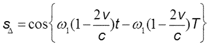 The difference signal is represented mathematically as follows
Demoduliert man dieses Signal mit der ersten Modulationsfrequenz 001 so erhält man die Phasendifferenz 001 T zwischen dem mit der ersten Modulationsfrequenz 001 modulierten Signalanteil und dem unmodulierten Signalanteil des reflektierten If this signal is demodulated with the first modulation frequency 001, the phase difference 001 T is obtained between the signal component modulated with the first modulation frequency 001 and the unmodulated signal component of the reflected one
Objektstrahls 15, wobei T der Laufzeitunterschied zwischen dem Referenzstrahl und dem Objektstrahl ist. Über die bekannte Beziehung T = 2 X/C kann der Abstand bzw. die Distanz X zum reflektierenden Objekt 80 präzise bestimmt werden. Die Faktoren
 sind sehr nahe bei 1. Object beam 15, where T is the transit time difference between the reference beam and the object beam. The distance or the distance X to the reflective object 80 can be precisely determined via the known relationship T = 2 X / C. The factors are very close to 1.
Alternativ könnte anstelle des Signals sA auch lediglich die Signalkomponente sa , welche die gleiche spektrale Form wie sA hat, verwendet werden. Im Gegensatz zu letzterer enthält jene lediglich das Produkt der Amplituden aus dem reflektierten Objektstrahl A0At (welche je nach Reflektivität des Messobjekts sehr klein sein können), während sA das Produkt aus der Amplitude der jeweiligen Komponente des Objektstrahls und des Referenzstrahls enthält ( A0B bzw. AtB ) und hierüber eine optische Verstärkung bewirkt. Alternatively, instead of the signal s A , only the signal component s a , which has the same spectral shape as s A , could be used. In contrast to the latter, the latter only contains the product of the amplitudes from the reflected object beam A 0 A t (which can be very small depending on the reflectivity of the measurement object), while s A contains the product of the amplitude of the respective component of the object beam and the reference beam ( A 0 B or A t B) and this brings about an optical amplification.
Die Geschwindigkeits-Auswerteeinheit 54 erhält das Signal So als Eingangssignal im Demodulator 74. Der Demodulator 74 führt eine Demodulation bei der zweiten The speed evaluation unit 54 receives the signal So as an input signal in the demodulator 74. The demodulator 74 performs a demodulation in the second
Modulationsfrequenz 002 aus. Durch diese Demodulation und durch die zeitliche Ableitung mittels des nachgeschalteten Differenzierers 76 erhält man das Argument V/C wo, welches durch Multiplikation mit dem Term C/2 wo nach der Geschwindigkeit aufgelöst werden kann. Modulation frequency 002 off. This demodulation and the time derivative by means of the downstream differentiator 76 gives the argument V / C wo, which can be resolved according to the speed by multiplication with the term C / 2 wo.
Die Geschwindigkeit, bzw. Vibration oder Schwingung des Objekts 80 können insoweit zeitgleich bestimmt werden. The speed or vibration or oscillation of the object 80 can in this respect be determined at the same time.
Das Verfahren gemäß dem Flussdiagramm nach Fig. 4 ähnelt demjenigen gemäß Fig. 3. Auch hier werden in einem ersten Schritt 100 ausgehend von der Strahlungsquelle ein Objektstrahl 12 und ein Referenzstrahl 14 bereitgestellt. Im nachfolgenden Schritt 102 wird die Sendestrahlung 11 oder der Objektstrahl 12 mit einer ersten
Modulationsfrequenz mittels des ersten Modulators 20 moduliert. Im Schritt 104 wird ein Interferenzsignal am Strahlungsdetektor 40 detektiert. Das Interferenzsignal beruht auf der Interferenz des vom Objekt reflektierten Objektstrahls 15 mit dem Referenzstrahl 14. Im Schritt 108 erfolgt ähnlich wie im Schritt 106 des in Fig. 3 gezeigten The method according to the flowchart according to FIG. 4 is similar to that according to FIG. 3. Here too, in a first step 100, an object beam 12 and a reference beam 14 are provided starting from the radiation source. In the following step 102, the transmission radiation 11 or the object beam 12 is first Modulation frequency modulated by means of the first modulator 20. In step 104, an interference signal is detected at the radiation detector 40. The interference signal is based on the interference of the object beam 15 reflected by the object with the reference beam 14. Step 108 takes place in a manner similar to that shown in step 106 in FIG
Flussdiagramms eine Bestimmung der mit der zu messenden Distanz korrelierenden Phasendifferenz zwischen einem mit der ersten Modulationsfrequenz modulierten Signalanteil des reflektierten Objektstrahls und einem unmodulierten Signalanteil des reflektierten Objektstrahls. Flowchart shows a determination of the phase difference, which correlates with the distance to be measured, between a signal component of the reflected object beam modulated with the first modulation frequency and an unmodulated signal component of the reflected object beam.
Währenddessen, mit zeitlichem Überlapp oder zeitgleich hierzu wird im Schritt 110 die Geschwindigkeit bzw. der Bewegungszustand des Objekts relativ zur Messvorrichtung bestimmt. Letzteres erfolgt typischerweise mittels der zweiten Modulation des zweiten Modulators 16 sowie mittels der logischen Geschwindigkeits-Auswerteeinheit 54. Meanwhile, with a temporal overlap or at the same time as this, the speed or the state of motion of the object relative to the measuring device is determined in step 110. The latter typically takes place by means of the second modulation of the second modulator 16 and by means of the logical speed evaluation unit 54.
Während für die absolute Distanzmessung nach dem Schritt 108 die Sequenz der Schritte 102, 104 unter Verwendung einer anderen Modulationsfrequenz erneut und sukzessive durchgeführt werden, die Frequenz der Modulationsfrequenz sozusagen durchgestimmt wird, kann die Frequenz des zweiten Modulators für die While for the absolute distance measurement after step 108 the sequence of steps 102, 104 are carried out again and successively using a different modulation frequency, the frequency of the modulation frequency is tuned, so to speak, the frequency of the second modulator for the
Geschwindigkeits-Auswerteeinheit 54 beibehalten werden. Speed evaluation unit 54 are retained.
Somit kann während Veränderung der Modulationsfrequenz des ersten Modulators 20, die eine endliche Zeit in Anspruch nimmt, die Geschwindigkeit bzw. der Thus, while changing the modulation frequency of the first modulator 20, which takes a finite time, the speed or the
Schwingungszustand des Objekts 80 fortwährend und ununterbrochen gemessen werden. Für den Fall, dass während dieses Zeitintervalls der Eindeutigkeitsbereich für die absolute Distanzmessung verloren gehen sollte kann dies mittels Rückkopplung von der logischen Geschwindigkeits-Auswerteeinheit 54 an die Laufzeit-Auswerteeinheit 53 detektiert gegebenenfalls sogar quantitativ erfasst werden. The vibration state of the object 80 can be measured continuously and uninterruptedly. In the event that the uniqueness range for the absolute distance measurement should be lost during this time interval, this can possibly even be quantitatively detected by means of feedback from the logical speed evaluation unit 54 to the transit time evaluation unit 53.
Insoweit ist es hierfür denkbar und nach einer Ausführungsform vorgesehen, dass der in Fig. 3 dargestellte Differenzierer 76 signaltechnisch mit dem Demodulator 66 verbunden ist und dass ein Ausgang des Differenzierers 76 mit einem weiteren Eingang des Demodulators 66 datentechnisch gekoppelt ist. In this respect, it is conceivable for this purpose and, according to one embodiment, provided that the differentiator 76 shown in FIG. 3 is connected to the demodulator 66 for signaling purposes and that an output of the differentiator 76 is data-related to a further input of the demodulator 66.
Während die Ausführungsformen der Messvorrichtung und des Verfahrens gemäß der Figuren 1 bis 4 eine zeitgleiche Abstands- und Geschwindigkeit bzw. While the embodiments of the measuring device and the method according to Figures 1 to 4 have a simultaneous distance and speed or
Schwingungsmessungen auf Basis der Verwendung zweier unterschiedlicher
Modulatoren 16, 20 ermöglichen, findet bei der alternativen Ausgestaltung gemäß der Figuren 5 bis 6 lediglich ein einziger Modulator 20 Anwendung. Vibration measurements based on the use of two different Modulators 16, 20 enable only a single modulator 20 to be used in the alternative embodiment according to FIGS. 5 to 6.
Die weitere Ausgestaltung der Messvorrichtung 1 gemäß der Figuren 5 und 6 ist lediglich mit einem einzigen Modulator 20 ausgestaltet. Der Modulator 20 ist mit einer Durchstimmeinrichtung 90 versehen, mittels welcher die Modulationsfrequenz des Modulators 20 bedarfsgerecht modulierbar bzw. veränderbar ist. Bei der Ausgestaltung gemäß Fig. 1 ist die Durchstimmeinrichtung 90 typischerweise in der Auswerteeinheit 50 oder in eine gesonderte Steuerung für den Modulator integriert. The further configuration of the measuring device 1 according to FIGS. 5 and 6 is designed with only a single modulator 20. The modulator 20 is provided with a tuning device 90, by means of which the modulation frequency of the modulator 20 can be modulated or changed as required. In the embodiment according to FIG. 1, the tuning device 90 is typically integrated in the evaluation unit 50 or in a separate control for the modulator.
Bei der Ausgestaltung gemäß Fig. 5 und 6 ist die logische Laufzeit-Auswerteeinheit 53 bzw. der Linienseparator 52 nahezu identisch wie bei der Ausgestaltung gemäß Fig. 3 ausgebildet. Anders als in Fig. 3 dargestellt ist jedoch der erste Bandpass 68 des Linienseparators 52 von der Geschwindigkeits-Auswerteeinheit 54 entkoppelt. Anstelle dessen ist die Geschwindigkeits-Auswerteeinheit 54 direkt mit dem Ausgang des Analog Digital Wandlers 56 gekoppelt. Der Ausgang des Analog Digital Wandlers 56 verzweigt quasi einerseits in den Linienseparator 52 und andererseits in die logische Geschwindigkeit-Auswerteeinheit 54. Diese sind datentechnisch sozusagen parallel geschaltet. In the embodiment according to FIGS. 5 and 6, the logic transit time evaluation unit 53 or the line separator 52 is almost identical to that in the embodiment according to FIG. 3. In contrast to what is shown in FIG. 3, however, the first band pass 68 of the line separator 52 is decoupled from the speed evaluation unit 54. Instead, the speed evaluation unit 54 is coupled directly to the output of the analog-digital converter 56. The output of the analog-to-digital converter 56 branches, as it were, on the one hand into the line separator 52 and on the other hand into the logical speed evaluation unit 54. These are connected in parallel, so to speak, for data purposes.
Die Geschwindigkeits-Auswerteeinheit 54 gemäß Fig. 6 weist im Unterschied zu derjenigen gemäß Fig. 3 einen anderen Demodulator 94 auf, welcher unmittelbar mit dem Ausgang des Analog-Digitalwandlers der Signalaufbereitung 51 gekoppelt ist. Das Ausgangssignal des Analog-Digital-Wandler 56 enthält mehrere Frequenzanteile, hierunter insbesondere eine erste harmonische (m=1) und eine zweite harmonische (m=2) der Modulationsfrequenz. Der Demodulator 94 der logischen Geschwindigkeit- Auswerteeinheit 54 kann insbesondere als sogenannter PGC - Demodulator (Phase Generated Carrier) Modulator ausgestaltet sein. Mittels diesem kann der Betrag und die Richtung einer Bewegung des Objekts 80 relativ zur Messvorrichtung 1 bestimmt werden. Der Demodulator 94 ist ferner signaltechnisch mit dem ersten Modulator 20 gekoppelt. The speed evaluation unit 54 according to FIG. 6, in contrast to that according to FIG. 3, has a different demodulator 94 which is coupled directly to the output of the analog-digital converter of the signal conditioning 51. The output signal of the analog / digital converter 56 contains several frequency components, including in particular a first harmonic (m = 1) and a second harmonic (m = 2) of the modulation frequency. The demodulator 94 of the logic speed evaluation unit 54 can in particular be designed as a so-called PGC demodulator (Phase Generated Carrier) modulator. By means of this, the amount and the direction of a movement of the object 80 relative to the measuring device 1 can be determined. The demodulator 94 is also coupled to the first modulator 20 in terms of signals.
In gleicher Art und Weise wie bereits zuvor beschriebenen kann alsdann die In the same way as described above, the
Geschwindigkeits-Auswerteeinheit 54 die Geschwindigkeit bzw. den Speed evaluation unit 54 the speed or the
Bewegungszustand des Objekts 80 relativ zur Messvorrichtung 1 zeitgleich bzw. zeitlich
überlappend zur absoluten Distanzmessung der logischen Laufzeit-Auswerteeinheit 53 bestimmen. State of motion of the object 80 relative to the measuring device 1 at the same time or in time determine overlapping to the absolute distance measurement of the logical transit time evaluation unit 53.
Insoweit ist mit der gestrichelten Verbindung zwischen dem Ausgang 78 der In this respect, the dashed connection between the output 78 of
Geschwindigkeits-Auswerteeinheit 54 und der Laufzeit-Auswerteeinheit 53 in Fig. 6 eine Rückkopplung bzw. ein Feedback von der Geschwindigkeit-Auswerteeinheit 54 zur Laufzeit-Auswerteeinheit 53 dargestellt. Dieses kann insbesondere zur Korrektur der Positionsbestimmung für solche Zeitintervalle Verwendung finden, in welchen die Positionsbestimmung aufgrund der Veränderung der Modulationsfrequenz zu ungenau oder nicht mehr eindeutig ist. Die Rückkopplung bzw. das Feedback kann direkt mit dem Demodulator 66 der Laufzeit-Auswerteeinheit 53 gekoppelt sein. Speed evaluation unit 54 and run time evaluation unit 53 in FIG. 6 show a feedback or feedback from speed evaluation unit 54 to run time evaluation unit 53. This can be used in particular to correct the position determination for those time intervals in which the position determination is too imprecise or no longer clear due to the change in the modulation frequency. The feedback or the feedback can be coupled directly to the demodulator 66 of the transit time evaluation unit 53.
Dadurch dass die Geschwindigkeitsbestimmung bei allen Frequenzen grundsätzlich mit interferometrischer Genauigkeit möglich ist und gegebenenfalls auch erfolgt, kann während des Durchstimmens bzw. während der Veränderung der Modulationsfrequenz des ersten und gegebenenfalls einzigen Modulators die Messung der Geschwindigkeit ununterbrochen fortgeführt werden und zur Korrektur des von der logischen Laufzeit- Auswerteeinheit 53 bereitgestellten Positions- oder Abstandssignals verwendet werden. Since the speed determination is basically possible with interferometric accuracy at all frequencies and possibly also takes place, the measurement of the speed can be continued without interruption during the tuning or during the change of the modulation frequency of the first and possibly only modulator and for the correction of the logical transit time - Evaluation unit 53 provided position or distance signal can be used.
Im Blockdiagramm der Fig. 5 ist zudem gezeigt, dass die Vorrichtung zur In the block diagram of FIG. 5 it is also shown that the device for
Distanzmessung 1 ferner mit einer Strahlablenkeinheit 92 versehen ist, mittels dieser kann der Objektstrahl 12 hinsichtlich seiner Transversalrichtung bedarfsgerecht abgelenkt werden, sodass unterschiedliche Flächenabschnitte des Objekts 80 punktuell oder kontinuierlich mit dem Objektstrahl abgetastet bzw. abgescannt werden können. Dies ist in Fig. 5 mit dem transversal abgelenkten Objektstrahl 12‘ gekennzeichnet. Selbstredend kann auch die Vorrichtung gemäß Fig. 1 mit einer solchen Distance measurement 1 is also provided with a beam deflection unit 92, by means of which the object beam 12 can be deflected as required with regard to its transverse direction so that different surface sections of the object 80 can be scanned or scanned punctually or continuously with the object beam. This is indicated in Fig. 5 with the transversely deflected object beam 12 ‘. Of course, the device according to FIG. 1 can also have such a
Strahlablenkeinheit 92 ausgestattet sein. Ein hochpräzises ortsaufgelöstes Vermessen des Objekts wird somit möglich. Die Strahlablenkeinheit 92 kann ein oder mehrere verstellbare Spiegel sowie anderweitige strahlablenkende optische Elemente aufweisen. Anstelle oder ergänzenden zu einem sukzessiven Abtasten der Oberfläche des Mesobjekts kann auch die gleichzeitige Messung der Oberfläche über mehrere Messtrahlen in Verbindung mit jeweils einer beschreibungsgemäßen Vorrichtung zur Entfernungsmessung erfolgen (Mehrpunkt-Interferometrie).
Bezugszeichenliste Beam deflection unit 92 be equipped. A high-precision, spatially resolved measurement of the object is thus possible. The beam deflection unit 92 can have one or more adjustable mirrors as well as other beam-deflecting optical elements. Instead of or in addition to successive scanning of the surface of the object to be measured, the surface can also be measured simultaneously using several measuring beams in conjunction with one device according to the description for distance measurement (multi-point interferometry). List of reference symbols
I Vorrichtung zur DistanzmessungI Device for distance measurement
10 Strahlungsquelle 10 radiation source
I I Sendestrahlung I I transmission radiation
12 Objektstrahl 12 object beam
14 Referenzstrahl 14 reference beam
15 reflektierte Objektstrahl 15 reflected object beam
16 Modulator 16 modulator
17 Strahlteiler 17 beam splitter
18 Spiegel 18 mirrors
19 Strahlteiler 19 beam splitters
20 Modulator 20 modulator
30 Strahlteiler 30 beam splitters
40 Detektor 40 detector
50 Auswerteeinheit 50 evaluation unit
51 Signalaufbereitung 51 Signal conditioning
52 Linienseparator 52 line separator
53 Laufzeit-Auswerteeinheit 53 Runtime evaluation unit
54 Geschwindigkeits-Auswerteeinheit 54 Speed evaluation unit
56 Analog-digital-Wandler 56 analog-to-digital converter
60 Mischer 60 mixers
61 Eingang 61 input
62 Eingang 62 entrance
64 Tiefbass 64 deep bass
66 Demodulator 66 demodulator
68 Bandpass 68 band pass
69 Ausgang 69 exit
70 Bandpass 70 band pass
71 Ausgang 71 exit
72 Ausgang 72 exit
74 Demodulator 74 demodulator
76 Differenzierer 76 differentiators
78 Ausgang 78 exit
80 Objekt
Durchstimmeinrichtung Strahlablenkeinheit Demodulator
80 object Tuning device Beam deflection unit Demodulator
Claims
1. Vorrichtung zur Messung einer Distanz zu einem reflektierenden Objekt (80), mit: einer Strahlungsquelle (10) zur Erzeugung eines Objektstrahls (12) und eines Referenzstrahls (14), wobei der Objektstrahl zum Objekt (80) propagiert, zumindest einem ersten Modulator (20) zur Modulation des Objektstrahls (12), wobei der Modulator (20) dazu ausgestaltet ist, den Objektstrahl (12) mit einer ersten Modulationsfrequenz zeitlich periodisch zu modulieren, einem Strahlungsdetektor (40), an welchem zumindest ein Teil des vom Objekt (80) reflektierten Objektstrahls (15) unter Bildung eines A device for measuring a distance to a reflective object (80), comprising: a radiation source (10) for generating an object beam (12) and a reference beam (14), the object beam propagating to the object (80), at least one first modulator (20) for modulating the object beam (12), the modulator (20) being designed to periodically modulate the object beam (12) with a first modulation frequency, a radiation detector (40) on which at least part of the object ( 80) reflected object beam (15) to form a
Interferenzsignals mit dem Referenzstrahl (14) interferiert, und mit einer mit dem Strahlungsdetektor (40) gekoppelten elektronischen Auswerteeinheit (50), welche dazu ausgestaltet ist, auf Basis des Interference signal interferes with the reference beam (14), and with an electronic evaluation unit (50) which is coupled to the radiation detector (40) and is designed based on the
Interferenzsignals am Strahlungsdetektor (40) eine mit der zu messenden Distanz korrelierende Phasendifferenz: zwischen einem mit der ersten Modulationsfrequenz modulierten Signalanteil des reflektierten Objektstrahls (15) und einem unmodulierten Signalanteil des reflektierten Objektstrahls (15), oder zwischen einem mit der ersten Modulationsfrequenz modulierten Signalanteil des reflektierten Objektstrahls (15) und einer Interference signal at the radiation detector (40) has a phase difference correlating with the distance to be measured: between a signal component of the reflected object beam (15) modulated with the first modulation frequency and an unmodulated signal component of the reflected object beam (15), or between a signal component of the modulated with the first modulation frequency reflected object beam (15) and one
Phasenlage des Modulators (20) zu bestimmen. To determine the phase position of the modulator (20).
2. Vorrichtung nach Anspruch 1 , wobei die Auswerteeinheit (50) dazu 2. Device according to claim 1, wherein the evaluation unit (50) for this purpose
ausgestaltet ist, auf Basis der Phasendifferenz eine Laufzeit des
reflektierten Objektstrahls (15) und/oder die Distanz zum reflektierenden Objekt (80) zu bestimmen. is designed, based on the phase difference, a running time of the to determine the reflected object beam (15) and / or the distance to the reflecting object (80).
3. Vorrichtung nach Anspruch 1 oder 2, wobei die Auswerteeinheit (50) dazu ausgestaltet ist, einen Laufzeitunterschied (T) zwischen dem 3. Apparatus according to claim 1 or 2, wherein the evaluation unit (50) is designed to a delay time difference (T) between the
Referenzstrahl (14) und dem reflektierten Objektstrahl (12) auf Basis der Phasendifferenz zu bestimmen. To determine the reference beam (14) and the reflected object beam (12) based on the phase difference.
4. Vorrichtung nach einem der vorhergehenden Ansprüche, wobei der erste Modulator (20) dazu ausgestaltet ist, die erste Modulationsfrequenz elektronisch zu erzeugen. 4. Device according to one of the preceding claims, wherein the first modulator (20) is designed to generate the first modulation frequency electronically.
5. Vorrichtung nach einem der vorhergehenden Ansprüche, wobei der erste Modulator (20) ein Phasenmodulator, ein Amplitudenmodulator, ein Polarisationsmodulator oder ein Frequenzmodulator ist. 5. Device according to one of the preceding claims, wherein the first modulator (20) is a phase modulator, an amplitude modulator, a polarization modulator or a frequency modulator.
6. Vorrichtung nach einem der vorhergehenden Ansprüche, wobei die 6. Device according to one of the preceding claims, wherein the
Auswerteeinheit (50) einen multiplikativen Mischer (60) und einen dem Mischer (60) nachgeschalteten Filter (62) aufweist, mittels welchem aus dem Interferenzsignal ein mit der ersten Modulationsfrequenz The evaluation unit (50) has a multiplicative mixer (60) and a filter (62) connected downstream of the mixer (60), by means of which the interference signal is converted to the first modulation frequency
oszillierendes Differenzsignal generierbar ist. oscillating difference signal can be generated.
7. Vorrichtung nach Anspruch 6, wobei die Auswerteeinheit (50) einen 7. The device according to claim 6, wherein the evaluation unit (50) one
Demodulator (64) aufweist, mittels welchem durch Demodulation des Differenzsignals bei der ersten Modulationsfrequenz die Phasendifferenz oder der Laufzeitunterschied bestimmbar ist. Demodulator (64), by means of which the phase difference or the transit time difference can be determined by demodulating the difference signal at the first modulation frequency.
8. Vorrichtung nach einem der vorhergehenden Ansprüche, wobei im 8. Device according to one of the preceding claims, wherein im
Strahlengang des Referenzstrahls (14) oder im Strahlengang des Beam path of the reference beam (14) or in the beam path of the
Objektstrahls (12) ein zweiter Modulator (16) angeordnet ist, welcher dazu ausgebildet ist, den Referenzstrahl (14) und/oder den Objektstrahl (12) mit einer zweiten Modulationsfrequenz zu modulieren. Object beam (12) a second modulator (16) is arranged, which is designed to modulate the reference beam (14) and / or the object beam (12) with a second modulation frequency.
9. Vorrichtung nach Anspruch 8, wobei die Auswerteeinheit (50) einen ersten Bandpassfilter (68) und einen hierzu parallel geschalteten zweiten
Bandpassfilter (70) aufweist, wobei der erste Bandpassfilter (68) dazu ausgestaltet ist, aus dem Interferenzsignal einen ersten Signalanteil bei der zweiten Modulationsfrequenz zu extrahieren und wobei der zweite Bandpassfilter (70) dazu ausgestaltet ist, aus dem Interferenzsignal bei der Differenz zwischen der ersten Modulationsfrequenz und der zweiten Modulationsfrequenz einen zweiten Signalanteil zu extrahieren. 9. Apparatus according to claim 8, wherein the evaluation unit (50) has a first bandpass filter (68) and a second one connected in parallel therewith Having bandpass filter (70), wherein the first bandpass filter (68) is designed to extract a first signal component at the second modulation frequency from the interference signal and wherein the second bandpass filter (70) is designed to extract from the interference signal at the difference between the first Modulation frequency and the second modulation frequency to extract a second signal component.
10. Vorrichtung nach Anspruch 6 und 9, wobei der multiplikative Mischer (60) einen ersten Eingang (61) aufweist, welcher mit einem Ausgang (69) des ersten Bandpassfilters (68) signaltechnisch verbunden ist und wobei der multiplikative Mischer (60) einen zweiten Eingang (62) aufweist, welcher mit einem Ausgang (71) des zweiten Bandpassfilters (70) signaltechnisch verbunden ist. 10. Apparatus according to claim 6 and 9, wherein the multiplicative mixer (60) has a first input (61) which is signal-connected to an output (69) of the first bandpass filter (68) and wherein the multiplicative mixer (60) has a second Has input (62) which is signal-connected to an output (71) of the second bandpass filter (70).
1 1. Vorrichtung nach einem der vorhergehenden Ansprüche, wobei der 1 1. Device according to one of the preceding claims, wherein the
Modulator (20) signaltechnisch mit der Auswerteeinheit (50) gekoppelt ist und wobei der Modulator (20) zur Erzeugung mehrerer unterschiedlicher erster Modulationsfrequenzen ausgestaltet ist. The modulator (20) is coupled to the evaluation unit (50) for signaling purposes, and the modulator (20) is designed to generate several different first modulation frequencies.
12. Vorrichtung nach einem der vorhergehenden Ansprüche, ferner mit einer Strahlablenkeinheit (92) zum kontinuierlichen oder punktweisen Abtasten des Objekts (80). 12. Device according to one of the preceding claims, further comprising a beam deflection unit (92) for continuous or point-by-point scanning of the object (80).
13. Vorrichtung nach einem der vorhergehenden Ansprüche, wobei die 13. Device according to one of the preceding claims, wherein the
elektronische Auswerteeinheit (50) dazu ausgestaltet ist, die electronic evaluation unit (50) is designed to
Geschwindigkeit des Objekts (80) relativ zur Messvorrichtung und einen Abstand zwischen der Messvorrichtung und dem Objekt (80) gleichzeitig zu bestimmen. To determine the speed of the object (80) relative to the measuring device and a distance between the measuring device and the object (80) simultaneously.
14. Vorrichtung nach einem der vorhergehenden Ansprüche, wobei die 14. Device according to one of the preceding claims, wherein the
elektronischen Auswerteeinheit (50) eine logische Laufzeit- Auswerteeinheit (53) und eine logische Geschwindigkeits-Auswerteeinheit (54) aufweist, wobei die logische Laufzeit-Auswerteeinheit (53) zur Bestimmung eines Abstandes zum Objekt (80) und die logische electronic evaluation unit (50) has a logical transit time evaluation unit (53) and a logical speed evaluation unit (54), the logical transit time evaluation unit (53) for determining a distance to the object (80) and the logical
Geschwindigkeits-Auswerteeinheit (54) zur Bestimmung einer
Geschwindigkeit des Objekts (80) relativ zur Messvorrichtung ausgebildet sind. Speed evaluation unit (54) for determining a Speed of the object (80) are formed relative to the measuring device.
15. Vorrichtung nach Anspruch 14, wobei die elektronische Auswerteeinheit (50) dazu ausgestaltet ist, ein von der logischen Geschwindigkeit- Auswerteeinheit (54) erzeugbares Geschwindigkeitssignal zur Korrektur einer von der logischen Laufzeit-Auswerteeinheit (53) bestimmbaren absoluten Abstandsmessung zum Objekt (80) zu verwenden. 15. The device according to claim 14, wherein the electronic evaluation unit (50) is designed to generate a speed signal that can be generated by the logical speed evaluation unit (54) for correcting an absolute distance measurement to the object (80) which can be determined by the logical transit time evaluation unit (53). to use.
16. Verfahren zur Messung einer Distanz zu einem reflektierenden Objekt (80), mit den Schritten: 16. Method for measuring a distance to a reflective object (80), with the steps:
Erzeugen eines Objektstrahls (12) und eines Referenzstrahls (14) mittels einer Strahlungsquelle (10), wobei der Objektstrahl zum Objekt (80) propagiert, zeitlich periodisches Modulieren des Objektsstrahls (12) mit einer ersten Modulationsfrequenz mittels eines ersten Modulators (20), Generating an object beam (12) and a reference beam (14) by means of a radiation source (10), the object beam propagating to the object (80), temporally periodic modulation of the object beam (12) with a first modulation frequency by means of a first modulator (20),
Detektieren eines Interferenzsignals an einem Strahlungsdetektor (40), an welchem zumindest ein Teils des vom Objekt (80) reflektierten Detecting an interference signal at a radiation detector (40) on which at least part of the signal reflected from the object (80)
Objektstrahls (15) mit dem Referenzstrahl (14) interferiert, Object beam (15) interferes with the reference beam (14),
Bestimmen einer mit der zu messenden Distanz korrelierenden Determining a correlation with the distance to be measured
Phasendifferenz zwischen einem mit der ersten Modulationsfrequenz modulierten Signalanteil des reflektierten Objektstrahls (15) und einem unmodulierten Signalanteil des reflektierten Objektstrahls (15) oder zwischen einem mit der ersten Modulationsfrequenz modulierten Signalanteil des reflektierten Objektstrahls (15) und einer Phasenlage des Modulators (20)
auf Basis des Interferenzsignals am Strahlungsdetektor (40). Phase difference between a signal component of the reflected object beam (15) modulated with the first modulation frequency and an unmodulated signal component of the reflected object beam (15) or between a signal component of the reflected object beam (15) modulated with the first modulation frequency and a phase position of the modulator (20) based on the interference signal at the radiation detector (40).
17. Verfahren nach Anspruch 16, wobei die erste Modulationsfrequenz derart bestimmt wird, dass die zu messende Distanz kleiner ist als ein durch die erste Modulationsfrequenz vorgegebener Eindeutigkeitsbereich. 17. The method according to claim 16, wherein the first modulation frequency is determined in such a way that the distance to be measured is smaller than a uniqueness range predetermined by the first modulation frequency.
18. Verfahren nach Anspruch 16 oder 17, wobei die Phasendifferenz, bzw. der Laufzeitunterschied (T) wiederholt und sukzessive auf Basis 18. The method according to claim 16 or 17, wherein the phase difference or the transit time difference (T) is repeated and successively based
unterschiedlicher erster Modulationsfrequenzen bestimmt wird. different first modulation frequencies is determined.
19. Verfahren nach einem der vorhergehenden Ansprüche 16 bis 18, wobei auf Basis der Phasendifferenz ein Abstand zum Objekt (80) als auch eine Geschwindigkeit des Objekts (80) relativ zur Messvorrichtung (1) gleichzeitig gemessen werden. 19. The method according to any one of the preceding claims 16 to 18, wherein a distance to the object (80) and a speed of the object (80) relative to the measuring device (1) are measured simultaneously on the basis of the phase difference.
20. Verfahren nach einem der vorhergehenden Ansprüche 16 bis 19, welches mit einer Vorrichtung (1) nach einem der vorhergehenden Ansprüche 1 bis 15 durchgeführt wird. 20. The method according to any one of the preceding claims 16 to 19, which is carried out with a device (1) according to one of the preceding claims 1 to 15.
21. Computerprogramm zur Messung einer Distanz zu einem reflektierenden Objekt (80), wobei das Computerprogramm in einer Auswerteeinheit (50) einer Vorrichtung zur Distanzmessung nach einem der vorhergehenden Ansprüche 1 bis 15 implementierbar ist und wobei das Computerprogramm: 21. Computer program for measuring a distance to a reflective object (80), wherein the computer program can be implemented in an evaluation unit (50) of a device for distance measurement according to one of the preceding claims 1 to 15, and wherein the computer program:
Programmmittel zum zeitlich periodischen Modulieren des Objektsstrahls (12) mit einer ersten Modulationsfrequenz mittels eines ersten Modulators (20) , Program means for modulating the object beam (12) periodically with a first modulation frequency by means of a first modulator (20),
Programmmittel zum Detektieren eines Interferenzsignals an einem Strahlungsdetektor (40), an welchem zumindest ein Teils des vom Objekt (80) reflektierten Objektstrahls (15) mit dem Referenzstrahl (14) interferiert, Program means for detecting an interference signal on a radiation detector (40) on which at least part of the object beam (15) reflected by the object (80) interferes with the reference beam (14),
Programmmittel zum Bestimmen einer mit der zu messenden Distanz korrelierenden Phasendifferenz
zwischen einem mit der ersten Modulationsfrequenz modulierten Signalanteil des reflektierten Objektstrahls (15) und einem unmodulierten Signalanteil des reflektierten Objektstrahls (15) oder zwischen einem mit der ersten Modulationsfrequenz modulierten Signalanteil des reflektierten Objektstrahls (15) und einer Phasenlage des Modulators (20) auf Basis des Interferenzsignals am Strahlungsdetektor (40) aufweist.
Program means for determining a phase difference correlating with the distance to be measured between a signal component of the reflected object beam (15) modulated with the first modulation frequency and an unmodulated signal component of the reflected object beam (15) or between a signal component of the reflected object beam (15) modulated with the first modulation frequency and a phase position of the modulator (20) based on the Having interference signal on the radiation detector (40).
Priority Applications (1)
| Application Number | Priority Date | Filing Date | Title |
|---|---|---|---|
| DE112020000945.9T DE112020000945A5 (en) | 2019-02-22 | 2020-02-24 | Interferometric distance measurement based on time differences |
Applications Claiming Priority (2)
| Application Number | Priority Date | Filing Date | Title |
|---|---|---|---|
| DE102019001275.5A DE102019001275A1 (en) | 2019-02-22 | 2019-02-22 | Interferometric distance measurement based on transit time differences |
| DE102019001275.5 | 2019-02-22 |
Publications (1)
| Publication Number | Publication Date |
|---|---|
| WO2020169845A1 true WO2020169845A1 (en) | 2020-08-27 |
Family
ID=69714015
Family Applications (1)
| Application Number | Title | Priority Date | Filing Date |
|---|---|---|---|
| PCT/EP2020/054738 WO2020169845A1 (en) | 2019-02-22 | 2020-02-24 | Interferometric distance measurement on the basis of propagation time differences |
Country Status (2)
| Country | Link |
|---|---|
| DE (2) | DE102019001275A1 (en) |
| WO (1) | WO2020169845A1 (en) |
Families Citing this family (1)
| Publication number | Priority date | Publication date | Assignee | Title |
|---|---|---|---|---|
| WO2022137410A1 (en) * | 2020-12-24 | 2022-06-30 | 三菱電機株式会社 | Laser radar device and wind measurement method |
Citations (2)
| Publication number | Priority date | Publication date | Assignee | Title |
|---|---|---|---|---|
| US4741620A (en) * | 1982-10-08 | 1988-05-03 | National Research Development Corporation | Irradiative probe system |
| EP2045572A1 (en) * | 2007-10-04 | 2009-04-08 | Attocube Systems AG | Method and apparatus for determining a position |
Family Cites Families (1)
| Publication number | Priority date | Publication date | Assignee | Title |
|---|---|---|---|---|
| DE102017220408A1 (en) * | 2017-11-15 | 2018-12-13 | Carl Zeiss Smt Gmbh | Optical system for microlithography, as well as methods for position determination |
-
2019
- 2019-02-22 DE DE102019001275.5A patent/DE102019001275A1/en not_active Withdrawn
-
2020
- 2020-02-24 DE DE112020000945.9T patent/DE112020000945A5/en active Pending
- 2020-02-24 WO PCT/EP2020/054738 patent/WO2020169845A1/en active Application Filing
Patent Citations (2)
| Publication number | Priority date | Publication date | Assignee | Title |
|---|---|---|---|---|
| US4741620A (en) * | 1982-10-08 | 1988-05-03 | National Research Development Corporation | Irradiative probe system |
| EP2045572A1 (en) * | 2007-10-04 | 2009-04-08 | Attocube Systems AG | Method and apparatus for determining a position |
Non-Patent Citations (2)
| Title |
|---|
| E. DALHOFF ET AL: "Double heterodyne interferometry for high-precision distance measurements", SPIE - INTERNATIONAL SOCIETY FOR OPTICAL ENGINEERING. PROCEEDINGS, vol. 2252, 1 March 1994 (1994-03-01), US, pages 379 - 385, XP055703599, ISSN: 0277-786X, DOI: 10.1117/12.169861 * |
| YOSHIYUKI KURAMOTO ET AL: "High-accuracy absolute distance measurement by two-wavelength double heterodyne interferometry with variable synthetic wavelengths", ARXIV.ORG, 22 February 2014 (2014-02-22), pages 1 - 7, XP055533071, Retrieved from the Internet <URL:https://arxiv.org/ftp/arxiv/papers/1402/1402.5575.pdf> [retrieved on 20181211] * |
Also Published As
| Publication number | Publication date |
|---|---|
| DE102019001275A1 (en) | 2020-08-27 |
| DE112020000945A5 (en) | 2021-12-16 |
Similar Documents
| Publication | Publication Date | Title |
|---|---|---|
| DE19601875C2 (en) | Method and device for eliminating interference from FMCW radar | |
| EP1051640B1 (en) | Device for measuring distance using a semiconductor laser in the visible wavelength range according to the running time method | |
| DE19811550C2 (en) | Method and circuit arrangement for generating frequency signals | |
| DE19522262C2 (en) | Heterodyne interferometer arrangement | |
| DE102004037137B4 (en) | Method and device for distance measurement | |
| EP0834086A1 (en) | Fmcw distance measurement process | |
| DE102012211549B3 (en) | Apparatus and method for interferometric measurement of an object | |
| DE10106801B4 (en) | Vibration measuring method and frequency measuring device | |
| WO2019234034A1 (en) | Operating method for a lidar system, control unit, lidar system, and device | |
| DE102013100367A1 (en) | Distance measuring optoelectronic sensor and method for determining the distance of objects | |
| WO2020169845A1 (en) | Interferometric distance measurement on the basis of propagation time differences | |
| DE19537647C1 (en) | Method and arrangement for measuring physical quantities of light-scattering moving particles using a laser Doppler anemometer | |
| DE4429416A1 (en) | Method and interference microscope for microscoping an object to achieve a resolution beyond the diffraction limit (super resolution) | |
| EP1540374B1 (en) | Method for determination of a distance and distance measuring device with improvement of the effective resolution of an a/d converter by phase modulation of the measured signal | |
| DE102010062842B4 (en) | Method and device for determining the absolute position of an object | |
| WO1993009395A1 (en) | Process for measuring the inclination of boundary areas in an optical system | |
| DE60105791T2 (en) | METHOD AND DEVICE FOR MEASURING THE PHASE DIFFERENCE BETWEEN INTENSITY MODULATED OPTICAL SIGNALS | |
| EP0937229B1 (en) | Interferometric measuring device for form measurement on rough surfaces | |
| EP0646766A2 (en) | Procedure and device for absolute interferometry with a laser-diode beam | |
| WO2011151255A1 (en) | Measuring device and measuring method for absolute distance measurement | |
| DE102008045366B4 (en) | Apparatus and method for speed measurement | |
| EP3794309B1 (en) | Contactless optical extensometer | |
| DE2922873C2 (en) | Method and arrangement for non-contact photoelectric speed measurement in at least one measurement coordinate on the surfaces of rigid or deformable objects to be measured | |
| DE102011001161A1 (en) | Method for interferometric distance measurement by micro-optical sensor oscillating in measuring direction, involves bringing light emitted from light emission of sensor on measuring object to interference with light | |
| DE10120746C1 (en) | Method for evaluating laser-Doppler signals has pair of phase shifted signals mixed and used to generate a side band frequency |
Legal Events
| Date | Code | Title | Description |
|---|---|---|---|
| 121 | Ep: the epo has been informed by wipo that ep was designated in this application |
Ref document number: 20707384 Country of ref document: EP Kind code of ref document: A1 |
|
| REG | Reference to national code |
Ref country code: DE Ref legal event code: R225 Ref document number: 112020000945 Country of ref document: DE |
|
| 122 | Ep: pct application non-entry in european phase |
Ref document number: 20707384 Country of ref document: EP Kind code of ref document: A1 |