WO2020166697A1 - Medical instrument color correction device - Google Patents
Medical instrument color correction device Download PDFInfo
- Publication number
- WO2020166697A1 WO2020166697A1 PCT/JP2020/005770 JP2020005770W WO2020166697A1 WO 2020166697 A1 WO2020166697 A1 WO 2020166697A1 JP 2020005770 W JP2020005770 W JP 2020005770W WO 2020166697 A1 WO2020166697 A1 WO 2020166697A1
- Authority
- WO
- WIPO (PCT)
- Prior art keywords
- color
- conversion
- tissue
- data
- specific
- Prior art date
Links
- 238000012937 correction Methods 0.000 title claims description 238
- 238000006243 chemical reaction Methods 0.000 claims abstract description 623
- 210000004204 blood vessel Anatomy 0.000 claims abstract description 109
- 238000003384 imaging method Methods 0.000 claims abstract description 108
- 238000002059 diagnostic imaging Methods 0.000 claims abstract description 89
- 238000013500 data storage Methods 0.000 claims description 117
- 238000010586 diagram Methods 0.000 claims description 111
- 239000002344 surface layer Substances 0.000 claims description 57
- 238000005286 illumination Methods 0.000 claims description 54
- 230000001965 increasing effect Effects 0.000 claims description 35
- 230000003247 decreasing effect Effects 0.000 claims description 23
- 230000007423 decrease Effects 0.000 claims description 11
- 210000001519 tissue Anatomy 0.000 description 363
- 238000009826 distribution Methods 0.000 description 87
- 238000000034 method Methods 0.000 description 80
- 239000003925 fat Substances 0.000 description 70
- 230000008569 process Effects 0.000 description 43
- 238000005259 measurement Methods 0.000 description 41
- 238000012545 processing Methods 0.000 description 41
- 239000003086 colorant Substances 0.000 description 38
- 238000001228 spectrum Methods 0.000 description 31
- 235000019646 color tone Nutrition 0.000 description 25
- 230000000875 corresponding effect Effects 0.000 description 22
- 210000002429 large intestine Anatomy 0.000 description 22
- 230000008520 organization Effects 0.000 description 21
- 238000001356 surgical procedure Methods 0.000 description 19
- 230000002708 enhancing effect Effects 0.000 description 16
- 210000000056 organ Anatomy 0.000 description 15
- 230000003595 spectral effect Effects 0.000 description 12
- 239000012528 membrane Substances 0.000 description 10
- 239000000047 product Substances 0.000 description 10
- 238000002357 laparoscopic surgery Methods 0.000 description 8
- 229920006395 saturated elastomer Polymers 0.000 description 7
- 238000002350 laparotomy Methods 0.000 description 6
- 238000004088 simulation Methods 0.000 description 5
- 238000002474 experimental method Methods 0.000 description 4
- 239000000835 fiber Substances 0.000 description 4
- 238000007726 management method Methods 0.000 description 4
- 210000000683 abdominal cavity Anatomy 0.000 description 3
- 238000007630 basic procedure Methods 0.000 description 3
- 239000000284 extract Substances 0.000 description 3
- 238000003825 pressing Methods 0.000 description 3
- 239000000126 substance Substances 0.000 description 3
- 210000001015 abdomen Anatomy 0.000 description 2
- 210000000988 bone and bone Anatomy 0.000 description 2
- 238000004364 calculation method Methods 0.000 description 2
- 210000000845 cartilage Anatomy 0.000 description 2
- 230000008859 change Effects 0.000 description 2
- 238000003745 diagnosis Methods 0.000 description 2
- 238000000295 emission spectrum Methods 0.000 description 2
- 238000011156 evaluation Methods 0.000 description 2
- PCHJSUWPFVWCPO-UHFFFAOYSA-N gold Chemical compound [Au] PCHJSUWPFVWCPO-UHFFFAOYSA-N 0.000 description 2
- 229910052737 gold Inorganic materials 0.000 description 2
- 239000010931 gold Substances 0.000 description 2
- 210000003205 muscle Anatomy 0.000 description 2
- 241000238097 Callinectes sapidus Species 0.000 description 1
- 230000008901 benefit Effects 0.000 description 1
- 239000008280 blood Substances 0.000 description 1
- 210000004369 blood Anatomy 0.000 description 1
- 238000004422 calculation algorithm Methods 0.000 description 1
- 210000001072 colon Anatomy 0.000 description 1
- 239000002131 composite material Substances 0.000 description 1
- 239000000470 constituent Substances 0.000 description 1
- 230000001276 controlling effect Effects 0.000 description 1
- 230000002596 correlated effect Effects 0.000 description 1
- 238000013461 design Methods 0.000 description 1
- 230000000694 effects Effects 0.000 description 1
- 229910052736 halogen Inorganic materials 0.000 description 1
- 150000002367 halogens Chemical class 0.000 description 1
- 230000012447 hatching Effects 0.000 description 1
- 229910052738 indium Inorganic materials 0.000 description 1
- 238000012905 input function Methods 0.000 description 1
- 238000007689 inspection Methods 0.000 description 1
- 238000009434 installation Methods 0.000 description 1
- 238000011160 research Methods 0.000 description 1
- 229910052709 silver Inorganic materials 0.000 description 1
- 238000004611 spectroscopical analysis Methods 0.000 description 1
- 238000010183 spectrum analysis Methods 0.000 description 1
- 239000013589 supplement Substances 0.000 description 1
- 230000000007 visual effect Effects 0.000 description 1
- 229910052724 xenon Inorganic materials 0.000 description 1
- FHNFHKCVQCLJFQ-UHFFFAOYSA-N xenon atom Chemical compound [Xe] FHNFHKCVQCLJFQ-UHFFFAOYSA-N 0.000 description 1
Images


Classifications
-
- A—HUMAN NECESSITIES
- A61—MEDICAL OR VETERINARY SCIENCE; HYGIENE
- A61B—DIAGNOSIS; SURGERY; IDENTIFICATION
- A61B1/00—Instruments for performing medical examinations of the interior of cavities or tubes of the body by visual or photographical inspection, e.g. endoscopes; Illuminating arrangements therefor
- A61B1/00002—Operational features of endoscopes
- A61B1/00004—Operational features of endoscopes characterised by electronic signal processing
- A61B1/00009—Operational features of endoscopes characterised by electronic signal processing of image signals during a use of endoscope
- A61B1/000094—Operational features of endoscopes characterised by electronic signal processing of image signals during a use of endoscope extracting biological structures
-
- A—HUMAN NECESSITIES
- A61—MEDICAL OR VETERINARY SCIENCE; HYGIENE
- A61B—DIAGNOSIS; SURGERY; IDENTIFICATION
- A61B1/00—Instruments for performing medical examinations of the interior of cavities or tubes of the body by visual or photographical inspection, e.g. endoscopes; Illuminating arrangements therefor
- A61B1/00002—Operational features of endoscopes
- A61B1/00004—Operational features of endoscopes characterised by electronic signal processing
- A61B1/00009—Operational features of endoscopes characterised by electronic signal processing of image signals during a use of endoscope
- A61B1/000095—Operational features of endoscopes characterised by electronic signal processing of image signals during a use of endoscope for image enhancement
-
- A—HUMAN NECESSITIES
- A61—MEDICAL OR VETERINARY SCIENCE; HYGIENE
- A61B—DIAGNOSIS; SURGERY; IDENTIFICATION
- A61B1/00—Instruments for performing medical examinations of the interior of cavities or tubes of the body by visual or photographical inspection, e.g. endoscopes; Illuminating arrangements therefor
- A61B1/00002—Operational features of endoscopes
- A61B1/00043—Operational features of endoscopes provided with output arrangements
- A61B1/00045—Display arrangement
-
- A—HUMAN NECESSITIES
- A61—MEDICAL OR VETERINARY SCIENCE; HYGIENE
- A61B—DIAGNOSIS; SURGERY; IDENTIFICATION
- A61B1/00—Instruments for performing medical examinations of the interior of cavities or tubes of the body by visual or photographical inspection, e.g. endoscopes; Illuminating arrangements therefor
- A61B1/04—Instruments for performing medical examinations of the interior of cavities or tubes of the body by visual or photographical inspection, e.g. endoscopes; Illuminating arrangements therefor combined with photographic or television appliances
- A61B1/042—Instruments for performing medical examinations of the interior of cavities or tubes of the body by visual or photographical inspection, e.g. endoscopes; Illuminating arrangements therefor combined with photographic or television appliances characterised by a proximal camera, e.g. a CCD camera
-
- A—HUMAN NECESSITIES
- A61—MEDICAL OR VETERINARY SCIENCE; HYGIENE
- A61B—DIAGNOSIS; SURGERY; IDENTIFICATION
- A61B1/00—Instruments for performing medical examinations of the interior of cavities or tubes of the body by visual or photographical inspection, e.g. endoscopes; Illuminating arrangements therefor
- A61B1/04—Instruments for performing medical examinations of the interior of cavities or tubes of the body by visual or photographical inspection, e.g. endoscopes; Illuminating arrangements therefor combined with photographic or television appliances
- A61B1/05—Instruments for performing medical examinations of the interior of cavities or tubes of the body by visual or photographical inspection, e.g. endoscopes; Illuminating arrangements therefor combined with photographic or television appliances characterised by the image sensor, e.g. camera, being in the distal end portion
-
- G—PHYSICS
- G06—COMPUTING; CALCULATING OR COUNTING
- G06T—IMAGE DATA PROCESSING OR GENERATION, IN GENERAL
- G06T7/00—Image analysis
- G06T7/0002—Inspection of images, e.g. flaw detection
- G06T7/0012—Biomedical image inspection
-
- H—ELECTRICITY
- H04—ELECTRIC COMMUNICATION TECHNIQUE
- H04N—PICTORIAL COMMUNICATION, e.g. TELEVISION
- H04N1/00—Scanning, transmission or reproduction of documents or the like, e.g. facsimile transmission; Details thereof
- H04N1/46—Colour picture communication systems
- H04N1/56—Processing of colour picture signals
- H04N1/60—Colour correction or control
- H04N1/62—Retouching, i.e. modification of isolated colours only or in isolated picture areas only
- H04N1/628—Memory colours, e.g. skin or sky
-
- H—ELECTRICITY
- H04—ELECTRIC COMMUNICATION TECHNIQUE
- H04N—PICTORIAL COMMUNICATION, e.g. TELEVISION
- H04N9/00—Details of colour television systems
- H04N9/64—Circuits for processing colour signals
-
- H—ELECTRICITY
- H04—ELECTRIC COMMUNICATION TECHNIQUE
- H04N—PICTORIAL COMMUNICATION, e.g. TELEVISION
- H04N9/00—Details of colour television systems
- H04N9/64—Circuits for processing colour signals
- H04N9/67—Circuits for processing colour signals for matrixing
-
- H—ELECTRICITY
- H04—ELECTRIC COMMUNICATION TECHNIQUE
- H04N—PICTORIAL COMMUNICATION, e.g. TELEVISION
- H04N9/00—Details of colour television systems
- H04N9/64—Circuits for processing colour signals
- H04N9/74—Circuits for processing colour signals for obtaining special effects
-
- G—PHYSICS
- G06—COMPUTING; CALCULATING OR COUNTING
- G06T—IMAGE DATA PROCESSING OR GENERATION, IN GENERAL
- G06T2207/00—Indexing scheme for image analysis or image enhancement
- G06T2207/10—Image acquisition modality
- G06T2207/10024—Color image
-
- G—PHYSICS
- G06—COMPUTING; CALCULATING OR COUNTING
- G06T—IMAGE DATA PROCESSING OR GENERATION, IN GENERAL
- G06T2207/00—Indexing scheme for image analysis or image enhancement
- G06T2207/10—Image acquisition modality
- G06T2207/10068—Endoscopic image
Definitions
- the present invention relates to a color correction device for medical equipment, and particularly to color correction suitable for display on a color monitor for image data obtained by imaging with a medical imaging device and having a body tissue group as a subject.
- the present invention relates to a color correction device.
- Medical image display systems that capture the patient's affected area during surgery and display it on the monitor screen are used in many medical settings. For example, in the case of general open surgery, the state of the surgery can be confirmed on the monitor by using a medical image display system that takes an image of the open abdomen with a camera installed in the operating room and displays it on the monitor. can do. On the other hand, in laparoscopic surgery, it is necessary to insert an endoscopic camera into the abdominal cavity of a patient without performing a laparotomy and perform the operation while watching the image displayed on the monitor. Utilization is essential. Further, not only in the case of surgery, but also in the case of inspecting or diagnosing a sample tissue cut out from a human body, a medical image display system for imaging and displaying it on a monitor may be used.
- Patent Document 1 discloses a medical image display system that inserts an endoscope camera into a body cavity of a patient and displays an image inside the body cavity on a monitor.
- a system that supports surgery from a remote location by transmitting a captured image of a mirror camera via a public line and displaying the image on a monitor installed at a remote location is disclosed.
- a system has also been proposed in which an image captured during surgery is subjected to some image processing and displayed on a monitor.
- Patent Document 3 discloses a surgical system that performs appropriate image display on a monitor by applying image processing that matches the observation direction of a practitioner to a captured image during surgery. ..
- Patent Document 4 discloses a medical image display system capable of generating three-dimensional volume data from imaging data of an affected part of a patient undergoing surgery and displaying an intraoperative CT image on a monitor based on the three-dimensional volume data. ing.
- JP, 2005-116425 A Japanese Patent Laid-Open No. 2000-237206 JP, 2005-046200, A JP, 2011-136132, A
- cameras and monitors have unique color characteristics for each device. For example, when the same subject is photographed by a plurality of cameras in the same lighting environment, the obtained image data (usually data consisting of a set of pixels having the values of the three primary colors R, G, B) is Each is different. This is because the color characteristics of each camera are different from each other. Similarly, when the same image data is given to a plurality of color monitors for image display, the color reproducibility is different for each individual monitor. This is because the color characteristics of each color monitor are different from each other. Under such circumstances, the color reproducibility of the medical image display system provided by each provider will be different from each other. This is a great problem for the practitioner to make various diagnoses based on the image on the color monitor.
- Patent Document 3 discloses a technique of displaying an image that matches the observation direction of the practitioner on a monitor by performing image processing on the captured image
- Patent Document 4 discloses.
- a technique for generating three-dimensional volume data based on a captured image and displaying a CT image on a monitor is disclosed.
- these techniques cannot display a visible image suitable for observing a specific living tissue.
- a first object of the present invention is to eliminate the difference in color characteristics of each device and display an image with a uniform color tone even when a medical image display system is configured by combining devices having various color characteristics. Is to enable.
- a second object of the present invention is to enable a visible image display suitable for observing a specific living tissue when using the medical image display system.
- a first aspect of the present invention is a color correction device for a medical device, which performs color correction suitable for display on a color monitor with respect to image data obtained by imaging by a medical imaging device, Individual conversion data storage for imaging device that stores individual conversion data for converting the color characteristics of the imaging data by the medical imaging device into standard color characteristics in consideration of the unique color characteristics of the specific medical imaging device Department, A specific tissue emphasizing conversion data storage unit that stores specific tissue emphasizing conversion data for performing color conversion emphasizing a specific biological tissue, Storing individual conversion data for the monitor that stores individual conversion data for performing color conversion so that an image with standard color characteristics is displayed on the color monitor in consideration of the unique color characteristics of the specific color monitor Department, Image data input from a specific medical imaging device is standardized by performing color conversion using the individual conversion data for the specific medical imaging device stored in the individual conversion data storage unit for the imaging device.
- a color conversion unit for an imaging device that generates color image data An emphasized tissue designation unit that receives a designation input that designates a specific biological tissue to be highlighted, For the standard color image data, the specific tissue emphasizing conversion data for performing color conversion emphasizing the specific living tissue specified by the specified input, which is stored in the specific tissue emphasizing conversion data storage unit, is used.
- a color conversion unit for specific tissue emphasis that performs color conversion to generate specific tissue emphasized image data, The specific tissue emphasized image data is subjected to color conversion using the individual conversion data stored in the monitor individual conversion data storage unit for the specific color monitor to generate display data, and the generated display data is generated.
- a monitor color conversion unit that outputs data to the specific color monitor, Is provided.
- a second aspect of the present invention is the color correcting apparatus for a medical device according to the above-mentioned first aspect,
- the individual conversion data to be stored in the individual conversion data storage unit for the image pickup device use conversion data capable of color conversion that covers the wide color gamut defined by the international standard BT.2020 specifications for ultra-high definition television. It was done.
- a third aspect of the present invention is the color correcting apparatus for a medical device according to the first or second aspect described above, As the individual conversion data to be stored in the individual conversion data storage unit for the image pickup device, conversion using the color characteristics of the transmitted light of a predetermined color chart with the light from the D65 light source defined by the International Commission on Illumination as the standard color characteristics It uses data.
- a fourth aspect of the present invention is the color correction apparatus for a medical device according to the first to third aspects described above,
- the conversion data for converting the three primary color components Rold, Gold, Bold of the image pickup data into the three primary color components Rnew, Gnew, Bnew of the standard color image data are used. It is the one.
- a fifth aspect of the present invention is the color correction apparatus for a medical device according to the above-mentioned first to fourth aspects,
- the individual conversion data for a plurality of I medical imaging devices are stored in the individual conversion data storage unit for imaging device,
- the imaging device color conversion unit performs color conversion using the i-th individual conversion data on the imaging data input from the i-th (1 ⁇ i ⁇ I) medical imaging device to obtain a standard color.
- the image data is generated.
- a sixth aspect of the present invention is the color correction apparatus for a medical device according to the first to fifth aspects described above,
- the color conversion unit for an image pickup device inputs image pickup data photographed under a surgical light or an endoscope light source, and performs color conversion on the image pickup data to generate standard color image data.
- a seventh aspect of the present invention is the color correction apparatus for a medical device according to the first to sixth aspects described above,
- the individual conversion data stored in the individual conversion data storage unit for the image pickup device is configured by a look-up table that converts a combination of each color component forming the image pickup data into a combination of each color component forming the standard color image data. It was made to exist.
- An eighth aspect of the present invention is the color correction apparatus for a medical device according to the first to sixth aspects described above, A function for calculating the combination of each color component forming the standard color image data by giving the combination of each color component forming the image pickup data as a variable value to the individual conversion data stored in the individual conversion data storage unit for the image pickup apparatus. It is made up of,.
- a ninth aspect of the present invention is the color correcting apparatus for a medical device according to the first to eighth aspects described above,
- the specific tissue emphasizing conversion data for a plurality of J types of biological tissues are stored in the specific tissue emphasizing conversion data storage unit,
- the specific tissue emphasizing color conversion unit receives a designation input for designating the jth (1 ⁇ j ⁇ J) biological tissue from the emphasized tissue designating unit, the jth specific tissue emphasizing conversion data is used.
- the color conversion is performed to generate the specific tissue emphasized image data.
- a tenth aspect of the present invention is the color correcting apparatus for a medical device according to the ninth aspect described above,
- the emphasized tissue designating unit has a function of accepting designation input for designating a plurality of H kinds (H ⁇ J) of biological tissues in duplicate.
- the specific tissue emphasizing color conversion unit receives a designation input for designating a plurality of H kinds of living tissues from the emphasizing tissue specifying unit, a plurality of H kinds of specific tissue emphasizing conversion corresponding to the plurality of H kinds of living tissues.
- the specific tissue-enhanced image data is generated by performing color conversion using the data in duplicate.
- An eleventh aspect of the present invention is the color correction apparatus for a medical device according to the first to tenth aspects described above,
- the emphasized tissue designating unit has a function of accepting an empty designation input indicating that no living body tissue is designated,
- the specific organization emphasizing color conversion unit receives an empty designation input from the emphasis organization designating unit, the standard color image data is directly output as the specific organization emphasis image data without performing color conversion. ..
- a twelfth aspect of the present invention is the color correction apparatus for a medical device according to the first to eleventh aspects described above, As a specific tissue emphasizing conversion data stored in the specific tissue emphasizing conversion data storage unit, a specific color correction is performed on a color included in a localized color region specific to a specific biological tissue in a predetermined color space. It uses data.
- a thirteenth aspect of the present invention is the medical device color correcting apparatus according to the twelfth aspect described above, As the specific tissue emphasizing conversion data stored in the specific tissue emphasizing conversion data storage unit, on the predetermined two-dimensional chromaticity diagram, the abscissa is shown with respect to the color included in the localized color region peculiar to the specific biological tissue. Data for color correction that increases or decreases the value, the ordinate value, or both are used.
- a fourteenth aspect of the present invention is the color correcting apparatus for a medical device according to the thirteenth aspect described above,
- u′v′ chromaticity diagram shows u′ for a color included in a localized color region unique to a specific living tissue. The data is used to perform color correction by increasing or decreasing the value or the v'value or both of them.
- a fifteenth aspect of the present invention is the medical device color correction apparatus according to the fourteenth aspect described above,
- the emphasized tissue designating unit has a function of accepting a designation input for designating a “blood vessel” as a specific living tissue to be highlighted
- the specific tissue emphasizing conversion data storage unit includes the specific tissue emphasizing conversion data for performing color conversion emphasizing “blood vessel” in the localized color region unique to the blood vessel on the u′v′ chromaticity diagram.
- the conversion data for performing color correction for increasing the u'value is stored for the color to be displayed.
- a sixteenth aspect of the present invention is the color correction apparatus for a medical device according to the above-mentioned fourteenth or fifteenth aspect
- the emphasized tissue designating unit has a function of accepting a designation input for designating “fat” as a specific living tissue to be highlighted
- the specific tissue emphasizing conversion data storage unit includes the specific tissue emphasizing conversion data for performing the color conversion emphasizing “fat” in the localized color region unique to fat on the u′v′ chromaticity diagram.
- the conversion data for performing color correction for decreasing the u'value and increasing the v'value is stored for the color.
- a seventeenth aspect of the present invention is the color correction apparatus for a medical device according to the above fourteenth to sixteenth aspects,
- the emphasized tissue designating unit has a function of accepting a designation input for designating “surface layer” as a specific living tissue to be highlighted,
- the specific tissue emphasizing conversion data storage unit stores, as the specific tissue emphasizing conversion data for performing color conversion emphasizing the “surface layer”, a localized color region unique to the surface layer on the u′v′ chromaticity diagram.
- the conversion data for performing color correction for increasing the u'value and decreasing the v'value is stored for the color included in.
- An eighteenth aspect of the present invention is the color correction apparatus for a medical device according to the first to seventeenth aspects described above,
- the individual conversion data stored in the monitor individual conversion data storage unit use conversion data that is capable of color conversion that covers the wide color gamut defined by the international standard BT.2020 specifications for ultra-high definition TV. It is the one.
- a nineteenth aspect of the present invention provides a color correction apparatus for a medical device according to any of the first to eighteenth aspects described above,
- the monitor individual conversion data storage unit stores the individual conversion data for a plurality of K color monitors, When the monitor color conversion unit generates display data to be output to the kth (1 ⁇ k ⁇ K) color monitor, color conversion using the kth individual conversion data is performed. It is the one.
- a twentieth aspect of the present invention is the color correction apparatus for a medical device according to the first to nineteenth aspects described above,
- the individual conversion data stored in the monitor individual conversion data storage unit is configured by a look-up table that converts the combination of each color component forming the specific tissue emphasized image data into the combination of each color component forming the display data. It is something like that.
- a twenty-first aspect of the present invention is the color correction apparatus for a medical device according to the first to nineteenth aspects described above,
- the individual conversion data stored in the monitor individual conversion data storage unit calculates the combination of each color component forming the display data by giving the combination of each color component forming the specific tissue emphasized image data as a variable value. It is made up of functions.
- a twenty-second aspect of the present invention is a color correcting apparatus for a medical device, which performs color conversion for emphasizing a specific biological tissue with respect to image data having a biological tissue group as a subject,
- a specific tissue emphasizing conversion data storage unit that stores specific tissue emphasizing conversion data for performing color conversion emphasizing a specific biological tissue
- An emphasized tissue designation unit that receives a designation input that designates a specific biological tissue to be highlighted, In order to perform color conversion for emphasizing a specific biological tissue designated by a designated input, which is stored in the conversion data storage unit for specific tissue enhancement, with respect to image data obtained based on imaging by a medical imaging device
- a specific tissue emphasizing color conversion unit that performs color conversion using the specific tissue emphasizing conversion data to generate specific tissue emphasizing image data; Is provided.
- a twenty-third aspect of the present invention is the medical device color correcting apparatus according to the twenty-second aspect, As the specific tissue emphasizing conversion data stored in the specific tissue emphasizing conversion data storage unit, a specific color correction is performed on a color included in a specific localized color region specific to a specific biological tissue in a predetermined color space. The data to be used is used.
- a twenty-fourth aspect of the present invention is the medical device color correcting apparatus according to the twenty-third aspect,
- the specific tissue emphasizing conversion data to be stored in the specific tissue emphasizing conversion data storage unit the abscissa value for the color included in the localized color region specific to the specific biological tissue on the predetermined two-dimensional chromaticity diagram.
- data for color correction that increases or decreases the ordinate value or both of them is used.
- a twenty-fifth aspect of the present invention is the medical device color correction apparatus according to the twenty-fourth aspect described above,
- the u'value is set for the color included in the localized color region peculiar to the specific biological tissue on the u'v' chromaticity diagram.
- data for color correction that increases or decreases the v'value or both of them is used.
- a twenty-sixth aspect of the present invention is the medical device color correction apparatus according to the twenty-fifth aspect described above,
- the emphasized tissue designating unit has a function of accepting a designation input for designating a “blood vessel” as a specific living tissue to be highlighted,
- the specific tissue emphasizing conversion data storage unit includes the specific tissue emphasizing conversion data for performing color conversion emphasizing “blood vessel” in the localized color region unique to the blood vessel on the u′v′ chromaticity diagram.
- the conversion data for performing color correction for increasing the u'value is stored for the color to be displayed.
- a twenty-seventh aspect of the present invention is the color correction apparatus for a medical device according to the twenty-fifth or twenty-sixth aspect described above,
- the emphasized tissue designating unit has a function of accepting a designation input for designating “fat” as a specific living tissue to be highlighted,
- the specific tissue emphasizing conversion data storage unit includes the specific tissue emphasizing conversion data for performing the color conversion emphasizing “fat” in the localized color region unique to fat on the u′v′ chromaticity diagram.
- the conversion data for performing color correction for decreasing the u'value and increasing the v'value is stored for the color.
- a twenty-eighth aspect of the present invention is the color correcting apparatus for a medical device according to the twenty-fifth to twenty-seventh aspects described above,
- the emphasized tissue designating unit has a function of accepting a designation input for designating “surface layer” as a specific living tissue to be highlighted,
- the specific tissue emphasizing conversion data storage unit stores, as the specific tissue emphasizing conversion data for performing color conversion emphasizing the “surface layer”, a localized color region unique to the surface layer on the u′v′ chromaticity diagram.
- the conversion data for performing color correction for increasing the u'value and decreasing the v'value is stored for the color included in.
- a twenty-ninth aspect of the present invention provides a color correction apparatus for a medical device according to any of the first to twenty-first aspects described above, At least one medical imaging device for providing imaging data to the medical device color correction device; At least one color monitor that displays an image based on the display data output from the color correction device for a medical device; Is added to form a medical image display system.
- a thirtieth aspect of the present invention is configured by incorporating the program into a computer, the color correcting apparatus for a medical device according to the first to twenty-eighth aspects described above.
- the color correcting apparatus for a medical device is an apparatus used by being incorporated in a medical image display system including a medical imaging device and a color monitor.
- this color correction device the difference in color characteristics of individual medical imaging devices is eliminated by the color conversion unit for imaging devices, and the difference in color characteristics of individual color monitors is eliminated by the color conversion unit for monitors.
- the first object of the invention is achieved.
- standard color image data is generated by conversion by the color conversion unit for the image pickup device, and color conversion that emphasizes specific living tissue is performed on this standard color image data.
- the second object of the present invention "that enables image display with visibility suitable for observation of biological tissue” is also achieved.
- the medical device color correcting apparatus is also an apparatus used by being incorporated in a medical image display system including a medical imaging device and a color monitor.
- a medical imaging device since color conversion for emphasizing a specific living tissue is performed on image data obtained based on imaging by a medical imaging device, “visibility suitable for observing a specific living tissue”
- the second object of the present invention which enables "display of a certain image", is achieved.
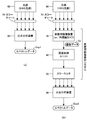
- FIG. 1 is a block diagram showing a basic configuration of a medical image display system 1000 including a medical device color correction apparatus 100 according to the present invention.
- 4 is a block diagram showing a procedure for creating individual conversion data Cx stored in an individual conversion data storage unit 110 for an imaging device shown in FIG. 3.
- FIG. 3 It is a top view which shows the specific example of the color chart 70 shown in FIG.
- FIG. 4 is a diagram showing a specific example of individual conversion data stored in an individual conversion data storage unit for imaging device 110 shown in FIG. 3 and individual conversion data stored in an individual conversion data storage unit for monitor 130.
- FIG. 8 is a u′v′ chromaticity diagram showing a color distribution obtained by performing the measurement procedure shown in FIG. 7 on the multi-color chart 72 shown in FIG. 5( b ).
- FIG. 8 is a u′v′ chromaticity diagram showing a color distribution obtained by performing the measurement procedure shown in FIG. 7 on the wide color gamut color chart 73 shown in FIG. 5C.
- the u'v' chromaticity diagram (upper row) showing the composite color distribution obtained by combining the color distribution shown in FIG. 8(b) and the color distribution shown in FIG. 9(b) and the gamut usage rate for the color distribution.
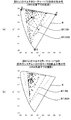
- FIG. 14 is a u′v′ chromaticity diagram showing the color distribution of each part of the large intestine specimen itself measured under an endoscope light source (via a fiber) (actually, the measurement result of FIG. That was converted to the measurement result).
- FIG. 14 is a u′v′ chromaticity diagram showing the color distribution of each part of the large intestine specimen itself measured under an endoscope light source (via a fiber) (actually, the measurement result of FIG. That was converted to the measurement result).
- FIG. 14 is a u′v′ chromaticity diagram showing a color distribution of each part of the large intestine specimen itself measured under a D65 light source (actually, the measurement result of FIG. 13 is converted into a measurement result under a D65 light source by simulation). .. It is a top view which shows the sample location of the large intestine sample and its specific tissue used for the measurement of FIG.
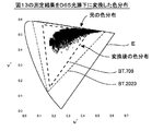
- FIG. 17 is a u′v′ chromaticity diagram showing a color distribution obtained by measuring each sample place shown in FIG. 16 under an operating light.
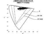
- FIG. 17 is a u′v′ chromaticity diagram showing a color distribution obtained by measuring each sample portion shown in FIG. 16 under a D65 light source.
- FIG. 4 is a front view showing an example of an instruction button forming an emphasized tissue designating section 150 in the medical device color correction apparatus 100 shown in FIG. 3.
- 10 is a u′v′ chromaticity diagram showing a color distribution of image data obtained by performing various enhancement corrections by the specific tissue enhancement color conversion unit 160 on the image data having the color distribution shown in FIG. is there.
- FIG. 1 is a block diagram showing a state of an operating room in which a conventional general medical image display system is introduced.
- an operating table 10 is installed in the operating room, and a subject (patient) P is lying thereon.
- a surgical light 20 is installed above the operating table 10 to illuminate the affected part of the subject P.
- the illustrated example is an example in which a laparoscopic surgery is performed on the subject P. During the surgery, an opening with a diameter of about 10 mm is formed in the abdomen of the subject P, and the distal end of the endoscope camera 31. The part is inserted into the abdominal cavity of the subject P.
- the endoscope camera 31 is connected to the endoscope control unit 41 by a cable.
- the endoscopic control unit 41 is a device for controlling the endoscopic camera 31, and supplies power to the endoscopic camera 31, captures imaging data from the endoscopic camera 31, and attaches to the endoscopic camera 31. It has a function of turning on/off the existing endoscope light source and recording image data. Although only one endoscopic camera 31 is shown in the drawing, a plurality of endoscopic cameras may be used as needed.
- color monitors 51 to 54 are connected to the endoscope control unit 41, and the image captured by the endoscope camera 31 is displayed in each color via the endoscope control unit 41. It is sent to the monitors 51 to 54 and displayed on each screen. The practitioner performs laparoscopic surgery while looking at the image on the screen (illustration of surgical instruments is omitted).
- the color monitors 51 to 54 do not necessarily have to be installed in the operating room, and some or all of them may be installed in another room (for example, a conference room).
- a monitor is arranged at a remote place, and surgery is performed by remote control.
- the system including the endoscope camera 31, the endoscope control unit 41, and the color monitors 51 to 54 constitutes a medical image display system.
- a medical image display system is introduced as necessary.
- a normal camera that images the affected area from above is usually used instead of the endoscope camera 31, but in a special laparotomy, an endoscope camera may be used together.
- the practitioner usually performs the operation while observing the affected area with the naked eye, so the display image on the monitor is used as information to be presented to the practitioner assistant and other related persons.
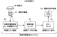
- FIG. 2 is a block diagram showing the flow of image data in a conventional general medical image display system.
- an image of an actual organ P1 which is an affected part of the subject P is imaged by the medical imaging device 30, and the obtained imaging data is transmitted to the color monitor 50 via the imaging control unit 40.
- An example in which the display image P2 of the organ is displayed on the screen is shown.
- the endoscope camera 31 is used as the medical imaging device 30, and the endoscope control unit 41 is used as the imaging control unit 40.
- a surgical light 20 is arranged above the subject P, and the subject P is illuminated by light from the surgical light 20 (in FIG. 2, the surgical light 20 is actually used).
- the dashed arrow pointing to the organ P1 indicates such illumination light.
- the illumination light from the surgical light 20 does not reach the actual organ P1 that is the subject, so the endoscope light source attached to the endoscope camera (the light source with the endoscope camera) ) (In FIG. 2, the dashed arrow pointing from the medical imaging device 30 to the actual organ P1 indicates the illumination light from the endoscope light source).
- the system including the medical imaging device 30, the imaging control unit 40, and the color monitor 50 constitutes a medical image display system.
- the medical imaging device 30 is a component that inputs an image by capturing an image of an actual organ P1
- the imaging control unit 40 performs a process of relaying image data obtained by this image input.
- the color monitor 50 is an element that is an element that outputs an image by displaying the display image P2 of the organ on the screen based on the given image data.
- the medical imaging device 30 and the color monitor 50 have unique color characteristics for each device. Therefore, between the color tone of the display image P2 of the organ normally displayed on the screen of the color monitor 50 and the color tone of the actual organ P1 (the color tone under the illumination of the surgical light 20 or the endoscope light source). There will be a difference. Moreover, this difference in color tone differs depending on the device actually used as the medical imaging device 30 and the device actually used as the color monitor 50. Therefore, when a plurality of types of cameras are used as the medical imaging apparatus 30 or a plurality of types of devices are used as the color monitor 50, a specific mode of which color monitor displays an image captured by which camera is used. As a result, the color tone of the display image P2 of the organ changes.
- a first object of the present invention is to eliminate the difference in color characteristics between devices even when a medical image display system is configured by combining devices having various color characteristics. It is to enable image display with a uniform color tone.
- a second object of the present invention is to enable a visible image display suitable for observing a specific living tissue.
- Medical image display system according to the present invention >>>
- a basic configuration and a basic function of the medical image display system according to the present invention and the color correcting apparatus for a medical device incorporated and used in the system will be described.
- FIG. 3 is a block diagram showing the basic configuration of a medical image display system 1000 including the medical device color correction apparatus 100 according to the present invention.
- the medical image display system 1000 illustrated here includes three medical imaging devices 30X to 30Z, four color monitors 50A to 50D, and one medical device color correction device 100.
- the medical imaging devices 30X to 30Z correspond to the medical imaging device 30 and the color monitors 50A to 50D.
- the medical device color correction apparatus 100 corresponds to the imaging control unit 40.
- the device 100 performs predetermined color correction processing on the image data Dx to Dz obtained from the medical image pickup devices 30X to 30Z to create display data Da to Dd suitable for the color monitors 50A to 50D. It has a function.
- the medical imaging devices 30X to 30Z may be any devices as long as they are devices that capture medical images. Specifically, for example, it may be an endoscopic camera used for laparoscopic surgery or a normal video camera arranged in an operating room. Of course, the image data obtained by the imaging by the medical imaging devices 30X to 30Z may be still image data or moving image data. Further, the medical image display system 1000 shown here is not limited to the use for surgery, but is also used for the purpose of taking an image of a sample tissue cut out from a human body and displaying it on a color monitor for inspection or diagnosis. It is possible, and when used for such an application, for example, a microscope camera can be used as a medical imaging device.
- the color monitors 50A to 50D may be any device as long as it has a color image display function.
- a color display connected to a computer may be used as the color monitors 50A to 50D.
- the installation locations of the color monitors 50A to 50D are also arbitrary.
- the medical image display system 1000 is configured by connecting the three medical imaging devices 30X to 30Z and the four color monitors 50A to 50D to the medical device color correction device 100.
- the number of medical imaging devices and the number of color monitors may be arbitrary. In order to configure the medical image display system 1000 according to the present invention, it is sufficient to connect at least one medical imaging device 30 and at least one color monitor 50 to the medical device color correction device 100.
- the medical device color correction apparatus 100 shown in FIG. 3 has an imaging device individual conversion data storage unit 110, a specific tissue emphasizing conversion data storage unit 120, and a monitor individual conversion data storage unit, as indicated by the one-dot chain line in the figure.
- the unit 130, the imaging device color conversion unit 140, the emphasized tissue designation unit 150, the specific tissue emphasis color conversion unit 160, and the monitor color conversion unit 170 are included.
- each of these components can be realized by incorporating a dedicated program into a computer. Therefore, in practice, the medical device color correction apparatus 100 shown in FIG. 3 is configured by a computer incorporating a dedicated program, and the medical imaging devices 30X to 30Z and the color monitors 50A to 50D are connected to this computer. It will be. Note that in FIG. 3, each component is drawn as a rectangular block, and digital data transmitted and received between the rectangular blocks is drawn as an elliptical block.
- the color correcting apparatus 100 for a medical device processes image data (actually, a plurality of image data arranged in time series to form a moving image) obtained by imaging by the medical imaging apparatuses 30X to 30Z. , And has a function of performing color correction suitable for display on the color monitors 50A to 50D.
- image data image data input to the medical device color correction apparatus 100
- imaging data Dx, Dy, and Dz image data obtained by imaging by the medical imaging apparatuses 30X to 30Z
- Image data provided to the color monitors 50A to 50D image data output from the medical device color correction apparatus 100
- display data Da, Db, Dc, and Dd respectively. Therefore, the medical-apparatus color correction apparatus 100 performs predetermined color correction processing on the input image pickup data Dx, Dy, Dz, and sets the processed image data as display data Da, Db, Dc, Dd. It plays the role of outputting.
- the first conversion process is a process performed on the input imaging data Dx, Dy, Dz, and uses the individual conversion data Cx, Cy, Cz stored in the imaging device individual conversion data storage unit 110. Then, it is executed by the color conversion unit 140 for the imaging device.
- the purpose of this first conversion process is to eliminate the difference in color characteristics of the medical imaging devices 30X, 30Y, and 30Z for each device, and the standard color image output from the imaging device color conversion unit 140.
- the data Ds is image data having a tint of a standard color that eliminates the difference in color characteristics between devices.
- the subsequent second conversion process is a process performed on the standard color image data Ds output from the imaging device color conversion unit 140, and is stored in the specific tissue emphasis conversion data storage unit 120.
- the specific tissue emphasizing conversion data (in the illustrated example, blood vessel emphasizing data Ce, fat emphasizing data Cf, surface layer emphasizing data Cg) is used by the specific tissue emphasizing color conversion unit 160.
- the purpose of the second conversion processing is to perform color conversion that emphasizes the specific living tissue in order to display an image with visibility suitable for observing the specific living tissue designated by the operator.
- the specific tissue emphasized image data (data De, Df, Dg are shown in the figure according to the specified biological tissue) output from the specific tissue emphasis color conversion unit 160 is the observation of the specific biological tissue.
- the image data corresponds to an image with visibility suitable for.
- the third conversion process performed last is a process performed on the specific tissue emphasized image data De, Df, and Dg output from the specific tissue emphasis color conversion unit 160, and the monitor individual conversion data storage unit 130.
- the color conversion unit for monitor 170 uses the individual conversion data Ca, Cb, Cc, and Cd stored in.
- the purpose of the third conversion process is to eliminate the difference in color characteristics between the devices of the color monitors 50A to 50D, and to display each of the display data Da, Db, output from the monitor color conversion unit 170.
- Dc and Dd are image data that have been corrected to eliminate the difference in color characteristics between individual devices.
- each arrow pointing downward does not show the flow of individual image data itself, but shows the flow of the conversion process regarding the hue.
- the three sets of image pickup data Dx, Dy, Dz on the side have unique hues
- the standard color image data Ds on the output side has a common standard color.
- the three downward arrows on the input stage have different imaging data Dx, Dy, and Dz due to the unique color characteristics of the respective imaging devices even when the same subject is imaged under the same conditions.
- the specific tissue emphasizing color conversion unit 160 converts the hue of the standard color image data Ds in accordance with the specific living tissue to be emphasized, so that the specific tissue emphasizing image data (image data De, Df, Dg Or) is output. Therefore, the specific organization emphasized image data drawn as one downward arrow is given to the input stage of the monitor color conversion section 170.
- the four downward arrows are drawn on the output stage of the monitor color conversion unit 170 because the shades of the display data Da to Dd given to the individual color monitors 50A to 50D are different from those of the individual color monitors 50A to 50D. It is shown that it differs depending on the inherent color characteristics that it has. That is, even if the same specific tissue emphasized image data is given to the input stage of the monitor color conversion section 170, different display data Da to Dd are obtained at the output stage.
- the imaging device individual conversion data storage unit 110 converts the color characteristics of the imaging data of the medical imaging device into standard color characteristics in consideration of the unique color characteristics of a specific medical imaging device. It is a component that stores individual conversion data.
- the imaging device individual conversion data storage unit 110 is Individual conversion data Cx, Cy, Cz are prepared corresponding to these three medical imaging devices 30X, 30Y, 30Z, respectively.
- the individual conversion data Cx is conversion data for converting the color characteristics of the imaging data Dx captured by the medical imaging apparatus 30X into standard color characteristics in consideration of the unique color characteristics of the medical imaging apparatus 30X. The substance of such conversion data will be described in detail in ⁇ 3.
- the imaging device color conversion unit 140 performs individual conversion on the specific medical imaging device stored in the imaging device individual conversion data storage unit 110 with respect to the imaging data input from the specific medical imaging device. It is a component that generates standard color image data by performing color conversion using data. For example, when the imaging data Dx is given from the medical imaging device 30X, the imaging device color conversion unit 140 stores the imaging data Dx in the imaging device individual conversion data storage unit 110. The processing for generating the standard color image data Ds by performing color conversion using the individual conversion data Cx for the image capturing device 30X is executed.
- the imaging device individual conversion data storage unit 110 includes three sets of individual devices. Although conversion data Cx, Cy, Cz are prepared, in general, if the use of a plurality of I medical imaging devices is assumed, the I conversion data storage unit 110 for each of these I medical imaging devices is used. It is only necessary to store the individual conversion data for each image pickup device.
- the imaging device color conversion unit 140 for the imaging data Di input from the i-th (1 ⁇ i ⁇ I) medical imaging device 30i, converts the i-th individual conversion data Ci (i-th). The color conversion is performed using the individual conversion data of the th medical imaging device 30i) to generate the standard color image data Ds.
- the standard color image data Ds obtained by the color conversion processing by the image-capturing device color conversion unit 140 is obtained by converting the color characteristics unique to each medical imaging device into the standard color characteristics.
- the image data has a uniform color tone by eliminating the difference in the color characteristics of. Therefore, when the same subject is photographed by the three medical image pickup devices 30X, 30Y, 30Z under the same image pickup condition, the contents of the obtained image pickup data Dx, Dy, Dz are different from each other.
- the three types of standard color image data (herein referred to as Dsx, Dsy, Dsz) obtained by the color conversion processing on the image pickup data Dx, Dy, Dz are theoretically the same image data.
- the hues of the images represented by the individual image pickup data Dx, Dy, and Dz differ from each other according to the color characteristics unique to each image pickup device.
- the hues of the images represented by the standard color image data Dsx, Dsy, and Dsz obtained after the conversion are theoretically the same.
- One of the important features of the color correcting apparatus 100 for medical equipment shown in FIG. 3 is the imaging data Dx obtained from each of the medical imaging apparatuses 30X, 30Y, 30Z by the color conversion processing by the color conversion unit for imaging apparatus 140.
- Dy, Dz are once converted into standard color image data Ds (first conversion processing), and the color conversion processing by the specific tissue emphasizing color conversion section 160 is performed on the standard color image data Ds,
- the specific tissue emphasized image data De, Df, Dg in which the specific biological tissue is emphasized is generated (second conversion processing), and the color conversion processing by the monitor color conversion section 170 is further performed on it. This is at the point of generating the display data Da to Dd corresponding to the color monitors 50A to 50D (third conversion processing).
- each medical treatment is performed when performing color conversion processing by the specific tissue emphasizing color conversion unit 160. It is not necessary to consider the color characteristics peculiar to the image pickup devices 30X, 30Y, 30Z.
- the specific tissue emphasizing conversion data storage unit 120 stores the specific tissue emphasizing conversion data for performing color conversion for emphasizing a specific biological tissue with respect to the standard color image data Ds having a standard hue. Just keep it.
- the specific organization emphasizing conversion data storage unit 120 stores three types of specific organization emphasizing conversion data. Specifically, the blood vessel emphasis data Ce for performing color conversion for emphasizing blood vessels, the fat emphasis data Cf for performing color conversion for emphasizing fat, and the surface layer film (film forming a surface layer of an organ or the like) are emphasized.
- the three types of specific tissue emphasizing conversion data that is, surface layer emphasizing data Cg for performing color conversion, are stored. Specific examples of the specific tissue emphasizing conversion data Ce, Cf, Cg, and an example of “emphasized display” of specific biological tissue will be described in detail in ⁇ 6.
- the emphasized organization designating unit 150 is a component that receives a designation input that designates a specific biological tissue to be highlighted. This designation input is performed by an operator of the medical device color correction apparatus 100 (for example, a practitioner during surgery). The operator makes an input for designating the living tissue to be highlighted on the images displayed on the color monitors 50A to 50D. In short, the operator wants to display an image with improved visibility of which living tissue, in other words, which living tissue to display an image suitable for observation, Specify the organization.
- the emphasized tissue designating unit 150 plays a role of transmitting a designation input from the operator to the specific tissue enhancing color conversion unit 160.
- the specific tissue emphasizing color conversion unit 160 performs color conversion on the standard color image data Ds, which is stored in the specific tissue emphasizing conversion data storage unit 120 and emphasizes a specific biological tissue designated by a designation input. Color conversion is performed using the specific tissue emphasizing conversion data for performing the specific tissue emphasizing image data. For example, if the operator inputs “blood vessel” as the specific biological tissue to be highlighted, the highlighted tissue designation unit 150 instructs the specific tissue highlighting color conversion unit 160 to highlight the target. Is transmitted as "blood vessel”. Therefore, the specific tissue emphasizing color conversion unit 160 selects the blood vessel emphasizing data Ce from the three sets of the specific tissue emphasizing conversion data stored in the specific tissue emphasizing conversion data storage unit 120, and selects the blood vessel emphasizing data Ce.
- the Ce is used to perform the color conversion process on the standard color image data Ds, and the specific tissue emphasized image data De of the blood vessel is output as the processed image data.
- the specific tissue emphasized image data Df for fat is subjected to color conversion processing using the fat emphasis data Cf or the surface layer emphasis data Cg.
- the specific tissue emphasized image data Dg of the surface layer film is output.
- tissue enhancement conversion data for a plurality of J types of biological tissues are stored in the specific tissue enhancement conversion data storage unit 120, respectively.
- the tissue-enhancing color conversion unit 160 receives a designation input for designating the j-th (1 ⁇ j ⁇ J) biological tissue from the emphasized-tissue designating unit 150, the j-th specific tissue-enhancing conversion data Cj Color conversion using (conversion data for emphasizing the j-th biological tissue) may be performed to generate specific tissue emphasized image data.
- the designation input to the emphasized tissue designation unit 150 does not necessarily have to be an input that designates a single living tissue, and may be an input that designates a plurality of living tissues. For example, if the operator wants to highlight both “blood vessel” and “fat”, he/she may input to the emphasized tissue designating section 150 to designate both of them. In this case, the fact that both “blood vessel” and “fat” have been designated is transmitted from the emphasized tissue designating unit 150 to the specific tissue enhancing color converting unit 160, so that the specific tissue enhancing color converting unit 160 , The standard color image data Ds is overlapped with the color conversion using the blood vessel emphasis data Ce and the color conversion using the fat emphasis data Cf, and the specific tissue emphasis image data Def is output. The display on the color monitor using the specific tissue emphasized image data Def is a display in which both “blood vessel” and “fat” are emphasized.
- the emphasized tissue designating unit 150 has a function of accepting a designation input for designating a plurality of H (H ⁇ J) biological tissues in duplicate. It is provided (J is the total number of the specific organization emphasizing conversion data stored in the specific organization emphasizing conversion data storage section 120 ), and the specific organization emphasizing color converting section 160 has a plurality of H types from the emphasizing organization designating section 150.
- the specific tissue-enhanced image data is obtained by performing the color conversion using the plurality of H types of the specific-tissue-enhancing conversion data corresponding to the plurality of H types of the biological tissues in duplicate. Should be generated.
- the emphasized organization designating section 150 can also accept a designation input “hereinafter, no body tissue is designated” (hereinafter referred to as “empty designation input”).
- the specific tissue emphasizing color conversion unit 160 outputs the input standard color image data Ds as it is without performing any substantial color conversion processing.
- the standard color image data Ds is output as it is as the specific tissue emphasized image data Ds.
- the display on the color monitor using the specific tissue emphasized image data Ds is an image in which neither living body tissue is emphasized.
- the emphasized tissue designating unit 150 has a function of accepting an empty designation input indicating that no living body tissue is designated, and the specific tissue enhancing color conversion unit 160 uses the emphasized tissue designation.
- the standard color image data Ds is directly output as the specific tissue emphasized image data without performing color conversion.
- the specific tissue enhancing conversion data storage unit 120 stores It is sufficient to store only the blood vessel emphasis data Ce.
- the specific tissue emphasizing color conversion unit 160 performs the color conversion, the color conversion using the blood vessel emphasizing data Ce is always performed, and the specific tissue emphasizing image data De is always output.
- the emphasized organization designating section 150 can be provided with a function of accepting an empty designation input. Then, the designation input to the emphasized tissue designation unit 150 is an input for selecting whether to perform highlighting (input to specify a blood vessel) or not to perform highlighting (empty designation input). ..
- the emphasized tissue designating unit 150 is provided with a function of accepting different designation inputs for the individual color monitors 50A to 50D, different living tissues are highlighted for the individual color monitors 50A to 50D. Images can be displayed. For example, with respect to the emphasized tissue designating unit 150, an empty designation input for the color monitor 50A, a "blood vessel” designation input for the color monitor 50B, a “fat” designation input for the color monitor 50C, and a “fat” designation input for the color monitor 50D.
- the specific tissue emphasizing color conversion unit 160 may output four types of specific tissue emphasizing image data Ds, De, Df, Dg.
- the monitor color converter 170 performs color conversion using the individual conversion data Ca on the image data Ds to generate display data Da, and uses the individual conversion data Cb on the image data De. Color conversion is performed to generate display data Db, image data Df is subjected to color conversion using individual conversion data Cc to generate display data Dc, and image data Dg is converted to individual conversion data Cd.
- the display data Dd may be generated by performing the color conversion used. Then, the standard color image is displayed on the color monitor 50A, the image in which "blood vessel” is emphasized is displayed in the color monitor 50B, and the image in which "fat” is emphasized is displayed on the color monitor 50C. Then, the image in which the “surface layer” is emphasized is displayed on the color monitor 50D.
- the monitor individual conversion data storage unit 130 is a component that stores the individual conversion data Ca to Cd corresponding to each of the color monitors 50A to 50D.
- These individual conversion data Ca to Cd are designed so that images having standard color characteristics are displayed on the color monitors 50A to 50D in consideration of the unique color characteristics of the corresponding specific color monitors 50A to 50D. This is conversion data for performing various color conversions.
- the monitor color conversion unit 170 for the specific tissue emphasized image data provided from the specific tissue emphasis color conversion unit 160, regarding the specific color monitor stored in the monitor individual conversion data storage unit 130. Is a constituent element that performs color conversion using the individual conversion data to generate display data, and outputs the generated display data to the specific color monitor.
- the specific tissue emphasis image data De for emphasizing the “blood vessel” is given to the monitor color conversion unit 170 from the specific tissue emphasis color conversion unit 160, and an image based on this image data De is converted into a first color image.
- the individual conversion data Ca for the first color monitor 50A stored in the monitor individual conversion data storage unit 130 is used for the specific tissue emphasized image data De. The color conversion is performed to generate the display data Da, and the generated display data Da is output to the first color monitor 50A.
- the individual conversion data Cx to Cz stored in the individual conversion data storage unit 110 for the imaging device are converted to eliminate the difference in the unique color characteristics of the medical imaging devices 30X to 30Z.
- the image capturing device color conversion unit 140 performs a process of generating standard color image data Ds in which such a difference in unique color characteristics is resolved.
- the individual conversion data Ca to Cd stored in the monitor individual conversion data storage unit 130 are data for performing conversion for eliminating the difference in the unique color characteristics of the color monitors 50A to 50D. Therefore, the monitor color conversion section 170 eliminates such a difference in the unique color characteristics and enables the individual color monitors 50A to 50D to display with the same color tone on the screen of any color monitor. Processing for generating display data Da to Dd suitable for
- the monitor individual conversion data storage unit 130 stores the individual conversion data for each of the K medical imaging devices. Just keep it.
- the monitor color conversion unit 170 when the monitor color conversion unit 170 generates the display data Dk to be output to the kth (1 ⁇ k ⁇ K) color monitor 50k, the kth individual conversion data Ck( Color conversion may be performed using (individual conversion data for the kth color monitor 50k).
- the individual images are displayed on the screens of the individual color monitors in the same color tone.
- the technique itself for performing color conversion on image data using the individual conversion data prepared for each color monitor is already known.
- individual conversion data generally called color profile data
- the color profile data may be used as the individual conversion data stored in the monitor individual conversion data storage unit 130.
- the method of creating the color profile data unique to each color monitor is also a known method, and a detailed description thereof will be omitted here.
- the first conversion process by the imaging device color conversion unit 140 the second conversion process by the specific tissue enhancing color conversion unit 160, and the monitor process.
- a three-stage color conversion process of the third conversion process by the color conversion unit 170 is performed.
- the first conversion process and the third conversion process play a role of eliminating the difference in color characteristics between devices, and by these processes, "a device having various color characteristics is combined to form a medical image display system. Even when configured, the first object of the present invention is achieved, which eliminates the difference in color characteristics of each device and enables image display with a uniform color tone.
- the second conversion process plays a role of highlighting a specific living tissue specified by the operator, and by this processing, “when using the medical image display system, it is suitable for observing a specific living tissue”.
- the second object of the present invention "to enable visible image display” is achieved. For example, as will be described in detail later, if the operator designates a specific living tissue such as “blood vessel”, “fat”, or “surface membrane” as an object to be highlighted, the visibility of the designated living tissue is improved. Improved display will be obtained. For example, in the conventional system, the color of blood, which is saturated in the imaging stage, can be accurately read on the color monitor.
- the second conversion process since the second conversion process is performed between the first conversion process and the third conversion process, it can be executed as a process for the standard color image data Ds obtained by the first conversion process. it can. Therefore, when performing the second conversion processing, it is not necessary to consider the “color characteristic unique to the device”, which is the color characteristic of each medical imaging device, and the standard color image data having the standard color characteristic is always used. It suffices to perform uniform color correction with Ds as the processing target.
- the third conversion process since the third conversion process is performed after the second conversion process, when performing the second conversion process, the color characteristic of the color monitor that is finally displayed as an image is a “device specific”. It is not necessary to consider "color characteristics". In other words, regardless of the model of the medical imaging device or the color monitor that is actually used, the specific organization emphasizing conversion data storage unit 120 should always have uniform specific organization emphasizing conversion data. Is enough.
- the color correcting apparatus 100 for a medical device according to the present invention is a color monitor connected to the output side regardless of which model is provided by which manufacturer the medical imaging apparatus connected to the input side is.
- any model provided by any manufacturer can be used without considering the difference in color characteristics between models. Therefore, it is possible to perform color judgment based on the same standard regardless of which hospital or research facility as long as the facility has introduced the medical image display system 1000 according to the present invention. Become.
- image data handled by an image pickup device or a color monitor device is composed of a set of many pixels.
- Each pixel usually has pixel values of the three primary color components R, G, B.
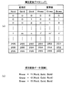
- R, G, B For example, if one color component is represented by 8-bit data, the pixel value of one pixel is represented by 24-bit data. Therefore, the pixel values of the individual pixels forming the imaging data Dx obtained from the medical imaging device 30X are represented by the three primary color components Rold, Gold, Bold, and the standard color image obtained by color conversion by the imaging device color conversion unit 140.
- the individual conversion data Cx stored in the individual conversion data storage unit 110 for the image pickup device is the three primary color components of the imaging data Dx.
- This is conversion data for converting Rold, Gold, Bold into the three primary color components Rnew, Gnew, Bnew of the standard color image data Ds. That is, it is possible to use, as the individual conversion data Cx, some information that can uniquely obtain another value (Rnew, Gnew, Bnew) based on an arbitrary value (Rold, Gold, Bold).
- a white light source 60 and a color chart 70 are prepared.
- a light source compliant with the CIE standard light source D65 (hereinafter, simply referred to as “D65 light source”) is used.
- This D65 light source is a standard light source defined by the International Commission on Illumination (CIE), is a virtual light source having a spectrum corresponding to the average noon light in Europe/North Europe, and has a correlated color temperature of about 6500K. Has been done.
- CIE International Commission on Illumination
- the standard light source itself which is the “D65 light source”
- D65 light source is not actually commercially available as a device
- a commercially available device for example, an LED light source
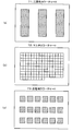
- the color chart 70 is a plate-shaped object in which color samples are arranged, and is used for purposes such as checking color reproducibility and color calibration for various image devices. Plan views of some specific examples of the color chart 70 are shown in FIGS. 5(a), (b), and (c).
- the three primary color chart 71 shown in FIG. 5(a) is the simplest color chart in which color samples of the three primary colors of red, blue, and green are arranged.
- the three regions shown by hatching in the figure are the portions of the color samples of the three primary colors, each of which has translucency for transmitting red, blue, and green color components. Therefore, when the white light source 60 is arranged on the back surface and the three primary color chart 71 is observed from the front, each area is observed as a window of red, blue, and green.
- the multi-color chart 72 shown in FIG. 5(b) is one in which a large number of square color samples are arranged in a two-dimensional array. Normally, the color reproducibility of a camera or monitor in low to medium saturation is reproducible. Is used to verify. In the three primary color chart 71 shown in FIG. 5(a), only the color samples of the three primary colors of red, blue, and green are arranged, while in the multi-color chart 72 shown in FIG. 5(b), there are 153 The color swatches of are laid out so that finer color calibration can be performed. On the other hand, in the wide color gamut color chart 73 shown in FIG.
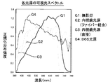
- the wide color gamut defined by the international standard BT.2020 for ultra-high definition TV is specified. It is a color sample that covers the area.
- the wide color gamut color chart 73 is suitable for verifying the color reproducibility of highly saturated colors and primary colors, and a specific color calibration method using this will be described in ⁇ 4.
- FIG. 5 illustrates three types of color charts 71, 72, 73, of course, various products are commercially available as the color chart, and the color chart used in the present invention is shown in FIG. It is not limited to three types.
- a color chart generally called a Macbeth chart may be used to supplement the medium saturation color.
- the light source 60 is arranged on the back surface of the color chart 70
- the medical imaging device 30X for example, an endoscope camera
- An image is taken by the medical imaging device 30X.
- the transmitted light in each color sample area of the color chart 70 is incident on the light receiving surface of the medical imaging device 30X.
- the dashed arrow shown in FIG. 4 indicates the path of light from the light source 60.
- the color components of the three primary colors (R, G, B) for the individual color sample areas of the color chart 70 will be referred to as image color data Dt (Rt, Gt, Bt). ..
- the image pickup color data Dt1 (Rt1, Gt1, Bt1) for the red area and the image pickup color data Dt2 (Rt2 for the green area) are used.
- Gt2, Bt2) and imaging color data Dt3 (Rt3, Gt3, Bt3) for the red region are obtained.
- the multi-color chart 72 shown in FIG. 5B is used as the color chart 70, the captured color data Dt1 (Rt1, Gt1, Bt1) to the 153rd color for the first color sample Imaging color data Dt153 (Rt153, Gt153, Bt153) for the sample will be obtained.
- the original color data DT (RT, GT, BT) of each color sample of the color chart 70 is measured.
- the dashed-dotted arrow in FIG. 4 indicates that the color data DT can be obtained by using such a measurement process.
- the original color data DT1 (RT1, GT1, BT1) for the red area and the original color data DT2 for the green area are used.
- RT2, GT2, BT2 the original color data DT3 (RT3, GT3, BT3) for the blue area are obtained.
- the multi-color chart 72 shown in FIG. 5B is used as the color chart 70
- the original color data DT153 (RT153, GT153, BT153) for the color sample is obtained.
- the original color data DT is measured, for example, by disposing a spectroscopic analyzer (colorimeter) at the position of the medical imaging device 30X shown in FIG. 4 and measuring the spectrum for each of the regions of each color sample (The measurement system similar to the measurement system shown in FIG. 7(a) described later may be used), and the values of the three primary color components (RT, GT, BT) may be calculated based on the data of this spectrum.
- the commercially available color chart 70 has the original color data DT (RT, GT, BT) obtained by the measurement at the supplier attached, and in such a case, the measurement work is omitted. Then, the attached original color data DT (RT, GT, BT) may be used as it is.
- the individual conversion data creation unit 80 is actually a device that is configured by incorporating a dedicated program into a computer, and the captured color data Dt (Rt, Gt, Bt) for each color sample and the original color data DT (RT , GT, BT) based on the difference between the color characteristics unique to the medical imaging device 30X and the imaging color data Dt (Rt, Gt, Bt) as the original color data DT (RT, GT, BT).
- the data Dt (Rt, Gt, Bt) and the data DT (RT, GT, BT) are compared for each of the three color samples based on the result. Since it is necessary to create the individual conversion data Cx (data that enables conversion for an arbitrary color), the accuracy of the obtained individual conversion data Cx becomes relatively coarse.
- the data Dt (Rt, Gt, Bt) and the data DT (RT, GT, BT) for 153 color samples are respectively obtained. Since the individual conversion data Cx can be created based on the comparison result, the individual conversion data Cx with higher accuracy can be obtained.
- the individual conversion data Cx includes the three primary color components Rold, Gold, and Bold of the individual pixels forming the image pickup data Dx obtained by the medical image pickup apparatus 30X and the individual pixels forming the standard color image data Ds.
- Such individual conversion data Cx can be prepared, for example, in the form of a lookup table LUT as shown in FIG.
- the left half of the table of FIG. 6(a) shows the three primary color components Rold, Gold, Bold of the individual pixels that make up the image data before conversion (imaging data Dx), and the right half shows the image data after conversion.
- each color component is represented by a numerical value of 8 bits (0 to 255).
- the left half of the table from (0,0,0) to (255,255,255), 256 ⁇ 256.
- the individual conversion data composed of the lookup table LUT when a combination (l, m, n) of arbitrary pixel values indicating the three primary color components is given, this is combined with a predetermined pixel value combination (l' , M', n').
- the combination of the color components of the pixels forming the image pickup data Dx is set to the color components of the pixels forming the standard color image data Ds.
- the individual conversion data Cx can also be prepared in the form of a function as shown in FIG. 6(b).
- a function for calculating the combination of the color components of the pixels forming the standard color image data Ds is prepared by giving the combination of the color components of the pixels forming the image pickup data Dx as a variable value. It may be stored as individual conversion data Cx in the device individual conversion data storage unit 110.
- the form of the lookup table LUT shown in FIG. 6(a) and the form of the function shown in FIG. 6(b) have been illustrated as the substance of the individual converted data stored in the individual converted data storage unit 110 for the imaging device.
- the same form can be adopted for the individual conversion data stored in the monitor individual conversion data storage unit 130. That is, as the individual conversion data (for example, data Ca) stored in the monitor individual conversion data storage unit 130, a combination of each color component of the pixels forming the specific tissue emphasized image data (for example, data De) is displayed.
- a lookup table for converting into a combination of color components of pixels forming data for example, data Da
- a combination of color components of pixels forming specific tissue emphasized image data for example, data De
- a function for calculating the combination of the respective color components of the pixels forming the display data for example, the data Da
- FIG. 7 is a diagram showing a basic procedure of measurement for examining color reproducibility on a color monitor in a medical image display system (a broken line in the figure indicates a light path).
- a color chart 70 in which a plurality of color samples are arranged is used.
- the first procedure shown in FIG. 7A the original color of each color sample of this color chart 70 is measured.
- the second procedure shown in FIG. 7B each color sample of the color chart 70 is imaged by the medical image display system and displayed on the color monitor, and the color displayed on the color monitor is measured.
- the measurement is performed by the following method.
- the light source 60 is arranged on the back surface of the color chart 70, the spectroscopic analysis device 90 is arranged on the front surface of the color chart 70, and the light source 60 is arranged on the color chart 70.
- the spectrum of the transmitted light from each color sample is measured to obtain spectrum data Dsp1.
- spectrum data Dsp1 of transmitted light is obtained for all 153 sets of color samples.
- the light source 60 is arranged on the back side of the color chart 70, and the medical imaging device 30 (for example, an endoscope camera) is placed on the front side of the color chart 70.
- the color chart 70 is arranged and imaged to obtain the imaged data Dp.
- This image pickup data Dp is given to the color monitor 50 via the image pickup control unit 40, and the imaged color chart 70 is displayed on the screen of the color monitor 50.
- the medical imaging device 30, the imaging control unit 40, and the color monitor 50 are components of the medical image display system as shown in FIG.
- the spectral analyzer 90 is arranged in front of the color monitor 50, and the spectrum of each color sample of the color chart 70 displayed on the color monitor 50 is measured to obtain spectrum data Dsp2.
- spectrum data Dsp2 of the transmitted light is obtained for all 153 sets of color samples.
- the same D65 light source is used as the light source 60 used in FIGS. 7A and 7B, and the same multi-color chart 72 is used as the color chart 70. Therefore, the first procedure shown in FIG. 7(a) and the second procedure shown in FIG. 7(b) illuminate the same subject (multi-color chart 72) in the same illumination environment (D65 light source).
- the spectrum data Dsp1 obtained in the former is a spectrum obtained by directly measuring the transmitted light of the color sample
- the spectrum data Dsp2 obtained in the latter is a spectrum image for a medical image display system ( This is a spectrum obtained when observed through the medical imaging device 30, the imaging control unit 40, and the color monitor 50).
- the measurement is performed with the endoscope light source built in this endoscope camera in the OFF state. That is, in the second procedure shown in FIG. 7B, the light source for illuminating the color chart 70 is only the light source 60 (D65 light source).
- the color reproducibility when observed through the medical image display system can be evaluated.
- a two-dimensional chromaticity diagram is used.
- FIG. 8 shows an example of such an evaluation result, and shows a color distribution obtained by performing the measurement procedure shown in FIG. 7 on the multi-color chart 72 shown in FIG. 5(b). It is a u'v' chromaticity diagram.
- FIG. 8A is a plot of the colors corresponding to the spectral data Dsp1 obtained by the first procedure shown in FIG. 7A on the u′v′ chromaticity diagram.
- This shows the original color distribution (measurement value under a D65 light source) of the multi-color chart 72 itself shown in FIG.
- a total of 135 sets of color samples are arranged in the multi-color chart 72.
- the spectral data Dsp1 for each of the 135 sets of color samples is stored. can get. Therefore, if the u'v' value for each color sample is calculated based on each spectrum data Dsp1 and plotted on the u'v' chromaticity diagram, the color distribution shown in FIG.
- FIG. 8B is a plot of the colors corresponding to the spectral data Dsp2 obtained by the second procedure shown in FIG. 7B on the u′v′ chromaticity diagram.
- This is a color distribution (photographing under a D65 light source) obtained by observing the multi-color chart 72 shown in FIG. 5(b) through a conventional medical image display system (observing the screen of the color monitor 50). It is shown.
- the spectrum data Dsp2 is obtained for each of the 135 sets of color samples. Therefore, if the u'v' value for each color sample is calculated based on each spectrum data Dsp2 and plotted on the u'v' chromaticity diagram, the color distribution shown in FIG. 8(b) is obtained. ..
- the small black squares plotted represent the colors of the individual color swatches.
- Fig. 8(a) The horizontal axis of this figure is the u'axis and the vertical axis is the v'axis, and any coordinate point (u', v') corresponds to a specific color. Therefore, each of the plotted small white squares represents the color of a particular color swatch. Points R, G, and B (indicated by white circles) plotted on this u′v′ chromaticity diagram correspond to ideal red, green, and blue, respectively. , G, and B, a region close to a triangle surrounded by a solid line indicates an existing color region E in which colors that actually exist are distributed.
- the triangle BT.709 indicates the color area defined by the specifications of the international standard BT.709 for high-definition image quality television, and the color monitor compatible with high-definition television (corresponding to 2K) is within this color area. Any color of can be displayed.
- the triangle BT.2020 indicates the color range defined by the international standard BT.2020 for ultra-high definition TV, and the color monitor compatible with 4K8K TV displays any color within this color range. Can be displayed. As shown in the figure, the area of the triangle BT.2020 is wider than the area of the triangle BT.709, and it can be seen that the color monitor compatible with the 4K8K television can display a wider color gamut. ..
- FIG. 8(a) shows the original color distribution of the multi-color chart 72 itself shown in FIG. 5(b). Therefore, 135 sets of color samples arranged in the multi-color chart 72 are shown.
- the color distribution of itself sufficiently covers the area of the triangle BT.709 and further covers the area of the triangle BT.2020 to some extent.
- FIG. 8(b) shows the original color distribution of the subject (living tissue) in the color monitor 50 of the conventional medical image display system.
- the original color distribution of the subject living tissue
- the intermediate color is reduced in order to emphasize yellow and red.
- the inventor of the present application also performed the measurement showing the basic procedure in FIG. 7 for another color chart. That is, the results shown in FIG. 8 are for the example in which the multi-color chart 72 shown in FIG. 5(b) is used as a subject, but instead, the wide color gamut color chart 73 shown in FIG. 5(c) is used. The same measurement was performed using as a subject.
- the wide color gamut color chart 73 was originally developed by the applicant of the present invention to perform color management for a 4K8K image, and is a color sample required to cover the area of the triangle BT.2020. It is an arranged color chart.
- FIG. 9 is a u′v′ chromaticity diagram showing the color distribution obtained by performing the measurement procedure shown in FIG. 7 on the wide color gamut color chart 73 shown in FIG. 5C in this way.
- FIG. 9(a) is a plot of the color corresponding to the spectral data Dsp1 obtained by the first procedure shown in FIG. 7(a) on the u′v′ chromaticity diagram, The original color distribution (measurement value under a D65 light source) of the wide color gamut color chart 73 itself is shown. A total of 18 sets of color samples are arranged on the wide color gamut color chart 73, and the plotted white squares indicate the colors of these color samples.
- FIG. 9(a) is a plot of the color corresponding to the spectral data Dsp1 obtained by the first procedure shown in FIG. 7(a) on the u′v′ chromaticity diagram
- the original color distribution (measurement value under a D65 light source) of the wide color gamut color chart 73 itself is shown
- 9(b) is a plot of the colors corresponding to the spectral data Dsp2 obtained by the second procedure shown in FIG. 7(b) on the u′v′ chromaticity diagram, which shows a wide color gamut.
- 6 shows a color distribution (imaging under a D65 light source) obtained by observing the color chart 73 through a conventional medical image display system (observing the screen of the color monitor 50).
- the black squares plotted indicate the colors of the individual color swatches.
- the points RR, GG, and BB (indicated by white squares) shown in FIG. 9A indicate the colors of the red sample, the green sample, and the blue sample, which are arranged in the wide color gamut color chart 73, respectively. There is. In this way, the color distribution of the 18 color samples themselves arranged on the wide color gamut color chart 73 sufficiently covers the area of the triangle BT.2020. However, when observing this wide color gamut color chart 73 through a conventional medical image display system, the color distribution is considerably narrowed as shown in FIG. 9(b), and even the area of the triangle BT.709 is sufficiently narrowed. You can see that it is not covered.
- the diagram shown in the upper part of FIG. 10 is a u′v′ chromaticity diagram showing a combined color distribution obtained by combining the color distribution shown in FIG. 8(b) and the color distribution shown in FIG. 9(b).
- the dots plotted in black indicate the colors of the respective color samples.
- a polygon M shown by a broken line in the drawing is a circumscribed polygon of each of these points and indicates a color distribution area on the monitor screen.
- the medical image display system 1000 when constructing the medical image display system 1000 according to the present invention shown in FIG. 3, as each of the medical imaging devices 30X, 30Y, 30Z, a device corresponding to the imaging of 4K8K images is used. As the color monitors 50A to 50D, it is preferable to use a device compatible with the display of 4K8K images. Further, as the medical device color correction apparatus 100 according to the present invention, it is preferable to perform color management corresponding to a wide color gamut of a 4K8K image on the assumption that a device corresponding to a 4K8K image is connected and used. Then, the practitioner can perform more precise color determination as compared with the conventional medical image display system.
- the individual conversion data stored in the individual conversion data storage unit 110 for the image pickup device color conversion that covers a wide color gamut defined by the specification of the international standard BT.2020 regarding ultra-high definition image quality television It suffices to use conversion data that is capable of performing color conversion (standard color image data Ds that covers a wide color gamut).
- a wide color gamut color chart 73 as shown in FIG. 5(c) may be used as the color chart 70 in the block diagram shown in FIG.
- the individual conversion data stored in the monitor individual conversion data storage unit 130 color conversion that covers a wide color gamut defined by the specification of the international standard BT.2020 regarding ultra-high definition image quality television
- the color that covers the color may be converted data that can be displayed on a color monitor).
- FIG. 11 is a graph showing the visible light spectrum of each light source (the vertical axis is normalized so that the spectral intensity at 560 nm is 1.0).
- the graph G1 is a surgical light
- the graph G2 is an endoscope light source (however, light observed through a fiber is observed)
- the graph G3 is an endoscope light source (however, light of the light source is directly observed).
- Graph G4 is each spectrum of the D65 light source.
- FIG. 12 is a u′v′ chromaticity diagram showing the color temperature of each light source.
- a point G1 indicates an operating light
- a point G3 indicates an endoscope light source (what the light of the light source is directly observed)
- a point G4 indicates a D65 light source
- a point G5 indicates a color temperature of the D50 light source.
- the triangle BT.709 and the triangle BT.2020 are the color regions defined by the specifications of the international standards BT.709 and BT.2020, respectively (the same applies to the u′v′ chromaticity diagram below).
- each of these light sources has a considerable difference in spectral waveform and color temperature.
- the results shown here are the results of measurements using a specific surgical light and a specific endoscope light source.
- the spectrum and color temperature of the surgical light and the endoscope light source are It varies from product to product.
- a halogen lamp is used as the surgical light, and reddish illumination light having a color temperature of about 3400K can be obtained.
- a xenon lamp is usually used as the endoscope light source, and white illumination light having a color temperature of about 4700K can be obtained.
- the light from the D65 light source becomes bluish illumination light having a color temperature of 6504K.
- the D65 light source and the D50 light source are standard light sources defined by the International Commission on Illumination (CIE), and their spectra and color temperatures are defined by clear standards.
- CIE International Commission on Illumination
- the light source used to illuminate a subject is an important factor that influences the hue when the subject is observed. Even if the same subject is used, the hue of the observed subject will be different if the light source is different. .. Therefore, in the case of the medical image display system shown in FIG. 3, depending on which light source illuminates the subject (living tissue) to be imaged by the medical imaging devices 30X to 30Z, the obtained image data Dx to Dz have different hues. Will be different.
- FIG. 13 is a u′v′ chromaticity diagram showing the color distribution of each part of the large intestine specimen itself under illumination by a surgical light, showing a plurality of sample locations in a state where the large intestine specimen is illuminated by the surgical light.
- the actual measurement result which measured the color directly using the spectroscopic analyzer is shown.
- the plot group consisting of a large number of black dots in the color distribution diagram of FIG. 13 shows the color at each sample location. All of them show highly saturated colors from red to orange.
- FIG. 14 is a u′v′ chromaticity diagram showing the color distribution of each part of the large intestine specimen itself under illumination by the endoscope light source (via a fiber). The result of having measured the color of many sample places in the illuminated state is shown.
- the color distribution shown in FIG. 13 is also shown for convenience of comparison. That is, the plot group consisting of a large number of black dots described as “original color distribution” in the figure shows the measurement result under the shadowless lamp shown in FIG.
- FIG. 15 is a u′v′ chromaticity diagram showing the color distribution of each part of the large intestine specimen itself under illumination by the D65 light source.
- the color of a large number of sample points was measured in the state where the large intestine specimen was illuminated by the D65 light source. The results are shown.
- a simulation for converting the measurement result of FIG. 13 under the D65 light source is performed based on the spectrum difference shown in FIG. Are getting the results.
- the color distribution shown in FIG. 13 is also shown for convenience of comparison. That is, the plot group consisting of a large number of black dots described as “original color distribution” in the figure shows the measurement result under the shadowless lamp shown in FIG.
- FIGS. 13 to 15 show that the color distributions measured by the light sources used are greatly different, even though the subject is an identical colon specimen.
- the relationship “under illumination by an operating light” ⁇ “under illumination by an endoscope light source” ⁇ “under illumination by a D65 light source” is obtained.
- the plot group of black dots marked with "original color distribution" in the figure is distributed near the upper side of the triangle BT.2020.
- the results shown in FIGS. 13 to 15 do not necessarily show that the illumination by the D65 light source is superior to the illumination by the surgical light or the endoscope light source as the illumination used when performing the surgery. However, it does not mean that the illumination with the D65 light source is preferable from the viewpoint of improving the visibility (the ease of recognizing one tissue from another tissue in the case of surgery). Absent. Actually, as a light source for illuminating an operating table, a surgical light has been used empirically so far, and as a light source for illuminating the abdominal cavity in laparoscopic surgery, an endoscopic light source has been empirically used so far. Has been done. Therefore, when these light sources are suddenly replaced by the D65 light source, many practitioners are expected to experience a sense of discomfort based on their past experience.
- a surgical light or an endoscope is used as a conventional light source for illuminating a subject (living tissue). It is assumed that mirror light sources are used, and replacement of these with D65 light sources is not required. That is, on the assumption that the imaging device color conversion unit 140 shown in FIG. 3 inputs the imaging data Dx to Dz imaged under a surgical light or an endoscope light source, color conversion is performed on the imaging data Dx to Dz to obtain standard colors. The process of generating the image data Ds may be performed.
- the standard color image data Ds obtained by the conversion processing of the color conversion unit 140 for the image pickup device becomes the image data having the standard color characteristic that would be obtained under the illumination of the D65 light source.
- the medical imaging device 30X is a medical video camera manufactured by X company provided in the operating room
- the medical imaging device 30Y is an endoscopic camera manufactured by Y company.
- the image pickup device 30Z is assumed to be an endoscopic camera manufactured by Z company.
- the medical imaging device 30X gives the imaging data Dx imaged under the illumination of the X-ray of the company X
- the medical imaging device 30Y receives the illumination of the Y company endoscope light source. It is assumed that the image pickup data Dy picked up in 1 is given, and the image pickup data Dz picked up under the illumination by the endoscope light source manufactured by Z company is given from the medical image pickup apparatus 30Z.
- the spectrum of the surgical light and the endoscope light source is different for each product, and the surgical light manufactured by X company, the endoscope light source manufactured by Y company, and the endoscope light source manufactured by Z company.
- the image-capturing device color conversion unit 140 eliminates the difference in the unique color characteristics of the image pickup data Dx to Dz, and generates the standard color image data Ds having common color characteristics. Is a component that performs color conversion. Therefore, as one of the conditions of the common color characteristic, the condition of the color characteristic under illumination by the D65 light source is included.
- the imaging data Dx is the image data obtained under the illumination of the X-company shadowless lamp
- the imaging data Dy is the image data obtained under the illumination of the Y-company endoscope light source.
- the image pickup data Dz is image data obtained under illumination by an endoscope light source manufactured by Z.
- the image pickup data Dz is converted by the image pickup device color conversion unit 140. Color conversion is performed so that an image obtained under illumination by the D65 light source is obtained. By performing such color conversion, the color distribution range of the image finally displayed on the screen of each of the color monitors 50A to 50D is expanded, and the visibility of the living tissue is improved. Become.
- the individual conversion data Cx stored in the individual conversion data storage unit 110 for the image pickup device is converted.
- Cy, and Cz, conversion data may be used in which the standard color characteristic is the color characteristic of the transmitted light of a predetermined color chart with the light from the D65 light source defined by the International Commission on Illumination as the background light.
- the D65 light source may be adopted as the light source 60 in the procedure shown in FIG.
- the color characteristics under illumination by the D65 light source are converted to the standard color characteristics in this way, the color tone of the living tissue becomes different from the color tone when observed directly with the naked eye.
- the practitioner can directly observe the living tissue under naked-light illumination of the laparotomy with the naked eye.
- the biological tissue observed by the naked eye and the biological tissue displayed on the color monitor have different colors.
- the color tone of the living tissue displayed on the color monitor is different from the color tone of the actual living tissue under the operating light illumination. Therefore, from the viewpoint of faithfully reproducing the hue of the actual biological tissue under the shadowless lamp illumination and displaying it on the color monitor, it is possible to use the color characteristic under illumination by the D65 light source as the standard color characteristic. The conversion is counterproductive.
- the color characteristics under illumination by the D65 light source to the standard color characteristics to generate the standard color image data Ds.
- the tint of the image displayed on the color monitor based on the standard color image data Ds is slightly different from the tint of the image observed under the illumination of the surgical light or the endoscope light source, There is no particular discomfort.
- the “original color distribution” occupies a highly saturated red to orange region, whereas the “converted color distribution” is high from red to orange. It occupies the area from saturation to low saturation, and there is no significant change in hue.
- a D65 light source as a light source that gives standard color characteristics (that is, to use a D65 light source as the light source 60 shown in FIG. 4).
- the color tone (emission spectrum) of the mirror light source is different for each manufacturer and each product, while the color tone (emission spectrum) of the D65 light source has the uniformity defined by the International Commission on Illumination (CIE). This is a point. Therefore, if the hue of the standard color image data Ds is set based on the D65 light source, the operating light or endoscope light source used as the light source when obtaining the individual image data Dx, Dy, Dz can be used. Regardless of which product of which manufacturer, display images that match the color tone of the D65 light source are always obtained on the color monitors 50A to 50D.
- the second reason is that by using a D65 light source as a light source that gives standard color characteristics, the color distribution range can be expanded and visibility can be improved.
- various living tissues that make up the human body have their own unique hues, and the practitioner can distinguish many living tissues from each other with the naked eye.
- a plurality of living tissues such as blood vessels, fats, and surface membranes can be observed therein.
- 13 to 15 are diagrams showing the color distribution of each part of the large intestine specimen itself, and the individual points plotted here represent the colors of various living tissues forming the large intestine.
- FIG. 16 is a top view showing a sample site of a large intestine specimen and its specific tissue used in the measurement of the color distribution charts shown in FIGS. 13 to 15.
- the large intestine specimen contains living tissues such as blood vessel portions V1, V2, V3 and fat portions F1, F2, in addition to the main body constituting the large intestine body. Therefore, the inventor of the present application determined a plurality of sample points on this large intestine specimen and directly measured the color of each sample point using a spectroscopic analyzer.
- Regions indicated by circled numbers 1 to 8 (hatched circular regions) in FIG. 16 represent respective sample locations. Specifically, the areas indicated by circled numbers 1 to 3 indicate sample locations for blood vessel portions, the areas indicated by circled numbers 4 and 5 indicate sample locations on fat portions, and the areas indicated by circled numbers 6 to 8 indicate The sample locations for the surface film portion are shown.
- FIG. 17 is a u′v′ chromaticity diagram showing the color distribution obtained by measuring each sample place shown in FIG. 16 under an operating light
- FIG. 18 shows each sample place shown in FIG. It is a u'v' chromaticity diagram which shows the color distribution obtained by measuring under a D65 light source.
- the circled numbers 1 to 8 shown on these u'v' chromaticity diagrams correspond to the sample locations shown by the circled numbers 1 to 8 in FIG. It can be seen from FIGS. 17 and 18 that each sample location has its own unique hue. Specifically, the blood vessel sample points indicated by circled numbers 1 to 3 are highly saturated red, and the fat sample points indicated by circled numbers 4 and 5 are highly saturated orange. The sample points on the surface layer indicated by the circled numbers 6 to 8 are orange with slightly lower saturation.
- FIG. 19A is a u′v′ chromaticity diagram showing a state in which the points plotted to show individual colors in FIG. 18 are grouped for each area. That is, in FIG. 19( a ), the distribution area of the plot group of the blood vessel portion indicated by circled numbers 1 to 3 in FIG. 18 is shown as a region Ae, and is shown by circled numbers 4 and 5 in FIG. 18. The distribution area of the plot group of the fat portion is shown as an area Af, and the distribution area of the plot group of the surface layer membrane portion shown by circled numbers 6 to 8 in FIG. 18 is shown as an area Ag.
- each of these areas Ae, Af, and Ag will be referred to as a “localized color area unique to a specific living tissue”.
- the color area Ae is a localized color area unique to blood vessels (blood vessel color area Ae)
- the color area Af is a localized color area unique to fat (fat color area Af)
- the color area Ag is a local area unique to the surface layer film. This is the colored area (surface layer film color area Ag).
- an arbitrary point on the u′v′ chromaticity diagram indicates which living tissue.
- the above estimation is 100. Although it cannot be said to be certain, it is possible to make an estimation with a certain degree of accuracy by such a method.
- the specific tissue emphasizing color conversion unit 160 shown in FIG. 3 specifies the emphasized tissue specification unit 150 with respect to the standard color image data Ds provided from the imaging device color conversion unit 140.
- the color distribution diagram shown in FIG. 19(a) shows the color distribution of the specific tissue on the standard color image data Ds, which is a component that performs color conversion that emphasizes the specific biological tissue specified by the input. It can be used as a figure.
- the specific tissue-enhancing color conversion unit 160 sets the blood vessel shown in FIG. 19(a) in the standard color image data Ds. It is only necessary to select the color in the color area Ae as the conversion target.
- the color in the blood vessel color area Ae can be estimated to be the color exhibited by the blood vessel portion. Therefore, the color in the blood vessel color area Ae (pixels having the color) is selected and enhanced conversion is performed. By performing the processing, it becomes possible to highlight the blood vessel portion.
- the purpose of highlighting in the present invention is to display a visible image suitable for observing a specific living tissue.
- the target to be treated is a blood vessel
- the practitioner may want to perform image processing that emphasizes only the blood vessel to display a visible image suitable for observing the blood vessel.
- the shade of the blood vessel should be changed to have a more characteristic shade so that the blood vessel can be clearly distinguished from other living tissues.
- the specific biological tissue is more clearly colored so that the specific biological tissue can be clearly distinguished from other biological tissues. It may be changed so that it has a characteristic color.
- FIG. 19B is a u′v′ chromaticity diagram showing the correction directions Me, Mf, and Mg for the localized color areas Ae, Af, and Ag shown in FIG. 19A.
- the color conversion processing for moving the color included in the blood vessel color area Ae in the correction direction Me is performed, and the color conversion processing for moving the color included in the fat color area Af in the correction direction Mf is performed.
- the color included in the film color area Ag is subjected to color conversion processing to move it in the correction direction Mg.
- the correction direction Me for the blood vessel color region Ae shown in FIG. 19(b) is the right direction on the u′v′ chromaticity diagram, that is, the direction in which the u′ value is increased.
- the specific tissue emphasizing conversion data storage unit 120 stores specific tissue emphasizing conversion data (blood vessel emphasizing data) for performing color conversion emphasizing “blood vessel”. )
- tissue emphasizing conversion data blood vessel emphasizing data
- the blood vessel emphasis data Ce data indicating the localized color area (blood vessel color area) Ae of the blood vessel in FIG. 19B, and the correction direction Me and the correction amount for the blood vessel color area Ae are shown.
- the data indicating the blood vessel color area Ae for example, data indicating the boundary line of the area Ae can be used.
- the data indicating the correction direction Me and the correction amount for example, data indicating a correction operation for adding the correction value ⁇ u′e can be used. In practice, it is preferable to set an upper limit on the corrected value after addition so that the existing color area E shown by the solid line on the u′v′ chromaticity diagram is not projected.
- the specific tissue enhancing color conversion unit 160 determines the specific tissue enhancing conversion data.
- the blood vessel emphasis data Ce is read from the storage unit 120, and the blood vessel color region Ae defined by the blood vessel emphasis data Ce is recognized. Then, the specific tissue emphasizing color conversion unit 160 extracts pixels of a color included in the recognized blood vessel color region Ae from the standard color image data Ds provided from the imaging device color conversion unit 140.
- a correction operation of adding the correction value ⁇ u′e is performed on the pixel color data (in practice, the correction of increasing or decreasing the RGB value is performed), and the data after the correction operation is applied to the specific tissue in which the blood vessel is emphasized. It is output as the emphasized image data De.
- the correction is uniformly added to the u′ value of the color included in the blood vessel color area Ae by a predetermined correction value ⁇ u′e.
- the correction value ⁇ u′e may be modified.
- the correction value ⁇ u'e is set large, and when the original u'value is large.
- the correction value ⁇ u′e is set to a small value.
- only the u'value is modified, but the operation may also be modified so that the v'value is also modified if necessary.
- the correction direction Mf for the fat color area Af shown in FIG. 19B is in the upper left direction on the u′v′ chromaticity diagram, that is, the u′ value is decreased and the v′ value is increased. It is in the direction.
- the color included in the fat-colored area Af (the color estimated to be present in the fat part) is corrected in a direction that increases the yellowness while maintaining the saturation.
- the visibility of fat can be improved by performing such color correction. It is considered that this is because the fat portion is differentiated from other living tissues by performing color correction to increase the yellowness while maintaining the saturation.
- the specific tissue emphasizing conversion data storage unit 120 stores specific tissue emphasizing conversion data (fat emphasizing data) for performing color conversion emphasizing “fat”.
- Cf stored is conversion data for performing color correction for decreasing the u'value and increasing the v'value for a color included in a localized color region unique to fat on the u'v' chromaticity diagram. It will be good if you keep it.
- the fat emphasis data Cf data indicating a localized color region (fat color region) Af for fat in FIG. 19B, and a correction direction Mf and a correction amount for the fat color region Af are shown.
- the data indicating the fat color area Af for example, data indicating the boundary line of the area Af can be used.
- the data indicating the correction direction Mf and the correction amount for example, data indicating a correction calculation for subtracting the correction value ⁇ u′f and adding the correction value ⁇ v′f can be used.
- the specific tissue enhancing color conversion unit 160 uses the specific tissue enhancing conversion data.
- the fat emphasis data Cf is read from the storage unit 120, and the fat color area Af defined by the fat emphasis data Cf is recognized.
- the specific tissue emphasizing color conversion unit 160 extracts the pixel of the color included in the recognized fat color area Af from the standard color image data Ds provided from the imaging device color conversion unit 140, and After the correction calculation, the correction data ⁇ u′f is subtracted and the correction value ⁇ v′f is added to the pixel color data (correction is actually performed to increase or decrease the RGB value). Is output as specific tissue emphasized image data Df in which fat is emphasized.
- the correction direction Mg for the surface layer film color area Ag shown in FIG. 19B is in the lower right direction on the u′v′ chromaticity diagram, that is, the u′ value is increased and the v′ value is increased. Is decreasing.
- the color contained in the surface layer film color area Ag (the color estimated to be exhibited by the surface layer film portion) is corrected in the direction of increasing redness while decreasing the saturation.
- the visibility of the surface layer film could be improved by performing such color correction. It is considered that this is because the surface layer portion is differentiated from other living tissues by performing color correction that increases redness while reducing saturation.
- the specific tissue emphasizing conversion data storage unit 120 stores the specific tissue emphasizing conversion data (surface layer film) for performing the color conversion emphasizing the “surface layer film”.
- (Enhancement data) As Cg, conversion for performing color correction for increasing the u′ value and decreasing the v′ value for a color included in the localized color region unique to the surface film on the u′v′ chromaticity diagram. You just need to store the data.
- the surface layer emphasis data Cg data indicating the localized color area (surface layer color area) Ag for the surface layer in FIG. 19B, the correction direction Mg for the surface layer color area Ag, and It is only necessary to prepare data indicating the correction amount.
- the data indicating the surface layer film color area Ag for example, data indicating the boundary line of the area Ag can be used.
- the data indicating the correction direction Mg and the correction amount for example, data indicating a correction operation for adding the correction value ⁇ u′g and subtracting the correction value ⁇ v′g can be used.
- the specific tissue enhancing color conversion unit 160 causes the specific tissue enhancing conversion.
- the surface layer emphasis data Cg is read from the data storage unit 120, and the surface layer color region Ag defined by the surface layer emphasis data Cg is recognized.
- the specific tissue emphasizing color conversion unit 160 extracts pixels of the color included in the recognized surface layer film color region Ag from the standard color image data Ds provided from the imaging device color conversion unit 140, A correction operation of adding the correction value ⁇ u′g and subtracting the correction value ⁇ v′g is performed on the color data of the pixel (actually, the correction of increasing or decreasing the RGB value is performed), and the correction operation.
- the subsequent data is output as specific tissue emphasized image data Dg with the surface layer emphasized.
- correction values ⁇ u′g and ⁇ v′g may be changed according to the original u′ and v′ values.
- the medical device color correction apparatus 100 illustrated in FIG. 3 has a function of performing color conversion for emphasizing a specific biological tissue with respect to image data (standard color image data Ds) having a biological tissue group as a subject.
- the specific tissue emphasizing conversion data storage unit 120 stores specific tissue emphasizing conversion data Ce, Cf, and Cg for performing color conversion that emphasizes a specific biological tissue. Then, when the emphasized tissue designating unit 150 receives a designation input for designating a specific living tissue to be highlighted, the specific tissue enhancing color conversion unit 160 is obtained based on the imaging by the medical imaging device.
- the image data (that is, the standard color image data Ds obtained based on the imaged data Dx, Dy, Dz) specified by the specified input stored in the specific tissue emphasis conversion data storage unit 120
- the specific tissue emphasis image data De, Df, Dg is generated by performing color conversion using the specific tissue emphasis conversion data Ce, Cf, Cg for performing color conversion for emphasizing the biological tissue.
- the specific tissue emphasizing conversion data Ce, Cf, Cg stored in the specific tissue emphasizing conversion data storage unit 120 is a localized color region unique to a specific biological tissue in a predetermined color space. This is the data for performing a specific color correction for the colors included in.
- a three-dimensional color space may be used as the predetermined color space.
- a three-dimensional area in the three-dimensional color space is set as the localized color area unique to a specific living tissue, and a predetermined direction in the three-dimensional space is set as the color correction direction. It will be.
- the two-dimensional color space is used as the predetermined color space in order to perform the color conversion with respect to the hue and the saturation by the specific organization emphasizing color conversion unit 160. That is, the specific tissue emphasizing conversion data Ce, Cf, and Cg are abscissa or ordinate with respect to the color included in the localized color region peculiar to the specific biological tissue on the predetermined two-dimensional chromaticity diagram. The data is for color correction that increases or decreases the value or both.
- the conversion data Ce, Cf, Cg for emphasizing specific tissues are the u′v′ color.
- the data is color correction for increasing or decreasing the u'value or the v'value or both of the colors included in the localized color region unique to a specific living tissue.
- a chromaticity diagram other than the u′v′ chromaticity diagram for example, an xy chromaticity diagram
- a three-dimensional color space is used as a color space for performing color conversion by the specific tissue emphasizing color conversion unit 160
- the colors included in the localized color area (three-dimensional area) unique to each living tissue Then, color correction may be performed to increase or decrease a part or all of the three-dimensional coordinate value.
- color correction may be performed to increase or decrease a part or all of the three-dimensional coordinate value.
- the Lu'v' space three-dimensional color space
- one point (u', v', L) on this three-dimensional color space allows the color distribution of the three elements of hue, saturation, and lightness.
- a color included in a localized color region (three-dimensional region) unique to a specific living tissue not only the u′ value and the v′ value but also the L value is increased/decreased. It is also possible to highlight the living tissue. That is, not only the color difference in hue and saturation can be emphasized, but also the difference in lightness can be emphasized. In this way, the visual distinction between a specific living tissue and another living tissue can be performed in terms of brightness as well, so that the visibility of the specific living tissue can be further improved.
- a three-dimensional three-dimensional area is defined as each localized color area Ae, Af, Ag shown in FIG. 19B, and each correction direction is defined.
- Me, Mf, and Mg are set to the three-dimensional directions in which the L-axis direction components are added, and the correction is performed so as to emphasize the difference in brightness between different living tissues with respect to individual living tissues. Good.
- at least a correction for increasing the u′ value (a correction for increasing or decreasing the v′ value or the L value may be performed) may be performed.
- At least the u′ value is decreased and the v′ value is increased (correction may be performed to increase or decrease the L value), and the color is included in the surface layer film color region Ag.
- at least the u′ value is increased and the v′ value is decreased (correction for increasing/decreasing the L value may be performed).
- the three-dimensional color space for performing the color conversion by the specific tissue emphasizing color conversion unit 160 is not limited to the Lu'v' space described above, and for example, the HLS space in the HLS color model or the HSV color model may be used. It is also possible to use the HSV space in the model. In this case, the correction directions Me, Mf, and Mg are set to proper directions according to the three-dimensional color space used.
- the emphasized tissue designating unit 150 has a function of accepting a designation input for designating a “blood vessel” as a specific living tissue to be highlighted, and the specific tissue enhancing conversion data storage unit 120 stores it.
- the specific tissue emphasis conversion data Ce for performing the color conversion to emphasize the “blood vessel”.
- the conversion data for performing color correction for increasing the u'value is stored for the colors included in the area Ae.
- the emphasized tissue designating unit 150 has a function of receiving a designation input for designating “fat” as a specific living tissue to be highlighted, and the specific tissue enhancing conversion data storage unit is provided.
- Reference numeral 120 denotes a specific tissue emphasizing conversion data Cf for performing color conversion emphasizing “fat”, which is a region specific to fat on the u′v′ chromaticity diagram (or Lu′v′ space).
- the conversion data for performing color correction for at least reducing the u′ value and increasing the v′ value is stored for the colors included in the existing color area Af.
- the emphasized tissue designating unit 150 has a function of accepting a designation input for designating a “surface layer” as a specific living tissue to be highlighted, and stores the specific tissue emphasizing conversion data.
- the specific tissue emphasizing conversion data Cg for performing the color conversion emphasizing the “surface layer” the surface layer film on the u′v′ chromaticity diagram (or Lu′v′ space may be used) is displayed.
- FIG. 20 is a front view showing an example of an instruction button forming the emphasized tissue designating unit 150 in the medical device color correcting apparatus 100 shown in FIG.
- the emphasized tissue designating unit 150 has an input function of designating “blood vessel”, “fat”, and “surface membrane” as the specific living tissue to be highlighted.
- the emphasized tissue designation section 150 is provided with a blood vessel emphasis instruction button Q1, a fat emphasis instruction button Q2, a surface layer emphasis instruction button Q3, and an emphasis cancellation button Q4.
- the specific organization emphasizing color conversion unit 160 outputs the input standard color image data Ds as it is, without performing any substantial color conversion processing.
- the emphasized tissue designating unit 150 can also designate a plurality of living tissues redundantly. For example, when the operator wants to highlight both “blood vessel” and “fat”, the operation of pressing the blood vessel emphasizing instruction button Q1 and the operation of pressing the fat emphasizing instruction button Q2 may be repeated.
- the specific tissue emphasizing color conversion unit 160 performs, on the standard color image data Ds, the color conversion using the blood vessel emphasizing data Ce and the color conversion using the fat emphasizing data Cf in an overlapping manner to obtain the specific tissue.
- the emphasized image data Def is output. Specifically, in FIG. 19B, the color included in the blood vessel color area Ae is corrected in the correction direction Me, and the color included in the blood vessel color area Af is corrected in the correction direction Mf. If there are overlapping parts in the localized color areas of a plurality of biological tissues that are designated in an overlapping manner, overlapping colors will be corrected for the colors in the overlapping parts. Does not occur.
- the emphasized tissue designating unit 150 shown in FIG. 20 can be realized using a display for computer operation. That is, if the input screen shown in FIG. 20 is displayed on the display for computer operation and the pressing instruction for each of the buttons Q1 to Q4 is recognized by the input operation using the touch panel or the pointing device such as the mouse. Good. Further, in the case of a system in which a plurality of color monitors 50A to 50D are connected as in the example shown in FIG. 3, it is possible to perform image display in which different living tissues are emphasized for each color monitor. However, in that case, the designation input shown in FIG. 20 may be performed for each individual color monitor (for example, a monitor designation button for designating the color monitor to be displayed may be provided).
- FIG. 21 shows various enhancement corrections (shown in FIG. 19) for the image data having the color distribution shown in FIG. 10 (image data including color samples of various color charts 70) by the specific tissue enhancement color conversion unit 160.
- the color distribution for the image data obtained by executing the "enhancement color conversion for "blood vessels", “fat”, “surface layer” and some other color conversions for body tissue” is performed. It is a u'v' chromaticity diagram shown.
- the black dots shown in FIG. 21 show the color distribution before correction, and the white squares show the color distribution after correction.
- the color chart 70 is used as an object, not as an actual biological tissue as an object. Therefore, the color (black dots) before correction is also distributed over a wide range to some extent. However, it can be seen that the distribution range of the corrected color (white square) is further widened by performing the color conversion correction by the specific tissue emphasizing color conversion unit 160.
- BT.2020 Triangles Ca, Cb, Cc, Cd indicating color regions defined by the specification of international standard BT.2020: Individual conversion data for monitor Ce: Conversion data for specific tissue emphasis (blood vessel emphasis data) Cf: Transformed data for specific tissue enhancement (fat weighted data) Cg: Converted data for emphasizing specific tissues (surface layer emphasizing data) Cx, Cy, Cz: Individual conversion data for imaging device Da, Db, Dc, Dd: Display data De, Df, Dg: Specific tissue emphasized image data Dp: Imaging data Ds: Standard color image data Dsp1, Dsp2: Spectral data DT: Original color data Dt: Imaging color data Dx, Dy, Dz: Imaging data E: Real color areas F1, F2: Fat areas f1, f2, f3: Conversion functions G, GG: u'v' chromaticity Green point G1: visible light spectrum of an operating light/u'v' chromaticity point G2: visible light spectrum of endoscope light source (via fiber)
Landscapes
- Health & Medical Sciences (AREA)
- Life Sciences & Earth Sciences (AREA)
- Engineering & Computer Science (AREA)
- Surgery (AREA)
- Medical Informatics (AREA)
- Nuclear Medicine, Radiotherapy & Molecular Imaging (AREA)
- General Health & Medical Sciences (AREA)
- Physics & Mathematics (AREA)
- Radiology & Medical Imaging (AREA)
- Signal Processing (AREA)
- Animal Behavior & Ethology (AREA)
- Heart & Thoracic Surgery (AREA)
- Biomedical Technology (AREA)
- Molecular Biology (AREA)
- Pathology (AREA)
- Optics & Photonics (AREA)
- Public Health (AREA)
- Veterinary Medicine (AREA)
- Biophysics (AREA)
- Multimedia (AREA)
- Quality & Reliability (AREA)
- Computer Vision & Pattern Recognition (AREA)
- General Physics & Mathematics (AREA)
- Theoretical Computer Science (AREA)
- Endoscopes (AREA)
- Instruments For Viewing The Inside Of Hollow Bodies (AREA)
- Image Processing (AREA)
- Color Image Communication Systems (AREA)
Abstract
In the present invention, an imaging device color conversion unit (140) performs, on imaging data (Dx-Dz) created by respective medical imaging devices (30X-30Z), conversion for eliminating differences in color characteristic among the imaging devices to generate standard color image data (Ds). A specific tissue emphasis color conversion unit (160) performs, on the standard color image data (Ds), color conversion for emphasizing a designated specific living organism tissue (a blood vessel, for example) to generate specific tissue-emphasized image data (De). A monitor color conversion unit (170) performs, on the specific tissue-emphasized image data (De), conversion for eliminating differences in color characteristic among monitors to generate display data (Da-Dd). Color monitors (50A-50D) display images on the basis of the display data (Da-Dd).
Description
本発明は、医療機器用色修正装置に関し、特に、医療用撮像装置による撮像によって得られた、生体組織群を被写体とする画像データに対して、カラーモニタへの表示に適した色修正を行う色修正装置に関する。
The present invention relates to a color correction device for medical equipment, and particularly to color correction suitable for display on a color monitor for image data obtained by imaging with a medical imaging device and having a body tissue group as a subject. The present invention relates to a color correction device.
手術中に患者の患部周辺を撮影し、これをモニタ画面上に表示する医療用画像表示システムは、多くの医療現場において利用されている。たとえば、一般的な開腹手術の場合、開腹部を手術室内に設置されたカメラにより撮影し、これをモニタ上に表示する医療用画像表示システムを利用することにより、手術の様子をモニタ上で確認することができる。一方、腹腔鏡手術では、開腹を行わずに、内視鏡カメラを患者の腹腔内に挿入し、モニタ上に映し出された映像を見ながら施術を行う必要があるので、医療用画像表示システムの利用は不可欠である。また、手術に限らず、人体から切り出したサンプル組織に対する検査や診断を行う際にも、これを撮影してモニタに表示する医療用画像表示システムが用いられることもある。
Medical image display systems that capture the patient's affected area during surgery and display it on the monitor screen are used in many medical settings. For example, in the case of general open surgery, the state of the surgery can be confirmed on the monitor by using a medical image display system that takes an image of the open abdomen with a camera installed in the operating room and displays it on the monitor. can do. On the other hand, in laparoscopic surgery, it is necessary to insert an endoscopic camera into the abdominal cavity of a patient without performing a laparotomy and perform the operation while watching the image displayed on the monitor. Utilization is essential. Further, not only in the case of surgery, but also in the case of inspecting or diagnosing a sample tissue cut out from a human body, a medical image display system for imaging and displaying it on a monitor may be used.
たとえば、下記の特許文献1には、内視鏡カメラを患者の体腔内に挿入し、体腔内画像をモニタに表示する医療用画像表示システムが開示されており、特許文献2には、内視鏡カメラの撮影画像を公衆回線を介して伝送し、遠隔地に設置されたモニタ上に表示することにより、遠隔地からの手術を支援するシステムが開示されている。一方、手術中に撮影された画像に、何らかの画像処理を施してモニタに表示するシステムも提案されている。たとえば、特許文献3には、手術中の撮影画像に対して、施術者の観察方向に合致するような画像処理を加えることにより、モニタ上により適切な画像表示を行う手術システムが開示されている。また、特許文献4には、手術中の患者の患部の撮影データから三次元ボリュームデータを生成し、これに基づいて術中CT画像をモニタに表示することが可能な医療用画像表示システムが開示されている。
For example, Patent Document 1 below discloses a medical image display system that inserts an endoscope camera into a body cavity of a patient and displays an image inside the body cavity on a monitor. A system that supports surgery from a remote location by transmitting a captured image of a mirror camera via a public line and displaying the image on a monitor installed at a remote location is disclosed. On the other hand, a system has also been proposed in which an image captured during surgery is subjected to some image processing and displayed on a monitor. For example, Patent Document 3 discloses a surgical system that performs appropriate image display on a monitor by applying image processing that matches the observation direction of a practitioner to a captured image during surgery. .. Further, Patent Document 4 discloses a medical image display system capable of generating three-dimensional volume data from imaging data of an affected part of a patient undergoing surgery and displaying an intraoperative CT image on a monitor based on the three-dimensional volume data. ing.
上述した医療用画像表示システムの多くは、カメラからモニタに至るまでの全システムを含む一式の製品として、単一のプロバイダーによって提供されている。しかしながら、個々のプロバイダーごとに、用いるカメラやモニタの機種は様々であり、その特性の調整基準も様々である。このような事情から、現在、複数のプロバイダーから提供されている医療用画像表示システムは、相互に異なる色特性を有している。このため、全く同一の被写体を全く同一の照明環境で撮影し、これをカラーモニタ上に表示させたとしても、モニタ上に表示される被写体の色合いは、個々の医療用画像表示システムごとに異なってしまう。
Most of the above-mentioned medical image display systems are provided by a single provider as a set of products that include the entire system from cameras to monitors. However, the types of cameras and monitors used vary from provider to provider, and the adjustment standards for their characteristics also vary. Under such circumstances, medical image display systems currently provided by a plurality of providers have mutually different color characteristics. Therefore, even if the same subject is photographed in the same lighting environment and is displayed on the color monitor, the color shade of the subject displayed on the monitor is different for each medical image display system. Will end up.
一般に、カメラやモニタは、それぞれの機器ごとに固有の色特性を有している。たとえば、全く同一の被写体を全く同一の照明環境で、複数台のカメラで撮影した場合、得られる画像データ(通常、三原色R,G,Bの値をもった画素の集合体からなるデータ)はそれぞれ異なる。これは、各カメラの色特性が、互いに相違するためである。同様に、全く同一の画像データを複数台のカラーモニタに与えて画像表示を行った場合、個々のモニタごとに色の再現性は異なる。これは、各カラーモニタの色特性が、互いに相違するためである。このような事情から、個々のプロバイダーから提供されている医療用画像表示システムの色再現性は、相互に異なってしまうことになる。これは、施術者がカラーモニタ上の画像に基づいて種々の診断を行う上で大きな問題になる。
Generally, cameras and monitors have unique color characteristics for each device. For example, when the same subject is photographed by a plurality of cameras in the same lighting environment, the obtained image data (usually data consisting of a set of pixels having the values of the three primary colors R, G, B) is Each is different. This is because the color characteristics of each camera are different from each other. Similarly, when the same image data is given to a plurality of color monitors for image display, the color reproducibility is different for each individual monitor. This is because the color characteristics of each color monitor are different from each other. Under such circumstances, the color reproducibility of the medical image display system provided by each provider will be different from each other. This is a great problem for the practitioner to make various diagnoses based on the image on the color monitor.
今後は、このような医療用画像表示システムが広く普及することにより、多数のプロバイダーから様々な医療用撮像装置(手術用カメラ、内視鏡カメラ、顕微鏡カメラなど)やモニタが提供されるようになり、異なるプロバイダーから提供された様々な機器を組み合わせて、1台の医療用画像表示システムを構築する例も増えてくるものと予想される。そうなると、個々のシステムごとの色再現性のバリエーションは更に広がることになり、施術者が正しい診断を行う上で弊害になる。
With the widespread use of such medical image display systems in the future, various providers will be able to provide various medical imaging devices (surgical cameras, endoscope cameras, microscope cameras, etc.) and monitors. Therefore, it is expected that there will be an increasing number of examples in which one medical image display system is constructed by combining various devices provided by different providers. If this happens, the variation in color reproducibility for each individual system will be further widened, which will be a hindrance for the operator to make a correct diagnosis.
また、手術によっては、特定の生体組織のみを詳細に観察したいケースも少なくない。前述したように、特許文献3には、撮影画像に対して画像処理を加えることにより、モニタ上に施術者の観察方向に合致した画像を表示させる技術が開示されており、特許文献4には、撮影画像に基づいて三次元ボリュームデータを生成し、モニタ上にCT画像を表示させる技術が開示されている。しかしながら、これらの技術では、特定の生体組織の観察に適した視認性のある画像表示を行うことはできない。
Also, depending on the surgery, there are many cases where it is desired to observe only a specific living tissue in detail. As described above, Patent Document 3 discloses a technique of displaying an image that matches the observation direction of the practitioner on a monitor by performing image processing on the captured image, and Patent Document 4 discloses. A technique for generating three-dimensional volume data based on a captured image and displaying a CT image on a monitor is disclosed. However, these techniques cannot display a visible image suitable for observing a specific living tissue.
本発明は、これらの問題を解決するための新たな技術を提供するものである。本発明の第1の目的は、様々な色特性をもつ機器を組み合わせて医療用画像表示システムを構成した場合でも、機器ごとの色特性の差を解消して、統一した色調をもった画像表示を可能にすることにある。そして、本発明の第2の目的は、医療用画像表示システムを利用する際に、特定の生体組織の観察に適した視認性のある画像表示を可能にすることにある。
The present invention provides a new technique for solving these problems. A first object of the present invention is to eliminate the difference in color characteristics of each device and display an image with a uniform color tone even when a medical image display system is configured by combining devices having various color characteristics. Is to enable. A second object of the present invention is to enable a visible image display suitable for observing a specific living tissue when using the medical image display system.
(1) 本発明の第1の態様は、医療用撮像装置による撮像によって得られた画像データに対して、カラーモニタへの表示に適した色修正を行う医療機器用色修正装置において、
特定の医療用撮像装置がもつ固有の色特性を考慮して、当該医療用撮像装置による撮像データの色特性を標準色特性に変換するための個別変換データを格納する撮像装置用個別変換データ格納部と、
特定の生体組織を強調する色変換を行うための特定組織強調用変換データを格納する特定組織強調用変換データ格納部と、
特定のカラーモニタがもつ固有の色特性を考慮して、当該カラーモニタ上に標準色特性をもつ画像が表示されるような色変換を行うための個別変換データを格納するモニタ用個別変換データ格納部と、
特定の医療用撮像装置から入力した撮像データに対して、撮像装置用個別変換データ格納部に格納されている、当該特定の医療用撮像装置についての個別変換データを用いた色変換を行って標準色画像データを生成する撮像装置用色変換部と、
強調表示の対象となる特定の生体組織を指定する指定入力を受け付ける強調組織指定部と、
標準色画像データに対して、特定組織強調用変換データ格納部に格納されている、指定入力によって指定された特定の生体組織を強調する色変換を行うための特定組織強調用変換データを用いた色変換を行って特定組織強調画像データを生成する特定組織強調用色変換部と、
特定組織強調画像データに対して、モニタ用個別変換データ格納部に格納されている、特定のカラーモニタについての個別変換データを用いた色変換を行って表示用データを生成し、生成した表示用データを当該特定のカラーモニタに出力するモニタ用色変換部と、
を設けたものである。 (1) A first aspect of the present invention is a color correction device for a medical device, which performs color correction suitable for display on a color monitor with respect to image data obtained by imaging by a medical imaging device,
Individual conversion data storage for imaging device that stores individual conversion data for converting the color characteristics of the imaging data by the medical imaging device into standard color characteristics in consideration of the unique color characteristics of the specific medical imaging device Department,
A specific tissue emphasizing conversion data storage unit that stores specific tissue emphasizing conversion data for performing color conversion emphasizing a specific biological tissue,
Storing individual conversion data for the monitor that stores individual conversion data for performing color conversion so that an image with standard color characteristics is displayed on the color monitor in consideration of the unique color characteristics of the specific color monitor Department,
Image data input from a specific medical imaging device is standardized by performing color conversion using the individual conversion data for the specific medical imaging device stored in the individual conversion data storage unit for the imaging device. A color conversion unit for an imaging device that generates color image data;
An emphasized tissue designation unit that receives a designation input that designates a specific biological tissue to be highlighted,
For the standard color image data, the specific tissue emphasizing conversion data for performing color conversion emphasizing the specific living tissue specified by the specified input, which is stored in the specific tissue emphasizing conversion data storage unit, is used. A color conversion unit for specific tissue emphasis that performs color conversion to generate specific tissue emphasized image data,
The specific tissue emphasized image data is subjected to color conversion using the individual conversion data stored in the monitor individual conversion data storage unit for the specific color monitor to generate display data, and the generated display data is generated. A monitor color conversion unit that outputs data to the specific color monitor,
Is provided.
(2) 本発明の第2の態様は、上述した第1の態様に係る医療機器用色修正装置において、
撮像装置用個別変換データ格納部に格納する個別変換データとして、超高精細画質テレビに関する国際規格 BT.2020の仕様で定められた広色域をカバーする色変換が可能な変換データを用いるようにしたものである。 (2) A second aspect of the present invention is the color correcting apparatus for a medical device according to the above-mentioned first aspect,
As the individual conversion data to be stored in the individual conversion data storage unit for the image pickup device, use conversion data capable of color conversion that covers the wide color gamut defined by the international standard BT.2020 specifications for ultra-high definition television. It was done.
(3) 本発明の第3の態様は、上述した第1または第2の態様に係る医療機器用色修正装置において、
撮像装置用個別変換データ格納部に格納する個別変換データとして、国際照明委員会が規定するD65光源からの光を背景光とした所定のカラーチャートの透過光の色特性を標準色特性とする変換データを用いるようにしたものである。 (3) A third aspect of the present invention is the color correcting apparatus for a medical device according to the first or second aspect described above,
As the individual conversion data to be stored in the individual conversion data storage unit for the image pickup device, conversion using the color characteristics of the transmitted light of a predetermined color chart with the light from the D65 light source defined by the International Commission on Illumination as the standard color characteristics It uses data.
(4) 本発明の第4の態様は、上述した第1~第3の態様に係る医療機器用色修正装置において、
撮像装置用個別変換データ格納部に格納する個別変換データとして、撮像データの三原色成分Rold,Gold,Bold を、標準色画像データの三原色成分Rnew,Gnew,Bnew に変換するための変換データを用いるようにしたものである。 (4) A fourth aspect of the present invention is the color correction apparatus for a medical device according to the first to third aspects described above,
As the individual conversion data stored in the individual conversion data storage unit for the image pickup device, the conversion data for converting the three primary color components Rold, Gold, Bold of the image pickup data into the three primary color components Rnew, Gnew, Bnew of the standard color image data are used. It is the one.
(5) 本発明の第5の態様は、上述した第1~第4の態様に係る医療機器用色修正装置において、
撮像装置用個別変換データ格納部に、複数I台の医療用撮像装置についての個別変換データをそれぞれ格納しておき、
撮像装置用色変換部が、第i番目(1≦i≦I)の医療用撮像装置から入力した撮像データに対しては、第i番目の個別変換データを用いた色変換を行って標準色画像データを生成するようにしたものである。 (5) A fifth aspect of the present invention is the color correction apparatus for a medical device according to the above-mentioned first to fourth aspects,
The individual conversion data for a plurality of I medical imaging devices are stored in the individual conversion data storage unit for imaging device,
The imaging device color conversion unit performs color conversion using the i-th individual conversion data on the imaging data input from the i-th (1≦i≦I) medical imaging device to obtain a standard color. The image data is generated.
(6) 本発明の第6の態様は、上述した第1~第5の態様に係る医療機器用色修正装置において、
撮像装置用色変換部が、無影灯もしくは内視鏡光源下で撮影された撮像データを入力し、これに対する色変換を行って標準色画像データを生成するようにしたものである。 (6) A sixth aspect of the present invention is the color correction apparatus for a medical device according to the first to fifth aspects described above,
The color conversion unit for an image pickup device inputs image pickup data photographed under a surgical light or an endoscope light source, and performs color conversion on the image pickup data to generate standard color image data.
(7) 本発明の第7の態様は、上述した第1~第6の態様に係る医療機器用色修正装置において、
撮像装置用個別変換データ格納部に格納されている個別変換データが、撮像データを構成する各色成分の組み合わせを、標準色画像データを構成する各色成分の組み合わせに変換するルックアップテーブルによって構成されているようにしたものである。 (7) A seventh aspect of the present invention is the color correction apparatus for a medical device according to the first to sixth aspects described above,
The individual conversion data stored in the individual conversion data storage unit for the image pickup device is configured by a look-up table that converts a combination of each color component forming the image pickup data into a combination of each color component forming the standard color image data. It was made to exist.
(8) 本発明の第8の態様は、上述した第1~第6の態様に係る医療機器用色修正装置において、
撮像装置用個別変換データ格納部に格納されている個別変換データが、撮像データを構成する各色成分の組み合わせを変数値として与えることにより、標準色画像データを構成する各色成分の組み合わせを算出する関数、によって構成されているようにしたものである。 (8) An eighth aspect of the present invention is the color correction apparatus for a medical device according to the first to sixth aspects described above,
A function for calculating the combination of each color component forming the standard color image data by giving the combination of each color component forming the image pickup data as a variable value to the individual conversion data stored in the individual conversion data storage unit for the image pickup apparatus. It is made up of,.
(9) 本発明の第9の態様は、上述した第1~第8の態様に係る医療機器用色修正装置において、
特定組織強調用変換データ格納部に、複数J通りの生体組織についての特定組織強調用変換データをそれぞれ格納しておき、
特定組織強調用色変換部が、強調組織指定部から第j番目(1≦j≦J)の生体組織を指定する指定入力を受け付けた場合に、第j番目の特定組織強調用変換データを用いた色変換を行って特定組織強調画像データを生成するようにしたものである。 (9) A ninth aspect of the present invention is the color correcting apparatus for a medical device according to the first to eighth aspects described above,
The specific tissue emphasizing conversion data for a plurality of J types of biological tissues are stored in the specific tissue emphasizing conversion data storage unit,
When the specific tissue emphasizing color conversion unit receives a designation input for designating the jth (1≦j≦J) biological tissue from the emphasized tissue designating unit, the jth specific tissue emphasizing conversion data is used. The color conversion is performed to generate the specific tissue emphasized image data.
(10) 本発明の第10の態様は、上述した第9の態様に係る医療機器用色修正装置において、
強調組織指定部が、複数H通り(H≦J)の生体組織を重複して指定する指定入力を受け付ける機能を有し、
特定組織強調用色変換部が、強調組織指定部から複数H通りの生体組織を指定する指定入力を受け付けた場合に、これら複数H通りの生体組織に対応する複数H通りの特定組織強調用変換データを用いた色変換を重複して行って特定組織強調画像データを生成するようにしたものである。 (10) A tenth aspect of the present invention is the color correcting apparatus for a medical device according to the ninth aspect described above,
The emphasized tissue designating unit has a function of accepting designation input for designating a plurality of H kinds (H≦J) of biological tissues in duplicate.
When the specific tissue emphasizing color conversion unit receives a designation input for designating a plurality of H kinds of living tissues from the emphasizing tissue specifying unit, a plurality of H kinds of specific tissue emphasizing conversion corresponding to the plurality of H kinds of living tissues. The specific tissue-enhanced image data is generated by performing color conversion using the data in duplicate.
(11) 本発明の第11の態様は、上述した第1~第10の態様に係る医療機器用色修正装置において、
強調組織指定部が、いずれの生体組織も指定しないことを示す空指定入力を受け付ける機能を有し、
特定組織強調用色変換部が、強調組織指定部から空指定入力を受け付けた場合に、色変換を行わずに、標準色画像データをそのまま特定組織強調画像データとして出力するようにしたものである。 (11) An eleventh aspect of the present invention is the color correction apparatus for a medical device according to the first to tenth aspects described above,
The emphasized tissue designating unit has a function of accepting an empty designation input indicating that no living body tissue is designated,
When the specific organization emphasizing color conversion unit receives an empty designation input from the emphasis organization designating unit, the standard color image data is directly output as the specific organization emphasis image data without performing color conversion. ..
(12) 本発明の第12の態様は、上述した第1~第11の態様に係る医療機器用色修正装置において、
特定組織強調用変換データ格納部に格納する特定組織強調用変換データとして、所定の色空間において、特定の生体組織に固有の局在色領域に含まれる色に対して、特定の色修正を行うデータを用いるようにしたものである。 (12) A twelfth aspect of the present invention is the color correction apparatus for a medical device according to the first to eleventh aspects described above,
As a specific tissue emphasizing conversion data stored in the specific tissue emphasizing conversion data storage unit, a specific color correction is performed on a color included in a localized color region specific to a specific biological tissue in a predetermined color space. It uses data.
(13) 本発明の第13の態様は、上述した第12の態様に係る医療機器用色修正装置において、
特定組織強調用変換データ格納部に格納する特定組織強調用変換データとして、所定の二次元色度図上において、特定の生体組織に固有の局在色領域に含まれる色に対して、横座標値もしくは縦座標値またはその双方を増減させる色修正を行うデータを用いるようにしたものである。 (13) A thirteenth aspect of the present invention is the medical device color correcting apparatus according to the twelfth aspect described above,
As the specific tissue emphasizing conversion data stored in the specific tissue emphasizing conversion data storage unit, on the predetermined two-dimensional chromaticity diagram, the abscissa is shown with respect to the color included in the localized color region peculiar to the specific biological tissue. Data for color correction that increases or decreases the value, the ordinate value, or both are used.
(14) 本発明の第14の態様は、上述した第13の態様に係る医療機器用色修正装置において、
特定組織強調用変換データ格納部に格納する特定組織強調用変換データとして、u′v′色度図上において、特定の生体組織に固有の局在色領域に含まれる色に対して、u′値もしくはv′値またはその双方を増減させる色修正を行うデータを用いるようにしたものである。 (14) A fourteenth aspect of the present invention is the color correcting apparatus for a medical device according to the thirteenth aspect described above,
As the specific tissue emphasizing conversion data stored in the specific tissue emphasizing conversion data storing unit, u′v′ chromaticity diagram shows u′ for a color included in a localized color region unique to a specific living tissue. The data is used to perform color correction by increasing or decreasing the value or the v'value or both of them.
(15) 本発明の第15の態様は、上述した第14の態様に係る医療機器用色修正装置において、
強調組織指定部が、強調表示の対象となる特定の生体組織として「血管」を指定する指定入力を受け付ける機能を有し、
特定組織強調用変換データ格納部には、「血管」を強調する色変換を行うための特定組織強調用変換データとして、u′v′色度図上における血管に固有の局在色領域に含まれる色に対して、u′値を増加させる色修正を行う変換データが格納されているようにしたものである。 (15) A fifteenth aspect of the present invention is the medical device color correction apparatus according to the fourteenth aspect described above,
The emphasized tissue designating unit has a function of accepting a designation input for designating a “blood vessel” as a specific living tissue to be highlighted,
The specific tissue emphasizing conversion data storage unit includes the specific tissue emphasizing conversion data for performing color conversion emphasizing “blood vessel” in the localized color region unique to the blood vessel on the u′v′ chromaticity diagram. The conversion data for performing color correction for increasing the u'value is stored for the color to be displayed.
(16) 本発明の第16の態様は、上述した第14または第15の態様に係る医療機器用色修正装置において、
強調組織指定部が、強調表示の対象となる特定の生体組織として「脂肪」を指定する指定入力を受け付ける機能を有し、
特定組織強調用変換データ格納部には、「脂肪」を強調する色変換を行うための特定組織強調用変換データとして、u′v′色度図上における脂肪に固有の局在色領域に含まれる色に対して、u′値を減少させるとともにv′値を増加させる色修正を行う変換データが格納されているようにしたものである。 (16) A sixteenth aspect of the present invention is the color correction apparatus for a medical device according to the above-mentioned fourteenth or fifteenth aspect,
The emphasized tissue designating unit has a function of accepting a designation input for designating “fat” as a specific living tissue to be highlighted,
The specific tissue emphasizing conversion data storage unit includes the specific tissue emphasizing conversion data for performing the color conversion emphasizing “fat” in the localized color region unique to fat on the u′v′ chromaticity diagram. The conversion data for performing color correction for decreasing the u'value and increasing the v'value is stored for the color.
(17) 本発明の第17の態様は、上述した第14~第16の態様に係る医療機器用色修正装置において、
強調組織指定部が、強調表示の対象となる特定の生体組織として「表層膜」を指定する指定入力を受け付ける機能を有し、
特定組織強調用変換データ格納部には、「表層膜」を強調する色変換を行うための特定組織強調用変換データとして、u′v′色度図上における表層膜に固有の局在色領域に含まれる色に対して、u′値を増加させるとともにv′値を減少させる色修正を行う変換データが格納されているようにしたものである。 (17) A seventeenth aspect of the present invention is the color correction apparatus for a medical device according to the above fourteenth to sixteenth aspects,
The emphasized tissue designating unit has a function of accepting a designation input for designating “surface layer” as a specific living tissue to be highlighted,
The specific tissue emphasizing conversion data storage unit stores, as the specific tissue emphasizing conversion data for performing color conversion emphasizing the “surface layer”, a localized color region unique to the surface layer on the u′v′ chromaticity diagram. The conversion data for performing color correction for increasing the u'value and decreasing the v'value is stored for the color included in.
(18) 本発明の第18の態様は、上述した第1~第17の態様に係る医療機器用色修正装置において、
モニタ用個別変換データ格納部に格納されている個別変換データとして、超高精細画質テレビに関する国際規格 BT.2020の仕様で定められた広色域をカバーする色変換が可能な変換データを用いるようにしたものである。 (18) An eighteenth aspect of the present invention is the color correction apparatus for a medical device according to the first to seventeenth aspects described above,
As the individual conversion data stored in the monitor individual conversion data storage unit, use conversion data that is capable of color conversion that covers the wide color gamut defined by the international standard BT.2020 specifications for ultra-high definition TV. It is the one.
(19) 本発明の第19の態様は、上述した第1~第18の態様に係る医療機器用色修正装置において、
モニタ用個別変換データ格納部に、複数K台のカラーモニタについての個別変換データをそれぞれ格納しておき、
モニタ用色変換部が、第k番目(1≦k≦K)のカラーモニタに対して出力する表示用データを生成する際には、第k番目の個別変換データを用いた色変換を行うようにしたものである。 (19) A nineteenth aspect of the present invention provides a color correction apparatus for a medical device according to any of the first to eighteenth aspects described above,
The monitor individual conversion data storage unit stores the individual conversion data for a plurality of K color monitors,
When the monitor color conversion unit generates display data to be output to the kth (1≦k≦K) color monitor, color conversion using the kth individual conversion data is performed. It is the one.
(20) 本発明の第20の態様は、上述した第1~第19の態様に係る医療機器用色修正装置において、
モニタ用個別変換データ格納部に格納されている個別変換データが、特定組織強調画像データを構成する各色成分の組み合わせを、表示用データを構成する各色成分の組み合わせに変換するルックアップテーブルによって構成されているようにしたものである。 (20) A twentieth aspect of the present invention is the color correction apparatus for a medical device according to the first to nineteenth aspects described above,
The individual conversion data stored in the monitor individual conversion data storage unit is configured by a look-up table that converts the combination of each color component forming the specific tissue emphasized image data into the combination of each color component forming the display data. It is something like that.
(21) 本発明の第21の態様は、上述した第1~第19の態様に係る医療機器用色修正装置において、
モニタ用個別変換データ格納部に格納されている個別変換データが、特定組織強調画像データを構成する各色成分の組み合わせを変数値として与えることにより、表示用データを構成する各色成分の組み合わせを算出する関数、によって構成されているようにしたものである。 (21) A twenty-first aspect of the present invention is the color correction apparatus for a medical device according to the first to nineteenth aspects described above,
The individual conversion data stored in the monitor individual conversion data storage unit calculates the combination of each color component forming the display data by giving the combination of each color component forming the specific tissue emphasized image data as a variable value. It is made up of functions.
(22) 本発明の第22の態様は、生体組織群を被写体とする画像データに対して、特定の生体組織を強調する色変換を行う医療機器用色修正装置において、
特定の生体組織を強調する色変換を行うための特定組織強調用変換データを格納する特定組織強調用変換データ格納部と、
強調表示の対象となる特定の生体組織を指定する指定入力を受け付ける強調組織指定部と、
医療用撮像装置による撮像に基づいて得られた画像データに対して、特定組織強調用変換データ格納部に格納されている、指定入力によって指定された特定の生体組織を強調する色変換を行うための特定組織強調用変換データを用いた色変換を行って特定組織強調画像データを生成する特定組織強調用色変換部と、
を設けるようにしたものである。 (22) A twenty-second aspect of the present invention is a color correcting apparatus for a medical device, which performs color conversion for emphasizing a specific biological tissue with respect to image data having a biological tissue group as a subject,
A specific tissue emphasizing conversion data storage unit that stores specific tissue emphasizing conversion data for performing color conversion emphasizing a specific biological tissue,
An emphasized tissue designation unit that receives a designation input that designates a specific biological tissue to be highlighted,
In order to perform color conversion for emphasizing a specific biological tissue designated by a designated input, which is stored in the conversion data storage unit for specific tissue enhancement, with respect to image data obtained based on imaging by a medical imaging device A specific tissue emphasizing color conversion unit that performs color conversion using the specific tissue emphasizing conversion data to generate specific tissue emphasizing image data;
Is provided.
(23) 本発明の第23の態様は、上述した第22の態様に係る医療機器用色修正装置において、
特定組織強調用変換データ格納部に格納する特定組織強調用変換データとして、所定の色空間において特定の生体組織に固有の特定の局在色領域に含まれる色に対して、特定の色修正を行うデータを用いるようにしたものである。 (23) A twenty-third aspect of the present invention is the medical device color correcting apparatus according to the twenty-second aspect,
As the specific tissue emphasizing conversion data stored in the specific tissue emphasizing conversion data storage unit, a specific color correction is performed on a color included in a specific localized color region specific to a specific biological tissue in a predetermined color space. The data to be used is used.
(24) 本発明の第24の態様は、上述した第23の態様に係る医療機器用色修正装置において、
特定組織強調用変換データ格納部に格納する特定組織強調用変換データとして、所定の二次元色度図上における特定の生体組織に固有の局在色領域に含まれる色に対して、横座標値もしくは縦座標値またはその双方を増減させる色修正を行うデータを用いるようにしたものである。 (24) A twenty-fourth aspect of the present invention is the medical device color correcting apparatus according to the twenty-third aspect,
As the specific tissue emphasizing conversion data to be stored in the specific tissue emphasizing conversion data storage unit, the abscissa value for the color included in the localized color region specific to the specific biological tissue on the predetermined two-dimensional chromaticity diagram. Alternatively, data for color correction that increases or decreases the ordinate value or both of them is used.
(25) 本発明の第25の態様は、上述した第24の態様に係る医療機器用色修正装置において、
特定組織強調用変換データ格納部に格納する特定組織強調用変換データとして、u′v′色度図上における特定の生体組織に固有の局在色領域に含まれる色に対して、u′値もしくはv′値またはその双方を増減させる色修正を行うデータを用いるようにしたものである。 (25) A twenty-fifth aspect of the present invention is the medical device color correction apparatus according to the twenty-fourth aspect described above,
As the specific tissue emphasizing conversion data stored in the specific tissue emphasizing conversion data storage unit, the u'value is set for the color included in the localized color region peculiar to the specific biological tissue on the u'v' chromaticity diagram. Alternatively, data for color correction that increases or decreases the v'value or both of them is used.
(26) 本発明の第26の態様は、上述した第25の態様に係る医療機器用色修正装置において、
強調組織指定部が、強調表示の対象となる特定の生体組織として「血管」を指定する指定入力を受け付ける機能を有し、
特定組織強調用変換データ格納部には、「血管」を強調する色変換を行うための特定組織強調用変換データとして、u′v′色度図上における血管に固有の局在色領域に含まれる色に対して、u′値を増加させる色修正を行う変換データが格納されているようにしたものである。 (26) A twenty-sixth aspect of the present invention is the medical device color correction apparatus according to the twenty-fifth aspect described above,
The emphasized tissue designating unit has a function of accepting a designation input for designating a “blood vessel” as a specific living tissue to be highlighted,
The specific tissue emphasizing conversion data storage unit includes the specific tissue emphasizing conversion data for performing color conversion emphasizing “blood vessel” in the localized color region unique to the blood vessel on the u′v′ chromaticity diagram. The conversion data for performing color correction for increasing the u'value is stored for the color to be displayed.
(27) 本発明の第27の態様は、上述した第25または第26の態様に係る医療機器用色修正装置において、
強調組織指定部が、強調表示の対象となる特定の生体組織として「脂肪」を指定する指定入力を受け付ける機能を有し、
特定組織強調用変換データ格納部には、「脂肪」を強調する色変換を行うための特定組織強調用変換データとして、u′v′色度図上における脂肪に固有の局在色領域に含まれる色に対して、u′値を減少させるとともにv′値を増加させる色修正を行う変換データが格納されているようにしたものである。 (27) A twenty-seventh aspect of the present invention is the color correction apparatus for a medical device according to the twenty-fifth or twenty-sixth aspect described above,
The emphasized tissue designating unit has a function of accepting a designation input for designating “fat” as a specific living tissue to be highlighted,
The specific tissue emphasizing conversion data storage unit includes the specific tissue emphasizing conversion data for performing the color conversion emphasizing “fat” in the localized color region unique to fat on the u′v′ chromaticity diagram. The conversion data for performing color correction for decreasing the u'value and increasing the v'value is stored for the color.
(28) 本発明の第28の態様は、上述した第25~第27の態様に係る医療機器用色修正装置において、
強調組織指定部が、強調表示の対象となる特定の生体組織として「表層膜」を指定する指定入力を受け付ける機能を有し、
特定組織強調用変換データ格納部には、「表層膜」を強調する色変換を行うための特定組織強調用変換データとして、u′v′色度図上における表層膜に固有の局在色領域に含まれる色に対して、u′値を増加させるとともにv′値を減少させる色修正を行う変換データが格納されているようにしたものである。 (28) A twenty-eighth aspect of the present invention is the color correcting apparatus for a medical device according to the twenty-fifth to twenty-seventh aspects described above,
The emphasized tissue designating unit has a function of accepting a designation input for designating “surface layer” as a specific living tissue to be highlighted,
The specific tissue emphasizing conversion data storage unit stores, as the specific tissue emphasizing conversion data for performing color conversion emphasizing the “surface layer”, a localized color region unique to the surface layer on the u′v′ chromaticity diagram. The conversion data for performing color correction for increasing the u'value and decreasing the v'value is stored for the color included in.
(29) 本発明の第29の態様は、上述した第1~第21の態様に係る医療機器用色修正装置に、
この医療機器用色修正装置に撮像データを与える少なくとも1台の医療用撮像装置と、
この医療機器用色修正装置から出力された表示用データに基づいて画像表示を行う少なくとも1台のカラーモニタと、
を付加することにより、医療用画像表示システムを構成したものである。 (29) A twenty-ninth aspect of the present invention provides a color correction apparatus for a medical device according to any of the first to twenty-first aspects described above,
At least one medical imaging device for providing imaging data to the medical device color correction device;
At least one color monitor that displays an image based on the display data output from the color correction device for a medical device;
Is added to form a medical image display system.
(30) 本発明の第30の態様は、上述した第1~第28の態様に係る医療機器用色修正装置を、コンピュータにプログラムを組み込むことにより構成したものである。
(30) A thirtieth aspect of the present invention is configured by incorporating the program into a computer, the color correcting apparatus for a medical device according to the first to twenty-eighth aspects described above.
本発明の第1~第21の態様に係る医療機器用色修正装置は、医療用撮像装置とカラーモニタとを含む医療用画像表示システムに組み込まれて用いられる装置である。この色修正装置では、個々の医療用撮像装置のもつ色特性の差が撮像装置用色変換部によって解消され、個々のカラーモニタのもつ色特性の差がモニタ用色変換部によって解消されるため、「様々な色特性をもつ機器を組み合わせて医療用画像表示システムを構成した場合でも、機器ごとの色特性の差を解消して、統一した色調をもった画像表示を可能にする」という本発明の第1の目的が達成される。更に、この色修正装置では、撮像装置用色変換部による変換によって標準色画像データが生成され、この標準色画像データに対して、特定の生体組織を強調する色変換が行われるため、「特定の生体組織の観察に適した視認性のある画像表示を可能にする」という本発明の第2の目的も達成される。
The color correcting apparatus for a medical device according to the first to twenty-first aspects of the present invention is an apparatus used by being incorporated in a medical image display system including a medical imaging device and a color monitor. In this color correction device, the difference in color characteristics of individual medical imaging devices is eliminated by the color conversion unit for imaging devices, and the difference in color characteristics of individual color monitors is eliminated by the color conversion unit for monitors. , "Even when a medical image display system is configured by combining devices with various color characteristics, the difference in color characteristics between devices is eliminated, enabling image display with a uniform color tone" The first object of the invention is achieved. Further, in this color correction device, standard color image data is generated by conversion by the color conversion unit for the image pickup device, and color conversion that emphasizes specific living tissue is performed on this standard color image data. The second object of the present invention "that enables image display with visibility suitable for observation of biological tissue" is also achieved.
一方、本発明の第22~第28の態様に係る医療機器用色修正装置も、医療用撮像装置とカラーモニタとを含む医療用画像表示システムに組み込まれて用いられる装置である。この色修正装置では、医療用撮像装置による撮像に基づいて得られた画像データに対して、特定の生体組織を強調する色変換が行われるため、「特定の生体組織の観察に適した視認性のある画像表示を可能にする」という本発明の第2の目的が達成される。
On the other hand, the medical device color correcting apparatus according to the twenty-second to twenty-eighth aspects of the present invention is also an apparatus used by being incorporated in a medical image display system including a medical imaging device and a color monitor. In this color correction device, since color conversion for emphasizing a specific living tissue is performed on image data obtained based on imaging by a medical imaging device, “visibility suitable for observing a specific living tissue” The second object of the present invention, which enables "display of a certain image", is achieved.
以下、本発明を図示する実施形態に基づいて説明する。
Hereinafter, the present invention will be described based on the illustrated embodiments.
<<< §1. 従来の一般的な医療用画像表示システム >>>
はじめに、従来の一般的な医療用画像表示システムについて、簡単な説明を行う。図1は、従来の一般的な医療用画像表示システムを導入した手術室の様子を示すブロック図である。図示のとおり、手術室には、手術台10が設置され、その上に被術者(患者)Pが横たわっている。手術台10の上方には、無影灯20が設置されており、被術者Pの患部を照明している。図示の例は、被術者Pに対して腹腔鏡手術が行われる例であり、手術中は、被術者Pの腹部に直径10mm程度の開口部が形成され、内視鏡カメラ31の先端部が被術者Pの腹腔内に挿入される。 <<<< §1. Conventional general medical image display system >>>
First, a brief description will be given of a conventional general medical image display system. FIG. 1 is a block diagram showing a state of an operating room in which a conventional general medical image display system is introduced. As shown in the figure, an operating table 10 is installed in the operating room, and a subject (patient) P is lying thereon. Asurgical light 20 is installed above the operating table 10 to illuminate the affected part of the subject P. The illustrated example is an example in which a laparoscopic surgery is performed on the subject P. During the surgery, an opening with a diameter of about 10 mm is formed in the abdomen of the subject P, and the distal end of the endoscope camera 31. The part is inserted into the abdominal cavity of the subject P.
はじめに、従来の一般的な医療用画像表示システムについて、簡単な説明を行う。図1は、従来の一般的な医療用画像表示システムを導入した手術室の様子を示すブロック図である。図示のとおり、手術室には、手術台10が設置され、その上に被術者(患者)Pが横たわっている。手術台10の上方には、無影灯20が設置されており、被術者Pの患部を照明している。図示の例は、被術者Pに対して腹腔鏡手術が行われる例であり、手術中は、被術者Pの腹部に直径10mm程度の開口部が形成され、内視鏡カメラ31の先端部が被術者Pの腹腔内に挿入される。 <<<< §1. Conventional general medical image display system >>>
First, a brief description will be given of a conventional general medical image display system. FIG. 1 is a block diagram showing a state of an operating room in which a conventional general medical image display system is introduced. As shown in the figure, an operating table 10 is installed in the operating room, and a subject (patient) P is lying thereon. A
内視鏡カメラ31は、ケーブルによって内視鏡制御ユニット41に接続されている。内視鏡制御ユニット41は、内視鏡カメラ31を制御するための装置であり、内視鏡カメラ31に対する電源供給、内視鏡カメラ31からの撮像データの取り込み、内視鏡カメラ31に取り付けられている内視鏡光源のON/OFF、撮像データの録画などを行う機能を有する。なお、図には1台の内視鏡カメラ31のみが描かれているが、必要に応じて、複数台の内視鏡カメラが用いられる場合もある。
The endoscope camera 31 is connected to the endoscope control unit 41 by a cable. The endoscopic control unit 41 is a device for controlling the endoscopic camera 31, and supplies power to the endoscopic camera 31, captures imaging data from the endoscopic camera 31, and attaches to the endoscopic camera 31. It has a function of turning on/off the existing endoscope light source and recording image data. Although only one endoscopic camera 31 is shown in the drawing, a plurality of endoscopic cameras may be used as needed.
図示の例の場合、内視鏡制御ユニット41には4台のカラーモニタ51~54が接続されており、内視鏡カメラ31による撮像画像は、内視鏡制御ユニット41を介して、各カラーモニタ51~54に送られ、各画面上に表示される。施術者は、画面上の画像を見ながら、腹腔鏡手術を行うことになる(手術用の器具についての図示は省略されている)。カラーモニタ51~54は、必ずしも手術室内に設置する必要はなく、一部もしくは全部を別な部屋(たとえば、カンファレンスルーム)に設置してもかまわない。前掲の特許文献2に開示されたシステムでは、モニタが遠隔地に配置され、遠隔操作による手術が行われる。
In the case of the illustrated example, four color monitors 51 to 54 are connected to the endoscope control unit 41, and the image captured by the endoscope camera 31 is displayed in each color via the endoscope control unit 41. It is sent to the monitors 51 to 54 and displayed on each screen. The practitioner performs laparoscopic surgery while looking at the image on the screen (illustration of surgical instruments is omitted). The color monitors 51 to 54 do not necessarily have to be installed in the operating room, and some or all of them may be installed in another room (for example, a conference room). In the system disclosed in the above-mentioned Patent Document 2, a monitor is arranged at a remote place, and surgery is performed by remote control.
この図1に示す例の場合、内視鏡カメラ31、内視鏡制御ユニット41、カラーモニタ51~54を含むシステムが、医療用画像表示システムを構成することになる。もちろん、一般的な開腹手術の場合にも、必要に応じて、このような医療用画像表示システムが導入される。開腹手術の場合、通常、内視鏡カメラ31の代わりに、患部を上方から撮影する通常のカメラが利用されるが、特殊な開腹手術では、内視鏡カメラが併用される場合もある。開腹手術の場合、施術者は、通常、患部を肉眼観察しながら施術することになるので、モニタ上の表示画像は、施術助手や他の関係者に対して提示する情報として利用される。
In the case of the example shown in FIG. 1, the system including the endoscope camera 31, the endoscope control unit 41, and the color monitors 51 to 54 constitutes a medical image display system. Of course, even in the case of general open surgery, such a medical image display system is introduced as necessary. In the case of laparotomy, a normal camera that images the affected area from above is usually used instead of the endoscope camera 31, but in a special laparotomy, an endoscope camera may be used together. In the case of laparotomy, the practitioner usually performs the operation while observing the affected area with the naked eye, so the display image on the monitor is used as information to be presented to the practitioner assistant and other related persons.
図2は、従来の一般的な医療用画像表示システムにおける画像データの流れを示すブロック図である。この図2には、被術者Pの患部となる実際の臓器P1の画像を医療用撮像装置30で撮像し、得られた撮像データを撮像制御ユニット40を介してカラーモニタ50に伝送し、その画面上に臓器の表示画像P2を表示させた例が示されている。図1に示すような腹腔鏡手術の場合、内視鏡カメラ31が医療用撮像装置30として用いられ、内視鏡制御ユニット41が撮像制御ユニット40として用いられる。被術者Pの上方には、無影灯20が配置されており、被術者Pは、この無影灯20からの光によって照明されている(図2において、無影灯20から実際の臓器P1へ向かう破線の矢印は、このような照明光を示している。)。もっとも、腹腔鏡手術の場合、無影灯20からの照明光は、被写体となる実際の臓器P1には届かないため、内視鏡カメラに取り付けられた内視鏡光源(内視鏡カメラ付帯光源)からの照明を受けることになる(図2において、医療用撮像装置30から実際の臓器P1へ向かう破線の矢印は、この内視鏡光源からの照明光を示している)。
FIG. 2 is a block diagram showing the flow of image data in a conventional general medical image display system. In FIG. 2, an image of an actual organ P1 which is an affected part of the subject P is imaged by the medical imaging device 30, and the obtained imaging data is transmitted to the color monitor 50 via the imaging control unit 40. An example in which the display image P2 of the organ is displayed on the screen is shown. In the case of laparoscopic surgery as shown in FIG. 1, the endoscope camera 31 is used as the medical imaging device 30, and the endoscope control unit 41 is used as the imaging control unit 40. A surgical light 20 is arranged above the subject P, and the subject P is illuminated by light from the surgical light 20 (in FIG. 2, the surgical light 20 is actually used). The dashed arrow pointing to the organ P1 indicates such illumination light.) However, in the case of laparoscopic surgery, the illumination light from the surgical light 20 does not reach the actual organ P1 that is the subject, so the endoscope light source attached to the endoscope camera (the light source with the endoscope camera) ) (In FIG. 2, the dashed arrow pointing from the medical imaging device 30 to the actual organ P1 indicates the illumination light from the endoscope light source).
結局、図2に示す例の場合、医療用撮像装置30、撮像制御ユニット40、カラーモニタ50を含むシステムが、医療用画像表示システムを構成することになる。ここで、医療用撮像装置30は、実際の臓器P1を撮像することにより画像入力を行う構成要素であり、撮像制御ユニット40は、この画像入力によって得られた画像データを中継する処理を行う構成要素であり、カラーモニタ50は、与えられた画像データに基づいて、臓器の表示画像P2を画面上に表示することにより画像出力を行う構成要素である。
After all, in the case of the example shown in FIG. 2, the system including the medical imaging device 30, the imaging control unit 40, and the color monitor 50 constitutes a medical image display system. Here, the medical imaging device 30 is a component that inputs an image by capturing an image of an actual organ P1, and the imaging control unit 40 performs a process of relaying image data obtained by this image input. The color monitor 50 is an element that is an element that outputs an image by displaying the display image P2 of the organ on the screen based on the given image data.
既に述べたように、医療用撮像装置30やカラーモニタ50は、それぞれの機器ごとに固有の色特性を有している。このため、通常、カラーモニタ50の画面上に表示される臓器の表示画像P2の色調と、実際の臓器P1の色調(無影灯20もしくは内視鏡光源の照明下での色調)との間には差が生じることになる。しかも、この色調の差は、医療用撮像装置30として実際に用いる機器や、カラーモニタ50として実際に用いる機器によって異なる。このため、医療用撮像装置30として複数種類のカメラを用いたり、カラーモニタ50として複数種類の機器を用いた場合、どのカメラで撮影した画像をどのカラーモニタで表示するか、という具体的な態様によって、臓器の表示画像P2の色調は変わってしまう。
As described above, the medical imaging device 30 and the color monitor 50 have unique color characteristics for each device. Therefore, between the color tone of the display image P2 of the organ normally displayed on the screen of the color monitor 50 and the color tone of the actual organ P1 (the color tone under the illumination of the surgical light 20 or the endoscope light source). There will be a difference. Moreover, this difference in color tone differs depending on the device actually used as the medical imaging device 30 and the device actually used as the color monitor 50. Therefore, when a plurality of types of cameras are used as the medical imaging apparatus 30 or a plurality of types of devices are used as the color monitor 50, a specific mode of which color monitor displays an image captured by which camera is used. As a result, the color tone of the display image P2 of the organ changes.
今後は、様々な特徴をもった内視鏡カメラが多数開発され、様々なプロバイダーから提供されることが予想され、また、様々な特徴をもったカラーモニタが多数開発され、様々なプロバイダーから提供されることが予想される。このように、様々な色特性をもつ機器を組み合わせて医療用画像表示システムを構成した場合、臓器の表示画像P2の色調も様々になる。これは、施術者がカラーモニタ50上の画像に基づいて種々の診断を行う上で大きな問題である。
In the future, it is expected that many endoscopic cameras with various features will be developed and provided by various providers, and many color monitors with various features will be developed and provided by various providers. Expected to be done. In this way, when the medical image display system is configured by combining the devices having various color characteristics, the color tone of the display image P2 of the organ also becomes various. This is a great problem for the practitioner to make various diagnoses based on the image on the color monitor 50.
前掲の特許文献3に記載されたシステムの場合、撮像制御ユニット40に相当する装置内で、撮影画像に対する画像処理が行われ、カラーモニタ50上に、施術者の観察方向に合致した画像が表示されることになるが、各機器の色特性の相違を解消する処理は行われていない。また、前掲の特許文献4に記載されたシステムの場合、撮像制御ユニット40に相当する装置内で、三次元ボリュームデータが生成され、カラーモニタ上にCT画像が表示されることになるが、やはり各機器の色特性の相違を解消する処理は行われていない。
In the case of the system described in the above-mentioned Patent Document 3, image processing is performed on a captured image in a device corresponding to the imaging control unit 40, and an image that matches the observation direction of the practitioner is displayed on the color monitor 50. However, the processing for eliminating the difference in the color characteristics of each device is not performed. Further, in the case of the system described in the above-mentioned Patent Document 4, three-dimensional volume data is generated in the device corresponding to the imaging control unit 40 and the CT image is displayed on the color monitor. The process for eliminating the difference in the color characteristics of each device is not performed.
このように、従来の医療用画像表示システムには、様々な色特性をもつ機器を組み合わせて医療用画像表示システムを構成した場合、機器ごとの色特性の差に起因して、カラーモニタ上に表示される画像の色調が統一されない、という問題がある。本発明の第1の目的は、このような問題に鑑みて、様々な色特性をもつ機器を組み合わせて医療用画像表示システムを構成した場合でも、機器ごとの色特性の差を解消して、統一した色調をもった画像表示を可能にすることにある。
As described above, in the conventional medical image display system, when the medical image display system is configured by combining the devices having various color characteristics, the difference in the color characteristics of each device causes the color image to be displayed on the color monitor. There is a problem that the color tones of displayed images are not uniform. In view of such a problem, a first object of the present invention is to eliminate the difference in color characteristics between devices even when a medical image display system is configured by combining devices having various color characteristics. It is to enable image display with a uniform color tone.
また、実際に手術を行う施術者の立場からは、特定の生体組織のみを詳細に観察したい場合があるが、図1や図2に示す従来の医療用画像表示システムでは、このような要求に応えることはできない。たとえば、ある臓器の血管が施術対象となる場合、施術者は、血管の部分を詳細に観察しながら手術を進めたいことになる。ところが、従来の医療用画像表示システムでは、カラーモニタ上に血管部分が全体的に赤味を帯びた色で表示されることになるので、カラーモニタ上の表示画像から血管部分についての微妙な色調の相違や陰影を把握することは困難である。本発明の第2の目的は、このような問題に鑑みて、特定の生体組織の観察に適した視認性のある画像表示を可能にすることにある。
Further, from the standpoint of a practitioner who actually performs surgery, it may be desired to observe only a specific living tissue in detail, but the conventional medical image display system shown in FIG. 1 and FIG. I can't answer. For example, when the blood vessel of a certain organ is to be treated, the practitioner wants to proceed with the surgery while observing the blood vessel portion in detail. However, in the conventional medical image display system, since the blood vessel part is displayed in a reddish color on the color monitor as a whole, the subtle color tone of the blood vessel part is displayed from the display image on the color monitor. It is difficult to understand the differences and the shadows. In view of such a problem, a second object of the present invention is to enable a visible image display suitable for observing a specific living tissue.
そこで、§2以降では、上記2つの目的を達成することが可能な本発明に係る医療機器用色修正装置について詳述する。
Therefore, from §2 onward, the color correction device for a medical device according to the present invention that can achieve the above two objects will be described in detail.
<<< §2. 本発明に係る医療用画像表示システム >>>
ここでは、本発明に係る医療用画像表示システムと、当該システムに組み込まれて用いられる医療機器用色修正装置の基本構成および基本機能を説明する。 <<<< §2. Medical image display system according to the present invention >>>
Here, a basic configuration and a basic function of the medical image display system according to the present invention and the color correcting apparatus for a medical device incorporated and used in the system will be described.
<2.0 医療用画像表示システムの基本構成>
図3は、本発明に係る医療機器用色修正装置100を含む医療用画像表示システム1000の基本構成を示すブロック図である。ここに例示する医療用画像表示システム1000は、3台の医療用撮像装置30X~30Z、4台のカラーモニタ50A~50D、1台の医療機器用色修正装置100によって構成されている。この図3に示す医療用画像表示システム1000を、図2に示す従来の医療用画像表示システムと対比すると、医療用撮像装置30X~30Zは医療用撮像装置30に対応し、カラーモニタ50A~50Dはカラーモニタ50に対応し、医療機器用色修正装置100は撮像制御ユニット40に対応することになる。ただ、図2に示す撮像制御ユニット40が、医療用撮像装置30から得られる撮像データをそのままカラーモニタ50へ引き渡す中継機能しか有していないのに対して、図3に示す医療機器用色修正装置100は、医療用撮像装置30X~30Zから得られる撮像データDx~Dzに対して、所定の色修正処理を施し、各カラーモニタ50A~50Dに適した各表示用データDa~Ddを作成する機能を有している。 <2.0 Basic configuration of medical image display system>
FIG. 3 is a block diagram showing the basic configuration of a medical image display system 1000 including the medical devicecolor correction apparatus 100 according to the present invention. The medical image display system 1000 illustrated here includes three medical imaging devices 30X to 30Z, four color monitors 50A to 50D, and one medical device color correction device 100. When the medical image display system 1000 shown in FIG. 3 is compared with the conventional medical image display system shown in FIG. 2, the medical imaging devices 30X to 30Z correspond to the medical imaging device 30 and the color monitors 50A to 50D. Corresponds to the color monitor 50, and the medical device color correction apparatus 100 corresponds to the imaging control unit 40. However, while the image pickup control unit 40 shown in FIG. 2 has only a relay function of passing the image pickup data obtained from the medical image pickup apparatus 30 to the color monitor 50 as it is, the medical device color correction shown in FIG. The device 100 performs predetermined color correction processing on the image data Dx to Dz obtained from the medical image pickup devices 30X to 30Z to create display data Da to Dd suitable for the color monitors 50A to 50D. It has a function.
図3は、本発明に係る医療機器用色修正装置100を含む医療用画像表示システム1000の基本構成を示すブロック図である。ここに例示する医療用画像表示システム1000は、3台の医療用撮像装置30X~30Z、4台のカラーモニタ50A~50D、1台の医療機器用色修正装置100によって構成されている。この図3に示す医療用画像表示システム1000を、図2に示す従来の医療用画像表示システムと対比すると、医療用撮像装置30X~30Zは医療用撮像装置30に対応し、カラーモニタ50A~50Dはカラーモニタ50に対応し、医療機器用色修正装置100は撮像制御ユニット40に対応することになる。ただ、図2に示す撮像制御ユニット40が、医療用撮像装置30から得られる撮像データをそのままカラーモニタ50へ引き渡す中継機能しか有していないのに対して、図3に示す医療機器用色修正装置100は、医療用撮像装置30X~30Zから得られる撮像データDx~Dzに対して、所定の色修正処理を施し、各カラーモニタ50A~50Dに適した各表示用データDa~Ddを作成する機能を有している。 <2.0 Basic configuration of medical image display system>
FIG. 3 is a block diagram showing the basic configuration of a medical image display system 1000 including the medical device
医療用撮像装置30X~30Zは、医療用画像を撮影する装置であれば、どのような装置であってもかまわない。具体的には、たとえば、腹腔鏡手術に用いる内視鏡カメラであってもよいし、手術室に配置された通常のビデオカメラであってもよい。もちろん、医療用撮像装置30X~30Zによる撮像によって得られる画像データは、静止画データであってもよいし、動画データであってもよい。また、ここに示す医療用画像表示システム1000は、手術への利用に限定されるものではなく、人体から切り出したサンプル組織を撮影してカラーモニタに表示し、検査や診断を行う用途にも利用可能であり、そのような用途に利用する際には、たとえば、顕微鏡カメラを医療用撮像装置として用いることもできる。
The medical imaging devices 30X to 30Z may be any devices as long as they are devices that capture medical images. Specifically, for example, it may be an endoscopic camera used for laparoscopic surgery or a normal video camera arranged in an operating room. Of course, the image data obtained by the imaging by the medical imaging devices 30X to 30Z may be still image data or moving image data. Further, the medical image display system 1000 shown here is not limited to the use for surgery, but is also used for the purpose of taking an image of a sample tissue cut out from a human body and displaying it on a color monitor for inspection or diagnosis. It is possible, and when used for such an application, for example, a microscope camera can be used as a medical imaging device.
一方、カラーモニタ50A~50Dは、カラー画像の表示機能をもった装置であれば、どのような装置であってもかまわない。一般的には、コンピュータに接続して用いるカラーディスプレイをカラーモニタ50A~50Dとして用いればよい。§1で述べたように、各カラーモニタ50A~50Dの設置場所も任意である。
On the other hand, the color monitors 50A to 50D may be any device as long as it has a color image display function. Generally, a color display connected to a computer may be used as the color monitors 50A to 50D. As described in §1, the installation locations of the color monitors 50A to 50D are also arbitrary.
なお、ここでは説明の便宜上、3台の医療用撮像装置30X~30Zと4台のカラーモニタ50A~50Dとを医療機器用色修正装置100に接続することにより、医療用画像表示システム1000を構成した例を示すが、医療用撮像装置の台数やカラーモニタの台数は任意でかまわない。本発明に係る医療用画像表示システム1000を構成するには、医療機器用色修正装置100に、少なくとも1台の医療用撮像装置30と少なくとも1台のカラーモニタ50とを接続すれば足りる。
Here, for convenience of description, the medical image display system 1000 is configured by connecting the three medical imaging devices 30X to 30Z and the four color monitors 50A to 50D to the medical device color correction device 100. However, the number of medical imaging devices and the number of color monitors may be arbitrary. In order to configure the medical image display system 1000 according to the present invention, it is sufficient to connect at least one medical imaging device 30 and at least one color monitor 50 to the medical device color correction device 100.
図3に示す医療機器用色修正装置100は、図に一点鎖線で囲って示すように、撮像装置用個別変換データ格納部110、特定組織強調用変換データ格納部120、モニタ用個別変換データ格納部130、撮像装置用色変換部140、強調組織指定部150、特定組織強調用色変換部160、モニタ用色変換部170を有している。実際には、これらの各構成要素は、コンピュータに専用のプログラムを組み込むことによって実現することができる。したがって、実用上、図3に示す医療機器用色修正装置100は、専用のプログラムを組み込んだコンピュータによって構成され、医療用撮像装置30X~30Zやカラーモニタ50A~50Dは、このコンピュータに接続されることになる。なお、図3では、個々の構成要素を矩形ブロックで描き、この矩形ブロック間で送受されるデジタルデータを楕円ブロックで描いている。
The medical device color correction apparatus 100 shown in FIG. 3 has an imaging device individual conversion data storage unit 110, a specific tissue emphasizing conversion data storage unit 120, and a monitor individual conversion data storage unit, as indicated by the one-dot chain line in the figure. The unit 130, the imaging device color conversion unit 140, the emphasized tissue designation unit 150, the specific tissue emphasis color conversion unit 160, and the monitor color conversion unit 170 are included. Actually, each of these components can be realized by incorporating a dedicated program into a computer. Therefore, in practice, the medical device color correction apparatus 100 shown in FIG. 3 is configured by a computer incorporating a dedicated program, and the medical imaging devices 30X to 30Z and the color monitors 50A to 50D are connected to this computer. It will be. Note that in FIG. 3, each component is drawn as a rectangular block, and digital data transmitted and received between the rectangular blocks is drawn as an elliptical block.
この医療機器用色修正装置100は、医療用撮像装置30X~30Zによる撮像によって得られた画像データ(実際には、動画を構成するために時系列的に並んだ複数の画像データ)に対して、カラーモニタ50A~50Dへの表示に適した色修正を行う機能を有する。図3のブロック図では、各医療用撮像装置30X~30Zによる撮像によって得られた画像データ(医療機器用色修正装置100に入力される画像データ)を、それぞれ撮像データDx,Dy,Dzと呼び、各カラーモニタ50A~50Dに与えられる画像データ(医療機器用色修正装置100から出力される画像データ)を、それぞれ表示用データDa,Db,Dc,Ddと呼んでいる。したがって、医療機器用色修正装置100は、入力した撮像データDx,Dy,Dzに対して、それぞれ所定の色修正処理を施し、処理後の画像データを表示用データDa,Db,Dc,Ddとして出力する役割を果たす。
The color correcting apparatus 100 for a medical device processes image data (actually, a plurality of image data arranged in time series to form a moving image) obtained by imaging by the medical imaging apparatuses 30X to 30Z. , And has a function of performing color correction suitable for display on the color monitors 50A to 50D. In the block diagram of FIG. 3, image data (image data input to the medical device color correction apparatus 100) obtained by imaging by the medical imaging apparatuses 30X to 30Z are referred to as imaging data Dx, Dy, and Dz, respectively. Image data provided to the color monitors 50A to 50D (image data output from the medical device color correction apparatus 100) are referred to as display data Da, Db, Dc, and Dd, respectively. Therefore, the medical-apparatus color correction apparatus 100 performs predetermined color correction processing on the input image pickup data Dx, Dy, Dz, and sets the processed image data as display data Da, Db, Dc, Dd. It plays the role of outputting.
このような色修正処理は、3段階の変換処理として実行される。第1の変換処理は、入力した撮像データDx,Dy,Dzに対して行われる処理であり、撮像装置用個別変換データ格納部110に格納されている個別変換データCx,Cy,Czを利用して、撮像装置用色変換部140によって実行される。この第1の変換処理の目的は、各医療用撮像装置30X,30Y,30Zがもつ機器ごとの色特性の差を解消することにあり、撮像装置用色変換部140から出力される標準色画像データDsは、機器ごとの色特性の差を解消した標準色の色合いをもった画像データになる。
Such color correction processing is executed as a three-step conversion processing. The first conversion process is a process performed on the input imaging data Dx, Dy, Dz, and uses the individual conversion data Cx, Cy, Cz stored in the imaging device individual conversion data storage unit 110. Then, it is executed by the color conversion unit 140 for the imaging device. The purpose of this first conversion process is to eliminate the difference in color characteristics of the medical imaging devices 30X, 30Y, and 30Z for each device, and the standard color image output from the imaging device color conversion unit 140. The data Ds is image data having a tint of a standard color that eliminates the difference in color characteristics between devices.
続いて行われる第2の変換処理は、撮像装置用色変換部140から出力された標準色画像データDsに対して行われる処理であり、特定組織強調用変換データ格納部120に格納されている特定組織強調用変換データ(図示の例の場合、血管強調データCe,脂肪強調データCf,表層膜強調データCg)を利用して、特定組織強調用色変換部160によって実行される。この第2の変換処理の目的は、オペレータが指定した特定の生体組織の観察に適した視認性のある画像表示を行うために、当該特定の生体組織を強調する色変換を行うことにある。特定組織強調用色変換部160から出力される特定組織強調画像データ(図では、指定された生体組織に応じて、データDe,Df,Dgが示されている)は、特定の生体組織の観察に適した視認性のある画像に対応する画像データになる。
The subsequent second conversion process is a process performed on the standard color image data Ds output from the imaging device color conversion unit 140, and is stored in the specific tissue emphasis conversion data storage unit 120. The specific tissue emphasizing conversion data (in the illustrated example, blood vessel emphasizing data Ce, fat emphasizing data Cf, surface layer emphasizing data Cg) is used by the specific tissue emphasizing color conversion unit 160. The purpose of the second conversion processing is to perform color conversion that emphasizes the specific living tissue in order to display an image with visibility suitable for observing the specific living tissue designated by the operator. The specific tissue emphasized image data (data De, Df, Dg are shown in the figure according to the specified biological tissue) output from the specific tissue emphasis color conversion unit 160 is the observation of the specific biological tissue. The image data corresponds to an image with visibility suitable for.
最後に行われる第3の変換処理は、特定組織強調用色変換部160から出力された特定組織強調画像データDe,Df,Dgに対して行われる処理であり、モニタ用個別変換データ格納部130に格納されている個別変換データCa,Cb,Cc,Cdを利用して、モニタ用色変換部170によって実行される。この第3の変換処理の目的は、各カラーモニタ50A~50Dがもつ機器ごとの色特性の差を解消することにあり、モニタ用色変換部170から出力される各表示用データDa,Db,Dc,Ddは、個々の機器ごとの色特性の差を解消するための補正がなされた画像データになる。
The third conversion process performed last is a process performed on the specific tissue emphasized image data De, Df, and Dg output from the specific tissue emphasis color conversion unit 160, and the monitor individual conversion data storage unit 130. The color conversion unit for monitor 170 uses the individual conversion data Ca, Cb, Cc, and Cd stored in. The purpose of the third conversion process is to eliminate the difference in color characteristics between the devices of the color monitors 50A to 50D, and to display each of the display data Da, Db, output from the monitor color conversion unit 170. Dc and Dd are image data that have been corrected to eliminate the difference in color characteristics between individual devices.
なお、図3において、下方に向かう各矢印は、個々の画像データ自体の流れを示すものではなく、色合いに関する変換プロセスの流れを示すものである。たとえば、撮像装置用色変換部140の入力段には、3本の下方矢印が描かれているのに対して、出力段には1本の下方矢印のみが描かれているが、これは入力側の3組の撮像データDx,Dy,Dzが、それぞれ固有の色合いを有しているのに対して、出力側の標準色画像データDsは共通の標準色を有していることを示している。別言すれば、入力段の3本の下方矢印は、同一の被写体を同一の条件で撮像した場合でも、それぞれの撮像装置がもつ固有の色特性により、撮像データDx,Dy,Dzが互いに異なるデータ(異なる色合いをもつデータ)になることを示しており、出力段の1本の下方矢印は、撮像装置用色変換部140による変換処理により、撮像データDx,Dy,Dzの色合いの差が解消され、共通した色合いをもつ標準色画像データDsが得られることを示している。
Note that, in FIG. 3, each arrow pointing downward does not show the flow of individual image data itself, but shows the flow of the conversion process regarding the hue. For example, while three down arrows are drawn on the input stage of the color conversion unit 140 for the image pickup device, only one down arrow is drawn on the output stage, which is the input line. It is shown that the three sets of image pickup data Dx, Dy, Dz on the side have unique hues, while the standard color image data Ds on the output side has a common standard color. There is. In other words, the three downward arrows on the input stage have different imaging data Dx, Dy, and Dz due to the unique color characteristics of the respective imaging devices even when the same subject is imaged under the same conditions. This indicates that the data (data having different hues) becomes one, and one downward arrow in the output stage indicates that the difference in the hue of the image pickup data Dx, Dy, Dz is due to the conversion processing by the color conversion unit 140 for the image pickup apparatus. This indicates that the standard color image data Ds having the common color tone is obtained.
特定組織強調用色変換部160は、強調対象となる特定の生体組織に応じて、この標準色画像データDsの色合いを変換して、特定組織強調画像データ(画像データDe,Df,Dgのいずれか)を出力する。したがって、モニタ用色変換部170の入力段には、1本の下方矢印として描かれている特定組織強調画像データが与えられる。モニタ用色変換部170の出力段に4本の下方矢印が描かれているのは、個々のカラーモニタ50A~50Dに与える表示用データDa~Ddの色合いが、個々のカラーモニタ50A~50Dのもつ固有の色特性に応じて異なることを示している。すなわち、モニタ用色変換部170の入力段に同一の特定組織強調画像データが与えられたとしても、出力段には、それぞれ異なる表示用データDa~Ddが得られることになる。
The specific tissue emphasizing color conversion unit 160 converts the hue of the standard color image data Ds in accordance with the specific living tissue to be emphasized, so that the specific tissue emphasizing image data (image data De, Df, Dg Or) is output. Therefore, the specific organization emphasized image data drawn as one downward arrow is given to the input stage of the monitor color conversion section 170. The four downward arrows are drawn on the output stage of the monitor color conversion unit 170 because the shades of the display data Da to Dd given to the individual color monitors 50A to 50D are different from those of the individual color monitors 50A to 50D. It is shown that it differs depending on the inherent color characteristics that it has. That is, even if the same specific tissue emphasized image data is given to the input stage of the monitor color conversion section 170, different display data Da to Dd are obtained at the output stage.
<2.1 第1の変換処理に関する基本動作>
続いて、医療機器用色修正装置100内に矩形ブロックとして示されている個々の構成要素についての基本機能を順に説明する。はじめに、第1の変換処理(入力した撮像データDx,Dy,Dzに対して行われる処理)に関する撮像装置用個別変換データ格納部110および撮像装置用色変換部140の基本機能を述べる。 <2.1 Basic Operation Regarding First Conversion Processing>
Next, the basic functions of the individual components shown as rectangular blocks in the medical devicecolor correction apparatus 100 will be described in order. First, the basic functions of the image pickup device individual conversion data storage unit 110 and the image pickup device color conversion unit 140 regarding the first conversion process (processes performed on the input image pickup data Dx, Dy, and Dz) will be described.
続いて、医療機器用色修正装置100内に矩形ブロックとして示されている個々の構成要素についての基本機能を順に説明する。はじめに、第1の変換処理(入力した撮像データDx,Dy,Dzに対して行われる処理)に関する撮像装置用個別変換データ格納部110および撮像装置用色変換部140の基本機能を述べる。 <2.1 Basic Operation Regarding First Conversion Processing>
Next, the basic functions of the individual components shown as rectangular blocks in the medical device
まず、撮像装置用個別変換データ格納部110は、特定の医療用撮像装置がもつ固有の色特性を考慮して、当該医療用撮像装置による撮像データの色特性を標準色特性に変換するための個別変換データを格納する構成要素である。図3に示す実施例の場合、医療機器用色修正装置100には、3台の医療用撮像装置30X,30Y,30Zが接続されているので、撮像装置用個別変換データ格納部110には、これら3台の医療用撮像装置30X,30Y,30Zに対応して、それぞれ個別変換データCx,Cy,Czが用意されている。たとえば、個別変換データCxは、医療用撮像装置30Xがもつ固有の色特性を考慮して、医療用撮像装置30Xによる撮像データDxの色特性を標準色特性に変換するための変換データである。このような変換データの実体は、§3において詳述する。
First, the imaging device individual conversion data storage unit 110 converts the color characteristics of the imaging data of the medical imaging device into standard color characteristics in consideration of the unique color characteristics of a specific medical imaging device. It is a component that stores individual conversion data. In the case of the embodiment shown in FIG. 3, since three medical imaging devices 30X, 30Y, 30Z are connected to the medical device color correction device 100, the imaging device individual conversion data storage unit 110 is Individual conversion data Cx, Cy, Cz are prepared corresponding to these three medical imaging devices 30X, 30Y, 30Z, respectively. For example, the individual conversion data Cx is conversion data for converting the color characteristics of the imaging data Dx captured by the medical imaging apparatus 30X into standard color characteristics in consideration of the unique color characteristics of the medical imaging apparatus 30X. The substance of such conversion data will be described in detail in §3.
撮像装置用色変換部140は、特定の医療用撮像装置から入力した撮像データに対して、撮像装置用個別変換データ格納部110に格納されている、当該特定の医療用撮像装置についての個別変換データを用いた色変換を行って標準色画像データを生成する構成要素である。たとえば、医療用撮像装置30Xから撮像データDxが与えられた場合、撮像装置用色変換部140は、この撮像データDxに対して、撮像装置用個別変換データ格納部110に格納されている、医療用撮像装置30Xについての個別変換データCxを用いた色変換を行って標準色画像データDsを生成する処理を実行する。
The imaging device color conversion unit 140 performs individual conversion on the specific medical imaging device stored in the imaging device individual conversion data storage unit 110 with respect to the imaging data input from the specific medical imaging device. It is a component that generates standard color image data by performing color conversion using data. For example, when the imaging data Dx is given from the medical imaging device 30X, the imaging device color conversion unit 140 stores the imaging data Dx in the imaging device individual conversion data storage unit 110. The processing for generating the standard color image data Ds by performing color conversion using the individual conversion data Cx for the image capturing device 30X is executed.
図示の例の場合、医療機器用色修正装置100に、3台の医療用撮像装置30X,30Y,30Zが接続されているので、撮像装置用個別変換データ格納部110には、3組の個別変換データCx,Cy,Czが用意されているが、一般に、複数I台の医療用撮像装置の利用が想定される場合なら、撮像装置用個別変換データ格納部110に、これらI台の医療用撮像装置についての個別変換データをそれぞれ格納しておけばよい。この場合、撮像装置用色変換部140は、第i番目(1≦i≦I)の医療用撮像装置30iから入力した撮像データDiに対しては、第i番目の個別変換データCi(第i番目の医療用撮像装置30iについての個別変換データ)を用いた色変換を行って標準色画像データDsを生成する。
In the case of the illustrated example, since three medical imaging devices 30X, 30Y, 30Z are connected to the medical device color correction device 100, the imaging device individual conversion data storage unit 110 includes three sets of individual devices. Although conversion data Cx, Cy, Cz are prepared, in general, if the use of a plurality of I medical imaging devices is assumed, the I conversion data storage unit 110 for each of these I medical imaging devices is used. It is only necessary to store the individual conversion data for each image pickup device. In this case, the imaging device color conversion unit 140, for the imaging data Di input from the i-th (1≦i≦I) medical imaging device 30i, converts the i-th individual conversion data Ci (i-th). The color conversion is performed using the individual conversion data of the th medical imaging device 30i) to generate the standard color image data Ds.
このように、撮像装置用色変換部140による色変換処理によって得られた標準色画像データDsは、各医療用撮像装置に固有の色特性を標準色特性に変換したものであるため、機器ごとの色特性の差を解消した統一した色調をもった画像データになる。したがって、同一の被写体を同一の撮像条件で、3台の医療用撮像装置30X,30Y,30Zによって撮影した場合、得られる撮像データDx,Dy,Dzの内容は相互に異なるものになるが、これら撮像データDx,Dy,Dzに対する色変換処理によって得られる3通りの標準色画像データ(ここでは、Dsx,Dsy,Dszと呼ぶ)は、理論的には同一の画像データになる。別言すれば、個々の撮像データDx,Dy,Dzによって表現される画像の色合いは、各撮像装置に固有の色特性に応じて互いに異なるものになるが、撮像装置用色変換部140による色変換後に得られる標準色画像データDsx,Dsy,Dszによって表現される画像の色合いは、理論的には同一のものになる。
As described above, the standard color image data Ds obtained by the color conversion processing by the image-capturing device color conversion unit 140 is obtained by converting the color characteristics unique to each medical imaging device into the standard color characteristics. The image data has a uniform color tone by eliminating the difference in the color characteristics of. Therefore, when the same subject is photographed by the three medical image pickup devices 30X, 30Y, 30Z under the same image pickup condition, the contents of the obtained image pickup data Dx, Dy, Dz are different from each other. The three types of standard color image data (herein referred to as Dsx, Dsy, Dsz) obtained by the color conversion processing on the image pickup data Dx, Dy, Dz are theoretically the same image data. In other words, the hues of the images represented by the individual image pickup data Dx, Dy, and Dz differ from each other according to the color characteristics unique to each image pickup device. The hues of the images represented by the standard color image data Dsx, Dsy, and Dsz obtained after the conversion are theoretically the same.
<2.2 第2の変換処理に関する基本動作>
続いて、第2の変換処理(撮像装置用色変換部140から出力された標準色画像データDsに対して行われる処理)に関する特定組織強調用変換データ格納部120、強調組織指定部150、および特定組織強調用色変換部160の基本機能を述べる。 <2.2 Basic operation relating to second conversion processing>
Subsequently, a specific tissue emphasizing conversiondata storage unit 120, an emphasizing tissue designating unit 150, and a second conversion process (a process performed on the standard color image data Ds output from the imaging device color converting unit 140) The basic function of the specific organization emphasizing color conversion unit 160 will be described.
続いて、第2の変換処理(撮像装置用色変換部140から出力された標準色画像データDsに対して行われる処理)に関する特定組織強調用変換データ格納部120、強調組織指定部150、および特定組織強調用色変換部160の基本機能を述べる。 <2.2 Basic operation relating to second conversion processing>
Subsequently, a specific tissue emphasizing conversion
図3に示す医療機器用色修正装置100の重要な特徴の1つは、撮像装置用色変換部140による色変換処理によって、各医療用撮像装置30X,30Y,30Zから得られた撮像データDx,Dy,Dzを、一旦、標準色画像データDsに変換し(第1の変換処理)、この標準色画像データDsに対して、特定組織強調用色変換部160による色変換処理を行って、特定の生体組織が強調された特定組織強調画像データDe,Df,Dgを生成し(第2の変換処理)、これに対して、更に、モニタ用色変換部170による色変換処理を行って、各カラーモニタ50A~50Dに対応した表示データDa~Ddを生成する(第3の変換処理)点にある。特定組織強調用色変換部160による色変換処理の対象は、標準の色合いをもった標準色画像データDsであるので、特定組織強調用色変換部160による色変換処理を行う上では、各医療用撮像装置30X,30Y,30Zに固有の色特性は考慮する必要がない。
One of the important features of the color correcting apparatus 100 for medical equipment shown in FIG. 3 is the imaging data Dx obtained from each of the medical imaging apparatuses 30X, 30Y, 30Z by the color conversion processing by the color conversion unit for imaging apparatus 140. , Dy, Dz are once converted into standard color image data Ds (first conversion processing), and the color conversion processing by the specific tissue emphasizing color conversion section 160 is performed on the standard color image data Ds, The specific tissue emphasized image data De, Df, Dg in which the specific biological tissue is emphasized is generated (second conversion processing), and the color conversion processing by the monitor color conversion section 170 is further performed on it. This is at the point of generating the display data Da to Dd corresponding to the color monitors 50A to 50D (third conversion processing). Since the target of color conversion processing by the specific tissue emphasizing color conversion unit 160 is the standard color image data Ds having a standard hue, each medical treatment is performed when performing color conversion processing by the specific tissue emphasizing color conversion unit 160. It is not necessary to consider the color characteristics peculiar to the image pickup devices 30X, 30Y, 30Z.
したがって、特定組織強調用変換データ格納部120には、標準の色合いをもった標準色画像データDsに対して、特定の生体組織を強調する色変換を行うための特定組織強調用変換データを格納しておけばよい。図3に示す実施例の場合、特定組織強調用変換データ格納部120には、3通りの特定組織強調用変換データが格納されている。具体的には、血管を強調する色変換を行うための血管強調データCe、脂肪を強調する色変換を行うための脂肪強調データCf、表層膜(臓器等の表面層を構成する膜)を強調する色変換を行うための表層膜強調データCgという3通りの特定組織強調用変換データが格納されている。これら特定組織強調用変換データCe,Cf,Cgの実体や、特定の生体組織の「強調表示」の実例については、§6において詳述する。
Therefore, the specific tissue emphasizing conversion data storage unit 120 stores the specific tissue emphasizing conversion data for performing color conversion for emphasizing a specific biological tissue with respect to the standard color image data Ds having a standard hue. Just keep it. In the embodiment shown in FIG. 3, the specific organization emphasizing conversion data storage unit 120 stores three types of specific organization emphasizing conversion data. Specifically, the blood vessel emphasis data Ce for performing color conversion for emphasizing blood vessels, the fat emphasis data Cf for performing color conversion for emphasizing fat, and the surface layer film (film forming a surface layer of an organ or the like) are emphasized. The three types of specific tissue emphasizing conversion data, that is, surface layer emphasizing data Cg for performing color conversion, are stored. Specific examples of the specific tissue emphasizing conversion data Ce, Cf, Cg, and an example of “emphasized display” of specific biological tissue will be described in detail in §6.
強調組織指定部150は、強調表示の対象となる特定の生体組織を指定する指定入力を受け付ける構成要素である。この指定入力は、医療機器用色修正装置100のオペレータ(たとえば、手術中であれば、施術者など)によって行われる。オペレータは、カラーモニタ50A~50Dに表示させる画像について、強調表示したい生体組織を指定する入力を行うことになる。要するに、オペレータは、どの生体組織についての視認性を向上させた画像を表示させたいか、別言すれば、どの生体組織の観察に適した画像を表示させたいか、という観点から、特定の生体組織を指定すればよい。強調組織指定部150は、オペレータからの指定入力を特定組織強調用色変換部160に伝達する役割を果たす。
The emphasized organization designating unit 150 is a component that receives a designation input that designates a specific biological tissue to be highlighted. This designation input is performed by an operator of the medical device color correction apparatus 100 (for example, a practitioner during surgery). The operator makes an input for designating the living tissue to be highlighted on the images displayed on the color monitors 50A to 50D. In short, the operator wants to display an image with improved visibility of which living tissue, in other words, which living tissue to display an image suitable for observation, Specify the organization. The emphasized tissue designating unit 150 plays a role of transmitting a designation input from the operator to the specific tissue enhancing color conversion unit 160.
特定組織強調用色変換部160は、標準色画像データDsに対して、特定組織強調用変換データ格納部120に格納されている、指定入力によって指定された特定の生体組織を強調する色変換を行うための特定組織強調用変換データを用いた色変換を行って特定組織強調画像データを生成する。たとえば、オペレータが、強調表示の対象となる特定の生体組織として「血管」を指定する入力を行ったとすると、強調組織指定部150から特定組織強調用色変換部160に対して、強調表示の対象が「血管」である旨が伝達される。そこで、特定組織強調用色変換部160は、特定組織強調用変換データ格納部120に格納されている3組の特定組織強調用変換データの中から血管強調データCeを選択し、この血管強調データCeを用いて、標準色画像データDsに対する色変換処理を行い、処理後の画像データとして、血管についての特定組織強調画像データDeを出力する。同様に、強調表示の対象として「脂肪」や「表層膜」が指定された場合は、脂肪強調データCfや表層膜強調データCgを用いた色変換処理により、脂肪についての特定組織強調画像データDfや、表層膜についての特定組織強調画像データDgが出力されることになる。
The specific tissue emphasizing color conversion unit 160 performs color conversion on the standard color image data Ds, which is stored in the specific tissue emphasizing conversion data storage unit 120 and emphasizes a specific biological tissue designated by a designation input. Color conversion is performed using the specific tissue emphasizing conversion data for performing the specific tissue emphasizing image data. For example, if the operator inputs “blood vessel” as the specific biological tissue to be highlighted, the highlighted tissue designation unit 150 instructs the specific tissue highlighting color conversion unit 160 to highlight the target. Is transmitted as "blood vessel". Therefore, the specific tissue emphasizing color conversion unit 160 selects the blood vessel emphasizing data Ce from the three sets of the specific tissue emphasizing conversion data stored in the specific tissue emphasizing conversion data storage unit 120, and selects the blood vessel emphasizing data Ce. The Ce is used to perform the color conversion process on the standard color image data Ds, and the specific tissue emphasized image data De of the blood vessel is output as the processed image data. Similarly, when "fat" or "surface layer" is specified as the target of highlighting, the specific tissue emphasized image data Df for fat is subjected to color conversion processing using the fat emphasis data Cf or the surface layer emphasis data Cg. Alternatively, the specific tissue emphasized image data Dg of the surface layer film is output.
図示の例の場合、強調表示の対象として指定可能な生体組織として、「血管」,「脂肪」,「表層膜」の3種類が用意されているが、もちろん、この他にも、「骨」,「軟骨」,「筋肉」など、様々な生体組織を強調表示の対象として指定できるようにすることが可能である。要するに、複数通りの生体組織を強調表示の対象とする場合は、特定組織強調用変換データ格納部120に、複数J通りの生体組織についての特定組織強調用変換データをそれぞれ格納しておき、特定組織強調用色変換部160が、強調組織指定部150から第j番目(1≦j≦J)の生体組織を指定する指定入力を受け付けた場合に、第j番目の特定組織強調用変換データCj(第j番目の生体組織を強調するための変換データ)を用いた色変換を行って特定組織強調画像データを生成すればよい。
In the case of the illustrated example, three types of “blood vessel”, “fat”, and “superficial membrane” are prepared as living tissue that can be designated as an object to be highlighted, but of course, in addition to these, “bone” , "Cartilage", "muscle" and the like can be specified as various highlighting targets. In short, when a plurality of types of biological tissues are to be highlighted, specific tissue enhancement conversion data for a plurality of J types of biological tissues are stored in the specific tissue enhancement conversion data storage unit 120, respectively. When the tissue-enhancing color conversion unit 160 receives a designation input for designating the j-th (1≦j≦J) biological tissue from the emphasized-tissue designating unit 150, the j-th specific tissue-enhancing conversion data Cj Color conversion using (conversion data for emphasizing the j-th biological tissue) may be performed to generate specific tissue emphasized image data.
なお、強調組織指定部150に対する指定入力は、必ずしも単一の生体組織を指定する入力である必要はなく、複数の生体組織を指定する入力であってもかまわない。たとえば、オペレータが、「血管」と「脂肪」の双方について強調表示したいと考えた場合は、強調組織指定部150に対して、これら双方を指定する入力を行えばよい。この場合、強調組織指定部150から特定組織強調用色変換部160に対して、「血管」および「脂肪」の双方が指定された旨が伝達されるので、特定組織強調用色変換部160は、標準色画像データDsに対して、血管強調データCeを用いた色変換と脂肪強調データCfを用いた色変換とを重複して行い、特定組織強調画像データDefを出力することになる。この特定組織強調画像データDefを用いたカラーモニタ上の表示は、「血管」と「脂肪」の双方が強調された表示になる。
It should be noted that the designation input to the emphasized tissue designation unit 150 does not necessarily have to be an input that designates a single living tissue, and may be an input that designates a plurality of living tissues. For example, if the operator wants to highlight both “blood vessel” and “fat”, he/she may input to the emphasized tissue designating section 150 to designate both of them. In this case, the fact that both “blood vessel” and “fat” have been designated is transmitted from the emphasized tissue designating unit 150 to the specific tissue enhancing color converting unit 160, so that the specific tissue enhancing color converting unit 160 , The standard color image data Ds is overlapped with the color conversion using the blood vessel emphasis data Ce and the color conversion using the fat emphasis data Cf, and the specific tissue emphasis image data Def is output. The display on the color monitor using the specific tissue emphasized image data Def is a display in which both “blood vessel” and “fat” are emphasized.
要するに、強調表示の対象として複数の生体組織を指定できるようにするには、強調組織指定部150に、複数H通り(H≦J)の生体組織を重複して指定する指定入力を受け付ける機能を設けておき(Jは、特定組織強調用変換データ格納部120に格納されている特定組織強調用変換データの総数)、特定組織強調用色変換部160が、強調組織指定部150から複数H通りの生体組織を指定する指定入力を受け付けた場合に、これら複数H通りの生体組織に対応する複数H通りの特定組織強調用変換データを用いた色変換を重複して行って特定組織強調画像データを生成するようにすればよい。
In short, in order to be able to specify a plurality of biological tissues as targets of highlighting, the emphasized tissue designating unit 150 has a function of accepting a designation input for designating a plurality of H (H≦J) biological tissues in duplicate. It is provided (J is the total number of the specific organization emphasizing conversion data stored in the specific organization emphasizing conversion data storage section 120 ), and the specific organization emphasizing color converting section 160 has a plurality of H types from the emphasizing organization designating section 150. When the designation input for designating the biological tissue is received, the specific tissue-enhanced image data is obtained by performing the color conversion using the plurality of H types of the specific-tissue-enhancing conversion data corresponding to the plurality of H types of the biological tissues in duplicate. Should be generated.
また、強調組織指定部150は、「いずれの生体組織も指定しない」という指定入力(以下、「空指定入力」と呼ぶ)を受け付けることも可能である。この「空指定入力」があった場合、特定組織強調用色変換部160は、実質的な色変換処理を何ら行わずに、入力した標準色画像データDsをそのまま出力する。この場合、標準色画像データDsが、そのまま特定組織強調画像データDsとして出力されることになる。当然ながら、この特定組織強調画像データDsを用いたカラーモニタ上の表示は、いずれの生体組織も強調されない画像になる。
Further, the emphasized organization designating section 150 can also accept a designation input “hereinafter, no body tissue is designated” (hereinafter referred to as “empty designation input”). When there is this “empty designation input”, the specific tissue emphasizing color conversion unit 160 outputs the input standard color image data Ds as it is without performing any substantial color conversion processing. In this case, the standard color image data Ds is output as it is as the specific tissue emphasized image data Ds. As a matter of course, the display on the color monitor using the specific tissue emphasized image data Ds is an image in which neither living body tissue is emphasized.
要するに、ここで述べる実施例の場合、強調組織指定部150は、いずれの生体組織も指定しないことを示す空指定入力を受け付ける機能を有し、特定組織強調用色変換部160は、強調組織指定部から150から空指定入力を受け付けた場合には、色変換を行わずに、標準色画像データDsをそのまま特定組織強調画像データとして出力することになる。
In short, in the case of the embodiment described here, the emphasized tissue designating unit 150 has a function of accepting an empty designation input indicating that no living body tissue is designated, and the specific tissue enhancing color conversion unit 160 uses the emphasized tissue designation. When a blank designation input is received from the unit 150, the standard color image data Ds is directly output as the specific tissue emphasized image data without performing color conversion.
もちろん、常に特定の生体組織のみを強調表示の対象とする専用の色修正装置100を提供することも可能である。たとえば、「血管」のみを強調表示の対象としておけば足り、他の生体組織については強調表示する必要がない環境で用いる実施例の場合には、特定組織強調用変換データ格納部120には、血管強調データCeのみを格納しておけば足りる。この場合、特定組織強調用色変換部160が色変換を行うときには、常に血管強調データCeを用いた色変換を行うことになり、常に特定組織強調画像データDeが出力されることになる。もちろん、この場合も、強調組織指定部150に空指定入力を受け付ける機能をもたせておくことができる。そうすれば、強調組織指定部150への指定入力は、強調表示を行うか(血管を指定する入力)、強調表示を行わないか(空指定入力)のいずれかを選択する入力ということになる。
Of course, it is also possible to provide a dedicated color correction device 100 that always highlights only a specific biological tissue. For example, in the case of an embodiment used in an environment in which only “blood vessels” need to be highlighted and other living tissues need not be highlighted, the specific tissue enhancing conversion data storage unit 120 stores It is sufficient to store only the blood vessel emphasis data Ce. In this case, when the specific tissue emphasizing color conversion unit 160 performs the color conversion, the color conversion using the blood vessel emphasizing data Ce is always performed, and the specific tissue emphasizing image data De is always output. Of course, also in this case, the emphasized organization designating section 150 can be provided with a function of accepting an empty designation input. Then, the designation input to the emphasized tissue designation unit 150 is an input for selecting whether to perform highlighting (input to specify a blood vessel) or not to perform highlighting (empty designation input). ..
また、強調組織指定部150に、個々のカラーモニタ50A~50Dごとに、それぞれ異なる指定入力を受け付ける機能をもたせておけば、個々のカラーモニタ50A~50Dごとに、それぞれ別々の生体組織を強調した画像を表示させることができる。たとえば、強調組織指定部150に対して、カラーモニタ50Aについては空指定入力、カラーモニタ50Bについては「血管」の指定入力、カラーモニタ50Cについては「脂肪」の指定入力、カラーモニタ50Dについては「表層膜」の指定入力が行われた場合、特定組織強調用色変換部160は、4通りの特定組織強調画像データDs,De,Df,Dgを出力すればよい。
If the emphasized tissue designating unit 150 is provided with a function of accepting different designation inputs for the individual color monitors 50A to 50D, different living tissues are highlighted for the individual color monitors 50A to 50D. Images can be displayed. For example, with respect to the emphasized tissue designating unit 150, an empty designation input for the color monitor 50A, a "blood vessel" designation input for the color monitor 50B, a "fat" designation input for the color monitor 50C, and a "fat" designation input for the color monitor 50D. When the designation input of "surface layer" is performed, the specific tissue emphasizing color conversion unit 160 may output four types of specific tissue emphasizing image data Ds, De, Df, Dg.
この場合、モニタ用色変換部170は、画像データDsに対して個別変換データCaを用いた色変換を行って表示用データDaを生成し、画像データDeに対して個別変換データCbを用いた色変換を行って表示用データDbを生成し、画像データDfに対して個別変換データCcを用いた色変換を行って表示用データDcを生成し、画像データDgに対して個別変換データCdを用いた色変換を行って表示用データDdを生成すればよい。そうすれば、カラーモニタ50Aには、標準色の画像が表示され、カラーモニタ50Bには「血管」が強調された画像が表示され、カラーモニタ50Cには「脂肪」が強調された画像が表示され、カラーモニタ50Dには「表層膜」が強調された画像が表示されることになる。
In this case, the monitor color converter 170 performs color conversion using the individual conversion data Ca on the image data Ds to generate display data Da, and uses the individual conversion data Cb on the image data De. Color conversion is performed to generate display data Db, image data Df is subjected to color conversion using individual conversion data Cc to generate display data Dc, and image data Dg is converted to individual conversion data Cd. The display data Dd may be generated by performing the color conversion used. Then, the standard color image is displayed on the color monitor 50A, the image in which "blood vessel" is emphasized is displayed in the color monitor 50B, and the image in which "fat" is emphasized is displayed on the color monitor 50C. Then, the image in which the “surface layer” is emphasized is displayed on the color monitor 50D.
<2.3 第3の変換処理に関する基本動作>
最後に、第3の変換処理(特定組織強調用色変換部160から出力された特定組織強調画像データDe,Df,Dg等に対して行われる処理)に関するモニタ用個別変換データ格納部130およびモニタ用色変換部170の基本機能を述べる。 <2.3 Basic operation relating to third conversion processing>
Finally, the monitor individual conversiondata storage unit 130 and the monitor regarding the third conversion process (process performed on the specific tissue emphasized image data De, Df, Dg, etc. output from the specific tissue emphasis color conversion unit 160) The basic function of the color conversion unit 170 will be described.
最後に、第3の変換処理(特定組織強調用色変換部160から出力された特定組織強調画像データDe,Df,Dg等に対して行われる処理)に関するモニタ用個別変換データ格納部130およびモニタ用色変換部170の基本機能を述べる。 <2.3 Basic operation relating to third conversion processing>
Finally, the monitor individual conversion
まず、モニタ用個別変換データ格納部130は、各カラーモニタ50A~50Dに対応する個別変換データCa~Cdを格納する構成要素である。これらの個別変換データCa~Cdは、それぞれ対応する特定のカラーモニタ50A~50Dがもつ固有の色特性を考慮して、当該カラーモニタ50A~50D上に標準色特性をもつ画像が表示されるような色変換を行うための変換データである。
First, the monitor individual conversion data storage unit 130 is a component that stores the individual conversion data Ca to Cd corresponding to each of the color monitors 50A to 50D. These individual conversion data Ca to Cd are designed so that images having standard color characteristics are displayed on the color monitors 50A to 50D in consideration of the unique color characteristics of the corresponding specific color monitors 50A to 50D. This is conversion data for performing various color conversions.
一方、モニタ用色変換部170は、特定組織強調用色変換部160から与えられた特定組織強調画像データに対して、モニタ用個別変換データ格納部130に格納されている、特定のカラーモニタについての個別変換データを用いた色変換を行って表示用データを生成し、生成した表示用データを前記特定のカラーモニタに出力する構成要素である。たとえば、モニタ用色変換部170に対して、特定組織強調用色変換部160から「血管」を強調する特定組織強調画像データDeが与えられ、この画像データDeに基づく画像を、第1のカラーモニタ50Aに表示する場合を例にとると、特定組織強調画像データDeに対して、モニタ用個別変換データ格納部130に格納されている、第1のカラーモニタ50Aについての個別変換データCaを用いた色変換を行って表示用データDaを生成し、生成した表示用データDaを第1のカラーモニタ50Aに出力する処理が行われることになる。
On the other hand, the monitor color conversion unit 170, for the specific tissue emphasized image data provided from the specific tissue emphasis color conversion unit 160, regarding the specific color monitor stored in the monitor individual conversion data storage unit 130. Is a constituent element that performs color conversion using the individual conversion data to generate display data, and outputs the generated display data to the specific color monitor. For example, the specific tissue emphasis image data De for emphasizing the “blood vessel” is given to the monitor color conversion unit 170 from the specific tissue emphasis color conversion unit 160, and an image based on this image data De is converted into a first color image. Taking the case of displaying on the monitor 50A as an example, the individual conversion data Ca for the first color monitor 50A stored in the monitor individual conversion data storage unit 130 is used for the specific tissue emphasized image data De. The color conversion is performed to generate the display data Da, and the generated display data Da is output to the first color monitor 50A.
前述したとおり、撮像装置用個別変換データ格納部110に格納されている各個別変換データCx~Czは、医療用撮像装置30X~30Zのもつ固有の色特性の相違を解消するための変換を行うデータであり、撮像装置用色変換部140は、このような固有の色特性の相違を解消した標準色画像データDsを生成する処理を行う。これに対して、モニタ用個別変換データ格納部130に格納されている各個別変換データCa~Cdは、カラーモニタ50A~50Dのもつ固有の色特性の相違を解消するための変換を行うデータであり、モニタ用色変換部170は、このような固有の色特性の相違を解消し、いずれのカラーモニタの画面上でも同じ色合いをもった表示が行われるように、個々のカラーモニタ50A~50Dに適した表示用データDa~Ddを生成する処理を行う。
As described above, the individual conversion data Cx to Cz stored in the individual conversion data storage unit 110 for the imaging device are converted to eliminate the difference in the unique color characteristics of the medical imaging devices 30X to 30Z. The image capturing device color conversion unit 140 performs a process of generating standard color image data Ds in which such a difference in unique color characteristics is resolved. On the other hand, the individual conversion data Ca to Cd stored in the monitor individual conversion data storage unit 130 are data for performing conversion for eliminating the difference in the unique color characteristics of the color monitors 50A to 50D. Therefore, the monitor color conversion section 170 eliminates such a difference in the unique color characteristics and enables the individual color monitors 50A to 50D to display with the same color tone on the screen of any color monitor. Processing for generating display data Da to Dd suitable for
図示の例の場合、医療機器用色修正装置100に、4台のカラーモニタ50A~50Dが接続されているので、モニタ用個別変換データ格納部130には、4組の個別変換データCa~Cdが用意されているが、一般に、複数K台のカラーモニタの利用が想定される場合なら、モニタ用個別変換データ格納部130に、これらK台の医療用撮像装置についての個別変換データをそれぞれ格納しておけばよい。この場合、モニタ用色変換部170は、第k番目(1≦k≦K)のカラーモニタ50kに対して出力する表示用データDkを生成する際には、第k番目の個別変換データCk(第k番目のカラーモニタ50kについての個別変換データ)を用いた色変換を行えばよい。
In the case of the illustrated example, since the four color monitors 50A to 50D are connected to the medical device color correction apparatus 100, four sets of individual conversion data Ca to Cd are stored in the monitor individual conversion data storage unit 130. However, in general, if it is assumed that a plurality of K color monitors are used, the monitor individual conversion data storage unit 130 stores the individual conversion data for each of the K medical imaging devices. Just keep it. In this case, when the monitor color conversion unit 170 generates the display data Dk to be output to the kth (1≦k≦K) color monitor 50k, the kth individual conversion data Ck( Color conversion may be performed using (individual conversion data for the kth color monitor 50k).
なお、このように、同一の画像データを互いに色特性の異なる複数のカラーモニタに与えて表示を行う際に、個々のカラーモニタの画面に得られる表示画像の色合いを同一にするために、個々のカラーモニタごとに用意された個別変換データを用いて画像データに対する色変換を行う技術自体は、既に公知の技術である。特に、印刷業者などのプロフェッショナルが利用するカラーモニタの場合、予め、当該カラーモニタに固有の色特性を考慮した個別変換データ(一般に、カラープロファイルデータと呼ばれる)が用意されている場合が多い。このように、カラーモニタにカラープロファイルデータが添付されている場合には、当該カラープロファイルデータを、モニタ用個別変換データ格納部130に格納する個別変換データとして利用すればよい。このように、個々のカラーモニタに固有のカラープロファイルデータを作成する方法も既に公知の方法であるため、ここでは詳しい説明は省略する。
As described above, when the same image data is displayed on a plurality of color monitors having different color characteristics for display, the individual images are displayed on the screens of the individual color monitors in the same color tone. The technique itself for performing color conversion on image data using the individual conversion data prepared for each color monitor is already known. In particular, in the case of a color monitor used by a professional such as a printer, individual conversion data (generally called color profile data) in consideration of the color characteristics peculiar to the color monitor are often prepared in advance. As described above, when the color profile data is attached to the color monitor, the color profile data may be used as the individual conversion data stored in the monitor individual conversion data storage unit 130. As described above, the method of creating the color profile data unique to each color monitor is also a known method, and a detailed description thereof will be omitted here.
<2.4 本発明に係る医療機器用色修正装置の特徴>
以上、述べたとおり、本発明に係る医療機器用色修正装置100では、撮像装置用色変換部140による第1の変換処理、特定組織強調用色変換部160による第2の変換処理、モニタ用色変換部170による第3の変換処理、という3段階の色変換処理が実施される。 <2.4 Characteristics of Color Correcting Device for Medical Equipment According to the Present Invention>
As described above, in the medical devicecolor correction apparatus 100 according to the present invention, the first conversion process by the imaging device color conversion unit 140, the second conversion process by the specific tissue enhancing color conversion unit 160, and the monitor process. A three-stage color conversion process of the third conversion process by the color conversion unit 170 is performed.
以上、述べたとおり、本発明に係る医療機器用色修正装置100では、撮像装置用色変換部140による第1の変換処理、特定組織強調用色変換部160による第2の変換処理、モニタ用色変換部170による第3の変換処理、という3段階の色変換処理が実施される。 <2.4 Characteristics of Color Correcting Device for Medical Equipment According to the Present Invention>
As described above, in the medical device
第1の変換処理と第3の変換処理とは、機器ごとの色特性の差を解消する役割を果たし、これらの処理により、「様々な色特性をもつ機器を組み合わせて医療用画像表示システムを構成した場合でも、機器ごとの色特性の差を解消して、統一した色調をもった画像表示を可能にする」という本発明の第1の目的が達成されることになる。
The first conversion process and the third conversion process play a role of eliminating the difference in color characteristics between devices, and by these processes, "a device having various color characteristics is combined to form a medical image display system. Even when configured, the first object of the present invention is achieved, which eliminates the difference in color characteristics of each device and enables image display with a uniform color tone.
また、第2の変換処理は、オペレータが指定した特定の生体組織を強調表示する役割を果たし、この処理により、「医療用画像表示システムを利用する際に、特定の生体組織の観察に適した視認性のある画像表示を可能にする」という本発明の第2の目的が達成されることになる。たとえば、後に詳述するように、オペレータが「血管」、「脂肪」、「表層膜」のような特定の生体組織を強調表示の対象として指定すれば、指定された生体組織の視認性をより向上させた表示が得られるようになる。たとえば、従来のシステムでは、撮像段階においてサチュレーションを起こしていた血液の色などが、カラーモニタ上において正確に読み取れるようになる。
In addition, the second conversion process plays a role of highlighting a specific living tissue specified by the operator, and by this processing, “when using the medical image display system, it is suitable for observing a specific living tissue”. The second object of the present invention "to enable visible image display" is achieved. For example, as will be described in detail later, if the operator designates a specific living tissue such as “blood vessel”, “fat”, or “surface membrane” as an object to be highlighted, the visibility of the designated living tissue is improved. Improved display will be obtained. For example, in the conventional system, the color of blood, which is saturated in the imaging stage, can be accurately read on the color monitor.
しかも、第2の変換処理は、第1の変換処理と第3の変換処理との間に実施されるため、第1の変換処理によって得られた標準色画像データDsに対する処理として実行することができる。このため、第2の変換処理を行う際には、各医療用撮像装置の色特性という「機器に固有の色特性」は考慮する必要がなく、常に、標準の色特性を有する標準色画像データDsを処理対象とする統一的な色修正を行えば足りる。また、第2の変換処理の後に、第3の変換処理が行われるため、第2の変換処理を行う際には、最終的に画像表示が行われるカラーモニタの色特性という「機器に固有の色特性」を考慮する必要もない。別言すれば、特定組織強調用変換データ格納部120には、実際に用いる医療用撮像装置やカラーモニタの機種に関わらず、常に、統一的な特定組織強調用変換データを用意しておけば足りる。
Moreover, since the second conversion process is performed between the first conversion process and the third conversion process, it can be executed as a process for the standard color image data Ds obtained by the first conversion process. it can. Therefore, when performing the second conversion processing, it is not necessary to consider the “color characteristic unique to the device”, which is the color characteristic of each medical imaging device, and the standard color image data having the standard color characteristic is always used. It suffices to perform uniform color correction with Ds as the processing target. In addition, since the third conversion process is performed after the second conversion process, when performing the second conversion process, the color characteristic of the color monitor that is finally displayed as an image is a “device specific”. It is not necessary to consider "color characteristics". In other words, regardless of the model of the medical imaging device or the color monitor that is actually used, the specific organization emphasizing conversion data storage unit 120 should always have uniform specific organization emphasizing conversion data. Is enough.
このように、本発明に係る医療機器用色修正装置100は、入力側に接続される医療用撮像装置が、どのメーカーによって提供されるどの機種であっても、出力側に接続されるカラーモニタが、どのメーカーによって提供されるどの機種であっても、機種ごとの色特性の差を考慮することなしに利用することができる。このため、本発明に係る医療用画像表示システム1000を導入した施設であれば、どの病院であろうが、どの研究施設であろうが、同様の基準に基づく色判断を行うことができるようになる。
As described above, the color correcting apparatus 100 for a medical device according to the present invention is a color monitor connected to the output side regardless of which model is provided by which manufacturer the medical imaging apparatus connected to the input side is. However, any model provided by any manufacturer can be used without considering the difference in color characteristics between models. Therefore, it is possible to perform color judgment based on the same standard regardless of which hospital or research facility as long as the facility has introduced the medical image display system 1000 according to the present invention. Become.
<<< §3. 撮像装置用個別変換データの実体 >>>
ここでは、図3に示す医療機器用色修正装置100の構成要素である撮像装置用個別変換データ格納部110に格納される撮像装置用個別変換データCx,Cy,Czの実体について、より詳しい説明を行う。既に§2で説明したとおり、個別変換データCx,Cy,Czは、それぞれ対応する医療用撮像装置30X,30Y,30Zがもつ固有の色特性を考慮して、各撮像データDx,Dy,Dzの色特性を標準色特性に変換するための変換データである。ここでは、医療用撮像装置30Xについての個別変換データCxを作成する具体的な手順を、図4のブロック図を参照しながら説明する。 <<<<§3. Entity of individual conversion data for imaging device >>>
Here, the substance of the individual conversion data for image pickup device Cx, Cy, Cz stored in the individual conversion data forimage pickup device 110 which is a component of the color correction device for medical device 100 shown in FIG. 3 will be described in more detail. I do. As already described in §2, the individual conversion data Cx, Cy, and Cz are converted into the individual imaging data Dx, Dy, and Dz in consideration of the unique color characteristics of the corresponding medical imaging devices 30X, 30Y, and 30Z. It is conversion data for converting color characteristics into standard color characteristics. Here, a specific procedure for creating the individual conversion data Cx for the medical imaging device 30X will be described with reference to the block diagram of FIG.
ここでは、図3に示す医療機器用色修正装置100の構成要素である撮像装置用個別変換データ格納部110に格納される撮像装置用個別変換データCx,Cy,Czの実体について、より詳しい説明を行う。既に§2で説明したとおり、個別変換データCx,Cy,Czは、それぞれ対応する医療用撮像装置30X,30Y,30Zがもつ固有の色特性を考慮して、各撮像データDx,Dy,Dzの色特性を標準色特性に変換するための変換データである。ここでは、医療用撮像装置30Xについての個別変換データCxを作成する具体的な手順を、図4のブロック図を参照しながら説明する。 <<<<§3. Entity of individual conversion data for imaging device >>>
Here, the substance of the individual conversion data for image pickup device Cx, Cy, Cz stored in the individual conversion data for
一般に、撮像装置やカラーモニタ装置で取り扱う画像データは、多数の画素の集合体によって構成されている。そして、個々の画素は、通常、三原色成分R,G,Bの各画素値を有している。たとえば、1つの色成分を8ビットのデータで表現すれば、1つの画素のもつ画素値は24ビットのデータで表わされる。そこで、医療用撮像装置30Xから得られる撮像データDxを構成する個々の画素の画素値を、三原色成分Rold,Gold,Bold で表し、撮像装置用色変換部140による色変換によって得られる標準色画像データDsを構成する個々の画素の画素値を、三原色成分Rnew,Gnew,Bnew で表せば、撮像装置用個別変換データ格納部110に格納されている個別変換データCxは、撮像データDxの三原色成分Rold,Gold,Bold を、標準色画像データDsの三原色成分Rnew,Gnew,Bnew に変換するための変換データということになる。すなわち、任意の値(Rold,Gold,Bold )に基づいて、別な値(Rnew,Gnew,Bnew )を一義的に求めることができる何らかの情報を、個別変換データCxとして用いることが可能である。
Generally, image data handled by an image pickup device or a color monitor device is composed of a set of many pixels. Each pixel usually has pixel values of the three primary color components R, G, B. For example, if one color component is represented by 8-bit data, the pixel value of one pixel is represented by 24-bit data. Therefore, the pixel values of the individual pixels forming the imaging data Dx obtained from the medical imaging device 30X are represented by the three primary color components Rold, Gold, Bold, and the standard color image obtained by color conversion by the imaging device color conversion unit 140. If the pixel values of the individual pixels forming the data Ds are represented by the three primary color components Rnew, Gnew, and Bnew, the individual conversion data Cx stored in the individual conversion data storage unit 110 for the image pickup device is the three primary color components of the imaging data Dx. This is conversion data for converting Rold, Gold, Bold into the three primary color components Rnew, Gnew, Bnew of the standard color image data Ds. That is, it is possible to use, as the individual conversion data Cx, some information that can uniquely obtain another value (Rnew, Gnew, Bnew) based on an arbitrary value (Rold, Gold, Bold).
このような個別変換データCxを作成するには、色見本を提示するカラーチャートを用いた実測を行えばよい。いま、図4に示すように、白色の光源60とカラーチャート70を用意する。ここに示す例の場合、白色の光源60としてCIE標準光源D65に準拠した光源(以下、単に、「D65光源」と呼ぶ)を用いている。このD65光源は、国際照明委員会(CIE)によって定義された標準光源であり、欧州/北欧における平均的な正午の光に相当するスペクトルをもつ仮想の光源とされ、相関色温度はおよそ6500Kとされている。なお、「D65光源」なる標準光源自体は、装置として実際に市販されているものではないので、実用上は、標準光源D65に近似した光を発する市販の装置(たとえば、LED光源など)を、図4に示す光源60として用いるようにすればよい。光源として、このD65光源を用いる理由については、§5で述べることにする。
To create such individual conversion data Cx, actual measurement using a color chart that presents color samples may be performed. Now, as shown in FIG. 4, a white light source 60 and a color chart 70 are prepared. In the example shown here, as the white light source 60, a light source compliant with the CIE standard light source D65 (hereinafter, simply referred to as “D65 light source”) is used. This D65 light source is a standard light source defined by the International Commission on Illumination (CIE), is a virtual light source having a spectrum corresponding to the average noon light in Europe/North Europe, and has a correlated color temperature of about 6500K. Has been done. Since the standard light source itself, which is the “D65 light source”, is not actually commercially available as a device, in practice, a commercially available device (for example, an LED light source) that emits light similar to the standard light source D65 is used. It may be used as the light source 60 shown in FIG. The reason for using this D65 light source as the light source will be described in §5.
一方、カラーチャート70は、色見本を配列した板状の物体であり、様々な画像機器についての色彩再現性のチェックや色較正などの用途に利用されている。このカラーチャート70のいくつかの具体例の平面図を、図5(a) ,(b) ,(c) に示す。図5(a) に示す三原色カラーチャート71は、赤・青・緑の三原色の色見本を配置した最も単純なカラーチャートである。図にハッチングを施して示す3つの領域が、三原色の色見本の部分であり、それぞれ赤・青・緑の色成分を透過する透光性を有している。したがって、背面に白色の光源60を配置して、この三原色カラーチャート71を前方から観察すると、各領域が赤・青・緑の窓として観察されることになる。
On the other hand, the color chart 70 is a plate-shaped object in which color samples are arranged, and is used for purposes such as checking color reproducibility and color calibration for various image devices. Plan views of some specific examples of the color chart 70 are shown in FIGS. 5(a), (b), and (c). The three primary color chart 71 shown in FIG. 5(a) is the simplest color chart in which color samples of the three primary colors of red, blue, and green are arranged. The three regions shown by hatching in the figure are the portions of the color samples of the three primary colors, each of which has translucency for transmitting red, blue, and green color components. Therefore, when the white light source 60 is arranged on the back surface and the three primary color chart 71 is observed from the front, each area is observed as a window of red, blue, and green.
図5(b) に示すマルチカラーチャート72は、多数の正方形状の色見本を二次元配列上に配置したものであり、通常、カメラやモニタについての低彩度から中彩度における色再現性を検証するために利用されている。図5(a) に示す三原色カラーチャート71には、赤・青・緑の三原色の色見本しか配置されていないのに対して、図5(b) に示すマルチカラーチャート72には、153個の色見本が配置されており、よりきめの細かな色較正を行うことができる。一方、図5(c) に示す広色域カラーチャート73は、配置されている色見本の総数はそれほど多くないものの、超高精細画質テレビに関する国際規格 BT.2020の仕様で定められた広色域をカバーする色見本になっている。この広色域カラーチャート73は高彩度色や原色の色再現性の検証に適しており、これを利用した具体的な色較正の方法については、§4において説明する。
The multi-color chart 72 shown in FIG. 5(b) is one in which a large number of square color samples are arranged in a two-dimensional array. Normally, the color reproducibility of a camera or monitor in low to medium saturation is reproducible. Is used to verify. In the three primary color chart 71 shown in FIG. 5(a), only the color samples of the three primary colors of red, blue, and green are arranged, while in the multi-color chart 72 shown in FIG. 5(b), there are 153 The color swatches of are laid out so that finer color calibration can be performed. On the other hand, in the wide color gamut color chart 73 shown in FIG. 5(c), although the total number of color samples arranged is not so large, the wide color gamut defined by the international standard BT.2020 for ultra-high definition TV is specified. It is a color sample that covers the area. The wide color gamut color chart 73 is suitable for verifying the color reproducibility of highly saturated colors and primary colors, and a specific color calibration method using this will be described in §4.
なお、図5には、3種類のカラーチャート71,72,73を例示したが、もちろん、カラーチャートには様々な製品が市販されており、本発明に利用するカラーチャートは、図5に示す3種類に限定されるものではない。たとえば、中彩度色を補う上では、一般にマクベスチャートと呼ばれているカラーチャートを利用してもかまわない。
Although FIG. 5 illustrates three types of color charts 71, 72, 73, of course, various products are commercially available as the color chart, and the color chart used in the present invention is shown in FIG. It is not limited to three types. For example, a color chart generally called a Macbeth chart may be used to supplement the medium saturation color.
さて、図4に示すように、カラーチャート70の背面に光源60を配置し、カラーチャート70の前面に医療用撮像装置30X(たとえば、内視鏡カメラ)を配置し、カラーチャート70の前面の画像を医療用撮像装置30Xで撮像する。医療用撮像装置30Xの受光面には、カラーチャート70の各色見本領域内の透過光が入射することになる。図4に示す破線の矢印は、光源60からの光の経路を示している。こうして得られた撮像データのうち、カラーチャート70の個々の色見本となる領域についての三原色(R,G,B)の色成分を撮像色データDt(Rt,Gt,Bt)と呼ぶことにする。
Now, as shown in FIG. 4, the light source 60 is arranged on the back surface of the color chart 70, the medical imaging device 30X (for example, an endoscope camera) is arranged on the front surface of the color chart 70, and An image is taken by the medical imaging device 30X. The transmitted light in each color sample area of the color chart 70 is incident on the light receiving surface of the medical imaging device 30X. The dashed arrow shown in FIG. 4 indicates the path of light from the light source 60. Of the image data thus obtained, the color components of the three primary colors (R, G, B) for the individual color sample areas of the color chart 70 will be referred to as image color data Dt (Rt, Gt, Bt). ..
たとえば、カラーチャート70として、図5(a) に示す三原色カラーチャート71を用いた場合、赤領域についての撮像色データDt1(Rt1,Gt1,Bt1)と、緑領域についての撮像色データDt2(Rt2,Gt2,Bt2)と、赤領域についての撮像色データDt3(Rt3,Gt3,Bt3)が得られることになる。同様に、カラーチャート70として、図5(b) に示すマルチカラーチャート72を用いた場合は、第1番目の色見本についての撮像色データDt1(Rt1,Gt1,Bt1)~第153番目の色見本についての撮像色データDt153(Rt153,Gt153,Bt153)が得られることになる。
For example, when the three primary color chart 71 shown in FIG. 5A is used as the color chart 70, the image pickup color data Dt1 (Rt1, Gt1, Bt1) for the red area and the image pickup color data Dt2 (Rt2 for the green area) are used. , Gt2, Bt2) and imaging color data Dt3 (Rt3, Gt3, Bt3) for the red region are obtained. Similarly, when the multi-color chart 72 shown in FIG. 5B is used as the color chart 70, the captured color data Dt1 (Rt1, Gt1, Bt1) to the 153rd color for the first color sample Imaging color data Dt153 (Rt153, Gt153, Bt153) for the sample will be obtained.
一方、カラーチャート70の各色見本について、本来の色データDT(RT,GT,BT)を測定しておく。図4の一点鎖線の矢印は、このような測定プロセスを利用して色データDTが得られること示している。たとえば、カラーチャート70として、図5(a) に示す三原色カラーチャート71を用いた場合、赤領域についての本来の色データDT1(RT1,GT1,BT1)と、緑領域についての本来の色データDT2(RT2,GT2,BT2)と、青領域についての本来の色データDT3(RT3,GT3,BT3)が得られることになる。同様に、カラーチャート70として、図5(b) に示すマルチカラーチャート72を用いた場合は、第1番目の色見本についての本来の色データDT1(RT1,GT1,BT1)~第153番目の色見本についての本来の色データDT153(RT153,GT153,BT153)が得られることになる。
Meanwhile, the original color data DT (RT, GT, BT) of each color sample of the color chart 70 is measured. The dashed-dotted arrow in FIG. 4 indicates that the color data DT can be obtained by using such a measurement process. For example, when the three primary color chart 71 shown in FIG. 5A is used as the color chart 70, the original color data DT1 (RT1, GT1, BT1) for the red area and the original color data DT2 for the green area are used. (RT2, GT2, BT2) and the original color data DT3 (RT3, GT3, BT3) for the blue area are obtained. Similarly, when the multi-color chart 72 shown in FIG. 5B is used as the color chart 70, the original color data DT1 (RT1, GT1, BT1) to the 153rd color chart for the first color sample The original color data DT153 (RT153, GT153, BT153) for the color sample is obtained.
本来の色データDTの測定は、たとえば、図4に示す医療用撮像装置30Xの位置に分光分析装置(測色器)を配置して、個々の色見本の領域のそれぞれについてスペクトルを測定し(後述する図7(a) の測定系と同様の測定系を用いればよい)、このスペクトルのデータに基づいて三原色成分(RT,GT,BT)の値を算出すればよい。もっとも、市販のカラーチャート70には、供給元における測定で得られた本来の色データDT(RT,GT,BT)が添付されているケースもあり、そのようなケースでは、測定作業を省略して、添付されていた本来の色データDT(RT,GT,BT)をそのまま利用すればよい。
The original color data DT is measured, for example, by disposing a spectroscopic analyzer (colorimeter) at the position of the medical imaging device 30X shown in FIG. 4 and measuring the spectrum for each of the regions of each color sample ( The measurement system similar to the measurement system shown in FIG. 7(a) described later may be used), and the values of the three primary color components (RT, GT, BT) may be calculated based on the data of this spectrum. However, in some cases, the commercially available color chart 70 has the original color data DT (RT, GT, BT) obtained by the measurement at the supplier attached, and in such a case, the measurement work is omitted. Then, the attached original color data DT (RT, GT, BT) may be used as it is.
こうして、同一のカラーチャート70について、撮像色データDt(Rt,Gt,Bt)と本来の色データDT(RT,GT,BT)とが得られたら、これらのデータを個別変換データ作成部80に与えて、個別変換データCxを求めればよい。個別変換データ作成部80は、実際には、コンピュータに専用のプログラムを組み込んで構成される装置であり、各色見本についての撮像色データDt(Rt,Gt,Bt)と本来の色データDT(RT,GT,BT)との相違に基づいて、医療用撮像装置30Xに固有の色特性を認識し、撮像色データDt(Rt,Gt,Bt)を本来の色データDT(RT,GT,BT)に一致させるための個別変換データCxを作成する処理を行う。
In this way, when the imaging color data Dt (Rt, Gt, Bt) and the original color data DT (RT, GT, BT) are obtained for the same color chart 70, these data are sent to the individual conversion data creation unit 80. Then, the individual conversion data Cx may be obtained. The individual conversion data creation unit 80 is actually a device that is configured by incorporating a dedicated program into a computer, and the captured color data Dt (Rt, Gt, Bt) for each color sample and the original color data DT (RT , GT, BT) based on the difference between the color characteristics unique to the medical imaging device 30X and the imaging color data Dt (Rt, Gt, Bt) as the original color data DT (RT, GT, BT). The process of creating the individual conversion data Cx for matching
図5(a) に示す三原色カラーチャート71を用いた場合、3つの色見本について、それぞれデータDt(Rt,Gt,Bt)とデータDT(RT,GT,BT)とを対比した結果に基づいて、個別変換データCx(任意の色についての変換を可能にするデータ)を作成する必要があるため、得られる個別変換データCxの精度は比較的粗いものになる。これに対して、図5(b) に示すマルチカラーチャート72を用いた場合、153個の色見本について、それぞれデータDt(Rt,Gt,Bt)とデータDT(RT,GT,BT)とを対比した結果に基づいて、個別変換データCxを作成することができるため、より精度の高い個別変換データCxを得ることができる。このように、いくつかの色見本についてのデータDt(Rt,Gt,Bt)とデータDT(RT,GT,BT)とを対比した結果に基づいて、個別変換データCxを作成する処理自体は、色較正の方法として公知の処理であるため、ここでは、個別変換データ作成部80における具体的な処理アルゴリズムの説明は省略する。
When the three primary color chart 71 shown in FIG. 5(a) is used, the data Dt (Rt, Gt, Bt) and the data DT (RT, GT, BT) are compared for each of the three color samples based on the result. Since it is necessary to create the individual conversion data Cx (data that enables conversion for an arbitrary color), the accuracy of the obtained individual conversion data Cx becomes relatively coarse. On the other hand, when the multi-color chart 72 shown in FIG. 5(b) is used, the data Dt (Rt, Gt, Bt) and the data DT (RT, GT, BT) for 153 color samples are respectively obtained. Since the individual conversion data Cx can be created based on the comparison result, the individual conversion data Cx with higher accuracy can be obtained. In this way, the process itself for creating the individual conversion data Cx based on the result of comparing the data Dt (Rt, Gt, Bt) and the data DT (RT, GT, BT) for some color samples is Since this is a known process as a color calibration method, a description of a specific processing algorithm in the individual conversion data creation unit 80 will be omitted here.
前述したように、個別変換データCxは、医療用撮像装置30Xによって得られた撮像データDxを構成する個々の画素の三原色成分Rold,Gold,Bold を、標準色画像データDsを構成する個々の画素の三原色成分Rnew,Gnew,Bnew に変換するための変換データである。このような個別変換データCxは、たとえば、図6(a) に示すようなルックアップテーブルLUTの形式で用意することができる。図6(a) の表の左半分は、変換前の画像データ(撮像データDx)を構成する個々の画素の三原色成分Rold,Gold,Bold を示しており、右半分は、変換後の画像データ(標準色画像データDs)を構成する個々の画素の三原色成分Rnew,Gnew,Bnew を示している。この例は、各色成分を8ビット(0~255)の数値で表現した例であり、表の左半分には、(0,0,0)~(255,255,255)まで、256×256×256通りの欄が設けられており、表の右半分には、これら各欄に対応した新たな色成分の値が記載されている。
As described above, the individual conversion data Cx includes the three primary color components Rold, Gold, and Bold of the individual pixels forming the image pickup data Dx obtained by the medical image pickup apparatus 30X and the individual pixels forming the standard color image data Ds. Conversion data for converting into the three primary color components Rnew, Gnew, and Bnew. Such individual conversion data Cx can be prepared, for example, in the form of a lookup table LUT as shown in FIG. The left half of the table of FIG. 6(a) shows the three primary color components Rold, Gold, Bold of the individual pixels that make up the image data before conversion (imaging data Dx), and the right half shows the image data after conversion. The three primary color components Rnew, Gnew, and Bnew of each pixel forming the (standard color image data Ds) are shown. In this example, each color component is represented by a numerical value of 8 bits (0 to 255). In the left half of the table, from (0,0,0) to (255,255,255), 256×256. There are 256 columns, and the right half of the table shows the values of new color components corresponding to these columns.
したがって、このルックアップテーブルLUTからなる個別変換データを用いれば、三原色成分を示す任意の画素値の組合せ(l,m,n)が与えられた場合、これを所定の画素値の組合せ(l′,m′,n′)に変換することができる。このように、撮像装置用個別変換データ格納部110に格納されている個別変換データCxは、撮像データDxを構成する画素の各色成分の組み合わせを、標準色画像データDsを構成する画素の各色成分の組み合わせに変換するルックアップテーブルLUTによって構成できる。
Therefore, by using the individual conversion data composed of the lookup table LUT, when a combination (l, m, n) of arbitrary pixel values indicating the three primary color components is given, this is combined with a predetermined pixel value combination (l' , M', n'). As described above, in the individual conversion data Cx stored in the individual conversion data storage unit 110 for the image pickup apparatus, the combination of the color components of the pixels forming the image pickup data Dx is set to the color components of the pixels forming the standard color image data Ds. Can be configured by a lookup table LUT that is converted into a combination of
また、個別変換データCxは、図6(b) に示すような関数の形式で用意することもできる。この場合、撮像データDxを構成する画素の各色成分の組み合わせを変数値として与えることにより、標準色画像データDsを構成する画素の各色成分の組み合わせを算出する関数を用意し、この関数を、撮像装置用個別変換データ格納部110に個別変換データCxとして格納しておけばよい。
The individual conversion data Cx can also be prepared in the form of a function as shown in FIG. 6(b). In this case, a function for calculating the combination of the color components of the pixels forming the standard color image data Ds is prepared by giving the combination of the color components of the pixels forming the image pickup data Dx as a variable value. It may be stored as individual conversion data Cx in the device individual conversion data storage unit 110.
たとえば、図6(a) に示すルックアップテーブルLUTにおける三原色成分(Rold,Gold,Bold )と(Rnew,Gnew,Bnew )との関係を、
Rnew = f1(Rold,Gold,Bold )
Gnew = f2(Rold,Gold,Bold )
Bnew = f3(Rold,Gold,Bold )
のような関数f1,f2,f3で表すことができれば、ルックアップテーブルLUTの代わりに、上記関数f1,f2,f3を個別変換データCxとして用いることができる。一般的には、ルックアップテーブルLUTによる変換と全く同一の変換を行うことができる関数を見つけることは困難であるが、ルックアップテーブルLUTによる変換をある程度近似することができる関数であれば、実用上、個別変換データCxとして用いて問題はない。 For example, the relationship between the three primary color components (Rold, Gold, Bold) and (Rnew, Gnew, Bnew) in the lookup table LUT shown in FIG.
Rnew = f1 (Rold, Gold, Bold)
Gnew = f2 (Rold, Gold, Bold)
Bnew = f3 (Rold, Gold, Bold)
If such functions f1, f2, and f3 can be expressed, the above functions f1, f2, and f3 can be used as the individual conversion data Cx instead of the lookup table LUT. In general, it is difficult to find a function that can perform exactly the same conversion as the lookup table LUT, but a function that can approximate the conversion by the lookup table LUT to some extent is practical. There is no problem when used as the individual conversion data Cx.
8ビットの画素値についてのルックアップテーブルLUTの場合、上述したとおり、256×256×256通りの変換データが必要になる。したがって、ルックアップテーブルLUTを個別変換データCxとして用いる場合、撮像装置用個別変換データ格納部110には、ある程度大きな格納容量を確保しておく必要がある。これに対して、関数を個別変換データCxとして用いれば、撮像装置用個別変換データ格納部110に必要な格納容量は大幅に軽減される。
In the case of a look-up table LUT for 8-bit pixel values, 256×256×256 types of conversion data are required as described above. Therefore, when the lookup table LUT is used as the individual conversion data Cx, it is necessary to secure a certain large storage capacity in the imaging device individual conversion data storage unit 110. On the other hand, if the function is used as the individual conversion data Cx, the storage capacity required for the individual conversion data storage unit 110 for the image pickup device is significantly reduced.
以上、撮像装置用個別変換データ格納部110に格納する個別変換データの実体として、図6(a) に示すルックアップテーブルLUTの形態と、図6(b) に示す関数の形態を例示したが、モニタ用個別変換データ格納部130に格納する個別変換データについても、同様の形態を採用することができる。すなわち、モニタ用個別変換データ格納部130に格納されている個別変換データ(たとえば、データCa)として、特定組織強調画像データ(たとえば、データDe)を構成する画素の各色成分の組み合わせを、表示用データ(たとえば、データDa)を構成する画素の各色成分の組み合わせに変換するルックアップテーブルや、特定組織強調画像データ(たとえば、データDe)を構成する画素の各色成分の組み合わせを変数値として与えることにより、表示用データ(たとえば、データDa)を構成する画素の各色成分の組み合わせを算出する関数を用いることができる。
As described above, the form of the lookup table LUT shown in FIG. 6(a) and the form of the function shown in FIG. 6(b) have been illustrated as the substance of the individual converted data stored in the individual converted data storage unit 110 for the imaging device. The same form can be adopted for the individual conversion data stored in the monitor individual conversion data storage unit 130. That is, as the individual conversion data (for example, data Ca) stored in the monitor individual conversion data storage unit 130, a combination of each color component of the pixels forming the specific tissue emphasized image data (for example, data De) is displayed. A lookup table for converting into a combination of color components of pixels forming data (for example, data Da) or a combination of color components of pixels forming specific tissue emphasized image data (for example, data De) is given as a variable value. Thus, it is possible to use a function for calculating the combination of the respective color components of the pixels forming the display data (for example, the data Da).
<<< §4. 4K8K画像システムへの拡張 >>>
近年、4K8K衛星放送が開始され、一般家庭においても、高精細な画像表示を可能とする4Kテレビや8Kテレビが普及し始めている。しかしながら、現在市販されている医療用画像表示システムでは、このような4K8K画像を対象としたカラーマネジメントプラットホームは採用されておらず、高精細な生体組織画像をカラーモニタ上に表示することが困難である。そこで、本願発明者は、図1や図2に例示した従来の一般的な医療用画像表示システムについて、カラーモニタ上で、どの程度の色再現性が得られているかを調べてみた。以下、その測定結果を説明する。 <<<< §4. Expansion to 4K8K image system >>>
In recent years, 4K8K satellite broadcasting has begun, and 4K televisions and 8K televisions capable of displaying high-definition images are becoming popular even in ordinary homes. However, currently available medical image display systems do not employ such a color management platform for 4K8K images, and it is difficult to display a high-definition biological tissue image on a color monitor. is there. Therefore, the inventor of the present application examined how much color reproducibility was obtained on a color monitor in the conventional general medical image display system illustrated in FIGS. 1 and 2. The measurement results will be described below.
図7は、医療用画像表示システムについて、カラーモニタ上での色再現性を調べる測定の基本手順を示す図である(図における破線は、光の経路を示している)。ここで述べる測定では、複数の色見本が配置されたカラーチャート70が用いられる。図7(a) に示す第1の手順では、このカラーチャート70の各色見本についての本来の色が測定される。一方、図7(b) に示す第2の手順では、このカラーチャート70の各色見本を医療用画像表示システムで撮像してカラーモニタ上に表示し、このカラーモニタ上に表示された色が測定される。具体的には、次のような方法で測定が行われる。
FIG. 7 is a diagram showing a basic procedure of measurement for examining color reproducibility on a color monitor in a medical image display system (a broken line in the figure indicates a light path). In the measurement described here, a color chart 70 in which a plurality of color samples are arranged is used. In the first procedure shown in FIG. 7A, the original color of each color sample of this color chart 70 is measured. On the other hand, in the second procedure shown in FIG. 7B, each color sample of the color chart 70 is imaged by the medical image display system and displayed on the color monitor, and the color displayed on the color monitor is measured. To be done. Specifically, the measurement is performed by the following method.
まず、第1の手順では、図7(a) に示すように、カラーチャート70の背面に光源60を配置し、カラーチャート70の前面に分光分析装置90を配置し、カラーチャート70上に配置された各色見本からの透過光のスペクトルを測定し、スペクトルデータDsp1を得る。たとえば、カラーチャート70として、図5(b) に示すマルチカラーチャート72を用いた場合、全153組の色見本について、それぞれ透過光のスペクトルデータDsp1が得られることになる。
First, in the first procedure, as shown in FIG. 7A, the light source 60 is arranged on the back surface of the color chart 70, the spectroscopic analysis device 90 is arranged on the front surface of the color chart 70, and the light source 60 is arranged on the color chart 70. The spectrum of the transmitted light from each color sample is measured to obtain spectrum data Dsp1. For example, when the multi-color chart 72 shown in FIG. 5B is used as the color chart 70, spectral data Dsp1 of transmitted light is obtained for all 153 sets of color samples.
一方、第2の手順では、図7(b) に示すように、カラーチャート70の背面に光源60を配置し、カラーチャート70の前面に医療用撮像装置30(たとえば、内視鏡カメラ)を配置し、カラーチャート70を撮像して撮像データDpを得る。この撮像データDpを撮像制御ユニット40を介してカラーモニタ50に与え、カラーモニタ50の画面上に撮像したカラーチャート70を表示する。ここで、医療用撮像装置30、撮像制御ユニット40、カラーモニタ50は、図2に示すとおり、医療用画像表示システムの構成要素である。更に、カラーモニタ50の前面に分光分析装置90を配置し、カラーモニタ50上に表示されたカラーチャート70の各色見本のスペクトルを測定し、スペクトルデータDsp2を得る。たとえば、カラーチャート70として、図5(b) に示すマルチカラーチャート72を用いた場合、全153組の色見本について、それぞれ透過光のスペクトルデータDsp2が得られることになる。
On the other hand, in the second procedure, as shown in FIG. 7B, the light source 60 is arranged on the back side of the color chart 70, and the medical imaging device 30 (for example, an endoscope camera) is placed on the front side of the color chart 70. The color chart 70 is arranged and imaged to obtain the imaged data Dp. This image pickup data Dp is given to the color monitor 50 via the image pickup control unit 40, and the imaged color chart 70 is displayed on the screen of the color monitor 50. Here, the medical imaging device 30, the imaging control unit 40, and the color monitor 50 are components of the medical image display system as shown in FIG. Further, the spectral analyzer 90 is arranged in front of the color monitor 50, and the spectrum of each color sample of the color chart 70 displayed on the color monitor 50 is measured to obtain spectrum data Dsp2. For example, when the multi-color chart 72 shown in FIG. 5B is used as the color chart 70, the spectrum data Dsp2 of the transmitted light is obtained for all 153 sets of color samples.
図7(a) ,(b) に用いられる光源60としては同一のD65光源を用い、カラーチャート70としては同一のマルチカラーチャート72を用いている。したがって、図7(a) に示す第1の手順と図7(b) に示す第2の手順は、同一の被写体(マルチカラーチャート72)を同一の照明環境(D65光源)で照明する、という点において共通するが、前者で得られるスペクトルデータDsp1が、色見本の透過光を直接測定したスペクトルであるのに対して、後者で得られるスペクトルデータDsp2は、色見本を医療用画像表示システム(医療用撮像装置30、撮像制御ユニット40、カラーモニタ50)を介して観察したときに得られるスペクトルということになる。なお、医療用撮像装置30としては、内視鏡カメラを用いているが、この内視鏡カメラに内蔵されている内視鏡光源はOFFの状態で測定を行っている。すなわち、図7(b) に示す第2の手順において、カラーチャート70を照明する光源は、光源60(D65光源)のみである。
The same D65 light source is used as the light source 60 used in FIGS. 7A and 7B, and the same multi-color chart 72 is used as the color chart 70. Therefore, the first procedure shown in FIG. 7(a) and the second procedure shown in FIG. 7(b) illuminate the same subject (multi-color chart 72) in the same illumination environment (D65 light source). Although common in points, the spectrum data Dsp1 obtained in the former is a spectrum obtained by directly measuring the transmitted light of the color sample, whereas the spectrum data Dsp2 obtained in the latter is a spectrum image for a medical image display system ( This is a spectrum obtained when observed through the medical imaging device 30, the imaging control unit 40, and the color monitor 50). Although an endoscope camera is used as the medical imaging device 30, the measurement is performed with the endoscope light source built in this endoscope camera in the OFF state. That is, in the second procedure shown in FIG. 7B, the light source for illuminating the color chart 70 is only the light source 60 (D65 light source).
したがって、スペクトルデータDsp1とスペクトルデータDsp2とを比較することにより、医療用画像表示システムを通して観察した場合の色再現性を評価することができる。一般に、色再現性を評価する際には、二次元色度図が利用される。ここでは、二次元色度図として、u′v′色度図を用いて色再現性を評価した結果を示す。図8は、このような評価結果の一例を示すものであり、図5(b) に示すマルチカラーチャート72に対して、図7に示す測定手順を実施することによって得られた色分布を示すu′v′色度図である。
Therefore, by comparing the spectral data Dsp1 and the spectral data Dsp2, the color reproducibility when observed through the medical image display system can be evaluated. Generally, when evaluating color reproducibility, a two-dimensional chromaticity diagram is used. Here, the result of evaluation of color reproducibility using a u′v′ chromaticity diagram as a two-dimensional chromaticity diagram is shown. FIG. 8 shows an example of such an evaluation result, and shows a color distribution obtained by performing the measurement procedure shown in FIG. 7 on the multi-color chart 72 shown in FIG. 5(b). It is a u'v' chromaticity diagram.
具体的には、図8(a) は、図7(a) に示す第1の手順によって得られたスペクトルデータDsp1に対応する色をu′v′色度図上にプロットしたものである。これは、図5(b) に示すマルチカラーチャート72自体の本来の色分布(D65光源下での測定値)を示すものである。前述のとおり、マルチカラーチャート72には、合計135組の色見本が配置されており、図7(a) に示す第1の手順では、この135組の色見本のそれぞれについて、スペクトルデータDsp1が得られる。そこで、各スペクトルデータDsp1に基づいて、各色見本についてのu′v′値を算出し、これをu′v′色度図上にプロットすれば、図8(a) に示す色分布が得られる。プロットされた微小な白い正方形は、個々の色見本の色を示している。なお、任意のスペクトルデータに基づいて、所定の色値(RGB値、三刺激値、u′v′値など)を算出する方法は、古くから知られている公知の方法であるため、ここでは具体的な説明は省略する。
Specifically, FIG. 8A is a plot of the colors corresponding to the spectral data Dsp1 obtained by the first procedure shown in FIG. 7A on the u′v′ chromaticity diagram. This shows the original color distribution (measurement value under a D65 light source) of the multi-color chart 72 itself shown in FIG. As described above, a total of 135 sets of color samples are arranged in the multi-color chart 72. In the first procedure shown in FIG. 7(a), the spectral data Dsp1 for each of the 135 sets of color samples is stored. can get. Therefore, if the u'v' value for each color sample is calculated based on each spectrum data Dsp1 and plotted on the u'v' chromaticity diagram, the color distribution shown in FIG. 8(a) is obtained. .. The small white squares plotted represent the colors of the individual color swatches. Since a method of calculating a predetermined color value (RGB value, tristimulus value, u'v' value, etc.) based on arbitrary spectrum data is a known method that has been known for a long time, Detailed description is omitted.
同様に、図8(b) は、図7(b) に示す第2の手順によって得られたスペクトルデータDsp2に対応する色をu′v′色度図上にプロットしたものである。これは、図5(b) に示すマルチカラーチャート72を、従来の医療用画像表示システムを通して観察(カラーモニタ50の画面を観察)することにより得られる色分布(D65光源下での撮影)を示すものである。図7(b) に示す第2の手順においても、135組の色見本のそれぞれについて、スペクトルデータDsp2が得られる。そこで、各スペクトルデータDsp2に基づいて、各色見本についてのu′v′値を算出し、これをu′v′色度図上にプロットすれば、図8(b) に示す色分布が得られる。プロットされた微小な黒い正方形は、個々の色見本の色を示している。
Similarly, FIG. 8B is a plot of the colors corresponding to the spectral data Dsp2 obtained by the second procedure shown in FIG. 7B on the u′v′ chromaticity diagram. This is a color distribution (photographing under a D65 light source) obtained by observing the multi-color chart 72 shown in FIG. 5(b) through a conventional medical image display system (observing the screen of the color monitor 50). It is shown. Also in the second procedure shown in FIG. 7B, the spectrum data Dsp2 is obtained for each of the 135 sets of color samples. Therefore, if the u'v' value for each color sample is calculated based on each spectrum data Dsp2 and plotted on the u'v' chromaticity diagram, the color distribution shown in FIG. 8(b) is obtained. .. The small black squares plotted represent the colors of the individual color swatches.
続いて、図8(a) に示すu′v′色度図を詳しく観察してみる。この図の横軸はu′軸、縦軸はv′軸であり、任意の座標点(u′,v′)は特定の色に対応する。したがって、プロットされた微小な白い正方形は、それぞれ特定の色見本の色を示している。このu′v′色度図上にプロットされた点R,点G,点B(白丸で示されている)は、それぞれ理想的な赤色,緑色,青色に対応しており、これら各点R,G,Bを通る実線で囲まれた三角形に近い領域は、実際に存在する色が分布する実在色領域Eを示している。画像システムとしては、この実在色領域E内のすべてをカバーすることが望ましいが、そのような画像システムを実現することは非常に困難である。この実在色領域Eの境界線上は、彩度が最も高い色を示しており、この境界線に沿って点R→G→Bへと辿ってゆくと、高い彩度を維持したまま、波長660nm→440nmへと色相が変化してゆく。図8(a) に符号Wを付した点(×印の点)は白色に対応する点である。
Next, take a closer look at the u'v' chromaticity diagram shown in Fig. 8(a). The horizontal axis of this figure is the u'axis and the vertical axis is the v'axis, and any coordinate point (u', v') corresponds to a specific color. Therefore, each of the plotted small white squares represents the color of a particular color swatch. Points R, G, and B (indicated by white circles) plotted on this u′v′ chromaticity diagram correspond to ideal red, green, and blue, respectively. , G, and B, a region close to a triangle surrounded by a solid line indicates an existing color region E in which colors that actually exist are distributed. Although it is desirable for the image system to cover all of the existing color area E, it is very difficult to realize such an image system. The color with the highest saturation is shown on the boundary line of the existing color region E. When the point R→G→B is traced along this boundary line, the wavelength of 660 nm is maintained while maintaining the high saturation. → The hue changes to 440 nm. The points with the symbol W in FIG. 8(a) (points marked with x) are points corresponding to white.
このように、二次元u′v′色度図上では、色相および彩度の分布を示すことができる。明度を示すためには、このu′v′色度図の平面(図の紙面)に直交する明度軸を追加し、三次元色空間を定義する必要があるが、ここでは、説明の便宜上、二次元u′v′色度図を用いて、色相および彩度についての色分布に関する説明を行う。
In this way, the distribution of hue and saturation can be shown on the two-dimensional u′v′ chromaticity diagram. In order to show the lightness, it is necessary to add a lightness axis orthogonal to the plane of the u′v′ chromaticity diagram (paper surface of the drawing) to define the three-dimensional color space, but here, for convenience of explanation, The two-dimensional u′v′ chromaticity diagram will be used to explain the color distribution of hue and saturation.
本願で用いるu′v′色度図には、「BT.709」や「BT.2020」と記された破線の三角形が描かれている。ここで、三角形BT.709は、高精細画質テレビに関する国際規格 BT.709の仕様で定められた色領域を示しており、ハイビジョンテレビ(2Kに相当)に対応したカラーモニタは、この色領域内の任意の色を表示することができる。一方、三角形BT.2020は、超高精細画質テレビに関する国際規格 BT.2020の仕様で定められた色領域を示しており、4K8Kテレビに対応したカラーモニタは、この色領域内の任意の色を表示することができる。図示のとおり、三角形BT.2020の領域は、三角形BT.709の領域よりも広がっており、4K8Kテレビに対応したカラーモニタは、より広い色域をカバーした表示が可能になっていることがわかる。
In the u'v' chromaticity diagram used in this application, dashed triangles labeled "BT.709" and "BT.2020" are drawn. Here, the triangle BT.709 indicates the color area defined by the specifications of the international standard BT.709 for high-definition image quality television, and the color monitor compatible with high-definition television (corresponding to 2K) is within this color area. Any color of can be displayed. On the other hand, the triangle BT.2020 indicates the color range defined by the international standard BT.2020 for ultra-high definition TV, and the color monitor compatible with 4K8K TV displays any color within this color range. Can be displayed. As shown in the figure, the area of the triangle BT.2020 is wider than the area of the triangle BT.709, and it can be seen that the color monitor compatible with the 4K8K television can display a wider color gamut. ..
前述したとおり、図8(a) は、図5(b) に示すマルチカラーチャート72自体の本来の色分布を示すものであるから、このマルチカラーチャート72に配置されている135組の色見本それ自体の色分布は、三角形BT.709の領域を十分にカバーしており、更に、三角形BT.2020の領域もある程度カバーしていることになる。ところが、このマルチカラーチャート72を、従来の医療用画像表示システムを通して観察すると、その色分布は図8(b) に示すように、かなり狭まってしまうことがわかる。別言すれば、従来の医療用画像表示システムのカラーモニタ50上では、被写体(生体組織)のもつ本来の色分布が十分に再現されておらず、被写体を肉眼で直視した場合と比べて、色再現性がかなり低下していることがわかる。特に、この従来システムの場合、カラーモニタ上で、オレンジ色が黄と赤に振り分けられており、黄と赤を強調するために中間色が減らされた状態になっている。
As described above, FIG. 8(a) shows the original color distribution of the multi-color chart 72 itself shown in FIG. 5(b). Therefore, 135 sets of color samples arranged in the multi-color chart 72 are shown. The color distribution of itself sufficiently covers the area of the triangle BT.709 and further covers the area of the triangle BT.2020 to some extent. However, when observing the multi-color chart 72 through a conventional medical image display system, it is found that the color distribution is considerably narrowed as shown in FIG. 8(b). In other words, on the color monitor 50 of the conventional medical image display system, the original color distribution of the subject (living tissue) is not sufficiently reproduced, and compared with the case where the subject is directly viewed with the naked eye, It can be seen that the color reproducibility is considerably reduced. Particularly, in the case of this conventional system, orange is divided into yellow and red on the color monitor, and the intermediate color is reduced in order to emphasize yellow and red.
本願発明者は、図7に基本手順を示す測定を、別なカラーチャートについても行ってみた。すなわち、図8に示す結果は、図5(b) に示すマルチカラーチャート72を被写体として用いた例についてのものであるが、その代わりに、図5(c) に示す広色域カラーチャート73を被写体として用いて同様の測定を行ってみた。ここで、広色域カラーチャート73は、本願出願人が、4K8K画像用のカラーマネジメントを行うために独自に開発したものであり、三角形BT.2020の領域をカバーするために必要な色見本を配列したカラーチャートである。このように、4K8K画像用のカラーマネジメントに対応した広色域のカラーチャートの構成については、国際公開WO2017/170910号公報や、国際出願PCT/JP2018/038780号明細書に詳述されているため、ここでは詳しい説明は省略する。
The inventor of the present application also performed the measurement showing the basic procedure in FIG. 7 for another color chart. That is, the results shown in FIG. 8 are for the example in which the multi-color chart 72 shown in FIG. 5(b) is used as a subject, but instead, the wide color gamut color chart 73 shown in FIG. 5(c) is used. The same measurement was performed using as a subject. Here, the wide color gamut color chart 73 was originally developed by the applicant of the present invention to perform color management for a 4K8K image, and is a color sample required to cover the area of the triangle BT.2020. It is an arranged color chart. As described above, the configuration of the wide color gamut color chart corresponding to color management for 4K8K images is described in detail in International Publication WO2017/170910 and International Application PCT/JP2018/038780. , Detailed description is omitted here.
図9は、このように、図5(c) に示す広色域カラーチャート73に対して、図7に示す測定手順を実施することによって得られた色分布を示すu′v′色度図である。具体的には、図9(a) は、図7(a) に示す第1の手順によって得られたスペクトルデータDsp1に対応する色をu′v′色度図上にプロットしたものであり、広色域カラーチャート73自体の本来の色分布(D65光源下での測定値)を示すものである。広色域カラーチャート73には、合計18組の色見本が配置されており、プロットされた白い正方形は、これら色見本の色を示している。一方、図9(b) は、図7(b) に示す第2の手順によって得られたスペクトルデータDsp2に対応する色をu′v′色度図上にプロットしたものであり、広色域カラーチャート73を、従来の医療用画像表示システムを通して観察(カラーモニタ50の画面を観察)することにより得られる色分布(D65光源下での撮影)を示すものである。プロットされた黒い正方形は、個々の色見本の色を示している。
FIG. 9 is a u′v′ chromaticity diagram showing the color distribution obtained by performing the measurement procedure shown in FIG. 7 on the wide color gamut color chart 73 shown in FIG. 5C in this way. Is. Specifically, FIG. 9(a) is a plot of the color corresponding to the spectral data Dsp1 obtained by the first procedure shown in FIG. 7(a) on the u′v′ chromaticity diagram, The original color distribution (measurement value under a D65 light source) of the wide color gamut color chart 73 itself is shown. A total of 18 sets of color samples are arranged on the wide color gamut color chart 73, and the plotted white squares indicate the colors of these color samples. On the other hand, FIG. 9(b) is a plot of the colors corresponding to the spectral data Dsp2 obtained by the second procedure shown in FIG. 7(b) on the u′v′ chromaticity diagram, which shows a wide color gamut. 6 shows a color distribution (imaging under a D65 light source) obtained by observing the color chart 73 through a conventional medical image display system (observing the screen of the color monitor 50). The black squares plotted indicate the colors of the individual color swatches.
図9(a) に示す点RR,点GG,点BB(白い四角で示されている)は、それぞれ広色域カラーチャート73に配置された赤色見本,緑色見本,青色見本の色を示している。このように、広色域カラーチャート73に配置されている18組の色見本それ自体の色分布は、三角形BT.2020の領域を十分にカバーしていることになる。ところが、この広色域カラーチャート73を、従来の医療用画像表示システムを通して観察すると、その色分布は図9(b) に示すように、かなり狭まってしまい、三角形BT.709の領域すら十分にカバーできていないことがわかる。具体的には、この従来システムの場合、カラーモニタ上で、赤系色は彩度が大幅に低下し、黄系色は緑色方向への色相変化を生じ、青系色は彩度が低下するとともに、シアン色方向への色相変化を生じている。
The points RR, GG, and BB (indicated by white squares) shown in FIG. 9A indicate the colors of the red sample, the green sample, and the blue sample, which are arranged in the wide color gamut color chart 73, respectively. There is. In this way, the color distribution of the 18 color samples themselves arranged on the wide color gamut color chart 73 sufficiently covers the area of the triangle BT.2020. However, when observing this wide color gamut color chart 73 through a conventional medical image display system, the color distribution is considerably narrowed as shown in FIG. 9(b), and even the area of the triangle BT.709 is sufficiently narrowed. You can see that it is not covered. Specifically, in the case of this conventional system, on a color monitor, the saturation of red-based colors is greatly reduced, the hue of yellow-based colors changes toward green, and the saturation of blue-based colors is reduced. At the same time, the hue changes in the cyan color direction.
図10の上段に示す図は、図8(b) に示す色分布と図9(b) に示す色分布とを合成した合成色分布を示すu′v′色度図であり、いわば、図5(b) に示すマルチカラーチャート72上の色見本と図5(c) に示す広色域カラーチャート73上の色見本との双方を含むカラーチャートを、従来の医療用画像表示システムを通して観察したときの色分布図ということになる。この色分布図において、黒くプロットされている点は、各色見本の色を示している。図に破線で示す多角形Mは、これら各点の外接多角形であり、モニタ画面上の色分布領域を示している。
The diagram shown in the upper part of FIG. 10 is a u′v′ chromaticity diagram showing a combined color distribution obtained by combining the color distribution shown in FIG. 8(b) and the color distribution shown in FIG. 9(b). Observe a color chart including both the color sample on the multi-color chart 72 shown in 5(b) and the color sample on the wide color gamut color chart 73 shown in FIG. 5(c) through a conventional medical image display system. It will be a color distribution map when doing. In this color distribution diagram, the dots plotted in black indicate the colors of the respective color samples. A polygon M shown by a broken line in the drawing is a circumscribed polygon of each of these points and indicates a color distribution area on the monitor screen.
そこで、この色分布領域Mの面積Area(M)と、三角形BT.709の面積Area(BT.709)との比率を計算してみると、図10下段に示すとおり、Area(M)/Area(BT.709)=63%という結果が得られた。これは、従来の医療用画像表示システムのカラーモニタ上の表示画面は、ハイビジョンモニタの色域の63%しか使用していないことを示している。同様に、この色分布領域Mの面積Area(M)と、三角形BT.2020の面積Area(BT.2020)との比率を計算してみると、図10下段に示すとおり、Area(M)/Area(BT.2020)=37%という結果が得られた。これは、従来の医療用画像表示システムのカラーモニタ上の表示画面は、4K8Kモニタの色域の37%しか使用していないことを示している。
Then, when the ratio of the area Area (M) of the color distribution area M and the area Area (BT.709) of the triangle BT.709 is calculated, as shown in the lower part of FIG. 10, Area (M)/Area (BT.709)=63% was obtained. This indicates that the display screen on the color monitor of the conventional medical image display system uses only 63% of the color gamut of the high-definition monitor. Similarly, when the ratio of the area Area (M) of the color distribution area M and the area Area (BT.2020) of the triangle BT.2020 is calculated, as shown in the lower part of FIG. 10, Area (M)/ Area (BT.2020) = 37% was obtained. This indicates that the display screen on the color monitor of the conventional medical image display system uses only 37% of the color gamut of the 4K8K monitor.
このような結果から、従来の医療用画像表示システムにおける色域使用率はかなり低いことがわかる。したがって、今後は、医療用画像表示システムについても、4K8K画像を取り扱う機器を導入し、高精細カメラによって取り込んだ高精細な生体組織画像を、4K8Kに対応したカラーモニタ上に表示するのが好ましい。
From these results, it can be seen that the color gamut usage rate in the conventional medical image display system is quite low. Therefore, in the future, it is preferable to introduce a device that handles 4K8K images into a medical image display system and display a high-definition biological tissue image captured by a high-definition camera on a color monitor compatible with 4K8K.
このような観点から、図3に示す本発明に係る医療用画像表示システム1000を構築するにあたっては、各医療用撮像装置30X,30Y,30Zとして、4K8K画像の撮像に対応した機器を用いるようにし、カラーモニタ50A~50Dとして、4K8K画像の表示に対応した機器を用いるようにするのが好ましい。また、本発明に係る医療機器用色修正装置100としては、4K8K画像に対応した機器を接続して用いることを前提として、4K8K画像の広色域に対応したカラーマネジネントを行うのが好ましい。そうすれば、施術者は、従来の医療用画像表示システムに比べて、より精細な色判定を行うことができるようになる。
From such a point of view, when constructing the medical image display system 1000 according to the present invention shown in FIG. 3, as each of the medical imaging devices 30X, 30Y, 30Z, a device corresponding to the imaging of 4K8K images is used. As the color monitors 50A to 50D, it is preferable to use a device compatible with the display of 4K8K images. Further, as the medical device color correction apparatus 100 according to the present invention, it is preferable to perform color management corresponding to a wide color gamut of a 4K8K image on the assumption that a device corresponding to a 4K8K image is connected and used. Then, the practitioner can perform more precise color determination as compared with the conventional medical image display system.
具体的には、撮像装置用個別変換データ格納部110に格納する個別変換データとしては、超高精細画質テレビに関する国際規格 BT.2020の仕様で定められた広色域をカバーする色変換(当該広色域をカバーする標準色画像データDsが得られる色変換)が可能な変換データを用いるようにすればよい。このような変換データを作成するには、図4に示すブロック図において、カラーチャート70として、図5(c) に示すような広色域カラーチャート73を用いるようにすればよい。同様に、モニタ用個別変換データ格納部130に格納する個別変換データとしては、超高精細画質テレビに関する国際規格 BT.2020の仕様で定められた広色域をカバーする色変換(当該広色域をカバーする色が、カラーモニタ上に表示可能な色変換)が可能な変換データを用いるようにすればよい。
Specifically, as the individual conversion data stored in the individual conversion data storage unit 110 for the image pickup device, color conversion that covers a wide color gamut defined by the specification of the international standard BT.2020 regarding ultra-high definition image quality television It suffices to use conversion data that is capable of performing color conversion (standard color image data Ds that covers a wide color gamut). In order to create such conversion data, a wide color gamut color chart 73 as shown in FIG. 5(c) may be used as the color chart 70 in the block diagram shown in FIG. Similarly, as the individual conversion data stored in the monitor individual conversion data storage unit 130, color conversion that covers a wide color gamut defined by the specification of the international standard BT.2020 regarding ultra-high definition image quality television The color that covers the color may be converted data that can be displayed on a color monitor).
<<< §5. D65光源を用いるメリット >>>
前述した§3では、図4のブロック図を参照しながら、医療用撮像装置30Xについての個別変換データCxを作成する具体的な手順を説明した。この手順では、光源60として「D65光源」を用いている。そこで、ここでは、撮像装置用個別変換データ格納部110に格納されている個別変換データを作成する際の光源60として、「D65光源」を用いることが好ましい理由を説明する。 <<<<§5. Merit of using D65 light source >>>
InSection 3 described above, the specific procedure for creating the individual conversion data Cx for the medical imaging apparatus 30X has been described with reference to the block diagram of FIG. In this procedure, "D65 light source" is used as the light source 60. Therefore, here, the reason why it is preferable to use the “D65 light source” as the light source 60 when creating the individual conversion data stored in the individual conversion data storage unit 110 for the imaging device will be described.
前述した§3では、図4のブロック図を参照しながら、医療用撮像装置30Xについての個別変換データCxを作成する具体的な手順を説明した。この手順では、光源60として「D65光源」を用いている。そこで、ここでは、撮像装置用個別変換データ格納部110に格納されている個別変換データを作成する際の光源60として、「D65光源」を用いることが好ましい理由を説明する。 <<<<§5. Merit of using D65 light source >>>
In
まず、様々な光源のスペクトルを比較してみる。図11は、各光源の可視光スペクトルを示すグラフである(縦軸は、560nmの分光強度が1.0になるように正規化してある)。ここで、グラフG1は無影灯、グラフG2は内視鏡光源(但し、ファイバーを経由した光を観測したもの)、グラフG3は内視鏡光源(但し、光源の光を直接観測したもの)、グラフG4はD65光源の各スペクトルである。一方、図12は、各光源の色温度を示すu′v′色度図である。ここで、点G1は無影灯、点G3は内視鏡光源(光源の光を直接観測したもの)、点G4はD65光源、点G5はD50光源の色温度を示している。前述したとおり、三角形BT.709および三角形BT.2020は、それぞれ国際規格 BT.709 および BT.2020の仕様で定められた色領域である(以下のu′v′色度図でも同様)。
First, compare the spectra of various light sources. FIG. 11 is a graph showing the visible light spectrum of each light source (the vertical axis is normalized so that the spectral intensity at 560 nm is 1.0). Here, the graph G1 is a surgical light, the graph G2 is an endoscope light source (however, light observed through a fiber is observed), and the graph G3 is an endoscope light source (however, light of the light source is directly observed). , Graph G4 is each spectrum of the D65 light source. On the other hand, FIG. 12 is a u′v′ chromaticity diagram showing the color temperature of each light source. Here, a point G1 indicates an operating light, a point G3 indicates an endoscope light source (what the light of the light source is directly observed), a point G4 indicates a D65 light source, and a point G5 indicates a color temperature of the D50 light source. As described above, the triangle BT.709 and the triangle BT.2020 are the color regions defined by the specifications of the international standards BT.709 and BT.2020, respectively (the same applies to the u′v′ chromaticity diagram below).
図11および図12を見ると、これら各光源は、スペクトル波形についても色温度についても、互いにかなりの違いがあることがわかる。ここに示す結果は、特定の無影灯および特定の内視鏡光源を用いて測定を行った結果であるが、実際には、無影灯および内視鏡光源のスペクトルや色温度は、個々の製品ごとに異なっている。一般に、無影灯には、ハロゲンランプが用いられており、色温度が3400K程度の赤みがかった照明光が得られる。また、内視鏡光源には、通常、キセノンランプが用いられており、色温度が4700K程度の白色照明光が得られる。これに対して、D65光源の光は、色温度が6504Kの青みがかった照明光になる。なお、D65光源やD50光源は、国際照明委員会(CIE)によって定義された標準光源であり、そのスペクトルや色温度は明確な基準により定められている。
11 and 12, it can be seen that each of these light sources has a considerable difference in spectral waveform and color temperature. The results shown here are the results of measurements using a specific surgical light and a specific endoscope light source.In reality, the spectrum and color temperature of the surgical light and the endoscope light source are It varies from product to product. Generally, a halogen lamp is used as the surgical light, and reddish illumination light having a color temperature of about 3400K can be obtained. Further, a xenon lamp is usually used as the endoscope light source, and white illumination light having a color temperature of about 4700K can be obtained. On the other hand, the light from the D65 light source becomes bluish illumination light having a color temperature of 6504K. The D65 light source and the D50 light source are standard light sources defined by the International Commission on Illumination (CIE), and their spectra and color temperatures are defined by clear standards.
一般に、被写体の照明に用いる光源は、当該被写体を観察したときの色合いを左右する重要なファクターになり、同一の被写体であっても、光源が異なれば、観察される被写体の色合いは異なってくる。したがって、図3に示す医療用画像表示システムの場合、医療用撮像装置30X~30Zの撮像対象となる被写体(生体組織)をどの光源で照明するかによって、得られる撮像データDx~Dzの色合いは異なってくる。
In general, the light source used to illuminate a subject is an important factor that influences the hue when the subject is observed. Even if the same subject is used, the hue of the observed subject will be different if the light source is different. .. Therefore, in the case of the medical image display system shown in FIG. 3, depending on which light source illuminates the subject (living tissue) to be imaged by the medical imaging devices 30X to 30Z, the obtained image data Dx to Dz have different hues. Will be different.
そこで、本願発明者は、同一の大腸検体を被写体として用意し、この大腸検体を様々な光源で照明した場合の色合いを比較する実験を行ってみた。図13~図15は、その結果を示すu′v′色度図である。まず、図13は、無影灯による照明下における大腸検体自体の各部の色分布を示すu′v′色度図であり、大腸検体を無影灯で照明した状態において、複数のサンプル箇所の色を、分光分析装置を用いて直接測定した実測結果を示している。この図13の色分布図における多数の黒点からなるプロット群は、個々のサンプル箇所の色を示している。いずれも、赤色からオレンジ色にかけての彩度の高い色を示している。
Therefore, the inventor of the present application prepared the same large intestine sample as a subject, and conducted an experiment to compare the hues when the large intestine sample was illuminated with various light sources. 13 to 15 are u′v′ chromaticity diagrams showing the results. First, FIG. 13 is a u′v′ chromaticity diagram showing the color distribution of each part of the large intestine specimen itself under illumination by a surgical light, showing a plurality of sample locations in a state where the large intestine specimen is illuminated by the surgical light. The actual measurement result which measured the color directly using the spectroscopic analyzer is shown. The plot group consisting of a large number of black dots in the color distribution diagram of FIG. 13 shows the color at each sample location. All of them show highly saturated colors from red to orange.
一方、図14は、内視鏡光源(ファイバー経由)による照明下における大腸検体自体の各部の色分布を示すu′v′色度図であり、大腸検体をファイバーを経由した内視鏡光源で照明した状態において、多数のサンプル箇所の色を測定した結果を示している。ただ、実際には、内視鏡光源下での実測を行う代わりに、図11に示すスペクトルの相違に基づいて、図13の測定結果を内視鏡光源下に変換するシミュレーションを行うことにより、図14の結果を得ている。この図14では、比較を行う便宜上、図13に示す色分布も併せて掲載している。すなわち、図に「元の色分布」と記された多数の黒点からなるプロット群は、図13に示す無影灯下での測定結果を示すものであり、図に「変換後の色分布」と記された多数の+印からなるプロット群は、内視鏡光源下での測定結果(シミュレーションによる変換後の結果)を示すものである。図示のとおり、「元の色分布」に比べて「変換後の色分布」の方が、広がっていることがわかる。
On the other hand, FIG. 14 is a u′v′ chromaticity diagram showing the color distribution of each part of the large intestine specimen itself under illumination by the endoscope light source (via a fiber). The result of having measured the color of many sample places in the illuminated state is shown. However, in practice, instead of performing actual measurement under the endoscope light source, by performing a simulation for converting the measurement result of FIG. 13 under the endoscope light source based on the difference in spectrum shown in FIG. The result of FIG. 14 is obtained. In FIG. 14, the color distribution shown in FIG. 13 is also shown for convenience of comparison. That is, the plot group consisting of a large number of black dots described as “original color distribution” in the figure shows the measurement result under the shadowless lamp shown in FIG. 13, and the “color distribution after conversion” is shown in the figure. A group of plots composed of a large number of + marks indicated by means the measurement results under the endoscope light source (results after conversion by simulation). As shown in the figure, the “color distribution after conversion” is wider than the “original color distribution”.
図15は、D65光源による照明下における大腸検体自体の各部の色分布を示すu′v′色度図であり、大腸検体をD65光源で照明した状態において、多数のサンプル箇所の色を測定した結果を示している。ただ、ここでも実際には、D65光源下での実測を行う代わりに、図11に示すスペクトルの相違に基づいて、図13の測定結果をD65光源下に変換するシミュレーションを行うことにより、図15の結果を得ている。この図15でも、比較を行う便宜上、図13に示す色分布を併せて掲載している。すなわち、図に「元の色分布」と記された多数の黒点からなるプロット群は、図13に示す無影灯下での測定結果を示すものであり、図に「変換後の色分布」と記された多数の×印からなるプロット群は、D65光源下での測定結果(シミュレーションによる変換後の結果)を示すものである。図示のとおり、「元の色分布」に比べて「変換後の色分布」の方が、更に広がっていることがわかる。
FIG. 15 is a u′v′ chromaticity diagram showing the color distribution of each part of the large intestine specimen itself under illumination by the D65 light source. The color of a large number of sample points was measured in the state where the large intestine specimen was illuminated by the D65 light source. The results are shown. However, also here, actually, instead of performing actual measurement under the D65 light source, a simulation for converting the measurement result of FIG. 13 under the D65 light source is performed based on the spectrum difference shown in FIG. Are getting the results. Also in FIG. 15, the color distribution shown in FIG. 13 is also shown for convenience of comparison. That is, the plot group consisting of a large number of black dots described as “original color distribution” in the figure shows the measurement result under the shadowless lamp shown in FIG. 13, and the “color distribution after conversion” is shown in the figure. A group of plots composed of a large number of crosses marked with "" indicates the measurement results under the D65 light source (results after conversion by simulation). As shown in the figure, it can be seen that the “color distribution after conversion” is wider than the “original color distribution”.
この図13~図15に示す結果は、全く同一の大腸検体を被写体としているにもかかわらず、用いる光源によって測定される色分布が大きく異なることを示している。ここで、色の分布範囲の広さに着目すると、「無影灯による照明下」 < 「内視鏡光源による照明下」 < 「D65光源による照明下」という関係が得られている。特に、図15に示す結果を見ると、図に「元の色分布」と記された黒点のプロット群(無影灯による照明下での測定結果)が三角形BT.2020 の上辺近傍に分布しているのに対して、図に「変換後の色分布」と記された×印のプロット群(D65光源による照明下での測定結果)は、三角形BT.2020 の上半分の領域に広く分布していることがわかる。ここに示す例は、特定の大腸検体を被写体とした測定結果であるが、このような傾向は、大腸検体だけでなく、様々な生体組織に見られる傾向である。
The results shown in FIGS. 13 to 15 show that the color distributions measured by the light sources used are greatly different, even though the subject is an identical colon specimen. Here, focusing on the width of the color distribution range, the relationship “under illumination by an operating light”<“under illumination by an endoscope light source”<<“under illumination by a D65 light source” is obtained. In particular, looking at the results shown in Fig. 15, the plot group of black dots marked with "original color distribution" in the figure (measurement result under the operation of the operating light) is distributed near the upper side of the triangle BT.2020. On the other hand, the group of plots marked with “X” in the figure labeled “Color distribution after conversion” (measurement results under illumination by the D65 light source) are widely distributed in the upper half area of the triangle BT.2020. You can see that The example shown here is a measurement result of a specific large intestine sample as a subject, but such a tendency is observed not only in the large intestine sample but also in various living tissues.
一般に、何らかの被写体の撮影像をカラーモニタ上に表示する場合、色の分布範囲が広ければ広いほど、より多数の色を用いた表現が可能になるため、視認性(ある部分を別な部分と視覚的に分別して認識する容易性)を向上させることができる。たとえば、図15に示す例の場合、無影灯による照明下では、「元の色分布」と記された範囲内の、比較的彩度の高い色(三角形BT.2020 の上辺近傍の色)のみを用いた表現しかできないが、D65光源による照明下では、「変換後の色分布」と記されたより広い範囲内の、彩度の低い色も含めた(三角形BT.2020 の上半分の色)を用いた表現が可能になる。したがって、少なくとも生体組織に関して、視認性を向上させるという目的では、無影灯による照明や内視鏡光源による照明よりも、D65光源による照明を行った方が好ましい、ということになる。
In general, when displaying a captured image of a certain subject on a color monitor, the wider the color distribution range, the more expression can be made using more colors, and thus the visibility (one part is different from another part). (Ease of visually distinguishing and recognizing) can be improved. For example, in the case of the example shown in FIG. 15, under illumination by an operating light, a relatively saturated color within the range described as “original color distribution” (color near the upper side of triangle BT.2020). Although it can only be expressed using only the D65 light source, under the illumination of the D65 light source, the low-saturation colors within the wider range described as "color distribution after conversion" are also included (the upper half of the triangle BT.2020). ) Can be used for expression. Therefore, for at least the purpose of improving the visibility of the living tissue, it is preferable to illuminate with the D65 light source rather than illuminating with the surgical light or the endoscope light source.
もっとも、図13~図15に示す結果は、手術を行う際に用いる照明として、無影灯や内視鏡光源による照明よりも、D65光源による照明の方が優れている、ということを必ずしも示しているわけではなく、あくまでも、視認性(手術の場合、ある組織を別な組織と分別して認識する容易性)を向上させる観点では、D65光源による照明が好ましい、ということを示しているにすぎない。実際のところ、手術台を照らす光源としては、これまで経験的に無影灯が用いられてきており、腹腔鏡手術において腹腔内を照らす光源としては、これまで経験的に内視鏡光源が用いられてきている。したがって、これらの光源をいきなりD65光源に置き換えた場合、多くの施術者は、これまでの経験から違和感を生じるものと予想される。
However, the results shown in FIGS. 13 to 15 do not necessarily show that the illumination by the D65 light source is superior to the illumination by the surgical light or the endoscope light source as the illumination used when performing the surgery. However, it does not mean that the illumination with the D65 light source is preferable from the viewpoint of improving the visibility (the ease of recognizing one tissue from another tissue in the case of surgery). Absent. Actually, as a light source for illuminating an operating table, a surgical light has been used empirically so far, and as a light source for illuminating the abdominal cavity in laparoscopic surgery, an endoscopic light source has been empirically used so far. Has been done. Therefore, when these light sources are suddenly replaced by the D65 light source, many practitioners are expected to experience a sense of discomfort based on their past experience.
§2で述べた本発明に係る医療用画像表示システム1000や、これに用いる医療機器用色修正装置100では、被写体(生体組織)に対する照明用の光源として、従前どおり、無影灯もしくは内視鏡光源を用いることを想定しており、これらをD65光源に置き換えることを強要するものではない。すなわち、図3に示す撮像装置用色変換部140は、無影灯もしくは内視鏡光源下で撮影された撮像データDx~Dzを入力することを前提として、これに対する色変換を行って標準色画像データDsを生成する処理を行うようにしてかまわない。
In the medical image display system 1000 according to the present invention described in §2 and the color correction apparatus 100 for a medical device used in the medical image display system 1000 according to the present invention, as a conventional light source for illuminating a subject (living tissue), a surgical light or an endoscope is used. It is assumed that mirror light sources are used, and replacement of these with D65 light sources is not required. That is, on the assumption that the imaging device color conversion unit 140 shown in FIG. 3 inputs the imaging data Dx to Dz imaged under a surgical light or an endoscope light source, color conversion is performed on the imaging data Dx to Dz to obtain standard colors. The process of generating the image data Ds may be performed.
ただ、撮像装置用色変換部140の変換処理によって得られる標準色画像データDsは、D65光源による照明下で得られるであろう色特性を標準色特性とする画像データになるようにするのが好ましい。たとえば、図3に示すシステムにおいて、医療用撮像装置30Xは手術室に設けられたX社製の医療用ビデオカメラであり、医療用撮像装置30YはY社製の内視鏡カメラであり、医療用撮像装置30ZはZ社製の内視鏡カメラであるものとしよう。そして、医療用撮像装置30Xからは、X社製の無影灯による照明下で撮像された撮像データDxが与えられ、医療用撮像装置30Yからは、Y社製の内視鏡光源による照明下で撮像された撮像データDyが与えられ、医療用撮像装置30Zからは、Z社製の内視鏡光源による照明下で撮像された撮像データDzが与えられたものとしよう。
However, it is preferable that the standard color image data Ds obtained by the conversion processing of the color conversion unit 140 for the image pickup device becomes the image data having the standard color characteristic that would be obtained under the illumination of the D65 light source. preferable. For example, in the system shown in FIG. 3, the medical imaging device 30X is a medical video camera manufactured by X company provided in the operating room, and the medical imaging device 30Y is an endoscopic camera manufactured by Y company. The image pickup device 30Z is assumed to be an endoscopic camera manufactured by Z company. Then, the medical imaging device 30X gives the imaging data Dx imaged under the illumination of the X-ray of the company X, and the medical imaging device 30Y receives the illumination of the Y company endoscope light source. It is assumed that the image pickup data Dy picked up in 1 is given, and the image pickup data Dz picked up under the illumination by the endoscope light source manufactured by Z company is given from the medical image pickup apparatus 30Z.
上述したとおり、無影灯や内視鏡光源のスペクトルは、個々の製品ごとに異なっており、X社製の無影灯、Y社製の内視鏡光源、Z社製の内視鏡光源は、各製品提供元の設計仕様に基づいて、それぞれ固有の色特性を有している。既に述べたとおり、撮像装置用色変換部140は、各撮像データDx~Dzについて、それぞれがもつ固有の色特性の相違を解消して、共通の色特性をもった標準色画像データDsを生成する色変換を行う構成要素である。そこで、この共通の色特性の条件のひとつとして、D65光源による照明下の色特性という条件を入れるようにするのである。そうすれば、撮像データDxは、X社製の無影灯による照明下で得られた画像データであり、撮像データDyは、Y社製の内視鏡光源による照明下で得られた画像データであり、撮像データDzは、Z社製の内視鏡光源による照明下で得られた画像データであるが、撮像装置用色変換部140の変換処理によって、いずれの撮像データに対しても、D65光源による照明下で得られた画像となるような色変換が行われることになる。このような色変換を行うことにより、最終的に各カラーモニタ50A~50Dの画面上に表示される画像は、色の分布範囲が広がることになり、生体組織についての視認性が向上することになる。
As described above, the spectrum of the surgical light and the endoscope light source is different for each product, and the surgical light manufactured by X company, the endoscope light source manufactured by Y company, and the endoscope light source manufactured by Z company. Has unique color characteristics based on the design specifications of each product provider. As described above, the image-capturing device color conversion unit 140 eliminates the difference in the unique color characteristics of the image pickup data Dx to Dz, and generates the standard color image data Ds having common color characteristics. Is a component that performs color conversion. Therefore, as one of the conditions of the common color characteristic, the condition of the color characteristic under illumination by the D65 light source is included. Then, the imaging data Dx is the image data obtained under the illumination of the X-company shadowless lamp, and the imaging data Dy is the image data obtained under the illumination of the Y-company endoscope light source. The image pickup data Dz is image data obtained under illumination by an endoscope light source manufactured by Z. However, the image pickup data Dz is converted by the image pickup device color conversion unit 140. Color conversion is performed so that an image obtained under illumination by the D65 light source is obtained. By performing such color conversion, the color distribution range of the image finally displayed on the screen of each of the color monitors 50A to 50D is expanded, and the visibility of the living tissue is improved. Become.
このように、D65光源による照明下の色特性を標準の色特性とした変換を行って標準色画像データDsを生成するには、撮像装置用個別変換データ格納部110に格納する個別変換データCx,Cy,Czとして、国際照明委員会が規定するD65光源からの光を背景光とした所定のカラーチャートの透過光の色特性を標準色特性とする変換データを用いればよい。具体的には、§3で述べたとおり、図4に示す手順において、光源60としてD65光源を採用すればよい。
As described above, in order to generate the standard color image data Ds by converting the color characteristic under illumination by the D65 light source into the standard color characteristic, the individual conversion data Cx stored in the individual conversion data storage unit 110 for the image pickup device is converted. , Cy, and Cz, conversion data may be used in which the standard color characteristic is the color characteristic of the transmitted light of a predetermined color chart with the light from the D65 light source defined by the International Commission on Illumination as the background light. Specifically, as described in Section 3, the D65 light source may be adopted as the light source 60 in the procedure shown in FIG.
もちろん、このようにD65光源による照明下の色特性を標準の色特性とした変換を行うと、生体組織の色合いは、これを直接肉眼で観察したときの色合いとは異なったものになる。たとえば、開腹手術の場合、施術者は開腹部分の無影灯照明下での生体組織を肉眼で直接観察することができる。この場合、肉眼観察した生体組織とカラーモニタに表示された生体組織とは、色合いが異なったものになる。別言すれば、カラーモニタに表示された生体組織の色合いは、無影灯照明下での実際の生体組織の色合いとは異なったものになる。したがって、無影灯照明下での実際の生体組織の色合いを忠実に再現してカラーモニタに表示する、という観点では、「D65光源による照明下の色特性を標準の色特性とする」ような変換は逆効果である。
Of course, if the color characteristics under illumination by the D65 light source are converted to the standard color characteristics in this way, the color tone of the living tissue becomes different from the color tone when observed directly with the naked eye. For example, in the case of laparotomy, the practitioner can directly observe the living tissue under naked-light illumination of the laparotomy with the naked eye. In this case, the biological tissue observed by the naked eye and the biological tissue displayed on the color monitor have different colors. In other words, the color tone of the living tissue displayed on the color monitor is different from the color tone of the actual living tissue under the operating light illumination. Therefore, from the viewpoint of faithfully reproducing the hue of the actual biological tissue under the shadowless lamp illumination and displaying it on the color monitor, it is possible to use the color characteristic under illumination by the D65 light source as the standard color characteristic. The conversion is counterproductive.
しかしながら、そもそも「実際の生体組織の色合い」という絶対的な基準は存在しない。すなわち、手術中に肉眼観察している生体組織の色合いは、特定のメーカーから提供された特定の製品である無影灯による照明下での色合いにすぎず、無影灯を別な製品に交換すれば、色合いも変わってくる。また、腹腔鏡手術の場合は、そもそも、実際の生体組織を肉眼観察することはできないので、「実際の生体組織の色合い」を確認する術はない。このような点を考慮すれば、特定の無影灯や特定の内視鏡光源の照明下で得られる色合いを、カラーモニタ上に忠実に再現することには、それほど意味がないことが理解できよう。
However, in the first place, there is no absolute standard for "color tone of actual living tissue". That is, the shade of living tissue that is visually observed during surgery is only the shade under the illumination of the surgical light, which is a specific product provided by a specific manufacturer, and the surgical light is replaced with another product. If you do, the shade will change. Further, in the case of laparoscopic surgery, since the actual living tissue cannot be visually observed in the first place, there is no way to confirm the “color shade of the actual living tissue”. Considering these points, it can be understood that it is meaningless to faithfully reproduce the color tone obtained under the illumination of a specific surgical light or a specific endoscope light source on a color monitor. See.
したがって、実用上は、D65光源による照明下の色特性を標準の色特性とした変換を行い、標準色画像データDsを生成するのが好ましい。このような標準色画像データDsに基づいてカラーモニタ上に表示された画像の色合いは、無影灯や内視鏡光源の照明下で観察される画像の色合いと若干異なったものになるが、特に違和感が生じるものではない。たとえば、図15に示す例の場合、「元の色分布」が彩度の高い赤色からオレンジ色の領域を占めているのに対して、「変換後の色分布」は赤色からオレンジ色について高い彩度から低い彩度に至る領域を占めており、色相に関して大きな変化は生じていない。
Therefore, in practice, it is preferable to convert the color characteristics under illumination by the D65 light source to the standard color characteristics to generate the standard color image data Ds. The tint of the image displayed on the color monitor based on the standard color image data Ds is slightly different from the tint of the image observed under the illumination of the surgical light or the endoscope light source, There is no particular discomfort. For example, in the case of the example shown in FIG. 15, the “original color distribution” occupies a highly saturated red to orange region, whereas the “converted color distribution” is high from red to orange. It occupies the area from saturation to low saturation, and there is no significant change in hue.
本発明を実施するにあたり、標準色特性を与える光源としてD65光源を用いること(すなわち、図4に示す光源60として、D65光源を用いること)が好ましい第1の理由は、無影灯や内視鏡光源の色合い(発光スペクトル)が、個々のメーカーや個々の製品ごとに異なるのに対して、D65光源の色合い(発光スペクトル)は、国際照明委員会(CIE)によって定義された統一性のあるものになっている点である。したがって、標準色画像データDsの色合いを、D65光源を基準に定めておくようにすれば、個々の撮像データDx,Dy,Dzを得る際の光源として用いた無影灯や内視鏡光源が、どのメーカーのどの製品であったとしても、カラーモニタ50A~50D上には、常に、統一性のあるD65光源の色合いに合致した表示画像が得られることになる。
In carrying out the present invention, it is preferable to use a D65 light source as a light source that gives standard color characteristics (that is, to use a D65 light source as the light source 60 shown in FIG. 4). The color tone (emission spectrum) of the mirror light source is different for each manufacturer and each product, while the color tone (emission spectrum) of the D65 light source has the uniformity defined by the International Commission on Illumination (CIE). This is a point. Therefore, if the hue of the standard color image data Ds is set based on the D65 light source, the operating light or endoscope light source used as the light source when obtaining the individual image data Dx, Dy, Dz can be used. Regardless of which product of which manufacturer, display images that match the color tone of the D65 light source are always obtained on the color monitors 50A to 50D.
そして、第2の理由は、標準色特性を与える光源としてD65光源を用いることにより、色の分布範囲を広げることができ、視認性を向上させることができる点である。既に、図13~図15の測定結果を参照しながら説明したとおり、色の分布範囲の広さに関しては、「無影灯による照明下」 < 「内視鏡光源による照明下」 < 「D65光源による照明下」という関係が得られている。このため、D65光源による照明下の色特性を標準色特性に設定しておけば、カラーモニタ上に得られる画像上の色の分布範囲が広がり、視認性を向上させることができる。たとえば、同じオレンジ色の色相をもつ生体組織であっても、高い彩度をもつ部分と低い彩度をもつ部分とが、カラーモニタ上で区別して表示されることになるので、視覚的に各部分を相互に識別しやすくなる。
The second reason is that by using a D65 light source as a light source that gives standard color characteristics, the color distribution range can be expanded and visibility can be improved. As already explained with reference to the measurement results of FIGS. 13 to 15, regarding the width of the color distribution range, “under illumination by an operating light” < “under illumination by an endoscope light source” < “D65 light source” Under the illumination of ". Therefore, if the color characteristic under illumination by the D65 light source is set to the standard color characteristic, the color distribution range on the image obtained on the color monitor is widened and the visibility can be improved. For example, even in a biological tissue having the same orange hue, a portion having high saturation and a portion having low saturation will be displayed separately on the color monitor, so that each of them will be visually displayed. It becomes easier to distinguish the parts from each other.
<<< §6. 特定組織強調用色変換の具体例 >>>
前述した§2.2では、「第2の変換処理に関する基本動作」として、図3に示す医療機器用色修正装置100における特定組織強調用色変換部160の基本動作を説明した。この基本動作では、特定組織強調用変換データ格納部120に、血管を強調する色変換を行うための血管強調データCe、脂肪を強調する色変換を行うための脂肪強調データCf、表層膜を強調する色変換を行うための表層膜強調データCgという3通りの特定組織強調用変換データを格納しておき、特定組織強調用色変換部160によって、これらの変換データを用いて、標準色画像データDsに対して特定の生体組織を強調する色変換を行い、特定組織強調画像データDe,Df,Dgを生成する処理が行われる。ここでは、これら特定組織強調用変換データCe,Cf,Cgの実体や、特定の生体組織の「強調表示」の実例について、より詳しい説明を行う。 <<<<§6. Specific example of color conversion for emphasizing specific organization >>>
In the above-mentioned §2.2, the basic operation of the specific tissue emphasizingcolor conversion unit 160 in the medical device color correction apparatus 100 shown in FIG. 3 has been described as the “basic operation regarding the second conversion processing”. In this basic operation, in the specific tissue emphasizing conversion data storage unit 120, blood vessel emphasizing data Ce for performing color conversion emphasizing blood vessels, fat emphasizing data Cf for performing color conversion emphasizing fat, and surface membrane emphasizing. Three types of conversion data for specific tissue enhancement called surface layer enhancement data Cg for performing color conversion are stored, and the specific organization enhancement color conversion unit 160 uses these conversion data to generate standard color image data. Color conversion for emphasizing a specific biological tissue is performed on Ds, and processing for generating specific tissue emphasized image data De, Df, Dg is performed. Here, a more detailed description will be given of the actual body of these specific tissue emphasizing conversion data Ce, Cf, Cg and an example of “highlighting display” of a specific biological tissue.
前述した§2.2では、「第2の変換処理に関する基本動作」として、図3に示す医療機器用色修正装置100における特定組織強調用色変換部160の基本動作を説明した。この基本動作では、特定組織強調用変換データ格納部120に、血管を強調する色変換を行うための血管強調データCe、脂肪を強調する色変換を行うための脂肪強調データCf、表層膜を強調する色変換を行うための表層膜強調データCgという3通りの特定組織強調用変換データを格納しておき、特定組織強調用色変換部160によって、これらの変換データを用いて、標準色画像データDsに対して特定の生体組織を強調する色変換を行い、特定組織強調画像データDe,Df,Dgを生成する処理が行われる。ここでは、これら特定組織強調用変換データCe,Cf,Cgの実体や、特定の生体組織の「強調表示」の実例について、より詳しい説明を行う。 <<<<§6. Specific example of color conversion for emphasizing specific organization >>>
In the above-mentioned §2.2, the basic operation of the specific tissue emphasizing
一般に、人体を構成する様々な生体組織は、それぞれ固有の色合いを有しており、施術者は肉眼によって多くの生体組織を相互に分別して認識することが可能である。たとえば、人間の大腸を目視した場合、そこには、血管、脂肪、表層膜などの複数の生体組織が観察できる。図13~図15は、大腸検体自体の各部の色分布を示す図であるが、ここにプロットされた個々の点は、大腸を構成する様々な生体組織の色を表している。
In general, various living tissues that make up the human body have their own unique hues, and the practitioner can distinguish many living tissues from each other with the naked eye. For example, when the human large intestine is visually observed, a plurality of living tissues such as blood vessels, fats, and surface membranes can be observed therein. 13 to 15 are diagrams showing the color distribution of each part of the large intestine specimen itself, and the individual points plotted here represent the colors of various living tissues forming the large intestine.
図16は、図13~図15に示す色分布図の測定に用いた大腸検体およびその特定組織のサンプル箇所を示す上面図である。図示のとおり、この大腸検体には、大腸本体を構成する本体部の他に、血管部V1,V2,V3や、脂肪部F1,F2などの生体組織が含まれている。そこで、本願発明者は、この大腸検体上に、複数のサンプル箇所を定め、個々のサンプル箇所の色を、分光分析装置を用いて直接測定してみた。図16に丸数字1~8で示す領域(ハッチングを施した円形領域)は、それぞれのサンプル箇所を示している。具体的には、丸数字1~3で示す領域は血管部分についてのサンプル箇所を示し、丸数字4,5で示す領域は脂肪部分についてのサンプル箇所を示し、丸数字6~8で示す領域は表層膜部分についてのサンプル箇所を示している。
FIG. 16 is a top view showing a sample site of a large intestine specimen and its specific tissue used in the measurement of the color distribution charts shown in FIGS. 13 to 15. As shown in the figure, the large intestine specimen contains living tissues such as blood vessel portions V1, V2, V3 and fat portions F1, F2, in addition to the main body constituting the large intestine body. Therefore, the inventor of the present application determined a plurality of sample points on this large intestine specimen and directly measured the color of each sample point using a spectroscopic analyzer. Regions indicated by circled numbers 1 to 8 (hatched circular regions) in FIG. 16 represent respective sample locations. Specifically, the areas indicated by circled numbers 1 to 3 indicate sample locations for blood vessel portions, the areas indicated by circled numbers 4 and 5 indicate sample locations on fat portions, and the areas indicated by circled numbers 6 to 8 indicate The sample locations for the surface film portion are shown.
図17は、図16に示す各サンプル箇所を無影灯下で測定することにより得られた色分布を示すu′v′色度図であり、図18は、図16に示す各サンプル箇所をD65光源下で測定することにより得られた色分布を示すu′v′色度図である。これらu′v′色度図上に示す丸数字1~8は、図16に丸数字1~8で示された各サンプル箇所に対応している。図17,図18を見れば、個々のサンプル箇所が、それぞれ固有の色合いを有していることがわかる。具体的には、丸数字1~3で示す血管部のサンプル箇所は、彩度の高い赤色を呈しており、丸数字4,5で示す脂肪部のサンプル箇所は、彩度の高いオレンジ色を呈しており、丸数字6~8で示す表層部のサンプル箇所は、彩度が若干低めのオレンジ色を呈している。
FIG. 17 is a u′v′ chromaticity diagram showing the color distribution obtained by measuring each sample place shown in FIG. 16 under an operating light, and FIG. 18 shows each sample place shown in FIG. It is a u'v' chromaticity diagram which shows the color distribution obtained by measuring under a D65 light source. The circled numbers 1 to 8 shown on these u'v' chromaticity diagrams correspond to the sample locations shown by the circled numbers 1 to 8 in FIG. It can be seen from FIGS. 17 and 18 that each sample location has its own unique hue. Specifically, the blood vessel sample points indicated by circled numbers 1 to 3 are highly saturated red, and the fat sample points indicated by circled numbers 4 and 5 are highly saturated orange. The sample points on the surface layer indicated by the circled numbers 6 to 8 are orange with slightly lower saturation.
§5で述べたとおり、同一の大腸検体であっても、照明に用いる光源によって、観察される色合いは異なっており、無影灯で照明した場合(図17)に比べて、D65光源で照明した場合(図18)の方が、色の分布範囲が広がることになる。図17および図18において、同じサンプル箇所についての色の分布範囲を比較すれば、前者よりも後者の方が広いことがわかる。このように色の分布範囲が広がると、同じ生体組織を、より多数の色を用いて表現することが可能になり、視認性が向上するメリットが得られる点は、既に§5で説明したとおりである。そこで、以下、D65光源で照明した結果(図18)を用いて説明を続けることにする。
As described in §5, even with the same large intestine specimen, the observed color shade is different depending on the light source used for illumination, and compared with the case of illumination with a surgical light (Fig. 17), illumination with the D65 light source is performed. In this case (FIG. 18), the color distribution range becomes wider. Comparing the color distribution ranges for the same sample location in FIGS. 17 and 18, it can be seen that the latter is wider than the former. When the color distribution range is widened in this way, the same biological tissue can be expressed using a larger number of colors, and the advantage of improved visibility is obtained, as already explained in §5. Is. Therefore, the description will be continued below using the result of illumination with the D65 light source (FIG. 18).
図19(a) は、図18において個々の色を示すためにプロットされた点を、領域ごとにまとめた状態を示すu′v′色度図である。すなわち、図19(a) では、図18において丸数字1~3で示された血管部のプロット群の分布領域が領域Aeとして示されており、図18において丸数字4,5で示された脂肪部のプロット群の分布領域が領域Afとして示されており、図18において丸数字6~8で示された表層膜部のプロット群の分布領域が領域Agとして示されている。ここでは、これらの各領域Ae,Af,Agを、「特定の生体組織に固有の局在色領域」と呼ぶことにする。すなわち、色領域Aeは血管に固有の局在色領域(血管色領域Ae)、色領域Afは脂肪に固有の局在色領域(脂肪色領域Af)、色領域Agは表層膜に固有の局在色領域(表層膜色領域Ag)、ということになる。
FIG. 19A is a u′v′ chromaticity diagram showing a state in which the points plotted to show individual colors in FIG. 18 are grouped for each area. That is, in FIG. 19( a ), the distribution area of the plot group of the blood vessel portion indicated by circled numbers 1 to 3 in FIG. 18 is shown as a region Ae, and is shown by circled numbers 4 and 5 in FIG. 18. The distribution area of the plot group of the fat portion is shown as an area Af, and the distribution area of the plot group of the surface layer membrane portion shown by circled numbers 6 to 8 in FIG. 18 is shown as an area Ag. Here, each of these areas Ae, Af, and Ag will be referred to as a “localized color area unique to a specific living tissue”. That is, the color area Ae is a localized color area unique to blood vessels (blood vessel color area Ae), the color area Af is a localized color area unique to fat (fat color area Af), and the color area Ag is a local area unique to the surface layer film. This is the colored area (surface layer film color area Ag).
このように、個々の生体組織ごとに、u′v′色度図上における局在色領域の配置が異なることを考慮すると、u′v′色度図上の任意の点が、どの生体組織についての測定点であるのかを推定することが可能である。たとえば、図19(a) の血管色領域Ae内にプロットされた点であれば、血管部に属するサンプル箇所についての測定点であることが推定できる。もちろん、大腸検体上には、血管部、脂肪部、表層膜部以外の生体組織も存在するし、血管部であっても血管色領域Ae外の色を呈するケースもあるので、上記推定は100%確実とは言えないが、このような方法によって、ある程度の確度をもった推定が可能である。
In this way, considering that the arrangement of the localized color regions on the u′v′ chromaticity diagram is different for each living tissue, an arbitrary point on the u′v′ chromaticity diagram indicates which living tissue. Can be estimated. For example, if the points are plotted in the blood vessel color area Ae of FIG. 19(a), it can be estimated that they are the measurement points for the sample points belonging to the blood vessel portion. Of course, since there are living tissues other than the blood vessel portion, the fat portion, and the superficial membrane portion on the large intestine specimen, and even the blood vessel portion may exhibit a color outside the blood vessel color region Ae, the above estimation is 100. Although it cannot be said to be certain, it is possible to make an estimation with a certain degree of accuracy by such a method.
既に§2で述べたとおり、図3に示す特定組織強調用色変換部160は、撮像装置用色変換部140から与えられた標準色画像データDsに対して、強調組織指定部150への指定入力によって指定された特定の生体組織を強調する色変換を行う構成要素であるが、図19(a) に示す色分布図は、この標準色画像データDs上での特定組織の色分布を示す図として利用することができる。たとえば、強調表示の対象となる特定の生体組織が「血管」であることが指定された場合、特定組織強調用色変換部160は、標準色画像データDsにおいて、図19(a) に示す血管色領域Ae内の色を変換対象として選択すればよいことになる。上述したとおり、血管色領域Ae内の色は、血管部が呈している色であると推定することができるので、血管色領域Ae内の色(当該色をもつ画素)を選択して強調変換処理を施せば、血管部を強調表示することが可能になる。
As already described in §2, the specific tissue emphasizing color conversion unit 160 shown in FIG. 3 specifies the emphasized tissue specification unit 150 with respect to the standard color image data Ds provided from the imaging device color conversion unit 140. The color distribution diagram shown in FIG. 19(a) shows the color distribution of the specific tissue on the standard color image data Ds, which is a component that performs color conversion that emphasizes the specific biological tissue specified by the input. It can be used as a figure. For example, when the specific biological tissue to be highlighted is designated as a “blood vessel”, the specific tissue-enhancing color conversion unit 160 sets the blood vessel shown in FIG. 19(a) in the standard color image data Ds. It is only necessary to select the color in the color area Ae as the conversion target. As described above, the color in the blood vessel color area Ae can be estimated to be the color exhibited by the blood vessel portion. Therefore, the color in the blood vessel color area Ae (pixels having the color) is selected and enhanced conversion is performed. By performing the processing, it becomes possible to highlight the blood vessel portion.
続いて、強調表示の方法について、具体例を挙げた説明を行う。本発明における強調表示の目的は、特定の生体組織の観察に適した視認性のある画像表示を行うことにある。たとえば、施術対象が血管である場合、施術者は、血管のみを強調する画像処理を施して、血管の観察に適した視認性のある画像が表示されることを望むであろう。このように、血管についての視認性を向上させるには、血管部を、他の生体組織と明確に区別できるように、血管部の色合いを、より特徴的な色合いになるように変化させればよい。一般論として述べれば、ある特定の生体組織についての視認性を向上させるには、当該特定の生体組織を、他の生体組織と明確に区別できるように、当該特定の生体組織の色合いを、より特徴的な色合いになるように変化させればよい。
Next, we will explain the highlighting method with specific examples. The purpose of highlighting in the present invention is to display a visible image suitable for observing a specific living tissue. For example, when the target to be treated is a blood vessel, the practitioner may want to perform image processing that emphasizes only the blood vessel to display a visible image suitable for observing the blood vessel. As described above, in order to improve the visibility of the blood vessel, the shade of the blood vessel should be changed to have a more characteristic shade so that the blood vessel can be clearly distinguished from other living tissues. Good. Generally speaking, in order to improve the visibility of a specific biological tissue, the specific biological tissue is more clearly colored so that the specific biological tissue can be clearly distinguished from other biological tissues. It may be changed so that it has a characteristic color.
このような考え方に基づいて、ここで述べる実施例の場合、特定の生体組織を強調する色変換の方法として、当該特定の生体組織に対応する色分布図上の局在色領域に含まれる色に対して、色分布図上を所定の補正方向に向けて移動させる処理を行っている。図19(b) は、図19(a) に示す局在色領域Ae,Af,Agについての補正方向Me,Mf,Mgを示すu′v′色度図である。具体的には、血管色領域Aeに含まれる色については補正方向Meへ移動させる色変換処理を行い、脂肪色領域Afに含まれる色については補正方向Mfへ移動させる色変換処理を行い、表層膜色領域Agに含まれる色については補正方向Mgへ移動させる色変換処理を行っている。
Based on such an idea, in the case of the embodiment described here, as a method of color conversion for emphasizing a specific living tissue, colors included in the localized color region on the color distribution diagram corresponding to the specific living tissue On the other hand, a process of moving the color distribution map in a predetermined correction direction is performed. FIG. 19B is a u′v′ chromaticity diagram showing the correction directions Me, Mf, and Mg for the localized color areas Ae, Af, and Ag shown in FIG. 19A. Specifically, the color conversion processing for moving the color included in the blood vessel color area Ae in the correction direction Me is performed, and the color conversion processing for moving the color included in the fat color area Af in the correction direction Mf is performed. The color included in the film color area Ag is subjected to color conversion processing to move it in the correction direction Mg.
図19(b) に示されている血管色領域Aeについての補正方向Meは、u′v′色度図上の右方向、すなわち、u′値を増加させる方向になっている。これは、血管色領域Aeに含まれる色(血管部が呈していると推定される色)を、より赤みを増す方向に修正することを意味する。本願発明者が行った実験によると、このような色修正を行うことにより、血管についての視認性を向上させることができた。これは、血管部について、より赤みを増す色修正を行うことにより、他の生体組織に対する差別化が図られるためと考えられる。
The correction direction Me for the blood vessel color region Ae shown in FIG. 19(b) is the right direction on the u′v′ chromaticity diagram, that is, the direction in which the u′ value is increased. This means that the color included in the blood vessel color area Ae (the color estimated to be exhibited by the blood vessel portion) is corrected in the direction of increasing redness. According to an experiment conducted by the inventor of the present application, it was possible to improve the visibility of blood vessels by performing such color correction. It is considered that this is because the blood vessel portion is differentiated from other living tissues by performing color correction to increase redness.
結局、図3に示す医療機器用色修正装置100の場合、特定組織強調用変換データ格納部120には、「血管」を強調する色変換を行うための特定組織強調用変換データ(血管強調データ)Ceとして、u′v′色度図上における血管に固有の局在色領域に含まれる色に対して、u′値を増加させる色修正を行う変換データを格納しておけばよいことになる。
After all, in the case of the medical device color correction apparatus 100 shown in FIG. 3, the specific tissue emphasizing conversion data storage unit 120 stores specific tissue emphasizing conversion data (blood vessel emphasizing data) for performing color conversion emphasizing “blood vessel”. ) As Ce, it is sufficient to store conversion data for performing color correction for increasing the u′ value for the color included in the localized color region unique to the blood vessel on the u′v′ chromaticity diagram. Become.
具体的には、血管強調データCeとして、図19(b) における血管についての局在色領域(血管色領域)Aeを示すデータと、この血管色領域Aeについての補正方向Meおよび補正量を示すデータと、を用意しておけばよい。血管色領域Aeを示すデータとしては、たとえば、領域Aeの境界線を示すデータを用いることができる。また、補正方向Meおよび補正量を示すデータとしては、たとえば、補正値Δu′eを加算する修正演算を示すデータを用いることができる。なお、実用上は、加算後の修正値に上限を設けておき、u′v′色度図上に実線で示す実在色領域Eを食み出さないようにするのが好ましい。
Specifically, as the blood vessel emphasis data Ce, data indicating the localized color area (blood vessel color area) Ae of the blood vessel in FIG. 19B, and the correction direction Me and the correction amount for the blood vessel color area Ae are shown. Just prepare the data and. As the data indicating the blood vessel color area Ae, for example, data indicating the boundary line of the area Ae can be used. Further, as the data indicating the correction direction Me and the correction amount, for example, data indicating a correction operation for adding the correction value Δu′e can be used. In practice, it is preferable to set an upper limit on the corrected value after addition so that the existing color area E shown by the solid line on the u′v′ chromaticity diagram is not projected.
ここで、強調組織指定部150が、強調表示の対象となる特定の生体組織として「血管」を指定する指定入力を受け付けたとすると、特定組織強調用色変換部160は、特定組織強調用変換データ格納部120から血管強調データCeを読出し、この血管強調データCeによって定められている血管色領域Aeを認識する。続いて、特定組織強調用色変換部160は、撮像装置用色変換部140から与えられた標準色画像データDsの中から、認識した血管色領域Aeに含まれる色の画素を抽出し、当該画素の色のデータに対して、補正値Δu′eを加算する修正演算を施し(実際には、RGB値を増減させる修正が行われる。)、修正演算後のデータを血管を強調した特定組織強調画像データDeとして出力する。
Here, if the emphasized tissue designating unit 150 receives a designation input for designating a “blood vessel” as a specific living tissue to be highlighted, the specific tissue enhancing color conversion unit 160 determines the specific tissue enhancing conversion data. The blood vessel emphasis data Ce is read from the storage unit 120, and the blood vessel color region Ae defined by the blood vessel emphasis data Ce is recognized. Then, the specific tissue emphasizing color conversion unit 160 extracts pixels of a color included in the recognized blood vessel color region Ae from the standard color image data Ds provided from the imaging device color conversion unit 140. A correction operation of adding the correction value Δu′e is performed on the pixel color data (in practice, the correction of increasing or decreasing the RGB value is performed), and the data after the correction operation is applied to the specific tissue in which the blood vessel is emphasized. It is output as the emphasized image data De.
なお、上述した実施例の場合、血管色領域Aeに含まれる色のu′値に対して、一律に所定の補正値Δu′eを加算する修正を行っているが、元のu′値に応じて、補正値Δu′eを変えるような修正を行うようにしてもかまわない。たとえば、元のu′値が小さい場合(図19(b) に示す血管色領域Aeの左側に位置する色の場合)は補正値Δu′eを大きく設定し、元のu′値が大きい場合(図19(b) に示す血管色領域Aeの右側に位置する色の場合)は補正値Δu′eを小さく設定するような運用も可能である。また、上述した実施例の場合、u′値のみを修正しているが、必要に応じて、v′値も併せて修正するような運用も可能である。
Incidentally, in the case of the above-described embodiment, the correction is uniformly added to the u′ value of the color included in the blood vessel color area Ae by a predetermined correction value Δu′e. Accordingly, the correction value Δu′e may be modified. For example, when the original u'value is small (in the case of the color located on the left side of the blood vessel color area Ae shown in FIG. 19B), the correction value Δu'e is set large, and when the original u'value is large. In the case of the color located on the right side of the blood vessel color area Ae shown in FIG. 19(b), it is possible to set the correction value Δu′e to a small value. Further, in the above-described embodiment, only the u'value is modified, but the operation may also be modified so that the v'value is also modified if necessary.
一方、図19(b) に示されている脂肪色領域Afについての補正方向Mfは、u′v′色度図上の左上方向、すなわち、u′値を減少させるとともにv′値を増加させる方向になっている。これは、脂肪色領域Afに含まれる色(脂肪部が呈していると推定される色)を、彩度を維持したまま、より黄みを増す方向に修正することを意味する。本願発明者が行った実験によると、このような色修正を行うことにより、脂肪についての視認性を向上させることができた。これは、脂肪部について、彩度を維持したまま、より黄みを増す色修正を行うことにより、他の生体組織に対する差別化が図られるためと考えられる。
On the other hand, the correction direction Mf for the fat color area Af shown in FIG. 19B is in the upper left direction on the u′v′ chromaticity diagram, that is, the u′ value is decreased and the v′ value is increased. It is in the direction. This means that the color included in the fat-colored area Af (the color estimated to be present in the fat part) is corrected in a direction that increases the yellowness while maintaining the saturation. According to the experiment conducted by the inventor of the present application, the visibility of fat can be improved by performing such color correction. It is considered that this is because the fat portion is differentiated from other living tissues by performing color correction to increase the yellowness while maintaining the saturation.
したがって、図3に示す医療機器用色修正装置100の場合、特定組織強調用変換データ格納部120には、「脂肪」を強調する色変換を行うための特定組織強調用変換データ(脂肪強調データ)Cfとして、u′v′色度図上における脂肪に固有の局在色領域に含まれる色に対して、u′値を減少させるとともにv′値を増加させる色修正を行う変換データを格納しておけばよいことになる。
Therefore, in the case of the medical device color correction apparatus 100 shown in FIG. 3, the specific tissue emphasizing conversion data storage unit 120 stores specific tissue emphasizing conversion data (fat emphasizing data) for performing color conversion emphasizing “fat”. ) As Cf, stored is conversion data for performing color correction for decreasing the u'value and increasing the v'value for a color included in a localized color region unique to fat on the u'v' chromaticity diagram. It will be good if you keep it.
具体的には、脂肪強調データCfとして、図19(b) における脂肪についての局在色領域(脂肪色領域)Afを示すデータと、この脂肪色領域Afについての補正方向Mfおよび補正量を示すデータと、を用意しておけばよい。脂肪色領域Afを示すデータとしては、たとえば、領域Afの境界線を示すデータを用いることができる。また、補正方向Mfおよび補正量を示すデータとしては、たとえば、補正値Δu′fを減算するとともに補正値Δv′fを加算する修正演算を示すデータを用いることができる。ここでも、実用上は、加減算後の修正値に上下限を設けておき、u′v′色度図上に実線で示す実在色領域Eを食み出さないようにするのが好ましい。
Specifically, as the fat emphasis data Cf, data indicating a localized color region (fat color region) Af for fat in FIG. 19B, and a correction direction Mf and a correction amount for the fat color region Af are shown. Just prepare the data and. As the data indicating the fat color area Af, for example, data indicating the boundary line of the area Af can be used. Further, as the data indicating the correction direction Mf and the correction amount, for example, data indicating a correction calculation for subtracting the correction value Δu′f and adding the correction value Δv′f can be used. Here again, in practice, it is preferable to set upper and lower limits for the corrected value after addition and subtraction so that the existing color area E shown by the solid line on the u′v′ chromaticity diagram is not projected.
ここで、強調組織指定部150が、強調表示の対象となる特定の生体組織として「脂肪」を指定する指定入力を受け付けたとすると、特定組織強調用色変換部160は、特定組織強調用変換データ格納部120から脂肪強調データCfを読出し、この脂肪強調データCfによって定められている脂肪色領域Afを認識する。続いて、特定組織強調用色変換部160は、撮像装置用色変換部140から与えられた標準色画像データDsの中から、認識した脂肪色領域Afに含まれる色の画素を抽出し、当該画素の色のデータに対して、補正値Δu′fを減算するとともに補正値Δv′fを加算する修正演算を施し(実際には、RGB値を増減させる修正が行われる。)、修正演算後のデータを脂肪を強調した特定組織強調画像データDfとして出力する。
Here, if the emphasized tissue designating unit 150 accepts a designation input for designating “fat” as the specific living tissue to be highlighted, the specific tissue enhancing color conversion unit 160 uses the specific tissue enhancing conversion data. The fat emphasis data Cf is read from the storage unit 120, and the fat color area Af defined by the fat emphasis data Cf is recognized. Subsequently, the specific tissue emphasizing color conversion unit 160 extracts the pixel of the color included in the recognized fat color area Af from the standard color image data Ds provided from the imaging device color conversion unit 140, and After the correction calculation, the correction data Δu′f is subtracted and the correction value Δv′f is added to the pixel color data (correction is actually performed to increase or decrease the RGB value). Is output as specific tissue emphasized image data Df in which fat is emphasized.
この実施例の場合も、脂肪色領域Afに含まれる色のu′値およびv′値に対して、一律に所定の補正値Δu′fの減算や補正値Δv′fの加算を行う代わりに、元のu′値,v′値に応じて、補正値Δu′f,Δv′fを変えるような運用を行ってもかまわない。
Also in the case of this embodiment, instead of uniformly subtracting the predetermined correction value Δu′f or adding the correction value Δv′f to the u′ value and the v′ value of the color included in the fat area Af, , And the correction values Δu′f and Δv′f may be changed according to the original u′ and v′ values.
同様に、図19(b) に示されている表層膜色領域Agについての補正方向Mgは、u′v′色度図上の右下方向、すなわち、u′値を増加させるとともにv′値を減少させる方向になっている。これは、表層膜色領域Agに含まれる色(表層膜部が呈していると推定される色)を、彩度を低下させながら、より赤みを増す方向に修正することを意味する。本願発明者が行った実験によると、このような色修正を行うことにより、表層膜についての視認性を向上させることができた。これは、表層膜部について、彩度を低下させながら、より赤みを増す色修正を行うことにより、他の生体組織に対する差別化が図られるためと考えられる。
Similarly, the correction direction Mg for the surface layer film color area Ag shown in FIG. 19B is in the lower right direction on the u′v′ chromaticity diagram, that is, the u′ value is increased and the v′ value is increased. Is decreasing. This means that the color contained in the surface layer film color area Ag (the color estimated to be exhibited by the surface layer film portion) is corrected in the direction of increasing redness while decreasing the saturation. According to an experiment conducted by the inventor of the present application, the visibility of the surface layer film could be improved by performing such color correction. It is considered that this is because the surface layer portion is differentiated from other living tissues by performing color correction that increases redness while reducing saturation.
したがって、図3に示す医療機器用色修正装置100の場合、特定組織強調用変換データ格納部120には、「表層膜」を強調する色変換を行うための特定組織強調用変換データ(表層膜強調データ)Cgとして、u′v′色度図上における表層膜に固有の局在色領域に含まれる色に対して、u′値を増加させるとともにv′値を減少させる色修正を行う変換データを格納しておけばよいことになる。
Therefore, in the case of the color correcting apparatus 100 for medical device shown in FIG. 3, the specific tissue emphasizing conversion data storage unit 120 stores the specific tissue emphasizing conversion data (surface layer film) for performing the color conversion emphasizing the “surface layer film”. (Enhancement data) As Cg, conversion for performing color correction for increasing the u′ value and decreasing the v′ value for a color included in the localized color region unique to the surface film on the u′v′ chromaticity diagram. You just need to store the data.
具体的には、表層膜強調データCgとして、図19(b) における表層膜についての局在色領域(表層膜色領域)Agを示すデータと、この表層膜色領域Agについての補正方向Mgおよび補正量を示すデータと、を用意しておけばよい。表層膜色領域Agを示すデータとしては、たとえば、領域Agの境界線を示すデータを用いることができる。また、補正方向Mgおよび補正量を示すデータとしては、たとえば、補正値Δu′gを加算するとともに補正値Δv′gを減算する修正演算を示すデータを用いることができる。ここでも、実用上は、加減算後の修正値に上下限を設けておき、u′v′色度図上に実線で示す実在色領域Eを食み出さないようにするのが好ましい。
Specifically, as the surface layer emphasis data Cg, data indicating the localized color area (surface layer color area) Ag for the surface layer in FIG. 19B, the correction direction Mg for the surface layer color area Ag, and It is only necessary to prepare data indicating the correction amount. As the data indicating the surface layer film color area Ag, for example, data indicating the boundary line of the area Ag can be used. Further, as the data indicating the correction direction Mg and the correction amount, for example, data indicating a correction operation for adding the correction value Δu′g and subtracting the correction value Δv′g can be used. Here again, in practice, it is preferable to set upper and lower limits for the corrected value after addition and subtraction so that the existing color area E shown by the solid line on the u′v′ chromaticity diagram is not projected.
ここで、強調組織指定部150が、強調表示の対象となる特定の生体組織として「表層膜」を指定する指定入力を受け付けたとすると、特定組織強調用色変換部160は、特定組織強調用変換データ格納部120から表層膜強調データCgを読出し、この表層膜強調データCgによって定められている表層膜色領域Agを認識する。続いて、特定組織強調用色変換部160は、撮像装置用色変換部140から与えられた標準色画像データDsの中から、認識した表層膜色領域Agに含まれる色の画素を抽出し、当該画素の色のデータに対して、補正値Δu′gを加算するとともに補正値Δv′gを減算する修正演算を施し(実際には、RGB値を増減させる修正が行われる。)、修正演算後のデータを表層膜を強調した特定組織強調画像データDgとして出力する。
Here, if the emphasized tissue designating unit 150 receives a designation input for designating “surface layer” as a specific living tissue to be highlighted, the specific tissue enhancing color conversion unit 160 causes the specific tissue enhancing conversion. The surface layer emphasis data Cg is read from the data storage unit 120, and the surface layer color region Ag defined by the surface layer emphasis data Cg is recognized. Subsequently, the specific tissue emphasizing color conversion unit 160 extracts pixels of the color included in the recognized surface layer film color region Ag from the standard color image data Ds provided from the imaging device color conversion unit 140, A correction operation of adding the correction value Δu′g and subtracting the correction value Δv′g is performed on the color data of the pixel (actually, the correction of increasing or decreasing the RGB value is performed), and the correction operation. The subsequent data is output as specific tissue emphasized image data Dg with the surface layer emphasized.
この実施例の場合も、表層膜色領域Agに含まれる色のu′値およびv′値に対して、一律に所定の補正値Δu′gの加算や補正値Δv′gの減算を行う代わりに、元のu′値,v′値に応じて、補正値Δu′g,Δv′gを変えるような運用を行ってもかまわない。
Also in this embodiment, instead of uniformly adding a predetermined correction value Δu′g or subtracting the correction value Δv′g to the u′ value and the v′ value of the color included in the surface layer film color area Ag, In addition, the correction values Δu′g and Δv′g may be changed according to the original u′ and v′ values.
このように、図3に示す医療機器用色修正装置100は、生体組織群を被写体とする画像データ(標準色画像データDs)に対して、特定の生体組織を強調する色変換を行う機能を有しており、特定組織強調用変換データ格納部120には、特定の生体組織を強調する色変換を行うための特定組織強調用変換データCe,Cf,Cgが格納されている。そして、強調組織指定部150が、強調表示の対象となる特定の生体組織を指定する指定入力を受け付けると、特定組織強調用色変換部160は、医療用撮像装置による撮像に基づいて得られた画像データ(すなわち、撮像データDx,Dy,Dzに基づいて得られた標準色画像データDs)に対して、特定組織強調用変換データ格納部120に格納されている、指定入力によって指定された特定の生体組織を強調する色変換を行うための特定組織強調用変換データCe,Cf,Cgを用いた色変換を行って特定組織強調画像データDe,Df,Dgを生成することになる。
As described above, the medical device color correction apparatus 100 illustrated in FIG. 3 has a function of performing color conversion for emphasizing a specific biological tissue with respect to image data (standard color image data Ds) having a biological tissue group as a subject. The specific tissue emphasizing conversion data storage unit 120 stores specific tissue emphasizing conversion data Ce, Cf, and Cg for performing color conversion that emphasizes a specific biological tissue. Then, when the emphasized tissue designating unit 150 receives a designation input for designating a specific living tissue to be highlighted, the specific tissue enhancing color conversion unit 160 is obtained based on the imaging by the medical imaging device. The image data (that is, the standard color image data Ds obtained based on the imaged data Dx, Dy, Dz) specified by the specified input stored in the specific tissue emphasis conversion data storage unit 120 The specific tissue emphasis image data De, Df, Dg is generated by performing color conversion using the specific tissue emphasis conversion data Ce, Cf, Cg for performing color conversion for emphasizing the biological tissue.
一般論として述べれば、特定組織強調用変換データ格納部120に格納されている特定組織強調用変換データCe,Cf,Cgは、所定の色空間において、特定の生体組織に固有の局在色領域に含まれる色に対して、特定の色修正を行うデータということになる。ここで、所定の色空間としては、三次元色空間を用いてもかまわない。この場合、特定の生体組織に固有の局在色領域としては、三次元色空間上での三次元領域が設定され、色の補正方向としては、三次元空間上での所定方向が設定されることになる。
Generally speaking, the specific tissue emphasizing conversion data Ce, Cf, Cg stored in the specific tissue emphasizing conversion data storage unit 120 is a localized color region unique to a specific biological tissue in a predetermined color space. This is the data for performing a specific color correction for the colors included in. Here, a three-dimensional color space may be used as the predetermined color space. In this case, a three-dimensional area in the three-dimensional color space is set as the localized color area unique to a specific living tissue, and a predetermined direction in the three-dimensional space is set as the color correction direction. It will be.
これまで述べてきた実施例では、特定組織強調用色変換部160により、色相および彩度に対する色変換を行うため、所定の色空間として二次元色空間を用いている。すなわち、特定組織強調用変換データCe,Cf,Cgは、所定の二次元色度図上において、特定の生体組織に固有の局在色領域に含まれる色に対して、横座標値もしくは縦座標値またはその双方を増減させる色修正を行うデータになっている。特に、図19に示す実施例の場合、二次元色度図として、u′v′色度図を採用しているため、特定組織強調用変換データCe,Cf,Cgは、u′v′色度図上において、特定の生体組織に固有の局在色領域に含まれる色に対して、u′値もしくはv′値またはその双方を増減させる色修正を行うデータになっている。もちろん、二次元色度図としては、u′v′色度図以外の色度図(たとえば、xy色度図など)を用いてもかまわない。
In the embodiments described so far, the two-dimensional color space is used as the predetermined color space in order to perform the color conversion with respect to the hue and the saturation by the specific organization emphasizing color conversion unit 160. That is, the specific tissue emphasizing conversion data Ce, Cf, and Cg are abscissa or ordinate with respect to the color included in the localized color region peculiar to the specific biological tissue on the predetermined two-dimensional chromaticity diagram. The data is for color correction that increases or decreases the value or both. In particular, in the case of the embodiment shown in FIG. 19, since the u′v′ chromaticity diagram is adopted as the two-dimensional chromaticity diagram, the conversion data Ce, Cf, Cg for emphasizing specific tissues are the u′v′ color. In the diagram, the data is color correction for increasing or decreasing the u'value or the v'value or both of the colors included in the localized color region unique to a specific living tissue. Of course, as the two-dimensional chromaticity diagram, a chromaticity diagram other than the u′v′ chromaticity diagram (for example, an xy chromaticity diagram) may be used.
一方、特定組織強調用色変換部160による色変換を行うための色空間として三次元色空間を用いる場合は、各生体組織に固有の局在色領域(三次元領域)に含まれる色に対して、三次元座標値の一部もしくは全部を増減させる色修正を行うようにすればよい。たとえば、二次元u′v′色度図上では、色相および彩度の分布しか示すことができないが、このu′v′色度図に対して、これに直交する明度軸Lを追加してLu′v′空間(三次元の色空間)を定義すれば、この三次元色空間上の1点(u′,v′,L)によって、色相,彩度,明度という3要素についての色分布を示すことが可能になる。したがって、特定の生体組織に固有の局在色領域(三次元領域)に含まれる色に対しては、u′値,v′値だけでなく、L値を増減させる色修正を行うことにより、当該生体組織を強調表示することも可能である。すなわち、色相および彩度についての色差を強調するだけでなく、更に、明度の差を強調することができるようになる。このように、特定の生体組織と他の生体組織との視覚的な差別化を、明度に関しても行うことができるので、当該特定の生体組織の視認性を更に向上させることができる。
On the other hand, when a three-dimensional color space is used as a color space for performing color conversion by the specific tissue emphasizing color conversion unit 160, the colors included in the localized color area (three-dimensional area) unique to each living tissue Then, color correction may be performed to increase or decrease a part or all of the three-dimensional coordinate value. For example, on the two-dimensional u′v′ chromaticity diagram, only the distribution of hue and saturation can be shown, but a lightness axis L orthogonal to this is added to this u′v′ chromaticity diagram. By defining the Lu'v' space (three-dimensional color space), one point (u', v', L) on this three-dimensional color space allows the color distribution of the three elements of hue, saturation, and lightness. It becomes possible to show. Therefore, for a color included in a localized color region (three-dimensional region) unique to a specific living tissue, not only the u′ value and the v′ value but also the L value is increased/decreased. It is also possible to highlight the living tissue. That is, not only the color difference in hue and saturation can be emphasized, but also the difference in lightness can be emphasized. In this way, the visual distinction between a specific living tissue and another living tissue can be performed in terms of brightness as well, so that the visibility of the specific living tissue can be further improved.
このようなLu′v′空間上での色変換を行うのであれば、図19(b) に示す各局在色領域Ae,Af,Agとして、立体的な三次元領域を定義し、各補正方向Me,Mf,Mgとして、それぞれL軸方向成分を加えた三次元方向を設定し、個々の生体組織に対して、別な組織との明度差が強調されるような補正を行うようにすればよい。具体的には、血管色領域Aeに含まれる色については、少なくともu′値を増加させる補正(v′値やL値を増減させる補正を行ってもかまわない)を行えばよく、脂肪色領域Afに含まれる色については、少なくともu′値を減少させ、v′値を増加させる補正(L値を増減させる補正を行ってもかまわない)を行えばよく、表層膜色領域Agに含まれる色については、少なくともu′値を増加させ、v′値を減少させる補正(L値を増減させる補正を行ってもかまわない)を行えばよい。
If such color conversion on the Lu'v' space is performed, a three-dimensional three-dimensional area is defined as each localized color area Ae, Af, Ag shown in FIG. 19B, and each correction direction is defined. If Me, Mf, and Mg are set to the three-dimensional directions in which the L-axis direction components are added, and the correction is performed so as to emphasize the difference in brightness between different living tissues with respect to individual living tissues. Good. Specifically, for the colors included in the blood vessel color region Ae, at least a correction for increasing the u′ value (a correction for increasing or decreasing the v′ value or the L value may be performed) may be performed. For the color included in Af, at least the u′ value is decreased and the v′ value is increased (correction may be performed to increase or decrease the L value), and the color is included in the surface layer film color region Ag. For a color, at least the u′ value is increased and the v′ value is decreased (correction for increasing/decreasing the L value may be performed).
もちろん、特定組織強調用色変換部160による色変換を行うための三次元色空間は、上述したLu′v′空間に限定されるものではなく、たとえば、HLSカラーモデルにおけるHLS空間や、HSVカラーモデルにおけるHSV空間などを利用することも可能である。この場合、各補正方向Me,Mf,Mgは、利用する三次元色空間に応じて、それぞれ適切な方向に設定することになる。
Of course, the three-dimensional color space for performing the color conversion by the specific tissue emphasizing color conversion unit 160 is not limited to the Lu'v' space described above, and for example, the HLS space in the HLS color model or the HSV color model may be used. It is also possible to use the HSV space in the model. In this case, the correction directions Me, Mf, and Mg are set to proper directions according to the three-dimensional color space used.
図19では、特定組織強調用変換データとして、血管、脂肪、表層膜という3種類の生体組織についての具体的な変換データを用いる実施例を例示した。この実施例では、強調組織指定部150が、強調表示の対象となる特定の生体組織として「血管」を指定する指定入力を受け付ける機能を有しており、特定組織強調用変換データ格納部120には、「血管」を強調する色変換を行うための特定組織強調用変換データCeとして、u′v′色度図(もしくは、Lu′v′空間でもよい)上における血管に固有の局在色領域Aeに含まれる色に対して、少なくともu′値を増加させる色修正を行う変換データが格納されている。
In FIG. 19, as an example of the specific tissue emphasizing conversion data, an example is shown in which specific conversion data of three types of living tissues of blood vessel, fat, and superficial membrane are used. In this embodiment, the emphasized tissue designating unit 150 has a function of accepting a designation input for designating a “blood vessel” as a specific living tissue to be highlighted, and the specific tissue enhancing conversion data storage unit 120 stores it. Is the localized color specific to the blood vessel on the u′v′ chromaticity diagram (or Lu′v′ space may be used) as the specific tissue emphasis conversion data Ce for performing the color conversion to emphasize the “blood vessel”. The conversion data for performing color correction for increasing the u'value is stored for the colors included in the area Ae.
また、この実施例では、強調組織指定部150が、強調表示の対象となる特定の生体組織として「脂肪」を指定する指定入力を受け付ける機能を有しており、特定組織強調用変換データ格納部120には、「脂肪」を強調する色変換を行うための特定組織強調用変換データCfとして、u′v′色度図(もしくは、Lu′v′空間でもよい)上における脂肪に固有の局在色領域Afに含まれる色に対して、少なくともu′値を減少させるとともにv′値を増加させる色修正を行う変換データが格納されている。
Further, in this embodiment, the emphasized tissue designating unit 150 has a function of receiving a designation input for designating “fat” as a specific living tissue to be highlighted, and the specific tissue enhancing conversion data storage unit is provided. Reference numeral 120 denotes a specific tissue emphasizing conversion data Cf for performing color conversion emphasizing “fat”, which is a region specific to fat on the u′v′ chromaticity diagram (or Lu′v′ space). The conversion data for performing color correction for at least reducing the u′ value and increasing the v′ value is stored for the colors included in the existing color area Af.
更に、この実施例では、強調組織指定部150が、強調表示の対象となる特定の生体組織として「表層膜」を指定する指定入力を受け付ける機能を有しており、特定組織強調用変換データ格納部120には、「表層膜」を強調する色変換を行うための特定組織強調用変換データCgとして、u′v′色度図(もしくは、Lu′v′空間でもよい)上における表層膜に固有の局在色領域Agに含まれる色に対して、少なくともu′値を増加させるとともにv′値を減少させる色修正を行う変換データが格納されている。
Further, in this embodiment, the emphasized tissue designating unit 150 has a function of accepting a designation input for designating a “surface layer” as a specific living tissue to be highlighted, and stores the specific tissue emphasizing conversion data. In the part 120, as the specific tissue emphasizing conversion data Cg for performing the color conversion emphasizing the “surface layer”, the surface layer film on the u′v′ chromaticity diagram (or Lu′v′ space may be used) is displayed. Stored is conversion data for performing color correction for at least increasing the u′ value and decreasing the v′ value for a color included in the unique localized color area Ag.
図20は、図3に示す医療機器用色修正装置100内の強調組織指定部150を構成する指示ボタンの一例を示す正面図である。ここに示す例は、強調組織指定部150が、強調表示の対象となる特定の生体組織として、「血管」、「脂肪」、「表層膜」を指定する入力機能をもつ例である。図示のとおり、強調組織指定部150には、血管強調指示ボタンQ1、脂肪強調指示ボタンQ2、表層膜強調指示ボタンQ3、強調解除ボタンQ4が設けられている。この強調組織指定部150では、いずれの生体組織も強調表示の対象として指定されていない空指定状態がデフォルトとなっているので、オペレータが何も操作しない場合には、「空指定入力」があったものとして取り扱われ、特定組織強調用色変換部160は、実質的な色変換処理を何ら行わずに、入力した標準色画像データDsをそのまま出力する。
FIG. 20 is a front view showing an example of an instruction button forming the emphasized tissue designating unit 150 in the medical device color correcting apparatus 100 shown in FIG. In the example shown here, the emphasized tissue designating unit 150 has an input function of designating “blood vessel”, “fat”, and “surface membrane” as the specific living tissue to be highlighted. As shown in the figure, the emphasized tissue designation section 150 is provided with a blood vessel emphasis instruction button Q1, a fat emphasis instruction button Q2, a surface layer emphasis instruction button Q3, and an emphasis cancellation button Q4. In this emphasized tissue designating unit 150, since the default is the empty designation state in which no living body tissue is designated as the target of highlighting, there is an “empty designation input” when the operator does not operate anything. The specific organization emphasizing color conversion unit 160 outputs the input standard color image data Ds as it is, without performing any substantial color conversion processing.
オペレータは、「血管」を強調表示したい場合には血管強調指示ボタンQ1を押下し、「脂肪」を強調表示したい場合には脂肪強調指示ボタンQ2を押下し、「表層膜」を強調表示したい場合には表層膜強調指示ボタンQ3を押下すればよい。強調解除ボタンQ4を押下すると、すべての生体組織についての強調指定が解除される。また、この強調組織指定部150では、複数の生体組織を重複して指定することも可能である。たとえば、オペレータが、「血管」と「脂肪」の双方について強調表示したいと考えた場合は、血管強調指示ボタンQ1の押下操作と脂肪強調指示ボタンQ2の押下操作とを重複して行えばよい。この場合、特定組織強調用色変換部160は、標準色画像データDsに対して、血管強調データCeを用いた色変換と脂肪強調データCfを用いた色変換とを重複して行い、特定組織強調画像データDefを出力する。具体的には、図19(b) において、血管色領域Aeに含まれる色は補正方向Meへ色修正され、血管色領域Afに含まれる色は補正方向Mfへ色修正されることになる。なお、重複して指定された複数の生体組織についての局在色領域に重なり部分が存在する場合、当該重なり部分内の色に対しては重複した色修正が行われることになるが、特に問題は生じない。
When the operator wants to highlight “blood vessel”, he/she presses the blood vessel emphasis instruction button Q1, when he/she wants to highlight “fat”, he/she presses the fat emphasis instruction button Q2, and when he/she wants to highlight “surface membrane”. To do this, the surface layer emphasis command button Q3 may be pressed. When the highlight cancel button Q4 is pressed, the highlight designation for all living tissues is cancelled. The emphasized tissue designating unit 150 can also designate a plurality of living tissues redundantly. For example, when the operator wants to highlight both “blood vessel” and “fat”, the operation of pressing the blood vessel emphasizing instruction button Q1 and the operation of pressing the fat emphasizing instruction button Q2 may be repeated. In this case, the specific tissue emphasizing color conversion unit 160 performs, on the standard color image data Ds, the color conversion using the blood vessel emphasizing data Ce and the color conversion using the fat emphasizing data Cf in an overlapping manner to obtain the specific tissue. The emphasized image data Def is output. Specifically, in FIG. 19B, the color included in the blood vessel color area Ae is corrected in the correction direction Me, and the color included in the blood vessel color area Af is corrected in the correction direction Mf. If there are overlapping parts in the localized color areas of a plurality of biological tissues that are designated in an overlapping manner, overlapping colors will be corrected for the colors in the overlapping parts. Does not occur.
なお、医療機器用色修正装置100をコンピュータを用いて構成する場合、図20に示す強調組織指定部150は、コンピュータ操作用のディスプレイを利用して実現することができる。すなわち、コンピュータ操作用のディスプレイに、図20に示す入力画面を表示させ、タッチパネルによる入力操作やマウスなどのポインティングデバイスによる入力操作により、各ボタンQ1~Q4に対する押下指示の認識を行うようにすればよい。また、図3に示す例のように、複数のカラーモニタ50A~50Dが接続されているシステムの場合、個々のカラーモニタごとに、それぞれ異なる生体組織を強調した画像表示を行うことが可能であるが、その場合は、個々のカラーモニタごとに、図20に示す指定入力を行うようにすればよい(たとえば、表示対象となるカラーモニタを指定するモニタ指定ボタンを設けておけばよい)。
When the medical device color correction apparatus 100 is configured using a computer, the emphasized tissue designating unit 150 shown in FIG. 20 can be realized using a display for computer operation. That is, if the input screen shown in FIG. 20 is displayed on the display for computer operation and the pressing instruction for each of the buttons Q1 to Q4 is recognized by the input operation using the touch panel or the pointing device such as the mouse. Good. Further, in the case of a system in which a plurality of color monitors 50A to 50D are connected as in the example shown in FIG. 3, it is possible to perform image display in which different living tissues are emphasized for each color monitor. However, in that case, the designation input shown in FIG. 20 may be performed for each individual color monitor (for example, a monitor designation button for designating the color monitor to be displayed may be provided).
以上、強調表示の対象となる生体組織として、「血管」、「脂肪」、「表層膜」の3種類を取り扱うことができる実施例を述べたが、この他にも、「骨」,「軟骨」,「筋肉」など、様々な生体組織を強調表示の対象とすることが可能である。
As described above, the examples in which three types of “blood vessel”, “fat”, and “surface membrane” can be handled as the living tissues to be highlighted are described. In addition to these, “bone”, “cartilage” ], “muscle”, and other various biological tissues can be targeted for highlighting.
図21は、図10に示す色分布を有する画像データ(種々のカラーチャート70の色見本を含む画像データ)に対して、特定組織強調用色変換部160によって様々な強調補正(図19に示す「血管」、「脂肪」、「表層膜」に対する強調用色変換に、その他のいくつかの生体組織に対する強調用色変換を加えたもの)を実行することにより得られる画像データについての色分布を示すu′v′色度図である。図21に示す黒点は補正前の色分布を示し、白四角は補正後の色分布を示している。この図21に示す例は、実際の生体組織を被写体としたものではなく、カラーチャート70を被写体としたものであるため、補正前の色(黒点)も、ある程度の広い範囲に分布しているが、特定組織強調用色変換部160による色変換補正を行うことにより、補正後の色(白四角)の分布範囲は更に広がっていることがわかる。
21. FIG. 21 shows various enhancement corrections (shown in FIG. 19) for the image data having the color distribution shown in FIG. 10 (image data including color samples of various color charts 70) by the specific tissue enhancement color conversion unit 160. The color distribution for the image data obtained by executing the "enhancement color conversion for "blood vessels", "fat", "surface layer" and some other color conversions for body tissue" is performed. It is a u'v' chromaticity diagram shown. The black dots shown in FIG. 21 show the color distribution before correction, and the white squares show the color distribution after correction. In the example shown in FIG. 21, the color chart 70 is used as an object, not as an actual biological tissue as an object. Therefore, the color (black dots) before correction is also distributed over a wide range to some extent. However, it can be seen that the distribution range of the corrected color (white square) is further widened by performing the color conversion correction by the specific tissue emphasizing color conversion unit 160.
このように、カラーモニタへの表示を行う際に、色の分布範囲を広げる補正を行えば、個々の生体組織をより多くの色によって表現することができるようになり、全体的な視認性を向上させる効果が得られる。
In this way, when displaying on a color monitor, if correction is performed to widen the color distribution range, individual living tissues can be expressed in more colors, and overall visibility is improved. The effect of improving is obtained.
10:手術台
20:無影灯
30:医療用撮像装置(例えば、内視鏡カメラ)
30X,30Y,30Z:医療用撮像装置(例えば、内視鏡カメラ)
31:内視鏡カメラ
40:撮像制御ユニット
41:内視鏡制御ユニット
50:カラーモニタ
50A,50B,50C,50D:カラーモニタ
51~54:カラーモニタ
60:光源(D65光源)
70:カラーチャート
71:三原色カラーチャート
72:マルチカラーチャート
73:広色域カラーチャート
80:個別変換データ作成部
90:分光分析装置
100:医療機器用色修正装置
110:撮像装置用個別変換データ格納部
120:特定組織強調用変換データ格納部
130:モニタ用個別変換データ格納部
140:撮像装置用色変換部
150:強調組織指定部
160:特定組織強調用色変換部
170:モニタ用色変換部
1000:医療用画像表示システム
Ae:血管色領域(血管に固有の局在色領域)
Af:脂肪色領域(脂肪に固有の局在色領域)
Ag:表層膜色領域(表層膜に固有の局在色領域)
B,BB:u′v′色度図上の青色点
Bnew:変換後の色データの青色成分
Bold:変換前の色データの青色成分
BT:本来の色データの青色成分
Bt:撮像色データの青色成分
BT.709:国際規格 BT.709 の仕様で定められた色領域を示す三角形
BT.2020:国際規格 BT.2020 の仕様で定められた色領域を示す三角形
Ca,Cb,Cc,Cd:モニタ用個別変換データ
Ce:特定組織強調用変換データ(血管強調データ)
Cf:特定組織強調用変換データ(脂肪強調データ)
Cg:特定組織強調用変換データ(表層膜強調データ)
Cx,Cy,Cz:撮像装置用個別変換データ
Da,Db,Dc,Dd:表示用データ
De,Df,Dg:特定組織強調画像データ
Dp:撮像データ
Ds:標準色画像データ
Dsp1,Dsp2:スペクトルデータ
DT:本来の色データ
Dt:撮像色データ
Dx,Dy,Dz:撮像データ
E:実在色領域
F1,F2:脂肪領域
f1,f2,f3:変換用の関数
G,GG:u′v′色度図上の緑色点
G1:無影灯の可視光スペクトル/u′v′色度図上の色温度点
G2:内視鏡光源(ファイバー経由)の可視光スペクトル
G3:内視鏡光源(直接)の可視光スペクトル/u′v′色度図上の色温度点
G4:D65光源の可視光スペクトル/u′v′色度図上の色温度点
G5:D50光源の可視光スペクトル/u′v′色度図上の色温度点
Gnew:変換後の色データの緑色成分
Gold:変換前の色データの緑色成分
GT:本来の色データの緑色成分
Gt:撮像色データの緑色成分
l,l′:色データの赤色成分
LUT:ルックアップテーブル
M:モニタ画面上の色分布領域
Me:血管色領域Aeについての補正方向
Mf:脂肪色領域Afについての補正方向
Mg:表層膜色領域Agについての補正方向
m,m′:色データの緑色成分
n,n′:色データの青色成分
P:被術者(患者)
P1:実際の臓器
P2:臓器の表示画像
Q1:血管強調指示ボタン
Q2:脂肪強調指示ボタン
Q3:表層膜強調指示ボタン
Q4:強調解除ボタン
R,RR:u′v′色度図上の赤色点
RT:本来の色データの赤色成分
Rt:撮像色データの赤色成分
Rold:変換前の色データの赤色成分
Rnew:変換後の色データの赤色成分
u′:u′v′色度図上の横軸
V1,V2,V3:血管領域
v′:u′v′色度図上の縦軸
W:u′v′色度図上の白色点 10: Operating table 20: Operating light 30: Medical imaging device (for example, endoscope camera)
30X, 30Y, 30Z: Medical imaging device (for example, endoscope camera)
31: Endoscope camera 40: Imaging control unit 41: Endoscope control unit 50: Color monitors 50A, 50B, 50C, 50D: Color monitors 51 to 54: Color monitor 60: Light source (D65 light source)
70: Color chart 71: Three primary color chart 72: Multi color chart 73: Wide color gamut color chart 80: Individual conversion data creation unit 90: Spectral analysis device 100: Color correction device for medical equipment 110: Individual conversion data storage for imaging device Unit 120: Conversion data storage unit for specific tissue enhancement 130: Individual conversion data storage unit for monitor 140: Color conversion unit for imaging device 150: Enhanced tissue designation unit 160: Color conversion unit for specific tissue enhancement 170: Color conversion unit for monitor 1000: Medical image display system Ae: Blood vessel color area (localized color area unique to blood vessel)
Af: Fat color area (local color area unique to fat)
Ag: Surface layer color region (localized color region specific to the surface layer)
B, BB: blue point on the u′v′ chromaticity diagram Bnew: blue component of color data after conversion Bold: blue component of color data before conversion BT: blue component of original color data Bt: imaging color data Blue component
BT.709: A triangle that indicates the color area defined by the international standard BT.709.
BT.2020: Triangles Ca, Cb, Cc, Cd indicating color regions defined by the specification of international standard BT.2020: Individual conversion data for monitor Ce: Conversion data for specific tissue emphasis (blood vessel emphasis data)
Cf: Transformed data for specific tissue enhancement (fat weighted data)
Cg: Converted data for emphasizing specific tissues (surface layer emphasizing data)
Cx, Cy, Cz: Individual conversion data for imaging device Da, Db, Dc, Dd: Display data De, Df, Dg: Specific tissue emphasized image data Dp: Imaging data Ds: Standard color image data Dsp1, Dsp2: Spectral data DT: Original color data Dt: Imaging color data Dx, Dy, Dz: Imaging data E: Real color areas F1, F2: Fat areas f1, f2, f3: Conversion functions G, GG: u'v' chromaticity Green point G1: visible light spectrum of an operating light/u'v' chromaticity point G2: visible light spectrum of endoscope light source (via fiber) G3: endoscope light source (direct) Visible light spectrum/u'v' chromaticity point on the chromaticity diagram G4: visible light spectrum of the D65 light source/u'v' chromaticity point G5: visible light spectrum of the D50 light source/u'v ′ Color temperature point on the chromaticity diagram Gnew: green component of the color data after conversion Gold: green component of the color data before conversion GT: green component of the original color data Gt: green components of the captured color data l, l′ : Red component of color data LUT: Look-up table M: Color distribution area Me on monitor screen: Correction direction for blood vessel color area Ae Mf: Correction direction for fat color area Af Mg: Correction for surface layer film color area Ag Direction m, m': green component of color data n, n': blue component of color data P: subject (patient)
P1: Actual organ P2: Display image of organ Q1: Blood vessel emphasis instruction button Q2: Fat emphasis instruction button Q3: Surface layer emphasis instruction button Q4: Emphasis release button R, RR: u'v' Red point on chromaticity diagram RT: Red component of original color data Rt: Red component of captured color data Rold: Red component of pre-conversion color data Rnew: Red component of post-conversion color data u': u'v' Horizontal on chromaticity diagram Axis V1, V2, V3: Blood vessel region v': u'v' Vertical axis on chromaticity diagram W: White point on u'v' chromaticity diagram
Claims (30)
- 医療用撮像装置による撮像によって得られた画像データに対して、カラーモニタへの表示に適した色修正を行う医療機器用色修正装置であって、
特定の医療用撮像装置がもつ固有の色特性を考慮して、当該医療用撮像装置による撮像データの色特性を標準色特性に変換するための個別変換データを格納する撮像装置用個別変換データ格納部と、
特定の生体組織を強調する色変換を行うための特定組織強調用変換データを格納する特定組織強調用変換データ格納部と、
特定のカラーモニタがもつ固有の色特性を考慮して、当該カラーモニタ上に標準色特性をもつ画像が表示されるような色変換を行うための個別変換データを格納するモニタ用個別変換データ格納部と、
前記特定の医療用撮像装置から入力した撮像データに対して、前記撮像装置用個別変換データ格納部に格納されている、前記特定の医療用撮像装置についての個別変換データを用いた色変換を行って標準色画像データを生成する撮像装置用色変換部と、
強調表示の対象となる特定の生体組織を指定する指定入力を受け付ける強調組織指定部と、
前記標準色画像データに対して、前記特定組織強調用変換データ格納部に格納されている、前記指定入力によって指定された特定の生体組織を強調する色変換を行うための特定組織強調用変換データを用いた色変換を行って特定組織強調画像データを生成する特定組織強調用色変換部と、
前記特定組織強調画像データに対して、前記モニタ用個別変換データ格納部に格納されている、前記特定のカラーモニタについての個別変換データを用いた色変換を行って表示用データを生成し、生成した表示用データを前記特定のカラーモニタに出力するモニタ用色変換部と、
を備えることを特徴とする医療機器用色修正装置。 A color correction device for medical equipment, which performs color correction suitable for display on a color monitor, for image data obtained by imaging by a medical imaging device,
Individual conversion data storage for imaging device that stores individual conversion data for converting the color characteristics of the imaging data by the medical imaging device into standard color characteristics in consideration of the unique color characteristics of the specific medical imaging device Department,
A specific tissue emphasizing conversion data storage unit that stores specific tissue emphasizing conversion data for performing color conversion emphasizing a specific biological tissue,
Storing individual conversion data for the monitor that stores individual conversion data for performing color conversion so that an image with standard color characteristics is displayed on the color monitor in consideration of the unique color characteristics of the specific color monitor Department,
The image data input from the specific medical imaging device is subjected to color conversion using the individual conversion data stored in the imaging device individual conversion data storage unit for the specific medical imaging device. A color conversion unit for an imaging device that generates standard color image data by
An emphasized tissue designation unit that receives a designation input that designates a specific biological tissue to be highlighted,
With respect to the standard color image data, specific tissue emphasizing conversion data stored in the specific tissue emphasizing conversion data storage unit for performing color conversion emphasizing the specific biological tissue designated by the designation input. A color conversion unit for specific tissue emphasis for generating specific tissue emphasized image data by performing color conversion using
The specific tissue-emphasized image data is subjected to color conversion using the individual conversion data stored in the monitor individual conversion data storage unit for the specific color monitor to generate display data, and is generated. A monitor color conversion unit for outputting the display data to the specific color monitor;
A color correction device for medical equipment, comprising: - 請求項1に記載の医療機器用色修正装置において、
撮像装置用個別変換データ格納部に格納されている個別変換データが、超高精細画質テレビに関する国際規格 BT.2020の仕様で定められた広色域をカバーする色変換が可能な変換データであることを特徴とする医療機器用色修正装置。 The color correction device for a medical device according to claim 1,
The individual conversion data stored in the individual conversion data storage unit for the image pickup device is conversion data capable of color conversion that covers the wide color gamut defined by the international standard BT.2020 for ultra-high definition television. A color correction device for medical equipment characterized by the above. - 請求項1または2に記載の医療機器用色修正装置において、
撮像装置用個別変換データ格納部に格納されている個別変換データが、国際照明委員会が規定するD65光源からの光を背景光とした所定のカラーチャートの透過光の色特性を標準色特性とする変換データであることを特徴とする医療機器用色修正装置。 The color correction device for a medical device according to claim 1 or 2,
The individual conversion data stored in the individual conversion data storage unit for the image pickup device has the color characteristic of the transmitted light of the predetermined color chart with the light from the D65 light source defined by the International Commission on Illumination as the standard color characteristic. A color correction device for medical equipment, which is conversion data to be used. - 請求項1~3のいずれかに記載の医療機器用色修正装置において、
撮像装置用個別変換データ格納部に格納されている個別変換データが、撮像データの三原色成分Rold,Gold,Bold を、標準色画像データの三原色成分Rnew,Gnew,Bnew に変換するための変換データであることを特徴とする医療機器用色修正装置。 The color correction device for a medical device according to any one of claims 1 to 3,
The individual conversion data stored in the individual conversion data storage unit for the image pickup device is conversion data for converting the three primary color components Rold, Gold, Bold of the image pickup data into the three primary color components Rnew, Gnew, Bnew of the standard color image data. A color correction device for medical equipment, characterized by being present. - 請求項1~4のいずれかに記載の医療機器用色修正装置において、
撮像装置用個別変換データ格納部に、複数I台の医療用撮像装置についての個別変換データがそれぞれ格納されており、
撮像装置用色変換部が、第i番目(1≦i≦I)の医療用撮像装置から入力した撮像データに対しては、第i番目の個別変換データを用いた色変換を行って標準色画像データを生成することを特徴とする医療機器用色修正装置。 The color correction device for a medical device according to any one of claims 1 to 4,
The individual conversion data for a plurality of I medical imaging devices are respectively stored in the individual conversion data storage unit for imaging device,
The imaging device color conversion unit performs color conversion using the i-th individual conversion data on the imaging data input from the i-th (1≦i≦I) medical imaging device to obtain a standard color. A color correction device for a medical device, which is characterized by generating image data. - 請求項1~5のいずれかに記載の医療機器用色修正装置において、
撮像装置用色変換部が、無影灯もしくは内視鏡光源下で撮影された撮像データを入力し、これに対する色変換を行って標準色画像データを生成することを特徴とする医療機器用色修正装置。 The color correction device for a medical device according to any one of claims 1 to 5,
A color for a medical device characterized in that a color conversion unit for an image pickup device inputs image pickup data photographed under a surgical light or an endoscope light source and performs color conversion on the image pickup data to generate standard color image data. Correction device. - 請求項1~6のいずれかに記載の医療機器用色修正装置において、
撮像装置用個別変換データ格納部に格納されている個別変換データが、撮像データを構成する各色成分の組み合わせを、標準色画像データを構成する各色成分の組み合わせに変換するルックアップテーブルによって構成されていることを特徴とする医療機器用色修正装置。 The color correction device for a medical device according to any one of claims 1 to 6,
The individual conversion data stored in the individual conversion data storage unit for the image pickup device is configured by a look-up table that converts a combination of each color component forming the image pickup data into a combination of each color component forming the standard color image data. A color correction device for medical equipment, which is characterized in that - 請求項1~6のいずれかに記載の医療機器用色修正装置において、
撮像装置用個別変換データ格納部に格納されている個別変換データが、撮像データを構成する各色成分の組み合わせを変数値として与えることにより、標準色画像データを構成する各色成分の組み合わせを算出する関数、によって構成されていることを特徴とする医療機器用色修正装置。 The color correction device for a medical device according to any one of claims 1 to 6,
A function for calculating the combination of each color component forming the standard color image data by giving the combination of each color component forming the image pickup data as a variable value to the individual conversion data stored in the individual conversion data storage unit for the image pickup apparatus. A color correction device for a medical device, comprising: - 請求項1~8のいずれかに記載の医療機器用色修正装置において、
特定組織強調用変換データ格納部に、複数J通りの生体組織についての特定組織強調用変換データがそれぞれ格納されており、
特定組織強調用色変換部が、強調組織指定部から第j番目(1≦j≦J)の生体組織を指定する指定入力を受け付けた場合に、第j番目の特定組織強調用変換データを用いた色変換を行って特定組織強調画像データを生成することを特徴とする医療機器用色修正装置。 The color correction device for a medical device according to any one of claims 1 to 8,
The specific tissue emphasizing conversion data is stored in the specific tissue emphasizing conversion data storage unit for a plurality of J types of biological tissues,
When the specific tissue emphasizing color conversion unit receives a designation input for designating the jth (1≦j≦J) biological tissue from the emphasized tissue designating unit, the jth specific tissue emphasizing conversion data is used. A color correction device for medical equipment, which is characterized by performing specific color conversion to generate specific tissue emphasized image data. - 請求項9に記載の医療機器用色修正装置において、
強調組織指定部が、複数H通り(H≦J)の生体組織を重複して指定する指定入力を受け付ける機能を有し、
特定組織強調用色変換部が、強調組織指定部から複数H通りの生体組織を指定する指定入力を受け付けた場合に、これら複数H通りの生体組織に対応する複数H通りの特定組織強調用変換データを用いた色変換を重複して行って特定組織強調画像データを生成することを特徴とする医療機器用色修正装置。 The color correction device for a medical device according to claim 9,
The emphasized tissue designating unit has a function of accepting designation input for designating a plurality of H kinds (H≦J) of biological tissues in duplicate.
When the specific tissue emphasizing color conversion unit receives a designation input for designating a plurality of H kinds of living tissues from the emphasizing tissue specifying unit, a plurality of H kinds of specific tissue emphasizing conversion corresponding to the plurality of H kinds of living tissues. A color correction device for a medical device, which is characterized by performing color conversion using data to generate specific tissue emphasized image data. - 請求項1~10のいずれかに記載の医療機器用色修正装置において、
強調組織指定部が、いずれの生体組織も指定しないことを示す空指定入力を受け付ける機能を有し、
特定組織強調用色変換部が、強調組織指定部から前記空指定入力を受け付けた場合に、色変換を行わずに、標準色画像データをそのまま特定組織強調画像データとして出力することを特徴とする医療機器用色修正装置。 The color correction device for a medical device according to any one of claims 1 to 10,
The emphasized tissue designating unit has a function of accepting an empty designation input indicating that no living body tissue is designated,
The specific tissue emphasizing color conversion unit outputs the standard color image data as it is as the specific tissue emphasizing image data without performing color conversion when the empty designation input is received from the emphasizing tissue designating unit. Color correction device for medical equipment. - 請求項1~11のいずれかに記載の医療機器用色修正装置において、
特定組織強調用変換データ格納部に格納されている特定組織強調用変換データが、所定の色空間において、特定の生体組織に固有の局在色領域に含まれる色に対して、特定の色修正を行うデータであることを特徴とする医療機器用色修正装置。 The color correction device for a medical device according to any one of claims 1 to 11,
The specific tissue emphasizing conversion data stored in the specific tissue emphasizing conversion data storing unit corrects a specific color in a predetermined color space with respect to a color included in a localized color region unique to a specific living tissue. A color correction device for a medical device, which is data for performing - 請求項12に記載の医療機器用色修正装置において、
特定組織強調用変換データ格納部に格納されている特定組織強調用変換データが、所定の二次元色度図上において、特定の生体組織に固有の局在色領域に含まれる色に対して、横座標値もしくは縦座標値またはその双方を増減させる色修正を行うデータであることを特徴とする医療機器用色修正装置。 The color correction device for a medical device according to claim 12,
The specific tissue emphasizing conversion data stored in the specific tissue emphasizing conversion data storage unit, on a predetermined two-dimensional chromaticity diagram, for a color included in a localized color region specific to a specific biological tissue, A color correction device for a medical device, which is data for performing color correction to increase or decrease an abscissa value, an ordinate value, or both. - 請求項13に記載の医療機器用色修正装置において、
特定組織強調用変換データ格納部に格納されている特定組織強調用変換データが、u′v′色度図上において、特定の生体組織に固有の局在色領域に含まれる色に対して、u′値もしくはv′値またはその双方を増減させる色修正を行うデータであることを特徴とする医療機器用色修正装置。 The color correction device for a medical device according to claim 13,
The specific tissue emphasizing conversion data stored in the specific tissue emphasizing conversion data storage unit is compared with the color included in the localized color region specific to the specific biological tissue on the u′v′ chromaticity diagram. A color correction device for a medical device, which is data for performing color correction to increase or decrease a u'value or a v'value or both of them. - 請求項14に記載の医療機器用色修正装置において、
強調組織指定部が、強調表示の対象となる特定の生体組織として「血管」を指定する指定入力を受け付ける機能を有し、
特定組織強調用変換データ格納部には、「血管」を強調する色変換を行うための特定組織強調用変換データとして、u′v′色度図上における血管に固有の局在色領域に含まれる色に対して、u′値を増加させる色修正を行う変換データが格納されていることを特徴とする医療機器用色修正装置。 The color correction device for a medical device according to claim 14,
The emphasized tissue designating unit has a function of accepting a designation input for designating a “blood vessel” as a specific living tissue to be highlighted,
The specific tissue emphasizing conversion data storage unit includes the specific tissue emphasizing conversion data for performing color conversion emphasizing “blood vessel” in the localized color region unique to the blood vessel on the u′v′ chromaticity diagram. A color correction device for a medical device, characterized in that conversion data for performing color correction for increasing a u'value is stored for a color to be displayed. - 請求項14または15に記載の医療機器用色修正装置において、
強調組織指定部が、強調表示の対象となる特定の生体組織として「脂肪」を指定する指定入力を受け付ける機能を有し、
特定組織強調用変換データ格納部には、「脂肪」を強調する色変換を行うための特定組織強調用変換データとして、u′v′色度図上における脂肪に固有の局在色領域に含まれる色に対して、u′値を減少させるとともにv′値を増加させる色修正を行う変換データが格納されていることを特徴とする医療機器用色修正装置。 The color correction device for a medical device according to claim 14 or 15,
The emphasized tissue designating unit has a function of accepting a designation input for designating “fat” as a specific living tissue to be highlighted,
The specific tissue emphasizing conversion data storage unit includes the specific tissue emphasizing conversion data for performing the color conversion emphasizing “fat” in the localized color region unique to fat on the u′v′ chromaticity diagram. A color correction device for a medical device, which stores conversion data for performing color correction for decreasing a u'value and increasing a v'value for a color to be displayed. - 請求項14~16のいずれかに記載の医療機器用色修正装置において、
強調組織指定部が、強調表示の対象となる特定の生体組織として「表層膜」を指定する指定入力を受け付ける機能を有し、
特定組織強調用変換データ格納部には、「表層膜」を強調する色変換を行うための特定組織強調用変換データとして、u′v′色度図上における表層膜に固有の局在色領域に含まれる色に対して、u′値を増加させるとともにv′値を減少させる色修正を行う変換データが格納されていることを特徴とする医療機器用色修正装置。 The color correction device for a medical device according to any one of claims 14 to 16,
The emphasized tissue designating unit has a function of accepting a designation input for designating “surface layer” as a specific living tissue to be highlighted,
The specific tissue emphasizing conversion data storage unit stores, as the specific tissue emphasizing conversion data for performing color conversion emphasizing the “surface layer”, a localized color region unique to the surface layer on the u′v′ chromaticity diagram. A color correction device for a medical device, wherein conversion data for performing color correction for increasing the u'value and decreasing the v'value is stored for the color included in the color correction device. - 請求項1~17のいずれかに記載の医療機器用色修正装置において、
モニタ用個別変換データ格納部に格納されている個別変換データが、超高精細画質テレビに関する国際規格 BT.2020の仕様で定められた広色域をカバーする色変換が可能な変換データであることを特徴とする医療機器用色修正装置。 The color correction device for a medical device according to any one of claims 1 to 17,
The individual conversion data stored in the monitor individual conversion data storage unit must be conversion data capable of color conversion that covers the wide color gamut defined by the international standard BT.2020 specifications for ultra-high definition television. A color correction device for medical equipment characterized by: - 請求項1~18のいずれかに記載の医療機器用色修正装置において、
モニタ用個別変換データ格納部に、複数K台のカラーモニタについての個別変換データがそれぞれ格納されており、
モニタ用色変換部が、第k番目(1≦k≦K)のカラーモニタに対して出力する表示用データを生成する際には、第k番目の個別変換データを用いた色変換を行うことを特徴とする医療機器用色修正装置。 The color correction device for a medical device according to any one of claims 1 to 18,
Individual conversion data for a plurality of K color monitors are stored in the individual monitor conversion data storage unit,
When the monitor color conversion unit generates display data to be output to the kth (1≦k≦K) color monitor, color conversion using the kth individual conversion data should be performed. A color correction device for medical equipment characterized by: - 請求項1~19のいずれかに記載の医療機器用色修正装置において、
モニタ用個別変換データ格納部に格納されている個別変換データが、特定組織強調画像データを構成する各色成分の組み合わせを、表示用データを構成する各色成分の組み合わせに変換するルックアップテーブルによって構成されていることを特徴とする医療機器用色修正装置。 The color correction device for a medical device according to any one of claims 1 to 19,
The individual conversion data stored in the monitor individual conversion data storage unit is configured by a look-up table that converts the combination of each color component forming the specific tissue emphasized image data into the combination of each color component forming the display data. A color correction device for medical equipment, which is characterized in that - 請求項1~19のいずれかに記載の医療機器用色修正装置において、
モニタ用個別変換データ格納部に格納されている個別変換データが、特定組織強調画像データを構成する各色成分の組み合わせを変数値として与えることにより、表示用データを構成する各色成分の組み合わせを算出する関数、によって構成されていることを特徴とする医療機器用色修正装置。 The color correction device for a medical device according to any one of claims 1 to 19,
The individual conversion data stored in the monitor individual conversion data storage unit calculates the combination of each color component forming the display data by giving the combination of each color component forming the specific tissue emphasized image data as a variable value. A color correction device for a medical device, which is configured by a function. - 生体組織群を被写体とする画像データに対して、特定の生体組織を強調する色変換を行う医療機器用色修正装置であって、
特定の生体組織を強調する色変換を行うための特定組織強調用変換データを格納する特定組織強調用変換データ格納部と、
強調表示の対象となる特定の生体組織を指定する指定入力を受け付ける強調組織指定部と、
医療用撮像装置による撮像に基づいて得られた画像データに対して、前記特定組織強調用変換データ格納部に格納されている、前記指定入力によって指定された特定の生体組織を強調する色変換を行うための特定組織強調用変換データを用いた色変換を行って特定組織強調画像データを生成する特定組織強調用色変換部と、
を備えることを特徴とする医療機器用色修正装置。 A color correction device for a medical device that performs color conversion for emphasizing a specific biological tissue with respect to image data having a biological tissue group as a subject,
A specific tissue emphasizing conversion data storage unit that stores specific tissue emphasizing conversion data for performing color conversion emphasizing a specific biological tissue,
An emphasized tissue designation unit that receives a designation input that designates a specific biological tissue to be highlighted,
Color conversion for emphasizing a specific biological tissue designated by the designation input, which is stored in the specific tissue emphasizing conversion data storage unit, is performed on image data obtained based on imaging by a medical imaging device. A specific tissue emphasizing color conversion unit that generates specific tissue emphasizing image data by performing color conversion using the specific tissue emphasizing conversion data,
A color correction device for medical equipment, comprising: - 請求項22に記載の医療機器用色修正装置において、
特定組織強調用変換データ格納部に格納されている特定組織強調用変換データが、所定の色空間において特定の生体組織に固有の特定の局在色領域に含まれる色に対して、特定の色修正を行うデータであることを特徴とする医療機器用色修正装置。 The color correction device for a medical device according to claim 22,
The specific tissue emphasizing conversion data stored in the specific tissue emphasizing conversion data storage unit has a specific color with respect to a color included in a specific localized color region unique to a specific biological tissue in a predetermined color space. A color correction device for medical equipment, which is data for correction. - 請求項23に記載の医療機器用色修正装置において、
特定組織強調用変換データ格納部に格納されている特定組織強調用変換データが、所定の二次元色度図上における特定の生体組織に固有の局在色領域に含まれる色に対して、横座標値もしくは縦座標値またはその双方を増減させる色修正を行うデータであることを特徴とする医療機器用色修正装置。 The color correction device for a medical device according to claim 23,
The specific tissue emphasizing conversion data stored in the specific tissue emphasizing conversion data storage unit is lateral to the color included in the localized color region specific to the specific biological tissue on the predetermined two-dimensional chromaticity diagram. A color correction device for medical equipment, which is data for performing color correction to increase or decrease coordinate values or ordinate values or both. - 請求項24に記載の医療機器用色修正装置において、
特定組織強調用変換データ格納部に格納されている特定組織強調用変換データが、u′v′色度図上における特定の生体組織に固有の局在色領域に含まれる色に対して、u′値もしくはv′値またはその双方を増減させる色修正を行うデータであることを特徴とする医療機器用色修正装置。 The color correction device for a medical device according to claim 24,
The specific tissue emphasizing conversion data stored in the specific tissue emphasizing conversion data storage unit is compared with u for the color included in the localized color region peculiar to the specific living tissue on the u′v′ chromaticity diagram. A color correction device for medical equipment, which is data for performing color correction to increase or decrease a'value, a v'value, or both. - 請求項25に記載の医療機器用色修正装置において、
強調組織指定部が、強調表示の対象となる特定の生体組織として「血管」を指定する指定入力を受け付ける機能を有し、
特定組織強調用変換データ格納部には、「血管」を強調する色変換を行うための特定組織強調用変換データとして、u′v′色度図上における血管に固有の局在色領域に含まれる色に対して、u′値を増加させる色修正を行う変換データが格納されていることを特徴とする医療機器用色修正装置。 The color correction device for a medical device according to claim 25,
The emphasized tissue designating unit has a function of accepting a designation input for designating a “blood vessel” as a specific living tissue to be highlighted,
The specific tissue emphasizing conversion data storage unit includes the specific tissue emphasizing conversion data for performing color conversion emphasizing “blood vessel” in the localized color region unique to the blood vessel on the u′v′ chromaticity diagram. A color correction device for a medical device, characterized in that conversion data for performing color correction for increasing a u'value is stored for a color to be displayed. - 請求項25または26に記載の医療機器用色修正装置において、
強調組織指定部が、強調表示の対象となる特定の生体組織として「脂肪」を指定する指定入力を受け付ける機能を有し、
特定組織強調用変換データ格納部には、「脂肪」を強調する色変換を行うための特定組織強調用変換データとして、u′v′色度図上における脂肪に固有の局在色領域に含まれる色に対して、u′値を減少させるとともにv′値を増加させる色修正を行う変換データが格納されていることを特徴とする医療機器用色修正装置。 The color correction device for a medical device according to claim 25 or 26,
The emphasized tissue designating unit has a function of accepting a designation input for designating “fat” as a specific living tissue to be highlighted,
The specific tissue emphasizing conversion data storage unit includes the specific tissue emphasizing conversion data for performing the color conversion emphasizing “fat” in the localized color region unique to fat on the u′v′ chromaticity diagram. A color correction device for a medical device, which stores conversion data for performing color correction for decreasing a u'value and increasing a v'value for a color to be displayed. - 請求項25~27のいずれかに記載の医療機器用色修正装置において、
強調組織指定部が、強調表示の対象となる特定の生体組織として「表層膜」を指定する指定入力を受け付ける機能を有し、
特定組織強調用変換データ格納部には、「表層膜」を強調する色変換を行うための特定組織強調用変換データとして、u′v′色度図上における表層膜に固有の局在色領域に含まれる色に対して、u′値を増加させるとともにv′値を減少させる色修正を行う変換データが格納されていることを特徴とする医療機器用色修正装置。 The color correction apparatus for a medical device according to any one of claims 25 to 27,
The emphasized tissue designating unit has a function of accepting a designation input for designating “surface layer” as a specific living tissue to be highlighted,
The specific tissue emphasizing conversion data storage unit stores, as the specific tissue emphasizing conversion data for performing color conversion emphasizing the “surface layer”, a localized color region unique to the surface layer on the u′v′ chromaticity diagram. A color correction device for a medical device, wherein conversion data for performing color correction for increasing the u'value and decreasing the v'value is stored for the color included in the color correction device. - 請求項1~21のいずれかに記載の医療機器用色修正装置と、前記医療機器用色修正装置に撮像データを与える少なくとも1台の医療用撮像装置と、前記医療機器用色修正装置から出力された表示用データに基づいて画像表示を行う少なくとも1台のカラーモニタと、を備えることを特徴とする医療用画像表示システム。 22. A medical device color correction apparatus according to claim 1, at least one medical imaging device for providing imaging data to the medical device color correction apparatus, and an output from the medical device color correction apparatus. A medical image display system, comprising: at least one color monitor that displays an image based on the displayed data.
- 請求項1~28のいずれかに記載の医療機器用色修正装置としてコンピュータを機能させるプログラム。 A program for causing a computer to function as the color correction device for a medical device according to any one of claims 1 to 28.
Priority Applications (5)
| Application Number | Priority Date | Filing Date | Title |
|---|---|---|---|
| EP20755585.5A EP3929647A4 (en) | 2019-02-14 | 2020-02-14 | Medical instrument color correction device |
| US17/430,127 US20220095891A1 (en) | 2019-02-14 | 2020-02-14 | Color correction device for medical apparatus |
| CN202080014112.6A CN113474710B (en) | 2019-02-14 | 2020-02-14 | Color correction device for medical equipment, medical image display system, and recording medium |
| JP2020572332A JP7447821B2 (en) | 2019-02-14 | 2020-02-14 | Color correction device for medical equipment |
| JP2024028430A JP2024063096A (en) | 2019-02-14 | 2024-02-28 | Color correction device for medical equipment |
Applications Claiming Priority (2)
| Application Number | Priority Date | Filing Date | Title |
|---|---|---|---|
| JP2019024677 | 2019-02-14 | ||
| JP2019-024677 | 2019-02-14 |
Publications (1)
| Publication Number | Publication Date |
|---|---|
| WO2020166697A1 true WO2020166697A1 (en) | 2020-08-20 |
Family
ID=72044244
Family Applications (1)
| Application Number | Title | Priority Date | Filing Date |
|---|---|---|---|
| PCT/JP2020/005770 WO2020166697A1 (en) | 2019-02-14 | 2020-02-14 | Medical instrument color correction device |
Country Status (5)
| Country | Link |
|---|---|
| US (1) | US20220095891A1 (en) |
| EP (1) | EP3929647A4 (en) |
| JP (2) | JP7447821B2 (en) |
| CN (1) | CN113474710B (en) |
| WO (1) | WO2020166697A1 (en) |
Citations (13)
| Publication number | Priority date | Publication date | Assignee | Title |
|---|---|---|---|---|
| JPH01138876A (en) * | 1987-11-26 | 1989-05-31 | Toshiba Corp | Color picture processing unit |
| JP2000237206A (en) | 1999-02-18 | 2000-09-05 | Olympus Optical Co Ltd | Remote operation aid system |
| JP2005046200A (en) | 2003-07-29 | 2005-02-24 | Olympus Corp | Endoscopic operation system |
| JP2006142002A (en) * | 2004-10-20 | 2006-06-08 | Fuji Photo Film Co Ltd | Electronic endoscope apparatus |
| JP2006311352A (en) * | 2005-04-28 | 2006-11-09 | Olympus Corp | Color reproduction system |
| JP2008093225A (en) * | 2006-10-13 | 2008-04-24 | Olympus Medical Systems Corp | Endoscope system and image processing method in this endoscope system |
| JP2008272507A (en) * | 2008-06-30 | 2008-11-13 | Olympus Corp | Endoscope apparatus |
| JP2011136132A (en) | 2010-01-04 | 2011-07-14 | Toshiba Corp | Medical image diagnostic apparatus and image processor |
| WO2014156937A1 (en) * | 2013-03-27 | 2014-10-02 | 富士フイルム株式会社 | Image processing device, and method for operating endoscope system |
| JP2015066262A (en) * | 2013-09-30 | 2015-04-13 | 富士フイルム株式会社 | Image processor, image processing system, and image processing method |
| JP2015116425A (en) | 2013-12-19 | 2015-06-25 | 諒治 塩川 | System for laparoscopic surgery |
| WO2017170910A1 (en) | 2016-03-31 | 2017-10-05 | 大日本印刷株式会社 | Transmission-type color calibration chart and calibration slide glass |
| WO2018079205A1 (en) * | 2016-10-27 | 2018-05-03 | 富士フイルム株式会社 | Processor device and endoscopic system |
Family Cites Families (21)
| Publication number | Priority date | Publication date | Assignee | Title |
|---|---|---|---|---|
| US7184057B2 (en) * | 2002-06-24 | 2007-02-27 | Microsoft Corpoartion | Systems and methods for providing color management |
| US8160315B2 (en) * | 2004-09-13 | 2012-04-17 | Hitachi Medical Corporation | Ultrasonic imaging apparatus and projection image generating method |
| EP1650980A3 (en) * | 2004-10-20 | 2010-09-29 | FUJIFILM Corporation | Electronic endoscope apparatus |
| JP2006314557A (en) * | 2005-05-12 | 2006-11-24 | Olympus Medical Systems Corp | Biological observation apparatus |
| JP5631757B2 (en) * | 2011-01-19 | 2014-11-26 | 富士フイルム株式会社 | Electronic endoscope system |
| JP5730634B2 (en) * | 2011-03-24 | 2015-06-10 | オリンパス株式会社 | Image processing device |
| JP5451802B2 (en) * | 2011-04-01 | 2014-03-26 | 富士フイルム株式会社 | Electronic endoscope system and calibration method for electronic endoscope system |
| JP5762344B2 (en) * | 2012-03-28 | 2015-08-12 | 富士フイルム株式会社 | Image processing apparatus and endoscope system |
| JP5931031B2 (en) * | 2013-09-23 | 2016-06-08 | 富士フイルム株式会社 | Endoscope system and method for operating endoscope system |
| WO2016116946A2 (en) * | 2015-01-20 | 2016-07-28 | Indian Institute Of Technology, Bombay | A system and method for obtaining 3-dimensional images using conventional 2-dimensional x-ray images |
| WO2016139768A1 (en) | 2015-03-04 | 2016-09-09 | オリンパス株式会社 | Image processing device, living-body observation device, and image processing method |
| CN107847117B (en) * | 2015-04-30 | 2019-12-17 | 富士胶片株式会社 | Image processing apparatus and image processing method |
| US11058288B2 (en) * | 2015-10-22 | 2021-07-13 | Covidien Lp | Systems and methods for amplifying changes in a region of interest in a surgical environment |
| JP6906802B2 (en) * | 2016-06-30 | 2021-07-21 | 株式会社プロスパークリエイティブ | Color conversion system, color conversion device and color conversion method |
| WO2018043551A1 (en) * | 2016-08-31 | 2018-03-08 | Hoya株式会社 | Processor for electronic endoscope, and electronic endoscope system |
| RU2019130127A (en) * | 2017-02-27 | 2021-03-29 | Конинклейке Филипс Н.В. | GUIDELINES FOR VENOPUNCTION AND INTRODUCTION OF THE INTRAARTERIAL CATHETER THROUGH AMPLIFIED SIGNAL CHANGE |
| US10806334B2 (en) * | 2017-02-28 | 2020-10-20 | Verily Life Sciences Llc | System and method for multiclass classification of images using a programmable light source |
| CA3108862A1 (en) * | 2017-08-07 | 2019-02-14 | Imago Systems, Inc. | System and method for the visualization and characterization of objects in images |
| US20190069957A1 (en) * | 2017-09-06 | 2019-03-07 | Verily Life Sciences Llc | Surgical recognition system |
| CN111373443A (en) * | 2017-10-18 | 2020-07-03 | 皇家飞利浦有限公司 | Landmark visualization for medical image segmentation |
| EP3731725A4 (en) * | 2017-12-27 | 2021-10-13 | Ethicon LLC | Fluorescence imaging in a light deficient environment |
-
2020
- 2020-02-14 US US17/430,127 patent/US20220095891A1/en active Pending
- 2020-02-14 CN CN202080014112.6A patent/CN113474710B/en active Active
- 2020-02-14 EP EP20755585.5A patent/EP3929647A4/en active Pending
- 2020-02-14 WO PCT/JP2020/005770 patent/WO2020166697A1/en unknown
- 2020-02-14 JP JP2020572332A patent/JP7447821B2/en active Active
-
2024
- 2024-02-28 JP JP2024028430A patent/JP2024063096A/en active Pending
Patent Citations (13)
| Publication number | Priority date | Publication date | Assignee | Title |
|---|---|---|---|---|
| JPH01138876A (en) * | 1987-11-26 | 1989-05-31 | Toshiba Corp | Color picture processing unit |
| JP2000237206A (en) | 1999-02-18 | 2000-09-05 | Olympus Optical Co Ltd | Remote operation aid system |
| JP2005046200A (en) | 2003-07-29 | 2005-02-24 | Olympus Corp | Endoscopic operation system |
| JP2006142002A (en) * | 2004-10-20 | 2006-06-08 | Fuji Photo Film Co Ltd | Electronic endoscope apparatus |
| JP2006311352A (en) * | 2005-04-28 | 2006-11-09 | Olympus Corp | Color reproduction system |
| JP2008093225A (en) * | 2006-10-13 | 2008-04-24 | Olympus Medical Systems Corp | Endoscope system and image processing method in this endoscope system |
| JP2008272507A (en) * | 2008-06-30 | 2008-11-13 | Olympus Corp | Endoscope apparatus |
| JP2011136132A (en) | 2010-01-04 | 2011-07-14 | Toshiba Corp | Medical image diagnostic apparatus and image processor |
| WO2014156937A1 (en) * | 2013-03-27 | 2014-10-02 | 富士フイルム株式会社 | Image processing device, and method for operating endoscope system |
| JP2015066262A (en) * | 2013-09-30 | 2015-04-13 | 富士フイルム株式会社 | Image processor, image processing system, and image processing method |
| JP2015116425A (en) | 2013-12-19 | 2015-06-25 | 諒治 塩川 | System for laparoscopic surgery |
| WO2017170910A1 (en) | 2016-03-31 | 2017-10-05 | 大日本印刷株式会社 | Transmission-type color calibration chart and calibration slide glass |
| WO2018079205A1 (en) * | 2016-10-27 | 2018-05-03 | 富士フイルム株式会社 | Processor device and endoscopic system |
Non-Patent Citations (1)
| Title |
|---|
| See also references of EP3929647A4 |
Also Published As
| Publication number | Publication date |
|---|---|
| JPWO2020166697A1 (en) | 2021-12-16 |
| CN113474710B (en) | 2023-10-27 |
| EP3929647A1 (en) | 2021-12-29 |
| JP7447821B2 (en) | 2024-03-12 |
| CN113474710A (en) | 2021-10-01 |
| JP2024063096A (en) | 2024-05-10 |
| EP3929647A4 (en) | 2022-11-23 |
| US20220095891A1 (en) | 2022-03-31 |
Similar Documents
| Publication | Publication Date | Title |
|---|---|---|
| US10708478B2 (en) | Image transformation and display for fluorescent and visible imaging | |
| CN105266750B (en) | Medical image-processing apparatus and its working method and endoscopic system | |
| EP3269295B1 (en) | Image processing device | |
| EP1759631B1 (en) | Fluorescent-light image display method and apparatus therefor | |
| CA2607623C (en) | Biological observation apparatus | |
| CN105310633B (en) | Medical image-processing apparatus and its method of work and endoscopic system | |
| JP4327380B2 (en) | Fluorescent image display method and apparatus | |
| US11116384B2 (en) | Endoscope system capable of image alignment, processor device, and method for operating endoscope system | |
| CN105212885B (en) | Medical image-processing apparatus and its method of work and endoscopic system | |
| WO2007072956A1 (en) | Dental colorimetry apparatus | |
| WO2018079205A1 (en) | Processor device and endoscopic system | |
| JP2016195684A (en) | Endoscope system, processor device, and operation method of endoscope system | |
| JP5280026B2 (en) | Image processing apparatus and endoscope system | |
| JP5173130B2 (en) | Electronic endoscope device | |
| JP2008093225A (en) | Endoscope system and image processing method in this endoscope system | |
| WO2020166697A1 (en) | Medical instrument color correction device | |
| WO2018079217A1 (en) | Endoscopic system and operation method thereof | |
| WO2018079116A1 (en) | Endoscopic system | |
| EP4275581A1 (en) | Method, processor, and medical fluorescence observation device for toggling images | |
| JP6960773B2 (en) | Captured image processing system | |
| EP4275578A1 (en) | Method, processor, and medical fluorescence observation device using a color-dependent color conversion function | |
| EP4275580A1 (en) | Method, processor, and medical fluorescence observation device using two color images to record fluorescence | |
| WO2020084651A1 (en) | Image processing device, image processing method, endoscope system, and endoscopic observation method | |
| WO2023218098A1 (en) | Method, processor, and medical fluorescence observation device for toggling images | |
| Taylor et al. | Color imaging in endoscopy perspectives and new directions |
Legal Events
| Date | Code | Title | Description |
|---|---|---|---|
| 121 | Ep: the epo has been informed by wipo that ep was designated in this application |
Ref document number: 20755585 Country of ref document: EP Kind code of ref document: A1 |
|
| ENP | Entry into the national phase |
Ref document number: 2020572332 Country of ref document: JP Kind code of ref document: A |
|
| NENP | Non-entry into the national phase |
Ref country code: DE |
|
| ENP | Entry into the national phase |
Ref document number: 2020755585 Country of ref document: EP Effective date: 20210914 |