WO2020090961A1 - Processing system and processing method - Google Patents
Processing system and processing method Download PDFInfo
- Publication number
- WO2020090961A1 WO2020090961A1 PCT/JP2019/042734 JP2019042734W WO2020090961A1 WO 2020090961 A1 WO2020090961 A1 WO 2020090961A1 JP 2019042734 W JP2019042734 W JP 2019042734W WO 2020090961 A1 WO2020090961 A1 WO 2020090961A1
- Authority
- WO
- WIPO (PCT)
- Prior art keywords
- processing
- light
- work
- measurement
- measuring
- Prior art date
Links
Images


Classifications
-
- B—PERFORMING OPERATIONS; TRANSPORTING
- B24—GRINDING; POLISHING
- B24B—MACHINES, DEVICES, OR PROCESSES FOR GRINDING OR POLISHING; DRESSING OR CONDITIONING OF ABRADING SURFACES; FEEDING OF GRINDING, POLISHING, OR LAPPING AGENTS
- B24B51/00—Arrangements for automatic control of a series of individual steps in grinding a workpiece
-
- B—PERFORMING OPERATIONS; TRANSPORTING
- B23—MACHINE TOOLS; METAL-WORKING NOT OTHERWISE PROVIDED FOR
- B23K—SOLDERING OR UNSOLDERING; WELDING; CLADDING OR PLATING BY SOLDERING OR WELDING; CUTTING BY APPLYING HEAT LOCALLY, e.g. FLAME CUTTING; WORKING BY LASER BEAM
- B23K26/00—Working by laser beam, e.g. welding, cutting or boring
- B23K26/36—Removing material
-
- B—PERFORMING OPERATIONS; TRANSPORTING
- B23—MACHINE TOOLS; METAL-WORKING NOT OTHERWISE PROVIDED FOR
- B23K—SOLDERING OR UNSOLDERING; WELDING; CLADDING OR PLATING BY SOLDERING OR WELDING; CUTTING BY APPLYING HEAT LOCALLY, e.g. FLAME CUTTING; WORKING BY LASER BEAM
- B23K26/00—Working by laser beam, e.g. welding, cutting or boring
- B23K26/02—Positioning or observing the workpiece, e.g. with respect to the point of impact; Aligning, aiming or focusing the laser beam
- B23K26/03—Observing, e.g. monitoring, the workpiece
-
- B—PERFORMING OPERATIONS; TRANSPORTING
- B23—MACHINE TOOLS; METAL-WORKING NOT OTHERWISE PROVIDED FOR
- B23K—SOLDERING OR UNSOLDERING; WELDING; CLADDING OR PLATING BY SOLDERING OR WELDING; CUTTING BY APPLYING HEAT LOCALLY, e.g. FLAME CUTTING; WORKING BY LASER BEAM
- B23K26/00—Working by laser beam, e.g. welding, cutting or boring
- B23K26/12—Working by laser beam, e.g. welding, cutting or boring in a special atmosphere, e.g. in an enclosure
- B23K26/127—Working by laser beam, e.g. welding, cutting or boring in a special atmosphere, e.g. in an enclosure in an enclosure
-
- B—PERFORMING OPERATIONS; TRANSPORTING
- B23—MACHINE TOOLS; METAL-WORKING NOT OTHERWISE PROVIDED FOR
- B23K—SOLDERING OR UNSOLDERING; WELDING; CLADDING OR PLATING BY SOLDERING OR WELDING; CUTTING BY APPLYING HEAT LOCALLY, e.g. FLAME CUTTING; WORKING BY LASER BEAM
- B23K37/00—Auxiliary devices or processes, not specially adapted to a procedure covered by only one of the preceding main groups
- B23K37/04—Auxiliary devices or processes, not specially adapted to a procedure covered by only one of the preceding main groups for holding or positioning work
- B23K37/047—Auxiliary devices or processes, not specially adapted to a procedure covered by only one of the preceding main groups for holding or positioning work moving work to adjust its position between soldering, welding or cutting steps
Definitions
- the present invention relates to a technical field of a processing system and a processing method for processing an object, for example.
- Patent Document 1 describes a processing device that irradiates a laser beam onto an object to process the object. In the technical field related to the processing of such an object, it is desired to improve convenience and performance related to the processing of the object.
- a casing that accommodates an object, a processing device that is provided in the casing to process the object, a measuring device that is provided in the casing and measures the object, and the measurement device.
- a processing system includes a control device that sets a processing condition using a measurement result of the device.
- a housing that accommodates an object, a processing device that is provided in the housing and processes the object, and a processing of the object that is provided in the housing and processed by the processing device.
- a processing system includes a measuring device that measures an amount and a control device that sets a processing condition by using the processing amount measured by the measuring device.
- an object placing device that places an object
- a processing device that processes the object placed on the object placing device, and the object placed on the object placing device
- a measuring device for measuring, and using a measurement result by the measuring device
- a control device for setting processing conditions, between the processing of the object by the processing device and the measurement of the object by the measuring device,
- a processing system is provided in which the object remains mounted on the object mounting device.
- a processing device that processes an object, a measuring device that measures the object, and a positional relationship among the object, the processing device, and the measuring device are set to the processing position of the processing device by the object.
- a positional change device that makes a first positional relationship in which the object is positioned, or a second positional relationship in which the object is positioned at a position that can be measured by the measuring device, and control that sets processing conditions using the measurement result by the measuring device.
- a processing system including a device is provided.
- an irradiation optical system for irradiating an object with an energy beam is provided, a processing device for processing the object, and a measuring device for measuring the object processed by the processing device are provided, and the irradiation is performed.
- the irradiation position of the energy beam irradiated onto the object from the optical system can be changed at least in the first direction, and the processing device and the measuring device are arranged along a second direction intersecting the first direction.
- a side-by-side processing system is provided.
- the object is processed by using the processing device provided in the housing that accommodates the object, and processed by the processing device by using the measuring device provided in the housing.
- a processing method including measuring the processed object and setting a processing condition using the measurement result of the object.
- the object is processed by using the processing device provided in the housing that accommodates the object, and the processing device is processed by the processing device using the measuring device provided in the housing.
- a processing method including: measuring a processing amount of the processed object at a processing position; and setting a processing condition using the processing amount measured by the measuring device.
- the object is placed on the object placing device, the object placed on the object placing device is processed, the processed object is placed on the object placing device. Measuring the placed object, and using the measurement result of the object, to set the processing conditions, the object between the processing and the measurement of the object, the object to the object mounting device. A processing method is provided that remains mounted.
- the object is processed by using the processing device, the processed object is measured by the measuring device, and the object, the processing device, and the measuring device are combined.
- the positional relationship is set to a first positional relationship in which the object is located at a processing position by the processing device or a second positional relationship in which the object is located at a measurement position by the measuring device, and a measurement result of the object is used.
- a machining method including setting machining conditions.
- the method includes irradiating an object with an energy beam using a processing device to process the object, and measuring the object processed by the processing device using a measuring device.
- the processing includes changing an irradiation position of the energy beam with which the object is irradiated in at least a first direction, and the processing device and the measuring device intersect with the first direction in a second direction.
- a processing method is provided that is arranged side by side along a direction.
- FIG. 1 is a cross-sectional view showing the structure of the processing system of this embodiment.
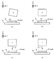
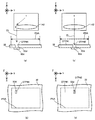
- 2A to 2C are cross-sectional views showing a state of removal processing performed on a work.
- 3 (a) to 3 (c) are cross-sectional views showing a state of a work processed by non-thermal processing.
- FIG. 4 is a cross-sectional view showing the structure of the processing device.
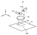
- FIG. 5 is a perspective view showing the structure of an optical system included in the processing apparatus.
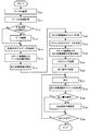
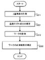
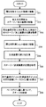
- FIG. 6 is a flowchart showing the flow of the processing operation performed by the processing system SYS.
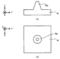
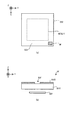
- FIG. 7A is a cross-sectional view showing a cross section of an unworked work
- FIG. 7B is a plan view showing the upper surface of the unworked work W.
- FIG. 7A is a cross-sectional view showing a cross section of an unworked work
- FIG. 7B is a plan view showing the upper surface of the unworked work W.
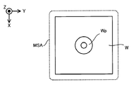
- FIG. 8 is a plan view showing an example of the positional relationship between the measurement shot area and the work.
- FIG. 9 is a plan view showing another example of the positional relationship between the measurement shot area and the work.
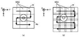
- FIG. 10A and FIG. 10B is a plan view showing an example of the movement locus of the measurement shot area moving with respect to the surface of the work.
- 11A is a cross-sectional view showing an example of the positional relationship between the processing target area and the work
- FIG. 11B is a plan view showing an example of the positional relationship between the processing target area and the work.
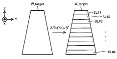
- FIG. 12 is a cross-sectional view showing a cross section of the processing target portion and the plurality of layered structure portions.
- FIG. 13D shows a position where the slice data corresponding to a certain layered structure portion is actually removed in the processing target region in the process of removing the certain layered structure portion. It is a top view which shows the example which has shown.
- FIG. 14 is a cross-sectional view showing how the processing target portion is removed.
- FIG. 15 is a cross-sectional view showing the work that has been removed.
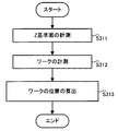
- FIG. 16 is a flowchart showing the flow of the initial setting operation for setting the initial value of the processing condition.
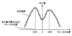
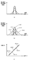
- FIG. 17 is a plot diagram in which the processing amount is plotted with respect to the focus position of the processing light.
- FIG. 18 is a graph showing the relationship between the focus position of the processing light and the processing amount with an approximate curve.
- FIG. 19 is a sectional view showing the positional relationship between the focus position of the processing light and the surface of the work.
- FIG. 20 is a flowchart showing the flow of the first temperature drift reduction operation.
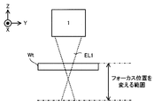
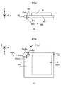
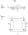
- 21A is a cross-sectional view showing a cross section of the stage device, and
- FIG. 21B is a plan view showing the upper surface of the stage device.
- 22A is a sectional view showing a section of the stage device, and FIG. 22B is a plan view showing an upper surface of the stage device.
- FIG. 23 is a graph showing the time transition of the position of the work in the Z-axis direction calculated by the control device.
- FIG. 24 is a flowchart showing the flow of the second temperature drift reduction operation.
- FIG. 25 is a graph schematically showing the distribution of the position of the work in the Z-axis direction on the XY plane.
- FIG. 26 is a flowchart showing the flow of the third temperature drift reduction operation.
- 27A is a cross-sectional view showing the measuring device tilted with respect to the stage, and FIG. 27B is calculated from the measurement result of the measuring device under the situation shown in FIG. 27A.
- 27C is a cross-sectional view showing the shape of the work, and FIG. 27C is a cross-sectional view showing the work W to be processed by the processing device under the condition that the measuring device is inclined with respect to the stage.
- FIG. 8A is a cross-sectional view showing a work processed to reduce the influence of the tilt amount.
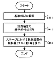
- FIG. 28 is a flowchart showing the flow of the first tilt measuring operation for measuring the tilt amount of the measuring device with respect to the work.
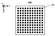
- FIG. 29 is a plan view showing the reference member.
- 30A is a plan view showing the reference member, and
- FIG. 30B is a sectional view showing the reference member.
- FIG. 31 is a plan view showing a stage modified to perform the first tilt measurement operation.
- FIG. 32 is a flowchart showing the flow of the first tilt measurement operation for measuring the tilt amount of the processing device with respect to the work.
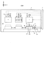
- FIG. 33 is a schematic diagram showing the structure of the processing system of the first modified example.
- FIG. 34 is a cross-sectional view showing a first mode of supplying gas by the gas supply device.
- FIG. 35 is a cross-sectional view showing a second gas supply mode by the gas supply device.
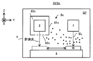
- FIG. 36 is a schematic diagram showing the structure of the processing system of the second modified example.
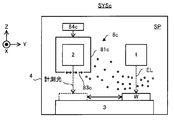
- FIG. 37 is a schematic diagram showing the structure of the processing system of the third modified example.
- FIG. 38 is a schematic diagram showing another structure of the processing system of the third modified example.
- 39A is a sectional view showing the structure of the light receiving device
- FIG. 39B is a plan view showing the structure of the light receiving device.
- FIG. 40 is a cross-sectional view showing the processing light with which the light receiving device is irradiated.
- FIG. 41 (a) is a cross-sectional view showing how the processing device irradiates the light receiving device with the processing light to perform the focus control operation, and FIG.
- FIG. 41 (b) shows the processing device to perform the focus control operation.
- FIG. 41C is a plan view showing how the processing device irradiates the light receiving device, and FIG. 41C is a graph showing the detection result of the detector provided in the light receiving device.
- FIG. 42 is a graph showing the detection result of the detector.
- FIG. 43 is a plan view schematically showing the spot diameter of the processing light EL at each position on the surface of the work when the processing light deflected by the galvanometer mirror scans the surface of the work.
- 44 (a) and 44 (c) are cross-sectional views showing the positional relationship between the processing device and the light receiving device 9d during the period in which the state detection operation is performed, and FIGS.
- Each of d) is a plan view showing the positional relationship between the processing device and the light receiving device during the period in which the state detection operation is performed.
- FIG. 45A is a plan view showing the irradiation position of the processing light on the surface of the work (that is, the surface along the XY plane) under the condition that the temperature drift does not occur
- FIG. FIG. 5 is a plan view showing an irradiation position of processing light on a surface of a work (that is, a surface along an XY plane) under a condition where temperature drift occurs.
- 46A is a sectional view showing the stage
- FIG. 46B is a plan view showing the stage.
- FIG. 47 is a flowchart showing the flow of stage control operation for controlling the position of the stage based on the measurement result of the opening by the measuring device.
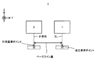
- FIG. 48 is a sectional view schematically showing the baseline amount in the fourth modified example.
- FIGS. 49A to 49D is a plan view showing a marker used in the stage control operation.
- FIG. 50 is a sectional view showing the structure of the processing system of the fifth modified example.
- FIG. 51 is a diagram showing the configuration of a processing head of the fifth modification.
- FIG. 52 is a cross-sectional view showing the structure of the processing system of the sixth modified example.
- FIG. 53 (a) is a plan view showing a light receiving device of a seventh modified example, and FIG. 53 (b) is a sectional view thereof.
- FIG. 54 is a sectional view showing the structure of the eighth modification.
- FIG. 55 is a sectional view showing the structure of the ninth modification.
- each of the X-axis direction and the Y-axis direction is a horizontal direction (that is, a predetermined direction in the horizontal plane), and the Z-axis direction is a vertical direction (that is, a direction orthogonal to the horizontal plane). Yes, and substantially in the vertical direction or gravity direction).
- the rotation directions around the X axis, the Y axis, and the Z axis are referred to as the ⁇ X direction, the ⁇ Y direction, and the ⁇ Z direction, respectively.
- the Z-axis direction may be the gravity direction.
- the XY plane may be horizontal.
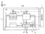
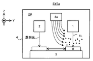
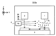
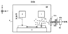
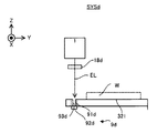
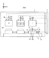
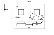
- FIG. 1 is a cross-sectional view showing the structure of the processing system SYS. Note that, for simplification of the drawing, FIG. 1 does not show a cross section of a part of the components of the processing system SYS.
- the processing system SYS includes a processing device 1, a measuring device 2, a stage device 3, a housing 4, a drive system 5, a drive system 6, and a control device 7.
- the processing device 1 can process the work W under the control of the control device 7.
- the work W may be, for example, a metal, an alloy (for example, duralumin, etc.), a semiconductor (for example, silicon), a resin, or CFRP. It may be a composite material such as (Carbon Fiber Reinforced Plastic), glass, ceramics, or an object made of any other material.
- the processing device 1 irradiates the work W with the processing light EL in order to process the work W.
- the processing light EL may be any type of light as long as the work W can be processed by being irradiated on the work W.
- the processing light EL is described as an example in which the processing light EL is laser light, but the processing light EL may be light of a type different from the laser light.
- the wavelength of the processing light EL may be any wavelength as long as the work W can be processed by being irradiated with the work W.
- the processing light EL may be visible light or invisible light (for example, at least one of infrared light and ultraviolet light).
- the processing apparatus 1 irradiates the work W with the processing light EL1 to perform a removal process (a so-called cutting process or grinding process) for removing a part of the work W.
- a removal process a so-called cutting process or grinding process
- the processing apparatus 1 may perform processing different from the removal processing (for example, additional processing or marking processing).
- the removal processing includes surface cutting processing, surface grinding processing, cylindrical cutting processing, cylindrical grinding processing, hole cutting processing, hole grinding processing, surface polishing processing, cutting processing, and formation of arbitrary characters or arbitrary patterns (in other words, , Engraving) (in other words, engraving) may be included.
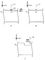
- FIGS. 2A to 2C are cross-sectional views showing a state of the removal process performed on the work W.
- the processing apparatus 1 irradiates the irradiation light EA set (in other words, formed) on the surface of the work W with the processing light EL.
- the irradiation light EA is irradiated with the processing light EL, the energy of the processing light EL is transmitted to the irradiation area EA and a portion near the irradiation area EA in the work W.
- the heat resulting from the energy of the processing light EL melts the material forming the irradiation area EA and the portion of the workpiece W close to the irradiation area EA.
- the melted material becomes droplets and scatters.
- the melted material is evaporated by the heat caused by the energy of the processing light EL.
- the irradiation area EA of the work W and the portion adjacent to the irradiation area EA are removed. That is, as shown in FIG. 2B, a recess (in other words, a groove) is formed on the surface of the work W.
- the processing apparatus 1 processes the work W by utilizing the so-called thermal processing principle.
- the processing light EL scans the surface of the work W
- the irradiation area EA moves on the surface of the work W.
- the surface of the work W is at least partially removed along the scanning locus of the processing light EL (that is, the movement locus of the irradiation area EA). That is, the surface of the work W is substantially scraped off along the scanning locus of the processing light EL (that is, the movement locus of the irradiation area EA).
- the processing apparatus 1 causes the processing light EL to scan the surface of the work W along a desired scanning locus corresponding to the region to be processed for removal, thereby appropriately removing the portion of the work W to be processed for removal. be able to.
- the processing apparatus 1 can process the work W by using the principle of non-thermal processing (for example, ablation processing). That is, the processing apparatus 1 may perform non-thermal processing (for example, ablation processing) on the work W.
- non-thermal processing for example, ablation processing
- the processing apparatus 1 may perform non-thermal processing (for example, ablation processing) on the work W.
- pulsed light with a light emission time of picoseconds or less or, in some cases, nanoseconds or femtoseconds or less
- the irradiation area EA of the work W and a portion close to the irradiation area EA are detected.
- the constituent materials are instantly evaporated and scattered.
- FIGS. 3A to 3C which are cross-sectional views showing the state of the work W processed by the non-thermal processing, the work W is heated by the heat caused by the energy of the processing light EL.
- a recess (in other words, a groove) can be formed on the surface of the work W while suppressing the influence as much as possible.
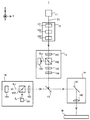
- the processing apparatus 1 includes a light source 11, an optical system 12, a dichroic mirror 13, and an optical system 14 as shown in FIG. 4, which is a sectional view showing the structure of the processing apparatus 1. And a return light prevention device 15 and an observation device 16.
- the light source 11 can generate the processing light EL.
- the processing light EL is laser light
- the light source 11 may be, for example, a laser diode.
- the light source 11 may be a light source capable of pulse oscillation.
- the light source 11 can generate pulsed light (for example, pulsed light having a light emission time of picoseconds or less) as the processing light EL.
- the light source 11 emits the generated processing light EL toward the optical system 12.
- the light source 11 may emit the processing light EL in a linearly polarized state.
- the optical system 12 is an optical system into which the processing light EL emitted from the light source 11 enters.
- the optical system 12 is an optical system that emits the processing light EL that has entered the optical system 12 toward the return light prevention device 15. That is, the optical system 12 is an optical system that guides the processing light EL emitted from the light source 11 to the return light prevention device 15.
- the optical system 12 may control the state of the processing light EL emitted from the light source 11, and may emit the processing light EL whose state is controlled toward the return light prevention device 15.
- the optical system 12 may control the beam diameter of the processing light EL (that is, the size of the processing light EL in the plane intersecting the traveling direction of the processing light EL).
- the optical system 12 may control the beam diameter of the processing light EL (that is, the spot diameter) on the surface of the work W by controlling the beam diameter of the processing light EL.
- the optical system 12 may include the beam expander 121.
- the optical system 12 may control the degree of convergence or divergence of the processing light emitted from the optical system 12.
- the optical system 12 may include the focus lens 122.
- the focus lens 122 is composed of one or more lenses, and by adjusting the position of at least a part of the lenses along the optical axis direction, the convergence degree or divergence degree of the processing light EL is changed to adjust the position of the processing light EL.
- the focus lens 122 may be integrated with the beam expander 121 or may be a separate body from the beam expander 121.
- the optical system 12 may control the intensity distribution of the processing light EL in the plane intersecting the traveling direction of the processing light EL.
- the optical system 12 may include an intensity distribution control member 123 capable of controlling the intensity distribution of the processing light EL.
- the state of the processing light EL controlled by the optical system 12 includes the focus position of the processing light EL, the beam diameter of the processing light EL, the convergence or divergence of the processing light EL, and the intensity distribution of the processing light EL.
- the pulse length and the number of pulses of the processing light EL, the intensity of the processing light EL, the traveling direction of the processing light EL, and the polarization state of the processing light EL may be used.
- the dichroic mirror 13 guides the processing light EL that enters the dichroic mirror 13 from the optical system 12 via the return light prevention device 15 to the optical system 14.
- the dichroic mirror 13 reflects one of the processing light and the observation light (illumination light IL and reflected light ILr) having a wavelength different from the processing light and transmits the other.
- the dichroic mirror 13 guides the processing light EL to the optical system 14 by reflecting the processing light EL toward the optical system 14.
- the dichroic mirror 13 may guide the processing light EL to the optical system 14 by passing the processing light EL.
- the optical system 14 is an optical system for irradiating (that is, guiding) the processing light EL from the dichroic mirror 13 to the work W.
- the optical system 14 includes a galvanometer mirror 141 and an f ⁇ lens 142.
- the galvano mirror 141 deflects the processing light EL so that the processing light EL from the f ⁇ lens 142 scans the work W (that is, the irradiation area EA irradiated with the processing light EL moves on the surface of the work W). ..
- a polygon mirror may be used instead of or in addition to the galvano mirror 141.
- the galvano mirror 141 includes an X scanning mirror 141X and a Y scanning mirror 141Y, as shown in FIG. 5, which is a perspective view showing the structure of the optical system 14.
- the X scanning mirror 141X reflects the processing light EL toward the Y scanning mirror 141Y.
- the X scanning mirror 141X can swing or rotate about the ⁇ Y direction (that is, the rotation direction around the Y axis) as an axis.
- the machining light EL scans the surface of the work W along the X-axis direction by swinging or rotating the X-scanning mirror 141X.
- the irradiation area EA moves on the surface of the work W along the X-axis direction by swinging or rotating the X-scanning mirror 141X.
- the Y scanning mirror 141Y reflects the processing light EL toward the f ⁇ lens 142.
- the Y scanning mirror 141Y can swing or rotate about the ⁇ X direction (that is, the rotation direction around the X axis) as an axis.
- the processing light EL scans the surface of the work W along the Y-axis direction.
- the irradiation area EA moves on the surface of the work W along the Y-axis direction by swinging or rotating the Y scanning mirror 141Y.
- the f ⁇ lens 142 is an optical element for condensing the processing light EL from the galvano mirror 141 onto the work W.
- the X scanning mirror 141X may be swingable or rotatable about a direction slightly tilted from the ⁇ Y direction (that is, the rotation direction around the Y axis), and the Y scanning mirror 141Y may rotate in the ⁇ X direction (that is, It may be swingable or rotatable about a direction slightly inclined from the direction of rotation about the X axis).
- the f ⁇ lens 142 is a telecentric optical system on the exit surface side (workpiece W side) in this example, the f ⁇ lens 142 may not be a telecentric optical system.
- the f ⁇ lens 142 is a telecentric optical system on the exit surface side (workpiece W side)
- the irradiation position of the processing light EL does not change in the XY plane even if the thickness of the work W (size in the Z-axis direction) changes.
- the return light prevention device 15 prevents the return light ELr, which is the processing light EL reflected by the work W, from returning to the optical system 12 and the light source 11.
- the returning light prevention device 15 guides the processing light EL emitted from the optical system 12 to the dichroic mirror 13 (that is, to the work W).
- the return light prevention device 15 may use polarized light, for example.
- the light source 11 preferably emits the processing light EL in the linearly polarized state.
- a quarter wavelength plate may be arranged between the light source 11 and the return light prevention device 15.
- the return light prevention device 15 includes, for example, a half-wave plate 151, a polarization beam splitter 152, a quarter-wave plate 153, a half-wave plate 154, and a beam diffuser 155.
- the half-wave plate 151 changes the polarization direction of the processing light EL from the optical system 12.
- the 1 ⁇ 2 wavelength plate 151 changes the polarization direction of the processing light EL from the optical system 12 to a direction in which the processing beam EL can pass through the polarization beam splitter 152.
- the processing light EL that has passed through the half-wave plate 151 passes through the polarization beam splitter 152.
- the polarization beam splitter 152 transmits p-polarized light while reflecting s-polarized light with respect to a polarization separation surface of the polarization beam splitter. That is, description will be given using an example in which the processed light EL that has passed through the polarization beam splitter 152 is p-polarized light.
- the processed light EL that has passed through the polarization beam splitter 152 passes through the quarter-wave plate 153 and becomes circularly polarized light.
- the processing light EL that has passed through the quarter-wave plate 153 passes through the half-wave plate 154.
- each of the half-wave plate 151, the quarter-wave plate 153, and the half-wave plate 154 is rotatably provided about the traveling direction of the processing light EL.
- the processed light EL from the half-wave plate 154 becomes circularly polarized light and enters the dichroic mirror 13.
- the return light prevention device 15 can guide the processing light EL to the dichroic mirror 13.
- the return light ELr that has entered the return light prevention device 15 passes through the half-wave plate 154 and then enters the quarter-wave plate 153.
- the rotation direction of the return light ELr is inverted with respect to the rotation direction of the processing light EL. Therefore, the return light ELr that has passed through the quarter-wave plate 153 becomes s-polarized light.
- the return light prevention device 15 can prevent the return light ELr from returning to the optical system 12 and the light source 11.
- the processing light EL applied to the work W is in a circularly polarized state, so that it is possible to reduce the difference in the processing characteristics due to the linear polarization direction. Such differences in processing characteristics often differ depending on the material of the work W and the angle of incidence on the work W.
- the quarter wave plate may be arranged in the optical path between the quarter wave plate 154 and the work W.
- the observation device 16 can optically observe the state of the surface of the work W.
- FIG. 4 illustrates an example in which the observation device 16 can optically capture the state of the surface of the work W.
- the observation device 16 may include a light source 161, a beam splitter 162, a notch filter 163, and an image sensor 164.
- the light source 161 generates the illumination light IL.
- the illumination light IL is visible light, but may be invisible light.
- the wavelength of the illumination light IL is different from the wavelength of the processing light EL.
- the wavelength of the illumination light IL is set to a wavelength that can pass through the dichroic mirror 13.
- the light source 161 emits the generated illumination light IL toward the beam splitter 162.
- the beam splitter 162 reflects at least a part of the illumination light IL from the light source 161 toward the notch filter 163.
- the notch filter 163 is a filter that attenuates only the light in a partial wavelength band of the incident illumination light IL.
- a bandpass filter that transmits only light in a part of the wavelength band of the incident illumination light IL may be used.
- the notch filter 163 limits the wavelength band of the illumination light IL that passes through the notch filter 163 to a wavelength band that can pass through the dichroic mirror 13.
- the illumination light IL reflected by the beam splitter 162 enters the dichroic mirror 13 via the notch filter 163.
- the illumination light EL that has entered the dichroic mirror 13 passes through the dichroic mirror 13.
- the illumination light IL is applied to the surface of the work W via the optical system 14. That is, the illumination light IL is applied to the surface of the work W through an optical path that at least partially overlaps the optical path of the processing light EL.
- the illumination light IL is applied to the surface of the work W through a part of the optical system (in the example shown in FIG. 4, the dichroic mirror 13 and the optical system 14) that guides the processing light EL from the light source 11 to the work W. Therefore, in the example shown in FIG. 4, a part of the optical system that guides the processing light EL from the light source 11 to the work W is shared as a part of the optical system that guides the illumination light IL from the light source 161 to the work W. ..
- the optical system that guides the processing light EL from the light source 11 to the work W and the optical system that guides the illumination light IL from the light source 161 to the work W may be optically separated. At least a part of the illumination light IL applied to the surface of the work W is reflected by the surface of the work W. As a result, the illumination light IL reflected by the work W enters the optical system 14 as reflected light ILr.
- the reflected light ILr enters the observation device 16 via the optical system 14.
- the reflected light ILr that has entered the observation device 16 enters the beam splitter 162 via the notch filter 163.
- the illumination light IL and the reflected light ILr may be referred to as observation light.
- the notch filter 163 is used as a light blocking member for preventing the processing light EL having a wavelength different from that of the observation light from entering the inside of the observation device 16 (in particular, the image pickup element 164). At least part of the reflected light ILr incident on the beam splitter 162 passes through the beam splitter 162 and is incident on the image sensor 164. As a result, the observation device 16 can optically capture the state of the surface of the work W.
- the observation result of the observation device 16 includes information with which the state of the work W can be specified. Therefore, the observation device 16 may be used as a measurement device for measuring the work W.
- the observation result (specifically, the imaging result) of the observation device 16 includes information that can specify the shape of the work W (for example, the shape of the surface of the work W). Therefore, the observation device 16 may be used as a measurement device for measuring the shape of the work W.
- a part of the processing device 1 is shared with at least a part of the measuring device (in the example shown in FIG. 4, the observation device 16) for measuring the work W.
- the measuring device 2 can measure the measuring object under the control of the control device 7.
- the measurement target includes, for example, the work W.
- the measuring device 2 may be a device capable of measuring the state of the work W.
- the state of the work W may include the position of the work W.
- the position of the work W may include the position of the surface of the work W.
- the position of the surface of the work W may include a position in at least one of the X-axis direction, the Y-axis direction, and the Z-axis direction of each surface portion obtained by subdividing the surface of the work W.
- the state of the work W may include the shape of the work W (for example, a three-dimensional shape).
- the shape of the work W may include the shape of the surface of the work W.
- the shape of the surface of the work W is, in addition to or instead of the position of the surface of the work W described above, the direction of each surface portion obtained by subdividing the surface of the work W (for example, the direction of the normal line of each surface portion, (Substantially equivalent to the amount of inclination of each surface portion with respect to at least one of the X axis, the Y axis, and the Z axis) may be included.
- the state of the work W may include the size of the work W (for example, the size in at least one of the X-axis direction, the Y-axis direction, and the Z-axis direction).
- the measurement information regarding the measurement result of the measurement device 2 is output from the measurement device 2 to the control device 7.
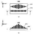
- the measuring device 2 may include a plurality of measuring devices 21 that differ in at least one of the size (in other words, the width) and the measurement resolution of the measurement shot area MSA.
- the “measurement shot area MSA” in the present embodiment is measured by the measurement device 21 in a state where the positional relationship between the measurement device 21 and the measurement target (for example, the work W) is fixed (that is, without change).
- the region (in other words, range) to be performed is shown (see FIGS. 8 and 9 described later).
- the measurement shot MSA may be referred to as a measurable range or measurable field of the measuring device 2.
- FIG. 1 shows an example in which the measuring device 2 includes two measuring devices 21 (specifically, the measuring devices 21-1 and 21-2).
- the measuring device 2 may include a single measuring device 21.
- the measurement shot area MSA of the first measurement device 21 of the plurality of measurement devices 21 is larger than the measurement shot area MSA of the second measurement device 21 of the plurality of measurement devices 21 different from the first measurement device 21. May be wider (that is, larger).
- the measurement resolution of the first measurement device 21 having the relatively wide measurement shot area MSA may be lower than the measurement resolution of the second measurement device 21 having the relatively narrow measurement shot area MSA. .. That is, the measurement resolution of the second measurement device 21 having the relatively narrow measurement shot area MSA may be higher than the measurement resolution of the first measurement device 21 having the relatively wide measurement shot area MSA.
- the measurement shot area MSA of the measurement device 21-1 is wider than the measurement shot area MSA of the measurement device 21-2, and the measurement resolution of the measurement device 21-1 is the measurement device 21-2. It may be lower than the measurement resolution of.
- the measuring devices 21-1 and 21-2 satisfying such a condition, the work W is measured using a light cutting method that projects slit light onto the surface of the work W and measures the shape of the projected slit light.
- a measuring device 21-1 for measuring the work W and a measuring device 21-2 for measuring the work W by using a white light interferometry method for measuring an interference pattern of the white light passing through the work W and the white light not passing through the work W are included.
- the measuring device 21-2 may be a Michelson interferometer, a Mirau interferometer, or a Linnik interferometer.
- the white light referred to here may mean that it has a wavelength width (spectral width) with respect to monochromatic light.
- each measuring device 21 may measure the work W using another method different from the light section method and the white light interferometry method.
- moire topography method specifically, grid irradiation method or grid projection method
- holography At least one of an interferometry method, an autocollimation method, a stereo method, an astigmatism method, a critical angle method, a knife edge method, an interferometry method, and a confocal method can be given.
- the measuring device 21 receives a light source that emits measurement light (for example, slit light or white light) and light (for example, reflected light of measurement light) from the work W irradiated with the measurement light. It may be provided with a light receiver.
- the light receiver may include a single photodetector, may include a plurality of photodetectors arranged in a one-dimensional direction, or may include a plurality of photodetectors arranged in a two-dimensional direction. ..
- the stage device 3 is arranged (that is, provided) below the processing device 1 and the measuring device 2 (that is, on the ⁇ Z side).
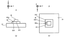
- the stage device 3 includes a surface plate 31 and a stage 32.
- the surface plate 31 is arranged on the bottom surface of the housing 4 (or on a supporting surface such as a floor surface on which the housing 4 is placed).
- a stage 32 is arranged on the surface plate 31.
- a not-shown protective member for reducing the transmission of the vibration of the surface plate 31 to the stage 32 is provided.
- a shaking device may be installed.
- the support frame 8 that supports the processing device 1 and the measuring device 2 may be arranged on the surface plate 31.
- the processing device 1 and the measuring device 2 may be supported by the same surface plate 31.
- at least a part of the processing device 1 may not be arranged on the surface plate 31.
- at least a part of the measuring device 2 may not be arranged on the surface plate 31.
- At least a part of the processing device 1 and at least a part of the measuring device 2 may be arranged on different surface plates (or other supporting surfaces).
- the measurement system SYS may be configured without the surface plate 31.
- the stage 32 may be provided on the predetermined structure of the housing 4.
- the stage 32 may be made of quartz glass, or may be made of other materials (for example, stones such as granite, metal, ceramics, etc.).
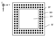
- the work W is placed on the stage 32.
- the surface of the stage 32 includes a mounting surface 321 on which the work W can be mounted.
- the mounting surface 321 is a surface parallel to the XY plane.
- the work W is placed on the placing surface 321.
- the stage 32 does not have to hold the mounted work W.
- the stage 32 may hold the mounted work W.
- the stage 32 may hold the work W by vacuum suction and / or electrostatic suction of the work W.
- FIG. 1 shows an example in which at least one opening 322 for vacuum suction of the work W is formed on the mounting surface 321 of the stage 32.
- the stage 32 sucks the work W in vacuum by sucking the back surface of the work W through the opening 322.
- the stage 32 can move on the surface plate 31 while the work W is placed under the control of the control device 7.
- the stage 32 is movable with respect to at least one of the surface plate 31, the processing device 1, and the measuring device 2.
- the stage 32 is movable along each of the X-axis direction and the Y-axis direction. In this case, the stage 32 can move along a stage running surface parallel to the XY plane.
- the stage 32 may be further movable along at least one of the Z axis direction, the ⁇ X direction, the ⁇ Y direction, and the ⁇ Z direction.
- the stage device 3 includes a stage drive system 33.
- the stage drive system 33 moves the stage 32 using, for example, an arbitrary motor (for example, a linear motor or the like).
- the stage device 3 includes a position measuring device 34 for measuring the position of the stage 32.
- the position measuring instrument 34 may include, for example, at least one of an encoder and a laser interferometer.
- the processing device 1 and the measuring device 2 changes. That is, when the stage 32 moves, the position of the stage 32 (further, the work W placed on the stage 32) with respect to the processing device 1 and the measuring device 2 changes. Therefore, moving the stage 32 is equivalent to changing the positional relationship between the stage 32 (further, the workpiece W placed on the stage 32), the processing apparatus 1 and the measuring apparatus 2.
- the stage 32 may be moved so that at least a part of the work W is located in the processing shot area PSA during at least a part of the processing period in which the processing apparatus 1 processes the work W.
- the stage 32 may move so that the processing shot area PSA is located on the work W during at least a part of the processing period.
- the “machining shot area PSA” in the present embodiment is processed by the machining apparatus 1 in a state where the positional relationship between the machining apparatus 1 and an object to be machined (for example, the work W) is fixed (that is, without changing).
- the region (in other words, range) to be performed is shown.
- the processing shot area PSA coincides with the scanning range of the processing light EL deflected by the galvano mirror 141 in a state where the positional relationship between the processing device 1 and the processing object is fixed, as shown in FIG.
- the area is set to be narrower than the scanning range.
- the processing shot area PSA is an area in which the irradiation area EA to which the processing light EL is irradiated in a state where the positional relationship between the processing device 1 and the processing object is fixed matches the movable range or is narrower than the range. Is set to. Therefore, the processing shot area PSA is an area determined based on the processing apparatus 1 (that is, an area having a predetermined positional relationship with the processing apparatus 1).
- the processing apparatus 1 detects the workpiece W located in the processing shot area PSA. At least a part of the processing light EL can be irradiated. As a result, at least a part of the work W is processed by the processing light EL emitted from the processing apparatus 1 while being placed on the stage 32 (or being held by the stage 32).
- the work W is so large that the entire work W cannot be located in the processing shot area PSA, the first portion of the work W is included in the processing shot area PSA.
- the stage 32 moves so that the second part of the work W different from the first part is included in the processing shot area PSA (further, if necessary, it is processed by the drive system 5 described later).
- the apparatus 1 moves), and then the second portion of the work W is processed. After that, the same operation is repeated until the processing of the work W is completed.
- the stage 32 may move so that at least a part of the work W is located in the measurement shot area MSA during at least a part of the measurement period in which the measuring device 2 measures the work W.
- the stage 32 may move so that the measurement shot area MSA is located on the work W during at least a part of the measurement period.
- the measuring shot area MSA is the measuring device 2 Of the slit light used for the light cutting method and / or the white light used for the white light interferometry in a state where the positional relationship between the object and the measurement object is fixed (for example, the scanning range of the slit light and / or the white light).
- the measurement shot area MSA is a light receiving surface (for example, a single light receiving surface of a light receiver that receives light from the work W irradiated with slit light and / or white light in a state where the positional relationship between the measuring device 2 and the measurement object is fixed.
- the range may be set to correspond to one photodetector or a plurality of photodetectors arranged in the one-dimensional direction or the two-dimensional direction. Therefore, the measurement shot area MSA is an area determined with the measuring device 2 as a reference (that is, an area having a predetermined positional relationship with the measuring device 2).
- the measuring device 2 measures the work W located in the measurement shot area MSA. At least a part can be measured. That is, at least a part of the work W is measured by the measuring device 2 while being placed on the stage 32 (or being held by the stage 32).
- the stage 32 moves so that the second part of the work W different from the first part is included in the measurement shot area MSA (further, if necessary, measured by the drive system 6 described later).
- the device 2 moves), and then the second portion of the work W is measured. After that, the same operation is repeated until the measurement of the work W is completed.
- the measurement shot area MSA is typically in the shape of a slit extending in a predetermined direction, so that the work W is moved by the stage 32 along the direction intersecting the longitudinal direction of the slit. The work W may be measured while moving.
- the stage 32 may move between the processing shot area PSA and the measurement shot area MSA while the work W is placed on the stage 32.
- the stage 32 may move such that the work W moves between the processing shot area PSA and the measurement shot area MSA with the work W placed on the stage 32. That is, the work W moves between the processing shot area PSA and the measurement shot area MSA in addition to the processing period in which the processing apparatus 1 processes the work W and the measurement period in which the measuring apparatus 2 measures the work W. It may remain mounted on the stage 32 during the movement period during which the movement is performed.
- the work W may remain mounted on the stage 32 between the processing of the work W by the processing device 1 and the measurement of the work W by the measuring device 2.
- the work W may remain mounted on the stage 32 between the processing of the work W by the processing device 1 and the measurement of the work W by the measuring device 2.
- the work W may remain mounted on the stage 32 between the measurement of the work W by the measuring device 2 and the processing of the work W by the processing device 1. In other words, between the time when the machining of the workpiece W by the machining apparatus 1 is completed and the time when the measurement of the workpiece W is started by the measuring apparatus 2 or the measurement of the work W by the measuring apparatus 2 is completed, The work W does not have to be removed from the stage 32 before the processing of the work W is started.
- a holding mode in which the stage 32 holds the work W in at least a part of the machining period and a holding mode in which the stage 32 holds the work W in at least a part of the measurement period. May be the same.
- An example of the holding mode is the force with which the stage 32 holds the work W.
- the force with which the stage 32 holds the work W depends on the exhaust speed through the opening 322. In this case, the exhaust speed during the processing period may be the same as the exhaust speed during the measurement period so that the stage 32 has the same force for holding the work W.
- the force with which the stage 32 holds the work W depends on the voltage applied to the electrodes.
- the voltage may be the same.
- the holding mode in which the stage 32 holds the work W during at least a part of the processing period may be different from the holding mode in which the stage 32 holds the work W during at least a part of the measurement period.
- a weight may be placed on the work W. This is particularly effective when the work W is lightweight or small.
- the stage 32 may have a plurality of stages 32.
- the processing device 1 and the measuring device 2 are arranged along the moving direction of the stage 32.
- the processing device 1 and the measuring device 2 are arranged side by side along the Y direction.
- the processing device 1 and the measuring device 2 may be arranged along a direction intersecting the moving direction of the stage 32.
- the processing device 1 and the measuring device 2 are arranged along a direction intersecting the scanning direction of the processing light EL by the processing device 1.
- the scanning direction of the processing light EL by the processing device 1 is the X direction
- the processing device 1 and the measuring device 2 are arranged side by side along the Y direction intersecting the X direction.
- the processing device 1 and the measuring device 2 may be arranged in a direction along the scanning direction of the processing light EL.
- the casing 4 accommodates the processing device 1, the measuring device 2, and the stage device 3 in an internal accommodation space SP that is separated from the space outside the casing 4. That is, in this embodiment, the processing device 1, the measuring device 2, and the stage device 3 are arranged in the same housing 4.
- the processing device 1, the measuring device 2, and the stage device 3 are arranged in the same accommodation space SP.
- the housing 4 accommodates the work W in the accommodation space SP therein. That is, the processing device 1, the measuring device 2, and the work W are arranged in the same accommodation space SP.
- at least a part of the processing device 1 may not be arranged in the accommodation space SP.
- At least a part of the processing device 1 may not be arranged outside the housing 4.
- At least a part of the measuring device 2 may not be arranged in the accommodation space SP. At least a part of the measuring device 2 may not be arranged outside the housing 4. At least a part of the stage device 3 may not be arranged in the accommodation space SP. At least a part of the stage device 3 may not be arranged outside the housing 4.
- the stage 32 is in a state where the work W is placed on the stage 32. It is possible to move between the processing shot area PSA and the measurement shot area MSA. Furthermore, the same housing 4 can continue to accommodate the work W in at least part of the processing period and at least part of the measurement period. In other words, the work W can be continuously located inside the same housing 4 in at least part of the processing period and at least part of the measurement period.
- the drive system 5 moves the processing device 1 under the control of the control device 7.
- the drive system 5 moves the processing apparatus 1 with respect to at least one of the surface plate 31, the stage 32, and the work W placed on the stage 32.
- the drive system 5 may move the processing device 1 with respect to the measuring device 2.
- the drive system 5 moves the processing apparatus 1 along at least one of the X axis direction, the Y axis direction, the Z axis direction, the ⁇ X direction, the ⁇ Y direction, and the ⁇ Z direction.
- the drive system 5 includes, for example, a motor and the like.
- the processing system SYS includes a position measuring device 51 capable of measuring the position of the processing device 1 moved by the drive system 5.
- the position measuring device 51 may include, for example, at least one of an encoder and a laser interferometer.
- the drive system 5 moves the processing apparatus 1, the irradiation area EA and the processing shot area PSA move on the work W. Therefore, the drive system 5 can change the positional relationship between the workpiece W, the irradiation area EA, and the processing shot area PSA by moving the processing apparatus 1.
- the stage 32 is movable, the positional relationship between the work W and the irradiation area EA and the processing shot area PSA can be changed even if the processing apparatus 1 is not movable. Therefore, the processing device 1 does not have to be movable. In this case, the processing system SYS does not have to include the drive system 5.
- the processing device 1 since the stage 32 is movable in the XY directions, the processing device 1 may be movable in the Z axis direction. At this time, the focus position of the processing light EL and the focus position of the observation device 16 may be controlled by moving the processing device 1 in the Z-axis direction.
- the drive system 6 moves the measuring device 2 under the control of the control device 7.
- the drive system 6 moves the measuring device 2 with respect to at least one of the surface plate 31, the stage 32, and the work W placed on the stage 32.
- the drive system 6 may move the measuring device 2 with respect to the processing device 1.
- the drive system 6 moves the measuring device 2 along at least one of the X axis direction, the Y axis direction, the Z axis direction, the ⁇ X direction, the ⁇ Y direction, and the ⁇ Z direction.
- the drive system 6 includes, for example, a motor and the like.
- the processing system SYS includes a position measuring device 61 capable of measuring the position of the measuring device 2 moved by the drive system 6.
- the position measuring device 61 may include, for example, at least one of an encoder and a laser interferometer.
- the drive system 6 moves the measuring device 2
- the measurement shot area MSA moves on the work W. Therefore, the drive system 6 can change the positional relationship between the work W and the measurement shot area MSA by moving the measuring device 2.
- the stage 32 is movable
- the positional relationship between the workpiece W and the measurement shot area MSA can be changed even if the measuring device 2 is not movable. Therefore, the measuring device 2 may not be movable. In this case, the processing system SYS does not have to include the drive system 6.
- the measuring device 2 since the stage 32 is movable in the XY directions, the measuring device 2 may be movable in the Z axis direction. At this time, the focus position of the measuring device 2 may be controlled by moving the measuring device 2 in the Z-axis direction.
- the drive system 6 may move the plurality of measuring devices 21 collectively, or may move each measuring device 21 individually. Good.
- the control device 7 controls the operation of the processing system SYS.
- the control device 7 may include, for example, at least one of a CPU (Central Processing Unit) and a GPU (Graphics Processing Unit), and a memory.
- the control device 7 sets the processing conditions for the work W, and the processing device 1, the measuring device 2, the stage device 3, and the drive system 5 so that the work W is processed according to the set processing conditions.
- the drive system 6 are controlled.
- the control device 7 does not have to be arranged inside the processing system SYS, and may be arranged as a server or the like outside the processing system SYS, for example. In this case, the control device 7 and the processing system SYS may be connected by a wired or wireless communication line.
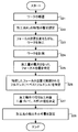
- FIG. 6 is a flowchart showing the flow of the processing operation performed by the processing system SYS.
- a work W scheduled to be processed by the processing device 1 is newly placed on the stage 32 (step S101). That is, the unprocessed work W is newly placed on the stage 32.
- the unprocessed work W is transferred from the outside of the housing 4 to the storage space SP inside the housing 4, and then the work W transferred to the storage space SP is newly placed on the stage 32.
- the work W may be held by the stage 32.
- FIG. 7A which is a cross-sectional view showing a cross section of the unprocessed work W
- FIG. 7B which is a plan view showing the upper surface of the unprocessed work W.
- W will be described with reference to the workpiece W having a projection Wp protruding to the + Z side on the surface as an example.
- the machining operation will be described using the machining operation performed on the work W so as to remove the protrusion Wp as an example.
- the processing system SYS can process an arbitrary work having a different shape from the work W shown in FIGS. 7A and 7B by performing the processing operation based on the flowchart shown in FIG. ..
- the measuring device 21-1 included in the measuring device 2 measures the work W (step S111). Specifically, first, the stage 32 and / or the measuring device 21-1 is moved so that the entire work W (or a part thereof in some cases) is positioned within the measurement shot area MSA of the measuring device 21-1. To do. After that, the measuring device 21-1 measures the work W. Since the measurement shot area MSA of the measurement device 21-1 is wider than the measurement shot area MSA of the measurement device 2-12, the measurement by the measurement device 21-1 is referred to as “wide area measurement” in the present embodiment for convenience of description. ..
- the outer edge of the measurement shot area MSA of the measurement device 21-1 that performs wide area measurement is a plan view showing an example of the positional relationship between the measurement shot area MSA and the work W, as shown in FIG. May have a size that can include
- the size of the outer edge of the measurement shot area MSA of the measuring device 21-1 in the XY plane (or the plane along the surface of the work W, the same applies hereinafter) is larger than the size of the outer edge of the surface of the work W in the XY plane. It may be larger or the same. In this case, after the stage 32 moves so that the work W is located in the measurement shot area MSA, the measurement device 21-1 does not move even if the stage 32 and the measurement device 21-1 do not move. The measurement can be completed.
- the outer edge of the measurement shot area MSA of the measurement device 21-1 is a plan view showing another example of the positional relationship between the measurement shot area MSA and the work W, as shown in FIG. It may have a size such that it can include a part but cannot include another part of the surface of the work W.
- the size of the outer edge of the measurement shot area MSA of the measuring device 21-1 in the XY plane may be smaller than the size of the outer edge of the surface of the work W in the XY plane. In this case, after the stage 32 moves so that a part of the work W is located in the measurement shot area MSA, the measuring device 21-1 is located in the measurement shot area MSA of the work W as described above.
- the stage 32 and / or the measurement device 21-1 moves so that another part of the workpiece W, which has not been measured by the measurement device 21-1 yet, is located in the measurement shot area MSA.
- the operation is repeated. That is, each time the measuring device 21-1 completes the measurement of the portion of the work W located in the measurement shot area MSA, the measurement shot area MSA is set on the surface of the work W in at least one of the X-axis direction and the Y-axis direction. The operation of moving along is repeated.
- the measurement shot area MSA is the measurement shot area MSA before the movement.
- the measurement shot area MSA after the movement may be moved so as not to overlap. That is, in the measurement shot area MSA, the measurement shot area MSA including the first portion of the surface of the work W and the measurement shot area MSA including the second portion adjacent to the first portion of the surface of the work W overlap. You may move so as not to.
- the measurement shot area MSA includes a first portion of the surface of the work W included in the measurement shot area MSA before the movement and a second portion of the surface of the work W included in the measurement shot area MSA after the movement.
- the measurement shot area MSA is the same as the measurement shot area MSA before the movement. You may move so that the measurement shot area MSA after movement may partially overlap. That is, the measurement shot area MSA is composed of the measurement shot area MSA including the first portion on the surface of the work W and the measurement shot area MSA including the second portion adjacent to the first portion on the surface of the work W. You may move so that it may overlap.
- the measurement shot area MSA includes a first portion of the surface of the work W included in the measurement shot area MSA before the movement and a second portion of the surface of the work W included in the measurement shot area MSA after the movement. You may move so that and may partially overlap. Although the work W is moved with respect to the measurement shot area MSA in the above description, the measurement shot area MSA may be moved with respect to the work W by moving the measuring device 21-1, for example.
- the control device 7 determines whether or not there is a defect in the wide area measurement information indicating the measurement result of the measurement device 21-1 (step S112).
- the term “deficiency” as used herein means that the wide area measurement information does not include information about the measurement result of a portion of the surface of the work W.
- the control device 7 interpolates the missing information using the existing data interpolation method or the like ( Step S113).
- control device 7 may control the measuring device 21-1 or the like to control the measuring device 21-1 or the like so as to measure the portion of the work W corresponding to the missing information again.
- the measurement conditions for example, the wavelength and the orientation of the measurement device 21-1) by the measurement device 21-1 may be changed and the measurement may be performed again.
- the control device 7 After that, the control device 7 generates three-dimensional model data of the work W based on the wide area measurement information (step S114).
- the three-dimensional model data based on the wide area measurement information is referred to as “wide area 3D model data”.
- the measuring device 21-1 may not perform the wide area measurement in step S111. Specifically, the operations from step S111 to step S114 for generating wide area 3D data may not be performed. In this case, the operation after step S115 may be performed using the wide area 3D data that has already been generated.
- the control device 7 specifies the position of the work W in the coordinate system used when the stage 32 moves (hereinafter, “stage coordinate system”) (step S115).
- the measurement device 21-1 performs a wide area measurement in step S111, and a reference mark (for example, described later) formed in advance on the surface of the stage 32 (or other member such as the surface plate 31).
- the opening 93d (see FIG. 39), the marker AM (see FIG. 49) or any other mark) is measured.
- the information about the measurement result of the reference mark includes the information about the position of the reference mark. Therefore, the control device 7 can specify the positional relationship between the reference mark and the work W based on the wide area measurement information including the measurement result of the reference mark.
- the control device 7 controls the position of the stage 32 measured by the position measuring device 34.
- the position of the reference mark in the stage coordinate system can be specified based on the information about (that is, the position in the stage coordinate system) and the information about the positional relationship between the reference mark and the stage 32.
- the control device 7 determines the position within the stage coordinate system based on the information regarding the position of the reference mark within the stage coordinate system and the information regarding the positional relationship between the reference mark and the workpiece W measured by the wide area measurement.
- the position of the work W can be specified. Note that instead of measuring the reference mark on the stage 32, characteristic points on the stage 32 may be measured.
- the control device 7 sets the processing target area TA of the work W to be actually processed by the processing device 1 (step S116).
- the control device 7 is based on an instruction (for example, an instruction to set the processing target area TA) of the user of the processing system SYS that has confirmed the three-dimensional model of the workpiece W based on the wide area 3D model data generated in step S114.
- the processing target area TA may be set.
- the control device 7 may specify a portion of the work W that satisfies a predetermined specific condition and set a processing target area TA including the specified portion.
- the control device 7 may specify a surface of the work W that protrudes by a predetermined amount or more in the Z-axis direction as compared with the peripheral surface, and may set the processing target area TA including the specified surface.
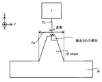
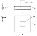
- FIG. 11A is a cross-sectional view showing an example of the positional relationship between the processing target area TA and the work W, and a plan view showing an example of the positional relationship between the processing target area TA and the work W.
- FIG. 11B the description will proceed using an example in which the processing target area TA including the protrusion Wp is set.
- the measuring device 21-2 included in the measuring device 2 measures the processing target portion W_target which is a portion included in the processing target area TA of the work W (step S121).
- the processing target portion W_target matches the protrusion Wp (or includes at least a part of the protrusion Wp).
- the entire processing target area TA (or a part thereof in some cases) is positioned within the measurement shot area MSA of the measuring device 21-2. Move to. That is, the stage 32 moves so that the entire (or in some cases, part of) the processing target portion W_target is located within the measurement shot area MSA of the measuring device 21-2.
- the measuring device 21-2 measures the processing target portion W_target. Since the measurement resolution of the measurement device 21-2 is higher than the measurement resolution of the measurement device 21-1, the measurement by the measurement device 21-2 is referred to as “fine measurement” in the present embodiment for convenience of description.
- the outer edge of the measurement shot area MSA of the measurement device 21-2 that performs fine measurement may be large enough to include the entire processing target area TA.
- the size of the outer edge of the measurement shot area MSA of the measuring apparatus 21-2 in the XY plane may be larger than or the same as the size of the outer edge of the processing target area TA in the XY plane. In this case, after the stage 32 is moved so that the processing target area TA is located in the measurement shot area MSA, the measuring apparatus 21-2 does not move even if the stage 32 and the measuring apparatus 21-2 do not move. Wide area measurement of the portion W_target can be completed.
- the outer edge of the measurement shot area MSA of the measurement device 21-2 that performs fine measurement may have a size that cannot cover the entire processing target area TA.
- the size of the outer edge of the measurement shot area MSA of the measuring apparatus 21-2 in the XY plane may be smaller than the size of the outer edge of the processing target area TA in the XY plane.
- the stage 32 and / or the measuring device 21-2 are arranged such that the other portion of the processing target portion W_target which is not yet measured by the measuring device 21-2 is located in the measurement shot area MSA.
- the movement of moving is repeated. That is, every time the measuring device 21-2 completes the measurement of the portion located in the measurement shot area MSA of the processing target portion W_target, the operation of moving the measurement shot area MSA with respect to the surface of the work W is repeated.
- the measurement shot area MSA of the measurement device 21-2 is similar to the measurement shot area MSA of the measurement device 21-1 so that the measurement shot area MSA before the movement and the measurement shot area MSA after the movement do not overlap. You may move. Alternatively, the measurement shot area MSA may be moved such that the measurement shot area MSA before the movement and the measurement shot area MSA after the movement partially overlap.
- the control device 7 After the fine measurement of the work W is performed, the control device 7 generates three-dimensional model data of the processing target portion W_target based on the fine measurement information indicating the measurement result of the measuring device 21-2 (step S122).
- the three-dimensional model data based on the fine measurement information is referred to as “fine 3D model data”.
- the measuring device 21-2 does not have to perform the fine measurement in step S121.
- the operations of steps S121 to S122 for generating fine 3D data may not be performed.
- the operations after step S123 may be performed using the already generated fine 3D data.
- the fine 3D data may be generated using 3D-CAD.
- control device 7 identifies the position of the processing target portion W_target in the stage coordinate system (step S123). Since the operation of specifying the position of the processing target portion W_target in the stage coordinate system may be performed in the same manner as the operation of specifying the position of the work W in the stage coordinate system (step S116 in FIG. 6), Detailed description thereof will be omitted.
- the control device 7 slices the fine 3D model data at a predetermined slice pitch to create slice data corresponding to the three-dimensional model data of the layer-sliced processing target portion W_target (step S124). Specifically, first, the control device 7 specifies the amount of the reference removal thickness which is a parameter indicating the thickness (that is, the length in the Z-axis direction) of the removed portion removed by one scanning of the processing light EL. To do.
- the amount of reference removal thickness depends on the characteristics of the processing light EL.
- the characteristics of the processing light EL are, for example, the total amount of energy of the processing light EL (for example, the total amount of energy transmitted from the processing light EL to the work W), the amount of energy per unit area of the processing light EL (for example, processing).
- At least one of the transmitted energy amount), the size of the irradiation area EA to which the processing light EL is irradiated, and the irradiation time of the processing light EL may be included.
- the characteristics of the processing light EL may include at least one of the focus position, the beam diameter (or the spot diameter), and the polarization state of the processing light EL.
- the characteristics of the processing light EL may include the number of pulses per unit time.
- the control device 7 specifies the amount of the reference removal thickness based on the characteristics of the processing light EL emitted by the processing device 1. After that, the control device 7 slices the fine 3D model data at a slice pitch corresponding to the amount of the standard removal thickness. As a result, slice data corresponding to the three-dimensional model data of the plurality of layered structure portions SL obtained by slicing the processing target portion W_target in the Z-axis direction is generated. That is, as shown in FIG. 12, which is a cross-sectional view showing the cross section of the processing target portion W_target and the plurality of layered structure portions SL, the control device 7 constitutes the processing target portion W_target by being stacked along the Z-axis direction. Slice data including a plurality of three-dimensional model data respectively corresponding to the plurality of layered structure portions SL is generated. The plurality of layered structure portions SL are virtual on the data.
- Each layered structure portion SL scans the processing light EL performed in a state where the positional relationship between the work W and the processing apparatus 1 in the Z-axis direction (particularly, the positional relationship between the work W and the focus position of the processing light EL) is fixed. It can be regarded as corresponding to the removed portion removed by. Therefore, the processing apparatus 1 can be regarded as sequentially removing the plurality of layered structure portions SL. Specifically, first, the processing apparatus 1 removes a portion corresponding to the uppermost layered structure portion SL # 1. After that, the stage 32 and / or the processing apparatus 1 is moved so that the processing apparatus 1 approaches the work W by the reference removal thickness amount.
- the optical system 12 is controlled so that the focus position of the processing light EL approaches the work W by the amount of the reference removal thickness.
- the processing device 1 removes a portion corresponding to the layered structure portion SL # 2 immediately below the layered structure portion SL # 1.
- the same operation is repeated until the portions corresponding to all the layered structure portions SL are removed.
- the slice data may indicate an area where the removal processing is actually performed in the processing target area TA in the process of removing each layered structure portion SL. That is, the slice data may indicate an area to be removed in the processing target area TA in the process of removing each layered structure portion SL. An actual portion corresponding to the layered structure portion SL exists in a region where the removal processing is actually performed in the processing target area TA. Therefore, the slice data may indicate an area in which a portion corresponding to the layered structure portion SL to be actually removed exists in the processing target area TA at the time of removing the portion corresponding to each layered structure portion SL. The processing light EL is actually applied to the area in the processing target area TA where the removal processing is actually performed.
- the slice data may indicate an area to which the irradiation light EL is actually irradiated in the processing target area TA in the process of removing each layered structure SL. That is, the slice data may indicate the irradiation planned area of the irradiation light EL in the processing target area TA in the process of removing each layered structure SL. For example, FIG.
- FIG. 13A schematically illustrates an example in which the slice data indicates an area in which the removal processing is actually performed in the processing target area TA in the process of removing the portion corresponding to the layered structure portion SL # 1. Is shown in.
- FIG. 13B schematically shows an example in which the slice data shows an area in which the removal processing is actually performed in the processing target area TA in the process of removing the portion corresponding to the layered structure portion SL # 2. ing.
- FIG. 13C schematically shows an example in which the slice data shows a region in which the removal processing is actually performed in the processing target area TA in the process of removing the portion corresponding to the layered structure portion SL # 3. ing.
- 13D shows that the slice data is actually removed in the processing target area TA in the process of removing a portion corresponding to the layered structure portion SL # n (where n is the number of layered structure portions SL).
- the example which has shown the position performed is shown typically.
- the control device 7 sets the processing conditions for removing and processing the workpiece W based on the slice data generated in step S124 (step S125). Specifically, the control device 7 sets machining conditions that determine the operation content of the machining device 1, the stage device 3, and / or the drive system 5 that is required to appropriately remove the machining target portion W_target of the work W. .. Therefore, if the processing device 1, the stage device 3, and / or the drive system 5 operates based on the processing conditions set in step S125, the processing target portion W_target of the work W is appropriately removed.
- the processing condition may include the first condition regarding the processing device 1 that processes the work W.
- the first condition may include a condition regarding the characteristics of the processing light EL described above.
- the first condition may include a condition regarding the irradiation position of the processing light EL.
- the first condition may include a condition relating to the irradiation timing of the processing light EL (for example, the timing of turning on the processing light EL and / or the timing of turning off the processing light EL).
- the first condition may include a condition regarding the size and / or the shape of the irradiation area EA on the work W.
- the first condition may include a condition regarding the frequency of the pulse.
- the first condition may include a condition regarding the scanning speed.
- the first condition may include a condition relating to intervals (shot intervals) between a plurality of irradiation positions of the processing light EL when the processing light EL is pulsed light and the processing light EL scans the work W.
- the first condition may include a condition regarding the number of pulses.
- the first condition may include a condition regarding a pulse width (temporal width).
- the first condition may include a condition regarding the pitch of the scanning lines when the processing light EL scans the work W along the plurality of scanning lines.
- the first condition may include a condition related to the movement of the processing device 1 (in other words, a condition related to the drive system 5 that moves the processing device 1).
- the condition regarding the movement of the processing device 1 may include a condition regarding at least one of the moving direction, the moving amount, the moving speed, and the moving timing of the processing device 1.
- the processing conditions may include the second condition regarding the stage device 3 on which the work W is placed.
- the second condition may include a condition regarding the movement of the stage 32 (in other words, a condition regarding the stage drive system 33 that moves the stage 32).
- the condition regarding the movement of the stage 32 may include a condition regarding at least one of the moving direction, the moving amount, the moving speed, and the moving timing of the stage 32.
- the processing conditions may include conditions regarding the positional relationship between the processing shot area PSA, the irradiation area EA, and the work W.
- the processing conditions may be set using an initial setting operation described later.
- the processing apparatus 1 starts the removal processing of the work W (step S131). Specifically, the stage 32 and / or the processing apparatus 1 moves so that the processing target area TA is located within the processing shot area PSA of the processing apparatus 1. That is, the stage 32 and / or the processing apparatus 1 moves so that the workpiece W moves from the measurement shot area MSA toward the processing shot area PSA. The stage 32 and / or the processing apparatus 1 moves so that the workpiece W moves from a position below the measuring apparatus 2 toward a position below the processing apparatus 1. At this time, as described above, the work W may remain mounted on the stage 32.
- the control device 7 controls the processing device 1, the stage device 3, and the drive system 5 so as to sequentially remove the portions corresponding to the plurality of layered structure portions SL based on the processing conditions set in step S125.
- the plurality of layered structure portions SL are sequentially removed.
- FIG. 14 which is a cross-sectional view showing a state in which the processing target portion W_target is removed
- the processing apparatus 1 has a position where the removal processing is actually performed in the processing target area TA (that is, the layered structure portion SL). Is irradiated with the processing light EL.
- the layered structure portion SL irradiated with the processing light EL is removed.
- the outer edge of the processing shot area PSA may be large enough to include the entire processing target area TA.
- the size of the outer edge of the processing shot area PSA in the XY plane may be larger than or the same as the size of the outer edge of the processing target area TA in the XY plane. In this case, after the stage 32 moves so that the processing target area TA is located in the processing shot area PSA, the processing apparatus 1 completes the processing of the work W even if the stage 32 and the processing apparatus 1 do not move. can do.
- the outer edge of the processing shot area PSA may have a size that can include a part of the processing target area TA but cannot include another part of the processing target area TA. Good.
- the size of the outer edge of the processing shot area PSA in the XY plane may be smaller than the size of the outer edge of the processing target area TA in the XY plane.
- the stage 32 and / or the processing apparatus 1 moves so that another portion of the same layered structure portion SL that has not been subjected to the removal processing by the processing apparatus 1 is located in the processing shot area PSA.
- the operation is repeated. That is, each time the removal processing of the portion of the layered structure portion SL in which the processing apparatus 1 is located is located within the processing shot area PSA is completed, the processing shot area PSA is formed on the work W in at least one of the X-axis direction and the Y-axis direction. The operation of moving along is repeated.
- each time the processing target portion W_target is processed by a desired amount whether or not the removal processing of the processing target portion W_target may be appropriately performed may be evaluated. For example, every time one layered structure portion SL is removed, it may be evaluated whether or not the removal processing of the layered structure portion SL is appropriately performed.
- the evaluation of whether or not the removal processing of the layered structure portion SL has been appropriately performed is not limited to the timing at which one layered structure portion SL is removed, but during the period until the removal processing of the work W is completed. May be performed at any desired timing.
- an example will be described in which whether or not the removal processing of the layered structure portion SL is appropriately performed is performed at the timing when one layered structure portion SL is removed.
- the measuring device 21-2 measures the processing target portion W_target every time the portion corresponding to the layered structure portion SL is removed (step S132). Therefore, first, the stage 32 and / or the measuring device 21-2 moves so that the processing target area TA (that is, the processing target portion W_target) is located within the measurement shot area MSA of the measuring device 21-2. That is, the stage 32 moves such that the workpiece W (particularly, the processing target portion W_target) moves from the processing shot area PSA toward the measurement shot area MSA. At this time, as described above, the work W may remain mounted on the stage 32. Then, the measuring device 21-2 measures the processing target portion W_target.
- the measuring device 21-2 is scheduled to perform the removal process on the part of the processing target part W_target that has been actually removed (that is, the part irradiated with the processing light EL) and the processing target part W_target. At least one of the existing portions (that is, the portion where the processing light EL was to be irradiated) is measured.
- the control device 7 determines whether or not the processing amount by the processing device 1 is a predetermined or assumed appropriate amount (step S133).
- the processing amount is such that the shape of the processing target portion W_target before the removal processing for removing the portion corresponding to the certain layered structure portion SL and the portion corresponding to the certain layered structure portion SL are removed. Is a parameter indicating the difference from the shape of the processing target portion W_target after the removal processing is performed. For example, the processing amount when the portion corresponding to the layered structure portion SL # 1 is removed and processed is the shape of the processing target portion W_target before the removal processing for removing the portion corresponding to the layered structure portion SL # 1 is performed.
- the shape of the processing target portion W_target after the removal processing for removing the portion corresponding to the layered structure portion SL # 1 is performed.
- the processing amount when the portion corresponding to the layered structure portion SL # 2 is removed is the shape of the processing target portion W_target before the removal processing for removing the portion corresponding to the layered structure portion SL # 2 is performed. That is, the difference between the shape of the processing target portion W_targetn in which the layered structure portion SL # 1 is removed and the shape of the processing target portion W_target after the removal processing for removing the layered structure portion SL # 2 is performed. It is a parameter to show.
- the processing amount when the portion corresponding to the layered structure portion SL # 3 is removed is the shape of the processing target portion W_target before the removal processing for removing the portion corresponding to the layered structure portion SL # 3 is performed. (That is, the processing target portion W_targetn shape in which the portions corresponding to the layered structure portions SL # 1 and 2 are removed) and the removal processing for removing the portion corresponding to the layered structure portion SL # 3 are performed. It is a parameter indicating a difference from the shape of the processing target portion W_target.
- the fine measurement information indicating the measurement result of the measuring device 21-2 before the removal processing is performed indicates the shape of the processing target portion W_target before the removal processing is performed.
- the fine measurement information indicating the measurement result of the measuring device 21-2 after the removal processing is performed indicates the shape of the processing target portion W_target after the removal processing is performed. Therefore, the control device 7 controls the fine measurement information indicating the measurement result of the measuring device 21-2 before the removal processing and the fine measurement information indicating the measurement result of the measuring device 21-2 after the removal processing.
- the processing amount can be calculated based on When the processing device 1 performs the removal processing, the processing amount can be referred to as the removal amount.
- the control device 7 determines whether or not the processing amount for the comparison target portion that is a part of the processing target portion W_target is an appropriate processing amount that is predetermined or assumed for the comparison target portion. You may. In this case, the control device 7 is based on the information indicating the position of the comparison target portion (for example, the information indicating the position of the comparison target portion in the stage coordinate system described above), and the fine measurement information before the removal processing is performed. Information regarding the shape of the comparison target portion may be acquired from each of the fine measurement information after the removal processing and the processing amount of the comparison target portion may be calculated based on the acquired information. In this case, it can be said that the control device 7 is substantially determining whether or not the removal processing is correctly performed on the portion where the removal processing was to be performed.
- the processing amount may be a removal amount which is a parameter related to a portion actually removed by the removal processing.
- the processing amount (removal amount) may be an actual removal thickness amount indicating the thickness of the portion actually removed by the removal processing.
- the control device 7 may determine whether or not the processing amount is an appropriate amount by comparing the actual removal thickness amount with the above-described reference removal thickness amount. For example, if the difference between the actual removal thickness amount and the reference removal thickness amount is smaller than the predetermined threshold value, the control device 7 may determine that the processing amount is an appropriate amount. For example, if the difference between the amount of actual removal thickness and the amount of reference removal thickness is larger than the predetermined threshold value, the control device 7 may determine that the processing amount is not an appropriate amount.
- step S133 when it is determined that the machining amount is not an appropriate amount (step S133: No), it is relatively likely that the machining conditions that influence the machining amount are not appropriate. To be done. Therefore, the control device 7 resets the processing conditions. Specifically, the control device 7 sets at least the currently set processing conditions and fine measurement information indicating the measurement result of the processing target portion W_target after the removal processing has been performed (that is, the fine measurement information acquired in step S132). The processing conditions are reset based on the information (step S134). For example, the control device 7 may correct the currently set machining condition based on the fine measurement information acquired in step S132, and set the corrected machining condition as a new machining condition. At this time, the control device 7 may correct the currently set processing conditions based on the fine measurement information acquired in step S132.
- step S133 when the processing amount is determined to be an appropriate amount as a result of the determination in step S133 (step S133: No), the processing conditions that influence the processing amount are relatively likely to be appropriate. Expected to be high. Therefore, in this case, the control device 7 does not have to reset the processing conditions.
- step S135) the operations from step S131 to step S134 are repeated until all the removal processing for the work W is completed (that is, until all the layered structure portions SL are removed) (step S135). That is, the processing apparatus 1 irradiates the processing target portion W_target measured by the measuring apparatus 21-2 with the processing light EL, and removes the processing target portion W_target measured by the measuring apparatus 21-2. Then, the measuring device 21-2 measures the processing target portion W_target processed by the processing device 1. After that, the control device 7 resets the processing conditions as needed based on the measurement result of the measurement device 21-2. The above operation is repeated until the removal processing for the work W is completed. As a result, as shown in FIG. 15, which is a cross-sectional view showing the work W that has been completely removed, the processing target portion W_target (the projection Wp in the example shown in FIG. 15) is removed from the work W.
- FIG. 15 is a cross-sectional view showing the work W that has been completely removed
- the measuring device 21-2 does not have to measure the processing target portion W_target each time the portion corresponding to the layered structure portion SL is removed.
- the processing target portion W_target is measured before and after the removal processing of the portion corresponding to the uppermost layered structure portion SL # 1, and it is determined whether or not the processing conditions are appropriate and necessary.
- the processing conditions may be reset according to the above. After that, the processing target portion W_target does not have to be measured every time the portion corresponding to the layered structure portion SL is removed.
- the initial setting operation is an operation for setting an initial value (in other words, a reference value or a default value) of the processing condition used in the above-described processing operation.
- the initial setting operation for setting the initial value of the processing conditions regarding the characteristics of the processing light EL will be described.
- FIG. 16 is a flowchart showing the flow of the initial setting operation.
- the processing system SYS typically performs the initial setting operation before performing the above-described processing operation, but may perform the initial setting operation during the processing operation or after the processing operation is completed. ..
- the processing system SYS may perform the initial setting operation between performing one processing operation and performing another processing operation next.
- the processing system SYS may perform the initial setting operation between one period for processing the work W and another period for processing the same work W.
- the characteristics of the work W to be processed for example, the characteristics of the material forming the work W
- the processing conditions may change. Therefore, when the machining system SYS sets the initial value of the machining condition used in the machining operation for one work W and then performs the machining operation for another work W having a characteristic different from that of the one work W, The initial value of the processing condition used in the processing operation for another work W may be set by performing the initial setting operation again.
- the processing system SYS does not necessarily have to perform the initial setting operation.
- the work W is newly placed on the stage 32 (step S21).
- the work W placed on the stage 32 in step S21 is different from the work W scheduled to be processed by the above-described processing operation.
- the work W placed on the stage 32 in step S21 is a test work W used for performing the initial setting operation.
- the test work W used for performing the initial setting operation is referred to as “work Wt”, and is distinguished from the work W scheduled to be processed by the above-described processing operation.
- the work W placed on the stage 32 in step S21 may be the work W itself scheduled to be processed by the above-described processing operation. That is, the work W scheduled to be processed by the above-described processing operation may be placed on the stage 32 in the initial setting operation.
- the control device 7 sets the processing condition regarding the characteristics of the processing light EL to a predetermined provisional condition (step S22).
- the provisional condition may be a processing condition predetermined for the initial setting operation.
- the provisional condition may be a processing condition actually (already) used as the processing condition regarding the characteristics of the processing light EL when the initial setting operation is performed.
- the processing device 1 starts the processing of the work Wt under the control of the control device 7 (step S23). Specifically, in the initial setting operation, the processing device 1 processes a plurality of parts of the surface of the work Wt. In the following description, for convenience of description, a portion of the surface of the workpiece Wt that is machined by the initial setting operation is referred to as a trial machined surface. Therefore, the processing apparatus 1 processes each of the plurality of trial processing surfaces set on the surface of the work Wt. Therefore, first, the stage 32 and / or the processing apparatus 1 moves so that at least a part of the plurality of trial processing surfaces is located within the processing shot area PSA. After that, the processing apparatus 1 irradiates each of the plurality of trial processed surfaces with the processing light EL to remove and process the test processed surfaces.
- the focus position of the processing light EL is controlled so that the focus position of the processing light EL changes for each trial processing surface. That is, the focus position of the processing light EL is controlled so that the positional relationship between the focus position of the processing light EL in the Z-axis direction and the surface of the work Wt changes for each trial processing surface.
- the processing apparatus 1 irradiates the first trial processing surface with the processing light EL whose focus position is set to the first position, and the second trial processing surface has the second focus position. (However, the second position is different from the first position along the Z-axis direction) is irradiated with the processing light EL, and the focus position is set to the third trial processing surface with respect to the focus position.
- the processing light EL set to a position different from the position 1) is emitted.
- the processing device 1 irradiates the first trial processing surface with the processing light EL in a state where the positional relationship between the focus position and the surface of the workpiece Wt is the first positional relationship, and the second With respect to the trial processing surface of the processing light, the processing light is generated in a state where the positional relationship between the focus position and the surface of the workpiece Wt is the second positional relationship (however, the second positional relationship is different from the first positional relationship).
- the EL is irradiated, and the positional relationship between the focus position and the surface of the workpiece Wt is the third positional relationship with respect to the third trial processed surface (however, the third positional relationship is the first to second positional relationships).
- the k-th positional relationship is different from the first to k-1th positional relationships). Irradiating the processing light EL in a state.
- the processing apparatus 1 may control the focus lens 122 in order to control the focus position. Specifically, the processing device 1 may control the focus position by adjusting the position along the optical axis direction of at least one lens forming the focus lens 122. The processing device 1 may control the focus position by moving along the Z-axis direction under the control of the drive system 5. The focus position may be controlled by moving the stage 32 along the Z-axis direction.
- the spot diameter of the processing light EL on the surface of the work W changes.
- the fluence of the processing light EL on the surface of the work W changes.
- the fluence means the energy density of the processing light EL per unit area.
- the processing device 1 irradiates the first trial processing surface with the processing light EL whose fluence is set to the first fluence value by setting the focus position to the first position
- the second trial machining surface is irradiated with the machining light EL whose fluence is set to the second fluence value different from the first fluence value by setting the focus position to the second position
- the focus processing position is set to the third position on the trial processed surface of No. 1, and the processing light EL having the fluence set to the third fluence value different from the first to the second fluence value is irradiated, ....
- the processing apparatus 1 changes the fluence of the processing light EL for each trial processing surface by changing the focus position of the processing light EL for each trial processing surface. That is, the operation of changing the focus position of the processing light EL for each trial processing surface is substantially equivalent to the operation of changing the fluence of the processing light EL for each trial processing surface.
- the processing device 1 does not have to change (that is, fix) the characteristics of the processing light EL other than the focus position for each trial processing surface.
- the processing apparatus 1 may irradiate each of the first to k-th trial processing surfaces with the processing light EL having the same characteristics other than the focus position. If the characteristics other than the focus position do not change, the total amount of energy of the processing light EL (that is, the total amount of energy transmitted from the processing light EL to the work Wt) does not change even if the focus position changes. For this reason, the processing device 1 changes the focus position of the processing light EL for each trial processing surface while fixing the characteristics of the processing light EL other than the focus position, so that the total amount of energy of the processing light EL is fixed.
- the fluence of EL is changed for each trial processing surface. That is, the operation of changing the focus position of the processing light EL for each trial processing surface while fixing the characteristics of the processing light EL other than the focus position is performed for each trial processing surface EL with the total energy amount of the processing light EL fixed. Is substantially equivalent to the action of changing the fluence of.
- the processing apparatus 1 uses the irradiation interval (or irradiation pitch) which is the interval (or pitch) on the work W between the plurality of irradiation areas EA formed by different pulsed lights. ) May be added.
- the overlap rate between the irradiation areas EA formed by different pulse lights changes. Since the processing efficiency may change when the overlap rate changes, other conditions (such as the scanning speed of the irradiation area EA and the frequency of the pulsed light are set so that the overlap rate remains the same when changing the focus position. ) May be adjusted.
- the measuring device 21-2 measures the work Wt (step S24).
- the measuring device 21-2 measures the shapes of the plurality of trial-processed surfaces processed in step S23 of the work Wt (step S24). Therefore, first, the stage 32 and / or the measuring device 21-2 moves so that at least a part of the plurality of processed trial-processed surfaces is positioned within the measurement shot area MSA of the measuring device 21-2. That is, the stage 32 moves such that the portion of the workpiece W in which at least a part of the plurality of trial processing surfaces exists moves from the processing shot area PSA toward the measurement shot area MSA. At this time, as described above, The work Wt may remain mounted on the stage 32. After that, the measuring device 21-2 measures the shapes of the plurality of trial processed surfaces.
- the control device 7 identifies the focus position where the processing amount is maximum based on the measurement result of the measuring device 21-2 in step S24 (step S25). Specifically, the control device 7 uses the measurement results of the measurement device 21-2 in step S24 to calculate the processing amount of each of the plurality of trial processed surfaces (for example, the actual amount corresponding to the thickness of the actually removed portion). The amount of removal thickness) can be specified. As a result, the control device 7 shows the relationship between the focus position and the processing amount of the processing light EL irradiated on each trial processing surface, as shown in FIG. 17, which is a plot diagram in which the processing amount is plotted with respect to the focus position. Can be specified. The circles in FIG.
- the control device 7 can specify the focus position where the processing amount is maximum.
- the focus position can be the position in the Z-axis direction of the condensing point of the processing light EL (the position in the Z-axis direction where the cross-sectional area of the processing light EL is the smallest in the plane intersecting the Z axis).
- the horizontal axis may be replaced with fluence.
- the processing light EL is pulsed light and the number of pulses (the number of times of irradiation) is different for each condition, the number of times of irradiation or the total amount of energy may be standardized. At this time, the pulse energy per one pulsed light may be standardized.
- the focus position is represented by using the distance from the surface of the work Wt in the Z-axis direction.
- the focus position away from the surface of the work Wt on the + Z side is represented by using a positive distance
- the focus position away from the surface of the work Wt on the ⁇ Z side is represented by using a negative distance.
- the processing amount does not always become maximum when the focus position coincides with the surface of the work Wt (that is, the spot diameter of the processing light EL on the surface of the work Wt is minimum).
- the processing amount has a minimum value in a state where the focus position matches the surface of the work Wt.
- the processing amount has a maximum value when the focus position is separated from the surface of the work Wt by the first distance DF1 toward the ⁇ Z side.
- the processing amount has a maximum value when the focus position is apart from the surface of the work Wt by the second distance DF2 on the + Z side.
- the focus position where the machining amount is maximum is the focus position separated from the surface of the work Wt by the first distance DF1 on the + Z side and the focus position separated from the surface of the work Wt by the second distance DF2 on the ⁇ Z side.
- the processing amount does not take the maximum value when the focus position is separated from the surface of the work Wt by the first distance DF1 toward the ⁇ Z side.
- the processing amount may not reach the maximum value in the state where the focus position is apart from the surface of the work Wt by the second distance DF2 toward the + Z side. Further, the processing amount may be maximized when the focus position matches the surface of the work Wt.
- the control device 7 controls the focus position and the processing amount.
- An approximate curve indicating the relationship may be calculated, and the focus position where the processing amount is maximum may be specified based on the approximate curve.
- the control device 7 sets a focus position (for example, a focus position between adjacent plots) different from the focus position actually used when the trial processing surface is irradiated with the processing light EL as the processing amount. It can be specified as the maximum focus position. In the example shown in FIG.
- the processing amount indicated by the approximate curve has a maximum value in a state where the focus position is apart from the surface of the work Wt by the third distance DF3 toward the ⁇ Z side.
- the third distance DF3 may or may not match the above-described first distance DF1.
- the processing amount indicated by the approximate curve has a maximum value in a state where the focus position is apart from the surface of the work Wt by the fourth distance DF4 on the + Z side.
- the fourth distance DF4 may or may not match the above-described second distance DF2.
- the focus position where the machining amount is maximum is the focus position separated from the surface of the work Wt by the third distance DF3 on the + Z side and the focus position separated from the surface of the work Wt by the fourth distance DF4 on the ⁇ Z side. At least one.
- the control device 7 may specify the focus position where the light amount is maximum, without calculating an approximate curve showing the relationship between the focus position and the processing amount. In this case, for example, the focus position at which the processing amount is maximum among the focus positions actually used when the trial processing surface is irradiated with the processing light EL may be specified as the focus position.
- the possibility that the machining amount is maximum when the focus position is away from the surface of the work Wt to the ⁇ Z side is that the focus position is away from the surface of the work Wt to the + Z side. It was found that it is more likely that the machining amount will be higher than the maximum possibility under the condition. Therefore, when changing the focus position of the processing light EL for each trial processing surface, the processing device 1 may change the focus position only in the range on the ⁇ Z side of the surface of the work Wt. When changing the focus position of the processing light EL for each trial processing surface, the processing device 1 does not have to change the focus position so that the focus position does not fall within the range on the + Z side of the surface of the work Wt. Good.
- FIG. 19 is a cross-sectional view showing the positional relationship between the focus position and the surface of the work Wt
- the processing apparatus 1 is located on the far side (that is, the far side from the surface of the work Wt as viewed from the processing apparatus 1). ),
- the focus position may be changed.
- the processing device 1 may change the focus position so that the focus position is not located in the range on the front side (that is, the near side) of the surface of the work Wt as viewed from the processing device 1.
- the processing amount is not set at the position where the focus position is apart from the surface of the work Wt to the ⁇ Z side, but is set to the position where the focus position is separated from the surface of the work Wt to the + Z side. If it is, it may be the maximum.
- the processing apparatus 1 when changing the focus position of the processing light EL for each trial processing surface, the processing apparatus 1 has a focus position in the range on the + Z side of the surface of the work Wt and / or on the ⁇ Z side of the surface of the work Wt. May be changed.
- the control device 7 calculates the fluence realized by the focus position specified in step S25 (step S26). That is, the control device 7 calculates the fluence of the processing light EL whose focus position is set to the focus position specified in step S25 (step S26). Specifically, the control device 7 determines the total energy amount of the processing light EL determined from the output of the light source 11 and the like (when the processing light EL is pulsed light, the energy amount per pulse) and the processing light determined from the focus position. The fluence is calculated based on the EL spot diameter (that is, the spot diameter (spot area) on the surface of the work Wt).
- the control device 7 calculates the fluence by dividing the total energy amount of the processing light EL determined from the output of the light source 11 or the like by the spot diameter (spot area) of the processing light EL determined from the focus position. To do.
- the fluence calculated in step S26 corresponds to the fluence capable of maximizing the processing amount. That is, the fluence calculated in step S26 corresponds to the fluence that maximizes the processing efficiency (specifically, the processing amount per unit energy amount).
- the fluence calculated in step S26 will be referred to as “calculated fluence”.
- the fluence specified in step S26 becomes the initial value of the fluence of the processing light EL.
- the control device 7 determines the spot diameter of the processing light EL, which is one of the processing conditions regarding the characteristics of the processing light EL, based on the processing content to be actually performed in the processing operation performed subsequent to the initial setting operation. (Step S27). For example, the smaller the spot diameter of the processing light EL, the finer the processing becomes possible by the processing operation. Therefore, the control device 7 may determine the spot diameter of the processing light EL based on the fineness of processing desired to be realized by the processing operation. The spot diameter determined in step S27 becomes the initial value of the spot diameter of the processing light EL.
- the control device 7 calculates the total energy amount of the processing light EL based on the calculated fluence specified in step S26 and the spot diameter determined in step S27.
- the initial value of (amount) is set (step S28). Specifically, the control device 7 sets a value obtained by multiplying the calculated fluence specified in step S26 by the spot diameter determined in step S27 as an initial value of the total energy amount of the processing light EL. . In this case, the control device 7 controls the processing light EL so that the fluence of the processing light EL becomes the calculated fluence specified in step S26 when the work W is irradiated with the processing light EL having the spot diameter determined in step S27. It can be said that the initial value of the total energy amount is set.
- control device 7 maximizes the processing efficiency (specifically, the processing amount per unit energy amount) when processing the work W using the processing light EL having the spot diameter determined in step S27. It can be said that the initial value of the total energy amount of the processing light EL is set.
- the initial value of the output of the light source 11 is also determined according to the total energy amount.
- the control device 7 sets the other values of the processing light EL, if necessary, based on the set initial values (specifically, the initial value of the fluence, the initial value of the spot diameter, and the initial value of the total energy amount). You may set the processing conditions regarding the characteristic of.
- the work Wt may remain mounted on the stage 32 between the measurement of the work Wt by the measuring device 21 and the processing of the work Wt by the processing device 1.
- the temperature drift reduction operation is an operation for reducing the influence of temperature drift, which is a phenomenon in which the measurement accuracy of the measurement device 21 changes due to the temperature of the measurement device 21 (in other words, heat).
- temperature drift a phenomenon in which the measurement accuracy of the measurement device 21 changes due to the temperature of the measurement device 21 (in other words, heat).
- the measurement accuracy of the measuring device 21 deteriorates.
- a temperature drift component that is an error component caused by the temperature of the measuring device 21 is superimposed on the measurement result of the measuring device 21.
- the temperature drift reduction operation is an operation for reducing the deterioration of the measurement accuracy of the measurement device 21 due to the superposition of such temperature drift components.
- the temperature drift reducing operation in order to reduce the deterioration of the measurement accuracy of the position of the work W in the Z-axis direction (specifically, to reduce the influence of the temperature drift component in the Z-axis direction).
- the temperature drift reducing operation of will be described.
- the processing system SYS may perform the temperature drift reducing operation before the above-described processing operation is performed.
- the processing system SYS may perform the temperature drift reducing operation after the above-described processing operation is performed.
- the processing system SYS may perform the temperature drift reducing operation during the period when the above-described processing operation is performed.
- the processing system SYS may perform the temperature drift reducing operation between performing one processing operation and performing another processing operation next.
- the processing system SYS may perform the temperature drift reducing operation between one period for processing the work W and another period for processing the same work W.
- the processing system SYS may perform the temperature drift reducing operation before the measuring device 21 measures the work W.
- the processing system SYS may perform the temperature drift reducing operation after the measuring device 21 measures the work W.
- the processing system SYS may perform the temperature drift reducing operation during the period in which the measuring device 21 measures the work W.
- the processing system SYS may perform the temperature drift reduction operation each time the measuring device 21 measures the workpiece W.
- the processing system SYS may perform the temperature drift reducing operation each time a fixed time period has elapsed since the use of the measuring device 21 was started.
- the processing system SYS may perform the temperature drift reducing operation every time the measuring device 21 measures the work W a certain number of times. However, the processing system SYS does not necessarily have to perform the temperature drift reducing operation.
- the processing system SYS may perform at least one of the first temperature drift reducing operation to the third temperature drift reducing operation as the temperature drift reducing operation.
- the first temperature drift reducing operation to the third temperature drift reducing operation will be described in order.
- FIG. 20 is a flowchart showing the flow of the first temperature drift reduction operation.
- the measuring device 21 measures the Z reference plane BSz (step S311). Specifically, the stage 32 and / or the measuring device 21 moves so that the entire Z reference plane BSz (or a part thereof in some cases) is located within the measurement shot area MSA of the measuring device 21. Then, the measuring device 21 measures the Z reference plane BSz.
- the Z reference plane BSz may be a part of the surface of the stage 32, for example.
- the Z reference plane BSz is the surface of the stage 32.
- the Z reference plane BSz is the surface of the surface plate 31. It may be part of the surface.
- the Z reference plane BSz may be a part of the surface of another member.
- the measuring device 21 measures the work W (step S312). Specifically, the stage 32 and / or the measuring device 21 moves such that the entire work W (or a part thereof in some cases) is located within the measurement shot area MSA of the measuring device 21. Then, the measuring device 21 measures the work W.
- the operation of step S312 may be performed as at least a part of the measurement operation of the work W (step S111 or S121 in FIG. 6) in the above-described machining operation. Therefore, when performing the first temperature drift reducing operation, the machining system SYS performs the operation of step S311 of FIG. 20 (that is, the Z reference plane BSz) before and after the operations of step S111 and S121 of FIG. Measurement) may be performed.
- step S313 is the operation of generating the three-dimensional model data in the above-described machining operation (step S114 or S122 of FIG. 6) and the operation of specifying the position of the work W or the machining target area TA (step S115 of FIG. 6). Alternatively, it may be performed as a part of S123).
- the control device 7 calculates the position (that is, height) of the Z reference plane BSz in the Z axis direction based on the measurement result of the Z reference plane BSz. Further, the control device 7 calculates the position (that is, height) of the work W in the Z-axis direction based on the measurement result of the work W.
- the temperature drift component is superimposed on both the position of the Z reference surface BSz and the position of the workpiece W calculated here. In this case, the temperature drift component is not superimposed on the difference between the position of the work W and the position of the Z reference plane BSz. That is, the drift component is not superimposed on the relative position of the work W with respect to the Z reference surface BSz.
- the control device 7 calculates the relative position of the work W in the Z-axis direction with respect to the Z reference plane BSz based on the position of the Z reference plane BSz and the position of the work W.
- the control system SYS replaces the information on the position of the work W in the Z-axis direction calculated from the measurement result of the work W with information about the relative position of the work W with respect to the Z reference plane BSz in the Z-axis direction.
- the processing system SYS can perform the processing operation without being affected by the temperature drift component.
- FIG. 23 which is a graph showing the time transition of the position of the work W in the Z-axis direction calculated by the control device 7, the position of the work W calculated when the temperature drift reducing operation is not performed ( Compared with (see the dotted line), the position of the workpiece W (solid line) calculated when the first temperature drift reduction operation is performed does not or does not easily overlap the drift component.
- the machining system SYS performs the same operation as the first temperature drift reducing operation for reducing the deterioration of the measurement accuracy of the position of the work W in the Z-axis direction, so that a direction different from the Z-axis direction (for example, A first temperature drift reducing operation may be performed to reduce deterioration of measurement accuracy of the position of the work W in at least one of the X-axis direction and the Y-axis direction.
- the control device 7 controls the Z reference plane BSz (or another arbitrary reference plane) in a direction different from the Z-axis direction based on the measurement result of the Z reference plane BSz (or another arbitrary reference plane).
- Position of the work W in the direction different from the Z-axis direction based on the measurement result of the work W, and the position of the work reference W in the direction different from the Z-axis direction (or other The relative position of the work W with respect to the arbitrary reference plane of 1) may be calculated.
- FIG. 24 is a flowchart showing the flow of the second temperature drift reduction operation.
- the same operations as the operations performed in the first temperature drift reducing operation described above are designated by the same step numbers, and detailed description thereof will be omitted.
- the measuring device 21 measures the Z reference plane BSz (step S311).
- step S321 is an operation of generating the three-dimensional model data in the above-described machining operation (step S114 or S122 of FIG. 6) and an operation of specifying the position of the work W or the machining target area TA (step S115 of FIG. 6). Alternatively, it may be performed as a part of S123).
- the Z reference plane BSz at least a part of the surface of the member whose position in the Z-axis direction is known to the control device 7 is used as the Z reference plane BSz. Further, as the Z reference plane BSz, at least a part of the surface of the member having no (or extremely small) position variation in the Z axis direction is used.
- a surface plate 31 is an example of a member that satisfies this condition.
- the surface plate 31 may be formed of a low thermal expansion ceramic member or a low thermal expansion glass member.
- the position of the Z reference plane BSz calculated from the measurement result of the measuring device 21 should match the designed position. is there.
- the position of the Z reference plane BSz calculated from the measurement result of the measuring device 21 is It is relatively likely that they are affected by drift. In this case, the difference between the position of the Z reference plane BSz calculated from the measurement result of the measuring device 21 and the design position is relatively likely to correspond to the temperature drift component.
- the control device 7 first calculates the position of the Z reference plane BSz in the Z-axis direction based on the measurement result of the Z reference plane BSz. After that, the control device 7 calculates the difference between the calculated position of the Z reference plane BSz and the designed position of the Z reference plane BSz. The calculated difference is used as an estimated value of the temperature drift component.
- the measuring device 21 measures the work W (step S312).
- the Z reference plane BSz may be measured before and after the measuring device 21 measures the work W.
- a temperature drift component between the time of measuring the Z reference surface BSz before the measurement of the work W and the time of measuring the Z reference surface BSz after the measurement of the work W may be estimated.
- the control device 7 corrects the measurement result of the work W based on the temperature drift component estimated in step S321 (step S322).
- the operation of step S322 is an operation of generating the three-dimensional model data in the above-described machining operation (step S114 or S122 in FIG. 6) and an operation of specifying the position of the work W or the machining target area TA (step S115 in FIG. 6). Alternatively, it may be performed as a part of S123).
- the control device 7 calculates the position of the work W in the Z-axis direction based on the measurement result of the work W. A temperature drift component is superimposed on the position of the workpiece W calculated here. Therefore, the control device 7 subtracts the temperature drift component estimated in step S321 from the calculated position of the work W. That is, the control device 7 removes the temperature drift component estimated in step S321 from the calculated position of the work W. As a result, as shown in FIG. 25, which is a graph schematically showing the distribution of the position of the work W in the Z-axis direction on the XY plane, the control device 7 controls the position of the work W on which the temperature drift component is not superimposed. You can get information about.
- control system SYS replaces the information on the position of the work W in the Z-axis direction calculated from the measurement result of the work W with the information on the position of the work W from which the temperature drift component is subtracted, in the Z-axis. It is used as information about the position of the work W in the direction.
- the processing system SYS can perform the processing operation without being affected by the temperature drift component.
- the machining system SYS performs the same operation as the second temperature drift reducing operation for reducing the deterioration of the measurement accuracy of the position of the work W in the Z-axis direction, and thus the direction different from the Z-axis direction (for example, A second temperature drift reduction operation may be performed to reduce deterioration of measurement accuracy of the position of the work W in at least one of the X-axis direction and the Y-axis direction.
- the position of the Z reference plane BSz (or any other reference plane) in a direction different from the Z axis direction is known to the control device 7, and is different from the Z axis direction. It is a surface where there is no (or very little) position variation in direction.
- control device 7 determines the Z reference plane BSz (or another arbitrary reference plane) in a direction different from the Z-axis direction based on the measurement result of the Z reference plane BSz (or another arbitrary reference plane).
- the position is calculated, the temperature drift component (in particular, the temperature drift component in a direction different from the Z-axis direction) is estimated based on the measurement result of the Z reference plane BSz (or another arbitrary reference plane), and the estimated temperature is calculated.
- the measurement result of the work W may be corrected based on the drift component.
- FIG. 26 is a flowchart showing the flow of the third temperature drift reduction operation.
- the same operation as the operation performed in the first or second temperature drift reducing operation described above is denoted by the same step number, and detailed description thereof will be omitted.
- the control device 7 acquires temperature information regarding the temperature of the measuring device 21 (step S331).
- the control device 7 may acquire the temperature information from a temperature sensor that detects the temperature of the measuring device 21.
- the control device 7 may estimate the temperature of the measuring device 21 from the operating state of the measuring device 21.
- the operating state of the measuring device 21 may be, for example, operating time (time while the power is on).
- the control device may estimate the temperature of the measuring device 21 from the operating state of the equipment related to the measuring device 21. Examples of the device related to the measuring device 21 include a device that controls the temperature of the measuring device 21 itself.
- the control device 7 estimates the temperature drift component based on the temperature information acquired in step S331 (step S332). Specifically, considering that the temperature drift component is generated due to the increase in the temperature of the measuring device 21, the temperature drift component is relatively likely to have a correlation with the temperature of the measuring device 21. Very expensive. Therefore, the control device 7 can estimate the temperature drift component based on the temperature information. For example, the control device 7 may estimate the temperature drift component based on the temperature information and the correlation information indicating the correlation between the temperature drift component and the temperature of the measuring device 21.
- the measuring device 21 measures the work W before and after the operation of steps S331 to S332 (step S312). Therefore, when performing the third temperature drift reduction operation, the processing system SYS performs the operations of steps S331 to S332 of FIG. 26 (that is, temperature The operation of estimating the drift component) may be performed.
- the control device 7 corrects the measurement result of the work W based on the temperature drift component estimated in step S332, as in the second temperature drift reducing operation (step S322). ..
- the processing system SYS can perform the processing operation without being affected by the temperature drift component.
- the machining system SYS performs the same operation as the third temperature drift reducing operation for reducing the deterioration of the measurement accuracy of the position of the work W in the Z-axis direction, so that a direction different from the Z-axis direction (for example, A third temperature drift reducing operation may be performed to reduce deterioration in measurement accuracy of the position of the work W in at least one of the X-axis direction and the Y-axis direction. That is, the control device 7 may estimate the temperature drift component in the direction different from the Z-axis direction based on the temperature information, and correct the measurement result of the work W based on the estimated temperature drift component.
- the tilt measuring operation which is one of the operations performed by the processing apparatus SYS will be described.
- the tilt measurement operation is an operation for measuring the tilt amount of each of the processing device 1 and the measuring device 2 with respect to the stage 32 (particularly, each tilt amount in the ⁇ X direction and the ⁇ Y direction).
- the processing system SYS does not necessarily have to perform the tilt measurement operation.
- FIG. 27A is a sectional view showing the measuring device 2 tilted with respect to the stage 32.
- the inclination of the measuring device 2 with respect to the stage 32 may mean the inclination of each measuring device 21 with respect to the stage 32.
- the state in which the measuring device 2 is tilted with respect to the stage 32 may include a state in which the measuring device 2 is tilted.
- the state in which the measuring device 2 is inclined may include the state in which the measuring device 2 is inclined with respect to the designed arrangement of the measuring device 2.
- the state in which the measuring device 2 is inclined with respect to the stage 32 may include a state in which the stage 32 is inclined.
- the state in which the stage 32 is tilted may include a state in which the stage 32 is tilted with respect to the design arrangement of the stage 32.
- the design placement of the stage 32 is such that the mounting surface 321 of the stage 32 is parallel to the XY plane, the mounting surface 321 is in the XY plane when the stage 32 is tilted. It may include a state of being inclined with respect to.
- FIG. 27B is a cross-sectional view showing the shape of the work W calculated from the measurement result of the measuring device 2 under the situation shown in FIG.
- the measuring device 2 when the measuring device 2 is tilted with respect to the stage 32 (conversely, when the stage 32 is tilted with respect to the measuring device 2), the measuring device The shape of the work W calculated by the control device 7 from the measurement result 2 is different from the original shape of the work W.
- the original shape of the work W is a shape in which the surface of the work W is parallel to the mounting surface 321 of the stage 32.
- the shape of the work W calculated from the measurement result of the measuring device 2 becomes a shape in which the surface of the work W is inclined with respect to the mounting surface 321 of the stage 32. This is because the inclination of the measuring device 2 is not considered at all. That is, although the original shape of the work W is such that the surface of the work W is parallel to the XY plane, the shape of the work W calculated from the measurement result of the measuring device 2 is the surface of the work W. The shape is inclined with respect to the XY plane.
- FIG. 27B which is a cross-sectional view showing the workpiece W processed by the processing device 1 in the situation where the measuring device 2 is inclined with respect to the stage 32, the processing device 1 is XY.
- the work W should be machined so that the machining amount (for example, the amount of actual removal thickness) is constant in the direction along the plane, the work amount is changed in the direction along the XY plane. W will be processed. Therefore, although the surface of the work W after processing should be originally parallel to the XY plane, the surface of the work W after processing is inclined with respect to the XY plane.
- the processing system SYS performs a tilt measurement operation for measuring the tilt amount of the measuring device 2 with respect to the stage 32. Further, the processing system SYS is based on the measured tilt amount, even when the measuring device 2 is tilted with respect to the stage 32, as in the case where the measuring device 2 is not tilted with respect to the stage 32.
- the processing operation is performed so as to process the work W.
- the control device 7 may correct the measurement result of the measuring device 2 so as to eliminate the influence of the tilt of the measuring device 2 with respect to the stage 32, based on the measured tilt amount.
- the control device 7 indicates that the measurement result of the measurement device 2 when the measurement device 2 is tilted with respect to the stage 32 is the measurement result of the measurement device 2 when the measurement device 2 is not tilted with respect to the stage 32.
- the measurement result of the measuring device 2 may be corrected so as to match the measurement result.
- the control device 7 may move the measuring device 2 using the drive system 6 based on the measured tilt amount so that the measuring device 2 is not tilted with respect to the stage 32 and / or the stage is driven.
- the system 32 may be used to move the stage 32.
- the control device 7 may set the processing target portion W_target so as to eliminate the influence of the tilt of the measuring device 2 with respect to the stage 32 based on the measured tilt amount (for example, the processing target area TA is set. May be).
- the control device 7 is set when the processing target portion W_target set when the measuring device 2 is tilted with respect to the stage 32 is not tilted with respect to the stage 32.
- the processing target portion W_target may be set so as to match the processing target portion W_target.
- the control device 7 may control the processing device 1 so as to eliminate the influence of the tilt of the measuring device 2 with respect to the stage 32 based on the measured tilt amount.
- the control device 7 processes the portion processed by the processing device 1 when the measuring device 2 is tilted with respect to the stage 32 and the processing device 1 when the measuring device 2 is not tilted with respect to the stage 32.
- the processing apparatus 1 may be controlled so that the parts match with the parts to be processed.
- the control of the processing apparatus 1 includes the control of the position of the processing apparatus 1 (that is, the control of the drive system 5 that moves the processing apparatus 1), the control of the optical system 12, and the control of the optical system 14 (in particular, the galvano mirror 141). May be included.
- the measuring device 2 is tilted with respect to the stage 32, as shown in FIG.
- FIG. 27D which is a cross-sectional view showing the workpiece W processed so as to eliminate the influence of the tilt of the measuring device 2 on the stage 32. Even if it is, the processing apparatus 1 can process the work W such that the processing amount (for example, the amount of actual removal thickness) is constant in the direction along the XY plane.
- the processing amount for example, the amount of actual removal thickness
- the processing system SYS performs a tilt measurement operation for measuring the tilt amount of the processing device 1 with respect to the stage 32. Further, the processing system SYS is based on the measured tilt amount, and even when the processing apparatus 1 is tilted with respect to the stage 32, it is the same as when the processing apparatus 1 is not tilted with respect to the stage 32.
- the work W is processed.
- the control device 7 may control the processing device 1 based on the measured tilt amount so as to eliminate the influence of the inclination of the processing device 1 with respect to the stage 32.
- the control device 7 controls the processing device 1 when the processing device 1 is tilted with respect to the stage 32 and when the processing device 1 is not tilted with respect to the stage 32.
- the processing device 1 may be controlled so that the parts match with the parts to be processed. As a result, even when the processing apparatus 1 is inclined with respect to the stage 32, the processing apparatus 1 can appropriately process the work W in a processing mode that should be originally processed.
- the processing system SYS may perform the tilt measurement operation before the above-described processing operation is performed.
- the processing system SYS may perform the tilt measurement reduction operation after the above-described processing operation is performed.
- the processing system SYS may perform the tilt measurement operation during the period when the above-described processing operation is performed.
- the processing system SYS may perform the tilt measurement operation between performing one processing operation and performing another processing operation next.
- the processing system SYS may perform the tilt measurement operation between one period for processing the work W and another period for processing the same work W.
- the processing system SYS may perform the tilt measurement operation before the measuring device 21 measures the work W.
- the processing system SYS may perform the tilt measurement operation after the measuring device 21 measures the work W.
- the processing system SYS may perform the tilt measurement operation during the period when the measuring device 21 measures the work W.
- the processing system SYS may perform the tilt measurement operation each time a fixed time has elapsed after the use of the processing system SYS was started.
- FIG. 28 is a flowchart showing the flow of the first tilt measurement operation for measuring the tilt amount of the measuring device 2 with respect to the stage 32. If the measuring device 2 includes a plurality of measuring devices 21, the first tilt measurement operation may be performed for each measuring device 21. For example, when the measuring device 2 includes the measuring devices 21-1 and 21-2, the first tilt measuring operation of measuring the tilt amount of the measuring device 21-1 with respect to the stage 32 and the measuring device 21 with respect to the stage 32 are performed.
- the first tilt measurement operation of measuring the tilt amount of ⁇ 2 may be performed separately.
- the first tilt measurement operation may be performed on a specific measurement device 21.
- the tilt amount measured by the first tilt measuring operation is used not only as the tilt amount of the measuring device 21 that actually performed the first tilt measuring operation but also as the tilt amount of the other measuring devices 21. May be. That is, the tilt amount measured by the first tilt measurement operation may be used as the tilt amount of each of the plurality of measuring devices 2.
- the reference member BM is newly placed on the stage 32 (step S411).
- the reference member BM is a member on the surface of which a predetermined pattern used for measuring the tilt amount of the measuring device 2 with respect to the stage 32 is formed.
- An example of such a reference member BM is described in FIGS. 29 and 30 (a) to 30 (b).
- FIG. 29 which is a plan view showing the reference member BM1 which is an example of the reference member BM
- the reference member BM has a dot pattern DP of an arbitrary shape on the surface (particularly, the surface along the XY plane).
- the regularly formed reference member BM1 may be used. Note that in FIG.
- the reference in which the rectangular dot patterns DP are formed in a matrix (that is, regularly in each of the X-axis direction and the Y-axis direction, in other words, at a predetermined cycle in the X-axis direction and the Y-axis direction).
- the example of member BM1 is shown.
- the reference member BM1 may be referred to as a pattern reticle.
- the reference member BM has a surface as shown in FIG. 30A which is a plan view showing the reference member BM2 which is an example of the reference member BM and FIG. 30B which is a sectional view showing the reference member BM2.
- the reference member BM2 may be the reference member BM2 in which a plurality of block patterns BP are formed (in particular, the surface along the XY plane).
- the plurality of block patterns BP may be integrated with the reference member BM2 or may be removable from the reference member BM2.
- the plurality of block patterns BP may include a plurality of block patterns BP1 having different sizes in an arbitrary direction along the XY plane (in the example shown in FIG. 30A, the X axis direction).
- the plurality of block patterns BP may include a plurality of block patterns BP2 having different sizes in the direction intersecting the XY plane (Z-axis direction in the example shown in FIG. 30B).
- the plurality of block patterns BP may include a plurality of block patterns BP2 having different heights in the direction intersecting the XY plane (Z-axis direction in the example shown in FIG. 30B).
- the block pattern BP2 has a shape protruding from the reference member BM2 in the example shown in FIG. 30B, it may have a shape engraved on the reference member BM2.
- the reference member BM a block gauge whose thickness is controlled, a glass member having a uniform flatness, or the like can be used.
- the measuring device 21 measures the reference member BM (step S412). Specifically, the stage 32 and / or the measuring device 21 moves such that the entire reference member BM (or a part thereof in some cases) is located within the measurement shot area MSA of the measuring device 21. Alternatively, the stage 32 and / or the measuring device 21 moves so that the entire (or, in some cases, part of) the predetermined pattern formed on the reference member BM is located within the measurement shot area MSA of the measuring device 21. May be. Then, the measuring device 21 measures the reference member BM. In particular, the measuring device 21 measures a pattern formed on the reference member BM (that is, a predetermined pattern used to measure the tilt amount of the measuring device 2).
- the control device 7 calculates the tilt amount of the measurement device 21 with respect to the stage 32 (in particular, the tilt amount of the measurement device 21 in each of the ⁇ X direction and the ⁇ Y direction) based on the measurement result of the measurement device 21 (step S413). ).
- the control device 7 specifies the position and / or the shape of the pattern formed on the reference member BM based on the measurement result of the measurement device 21.
- the control device 7 identifies the design position and / or shape of the pattern formed on the reference member BM (that is, the measurement result of the measurement device 2 when the measurement device 21 is not inclined with respect to the stage 32).
- the tilt amount of the measuring device 21 with respect to the stage 32 is calculated based on the difference between the position and / or shape of the pattern that should be formed and the position and / or shape of the actually specified pattern. As described above, even when the measuring device 2 is tilted with respect to the stage 32, the calculated tilt amount is set on the workpiece W in the same manner as when the measuring device 2 is not tilted with respect to the stage 32. It is used as a parameter for operating the processing system SYS so that it can be processed. Further, the control device 7 may calculate the tilt amount of the stage 32 itself (in particular, the tilt amount of the stage 32 in each of the ⁇ X direction and the ⁇ Y direction) based on the measurement result of the measuring device 21.
- the control device 7 may determine the tilt amount of the measuring device 21 in the ⁇ Z direction and the offset amount of the position of the measuring device 21 in the Z-axis direction based on the measurement result of the measuring device 21. At least one of (the offset amount of the position of the measuring device 21 from the reference position in the Z-axis direction) can be calculated. For example, when the reference member BM2 in which the dot pattern DP is regularly formed as shown in FIG. 29 is used, the control device 7 determines the measurement device 21 in the ⁇ Z direction based on the measurement result of the measurement device 21. The tilt amount can be calculated.
- the tilt amount of the measuring device 21 in the ⁇ Z direction is such that the measuring device 21 tilts in the ⁇ Z direction with respect to the stage 32 even when the measuring device 21 tilts in the ⁇ Z direction with respect to the stage 32. It may be used as a parameter for operating the processing system SYS so that the work W can be processed in the same manner as in the case where the processing is not performed.
- the offset amount of the position of the measuring device 2 in the Z-axis direction is the same as when the offset of the measuring device 21 in the Z-axis direction occurs, as in the case where the offset of the measuring device 21 in the Z-axis direction does not occur. It may be used as a parameter for operating the processing system SYS so that W can be processed.
- the control device 7 can calculate the parameter regarding the shape of the measurement shot area MSA of the measurement device 21.
- the parameters relating to the shape of the measurement shot area MSA are, for example, the degree of distortion of the measurement shot area MSA, the magnification of the measurement shot area MSA (for example, the magnification of the actual size of the measurement shot area MSA with respect to the design size of the measurement shot area MSA).
- the curvature of the measurement shot area MSA (for example, the curvature of the measurement shot area MSA with respect to the plane along the XY plane).
- the measurement shot area MSA may be a three-dimensional area.
- the degree of distortion of the measurement shot area MSA is the difference between the XY position when there is no error and the Z position when there is no error in the XYZ coordinate system in which the measurement shot area MSA is defined. It may be represented by the difference between the Z positions actually measured.
- the degree of curvature of the measurement shot area MSA is based on a surface and a reference that approximate the XYZ position where the Z displacement output from the measuring device 21 becomes a predetermined Z displacement output in the XYZ coordinate system in which the measurement shot area MSA is defined. Can be represented by the degree of deviation from the XY plane.
- the control device 7 based on the measurement result of the measurement device 21, the degree of distortion of the measurement shot area MSA. Also, at least one of the magnification of the measurement shot area MSA can be calculated. For example, when the reference member BM2 having a plurality of block patterns BP2 having different heights in the direction intersecting the XY plane is used as shown in FIG. The curvature of the measurement shot area MSA can be calculated based on the measurement result.
- the degree of distortion of the measurement shot area MSA is such that the work W can be processed even when the measurement shot area MSA is distorted in the same manner as when the measurement shot area MSA is not distorted.
- it may be used as a parameter for operating the processing system SYS.
- the processing system for the magnification of the measurement shot area MSA is such that the workpiece W can be machined even when the magnification of the measurement shot area MSA is not the desired magnification, as in the case where the magnification of the measurement shot area MSA is the desired rate. It may be used as a parameter for operating SYS.
- the bending degree of the measurement shot area MSA is set by the processing system SYS such that the workpiece W can be processed even when the measurement shot area MSA is curved, as in the case where the measurement shot area MSA is not curved. It may be used as a parameter for operating.
- the reference member BM is placed on the stage 32 in order to perform the first tilt measurement operation.
- FIG. 31 which is a plan view showing the stage 32 ′ modified to perform the first tilt measurement operation
- the stage 32 ′ itself is used to measure the tilt amount of the measuring device 2 with respect to the stage 32.
- the predetermined pattern used may be formed.
- FIG. 31 shows an example in which the dot pattern DP is formed on the outer peripheral surface 323 located around the mounting surface 321 on the surface of the stage 32 '.
- the reference member BM may not be placed on the stage 32, and the measuring device 2 may be in addition to or in place of the reference member BM placed on the stage 32.
- the pattern formed on the stage 32 ′ may be measured.
- the dot pattern DP may be formed on a part of the outer peripheral surface 323 located around the mounting surface 321 on the surface of the stage 32 ′.
- the pattern formed on the work W by the processing device 1 processing the work W may be used as a pattern measured by the measuring device 2 to measure the tilt amount and the like.
- the processing apparatus 1 may process the work W such that a predetermined pattern used for measuring the tilt amount of the measuring device 2 with respect to the stage 32 is formed on the work W.
- the work W on which the predetermined pattern used for measuring the tilt amount of the measuring device 2 with respect to the stage 32 is formed may be different from the work W scheduled to be processed by the above-described processing operation.
- the work W may be a test work or the work W scheduled to be processed by the above-described processing operation.
- the measuring device 2 may measure the pattern formed on the work W in addition to or in place of the reference member BM placed on the stage 32.
- FIG. 32 is a flowchart showing the flow of the second tilt measuring operation for measuring the tilt amount of the processing apparatus 1 with respect to the stage 32.
- the processing apparatus 1 processes the work W so that a predetermined pattern used for measuring the tilt amount of the processing apparatus 1 with respect to the stage 32 is formed on the work W (step S421). ).
- the pattern formed in step S421 may be the same pattern as the predetermined pattern used for measuring the tilt amount of the measuring device 2 with respect to the stage 32 in the first tilt measurement operation.
- the pattern formed in step S421 may be a pattern different from the predetermined pattern used for measuring the tilt amount of the measuring device 2 with respect to the stage 32.
- the measuring device 21 measures the work W processed in step S421 (in particular, the processed portion processed in step S421) (step S422). Therefore, first, the stage 32 and / or the measuring device 21 moves so that the processed portion of the work W processed in step S421 is positioned within the measurement shot area MSA of the measuring device 21. That is, the stage 32 moves such that the processed portion of the work W processed in step S421 moves from the processing shot area PSA toward the measurement shot area MSA. At this time, as described above, the work W may remain mounted on the stage 32. After that, the measuring device 21 measures the processed portion of the work W processed in step S421.
- the control device 7 calculates the tilt amount of the processing device 1 with respect to the stage 32 (in particular, the tilt amount of the processing device 1 in each of the ⁇ X direction and the ⁇ Y direction) based on the measurement result of the measurement device 21 (step S423). ).
- the control device 7 specifies the actual position and / or shape of the pattern formed on the work W based on the measurement result of the measurement device 21.
- the control device 7 forms the design position and / or shape of the pattern formed on the work W (that is, the processing device 1 forms the work W on the work W when the processing device 1 is not inclined with respect to the stage 32).
- the tilt amount of the processing apparatus 1 with respect to the stage 32 is calculated based on the difference between the position and / or shape of the pattern that should be present and the actual position and / or shape of the pattern formed on the work W. As described above, even if the processing apparatus 1 is tilted with respect to the stage 32, the calculated tilt amount is set in the same manner as when the processing apparatus 1 is not tilted with respect to the stage 32. It is used as a parameter for operating the processing system SYS so that it can be processed.
- the control device 7 determines the tilt amount of the processing device 1 in the ⁇ Z direction and the offset amount of the position of the processing device 1 in the Z-axis direction (based on the measurement result of the measurement device 21). That is, it is possible to calculate the offset amount of the position of the processing apparatus 1 from the reference position in the Z-axis direction) and the parameters related to the shape of the processing shot area PSA of the processing apparatus 1.
- the parameters relating to the shape of the processing shot area PSA are, for example, the degree of distortion of the processing shot area PSA and the magnification of the processing shot area PSA (for example, the magnification of the actual size of the processing shot area PSA with respect to the design size of the processing shot area PSA).
- the tilt amount of the processing apparatus 1 in the ⁇ Z direction is such that the processing apparatus 1 tilts in the ⁇ Z direction with respect to the stage 32 even when the processing apparatus 1 tilts in the ⁇ Z direction with respect to the stage 32. It may be used as a parameter for operating the processing system SYS so that the work W can be processed in the same manner as in the case where it is not performed.
- the offset amount of the position of the processing apparatus 1 in the Z-axis direction is the same as when the offset of the processing apparatus 1 in the Z-axis direction is generated, as in the case where the offset of the processing apparatus 1 in the Z-axis direction is not generated. It may be used as a parameter for operating the processing system SYS so that W can be processed.
- the degree of distortion of the processing shot area PSA is set by the processing system SYS so that the workpiece W can be processed in the same manner as when the processing shot area PSA is not distorted even when the processing shot area PSA is distorted. It may be used as a parameter for operating.
- the processing system is such that the magnification of the processing shot area PSA can process the work W in the same manner as when the processing shot area PSA has a desired rate even when the processing shot area PSA does not have a desired rate. It may be used as a parameter for operating SYS.
- the degree of curvature of the processing shot area PSA is set by the processing system SYS so that the workpiece W can be processed in the same manner as when the processing shot area PSA is not curved even when the processing shot area PSA is curved. It may be used as a parameter for operating.
- magnification, distortion and field curvature of the optical system (typically the f ⁇ lens) of the processing apparatus 1 may be used as parameters.
- the reference member BM (particularly, the reference member on which a predetermined pattern used to measure the tilt amount of the processing device 1 with respect to the stage 32 is formed).
- BM may be mounted on the stage 32.
- the stage 32 may be formed with a predetermined pattern used for measuring the tilt amount of the processing apparatus 1 with respect to the stage 32.
- the processing apparatus 1 observes (substantially measures) the position and / or the shape of the pattern formed on the reference member BM and / or the stage 32 using the observation device 16 included in the processing apparatus 1. May be.
- the control device 7 may calculate the tilt amount of the processing device 1 with respect to the stage 32 based on the observation result of the observation device 16.
- control device 7 may specify the position and / or the shape of the pattern formed on the reference member BM based on the measurement result of the observation device 16. After that, the control device 7 processes the stage 32 based on the difference between the designed position and / or shape of the pattern formed on the reference member BM and the actually specified position and / or shape of the pattern.
- the tilt amount of 1 may be calculated. In this case, the processing apparatus 1 does not have to process the work W so as to form a predetermined pattern on the work W that is used to measure the tilt amount of the processing apparatus 1 with respect to the stage 32.
- the processing system SYS includes both the processing device 1 and the measuring device 2.
- the processing system SYS includes the processing device 1 and the measuring device 2 in the housing 4 in which the stage device 3 is housed (that is, the work W is housed). Therefore, it is not necessary to remove the work W from the stage 32 between the time when the processing device 1 processes the work W and the time when the measuring device 2 measures the processed work W. Similarly, the work W does not have to be removed from the stage 32 between the time when the measuring device 2 measures the work W and the time when the processing device 1 processes the measured work W. Therefore, the work W measured by the processing device 1 until the measurement device 2 measures the processed work W and / or the work W measured by the measurement device 2 after the measurement of the work W is performed.
- the workpiece W is still placed on the stage 32 between the processing of the workpiece W by the processing device 1 and the measurement of the workpiece W by the measuring device 2. Therefore, it is possible to reduce the influence of the processing error and the measurement error due to the placement and removal of the work W, and it is possible to improve the throughput related to the processing of the work W.
- the machining system SYS includes both the machining device 1 and the measuring device 2, the machining system SYS measures the state of the workpiece W processed by the machining device 1 with the measuring device 2 while measuring the workpiece W. It can be processed. As a result, the processing system SYS, when the state of the work W deviates from the desired state (for example, the processing amount of the work W is not appropriate and / or the processing position of the work W is not appropriate), the work W is not.
- the processing apparatus 1 can be immediately controlled such that the state of 1 approaches or matches the desired state.
- the machining system SYS adjusts the machining amount of the work W and / or the machining position of the work W to be appropriate.
- the processing device 1 can be controlled immediately, as appropriate. Therefore, the processing system SYS can process the work W with higher accuracy as compared with the case where the work W is processed without the measuring device 2 measuring the state of the work W processed by the processing device 1. .
- the processing device 1 processes the work W by using the processing light EL, the cutting waste of the work W is less likely to occur as compared with the case where the work W is processed by using the cutting member or the like. Therefore, even if the processing apparatus 1 and the measuring apparatus 2 are arranged in the same housing 4, the cutting waste hardly interferes with the proper operation of the measuring apparatus 2.
- the processing device 1 processes the work W using the processing light EL
- a relatively large external force acts on the work W as compared with the case where the work W is processed using a cutting member or the like.
- the stage 32 does not have to hold the work W with a relatively large holding force.
- the work W can be placed on the stage 32 in substantially the same state both when the processing device 1 processes the work W and when the measuring device 2 measures the work W. Therefore, the measuring device 2 can measure the work W placed on the stage 32 in the same state as when the processing device 1 is processing the work W. That is, the measuring device 2 has a relatively strong holding force when the processing device 1 is processing the work W, as compared with the case where the work W is held by the stage 32.
- the work W can be measured with relatively high accuracy without being affected by the minute distortion of the work W that may occur. Further, the work W can be processed with high accuracy in a state where the influence of the distortion of the work W is reduced.
- the processing system SYS can perform an initial setting operation for setting an initial value of processing conditions. Therefore, the processing system SYS can set the initial values of the processing conditions relatively easily and in a short time.
- the processing system SYS can perform a temperature drift reducing operation. Therefore, the processing system SYS can appropriately reduce the influence of temperature drift, which is a phenomenon in which the measurement accuracy of the measurement device 21 varies due to the temperature of the measurement device 21. Therefore, the processing system SYS can measure the work W with relatively high accuracy as compared with the case where the influence of the temperature drift is not reduced. Further, the processing system SYS can process the work W with relatively high accuracy based on the measurement result of the work W with relatively high accuracy.
- the processing system SYS can perform tilt measurement operation. Therefore, the processing system SYS can process the work W so as to eliminate the influence of tilt. That is, in the processing system SYS, the processing apparatus 1 and / or the measuring apparatus 2 is not tilted with respect to the stage 32 even when the processing apparatus 1 and / or the measuring apparatus 2 is tilted with respect to the stage 32.
- the work W can be processed as in the case.
- FIG. 33 is a sectional view showing the structure of the processing system SYSa of the first modified example. Note that, for simplification of the drawing, FIG. 33 does not show the cross section of a part of the components of the processing system SYSa.
- the processing system SYSa of the first modified example is different from the above-described processing system SYS in that it is equipped with a gas supply device 8a.
- Other features of the processing system SYSa may be the same as those of the processing system SYS. Note that, in FIG. 33, for simplification of the drawing, description of some of the constituent elements included in the processing system SYSa is omitted or simplified.
- the gas supply device 8a supplies (that is, flows) gas into the accommodation space SP.
- At least one of the atmosphere, CDA (clean dry air), and an inert gas can be given as an example of the gas supplied by the gas supply device 8a.
- the inert gas include nitrogen gas and argon gas.
- the gas supply device 8a may reduce adhesion of a substance generated from the work W to the measuring device 2 by irradiating the work W with the processing light EL by supplying the gas. That is, the gas supply device 8a may function as an adhesion reduction device that can reduce the adhesion of the substance generated from the work W to the measurement device 2 by irradiating the work W with the processing light EL.
- the substance generated from the work W by irradiating the work W with the processing light EL may include a material of the work W that has been melted or evaporated.
- a substance generated from the work W by irradiating the work W with the processing light EL is referred to as “fumes”.
- the gas supply device 8a may particularly reduce the adhesion of fumes to a specific portion of the measuring device 2 by supplying gas.
- the specific part of the measuring device 2 may be a part that may lead to deterioration of the measurement accuracy of the measuring device 2 when fume adheres.
- the measurement device 2 measures the work W by irradiating the work W with the measurement light (for example, slit light in the light cutting method or white light in the white light interferometry), the measurement device 2 through which the measurement light passes is measured.
- the optical surface 211s of the optical system 211 is an example of the specific portion.
- the optical surface of the terminal optical element of the optical system 211 that is, the optical element facing the accommodation space SP
- the specific portion is an example of the specific portion.
- the adhered fume may hinder the irradiation of the measurement light (for example, the irradiation of the work W). As a result, the measuring device 2 may not be able to measure the work W appropriately.
- the adhesion of fumes to the measuring device 2 is reduced. As a result, the measuring device 2 can appropriately measure the work W in a state where the influence of fumes is reduced.
- the gas supply device 8a supplies the gas to the space between the processing device 1 and the measuring device 2 in the accommodation space SP, as shown in FIG. 34, which is a cross-sectional view showing the first supply mode of the gas by the gas supply device 8a. May be supplied.
- the gas supply device 8a supplies the gas along a direction including a component along the traveling direction of the processing light EL from the processing device 1 to the work W (in the example illustrated in FIG. 34, a direction including the Z-axis direction as a component). May be supplied.
- the gas supplied by the gas supply device 8a functions as an air curtain.
- the gas supplied by the gas supply device 8a can reduce the possibility that the fumes enter the space located on the processing device 1 side of the air curtain to the space located on the measuring device 2 side of the air curtain. It functions as a possible air curtain. As a result, the possibility that the fume adheres to the measuring device 2 is appropriately reduced. Furthermore, the possibility that the fume will enter the space including the optical path of the measurement light is appropriately reduced.
- the gas supply device 8a supplies the gas to the space between the measurement device 2 and the stage 32 in the accommodation space SP, as shown in FIG. 35, which is a cross-sectional view showing the second supply mode of the gas by the gas supply device 8a. You may.
- the gas supply device 8a may supply gas to the space including the optical path of the measurement light from the measurement device 2 in the accommodation space SP.
- the gas supply device 8a may supply the gas along a direction (in the example shown in FIG. 35, the Y-axis direction) intersecting the traveling direction of the processing light EL from the processing device 1 to the work W.
- the gas supply device 8a may supply the gas flowing from the space including the optical path of the measurement light toward the space including the optical path of the processing light EL.
- the possibility that the fume adheres to the measurement device 2 is appropriately reduced. Furthermore, the possibility that the fume will enter the space including the optical path of the measurement light is appropriately reduced. Furthermore, if the gas supplied from the gas supply device 8a is blown onto a specific portion of the measuring device 2 (for example, the optical surface 211s of the optical system 211 described above), the gas causes the specific portion of the measuring device 2 to be blown. Fume that had adhered is blown off (that is, removed). Therefore, even if the fume adheres to the measuring device 2, the possibility that the fume continues to adhere to the measuring device 2 is appropriately reduced.
- the gas supply device 8a supplies the gas to form a gas flow path in a direction that crosses the optical paths of the processing light EL and / or the measurement light, and thus the fumes travel along the flow path to generate fumes. Is less likely to adhere to the measuring device 2 and the processing device 1.
- FIG. 36 is a cross-sectional view showing the structure of the processing system SYSb of the second modified example.
- FIG. 36 does not show a cross section of a part of the components of the processing system SYSb.
- the processing system SYSb of the second modified example is different from the above-described processing system SYS in that the processing system SYSb includes a recovery device 8b.
- Other features of the processing system SYSb may be the same as those of the processing system SYS. Note that, in FIG. 36, for simplification of the drawing, description of some of the components included in the processing system SYSb is omitted or simplified.
- the recovery device 8b recovers a gas (or an arbitrary fluid including a liquid, the same applies to the second modified example below) from the accommodation space SP inside the housing 4. Specifically, the recovery device 8b recovers the gas from the accommodation space SP via the recovery port 81b, which is an opening formed in the partition wall of the housing 4, and the recovery pipe 82b connected to the recovery port 81b. Good.
- the recovery device 8b may recover the gas by sucking the gas from the accommodation space SP via the recovery port 81b and the recovery pipe 82b.
- the recovery device 8b may recover the gas by exhausting at least a part of the accommodation space SP via the recovery port 81b and the recovery pipe 82b.
- the recovery device 8b is provided with a recovery port 81b on the opposite side of the processing device 1 from the measurement device 2, and the flow of the fluid (gas) in the path from immediately below the measurement device 2 to directly below the processing device 1 to the recovery port 81b. Forming a path. Note that, even in the case of FIG. 36, it may be considered that the space outside the housing 4 and the space inside (the housing space SP) are substantially separated by the housing 4.
- the recovery device 8b may collect at least a part of the fumes in the accommodation space SP together with the gas.
- the recovery device 8b may recover gas and fumes along a direction (in the example shown in FIG. 36, the Y-axis direction) intersecting the traveling direction of the processing light EL that travels from the processing device 1 to the work W.
- the fumes collected from the storage space SP by the collection device 8b may be adsorbed by the filter 83b arranged in the collection pipe 82b.
- the filter 83b may be removable or replaceable. As a result, it is possible to more appropriately prevent the fume from adhering to the measuring device 2 as compared with the case where the fume is not collected by the collecting device 8b.
- the collection device 8b may function as an adhesion prevention device that can reduce the adhesion of fumes to the measurement device 2.
- a flow rate sensor may be provided on the downstream side of the filter 83b to monitor the degree of clogging of the filter 83b. Further, the replacement time of the filter 83b may be estimated from the output of the flow rate sensor.
- a gas flow path is formed in a direction crossing the optical path of the processing light EL and / or the measuring light, and thus the fumes are collected by the collecting device 8b along the flow path, and the fumes are collected. The possibility that it will adhere to the measuring device 2 and the processing device 1 is reduced.
- processing system SYSb of the second modified example may include the gas supply device 8a similarly to the processing system SYSa of the first modified example. In this case, fume is further reduced from adhering to the measuring device 2 and the processing device 1.
- FIG. 37 is a sectional view showing the structure of the processing system SYSc of the third modified example. Note that, for simplification of the drawing, FIG. 37 does not show a cross section of a part of the components of the processing system SYSc.
- the processing system SYSc of the third modified example is different from the above-described processing system SYS in that it has a housing 8c.
- Other features of the processing system SYSc may be the same as those of the processing system SYS. Note that in FIG. 37, for simplification of the drawing, description of some of the constituent elements included in the processing system SYSc is omitted or simplified.
- the housing 8c is arranged in the accommodation space SP.
- the housing 8c houses at least a part of the measuring device 2 (for example, a specific part of the measuring device 2) in the housing space SP.
- the housing 8c includes a partition member 81c.
- the partition member 81c defines an internal space 82c in which the measuring device 2 is housed.
- the housing 8c (particularly, the partition wall member 81c) prevents the fume from entering the housing space 82c from the housing space SP. Therefore, it is possible to appropriately prevent fume from adhering to the measuring device 2 housed in the housing space 82c.
- the measuring device 2 measures the work W by irradiating the measuring light
- the light passage member 83c may be a member through which the measurement light can pass but through which fumes cannot pass.
- the light passage member 83c may be, for example, a member that is transparent to the measurement light (for example, the transmittance is equal to or higher than a predetermined ratio).
- the light passing member 83c can pass the measurement light during at least a part of the period in which the measurement light is irradiated (for example, the period during which the measuring device 2 measures the work W), while the measurement light is transmitted. Is not irradiated (for example, a period in which the measuring device 2 is not measuring the work W, typically, the processing device 1 is processing the work W), at least in part. It may be a member that prevents the fume from passing.
- An example of such a light transmitting member 83c is a light transmissive substrate such as a glass substrate.
- the light passing member 83c prevents the fume from entering the housing space SP from the housing space SP
- the measurement light from the measuring device 2 is applied to the work W via the light passing member 83c. .. Therefore, it is possible to appropriately prevent the measuring device 2 from measuring the work W while appropriately preventing fume from adhering to the measuring device 2 housed in the housing space 82a-3.
- the processing system SYSc may supply the gas so as to blow off (that is, remove) the fumes attached to the light passing member 83c.
- the processing system SYSc may blow off (that is, remove) the fumes attached to the light passage member 83c by using the gas supply device 8a described above. For example, as shown in FIG.
- the processing system SYSc removes the fume adhering to the light passing member 83c (that is, removes the light passing member 83c).
- a vibrating device 84c for vibrating may be provided. As a result, fume is prevented from continuing to adhere to the light passing member 83c. Therefore, the irradiation of the measurement light from the measurement device 2 is not hindered by the fumes that continue to adhere to the light passage member 83c.
- the fumes adhering to the light passing member 83c may be removed at a desired timing. For example, as the amount of fumes adhering to the light passing member 83c increases, the measurement light scattered by the fumes also increases. Therefore, the control device 7 determines whether or not the fume adheres to the light passage member 83c based on the detection result of the detection device that detects the scattered measurement light (or whether or not the fume adheres to a certain amount or more). ) Is determined and it is determined that the fume is attached to the light passing member 83c (or the fume is attached to a certain amount or more), the fume attached to the light passing member 83c may be removed. ..
- the light passing agent 83c may be removable from the housing 8c. Further, the light passing member 83c may be replaceable with a different light passing member.
- the processing system SYSc of the third modified example includes at least one of the gas supply device 8a and the recovery device 8b, like at least one of the processing system SYSa of the first modified example and the processing system SYSb of the second modified example. May be. In this case, the fume is more appropriately prevented from adhering to the measuring device 2.
- the processing system SYSd of the fourth modified example is different from the above-described processing system SYS in that it includes a light receiving device 9d.
- Other features of the processing system SYSd may be the same as those of the processing system SYS. Therefore, hereinafter, the light receiving device 9d will be described with reference to FIGS. 39 (a) and 39 (b).
- 39A is a sectional view showing the structure of the light receiving device 9d
- FIG. 39B is a plan view showing the structure of the light receiving device 9d.
- the light receiving device 9d is arranged on the stage 32.
- the light receiving device 9d may be arranged at a position apart from the mounting surface 321 on which the work W is mounted in the stage 32 in at least one of the X-axis direction and the Y-axis direction.
- the light receiving device 9d may be arranged on the outer peripheral surface 322 of the stage 32 (more specifically, the member of the stage 32 whose outer peripheral surface 322 is the surface).
- the light receiving device 9d may be arranged on the mounting surface 321 of the stage 32 (more specifically, a member of the stage 32 whose surface is the mounting surface 321).
- the light receiving device 9d may be arranged at any position on the stage 32. At least a part of the light receiving device 9d may be removable from the stage 32. Alternatively, the light receiving device 9d may be integrated with the stage 32. Further, the light receiving device 9d may be arranged in the mounting surface 321.
- the light receiving device 9d includes a light blocking member 91d and a detector 92d.
- the light blocking member 91d is a member capable of blocking the processing light EL.
- the light blocking member 91d is arranged on the stage 32.
- the surface (the surface on the + Z side) of the light shielding member 91d has the same height as the surface (the surface on the + Z side, for example, the outer peripheral surface 322) of the stage 32, but may have a different height.
- the back surface (the surface on the ⁇ Z side) of the light shielding member 91d has the same height as the back surface (the surface on the ⁇ Z side) of the stage 32, but may have a different height.
- At least a part of the light shielding member 91d may be integrated with the stage 32.
- At least a part of the stage 32 may also serve as the light blocking member 91d.
- the light blocking member 91d may be removable from the stage 32.
- An opening 93d is formed in the light shielding member 91d.
- the opening 93d is a through hole that penetrates from the front surface to the back surface of the light shielding member 91d.
- the opening 93d may be a through hole penetrating from the front surface (for example, the outer peripheral surface 322) of the stage 32 to the back surface.
- the shape of the opening 93d in the plane along the XY plane is a slit shape, but may be any other shape.
- the size of the opening 93d in the plane along the XY plane is, for example, several micrometers to several tens of micrometers (for example, 5 micrometers to 10 micrometers). , Other sizes may be used.
- the opening 93d is a through hole through which the processing light EL can pass.
- the opening 93d is a through hole through which the processing light EL emitted toward the front surface of the stage 32 can pass to the back surface of the stage 32. Therefore, the light blocking member 91d in which the opening 93d is formed functions as a light passing member capable of passing the processing light EL.
- the light shielding member 91d may be formed by forming a light shielding film on a part of the upper surface of the light transmissive substrate. In this case, the portion where the light shielding film is not formed becomes the opening 93d.
- the detector 92d is a photodetector capable of detecting the processing light EL (for example, capable of receiving light).
- An example of the photodetector is a photoelectric converter capable of photoelectrically converting the received processing light EL.
- the detector 92d is arranged on the back surface of the light shielding member 91d. When at least a part of the light shielding member 91d is integrated with the stage 32, the detector 92d is arranged on the back surface of the stage 32.
- the detector 92d detects the processing light EL that enters the detector 92d through the opening 93d.
- the detector 92d detects the processing light EL that passes through the opening 93d and enters the detector 92d.
- the detection result of the detector 92d includes information regarding the state of the processing light EL that has entered the detector 92d.
- the detection result of the detector 92d includes information on the intensity of the processing light EL that has entered the detector 92d (specifically, the intensity within the plane intersecting the XY plane). More specifically, the detection result of the detector 92d includes information on the intensity distribution of the processing light EL in the plane along the XY plane.
- the detection result of the detector 92d is output to the control device 7.
- the control device 7 processes the processing system SYSd (for example, the processing device 1, the measuring device 2, the stage device 3, the drive device) so that the processing system SYSd can appropriately process the work W based on the detection result of the detector 92d. At least one of the system 5 and the drive system 6) is controlled. For example, the control device 7 may perform the focus control operation of controlling the focus position based on the detection result of the detector 92d. For example, the control device 7 may perform an optical state control operation of controlling the state of the processing light EL in synchronization with the scanning of the processing light EL using the galvano mirror 141 based on the detection result of the detector 92d.
- the control device 7 is a phenomenon in which the irradiation position of the processing light EL in the plane along the XY plane varies due to the temperature (that is, heat) of the galvano mirror 141 based on the detection result of the detector 92d.
- a galvano control operation for controlling the galvano mirror 141 may be performed so as to reduce the influence of a certain temperature drift.
- the processing system SYSd may perform at least a part of these operations (for example, the focus control operation, the light state control operation, and the galvano control operation) before the above-described processing operation is performed.
- the processing system SYSd may perform at least part of these operations after the above-described processing operations have been performed.
- the processing system SYSd may perform at least some of these operations during the above-described processing operations.
- the processing system SYSd may perform at least a part of these processing operations between one processing operation and another processing operation.
- the processing system SYSd may perform at least part of these operations between one period for processing the work W and another period for processing the same work W.
- the processing system SYSd may perform at least a part of these operations each time a certain time has elapsed after the processing system SYSd started operating.
- the work W is placed on the stage 32 during a period in which at least a part of these operations is performed. It does not have to be done.
- the details of the focus control operation, the light state control operation, and the galvano control operation will be described later.
- the processing system SYSd may include a plurality of light receiving devices 9d.
- FIG. 39B shows an example in which the processing system SYSd includes two light receiving devices 9d (x) and 9d (y).
- the shape of the openings 93d of the plurality of light receiving devices 9d may be a slit shape in which the longitudinal directions are different.
- the opening 93d (x) of the light receiving device 9d (x) has a slit shape whose longitudinal direction is along the X-axis direction, and the opening 93d (y) of the light receiving device 9d (y) is formed.
- Shows an example in which the longitudinal direction is a slit shape whose longitudinal direction is along the Y-axis direction.
- the number of the plurality of light receiving devices 9d is not limited to two.
- One or more light receiving devices 9d having a slit shape of ⁇ 45 degrees may be provided.
- the shape of the opening 93d of the light receiving device 9d is not limited to the rectangular shape, and may be, for example, a circular shape (pinhole shape), an L shape, or a cross shape.
- a circular shape pinhole shape
- L shape L-shaped or cross-shaped
- the functions of the plurality of light receiving devices 9d can be achieved by one light receiving device 9d.
- the workpiece W is processed by the irradiation of the processing light EL
- at least a part of the light receiving device 9d is also processed by the irradiation of the processing light EL ( In fact, it may be destroyed). Therefore, the intensity of the processing light EL with which the light receiving device 9d is irradiated (for example, the amount of energy per unit area on the detection surface of the detector 92d) is the processing light EL with which the work W is irradiated to process the work W.
- Intensity (for example, the amount of energy per unit area on the surface of the work W) becomes smaller than the intensity of the processing light EL (for example, the amount of energy per unit area in the plane intersecting the traveling direction of the processing light EL). ) May be controlled.
- the intensity of the processing light EL emitted during the period when the light receiving device 9d is irradiated with the processing light EL is such that the work W is irradiated with the processing light EL for processing the work W.
- the processing light EL may be generated so as to have a smaller intensity than the processing light EL emitted during the period. For example, as shown in FIG.
- an attenuation member 18d capable of attenuating the processing light EL may be arranged in the optical path of the processing light EL.
- the processing apparatus 1 may irradiate the light receiving device 9d with the processing light EL via the attenuating member 18d, while irradiating the work W with the processing light EL without passing through the attenuating member 18d.
- the attenuating member 18 is located in the optical path of the processing light EL during the period when the light receiving device 9d is irradiated with the processing light EL, and the period when the work W is irradiated with the processing light EL for processing the work W. It may be insertable into and removable from the optical path of the processing light EL so that it is not located in the optical path of the processing light EL.
- the attenuating member 18d may be arranged inside the processing device 1 or may be outside the processing device 1 (for example, a space between the processing device 1 and the light receiving device 9d or a space above the light receiving device 9d). May be placed in.
- the processing light EL can be measured while keeping the light emission condition of the light source 11 (laser oscillation condition as an example) the same as during processing. Therefore, the intensity distribution of the measured processing light EL is It is possible to reduce the problem that it is different from that during processing.
- the intensity of the processing light EL may be changed by changing the light emitting condition of the light source 11. In this case, the measurement result may be corrected using information about the relationship between the light emission condition of the light source 11 and the intensity distribution of the processing light EL.
- FIGS. 41 (a) to 41 (c) one specific example of operation performed based on the light reception result of the detector 92d included in the light receiving device 9d.
- the focus control operation is described below.
- 41A is a cross-sectional view showing how the processing device 1 irradiates the light receiving device 9d with the processing light EL in order to perform the focus control operation
- FIG. 41B shows in order to perform the focus control operation
- FIG. 41C is a plan view showing how the processing device 1 irradiates the light receiving device 9d with the processing light EL
- FIG. 41C is a graph showing the detection result of the detector 92d included in the light receiving device 9d.
- the processing device 1 irradiates the light receiving device 9d (particularly, the detector 92d) with the processing light EL in order to perform the focus control operation. Therefore, first, the stage 32 and / or the processing apparatus 1 moves so that the opening 93d is located in the processing shot area PSA. After that, the processing device 1 irradiates the processing light EL toward the detector 92d through the opening 93d.
- the processing device 1 allows the processing light EL deflected by using the galvano mirror 141 to pass through the f ⁇ lens 142, so that the processing light EL has at least a part of the surface of the stage 32 (specifically, the opening 93d. (A surface including a portion where is formed) is scanned.
- the processing apparatus 1 applies the processing light EL to the surface of the stage 32 so that the processing light EL (more specifically, the irradiation area EA of the processing light EL) crosses the opening 93d in the plane along the XY plane. Scan at least a portion.
- the processing apparatus 1 allows the processing light EL to pass through at least the surface of the stage 32 so that the processing light EL crosses the opening 93d along the lateral direction of the slits forming the opening 93d in the plane along the XY plane.
- a part may be scanned.
- the processing device 1 irradiates the light receiving device 9d (x) shown in FIG. 39 (b) with the processing light EL, the processing device 1 has an opening 93d (x in the plane along the XY plane. ),
- the processing light EL may scan at least a part of the surface of the stage 32 so that the processing light EL crosses the opening 93d (x) along the Y-axis direction that is the lateral direction of the slit.
- the processing device 1 when the processing device 1 irradiates the light receiving device 9d (y) shown in FIG. 39 (b) with the processing light EL, the processing device 1 has an opening 93d (y) in a plane along the XY plane. ),
- the processing light EL may scan at least a part of the surface of the stage 32 so that the processing light EL crosses the opening 93d (y) along the X-axis direction that is the lateral direction of the slit. Strictly speaking, the result of scanning the processing light EL with respect to the spatially stationary openings 93 (x) and 93 (y) and the opening 93 with respect to the spatially stationary processing light EL.
- (X) and 93 (y) are different from the results obtained by scanning, but when the scanning amount (moving amount of the processing light EL in the XY plane) is small (as an example, within 10 times the spot size of the processing light EL). Can be treated equally.
- 41A and 41B in the plane along the XY plane, the processing light EL crosses the opening 93d along the Y-axis direction, which is the lateral direction of the slit forming the opening 93d. An example is shown.
- the stage 32 does not have to move while the processing light EL is scanning at least a part of the surface of the stage 32. That is, the positional relationship between the processing apparatus 1 and the stage 32 (in particular, the direction along the XY plane) may be fixed while the processing light EL scans at least a part of the surface of the stage 32. . As a result, the processing light EL scans at least a part of the surface of the stage 32 at a constant scanning speed determined according to the characteristics of the galvano mirror 141.
- the irradiation area EA of the processing light EL has a constant velocity on at least a part of the surface of the stage 32 along the direction along the surface of the stage 32 (for example, at least one of the X-axis direction and the Y-axis direction). Will be moved in.
- the processing light EL is irradiated onto the opening 93d at a certain timing during the period in which the processing light EL scans at least a part of the surface of the stage 32. That is, the processing light EL is detected by the detector 92d at a certain timing during the period in which the processing light EL scans at least a part of the surface of the stage 32.
- the control device 7 compares at least a part of the processing light EL with the opening 93d in comparison with the intensity of the processing light EL during the period in which the opening 93d is not irradiated with the processing light EL.
- a detection signal indicating that the intensity of the processing light EL is high during the irradiation period is acquired as the detection result of the detector 92d.
- the time (detection time) on the horizontal axis of FIG. 41C can be read as a relative position between the processing light EL and the stage 32 along the scanning direction (Y direction).
- the control device 7 can calculate the spot diameter of the processing light EL (that is, the spot diameter on the surface of the work W) based on the detection signal.
- the control device 7 identifies, from the detection signal, the time during which the intensity of the processing light EL is larger than a predetermined value (that is, the time during which at least a part of the processing light EL is irradiated on the opening 93d). can do. In this case, the control device 7 can calculate the spot diameter of the processing light EL based on the specified time and the scanning speed of the processing light EL.
- the control device 7 sets the focus position of the processing light EL so that the calculated spot diameter matches the spot diameter set as the processing condition (for example, the spot diameter set by the above-described initial setting operation). You may control. At this time, when the focus position is changed, the control device 7 causes the light receiving device 9d to detect the processing light EL again in order to confirm whether or not the changed focus position is appropriate.
- the processing device 1 may be controlled. In this case, the control device 7 may determine whether or not the spot diameter newly calculated based on the re-detection result of the detector 92d matches the spot diameter set as the processing condition.
- the opening 93d (x) having the longitudinal direction in the X direction (the width in the Y direction is narrower than the X direction) is scanned in the Y direction to detect the spot of the processing light EL.
- the width (position) along the Y direction is detected, and the opening 93d (y) having the longitudinal direction in the Y direction (the width in the X direction is narrower than the Y direction) is scanned in the X direction to detect the processing light EL.
- the width (position) of the spot along the X direction is detected. Therefore, the ellipticity (ratio (difference) between the size in the X direction and the size in the Y direction) of the spot of the processing light EL can be obtained.
- an optical member having different refractive powers in two orthogonal directions in the optical system of the processing apparatus 1 (example As an alternative, a toric lens or a cylindrical lens may be arranged to reduce the ellipticity.
- the focus position of the processing light EL can be controlled appropriately.
- the detection of the processing light EL by the light receiving device 9d is repeated while changing the position of the light receiving device 9d (particularly, the detector 92d) in the direction intersecting the XY plane (for example, the Z-axis direction). Good. That is, the processing light EL is detected by the light receiving device 9d in a state where the light receiving device 9d (particularly, the detector 92d) is located at the first position in the direction intersecting the XY plane, and the processing light EL is detected in the direction intersecting the XY plane.
- the processing light EL may be detected by the light receiving device 9d in a state where the light receiving device 9d (particularly, the detector 92d) is located at two positions (however, the second position is different from the first position).
- the detection of the processing light EL by the light receiving device 9d may be repeated while changing the focus position of the processing light EL in the direction intersecting the XY plane (for example, the Z-axis direction).
- FIG. 42 (a) which is a graph showing the detection result of the detector 92d
- the control device 7 can acquire a plurality of detection signals according to the change of the position of the light receiving device 9d. ..
- the control device 7 may obtain the focus position of the processing light EL based on the plurality of detection signals and the position of the light receiving device 9d when each detection signal is acquired.
- the focus position may be controlled. For example, changing the position of the light receiving device 9d (particularly, the detector 92d) in the direction intersecting the XY plane is substantially equivalent to changing the focus position of the processing light EL with respect to the light receiving device 9d. Therefore, the control device 7 should move the light receiving device 9d based on the plurality of detection signals and the position of the light receiving device 9d at the time when each detection signal is acquired (that is, what is the focus position). It is possible to specify how much the spot diameter of the processing light EL changes by moving the processing light EL). As a result, the control device 7 can specify how much the focus position should be moved to match the spot diameter of the processing light EL with the spot diameter set as the processing condition.
- FIG. 42B shows the detection results at a plurality of positions in the Z-axis direction in an overlapping manner.
- Z (0) is the detection result when the light receiving device 9d is located at the first position in the Z axis direction
- Z (+1) is the light receiving device 9d is located at the second position in the Z axis direction.
- Detection result in the state where the light receiving device 9d is located at the third position in the Z-axis direction (the second position is on the + Z side (processing device 1 side) than the first position) ( The third position is the + Z side (processing device 1 side) of the second position
- Z (-1) is the detection result when the light receiving device 9d is located at the fourth position in the Z-axis direction (the fourth position is the first position).
- -Z side of the position (opposite to the processing device 1), Z (-2) is the detection result when the light receiving device 9d is located at the fifth position in the Z-axis direction (the fifth position is more than the fourth position).
- -Z side (side opposite to the processing device 1) is shown in Fig. 42 (c). It is a plot of the maximum position PZ, and the straight line connecting these plotted positions PZ (-2), PZ (-1), PZ (0), PZ (+1), and PZ (+2) has telecentricity.
- the straight line extends vertically, the Y-direction position of the point PZ at which the strength is maximum does not change even if the position in the Z-axis direction changes, which is telecentric.
- -2), PZ (-1), PZ (0), PZ (+1), PZ (+2) are detection results Z (-2), Z (-1), Z (0), Z (+1), respectively. , Z (+2).
- the position of at least part (or all) of the f ⁇ lens 142 in the optical axis direction may be changed to correct the telecentricity.
- FIG. 43 is a plan view schematically showing spot diameters of the processing light EL at respective positions on the surface of the work W when the processing light EL deflected by the galvano mirror 141 and displaced by the f ⁇ lens scans the surface of the work W. It is a figure.
- the galvano mirror 141 deflects the processing light EL so that the surface portion of the surface of the workpiece W included in the processing shot area PSA is scanned with the processing light EL.
- the state where the processing light EL is the same at any position in the processing shot area PSA is an example of an ideal state in that the work W is processed with high accuracy.
- the state of the processing light EL applied to the position P # 1 the state of the processing light EL applied to the position P # 2
- the state of the processing light EL irradiated on the position P # 4 the state of the processing light EL irradiated on the position P # 5, the state of the processing light EL irradiated on the position P # 6, and the position
- the state of the processing light EL applied to P # 7, the state of the processing light EL applied to the position P # 8, and the state of the processing light EL applied to the position P # 9 are the same. , Is an example of an ideal state.
- the state of the processing light EL applied to a certain position of the processing shot area PSA is different from the state of the processing light EL applied to another position in the processing shot area PSA. It may not be the same. That is, in the processing shot area PSA, the state of the processing light EL may vary depending on the position irradiated with the processing light EL.
- FIG. 43 shows an example in which the spot diameter of the processing light EL irradiated on a certain position of the processing shot area PSA is not the same as the spot diameter of the processing light EL irradiated on another position of the processing shot area PSA. Shows.
- One of the reasons may be due to the characteristics of the galvanometer mirror 141 and the characteristics (typically aberration) of the f ⁇ lens 42.
- the processing system SYSd performs the optical state control operation so that the state of the processing light EL and the processing shot area PSA irradiated at a certain position of the processing shot area PSA are different from the case where the optical state control operation is not performed.
- the state of the processing light EL is changed in synchronization with the scanning of the processing light EL so that the difference from the state of the processing light EL applied to another position in the inside becomes small.
- FIG. 44A is a cross-sectional view showing the positional relationship between the processing device 1 and the light receiving device 9d during the period in which the state detection operation is performed in order to perform the state detection operation.
- FIG. 44B which is a plan view showing the positional relationship between the device 1 and the light receiving device 9d
- the stage 32 and / or the processing device 1 includes the light receiving device 9d (particularly, the opening 93d) in the processing shot area PSA. ) So that it is located.
- the processing system SYSd has a positional relationship between the processing device 1 and the light receiving device 9d in the plane along the XY plane so that the opening 93d is located in the processing shot region PSA (more specifically, the processing shot region).
- the positional relationship between the PSA and the opening 93d) is changed.
- the opening 93d is located at the first position DTP # 1 in the processing shot area PSA.
- the processing apparatus 1 scans the surface portion of the surface of the stage 32 included in the processing shot area PSA with the processing light EL.
- the detector 92d detects the processing light EL at the timing when the processing light EL crosses the opening 92d located at the first position DTP # 1.
- the control device 7 acquires, from the detector 92d, information regarding the state of the processing light EL that is applied to the first position DTP # 1 in the processing shot area PSA. That is, the control device 7 acquires information regarding the state of the processing light EL whose displacement amount is the first displacement amount from the detector 92d.
- the control device 7 also obtains from the position measuring device 34 information regarding the position of the stage 32 at the time when the detector 92d detects the processing light EL. .. Since the light receiving device 9d is arranged on the stage 32, the information on the position of the stage 32 includes the information on the position of the light receiving device 9d (in particular, the position of the opening 93d).
- FIG. 44C is a cross-sectional view showing the positional relationship between the processing device 1 and the light receiving device 9d during the period when the state detecting operation is performed, and FIG. 44C and the processing device 1 and the light receiving device 9d during the period when the state detecting operation is performed.
- FIG. 44 (d) which is a plan view showing the positional relationship with the stage 32 and / or the processing apparatus 1, the light receiving device 9d (particularly, the opening 93d) in the processing shot area PSA still has the processing light. Move to a position where EL has never been detected.
- the processing system SYSd changes the positional relationship between the processing device 1 and the light receiving device 9d in the plane along the XY plane so that the positional relationship between the processing shot area PSA and the opening 93d in the plane along the XY plane.
- the opening 93d is located at the second position within the processing shot area PSA.
- the processing apparatus 1 scans the surface portion of the surface of the stage 32 included in the processing shot area PSA with the processing light EL.
- the detector 92d detects the processing light EL at the timing when the processing light EL crosses the opening 92d located at the second position.
- the control device 7 acquires, from the detector 92d, information regarding the state of the processing light EL that is applied to the second position within the processing shot area PSA. That is, the control device 7 acquires information regarding the state of the processing light EL whose displacement amount is the second displacement amount from the detector 92d. Also at this time, the control device 7 further acquires information on the position of the stage 32 from the position measuring device 34.
- control device 7 can acquire information regarding the state of the processing light EL that has been irradiated to each of the plurality of positions within the processing shot area PSA.
- the control device 7 synchronizes with the scanning of the processing light EL based on the information acquired by the state detection operation as another part of the light state control operation. Perform a state control operation to control the state. Specifically, first, the control device 7 controls the position of the opening 93d at the time when the detector 92d detects the processing light EL (in particular, the stage based on the information on the position of the stage 32 acquired by the state detection operation). Position in the coordinate system). As a result, the control device 7 can provide information regarding the relationship between the position of the opening 93d and the state of the processing light EL detected through the opening 93d.
- the control device 7 can acquire information regarding the relationship between the position of the opening 93d in the processing shot area PSA and the state of the processing light EL detected through the opening 93d. That is, the control device 7 can acquire information regarding the relationship between the irradiation position of the processing light EL in the processing shot area PSA and the state of the processing light EL irradiated to the irradiation position.
- the processing light EL indicates that the state of the processing light EL is the same regardless of the irradiation position of the processing light EL in the processing shot area PSA (that is, it does not change), the processing light EL The state is presumed to be an ideal state in which the state of the processing light EL is the same at any position in the processing shot area PSA. Therefore, in this case, the control device 7 does not have to change the state of the processing light EL in synchronization with the scanning of the processing light EL when actually processing the work W. On the other hand, if the information acquired here indicates that the state of the processing light EL changes depending on the irradiation position of the processing light EL in the processing shot area PSA, the state of the processing light EL is not ideal.
- the control device 7 changes the state of the processing light EL in synchronization with the scanning of the processing light EL.
- the control device 7 has a small difference between the state of the processing light EL applied to a certain position in the processing shot area PSA and the state of the processing light EL applied to another position in the processing shot area PSA. Therefore, the state of the processing light EL is changed in synchronization with the scanning of the processing light EL.
- the control device 7 changes the state of the processing light EL in synchronization with the scanning of the processing light EL so that the variation in the state of the processing light EL in the processing shot area PSA becomes small.
- the control device 7 may change the state of the processing light EL in synchronization with the scanning of the processing light EL so that the state of the processing light EL is the same at any position in the processing shot area PSA.
- the control device 7 may change the state of the processing light EL in synchronization with the scanning of the processing light EL so that there is no variation in the state of the processing light EL in the processing shot area PSA. Even when the state of the processing light EL changes depending on the irradiation position of the processing light EL in the processing shot area PSA, the control device 7 scans the processing light EL when actually processing the work W. It is not necessary to change the state of the processing light EL in synchronization.
- the control device 7 determines that the difference between the spot diameter of the processing light EL at the first position in the processing shot area PSA and the spot diameter of the processing light EL at the second position in the processing shot area PSA is greater than a predetermined allowable value.
- the state of the processing light EL may be changed in synchronization with the scanning of the processing light EL so that the spot diameter condition that becomes smaller (or becomes the same) is satisfied.
- the control device 7 may change the focus position of the processing light EL in synchronization with the scanning of the processing light EL so as to satisfy the spot diameter condition.
- control device 7 may change the focus position of the processing light EL to a desired value that is determined according to the irradiation position of the processing light EL so as to satisfy the spot diameter condition.
- control device 7 may change the focus position of the processing light EL to a desired value that is different or optimized for each irradiation position of the processing light EL so as to satisfy the spot diameter condition.
- the control device 7 sets the intensity of the processing light EL at the first position in the processing shot area PSA (for example, the amount of energy per unit area) and the intensity of the processing light EL at the second position in the processing shot area PSA.
- the state of the processing light EL may be changed in synchronization with the scanning of the processing light EL so as to satisfy the intensity condition that the difference is smaller than (or the same as) the predetermined allowable value.
- the control device 7 may change the intensity of the processing light EL generated by the light source 11 in synchronization with the scanning of the processing light EL so as to satisfy the intensity condition.
- the control device 7 may change the control mode of the intensity distribution of the processing light EL by the intensity distribution control member 123 included in the optical system 12 in synchronization with the scanning of the processing light EL so as to satisfy the intensity condition.
- the control device 7 determines that the difference between the intensity distribution of the processing light EL at the first position within the processing shot area PSA and the intensity distribution of the processing light EL at the second position within the processing shot area PSA is within a predetermined allowable range.
- the state of the processing light EL may be changed in synchronization with the scanning of the processing light EL so that the intensity distribution condition that becomes smaller (or becomes the same) is satisfied.
- the control device 7 changes the control mode of the intensity distribution of the processing light EL by the intensity distribution control member 123 included in the optical system 12 in synchronization with the scanning of the processing light EL so as to satisfy the intensity distribution condition. Good.
- the control device 7 determines, based on the detection result of the state of the processing light EL that has entered the detector 92d through the opening 93d located at the first position in the processing shot area PSA.
- the state of the processing light EL applied to the first position in the processing shot area PSA may be controlled.
- the control device 7 opens the 93d opening located at the first position in the processing shot area PSA at the timing when the processing light EL is irradiated to the first position in the processing shot area PSA.
- the state of the processing light EL may be controlled based on the detection result of the state of the processing light EL that has entered the detector 92d via.
- the control device 7 determines the detection result of the state of the processing light EL that has entered the detector 92d through the opening 93d located at the second position in the processing shot area PSA. Based on this, the state of the processing light EL applied to the second position within the processing shot area PSA may be controlled.
- the control device 7 opens 93d located at the second position in the processing shot area PSA at the timing when the processing light EL is irradiated to the second position in the processing shot area PSA. The state of the processing light EL may be controlled based on the detection result of the state of the processing light EL that has entered the detector 92d via.
- the optical state control operation described above suppresses variations in the state of the processing light EL due to the characteristics of the galvano mirror 141 and the f ⁇ lens 142. Therefore, the processing system SYSd can appropriately process the work W by using the processing light EL in which the variation in the state is suppressed.
- the processing system SYSd uses the processing device 1 to process the work W (for example, a work for which a processing operation is actually performed or a test work), and uses the measurement device 2 to measure the work W. Measure the processing result.
- the processing system SYSd acquires information about the relationship between the irradiation position of the processing light EL in the processing shot area PSA and the state of the processing light EL irradiated on the irradiation position, based on the measurement result of the measuring device 2. .. After that, the processing system SYSd irradiates the irradiation position and the irradiation position of the processing light EL in the processing shot area PSA, as in the case of changing the state of the processing light EL based on the detection result of the detector 92d. The state of the processing light EL is changed based on the information regarding the relationship with the state of the processing light EL.
- the optical state control operation described above is not limited to the case where the variation of the state of the processing light EL does not change with time, and can be applied to the case where the variation of the state of the processing light EL changes with time.
- the state detection operation may be performed during the removal process (step S131 in the example of FIG. 6), and the state control operation may be performed using the result.
- the galvano control operation reduces the influence of temperature drift, which is a phenomenon that the irradiation position of the processing light EL in the plane along the XY plane varies (that is, changes) due to the temperature of the galvano mirror 141.
- This is an operation of controlling the galvano mirror 141 so as to reduce the amount. Therefore, first, referring to FIGS. 45 (a) and 45 (b), a phenomenon in which the irradiation position of the processing light EL in the plane along the XY plane varies due to the temperature of the galvano mirror 141 will be briefly described. explain.
- FIG. 45A is a plan view showing the irradiation position of the processing light EL on the surface of the work W (that is, the surface along the XY plane) under the condition that the temperature drift does not occur.
- FIG. 45B is a plan view showing the irradiation position of the processing light EL on the surface of the work W (that is, the surface along the XY plane) under the condition where the temperature drift occurs.
- the processing light EL is moved to the surface of the work W (that is, the XY plane) along the ideal scanning locus in the processing shot area PSA. Surface) can be scanned.
- the processing light EL can scan the surface of the work W so that the scanning locus of the processing light EL in the Y-axis direction becomes linear.
- the processing light EL causes the workpiece to follow a scanning locus different from the ideal scanning locus within the processing shot area PSA.
- the processing light EL may scan the surface of the work W so that the scanning locus of the processing light EL in the Y-axis direction is curved.
- the irradiation position of the processing light EL deflected by the galvano mirror 141 is an ideal position (for example, in design) as compared with the case where the temperature drift does not occur. Position).
- the scanning locus of the processing light EL deflected by the galvano mirror 141 is an ideal scanning locus (for example, the designed scanning locus) as compared with the case where the temperature drift does not occur. It may be different from a miracle). It is difficult to say that such a state in which the irradiation position of the processing light EL is different from the ideal position is preferable in terms of appropriate processing of the work W.
- the control device 7 specifies the irradiation position of the processing light EL in the plane along the XY plane during the period in which the galvano mirror 141 is deflecting the processing light EL, based on the detection result of the detector 92d. .. Then, the control device 7 causes the irradiation position of the processing light EL in the plane along the XY plane during the period in which the galvano mirror 141 is deflecting the processing light EL to approach the ideal position (or to match).
- the galvanometer mirror 141 is controlled as described above.
- the processing system SYSd first performs an irradiation position detection operation for detecting the irradiation position of the processing light EL deflected by the galvano mirror 141 with the light receiving device 9d.
- the stage 32 and / or the processing apparatus 1 moves so that the light receiving device 9d (particularly, the opening 93d) is located in the processing shot area PSA.
- the processing apparatus 1 scans the surface portion of the surface of the stage 32 included in the processing shot area PSA with the processing light EL.
- the detector 92d detects the processing light EL at the timing when the processing light EL crosses the opening 92d.
- the control device 7 acquires, from the position measuring device 34, information regarding the position of the stage 32 at the time when the detector 92d detects the processing light EL. Since the light receiving device 9d is arranged on the stage 32, the information on the position of the stage 32 includes the information on the position of the light receiving device 9d (in particular, the position of the opening 93d). The above operation is repeated while moving the light receiving device 9d (in particular, the opening 93d) within the processing shot area PSA. As a result, the control device 7 can acquire information regarding a plurality of irradiation positions to which the processing light EL deflected by the galvanometer mirror 141 is irradiated.
- control device 7 can acquire information regarding the irradiation position of the processing light EL in each of the plurality of regions in the plane along the XY plane. Considering that the locus connecting the plurality of irradiation positions in order is the scanning locus of the processing light EL, the control device 7 can obtain information about the scanning locus of the processing light EL deflected by the galvano mirror 141. ..
- the control device 7 After the irradiation position detection operation is performed, the control device 7 performs the control operation of actually controlling the galvano mirror 141 based on the information acquired by the irradiation position detection operation as another part of the galvano control operation. .. Specifically, first, based on the information about the irradiation position of the processing light EL acquired by the irradiation position detection operation, the control device 7 sets the XY plane during the period in which the galvano mirror 141 is deflecting the processing light EL. A deviation amount between the irradiation position of the processing light EL and the ideal position in the in-plane is calculated. After that, the control device 7 controls the galvanometer mirror 141 so that the calculated shift amount becomes small (or becomes zero).
- control device 7 may control the drive amount (specifically, the amount of swing or the amount of rotation) of the X scanning mirror 141X and the Y scanning mirror 141Y included in the galvano mirror 141.
- the irradiation position (that is, the scanning position) of the processing light EL in the plane along the XY plane is corrected and approaches or coincides with the ideal position.
- the irradiation position of the processing light EL in at least one of the X-axis direction and the Y-axis direction is corrected and approaches or coincides with the ideal position.
- the scanning locus of the processing light EL is corrected to approach or match the ideal locus.
- the processing system SYS can process the work W with relatively high precision by irradiating the ideal position with the processing light EL deflected by the galvano mirror 141.
- the phenomenon that the irradiation position of the processing light EL in the plane along the XY plane varies (that is, fluctuates) due to the temperature of the optical system other than the galvanometer mirror 141 (for example, the f ⁇ lens 142) is described below. You may reduce by the procedure similar to an example.
- any detection device capable of detecting the processing light EL may be used to specify the irradiation position of the processing light EL displaced by the galvano mirror 141.
- FIG. 46A which is a cross-sectional view showing the stage 32
- FIG. 46B which is a plan view showing the stage 32
- a plurality of photodetectors arranged at a plurality of positions of the stage 32 (for example, The four-division photo detector) 9e may be used to specify the irradiation position of the processing light EL displaced by the galvanometer mirror 141.
- the light receiving device 9d having the opening 93d may be arranged at a plurality of positions of the stage 32 as in the example of FIG.
- the processing system SYSd in addition to or instead of the detection result of the detector 92d, based on the measurement result of the actual processing amount of the work W, in each of the plurality of regions in the plane along the XY plane.
- Information about the irradiation position of the processing light EL may be acquired.
- the processing system SYSd uses the processing device 1 to process the work W (for example, the work in which the processing operation is actually performed or the test work), and uses the measurement device 2 to perform the work W. Measure the processing result of.
- the processing system SYSd may acquire information regarding the irradiation position of the processing light EL in each of the plurality of regions in the plane along the XY plane based on the measurement result of the measuring device 2.
- the control device 7 detects the detection result of the detector 92d. Additionally or alternatively, the irradiation position of the processing light EL in each of the plurality of regions in the plane along the XY plane may be estimated based on the temperature of the galvano mirror 141. Further, since the processing apparatus 1 includes the galvano mirror 141, the temperature of the galvano mirror 141 may have a correlation with the temperature of the processing apparatus 1.
- control device 7 may estimate the irradiation position of the processing light EL in each of the plurality of regions in the plane along the XY plane based on the temperature of the processing device 1.
- the information about the estimated irradiation position may be used as the information about the irradiation position of the processing light EL in each of the plurality of regions in the plane along the XY plane.
- the galvano control operation described above is not limited to the case where the variation of the irradiation position of the processing light EL changes with time, and can be applied to the case where the variation of the irradiation position of the processing light EL does not change with time.
- the initial value of the variation of the irradiation position of the processing light EL in the plane along the XY plane is obtained by using the irradiation position detection operation, and the control operation for actually controlling the galvano mirror 141 is performed using the result. May be.
- the light receiving device 9d is mainly used for controlling the processing system SYSd based on the detection result of the detector 92d included in the light receiving device 9d. ing. However, the light receiving device 9d may be used for other purposes. As an example, at least a part of the light receiving device 9d (for example, the opening 93d) may be used as a marker (that is, an index) that can be measured or detected by the measuring device 2. In this case, based on the measurement result of the opening 93d by the measuring device 2, the processing system SYSd (for example, the processing device 1, the measuring device 2, the stage device 3, so that the processing system SYSd can appropriately process the work W).
- the processing system SYSd for example, the processing device 1, the measuring device 2, the stage device 3, so that the processing system SYSd can appropriately process the work W.
- FIG. 47 is a flowchart showing the flow of a stage control operation for controlling the position of the stage 32 based on the measurement result of the opening 93d by the measuring device 2.
- the stage 32 and / or the processing apparatus 1 moves so that the light receiving device 9d (particularly, the opening 93d) is located within the processing shot area PSA (step S51). That is, the stage 32 and / or the processing device 1 moves so that the light receiving device 9d (in particular, the opening 93d) is located at a position where the processing light EL from the processing device 1 can be received.
- the processing apparatus 1 irradiates the processing light point EL to the processing reference point in the processing shot area PSA (step S52).
- the processing device 1 irradiates the processing light EL without deflecting the processing light EL by the galvano mirror 141 (that is, without driving the galvano mirror 141) to irradiate the processing light EL to the processing reference point.
- the processing light EL may be irradiated to the processing reference point by deflecting the processing light EL (that is, driving the galvanometer mirror 141) and irradiating the processing light EL.
- the processing reference point may be, for example, the center of the processing shot area PSA.
- the processing reference point may be, for example, the intersection of the optical axis of the processing apparatus 1 and the processing shot area PSA.
- the stage 32 and / or the processing apparatus 1 moves along the XY plane until the detector 92d can detect the processing light EL (step S52). That is, the stage 32 and / or the processing device 1 moves along the XY plane until the light receiving device 9d can receive the processing light EL (step S52).
- the movement may be stepwise (repeated movement and stopping).
- the control device 7 controls the position of the stage 32 at the time when the detector 92d can detect the processing light EL (in particular, the stage 32).
- the stage position information regarding the position (in-plane position along the XY plane) to which is moved is acquired from the position measuring device 34 (step S53).
- the stage 32 is located on the surface plate 31 when the detector 92d can detect the processing light EL.
- the control device 7 positions the processing device 1 at the time when the detector 92d can detect the processing light EL (in particular, The processing position information regarding the position within the plane along the XY plane to which the processing device 1 has moved is acquired from the position measuring instrument 51 (step S53).
- the stage 32 and / or the measuring device 2 moves so that the light receiving device 9d (in particular, the opening 93d) is located within the measurement shot area MSA (step S54). Then, the measuring device 2 measures the opening 93d (step S55). In particular, the measuring device 2 measures the position of the opening 93d. In that state, the stage 32 and / or the measuring device 2 moves along the XY plane until the opening 93d comes to be located at the measurement reference point in the measurement shot area MSA (step S55).
- the measurement reference point may be, for example, the center of the measurement shot area MSA.
- the measurement reference point may be, for example, the intersection of the optical axis of the measuring device 2 and the measurement shot area MSA.
- the measurement reference point is It is a position in the measurement shot area MSA corresponding to at least one specific photodetector of the plurality of photodetectors.
- the control device 7 controls the position of the stage 32 at the time when the opening 93d is positioned at the measurement reference point (particularly, the XY plane where the stage 32 moves).
- the stage position information regarding the position in the plane along) is acquired from the position measuring instrument 34 (step S56).
- the stage 32 is located on the surface plate 31 when the opening 93d is located at the measurement reference point.
- the control device 7 controls the position of the measuring device 2 at the time when the opening 93d is positioned at the measurement reference point (in particular, the measuring device 2 moves).
- the measurement position information regarding the in-plane position along the XY plane is obtained from the position measuring device 61 (step S56).
- the stage position information acquired in step S53 corresponds to information about the position of the stage 32 when the opening 93d is located at the processing reference point. Since the opening 93d is arranged on the stage 32, information about the position of the stage 32 in the state where the opening 93d is located at the processing reference point is the position of the opening 93d located at the processing reference point, the processing reference point. It can be said that the position of No. 1 and the relative position of the processing apparatus 1 and the opening 93d, which serve as the reference of the processing reference point, are indirectly shown. Furthermore, the stage position information acquired in step S56 corresponds to information about the position of the stage 32 when the opening 93d is located at the measurement reference point.
- the information on the position of the stage 32 in the state where the opening 93d is located at the measurement reference point includes the position of the opening 93d located at the measurement reference point, the position of the measurement reference point, and the measurement reference point. It can also be said that the relative position between the reference measuring device 2 and the opening 93d is shown.
- the difference between the position of the stage 32 indicated by the stage position information acquired in step S53 and the position of the stage 32 indicated by the stage position information acquired in step S56 is the position of the processing reference point and the position of the measurement reference point. It corresponds to the difference with.
- the control device 7 determines the distance (specifically, the distance along the XY plane) between the processing reference point and the measurement reference point based on the stage position information acquired in steps S53 and S56. A corresponding baseline amount is calculated (step S57). At this time, since the stage position information acquired in steps S53 and S56 is information related to the position in the stage coordinate system, the control device 7 calculates the baseline amount in the stage coordinate system. Note that FIG. 48 is a cross-sectional view schematically showing the baseline amount in the fourth modified example.
- the processing position information acquired in step S53 corresponds to the information on the position of the processing device 1 when the opening 93d is located at the processing reference point. Furthermore, since the position of the processing shot area PSA (further, the processing reference point) is determined based on the processing device 1, the processing position information acquired in step S53 is the processing device that is the reference of the processing reference point. It can be said that the relative position between 1 and the opening 93d is indirectly indicated.
- the measurement position information acquired in step S56 corresponds to the information about the position of the measuring device 2 in the state where the opening 93d is located at the measurement reference point.
- the measurement position information acquired in step S56 is the reference of the measurement reference point. It can be said that the relative position between 2 and the opening 93d is indirectly indicated. Therefore, the difference between the position of the processing device 1 indicated by the processing position information acquired in step S53 and the position of the measuring device 2 indicated by the measurement position information acquired in step S56 is the position of the processing reference point and the measurement reference point. Corresponds to the difference from the position of. Therefore, the control device 7 determines the distance between the machining reference points (specifically, on the XY plane) based on the machining position information and the measurement position information acquired in step S53 and step S56, respectively. A baseline amount corresponding to the distance along the line is calculated (step S57).
- the control device 7 may calculate information regarding the relative position between the processing device 1 and the measuring device 2 in addition to the baseline amount.
- the information regarding the relative position between the processing apparatus 1 and the measuring apparatus 2 is, for example, at least one of information regarding the relative position between the processing shot area PSA and the measurement shot area MSA and information regarding the relative position between the processing reference point and the measurement reference point. May be included.
- the control device 7 controls Each of the plurality of photodetectors of the container may be associated with the stage coordinate system.
- step S57 the control device 7 sets, as the baseline amount, the baseline amount indicating the distance between the machining reference point and the measurement reference point in the X-axis direction, and the machining reference point and the measurement reference point in the Y-axis direction.
- the baseline amount indicating the distance between them may be calculated separately.
- the control device 7 may calculate a baseline amount indicating the distance between the machining reference point and the measurement reference point in the Z-axis direction.
- the control device 7 may perform at least one of an operation of calculating the baseline amount based on the stage position information and an operation of calculating the baseline amount based on the processing position information and the measurement position information. ..
- the information regarding the position of the stage 32 may not be acquired in each of steps S53 and S56.
- the operation of calculating the baseline amount based on the processing position information and the measurement position information is not performed, the information regarding the position of the processing device 1 may not be acquired in step S53, and the measurement device 2 may be acquired in step S56. It is not necessary to obtain the information regarding the position of.
- step S51 to step S57 may be performed before the processing system SYSd actually processes the work W.
- the operations from step S51 to step S57 may be performed after the processing system SYSd actually processes the work W.
- the operations from step S51 to step S57 may be performed between one processing operation of the processing system SYSd and another processing operation.
- the operations from step S51 to step S57 may be performed between one period for processing the work W and another period for processing the same work W.
- the operations from step S51 to step S57 may be performed during the period when the machining system SYSd is actually machining the work W.
- the operation from step S51 to step S57 may be performed each time a fixed period of time has elapsed after the use of the processing system SYSd was started.
- the machining system SYSd performs the machining operation based on the baseline amount calculated in step S57.
- Perform step S58.
- the control device 7 may control the position of the stage 32 based on the baseline amount calculated in step S57 (step S58).
- the controller 7 may control the stage drive system 33 so that the stage 32 moves based on the baseline amount calculated in step S57 (step S58).
- the control device 7 may control the drive system 5 so that the processing device 1 moves based on the baseline amount calculated in step S57.
- the control device 7 may control the drive system 6 so that the measuring device 2 moves based on the baseline amount calculated in step S57.
- step S58 the control device 7 causes the processing device 1 to irradiate the measured light of the workpiece W, which is actually measured by the measuring device 2, with the processing light EL so that the measured part is processed.
- the stage 32 may be moved.
- the control device 7 may move the stage 32 so that the measuring device 2 measures the processed portion of the workpiece W processed by the processing device 1 (that is, the portion irradiated with the processing light EL). ..
- the control device 7 does not calculate the baseline amount, and the control device 7 performs steps S53 and S56.
- the position of the stage 32 may be controlled based on the acquired stage position information.
- the position of the stage 32 may be controlled based on the processing position information and the measurement position information acquired in steps S53 and S56, respectively.
- the control device 7 causes the measuring device 2 to measure the processed portion of the work W processed by the processing device 1 (that is, the portion irradiated with the processing light EL) based on the processing position information and the measurement position information.
- the stage 32 may be moved as described above.
- the control device 7 may manage the position indicated by the processing position information as the position in the stage coordinate system.
- the control device 7 may manage the position indicated by the measurement position information as the position in the stage coordinate system.
- the control device 7 performs processing in the stage coordinate system based on the position indicated by the processing position information acquired in step S53 (further, if necessary, the stage position information acquired in step S53).
- the position of the reference point may be calculated.
- control device 7 determines the stage coordinate system and the measurement shot area MSA based on the position indicated by the measurement position information acquired in step S56 (further, if necessary, the stage position information acquired in step S56). You may calculate the positional relationship with. Then, the control device 7 processes the workpiece W by the processing device 1 based on the information on the relationship between the stage coordinate system and the measurement shot area MSA and the information on the position of the processing reference point in the stage coordinate system. The stage 32 may be moved so that the measuring device 2 measures the processed portion (that is, the portion irradiated with the processing light EL).
- control device 7 actually measures the workpiece W in the workpiece W based on the information on the relationship between the stage coordinate system and the measurement shot area MSA and the information on the position of the processing reference point in the stage coordinate system.
- the stage 32 may be moved such that the processing device 1 irradiates the measured portion with the processing light EL to process the measured portion.
- the processing system SYSd can perform the processing operation based on the relative position between the processing device 1 and the measuring device 2 (for example, the relative position between the processing reference point and the measurement reference point). .. Therefore, the processing system SYSd is configured so that even if the relative position between the processing device 1 and the measuring device 2 (for example, the relative position between the processing reference point and the measurement reference point) changes with the passage of time, The processing operation can be performed without being affected by the change in the relative position with respect to the measuring device 2. As a result, the processing system SYSd can process the work W with relatively high accuracy as compared with the case where the stage movement control is not performed.
- the opening 93d is used as a marker (that is, an index) that can be measured by the measuring device 2.
- an arbitrary marker AM different from the opening 93d may be measured by the measuring device 2.
- the stage 32 and / or the processing apparatus 1 moves so that the marker AM is located in the processing shot area PSA (step S51 in FIG. 47), and the observation apparatus 16 images the marker AM (that is, the observation apparatus).
- 16 receives the return light ILr of the illumination light IL from the marker AM), measures the position of the marker AM, and the control device 7 obtains information about the positions of the stage 32 and the processing device 1 at that time. Good (step S53 of FIG. 47).
- the stage 32 and / or the measuring device 2 moves so that the marker AM is located in the measurement shot area MSA (step S54 in FIG. 47), and the measuring device 2 measures the position of the marker AM and at that time.
- the control device 7 may acquire information on the positions of the stage 32 and the measuring device 2 (step S56 in FIG. 47). After that, the same operation as when the opening 93d is used may be performed.
- the measuring device 2 may measure the opening 93d and the arbitrary marker AM.
- the stage 32 and / or the processing apparatus 1 is moved so that the opening 93d is positioned in the measurement shot area MSA, and the measurement apparatus 2 measures the opening 93d, and the marker AM is positioned in the measurement shot area MSA. It is also possible to move the stage 32 and / or the processing device 1 so as to perform the operation of measuring the marker AM by the measuring device 2 in a different operation. Further, when the opening 93d and the marker AM can be positioned in the measurement shot area MSA of the measuring device 2, both operations may be performed at the same time.
- 49A shows an example in which the marker AM is formed on the surface of the stage 32 (for example, the outer peripheral surface 322 (or the mounting surface 321).
- FIG. 49A shows the surface of the stage 32).
- 49 (b) shows an example in which the marker AM is formed
- FIG. 49 (b) shows an example in which the marker AM is formed on the surface of the surface plate 31.
- FIG. An example is shown in which the marker member 36 on which the marker AM is formed is arranged on the surface plate 31.
- the marker member 36 may be movable together with the stage 32.
- FIG. An example is shown in which the marker AM is formed on the mounted work W.
- the marker AM formed on the work W may include the marker AM previously formed on the work W, or the processing apparatus 1 Including the structure formed by the machining operation by It may contain a marker AM.
- the measuring device 2 When an arbitrary marker AM different from the opening 93d is measured by the measuring device 2, the relationship between the position of the opening 93d and the position of the arbitrary marker AM is obtained by the measuring device 2 or another measuring device. You may stay.
- the arbitrary marker AM may be regarded as a part of the related object associated with the opening 93d (light receiving device 9d).
- the baseline amount may be obtained by processing the work by the processing device 1 and measuring the work processed by the measuring device 2.
- the processing apparatus 1 irradiates the work W with the processing light EL to perform the removal processing for removing a part of the work W.
- the processing apparatus 1 may irradiate the work W with the processing light EL to perform processing different from the removal processing.
- the processing device 1 may perform processing different from the removal processing in addition to or instead of the removal processing.
- the processing apparatus 1 may irradiate the work W with the processing light EL to perform additional processing on the work W.
- the operation of determining whether the processing amount by the processing apparatus 1 is an appropriate amount in the processing operation (step S133 in FIG. 6) An operation of determining whether or not the amount is appropriate may be included.
- the addition amount is an amount related to the material newly added to the work W. For example, when an addition operation of sequentially forming a plurality of layered structures is performed, the thickness of the layered structure is used as the addition amount. Good.
- FIG. 50 is a diagram showing a schematic configuration of a processing system SYSe that performs removal processing and additional processing.
- the processing system SYSe shown in FIG. 50 includes a processing device 1B that performs additional processing in addition to the processing system SYS shown in FIG. Note that in FIG. 50, the instruction frame 8 is omitted for convenience of description.
- the processing device 1B of the processing system SYSe can additionally process the work W under the control of the control device 7.
- the processing apparatus 1B is capable of forming a three-dimensional structure (that is, a three-dimensional object having a size in any of the three-dimensional directions and a three-dimensional object). is there.
- the processing apparatus 1B can form a three-dimensional structure on the work W that is a basis for forming the three-dimensional structure.
- the processing apparatus 1B can form a three-dimensional structure on the work W that is a target of additional processing (that is, a target of processing).
- This work W may be referred to as a base material or a pedestal.
- the processing apparatus 1B can form a three-dimensional structure by performing additional processing on the work W.
- the processing apparatus 1B forms a three-dimensional structure on the existing structure. It is possible.
- the processing device 1B may form a three-dimensional structure integrated with the existing structure.
- the operation of forming a three-dimensional structure integrated with the existing structure can be regarded as equivalent to the operation of adding a new structure to the existing structure.
- the processing system SYS may form a three-dimensional structure ST that is separable from the existing structure.
- 50 and 51 show an example in which the work W is an existing structure held by the stage 31. Further, in the following, description will be given using an example in which the work W is an existing structure held by the stage 31.
- the processing device 1B can form a three-dimensional structure by the laser overlay welding method. That is, it can be said that the processing system SYSe is a 3D printer that forms an object by using additive manufacturing technology.
- the additive manufacturing technology is also referred to as rapid prototyping, rapid manufacturing, or additive manufacturing.
- the processing device 1B includes a material supply device 101 and a processing head 102, as shown in FIG. At least a part of each of the processing head 102 and the stage 32 is housed in a housing 4 that houses the processing device 1 and the measuring device 2.
- the material supply device 101 supplies the molding material M.
- the material supply device 101 uses the modeling material at a supply rate according to the necessary amount so that the modeling material M of the required amount per unit time for forming the three-dimensional structure is supplied to the processing head 102.
- Supply M That is, the material supply device 101 supplies the modeling material M such that the supply amount of the modeling material M per unit time becomes a desired supply amount according to the necessary amount.
- the modeling material M is a material that can be melted by irradiation with the processing light EL having a predetermined intensity or higher.
- a molding material M for example, at least one of a metal material and a resin material can be used.
- the modeling material M other materials different from the metal material and the resin material may be used.
- the modeling material M is a powdery material.
- the molding material M may be a wire-shaped material.
- the processing apparatus 1B forms a three-dimensional structure using the modeling material M supplied from the material supply apparatus 101.
- the processing device 1B includes the processing head 102 and the drive system 5B. Further, the processing head 102 includes an irradiation optical system 1021 and a material nozzle 1022 (that is, a supply system or a supply device that supplies the modeling material M).
- the irradiation optical system 1021 is an optical system (for example, a condensing optical system) for emitting the processing light FL from the emitting unit 1023.
- the processing light EL emitted by the irradiation optical system 1021 (that is, the processing light EL emitted by the processing device 1B) is referred to as “processing light FL”, and thus the processing light emitted by the processing device 1 described above. Distinguish from EL.
- the irradiation optical system 1021 irradiates the processing light FL downward (that is, on the ⁇ Z side) from the irradiation optical system 1021.
- the stage 32 can be arranged below the irradiation optical system 211.
- the irradiation optical system 1021 irradiates the work W with the processing light FL.
- the irradiation optical system 1021 can irradiate the processing light FL to the irradiation area FA set on the work W as an area (typically, to be condensed) with the processing light FL. ..
- the state of the irradiation optical system 1021 can be switched between a state in which the processing area FL is irradiated with the processing light FL and a state in which the processing area FL is not irradiated under the control of the control device 7. ..
- the direction of the processing light FL emitted from the irradiation optical system 211 is not limited to the direction directly below (that is, coincident with the ⁇ Z axis direction), and may be, for example, a direction inclined by a predetermined angle with respect to the Z axis. Good.
- the material nozzle 1022 is a material supply member (powder supply member) that supplies the modeling material M toward the work W. Specifically, the material nozzle 1022 has a supply port 1024 for supplying the modeling material M.
- the supply port 1024 is formed, for example, in a portion of the material nozzle 1022 facing the work W (that is, a portion facing the work W and facing the ⁇ Z side).
- the material nozzle 1022 supplies (for example, ejects, ejects, or sprays) the modeling material M from the supply port 214.
- the material nozzle 1022 supplies the modeling material M from the material nozzle 1022 downward (that is, ⁇ Z side).
- the stage 32 can be arranged below the material nozzle 1022.
- the material nozzle 1022 supplies the modeling material M toward the work W.
- the traveling direction of the molding material M supplied from the material nozzle 1022 is inclined by a predetermined angle (an acute angle, for example) with respect to the Z-axis direction, but may be on the ⁇ Z side (that is, directly below). Good.
- the material nozzle 1022 is aligned with the irradiation optical system 1021 so that the irradiation optical system 1021 supplies the modeling material M toward the irradiation area FA where the processing light FL is irradiated.
- the irradiation optical system 1021 emits the processing light FL toward the supply area MA set on the work W as the area where the material nozzle 1022 supplies the modeling material M.
- Material nozzle 1022 is aligned so that the supply area MA and the irradiation area FA coincide (or at least partially overlap).
- the material nozzle 1022 may be positioned so as to supply the modeling material M to the molten pool formed by the processing light FL emitted from the irradiation optical system 1021.
- the drive system 5B moves the processing head 102.
- the drive system 5B moves the processing head 102 along at least one of the X axis, the Y axis, and the Z axis.
- the drive system 5B may move the processing head 102 along at least one rotation direction of the ⁇ X direction, the ⁇ Y direction, and the ⁇ Z direction in addition to at least one of the X axis, the Y axis, and the Z axis.
- the drive system 5B may rotate the processing head 102 around at least one of the X axis, the Y axis, and the Z axis.
- the drive system 5B may change the posture of the processing head 102 around at least one of the X axis, the Y axis, and the Z axis.
- the drive system 5B includes, for example, a motor.
- the processing system SYSe may include a position measuring device 51B capable of measuring the position of the processing head 101 moved by the drive system 5B.
- the position measuring instrument 51B may include, for example, at least one of an encoder and a laser interferometer.
- each of the irradiation area FA and the supply area MA moves on the work W along the X axis.
- the processing head 102 moves along at least one of the Y axis and the ⁇ X direction, each of the irradiation area FA and the supply area MA moves on the work W along the Y axis. That is, the drive system 5B can change the positional relationship between each of the irradiation area FA and the supply area MA and the work W by moving the processing head 102.
- the drive system 5B may move the irradiation optical system 1021 and the material nozzle 1022 separately.
- the drive system 5B may be capable of adjusting at least one of the position of the ejection unit 1023, the orientation of the ejection unit 1023, the position of the supply port 1024, and the orientation of the supply port 1024.
- the irradiation area FA in which the irradiation optical system 1021 irradiates the processing light FL and the supply area MA in which the material nozzle 1022 supplies the modeling material M can be separately controlled.
- the control device 7 controls the operation of the processing system SYSe.
- the control device 7 may control the emission mode of the processing light FL by the irradiation optical system 1021.
- the emission mode may include, for example, at least one of the intensity of the processing light FL and the emission timing of the processing light FL.
- the emission mode may include, for example, a ratio (so-called duty ratio) between the length of the light emission time of the pulsed light and the light emission cycle of the pulsed light.
- the emission mode may include at least one of the emission time length itself of the pulsed light and the emission cycle itself.
- the control device 7 may control the movement mode of the processing head 102 by the drive system 5B.
- the movement mode may include at least one of a movement amount, a movement speed, a movement direction, and a movement timing, for example. Further, the control device 7 may control the supply mode of the modeling material M by the material supply device 101.
- the supply mode may include, for example, at least one of a supply amount (particularly, a supply amount per unit time) and a supply timing.
- the processing system SYSe determines whether the additional processing amount and the removal processing amount are appropriate amounts, and based on the determination result, the processing conditions (in the case of the additional processing, as an example, the processing light FL Since at least one of the injection mode, the mode of supplying the modeling material M, and the mode of relative movement between the irradiation area FA and the supply area MA) is set, highly accurate processing can be achieved.
- the processing system SYS includes one type of processing device 1.
- the processing system SYS may include a plurality of types of processing devices.
- the processing system SYSf shown in FIG. 52 includes a processing device 1 including a light source 11 having a first output, and a light source having a second output (typically larger than the first output) different from the first output.
- a processing device 17 provided with The light source 11 included in the processing device 1 may be capable of supplying pulsed light having a first emission time (typically picoseconds and femtoseconds) as the processing light EL.
- the light source included in the processing device 17 may be capable of supplying pulsed light having a second emission time (typically nanoseconds) longer than the first emission time as processing light. However, the light source included in the processing device 17 may be capable of supplying pulsed light having a light emission time (typically picoseconds, femtoseconds) similar to the first light emission time as the processing light EL.
- the processing device 17 irradiates the work W with the processing light EL1 to perform a removal process for removing a part of the work W.
- the second output of the light source included in the processing device 17 is larger than the first output of the light source 11 included in the processing device 1, the work W can be removed and processed with high throughput.
- the drive system 171 is controlled by the control device 7 along at least one of the X-axis direction, the Y-axis direction, the Z-axis direction, the ⁇ X direction, the ⁇ Y direction, and the ⁇ Z direction.
- the position measuring device 1711 can measure the position of the processing device 17 moved by the drive system 171.
- the measuring device 2 measures the work W processed by the processing device 17.
- the measuring device 2 may measure the shape (three-dimensional shape) of the processed portion of the work W processed by the processing device 17.
- the processing apparatus 1 performs additional machining based on the measurement result of the shape of the processed portion of the workpiece W measured by the measurement device 2 so that the portion has a target shape. As described above, by properly using the plurality of types of processing devices 1 and 17, high-precision processing can be realized with high throughput.
- the light receiving device 9d capable of detecting the processing light EL detects the processing light EL passing through the opening 93d provided in the light shielding member 91d by the detector 92d.
- the light receiving device 9d may detect the processing light EL that has passed through the light transmissive substrate having the light shielding film formed on a part of the upper surface thereof with the detector.
- FIGS. 53 (a), 53 (b) and 54 The light receiving device 9f will be described below with reference to FIGS. 53 (a), 53 (b) and 54.
- 53A is a plan view showing the arrangement of the light receiving device 9f
- FIG. 53B is a cross-sectional view showing the structure of the light receiving device 9f.
- FIG. 54 is a plan view showing a pattern formed on the light shielding film.
- the light receiving device 9f is arranged on the stage 32.
- the light receiving device 9f may be arranged at a position apart from the mounting surface 321 on which the work W is mounted in the stage 32 in at least one of the X-axis direction and the Y-axis direction.
- the light receiving device 9f includes a light transmissive substrate 91f1, a light shielding film 91f2 formed on a part of the upper surface of the light transmissive substrate 91f1, and a detector 92f.
- the light shielding film 91f2 is a member capable of shielding the processing light EL.
- the surface on which the light shielding film 91f2 is formed (the upper surface of the light transmitting member 91f1) has the same height as the surface of the stage 32 (for example, the outer peripheral surface 322), but may have a different height.
- An opening 93f is formed in the light shielding film 91f2.
- a part of the processing light EL irradiated toward the opening 93f and the periphery of the opening 93f is applied to the light shielding film 91f2, and the other part is applied to the opening 93f.
- the processing light EL applied to the opening 93f passes through the opening 93f and is received by the detector 92f.
- the processing system SYSg shown in FIG. 54 includes a separation wall 81g for separating the accommodation space SP1 and the space SP2. Then, at least a part of the gas supply device 8a is provided in the space SP2. Here, at least the gas supply port of the gas supply device 8a may be provided in the space SP2.
- the gas supply device 8a supplies the gas along the direction (the Y-axis direction in the example shown in FIG. 54) intersecting the traveling direction of the processing light EL from the processing device 1 to the work W, and the space SP2.
- a laminar flow may be formed in the vicinity of the processing apparatus 1 in. That is, the separation wall 81g may be one of the means for forming a laminar flow.
- the gas supply device 8a supplies gas to the entire accommodation space SP inside the housing 4, and the recovery device 8b operates from the entire accommodation space SP.
- the gas etc. were collected.
- the gas supply device 8a may supply gas to the space in the accommodation space SP in the vicinity of the work W (in the vicinity of the optical path of the processing light EL), and the recovery device 8b may operate in the accommodation space SP. Gas or the like may be recovered from the space near W (near the optical path of the processing light EL).
- the gas supply device 8a includes a gas supply port 8a1.
- the position of the gas supply port 8a1 may be changeable.
- the recovery device 8b includes a recovery port 8b1.
- the position of the recovery port 8b1 may be changeable.
- the position of the gas supply port 8a1 and the position of the recovery port 8b1 are a laminar flow that flows in a direction crossing the optical path of the processing light in a space near the work W in the accommodation space SP (near the optical path of the processing light EL). You may set so that it may be formed.
- the positions of the gas supply port 8a1 and the recovery port 8b1 may be changeable not only in the Z-axis direction but also in the XY-axis directions.
- the processing apparatus 1 irradiates the work W with the processing light EL to perform removal processing or additional processing for removing a part of the work W.
- the processing apparatus 1 may irradiate the work W with the processing light EL to perform processing different from the removal processing and the additional processing.
- the processing apparatus 1 may perform processing different from the removal processing or the additional processing in addition to or instead of at least one of the removal processing and the additional processing.
- the processing apparatus 1 changes at least a part of the characteristics of the surface of the work W by the irradiation of the processing light EL to form a desired pattern (for example, a character pattern, a figure pattern, or an arbitrary pattern) on the surface of the work W. Marking may be performed.
- the operation of determining whether the processing amount by the processing apparatus 1 is an appropriate amount in the processing operation (step S133 in FIG. 6) is performed by the processing apparatus 1. It may include an operation of determining whether or not the characteristics of the pattern are appropriate. Examples of the characteristics of the pattern include the reflectance of the pattern with respect to light, the color exhibited by the pattern, and the shape of the pattern.
- the stage device 3 includes the stage drive system 33, but the stage drive system 33 may not be provided. That is, the stage 32 does not have to move. When the stage 32 does not move, the stage device 3 may not include the position measuring device 34.
- the processing system SYS includes the drive system 5, but may not include the drive system 5. That is, the processing device 1 does not have to move. When the processing device 1 does not move, the processing system SYS does not need to include the position measuring device 51.
- the processing system SYS includes the drive system 6, but may not include the drive system 6. That is, the measuring device 2 does not have to move. When the measuring device 2 does not move, the processing system SYS does not have to include the position measuring device 61.
- the processing device 1 includes the return light prevention device 15, but the return light prevention device 15 may not be provided.
- the processing device 1 includes the observation device 16, but the observation device 16 may not be provided.
- the processing device 1 does not include the observation device 16, the processing device 1 includes the dichroic mirror 13, which is an optical element used to at least partially overlap the optical path of the processing light EL and the optical path of the illumination light IL. It does not have to be provided.
- the processing apparatus 1 processes the work W by irradiating the work W with the processing light EL.
- the processing apparatus 1 may process the work W by irradiating the work W with an arbitrary energy beam different from light.
- the processing apparatus 1 may include a beam irradiation device that can irradiate an arbitrary energy beam in addition to or instead of the light source 11.
- the optional energy beam may include, but is not limited to, a charged particle beam such as an electron beam, an ion beam, or an electromagnetic wave.
- the processing system described in Clause 1 is a processing system that includes a processing device that processes an object and a measurement device that performs a measurement operation related to the processing by the processing device.
- the processing system described in Clause 2 is the processing system described in Clause 1, further including an object placement device on which the object is placed.
- the processing device processes an object placed on the object placing device, and the measuring device performs the measurement on the object placed on the object placing device. It is the processing system described in Clause 2 that operates.
- the object placement device is movable between a processing execution position where the processing device performs processing and a measurement execution position where the measurement operation is performed by the measurement device. It is the processing system described in Clause 2 or 3.
- the object placing device is located at the processing execution position in at least a part of a processing period in which the processing device processes the object, and the measuring device performs the measuring operation.
- the processing system according to clause 4 wherein the processing system moves so as to be located at the measurement execution position in at least part of a measurement period to be performed.
- the processing system according to Clause 6 is the processing according to Clause 4 or 5, wherein the object mounting device is movable between the processing execution position and the measurement execution position while the object is mounted. System.
- the object mounting device can hold the object, and the object mounting device holds the object during at least a part of a processing period in which the processing device processes the object.
- the holding mode according to any one of Clauses 2 to 6 is the same as the holding mode in which the object placing device holds the object in at least a part of a measurement period in which the measuring device performs the measuring operation. It is a processing system.
- the processing system according to clause 8 is the processing system according to clause 7, wherein the holding mode includes a force for holding the object.
- the processing system according to Clause 9 further includes a housing device that can house at least a part of the processing device, at least a part of the measuring device, and the object in a housing space. It is the described processing system.
- the processing system according to clause 11 is the processing system according to any one of clauses 1 to 10, wherein the processing device processes the object based on a measurement result of the measuring device.
- the processing system described in Clause 12 is the processing system according to any one of Clauses 1 to 11, in which the measurement operation by the measuring device and the processing of the object by the processing device are alternately repeated.
- the processing system according to clause 13 is the processing system according to any one of clauses 1 to 12, which determines a processing target region to be processed by the processing device in the object based on a measurement result of the measurement device. Is.
- the processing system described in Clause 14 is the processing system according to any one of Clauses 1 to 13 that determines the processing conditions of the processing apparatus based on the measurement result of the measurement apparatus.
- the measuring device performs the measuring operation each time the processing device processes the object, and the processing device next detects the object based on the measurement result of the measuring device. 15.
- the processing system according to clause 16 is the processing system according to any one of clauses 1 to 15, in which the measuring device measures the state of the object by performing the measuring operation.
- the processing system according to clause 17 is the processing system according to clause 16, wherein the state of the object includes at least one of the position, shape, and size of the object.
- the measuring device measures the state of one portion of the object and then measures the state of another portion of the object different from the one portion.
- 16 or 17 is a processing system.
- the processing system described in Clause 19 is the processing system described in Clause 18, in which the one portion and the other portion are adjacent to each other without overlapping each other.
- the processing system described in Clause 20 is the processing system described in Clause 18, in which the one portion and the other portion are adjacent to each other while partially overlapping each other.
- the processing system according to clause 21 is the processing system according to any one of clauses 1 to 20, wherein the processing device irradiates the object with an energy beam to process the object.
- the processing system described in Clause 22 is the processing system described in Clause 21, in which the energy beam includes pulsed light that emits a pulse with a light emission time of femtosecond or less.
- the processing system according to clause 23 is the processing system according to any one of clauses 1 to 22, wherein the measuring device includes a first measuring device and a second measuring device.
- the processing system described in Clause 24 is the processing system described in Clause 23, in which the measurement resolution of the first measuring device is different from the measurement resolution of the second measuring device.
- the processing system described in Clause 25 is the processing system according to Clause 23 or 24, in which the measurement range of the first measurement device is different from the measurement range of the second measurement device.
- the measurement device performs the measurement operation to measure the position of the measurement target, and the measurement device is based on accuracy information regarding the accuracy of the measurement result of the position of the measurement target.
- the processing system described in Clause 27 is the processing system described in Clause 26, in which the accuracy information includes information on the position of a predetermined reference plane.
- the measurement device performs the measurement operation to measure the positions of the reference plane and the measurement target, and the measurement device provides information regarding the measurement result of the position of the reference plane. 28.
- the processing system according to clause 29 is the processing system according to clause 27 or 28, further including an object placement device including a placement surface on which the object is placed and the reference surface.
- the processing system according to clause 30 is the processing system according to any one of clauses 27 to 29, further including an object device on which the object is placed and a reference member including the reference surface.
- the measuring device measures the position of the measurement target object in the one direction based on the accuracy information including information about a measurement result of the position of the reference plane in the one direction. 31.
- the accuracy information includes information regarding accuracy of a measurement result of a position of the measurement target in one direction
- the measuring device is configured to perform the one direction based on the accuracy information. 32.
- the processing system described in article 33 is the processing system described in article 31 or 32 in which the one direction includes the gravity direction.
- the processing system described in Clause 34 is the processing system according to any one of Clauses 26 to 33, in which the accuracy information includes information about the temperature of the measuring device.
- the processing system described in Clause 35 is the processing system according to any one of Clauses 26 to 34, in which the measurement object includes the object.
- the processing system according to clause 36 generates any one of first position information regarding a relative position between the processing device and the measuring device, and processes the object based on the first position information.
- the processing system according to item generates any one of first position information regarding a relative position between the processing device and the measuring device, and processes the object based on the first position information.
- the processing system described in Clause 37 is the processing system described in Clause 36 that generates the first position information using a predetermined marker.
- the processing system specifies the relative position between the marker and the processing device using the marker and specifies the relative position between the marker and the measuring device using the marker, and then the marker.
- the clause 37 for generating the first position information by specifying the relative position between the processing device and the measuring device based on the relative position between the processing device and the processing device and the relative position between the marker and the measuring device. It is the described processing system.
- the processing system according to clause 39 further includes a position measuring device that measures a relative position between the processing device and the marker, and generates the first position information based on a measurement result of the first position measuring device. It is the processing system according to clause 37 or 38.
- the processing system described in Clause 40 is the processing system described in Clause 39, in which the position measuring device images the marker and measures a relative position between the processing device and the marker.
- the processing device irradiates an energy beam on a surface of the object to process the object, and the position measuring device irradiates the energy beam with a beam passing through the marker. 41.
- the marker includes an opening formed in a predetermined surface, and the position measuring device detects the state of the energy beam through the opening to detect the marker and the processing device. 42.
- the measuring device measures the relative position between the measuring device and the marker, and generates the first position information based on the measurement result of the measuring device.
- the processing system according to any one of 1.
- the processing system according to clause 44 is the processing system according to any one of clauses 37 to 43, in which the marker is formed on at least a part of the object.
- the processing system according to clause 45 is the processing system according to clause 44, in which the marker includes a structure formed on the object by the processing of the processing device.
- the processing system according to clause 46 is the processing system according to any one of clauses 37 to 45, in which the marker includes an opening formed on a predetermined surface.
- the processing system according to clause 47 further comprises an object placement device including a placement surface on which the object is placed and a marker forming surface on which the marker is formed. It is a processing system.
- the processing system according to clause 48 is the processing system according to any one of clauses 37 to 47, further including an object placement device on which the object is placed and a marker member on which the marker is formed.
- the first position information is a relative value between the processing device and the measuring device in at least one of a first direction and a second direction intersecting the first direction. 49.
- the processing system according to clause 50 further includes an object mounting device on which the object is mounted, and generates second position information regarding a relative position between at least one of the processing device and the measuring device and the object mounting device.
- the processing system described in Clause 51 is the processing system described in Clause 50 that generates the second position information using a predetermined reference member.
- the processing system according to clause 52 is the processing system according to clause 51, wherein the reference member is placed on the object placement device.
- the processing system according to clause 53 is the processing system according to clause 51 or 52, in which the reference member is formed on the object placement device.
- the processing system according to clause 54 is the processing system according to any one of clauses 51 to 53, in which the reference member includes a structure formed on the object by the processing of the processing device.
- the reference member includes clauses 51 to 54 including a pattern member in which a predetermined pattern is formed on a surface along a mounting surface of the object mounting device on which the object is mounted.
- the processing system according to any one of 1.
- the reference member has a size along at least one of a direction along a mounting surface of the object mounting device on which the object is mounted and a direction intersecting with the mounting surface. 56.
- the processing system according to clause 58 further includes a position measuring device that measures the state of the reference member, and any one of clauses 52 to 57 that generates the second position information based on a measurement result of the position measuring device. It is the processing system described in one item.
- the second position information includes a first rotation direction around an axis along a first direction and an axis along a second direction intersecting the first direction.
- the processing system according to any one of clauses 50 to 58 including information about a relative position between at least one of the processing device and the measuring device and the object mounting device in at least one of the second rotation directions of is there.
- the processing system according to Clause 60 further includes an adhesion preventing device that prevents adhesion of a substance generated due to the processing of the object to a specific portion that is at least a part of the measuring device. 59.
- the processing system according to Clause 61 is the processing system according to Clause 60, in which the specific portion includes a portion of the measuring device that causes deterioration of measurement accuracy when the substance adheres.
- the processing system according to clause 62 is the processing system according to clause 60 or 61, in which the specific portion includes an optical surface of an optical system included in the measuring device.
- the processing system according to clause 63 is the processing system according to any one of clauses 60 to 62, in which the adhesion prevention device includes a gas supply device that supplies gas.
- the processing system according to clause 64 is the processing system according to clause 63, in which the gas supply device supplies gas so as to prevent the substance from entering the space between the specific portion and the object.
- the processing system according to clause 65 is the processing system according to clause 63 or 64, wherein the gas supply device supplies gas so as to prevent the substance from entering the specific portion.
- the processing system described in Clause 66 is the processing system according to any one of Clauses 63 to 65, in which the gas supply device supplies gas so as to blow off the substance attached to the specific portion.
- the processing system according to Clause 67 is the processing system according to any one of Clauses 60 to 66, in which the adhesion preventing device includes a storage device that stores the specific portion in the internal space.
- the processing system according to clause 68 is the processing system according to clause 67, wherein the storage device includes a partition wall portion that separates the space in which the object is generated from the internal space.
- the measurement device performs measurement operation by irradiating the measurement light with the specific portion, and the storage device includes a passage portion through which the measurement light can pass.
- 68 is a processing system.
- the processing system according to clause 70 is the processing system according to clause 69, wherein the adhesion preventing device prevents the substance from entering the space between the passage portion and the object.
- the processing system according to clause 71 is the processing system according to clause 70, in which the adhesion preventing device supplies gas so as to prevent the substance from entering the space between the passage portion and the object.
- the processing system according to clause 72 is the processing system according to any one of clauses 69 to 71, in which the adhesion prevention device removes the substance adhering to the passage portion.
- the processing system according to Clause 73 is the processing system according to Clause 72, in which the adhesion preventing device removes the substance by blowing gas to the passage portion and / or vibrating the passage portion.
- the adhesion prevention device determines whether the substance adheres to the passage part based on light generated by irradiating the substance adhered to the passage part with the measurement light.
- the processing system according to clause 72 or 73 wherein it is determined whether or not the substance is attached to the passage portion, and when the substance is attached to the passage portion, the substance attached to the passage portion is removed.
- the processing system according to Clause 75 is the processing system according to any one of Clauses 1 to 74, further including a suction device that sucks a substance generated due to the processing of the object.
- the processing device processes the object by irradiating the surface of the object with the energy beam while changing the amount of energy per unit area of the energy beam on the surface of the object,
- the measuring device performs the measuring operation, measures the state of the object processed by the processing device, and determines the processing conditions of the processing device based on the measurement result of the measuring device.
- the processing system according to Clause 77 is such that the processing device controls the energy beam so that the total energy amount applied to the object by the energy beam does not change before and after the change in the energy amount per unit area of the energy beam.
- the processing system according to clause 76 which irradiates to process the object.
- the processing device changes the relative position between the surface of the object and a focus position where the energy beam converges in a direction intersecting the surface of the object to change the surface of the object.
- the processing system according to clause 76 or 77 which changes the amount of energy per unit area of the energy beam.
- the processing device changes the relative position between the surface of the object and the focus position while fixing the characteristics of the energy beam other than the focus position, and changes the relative position on the surface of the object. 79.
- the processing system according to clause 78 which changes the amount of energy per unit area of the energy beam.
- the processing system according to Clause 80 is such that the processing device determines a relative position between the surface of the object and the focus position in a state where the focus position is located farther back than the surface of the object when viewed from the processing device.
- the processing system according to clause 81 is the processing system according to any one of clauses 76 to 80, which determines the processing conditions of the processing device so that the processing amount of the object per unit energy by the processing device is maximized. It is a processing system.
- the processing system described in Clause 82 is the processing system according to any one of Clauses 76 to 81, in which the state of the object includes a processing amount of the object by the processing device.
- the processing system according to clause 83 is the processing system according to any one of clauses 76 to 82, in which the processing conditions include the amount of energy per unit area of the energy beam on the surface of the object.
- the processing system according to clause 84 is such that the processing conditions are that the amount of energy per unit area of the energy beam on the surface of the object, the beam diameter of the energy beam on the surface of the object, and the energy beam is the object. 84.
- the processing system determines the amount of energy per unit area of the energy beam on the surface of the object based on the measurement result of the measuring device, determines the beam diameter according to the processing content, and Clause 84 for determining the total amount of energy the energy beam imparts to the object such that the amount of energy of the energy beam having the determined beam diameter per unit area on the surface of the object is the determined amount of energy. It is the described processing system.
- the processing device irradiates an energy beam on a surface of the object to process the object, and a mounting surface on which the object is mounted and an opening forming surface on which an opening is formed. Further comprising an object placement device including a beam detection device that detects a state of the energy beam through the opening, the processing device based on a detection result of the beam detection device. 87.
- the processing system includes an object mounting device including a mounting surface on which an object is mounted and an opening forming surface in which an opening is formed, and the surface of the object is irradiated with an energy beam to process the object. And a beam detection device that detects the state of the energy beam through the opening, the processing device changing the characteristics of the energy beam based on the detection result of the beam detection device.
- the processing system described in article 88 is the processing system described in article 86 or 87, in which the placement surface and the opening forming surface face the same direction.
- the processing system according to clause 89 is the processing system according to any one of clauses 86 to 88, in which the object is not placed on the opening forming surface.
- the processing system according to clause 90 is the processing system according to any one of clauses 86 to 89, wherein the processing device irradiates the energy beam so that the energy beam crosses the opening.
- the processing device irradiates the surface of the object with an energy beam to process the object, and detects the state of the energy beam through an opening formed in a predetermined surface.
- the processing device further includes a detection device, and the processing device irradiates the energy beam so that the energy beam crosses the opening and changes a characteristic of the energy beam based on a detection result of the beam detection device.
- the processing system according to any one of 90.
- the processing system according to Clause 92 includes a processing device that irradiates the surface of an object with an energy beam to process the object, and a beam detection device that detects a state of the energy beam through an opening formed in a predetermined surface.
- the machining apparatus is a machining system that irradiates the energy beam so that the energy beam traverses the opening, and changes the characteristic of the energy beam based on a detection result of the beam detection apparatus.
- the processing system according to clause 93 is the processing system according to any one of clauses 90 to 92, wherein the processing device deflects the energy beam so that the energy beam crosses the opening.
- the processing device deflects the energy beam to direct the energy beam to the opening during at least a part of a period in which the relative position between the processing device and the opening is fixed.
- Clause 95 is the processing system according to Clause 95, wherein the opening is along a surface of the object and a first opening extending along a first direction of extension along the surface of the object. Processing system according to any one of clauses 86 to 94, including a second opening extending along a second extending direction that intersects the extending direction of the.
- the processing apparatus deflects the energy beam to irradiate the aperture with the energy beam, and the beam detection apparatus detects states of the plurality of energy beams having different deflection amounts.
- the processing device according to any one of Clauses 86 to 95, wherein the processing device changes a state of the energy beam based on a detection result of the beam detection device in at least a part of a processing period for processing the object. It is a processing system.
- the processing system according to Clause 97 is a processing apparatus that irradiates the surface of an object with the energy beam while deflecting the energy beam to process the object, and a beam that detects a state of the plurality of energy beams having different deflection amounts.
- the processing apparatus is a processing system that includes a detection device, and that changes the characteristics of the energy beam based on a detection result of the beam detection device during at least a part of a processing period in which the object is processed.
- the beam detection device sets a state of the energy beam in which a deflection amount is a first amount and a state of the energy beam in which a deflection amount is a second amount different from the first amount.
- the processing device detects the state of the energy beam having the deflection amount of the first amount at the timing of irradiating the energy beam having the deflection amount of the first amount during the processing period.
- the state of the energy beam is changed based on the detection result of the state of the energy beam whose deflection amount is the second amount at the timing of irradiating the energy beam whose deflection amount is the second amount.
- the processing system according to clause 96 or 97 for changing the state of the energy beam.
- the beam detection device changes a relative position between the processing device and the beam detection device in a direction intersecting with a traveling direction of the energy beam, and the plurality of the deflection amounts are different.
- the processing system according to any one of clauses 96 to 98 for detecting a state of an energy beam.
- the processing system according to clause 100 is the processing system according to any one of clauses 96 to 99, in which the state of the energy beam includes a focus position at which the energy beam converges.
- the processing system described in Clause 101 is the processing system described in Clause 100, in which the processing apparatus changes the focus position to a desired position determined based on the detection result of the beam detection apparatus.
- the beam detection device detects states of the plurality of energy beams having different focus positions, and the processing device determines the focus position by the plurality of energies by the beam detection device.
- the processing system according to clause 100 or 101 changes to a desired position that is determined based on the detection result of the state of the beam.
- the processing system described in Clause 103 is the processing system according to any one of Clauses 96 to 100, in which the state of the energy beam includes the intensity per unit area of the energy beam.
- the processing system according to clause 104 is the processing system according to clause 103, in which the processing device changes the intensity to a desired intensity determined based on a detection result of the beam detection device.
- the amount of energy per unit area of the energy beam on the detection surface of the beam detection device during the period in which the beam detection device detects the state of the energy beam is 105.
- the processing system according to clause 106 is the processing system according to clause 105, further including an attenuator that attenuates the energy beam on a path of the energy beam between the processing device and the beam detection device.
- the processing device includes a beam source that generates the energy beam, and the beam source is configured to output the energy beam during a period in which the beam detection device detects a state of the energy beam.
- the energy beam is generated such that the amount of energy per unit area on the optical surface intersecting the traveling direction of is equal to the processing period for processing the object.
- the processing device comprises a beam source for generating the energy beam, the beam source for the object during the period when the beam detection device detects the state of the energy beam.
- the energy beam is generated with a smaller amount of energy per unit area on an optical surface intersecting the traveling direction of the energy beam, as compared with a processing period for processing.
- the processing device irradiates the energy beam onto the surface of the object while deflecting the energy beam to process the object, and displays the state of the object processed by the processing device. Any one of Clauses 1 to 108 for changing the state of the energy beam based on the detection result of the measuring device during the processing period for processing the object, the processing device further comprising a measuring device for performing a measuring operation. It is the processing system according to item 1.
- the measuring device measures a variation in a state of the object in a direction intersecting a surface of the object, and the processing device reduces the variation during the processing period.
- the processing system according to clause 109 which changes the state of the energy beam based on the detection result of the measuring device.
- the processing system described in Clause 111 is the processing system described in Clause 109 or 110 in which the state of the object includes the processing amount of the object by the processing device.
- the processing device scans the surface of the object with the energy beam to process the object, and based on scanning position information regarding a scanning position of the energy beam, the processing device is 112.
- the processing system according to any one of Clauses 1 to 111, further including a scanning position correction device that corrects a scanning position of the energy beam during at least a part of a processing period for processing the object.
- the processing system according to Clause 113 is a processing device that scans a surface of an object with an energy beam to process the object, and the processing device processes the object based on scanning position information regarding a scanning position of the energy beam. And a scanning position correction device that corrects the scanning position of the energy beam in at least a part of the processing period.
- the processing system according to clause 114 is the processing system according to clause 112 or 113, wherein the scanning position information is generated based on the state of the object after the processing device has processed the object.
- the processing system according to clause 115 is the processing system according to clause 114, further including a measuring device that measures the state of the object processed by the processing device.
- the processing system described in Clause 116 is the processing system described in Clause 115 in which the scanning position correction device generates the scanning position information based on the measurement result of the measuring device.
- Clause 117 The processing system according to Clause 117, wherein the scanning position information is generated based on a detection result of a scanning position of the energy beam during at least a part of a period in which the energy beam scans the surface of the object.
- the processing system according to any one of 112 to 116.
- the scanning position information is generated based on a detection result of the scanning position of the energy beam in each of a plurality of regions having different positions in the direction along the surface of the object.
- the processing system according to any one of 112 to 117.
- the processing system according to clause 119 is the processing system according to clause 117 or 118, further including a scanning position detection device that detects a scanning position of the energy beam.
- the processing system described in Clause 120 is the processing system described in Clause 119, in which the scanning position correcting device generates the scanning position information based on the detection result of the scanning position detecting device.
- the processing system described in Clause 121 is the processing system described in Clause 119 or 120 including a plurality of the scanning position detecting devices.
- the processing system according to clause 122 includes an object placing device on which the object is placed, and the scanning position detecting device according to any one of clauses 119 to 121 arranged in the object placing device. Processing system.
- the processing system according to clause 123 is the processing system according to clause 122, wherein the object placement device includes a placement surface on which the object is placed and a device placement surface on which the scanning position detection device is placed. ..
- the processing system according to Clause 124 is characterized in that the processing device compares the traveling direction of the energy beam during a period in which the scanning position detection device detects the scanning position of the energy beam with a period during which the object is processed. 124.
- the processing system described in clause 125 is the processing system according to any one of clauses 112 to 124, wherein the scanning position information is generated based on the temperature of the processing device.
- the processing system according to clause 126 is the processing system according to clause 125, wherein the scanning position information is generated based on the temperature of a scanning device that performs scanning with the energy beam in the processing device.
- the processing system according to clause 127 is characterized in that the scanning position changing device is in at least one of one direction along a surface of the object and another direction along the surface of the object and intersecting the one direction. 127.
- the processing device irradiates the energy beam emitted from a beam source to the object through an optical system to process the object, and the energy beam is applied to the object.
- a return beam prevention device that prevents a return beam from an object from returning to at least one of the beam source and the irradiation optical system.
- the processing system according to Clause 129 further includes an observation device in which the processing device irradiates the energy beam to the object via an optical system to process the object, and observes the object via the optical system.
- the processing device includes a removal process for removing at least a part of the object, a joining process for joining the object and another object, an additional process for adding a material to the object, and
- SYS Processing system 1 Processing device 11 Light source 12 Optical system 121 Beam expander 122 Focus lens 13 Dichroic mirror 14 Optical system 141 Galvano mirror 142 f ⁇ lens 15 Return light prevention device 16 Observation device 2, 21-1, 21-2 Measuring device 3 Stage device 32 Stage 4 Housing 7 Control device W Work EL Processing light
Landscapes
- Engineering & Computer Science (AREA)
- Mechanical Engineering (AREA)
- Physics & Mathematics (AREA)
- Optics & Photonics (AREA)
- Plasma & Fusion (AREA)
- Laser Beam Processing (AREA)
Abstract
This processing system is provided with a housing which houses an object, a processing device which is disposed in the housing and which processes the object, a measurement device which is disposed in the housing and which measures the object processed by the processing device, and a control device which uses the results of measuring the object to set processing conditions.
Description
本発明は、例えば、物体を加工する加工システム及び加工方法の技術分野に関する。
The present invention relates to a technical field of a processing system and a processing method for processing an object, for example.
特許文献1には、レーザ光を物体に照射して物体を加工する加工装置が記載されている。このような物体の加工に関する技術分野では、物体の加工に関する利便性及び性能の向上が望まれている。
Patent Document 1 describes a processing device that irradiates a laser beam onto an object to process the object. In the technical field related to the processing of such an object, it is desired to improve convenience and performance related to the processing of the object.
第1の態様によれば、物体を収容する筐体と、前記筐体内に設けられ、前記物体を加工する加工装置と、前記筐体内に設けられ、前記物体を計測する計測装置と、前記計測装置による計測結果を用いて、加工条件を設定する制御装置とを備える加工システムが提供される。
According to the first aspect, a casing that accommodates an object, a processing device that is provided in the casing to process the object, a measuring device that is provided in the casing and measures the object, and the measurement device. A processing system is provided that includes a control device that sets a processing condition using a measurement result of the device.
第2の態様によれば、物体を収容する筐体と、前記筐体内に設けられ、前記物体を加工する加工装置と、前記筐体内に設けられ、前記加工装置によって加工された前記物体の加工量を計測する計測装置と、前記計測装置を用いて計測された前記加工量を用いて、加工条件を設定する制御装置とを備える加工システムが提供される。
According to the second aspect, a housing that accommodates an object, a processing device that is provided in the housing and processes the object, and a processing of the object that is provided in the housing and processed by the processing device. A processing system is provided that includes a measuring device that measures an amount and a control device that sets a processing condition by using the processing amount measured by the measuring device.
第3の態様によれば、物体を載置する物体載置装置と、前記物体載置装置に載置された前記物体を加工する加工装置と、前記物体載置装置に載置された前記物体を計測する計測装置と、前記計測装置による計測結果を用いて、加工条件を設定する制御装置とを備え、前記加工装置による前記物体の加工と前記計測装置による前記物体の計測との間で、前記物体は前記物体載置装置に載置されたままである加工システムが提供される。
According to the third aspect, an object placing device that places an object, a processing device that processes the object placed on the object placing device, and the object placed on the object placing device A measuring device for measuring, and using a measurement result by the measuring device, a control device for setting processing conditions, between the processing of the object by the processing device and the measurement of the object by the measuring device, A processing system is provided in which the object remains mounted on the object mounting device.
第4の態様によれば、物体を加工する加工装置と、前記物体を計測する計測装置と、前記物体と前記加工装置と前記計測装置との位置関係を、前記加工装置による加工位置に前記物体が位置する第1位置関係、または前記計測装置による計測可能な位置に前記物体が位置する第2位置関係にする位置変更装置と、前記計測装置による計測結果を用いて、加工条件を設定する制御装置とを備える加工システムが提供される。
According to the fourth aspect, a processing device that processes an object, a measuring device that measures the object, and a positional relationship among the object, the processing device, and the measuring device are set to the processing position of the processing device by the object. A positional change device that makes a first positional relationship in which the object is positioned, or a second positional relationship in which the object is positioned at a position that can be measured by the measuring device, and control that sets processing conditions using the measurement result by the measuring device. A processing system including a device is provided.
第5の態様によれば、物体にエネルギビームを照射する照射光学系を備え、前記物体を加工する加工装置と、前記加工装置によって加工された前記物体を計測する計測装置とを備え、前記照射光学系から前記物体上に照射される前記エネルギビームの照射位置は、少なくとも第1方向において変更可能であり、前記加工装置と前記計測装置とは前記第1方向と交差する第2方向に沿って並んで配置される加工システムが提供される。
According to a fifth aspect, an irradiation optical system for irradiating an object with an energy beam is provided, a processing device for processing the object, and a measuring device for measuring the object processed by the processing device are provided, and the irradiation is performed. The irradiation position of the energy beam irradiated onto the object from the optical system can be changed at least in the first direction, and the processing device and the measuring device are arranged along a second direction intersecting the first direction. A side-by-side processing system is provided.
第6の態様によれば、物体を収容する筐体内に設けられた加工装置を用いて、前記物体を加工することと、前記筐体内に設けられた計測装置を用いて、前記加工装置によって加工された前記物体を計測することと、前記物体の計測結果を用いて、加工条件を設定することとを含む加工方法が提供される。
According to the sixth aspect, the object is processed by using the processing device provided in the housing that accommodates the object, and processed by the processing device by using the measuring device provided in the housing. There is provided a processing method including measuring the processed object and setting a processing condition using the measurement result of the object.
第7の態様によれば、物体を収容する筐体内に設けられた加工装置を用いて、前記物体を加工することと、前記筐体内に設けられた計測装置を用いて、前記加工装置によって加工された前記物体の加工位置における加工量を計測することと、前記計測装置によって計測された前記加工量を用いて、加工条件を設定することとを含む加工方法が提供される。
According to the seventh aspect, the object is processed by using the processing device provided in the housing that accommodates the object, and the processing device is processed by the processing device using the measuring device provided in the housing. There is provided a processing method including: measuring a processing amount of the processed object at a processing position; and setting a processing condition using the processing amount measured by the measuring device.
第8の態様によれば、物体を物体載置装置に載置することと、前記物体載置装置に載置された前記物体を加工することと、前記加工され、前記物体載置装置に載置された前記物体を計測することと、前記物体の計測結果を用いて、加工条件を設定することとを含み、前記加工と前記物体の計測との間で前記物体は前記物体載置装置に載置されたままである加工方法が提供される。
According to the eighth aspect, the object is placed on the object placing device, the object placed on the object placing device is processed, the processed object is placed on the object placing device. Measuring the placed object, and using the measurement result of the object, to set the processing conditions, the object between the processing and the measurement of the object, the object to the object mounting device. A processing method is provided that remains mounted.
第9の態様によれば、加工装置を用いて物体を加工することと、前記加工された前記物体を、計測装置を用いて計測することと、前記物体と前記加工装置と前記計測装置との位置関係を、前記加工装置による加工位置に前記物体が位置する第1位置関係、または前記計測装置による計測位置に前記物体が位置する第2位置関係にすることと、前記物体の計測結果を用いて、加工条件を設定することとを含む加工方法が提供されている。
According to the ninth aspect, the object is processed by using the processing device, the processed object is measured by the measuring device, and the object, the processing device, and the measuring device are combined. The positional relationship is set to a first positional relationship in which the object is located at a processing position by the processing device or a second positional relationship in which the object is located at a measurement position by the measuring device, and a measurement result of the object is used. And a machining method including setting machining conditions.
第10の態様によれば、加工装置を用いて物体にエネルギビームを照射して前記物体を加工することと、前記加工装置によって加工された前記物体を計測装置を用いて計測することとを含み、前記加工することは、前記物体上に照射される前記エネルギビームの照射位置を少なくとも第1方向において変更することを含み、前記加工装置と前記計測装置とは前記第1方向と交差する第2方向に沿って並んで配置される加工方法が提供される。
According to a tenth aspect, the method includes irradiating an object with an energy beam using a processing device to process the object, and measuring the object processed by the processing device using a measuring device. The processing includes changing an irradiation position of the energy beam with which the object is irradiated in at least a first direction, and the processing device and the measuring device intersect with the first direction in a second direction. A processing method is provided that is arranged side by side along a direction.
本発明の作用及び他の利得は次に説明する実施するための形態から明らかにされる。
The operation and other advantages of the present invention will be clarified from the modes for carrying out the invention described below.
以下、図面を参照して加工システム及び加工方法の実施形態について説明する。以下では、ワークWを加工する加工システムSYSを一例として用いて、加工システム及び加工方法の実施形態を説明する。
Hereinafter, an embodiment of a processing system and a processing method will be described with reference to the drawings. Hereinafter, the embodiment of the processing system and the processing method will be described using the processing system SYS for processing the work W as an example.
また、以下の説明では、互いに直交するX軸、Y軸及びZ軸から定義されるXYZ直交座標系を用いて、加工システムSYSを構成する各種構成要素の位置関係について説明する。尚、以下の説明では、説明の便宜上、X軸方向及びY軸方向のそれぞれが水平方向(つまり、水平面内の所定方向)であり、Z軸方向が鉛直方向(つまり、水平面に直交する方向であり、実質的には上下方向或いは重力方向)であるものとする。また、X軸、Y軸及びZ軸周りの回転方向(言い換えれば、傾斜方向)を、それぞれ、θX方向、θY方向及びθZ方向と称する。ここで、Z軸方向を重力方向としてもよい。また、XY平面を水平方向としてもよい。
Also, in the following description, the positional relationship between various components that make up the machining system SYS will be described using an XYZ orthogonal coordinate system defined by mutually orthogonal X-axis, Y-axis, and Z-axis. In the following description, for convenience of description, each of the X-axis direction and the Y-axis direction is a horizontal direction (that is, a predetermined direction in the horizontal plane), and the Z-axis direction is a vertical direction (that is, a direction orthogonal to the horizontal plane). Yes, and substantially in the vertical direction or gravity direction). Further, the rotation directions around the X axis, the Y axis, and the Z axis (in other words, the tilt direction) are referred to as the θX direction, the θY direction, and the θZ direction, respectively. Here, the Z-axis direction may be the gravity direction. Further, the XY plane may be horizontal.
(1)加工システムSYSの構造
初めに、図1を参照しながら、加工システムSYSの構造について説明する。図1は、加工システムSYSの構造を示す断面図である。尚、図面の簡略化のために、図1は、加工システムSYSの一部の構成要素については、その断面を示していない。 (1) Structure of Processing System SYS First, the structure of the processing system SYS will be described with reference to FIG. FIG. 1 is a cross-sectional view showing the structure of the processing system SYS. Note that, for simplification of the drawing, FIG. 1 does not show a cross section of a part of the components of the processing system SYS.
初めに、図1を参照しながら、加工システムSYSの構造について説明する。図1は、加工システムSYSの構造を示す断面図である。尚、図面の簡略化のために、図1は、加工システムSYSの一部の構成要素については、その断面を示していない。 (1) Structure of Processing System SYS First, the structure of the processing system SYS will be described with reference to FIG. FIG. 1 is a cross-sectional view showing the structure of the processing system SYS. Note that, for simplification of the drawing, FIG. 1 does not show a cross section of a part of the components of the processing system SYS.
図1に示すように、加工システムSYSは、加工装置1と、計測装置2と、ステージ装置3と、筐体4と、駆動系5と、駆動系6と、制御装置7とを備える。
As shown in FIG. 1, the processing system SYS includes a processing device 1, a measuring device 2, a stage device 3, a housing 4, a drive system 5, a drive system 6, and a control device 7.
加工装置1は、制御装置7の制御下で、ワークWを加工可能である。ワークWは、例えば、金属であってもよいし、合金(例えば、ジュラルミン等)であってもよいし、半導体(例えば、シリコン)であってもよいし、樹脂であってもよいし、CFRP(Carbon Fiber Reinforced Plastic)等の複合材料であってもよいし、ガラスであってもよいし、セラミックスであってもよいし、それ以外の任意の材料から構成される物体であってもよい。
The processing device 1 can process the work W under the control of the control device 7. The work W may be, for example, a metal, an alloy (for example, duralumin, etc.), a semiconductor (for example, silicon), a resin, or CFRP. It may be a composite material such as (Carbon Fiber Reinforced Plastic), glass, ceramics, or an object made of any other material.
加工装置1は、ワークWを加工するために、ワークWに対して加工光ELを照射する。加工光ELは、ワークWに照射されることでワークWを加工可能である限りは、どのような種類の光であってもよい。本実施形態では、加工光ELがレーザ光である例を用いて説明を進めるが、加工光ELは、レーザ光とは異なる種類の光であってもよい。更に、加工光ELの波長は、ワークWに照射されることでワークWを加工可能である限りは、どのような波長であってもよい。例えば、加工光ELは、可視光であってもよいし、不可視光(例えば、赤外光及び紫外光の少なくとも一方等)であってもよい。
The processing device 1 irradiates the work W with the processing light EL in order to process the work W. The processing light EL may be any type of light as long as the work W can be processed by being irradiated on the work W. In the present embodiment, the processing light EL is described as an example in which the processing light EL is laser light, but the processing light EL may be light of a type different from the laser light. Further, the wavelength of the processing light EL may be any wavelength as long as the work W can be processed by being irradiated with the work W. For example, the processing light EL may be visible light or invisible light (for example, at least one of infrared light and ultraviolet light).
本実施形態では、加工装置1は、ワークWに加工光EL1を照射して、ワークWの一部を除去する除去加工(いわゆる、切削加工又は研削加工)を行うものとする。但し、後述するように、加工装置1は、除去加工とは異なる加工(例えば、付加加工又はマーキング加工)を行ってもよい。除去加工は、平面切削加工、平面研削加工、円筒切削加工、円筒研削加工、穴あけ切削加工、穴あけ研削加工、平面研磨加工、切断加工、及び、任意の文字若しくは任意のパターンを形成する(言い換えれば、刻む)彫刻加工(言い換えれば、刻印加工)の少なくとも一つを含んでいてもよい。
In this embodiment, the processing apparatus 1 irradiates the work W with the processing light EL1 to perform a removal process (a so-called cutting process or grinding process) for removing a part of the work W. However, as will be described later, the processing apparatus 1 may perform processing different from the removal processing (for example, additional processing or marking processing). The removal processing includes surface cutting processing, surface grinding processing, cylindrical cutting processing, cylindrical grinding processing, hole cutting processing, hole grinding processing, surface polishing processing, cutting processing, and formation of arbitrary characters or arbitrary patterns (in other words, , Engraving) (in other words, engraving) may be included.
ここで、図2(a)から図2(c)のそれぞれを参照しながら、加工光ELを用いた除去加工の一例について説明する。図2(a)から図2(c)のそれぞれは、ワークWに対して行われる除去加工の様子を示す断面図である。図2(a)に示すように、加工装置1は、ワークWの表面に設定(言い換えれば、形成)される照射領域EAに対して加工光ELを照射する。照射領域EAに加工光ELが照射されると、ワークWのうち照射領域EA及び照射領域EAと近接する部分に、加工光ELのエネルギが伝達される。加工光ELのエネルギに起因した熱が伝達されると、加工光ELのエネルギに起因した熱によって、ワークWのうち照射領域EA及び照射領域EAと近接する部分を構成する材料が溶融する。溶融した材料は、液滴となって飛散する。或いは、溶融した材料は、加工光ELのエネルギに起因した熱によって蒸発する。その結果、ワークWのうち照射領域EA及び照射領域EAと近接する部分が除去される。つまり、図2(b)に示すように、ワークWの表面に凹部(言い換えれば、溝部)が形成される。この場合、加工装置1は、いわゆる熱加工の原理を利用して、ワークWを加工しているといえる。更に、加工光ELがワークWの表面を走査すると、ワークWの表面上で照射領域EAが移動する。その結果、図2(c)に示すように、加工光ELの走査軌跡(つまり、照射領域EAの移動軌跡)に沿って、ワークWの表面が少なくとも部分的に除去される。つまり、加工光ELの走査軌跡(つまり、照射領域EAの移動軌跡)に沿って、ワークWの表面が実質的に削り取られる。このため、加工装置1は、除去加工したい領域に対応する所望の走査軌跡に沿って加工光ELにワークWの表面上を走査させることで、ワークWのうち除去加工したい部分を適切に除去することができる。
Here, an example of the removal processing using the processing light EL will be described with reference to FIGS. 2A to 2C. 2A to 2C are cross-sectional views showing a state of the removal process performed on the work W. As shown in FIG. As shown in FIG. 2A, the processing apparatus 1 irradiates the irradiation light EA set (in other words, formed) on the surface of the work W with the processing light EL. When the irradiation light EA is irradiated with the processing light EL, the energy of the processing light EL is transmitted to the irradiation area EA and a portion near the irradiation area EA in the work W. When the heat resulting from the energy of the processing light EL is transferred, the heat resulting from the energy of the processing light EL melts the material forming the irradiation area EA and the portion of the workpiece W close to the irradiation area EA. The melted material becomes droplets and scatters. Alternatively, the melted material is evaporated by the heat caused by the energy of the processing light EL. As a result, the irradiation area EA of the work W and the portion adjacent to the irradiation area EA are removed. That is, as shown in FIG. 2B, a recess (in other words, a groove) is formed on the surface of the work W. In this case, it can be said that the processing apparatus 1 processes the work W by utilizing the so-called thermal processing principle. Further, when the processing light EL scans the surface of the work W, the irradiation area EA moves on the surface of the work W. As a result, as shown in FIG. 2C, the surface of the work W is at least partially removed along the scanning locus of the processing light EL (that is, the movement locus of the irradiation area EA). That is, the surface of the work W is substantially scraped off along the scanning locus of the processing light EL (that is, the movement locus of the irradiation area EA). For this reason, the processing apparatus 1 causes the processing light EL to scan the surface of the work W along a desired scanning locus corresponding to the region to be processed for removal, thereby appropriately removing the portion of the work W to be processed for removal. be able to.
一方で、加工光ELの特性によっては、加工装置1は、非熱加工(例えば、アブレーション加工)の原理を利用して、ワークWを加工することも可能である。つまり、加工装置1は、ワークWに対して非熱加工(例えば、アブレーション加工)を行ってもよい。例えば、発光時間がピコ秒以下(或いは、場合によっては、ナノ秒又はフェムト秒以下)のパルス光が加工光ELとして用いられると、ワークWのうち照射領域EA及び照射領域EAと近接する部分を構成する材料は、瞬時に蒸発及び飛散する。尚、発光時間がピコ秒以下(或いは、場合によっては、ナノ秒又はフェムト秒以下)のパルス光が加工光ELとして用いられる場合、ワークWのうち照射領域EA及び照射領域EAと近接する部分を構成する材料は、溶融状態を経ずに昇華することもある。このため、非熱加工によって加工されるワークWの様子を示す断面図である図3(a)から図3(c)に示すように、加工光ELのエネルギに起因した熱によるワークWへの影響を極力抑制しながら、ワークWの表面に凹部(言い換えれば、溝部)が形成可能となる。
On the other hand, depending on the characteristics of the processing light EL, the processing apparatus 1 can process the work W by using the principle of non-thermal processing (for example, ablation processing). That is, the processing apparatus 1 may perform non-thermal processing (for example, ablation processing) on the work W. For example, when pulsed light with a light emission time of picoseconds or less (or, in some cases, nanoseconds or femtoseconds or less) is used as the processing light EL, the irradiation area EA of the work W and a portion close to the irradiation area EA are detected. The constituent materials are instantly evaporated and scattered. When pulsed light with a light emission time of picoseconds or less (or, in some cases, nanoseconds or femtoseconds or less) is used as the processing light EL, the irradiation area EA of the workpiece W and a portion close to the irradiation area EA are processed. The constituent materials may sublime without passing through the molten state. Therefore, as shown in FIGS. 3A to 3C, which are cross-sectional views showing the state of the work W processed by the non-thermal processing, the work W is heated by the heat caused by the energy of the processing light EL. A recess (in other words, a groove) can be formed on the surface of the work W while suppressing the influence as much as possible.
このような除去加工を行うために、加工装置1は、加工装置1の構造を示す断面図である図4に示すように、光源11と、光学系12と、ダイクロイックミラー13と、光学系14と、戻り光防止装置15と、観察装置16とを備えている。
In order to perform such removal processing, the processing apparatus 1 includes a light source 11, an optical system 12, a dichroic mirror 13, and an optical system 14 as shown in FIG. 4, which is a sectional view showing the structure of the processing apparatus 1. And a return light prevention device 15 and an observation device 16.
光源11は、加工光ELを生成可能である。加工光ELがレーザ光である場合には、光源11は、例えば、レーザダイオードであってもよい。更に、光源11は、パルス発振可能な光源であってもよい。この場合、光源11は、パルス光(例えば、発光時間がピコ秒以下のパルス光)を加工光ELとして生成可能である。光源11は、生成した加工光ELを、光学系12に向けて射出する。尚、光源11は直線偏光状態の加工光ELを射出してもよい。
The light source 11 can generate the processing light EL. When the processing light EL is laser light, the light source 11 may be, for example, a laser diode. Further, the light source 11 may be a light source capable of pulse oscillation. In this case, the light source 11 can generate pulsed light (for example, pulsed light having a light emission time of picoseconds or less) as the processing light EL. The light source 11 emits the generated processing light EL toward the optical system 12. The light source 11 may emit the processing light EL in a linearly polarized state.
光学系12は、光源11から射出された加工光ELが入射する光学系である。光学系12は、光学系12に入射した加工光ELを、戻り光防止装置15に向けて射出する光学系である。つまり、光学系12は、光源11から射出された加工光ELを、戻り光防止装置15に導く光学系である。
The optical system 12 is an optical system into which the processing light EL emitted from the light source 11 enters. The optical system 12 is an optical system that emits the processing light EL that has entered the optical system 12 toward the return light prevention device 15. That is, the optical system 12 is an optical system that guides the processing light EL emitted from the light source 11 to the return light prevention device 15.
光学系12は、光源11から射出された加工光ELの状態を制御すると共に、状態が制御された加工光ELを、戻り光防止装置15に向けて射出してもよい。例えば、光学系12は、加工光ELのビーム径(つまり、加工光ELの進行方向に交差する面内における加工光ELのサイズ)を制御してもよい。光学系12は、加工光ELのビーム径を制御することで、ワークWの表面における加工光ELのビーム径(つまり、スポット径)を制御してもよい。この場合、光学系12は、ビームエキスパンダ121を備えていてもよい。例えば、光学系12は、光学系12から射出される加工光の収斂度或いは発散度を制御してもよい。これにより、加工光ELのフォーカス位置(例えば、いわゆるベストフォーカス位置)が制御される。この場合、光学系12は、フォーカスレンズ122を備えていてもよい。フォーカスレンズ122は、1以上のレンズで構成され、その少なくとも一部のレンズの光軸方向に沿った位置を調整することで、加工光ELの収斂度又は発散度を変更して加工光ELのフォーカス位置を調整するための光学素子である。尚、フォーカスレンズ122は、ビームエキスパンダ121と一体化されていてもよいし、ビームエキスパンダ121と別体であってもよい。例えば、光学系12は、加工光ELの進行方向に交差する面内における加工光ELの強度分布を制御してもよい。この場合、光学系12は、加工光ELの強度分布を制御可能な強度分布制御部材123を備えていてもよい。尚、光学系12によって制御される加工光ELの状態は、加工光ELのフォーカス位置、加工光ELのビーム径、加工光ELの収斂度又は発散度、及び加工光ELの強度分布の他に、加工光ELのパルス長やパルス数、加工光ELの強度、加工光ELの進行方向、加工光ELの偏光状態であってもよい。
The optical system 12 may control the state of the processing light EL emitted from the light source 11, and may emit the processing light EL whose state is controlled toward the return light prevention device 15. For example, the optical system 12 may control the beam diameter of the processing light EL (that is, the size of the processing light EL in the plane intersecting the traveling direction of the processing light EL). The optical system 12 may control the beam diameter of the processing light EL (that is, the spot diameter) on the surface of the work W by controlling the beam diameter of the processing light EL. In this case, the optical system 12 may include the beam expander 121. For example, the optical system 12 may control the degree of convergence or divergence of the processing light emitted from the optical system 12. As a result, the focus position of the processing light EL (for example, the so-called best focus position) is controlled. In this case, the optical system 12 may include the focus lens 122. The focus lens 122 is composed of one or more lenses, and by adjusting the position of at least a part of the lenses along the optical axis direction, the convergence degree or divergence degree of the processing light EL is changed to adjust the position of the processing light EL. An optical element for adjusting the focus position. The focus lens 122 may be integrated with the beam expander 121 or may be a separate body from the beam expander 121. For example, the optical system 12 may control the intensity distribution of the processing light EL in the plane intersecting the traveling direction of the processing light EL. In this case, the optical system 12 may include an intensity distribution control member 123 capable of controlling the intensity distribution of the processing light EL. The state of the processing light EL controlled by the optical system 12 includes the focus position of the processing light EL, the beam diameter of the processing light EL, the convergence or divergence of the processing light EL, and the intensity distribution of the processing light EL. The pulse length and the number of pulses of the processing light EL, the intensity of the processing light EL, the traveling direction of the processing light EL, and the polarization state of the processing light EL may be used.
ダイクロイックミラー13は、光学系12から戻り光防止装置15を介してダイクロイックミラー13に入射する加工光ELを、光学系14に導く。ダイクロイックミラー13は、加工光及び当該加工光と異なる波長の観察光(照明光IL及び反射光ILr)のうち一方を反射し他方を透過する。図4に示す例では、ダイクロイックミラー13は、加工光ELを光学系14に向けて反射することで加工光ELを光学系14に導いている。但し、ダイクロイックミラー13は、加工光ELを通過させることで加工光ELを光学系14に導いてもよい。
The dichroic mirror 13 guides the processing light EL that enters the dichroic mirror 13 from the optical system 12 via the return light prevention device 15 to the optical system 14. The dichroic mirror 13 reflects one of the processing light and the observation light (illumination light IL and reflected light ILr) having a wavelength different from the processing light and transmits the other. In the example shown in FIG. 4, the dichroic mirror 13 guides the processing light EL to the optical system 14 by reflecting the processing light EL toward the optical system 14. However, the dichroic mirror 13 may guide the processing light EL to the optical system 14 by passing the processing light EL.
光学系14は、ダイクロイックミラー13からの加工光ELを、ワークWに照射する(つまり、導く)ための光学系である。加工光ELをワークWに照射するために、光学系14は、ガルバノミラー141と、fθレンズ142とを備える。ガルバノミラー141は、fθレンズ142からの加工光ELがワークWを走査する(つまり、加工光ELが照射される照射領域EAがワークWの表面を移動する)ように、加工光ELを偏向する。尚、ガルバノミラー141に代えて、或いは加えてポリゴンミラーを用いてもよい。ガルバノミラー141は、光学系14の構造を示す斜視図である図5に示すように、X走査ミラー141Xと、Y走査ミラー141Yとを備える。X走査ミラー141Xは、加工光ELをY走査ミラー141Yに向けて反射する。X走査ミラー141Xは、θY方向(つまり、Y軸周りの回転方向)を軸として揺動又は回転可能である。X走査ミラー141Xの揺動又は回転により、加工光ELは、ワークWの表面をX軸方向に沿って走査する。X走査ミラー141Xの揺動又は回転により、照射領域EAは、ワークWの表面上をX軸方向に沿って移動する。Y走査ミラー141Yは、加工光ELをfθレンズ142に向けて反射する。Y走査ミラー141Yは、θX方向(つまり、X軸周りの回転方向)を軸として揺動又は回転可能である。Y走査ミラー141Yの揺動又は回転により、加工光ELは、ワークWの表面をY軸方向に沿って走査する。Y走査ミラー141Yの揺動又は回転により、照射領域EAは、ワークWの表面上をY軸方向に沿って移動する。fθレンズ142は、ガルバノミラー141からの加工光ELをワークW上に集光するための光学素子である。尚、X走査ミラー141Xは、θY方向(つまり、Y軸周りの回転方向)から若干傾いた方向を軸として揺動又は回転可能であってもよく、Y走査ミラー141Yは、θX方向(つまり、X軸周りの回転方向)から若干傾いた方向を軸として揺動又は回転可能であってもよい。尚、本例では、fθレンズ142が射出面側(ワークW側)テレセントリックな光学系であるが、fθレンズ142としては、テレセントリックな光学系でなくてもよい。fθレンズ142が射出面側(ワークW側)テレセントリックな光学系である場合には、ワークWの厚み(Z軸方向のサイズ)が変わっても加工光ELのXY面内で照射位置が変わらないという利点がある。
The optical system 14 is an optical system for irradiating (that is, guiding) the processing light EL from the dichroic mirror 13 to the work W. In order to irradiate the work W with the processing light EL, the optical system 14 includes a galvanometer mirror 141 and an fθ lens 142. The galvano mirror 141 deflects the processing light EL so that the processing light EL from the fθ lens 142 scans the work W (that is, the irradiation area EA irradiated with the processing light EL moves on the surface of the work W). .. A polygon mirror may be used instead of or in addition to the galvano mirror 141. The galvano mirror 141 includes an X scanning mirror 141X and a Y scanning mirror 141Y, as shown in FIG. 5, which is a perspective view showing the structure of the optical system 14. The X scanning mirror 141X reflects the processing light EL toward the Y scanning mirror 141Y. The X scanning mirror 141X can swing or rotate about the θY direction (that is, the rotation direction around the Y axis) as an axis. The machining light EL scans the surface of the work W along the X-axis direction by swinging or rotating the X-scanning mirror 141X. The irradiation area EA moves on the surface of the work W along the X-axis direction by swinging or rotating the X-scanning mirror 141X. The Y scanning mirror 141Y reflects the processing light EL toward the fθ lens 142. The Y scanning mirror 141Y can swing or rotate about the θX direction (that is, the rotation direction around the X axis) as an axis. By the swing or rotation of the Y scanning mirror 141Y, the processing light EL scans the surface of the work W along the Y-axis direction. The irradiation area EA moves on the surface of the work W along the Y-axis direction by swinging or rotating the Y scanning mirror 141Y. The fθ lens 142 is an optical element for condensing the processing light EL from the galvano mirror 141 onto the work W. The X scanning mirror 141X may be swingable or rotatable about a direction slightly tilted from the θY direction (that is, the rotation direction around the Y axis), and the Y scanning mirror 141Y may rotate in the θX direction (that is, It may be swingable or rotatable about a direction slightly inclined from the direction of rotation about the X axis). Although the fθ lens 142 is a telecentric optical system on the exit surface side (workpiece W side) in this example, the fθ lens 142 may not be a telecentric optical system. When the fθ lens 142 is a telecentric optical system on the exit surface side (workpiece W side), the irradiation position of the processing light EL does not change in the XY plane even if the thickness of the work W (size in the Z-axis direction) changes. There is an advantage that.
再び図4において、戻り光防止装置15は、ワークWによって反射した加工光ELである戻り光ELrが光学系12及び光源11へと戻ることを防止する。一方で、戻り光防止装置15は、光学系12が射出した加工光ELをダイクロイックミラー13へと導く(つまり、ワークWへと導く)。戻り光ELrが光学系12及び光源11へと戻ることを防止しながら加工光ELをダイクロイックミラー13へと導くために、戻り光防止装置15は、例えば、偏光を利用してもよい。このような偏光を利用する戻り光防止装置15を用いる場合には、光源11は直線偏光状態の加工光ELを射出することが好ましい。尚、光源11が円偏光状態の加工光ELを射出する場合には、光源11と戻り光防止装置15との間に1/4波長板を配置してもよい。戻り光防止装置15は、例えば、1/2波長板151と、偏光ビームスプリッタ152と、1/4波長板153と、1/2波長板154と、ビームディフューザー155とを備えている。1/2波長板151は、光学系12からの加工光ELの偏光方向を変更する。例えば、1/2波長板151は、光学系12からの加工光ELの偏光方向を、偏光ビームスプリッタ152を通過可能な方向に変更する。1/2波長板151を通過した加工光ELは、偏光ビームスプリッタ152を通過する。ここでは、説明の便宜上、偏光ビームスプリッタ152が、偏光ビームスプリッタの偏光分離面に対してp偏光を通過させる一方でs偏光を反射させる例を用いて説明を進める。つまり、偏光ビームスプリッタ152を通過した加工光ELがp偏光である例を用いて説明を進める。偏光ビームスプリッタ152を通過した加工光ELは、1/4波長板153を通過して円偏光になる。1/4波長板153を通過した加工光ELは、1/2波長板154を通過する。ここで、1/2波長板151、1/4波長板153及び1/2波長板154のそれぞれは、加工光ELの進行方向を軸として回転可能に設けられている。
In FIG. 4 again, the return light prevention device 15 prevents the return light ELr, which is the processing light EL reflected by the work W, from returning to the optical system 12 and the light source 11. On the other hand, the returning light prevention device 15 guides the processing light EL emitted from the optical system 12 to the dichroic mirror 13 (that is, to the work W). In order to guide the processing light EL to the dichroic mirror 13 while preventing the return light ELr from returning to the optical system 12 and the light source 11, the return light prevention device 15 may use polarized light, for example. When the return light prevention device 15 that uses such polarized light is used, the light source 11 preferably emits the processing light EL in the linearly polarized state. When the light source 11 emits the circularly polarized processing light EL, a quarter wavelength plate may be arranged between the light source 11 and the return light prevention device 15. The return light prevention device 15 includes, for example, a half-wave plate 151, a polarization beam splitter 152, a quarter-wave plate 153, a half-wave plate 154, and a beam diffuser 155. The half-wave plate 151 changes the polarization direction of the processing light EL from the optical system 12. For example, the ½ wavelength plate 151 changes the polarization direction of the processing light EL from the optical system 12 to a direction in which the processing beam EL can pass through the polarization beam splitter 152. The processing light EL that has passed through the half-wave plate 151 passes through the polarization beam splitter 152. Here, for convenience of description, an explanation will be given using an example in which the polarization beam splitter 152 transmits p-polarized light while reflecting s-polarized light with respect to a polarization separation surface of the polarization beam splitter. That is, description will be given using an example in which the processed light EL that has passed through the polarization beam splitter 152 is p-polarized light. The processed light EL that has passed through the polarization beam splitter 152 passes through the quarter-wave plate 153 and becomes circularly polarized light. The processing light EL that has passed through the quarter-wave plate 153 passes through the half-wave plate 154. Here, each of the half-wave plate 151, the quarter-wave plate 153, and the half-wave plate 154 is rotatably provided about the traveling direction of the processing light EL.
さて、1/2波長板154からの加工光ELは、円偏光となってダイクロイックミラー13に入射する。戻り光防止装置15は、加工光ELをダイクロイックミラー13へと導くことができる。一方で、戻り光防止装置15に入射した戻り光ELrは、1/2波長板154を通過した後に1/4波長板153に入射する。このとき、戻り光ELrは、ワークWの表面で反射された加工光ELであるため、戻り光ELrの回転方向は、加工光ELの回転方向に対して反転している。このため、1/4波長板153を通過した戻り光ELrは、s偏光になる。その結果、1/4波長板153を通過した戻り光ELrは、偏光ビームスプリッタ152によって反射される。偏光ビームスプリッタ152が反射した戻り光ELrは、ビームディフューザー155によって吸収される。このため、戻り光防止装置15は、戻り光ELrが光学系12及び光源11へと戻ることを防止することができる。この戻り光防止装置15を用いることによって、ワークWに照射される加工光ELが円偏光状態となるため、直線偏光方向に起因する加工特性の違いを低減させることができる。このような加工特性の違いは、ワークWの材質やワークWへの入射角度によって異なることが多い。従って、円偏光状態の加工光ELを用いて加工を行うことにより、ワークWの材質やワークWへの入射角度の違いによる加工結果の差異を低減することができる。尚、直線偏光状態の加工光でワークWを加工する場合には、1/4波長板154とワークWとの間の光路中に1/4波長板を配置してもよい。
Now, the processed light EL from the half-wave plate 154 becomes circularly polarized light and enters the dichroic mirror 13. The return light prevention device 15 can guide the processing light EL to the dichroic mirror 13. On the other hand, the return light ELr that has entered the return light prevention device 15 passes through the half-wave plate 154 and then enters the quarter-wave plate 153. At this time, since the return light ELr is the processing light EL reflected on the surface of the work W, the rotation direction of the return light ELr is inverted with respect to the rotation direction of the processing light EL. Therefore, the return light ELr that has passed through the quarter-wave plate 153 becomes s-polarized light. As a result, the return light ELr that has passed through the quarter-wave plate 153 is reflected by the polarization beam splitter 152. The return light ELr reflected by the polarization beam splitter 152 is absorbed by the beam diffuser 155. Therefore, the return light prevention device 15 can prevent the return light ELr from returning to the optical system 12 and the light source 11. By using the return light prevention device 15, the processing light EL applied to the work W is in a circularly polarized state, so that it is possible to reduce the difference in the processing characteristics due to the linear polarization direction. Such differences in processing characteristics often differ depending on the material of the work W and the angle of incidence on the work W. Therefore, by performing the processing using the processing light EL in the circularly polarized state, it is possible to reduce the difference in the processing results due to the difference in the material of the work W and the incident angle to the work W. When processing the work W with the processing light in the linearly polarized state, the quarter wave plate may be arranged in the optical path between the quarter wave plate 154 and the work W.
観察装置16は、ワークWの表面の状態を光学的に観察可能である。例えば、図4は、観察装置16がワークWの表面の状態を光学的に撮像可能な例を示している。この場合、観察装置16は、光源161と、ビームスプリッタ162と、ノッチフィルタ163と、撮像素子164とを備えていてもよい。光源161は、照明光ILを生成する。照明光ILは、可視光であるが、不可視光であってもよい。但し、照明光ILの波長は、加工光ELの波長とは異なる。特に、照明光ILの波長は、ダイクロイックミラー13を通過可能な波長に設定される。光源161は、生成した照明光ILを、ビームスプリッタ162に向けて射出する。ビームスプリッタ162は、光源161からの照明光ILの少なくとも一部を、ノッチフィルタ163に向けて反射する。ノッチフィルタ163は、入射する照明光ILのうち一部の波長帯域の光のみを減衰させるフィルタである。尚、入射する照明光ILのうち一部の波長帯域の光のみを透過させるバンドパスフィルタを用いてもよい。このノッチフィルタ163は、ノッチフィルタ163を通過する照明光ILの波長帯域を、ダイクロイックミラー13を透過できる波長帯域に制限する。ビームスプリッタ162が反射した照明光ILは、ノッチフィルタ163を介してダイクロイックミラー13に入射する。ダイクロイックミラー13に入射した照明光ELは、ダイクロイックミラー13を通過する。その結果、照明光ILは、光学系14を介してワークWの表面に照射される。つまり、照明光ILは、加工光ELの光路と少なくとも部分的に重複する光路を介してワークWの表面に照射される。照明光ILは、光源11からの加工光ELをワークWに導く光学系の一部(図4に示す例では、ダイクロイックミラー13及び光学系14)を介してワークWの表面に照射される。従って、図4に示す例では、光源11からの加工光ELをワークWに導く光学系の一部が、光源161からの照明光ILをワークWに導く光学系の一部として共用されている。但し、光源11からの加工光ELをワークWに導く光学系と、光源161からの照明光ILをワークWに導く光学系とが、光学的に分離されていてもよい。ワークWの表面に照射された照明光ILの少なくとも一部は、ワークWの表面で反射される。その結果、ワークWによって反射した照明光ILは、反射光ILrとして光学系14に入射する。反射光ILrは、光学系14を介して観察装置16に入射する。観察装置16に入射した反射光ILrは、ノッチフィルタ163を介してビームスプリッタ162に入射する。尚、照明光ILと反射光ILrとを観察光と称してもよい。尚、ノッチフィルタ163は、観察光と波長が異なる加工光ELが観察装置16の内部(特に、撮像素子164)に入射することを防止するための遮光部材として用いられる。ビームスプリッタ162に入射した反射光ILrの少なくとも一部は、ビームスプリッタ162を通過して撮像素子164に入射する。その結果、観察装置16は、ワークWの表面の状態を光学的に撮像することができる。
The observation device 16 can optically observe the state of the surface of the work W. For example, FIG. 4 illustrates an example in which the observation device 16 can optically capture the state of the surface of the work W. In this case, the observation device 16 may include a light source 161, a beam splitter 162, a notch filter 163, and an image sensor 164. The light source 161 generates the illumination light IL. The illumination light IL is visible light, but may be invisible light. However, the wavelength of the illumination light IL is different from the wavelength of the processing light EL. In particular, the wavelength of the illumination light IL is set to a wavelength that can pass through the dichroic mirror 13. The light source 161 emits the generated illumination light IL toward the beam splitter 162. The beam splitter 162 reflects at least a part of the illumination light IL from the light source 161 toward the notch filter 163. The notch filter 163 is a filter that attenuates only the light in a partial wavelength band of the incident illumination light IL. A bandpass filter that transmits only light in a part of the wavelength band of the incident illumination light IL may be used. The notch filter 163 limits the wavelength band of the illumination light IL that passes through the notch filter 163 to a wavelength band that can pass through the dichroic mirror 13. The illumination light IL reflected by the beam splitter 162 enters the dichroic mirror 13 via the notch filter 163. The illumination light EL that has entered the dichroic mirror 13 passes through the dichroic mirror 13. As a result, the illumination light IL is applied to the surface of the work W via the optical system 14. That is, the illumination light IL is applied to the surface of the work W through an optical path that at least partially overlaps the optical path of the processing light EL. The illumination light IL is applied to the surface of the work W through a part of the optical system (in the example shown in FIG. 4, the dichroic mirror 13 and the optical system 14) that guides the processing light EL from the light source 11 to the work W. Therefore, in the example shown in FIG. 4, a part of the optical system that guides the processing light EL from the light source 11 to the work W is shared as a part of the optical system that guides the illumination light IL from the light source 161 to the work W. .. However, the optical system that guides the processing light EL from the light source 11 to the work W and the optical system that guides the illumination light IL from the light source 161 to the work W may be optically separated. At least a part of the illumination light IL applied to the surface of the work W is reflected by the surface of the work W. As a result, the illumination light IL reflected by the work W enters the optical system 14 as reflected light ILr. The reflected light ILr enters the observation device 16 via the optical system 14. The reflected light ILr that has entered the observation device 16 enters the beam splitter 162 via the notch filter 163. The illumination light IL and the reflected light ILr may be referred to as observation light. The notch filter 163 is used as a light blocking member for preventing the processing light EL having a wavelength different from that of the observation light from entering the inside of the observation device 16 (in particular, the image pickup element 164). At least part of the reflected light ILr incident on the beam splitter 162 passes through the beam splitter 162 and is incident on the image sensor 164. As a result, the observation device 16 can optically capture the state of the surface of the work W.
観察装置16の観察結果(具体的には、撮像結果)は、ワークWの状態を特定可能な情報を含んでいる。従って、観察装置16は、ワークWを計測するための計測装置として用いられてもよい。特に、観察装置16の観察結果(具体的には、撮像結果)は、ワークWの形状(例えば、ワークWの表面の形状)を特定可能な情報を含んでいる。従って、観察装置16は、ワークWの形状を計測するための計測装置として用いられてもよい。この場合、加工装置1の一部が、ワークWを計測するための計測装置(図4に示す例では、観察装置16)の少なくとも一部と共用されていると言える。
The observation result of the observation device 16 (specifically, the imaging result) includes information with which the state of the work W can be specified. Therefore, the observation device 16 may be used as a measurement device for measuring the work W. In particular, the observation result (specifically, the imaging result) of the observation device 16 includes information that can specify the shape of the work W (for example, the shape of the surface of the work W). Therefore, the observation device 16 may be used as a measurement device for measuring the shape of the work W. In this case, it can be said that a part of the processing device 1 is shared with at least a part of the measuring device (in the example shown in FIG. 4, the observation device 16) for measuring the work W.
再び図1において、計測装置2は、制御装置7の制御下で、計測対象物を計測可能である。計測対象物は、例えばワークWを含む。例えば、計測装置2は、ワークWの状態を計測可能な装置であってもよい。ワークWの状態は、ワークWの位置を含んでいてもよい。ワークWの位置は、ワークWの表面の位置を含んでいてもよい。ワークWの表面の位置は、ワークWの表面を細分化した各面部分のX軸方向、Y軸方向及びZ軸方向の少なくとも一つにおける位置を含んでいてもよい。ワークWの状態は、ワークWの形状(例えば、3次元形状)を含んでいてもよい。ワークWの形状は、ワークWの表面の形状を含んでいてもよい。ワークWの表面の形状は、上述したワークWの表面の位置に加えて又は代えて、ワークWの表面を細分化した各面部分の向き(例えば、各面部分の法線の向きであり、X軸、Y軸及びZ軸の少なくとも一つに対する各面部分の傾斜量と実質的に等価)を含んでいてもよい。ワークWの状態は、ワークWのサイズ(例えば、X軸方向、Y軸方向及びZ軸方向の少なくとも一つにおけるサイズ)を含んでいてもよい。計測装置2の計測結果に関する計測情報は、計測装置2から制御装置7に出力される。
Again in FIG. 1, the measuring device 2 can measure the measuring object under the control of the control device 7. The measurement target includes, for example, the work W. For example, the measuring device 2 may be a device capable of measuring the state of the work W. The state of the work W may include the position of the work W. The position of the work W may include the position of the surface of the work W. The position of the surface of the work W may include a position in at least one of the X-axis direction, the Y-axis direction, and the Z-axis direction of each surface portion obtained by subdividing the surface of the work W. The state of the work W may include the shape of the work W (for example, a three-dimensional shape). The shape of the work W may include the shape of the surface of the work W. The shape of the surface of the work W is, in addition to or instead of the position of the surface of the work W described above, the direction of each surface portion obtained by subdividing the surface of the work W (for example, the direction of the normal line of each surface portion, (Substantially equivalent to the amount of inclination of each surface portion with respect to at least one of the X axis, the Y axis, and the Z axis) may be included. The state of the work W may include the size of the work W (for example, the size in at least one of the X-axis direction, the Y-axis direction, and the Z-axis direction). The measurement information regarding the measurement result of the measurement device 2 is output from the measurement device 2 to the control device 7.
ワークWを計測するために、計測装置2は、計測ショット領域MSAの大きさ(言い換えれば、広さ)及び計測分解能のうち少なくとも一方が異なる複数の計測装置21を備えていてもよい。尚、本実施形態における「計測ショット領域MSA」は、計測装置21と計測対象物(例えば、ワークW)との位置関係を固定した状態で(つまり、変更することなく)計測装置21による計測が行われる領域(言い換えれば、範囲)を示す(後述する図8及び図9等参照)。尚、計測ショットMSAを計測装置2の計測可能範囲、計測可能フィールドと称してもよい。図1は、計測装置2が2つの計測装置21(具体的には、計測装置21-1及び21-2)を備えている例を示している。但し、計測装置2は、単一の計測装置21を備えていてもよい。複数の計測装置21のうちの第1の計測装置21の計測ショット領域MSAは、複数の計測装置21のうちの第1の計測装置21とは異なる第2の計測装置21の計測ショット領域MSAよりも広くてもよい(つまり、大きくてもよい)。その一方で、相対的に広い計測ショット領域MSAを有する第1の計測装置21の計測分解能は、相対的に狭い計測ショット領域MSAを有する第2の計測装置21の計測分解能よりも低くてもよい。つまり、相対的に狭い計測ショット領域MSAを有する第2の計測装置21の計測分解能は、相対的に広い計測ショット領域MSAを有する第1の計測装置21の計測分解能よりも高くてもよい。図1に示す例で言えば、計測装置21-1の計測ショット領域MSAは、計測装置21-2の計測ショット領域MSAよりも広く、計測装置21-1の計測分解能は、計測装置21-2の計測分解能よりも低くてもよい。このような条件を満たす計測装置21-1及び21-2の一例として、ワークWの表面にスリット光を投影すると共に投影されたスリット光の形状を計測する光切断法を用いてワークWを計測する計測装置21-1及びワークWを介した白色光とワークWを介していない白色光との干渉パターンを計測する白色干渉法を用いてワークWを計測する計測装置21-2があげられる。計測装置21-2は、マイケルソン干渉計、ミラウ干渉計、又はリニク干渉計であってもよい。尚、ここで言う白色光は、単色光に対して波長幅(スペクトル幅)を持つという意味であってもよい。但し、各計測装置21は、光切断法及び白色干渉法とは異なるその他の方法を用いて、ワークWを計測してもよい。その他の方法の一例として、ワークWの表面に光パターンを投影し、投影されたパターンの形状を計測するパターン投影法、ワークWの表面に光を投射し、投射された光が戻ってくるまでの時間からワークWまでの距離を測定し、これをワークW上の複数の位置で行うタイム・オブ・フライト法、モアレトポグラフィ法(具体的には、格子照射法若しくは格子投影法)、ホログラフィック干渉法、オートコリメーション法、ステレオ法、非点収差法、臨界角法、ナイフエッジ法、干渉計測法、及び、共焦点法の少なくとも一つがあげられる。いずれの場合においても、計測装置21は、計測光(例えば、スリット光又は白色光)を射出する光源と、計測光が照射されたワークWからの光(例えば、計測光の反射光)を受光する受光器とを備えていてもよい。受光器は、単一のフォトディテクタを含んでいてもよいし、一次元方向に配列された複数のフォトディテクタを含んでいてもよいし、二次元方向に配列された複数のフォトディテクタを含んでいてもよい。
In order to measure the workpiece W, the measuring device 2 may include a plurality of measuring devices 21 that differ in at least one of the size (in other words, the width) and the measurement resolution of the measurement shot area MSA. The “measurement shot area MSA” in the present embodiment is measured by the measurement device 21 in a state where the positional relationship between the measurement device 21 and the measurement target (for example, the work W) is fixed (that is, without change). The region (in other words, range) to be performed is shown (see FIGS. 8 and 9 described later). The measurement shot MSA may be referred to as a measurable range or measurable field of the measuring device 2. FIG. 1 shows an example in which the measuring device 2 includes two measuring devices 21 (specifically, the measuring devices 21-1 and 21-2). However, the measuring device 2 may include a single measuring device 21. The measurement shot area MSA of the first measurement device 21 of the plurality of measurement devices 21 is larger than the measurement shot area MSA of the second measurement device 21 of the plurality of measurement devices 21 different from the first measurement device 21. May be wider (that is, larger). On the other hand, the measurement resolution of the first measurement device 21 having the relatively wide measurement shot area MSA may be lower than the measurement resolution of the second measurement device 21 having the relatively narrow measurement shot area MSA. .. That is, the measurement resolution of the second measurement device 21 having the relatively narrow measurement shot area MSA may be higher than the measurement resolution of the first measurement device 21 having the relatively wide measurement shot area MSA. In the example shown in FIG. 1, the measurement shot area MSA of the measurement device 21-1 is wider than the measurement shot area MSA of the measurement device 21-2, and the measurement resolution of the measurement device 21-1 is the measurement device 21-2. It may be lower than the measurement resolution of. As an example of the measuring devices 21-1 and 21-2 satisfying such a condition, the work W is measured using a light cutting method that projects slit light onto the surface of the work W and measures the shape of the projected slit light. A measuring device 21-1 for measuring the work W and a measuring device 21-2 for measuring the work W by using a white light interferometry method for measuring an interference pattern of the white light passing through the work W and the white light not passing through the work W are included. The measuring device 21-2 may be a Michelson interferometer, a Mirau interferometer, or a Linnik interferometer. The white light referred to here may mean that it has a wavelength width (spectral width) with respect to monochromatic light. However, each measuring device 21 may measure the work W using another method different from the light section method and the white light interferometry method. As another example of the method, a pattern projection method of projecting a light pattern on the surface of the work W and measuring the shape of the projected pattern, projecting light on the surface of the work W, and returning the projected light Time to flight method for measuring the distance from the time to the work W at multiple positions on the work W, moire topography method (specifically, grid irradiation method or grid projection method), holography At least one of an interferometry method, an autocollimation method, a stereo method, an astigmatism method, a critical angle method, a knife edge method, an interferometry method, and a confocal method can be given. In any case, the measuring device 21 receives a light source that emits measurement light (for example, slit light or white light) and light (for example, reflected light of measurement light) from the work W irradiated with the measurement light. It may be provided with a light receiver. The light receiver may include a single photodetector, may include a plurality of photodetectors arranged in a one-dimensional direction, or may include a plurality of photodetectors arranged in a two-dimensional direction. ..
ステージ装置3は、加工装置1及び計測装置2の下方(つまり、-Z側)に配置される(つまり、設けられる)。ステージ装置3は、定盤31と、ステージ32とを備える。定盤31は、筐体4の底面上(或いは、筐体4が載置される床面等の支持面上)に配置される。定盤31上には、ステージ32が配置される。筐体4の底面或いは筐体4が載置される床面等の支持面と定盤31との間には、定盤31の振動のステージ32への伝達を低減するための不図示の防振装置が設置されていてもよい。更に、定盤31上には、加工装置1及び計測装置2を支持する支持フレーム8が配置されていてもよい。つまり、加工装置1及び計測装置2(更には、ステージ32)は、同じ定盤31によって支持されていてもよい。但し、加工装置1の少なくとも一部が、定盤31上に配置されていなくてもよい。また、計測装置2の少なくとも一部が、定盤31上に配置されていなくてもよい。加工装置1の少なくとも一部と、計測装置2の少なくとも一部とが、それぞれ異なる定盤(或いは、その他の支持面)上に配置されていてもよい。尚、計測システムSYSは定盤31を省いて構成されていたもよい。この場合、筐体4の所定構造上にステージ32を設けてもよい。
The stage device 3 is arranged (that is, provided) below the processing device 1 and the measuring device 2 (that is, on the −Z side). The stage device 3 includes a surface plate 31 and a stage 32. The surface plate 31 is arranged on the bottom surface of the housing 4 (or on a supporting surface such as a floor surface on which the housing 4 is placed). A stage 32 is arranged on the surface plate 31. Between the support surface such as the bottom surface of the housing 4 or the floor surface on which the housing 4 is placed and the surface plate 31, a not-shown protective member for reducing the transmission of the vibration of the surface plate 31 to the stage 32 is provided. A shaking device may be installed. Further, the support frame 8 that supports the processing device 1 and the measuring device 2 may be arranged on the surface plate 31. That is, the processing device 1 and the measuring device 2 (further, the stage 32) may be supported by the same surface plate 31. However, at least a part of the processing device 1 may not be arranged on the surface plate 31. Further, at least a part of the measuring device 2 may not be arranged on the surface plate 31. At least a part of the processing device 1 and at least a part of the measuring device 2 may be arranged on different surface plates (or other supporting surfaces). The measurement system SYS may be configured without the surface plate 31. In this case, the stage 32 may be provided on the predetermined structure of the housing 4.
ステージ32は、石英ガラスから構成されていてもよいし、その他の材料(例えば、花崗岩(グラナイト)等の石、金属、セラミックス等)から構成されていてもよい。ステージ32上には、ワークWが載置される。具体的には、ステージ32の表面は、ワークWを載置可能な載置面321を含む。載置面321は、XY平面に平行な面である。ワークWは、載置面321上に載置される。この際、ステージ32は、載置されたワークWを保持しなくてもよい。或いは、ステージ32は、載置されたワークWを保持してもよい。例えば、ステージ32は、ワークWを真空吸着及び/又は静電吸着することで、ワークWを保持してもよい。尚、図1は、ステージ32の載置面321に、ワークWを真空吸着するための少なくとも一つの開口322が形成されている例を示している。ステージ32は、当該開口322を介してワークWの裏面を吸引することで、ワークWを真空吸着する。
The stage 32 may be made of quartz glass, or may be made of other materials (for example, stones such as granite, metal, ceramics, etc.). The work W is placed on the stage 32. Specifically, the surface of the stage 32 includes a mounting surface 321 on which the work W can be mounted. The mounting surface 321 is a surface parallel to the XY plane. The work W is placed on the placing surface 321. At this time, the stage 32 does not have to hold the mounted work W. Alternatively, the stage 32 may hold the mounted work W. For example, the stage 32 may hold the work W by vacuum suction and / or electrostatic suction of the work W. Note that FIG. 1 shows an example in which at least one opening 322 for vacuum suction of the work W is formed on the mounting surface 321 of the stage 32. The stage 32 sucks the work W in vacuum by sucking the back surface of the work W through the opening 322.
ステージ32は、制御装置7の制御下で、ワークWが載置されたまま定盤31上を移動可能である。ステージ32は、定盤31、加工装置1及び計測装置2の少なくとも一つに対して移動可能である。ステージ32は、X軸方向及びY軸方向のそれぞれに沿って移動可能である。この場合、ステージ32は、XY平面に平行なステージ走り面に沿って移動可能である。ステージ32は更に、Z軸方向、θX方向、θY方向及びθZ方向の少なくとも一つに沿って移動可能であってもよい。ステージ32を移動させるために、ステージ装置3は、ステージ駆動系33を備えている。ステージ駆動系33は、例えば、任意のモータ(例えば、リニアモータ等)を用いて、ステージ32を移動させる。更に、ステージ装置3は、ステージ32の位置を計測するため位置計測器34を備えている。位置計測器34は、例えば、エンコーダ及びレーザ干渉計のうちの少なくとも一方を含んでいてもよい。
The stage 32 can move on the surface plate 31 while the work W is placed under the control of the control device 7. The stage 32 is movable with respect to at least one of the surface plate 31, the processing device 1, and the measuring device 2. The stage 32 is movable along each of the X-axis direction and the Y-axis direction. In this case, the stage 32 can move along a stage running surface parallel to the XY plane. The stage 32 may be further movable along at least one of the Z axis direction, the θX direction, the θY direction, and the θZ direction. In order to move the stage 32, the stage device 3 includes a stage drive system 33. The stage drive system 33 moves the stage 32 using, for example, an arbitrary motor (for example, a linear motor or the like). Further, the stage device 3 includes a position measuring device 34 for measuring the position of the stage 32. The position measuring instrument 34 may include, for example, at least one of an encoder and a laser interferometer.
ステージ32が移動すると、ステージ32(更には、ステージ32に載置されたワークW)と加工装置1と計測装置2との位置関係が変わる。つまり、ステージ32が移動すると、加工装置1及び計測装置2に対するステージ32(更には、ステージ32に載置されたワークW)の位置が変わる。従って、ステージ32を移動させることは、ステージ32(更には、ステージ32に載置されたワークW)と加工装置1と計測装置2との位置関係を変更することと等価である。
When the stage 32 moves, the positional relationship between the stage 32 (further, the work W placed on the stage 32), the processing device 1 and the measuring device 2 changes. That is, when the stage 32 moves, the position of the stage 32 (further, the work W placed on the stage 32) with respect to the processing device 1 and the measuring device 2 changes. Therefore, moving the stage 32 is equivalent to changing the positional relationship between the stage 32 (further, the workpiece W placed on the stage 32), the processing apparatus 1 and the measuring apparatus 2.
ステージ32は、加工装置1がワークWを加工する加工期間の少なくとも一部において加工ショット領域PSA内にワークWの少なくとも一部が位置するように、移動してもよい。ステージ32は、加工期間の少なくとも一部においてワークW上に加工ショット領域PSAが位置するように、移動してもよい。尚、本実施形態における「加工ショット領域PSA」は、加工装置1と加工対象物(例えば、ワークW)との位置関係を固定した状態で(つまり、変更することなく)加工装置1による加工が行われる領域(言い換えれば、範囲)を示す。典型的には、加工ショット領域PSAは、図5に示すように、加工装置1と加工対象物との位置関係を固定した状態でガルバノミラー141によって偏向される加工光ELの走査範囲と一致する又は当該走査範囲よりも狭い領域になるように設定される。言い換えれば、加工ショット領域PSAは、加工装置1と加工対象物との位置関係を固定した状態で加工光ELが照射される照射領域EAが移動可能な範囲と一致する又は当該範囲よりも狭い領域になるように設定される。このため、加工ショット領域PSAは、加工装置1を基準に定まる領域(つまり、加工装置1と所定の位置関係を有する領域)になる。加工ショット領域PSA内にワークWの少なくとも一部が位置する(つまり、ワークW上に加工ショット領域PSAが位置する)場合には、加工装置1は、加工ショット領域PSA内に位置するワークWの少なくとも一部に加工光ELを照射することができる。その結果、ワークWの少なくとも一部は、ステージ32上に載置された状態(或いは、ステージ32に保持された状態)で、加工装置1が照射する加工光ELによって加工される。尚、ワークWの全体が加工ショット領域PSA内に位置することができない程度にワークWが大きい場合には、ワークWのうちの第1部分が加工ショット領域PSAに含まれる状態で第1部分が加工され、その後、ワークWのうちの第1部分とは異なる第2部分が加工ショット領域PSAに含まれるようにステージ32が移動し(更には、必要に応じて、後述する駆動系5によって加工装置1が移動し)、その後、ワークWのうちの第2部分が加工される。以降、ワークWの加工が完了するまで同様の動作が繰り返される。
The stage 32 may be moved so that at least a part of the work W is located in the processing shot area PSA during at least a part of the processing period in which the processing apparatus 1 processes the work W. The stage 32 may move so that the processing shot area PSA is located on the work W during at least a part of the processing period. The “machining shot area PSA” in the present embodiment is processed by the machining apparatus 1 in a state where the positional relationship between the machining apparatus 1 and an object to be machined (for example, the work W) is fixed (that is, without changing). The region (in other words, range) to be performed is shown. Typically, the processing shot area PSA coincides with the scanning range of the processing light EL deflected by the galvano mirror 141 in a state where the positional relationship between the processing device 1 and the processing object is fixed, as shown in FIG. Alternatively, the area is set to be narrower than the scanning range. In other words, the processing shot area PSA is an area in which the irradiation area EA to which the processing light EL is irradiated in a state where the positional relationship between the processing device 1 and the processing object is fixed matches the movable range or is narrower than the range. Is set to. Therefore, the processing shot area PSA is an area determined based on the processing apparatus 1 (that is, an area having a predetermined positional relationship with the processing apparatus 1). When at least a part of the work W is located in the processing shot area PSA (that is, the processing shot area PSA is located on the work W), the processing apparatus 1 detects the workpiece W located in the processing shot area PSA. At least a part of the processing light EL can be irradiated. As a result, at least a part of the work W is processed by the processing light EL emitted from the processing apparatus 1 while being placed on the stage 32 (or being held by the stage 32). When the work W is so large that the entire work W cannot be located in the processing shot area PSA, the first portion of the work W is included in the processing shot area PSA. After being processed, the stage 32 moves so that the second part of the work W different from the first part is included in the processing shot area PSA (further, if necessary, it is processed by the drive system 5 described later). The apparatus 1 moves), and then the second portion of the work W is processed. After that, the same operation is repeated until the processing of the work W is completed.
ステージ32は、計測装置2がワークWを計測する計測期間の少なくとも一部において計測ショット領域MSA内にワークWの少なくとも一部が位置するように、移動してもよい。ステージ32は、計測期間の少なくとも一部においてワークW上に計測ショット領域MSAが位置するように、移動してもよい。例えば、計測装置2が、光切断法を用いる計測装置21-1及び白色干渉法を用いる計測装置21-2を備えている場合には、典型的には、計測ショット領域MSAは、計測装置2と計測対象物との位置関係を固定した状態で光切断法に用いられるスリット光及び/又は白色干渉法に用いられる白色光を照射可能な範囲(例えば、スリット光及び/又は白色光の走査範囲)と一致するように又は当該範囲よりも狭い範囲になるように設定されてもよい。計測ショット領域MSAは、計測装置2と計測対象物との位置関係を固定した状態でスリット光及び/又は白色光が照射されたワークWからの光を受光する受光器の受光面(例えば、単一のフォトディテクタ、又は、一次元方向若しくは二次元方向に配列された複数のフォトディテクタの受光面)に対応する範囲になるように設定されてもよい。このため、計測ショット領域MSAは、計測装置2を基準に定まる領域(つまり、計測装置2と所定の位置関係を有する領域)になる。計測ショット領域MSA内にワークWの少なくとも一部が位置する(つまり、ワークW上に計測ショット領域MSAが位置する)場合には、計測装置2は、計測ショット領域MSA内に位置するワークWの少なくとも一部を計測することができる。つまり、ワークWの少なくとも一部は、ステージ32上に載置された状態(或いは、ステージ32に保持された状態)で、計測装置2によって計測される。尚、ワークWの全体が計測ショット領域MSA内に位置することができない程度にワークWが大きい場合には、ワークWのうちの第1部分が計測ショット領域MSAに含まれる状態で第1部分が計測され、その後、ワークWのうちの第1部分とは異なる第2部分が計測ショット領域MSAに含まれるようにステージ32が移動し(更には、必要に応じて、後述する駆動系6によって計測装置2が移動し)、その後、ワークWのうちの第2部分が計測される。以降、ワークWの計測が完了するまで同様の動作が繰り返される。光切断法を用いる計測装置21-1では、計測ショット領域MSAは典型的には所定方向に伸びたスリット形状であるため、当該スリットの長手方向と交差する方向に沿ってワークWをステージ32によって移動させつつワークWの計測が行われてもよい。
The stage 32 may move so that at least a part of the work W is located in the measurement shot area MSA during at least a part of the measurement period in which the measuring device 2 measures the work W. The stage 32 may move so that the measurement shot area MSA is located on the work W during at least a part of the measurement period. For example, when the measuring device 2 includes the measuring device 21-1 that uses the optical cutting method and the measuring device 21-2 that uses the white light interferometry, typically, the measuring shot area MSA is the measuring device 2 Of the slit light used for the light cutting method and / or the white light used for the white light interferometry in a state where the positional relationship between the object and the measurement object is fixed (for example, the scanning range of the slit light and / or the white light). ), Or may be set to a range narrower than the range. The measurement shot area MSA is a light receiving surface (for example, a single light receiving surface of a light receiver that receives light from the work W irradiated with slit light and / or white light in a state where the positional relationship between the measuring device 2 and the measurement object is fixed. The range may be set to correspond to one photodetector or a plurality of photodetectors arranged in the one-dimensional direction or the two-dimensional direction. Therefore, the measurement shot area MSA is an area determined with the measuring device 2 as a reference (that is, an area having a predetermined positional relationship with the measuring device 2). When at least a part of the work W is located in the measurement shot area MSA (that is, the measurement shot area MSA is located on the work W), the measuring device 2 measures the work W located in the measurement shot area MSA. At least a part can be measured. That is, at least a part of the work W is measured by the measuring device 2 while being placed on the stage 32 (or being held by the stage 32). When the work W is so large that the whole work W cannot be located in the measurement shot area MSA, the first portion of the work W is included in the measurement shot area MSA. After the measurement, the stage 32 moves so that the second part of the work W different from the first part is included in the measurement shot area MSA (further, if necessary, measured by the drive system 6 described later). The device 2 moves), and then the second portion of the work W is measured. After that, the same operation is repeated until the measurement of the work W is completed. In the measuring device 21-1 using the optical cutting method, the measurement shot area MSA is typically in the shape of a slit extending in a predetermined direction, so that the work W is moved by the stage 32 along the direction intersecting the longitudinal direction of the slit. The work W may be measured while moving.
ステージ32は、ステージ32上にワークWが載置された状態で、加工ショット領域PSAと計測ショット領域MSAとの間で移動してもよい。ステージ32は、ステージ32上にワークWが載置された状態で、ワークWが加工ショット領域PSAと計測ショット領域MSAとの間で移動するように移動してもよい。つまり、ワークWは、加工装置1がワークWを加工する加工期間及び計測装置2がワークWを計測する計測期間に加えて、ワークWが加工ショット領域PSAと計測ショット領域MSAとの間を移動する移動期間中もまた、ステージ32に載置されたままであってもよい。ワークWは、加工装置1によるワークWの加工と計測装置2によるワークWの計測との間で、ステージ32に載置されたままであってもよい。ワークWは、加工装置1によるワークWの加工から計測装置2によるワークWの計測までの間で、ステージ32に載置されたままであってもよい。ワークWは、計測装置2によるワークWの計測から加工装置1によるワークWの加工までの間で、ステージ32に載置されたままであってもよい。言い換えれば、加工装置1によるワークWの加工が完了してから計測装置2によるワークWの計測が開始されるまでの間に又は計測装置2によるワークWの計測が完了してから加工装置1によるワークWの加工が開始されるまでの間に、ステージ32からワークWが取り外されなくてもよい。
The stage 32 may move between the processing shot area PSA and the measurement shot area MSA while the work W is placed on the stage 32. The stage 32 may move such that the work W moves between the processing shot area PSA and the measurement shot area MSA with the work W placed on the stage 32. That is, the work W moves between the processing shot area PSA and the measurement shot area MSA in addition to the processing period in which the processing apparatus 1 processes the work W and the measurement period in which the measuring apparatus 2 measures the work W. It may remain mounted on the stage 32 during the movement period during which the movement is performed. The work W may remain mounted on the stage 32 between the processing of the work W by the processing device 1 and the measurement of the work W by the measuring device 2. The work W may remain mounted on the stage 32 between the processing of the work W by the processing device 1 and the measurement of the work W by the measuring device 2. The work W may remain mounted on the stage 32 between the measurement of the work W by the measuring device 2 and the processing of the work W by the processing device 1. In other words, between the time when the machining of the workpiece W by the machining apparatus 1 is completed and the time when the measurement of the workpiece W is started by the measuring apparatus 2 or the measurement of the work W by the measuring apparatus 2 is completed, The work W does not have to be removed from the stage 32 before the processing of the work W is started.
ステージ32がワークWを保持している場合は、加工期間の少なくとも一部においてステージ32がワークWを保持する保持態様と、計測期間の少なくとも一部においてステージ32がワークWを保持する保持態様とが同じであってもよい。保持態様の一例として、ステージ32がワークWを保持する力があげられる。ステージ32がワークWを真空吸着することでワークWを保持する場合には、ステージ32がワークWを保持する力は、開口322を介した排気速度に依存する。この場合、ステージ32がワークWを保持する力を同じにするために、加工期間中における排気速度と、計測期間中における排気速度とが同じになってもよい。ステージ32がワークWを静電吸着することでワークWを保持する場合には、ステージ32がワークWを保持する力は、電極に印加される電圧に依存する。この場合、ステージ32がワークWを保持する力を同じにするために、加工期間中に静電吸着用の電極に印加される電圧と、計測期間中に静電吸着用の電極に印加される電圧とが同じになってもよい。但し、加工期間の少なくとも一部においてステージ32がワークWを保持する保持態様と、計測期間の少なくとも一部においてステージ32がワークWを保持する保持態様とが異なっていてもよい。また、ワークWに重り(ウエイト)を載せてもよい。特にワークWが軽量、或いは小型である場合に有効である。
When the stage 32 holds the work W, a holding mode in which the stage 32 holds the work W in at least a part of the machining period and a holding mode in which the stage 32 holds the work W in at least a part of the measurement period. May be the same. An example of the holding mode is the force with which the stage 32 holds the work W. When the stage 32 holds the work W by vacuum-sucking the work W, the force with which the stage 32 holds the work W depends on the exhaust speed through the opening 322. In this case, the exhaust speed during the processing period may be the same as the exhaust speed during the measurement period so that the stage 32 has the same force for holding the work W. When the stage 32 holds the work W by electrostatically adsorbing the work W, the force with which the stage 32 holds the work W depends on the voltage applied to the electrodes. In this case, in order to make the stage 32 have the same force for holding the work W, the voltage applied to the electrostatic attraction electrode during the processing period and the voltage applied to the electrostatic attraction electrode during the measurement period. The voltage may be the same. However, the holding mode in which the stage 32 holds the work W during at least a part of the processing period may be different from the holding mode in which the stage 32 holds the work W during at least a part of the measurement period. A weight may be placed on the work W. This is particularly effective when the work W is lightweight or small.
尚、ステージ32は、複数のステージ32を有していてもよい。
The stage 32 may have a plurality of stages 32.
尚、本例においては、加工装置1と計測装置2とは、ステージ32の移動方向に沿って配置されている。例えば、ステージ32の移動方向が少なくともY方向であれば、加工装置1と計測装置2とはY方向に沿って並んで配置される。ここで、加工装置1と計測装置2とは、ステージ32の移動方向と交差する方向に沿って配置されていてもよい。
In this example, the processing device 1 and the measuring device 2 are arranged along the moving direction of the stage 32. For example, when the moving direction of the stage 32 is at least the Y direction, the processing device 1 and the measuring device 2 are arranged side by side along the Y direction. Here, the processing device 1 and the measuring device 2 may be arranged along a direction intersecting the moving direction of the stage 32.
また、本例においては、加工装置1と計測装置2とは、加工装置1による加工光ELの走査方向と交差する方向に沿って配置されている。例えば、加工装置1による加工光ELの走査方向がX方向であれば、加工装置1と計測装置2とはX方向と交差するY方向に沿って並んで配置される。ここで、加工装置1と計測装置2とは、加工光ELの走査方向に沿った方向に配置されていてもよい。
Further, in this example, the processing device 1 and the measuring device 2 are arranged along a direction intersecting the scanning direction of the processing light EL by the processing device 1. For example, if the scanning direction of the processing light EL by the processing device 1 is the X direction, the processing device 1 and the measuring device 2 are arranged side by side along the Y direction intersecting the X direction. Here, the processing device 1 and the measuring device 2 may be arranged in a direction along the scanning direction of the processing light EL.
筐体4は、筐体4の外部の空間に対して隔てられた内部の収容空間SPに、加工装置1、計測装置2及びステージ装置3を収容する。つまり、本実施形態では、加工装置1、計測装置2及びステージ装置3は、同じ筐体4に配置されている。加工装置1、計測装置2及びステージ装置3は、同じ収容空間SPに配置されている。ステージ装置3のステージ32にワークWが載置されている場合には、筐体4は、その内部の収容空間SPにワークWを収容する。つまり、加工装置1、計測装置2及びワークWは、同じ収容空間SPに配置されている。但し、加工装置1の少なくとも一部が収容空間SPに配置されていなくてもよい。加工装置1の少なくとも一部が、筐体4の外部に配置されていなくてもよい。計測装置2の少なくとも一部が収容空間SPに配置されていなくてもよい。計測装置2の少なくとも一部が、筐体4の外部に配置されていなくてもよい。ステージ装置3の少なくとも一部が収容空間SPに配置されていなくてもよい。ステージ装置3の少なくとも一部が、筐体4の外部に配置されていなくてもよい。
The casing 4 accommodates the processing device 1, the measuring device 2, and the stage device 3 in an internal accommodation space SP that is separated from the space outside the casing 4. That is, in this embodiment, the processing device 1, the measuring device 2, and the stage device 3 are arranged in the same housing 4. The processing device 1, the measuring device 2, and the stage device 3 are arranged in the same accommodation space SP. When the work W is placed on the stage 32 of the stage device 3, the housing 4 accommodates the work W in the accommodation space SP therein. That is, the processing device 1, the measuring device 2, and the work W are arranged in the same accommodation space SP. However, at least a part of the processing device 1 may not be arranged in the accommodation space SP. At least a part of the processing device 1 may not be arranged outside the housing 4. At least a part of the measuring device 2 may not be arranged in the accommodation space SP. At least a part of the measuring device 2 may not be arranged outside the housing 4. At least a part of the stage device 3 may not be arranged in the accommodation space SP. At least a part of the stage device 3 may not be arranged outside the housing 4.
このように加工装置1、計測装置2及びステージ装置3(更には、ワークW)が同じ収容空間SPに配置されているため、ステージ32は、ステージ32上にワークWが載置された状態で、加工ショット領域PSAと計測ショット領域MSAとの間で移動することができる。更には、加工期間の少なくとも一部及び計測期間の少なくとも一部の双方において、同じ筐体4がワークWを収容し続けることができる。別の言い方をすると、加工期間の少なくとも一部及び計測期間の少なくとも一部の双方において、ワークWが同じ筐体4の内部に位置し続けることができる。
Since the processing device 1, the measuring device 2, and the stage device 3 (further, the work W) are arranged in the same accommodation space SP in this manner, the stage 32 is in a state where the work W is placed on the stage 32. It is possible to move between the processing shot area PSA and the measurement shot area MSA. Furthermore, the same housing 4 can continue to accommodate the work W in at least part of the processing period and at least part of the measurement period. In other words, the work W can be continuously located inside the same housing 4 in at least part of the processing period and at least part of the measurement period.
駆動系5は、制御装置7の制御下で、加工装置1を移動させる。駆動系5は、定盤31、ステージ32及びステージ32に載置されたワークWの少なくとも一つに対して加工装置1を移動させる。駆動系5は、計測装置2に対して加工装置1を移動させてもよい。駆動系5は、加工装置1を、X軸方向、Y軸方向、Z軸方向、θX方向、θY方向及びθZ方向の少なくとも一つに沿って移動させる。駆動系5は、例えば、モータ等を含む。更に、加工システムSYSは、駆動系5が移動させる加工装置1の位置を計測可能な位置計測器51を備えている。位置計測器51は、例えば、エンコーダ及びレーザ干渉計のうちの少なくとも一方を含んでいてもよい。
The drive system 5 moves the processing device 1 under the control of the control device 7. The drive system 5 moves the processing apparatus 1 with respect to at least one of the surface plate 31, the stage 32, and the work W placed on the stage 32. The drive system 5 may move the processing device 1 with respect to the measuring device 2. The drive system 5 moves the processing apparatus 1 along at least one of the X axis direction, the Y axis direction, the Z axis direction, the θX direction, the θY direction, and the θZ direction. The drive system 5 includes, for example, a motor and the like. Further, the processing system SYS includes a position measuring device 51 capable of measuring the position of the processing device 1 moved by the drive system 5. The position measuring device 51 may include, for example, at least one of an encoder and a laser interferometer.
駆動系5が加工装置1を移動させると、ワークW上において、照射領域EA及び加工ショット領域PSAが移動する。従って、駆動系5は、加工装置1を移動させることで、ワークWと照射領域EA及び加工ショット領域PSAとの位置関係を変更可能である。但し、ステージ32が移動可能であるがゆえに、加工装置1が移動可能でなくても、ワークWと照射領域EA及び加工ショット領域PSAとの位置関係を変更可能である。このため、加工装置1が移動可能でなくてもよい。この場合、加工システムSYSは、駆動系5を備えていなくてもよい。
When the drive system 5 moves the processing apparatus 1, the irradiation area EA and the processing shot area PSA move on the work W. Therefore, the drive system 5 can change the positional relationship between the workpiece W, the irradiation area EA, and the processing shot area PSA by moving the processing apparatus 1. However, since the stage 32 is movable, the positional relationship between the work W and the irradiation area EA and the processing shot area PSA can be changed even if the processing apparatus 1 is not movable. Therefore, the processing device 1 does not have to be movable. In this case, the processing system SYS does not have to include the drive system 5.
また、本実施形態においては、ステージ32がXY方向に移動可能であるため、加工装置1はZ軸方向に移動可能であってもよい。このとき、加工装置1のZ軸方向への移動によって、加工光ELのフォーカス位置の制御、観察装置16のピント位置の制御を行ってもよい。
Further, in the present embodiment, since the stage 32 is movable in the XY directions, the processing device 1 may be movable in the Z axis direction. At this time, the focus position of the processing light EL and the focus position of the observation device 16 may be controlled by moving the processing device 1 in the Z-axis direction.
駆動系6は、制御装置7の制御下で、計測装置2を移動させる。駆動系6は、定盤31、ステージ32及びステージ32に載置されたワークWの少なくとも一つに対して計測装置2を移動させる。駆動系6は、加工装置1に対して計測装置2を移動させてもよい。駆動系6は、計測装置2を、X軸方向、Y軸方向、Z軸方向、θX方向、θY方向及びθZ方向の少なくとも一つに沿って移動させる。駆動系6は、例えば、モータ等を含む。更に、加工システムSYSは、駆動系6が移動させる計測装置2の位置を計測可能な位置計測器61を備えている。位置計測器61は、例えば、エンコーダ及びレーザ干渉計のうちの少なくとも一方を含んでいてもよい。
The drive system 6 moves the measuring device 2 under the control of the control device 7. The drive system 6 moves the measuring device 2 with respect to at least one of the surface plate 31, the stage 32, and the work W placed on the stage 32. The drive system 6 may move the measuring device 2 with respect to the processing device 1. The drive system 6 moves the measuring device 2 along at least one of the X axis direction, the Y axis direction, the Z axis direction, the θX direction, the θY direction, and the θZ direction. The drive system 6 includes, for example, a motor and the like. Further, the processing system SYS includes a position measuring device 61 capable of measuring the position of the measuring device 2 moved by the drive system 6. The position measuring device 61 may include, for example, at least one of an encoder and a laser interferometer.
駆動系6が計測装置2を移動させると、ワークW上において、計測ショット領域MSAが移動する。従って、駆動系6は、計測装置2を移動させることで、ワークWと計測ショット領域MSAとの位置関係を変更可能である。但し、ステージ32が移動可能であるがゆえに、計測装置2が移動可能でなくても、ワークWと計測ショット領域MSAとの位置関係を変更可能である。このため、計測装置2が移動可能でなくてもよい。この場合、加工システムSYSは、駆動系6を備えていなくてもよい。
When the drive system 6 moves the measuring device 2, the measurement shot area MSA moves on the work W. Therefore, the drive system 6 can change the positional relationship between the work W and the measurement shot area MSA by moving the measuring device 2. However, since the stage 32 is movable, the positional relationship between the workpiece W and the measurement shot area MSA can be changed even if the measuring device 2 is not movable. Therefore, the measuring device 2 may not be movable. In this case, the processing system SYS does not have to include the drive system 6.
また、本実施形態においては、ステージ32がXY方向に移動可能であるため、計測装置2はZ軸方向に移動可能であってもよい。このとき、計測装置2のZ軸方向への移動によって、計測装置2のピント位置の制御を行ってもよい。
Further, in the present embodiment, since the stage 32 is movable in the XY directions, the measuring device 2 may be movable in the Z axis direction. At this time, the focus position of the measuring device 2 may be controlled by moving the measuring device 2 in the Z-axis direction.
尚、計測装置2が複数の計測装置21を備えている場合には、駆動系6は、複数の計測装置21をまとめて移動させてもよいし、各計測装置21を個別に移動させてもよい。
In addition, when the measuring device 2 includes a plurality of measuring devices 21, the drive system 6 may move the plurality of measuring devices 21 collectively, or may move each measuring device 21 individually. Good.
制御装置7は、加工システムSYSの動作を制御する。制御装置7は、例えば、CPU(Central Processing Unit)及びGPU(Graphics Processing Unit)の少なくとも一方と、メモリとを含んでいてもよい。特に、本実施形態では、制御装置7は、ワークWの加工条件を設定すると共に、設定した加工条件に従ってワークWが加工されるように加工装置1、計測装置2、ステージ装置3、駆動系5及び駆動系6を制御する。尚、制御装置7は、加工システムSYSの内部に配置されていなくてもよく、例えば、加工システムSYS外にサーバ等として配置されていてもよい。この場合、制御装置7と加工システムSYSとは、有線、無線等の通信回線で接続されていてもよい。
The control device 7 controls the operation of the processing system SYS. The control device 7 may include, for example, at least one of a CPU (Central Processing Unit) and a GPU (Graphics Processing Unit), and a memory. In particular, in the present embodiment, the control device 7 sets the processing conditions for the work W, and the processing device 1, the measuring device 2, the stage device 3, and the drive system 5 so that the work W is processed according to the set processing conditions. And the drive system 6 are controlled. The control device 7 does not have to be arranged inside the processing system SYS, and may be arranged as a server or the like outside the processing system SYS, for example. In this case, the control device 7 and the processing system SYS may be connected by a wired or wireless communication line.
(2)加工システムSYSの動作
続いて、加工システムSYSが行う動作について説明する。 (2) Operation of Processing System SYS Next, the operation performed by the processing system SYS will be described.
続いて、加工システムSYSが行う動作について説明する。 (2) Operation of Processing System SYS Next, the operation performed by the processing system SYS will be described.
(2-1)加工動作
初めに、図6を参照しながら、加工システムSYSが行う動作の一つである加工動作(つまり、ワークWを加工する動作)について説明する。図6は、加工システムSYSが行う加工動作の流れを示すフローチャートである。 (2-1) Machining Operation First, referring to FIG. 6, a machining operation (that is, an operation of machining the work W) which is one of the operations performed by the machining system SYS will be described. FIG. 6 is a flowchart showing the flow of the processing operation performed by the processing system SYS.
初めに、図6を参照しながら、加工システムSYSが行う動作の一つである加工動作(つまり、ワークWを加工する動作)について説明する。図6は、加工システムSYSが行う加工動作の流れを示すフローチャートである。 (2-1) Machining Operation First, referring to FIG. 6, a machining operation (that is, an operation of machining the work W) which is one of the operations performed by the machining system SYS will be described. FIG. 6 is a flowchart showing the flow of the processing operation performed by the processing system SYS.
図6に示すように、加工装置1による加工が予定されているワークWがステージ32に新たに載置される(ステップS101)。つまり、未加工のワークWがステージ32に新たに載置される。例えば、筐体4の外部から筐体4の内部の収容空間SPに未加工のワークWが搬送され、その後、収容空間SPに搬送されたワークWがステージ32に新たに載置される。尚、ワークWはステージ32によって保持されていてもよい。
As shown in FIG. 6, a work W scheduled to be processed by the processing device 1 is newly placed on the stage 32 (step S101). That is, the unprocessed work W is newly placed on the stage 32. For example, the unprocessed work W is transferred from the outside of the housing 4 to the storage space SP inside the housing 4, and then the work W transferred to the storage space SP is newly placed on the stage 32. The work W may be held by the stage 32.
本実施形態では、説明の便宜上、未加工のワークWの断面を示す断面図である図7(a)及び未加工のワークWの上面を示す平面図である図7(b)に示すように、+Z側に突き出た突起Wpが表面に形成されているワークWを一例として用いて、加工動作の説明を進める。特に、本実施形態では、突起Wpを除去するようにワークWに対して行われる加工動作を一例として用いて、加工動作について説明する。但し、加工システムSYSは、図6に示すフローチャートに基づく加工動作を行うことで、図7(a)及び図7(b)に示すワークWとは異なる形状を有する任意のワークを加工可能である。
In the present embodiment, for convenience of description, as shown in FIG. 7A which is a cross-sectional view showing a cross section of the unprocessed work W and FIG. 7B which is a plan view showing the upper surface of the unprocessed work W. , W will be described with reference to the workpiece W having a projection Wp protruding to the + Z side on the surface as an example. In particular, in the present embodiment, the machining operation will be described using the machining operation performed on the work W so as to remove the protrusion Wp as an example. However, the processing system SYS can process an arbitrary work having a different shape from the work W shown in FIGS. 7A and 7B by performing the processing operation based on the flowchart shown in FIG. ..
ワークWがステージ32に載置された後、計測装置2が備える計測装置21-1が、ワークWを計測する(ステップS111)。具体的には、まず、ステージ32及び/又は計測装置21-1は、ワークWの全体(或いは、場合によっては一部)が計測装置21-1の計測ショット領域MSA内に位置するように移動する。その後、計測装置21-1は、ワークWを計測する。計測装置21-1の計測ショット領域MSAが計測装置2-12の計測ショット領域MSAよりも広いため、本実施形態では、説明の便宜上、計測装置21-1による計測を、“広域計測”と称する。
After the work W is placed on the stage 32, the measuring device 21-1 included in the measuring device 2 measures the work W (step S111). Specifically, first, the stage 32 and / or the measuring device 21-1 is moved so that the entire work W (or a part thereof in some cases) is positioned within the measurement shot area MSA of the measuring device 21-1. To do. After that, the measuring device 21-1 measures the work W. Since the measurement shot area MSA of the measurement device 21-1 is wider than the measurement shot area MSA of the measurement device 2-12, the measurement by the measurement device 21-1 is referred to as “wide area measurement” in the present embodiment for convenience of description. ..
広域計測を行う計測装置21-1の計測ショット領域MSAの外縁は、計測ショット領域MSAとワークWとの位置関係の一例を示す平面図である図8に示すように、ワークWの表面の全体を包含することができる程度の大きさを有していてもよい。XY平面(或いは、ワークWの表面に沿った面、以下同じ)内における計測装置21-1の計測ショット領域MSAの外縁の大きさは、XY平面内におけるワークWの表面の外縁の大きさよりも大きくてもよい又は同じでもよい。この場合、ワークWが計測ショット領域MSA内に位置するようにステージ32が移動した後には、ステージ32及び計測装置21-1が移動しなくても、計測装置21-1は、ワークWの広域計測を完了することができる。
The outer edge of the measurement shot area MSA of the measurement device 21-1 that performs wide area measurement is a plan view showing an example of the positional relationship between the measurement shot area MSA and the work W, as shown in FIG. May have a size that can include The size of the outer edge of the measurement shot area MSA of the measuring device 21-1 in the XY plane (or the plane along the surface of the work W, the same applies hereinafter) is larger than the size of the outer edge of the surface of the work W in the XY plane. It may be larger or the same. In this case, after the stage 32 moves so that the work W is located in the measurement shot area MSA, the measurement device 21-1 does not move even if the stage 32 and the measurement device 21-1 do not move. The measurement can be completed.
或いは、計測装置21-1の計測ショット領域MSAの外縁は、計測ショット領域MSAとワークWとの位置関係の他の一例を示す平面図である図9に示すように、ワークWの表面の一部を包含することができる一方でワークWの表面の他の一部を包含することができない程度の大きさを有していてもよい。XY平面内における計測装置21-1の計測ショット領域MSAの外縁の大きさは、XY平面内におけるワークWの表面の外縁の大きさよりも小さくてもよい。この場合、ワークWの一部が計測ショット領域MSA内に位置するようにステージ32が移動した後には、上述したように、計測装置21-1がワークWのうち計測ショット領域MSA内に位置する部分の計測を完了する都度、ワークWのうちいまだ計測装置21-1が計測していない他の部分が計測ショット領域MSA内に位置するようにステージ32及び/又は計測装置21-1が移動する動作が繰り返される。つまり、計測装置21-1がワークWのうち計測ショット領域MSA内に位置する部分の計測を完了する都度、ワークWの表面に対して計測ショット領域MSAをX軸方向及びY軸方向の少なくとも一方に沿って移動させる動作が繰り返される。
Alternatively, the outer edge of the measurement shot area MSA of the measurement device 21-1 is a plan view showing another example of the positional relationship between the measurement shot area MSA and the work W, as shown in FIG. It may have a size such that it can include a part but cannot include another part of the surface of the work W. The size of the outer edge of the measurement shot area MSA of the measuring device 21-1 in the XY plane may be smaller than the size of the outer edge of the surface of the work W in the XY plane. In this case, after the stage 32 moves so that a part of the work W is located in the measurement shot area MSA, the measuring device 21-1 is located in the measurement shot area MSA of the work W as described above. Each time the measurement of a part is completed, the stage 32 and / or the measurement device 21-1 moves so that another part of the workpiece W, which has not been measured by the measurement device 21-1 yet, is located in the measurement shot area MSA. The operation is repeated. That is, each time the measuring device 21-1 completes the measurement of the portion of the work W located in the measurement shot area MSA, the measurement shot area MSA is set on the surface of the work W in at least one of the X-axis direction and the Y-axis direction. The operation of moving along is repeated.
この際、ワークWの表面に対して移動する計測ショット領域MSAの移動軌跡の一例を示す平面図である図10(a)に示すように、計測ショット領域MSAは、移動前の計測ショット領域MSAと移動後の計測ショット領域MSAとが重複しないように移動してもよい。つまり、計測ショット領域MSAは、ワークWの表面の第1の部分を含む計測ショット領域MSAと、ワークWの表面の第1の部分に隣接する第2の部分を含む計測ショット領域MSAとが重複しないように移動してもよい。計測ショット領域MSAは、移動前の計測ショット領域MSAに含まれていたワークWの表面の第1の部分と、移動後の計測ショット領域MSAに含まれているワークWの表面の第2の部分とが重複しないように移動してもよい。或いは、ワークWの表面に対して移動する計測ショット領域MSAの移動軌跡の一例を示す平面図である図10(b)に示すように、計測ショット領域MSAは、移動前の計測ショット領域MSAと移動後の計測ショット領域MSAとが部分的に重複するように移動してもよい。つまり、計測ショット領域MSAは、ワークWの表面の第1の部分を含む計測ショット領域MSAと、ワークWの表面の第1の部分に隣接する第2の部分を含む計測ショット領域MSAとが部分的に重複するように移動してもよい。計測ショット領域MSAは、移動前の計測ショット領域MSAに含まれていたワークWの表面の第1の部分と、移動後の計測ショット領域MSAに含まれているワークWの表面の第2の部分とが部分的に重複するように移動してもよい。尚、上述では計測ショット領域MSAに対してワークWを移動させたが、例えば計測装置21-1の移動によりワークWに対して計測ショット領域MSAを移動させてもよい。
At this time, as shown in FIG. 10A which is a plan view showing an example of the movement trajectory of the measurement shot area MSA moving with respect to the surface of the work W, the measurement shot area MSA is the measurement shot area MSA before the movement. The measurement shot area MSA after the movement may be moved so as not to overlap. That is, in the measurement shot area MSA, the measurement shot area MSA including the first portion of the surface of the work W and the measurement shot area MSA including the second portion adjacent to the first portion of the surface of the work W overlap. You may move so as not to. The measurement shot area MSA includes a first portion of the surface of the work W included in the measurement shot area MSA before the movement and a second portion of the surface of the work W included in the measurement shot area MSA after the movement. You may move so that and do not overlap. Alternatively, as shown in FIG. 10B which is a plan view showing an example of the movement trajectory of the measurement shot area MSA moving with respect to the surface of the work W, the measurement shot area MSA is the same as the measurement shot area MSA before the movement. You may move so that the measurement shot area MSA after movement may partially overlap. That is, the measurement shot area MSA is composed of the measurement shot area MSA including the first portion on the surface of the work W and the measurement shot area MSA including the second portion adjacent to the first portion on the surface of the work W. You may move so that it may overlap. The measurement shot area MSA includes a first portion of the surface of the work W included in the measurement shot area MSA before the movement and a second portion of the surface of the work W included in the measurement shot area MSA after the movement. You may move so that and may partially overlap. Although the work W is moved with respect to the measurement shot area MSA in the above description, the measurement shot area MSA may be moved with respect to the work W by moving the measuring device 21-1, for example.
再び図6において、ワークWの広域計測が行われた後、制御装置7は、計測装置21-1の計測結果を示す広域計測情報に欠損が存在するか否かを判定する(ステップS112)。ここで言う欠損とは、ワークWの表面のある部分の計測結果に関する情報が広域計測情報に含まれていないことを意味する。ステップS112における判定の結果、広域計測情報に欠損が存在すると判定された場合には(ステップS112:Yes)、制御装置7は、既存のデータ補間法等を用いて、欠損した情報を補間する(ステップS113)。或いは、制御装置7は、計測装置21-1等を制御して、ワークWのうち欠損した情報に対応する部分を再度計測するように計測装置21-1等を制御してもよい。このとき、計測装置21-1による計測条件(例えば、波長や計測装置21-1の向き等)を変えて再度計測してもよい。
Again in FIG. 6, after the wide area measurement of the work W is performed, the control device 7 determines whether or not there is a defect in the wide area measurement information indicating the measurement result of the measurement device 21-1 (step S112). The term “deficiency” as used herein means that the wide area measurement information does not include information about the measurement result of a portion of the surface of the work W. When it is determined as a result of the determination in step S112 that there is a defect in the wide area measurement information (step S112: Yes), the control device 7 interpolates the missing information using the existing data interpolation method or the like ( Step S113). Alternatively, the control device 7 may control the measuring device 21-1 or the like to control the measuring device 21-1 or the like so as to measure the portion of the work W corresponding to the missing information again. At this time, the measurement conditions (for example, the wavelength and the orientation of the measurement device 21-1) by the measurement device 21-1 may be changed and the measurement may be performed again.
その後、制御装置7は、広域計測情報に基づいて、ワークWの3次元モデルデータを生成する(ステップS114)。以降、説明の便宜上、広域計測情報に基づく3次元モデルデータを、“広域3Dモデルデータ”と称する。尚、ステップS101において、広域3Dモデルデータが生成済みであるワークWがステージ32に新たに載置された場合には、計測装置21-1は、ステップS111において広域計測を行わなくてもよい。具体的には、広域3Dデータを生成するためのステップS111からステップS114の動作が行われなくてもよい。この場合には、既に生成済みの広域3Dデータを用いてステップS115以降の動作が行われてもよい。
After that, the control device 7 generates three-dimensional model data of the work W based on the wide area measurement information (step S114). Hereinafter, for convenience of description, the three-dimensional model data based on the wide area measurement information is referred to as “wide area 3D model data”. If the work W for which the wide area 3D model data has been generated is newly placed on the stage 32 in step S101, the measuring device 21-1 may not perform the wide area measurement in step S111. Specifically, the operations from step S111 to step S114 for generating wide area 3D data may not be performed. In this case, the operation after step S115 may be performed using the wide area 3D data that has already been generated.
その後、制御装置7は、ステージ32が移動する際に用いられる座標系(以降、“ステージ座標系”)内でのワークWの位置を特定する(ステップS115)。具体的には、計測装置21-1は、ステップS111における広域計測を行う際に、ステージ32の表面(或いは、定盤31等のその他の部材)に予め形成された基準マーク(例えば、後述する開口93d(図39参照)、マーカAM(図49参照)又はそれ以外の任意のマーク)を計測する。基準マークの計測結果に関する情報は、基準マークの位置に関する情報を含む。このため、制御装置7は、基準マークの計測結果を含む広域計測情報に基づいて、基準マークとワークWとの位置関係を特定することができる。更に、基準マークがステージ32に形成されている(つまり、基準マークとステージ32との位置関係が固定されている)がゆえに、制御装置7は、位置計測器34によって計測されるステージ32の位置(つまり、ステージ座標系内での位置)に関する情報と、基準マークとステージ32との位置関係に関する情報とに基づいて、ステージ座標系内での基準マークの位置を特定することができる。その結果、制御装置7は、ステージ座標系内での基準マークの位置に関する情報と、広域計測によって計測された基準マークとワークWとの位置関係に関する情報とに基づいて、ステージ座標系内でのワークWの位置を特定することができる。尚、ステージ32の基準マークを計測する代わりに、ステージ32の特徴点を計測してもよい。
After that, the control device 7 specifies the position of the work W in the coordinate system used when the stage 32 moves (hereinafter, “stage coordinate system”) (step S115). Specifically, the measurement device 21-1 performs a wide area measurement in step S111, and a reference mark (for example, described later) formed in advance on the surface of the stage 32 (or other member such as the surface plate 31). The opening 93d (see FIG. 39), the marker AM (see FIG. 49) or any other mark) is measured. The information about the measurement result of the reference mark includes the information about the position of the reference mark. Therefore, the control device 7 can specify the positional relationship between the reference mark and the work W based on the wide area measurement information including the measurement result of the reference mark. Further, since the reference mark is formed on the stage 32 (that is, the positional relationship between the reference mark and the stage 32 is fixed), the control device 7 controls the position of the stage 32 measured by the position measuring device 34. The position of the reference mark in the stage coordinate system can be specified based on the information about (that is, the position in the stage coordinate system) and the information about the positional relationship between the reference mark and the stage 32. As a result, the control device 7 determines the position within the stage coordinate system based on the information regarding the position of the reference mark within the stage coordinate system and the information regarding the positional relationship between the reference mark and the workpiece W measured by the wide area measurement. The position of the work W can be specified. Note that instead of measuring the reference mark on the stage 32, characteristic points on the stage 32 may be measured.
その後、制御装置7は、ワークWのうち加工装置1が実際に加工するべき加工対象領域TAを設定する(ステップS116)。例えば、制御装置7は、ステップS114で生成された広域3Dモデルデータに基づくワークWの3次元モデルを確認した加工システムSYSのユーザの指示(例えば、加工対象領域TAを設定する指示)に基づいて、加工対象領域TAを設定してもよい。或いは、例えば、制御装置7は、ワークWのうち所定の特定条件を満たす部分を特定すると共に、特定した部分を含む加工対象領域TAを設定してもよい。具体的には、例えば、「周囲の面と比較してZ軸方向に沿って所定量以上突き出ている面を、加工対象領域TAに設定する」という特定条件が設定されている場合には、制御装置7は、ワークWのうち周囲の面と比較してZ軸方向に沿って所定量以上突き出ている面を特定すると共に、特定した面を含む加工対象領域TAを設定してもよい。尚、以下の説明では、加工対象領域TAとワークWとの位置関係の一例を示す断面図である図11(a)及び加工対象領域TAとワークWとの位置関係の一例を示す平面図である図11(b)に示すように、突起Wpを含む加工対象領域TAが設定される例を用いて説明を進める。
After that, the control device 7 sets the processing target area TA of the work W to be actually processed by the processing device 1 (step S116). For example, the control device 7 is based on an instruction (for example, an instruction to set the processing target area TA) of the user of the processing system SYS that has confirmed the three-dimensional model of the workpiece W based on the wide area 3D model data generated in step S114. The processing target area TA may be set. Alternatively, for example, the control device 7 may specify a portion of the work W that satisfies a predetermined specific condition and set a processing target area TA including the specified portion. Specifically, for example, in the case where a specific condition of “setting a surface protruding more than a predetermined amount in the Z-axis direction as compared with the surrounding surface in the processing target area TA” is set, The control device 7 may specify a surface of the work W that protrudes by a predetermined amount or more in the Z-axis direction as compared with the peripheral surface, and may set the processing target area TA including the specified surface. In the following description, FIG. 11A is a cross-sectional view showing an example of the positional relationship between the processing target area TA and the work W, and a plan view showing an example of the positional relationship between the processing target area TA and the work W. As shown in FIG. 11B, the description will proceed using an example in which the processing target area TA including the protrusion Wp is set.
その後、計測装置2が備える計測装置21-2が、ワークWのうち加工対象領域TAに含まれる部分である加工対象部分W_targetを計測する(ステップS121)。尚、図11(a)及び図11(b)に示す例では、加工対象部分W_targetは、突起Wpと一致する(或いは、突起Wpの少なくとも一部を含む)。具体的には、まず、ステージ32及び/又は計測装置21-2は、加工対象領域TAの全体(或いは、場合によっては一部)が計測装置21-2の計測ショット領域MSA内に位置するように移動する。つまり、ステージ32は、加工対象部分W_targetの全体(或いは、場合によっては一部)が計測装置21-2の計測ショット領域MSA内に位置するように移動する。その後、計測装置21-2は、加工対象部分W_targetを計測する。計測装置21-2の計測分解能が計測装置21-1の計測分解能よりも高いため、本実施形態では、説明の便宜上、計測装置21-2による計測を、“ファイン計測”と称する。
After that, the measuring device 21-2 included in the measuring device 2 measures the processing target portion W_target which is a portion included in the processing target area TA of the work W (step S121). In the example illustrated in FIGS. 11A and 11B, the processing target portion W_target matches the protrusion Wp (or includes at least a part of the protrusion Wp). Specifically, first, in the stage 32 and / or the measuring device 21-2, the entire processing target area TA (or a part thereof in some cases) is positioned within the measurement shot area MSA of the measuring device 21-2. Move to. That is, the stage 32 moves so that the entire (or in some cases, part of) the processing target portion W_target is located within the measurement shot area MSA of the measuring device 21-2. Then, the measuring device 21-2 measures the processing target portion W_target. Since the measurement resolution of the measurement device 21-2 is higher than the measurement resolution of the measurement device 21-1, the measurement by the measurement device 21-2 is referred to as “fine measurement” in the present embodiment for convenience of description.
ファイン計測を行う計測装置21-2の計測ショット領域MSAの外縁は、加工対象領域TAの全体を包含することができる程度の大きさを有していてもよい。XY平面内における計測装置21-2の計測ショット領域MSAの外縁の大きさは、XY平面内における加工対象領域TAの外縁の大きさよりも大きくてもよい又は同じでもよい。この場合、加工対象領域TAが計測ショット領域MSA内に位置するようにステージ32が移動した後には、ステージ32及び計測装置21-2が移動しなくても、計測装置21-2は、加工対象部分W_targetの広域計測を完了することができる。
The outer edge of the measurement shot area MSA of the measurement device 21-2 that performs fine measurement may be large enough to include the entire processing target area TA. The size of the outer edge of the measurement shot area MSA of the measuring apparatus 21-2 in the XY plane may be larger than or the same as the size of the outer edge of the processing target area TA in the XY plane. In this case, after the stage 32 is moved so that the processing target area TA is located in the measurement shot area MSA, the measuring apparatus 21-2 does not move even if the stage 32 and the measuring apparatus 21-2 do not move. Wide area measurement of the portion W_target can be completed.
或いは、ファイン計測を行う計測装置21-2の計測ショット領域MSAの外縁は、加工対象領域TAの全体を包含することができない程度の大きさを有していてもよい。XY平面内における計測装置21-2の計測ショット領域MSAの外縁の大きさは、XY平面内における加工対象領域TAの外縁の大きさよりも小さくてもよい。この場合、加工対象部分W_targetが計測ショット領域MSA内に位置するようにステージ32が移動した後には、上述したように、計測装置21-2が加工対象部分W_targetのうち計測ショット領域MSA内に位置する部分の計測を完了する都度、加工対象部分W_targetのうちいまだ計測装置21-2が計測していない他の部分が計測ショット領域MSA内に位置するようにステージ32及び/又は計測装置21-2が移動する動作が繰り返される。つまり、計測装置21-2が加工対象部分W_targetのうち計測ショット領域MSA内に位置する部分の計測を完了する都度、ワークWの表面に対して計測ショット領域MSAを移動させる動作が繰り返される。この際、計測装置21-2の計測ショット領域MSAは、計測装置21-1の計測ショット領域MSAと同様に、移動前の計測ショット領域MSAと移動後の計測ショット領域MSAとが重複しないように移動してもよい。或いは、計測ショット領域MSAは、移動前の計測ショット領域MSAと移動後の計測ショット領域MSAとが部分的に重複するように移動してもよい。
Alternatively, the outer edge of the measurement shot area MSA of the measurement device 21-2 that performs fine measurement may have a size that cannot cover the entire processing target area TA. The size of the outer edge of the measurement shot area MSA of the measuring apparatus 21-2 in the XY plane may be smaller than the size of the outer edge of the processing target area TA in the XY plane. In this case, after the stage 32 moves so that the processing target portion W_target is located in the measurement shot area MSA, the measuring device 21-2 is positioned in the measurement shot area MSA of the processing target portion W_target, as described above. Each time the measurement of the portion to be processed is completed, the stage 32 and / or the measuring device 21-2 are arranged such that the other portion of the processing target portion W_target which is not yet measured by the measuring device 21-2 is located in the measurement shot area MSA. The movement of moving is repeated. That is, every time the measuring device 21-2 completes the measurement of the portion located in the measurement shot area MSA of the processing target portion W_target, the operation of moving the measurement shot area MSA with respect to the surface of the work W is repeated. At this time, the measurement shot area MSA of the measurement device 21-2 is similar to the measurement shot area MSA of the measurement device 21-1 so that the measurement shot area MSA before the movement and the measurement shot area MSA after the movement do not overlap. You may move. Alternatively, the measurement shot area MSA may be moved such that the measurement shot area MSA before the movement and the measurement shot area MSA after the movement partially overlap.
ワークWのファイン計測が行われた後、制御装置7は、計測装置21-2の計測結果を示すファイン計測情報に基づいて、加工対象部分W_targetの3次元モデルデータを生成する(ステップS122)。以降、説明の便宜上、ファイン計測情報に基づく3次元モデルデータを、“ファイン3Dモデルデータ”と称する。尚、ステップS101において、ファイン3Dモデルデータが生成済みであるワークWがステージ32に新たに載置された場合には、計測装置21-2は、ステップS121においてファイン計測を行わなくてもよい。具体的には、ファイン3Dデータを生成するためのステップS121からステップS122の動作が行われなくてもよい。この場合には、既に生成済みのファイン3Dデータを用いてステップS123以降の動作が行われてもよい。この場合、ファイン3Dデータは、3D-CADを用いて生成されてもよい。
After the fine measurement of the work W is performed, the control device 7 generates three-dimensional model data of the processing target portion W_target based on the fine measurement information indicating the measurement result of the measuring device 21-2 (step S122). Hereinafter, for convenience of description, the three-dimensional model data based on the fine measurement information is referred to as “fine 3D model data”. When the work W for which the fine 3D model data has been generated is newly placed on the stage 32 in step S101, the measuring device 21-2 does not have to perform the fine measurement in step S121. Specifically, the operations of steps S121 to S122 for generating fine 3D data may not be performed. In this case, the operations after step S123 may be performed using the already generated fine 3D data. In this case, the fine 3D data may be generated using 3D-CAD.
更に、制御装置7は、ステージ座標系内での加工対象部分W_targetの位置を特定する(ステップS123)。尚、ステージ座標系内での加工対象部分W_targetの位置を特定する動作は、ステージ座標系内でのワークWの位置を特定する動作(図6のステップS116)と同様に行われればよいため、その詳細な説明を省略する。
Further, the control device 7 identifies the position of the processing target portion W_target in the stage coordinate system (step S123). Since the operation of specifying the position of the processing target portion W_target in the stage coordinate system may be performed in the same manner as the operation of specifying the position of the work W in the stage coordinate system (step S116 in FIG. 6), Detailed description thereof will be omitted.
その後、制御装置7は、ファイン3Dモデルデータを所定のスライスピッチでスライス処理して、層状にスライスされた加工対象部分W_targetの3次元モデルデータに相当するスライスデータを作成する(ステップS124)。具体的には、まず、制御装置7は、加工光ELの1回の走査によって除去される除去部分の厚み(つまり、Z軸方向における長さ)を示すパラメータである基準除去厚の量を指定する。基準除去厚の量は、加工光ELの特性に依存する。加工光ELの特性は、例えば、加工光ELの総エネルギ量(例えば、加工光ELからワークWに対して伝達されるエネルギの総量)、加工光ELの単位面積当たりのエネルギ量(例えば、加工光ELからワークWに対して単位面積あたりに伝達されるエネルギ量であり、いわゆるフルエンス)、加工光ELの単位時間当たりのエネルギ量(例えば、加工光ELからワークWに対して単位時間あたりに伝達されるエネルギ量)、加工光ELが照射される照射領域EAのサイズ及び加工光ELの照射時間の少なくとも一つを含んでいてもよい。加工光ELの特性は、加工光ELのフォーカス位置、ビーム径(或いは、スポット径)及び偏光状態の少なくとも一つを含んでいてもよい。加工光ELがパルス光である場合には、加工光ELの特性は、単位時間当たりのパルス数を含んでいてもよい。従って、制御装置7は、加工装置1が照射する加工光ELの特性に基づいて、基準除去厚の量を指定する。その後、制御装置7は、基準除去厚の量に相当するスライスピッチでファイン3Dモデルデータをスライス処理する。その結果、加工対象部分W_targetをZ軸方向においてスライシングすることで得られる複数の層状構造部分SLの3次元モデルデータに相当するスライスデータが生成される。つまり、加工対象部分W_target及び複数の層状構造部分SLの断面を示す断面図である図12に示すように、制御装置7は、Z軸方向に沿って積層されることで加工対象部分W_targetを構成する複数の層状構造部分SLにそれぞれ対応する複数の3次元モデルデータを含むスライスデータを生成する。尚、複数の層状構造部分SLはデータ上における仮想的なものである。
After that, the control device 7 slices the fine 3D model data at a predetermined slice pitch to create slice data corresponding to the three-dimensional model data of the layer-sliced processing target portion W_target (step S124). Specifically, first, the control device 7 specifies the amount of the reference removal thickness which is a parameter indicating the thickness (that is, the length in the Z-axis direction) of the removed portion removed by one scanning of the processing light EL. To do. The amount of reference removal thickness depends on the characteristics of the processing light EL. The characteristics of the processing light EL are, for example, the total amount of energy of the processing light EL (for example, the total amount of energy transmitted from the processing light EL to the work W), the amount of energy per unit area of the processing light EL (for example, processing). The amount of energy transmitted from the light EL to the work W per unit area, so-called fluence, and the amount of energy of the processing light EL per unit time (for example, per unit time from the processing light EL to the work W). At least one of the transmitted energy amount), the size of the irradiation area EA to which the processing light EL is irradiated, and the irradiation time of the processing light EL may be included. The characteristics of the processing light EL may include at least one of the focus position, the beam diameter (or the spot diameter), and the polarization state of the processing light EL. When the processing light EL is pulsed light, the characteristics of the processing light EL may include the number of pulses per unit time. Therefore, the control device 7 specifies the amount of the reference removal thickness based on the characteristics of the processing light EL emitted by the processing device 1. After that, the control device 7 slices the fine 3D model data at a slice pitch corresponding to the amount of the standard removal thickness. As a result, slice data corresponding to the three-dimensional model data of the plurality of layered structure portions SL obtained by slicing the processing target portion W_target in the Z-axis direction is generated. That is, as shown in FIG. 12, which is a cross-sectional view showing the cross section of the processing target portion W_target and the plurality of layered structure portions SL, the control device 7 constitutes the processing target portion W_target by being stacked along the Z-axis direction. Slice data including a plurality of three-dimensional model data respectively corresponding to the plurality of layered structure portions SL is generated. The plurality of layered structure portions SL are virtual on the data.
各層状構造部分SLは、Z軸方向におけるワークWと加工装置1との位置関係(特に、ワークWと加工光ELのフォーカス位置との位置関係)を固定した状態で行われる加工光ELの走査によって除去される除去部分に相当すると見なせる。従って、加工装置1は、複数の層状構造部分SLを順に除去すると見なせる。具体的には、まず、加工装置1によって最上層の層状構造部分SL#1に相当する部位が除去される。その後、ワークWに対して加工装置1が基準除去厚の量だけ近づくようにステージ32及び/又は加工装置1が移動される。或いは、ワークWに対して加工光ELのフォーカス位置が基準除去厚の量だけ近づくように、光学系12が制御される。その後、加工装置1によって層状構造部分SL#1の一つ下の層状構造部分SL#2に相当する部位が除去される。以下、全ての層状構造部分SLに相当する部位が除去されるまで、同様の動作が繰り返される。
Each layered structure portion SL scans the processing light EL performed in a state where the positional relationship between the work W and the processing apparatus 1 in the Z-axis direction (particularly, the positional relationship between the work W and the focus position of the processing light EL) is fixed. It can be regarded as corresponding to the removed portion removed by. Therefore, the processing apparatus 1 can be regarded as sequentially removing the plurality of layered structure portions SL. Specifically, first, the processing apparatus 1 removes a portion corresponding to the uppermost layered structure portion SL # 1. After that, the stage 32 and / or the processing apparatus 1 is moved so that the processing apparatus 1 approaches the work W by the reference removal thickness amount. Alternatively, the optical system 12 is controlled so that the focus position of the processing light EL approaches the work W by the amount of the reference removal thickness. After that, the processing device 1 removes a portion corresponding to the layered structure portion SL # 2 immediately below the layered structure portion SL # 1. Hereinafter, the same operation is repeated until the portions corresponding to all the layered structure portions SL are removed.
この際、スライスデータは、各層状構造部分SLを除去する過程において加工対象領域TA内で実際に除去加工が行われる領域を示していてもよい。つまり、スライスデータは、各層状構造部分SLを除去する過程において加工対象領域TA内での除去加工が行われる予定領域を示していてもよい。加工対象領域TA内で実際に除去加工が行われる領域には、層状構造部分SLに相当する実際の部位が存在する。従って、スライスデータは、各層状構造部分SLに相当する部位を除去する時点において加工対象領域TA内で実際に除去すべき層状構造部分SLに相当する部位が存在する領域を示していてもよい。加工対象領域TA内で実際に除去加工が行われる領域には、加工光ELが実際に照射される。一方で、加工対象領域TA内で実際に除去加工が行われない位置(つまり、除去加工が行われる予定がない領域)には、加工光ELが照射されない。このため、スライスデータは、各層状構造物SLを除去する過程において加工対象領域TA内で実際に照射光ELが照射される領域を示していてもよい。つまり、スライスデータは、各層状構造物SLを除去する過程において加工対象領域TA内での照射光ELの照射予定領域を示していてもよい。例えば、図13(a)は、スライスデータが、層状構造部分SL#1に相当する部位を除去する過程において加工対象領域TA内で実際に除去加工が行われる領域を示している例を模式的に示している。図13(b)は、スライスデータが、層状構造部分SL#2に相当する部位を除去する過程において加工対象領域TA内で実際に除去加工が行われる領域を示している例を模式的に示している。図13(c)は、スライスデータが、層状構造部分SL#3に相当する部位を除去する過程において加工対象領域TA内で実際に除去加工が行われる領域を示している例を模式的に示している。図13(d)は、スライスデータが、層状構造部分SL#n(但し、nは、層状構造部分SLの数)に相当する部位を除去する過程において加工対象領域TA内で実際に除去加工が行われる位置を示している例を模式的に示している。
At this time, the slice data may indicate an area where the removal processing is actually performed in the processing target area TA in the process of removing each layered structure portion SL. That is, the slice data may indicate an area to be removed in the processing target area TA in the process of removing each layered structure portion SL. An actual portion corresponding to the layered structure portion SL exists in a region where the removal processing is actually performed in the processing target area TA. Therefore, the slice data may indicate an area in which a portion corresponding to the layered structure portion SL to be actually removed exists in the processing target area TA at the time of removing the portion corresponding to each layered structure portion SL. The processing light EL is actually applied to the area in the processing target area TA where the removal processing is actually performed. On the other hand, the processing light EL is not irradiated to the position where the removal processing is not actually performed (that is, the area where the removal processing is not scheduled) in the processing target area TA. For this reason, the slice data may indicate an area to which the irradiation light EL is actually irradiated in the processing target area TA in the process of removing each layered structure SL. That is, the slice data may indicate the irradiation planned area of the irradiation light EL in the processing target area TA in the process of removing each layered structure SL. For example, FIG. 13A schematically illustrates an example in which the slice data indicates an area in which the removal processing is actually performed in the processing target area TA in the process of removing the portion corresponding to the layered structure portion SL # 1. Is shown in. FIG. 13B schematically shows an example in which the slice data shows an area in which the removal processing is actually performed in the processing target area TA in the process of removing the portion corresponding to the layered structure portion SL # 2. ing. FIG. 13C schematically shows an example in which the slice data shows a region in which the removal processing is actually performed in the processing target area TA in the process of removing the portion corresponding to the layered structure portion SL # 3. ing. FIG. 13D shows that the slice data is actually removed in the processing target area TA in the process of removing a portion corresponding to the layered structure portion SL # n (where n is the number of layered structure portions SL). The example which has shown the position performed is shown typically.
再び図6において、その後、制御装置7は、ステップS124で生成したスライスデータに基づいて、ワークWを除去加工する際の加工条件を設定する(ステップS125)。具体的には、制御装置7は、ワークWのうち加工対象部分W_targetを適切に除去するために求められる加工装置1、ステージ装置3及び/又は駆動系5の動作内容を定める加工条件を設定する。従って、加工装置1、ステージ装置3及び/又は駆動系5がステップS125で設定された加工条件に基づいて動作すれば、ワークWのうち加工対象部分W_targetを適切に除去される。
Referring again to FIG. 6, thereafter, the control device 7 sets the processing conditions for removing and processing the workpiece W based on the slice data generated in step S124 (step S125). Specifically, the control device 7 sets machining conditions that determine the operation content of the machining device 1, the stage device 3, and / or the drive system 5 that is required to appropriately remove the machining target portion W_target of the work W. .. Therefore, if the processing device 1, the stage device 3, and / or the drive system 5 operates based on the processing conditions set in step S125, the processing target portion W_target of the work W is appropriately removed.
加工条件は、ワークWを加工する加工装置1に関する第1条件を含んでいてもよい。第1条件は、上述した加工光ELの特性に関する条件を含んでいてもよい。第1条件は、加工光ELの照射位置に関する条件を含んでいてもよい。第1条件は、加工光ELの照射タイミング(例えば、加工光ELをオンするタイミング及び/又は加工光ELをオフするタイミング)に関する条件を含んでいてもよい。第1条件は、ワークW上の照射領域EAの大きさ及び/又は形状に関する条件を含んでいてもよい。第1条件は、加工光ELがパルス光である場合、パルスの周波数に関する条件を含んでいてもよい。第1条件は、加工光ELがワークW上を走査する場合、走査速度に関する条件を含んでいてもよい。第1条件は、加工光ELがパルス光であり且つ加工光ELがワークW上を走査する場合、加工光ELの複数の照射位置間の間隔(ショット間隔)に関する条件を含んでいてもよい。第1条件は、加工光ELがパルス光である場合、パルス数に関する条件を含んでいてもよい。第1条件は、加工光ELがパルス光である場合、パルス幅(時間的な幅)に関する条件を含んでいてもよい。第1条件は、加工光ELが複数の走査線に沿ってワークW上を走査する場合、走査線のピッチに関する条件を含んでいてもよい。第1条件は、加工装置1の移動に関する条件(言い換えれば、加工装置1を移動させる駆動系5に関する条件)を含んでいてもよい。加工装置1の移動に関する条件は、加工装置1の移動方向、移動量、移動速度及び移動タイミングの少なくとも一つに関する条件を含んでいてもよい。
The processing condition may include the first condition regarding the processing device 1 that processes the work W. The first condition may include a condition regarding the characteristics of the processing light EL described above. The first condition may include a condition regarding the irradiation position of the processing light EL. The first condition may include a condition relating to the irradiation timing of the processing light EL (for example, the timing of turning on the processing light EL and / or the timing of turning off the processing light EL). The first condition may include a condition regarding the size and / or the shape of the irradiation area EA on the work W. When the processing light EL is pulsed light, the first condition may include a condition regarding the frequency of the pulse. When the processing light EL scans the work W, the first condition may include a condition regarding the scanning speed. The first condition may include a condition relating to intervals (shot intervals) between a plurality of irradiation positions of the processing light EL when the processing light EL is pulsed light and the processing light EL scans the work W. When the processing light EL is pulsed light, the first condition may include a condition regarding the number of pulses. When the processing light EL is pulsed light, the first condition may include a condition regarding a pulse width (temporal width). The first condition may include a condition regarding the pitch of the scanning lines when the processing light EL scans the work W along the plurality of scanning lines. The first condition may include a condition related to the movement of the processing device 1 (in other words, a condition related to the drive system 5 that moves the processing device 1). The condition regarding the movement of the processing device 1 may include a condition regarding at least one of the moving direction, the moving amount, the moving speed, and the moving timing of the processing device 1.
加工条件は、ワークWが載置されるステージ装置3に関する第2条件を含んでいてもよい。第2条件は、ステージ32の移動に関する条件(言い換えれば、ステージ32を移動させるステージ駆動系33に関する条件)を含んでいてもよい。ステージ32の移動に関する条件は、ステージ32の移動方向、移動量、移動速度及び移動タイミングの少なくとも一つに関する条件を含んでいてもよい。加工装置1及び/又はステージ32が移動すると、加工装置1とステージ32に載置されたワークWとの位置関係が変わる。このため、加工条件は、加工装置1とワークWとの位置関係に関する条件を含んでいてもよい。加工装置1とワークWとの位置関係が変わると、加工ショット領域PSA及び照射領域EAとワークWとの位置関係が変わる。このため、加工条件は、加工ショット領域PSA及び照射領域EAとワークWとの位置関係に関する条件を含んでいてもよい。尚、加工条件は、後述する初期設定動作を用いて定められていてもよい。
The processing conditions may include the second condition regarding the stage device 3 on which the work W is placed. The second condition may include a condition regarding the movement of the stage 32 (in other words, a condition regarding the stage drive system 33 that moves the stage 32). The condition regarding the movement of the stage 32 may include a condition regarding at least one of the moving direction, the moving amount, the moving speed, and the moving timing of the stage 32. When the processing device 1 and / or the stage 32 moves, the positional relationship between the processing device 1 and the work W placed on the stage 32 changes. Therefore, the processing condition may include a condition relating to the positional relationship between the processing device 1 and the work W. When the positional relationship between the processing device 1 and the work W changes, the positional relationship between the processing shot area PSA and the irradiation area EA and the work W changes. Therefore, the processing conditions may include conditions regarding the positional relationship between the processing shot area PSA, the irradiation area EA, and the work W. The processing conditions may be set using an initial setting operation described later.
その後、加工装置1は、ワークWの除去加工を開始する(ステップS131)。具体的には、ステージ32及び/又は加工装置1は、加工対象領域TAが加工装置1の加工ショット領域PSA内に位置するように移動する。つまり、ステージ32及び/又は加工装置1は、ワークWが計測ショット領域MSAから加工ショット領域PSAに向かって移動するように、移動する。ステージ32及び/又は加工装置1は、ワークWが計測装置2の下方の位置から加工装置1の下方の位置に向かって移動するように、移動する。この際、上述したように、ステージ32にはワークWが載置されたままであってよい。その後、制御装置7は、ステップS125で設定した加工条件に基づいて、複数の層状構造部分SLに対応する部位を順に除去するように、加工装置1、ステージ装置3及び駆動系5を制御する。その結果、複数の層状構造部分SLが順に除去される。例えば、加工対象部分W_targetが除去される様子を示す断面図である図14に示すように、加工装置1は、加工対象領域TA内において実際に除去加工が行われる位置(つまり、層状構造部分SLが存在する位置)に対して加工光ELを照射する。その結果、加工光ELが照射された層状構造部分SLが除去される。
After that, the processing apparatus 1 starts the removal processing of the work W (step S131). Specifically, the stage 32 and / or the processing apparatus 1 moves so that the processing target area TA is located within the processing shot area PSA of the processing apparatus 1. That is, the stage 32 and / or the processing apparatus 1 moves so that the workpiece W moves from the measurement shot area MSA toward the processing shot area PSA. The stage 32 and / or the processing apparatus 1 moves so that the workpiece W moves from a position below the measuring apparatus 2 toward a position below the processing apparatus 1. At this time, as described above, the work W may remain mounted on the stage 32. After that, the control device 7 controls the processing device 1, the stage device 3, and the drive system 5 so as to sequentially remove the portions corresponding to the plurality of layered structure portions SL based on the processing conditions set in step S125. As a result, the plurality of layered structure portions SL are sequentially removed. For example, as shown in FIG. 14 which is a cross-sectional view showing a state in which the processing target portion W_target is removed, the processing apparatus 1 has a position where the removal processing is actually performed in the processing target area TA (that is, the layered structure portion SL). Is irradiated with the processing light EL. As a result, the layered structure portion SL irradiated with the processing light EL is removed.
加工ショット領域PSAの外縁は、加工対象領域TAの全体を包含することができる程度の大きさを有していてもよい。XY平面内における加工ショット領域PSAの外縁の大きさは、XY平面内における加工対象領域TAの外縁の大きさよりも大きくてもよい又は同じでもよい。この場合、加工対象領域TAが加工ショット領域PSA内に位置するようにステージ32が移動した後には、ステージ32及び加工装置1が移動しなくても、加工装置1は、ワークWの加工を完了することができる。
The outer edge of the processing shot area PSA may be large enough to include the entire processing target area TA. The size of the outer edge of the processing shot area PSA in the XY plane may be larger than or the same as the size of the outer edge of the processing target area TA in the XY plane. In this case, after the stage 32 moves so that the processing target area TA is located in the processing shot area PSA, the processing apparatus 1 completes the processing of the work W even if the stage 32 and the processing apparatus 1 do not move. can do.
或いは、加工ショット領域PSAの外縁は、加工対象領域TAの一部を包含することができる一方で加工対象領域TAの他の一部を包含することができない程度の大きさを有していてもよい。XY平面内における加工ショット領域PSAの外縁の大きさは、XY平面内における加工対象領域TAの外縁の大きさよりも小さくてもよい。この場合、加工対象領域TAの一部が加工ショット領域PSA内に位置するようにステージ32が移動した後には、加工装置1がある層状構造部分SLのうち加工ショット領域PSA内に位置する部分の除去加工を完了する都度、同じ層状構造部分SLのうちいまだ加工装置1が除去加工を行っていない他の部分が加工ショット領域PSA内に位置するようにステージ32及び/又は加工装置1が移動する動作が繰り返される。つまり、加工装置1がある層状構造部分SLのうち加工ショット領域PSA内に位置する部分の除去加工を完了する都度、ワークWに対して加工ショット領域PSAをX軸方向及びY軸方向の少なくとも一方に沿って移動させる動作が繰り返される。
Alternatively, the outer edge of the processing shot area PSA may have a size that can include a part of the processing target area TA but cannot include another part of the processing target area TA. Good. The size of the outer edge of the processing shot area PSA in the XY plane may be smaller than the size of the outer edge of the processing target area TA in the XY plane. In this case, after the stage 32 moves so that a part of the processing target area TA is located in the processing shot area PSA, a part of the layered structure portion SL where the processing apparatus 1 is located is located in the processing shot area PSA. Each time the removal processing is completed, the stage 32 and / or the processing apparatus 1 moves so that another portion of the same layered structure portion SL that has not been subjected to the removal processing by the processing apparatus 1 is located in the processing shot area PSA. The operation is repeated. That is, each time the removal processing of the portion of the layered structure portion SL in which the processing apparatus 1 is located is located within the processing shot area PSA is completed, the processing shot area PSA is formed on the work W in at least one of the X-axis direction and the Y-axis direction. The operation of moving along is repeated.
本実施形態では、特に、加工対象部分W_targetが所望量だけ加工される都度、加工対象部分W_targetの除去加工が適切に行われたか否かが評価されてもよい。例えば、層状構造部分SLが一つ除去される都度、その層状構造部分SLの除去加工が適切に行われたか否かが評価されてもよい。或いは、層状構造部分SLの除去加工が適切に行われたか否かの評価は、層状構造部分SLが一つ除去されるタイミングに限らず、ワークWに対する除去加工が完了するまでの間の期間中の所望のタイミングで行われてもよい。以下では、説明の便宜上、層状構造部分SLの除去加工が適切に行われたか否かの評価が、層状構造部分SLが一つ除去されるタイミングで行われる例について説明する。
In the present embodiment, particularly, each time the processing target portion W_target is processed by a desired amount, whether or not the removal processing of the processing target portion W_target may be appropriately performed may be evaluated. For example, every time one layered structure portion SL is removed, it may be evaluated whether or not the removal processing of the layered structure portion SL is appropriately performed. Alternatively, the evaluation of whether or not the removal processing of the layered structure portion SL has been appropriately performed is not limited to the timing at which one layered structure portion SL is removed, but during the period until the removal processing of the work W is completed. May be performed at any desired timing. Hereinafter, for convenience of description, an example will be described in which whether or not the removal processing of the layered structure portion SL is appropriately performed is performed at the timing when one layered structure portion SL is removed.
具体的には、図6に示すように、層状構造部分SLに相当する部位が除去される都度、計測装置21-2が加工対象部分W_targetを計測する(ステップS132)。このため、まずは、ステージ32及び/又は計測装置21-2は、加工対象領域TA(つまり、加工対象部分W_target)が計測装置21-2の計測ショット領域MSA内に位置するように移動する。つまり、ステージ32は、ワークW(特に、加工対象部分W_target)が加工ショット領域PSAから計測ショット領域MSAに向かって移動するように、移動する。この際、上述したように、ステージ32にはワークWが載置されたままであってよい。その後、計測装置21-2は、加工対象部分W_targetを計測する。特に、計測装置21-2は、加工対象部分W_targetのうち実際に除去加工が行われた部分(つまり、加工光ELが照射された部分)及び加工対象部分W_targetのうち除去加工が行われる予定であった部分(つまり、加工光ELが照射される予定であった部分))の少なくとも一方を計測する。
Specifically, as shown in FIG. 6, the measuring device 21-2 measures the processing target portion W_target every time the portion corresponding to the layered structure portion SL is removed (step S132). Therefore, first, the stage 32 and / or the measuring device 21-2 moves so that the processing target area TA (that is, the processing target portion W_target) is located within the measurement shot area MSA of the measuring device 21-2. That is, the stage 32 moves such that the workpiece W (particularly, the processing target portion W_target) moves from the processing shot area PSA toward the measurement shot area MSA. At this time, as described above, the work W may remain mounted on the stage 32. Then, the measuring device 21-2 measures the processing target portion W_target. In particular, the measuring device 21-2 is scheduled to perform the removal process on the part of the processing target part W_target that has been actually removed (that is, the part irradiated with the processing light EL) and the processing target part W_target. At least one of the existing portions (that is, the portion where the processing light EL was to be irradiated) is measured.
その後、制御装置7は、加工装置1による加工量が、予め定めた又は想定していた適切な量であるか否かを判定する(ステップS133)。本実施形態では、加工量は、ある層状構造部分SLに相当する部位を除去するための除去加工が行われる前の加工対象部分W_targetの形状と、ある層状構造部分SLに相当する部位を除去するための除去加工が行われた後の加工対象部分W_targetの形状との差分を示すパラメータであるものとする。例えば、層状構造部分SL#1に相当する部位を除去加工したときの加工量は、層状構造部分SL#1に相当する部位を除去するための除去加工が行われる前の加工対象部分W_targetの形状と、層状構造部分SL#1に相当する部位を除去するための除去加工が行われた後の加工対象部分W_targetの形状との差分を示すパラメータとなる。例えば、層状構造部分SL#2に相当する部位を除去加工したときの加工量は、層状構造部分SL#2に相当する部位を除去するための除去加工が行われる前の加工対象部分W_targetの形状(つまり、層状構造部分SL#1が除去された加工対象部分W_targetn形状)と、層状構造部分SL#2を除去するための除去加工が行われた後の加工対象部分W_targetの形状との差分を示すパラメータである。例えば、層状構造部分SL#3に相当する部位を除去加工したときの加工量は、層状構造部分SL#3に相当する部位を除去するための除去加工が行われる前の加工対象部分W_targetの形状(つまり、層状構造部分SL#1及び2に相当する部位が除去された加工対象部分W_targetn形状)と、層状構造部分SL#3に相当する部位を除去するための除去加工が行われた後の加工対象部分W_targetの形状との差分を示すパラメータである。除去加工が行われる前の計測装置21-2の計測結果を示すファイン計測情報は、除去加工が行われる前の加工対象部分W_targetの形状を示す。除去加工が行われた後の計測装置21-2の計測結果を示すファイン計測情報は、除去加工が行われた後の加工対象部分W_targetの形状を示す。従って、制御装置7は、除去加工が行われる前の計測装置21-2の計測結果を示すファイン計測情報と、除去加工が行われた後の計測装置21-2の計測結果を示すファイン計測情報とに基づいて、加工量を算出することができる。尚、加工装置1が除去加工を行う場合、加工量は除去量と称することができる。
After that, the control device 7 determines whether or not the processing amount by the processing device 1 is a predetermined or assumed appropriate amount (step S133). In the present embodiment, the processing amount is such that the shape of the processing target portion W_target before the removal processing for removing the portion corresponding to the certain layered structure portion SL and the portion corresponding to the certain layered structure portion SL are removed. Is a parameter indicating the difference from the shape of the processing target portion W_target after the removal processing is performed. For example, the processing amount when the portion corresponding to the layered structure portion SL # 1 is removed and processed is the shape of the processing target portion W_target before the removal processing for removing the portion corresponding to the layered structure portion SL # 1 is performed. And the shape of the processing target portion W_target after the removal processing for removing the portion corresponding to the layered structure portion SL # 1 is performed. For example, the processing amount when the portion corresponding to the layered structure portion SL # 2 is removed is the shape of the processing target portion W_target before the removal processing for removing the portion corresponding to the layered structure portion SL # 2 is performed. That is, the difference between the shape of the processing target portion W_targetn in which the layered structure portion SL # 1 is removed and the shape of the processing target portion W_target after the removal processing for removing the layered structure portion SL # 2 is performed. It is a parameter to show. For example, the processing amount when the portion corresponding to the layered structure portion SL # 3 is removed is the shape of the processing target portion W_target before the removal processing for removing the portion corresponding to the layered structure portion SL # 3 is performed. (That is, the processing target portion W_targetn shape in which the portions corresponding to the layered structure portions SL # 1 and 2 are removed) and the removal processing for removing the portion corresponding to the layered structure portion SL # 3 are performed. It is a parameter indicating a difference from the shape of the processing target portion W_target. The fine measurement information indicating the measurement result of the measuring device 21-2 before the removal processing is performed indicates the shape of the processing target portion W_target before the removal processing is performed. The fine measurement information indicating the measurement result of the measuring device 21-2 after the removal processing is performed indicates the shape of the processing target portion W_target after the removal processing is performed. Therefore, the control device 7 controls the fine measurement information indicating the measurement result of the measuring device 21-2 before the removal processing and the fine measurement information indicating the measurement result of the measuring device 21-2 after the removal processing. The processing amount can be calculated based on When the processing device 1 performs the removal processing, the processing amount can be referred to as the removal amount.
制御装置7は、加工対象部分W_targetのうちの一部である比較対象部分に対する加工量が、当該比較対象部分に対して予め定めた又は想定していた適切な加工量であるか否かを判定してもよい。この場合、制御装置7は、比較対象部分の位置を示す情報(例えば、上述したステージ座標系内での比較対象部分の位置を示す情報)に基づいて、除去加工が行われる前のファイン計測情報及び除去加工が行われた後のファイン計測情報のそれぞれから、比較対象部分の形状に関する情報を取得すると共に、当該取得した情報に基づいて比較対象部分の加工量を算出してもよい。この場合、制御装置7は、実質的には、ある除去加工を行う予定であった部分に対してその除去加工が正しく行われたか否かを判定していると言える。
The control device 7 determines whether or not the processing amount for the comparison target portion that is a part of the processing target portion W_target is an appropriate processing amount that is predetermined or assumed for the comparison target portion. You may. In this case, the control device 7 is based on the information indicating the position of the comparison target portion (for example, the information indicating the position of the comparison target portion in the stage coordinate system described above), and the fine measurement information before the removal processing is performed. Information regarding the shape of the comparison target portion may be acquired from each of the fine measurement information after the removal processing and the processing amount of the comparison target portion may be calculated based on the acquired information. In this case, it can be said that the control device 7 is substantially determining whether or not the removal processing is correctly performed on the portion where the removal processing was to be performed.
本実施形態では、加工装置1が除去加工を行うため、加工量は、除去加工によって実際に除去された部分に関するパラメータである除去量であってもよい。一例として、加工量(除去量)は、除去加工によって実際に除去された部分の厚みを示す実除去厚の量であってもよい。この場合、制御装置7は、実除去厚の量と上述した基準除去厚の量とを比較することで、加工量が適切な量であるか否かを判定してもよい。例えば、実除去厚の量と基準除去厚の量との差分が所定閾値よりも小さければ、制御装置7は、加工量が適切な量であると判定してもよい。例えば、実除去厚の量と基準除去厚の量との差分が所定閾値よりも大きければ、制御装置7は、加工量が適切な量ではないと判定してもよい。
In the present embodiment, since the processing device 1 performs the removal processing, the processing amount may be a removal amount which is a parameter related to a portion actually removed by the removal processing. As an example, the processing amount (removal amount) may be an actual removal thickness amount indicating the thickness of the portion actually removed by the removal processing. In this case, the control device 7 may determine whether or not the processing amount is an appropriate amount by comparing the actual removal thickness amount with the above-described reference removal thickness amount. For example, if the difference between the actual removal thickness amount and the reference removal thickness amount is smaller than the predetermined threshold value, the control device 7 may determine that the processing amount is an appropriate amount. For example, if the difference between the amount of actual removal thickness and the amount of reference removal thickness is larger than the predetermined threshold value, the control device 7 may determine that the processing amount is not an appropriate amount.
ステップS133における判定の結果、加工量が適切な量でないと判定された場合には(ステップS133:No)、加工量に影響を与える加工条件が適切でなかった可能性が相対的に高いと想定される。そこで、制御装置7は、加工条件を再設定する。具体的には、制御装置7は、少なくとも現在設定されている加工条件と除去加工が行われた後の加工対象部分W_targetの計測結果を示すファイン計測情報(つまり、ステップS132で取得されたファイン計測情報)とに基づいて、加工条件を再設定する(ステップS134)。例えば、制御装置7は、現在設定されている加工条件をステップS132で取得されたファイン計測情報に基づいて補正すると共に、補正した加工条件を、新たな加工条件に設定してもよい。この際、制御装置7は、ステップS132で取得されたファイン計測情報に基づいて、現在設定されている加工条件を補正してもよい。
As a result of the determination in step S133, when it is determined that the machining amount is not an appropriate amount (step S133: No), it is relatively likely that the machining conditions that influence the machining amount are not appropriate. To be done. Therefore, the control device 7 resets the processing conditions. Specifically, the control device 7 sets at least the currently set processing conditions and fine measurement information indicating the measurement result of the processing target portion W_target after the removal processing has been performed (that is, the fine measurement information acquired in step S132). The processing conditions are reset based on the information (step S134). For example, the control device 7 may correct the currently set machining condition based on the fine measurement information acquired in step S132, and set the corrected machining condition as a new machining condition. At this time, the control device 7 may correct the currently set processing conditions based on the fine measurement information acquired in step S132.
他方で、ステップS133における判定の結果、加工量が適切な量であると判定された場合には(ステップS133:No)、加工量に影響を与える加工条件が適切である可能性が相対的に高いと想定される。このため、この場合には、制御装置7は、加工条件を再設定しなくてもよい。
On the other hand, when the processing amount is determined to be an appropriate amount as a result of the determination in step S133 (step S133: No), the processing conditions that influence the processing amount are relatively likely to be appropriate. Expected to be high. Therefore, in this case, the control device 7 does not have to reset the processing conditions.
その後、ワークWに対する除去加工が全て完了するまで(つまり、全ての層状構造部分SLが除去されるまで)、ステップS131からステップS134までの動作が繰り返される(ステップS135)。つまり、加工装置1は、計測装置21-2が計測済みの加工対象部分W_targetに対して加工光ELを照射して、計測装置21-2が計測済みの加工対象部分W_targetを除去加工する。その後、計測装置21-2は、加工装置1が加工した加工対象部分W_targetを計測する。その後、制御装置7は、計測装置21-2の計測結果に基づいて、必要に応じて加工条件を再設定する。以上の動作が、ワークWに対する除去加工が全て完了するまで繰り返される。その結果、除去加工が完了したワークWを示す断面図である図15に示すように、ワークWから加工対象部分W_target(図15に示す例では、突起Wp)が除去される。
After that, the operations from step S131 to step S134 are repeated until all the removal processing for the work W is completed (that is, until all the layered structure portions SL are removed) (step S135). That is, the processing apparatus 1 irradiates the processing target portion W_target measured by the measuring apparatus 21-2 with the processing light EL, and removes the processing target portion W_target measured by the measuring apparatus 21-2. Then, the measuring device 21-2 measures the processing target portion W_target processed by the processing device 1. After that, the control device 7 resets the processing conditions as needed based on the measurement result of the measurement device 21-2. The above operation is repeated until the removal processing for the work W is completed. As a result, as shown in FIG. 15, which is a cross-sectional view showing the work W that has been completely removed, the processing target portion W_target (the projection Wp in the example shown in FIG. 15) is removed from the work W.
尚、計測装置21-2は、層状構造部分SLに相当する部位が除去される都度、加工対象部分W_targetを計測しなくてもよい。一例として、最上層の層状構造部分SL#1に相当する部位を除去加工する前と除去加工した後とに加工対象部分W_targetを計測し、加工条件が適切であるか否かを判定し、必要に応じて加工条件を再設定してもよい。その後は、層状構造部分SLに相当する部位が除去される都度、加工対象部分W_targetを計測しなくてもよい。
Note that the measuring device 21-2 does not have to measure the processing target portion W_target each time the portion corresponding to the layered structure portion SL is removed. As an example, the processing target portion W_target is measured before and after the removal processing of the portion corresponding to the uppermost layered structure portion SL # 1, and it is determined whether or not the processing conditions are appropriate and necessary. The processing conditions may be reset according to the above. After that, the processing target portion W_target does not have to be measured every time the portion corresponding to the layered structure portion SL is removed.
(2-2)加工条件の初期値を設定する初期設定動作
続いて、図16を参照しながら、加工装置SYSが行う動作の一つである初期設定動作について説明する。初期設定動作は、上述した加工動作において用いられる加工条件の初期値(言い換えれば、基準値又はデフォルト値)を設定するための動作である。特に、加工光ELの特性に関する加工条件の初期値を設定するための初期設定動作について説明する。図16は、初期設定動作の流れを示すフローチャートである。尚、加工システムSYSは、典型的には、上述した加工動作を行う前に初期設定動作を行うが、加工動作を行っている途中で又は加工動作を終了した後に初期設定動作を行ってもよい。加工システムSYSは、ある加工動作を行ってから、次に別の加工動作を行うまでの間に初期設定動作を行ってもよい。加工システムSYSは、ワークWを加工する一の期間と同じワークWを加工する他の期間との間に初期設定動作を行ってもよい。また、加工対象となるワークWの特性(例えば、ワークWを構成する材料の特性)が変わると、加工条件も変わる可能性がある。このため、加工システムSYSは、一のワークWに対する加工動作において用いられる加工条件の初期値を設定した後に、一のワークWとは特性が異なる他のワークWに対する加工動作を行う場合には、改めて初期設定動作を行うことで他のワークWに対する加工動作において用いられる加工条件の初期値を設定してもよい。但し、加工システムSYSは、初期設定動作を必ずしも行わなくてもよい。 (2-2) Initial Setting Operation for Setting Initial Value of Processing Condition Next, the initial setting operation which is one of the operations performed by the processing apparatus SYS will be described with reference to FIG. The initial setting operation is an operation for setting an initial value (in other words, a reference value or a default value) of the processing condition used in the above-described processing operation. In particular, the initial setting operation for setting the initial value of the processing conditions regarding the characteristics of the processing light EL will be described. FIG. 16 is a flowchart showing the flow of the initial setting operation. The processing system SYS typically performs the initial setting operation before performing the above-described processing operation, but may perform the initial setting operation during the processing operation or after the processing operation is completed. .. The processing system SYS may perform the initial setting operation between performing one processing operation and performing another processing operation next. The processing system SYS may perform the initial setting operation between one period for processing the work W and another period for processing the same work W. Further, if the characteristics of the work W to be processed (for example, the characteristics of the material forming the work W) change, the processing conditions may change. Therefore, when the machining system SYS sets the initial value of the machining condition used in the machining operation for one work W and then performs the machining operation for another work W having a characteristic different from that of the one work W, The initial value of the processing condition used in the processing operation for another work W may be set by performing the initial setting operation again. However, the processing system SYS does not necessarily have to perform the initial setting operation.
続いて、図16を参照しながら、加工装置SYSが行う動作の一つである初期設定動作について説明する。初期設定動作は、上述した加工動作において用いられる加工条件の初期値(言い換えれば、基準値又はデフォルト値)を設定するための動作である。特に、加工光ELの特性に関する加工条件の初期値を設定するための初期設定動作について説明する。図16は、初期設定動作の流れを示すフローチャートである。尚、加工システムSYSは、典型的には、上述した加工動作を行う前に初期設定動作を行うが、加工動作を行っている途中で又は加工動作を終了した後に初期設定動作を行ってもよい。加工システムSYSは、ある加工動作を行ってから、次に別の加工動作を行うまでの間に初期設定動作を行ってもよい。加工システムSYSは、ワークWを加工する一の期間と同じワークWを加工する他の期間との間に初期設定動作を行ってもよい。また、加工対象となるワークWの特性(例えば、ワークWを構成する材料の特性)が変わると、加工条件も変わる可能性がある。このため、加工システムSYSは、一のワークWに対する加工動作において用いられる加工条件の初期値を設定した後に、一のワークWとは特性が異なる他のワークWに対する加工動作を行う場合には、改めて初期設定動作を行うことで他のワークWに対する加工動作において用いられる加工条件の初期値を設定してもよい。但し、加工システムSYSは、初期設定動作を必ずしも行わなくてもよい。 (2-2) Initial Setting Operation for Setting Initial Value of Processing Condition Next, the initial setting operation which is one of the operations performed by the processing apparatus SYS will be described with reference to FIG. The initial setting operation is an operation for setting an initial value (in other words, a reference value or a default value) of the processing condition used in the above-described processing operation. In particular, the initial setting operation for setting the initial value of the processing conditions regarding the characteristics of the processing light EL will be described. FIG. 16 is a flowchart showing the flow of the initial setting operation. The processing system SYS typically performs the initial setting operation before performing the above-described processing operation, but may perform the initial setting operation during the processing operation or after the processing operation is completed. .. The processing system SYS may perform the initial setting operation between performing one processing operation and performing another processing operation next. The processing system SYS may perform the initial setting operation between one period for processing the work W and another period for processing the same work W. Further, if the characteristics of the work W to be processed (for example, the characteristics of the material forming the work W) change, the processing conditions may change. Therefore, when the machining system SYS sets the initial value of the machining condition used in the machining operation for one work W and then performs the machining operation for another work W having a characteristic different from that of the one work W, The initial value of the processing condition used in the processing operation for another work W may be set by performing the initial setting operation again. However, the processing system SYS does not necessarily have to perform the initial setting operation.
図16に示すように、まずは、ワークWがステージ32に新たに載置される(ステップS21)。ステップS21でステージ32に載置されるワークWは、上述した加工動作による加工が予定されているワークWとは異なる。例えば、ステップS21でステージ32に載置されるワークWは、初期設定動作を行うために用いられるテスト用のワークWである。以下、説明の便宜上、初期設定動作を行うために用いられるテスト用のワークWを、“ワークWt”と称して、上述した加工動作による加工が予定されているワークWとは区別する。但し、ステップS21でステージ32に載置されるワークWは、上述した加工動作による加工が予定されているワークWそのものであってもよい。つまり、上述した加工動作による加工が予定されているワークWが、初期設定動作においてステージ32に載置されてもよい。
As shown in FIG. 16, first, the work W is newly placed on the stage 32 (step S21). The work W placed on the stage 32 in step S21 is different from the work W scheduled to be processed by the above-described processing operation. For example, the work W placed on the stage 32 in step S21 is a test work W used for performing the initial setting operation. Hereinafter, for convenience of description, the test work W used for performing the initial setting operation is referred to as “work Wt”, and is distinguished from the work W scheduled to be processed by the above-described processing operation. However, the work W placed on the stage 32 in step S21 may be the work W itself scheduled to be processed by the above-described processing operation. That is, the work W scheduled to be processed by the above-described processing operation may be placed on the stage 32 in the initial setting operation.
その後、制御装置7は、加工光ELの特性に関する加工条件を、所定の暫定条件に設定する(ステップS22)。尚、暫定条件は、初期設定動作用に予め定められた加工条件であってもよい。或いは、暫定条件は、初期設定動作が行われた時点で加工光ELの特性に関する加工条件として実際に(既に)用いられていた加工条件であってもよい。
After that, the control device 7 sets the processing condition regarding the characteristics of the processing light EL to a predetermined provisional condition (step S22). Note that the provisional condition may be a processing condition predetermined for the initial setting operation. Alternatively, the provisional condition may be a processing condition actually (already) used as the processing condition regarding the characteristics of the processing light EL when the initial setting operation is performed.
その後、加工装置1は、制御装置7の制御下で、ワークWtの加工を開始する(ステップS23)。具体的には、初期設定動作では、加工装置1は、ワークWtの表面の複数部分を加工する。以下の説明では、説明の便宜上、ワークWtの表面のうち初期設定動作で加工される部分を、試し加工面と称する。従って、加工装置1は、ワークWtの表面に設定された複数の試し加工面のそれぞれを加工する。このため、まずは、ステージ32及び/又は加工装置1は、複数の試し加工面の少なくとも一部が加工ショット領域PSA内に位置するように移動する。その後、加工装置1は、複数の試し加工面のそれぞれに加工光ELを照射して当該試し加工面を除去加工する。
After that, the processing device 1 starts the processing of the work Wt under the control of the control device 7 (step S23). Specifically, in the initial setting operation, the processing device 1 processes a plurality of parts of the surface of the work Wt. In the following description, for convenience of description, a portion of the surface of the workpiece Wt that is machined by the initial setting operation is referred to as a trial machined surface. Therefore, the processing apparatus 1 processes each of the plurality of trial processing surfaces set on the surface of the work Wt. Therefore, first, the stage 32 and / or the processing apparatus 1 moves so that at least a part of the plurality of trial processing surfaces is located within the processing shot area PSA. After that, the processing apparatus 1 irradiates each of the plurality of trial processed surfaces with the processing light EL to remove and process the test processed surfaces.
この際、加工光ELのフォーカス位置が試し加工面毎に変わるように、加工光ELのフォーカス位置が制御される。つまり、Z軸方向における加工光ELのフォーカス位置とワークWtの表面との位置関係が試し加工面毎に変わるように、加工光ELのフォーカス位置が制御される。例えば、加工装置1は、第1の試し加工面に対して、フォーカス位置が第1の位置に設定された加工光ELを照射し、第2の試し加工面に対して、フォーカス位置が第2の位置(但し、第2の位置は、Z軸方向に沿って第1の位置とは異なる)に設定された加工光ELを照射し、第3の試し加工面に対して、フォーカス位置が第3の位置(但し、第3の位置は、Z軸方向に沿って第1から第2の位置とは異なる)に設定された加工光ELを照射し、・・・・、第k(但し、kは、試し加工面の総数を示す2以上の整数)の試し加工面に対して、フォーカス位置が第kの位置(但し、第k位置は、Z軸方向に沿って第1から第k-1の位置とは異なる)に設定された加工光ELを照射する。言い換えれば、例えば、加工装置1は、第1の試し加工面に対して、フォーカス位置とワークWtの表面との位置関係が第1の位置関係となる状態で加工光ELを照射し、第2の試し加工面に対して、フォーカス位置とワークWtの表面との位置関係が第2の位置関係(但し、第2の位置関係は、第1の位置関係とは異なる)となる状態で加工光ELを照射し、第3の試し加工面に対して、フォーカス位置とワークWtの表面との位置関係が第3の位置関係(但し、第3の位置関係は、第1から第2の位置関係とは異なる)となる状態で加工光ELを照射し、・・・・、第kの試し加工面に対して、フォーカス位置とワークWtの表面との位置関係が第kの位置関係(但し、第kの位置関係は、第1から第k-1の位置関係とは異なる)となる状態で加工光ELを照射する。
At this time, the focus position of the processing light EL is controlled so that the focus position of the processing light EL changes for each trial processing surface. That is, the focus position of the processing light EL is controlled so that the positional relationship between the focus position of the processing light EL in the Z-axis direction and the surface of the work Wt changes for each trial processing surface. For example, the processing apparatus 1 irradiates the first trial processing surface with the processing light EL whose focus position is set to the first position, and the second trial processing surface has the second focus position. (However, the second position is different from the first position along the Z-axis direction) is irradiated with the processing light EL, and the focus position is set to the third trial processing surface with respect to the focus position. Irradiating the processing light EL set to the third position (however, the third position is different from the first to second positions along the Z-axis direction), ..., Kth (however, k is an integer of 2 or more indicating the total number of trial-machined surfaces, and the focus position is the k-th position (where the k-th position is the first to the k-th positions along the Z-axis direction). The processing light EL set to a position different from the position 1) is emitted. In other words, for example, the processing device 1 irradiates the first trial processing surface with the processing light EL in a state where the positional relationship between the focus position and the surface of the workpiece Wt is the first positional relationship, and the second With respect to the trial processing surface of the processing light, the processing light is generated in a state where the positional relationship between the focus position and the surface of the workpiece Wt is the second positional relationship (however, the second positional relationship is different from the first positional relationship). The EL is irradiated, and the positional relationship between the focus position and the surface of the workpiece Wt is the third positional relationship with respect to the third trial processed surface (however, the third positional relationship is the first to second positional relationships). Irradiating the processing light EL in a state in which the focus position and the surface of the work Wt are in the k-th positional relationship (however, with respect to the k-th trial processing surface). The k-th positional relationship is different from the first to k-1th positional relationships). Irradiating the processing light EL in a state.
フォーカス位置を制御するために、加工装置1は、フォーカスレンズ122を制御してもよい。具体的には、加工装置1は、フォーカスレンズ122を構成する少なくとも一つのレンズの光軸方向に沿った位置を調整することで、フォーカス位置を制御してもよい。加工装置1は、駆動系5の制御下でZ軸方向に沿って移動することで、フォーカス位置を制御してもよい。ステージ32がZ軸方向に沿って移動することで、フォーカス位置が制御されてもよい。
The processing apparatus 1 may control the focus lens 122 in order to control the focus position. Specifically, the processing device 1 may control the focus position by adjusting the position along the optical axis direction of at least one lens forming the focus lens 122. The processing device 1 may control the focus position by moving along the Z-axis direction under the control of the drive system 5. The focus position may be controlled by moving the stage 32 along the Z-axis direction.
フォーカス位置が変わると、ワークWの表面における加工光ELのスポット径、ひいては加工光ELが照射されている照射領域EAの面積が変わる。その結果、ワークWの表面における加工光ELのフルエンスが変わる。尚、フルエンスは、単位面積当たりの加工光ELのエネルギ密度を意味する。この場合、加工装置1は、第1の試し加工面に対して、フォーカス位置が第1の位置に設定されることでフルエンスが第1のフルエンス値に設定された加工光ELを照射し、第2の試し加工面に対して、フォーカス位置が第2の位置に設定されることでフルエンスが第1のフルエンス値とは異なる第2のフルエンス値に設定された加工光ELを照射し、第3の試し加工面に対して、フォーカス位置が第3の位置に設定されることでフルエンスが第1から第2のフルエンス値とは異なる第3のフルエンス値に設定された加工光ELを照射し、・・・・、第kの試し加工面に対して、フォーカス位置が第kの位置に設定されることでフルエンスが第1から第k-1のフルエンス値とは異なる第kのフルエンス値に設定された加工光ELを照射することになる。従って、加工装置1は、加工光ELのフォーカス位置を試し加工面毎に変えることで、加工光ELのフルエンスを試し加工面毎に変えていると言える。つまり、試し加工面毎に加工光ELのフォーカス位置を変える動作は、試し加工面毎に加工光ELのフルエンスを変える動作と実質的に等価である。
When the focus position changes, the spot diameter of the processing light EL on the surface of the work W, and thus the area of the irradiation area EA irradiated with the processing light EL, changes. As a result, the fluence of the processing light EL on the surface of the work W changes. The fluence means the energy density of the processing light EL per unit area. In this case, the processing device 1 irradiates the first trial processing surface with the processing light EL whose fluence is set to the first fluence value by setting the focus position to the first position, The second trial machining surface is irradiated with the machining light EL whose fluence is set to the second fluence value different from the first fluence value by setting the focus position to the second position, The focus processing position is set to the third position on the trial processed surface of No. 1, and the processing light EL having the fluence set to the third fluence value different from the first to the second fluence value is irradiated, .... Setting the focus position at the k-th position with respect to the k-th trial processed surface so that the fluence is set to a k-th fluence value different from the 1st to the (k-1) th fluence values. The processed light EL It becomes door. Therefore, it can be said that the processing apparatus 1 changes the fluence of the processing light EL for each trial processing surface by changing the focus position of the processing light EL for each trial processing surface. That is, the operation of changing the focus position of the processing light EL for each trial processing surface is substantially equivalent to the operation of changing the fluence of the processing light EL for each trial processing surface.
一方で、加工装置1は、フォーカス位置以外の加工光ELの特性を試し加工面毎に変えなくてもよい(つまり、固定してもよい)。例えば、加工装置1は、第1から第kの試し加工面のそれぞれに対して、フォーカス位置以外の特性が同じ加工光ELを照射してもよい。フォーカス位置以外の特性が変わらなければ、フォーカス位置が変わったとしても、加工光ELの総エネルギ量(つまり、加工光ELからワークWtに伝達されるエネルギの総量)が変わることはない。このため、加工装置1は、フォーカス位置以外の加工光ELの特性を固定したまま加工光ELのフォーカス位置を試し加工面毎に変えることで、加工光ELの総エネルギ量を固定したまま加工光ELのフルエンスを試し加工面毎に変えていると言える。つまり、フォーカス位置以外の加工光ELの特性を固定したまま試し加工面毎に加工光ELのフォーカス位置を変える動作は、加工光ELの総エネルギ量を固定したまま試し加工面毎に加工光ELのフルエンスを変える動作と実質的に等価である。また、加工光ELがパルス光であるとき、加工装置1は、互いに別のパルス光によって形成される複数の照射領域EAのワークW上での間隔(或いはピッチ)である照射間隔(或いは照射ピッチ)を加味してもよい。フォーカス位置が変わると照射領域EAの大きさ(スポット径)が変わるため、互いに別のパルス光によって形成される複数の照射領域EA間のオーバーラップ率が変わる。オーバーラップ率が変わると加工効率が変わる可能性があるため、フォーカス位置を変えるときに、オーバーラップ率が同じとなるように他の条件(一例として、照射領域EAの走査速度やパルス光の周波数)を調整してもよい。
On the other hand, the processing device 1 does not have to change (that is, fix) the characteristics of the processing light EL other than the focus position for each trial processing surface. For example, the processing apparatus 1 may irradiate each of the first to k-th trial processing surfaces with the processing light EL having the same characteristics other than the focus position. If the characteristics other than the focus position do not change, the total amount of energy of the processing light EL (that is, the total amount of energy transmitted from the processing light EL to the work Wt) does not change even if the focus position changes. For this reason, the processing device 1 changes the focus position of the processing light EL for each trial processing surface while fixing the characteristics of the processing light EL other than the focus position, so that the total amount of energy of the processing light EL is fixed. It can be said that the fluence of EL is changed for each trial processing surface. That is, the operation of changing the focus position of the processing light EL for each trial processing surface while fixing the characteristics of the processing light EL other than the focus position is performed for each trial processing surface EL with the total energy amount of the processing light EL fixed. Is substantially equivalent to the action of changing the fluence of. Further, when the processing light EL is pulsed light, the processing apparatus 1 uses the irradiation interval (or irradiation pitch) which is the interval (or pitch) on the work W between the plurality of irradiation areas EA formed by different pulsed lights. ) May be added. Since the size (spot diameter) of the irradiation area EA changes when the focus position changes, the overlap rate between the irradiation areas EA formed by different pulse lights changes. Since the processing efficiency may change when the overlap rate changes, other conditions (such as the scanning speed of the irradiation area EA and the frequency of the pulsed light are set so that the overlap rate remains the same when changing the focus position. ) May be adjusted.
複数の試し加工面に対する加工が完了した後には、計測装置21-2が、ワークWtを計測する(ステップS24)。特に、計測装置21-2は、ワークWtのうちステップS23で加工された複数の試し加工面の形状を計測する(ステップS24)。このため、まずは、ステージ32及び/又は計測装置21-2は、加工された複数の試し加工面の少なくとも一部が計測装置21-2の計測ショット領域MSA内に位置するように移動する。つまり、ステージ32は、ワークWのうち複数の試し加工面の少なくとも一部が存在する部分が加工ショット領域PSAから計測ショット領域MSAに向かって移動するように、移動するこの際、上述したように、ステージ32にはワークWtが載置されたままであってよい。その後、計測装置21-2は、複数の試し加工面の形状を計測する。
After the processing on the plurality of trial processing surfaces is completed, the measuring device 21-2 measures the work Wt (step S24). In particular, the measuring device 21-2 measures the shapes of the plurality of trial-processed surfaces processed in step S23 of the work Wt (step S24). Therefore, first, the stage 32 and / or the measuring device 21-2 moves so that at least a part of the plurality of processed trial-processed surfaces is positioned within the measurement shot area MSA of the measuring device 21-2. That is, the stage 32 moves such that the portion of the workpiece W in which at least a part of the plurality of trial processing surfaces exists moves from the processing shot area PSA toward the measurement shot area MSA. At this time, as described above, The work Wt may remain mounted on the stage 32. After that, the measuring device 21-2 measures the shapes of the plurality of trial processed surfaces.
その後、制御装置7は、ステップS24における計測装置21-2の計測結果に基づいて、加工量が最大となったフォーカス位置を特定する(ステップS25)。具体的には、制御装置7は、ステップS24における計測装置21-2の計測結果に基づいて、複数の試し加工面のそれぞれの加工量(例えば、実際に除去された部分の厚みに相当する実除去厚の量)を特定することができる。その結果、制御装置7は、フォーカス位置に対して加工量をプロットしたプロット図である図17に示すように、各試し加工面に照射された加工光ELのフォーカス位置と加工量との関係を特定することができる。尚、図17中の丸印は、計測装置21-2の計測結果に基づいて特定される加工量を、フォーカス位置に対応付けてプロットしたプロット点に相当する。従って、制御装置7は、加工量が最大となったフォーカス位置を特定することができる。ここで、フォーカス位置は、加工光ELの集光点のZ軸方向の位置(Z軸と交差する面内における加工光ELの断面積が最も小さくなるZ軸方向の位置)とすることができる。尚、図17において、横軸をフルエンスに置き換えてもよい。また、加工光ELがパルス光である場合、パルス数(照射回数)が条件毎に異なるときには、照射回数又は総エネルギ量で規格化してもよい。尚、このとき、パルス光1発あたりのパルスエネルギで規格化してもよい。
After that, the control device 7 identifies the focus position where the processing amount is maximum based on the measurement result of the measuring device 21-2 in step S24 (step S25). Specifically, the control device 7 uses the measurement results of the measurement device 21-2 in step S24 to calculate the processing amount of each of the plurality of trial processed surfaces (for example, the actual amount corresponding to the thickness of the actually removed portion). The amount of removal thickness) can be specified. As a result, the control device 7 shows the relationship between the focus position and the processing amount of the processing light EL irradiated on each trial processing surface, as shown in FIG. 17, which is a plot diagram in which the processing amount is plotted with respect to the focus position. Can be specified. The circles in FIG. 17 correspond to plot points in which the machining amount specified based on the measurement result of the measuring device 21-2 is plotted in association with the focus position. Therefore, the control device 7 can specify the focus position where the processing amount is maximum. Here, the focus position can be the position in the Z-axis direction of the condensing point of the processing light EL (the position in the Z-axis direction where the cross-sectional area of the processing light EL is the smallest in the plane intersecting the Z axis). . Note that in FIG. 17, the horizontal axis may be replaced with fluence. When the processing light EL is pulsed light and the number of pulses (the number of times of irradiation) is different for each condition, the number of times of irradiation or the total amount of energy may be standardized. At this time, the pulse energy per one pulsed light may be standardized.
図17では、フォーカス位置は、Z軸方向におけるワークWtの表面からの距離を用いて表されている。ワークWtの表面から+Z側に離れたフォーカス位置は、正の距離を用いて表され、ワークWtの表面から-Z側に離れたフォーカス位置は、負の距離を用いて表されている。図17に示すように、加工量は、フォーカス位置がワークWtの表面に一致する(つまり、ワークWtの表面における加工光ELのスポット径が最小となる)状態で最大になるとは限らない。例えば、図17に示すように、加工量は、フォーカス位置がワークWtの表面に一致する状態で極小値をとる。例えば、加工量は、フォーカス位置がワークWtの表面から-Z側に第1距離DF1だけ離れた状態で極大値をとる。例えば、加工量は、フォーカス位置がワークWtの表面から+Z側に第2距離DF2だけ離れた状態で極大値をとる。この場合、加工量が最大となるフォーカス位置は、ワークWtの表面から+Z側に第1距離DF1だけ離れたフォーカス位置及びワークWtの表面から-Z側に第2距離DF2だけ離れたフォーカス位置の少なくとも一方になる。但し、加工量は、フォーカス位置がワークWtの表面から-Z側に第1距離DF1だけ離れた状態で極大値をとらない可能性もある。加工量は、フォーカス位置がワークWtの表面から+Z側に第2距離DF2だけ離れた状態で極大値をとらない可能性もある。更に、加工量は、フォーカス位置がワークWtの表面に一致している場合に最大となる可能性もある。
In FIG. 17, the focus position is represented by using the distance from the surface of the work Wt in the Z-axis direction. The focus position away from the surface of the work Wt on the + Z side is represented by using a positive distance, and the focus position away from the surface of the work Wt on the −Z side is represented by using a negative distance. As shown in FIG. 17, the processing amount does not always become maximum when the focus position coincides with the surface of the work Wt (that is, the spot diameter of the processing light EL on the surface of the work Wt is minimum). For example, as shown in FIG. 17, the processing amount has a minimum value in a state where the focus position matches the surface of the work Wt. For example, the processing amount has a maximum value when the focus position is separated from the surface of the work Wt by the first distance DF1 toward the −Z side. For example, the processing amount has a maximum value when the focus position is apart from the surface of the work Wt by the second distance DF2 on the + Z side. In this case, the focus position where the machining amount is maximum is the focus position separated from the surface of the work Wt by the first distance DF1 on the + Z side and the focus position separated from the surface of the work Wt by the second distance DF2 on the −Z side. At least one. However, there is a possibility that the processing amount does not take the maximum value when the focus position is separated from the surface of the work Wt by the first distance DF1 toward the −Z side. The processing amount may not reach the maximum value in the state where the focus position is apart from the surface of the work Wt by the second distance DF2 toward the + Z side. Further, the processing amount may be maximized when the focus position matches the surface of the work Wt.
加工量が最大となったフォーカス位置を特定する際に、フォーカス位置と加工量との関係を近似曲線で示すグラフである図18に示すように、制御装置7は、フォーカス位置と加工量との関係を示す近似曲線を算出し、当該近似曲線に基づいて加工量が最大となるフォーカス位置を特定してもよい。この場合、制御装置7は、試し加工面に加工光ELが照射されたときに実際に用いられたフォーカス位置とは異なるフォーカス位置(例えば、隣接するプロットの間のフォーカス位置)を、加工量が最大となったフォーカス位置として特定することができる。図18に示す例では、近似曲線によって示される加工量は、フォーカス位置がワークWtの表面から-Z側に第3距離DF3だけ離れた状態で極大値をとる。第3距離DF3は、上述した第1距離DF1と一致する場合もあれば、一致しない場合もある。更に、図18に示す例では、近似曲線によって示される加工量は、フォーカス位置がワークWtの表面から+Z側に第4距離DF4だけ離れた状態で極大値をとる。第4距離DF4は、上述した第2距離DF2と一致する場合もあれば、一致しない場合もある。この場合、加工量が最大となるフォーカス位置は、ワークWtの表面から+Z側に第3距離DF3だけ離れたフォーカス位置及びワークWtの表面から-Z側に第4距離DF4だけ離れたフォーカス位置の少なくとも一方になる。尚、制御装置7は、フォーカス位置と加工量との関係を示す近似曲線を算出せずに、光量が最大となるフォーカス位置を特定してもよい。この場合、例えば試し加工面に加工光ELが照射されたときに実際に用いられたフォーカス位置のうち加工量が最大となるフォーカス位置を、フォーカス位置として特定してもよい。
When specifying the focus position where the processing amount is maximum, as shown in FIG. 18, which is a graph showing the relationship between the focus position and the processing amount, the control device 7 controls the focus position and the processing amount. An approximate curve indicating the relationship may be calculated, and the focus position where the processing amount is maximum may be specified based on the approximate curve. In this case, the control device 7 sets a focus position (for example, a focus position between adjacent plots) different from the focus position actually used when the trial processing surface is irradiated with the processing light EL as the processing amount. It can be specified as the maximum focus position. In the example shown in FIG. 18, the processing amount indicated by the approximate curve has a maximum value in a state where the focus position is apart from the surface of the work Wt by the third distance DF3 toward the −Z side. The third distance DF3 may or may not match the above-described first distance DF1. Further, in the example shown in FIG. 18, the processing amount indicated by the approximate curve has a maximum value in a state where the focus position is apart from the surface of the work Wt by the fourth distance DF4 on the + Z side. The fourth distance DF4 may or may not match the above-described second distance DF2. In this case, the focus position where the machining amount is maximum is the focus position separated from the surface of the work Wt by the third distance DF3 on the + Z side and the focus position separated from the surface of the work Wt by the fourth distance DF4 on the −Z side. At least one. It should be noted that the control device 7 may specify the focus position where the light amount is maximum, without calculating an approximate curve showing the relationship between the focus position and the processing amount. In this case, for example, the focus position at which the processing amount is maximum among the focus positions actually used when the trial processing surface is irradiated with the processing light EL may be specified as the focus position.
本願発明者等の実験によれば、フォーカス位置がワークWtの表面から-Z側に離れた状態で加工量が最大となる可能性の方が、フォーカス位置がワークWtの表面から+Z側に離れた状態で加工量が最大となる可能性よりも高くなりやすいことが判明した。このため、加工装置1は、加工光ELのフォーカス位置を試し加工面毎に変える際に、ワークWtの表面よりも-Z側の範囲のみにおいてフォーカス位置を変えてもよい。加工装置1は、加工光ELのフォーカス位置を試し加工面毎に変える際に、ワークWtの表面よりも+Z側の範囲にフォーカス位置が位置することがないように、フォーカス位置を変えなくてもよい。つまり、フォーカス位置とワークWtの表面との位置関係を示す断面図である図19に示すように、加工装置1は、加工装置1から見てワークWtの表面よりも奥側(つまり、遠い側)の範囲においてフォーカス位置を変えてもよい。加工装置1は、加工装置1から見てワークWtの表面よりも手前側(つまり、近い側)の範囲においてフォーカス位置が位置することがないように、フォーカス位置を変えてもよい。その結果、ワークWtの表面よりも-Z側の範囲及びワークWtの表面よりも+Z側の範囲の双方においてフォーカス位置を変える場合と比較して、試し加工面の加工に要する時間の短縮が可能となる。但し、場合によっては、加工量は、フォーカス位置がワークWtの表面から-Z側に離れた位置に設定されている場合ではなく、フォーカス位置がワークWtの表面から+Z側に離れた位置に設定されている場合に最大となる可能性もある。従って、加工装置1は、加工光ELのフォーカス位置を試し加工面毎に変える際に、ワークWtの表面よりも+Z側の範囲及び/又はワークWtの表面よりも-Z側の範囲においてフォーカス位置を変えてもよい。
According to the experiments conducted by the inventors of the present application, the possibility that the machining amount is maximum when the focus position is away from the surface of the work Wt to the −Z side is that the focus position is away from the surface of the work Wt to the + Z side. It was found that it is more likely that the machining amount will be higher than the maximum possibility under the condition. Therefore, when changing the focus position of the processing light EL for each trial processing surface, the processing device 1 may change the focus position only in the range on the −Z side of the surface of the work Wt. When changing the focus position of the processing light EL for each trial processing surface, the processing device 1 does not have to change the focus position so that the focus position does not fall within the range on the + Z side of the surface of the work Wt. Good. That is, as shown in FIG. 19 which is a cross-sectional view showing the positional relationship between the focus position and the surface of the work Wt, the processing apparatus 1 is located on the far side (that is, the far side from the surface of the work Wt as viewed from the processing apparatus 1). ), The focus position may be changed. The processing device 1 may change the focus position so that the focus position is not located in the range on the front side (that is, the near side) of the surface of the work Wt as viewed from the processing device 1. As a result, it is possible to reduce the time required to process the trial machined surface as compared with the case where the focus position is changed in both the range on the -Z side of the surface of the work Wt and the range on the + Z side of the surface of the work Wt. Becomes However, depending on the case, the processing amount is not set at the position where the focus position is apart from the surface of the work Wt to the −Z side, but is set to the position where the focus position is separated from the surface of the work Wt to the + Z side. If it is, it may be the maximum. Therefore, when changing the focus position of the processing light EL for each trial processing surface, the processing apparatus 1 has a focus position in the range on the + Z side of the surface of the work Wt and / or on the −Z side of the surface of the work Wt. May be changed.
再び図16において、その後、制御装置7は、ステップS25で特定したフォーカス位置によって実現されるフルエンスを算出する(ステップS26)。つまり、制御装置7は、フォーカス位置がステップS25で特定されたフォーカス位置に設定された加工光ELのフルエンスを算出する(ステップS26)。具体的には、制御装置7は、光源11の出力等から定まる加工光ELの総エネルギ量(加工光ELがパルス光である場合、1パルス当たりのエネルギ量)と、フォーカス位置から定まる加工光ELのスポット径(つまり、ワークWtの表面でのスポット径(スポット面積))とに基づいて、フルエンスを算出する。より具体的には、制御装置7は、光源11の出力等から定まる加工光ELの総エネルギ量を、フォーカス位置から定まる加工光ELのスポット径(スポット面積)で除算することで、フルエンスを算出する。ステップS26で算出されるフルエンスは、加工量を最大にすることが可能なフルエンスに相当する。つまり、ステップS26で算出されるフルエンスは、加工効率(具体的には、単位エネルギ量あたりの加工量)が最大となるフルエンスに相当する。以下、ステップS26で算出されたフルエンスを、“算出フルエンス”と称する。ステップS26で特定されたフルエンスは、加工光ELのフルエンスの初期値となる。
Again in FIG. 16, thereafter, the control device 7 calculates the fluence realized by the focus position specified in step S25 (step S26). That is, the control device 7 calculates the fluence of the processing light EL whose focus position is set to the focus position specified in step S25 (step S26). Specifically, the control device 7 determines the total energy amount of the processing light EL determined from the output of the light source 11 and the like (when the processing light EL is pulsed light, the energy amount per pulse) and the processing light determined from the focus position. The fluence is calculated based on the EL spot diameter (that is, the spot diameter (spot area) on the surface of the work Wt). More specifically, the control device 7 calculates the fluence by dividing the total energy amount of the processing light EL determined from the output of the light source 11 or the like by the spot diameter (spot area) of the processing light EL determined from the focus position. To do. The fluence calculated in step S26 corresponds to the fluence capable of maximizing the processing amount. That is, the fluence calculated in step S26 corresponds to the fluence that maximizes the processing efficiency (specifically, the processing amount per unit energy amount). Hereinafter, the fluence calculated in step S26 will be referred to as “calculated fluence”. The fluence specified in step S26 becomes the initial value of the fluence of the processing light EL.
その後、制御装置7は、初期設定動作に続いて行われる加工動作において実際に行いたい加工内容に基づいて、加工光ELの特性に関する加工条件の一つである加工光ELのスポット径を決定する(ステップS27)。例えば、加工光ELのスポット径が小さくなればなるほど、加工動作によってより微細な加工が可能になる。このため、制御装置7は、加工動作で実現したい加工の微細度に基づいて、加工光ELのスポット径を決定してもよい。ステップS27で決定されたスポット径は、加工光ELのスポット径の初期値となる。
After that, the control device 7 determines the spot diameter of the processing light EL, which is one of the processing conditions regarding the characteristics of the processing light EL, based on the processing content to be actually performed in the processing operation performed subsequent to the initial setting operation. (Step S27). For example, the smaller the spot diameter of the processing light EL, the finer the processing becomes possible by the processing operation. Therefore, the control device 7 may determine the spot diameter of the processing light EL based on the fineness of processing desired to be realized by the processing operation. The spot diameter determined in step S27 becomes the initial value of the spot diameter of the processing light EL.
その後、制御装置7は、ステップS26で特定した算出フルエンスと、ステップS27で決定したスポット径とに基づいて、加工光ELの総エネルギ量加工光ELがパルス光である場合、1パルス当たりのエネルギ量)の初期値を設定する(ステップS28)。具体的には、制御装置7は、ステップS26で特定した算出フルエンスに対してステップS27で決定したスポット径を掛け合わせることで得られる値を、加工光ELの総エネルギ量の初期値に設定する。この場合、制御装置7は、ステップS27で決定したスポット径の加工光ELをワークWに照射した場合に、加工光ELのフルエンスがステップS26で特定した算出フルエンスとなるように、加工光ELの総エネルギ量の初期値を設定していると言える。つまり、制御装置7は、ステップS27で決定したスポット径の加工光ELを用いてワークWを加工する際の加工効率(具体的には、単位エネルギ量あたりの加工量)が最大となるように、加工光ELの総エネルギ量の初期値を設定していると言える。
After that, the control device 7 calculates the total energy amount of the processing light EL based on the calculated fluence specified in step S26 and the spot diameter determined in step S27. The initial value of (amount) is set (step S28). Specifically, the control device 7 sets a value obtained by multiplying the calculated fluence specified in step S26 by the spot diameter determined in step S27 as an initial value of the total energy amount of the processing light EL. . In this case, the control device 7 controls the processing light EL so that the fluence of the processing light EL becomes the calculated fluence specified in step S26 when the work W is irradiated with the processing light EL having the spot diameter determined in step S27. It can be said that the initial value of the total energy amount is set. That is, the control device 7 maximizes the processing efficiency (specifically, the processing amount per unit energy amount) when processing the work W using the processing light EL having the spot diameter determined in step S27. It can be said that the initial value of the total energy amount of the processing light EL is set.
加工光ELの総エネルギ量の初期値が定まると、光源11の出力等の初期値もまた、総エネルギ量に応じて定まる。その後、制御装置7は、設定済みの初期値(具体的には、フルエンスの初期値、スポット径の初期値及び総エネルギ量の初期値)等に基づいて、必要であれば加工光ELのその他の特性に関する加工条件を設定してもよい。
When the initial value of the total energy amount of the processing light EL is determined, the initial value of the output of the light source 11 is also determined according to the total energy amount. After that, the control device 7 sets the other values of the processing light EL, if necessary, based on the set initial values (specifically, the initial value of the fluence, the initial value of the spot diameter, and the initial value of the total energy amount). You may set the processing conditions regarding the characteristic of.
尚、この初期設定動作においても、計測装置21によるワークWtの計測と、加工装置1によるワークWtの加工との間において、ワークWtはステージ32に載置されたままであってもよい。
Note that, also in this initial setting operation, the work Wt may remain mounted on the stage 32 between the measurement of the work Wt by the measuring device 21 and the processing of the work Wt by the processing device 1.
(2-3)温度ドリフト低減動作
続いて、加工装置SYSが行う動作の一つである温度ドリフト低減動作について説明する。温度ドリフト低減動作は、計測装置21の温度(言い換えれば、熱)に起因して計測装置21の計測精度が変動する現象である温度ドリフトの影響を低減するための動作である。典型的には、計測装置2の継続使用に伴って計測装置21の温度が上昇すると、計測装置21の計測精度は悪化する。例えば、計測装置21の計測結果に対して、計測装置21の温度に起因した誤差成分である温度ドリフト成分が重畳する。温度ドリフト低減動作は、このような温度ドリフト成分の重畳に起因した計測装置21の計測精度の悪化を低減するための動作である。本実施形態では特に、温度ドリフト低減動作の一例として、Z軸方向におけるワークWの位置の計測精度の悪化を低減する(具体的には、Z軸方向における温度ドリフト成分の影響を低減する)ための温度ドリフト低減動作について説明する。 (2-3) Temperature Drift Reduction Operation Next, the temperature drift reduction operation, which is one of the operations performed by the processing device SYS, will be described. The temperature drift reduction operation is an operation for reducing the influence of temperature drift, which is a phenomenon in which the measurement accuracy of themeasurement device 21 changes due to the temperature of the measurement device 21 (in other words, heat). Typically, when the temperature of the measuring device 21 rises as the measuring device 2 is continuously used, the measurement accuracy of the measuring device 21 deteriorates. For example, a temperature drift component that is an error component caused by the temperature of the measuring device 21 is superimposed on the measurement result of the measuring device 21. The temperature drift reduction operation is an operation for reducing the deterioration of the measurement accuracy of the measurement device 21 due to the superposition of such temperature drift components. Particularly in the present embodiment, as an example of the temperature drift reducing operation, in order to reduce the deterioration of the measurement accuracy of the position of the work W in the Z-axis direction (specifically, to reduce the influence of the temperature drift component in the Z-axis direction). The temperature drift reducing operation of will be described.
続いて、加工装置SYSが行う動作の一つである温度ドリフト低減動作について説明する。温度ドリフト低減動作は、計測装置21の温度(言い換えれば、熱)に起因して計測装置21の計測精度が変動する現象である温度ドリフトの影響を低減するための動作である。典型的には、計測装置2の継続使用に伴って計測装置21の温度が上昇すると、計測装置21の計測精度は悪化する。例えば、計測装置21の計測結果に対して、計測装置21の温度に起因した誤差成分である温度ドリフト成分が重畳する。温度ドリフト低減動作は、このような温度ドリフト成分の重畳に起因した計測装置21の計測精度の悪化を低減するための動作である。本実施形態では特に、温度ドリフト低減動作の一例として、Z軸方向におけるワークWの位置の計測精度の悪化を低減する(具体的には、Z軸方向における温度ドリフト成分の影響を低減する)ための温度ドリフト低減動作について説明する。 (2-3) Temperature Drift Reduction Operation Next, the temperature drift reduction operation, which is one of the operations performed by the processing device SYS, will be described. The temperature drift reduction operation is an operation for reducing the influence of temperature drift, which is a phenomenon in which the measurement accuracy of the
加工システムSYSは、上述した加工動作が行われる前に、温度ドリフト低減動作を行ってもよい。加工システムSYSは、上述した加工動作が行われた後に、温度ドリフト低減動作を行ってもよい。加工システムSYSは、上述した加工動作が行われる期間中に、温度ドリフト低減動作を行ってもよい。加工システムSYSは、ある加工動作を行ってから、次に別の加工動作を行うまでの間に温度ドリフト低減動作を行ってもよい。加工システムSYSは、ワークWを加工する一の期間と同じワークWを加工する他の期間との間に温度ドリフト低減動作を行ってもよい。加工システムSYSは、計測装置21がワークWを計測する前に、温度ドリフト低減動作を行ってもよい。加工システムSYSは、計測装置21がワークWを計測した後に、温度ドリフト低減動作を行ってもよい。加工システムSYSは、計測装置21がワークWを計測する期間中に、温度ドリフト低減動作を行ってもよい。加工システムSYSは、計測装置21がワークWを計測する都度、温度ドリフト低減動作を行ってもよい。加工システムSYSは、計測装置21の使用を開始してから一定時間が経過するごとに、温度ドリフト低減動作を行ってもよい。加工システムSYSは、計測装置21がワークWを一定回数計測する都度、温度ドリフト低減動作を行ってもよい。但し、加工システムSYSは、温度ドリフト低減動作を必ずしも行わなくてもよい。
The processing system SYS may perform the temperature drift reducing operation before the above-described processing operation is performed. The processing system SYS may perform the temperature drift reducing operation after the above-described processing operation is performed. The processing system SYS may perform the temperature drift reducing operation during the period when the above-described processing operation is performed. The processing system SYS may perform the temperature drift reducing operation between performing one processing operation and performing another processing operation next. The processing system SYS may perform the temperature drift reducing operation between one period for processing the work W and another period for processing the same work W. The processing system SYS may perform the temperature drift reducing operation before the measuring device 21 measures the work W. The processing system SYS may perform the temperature drift reducing operation after the measuring device 21 measures the work W. The processing system SYS may perform the temperature drift reducing operation during the period in which the measuring device 21 measures the work W. The processing system SYS may perform the temperature drift reduction operation each time the measuring device 21 measures the workpiece W. The processing system SYS may perform the temperature drift reducing operation each time a fixed time period has elapsed since the use of the measuring device 21 was started. The processing system SYS may perform the temperature drift reducing operation every time the measuring device 21 measures the work W a certain number of times. However, the processing system SYS does not necessarily have to perform the temperature drift reducing operation.
本実施形態では、加工システムSYSは、温度ドリフト低減動作として、第1温度ドリフト低減動作から第3温度ドリフト低減動作の少なくとも一つを行ってもよい。以下、第1温度ドリフト低減動作から第3温度ドリフト低減動作について順に説明する。
In the present embodiment, the processing system SYS may perform at least one of the first temperature drift reducing operation to the third temperature drift reducing operation as the temperature drift reducing operation. Hereinafter, the first temperature drift reducing operation to the third temperature drift reducing operation will be described in order.
(2-3-1)第1温度ドリフト低減動作
はじめに、図20を参照しながら、第1温度ドリフト低減動作について説明する。図20は、第1温度ドリフト低減動作の流れを示すフローチャートである。 (2-3-1) First Temperature Drift Reduction Operation First, the first temperature drift reduction operation will be described with reference to FIG. FIG. 20 is a flowchart showing the flow of the first temperature drift reduction operation.
はじめに、図20を参照しながら、第1温度ドリフト低減動作について説明する。図20は、第1温度ドリフト低減動作の流れを示すフローチャートである。 (2-3-1) First Temperature Drift Reduction Operation First, the first temperature drift reduction operation will be described with reference to FIG. FIG. 20 is a flowchart showing the flow of the first temperature drift reduction operation.
図20に示すように、はじめに、計測装置21は、Z基準面BSzを計測する(ステップS311)。具体的には、ステージ32及び/又は計測装置21は、Z基準面BSzの全体(或いは、場合によっては一部)が計測装置21の計測ショット領域MSA内に位置するように移動する。その後、計測装置21は、Z基準面BSzを計測する。
As shown in FIG. 20, first, the measuring device 21 measures the Z reference plane BSz (step S311). Specifically, the stage 32 and / or the measuring device 21 moves so that the entire Z reference plane BSz (or a part thereof in some cases) is located within the measurement shot area MSA of the measuring device 21. Then, the measuring device 21 measures the Z reference plane BSz.
Z基準面BSzは、例えば、ステージ32の表面の一部であってもよい。例えば、ステージ装置3の断面を示す断面図である図21(a)及びステージ装置3の上面を示す平面図である図21(b)に示すように、Z基準面BSzは、ステージ32の表面のうち、ワークWが載置される載置面321の周辺に位置する外周面323の少なくとも一部であってもよい。或いは、ステージ装置3の断面を示す断面図である図22(a)及びステージ装置3の上面を示す平面図である図22(b)に示すように、Z基準面BSzは、定盤31の表面の一部であってもよい。或いは、Z基準面BSzは、その他の部材の表面の一部であってもよい。
The Z reference plane BSz may be a part of the surface of the stage 32, for example. For example, as shown in FIG. 21A which is a cross-sectional view showing the cross section of the stage device 3 and FIG. 21B which is a plan view showing the upper surface of the stage device 3, the Z reference plane BSz is the surface of the stage 32. Of these, at least a part of the outer peripheral surface 323 located around the mounting surface 321 on which the work W is mounted may be used. Alternatively, as shown in FIG. 22A which is a cross-sectional view showing the cross section of the stage device 3 and FIG. 22B which is a plan view showing the upper surface of the stage device 3, the Z reference plane BSz is the surface of the surface plate 31. It may be part of the surface. Alternatively, the Z reference plane BSz may be a part of the surface of another member.
Z基準面BSzの計測に相前後して、計測装置21は、ワークWを計測する(ステップS312)。具体的には、ステージ32及び/又は計測装置21は、ワークWの全体(或いは、場合によっては一部)が計測装置21の計測ショット領域MSA内に位置するように移動する。その後、計測装置21は、ワークWを計測する。尚、ステップS312の動作は、上述した加工動作におけるワークWの計測動作(図6のステップS111又はS121)の少なくとも一部として行われてもよい。従って、第1温度ドリフト低減動作を行う場合には、加工システムSYSは、図6のステップS111及びS121のそれぞれの動作に相前後して、図20のステップS311の動作(つまり、Z基準面BSzの計測)を行ってもよい。
Before and after the measurement of the Z reference plane BSz, the measuring device 21 measures the work W (step S312). Specifically, the stage 32 and / or the measuring device 21 moves such that the entire work W (or a part thereof in some cases) is located within the measurement shot area MSA of the measuring device 21. Then, the measuring device 21 measures the work W. The operation of step S312 may be performed as at least a part of the measurement operation of the work W (step S111 or S121 in FIG. 6) in the above-described machining operation. Therefore, when performing the first temperature drift reducing operation, the machining system SYS performs the operation of step S311 of FIG. 20 (that is, the Z reference plane BSz) before and after the operations of step S111 and S121 of FIG. Measurement) may be performed.
その後、制御装置7は、Z基準面BSzの計測結果及びワークWの計測結果に基づいて、ワークWの位置(特に、Z軸方向における位置)を算出する(ステップS313)。尚、ステップS313の動作は、上述した加工動作における3次元モデルデータを生成する動作(図6のステップS114又はS122)及びワークW若しくは加工対象領域TAの位置を特定する動作(図6のステップS115又はS123)の一部として行われてもよい。
After that, the control device 7 calculates the position of the work W (in particular, the position in the Z-axis direction) based on the measurement result of the Z reference plane BSz and the measurement result of the work W (step S313). The operation of step S313 is the operation of generating the three-dimensional model data in the above-described machining operation (step S114 or S122 of FIG. 6) and the operation of specifying the position of the work W or the machining target area TA (step S115 of FIG. 6). Alternatively, it may be performed as a part of S123).
具体的には、制御装置7は、Z基準面BSzの計測結果に基づいて、Z軸方向におけるZ基準面BSzの位置(つまり、高さ)を算出する。更に、制御装置7は、ワークWの計測結果に基づいて、Z軸方向におけるワークWの位置(つまり、高さ)を算出する。ここで算出されたZ基準面BSzの位置及びワークWの位置の双方には、温度ドリフト成分が重畳されている。この場合、ワークWの位置とZ基準面BSzの位置との差分には、温度ドリフト成分が重畳されなくなる。つまり、Z基準面BSzに対するワークWの相対位置には、ドリフト成分が重畳されていない。なぜならば、ワークWの位置Zから基準面BSzの位置を差し引く時点で、Z基準面BSzの位置に重畳されていた温度ドリフト成分とワークWの位置に重畳されていた温度ドリフト成分とが相殺されるからである。従って、制御装置7は、Z基準面BSzの位置及びワークWの位置に基づいて、Z軸方向におけるZ基準面BSzに対するワークWの相対位置を算出する。以降の処理では、制御システムSYSは、ワークWの計測結果から算出されるZ軸方向におけるワークWの位置に関する情報に代えて、Z軸方向におけるZ基準面BSzに対するワークWの相対位置に関する情報を、Z軸方向におけるワークWの位置に関する情報として用いる。その結果、加工システムSYSは、温度ドリフト成分の影響を受けることなく加工動作を行うことができる。例えば、制御装置7が算出したZ軸方向におけるワークWの位置の時間推移を示すグラフである図23に示すように、温度ドリフト低減動作が行われなかった場合に算出されるワークWの位置(点線参照)と比較して、第1温度ドリフト低減動作が行われた場合に算出されるワークWの位置(実線)は、ドリフト成分が重畳されなくなる又は重畳されにくくなる。
Specifically, the control device 7 calculates the position (that is, height) of the Z reference plane BSz in the Z axis direction based on the measurement result of the Z reference plane BSz. Further, the control device 7 calculates the position (that is, height) of the work W in the Z-axis direction based on the measurement result of the work W. The temperature drift component is superimposed on both the position of the Z reference surface BSz and the position of the workpiece W calculated here. In this case, the temperature drift component is not superimposed on the difference between the position of the work W and the position of the Z reference plane BSz. That is, the drift component is not superimposed on the relative position of the work W with respect to the Z reference surface BSz. This is because at the time when the position of the reference plane BSz is subtracted from the position Z of the work W, the temperature drift component superposed at the position of the Z reference plane BSz and the temperature drift component superposed at the position of the work W are offset. This is because that. Therefore, the control device 7 calculates the relative position of the work W in the Z-axis direction with respect to the Z reference plane BSz based on the position of the Z reference plane BSz and the position of the work W. In the subsequent processing, the control system SYS replaces the information on the position of the work W in the Z-axis direction calculated from the measurement result of the work W with information about the relative position of the work W with respect to the Z reference plane BSz in the Z-axis direction. , Used as information about the position of the work W in the Z-axis direction. As a result, the processing system SYS can perform the processing operation without being affected by the temperature drift component. For example, as shown in FIG. 23 which is a graph showing the time transition of the position of the work W in the Z-axis direction calculated by the control device 7, the position of the work W calculated when the temperature drift reducing operation is not performed ( Compared with (see the dotted line), the position of the workpiece W (solid line) calculated when the first temperature drift reduction operation is performed does not or does not easily overlap the drift component.
尚、加工システムSYSは、Z軸方向におけるワークWの位置の計測精度の悪化を低減するための第1温度ドリフト低減動作と同様の動作を行うことで、Z軸方向とは異なる方向(例えば、X軸方向及びY軸方向の少なくとも一つ)におけるワークWの位置の計測精度の悪化を低減するための第1温度ドリフト低減動作を行ってもよい。但し、この場合には、制御装置7は、Z基準面BSz(或いは、その他の任意の基準面)の計測結果に基づいてZ軸方向とは異なる方向におけるZ基準面BSz(或いは、その他の任意の基準面)の位置を算出し、ワークWの計測結果に基づいてZ軸方向とは異なる方向におけるワークWの位置を算出し、Z軸方向とは異なる方向におけるZ基準面BSz(或いは、その他の任意の基準面)に対するワークWの相対位置を算出してもよい。
The machining system SYS performs the same operation as the first temperature drift reducing operation for reducing the deterioration of the measurement accuracy of the position of the work W in the Z-axis direction, so that a direction different from the Z-axis direction (for example, A first temperature drift reducing operation may be performed to reduce deterioration of measurement accuracy of the position of the work W in at least one of the X-axis direction and the Y-axis direction. However, in this case, the control device 7 controls the Z reference plane BSz (or another arbitrary reference plane) in a direction different from the Z-axis direction based on the measurement result of the Z reference plane BSz (or another arbitrary reference plane). Position of the work W in the direction different from the Z-axis direction based on the measurement result of the work W, and the position of the work reference W in the direction different from the Z-axis direction (or other The relative position of the work W with respect to the arbitrary reference plane of 1) may be calculated.
(2-3-2)第2温度ドリフト低減動作
続いて、図24を参照しながら、第2温度ドリフト低減動作について説明する。図24は、第2温度ドリフト低減動作の流れを示すフローチャートである。尚、上述した第1温度ドリフト低減動作で行われる動作と同一の動作については、同一のステップ番号を付してその詳細な説明を省略する。 (2-3-2) Second Temperature Drift Reduction Operation Next, the second temperature drift reduction operation will be described with reference to FIG. FIG. 24 is a flowchart showing the flow of the second temperature drift reduction operation. The same operations as the operations performed in the first temperature drift reducing operation described above are designated by the same step numbers, and detailed description thereof will be omitted.
続いて、図24を参照しながら、第2温度ドリフト低減動作について説明する。図24は、第2温度ドリフト低減動作の流れを示すフローチャートである。尚、上述した第1温度ドリフト低減動作で行われる動作と同一の動作については、同一のステップ番号を付してその詳細な説明を省略する。 (2-3-2) Second Temperature Drift Reduction Operation Next, the second temperature drift reduction operation will be described with reference to FIG. FIG. 24 is a flowchart showing the flow of the second temperature drift reduction operation. The same operations as the operations performed in the first temperature drift reducing operation described above are designated by the same step numbers, and detailed description thereof will be omitted.
図24に示すように、はじめに、計測装置21は、Z基準面BSzを計測する(ステップS311)。
As shown in FIG. 24, first, the measuring device 21 measures the Z reference plane BSz (step S311).
その後、第2温度ドリフト低減動作では、制御装置7は、Z基準面BSzの計測結果に基づいて、計測装置21の計測結果に重畳されている温度ドリフト成分を推定する(ステップS321)。尚、ステップS321の動作は、上述した加工動作における3次元モデルデータを生成する動作(図6のステップS114又はS122)及びワークW若しくは加工対象領域TAの位置を特定する動作(図6のステップS115又はS123)の一部として行われてもよい。
Thereafter, in the second temperature drift reducing operation, the control device 7 estimates the temperature drift component superimposed on the measurement result of the measurement device 21 based on the measurement result of the Z reference plane BSz (step S321). The operation of step S321 is an operation of generating the three-dimensional model data in the above-described machining operation (step S114 or S122 of FIG. 6) and an operation of specifying the position of the work W or the machining target area TA (step S115 of FIG. 6). Alternatively, it may be performed as a part of S123).
具体的には、前提として、第2温度ドリフト低減動作では、Z基準面BSzとして、Z軸方向における位置が制御装置7にとって既知となる部材の表面の少なくとも一部が用いられる。更に、Z基準面BSzとして、Z軸方向における位置の変動がない(或いは、極めて少ない)部材の表面の少なくとも一部が用いられる。この条件を満たす部材の一例として、定盤31があげられる。尚、定盤31は低熱膨張セラミックス部材や低熱膨張ガラス部材で形成されていてもよい。この条件を満たすZ基準面BSzが用いられる場合には、まず、Z基準面BSzの設計上の位置は、制御装置7にとっては既知の情報である。従って、計測装置21の温度に起因して計測装置21の計測精度がばらついていなければ、計測装置21の計測結果から算出されるZ基準面BSzの位置は、設計上の位置と一致するはずである。一方で、計測装置21の計測結果から算出されるZ基準面BSzの位置が設計上の位置と一致していなければ、計測装置21の計測結果から算出されるZ基準面BSzの位置は、温度ドリフトの影響を受けている可能性が相対的に高い。この場合、計測装置21の計測結果から算出されるZ基準面BSzの位置と設計上の位置との差分が、温度ドリフト成分に相当する可能性が相対的に高い。そこで、制御装置7は、まず、Z基準面BSzの計測結果に基づいて、Z軸方向におけるZ基準面BSzの位置を算出する。その後、制御装置7は、算出したZ基準面BSzの位置と、Z基準面BSzの設計上の位置との差分を算出する。算出した差分は、温度ドリフト成分の推定値として用いられる。
Specifically, as a premise, in the second temperature drift reduction operation, at least a part of the surface of the member whose position in the Z-axis direction is known to the control device 7 is used as the Z reference plane BSz. Further, as the Z reference plane BSz, at least a part of the surface of the member having no (or extremely small) position variation in the Z axis direction is used. A surface plate 31 is an example of a member that satisfies this condition. The surface plate 31 may be formed of a low thermal expansion ceramic member or a low thermal expansion glass member. When the Z reference plane BSz that satisfies this condition is used, first, the design position of the Z reference plane BSz is information known to the control device 7. Therefore, if the measurement accuracy of the measuring device 21 does not vary due to the temperature of the measuring device 21, the position of the Z reference plane BSz calculated from the measurement result of the measuring device 21 should match the designed position. is there. On the other hand, if the position of the Z reference plane BSz calculated from the measurement result of the measuring device 21 does not match the design position, the position of the Z reference plane BSz calculated from the measurement result of the measuring device 21 is It is relatively likely that they are affected by drift. In this case, the difference between the position of the Z reference plane BSz calculated from the measurement result of the measuring device 21 and the design position is relatively likely to correspond to the temperature drift component. Therefore, the control device 7 first calculates the position of the Z reference plane BSz in the Z-axis direction based on the measurement result of the Z reference plane BSz. After that, the control device 7 calculates the difference between the calculated position of the Z reference plane BSz and the designed position of the Z reference plane BSz. The calculated difference is used as an estimated value of the temperature drift component.
Z基準面BSzの計測に相前後して、計測装置21は、ワークWを計測する(ステップS312)。一例として、計測装置21がワークWを計測する前後においてZ基準面BSzを計測してもよい。このとき、温度ドリフト成分は、ワークW計測前のZ基準面BSzの計測時とワークW計測後のZ基準面BSzの計測時との間の温度ドリフト成分を推定してもよい。その後、制御装置7は、ステップS321で推定した温度ドリフト成分に基づいて、ワークWの計測結果を補正する(ステップS322)。尚、ステップS322の動作は、上述した加工動作における3次元モデルデータを生成する動作(図6のステップS114又はS122)及びワークW若しくは加工対象領域TAの位置を特定する動作(図6のステップS115又はS123)の一部として行われてもよい。
Before and after the measurement of the Z reference plane BSz, the measuring device 21 measures the work W (step S312). As an example, the Z reference plane BSz may be measured before and after the measuring device 21 measures the work W. At this time, as the temperature drift component, a temperature drift component between the time of measuring the Z reference surface BSz before the measurement of the work W and the time of measuring the Z reference surface BSz after the measurement of the work W may be estimated. After that, the control device 7 corrects the measurement result of the work W based on the temperature drift component estimated in step S321 (step S322). The operation of step S322 is an operation of generating the three-dimensional model data in the above-described machining operation (step S114 or S122 in FIG. 6) and an operation of specifying the position of the work W or the machining target area TA (step S115 in FIG. 6). Alternatively, it may be performed as a part of S123).
具体的には、制御装置7は、ワークWの計測結果に基づいて、Z軸方向におけるワークWの位置を算出する。ここで算出されたワークWの位置には、温度ドリフト成分が重畳されている。そこで、制御装置7は、算出したワークWの位置から、ステップS321で推定した温度ドリフト成分を差し引く。つまり、制御装置7は、算出したワークWの位置から、ステップS321で推定した温度ドリフト成分を除去する。その結果、Z軸方向におけるワークWの位置のXY平面内での分布を模式的に示すグラフである図25に示すように、制御装置7は、温度ドリフト成分が重畳されていないワークWの位置に関する情報を取得することができる。以降の処理では、制御システムSYSは、ワークWの計測結果から算出されるZ軸方向におけるワークWの位置に関する情報に代えて、温度ドリフト成分が差し引かれたワークWの位置に関する情報を、Z軸方向におけるワークWの位置に関する情報として用いる。その結果、加工システムSYSは、温度ドリフト成分の影響を受けることなく加工動作を行うことができる。
Specifically, the control device 7 calculates the position of the work W in the Z-axis direction based on the measurement result of the work W. A temperature drift component is superimposed on the position of the workpiece W calculated here. Therefore, the control device 7 subtracts the temperature drift component estimated in step S321 from the calculated position of the work W. That is, the control device 7 removes the temperature drift component estimated in step S321 from the calculated position of the work W. As a result, as shown in FIG. 25, which is a graph schematically showing the distribution of the position of the work W in the Z-axis direction on the XY plane, the control device 7 controls the position of the work W on which the temperature drift component is not superimposed. You can get information about. In the subsequent processing, the control system SYS replaces the information on the position of the work W in the Z-axis direction calculated from the measurement result of the work W with the information on the position of the work W from which the temperature drift component is subtracted, in the Z-axis. It is used as information about the position of the work W in the direction. As a result, the processing system SYS can perform the processing operation without being affected by the temperature drift component.
尚、加工システムSYSは、Z軸方向におけるワークWの位置の計測精度の悪化を低減するための第2温度ドリフト低減動作と同様の動作を行うことで、Z軸方向とは異なる方向(例えば、X軸方向及びY軸方向の少なくとも一つ)におけるワークWの位置の計測精度の悪化を低減するための第2温度ドリフト低減動作を行ってもよい。但し、この場合には、Z基準面BSz(或いは、その他の任意の基準面)は、Z軸方向とは異なる方向における位置が制御装置7にとって既知であって、且つ、Z軸方向とは異なる方向における位置の変動がない(或いは、極めて少ない)面である。更に、制御装置7は、Z基準面BSz(或いは、その他の任意の基準面)の計測結果に基づいてZ軸方向とは異なる方向におけるZ基準面BSz(或いは、その他の任意の基準面)の位置を算出し、Z基準面BSz(或いは、その他の任意の基準面)の計測結果に基づいて温度ドリフト成分(特に、Z軸方向とは異なる方向における温度ドリフト成分)を推定し、推定した温度ドリフト成分に基づいてワークWの計測結果を補正してもよい。
The machining system SYS performs the same operation as the second temperature drift reducing operation for reducing the deterioration of the measurement accuracy of the position of the work W in the Z-axis direction, and thus the direction different from the Z-axis direction (for example, A second temperature drift reduction operation may be performed to reduce deterioration of measurement accuracy of the position of the work W in at least one of the X-axis direction and the Y-axis direction. However, in this case, the position of the Z reference plane BSz (or any other reference plane) in a direction different from the Z axis direction is known to the control device 7, and is different from the Z axis direction. It is a surface where there is no (or very little) position variation in direction. Furthermore, the control device 7 determines the Z reference plane BSz (or another arbitrary reference plane) in a direction different from the Z-axis direction based on the measurement result of the Z reference plane BSz (or another arbitrary reference plane). The position is calculated, the temperature drift component (in particular, the temperature drift component in a direction different from the Z-axis direction) is estimated based on the measurement result of the Z reference plane BSz (or another arbitrary reference plane), and the estimated temperature is calculated. The measurement result of the work W may be corrected based on the drift component.
(2-3-3)第3温度ドリフト低減動作
続いて、図26を参照しながら、第3温度ドリフト低減動作について説明する。図26は、第3温度ドリフト低減動作の流れを示すフローチャートである。尚、上述した第1又は第2温度ドリフト低減動作で行われる動作と同一の動作については、同一のステップ番号を付してその詳細な説明を省略する。 (2-3-3) Third Temperature Drift Reduction Operation Next, the third temperature drift reduction operation will be described with reference to FIG. FIG. 26 is a flowchart showing the flow of the third temperature drift reduction operation. The same operation as the operation performed in the first or second temperature drift reducing operation described above is denoted by the same step number, and detailed description thereof will be omitted.
続いて、図26を参照しながら、第3温度ドリフト低減動作について説明する。図26は、第3温度ドリフト低減動作の流れを示すフローチャートである。尚、上述した第1又は第2温度ドリフト低減動作で行われる動作と同一の動作については、同一のステップ番号を付してその詳細な説明を省略する。 (2-3-3) Third Temperature Drift Reduction Operation Next, the third temperature drift reduction operation will be described with reference to FIG. FIG. 26 is a flowchart showing the flow of the third temperature drift reduction operation. The same operation as the operation performed in the first or second temperature drift reducing operation described above is denoted by the same step number, and detailed description thereof will be omitted.
図26に示すように、まず、制御装置7は、計測装置21の温度に関する温度情報を取得する(ステップS331)。例えば、制御装置7は、計測装置21の温度を検出する温度センサから、温度情報を取得してもよい。例えば、制御装置7は、計測装置21の動作状態から計測装置21の温度を推定してもよい。尚、計測装置21の動作状態としては、例えば稼働時間(電源が入っている間の時間)を用いてもよい。また、制御装置は、計測装置21に関連する機器の動作状態から計測装置21の温度を推定してもよい。計測装置21に関連する機器としては、計測装置21自体の温度を制御する機器などが挙げられる。
As shown in FIG. 26, first, the control device 7 acquires temperature information regarding the temperature of the measuring device 21 (step S331). For example, the control device 7 may acquire the temperature information from a temperature sensor that detects the temperature of the measuring device 21. For example, the control device 7 may estimate the temperature of the measuring device 21 from the operating state of the measuring device 21. The operating state of the measuring device 21 may be, for example, operating time (time while the power is on). Further, the control device may estimate the temperature of the measuring device 21 from the operating state of the equipment related to the measuring device 21. Examples of the device related to the measuring device 21 include a device that controls the temperature of the measuring device 21 itself.
その後、制御装置7は、ステップS331において取得した温度情報に基づいて、温度ドリフト成分を推定する(ステップS332)。具体的には、温度ドリフト成分が計測装置21の温度の上昇に起因して発生することを考慮すれば、温度ドリフト成分は、計測装置21の温度に相関を有している可能性が相対的に高い。このため、制御装置7は、温度情報に基づいて、温度ドリフト成分を推定することができる。例えば、制御装置7は、温度ドリフト成分と計測装置21の温度との相関関係を示す相関情報と温度情報とに基づいて、温度ドリフト成分を推定してもよい。
After that, the control device 7 estimates the temperature drift component based on the temperature information acquired in step S331 (step S332). Specifically, considering that the temperature drift component is generated due to the increase in the temperature of the measuring device 21, the temperature drift component is relatively likely to have a correlation with the temperature of the measuring device 21. Very expensive. Therefore, the control device 7 can estimate the temperature drift component based on the temperature information. For example, the control device 7 may estimate the temperature drift component based on the temperature information and the correlation information indicating the correlation between the temperature drift component and the temperature of the measuring device 21.
ステップS331からステップS332の動作に相前後して、計測装置21は、ワークWを計測する(ステップS312)。従って、第3温度ドリフト低減動作を行う場合には、加工システムSYSは、図6のステップS111及びS121のそれぞれの動作に相前後して、図26のステップS331からステップS332の動作(つまり、温度ドリフト成分を推定する動作)を行ってもよい。
The measuring device 21 measures the work W before and after the operation of steps S331 to S332 (step S312). Therefore, when performing the third temperature drift reduction operation, the processing system SYS performs the operations of steps S331 to S332 of FIG. 26 (that is, temperature The operation of estimating the drift component) may be performed.
その後、第3温度ドリフト低減動作においても、第2温度ドリフト低減動作と同様に、制御装置7は、ステップS332で推定した温度ドリフト成分に基づいて、ワークWの計測結果を補正する(ステップS322)。その結果、加工システムSYSは、温度ドリフト成分の影響を受けることなく加工動作を行うことができる。
Thereafter, also in the third temperature drift reducing operation, the control device 7 corrects the measurement result of the work W based on the temperature drift component estimated in step S332, as in the second temperature drift reducing operation (step S322). .. As a result, the processing system SYS can perform the processing operation without being affected by the temperature drift component.
尚、加工システムSYSは、Z軸方向におけるワークWの位置の計測精度の悪化を低減するための第3温度ドリフト低減動作と同様の動作を行うことで、Z軸方向とは異なる方向(例えば、X軸方向及びY軸方向の少なくとも一つ)におけるワークWの位置の計測精度の悪化を低減するための第3温度ドリフト低減動作を行ってもよい。つまり、制御装置7は、温度情報に基づいてZ軸方向とは異なる方向における温度ドリフト成分を推定し、推定した温度ドリフト成分に基づいてワークWの計測結果を補正してもよい。
The machining system SYS performs the same operation as the third temperature drift reducing operation for reducing the deterioration of the measurement accuracy of the position of the work W in the Z-axis direction, so that a direction different from the Z-axis direction (for example, A third temperature drift reducing operation may be performed to reduce deterioration in measurement accuracy of the position of the work W in at least one of the X-axis direction and the Y-axis direction. That is, the control device 7 may estimate the temperature drift component in the direction different from the Z-axis direction based on the temperature information, and correct the measurement result of the work W based on the estimated temperature drift component.
(2-4)チルト測定動作
続いて、加工装置SYSが行う動作の一つであるチルト測定動作について説明する。チルト測定動作は、ステージ32に対する加工装置1及び計測装置2のそれぞれのチルト量(特に、θX方向及びθY方向のそれぞれのチルト量)を測定するための動作である。但し、加工システムSYSは、チルト測定動作を必ずしも行わなくてもよい。 (2-4) Tilt Measuring Operation Next, the tilt measuring operation which is one of the operations performed by the processing apparatus SYS will be described. The tilt measurement operation is an operation for measuring the tilt amount of each of theprocessing device 1 and the measuring device 2 with respect to the stage 32 (particularly, each tilt amount in the θX direction and the θY direction). However, the processing system SYS does not necessarily have to perform the tilt measurement operation.
続いて、加工装置SYSが行う動作の一つであるチルト測定動作について説明する。チルト測定動作は、ステージ32に対する加工装置1及び計測装置2のそれぞれのチルト量(特に、θX方向及びθY方向のそれぞれのチルト量)を測定するための動作である。但し、加工システムSYSは、チルト測定動作を必ずしも行わなくてもよい。 (2-4) Tilt Measuring Operation Next, the tilt measuring operation which is one of the operations performed by the processing apparatus SYS will be described. The tilt measurement operation is an operation for measuring the tilt amount of each of the
(2-4-1)チルトによる技術的問題
はじめに、図27(a)から図27(d)を参照しながら、ステージ32に対して加工装置1及び計測装置2のそれぞれが傾斜している場合に生ずる技術的問題について説明する。 (2-4-1) Technical Problem Due to Tilt First, in the case where each of theprocessing apparatus 1 and the measuring apparatus 2 is tilted with respect to the stage 32 with reference to FIGS. 27A to 27D The technical problems that occur in 1.
はじめに、図27(a)から図27(d)を参照しながら、ステージ32に対して加工装置1及び計測装置2のそれぞれが傾斜している場合に生ずる技術的問題について説明する。 (2-4-1) Technical Problem Due to Tilt First, in the case where each of the
図27(a)は、ステージ32に対して傾斜している計測装置2を示す断面図である。尚、計測装置2が複数の計測装置21を備えている場合には、ステージ32に対する計測装置2の傾斜は、ステージ32に対する各計測装置21の傾斜を意味していてもよい。ステージ32に対して計測装置2が傾斜している状態は、計測装置2が傾斜している状態を含んでいてもよい。計測装置2が傾斜している状態は、計測装置2の設計上の配置に対して計測装置2が傾斜している状態を含んでいてもよい。ステージ32に対して計測装置2が傾斜している状態は、ステージ32が傾斜している状態を含んでいてもよい。ステージ32が傾斜している状態は、ステージ32の設計上の配置に対してステージ32が傾斜している状態を含んでいてもよい。例えば、ステージ32の載置面321がXY平面に平行な面となる状態がステージ32の設計上の配置となる場合には、ステージ32が傾斜している状態は、載置面321がXY平面に対して傾斜している状態を含んでいてもよい。
FIG. 27A is a sectional view showing the measuring device 2 tilted with respect to the stage 32. If the measuring device 2 includes a plurality of measuring devices 21, the inclination of the measuring device 2 with respect to the stage 32 may mean the inclination of each measuring device 21 with respect to the stage 32. The state in which the measuring device 2 is tilted with respect to the stage 32 may include a state in which the measuring device 2 is tilted. The state in which the measuring device 2 is inclined may include the state in which the measuring device 2 is inclined with respect to the designed arrangement of the measuring device 2. The state in which the measuring device 2 is inclined with respect to the stage 32 may include a state in which the stage 32 is inclined. The state in which the stage 32 is tilted may include a state in which the stage 32 is tilted with respect to the design arrangement of the stage 32. For example, when the design placement of the stage 32 is such that the mounting surface 321 of the stage 32 is parallel to the XY plane, the mounting surface 321 is in the XY plane when the stage 32 is tilted. It may include a state of being inclined with respect to.
図27(b)は、図27(a)に示す状況下で計測装置2の計測結果から算出されるワークWの形状を示す断面図である。図27(b)に示すように、ステージ32に対して計測装置2が傾斜している場合(逆に言えば、計測装置2に対してステージ32が傾斜している場合)には、計測装置2の計測結果から制御装置7によって算出されるワークWの形状は、ワークWの本来の形状とは異なってしまう。例えば、図27(a)及び図27(b)に示す例では、ワークWの本来の形状は、ワークWの表面がステージ32の載置面321に平行になる形状であるにも関わらず、計測装置2の計測結果から算出されるワークWの形状は、ワークWの表面がステージ32の載置面321に対して傾斜している形状になってしまう。なぜならば、計測装置2の傾斜が何ら考慮されないからである。つまり、ワークWの本来の形状は、ワークWの表面がXY平面に平行になる形状であるにも関わらず、計測装置2の計測結果から算出されるワークWの形状は、ワークWの表面がXY平面に対して傾斜している形状になってしまう。
27B is a cross-sectional view showing the shape of the work W calculated from the measurement result of the measuring device 2 under the situation shown in FIG. As shown in FIG. 27B, when the measuring device 2 is tilted with respect to the stage 32 (conversely, when the stage 32 is tilted with respect to the measuring device 2), the measuring device The shape of the work W calculated by the control device 7 from the measurement result 2 is different from the original shape of the work W. For example, in the example shown in FIGS. 27A and 27B, the original shape of the work W is a shape in which the surface of the work W is parallel to the mounting surface 321 of the stage 32. The shape of the work W calculated from the measurement result of the measuring device 2 becomes a shape in which the surface of the work W is inclined with respect to the mounting surface 321 of the stage 32. This is because the inclination of the measuring device 2 is not considered at all. That is, although the original shape of the work W is such that the surface of the work W is parallel to the XY plane, the shape of the work W calculated from the measurement result of the measuring device 2 is the surface of the work W. The shape is inclined with respect to the XY plane.
このような状況において、ワークWの表面がXY平面に平行になるようにワークWを除去加工するケースを想定する。この場合、加工前のワークWの表面がXY平面に平行であるため、本来であれば、図27(a)に示すように、一定の厚みを有する加工対象部分W_targetが、除去加工によって除去されるべき部分となる。しかしながら、ステージ32に対して計測装置2が相対的に傾斜している場合には、図27(b)に示すように、制御装置7は、加工前のワークWの表面がXY平面に対して傾斜していると誤認識してしまう。その結果、図27(b)に示すように、XY平面に沿った方向において厚みが変わる加工対象部分W_targetが、除去加工によって除去されるべき部分として設定されてしまう。その結果、ステージ32に対して計測装置2が傾斜している状況下で加工装置1によって加工されるワークWを示す断面図である図27(c)に示すように、加工装置1は、XY平面に沿った方向において加工量(例えば、実除去厚の量)が一定となるようにワークWを加工すべきであるにも関わらず、XY平面に沿った方向において加工量が変わるようにワークWを加工してしまう。このため、加工後のワークWの表面が本来はXY平面に平行になるべきであるにも関わらず、加工後のワークWの表面がXY平面に対して傾斜してしまう。
In such a situation, assume a case where the work W is removed and processed so that the surface of the work W is parallel to the XY plane. In this case, since the surface of the workpiece W before processing is parallel to the XY plane, the processing target portion W_target having a constant thickness is originally removed by the removal processing as shown in FIG. 27A. It should be a part. However, when the measuring device 2 is relatively inclined with respect to the stage 32, as shown in FIG. 27B, the control device 7 controls the surface of the workpiece W before processing with respect to the XY plane. I misunderstand that it is inclined. As a result, as shown in FIG. 27B, the processing target portion W_target whose thickness changes in the direction along the XY plane is set as the portion to be removed by the removal processing. As a result, as shown in FIG. 27C, which is a cross-sectional view showing the workpiece W processed by the processing device 1 in the situation where the measuring device 2 is inclined with respect to the stage 32, the processing device 1 is XY. Although the work W should be machined so that the machining amount (for example, the amount of actual removal thickness) is constant in the direction along the plane, the work amount is changed in the direction along the XY plane. W will be processed. Therefore, although the surface of the work W after processing should be originally parallel to the XY plane, the surface of the work W after processing is inclined with respect to the XY plane.
そこで、本実施形態では、加工システムSYSは、ステージ32に対する計測装置2のチルト量を測定するチルト測定動作を行う。更に、加工システムSYSは、測定したチルト量に基づいて、ステージ32に対して計測装置2が傾斜している場合であってもステージ32に対して計測装置2が傾斜していない場合と同様にワークWを加工するように、加工動作を行う。例えば、制御装置7は、測定したチルト量に基づいて、ステージ32に対する計測装置2の傾斜の影響を排除するように計測装置2の計測結果を補正してもよい。一例として、制御装置7は、ステージ32に対して計測装置2が傾斜している場合の計測装置2の計測結果が、ステージ32に対して計測装置2が傾斜していない場合の計測装置2の計測結果と一致するように、計測装置2の計測結果を補正してもよい。例えば、制御装置7は、測定したチルト量に基づいて、ステージ32に対して計測装置2が傾斜しなくなるように、駆動系6を用いて計測装置2を移動させてもよい及び/又はステージ駆動系33を用いてステージ32を移動させてもよい。例えば、制御装置7は、測定したチルト量に基づいて、ステージ32に対する計測装置2の傾斜の影響を排除するように加工対象部分W_targetを設定してもよい(例えば、加工対象領域TAを設定してもよい)。一例として、制御装置7は、ステージ32に対して計測装置2が傾斜している場合に設定される加工対象部分W_targetが、ステージ32に対して計測装置2が傾斜していない場合に設定される加工対象部分W_targetと一致するように、加工対象部分W_targetを設定してもよい。例えば、制御装置7は、測定したチルト量に基づいて、ステージ32に対する計測装置2の傾斜の影響を排除するように加工装置1を制御してもよい。一例として、制御装置7は、ステージ32に対して計測装置2が傾斜している場合に加工装置1が加工する部分が、ステージ32に対して計測装置2が傾斜していない場合に加工装置1が加工する部分と一致するように、加工装置1を制御してもよい。加工装置1の制御は、加工装置1の位置の制御(つまり、加工装置1を移動させる駆動系5の制御)、光学系12の制御及び光学系14(特に、ガルバノミラー141)の制御のうちの少なくとも一つを含んでいてもよい。その結果、ステージ32に対する計測装置2の傾斜の影響を排除するように加工されたワークWを示す断面図である図27(d)に示すように、ステージ32に対して計測装置2が傾斜している場合であっても、加工装置1は、XY平面に沿った方向において加工量(例えば、実除去厚の量)が一定となるようにワークWを加工することができる。
Therefore, in the present embodiment, the processing system SYS performs a tilt measurement operation for measuring the tilt amount of the measuring device 2 with respect to the stage 32. Further, the processing system SYS is based on the measured tilt amount, even when the measuring device 2 is tilted with respect to the stage 32, as in the case where the measuring device 2 is not tilted with respect to the stage 32. The processing operation is performed so as to process the work W. For example, the control device 7 may correct the measurement result of the measuring device 2 so as to eliminate the influence of the tilt of the measuring device 2 with respect to the stage 32, based on the measured tilt amount. As an example, the control device 7 indicates that the measurement result of the measurement device 2 when the measurement device 2 is tilted with respect to the stage 32 is the measurement result of the measurement device 2 when the measurement device 2 is not tilted with respect to the stage 32. The measurement result of the measuring device 2 may be corrected so as to match the measurement result. For example, the control device 7 may move the measuring device 2 using the drive system 6 based on the measured tilt amount so that the measuring device 2 is not tilted with respect to the stage 32 and / or the stage is driven. The system 32 may be used to move the stage 32. For example, the control device 7 may set the processing target portion W_target so as to eliminate the influence of the tilt of the measuring device 2 with respect to the stage 32 based on the measured tilt amount (for example, the processing target area TA is set. May be). As an example, the control device 7 is set when the processing target portion W_target set when the measuring device 2 is tilted with respect to the stage 32 is not tilted with respect to the stage 32. The processing target portion W_target may be set so as to match the processing target portion W_target. For example, the control device 7 may control the processing device 1 so as to eliminate the influence of the tilt of the measuring device 2 with respect to the stage 32 based on the measured tilt amount. As an example, the control device 7 processes the portion processed by the processing device 1 when the measuring device 2 is tilted with respect to the stage 32 and the processing device 1 when the measuring device 2 is not tilted with respect to the stage 32. The processing apparatus 1 may be controlled so that the parts match with the parts to be processed. The control of the processing apparatus 1 includes the control of the position of the processing apparatus 1 (that is, the control of the drive system 5 that moves the processing apparatus 1), the control of the optical system 12, and the control of the optical system 14 (in particular, the galvano mirror 141). May be included. As a result, the measuring device 2 is tilted with respect to the stage 32, as shown in FIG. 27D, which is a cross-sectional view showing the workpiece W processed so as to eliminate the influence of the tilt of the measuring device 2 on the stage 32. Even if it is, the processing apparatus 1 can process the work W such that the processing amount (for example, the amount of actual removal thickness) is constant in the direction along the XY plane.
更に、説明の簡略化のために詳細な説明は省略するものの、ステージ32に対して加工装置1が傾斜している場合においても、ステージ32に対して計測装置2が傾斜している場合と同様に、ステージ32に対する加工装置1の傾斜に起因して、加工装置1は、ワークWを、本来加工するべき加工態様とは異なる加工態様で加工してしまう可能性がある。このため、本実施形態では、加工システムSYSは、ステージ32に対する加工装置1のチルト量を測定するチルト測定動作を行う。更に、加工システムSYSは、測定したチルト量に基づいて、ステージ32に対して加工装置1が傾斜している場合であっても、ステージ32に対して加工装置1が傾斜していない場合と同様にワークWを加工する。例えば、制御装置7は、測定したチルト量に基づいて、ステージ32に対する加工装置1の傾斜の影響を排除するように加工装置1を制御してもよい。一例として、制御装置7は、ステージ32に対して加工装置1が傾斜している場合に加工装置1が加工する部分が、ステージ32に対して加工装置1が傾斜していない場合に加工装置1が加工する部分と一致するように、加工装置1を制御してもよい。その結果、ステージ32に対して加工装置1が傾斜している場合であっても、加工装置1は、ワークWを、本来加工するべき加工態様で適切に加工することができる。
Further, although detailed description is omitted for simplification of the description, even when the processing apparatus 1 is tilted with respect to the stage 32, it is the same as when the measurement apparatus 2 is tilted with respect to the stage 32. In addition, due to the inclination of the processing apparatus 1 with respect to the stage 32, the processing apparatus 1 may process the work W in a processing mode different from the processing mode that should be originally processed. Therefore, in the present embodiment, the processing system SYS performs a tilt measurement operation for measuring the tilt amount of the processing device 1 with respect to the stage 32. Further, the processing system SYS is based on the measured tilt amount, and even when the processing apparatus 1 is tilted with respect to the stage 32, it is the same as when the processing apparatus 1 is not tilted with respect to the stage 32. The work W is processed. For example, the control device 7 may control the processing device 1 based on the measured tilt amount so as to eliminate the influence of the inclination of the processing device 1 with respect to the stage 32. As an example, the control device 7 controls the processing device 1 when the processing device 1 is tilted with respect to the stage 32 and when the processing device 1 is not tilted with respect to the stage 32. The processing device 1 may be controlled so that the parts match with the parts to be processed. As a result, even when the processing apparatus 1 is inclined with respect to the stage 32, the processing apparatus 1 can appropriately process the work W in a processing mode that should be originally processed.
加工システムSYSは、上述した加工動作が行われる前に、チルト測定動作を行ってもよい。加工システムSYSは、上述した加工動作が行われた後に、チルト測定低減動作を行ってもよい。加工システムSYSは、上述した加工動作が行われる期間中に、チルト測定動作を行ってもよい。加工システムSYSは、ある加工動作を行ってから、次に別の加工動作を行うまでの間にチルト測定動作を行ってもよい。加工システムSYSは、ワークWを加工する一の期間と同じワークWを加工する他の期間との間にチルト測定動作を行ってもよい。加工システムSYSは、計測装置21がワークWを計測する前に、チルト測定動作を行ってもよい。加工システムSYSは、計測装置21がワークWを計測した後に、チルト測定動作を行ってもよい。加工システムSYSは、計測装置21がワークWを計測する期間中に、チルト測定動作を行ってもよい。加工システムSYSは、加工システムSYSの使用を開始してから一定時間が経過する都度、チルト測定動作を行ってもよい。
The processing system SYS may perform the tilt measurement operation before the above-described processing operation is performed. The processing system SYS may perform the tilt measurement reduction operation after the above-described processing operation is performed. The processing system SYS may perform the tilt measurement operation during the period when the above-described processing operation is performed. The processing system SYS may perform the tilt measurement operation between performing one processing operation and performing another processing operation next. The processing system SYS may perform the tilt measurement operation between one period for processing the work W and another period for processing the same work W. The processing system SYS may perform the tilt measurement operation before the measuring device 21 measures the work W. The processing system SYS may perform the tilt measurement operation after the measuring device 21 measures the work W. The processing system SYS may perform the tilt measurement operation during the period when the measuring device 21 measures the work W. The processing system SYS may perform the tilt measurement operation each time a fixed time has elapsed after the use of the processing system SYS was started.
以下、ステージ32に対する計測装置2のチルト量を測定する第1チルト測定動作及びステージ32に対する加工装置1のチルト量を測定する第2チルト測定動作のそれぞれについて順に説明する。
Hereinafter, each of the first tilt measuring operation for measuring the tilt amount of the measuring device 2 with respect to the stage 32 and the second tilt measuring operation for measuring the tilt amount of the processing device 1 with respect to the stage 32 will be sequentially described.
(2-4-2)ステージ32に対する計測装置2のチルト量を測定する第1チルト測定動作
初めに、図28を参照しながら、ステージ32に対する計測装置2のチルト量を測定する第1チルト測定動作について説明する。図28は、ステージ32に対する計測装置2のチルト量を測定する第1チルト測定動作の流れを示すフローチャートである。尚、計測装置2が複数の計測装置21を備えている場合には、第1チルト測定動作は、計測装置21毎に行われてもよい。例えば、計測装置2が計測装置21-1及び21-2を備えている場合には、ステージ32に対する計測装置21-1のチルト量を測定する第1チルト測定動作と、ステージ32に対する計測装置21-2のチルト量を測定する第1チルト測定動作とが別個に行われてもよい。或いは、計測装置2が複数の計測装置21を備えている場合には、第1チルト測定動作は、ある特定の計測装置21を対象に行われてもよい。この場合、第1チルト測定動作によって測定されたチルト量は、実際に第1チルト測定動作が行われた計測装置21のチルト量としてのみならず、その他の計測装置21のチルト量としても用いられてもよい。つまり、第1チルト測定動作によって測定されたチルト量が、複数の計測装置2のそれぞれのチルト量として用いられてもよい。 (2-4-2) First Tilt Measurement Operation for Measuring Tilt Amount ofMeasuring Device 2 with respect to Stage 32 First, first tilt measurement for measuring tilt amount of the measuring device 2 with respect to the stage 32 with reference to FIG. 28. The operation will be described. FIG. 28 is a flowchart showing the flow of the first tilt measurement operation for measuring the tilt amount of the measuring device 2 with respect to the stage 32. If the measuring device 2 includes a plurality of measuring devices 21, the first tilt measurement operation may be performed for each measuring device 21. For example, when the measuring device 2 includes the measuring devices 21-1 and 21-2, the first tilt measuring operation of measuring the tilt amount of the measuring device 21-1 with respect to the stage 32 and the measuring device 21 with respect to the stage 32 are performed. The first tilt measurement operation of measuring the tilt amount of −2 may be performed separately. Alternatively, when the measurement device 2 includes a plurality of measurement devices 21, the first tilt measurement operation may be performed on a specific measurement device 21. In this case, the tilt amount measured by the first tilt measuring operation is used not only as the tilt amount of the measuring device 21 that actually performed the first tilt measuring operation but also as the tilt amount of the other measuring devices 21. May be. That is, the tilt amount measured by the first tilt measurement operation may be used as the tilt amount of each of the plurality of measuring devices 2.
初めに、図28を参照しながら、ステージ32に対する計測装置2のチルト量を測定する第1チルト測定動作について説明する。図28は、ステージ32に対する計測装置2のチルト量を測定する第1チルト測定動作の流れを示すフローチャートである。尚、計測装置2が複数の計測装置21を備えている場合には、第1チルト測定動作は、計測装置21毎に行われてもよい。例えば、計測装置2が計測装置21-1及び21-2を備えている場合には、ステージ32に対する計測装置21-1のチルト量を測定する第1チルト測定動作と、ステージ32に対する計測装置21-2のチルト量を測定する第1チルト測定動作とが別個に行われてもよい。或いは、計測装置2が複数の計測装置21を備えている場合には、第1チルト測定動作は、ある特定の計測装置21を対象に行われてもよい。この場合、第1チルト測定動作によって測定されたチルト量は、実際に第1チルト測定動作が行われた計測装置21のチルト量としてのみならず、その他の計測装置21のチルト量としても用いられてもよい。つまり、第1チルト測定動作によって測定されたチルト量が、複数の計測装置2のそれぞれのチルト量として用いられてもよい。 (2-4-2) First Tilt Measurement Operation for Measuring Tilt Amount of
図28に示すように、まずは、基準部材BMがステージ32に新たに載置される(ステップS411)。基準部材BMは、ステージ32に対する計測装置2のチルト量を測定するために用いられる所定のパターンがその表面に形成された部材である。このような基準部材BMの一例が、図29及び図30(a)から図30(b)に記載されている。例えば、基準部材BMは、基準部材BMの一例である基準部材BM1を示す平面図である図29に示すように、表面(特に、XY平面に沿った面)に任意の形状のドットパターンDPが規則的に形成された基準部材BM1であってもよい。尚、図29は、矩形のドットパターンDPがマトリクス状に(つまり、X軸方向及びY軸方向のそれぞれにおいて規則的に、言い換えると、X軸及びY軸方向において所定周期で)形成された基準部材BM1の例を示している。基準部材BM1は、パターンレチクルと称されてもよい。例えば、基準部材BMは、基準部材BMの一例である基準部材BM2を示す平面図である図30(a)及び基準部材BM2を示す断面図である図30(b)に示すように、その表面(特に、XY平面に沿った面)に複数のブロックパターンBPが形成された基準部材BM2であってもよい。複数のブロックパターンBPは、基準部材BM2と一体化されていてもよいし、基準部材BM2から取り外し可能であってもよい。複数のブロックパターンBPは、XY平面に沿った任意の方向(図30(a)に示す例では、X軸方向)におけるサイズが異なる複数のブロックパターンBP1を含んでいてもよい。複数のブロックパターンBPは、XY平面に交差する方向(図30(b)に示す例では、Z軸方向)におけるサイズが異なる複数のブロックパターンBP2を含んでいてもよい。つまり、複数のブロックパターンBPは、XY平面に交差する方向(図30(b)に示す例では、Z軸方向)における高さが異なる複数のブロックパターンBP2を含んでいてもよい。尚、図30(b)に示す例では、ブロックパターンBP2は、基準部材BM2から突出する形状を有しているが、基準部材BM2に彫り込まれる形状であってもよい。
As shown in FIG. 28, first, the reference member BM is newly placed on the stage 32 (step S411). The reference member BM is a member on the surface of which a predetermined pattern used for measuring the tilt amount of the measuring device 2 with respect to the stage 32 is formed. An example of such a reference member BM is described in FIGS. 29 and 30 (a) to 30 (b). For example, as shown in FIG. 29, which is a plan view showing the reference member BM1 which is an example of the reference member BM, the reference member BM has a dot pattern DP of an arbitrary shape on the surface (particularly, the surface along the XY plane). The regularly formed reference member BM1 may be used. Note that in FIG. 29, the reference in which the rectangular dot patterns DP are formed in a matrix (that is, regularly in each of the X-axis direction and the Y-axis direction, in other words, at a predetermined cycle in the X-axis direction and the Y-axis direction). The example of member BM1 is shown. The reference member BM1 may be referred to as a pattern reticle. For example, the reference member BM has a surface as shown in FIG. 30A which is a plan view showing the reference member BM2 which is an example of the reference member BM and FIG. 30B which is a sectional view showing the reference member BM2. It may be the reference member BM2 in which a plurality of block patterns BP are formed (in particular, the surface along the XY plane). The plurality of block patterns BP may be integrated with the reference member BM2 or may be removable from the reference member BM2. The plurality of block patterns BP may include a plurality of block patterns BP1 having different sizes in an arbitrary direction along the XY plane (in the example shown in FIG. 30A, the X axis direction). The plurality of block patterns BP may include a plurality of block patterns BP2 having different sizes in the direction intersecting the XY plane (Z-axis direction in the example shown in FIG. 30B). That is, the plurality of block patterns BP may include a plurality of block patterns BP2 having different heights in the direction intersecting the XY plane (Z-axis direction in the example shown in FIG. 30B). Although the block pattern BP2 has a shape protruding from the reference member BM2 in the example shown in FIG. 30B, it may have a shape engraved on the reference member BM2.
また、基準部材BMとして、厚みが管理されたブロックゲージや平面度が均一なガラス部材等を用いることができる。
Also, as the reference member BM, a block gauge whose thickness is controlled, a glass member having a uniform flatness, or the like can be used.
再び図28において、その後、計測装置21は、基準部材BMを計測する(ステップS412)。具体的には、ステージ32及び/又は計測装置21は、基準部材BMの全体(或いは、場合によっては一部)が計測装置21の計測ショット領域MSA内に位置するように移動する。或いは、ステージ32及び/又は計測装置21は、基準部材BMに形成された所定のパターンの全体(或いは、場合によっては一部)が計測装置21の計測ショット領域MSA内に位置するように移動してもよい。その後、計測装置21は、基準部材BMを計測する。特に、計測装置21は、基準部材BMに形成されたパターン(つまり、計測装置2のチルト量を測定するために用いられる所定のパターン)を計測する。
In FIG. 28 again, thereafter, the measuring device 21 measures the reference member BM (step S412). Specifically, the stage 32 and / or the measuring device 21 moves such that the entire reference member BM (or a part thereof in some cases) is located within the measurement shot area MSA of the measuring device 21. Alternatively, the stage 32 and / or the measuring device 21 moves so that the entire (or, in some cases, part of) the predetermined pattern formed on the reference member BM is located within the measurement shot area MSA of the measuring device 21. May be. Then, the measuring device 21 measures the reference member BM. In particular, the measuring device 21 measures a pattern formed on the reference member BM (that is, a predetermined pattern used to measure the tilt amount of the measuring device 2).
その後、制御装置7は、計測装置21の計測結果に基づいて、ステージ32に対する計測装置21のチルト量(特に、θX方向及びθY方向のそれぞれにおける計測装置21のチルト量)を算出する(ステップS413)。例えば、制御装置7は、計測装置21の計測結果に基づいて、基準部材BMに形成されたパターンの位置及び/又は形状を特定する。その後、制御装置7は、基準部材BMに形成されたパターンの設計上の位置及び/又は形状(つまり、計測装置21がステージ32に対して傾斜していない場合に計測装置2の計測結果から特定されるはずのパターンの位置及び/又は形状)と、実際に特定されたパターンの位置及び/又は形状との違いに基づいて、ステージ32に対する計測装置21のチルト量を算出する。算出されたチルト量は、上述したように、ステージ32に対して計測装置2が傾斜している場合であってもステージ32に対して計測装置2が傾斜していない場合と同様にワークWを加工することができるように加工システムSYSが動作するためのパラメータとして用いられる。また、制御装置7は、計測装置21の計測結果に基づいて、ステージ32自体のチルト量(特に、θX方向及びθY方向のそれぞれにおけるステージ32のチルト量)を算出してもよい。
After that, the control device 7 calculates the tilt amount of the measurement device 21 with respect to the stage 32 (in particular, the tilt amount of the measurement device 21 in each of the θX direction and the θY direction) based on the measurement result of the measurement device 21 (step S413). ). For example, the control device 7 specifies the position and / or the shape of the pattern formed on the reference member BM based on the measurement result of the measurement device 21. After that, the control device 7 identifies the design position and / or shape of the pattern formed on the reference member BM (that is, the measurement result of the measurement device 2 when the measurement device 21 is not inclined with respect to the stage 32). The tilt amount of the measuring device 21 with respect to the stage 32 is calculated based on the difference between the position and / or shape of the pattern that should be formed and the position and / or shape of the actually specified pattern. As described above, even when the measuring device 2 is tilted with respect to the stage 32, the calculated tilt amount is set on the workpiece W in the same manner as when the measuring device 2 is not tilted with respect to the stage 32. It is used as a parameter for operating the processing system SYS so that it can be processed. Further, the control device 7 may calculate the tilt amount of the stage 32 itself (in particular, the tilt amount of the stage 32 in each of the θX direction and the θY direction) based on the measurement result of the measuring device 21.
尚、基準部材BMに形成されるパターンによっては、制御装置7は、計測装置21の計測結果に基づいて、θZ方向における計測装置21のチルト量及びZ軸方向における計測装置21の位置のオフセット量(つまり、Z軸方向における基準位置からの計測装置21の位置のオフセット量)の少なくとも一方を算出することができる。例えば、図29に示すようにドットパターンDPが規則的に形成された基準部材BM2が用いられる場合には、制御装置7は、計測装置21の計測結果に基づいて、θZ方向における計測装置21のチルト量を算出することができる。例えば、図30(b)に示すようにXY平面に交差する方向における高さが異なる複数のブロックパターンBP2が形成された基準部材BM2が用いられる場合には、制御装置7は、計測装置21の計測結果に基づいて、Z軸方向における計測装置21の位置のオフセット量を算出することができる。この場合には、θZ方向における計測装置21のチルト量は、ステージ32に対して計測装置21がθZ方向において傾斜している場合であってもステージ32に対して計測装置21がθZ方向において傾斜していない場合と同様にワークWを加工することができるように加工システムSYSが動作するためのパラメータとして用いられてもよい。Z軸方向における計測装置2の位置のオフセット量は、Z軸方向における計測装置21のオフセットが生じている場合であってもZ軸方向における計測装置21のオフセットが生じていない場合と同様にワークWを加工することができるように加工システムSYSが動作するためのパラメータとして用いられてもよい。
Depending on the pattern formed on the reference member BM, the control device 7 may determine the tilt amount of the measuring device 21 in the θZ direction and the offset amount of the position of the measuring device 21 in the Z-axis direction based on the measurement result of the measuring device 21. At least one of (the offset amount of the position of the measuring device 21 from the reference position in the Z-axis direction) can be calculated. For example, when the reference member BM2 in which the dot pattern DP is regularly formed as shown in FIG. 29 is used, the control device 7 determines the measurement device 21 in the θZ direction based on the measurement result of the measurement device 21. The tilt amount can be calculated. For example, when the reference member BM2 having a plurality of block patterns BP2 having different heights in the direction intersecting the XY plane is used as shown in FIG. Based on the measurement result, the offset amount of the position of the measuring device 21 in the Z-axis direction can be calculated. In this case, the tilt amount of the measuring device 21 in the θZ direction is such that the measuring device 21 tilts in the θZ direction with respect to the stage 32 even when the measuring device 21 tilts in the θZ direction with respect to the stage 32. It may be used as a parameter for operating the processing system SYS so that the work W can be processed in the same manner as in the case where the processing is not performed. The offset amount of the position of the measuring device 2 in the Z-axis direction is the same as when the offset of the measuring device 21 in the Z-axis direction occurs, as in the case where the offset of the measuring device 21 in the Z-axis direction does not occur. It may be used as a parameter for operating the processing system SYS so that W can be processed.
更には、基準部材BMに形成されるパターンによっては、制御装置7は、計測装置21の計測ショット領域MSAの形状に関するパラメータを算出することができる。計測ショット領域MSAの形状に関するパラメータは、例えば、計測ショット領域MSAの歪曲度合い、計測ショット領域MSAの倍率(例えば、計測ショット領域MSAの設計上のサイズに対する計測ショット領域MSAの実際のサイズの倍率)、及び、計測ショット領域MSAの湾曲度(例えば、XY平面に沿った面に対する計測ショット領域MSAの湾曲度)の少なくとも一つを含んでいてもよい。ここで、計測ショット領域MSAは3次元的な領域であってもよい。尚、計測ショット領域MSAの歪曲度合いは、計測ショット領域MSAが定義されるXYZ座標系において、誤差がないときのXY位置に対する実際に計測されるXY位置の差や誤差がないときのZ位置に対する実際に計測されるZ位置の差で表してもよい。また、計測ショット領域MSAの湾曲度は、計測ショット領域MSAが定義されるXYZ座標系において、計測装置21から出力されるZ変位が所定のZ変位出力となるXYZ位置を近似した面と基準となるXY平面との乖離度で表すことができる。
Further, depending on the pattern formed on the reference member BM, the control device 7 can calculate the parameter regarding the shape of the measurement shot area MSA of the measurement device 21. The parameters relating to the shape of the measurement shot area MSA are, for example, the degree of distortion of the measurement shot area MSA, the magnification of the measurement shot area MSA (for example, the magnification of the actual size of the measurement shot area MSA with respect to the design size of the measurement shot area MSA). , And the curvature of the measurement shot area MSA (for example, the curvature of the measurement shot area MSA with respect to the plane along the XY plane). Here, the measurement shot area MSA may be a three-dimensional area. The degree of distortion of the measurement shot area MSA is the difference between the XY position when there is no error and the Z position when there is no error in the XYZ coordinate system in which the measurement shot area MSA is defined. It may be represented by the difference between the Z positions actually measured. The degree of curvature of the measurement shot area MSA is based on a surface and a reference that approximate the XYZ position where the Z displacement output from the measuring device 21 becomes a predetermined Z displacement output in the XYZ coordinate system in which the measurement shot area MSA is defined. Can be represented by the degree of deviation from the XY plane.
例えば、図29に示すようにドットパターンDPが規則的に形成された基準部材BM2が用いられる場合には、制御装置7は、計測装置21の計測結果に基づいて、計測ショット領域MSAの歪曲度合い及び計測ショット領域MSAの倍率の少なくとも一方を算出することができる。例えば、図30(b)に示すようにXY平面に交差する方向における高さが異なる複数のブロックパターンBP2が形成された基準部材BM2が用いられる場合には、制御装置7は、計測装置21の計測結果に基づいて、計測ショット領域MSAの湾曲度を算出することができる。この場合には、計測ショット領域MSAの歪曲度合いは、計測ショット領域MSAが歪曲している場合であっても計測ショット領域MSAが歪曲していない場合と同様にワークWを加工することができるように加工システムSYSが動作するためのパラメータとして用いられてもよい。計測ショット領域MSAの倍率は、計測ショット領域MSAの倍率が所望倍率でない場合であっても計測ショット領域MSAの倍率が所望率である場合と同様にワークWを加工することができるように加工システムSYSが動作するためのパラメータとして用いられてもよい。計測ショット領域MSAの湾曲度合いは、計測ショット領域MSAが湾曲している場合であっても計測ショット領域MSAが湾曲していない場合と同様にワークWを加工することができるように加工システムSYSが動作するためのパラメータとして用いられてもよい。
For example, when the reference member BM2 in which the dot pattern DP is regularly formed as shown in FIG. 29 is used, the control device 7 based on the measurement result of the measurement device 21, the degree of distortion of the measurement shot area MSA. Also, at least one of the magnification of the measurement shot area MSA can be calculated. For example, when the reference member BM2 having a plurality of block patterns BP2 having different heights in the direction intersecting the XY plane is used as shown in FIG. The curvature of the measurement shot area MSA can be calculated based on the measurement result. In this case, the degree of distortion of the measurement shot area MSA is such that the work W can be processed even when the measurement shot area MSA is distorted in the same manner as when the measurement shot area MSA is not distorted. In addition, it may be used as a parameter for operating the processing system SYS. The processing system for the magnification of the measurement shot area MSA is such that the workpiece W can be machined even when the magnification of the measurement shot area MSA is not the desired magnification, as in the case where the magnification of the measurement shot area MSA is the desired rate. It may be used as a parameter for operating SYS. The bending degree of the measurement shot area MSA is set by the processing system SYS such that the workpiece W can be processed even when the measurement shot area MSA is curved, as in the case where the measurement shot area MSA is not curved. It may be used as a parameter for operating.
また、上述した説明では、第1チルト測定動作を行うために、ステージ32に基準部材BMが載置されている。しかしながら、第1チルト測定動作を行うために改変されたステージ32’を示す平面図である図31に示すように、ステージ32’自体に、ステージ32に対する計測装置2のチルト量を測定するために用いられる所定のパターンが形成されていてもよい。図31は、ステージ32’の表面のうち載置面321の周辺に位置する外周面323にドットパターンDPが形成される例を示している。この場合には、第1チルト測定動作において、ステージ32に基準部材BMが載置されなくてもよいし、計測装置2は、ステージ32に載置された基準部材BMに加えて又は代えて、ステージ32’に形成されたパターンを計測してもよい。尚、ドットパターンDPは、ステージ32’の表面のうち載置面321の周辺に位置する外周面323の一部に形成されていてもよい。
Further, in the above description, the reference member BM is placed on the stage 32 in order to perform the first tilt measurement operation. However, as shown in FIG. 31, which is a plan view showing the stage 32 ′ modified to perform the first tilt measurement operation, the stage 32 ′ itself is used to measure the tilt amount of the measuring device 2 with respect to the stage 32. The predetermined pattern used may be formed. FIG. 31 shows an example in which the dot pattern DP is formed on the outer peripheral surface 323 located around the mounting surface 321 on the surface of the stage 32 '. In this case, in the first tilt measurement operation, the reference member BM may not be placed on the stage 32, and the measuring device 2 may be in addition to or in place of the reference member BM placed on the stage 32. The pattern formed on the stage 32 ′ may be measured. The dot pattern DP may be formed on a part of the outer peripheral surface 323 located around the mounting surface 321 on the surface of the stage 32 ′.
また、加工装置1がワークWを加工することでワークWに形成したパターンを、チルト量等を測定するために計測装置2によって計測されるパターンとして用いてもよい。この場合、まず、加工装置1は、ステージ32に対する計測装置2のチルト量を測定するために用いられる所定のパターンをワークWに形成するようにワークWを加工してもよい。このとき、ステージ32に対する計測装置2のチルト量を測定するために用いられる所定のパターンが形成されるワークWは、上述した加工動作による加工が予定されているワークWとは異なっていてもよいし(例えば、テスト用のワークであってもよいし)、上述した加工動作による加工が予定されているワークWであってもよい。その後、計測装置2は、ステージ32に載置された基準部材BMに加えて又は代えて、ワークWに形成されたパターンを計測してもよい。
The pattern formed on the work W by the processing device 1 processing the work W may be used as a pattern measured by the measuring device 2 to measure the tilt amount and the like. In this case, first, the processing apparatus 1 may process the work W such that a predetermined pattern used for measuring the tilt amount of the measuring device 2 with respect to the stage 32 is formed on the work W. At this time, the work W on which the predetermined pattern used for measuring the tilt amount of the measuring device 2 with respect to the stage 32 is formed may be different from the work W scheduled to be processed by the above-described processing operation. However, the work W may be a test work or the work W scheduled to be processed by the above-described processing operation. After that, the measuring device 2 may measure the pattern formed on the work W in addition to or in place of the reference member BM placed on the stage 32.
(2-4-3)ステージ32に対する加工装置1のチルト量を測定する第2チルト測定動作
続いて、図32を参照しながら、ステージ32に対する加工装置1のチルト量を測定する第2チルト測定動作について説明する。図32は、ステージ32に対する加工装置1のチルト量を測定する第2チルト測定動作の流れを示すフローチャートである。 (2-4-3) Second tilt measurement operation for measuring the tilt amount of theprocessing apparatus 1 with respect to the stage 32. Next, with reference to FIG. 32, a second tilt measurement for measuring the tilt amount of the processing apparatus 1 with respect to the stage 32. The operation will be described. FIG. 32 is a flowchart showing the flow of the second tilt measuring operation for measuring the tilt amount of the processing apparatus 1 with respect to the stage 32.
続いて、図32を参照しながら、ステージ32に対する加工装置1のチルト量を測定する第2チルト測定動作について説明する。図32は、ステージ32に対する加工装置1のチルト量を測定する第2チルト測定動作の流れを示すフローチャートである。 (2-4-3) Second tilt measurement operation for measuring the tilt amount of the
図32に示すように、まず、加工装置1は、ステージ32に対する加工装置1のチルト量を測定するために用いられる所定のパターンをワークWに形成するように、ワークWを加工する(ステップS421)。ステップS421で形成されるパターンは、第1チルト測定動作においてステージ32に対する計測装置2のチルト量を測定するために用いられる所定のパターンと同様のパターンであってもよい。或いは、ステップS421で形成されるパターンは、ステージ32に対する計測装置2のチルト量を測定するために用いられる所定のパターンとは異なるパターンであってもよい。
As shown in FIG. 32, first, the processing apparatus 1 processes the work W so that a predetermined pattern used for measuring the tilt amount of the processing apparatus 1 with respect to the stage 32 is formed on the work W (step S421). ). The pattern formed in step S421 may be the same pattern as the predetermined pattern used for measuring the tilt amount of the measuring device 2 with respect to the stage 32 in the first tilt measurement operation. Alternatively, the pattern formed in step S421 may be a pattern different from the predetermined pattern used for measuring the tilt amount of the measuring device 2 with respect to the stage 32.
その後、計測装置21は、ステップS421で加工されたワークW(特に、ステップS421で加工された加工部分)を計測する(ステップS422)。このため、まずは、ステージ32及び/又は計測装置21は、ステップS421で加工されたワークWの加工部分が計測装置21の計測ショット領域MSA内に位置するように移動する。つまり、ステージ32は、ステップS421で加工されたワークWの加工部分が加工ショット領域PSAから計測ショット領域MSAに向かって移動するように、移動する。この際、上述したように、ステージ32にはワークWが載置されたままであってよい。その後、計測装置21は、ステップS421で加工されたワークWの加工部分を計測する。
After that, the measuring device 21 measures the work W processed in step S421 (in particular, the processed portion processed in step S421) (step S422). Therefore, first, the stage 32 and / or the measuring device 21 moves so that the processed portion of the work W processed in step S421 is positioned within the measurement shot area MSA of the measuring device 21. That is, the stage 32 moves such that the processed portion of the work W processed in step S421 moves from the processing shot area PSA toward the measurement shot area MSA. At this time, as described above, the work W may remain mounted on the stage 32. After that, the measuring device 21 measures the processed portion of the work W processed in step S421.
その後、制御装置7は、計測装置21の計測結果に基づいて、ステージ32に対する加工装置1のチルト量(特に、θX方向及びθY方向のそれぞれにおける加工装置1のチルト量)を算出する(ステップS423)。例えば、制御装置7は、計測装置21の計測結果に基づいて、ワークWに形成されたパターンの実際の位置及び/又は形状を特定する。その後、制御装置7は、ワークWに形成されたパターンの設計上の位置及び/又は形状(つまり、加工装置1がステージ32に対して傾斜していない場合に加工装置1がワークWに形成するはずのパターンの位置及び/又は形状)と、ワークWに形成されたパターンの実際の位置及び/又は形状との違いに基づいて、ステージ32に対する加工装置1のチルト量を算出する。算出されたチルト量は、上述したように、ステージ32に対して加工装置1が傾斜している場合であってもステージ32に対して加工装置1が傾斜していない場合と同様にワークWを加工することができるように加工システムSYSが動作するためのパラメータとして用いられる。
After that, the control device 7 calculates the tilt amount of the processing device 1 with respect to the stage 32 (in particular, the tilt amount of the processing device 1 in each of the θX direction and the θY direction) based on the measurement result of the measurement device 21 (step S423). ). For example, the control device 7 specifies the actual position and / or shape of the pattern formed on the work W based on the measurement result of the measurement device 21. After that, the control device 7 forms the design position and / or shape of the pattern formed on the work W (that is, the processing device 1 forms the work W on the work W when the processing device 1 is not inclined with respect to the stage 32). The tilt amount of the processing apparatus 1 with respect to the stage 32 is calculated based on the difference between the position and / or shape of the pattern that should be present and the actual position and / or shape of the pattern formed on the work W. As described above, even if the processing apparatus 1 is tilted with respect to the stage 32, the calculated tilt amount is set in the same manner as when the processing apparatus 1 is not tilted with respect to the stage 32. It is used as a parameter for operating the processing system SYS so that it can be processed.
尚、ワークWに形成されるパターンによっては、制御装置7は、計測装置21の計測結果に基づいて、θZ方向における加工装置1のチルト量、Z軸方向における加工装置1の位置のオフセット量(つまり、Z軸方向における基準位置からの加工装置1の位置のオフセット量)、及び、加工装置1の加工ショット領域PSAの形状に関するパラメータを算出することができる。加工ショット領域PSAの形状に関するパラメータは、例えば、加工ショット領域PSAの歪曲度合い、加工ショット領域PSAの倍率(例えば、加工ショット領域PSAの設計上のサイズに対する加工ショット領域PSAの実際のサイズの倍率)、及び、加工ショット領域PSAの湾曲度(例えば、XY平面に沿った面に対する加工ショット領域PSAの湾曲度)の少なくとも一つを含んでいてもよい。この場合には、θZ方向における加工装置1のチルト量は、ステージ32に対して加工装置1がθZ方向において傾斜している場合であってもステージ32に対して加工装置1がθZ方向において傾斜していない場合と同様にワークWを加工することができるように加工システムSYSが動作するためのパラメータとして用いられてもよい。Z軸方向における加工装置1の位置のオフセット量は、Z軸方向における加工装置1のオフセットが生じている場合であってもZ軸方向における加工装置1のオフセットが生じていない場合と同様にワークWを加工することができるように加工システムSYSが動作するためのパラメータとして用いられてもよい。加工ショット領域PSAの歪曲度合いは、加工ショット領域PSAが歪曲している場合であっても加工ショット領域PSAが歪曲していない場合と同様にワークWを加工することができるように加工システムSYSが動作するためのパラメータとして用いられてもよい。加工ショット領域PSAの倍率は、加工ショット領域PSAの倍率が所望率でない場合であっても加工ショット領域PSAの倍率が所望率である場合と同様にワークWを加工することができるように加工システムSYSが動作するためのパラメータとして用いられてもよい。加工ショット領域PSAの湾曲度合いは、加工ショット領域PSAが湾曲している場合であっても加工ショット領域PSAが湾曲していない場合と同様にワークWを加工することができるように加工システムSYSが動作するためのパラメータとして用いられてもよい。尚、加工装置1の加工ショット領域PSAの形状に関するパラメータに代えて、或いは加えて、加工装置1の光学系(典型的にはfθレンズ)の倍率、歪曲及び像面湾曲をパラメータとしてもよい。
Depending on the pattern formed on the work W, the control device 7 determines the tilt amount of the processing device 1 in the θZ direction and the offset amount of the position of the processing device 1 in the Z-axis direction (based on the measurement result of the measurement device 21). That is, it is possible to calculate the offset amount of the position of the processing apparatus 1 from the reference position in the Z-axis direction) and the parameters related to the shape of the processing shot area PSA of the processing apparatus 1. The parameters relating to the shape of the processing shot area PSA are, for example, the degree of distortion of the processing shot area PSA and the magnification of the processing shot area PSA (for example, the magnification of the actual size of the processing shot area PSA with respect to the design size of the processing shot area PSA). , And the degree of curvature of the processed shot area PSA (for example, the degree of curvature of the processed shot area PSA with respect to the plane along the XY plane). In this case, the tilt amount of the processing apparatus 1 in the θZ direction is such that the processing apparatus 1 tilts in the θZ direction with respect to the stage 32 even when the processing apparatus 1 tilts in the θZ direction with respect to the stage 32. It may be used as a parameter for operating the processing system SYS so that the work W can be processed in the same manner as in the case where it is not performed. The offset amount of the position of the processing apparatus 1 in the Z-axis direction is the same as when the offset of the processing apparatus 1 in the Z-axis direction is generated, as in the case where the offset of the processing apparatus 1 in the Z-axis direction is not generated. It may be used as a parameter for operating the processing system SYS so that W can be processed. The degree of distortion of the processing shot area PSA is set by the processing system SYS so that the workpiece W can be processed in the same manner as when the processing shot area PSA is not distorted even when the processing shot area PSA is distorted. It may be used as a parameter for operating. The processing system is such that the magnification of the processing shot area PSA can process the work W in the same manner as when the processing shot area PSA has a desired rate even when the processing shot area PSA does not have a desired rate. It may be used as a parameter for operating SYS. The degree of curvature of the processing shot area PSA is set by the processing system SYS so that the workpiece W can be processed in the same manner as when the processing shot area PSA is not curved even when the processing shot area PSA is curved. It may be used as a parameter for operating. Incidentally, instead of or in addition to the parameters relating to the shape of the processing shot area PSA of the processing apparatus 1, the magnification, distortion and field curvature of the optical system (typically the fθ lens) of the processing apparatus 1 may be used as parameters.
また、第2チルト測定動作においても、第1チルト測定動作と同様に、基準部材BM(特に、ステージ32に対する加工装置1のチルト量を測定するために用いられる所定のパターンが形成された基準部材BM)がステージ32に載置されてもよい。或いは、ステージ32に、ステージ32に対する加工装置1のチルト量を測定するために用いられる所定のパターンが形成されていてもよい。この場合、加工装置1は、加工装置1が備える観察装置16を用いて、基準部材BM及び/又はステージ32に形成されたパターンの位置及び/又は形状を観察(実質的には、計測)してもよい。更に、制御装置7は、観察装置16の観察結果に基づいて、ステージ32に対する加工装置1のチルト量を算出してもよい。具体的には、制御装置7は、観察装置16の計測結果に基づいて、基準部材BMに形成されたパターンの位置及び/又は形状を特定してもよい。その後、制御装置7は、基準部材BMに形成されたパターンの設計上の位置及び/又は形状と、実際に特定されたパターンの位置及び/又は形状との違いに基づいて、ステージ32に対する加工装置1のチルト量を算出してもよい。この場合、加工装置1は、ステージ32に対する加工装置1のチルト量を測定するために用いられる所定のパターンをワークWに形成するようにワークWを加工しなくてもよい。
Also in the second tilt measurement operation, similarly to the first tilt measurement operation, the reference member BM (particularly, the reference member on which a predetermined pattern used to measure the tilt amount of the processing device 1 with respect to the stage 32 is formed). BM) may be mounted on the stage 32. Alternatively, the stage 32 may be formed with a predetermined pattern used for measuring the tilt amount of the processing apparatus 1 with respect to the stage 32. In this case, the processing apparatus 1 observes (substantially measures) the position and / or the shape of the pattern formed on the reference member BM and / or the stage 32 using the observation device 16 included in the processing apparatus 1. May be. Further, the control device 7 may calculate the tilt amount of the processing device 1 with respect to the stage 32 based on the observation result of the observation device 16. Specifically, the control device 7 may specify the position and / or the shape of the pattern formed on the reference member BM based on the measurement result of the observation device 16. After that, the control device 7 processes the stage 32 based on the difference between the designed position and / or shape of the pattern formed on the reference member BM and the actually specified position and / or shape of the pattern. The tilt amount of 1 may be calculated. In this case, the processing apparatus 1 does not have to process the work W so as to form a predetermined pattern on the work W that is used to measure the tilt amount of the processing apparatus 1 with respect to the stage 32.
(3)技術的効果
以上説明したように、加工システムSYSは、加工装置1と計測装置2との双方を備えている。特に、加工システムSYSは、加工装置1と計測装置2とを、ステージ装置3が収容される(つまり、ワークWが収容される)筐体4内に備えている。このため、加工装置1がワークWを加工してから加工されたワークWを計測装置2が計測するまでの間に、ステージ32からワークWを取り外さなくてもよい。同様に、計測装置2がワークWを計測してから計測されたワークWを加工装置1が加工するまでの間に、ステージ32からワークWを取り外さなくてもよい。このため、加工装置1がワークWを加工してから加工されたワークWを計測装置2が計測するまでの間に及び/又は計測装置2がワークWを計測してから計測されたワークWを加工装置1が加工するまでの間にステージ32からワークWを取り外す必要がある場合と比較して、ワークWのステージ32からの取り外し及びワークWのステージ32への再載置が不要な分だけワークWの加工に関するスループットが向上する。更には、ワークWのステージ32への再載置に伴って必要になりかねないアライメント動作(例えば、ステージ32に対するワークWの位置合わせ動作)を行わなくてもよいがゆえに、その分もワークWの加工に関するスループットが向上する。 (3) Technical Effect As described above, the processing system SYS includes both theprocessing device 1 and the measuring device 2. In particular, the processing system SYS includes the processing device 1 and the measuring device 2 in the housing 4 in which the stage device 3 is housed (that is, the work W is housed). Therefore, it is not necessary to remove the work W from the stage 32 between the time when the processing device 1 processes the work W and the time when the measuring device 2 measures the processed work W. Similarly, the work W does not have to be removed from the stage 32 between the time when the measuring device 2 measures the work W and the time when the processing device 1 processes the measured work W. Therefore, the work W measured by the processing device 1 until the measurement device 2 measures the processed work W and / or the work W measured by the measurement device 2 after the measurement of the work W is performed. Compared with the case where the work W needs to be removed from the stage 32 before the processing device 1 processes, it is unnecessary to remove the work W from the stage 32 and re-mount the work W on the stage 32. Throughput for processing the work W is improved. Furthermore, since it is not necessary to perform an alignment operation (for example, a positioning operation of the work W with respect to the stage 32) that may be necessary when the work W is re-mounted on the stage 32, the work W is also corresponding to that position. The throughput related to processing is improved.
以上説明したように、加工システムSYSは、加工装置1と計測装置2との双方を備えている。特に、加工システムSYSは、加工装置1と計測装置2とを、ステージ装置3が収容される(つまり、ワークWが収容される)筐体4内に備えている。このため、加工装置1がワークWを加工してから加工されたワークWを計測装置2が計測するまでの間に、ステージ32からワークWを取り外さなくてもよい。同様に、計測装置2がワークWを計測してから計測されたワークWを加工装置1が加工するまでの間に、ステージ32からワークWを取り外さなくてもよい。このため、加工装置1がワークWを加工してから加工されたワークWを計測装置2が計測するまでの間に及び/又は計測装置2がワークWを計測してから計測されたワークWを加工装置1が加工するまでの間にステージ32からワークWを取り外す必要がある場合と比較して、ワークWのステージ32からの取り外し及びワークWのステージ32への再載置が不要な分だけワークWの加工に関するスループットが向上する。更には、ワークWのステージ32への再載置に伴って必要になりかねないアライメント動作(例えば、ステージ32に対するワークWの位置合わせ動作)を行わなくてもよいがゆえに、その分もワークWの加工に関するスループットが向上する。 (3) Technical Effect As described above, the processing system SYS includes both the
また、加工システムSYSは、加工装置1によるワークWの加工と、計測装置2によるワークWの計測との間で、ステージ32にワークWが載置されたままである。このため、ワークWの載置や取り外しに起因する加工誤差や計測誤差の影響を低減することができ、ワークWの加工に関するスループットを向上させることができる。
Further, in the processing system SYS, the workpiece W is still placed on the stage 32 between the processing of the workpiece W by the processing device 1 and the measurement of the workpiece W by the measuring device 2. Therefore, it is possible to reduce the influence of the processing error and the measurement error due to the placement and removal of the work W, and it is possible to improve the throughput related to the processing of the work W.
また、加工システムSYSが加工装置1と計測装置2との双方を備えているがゆえに、加工システムSYSは、加工装置1が加工したワークWの状態を計測装置2で計測しながら、ワークWを加工することができる。その結果、加工システムSYSは、ワークWの状態が所望の状態から乖離している(例えば、ワークWの加工量が適切でない及び/又はワークWの加工位置が適切でない)場合には、ワークWの状態が所望の状態に近づくように又は一致するように、加工装置1を即座に制御することができる。例えば、加工システムSYSは、ワークWの加工量が適切でない及び/又はワークWの加工位置が適切でない場合には、ワークWの加工量が適切になるように及び/又はワークWの加工位置が適切になるように、加工装置1を即座に制御することができる。このため、加工装置1が加工したワークWの状態を計測装置2で計測することなくワークWを加工する場合と比較して、加工システムSYSは、ワークWをより高精度に加工することができる。
Further, since the machining system SYS includes both the machining device 1 and the measuring device 2, the machining system SYS measures the state of the workpiece W processed by the machining device 1 with the measuring device 2 while measuring the workpiece W. It can be processed. As a result, the processing system SYS, when the state of the work W deviates from the desired state (for example, the processing amount of the work W is not appropriate and / or the processing position of the work W is not appropriate), the work W is not. The processing apparatus 1 can be immediately controlled such that the state of 1 approaches or matches the desired state. For example, when the machining amount of the work W is not appropriate and / or the machining position of the work W is not appropriate, the machining system SYS adjusts the machining amount of the work W and / or the machining position of the work W to be appropriate. The processing device 1 can be controlled immediately, as appropriate. Therefore, the processing system SYS can process the work W with higher accuracy as compared with the case where the work W is processed without the measuring device 2 measuring the state of the work W processed by the processing device 1. .
また、加工装置1が加工光ELを用いてワークWを加工するがゆえに、ワークWが切削部材等を用いて加工される場合と比較して、ワークWの切削くずが発生しにくい。このため、加工装置1と計測装置2とを同じ筐体4内に配置したとしても、切削くずによって計測装置2の適切な動作が妨げられることは殆どない。
Further, since the processing device 1 processes the work W by using the processing light EL, the cutting waste of the work W is less likely to occur as compared with the case where the work W is processed by using the cutting member or the like. Therefore, even if the processing apparatus 1 and the measuring apparatus 2 are arranged in the same housing 4, the cutting waste hardly interferes with the proper operation of the measuring apparatus 2.
また、加工装置1が加工光ELを用いてワークWを加工するがゆえに、ワークWが切削部材等を用いて加工される場合と比較して、ワークWに相対的に大きな外力が作用することはない。このため、ステージ32は、ワークWを相対的に大きな保持力で保持しなくてもよくなる。その結果、ステージ32には、加工装置1がワークWを加工する場合及び計測装置2がワークWを計測する場合の双方において実質的に同じ状態でワークWが載置可能となる。このため、計測装置2は、加工装置1がワークWを加工している場合と同様の状態でステージ32に載置されているワークWを計測することができる。つまり、計測装置2は、加工装置1がワークWを加工している場合に相対的に強い保持力でワークWがステージ32によって保持されている場合と比較して、相対的に強い力に起因して生じ得るワークWの微小な歪みの影響を受けることなく、ワークWを相対的に高精度に計測することができる。また、ワークWの歪みの影響を低減した状態でワークWを高精度に加工することができる。
Further, since the processing device 1 processes the work W using the processing light EL, a relatively large external force acts on the work W as compared with the case where the work W is processed using a cutting member or the like. There is no. Therefore, the stage 32 does not have to hold the work W with a relatively large holding force. As a result, the work W can be placed on the stage 32 in substantially the same state both when the processing device 1 processes the work W and when the measuring device 2 measures the work W. Therefore, the measuring device 2 can measure the work W placed on the stage 32 in the same state as when the processing device 1 is processing the work W. That is, the measuring device 2 has a relatively strong holding force when the processing device 1 is processing the work W, as compared with the case where the work W is held by the stage 32. The work W can be measured with relatively high accuracy without being affected by the minute distortion of the work W that may occur. Further, the work W can be processed with high accuracy in a state where the influence of the distortion of the work W is reduced.
また、加工システムSYSは、加工条件の初期値を設定するための初期設定動作を行うことができる。このため、加工システムSYSは、相対的に容易に且つ短い時間で、加工条件の初期値を設定することができる。
Also, the processing system SYS can perform an initial setting operation for setting an initial value of processing conditions. Therefore, the processing system SYS can set the initial values of the processing conditions relatively easily and in a short time.
また、加工システムSYSは、温度ドリフト低減動作を行うことができる。このため、加工システムSYSは、計測装置21の温度に起因して計測装置21の計測精度がばらつく現象である温度ドリフトの影響を適切に低減することができる。従って、加工システムSYSは、温度ドリフトの影響が低減されない場合と比較して、ワークWを相対的に高精度に計測することができる。更に、加工システムSYSは、相対的に高精度なワークWの計測結果に基づいてワークWを相対的に高精度に加工することができる。
Also, the processing system SYS can perform a temperature drift reducing operation. Therefore, the processing system SYS can appropriately reduce the influence of temperature drift, which is a phenomenon in which the measurement accuracy of the measurement device 21 varies due to the temperature of the measurement device 21. Therefore, the processing system SYS can measure the work W with relatively high accuracy as compared with the case where the influence of the temperature drift is not reduced. Further, the processing system SYS can process the work W with relatively high accuracy based on the measurement result of the work W with relatively high accuracy.
また、加工システムSYSは、チルト測定動作を行うことができる。このため、加工システムSYSは、チルトの影響を排除するようにワークWを加工することができる。つまり、加工システムSYSは、ステージ32に対して加工装置1及び/又は計測装置2が傾斜している場合であってもステージ32に対して加工装置1及び/又は計測装置2が傾斜していない場合と同様にワークWを加工することができる。
Also, the processing system SYS can perform tilt measurement operation. Therefore, the processing system SYS can process the work W so as to eliminate the influence of tilt. That is, in the processing system SYS, the processing apparatus 1 and / or the measuring apparatus 2 is not tilted with respect to the stage 32 even when the processing apparatus 1 and / or the measuring apparatus 2 is tilted with respect to the stage 32. The work W can be processed as in the case.
(4)変形例
続いて、加工システムSYSの変形例について説明する。 (4) Modified Example Next, a modified example of the processing system SYS will be described.
続いて、加工システムSYSの変形例について説明する。 (4) Modified Example Next, a modified example of the processing system SYS will be described.
(4-1)第1変形例の加工システムSYSa
初めに、図33を参照しながら、第1変形例の加工システムSYSaについて説明する。図33は、第1変形例の加工システムSYSaの構造を示す断面図である。尚、図面の簡略化のために、図33は、加工システムSYSaの一部の構成要素については、その断面を示していない。 (4-1) Processing System SYSa of First Modification
First, the processing system SYSa of the first modification will be described with reference to FIG. FIG. 33 is a sectional view showing the structure of the processing system SYSa of the first modified example. Note that, for simplification of the drawing, FIG. 33 does not show the cross section of a part of the components of the processing system SYSa.
図33に示すように、第1変形例の加工システムSYSaは、上述した加工システムSYSと比較して、気体供給装置8aを備えているという点で異なっている。加工システムSYSaのその他の特徴は、加工システムSYSと同一であってもよい。尚、図33は、図面の簡略化のために、加工システムSYSaが備える一部の構成要素の記載を省略又は簡略化している。
As shown in FIG. 33, the processing system SYSa of the first modified example is different from the above-described processing system SYS in that it is equipped with a gas supply device 8a. Other features of the processing system SYSa may be the same as those of the processing system SYS. Note that, in FIG. 33, for simplification of the drawing, description of some of the constituent elements included in the processing system SYSa is omitted or simplified.
気体供給装置8aは、収容空間SP内に気体を供給する(つまり、流す)。気体供給装置8aが供給する気体の一例として、大気、CDA(クリーン・ドライ・エア)及び不活性ガスの少なくとも一つがあげられる。不活性ガスの一例として、窒素ガスやアルゴンガスがあげられる。
The gas supply device 8a supplies (that is, flows) gas into the accommodation space SP. At least one of the atmosphere, CDA (clean dry air), and an inert gas can be given as an example of the gas supplied by the gas supply device 8a. Examples of the inert gas include nitrogen gas and argon gas.
気体供給装置8aは、気体を供給することで、ワークWへの加工光ELの照射によってワークWから生ずる物質が計測装置2に付着することを低減してもよい。つまり、気体供給装置8aは、ワークWへの加工光ELの照射によってワークWから生ずる物質が計測装置2に付着することを低減可能な付着低減装置として機能してもよい。ワークWへの加工光ELの照射によってワークWから生ずる物質は、溶融した又は蒸発したワークWの材料を含んでいてもよい。以降、説明の便宜上、ワークWへの加工光ELの照射によってワークWから生ずる物質を、“ヒューム”と称する。
The gas supply device 8a may reduce adhesion of a substance generated from the work W to the measuring device 2 by irradiating the work W with the processing light EL by supplying the gas. That is, the gas supply device 8a may function as an adhesion reduction device that can reduce the adhesion of the substance generated from the work W to the measurement device 2 by irradiating the work W with the processing light EL. The substance generated from the work W by irradiating the work W with the processing light EL may include a material of the work W that has been melted or evaporated. Hereinafter, for convenience of description, a substance generated from the work W by irradiating the work W with the processing light EL is referred to as “fumes”.
気体供給装置8aは特に、気体を供給することで、ヒュームが計測装置2の特定部分に付着することを低減してもよい。計測装置2の特定部分は、ヒュームが付着すると計測装置2の計測精度の悪化につながりかねない部分であってもよい。例えば、計測装置2が計測光(例えば、光切断法におけるスリット光又は白色干渉法における白色光)をワークWに照射してワークWを計測する場合には、計測光が通過する計測装置2の光学系211の光学面211sが、特定部分の一例としてあげられる。特に、光学系211の終端光学素子(つまり、収容空間SPに面する光学素子)の光学面が、特定部分の一例としてあげられる。
The gas supply device 8a may particularly reduce the adhesion of fumes to a specific portion of the measuring device 2 by supplying gas. The specific part of the measuring device 2 may be a part that may lead to deterioration of the measurement accuracy of the measuring device 2 when fume adheres. For example, when the measurement device 2 measures the work W by irradiating the work W with the measurement light (for example, slit light in the light cutting method or white light in the white light interferometry), the measurement device 2 through which the measurement light passes is measured. The optical surface 211s of the optical system 211 is an example of the specific portion. In particular, the optical surface of the terminal optical element of the optical system 211 (that is, the optical element facing the accommodation space SP) is an example of the specific portion.
計測装置2(特に、その特定部分)にヒュームが付着すると、付着したヒュームによって計測光の照射(例えば、ワークWへの照射)が妨げられる可能性がある。その結果、計測装置2がワークWを適切に計測することができなくなる可能性がある。しかるに、第1変形例では、計測装置2(特に、その特定部分)に対してヒュームが付着することが低減される。その結果、計測装置2は、ヒュームの影響が低減された状態でワークWを適切に計測することができる。
When the fume adheres to the measuring device 2 (particularly, its specific part), the adhered fume may hinder the irradiation of the measurement light (for example, the irradiation of the work W). As a result, the measuring device 2 may not be able to measure the work W appropriately. However, in the first modified example, the adhesion of fumes to the measuring device 2 (particularly, its specific portion) is reduced. As a result, the measuring device 2 can appropriately measure the work W in a state where the influence of fumes is reduced.
気体供給装置8aは、気体供給装置8aによる気体の第1供給態様を示す断面図である図34に示すように、収容空間SP内における加工装置1と計測装置2との間の空間に気体を供給してもよい。気体供給装置8aは、加工装置1からワークWへと向かう加工光ELの進行方向に沿った成分を含む方向(図34に示す例では、Z軸方向を成分として含む方向)に沿って気体を供給してもよい。この場合、気体供給装置8aが供給した気体は、エアカーテンとして機能する。つまり、気体供給装置8aが供給した気体は、エアカーテンよりも加工装置1側に位置する空間からエアカーテンよりも計測装置2側に位置する空間へとヒュームが侵入する可能性を低減することができるエアカーテンとして機能する。その結果、ヒュームが計測装置2に付着する可能性が適切に低減される。更には、計測光の光路を含む空間にヒュームが侵入する可能性が適切に低減される。
The gas supply device 8a supplies the gas to the space between the processing device 1 and the measuring device 2 in the accommodation space SP, as shown in FIG. 34, which is a cross-sectional view showing the first supply mode of the gas by the gas supply device 8a. May be supplied. The gas supply device 8a supplies the gas along a direction including a component along the traveling direction of the processing light EL from the processing device 1 to the work W (in the example illustrated in FIG. 34, a direction including the Z-axis direction as a component). May be supplied. In this case, the gas supplied by the gas supply device 8a functions as an air curtain. That is, the gas supplied by the gas supply device 8a can reduce the possibility that the fumes enter the space located on the processing device 1 side of the air curtain to the space located on the measuring device 2 side of the air curtain. It functions as a possible air curtain. As a result, the possibility that the fume adheres to the measuring device 2 is appropriately reduced. Furthermore, the possibility that the fume will enter the space including the optical path of the measurement light is appropriately reduced.
気体供給装置8aは、気体供給装置8aによる気体の第2供給態様を示す断面図である図35に示すように、収容空間SP内における計測装置2とステージ32との間の空間に気体を供給してもよい。気体供給装置8aは、収容空間SP内における計測装置2からの計測光の光路を含む空間に気体を供給してもよい。気体供給装置8aは、加工装置1からワークWへと向かう加工光ELの進行方向に交差する方向(図35に示す例では、Y軸方向)に沿って気体を供給してもよい。気体供給装置8aは、計測光の光路を含む空間から加工光ELの光路を含む空間に向かって流れる気体を供給してもよい。その結果、ヒュームが計測光の光路を含む空間に侵入しにくくなるがゆえに、ヒュームが計測装置2に付着する可能性が適切に低減される。更には、計測光の光路を含む空間にヒュームが侵入する可能性が適切に低減される。更には、気体供給装置8aから供給される気体が計測装置2の特定部分(例えば、上述した光学系211の光学面211s)に吹き付けられていれば、当該気体によって、計測装置2の特定部分に付着していたヒュームが吹き飛ばされる(つまり、取り除かれる)。従って、ヒュームが計測装置2に仮に付着してしまったとしても、ヒュームが計測装置2に付着し続ける可能性が適切に低減される。そして、加工装置1の特定部分(例えば、fθレンズ142の終端光学素子の光学面)にヒュームが付着する可能性を低減でき、適切な加工を達成できる。このように、気体供給装置8aによる気体の供給により、加工光EL及び/又は計測光の光路を横切る方向に気体の流路が形成されるため、ヒュームは当該流路に沿って進行し、ヒュームが計測装置2や加工装置1に付着する可能性が低減される。
The gas supply device 8a supplies the gas to the space between the measurement device 2 and the stage 32 in the accommodation space SP, as shown in FIG. 35, which is a cross-sectional view showing the second supply mode of the gas by the gas supply device 8a. You may. The gas supply device 8a may supply gas to the space including the optical path of the measurement light from the measurement device 2 in the accommodation space SP. The gas supply device 8a may supply the gas along a direction (in the example shown in FIG. 35, the Y-axis direction) intersecting the traveling direction of the processing light EL from the processing device 1 to the work W. The gas supply device 8a may supply the gas flowing from the space including the optical path of the measurement light toward the space including the optical path of the processing light EL. As a result, it becomes difficult for the fume to enter the space including the optical path of the measurement light, and thus the possibility that the fume adheres to the measurement device 2 is appropriately reduced. Furthermore, the possibility that the fume will enter the space including the optical path of the measurement light is appropriately reduced. Furthermore, if the gas supplied from the gas supply device 8a is blown onto a specific portion of the measuring device 2 (for example, the optical surface 211s of the optical system 211 described above), the gas causes the specific portion of the measuring device 2 to be blown. Fume that had adhered is blown off (that is, removed). Therefore, even if the fume adheres to the measuring device 2, the possibility that the fume continues to adhere to the measuring device 2 is appropriately reduced. Then, it is possible to reduce the possibility that fumes adhere to a specific portion of the processing apparatus 1 (for example, the optical surface of the terminal optical element of the fθ lens 142), and it is possible to achieve appropriate processing. In this way, the gas supply device 8a supplies the gas to form a gas flow path in a direction that crosses the optical paths of the processing light EL and / or the measurement light, and thus the fumes travel along the flow path to generate fumes. Is less likely to adhere to the measuring device 2 and the processing device 1.
(4-2)第2変形例の加工システムSYSb
続いて、図36を参照しながら、第2変形例の加工システムSYSbについて説明する。図36は、第2変形例の加工システムSYSbの構造を示す断面図である。尚、図面の簡略化のために、図36は、加工システムSYSbの一部の構成要素については、その断面を示していない。 (4-2) Processing System SYSb of Second Modification
Next, the processing system SYSb of the second modified example will be described with reference to FIG. 36. FIG. 36 is a cross-sectional view showing the structure of the processing system SYSb of the second modified example. For simplification of the drawing, FIG. 36 does not show a cross section of a part of the components of the processing system SYSb.
図36に示すように、第2変形例の加工システムSYSbは、上述した加工システムSYSと比較して、回収装置8bを備えているという点で異なっている。加工システムSYSbのその他の特徴は、加工システムSYSと同一であってもよい。尚、図36は、図面の簡略化のために、加工システムSYSbが備える一部の構成要素の記載を省略又は簡略化している。
As shown in FIG. 36, the processing system SYSb of the second modified example is different from the above-described processing system SYS in that the processing system SYSb includes a recovery device 8b. Other features of the processing system SYSb may be the same as those of the processing system SYS. Note that, in FIG. 36, for simplification of the drawing, description of some of the components included in the processing system SYSb is omitted or simplified.
回収装置8bは、筐体4の内部の収容空間SPから気体(或いは、液体を含む任意の流体、以下第2変形例において同じ)を回収する。具体的には、回収装置8bは、筐体4の隔壁に形成された開口である回収口81b及び回収口81bに連結された回収管82bを介して、収容空間SPから気体を回収してもよい。回収装置8bは、回収口81b及び回収管82bを介して収容空間SPから気体を吸引することで気体を回収してもよい。回収装置8bは、回収口81b及び回収管82bを介して収容空間SPの少なくとも一部を排気することで気体を回収してもよい。回収装置8bは、加工装置1に関して計測装置2と反対側に回収口81bを備えており、計測装置2の直下から加工装置1の直下を経て回収口81bに至る経路に流体(気体)の流路を形成する。尚、図36の場合であっても、筐体4の外部の空間と内部の空間(収容空間SP)とは、筐体4によって実質的に隔てられていると見なしてもよい。
The recovery device 8b recovers a gas (or an arbitrary fluid including a liquid, the same applies to the second modified example below) from the accommodation space SP inside the housing 4. Specifically, the recovery device 8b recovers the gas from the accommodation space SP via the recovery port 81b, which is an opening formed in the partition wall of the housing 4, and the recovery pipe 82b connected to the recovery port 81b. Good. The recovery device 8b may recover the gas by sucking the gas from the accommodation space SP via the recovery port 81b and the recovery pipe 82b. The recovery device 8b may recover the gas by exhausting at least a part of the accommodation space SP via the recovery port 81b and the recovery pipe 82b. The recovery device 8b is provided with a recovery port 81b on the opposite side of the processing device 1 from the measurement device 2, and the flow of the fluid (gas) in the path from immediately below the measurement device 2 to directly below the processing device 1 to the recovery port 81b. Forming a path. Note that, even in the case of FIG. 36, it may be considered that the space outside the housing 4 and the space inside (the housing space SP) are substantially separated by the housing 4.
回収装置8bは、気体と共に、収容空間SP内のヒュームの少なくとも一部を合わせて回収してもよい。回収装置8bは、加工装置1からワークWへと向かう加工光ELの進行方向に交差する方向(図36に示す例では、Y軸方向)に沿って気体及びヒュームを回収してもよい。回収装置8bが収容空間SPから回収したヒュームは、回収管82bに配置されたフィルタ83bによって吸着されてもよい。フィルタ83bは、着脱可能であってもよいし、交換可能であってもよい。その結果、回収装置8bによってヒュームが回収されない場合と比較して、ヒュームが計測装置2に付着することがより適切に防止される。従って、回収装置8bは、ヒュームが計測装置2に付着することを低減可能な付着防止装置として機能してもよい。尚、フィルタ83bの下流側に流量センサを設けておき、フィルタ83bの詰まり具合をモニタしてもよい。また、当該流量センサの出力からフィルタ83bの交換時期を推定してもよい。
The recovery device 8b may collect at least a part of the fumes in the accommodation space SP together with the gas. The recovery device 8b may recover gas and fumes along a direction (in the example shown in FIG. 36, the Y-axis direction) intersecting the traveling direction of the processing light EL that travels from the processing device 1 to the work W. The fumes collected from the storage space SP by the collection device 8b may be adsorbed by the filter 83b arranged in the collection pipe 82b. The filter 83b may be removable or replaceable. As a result, it is possible to more appropriately prevent the fume from adhering to the measuring device 2 as compared with the case where the fume is not collected by the collecting device 8b. Therefore, the collection device 8b may function as an adhesion prevention device that can reduce the adhesion of fumes to the measurement device 2. A flow rate sensor may be provided on the downstream side of the filter 83b to monitor the degree of clogging of the filter 83b. Further, the replacement time of the filter 83b may be estimated from the output of the flow rate sensor.
回収装置8bによる気体の回収により、加工光EL及び/又は計測光の光路を横切る方向に気体の流路が形成されるため、ヒュームは当該流路に沿って回収装置8bで回収され、ヒュームが計測装置2や加工装置1に付着する可能性が低減される。
By collecting the gas by the collecting device 8b, a gas flow path is formed in a direction crossing the optical path of the processing light EL and / or the measuring light, and thus the fumes are collected by the collecting device 8b along the flow path, and the fumes are collected. The possibility that it will adhere to the measuring device 2 and the processing device 1 is reduced.
尚、第2変形例の加工システムSYSbは、第1変形例の加工システムSYSaと同様に、気体供給装置8aを備えていてもよい。この場合、ヒュームが計測装置2や加工装置1に付着することがより低減される。
Note that the processing system SYSb of the second modified example may include the gas supply device 8a similarly to the processing system SYSa of the first modified example. In this case, fume is further reduced from adhering to the measuring device 2 and the processing device 1.
(4-3)第3変形例の加工システムSYSc
続いて、図37を参照しながら、第3変形例の加工システムSYScについて説明する。図37は、第3変形例の加工システムSYScの構造を示す断面図である。尚、図面の簡略化のために、図37は、加工システムSYScの一部の構成要素については、その断面を示していない。 (4-3) Processing System SYSc of Third Modification
Subsequently, the processing system SYSc of the third modified example will be described with reference to FIG. 37. FIG. 37 is a sectional view showing the structure of the processing system SYSc of the third modified example. Note that, for simplification of the drawing, FIG. 37 does not show a cross section of a part of the components of the processing system SYSc.
図37に示すように、第3変形例の加工システムSYScは、上述した加工システムSYSと比較して、筐体8cを備えているという点で異なっている。加工システムSYScのその他の特徴は、加工システムSYSと同一であってもよい。尚、図37は、図面の簡略化のために、加工システムSYScが備える一部の構成要素の記載を省略又は簡略化している。
As shown in FIG. 37, the processing system SYSc of the third modified example is different from the above-described processing system SYS in that it has a housing 8c. Other features of the processing system SYSc may be the same as those of the processing system SYS. Note that in FIG. 37, for simplification of the drawing, description of some of the constituent elements included in the processing system SYSc is omitted or simplified.
筐体8cは、収容空間SP内に配置される。筐体8cは、収容空間SP内において計測装置2の少なくとも一部(例えば、計測装置2の特定部分)を収容する。具体的には、図37に示すように、筐体8cは、隔壁部材81cを備えている。隔壁部材81cは、計測装置2が収容される内部空間82cを規定する。その結果、筐体8c(特に、隔壁部材81c)によって収容空間SPから収容空間82cへのヒュームの侵入が防止される。このため、収容空間82cに収容されている計測装置2にヒュームが付着することが適切に防止される。
The housing 8c is arranged in the accommodation space SP. The housing 8c houses at least a part of the measuring device 2 (for example, a specific part of the measuring device 2) in the housing space SP. Specifically, as shown in FIG. 37, the housing 8c includes a partition member 81c. The partition member 81c defines an internal space 82c in which the measuring device 2 is housed. As a result, the housing 8c (particularly, the partition wall member 81c) prevents the fume from entering the housing space 82c from the housing space SP. Therefore, it is possible to appropriately prevent fume from adhering to the measuring device 2 housed in the housing space 82c.
但し、計測装置2が計測光を照射することでワークWを計測する場合には、計測光の照射が筐体4によって妨げられることは好ましくない。このため、隔壁部材81cのうち計測装置2からの計測光の光路と重複する部分は、光通過部材83cから構成されていてもよい。光通過部材83cは、計測光が通過可能である一方でヒュームが通過不可能な部材であってもよい。一例として、光通過部材83cは、例えば、計測光に対して透明な(例えば、透過率が所定率以上である)部材であってもよい。或いは、光通過部材83cは、計測光が照射されている期間(例えば、計測装置2がワークWを計測している期間)の少なくとも一部においては計測光が通過可能である一方で、計測光が照射されていない期間(例えば、計測装置2がワークWを計測していない期間であって、典型的には、加工装置1がワークWを加工している期間)の少なくとも一部においては、ヒュームが通過不可能となる部材であってもよい。このような光通過部材83cの一例として、ガラス基板等の光透過性基板があげられる。こその結果、光通過部材83cによって、収容空間SPから収容空間82cへのヒュームの侵入が防止されつつも、計測装置2からの計測光は、光通過部材83cを介してワークWに照射される。このため、収容空間82a-3に収容されている計測装置2にヒュームが付着することが適切に防止されつつも、計測装置2がワークWを適切に計測することができる。
However, when the measuring device 2 measures the work W by irradiating the measuring light, it is not preferable that the irradiation of the measuring light is blocked by the housing 4. Therefore, a portion of the partition member 81c that overlaps the optical path of the measurement light from the measuring device 2 may be configured by the light passing member 83c. The light passage member 83c may be a member through which the measurement light can pass but through which fumes cannot pass. As an example, the light passage member 83c may be, for example, a member that is transparent to the measurement light (for example, the transmittance is equal to or higher than a predetermined ratio). Alternatively, the light passing member 83c can pass the measurement light during at least a part of the period in which the measurement light is irradiated (for example, the period during which the measuring device 2 measures the work W), while the measurement light is transmitted. Is not irradiated (for example, a period in which the measuring device 2 is not measuring the work W, typically, the processing device 1 is processing the work W), at least in part. It may be a member that prevents the fume from passing. An example of such a light transmitting member 83c is a light transmissive substrate such as a glass substrate. As a result, while the light passing member 83c prevents the fume from entering the housing space SP from the housing space SP, the measurement light from the measuring device 2 is applied to the work W via the light passing member 83c. .. Therefore, it is possible to appropriately prevent the measuring device 2 from measuring the work W while appropriately preventing fume from adhering to the measuring device 2 housed in the housing space 82a-3.
ところで、光通過部材83cが収容空間SPに面しているがゆえに、光通過部材83cには、ヒュームが付着する可能性がある。このため、光通過部材83cに付着したヒュームが取り除かれてもよい。例えば、加工システムSYScは、光通過部材83cに付着したヒュームを吹き飛ばす(つまり、取り除く)ように気体を供給してもよい。この場合、加工システムSYScは、上述した気体供給装置8aを用いて、光通過部材83cに付着したヒュームを吹き飛ばしてもよい(つまり、取り除いてもよい)。例えば、加工システムSYScの他の構造を示す断面図である図38に示すように、加工システムSYScは、光通過部材83cに付着したヒュームをふるい落とす(つまり、取り除く)ように光通過部材83cを振動させる振動装置84cを備えていてもよい。その結果、光通過部材83cにヒュームが付着し続けることが防止される。従って、光通過部材83cに付着し続けたヒュームによって計測装置2からの計測光の照射が妨げられることはない。
By the way, since the light passing member 83c faces the accommodation space SP, fumes may adhere to the light passing member 83c. Therefore, the fumes attached to the light passing member 83c may be removed. For example, the processing system SYSc may supply the gas so as to blow off (that is, remove) the fumes attached to the light passing member 83c. In this case, the processing system SYSc may blow off (that is, remove) the fumes attached to the light passage member 83c by using the gas supply device 8a described above. For example, as shown in FIG. 38, which is a cross-sectional view showing another structure of the processing system SYSc, the processing system SYSc removes the fume adhering to the light passing member 83c (that is, removes the light passing member 83c). A vibrating device 84c for vibrating may be provided. As a result, fume is prevented from continuing to adhere to the light passing member 83c. Therefore, the irradiation of the measurement light from the measurement device 2 is not hindered by the fumes that continue to adhere to the light passage member 83c.
光通過部材83cに付着したヒュームは、所望のタイミングで取り除かれてもよい。例えば、光通過部材83cに付着するヒュームの量が多くなればなるほど、ヒュームによって散乱される計測光が多くなる。このため、制御装置7は、散乱した計測光を検出する検出装置の検出結果に基づいて光通過部材83cにヒュームが付着しているか否か(或いは、ヒュームが一定量以上付着しているか否か)を判定し、光通過部材83cにヒュームが付着している(或いは、ヒュームが一定量以上付着している)と判定された場合に、光通過部材83cに付着したヒュームが取り除かれてもよい。
The fumes adhering to the light passing member 83c may be removed at a desired timing. For example, as the amount of fumes adhering to the light passing member 83c increases, the measurement light scattered by the fumes also increases. Therefore, the control device 7 determines whether or not the fume adheres to the light passage member 83c based on the detection result of the detection device that detects the scattered measurement light (or whether or not the fume adheres to a certain amount or more). ) Is determined and it is determined that the fume is attached to the light passing member 83c (or the fume is attached to a certain amount or more), the fume attached to the light passing member 83c may be removed. ..
尚、光通過部剤83cは、筐体8cから取り外し可能であってもよい。また、光通過部材83cは、それとは異なる光通過部材と交換可能であってもよい。
Incidentally, the light passing agent 83c may be removable from the housing 8c. Further, the light passing member 83c may be replaceable with a different light passing member.
尚、第3変形例の加工システムSYScは、第1変形例の加工システムSYSa及び第2変形例の加工システムSYSbの少なくとも一方と同様に、気体供給装置8a及び回収装置8bの少なくとも一方を備えていてもよい。この場合、ヒュームが計測装置2に付着することがより適切に防止される。
The processing system SYSc of the third modified example includes at least one of the gas supply device 8a and the recovery device 8b, like at least one of the processing system SYSa of the first modified example and the processing system SYSb of the second modified example. May be. In this case, the fume is more appropriately prevented from adhering to the measuring device 2.
(4-4)第4変形例の加工システムSYSd
続いて、第4変形例の加工システムSYSdについて説明する。第4変形例の加工システムSYSdは、上述した加工システムSYSと比較して、受光装置9dを備えているという点で異なっている。加工システムSYSdのその他の特徴は、加工システムSYSと同一であってもよい。従って、以下では、図39(a)及び図39(b)を参照しながら、受光装置9dについて説明する。図39(a)は、受光装置9dの構造を示す断面図であり、図39(b)は、受光装置9dの構造を示す平面図である。 (4-4) Processing System SYSd of Fourth Modification
Next, the processing system SYSd of the fourth modified example will be described. The processing system SYSd of the fourth modified example is different from the above-described processing system SYS in that it includes alight receiving device 9d. Other features of the processing system SYSd may be the same as those of the processing system SYS. Therefore, hereinafter, the light receiving device 9d will be described with reference to FIGS. 39 (a) and 39 (b). 39A is a sectional view showing the structure of the light receiving device 9d, and FIG. 39B is a plan view showing the structure of the light receiving device 9d.
続いて、第4変形例の加工システムSYSdについて説明する。第4変形例の加工システムSYSdは、上述した加工システムSYSと比較して、受光装置9dを備えているという点で異なっている。加工システムSYSdのその他の特徴は、加工システムSYSと同一であってもよい。従って、以下では、図39(a)及び図39(b)を参照しながら、受光装置9dについて説明する。図39(a)は、受光装置9dの構造を示す断面図であり、図39(b)は、受光装置9dの構造を示す平面図である。 (4-4) Processing System SYSd of Fourth Modification
Next, the processing system SYSd of the fourth modified example will be described. The processing system SYSd of the fourth modified example is different from the above-described processing system SYS in that it includes a
図39(a)及び図39(b)に示すように、受光装置9dは、ステージ32に配置されている。受光装置9dは、ステージ32のうちワークWが載置される載置面321からX軸方向及びY軸方向の少なくとも一方に離れた位置に配置されてもよい。例えば、受光装置9dは、ステージ32のうち外周面322(より具体的には、ステージ32のうち、外周面322が表面となる部材)に配置されてもよい。但し、受光装置9dは、ステージ32のうち載置面321(より具体的には、ステージ32のうち、載置面321が表面となる部材)に配置されてもよい。受光装置9dは、ステージ32の任意の位置に配置されてもよい。受光装置9dの少なくとも一部は、ステージ32から取り外し可能であってもよい。或いは、受光装置9dは、ステージ32と一体化されていてもよい。また、受光装置9dは、載置面321内に配置されていてもよい。
As shown in FIGS. 39 (a) and 39 (b), the light receiving device 9d is arranged on the stage 32. The light receiving device 9d may be arranged at a position apart from the mounting surface 321 on which the work W is mounted in the stage 32 in at least one of the X-axis direction and the Y-axis direction. For example, the light receiving device 9d may be arranged on the outer peripheral surface 322 of the stage 32 (more specifically, the member of the stage 32 whose outer peripheral surface 322 is the surface). However, the light receiving device 9d may be arranged on the mounting surface 321 of the stage 32 (more specifically, a member of the stage 32 whose surface is the mounting surface 321). The light receiving device 9d may be arranged at any position on the stage 32. At least a part of the light receiving device 9d may be removable from the stage 32. Alternatively, the light receiving device 9d may be integrated with the stage 32. Further, the light receiving device 9d may be arranged in the mounting surface 321.
受光装置9dは、遮光部材91dと、検出器92dとを備える。
The light receiving device 9d includes a light blocking member 91d and a detector 92d.
遮光部材91dは、加工光ELを遮光可能な部材である。遮光部材91dは、ステージ32に配置されている。遮光部材91dの表面(+Z側の面)は、ステージ32の表面(+Z側の面であり、例えば、外周面322)と同じ高さであるが、異なる高さであってもよい。遮光部材91dの裏面(-Z側の面)は、ステージ32の裏面(-Z側の面)と同じ高さであるが、異なる高さであってもよい。遮光部材91dの少なくとも一部は、ステージ32と一体化されていてもよい。ステージ32の少なくとも一部が、遮光部材91dとして兼用されてもよい。但し、遮光部材91dは、ステージ32から取り外し可能であってもよい。
The light blocking member 91d is a member capable of blocking the processing light EL. The light blocking member 91d is arranged on the stage 32. The surface (the surface on the + Z side) of the light shielding member 91d has the same height as the surface (the surface on the + Z side, for example, the outer peripheral surface 322) of the stage 32, but may have a different height. The back surface (the surface on the −Z side) of the light shielding member 91d has the same height as the back surface (the surface on the −Z side) of the stage 32, but may have a different height. At least a part of the light shielding member 91d may be integrated with the stage 32. At least a part of the stage 32 may also serve as the light blocking member 91d. However, the light blocking member 91d may be removable from the stage 32.
遮光部材91dには、開口93dが形成されている。開口93dは、遮光部材91dの表面から裏面まで貫通する貫通穴である。遮光部材91dの少なくとも一部がステージ32と一体化されている場合には、開口93dは、ステージ32の表面(例えば、外周面322)から裏面まで貫通する貫通穴であってもよい。XY平面に沿った面内での開口93dの形状は、スリット形状であるが、その他の任意の形状であってもよい。XY平面に沿った面内での開口93dのサイズ(例えば、スリット形状の長手方向のサイズ)は、例えば、数マイクロメートルから数十マイクロメートル(例えば、5マイクロメートルから10マイクロメートル)であるが、その他のサイズであってもよい。開口93dは、加工光ELが通過可能な貫通穴である。開口93dは、ステージ32の表面に向けて照射された加工光ELが、ステージ32の裏面まで通過可能な貫通穴である。従って、開口93dが形成された遮光部材91dは、加工光ELを通過させることが可能な光通過部材として機能する。尚、遮光部材91dは、光透過性基板の上面の一部に遮光膜を形成したもので構成されていてもよい。この場合、遮光膜が形成されていない部分が開口93dとなる。
An opening 93d is formed in the light shielding member 91d. The opening 93d is a through hole that penetrates from the front surface to the back surface of the light shielding member 91d. When at least a part of the light shielding member 91d is integrated with the stage 32, the opening 93d may be a through hole penetrating from the front surface (for example, the outer peripheral surface 322) of the stage 32 to the back surface. The shape of the opening 93d in the plane along the XY plane is a slit shape, but may be any other shape. The size of the opening 93d in the plane along the XY plane (for example, the size of the slit shape in the longitudinal direction) is, for example, several micrometers to several tens of micrometers (for example, 5 micrometers to 10 micrometers). , Other sizes may be used. The opening 93d is a through hole through which the processing light EL can pass. The opening 93d is a through hole through which the processing light EL emitted toward the front surface of the stage 32 can pass to the back surface of the stage 32. Therefore, the light blocking member 91d in which the opening 93d is formed functions as a light passing member capable of passing the processing light EL. The light shielding member 91d may be formed by forming a light shielding film on a part of the upper surface of the light transmissive substrate. In this case, the portion where the light shielding film is not formed becomes the opening 93d.
検出器92dは、加工光ELを検出可能な(例えば、受光可能な)光検出器である。光検出器の一例として、受光した加工光ELを光電変換可能な光電変換器があげられる。検出器92dは、遮光部材91dの裏面に配置される。遮光部材91dの少なくとも一部がステージ32と一体化されている場合には、検出器92dは、ステージ32の裏面に配置される。検出器92dは、開口93dを介して検出器92dに入射してくる加工光ELを検出する。検出器92dは、開口93dを通過して検出器92dに入射してくる加工光ELを検出する。
The detector 92d is a photodetector capable of detecting the processing light EL (for example, capable of receiving light). An example of the photodetector is a photoelectric converter capable of photoelectrically converting the received processing light EL. The detector 92d is arranged on the back surface of the light shielding member 91d. When at least a part of the light shielding member 91d is integrated with the stage 32, the detector 92d is arranged on the back surface of the stage 32. The detector 92d detects the processing light EL that enters the detector 92d through the opening 93d. The detector 92d detects the processing light EL that passes through the opening 93d and enters the detector 92d.
検出器92dの検出結果は、検出器92dに入射した加工光ELの状態に関する情報を含む。例えば、検出器92dの検出結果は、検出器92dに入射した加工光ELの強度(具体的には、XY平面に交差する面内での強度)に関する情報を含む。より具体的には、検出器92dの検出結果は、XY平面に沿った面内における加工光ELの強度分布に関する情報を含む。検出器92dの検出結果は、制御装置7に出力される。
The detection result of the detector 92d includes information regarding the state of the processing light EL that has entered the detector 92d. For example, the detection result of the detector 92d includes information on the intensity of the processing light EL that has entered the detector 92d (specifically, the intensity within the plane intersecting the XY plane). More specifically, the detection result of the detector 92d includes information on the intensity distribution of the processing light EL in the plane along the XY plane. The detection result of the detector 92d is output to the control device 7.
制御装置7は、検出器92dの検出結果に基づいて、加工システムSYSdがワークWを適切に加工することができるように加工システムSYSd(例えば、加工装置1、計測装置2、ステージ装置3、駆動系5及び駆動系6の少なくとも一つ)を制御する。例えば、制御装置7は、検出器92dの検出結果に基づいて、フォーカス位置を制御するフォーカス制御動作を行ってもよい。例えば、制御装置7は、検出器92dの検出結果に基づいて、ガルバノミラー141を用いた加工光ELの走査に同期して加工光ELの状態を制御する光状態制御動作を行ってもよい。例えば、制御装置7は、検出器92dの検出結果に基づいて、ガルバノミラー141の温度(つまり、熱)に起因してXY平面に沿った面内での加工光ELの照射位置がばらつく現象である温度ドリフトの影響を低減するようにガルバノミラー141を制御するガルバノ制御動作を行ってもよい。加工システムSYSdは、上述した加工動作が行われる前に、これらの動作(例えば、フォーカス制御動作、光状態制御動作及びガルバノ制御動作)の少なくとも一部を行ってもよい。加工システムSYSdは、上述した加工動作が行われた後に、これらの動作の少なくとも一部を行ってもよい。加工システムSYSdは、上述した加工動作が行われる期間中に、これらの動作の少なくとも一部を行ってもよい。加工システムSYSdは、ある加工動作を行ってから、次に別の加工動作を行うまでの間に、これらの動作の少なくとも一部を行ってもよい。加工システムSYSdは、ワークWを加工する一の期間と同じワークWを加工する他の期間との間に、これら動作の少なくとも一部を行ってもよい。加工システムSYSdは、加工システムSYSdが動作を開始してから一定時間が経過する都度、これらの動作の少なくとも一部を行ってもよい。加工動作が行われる前に又は加工動作が行われた後にこれらの動作の少なくとも一部が行われる場合には、これらの動作の少なくとも一部が行われる期間において、ステージ32にワークWが載置されていなくてもよい。尚、フォーカス制御動作、光状態制御動作及びガルバノ制御動作のそれぞれの詳細については、後に説明する。
The control device 7 processes the processing system SYSd (for example, the processing device 1, the measuring device 2, the stage device 3, the drive device) so that the processing system SYSd can appropriately process the work W based on the detection result of the detector 92d. At least one of the system 5 and the drive system 6) is controlled. For example, the control device 7 may perform the focus control operation of controlling the focus position based on the detection result of the detector 92d. For example, the control device 7 may perform an optical state control operation of controlling the state of the processing light EL in synchronization with the scanning of the processing light EL using the galvano mirror 141 based on the detection result of the detector 92d. For example, the control device 7 is a phenomenon in which the irradiation position of the processing light EL in the plane along the XY plane varies due to the temperature (that is, heat) of the galvano mirror 141 based on the detection result of the detector 92d. A galvano control operation for controlling the galvano mirror 141 may be performed so as to reduce the influence of a certain temperature drift. The processing system SYSd may perform at least a part of these operations (for example, the focus control operation, the light state control operation, and the galvano control operation) before the above-described processing operation is performed. The processing system SYSd may perform at least part of these operations after the above-described processing operations have been performed. The processing system SYSd may perform at least some of these operations during the above-described processing operations. The processing system SYSd may perform at least a part of these processing operations between one processing operation and another processing operation. The processing system SYSd may perform at least part of these operations between one period for processing the work W and another period for processing the same work W. The processing system SYSd may perform at least a part of these operations each time a certain time has elapsed after the processing system SYSd started operating. When at least a part of these operations is performed before the machining operation is performed or after the machining operation is performed, the work W is placed on the stage 32 during a period in which at least a part of these operations is performed. It does not have to be done. The details of the focus control operation, the light state control operation, and the galvano control operation will be described later.
加工システムSYSdは、複数の受光装置9dを備えていてもよい。図39(b)は、加工システムSYSdが2つの受光装置9d(x)及び9d(y)を備える例を示している。複数の受光装置9dの開口93dの形状(具体的には、XY平面に沿った面内での形状)は、長手方向がそれぞれ異なる方向に沿ったスリット形状であってもよい。例えば、図39(b)は、受光装置9d(x)の開口93d(x)の形状が、長手方向がX軸方向に沿ったスリット形状になり、受光装置9d(y)の開口93d(y)の形状が、長手方向がY軸方向に沿ったスリット形状になる例を示している。
The processing system SYSd may include a plurality of light receiving devices 9d. FIG. 39B shows an example in which the processing system SYSd includes two light receiving devices 9d (x) and 9d (y). The shape of the openings 93d of the plurality of light receiving devices 9d (specifically, the shape in the plane along the XY plane) may be a slit shape in which the longitudinal directions are different. For example, in FIG. 39B, the opening 93d (x) of the light receiving device 9d (x) has a slit shape whose longitudinal direction is along the X-axis direction, and the opening 93d (y) of the light receiving device 9d (y) is formed. ) Shows an example in which the longitudinal direction is a slit shape whose longitudinal direction is along the Y-axis direction.
尚、複数の受光装置9dの数は2つには限定されず、例えば、受光装置9d(x)及び9d(y)に加えて、長手方向がX軸又はY軸に対して所定角度(一例として±45度)をなすスリット形状を有する1以上の受光装置9dが備えられていてもよい。
Note that the number of the plurality of light receiving devices 9d is not limited to two. One or more light receiving devices 9d having a slit shape of ± 45 degrees may be provided.
また、受光装置9dの開口93dの形状は、矩形状には限定されず、一例として、円形状(ピンホール状)やL字形状、十字形状であってもよい。ここで、開口93dの形状がL字形状や十字形状等である場合、複数の受光装置9dの機能を1つの受光装置9dで達成することができる。
The shape of the opening 93d of the light receiving device 9d is not limited to the rectangular shape, and may be, for example, a circular shape (pinhole shape), an L shape, or a cross shape. Here, when the shape of the opening 93d is L-shaped or cross-shaped, the functions of the plurality of light receiving devices 9d can be achieved by one light receiving device 9d.
加工光ELの照射によってワークWが加工されることを考慮すれば、加工光ELの照射によって受光装置9d(更には、受光装置9dが配置されているステージ32)の少なくとも一部もまた加工(実質的には、破壊)されてしまう可能性がある。このため、受光装置9dに照射される加工光ELの強度(例えば、検出器92dの検出面における単位面積あたりのエネルギ量)が、ワークWを加工するためにワークWに照射される加工光ELの強度(例えば、ワークWの表面における単位面積当たりのエネルギ量)よりも小さくなるように、加工光ELの強度(例えば、加工光ELの進行方向に交差する面内で単位面積当たりのエネルギ量)が制御されてもよい。例えば、加工装置1の光源11は、受光装置9dに加工光ELが照射される期間中に射出する加工光ELの強度が、ワークWを加工するためにワークWに加工光ELが照射される期間中に射出する加工光ELの強度よりも小さくなるように、加工光ELを生成してもよい。例えば、受光装置9dに照射される加工光ELを示す断面図である図40に示すように、加工光ELの光路に、加工光ELを減衰可能な減衰部材18dが配置されていてもよい。この場合、加工装置1は、減衰部材18dを介して受光装置9dに加工光ELを照射する一方で、減衰部材18dを介することなくワークWに加工光ELを照射してもよい。従って、減衰部材18は、受光装置9dに加工光ELが照射される期間中に加工光ELの光路に位置し、且つ、ワークWを加工するためにワークWに加工光ELが照射される期間中に加工光ELの光路に位置しないように、加工光ELの光路に対して挿脱可能であってもよい。尚、減衰部材18dは、加工装置1の内部に配置されていてもよいし、加工装置1の外部(例えば、加工装置1と受光装置9dとの間の空間又は受光装置9dの上方の空間)に配置されていてもよい。このように、減衰部材18dの使用により、光源11の発光条件(一例としてレーザ発振条件)を加工時と同じにしたまま、加工光ELを計測できるため、計測される加工光ELの強度分布が加工時のそれとは異なってしまうという不具合を低減できる。尚、光源11の発光条件を代えて、加工光ELの強度を変更してもよい。この場合、光源11の発光条件と加工光ELの強度分布との関係についての情報を用いて、計測結果を補正してもよい。
Considering that the workpiece W is processed by the irradiation of the processing light EL, at least a part of the light receiving device 9d (further, the stage 32 on which the light receiving device 9d is arranged) is also processed by the irradiation of the processing light EL ( In fact, it may be destroyed). Therefore, the intensity of the processing light EL with which the light receiving device 9d is irradiated (for example, the amount of energy per unit area on the detection surface of the detector 92d) is the processing light EL with which the work W is irradiated to process the work W. Intensity (for example, the amount of energy per unit area on the surface of the work W) becomes smaller than the intensity of the processing light EL (for example, the amount of energy per unit area in the plane intersecting the traveling direction of the processing light EL). ) May be controlled. For example, in the light source 11 of the processing apparatus 1, the intensity of the processing light EL emitted during the period when the light receiving device 9d is irradiated with the processing light EL is such that the work W is irradiated with the processing light EL for processing the work W. The processing light EL may be generated so as to have a smaller intensity than the processing light EL emitted during the period. For example, as shown in FIG. 40, which is a cross-sectional view showing the processing light EL with which the light receiving device 9d is irradiated, an attenuation member 18d capable of attenuating the processing light EL may be arranged in the optical path of the processing light EL. In this case, the processing apparatus 1 may irradiate the light receiving device 9d with the processing light EL via the attenuating member 18d, while irradiating the work W with the processing light EL without passing through the attenuating member 18d. Therefore, the attenuating member 18 is located in the optical path of the processing light EL during the period when the light receiving device 9d is irradiated with the processing light EL, and the period when the work W is irradiated with the processing light EL for processing the work W. It may be insertable into and removable from the optical path of the processing light EL so that it is not located in the optical path of the processing light EL. The attenuating member 18d may be arranged inside the processing device 1 or may be outside the processing device 1 (for example, a space between the processing device 1 and the light receiving device 9d or a space above the light receiving device 9d). May be placed in. As described above, by using the attenuating member 18d, the processing light EL can be measured while keeping the light emission condition of the light source 11 (laser oscillation condition as an example) the same as during processing. Therefore, the intensity distribution of the measured processing light EL is It is possible to reduce the problem that it is different from that during processing. The intensity of the processing light EL may be changed by changing the light emitting condition of the light source 11. In this case, the measurement result may be corrected using information about the relationship between the light emission condition of the light source 11 and the intensity distribution of the processing light EL.
(4-4-1)フォーカス制御動作
続いて、図41(a)から図41(c)を参照しながら、受光装置9dが備える検出器92dの受光結果に基づいて行われる動作の一具体例であるフォーカス制御動作について説明する。図41(a)は、フォーカス制御動作を行うために加工装置1が加工光ELを受光装置9dに照射する様子を示す断面図であり、図41(b)は、フォーカス制御動作を行うために加工装置1が加工光ELを受光装置9dに照射する様子を示す平面図であり、図41(c)は、受光装置9dが備える検出器92dの検出結果を示すグラフである。 (4-4-1) Focus Control Operation Subsequently, with reference to FIGS. 41 (a) to 41 (c), one specific example of operation performed based on the light reception result of thedetector 92d included in the light receiving device 9d. The focus control operation is described below. 41A is a cross-sectional view showing how the processing device 1 irradiates the light receiving device 9d with the processing light EL in order to perform the focus control operation, and FIG. 41B shows in order to perform the focus control operation. FIG. 41C is a plan view showing how the processing device 1 irradiates the light receiving device 9d with the processing light EL, and FIG. 41C is a graph showing the detection result of the detector 92d included in the light receiving device 9d.
続いて、図41(a)から図41(c)を参照しながら、受光装置9dが備える検出器92dの受光結果に基づいて行われる動作の一具体例であるフォーカス制御動作について説明する。図41(a)は、フォーカス制御動作を行うために加工装置1が加工光ELを受光装置9dに照射する様子を示す断面図であり、図41(b)は、フォーカス制御動作を行うために加工装置1が加工光ELを受光装置9dに照射する様子を示す平面図であり、図41(c)は、受光装置9dが備える検出器92dの検出結果を示すグラフである。 (4-4-1) Focus Control Operation Subsequently, with reference to FIGS. 41 (a) to 41 (c), one specific example of operation performed based on the light reception result of the
図41(a)及び図41(b)に示すように、フォーカス制御動作を行うために、加工装置1は、受光装置9d(特に、検出器92d)に対して加工光ELを照射する。このため、まずは、ステージ32及び/又は加工装置1は、開口93dが加工ショット領域PSA内に位置するように移動する。その後、加工装置1は、開口93dを介して検出器92dに向けて加工光ELを照射する。
As shown in FIGS. 41A and 41B, the processing device 1 irradiates the light receiving device 9d (particularly, the detector 92d) with the processing light EL in order to perform the focus control operation. Therefore, first, the stage 32 and / or the processing apparatus 1 moves so that the opening 93d is located in the processing shot area PSA. After that, the processing device 1 irradiates the processing light EL toward the detector 92d through the opening 93d.
この際、加工装置1は、ガルバノミラー141を用いて偏向された加工光ELをfθレンズ142を通過させることで、加工光ELにステージ32の表面の少なくとも一部(具体的には、開口93dが形成されている部分を含む面)を走査させる。特に、加工装置1は、XY平面に沿った面内において加工光EL(より具体的には、加工光ELの照射領域EA)が開口93dを横切るように、加工光ELにステージ32の表面の少なくとも一部を走査させる。特に、加工装置1は、XY平面に沿った面内において、開口93dを構成するスリットの短手方向に沿って加工光ELが開口93dを横切るように、加工光ELにステージ32の表面の少なくとも一部を走査させてもよい。例えば、図39(b)に示す受光装置9d(x)に対して加工装置1が加工光ELを照射する場合には、加工装置1は、XY平面に沿った面内において、開口93d(x)を構成するスリットの短手方向であるY軸方向に沿って加工光ELが開口93d(x)を横切るように、加工光ELにステージ32の表面の少なくとも一部を走査させてもよい。例えば、図39(b)に示す受光装置9d(y)に対して加工装置1が加工光ELを照射する場合には、加工装置1は、XY平面に沿った面内において、開口93d(y)を構成するスリットの短手方向であるX軸方向に沿って加工光ELが開口93d(y)を横切るように、加工光ELにステージ32の表面の少なくとも一部を走査させてもよい。厳密には、空間的に静止している開口93(x)、93(y)に対して加工光ELを走査させる場合の結果と、空間的に静止している加工光ELに対して開口93(x)、93(y)を走査させる場合の結果とは異なるが、走査量(XY面内における加工光ELの移動量)が小さい場合(一例として加工光ELのスポットサイズの10倍以内)には両者を等価に扱うことができる。尚、図41(a)及び図41(b)は、XY平面に沿った面内において、開口93dを構成するスリットの短手方向であるY軸方向に沿って加工光ELが開口93dを横切る例を示している。
At this time, the processing device 1 allows the processing light EL deflected by using the galvano mirror 141 to pass through the fθ lens 142, so that the processing light EL has at least a part of the surface of the stage 32 (specifically, the opening 93d. (A surface including a portion where is formed) is scanned. In particular, the processing apparatus 1 applies the processing light EL to the surface of the stage 32 so that the processing light EL (more specifically, the irradiation area EA of the processing light EL) crosses the opening 93d in the plane along the XY plane. Scan at least a portion. In particular, the processing apparatus 1 allows the processing light EL to pass through at least the surface of the stage 32 so that the processing light EL crosses the opening 93d along the lateral direction of the slits forming the opening 93d in the plane along the XY plane. A part may be scanned. For example, when the processing device 1 irradiates the light receiving device 9d (x) shown in FIG. 39 (b) with the processing light EL, the processing device 1 has an opening 93d (x in the plane along the XY plane. ), The processing light EL may scan at least a part of the surface of the stage 32 so that the processing light EL crosses the opening 93d (x) along the Y-axis direction that is the lateral direction of the slit. For example, when the processing device 1 irradiates the light receiving device 9d (y) shown in FIG. 39 (b) with the processing light EL, the processing device 1 has an opening 93d (y) in a plane along the XY plane. ), The processing light EL may scan at least a part of the surface of the stage 32 so that the processing light EL crosses the opening 93d (y) along the X-axis direction that is the lateral direction of the slit. Strictly speaking, the result of scanning the processing light EL with respect to the spatially stationary openings 93 (x) and 93 (y) and the opening 93 with respect to the spatially stationary processing light EL. (X) and 93 (y) are different from the results obtained by scanning, but when the scanning amount (moving amount of the processing light EL in the XY plane) is small (as an example, within 10 times the spot size of the processing light EL). Can be treated equally. 41A and 41B, in the plane along the XY plane, the processing light EL crosses the opening 93d along the Y-axis direction, which is the lateral direction of the slit forming the opening 93d. An example is shown.
加工光ELがステージ32の表面の少なくとも一部を走査している期間中は、ステージ32は移動しなくてもよい。つまり、加工光ELがステージ32の表面の少なくとも一部を走査している期間中は、加工装置1とステージ32との位置関係(特に、XY平面に沿った方向)は固定されていてもよい。その結果、加工光ELは、ガルバノミラー141の特性に応じて定まる一定の走査速度で、ステージ32の表面の少なくとも一部を走査することになる。つまり、加工光ELの照射領域EAは、ステージ32の表面の少なくとも一部上を、ステージ32の表面に沿った方向(例えば、X軸方向及びY軸方向の少なくとも一方)に沿って一定の速度で移動することになる。
The stage 32 does not have to move while the processing light EL is scanning at least a part of the surface of the stage 32. That is, the positional relationship between the processing apparatus 1 and the stage 32 (in particular, the direction along the XY plane) may be fixed while the processing light EL scans at least a part of the surface of the stage 32. . As a result, the processing light EL scans at least a part of the surface of the stage 32 at a constant scanning speed determined according to the characteristics of the galvano mirror 141. That is, the irradiation area EA of the processing light EL has a constant velocity on at least a part of the surface of the stage 32 along the direction along the surface of the stage 32 (for example, at least one of the X-axis direction and the Y-axis direction). Will be moved in.
その結果、加工光ELがステージ32の表面の少なくとも一部を走査している期間中のあるタイミングで加工光ELが開口93dに照射されることになる。つまり、加工光ELがステージ32の表面の少なくとも一部を走査している期間中のあるタイミングで加工光ELが検出器92dによって検出される。
As a result, the processing light EL is irradiated onto the opening 93d at a certain timing during the period in which the processing light EL scans at least a part of the surface of the stage 32. That is, the processing light EL is detected by the detector 92d at a certain timing during the period in which the processing light EL scans at least a part of the surface of the stage 32.
制御装置7は、図41(c)に示すように、加工光ELが開口93dに照射されていない期間中の加工光ELの強度と比較して、加工光ELの少なくとも一部が開口93dに照射されている期間中は加工光ELの強度が大きくなっていることを示す検出信号を、検出器92dの検出結果として取得する。尚、図41(c)の横軸である時間(検出時期)は、加工光ELとステージ32との走査方向(Y方向)に沿った相対的な位置に読み替えることができる。制御装置7は、検出信号に基づいて、加工光ELのスポット径(つまり、ワークWの表面上でのスポット径)を算出することができる。具体的には、制御装置7は、検出信号から、加工光ELの強度が所定値より大きくなっている時間(つまり、加工光ELの少なくとも一部が開口93dに照射されている時間)を特定することができる。この場合、制御装置7は、特定した時間と加工光ELの走査速度とに基づいて、加工光ELのスポット径を算出することができる。
As shown in FIG. 41 (c), the control device 7 compares at least a part of the processing light EL with the opening 93d in comparison with the intensity of the processing light EL during the period in which the opening 93d is not irradiated with the processing light EL. A detection signal indicating that the intensity of the processing light EL is high during the irradiation period is acquired as the detection result of the detector 92d. The time (detection time) on the horizontal axis of FIG. 41C can be read as a relative position between the processing light EL and the stage 32 along the scanning direction (Y direction). The control device 7 can calculate the spot diameter of the processing light EL (that is, the spot diameter on the surface of the work W) based on the detection signal. Specifically, the control device 7 identifies, from the detection signal, the time during which the intensity of the processing light EL is larger than a predetermined value (that is, the time during which at least a part of the processing light EL is irradiated on the opening 93d). can do. In this case, the control device 7 can calculate the spot diameter of the processing light EL based on the specified time and the scanning speed of the processing light EL.
その後、制御装置7は、算出したスポット径が、加工条件として設定されているスポット径(例えば、上述した初期設定動作によって設定されたスポット径)と一致するように、加工光ELのフォーカス位置を制御してもよい。この際、制御装置7は、フォーカス位置を変更した場合には、変更後のフォーカス位置が適切であるか否かを確認するために、受光装置9dによる加工光ELの検出が再度行われるように、加工装置1を制御してもよい。この場合、制御装置7は、検出器92dの再検出結果に基づいて改めて算出されたスポット径が、加工条件として設定されているスポット径と一致しているか否かを判定してもよい。
After that, the control device 7 sets the focus position of the processing light EL so that the calculated spot diameter matches the spot diameter set as the processing condition (for example, the spot diameter set by the above-described initial setting operation). You may control. At this time, when the focus position is changed, the control device 7 causes the light receiving device 9d to detect the processing light EL again in order to confirm whether or not the changed focus position is appropriate. The processing device 1 may be controlled. In this case, the control device 7 may determine whether or not the spot diameter newly calculated based on the re-detection result of the detector 92d matches the spot diameter set as the processing condition.
尚、図39から図41の例では、X方向に長手方向を有する(Y方向の幅がX方向に対して細い)開口93d(x)をY方向に走査して、加工光ELのスポットのY方向に沿った幅(位置)を検出し、Y方向に長手方向を有する(X方向の幅がY方向に対して細い)開口93d(y)をX方向に走査して、加工光ELのスポットのX方向に沿った幅(位置)を検出している。従って、加工光ELのスポットの楕円度(X方向サイズとY方向サイズとの比(差))を求めることができる。尚、加工光ELのスポットの楕円度が大きい(X方向サイズとY方向サイズとの差が大きい)場合、加工装置1の光学系中に、直交する2方向で屈折力が異なる光学部材(例として、トーリックレンズやシリンドリカルレンズ等)を配置して、楕円度を小さくしてもよい。
39 to 41, the opening 93d (x) having the longitudinal direction in the X direction (the width in the Y direction is narrower than the X direction) is scanned in the Y direction to detect the spot of the processing light EL. The width (position) along the Y direction is detected, and the opening 93d (y) having the longitudinal direction in the Y direction (the width in the X direction is narrower than the Y direction) is scanned in the X direction to detect the processing light EL. The width (position) of the spot along the X direction is detected. Therefore, the ellipticity (ratio (difference) between the size in the X direction and the size in the Y direction) of the spot of the processing light EL can be obtained. When the ellipticity of the spot of the processing light EL is large (the difference between the size in the X direction and the size in the Y direction is large), an optical member having different refractive powers in two orthogonal directions in the optical system of the processing apparatus 1 (example As an alternative, a toric lens or a cylindrical lens may be arranged to reduce the ellipticity.
以上のフォーカス制御動作により、加工光ELのフォーカス位置が適切に制御可能となる。
By the above focus control operation, the focus position of the processing light EL can be controlled appropriately.
尚、必要に応じて、受光装置9dによる加工光ELの検出は、XY平面に交差する方向(例えば、Z軸方向)における受光装置9d(特に、検出器92d)の位置を変えながら繰り返されてもよい。つまり、XY平面に交差する方向における第1位置に受光装置9d(特に、検出器92d)が位置する状態で、受光装置9dによる加工光ELの検出が行われ、XY平面に交差する方向における第2位置(但し、第2位置は、第1位置とは異なる)に受光装置9d(特に、検出器92d)が位置する状態で、受光装置9dによる加工光ELの検出が行われてもよい。尚、受光装置9dによる加工光ELの検出は、XY平面に交差する方向(例えば、Z軸方向)における加工光ELのフォーカス位置を変えながら繰り返されてもよい。これらの場合、検出器92dの検出結果を示すグラフである図42(a)に示すように、制御装置7は、受光装置9dの位置の変更に応じた複数の検出信号を取得することができる。この場合、制御装置7は、複数の検出信号と、各検出信号が取得されたときの受光装置9dの位置とに基づいて、加工光ELのフォーカス位置を求めてもよく、ひいては加工光ELのフォーカス位置を制御してもよい。例えば、XY平面に交差する方向における受光装置9d(特に、検出器92d)の位置を変更することは、受光装置9dに対する加工光ELのフォーカス位置を変更することと実質的には等価である。このため、制御装置7は、複数の検出信号と、各検出信号が取得されたときの受光装置9dの位置とに基づいて、受光装置9dをどの程度移動させれば(つまり、フォーカス位置をどの程度移動させれば)、加工光ELのスポット径がどの程度変わるかを特定することができる。その結果、制御装置7は、加工光ELのスポット径を加工条件として設定されているスポット径と一致させるためにフォーカス位置をどの程度を移動させればいいかを特定することができる。
It should be noted that, if necessary, the detection of the processing light EL by the light receiving device 9d is repeated while changing the position of the light receiving device 9d (particularly, the detector 92d) in the direction intersecting the XY plane (for example, the Z-axis direction). Good. That is, the processing light EL is detected by the light receiving device 9d in a state where the light receiving device 9d (particularly, the detector 92d) is located at the first position in the direction intersecting the XY plane, and the processing light EL is detected in the direction intersecting the XY plane. The processing light EL may be detected by the light receiving device 9d in a state where the light receiving device 9d (particularly, the detector 92d) is located at two positions (however, the second position is different from the first position). The detection of the processing light EL by the light receiving device 9d may be repeated while changing the focus position of the processing light EL in the direction intersecting the XY plane (for example, the Z-axis direction). In these cases, as shown in FIG. 42 (a) which is a graph showing the detection result of the detector 92d, the control device 7 can acquire a plurality of detection signals according to the change of the position of the light receiving device 9d. .. In this case, the control device 7 may obtain the focus position of the processing light EL based on the plurality of detection signals and the position of the light receiving device 9d when each detection signal is acquired. The focus position may be controlled. For example, changing the position of the light receiving device 9d (particularly, the detector 92d) in the direction intersecting the XY plane is substantially equivalent to changing the focus position of the processing light EL with respect to the light receiving device 9d. Therefore, the control device 7 should move the light receiving device 9d based on the plurality of detection signals and the position of the light receiving device 9d at the time when each detection signal is acquired (that is, what is the focus position). It is possible to specify how much the spot diameter of the processing light EL changes by moving the processing light EL). As a result, the control device 7 can specify how much the focus position should be moved to match the spot diameter of the processing light EL with the spot diameter set as the processing condition.
また、Z軸方向における受光装置9d(特に、検出器92d)の位置を変えながら加工光ELを検出する、或いはZ軸方向における加工光ELのフォーカス位置を変えながら加工光ELを検出することによって、加工光ELのテレセントリシティ(テレセントリック性、光軸に対する加工光ELの傾き具合)を求めることができる。図42(b)は、Z軸方向における複数の位置での検出結果を重ねて表したものである。図42(b)において、Z(0)はZ軸方向における第1位置に受光装置9dが位置する状態での検出結果、Z(+1)はZ軸方向における第2位置に受光装置9dが位置する状態での検出結果(第2位置は第1位置よりも+Z側(加工装置1側)、Z(+2)はZ軸方向における第3位置に受光装置9dが位置する状態での検出結果(第3位置は第2位置よりも+Z側(加工装置1側)、Z(-1)はZ軸方向における第4位置に受光装置9dが位置する状態での検出結果(第4位置は第1位置よりも-Z側(加工装置1と反対側)、Z(-2)はZ軸方向における第5位置に受光装置9dが位置する状態での検出結果(第5位置は第4位置よりも-Z側(加工装置1と反対側)をそれぞれ示す。図42(c)は各検出結果における強度が最大となる位置PZをプロットしたものであり、これらのプロットした位置PZ(-2)、PZ(-1)、PZ(0)、PZ(+1)、PZ(+2)を結んだ直線がテレセントリック性を表す。ここで、当該直線が垂直に伸びていた場合、Z軸方向の位置が変わっても強度が最大となる点PZのY方向位置が変わらないため、テレセントリックである。尚、位置PZ(-2)、PZ(-1)、PZ(0)、PZ(+1)、PZ(+2)は、それぞれ検出結果Z(-2)、Z(-1)、Z(0)、Z(+1)、Z(+2)に対応している。
Further, by detecting the processing light EL while changing the position of the light receiving device 9d (in particular, the detector 92d) in the Z-axis direction, or by detecting the processing light EL while changing the focus position of the processing light EL in the Z-axis direction. , The telecentricity of the processing light EL (telecentricity, the degree of inclination of the processing light EL with respect to the optical axis) can be obtained. FIG. 42B shows the detection results at a plurality of positions in the Z-axis direction in an overlapping manner. In FIG. 42B, Z (0) is the detection result when the light receiving device 9d is located at the first position in the Z axis direction, and Z (+1) is the light receiving device 9d is located at the second position in the Z axis direction. Detection result in the state where the light receiving device 9d is located at the third position in the Z-axis direction (the second position is on the + Z side (processing device 1 side) than the first position) ( The third position is the + Z side (processing device 1 side) of the second position, and Z (-1) is the detection result when the light receiving device 9d is located at the fourth position in the Z-axis direction (the fourth position is the first position). -Z side of the position (opposite to the processing device 1), Z (-2) is the detection result when the light receiving device 9d is located at the fifth position in the Z-axis direction (the fifth position is more than the fourth position). -Z side (side opposite to the processing device 1) is shown in Fig. 42 (c). It is a plot of the maximum position PZ, and the straight line connecting these plotted positions PZ (-2), PZ (-1), PZ (0), PZ (+1), and PZ (+2) has telecentricity. Here, if the straight line extends vertically, the Y-direction position of the point PZ at which the strength is maximum does not change even if the position in the Z-axis direction changes, which is telecentric. -2), PZ (-1), PZ (0), PZ (+1), PZ (+2) are detection results Z (-2), Z (-1), Z (0), Z (+1), respectively. , Z (+2).
尚、テレセントリック性が悪い場合には、例えばfθレンズ142を構成する少なくとも一部(全部でもよい)の光軸方向の位置を変えてテレセントリック性の補正を行ってもよい。
If the telecentricity is poor, for example, the position of at least part (or all) of the fθ lens 142 in the optical axis direction may be changed to correct the telecentricity.
(4-4-2)光状態制御動作
続いて、光状態制御動作について説明する。まず、図43を参照しながら、光状態制御動作を行う技術的理由について説明する。図43は、ガルバノミラー141によって偏向されfθレンズによって変位した加工光ELがワークWの表面を走査する際のワークWの表面上の各位置での加工光ELのスポット径を模式的に示す平面図である。 (4-4-2) Optical State Control Operation Next, the optical state control operation will be described. First, the technical reason for performing the optical state control operation will be described with reference to FIG. FIG. 43 is a plan view schematically showing spot diameters of the processing light EL at respective positions on the surface of the work W when the processing light EL deflected by thegalvano mirror 141 and displaced by the fθ lens scans the surface of the work W. It is a figure.
続いて、光状態制御動作について説明する。まず、図43を参照しながら、光状態制御動作を行う技術的理由について説明する。図43は、ガルバノミラー141によって偏向されfθレンズによって変位した加工光ELがワークWの表面を走査する際のワークWの表面上の各位置での加工光ELのスポット径を模式的に示す平面図である。 (4-4-2) Optical State Control Operation Next, the optical state control operation will be described. First, the technical reason for performing the optical state control operation will be described with reference to FIG. FIG. 43 is a plan view schematically showing spot diameters of the processing light EL at respective positions on the surface of the work W when the processing light EL deflected by the
図43に示すように、ガルバノミラー141は、ワークWの表面のうち加工ショット領域PSAに含まれる面部分を加工光ELで走査するように、加工光ELを偏向する。この際、加工ショット領域PSAのどの位置においても加工光ELの状態は同じとなる状態が、ワークWを高精度に加工するという点では理想的な状態の一例である。例えば、加工ショット領域PSA内において、位置P#1に照射された加工光ELの状態と、位置P#2に照射された加工光ELの状態と、位置P#3に照射された加工光ELの状態と、位置P#4に照射された加工光ELの状態と、位置P#5に照射された加工光ELの状態と、位置P#6に照射された加工光ELの状態と、位置P#7に照射された加工光ELの状態と、位置P#8に照射された加工光ELの状態と、位置P#9に照射された加工光ELの状態とは互いに同じになる状態が、理想的な状態の一例である。
As shown in FIG. 43, the galvano mirror 141 deflects the processing light EL so that the surface portion of the surface of the workpiece W included in the processing shot area PSA is scanned with the processing light EL. At this time, the state where the processing light EL is the same at any position in the processing shot area PSA is an example of an ideal state in that the work W is processed with high accuracy. For example, in the processing shot area PSA, the state of the processing light EL applied to the position P # 1, the state of the processing light EL applied to the position P # 2, and the processing light EL applied to the position P # 3. State, the state of the processing light EL irradiated on the position P # 4, the state of the processing light EL irradiated on the position P # 5, the state of the processing light EL irradiated on the position P # 6, and the position The state of the processing light EL applied to P # 7, the state of the processing light EL applied to the position P # 8, and the state of the processing light EL applied to the position P # 9 are the same. , Is an example of an ideal state.
しかしながら、実際には、図43に示すように、加工ショット領域PSAのある位置に照射された加工光ELの状態は、加工ショット領域PSA内の別の位置に照射された加工光ELの状態と同じにならない可能性がある。つまり、加工ショット領域PSA内において、加工光ELが照射される位置に応じて、加工光ELの状態がばらつく可能性がある。尚、図43は、加工ショット領域PSAのある位置に照射された加工光ELのスポット径が、加工ショット領域PSA内の別の位置に照射された加工光ELのスポット径と同じにならない例を示している。その理由の一つは、ガルバノミラー141の特性やfθレンズ42の特性(典型的には収差)によるものが考えられる。
However, in reality, as shown in FIG. 43, the state of the processing light EL applied to a certain position of the processing shot area PSA is different from the state of the processing light EL applied to another position in the processing shot area PSA. It may not be the same. That is, in the processing shot area PSA, the state of the processing light EL may vary depending on the position irradiated with the processing light EL. Note that FIG. 43 shows an example in which the spot diameter of the processing light EL irradiated on a certain position of the processing shot area PSA is not the same as the spot diameter of the processing light EL irradiated on another position of the processing shot area PSA. Shows. One of the reasons may be due to the characteristics of the galvanometer mirror 141 and the characteristics (typically aberration) of the fθ lens 42.
そこで、加工システムSYSdは、光状態制御動作を行うことで、光状態制御動作を行わない場合と比較して、加工ショット領域PSAのある位置に照射された加工光ELの状態と加工ショット領域PSA内の別の位置に照射された加工光ELの状態との差分が小さくなるように、加工光ELの走査に同期して加工光ELの状態を変更する。
Therefore, the processing system SYSd performs the optical state control operation so that the state of the processing light EL and the processing shot area PSA irradiated at a certain position of the processing shot area PSA are different from the case where the optical state control operation is not performed. The state of the processing light EL is changed in synchronization with the scanning of the processing light EL so that the difference from the state of the processing light EL applied to another position in the inside becomes small.
光状態制御動作の一部として、加工システムSYSdは、まず、加工ショット領域PSA内の複数の位置のそれぞれに照射される加工光ELの状態を受光装置9dで検出するための状態検出動作を行う。状態検出動作を行うために、状態検出動作が行われる期間中の加工装置1と受光装置9dとの位置関係を示す断面図である図44(a)及び状態検出動作が行われる期間中の加工装置1と受光装置9dとの位置関係を示す平面図である図44(b)に示すように、ステージ32及び/又は加工装置1は、加工ショット領域PSA内に受光装置9d(特に、開口93d)が位置するように、移動する。つまり、加工システムSYSdは、加工ショット領域PSA内に開口93dが位置するように、XY平面に沿った面内における加工装置1と受光装置9dとの位置関係(より具体的には、加工ショット領域PSAと開口93dとの位置関係)を変更する。その結果、開口93dは、加工ショット領域PSA内の第1の位置DTP#1に位置することになる。その上で、加工装置1は、ステージ32の表面のうち加工ショット領域PSAに含まれる面部分を加工光ELで走査する。その結果、加工光ELが第1の位置DTP#1に位置する開口92dを横切るタイミングで、検出器92dが加工光ELを検出する。つまり、加工光ELの変位量(言い換えれば、偏向角度)が第1の変位量となるタイミングで、加工光ELが第1の位置に位置する開口93dに照射され、検出器92dが加工光ELを検出する。このため、制御装置7は、加工ショット領域PSA内の第1の位置DTP#1に照射される加工光ELの状態に関する情報を、検出器92dから取得する。つまり、制御装置7は、変位量が第1の変位量となる加工光ELの状態に関する情報を、検出器92dから取得する。更に、検出器92dが加工光ELを検出する際に、制御装置7は、位置計測器34から、検出器92dが加工光ELを検出した時点でのステージ32の位置に関する情報を併せて取得する。受光装置9dがステージ32に配置されているため、ステージ32の位置に関する情報は、受光装置9dの位置(特に、開口93dの位置)に関する情報を含んでいる。
As a part of the optical state control operation, the processing system SYSd first performs a state detection operation for detecting the state of the processing light EL applied to each of the plurality of positions in the processing shot area PSA with the light receiving device 9d. .. FIG. 44A is a cross-sectional view showing the positional relationship between the processing device 1 and the light receiving device 9d during the period in which the state detection operation is performed in order to perform the state detection operation. As shown in FIG. 44B, which is a plan view showing the positional relationship between the device 1 and the light receiving device 9d, the stage 32 and / or the processing device 1 includes the light receiving device 9d (particularly, the opening 93d) in the processing shot area PSA. ) So that it is located. In other words, the processing system SYSd has a positional relationship between the processing device 1 and the light receiving device 9d in the plane along the XY plane so that the opening 93d is located in the processing shot region PSA (more specifically, the processing shot region). The positional relationship between the PSA and the opening 93d) is changed. As a result, the opening 93d is located at the first position DTP # 1 in the processing shot area PSA. Then, the processing apparatus 1 scans the surface portion of the surface of the stage 32 included in the processing shot area PSA with the processing light EL. As a result, the detector 92d detects the processing light EL at the timing when the processing light EL crosses the opening 92d located at the first position DTP # 1. That is, at the timing when the displacement amount of the processing light EL (in other words, the deflection angle) becomes the first displacement amount, the processing light EL is emitted to the opening 93d located at the first position, and the detector 92d causes the processing light EL to be emitted. To detect. Therefore, the control device 7 acquires, from the detector 92d, information regarding the state of the processing light EL that is applied to the first position DTP # 1 in the processing shot area PSA. That is, the control device 7 acquires information regarding the state of the processing light EL whose displacement amount is the first displacement amount from the detector 92d. Further, when the detector 92d detects the processing light EL, the control device 7 also obtains from the position measuring device 34 information regarding the position of the stage 32 at the time when the detector 92d detects the processing light EL. .. Since the light receiving device 9d is arranged on the stage 32, the information on the position of the stage 32 includes the information on the position of the light receiving device 9d (in particular, the position of the opening 93d).
その後、状態検出動作が行われる期間中の加工装置1と受光装置9dとの位置関係を示す断面図である図44(c)及び状態検出動作が行われる期間中の加工装置1と受光装置9dとの位置関係を示す平面図である図44(d)に示すように、ステージ32及び/又は加工装置1は、加工ショット領域PSA内のうち受光装置9d(特に、開口93d)が未だ加工光ELを検出したことがない位置に位置するように、移動する。つまり、加工システムSYSdは、XY平面に沿った面内における加工装置1と受光装置9dとの位置関係を変更して、XY平面に沿った面内における加工ショット領域PSAと開口93dとの位置関係を変更する。その結果、開口93dは、加工ショット領域PSA内の第2の位置に位置することになる。その上で、加工装置1は、ステージ32の表面のうち加工ショット領域PSAに含まれる面部分を加工光ELで走査する。その結果、加工光ELが第2の位置に位置している開口92dを横切るタイミングで、検出器92dが加工光ELを検出する。つまり、加工光ELの変位量が第2の変位量となるタイミングで、加工光ELが第2の位置に位置する開口93dに照射され、検出器92dが加工光ELを検出する。このため、制御装置7は、加工ショット領域PSA内の第2の位置に照射される加工光ELの状態に関する情報を、検出器92dから取得する。つまり、制御装置7は、変位量が第2の変位量となる加工光ELの状態に関する情報を、検出器92dから取得する。この際も、制御装置7は更に、位置計測器34から、ステージ32の位置に関する情報を取得する。
After that, FIG. 44C is a cross-sectional view showing the positional relationship between the processing device 1 and the light receiving device 9d during the period when the state detecting operation is performed, and FIG. 44C and the processing device 1 and the light receiving device 9d during the period when the state detecting operation is performed. As shown in FIG. 44 (d), which is a plan view showing the positional relationship with the stage 32 and / or the processing apparatus 1, the light receiving device 9d (particularly, the opening 93d) in the processing shot area PSA still has the processing light. Move to a position where EL has never been detected. That is, the processing system SYSd changes the positional relationship between the processing device 1 and the light receiving device 9d in the plane along the XY plane so that the positional relationship between the processing shot area PSA and the opening 93d in the plane along the XY plane. To change. As a result, the opening 93d is located at the second position within the processing shot area PSA. Then, the processing apparatus 1 scans the surface portion of the surface of the stage 32 included in the processing shot area PSA with the processing light EL. As a result, the detector 92d detects the processing light EL at the timing when the processing light EL crosses the opening 92d located at the second position. That is, at the timing when the displacement amount of the processing light EL reaches the second displacement amount, the processing light EL is applied to the opening 93d located at the second position, and the detector 92d detects the processing light EL. Therefore, the control device 7 acquires, from the detector 92d, information regarding the state of the processing light EL that is applied to the second position within the processing shot area PSA. That is, the control device 7 acquires information regarding the state of the processing light EL whose displacement amount is the second displacement amount from the detector 92d. Also at this time, the control device 7 further acquires information on the position of the stage 32 from the position measuring device 34.
以降、必要な回数だけ、XY平面に沿った面内における加工ショット領域PSAと開口93dとの位置関係を変更する動作と、加工光ELの状態に関する情報及びステージ32の位置に関する情報を取得する動作とを繰り返す。その結果、制御装置7は、加工ショット領域PSA内の複数の位置のそれぞれに照射された加工光ELの状態に関する情報を取得することができる。
After that, an operation of changing the positional relationship between the processing shot area PSA and the opening 93d in the plane along the XY plane and an operation of acquiring information regarding the state of the processing light EL and information regarding the position of the stage 32 as many times as necessary. And repeat. As a result, the control device 7 can acquire information regarding the state of the processing light EL that has been irradiated to each of the plurality of positions within the processing shot area PSA.
状態検出動作が行われた後、制御装置7は、光状態制御動作の他の一部として、状態検出動作で取得された情報に基づいて、加工光ELの走査に同期して加工光ELの状態を制御する状態制御動作を行う。具体的には、まず、制御装置7は、状態検出動作で取得されたステージ32の位置に関する情報に基づいて、検出器92dが加工光ELを検出した時点での開口93dの位置(特に、ステージ座標系での位置)を算出する。その結果、制御装置7は、開口93dの位置と開口93dを介して検出された加工光ELの状態との関係に関する情報することができる。更に、ステージ座標系での開口93dの位置は、加工ショット領域PSA内での開口93dの位置に変換可能である。このため、制御装置7は、加工ショット領域PSA内での開口93dの位置と開口93dを介して検出された加工光ELの状態との関係に関する情報を取得することができる。つまり、制御装置7は、加工ショット領域PSA内での加工光ELの照射位置と照射位置に照射された加工光ELの状態との関係に関する情報を取得することができる。
After the state detection operation is performed, the control device 7 synchronizes with the scanning of the processing light EL based on the information acquired by the state detection operation as another part of the light state control operation. Perform a state control operation to control the state. Specifically, first, the control device 7 controls the position of the opening 93d at the time when the detector 92d detects the processing light EL (in particular, the stage based on the information on the position of the stage 32 acquired by the state detection operation). Position in the coordinate system). As a result, the control device 7 can provide information regarding the relationship between the position of the opening 93d and the state of the processing light EL detected through the opening 93d. Further, the position of the opening 93d in the stage coordinate system can be converted into the position of the opening 93d in the processing shot area PSA. Therefore, the control device 7 can acquire information regarding the relationship between the position of the opening 93d in the processing shot area PSA and the state of the processing light EL detected through the opening 93d. That is, the control device 7 can acquire information regarding the relationship between the irradiation position of the processing light EL in the processing shot area PSA and the state of the processing light EL irradiated to the irradiation position.
ここで取得された情報が、加工ショット領域PSA内での加工光ELの照射位置に関わらず加工光ELの状態が同じである(つまり、変わらない)ことを示していれば、加工光ELの状態は、加工ショット領域PSAのどの位置においても加工光ELの状態が同じになるという理想的な状態であると推定される。従って、この場合には、制御装置7は、実際にワークWを加工する際に、加工光ELの走査に同期して加工光ELの状態を変更しなくてもよい。一方で、ここで取得された情報が、加工ショット領域PSA内での加工光ELの照射位置によって加工光ELの状態が変わることを示していれば、加工光ELの状態は理想的な状態ではないと推定される。従って、この場合には、制御装置7は、実際にワークWを加工する際に、加工光ELの走査に同期して加工光ELの状態を変更する。具体的には、制御装置7は、加工ショット領域PSAのある位置に照射された加工光ELの状態と加工ショット領域PSA内の別の位置に照射された加工光ELの状態との差分が小さくなるように、加工光ELの走査に同期して加工光ELの状態を変更する。制御装置7は、加工ショット領域PSA内での加工光ELの状態のばらつきが小さくなるように、加工光ELの走査に同期して加工光ELの状態を変更する。このとき、制御装置7は、加工ショット領域PSAのどの位置においても加工光ELの状態が同じになるように、加工光ELの走査に同期して加工光ELの状態を変更してもよい。制御装置7は、加工ショット領域PSA内での加工光ELの状態のばらつきがなくなるように、加工光ELの走査に同期して加工光ELの状態を変更してもよい。尚、加工ショット領域PSA内での加工光ELの照射位置によって加工光ELの状態が変わる場合であっても、制御装置7は、実際にワークWを加工する際に、加工光ELの走査に同期して加工光ELの状態を変更しなくてもよい。
If the information acquired here indicates that the state of the processing light EL is the same regardless of the irradiation position of the processing light EL in the processing shot area PSA (that is, it does not change), the processing light EL The state is presumed to be an ideal state in which the state of the processing light EL is the same at any position in the processing shot area PSA. Therefore, in this case, the control device 7 does not have to change the state of the processing light EL in synchronization with the scanning of the processing light EL when actually processing the work W. On the other hand, if the information acquired here indicates that the state of the processing light EL changes depending on the irradiation position of the processing light EL in the processing shot area PSA, the state of the processing light EL is not ideal. Presumed not to. Therefore, in this case, when the work W is actually processed, the control device 7 changes the state of the processing light EL in synchronization with the scanning of the processing light EL. Specifically, the control device 7 has a small difference between the state of the processing light EL applied to a certain position in the processing shot area PSA and the state of the processing light EL applied to another position in the processing shot area PSA. Therefore, the state of the processing light EL is changed in synchronization with the scanning of the processing light EL. The control device 7 changes the state of the processing light EL in synchronization with the scanning of the processing light EL so that the variation in the state of the processing light EL in the processing shot area PSA becomes small. At this time, the control device 7 may change the state of the processing light EL in synchronization with the scanning of the processing light EL so that the state of the processing light EL is the same at any position in the processing shot area PSA. The control device 7 may change the state of the processing light EL in synchronization with the scanning of the processing light EL so that there is no variation in the state of the processing light EL in the processing shot area PSA. Even when the state of the processing light EL changes depending on the irradiation position of the processing light EL in the processing shot area PSA, the control device 7 scans the processing light EL when actually processing the work W. It is not necessary to change the state of the processing light EL in synchronization.
例えば、制御装置7は、加工ショット領域PSA内の第1位置における加工光ELのスポット径と、加工ショット領域PSA内の第2位置における加工光ELのスポット径との差分が所定の許容値よりも小さくなる(或いは、同じになる)というスポット径条件を満たすように、加工光ELの走査に同期して加工光ELの状態を変更してもよい。この場合、制御装置7は、スポット径条件を満たすように、加工光ELの走査に同期して加工光ELのフォーカス位置を変更してもよい。例えば、制御装置7は、スポット径条件を満たすように、加工光ELのフォーカス位置を、加工光ELの照射位置に応じて定まる所望値に変更してもよい。例えば、制御装置7は、スポット径条件を満たすように、加工光ELのフォーカス位置を、加工光ELの照射位置毎に異なる又は最適化された所望値に変更してもよい。
For example, the control device 7 determines that the difference between the spot diameter of the processing light EL at the first position in the processing shot area PSA and the spot diameter of the processing light EL at the second position in the processing shot area PSA is greater than a predetermined allowable value. The state of the processing light EL may be changed in synchronization with the scanning of the processing light EL so that the spot diameter condition that becomes smaller (or becomes the same) is satisfied. In this case, the control device 7 may change the focus position of the processing light EL in synchronization with the scanning of the processing light EL so as to satisfy the spot diameter condition. For example, the control device 7 may change the focus position of the processing light EL to a desired value that is determined according to the irradiation position of the processing light EL so as to satisfy the spot diameter condition. For example, the control device 7 may change the focus position of the processing light EL to a desired value that is different or optimized for each irradiation position of the processing light EL so as to satisfy the spot diameter condition.
例えば、制御装置7は、加工ショット領域PSA内の第1位置における加工光ELの強度(例えば、単位面積当たりのエネルギ量)と、加工ショット領域PSA内の第2位置における加工光ELの強度との差分が所定の許容値よりも小さくなる(或いは、同じになる)という強度条件を満たすように、加工光ELの走査に同期して加工光ELの状態を変更してもよい。この場合、制御装置7は、強度条件を満たすように、加工光ELの走査に同期して、光源11が生成する加工光ELの強度を変更してもよい。制御装置7は、強度条件を満たすように、加工光ELの走査に同期して、光学系12が備える強度分布制御部材123による加工光ELの強度分布の制御態様を変更してもよい。
For example, the control device 7 sets the intensity of the processing light EL at the first position in the processing shot area PSA (for example, the amount of energy per unit area) and the intensity of the processing light EL at the second position in the processing shot area PSA. The state of the processing light EL may be changed in synchronization with the scanning of the processing light EL so as to satisfy the intensity condition that the difference is smaller than (or the same as) the predetermined allowable value. In this case, the control device 7 may change the intensity of the processing light EL generated by the light source 11 in synchronization with the scanning of the processing light EL so as to satisfy the intensity condition. The control device 7 may change the control mode of the intensity distribution of the processing light EL by the intensity distribution control member 123 included in the optical system 12 in synchronization with the scanning of the processing light EL so as to satisfy the intensity condition.
例えば、制御装置7は、加工ショット領域PSA内の第1位置における加工光ELの強度分布と、加工ショット領域PSA内の第2位置における加工光ELの強度分布との差分が所定の許容範囲よりも小さくなる(或いは、同じになる)という強度分布条件を満たすように、加工光ELの走査に同期して加工光ELの状態を変更してもよい。この場合、制御装置7は、強度分布条件を満たすように、加工光ELの走査に同期して、光学系12が備える強度分布制御部材123による加工光ELの強度分布の制御態様を変更してもよい。
For example, the control device 7 determines that the difference between the intensity distribution of the processing light EL at the first position within the processing shot area PSA and the intensity distribution of the processing light EL at the second position within the processing shot area PSA is within a predetermined allowable range. The state of the processing light EL may be changed in synchronization with the scanning of the processing light EL so that the intensity distribution condition that becomes smaller (or becomes the same) is satisfied. In this case, the control device 7 changes the control mode of the intensity distribution of the processing light EL by the intensity distribution control member 123 included in the optical system 12 in synchronization with the scanning of the processing light EL so as to satisfy the intensity distribution condition. Good.
制御装置7は、ワークWを加工する際には、加工ショット領域PSA内の第1の位置に位置する開口93dを介して検出器92dに入射した加工光ELの状態の検出結果に基づいて、加工ショット領域PSA内の第1の位置に照射される加工光ELの状態を制御してもよい。制御装置7は、ワークWを加工する際には、加工ショット領域PSA内の第1の位置に加工光ELが照射されるタイミングで、加工ショット領域PSA内の第1の位置に位置する開口93dを介して検出器92dに入射した加工光ELの状態の検出結果に基づいて加工光ELの状態を制御してもよい。一方で、制御装置7は、ワークWを加工する際には、加工ショット領域PSA内の第2の位置に位置する開口93dを介して検出器92dに入射した加工光ELの状態の検出結果に基づいて、加工ショット領域PSA内の第2の位置に照射される加工光ELの状態を制御してもよい。制御装置7は、ワークWを加工する際には、加工ショット領域PSA内の第2の位置に加工光ELが照射されるタイミングで、加工ショット領域PSA内の第2の位置に位置する開口93dを介して検出器92dに入射した加工光ELの状態の検出結果に基づいて加工光ELの状態を制御してもよい。
When processing the work W, the control device 7 determines, based on the detection result of the state of the processing light EL that has entered the detector 92d through the opening 93d located at the first position in the processing shot area PSA. The state of the processing light EL applied to the first position in the processing shot area PSA may be controlled. When processing the work W, the control device 7 opens the 93d opening located at the first position in the processing shot area PSA at the timing when the processing light EL is irradiated to the first position in the processing shot area PSA. The state of the processing light EL may be controlled based on the detection result of the state of the processing light EL that has entered the detector 92d via. On the other hand, when processing the work W, the control device 7 determines the detection result of the state of the processing light EL that has entered the detector 92d through the opening 93d located at the second position in the processing shot area PSA. Based on this, the state of the processing light EL applied to the second position within the processing shot area PSA may be controlled. When processing the work W, the control device 7 opens 93d located at the second position in the processing shot area PSA at the timing when the processing light EL is irradiated to the second position in the processing shot area PSA. The state of the processing light EL may be controlled based on the detection result of the state of the processing light EL that has entered the detector 92d via.
以上説明した光状態制御動作により、ガルバノミラー141やfθレンズ142の特性に起因した加工光ELの状態のばらつきが抑制される。従って、加工システムSYSdは、状態のばらつきが抑制された加工光ELを用いて、ワークWを適切に加工することができる。
The optical state control operation described above suppresses variations in the state of the processing light EL due to the characteristics of the galvano mirror 141 and the fθ lens 142. Therefore, the processing system SYSd can appropriately process the work W by using the processing light EL in which the variation in the state is suppressed.
尚、加工ショット領域PSA内において加工光ELの状態がばらつく場合には、そのばらつきの影響は、ワークWの加工量のばらつきとなって現れる可能性がある。このため、加工システムSYSdは、検出器92dの検出結果に基づいて、加工光ELの走査に同期して加工光ELの状態を変更することに加えて又は代えて、ワークWの実際の加工量の計測結果に基づいて、加工光ELの走査に同期して加工光ELの状態を変更してもよい。この場合、例えば、加工システムSYSdは、加工装置1を用いて、ワークW(例えば、実際に加工動作が行われる又はテスト用のワーク)を加工すると共に、計測装置2を用いて、ワークWの加工結果を計測する。その後、加工システムSYSdは、計測装置2の計測結果に基づいて、加工ショット領域PSA内での加工光ELの照射位置と照射位置に照射された加工光ELの状態との関係に関する情報を取得する。以降は、加工システムSYSdは、検出器92dの検出結果に基づいて加工光ELの状態を変更する場合と同様に、加工ショット領域PSA内での加工光ELの照射位置と照射位置に照射された加工光ELの状態との関係に関する情報に基づいて加工光ELの状態を変更する。
When the state of the processing light EL varies within the processing shot area PSA, the influence of the variation may appear as variation in the processing amount of the work W. Therefore, the processing system SYSd, in addition to or instead of changing the state of the processing light EL in synchronization with the scanning of the processing light EL, based on the detection result of the detector 92d, the actual processing amount of the work W. The state of the processing light EL may be changed in synchronization with the scanning of the processing light EL based on the measurement result of 1. In this case, for example, the processing system SYSd uses the processing device 1 to process the work W (for example, a work for which a processing operation is actually performed or a test work), and uses the measurement device 2 to measure the work W. Measure the processing result. After that, the processing system SYSd acquires information about the relationship between the irradiation position of the processing light EL in the processing shot area PSA and the state of the processing light EL irradiated on the irradiation position, based on the measurement result of the measuring device 2. .. After that, the processing system SYSd irradiates the irradiation position and the irradiation position of the processing light EL in the processing shot area PSA, as in the case of changing the state of the processing light EL based on the detection result of the detector 92d. The state of the processing light EL is changed based on the information regarding the relationship with the state of the processing light EL.
尚、上述した光状態制御動作は、加工光ELの状態のばらつきが経時的に変化しない場合には限定されず、加工光ELの状態のばらつきが経時的に変化する場合にも適用できる。この場合、除去加工(図6の例におけるステップS131)の途中で状態検出動作を行い、その結果を用いて、状態制御動作を行ってもよい。
The optical state control operation described above is not limited to the case where the variation of the state of the processing light EL does not change with time, and can be applied to the case where the variation of the state of the processing light EL changes with time. In this case, the state detection operation may be performed during the removal process (step S131 in the example of FIG. 6), and the state control operation may be performed using the result.
(4-4-3)ガルバノ制御動作
続いて、ガルバノ制御動作について説明する。ガルバノ制御動作は、上述したように、ガルバノミラー141の温度に起因してXY平面に沿った面内での加工光ELの照射位置がばらつく(つまり、変動する)現象である温度ドリフトの影響を低減するようにガルバノミラー141を制御する動作である。そこで、まず、図45(a)及び図45(b)を参照しながら、ガルバノミラー141の温度に起因してXY平面に沿った面内での加工光ELの照射位置がばらつく現象について簡単に説明する。 (4-4-3) Galvano Control Operation Next, the galvano control operation will be described. As described above, the galvano control operation reduces the influence of temperature drift, which is a phenomenon that the irradiation position of the processing light EL in the plane along the XY plane varies (that is, changes) due to the temperature of thegalvano mirror 141. This is an operation of controlling the galvano mirror 141 so as to reduce the amount. Therefore, first, referring to FIGS. 45 (a) and 45 (b), a phenomenon in which the irradiation position of the processing light EL in the plane along the XY plane varies due to the temperature of the galvano mirror 141 will be briefly described. explain.
続いて、ガルバノ制御動作について説明する。ガルバノ制御動作は、上述したように、ガルバノミラー141の温度に起因してXY平面に沿った面内での加工光ELの照射位置がばらつく(つまり、変動する)現象である温度ドリフトの影響を低減するようにガルバノミラー141を制御する動作である。そこで、まず、図45(a)及び図45(b)を参照しながら、ガルバノミラー141の温度に起因してXY平面に沿った面内での加工光ELの照射位置がばらつく現象について簡単に説明する。 (4-4-3) Galvano Control Operation Next, the galvano control operation will be described. As described above, the galvano control operation reduces the influence of temperature drift, which is a phenomenon that the irradiation position of the processing light EL in the plane along the XY plane varies (that is, changes) due to the temperature of the
図45(a)は、温度ドリフトが発生していない状況下でのワークWの表面(つまり、XY平面に沿った面)における加工光ELの照射位置を示す平面図である。図45(b)は、温度ドリフトが発生している状況下でのワークWの表面(つまり、XY平面に沿った面)における加工光ELの照射位置を示す平面図である。図45(a)に示すように、温度ドリフトが発生していない場合には、加工光ELは、加工ショット領域PSA内において、理想的な走査軌跡に沿ってワークWの表面(つまり、XY平面に沿った面)を走査することができる。具体的には、Y軸方向における加工光ELの走査軌跡が直線状になるように、加工光ELがワークWの表面を走査することができる。一方で、図45(b)に示すように、温度ドリフトが発生している場合には、加工光ELは、加工ショット領域PSA内において、理想的な走査軌跡とは異なる走査軌跡に沿ってワークWの表面を走査する可能性がある。具体的には、Y軸方向における加工光ELの走査軌跡が曲線状になるように、加工光ELがワークWの表面を走査する可能性がある。
FIG. 45A is a plan view showing the irradiation position of the processing light EL on the surface of the work W (that is, the surface along the XY plane) under the condition that the temperature drift does not occur. FIG. 45B is a plan view showing the irradiation position of the processing light EL on the surface of the work W (that is, the surface along the XY plane) under the condition where the temperature drift occurs. As shown in FIG. 45A, when the temperature drift does not occur, the processing light EL is moved to the surface of the work W (that is, the XY plane) along the ideal scanning locus in the processing shot area PSA. Surface) can be scanned. Specifically, the processing light EL can scan the surface of the work W so that the scanning locus of the processing light EL in the Y-axis direction becomes linear. On the other hand, as shown in FIG. 45B, when the temperature drift is generated, the processing light EL causes the workpiece to follow a scanning locus different from the ideal scanning locus within the processing shot area PSA. There is a possibility of scanning the surface of W. Specifically, the processing light EL may scan the surface of the work W so that the scanning locus of the processing light EL in the Y-axis direction is curved.
つまり、温度ドリフトが発生している場合には、温度ドリフトが発生していない場合と比較して、ガルバノミラー141が偏向した加工光ELの照射位置が、理想的な位置(例えば、設計上の位置)とは異なってしまう可能性がある。温度ドリフトが発生している場合には、温度ドリフトが発生していない場合と比較して、ガルバノミラー141が偏向した加工光ELの走査軌跡が、理想的な走査軌跡(例えば、設計上の走査奇跡)とは異なってしまう可能性がある。このような加工光ELの照射位置が理想的な位置とは異なってしまう状態は、ワークWの適切な加工と言う点から言えば好ましいとは言いがたい。
That is, when the temperature drift occurs, the irradiation position of the processing light EL deflected by the galvano mirror 141 is an ideal position (for example, in design) as compared with the case where the temperature drift does not occur. Position). When the temperature drift occurs, the scanning locus of the processing light EL deflected by the galvano mirror 141 is an ideal scanning locus (for example, the designed scanning locus) as compared with the case where the temperature drift does not occur. It may be different from a miracle). It is difficult to say that such a state in which the irradiation position of the processing light EL is different from the ideal position is preferable in terms of appropriate processing of the work W.
そこで、制御装置7は、検出器92dの検出結果に基づいて、ガルバノミラー141が加工光ELを偏向している期間中のXY平面に沿った面内での加工光ELの照射位置を特定する。その上で、制御装置7は、ガルバノミラー141が加工光ELを偏向している期間中のXY平面に沿った面内での加工光ELの照射位置が理想的な位置に近づく(或いは、一致する)ように、ガルバノミラー141を制御する。
Therefore, the control device 7 specifies the irradiation position of the processing light EL in the plane along the XY plane during the period in which the galvano mirror 141 is deflecting the processing light EL, based on the detection result of the detector 92d. .. Then, the control device 7 causes the irradiation position of the processing light EL in the plane along the XY plane during the period in which the galvano mirror 141 is deflecting the processing light EL to approach the ideal position (or to match). The galvanometer mirror 141 is controlled as described above.
ガルバノ制御動作の一部として、加工システムSYSdは、まず、ガルバノミラー141によって偏向されている加工光ELの照射位置を受光装置9dで検出するための照射位置検出動作を行う。照射位置検出動作を行うために、ステージ32及び/又は加工装置1は、加工ショット領域PSA内に受光装置9d(特に、開口93d)が位置するように、移動する。その状態で、加工装置1は、ステージ32の表面のうち加工ショット領域PSAに含まれる面部分を加工光ELで走査する。その結果、加工光ELが開口92dを横切るタイミングで、検出器92dが加工光ELを検出する。このとき、制御装置7は、位置計測器34から、検出器92dが加工光ELを検出した時点でのステージ32の位置に関する情報を取得する。受光装置9dがステージ32に配置されているため、ステージ32の位置に関する情報は、受光装置9dの位置(特に、開口93dの位置)に関する情報を含んでいる。以上の動作が、加工ショット領域PSA内で受光装置9d(特に、開口93d)を移動させながら繰り返される。その結果、制御装置7は、ガルバノミラー141が偏向している加工光ELが照射される複数の照射位置に関する情報を取得することができる。つまり、制御装置7は、XY平面に沿った面内における複数の領域のそれぞれでの加工光ELの照射位置に関する情報を取得することができる。複数の照射位置を順に結ぶ軌跡が加工光ELの走査軌跡であることを考慮すれば、制御装置7は、ガルバノミラー141が偏向している加工光ELの走査軌跡に関する情報を取得することができる。
As a part of the galvano control operation, the processing system SYSd first performs an irradiation position detection operation for detecting the irradiation position of the processing light EL deflected by the galvano mirror 141 with the light receiving device 9d. In order to perform the irradiation position detection operation, the stage 32 and / or the processing apparatus 1 moves so that the light receiving device 9d (particularly, the opening 93d) is located in the processing shot area PSA. In this state, the processing apparatus 1 scans the surface portion of the surface of the stage 32 included in the processing shot area PSA with the processing light EL. As a result, the detector 92d detects the processing light EL at the timing when the processing light EL crosses the opening 92d. At this time, the control device 7 acquires, from the position measuring device 34, information regarding the position of the stage 32 at the time when the detector 92d detects the processing light EL. Since the light receiving device 9d is arranged on the stage 32, the information on the position of the stage 32 includes the information on the position of the light receiving device 9d (in particular, the position of the opening 93d). The above operation is repeated while moving the light receiving device 9d (in particular, the opening 93d) within the processing shot area PSA. As a result, the control device 7 can acquire information regarding a plurality of irradiation positions to which the processing light EL deflected by the galvanometer mirror 141 is irradiated. That is, the control device 7 can acquire information regarding the irradiation position of the processing light EL in each of the plurality of regions in the plane along the XY plane. Considering that the locus connecting the plurality of irradiation positions in order is the scanning locus of the processing light EL, the control device 7 can obtain information about the scanning locus of the processing light EL deflected by the galvano mirror 141. ..
照射位置検出動作が行われた後、制御装置7は、ガルバノ制御動作の他の一部として、照射位置検出動作で取得された情報に基づいて、ガルバノミラー141を実際に制御する制御動作を行う。具体的には、まず、制御装置7は、照射位置検出動作で取得された加工光ELの照射位置に関する情報に基づいて、ガルバノミラー141が加工光ELを偏向している期間中のXY平面に沿った面内での加工光ELの照射位置と理想的な位置とのずれ量を算出する。その後、制御装置7は、算出したずれ量が小さくなるように(或いは、ゼロになるように)、ガルバノミラー141を制御する。例えば、制御装置7は、ガルバノミラー141が備えるX走査ミラー141X及びY走査ミラー141Yの駆動量(具体的には、遥動量又は回転量)を制御してもよい。その結果、XY平面に沿った面内での加工光ELの照射位置(つまり、走査位置)が補正されて、理想的な位置に近づく又は一致する。X軸方向及びY軸方向の少なくとも一方における加工光ELの照射位置が補正されて、理想的な位置に近づく又は一致する。加工光ELの走査軌跡が補正されて、理想的な軌跡に近づく又は一致する。
After the irradiation position detection operation is performed, the control device 7 performs the control operation of actually controlling the galvano mirror 141 based on the information acquired by the irradiation position detection operation as another part of the galvano control operation. .. Specifically, first, based on the information about the irradiation position of the processing light EL acquired by the irradiation position detection operation, the control device 7 sets the XY plane during the period in which the galvano mirror 141 is deflecting the processing light EL. A deviation amount between the irradiation position of the processing light EL and the ideal position in the in-plane is calculated. After that, the control device 7 controls the galvanometer mirror 141 so that the calculated shift amount becomes small (or becomes zero). For example, the control device 7 may control the drive amount (specifically, the amount of swing or the amount of rotation) of the X scanning mirror 141X and the Y scanning mirror 141Y included in the galvano mirror 141. As a result, the irradiation position (that is, the scanning position) of the processing light EL in the plane along the XY plane is corrected and approaches or coincides with the ideal position. The irradiation position of the processing light EL in at least one of the X-axis direction and the Y-axis direction is corrected and approaches or coincides with the ideal position. The scanning locus of the processing light EL is corrected to approach or match the ideal locus.
以上説明したガルバノ制御動作により、ガルバノミラー141の温度に起因してXY平面に沿った面内での加工光ELの照射位置がばらつく(つまり、変動する)現象である温度ドリフトの影響を低減することができる。従って、加工システムSYSは、ガルバノミラー141が偏向した加工光ELを理想的な位置に照射することで、ワークWを相対的に高精度に加工することができる。尚、ガルバノミラー141以外の光学系(一例として、fθレンズ142)の温度に起因してXY平面に沿った面内での加工光ELの照射位置がばらつく(つまり、変動する)現象を、本例と同様の手順により低減してもよい。
By the galvano control operation described above, the influence of temperature drift, which is a phenomenon in which the irradiation position of the processing light EL in the plane along the XY plane varies (that is, fluctuates) due to the temperature of the galvano mirror 141 is reduced. be able to. Therefore, the processing system SYS can process the work W with relatively high precision by irradiating the ideal position with the processing light EL deflected by the galvano mirror 141. The phenomenon that the irradiation position of the processing light EL in the plane along the XY plane varies (that is, fluctuates) due to the temperature of the optical system other than the galvanometer mirror 141 (for example, the fθ lens 142) is described below. You may reduce by the procedure similar to an example.
尚、受光装置9dに限らず、加工光ELを検出可能な任意の検出装置が、ガルバノミラー141によって変位している加工光ELの照射位置を特定するために用いられてもよい。例えば、ステージ32を示す断面図である図46(a)及びステージ32を示す平面図である図46(b)に示すように、ステージ32の複数の位置に配置された複数のフォトディテクタ(例えば、4分割フォトディテクタ)9eが、ガルバノミラー141によって変位している加工光ELの照射位置を特定するために用いられてもよい。尚、開口93dを有する受光装置9dも、図46の例と同様にステージ32の複数の位置に配置してもよい。
Note that not limited to the light receiving device 9d, any detection device capable of detecting the processing light EL may be used to specify the irradiation position of the processing light EL displaced by the galvano mirror 141. For example, as shown in FIG. 46A, which is a cross-sectional view showing the stage 32, and FIG. 46B, which is a plan view showing the stage 32, a plurality of photodetectors arranged at a plurality of positions of the stage 32 (for example, The four-division photo detector) 9e may be used to specify the irradiation position of the processing light EL displaced by the galvanometer mirror 141. The light receiving device 9d having the opening 93d may be arranged at a plurality of positions of the stage 32 as in the example of FIG.
尚、加工光ELの照射位置が理想的な位置とは異なる場合には、その影響は、ワークWの加工量のばらつきとなって現れる可能性がある。このため、加工システムSYSdは、検出器92dの検出結果に加えて又は代えて、ワークWの実際の加工量の計測結果に基づいて、XY平面に沿った面内における複数の領域のそれぞれでの加工光ELの照射位置に関する情報を取得してもよい。この場合、例えば、加工システムSYSdは、加工装置1を用いて、ワークW(例えば、実際に加工動作が行われるワーク又はテスト用のワーク)を加工すると共に、計測装置2を用いて、ワークWの加工結果を計測する。その後、加工システムSYSdは、計測装置2の計測結果に基づいて、XY平面に沿った面内における複数の領域のそれぞれでの加工光ELの照射位置に関する情報を取得してもよい。
Note that if the irradiation position of the processing light EL is different from the ideal position, the effect may appear as a variation in the processing amount of the work W. Therefore, the processing system SYSd, in addition to or instead of the detection result of the detector 92d, based on the measurement result of the actual processing amount of the work W, in each of the plurality of regions in the plane along the XY plane. Information about the irradiation position of the processing light EL may be acquired. In this case, for example, the processing system SYSd uses the processing device 1 to process the work W (for example, the work in which the processing operation is actually performed or the test work), and uses the measurement device 2 to perform the work W. Measure the processing result of. After that, the processing system SYSd may acquire information regarding the irradiation position of the processing light EL in each of the plurality of regions in the plane along the XY plane based on the measurement result of the measuring device 2.
また、加工光ELの照射位置が理想的な位置とは異なるものになってしまう原因がガルバノミラー141の温度(つまり、熱)であるがゆえに、制御装置7は、検出器92dの検出結果に加えて又は代えて、ガルバノミラー141の温度に基づいて、XY平面に沿った面内における複数の領域のそれぞれでの加工光ELの照射位置を推定してもよい。更に、加工装置1がガルバノミラー141を備えているがゆえに、ガルバノミラー141の温度は、加工装置1の温度と相関を有している可能性がある。このため、制御装置7は、加工装置1の温度に基づいて、XY平面に沿った面内における複数の領域のそれぞれでの加工光ELの照射位置を推定してもよい。この場合、推定した照射位置に関する情報が、XY平面に沿った面内における複数の領域のそれぞれでの加工光ELの照射位置に関する情報として用いられてもよい。
Further, since the temperature (that is, heat) of the galvano mirror 141 causes the irradiation position of the processing light EL to be different from the ideal position, the control device 7 detects the detection result of the detector 92d. Additionally or alternatively, the irradiation position of the processing light EL in each of the plurality of regions in the plane along the XY plane may be estimated based on the temperature of the galvano mirror 141. Further, since the processing apparatus 1 includes the galvano mirror 141, the temperature of the galvano mirror 141 may have a correlation with the temperature of the processing apparatus 1. Therefore, the control device 7 may estimate the irradiation position of the processing light EL in each of the plurality of regions in the plane along the XY plane based on the temperature of the processing device 1. In this case, the information about the estimated irradiation position may be used as the information about the irradiation position of the processing light EL in each of the plurality of regions in the plane along the XY plane.
尚、上述したガルバノ制御動作は、加工光ELの照射位置のばらつきが経時的に変化する場合には限定されず、加工光ELの照射位置のばらつきが経時的に変化しない場合にも適用できる。この場合、XY平面に沿った面内での加工光ELの照射位置のばらつきの初期値を照射位置検出動作を用いて求め、その結果を用いてガルバノミラー141を実際に制御する制御動作を行ってもよい。
The galvano control operation described above is not limited to the case where the variation of the irradiation position of the processing light EL changes with time, and can be applied to the case where the variation of the irradiation position of the processing light EL does not change with time. In this case, the initial value of the variation of the irradiation position of the processing light EL in the plane along the XY plane is obtained by using the irradiation position detection operation, and the control operation for actually controlling the galvano mirror 141 is performed using the result. May be.
(4-4-4)受光装置9dのその他の用途
上述した説明では、受光装置9dは、主として、受光装置9dが備える検出器92dの検出結果に基づいて加工システムSYSdを制御する用途で用いられている。しかしながら、受光装置9dは、その他の用途で用いられてもよい。一例として、受光装置9dの少なくとも一部(例えば、開口93d)は、計測装置2によって計測可能或いは検出可能なマーカ(つまり、指標)として用いられてもよい。この場合、計測装置2による開口93dの計測結果に基づいて、加工システムSYSdがワークWを適切に加工することができるように加工システムSYSd(例えば、加工装置1、計測装置2、ステージ装置3、駆動系5及び駆動系6の少なくとも一つ)が制御されてもよい。以下、一例として、図47を参照しながら、計測装置2による開口93dの計測結果に基づいてステージ32の位置を制御するステージ制御動作について説明する。図47は、計測装置2による開口93dの計測結果に基づいてステージ32の位置を制御するステージ制御動作の流れを示すフローチャートである。 (4-4-4) Other Uses ofLight Receiving Device 9d In the above description, the light receiving device 9d is mainly used for controlling the processing system SYSd based on the detection result of the detector 92d included in the light receiving device 9d. ing. However, the light receiving device 9d may be used for other purposes. As an example, at least a part of the light receiving device 9d (for example, the opening 93d) may be used as a marker (that is, an index) that can be measured or detected by the measuring device 2. In this case, based on the measurement result of the opening 93d by the measuring device 2, the processing system SYSd (for example, the processing device 1, the measuring device 2, the stage device 3, so that the processing system SYSd can appropriately process the work W). At least one of the drive system 5 and the drive system 6) may be controlled. Hereinafter, as an example, the stage control operation for controlling the position of the stage 32 based on the measurement result of the opening 93d by the measuring device 2 will be described with reference to FIG. FIG. 47 is a flowchart showing the flow of a stage control operation for controlling the position of the stage 32 based on the measurement result of the opening 93d by the measuring device 2.
上述した説明では、受光装置9dは、主として、受光装置9dが備える検出器92dの検出結果に基づいて加工システムSYSdを制御する用途で用いられている。しかしながら、受光装置9dは、その他の用途で用いられてもよい。一例として、受光装置9dの少なくとも一部(例えば、開口93d)は、計測装置2によって計測可能或いは検出可能なマーカ(つまり、指標)として用いられてもよい。この場合、計測装置2による開口93dの計測結果に基づいて、加工システムSYSdがワークWを適切に加工することができるように加工システムSYSd(例えば、加工装置1、計測装置2、ステージ装置3、駆動系5及び駆動系6の少なくとも一つ)が制御されてもよい。以下、一例として、図47を参照しながら、計測装置2による開口93dの計測結果に基づいてステージ32の位置を制御するステージ制御動作について説明する。図47は、計測装置2による開口93dの計測結果に基づいてステージ32の位置を制御するステージ制御動作の流れを示すフローチャートである。 (4-4-4) Other Uses of
図47に示すように、まず、ステージ32及び/又は加工装置1は、加工ショット領域PSA内に受光装置9d(特に、開口93d)が位置するように、移動する(ステップS51)。つまり、ステージ32及び/又は加工装置1は、加工装置1からの加工光ELを受光可能な位置に受光装置9d(特に、開口93d)が位置するように、移動する。
As shown in FIG. 47, first, the stage 32 and / or the processing apparatus 1 moves so that the light receiving device 9d (particularly, the opening 93d) is located within the processing shot area PSA (step S51). That is, the stage 32 and / or the processing device 1 moves so that the light receiving device 9d (in particular, the opening 93d) is located at a position where the processing light EL from the processing device 1 can be received.
その後、加工装置1は、加工ショット領域PSA内の加工基準ポイントに対して加工光ELを照射する(ステップS52)。例えば、加工装置1は、ガルバノミラー141で加工光ELを偏向することなく(つまり、ガルバノミラー141を駆動させることなく)加工光ELを照射することで、加工基準ポイントに加工光ELを照射してもよい。尚、加工光ELを偏向して(つまり、ガルバノミラー141を駆動して)加工光ELを照射することで、加工基準ポイントに加工光ELを照射してもよい。加工基準ポイントは、例えば、加工ショット領域PSAの中心であってもよい。加工基準ポイントは、例えば、加工装置1の光軸と加工ショット領域PSAとの交点であってもよい。その状態で、ステージ32及び/又は加工装置1は、検出器92dが加工光ELを検出することができるようになるまで、XY平面に沿って移動する(ステップS52)。つまり、ステージ32及び/又は加工装置1は、受光装置9dが加工光ELを受光することができるようになるまで、XY平面に沿って移動する(ステップS52)。尚、この移動は、ステップ的(移動、停止の繰り返し)であってもよい。
After that, the processing apparatus 1 irradiates the processing light point EL to the processing reference point in the processing shot area PSA (step S52). For example, the processing device 1 irradiates the processing light EL without deflecting the processing light EL by the galvano mirror 141 (that is, without driving the galvano mirror 141) to irradiate the processing light EL to the processing reference point. May be. The processing light EL may be irradiated to the processing reference point by deflecting the processing light EL (that is, driving the galvanometer mirror 141) and irradiating the processing light EL. The processing reference point may be, for example, the center of the processing shot area PSA. The processing reference point may be, for example, the intersection of the optical axis of the processing apparatus 1 and the processing shot area PSA. In that state, the stage 32 and / or the processing apparatus 1 moves along the XY plane until the detector 92d can detect the processing light EL (step S52). That is, the stage 32 and / or the processing device 1 moves along the XY plane until the light receiving device 9d can receive the processing light EL (step S52). The movement may be stepwise (repeated movement and stopping).
その後、ステップS51及びS52の少なくとも一方でステージ32が移動した場合には、制御装置7は、検出器92dが加工光ELを検出することができた時点でのステージ32の位置(特に、ステージ32が移動したXY平面に沿った面内での位置)に関するステージ位置情報を、位置計測器34から取得する(ステップS53)。尚、検出器92dが加工光ELを検出することができた時点では、ステージ32は、定盤31上に位置する。
更に、制御装置7は、ステップS51及びS52の少なくとも一方で加工装置1が移動した場合には、検出器92dが加工光ELを検出することができた時点での加工装置1の位置(特に、加工装置1が移動したXY平面に沿った面内での位置)に関する加工位置情報を、位置計測器51から取得する(ステップS53)。 After that, when thestage 32 moves in at least one of steps S51 and S52, the control device 7 controls the position of the stage 32 at the time when the detector 92d can detect the processing light EL (in particular, the stage 32). The stage position information regarding the position (in-plane position along the XY plane) to which is moved is acquired from the position measuring device 34 (step S53). The stage 32 is located on the surface plate 31 when the detector 92d can detect the processing light EL.
Further, when theprocessing device 1 moves in at least one of steps S51 and S52, the control device 7 positions the processing device 1 at the time when the detector 92d can detect the processing light EL (in particular, The processing position information regarding the position within the plane along the XY plane to which the processing device 1 has moved is acquired from the position measuring instrument 51 (step S53).
更に、制御装置7は、ステップS51及びS52の少なくとも一方で加工装置1が移動した場合には、検出器92dが加工光ELを検出することができた時点での加工装置1の位置(特に、加工装置1が移動したXY平面に沿った面内での位置)に関する加工位置情報を、位置計測器51から取得する(ステップS53)。 After that, when the
Further, when the
その後、ステージ32及び/又は計測装置2は、計測ショット領域MSA内に受光装置9d(特に、開口93d)が位置するように、移動する(ステップS54)。その後、計測装置2は、開口93dを計測する(ステップS55)。特に、計測装置2は、開口93dの位置を計測する。その状態で、ステージ32及び/又は計測装置2は、開口93dが計測ショット領域MSA内の計測基準ポイントに位置するようになるまで、XY平面に沿って移動する(ステップS55)。計測基準ポイントは、例えば、計測ショット領域MSAの中心であってもよい。計測基準ポイントは、例えば、計測装置2の光軸と計測ショット領域MSAとの交点であってもよい。計測装置2が、一次元方向又は二次元方向に配列された複数のフォトディテクタを含む受光器(一例として、一次元撮像センサ又は二次元撮像センサ)を備えている場合には、計測基準ポイントは、複数のフォトディテクタのうちの少なくとも一つの特定のフォトディテクタに対応する計測ショット領域MSA内の位置である。
After that, the stage 32 and / or the measuring device 2 moves so that the light receiving device 9d (in particular, the opening 93d) is located within the measurement shot area MSA (step S54). Then, the measuring device 2 measures the opening 93d (step S55). In particular, the measuring device 2 measures the position of the opening 93d. In that state, the stage 32 and / or the measuring device 2 moves along the XY plane until the opening 93d comes to be located at the measurement reference point in the measurement shot area MSA (step S55). The measurement reference point may be, for example, the center of the measurement shot area MSA. The measurement reference point may be, for example, the intersection of the optical axis of the measuring device 2 and the measurement shot area MSA. When the measuring device 2 includes a photodetector (for example, a one-dimensional image sensor or a two-dimensional image sensor) including a plurality of photodetectors arranged in the one-dimensional direction or the two-dimensional direction, the measurement reference point is It is a position in the measurement shot area MSA corresponding to at least one specific photodetector of the plurality of photodetectors.
その後、ステップS51及びS52の少なくとも一方でステージ32が移動した場合には、制御装置7は、開口93dが計測基準ポイントに位置した時点でのステージ32の位置(特に、ステージ32が移動したXY平面に沿った面内での位置)に関するステージ位置情報を、位置計測器34から取得する(ステップS56)。尚、開口93dが計測基準ポイントに位置した時点では、ステージ32は、定盤31上に位置する。更に、ステップS51及びS52の少なくとも一方で計測装置2が移動した場合には、制御装置7は、開口93dが計測基準ポイントに位置した時点での計測装置2の位置(特に、計測装置2が移動したXY平面に沿った面内での位置)に関する計測位置情報を、位置計測器61から取得する(ステップS56)。
After that, when the stage 32 moves in at least one of steps S51 and S52, the control device 7 controls the position of the stage 32 at the time when the opening 93d is positioned at the measurement reference point (particularly, the XY plane where the stage 32 moves). The stage position information regarding the position in the plane along) is acquired from the position measuring instrument 34 (step S56). The stage 32 is located on the surface plate 31 when the opening 93d is located at the measurement reference point. Further, when the measuring device 2 moves in at least one of steps S51 and S52, the control device 7 controls the position of the measuring device 2 at the time when the opening 93d is positioned at the measurement reference point (in particular, the measuring device 2 moves). The measurement position information regarding the in-plane position along the XY plane is obtained from the position measuring device 61 (step S56).
ステップS53で取得されたステージ位置情報は、開口93dが加工基準ポイントに位置している状態でのステージ32の位置に関する情報に相当する。開口93dがステージ32に配置されているため、開口93dが加工基準ポイントに位置している状態でのステージ32の位置に関する情報は、加工基準ポイントに位置している開口93dの位置、加工基準ポイントの位置、及び、加工基準ポイントの基準となる加工装置1と開口93dとの相対位置を間接的に示しているとも言える。更に、ステップS56で取得されたステージ位置情報は、開口93dが計測基準ポイントに位置している状態でのステージ32の位置に関する情報に相当する。このため、開口93dが計測基準ポイントに位置している状態でのステージ32の位置に関する情報は、計測基準ポイントに位置している開口93dの位置、計測基準ポイントの位置、及び、計測基準ポイントの基準となる計測装置2と開口93dとの相対位置を示しているとも言える。加えて、ステップS53で取得されたステージ位置情報が示すステージ32の位置とステップS56で取得されたステージ位置情報が示すステージ32の位置との差分は、加工基準ポイントの位置と計測基準ポイントの位置との差分に相当する。このため、制御装置7は、ステップS53及びステップS56で取得されたステージ位置情報に基づいて、加工基準ポイントと計測基準ポイントとの間の距離(具体的には、XY平面に沿った距離)に相当するベースライン量を算出する(ステップS57)。このとき、ステップS53及びステップS56で取得されたステージ位置情報がいずれもステージ座標系での位置に関する情報であるため、制御装置7は、ステージ座標系におけるベースライン量を算出する。尚、図48は、第4変形例におけるベースライン量を模式的に示す断面図である。
The stage position information acquired in step S53 corresponds to information about the position of the stage 32 when the opening 93d is located at the processing reference point. Since the opening 93d is arranged on the stage 32, information about the position of the stage 32 in the state where the opening 93d is located at the processing reference point is the position of the opening 93d located at the processing reference point, the processing reference point. It can be said that the position of No. 1 and the relative position of the processing apparatus 1 and the opening 93d, which serve as the reference of the processing reference point, are indirectly shown. Furthermore, the stage position information acquired in step S56 corresponds to information about the position of the stage 32 when the opening 93d is located at the measurement reference point. Therefore, the information on the position of the stage 32 in the state where the opening 93d is located at the measurement reference point includes the position of the opening 93d located at the measurement reference point, the position of the measurement reference point, and the measurement reference point. It can also be said that the relative position between the reference measuring device 2 and the opening 93d is shown. In addition, the difference between the position of the stage 32 indicated by the stage position information acquired in step S53 and the position of the stage 32 indicated by the stage position information acquired in step S56 is the position of the processing reference point and the position of the measurement reference point. It corresponds to the difference with. Therefore, the control device 7 determines the distance (specifically, the distance along the XY plane) between the processing reference point and the measurement reference point based on the stage position information acquired in steps S53 and S56. A corresponding baseline amount is calculated (step S57). At this time, since the stage position information acquired in steps S53 and S56 is information related to the position in the stage coordinate system, the control device 7 calculates the baseline amount in the stage coordinate system. Note that FIG. 48 is a cross-sectional view schematically showing the baseline amount in the fourth modified example.
更に、ステップS53で取得された加工位置情報は、開口93dが加工基準ポイントに位置している状態での加工装置1の位置に関する情報に相当する。更には、加工ショット領域PSAの位置(更には、加工基準ポイント)が加工装置1を基準に定まる位置であるため、ステップS53で取得された加工位置情報は、加工基準ポイントの基準となる加工装置1と開口93dとの相対位置を間接的に示すと言える。ステップS56で取得された計測位置情報は、開口93dが計測基準ポイントに位置している状態での計測装置2の位置に関する情報に相当する。更には、計測ショット領域MSAの位置(更には、計測基準ポイント)が計測装置2を基準に定まる位置であるため、ステップS56で取得された計測位置情報は、計測基準ポイントの基準となる計測装置2と開口93dとの相対位置を間接的に示すと言える。このため、ステップS53で取得された加工位置情報が示す加工装置1の位置とステップS56で取得された計測位置情報が示す計測装置2の位置との差分は、加工基準ポイントの位置と計測基準ポイントの位置との差分に相当する。このため、制御装置7は、ステップS53及びステップS56でそれぞれ取得された加工位置情報及び計測位置情報に基づいて、加工基準ポイントと計測基準ポイントとの間の距離(具体的には、XY平面に沿った距離)に相当するベースライン量を算出する(ステップS57)。
Further, the processing position information acquired in step S53 corresponds to the information on the position of the processing device 1 when the opening 93d is located at the processing reference point. Furthermore, since the position of the processing shot area PSA (further, the processing reference point) is determined based on the processing device 1, the processing position information acquired in step S53 is the processing device that is the reference of the processing reference point. It can be said that the relative position between 1 and the opening 93d is indirectly indicated. The measurement position information acquired in step S56 corresponds to the information about the position of the measuring device 2 in the state where the opening 93d is located at the measurement reference point. Furthermore, since the position of the measurement shot area MSA (further, the measurement reference point) is the position determined with the measurement device 2 as the reference, the measurement position information acquired in step S56 is the reference of the measurement reference point. It can be said that the relative position between 2 and the opening 93d is indirectly indicated. Therefore, the difference between the position of the processing device 1 indicated by the processing position information acquired in step S53 and the position of the measuring device 2 indicated by the measurement position information acquired in step S56 is the position of the processing reference point and the measurement reference point. Corresponds to the difference from the position of. Therefore, the control device 7 determines the distance between the machining reference points (specifically, on the XY plane) based on the machining position information and the measurement position information acquired in step S53 and step S56, respectively. A baseline amount corresponding to the distance along the line is calculated (step S57).
加工基準ポイントが加工装置1を基準に定まる位置であり且つ計測基準ポイントが計測装置2を基準に定まる位置であることを考慮すれば、ステップS57で算出されるベースライン量は、加工装置1と計測装置2との相対位置に関する情報であるとも言える。従って、制御装置7は、ステップS57において、ベースライン量に限らず、加工装置1と計測装置2との相対位置に関する情報を算出してもよい。加工装置1と計測装置2との相対位置に関する情報は、例えば、加工ショット領域PSAと計測ショット領域MSAとの相対位置に関する情報及び加工基準ポイントと計測基準ポイントとの相対位置に関する情報の少なくとも一方を含んでいてもよい。尚、計測装置2が一次元方向又は二次元方向に配列された複数のフォトディテクタを含む受光器(一例として、一次元撮像センサ又は二次元撮像センサ)を備えている場合、制御装置7は、受光器の複数のフォトディテクタのそれぞれとステージ座標系とを対応づけてもよい。
Considering that the processing reference point is a position determined with reference to the processing apparatus 1 and the measurement reference point is a position determined with reference to the measurement apparatus 2, the baseline amount calculated in step S57 is the same as that of the processing apparatus 1. It can be said that the information is information on the relative position with respect to the measuring device 2. Therefore, in step S57, the control device 7 may calculate information regarding the relative position between the processing device 1 and the measuring device 2 in addition to the baseline amount. The information regarding the relative position between the processing apparatus 1 and the measuring apparatus 2 is, for example, at least one of information regarding the relative position between the processing shot area PSA and the measurement shot area MSA and information regarding the relative position between the processing reference point and the measurement reference point. May be included. When the measuring device 2 includes a photodetector (for example, a one-dimensional image sensor or a two-dimensional image sensor) including a plurality of photodetectors arranged in the one-dimensional direction or the two-dimensional direction, the control device 7 controls Each of the plurality of photodetectors of the container may be associated with the stage coordinate system.
ステップS57において、制御装置7は、ベースライン量として、X軸方向における加工基準ポイントと計測基準ポイントとの間の距離を示すベースライン量と、Y軸方向における加工基準ポイントと計測基準ポイントとの間の距離を示すベースライン量とを別々に算出してもよい。また、制御装置7は、上記X軸方向、Y軸方向に関するベースラインとは別に、Z軸方向における加工基準ポイントと計測基準ポイントとの間の距離を示すベースライン量を算出してもよい。
In step S57, the control device 7 sets, as the baseline amount, the baseline amount indicating the distance between the machining reference point and the measurement reference point in the X-axis direction, and the machining reference point and the measurement reference point in the Y-axis direction. The baseline amount indicating the distance between them may be calculated separately. In addition to the baselines in the X-axis direction and the Y-axis direction, the control device 7 may calculate a baseline amount indicating the distance between the machining reference point and the measurement reference point in the Z-axis direction.
ステップS57では、制御装置7は、ステージ位置情報に基づいてベースライン量を算出する動作と、加工位置情報及び計測位置情報に基づいてベースライン量を算出する動作との少なくとも一方を行ってもよい。ステージ位置情報に基づいてベースライン量を算出する動作が行われない場合には、ステップS53及びS56のそれぞれにおいてステージ32の位置に関する情報が取得されなくてもよい。加工位置情報及び計測位置情報に基づいてベースライン量を算出する動作が行われない場合には、ステップS53において加工装置1の位置に関する情報が取得されなくてもよいし、ステップS56において計測装置2の位置に関する情報が取得されなくてもよい。
In step S57, the control device 7 may perform at least one of an operation of calculating the baseline amount based on the stage position information and an operation of calculating the baseline amount based on the processing position information and the measurement position information. .. When the operation of calculating the baseline amount based on the stage position information is not performed, the information regarding the position of the stage 32 may not be acquired in each of steps S53 and S56. When the operation of calculating the baseline amount based on the processing position information and the measurement position information is not performed, the information regarding the position of the processing device 1 may not be acquired in step S53, and the measurement device 2 may be acquired in step S56. It is not necessary to obtain the information regarding the position of.
ステップS51からステップS57までの動作は、加工システムSYSdがワークWを実際に加工する前に行われてもよい。ステップS51からステップS57までの動作は、加工システムSYSdがワークWを実際に加工した後に行われてもよい。ステップS51からステップS57までの動作は、加工システムSYSdがある加工動作を行ってから、次に別の加工動作を行うまでの間に行われてもよい。ステップS51からステップS57までの動作は、ワークWを加工する一の期間と同じワークWを加工する他の期間との間に行われてもよい。但し、ステップS51からステップS57までの動作は、加工システムSYSdがワークWを実際に加工している期間中に行われてもよい。ステップS51からステップS57までの動作は、加工システムSYSdの使用を開始してから一定期間が経過する都度行われてもよい。
The operations from step S51 to step S57 may be performed before the processing system SYSd actually processes the work W. The operations from step S51 to step S57 may be performed after the processing system SYSd actually processes the work W. The operations from step S51 to step S57 may be performed between one processing operation of the processing system SYSd and another processing operation. The operations from step S51 to step S57 may be performed between one period for processing the work W and another period for processing the same work W. However, the operations from step S51 to step S57 may be performed during the period when the machining system SYSd is actually machining the work W. The operation from step S51 to step S57 may be performed each time a fixed period of time has elapsed after the use of the processing system SYSd was started.
その後、加工システムSYSdが実際にワークWを加工する期間中(つまり、上述した加工動作が行われる期間中)において、加工システムSYSdは、ステップS57で算出されたベースライン量に基づいて加工動作を行う(ステップS58)。例えば、制御装置7は、ステップS57で算出されたベースライン量に基づいて、ステージ32の位置を制御してもよい(ステップS58)。制御装置7は、ステップS57で算出されたベースライン量に基づいてステージ32が移動するように、ステージ駆動系33を制御してもよい(ステップS58)。制御装置7は、ステップS57で算出されたベースライン量に基づいて加工装置1が移動するように、駆動系5を制御してもよい。制御装置7は、ステップS57で算出されたベースライン量に基づいて計測装置2が移動するように、駆動系6を制御してもよい。
After that, during the period when the machining system SYSd is actually machining the work W (that is, during the period when the above-described machining operation is performed), the machining system SYSd performs the machining operation based on the baseline amount calculated in step S57. Perform (step S58). For example, the control device 7 may control the position of the stage 32 based on the baseline amount calculated in step S57 (step S58). The controller 7 may control the stage drive system 33 so that the stage 32 moves based on the baseline amount calculated in step S57 (step S58). The control device 7 may control the drive system 5 so that the processing device 1 moves based on the baseline amount calculated in step S57. The control device 7 may control the drive system 6 so that the measuring device 2 moves based on the baseline amount calculated in step S57.
ステップS58では、例えば、制御装置7は、ワークWのうち計測装置2が実際に計測した計測済み部分に対して加工装置1が加工光ELを照射することで当該計測済み部分が加工されるように、ステージ32を移動させてもよい。例えば、制御装置7は、ワークWのうち加工装置1が加工した加工済み部分(つまり、加工光ELが照射された部分)を計測装置2が計測するように、ステージ32を移動させてもよい。
In step S58, for example, the control device 7 causes the processing device 1 to irradiate the measured light of the workpiece W, which is actually measured by the measuring device 2, with the processing light EL so that the measured part is processed. Alternatively, the stage 32 may be moved. For example, the control device 7 may move the stage 32 so that the measuring device 2 measures the processed portion of the workpiece W processed by the processing device 1 (that is, the portion irradiated with the processing light EL). ..
但し、ベースライン量が、ステップS53及びS56で取得されたステージ位置情報に基づいて算出可能であることを考慮すれば、制御装置7は、ベースライン量を算出することなく、ステップS53及びS56で取得されたステージ位置情報に基づいてステージ32の位置を制御してもよい。
However, considering that the baseline amount can be calculated based on the stage position information acquired in steps S53 and S56, the control device 7 does not calculate the baseline amount, and the control device 7 performs steps S53 and S56. The position of the stage 32 may be controlled based on the acquired stage position information.
同様に、ベースライン量が、ステップS53及びS56でそれぞれ取得された加工位置情報及び計測位置情報に基づいて算出されることを考慮すれば、制御装置7は、ベースライン量を算出することなく、ステップS53及びS56でそれぞれ取得された加工位置情報及び計測位置情報に基づいてステージ32の位置を制御してもよい。例えば、制御装置7は、加工位置情報と計測位置情報とに基づいて、ワークWのうち加工装置1が加工した加工済み部分(つまり、加工光ELが照射された部分)を計測装置2が計測するように、ステージ32を移動させてもよい。
Similarly, considering that the baseline amount is calculated based on the processing position information and the measurement position information acquired in steps S53 and S56, respectively, the control device 7 does not calculate the baseline amount, The position of the stage 32 may be controlled based on the processing position information and the measurement position information acquired in steps S53 and S56, respectively. For example, the control device 7 causes the measuring device 2 to measure the processed portion of the work W processed by the processing device 1 (that is, the portion irradiated with the processing light EL) based on the processing position information and the measurement position information. The stage 32 may be moved as described above.
加工位置情報が示す位置及び計測位置情報が示す位置は、ステージ座標系における位置とは異なる。このため、制御装置7は、加工位置情報が示す位置を、ステージ座標系における位置として管理してもよい。同様に、制御装置7は、計測位置情報が示す位置を、ステージ座標系における位置として管理してもよい。一例として、例えば、制御装置7は、ステップS53で取得された加工位置情報が示す位置(更には、必要に応じて、ステップS53で取得されたステージ位置情報)に基づいて、ステージ座標系における加工基準ポイントの位置を算出してもよい。例えば、制御装置7は、ステップS56で取得された計測位置情報が示す位置(更には、必要に応じて、ステップS56で取得されたステージ位置情報)に基づいて、ステージ座標系と計測ショット領域MSAとの位置関係を算出してもよい。その上で、制御装置7は、ステージ座標系と計測ショット領域MSAとの関係に関する情報と、ステージ座標系における加工基準ポイントの位置に関する情報とに基づいて、ワークWのうち加工装置1が加工した加工済み部分(つまり、加工光ELが照射された部分)を計測装置2が計測するように、ステージ32を移動させてもよい。或いは、制御装置7は、ステージ座標系と計測ショット領域MSAとの関係に関する情報と、ステージ座標系における加工基準ポイントの位置に関する情報とに基づいて、ワークWのうち計測装置2が実際に計測した計測済み部分に対して加工装置1が加工光ELを照射することで当該計測済み部分が加工されるように、ステージ32を移動させてもよい。
The position indicated by the machining position information and the position indicated by the measurement position information are different from the position in the stage coordinate system. Therefore, the control device 7 may manage the position indicated by the processing position information as the position in the stage coordinate system. Similarly, the control device 7 may manage the position indicated by the measurement position information as the position in the stage coordinate system. As an example, for example, the control device 7 performs processing in the stage coordinate system based on the position indicated by the processing position information acquired in step S53 (further, if necessary, the stage position information acquired in step S53). The position of the reference point may be calculated. For example, the control device 7 determines the stage coordinate system and the measurement shot area MSA based on the position indicated by the measurement position information acquired in step S56 (further, if necessary, the stage position information acquired in step S56). You may calculate the positional relationship with. Then, the control device 7 processes the workpiece W by the processing device 1 based on the information on the relationship between the stage coordinate system and the measurement shot area MSA and the information on the position of the processing reference point in the stage coordinate system. The stage 32 may be moved so that the measuring device 2 measures the processed portion (that is, the portion irradiated with the processing light EL). Alternatively, the control device 7 actually measures the workpiece W in the workpiece W based on the information on the relationship between the stage coordinate system and the measurement shot area MSA and the information on the position of the processing reference point in the stage coordinate system. The stage 32 may be moved such that the processing device 1 irradiates the measured portion with the processing light EL to process the measured portion.
以上説明したステージ制御動作により、加工システムSYSdは、加工装置1と計測装置2との相対位置(例えば、加工基準ポイントと計測基準ポイントとの相対位置)に基づいて、加工動作を行うことができる。従って、加工システムSYSdは、時間の経過と共に加工装置1と計測装置2との相対位置(例えば、加工基準ポイントと計測基準ポイントとの相対位置)が変動する場合であっても、加工装置1と計測装置2との相対位置の変動の影響を受けることなく、加工動作を行うことができる。その結果、加工システムSYSdは、ステージ移動制御が行われない場合と比較して、ワークWを相対的に高精度に加工することができる。
By the stage control operation described above, the processing system SYSd can perform the processing operation based on the relative position between the processing device 1 and the measuring device 2 (for example, the relative position between the processing reference point and the measurement reference point). .. Therefore, the processing system SYSd is configured so that even if the relative position between the processing device 1 and the measuring device 2 (for example, the relative position between the processing reference point and the measurement reference point) changes with the passage of time, The processing operation can be performed without being affected by the change in the relative position with respect to the measuring device 2. As a result, the processing system SYSd can process the work W with relatively high accuracy as compared with the case where the stage movement control is not performed.
尚、上述した説明では、開口93dが、計測装置2によって計測可能なマーカ(つまり、指標)として用いられている。しかしながら、開口93dとは異なる任意のマーカAMが、計測装置2によって計測されてもよい。この場合、加工ショット領域PSA内にマーカAMが位置するようにステージ32及び/又は加工装置1が移動し(図47のステップS51)、観察装置16がマーカAMを撮像して(つまり、観察装置16がマーカAMからの照明光ILの戻り光ILrを受光して)、マーカAMの位置を計測すると共にその時点でのステージ32及び加工装置1の位置に関する情報を制御装置7が取得してもよい(図47のステップS53)。更に、計測ショット領域MSA内にマーカAMが位置するようにステージ32及び/又は計測装置2が移動し(図47のステップS54)、計測装置2でマーカAMの位置を計測すると共にその時点でのステージ32及び計測装置2の位置に関する情報を制御装置7が取得してもよい(図47のステップS56)。以降は、開口93dが用いられる場合と同様の動作が行われてもよい。
In the above description, the opening 93d is used as a marker (that is, an index) that can be measured by the measuring device 2. However, an arbitrary marker AM different from the opening 93d may be measured by the measuring device 2. In this case, the stage 32 and / or the processing apparatus 1 moves so that the marker AM is located in the processing shot area PSA (step S51 in FIG. 47), and the observation apparatus 16 images the marker AM (that is, the observation apparatus). 16 receives the return light ILr of the illumination light IL from the marker AM), measures the position of the marker AM, and the control device 7 obtains information about the positions of the stage 32 and the processing device 1 at that time. Good (step S53 of FIG. 47). Furthermore, the stage 32 and / or the measuring device 2 moves so that the marker AM is located in the measurement shot area MSA (step S54 in FIG. 47), and the measuring device 2 measures the position of the marker AM and at that time. The control device 7 may acquire information on the positions of the stage 32 and the measuring device 2 (step S56 in FIG. 47). After that, the same operation as when the opening 93d is used may be performed.
尚、計測装置2が開口93dと任意のマーカAMとを計測してもよい。この場合、計測ショット領域MSA内に開口93dが位置するようにステージ32及び/又は加工装置1を移動させ、計測装置2によって開口93dを計測する動作と、計測ショット領域MSA内にマーカAMが位置するようにステージ32及び/又は加工装置1を移動させ、計測装置2によってマーカAM計測する動作とを別動作で行ってもよい。また、計測装置2の計測ショット領域MSA内に開口93dとマーカAMとが位置可能な場合には、両動作を同時に行ってもよい。
The measuring device 2 may measure the opening 93d and the arbitrary marker AM. In this case, the stage 32 and / or the processing apparatus 1 is moved so that the opening 93d is positioned in the measurement shot area MSA, and the measurement apparatus 2 measures the opening 93d, and the marker AM is positioned in the measurement shot area MSA. It is also possible to move the stage 32 and / or the processing device 1 so as to perform the operation of measuring the marker AM by the measuring device 2 in a different operation. Further, when the opening 93d and the marker AM can be positioned in the measurement shot area MSA of the measuring device 2, both operations may be performed at the same time.
開口93dとは異なる任意のマーカの一例が、図49(a)から図49(d)に記載されている。図49(a)は、ステージ32の表面(例えば、外周面322(或いは、載置面321)にマーカAMが形成される例を示している。図49(a)は、ステージ32の表面にマーカAMが形成される例を示している。図49(b)は、定盤31の表面にマーカAMが形成される例を示している。図49(c)は、ステージ32とは別に、マーカAMが形成されたマーカ部材36が定盤31上に配置される例を示している。マーカ部材36は、ステージ32と共に移動可能であってもよい。図49(d)は、ステージ32に載置されたワークWにマーカAMが形成される例を示している。ワークWに形成されたマーカAMは、ワークWに予め形成されているマーカAMを含んでいてもよいし、加工装置1による加工動作で形成された構造物を含むマーカAMを含んでいてもよい。
An example of an arbitrary marker different from the opening 93d is described in FIGS. 49 (a) to 49 (d). 49A shows an example in which the marker AM is formed on the surface of the stage 32 (for example, the outer peripheral surface 322 (or the mounting surface 321). FIG. 49A shows the surface of the stage 32). 49 (b) shows an example in which the marker AM is formed, and FIG. 49 (b) shows an example in which the marker AM is formed on the surface of the surface plate 31. FIG. An example is shown in which the marker member 36 on which the marker AM is formed is arranged on the surface plate 31. The marker member 36 may be movable together with the stage 32. FIG. An example is shown in which the marker AM is formed on the mounted work W. The marker AM formed on the work W may include the marker AM previously formed on the work W, or the processing apparatus 1 Including the structure formed by the machining operation by It may contain a marker AM.
尚、開口93dとは異なる任意のマーカAMが、計測装置2によって計測される場合、開口93dの位置と任意のマーカAMの位置との関係を、計測装置2又はその他の計測装置によって求めておいてもよい。ここで、任意のマーカAMは、開口93d(受光装置9d)と関連した関連物体の部位と見なしてもよい。
When an arbitrary marker AM different from the opening 93d is measured by the measuring device 2, the relationship between the position of the opening 93d and the position of the arbitrary marker AM is obtained by the measuring device 2 or another measuring device. You may stay. Here, the arbitrary marker AM may be regarded as a part of the related object associated with the opening 93d (light receiving device 9d).
また、加工装置1によってワークを加工して、計測装置2で加工されたワークを計測することによって、ベースライン量を求めてもよい。
Alternatively, the baseline amount may be obtained by processing the work by the processing device 1 and measuring the work processed by the measuring device 2.
(4-5)第5変形例
上述した説明では、加工装置1は、ワークWに加工光ELを照射して、ワークWの一部を除去する除去加工を行っている。しかしながら、加工装置1は、ワークWに加工光ELを照射して、除去加工とは異なる加工を行ってもよい。加工装置1は、除去加工に加えて又は代えて、除去加工とは異なる加工を行ってもよい。例えば、加工装置1は、ワークWに加工光ELを照射して、ワークWに付加加工を行ってもよい。 (4-5) Fifth Modification In the above description, theprocessing apparatus 1 irradiates the work W with the processing light EL to perform the removal processing for removing a part of the work W. However, the processing apparatus 1 may irradiate the work W with the processing light EL to perform processing different from the removal processing. The processing device 1 may perform processing different from the removal processing in addition to or instead of the removal processing. For example, the processing apparatus 1 may irradiate the work W with the processing light EL to perform additional processing on the work W.
上述した説明では、加工装置1は、ワークWに加工光ELを照射して、ワークWの一部を除去する除去加工を行っている。しかしながら、加工装置1は、ワークWに加工光ELを照射して、除去加工とは異なる加工を行ってもよい。加工装置1は、除去加工に加えて又は代えて、除去加工とは異なる加工を行ってもよい。例えば、加工装置1は、ワークWに加工光ELを照射して、ワークWに付加加工を行ってもよい。 (4-5) Fifth Modification In the above description, the
加工装置1が付加加工を行う場合には、加工動作において加工装置1による加工量が適切な量であるか否かを判定する動作(図6のステップS133)は、加工装置1による付加量が適切な量であるか否かを判定する動作を含んでいてもよい。付加量は、ワークWに新たに付加された材料に関する量であり、例えば、複数の層状構造物を順に形成する付加動作が行われる場合には、層状構造物の厚みが付加量として用いられてもよい。
When the processing apparatus 1 performs additional processing, the operation of determining whether the processing amount by the processing apparatus 1 is an appropriate amount in the processing operation (step S133 in FIG. 6) An operation of determining whether or not the amount is appropriate may be included. The addition amount is an amount related to the material newly added to the work W. For example, when an addition operation of sequentially forming a plurality of layered structures is performed, the thickness of the layered structure is used as the addition amount. Good.
図50は、除去加工及び付加加工を行う加工システムSYSeの概略構成を示す図である。図50に示した加工システムSYSeは、図1に示した加工システムSYSに加えて、付加加工を行う加工装置1Bを備える。尚、図50では、説明の便宜上、指示フレーム8が省略されている。加工システムSYSeの加工装置1Bは、制御装置7の制御下で、ワークWを付加加工可能である。
FIG. 50 is a diagram showing a schematic configuration of a processing system SYSe that performs removal processing and additional processing. The processing system SYSe shown in FIG. 50 includes a processing device 1B that performs additional processing in addition to the processing system SYS shown in FIG. Note that in FIG. 50, the instruction frame 8 is omitted for convenience of description. The processing device 1B of the processing system SYSe can additionally process the work W under the control of the control device 7.
加工装置1Bを詳細に示す図51において、加工装置1Bは、3次元構造物(つまり、3次元方向のいずれの方向においても大きさを持つ3次元の物体であり、立体物)を形成可能である。加工装置1Bは、3次元構造物を形成するための基礎となるワークW上に、3次元構造物を形成可能である。加工装置1Bは、付加加工の対象となる(つまり、加工処理の対象となる)ワークW上に、3次元構造物を形成可能である。このワークWを基材又は台座と称してもよい。加工装置1Bは、ワークWに付加加工を行うことで、3次元構造物を形成可能である。ワークWがステージ31によって保持されている(或いは、ステージ31に支持又は載置されている)既存構造物である場合には、加工装置1Bは、既存構造物上に、3次元構造物を形成可能である。この場合、加工装置1Bは、既存構造物と一体化された3次元構造物を形成してもよい。既存構造物と一体化された3次元構造物を形成する動作は、既存構造物に新たな構造物を付加する動作と等価とみなせる。尚、加工システムSYSは、既存構造物と分離可能な3次元構造物STを形成してもよい。尚、図50及び図51では、ワークWがステージ31によって保持されている既存構造物である例を示している。また、以下でも、ワークWがステージ31によって保持されている既存構造物である例を用いて説明を進める。
In FIG. 51 showing the processing apparatus 1B in detail, the processing apparatus 1B is capable of forming a three-dimensional structure (that is, a three-dimensional object having a size in any of the three-dimensional directions and a three-dimensional object). is there. The processing apparatus 1B can form a three-dimensional structure on the work W that is a basis for forming the three-dimensional structure. The processing apparatus 1B can form a three-dimensional structure on the work W that is a target of additional processing (that is, a target of processing). This work W may be referred to as a base material or a pedestal. The processing apparatus 1B can form a three-dimensional structure by performing additional processing on the work W. When the work W is an existing structure held by the stage 31 (or supported or placed on the stage 31), the processing apparatus 1B forms a three-dimensional structure on the existing structure. It is possible. In this case, the processing device 1B may form a three-dimensional structure integrated with the existing structure. The operation of forming a three-dimensional structure integrated with the existing structure can be regarded as equivalent to the operation of adding a new structure to the existing structure. The processing system SYS may form a three-dimensional structure ST that is separable from the existing structure. 50 and 51 show an example in which the work W is an existing structure held by the stage 31. Further, in the following, description will be given using an example in which the work W is an existing structure held by the stage 31.
加工装置1Bは、レーザ肉盛溶接法により3次元構造物を形成可能である。つまり、加工システムSYSeは、積層造形技術を用いて物体を形成する3Dプリンタであるとも言える。尚、積層造形技術は、ラピッドプロトタイピング(Rapid Prototyping)、ラピッドマニュファクチャリング(Rapid Manufacturing)、又は、アディティブマニュファクチャリング(Additive Manufacturing)とも称される。
The processing device 1B can form a three-dimensional structure by the laser overlay welding method. That is, it can be said that the processing system SYSe is a 3D printer that forms an object by using additive manufacturing technology. The additive manufacturing technology is also referred to as rapid prototyping, rapid manufacturing, or additive manufacturing.
3次元構造物を形成するために、加工装置1Bは、図51に示すように、材料供給装置101と、加工ヘッド102とを備える。加工ヘッド102とステージ32とのそれぞれの少なくとも一部は、加工装置1及び計測装置2を収容する筐体4内に収容されている。
In order to form a three-dimensional structure, the processing device 1B includes a material supply device 101 and a processing head 102, as shown in FIG. At least a part of each of the processing head 102 and the stage 32 is housed in a housing 4 that houses the processing device 1 and the measuring device 2.
材料供給装置101は造形材料Mを供給する。材料供給装置101は、3次元構造物を形成するために単位時間あたりに必要とする分量の造形材料Mが加工ヘッド102に供給されるように、当該必要な分量に応じた供給レートで造形材料Mを供給する。つまり、材料供給装置101は、単位時間当たりの造形材料Mの供給量が、当該必要な分量に応じた所望の供給量となるように、造形材料Mを供給する。
The material supply device 101 supplies the molding material M. The material supply device 101 uses the modeling material at a supply rate according to the necessary amount so that the modeling material M of the required amount per unit time for forming the three-dimensional structure is supplied to the processing head 102. Supply M. That is, the material supply device 101 supplies the modeling material M such that the supply amount of the modeling material M per unit time becomes a desired supply amount according to the necessary amount.
造形材料Mは、所定強度以上の加工光ELの照射によって溶融可能な材料である。このような造形材料Mとして、例えば、金属材料及び樹脂材料の少なくとも一方が使用可能である。但し、造形材料Mとして、金属材料及び樹脂材料とは異なるその他の材料が用いられてもよい。本例において、造形材料Mは粉状の材料である。但し、造形材料Mがワイヤ状の材料であってもよい。
The modeling material M is a material that can be melted by irradiation with the processing light EL having a predetermined intensity or higher. As such a molding material M, for example, at least one of a metal material and a resin material can be used. However, as the modeling material M, other materials different from the metal material and the resin material may be used. In this example, the modeling material M is a powdery material. However, the molding material M may be a wire-shaped material.
加工装置1Bは、材料供給装置101から供給される造形材料Mを用いて3次元構造物を形成する。造形材料Mを用いて3次元構造物を形成するために、加工装置1Bは、加工ヘッド102と、駆動系5Bとを備える。更に、加工ヘッド102は、照射光学系1021と、材料ノズル1022(つまり造形材料Mを供給する供給系又は供給装置)とを備えている。
The processing apparatus 1B forms a three-dimensional structure using the modeling material M supplied from the material supply apparatus 101. In order to form the three-dimensional structure using the modeling material M, the processing device 1B includes the processing head 102 and the drive system 5B. Further, the processing head 102 includes an irradiation optical system 1021 and a material nozzle 1022 (that is, a supply system or a supply device that supplies the modeling material M).
照射光学系1021は、射出部1023から加工光FLを射出するための光学系(例えば、集光光学系)である。尚、以下では、照射光学系1021が射出する加工光EL(つまり、加工装置1Bが射出する加工光EL)を、“加工光FL”と称することで、上述した加工装置1が射出する加工光ELと区別する。照射光学系1021は、照射光学系1021から下方(つまり、-Z側)に向けて加工光FLを照射する。照射光学系211の下方には、ステージ32が配置可能である。ステージ32にワークWが載置されている場合には、照射光学系1021は、ワークWに向けて加工光FLを照射する。具体的には、照射光学系1021は、加工光FLが照射される(典型的には、集光される)領域としてワークW上に設定される照射領域FAに加工光FLを照射可能である。更に、照射光学系1021の状態は、制御装置7の制御下で、照射領域FAに加工光FLを照射する状態と、照射領域FAに加工光FLを照射しない状態との間で切替可能である。尚、照射光学系211から射出される加工光FLの方向は真下(つまり、-Z軸方向と一致)には限定されず、例えば、Z軸に対して所定の角度だけ傾いた方向であってもよい。
The irradiation optical system 1021 is an optical system (for example, a condensing optical system) for emitting the processing light FL from the emitting unit 1023. In the following, the processing light EL emitted by the irradiation optical system 1021 (that is, the processing light EL emitted by the processing device 1B) is referred to as “processing light FL”, and thus the processing light emitted by the processing device 1 described above. Distinguish from EL. The irradiation optical system 1021 irradiates the processing light FL downward (that is, on the −Z side) from the irradiation optical system 1021. The stage 32 can be arranged below the irradiation optical system 211. When the work W is placed on the stage 32, the irradiation optical system 1021 irradiates the work W with the processing light FL. Specifically, the irradiation optical system 1021 can irradiate the processing light FL to the irradiation area FA set on the work W as an area (typically, to be condensed) with the processing light FL. .. Furthermore, the state of the irradiation optical system 1021 can be switched between a state in which the processing area FL is irradiated with the processing light FL and a state in which the processing area FL is not irradiated under the control of the control device 7. .. The direction of the processing light FL emitted from the irradiation optical system 211 is not limited to the direction directly below (that is, coincident with the −Z axis direction), and may be, for example, a direction inclined by a predetermined angle with respect to the Z axis. Good.
材料ノズル1022は、ワークWに向けて造形材料Mを供給する材料供給部材(粉体供給部材)である。具体的には、材料ノズル1022には、造形材料Mを供給する供給口1024が形成されている。供給口1024は、例えば、材料ノズル1022のうちのワークW側を向いた部分(つまり、ワークWに対向する部分であり、-Z側を向いた部分)に形成される。材料ノズル1022は、供給口214から造形材料Mを供給する(例えば、噴射する、噴出する、又は、吹き付ける)。材料ノズル1022は、材料ノズル1022から下方(つまり、-Z側)に向けて造形材料Mを供給する。材料ノズル1022の下方には、ステージ32が配置可能である。ステージ32にワークWが搭載されている場合には、材料ノズル1022は、ワークWに向けて造形材料Mを供給する。尚、材料ノズル1022から供給される造形材料Mの進行方向はZ軸方向に対して所定の角度(一例として鋭角)だけ傾いた方向であるが、-Z側(つまり、真下)であってもよい。
The material nozzle 1022 is a material supply member (powder supply member) that supplies the modeling material M toward the work W. Specifically, the material nozzle 1022 has a supply port 1024 for supplying the modeling material M. The supply port 1024 is formed, for example, in a portion of the material nozzle 1022 facing the work W (that is, a portion facing the work W and facing the −Z side). The material nozzle 1022 supplies (for example, ejects, ejects, or sprays) the modeling material M from the supply port 214. The material nozzle 1022 supplies the modeling material M from the material nozzle 1022 downward (that is, −Z side). The stage 32 can be arranged below the material nozzle 1022. When the work W is mounted on the stage 32, the material nozzle 1022 supplies the modeling material M toward the work W. The traveling direction of the molding material M supplied from the material nozzle 1022 is inclined by a predetermined angle (an acute angle, for example) with respect to the Z-axis direction, but may be on the −Z side (that is, directly below). Good.
第5変形例では、材料ノズル1022は、照射光学系1021が加工光FLを照射する照射領域FAに向けて造形材料Mを供給するように、照射光学系1021に対して位置合わせされている。逆に言えば、第5変形例では、照射光学系1021は、材料ノズル1022が造形材料Mを供給する領域としてワークW上に設定される供給領域MAに向けて加工光FLを射出するように、材料ノズル1022に対して位置合わせされている。つまり、供給領域MAと照射領域FAとが一致する(或いは、少なくとも部分的に重複する)ように、材料ノズル1022と照射光学系1021とが位置合わせされている。尚、照射光学系1021から射出された加工光FLによって形成される溶融池に、材料ノズル1022が造形材料Mを供給するように位置合わせされていてもよい。
In the fifth modification, the material nozzle 1022 is aligned with the irradiation optical system 1021 so that the irradiation optical system 1021 supplies the modeling material M toward the irradiation area FA where the processing light FL is irradiated. Conversely, in the fifth modification, the irradiation optical system 1021 emits the processing light FL toward the supply area MA set on the work W as the area where the material nozzle 1022 supplies the modeling material M. , Material nozzle 1022. That is, the material nozzle 1022 and the irradiation optical system 1021 are aligned so that the supply area MA and the irradiation area FA coincide (or at least partially overlap). The material nozzle 1022 may be positioned so as to supply the modeling material M to the molten pool formed by the processing light FL emitted from the irradiation optical system 1021.
駆動系5Bは、加工ヘッド102を移動させる。駆動系5Bは、X軸、Y軸及びZ軸の少なくとも一つに沿って加工ヘッド102を移動させる。更に、駆動系5Bは、X軸、Y軸及びZ軸の少なくとも一つに加えて、θX方向、θY方向及びθZ方向の少なくとも一つの回転方向に沿って加工ヘッド102を移動させてもよい。言い換えると、駆動系5Bは、X軸、Y軸及びZ軸の少なくとも一つの軸回りに加工ヘッド102を回転させてもよい。駆動系5Bは、X軸、Y軸及びZ軸の少なくとも一つの軸回りに加工ヘッド102の姿勢を変えてもよい。駆動系5Bは、例えば、モータ等を含む。更に、加工システムSYSeは、駆動系5Bが移動させる加工ヘッド101の位置を計測可能な位置計測器51Bを備えていてもよい。位置計測器51Bは、例えば、エンコーダ及びレーザ干渉計のうちの少なくとも一方を含んでいてもよい。
The drive system 5B moves the processing head 102. The drive system 5B moves the processing head 102 along at least one of the X axis, the Y axis, and the Z axis. Further, the drive system 5B may move the processing head 102 along at least one rotation direction of the θX direction, the θY direction, and the θZ direction in addition to at least one of the X axis, the Y axis, and the Z axis. In other words, the drive system 5B may rotate the processing head 102 around at least one of the X axis, the Y axis, and the Z axis. The drive system 5B may change the posture of the processing head 102 around at least one of the X axis, the Y axis, and the Z axis. The drive system 5B includes, for example, a motor. Further, the processing system SYSe may include a position measuring device 51B capable of measuring the position of the processing head 101 moved by the drive system 5B. The position measuring instrument 51B may include, for example, at least one of an encoder and a laser interferometer.
加工ヘッド102がX軸及びθY方向の少なくとも一つに沿って移動すると、照射領域FA及び供給領域MAのそれぞれは、ワークW上をX軸に沿って移動する。加工ヘッド102がY軸及びθX方向の少なくとも一つに沿って移動すると、照射領域FA及び供給領域MAのそれぞれは、ワークW上をY軸に沿って移動する。つまり、駆動系5Bは、加工ヘッド102を移動させることで、照射領域FA及び供給領域MAのそれぞれとワークWとの位置関係を変更することができる。
When the processing head 102 moves along at least one of the X axis and the θY direction, each of the irradiation area FA and the supply area MA moves on the work W along the X axis. When the processing head 102 moves along at least one of the Y axis and the θX direction, each of the irradiation area FA and the supply area MA moves on the work W along the Y axis. That is, the drive system 5B can change the positional relationship between each of the irradiation area FA and the supply area MA and the work W by moving the processing head 102.
尚、駆動系5Bは、照射光学系1021と材料ノズル1022とを別々に移動させてもよい。具体的には、例えば、駆動系5Bは、射出部1023の位置、射出部1023の向き、供給口1024の位置及び供給口1024の向きの少なくとも一つを調整可能であってもよい。この場合、照射光学系1021が加工光FLを照射する照射領域FAと、材料ノズル1022が造形材料Mを供給する供給領域MAとが別々に制御可能となる。
The drive system 5B may move the irradiation optical system 1021 and the material nozzle 1022 separately. Specifically, for example, the drive system 5B may be capable of adjusting at least one of the position of the ejection unit 1023, the orientation of the ejection unit 1023, the position of the supply port 1024, and the orientation of the supply port 1024. In this case, the irradiation area FA in which the irradiation optical system 1021 irradiates the processing light FL and the supply area MA in which the material nozzle 1022 supplies the modeling material M can be separately controlled.
制御装置7は、加工システムSYSeの動作を制御する。例えば、制御装置7は、照射光学系1021による加工光FLの射出態様を制御してもよい。射出態様は、例えば、加工光FLの強度及び加工光FLの射出タイミングの少なくとも一方を含んでいてもよい。加工光FLがパルス光である場合には、射出態様は、例えば、パルス光の発光時間の長さとパルス光の発光周期との比(いわゆる、デューティ比)を含んでいてもよい。また、射出態様は、例えば、パルス光の発光時間の長さそのもの及び発光周期そのものの少なくとも一方を含んでいてもよい。更に、制御装置7は、駆動系5Bによる加工ヘッド102の移動態様を制御してもよい。移動態様は、例えば、移動量、移動速度、移動方向及び移動タイミングの少なくとも一つを含んでいてもよい。更に、制御装置7は、材料供給装置101による造形材料Mの供給態様を制御してもよい。供給態様は、例えば、供給量(特に、単位時間当たりの供給量)及び供給タイミングの少なくとも一方を含んでいてもよい。
The control device 7 controls the operation of the processing system SYSe. For example, the control device 7 may control the emission mode of the processing light FL by the irradiation optical system 1021. The emission mode may include, for example, at least one of the intensity of the processing light FL and the emission timing of the processing light FL. When the processing light FL is pulsed light, the emission mode may include, for example, a ratio (so-called duty ratio) between the length of the light emission time of the pulsed light and the light emission cycle of the pulsed light. Further, the emission mode may include at least one of the emission time length itself of the pulsed light and the emission cycle itself. Further, the control device 7 may control the movement mode of the processing head 102 by the drive system 5B. The movement mode may include at least one of a movement amount, a movement speed, a movement direction, and a movement timing, for example. Further, the control device 7 may control the supply mode of the modeling material M by the material supply device 101. The supply mode may include, for example, at least one of a supply amount (particularly, a supply amount per unit time) and a supply timing.
このように加工システムSYSeは、付加加工量及び除去加工量が適切な量であるか否かを判定して、この判定結果に基づいて、加工条件(付加加工の場合、一例として加工光FLの射出態様、造形材料Mの供給態様、及び、照射領域FAと供給領域MAとの相対移動態様のうち少なくとも1つの態様)を設定しているため、高精度な加工を達成できる。
As described above, the processing system SYSe determines whether the additional processing amount and the removal processing amount are appropriate amounts, and based on the determination result, the processing conditions (in the case of the additional processing, as an example, the processing light FL Since at least one of the injection mode, the mode of supplying the modeling material M, and the mode of relative movement between the irradiation area FA and the supply area MA) is set, highly accurate processing can be achieved.
(4-6)第6変形例
上述した説明では、加工システムSYSが1つの種類の加工装置1を備えていた。しかしながら、加工システムSYSは、複数種類の加工装置を備えていてもよい。図52に示す加工システムSYSfは、第1出力を有する光源11を備えた加工装置1と、第1出力とは異なる第2出力(典型的には第1出力よりも大きな出力)を有する光源を備えた加工装置17とを備えている、
加工装置1が有する光源11は、第1の発光時間(典型的にはピコ秒、フェムト秒)のパルス光を加工光ELとして供給可能であってもよい。加工装置17が有する光源は、第1の発光時間よりも長い第2の発光時間(典型的にはナノ秒)のパルス光を加工光として供給可能であってもよい。但し、加工装置17が有する光源は、第1の発光時間と同程度の発光時間(典型的にはピコ秒、フェムト秒)のパルス光を加工光ELとして供給可能であってもよい。 (4-6) Sixth Modification In the above description, the processing system SYS includes one type ofprocessing device 1. However, the processing system SYS may include a plurality of types of processing devices. The processing system SYSf shown in FIG. 52 includes a processing device 1 including a light source 11 having a first output, and a light source having a second output (typically larger than the first output) different from the first output. And a processing device 17 provided with
The light source 11 included in theprocessing device 1 may be capable of supplying pulsed light having a first emission time (typically picoseconds and femtoseconds) as the processing light EL. The light source included in the processing device 17 may be capable of supplying pulsed light having a second emission time (typically nanoseconds) longer than the first emission time as processing light. However, the light source included in the processing device 17 may be capable of supplying pulsed light having a light emission time (typically picoseconds, femtoseconds) similar to the first light emission time as the processing light EL.
上述した説明では、加工システムSYSが1つの種類の加工装置1を備えていた。しかしながら、加工システムSYSは、複数種類の加工装置を備えていてもよい。図52に示す加工システムSYSfは、第1出力を有する光源11を備えた加工装置1と、第1出力とは異なる第2出力(典型的には第1出力よりも大きな出力)を有する光源を備えた加工装置17とを備えている、
加工装置1が有する光源11は、第1の発光時間(典型的にはピコ秒、フェムト秒)のパルス光を加工光ELとして供給可能であってもよい。加工装置17が有する光源は、第1の発光時間よりも長い第2の発光時間(典型的にはナノ秒)のパルス光を加工光として供給可能であってもよい。但し、加工装置17が有する光源は、第1の発光時間と同程度の発光時間(典型的にはピコ秒、フェムト秒)のパルス光を加工光ELとして供給可能であってもよい。 (4-6) Sixth Modification In the above description, the processing system SYS includes one type of
The light source 11 included in the
図52において、加工装置17は、ワークWに加工光EL1を照射して、ワークWの一部を除去する除去加工を行う。ここで、加工装置17が有する光源の第2出力が、加工装置1が有する光源11の第1出力よりも大きいため、高いスループットのもとでワークWの除去加工を行うことができる。
In FIG. 52, the processing device 17 irradiates the work W with the processing light EL1 to perform a removal process for removing a part of the work W. Here, since the second output of the light source included in the processing device 17 is larger than the first output of the light source 11 included in the processing device 1, the work W can be removed and processed with high throughput.
尚、図52において、駆動系171は、制御装置7の制御下で、X軸方向、Y軸方向、Z軸方向、θX方向、θY方向及びθZ方向の少なくとも一つの方向に沿って加工装置17を移動させる。そして、位置計測器1711は、駆動系171が移動させる加工装置17の位置を計測可能である。
Note that, in FIG. 52, the drive system 171 is controlled by the control device 7 along at least one of the X-axis direction, the Y-axis direction, the Z-axis direction, the θX direction, the θY direction, and the θZ direction. To move. The position measuring device 1711 can measure the position of the processing device 17 moved by the drive system 171.
さて、計測装置2は、加工装置17によって加工されたワークWを計測する。計測装置2は、加工装置17によって加工されたワークWの加工部位の形状(3次元形状)を計測してもよい。
The measuring device 2 measures the work W processed by the processing device 17. The measuring device 2 may measure the shape (three-dimensional shape) of the processed portion of the work W processed by the processing device 17.
加工装置1は、計測装置2によって計測されたワークWの被加工部位の形状に関する計測結果に基づいて、当該部位がターゲットとする形状となるように、追加工を行う。このように、複数種類の加工装置1及び17を使い分けることで、高いスループットのもとで高精度な加工が実現される。
The processing apparatus 1 performs additional machining based on the measurement result of the shape of the processed portion of the workpiece W measured by the measurement device 2 so that the portion has a target shape. As described above, by properly using the plurality of types of processing devices 1 and 17, high-precision processing can be realized with high throughput.
(4-7)第7変形例
上述した説明において加工光ELを検出可能な受光装置9dは、遮光部材91dに設けられた開口93dを通過する加工光ELを検出器92dで検出していた。しかしながら、受光装置9dは、上面の一部に遮光膜が形成された光透過性基板を介した加工光ELを検出器で検出してもよい。 (4-7) Seventh Modification In the above description, thelight receiving device 9d capable of detecting the processing light EL detects the processing light EL passing through the opening 93d provided in the light shielding member 91d by the detector 92d. However, the light receiving device 9d may detect the processing light EL that has passed through the light transmissive substrate having the light shielding film formed on a part of the upper surface thereof with the detector.
上述した説明において加工光ELを検出可能な受光装置9dは、遮光部材91dに設けられた開口93dを通過する加工光ELを検出器92dで検出していた。しかしながら、受光装置9dは、上面の一部に遮光膜が形成された光透過性基板を介した加工光ELを検出器で検出してもよい。 (4-7) Seventh Modification In the above description, the
以下、図53(a)、図53(b)及び図54を参照しながら、受光装置9fについて説明する。図53(a)は、受光装置9fの配置を示す平面図であり、図53(b)は、受光装置9fの構造を示す断面図である。図54は、遮光膜に形成されるパターンを示す平面図である。
The light receiving device 9f will be described below with reference to FIGS. 53 (a), 53 (b) and 54. 53A is a plan view showing the arrangement of the light receiving device 9f, and FIG. 53B is a cross-sectional view showing the structure of the light receiving device 9f. FIG. 54 is a plan view showing a pattern formed on the light shielding film.
図53(a)に示すように、受光装置9fは、ステージ32に配置されている。受光装置9fは、ステージ32のうちワークWが載置される載置面321からX軸方向及びY軸方向の少なくとも一方に離れた位置に配置されてもよい。
As shown in FIG. 53A, the light receiving device 9f is arranged on the stage 32. The light receiving device 9f may be arranged at a position apart from the mounting surface 321 on which the work W is mounted in the stage 32 in at least one of the X-axis direction and the Y-axis direction.
図53(b)に示す通り、受光装置9fは、光透過性基板91f1と、光透過性基板91f1の上面の一部に形成された遮光膜91f2と、検出器92fとを備える。
As shown in FIG. 53B, the light receiving device 9f includes a light transmissive substrate 91f1, a light shielding film 91f2 formed on a part of the upper surface of the light transmissive substrate 91f1, and a detector 92f.
遮光膜91f2は、加工光ELを遮光可能な部材である。遮光膜91f2が形成される面(光透過部材91f1の上面)は、ステージ32の表面(例えば、外周面322)と同じ高さであるが、異なる高さであってもよい。
The light shielding film 91f2 is a member capable of shielding the processing light EL. The surface on which the light shielding film 91f2 is formed (the upper surface of the light transmitting member 91f1) has the same height as the surface of the stage 32 (for example, the outer peripheral surface 322), but may have a different height.
遮光膜91f2には、開口93fが形成されている。開口93f及びこの開口93fの周囲に向けて照射された加工光ELは、その一部が遮光膜91f2に照射され、その他の一部が開口93fに照射される。開口93fに照射された加工光ELは、開口93fを通過し検出器92fで受光される。
An opening 93f is formed in the light shielding film 91f2. A part of the processing light EL irradiated toward the opening 93f and the periphery of the opening 93f is applied to the light shielding film 91f2, and the other part is applied to the opening 93f. The processing light EL applied to the opening 93f passes through the opening 93f and is received by the detector 92f.
(4-8)第8変形例
図35に示した気体供給装置8aによる気体の第2供給態様では、加工装置1及び計測装置2が収容されている収容空間SPで加工が行われていた。しかしながら、図54に示すように、加工装置1及び計測装置2が収容されている収容空間SP1を、加工が行われる空間SP2と分離してもよい。図54に示す加工システムSYSgは、収容空間SP1と空間SP2とを分離するために、分離壁81gを備えている。そして、気体供給装置8aの少なくとも一部が空間SP2に設けられている。ここで、気体供給装置8aのうち少なくとも気体供給口の部分が空間SP2に設けられていればよい。そして、気体供給装置8aは、加工装置1からワークWへと向かう加工光ELの進行方向に交差する方向(図54に示す例では、Y軸方向)に沿って気体を供給して、空間SP2における加工装置1の近傍に層流を形成してもよい。つまり、分離壁81gは、層流を形成する手段のうちの1つとなってもよい。 (4-8) Eighth Modification In the second gas supply mode by thegas supply device 8a shown in FIG. 35, the processing is performed in the accommodation space SP in which the processing device 1 and the measuring device 2 are accommodated. However, as shown in FIG. 54, the storage space SP1 in which the processing device 1 and the measuring device 2 are stored may be separated from the space SP2 in which the processing is performed. The processing system SYSg shown in FIG. 54 includes a separation wall 81g for separating the accommodation space SP1 and the space SP2. Then, at least a part of the gas supply device 8a is provided in the space SP2. Here, at least the gas supply port of the gas supply device 8a may be provided in the space SP2. Then, the gas supply device 8a supplies the gas along the direction (the Y-axis direction in the example shown in FIG. 54) intersecting the traveling direction of the processing light EL from the processing device 1 to the work W, and the space SP2. A laminar flow may be formed in the vicinity of the processing apparatus 1 in. That is, the separation wall 81g may be one of the means for forming a laminar flow.
図35に示した気体供給装置8aによる気体の第2供給態様では、加工装置1及び計測装置2が収容されている収容空間SPで加工が行われていた。しかしながら、図54に示すように、加工装置1及び計測装置2が収容されている収容空間SP1を、加工が行われる空間SP2と分離してもよい。図54に示す加工システムSYSgは、収容空間SP1と空間SP2とを分離するために、分離壁81gを備えている。そして、気体供給装置8aの少なくとも一部が空間SP2に設けられている。ここで、気体供給装置8aのうち少なくとも気体供給口の部分が空間SP2に設けられていればよい。そして、気体供給装置8aは、加工装置1からワークWへと向かう加工光ELの進行方向に交差する方向(図54に示す例では、Y軸方向)に沿って気体を供給して、空間SP2における加工装置1の近傍に層流を形成してもよい。つまり、分離壁81gは、層流を形成する手段のうちの1つとなってもよい。 (4-8) Eighth Modification In the second gas supply mode by the
(4-9)第9変形例
上述に示した例では、気体供給装置8aは、筐体4の内部の収容空間SPの全体に気体を供給し、回収装置8bは、収容空間SPの全体から気体等を回収していた。しかしながら、図55に示すように、気体供給装置8aが収容空間SPにおけるワークWの近傍の空間(加工光ELの光路近傍)に気体を供給してもよく、回収装置8bが収容空間SPにおけるワークWの近傍の空間(加工光ELの光路近傍)から気体等を回収してもよい。図55において、気体供給装置8aは、気体供給口8a1を備えている。この気体供給口8a1は、その位置が変更可能であってもよい。また、回収装置8bは、回収口8b1を備えている。この回収口8b1は、その位置が変更可能であってもよい。ここで、気体供給口8a1の位置と回収口8b1の位置とを、収容空間SPにおけるワークWの近傍の空間(加工光ELの光路近傍)で、加工光の光路を横切る方向に流れる層流を形成するように設定してもよい。尚、気体供給口8a1と回収口8b1とは、Z軸方向のみならず、XY軸方向においても位置変更可能であってもよい。 (4-9) Ninth Modification In the example described above, thegas supply device 8a supplies gas to the entire accommodation space SP inside the housing 4, and the recovery device 8b operates from the entire accommodation space SP. The gas etc. were collected. However, as shown in FIG. 55, the gas supply device 8a may supply gas to the space in the accommodation space SP in the vicinity of the work W (in the vicinity of the optical path of the processing light EL), and the recovery device 8b may operate in the accommodation space SP. Gas or the like may be recovered from the space near W (near the optical path of the processing light EL). In FIG. 55, the gas supply device 8a includes a gas supply port 8a1. The position of the gas supply port 8a1 may be changeable. Further, the recovery device 8b includes a recovery port 8b1. The position of the recovery port 8b1 may be changeable. Here, the position of the gas supply port 8a1 and the position of the recovery port 8b1 are a laminar flow that flows in a direction crossing the optical path of the processing light in a space near the work W in the accommodation space SP (near the optical path of the processing light EL). You may set so that it may be formed. The positions of the gas supply port 8a1 and the recovery port 8b1 may be changeable not only in the Z-axis direction but also in the XY-axis directions.
上述に示した例では、気体供給装置8aは、筐体4の内部の収容空間SPの全体に気体を供給し、回収装置8bは、収容空間SPの全体から気体等を回収していた。しかしながら、図55に示すように、気体供給装置8aが収容空間SPにおけるワークWの近傍の空間(加工光ELの光路近傍)に気体を供給してもよく、回収装置8bが収容空間SPにおけるワークWの近傍の空間(加工光ELの光路近傍)から気体等を回収してもよい。図55において、気体供給装置8aは、気体供給口8a1を備えている。この気体供給口8a1は、その位置が変更可能であってもよい。また、回収装置8bは、回収口8b1を備えている。この回収口8b1は、その位置が変更可能であってもよい。ここで、気体供給口8a1の位置と回収口8b1の位置とを、収容空間SPにおけるワークWの近傍の空間(加工光ELの光路近傍)で、加工光の光路を横切る方向に流れる層流を形成するように設定してもよい。尚、気体供給口8a1と回収口8b1とは、Z軸方向のみならず、XY軸方向においても位置変更可能であってもよい。 (4-9) Ninth Modification In the example described above, the
(4-10)その他の変形例
上述した説明では、加工装置1は、ワークWに加工光ELを照射して、ワークWの一部を除去する除去加工又は付加加工を行っている。しかしながら、加工装置1は、ワークWに加工光ELを照射して、除去加工や付加加工とは異なる加工を行ってもよい。加工装置1は、除去加工及び付加加工のうち少なくとも一方に加えて又は代えて、除去加工又は付加加工とは異なる加工を行ってもよい。例えば、加工装置1は、ワークWの表面の少なくとも一部の特性を加工光ELの照射によって変えて、ワークWの表面に所望のパターン(例えば、文字パターン、図形パターン又は任意のパターン)を形成するマーキング加工を行ってもよい。 (4-10) Other Modifications In the above description, theprocessing apparatus 1 irradiates the work W with the processing light EL to perform removal processing or additional processing for removing a part of the work W. However, the processing apparatus 1 may irradiate the work W with the processing light EL to perform processing different from the removal processing and the additional processing. The processing apparatus 1 may perform processing different from the removal processing or the additional processing in addition to or instead of at least one of the removal processing and the additional processing. For example, the processing apparatus 1 changes at least a part of the characteristics of the surface of the work W by the irradiation of the processing light EL to form a desired pattern (for example, a character pattern, a figure pattern, or an arbitrary pattern) on the surface of the work W. Marking may be performed.
上述した説明では、加工装置1は、ワークWに加工光ELを照射して、ワークWの一部を除去する除去加工又は付加加工を行っている。しかしながら、加工装置1は、ワークWに加工光ELを照射して、除去加工や付加加工とは異なる加工を行ってもよい。加工装置1は、除去加工及び付加加工のうち少なくとも一方に加えて又は代えて、除去加工又は付加加工とは異なる加工を行ってもよい。例えば、加工装置1は、ワークWの表面の少なくとも一部の特性を加工光ELの照射によって変えて、ワークWの表面に所望のパターン(例えば、文字パターン、図形パターン又は任意のパターン)を形成するマーキング加工を行ってもよい。 (4-10) Other Modifications In the above description, the
加工装置1がマーキング加工を行う場合には、加工動作において加工装置1による加工量が適切な量であるか否かを判定する動作(図6のステップS133)は、加工装置1により形成されたパターンの特性が適切であるか否かを判定する動作を含んでいてもよい。パターンの特性は、例えば、光に対するパターンの反射率、パターンが呈する色及びパターンの形状が一例としてあげられる。
When the processing apparatus 1 performs marking processing, the operation of determining whether the processing amount by the processing apparatus 1 is an appropriate amount in the processing operation (step S133 in FIG. 6) is performed by the processing apparatus 1. It may include an operation of determining whether or not the characteristics of the pattern are appropriate. Examples of the characteristics of the pattern include the reflectance of the pattern with respect to light, the color exhibited by the pattern, and the shape of the pattern.
上述した説明では、ステージ装置3は、ステージ駆動系33を備えているが、ステージ駆動系33を備えていなくてもよい。つまり、ステージ32が移動しなくてもよい。ステージ32が移動しない場合には、ステージ装置3は、位置計測器34を備えていなくてもよい。上述した説明では、加工システムSYSは、駆動系5を備えているが、駆動系5を備えていなくてもよい。つまり、加工装置1が移動しなくてもよい。加工装置1が移動しない場合には、加工システムSYSは、位置計測器51を備えていなくてもよい。上述した説明では、加工システムSYSは、駆動系6を備えているが、駆動系6を備えていなくてもよい。つまり、計測装置2が移動しなくてもよい。計測装置2が移動しない場合には、加工システムSYSは、位置計測器61を備えていなくてもよい。
In the above description, the stage device 3 includes the stage drive system 33, but the stage drive system 33 may not be provided. That is, the stage 32 does not have to move. When the stage 32 does not move, the stage device 3 may not include the position measuring device 34. In the above description, the processing system SYS includes the drive system 5, but may not include the drive system 5. That is, the processing device 1 does not have to move. When the processing device 1 does not move, the processing system SYS does not need to include the position measuring device 51. In the above description, the processing system SYS includes the drive system 6, but may not include the drive system 6. That is, the measuring device 2 does not have to move. When the measuring device 2 does not move, the processing system SYS does not have to include the position measuring device 61.
上述した説明では、加工装置1は、戻り光防止装置15を備えているが、戻り光防止装置15を備えていなくてもよい。上述した説明では、加工装置1は、観察装置16を備えているが、観察装置16を備えていなくてもよい。加工装置1が観察装置16を備えていない場合には、加工装置1は、加工光ELの光路及び照明光ILの光路を少なくとも部分的に重複させるために用いられる光学素子であるダイクロイックミラー13を備えていなくてもよい。
In the above description, the processing device 1 includes the return light prevention device 15, but the return light prevention device 15 may not be provided. In the above description, the processing device 1 includes the observation device 16, but the observation device 16 may not be provided. When the processing device 1 does not include the observation device 16, the processing device 1 includes the dichroic mirror 13, which is an optical element used to at least partially overlap the optical path of the processing light EL and the optical path of the illumination light IL. It does not have to be provided.
上述した説明では、加工装置1は、ワークWに加工光ELを照射することで、ワークWを加工している。しかしながら、加工装置1は、光とは異なる任意のエネルギビームをワークWに照射して、ワークWを加工させてもよい。この場合、加工装置1は、光源11に加えて又は代えて、任意のエネルギビームを照射可能なビーム照射装置を備えていてもよい。任意のエネルギビームは、限定されないが、電子ビーム、イオンビーム等の荷電粒子ビーム又は電磁波を含んでいてもよい。
In the above description, the processing apparatus 1 processes the work W by irradiating the work W with the processing light EL. However, the processing apparatus 1 may process the work W by irradiating the work W with an arbitrary energy beam different from light. In this case, the processing apparatus 1 may include a beam irradiation device that can irradiate an arbitrary energy beam in addition to or instead of the light source 11. The optional energy beam may include, but is not limited to, a charged particle beam such as an electron beam, an ion beam, or an electromagnetic wave.
(5)付記
以上説明した実施形態に関して、更に以下の付記を開示する。 (5) Supplementary notes The following supplementary notes will be disclosed with respect to the embodiments described above.
以上説明した実施形態に関して、更に以下の付記を開示する。 (5) Supplementary notes The following supplementary notes will be disclosed with respect to the embodiments described above.
条項1に記載の加工システムは、物体を加工する加工装置と、前記加工装置による加工に関する計測動作を行う計測装置とを備える加工システムである。
The processing system described in Clause 1 is a processing system that includes a processing device that processes an object and a measurement device that performs a measurement operation related to the processing by the processing device.
条項2に記載の加工システムは、前記物体が載置される物体載置装置を更に備える条項1に記載の加工システムである。
The processing system described in Clause 2 is the processing system described in Clause 1, further including an object placement device on which the object is placed.
条項3に記載の加工システムは、前記加工装置は、前記物体載置装置に載置される物体を加工し、前記計測装置は、前記物体載置装置に載置される物体に対して前記計測動作を行う条項2に記載の加工システムである。
In the processing system according to Clause 3, the processing device processes an object placed on the object placing device, and the measuring device performs the measurement on the object placed on the object placing device. It is the processing system described in Clause 2 that operates.
条項4に記載の加工システムは、前記物体載置装置は、前記加工装置による加工が行われる加工実行位置と、前記計測装置による前記計測動作が行われる計測実行位置との間で移動可能である条項2又は3に記載の加工システムである。
In the processing system according to Clause 4, the object placement device is movable between a processing execution position where the processing device performs processing and a measurement execution position where the measurement operation is performed by the measurement device. It is the processing system described in Clause 2 or 3.
条項5に記載の加工システムは、前記物体載置装置は、前記加工装置が前記物体を加工する加工期間の少なくとも一部において前記加工実行位置に位置し、且つ、前記計測装置が前記計測動作を行う計測期間の少なくとも一部において前記計測実行位置に位置するように、移動する条項4に記載の加工システムである。
In the processing system according to Clause 5, the object placing device is located at the processing execution position in at least a part of a processing period in which the processing device processes the object, and the measuring device performs the measuring operation. The processing system according to clause 4, wherein the processing system moves so as to be located at the measurement execution position in at least part of a measurement period to be performed.
条項6に記載の加工システムは、前記物体載置装置は、前記物体が載置されたまま、前記加工実行位置と前記計測実行位置との間で移動可能である条項4又は5に記載の加工システムである。
The processing system according to Clause 6 is the processing according to Clause 4 or 5, wherein the object mounting device is movable between the processing execution position and the measurement execution position while the object is mounted. System.
条項7に記載の加工システムは、前記物体載置装置は、前記物体を保持可能であり、前記加工装置が前記物体を加工する加工期間の少なくとも一部において前記物体載置装置が前記物体を保持する保持態様は、前記計測装置が前記計測動作を行う計測期間の少なくとも一部において前記物体載置装置が前記物体を保持する保持態様と同じである条項2から6のいずれか一項に記載の加工システムである。
In the processing system according to Clause 7, the object mounting device can hold the object, and the object mounting device holds the object during at least a part of a processing period in which the processing device processes the object. The holding mode according to any one of Clauses 2 to 6 is the same as the holding mode in which the object placing device holds the object in at least a part of a measurement period in which the measuring device performs the measuring operation. It is a processing system.
条項8に記載の加工システムは、前記保持態様は、前記物体を保持する力を含む条項7に記載の加工システムである。
The processing system according to clause 8 is the processing system according to clause 7, wherein the holding mode includes a force for holding the object.
条項9に記載の加工システムは、前記加工装置の少なくとも一部と前記計測装置の少なくとも一部と前記物体とを収容空間に収容可能な収容装置を更に備える条項1から8のいずれか一項に記載の加工システムである。
The processing system according to Clause 9 further includes a housing device that can house at least a part of the processing device, at least a part of the measuring device, and the object in a housing space. It is the described processing system.
条項10に記載の加工システムは、前記収容装置は、前記加工装置が前記物体を加工する加工期間の少なくとも一部及び前記計測装置が前記計測動作を行う計測期間の少なくとも一部の双方において、前記物体を前記収容空間に収容する条項9に記載の加工システムである。
In the processing system according to Clause 10, in the housing device, in both at least a part of a processing period in which the processing device processes the object and at least a part of a measurement period in which the measurement device performs the measurement operation, The processing system according to clause 9, wherein an object is housed in the housing space.
条項11に記載の加工システムは、前記加工装置は、前記計測装置の計測結果に基づいて前記物体を加工する条項1から10のいずれか一項に記載の加工システムである。
The processing system according to clause 11 is the processing system according to any one of clauses 1 to 10, wherein the processing device processes the object based on a measurement result of the measuring device.
条項12に記載の加工システムは、前記計測装置による前記計測動作と、前記加工装置による前記物体の加工とを交互に繰り返す条項1から11のいずれか一項に記載の加工システムである。
The processing system described in Clause 12 is the processing system according to any one of Clauses 1 to 11, in which the measurement operation by the measuring device and the processing of the object by the processing device are alternately repeated.
条項13に記載の加工システムは、前記計測装置の計測結果に基づいて、前記物体のうち前記加工装置が加工するべき加工対象領域を決定する条項1から12のいずれか一項に記載の加工システムである。
The processing system according to clause 13 is the processing system according to any one of clauses 1 to 12, which determines a processing target region to be processed by the processing device in the object based on a measurement result of the measurement device. Is.
条項14に記載の加工システムは、前記計測装置の計測結果に基づいて、前記加工装置の加工条件を決定する条項1から13のいずれか一項に記載の加工システムである。
The processing system described in Clause 14 is the processing system according to any one of Clauses 1 to 13 that determines the processing conditions of the processing apparatus based on the measurement result of the measurement apparatus.
条項15に記載の加工システムは、前記計測装置は、前記加工装置が前記物体を加工する都度、前記計測動作を行い、前記計測装置の計測結果に基づいて、前記加工装置が前記物体を次に加工する際の前記加工装置の加工条件を変更する条項1から14のいずれか一項に記載の加工システムである。
In the processing system according to Clause 15, the measuring device performs the measuring operation each time the processing device processes the object, and the processing device next detects the object based on the measurement result of the measuring device. 15. The processing system according to any one of Clauses 1 to 14 for changing the processing conditions of the processing device when processing.
条項16に記載の加工システムは、前記計測装置は、前記計測動作を行って前記物体の状態を計測する条項1から15のいずれか一項に記載の加工システムである。
The processing system according to clause 16 is the processing system according to any one of clauses 1 to 15, in which the measuring device measures the state of the object by performing the measuring operation.
条項17に記載の加工システムは、前記物体の状態は、前記物体の位置、形状及びサイズの少なくとも一つを含む条項16に記載の加工システムである。
The processing system according to clause 17 is the processing system according to clause 16, wherein the state of the object includes at least one of the position, shape, and size of the object.
条項18に記載の加工システムは、前記計測装置は、前記物体のうちの一の部分の状態を計測した後に、前記物体のうちの前記一の部分とは異なる他の部分の状態を計測する条項16又は17に記載の加工システムである。
In the processing system according to Clause 18, the measuring device measures the state of one portion of the object and then measures the state of another portion of the object different from the one portion. 16 or 17 is a processing system.
条項19に記載の加工システムは、前記一の部分と前記他の部分とは、互いに重複することなく隣接する条項18に記載の加工システムである。
The processing system described in Clause 19 is the processing system described in Clause 18, in which the one portion and the other portion are adjacent to each other without overlapping each other.
条項20に記載の加工システムは、前記一の部分と前記他の部分とは、部分的に重複しながら隣接する条項18に記載の加工システムである。
The processing system described in Clause 20 is the processing system described in Clause 18, in which the one portion and the other portion are adjacent to each other while partially overlapping each other.
条項21に記載の加工システムは、前記加工装置は、前記物体にエネルギビームを照射して前記物体を加工する条項1から20のいずれか一項に記載の加工システムである。
The processing system according to clause 21 is the processing system according to any one of clauses 1 to 20, wherein the processing device irradiates the object with an energy beam to process the object.
条項22に記載の加工システムは、前記エネルギビームは、フェムト秒以下の発光時間でパルス発光するパルス光を含む条項21に記載の加工システムである。
The processing system described in Clause 22 is the processing system described in Clause 21, in which the energy beam includes pulsed light that emits a pulse with a light emission time of femtosecond or less.
条項23に記載の加工システムは、前記計測装置は、第1の計測装置と、第2の計測装置とを含む条項1から22のいずれか一項に記載の加工システムである。
The processing system according to clause 23 is the processing system according to any one of clauses 1 to 22, wherein the measuring device includes a first measuring device and a second measuring device.
条項24に記載の加工システムは、前記第1の計測装置の計測分解能は、前記第2の計測装置の計測分解能とは異なる条項23に記載の加工システムである。
The processing system described in Clause 24 is the processing system described in Clause 23, in which the measurement resolution of the first measuring device is different from the measurement resolution of the second measuring device.
条項25に記載の加工システムは、前記第1の計測装置の計測範囲は、前記第2の計測装置の計測範囲とは異なる条項23又は24に記載の加工システムである。
The processing system described in Clause 25 is the processing system according to Clause 23 or 24, in which the measurement range of the first measurement device is different from the measurement range of the second measurement device.
条項26に記載の加工システムは、前記計測装置は、前記計測動作を行って計測対象物の位置を計測し、前記計測装置は、前記計測対象物の位置の計測結果の精度に関する精度情報に基づいて、前記計測対象物の位置の計測結果を補正する条項1から25のいずれか一項に記載の加工システムである。
In the processing system according to Clause 26, the measurement device performs the measurement operation to measure the position of the measurement target, and the measurement device is based on accuracy information regarding the accuracy of the measurement result of the position of the measurement target. The processing system according to any one of Clauses 1 to 25, which corrects the measurement result of the position of the measurement target.
条項27に記載の加工システムは、前記精度情報は、所定の基準面の位置に関する情報を含む条項26に記載の加工システムである。
The processing system described in Clause 27 is the processing system described in Clause 26, in which the accuracy information includes information on the position of a predetermined reference plane.
条項28に記載の加工システムは、前記計測装置は、前記計測動作を行って前記基準面及び前記計測対象物の位置を計測し、前記計測装置は、前記基準面の位置の計測結果に関する情報を含む前記精度情報に基づいて、前記計測対象物の位置の計測結果を補正する条項27に記載の加工システムである。
In the processing system according to Clause 28, the measurement device performs the measurement operation to measure the positions of the reference plane and the measurement target, and the measurement device provides information regarding the measurement result of the position of the reference plane. 28. The processing system according to clause 27, which corrects the measurement result of the position of the measurement object based on the accuracy information including the accuracy information.
条項29に記載の加工システムは、前記物体が載置される載置面及び前記基準面を含む物体載置装置を更に備える条項27又は28に記載の加工システムである。
The processing system according to clause 29 is the processing system according to clause 27 or 28, further including an object placement device including a placement surface on which the object is placed and the reference surface.
条項30に記載の加工システムは、前記物体が載置される物体装置と、前記基準面を含む基準部材とを更に備える条項27から29のいずれか一項に記載の加工システムである。
The processing system according to clause 30 is the processing system according to any one of clauses 27 to 29, further including an object device on which the object is placed and a reference member including the reference surface.
条項31に記載の加工システムは、前記計測装置は、一の方向における前記基準面の位置の計測結果に関する情報を含む前記精度情報に基づいて、前記一の方向における前記計測対象物の位置の計測結果を補正する条項27から30のいずれか一項に記載の加工システムである。
In the processing system according to Clause 31, the measuring device measures the position of the measurement target object in the one direction based on the accuracy information including information about a measurement result of the position of the reference plane in the one direction. 31. The processing system according to any one of clauses 27 to 30 for correcting the result.
条項32に記載の加工システムは、前記精度情報は、一の方向における前記計測対象物の位置の計測結果の精度に関する情報を含み、前記計測装置は、前記精度情報に基づいて、前記一の方向における前記計測対象物の位置の計測結果を補正する条項26から31のいずれか一項に記載の加工システムである。
In the processing system according to Clause 32, the accuracy information includes information regarding accuracy of a measurement result of a position of the measurement target in one direction, and the measuring device is configured to perform the one direction based on the accuracy information. 32. The processing system according to any one of Clauses 26 to 31 for correcting the measurement result of the position of the measurement object in.
条項33に記載の加工システムは、前記一の方向は、重力方向を含む条項31又は32に記載の加工システムである。
The processing system described in article 33 is the processing system described in article 31 or 32 in which the one direction includes the gravity direction.
条項34に記載の加工システムは、前記精度情報は、前記計測装置の温度に関する情報を含む条項26から33のいずれか一項に記載の加工システムである。
The processing system described in Clause 34 is the processing system according to any one of Clauses 26 to 33, in which the accuracy information includes information about the temperature of the measuring device.
条項35に記載の加工システムは、前記計測対象物は、前記物体を含む条項26から34のいずれか一項に記載の加工システムである。
The processing system described in Clause 35 is the processing system according to any one of Clauses 26 to 34, in which the measurement object includes the object.
条項36に記載の加工システムは、前記加工装置と前記計測装置との相対位置に関する第1位置情報を生成し、前記第1位置情報に基づいて前記物体を加工する条項1から35のいずれか一項に記載の加工システムである。
The processing system according to clause 36 generates any one of first position information regarding a relative position between the processing device and the measuring device, and processes the object based on the first position information. The processing system according to item.
条項37に記載の加工システムは、所定のマーカを用いて前記第1位置情報を生成する条項36に記載の加工システムである。
The processing system described in Clause 37 is the processing system described in Clause 36 that generates the first position information using a predetermined marker.
条項38に記載の加工システムは、前記マーカを用いて前記マーカと前記加工装置との相対位置を特定し且つ前記マーカを用いて前記マーカと前記計測装置との相対位置を特定した後に、前記マーカと前記加工装置との相対位置及び前記マーカと前記計測装置との相対位置に基づいて前記加工装置と前記計測装置との相対位置を特定することで、前記第1位置情報を生成する条項37に記載の加工システムである。
The processing system according to Clause 38 specifies the relative position between the marker and the processing device using the marker and specifies the relative position between the marker and the measuring device using the marker, and then the marker. The clause 37 for generating the first position information by specifying the relative position between the processing device and the measuring device based on the relative position between the processing device and the processing device and the relative position between the marker and the measuring device. It is the described processing system.
条項39に記載の加工システムは、前記加工装置と前記マーカとの相対位置を計測する位置計測装置を更に備え、前記第1位置計測装置の計測結果に基づいて、前記第1位置情報を生成する条項37又は38に記載の加工システムである。
The processing system according to clause 39 further includes a position measuring device that measures a relative position between the processing device and the marker, and generates the first position information based on a measurement result of the first position measuring device. It is the processing system according to clause 37 or 38.
条項40に記載の加工システムは、前記位置計測装置は、前記マーカを撮像して前記加工装置と前記マーカとの相対位置を計測する条項39に記載の加工システムである。
The processing system described in Clause 40 is the processing system described in Clause 39, in which the position measuring device images the marker and measures a relative position between the processing device and the marker.
条項41に記載の加工システムは、前記加工装置は、前記物体の表面にエネルギビームを照射して前記物体を加工し、前記位置計測装置は、前記エネルギビームが照射された前記マーカを介したビームを検出して前記マーカと前記加工装置との相対位置を計測する条項39又は40に記載の加工システムである。
In the processing system according to clause 41, the processing device irradiates an energy beam on a surface of the object to process the object, and the position measuring device irradiates the energy beam with a beam passing through the marker. 41. The processing system according to clause 39 or 40, wherein the processing position is detected to measure the relative position between the marker and the processing device.
条項42に記載の加工システムは、前記マーカは、所定面に形成された開口を含み、前記位置計測装置は、前記開口を介した前記エネルギビームの状態を検出して前記マーカと前記加工装置との相対位置を計測する条項39から41のいずれか一項に記載の加工システムである。
In the processing system according to Clause 42, the marker includes an opening formed in a predetermined surface, and the position measuring device detects the state of the energy beam through the opening to detect the marker and the processing device. 42. The processing system according to any one of Clauses 39 to 41 for measuring the relative position of.
条項43に記載の加工システムは、前記計測装置は、前記計測装置と前記マーカとの相対位置を計測し、前記計測装置の計測結果に基づいて、前記第1位置情報を生成する条項37から42のいずれか一項に記載の加工システムである。
In the processing system according to clause 43, the measuring device measures the relative position between the measuring device and the marker, and generates the first position information based on the measurement result of the measuring device. The processing system according to any one of 1.
条項44に記載の加工システムは、前記マーカは、前記物体の少なくとも一部に形成されている条項37から43のいずれか一項に記載の加工システムである。
The processing system according to clause 44 is the processing system according to any one of clauses 37 to 43, in which the marker is formed on at least a part of the object.
条項45に記載の加工システムは、前記マーカは、前記加工装置の加工によって前記物体に形成された構造物を含む条項44に記載の加工システムである。
The processing system according to clause 45 is the processing system according to clause 44, in which the marker includes a structure formed on the object by the processing of the processing device.
条項46に記載の加工システムは、前記マーカは、所定面に形成された開口を含む条項37から45のいずれか一項に記載の加工システムである。
The processing system according to clause 46 is the processing system according to any one of clauses 37 to 45, in which the marker includes an opening formed on a predetermined surface.
条項47に記載の加工システムは、前記物体を載置される載置面及び前記マーカが形成されたマーカ形成面を含む物体載置装置を更に備える条項37から46のいずれか一項に記載の加工システムである。
47. The processing system according to clause 47 further comprises an object placement device including a placement surface on which the object is placed and a marker forming surface on which the marker is formed. It is a processing system.
条項48に記載の加工システムは、前記物体が載置される物体載置装置と前記マーカが形成されたマーカ部材とを更に備える条項37から47のいずれか一項に記載の加工システムである。
The processing system according to clause 48 is the processing system according to any one of clauses 37 to 47, further including an object placement device on which the object is placed and a marker member on which the marker is formed.
条項49に記載の加工システムは、前記第1位置情報は、第1の方向及び前記第1の方向に交差する第2の方向のうちの少なくとも一つにおける前記加工装置と前記計測装置との相対位置に関する情報を含む条項36から48のいずれか一項に記載の加工システムである。
According to the processing system of Clause 49, the first position information is a relative value between the processing device and the measuring device in at least one of a first direction and a second direction intersecting the first direction. 49. The processing system according to any one of clauses 36 to 48 including information regarding a position.
条項50に記載の加工システムは、前記物体が載置される物体載置装置を更に備え、前記加工装置及び計測装置の少なくとも一方と前記物体載置装置との相対位置に関する第2位置情報を生成し、前記第2位置情報に基づいて前記物体を加工する条項1から49のいずれか一項に記載の加工システムである。
The processing system according to clause 50 further includes an object mounting device on which the object is mounted, and generates second position information regarding a relative position between at least one of the processing device and the measuring device and the object mounting device. The processing system according to any one of Clauses 1 to 49, which processes the object based on the second position information.
条項51に記載の加工システムは、所定の基準部材を用いて前記第2位置情報を生成する条項50に記載の加工システムである。
The processing system described in Clause 51 is the processing system described in Clause 50 that generates the second position information using a predetermined reference member.
条項52に記載の加工システムは、前記基準部材は、前記物体載置装置に載置されている条項51に記載の加工システムである。
The processing system according to clause 52 is the processing system according to clause 51, wherein the reference member is placed on the object placement device.
条項53に記載の加工システムは、前記基準部材は、前記物体載置装置に形成されている条項51又は52に記載の加工システムである。
The processing system according to clause 53 is the processing system according to clause 51 or 52, in which the reference member is formed on the object placement device.
条項54に記載の加工システムは、前記基準部材は、前記加工装置の加工によって前記物体に形成された構造物を含む条項51から53のいずれか一項に記載の加工システムである。
The processing system according to clause 54 is the processing system according to any one of clauses 51 to 53, in which the reference member includes a structure formed on the object by the processing of the processing device.
条項55に記載の加工システムは、前記基準部材は、前記物体が載置される前記物体載置装置の載置面に沿った面に所定のパターンが形成されたパターン部材を含む条項51から54のいずれか一項に記載の加工システムである。
In the processing system according to clause 55, the reference member includes clauses 51 to 54 including a pattern member in which a predetermined pattern is formed on a surface along a mounting surface of the object mounting device on which the object is mounted. The processing system according to any one of 1.
条項56に記載の加工システムは、前記基準部材は、前記物体が載置される前記物体載置装置の載置面に沿った方向及び前記載置面に交差する方向の少なくとも一方に沿ったサイズが異なる複数の段差部材を含む条項51から55のいずれか一項に記載の加工システムである。
In the processing system according to Clause 56, the reference member has a size along at least one of a direction along a mounting surface of the object mounting device on which the object is mounted and a direction intersecting with the mounting surface. 56. The processing system according to any one of clauses 51 to 55, which includes a plurality of step members with different values.
条項57に記載の加工システムは、前記計測装置は、前記基準部材の状態を計測し、前記計測装置の計測結果に基づいて、前記第2位置情報を生成する条項52から56のいずれか一項に記載の加工システムである。
57. The processing system according to clause 57, wherein the measuring device measures the state of the reference member and generates the second position information based on the measurement result of the measuring device. The processing system described in 1.
条項58に記載の加工システムは、前記基準部材の状態を計測する位置計測装置を更に備え、前記位置計測装置の計測結果に基づいて、前記第2位置情報を生成する条項52から57のいずれか一項に記載の加工システムである。
The processing system according to clause 58 further includes a position measuring device that measures the state of the reference member, and any one of clauses 52 to 57 that generates the second position information based on a measurement result of the position measuring device. It is the processing system described in one item.
条項59に記載の加工システムは、前記第2位置情報は、第1の方向に沿った軸周りの第1回転方向、及び、前記第1の方向に交差する第2の方向に沿った軸周りの第2回転方向のうちの少なくとも一つにおける前記加工装置及び計測装置の少なくとも一方と前記物体載置装置との相対位置に関する情報を含む条項50から58のいずれか一項に記載の加工システムである。
In the processing system according to Clause 59, the second position information includes a first rotation direction around an axis along a first direction and an axis along a second direction intersecting the first direction. 59. The processing system according to any one of clauses 50 to 58 including information about a relative position between at least one of the processing device and the measuring device and the object mounting device in at least one of the second rotation directions of is there.
条項60に記載の加工システムは、前記計測装置のうちの少なくとも一部である特定部分への、前記物体の加工に起因して発生する物質の付着を防止する付着防止装置を更に備える条項1から59のいずれか一項に記載の加工システムである。
The processing system according to Clause 60 further includes an adhesion preventing device that prevents adhesion of a substance generated due to the processing of the object to a specific portion that is at least a part of the measuring device. 59. The processing system according to any one of 59.
条項61に記載の加工システムは、前記特定部分は、前記計測装置のうち前記物質が付着すると計測精度の悪化を引き起こす部分を含む条項60に記載の加工システムである。
The processing system according to Clause 61 is the processing system according to Clause 60, in which the specific portion includes a portion of the measuring device that causes deterioration of measurement accuracy when the substance adheres.
条項62に記載の加工システムは、前記特定部分は、前記計測装置が備える光学系の光学面を含む条項60又は61に記載の加工システムである。
The processing system according to clause 62 is the processing system according to clause 60 or 61, in which the specific portion includes an optical surface of an optical system included in the measuring device.
条項63に記載の加工システムは、前記付着防止装置は、気体を供給する気体供給装置を含む条項60から62のいずれか一項に記載の加工システムである。
The processing system according to clause 63 is the processing system according to any one of clauses 60 to 62, in which the adhesion prevention device includes a gas supply device that supplies gas.
条項64に記載の加工システムは、前記気体供給装置は、前記特定部分と前記物体との間の空間への前記物質の侵入を防ぐように気体を供給する条項63に記載の加工システムである。
The processing system according to clause 64 is the processing system according to clause 63, in which the gas supply device supplies gas so as to prevent the substance from entering the space between the specific portion and the object.
条項65に記載の加工システムは、前記気体供給装置は、前記特定部分への前記物質の侵入を防ぐように気体を供給する条項63又は64に記載の加工システムである。
The processing system according to clause 65 is the processing system according to clause 63 or 64, wherein the gas supply device supplies gas so as to prevent the substance from entering the specific portion.
条項66に記載の加工システムは、前記気体供給装置は、前記特定部分に付着した前記物質を吹き飛ばすように気体を供給する条項63から65のいずれか一項に記載の加工システムである。
The processing system described in Clause 66 is the processing system according to any one of Clauses 63 to 65, in which the gas supply device supplies gas so as to blow off the substance attached to the specific portion.
条項67に記載の加工システムは、前記付着防止装置は、前記特定部分を内部空間に格納する格納装置を含む条項60から66のいずれか一項に記載の加工システムである。
The processing system according to Clause 67 is the processing system according to any one of Clauses 60 to 66, in which the adhesion preventing device includes a storage device that stores the specific portion in the internal space.
条項68に記載の加工システムは、前記格納装置は、前記物体が発生する空間と前記内部空間とを隔てる隔壁部を備える条項67に記載の加工システムである。
The processing system according to clause 68 is the processing system according to clause 67, wherein the storage device includes a partition wall portion that separates the space in which the object is generated from the internal space.
条項69に記載の加工システムは、前記計測装置は、前記特定部分を用いて計測光を照射して計測動作を行い、前記格納装置は、前記計測光が通過可能な通過部を含む 条項67又は68に記載の加工システムである。
In the processing system described in Clause 69, the measurement device performs measurement operation by irradiating the measurement light with the specific portion, and the storage device includes a passage portion through which the measurement light can pass. 68 is a processing system.
条項70に記載の加工システムは、前記付着防止装置は、前記通過部と前記物体の間の空間への前記物質の侵入を防ぐ条項69に記載の加工システムである。
The processing system according to clause 70 is the processing system according to clause 69, wherein the adhesion preventing device prevents the substance from entering the space between the passage portion and the object.
条項71に記載の加工システムは、前記付着防止装置は、前記通過部と前記物体の間の空間への前記物質の侵入を防ぐように気体を供給する条項70に記載の加工システムである。
The processing system according to clause 71 is the processing system according to clause 70, in which the adhesion preventing device supplies gas so as to prevent the substance from entering the space between the passage portion and the object.
条項72に記載の加工システムは、前記付着防止装置は、前記通過部に付着した前記物質を取り除く条項69から71のいずれか一項に記載の加工システムである。
The processing system according to clause 72 is the processing system according to any one of clauses 69 to 71, in which the adhesion prevention device removes the substance adhering to the passage portion.
条項73に記載の加工システムは、前記付着防止装置は、前記通過部に気体を吹き付けて及び/又は前記通過部を振動させて前記物質を取り除く条項72に記載の加工システムである。
The processing system according to Clause 73 is the processing system according to Clause 72, in which the adhesion preventing device removes the substance by blowing gas to the passage portion and / or vibrating the passage portion.
条項74に記載の加工システムは、前記付着防止装置は、前記通過部に付着した前記物質に前記計測光が照射されることで発生する光に基づいて前記通過部に前記物質が付着しているか否かを判定し、前記通過部に前記物質が付着していると判定された場合に、前記通過部に付着した前記物質を取り除く条項72又は73に記載の加工システムである。
In the processing system according to Clause 74, the adhesion prevention device determines whether the substance adheres to the passage part based on light generated by irradiating the substance adhered to the passage part with the measurement light. The processing system according to clause 72 or 73, wherein it is determined whether or not the substance is attached to the passage portion, and when the substance is attached to the passage portion, the substance attached to the passage portion is removed.
条項75に記載の加工システムは、前記物体の加工に起因して発生する物質を吸引する吸引装置を更に備える条項1から74のいずれか一項に記載の加工システムである。
The processing system according to Clause 75 is the processing system according to any one of Clauses 1 to 74, further including a suction device that sucks a substance generated due to the processing of the object.
条項76に記載の加工システムは、前記加工装置は、前記物体の表面におけるエネルギビームの単位面積当たりのエネルギ量を変更しながら前記物体の表面に前記エネルギビームを照射して前記物体を加工し、前記計測装置は、前記計測動作を行って、前記加工装置が加工した前記物体の状態を計測し、前記計測装置の計測結果に基づいて、前記加工装置の加工条件を決定する条項1から75のいずれか一項に記載の加工システムである。
In the processing system according to Clause 76, the processing device processes the object by irradiating the surface of the object with the energy beam while changing the amount of energy per unit area of the energy beam on the surface of the object, The measuring device performs the measuring operation, measures the state of the object processed by the processing device, and determines the processing conditions of the processing device based on the measurement result of the measuring device. The processing system according to any one of claims.
条項77に記載の加工システムは、前記加工装置は、前記エネルギビームの単位面積当たりのエネルギ量の変更の前後において前記エネルギビームが前記物体に付与する総エネルギ量が変わらないように前記エネルギビームを照射して前記物体を加工する条項76に記載の加工システムである。
The processing system according to Clause 77 is such that the processing device controls the energy beam so that the total energy amount applied to the object by the energy beam does not change before and after the change in the energy amount per unit area of the energy beam. The processing system according to clause 76, which irradiates to process the object.
条項78に記載の加工システムは、前記加工装置は、前記物体の表面に交差する方向における前記物体の表面と前記エネルギビームが収斂するフォーカス位置との相対位置を変更して、前記物体の表面における前記エネルギビームの単位面積当たりのエネルギ量を変更する条項76又は77に記載の加工システムである。
In the processing system according to Clause 78, the processing device changes the relative position between the surface of the object and a focus position where the energy beam converges in a direction intersecting the surface of the object to change the surface of the object. The processing system according to clause 76 or 77, which changes the amount of energy per unit area of the energy beam.
条項79に記載の加工システムは、前記加工装置は、前記フォーカス位置以外の前記エネルギビームの特性を固定したまま前記物体の表面と前記フォーカス位置との相対位置を変更して、前記物体の表面における前記エネルギビームの単位面積当たりのエネルギ量を変更する条項78に記載の加工システムである。
In the processing system according to Clause 79, the processing device changes the relative position between the surface of the object and the focus position while fixing the characteristics of the energy beam other than the focus position, and changes the relative position on the surface of the object. 79. The processing system according to clause 78, which changes the amount of energy per unit area of the energy beam.
条項80に記載の加工システムは、前記加工装置は、前記加工装置から見て前記フォーカス位置が前記物体の表面よりも奥側に位置する状態で前記物体の表面と前記フォーカス位置との相対位置を変更する条項78又は79に記載の加工システムである。
The processing system according to Clause 80 is such that the processing device determines a relative position between the surface of the object and the focus position in a state where the focus position is located farther back than the surface of the object when viewed from the processing device. The processing system according to clause 78 or 79 to be changed.
条項81に記載の加工システムは、前記加工装置による前記物体の単位エネルギ当たりの加工量が最大となるように、前記加工装置の加工条件を決定する条項76から80のいずれか一項に記載の加工システムである。
The processing system according to clause 81 is the processing system according to any one of clauses 76 to 80, which determines the processing conditions of the processing device so that the processing amount of the object per unit energy by the processing device is maximized. It is a processing system.
条項82に記載の加工システムは、前記物体の状態は、前記加工装置による前記物体の加工量を含む条項76から81のいずれか一項に記載の加工システムである。
The processing system described in Clause 82 is the processing system according to any one of Clauses 76 to 81, in which the state of the object includes a processing amount of the object by the processing device.
条項83に記載の加工システムは、前記加工条件は、前記物体の表面における前記エネルギビームの単位面積当たりのエネルギ量を含む条項76から82のいずれか一項に記載の加工システムである。
The processing system according to clause 83 is the processing system according to any one of clauses 76 to 82, in which the processing conditions include the amount of energy per unit area of the energy beam on the surface of the object.
条項84に記載の加工システムは、前記加工条件は、前記物体の表面における前記エネルギビームの単位面積当たりのエネルギ量、前記物体の表面における前記エネルギビームのビーム径、及び、前記エネルギビームが前記物体に付与する総エネルギ量を含む条項76から83のいずれか一項に記載の加工システムである。
The processing system according to clause 84 is such that the processing conditions are that the amount of energy per unit area of the energy beam on the surface of the object, the beam diameter of the energy beam on the surface of the object, and the energy beam is the object. 84. The processing system according to any one of clauses 76 to 83 including the total amount of energy to be applied to.
条項85に記載の加工システムは、前記計測装置の計測結果に基づいて前記物体の表面における前記エネルギビームの単位面積当たりのエネルギ量を決定し、加工内容に応じて前記ビーム径を決定し、前記決定したビーム径を有する前記エネルギビームの前記物体の表面における単位面積当たりのエネルギ量が前記決定したエネルギ量となるように、前記エネルギビームが前記物体に付与する総エネルギ量を決定する条項84に記載の加工システムである。
The processing system according to clause 85 determines the amount of energy per unit area of the energy beam on the surface of the object based on the measurement result of the measuring device, determines the beam diameter according to the processing content, and Clause 84 for determining the total amount of energy the energy beam imparts to the object such that the amount of energy of the energy beam having the determined beam diameter per unit area on the surface of the object is the determined amount of energy. It is the described processing system.
条項86に記載の加工システムは、前記加工装置は、前記物体の表面にエネルギビームを照射して前記物体を加工し、前記物体が載置される載置面及び開口が形成された開口形成面を含む物体載置装置と、前記開口を介して前記エネルギビームの状態を検出するビーム検出装置とを更に備え、前記加工装置は、前記ビーム検出装置の検出結果に基づいて、前記エネルギビームの特性を変更する条項1から85のいずれか一項に記載の加工システムである。
In the processing system according to clause 86, the processing device irradiates an energy beam on a surface of the object to process the object, and a mounting surface on which the object is mounted and an opening forming surface on which an opening is formed. Further comprising an object placement device including a beam detection device that detects a state of the energy beam through the opening, the processing device based on a detection result of the beam detection device. 87. The processing system according to any one of clauses 1 to 85 for changing the.
条項87に記載の加工システムは、物体が載置される載置面及び開口が形成された開口形成面を含む物体載置装置と、前記物体の表面にエネルギビームを照射して前記物体を加工する加工装置と、前記開口を介して前記エネルギビームの状態を検出するビーム検出装置とを備え、前記加工装置は、前記ビーム検出装置の検出結果に基づいて、前記エネルギビームの特性を変更する加工システムである。
The processing system according to clause 87 includes an object mounting device including a mounting surface on which an object is mounted and an opening forming surface in which an opening is formed, and the surface of the object is irradiated with an energy beam to process the object. And a beam detection device that detects the state of the energy beam through the opening, the processing device changing the characteristics of the energy beam based on the detection result of the beam detection device. System.
条項88に記載の加工システムは、前記載置面及び前記開口形成面は、同じ方向を向いている条項86又は87に記載の加工システムである。
The processing system described in article 88 is the processing system described in article 86 or 87, in which the placement surface and the opening forming surface face the same direction.
条項89に記載の加工システムは、前記開口形成面には、前記物体が載置されない条項86から88のいずれか一項に記載の加工システムである。
The processing system according to clause 89 is the processing system according to any one of clauses 86 to 88, in which the object is not placed on the opening forming surface.
条項90に記載の加工システムは、前記加工装置は、前記エネルギビームが前記開口を横切るように前記エネルギビームを照射する条項86から89のいずれか一項に記載の加工システムである。
The processing system according to clause 90 is the processing system according to any one of clauses 86 to 89, wherein the processing device irradiates the energy beam so that the energy beam crosses the opening.
条項91に記載の加工システムは、前記加工装置は、前記物体の表面にエネルギビームを照射して前記物体を加工し、所定面に形成された開口を介して前記エネルギビームの状態を検出するビーム検出装置を更に備え、前記加工装置は、前記エネルギビームが前記開口を横切るように前記エネルギビームを照射すると共に、前記ビーム検出装置の検出結果に基づいて前記エネルギビームの特性を変更する条項1から90のいずれか一項に記載の加工システムである。
In the processing system according to clause 91, the processing device irradiates the surface of the object with an energy beam to process the object, and detects the state of the energy beam through an opening formed in a predetermined surface. According to Clause 1, the processing device further includes a detection device, and the processing device irradiates the energy beam so that the energy beam crosses the opening and changes a characteristic of the energy beam based on a detection result of the beam detection device. The processing system according to any one of 90.
条項92に記載の加工システムは、物体の表面にエネルギビームを照射して前記物体を加工する加工装置と、所定面に形成された開口を介して前記エネルギビームの状態を検出するビーム検出装置とを備え、前記加工装置は、前記エネルギビームが前記開口を横切るように前記エネルギビームを照射すると共に、前記ビーム検出装置の検出結果に基づいて前記エネルギビームの特性を変更する加工システムである。
The processing system according to Clause 92 includes a processing device that irradiates the surface of an object with an energy beam to process the object, and a beam detection device that detects a state of the energy beam through an opening formed in a predetermined surface. The machining apparatus is a machining system that irradiates the energy beam so that the energy beam traverses the opening, and changes the characteristic of the energy beam based on a detection result of the beam detection apparatus.
条項93に記載の加工システムは、前記加工装置は、前記エネルギビームが前記開口を横切るように前記エネルギビームを偏向する条項90から92のいずれか一項に記載の加工システムである。
The processing system according to clause 93 is the processing system according to any one of clauses 90 to 92, wherein the processing device deflects the energy beam so that the energy beam crosses the opening.
条項94に記載の加工システムは、前記加工装置は、前記加工装置と前記開口との相対位置が固定されている期間の少なくとも一部において、前記エネルギビームを偏向して前記開口に前記エネルギビームを照射する条項93に記載の加工システムである。
In the processing system according to Clause 94, the processing device deflects the energy beam to direct the energy beam to the opening during at least a part of a period in which the relative position between the processing device and the opening is fixed. The processing system according to clause 93 for irradiation.
条項95に記載の加工システムは、前記開口は、前記物体の表面に沿った第1の延在方向に沿って延在する第1の開口と、前記物体の表面に沿っており且つ前記第1の延在方向に交差する第2の延在方向に沿って延びる第2の開口とを含む条項86から94のいずれか一項に記載の加工システムである。
Clause 95 is the processing system according to Clause 95, wherein the opening is along a surface of the object and a first opening extending along a first direction of extension along the surface of the object. Processing system according to any one of clauses 86 to 94, including a second opening extending along a second extending direction that intersects the extending direction of the.
条項96に記載の加工システムは、前記加工装置は、前記エネルギビームを偏向して前記開口に前記エネルギビームを照射し、前記ビーム検出装置は、偏向量が異なる複数の前記エネルギビームの状態を検出し、前記加工装置は、前記物体を加工する加工期間の少なくとも一部において、前記ビーム検出装置の検出結果に基づいて前記エネルギビームの状態を変更する条項86から95のいずれか一項に記載の加工システムである。
In the processing system according to Clause 96, the processing apparatus deflects the energy beam to irradiate the aperture with the energy beam, and the beam detection apparatus detects states of the plurality of energy beams having different deflection amounts. The processing device according to any one of Clauses 86 to 95, wherein the processing device changes a state of the energy beam based on a detection result of the beam detection device in at least a part of a processing period for processing the object. It is a processing system.
条項97に記載の加工システムは、エネルギビームを偏向しながら物体の表面に前記エネルギビームを照射して前記物体を加工する加工装置と、偏向量が異なる複数の前記エネルギビームの状態を検出するビーム検出装置とを備え、前記加工装置は、前記物体を加工する加工期間の少なくとも一部において、前記ビーム検出装置の検出結果に基づいて前記エネルギビームの特性を変更する加工システムである。
The processing system according to Clause 97 is a processing apparatus that irradiates the surface of an object with the energy beam while deflecting the energy beam to process the object, and a beam that detects a state of the plurality of energy beams having different deflection amounts. The processing apparatus is a processing system that includes a detection device, and that changes the characteristics of the energy beam based on a detection result of the beam detection device during at least a part of a processing period in which the object is processed.
条項98に記載の加工システムは、前記ビーム検出装置は、偏向量が第1量となる前記エネルギビームの状態及び偏向量が前記第1量とは異なる第2量となる前記エネルギビームの状態を検出し、前記加工装置は、前記加工期間中において、偏向量が前記第1量となる前記エネルギビームを照射するタイミングで、偏向量が前記第1量となる前記エネルギビームの状態の検出結果に基づいて前記エネルギビームの状態を変更し、偏向量が前記第2量となる前記エネルギビームを照射するタイミングで、偏向量が前記第2量となる前記エネルギビームの状態の検出結果に基づいて前記エネルギビームの状態を変更する条項96又は97に記載の加工システムである。
In the processing system according to Clause 98, the beam detection device sets a state of the energy beam in which a deflection amount is a first amount and a state of the energy beam in which a deflection amount is a second amount different from the first amount. The processing device detects the state of the energy beam having the deflection amount of the first amount at the timing of irradiating the energy beam having the deflection amount of the first amount during the processing period. The state of the energy beam is changed based on the detection result of the state of the energy beam whose deflection amount is the second amount at the timing of irradiating the energy beam whose deflection amount is the second amount. The processing system according to clause 96 or 97 for changing the state of the energy beam.
条項99に記載の加工システムは、前記ビーム検出装置は、前記エネルギビームの進行方向に交差する方向における前記加工装置と前記ビーム検出装置との相対位置を変更して、偏向量が異なる複数の前記エネルギビームの状態を検出する条項96から98のいずれか一項に記載の加工システムである。
In the processing system described in Clause 99, the beam detection device changes a relative position between the processing device and the beam detection device in a direction intersecting with a traveling direction of the energy beam, and the plurality of the deflection amounts are different. The processing system according to any one of clauses 96 to 98 for detecting a state of an energy beam.
条項100に記載の加工システムは、前記エネルギビームの状態は、前記エネルギビームが収斂するフォーカス位置を含む条項96から99のいずれか一項に記載の加工システムである。
The processing system according to clause 100 is the processing system according to any one of clauses 96 to 99, in which the state of the energy beam includes a focus position at which the energy beam converges.
条項101に記載の加工システムは、前記加工装置は、前記フォーカス位置を、前記ビーム検出装置の検出結果に基づいて定まる所望位置に変更する条項100に記載の加工システムである。
The processing system described in Clause 101 is the processing system described in Clause 100, in which the processing apparatus changes the focus position to a desired position determined based on the detection result of the beam detection apparatus.
条項102に記載の加工システムは、前記ビーム検出装置は、前記フォーカス位置が異なる複数の前記エネルギビームの状態を検出し、前記加工装置は、前記フォーカス位置を、前記ビーム検出装置による前記複数のエネルギビームの状態の検出結果に基づいて定まる所望位置に変更する条項100又は101に記載の加工システムである。
In the processing system according to article 102, the beam detection device detects states of the plurality of energy beams having different focus positions, and the processing device determines the focus position by the plurality of energies by the beam detection device. The processing system according to clause 100 or 101 changes to a desired position that is determined based on the detection result of the state of the beam.
条項103に記載の加工システムは、前記エネルギビームの状態は、前記エネルギビームの単位面積当たりの強度を含む条項96から100のいずれか一項に記載の加工システムである。
The processing system described in Clause 103 is the processing system according to any one of Clauses 96 to 100, in which the state of the energy beam includes the intensity per unit area of the energy beam.
条項104に記載の加工システムは、前記加工装置は、前記強度を、前記ビーム検出装置の検出結果に基づいて定まる所望強度に変更する条項103に記載の加工システムである。
The processing system according to clause 104 is the processing system according to clause 103, in which the processing device changes the intensity to a desired intensity determined based on a detection result of the beam detection device.
条項105に記載の加工システムは、前記ビーム検出装置が前記エネルギビームの状態を検出する期間中の前記ビーム検出装置の検出面での前記エネルギビームの単位面積当たりのエネルギ量は、前記加工装置が前記物体を加工する加工期間中の前記物体の表面での前記エネルギビームの単位面積当たりのエネルギ量よりも小さい条項86から104のいずれか一項に記載の加工システムである。
In the processing system according to article 105, the amount of energy per unit area of the energy beam on the detection surface of the beam detection device during the period in which the beam detection device detects the state of the energy beam is 105. The processing system according to any one of clauses 86 to 104, which is smaller than the amount of energy per unit area of the energy beam on the surface of the object during the processing of processing the object.
条項106に記載の加工システムは、前記加工装置から前記ビーム検出装置の間における前記エネルギビームの経路上において、前記エネルギビームを減衰する減衰装置を更に備える条項105に記載の加工システムである。
The processing system according to clause 106 is the processing system according to clause 105, further including an attenuator that attenuates the energy beam on a path of the energy beam between the processing device and the beam detection device.
条項107に記載の加工システムは、前記加工装置は、前記エネルギビームを生成するビーム源を備え、前記ビーム源は、前記ビーム検出装置が前記エネルギビームの状態を検出する期間中において、前記エネルギビームの進行方向に交差する光学面上での単位面積当たりのエネルギ量が前記物体を加工する加工期間と同じになる前記エネルギビームを生成する条項106に記載の加工システムである。
The processing system according to clause 107, wherein the processing device includes a beam source that generates the energy beam, and the beam source is configured to output the energy beam during a period in which the beam detection device detects a state of the energy beam. 107. The processing system according to Clause 106, wherein the energy beam is generated such that the amount of energy per unit area on the optical surface intersecting the traveling direction of is equal to the processing period for processing the object.
条項108に記載の加工システムは、前記加工装置は、前記エネルギビームを生成するビーム源を備え、前記ビーム源は、前記ビーム検出装置が前記エネルギビームの状態を検出する期間中は、前記物体を加工する加工期間と比較して、前記エネルギビームの進行方向に交差する光学面上での単位面積当たりのエネルギ量が小さい前記エネルギビームを生成する条項105に記載の加工システムである。
The processing system according to clause 108, wherein the processing device comprises a beam source for generating the energy beam, the beam source for the object during the period when the beam detection device detects the state of the energy beam. The processing system according to clause 105, wherein the energy beam is generated with a smaller amount of energy per unit area on an optical surface intersecting the traveling direction of the energy beam, as compared with a processing period for processing.
条項109に記載の加工システムは、前記加工装置は、前記エネルギビームを偏向しながら前記物体の表面に前記エネルギビームを照射して前記物体を加工し、前記加工装置が加工した前記物体の状態を計測する計測動作を行う計測装置を更に備え、前記加工装置は、前記物体を加工する加工期間中において、前記計測装置の検出結果に基づいて前記エネルギビームの状態を変更する条項1から108のいずれか一項に記載の加工システムである。
In the processing system according to Clause 109, the processing device irradiates the energy beam onto the surface of the object while deflecting the energy beam to process the object, and displays the state of the object processed by the processing device. Any one of Clauses 1 to 108 for changing the state of the energy beam based on the detection result of the measuring device during the processing period for processing the object, the processing device further comprising a measuring device for performing a measuring operation. It is the processing system according to item 1.
条項110に記載の加工システムは、前記計測装置は、前記物体の表面に交差する方向における前記物体の状態のばらつきを計測し、前記加工装置は、前記加工期間中において、前記ばらつきが小さくなるように、前記計測装置の検出結果に基づいて前記エネルギビームの状態を変更する条項109に記載の加工システムである。
In the processing system according to clause 110, the measuring device measures a variation in a state of the object in a direction intersecting a surface of the object, and the processing device reduces the variation during the processing period. The processing system according to clause 109, which changes the state of the energy beam based on the detection result of the measuring device.
条項111に記載の加工システムは、前記物体の状態は、前記加工装置による前記物体の加工量を含む条項109又は110に記載の加工システムである。
The processing system described in Clause 111 is the processing system described in Clause 109 or 110 in which the state of the object includes the processing amount of the object by the processing device.
条項112に記載の加工システムは、前記加工装置は、前記物体の表面を前記エネルギビームで走査して前記物体を加工し、前記エネルギビームの走査位置に関する走査位置情報に基づいて、前記加工装置が前記物体を加工する加工期間の少なくとも一部において、前記エネルギビームの走査位置を補正する走査位置補正装置を更に備える条項1から111のいずれか一項に記載の加工システムである。
In the processing system according to article 112, the processing device scans the surface of the object with the energy beam to process the object, and based on scanning position information regarding a scanning position of the energy beam, the processing device is 112. The processing system according to any one of Clauses 1 to 111, further including a scanning position correction device that corrects a scanning position of the energy beam during at least a part of a processing period for processing the object.
条項113に記載の加工システムは、物体の表面をエネルギビームで走査して前記物体を加工する加工装置と、前記エネルギビームの走査位置に関する走査位置情報に基づいて、前記加工装置が前記物体を加工する加工期間の少なくとも一部において、前記エネルギビームの走査位置を補正する走査位置補正装置とを備える加工システムである。
The processing system according to Clause 113 is a processing device that scans a surface of an object with an energy beam to process the object, and the processing device processes the object based on scanning position information regarding a scanning position of the energy beam. And a scanning position correction device that corrects the scanning position of the energy beam in at least a part of the processing period.
条項114に記載の加工システムは、前記走査位置情報は、前記加工装置が前記物体を加工した後における前記物体の状態に基づいて生成される条項112又は113に記載の加工システムである。
The processing system according to clause 114 is the processing system according to clause 112 or 113, wherein the scanning position information is generated based on the state of the object after the processing device has processed the object.
条項115に記載の加工システムは、前記加工装置が加工した前記物体の状態を計測する計測装置を更に備える条項114に記載の加工システムである。
The processing system according to clause 115 is the processing system according to clause 114, further including a measuring device that measures the state of the object processed by the processing device.
条項116に記載の加工システムは、前記走査位置補正装置は、前記計測装置の計測結果に基づいて、前記走査位置情報を生成する条項115に記載の加工システムである。
The processing system described in Clause 116 is the processing system described in Clause 115 in which the scanning position correction device generates the scanning position information based on the measurement result of the measuring device.
条項117に記載の加工システムは、前記走査位置情報は、前記エネルギビームが前記物体の表面を走査している期間の少なくとも一部における前記エネルギビームの走査位置の検出結果に基づいて生成される条項112から116のいずれか一項に記載の加工システムである。
Clause 117: The processing system according to Clause 117, wherein the scanning position information is generated based on a detection result of a scanning position of the energy beam during at least a part of a period in which the energy beam scans the surface of the object. The processing system according to any one of 112 to 116.
条項118に記載の加工システムは、前記走査位置情報は、前記物体の表面に沿った方向における位置が異なる複数の領域のそれぞれでの前記エネルギビームの走査位置の検出結果に基づいて生成される条項112から117のいずれか一項に記載の加工システムである。
In the processing system according to article 118, the scanning position information is generated based on a detection result of the scanning position of the energy beam in each of a plurality of regions having different positions in the direction along the surface of the object. The processing system according to any one of 112 to 117.
条項119に記載の加工システムは、前記エネルギビームの走査位置を検出する走査位置検出装置を更に備える条項117又は118に記載の加工システムである。
The processing system according to clause 119 is the processing system according to clause 117 or 118, further including a scanning position detection device that detects a scanning position of the energy beam.
条項120に記載の加工システムは、前記走査位置補正装置は、前記走査位置検出装置の検出結果に基づいて、前記走査位置情報を生成する条項119に記載の加工システムである。
The processing system described in Clause 120 is the processing system described in Clause 119, in which the scanning position correcting device generates the scanning position information based on the detection result of the scanning position detecting device.
条項121に記載の加工システムは、前記走査位置検出装置を複数備える条項119又は120に記載の加工システムである。
The processing system described in Clause 121 is the processing system described in Clause 119 or 120 including a plurality of the scanning position detecting devices.
条項122に記載の加工システムは、前記物体が載置される物体載置装置を備え、前記走査位置検出装置は、前記物体載置装置に配置される条項119から121のいずれか一項に記載の加工システムである。
The processing system according to clause 122 includes an object placing device on which the object is placed, and the scanning position detecting device according to any one of clauses 119 to 121 arranged in the object placing device. Processing system.
条項123に記載の加工システムは、前記物体載置装置は、前記物体が載置される載置面及び前記走査位置検出装置が配置される装置配置面を含む条項122に記載の加工システムである。
The processing system according to clause 123 is the processing system according to clause 122, wherein the object placement device includes a placement surface on which the object is placed and a device placement surface on which the scanning position detection device is placed. ..
条項124に記載の加工システムは、前記加工装置は、前記走査位置検出装置が前記エネルギビームの走査位置を検出する期間中は、前記物体を加工する期間と比較して、前記エネルギビームの進行方向に交差する光学面上での単位面積当たりのエネルギ量が小さい前記エネルギビームで前記物体の表面を走査する条項119から123のいずれか一項に記載の加工システムである。
The processing system according to Clause 124 is characterized in that the processing device compares the traveling direction of the energy beam during a period in which the scanning position detection device detects the scanning position of the energy beam with a period during which the object is processed. 124. The processing system of any one of clauses 119 to 123, wherein the surface of the object is scanned with the energy beam having a small amount of energy per unit area on an optical surface intersecting with.
条項125に記載の加工システムは、前記走査位置情報は、前記加工装置の温度に基づいて生成される条項112から124のいずれか一項に記載の加工システムである。
The processing system described in clause 125 is the processing system according to any one of clauses 112 to 124, wherein the scanning position information is generated based on the temperature of the processing device.
条項126に記載の加工システムは、前記走査位置情報は、前記加工装置のうち前記エネルギビームによる走査を行う走査装置の温度に基づいて生成される条項125に記載の加工システムである。
The processing system according to clause 126 is the processing system according to clause 125, wherein the scanning position information is generated based on the temperature of a scanning device that performs scanning with the energy beam in the processing device.
条項127に記載の加工システムは、前記走査位置変更装置は、前記物体の表面に沿った一の方向及び前記物体の表面に沿っており且つ前記一の方向に交差する他の方向の少なくとも一方における前記エネルギビームの走査位置を補正する条項112から126のいずれか一項に記載の加工システムである。
The processing system according to clause 127 is characterized in that the scanning position changing device is in at least one of one direction along a surface of the object and another direction along the surface of the object and intersecting the one direction. 127. The processing system according to any one of clauses 112 to 126 for correcting the scanning position of the energy beam.
条項128に記載の加工システムは、前記加工装置は、ビーム源から射出される前記エネルギビームを、光学系を介して前記物体に照射して前記物体を加工し、前記エネルギビームが照射された前記物体からの戻りビームが前記ビーム源及び前記照射光学系の少なくとも一方に戻ることを防止する戻りビーム防止装置を更に備える条項1から127のいずれか一項に記載の加工システムである。
In the processing system according to clause 128, the processing device irradiates the energy beam emitted from a beam source to the object through an optical system to process the object, and the energy beam is applied to the object. 129. The processing system according to any one of clauses 1 to 127, further comprising a return beam prevention device that prevents a return beam from an object from returning to at least one of the beam source and the irradiation optical system.
条項129に記載の加工システムは、前記加工装置は、光学系を介して前記エネルギビームを前記物体に照射して前記物体を加工し、前記光学系を介して前記物体を観察する観察装置を更に備える条項1から128のいずれか一項に記載の加工システムである。
The processing system according to Clause 129 further includes an observation device in which the processing device irradiates the energy beam to the object via an optical system to process the object, and observes the object via the optical system. The processing system according to any one of Clauses 1 to 128 provided.
条項130に記載の加工システムは、前記加工装置は、前記物体の少なくとも一部を除去する除去加工、前記物体と他の物体とを接合する接合加工、前記物体に材料を付加する付加加工、及び、前記物体にマーキングを施すマーキング加工の少なくとも一つを行う条項1から129のいずれか一項に記載の加工システムである。
In the processing system according to clause 130, the processing device includes a removal process for removing at least a part of the object, a joining process for joining the object and another object, an additional process for adding a material to the object, and The processing system according to any one of Clauses 1 to 129, wherein at least one of marking processing for marking the object is performed.
上述の各実施形態の構成要件の少なくとも一部は、上述の各実施形態の構成要件の少なくとも他の一部と適宜組み合わせることができる。上述の各実施形態の構成要件のうちの一部が用いられなくてもよい。また、法令で許容される限りにおいて、上述の各実施形態で引用した全ての公開公報及び米国特許の開示を援用して本文の記載の一部とする。
At least a part of the constituent requirements of each of the above-described embodiments can be appropriately combined with at least another part of the constituent requirements of each of the above-described embodiments. Some of the constituent features of the above-described embodiments may not be used. In addition, as long as it is permitted by law, the disclosures of all publications and US patents cited in the above-mentioned embodiments are incorporated into the description of the text.
本発明は、上述した実施例に限られるものではなく、特許請求の範囲及び明細書全体から読み取れる発明の要旨或いは思想に反しない範囲で適宜変更可能であり、そのような変更を伴う加工システム及び加工方法もまた本発明の技術的範囲に含まれるものである。
The present invention is not limited to the above-described embodiments, but can be appropriately modified within the scope of the gist or idea of the invention that can be read from the claims and the entire specification, and the processing system including such modifications and The processing method is also included in the technical scope of the present invention.
SYS 加工システム
1 加工装置
11 光源
12 光学系
121 ビームエキスパンダ
122 フォーカスレンズ
13 ダイクロイックミラー
14 光学系
141 ガルバノミラー
142 fθレンズ
15 戻り光防止装置
16 観察装置
2、21-1、21-2 計測装置
3 ステージ装置
32 ステージ
4 筐体
7 制御装置
W ワーク
EL 加工光SYS Processing system 1 Processing device 11 Light source 12 Optical system 121 Beam expander 122 Focus lens 13 Dichroic mirror 14 Optical system 141 Galvano mirror 142 fθ lens 15 Return light prevention device 16 Observation device 2, 21-1, 21-2 Measuring device 3 Stage device 32 Stage 4 Housing 7 Control device W Work EL Processing light
1 加工装置
11 光源
12 光学系
121 ビームエキスパンダ
122 フォーカスレンズ
13 ダイクロイックミラー
14 光学系
141 ガルバノミラー
142 fθレンズ
15 戻り光防止装置
16 観察装置
2、21-1、21-2 計測装置
3 ステージ装置
32 ステージ
4 筐体
7 制御装置
W ワーク
EL 加工光
Claims (58)
- 物体を収容する筐体と、
前記筐体内に設けられ、前記物体を加工する加工装置と、
前記筐体内に設けられ、前記物体を計測する計測装置と、
前記計測装置による計測結果を用いて、加工条件を設定する制御装置と
を備える加工システム。 A housing for containing the object,
A processing device provided in the housing for processing the object,
A measuring device which is provided in the housing and measures the object,
A processing system comprising: a control device that sets a processing condition by using a measurement result of the measurement device. - 前記計測装置による前記物体の計測は、前記加工装置により加工された前記物体の計測を含み、
前記制御装置は、前記加工装置による加工前の前記物体に関する第1情報、および前記加工装置によって前記加工された後の前記物体の計測結果に関する第2情報を用いて、前記加工条件を設定する
請求項1に記載の加工システム。 The measurement of the object by the measuring device includes measurement of the object processed by the processing device,
The control device sets the processing condition using first information about the object before being processed by the processing device and second information about a measurement result of the object after being processed by the processing device. The processing system according to Item 1. - 前記第1情報は、前記計測装置による前記加工前の前記物体の計測結果に関する情報を含む
請求項2に記載の加工システム。 The processing system according to claim 2, wherein the first information includes information regarding a measurement result of the object before the processing by the measuring device. - 前記制御装置は、
前記計測装置によって前記加工前の前記物体の加工予定部分を計測して前記第1情報としての第1計測結果を獲得し、
前記加工装置によって前記物体の加工位置を加工し、
前記計測装置によって前物体の前記加工が行われた部分を計測して前記第2情報としての第2計測結果を獲得するように、前記加工装置および前記計測装置を制御する
請求項3に記載の加工システム。 The control device is
The first measuring result as the first information is obtained by measuring the processing planned portion of the object before the processing by the measuring device,
The processing position of the object is processed by the processing device,
The processing device and the measuring device are controlled so as to obtain a second measurement result as the second information by measuring the processed portion of the front object by the measuring device. Processing system. - 前記第2情報と、前記加工予定位置に関する第3情報とを用いて、前記加工条件としての加工位置に関する第4情報を得る
請求項4に記載の加工システム。 The processing system according to claim 4, wherein the second information and the third information about the planned processing position are used to obtain fourth information about the processing position as the processing condition. - 前記第1情報と前記第2情報とを用いて、前記加工による前記物体の加工量を求める
請求項2から5のいずれか一項に記載の加工システム。 The processing system according to any one of claims 2 to 5, wherein a processing amount of the object by the processing is obtained using the first information and the second information. - 前記加工装置は、前記物体を第1加工条件のもとで加工し、
前記制御装置は、前記第1加工条件および前記第2情報を用いて、第2加工条件としての前記物体の加工条件を求める
請求項2から8のいずれか一項に記載の加工システム。 The processing device processes the object under a first processing condition,
The processing system according to any one of claims 2 to 8, wherein the control device obtains a processing condition of the object as a second processing condition using the first processing condition and the second information. - 前記計測装置は、前記物体の形状を計測する
請求項1から7のいずれか一項に記載の加工システム。 The processing system according to claim 1, wherein the measuring device measures the shape of the object. - 前記計測装置は、前記物体の表面と交差する方向における前記表面の位置を計測する
請求項1から8のいずれか一項に記載の加工システム。 The processing system according to claim 1, wherein the measuring device measures a position of the surface in a direction intersecting with a surface of the object. - 前記筐体は、前記筐体の外部の空間から隔てられた内部空間を形成し、
前記加工装置及び前記計測装置は、前記内部空間内に位置する
請求項1から9のいずれか一項に記載の加工システム。 The housing forms an internal space separated from a space outside the housing,
The processing system according to any one of claims 1 to 9, wherein the processing device and the measuring device are located in the internal space. - 物体を収容する筐体と、
前記筐体内に設けられ、前記物体を加工する加工装置と、
前記筐体内に設けられ、前記加工装置によって加工された前記物体の加工量を計測する計測装置と、
前記計測装置を用いて計測された前記加工量を用いて、加工条件を設定する制御装置と
を備える加工システム。 A housing for containing the object,
A processing device provided in the housing for processing the object,
A measuring device which is provided in the housing and which measures a processing amount of the object processed by the processing device,
A processing system including a control device that sets processing conditions using the processing amount measured by the measuring device. - 前記制御装置は、
前記加工前に、前記計測装置を用いて前記物体の前記加工位置を計測して第1計測結果を獲得し、
前記加工装置によって前記物体に前記加工を行い、
前記加工後に、前記計測装置を用いて前記物体の前記加工が行われた部分を計測して第2計測結果を獲得するように、前記加工装置および前記計測装置を制御する
請求項11に記載の加工システム。 The control device is
Before the processing, the processing position of the object is measured using the measuring device to obtain a first measurement result,
The object is processed by the processing device,
The processing device and the measuring device are controlled so as to obtain a second measurement result by measuring the processed portion of the object using the measuring device after the processing. Processing system. - 前記第1計測結果と前記第2計測結果とを用いて、前記加工量を求める
請求項12に記載の加工システム。 The processing system according to claim 12, wherein the processing amount is obtained using the first measurement result and the second measurement result. - 前記物体と前記加工装置と前記計測装置との位置関係を、前記加工装置によって前記物体を加工可能な第1位置関係、または前記計測装置によって前記物体のを計測可能な第2位置関係にする位置変更装置
をさらに備える請求項1から13のいずれか一項に記載の加工システム。 A position where the positional relationship among the object, the processing device, and the measuring device is set to a first positional relationship in which the processing device can process the object, or a second positional relationship in which the measuring device can measure the object. The processing system according to claim 1, further comprising: a changing device. - 前記制御装置は、前記位置変更装置を用いて前記加工装置と前記物体とを前記第1位置関係にして、前記加工装置を用いて前記設定された加工条件のもとで前記物体を加工するように、前記位置変更装置および前記加工装置を制御する
請求項14に記載の加工システム。 The control device uses the position changing device to bring the processing device and the object into the first positional relationship, and uses the processing device to process the object under the set processing conditions. The processing system according to claim 14, further comprising: controlling the position changing device and the processing device. - 前記位置変更装置は、前記加工装置および前記計測装置に対して前記物体の位置を変更する
請求項14または15のいずれか一項に記載の加工システム。 The processing system according to claim 14, wherein the position changing device changes the position of the object with respect to the processing device and the measuring device. - 前記位置変更装置は、前記物体に対して前記加工装置および前記計測装置の位置を変更する
請求項14から16のいずれか一項に記載の加工システム。 The processing system according to claim 14, wherein the position changing device changes the positions of the processing device and the measuring device with respect to the object. - 前記加工装置は、前記物体と異なる第2物体を加工し、
前記計測装置は、前記加工装置によって加工された前記第2物体を計測し、
前記制御装置は、前記計測装置によって計測された前記第2物体の計測結果に関する情報を用いて、前記物体に対する加工条件を設定する
請求項1から17のいずれか一項に記載の加工システム。 The processing device processes a second object different from the object,
The measuring device measures the second object processed by the processing device,
The processing system according to any one of claims 1 to 17, wherein the control device sets a processing condition for the object by using information about a measurement result of the second object measured by the measuring device. - 前記加工装置の一部と前記計測装置の少なくとも一部とは共用されている
請求項1から18のいずれか一項に記載の加工システム。 The processing system according to claim 1, wherein a part of the processing device and at least a part of the measuring device are shared. - 前記物体を載置する物体載置装置をさらに含み、
前記加工装置による前記物体の加工と前記計測装置による前記物体の計測との間で、前記物体は前記物体載置装置に載置されたままである
請求項1から19のいずれか一項に記載の加工システム。 Further comprising an object placement device for placing the object,
20. The object remains mounted on the object mounting device between the processing of the object by the processing device and the measurement of the object by the measurement device. Processing system. - 物体を載置する物体載置装置と、
前記物体載置装置に載置された前記物体を加工する加工装置と、
前記物体載置装置に載置された前記物体を計測する計測装置と、
前記計測装置による計測結果を用いて、加工条件を設定する制御装置と
を備える
加工システム。 An object placing device for placing an object,
A processing device for processing the object placed on the object placing device;
A measuring device for measuring the object placed on the object placing device,
A processing system comprising: a control device that sets a processing condition using a measurement result of the measuring device. - 前記加工装置による前記物体の加工と前記計測装置による前記物体の計測との間で、前記物体は前記物体載置装置に載置されたままである
請求項21に記載の加工システム。 The processing system according to claim 21, wherein the object remains mounted on the object mounting device between the processing of the object by the processing device and the measurement of the object by the measuring device. - 前記計測装置による前記物体の計測は、前記加工装置によって加工された前記物体の計測を含み、
前記制御装置は、前記加工装置による前記加工前の前記物体に関する第1情報、および前記加工装置による前記加工された後の前記物体の計測結果に関する第2情報を用いて前記加工条件を設定する
請求項21または22に記載の加工システム。 The measurement of the object by the measuring device includes measurement of the object processed by the processing device,
The control device sets the processing condition by using first information about the object before the processing by the processing device and second information about a measurement result of the object after the processing by the processing device. Item 23: The processing system according to Item 22. - 前記加工装置による前記物体の前記加工から前記計測装置による前記物体の計測までの間で、前記物体は前記物体載置装置に載置されたままである
請求項20から23のいずれか一項に記載の加工システム。 24. The object remains mounted on the object mounting device between the processing of the object by the processing device and the measurement of the object by the measuring device. Processing system. - 前記計測装置にょる前記物体の計測は、前記加工装置による前記加工前の前記物体の計測を含み、
前記計測装置による前記加工前の前記物体の前記計測から前記加工装置による前記加工までの間で前記物体は前記物体載置装置に載置されたままである
請求項20から24のいずれか一項に記載の加工システム。 The measurement of the object by the measuring device includes measurement of the object before the processing by the processing device,
25. The object remains mounted on the object mounting device between the measurement of the object before the processing by the measuring device and the processing by the processing device. The described processing system. - 前記物体載置装置は、前記物体を載置し、定盤上を移動可能な移動ステージを備える
請求項20から25のいずれか一項に記載の加工システム。 The processing system according to any one of claims 20 to 25, wherein the object mounting device includes a moving stage on which the object is mounted and which is movable on a surface plate. - 前記加工装置の少なくとも一部と、前記計測装置の少なくとも一部とは前記定盤上に設けられる
請求項26に記載の加工システム。 The processing system according to claim 26, wherein at least a part of the processing device and at least a part of the measuring device are provided on the surface plate. - 前記物体載置装置は、前記物体を保持する保持部を備える
請求項20から27のいずれかの加工システム。 The processing system according to any one of claims 20 to 27, wherein the object placement device includes a holding unit that holds the object. - 前記物体載置装置は、前記物体を保持したまま、前記加工装置よる加工が行われる加工実行位置と、前記計測装置による計測が行われる計測実行位置との間で移動可能である
請求項28に記載の加工システム。 29. The object placement device is movable while holding the object between a processing execution position where processing is performed by the processing device and a measurement execution position where measurement is performed by the measurement device. The described processing system. - 前記加工装置が前記物体を加工する加工期間の少なくとも一部において前記保持部が前記物体を保持する保持態様は、前記計測装置が前記計測動作を行う計測期間の少なくとも一部において前記保持部が前記物体を保持する保持態様と同じである
請求項28または29に記載の加工システム。 The holding mode in which the holding unit holds the object in at least a part of a processing period in which the processing device processes the object is such that the holding unit is in the at least a part of a measurement period in which the measurement device performs the measurement operation. The processing system according to claim 28 or 29, which has the same holding mode as that for holding an object. - 物体を加工する加工装置と、
前記物体を計測する計測装置と、
前記物体と前記加工装置と前記計測装置との位置関係を、前記加工装置による加工位置に前記物体が位置する第1位置関係、または前記計測装置による計測可能な位置に前記物体が位置する第2位置関係にする位置変更装置と、
前記計測装置による計測結果を用いて、加工条件を設定する制御装置と
を備える加工システム。 A processing device for processing an object,
A measuring device for measuring the object,
A second positional relationship between the object, the processing device, and the measuring device, a first positional relationship in which the object is located at a processing position by the processing device, or a second position in which the object is located at a position measurable by the measuring device. A position changing device for making a positional relationship,
A processing system comprising: a control device that sets a processing condition by using a measurement result of the measurement device. - 前記計測装置による前記物体の計測は、前記加工装置によって加工された前記物体の計測を含み、
前記制御装置は、前記加工装置による加工前の前記物体に関する第1情報、および前記加工装置によって前記加工された前記物体の計測結果に関する第2情報を用いて前記加工条件を設定する
請求項31に記載の加工システム。 The measurement of the object by the measuring device includes measurement of the object processed by the processing device,
The control device sets the processing condition using first information about the object before being processed by the processing device and second information about a measurement result of the object processed by the processing device. The described processing system. - 前記制御装置は、
前記位置変更装置を用いて前記計測装置と前記物体とを前記第2位置関係にして、前記計測装置を用いて前記物体の形状を計測し、
前記位置変更装置を用いて前記加工装置と前記物体とを前記第1位置関係にして、前記加工装置を用いて前記物体を加工し、
前記位置変更装置を用いて前記計測装置と前記物体とを前記第2位置関係にして、前記計測装置を用いて前記物体の加工後の形状を計測する
請求項31または32に記載の加工システム。 The control device is
Using the position changing device to bring the measuring device and the object into the second positional relationship, and measuring the shape of the object using the measuring device;
Using the position changing device, the processing device and the object in the first positional relationship, and processing the object using the processing device,
The processing system according to claim 31 or 32, wherein the position changing device is used to bring the measuring device and the object into the second positional relationship, and the processed device is used to measure the shape of the object after processing. - 前記加工装置は、前記物体を第1加工条件のもとで加工し、
前記制御装置は、前記第1加工条件および前記計測された前記加工後の形状に関する情報を用いて、第2加工条件としての前記物体の加工条件を求める
請求項33に記載の加工システム。 The processing device processes the object under a first processing condition,
The processing system according to claim 33, wherein the control device obtains a processing condition of the object as a second processing condition, using the first processing condition and the measured information on the shape after the processing. - 前記加工条件は、前記加工装置と前記物体との位置関係を含む
請求項31から34のいずれか一項に記載の加工システム。 The processing system according to any one of claims 31 to 34, wherein the processing conditions include a positional relationship between the processing device and the object. - 前記加工条件は、前記加工装置の加工条件である
請求項1から35のいずれか一項に記載の加工システム。 The processing system according to claim 1, wherein the processing condition is a processing condition of the processing device. - 前記加工装置は、前記物体にエネルギビームを照射する照射光学系を備える
請求項1から36のいずれか一項に記載の加工システム。 The processing system according to any one of claims 1 to 36, wherein the processing device includes an irradiation optical system that irradiates the object with an energy beam. - 前記加工条件は、前記エネルギビームの特性である
請求項37に記載の加工システム。 The processing system according to claim 37, wherein the processing condition is a characteristic of the energy beam. - 前記エネルギビームの特性は、前記エネルギビームの単位時間当たりのエネルギ量、前記物体上での前記エネルギビームの照射領域のサイズ、前記エネルギビームの照射時間のうち、少なくとも1つを含む
請求項38に記載の加工システム。 39. The characteristic of the energy beam includes at least one of an amount of energy of the energy beam per unit time, a size of an irradiation area of the energy beam on the object, and an irradiation time of the energy beam. The described processing system. - 前記エネルギビームは、パルス光を含み、
前記加工条件は、前記光の単位時間当たりのエネルギ量、前記物体上での前記光の照射領域のサイズ、および前記物体に照射される前記パルス光のパルス数のうち、少なくとも1つである
請求項37から39のいずれか一項に記載の加工システム。 The energy beam includes pulsed light,
The processing condition is at least one of an amount of energy of the light per unit time, a size of an irradiation region of the light on the object, and a pulse number of the pulsed light with which the object is irradiated. Item 40. The processing system according to any one of items 37 to 39. - 前記エネルギビームは、発光時間がピコ秒以下であるパルス光を含む
請求項37から40のいずれか一項に記載の加工システム。 The processing system according to claim 37, wherein the energy beam includes pulsed light having a light emission time of picosecond or less. - 前記加工装置は、前記物体を除去加工し、
前記物体の前記加工量は、前記物体の除去量である
請求項6、および11から20のいずれか一項に記載の加工システム。 The processing device removes and processes the object,
The processing system according to any one of claims 6 and 11 to 20, wherein the processing amount of the object is a removal amount of the object. - 前記加工装置は、前記物体を除去加工する
請求項1から42のいずれか一項に記載の加工システム。 The processing system according to any one of claims 1 to 42, wherein the processing device removes and processes the object. - 前記光照射部は、前記物体をアブレーション加工する
請求項43に記載の加工システム。 The processing system according to claim 43, wherein the light irradiation unit performs ablation processing on the object. - 前記制御装置は、前記加工装置による前記物体の単位エネルギ当たりの加工量が最大となるように、前記加工条件を決定する
請求項37から44のいずれか一項に記載の加工システム。 The processing system according to any one of claims 37 to 44, wherein the control device determines the processing conditions such that a processing amount of the object per unit energy by the processing device is maximized. - 流体を流す流路形成装置をさらに備える
請求項1から45のいずれか一項に記載の加工システム。 The processing system according to any one of claims 1 to 45, further comprising a flow path forming device for flowing a fluid. - 前記加工装置は、前記物体にエネルギビームを照射する照射光学系を備え、
前記流路形成装置は、前記照射光学系から前記物体へ向かう前記光の進行方向と交差する方向に沿って前記流体を流す
請求項46に記載の加工システム。 The processing device includes an irradiation optical system that irradiates the object with an energy beam,
The processing system according to claim 46, wherein the flow channel forming device causes the fluid to flow along a direction intersecting a traveling direction of the light traveling from the irradiation optical system to the object. - 前記流路形成装置は、前記交差する方向に沿って前記流体を供給する流体供給部材と、前記交差する方向に沿って前記流体を回収する流体回収部材との少なくとも一方を備える
請求項47に記載の加工システム。 The flow path forming device comprises at least one of a fluid supply member that supplies the fluid along the intersecting direction and a fluid recovery member that recovers the fluid along the intersecting direction. Processing system. - 前記流体は気体である
請求項46から48のいずれか一項に記載の加工システム。 The processing system according to any one of claims 46 to 48, wherein the fluid is a gas. - 前記加工装置は、前記物体にエネルギビームを照射する照射光学系を備え、
前記物体を載置する物体載置装置と、
前記物体載置装置に設けられ、前記照射光学系からの前記エネルギビームを受光する受光装置と、
前記物体載置装置を移動させる移動装置と
をさらに備え、
前記移動装置は、前記受光装置が前記照射光学系からの前記エネルギビームを受光できる位置に前記物体載置装置を移動させると共に、前記計測装置によって前記受光装置の位置を計測できる位置に前記物体載置装置を移動させ、
前記制御装置は、前記受光装置が前記エネルギビームを受光するときの、前記物体載置装置の位置に関する第1情報と、前記計測装置を用いて前記受光装置の位置を計測するときの、前記物体載置装置の位置に関する第2情報とを用いて、前記加工装置による前記加工の際の前記物体載置装置の位置と、前記計測装置による計測の際の前記物体載置装置の位置とのうち少なくとも一方を制御する
請求項1から49のいずれか一項に記載の加工システム。 The processing device includes an irradiation optical system that irradiates the object with an energy beam,
An object placing device for placing the object,
A light receiving device provided in the object placement device and receiving the energy beam from the irradiation optical system,
Further comprising a moving device for moving the object mounting device,
The moving device moves the object placement device to a position where the light receiving device can receive the energy beam from the irradiation optical system, and also moves the object placement device to a position where the position of the light receiving device can be measured by the measuring device. Move the storage device,
The control device includes the first information regarding the position of the object placement device when the light receiving device receives the energy beam, and the object when measuring the position of the light receiving device using the measuring device. Of the position of the object placing device when the processing is performed by the processing device and the position of the object placing device when the measurement is performed by the measuring device, using the second information regarding the position of the placing device. The processing system according to any one of claims 1 to 49, which controls at least one of them. - 物体にエネルギビームを照射する照射光学系を備え、前記物体を加工する加工装置と、
前記物体を計測する計測装置と
を備え、
前記照射光学系から前記物体上に照射される前記エネルギビームの照射位置は、少なくとも第1方向において変更可能であり、
前記加工装置と前記計測装置とは前記第1方向と交差する第2方向に沿って並んで配置される
加工システム。 An irradiation optical system that irradiates an object with an energy beam, and a processing device that processes the object,
A measuring device for measuring the object,
The irradiation position of the energy beam irradiated onto the object from the irradiation optical system is changeable in at least a first direction,
A processing system in which the processing device and the measuring device are arranged side by side along a second direction intersecting with the first direction. - 物体を収容する筐体内に設けられた加工装置を用いて、前記物体を加工することと、
前記筐体内に設けられた計測装置を用いて、前記加工装置によって加工された前記物体を計測することと、
前記物体の計測結果を用いて、加工条件を設定することと
を含む加工方法。 Processing the object using a processing device provided in a housing that houses the object;
Measuring the object processed by the processing device using a measuring device provided in the housing;
Setting a processing condition by using the measurement result of the object. - 物体を収容する筐体内に設けられた加工装置を用いて、前記物体を加工することと、
前記筐体内に設けられた計測装置を用いて、前記加工装置によって加工された前記物体の加工位置における加工量を計測することと、
前記計測装置によって計測された前記加工量を用いて、加工条件を設定することと
を含む加工方法。 Processing the object using a processing device provided in a housing that houses the object;
Measuring a processing amount at a processing position of the object processed by the processing device using a measuring device provided in the housing;
Setting a processing condition using the processing amount measured by the measuring device. - 物体を物体載置装置に載置することと、
前記物体載置装置に載置された前記物体を加工することと、
前記加工され、前記物体載置装置に載置された前記物体を計測することと、
前記物体の計測結果を用いて、加工条件を設定することと
を含む
加工方法。 Placing the object on the object placing device,
Processing the object placed on the object placing device,
Measuring the object that has been processed and placed on the object placing device;
Setting processing conditions using the measurement result of the object. - 前記加工と前記物体の計測との間で前記物体は前記物体載置装置に載置されたままである
請求項54に記載の加工方法。 The processing method according to claim 54, wherein the object is still mounted on the object mounting device between the processing and the measurement of the object. - 加工装置を用いて物体を加工することと、
前記加工された前記物体を、計測装置を用いて計測することと、
前記物体と前記加工装置と前記計測装置との位置関係を、前記加工装置による加工位置に前記物体が位置する第1位置関係、または前記計測装置による計測位置に前記物体が位置する第2位置関係にすることと、
前記物体の計測結果を用いて、加工条件を設定することと
を含む加工方法。 Processing an object using a processing device,
Measuring the processed object using a measuring device,
A positional relationship among the object, the processing device, and the measuring device is a first positional relationship in which the object is located at a processing position by the processing device, or a second positional relationship in which the object is located at a measurement position by the measuring device. And
Setting a processing condition by using the measurement result of the object. - 前記加工条件を設定することは、前記加工装置による加工前の前記物体に関する第1情報、および前記加工装置によって前記加工された前記物体の計測結果に関する第2情報を用いて、前記加工条件を設定することを含む
請求項52、54から56のいずれか一項に記載の加工方法。 To set the processing condition, the processing condition is set by using first information about the object before processing by the processing device and second information about a measurement result of the object processed by the processing device. 57. The processing method according to claim 52, further comprising: - 加工装置を用いて物体にエネルギビームを照射して前記物体を加工することと、
前記加工装置によって加工された前記物体を計測装置を用いて計測することと
を含み、
前記加工することは、前記物体上に照射される前記エネルギビームの照射位置を少なくとも第1方向において変更することを含み、
前記加工装置と前記計測装置とは前記第1方向と交差する第2方向に沿って並んで配置される
加工方法。 Irradiating the object with an energy beam using a processing device to process the object,
Measuring the object processed by the processing device using a measuring device,
The processing includes changing an irradiation position of the energy beam applied to the object in at least a first direction,
A processing method in which the processing device and the measuring device are arranged side by side along a second direction intersecting the first direction.
Priority Applications (4)
| Application Number | Priority Date | Filing Date | Title |
|---|---|---|---|
| US17/286,688 US20210339359A1 (en) | 2018-10-31 | 2018-10-31 | Processing system and processing method |
| EP19880348.8A EP3875206A4 (en) | 2018-10-31 | 2019-10-31 | Processing system and processing method |
| JP2020554024A JPWO2020090961A1 (en) | 2018-10-31 | 2019-10-31 | Processing system and processing method |
| CN201980070423.1A CN112930241A (en) | 2018-10-31 | 2019-10-31 | Machining system and machining method |
Applications Claiming Priority (2)
| Application Number | Priority Date | Filing Date | Title |
|---|---|---|---|
| PCT/JP2018/040625 WO2020090074A1 (en) | 2018-10-31 | 2018-10-31 | Processing system and processing method |
| JPPCT/JP2018/040625 | 2018-10-31 |
Publications (1)
| Publication Number | Publication Date |
|---|---|
| WO2020090961A1 true WO2020090961A1 (en) | 2020-05-07 |
Family
ID=70461831
Family Applications (2)
| Application Number | Title | Priority Date | Filing Date |
|---|---|---|---|
| PCT/JP2018/040625 WO2020090074A1 (en) | 2018-10-31 | 2018-10-31 | Processing system and processing method |
| PCT/JP2019/042734 WO2020090961A1 (en) | 2018-10-31 | 2019-10-31 | Processing system and processing method |
Family Applications Before (1)
| Application Number | Title | Priority Date | Filing Date |
|---|---|---|---|
| PCT/JP2018/040625 WO2020090074A1 (en) | 2018-10-31 | 2018-10-31 | Processing system and processing method |
Country Status (6)
| Country | Link |
|---|---|
| US (1) | US20210339359A1 (en) |
| EP (1) | EP3875206A4 (en) |
| JP (3) | JP7310829B2 (en) |
| CN (1) | CN112930241A (en) |
| TW (1) | TW202035047A (en) |
| WO (2) | WO2020090074A1 (en) |
Families Citing this family (2)
| Publication number | Priority date | Publication date | Assignee | Title |
|---|---|---|---|---|
| CN113319424B (en) * | 2021-05-31 | 2022-07-08 | 中国科学院西安光学精密机械研究所 | Three-dimensional shape accurate control processing system and processing method |
| WO2024057496A1 (en) * | 2022-09-15 | 2024-03-21 | 株式会社ニコン | Processing system, data structure, and processing method |
Citations (8)
| Publication number | Priority date | Publication date | Assignee | Title |
|---|---|---|---|---|
| JPH08187586A (en) * | 1994-12-28 | 1996-07-23 | Sharp Corp | Ink-jet recording head, its manufacturing method and its manufacturing device |
| JPH1015684A (en) * | 1996-07-01 | 1998-01-20 | Nikon Corp | Laser beam machine |
| JPH10109423A (en) * | 1996-10-08 | 1998-04-28 | Fuji Xerox Co Ltd | Ink jet recording head, and method and device for manufacture thereof |
| JPH115185A (en) * | 1997-06-11 | 1999-01-12 | Nikon Corp | Laser processing device |
| JP2001219282A (en) * | 1999-06-30 | 2001-08-14 | Canon Inc | Laser beam machining method, manufacturing method of ink jet recording head using laser beam machining method, ink jet recording head manufactured by manufacturing method |
| US20020017509A1 (en) | 2000-08-10 | 2002-02-14 | Takashi Ishide | Laser beam machining head and laser beam machining apparatus having same |
| JP2003181662A (en) * | 2001-12-19 | 2003-07-02 | Hitachi Via Mechanics Ltd | Apparatus and method for laser beam machining |
| JP2015196264A (en) * | 2014-03-31 | 2015-11-09 | 三菱重工業株式会社 | Apparatus and method for three-dimensional lamination |
Family Cites Families (12)
| Publication number | Priority date | Publication date | Assignee | Title |
|---|---|---|---|---|
| JPS6049887A (en) * | 1983-08-29 | 1985-03-19 | Mitsubishi Motors Corp | Laser welding method |
| JP4688525B2 (en) | 2004-09-27 | 2011-05-25 | 株式会社 日立ディスプレイズ | Pattern correction device and display device manufacturing method |
| US8237084B2 (en) * | 2006-12-22 | 2012-08-07 | Taylor Fresh Foods, Inc. | Laser microperforated fresh produce trays for modified/controlled atmosphere packaging |
| CN103878495B (en) * | 2014-04-02 | 2015-10-07 | 温州大学 | A kind of method of varifocal laser precision machining deep trouth deep hole and device |
| JP6218770B2 (en) * | 2014-06-23 | 2017-10-25 | 三菱電機株式会社 | Laser processing equipment |
| JP5905060B1 (en) | 2014-09-16 | 2016-04-20 | 株式会社東芝 | Additive manufacturing apparatus and additive manufacturing method |
| JP6395586B2 (en) * | 2014-12-15 | 2018-09-26 | 株式会社ディスコ | Workpiece division method |
| CN204747769U (en) * | 2015-05-27 | 2015-11-11 | 华中科技大学 | Laser on line measurement processes detection device |
| DE102016124742A1 (en) * | 2016-12-19 | 2018-06-21 | GFH GmbH | Apparatus and method for processing a workpiece by means of laser radiation |
| US10541180B2 (en) * | 2017-03-03 | 2020-01-21 | Veeco Precision Surface Processing Llc | Apparatus and method for wafer thinning in advanced packaging applications |
| JP6751040B2 (en) | 2017-03-13 | 2020-09-02 | 株式会社神戸製鋼所 | Manufacturing method, manufacturing system, and manufacturing program for layered product |
| CN107378255B (en) * | 2017-07-14 | 2019-03-15 | 中国科学院微电子研究所 | A kind of method and device laser machining wafer |
-
2018
- 2018-10-31 WO PCT/JP2018/040625 patent/WO2020090074A1/en active Application Filing
- 2018-10-31 US US17/286,688 patent/US20210339359A1/en active Pending
- 2018-10-31 JP JP2020554700A patent/JP7310829B2/en active Active
-
2019
- 2019-10-30 TW TW108139306A patent/TW202035047A/en unknown
- 2019-10-31 WO PCT/JP2019/042734 patent/WO2020090961A1/en unknown
- 2019-10-31 CN CN201980070423.1A patent/CN112930241A/en active Pending
- 2019-10-31 EP EP19880348.8A patent/EP3875206A4/en active Pending
- 2019-10-31 JP JP2020554024A patent/JPWO2020090961A1/en active Pending
-
2023
- 2023-07-06 JP JP2023111532A patent/JP2023126943A/en active Pending
Patent Citations (8)
| Publication number | Priority date | Publication date | Assignee | Title |
|---|---|---|---|---|
| JPH08187586A (en) * | 1994-12-28 | 1996-07-23 | Sharp Corp | Ink-jet recording head, its manufacturing method and its manufacturing device |
| JPH1015684A (en) * | 1996-07-01 | 1998-01-20 | Nikon Corp | Laser beam machine |
| JPH10109423A (en) * | 1996-10-08 | 1998-04-28 | Fuji Xerox Co Ltd | Ink jet recording head, and method and device for manufacture thereof |
| JPH115185A (en) * | 1997-06-11 | 1999-01-12 | Nikon Corp | Laser processing device |
| JP2001219282A (en) * | 1999-06-30 | 2001-08-14 | Canon Inc | Laser beam machining method, manufacturing method of ink jet recording head using laser beam machining method, ink jet recording head manufactured by manufacturing method |
| US20020017509A1 (en) | 2000-08-10 | 2002-02-14 | Takashi Ishide | Laser beam machining head and laser beam machining apparatus having same |
| JP2003181662A (en) * | 2001-12-19 | 2003-07-02 | Hitachi Via Mechanics Ltd | Apparatus and method for laser beam machining |
| JP2015196264A (en) * | 2014-03-31 | 2015-11-09 | 三菱重工業株式会社 | Apparatus and method for three-dimensional lamination |
Also Published As
| Publication number | Publication date |
|---|---|
| EP3875206A4 (en) | 2022-08-17 |
| TW202035047A (en) | 2020-10-01 |
| JP7310829B2 (en) | 2023-07-19 |
| EP3875206A1 (en) | 2021-09-08 |
| CN112930241A (en) | 2021-06-08 |
| JP2023126943A (en) | 2023-09-12 |
| JPWO2020090074A1 (en) | 2021-09-24 |
| US20210339359A1 (en) | 2021-11-04 |
| WO2020090074A1 (en) | 2020-05-07 |
| JPWO2020090961A1 (en) | 2021-09-30 |
Similar Documents
| Publication | Publication Date | Title |
|---|---|---|
| WO2020090962A1 (en) | Processing system and processing method | |
| JP7393944B2 (en) | Treatment method and treatment system | |
| JP2023126943A (en) | Processing system and processing method | |
| JP7347554B2 (en) | Processing equipment and processing method | |
| KR101666462B1 (en) | Autofocus method and apparatus for wafer scribing | |
| JP2006145810A (en) | Automatic focusing apparatus, laser beam machining apparatus and laser beam cutter | |
| TW200815939A (en) | Exposure equipment | |
| JP6964801B2 (en) | Laminated modeling equipment | |
| JP2011067840A (en) | Laser beam machine | |
| KR101540174B1 (en) | Method of performing beam characterization in a laser scribing apparatus, and laser scribing apparatus capable of performing such a method | |
| JP7417411B2 (en) | Confirmation method | |
| KR102189459B1 (en) | Method for drilling hole and the drilling apparatus | |
| JP2021030295A (en) | Laser processing device and optical adjustment method | |
| JPS62252136A (en) | Working apparatus | |
| US20230133779A1 (en) | Processing system and measurement member | |
| WO2024057496A1 (en) | Processing system, data structure, and processing method | |
| WO2023233514A1 (en) | Processing system | |
| JP2005014023A (en) | Laser beam machining method and machining device | |
| KR20060061123A (en) | Method and apparatus for laser beam machining making a minute three-dimensional part |
Legal Events
| Date | Code | Title | Description |
|---|---|---|---|
| 121 | Ep: the epo has been informed by wipo that ep was designated in this application |
Ref document number: 19880348 Country of ref document: EP Kind code of ref document: A1 |
|
| ENP | Entry into the national phase |
Ref document number: 2020554024 Country of ref document: JP Kind code of ref document: A |
|
| NENP | Non-entry into the national phase |
Ref country code: DE |
|
| ENP | Entry into the national phase |
Ref document number: 2019880348 Country of ref document: EP Effective date: 20210531 |