WO2020090670A1 - Battery pack and electric apparatus using same - Google Patents
Battery pack and electric apparatus using same Download PDFInfo
- Publication number
- WO2020090670A1 WO2020090670A1 PCT/JP2019/041958 JP2019041958W WO2020090670A1 WO 2020090670 A1 WO2020090670 A1 WO 2020090670A1 JP 2019041958 W JP2019041958 W JP 2019041958W WO 2020090670 A1 WO2020090670 A1 WO 2020090670A1
- Authority
- WO
- WIPO (PCT)
- Prior art keywords
- battery pack
- switching element
- unit
- cell unit
- cell
- Prior art date
Links
Images


Classifications
-
- B—PERFORMING OPERATIONS; TRANSPORTING
- B25—HAND TOOLS; PORTABLE POWER-DRIVEN TOOLS; MANIPULATORS
- B25F—COMBINATION OR MULTI-PURPOSE TOOLS NOT OTHERWISE PROVIDED FOR; DETAILS OR COMPONENTS OF PORTABLE POWER-DRIVEN TOOLS NOT PARTICULARLY RELATED TO THE OPERATIONS PERFORMED AND NOT OTHERWISE PROVIDED FOR
- B25F5/00—Details or components of portable power-driven tools not particularly related to the operations performed and not otherwise provided for
-
- H—ELECTRICITY
- H01—ELECTRIC ELEMENTS
- H01M—PROCESSES OR MEANS, e.g. BATTERIES, FOR THE DIRECT CONVERSION OF CHEMICAL ENERGY INTO ELECTRICAL ENERGY
- H01M10/00—Secondary cells; Manufacture thereof
- H01M10/42—Methods or arrangements for servicing or maintenance of secondary cells or secondary half-cells
- H01M10/44—Methods for charging or discharging
-
- H—ELECTRICITY
- H02—GENERATION; CONVERSION OR DISTRIBUTION OF ELECTRIC POWER
- H02J—CIRCUIT ARRANGEMENTS OR SYSTEMS FOR SUPPLYING OR DISTRIBUTING ELECTRIC POWER; SYSTEMS FOR STORING ELECTRIC ENERGY
- H02J7/00—Circuit arrangements for charging or depolarising batteries or for supplying loads from batteries
- H02J7/02—Circuit arrangements for charging or depolarising batteries or for supplying loads from batteries for charging batteries from ac mains by converters
-
- H—ELECTRICITY
- H01—ELECTRIC ELEMENTS
- H01M—PROCESSES OR MEANS, e.g. BATTERIES, FOR THE DIRECT CONVERSION OF CHEMICAL ENERGY INTO ELECTRICAL ENERGY
- H01M50/00—Constructional details or processes of manufacture of the non-active parts of electrochemical cells other than fuel cells, e.g. hybrid cells
- H01M50/20—Mountings; Secondary casings or frames; Racks, modules or packs; Suspension devices; Shock absorbers; Transport or carrying devices; Holders
- H01M50/204—Racks, modules or packs for multiple batteries or multiple cells
- H01M50/207—Racks, modules or packs for multiple batteries or multiple cells characterised by their shape
- H01M50/213—Racks, modules or packs for multiple batteries or multiple cells characterised by their shape adapted for cells having curved cross-section, e.g. round or elliptic
-
- H—ELECTRICITY
- H01—ELECTRIC ELEMENTS
- H01M—PROCESSES OR MEANS, e.g. BATTERIES, FOR THE DIRECT CONVERSION OF CHEMICAL ENERGY INTO ELECTRICAL ENERGY
- H01M50/00—Constructional details or processes of manufacture of the non-active parts of electrochemical cells other than fuel cells, e.g. hybrid cells
- H01M50/20—Mountings; Secondary casings or frames; Racks, modules or packs; Suspension devices; Shock absorbers; Transport or carrying devices; Holders
- H01M50/218—Mountings; Secondary casings or frames; Racks, modules or packs; Suspension devices; Shock absorbers; Transport or carrying devices; Holders characterised by the material
- H01M50/22—Mountings; Secondary casings or frames; Racks, modules or packs; Suspension devices; Shock absorbers; Transport or carrying devices; Holders characterised by the material of the casings or racks
- H01M50/227—Organic material
-
- H—ELECTRICITY
- H01—ELECTRIC ELEMENTS
- H01M—PROCESSES OR MEANS, e.g. BATTERIES, FOR THE DIRECT CONVERSION OF CHEMICAL ENERGY INTO ELECTRICAL ENERGY
- H01M50/00—Constructional details or processes of manufacture of the non-active parts of electrochemical cells other than fuel cells, e.g. hybrid cells
- H01M50/20—Mountings; Secondary casings or frames; Racks, modules or packs; Suspension devices; Shock absorbers; Transport or carrying devices; Holders
- H01M50/247—Mountings; Secondary casings or frames; Racks, modules or packs; Suspension devices; Shock absorbers; Transport or carrying devices; Holders specially adapted for portable devices, e.g. mobile phones, computers, hand tools or pacemakers
-
- H—ELECTRICITY
- H01—ELECTRIC ELEMENTS
- H01M—PROCESSES OR MEANS, e.g. BATTERIES, FOR THE DIRECT CONVERSION OF CHEMICAL ENERGY INTO ELECTRICAL ENERGY
- H01M50/00—Constructional details or processes of manufacture of the non-active parts of electrochemical cells other than fuel cells, e.g. hybrid cells
- H01M50/20—Mountings; Secondary casings or frames; Racks, modules or packs; Suspension devices; Shock absorbers; Transport or carrying devices; Holders
- H01M50/296—Mountings; Secondary casings or frames; Racks, modules or packs; Suspension devices; Shock absorbers; Transport or carrying devices; Holders characterised by terminals of battery packs
-
- Y—GENERAL TAGGING OF NEW TECHNOLOGICAL DEVELOPMENTS; GENERAL TAGGING OF CROSS-SECTIONAL TECHNOLOGIES SPANNING OVER SEVERAL SECTIONS OF THE IPC; TECHNICAL SUBJECTS COVERED BY FORMER USPC CROSS-REFERENCE ART COLLECTIONS [XRACs] AND DIGESTS
- Y02—TECHNOLOGIES OR APPLICATIONS FOR MITIGATION OR ADAPTATION AGAINST CLIMATE CHANGE
- Y02E—REDUCTION OF GREENHOUSE GAS [GHG] EMISSIONS, RELATED TO ENERGY GENERATION, TRANSMISSION OR DISTRIBUTION
- Y02E60/00—Enabling technologies; Technologies with a potential or indirect contribution to GHG emissions mitigation
- Y02E60/10—Energy storage using batteries
Definitions
- the present invention relates to a battery pack that supplies power to an electric device having a load such as a motor and lighting, and an electric device using the battery pack.
- a battery pack using a secondary battery such as a lithium ion battery
- cordless electric devices have been developed.
- a battery pack containing a plurality of secondary battery cells is used, and the motor is driven by electric energy stored in the battery pack.
- the battery pack is configured to be attachable / detachable to / from the power tool main body, and when the voltage drops due to discharge, the battery pack is removed from the power tool main body and charged by using an external charger.
- Another problem is that if the battery pack is left in a state where a high voltage is applied, the metal used in the electrodes will melt out, or the melted components will be generated again as a metal. This may cause a failure due to a short circuit between the electrodes of the printed circuit board. The higher the applied voltage and the longer the applied time, the higher the risk of this phenomenon occurring.
- a first cell unit, a second cell unit, a switching element connected in series between them, and a control unit for operating the switching element are provided, and In a battery pack configured such that the first and second cell units are electrically separated from each other during operation or storage), the operation of the connected external device, that is, the power supply of the external device, is controlled.
- the section electrically connects the switching element to connect the first cell unit and the second cell unit in series.
- the control unit shuts off the switching element to electrically separate the first cell unit and the second cell unit.
- the control unit on the battery pack side turns on the switching element, thereby establishing a series connection circuit of the first cell unit and the second cell unit.
- the first cell unit is arranged on the side closer to the positive electrode output terminal
- the second cell unit is arranged on the side closer to the negative electrode output terminal
- the second cell unit is arranged on the side closer to the negative electrode of the first cell unit.
- the negative output terminals are connected by a resistance circuit having a high resistance value.
- the resistance circuit includes a resistor and connects the switching element, the intermediate point of the first cell unit, and the negative output terminal. That is, the second cell unit and the resistance circuit are connected in parallel.
- a storage means is provided on the control input side of the switching element, and after the control signal input from the control unit disappears, the control signal is held for a certain period of time to delay the switching off of the switching element.
- the switching element is a field effect transistor, and the source-drain of the field effect transistor is provided between the first cell unit and the second cell unit.
- the power storage means can be composed of a resistor and a capacitor connected to the gate terminal side of the switching element.
- a display unit that displays the remaining amount of the battery pack and an operation unit that is input by the operator to instruct the display on the display unit are provided, and the operation unit is operated by the operator.
- the control unit turns on the switching element, measures the combined voltage of the first cell unit and the second cell unit, and displays the remaining battery level. Further, the control unit shuts off the switching element when the operation by the operation unit is released.
- a display unit that displays the remaining amount of the pack and an operation unit that is operated to display the remaining amount of the pack are provided, and when the operation unit is operated, the first and second cell units are connected in series.
- the battery pack has a battery pack mounting part for mounting the battery pack and a device side control part for outputting a power supply signal for controlling the switching element to the battery pack.
- the battery pack when the battery pack is removed or in a non-operational state, the plurality of cell units are brought into an electrically non-contact state with each other, so that it is possible to satisfy the restriction due to the transportation regulation. ..
- the battery pack side is equipped with a remaining capacity check function, and the remaining capacity is displayed not only by the voltage of one cell unit but also by the combined voltage of both cell units, so it is highly accurate.
- the voltage checker function was realized.
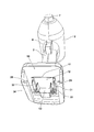
- FIG. 1 is a perspective view of a power tool body 1 according to an embodiment of the present invention and a battery pack 100 attached thereto. It is a perspective view of the battery pack 100 single body of FIG.
- FIG. 2 is a perspective view of the power tool body 1 of FIG. 1 viewed from below.
- FIG. 4 is a development view showing a connection state between a connection terminal of the electric power tool body 1 and a connection terminal of the battery pack 100.
- FIG. 3 is a block diagram for explaining the operation principle of the battery pack 100 of FIG. 1.
- 3 is a circuit diagram of the power tool body 1 and the battery pack 100.
- FIG. 3 is a circuit diagram of a charger 200 and a battery pack 100.
- FIG. 3 is a diagram showing an operation of a trigger switch 4 of the electric tool main body 1, an on / off state of a power source of the electric power tool main body 1, and an operation timing of a switching element 171.
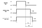
- 6 is a diagram showing the operation of the remaining amount check switch 161 of the battery pack 100 and the operation timing of the remaining amount display circuit 164 and the switching element 171.
- FIG. 1 is a perspective view for explaining a conventional low-power electric power tool body 1 and a conventional battery pack 100 mounting method.
- the electric power tool is composed of the electric power tool main body 1 and the battery pack 100 attached to the electric power tool main body 1, and drives a tip tool (not shown) or a working device (not shown) by using the rotational driving force of the motor.
- the electric tool main body 1 includes a housing 2 which is an outer frame forming an outer shape, a handle portion 3 is formed in the housing 2, and a trigger switch 4 operated by an operator is provided near the upper end of the handle portion 3.
- a tip tool mounting portion 7 is provided at the tip of the body portion of the housing 2. Below the handle portion 3, a battery pack mounting portion 10 for mounting the battery pack 100 is formed.
- the battery pack 100 can be attached to the power tool body 1 by moving it in the direction of arrow 8. Rail grooves 146 and 148 (148 are not visible in FIG. 1) are formed on both left and right sides of the battery pack 100.
- Rail grooves 146 and 148 (148 are not visible in FIG. 1) are formed on both left and right sides of the battery pack 100.
- the latch mechanism is formed in the upper rear part of the battery pack 100, in the center when viewed in the left-right direction, one large latch button 135 is provided in the left-right center, and a latch claw 136 that moves in conjunction with the latch button 135 is located from the front side to the upper side. Project to.
- the battery pack 100 When the battery pack 100 is attached to the power tool body 1, the battery pack 100 can be removed from the power tool body 1 by pressing the latch button 135 and then moving the battery pack 100 relatively in the direction opposite to the arrow 8. it can.
- the battery pack 100 accommodates a plurality of cylindrical battery cells (not visible in the figure) inside a housing 101 made of synthetic resin, and a plurality of battery cells are connected in series to have a predetermined rated voltage. You are getting the output. For example, a plurality of, for example, 10 lithium ion battery cells having a rating of 3.6V can be connected to obtain an output of 36V.
- FIG. 2 is a perspective view of the battery pack 100 according to the first embodiment of the present invention.
- the battery pack 100 is formed of a separable housing 101 made of synthetic resin, a flat lower step surface 112 is formed on the upper side of the housing 101, and an upper step surface 114 formed higher than the lower step surface 112 is formed near the center. To be done.
- a connecting portion between the lower surface 112 and the upper surface 114 is formed in a step shape, and a slot group for inserting a device-side terminal is arranged in the step portion.
- the slot group is formed with a large positive electrode terminal slot 121 and a negative electrode terminal slot 122 such as a notch that is long in the front-rear direction, and an LD terminal slot 123 and a D terminal slot 124 that are about half the length thereof. ..
- a large positive electrode terminal slot 121 and a negative electrode terminal slot 122 such as a notch that is long in the front-rear direction
- an LD terminal slot 123 and a D terminal slot 124 that are about half the length thereof. ..
- two connection terminal sets (described later in FIG. 3) that can be fitted to the device side terminals on the electric tool main body 1 side are provided.
- Only four slots are provided here, it is also possible to further provide slots and arrange the connection terminals therein, or to arrange the connection connector between the slots 123 and 124. It may be done.
- Rail grooves 146 and 148 are formed on the right side wall 147 and the left side wall 149 of the upper surface 114.
- the rail groove 146 is a recess recessed inward from the right side wall 147
- the rail groove 148 is a recess recessed inward from the left side wall 149.
- a raised portion 115 that curves upward is provided on the rear side of the upper step surface 114, and a latch button 135 is provided on the rear side surface thereof. When the latch button 135 is pushed in downward, the latch claw 136 also moves in conjunction with it.
- FIG. 3 is a perspective view of the power tool body 1 of FIG. 1 viewed from below.
- Rails 26, 28 extending parallel to the front-rear direction are formed on inner wall portions on both left and right sides of the battery pack mounting portion 10 (device-side battery pack mounting portion) of the power tool body 1 and are surrounded by the left and right rails 26, 28.
- the terminal portion 11 is provided in the space portion.
- the terminal portion 11 is manufactured by integrally molding a non-conductive material such as synthetic resin, and has a vertical surface 13 serving as an abutting surface in the mounting direction (front-back direction) and a horizontal surface 12 extending horizontally.
- the upper surface 114 and the upper surface 114 face each other.
- the terminal portion 11 is provided with a plurality of metal terminals, for example, a positive electrode input terminal 31, a negative electrode input terminal 32, an LD terminal (discharge permission signal terminal) 33, and a D terminal 34 (control signal terminal).
- the positive electrode input terminal 31 and the negative electrode input terminal 32 are formed of a metal flat plate and have a long shape in the mounting direction.
- the LD terminal 33 and the D terminal 34 are formed by a flat metal short plate.
- FIG. 4 is a perspective view showing a connection state between the connection terminals of the electric tool main body 1 and the connection terminals of the battery pack 100.
- two positive electrode output terminals 131 and 141 are arranged side by side in the mounting direction (front-back direction).
- two negative electrode output terminals 132 and 142 are arranged side by side in the mounting direction inside the slot 122 (see FIG. 2).
- the reason why two terminals are used is to eliminate poor contact with the connection terminals used on the electric tool main body 1 side and the external charger.
- the positive electrode output terminals 131 and 141 are arranged in a non-contact state in the slot 121 with a predetermined distance therebetween, and these are electrically connected by wiring.
- the negative electrode output terminals 132 and 142 are arranged in a non-contact state in the slot 122 with a predetermined distance therebetween, and these are electrically connected by wiring.
- the battery pack 100 accommodates two battery cell groups connected in series, that is, cell units 180 and 190, and the cell units 180 and 190 are connected in series.
- a rechargeable secondary battery is used as the battery cells forming the cell units 180 and 190, and is, for example, a lithium ion battery having a rated voltage of 3.6V. Therefore, the DC power having the rated voltage of 36 V is supplied between the positive electrode terminal (131, 141) and the negative electrode terminal (132, 142).
- the connection terminal group of the electric power tool body 1 includes a positive electrode input terminal 31 and a negative electrode input terminal 32.
- the DC power supplied from the battery pack 100 via the positive electrode input terminal 31 and the negative electrode input terminal 32 is supplied to the motor 5 via the trigger switch 4.
- FIG. 4 a circuit in which the main body side connection terminals (31, 32) and the motor 5 are directly connected is shown in FIG. 4 for ease of explanation, the motor 5 is driven via an inverter circuit (not shown).
- the configuration on the power tool body side is arbitrary.
- the connection terminals (31, 32) of the power tool body 1 are relatively moved as indicated by a dotted arrow, the connection terminals are inserted between the connection terminal groups (131 and 141, 132 and 142) of the battery pack 100. , An electrical connection state is established.
- the positive electrode input terminal 31 is a metal plate material bent in a crank shape, and is formed with a sufficient length so as to be fitted simultaneously with the positive electrode output terminal 131 on the front side and the positive electrode output terminal 141 on the rear side.
- the negative electrode input terminal 32 is a metal plate material bent in a crank shape, and is formed with a sufficient length so that the negative electrode output terminal 132 on the front side and the negative electrode output terminal 142 on the rear side can be simultaneously fitted. ..
- the positive electrode input terminal 31 and the negative electrode input terminal 32 are arranged so as to be plane-symmetrical, and the crank-shaped bent portion is held by being cast into the terminal portion 11 (see FIG. 3) made of synthetic resin. It The rear ends of the positive electrode input terminal 31 and the negative electrode input terminal 32 are soldered to the wiring to the motor 5 side.
- the positive electrode output terminals 131 and 141 and the negative electrode output terminals 132 and 142 have an inverted ⁇ shape when viewed from the main body side connection terminal insertion direction (direction indicated by a dotted arrow), and common parts are used for these.
- a rectangular flat plate portion 142a for fixing to a circuit board (not shown) in the battery pack 100 is formed, and the flat plate portion 142a is soldered or screwed (not shown) to the circuit board.
- Two arm portions 142b that are bent from the left and right ends of the flat plate portion 142a are formed upward from the left and right sides of the flat plate portion 142a.
- the two arm portions 142b are bent so that they approach each other as they go upward, and a terminal portion 142c is arranged at the upper end of the arm portion 142b.
- the terminal portion 142c is a substantially rectangular electrode in which the left and right terminal portions 142c are held in a non-contact state at a predetermined interval so as to be parallel to each other, and the front and rear sides thereof are separated from the opposing contact terminal portions.
- the main body side connection terminal is shaped so that it can be easily fitted from the front to the rear.
- the latch claw 136 When the latch claw 136 is inserted to a position where it comes into contact with the terminal 141, the latch claw 136 fits into a latch groove (not shown) on the battery pack 100 side. The same applies to the fitted state of the negative electrode input terminal 32 and the negative electrode output terminals 132 and 142.
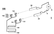
- FIG. 5 is a block diagram for explaining the operation principle of the battery pack 100.
- a total of 10 battery cells are included in the battery pack 100, but here, every 5 cells are combined into one cell unit (battery cell group), and two cell units 180 and 190 are included. Are connected in series.
- the battery cell is, for example, a cylindrical lithium ion battery having a size of 18650, and its rating is 3.6V.
- the switch 170 controllable by the control unit (control circuit) 150 is provided between the negative electrode terminal 180b of the cell unit 180 and the positive electrode terminal 190a of the cell unit 190.
- 5A shows a state of the switch 170 when the battery pack 100 is charged or when power is supplied to the electric device body by discharging.
- the switch 170 is turned on (conducting)
- a DC voltage with a rating of 36 V is output between the positive electrode output terminal 131 and the negative electrode output terminal 132.
- FIG. 5B shows a state in which the battery pack 100 is not attached to the external charger or the electric device main body or is attached to the external device (external charger or electric device main body).
- a state in which the power supply of the control unit is off (in this embodiment, this state is referred to as "normal state") is shown.
- the switch 170 is turned off, and the series connection state of the cell units 180 and 190 is canceled.
- the resistance circuit is provided in parallel with the connection circuit of the cell unit 190 and the switch 170, which is close to the ground potential.
- a resistance R having a large resistance value is provided in the resistance circuit.
- the resistor R is a resistor provided to make the positive electrode potential 180a of the cell unit 180 low when the switch 170 is turned off, and is not the purpose for flowing a substantial current through this resistor circuit.
- the resistance value of the resistor R is set to a sufficiently large value of several hundreds k to several M ⁇ to substantially block the flow of current. Therefore, although the resistance circuit of the resistance R remains connected even when the switch 170 is turned on as shown in FIG. 5 (A), there is substantially no hindrance to the charging / discharging operation of the battery pack.
- the switch 170 electrically connects or disconnects the cell units 180 and 190. Therefore, it can be realized as a device that includes mechanical components (power terminals) such as a relay switch, but if a contact-type switch is used, it is necessary to take measures against wear and sparks, and battery The life and reliability of the pack 100 may be affected. Therefore, in this embodiment, a semiconductor switching element is used as the switch 170. As the semiconductor switching element, for example, a field effect transistor (FET) or an insulated gate bipolar transistor (IGBT) can be used.
- FET field effect transistor
- IGBT insulated gate bipolar transistor
- a signal indicating the operating status of the external device is input to the control unit 150 from the external device (power tool body 1 or charger) via the D terminal (control signal terminal) 134, and the switch 170 is turned on in response to the input signal. Or switch it on. Also, the control unit 150 switches the switch 170 according to the output signal of the voltage check switch unit 160 when an operation button (not shown) of the voltage check switch unit 160 provided in the housing of the battery pack 100 is connected. Switch to the on state.
- the battery pack 100 when the battery pack 100 is not used "in a normal state", that is, when the battery pack 100 is detached from the external device and is in a single state, or when the battery pack 100 is attached, the power source of the electric device body or the external charger is In the OFF state, the series connection state of the cell unit 180 and the cell unit 190 is released by shutting off the switch 170. Therefore, it becomes easy to meet the requirements of transportation regulations. Further, it is possible to effectively suppress the ion migration phenomenon that occurs in the circuit board, the connection terminal, etc. in the battery pack 100.
- FIG. 6 is a detailed circuit diagram of the power tool body 1 and the battery pack 100 of this embodiment.
- the battery pack 100 accommodates two sets of a cell unit 180 arranged on the higher side of the voltage and a cell unit 190 arranged on the lower side, and the negative side output (ground potential 180b) of the cell unit 180 and the cell unit 190.
- a switching element 171 made of a semiconductor is interposed as a switch 170 between the positive electrode side output (positive electrode potential 190a).
- the switching element 171 is a field effect transistor (FET) having a body diode, the source is connected to the ground potential 180b of the cell unit 180, and the drain is connected to the positive potential 190a of the cell unit 190.
- the gate of the switching element 171 is connected to the drain of the switching element 163 which is a switching control unit.
- the control unit 150 includes a switching element 163 that is a switching control unit, a capacitor 172 that is a power storage unit, and a resistor 173.
- the switching element 163 stably switches the gate signal of the switching element 171 based on an external signal input from the D terminal 134.
- the switching element 163 is turned on, so that the positive potential (B +) of the cell unit 180 changes from the switching element 163 to the resistor 173 to the ground potential 180b of the cell unit 180.
- a current circuit is formed, the gate potential of the switching element 171 increases due to the potential difference between the voltages across the resistor 173, and the switching element 171 switches to the conductive state.
- the switching element 171 is turned on, a series-connected power supply circuit of the cell unit 180 and the cell unit 190 is established.
- the signal line 61 or / and the signal line 62 are high ( High voltage), and the signal is converted by a converter (not shown) including a semiconductor switching element (FET), and the D terminal 134 becomes a low signal. Therefore, the switching element 163 is maintained in the on state, and the gate signal of the switching element 171 is also maintained in the high state correspondingly, so that the switching element 171 is maintained in the on state.
- a capacitor 172 is provided in parallel with the resistor 173.
- the capacitor 172 is a delay circuit for keeping the switching element 171 in the ON state for a short period of time after the switching element 163 is switched from ON to OFF.
- the delay circuit can be composed of an electrolytic capacitor and a resistor 173, and the resistor 173 also has a function of consuming electric charge of the gate voltage of the switching element 171.
- the timing at which the switching element 171 is cut off can be delayed from about 1 to several seconds after the switching element 163 is turned off. ..
- the resistor 173 also functions to balance the consumption amounts of the cell unit 180 and the cell unit 190 when the switching element 171 is on, and if the resistance R and the resistance value of the resistor 173 are the same.
- the consumption amounts of the cell unit 180 and the cell unit 190 can be made substantially equal.
- the upper cell unit 180 is formed by connecting battery cells 181 to 185 of five lithium ion batteries and connecting them in series.
- the lower cell unit 190 is formed by connecting battery cells 191 to 195 of five lithium ion batteries and connecting them in series.
- Dedicated battery protection ICs 188 and 198 for protecting the battery cells are connected to the cell units 180 and 190, respectively.
- the battery protection IC 188 executes an overcharge protection function, an overdischarge protection function, as well as a cell balance function, a cascade connection function, and a disconnection detection function by inputting the voltages across the battery cells 181 to 185 of the cell unit 180. It is an integrated circuit which is commercially available as "protection IC for lithium ion battery". In FIG.
- the battery protection IC 188 has a built-in power supply circuit that obtains an operation power supply for the protection IC from the voltage of the cell unit 180. Therefore, one of the power supply terminals (not shown) of the battery protection IC 188 is connected to the positive potential 180a of the cell unit 180, and the other is connected to the ground potential 180b.
- the protection IC 188 grounds the LD signal 187 to the ground potential 180b to reduce the potential of the LD terminal to 0 when the voltage of at least one battery cell of the cell unit 180 falls below a predetermined value and enters an overdischarged state.
- the configuration and operation of the battery protection IC 198 are similar to those of the battery protection IC 188. Since the battery protection IC 198 obtains operating power from the voltage of the cell unit 190, one is connected to the positive potential 190a of the cell unit 190 and the other is grounded to the ground potential 190b. The protection IC 198 grounds the LD signal 197 to the ground potential 190b when the voltage of at least one battery cell of the cell unit 190 drops below a predetermined value and becomes an over-discharged state. Drop to 0.
- the voltage check switch unit 160 includes a switch (operation unit) 161, which is operated by an operator, a switching element 165, and a remaining amount display circuit 164.
- the remaining amount display circuit 164 checks the remaining amount of the battery pack 100 and displays the number of LEDs (not shown) according to the remaining amount. Therefore, a plurality of segment LED display devices and a switch 161 are provided on the side surface of the battery pack 100. When the operator operates the switch 161 to turn it on, as many LEDs as the remaining battery amount are lit during the operation and only for a few seconds after the operation state is canceled.
- the power supply of the remaining amount display circuit is obtained from the positive electrode battery 180a of the cell unit 180 connected in series and the ground potential 190b, and when the switch 161 is turned on, the cell units 180 and 190 are connected in series. In addition, the power is supplied to the circuit for displaying the remaining amount.
- the cell unit 180 and the cell unit 190 are not always connected, so some measures must be taken when checking the combined voltage of both. For example, when the battery pack 100 is removed from the external device (the power tool body 1 or the external charger), the D terminal 134 is in the high impedance state, so the switching element 163 is in the off state and the switching element 171 is also in the off state. is there. Since the combined voltage of the cell units 180 and 190 cannot be measured when the switching element 171 is off, it is necessary to turn on the switching element 171 temporarily when checking the remaining amount. Therefore, the signal line 162 is configured to be low when the switch 161 is turned on (for example, when the push button is pressed).
- a circuit for making the signal line 162 low by operating the switch 161 may be configured so that the signal line 162 is connected to the ground potential 190b when the switch 161 is operated, for example (detailed circuit description is omitted). ..
- a gate signal (low signal) having a predetermined voltage is input from the switch 161 through the signal line 162, the switching element 163 is turned on and the switching element 171 is also turned on. Then, since the cell units 180 and 190 are directly connected, the positive electrode potential (B +) 180a applied to the source terminal of the switching element 165 becomes a combined voltage of the cell units 180 and 190.
- the switching element 165 since the switching element 165 is turned on (conduction between the source and the drain) by the signal line 162 from the switch 161, the remaining amount display circuit 164 operates and the LED according to the positive electrode potential (B +) 180a and the ground potential 190b. The remaining amount is displayed by a display device (not shown). When the operation (depression) of the switch 161 is released, the switching element 163 is turned off, so that the gate voltage of the switching element 171 decreases.
- the delay circuit including the capacitor 172 and the resistor 173 can be used to continuously display a certain amount of time after the remaining amount display is turned off when the remaining amount display switch 161 is turned off, the switch can be used. The switching element 171 is turned off after a delay of several seconds occurs after the switch 161 is turned off.
- the power tool body 1 includes a power supply circuit 45.
- the power supply circuit 45 generates a reference voltage VDD that serves as an operating power supply for the control unit (device-side control unit) 50 of the power tool body 1.
- One terminal of the power supply circuit 45 is connected to the positive electrode input terminal 31 via the semiconductor switching element 43, and the other terminal is connected to the ground potential.
- the control unit 50 includes a microcomputer 51, and the microcomputer 51 monitors and controls various states in the power tool body 1.
- a DC motor 5 is provided in the power supply path between the positive input terminal 31 and the negative input terminal 32, and a trigger switch for turning on or off the rotation of the motor 5 is provided in the circuit. 4 are provided.
- a semiconductor switching element 41 and a shunt resistor 42 are inserted between the motor 5 and the negative electrode input terminal 32.
- the switching element 41 is, for example, a field effect transistor (FET), and its gate signal 63 is sent out by the microcomputer 51.
- FET field effect transistor
- the voltage across the shunt resistor 42 is input to the control unit 50 by the signal line 64 and detected by the microcomputer 51.
- the motor 5 is shown as a DC motor with a brush, but a known inverter circuit may be used to drive the three-phase brushless motor.
- An intermediate point between the positive electrode side of the motor 5 and the trigger switch 4 is connected to the D terminal 34 via a signal line 61 and a converter (not shown). Therefore, when the trigger switch 4 is pulled (turned on), the input voltage (high signal) of the positive input terminal 31 is applied to the converter (not shown). This input voltage is converted into a low signal by the converter, and a signal (low signal) indicating that the trigger switch 4 has been operated is input to the D terminal 34. When the trigger switch 4 is returned (turned off), the voltage of the signal line 61 becomes 0, so that the conversion section does not perform the conversion operation and the output side (D terminal 34) thereof is opened.
- a conversion unit provided on the input side of the switching element 43 with a device power ON signal (for example, a high signal of 5V or 3.3V) for keeping the power circuit 45 ON from the control unit 50 via the signal line 62. (Not shown).
- the conversion unit converts the signal level of the device power ON signal into a low signal, and the low signal is input to the switching element 43. Therefore, a signal (low signal) indicating that the trigger switch is on is input to the D terminal 34 when the trigger switch 4 is on, and the device power is on when the trigger switch 4 is off and the control unit 50 is running. A signal (low signal) is input.
- the device power-on signal (high signal) on the signal line 62 disappears to zero potential, and the D terminal 34 opens. From the above, by monitoring the signal level of the D terminal 134 on the battery pack 100 side, whether or not the power tool body 1 side is connected (whether the trigger switch 4 is operated) and whether it is connected or not. It is possible to easily determine whether the electric device body 1 is activated or shut down.
- the LD terminal 33 is connected to the LD terminal 133 of the battery pack 100, and the “abnormal signal” sent from the battery pack 100 is input to the control unit 50 via the LD terminal 33.
- a signal indicating whether to permit (or limit) or permit discharge from the battery pack 100 is used as the “abnormal signal”.
- the control unit 50 detects this change in the potential, sets the gate signal 63 of the switching element 41 to low to turn off the switching element 41, and supplies power to the motor 5. Stop.
- the control unit 50 does not perform stop control at the time of over-discharging based on a signal from the LD terminal of the battery pack 100, but measures the voltage between the positive electrode input terminal 31 and the negative electrode input terminal 32 in the electric tool body 1. It is also possible to provide a voltage detection circuit for performing such control and perform stop control at the time of overdischarge based on the detection value of the voltage detection circuit.
- the output of the motor 5 may be limited by controlling the on / off of the switching element 41 (known duty control) without shutting off the switching element 41 due to the disappearance of the discharge permission signal from the LD terminal.
- the control unit 50 not only monitors the voltage of the battery pack 100, but also monitors the current flowing through the motor 5, and particularly monitors the overcurrent.
- the current detection is performed by the control unit 50 by measuring the voltage across the shunt resistor 42.
- the battery pack 100 side may monitor the overcurrent, but the battery pack side overcurrent monitoring sets an average control condition (overcurrent threshold) that can be applied to a plurality of power tool bodies. Since there is no choice but to do so, it is preferable that the control unit 50 on the electric tool main body 1 side monitors the overcurrent.
- optimum control conditions higher threshold value of overcurrent
- the temperature of the motor 5 and the switching element 41 may be monitored by the control unit 50.
- a temperature sensor for example, a thermistor
- a component motor 5, switching element 41, etc.
- the switching element 41 may be controlled based on the temperature detected by the temperature sensor.
- the remaining battery level can be displayed by checking the combined voltage of the cell units 180 and 190 of the battery pack 100. Further, since the same two battery protection ICs 188 and 189 are used and the voltage check is performed using both the cell units 180 and 190 when checking the battery remaining amount, the cell units 180 and 190 consume almost the same amount.
- the LED display device (not shown) for displaying the remaining amount is turned off with a delay even after the operation of the switch 161 for remaining amount check is released, the battery pack 100 which is easy to use can be realized.
- FIG. 7 is a circuit diagram of the charger 200 and the battery pack 100 of this embodiment.
- the operation on the battery pack 100 side is the same as in FIG. That is, in the battery pack 100, when a predetermined signal (for example, a low signal) is input from the charger 200 via the D terminal 134, the switching elements 163 and 171 are turned on (conducting), and the cell units 180 and 190. Can be charged.
- a predetermined signal for example, a low signal
- the battery protection IC 188 or 198 A signal (for example, a high signal) indicating overcharge is transmitted to the control unit 250 via the LD terminals 133 and 233.
- a thermistor for detecting the temperatures of the battery cells 181 to 185 and 191 to 195 is arranged in the battery pack 100, and the output thereof is output to the controller 250 of the charger. Also good.
- the charger 200 is mainly configured by the main switch 204, the charging circuit 260, and the control unit 250.
- the control unit 250 manages the charging operation and includes a microcomputer 251.
- the microcomputer 251 executes a program that executes a known charging method such as a constant current constant voltage charging (CCCV) method that manages voltage and current, and controls the charging circuit 260 connected by the signal line 253.
- the charging circuit 260 provides a DC voltage and a DC current for charging a series connection set of 10 lithium ion battery cells using a commercial power supply of AC 100V to 240V by a power cord (not shown).
- a known circuit in which both charging currents can be adjusted by a microcomputer is used.
- the charging voltage and the charging current can be set according to the number of battery cells of the connected battery pack so that battery packs other than 10 battery cells can be charged.
- the main switch 204 can be turned on or off by the microcomputer 251.
- a constant power supply circuit for generating a DC power supply (for example, 3.3V or 5V) for operating the control unit 250 from a commercial power supply is provided, and a power supply cord (not shown) of the charger 200 is provided.
- a commercial power outlet not shown
- the charge ON signal 254 is set to high level. Then, the charging ON signal 254 is converted to a low level (low signal) via a conversion unit (not shown) provided on the input side of the D terminal 234, and the low signal is output to the D terminal 234. Then, a signal of a predetermined level (low signal) is input to the gate terminal of the switching element 163 via the D terminals 234 and 134, so that the switching element 163 becomes conductive, and the switching element 171 is also turned on (conductive). As a result, the cell units 180 and 190 are connected in series, and the total voltage of the cell units 180 and 190 is output between the positive electrode output terminal 131 and the negative electrode output terminal 132.
- the control unit 250 measures the voltage of the battery pack 100 through the signal line 255 to detect that the battery pack 100 has been attached and that the battery pack 100 is in a state to be charged, and then through the signal line 252. By turning on the main switch 204, the charging operation using the charging circuit 260 is started.
- the microcomputer 251 monitors the charging current by monitoring the voltage across the shunt resistor 261 on the signal line 262 (in the figure, two wires are bundled, but actually two wires).
- the known constant current constant voltage charging method is performed based on the voltage of the battery pack 100 measured by the microcomputer 251 on the signal line 255 and the signal line 262 and the current value during charging. That is, charging is performed by constant current control until the voltage of the battery pack 100 reaches a predetermined voltage, and then the charging current is flowed by the constant voltage control so as to maintain the predetermined voltage, and the charging current has a predetermined current value. When it reaches less than, you can stop charging. Further, the charging can be stopped based on the signals from the LD terminals 233 and 133. A signal indicating discharge permission is input to the LD terminal 233 from the battery pack 100, and is input to the microcomputer 251 of the control unit 250 via the signal line 256.
- the microcomputer 251 detects the potential drop and the control unit 250 turns off the main switch 204 to stop the charging by the charging circuit 260.
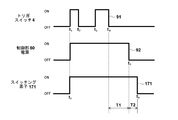
- FIG. 8 is a diagram showing the operation status 91 of the trigger switch 4 of the electric tool main body 1, the operation timing of the power supply of the control unit 50 of the electric tool main body 1, and the operation timing of the switching element 171.
- the battery voltage high signal
- the conversion unit converts the signal level into a low signal. Since a predetermined signal (low signal) is input to the gate terminal of the switching element 43 from, the power supply circuit 45 (see FIG. 6) is turned on as indicated by the operation timing 92.
- the control unit 50 see FIG.
- the control unit 50 outputs a high level signal (for example, a voltage of 3.3V) via the signal line 62.
- a high signal is converted into a low signal by a converter (not shown), and the low signal is output to the D terminal 34.
- the D terminal 134 of the battery pack 100 becomes low level, so that the switching element 163 is turned on and the switching element 171 is also turned on.
- the switching element 171 When the switching element 171 is turned on, the cell units 180 and 190 are connected in series, and a DC voltage having a rating of 36 V is output to the positive electrode output terminal 131 and the negative electrode output terminal 132 of the battery pack 100.
- the switching element 171 is not turned on when the trigger switch 4 is first pulled, in the present embodiment, the upper cell unit 180 is connected to the ground potential 190b via the resistance circuit (resistor R). Therefore, a voltage of 18 V can be supplied between the positive electrode output terminal 131 and the negative electrode output terminal 132.
- resistor R resistance circuit
- the power supply circuit 45 of the power tool body 1 is activated, even if the control unit 50 turns off the trigger switch 4 by the self-holding function, the operating state of the power supply circuit 45 is maintained for a certain period of time (eg, 10 minutes) thereafter. Maintained. Therefore, the trigger switch 4 at time t 2 is even when the trigger switch 4 again at time t 3 is turned off is drawn, the switching element 171 is kept turned on. At time t 4 the trigger switch 4 is returned (turned off), if subsequent free operation of the trigger switch 4 is, at time t 5 after the elapse of a predetermined time T1, the power supply circuit 45 of the power tool main body 1 is turned off.
- a certain period of time eg, 10 minutes
- the switching element 171 Since the switching element 171 is provided with the storage circuit of the capacitor 172 on the gate side, even if the gate signal of the switching element 171 (the drain output of the switching element 163) disappears, the switching element 171 is turned on by the capacitor 172 only for the time T2. Is maintained, and the switching element 171 is turned off at time t 6 .
- FIG. 9 is a diagram showing an operation 162 of the remaining amount check switch 161 of the battery pack 100 and operation timings of the remaining amount display circuit 164 and the switching element 171.
- the remaining amount display circuit 164 is turned on, the switching element 163 is turned on, and the switching element 173 is also turned on.
- the switching element 171 is turned on, the cell units 180 and 190 are connected in series, the remaining amount according to the total voltage of the cell units 180 and 190 is displayed, and is displayed until time t 13 .
- the remaining amount checking switch 161 at time t 12 is returned (turned off) will be not immediately turn off to the returned time t 12, the predetermined time T3 has elapsed continue the remaining amount display up to time t 13.
- the display is displayed for the time T3 or more, so that a power checker that is easy to see can be realized.
- the remaining amount checking switch 161 at time t 12 is turned off, because the power storage circuit is provided by capacitor 172 to the gate of the switching element 171, the capacitor 172 from the drain output of the switching element 163 is lost until the accumulated charge is lost, is maintained oN state of the switching device 171 by the time T4, the switching element 171 is turned off at time t 14.
- the battery pack 100 in the battery pack 100, a mechanism is realized in which each cell unit is connected during operation and the cell units 180 and 190 are electrically separated during non-operation.
- the number of battery cells connected in series can be increased, and in realizing the battery pack 100 having a higher voltage than before, it can be configured to satisfy the restriction of transportation regulation. Further, since the risk of ion migration of the circuit board in the battery pack 100 can be reduced, the battery pack 100 having high reliability and long life can be realized.
- the main device side is not limited to the electric power tool, and may be any electric device as long as it is a device that operates the battery pack as a main power source or an auxiliary power source.
- an additional switch means such as an FET is provided between the resistor R and the ground potential 190b so that the switching element 171 is turned on.
- the additional switch means may be turned off in conjunction with In this case, the resistance circuit formed by the resistor R disconnects the parallel connection with the cell unit 190 during charging and discharging.
- SYMBOLS 1 Electric tool main body, 2 ... Housing, 3 ... Handle part, 4 ... Trigger switch, 5 ... Motor, 7 ... Tip tool mounting part, 8 ... (Battery pack) mounting direction, 10 ... Battery pack mounting part, 11 ... Terminal part, 12 ... Horizontal surface, 13 ... Vertical surface, 26, 28 ... Rail, 31 ... Positive electrode input terminal, 32 ... Negative electrode input terminal, 33 ... LD terminal, 34 ... D terminal, 41 ... Switching element, 42 ... Shunt resistor, 43 ... Switching element, 45 ... Power supply circuit, 50 ... Control part, 61, 62 ... Signal line, 63 ... Gate signal, 64 ... Signal line, 100 ...
- Battery pack 101 ... Housing, 112 ... Lower surface, 114 ... Upper surface , 115 ... Protuberances, 121 ... Positive electrode terminal slots, 122 ... Negative electrode terminal slots, 123 ... LD terminal slots, 124 ... D terminal slots, 131 ... Positive electrode output terminals, 1 2 ... Negative output terminal, 133 ... LD terminal, 134 ... D terminal, 135 ... Latch button, 136 ... Latch claw, 141 ... Positive electrode output terminal, 142 ... Negative output terminal, 142a ... Flat plate part, 142b ... Arm part, 142c ... Terminal part, 146, 148 ... Rail groove, 147 ... Right side wall, 149 ... Left side wall, 150 ...
Abstract
The purpose of the present invention is to obtain a battery pack which is adapted to transport regulations and capable of providing high output. The battery pack is provided with cell units 180 and 190, a switching element 171 connected in series between the cell units, and a control circuit (switching element 163) for operating the switching element 171. The battery pack is configured such that, when not in operation, the cell units 180 and 190 are electrically separated from each other. When an external apparatus power supply signal has been transmitted via a D-terminal 134, the control circuit causes the switching element 171 to conduct, whereby a voltage of the series connection of the cell units 180 and 190 is output to a positive-pole output terminal 133 and a negative-pole output terminal 134. When the external apparatus power supply signal is lost, the switching element 171 is shut down after a short time of delay due to a capacitor 172.
Description
本発明はモータ、照明等の負荷を有する電気機器に対して電源を供給する電池パックと、それを用いた電気機器に関する。
The present invention relates to a battery pack that supplies power to an electric device having a load such as a motor and lighting, and an electric device using the battery pack.
様々な電気機器が、リチウムイオン電池等の二次電池を用いた電池パックにて駆動されるようになり、電気機器のコードレス化が進んでいる。例えば、モータにより先端工具を駆動する手持ち式の電動工具においては、複数の二次電池セルを収容した電池パックが用いられ、電池パックに蓄電された電気エネルギーにてモータを駆動する。電池パックは電動工具本体に着脱可能に構成され、放電によって電圧が低下したら電池パックを電動工具本体から取り外して、外部充電器を用いて充電される。
Various electric devices have come to be driven by a battery pack using a secondary battery such as a lithium ion battery, and cordless electric devices have been developed. For example, in a hand-held power tool in which a tip tool is driven by a motor, a battery pack containing a plurality of secondary battery cells is used, and the motor is driven by electric energy stored in the battery pack. The battery pack is configured to be attachable / detachable to / from the power tool main body, and when the voltage drops due to discharge, the battery pack is removed from the power tool main body and charged by using an external charger.
コードレス型の電動工具等の電気機器においては所定の稼働時間の確保や、所定の出力の確保が要求され、二次電池の性能向上に伴い高出力化や高電圧化が図られてきた。また、電池パックを電源とする様々な電気機器が開発されるにつれ、電圧の異なる電池パック群が商品化されるようになった。一般的に、特許文献1に記載のように、電池パックには二次電池の状態を監視するための保護ICが設けられている。また、通常、電池パックの出力電圧は固定であるが、特許文献2では、複数のセルユニット間にスイッチング素子を配置し、セルユニットを直列接続と並列接続に切り替えて2つの電圧を出力することを可能にしている。
In electrical equipment such as a cordless type power tool, it is required to secure a predetermined operating time and a predetermined output, and higher output and higher voltage have been achieved along with the performance improvement of the secondary battery. Further, as various electric devices using a battery pack as a power source have been developed, battery pack groups having different voltages have been commercialized. Generally, as described in Patent Document 1, the battery pack is provided with a protection IC for monitoring the state of the secondary battery. Moreover, although the output voltage of the battery pack is usually fixed, in Patent Document 2, a switching element is arranged between a plurality of cell units, and the cell units are switched between series connection and parallel connection to output two voltages. Is possible.
特許文献2のように複数のセルユニットを収容する電池パックを用いる場合は、高電圧の出力を可能とするが、輸送に関する規制(以下、「輸送規制」と称する)を受けることが考えられる。輸送に関する規制は、複数のリチウムイオン電池等を用いた電池パックにおいて、互いに接続されたリチウムイオン電池等の電力容量の合計が所定の値を超える場合に、輸送に際して特別な措置(ショートの防止措置等)を講ずることを規則づけたものである。よって、電池パック単体、又は電池パック付きの電気機器を輸送する際に、電池パックに収容された複数のリチウムイオン電池等の相互の接続を遮断するように何らかの工夫が必要となる。
When a battery pack containing a plurality of cell units is used as in Patent Document 2, it is possible to output a high voltage, but it is conceivable that there will be restrictions on transportation (hereinafter referred to as “transportation restrictions”). Regarding transportation regulations, in the case of a battery pack that uses multiple lithium-ion batteries, etc., if the total power capacity of the lithium-ion batteries that are connected to each other exceeds a specified value, special measures should be taken for transportation (short-circuit prevention measures). Etc.) is taken as a rule. Therefore, when transporting a single battery pack or an electric device with a battery pack, some kind of device is required to cut off the mutual connection of a plurality of lithium ion batteries accommodated in the battery pack.
別の問題として、高電圧が印加されている状態で電池パックを放置すると、電極に使用されている金属が溶け出したり、溶け出した成分が再び金属として生成されるというイオンマイグレーション現象が発生したりすることによって、プリント基板の電極間の短絡による故障を発生させる虞がある。この現象は、印加電圧が大きく印加時間が長いほど発生するリスクが高くなる。
Another problem is that if the battery pack is left in a state where a high voltage is applied, the metal used in the electrodes will melt out, or the melted components will be generated again as a metal. This may cause a failure due to a short circuit between the electrodes of the printed circuit board. The higher the applied voltage and the longer the applied time, the higher the risk of this phenomenon occurring.
本発明は上記背景に鑑みてなされたものであって、本発明の目的は輸送規制に適合させつつ高出力可能な電池パック及びそれを用いた電気機器を提供することにある。本発明の他の目的は、複数のセルユニットを収容した電池パックにおいて、放電も充電も行われていない状態において、複数のセルユニットを電気的に遮断するようにした電池パック及びそれを用いた電気機器を提供することにある。本発明のさらに他の目的は、セルユニット毎に電池の充放電が制御される電池パックにおいて、制御回路の動作のために各セルユニットの電圧バランスが崩れることを回避できるようにした電池パック及びそれを用いた電気機器を提供することにある。
The present invention has been made in view of the above background, and an object of the present invention is to provide a battery pack capable of high output while conforming to transportation regulations and an electric device using the same. Another object of the present invention is to use a battery pack containing a plurality of cell units, which is configured to electrically shut off a plurality of cell units in a state where neither discharging nor charging is performed, and a battery pack using the same. To provide electrical equipment. Still another object of the present invention is to provide a battery pack in which charging / discharging of the battery is controlled for each cell unit, and a battery pack capable of avoiding the voltage balance of each cell unit being destroyed due to the operation of the control circuit, and It is to provide an electric device using the same.
本願において開示される発明のうち代表的な特徴を説明すれば次のとおりである。本発明の一つの特徴によれば、第1のセルユニットと、第2のセルユニットと、それらの間に直列に接続されるスイッチング素子と、スイッチング素子を動作させる制御部を備え、常態(非稼働時又は保管時)において第1及び第2のセルユニットは互いに電気的に分離されるように構成された電池パックにおいて、接続された外部機器の動作、すなわち外部機器の電源に連動して制御部がスイッチング素子を導通させることで第1のセルユニットと第2のセルユニットを直列接続する。また、外部機器の電源がオフになった際に、制御部はスイッチング素子を遮断させて第1のセルユニットと第2のセルユニットを電気的に分離する。例えば、電池パックに接続された外部機器が起動すると、電池パック側の制御部がスイッチング素子を導通させることによって、第1のセルユニットと第2のセルユニットの直列接続回路が確立される。
Typical features of the invention disclosed in the present application will be described below. According to one feature of the present invention, a first cell unit, a second cell unit, a switching element connected in series between them, and a control unit for operating the switching element are provided, and In a battery pack configured such that the first and second cell units are electrically separated from each other during operation or storage), the operation of the connected external device, that is, the power supply of the external device, is controlled. The section electrically connects the switching element to connect the first cell unit and the second cell unit in series. Further, when the power of the external device is turned off, the control unit shuts off the switching element to electrically separate the first cell unit and the second cell unit. For example, when an external device connected to the battery pack is activated, the control unit on the battery pack side turns on the switching element, thereby establishing a series connection circuit of the first cell unit and the second cell unit.
本発明の他の特徴によれば、第1のセルユニットは正極出力端子に近い側に配置され、第2のセルユニットは負極出力端子に近い側に配置され、第1のセルユニットの負極と負極出力端子の間は、高抵抗値の抵抗回路によって接続される。抵抗回路は抵抗器を含んで構成され、スイッチング素子と第1のセルユニットの中間点と負極出力端子を接続するものである。つまり、第2のセルユニットと抵抗回路は並列接続の関係となる。また、スイッチング素子の制御入力側に蓄電手段を設け、制御部から入力された制御信号が消失した後に制御信号を一定時間保持することによりスイッチング素子の遮断を遅らせるように構成した。スイッチング素子は電界効果トランジスタであって、電界効果トランジスタのソース-ドレインが、第1のセルユニットと第2のセルユニットの間に設けられる。蓄電手段は、スイッチング素子のゲート端子側に接続された抵抗及びコンデンサによって構成できる。
According to another feature of the present invention, the first cell unit is arranged on the side closer to the positive electrode output terminal, the second cell unit is arranged on the side closer to the negative electrode output terminal, and the second cell unit is arranged on the side closer to the negative electrode of the first cell unit. The negative output terminals are connected by a resistance circuit having a high resistance value. The resistance circuit includes a resistor and connects the switching element, the intermediate point of the first cell unit, and the negative output terminal. That is, the second cell unit and the resistance circuit are connected in parallel. Further, a storage means is provided on the control input side of the switching element, and after the control signal input from the control unit disappears, the control signal is held for a certain period of time to delay the switching off of the switching element. The switching element is a field effect transistor, and the source-drain of the field effect transistor is provided between the first cell unit and the second cell unit. The power storage means can be composed of a resistor and a capacitor connected to the gate terminal side of the switching element.
本発明のさらに他の特徴によれば、電池パックの残量を表示する表示部と、表示部への表示を指示するために操作者によって入力される操作部を備え、作業者によって操作部が操作されたら、制御部はスイッチング素子を導通させて第1のセルユニットと第2のセルユニットの合成電圧を測定し、電池残量を表示する。また、制御部は操作部による操作が解除されたら、スイッチング素子を遮断させる。このように、互いに直列接続可能な第1のセルユニットと第2のセルユニットとを有し、常態において第1及び第2のセルユニットは互いに分離されるように構成された電池パックにおいて、電池パックの残量を表示する表示部と、表示部に表示させるために操作される操作部とを備え、操作部が操作されると第1及び第2のセルユニットが直列接続されるように構成した。以上の様に電池パックを構成することによって、電池パックを装着する電池パック装着部と、スイッチング素子を制御するための電源信号を電池パックに出力する機器側制御部を有し、電池パックからの電力により打撃機構部等の作業機器を稼働させる電気機器を実現した。
According to still another feature of the present invention, a display unit that displays the remaining amount of the battery pack and an operation unit that is input by the operator to instruct the display on the display unit are provided, and the operation unit is operated by the operator. When operated, the control unit turns on the switching element, measures the combined voltage of the first cell unit and the second cell unit, and displays the remaining battery level. Further, the control unit shuts off the switching element when the operation by the operation unit is released. As described above, in the battery pack having the first cell unit and the second cell unit that can be connected in series to each other, and the first and second cell units are normally separated from each other, A display unit that displays the remaining amount of the pack and an operation unit that is operated to display the remaining amount of the pack are provided, and when the operation unit is operated, the first and second cell units are connected in series. did. By configuring the battery pack as described above, it has a battery pack mounting part for mounting the battery pack and a device side control part for outputting a power supply signal for controlling the switching element to the battery pack. We have realized electrical equipment that operates working equipment such as the striking mechanism with electric power.
本発明によれば、電池パックが取り外されている時又は非稼働状態にある時には、複数のセルユニットが互いに電気的に非接触状態とされるので、輸送規制による制約を満たすことが可能となる。また、複数のセルユニットのそれぞれに付随する負荷回路や、複数のセルユニットを直列接続するための切り替え回路による消費電力によって、セルユニット間の電圧のアンバランスを防ぐことが可能となった。この結果、長期の使用に伴うセルユニット間の電圧差が生じることを抑制できるので、高寿命で使いやすい電池パックを実現できた。さらに、電池パック側に残量チェック機能が設けられ、その残量は、片側のセルユニットの電圧だけで表示されるのではなく、双方のセルユニットの合成電圧に基づいて表示するので精度の高い電圧チェッカー機能を実現できた。
According to the present invention, when the battery pack is removed or in a non-operational state, the plurality of cell units are brought into an electrically non-contact state with each other, so that it is possible to satisfy the restriction due to the transportation regulation. .. In addition, it is possible to prevent the imbalance of the voltage between the cell units by the power consumption by the load circuit associated with each of the cell units and the switching circuit for connecting the cell units in series. As a result, it is possible to suppress a voltage difference between the cell units due to long-term use, so that it is possible to realize a battery pack having a long life and easy to use. Furthermore, the battery pack side is equipped with a remaining capacity check function, and the remaining capacity is displayed not only by the voltage of one cell unit but also by the combined voltage of both cell units, so it is highly accurate. The voltage checker function was realized.
以下、本発明の実施例を図面に基づいて説明する。以下の図において、同一の部分には同一の符号を付し、繰り返しの説明は省略する。本明細書においては、電気機器の一例として電池パックにて動作する電動工具を例示して説明するものとし、電動工具本体の前後左右の方向は図1に示す方向とし、電池パックの単体で見た際の前後左右、上下の方向は、電池パックの装着方向を基準として図1に示す方向であるとして説明する。尚、電池パックの装着方向は、説明の都合上、電動工具本体側を動かさずに電池パック側を移動させる状況を基準とした方向として説明する。
Embodiments of the present invention will be described below with reference to the drawings. In the following drawings, the same parts are designated by the same reference numerals, and repeated description will be omitted. In this specification, an electric tool that operates in a battery pack will be described as an example of an electric device, and the front, rear, left, and right directions of the main body of the electric tool are the directions shown in FIG. The front, rear, left, right, and up and down directions will be described as the directions shown in FIG. 1 with reference to the mounting direction of the battery pack. For convenience of explanation, the mounting direction of the battery pack will be described with reference to the situation in which the battery pack side is moved without moving the power tool body side.
図1は従来の低出力の電動工具本体1と、それに装着される従来の電池パック100の装着方法を説明するための斜視図である。電動工具は、電動工具本体1とそれに装着される電池パック100によって構成され、モータによる回転駆動力を用いて図示しない先端工具や図示しない作業機器を駆動する。電動工具本体1は、外形を形成する外枠たるハウジング2を備え、ハウジング2にはハンドル部3が形成され、ハンドル部3の上端付近には、作業者が操作するトリガスイッチ4が設けられる。ハウジング2の胴体部の先端には、先端工具装着部7が設けられる。ハンドル部3の下方には、電池パック100を装着するための電池パック装着部10が形成される。
FIG. 1 is a perspective view for explaining a conventional low-power electric power tool body 1 and a conventional battery pack 100 mounting method. The electric power tool is composed of the electric power tool main body 1 and the battery pack 100 attached to the electric power tool main body 1, and drives a tip tool (not shown) or a working device (not shown) by using the rotational driving force of the motor. The electric tool main body 1 includes a housing 2 which is an outer frame forming an outer shape, a handle portion 3 is formed in the housing 2, and a trigger switch 4 operated by an operator is provided near the upper end of the handle portion 3. A tip tool mounting portion 7 is provided at the tip of the body portion of the housing 2. Below the handle portion 3, a battery pack mounting portion 10 for mounting the battery pack 100 is formed.
電池パック100は矢印8の方向に移動させることで電動工具本体1に装着できる。電池パック100の左右両側にはレール溝146、148(図1では148は見えない)が形成される。電池パック100が電動工具本体1に装着されるとラッチ機構によって電池パック100が固定される。ラッチ機構は電池パック100の後方の上部、左右方向にみて中央に形成され、1つの大きなラッチボタン135が左右中央に設けられ、ラッチボタン135に連動して移動するラッチ爪136がその前方から上側に突出する。電池パック100が電動工具本体1に装着されている状態では、ラッチボタン135を押してから電池パック100を矢印8と反対方向に相対移動させることで、電池パック100を電動工具本体1から取り外すことができる。電池パック100は、合成樹脂製のハウジング101の内部に複数本の円柱形の電池セル(図では見えない)を収容するものであり、電池セルを複数本直列に接続して所定の定格電圧の出力を得ている。例えば、定格3.6Vのリチウムイオン電池セルを複数、例えば10本接続して36Vの出力を得ることができる。
The battery pack 100 can be attached to the power tool body 1 by moving it in the direction of arrow 8. Rail grooves 146 and 148 (148 are not visible in FIG. 1) are formed on both left and right sides of the battery pack 100. When the battery pack 100 is attached to the power tool body 1, the battery pack 100 is fixed by the latch mechanism. The latch mechanism is formed in the upper rear part of the battery pack 100, in the center when viewed in the left-right direction, one large latch button 135 is provided in the left-right center, and a latch claw 136 that moves in conjunction with the latch button 135 is located from the front side to the upper side. Project to. When the battery pack 100 is attached to the power tool body 1, the battery pack 100 can be removed from the power tool body 1 by pressing the latch button 135 and then moving the battery pack 100 relatively in the direction opposite to the arrow 8. it can. The battery pack 100 accommodates a plurality of cylindrical battery cells (not visible in the figure) inside a housing 101 made of synthetic resin, and a plurality of battery cells are connected in series to have a predetermined rated voltage. You are getting the output. For example, a plurality of, for example, 10 lithium ion battery cells having a rating of 3.6V can be connected to obtain an output of 36V.
図2は本願発明の第一の実施例に係る電池パック100の斜視図である。電池パック100は合成樹脂製の分割可能なハウジング101によって形成され、その上側は、前方側に平らな下段面112が形成され、中央付近は下段面112よりも高く形成された上段面114が形成される。下段面112と上段面114の接続部分は段差状に形成され、段差状部分に機器側端子を挿入するためのスロット群が配置される。スロット群は、前後方向に長い切り欠きのような大きな正極端子用スロット121及び負極端子用スロット122と、それらの半分程度の長さのLD端子用スロット123及びD端子用スロット124が形成される。スロット121、122の内部には、電動工具本体1側の機器側端子と嵌合可能な2つの接続端子組(図3にて後述)が設けられる。尚、ここではスロットが4つだけ設けられているが、さらにスロットを設けて、その内部に接続端子を配置するように構成しても良いし、スロット123と124の間に、接続コネクタを配置するようにしても良い。上段面114の右側側壁147と左側側壁149には、レール溝146、148が形成される。レール溝146は右側側壁147から内側に向けて窪む凹部であり、レール溝148は左側側壁149から内側に向けて窪む凹部である。上段面114の後方側には上方に湾曲する隆起部115が設けられ、その後方側の側面にはラッチボタン135が設けられる。ラッチボタン135を下方向に押し込むとラッチ爪136も連動して下方に移動する。
FIG. 2 is a perspective view of the battery pack 100 according to the first embodiment of the present invention. The battery pack 100 is formed of a separable housing 101 made of synthetic resin, a flat lower step surface 112 is formed on the upper side of the housing 101, and an upper step surface 114 formed higher than the lower step surface 112 is formed near the center. To be done. A connecting portion between the lower surface 112 and the upper surface 114 is formed in a step shape, and a slot group for inserting a device-side terminal is arranged in the step portion. The slot group is formed with a large positive electrode terminal slot 121 and a negative electrode terminal slot 122 such as a notch that is long in the front-rear direction, and an LD terminal slot 123 and a D terminal slot 124 that are about half the length thereof. .. Inside the slots 121 and 122, two connection terminal sets (described later in FIG. 3) that can be fitted to the device side terminals on the electric tool main body 1 side are provided. Although only four slots are provided here, it is also possible to further provide slots and arrange the connection terminals therein, or to arrange the connection connector between the slots 123 and 124. It may be done. Rail grooves 146 and 148 are formed on the right side wall 147 and the left side wall 149 of the upper surface 114. The rail groove 146 is a recess recessed inward from the right side wall 147, and the rail groove 148 is a recess recessed inward from the left side wall 149. A raised portion 115 that curves upward is provided on the rear side of the upper step surface 114, and a latch button 135 is provided on the rear side surface thereof. When the latch button 135 is pushed in downward, the latch claw 136 also moves in conjunction with it.
図3は図1の電動工具本体1の下から見た斜視図である。電動工具本体1の電池パック装着部10(機器側電池パック装着部)には、左右両側の内壁部分に前後方向に平行に延びるレール26、28が形成され、左右のレール26、28に囲まれる空間部分にターミナル部11が設けられる。ターミナル部11は、合成樹脂等の不導体材料の一体成形により製造され、装着方向(前後方向)の突き当て面となる垂直面13と、水平に延在する水平面12が形成され、水平面12は電池パック100の装着時に、上段面114と近接するようにして対向する面となる。ターミナル部11には金属製の複数の端子、例えば正極入力端子31、負極入力端子32、LD端子(放電許可信号端子)33、D端子34(制御信号端子)が設けられる。正極入力端子31、負極入力端子32は金属の平板にて形成され、装着方向に長い形状とされる。LD端子33、D端子34は金属の短い平板にて形成される。
FIG. 3 is a perspective view of the power tool body 1 of FIG. 1 viewed from below. Rails 26, 28 extending parallel to the front-rear direction are formed on inner wall portions on both left and right sides of the battery pack mounting portion 10 (device-side battery pack mounting portion) of the power tool body 1 and are surrounded by the left and right rails 26, 28. The terminal portion 11 is provided in the space portion. The terminal portion 11 is manufactured by integrally molding a non-conductive material such as synthetic resin, and has a vertical surface 13 serving as an abutting surface in the mounting direction (front-back direction) and a horizontal surface 12 extending horizontally. When the battery pack 100 is mounted, the upper surface 114 and the upper surface 114 face each other. The terminal portion 11 is provided with a plurality of metal terminals, for example, a positive electrode input terminal 31, a negative electrode input terminal 32, an LD terminal (discharge permission signal terminal) 33, and a D terminal 34 (control signal terminal). The positive electrode input terminal 31 and the negative electrode input terminal 32 are formed of a metal flat plate and have a long shape in the mounting direction. The LD terminal 33 and the D terminal 34 are formed by a flat metal short plate.
図4は、電動工具本体1の接続端子と電池パック100の接続端子との接続状態を示す斜視図である。電池パック100のスロット121(図2参照)の内部には、2つの正極出力端子131、141が装着方向(前後方向)に並べて配置される。同様にしてスロット122(図2参照)の内部には、2つの負極出力端子132、142が装着方向に並べて配置される。それぞれ2つずつの端子を使用するのは、電動工具本体1側及び外部の充電器にて用いられる接続端子との接触不良を無くすためである。ここでは正極出力端子131と141は所定の距離を隔てて非接触状態にてスロット121内に配置され、これらは配線によって電気的に導通される。負極出力端子132と142は所定の距離を隔てて非接触状態にてスロット122内に配置され、これらは配線によって電気的に導通される。
FIG. 4 is a perspective view showing a connection state between the connection terminals of the electric tool main body 1 and the connection terminals of the battery pack 100. Inside the slot 121 (see FIG. 2) of the battery pack 100, two positive electrode output terminals 131 and 141 are arranged side by side in the mounting direction (front-back direction). Similarly, two negative electrode output terminals 132 and 142 are arranged side by side in the mounting direction inside the slot 122 (see FIG. 2). The reason why two terminals are used is to eliminate poor contact with the connection terminals used on the electric tool main body 1 side and the external charger. Here, the positive electrode output terminals 131 and 141 are arranged in a non-contact state in the slot 121 with a predetermined distance therebetween, and these are electrically connected by wiring. The negative electrode output terminals 132 and 142 are arranged in a non-contact state in the slot 122 with a predetermined distance therebetween, and these are electrically connected by wiring.
電池パック100には5本の直列接続された2つの電池セル組、即ちセルユニット180、190が収容され、セルユニット180、190は直列に接続される。セルユニット180、190を構成する電池セルとしては充放電可能な二次電池が用いられ、例えば定格電圧3.6Vのリチウムイオン電池である。従って、正極端子(131、141)と負極端子(132、142)との間には定格電圧36Vの直流電力が供給される。
The battery pack 100 accommodates two battery cell groups connected in series, that is, cell units 180 and 190, and the cell units 180 and 190 are connected in series. A rechargeable secondary battery is used as the battery cells forming the cell units 180 and 190, and is, for example, a lithium ion battery having a rated voltage of 3.6V. Therefore, the DC power having the rated voltage of 36 V is supplied between the positive electrode terminal (131, 141) and the negative electrode terminal (132, 142).
電動工具本体1の接続端子群には、正極入力端子31と、負極入力端子32が含まれる。正極入力端子31と負極入力端子32を介して電池パック100から供給される直流電力は、トリガスイッチ4を介在させてモータ5に供給される。図4では説明を容易にするために本体側接続端子(31、32)とモータ5が直接接続される回路で図示しているが、図示しないインバータ回路を介してモータ5を駆動するように構成しても良いし、電動工具本体側の構成は任意である。電動工具本体1の接続端子(31、32)が点線矢印のように相対的に移動されると、電池パック100の接続端子群(131と141、132と142)の間に挿入されることにより、電気的な接続状態が確立される。
The connection terminal group of the electric power tool body 1 includes a positive electrode input terminal 31 and a negative electrode input terminal 32. The DC power supplied from the battery pack 100 via the positive electrode input terminal 31 and the negative electrode input terminal 32 is supplied to the motor 5 via the trigger switch 4. Although a circuit in which the main body side connection terminals (31, 32) and the motor 5 are directly connected is shown in FIG. 4 for ease of explanation, the motor 5 is driven via an inverter circuit (not shown). However, the configuration on the power tool body side is arbitrary. When the connection terminals (31, 32) of the power tool body 1 are relatively moved as indicated by a dotted arrow, the connection terminals are inserted between the connection terminal groups (131 and 141, 132 and 142) of the battery pack 100. , An electrical connection state is established.
正極入力端子31は、クランク状に折り曲げられた金属板材であり、前側の正極出力端子131と後側の正極出力端子141と同時に嵌合するように十分な長さに形成される。同様にして、負極入力端子32は、クランク状に折り曲げられた金属板材であり、前側の負極出力端子132と後側の負極出力端子142と同時に嵌合するように十分な長さに形成される。正極入力端子31と負極入力端子32は面対称となるように配置され、クランク状に折り曲げられた部分は、合成樹脂製のターミナル部11(図3参照)の部分に鋳込まれることによって保持される。正極入力端子31と負極入力端子32の後端は、モータ5側への配線に半田付けされる。
The positive electrode input terminal 31 is a metal plate material bent in a crank shape, and is formed with a sufficient length so as to be fitted simultaneously with the positive electrode output terminal 131 on the front side and the positive electrode output terminal 141 on the rear side. Similarly, the negative electrode input terminal 32 is a metal plate material bent in a crank shape, and is formed with a sufficient length so that the negative electrode output terminal 132 on the front side and the negative electrode output terminal 142 on the rear side can be simultaneously fitted. .. The positive electrode input terminal 31 and the negative electrode input terminal 32 are arranged so as to be plane-symmetrical, and the crank-shaped bent portion is held by being cast into the terminal portion 11 (see FIG. 3) made of synthetic resin. It The rear ends of the positive electrode input terminal 31 and the negative electrode input terminal 32 are soldered to the wiring to the motor 5 side.
正極出力端子131と141、負極出力端子132と142は、本体側接続端子挿入方向(点線矢印で示す方向)から見た形状が倒立したΩ形の形状とされ、これらは共通部品が用いられる。その形状を負極出力端子142にて説明すると、電池パック100内の図示しない回路基板に固定するための長方形の平板部142aが形成され、平板部142aが半田付け又は図示しないネジ止めによって回路基板に固定される。平板部142aの左右両側辺部から上方向には、平板部142aの左右両端から折り曲げられた2つの腕部142bが形成される。2つの腕部142bは上方向に行くにつれてお互いが接近するように曲げられて、腕部142bの上端には端子部142cが配置される。端子部142cは、平行になるように所定の間隔を隔てて左右両側の端子部142cが非接触状態に保持される略長方形の電極であって、その前側及び後側が対向する接触端子部から離れるように拡がるように曲げられて、本体側接続端子が前から後ろ方向に嵌合されやすいような形状とされる。このような端子部品を用いたことによって、正極入力端子31は電池パック100のスロット121内に前側に配置される正極出力端子131と接触しながら後方にスライドされて、正極入力端子31が正極出力端子141と接触する位置にまで挿入されると、ラッチ爪136が電池パック100側のラッチ溝(図示せず)と嵌合する。負極入力端子32と負極出力端子132及び142との嵌合状態も同様である。
The positive electrode output terminals 131 and 141 and the negative electrode output terminals 132 and 142 have an inverted Ω shape when viewed from the main body side connection terminal insertion direction (direction indicated by a dotted arrow), and common parts are used for these. Explaining the shape with the negative electrode output terminal 142, a rectangular flat plate portion 142a for fixing to a circuit board (not shown) in the battery pack 100 is formed, and the flat plate portion 142a is soldered or screwed (not shown) to the circuit board. Fixed. Two arm portions 142b that are bent from the left and right ends of the flat plate portion 142a are formed upward from the left and right sides of the flat plate portion 142a. The two arm portions 142b are bent so that they approach each other as they go upward, and a terminal portion 142c is arranged at the upper end of the arm portion 142b. The terminal portion 142c is a substantially rectangular electrode in which the left and right terminal portions 142c are held in a non-contact state at a predetermined interval so as to be parallel to each other, and the front and rear sides thereof are separated from the opposing contact terminal portions. The main body side connection terminal is shaped so that it can be easily fitted from the front to the rear. By using such a terminal component, the positive electrode input terminal 31 is slid backward while making contact with the positive electrode output terminal 131 arranged on the front side in the slot 121 of the battery pack 100, and the positive electrode input terminal 31 outputs the positive electrode output. When the latch claw 136 is inserted to a position where it comes into contact with the terminal 141, the latch claw 136 fits into a latch groove (not shown) on the battery pack 100 side. The same applies to the fitted state of the negative electrode input terminal 32 and the negative electrode output terminals 132 and 142.
図5は電池パック100の動作原理を説明するためのブロック図である。本実施例では電池パック100の内部に合計10本の電池セルが含まれるが、ここでは5本毎にまとめて一つのセルユニット(電池セル組)とし、セルユニット180とセルユニット190の2つを直列に接続するようにした。電池セルは、例えば18650サイズの円筒形のリチウムイオン電池であり、その定格は3.6Vである。本実施例の電池パック100では、セルユニット180の負極端子180bとセルユニット190の正極端子190aの間に、制御部(制御回路)150によって制御可能なスイッチ170を設けた。図5(A)は、電池パック100が充電されるとき、又は、放電によって電気機器本体に電源を供給するときのスイッチ170の状態を示す。スイッチ170がオン(導通)状態となることで正極出力端子131と負極出力端子132の間には、定格36Vの直流電圧が出力される。
FIG. 5 is a block diagram for explaining the operation principle of the battery pack 100. In this embodiment, a total of 10 battery cells are included in the battery pack 100, but here, every 5 cells are combined into one cell unit (battery cell group), and two cell units 180 and 190 are included. Are connected in series. The battery cell is, for example, a cylindrical lithium ion battery having a size of 18650, and its rating is 3.6V. In the battery pack 100 of the present embodiment, the switch 170 controllable by the control unit (control circuit) 150 is provided between the negative electrode terminal 180b of the cell unit 180 and the positive electrode terminal 190a of the cell unit 190. FIG. 5A shows a state of the switch 170 when the battery pack 100 is charged or when power is supplied to the electric device body by discharging. When the switch 170 is turned on (conducting), a DC voltage with a rating of 36 V is output between the positive electrode output terminal 131 and the negative electrode output terminal 132.
図5(B)は、電池パック100が外部充電器にも電気機器本体にも装着されていない状態、又は、外部機器(外部充電器又は電気機器本体)に装着されているが、外部機器の制御部の電源がオフの状態(本実施例ではこの状態を「常態」と称する)を示す。このような電池パック100の充電も放電もされない時には、スイッチ170がオフになり、セルユニット180とセルユニット190の直列接続状態が解消される。ここでは、グランド電位に近いセルユニット190とスイッチ170の接続回路と並列するように抵抗回路を設けた。抵抗回路には大きな抵抗値の抵抗Rが設けられる。この結果、スイッチ170が開放状態にあるときは、太線にて示したように正極出力端子131と負極出力端子132の間には、抵抗回路を介して定格18Vの直流電圧が印加される状態となる。しかしながら抵抗Rは、スイッチ170のオフ時に、セルユニット180の正極電位180aが低くなるようにするために設けられる抵抗器であって、この抵抗回路に実質的な電流を流すための目的ではないので、抵抗Rの抵抗値は数百k~数MΩと十分大きな値として、電流の流れを実質的に阻止する。従って、図5(A)のようにスイッチ170がオンにされた際にも抵抗Rの抵抗回路が接続されたままとなるが、電池パックの充放電動作には実質的な支障は無い。
FIG. 5B shows a state in which the battery pack 100 is not attached to the external charger or the electric device main body or is attached to the external device (external charger or electric device main body). A state in which the power supply of the control unit is off (in this embodiment, this state is referred to as "normal state") is shown. When the battery pack 100 is neither charged nor discharged, the switch 170 is turned off, and the series connection state of the cell units 180 and 190 is canceled. Here, the resistance circuit is provided in parallel with the connection circuit of the cell unit 190 and the switch 170, which is close to the ground potential. A resistance R having a large resistance value is provided in the resistance circuit. As a result, when the switch 170 is in the open state, as shown by the bold line, a state in which a DC voltage of 18V is applied between the positive electrode output terminal 131 and the negative electrode output terminal 132 via the resistance circuit Become. However, the resistor R is a resistor provided to make the positive electrode potential 180a of the cell unit 180 low when the switch 170 is turned off, and is not the purpose for flowing a substantial current through this resistor circuit. The resistance value of the resistor R is set to a sufficiently large value of several hundreds k to several MΩ to substantially block the flow of current. Therefore, although the resistance circuit of the resistance R remains connected even when the switch 170 is turned on as shown in FIG. 5 (A), there is substantially no hindrance to the charging / discharging operation of the battery pack.
スイッチ170は、セルユニット180と190の電気的な接続又は遮断を行う。従って、リレースイッチ等の機械的な構成要素(パワー系端子)を含むものとして実現することも可能であるが、接点式のスイッチを用いると摩耗や火花の発生等の対策が必要になり、電池パック100の寿命や信頼性に影響がでる虞がある。そこで、本実施例ではスイッチ170として半導体スイッチング素子を用いるようにした。半導体スイッチング素子は、例えば電界効果トランジスタ(FET)、又は、絶縁ゲートバイポーラトランジスタ(IGBT) を用いることができる。半導体スイッチング素子をオン又はオフするために、制御部150を設ける必要がある。制御部150には、D端子(制御信号端子)134を介して外部機器(電動工具本体1又は充電器)から外部機器の稼働状況を示す信号が入力され、入力信号に応じてスイッチ170のオン又はオンを切り替える。また、制御部150は、電池パック100の筐体に設けられた電圧チェックスイッチ部160の操作ボタン(図示せず)が接続されたときに、電圧チェックスイッチ部160の出力信号に応じてスイッチ170をオン状態に切り替える。
The switch 170 electrically connects or disconnects the cell units 180 and 190. Therefore, it can be realized as a device that includes mechanical components (power terminals) such as a relay switch, but if a contact-type switch is used, it is necessary to take measures against wear and sparks, and battery The life and reliability of the pack 100 may be affected. Therefore, in this embodiment, a semiconductor switching element is used as the switch 170. As the semiconductor switching element, for example, a field effect transistor (FET) or an insulated gate bipolar transistor (IGBT) can be used. The control unit 150 needs to be provided to turn on or off the semiconductor switching element. A signal indicating the operating status of the external device is input to the control unit 150 from the external device (power tool body 1 or charger) via the D terminal (control signal terminal) 134, and the switch 170 is turned on in response to the input signal. Or switch it on. Also, the control unit 150 switches the switch 170 according to the output signal of the voltage check switch unit 160 when an operation button (not shown) of the voltage check switch unit 160 provided in the housing of the battery pack 100 is connected. Switch to the on state.
このように電池パック100が使用されない“常態”時、即ち、電池パック100が外部機器から取り外されて単体の状態にあるときや、装着されているものの、電気機器本体や外部充電器の電源がオフ状態にあるときには、スイッチ170の遮断によってセルユニット180とセルユニット190の直列接続状態が解除された状態になる。このため、輸送規制の要件に合致させることが容易となる。また、電池パック100内の回路基板や接続端子等に発生するイオンマイグレーション現象を効果的に抑制できる。
As described above, when the battery pack 100 is not used "in a normal state", that is, when the battery pack 100 is detached from the external device and is in a single state, or when the battery pack 100 is attached, the power source of the electric device body or the external charger is In the OFF state, the series connection state of the cell unit 180 and the cell unit 190 is released by shutting off the switch 170. Therefore, it becomes easy to meet the requirements of transportation regulations. Further, it is possible to effectively suppress the ion migration phenomenon that occurs in the circuit board, the connection terminal, etc. in the battery pack 100.
図6は電動工具本体1と本実施例の電池パック100の詳細回路図である。電池パック100には電圧の上位側に配置されるセルユニット180と、下位側に配置されるセルユニット190の2組が収容され、セルユニット180の負極側出力(接地電位180b)とセルユニット190の正極側出力(正極電位190a)の間には、スイッチ170として半導体によるスイッチング素子171が介在される。スイッチング素子171は、ボディダイオードを有する電界効果トランジスタ(FET)であり、ソースがセルユニット180の接地電位180bに接続され、ドレインがセルユニット190の正極電位190aに接続される。スイッチング素子171のゲートは、切替制御部たるスイッチング素子163のドレインに接続される。
FIG. 6 is a detailed circuit diagram of the power tool body 1 and the battery pack 100 of this embodiment. The battery pack 100 accommodates two sets of a cell unit 180 arranged on the higher side of the voltage and a cell unit 190 arranged on the lower side, and the negative side output (ground potential 180b) of the cell unit 180 and the cell unit 190. A switching element 171 made of a semiconductor is interposed as a switch 170 between the positive electrode side output (positive electrode potential 190a). The switching element 171 is a field effect transistor (FET) having a body diode, the source is connected to the ground potential 180b of the cell unit 180, and the drain is connected to the positive potential 190a of the cell unit 190. The gate of the switching element 171 is connected to the drain of the switching element 163 which is a switching control unit.
制御部150(図5参照)は、切替制御部たるスイッチング素子163と、蓄電手段たるコンデンサ172と抵抗器173を備えている。スイッチング素子163はD端子134より入力される外部信号に基づいてスイッチング素子171のゲート信号を安定的に切り替えるものである。スイッチング素子163のゲートにロー信号が入力されると、スイッチング素子163が導通することによって、セルユニット180の正極電位(B+)からスイッチング素子163→抵抗器173→セルユニット180の接地電位180bへの電流回路が形成され、抵抗器173の両端電圧の電位差によってスイッチング素子171のゲート電位が高くなり、スイッチング素子171が導通状態に切り替わる。一旦、スイッチング素子171が導通すると、セルユニット180とセルユニット190の直列接続の電力供給回路が確立される。電動工具本体1が接続されて、電動工具本体1のトリガスイッチ4がオンの状態、又は/及び、制御部50がオンの状態にあるときは、信号線61又は/及び信号線62はハイ(高電圧)であり、半導体スイッチング素子(FET)からなる変換部(不図示)によって信号が変換されてD端子134がロー信号となる。そのため、スイッチング素子163のオン状態が維持され、それに対応してスイッチング素子171のゲート信号もハイ状態が保たれるため、スイッチング素子171のオン状態が保たれる。
The control unit 150 (see FIG. 5) includes a switching element 163 that is a switching control unit, a capacitor 172 that is a power storage unit, and a resistor 173. The switching element 163 stably switches the gate signal of the switching element 171 based on an external signal input from the D terminal 134. When a low signal is input to the gate of the switching element 163, the switching element 163 is turned on, so that the positive potential (B +) of the cell unit 180 changes from the switching element 163 to the resistor 173 to the ground potential 180b of the cell unit 180. A current circuit is formed, the gate potential of the switching element 171 increases due to the potential difference between the voltages across the resistor 173, and the switching element 171 switches to the conductive state. Once the switching element 171 is turned on, a series-connected power supply circuit of the cell unit 180 and the cell unit 190 is established. When the power tool main body 1 is connected and the trigger switch 4 of the power tool main body 1 is on or / and the control unit 50 is on, the signal line 61 or / and the signal line 62 are high ( High voltage), and the signal is converted by a converter (not shown) including a semiconductor switching element (FET), and the D terminal 134 becomes a low signal. Therefore, the switching element 163 is maintained in the on state, and the gate signal of the switching element 171 is also maintained in the high state correspondingly, so that the switching element 171 is maintained in the on state.
抵抗器173には並列するようにコンデンサ172が設けられる。コンデンサ172はスイッチング素子163がオンからオフになった後の短い時間だけ、スイッチング素子171のオン状態を保つようにするための遅延回路である。遅延回路は、電解コンデンサと抵抗器173によって構成でき、抵抗器173はスイッチング素子171のゲート電圧の電荷を消費する機能も果たす。コンデンサ172の容量を選択することによって、スイッチング素子171がオフになるまでの時間を調整することができる。例えば、抵抗器173が1MΩの場合、コンデンサ172の容量を1~数μF程度とすれば、スイッチング素子171の遮断となるタイミングをスイッチング素子163のオフから1~数秒程度遅延させることが可能となる。また抵抗器173は、スイッチング素子171がオンしているときのセルユニット180とセルユニット190の消費量のバランスを取るためにも機能し、抵抗Rと抵抗器173の抵抗値を同じとすれば、セルユニット180とセルユニット190の消費量をほぼ同等とすることができる。
A capacitor 172 is provided in parallel with the resistor 173. The capacitor 172 is a delay circuit for keeping the switching element 171 in the ON state for a short period of time after the switching element 163 is switched from ON to OFF. The delay circuit can be composed of an electrolytic capacitor and a resistor 173, and the resistor 173 also has a function of consuming electric charge of the gate voltage of the switching element 171. By selecting the capacitance of the capacitor 172, the time until the switching element 171 is turned off can be adjusted. For example, when the resistance of the resistor 173 is 1 MΩ and the capacitance of the capacitor 172 is set to about 1 to several μF, the timing at which the switching element 171 is cut off can be delayed from about 1 to several seconds after the switching element 163 is turned off. .. Further, the resistor 173 also functions to balance the consumption amounts of the cell unit 180 and the cell unit 190 when the switching element 171 is on, and if the resistance R and the resistance value of the resistor 173 are the same. The consumption amounts of the cell unit 180 and the cell unit 190 can be made substantially equal.
上側のセルユニット180は、5本のリチウムイオン電池による電池セル181~185を連結して直列に接続したものである。同様に、下側のセルユニット190は、5本のリチウムイオン電池による電池セル191~195を連結して直列に接続したものである。それぞれのセルユニット180、190には、電池セルを保護するための専用の電池保護IC188、198が接続される。電池保護IC188は、セルユニット180の各電池セル181~185の両端電圧を入力することにより、過充電保護機能、過放電保護機能の他、セルバランス機能、カスケード接続機能、断線検出機能を実行するもので、“リチウムイオン電池用保護IC”として市販されている集積回路である。図6ではセルユニット180から電池保護IC188への信号線189の束として1本だけ図示しているが、実際には複数本の信号線を含んで構成される。電池保護IC188は、セルユニット180の電圧から、保護ICの動作電源を得る電源回路を内蔵している。そのため、電池保護IC188の電源端子(図示せず)の一方はセルユニット180の正極電位180aが接続され、他方は接地電位180bに接続される。保護IC188は、セルユニット180の少なくとも1つの電池セルの電圧が所定値未満に低下して過放電状態になった場合は、LD信号187をグランド電位180bに接地させることによりLD端子の電位を0にする。
The upper cell unit 180 is formed by connecting battery cells 181 to 185 of five lithium ion batteries and connecting them in series. Similarly, the lower cell unit 190 is formed by connecting battery cells 191 to 195 of five lithium ion batteries and connecting them in series. Dedicated battery protection ICs 188 and 198 for protecting the battery cells are connected to the cell units 180 and 190, respectively. The battery protection IC 188 executes an overcharge protection function, an overdischarge protection function, as well as a cell balance function, a cascade connection function, and a disconnection detection function by inputting the voltages across the battery cells 181 to 185 of the cell unit 180. It is an integrated circuit which is commercially available as "protection IC for lithium ion battery". In FIG. 6, only one signal line 189 from the cell unit 180 to the battery protection IC 188 is shown as a bundle, but actually, a plurality of signal lines are included. The battery protection IC 188 has a built-in power supply circuit that obtains an operation power supply for the protection IC from the voltage of the cell unit 180. Therefore, one of the power supply terminals (not shown) of the battery protection IC 188 is connected to the positive potential 180a of the cell unit 180, and the other is connected to the ground potential 180b. The protection IC 188 grounds the LD signal 187 to the ground potential 180b to reduce the potential of the LD terminal to 0 when the voltage of at least one battery cell of the cell unit 180 falls below a predetermined value and enters an overdischarged state. To
電池保護IC198の構成や作用は電池保護IC188と同様である。電池保護IC198はセルユニット190の電圧から動作電源を得るため、一方はセルユニット190の正極電位190aが接続され、他方はグランド電位190bに接地される。保護IC198は、セルユニット190の少なくとも1つの電池セルの電圧が所定値未満に低下して過放電状態になった場合は、LD信号197をグランド電位190bに接地させることによりLD端子133の電位を0に落とす。
The configuration and operation of the battery protection IC 198 are similar to those of the battery protection IC 188. Since the battery protection IC 198 obtains operating power from the voltage of the cell unit 190, one is connected to the positive potential 190a of the cell unit 190 and the other is grounded to the ground potential 190b. The protection IC 198 grounds the LD signal 197 to the ground potential 190b when the voltage of at least one battery cell of the cell unit 190 drops below a predetermined value and becomes an over-discharged state. Drop to 0.
電圧チェックスイッチ部160(図5参照)は、作業者によって操作されるスイッチ(操作部)161と、スイッチング素子165と、残量表示回路164を備えている。残量表示回路164は、電池パック100の残量チェックを行い、残量に応じた数のLED(図示せず)を表示する。そのため電池パック100の側面に複数セグメントのLED表示装置とスイッチ161が設けられる。作業者によってスイッチ161が操作されてONになると、操作されている間、及び、操作状態が解消してから数秒程度だけ電池残量に応じた数のLEDが点灯する。このような電池残量表示機能は、従来では電動工具本体1側に設けられることが多かったが、本実施例では電池パック100側に設けて、電池パック100を電動工具本体1から取り外しているときにも残量チェックができるようにしたものである。2つのセルユニットを直列接続したような従来の電池パックにおける残量チェックにおいては、片方のセルユニットの電圧を測定することによって電池パック全体の残量表示とする考えがあった。しかしながら、2つのセルユニットを分離させた状態で残量表示の回路を動作させる場合、残量表示回路が接続される片方のセルユニットだけ回路を動作させることになって、セルユニット間のアンバランスを生じてしまう。そこで、本実施例では残量表示回路の電源は直列接続されたセルユニット180の正極電池180aと、グランド電位190bから得るようにし、スイッチ161をオンにすると、セルユニット180、190が直列接続されるとともに、残量表示の回路へ電力が供給されるように構成した。
The voltage check switch unit 160 (see FIG. 5) includes a switch (operation unit) 161, which is operated by an operator, a switching element 165, and a remaining amount display circuit 164. The remaining amount display circuit 164 checks the remaining amount of the battery pack 100 and displays the number of LEDs (not shown) according to the remaining amount. Therefore, a plurality of segment LED display devices and a switch 161 are provided on the side surface of the battery pack 100. When the operator operates the switch 161 to turn it on, as many LEDs as the remaining battery amount are lit during the operation and only for a few seconds after the operation state is canceled. Although such a battery remaining amount display function was conventionally provided on the power tool body 1 side in the past, in the present embodiment, it is provided on the battery pack 100 side and the battery pack 100 is removed from the power tool body 1. Sometimes it is possible to check the remaining amount. In the remaining amount check in a conventional battery pack in which two cell units are connected in series, it was considered that the remaining amount of the entire battery pack is displayed by measuring the voltage of one cell unit. However, when the remaining amount display circuit is operated in a state where the two cell units are separated, only one of the cell units to which the remaining amount display circuit is connected operates the circuit, resulting in unbalance between the cell units. Will occur. Therefore, in this embodiment, the power supply of the remaining amount display circuit is obtained from the positive electrode battery 180a of the cell unit 180 connected in series and the ground potential 190b, and when the switch 161 is turned on, the cell units 180 and 190 are connected in series. In addition, the power is supplied to the circuit for displaying the remaining amount.
本実施例の電池パック100の場合は、セルユニット180とセルユニット190が常時接続されているわけではないので、双方の合成電圧のチェックを行う場合は工夫が必要である。例えば電池パック100が外部機器(電動工具本体1又は外部充電器)から取り外されている時は、D端子134はハイインピーダンス状態であるため、スイッチング素子163がオフ状態となり、スイッチング素子171もオフである。スイッチング素子171がオフの状態ではセルユニット180、190の合成電圧が測定できないので、残量チェックを行う際には一時的にスイッチング素子171をオンにする必要がある。そのためスイッチ161がONにされた際(例えば押しボタンが押された際)に、信号線162がローになるように構成する。スイッチ161の操作で信号線162をローにするための回路は、例えば、スイッチ161を操作すると信号線162がグランド電位190bに接続されるように構成すればよい(詳細回路の説明は省略する)。スイッチ161から信号線162を介して所定の電圧のゲート信号(ロー信号)が入力されると、スイッチング素子163がオンになることによってスイッチング素子171もオンになる。すると、セルユニット180と190が直接接続されるので、スイッチング素子165のソース端子に加わる正極電位(B+)180aはセルユニット180と190の合成電圧となる。また、スイッチ161から信号線162によってスイッチング素子165がオン(ソース-ドレイン間が導通)になるので、残量表示回路164が動作して、正極電位(B+)180aとグランド電位190bに応じてLED表示装置(図示せず)による残量表示を行う。スイッチ161の操作(押下)を解除するとスイッチング素子163がオフになるため、スイッチング素子171のゲート電圧が低下する。しかしながら、コンデンサ172と抵抗器173による遅延回路は、残量表示用のスイッチ161をオフにしたときに、残量表示をオフにしてからある程度の時間だけ持続表示するためにも利用できるので、スイッチ161をオフにしてから数秒程度の遅延が生じてからスイッチング素子171がオフになる。
In the case of the battery pack 100 of the present embodiment, the cell unit 180 and the cell unit 190 are not always connected, so some measures must be taken when checking the combined voltage of both. For example, when the battery pack 100 is removed from the external device (the power tool body 1 or the external charger), the D terminal 134 is in the high impedance state, so the switching element 163 is in the off state and the switching element 171 is also in the off state. is there. Since the combined voltage of the cell units 180 and 190 cannot be measured when the switching element 171 is off, it is necessary to turn on the switching element 171 temporarily when checking the remaining amount. Therefore, the signal line 162 is configured to be low when the switch 161 is turned on (for example, when the push button is pressed). A circuit for making the signal line 162 low by operating the switch 161 may be configured so that the signal line 162 is connected to the ground potential 190b when the switch 161 is operated, for example (detailed circuit description is omitted). .. When a gate signal (low signal) having a predetermined voltage is input from the switch 161 through the signal line 162, the switching element 163 is turned on and the switching element 171 is also turned on. Then, since the cell units 180 and 190 are directly connected, the positive electrode potential (B +) 180a applied to the source terminal of the switching element 165 becomes a combined voltage of the cell units 180 and 190. Further, since the switching element 165 is turned on (conduction between the source and the drain) by the signal line 162 from the switch 161, the remaining amount display circuit 164 operates and the LED according to the positive electrode potential (B +) 180a and the ground potential 190b. The remaining amount is displayed by a display device (not shown). When the operation (depression) of the switch 161 is released, the switching element 163 is turned off, so that the gate voltage of the switching element 171 decreases. However, since the delay circuit including the capacitor 172 and the resistor 173 can be used to continuously display a certain amount of time after the remaining amount display is turned off when the remaining amount display switch 161 is turned off, the switch can be used. The switching element 171 is turned off after a delay of several seconds occurs after the switch 161 is turned off.
電動工具本体1には、電源回路45が含まれる。電源回路45は、電動工具本体1の制御部(機器側制御部)50の動作電源となる基準電圧VDDを生成する。電源回路45の一方の端子は半導体スイッチング素子43を介して正極入力端子31に接続され、他方の端子はグランド電位に接続される。制御部50にはマイコン51が含まれ、マイコン51によって電動工具本体1内の種々の状態の監視や制御を行う。本実施例では正極入力端子31と負極入力端子32との間の電源経路中に、直流式のモータ5が設けられ、その回路中にはモータ5の回転のオン又はオフをするためのトリガスイッチ4が設けられる。また、モータ5と負極入力端子32との間には、半導体のスイッチング素子41とシャント抵抗42が挿入される。スイッチング素子41は、例えば電界効果トランジスタ(FET)であって、そのゲート信号63がマイコン51によって送出される。シャント抵抗42の両端電圧は信号線64によって制御部50に入力されることによって、マイコン51により検出される。この回路図においては、モータ5はブラシ付きの直流モータとして図示されているが、公知のインバータ回路を用いて3相ブラシレスモータを駆動する構成としても良い。
The power tool body 1 includes a power supply circuit 45. The power supply circuit 45 generates a reference voltage VDD that serves as an operating power supply for the control unit (device-side control unit) 50 of the power tool body 1. One terminal of the power supply circuit 45 is connected to the positive electrode input terminal 31 via the semiconductor switching element 43, and the other terminal is connected to the ground potential. The control unit 50 includes a microcomputer 51, and the microcomputer 51 monitors and controls various states in the power tool body 1. In this embodiment, a DC motor 5 is provided in the power supply path between the positive input terminal 31 and the negative input terminal 32, and a trigger switch for turning on or off the rotation of the motor 5 is provided in the circuit. 4 are provided. Further, a semiconductor switching element 41 and a shunt resistor 42 are inserted between the motor 5 and the negative electrode input terminal 32. The switching element 41 is, for example, a field effect transistor (FET), and its gate signal 63 is sent out by the microcomputer 51. The voltage across the shunt resistor 42 is input to the control unit 50 by the signal line 64 and detected by the microcomputer 51. In this circuit diagram, the motor 5 is shown as a DC motor with a brush, but a known inverter circuit may be used to drive the three-phase brushless motor.
モータ5の正極側とトリガスイッチ4の中間点が、信号線61によって変換部(不図示)を介してD端子34に接続される。従って、トリガスイッチ4が引かれる(オンすると)と変換部(図示せず)には正極入力端子31の入力電圧(ハイ信号)が印加される。この入力電圧は変換部によってロー信号に変換され、D端子34にはトリガスイッチ4が操作されたことを示す信号(ロー信号)が入力される。トリガスイッチ4が戻される(オフする)と、信号線61の電圧は0になるため、変換部は変換動作を行わず、その出力側(D端子34)はオープンになる。一方、制御部50から信号線62を介して電源回路45をオンに維持するための機器電源ON信号(例えば5V又は3.3Vのハイ信号)がスイッチング素子43の入力側に設けられた変換部(不図示)に入力される。変換部は機器電源ON信号の信号レベルをロー信号に変換し、そのロー信号がスイッチング素子43に入力される。従って、D端子34には、トリガスイッチ4がオンの時にはトリガスイッチのオンを示す信号(ロー信号)が入力され、トリガスイッチ4がオフであって制御部50が起動中の状態では機器電源ON信号(ロー信号)が入力される。この結果、制御部50がシャットダウンした場合は、信号線62の機器電源ON信号(ハイ信号)が消失してゼロ電位となり、D端子34はオープンになる。以上のことから、電池パック100側では、D端子134の信号レベルを監視することによって、電動工具本体1側が接続されているか(トリガスイッチ4が操作されているか)否かと、接続されている場合は電気機器本体1が起動しているか又はシャットダウンしているかを容易に判断することが可能となる。
An intermediate point between the positive electrode side of the motor 5 and the trigger switch 4 is connected to the D terminal 34 via a signal line 61 and a converter (not shown). Therefore, when the trigger switch 4 is pulled (turned on), the input voltage (high signal) of the positive input terminal 31 is applied to the converter (not shown). This input voltage is converted into a low signal by the converter, and a signal (low signal) indicating that the trigger switch 4 has been operated is input to the D terminal 34. When the trigger switch 4 is returned (turned off), the voltage of the signal line 61 becomes 0, so that the conversion section does not perform the conversion operation and the output side (D terminal 34) thereof is opened. On the other hand, a conversion unit provided on the input side of the switching element 43 with a device power ON signal (for example, a high signal of 5V or 3.3V) for keeping the power circuit 45 ON from the control unit 50 via the signal line 62. (Not shown). The conversion unit converts the signal level of the device power ON signal into a low signal, and the low signal is input to the switching element 43. Therefore, a signal (low signal) indicating that the trigger switch is on is input to the D terminal 34 when the trigger switch 4 is on, and the device power is on when the trigger switch 4 is off and the control unit 50 is running. A signal (low signal) is input. As a result, when the control unit 50 shuts down, the device power-on signal (high signal) on the signal line 62 disappears to zero potential, and the D terminal 34 opens. From the above, by monitoring the signal level of the D terminal 134 on the battery pack 100 side, whether or not the power tool body 1 side is connected (whether the trigger switch 4 is operated) and whether it is connected or not. It is possible to easily determine whether the electric device body 1 is activated or shut down.
電動工具本体1において、LD端子33は電池パック100のLD端子133に接続され、電池パック100から送出される“異常信号”がLD端子33を介して制御部50に入力される。ここでは“異常信号”として電池パック100からの放電を許可しないか(又は制限するか)又は許可するかを示す信号が用いられる。電池パック100からの放電が許可される場合は、例えばLD端子133がハイ(高電圧)であり、禁止又は制限される場合はLD端子がロー(グランド電位又はグランド電位に近い低電圧)となる。LD端子33がローになった場合は、制御部50はこの電位の変化を検出して、スイッチング素子41のゲート信号63をローにしてスイッチング素子41を遮断状態として、モータ5への電力供給を停止させる。尚、制御部50は、電池パック100のLD端子からの信号にもとづいて過放電時に停止制御を行うのではなく、電動工具本体1内に正極入力端子31と負極入力端子32間の電圧を測定する電圧検出回路を設け、電圧検出回路の検出値に基づいて過放電時の停止制御を行う構成にしても良い。また、LD端子からの放電許可信号の消失によってスイッチング素子41を遮断せずに、スイッチング素子41のオン及びオフを制御して(周知のデューティ制御)、モータ5の出力を制限しても良い。
In the power tool body 1, the LD terminal 33 is connected to the LD terminal 133 of the battery pack 100, and the “abnormal signal” sent from the battery pack 100 is input to the control unit 50 via the LD terminal 33. Here, a signal indicating whether to permit (or limit) or permit discharge from the battery pack 100 is used as the “abnormal signal”. When the discharge from the battery pack 100 is permitted, for example, the LD terminal 133 is high (high voltage), and when prohibited or restricted, the LD terminal is low (ground potential or low voltage close to ground potential). .. When the LD terminal 33 becomes low, the control unit 50 detects this change in the potential, sets the gate signal 63 of the switching element 41 to low to turn off the switching element 41, and supplies power to the motor 5. Stop. The control unit 50 does not perform stop control at the time of over-discharging based on a signal from the LD terminal of the battery pack 100, but measures the voltage between the positive electrode input terminal 31 and the negative electrode input terminal 32 in the electric tool body 1. It is also possible to provide a voltage detection circuit for performing such control and perform stop control at the time of overdischarge based on the detection value of the voltage detection circuit. The output of the motor 5 may be limited by controlling the on / off of the switching element 41 (known duty control) without shutting off the switching element 41 due to the disappearance of the discharge permission signal from the LD terminal.
制御部50は、電池パック100の電圧の監視だけで無く、モータ5に流れる電流の監視、特に過電流の監視を行う。電流検出はシャント抵抗42の両端電圧を測定することによって制御部50が行う。電池パック100側にて過電流の監視を行うようにしても良いが、電池パック側の過電流監視は複数の電動工具本体に適用できるような平均的な制御条件(過電流の閾値)を設定せざるを得ないので、電動工具本体1側の制御部50にて過電流監視を行うことが好ましい。制御部50が監視する場合は、電動工具本体1に最適な制御条件(過電流の高めの閾値)を設定できる。また、制御部50によって、モータ5やスイッチング素子41の温度を監視しても良い。この場合、温度が高くなり易い部品(モータ5、スイッチング素子41等)の近傍に温度センサ(例えばサーミスタ)を設け、温度センサが検出した温度に基づいてスイッチング素子41を制御すれば良い。
The control unit 50 not only monitors the voltage of the battery pack 100, but also monitors the current flowing through the motor 5, and particularly monitors the overcurrent. The current detection is performed by the control unit 50 by measuring the voltage across the shunt resistor 42. The battery pack 100 side may monitor the overcurrent, but the battery pack side overcurrent monitoring sets an average control condition (overcurrent threshold) that can be applied to a plurality of power tool bodies. Since there is no choice but to do so, it is preferable that the control unit 50 on the electric tool main body 1 side monitors the overcurrent. When the control unit 50 monitors, optimum control conditions (higher threshold value of overcurrent) can be set for the power tool body 1. Further, the temperature of the motor 5 and the switching element 41 may be monitored by the control unit 50. In this case, a temperature sensor (for example, a thermistor) may be provided in the vicinity of a component (motor 5, switching element 41, etc.) whose temperature tends to rise, and the switching element 41 may be controlled based on the temperature detected by the temperature sensor.
以上の様な回路構成によって、セルユニット180と190が取り外されている時であっても、電池パック100のセルユニット180と190の合成電圧のチェックによる電池残量表示が可能となる。また、2つの電池保護IC188、189として同じものを使用し、電池残量チェックの際にもセルユニット180と190の双方を用いて電圧チェックを行うので、セルユニット180と190の消費がほぼ同じになるように構成できた。この結果、長期の使用に伴うセルユニット180、190間の電圧差が生じることを抑制できるので、高寿命で使いやすい電池パックを実現できた。さらに、残量チェック用のスイッチ161の操作を解除した後も残量表示用のLED表示装置(図示せず)が遅延して消灯するので、使いやすい電池パック100を実現できた。
With the circuit configuration as described above, even when the cell units 180 and 190 are removed, the remaining battery level can be displayed by checking the combined voltage of the cell units 180 and 190 of the battery pack 100. Further, since the same two battery protection ICs 188 and 189 are used and the voltage check is performed using both the cell units 180 and 190 when checking the battery remaining amount, the cell units 180 and 190 consume almost the same amount. Could be configured to. As a result, it is possible to suppress a voltage difference between the cell units 180 and 190 due to long-term use, so that it is possible to realize a battery pack having a long life and easy to use. Furthermore, since the LED display device (not shown) for displaying the remaining amount is turned off with a delay even after the operation of the switch 161 for remaining amount check is released, the battery pack 100 which is easy to use can be realized.
図7は充電器200と本実施例の電池パック100の回路図である。電池パック100側の動作は図6と同じである。つまり、電池パック100はD端子134を介して充電器200から所定の信号(例えばロー信号)が入力されることにより、スイッチング素子163及び171がオン(導通)となって、セルユニット180、190の充電が可能となる。セルユニット180、190の少なくとも一方の電圧又は各電池セルの少なくとも1つの電圧が、充電時において各電圧に対応する所定値以上に到達して過充電状態でなった場合は、電池保護IC188又は198から過充電を示す信号(例えばハイ信号)がLD端子133、233を介して、制御部250に伝達される。尚、ここでは図示していないが、電池パック100内に、電池セル181~185、191~195の温度を検出するサーミスタを配置し、その出力を充電器の制御部250に出力するような構成としても良い。
FIG. 7 is a circuit diagram of the charger 200 and the battery pack 100 of this embodiment. The operation on the battery pack 100 side is the same as in FIG. That is, in the battery pack 100, when a predetermined signal (for example, a low signal) is input from the charger 200 via the D terminal 134, the switching elements 163 and 171 are turned on (conducting), and the cell units 180 and 190. Can be charged. When at least one voltage of the cell units 180, 190 or at least one voltage of each battery cell reaches a predetermined value or more corresponding to each voltage at the time of charging and is in an overcharged state, the battery protection IC 188 or 198 A signal (for example, a high signal) indicating overcharge is transmitted to the control unit 250 via the LD terminals 133 and 233. Although not shown here, a thermistor for detecting the temperatures of the battery cells 181 to 185 and 191 to 195 is arranged in the battery pack 100, and the output thereof is output to the controller 250 of the charger. Also good.
充電器200は、メインスイッチ204と充電回路260と制御部250によって主に構成される。制御部250は、充電動作を管理するものであって、マイコン251を含む。マイコン251は、電圧と電流を管理する定電流定電圧充電(CCCV)方式等の公知の充電方法を実行するプログラムを実行し、信号線253によって接続される充電回路260を制御する。充電回路260は、図示しない電源コードによって、AC100V~240Vの商用電源を用いて、リチウムイオン電池セル10本の直列接続組の充電用の直流電圧、直流電流を提供するものであり、充電電圧及び充電電流の双方がマイコンによって調整可能な公知の回路を用いる。尚、電池セル10本以外の電池パックも充電できるように、接続された電池パックの電池セル数に応じて充電電圧、充電電流を設定可能にしている。メインスイッチ204は、マイコン251によってオン又はオフが制御可能である。ここでは図示していないが、商用電源から制御部250の動作用の直流電源(例えば3.3V又は5V)を生成する定電源回路が設けられ、充電器200の電源コード(図示せず)のプラグが商用電源のコンセント(図示せず)に接続されると制御部250に給電され、マイコン251が起動する。
The charger 200 is mainly configured by the main switch 204, the charging circuit 260, and the control unit 250. The control unit 250 manages the charging operation and includes a microcomputer 251. The microcomputer 251 executes a program that executes a known charging method such as a constant current constant voltage charging (CCCV) method that manages voltage and current, and controls the charging circuit 260 connected by the signal line 253. The charging circuit 260 provides a DC voltage and a DC current for charging a series connection set of 10 lithium ion battery cells using a commercial power supply of AC 100V to 240V by a power cord (not shown). A known circuit in which both charging currents can be adjusted by a microcomputer is used. It should be noted that the charging voltage and the charging current can be set according to the number of battery cells of the connected battery pack so that battery packs other than 10 battery cells can be charged. The main switch 204 can be turned on or off by the microcomputer 251. Although not shown here, a constant power supply circuit for generating a DC power supply (for example, 3.3V or 5V) for operating the control unit 250 from a commercial power supply is provided, and a power supply cord (not shown) of the charger 200 is provided. When the plug is connected to a commercial power outlet (not shown), power is supplied to the control unit 250 and the microcomputer 251 is activated.
マイコン251が起動すると、充電ON信号254をハイレベルにする。そしてD端子234の入力側に設けられた不図示の変換部を介して充電ON信号254がローレベル(ロー信号)に変換され、ロー信号がD端子234に出力される。するとD端子234及び134を介して所定レベルの信号(ロー信号)がスイッチング素子163のゲート端子に入力されることによりスイッチング素子163が導通し、それによりスイッチング素子171もオン(導通)となる。この結果、セルユニット180と190は直列接続され、正極出力端子131と負極出力端子132の間にセルユニット180と190の合計電圧が出力される。制御部250は信号線255によって電池パック100の電圧を測定することによって、電池パック100の装着がなされたことと、電池パック100が充電すべき状態であることを検出した後に、信号線252によってメインスイッチ204をオンにすることによって充電回路260を用いた充電動作を開始する。マイコン251は、シャント抵抗261の両端電圧を信号線262(図では1本に束ねているが、実際には2本の電線)を監視することによって充電電流を監視する。
When the microcomputer 251 is activated, the charge ON signal 254 is set to high level. Then, the charging ON signal 254 is converted to a low level (low signal) via a conversion unit (not shown) provided on the input side of the D terminal 234, and the low signal is output to the D terminal 234. Then, a signal of a predetermined level (low signal) is input to the gate terminal of the switching element 163 via the D terminals 234 and 134, so that the switching element 163 becomes conductive, and the switching element 171 is also turned on (conductive). As a result, the cell units 180 and 190 are connected in series, and the total voltage of the cell units 180 and 190 is output between the positive electrode output terminal 131 and the negative electrode output terminal 132. The control unit 250 measures the voltage of the battery pack 100 through the signal line 255 to detect that the battery pack 100 has been attached and that the battery pack 100 is in a state to be charged, and then through the signal line 252. By turning on the main switch 204, the charging operation using the charging circuit 260 is started. The microcomputer 251 monitors the charging current by monitoring the voltage across the shunt resistor 261 on the signal line 262 (in the figure, two wires are bundled, but actually two wires).
マイコン251によって信号線255や信号線262で測定した電池パック100の電圧や充電中の電流値に基づいて行う周知の定電流定電圧充電方式で行う。すなわち、電池パック100の電圧が所定の電圧に到達するまでは定電流制御によって充電を行い、その後、定電圧制御によって所定の電圧を維持するように充電電流を流して充電電流が所定の電流値未満に到達したら充電を停止すれば良い。また、LD端子233,133の信号に基づいて充電を停止することもできる。LD端子233には電池パック100から放電許可を示す信号が入力され、信号線256を介して制御部250のマイコン251に入力される。LD端子133には通常の放電又は充電可能な状態にあるときは、例えばハイレベルの信号が伝達され、電池パック100側の電池保護IC188又は198が、過充電による充電禁止を指示する際にはLD端子133がグランド電位190b(例えばローレベル)に落とされるので、電位の低下をマイコン251が検出して制御部250はメインスイッチ204をオフにして充電回路260による充電を停止させる。
The known constant current constant voltage charging method is performed based on the voltage of the battery pack 100 measured by the microcomputer 251 on the signal line 255 and the signal line 262 and the current value during charging. That is, charging is performed by constant current control until the voltage of the battery pack 100 reaches a predetermined voltage, and then the charging current is flowed by the constant voltage control so as to maintain the predetermined voltage, and the charging current has a predetermined current value. When it reaches less than, you can stop charging. Further, the charging can be stopped based on the signals from the LD terminals 233 and 133. A signal indicating discharge permission is input to the LD terminal 233 from the battery pack 100, and is input to the microcomputer 251 of the control unit 250 via the signal line 256. When the LD terminal 133 is in a normal dischargeable or chargeable state, for example, a high level signal is transmitted, and when the battery protection IC 188 or 198 on the battery pack 100 side instructs charging prohibition due to overcharge. Since the LD terminal 133 is dropped to the ground potential 190b (for example, low level), the microcomputer 251 detects the potential drop and the control unit 250 turns off the main switch 204 to stop the charging by the charging circuit 260.
図8は電動工具本体1のトリガスイッチ4の操作状況91と、電動工具本体1の制御部50の電源の動作タイミング及びスイッチング素子171の動作タイミングを示す図である。作業者によって時刻t1にてトリガスイッチ4が引かれると、信号線61を介して不図示の変換部に電池電圧(ハイ信号)が入力され、変換部によって信号レベルがロー信号に変換されてからスイッチング素子43のゲート端子に所定の信号(ロー信号)が入力されるので、動作タイミング92にて示すように電源回路45(図6参照)がオンになる。この結果、電動工具本体1の制御部50(図6参照)もオンになり、制御部50は信号線62を介してハイレベルの信号(例えば3.3Vの電圧)を出力する。このハイ信号は不図示の変換部によってロー信号に変換され、D端子34にロー信号を出力する。すると電池パック100のD端子134がローレベルになるため、スイッチング素子163がオンになり、スイッチング素子171もオンになる。
FIG. 8 is a diagram showing the operation status 91 of the trigger switch 4 of the electric tool main body 1, the operation timing of the power supply of the control unit 50 of the electric tool main body 1, and the operation timing of the switching element 171. When the operator pulls the trigger switch 4 at time t 1 , the battery voltage (high signal) is input to the conversion unit (not shown) via the signal line 61, and the conversion unit converts the signal level into a low signal. Since a predetermined signal (low signal) is input to the gate terminal of the switching element 43 from, the power supply circuit 45 (see FIG. 6) is turned on as indicated by the operation timing 92. As a result, the control unit 50 (see FIG. 6) of the power tool body 1 is also turned on, and the control unit 50 outputs a high level signal (for example, a voltage of 3.3V) via the signal line 62. This high signal is converted into a low signal by a converter (not shown), and the low signal is output to the D terminal 34. Then, the D terminal 134 of the battery pack 100 becomes low level, so that the switching element 163 is turned on and the switching element 171 is also turned on.
スイッチング素子171がオンになると、セルユニット180と190が直列接続され、電池パック100の正極出力端子131と負極出力端子132には定格36Vの直流電圧が出力される。尚、トリガスイッチ4が最初に引かれる際には、スイッチング素子171がオンにされていないが、本実施例では抵抗回路(抵抗R)を介して上側のセルユニット180がグランド電位190bに接続されているので、正極出力端子131と負極出力端子132の間には、18Vの電圧が供給可能な状態にある。但し、高抵抗の抵抗Rを介しているので、正極出力端子131と負極出力端子132からほんのわずかな電流しか得ることができないが、電源回路45を起動させるには十分である。一旦、電動工具本体1の電源回路45が起動すれば、制御部50が自己保持機能によってトリガスイッチ4がオフになっても、その後の一定時間(例えば10分)だけ電源回路45の稼働状態が維持される。従って、時刻t2にてトリガスイッチ4がオフになって時刻t3で再びトリガスイッチ4が引かれるような場合でも、スイッチング素子171はオン状態を維持する。時刻t4においてトリガスイッチ4が戻され(オフされ)、その後トリガスイッチ4の操作が無い場合は、一定時間T1経過後の時刻t5において、電動工具本体1の電源回路45がオフになる。スイッチング素子171は、ゲート側にコンデンサ172による蓄電回路が設けられるので、スイッチング素子171のゲート信号(スイッチング素子163のドレイン出力)が消失しても、コンデンサ172によって時間T2だけスイッチング素子171のオン状態が維持され、時刻t6にてスイッチング素子171がオフになる。
When the switching element 171 is turned on, the cell units 180 and 190 are connected in series, and a DC voltage having a rating of 36 V is output to the positive electrode output terminal 131 and the negative electrode output terminal 132 of the battery pack 100. Although the switching element 171 is not turned on when the trigger switch 4 is first pulled, in the present embodiment, the upper cell unit 180 is connected to the ground potential 190b via the resistance circuit (resistor R). Therefore, a voltage of 18 V can be supplied between the positive electrode output terminal 131 and the negative electrode output terminal 132. However, since it passes through the high-resistance resistor R, only a very small current can be obtained from the positive electrode output terminal 131 and the negative electrode output terminal 132, but it is sufficient to activate the power supply circuit 45. Once the power supply circuit 45 of the power tool body 1 is activated, even if the control unit 50 turns off the trigger switch 4 by the self-holding function, the operating state of the power supply circuit 45 is maintained for a certain period of time (eg, 10 minutes) thereafter. Maintained. Therefore, the trigger switch 4 at time t 2 is even when the trigger switch 4 again at time t 3 is turned off is drawn, the switching element 171 is kept turned on. At time t 4 the trigger switch 4 is returned (turned off), if subsequent free operation of the trigger switch 4 is, at time t 5 after the elapse of a predetermined time T1, the power supply circuit 45 of the power tool main body 1 is turned off. Since the switching element 171 is provided with the storage circuit of the capacitor 172 on the gate side, even if the gate signal of the switching element 171 (the drain output of the switching element 163) disappears, the switching element 171 is turned on by the capacitor 172 only for the time T2. Is maintained, and the switching element 171 is turned off at time t 6 .
図9は電池パック100の残量チェックスイッチ161の動作162と、残量表示回路164及びスイッチング素子171の動作タイミングを示す図である。操作者によって残量チェックスイッチ161が押されると、残量表示回路164がオンになると共にスイッチング素子163がオンになりスイッチング素子173もオンになる。スイッチング素子171がオンになると、セルユニット180と190が直列接続され、セルユニット180と190の合計電圧に応じた残量が表示され、時刻t13まで表示される。ここで、時刻t12にて残量チェックスイッチ161が戻されている(オフになっている)が、この戻された時刻t12に直ちに消灯させるのではなくて、所定の時間T3が経過する時刻t13まで残量表示を続ける。このように構成することで、作業者が残量チェックスイッチ161を短く押した様な場合であっても、時間T3以上表示されることになるので、見やすい電源チェッカーを実現できる。さらに、時刻t12にて残量チェックスイッチ161がオフになっても、スイッチング素子171のゲート側にコンデンサ172による蓄電回路が設けられるので、スイッチング素子163のドレイン出力が消失してからコンデンサ172に蓄積された電荷が消失するまで、時間T4だけスイッチング素子171のオン状態が維持され、時刻t14にてスイッチング素子171がオフになる。
FIG. 9 is a diagram showing an operation 162 of the remaining amount check switch 161 of the battery pack 100 and operation timings of the remaining amount display circuit 164 and the switching element 171. When the operator presses the remaining amount check switch 161, the remaining amount display circuit 164 is turned on, the switching element 163 is turned on, and the switching element 173 is also turned on. When the switching element 171 is turned on, the cell units 180 and 190 are connected in series, the remaining amount according to the total voltage of the cell units 180 and 190 is displayed, and is displayed until time t 13 . Here, the remaining amount checking switch 161 at time t 12 is returned (turned off) will be not immediately turn off to the returned time t 12, the predetermined time T3 has elapsed continue the remaining amount display up to time t 13. With such a configuration, even when the worker presses the remaining amount check switch 161 for a short time, the display is displayed for the time T3 or more, so that a power checker that is easy to see can be realized. In addition, the remaining amount checking switch 161 at time t 12 is turned off, because the power storage circuit is provided by capacitor 172 to the gate of the switching element 171, the capacitor 172 from the drain output of the switching element 163 is lost until the accumulated charge is lost, is maintained oN state of the switching device 171 by the time T4, the switching element 171 is turned off at time t 14.
本実施例によれば電池パック100において、動作時に各セルユニットを接続し、非動作時にはセルユニット180と190を電気的に分離する仕組みを実現した。このように構成することによって、電池セルの直列接続数を増やして、従来よりも更に高電圧の電池パック100を実現するに当たり、輸送規制の制約を満たすように構成できた。また、電池パック100内の回路基板のイオンマイグレーションリスクも低減させることができるので、信頼性の高くて高寿命の電池パック100を実現できた。
According to the present embodiment, in the battery pack 100, a mechanism is realized in which each cell unit is connected during operation and the cell units 180 and 190 are electrically separated during non-operation. With such a configuration, the number of battery cells connected in series can be increased, and in realizing the battery pack 100 having a higher voltage than before, it can be configured to satisfy the restriction of transportation regulation. Further, since the risk of ion migration of the circuit board in the battery pack 100 can be reduced, the battery pack 100 having high reliability and long life can be realized.
以上、本発明を実施例に基づいて説明したが、本発明は上述の実施例に限定されるものではなく、その趣旨を逸脱しない範囲内で種々の変更が可能である。例えば、本体機器側は電動工具だけに限られずに、電池パックを主電源又は補助電源として作用する機器であるならば、任意の電気機器であっても良い。また、セルユニット190と並列に設けられる抵抗R(図5~6参照)において、抵抗Rとグランド電位190bの間にFET等の追加のスイッチ手段を設けて、スイッチング素子171がオンになったことと連動させて、追加のスイッチ手段がオフになるように構成しても良い。この場合は、充電及び放電時には抵抗Rによる抵抗回路がセルユニット190との並列接続が切り離される。
Although the present invention has been described above based on the embodiments, the present invention is not limited to the above embodiments, and various modifications can be made without departing from the spirit of the present invention. For example, the main device side is not limited to the electric power tool, and may be any electric device as long as it is a device that operates the battery pack as a main power source or an auxiliary power source. Further, in the resistor R (see FIGS. 5 to 6) provided in parallel with the cell unit 190, an additional switch means such as an FET is provided between the resistor R and the ground potential 190b so that the switching element 171 is turned on. The additional switch means may be turned off in conjunction with In this case, the resistance circuit formed by the resistor R disconnects the parallel connection with the cell unit 190 during charging and discharging.
1…電動工具本体、2…ハウジング、3…ハンドル部、4…トリガスイッチ、5…モータ、7…先端工具装着部、8…(電池パックの)装着方向、10…電池パック装着部、11…ターミナル部、12…水平面、13…垂直面、26,28…レール、31…正極入力端子、32…負極入力端子、33…LD端子、34…D端子、41…スイッチング素子、42…シャント抵抗、43…スイッチング素子、45…電源回路、50…制御部、61,62…信号線、63…ゲート信号、64…信号線、100…電池パック、101…ハウジング、112…下段面、114…上段面、115…隆起部、121…正極端子用スロット、122…負極端子用スロット、123…LD端子用スロット、124…D端子用スロット、131…正極出力端子、132…負極出力端子、133…LD端子、134…D端子、135…ラッチボタン、136…ラッチ爪、141…正極出力端子、142…負極出力端子、142a…平板部、142b…腕部、142c…端子部、146,148…レール溝、147…右側側壁、149…左側側壁、150…制御部、160…電圧チェックスイッチ部、161…(残量チェックの)スイッチ、162…信号線、163,165,171…スイッチング素子、164…残量表示回路、170…スイッチ、172…コンデンサ、173…抵抗器、180…セルユニット、180a…正極電位、180b…接地電位、181~185…電池セル、187…信号、188,198…電池保護IC、189,199…信号線、190…セルユニット、190a…正極電位、190b…グランド電位(負極電位)、191~195…電池セル、200…充電器、204…メインスイッチ、231…正極端子、232…負極端子、234…D端子、250…制御部、251…マイコン、252,253…信号線、254…充電ON信号、255,256…信号線、260…充電回路、261…シャント抵抗、262…信号線
DESCRIPTION OF SYMBOLS 1 ... Electric tool main body, 2 ... Housing, 3 ... Handle part, 4 ... Trigger switch, 5 ... Motor, 7 ... Tip tool mounting part, 8 ... (Battery pack) mounting direction, 10 ... Battery pack mounting part, 11 ... Terminal part, 12 ... Horizontal surface, 13 ... Vertical surface, 26, 28 ... Rail, 31 ... Positive electrode input terminal, 32 ... Negative electrode input terminal, 33 ... LD terminal, 34 ... D terminal, 41 ... Switching element, 42 ... Shunt resistor, 43 ... Switching element, 45 ... Power supply circuit, 50 ... Control part, 61, 62 ... Signal line, 63 ... Gate signal, 64 ... Signal line, 100 ... Battery pack, 101 ... Housing, 112 ... Lower surface, 114 ... Upper surface , 115 ... Protuberances, 121 ... Positive electrode terminal slots, 122 ... Negative electrode terminal slots, 123 ... LD terminal slots, 124 ... D terminal slots, 131 ... Positive electrode output terminals, 1 2 ... Negative output terminal, 133 ... LD terminal, 134 ... D terminal, 135 ... Latch button, 136 ... Latch claw, 141 ... Positive electrode output terminal, 142 ... Negative output terminal, 142a ... Flat plate part, 142b ... Arm part, 142c ... Terminal part, 146, 148 ... Rail groove, 147 ... Right side wall, 149 ... Left side wall, 150 ... Control part, 160 ... Voltage check switch part, 161 ... (Remaining amount check) switch, 162 ... Signal line, 163, 165 , 171 ... Switching element, 164 ... Remaining amount display circuit, 170 ... Switch, 172 ... Capacitor, 173 ... Resistor, 180 ... Cell unit, 180a ... Positive electrode potential, 180b ... Ground potential, 181-185 ... Battery cell, 187 ... Signal, 188, 198 ... Battery protection IC, 189, 199 ... Signal line, 190 ... Cell unit, 190a ... Positive electrode potential 190b ... Ground potential (negative potential), 191-195 ... Battery cell, 200 ... Charger, 204 ... Main switch, 231, ... Positive terminal, 232 ... Negative terminal, 234 ... D terminal, 250 ... Control section, 251, ... Microcomputer, 252, 253 ... Signal line, 254 ... Charging ON signal, 255, 256 ... Signal line, 260 ... Charging circuit, 261 ... Shunt resistor, 262 ... Signal line
Claims (14)
- 第1のセルユニットと、第2のセルユニットと、前記第1のセルユニットと前記第2のセルユニットの間に直列に接続されるスイッチング素子と、前記スイッチング素子を動作させる制御部と、を備え、常態において前記第1及び第2のセルユニットは互いに電気的に分離されるように構成された電池パックであって、
接続された外部機器の電源に連動して前記制御部が前記スイッチング素子を導通させることによって、前記第1のセルユニットと前記第2のセルユニットを直列接続することを特徴とする電池パック。 A first cell unit, a second cell unit, a switching element connected in series between the first cell unit and the second cell unit, and a control unit for operating the switching element. And a battery pack configured to be electrically separated from each other in the normal state, wherein the first and second cell units include:
A battery pack, wherein the first cell unit and the second cell unit are connected in series by causing the control unit to conduct the switching element in conjunction with the power supply of the connected external device. - 第1のセルユニットと、第2のセルユニットと、前記第1のセルユニットと前記第2のセルユニットの間に直列に接続されるスイッチング素子と、前記スイッチング素子を動作させる制御部と、を備え、常態において前記第1及び第2のセルユニットは互いに電気的に分離されるように構成された電池パックであって、
接続された外部機器が起動すると前記制御部が前記スイッチング素子を導通させることによって、前記第1のセルユニットと前記第2のセルユニットを直列接続することを特徴とする電池パック。 A first cell unit, a second cell unit, a switching element connected in series between the first cell unit and the second cell unit, and a control unit for operating the switching element. And a battery pack configured to be electrically separated from each other in the normal state, wherein the first and second cell units include:
When the connected external device is activated, the control unit conducts the switching element to connect the first cell unit and the second cell unit in series. - 接続された外部電源がオフすると前記制御部は前記スイッチング素子を遮断することを特徴とする請求項1又は2に記載の電池パック。 The battery pack according to claim 1, wherein the control unit shuts off the switching element when the connected external power source is turned off.
- 前記第1のセルユニットは正極出力端子に近い側に配置され、前記第2のセルユニットは負極出力端子に近い側に配置され、前記第1のセルユニットの負極と前記負極出力端子の間は、高抵抗値の抵抗回路によって接続されることを特徴とする請求項1から3のいずれか一項に記載の電池パック。 The first cell unit is arranged on the side closer to the positive electrode output terminal, the second cell unit is arranged on the side closer to the negative electrode output terminal, and between the negative electrode and the negative electrode output terminal of the first cell unit. The battery pack according to any one of claims 1 to 3, wherein the battery pack is connected by a high resistance resistance circuit.
- 前記スイッチング素子の制御入力側に蓄電手段を設け、前記制御部から入力された制御信号が消失した後に前記制御信号を一定時間保持することにより前記スイッチング素子の遮断を遅らせることを特徴とする請求項4に記載の電池パック。 The power storage means is provided on the control input side of the switching element, and the cutoff of the switching element is delayed by holding the control signal for a certain period of time after the control signal input from the control unit disappears. The battery pack according to item 4.
- 前記スイッチング素子は、電界効果トランジスタであって、前記電界効果トランジスタのソース-ドレインが、前記第1のセルユニットと前記第2のセルユニットの間に設けられ、
前記蓄電手段は、前記スイッチング素子のゲート端子側に接続された抵抗及びコンデンサであることを特徴とする請求項5に記載の電池パック。 The switching element is a field effect transistor, and the source-drain of the field effect transistor is provided between the first cell unit and the second cell unit,
The battery pack according to claim 5, wherein the storage means is a resistor and a capacitor connected to the gate terminal side of the switching element. - 前記抵抗回路は、前記スイッチング素子と前記第1のセルユニットの中間点と前記負極出力端子を接続するものであって、抵抗器を含むことを特徴とする請求項4から6のいずれか一項に記載の電池パック。 7. The resistor circuit is for connecting the intermediate point of the switching element and the first cell unit to the negative electrode output terminal, and includes a resistor. The battery pack described in.
- 電池パックの残量を表示する表示部と、前記表示部への表示を指示するために操作者によって入力される操作部を備え、
前記制御部は、前記操作部が操作されたら、前記スイッチング素子を導通させて前記第1のセルユニットと前記第2のセルユニットの合成電圧の残量を表示することを特徴とする請求項7に記載の電池パック。 A display unit that displays the remaining amount of the battery pack, and an operation unit that is input by the operator to instruct the display on the display unit,
8. The control unit displays the remaining amount of the combined voltage of the first cell unit and the second cell unit by turning on the switching element when the operation unit is operated. The battery pack described in. - 前記制御部は、前記操作部による操作が解除されたら、前記スイッチング素子を遮断させることを特徴とする請求項8に記載の電池パック。 The battery pack according to claim 8, wherein the control unit shuts off the switching element when the operation by the operation unit is released.
- 互いに直列接続可能な第1のセルユニットと第2のセルユニットとを有し、常態において前記第1及び第2のセルユニットは互いに分離されるように構成された電池パックであって、
前記電池パックの残量を表示する表示部と、前記表示部に表示させるために操作される操作部とを備え、
前記操作部が操作されると前記第1及び第2のセルユニットが直列接続されるように構成したことを特徴とする電池パック。 A battery pack having a first cell unit and a second cell unit connectable in series with each other, wherein the first and second cell units are configured to be separated from each other in a normal state,
A display unit that displays the remaining amount of the battery pack, and an operation unit that is operated to display on the display unit,
A battery pack, wherein the first and second cell units are connected in series when the operation unit is operated. - 前記第1のセルユニットと前記第2のセルユニットの間に直列に接続されるスイッチング素子と、前記スイッチング素子の動作を制御する制御部と、を備え、
前記制御部は、前記操作部が操作されたことを検出すると前記スイッチング素子を導通させることを特徴とする請求項10に記載の電池パック。 A switching element connected in series between the first cell unit and the second cell unit; and a control unit that controls the operation of the switching element,
The battery pack according to claim 10, wherein the control unit causes the switching element to conduct when it detects that the operation unit is operated. - 第1のセルユニットと、第2のセルユニットと、前記第1のセルユニットと前記第2のセルユニットの間に直列に接続されるスイッチング素子と、前記スイッチング素子の動作を制御する制御部と、を備え、常態において前記第1及び第2のセルユニットは電気的に互いに分離されるように構成された電池パックであって、
前記電池パックの残量を表示する表示部と、前記表示部を表示する操作部とを備え、
前記制御部は、前記操作部が操作されたことを検出したら前記スイッチング素子を制御して前記第1及び第2のセルユニットを直列接続することを特徴とする電池パック。 A first cell unit, a second cell unit, a switching element connected in series between the first cell unit and the second cell unit, and a controller for controlling the operation of the switching element And a battery pack configured such that the first and second cell units are electrically separated from each other in a normal state,
A display unit that displays the remaining amount of the battery pack, and an operation unit that displays the display unit,
The battery pack, wherein the control unit controls the switching element to connect the first and second cell units in series when detecting that the operation unit is operated. - 前記制御部は、接続された外部機器から入力された信号によって前記スイッチング素子を導通させることを特徴とする請求項11又は12に記載の電池パック。 The battery pack according to claim 11 or 12, wherein the control unit causes the switching element to be conductive by a signal input from a connected external device.
- 請求項1から13のいずれか一項に記載の前記電池パックを装着する電池パック装着部と、前記スイッチング素子を制御するための電源信号を前記電池パックに出力する機器側制御部と、を有し、
前記電池パックからの電力により作業機器を稼働させることを特徴とする電気機器。 A battery pack mounting section for mounting the battery pack according to any one of claims 1 to 13, and a device-side control section for outputting a power supply signal for controlling the switching element to the battery pack. Then
An electric device, wherein a working device is operated by electric power from the battery pack.
Priority Applications (1)
| Application Number | Priority Date | Filing Date | Title |
|---|---|---|---|
| JP2020553852A JP7056755B2 (en) | 2018-10-30 | 2019-10-25 | Battery pack and electrical equipment using it |
Applications Claiming Priority (2)
| Application Number | Priority Date | Filing Date | Title |
|---|---|---|---|
| JP2018-203874 | 2018-10-30 | ||
| JP2018203874 | 2018-10-30 |
Publications (1)
| Publication Number | Publication Date |
|---|---|
| WO2020090670A1 true WO2020090670A1 (en) | 2020-05-07 |
Family
ID=70462373
Family Applications (1)
| Application Number | Title | Priority Date | Filing Date |
|---|---|---|---|
| PCT/JP2019/041958 WO2020090670A1 (en) | 2018-10-30 | 2019-10-25 | Battery pack and electric apparatus using same |
Country Status (2)
| Country | Link |
|---|---|
| JP (1) | JP7056755B2 (en) |
| WO (1) | WO2020090670A1 (en) |
Citations (6)
| Publication number | Priority date | Publication date | Assignee | Title |
|---|---|---|---|---|
| JP2008061363A (en) * | 2006-08-30 | 2008-03-13 | Gs Yuasa Corporation:Kk | System for charging battery pack |
| JP2009261230A (en) * | 2008-03-25 | 2009-11-05 | Tokyo Electric Power Co Inc:The | Electric vehicle charging system |
| JP2012029491A (en) * | 2010-07-26 | 2012-02-09 | Nissan Motor Co Ltd | Motor-driven vehicle system |
| WO2014162645A1 (en) * | 2013-04-01 | 2014-10-09 | ソニー株式会社 | Electrical storage device, electrical storage system, and electric vehicle |
| WO2016152025A1 (en) * | 2015-03-26 | 2016-09-29 | 三洋電機株式会社 | Battery pack and manufacturing device therefor |
| JP2018078672A (en) * | 2016-11-07 | 2018-05-17 | 株式会社豊田自動織機 | Battery module and battery pack |
Family Cites Families (1)
| Publication number | Priority date | Publication date | Assignee | Title |
|---|---|---|---|---|
| CN109891621B (en) * | 2016-10-31 | 2022-02-22 | 工机控股株式会社 | Battery pack, electric machine using battery pack, and electric machine system |
-
2019
- 2019-10-25 JP JP2020553852A patent/JP7056755B2/en active Active
- 2019-10-25 WO PCT/JP2019/041958 patent/WO2020090670A1/en active Application Filing
Patent Citations (6)
| Publication number | Priority date | Publication date | Assignee | Title |
|---|---|---|---|---|
| JP2008061363A (en) * | 2006-08-30 | 2008-03-13 | Gs Yuasa Corporation:Kk | System for charging battery pack |
| JP2009261230A (en) * | 2008-03-25 | 2009-11-05 | Tokyo Electric Power Co Inc:The | Electric vehicle charging system |
| JP2012029491A (en) * | 2010-07-26 | 2012-02-09 | Nissan Motor Co Ltd | Motor-driven vehicle system |
| WO2014162645A1 (en) * | 2013-04-01 | 2014-10-09 | ソニー株式会社 | Electrical storage device, electrical storage system, and electric vehicle |
| WO2016152025A1 (en) * | 2015-03-26 | 2016-09-29 | 三洋電機株式会社 | Battery pack and manufacturing device therefor |
| JP2018078672A (en) * | 2016-11-07 | 2018-05-17 | 株式会社豊田自動織機 | Battery module and battery pack |
Also Published As
| Publication number | Publication date |
|---|---|
| JPWO2020090670A1 (en) | 2021-11-04 |
| JP7056755B2 (en) | 2022-04-19 |
Similar Documents
| Publication | Publication Date | Title |
|---|---|---|
| CN101145686B (en) | Power tool | |
| US9337677B2 (en) | Electric power tool powered by battery pack and adapter therefor | |
| US20200212505A1 (en) | Battery pack and electric apparatus using battery pack | |
| US20200127339A1 (en) | Battery pack and electrical apparatus using battery pack | |
| JP4011563B2 (en) | Method and system for battery protection | |
| JP5275176B2 (en) | Battery pack and its function stop method | |
| US8378624B2 (en) | Battery charger | |
| KR100193736B1 (en) | Battery pack with battery protection | |
| CN100442630C (en) | Rechargeable battery pack for a power tool | |
| EP1788686B1 (en) | Rechargeable battery pack for a power tool | |
| EP2221937B1 (en) | Built-in charge circuit for secondary battery and secondary battery with the built-in charge circuit | |
| US20140009857A1 (en) | Power supply device | |
| CN101295776A (en) | Battery pack | |
| AU2014100127A4 (en) | Mobile electric device with at least two lithium-ion batteries and arrangement of two such batteries electrically connected in series | |
| US10199844B2 (en) | Power-supplying device | |
| US20130051104A1 (en) | Battery Adapter and Power Source Device Employing Same | |
| JP2018062013A (en) | Electric work machine | |
| JP2009095162A (en) | Battery pack and power tool using the same | |
| JP2015050833A (en) | Battery pack, power tool having the same, and charger | |
| JP7375897B2 (en) | electrical equipment | |
| KR102609865B1 (en) | A battery pack and electronic device including the same | |
| US20080166624A1 (en) | Li-ion battery pack and method of outputting DC power supply from the Li-ion battery pack to a power hand tool | |
| JP7056755B2 (en) | Battery pack and electrical equipment using it | |
| JP2013105726A (en) | Battery pack and battery cover | |
| JP2014131431A (en) | Power source device |
Legal Events
| Date | Code | Title | Description |
|---|---|---|---|
| 121 | Ep: the epo has been informed by wipo that ep was designated in this application |
Ref document number: 19877621 Country of ref document: EP Kind code of ref document: A1 |
|
| ENP | Entry into the national phase |
Ref document number: 2020553852 Country of ref document: JP Kind code of ref document: A |
|
| NENP | Non-entry into the national phase |
Ref country code: DE |
|
| 122 | Ep: pct application non-entry in european phase |
Ref document number: 19877621 Country of ref document: EP Kind code of ref document: A1 |