WO2020085211A1 - Ventilation component - Google Patents
Ventilation component Download PDFInfo
- Publication number
- WO2020085211A1 WO2020085211A1 PCT/JP2019/040956 JP2019040956W WO2020085211A1 WO 2020085211 A1 WO2020085211 A1 WO 2020085211A1 JP 2019040956 W JP2019040956 W JP 2019040956W WO 2020085211 A1 WO2020085211 A1 WO 2020085211A1
- Authority
- WO
- WIPO (PCT)
- Prior art keywords
- ventilation
- housing
- valve
- contact
- ventilation valve
- Prior art date
Links
Images


Classifications
-
- F—MECHANICAL ENGINEERING; LIGHTING; HEATING; WEAPONS; BLASTING
- F16—ENGINEERING ELEMENTS AND UNITS; GENERAL MEASURES FOR PRODUCING AND MAINTAINING EFFECTIVE FUNCTIONING OF MACHINES OR INSTALLATIONS; THERMAL INSULATION IN GENERAL
- F16K—VALVES; TAPS; COCKS; ACTUATING-FLOATS; DEVICES FOR VENTING OR AERATING
- F16K17/00—Safety valves; Equalising valves, e.g. pressure relief valves
- F16K17/02—Safety valves; Equalising valves, e.g. pressure relief valves opening on surplus pressure on one side; closing on insufficient pressure on one side
- F16K17/04—Safety valves; Equalising valves, e.g. pressure relief valves opening on surplus pressure on one side; closing on insufficient pressure on one side spring-loaded
-
- F—MECHANICAL ENGINEERING; LIGHTING; HEATING; WEAPONS; BLASTING
- F16—ENGINEERING ELEMENTS AND UNITS; GENERAL MEASURES FOR PRODUCING AND MAINTAINING EFFECTIVE FUNCTIONING OF MACHINES OR INSTALLATIONS; THERMAL INSULATION IN GENERAL
- F16K—VALVES; TAPS; COCKS; ACTUATING-FLOATS; DEVICES FOR VENTING OR AERATING
- F16K24/00—Devices, e.g. valves, for venting or aerating enclosures
- F16K24/04—Devices, e.g. valves, for venting or aerating enclosures for venting only
-
- H—ELECTRICITY
- H01—ELECTRIC ELEMENTS
- H01M—PROCESSES OR MEANS, e.g. BATTERIES, FOR THE DIRECT CONVERSION OF CHEMICAL ENERGY INTO ELECTRICAL ENERGY
- H01M50/00—Constructional details or processes of manufacture of the non-active parts of electrochemical cells other than fuel cells, e.g. hybrid cells
- H01M50/30—Arrangements for facilitating escape of gases
-
- H—ELECTRICITY
- H05—ELECTRIC TECHNIQUES NOT OTHERWISE PROVIDED FOR
- H05K—PRINTED CIRCUITS; CASINGS OR CONSTRUCTIONAL DETAILS OF ELECTRIC APPARATUS; MANUFACTURE OF ASSEMBLAGES OF ELECTRICAL COMPONENTS
- H05K5/00—Casings, cabinets or drawers for electric apparatus
- H05K5/06—Hermetically-sealed casings
-
- Y—GENERAL TAGGING OF NEW TECHNOLOGICAL DEVELOPMENTS; GENERAL TAGGING OF CROSS-SECTIONAL TECHNOLOGIES SPANNING OVER SEVERAL SECTIONS OF THE IPC; TECHNICAL SUBJECTS COVERED BY FORMER USPC CROSS-REFERENCE ART COLLECTIONS [XRACs] AND DIGESTS
- Y02—TECHNOLOGIES OR APPLICATIONS FOR MITIGATION OR ADAPTATION AGAINST CLIMATE CHANGE
- Y02E—REDUCTION OF GREENHOUSE GAS [GHG] EMISSIONS, RELATED TO ENERGY GENERATION, TRANSMISSION OR DISTRIBUTION
- Y02E60/00—Enabling technologies; Technologies with a potential or indirect contribution to GHG emissions mitigation
- Y02E60/10—Energy storage using batteries
Definitions
- the present invention relates to a ventilation component.
- Patent Document 1 describes a pressure correction device that can be used in a housing in which an undesirable pressure difference between the inside and the outside should be avoided.
- the pressure compensator has an inner side and an outer side, and includes a cage, a gas permeable membrane, and a pressure release valve.
- the cage comprises an inner half and an outer half. Inside the cage, a vent membrane and a pressure relief valve are located between the inner and outer halves.
- the pressure relief valve provides explosion protection.
- the inner pressure becomes larger than the outer pressure and the differential pressure exceeds the threshold value, a flow path that directly connects the inner side and the outer side is formed for emergency exhaust of the inner gas.
- the breathable film does not contribute to explosion protection.
- Patent Document 1 The technology described in Patent Document 1 has room for improvement from the viewpoint of enhancing reliability. Therefore, the present invention provides a ventilation component suitable for exhaust gas for explosion-proof and advantageous from the viewpoint of enhancing reliability.
- the present invention is A ventilation component attached to the housing at the ventilation port, A breathable membrane, A ventilation valve including an elastic body, which opens and closes by elastic deformation of the elastic body; A structural member that supports the ventilation membrane and the ventilation valve, In the mounted state in which the ventilation component is mounted on the housing, the ventilation film vents the inside and outside of the housing, and the pressure inside the housing and the pressure outside the housing The gas inside the housing is discharged to the outside of the housing by opening the ventilation valve when the difference becomes equal to or more than a predetermined pressure.
- the ventilation valve has two opposing surfaces, and has an annular shape including a first end portion forming an inner peripheral portion and a second end portion forming an outer peripheral portion when one of the two surfaces is viewed in a plan view.
- the structural member is a support portion that supports the first end portion, and contacts the second end portion when the ventilation valve is closed, and the second end portion when the ventilation valve is opened. And a valve seat portion that is separated,
- the support part has a first contact part and a second contact part that sandwich the first end part, and the first contact part contacts one of a pair of opposing surfaces at the first end part and The second contact portion is in contact with the other of the pair of surfaces,
- the support portion is in contact with an end surface of the first end portion connecting the pair of surfaces between the first contact portion and the second contact portion, Provide ventilation components.
- the above ventilation components are suitable for explosion-proof exhaust and are advantageous from the viewpoint of enhancing reliability.
- FIG. 1 is a bottom view showing an example of the ventilation component of the present invention.
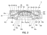
- FIG. 2 is a sectional view of the ventilation component taken along line II-II of FIG.
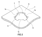
- FIG. 3 is a perspective view showing a ventilation port of the housing.
- FIG. 4 is a cross-sectional view showing a state in which the ventilation component is attached to the housing.
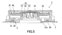
- FIG. 5 is a cross-sectional view showing a state in which the ventilation valve is open.
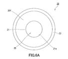
- FIG. 6A is a plan view of the ventilation valve.
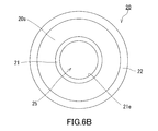
- FIG. 6B is a plan view of the ventilation valve.
- FIG. 7 is an enlarged cross-sectional view of a part of the ventilation component shown in FIG.
- the housing of electrical components of a vehicle needs to be breathable so that the differential pressure generated inside due to temperature changes is eliminated.
- the level of breathability required in the enclosure may vary due to events inside the enclosure. For example, it may be necessary to discharge a large amount of gas from the inside of the housing in a short time, as in the case of explosion protection of a battery pack. Therefore, it is conceivable to attach a ventilation component including a ventilation membrane and a ventilation valve to the ventilation port of the housing. In this case, for example, when normal ventilation is performed using the ventilation membrane with the ventilation valve closed and the difference between the pressure inside the housing and the pressure outside the housing rises above a predetermined pressure, the ventilation is performed. The valve opens and a large amount of gas is discharged from the inside of the housing in a short time. If a ventilation valve that opens and closes by elastic deformation of an elastic body is used as the ventilation valve, the ventilation valve can be reused.
- the pressure release valve is arranged inside the cage, and the inner half of the cage sandwiches the inner peripheral portion of the pressure release valve in the thickness direction of the pressure release valve.
- the inner peripheral end surface of the pressure relief valve does not contact the inner half of the cage.
- the inventors of the present invention repeatedly studied day and night about a technique for improving the sealing property between the ventilation valve and the member supporting the ventilation valve.
- the vent valve and the member supporting the vent valve were newly conceived so as to satisfy a predetermined relationship, and the vent component according to the present invention was devised.
- the case in which the ventilation component according to the present invention is mounted is not limited to the case of the electric component of the vehicle.
- the ventilation component 1 includes a ventilation membrane 10, a ventilation valve 20, and a structural member 30.
- the ventilation component 1 is a component that is attached to a housing 2 having a ventilation port 5 as shown in FIG. As shown in FIG. 4, the ventilation component 1 is attached to the housing 2 at the ventilation port 5.
- the ventilation valve 20 includes an elastic body and is opened and closed by elastic deformation of the elastic body.
- the structural member 30 supports the ventilation membrane 10 and the ventilation valve 20. In the mounted state in which the ventilation component 1 is mounted in the housing 2, the ventilation film 10 vents the inside and outside of the housing 2.
- the ventilation valve 20 opens and the gas inside the housing 2 is filled with the gas. It is discharged to the outside of the body 2. In other words, the vent valve 20 is closed when the difference between the pressure inside the housing 2 and the pressure outside the housing 2 is less than the predetermined pressure.
- the ventilation valve 20 includes a substantially plate-shaped structural portion having two facing surfaces 20f and 20s.
- the vent valve 20 has a first end 21 and a second end 22 as shown in FIGS. 6A and 6B.
- the first end portion 21 forms an inner peripheral portion when one of the two surfaces 20f and 20s is viewed in a plan view, and the second end portion 22 forms an outer peripheral portion at a position apart from the first end portion 21.
- the structural member 30 has a support portion 35 and a valve seat portion 36.
- the support portion 35 supports the first end portion 21.
- the valve seat portion 36 contacts the second end portion 22 when the ventilation valve 20 is closed and is separated from the second end portion 22 when the ventilation valve is opened. .
- the support portion 35 has a first contact portion 35f and a second contact portion 35s.
- the first contact portion 35f and the second contact portion 35s sandwich the first end portion 21 of the ventilation valve 20.
- the first contact portion 35f is in contact with the surface 21q, which is one of the pair of surfaces 21p facing each other at the first end portion 21.
- the second contact portion 35s is in contact with the surface 21r that is the other of the pair of surfaces 21p at the first end portion 21.
- the support portion 35 is in contact with the end surface 21e of the first end portion 21 that connects the pair of surfaces 21p between the first contact portion 35f and the second contact portion 35s.
- the first end portion 21 is sandwiched by the first contact portion 35f and the second contact portion 35s, and also in contact with the support portion 35 at the end surface 21e. Therefore, the ventilation between the ventilation valve 20 and the support portion 35 is high. As a result, liquid and gas do not pass between the support portion 35 and the first end portion 21, and the reliability of the ventilation component 1 and the product in which the ventilation component 1 is mounted can be improved.
- the end face 21e of the first end portion 21 is in contact with the support portion 35 in a state where the elastic body of the ventilation valve 20 is pressed against the support portion 35 by elastic deformation. In this case, the ventilation between the ventilation valve 20 and the support portion 35 is high.
- the first end 21 is in liquid-tight contact with the support 35 at the end face 21e, for example.
- the first end 21 is in liquid-tight and air-tight contact with the support 35 at the end face 21e.
- the sealing property between the ventilation valve 20 and the support portion 35 tends to be higher.
- airtight means that the pressure difference between the two spaces partitioned by the end face 21e can be maintained at 10 kPa or more.
- the first contact portion 35f and the second contact portion 35s are in contact with the first end portion 21 while being pressed against the first end portion 21 so that the elastic body of the ventilation valve 20 is elastically deformed.
- the first contact portion 35f and the second contact portion 35s are in liquid-tight contact with the first end portion 21, for example.
- the first contact portion 35f and the second contact portion 35s desirably contact the first end portion 21 in a liquid-tight and air-tight manner.
- the airtight means that the pressure difference between the two spaces partitioned by the first contact portion 35f or the second contact portion 35s can be maintained at 10 kPa or more.
- the ventilation valve 20 has a through hole 25 in the center thereof.
- the first end portion 21 is adjacent to the through hole 25.
- the ventilation valve 20 is, for example, a kind of so-called umbrella valve (umbrella-type opening valve), and when one of the two surfaces 20f and 20s is viewed in plan, the first end portion It has an annular shape including an inner peripheral portion 21 and an outer peripheral portion forming the second end portion 22. Accordingly, if the support portion 35 has an annular shape, when the end face 21e is in contact with the support portion 35 in a state where the elastic body of the ventilation valve 20 is pressed against the support portion 35 by elastic deformation. The deformation amount of the elastic body is likely to be uniform around the axis of the ventilation valve 20.
- Umbrella valves usually include a valve section that is responsible for opening and closing, and a shaft section that supports the valve section. There is also an umbrella valve that separately has a member forming a valve portion and another member forming a shaft portion.
- the ventilation valve 20 has only a valve portion, for example, and has an annular shape when the valve portion is viewed in a plan view.
- the structural member 30 serves as a shaft portion that supports the ventilation valve 20 that is the valve portion.
- the through hole 25 of the ventilation valve 20 is used by the structural member 30 to support the ventilation valve 20.
- the ventilation film 10 is arranged inside the inner peripheral surface forming the through hole 25 of the ventilation valve 20. As described above, the through hole 25 of the ventilation valve 20 has a sufficient size for accommodating the ventilation film 10.
- the inner diameter of the inner peripheral portion that forms the first end portion 21 is a direction perpendicular to the axis of the ventilation valve 20 in the portion that contacts the end surface 21e of the support portion 35. Smaller than the maximum dimension at. As a result, the end surface 21e easily contacts the support portion 35 in a state where the elastic body of the ventilation valve 20 is pressed against the support portion 35 by elastic deformation.
- the structural member 30 has, for example, an engaging portion 32c.
- the engaging portion 32c is inserted into the vent hole 5 of the housing 2.
- the ventilation component 1 further includes, for example, a seal member 60.
- the seal member 60 seals the gap between the structural member 30 and the outer surface 2s of the housing 2 on which the ventilation component 1 is mounted, in the mounted state. Accordingly, it is possible to prevent the liquid from passing through between the structural member 30 and the outer surface 2s and being guided to the inside of the housing 2.
- the seal member 60 is, for example, an O-ring or packing.
- the material of the seal member 60 is, for example, an elastically deformable material.
- the breathable membrane 10 is not limited to a particular breathable membrane as long as it has desired breathability.
- the ventilation film 10 may be a single layer film or a multilayer film.
- each layer may be one selected from the group consisting of a porous membrane, a non-woven fabric, a cloth, and a mesh.
- the gas permeable membrane 10 may include a porous membrane and a nonwoven fabric, may include at least one of a cloth and a mesh, and a porous membrane, and may include a plurality of nonwoven fabrics.
- the gas permeable membrane 10 is typically made of an organic polymer material (resin).
- the material of the porous film is, for example, fluororesin.
- fluororesin for example, polytetrafluoroethylene (PTFE), polychlorotrifluoroethylene, tetrafluoroethylene-hexafluoropropylene copolymer, or tetrafluoroethylene-ethylene copolymer can be used.
- the material of the non-woven fabric, cloth, and mesh is, for example, polyester such as polyethylene terephthalate, polyolefin such as polyethylene and polypropylene, nylon, aramid, or ethylene vinyl acetate copolymer.
- the breathable membrane 10 may be subjected to a liquid repellent treatment, if necessary.
- the liquid repellent treatment is performed, for example, by forming a liquid repellent coating film containing a fluorine-based surface modifier having a perfluoroalkyl group on the gas permeable membrane 10.
- the formation of the liquid-repellent coating is not particularly limited, for example, air spray method, electrostatic spray method, dip coating method, spin coating method, roll coating method, curtain flow coating method, or by a method such as impregnation, It is made by coating the resin porous film with a solution or dispersion of a fluorine-based surface modifier having a perfluoroalkyl group.
- the liquid repellent coating film may be formed by an electrodeposition coating method or a plasma polymerization method.
- the ventilation valve 20 opens by elastic deformation and closes by returning to the shape before deformation. Therefore, the ventilation valve 20 can be repeatedly opened and closed and can be used repeatedly. This has the advantage that the product after the inspection can be shipped after inspecting whether the ventilation valve 20 normally operates in the product in which the ventilation component 1 is attached to the housing 2.
- the surface 20f of the ventilation valve 20 is formed, for example, without a step between the portion of the ventilation valve 20 adjacent to the first end 21 and the first end 21. .
- the contact area between the first end 21 and the support 35 is likely to increase.
- the surface 20s of the ventilation valve 20 is formed so as to have a step between the portion adjacent to the first end 21 of the ventilation valve 20 and the first end 21. . Therefore, the thickness of the first end portion 21 is larger than the thickness of the portion of the ventilation valve 20 adjacent to the first end portion 21. Thereby, the amount of deformation of the first end portion 21 sandwiched by the support portion 35 is likely to be large, and the sealing property between the ventilation valve 20 and the support portion 35 is high. In addition, it is easy to adjust the differential pressure required for opening the ventilation valve 20 to a desired range.
- the structural portion of the ventilation valve 20 has a bent portion between a portion adjacent to the second end 22 of the ventilation valve 20 and the second end 22, and the bent portion is ventilated. It bends inside the valve 20. As a result, the contact area between the second end 22 and the valve seat portion 36 tends to increase with the ventilation valve 20 closed. As a result, the sealing property between the second end portion 20 and the valve seat portion 36 is high when the ventilation valve 20 is closed.
- the elastic body included in the ventilation valve 20 is not limited to a specific material as long as it is an elastically deformable material.
- the elastic body included in the ventilation valve 20 is, for example, an elastomer such as natural rubber, synthetic rubber, or a thermoplastic elastomer.
- the synthetic rubber is, for example, nitrile butadiene rubber (NBR), ethylene propylene rubber (EPDM), silicone rubber, fluororubber, acrylic rubber, or hydrogenated nitrile rubber.
- the ventilation valve 20 preferably contains silicone rubber as an elastic body. These elastic bodies can also be used as the material of the seal member 60.
- the structural member 30 includes, for example, a first member 31 and a second member 32.
- the first member 31 supports the gas permeable membrane 10.
- the first member 31 includes a base portion 31b and a shaft portion 31s.
- the base portion 31b has, for example, a disc shape and supports the gas permeable membrane 10.
- the base portion 31b has a through hole 31h for ventilation in the center thereof.
- the base 31b supports the peripheral edge of the gas permeable membrane 10 outside the through hole 31h in the direction perpendicular to the axis of the base 31b.
- the gas permeable membrane 10 is fixed to the base 31b by a method such as heat welding, ultrasonic welding, or bonding with an adhesive.
- the shaft portion 31s projects from the center of the base portion 31b in the axial direction of the base portion 31b.
- the shaft portion 31s is tubular and has a plurality of (for example, three) leg portions 31g at positions apart from the base portion 31b in the axial direction of the base portion 31b.
- the plurality of legs 31g are, for example, arranged equiangularly around the axis of the base 31b.
- Each of the plurality of leg portions 31g has an engaging portion 31c at the tip thereof that protrudes in a direction perpendicular to the axis of the base portion 31b. Gas is ventilated by the gas flowing in and out of the shaft portion 31s or between the leg portions 31g and through the through hole 31h.
- the second member 32 forms the bottom and side of the structural member 30.
- the second member 32 is an annular member, and includes an inner peripheral portion 32i, an outer peripheral portion 32e, and a connecting portion 32k.
- the inner peripheral portion 32i is located in the center of the second member 32 and has a tubular shape.
- the outer peripheral portion 32e is separated from the inner peripheral portion 32i in a direction perpendicular to the axis of the inner peripheral portion 32i and surrounds the inner peripheral portion 32i, and has a tubular shape.
- the outer peripheral portion 32e forms a side portion of the structural member 30.
- the connecting portion 32k is located between the outer peripheral portion 32e and the inner peripheral portion 32i in the direction perpendicular to the axis of the inner peripheral portion 32i, and connects the outer peripheral portion 32e and the inner peripheral portion 32i.
- the inner peripheral portion 32i and the connecting portion 32k form the bottom of the structural member 30.
- the inner peripheral portion 32i has a mounting hole 32h, which is a through hole, in the center thereof.
- the first member 31 is attached to the second member 32 at one end of the inner peripheral portion 32i in the axial direction.
- the mounting hole 32h is a tapered hole at one end of the inner peripheral portion 32i.
- the inner peripheral portion 32i is adjacent to the tapered hole and has an annular engaging surface 32f extending in a direction perpendicular to the axis of the inner peripheral portion 32i.
- the shaft portion 31s is inserted into the tapered hole of the mounting hole 32h, and the engaging portion 31c faces the engaging surface 32f, whereby the first member 31 is prevented from coming off the mounting hole 32h.
- the end surface of the inner peripheral portion 32i adjacent to the tapered hole in the axial direction of the inner peripheral portion 32i faces the bottom surface of the base portion 31b of the first member 31.
- the support portion 35 is formed by, for example, the bottom surface of the base portion 31b of the first member 31 and the outer surface of one end portion of the inner peripheral portion 32i in the axial direction.
- the inner peripheral surface of the inner peripheral portion 32i is formed so as to form a plurality of (for example, three) steps from the engagement surface 32f toward the other end of the inner peripheral portion 32i in the axial direction.
- the inner peripheral surface of the inner peripheral portion 32i has a first side surface 32p, a second side surface 32q, a third side surface 32r, a first connecting surface 32t, and a second connecting surface 32u.
- the first side surface 32p, the second side surface 32q, and the third side surface 32r extend in the axial direction of the inner peripheral portion 32i.
- the first side surface 32p, the second side surface 32q, and the third side surface 32r have a first inner diameter, a second inner diameter, and a third inner diameter, respectively.
- the first inner diameter is smaller than the second inner diameter, and the second inner diameter is smaller than the third inner diameter.
- the first connecting surface 32t and the second connecting surface 32u extend in a direction perpendicular to the axis of the inner peripheral portion 32i.
- the first connection surface 32t connects the first side surface 32p and the second side surface 32q.
- the second connection surface 32u connects the second side surface 32q and the third side surface 32r.
- the inner peripheral portion 32i includes, for example, a plurality (for example, three) of engaging portions 32c.
- the engaging portion 32c projects outward in the direction perpendicular to the axis of the inner peripheral portion 32i, for example, at the other end of the inner peripheral portion 32i in the axial direction of the inner peripheral portion 32i.
- the engagement portion 32c is, for example, a plate-shaped portion curved in an arc shape.
- the plurality of engaging portions 32c are, for example, arranged equiangularly around the axis of the inner peripheral portion 32i.
- a part of the vent hole 5 is formed by a plurality of (for example, three) protrusions 5p.
- the plurality of protrusions 5p are arranged equiangularly around the axis of the vent 5, and a plurality of grooves 5r forming part of the vent 5 are present between the protrusions 5p.
- the ventilation valve 20 is attached to the inner peripheral portion 32i so as to come into contact with the outer peripheral surface of the inner peripheral portion 32i forming a part of the support portion 35.
- the hole diameter of the through hole 25 of the ventilation valve 20 is determined so that it can come into contact with the outer peripheral surface of the inner peripheral portion 32i.
- the connecting portion 32k has, for example, a valve seat portion 36 and serves as a valve seat for the ventilation valve 20.
- the valve seat portion 36 is located on the peripheral portion of the connecting portion 32k.
- the connecting portion 32k has a flow path 32d for flowing gas.
- the flow passage 32d is formed so as to be continuous in the axial direction of the inner peripheral portion 32i between the valve seat portion 36 and the inner peripheral portion 32i.
- the ventilation valve 20 receives the pressure inside the housing 2 through the flow path 32d.
- the connecting portion 32k further includes, for example, an annular groove 32g.
- the seal member 60 is housed in the annular groove 32g.
- the annular groove 32g is formed on the bottom surface of the connecting portion 32k so as to overlap the valve seat portion 36 in the direction perpendicular to the axis of the inner peripheral portion 32i, for example.
- the outer peripheral portion 32e extends along the axial direction of the inner peripheral portion 32i outside the connecting portion 32k.
- the outer peripheral portion 32e has an outer protruding portion 32j protruding outward in a direction perpendicular to the axis of the inner peripheral portion 32i.
- the outer peripheral portion 32e has, for example, a plurality of inward protruding portions 32v.
- the inward projection 32v projects inward in a direction perpendicular to the axis of the inner peripheral portion 32i at one end of the outer peripheral portion 32e in the axial direction of the inner peripheral portion 32i.
- the plurality of inward protrusions 32v are arranged at predetermined intervals around the axis of the inner peripheral portion 32i.
- the structural member 30 further includes, for example, a third member 33.
- the third member 33 is, for example, a disk-shaped member.
- the third member 33 cooperates with the first member 31 and the second member 32 to form the internal space 40.
- the ventilation membrane 10 and the ventilation valve 20 are housed in the internal space 40, for example.
- the third member 33 covers the gas permeable membrane 10 and the gas permeable valve 20 and protects the gas permeable membrane 10 and the gas permeable valve 20.
- the third member 33 has a disk-shaped lid portion 33c and an engaging claw 33e.
- the engaging claw 33e projects in the axial direction of the lid 33c from the peripheral edge of one main surface of the lid 33c.
- the tip of the engaging claw 33e projects outward in the direction perpendicular to the axis of the lid 33c.
- the third member 33 is inserted into the outer peripheral portion 32e so that the engaging claw 33e passes through the gap between the inner protruding portions 32v.
- the third member 33 is rotated at a predetermined angle around the axis of the lid 33c so that the tip of the engaging claw 33e faces the inward protrusion 32v. In this way, the third member 33 is attached to the second member 32.
- the third member 33 is prevented from coming off the second member 32 because the tip of the engaging claw 33e faces the inward protruding portion 32v.
- the structural member 30 has a ventilation path 50.
- the ventilation passage 50 connects the internal space 40 and the external space of the ventilation component 1 so as to allow ventilation.
- the ventilation path 50 is formed, for example, between the connecting portion 32k and the inner surface of the outer peripheral portion 32e.
- the material of the structural member 30 is, for example, synthetic resin or metal.
- a thermoplastic resin can be used as the synthetic resin.
- the thermoplastic resin is, for example, polybutylene terephthalate (PBT), polyethylene terephthalate (PET), polyphenylene sulfide (PPS), polysulfone (PS), polypropylene (PP), polyethylene (PE), or ABS resin.
- the material of the structural member 30 may be a composite material having a thermoplastic resin as a base material.
- the reinforcing agent added to the composite material may be glass fiber, carbon fiber, metal, or inorganic filler.
- the ventilation valve 20 opens and the gas inside the housing 2 is It is discharged to the outside of the housing 2 through the flow path including the flow path 32d, the internal space 40, and the ventilation path 50. Since the gas permeable membrane 10 is not arranged in the gas flow path formed by opening the ventilation valve 20, a large amount of gas can be discharged from the inside of the housing 2 in a short period of time. In addition, even if the vent valve is provided, the vent membrane or the like may be damaged due to a rapid increase in the pressure inside the housing. However, the ventilation component 1 has a structure capable of suppressing such a phenomenon.
- the ventilation component 1 has an annular shape in which the ventilation valve 20 has a through hole in the center when seen in a plan view. Further, the ventilation component 1 has a structure in which the ventilation film 10 is housed such that the ventilation film 10 is located inside the inner peripheral surface forming the through hole 25 of the ventilation valve 20 when seen in a plan view.
- the cross-sectional area of the flow path through which the gas passes and the valve portion of the ventilation valve 20 are as large as possible.
Landscapes
- Engineering & Computer Science (AREA)
- General Engineering & Computer Science (AREA)
- Mechanical Engineering (AREA)
- Self-Closing Valves And Venting Or Aerating Valves (AREA)
- Gas Exhaust Devices For Batteries (AREA)
Abstract
This ventilation component (1) is mounted in a housing (2) in a ventilation opening (5). The ventilation component (1) is provided with a ventilation film (10), a ventilation valve (20) and a structural member (30). The structural member (30) supports the ventilation film (10) and the ventilation valve (20). The ventilation valve (20) includes an approximately plate-shaped structural part, and has an annular shape which, seen in planar view, includes a first end (21) which forms the inner peripheral part, and a second end (22) which forms the outer peripheral part. The structural member (30) has a support part (35) and a valve seat part (36). The support part (35) supports the first end (21). The valve seat part (36) contacts the second end (22) when the ventilation valve (20) is closed, and is away from the second end (22) when the ventilation valve (20) is open. The support unit (35) has a first contact part (35f) and a second contact part (35s) which hold the first end (21) from both sides, and, between the first contact part (35f) and the second contact part (35s), contacts the end surface (21e) of the first end (21).
Description
本発明は、通気部品に関する。
The present invention relates to a ventilation component.
従来、筐体の内部の圧力と筐体の外部の圧力との差を補正するための装置が知られている。
Conventionally, a device for correcting the difference between the pressure inside the housing and the pressure outside the housing is known.
例えば、特許文献1には、内外における望ましくない圧力差が避けられるべき筐体に使用可能な圧力補正装置が記載されている。この圧力補正装置は、内側及び外側を有し、ケージと、通気膜と、圧力開放弁とを備えている。ケージは、内側ハーフ及び外側ハーフを備えている。ケージの内部において、内側ハーフと外側ハーフとの間に、通気膜及び圧力開放弁が配置されている。圧力開放弁によって防爆が実現される。内側の圧力が外側の圧力より大きくなり差圧が閾値を超えたときに、内側のガスの緊急的な排気のために内側と外側とが直接つながる流路が形成される。なお、通気膜は、防爆には寄与しない。
For example, Patent Document 1 describes a pressure correction device that can be used in a housing in which an undesirable pressure difference between the inside and the outside should be avoided. The pressure compensator has an inner side and an outer side, and includes a cage, a gas permeable membrane, and a pressure release valve. The cage comprises an inner half and an outer half. Inside the cage, a vent membrane and a pressure relief valve are located between the inner and outer halves. The pressure relief valve provides explosion protection. When the inner pressure becomes larger than the outer pressure and the differential pressure exceeds the threshold value, a flow path that directly connects the inner side and the outer side is formed for emergency exhaust of the inner gas. The breathable film does not contribute to explosion protection.
特許文献1に記載の技術は、信頼性を高める観点から改良の余地を有している。そこで、本発明は、防爆のための排気に適し、かつ、信頼性を高める観点から有利な通気部品を提供する。
The technology described in Patent Document 1 has room for improvement from the viewpoint of enhancing reliability. Therefore, the present invention provides a ventilation component suitable for exhaust gas for explosion-proof and advantageous from the viewpoint of enhancing reliability.
本発明は、
通気口において筐体に装着される通気部品であって、
通気膜と、
弾性体を含み、前記弾性体の弾性変形により開閉する通気弁と、
前記通気膜及び前記通気弁を支持する構造部材と、を備え、
当該通気部品が前記筐体に装着された装着状態において、前記通気膜によって前記筐体の内部及び外部の通気が行われ、かつ、前記筐体の内部の圧力と前記筐体の外部の圧力との差が所定の圧力以上になったときに前記通気弁が開いて前記筐体の内部の気体が前記筐体の外部に排出され、
前記通気弁は、対向する2つの面を有し、前記2つの面の一方を平面視したときに、内周部をなす第一端部及び外周部をなす第二端部を含む円環状の形状を有し、
前記構造部材は、前記第一端部を支持する支持部と、前記通気弁が閉じたときに前記第二端部に接触し、かつ、前記通気弁が開いたときに前記第二端部と離れている弁座部とを有し、
前記支持部は、前記第一端部を挟持する第一接触部及び第二接触部を有し、前記第一接触部は前記第一端部において対向する一対の面の一方に接触するとともに前記第二接触部は前記一対の面の他方に接触しており、
前記支持部は、前記第一接触部と前記第二接触部との間で、前記一対の面を接続している前記第一端部の端面に接触している、
通気部品を提供する。 The present invention is
A ventilation component attached to the housing at the ventilation port,
A breathable membrane,
A ventilation valve including an elastic body, which opens and closes by elastic deformation of the elastic body;
A structural member that supports the ventilation membrane and the ventilation valve,
In the mounted state in which the ventilation component is mounted on the housing, the ventilation film vents the inside and outside of the housing, and the pressure inside the housing and the pressure outside the housing The gas inside the housing is discharged to the outside of the housing by opening the ventilation valve when the difference becomes equal to or more than a predetermined pressure.
The ventilation valve has two opposing surfaces, and has an annular shape including a first end portion forming an inner peripheral portion and a second end portion forming an outer peripheral portion when one of the two surfaces is viewed in a plan view. Have a shape,
The structural member is a support portion that supports the first end portion, and contacts the second end portion when the ventilation valve is closed, and the second end portion when the ventilation valve is opened. And a valve seat portion that is separated,
The support part has a first contact part and a second contact part that sandwich the first end part, and the first contact part contacts one of a pair of opposing surfaces at the first end part and The second contact portion is in contact with the other of the pair of surfaces,
The support portion is in contact with an end surface of the first end portion connecting the pair of surfaces between the first contact portion and the second contact portion,
Provide ventilation components.
上記の通気部品は、防爆のための排気に適し、かつ、信頼性を高める観点から有利である。
The above ventilation components are suitable for explosion-proof exhaust and are advantageous from the viewpoint of enhancing reliability.
例えば、車両の電装部品の筐体は、温度変化によりその内部に発生する差圧が解消されるように通気性を有する必要がある。一方、筐体において必要な通気性のレベルは、筐体の内部の事象により変動しうる。例えば、バッテリーパックの防爆のように、筐体の内部から多量のガスを短時間に排出できることが必要な場合がある。そこで、通気膜及び通気弁を備えた通気部品を筐体の通気口に装着することが考えられる。この場合、例えば、通気弁が閉じた状態で通気膜を用いて通常の通気が行われ、筐体の内部の圧力と筐体の外部の圧力との差が所定の圧力以上に高まると、通気弁が開いて筐体の内部から多量のガスが短時間に排出される。通気弁として弾性体の弾性変形により開閉する通気弁を使用すれば、通気弁の再使用が可能である。
For example, the housing of electrical components of a vehicle needs to be breathable so that the differential pressure generated inside due to temperature changes is eliminated. On the other hand, the level of breathability required in the enclosure may vary due to events inside the enclosure. For example, it may be necessary to discharge a large amount of gas from the inside of the housing in a short time, as in the case of explosion protection of a battery pack. Therefore, it is conceivable to attach a ventilation component including a ventilation membrane and a ventilation valve to the ventilation port of the housing. In this case, for example, when normal ventilation is performed using the ventilation membrane with the ventilation valve closed and the difference between the pressure inside the housing and the pressure outside the housing rises above a predetermined pressure, the ventilation is performed. The valve opens and a large amount of gas is discharged from the inside of the housing in a short time. If a ventilation valve that opens and closes by elastic deformation of an elastic body is used as the ventilation valve, the ventilation valve can be reused.
特許文献1に記載の圧力補正装置において、圧力開放弁はケージの内部に配置されており、ケージの内側ハーフが圧力開放弁の内周部を圧力開放弁の厚み方向に挟持している。圧力開放弁の内周部の端面はケージの内側ハーフには接触していない。本発明者らは、通気弁と通気弁を支持する部材とのシール性を高めることが、通気部品又は通気部品が装着された製品の信頼性に非常に重要であることを突き止めた。本発明者らの検討によれば、特許文献1に記載の技術において、圧力開放弁とケージの内側ハーフとのシール性が十分に高いとは言い難い。そこで、本発明者らは、通気弁と通気弁を支持する部材とのシール性を高めるための技術について日夜検討を重ねた。その結果、通気弁及び通気弁を支持する部材を所定の関係を満たすように構成することを新たに思いつき、本発明に係る通気部品を案出した。なお、本発明に係る通気部品が装着される筐体は、車両の電装部品の筐体に限られない。
In the pressure correction device described in Patent Document 1, the pressure release valve is arranged inside the cage, and the inner half of the cage sandwiches the inner peripheral portion of the pressure release valve in the thickness direction of the pressure release valve. The inner peripheral end surface of the pressure relief valve does not contact the inner half of the cage. The inventors of the present invention have found that enhancing the sealing property between the ventilation valve and the member supporting the ventilation valve is very important for the reliability of the ventilation component or the product in which the ventilation component is mounted. According to the studies by the present inventors, it is hard to say that the technology described in Patent Document 1 has a sufficiently high sealability between the pressure release valve and the inner half of the cage. Therefore, the inventors of the present invention repeatedly studied day and night about a technique for improving the sealing property between the ventilation valve and the member supporting the ventilation valve. As a result, the vent valve and the member supporting the vent valve were newly conceived so as to satisfy a predetermined relationship, and the vent component according to the present invention was devised. The case in which the ventilation component according to the present invention is mounted is not limited to the case of the electric component of the vehicle.
以下、添付の図面を参照しつつ本発明の実施形態について説明する。以下の説明は、本発明の例示であり、本発明は、以下の実施形態に限定されない。
Hereinafter, embodiments of the present invention will be described with reference to the accompanying drawings. The following description is an exemplification of the present invention, and the present invention is not limited to the following embodiments.
図1及び図2に示す通り、通気部品1は、通気膜10と、通気弁20と、構造部材30とを備えている。通気部品1は、図3に示すような、通気口5を有する筐体2に装着される部品である。図4に示す通り、通気部品1は、通気口5において筐体2に装着される。図4及び図5に示す通り、通気弁20は、弾性体を含み、弾性体の弾性変形により開閉する。構造部材30は、通気膜10及び通気弁20を支持する。通気部品1が筐体2に装着された装着状態において、通気膜10によって筐体2の内部及び外部の通気が行われる。加えて、装着状態において、筐体2の内部の圧力と筐体2の外部の圧力との差が所定の圧力以上になったときに通気弁20が開いて筐体2の内部の気体が筐体2の外部に排出される。換言すると、筐体2の内部の圧力と筐体2の外部の圧力との差が所定の圧力未満である場合には、通気弁20は閉じている。図2に示す通り、通気弁20は、対向する2つの面20f及び20sを有する略板状の構造部分を含む。加えて、通気弁20は、図6A及び図6Bに示す通り、第一端部21及び第二端部22を有する。第一端部21は、2つの面20f及び20sの一方を平面視したときに内周部をなし、第二端部22は、第一端部21から離れた位置で外周部をなす。図2に示す通り、構造部材30は、支持部35と、弁座部36とを有する。支持部35は、第一端部21を支持する。図4及び図5に示す通り、弁座部36は、通気弁20が閉じたときに第二端部22に接触し、かつ、通気弁が開いたときに第二端部22と離れている。
As shown in FIGS. 1 and 2, the ventilation component 1 includes a ventilation membrane 10, a ventilation valve 20, and a structural member 30. The ventilation component 1 is a component that is attached to a housing 2 having a ventilation port 5 as shown in FIG. As shown in FIG. 4, the ventilation component 1 is attached to the housing 2 at the ventilation port 5. As shown in FIGS. 4 and 5, the ventilation valve 20 includes an elastic body and is opened and closed by elastic deformation of the elastic body. The structural member 30 supports the ventilation membrane 10 and the ventilation valve 20. In the mounted state in which the ventilation component 1 is mounted in the housing 2, the ventilation film 10 vents the inside and outside of the housing 2. In addition, in the mounted state, when the difference between the pressure inside the housing 2 and the pressure outside the housing 2 becomes equal to or more than a predetermined pressure, the ventilation valve 20 opens and the gas inside the housing 2 is filled with the gas. It is discharged to the outside of the body 2. In other words, the vent valve 20 is closed when the difference between the pressure inside the housing 2 and the pressure outside the housing 2 is less than the predetermined pressure. As shown in FIG. 2, the ventilation valve 20 includes a substantially plate-shaped structural portion having two facing surfaces 20f and 20s. In addition, the vent valve 20 has a first end 21 and a second end 22 as shown in FIGS. 6A and 6B. The first end portion 21 forms an inner peripheral portion when one of the two surfaces 20f and 20s is viewed in a plan view, and the second end portion 22 forms an outer peripheral portion at a position apart from the first end portion 21. As shown in FIG. 2, the structural member 30 has a support portion 35 and a valve seat portion 36. The support portion 35 supports the first end portion 21. As shown in FIGS. 4 and 5, the valve seat portion 36 contacts the second end portion 22 when the ventilation valve 20 is closed and is separated from the second end portion 22 when the ventilation valve is opened. .
図7に示す通り、支持部35は、第一接触部35f及び第二接触部35sを有する。第一接触部35f及び第二接触部35sは、通気弁20の第一端部21を挟持している。第一接触部35fは、第一端部21において対向する一対の面21pの一方である面21qに接触している。加えて、第二接触部35sは、第一端部21において一対の面21pの他方である面21rに接触している。支持部35は、第一接触部35fと第二接触部35sとの間で、一対の面21pを接続している第一端部21の端面21eに接触している。第一端部21は、第一接触部35f及び第二接触部35sによって挟持されているとともに、端面21eにおいても支持部35と接触している。このため、通気弁20と支持部35とのシール性が高い。その結果、支持部35と第一端部21との間を液体及び気体が通過せず、通気部品1及び通気部品1が装着された製品の信頼性を高めることができる。
As shown in FIG. 7, the support portion 35 has a first contact portion 35f and a second contact portion 35s. The first contact portion 35f and the second contact portion 35s sandwich the first end portion 21 of the ventilation valve 20. The first contact portion 35f is in contact with the surface 21q, which is one of the pair of surfaces 21p facing each other at the first end portion 21. In addition, the second contact portion 35s is in contact with the surface 21r that is the other of the pair of surfaces 21p at the first end portion 21. The support portion 35 is in contact with the end surface 21e of the first end portion 21 that connects the pair of surfaces 21p between the first contact portion 35f and the second contact portion 35s. The first end portion 21 is sandwiched by the first contact portion 35f and the second contact portion 35s, and also in contact with the support portion 35 at the end surface 21e. Therefore, the ventilation between the ventilation valve 20 and the support portion 35 is high. As a result, liquid and gas do not pass between the support portion 35 and the first end portion 21, and the reliability of the ventilation component 1 and the product in which the ventilation component 1 is mounted can be improved.
従来、通気弁の可動性を確保する観点から、通気弁の内周部の端面が支持部に接触していないことが必要であると考えられていた。しかし、本発明者らの検討によれば、通気弁の内周部の端面が支持部に接触していても通気弁の可動性を確保できるとともに、通気部品及び通気部品が装着された製品の信頼性を高めることができることが新たに見出された。
Previously, from the viewpoint of ensuring the mobility of the ventilation valve, it was considered necessary that the end surface of the inner peripheral portion of the ventilation valve did not contact the support portion. However, according to a study by the present inventors, even if the end surface of the inner peripheral portion of the ventilation valve is in contact with the support portion, the mobility of the ventilation valve can be ensured, and the ventilation component and the product to which the ventilation component is mounted are It has been newly found that reliability can be increased.
例えば、通気弁20の弾性体が弾性変形により支持部35に押し付けられた状態で、第一端部21の端面21eが支持部35に接触している。この場合、通気弁20と支持部35とのシール性が高い。
For example, the end face 21e of the first end portion 21 is in contact with the support portion 35 in a state where the elastic body of the ventilation valve 20 is pressed against the support portion 35 by elastic deformation. In this case, the ventilation between the ventilation valve 20 and the support portion 35 is high.
第一端部21は、例えば、端面21eにおいて支持部35と液密に接触している。第一端部21は、望ましくは、端面21eにおいて支持部35と液密かつ気密に接触している。この場合、通気弁20と支持部35とのシール性がより高くなりやすい。この場合、気密とは、端面21eによって仕切られた2つの空間の圧力差を10kPa以上に保つことができることを意味する。
The first end 21 is in liquid-tight contact with the support 35 at the end face 21e, for example. Desirably, the first end 21 is in liquid-tight and air-tight contact with the support 35 at the end face 21e. In this case, the sealing property between the ventilation valve 20 and the support portion 35 tends to be higher. In this case, airtight means that the pressure difference between the two spaces partitioned by the end face 21e can be maintained at 10 kPa or more.
第一接触部35f及び第二接触部35sは、例えば、通気弁20の弾性体が弾性変形するように第一端部21に押し付けられた状態で、第一端部21に接触している。第一接触部35f及び第二接触部35sは、例えば、液密に第一端部21に接触している。第一接触部35f及び第二接触部35sは、望ましくは、液密かつ気密に第一端部21に接触している。この場合、気密とは、第一接触部35f又は第二接触部35sによって仕切られた2つの空間の圧力差を10kPa以上に保つことができることを意味する。図6A及び図6Bに示す通り、通気弁20は、その中央に貫通穴25を有している。第一端部21は、貫通穴25に隣接している。
The first contact portion 35f and the second contact portion 35s are in contact with the first end portion 21 while being pressed against the first end portion 21 so that the elastic body of the ventilation valve 20 is elastically deformed. The first contact portion 35f and the second contact portion 35s are in liquid-tight contact with the first end portion 21, for example. The first contact portion 35f and the second contact portion 35s desirably contact the first end portion 21 in a liquid-tight and air-tight manner. In this case, the airtight means that the pressure difference between the two spaces partitioned by the first contact portion 35f or the second contact portion 35s can be maintained at 10 kPa or more. As shown in FIGS. 6A and 6B, the ventilation valve 20 has a through hole 25 in the center thereof. The first end portion 21 is adjacent to the through hole 25.
図6A及び図6Bに示す通り、通気弁20は、例えば、いわゆるアンブレラバルブ(傘型の開放弁)の一種であり、2つの面20f及び20sの一方を平面視したときに、第一端部21をなす内周部及び第二端部22をなす外周部を含む円環状の形状を有する。これにより、支持部35が円環状の形状を有していれば、通気弁20の弾性体が弾性変形により支持部35に押し付けられた状態で端面21eが支持部35に接触している場合に、通気弁20の軸線周りにおいて、弾性体の変形量が均一になりやすい。アンブレラバルブは、通常、開閉を担う弁部と弁部を支持する軸部とを含んでいる。弁部をなす部材と、軸部をなす他の部材とを別々に有するアンブレラバルブもある。通気弁20は、例えば、弁部のみをなしており、弁部を平面視したときに円環状の形状を有する。一方、構造部材30は、弁部である通気弁20を支持する軸部の役割を果たしている。通気弁20の貫通穴25は、構造部材30によって通気弁20を支持するために利用される。また、通気部品1を平面視したときに、通気弁20の貫通穴25を形成する内周面より内側に通気膜10が配置されている。このように、通気弁20の貫通穴25は、通気膜10の収容のために十分な大きさを有している。
As shown in FIGS. 6A and 6B, the ventilation valve 20 is, for example, a kind of so-called umbrella valve (umbrella-type opening valve), and when one of the two surfaces 20f and 20s is viewed in plan, the first end portion It has an annular shape including an inner peripheral portion 21 and an outer peripheral portion forming the second end portion 22. Accordingly, if the support portion 35 has an annular shape, when the end face 21e is in contact with the support portion 35 in a state where the elastic body of the ventilation valve 20 is pressed against the support portion 35 by elastic deformation. The deformation amount of the elastic body is likely to be uniform around the axis of the ventilation valve 20. Umbrella valves usually include a valve section that is responsible for opening and closing, and a shaft section that supports the valve section. There is also an umbrella valve that separately has a member forming a valve portion and another member forming a shaft portion. The ventilation valve 20 has only a valve portion, for example, and has an annular shape when the valve portion is viewed in a plan view. On the other hand, the structural member 30 serves as a shaft portion that supports the ventilation valve 20 that is the valve portion. The through hole 25 of the ventilation valve 20 is used by the structural member 30 to support the ventilation valve 20. Further, when the ventilation component 1 is viewed in a plan view, the ventilation film 10 is arranged inside the inner peripheral surface forming the through hole 25 of the ventilation valve 20. As described above, the through hole 25 of the ventilation valve 20 has a sufficient size for accommodating the ventilation film 10.
例えば、支持部35に取り付けられていない状態の通気弁20において第一端部21をなす内周部の内径は、支持部35における端面21eと接触する部分の通気弁20の軸線に垂直な方向における最大寸法よりも小さい。これにより、通気弁20の弾性体が弾性変形により支持部35に押し付けられた状態で端面21eが支持部35に接触しやすい。
For example, in the ventilation valve 20 that is not attached to the support portion 35, the inner diameter of the inner peripheral portion that forms the first end portion 21 is a direction perpendicular to the axis of the ventilation valve 20 in the portion that contacts the end surface 21e of the support portion 35. Smaller than the maximum dimension at. As a result, the end surface 21e easily contacts the support portion 35 in a state where the elastic body of the ventilation valve 20 is pressed against the support portion 35 by elastic deformation.
図1及び図2に示す通り、構造部材30は、例えば、係合部32cを有する。係合部32cは、筐体2の通気口5に差し込まれる。通気部品1は、例えば、シール部材60をさらに備えている。図4に示す通り、シール部材60は、装着状態において、構造部材30と、筐体2の通気部品1が装着される外面2sとの隙間をシールする。これにより、構造部材30と外面2sとの間を液体が通過して筐体2の内部に液体が導かれることを防止できる。シール部材60は、例えば、O-リング又はパッキンである。シール部材60の材料は、例えば、弾性変形可能な材料である。
As shown in FIGS. 1 and 2, the structural member 30 has, for example, an engaging portion 32c. The engaging portion 32c is inserted into the vent hole 5 of the housing 2. The ventilation component 1 further includes, for example, a seal member 60. As shown in FIG. 4, the seal member 60 seals the gap between the structural member 30 and the outer surface 2s of the housing 2 on which the ventilation component 1 is mounted, in the mounted state. Accordingly, it is possible to prevent the liquid from passing through between the structural member 30 and the outer surface 2s and being guided to the inside of the housing 2. The seal member 60 is, for example, an O-ring or packing. The material of the seal member 60 is, for example, an elastically deformable material.
通気膜10は、所望の通気性を有する限り特定の通気膜に限定されない。通気膜10は、単層膜であってよいし、多層膜であってもよい。通気膜10が多層膜である場合、各層は、多孔質膜、不織布、クロス、及びメッシュからなる群より選ばれる1つでありうる。通気膜10は、多孔質膜及び不織布を含んでいてよく、クロス及びメッシュの少なくとも1つと多孔質膜とを含んでいてもよく、複数の不織布を含んでいてもよい。通気膜10は、典型的には、有機高分子材料(樹脂)によって構成されている。多孔質膜の材料は、例えば、フッ素樹脂である。フッ素樹脂としては、例えば、ポリテトラフルオロエチレン(PTFE)、ポリクロロトリフルオロエチレン、テトラフルオロエチレン-ヘキサフルオロプロピレン共重合体、又はテトラフルオロエチレン-エチレン共重合体を使用できる。不織布、クロス、及びメッシュの材料は、例えば、ポリエチレンテレフタレート等のポリエステル、ポリエチレン及びポリプロピレン等のポリオレフィン、ナイロン、アラミド、又はエチレン酢酸ビニル共重合体である。
The breathable membrane 10 is not limited to a particular breathable membrane as long as it has desired breathability. The ventilation film 10 may be a single layer film or a multilayer film. When the gas permeable membrane 10 is a multi-layer membrane, each layer may be one selected from the group consisting of a porous membrane, a non-woven fabric, a cloth, and a mesh. The gas permeable membrane 10 may include a porous membrane and a nonwoven fabric, may include at least one of a cloth and a mesh, and a porous membrane, and may include a plurality of nonwoven fabrics. The gas permeable membrane 10 is typically made of an organic polymer material (resin). The material of the porous film is, for example, fluororesin. As the fluororesin, for example, polytetrafluoroethylene (PTFE), polychlorotrifluoroethylene, tetrafluoroethylene-hexafluoropropylene copolymer, or tetrafluoroethylene-ethylene copolymer can be used. The material of the non-woven fabric, cloth, and mesh is, for example, polyester such as polyethylene terephthalate, polyolefin such as polyethylene and polypropylene, nylon, aramid, or ethylene vinyl acetate copolymer.
通気膜10は、必要に応じて撥液処理されていてもよい。撥液処理は、例えば、パーフルオロアルキル基を有するフッ素系表面修飾剤を含む撥液性の被膜を通気膜10に形成することによってなされる。撥液性の被膜の形成は、特に制限されないが、例えば、エアスプレイ法、静電スプレイ法、ディップコーティング法、スピンコーティング法、ロールコーティング法、カーテンフローコーティング法、又は含浸法等の方法により、パーフルオロアルキル基を有するフッ素系表面修飾剤の溶液又はディスパージョンで樹脂多孔質膜をコーティングすることによりなされる。また、電着塗装法又はプラズマ重合法によって、撥液性の被膜を形成してもよい。
The breathable membrane 10 may be subjected to a liquid repellent treatment, if necessary. The liquid repellent treatment is performed, for example, by forming a liquid repellent coating film containing a fluorine-based surface modifier having a perfluoroalkyl group on the gas permeable membrane 10. The formation of the liquid-repellent coating is not particularly limited, for example, air spray method, electrostatic spray method, dip coating method, spin coating method, roll coating method, curtain flow coating method, or by a method such as impregnation, It is made by coating the resin porous film with a solution or dispersion of a fluorine-based surface modifier having a perfluoroalkyl group. Further, the liquid repellent coating film may be formed by an electrodeposition coating method or a plasma polymerization method.
通気弁20は、弾性変形によって開き、変形前の形状に戻ることによって閉じる。このため、通気弁20は、開閉を繰り返すことができ、繰り返し使用できる。このことは、通気部品1が筐体2に取り付けられた製品において通気弁20が正常に作動するかどうかを検査した後に、検査後の製品を出荷可能にするという利点をもたらす。
The ventilation valve 20 opens by elastic deformation and closes by returning to the shape before deformation. Therefore, the ventilation valve 20 can be repeatedly opened and closed and can be used repeatedly. This has the advantage that the product after the inspection can be shipped after inspecting whether the ventilation valve 20 normally operates in the product in which the ventilation component 1 is attached to the housing 2.
図2に示す通り、通気弁20の面20fは、例えば、通気弁20の第一端部21に隣接している部分と第一端部21との間に段差を有することなく形成されている。これにより、第一端部21と支持部35との接触面積が大きくなりやすい。
As shown in FIG. 2, the surface 20f of the ventilation valve 20 is formed, for example, without a step between the portion of the ventilation valve 20 adjacent to the first end 21 and the first end 21. . As a result, the contact area between the first end 21 and the support 35 is likely to increase.
図2に示す通り、通気弁20の面20sは、例えば、通気弁20の第一端部21に隣接している部分と第一端部21との間に段差を有するように形成されている。このため、第一端部21の厚みは、通気弁20の第一端部21に隣接している部分の厚みよりも大きい。これにより、支持部35によって挟持された第一端部21の変形量が大きくなりやすく、通気弁20と支持部35との間のシール性が高い。加えて、通気弁20が開くために必要な差圧を所望の範囲に調整しやすい。
As shown in FIG. 2, the surface 20s of the ventilation valve 20 is formed so as to have a step between the portion adjacent to the first end 21 of the ventilation valve 20 and the first end 21. . Therefore, the thickness of the first end portion 21 is larger than the thickness of the portion of the ventilation valve 20 adjacent to the first end portion 21. Thereby, the amount of deformation of the first end portion 21 sandwiched by the support portion 35 is likely to be large, and the sealing property between the ventilation valve 20 and the support portion 35 is high. In addition, it is easy to adjust the differential pressure required for opening the ventilation valve 20 to a desired range.
図2に示す通り、通気弁20の構造部分は、通気弁20の第二端部22に隣接している部分と第二端部22との間に屈曲部を有し、その屈曲部は通気弁20の内側に屈曲している。これにより、通気弁20が閉じた状態で、第二端部22と弁座部36との接触面積が大きくなりやすい。その結果、通気弁20が閉じた状態で、第二端部20と弁座部36との間のシール性が高い。
As shown in FIG. 2, the structural portion of the ventilation valve 20 has a bent portion between a portion adjacent to the second end 22 of the ventilation valve 20 and the second end 22, and the bent portion is ventilated. It bends inside the valve 20. As a result, the contact area between the second end 22 and the valve seat portion 36 tends to increase with the ventilation valve 20 closed. As a result, the sealing property between the second end portion 20 and the valve seat portion 36 is high when the ventilation valve 20 is closed.
通気弁20に含まれる弾性体は、弾性変形可能な材料である限り特定の材料に限定されない。通気弁20に含まれる弾性体は、例えば、天然ゴム、合成ゴム、又は熱可塑性エラストマー等のエラストマーである。この場合、合成ゴムは、例えば、ニトリルブタジエンゴム(NBR)、エチレンプロピレンゴム(EPDM)、シリコーンゴム、フッ素ゴム、アクリルゴム、又は水素化ニトリルゴムである。通気弁20は、望ましくは、シリコーンゴムを弾性体として含んでいる。これらの弾性体は、シール部材60の材料としても使用可能である。
The elastic body included in the ventilation valve 20 is not limited to a specific material as long as it is an elastically deformable material. The elastic body included in the ventilation valve 20 is, for example, an elastomer such as natural rubber, synthetic rubber, or a thermoplastic elastomer. In this case, the synthetic rubber is, for example, nitrile butadiene rubber (NBR), ethylene propylene rubber (EPDM), silicone rubber, fluororubber, acrylic rubber, or hydrogenated nitrile rubber. The ventilation valve 20 preferably contains silicone rubber as an elastic body. These elastic bodies can also be used as the material of the seal member 60.
図2に示す通り、構造部材30は、例えば、第一部材31と、第二部材32とを備えている。第一部材31は、通気膜10を支持している。第一部材31は、基部31bと、軸部31sとを備えている。基部31bは、例えば、円板状であり、通気膜10を支持している。基部31bは、その中央に通気のための貫通穴31hを有する。基部31bは、基部31bの軸線に垂直な方向において貫通穴31hの外側で通気膜10の周縁部を支持している。通気膜10は、例えば、熱溶着、超音波溶着、又は接着剤による接着等の方法によって、基部31bに固定されている。軸部31sは、基部31bの中央から基部31bの軸線方向に突出している。軸部31sは、筒状であり、基部31bの軸線方向において基部31bから離れた位置に複数(例えば3つ)の脚部31gを有する。複数の脚部31gは、例えば、基部31bの軸線周りに等角で離れて配置されている。複数の脚部31gのそれぞれは、その先端に、基部31bの軸線に垂直な方向に向かって突出する係合部31cを有する。軸部31sの内部又は脚部31g同士の間及び貫通穴31hをガスが出入りして通気が行われる。
As shown in FIG. 2, the structural member 30 includes, for example, a first member 31 and a second member 32. The first member 31 supports the gas permeable membrane 10. The first member 31 includes a base portion 31b and a shaft portion 31s. The base portion 31b has, for example, a disc shape and supports the gas permeable membrane 10. The base portion 31b has a through hole 31h for ventilation in the center thereof. The base 31b supports the peripheral edge of the gas permeable membrane 10 outside the through hole 31h in the direction perpendicular to the axis of the base 31b. The gas permeable membrane 10 is fixed to the base 31b by a method such as heat welding, ultrasonic welding, or bonding with an adhesive. The shaft portion 31s projects from the center of the base portion 31b in the axial direction of the base portion 31b. The shaft portion 31s is tubular and has a plurality of (for example, three) leg portions 31g at positions apart from the base portion 31b in the axial direction of the base portion 31b. The plurality of legs 31g are, for example, arranged equiangularly around the axis of the base 31b. Each of the plurality of leg portions 31g has an engaging portion 31c at the tip thereof that protrudes in a direction perpendicular to the axis of the base portion 31b. Gas is ventilated by the gas flowing in and out of the shaft portion 31s or between the leg portions 31g and through the through hole 31h.
第二部材32は、構造部材30の底部及び側部をなしている。第二部材32は、環状の部材であり、内周部32i、外周部32e、及び連結部32kを備えている。内周部32iは、第二部材32の中央に位置しており、筒状である。外周部32eは、内周部32iの軸線に垂直な方向に内周部32iから離れて内周部32iを取り囲んでおり、筒状である。外周部32eは、構造部材30の側部をなしている。連結部32kは、内周部32iの軸線に垂直な方向において外周部32eと内周部32iとの間に位置し、外周部32eと内周部32iとを連結している。内周部32i及び連結部32kが構造部材30の底部をなしている。内周部32iは、その中央に貫通孔である取付孔32hを有する。第一部材31は、軸線方向における内周部32iの一方の端部において第二部材32に取り付けられている。内周部32iの一方の端部において取付孔32hはテーパー孔をなしている。加えて、内周部32iは、テーパー孔に隣接しており、内周部32iの軸線に垂直な方向に延びている環状の係合面32fを有する。取付孔32hのテーパー孔に軸部31sが差し込まれ、係合部31cが係合面32fと向かい合うことによって、第一部材31が取付孔32hから外れることが防止されている。加えて、内周部32iの軸線方向におけるテーパー孔に隣接した内周部32iの端面は、第一部材31の基部31bの底面と向かい合っている。
The second member 32 forms the bottom and side of the structural member 30. The second member 32 is an annular member, and includes an inner peripheral portion 32i, an outer peripheral portion 32e, and a connecting portion 32k. The inner peripheral portion 32i is located in the center of the second member 32 and has a tubular shape. The outer peripheral portion 32e is separated from the inner peripheral portion 32i in a direction perpendicular to the axis of the inner peripheral portion 32i and surrounds the inner peripheral portion 32i, and has a tubular shape. The outer peripheral portion 32e forms a side portion of the structural member 30. The connecting portion 32k is located between the outer peripheral portion 32e and the inner peripheral portion 32i in the direction perpendicular to the axis of the inner peripheral portion 32i, and connects the outer peripheral portion 32e and the inner peripheral portion 32i. The inner peripheral portion 32i and the connecting portion 32k form the bottom of the structural member 30. The inner peripheral portion 32i has a mounting hole 32h, which is a through hole, in the center thereof. The first member 31 is attached to the second member 32 at one end of the inner peripheral portion 32i in the axial direction. The mounting hole 32h is a tapered hole at one end of the inner peripheral portion 32i. In addition, the inner peripheral portion 32i is adjacent to the tapered hole and has an annular engaging surface 32f extending in a direction perpendicular to the axis of the inner peripheral portion 32i. The shaft portion 31s is inserted into the tapered hole of the mounting hole 32h, and the engaging portion 31c faces the engaging surface 32f, whereby the first member 31 is prevented from coming off the mounting hole 32h. In addition, the end surface of the inner peripheral portion 32i adjacent to the tapered hole in the axial direction of the inner peripheral portion 32i faces the bottom surface of the base portion 31b of the first member 31.
支持部35は、例えば、第一部材31の基部31bの底面と、軸線方向における内周部32iの一方の端部の外面とによって形成されている。
The support portion 35 is formed by, for example, the bottom surface of the base portion 31b of the first member 31 and the outer surface of one end portion of the inner peripheral portion 32i in the axial direction.
内周部32iの内周面は、係合面32fから、軸線方向における内周部32iの他方の端部に向かって複数(例えば、3つ)の段をなすように形成されている。例えば、内周部32iの内周面は、第一側面32p、第二側面32q、第三側面32r、第一接続面32t、及び第二接続面32uを有する。第一側面32p、第二側面32q、及び第三側面32rは、内周部32iの軸線方向に延びている。加えて、第一側面32p、第二側面32q、及び第三側面32rは、それぞれ、第一内径、第二内径、及び第三内径を有する。第一内径は第二内径より小さく、かつ、第二内径は第三内径より小さい。第一接続面32t及び第二接続面32uは、内周部32iの軸線に垂直な方向に延びている。第一接続面32tは、第一側面32pと第二側面32qとを接続している。第二接続面32uは、第二側面32qと第三側面32rとを接続している。
The inner peripheral surface of the inner peripheral portion 32i is formed so as to form a plurality of (for example, three) steps from the engagement surface 32f toward the other end of the inner peripheral portion 32i in the axial direction. For example, the inner peripheral surface of the inner peripheral portion 32i has a first side surface 32p, a second side surface 32q, a third side surface 32r, a first connecting surface 32t, and a second connecting surface 32u. The first side surface 32p, the second side surface 32q, and the third side surface 32r extend in the axial direction of the inner peripheral portion 32i. In addition, the first side surface 32p, the second side surface 32q, and the third side surface 32r have a first inner diameter, a second inner diameter, and a third inner diameter, respectively. The first inner diameter is smaller than the second inner diameter, and the second inner diameter is smaller than the third inner diameter. The first connecting surface 32t and the second connecting surface 32u extend in a direction perpendicular to the axis of the inner peripheral portion 32i. The first connection surface 32t connects the first side surface 32p and the second side surface 32q. The second connection surface 32u connects the second side surface 32q and the third side surface 32r.
図1に示す通り、内周部32iは、例えば、複数(例えば、3つ)の係合部32cを備える。係合部32cは、例えば、内周部32iの軸線方向における内周部32iの他方の端部において、内周部32iの軸線に垂直な方向に外側に突出している。係合部32cは、例えば、円弧状に湾曲した板状の部分である。複数の係合部32cは、例えば、内周部32iの軸線周りに等角で離れて配置されている。図3に示す通り、筐体2において、通気口5の一部は、複数(例えば、3つ)の突出部5pによって形成されている。複数の突出部5pは、通気口5の軸線周りに等角で離れて配置されており、突出部5p同士の間に、通気口5の一部をなす複数の溝5rが存在する。通気部品1を筐体2に装着するとき、係合部32cが溝5rを通過するように通気部品1が通気口5に差し込まれる。その後、筐体2の内部で係合部32cが突出部5pと向かい合うように、通気部品1が内周部32iの軸線周りに所定の角度で回転させられて通気部品1が筐体2に装着される。突出部5pと係合部32cとの協働により通気部品1が筐体2から外れることが防止される。
As shown in FIG. 1, the inner peripheral portion 32i includes, for example, a plurality (for example, three) of engaging portions 32c. The engaging portion 32c projects outward in the direction perpendicular to the axis of the inner peripheral portion 32i, for example, at the other end of the inner peripheral portion 32i in the axial direction of the inner peripheral portion 32i. The engagement portion 32c is, for example, a plate-shaped portion curved in an arc shape. The plurality of engaging portions 32c are, for example, arranged equiangularly around the axis of the inner peripheral portion 32i. As shown in FIG. 3, in the housing 2, a part of the vent hole 5 is formed by a plurality of (for example, three) protrusions 5p. The plurality of protrusions 5p are arranged equiangularly around the axis of the vent 5, and a plurality of grooves 5r forming part of the vent 5 are present between the protrusions 5p. When the ventilation component 1 is attached to the housing 2, the ventilation component 1 is inserted into the ventilation port 5 so that the engaging portion 32c passes through the groove 5r. Then, the ventilation component 1 is rotated around the axis of the inner peripheral portion 32i at a predetermined angle so that the engaging portion 32c faces the protrusion 5p inside the casing 2, and the ventilation component 1 is attached to the casing 2. To be done. The cooperation of the protruding portion 5p and the engaging portion 32c prevents the ventilation component 1 from coming off the housing 2.
通気弁20は、支持部35の一部をなす内周部32iの外周面と接触するように内周部32iに取り付けられている。例えば、通気弁20の貫通穴25の穴径は、内周部32iの外周面と接触できるように定められている。
The ventilation valve 20 is attached to the inner peripheral portion 32i so as to come into contact with the outer peripheral surface of the inner peripheral portion 32i forming a part of the support portion 35. For example, the hole diameter of the through hole 25 of the ventilation valve 20 is determined so that it can come into contact with the outer peripheral surface of the inner peripheral portion 32i.
連結部32kは、例えば、弁座部36を有し、通気弁20に対する弁座としての役割を担う。弁座部36は、連結部32kの周縁部に位置している。連結部32kは、ガスを流すための流路32dを有する。流路32dは、弁座部36と内周部32iとの間において、内周部32iの軸線方向に連なるように形成されている。通気弁20は、流路32dによって、筐体2の内部の圧力を受ける。
The connecting portion 32k has, for example, a valve seat portion 36 and serves as a valve seat for the ventilation valve 20. The valve seat portion 36 is located on the peripheral portion of the connecting portion 32k. The connecting portion 32k has a flow path 32d for flowing gas. The flow passage 32d is formed so as to be continuous in the axial direction of the inner peripheral portion 32i between the valve seat portion 36 and the inner peripheral portion 32i. The ventilation valve 20 receives the pressure inside the housing 2 through the flow path 32d.
連結部32kは、例えば、環状溝32gをさらに有する。環状溝32gには、シール部材60が収容されている。環状溝32gは、例えば、内周部32iの軸線に垂直な方向において、弁座部36と重なるように連結部32kの底面に形成されている。
The connecting portion 32k further includes, for example, an annular groove 32g. The seal member 60 is housed in the annular groove 32g. The annular groove 32g is formed on the bottom surface of the connecting portion 32k so as to overlap the valve seat portion 36 in the direction perpendicular to the axis of the inner peripheral portion 32i, for example.
外周部32eは、連結部32kの外側において、内周部32iの軸線方向に沿って延びている。外周部32eは、内周部32iの軸線に垂直な方向に外側に突出した外方突出部32jを有する。
The outer peripheral portion 32e extends along the axial direction of the inner peripheral portion 32i outside the connecting portion 32k. The outer peripheral portion 32e has an outer protruding portion 32j protruding outward in a direction perpendicular to the axis of the inner peripheral portion 32i.
外周部32eは、例えば、複数の内方突出部32vを有する。内方突出部32vは、内周部32iの軸線方向における外周部32eの一方の端部において、内周部32iの軸線に垂直な方向に内側に突出している。複数の内方突出部32vは、内周部32iの軸線周りに所定の間隔で離れて配置されている。
The outer peripheral portion 32e has, for example, a plurality of inward protruding portions 32v. The inward projection 32v projects inward in a direction perpendicular to the axis of the inner peripheral portion 32i at one end of the outer peripheral portion 32e in the axial direction of the inner peripheral portion 32i. The plurality of inward protrusions 32v are arranged at predetermined intervals around the axis of the inner peripheral portion 32i.
図1及び図2に示す通り、構造部材30は、例えば、第三部材33をさらに備えている。第三部材33は、例えば、円板状の部材である。第三部材33は、第一部材31及び第二部材32と協働して内部空間40を形成している。通気膜10及び通気弁20は、例えば、内部空間40に収容されている。第三部材33は、通気膜10及び通気弁20を覆っており、通気膜10及び通気弁20を保護している。
As shown in FIGS. 1 and 2, the structural member 30 further includes, for example, a third member 33. The third member 33 is, for example, a disk-shaped member. The third member 33 cooperates with the first member 31 and the second member 32 to form the internal space 40. The ventilation membrane 10 and the ventilation valve 20 are housed in the internal space 40, for example. The third member 33 covers the gas permeable membrane 10 and the gas permeable valve 20 and protects the gas permeable membrane 10 and the gas permeable valve 20.
第三部材33は、円板状の蓋部33cと、係合爪33eを有する。係合爪33eは、蓋部33cの一方の主面の周縁部から蓋部33cの軸線方向に突出している。係合爪33eの先端部は、蓋部33cの軸線に垂直な方向に外側に突出している。係合爪33eが内方突出部32v同士の隙間を通過するように第三部材33が外周部32eの内部に差し込まれる。その後、係合爪33eの先端部が内方突出部32vと向かい合うように、第三部材33が蓋部33cの軸線周りに所定の角度で回転させられる。このようにして、第三部材33が第二部材32に取り付けられる。係合爪33eの先端部が内方突出部32vと向かい合っていることによって、第三部材33が第二部材32から外れることが防止される。
The third member 33 has a disk-shaped lid portion 33c and an engaging claw 33e. The engaging claw 33e projects in the axial direction of the lid 33c from the peripheral edge of one main surface of the lid 33c. The tip of the engaging claw 33e projects outward in the direction perpendicular to the axis of the lid 33c. The third member 33 is inserted into the outer peripheral portion 32e so that the engaging claw 33e passes through the gap between the inner protruding portions 32v. Then, the third member 33 is rotated at a predetermined angle around the axis of the lid 33c so that the tip of the engaging claw 33e faces the inward protrusion 32v. In this way, the third member 33 is attached to the second member 32. The third member 33 is prevented from coming off the second member 32 because the tip of the engaging claw 33e faces the inward protruding portion 32v.
図1に示す通り、構造部材30は、通気路50を有する。通気路50は、内部空間40と通気部品1の外部空間とを通気可能に連通している。通気路50は、例えば、連結部32kと外周部32eの内面との間に形成されている。
As shown in FIG. 1, the structural member 30 has a ventilation path 50. The ventilation passage 50 connects the internal space 40 and the external space of the ventilation component 1 so as to allow ventilation. The ventilation path 50 is formed, for example, between the connecting portion 32k and the inner surface of the outer peripheral portion 32e.
構造部材30の材料は、例えば、合成樹脂又は金属である。合成樹脂としては、例えば、熱可塑性樹脂を使用できる。熱可塑性樹脂は、例えば、ポリブチレンテレフタレート(PBT)、ポリエチレンテレフタレート(PET)、ポリフェニレンサルファイド(PPS)、ポリサルフォン(PS)、ポリプロピレン(PP)、ポリエチレン(PE)、又はABS樹脂である。構造部材30の材料は、熱可塑性樹脂を母材とする複合材料であってもよい。この場合、複合材料に添加される強化剤は、ガラス繊維、炭素繊維、金属、又は無機フィラーでありうる。
The material of the structural member 30 is, for example, synthetic resin or metal. As the synthetic resin, for example, a thermoplastic resin can be used. The thermoplastic resin is, for example, polybutylene terephthalate (PBT), polyethylene terephthalate (PET), polyphenylene sulfide (PPS), polysulfone (PS), polypropylene (PP), polyethylene (PE), or ABS resin. The material of the structural member 30 may be a composite material having a thermoplastic resin as a base material. In this case, the reinforcing agent added to the composite material may be glass fiber, carbon fiber, metal, or inorganic filler.
図4に示す通り、筐体2の内部の圧力と筐体2の外部の圧力との差が所定の圧力未満である場合、通気弁20は閉じており、筐体2の内部のガスは、流路32dを通って筐体2の外部に移動できない。このため、ガスは、内周部32iの取付孔32h、第一部材31の貫通穴31h、通気膜10、内部空間40、及び通気路50を含む流路を通って筐体2の内部及び外部を出入りする。一方、図5に示す通り、筐体2の内部の圧力と筐体2の外部の圧力との差が所定の圧力以上である場合、通気弁20が開き、筐体2の内部のガスは、流路32d、内部空間40、及び通気路50を含む流路を通って筐体2の外部に排出される。通気弁20が開くことによって形成されるガスの流路には、通気膜10が配置されておらず、筐体2の内部から多量のガスを短期間に排出できる。なお、筐体内部の圧力が急上昇することによって、通気弁を備えていても通気膜等が破損してしまうことがある。しかし、通気部品1は、そのような現象を抑制できる構造を有する。通気膜等の破損を防止する手段として、通気弁を利用して筐体内部のガスを速やかに筐体外部に排出できる構造を提供することが考えらえる。そのためには、ガスが通過する流路の断面積の広さと、それを塞ぐ通気弁の弁部の大きさとを調整することが重要である。通気部品1は、平面視したときに、通気弁20が中央に貫通穴を有する円環状の形状を有している。さらに、通気部品1は、平面視したときに通気弁20の貫通穴25を形成する内周面より内側に通気膜10が位置するように通気膜10が収容される構造を有している。このため、通気部品1における限られた空間で、ガスが通過する流路の断面積及び通気弁20の弁部が可能な限り大きく確保されている。これにより、筐体2の内部の圧力が急上昇したときに、通気弁20が開いて速やかに流路32d及び内部空間40を含む流路を通って筐体2の外部に排出される。
As shown in FIG. 4, when the difference between the pressure inside the housing 2 and the pressure outside the housing 2 is less than a predetermined pressure, the ventilation valve 20 is closed and the gas inside the housing 2 is It cannot move to the outside of the housing 2 through the flow path 32d. Therefore, the gas passes through the mounting hole 32h of the inner peripheral portion 32i, the through hole 31h of the first member 31, the gas permeable membrane 10, the internal space 40, and the flow path including the gas flow path 50, and the inside and outside of the housing 2 passes through. Go in and out. On the other hand, as shown in FIG. 5, when the difference between the pressure inside the housing 2 and the pressure outside the housing 2 is equal to or more than a predetermined pressure, the ventilation valve 20 opens and the gas inside the housing 2 is It is discharged to the outside of the housing 2 through the flow path including the flow path 32d, the internal space 40, and the ventilation path 50. Since the gas permeable membrane 10 is not arranged in the gas flow path formed by opening the ventilation valve 20, a large amount of gas can be discharged from the inside of the housing 2 in a short period of time. In addition, even if the vent valve is provided, the vent membrane or the like may be damaged due to a rapid increase in the pressure inside the housing. However, the ventilation component 1 has a structure capable of suppressing such a phenomenon. As a means for preventing damage to the gas permeable membrane and the like, it is conceivable to provide a structure in which the gas inside the housing can be quickly discharged to the outside of the housing by using the ventilation valve. For that purpose, it is important to adjust the width of the cross-sectional area of the passage through which the gas passes and the size of the valve portion of the ventilation valve that closes the passage. The ventilation component 1 has an annular shape in which the ventilation valve 20 has a through hole in the center when seen in a plan view. Further, the ventilation component 1 has a structure in which the ventilation film 10 is housed such that the ventilation film 10 is located inside the inner peripheral surface forming the through hole 25 of the ventilation valve 20 when seen in a plan view. For this reason, in the limited space of the ventilation component 1, the cross-sectional area of the flow path through which the gas passes and the valve portion of the ventilation valve 20 are as large as possible. As a result, when the pressure inside the housing 2 suddenly rises, the ventilation valve 20 opens and is quickly discharged to the outside of the housing 2 through the flow path including the flow path 32d and the internal space 40.
Claims (2)
- 通気口において筐体に装着される通気部品であって、
通気膜と、
弾性体を含み、前記弾性体の弾性変形により開閉する通気弁と、
前記通気膜及び前記通気弁を支持する構造部材と、を備え、
当該通気部品が前記筐体に装着された装着状態において、前記通気膜によって前記筐体の内部及び外部の通気が行われ、かつ、前記筐体の内部の圧力と前記筐体の外部の圧力との差が所定の圧力以上になったときに前記通気弁が開いて前記筐体の内部の気体が前記筐体の外部に排出され、
前記通気弁は、対向する2つの面を有し、前記2つの面の一方を平面視したときに、内周部をなす第一端部及び外周部をなす第二端部を含む円環状の形状を有し、
前記構造部材は、前記第一端部を支持する支持部と、前記通気弁が閉じたときに前記第二端部に接触し、かつ、前記通気弁が開いたときに前記第二端部と離れている弁座部とを有し、
前記支持部は、前記第一端部を挟持する第一接触部及び第二接触部を有し、前記第一接触部は前記第一端部において対向する一対の面の一方に接触するとともに前記第二接触部は前記一対の面の他方に接触しており、
前記支持部は、前記第一接触部と前記第二接触部との間で、前記一対の面を接続している前記第一端部の端面に接触している、
通気部品。 A ventilation component attached to the housing at the ventilation port,
A breathable membrane,
A ventilation valve including an elastic body, which opens and closes by elastic deformation of the elastic body;
A structural member that supports the ventilation membrane and the ventilation valve,
In the mounted state in which the ventilation component is mounted on the housing, the ventilation film vents the inside and outside of the housing, and the pressure inside the housing and the pressure outside the housing The gas inside the housing is discharged to the outside of the housing by opening the ventilation valve when the difference becomes equal to or more than a predetermined pressure.
The ventilation valve has two opposing surfaces, and has an annular shape including a first end portion forming an inner peripheral portion and a second end portion forming an outer peripheral portion when one of the two surfaces is viewed in a plan view. Have a shape,
The structural member is a support portion that supports the first end portion, and contacts the second end portion when the ventilation valve is closed, and the second end portion when the ventilation valve is opened. And a valve seat portion that is separated,
The support part has a first contact part and a second contact part that sandwich the first end part, and the first contact part contacts one of a pair of opposing surfaces at the first end part and The second contact portion is in contact with the other of the pair of surfaces,
The support portion is in contact with an end surface of the first end portion connecting the pair of surfaces between the first contact portion and the second contact portion,
Ventilation parts. - 前記構造部材は、前記筐体の前記通気口に差し込まれる係合部を有し、
前記装着状態において、前記構造部材と前記筐体の当該通気部品が装着される外面との隙間をシールするシール部材をさらに備えた、
請求項1に記載の通気部品。 The structural member has an engaging portion that is inserted into the vent hole of the housing,
Further comprising a seal member for sealing a gap between the structural member and an outer surface of the housing on which the ventilation component is mounted in the mounted state,
The ventilation component according to claim 1.
Priority Applications (2)
| Application Number | Priority Date | Filing Date | Title |
|---|---|---|---|
| JP2020553306A JPWO2020085211A1 (en) | 2018-10-25 | 2019-10-17 | Ventilation parts |
| JP2023147330A JP2024001893A (en) | 2018-10-25 | 2023-09-12 | Ventilation component |
Applications Claiming Priority (2)
| Application Number | Priority Date | Filing Date | Title |
|---|---|---|---|
| JP2018-201124 | 2018-10-25 | ||
| JP2018201124 | 2018-10-25 |
Publications (1)
| Publication Number | Publication Date |
|---|---|
| WO2020085211A1 true WO2020085211A1 (en) | 2020-04-30 |
Family
ID=70330713
Family Applications (1)
| Application Number | Title | Priority Date | Filing Date |
|---|---|---|---|
| PCT/JP2019/040956 WO2020085211A1 (en) | 2018-10-25 | 2019-10-17 | Ventilation component |
Country Status (2)
| Country | Link |
|---|---|
| JP (2) | JPWO2020085211A1 (en) |
| WO (1) | WO2020085211A1 (en) |
Cited By (1)
| Publication number | Priority date | Publication date | Assignee | Title |
|---|---|---|---|---|
| US20230235826A1 (en) * | 2020-09-01 | 2023-07-27 | Neoperl Gmbh | Check valve with integrated pressure relied valve |
Citations (6)
| Publication number | Priority date | Publication date | Assignee | Title |
|---|---|---|---|---|
| JPS55158359U (en) * | 1979-04-30 | 1980-11-14 | ||
| JPS59112754U (en) * | 1983-01-19 | 1984-07-30 | リズム自動車部品製造株式会社 | Cap with intake and exhaust valve |
| JP2013168293A (en) * | 2012-02-16 | 2013-08-29 | Automotive Energy Supply Corp | Explosion-proof valve for battery pack |
| DE202015100970U1 (en) * | 2015-02-27 | 2015-03-23 | Samson Ag | vent valve |
| US20180292020A1 (en) * | 2017-04-06 | 2018-10-11 | Carl Freudenberg Kg | Pressure-compensation device for a housing |
| WO2018199238A1 (en) * | 2017-04-28 | 2018-11-01 | 日東電工株式会社 | Gas-permeable unit |
-
2019
- 2019-10-17 WO PCT/JP2019/040956 patent/WO2020085211A1/en active Application Filing
- 2019-10-17 JP JP2020553306A patent/JPWO2020085211A1/en active Pending
-
2023
- 2023-09-12 JP JP2023147330A patent/JP2024001893A/en active Pending
Patent Citations (6)
| Publication number | Priority date | Publication date | Assignee | Title |
|---|---|---|---|---|
| JPS55158359U (en) * | 1979-04-30 | 1980-11-14 | ||
| JPS59112754U (en) * | 1983-01-19 | 1984-07-30 | リズム自動車部品製造株式会社 | Cap with intake and exhaust valve |
| JP2013168293A (en) * | 2012-02-16 | 2013-08-29 | Automotive Energy Supply Corp | Explosion-proof valve for battery pack |
| DE202015100970U1 (en) * | 2015-02-27 | 2015-03-23 | Samson Ag | vent valve |
| US20180292020A1 (en) * | 2017-04-06 | 2018-10-11 | Carl Freudenberg Kg | Pressure-compensation device for a housing |
| WO2018199238A1 (en) * | 2017-04-28 | 2018-11-01 | 日東電工株式会社 | Gas-permeable unit |
Cited By (1)
| Publication number | Priority date | Publication date | Assignee | Title |
|---|---|---|---|---|
| US20230235826A1 (en) * | 2020-09-01 | 2023-07-27 | Neoperl Gmbh | Check valve with integrated pressure relied valve |
Also Published As
| Publication number | Publication date |
|---|---|
| JPWO2020085211A1 (en) | 2021-09-16 |
| JP2024001893A (en) | 2024-01-10 |
Similar Documents
| Publication | Publication Date | Title |
|---|---|---|
| WO2020085210A1 (en) | Ventilation component | |
| US9120059B2 (en) | Ventilation unit | |
| WO2012157149A1 (en) | Ventilation structure | |
| US20210324969A1 (en) | Vent with relief valve | |
| EP2704543B1 (en) | Ventilation unit | |
| JP7034581B2 (en) | Ventilation member | |
| WO2018199238A1 (en) | Gas-permeable unit | |
| JP2023179453A (en) | Ventilation component | |
| JP4498996B2 (en) | Enclosure ventilation structure | |
| JP6378334B2 (en) | Vent system | |
| JP2024001893A (en) | Ventilation component | |
| WO2018199192A1 (en) | Ventilation member | |
| JP5710359B2 (en) | Ventilation member | |
| US11739853B2 (en) | Ventilation component | |
| KR20160029001A (en) | Vent member, vent-member production method, and container exhibiting venting properties | |
| US20150175313A1 (en) | Packaging material | |
| JP2014151767A (en) | Ventilation member and ventilation structure | |
| JP2015186777A (en) | ventilation member |
Legal Events
| Date | Code | Title | Description |
|---|---|---|---|
| 121 | Ep: the epo has been informed by wipo that ep was designated in this application |
Ref document number: 19875497 Country of ref document: EP Kind code of ref document: A1 |
|
| ENP | Entry into the national phase |
Ref document number: 2020553306 Country of ref document: JP Kind code of ref document: A |
|
| NENP | Non-entry into the national phase |
Ref country code: DE |
|
| 122 | Ep: pct application non-entry in european phase |
Ref document number: 19875497 Country of ref document: EP Kind code of ref document: A1 |